

Bahasa
Halaman
Hukum


Pengembangan Perangkat Lunak
Dr. Mohammad Iqbal
Universitas Gunadarma
Workshop Peranan Teknologi Informasi dan Komunikasi dalam Pengembangan Aplikasi Cerdas
12 Juli 2018 di Lab E531 Kampus Kelapadua
USB (Unlimited Software Building) 2018
Outline
1. Pendahuluan : Pengertian, definisi, tujuan,
karakteristik produk perangkat lunak
2. Tahapan pengembangan perangkat lunak.
3. Teknik, model dan metode pengembangan
Perangkat Lunak.
4. Praktek pengembangan perangkat lunak

1. Pendahuluan
Pengertian Produk perangkat lunak • Produk Perangkat Lunak menurut Ian Sommerville
didefinisikan sebagai berikut:
• Software Products are Software Systems delivered to a customer with the documentation which describes how to install and use the system
• Produk perangkat lunak adalah sistem perangkat lunak beserta dokumentasinya yang menjelaskan prosedur penyiapan dan penggunaan perangkat lunak tersebut.

1. Pendahuluan
Definisi produk perangkat lunak a. instruksi-instruksi yang jika dieksekusi akan
memberikan layanan-layanan atau fungsi seperti
yang diinginkan
b. Struktur data yang diperlukan oleh suatu program untuk memanipulasi informasi
c. Dokumen-dokumen yang mendeskripsikan penggunaan suatu program.
Tujuan Rekayasa perangkat lunak Menghasilkan suatu produk perangkat lunak

1. Pendahuluan
Karakteristik produk perangkat lunak 1. Perangkat lunak adalah suatu produk yang lebih
menekankan pada kegiatan rekayasa (engineering) bukan kegiatan manufacturing (rancang bangun di pabrik) yang rumit.
2. Perangkat lunak bukanlah produk yang dapat usang atau rusak untuk kemudian dibuang, seperti halnya
produk perangkat keras : Yang dapat terjadi adalah produk-produk perangkat lunak tersebut tidak dapat melayani beberapa kebutuhan yang dikehendaki pemakainya, disebabkan berkembangnya kebutuhan-kebutuhan baru, sehingga perlu dilakukan perubahan-
perubahan pada perangkat lunak tersebut
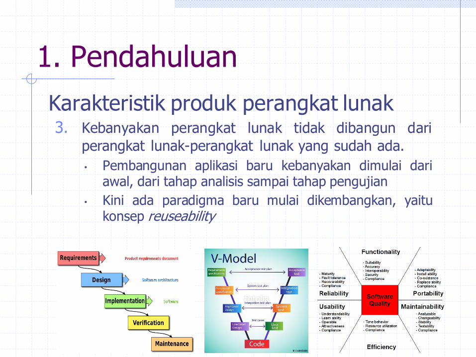
1. Pendahuluan
Karakteristik produk perangkat lunak 3. Kebanyakan perangkat lunak tidak dibangun dari
perangkat lunak-perangkat lunak yang sudah ada.
• Pembangunan aplikasi baru kebanyakan dimulai dari awal, dari tahap analisis sampai tahap pengujian
• Kini ada paradigma baru mulai dikembangkan, yaitu konsep reuseability
1. Pendahuluan
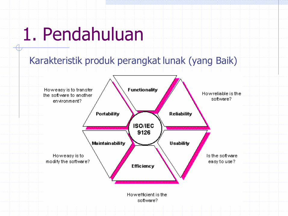
Karakteristik produk perangkat lunak (yang Baik)
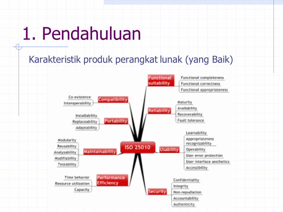
1. Pendahuluan
Karakteristik produk perangkat lunak (yang Baik)
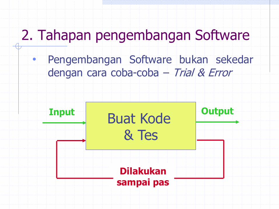
2. Tahapan pengembangan Software
• Pengembangan Software bukan sekedar
dengan cara coba-coba – Trial & Error
Buat Kode & Tes
Dilakukan sampai pas
Input Output
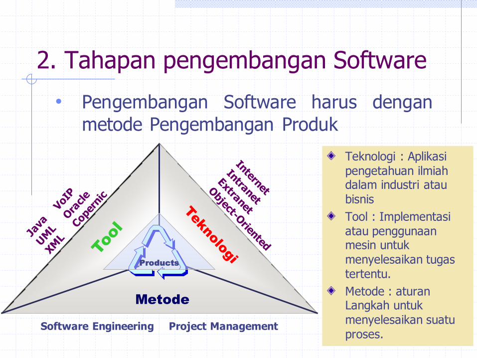
2. Tahapan pengembangan Software
• Pengembangan Software harus dengan
metode Pengembangan Produk
Software Engineering Project Management
Metode
Products
Teknologi : Aplikasi pengetahuan ilmiah dalam industri atau bisnis
Tool : Implementasi atau penggunaan mesin untuk menyelesaikan tugas tertentu.
Metode : aturan Langkah untuk menyelesaikan suatu proses.

2. Tahapan pengembangan Software
Metods
Pr
o
d
u
ct
s
Meth
ods
P
r
o
d
u
c
t
s
Ide
Produk
Manajemen Proyek Software akan mencegah resiko-resiko yang mungkin terjadi dalam proses
pengembangan
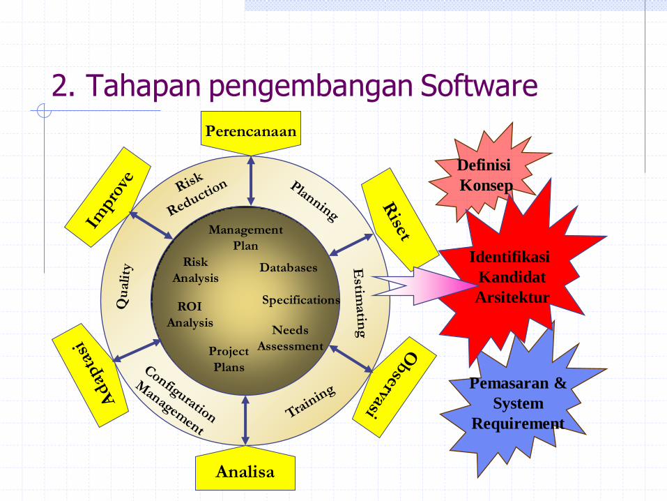
Definisi
Konsep
Needs
Assessment
Perencanaan
Project
Plans
Specifications
Databases
ROI
Analysis
Risk
Analysis
Analisa
Management
Plan
Pemasaran &
System
Requirement
Identifikasi
Kandidat
Arsitektur
2. Tahapan pengembangan Software
13
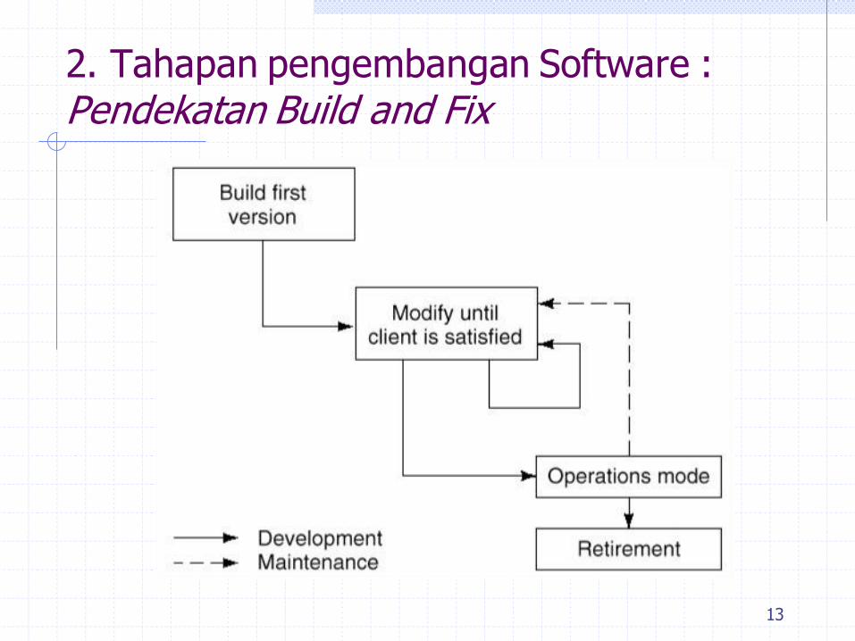
2. Tahapan pengembangan Software : Pendekatan Build and Fix

14
2. Tahapan pengembangan Software : Build and Fix – Kelebihan dan Kekurangan
Kelebihan Kekurangan
Akan bekerja untuk
proyek yang kurang dari
200 LOC (line of code)
Satu langkah ke depan
untuk membuat code
dan tes
Tidak bisa untuk proyek S/W besar
Tidak ada spec S/W
Tidak ada model life
cycle
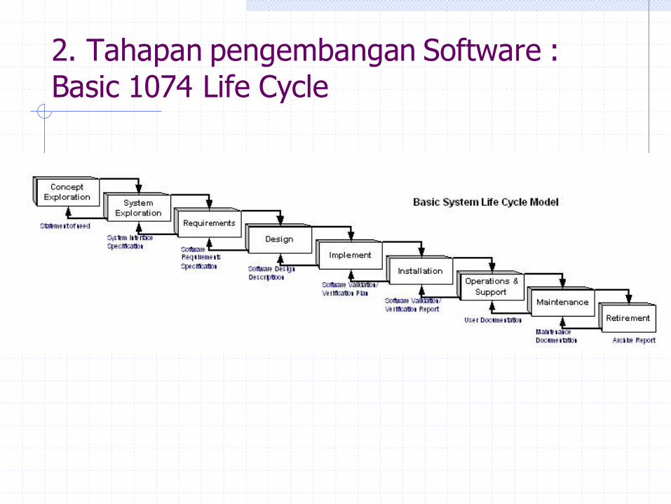
2. Tahapan pengembangan Software : Basic 1074 Life Cycle
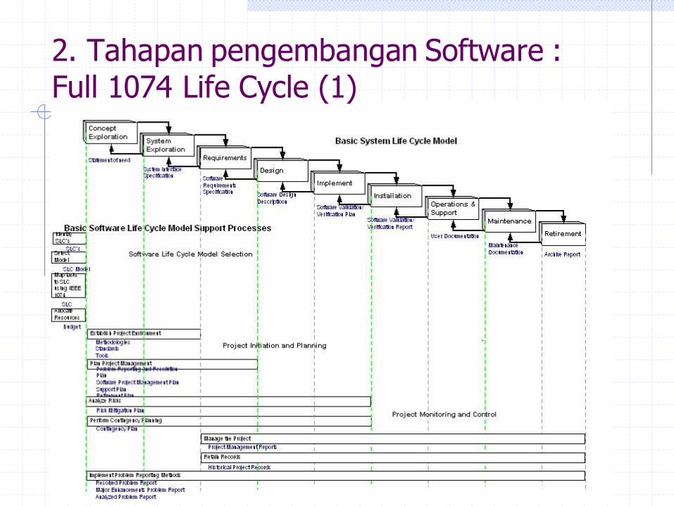
2. Tahapan pengembangan Software : Full 1074 Life Cycle (1)
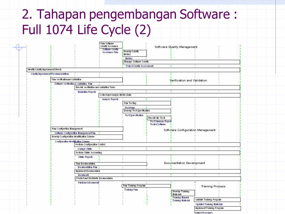
2. Tahapan pengembangan Software : Full 1074 Life Cycle (2)
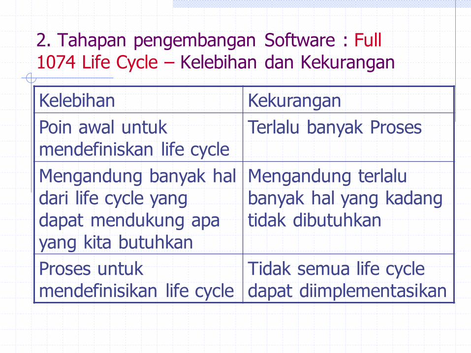
2. Tahapan pengembangan Software : Full
1074 Life Cycle – Kelebihan dan Kekurangan
Kelebihan Kekurangan
Poin awal untuk
mendefiniskan life cycle
Terlalu banyak Proses
Mengandung banyak hal
dari life cycle yang
dapat mendukung apa
yang kita butuhkan
Mengandung terlalu
banyak hal yang kadang
tidak dibutuhkan
Proses untuk
mendefinisikan life cycle
Tidak semua life cycle
dapat diimplementasikan
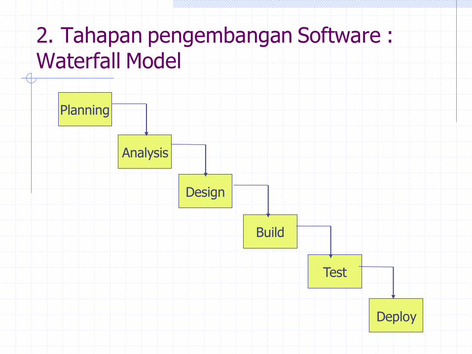
2. Tahapan pengembangan Software : Waterfall Model
Planning
Analysis
Design
Build
Test
Deploy

2. Tahapan pengembangan Software : Waterfall
Model – Kelebihan dan Kekurangan
Kelebihan Kekurangan
Mudah dipahami Tidak membuat model
dunia nyata secara tepat
Mudah diukur Terlalu banyak
dokumentasi
Menerapkan disiplin
Penyebarannya
dikendalikan dengan
dokumen
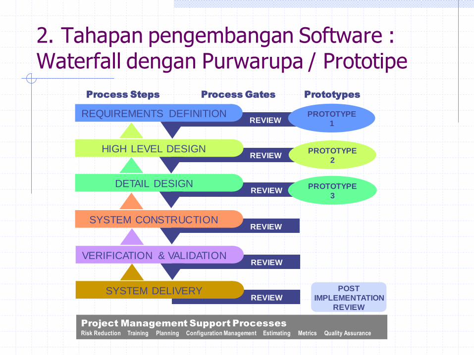
2. Tahapan pengembangan Software : Waterfall dengan Purwarupa / Prototipe
REVIEW DETAIL DESIGN
Process Steps Process Gates Prototypes
REVIEW REQUIREMENTS DEFINITION
REVIEW HIGH LEVEL DESIGN
REVIEW SYSTEM CONSTRUCTION
REVIEW VERIFICATION & VALIDATION
REVIEW SYSTEM DELIVERY
PROTOTYPE
1
PROTOTYPE
2
PROTOTYPE
3
POST
IMPLEMENTATION
REVIEW
Project Management Support Processes
Risk Reduction Training Planning Configuration Management Estimating Metrics Quality Assurance
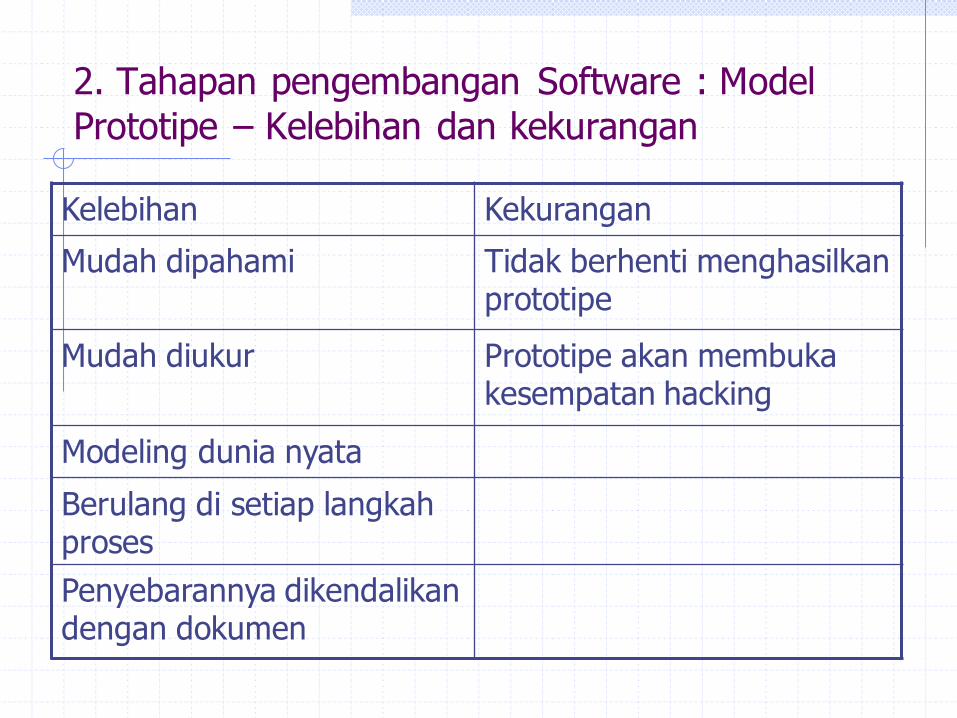
2. Tahapan pengembangan Software : Model
Prototipe – Kelebihan dan kekurangan
Kelebihan Kekurangan
Mudah dipahami Tidak berhenti menghasilkan prototipe
Mudah diukur Prototipe akan membuka kesempatan hacking
Modeling dunia nyata
Berulang di setiap langkah proses
Penyebarannya dikendalikan dengan dokumen

2. Tahapan pengembangan Software : Model Spiral

2. Tahapan pengembangan Software : Model Spiral – Kelebihan dan Kekurangan
Kelebihan Kekurangan
Mengurangi resiko Internal development sistem yang sangat besar
Mendukung penggunaan kembali
Biaya yang cukup mahal
Jaringan Maintenance dan development yang luas
Membutuhkan organisasi yang sudah teritegrasi
Mudah melihat hasil dengan adanya prototipe
Banyak menggunakan tools terkait resiko dan
prototipe
Pengujian fokus ke Resiko

2. Tahapan pengembangan Software : Rapid
Application Development (RAD)

2. Tahapan pengembangan Software : RAD – Kelebihan dan Kekurangan
Kelebihan Kekurangan
Interaksi user yang sangat kompleks
Keterlibatan pengguna sangat tinggi
Cepat mengimplementasikan konsep
Membutuhkan kematangan alat dan proses
Pembangunan secara bertahap dan teratur
Meningkatkan biaya overhead jika terlalu banyak prototipe
Pengendalian pengiriman yang sangat ketat
Penentuan ekspektasi yang buruk dikendalikan sistem

Requirements Waterfall Prototype Spiral RAD
Apakah kebutuhan gampang
didefinisikan atau mudah diketahui? Yes No No Yes
Dapatkan requirement
didefinisikan dalam siklus awal ? Yes No No Yes
Akankah kemudian kebutuhan
bisa berubah dalam siklus ? No Yes Yes No
Adakah kebutuhan
mendemonstrasikan kebutuhan
untuk mendapatkan definisi ?
No Yes Yes Yes
Apakah pembuktian konsep
dibutuhkan utk mendemonstrasikan
kapabilitas s/w ?
No Yes Yes Yes
2. Tahapan pengembangan Software : Memilih Model Life Cycle – Karakteristik Proyek Kategori Matrix
Requirements
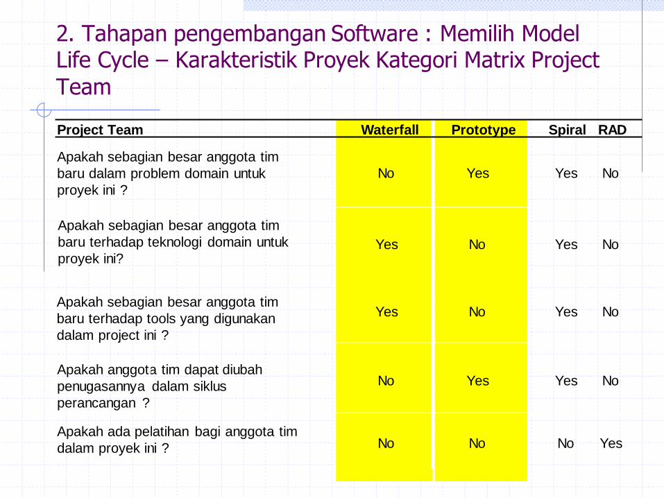
Project Team Waterfall Prototype Spiral RAD
Apakah sebagian besar anggota tim
baru dalam problem domain untuk
proyek ini ?
No Yes Yes No
Yes No Yes No
Yes No Yes No
Apakah anggota tim dapat diubah
penugasannya dalam siklus
perancangan ?
No Yes Yes No
Apakah ada pelatihan bagi anggota tim
dalam proyek ini ? No No No Yes
2. Tahapan pengembangan Software : Memilih Model Life Cycle – Karakteristik Proyek Kategori Matrix Project
Team
Apakah sebagian besar anggota tim
baru terhadap teknologi domain untuk
proyek ini?
Apakah sebagian besar anggota tim
baru terhadap tools yang digunakan
dalam project ini ?
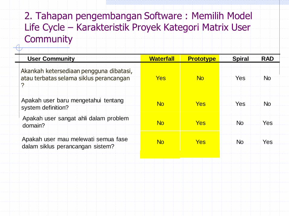
User Community Waterfall Prototype Spiral RAD
Akankah ketersediaan pengguna dibatasi, atau terbatas selama siklus perancangan ?
Yes No Yes No
Apakah user baru mengetahui tentang
system definition? No Yes Yes No
Apakah user sangat ahli dalam problem
domain? No Yes No Yes
Apakah user mau melewati semua fase
dalam siklus perancangan sistem? No Yes No Yes
2. Tahapan pengembangan Software : Memilih Model Life Cycle – Karakteristik Proyek Kategori Matrix User
Community
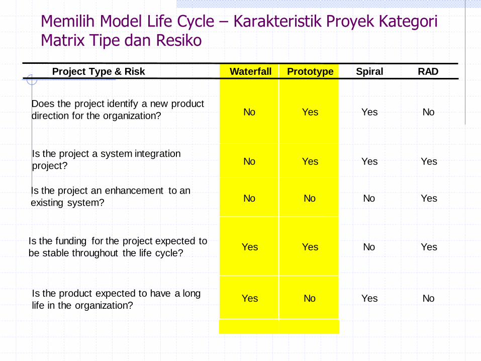
Project Type & Risk Waterfall Prototype Spiral RAD
Does the project identify a new product
direction for the organization? No Yes Yes No
Is the project a system integration
project? No Yes Yes Yes
Is the project an enhancement to an
existing system? No No No Yes
Is the funding for the project expected to
be stable throughout the life cycle? Yes Yes No Yes
Is the product expected to have a long
life in the organization? Yes No Yes No
Memilih Model Life Cycle – Karakteristik Proyek Kategori Matrix Tipe dan Resiko
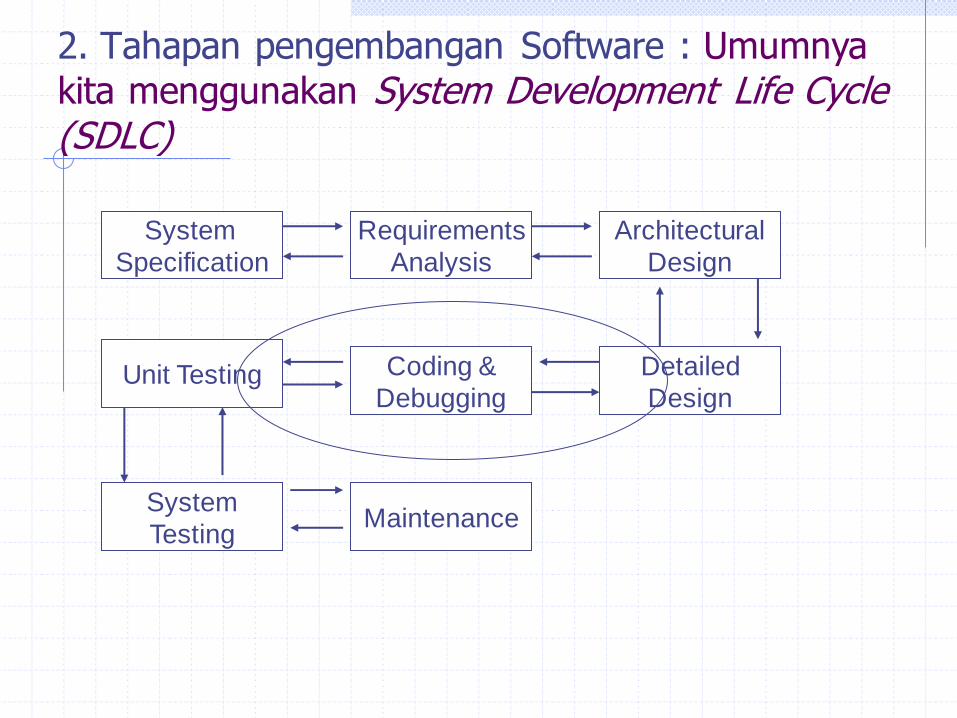
2. Tahapan pengembangan Software : Umumnya
kita menggunakan System Development Life Cycle (SDLC)
System
Specification
Requirements
Analysis
Architectural
Design
Detailed
Design
Coding &
Debugging Unit Testing
System
Testing Maintenance
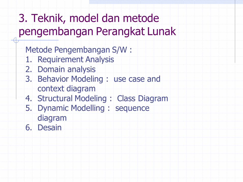
3. Teknik, model dan metode pengembangan Perangkat Lunak
Metode Pengembangan S/W : 1. Requirement Analysis
2. Domain analysis 3. Behavior Modeling : use case and
context diagram
4. Structural Modeling : Class Diagram 5. Dynamic Modelling : sequence
diagram 6. Desain
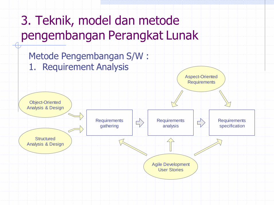
3. Teknik, model dan metode pengembangan Perangkat Lunak
Metode Pengembangan S/W : 1. Requirement Analysis
Requirements
analysis
Requirements
gathering
Requirements
specification
Agile Development
User Stories
Aspect-Oriented
Requirements
Object-Oriented
Analysis & Design
Structured
Analysis & Design
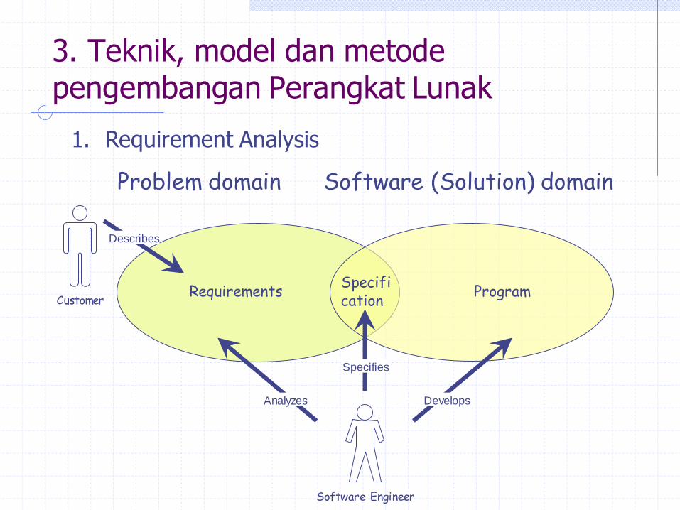
3. Teknik, model dan metode pengembangan Perangkat Lunak
1. Requirement Analysis
Problem domain
Specifi cation Customer
Software Engineer
Describes
Specifies
Requirements Program
Software (Solution) domain
Analyzes Develops
Bank’s
remote
datacenter
Bank
customer
ATM machine
12
345
678
90
12
345
678
90
12
345
678
90Communication link
35
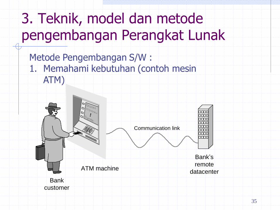
3. Teknik, model dan metode pengembangan Perangkat Lunak
Metode Pengembangan S/W : 1. Memahami kebutuhan (contoh mesin
ATM)
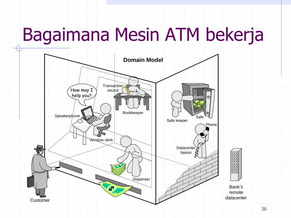
Bagaimana Mesin ATM bekerja
Window clerk
Bookkeeper
Safe keeper
Datacenter
liaison
Dispenser
Safe
Cash
Transaction
record
Phone
Speakerphone
Bank’s
remote
datacenter
Domain Model
How may I help you?
Customer
36
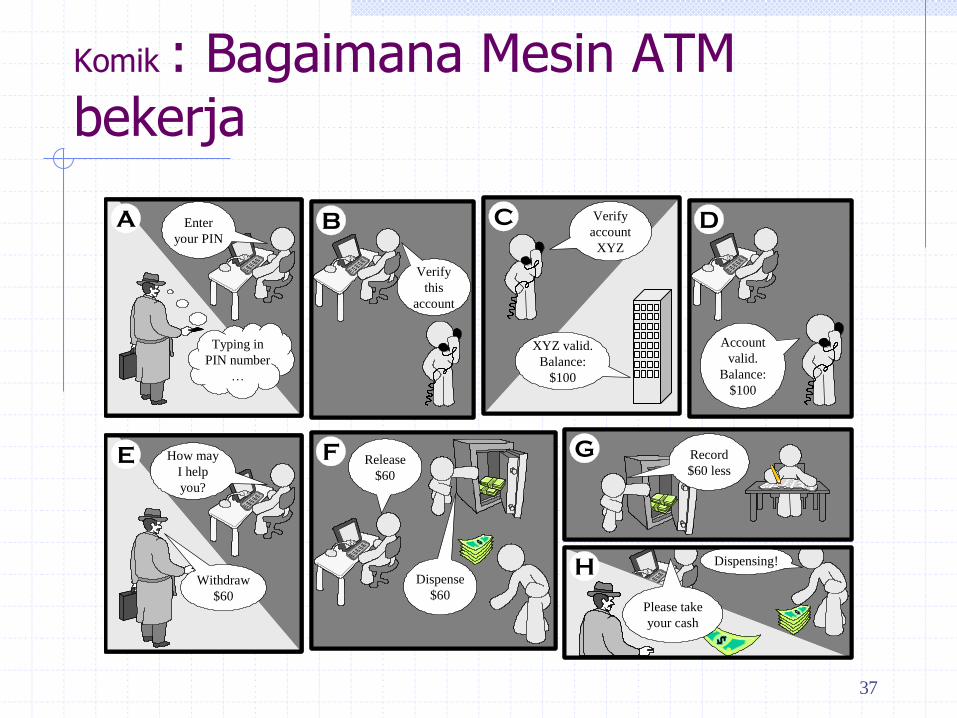
Komik : Bagaimana Mesin ATM bekerja
B
Verify
this
account
B
Verify
this
account
C Verify
account
XYZ
XYZ valid.
Balance:
$100
C Verify
account
XYZ
XYZ valid.
Balance:
$100
D
Account
valid.
Balance:
$100
D
Account
valid.
Balance:
$100
G Record
$60 less
G Record
$60 less
A Enter
your PIN
Typing in
PIN number
…
A Enter
your PIN
Typing in
PIN number
…
E How may
I help
you?
Withdraw
$60
E How may
I help
you?
Withdraw
$60
F Release
$60
Dispense
$60
F Release
$60
Dispense
$60
H
Please take
your cash
Dispensing!H
Please take
your cash
Dispensing!
37
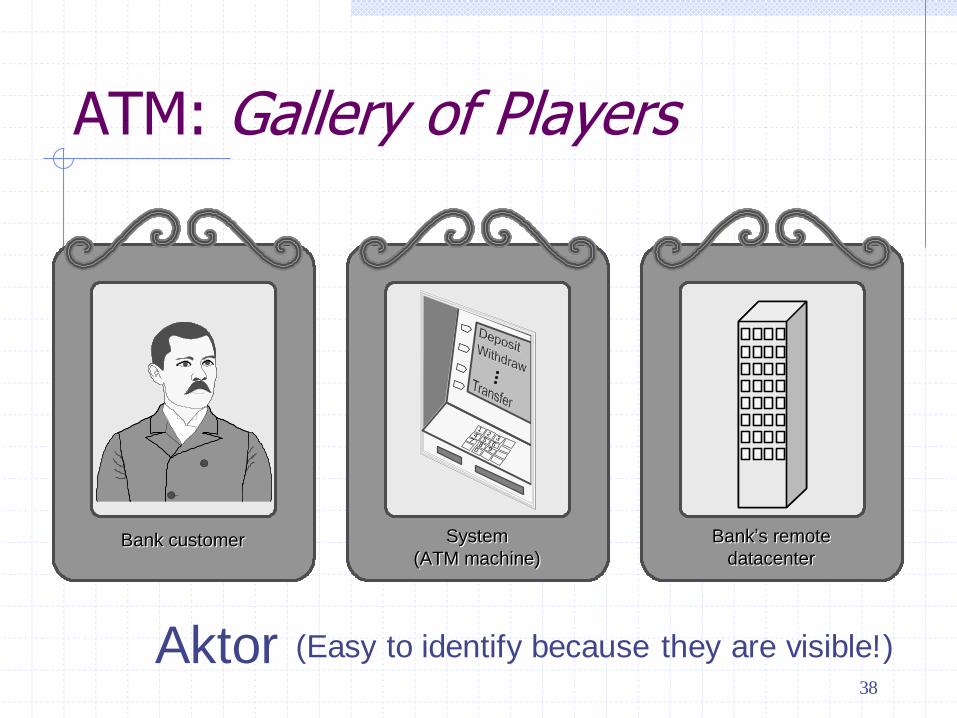
ATM: Gallery of Players
Aktor (Easy to identify because they are visible!)
Bank’s remote
datacenter
System
(ATM machine)Bank customer
12
345
67
890
12
345
67
890
Bank’s remote
datacenter
System
(ATM machine)Bank customer
38

Gallery of Workers + Tools
Konsep (Hard to identify because they are invisible/imaginary!)
Window clerk Bookkeeper Safe keeperDatacenter
liaisonDispenser
Safe CashTransaction
recordTelephoneSpeakerphone
39
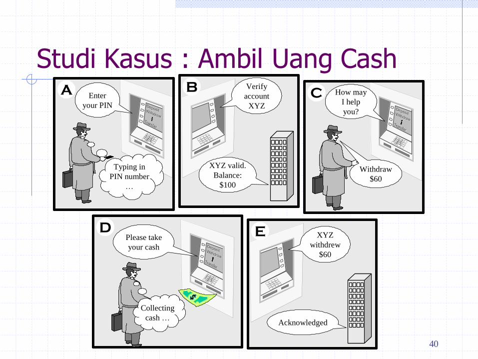
Studi Kasus : Ambil Uang Cash B Verify
account
XYZ
XYZ valid.
Balance:
$100
B Verify
account
XYZ
XYZ valid.
Balance:
$100
12
345
678
90
12
345
678
90
C How may
I help
you?
Withdraw
$60
12
345
678
90
12
345
678
90
C How may
I help
you?
Withdraw
$60
12
345
678
90
12
345
678
90
A Enter
your PIN
Typing in
PIN number
…
12
345
678
90
12
345
678
90
A Enter
your PIN
Typing in
PIN number
…
D
12
345
678
90
12
345
678
90
Please take
your cash
Collecting
cash …
D
12
345
678
90
12
345
678
90
Please take
your cash
Collecting
cash …
E XYZ
withdrew
$60
Acknowledged
E XYZ
withdrew
$60
Acknowledged
40

41
Contoh User Stories
Identifier User Story Size
ST-1 As an authorized person (tenant or landlord), I can keep the doors locked at all
times. 4 points
ST-2 As an authorized person (tenant or landlord), I can lock the doors on demand. 3 pts
ST-3 The lock should be automatically locked after a defined period of time. 6 pts
ST-4 As an authorized person (tenant or landlord), I can unlock the doors.
(Test: Allow a small number of mistakes, say three.) 9 points
ST-5 As a landlord, I can at runtime manage authorized persons. 10 pts
ST-6 As an authorized person (tenant or landlord), I can view past accesses. 6 pts
ST-7 As a tenant, I can configure the preferences for activation of various devices. 6 pts
ST-8 As a tenant, I can file complaint about “suspicious” accesses. 6 pts
• Note no priorities for user stories.
• Story priority is given by its order of appearance on the work backlog (described next)
• Size points (last column) will be described later

Contoh Hasil Requirement Analysis
Identifier Priority Requirement
REQ1 5
The system shall keep the door locked at all times, unless commanded otherwise by
authorized user. When the lock is disarmed, a countdown shall be initiated at the end
of which the lock shall be automatically armed (if still disarmed).
REQ2 2 The system shall lock the door when commanded by pressing a dedicated button.
REQ3 5 The system shall, given a valid key code, unlock the door and activate other devices.
REQ4 4
The system should allow mistakes while entering the key code. However, to resist “dictionary
attacks,” the number of allowed failed attempts shall be small, say three, after which the system
will block and the alarm bell shall be sounded.
REQ5 2 The system shall maintain a history log of all attempted accesses for later review.
REQ6 2 The system should allow adding new authorized persons at runtime or removing existing ones.
REQ7 2 The system shall allow configuring the preferences for device activation when the user provides a
valid key code, as well as when a burglary attempt is detected.
REQ8 1
The system should allow searching the history log by specifying one or more of these parameters:
the time frame, the actor role, the door location, or the event type (unlock, lock, power failure, etc.).
This function shall be available over the Web by pointing a browser to a specified URL.
REQ9 1 The system should allow filing inquiries about “suspicious” accesses. This function shall be
available over the Web.

3. Teknik, model dan metode pengembangan Perangkat Lunak
Metode Pengembangan S/W : 2. Domain analysis
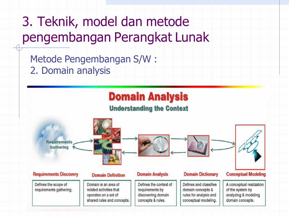
3. Teknik, model dan metode pengembangan Perangkat Lunak
Metode Pengembangan S/W : 2. Domain analysis
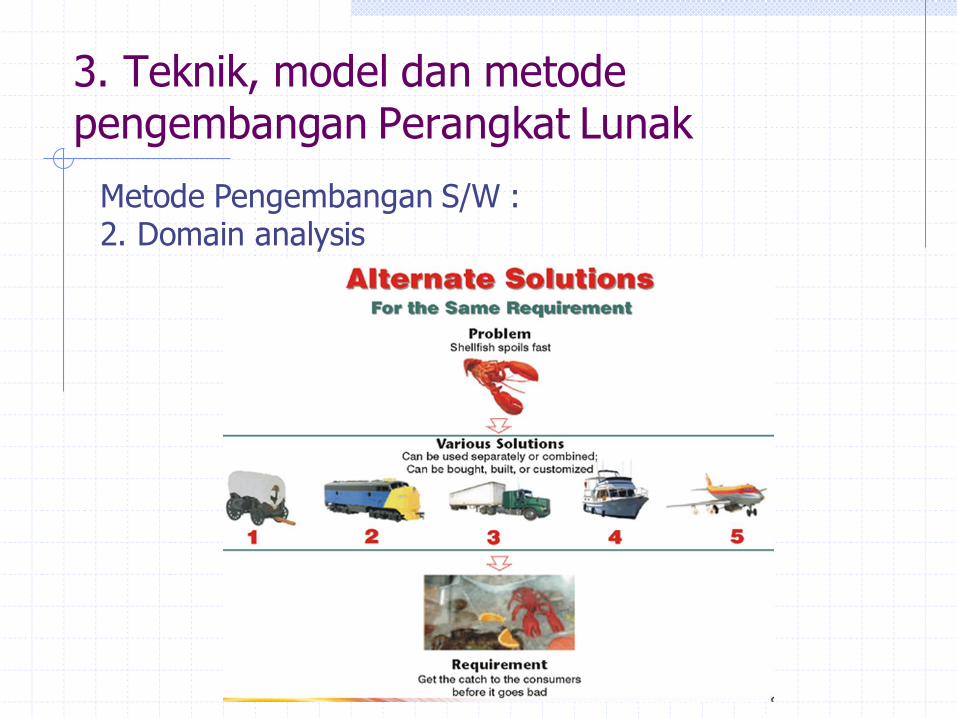
3. Teknik, model dan metode pengembangan Perangkat Lunak
Metode Pengembangan S/W : 2. Domain analysis

3. Teknik, model dan metode pengembangan Perangkat Lunak
Metode Pengembangan S/W : 2. Domain analysis
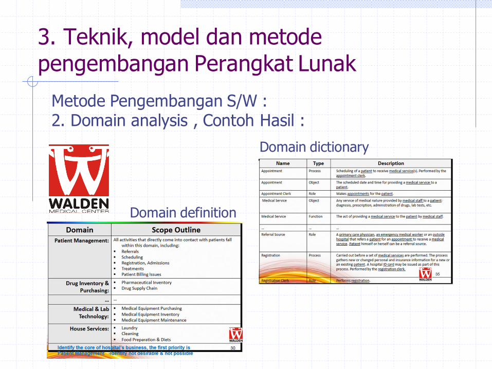
3. Teknik, model dan metode pengembangan Perangkat Lunak
Metode Pengembangan S/W : 2. Domain analysis , Contoh Hasil :
Domain definition
Domain dictionary

Penentuan Domain Anaysis : Bagaimana Pemula membagi Pekerjaannya
List the components of the system-to-be
Each sub-group of one or more team members is assigned a different component to develop
One or more team members is assigned to “write documentation”
“Chain” organization—every link is critical If any link fails, the whole project fails
Separation of concerns is impossible
48
User Interface Business Logic
and Algorithms
Database/
Network Documentation
49
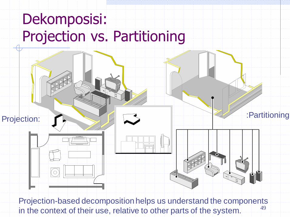
Dekomposisi: Projection vs. Partitioning
Projection: :Partitioning
Projection-based decomposition helps us understand the components
in the context of their use, relative to other parts of the system.
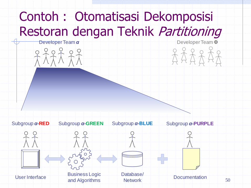
Contoh : Otomatisasi Dekomposisi Restoran dengan Teknik Partitioning
50 User Interface
Business Logic
and Algorithms
Database/
Network Documentation
Developer Team α Developer Team Φ
Subgroup α-RED Subgroup α-GREEN Subgroup α-BLUE Subgroup α-PURPLE

Contoh : Otomatisasi Restoran Beban Komunikasi
51 User Interface
Business Logic
and Algorithms
Database/
Network Documentation
Developer Team α Developer Team Φ
Interface for what functions?
What to write about?
Function-1: description Function-2:
description …
Tables for what data?

Contoh : Otomatisasi Dekomposisi Restoran dengan Teknik Projection
Different way of “slicing” the project:
Instead of horizontal slicing, we have vertical slicing—”stacks”
Each “stack” can be done independently of other stacks, as a mini-project
Separation of concerns!
52
Developer Team α Developer Team Φ
Subgroup
Φ-RED
Subgroup
Φ-GREEN
Subgroup
Φ-BLUE
Shared Infrastructure
Customer-related
functions
Kitchen-related
functions
Management-
related functions
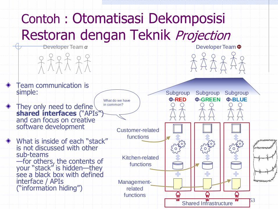
Contoh : Otomatisasi Dekomposisi Restoran dengan Teknik Projection
Team communication is simple:
They only need to define shared interfaces (“APIs”) and can focus on creative software development
What is inside of each “stack” is not discussed with other sub-teams —for others, the contents of your “stack” is hidden—they see a black box with defined interface / APIs (“information hiding”)
53
Developer Team α Developer Team Φ
Subgroup
Φ-RED
Subgroup
Φ-GREEN
Subgroup
Φ-BLUE
Shared Infrastructure
Customer-related
functions
Kitchen-related
functions
Management-
related functions
What do we have in common?
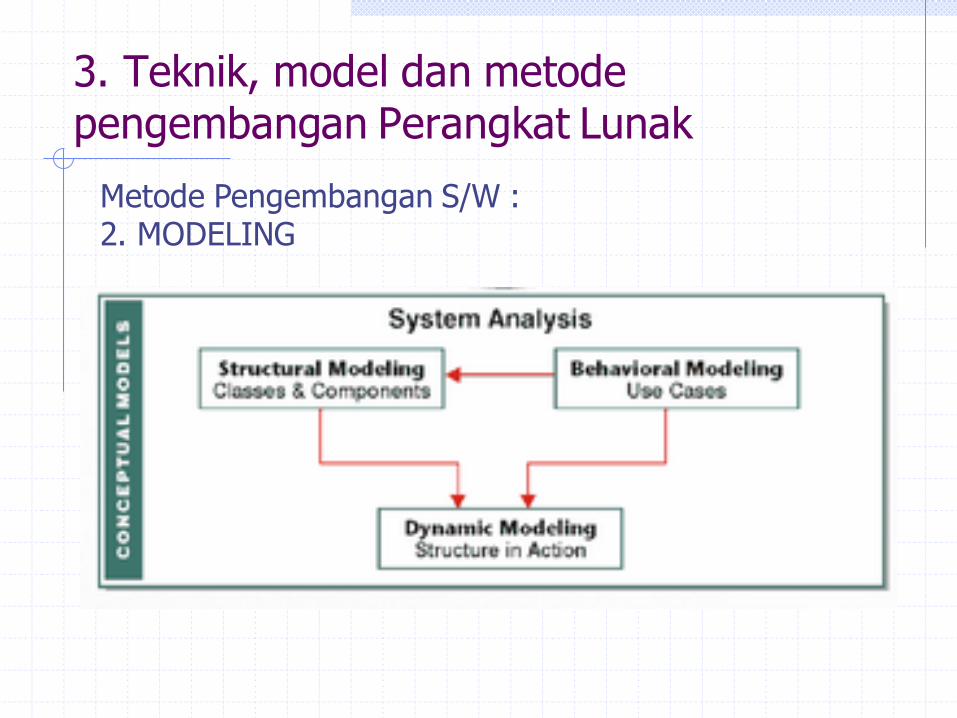
3. Teknik, model dan metode pengembangan Perangkat Lunak
Metode Pengembangan S/W : 2. MODELING

3. Teknik, model dan metode pengembangan Perangkat Lunak
Metode Pengembangan S/W : 3. Behavior Modeling : use case and
context diagram
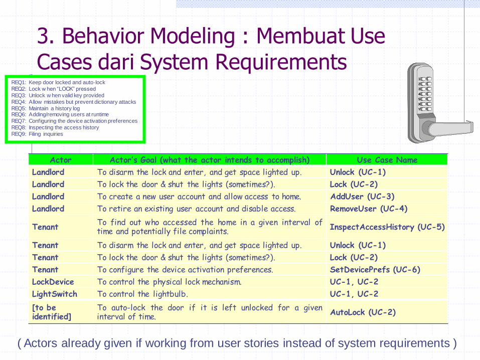
3. Behavior Modeling : Membuat Use Cases dari System Requirements
REQ1: Keep door locked and auto-lock
REQ2: Lock w hen “LOCK” pressed
REQ3: Unlock w hen valid key provided
REQ4: Allow mistakes but prevent dictionary attacks
REQ5: Maintain a history log REQ6: Adding/removing users at runtime
REQ7: Configuring the device activation preferences
REQ8: Inspecting the access history
REQ9: Filing inquiries
( Actors already given if working from user stories instead of system requirements )
1
2
3
4
5
X
Y
1
2
3
4
5
X
Y
Actor Actor’s Goal (what the actor intends to accomplish) Use Case Name
Landlord To disarm the lock and enter, and get space lighted up. Unlock (UC-1)
Landlord To lock the door & shut the lights (sometimes?). Lock (UC-2)
Landlord To create a new user account and allow access to home. AddUser (UC-3)
Landlord To retire an existing user account and disable access. RemoveUser (UC-4)
Tenant To find out who accessed the home in a given interval of time and potentially file complaints. InspectAccessHistory (UC-5)
Tenant To disarm the lock and enter, and get space lighted up. Unlock (UC-1)
Tenant To lock the door & shut the lights (sometimes?). Lock (UC-2)
Tenant To configure the device activation preferences. SetDevicePrefs (UC-6)
LockDevice To control the physical lock mechanism. UC-1, UC-2
LightSwitch To control the lightbulb. UC-1, UC-2
[to be identified]
To auto-lock the door if it is left unlocked for a given interval of time. AutoLock (UC-2)

3. Behavior Modeling : Use Case Diagram - Device Control UC1: Unlock
UC2: Lock
UC3: AddUser
UC4: RemoveUser
UC5: InspectAccessHistory UC6: SetDevicePrefs
UC7: AuthenticateUser
UC8: Login
«participate»
«initiate + participate»
«participate»
«participate»
«participate»
«participate»
First tier use cases Second tier use casessystem
boundary
communication
«include»
use case
«initiate»
«initiate»
Timer
LightSwitch
LockDevice
«initiate
»Tenant
Landlord
actor
«initiate»
UC1: Unlock
UC2: Lock
UC7: AuthenticateUser

3. Behavior Modeling : Use Case Diagram - Account Management UC1: Unlock
UC2: Lock
UC3: AddUser
UC4: RemoveUser
UC5: InspectAccessHistory UC6: SetDevicePrefs
UC7: AuthenticateUser
UC8: Login
Account Management Subsystem
«initiate»
Tenant
Landlord«include»
«include»«parti
cipa
te»
«initiate»«i
nclu
de»
«include»
«initiate»
«initiate»
UC8: Login
UC4: RemoveUser
UC6: SetDevicePrefs
UC3: AddUser
UC5: InspectAccessHistory
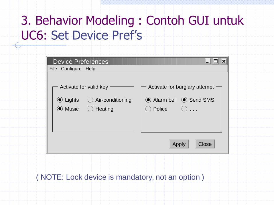
3. Behavior Modeling : Contoh GUI untuk UC6: Set Device Pref’s
( NOTE: Lock device is mandatory, not an option )
Device PreferencesFile Configure Help
CloseApply
Activate for burglary attemptActivate for burglary attempt
Alarm bellAlarm bell
PolicePolice ……
Activate for valid keyActivate for valid key
LightsLights
MusicMusic
AirAir--conditioningconditioning
HeatingHeating
Send SMSSend SMS

3. Behavior Modeling : Contoh Use Case 1- Unlock
Use Case UC-1: Unlock
Related Requirem’ts:
REQ1, REQ3, REQ4, and REQ5 stated in Table 2-1
Initiating Actor: Any of: Tenant, Landlord
Actor’s Goal: To disarm the lock and enter, and get space lighted up automatically.
Participating Actors:
LockDevice, LightSwitch, Timer
Preconditions: • The set of valid keys stored in the system database is non-empty.
• The system displays the menu of available functions; at the door keypad the menu choices are “Lock” and “Unlock.”
Postconditions: The auto-lock timer has started countdown from autoLockInterval.
Flow of Events for Main Success Scenario: 1. Tenant/Landlord arrives at the door and selects the menu item “Unlock” 2. include::AuthenticateUser (UC-7)
3. System (a) signals to the Tenant/Landlord the lock status, e.g., “disarmed,” (b) signals to LockDevice to disarm the lock, and (c) signals to LightSwitch to turn the light on
4. System signals to the Timer to start the auto-lock timer countdown
5. Tenant/Landlord opens the door, enters the home [and shuts the door and locks]
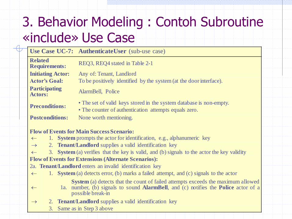
3. Behavior Modeling : Contoh Subroutine «include» Use Case
Use Case UC-7: AuthenticateUser (sub-use case)
Related Requirements:
REQ3, REQ4 stated in Table 2-1
Initiating Actor: Any of: Tenant, Landlord
Actor’s Goal: To be positively identified by the system (at the door interface).
Participating Actors:
AlarmBell, Police
Preconditions: • The set of valid keys stored in the system database is non-empty.
• The counter of authentication attempts equals zero.
Postconditions: None worth mentioning.
Flow of Events for Main Success Scenario: 1. System prompts the actor for identification, e.g., alphanumeric key
2. Tenant/Landlord supplies a valid identification key
3. System (a) verifies that the key is valid, and (b) signals to the actor the key validity
Flow of Events for Extensions (Alternate Scenarios):
2a. Tenant/Landlord enters an invalid identification key
1. System (a) detects error, (b) marks a failed attempt, and (c) signals to the actor
1a. System (a) detects that the count of failed attempts exceeds the maximum allowed number, (b) signals to sound AlarmBell, and (c) notifies the Police actor of a possible break-in
2. Tenant/Landlord supplies a valid identification key
3. Same as in Step 3 above
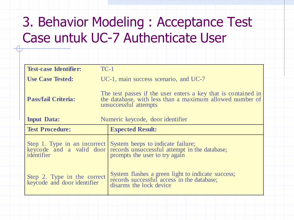
3. Behavior Modeling : Acceptance Test Case untuk UC-7 Authenticate User
Test-case Identifier: TC-1
Use Case Tested: UC-1, main success scenario, and UC-7
Pass/fail Criteria: The test passes if the user enters a key that is contained in the database, with less than a maximum allowed number of unsuccessful attempts
Input Data: Numeric keycode, door identifier
Test Procedure: Expected Result:
Step 1. Type in an incorrect keycode and a valid door identifier
System beeps to indicate failure; records unsuccessful attempt in the database; prompts the user to try again
Step 2. Type in the correct keycode and door identifier
System flashes a green light to indicate success; records successful access in the database; disarms the lock device
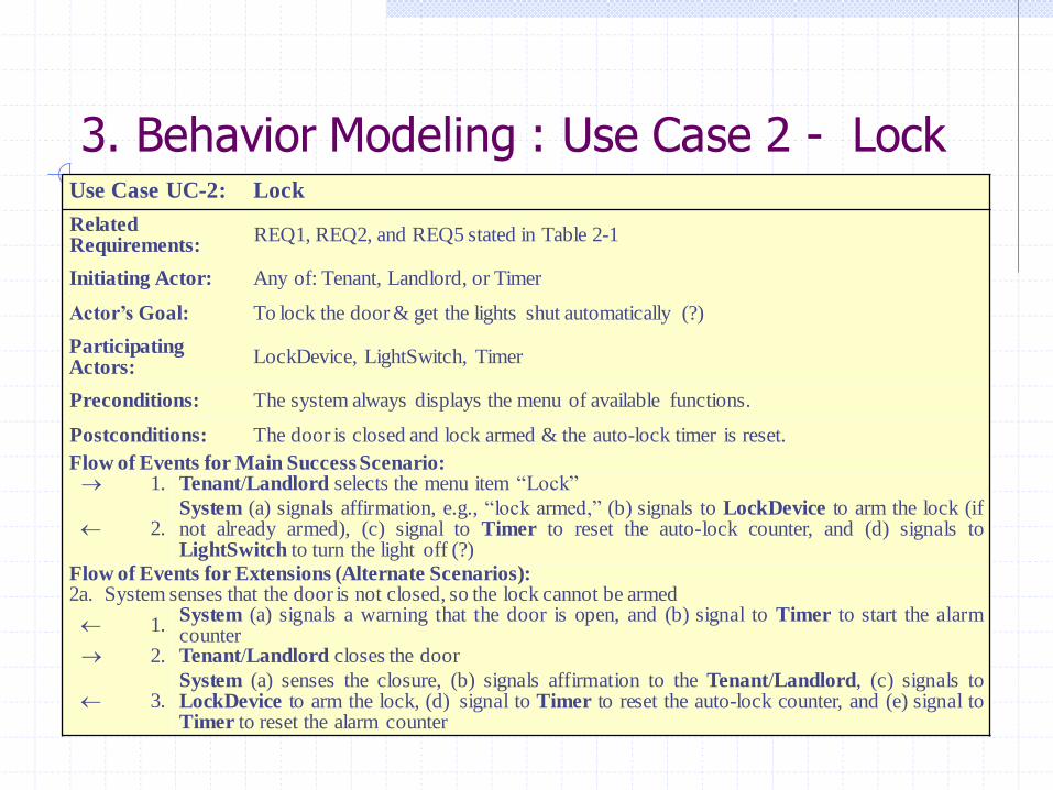
3. Behavior Modeling : Use Case 2 - Lock Use Case UC-2: Lock
Related Requirements:
REQ1, REQ2, and REQ5 stated in Table 2-1
Initiating Actor: Any of: Tenant, Landlord, or Timer
Actor’s Goal: To lock the door & get the lights shut automatically (?)
Participating Actors:
LockDevice, LightSwitch, Timer
Preconditions: The system always displays the menu of available functions.
Postconditions: The door is closed and lock armed & the auto-lock timer is reset.
Flow of Events for Main Success Scenario: 1. Tenant/Landlord selects the menu item “Lock”
2. System (a) signals affirmation, e.g., “lock armed,” (b) signals to LockDevice to arm the lock (if not already armed), (c) signal to Timer to reset the auto-lock counter, and (d) signals to LightSwitch to turn the light off (?)
Flow of Events for Extensions (Alternate Scenarios): 2a. System senses that the door is not closed, so the lock cannot be armed
1. System (a) signals a warning that the door is open, and (b) signal to Timer to start the alarm counter
2. Tenant/Landlord closes the door
3. System (a) senses the closure, (b) signals affirmation to the Tenant/Landlord, (c) signals to LockDevice to arm the lock, (d) signal to Timer to reset the auto-lock counter, and (e) signal to Timer to reset the alarm counter

3. Behavior Modeling : Diagram Konteks
Diagram konteks adalah diagram yang terdiri dari suatu proses dan menggambarkan ruang lingkup suatu sistem. Diagram konteks merupakan level tertinggi dari DFD yang menggambarkan seluruh input ke dalam sistem atau output dari sistem yang memberi gambaran tentang keseluruhan sistem.
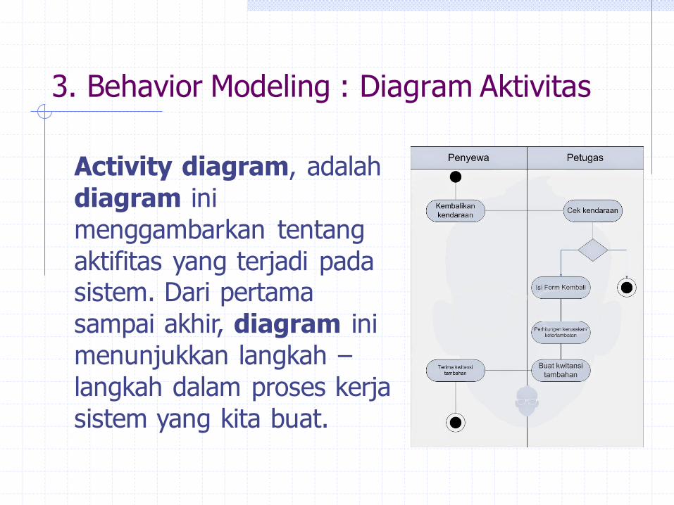
3. Behavior Modeling : Diagram Aktivitas
Activity diagram, adalah
diagram ini
menggambarkan tentang
aktifitas yang terjadi pada sistem. Dari pertama
sampai akhir, diagram ini
menunjukkan langkah –
langkah dalam proses kerja
sistem yang kita buat.

Behavior Modeling : Diagram Aktivitas
Select
“Unlock”
Enter Key
Verify Key
Signal
Success
Open Lock &
Lit Light
Start Autolock
Timer
[authorized]
Notify
Intrusion
Sound Alarm
[not authorized]
Initial
node
Activity
final node
Decision
Merge
Action
Select
“Unlock”
Enter Key
Verify Key
Signal
Success
Open Lock &
Lit Light
Start Autolock
Timer
[authorized]
Notify
Intrusion
Sound Alarm
[not authorized]
Initial
node
Activity
final node
Decision
Merge
Action
1
2
3
4
5
X
Y
1
2
3
4
5
X
Y
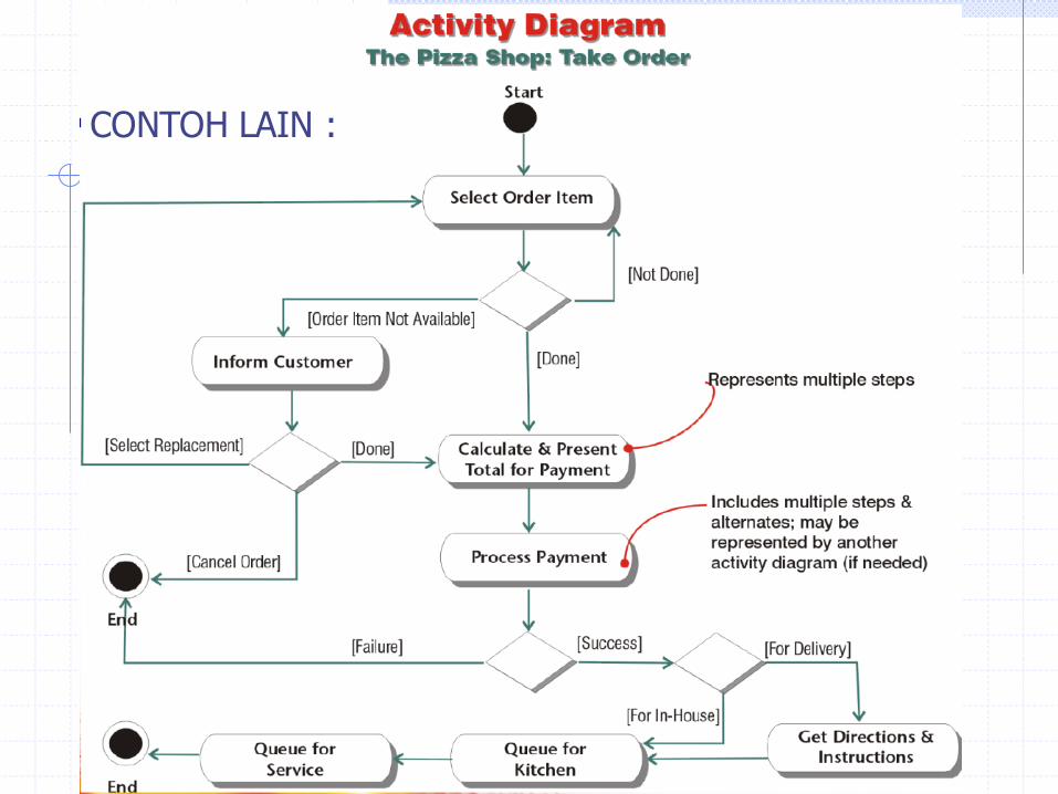
CONTOH LAIN :
3. Teknik, model dan metode pengembangan Perangkat Lunak
Metode Pengembangan S/W : 4. Structural Modeling : Class Diagram
Class diagram adalah model statis yang menggambarkan struktur dan deskripsi class serta
hubungannya antara class. Class diagram mirip ER-Diagram pada perancangan database, bedanya pada ER-diagram tdk terdapat operasi/metode tapi
hanya atribut. Class terdiri dari nama kelas, atribut dan operasi/metode.
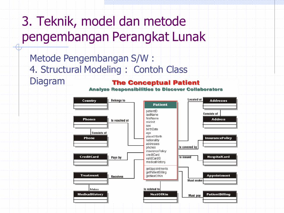
3. Teknik, model dan metode pengembangan Perangkat Lunak
Metode Pengembangan S/W : 4. Structural Modeling : Contoh Class
Diagram
3. Teknik, model dan metode pengembangan Perangkat Lunak
Metode Pengembangan S/W : 5. Dynamic Modelling - Sequence diagram
Sequence diagram adalah suatu penyajian perilaku yang tersusun sebagai langkah-langkah
percontohan dari waktu ke waktu. Sequence diagram digunakan untuk arus pekerjaan, pesan yang disampaikan dan bagaimana elemen-
elemen di dalamnya bekerja sama dari waktu ke waktu untuk mencapai suatu tujuan.
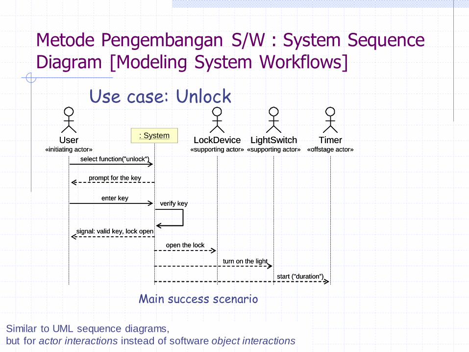
Metode Pengembangan S/W : System Sequence
Diagram [Modeling System Workflows]
Use case: Unlock
Main success scenario
Similar to UML sequence diagrams,
but for actor interactions instead of software object interactions
select function(“unlock")
: SystemUser
«initiating actor»
prompt for the key
enter keyverify key
signal: valid key, lock open
open the lock
LightSwitch«supporting actor»
turn on the light
LockDevice«supporting actor»
Timer«offstage actor»
start ("duration“)
select function(“unlock")
: SystemUser
«initiating actor»
prompt for the key
enter keyverify key
signal: valid key, lock open
open the lock
LightSwitch«supporting actor»
turn on the light
LockDevice«supporting actor»
Timer«offstage actor»
start ("duration“)

Metode Pengembangan S/W : System Sequence
Diagram [Modeling System Workflows]
Use case: Unlock
Alternate scenario (burglary attempt)
select function(“unlock")
: SystemUser
«initiating actor»
prompt for the key
enter keyverify key
signal: invalid key
prompt to try again
AlarmBell«supporting actor»
loop
sound alarm
Police«offstage actor»
notify intrusion
select function(“unlock")
: SystemUser
«initiating actor»
prompt for the key
enter keyverify key
signal: invalid key
prompt to try again
AlarmBell«supporting actor»
loop
sound alarm
Police«offstage actor»
notify intrusion
3. Teknik, model dan metode pengembangan Perangkat Lunak
3. Teknik, model dan metode pengembangan Perangkat Lunak
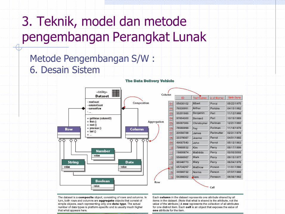
Metode Pengembangan S/W : 6. Desain Sistem

Metode Pengembangan S/W : 6. Desain Sistem

Metode Pengembangan S/W : 6. Desain Sistem
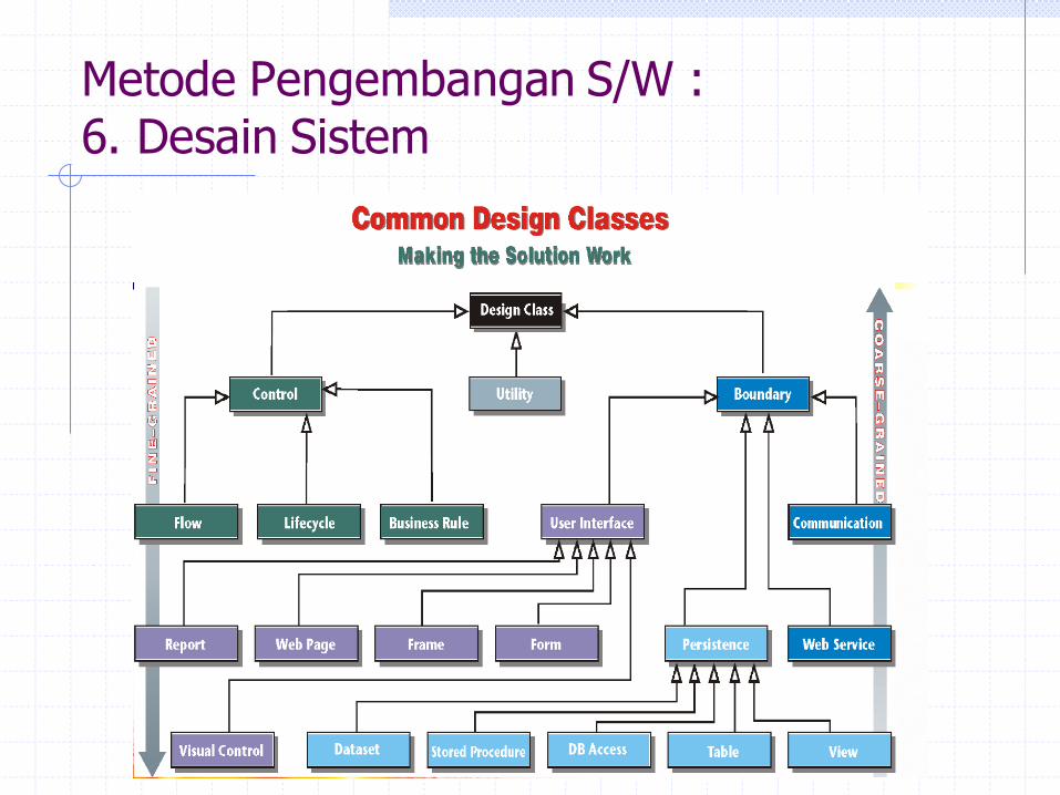
Metode Pengembangan S/W : 6. Desain Sistem
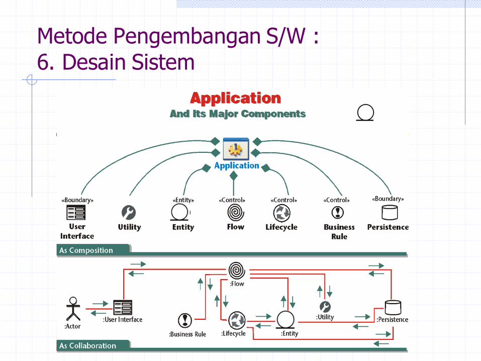
Metode Pengembangan S/W : 6. Desain Sistem
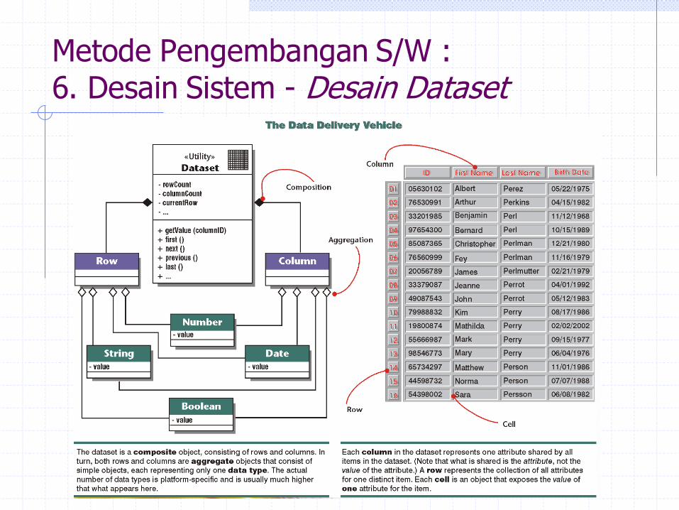
Metode Pengembangan S/W : 6. Desain Sistem - Desain Dataset
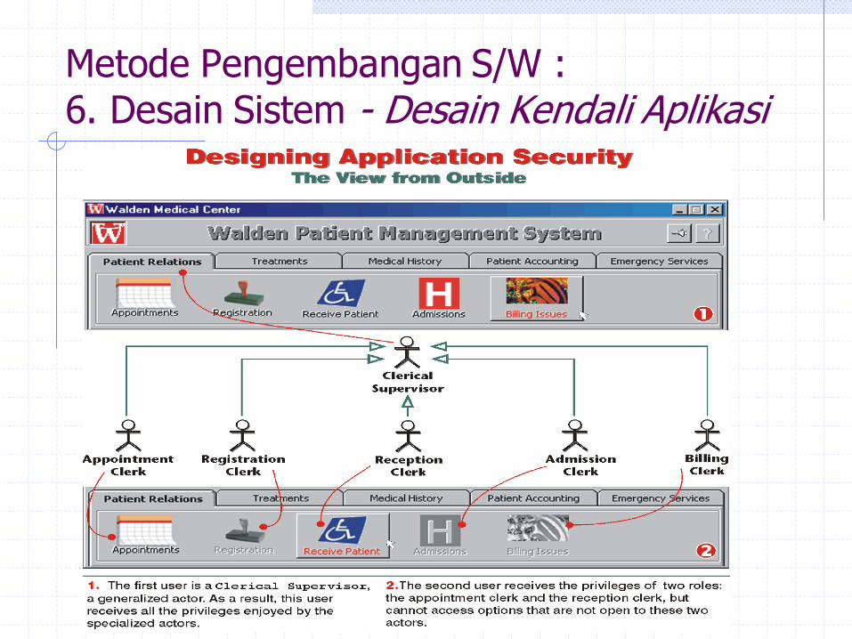
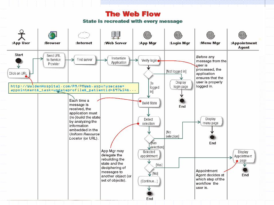
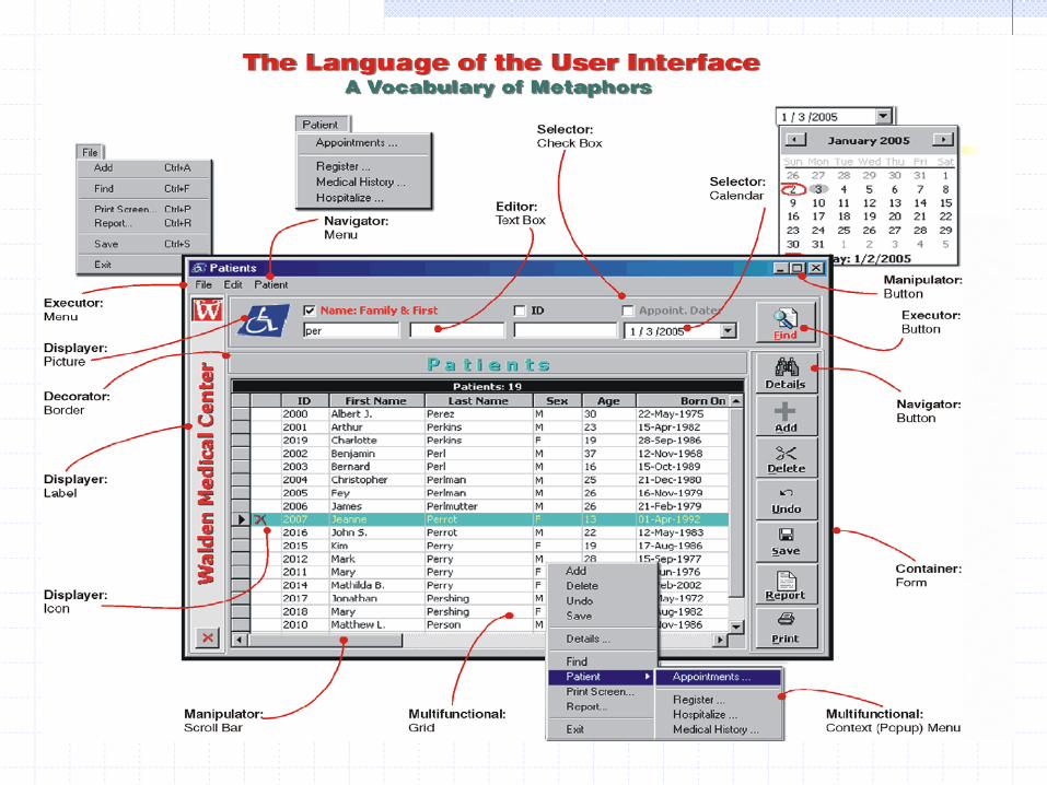
Metode Pengembangan S/W : 6. Desain Sistem - Desain Kendali Aplikasi


Selamat Berkarya GUNADARMA !
Top Related
Copyright © 2022 FDOKUMEN

