Vol lume-IIB B - NBPPL
579
BHEL SPEC Rev. No.: 0 ` N C. NO. : PE-TS- 01 Dated : 11.06 NTPC-BH FG FGU -404-165-N001 6.14 HEL POW TE C GUTPP-STA OW A BHARAT TECHN COOL UTPP STAGE‐ TECH WER PR ECHNICAL COOLING T AGE IV (1X Vol WNER: N ARCHITECT T HEAVY E Project Engi Power Sec Sector-1 NICAL SPECIF ING TOWER P ‐IV (1X 500 M HNICAL SPEC ROJECT L SPECIFIC OF TOWER PA FOR X500 MW) A lume-IIB NTPC L ENGINEERI ELECTRIC ineering Mana ctor, PPEI Bu 6A, Noida-210 ICATIONS PACKAGE MW) AT UNCH CIFICATIONS TS PRIVA CATIONS ACKAGE AT UNCHA B IMITED ING FIRM CALS LIMI agement uilding 0301 HAHAR DOC. NO Rev. No.: ATE LIM AHAR (UP) D ITED .: NBPPL-004-1 01 MITED 103-03-P4M-A 1
-
Upload
khangminh22 -
Category
Documents
-
view
1 -
download
0
Transcript of Vol lume-IIB B - NBPPL

BHEL SPEC Rev. No.: 0
`
N
C. NO. : PE-TS-01 Dated : 11.06
NTPC-BH
FG
FGU
-404-165-N001 6.14
HEL POW
TE
C
GUTPP-STA
OW
ABHARAT
TECHNCOOL
UTPP STAGE‐
TECH
WER PR
ECHNICAL
COOLING T
AGE IV (1X
Vol
WNER: N
ARCHITECT T HEAVY E
Project EngiPower Sec
Sector-1
NICAL SPECIFING TOWER P‐IV (1X 500 M
HNICAL SPEC
ROJECT
L SPECIFICOF
TOWER PAFOR
X500 MW) A
lume-IIB
NTPC L
ENGINEERIELECTRICineering Manactor, PPEI Bu6A, Noida-210
ICATIONS PACKAGE
MW) AT UNCH
CIFICATIONS
TS PRIVA
CATIONS
ACKAGE
AT UNCHA
B
IMITED
ING FIRM CALS LIMIagement
uilding 0301
HAHAR
DOC. NORev. No.:
ATE LIM
AHAR (UP)
D
ITED
.: NBPPL-004-101
MITED
103-03-P4M-A
1

BHEL SPEC Rev. No.: 0
SL.NO.
1. 2. 3. 4. 4.1 4.1.1 4.1.2 4.1.3 4.1.4 4.1.5 4.1.6 4.1.7 4.1.8 4.2 4.2.1 4.2.2 4.2.3 4.2.4 4.2.5 4.2.6 4.2.7 4.2.8 4.3 4.3.1 4.3.2 4.3.3 4.3.4 4.3.5 4.3.6 4.3.7 4.3.8 4.3.9 4.4 5.0 5.1 5.2 6.0
C. NO. : PE-TS-01 Dated : 11.06
BHEL InScope of Project InSpecific TSpecific TIntent of Scope of Cooling TPiping & Quality APlot Plan DatasheetList of MSpecific TScope betTechnicalDatasheetMotor SuCabling, EStation LFire ProoQuality ASpecific TScope of Control SMeasurinCabling PElectricalDatasheetWiring DType TesQuality ASpecific TStandard General TQuality AList of Su
FGU
-404-165-N001 6.14
dex for CooEnquiry
nformation Technical ReTechnical ReSpecificationSupply & se
Tower Sub-sFitting Sub-
Assurance Pl
t-A Mandatory Sp
Technical Retween NBPPl Specificatit-A
ub-section B-Earthing & Lighting Sub-f Cable Pene
Assurance Technical ReC&I
System ng InstrumenPhilosophy l Actuators t
Diagram(Termt Requireme
Assurance Technical ReTechnical S
Technical ReAssurance ub-vendors
TECHNCOOL
UTPP STAGE‐
TECH
CONling Tower S
equirement (equirement (n ervices section A-19-Section A-2an Sub- Sec
pares equirement (PL & Vendoon for IDCT
-09 Lightning Pr-Section B-1etration Seal
equirement (
nts
minal Plan)ent
equirement (Specificationequirements
NICAL SPECIFING TOWER P‐IV (1X 500 M
HNICAL SPEC
INDEX
NTENT Specification
(Section-C)(Section-C1,
9 26 tion E-40
(Section-C2,or T
rotection Sub14 ling System
(Section-C3,
(Section-C4, (Section D1
ICATIONS PACKAGE
MW) AT UNCH
CIFICATIONS
n
, Mechanica
, Electrical)
b-section B-
, C&I)
, Civil) 1, Electrical)
HAHAR
DOC. NORev. No.:
al)
-13
)
.: NBPPL-004-101
PAGE Page 3 tPage 4 tPage 6 t
Page 21Page 27Page 29Page 57Page 87Page 89Page 90Page 91
Page 98Page 10Page 10Page 10Page 11Page 13Page 17Page 18
Page 19Page 20Page 20Page 23Page 24Page 24Page 24Page 25Page 25Page 26 Page 52Page 53Page 55
103-03-P4M-A
NO. to 3 to 5
to 18
1 to 26
7 to 28
9 to 56
7 to 86
7 to 88
9 to 89
0 to 90
1 to 96
8 to 99
00 to 101
02 to 102
03 to 113
14 to 134
35 to 174
75 to 183
84 to 194
96 to 200
01 to 205 06 to 236
37 to 240
41 to 245
46 to 248
49 to 249 50 to 254 55 to 260 61 to 524
25 to 531 32 to 553 54 to 579
2

BHEL SPEC Rev. No.:0
1.0 Vo
2.0 Vo
3.0
C. NO. :PE-TS-41 Dated : 11.06
lume –IIA
This volumContract.
olume - II B
This volum
Section -
Section -
Section -
Section -
Volume - I
This volumcontract sfurnished w
The requirand govermentioned
TEC
FGUTP
404-165-N001 .14
me contains
: Technical
me is sub-div
A :
B :
C :
D :
II TECHNIC
me contains stage), whichwith the tech
rements men in case of
d in the desc
CHNICAL CONCOOLING
P STAGE‐IV (1
TECHNIC
General T
Specificatio
vided into fol
This sectio This sectio This sectiocontract, w This sectequipment Data sheetSheet B is
CAL SCHED
technical sch are to behnical bid.
entioned in Sconflict betw
criptive portio
NDITIONS OF TOWER PACK1X 500 MW)
CAL SPECIFICA
echnical Re
ons
llowing secti
on outlines th
on provides “
on indicates with subsectio
tion compris in complet
t - B specifiecontained in
DULES
chedules ane duly filled
Section C/Dween the saon in Section
CONTRACTKAGE AT UNCHAHA
ATION DORev
equirements
ions:
he scope of
“Project Info
technical reon-C1,C2,C
ises of tete with sub s
es data to bn Volume - I
nd Data Sheby the bid
Data Sheets-ame and the n -D.
AR
OC NO: NBPPL-v. No.: 01
and Erecti
enquiry.
ormation”
equirementsC3 & C4.
echnical spsection- D1.
be filled by thII).
eets – B (todder and the
-A of Sectiocorrespond
-004-103-03-P4M
ion conditio
s specific to
pecifications
he bidder (D
o be submitte same sha
on-C shall pding requirem
M-A,
ns of
the
of
Data
ted at all be
revail ments
3

BHEL SPEC Rev. No.:0
C. NO. :PE-TS-41 Dated : 11.06
TEC
FGUTP
404-165-N001 .14
CHNICAL CONCOOLING
P STAGE‐IV (1
TECHNIC
SEC
SCOPE
NDITIONS OF TOWER PACK1X 500 MW)
CAL SPECIFICA
CTION - A
OF ENQ
CONTRACTKAGE AT UNCHAHA
ATION DORev
A
UIRY
AR
OC. NO.: NBPPLv. No.: 01
L-004-103-03-P44M-A
4

BHEL SPEC Rev. No.:0
1.00.00 S 1.01.0 T
indcocssaS
Th fre
Fo
a qu 2.00.00 2.01.00
2.02.00
2.03.00
2.04.00
2.05.00
2.06.00 2.07.00
C. NO. :PE-TS-41 Dated : 11.06
SCOPE
This e nquiry nspection an delivery at siteommissioningivil & struct upares/specialpares, first filnd for effic ietage IV, (1 X
he Cement anee issue as p
or Bid evaluadding cost of uoted price fo
GENERA
It is not t hequipmenworkmansto Engineentitled towith the d
The omisperformansuch facildrives at q
NBPPL’s/are being
The equiphave been
In ca se oConditionfilled sche
Un priced
With the re along with applicable
Further if an details shall
TEC
FGUTP
404-165-N001 .14
covers t he cd testin g at e, transportatg, testing of Mural w orks (l tool s & ta cl & consumabnt & trou ble 500 MW).
nd Reinforcemer NIT. Howe
tion of CoolinCement and
or CT’s.
AL TECHNICA
he intent to snt shall conf oship, and shaer/Owner, wh
o reject any cuty requireme
sion of sp ecince of the e qities to compquoted prices
/ owner’s reprmanufacture
pments covern finally inspe
of any deviatis, the same s
edules it will b
copy of the p
eference of Sitechnical amfor Unchahar
ny contradictio be prevailing
CHNICAL CONCOOLING
P STAGE‐IV (1
TECHNIC
complete co omanufacture
ion, unloadinMechanical indincluding pil ickles f or m ables etc., as sfree operatio
ment Steel, foever, Structura
ng Towers of PReinforceme
AL INSTRUC
pecify hereinorm in all r e
all be capableho will interprecomponent, wents.
ific referenceuipments shalete the supp
s.
resentative shed or tested an
red under thiected, accepte
on from this shall be indicabe assumed th
price bid shal
ingraulli specmendments wh
r project.
on/ discrepang.
NDITIONS OF TOWER PACK1X 500 MW)
CAL SPECIFICA
oling to wers er’s an d/or hg/handling atduced draft cing if any) iaintenance , sspecified & ason for Feroze
or CT’s are exal Steel shall
Projects, Biddent Steel as p
TIONS
all t he detaiespects to hof performing
et the meaninwork or mater
to any c ompall not reliev eply/ erection /
hall be given nd all test rec
s specificatioed and shippi
technical spated in the schat the bid str
l be furnished
ification in cohich are attac
ncy in technica
CONTRACTKAGE AT UNCHAHA
ATION DORev
including d ehis sub -contrat site, storage
cooling tower including m astartup ,pre s necessary fGandhi Unch
xcluded from be in scope o
ders total pricper rates spec
ls of design ahigh stand ardg the requiredng of drawingrial, which in
ponent/ accee the bidder o
commissioni
access to thecords shall be
on shall not bing release is
ecification ( Vchedule of derictly conform
d along with th
ontract documched in the sp
al specificatio
AR
OC. NO.: NBPPLv. No.: 01
esign, manu factors wo rkse at s ite, erec(IDCT) includ
andatory Sp acommission
for completenhahar Therm
Bidder’s scopof bidder.
ce shall be decified elsewhe
and manufactds of designd duties in a m and specificahis opinion is
ssory necessof the r esponing etc. of co
e shop in whie made availa
be dispatchedssued by NBP
Vol. IIB) and eviations. In thms to the spec
he technical b
ment, the sampecification an
on then NTPC
L-004-103-03-P4
facture, as ses, prop er paction, site paiding electricalares/recomme
& commiss iness in all res
mal Power Pro
pe and shall b
etermined afteere in Bidder’s
ture. Howeve, en gineeringmanner accepations and shs not in confo
sary for the psibility of pro v
ooling tower a
ich the equipmable to him.
d unless the PPL.
General T eche absence ocification.
bid.
e shall be reand same shall
C specification
4M-A
embly, cking, inting, l, C&I, ended ioning spects oject –
be
er s total
er, the g and ptable hall be ormity
proper viding
and its
ments
same
hnical of duly
ad l be
n
5

BHEL SPEC Rev. No.:0
C. NO. :PE-TS-41 Dated : 11.06
TEC
FGUTP
404-165-N001 .14
P
CHNICAL CONCOOLING
P STAGE‐IV (1
TECHNIC
SEC
PROJECT
NDITIONS OF TOWER PACK1X 500 MW)
CAL SPECIFICA
CTION – B
T INFORM
CONTRACTKAGE AT UNCHAHA
ATION DR
B
MATION
AR
DOC NO: NBPPLRev. No.: 01
L-004-103-03-P44M-A,
6

( BACKGROUND
~ ~ I I M , ~ C < ~ , Y C - - Li3
Feroze Gandhi Unchahar Thermal Power Station, FGUTPS was conceived as a Load Centre coal based Power Station of 1050 MW capacity by UPSEB. The land for the project was acquired and stage-l (2x210MW) was implemented by UPSEB. The 2x210 MW Unchahar station was taken over by NTPC from Uttar Pradesh Rajya Vidyut Utpadan Nigam of Uttar Pradesh in 1992. Thereafter, NTPC implemented Stage- II (2x210 MW) and Stage-lll(1X 210 MW).
CLAUSE NO
-
The present expansion proposal is to install one additional unit of 500 MW under Stage-IV thus making the ultimate capacity of the FGUTPP 1550 MW.
LOCATION AND APPROACH
'7' ? ' ' < PROJECT INFORMATION 6 2 7 4 8
The plant is located in Raebareli district of Uttar Pradesh, having latitude and longitude of 25O54'50"N and 8lo19'50"E respectively. It is bounded by villages Khnapur, Faridpur and Khaliqpur Khurd. Mustafabad town is located at a distance of about 3 Kms from the plant. Unchahar railway station on Allahabad-Raebareli broad gauge (BG) section of Northern Railway (NR) is 2 Kms away. The nearest airport is located at Lucknow a distance of approximately 110 km from the project site.
I I Vicinity Plan of the project is placed at Annexure-I I 1.02.00 I LAND REQUIREMENT I
During the implementation of FGUTPS, Stage-I, II & Ill total area of about 2203 acres of land was acquired. The plant facilities, ash disposal and township for this expansion Stage-IV (Ix5QO MW) would be accommodated within the available land with dismantling and relocation of some buildings. No additional land has been envisaged to be acquired for this expansion project.
1 1.03.00 / WATER
As per agreement between NTPC & Irrigation department, 105 Cusec of water is supplied through S.S Canal to NTPC-Unchahar. The Stage-IV (500MW) consumptive water requirement shall be accommodated within the existing commitment of water to FGUTPP. Sharda sghayak canal and Dalmau Pump House (DPH) on Purwa Branch Canal are available sources of water for the proiect and therefore, the make up these sources.
COAL AVAILABILITY
Coal Availability
FGUTPP STAGE-IV (IXSOO MW)
EPC PACKAGE
AND TRANSPORTATION
SECTION - VI I PROJECT INFORMATION PART-A 1 'OFi2 I
7
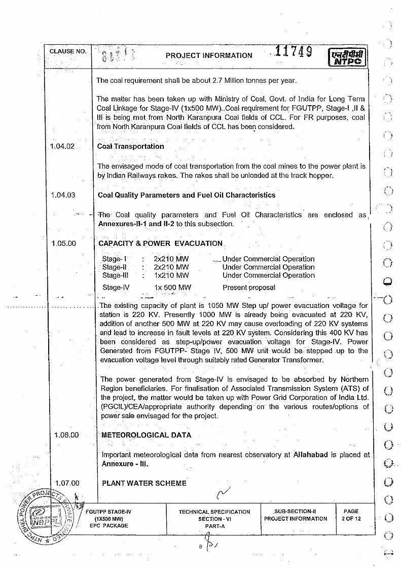
I I The coal requirement shall be about 2.7 Million tonnes per year. I The matter has been taken up with Ministry of Coal, Govt. of lndia for Long Term Coal Linkage for Stage-IV (1x500 MW)..Coal requirement for FGUTPP, Stage-l ,I1 & Ill is being met from North Karanpura Coal fields of CCL. For FR purposes, coal from North Karanpura Coal fields of CCL has been considered.
I Coal Transportation
The envisaged mode of coal transportation from the coal mines to the power plant is by Indian Railways rakes. The rakes shall be unloaded at the track hopper.
I Coal Quality Parameters and Fuel Oil Characteristics
I CAPACITY 8 POWER EVACUATION I : I
- -
Stage- I : 2x210 MW _ Under Commercial Operation Stage-ll : 2x210 MW Under Commercial Operation Stage-Ill : 1x210 MW Under Commercial Operation
The Coal quality parameters and Fuel Oil Characteristics are enclosed as, 1 ) Annexures-11-1 and 11-2 to this subsection. I 0
1 Stage-N I x 500 MW Present proposal . .. --
I 1 1.07.00 1 PLANT WATER SCHEME
The existing capacity of plant is 1050 MW Step up/ power evacuation voltage for station is 220 KV. Presently 1000 MW is already being evacuated at 220 KV, addition of another 500 MW at 220 KV may cause overloading of 220 KV systems and lead to increase in fault levels at 220 KV system. Considering this 400 KV has been considered as step-uplpower evacuation voltage for Stage-IV. Power Generated from FGUTPP- Stage IV, 500 MW unit would be stepped up to the evacuation voltage level through suitably rated Generator Transformer.
The power generated from Stage-IV is envisaged to be absorbed by Northern Region beneficiaries. For finalisation of Associated Transmission System (ATS) of the project, the matter would be taken up with Power Grid Corporation of lndia Ltd. (PGC1L)ICEAlappropriate authority depending on the various routes/options of
r sale envisaged for the project.
GICAL DATA
Important meteorological data from nearest observatory at Allahabad is placed at Annexure - Ill.
-
0 TECHNICAL SPECIFICATION SUB-SECTION-I1
(2 EPC PACKAGE .
if
CI
0 !3 0 (3r
0 0
0
8

/ The Plant weter scheme is described below.
Source of Water
The source of water for the project is normally from the Allahabad branch canal of the Sharda Sahayak link canal. During the canal closure period, water will be drawn from the Daimau canal.
Water Requirement
Normal Make up water requirement for this project would be about 2000 Cu.Mlhr with ash water re-circulation system in operation. However, whenever ash water system needs to be operated in once thru mode, water drawl shall be of the order of 3300 cumlhr.
I 1 .OT.03 I Raw Water System 1 Raw water shall be drawn from the source by a gravity channel upto raw water pump house located inside the plant. It is envisaged to provide three (3) numbers (3 x 50 % Capacity) of raw water pumps for supplying water to Water PT Plant in the raw water pump house. In addition two (2) numbers (2 x 100% capacity) of pumps shall be provided to supply raw water for ash handling plant which shall be operated as and when required. Separate set of pipelines of carbon steel construction shall be provided from respective raw water pumps to Water treatment plant and Ash Water tanks.
The quality of Raw water and Clarified water is enclosed with this sub-section I I 108.00 / Criteria for Wind Resistant Design of Structures and Equipment . . . . . . . .
All structures and equipment of the power plant, including plant auxiliary structures and equipment, shall be designed for wind forces as given in Sub-section- 0-01, Part-B, Section-VI, i.e. Technical Specification for Civil and Structural Works.
1 1.09.00 / Criteria for Earthquake Resistant Design of Structures and Equipment I All power plant structures and equipment, including plant auxiliary structures and equipment shall be designed for seismic forces as given in Sub-section- D-01, Part- B, Section-VI, i.e. Technical Specification for Civil and Structural Works.
FGUTPP STAGE-IV (1x500 MW)
EPC PACKAGE
TECHNICAL SPECIFICATION SECTION - V I
PART-A
SUB-SECTION-II PROJECT INFORMATION
PAGE 3 OF 12
9
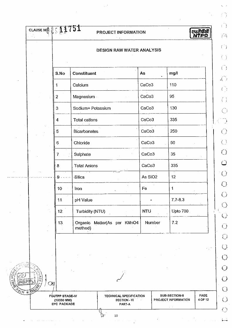
DESIGN RAW WATER ANALYSIS I - r
S.No Constituent As mgll
1 Calcium CaCo3 110
2 Magnesium CaCo3 95
3 Sodium+ Potassium CaCo3 130
4 Total cations CaCo3 335
5 Bicarbonates CaCo3 250
6 Chloride CaCo3 50
7 Sulphate CaCo3 35
11 8 1 Total Anions 1 CaCo3 1335 I
10 Iron Fe 1
11 pH Value - 7.7-8.3
12 Turbidity (NTU) NTU Upto 700
13 Organic Matter(As per KMn04 Number 7.2 method)
10

DESIGN CLARIFIED WATER ANALYSIS FOR DM PLANT
11

VICINITY PLAN
.
ANNEXURE-I 1
CLAUSE Nf&.
*: , i x~ i 5'3' , PROJECT INFORMATION
12
CLAUSE NO. . -.
~~ ~. PROJECT INFORMATION.^$^?,^;- - ti b ,
'
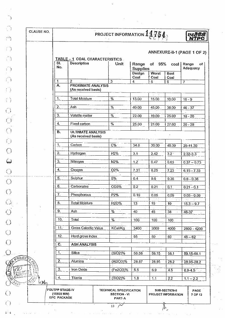
ANNEXURE-11-1 (PAGE 1 OF 2)
C 1
: : I r / "
<
FGUTPP STAGE-IV (1x500 MW)
EPC PACKAGE
TECHNICAL SPECIFICATION SECTION - VI
PART-A
SUB-SECTION-II PROJECT INFORMATION 1 :t:FZ!
13

St. Description Unit Range of 95% coal Range of No. Supplies Adequacy
Design Worst Best Coal Coal . Coal
1 7 'i A 15 I fi 7
I I FGUTPP STAGE-IV TECHNICAL SPECIFICATION SUB-SECTION-I1 PAGE
! (1x500 MW) SECTION - VI PROJECT INFORMATlOEi 8 OF 12 EPC 'PACKAGE PART-A
4 0 14

. . .
EPC PACKAGE
--- .
CLAUSE NO.
..
. . . . , . . . . . . , . . . . .
-
.at 7 6pRo,,,, INFORMATIO~ :?, 3 :. . . * * : . . la1 ANNEXURE-11-2 (PAGE 1 OF 2)
FUEL OIL CHARACTERISTICS
SI. Characteristics Heavy Furnace Low Sulphur Heavy Heavy Petroleum No. Oil Grade HV Stock (LSHS) Stock (HPS)
IS-I 593-1 982 15-1 1489-1985 ' 15-1 1489-1 985
1. Total sulphur content 4.5% Max. 1.0% Max. 4.5% Max.
2. Gross calorific value of the order of the order of the order (KCallkg) of 10,000 of 10,000 of 10,000
3. Flash Point (Min) 66 deg C 66 deg C 72 deg C
4. Water content by 1 .O% 1 .O% 1.0% volume (Max)
5. Sediment by weight 0.25% 0.25% 0.25% (Max)
6. Asphaltene content by 2.5% 2.5% 2.5% weight (Max.)
7. Kinematic viscosity 370 100 100 in Centistokes at - at 50deg C at 100deg C at 100deg C (Max)
8. Ash Content by weight 0.1% 0.1% . . . . . . . .
0.1% {Max:)
9. Acidity (inorganic) Nil Nil Nil
10. Pour Point (Max.) 57 deg C 66 deg C 72 deg C . .
11. Sodium content - - 100 ppm
12. ~ a n a d i h n content 25 P P ~ 25 ppm 25 P P ~
13. Specific heat below 0.65 pour point (KCallKg "C)
15

CLAUSE NO. 1 a u r .
18 7 5 7 PROJECT INFORMATIO~ - 3
....
ANNEXURE-11-2 (PAGE 2 OF 2)
LIGHT DIESEL OIL CHARACTERISTICS
AS PER IS 1460-2000
Characteristics LDO
1. Pour Point (max) 21 "C & 12°C for Summer and Winter respectively
2. Kinematic viscosity in 2.5 to 15.7 centistokes at 40 deg.C
3. Sediment percent by mass (max) 0.10
4. Total sulphur percent by 1 .8 mass (max)
5. Ash percentage by mass (max) 0.02
6. Carbon residue (Rans bottom) 1.50 percent by pass (max.)
7. Acidity inorganic Nil
8. Flash point (Min.) - Pensky Martens 66 deg.C
. g,. .. . ....cGFp.& 6tiip k6ir.o.si6"f6r. . . Not worse 3 hours at 100°C than No. 2
10. Water content, % by volume (max) 0.25
!.
' ~. i i ' i
{,' -%j
.. . l )
, > , '
( 1
t-t r_) - -. 1
'-) i/
K-
0 .. Y
0 t-t w
0 0 O
16

CLIMATOLOGICAL TABLE ANNEXURE-Ill
- ----- - -- --- --- - -
- - ..c. M" NS ->, - * y o - - ' - " *- - m o+ -- " S *D 0- " Y -I "," =.. n.r *- n s "- no - - z z 2 z z z = z - - -
-1 ^- D" D m ' - - o m - - n* -- n O ̂ /- N D '*g "3 "6 "& - = - - 3 " '. -I D % O* "i ..: z ? 2 - - - -
- - - - - - - - - --- - - - - -- -- -- - - - - - - - -
- - - - - - - - - - - - -- - - -- - - - - - . - - - - - - - - - - - -
17

CLIMATOLOGICAL TABLE
CLAUSE NO.
ANNEXURE-Ill (PAGE 2 OF 2)
, ,
1 1 7 5 9 PROJECT INFORMATION, . ; i . - i ' .
FGUTPP STAGE-IV (1x500 MW)
EPC PACKAGE
TECHNICAL SPECIFICATION SECTION - VI
PART-A
SUB-SECTION-II PROJECT INFORMATION
PAGE 12 OF 12
18

BHEL SPEC Rev. No.:0
SECTIO
SECTIOSECTIOSECTIO
C. NO. :PE-TS-41 Dated : 11.06
ON C1 - S
ON C2 - SON C3 - SON C4 - S
TEC
FGUTP
404-165-N001 .14
SPECIFIC
Specific TeA pecific Tecpecific Tecpecific Tec
CHNICAL CONCOOLING
P STAGE‐IV (1
TECHNIC
SEC
C TECHN
chnical Re
chnical Rechnical Rechnical Re
NDITIONS OF TOWER PACK1X 500 MW)
CAL SPECIFICA
CTION - C
NICAL RE
equiremen
equirementequirementequirement
CONTRACTKAGE AT UNCHAHA
ATION DR
C
EQUIREM
nts (Mech.)
ts (Electricts (C & I) ts (Civil)
AR
DOC NO: NBPPLRev. No.: 01
MENTS
) including
cal)
L-004-103-03-P4
g Data She
4M-A,
eet –
19

BHEL SPEC Rev. No.:0
1. INTE 2. SCO 3. COO 4. PIPIN 5. QUA 6. PLOT 7. DATA 8. MAN
C. NO. :PE-TS-41 Dated : 11.06
SPECIFI
ENT OF SPEOPE OF SUPOLING TOWNG & FITTIN
ALITY ASSUT PLAN. A SHEET-A
NDATORY S
TEC
FGUTP
404-165-N001 .14
IC TECHN
ECIFICATIOPPLY AND SER-SUB SENGS -SUB S
URANCE- SU
A. SPARES.
CHNICAL CONCOOLING
P STAGE‐IV (1
TECHNIC
SEC
NICAL RE
COM
ON SERVICES ECTION-A-1SECTION-AUBSECTION
NDITIONS OF TOWER PACK1X 500 MW)
CAL SPECIFICA
CTION – C
EQUIREM
PRISES O
9 -26 N E-40.
CONTRACTKAGE AT UNCHAHA
ATION DR
C1
MENTS (M
OF
AR
DOC NO: NBPPLRev. No.: 01
MECHANI
L-004-103-03-P4
ICAL)
4M-A,
20

BHEL SPEC Rev. No.:0
1.00.00 1.01.00
2.00.00
C. NO. :PE-TS-41 Dated : 11.06
INTENT O
This spe cmanufactuat s ite, ucommissiosite includincluding m,startup ,pand as n efollowing p
a) Feroz- 2 (Tw
The Cemeshall be fr
For Bid determinespecified
The perfoSheet-A.
SCOPE O
The equipand as ind
The itemscomplete shall also
The scop ecomplete cper th e s yworks. S capprovals,the sat isfaelectrificatbeen percborne by t
Bidder sharainfall daand other on any acc
The bidd ecomplete
TEC
FGUTP
404-165-N001 .14
OF SPECIFICA
cification co vurer’s and/or nloading/ h a
oning and peding completemandatory S
pre commissioecessary for cproject.
e Gandhi Unwo) Nos. Coo
ent and Reinree issue as
evaluation ed after addelse where i
rmance pa ra
OF EQUIPMEN
ment and w odicated in rele
s not specificin all respec
o be deemed
e o f supply/ civil works beystem re quir
cope o f w orks, materials, exaction of NB Ption, etc. NBPeived by the he bidder.
all visit and apta, availabilit yaspects for ccount shall be
er s hall furnispackage sha
CHNICAL CONCOOLING
P STAGE‐IV (1
TECHNIC
ATION:
vers the d ehis subcontra
andling a nd srformance tes
e Electrical, Cpares/recommon & commiscompleteness
nchahar Therling Tower.
nforcement Sper NIT. How
of Cooling ding cost oin Bidder’s to
meters and o
NTS & WORK
orks to be pr oevant portion o
cally mentioncts, as self-cto have been
works incl udetween the terements ex ces in cludes p rxecution as pPPL/ N TPC fPPL will not bbidder but fu
pprise himsely of all con stonstruction oe entertained
sh li st of iteall be deemed
NDITIONS OF TOWER PACK1X 500 MW)
CAL SPECIFICA
esign, manu factor’s worksstorage at ssting of Mec h
C&I ,Civil a nmended spa r
ssioning spares in all respe c
rmal Power
Steel, for CTwever, Struct
Towers of of Cement aotal quoted p
other pa rticul
KS UNDER T
ovided under of enclosed d
ned but deemcontained pan included in
ding civil worrminal points ept for items reparation of
per codes, spefor all mecha
bear any liabilnctionally req
f fully with extruction mat ef plant, buildinby NBPPL.
ms/ servi cesd to be in bi d
CONTRACTKAGE AT UNCHAHA
ATION DR
facture, ass, properly pa
site, erectio nhanical Inducnd structural res/special t oes, first fill & ct for efficien
Project – Sta
T’s are excludtural Steel s
Projects, Band Reinfoprice for CT’
ars of Coolin
THIS SPECIF
this specificadocuments.
med necessaackage for ren the scope o
rks a s com pwhich are staspecifically design and
ecification, beanical, archit elity for any e xquired. The co
xisting site coerials includinng structures
s not includedder’s scope
AR
DOC NO: NBPPLRev. No.: 01
embly, insp eacked for tran, sit e pai ntin
ced draft typeworks (includ
ools & tackleconsumable
nt and trouble
age IV, (1 X
ded from Bidhall be in sc
Bidders totaorcement Stes.
ng Towers a r
FICATION:
ation shall b e
ary to make eliable and eof the bidder
plete turnk ey ated or unstatmentioned i ndrawings, o b
est Engineerinectural, civil xtra work, whost of such w
nditions inclung backfill, g r etc. No extra
ed in his sc o& Purchaser
L-004-103-03-P4
ection/ t estinnsportation deng te sting ate cooling towding Piling if s for mainte ns etc. as sp e
e free operatio
500 MW).
dder’s scopeope of bidde
al price shaeel as per
re detailed in
e as detailed
the cooling tefficient operr.
package in cted but requirn e xclusion btaining ne ceng practices astructural, b uich might not
work will be en
ding soil condraded materi aa claim whats
ope, o therwisr’s interpretat
4M-A,
ng at elivery t s ite, ers at any )
nance ecified on for
e and er.
all be rates
Data
below
tower ration
cludes red as list of
essary and to uilding t have ntirely
dition, al et c. soever
se the tion in
21
6044549
Text Box

BHEL SPEC Rev. No.:0
2.01.00 2.01.01
2.01.02
2.01.03
2.01.04
2.01.05
C. NO. :PE-TS-41 Dated : 11.06
this regard
The bri ef distributionlevel to d ethe intent t
Each Coo
Scope (M(Cl. No- 9B,subsect
Scope (C&
a) Compscope
Scope (El
a) Compshall b
b) The ssectio
c) Base electri
Scope (Ci
a) Compdewatstackspit fostaircawater-gradinsteelw
b) Suppl y
c) The Cshall b
The follow
a) One sin the
b) Vario umainte
TEC
FGUTP
404-165-N001 .14
d shall be fina
scope of sun system, coleck and all o tto list all deta
oling Tower s
Mechanical): 9.00.00 Induction-A-19 ( C
&I):
lete C&I as .
lectrical):
lete electricalbe in bidders s
cope of pown C2 (electric
plate, foun dcal and mech
ivil):
lete ci vil w oering, backfi l
s at tower fanr ea ch bas
ases/ladders a-proofing, fin ing, rem oval works for reinf
y & applicatio
Cement and Rbe free issue a
wing are also i
et of special tcooling tower
us d rawings,enance manu
CHNICAL CONCOOLING
P STAGE‐IV (1
TECHNIC
al & binding on
pply, servic ed water basinther equipmeils herein; sco
shall be com
Refer NTPCced Draft CoCooling Tow
per specifica
l equipments scope.
er & con trol cal).
dation pl ates,hanical equipm
orks as detalling, concre ts outlet, founin se ction, as required, dishing and aof surp lus s
forcement etc
on of final pain
Reinforcemenas per NIT. H
ncluded in bid
tools & tacklers.
, data sheetsuals including
NDITIONS OF TOWER PACK1X 500 MW)
CAL SPECIFICA
n the bidder.
es & wor ks fon and outlet cents and acc eope of supply
mplete with fo
C Specificatooling Towerers).
ation/ details
as per specif
cables & spe
, an chor b oments & acce
ailed in Se cte wo rk in cludations (inclustaircase atdoors and theall other inci dsoil to a spc.
nting at site.
nt Steel, for CHowever, Stru
dder’s scope:
es required fo
s, calcul ation“As built draw
CONTRACTKAGE AT UNCHAHA
ATION DR
for Cooling t ochannels, sluessories as my listed is in br
ollowing:
tion- Sectiors - Page 8
indicated in S
fication/ detai
ecial cables
lts, sl eeves, essories.
ction - C4 uding ca sing, uding Piling if t both end seir frames, wadental ci vil wace de cided
CT’s are excuctural Steel s
:
or maintenanc
n, tes t rep owings” etc. as
AR
DOC NO: NBPPLRev. No.: 01
ower, c ompleudge pit, stai rmentioned herief.
n-VI,Part-A,s& 9 of 21) &
Section C3 s
ils indicated i
shall be as
inserts i n c
including exsidewalls, t o
any), cold wa of cooling
alkways, platfworks in cludind by the en g
luded f rom Bshall be in sco
ce of equipme
orts/ ce rtificas specified & a
L-004-103-03-P4
ete w ith hot r case from gerein af ter. It
subsection-II& Section-VI
shall be in b i
n Section C2
per Ann exure
concrete wo r
xcavation, s hop d eck, r ecater basins, s
tower, all forms, hand rng ea rth wogineer, shut t
Bidder’s scopeope of bidder.
ents & access
ates, operati oas necessary
4M-A,
water round is not
IIA-05 ,Part-
idders
& D1
e-1 of
rk for
horing, covery sludge
other ailing, rk for tering,
e and .
sories
on & y.
22
6044549
Text Box
Complete mechanical scope as per specification detail indicated in section C1 shall be in bidder scope.
6044549
Text Box

BHEL SPEC Rev. No.:0
2.01.06
2.02.00 3.00.00
4.00.00
5.00.00
C. NO. :PE-TS-41 Dated : 11.06
c) Suppl yreplen
d) Suppl y
e) Scop erun & site, l opersonof wo rbiddercivil w
f) R ecomprices
Fan Powe
The total f aterminal po
The CW including 1 No technicand CW p In the evenmore than Motor ratin The bidd emaximum
Exclusion
Equipmen
a) Suppl y
b) Cold -wElectriherein
The cooli ncooling towsheet-A’s &
PERFORM
TEC
FGUTP
404-165-N001 .14
y of first fill ofnishment as n
y of commiss
e of services performance
ocal cl earancnnel, materialrks etc. are r to arrange aorks.
mmended sp a. These price
er Consumpt
an Powe r C ooints shall no
pumping h ea10% margin o
cal advantageumping head
nt of total fan above maxim
ng for Fan driv
er’s Cooling permissible p
ns -- NIL
nt & Services
y and erection
water o utlet cical, C&I and
n.
ng towe r sh awers enclosed& section ‘C’,
MANCE GUA
CHNICAL CONCOOLING
P STAGE‐IV (1
TECHNIC
f lubricants foecessary afte
ioning spares
shall includee testing of c oce, storage als, erection toalso in cluded
all T & P requi
ares for 3 ys not to be in
ion (KW) and
onsumption ( Kt exceed the
ad s pecified on frictional lo
e shall be giv (MWC) offer
power consumum limits, th
ve shall howe
Tower the rmplan dimensio
s to be provi
n of incoming
channels fo r d C ivil wor ks
all comply wid in section -’the latter sha
ARANTEES A
NDITIONS OF TOWER PACK1X 500 MW)
CAL SPECIFICA
or all equipmeer commission
s on as requir
e but n ot limi tooling towersat s ite etc . &ools & tacklesd in bidder’s ired for the ex
ears op eratiocluded in the
d CW Pumpi
KW) and the respective m
limit is inclosses.
ven to any bred less than
umption (KW)he bids will be
ever be kept f
mal desi gn s hons indicated
ded by NBPP
g hot water pip
cooling to werefer Section
th standard t’C’. In the eveall prevail.
AND LIQUIDA
CONTRACTKAGE AT UNCHAHA
ATION DR
ents under thining & handin
red basis.
ted to erecti os. T ransporta& sup ply of s etc. as nece
scope. It s hxecution of co
on – bidder base price b
ng Head.
CW Pumpi naximum limits
usive of sta t
idder for totaabove maxim
) or the CW pe summarily re
for all the cell
hall t ake ca rin Data Shee
PL/NTPC:
ping up to bid
er beyo nd thns C 2/ D1, C
technical sp eent of any con
ATED DAMAG
AR
DOC NO: NBPPLRev. No.: 01
is package inng over of the
on/ testing/ coation of e quip
all l abor in cessary for exphall be th e r eomplete job in
to furnish li sbut to be furnis
ng he ad (M Ws specified in
tic head plu
al fan power cmum limits.
ump head (Mejected.
s based on th
re of above et A.
dder’s termina
he b idder’s tC3 & C4 r es
ecifications &nflict between
GES:
L-004-103-03-P4
ncluding secoe plant.
ommissioningpments, matecluding supe rpeditious execesponsibility oncluding erec
st w ith it em shed separat
WC) w ithin bi dData Sheets
s fri ctional l
consumption
MWC) offered
he Maxm Pow
aspects in cl
al point.
terminal poinpectively enc
& dat a she et-n Section-’D’
4M-A,
nd fill/
g/ trial rial to
rvision cution of the
ction &
wised ely.
dder’s A.
osses
(KW)
being
wer.
luding
t. For closed
- A of / data
23

BHEL SPEC Rev. No.:0
5.01.00
5.01.01
5.02.00
5.02.01
5.02.02
5.02.03
5.02.04
5.02.05
5.02.06
C. NO. :PE-TS-41 Dated : 11.06
Performan
The Bid dperformanBidder shasection of attract levy
Liquidate
All the coostipulationguaranteePerformanDRAFT (M
Should theRequiremeContractortests.
If the equishall be reasonableimprove th
Bidder sharequireme
The cold wContractordata sheet
For the copower conformula. cold wat econditionscontractortemperatuliquidated
For Tem
TEC
FGUTP
404-165-N001 .14
nce Guarant
er shall guance requiremeall also furnisthe bid fo rm
y of liquidated
d Damages f
oling towers s of relevant of all inter m
nce & GuaranMECHANICAL
e results of thents show thar shall carry
pment and ovprovided an e time as ma
he performanc
all guaranteent stipulated f
water temperar for the des it and design p
ooling tower, tnsumption as “Predicted c or te mperature and correcte. In case there”, Employ edamages wh
every 0.1 d emperature abo
CHNICAL CONCOOLING
P STAGE‐IV (1
TECHNIC
tees
arantee that ent stipulated h a declaratio
ms/bid proposd damages fo
for Short fall
shall be subjeclause of g
mediate equipntee Test is giL)” of this tech
he Performanat the equipmout modific a
verall tower popportunity
ay be decidece to guarant
that the e qufor various eq
ature as specgn conditionspower consum
the test circucompared to
old w ater teme by correcti
ed circulating “Test cold w
er r eserves tich shall be w
eg. Centigradove the guara
NDITIONS OF TOWER PACK1X 500 MW)
CAL SPECIFICA
the equi pmfor various eqon in the manal sheets for
or shortfall in p
l in Performa
ected to Perfogeneral te chnments. An i niven in sub-sehnical specific
nce & Guara nments have faations, if con s
performance fto c arry ou
ed by th e E need value at
uipments offequipments cov
cified in techns of CW flow,mption guara
lating water fo the design mperature” s hng t he sam ewater flow usater temperathe right to r
worked out as
de ri se in Coanteed value.
CONTRACTKAGE AT UNCHAHA
ATION DR
ment offere d quipments conner prescribcertain guar
performance.
ance
ormance and nical Conditi ondicative procection titled “Ccation.
ntee Test as ailed to meet tsidered ne ce
fails to meet tt modific atio
ngineer to m ano extra cost
red shall mevered in thes
nical data she, range, ambnteed by the
flow shall be cfan power co
hall t hen b e ae for the tessing the perfoture” is highereject/accept s given below
ld Water
AR
DOC NO: NBPPLRev. No.: 01
shall meet overed in this bed and includranteed param
Guarantee Tons to provecedure to be COOLING TO
stipulated in the guarantee
essary, wit hin
the guaranteeons and rectake good thet to the Emplo
et the ratingse specificatio
eets shall be ient WBT sp eBidder.
corrected for onsumption uarrived at fr ot conditions
ormance curveer than the “Pr
the tower af:-
US $ 3313
L-004-103-03-P4
the rating sspecification
ded in the re lmeters which
Test in line wie the perfor m
followed for OWERS-INDU
General Teced parametern 90 days o f
es, the Conttifications wi te def icienciesoyer.
s and performons.
guaranteed becified in tec
change in tesing the cube
om th e gua raof ra nge, a mes furnished bredicted cold fter as sessin
340 per coolin
4M-A,
s an d . The levant
h shall
th the mance
these UCED
hnical rs, the f such
tractor thin a s and
mance
by the hnical
est fan e root
anteed mbient by the water
ng the
ng towe
24

BHEL SPEC Rev. No.:0
5.02.07
5.03.00.
5.04.00
C. NO. :PE-TS-41 Dated : 11.06
The
A mbe atole
7 BID E
The bquanti
The bThe ev
The bi ddecomplete p
Tot a Tot a
loss
The succesite.
The em The lifractiorespecguaranvalue, alread
TERMINAL
a) Hot watitled “L
b) Stub comeasur
c) Sludge
d) Cold W
TEC
FGUTP
404-165-N001 .14
e Liquidated d
maximum toleallowed to ta krance shall be
VALUATION
ids will be evties of cemen
idder shall fuvaluation rate
Cement Reinforcem
er shall guarapackage.
al Power consal CW pumpinses for cooling
essful bidder s
mployer may
quidated da mon the reof s hctive guarantentee continuethe employe
dy made or ac
POINTS
ter pipes for eLayout of cool
onnections at rement in the
disposal to th
Water Channel
CHNICAL CONCOOLING
P STAGE‐IV (1
TECHNIC
damages shal
rance of 0.3 dke care of dee permitted.
N CRITERIA
valuated basent and reinforc
rnish quantities for Cement
ment Steel
antee the foll
sumption per ng head withg tower.
shall demons
accept the eq
mages @ U Shall be levie deed values oe to be more er may at his dccept the equ
each cooling ling towers”.
required locaCirculating w
he Employer’
l -- 10 M
NDITIONS OF TOWER PACK1X 500 MW)
CAL SPECIFICA
ll be pro-rata
deg Centigraesign & in stru
ed on th e coocement steel
es of Cement and Reinforc
- Rs. 6500 - Rs. 5200
owing, ap art
Cooling Towin the bidder’
trate the abov
quipment afte
S $ 4 646 fo rd in th e ev ef KW power than (+)1%
discretion rejipment only a
tower shall b
ations for intewater duct.
s nearest dra
Mtr from edge
CONTRACTKAGE AT UNCHAHA
ATION DR
for fractional
ade in the coldument uncerta
oling Tower pused in the c
nt and Reinforcement steel
Per MT 00 Per MT
from othe r p
wer, for the coo’s terminal po
ve guarantee
er levying LD
r e ach one (ent of failur econsumptionof guaranteeject the equip
after levying L
be terminated
erconnection f
ain.
e of the re spe
AR
DOC NO: NBPPLRev. No.: 01
parts of the d
d water tempainties and in
prices quoted cooling Tower
rcement steeshall be as fo
performance
oling tower faoints viz. stat
es during perf
as below:
(1) K W powee of bid der . However, i f
ed auxiliary ppment and reLD against the
as per releva
for Bidder’s G
ective CT bas
L-004-103-03-P4
deficiencies.
perature shall naccuracies.
by the bidd ers.
l in the Price ollows.
guarantees o
ans. ic head & fri c
formance test
er consu mptidemonstratinf the dem onspower consumcover the paye contractor.
ant tender dr
Gate valves fo
sin as shown
4M-A,
however No other
er and
offer.
of the
ctional
ting at
ion or g the trated
mption yment
awing
or flow
in the
25
6044549
Text Box
Hot water pipes for each cooling tower shall be terminated at 10.0 M from Cooling Tower as shown in the relevant tender drawing.

BHEL SPEC Rev. No.:0
6.00.00 6.01.00
7.00.00
C. NO. :PE-TS-41 Dated : 11.06
e) Cables f) Signal C g) Cable T h) Instrum
DRAWING
The follow
a) Compb) Gene r
cold wstairca
c) Pumpd) Ther m
Note:
e) Towe rf) Guar ag) Tech n
Apart frombid stage
Successfudocument
TEC
FGUTP
404-165-N001 .14
& Power Cab
Cables
Trench/cable T
ents & Contro
GS, CURVES
wing docume
liance certificral a rrangemewater chann ease etc. ing head calc
mal design cal
The GA drawnot be resubject to
r performanceantee Schedunical deviation
m above no and even if f
ul bidder in tts as listed i
CHNICAL CONCOOLING
P STAGE‐IV (1
TECHNIC
Plot
bles -- As
-- As s
Tray -- A
ols --- A
S AND INFOR
ents only sha
cate duly signeent dra wing fels / sludge
culations. culations.
wing/ calculaeviewed/com
approval on
e curves. le duly signed
n schedule (if
other drgs./dfurnished sh
the event of n Data Sheet
NDITIONS OF TOWER PACK1X 500 MW)
CAL SPECIFICA
Plan from re
s specified in
specified in th
As specified in
As per in the s
RMATION RE
all be furnish
ed and stampfor co oling t ochamber/ s
ations shall bmmented by nly during co
d and stampereqd.) (enclo
docs./data shhall not be ta
award of cont- B (VOL-III)
CONTRACTKAGE AT UNCHAHA
ATION DR
espective CT’
Section - C2
he Section - C
n the section -
section- C3.
EQUIRED:
hed by the b
ped (enclosedower, in corposcreens/ gat e
be only for rpurchaser
ontract).
ed (enclosed hsed herein)
heets etc. araken cogniza
ntract shall f).
AR
DOC NO: NBPPLRev. No.: 01
’s.
2/D1.
C2/C3/D1
-- C2/C3/D1
idder with hi
d herein). orating a ll reles in t he c o
reference purat this stag
herein)
re required toance of.
furnish the d
L-004-103-03-P4
is offer:
evant di menold water cha
rpose, samege and sha
o be submitt
drawings/
4M-A,
sions, annel,
shall all be
ted at
26
6044549
Text Box
Note: Joining of Hot water piping and Cold water channel shall be in Bidder scope.

CLAUSE NO. SCOPE OF SUPPLY AND SERVICES
SINGRAULI STPP STAGE-III (1X500 MW)
EPC PACKAGE
TECHNICAL SPECIFICATION SECTION - VI
PART-A
SUB-SECTION-IIIA-05 WATER SYSTEM AREA
PAGE 8 OF 21
9.00.00 INDUCED DRAUGHT COOLING TOWERS
9.01.00 Two (2) nos. of Induced Draft Cooling Towers comprising of:
i) Complete packing / fill material and drift eliminators for all cooling towers.
ii) Complete Hot water Distribution System consisting of:-
a) Two (2) numbers manually operated butterfly valves of size 1600 NB mm for each of the Cooling towers for isolating the hot water riser/header to the cooling tower along-with valve supports.
b) Mild Steel pipes to carry hot water from Employer’s terminal point to cooling tower including its supporting arrangement.
c) Manually operated butterfly valve at inlet to each cell of cooling towers.
d) Hot water distribution systems along with water spray nozzles for each cooling tower.
iii) Design and fabrication of anchors, hangers and supports wherever required.
iv) Drain sump and sludge disposal system for cooling towers, including sludge sump, associated pipe work, sludge pumps 01 nos. of 150 cum/hr capacity for each sludge sump, valves , accessories and piping up to Employer’s nearest plant drain.
v) Inlet air louvers (if applicable) for each cooling tower
vi) Complete air moving equipment consisting of fans, reduction gear unit, transmission equipment, lubricating system and electrical motors etc.
vii) Mechanical and electrical equipment Handling system and maintenance facilities for drive system gear reducers, fans, motor, stop logs (at the Cold Water Channel) for each cooling tower.
viii) Cross over facility, as required, over hot water pipes as per layout requirement.
ix) Provision of six numbers of Isolation (Gate valve) Valves (in the stub connections) for each unit at the locations where flow measurement is to be carried out by means of pitot tubes.
27

CLAUSE NO. SCOPE OF SUPPLY AND SERVICES
SINGRAULI STPP STAGE-III (1X500 MW)
EPC PACKAGE
TECHNICAL SPECIFICATION SECTION - VI
PART-A
SUB-SECTION-IIIA-05 WATER SYSTEM AREA
PAGE 9 OF 21
x) All steel / cast iron inserts, plates, bolts, nuts, sleeves etc. to be grouted in concrete work and used to hold/ support the equipment/ system being supplied and erected under this specifications.
xi) Any additional system/ equipment required to make the system complete.
xii) Carrying out performance test of one of the Cooling Tower through CTI (Cooling Technology Institute-USA) approved/listed testing agency. Carrying out performance test of balance cooling towers by the contractor.
xiii) Ventilation system for Cooling Tower Switch gear room comprising of 2 (two) number of Supply Air fans of capacity 8000 cum/hr with static pressure of 30 mmWC each and 2 (two) number of exhaust fans of capacity 4000 cum/hr with static pressure of 15 mmWC each along with all other accessories as detailed out elsewhere.
9.02.00 WATER PRE-TREATMENT PLANT
9.02.01 PT- CW System
Raw water pipe [Carbon (CS) Steel Pipe] upto the aerator through a set of Control Valve & Isolation Valves for Control Valves.
One (1) number Aerator and one (1) number stilling chamber of RCC Construction of capacity as mentioned in the data sheets along with isolation gates at the inlet to the inlet channels for PT-CW system clarifier.
One (1) number of inlet channel with flow measuring element in channel (parshall flume) of RCC Construction.
One number bypass channel of RCC Construction to by-pass clarifier(s) with required isolation gate(s)
One (1) number of reactor type clarifier of RCC Construction each of capacity as mentioned in the data sheets including associated equipment and drives for PT-CW system.
One (1) number Clarified Water / service water tank and pump house of capacity /sizes as mentioned in the data sheets with required isolation Valves.
Outlet channels of RCC Construction from Clarifiers upto the Clarified Water tank.
28
2980282
Text Box
2980282
Text Box

I COOLING TOWERS -INDUCED DRAFT
1 1.00.00 I GENERAL
This specification covers the design, engineering, manufacture, shop fabrication, testing at works, transportation to site, unloading and storage at site, fabrication at site, Installation, testing and commissioning of induced draught cooling tower f o i power plant cooling system.
2.00.00 CODES AND STANDARDS
The design, manufacture, inspection and testing shall comply with all currently applicable standards. The equipment shall also conform to the latest applicable BritishIAmerican standards. In particular the equipment shall conform to the latest edition of the following standards :-
I) Cooling Tower Institute Publications.
2) BS 4485-Specification for Water Cooling Towers.
DESIGN REQUIREMENTS I CRITERIA
Each cooling tower shall be complete with tower, basin, foundations and mechanical equipment as described below. The tower shall be of single or double inlet, cross flow or counter flow type with type of fill as specified in technical data sheets. The tower shall be of induced draught type with the fan located on top of the tower.
The cooling tower shall be designed to meet the duty conditions as specified in Technical Data Sheet enclosed as Annexure-l of this sub-section.
Number of operating cells in the cooling tower shall not be less than eight (8). Bidder shall provide spare cell(s) in the cooling tower to facilitate maintenance without affecting the tower performance Number of spare cells per cooling tower shall be one (1) number in case of double inlet cells and shall be two (2) number in case of single inlet cells.
The water distribution basin and piping system shall be so designed that when any one of the cells for double inlet type tower and two cells for single inlet type tower (other than standby cells) isiare out of operation for maintenance etc. the remaining cells shall be capable of handling the full quantity of water as indicated in technical data sheet.
Thermal des~gn of the cooling tower shall be such that the guaranteed performance IS met without operating spare cell(s) All cells of the tower shall be ident~cal
The Total available pressure head in the hot water header at the Employer's terminal point is mentioned in the technical data sheet enclosed as Annexure-l enclosed with this sub-section, The Bidder shall ensure that the height of the highest point of the hot water distribution system (with respect to the finished ground level), including head loss due to friction and other losses in the hot water
SlNGRAULl STPP STAGE-Ill / (iX500 MW)
EPC PACKAGE PV'
TECHNICAL SPECIFICATION SECTION - V I
PART.8
SUB-SECTION-A-19 COOLING TOWER
PAGE 1 OF 28
29

headers and entire ~ i p i n q system in his scope from the terminal point to the hydraulically remotest po~ni of the Cool~ng toher does no: exceed tI?e total available head wthour considering any syphon recovery Bidders may note that, in case the pumping head requirement quoted by them is less than available head, no credit shall be given during the evaluation of bids. Further in case the pressure head requirement quoted by the bidder exceeds the available head, such bids are liable to be rejected.
For countefflow tower the area covered by the projected circle at 45 deg. angle from the fan cylinder opening on the drift eliminator plan area shall not be less than 80% of the drift eliminator plan area.
The layout of the cooling tower in the plant area and the wind rose is indicated in the drawings titled "General Layout Plan" and "Layout of Cooling Tower". The Bidder shall examine the proposed layout of the tower and accordingly determine the recirculation which must be taken into consideration for the purpose of design of the tower to ensure that the design parameters of the tower are maintained when all the cooling towers in the plant are operating simultaneously. Bidder must apply a correction factor to the design wet bulb ambient temperature to accommodate the recirculation effect. Minimum value of this recirculation correction factor shall be as given in technical data sheets.
The length of the cooling tower shall be decided based on GLP drawing. However, the maximum length of the tower excluding space required for stair cases at both ends shall not exceed 130 M for cooling towers.
Sensible heat of evaporated water shall be taken into consideration in the thermal design of the cooling tower. The air flow requirement shall not be less than that worked out by the formula given below:
G x H = L (TI-T2) + EvT2
Where,
1 L = Water flow rate in KglHr
T I = Water inlet temperature to the tower in deg C.
T2 = Water outlet temperature from the tower in deg C
/ Ev , =. Evaporation loss in Kglhr.
To compute this factor theambient RH shalt be taken as specified in technical data sheets.
G = Air rate in Kglhr ,,, .~ - - Change in enthalpy of air in KcallKg
Calculations justifying the selected air flow and evaporation loss shall be enclosed with the bid, InternationalINational standard table of properties of air shall be used and a copy of the table clearly indicating the standard used shall be enclosed with the bid.
SlNGRAULl STPP STAGE-Ill TECHNICAL SPECIFICATION SUB-SECTION-A-19 (1x500 MW) SECTION - V I COOLING TOWER
EPC PACKAGE PART-B -"
30

TECHNICAL REQUIREMENTS
/ 3.12.00 / The bidder shall furnish in his bid the following :- I a) Heat balance calculations and air requirements for cooling tower as per format
given elsewhere.
b)' Available tower characteristics (KaVlL - as a function of air & water rates, fill geometry, hot water temperature, air velocity etc.) based on field performance tests. The relationship shall be of general form of equation given below and shall include values of the constants " C and "n". The equation shall cover range of LIG values from atleast 20% above to atleast 20% below design.
The bidder shall also submit an equation and I or curve defining the demand requirement at design approach, range and wet bulb temperature. The design LIG value shall be identified.
I I c) Various pressures drop in the air circuit of the cooling tower to arrive at discharge pressure of fan,
i 1 d) Calculations for arriving at the design power consumption. I e) Calculations for pumping head in the format given in elsewhere.
f) Tower Performance curves (for both ambient and inlet WET.)
Bidders may note that the calculationslcurves spec~fied above must be enclosed wcth the offer without which bids run the risk of reiection. In case, these calculations are based on the collaborator's design, then these calculations should be duly vetted by collaborator. The Bidder shall showlexplain and prove the validity and the basis of procedures and methods used in the calculations.
The tower configuration shall be such that it shall offer minimum restriction to air flow.
To ensure uniform and stable 'distribution of entering air, the velocity pressure ratio shall not be less than 5 (Five). Velocity pressute ratio is defined as the ratio of system pressure drop ({i.e) from air inlet to the drift eliminator) to the velocity pressure at the inlet. For counter flow towers, the velocity at air inlet shall be calculated based on the clear air entry area available in vertical plane at the inner face of cooling tower wall. For purpose of calculating the velocity pressure ratio, the air velocity shall be computed considering the total air flow entering the individual cell and the total gross inlet air area of the individual cell, This will be calculated independently for each cell and the value calculated for each cell shall not be less than 5. For towers provided with over-dimensioned cold water basin, the inlet air area shall be computed considering the water level in the cold water basin at normal water level.
SINGRAULI STPP STAGE-III (IXSOO MW)
EPC PACKAGE 0'
TECHNICAL SPECIFICATION SECTION - VI
PART.B
SUB-SECTION-A-19 COOLING TOWER
PAGE 3 OF 28
31

TECHNICAL REQUIREMENTS
1 4.00.00 I CONSTRUCTIONAL FEATURES
1 4.01.00 1 Material of Construction 1 The material to be used for various components shall be as follows. Woodltimber shall not be used as construction material in any part of the cooling tower.
SI Component description Material
a) Hot water header : MS to lS:2062
b) Hot water distribution pipes : PVC (IS 4985 Class 3) i FRP I
for counter-flow tower HDPE (IS 4984 PN6, Grade PE 80) I or RCCl pre-cast open trough. -
c) Hot water basin for cross flow : RCC
d) Cooling tower shell1 structure : RCC
e) Cooling tower basin RCC
9 Drift Eliminators : PVC
g) Louvers : RCC
h) F ~ l l : PVCIPPlprestressed precast concrete
i) Fill supports SS:304 channel or RCC
j) Fan blades : Fiber glass reinforced polyester (hollow cast)
k) Fan Hub : Heavily Galvanised M.S.
Drive shaft and coupling
Base frame and base plate for gear box and motor
Stair case
Recovety Stack
Stop logs . ~
Any other hardware such as fasteners, clamps, supports etc in direct contact with water
Any other mild steel parts used in cooling tower or its vicinity
Stainless steel conforming to AlSl304
Heavily Galvanised MS
RCC
RCC
Refer civil specifications
Stainless steel conforming to AISI:304 or equivalent.
Heavily galvanised (610 gml sq.m) in accordance with 1S:2629 Surface preparation in accordance with 1S:6129
s) Hand rails : Refer civil specifications.
t) Miscellaneous steel structure : Refer civil specifications,
TECHNICAL SPEClFlCATlON SECTION - VI i
PART-8
-
SUB-SECTION-A-19 COOLING TOWER
PAGE 4 OF 28
32
SI Component description Material
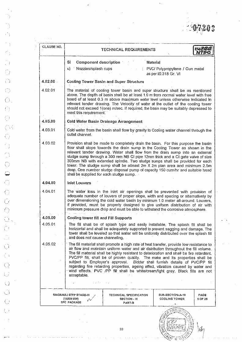
u) Nozzleslsplash cups : PVCl Polypropylene I Gun metal as per 1S:318 Gr. VI
Cooling Tower Basin and Super Structure
The material of cooling tower basin and super structure shall be as mentioned above. The depth of basin shall be at least 1.0 m from normal water level with free board of at least 0.3 m above maximum water level unless otherwise indicated in relevant tender drawing. The Velocity of water at the outlet of the cooling tower should not exceed l(one) rnlsec. If required, the basin may be suitably depressed to meet this requirement.
Cold Water Basin Drainage Arrangement
Cold water from the basin shall flow by gravity to Cooling water channel through the outlet channel.
Provision shall be made to completely drain the basin, For this purpose the basin floor shall slope towards the drain sump in the Cooling Tower as shown in the relevant tender drawing. Water shall flow from the drain sump into an external sludge sump through a 300 mm NB Cl pipe 12mm thick and a CI gate valve of size 300mm NB with extended spindle. Two sludge sumps shall be provided for each tower. The sludge sump shall be atleast 2m X 2m plan area and minimum 2.5m deep. One number sludge disposal pump of capacity 150 cumlhr and suitable head shall be supplied for each sludge sump.
Inlet Louvers
The water loss in the inlet air openings shall be prevented with provision of adequate number of louvers of proper slope, width and spacing or alternatively by over dimensioning the cold water basin by minimum 1.0 meter all-around. Louvers, if provided, must be properly designed to give uniform distribution of air with minimum pressure drop and must be able to withstand the corrosive atmosphere.
Cooling tower fill and Fill Supports
The fill shall be of splash type and easily installable. The splash fill shall be horizontal and shall be adequately supported to prevent sagging and damage. The tower shall be leveled so that water will be uniformly distributed over the splash fill and does not cause channeling.
The fill material shall promote a high rate of heat transfer, provide low resistance to air flow and maintain uniform water and air distribution throughout the fill volume. The fill material shall be highly resistant to deterioration and shall be fire retardant, PVCIPP fill, shall be of proven quality, The make and its properties shall be subject to Employer's approval. Bidder shall furnish details of PVCIPP fill regarding fire retarding properties, ageing effect, vibration caused by water and wind -effects, PVC IPP fill shall be whitelcreamllight grey. Black fills are not acceptable.
1 SINGRAULf STPP STAGE-It1 / TECHNICAL SPEClFlCATlON 1 SUB-SECTION-A-19 I P A G E / (1x500 MWJ SECTION -VI
EPC PACKAGE PART.B / COOLINGTPWER
33

In case of PVClPP fill, the materlal should be ultra violet ray stab~l~zed and only virgln PVCIPP material should be used
The type of fill to be supplied for this package shall be of proven design. Necessary .. ~
supporting data for this shall be enclosed along with the bid.
Preferably, the fill shall not be extended into the air inlet area. In case the bidder's standard design calls for such an arrangement, then field performance test results of towers with comparable fill arrangement supplied by the bidder duly certified by the user shall be furnished along with the bid to establish the design.
a) Type Test of PVCJPP Material
In addition to the routine tests specified in Sub-section-Ill E-01 of Part-B of this Technical specification, ultra-violet exposure for 500 hours on the PVClPP material shall be carried out for this contract once as per ASTM-G26, Test Method 3 and Impact resistance test before and after UV exposure shall be conducted as per ASTM D-256: The above type test shall be carried out by the Contractor at reputed third-party laboratory.
Inlet Water Distribution System
General Requirements : The hot water distribution system of the tower shall be designed to ensure uniform distribution to all operating cells and also to all areas in a cell. For cross flow type of towers a minimum free board of 50 mm shall be provided with the standby cell not in service. Each cell shall be able to operate independently. Suitable valves for isolation of any cell for any maintenance or repair work and to regulate the flow of water to individual cells shall be provided. The water shall be discharged throughout the plan area of the packing. For counter flow towers sufficient head room shall be provided between the water distribution system and packing for inspection and maintenance. Fill cone down spraylup spray water distribution system should be provided so that there is no interference between the nozzle exit and top of fill.
Specific Reauirements for cross flow towers :The hot water distribution basin shall be provided with a suitable cover to avoid direct sun rays falling on the distribution troughlbasin to minimise algae growth and to prevent choking of distribution nozzles. The covers provided shall be easily openable for inspection and maintenance of thedistribution system.
4.06.03 Specific Reauirements for counter flow towers : All distribution pipe work shall be adequately supported. The pipe supports shall accommodate thermal movement while ensuring the pipe joints do not fail when subjected to pressure surges. The Bidder shall submit the details of the proposed method of supporting distribution system. The design calculations for sizing of the system shall be furnished by the Bidder for Employer's approval during detailed engineering stage,
1 4.07.00 1 Drift Eliminators
4.07.01 The drift eliminators shall be designed to keep the drift loss to a maximum of0.05% of total water in circulation. The drift eliminators shall be of profile type and gluing is not allowed. The air pressure drop across the eliminators shall be kept to a
SlNGRAULl STPP STAGE411 LIX300 MW)
EPC PACKAGE
TECHNICAL SPECIFICATION , SECTION - V I 1
PART.B li
SUB-SECTION-A-19 COOLING TOWER
PAGE 6 OF 28
34

minimum by providing proper number of air flow direction changes across the eliminators. The water collected in the eliminators shall be returned to the tower basin and shall not mix with the discharge air system. -
I Recovery Stack
Recovery stack shall be of proper shape to improve the fan performance The helght of the stack shall be sufficient to recover the veloc~ty and discharge the humid air to a sufficiently hlgh level to mlnimlse recirculation. The maximum efficiency of the stack for velocity recovery to be considered for calculation of fan power consumption shall be 75% No credit shall be given during bid evaluation for efficiency of the stack for velocity recovery beyond the specified efficiency. In case, Fan power consumption figure (quoted by the bidder) is derived considering higher velocity recovery, the same shall be corrected for evaluation purpose. A minimum clearance between the stack and fan blades shall be maintained along the entire periphery of the stack to prevent the rubbing of fan blades wh~le rotating.
I Fan Deck
I Fan deck shall act as an access platform for the mechan~cal equipment
Adequate access for roof deck, fan deck, distribution level, drift eliminators shall be provided. For counter flow towers there shall be provision for access to water distribution level of each cell from tower roof deck or through stair case provided at each cased face of the tower. Walkways with platforms and suitable hand and knee rails and toe guards shall be provided inside towers.
Handrails shall be provided all around the periphery of the cooling tower fan deck with vertical pipe posts spaced at not more than one meter. Pipes shall be of 32 NB (Medium class). Handrails provided elsewhere should also conform to the above specification.
Internal Walkways.
For Cross FlowTowers. Walkways w~th permanents and suitable hand rails shall be provided inside the towers. The drift ellmlnators shall be easily access~ble from these walkways. One door at each cased face of the tower shall be provlded
Stair Case
For access upto the top (roo0 of the cooling tower, two numbers of stair cases one at each face of the tower shall be provided for main cooling tower and one number staircase for station auxiliary cooling tower.
OOLING TOWER
.> .. ,
35
Each gear box shall be provided wlth a base plate The vibration measurement sensors shall be mounted on the gear box
The design rating of the gear box shall be arrived at after considering a service factor of 3.0. While selecting the gear box design rating the thermal dearating effects at 50 deg.C shall also be considered. The detailed gear box sizing calculation shall be furnished for Employer's approval during detailed engineering. In no case the design rating of the gear box shall be less than the namE! plate KW rating of the selected drive motor.
The piping for oil level gaugeldipstick and thermometer shall be arranged in such a
B dder shall furnrsh the maxlrnurn temperature !hat tlie lube oil can \?!rhslar~d ant1 shall auarantee the maxlmum value of lube 011 temDerature rvhen lhe aeai reduccr
4.12.04
4.22.05
- is in operation.
way that oil can be drained and refilled from outside the stack, This pipe shall have proper supports at frequent intervals and shall be insulated. Further, a breather connection shall be provided in the gear box. The breather provided shall be such that it prevents moisture from entering the gear box. The breather arrangement and details of oil seals shall be to Employer's approval.
The gear box design should be such that the temperature of oil shall be within the manufacturer's recommended limits during all operating conditions.
The gear boxes shall utilise non-hygroscopic oil for lubrication so that its lubricating properties are not lost if contaminated with water vapour.
Drive Shaft
The drive shaft shall be of tubular construction. The design of the shaft shall take into consideration a factor of safety of 2. (minimum) over the torque to be transmitted at design duty conditions. The fan shaft shall be designed in such a way that the first critical speed shall be atleast 120% of the operating speed of the shaft. Shaft design requiring 'intermediate bearings-are not acceptable. The beams
'aifan deck level should be designed. based on dynamic analysis. The bearings shall b e of proven design and shall be suitablefor operation in the humid condition prevalent i n t h e fan stack. The minimum life of bearing shall not be less than 30,000 working hours. The drive shaft design shall be such that the fan blades should not be damaged in case of shaft failure.
Induced draught fans of suitable capacity shall be provided. Fans shall be axial/propeller type with blades which can be adjusted so that pitch can be altered +I- 5 deg. from the normal setting. For adjusting the fan blades, graduated stop marks with suitable locking arrangements shall be provided on the hub so that all the blades can be set to the same angleaccurately. The fan blades shall beeasily removable. These shall be of aero-foil section and shall provide uniform air velocity
SiNGRAULl STPP STAGE-Ill (1x500 MW)
EPC PACKAGE
TECHNICAL SPECIFICATION SECTION - VI
PART-8
SUB.SECTION-A-19 COOLING TOWER 8 OF 28
36

CLAUSE NO.
from hub to tip with low noise and vibration. Stack shall be provided to eliminate air turbulence in the throat area. Blades, shanks and hubs shall be suitably insulated to prevent electrolytic corrosion.
The number of blades shall not exceed twelve (12) and the blade tip velocity shall not exceed 65 mlSec. Each fan shall be driven by an electric motor.
Fans to be supplied for this package shall be of proven design and make and shall be subject to approval of Employer.
Fan Maintenance Facilities
For maintenance of drive equlpments (Fan, motor, gear reducer, etc.) following arrangements shall be furnished.
Each cell of cooling tower shall be provided with a monorail. In addition 3 numbers of manually operated chain pulley blocks along with travelling trolley for each of the cooling tower. The capacity of the hoist shall be such as to be able to lift the heaviest portion of the fan motor assembly, but in no case less than 2.0 MT. Out of these specified numbers of monorail hoists, one will be used to lift equipment from ground level to tower top and accordingly the lifl shall be provided. In cooling tower, balance two numbers of hoists shall be used for handling equipment for two (2) numbers of cells simultaneously during maintenance. The lifl of these two (2) hoists shall be selected accordingly. In addition to the above a hand trolley which is sized to carry the heaviest and largest single piece of equipment shall also be provided for the cooling tower. This trolley will be used on the fan deck to transport equipment from each cell to and from the end of tower where the monorail hoist is located to lift equipment from ground level to tower top. For cross flow type of tower care shall be taken so that the equipment to be lifled does not need to be carried over the distribution basin.
Suitable platforms1 scaffoldings (for atleast 2 fans) for doing maintenance work in situ for gear reducer, fan and motor shall also be provided.
Alternative arrangements are also acceptable, if the arrangement provided is adequate to carry out. maintenance on atleast two cells of the iower simultaneously. In such a case the complete equipment for easy removal of equipment from fan flume and bringing it down to ground level shall be furnished. The arrangement proposed shall-be clearly brought out in the offer by the bidder..
I Fan Motor 1 Each electric motor shall be provided with a base plate and a base frame. Fan motor shall have atleast 10% margin over the actual power requirement bf the gear box when the fan is working at rated duty point and at 50 deg. C ambient temperature,
Handling facility for Stoplog Gate
For isolation of the cold water basin of the tower, groove for steel stop log gate shall be provided in the cold water outlet channel of each tower Number of stoplogs to be supplied by bidder shall be as mentioned in the civil section.
SlNGRAULl STPP STAGE-Ill TECHNICAL SPECIFICATION SUB-SECTION-A.i9 (1x500 MW) SECTION - VI COOLING TOWER
EPC PACKAGE PART.8
37

To handle the stop log gate a monorail beam at sufficient height shall be provided across each cold water channel. A hand operated chain pulley block with travelling trolley of adequate capacity (as mentioned in relevant sub-sections of civil sections of this specifications) to handle the stop log gate shall be provided for each tower. The capacity of hoist however shall in no case be less than 125% the weight of the stoplog gate.
MISCELLANEOUS
Necessary stub connections for pitot tube shall be provided in the hot water header of cooling tower for measurement of flow using pitot tube as defined in mechanical and C&l chapters.
Any special equipment tools and tackles required for the successful completion of the Performance & Guarantee Test shall be included by the bidder in his scope.
I TESTS AT SITE
After Installation at site, the complete systemslequipment will be operated at site to show satisfactory performance as required by the applicable clauses of the specification. Further, all piping shall be hydraulically tested at site.
I PERFORMANCE & GUARANTEE TEST AT SITE I Bidder shall guarantee that the equipments offered shall meet the ratings and performance requirements stipulated for varlous equipments covered in these specifications
The cold water temperature as specified in technical data sheets shall be guaranteed forthe design conditions of CW flow, range, ambient WBT specified in technical data sheet and design power consumption indicated by the bidder,
Cooling Towers:-
The test circulating water flow shall be corrected for change in test fan power consumption as compared tothe design fan power consumption using thecube root formula. "Predicted cold water tempeiature" shall then be arrived at from the guaranteed cold water temperature by correcting the same for the test conditions of range, ambient conditions and corrected circulating water flow using the performance curves furnished by the contractor. In case the "Test cold water temperature is higher than the "Predicted cold water temperature", Employer reserves the right to rejecvaccept the tower after assessing the liquidated damages. The tquidated damages for not meeting the guarantee($ has been specified elsewhere.
in case required heat load is not available during the performance testing of the tower, individual cells may be tested and the average of tower capability of cells shall be considered as complete tower capability.
. . .
7.04.00 The performance test of one of the Cooling Tower shall be carried out by the Contractor through CTI approvedllisted testing agency in presence of Employer. The
~. . .
PAGE 10 OF 29
SiNGRAULi STPP STAGE-Ill (IXMO MW
EPC PACKAGE
%
TECHNICAL SPECiFlCATlON SECTION - Vi j
PART-B c4 SUB.SECTION-A-I9 COOLING TOWER
38

testlng agency proposed by the Contractor shall be approved by the Employer The tower to be tested through CTI testing agency shall be declded I chosen by Employer For the balance Cooling towers the performance test may be conducted by the Contractor for demonstration purpose only
To ascertain the fulfillment of Guarantees of the Cooling Towers, the test results of the tower tested through CTI approved testlng agency shall be considered for PG test evaluation and based on the test result, the liquidated damage if applicable shall be levied for all the Coolinq Towers
The ~ndicative procedure to be followed and other conditions shall be as glven below
Scope
Acceptance test procedure shall cover the determination of the thermal capability and verification of all the guarantee figures of all the cooling tower(s) supplied for the project.
1 7.05.02 1 Purpose I The purpose of this test procedure is to describe instrumentation and procedures for the testing and performance evaluation of water cooling towers
Codes
The following codes and standards shall be applicable for conducting the tests unless otherwise modified or supplemented by this procedure and mutually agreed to between the Employer and Contractor
a) Code ATC-105 - Acceptance test code for water cooling towers(latest Version).
b) BS-4485 - Specification for water cooling towers
c) BS-1042 - Methods for the measurement of fluid flow in pipes.
d) BS-3435 - Measurement of electr~cal power and energy in acceptance testing
I e) ASME 19.5 - Supplements on instruments and apparatus. I
7.05.04 Conduct of Tests I i) Test shall be conducted by accredited representatives of contractor/CTI
approved test agency as the case may be in presence of the Employer. The detailed test procedure shall be submitted by the contractor in consultation with the CTI approvedilisted agency and approved by Employer. The
- Contractor shall be given permission to inspect the tower in advance and ready it for the test. Contractor's representatives shall witness all phases of the test and record the data jointly with the Employer's representative in the
SINGRAULI STPP STAGE-Ill TECHNICAL SPECIFICATION SUB.SECTION-A-19 liX540 MW/ 1 "(-1
EPC PACKAGE SECTION - VI
PART.8 COOLING TOWER - $1 OF28
39

I I ii) Test Instruments
I / a) The responsrbil~ty for conducting the test W I be w~th the contractor
b) All test instruments required for the PG Test will be provided by the CTI approved testing agency for the tower to be tested by them and by the contractor for the balance towers. Calibration of test instruments shall be the responsibility of the contractor. All stubs1 tapping points are also to be provided by the contractor.
c) Calibration of instruments to be used in the test shall be carried out by an approved independent agency. Calibration of instruments should be carried out previous to, but not more than six months before the test. The calibration certificate of the instruments should be valid for the period of test.
d) List of instruments to be arranged by the contractor along with the calibration certificates of the instruments to be used and psychrometric charts and tables should be submitted to the Employer for approval at least one month prior to commencement of PG test.
iii) PG test shall be carried out by the contractor within one year of successful completion of trial operation of the cooling tower and at a time when the atmospheric conditions are within limits of deviation from the design conditions as specified in this section preferably in the period from May to September.
(4x500 M W EPC PACKAGE
iv) Performance Test shall be carried out based on ambient W.5.T (Wet Bulb temperature). The performance curves of the towers showing variation in performance with change in ambient wet bulb temperature, cooling range, relative humidity (if applicable), water loading of the tower etc., required to ascertain the performance of the tower shall be furnished alongwith the bid. Performance curves applicable to 90% 100% and 110% of the design water flow rate shall be furnished. Each set shall consist of three or more cooling range curves and atleast four relative humidity curves (if applicable), arranged to show the effects of wet bulb temperature, relative humidity (if applicable) and cooling range on outlet water temperature. i h e range curves shall be presented in uniform increments of 0.5 deg. C, with sufficient scope to cover approximately f 20% of design range. The relative humidity curves shall be presented for spaced increments to cover the extent of expected conditions such as 5%, 20%, 40%, 60% and 100% relative humidity. The design conditions shall be indicated on the set applicable to design water flow rate. The dry bulb temperature associated with the wet bulb on each fixed relative humidity graph shall be included (if applicable). The curves shall fully cover (but not necessarily 'be. limited to) the range of variations specified In clause 7.05.06 (a) to (d) of this procedure, All performance curves shall be based on ambient wet bulb temperature. Inlet W.B.T. shall
SECTION - VI COOLING TOWER PART,
PAGE SINGRAULI STPP STAGE-Ill TECHNICAL SPECiFiCATlON SUB-SECTION-A-IS
40

be measured for demonstration purpose only for induced draught towers. For natural drafl towers inlet wet bulb temperature need not be measured.
v) The guaranteed performance of the equipments shall be demonstrated by the contractor afler evaluating the P.G. Test. Should the result of the test deviate from the guaranteed values the contractor shall be given an opportunity to modify the equipment as required to enable it to meet the guarantees. In such cases the P.G. Test shall be repeated within one month from the date on which the equipment is ready for retest and cost of modification, including labour, materials and cost of additional testing shall be borne by the Contractor. The chance for repeat testing will be given only once during the contract period. All the modifications carried out by the Contractor in one cooling tower to meet the contractual requirements shall be carried out free of cost to the Employer in other towers (if applicable for the package).
vi) In case the test cold water temperature as determined from the PG Test is higher than the predicted value (based on the performance curves), Employer reserves the right to rejectiaccept the Tower after assessing the liquidated damages as specified.
vii) A maximum tolerance of 0.3 deg C in the cold water temperature shall be allowed to take care of design and instrument inaccuracies. No other tolerances will be permitted.
Conditions of Equipment
At the time of the test the tower shall be in good operating condition. Tower may be inspected and repaired, (if necessary) by the contractor, before the test to ensure the following:-
a) Water distribution system shall be essentially clear and free of foreign materials, which may impede the normal water flow.
b) Mechanicabequipment shall be in good working order. Fans shall be rotating in the correct direction, with proper orientation of leading and trailing edges. Fan blades shall be adjusted to a uniform angle so that the test power consumption is as close as possible to guaranteed power consumption. In addition, fans shall be free of foreign material and properly secured to the shafts.
c) Drift eliminators shall be essentially clear and free of algae and other deposits, which may impede normal air-flow.
d) Fill shall be essentially free of foreign materials such as oil, tar, scale or algae,
e) Water level in cold water basin shall be at normal operating elevation and shall be maintained substantially constant during the test.
SINGRAULI STPP STAGE-111 TECHNICAL SPECIFICATION SUB-SECTION.A.19 COOLING TOWER
41

TECHNICAL REQUIREMENTS
For multi-cell towers, one or more cells may be shut down, provided the circulating water flow to each operating cell is within the limits. The water distribution to all- operating cells and/or parts of the tower shall be as envisaged in the design. The ambient wind velocity shall be measured in accordance with subsequent Clause of this test produce shall not exceed the following:-
Operating Conditions
The test shall be conducted within the following limitations. Every effort shall be made to run the test under design conditions, or as close to design conditions as possible. The following variations from design conditions shall not be exceeded :-
a) Wet bulb temperature i 8 5 d e g C
b) Dry bulb temperature ( ~ f appl~cable) i 1 0 d e g G
c) Range i 20%
d) Clrculat~ng water flow 5 10%
e) Heat load k 20%
9 Fan power consumption i 10%
Average wind velocity
One minute duration
1 7.05.07 / Duration of test
: 18 kmph
: 25 k m ~ h
After reaching steady state conditions, the duration of the test run shall not be less than one hour, If thermal lag time is greater than five minutes, the time for the tests period shall be at least one hour plus thermal lag time, For calculation of thermal lag time refer Annexure -11 of this Sub-section.
Frequency of observations
Readings shall be taken atregular intervals & recorded in the in i ts and to the number of significant figures as shown in the following tabulation:-
SlNo Measurement Minimum number Unit Record to- each hour station nearest
1. Wet bulb temperature 12 deg C 0.05
I 1 Dry bulb temperature * 12 deg C 0 05 1 c; I Cold water temperature 12 deg C 0.05 I i ' -->
I Hot water temperature 12 deg C 0 05 1 %-
i I il
0 '1
5. Fan power input 1 KW . . ---
ii
i-i
%,>
-
PAGE 14 OF 28
SUB-SECTION-A-I9 COOLING TOWER
SlNGRAULl STPP STAGE-Ill (rxsoo MW
EPC PACKAGE
TECHNICAL SPECIFICATION SECTION -VI /
PART-B c'
42

Wind Veloclty 6 KMPH --- I 7. Circulating Water Flow"' 3
Note :
**Single center point readings for comparison with full traverse reading taken before test (when measurement is made by Pitot Tube). One full traverse shall be made immediately preceding the test and a minimum of three center point readings shall be taken during the test.
1 705.09 1 Constancy of test condition I I I For a valid test, variations in the test condttlons shall be wlthln the follow~ng Ibmits - /
a) Circulating water flow shall not vary by more than 5%
b) Heat load shall not vary by more than 5%.
I 1 c) Range shall not vary by more than 5%. I d) Instantaneous air temperature readings may fluctuate, but variations in the
averages during the test period shall not exceed 1 deg C per hour for Wet bulb temperature and 3 deg C per hour for Dry bulb temperature (if applicable).
1 7.05.IO Test Instruments, their Location 8 Method of Measurements I A) Wet Bulb Temperature
i) The wet bulb temperature shall be measured with mechanically aspirated instruments, each meeting the following requirements:-
a) The indicator shall be graduated in increments of not more than 0.1 deg. C.
. .
b) The temperature sensitive element shall be accurate to * 0.05 deg.C.
c) The temperature sensitive element shall be shielded from direct sunlight or from other significant sources of radiant heat. Shielding devices shall be substantially at the dry bulb temperature.
d) The temperature sensitive element shall be covered with a wick that is continuously fed form a rese~oir of distilled water.
e) The temperature of the distilled water used to wet the wick shall be at approximately the wet bulb temperature being measured. This may be obtained in practice by allowing adequate ventilated wick between the water supply and the temperature sensitive element.
~ . .
SINGRAULI STPP STAGE-Ill TECHNICAL SPECIFICATION SUB-SECTION-A-I9 PAGE (1x500 MW) / SECTION -V I COOLING TOWER I 5 0 F 2 8
EPC PACKAGE PART-B
43

TECHNICAL REQUIREMENTS
f) The wick shall fit snugly over the temperature sensitive element and extend at least two centimeters past the element over the stem, It shall be kept clean while in use.
g) The air velocity over the temperature sensitive element shall be maintained between 290 and 320 meters per minute.
ii)' Number of stations and their location
a) Ambient wet bulb temperature
The ambient wet bulb temperature shall be determined as the arithmetical average of measurements taken at not less than three locations approximately 1.5 meters above basin curb elevation, not less than 15 metres or more than 100 meters to windward of the equipment, and equally spread along a line substantially breaking the flow of air to the tower, typical locations are shown in Fig. 1. If such location is inaccessible or the area surrounding the tower contains elements which can affect the ambient wet bulb temperature, a suitable location shall be mutually agreed upon.
b) Inlet wet bulb temperature
For measurement of inlet wet bulb temperature, the instrument shall be located within 1.5 M of the air intakes(s). A sufficient no. of measuremenl stations shall be designated to ensure that the test average is ar accurate representation of the true average inlet wet bulb temperature.
The minimum number of stations for each air intake side may be determined from the equation:
n =0.517 ( A T
Where,
A = is the area to be traversed in sq meter
1 n = is the minimum no. of stations for each side of air intake.
(The area to be traversed applies to each individual air inlet area on each side of the cooling tower, rather than the total area applicable for the cooling tower). Each intake should be divided into 'n' number of imaginary rectangles and one wet bulb measurement station shall be located in the mid point of each rectangle. Typical locations are shown in Fig. 2 and 3 for counter-flow and cross flow towers respectively.
1
iii) The average of 3 successive readings taken at 10 second intervals at each station shall be considered to wet bulb temperature at that time at that instrument station. The station averages shall be averaged to obtain the effective wet bulb temperature for that run. Such runs shall be made every 5 minutes during the test period and the arithmetic average of these runs shall
SlNGRAULl STPP STAGE-Ill TECHNICAL SPECIFICATIO SUB-SECTION-A49 LlXMO MW) SECTION - VI COOLING TOWER
EPC PACKAGE PART-8 '
44

be considered the ambient or inlet wet bulb temperature, as the case may be, and shall be used for the evaluat~on of results
/ B) DN Bulb Temperature . (If applicable)
i) The ambient dry bulb temperature shall be measured with instruments each meeting the following requirements :
a) The indicator shall be graduated in increments of not more than 0.1 deg.C.
b) The temperature sensitive element shall be accurate to * 0.05 deg.C.
c) The temperature sensitive element shall be shielded from direct sunlight or from other significant sources of radiant heat. Shielding devices shall be substantially at the dry bulb temperature.
ii) For the measurement of ambient dry bulb temperatures, instrument location, the number of station, the frequency of readings and the reading and the averaging procedures shall be same as that of the procedure described in previous clauses for wet bulb temperature.
I C) Cold Water Temperature
1 I I) The indicator of the thermometer used for measurement shall be graduated in increments of not more than 0 1 deg C
ii) The recooled water temperature can be measured directly at the point where the circulating water is aischarged from the basin, the average cold water temperature being determined by simultaneous test reading where possible across the selected sections.
D) Hot Water Temperature
i) The indicator of the thermometer used for measurement shall be graduated in increments of notmore than 0.1 deg, C.
ii) Hot water temperature measurement shall be made in the tower risers or at the discharge of inlet risers into the flume or distribution system or for a multi-cell tower in the supply. header just upstream of the first riser. If the source is a mixture of two or more streams of different temperatures, complete mixing must be ensured at the point of measurement.
E) Circulatins Water Flow :
i) Wherever adequate upstream and down stream straight lengths are available, suitable pitot probes, shall be used for the flow
SECTION - VI
45

CLAUSE NO.
measurement. Pitot probes shall conform either to ASME (19.5) Section 4 (latest revision) or IS0 3966-1977. The probes shall be provided with calibration carried out in a laboratory approved by Employer. Pitot tube not conforming to the above codes but fabricated by Indian lnstitute of Technology Bombay, Delhillndian lnstitute of Science, Bangalore with recent calibration certificate could be used after obtaining prior approval of Employer.
ii) In case adequate upstream and downstream straight lengths are not available, the probe should conform to 150-3966-1977. In addition for velocity measurement, a 'Yaw-probe' shall be required as per ISO-7194-1983 for the measurement of swirl angle. Alternatively, special probe developed by IITIIISc for simultaneous measurement of velocity and swirl angle can be used.
iii) For obtaining swirl free and fully developed flow condition the minimum upstream and downstream straight lengths at the measuring cross section shall be 20 pipe diameter and 5 pipe diameter respectively. To meet the above criteria, it will be necessary to provide the stubs alongwith the isolating valves in the underground portion of the circulating water pipelducts leading hot water to the tower. It is proposed to provide the stub connections in hot water duct coming in Employer's scope of supply. Typical arrangement is shown in Fig. 4. Provision shall be made for traversing two diameters, at right angles to each other.
iv) In case it is not possible to comply with the straight length requirement the stubs shall be located in hot water pipes where maximum straight length is available. The flow shall be asymmetric and traversing of 3 or 4 diameters shall be necessary depending upon the available straight length and the type of disturbance.
v) For the measurement of differential pressure, inclined manometer with low density liquid shall be used to minimise the reading error. In case special probe developed by IITIIISc is used, another manometer with low density liquid shall be required for orienting the probe in the flow direction.
F) Fan Power
i) Power-consumption of the cooling tower shall be measured by two, Watt-meter method at MCC incomer (after switching off other miscellaneous load such as lighting, ventilation, etc.) and correction for power loss in cable for each motor shall be computed as 1 2 ~ . Current measurement of individual fan shall be carried out by clipon meter & resistance of cables shall be computed at (ambient temperature c 20 deg.C.) for PVC cables & (ambient temperature + 40 deg.C) for XLPE cables, Power loss in the cable shall be computed by I2R equation.
TECHNICAL SPEClFlCATION
46

TECHNICAL REQUIREMENTS
11) Wherever power measurement at MCC incomer 1s not feas~ble power input to one fan motor shall be measured by two watt meter method and current & voltage by clip on meters. Power factor of the fan shall be computed by the measured values of power, current, voltage & using equation P = 4 3 V x I Cos 0 Voltage & current for other motors shall be measured by same clip on meters used for first fan.
1 I iii) Power consumption of the other fans shall be calculated using above computed power factor.
iv) Correction for power loss in cable shall be calculated as discussed in (i) above.
v) In case of dispute C T M error shall be estimated at NTPC site lab by comparison with higher accuracy class (standard) meters, in the operating current region. Only CT and VF used for watt meter need to be checked.
1 / G) Wind Velocity I I I . i) Wind Velocity shall be measured by a rotating cup type anemometer. /
ii) Measurement shall be made in an open and unobstructed location within 30 meters of and to windward of the tower at a point 1.5 meters above the basin curb elevation. This location shall apply to check the requirement specified in para titled " Operating conditions" in previous clauses.
iii) For the measurement of ambient wet bulb temperature as indicated in Fig. 1, direction of the wind shall be determined by the anemometer, to fix the location of measurement stations.
Computation of Water Flow I The water flow for each radius traversed shall be determined separately by graphical integration method. The curves shall be plotted between (radius) versus (radius x velocity) on millimeter graph-sheets on large scale (not less than 15) to minimise the computation error. The water flow is computed from the following equation:
i Water flow (M~IS) = 2 x Pi(n) x Area under the curve. i I I The average flow of all radii traversed is the actual flow throughout the pipe. I
The computed area by graphical integration shall be cross checked with calculated area by numerical integration method. The area obtained by the two methods, may differ depending upon the smoothening carried out while drawing the curves.
SlNGRAULl STPP STAGE-It1 (rxsoo MW) /
EPC PACKAGE W
TECHNICAL SPECIFICATION SECTION -VI
PART-8
SUB-SECTION-A-I9 COOLING TOWER
PAGE 19 OF 28
47

1 7.05.12 1 CALCULATlON OF TOWER PERFORMANCE I i 1 Determination of oredlcted Cold Water temperature for CT I
The cold water temperature shall be read from the performance curves for 90%, 100% and 110% of rated flows at test wet bulb temperature, range and relative humldlty (for natural draught tower only) The three points thus obtalned from performance curves are plotted to obta~n a cross plot, which IS a reiatton betwE'en water flow and cold water temperature
The test water flow is corrected for difference in fan power consumption from design value as follows :
Corrected test water flow
I = pest Water Flow) x (Desian Dower Consumot~onl'"
(Test Power Consumption) "3
From the cross plot obtained above the predicted cold water temperature shall be read at corrected test water flow
( 7.05.13 Acceptance Criteria i For Cooling tower if the test cold water temperature IS less than or equal to predicted cold water temperature as detailed in above, the tower IS deemed to have met the guarantee.
i 8.00.00 ! Control and operation philosophy I This control write-up and operation philosophy detail the requirements of the interlocks and sequence related to the operation of fans for the cooling towers. This gives only a general guideline and the contractor shall furnish his proposed philosophy write-up during detailed engineering based on Contractor's systemlequipment design and the same shall be as per approval of Employer.
I Modes Of Operation: 1 . .
The faiis .can be started in SOLO mode or in GROUP mode. The selection for individual and Group operation shall be made from OWS. Further, each fan can be put either in STANDBY mode or NOT IN STANDBY mode..
/ Group Mode I 1 START In Grour Mode : I On receipt of the GROUP START command from OWS, all pre-selected fans (except for the fans selected as "STANDBY") wouid start sequentially one after another after pre-defined time gap between start of the fans.
C.. (-,
I L
~, ., i l
i_l
{J - i.
,~ -
SINGRAULI STPP STAGE-Ill (iX500 MW
EPC PACKAGE
TECHNICAL SPECIFICATION SECTION - VI /
PART-6 fny
SUB-SECTION-A-18 COOLING TOWER
PAGE 20 OF 28
48

TECHNICAL REQUIREMENTS
1 STOP in GROUP Mode :
On receipt of the GROUP STOP command from OWS, all the running fans will be tripped simultaneously. GROUP STOP command will have priority over and already executing GROUP START command.
1 8.01.02 / SOLO Mode : I In the OWS, for each individual FAN, a separate STARTISTOP facility will be provided. The START facility will be enabled only when the SOLO mode is selected. A fan can be started in SOLO mode immediately by pressing the START button. The fan can be stopped either by STOP (of the corresponding Fan) or GROUP STOP,
I Following are the Start-up permissive for the fans : I 1. MCC Healthy
2. Oil Level Not Very Low
3. Emergency PB not pressed
I 1 4. Gear box oil Temperature not high . I I / Following are the protections for Fan tripping: I
1. Oil Level Very Low
2. Emergency PB Pressed
3. Vibration Very High
4. Motor Overload
5. Gear box Temperature very high
Control system shall issue only OPENICLOSE command for Electrical Breaker operation and shall monitor status. Necessary interlocks as finalised during detailed engineering shall be implemented.
The close status of butterfly valves of each cell and the ONIOFF /TRIP status of fans shall be indicated in the OWS. Operator shall be alerted through audio visual indication during the condition when the fan of any cell is ON and the corresponding cell isolation valve is closed or v~ce-versa
Modification Of Set-Points Etc.
In OWS, there should be a provision to modify the ALARM and TRIP set point for the vibration monitoring system as well as for the sequence times under proper password protection and available only to the system maintenance engineer1 administrator. The operators can, however, view the settings.
SINGRAULI STPP STAGE.111 TECHNICAL SPECIFICATION SUB.SECTION-Am19 SECTION - V I COOLING TOWER
EPO PACKAGE
49

00.00 Following Figureslsketches referred in this sub-section are enclosed at the end of this Sub-section.
SI. Drawing No. Sht Nos Drawing Title No.
1. Fig:l 1 Sheet Location of Ambient Wet Bulb Temperature Stations
2. Fig::! 1 Sheet Location of inlet Wet Bulb Temperature for Counter Flow Towers
3, Fig:3 1 Sheet Location of inlet Wet Bulb Temperature for Cross Flow Towers
4. Fig :4 1 Sheet Stub Detail for Pitot tube traverse in CW ducts
SINGRAULI STPP STAGE-III TECHNICAL SPECIFICATION SUB-SECTION-A-ID PAGE (1x500 MW SECTION - V I I' COOLING TOWER 22 OF 28
EPC PACKAGE PART-8 r\l
50

Annexure-l
TECHNICAL DATA SHEET OF COOLING TOWERS & ACCESSORIES
SI n o Technical particulars Units . Parameters
A) MAIN CW SYSTEM COOLING TOWERS
1) Number of cooling towers No. Two(2)
2) Quantity of water to be cooled per Cu,M/hr. Condensercooling Cooling Tower (Design CW flow) water flow+ Auxiliary
cooling water flow(unit auxiliary)
4) Range of cooling (Design) deg. C Temperature rise across condenser +
One (1) deg.C
5) Cold water temperature deg. C To be decided by (Guaranteed) bidder
6) Re-circulation allowance (Minimum) deg. C 0.6
7) Design ambient wet bulb deg. C 27 temperature
8) Design inlet wet bulb temperature deg.C 27.6 (minimum)
(Design ambient plus re-circulation allowance)
9) Design ambient relative humidity % 50%
10) Terminal pressure available at GL MWC As required
11) Quality of water To be decided by Bidder
12) Type of fill splash type
13) Maximum, Normal and minimum To be decided by water level in Cooling Tower Basin. bidder
14) Location and Elevation of hot water To be decided by pipe header at terminal point bidder
15) Diameter of hot water header at To be decided by terminal point bidder
16) Number. of stop logs to be supplied No, One (1) by bidder per cooling tower
SlNGRAULl STPP STAGE-Ill TECHNICAL SPECIFICATION SECTION - VI COOLING TOWER
51
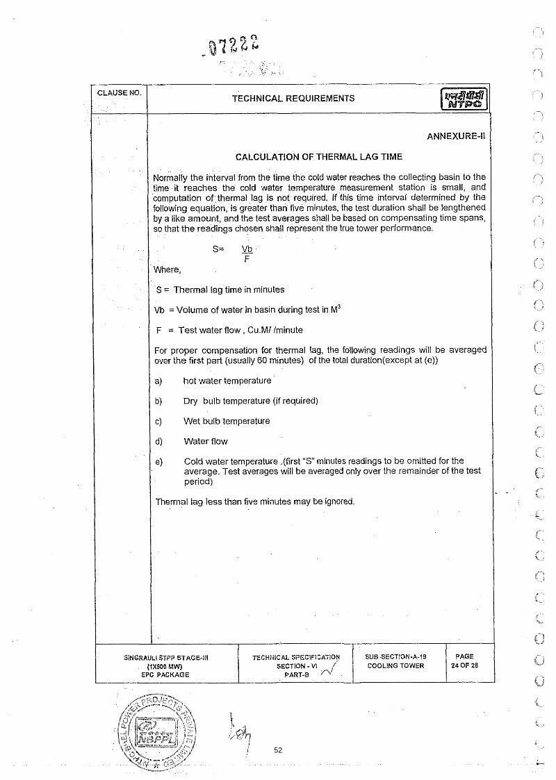
I CALCULATION OF THERMAL LAG TIME
Normally the interval from the time the cold water reaches the collecting basin to the time it reaches the cold water temperature measurement station is small, and computation of thermal lag is not required. If this time interval determined by the followinq equation. is greater than five minutes, the test duration shall be lengthened - - by a l~ke amount, and the test averages snall be based on cornpcnsatlng tlme spans so !hat the readings chosen shall represent the true lower perfcrrnance
S = Thermal lag time in minutes
Vb =Volume of water in basin during test in M3
I F = Test water flow, Cu.Ml /minute
For proper compensation for thermal lag, the following readings will be averaged over the first part (usually 60 minutes) of the total duration(except at (e))
I a) hot water temperature
b) Dry bulb temperature (if required)
c) Wet bulb temperature
/ d) water flow
e) Cold water temperature .(first " S minutes readings to be omitted for the average. Test averages will be averaged only over the remainder of the test period)
Thermal lag less than five minutes may be ignored.
.., i
, ....
, . ,
:.--. r i
' I , .
, ,
, . 1 & ,
- .. ' . .. , j
i? C' -1
f~ .. ;
,. i
I-.., i..
i L
r i
r 5 .
c , c - --.
<.- i
SlNGRAULl STPP STAGE-III (rxsoo MW)
I EPC PACKAGE
TECHNICAL SPECIFICATIOY SECTION -VI
PART-8
SUB-SECTION-A-19 COOLING TOWER
PAGE 24 OF 28
52

TECHNICAL SPECIFICATION SECTION - VI
53

TECHNICAL SPECIFICATION SUB-SECTION-A-19 SECTION - VI
PART.B P1/
54

TECHNICAL REQUIREMENTS
TECHNICAL SPECIFICATION SUB-SECTION-A-19
55

SUB-SECTION-A-19 COOLING TOWER
56
1 PIPING VALVES AND FITTINGS
I Is:458 - Concrete pipes (with and without reinforcement).
1.00.00
1.01.00
I 1 IS : 554 - Pipe thread for pressure tight joints. I
CODE &STANDARDS
The Design, manufacture, shop testing, erection, testing and commissioning of piping and valves shall conform to the latest revisions of the followibg codes and Indian Standards, in addition to other standards mentioned elsewhere in the tender documents subject to any modification and requirement as specified hereinafter.
I ( IS :778 - Gunmetal gate, globe and check valves for general purpose. I IS : 14846 - Sluice valves for water purpose.
IS : 783 - Code of practice for laying RCC pipes.
IS : 1239 - Mild steel tubes and fittings - Part I & II,
I I lS:1363 - Black hexagon bolts, nuts and lock nuts. I IS : 1364 - Precision and semi-precision hexagon bolts, screws, nuts
and lock nuts.
IS : 1536 - Centrifugally cast (spun) iron pipes for water, gas and sewage.
IS : 1537 - Vertically cast iron pressure pipe for water, gas and sewage.
IS : 1538 - Cast iron fittings for pressure plpes for water, gas and sewage.
IS : 1703 - Ball valves (horizontal) plunger type including floats for water supply purposes.
IS : 2062 - Structural steel fusion welding quality.
IS : 2379 - Colcur for the identification of pipe line.
IS : 2685 - Code of practice for erection, installat~on, and maintenance of sluice valves.
IS : 2712 - Gaskets.
- Code of unfired pressure vessels. I SECTION - Vi
57

IS : 3006 - Acid resistant SWG Pipe.
IS : 3114 - Code of practice for CI Pipes
CLAUSE NO.
/ IS: 3042 - Single faced sluice gates (200 to 1200 mm). 1 -
TECHNICAL REQUIREMENTS
IS : 3589 - Electrically welded steel pipes for Water gas & sewage (200 to 2000 mm).
I
IS : 3952 - Cast Iron butterfly valves for general purposes
IS : 4038 - Foot valve for water works purposes.
IS : 4192 - Part-l Rubber lining.
IS : 4736 - Hot d ~ p zinc coating on steel tubes.
IS : 4984 - High Density polyethylene plpes.
IS : 4985 - Unplasticised PVC Pipes.
IS : 5312 - Swing check type reflux (non-return) valve Part-l
BS : 5156
BS: EN 593
ASTM-A 106
ASTM - 53
AWWA-C-504
AWWA M I 1
ANSI:B - 16.5
ANSI:B - 31.1
- Standard for Diaphragm valve.
- lndustrisal Valves - Metallic Butterfly Valves
- CI globe valve.
- Gr.C Seamless carbon steel pipe.
- Seamless carbon steel.
- Rubber seated buttemy valve.
- Steel Pipe - A Guide for design and installaiion.
- Steel pipe flanges and flanged fittings.
- Power Piping code
1 200.00 1 SCOPE I The equipment & material to be supplied under this section shall inciude but not be limited to the following.
i SINGRAULI STPP STAGE-Ill TECHNICAL SPECIFICATION SUB-SECTION-A-26 ( IX500 MW) SECTION - VI PIPING VALVES AND 2 OF 30
EPC PACKAGE PART-B (j FITTINGS
58

a) Plpes, bends, elbows, tees, branches laterals, crosses, reducing unions, couplings, cap, expansion joints, flanges, blank flanges, saddles, shoes, sampling connections etc. necessary for making a rel~able ptping system
b) Gaskets, ring joint, bracking rings, jointing material etc. as required
I I C) Instrument tapping connection, stub and thermo-wells. 1 d) Supply and machining work of flanges, pipe spools and matching pipes to
connect flow measuring orifice nozzles etc., pressure accumulators as necessary.
g) Anchor block (for buriedlover-ground piping), support brackets, clamps, support trestles, hangers etc. for the piping under the scope of contract.
h) Bolts, nuts, fasteners as required for interconnecting piping, valves and fitting as well as for terminal points.
i) Secondary steel for pipe supports and embedded steel. Also pipe supports and necessary embedment required to be embedded in concrete for under groundlabove ground pipes.
j) Painting anti-corrosive coatings, etc. inside and outside of pipes as necessary.
k) All embedded parts required for all tankslwater retaining structures made of RCC including puddle pipes shall be supplied by the contractor.
I DESIGN. CONSTRUCTION AND ERECTION
Piping and Fittings (General)
I Design
All piping systems shall be capable of withstanding the maximum pressure in the corresponding lines at the relevant temperatures. The minimum thickness for pipes and fittings shall be adhered to. Higher thickness in equivalent material is acceptable, However, no credit will be given for higher thickness.
All the piping systems, fittings and accessories supplied under this package shall be designed to operate without replacement and with normal maintenance for a plant service life of 25 years, and shall withstand ihe operating parameter fluctuations and cycling which can be normally expected during this period.
SECTION - VI
59

TECHNICAL REQUIREMENTS
All piping systems shall be properly designed to take care of hydraulic shocks and pressure surges which may arise in the system during operation. Bidder should provide necessary protective arrangement like anchor blockslanchor bolts, etc. for the safeguard of the piping systems under above mentioned conditions. External and internal attachments to piping shall be designed so as not to cause flattening of pipes, exckssive localised bending stresses or harmful thermal gradients in pipe walls.
Piping and fittings shall be manufactured by an approved firm of repute. They should be truly cylindrical of clear internal diameter specified, of uniform thickness, smooth and strong, free from dents, cracks and holes and other defects. They shall allow ready cutting, chipping or drilling, welding etc.
/ 3.01.05 1 All rubber lined pipes shall be seamless or bead removed ERW pipes. I Inspection holes shall be provided at suitable locations for pipes 800 mm Nb and above as required for periodic observations and inspection purposes.
Material of construction for pipes carrying various fluids shail generally be as below:- I
I / S.NO I service I Recommended Material I 1 1 7 . I Raw water I Carbon Steel 1 1 2 I Clarified water I Carbon steel 1
a) SS-304 for the line from filtered water pumps upto DM Plant.
b) GI pipe for the pipe feeding to potable water system.
Above 100 NB: The piping systems handling sea-water shall be of carbon steel having i) coating of high build solvent free polyurethane (PU) of adequate thickness (mln~mum 2mm DFT) on the internal surface of the pipes as per AWWA-C-222.ii) 100% solvent
f r e e v i n y l
Sea Water a) Stainless steel-3161 or cupro- nickel alloy suitable for sea water applicat~on for sizes up to 100 NB or below
I ~ . .
PAGE 40F30
SUB-SECTION-A-26 PIPING VALVES AND
FITTINGS
SlNGRAULl STPP STAGE-Ill (fX500 MW
EPC PACKAGE
TECHNICAL SPECIFICATION SECTION - Vl
PART-B
60

CLAUSE NO.
Recommended Material
Ester glass flake filled coating of 1000 microns.
TECHNICAL REQUIREMENTS
S.No
.
5.
6.
7.
8.
The pipes which cannot be coated internally, shall be of stainless steel construction confirming to ASTM- A-312 GR. 316 L.
Rubber lined Steel
Rubber lined Steel
SS -304
Polypropylene lined steel
Service
Acidic Water
Decationised Water
Demineralised Water
Acid (Conc Hydrochloric acid)
9
a) Strong (Conc) I ss - 304 L I 10.
I / I b) Dilute (upto 10%) I Polypropylene lined steel I
(5 - 30%)
Acid (Dilute Hydrochloric acid)
(less than 5%)
Acid (Sulfuric)
Rubber lined Steel
Stainless Steel I 11.
Rubber lined Steel /Stainless steel - 1
Alkali (Sodium Hydroxide)
a) Strong (5% and above)
b) Dilute (below 5%)
1 1 2 I Alum Solution I Rubber lined Steel I 1 / 13. 1 Lime slurry/Solutionl Galvanised Steel
/ / / (Under Pressure) / Schedule 80 (Heavy Duty)
14.
15.
I SINGRAULI STPP STAGE-Ill / TECHNICAL SPECIFIOATlON SUB-SECTION-A-26 1 PAGE I
Suspens~ons
Coagulant a ~ d Solut~on
Liqu~d and Gas Chlor~ne
Rubber lined Steel
Seamless Carbon Steel
( I X 5 0 0 MW) EPC PACKAGE
SECTION - VI PIPING VALVESAND PART-B FITTINGS
.,-OJEp .... 5 0 F 30
61

TECHNICAL REQUIREMENTS
/ Recommended Material 1 --
16.
17.
/ Galvanised Steel I
18.
-
Chlorinated Water
Wet Chlorine gas
21 1 Resin water slurry / Stainless steel Type-304 /
Rubber lined Steel for above ground & HDPE plpe for below ground
Polypropylene
(Under Vacuum)
Sludge (From Clariiier /tube settlerllamella clarifier)
20
Cast lron [Class A as per IS: 1536) 1 Ductile Iron
However the portion down stream of the isolation valves of pipe lines conveying flushing water shall be of the material &type as that of the chemical pipelines which is being flushed.
Waste effluent from DM plant vessels & chemical solution tank's etc.
22
Rubber lined Steel for above ground &
HDPE pipe for below ground
SI. Description Velocity in meters1 second
Note: Irrespective of the recommended piping material as mentioned above, Bidder shall supply the material of pipes indicated in Scope of Work: (Part-A) and in tender Drawings.
BackwashlRinse water from discharge of Backwash pumps in DM plant
3.01.09
Pipe size Pipe Size 50 Pipe Size 200 Below 50mm to 100 mm mm &above
a) Pump suction 1.2 - 1.5 1.2 - 1.5 1.2 - 1.8
b) Pump discharge 1.2- 1.8 1.8 - 2.4 2.1 - 2.5
c) Header 1.5-2.4 1.5-2.4 2.1 - 2.4
SS-316
Minimum sizes for various pipelines are indicated in the tender drawingsldata sheet. Bidder to provide the same as specified. However, for plpe lines where sizes are not ind~cated, siz~ng shall be done based on the foliow~ng velocities as indicated below:.
G
0 - di
ij
. , ". ,j
e-~
PAGE 6 OF 30
SlNGRAULl STPP STAGE-Ill (1x500 MWj
EPC PACKAGE
TECHNICAL SPECIFICATION SECTION - V I
PART., fl'
SUB.SECTION-A-26 PIPING VALVES AND
FITTINGS
62

TECHNICAL REQUIREMENTS
Velocity in meters1 second
d) Compressed alr 15-20 20 - 30 25 - 35
below 2 ~ g l c m ~ ( ~ )
e) Compressed alr 20 - 30 25-40 35-45
2 ~ g l c m * ( ~ ) & above
f) Suctlon to compressor1 7 - 8 7 - 8 7 - 8
Blowers
Pipe line under gravlty flow shall be restricted to a flow veloc~ty of 1 misec generally. Channels (Other than Cold water channel of Circulating Water System) under grav~ty flow shall be sized for a maximum flow velocity of 0.6 mlsec
The following " C" Value shall be used in WILLIAM & HAZEN formula for calculating the friction loss in piping systems.
i) Carbon Steel pipe - 100 I ii) Carbon Steel pipe with internal lining - 120 I iii) C.1 Pipe I Ductile Iron - 100 I iv) Rubberlined steel pipe - 120 I iv) PVC / HDPE 1 GRP pipes - 140 1 v) Stainless Steel - 100 I For calculating the pump head, atleast 10% margin shall be taken over the pipe friction losses.
Material & Dimensional Standards for Piping
All piping system shall be capable of withstanding the maximum pressure and temperature in the corresponding line. The pressure rating of individual piping system component such as valves, flanges etc shall however be not less than that specified.
The Steel pipes (Welded type) for the services of waterlclarified water1 Filtered water / Sea water shall conform to the following standard or codes.:
Pioes uo to 150 NB: lS:1239 Part-l (Heavy grade-Black), ASTM-A-53 Grade B (Welded) -Schedule 80 up to 2 inch size and Schedule 40 above 2 inch nominal size.
SINGRAULI STPP STAGE-Ill TECHNICAL SPEClFlCATlON SUB-SECTION-A.26
63

Pipes 200 NB and above: 1S:3589 - Grade 410; ASTM - A53, Type-E Grade B (Welded) - Schedule 40.
However, condenser polisher headers for condensate polishing plant shall be of seamless carbon steel A 106 Gr.B all welded construction with 300 lb flange connection. Inlet and discharge end shall be prepared for field - welding.
(a) The thickness of the pipes shall be selected based on the des~gn pressure of the system (maximum test pressure or maximum surge pressure due to transients). Corrosion allowance of 2mm shall be ~ncluded for unl~nedi un- coated plpes and 1 mrn for lined/coated plpes and negatlve tolerance specifled by the StandardiCode shall be added to arrkve at the final thickness. Thickness selected shall also meet the requ~rements of AWWA - M11 (for deflection & buckling criteria considering water filled for compacted sod) in case of buried pipes. However the final thickness shall not be less than that specified as per IS: 3589 as indicated below.
! I St Nominal Pipe Outside Diameter (mm) Wall thickness Size (rnrn) (mm) 1
SINGRAULI STPP STAGE-III TECHNICAL SPECIF~CATION SUB-SECTION-A-26 PAGE (iX500 MW) SECTION - VI PIPING VALVES AND 8 OF 30
EPC PACKAGE PART-B d FITTINGS
64

SI Nominal Pipe Outside Diameter (mm) Wall thickness Size (mm) (mm)
1600 NB 1626 14.2
(b) Spirally welded pipes as per API - 5 LS or IS3589 are also acceptable for pipe of size 400 NB and above
(c) Preferably all steel pipes shall be supplied from the approved manufactures from their works. However, for Pipe Sizes 600NB and above, Bidder may fabricate pipes at site. Pipes to be fabricated by the bidder shall be rolled and butt welded from platesicoil conforming to ASTM A - 53 type E Gr. B I IS 2062 Grade 410 WC or Equivalent, of required thickness (as defined above) at site. Bidder shall clearly bring out their proposal regarding this aspect in their bid. The site-fabricated pipe (finished product) shall meet the required quality specified in the design Standard (133589) with regard to Mechanical, Chemical Properties, Tolerances etc. However, for such site fabricated pipes, the Hydrostatic Test Pressure shall be 1.5 times the design pressure or 2 times the working pressure as the case may be. Other Testing requirements for such site-fabricated pipes shall be as per relevant Table in Sub-section-Ill E of Part-B of this Technical Specification.
P~pes for the Air Service shall conform to the above Clauses 3 02 02 & 3 02 03 and shall be galvan~sed to IS:4736.
Pipes to be used for the rubber lined construction shall conform the above Clauses 3.02.02 & 3.02.03 and inside surface shall be completely debeaded and made suitable for lining.
I Other piping materials shall conform to the following standards. I 1) lS:4984 - PE-80 & PN-16-H~gh density polyetheylene pipes.
2) IS:4985 - Class-4 - PVC Pipes.
3) ASTM A-106, Gr. C, Schedule 80 -Seamless carbon steel plpe
4 ) ASTM A-312 Grade TP-316 Schedule 40 -Stainless Steel pipes (SS 316) 1
65

C
TECHNICAL REQUIREMENTS
15) ASTM A-312 Grade TP-304 Schedule 40 (min) (ANSI B36.19) - SS 304 I 16) ASTM A-312 Grade TP-304L Schedule 40 (min) (ANSI B36.19) - SS 304 L i 17) ASTM D 3517 & ASTM D 4024 - GRP pipes 1
1) Fittings to be used with carbon steel pipes shail conform to 1S:1239 Pait-ll (Heavy grade) for sizes upto 150 NB. For sizes 200 NB & above steel fittings shall conform to ASTM A 234 Gr. WPB.
2) For stainless steel fittings above 50 NB the same shall conform to ASTM-A- 403, GR. WP 304 (316 for sea water application, if any), Class W i.e. the fittings shall be of welded construction strictly in accordance with ASTM-A-403.
I 1 3) Unless otherwise specified elbows shall be long radius type. I 4) For pipe sizes upto 65 NB long radius forged elbows or seamless bends shall
be used. Pipe bends, if used, shall be cold bent to a radius measured to the centre line of pipe of 3 to 5 times the pipe diameter. For steel pipes 80 NB and above, seamless long radius forged elbows are used unless otherwise indicated in the drawings. For pipe size 350 NB and above meter bends may be used. The bend shail be 1% times the nominal pipe diameter. 90' meter bends shall be in 5 pieces (4 cuts) 45'mitre bends shall be in 4 pieces and 22%' in three pieces. Fabrication of meter bends shall be as detailed in BS 2633lBS534.
5) However inside surface of all the fittings used for the rubber lined application shall be debeaded and made suitable for rubber lining.
( 6) Galvanized pipe application all the fittings shall be galvanised as per 1S:4736. I 7) Fittings to be used in other type of piping shall conform to relevant ISIBS ANSI
Standards and in c<nformlty with the parent pipe standard.
I I 8) Unless otherwise shown eccentric reducers shall be installed with straight side at the top of piping connection.
1 3,03.00 1 Design of Piping Systems 1
I o o I All unlined steel pipes 65 NB and above (other than CI pipes and air service pipes) shall be jointed by butt welding.
3.03.01 Pipes 50 NB and smaller shall have socket welded joints for chlorine line. For water, air and other services where steel pipes are used, joints of this size range shall be screwedlflanged type.
66

i .,
, ,
. .. .
,- I.. ,!
i \ CI.'
r . L '
3.03.03 All rubber lined pipes shall have flanged joints.
Steel pipe flanges shall be generally slip on flat face type. Weld neck flanges shall be used when flange follows immediately after a butt welding or where it is required with respect to service conditions. When weld neck or socket weld flanges are used, their bore must be made the same as that of the pipe being welded to. Socket welded or threaded flanges may be used, with the appropriate piping system for connection of pipe to the flanged equipment.
All the piping flanges and counter flanges & their drilling shall conform to ANSl B 16.5 of relevant pressure & temperature class. However wherever the interference is involved with the Owner's pipe, the flangeiinterconnection details shall be designed to match the piping and the details of which will be intimated later. Flanges shall conform to ANSI 8.16.5 class 150 (minimum). However Stainless Steel Flanges shall be fabricated from SS Plates to ASTM-A-240, Gr. 304 (316 For Sea Water Application, if iny) or equivalent
The field joints of internally linedlcoated smaller size pipes (diameter 150 to 400 NB) shall be of flanged type to avoid manual coatingllining at joints.
For easy handling & removal of equipments, valves etc. and for maintenance purpose, break up flanges for 65 NB and above sizes and suitable type of compression flexible coupling for flanged joints of 50 NB and below size shall be provided. The over-ground piping wherever routed inside building, shall have a clear head room of minimum 2.1 meter from operating floor.
Pipes shall be generally be routed above ground but where specifically indicatedlspecified the plpe may be laid in trenches or buried. Burried piping shall be generally installed so that the top of pipe is 1.0 meter below the ground level unless otherwise specifically mentioned. Full length of buried piping shall be provided with 100 rnm thick sand bed.
Complete supporting system for the pipe line shall be designed, fabricated and supplied by the Bidder. Inside the building, the overhead portion of the pipe line may be supported from the building structures. N o support shall be taken from the brick wall. Outdoor, pipes other than buried pipes shall run on steel trestles. Crossing of the road shall be on a pipe bridge with a clear height of at least 7 meters over the road surface. All the. steel structure for the, pipe bridge, and the supporting postsltrestles along with all necessary hangers clamps, connecting steel, fixing bolts, nuts etc. shall be supplied and erected by the Bidder.
1 3.03.10 1 Butt welding edge preparation shall be done as per ANSI B 16.25. ! All welding electrodes and welding rods including special ones, if any shall be furnished by the Bidder.
67

Mitre bends will not be accepted for steel pipes of 350 NB and below. For sizes above 350 the mitre bends shall conform to BS:534. The bend radius shall be used for all pipes 1.5 times the nominal pipe diameter.
Hangers and supports shall be capable of carrying the sum of all concurrently actlng loads. They shall be designed to provide the required supporting effects and allow pipe line movements as necessary. All guides, anchors, braces, dampener, expansion jolnt and structural steel to be attached to the bu~ldinglstructure, trenches etc. shall be prov~ded. Type of hangers and components for all piping shall be selected and approval obtained from the ENGINEER.
A deta~led Hydraul~c transient analysis based on the method of characteristics shall be carried out for such piping system if included in the scope of supply. Thls study shall be carrled out by a reputed consultantllnstitute. The following shall be based on the results of the hydraulic transient study.
Pump discharge valve closing time and pump stopping sequence.
I * Conditions arising due to stoppingltripping of pumps I e Size, location and quantity of air release valves in the make-up water piping shall
be provided by bidder.
Pump discharge valve opening time during start-up condition and pump starting sequence.
The report of transient analysis should consist of methodology adopted, characteristics curvesldata for various boundary conditions, complete input data used for execution of software for various events and the results of the programme, The report shall be submitted to the Owner for approval. Based on the recommendations of such a study. Bidder shall take corrective measures and provide suitable surge suppression device in the piping system.
P~pe comtng under purvlew of IBR should meet its requ~rementsand getting the IBR approval shall be under Vendors scope
Internal & External Protection Of Pipes:
For rubber lined pipe, lining should be applied in two (2) layers, giving a total thickness not less than 3 mm. Surface hardness of rubber lining shall be 65 + 5 A class.
Painting and application procedures for over ground Piping shall be as follows:
68

CLAUSE NO. r / a) For Indoor Pioinq I I 1) Surface preparation shall be done either manualiy or by any other
approved method.
I 2) Primer coat shall consist of one coat of chlorinated rubber based zinc phosphate primer having minimum DFT of 50 microns.
3) intermediate coat (or under coat) shall consist of one coat of chlorinated rubber based paint pigmented with Titanium dioxide with minimum DFT of 50 microns.
4) Top coat shall consist of one coat of chlorinated rubber paint of approved shade and colour with glossy finish and DFT of 50 microns.
I Total DFT of paint system shail not be less than 150 microns. I I b)
For Outdoor Piainq I 1) Surface preparation shail be done by means of sand blasting, which shall
conform to Sa 2-112 Swiss Standard.
I 2 ) Primer coat shail consist of one coat of epoxy resin based zinc phosphate primer having minimum DFT of 100 microns.
I 3) Intermediate coat (or under coat) shall consist of epoxy resln based pant pigmented with Titanium dioxide with minimum DFT of 100 microns.
4) Top coat shall consist of one coat of epoxy paint su~table pigmented of approved shade and colour w~th glossy finish and DFT of 100 microns Addit~onaily finishing coat of polyurethane of minimum DFT of 25 mlcrons shall be provided.
. . The paint may be applied in one coat, in case high built paint is used, otherwise two coats shail be applied.
I Total DFT shail not be less than 300 microns. I Outside surfaces of steel pipes and fittings that are buried underground and laid inside a Hume pipe (in Roadlpipe or trench crossings) shall be given protective coating as per Annexure-I enclosed with this section.
/ VALVES b GATES I Valves wili be used to stadstop or control flow. Gates will be primarily used for isolation of flow in open channels aithough these should be capable of throttling the flow too. Sample valves wili be used in sample collection lines. Unless otherwise
(iX500 MW) SECTION - V I PIPIN(
I EPC PACKAGE 1 F'ART.B FITTINGS , , % x .>,;s,K:*, -- .., -.%
69
I I specified al l the Valves shall be supplied with counter flanges by the Contractor.
(b). All the actuators of the valves shall be designed to handle the maximum expected pressure differential across the valves and to overcome friction forces and unbalance forces due to the flow through valve.
Valves in Raw water, Clarified, Filtered and Sea water application:
(a) All valves, shall be suitable for service conditions i.e. flow, temperature and pressure under which they are required. All the valves shall be of standard pressure rating of the relevanfdesign standard. Non standard pressure rating shall not be accepted. The pressure and temperature rating of the valve shail not be less than the maximum expected pressure and temperature plus 5% additional margin of the system in which valves are proposed to be installed. The pressure rating of individual piping system component such as valves, flanges etc shall however be not less than that sper:;fiod.
/ ::
Unless otherwise mentioned in tender drawings, either Butterfly type or sluicelgate valves shail be used for isolation purposes.
i
SluicelGate valves :
a) Sluice /Gate Valves shall conform to BS:5150(BS:5163 PN 16) PN16, IS:14846 of rating PN 1.6 (min.). Stem, seat ring and wedge facing ring shall be of stainless steel construction. Other parts shall be as per 1S:14846 /BS:5163). Flanges shail be designed as per ANSI B 16.5 CI. 150 (min.) to meet with the piping flanges. Valves shall be of outside screw and rising stem type. Gate valves for sizes below 50 NB and below shall conforms to 13778 Class-2IANSI 816.34 straight, rising stem; without side screw.,For sea water application the Body, Bonnet, Wedge, Yoke etc shall be of ASTM A 439-Gr D2.
b) SluiceIGate valves shall be provided with the following accessories in addition to the standard items:
01) Hand wheel
02) Manual Gear reduction unit operator for valves 200 NB and above
I #"; I 03) Bypass valYe for valve of sizes 350 NB and above. ",i
04) Dra~ning arrangement wherever requ~red.
05) Arrow ~nd~cating flow direct~on.
1 06) Position indicator. 1 . (2
t' r ;I
SINGRAULI STPP STAGE-Ill (1x500 MWJ
EPC PACKAGE
<-:+,I
< 1 %.
I Y , ~
i I ,>
Qw i i I i i---r
TECHNICAL SPECIFICATION SECTION - vt
PART-E ryf SUB-SECTION-A-26
PIPING VALVES AND FlrTlNGS
PAGE $4 OF 30
70
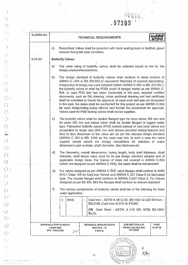
C) SlulceIGate Valves shall be provided with back seating bush to facilitate gland renewal durlng full open condltlon
1 4.03.03 I Butterfly Valves: I 1 I a) The valve rating of butterfly valves shall be selected based on the for the
design pressureltemperature.
b) The design standard of butterfly valves shall conform to latest revision of AWWA C -504 or BS: EN593 or equivalent Standard of required classlrating. Irrespective of design sla,l;ard adopted (either AWWA C-504 or BS: EN:593 ), the buttemy valves of shall be POD( proof of design) tested as per AWWA C- 504. In case POD test has been conducted in the past, required certified documents, such as GA drawing, cross sectional drawing and test certificate shall be submitted to Owner for approval. In case such test was not conducted in the past, the same shall be conducted for this project as per AWWA C-504 for each designtrating being offered and furnish the documents for approval. Valves used for POD testing valves shall not be supplied.
c) The butterfly valves shall be double flanged type for sizes above 300 mm and for sizes 300 mm and below valve shall be double flanged or lugged wafer type. Fabricated butterfly valves (POD tested) instead of cast body valves are acceptable for larger size (600 mm and above) provided testing features and face to face dimension of the valve are as per the relevant design standard (AWWA C 504 or BS: 5155 as the case may be). In such a case the valve supplier should submit the design calculations for selection of major dimensions such as body, shaft diameter, disc thickness etc
d) The Geometry, overall dimensions, laying length, body shell thickness, shaft diameter, shaft torque value shall be as per design standard adopted and of applicable design class. For Valves of sizes not covered in AWWA C-504 (which are designed as per AWWA C-504), the same shall be extrapolated.
e) For valves deslgned as per AWWA C-504, valve flanges shall conform to ANSI B16.1 Class 125 for Cast lron Valves and AWWA C 207 Class E for fabricated type The counter flanges shall conform to AWWA C-207 Class E. For Valves deslgned as per BS: EN: 593 the flanges shall conform to relevant standard
f) The various components of buttemy valves shall be of the following for fresh water application:
1 ) / Body 1 : 1 Cast Iron - ASTM A 48 C1.40; 831452 Gr.220 SG Iron - BS:2789.;Cast lron IS:210 Gr.FG260.
OR Cast Steel - ASTM. A 216 GR. WCB; BS:1504 1 I / / Eq.Gr.
I SINGRAULI STPP STAGE-Ill
(1x500 MWj EPC PACKAGE
PAGE 150F 30
TECHNICAL SPECIFICATION SECTION - VI
PART-8
SUB.SECTION-A-26 PIPING VALVES AND
FITTINGS
71

I I ! OR Fabricated Steel as per ASTM A515 Gr.60180 IS:2062. Gr.BllS:2002.(for higher size valves) 1 1 / ii) Disc. 1 : 1 Cast Iron 1S:210, Gr.260; Cast Iron - ASTM A 48 C1.40; BS:1452, Gr.220, SG Iron - BS:2789.
) 1 / / OR Cast Steel -ASTM A 216 Gr. WCB; B51504 EqGr. / 1 1 1 I / OR Fabricated Steel as oer ASTM A515 Gr.60180 I /
1S:2062, Gr.BllS:2002 (for higher sizes). /I I / iii) / ShaA I : / ASTM. A 296 Gr. CF8MIAISI 316: AlSl420; / /
Nitrile rubber, EPDM (Ethylene propylene rubber), Hv~alon.
For Condensate polishing plant all buttemy valves shall be of stainless steel construction, SS-316 (for body, disc and shaft). Seatiseat rings should be of Teflonlt~tanium back up rings. Seal shall also be of Teflon only.
I I For sea water application: I Austentic Ductile l ron (cast) Butterfly valves
Body & DISC ASTM A 439 D2 and epoxy coated internals
Shaft SS -316
Seat Rlngs 18-8 Stainless steel
Seal EPTIBUNAINEOPRENE I EPDM I Butterfly valves shall be fitted with sleeve type bearlng such as PTFE. Valves of size 350 NB and above shall be provided wlth one or two thrust bear~ngs to hold the dlsc securely in the center of valve seat w~thout hydraulic or external axial shaft loads Sleeve and other bearings fitted ~nto the valves body shall be of self lubricated materials that do not have any affect on the flu~d handled and other components of the valves.
All the buttemy valves shall be provided with Hand wheel or lever as per the requ~rements.
For larger sizes i.e. 150 NB and above hand wheel shall be provided. For leverlwrench operated valves, means shall be provided for positively holding the disc in not less than three intermediate positions.
PAGE 16 OF 30
SUB-SECTION-A-26 PIPING VALVES AND
FITTINGS
SINGRAULI STPP STAGE-Ill (1x500 MW)
EPC PACKAGE
TECHNICAL SPECIFICATION SECTION - VI i
PART-B so
72

j) Manually operated valves shall be provided with reduction gear unit for valves of size 250 NB and above. Valve provided with motorised or pneumatic actuator shall be provided with a hand wheel for manual operation. All the valves shall be equipped with adjustable mechanical stop-limiting devices to pyevent over travel of the valve disc in the open and closed positions. The manual valve operators (Hand wheel or Gear reduction unit) shall be designed as per relevant International Standard.
k) All the buttefly valves shall be provided with an indicator to show the position of the disc.
For Sizes 40 NB and below, Ball valves or Globe Valves may also be provided for the application of Raw1 ClarifiedlFiltered I water services conforming to the following specifications:
Ball Valves
iv)
v)
vi)
Seats
Valves shall be designed to be directly operatable by a wrench1 ~.
Handlever; . .
Suitable stops shall be provided for both the fully open and close condition
All the valves shall be provided with an indicator for showing the position of the ball port.
: Nitrile rubber; PTFE = .
73
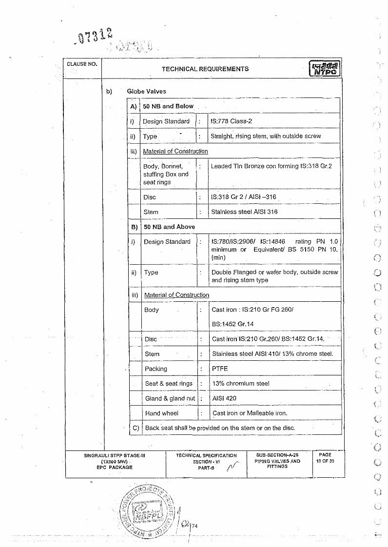
TECHNICAL REQUIREMENTS
Globe Valves
Stem : Stainless steel AlSl 316
B) 50 NB and Above
A)
i)
i ~ )
111)
i) Design Standard : 1S:780/1S:2906/ IS:14846 rating PN 1.0 minimum or Equivalent/ BS 5150 PN 10. (min)
ii) Type : Double Flanged or wafer body, outside screw and rising stem type
iii) Material of Construction
Body : Cast iron : 1S:210 Gr FG 2601
50 NB and Below
Disc : Cast iron IS:210 Gr.2601 BS:1452 Gr.14.
Stem : Stamless steel AlSl410/ 13% chrome steel.
Pack~ng : PTFE
Seat & seat rings : 13% chromium steel
Gland & gland nut : AlSl 420
/ / Hand wheel 1 : / Cast iron or Malleable iron. I I
1S:778 Class-;!
Straight, rising stem, with outside screw
Design Standard
Type -
I C) / Back seat shall be provided on the stem or on the disc. / I
:
:
SlNGRAULl STPP STAGE-Ill TECHNICAL SPECIFICATION SUB-SECTION-A-26 PAGE (IX500 MWJ SECTION - VI PIPING VALVES AND 78 OF 35
EPC PACKAGE PART-B ff FITTINGS
Material of Construction
Body, Bonnet, stuffing Box and seat rrngs
: Leaded Tin Bronze con form~ng IS.318 Gr 2
74

CLAUSE NO.
4 03.05
D) Renewable disc assembly shall consist of disc holder, disc, disc guide, / I check nut and disc retaining nut with washer 1 1 ring.
arrow to indicate direction of opening or closing.
U?wever, valves in the flushing water lines shall be of type and material specified for the chemicals which is being flushed by the line.
1 4.04.00 I Valves for Decationsed, Deanionsed and Dernineralised water application I Butterfly valves or Saunder's patented diaphram valves shall be used for the services of deanionised, decationised and demineralised water application for isolation purposes.
I The diaohracim valves shall conform to the following requirements.
1 1 1) ( 0esign 1 : / BS:5156 or equivalent of required ratinglciass. Standard (minimum rating of valves should be PN 10).
Flanged and lined body ends, sealed bonnet, weir pattern, tight shut off type.
iii)
iv)
I1 ! Cast steel ASTM A-216 Gr WCB.
Material of Construction
I v)
Body, Bonnet
vi)
vii)
viii)
ix)
Body iining
I
:
Diaphragm
Handwheel
Compressor
Stem & Bush
Cast iron IS:210 Gr.FG.260 or equivalent
:
PAGE 19 OF 30
>
Soft Natural rubber, Ebonite
Polypropylene
:
:
:
:
SUB-SECTION-A-26 PIPING VALVES AND
FITTINGS
SlNGRAULl STPP STAGE-Ill (rxsoo MW
EPC PACKAGE -
Reinforced rubber,hypalonlapproved . equalent
Cast Iron
Stainless Steel
Stainless Steel
TECHNICAL SPEClFlCATlON SECTION - VI r / PAR7.B
75

x) Hand wheels shall be marked with the direction of closure.
xi) Valves shall be provided with a position indicator to show the open and closed condition.
xii) Valves provided with pneumatic actuators shall 'be provided with a handwheel for manual operation. The valves operators shall be designed as per relevant International Standard
4.04.03 The butterfly valves shall conform to C1.4.03.03 above except to ihe following requirements. 1' ), +
1. Body shall be lined (minimum 3 mm) with natural rubber, ebonite, polypropylene.
2. Disc shall be lined with PVDF, polypropylene, or natural rubber. Disc of SS-316 is also acceptable.
3. Seat rings shall be of Nitrile rubber or Hypalon.
Valves for Acid & Alkali Services
4.05.01 Valves shall be Saunder's patented diaphragm type. The valves shall conform to CI. 4.04.02 above except that Diaphragm shall be of reinforced TEFLON, EPDMiBlack Bulilelapproved equivalent for acid sewices and reinforced NeoprenelHypalonl approved equivalent for alkali services.
4.06.00 Valves for Lime Slurry I Solutions & Resin transfer lines
4.06.01 Plug valves shall be used for the application of lime slurry /lime solutions.
4.06.01 The plug valves for lime slurrylsolution lines shall conform to the following requirements.
- .
Staineless Steel AlSl 316
SINGRAULI STPP STAGE-111 TECHNiCAL SPECIFICATION SUB.SECTI0N.A-26 PAGE (1x500 MW SECTION - V1 PIPING VALVES AN0 20 OF 30
EPC PACKAGE PART-B FITTINGS ./
76

CLAUSE NO.
4.06.03
4.07.00
4.07.01
TECHNICAL REQUIREMENTS
vii) Seat : PTFE
viii) Gland : AlSI 304 1 AISI 316
I 1 ix) / cover I : / Cast Steel ASTM A216 Gr WCB I I I x) / Gland Nut I / AlSl304 1 AlSl 316 I
xi) Valves shall be operated by permanently fitted wrench or Hand lever. Wrench shall be mounted so that they c:- ~aral lel to the valve bore axis when the valve is in fully open condition.
xii)
xiii)
xiv)
All valves shall be provided with an indicator for the position of the plug part.
Suitable stops shall be provided for the fully open and fully closed positions of the valve.
Valves of size of 250 NB and above shall be provided with a suitable reduction gear unit.
In resin transfer line of Condensate Polsihing Plant two way eccentric plug valve as manufactured by De Zurik or approved equal shall be used. The valves, shall have type 316 stainless steel body and bearings, resident faced plug and flanged ends. For service vessel area pressure rating should be in line with system requirement. In case Ball Valves are used in the resin transfer lines, the same shall be of SS-316 construction and pressure rating shall be in line with system requirement.
I Valves for Alum Solution and Coagulant aid Solution application I Valves shall be of Saunder's patented diaphragm type. I 1 4.07.02 1 Diaphragm valves shall conform to the requirements as menboned in CI 4.04.02 1 above. I Ball valves may also be used in PVC pipes (if permitted in specification) for alum and coagulant aid solution application conforming to the foliowing material of construction.
I I Body, Ball B Stem : PVC I I I Seat ring & Packing : EPDM (Ethylene propylene rubber) I 1 4.08.00 1 Valves for Chlorine gas (WetlDry) and Chlorinated Water Application 1
77

the valves in line with the Chlorination Plant Supplier (Manufacturer) recommendations and practice. The Valves in Chlorine gas (WeffDry) liquid chlorine and Chlorinated water lines shall be approved by the Chlorine Institute-USA and the Chief Controller of Explosives - INDIA.
I 4,080Z I The Materials of construction of various types of valves are indicated for the guidelines of the Contractor.
a) Needle Valve (Chlorine qas Shut off Valve1
/ . / Bronze (Silver plated) 1 Brass 1 / b) / Needle I : / Monel 1 I C) 1 Valve seat 1 : 1 Teflon I Monel I
1 : 1 Monel 1 e) Gland I Gland nut : Bronze1 Brass
I I I
f) Packing : Teflon
b) Ball Valve (Liquid Chlorine) 1 : ;:; 1 1 Carbon Steel 1 PVDF I Monel
Stem . Stainless Steel AlSl 316 L
d) Bolts & nuts : AlSl 316 L - e) Gland I Gland nut Bronze1 Brass - .
f) Seat ring . PTFE
C) Angle type needle valve (For tonne container Isolation)
a) Body Bronze (S~lver plated) 1 Brass
b) Needle : Monel
c) Valve seat . Teflon i Monel
d) Stem : Monel
I SlNGRAULl STPP STAGE-I11 TECHNICAL SPEClFlCATlON SUB-SECTION-A.26 PAGE
( IXSOO MW) SECTION - VI PIPING VALVES AND 22 OF 30 EPC PACKAGE PART-B FITTINGS
78

d) Butterfly type Valve /Ball Valves (Isolation 5f Chlorinated Water in PVC pipes)
e)
f)
/ a) I / : / pvc I / b) / Shaft I : / Carbon Steel nickel plated 1
Gland i Gland nut
Packing
/ c) I Disc I Ball I : / PVC 1 / d) / Seating ring / : / Viton I
:
:
/ e) / Packing (Ball Valve) I : / PTFE /
Bronze1 Brass
Teflon
/ f) / Bush i 0 -ring (Butterfly type) I : / EPDM, PVDF / e) Diaphragm Valves (Isolation of Chlorinated water in lined stek~ pipe):
These valves shall conform to CI 4.04.02 above.
Valves in Sludge pipe line application
Sluice valveiknife edge type slide valves shall be used in the sludge and drain pipe line.
ii) Type 1 I
The Valves shall conform to the following requirements:
I 1 Double Flanged or wafer body, outside screw and rising stem type.
i)
of Construction / I
Design Standard
I / Disc 1 : / Cast Iron IS:210 Gr. FG 260 /
Body
Stem
: IS:780/1S:2906 rating PN 10 (min).
:
:
Packing
Gland & Gland nut
Cast Iron : iS:210 Gr. FG 260
Stainless Steel AlSI 420
SINGRAULI STPP STAGE-Ill (iXS00 MW
EPC PACKAGE
:
:
PTFE
AlSl420
TECHNICAL SPECIFICATION SUB.SECTION-A-26 SECTION - V I PIPING VALVES AND
(" PART-B FITTINGS
PAGE I 23 OF 30
79

TECHNICAL REQUIREMENTS
/ 1 Handwheel 1 : 1 cast iron
v) The valves shall conform to the other requirements specified in CI. 1 / 4.03.02(b) & 4.03.02(~).
iv)
Valves for Air pipe line application
For Air services, globe valves d~aphragm value or Ball valves may be used for sizes 50 NB and below.
The flanged type valves shall have flanges conforming to ANSI-B 16.5 CI-150.
For sizes higher than 50 NB, either Bunerfly valve, diaphragm value or Ball valves shall be used.
Globe valves shall generally conform to CI. 4.03.12 (b) above
Ball valves shall conform to the requirements stipulated in C1.4.03.12 (a) above. However, Body material shall be leaded Tin Bronze (1S:318 Gr.2) or stainless steel (AISI:3041316).
Butterfly valves shall conform to the C1.4.02.05 to 4.02.09 of this section. However, the body & Disc shall be either cast iron lined with elastomer such as PVDF or PTFE or stainless steel construction (AISI 3041316).
Non-return valves (Check valves)
Non return valves shall be of swing check (reflux) type or dual plate type
I The valves shall conform to the following specifications.
1 i) I Design Standard I : / 1S:5312, BS:1868, BS:5153 API 5941 API 60(6D) or Equvalent - .
Flanged Swing check Type or Dual plate type of lugged wafer design
I I iii) I Material of Construction (For non corrosive application) 1
I High tensile Brass IS320 HT 2 or
Body & Cover Hinge DisWDoor
Hinge Pin and DoorlDisc Pin
:
:
SINGRAULI STPP STAGE-Ill (1x500 MW)
EPC PACKAGE
Cast Iron : 1S:210 Gr. FG 260
Cast lron 631452 Gr.220 or Eqvt
Cast steel ASTM A 216 Gr. WCB.
TECHNICAL SPECIFICATION SECTION - Vi
PART-B A*
SUB-SECTION-A-26 PIPING VALVES AND
FITTINGS
PAGE 24 OF 30
80

s .,
i.! i ", " , ,
: ~
\.L,,<
i. i 'I
Disc shall be lined with natural Rubber, PTFE or Viton. The Hinge. Hinge Pin 8 Disc Pin shall be coated with PVDF, or suitable elastomer. The
smaller sizes upto 150 rnrn NB, lugged wafer type is also acceptable. The material of construction of spring in dual type valve shall be of INCONEL or
Flanges shail conform to ANSI B 16.5 C1.150 to match with the piping flanges as specified elsewhere.
i i I /
( ',.
, . i
-'
SlNGRAULi STPP STAGE-Ill (1x500 MW
EPC PACKAGE - TECHNICAL SPECIFICATION
SECTION -Vt PART.,
SUB-SECTION-A.26 PIPING VALVES AND
FITTINGS
PAGE 25 OF 30
81

TECHNICAL REQUIREMENTS
Body shall be permanently marked with an "arrow" inscription indicating the direction of motion of the fluid for all the check valves.
Check valves for Raw i Clarified i Filtered water may be offered in Gun metal construction & with threaded ends for sizes 50 NB and below conforming to 13778 or Equivalent.
For Chlorine gas and Chlorinated water application check valve of Lift Ball type may be used in PVC construction (in case of PVC pipes). In case of rubber lined pipes, the check valves of swing check type shall be lined construction as referred in CI 4.11.02 (v) above.
The safety valves i relief valves at the down stream of positive displacement type rneter~ng pumps shall be of the standard type manufactured by the pump manufacturer and the material of construction shall suit to the fluid handled.
I Gates
Design standard for gates shall be 1S:3042 or Equivalent. For sizes not covered under iS::3042, the gates shall generally as be per 15:13349.
The gates shall be rectangular or square sluice, rising spindle type conforming to class-I of lS:3042,
Material of Construction
a) Frame and Door Cast Iron IS:210 Gr.260
b) Spindles, bolts & nuts : M.S. to lS:2062
c) Face & seat rings Gun metal (as per lS:3042)
All the parts of gates shall be applied with the coats of heavy duty bitumastic paint.
Each of the gates shall be provided with hand wheel, anda position indicator.
1 4.14.00 1 Automatic Air Release Value 1 4.13.06
The automatic air release cum vacuum breaker valves shall be of automatic double air vaive with two orifices and two floats conforming to 1514845. The float shall not close the valve at higher air velocities. The Orifice Contact jointwith the float shall be leak tight joint. An isolation valve shall be provided for each release vaive. The Air release valve in the makeup water pipelines shall be provided w i t h a suitable enclosure with locking arrangement so that the same is not tampered.
The gates for DM plant drainstcondensate Polishing Plant shall be rubber iined to a minimum thickness of 4.5 mm.
SINGRAULI STPP STAGE-Ill TECHNICAL SPECIFICATION SUB-SECTION-A.26 (iX500 MW) SECTION - VI
EPC PACKAGE PART-B FITTINGS
82
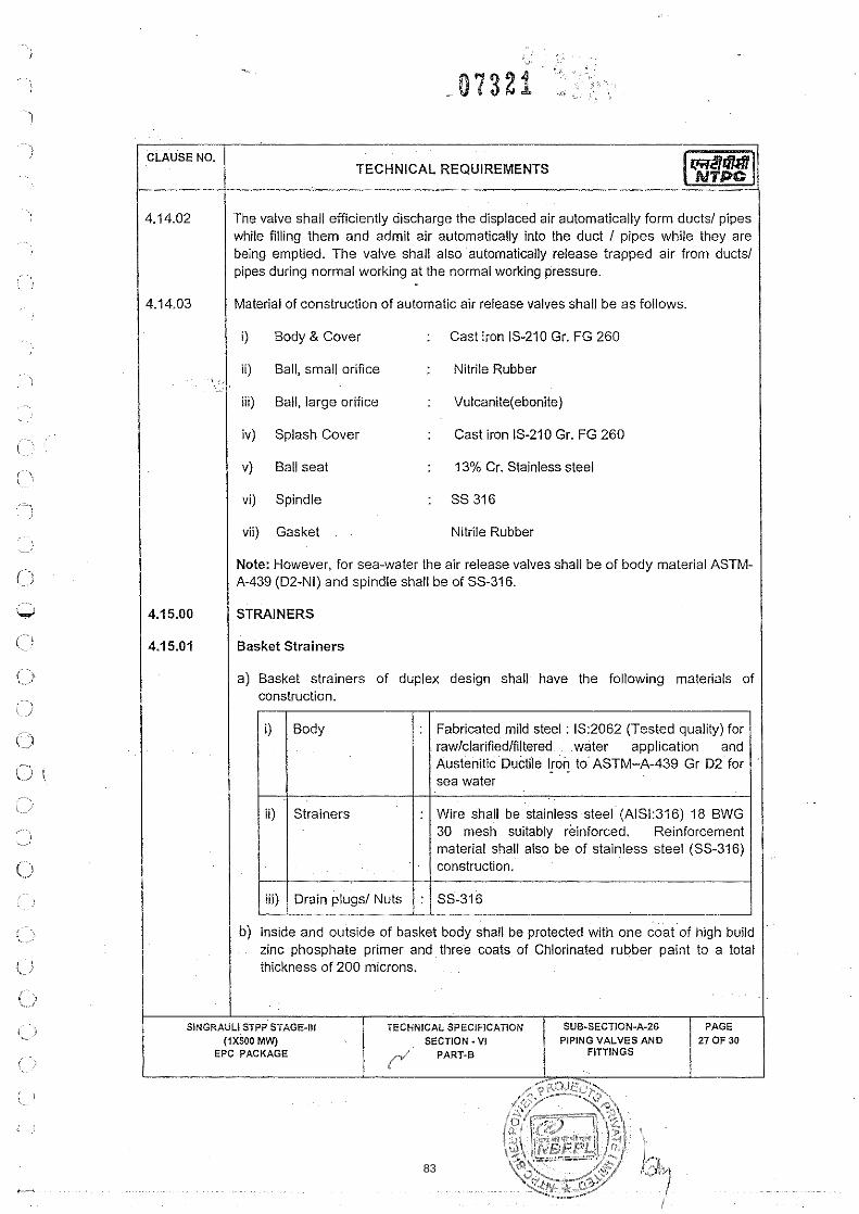
The valve shall efficiently discharge the displaced air automatically form ducts1 pipes while filling them and admit air automatically into the duct I pipes while they are being emptied. The valve shall also automatically release trapped air from ducts/ pipes during normal working at the normal working pressure.
Material of construction of automatic air release valves shall be as follows.
i) Body & Cover : Cast iron 13-210 Gr. FG 260
ii) Ball, small orifice : Nitrile Rubber
iii) Ball, large orifice : Vulcanite(eb0nite)
I iv) Splash Cover : Cast iron IS-210 Gr. FG 260 I : 13% Cr. Stainless steel I
vi) Spindle : SS316
vii) Gasket Nitrile Rubber
Note: However, for sea-water the air release valves shall be of body material ASTM- A-439 (D2-NI) and spindle shall be of SS-316.
STRAINERS
a) Basket strainers of duplex design shall have the following materials of construction.
/ 4.15.01
i) Body
I Basket Strainers I
: Fabricated mild steel : 1S:2062 (Tested qualily) for raw/clarified/filtered water application and Austenitic Ductile lron - . toASTM-A-439 Gr D2for sea water
ii) Strainers
. .
: Wire shall be stainless steel(~ISI:316) 18 BWG 30 mesh suitably reinforced, Reinforcement material shall also be of stainless steel (SS-316) construction.
I iii) I Drain plugs1 Nuts 1 : / SS-316 I b) Inside and ouiside of basket body shall be protected with one coatof high build
zinc phosphate primer and three coats of Chlorinated rubber paint to a total thickness of 200 microns.
SINGRAULI STPP STAGE-III TECHNICAL SPECIFICATION SU8.SECTION-A-26 (iX500 MW) SECTION -VI PIPING VALVES AND
EPC PACKAGE / PART-8 FITTINGS
83

I I c) Suitable Vent and drain valves shall be provided for the strainers.
d) Screen (strainer) flow area shall be at least four times pipe sectional area. Flow area in any portion of Basket strainer assembly shall not be less than the pipe cross sectional area.
e) Pressure drop in clean condition shall not be more than 4.0 MWC.
f) Duplex Strainer shall be provided with lifting lugs and suitable mounting arrangement.
g) For D M water service, body shall be rubber lined to minimum 4.5 mm thickness (soft rubber of shore Hardness 65 ?x ?A)
Y-Type Strainers
a) Y-Type strainer for water application shall be constructed of following materials :
i)
ii)
Body
Strainers
:
/ iii) I Drain plugs/ Nuts 1 : / SS-316 I
Cast lron 1S:210 Gr. FG 260 for rawlclarifiedlfiitered water application and Austenitic Ductile lron to ASTM-A-439 Gr D2 for sea water
-
:
b) Y-Type strainers shall also conform to CI. 4.14.01 (b), (c), (d), (e) and (0
Wire shall be stainless steel (AISl:316) 18 BWG 30 mesh suitably reinforced. Reinforcement material shall also be of stainless steel (SS-316) construction.
c) Body of the Y-type strainers of alkali, and demineralised water shall be of Cast lron (IS:210, Gr.fG 260) and lined with soft or hard rubber to a thickness of 3
I , mm.
d) For acid services, apart from the rubber lined body material, the screen material, shall be Polypropylene or HDPE wire cloth of suitable mesh and thickness.
/ 4.16.00 / Resin Traps
4.15.03
The resin traps for the Ion exchange vessels shall be provided for the collection of Ion exchange resin shall conform to the following:
Strainers for the application of chlorine gas (Wet I Dry) and liquid chlorine shall be of standard make and type of the chlorination plant manufacturer and material of construction shall be suitable for the duty conditions.
I PAGE
28 OF 30 SUB-SECTION-A-26
PIPING VALVES AND FITTINGS
SINGRAULI STPP STAGE-Ill (1x500 MW)
EPC PACKAGE
TECHNICAL SPECIFICATION SECTION - VI
PART-,
84

a) The body shall be of mild steel (15:2062) and lined internally with rubber (HardlSoR rubber), Saran or polypropylene. The internals (rod and screen) for all resin traps shall be of AlSl 316 construction. All screen components shall be welded at each intersection of wire and support rod for good strength, Resin traps screen opening shall not exceed 120 percent of the associated process vessel under drainlbackwash collection header nozzle screen opening and shall be suitably selected to retain even the minimum size of the resin selected for the process.
b) The resin iraps shall be provided with a draining arrangement with a valve for collection of trapped resins. Resin trap body shall have lifting lug for easy handling during maintenancelerection.
General Requirements for Valves, Gates, Strainers and Resin traps l a) All the equipments shall be of proven design for the duty conditions and the
contractor or manufacturer shall have sufficient experience in using the above equipments in water treatment application in the plants supplied earlier by them.
b) In case owner desires, the experience listifeed back from the users shall be made available to owner for any or all the equipments during the detailed engineering phase.
1 1 c) Valves coming under the p u ~ i e w of IBR if any shall meet its requirements and the approval of the same shall be obtained by the contractor.
I I d) Valves, Strainers etc for the Chlorination Plant shall be got approved by the Chief Controller of Explosives-INDIA, by the contractor.
e) Sizes of the valves shall be same as that of the interconnected pipe sizes except for the control valves.
f) The various equipments shall be installed so that they are easily approachable for the operating and maintenance personnel. Generally Valves shall be located about 1.2 metre to 1.5 metre from the operating platform and also they shall not be located below the ground level such as beneath the trenches etc. In such cases, extended spindle shall be provided with chain operating from operating floor. Valves which are installed below the ground floor shall be provided with a floor mounted pedestal at the top of the operating floor. Valves which are installed below the ground floor shall be provided with a floor mounted pedestal at the top of the operating floor. The position indicator for such valves shall be also provided along with the stand.
g) However valves which are provided (in the burried pipe line) with a valves chamber shall have manual operatorlHand wheel inside the valve chamber. The valve chamber shall be provided with built in ladderslstaircases and sufficient
-. . - . .. - -. - .. . . . . . . .- . - -. 5 hGRAUL1 STPP STAGE.,:# i E C h h I C h S ? E C I F . C A I # C ' ~ SUB-SiCT.Gli.A.26 , PAGE
1 (1x500 MLV) I SECT.Oh . VI PIPING VALVES A'.O 2 9 0 F 3 0 1
I EPC PACKAGE 1 p/ PART., I FITTINGS I I
85

I operating space within the chamber shall also be provided for easy operation of such valves.
h) All the valves, strainers, resin traps etc. shall be provided with external painting as that of the interconnected piping as specified in Clause 3.03.14 above. However, surfaces such as Stainless Steel, aluminium, copper, brass, bronze and other non-ferrous materials shall not be painted. No paint or filter shall be applied until all repairs, hydrostatic tests and final shop inspections are completed, but shall be applied prior to shipment.
/ TESTING FOR PIPING. VALVES. FITTINGS I I TESTS AT SITE
All piping, valves, Gates, resin traps, strainers and other fittings after erection at site shall be tested to hydraulic test pressure of two times the operating pressure or 1.5 times the maximum allowable pressure whichever is higher for a period of two hours.
All valves@ates (Manuai/Autornatic) shall be operated through-out 100% of the travel manually and as well as from control panel (if applicable) and these should funct~on w~thout any trouble whatsoever.
SlNGRAULl STPP STAGE-Ill TECHNICAL SPECIFICATION SUB-SECTI0N.A-26 PAGE (1x500 MW SECTION - V l PIPING VALVES AND 30 OF 30
EPC PACKAGE PART-B f l FITTINGS
86

87

88

90
6044549
Text Box
2980282
Text Box
Project- 1x500 MW UNCHAHAR TPP GENRAL LALYOUT PLAN Drg.N0-- PE-DG-401-100-M001

1.0 GENERAL INFORMATIONNo. of Cooling Towers required : Two (02)Location : Out doorDuty : ContinuousType : Mechanical Induced draft.Counter Flow/ Cross Flow : Cross flow/Counter Flow with single/double air inletFill Type : Splash type fills
2.0 DESIGN PERFORMANCE FOR EACH COOLING TOWER2.1 Design Cooling water flow : 300002.2 Design Air Inlet wet bulb temp : 27.6oC
( Inclusive of Recircuation Allowance).2.3 Cold water temperature : 33 oC2.4 Hot water inlet temperature : 44.05 oC 2.5 Cooling Range : 11.05 oC2.6 Atmospheric conditions : Dusty, hot & humid2.7 Liquid Handled : Clarified water (refer details of cooling water analysis)2.8 Total CW Pumping head permissible : Not to exceed 13 MWC.
viz. static head plus frictional losses asbelow
Static head w.r.t. F.G.L Frictional losses within bidders
T.P. with 10% margin2.9 Maximum limit on total power consumption : 750 KW
per cooling tower for the cooling towerfans at fan motor inlet terminals
2.10 No. of Cells:
2.11 Maximum permissible Evaporation loss. : 1.8% (Max)2.12 Maximum permissible drift loss : 0.050%2.13 Design pressure for hot water distribution syst: 5 kg/cm2(g)
2.14 : length to be restricted within 130 M
dimensions at ‘FGL’ (Excluding staircase)2.15 Maximum Cooling tower flow capacity to : 120% of design CW flow.
be considered for design of hot waterdistribution and cold water channel
3.0 Cold Water Basin Details
3.1 Finished ground level : EL (+) 0.00 M (RL 107.0 M)3.2 Maximum water level : EL (+)0.00 M3.3 Min. Water level : EL (-)1.20 M (RL 105.8 M)3.4 Free board above Maximum water level : Minimum 0.3 M3.5 Invert level of CW Channel near CT level : EL (-) 3.20 M.3.6 Length of outlet channel including : 10 M
expansion joint in CT vendor’s scope4.0 Pipe work Painting / Protection of Pipes:4.1 Internal surface (for pipe dia above 1000 mm)
a) Surface cleaning by sand blasting or Power Tool cleaning.b) Application of one coat of red oxide (zinc chromate/zinc phosphate) primer confirming to IS-2074/IS-12744 followed
4.2 External surface – Overground piping :a) Surface cleaning by sand blasting or Power Tool cleaning.b) Application of two coats of red oxide (Zinc chromate/zinc phosphate) primer confirming to IS-2074/IS-12744 followed
4.3 External surface – Buried piping : Burried Piping shall be concrete encased.Concrete encasement shall be min 500 mm thick with square shape outside.
5.0 Hot Water Supply Header Terminals As per terminal point drawing enclosed. CW return piping inCustomer scope (2200 NB) shall be terminated at C.L. elevationEL (-) 3.1 M i.e, buried below ground.
by one coat of finish paint of hot coal tar enamel or coal tar epoxy paint (cold) to achieve total DFT of at least 150 microns, including primer.
by three coats (1 intermediate coat + 2 finish coats) of synthetic enamel paint confirming to IS-2932 or eq. to acieve total DFT of at least 150 microns including primer.
TECHNICAL CONDITIONS OF CONTRACTCOOLING TOWER PACKAGE
FGUTPP STAGE-IV (1X 500 MW) AT UNCHAHAR
BHEL SPEC. NO. :PE-TS-404-165-N001 Rev. No.:01 Dated : 11.06.14
DOC. NO.: NBPPL-004-103-03-P4M-A Rev. No.: 01TECHNICAL SPECIFICATION
Min 8 nos working cells + 01 no spare cell for double inlet/2 nos spare cell for single inlet
Max permissible Cooling Tower plan dimension at FGL (excluding staircase)
PAGE 1 OF 189

91
2980282
Text Box

I " No' ' LIST OF MANDATORY SPARES FOR COOLING TOWERS 1-1 DESCRIPTION QUANTITY I
A) MECHANICAL /ELECTRICAL (Drive) ITEMS (Cooling Tower)
I ) Drive Shaft assembly complete with balanced 3 Sets couplings with all the fasteners
2) Support bearings Complete for the drive shaft (if 2 Sets provided)
! 3) Complete fan and hub assembly matched and 1 Set
balanced
4) Complete gear box 1 No. I / 5 ) Set of gear box internals 3 Sets I I 6) Bearings for gear box 3 Sets I I 7 ) Oil seals & '0' rings for gear box 6 Sets I I 8) Set of gaskets for gear box 3 Sets I
9) Coupling (Gearbox end) along with all fasteners 3 Sets
10) Coupling (motor end) along with all fasteners 3 Sets
11) Spare bolts, nuts, bushes, shims (as applicable) etc. 6 Sets for couplings
. .
12) Buttemy valve complete assembly for cell isolation 1 No.
1 13) Spare for Butteffly valves for each size I I a) Valve discs. 1 No. I I b) Shaft 1 No. I
c) Bearing bushes
d) Seals
1 Set
1 Set
EPC PACKAGE
92

CLAUSE NO. I LIST OF MANDATORY SPARES FOR COOLING TOWERS
NO DESCRIPTION QUANTITY
e) Gear box units for valve 1 Set
f) Gear box internals with shaft 1 Set
g) Bearing & 'O'rings for gear box unit of Valves 1 Set
14) Tower Internals :
a) Water spray nozzle
b)Fills (other than concrete fills)
c) Drift eliminator
5% of total population of one tower
5% of total population of one tower
5% of total population of one tower
d)lnternal distribution pipes, end caps and couplings 5% of total population of one tower
15) C.T. Fan drive motor 2 Nos
16) C.T. Fan motor bearing 3 Sets
17) Flow control valves (if applicable) 2 Sets
18) Vibration Switches 2 Sets
19) Low oil level switch 2 Sets
1 ''> ' -1
. . l i
, . , . j
, .. ,
.-%
t i
,-.
< i :
i ' ' t , ?
O .-. \I
0 I-
t.,.)
I \
V
0 8 if
I,.;
if!
0
ij
(1 I) V
0 C f 0
0 0 iJ
a , .
- -
SINGRAULI STPS STAGE-Ill
(t XMO MW)
EPC PACKAGE
TECHNICAL SPECIFICATION
SECTION-VI ,,,/ PART-F
SUB-SECTION -F-5 LIST OF MANDATORY
SPARES FOR COOLING TOWER
PAGE
2 OF 2
93

94

95

I I 4 Vibration Monitoring System
CLAUSE NO.
- (ii)
LIST OF MANDATORY SPARES FOR DDCMIS
(iii)
5. Flue Gas Anaiyser Instruments for 1 no. each complete instrument Oxygen, NOx cum SOX, CO,CO, I I etc.
Sensors
Power Supply Module Cards
Driver I Interface Cards & all other electronic cards.
I
(i) Electronic Card Assemblies of 10% each type
10% or minimum 2 nos which ever is more
10% or minimum 2 nos which ever is more
10% or minimum 2 nos which ever is more
Assembly.
2 sets.
I
(iv) Complete Probe wilh shield 2 nos. assembly.
[I (v) I Air flow meter. I I no. 1 Consumables like filter elements 100 % light sources etc.
I 1 I Calibration gases of all types and One year supply ranges. I
SlNGRAULl STPS STAGE-Ill TECHNICAL SPECIFICATION SUB-SECTION -F-3
( r xwo MW) SECTION.^^ LISTOF MANDATORY OF
EPC PACKAGE PART-F SPARES FOR DOCMIS I PAGE
.
~p
1 no. complete instrument - .
10%
100 %
10%
10%
~~ -
6. Stack Opacity MonitorslSPMlRPM
~. . ~
. (I)
(ii)
(iii)
(iv)
Electronic Card ~ssemblies of each type
~.
Light source bulb
Air blower and filter unit.
Solenoid assembly for shutter mechanism.
96
6119158
Line
6119158
Line

BHEL SPEC Rev. No.:0
1. SCO 2. TECH 3. DATA 4. MOT 5. CAB 6. STAT 7. FIRE 8. QUA
C. NO. :PE-TS-41 Dated : 11.06
SPECIF
OPE BETWEHNICAL SPA SHEET-A
TOR SUB SELING,EARTTION LIGHT
E PROOF CAALITY ASSU
TEC
FGUTP
404-165-N001 .14
FIC TECH
EEN NBPPL PE. FOR IDCA ECTION -B-THING & LIGTING SUB SABLE PENE
URANCE.
CHNICAL CONCOOLING
P STAGE‐IV (1
TECHNIC
SEC
NICAL R
COM
AND VENDCT
09
GHTING PRSECTION-B-ETRAION SE
NDITIONS OF TOWER PACK1X 500 MW)
CAL SPECIFICA
CTION – C
EQUIREM
PRISES O
DOR
ROT SUB SE-14 EALING SY
CONTRACTKAGE AT UNCHAHA
ATIONS DA
C2
MENTS (E
OF
EC- B-13
YS
AR
DOC. NO.: NBPPA, Rev. No.: 01
ELECTRI
PL-004-103-03-P
CAL)
P4M-
97
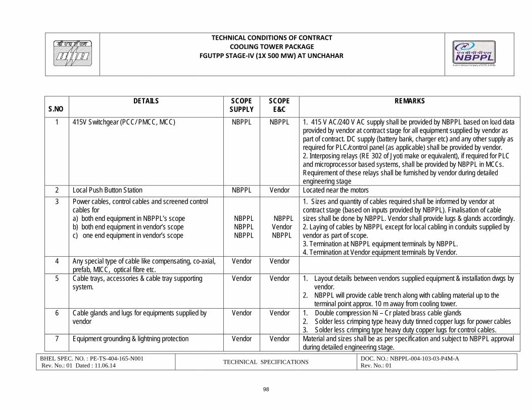
BHE Rev
S
EL SPEC. NO. : PE-Tv. No.: 01 Dated : 11
S.NO
1 415V Swit
2 Local Pus3 Power cab
cables for a) both enb) both enc) one en
4 Any speciaprefab, MI
5 Cable traysystem.
6 Cable glanvendor
7 Equipmen
TS-404-165-N001 1.06.14
DETA
tchgear (PCC/ PMC
h Button Station bles, control cables nd equipment in NBnd equipment in vend equipment in ve
al type of cable likeCC, optical fibre e
ys, accessories & c
nds and lugs for eq
nt grounding & lightn
AILS
CC, MCC)
s and screened con
BPPL’s scope ndor’s scope ndor’s scope
e compensating, coetc. able tray supportin
quipments supplied
ning protection
TECHNICAL CCOOLI
FGUTPP STAGE‐I
TECHNIC
SCOPSUPPLNBPP
NBPPntrol
NBPP NBPP NBPP
o-axial, Vendo
g Vendo
by Vendo
Vendo
CONDITIONS OF NG TOWER PACKIV (1X 500 MW) A
CAL SPECIFICATIO
E LY
SCOPE E&C
L NBPPL
L Vendor
PL PL PL
NBPPL Vendor NBPPL
or Vendor
or Vendor
or Vendor
or Vendor
CONTRACT KAGE AT UNCHAHAR
ONS
1. 415 V AC/240provided by vendpart of contract. Drequired for PLC/2. Interposing reland microprocessRequirement of tengineering stageLocated near the1. Sizes and quacontract stage (bsizes shall be do2. Laying of cablevendor as part of3. Termination at4. Termination at
1. Layout detailvendor.
2. NBPPL will pterminal poin
1. Double comp2. Solder less c3. Solder less cMaterial and sizeduring detailed e
DOC. NO.: NBRev. No.: 01
R
0 V AC supply shalldor at contract stagDC supply (battery /control panel (as aays (RE 302 of Jyosor based systemsthese relays shall be
e motors antity of cables req
based on inputs prone by NBPPL. Venes by NBPPL excef scope. t NBPPL equipment Vendor equipmen
ls between vendors
provide cable trencnt approx. 10 m awpression Ni – Cr plcrimping type heavcrimping type heaves shall be as per sngineering stage.
BPPL-004-103-03-P4
REMARKS
l be provided by NBe for all equipment bank, charger etc)applicable) shall beoti make or equivales, shall be providedbe furnished by ven
uired shall be inforovided by NBPPL). ndor shall provide lupt for local cabling
nt terminals by NBPnt terminals by Vend
s supplied equipme
h along with cablinay from cooling towated brass cable g
vy duty tinned coppevy duty copper lugs specification and su
M-A
BPPL based on loat supplied by vendo) and any other supe provided by vendoent), if required for by NBPPL in MCC
ndor during detailed
med by vendor at Finalisation of cabl
ugs & glands accor in conduits supplie
PPL. dor.
ent & installation dw
g material up to thewer. lands er lugs for power c for control cables.
ubject to NBPPL ap
ad data or as pply as or. PLC
Cs. d
le rdingly. ed by
wgs by
e
ables
pproval
98
6044549
Text Box
SCOPE BETWEEN NBBPL AND VENDOR

BHE Rev
N
As
EL SPEC. NO. : PE-Tv. No.: 01 Dated : 11
10 Lighting S
11 Any other completenabove.
12 Engineerstage, inca. Electb. Electr
drawic. Cabled. Contr
[includequip
e. Grounf. Cable
(diagrNOTES:
1. Make of a
All QPs shall be susame shall be appli
8
Below gra
9 LV Motors
TS-404-165-N001 1.06.14
System
equipment/ materiness of Cooling Tow
ing activities durinluding those listed trical load data subrical equipment GAngs
e trench/ tray layoutrol cable schedulesding cables suppliement]. nding and lightning e termination/ intercram)/ Cable block d
ll electrical equipm
bject to approval oficable. QAP attach
de grounding
s with base plate an
al/ service requiredwer but not specifie
ng detailed engineebelow:
bmission in PEM forA drawings and layo
t drawings showing routing de
ed by PEM for CT
protection system connection details diagram
ents/items supplied
f NBPPL/NTPC afteed with specificatio
nd foundation hardw
TECHNICAL CCOOLI
FGUTPP STAGE‐I
TECHNIC
Vendo
d for ed
Vendo
ering
rmat out
etails
layouts
Vendo
d shall be reputed m
er award of contracon is for reference o
NBPP
ware Vendo
CONDITIONS OF NG TOWER PACKIV (1X 500 MW) A
CAL SPECIFICATIO
or Vendor
or Vendor
or --
make & shall be su
ct without any priceonly.
L Vendor
or Vendor
CONTRACT KAGE AT UNCHAHAR
ONS
In addition todistribution bcontrol as peoutgoings &
1. DocumentatiNTPC appro
2. Vendor shall required eng
3. Any approvaequipment sh
bject to approval o
e implication to NBP
MS rod material sare in vendor’s scMakes shall be s
DOC. NO.: NBRev. No.: 01
o other lighting systboard (LDB) with 50er statutory require timer control as pe
ion shall be submitoval. be responsible for
gineering interfacingal required from elehall be arranged by
of NBPPL/NTPC aft
PPL. If bidders hav
shall be provided bcope.
subject to NBPPL /N
BPPL-004-103-03-P4
tem items, vendor s0kVA transformer, ment and Lighting
er requirement.
tted as per project s
r necessary coording during contract stctrical inspection ay vendor.
ter award of contrac
ve any reference QA
by NBPPL. All other
NTPC approval at c
M-A
shall consider lightaviation lights & thepanels (LP) with 8
schedule for NBPP
nation with NBPPL tage. uthority for electric
ct.
AP of NTPC projec
r materials/ consum
contract stage. ing eir
PL/
for
al
cts then
mables
99
6044549
Text Box
SCOPE BETWEEN NBBPL AND VENDOR

TECHNICAL SPECIFICATIONS COOLING TOWER PACKAGE
FGUTPP STAGE‐IV (1X 500 MW) AT UNCHAHAR
BHEL SPEC. NO. : PE-TS-404-165-N001 Rev. No.: 01 Dated : 11.06.14
TECHNICAL SPECIFICATIONS DOC NO: NBPPL-004-103-03-P4M-A Rev. No.: 01
1.0 EQUIPMENT & SERVICES TO BE PROVIDED BY BIDDER:
a) Services and equipment as per “Electrical Scope between NBPPL and Vendor”. b) Any item/work either supply of equipment or erection material which have not
been specifically mentioned but are necessary to complete the work for trouble free and efficient operation of the plant shall be deemed to be included within the scope of this specification. The same shall be provided by the bidder without any extra charge.
c) Supply of mandatory spares as specified in the specifications of mechanical equipments.
d) Erection and Commissioning spares. e) Erection & Maintenance tools & tackles. f) Electrical load requirement for INDUCED DRAFT COOLING TOWER. g) All equipment shall be suitable for the power supply fault levels and other climatic
conditions mentioned in the enclosed project information. h) Bidder to furnish list of makes for each equipment at contract stage, which shall be
subject to NTPC /NBPPL approval without any commercial and delivery implications to NBPPL
i) Various drawings, data sheets as per required format, Quality plans, calculations, test reports, test certificates, operation and maintenance manuals etc shall be furnished as specified at contract stage. All documents shall be subject to NTPC/NBPPL approval without any commercial implication to NBPPL.
j) Motor shall meet minimum requirement of motor specification. k) LT power & control cables shall meet minimum requirement of LT power &
control cables specification. l) Cabling, earthing & lightning protection shall meet minimum requirement of
cabling, earthing & lightning protection specification.
2.0 EQUIPMENT & SERVICES TO BE PROVIDED BY PURCHASER FOR ELECTRICAL & TERMINAL POINTS: Refer “Electrical Scope between NBPPL and Vendor”.
3.0 DOCUMENTS TO BE SUBMITTED ALONG WITH BID 3.1 Bidder shall confirm total compliance to the electrical specification without any
deviation from the technical/quality assurance requirements stipulated. In line with this two signed and stamped copies of the following shall be furnished by the bidder as technical offer: a) A copy of this sheet ”Electrical equipment Specification for INDUCED DRAFT
COOLING TOWER” and sheet “Electrical Scope between NBPPL and Vendor” with bidder’s signature and company stamp.
b) List of Erection and Commissioning spares. c) List of Erection & Maintenance tools & tackles. d) Electrical load requirement
3.2 No technical submittal such as copies of data sheets, drawings, write-up, quality plans, type test certificates, technical literature, etc, is required during tender stage. Any such submission even if made, shall not be considered as part of offer.
4.0 List of enclosures :
a) Electrical scope between NBBPL & vendor. b) Technical specification, datasheets & quality plans for 415V Electric motors. c) Technical Specification, datasheets & quality plans for LT power & control cables.
100
TECHNICAL SPECIFICATIONS COOLING TOWER PACKAGE
FGUTPP STAGE‐IV (1X 500 MW) AT UNCHAHAR
BHEL SPEC. NO. : PE-TS-404-165-N001 Rev. No.: 01 Dated : 11.06.14
TECHNICAL SPECIFICATIONS DOC NO: NBPPL-004-103-03-P4M-A Rev. No.: 01
d) Technical Specification, datasheets & quality plans for cabling, earthing & lightning protection.
e) Electrical Load data format.
5.0 The stipulations of NBBPL specification, Section-C2, followed by those of Datasheet-A shall prevail in case of any conflict between the stipulations of NBBPL specification, Section-C2, Datasheet-A and Section-D.
101
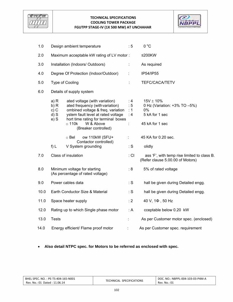
BH Re
EL SPEC. NO. : Pv. No.: 01 Date
1.0 2.0 3.0 4.0 5.0 6.0
7.0 8.0
9.0 10.0 11.0 12.0 13.0
14.0
Al
PE‐TS‐404‐165‐ed : 11.06.14
Design am
Maximum
Installatio
Degree O
Type of C
Details of
a) R ab) R ac) C od) S ye) S h
o
o
f) L V
Class of in
Minimum (As perce
Power cab
Earth Con
Space he
Rating up
Tests
Energy ef
so detail N
FGUTPP
‐N001
mbient temp
m acceptable
n (Indoors/
Of Protection
Cooling
supply syst
ated voltageated frequenombined voystem fault lhort time rato 110k W
(Break
o Bel owConta
V System gr
nsulation
voltage for ntage of rat
bles data
nductor Size
ater supply
to which S
fficient/ Flam
NTPC spec.
TECHNICACOOLING
P STAGE‐IV (1
T
perature
e kW rating
Outdoors)
n (Indoor/Ou
tem
e (with variancy (with valtage & freqlevel at rateting for term
W & Above ker controlle
w 110kW (SFactor controlrounding
starting ted voltage)
e & Materia
ingle phase
me proof m
. for Motors
AL SPECIFICATOWER PAC1X 500 MW)
TECHNICAL SPE
of LV moto
utdoor)
ation) ariation)q. variationed voltageminal boxes
ed)
FU+ lled)
)
l
e motor
otor
s to be refe
ATIONS CKAGE ) AT UNCHAH
ECIFICATIONS
: 5 0
or : ≤2
: As
: IP
: TE
: 4 1: 5 0: 1 0: 4 5
s : 45
: 45
: S o
: Cl (Re
: 8 5
: S h
: S h
: 2 4
: A c
: As
: As
erred as en
HAR
DOC.Rev.
0 oC
200KW
s required
P54/IP55
EFC/CACA/
15V 10%0 Hz (Variat0% 5 kA for 1 se
5 kA for 1 se
5 KA for 0.20
olidly
ass ‘F’, withefer clause
5% of rated
hall be give
hall be give
40 V, 1Φ , 5
cceptable b
s per Custo
per Custom
nclosed wit
. NO.: NBPPL‐00No.: 01
/TETV
tion: +3% T
ec
ec
0 sec.
h temp rise 5.00.00 of
voltage
n during De
n during De
50 Hz
elow 0.20
mer motor s
mer spec. re
th spec.
04‐103‐03‐P4M
O –5%)
limited to cMotors)
etailed engg
etailed engg
kW
spec. (enclo
equirement
M‐A
class B.
g.
g.
osed)
102
6044549
Text Box
LV MOTORS: DATASHEET-A

103

104
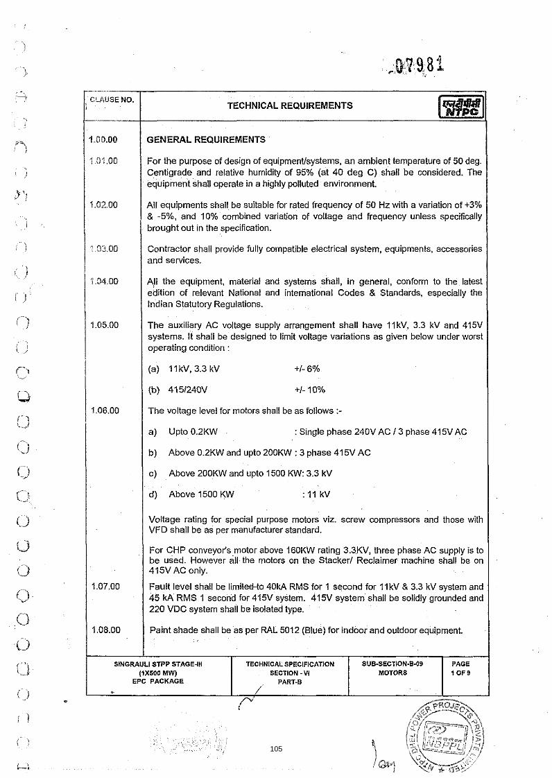
TECHNICAL REQUIREMENTS 1-1 I GENERAL REQUIREMENTS 1
For the purpose of design of equipmentlsystems, an ambient temperature of 50 deg. Centigrade and relative humidity of 95% (at 40 deg C) shall be considered. The equipment shall operate in a highly polluted environment.
All equipments shall be suitable for rated frequency of 50 Hz with a variation of +3% & -5% and 10% combined variation of voltage and frequency unless specifically
I brought out in the specification.
Contractor shall provide fully compatible electrical system, equipments, accessories and services.
A!l the equipment, material and systems shall, in general, conform to the latest edition of relevant National and international Codes 8 Standards, especially the Indian Statutory Regulations.
The auxiliary AC voltage supply arrangement shall have I lkV, 3.3 kV and 415V systems. It shall be designed to limit voltage variations as given below under worst operating condition :
(a) I I kV, 3.3 kV +I- 6%
(b) 4151240V +I- 10%
The voltage level for motors shall be as follows :-
: Single phase 240V AC 1 3 phase 415V AC I I b) Above 02KW and upto 20OKW w 3 phase 415V AC I
c) Above 200KW and upto 1500 KW: 3.3 kV
d) Above 1500 KW : I 1 kV
Voltage rating for special purpose motors viz. screw compressors and those with VFD shall be as per manufacturer standard.
For CHP conveyor's motor above 160KW rating 3.3KV, three phase AC supply is to be used. However all the motors on the Stacker1 Reclaimer machine shall be on 415VAC only.
Fault level shall be limikettto 40kA RMS for 1 second for I l k V & 3.3 kV system and 45 kA RMS 1 second for 415V system. 415V system shall be solidly grounded and 220 VDC system shall be isolated type.
Paint shade shall be as per RAL 5012 (Blue) for indoor and outdoor equipment. I SINGRAULI STPP STAGE-Ill TECHNICAL SPECIFICATION SUB-SECTION.B-09
SECTION - V I EPC PACKAGE
105
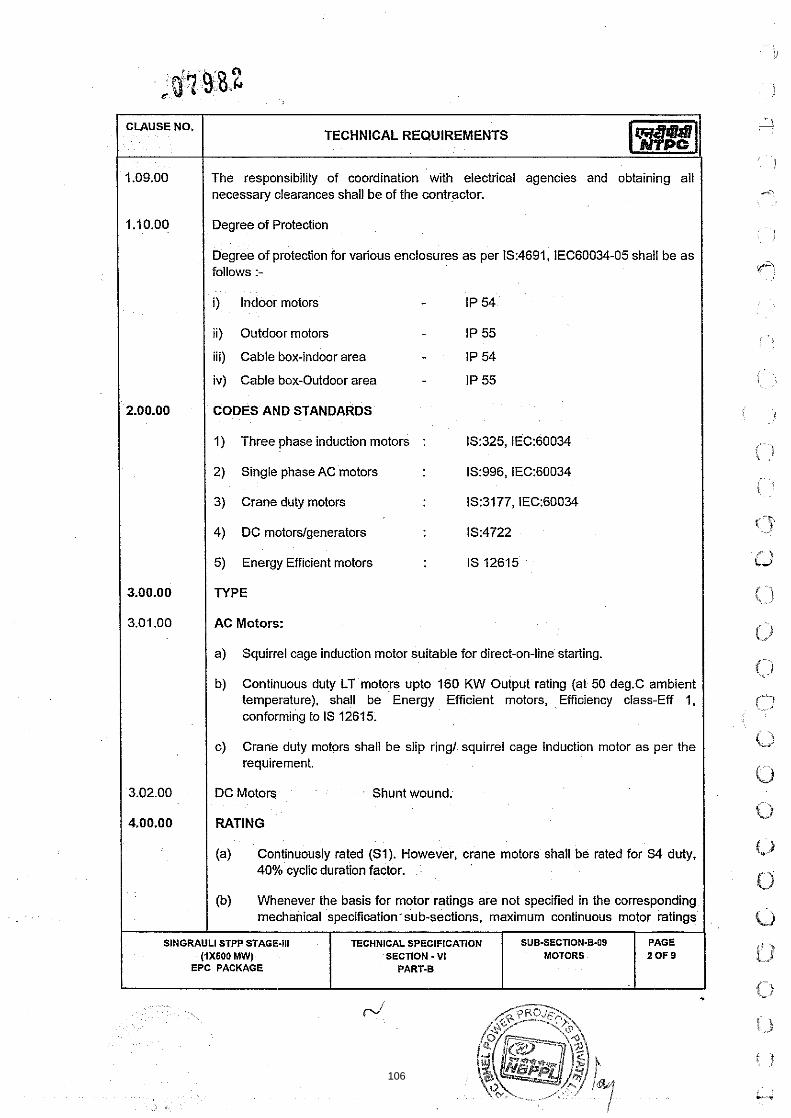
CLAUSE NO.
1.09.00
1 .I 0.00
2.00.00
3.00.00
3.01 .OO
3.02.00
4.00.00
SlNGRAULl
TECHNICAL REQUIREMENTS
The responsibility of coordination with electrical agencies and obtaining ail necessary clearances shall be of the contractor.
Degree of Protection
Degree of protection for various enclosures as per IS:4691, IEC60034-05 shall be as follows :-
i) Indoor motors - IP 54
11) Outdoor motors IP 55
iii) Cable box-indoor area - IP 54
iv) Cable box-Outdoor area - IP 55
CODES AND STANDARDS
1) Three phase induction motors : IS:325, IEC:60034
2) Single phase AC motors 1S:996, IEC:60034
3) Crane duty motors 1S:3177, IEC:60034
4) DC motors/generators lS:4722
5) Energy Efficient motors IS 12615
N P E
AC Motors:
a) Squirrel cage induction motor suitable for direct-on-line starting.
b) Continuous duty LT motors upto 160 KW Output rating (at 50 deg.C ambient temperature), shall be Energy Efficient motors, Efficiency class-Eff 1, conforming to IS 12615.
c) Crane duty motors shall be slip ring1 squirrel cage Induction motor as per the requirement.
DC Motors Shunt wound.
RATING
(a) Continuously rated (SI). However, crane motors shall be rated for S4 duty, 40% cyclic duration factor.
(b) Whenever the basis for motor ratings are not specified in the corresponding mechanical specification sub-sections, maximum continuous motor ratings
STPP STAGE-111 (1x600 MW)
EPC PACKAGE PART-B
TECHNICAL SPECIFICATION SECTION - VI
SUB-SECTI0N.B-W MOTORS
PAGE 2 0 F 9
106

*..
(3 0 'Q
(3
63 (1 s j f.,
C) 0 li i .j
.( )
i )
shall be at least 10% above the maximum load demand of the driven equipment under entire operating range including voltage and frequency variations.
I (c) For BFP motor the starting MVA shall be restricted to 58 MVA. I 1 610.00 I TEMPERATURE RISE I Air cooled motors
70 deg. C by resistance method for both thermal class 130(B) & 155(F) insulation.
1 I Water cooled I I I 80 deg. C over inlet cooling water temperature mentioned elsewhere, by resistance
method for both thermal class 130(B) & 155(F) insulation. I 41 deg.C over inlet cooling water maximum temperature of 39 deg.C for thermal class Y wet wound Boiler circulation pump motor.
1 6.00.00 1 OPERATIONAL REQUIREMENTS I / 6.01.00 1 Sta lng Time I 6.01.01 For motors with starting time upto 20 secs. at minimum permissible voltage during
starting, the locked rotor withstand time under hot condition at highest voltage limit shall be at least 2.5 secs. more than starting time.
6.01.02 For motors with starting time more than 20 secs. and upto 45 secs. at minimum permissible voltage during starting, the locked rotor withstand time under hot condition at highest voltage limit shall be at least 5 secs. more than starting time.
6.01.03
1 6.02.01 Accelerating torque at any speed with the lowest permissible starting voltage shall
I be at least 10% motor full load torque.
For motors with starting time more than 45 secs.,at minimum permissible voltage during starting, the locked rotor withstand time under hot condition at highest voltage limit shall be more than starting time by at least 10% of the starting time.
6.01.04
6.02.00
Speed switches mounted on the motor shaft shall be provided in cases where above requirements are not met.
Torque Requirements
6.02.02 Pull out torque at rated voltage shall not be less than 205% of full load torque. It shall be 275% for crane duty motors.
I SINGRAULI STPP STAGE-Ill
(rxsoo MW) EPC PACKAGE -
,
SUB-SECTION.B.09 MOTORS
TECHNICAL SPECIFICATION SECTION - VI
PART-B
PAGE 3 0 ~ 9
107

Starting voltage requirement
(a) 85% up to 1500KW (except for AOP motor which is 80%)
CLAUSE NO.
I I (b) 80% from 1501 KW to 4000KW 1
TECHNICAL REQUIREMENTS
1 1 (c) 75% > 4000KW I
1-11 I
I 1.00.00 I DESIGN AND CONSTRUCTIONAL FEATURES I Suitable single phase space heaters shall be provided on motors rated 30KW and above to maintain windings in dry condition when motor is standstill. Separate terminal box for space heaters & RTDs shall be provided. However for flame proof motors , space heater terminals inside the main terminal box may be acceptable.
All motors shall be either Totally enclosed fan cooled (TEFC) or totally enclosed tube ventilated (TETV) or Closed air circuit air cooled (CACA) type. However, motors rated 3000KW or above can be Closed air circuit water cooled (CACW). CW motors can be screen protected drip proof (SPDP) type. Motors located in hazardous areas shall have flame proof enclosures conforming to lS:2148 as detailed below
(a) Fuel oil area : Group-IIB
(b) Hydrogen generation : Group - IIC (or Group-I, Div-ll as per NEC) plant area
Winding and Insulation
(b) Starting duty : Two hot starts in succession, with motor initially at normal running temperature. However the conveyor motor shall be suitable for 3 consecutive hot starts.
I
(') l1 kV ' 3.3 kV : Thermal class 155 (F) insulation. motors The winding insulation process shall be total Vacuum Presure Impregnated i.e resin poor method. The lightning Impulse & interturn insulation surge withstand level shall be as per IEC-60034 part-1 5
(d) 240VAC, 415V AC : Thermal Class( B )or better & 220V DC motors
I (a) Type : Non-hygroscopic, oil resistant, flame resistant I
7.04.00 Motors rated above 1000KW shall have insulated bearings to prevent flow of shaft currents.
SlNGRAULl STPP STAGE-Ill (2x500 MW)
EPC PACKAGE
- J
t 14
TECHNICAL SPECIFICATION SECTION -VI
PART-B
SUB-SECTION-6-09 MOTORS
PAGE 4 0 F 9
108

I 7.05.00 I Motors with heat exchangers shall have dial type thermometer with adjustable alarm contacts to indicate inlet and outlet primary air temperature.
CLAUSE NO. TECHNICAL REQUIREMENTS
7.06.00
7.08.00 I Motor body shall have two eaithing points on opposite sides.
Noise level for all the motors shall be limited to 85dB(A) except for BFP motor for which the maximum limit shall be 9OdB(A). Vibration shall be limited within the limits prescribed in lS:12075 1 IEC 60034-14 . Motors shall withstand vibrations produced by driven equipment. HT motor bearing housings shall have flat surfaces, in both X and Y directions, suitable for mounting 80mmX80mm vibration pads.
7.07.00
HT motors can be offered with either elastimould termination or dust tight phase separated double walled (metallic as well as insulated barrier) cable boxes. In case elastimould terminations are offered, then protective cover and trifurcating sleeves shall also be provided. In case cable box is offered, then Employer shall provide termination kit. Removable gland plates of thickness 3 mm (hoffcold rolled sheet steel) or 4 mm (non magnetic material for single core cables) shall be provided in case of cable boxes.
The spacing between gland plate & centre of terminal stud shall be as per Table-I.
In HT motors, at least four numbers simplex I two numbers duplex platinum resistance type temperature detectors shall be provided in each phase stator winding. Each bearing of HT motor shall be provided with dial type thermometer with adjustable alarm contact and preferably 2 numbers duplex platinum resistance type temperature detectors.
All motors shall be so designed that maximum inrush currents and locked rotor and pullout torque developed by them at extreme voltage and frequency variations do not endanger the motor and driven equipment.
1 7.12.00 I The motors shall be suitable for bus transfer schemes provided on the I lkV, 3.3 kV 1415V systems without any injurious effect on its life.
For motors rated 2000 KW & above, neutral current transformers of PS class shall be provided on each phase in a separate neutral terminal box.
I l kV and 3.3 kV motor Terminal Box shall be suitable for fault level of 750MVA for 0.12 sec and 250 MVA for 0.12 sec respectively. Elastimould termination kit shall be suitable for fault level of 25 KA for 0.17 seconds.
The size and number of cables (for HT and LT motors) to be bntimated to the successful bidder during detailed engineering and the contractor shall provide terminal box subtable for the same. 1 8.0000 / The ratio of locked rotor KVA at rated voltage to rated KW shall not exceed the following (without any further tolerance) except for BFP Motor.
109

I I (a) upto 1 1 0 ~ ~ : 11.0 (For AOP motor it shall be 8.0) I
CLAUSE NO.
I 1 (b) Above I 1 OKW & upto 1500KW : 10.0 I
TECHNICAL REQUIREMENTS
I / (c) Above 1500KW & upto 4000KW : 9.0 I I I (d) Above 4000KW : 6 to 6.5 I / 9.00.00 1 CW Motor shall be desigined with minimum power factor of 0.8 at design point. I 1 10.00.00 1 TYPE TEST I 1 10.01.00 1 HT MOTORS I
The contractor shall carry out the type tests as listed in this specification on the equipment to be supplied under this contract. The bidder shall indicate the charges for each of these type tests separately in the relevant schedule of Section - VII- (BPS) and the same shall be considered for the evaluation of the bids. The type tests charges shall be paid only for the test@) actually conducted successfully undei this contract and upon cert~fication by the employer's engineer.
The type tests shall be carried out in presence of the employer's representative, for which minimum 15 days notice shall be given by the contractor. The contractor shall obtain the employer's approval for the type test procedure before conducting the type test. The type test procedure shall clearly specify the test set-up, instruments to be used, procedure, acceptance norms, recording of different parameters, interval of recording, precautions to be taken etc. for the type test(s) to be carried out.
In case the contractor has conducted such specified type testfs) within last ten years as on the date of bid opening, he may submit during detailed engineering the type test reports to the owner for waival of conductance of such test(s). These repofis should be for the tests conducted on the equipment similar to those proposed to be supplied under this contract and test@) should have been either conducted at an independent laboratory or should have been witnessed by a client. The owner reserves the right to waive conducting of any or all the specified type test(s) under this contract. In case type tests are waived, the type test charges shall not be payable to the contractor.
Further the Contractor shall only submit the reports of the type tests as listed in "LIST OF TESTS FOR WHICH REPORTS HAVE TO BE SUBMITTED"and carried out within last ten years from the date of bid opening. These reports should be for
I the test conducted on the equipment similar to those proposed-to be supplied under this contract and the test(s) should have been either conducted at an independent laboratory or should have been witnessed by a client. However if the wntractor is not able to submit report of the type test(s) conducted within last ten years from the date of bid opening, or in the case of type test report(s) are not found to be meeting the specification~requirements, the wntractor shall conduct all such tests under this
I
SlNGRAULl STPP STAGE-Ill (1x500 MW)
EPC PACKAGE
TECHNICAL SPECIFICATION SECTION - VI
PART-B
SUB-SEClION-B-OS MOTORS
PAGE @OF9
110

contract at no additional cost to the owner either at third party lab or in presence of clientlowners representative and submit the reports for approval.
' . :.. . '0 .? 9 8 "i' * ~ - . ,. C " . I
CLAUSE NO.
I I I The following type tests shall be conducted on each type and rating of HT I
TECHNICAL REQUIREMENTS
10.01.05
motor
(a) No load saturation and loss curves upto approximately 115% of rated voltage
(b) Measurement of noise at no load.
LIST OF TYPE TESTS TO BE CONDUCTED
/ (c) Momentary excess torque test (subject to test bed constraint). I I (d) Full load test(subject to test bed constraint) I
(e) Temperature rise test at rated conditions. During heat rufi test, bearing temp., winding temp., coolant flow and its temp. shall also be measured. in case the temperature rise test is carried at load other than rated load, specific approval for the test method and procedure is required to be obtained. Wherever ETD's are provided, the temperature shall be measured by ETD's also for the record purpose.
i I (9 Lightning Impulse withstand test on the sample coil shall be as per IEC- 60034, part-I 5 I
(g) Surge-withstand test on intertum insulation shall be as per clause no. 5.1.2 of IEC 60034, part-15
1 10.01.06 I LIST OF TESTS FOR WHICH REPORTS HAVE TO BE SUBMITTED
The following type test reports shall be submitted for each type and rating of HT I / motor . .
(a) Degree of protection test for the enclosure followed by IR, HV and no load run test.
(b) Temlinal box-fault level withstand ,test for each type of terminal box of HT motors only. I lO.02.00 1 LT Motors I
111

These reports should be for the test conducted on the equipment similar to those proposed to be supplied under this contract and the test(s) should have been either conducted at an independent laboratory or should have been witnessed by a client.
CLAUSE NO.
However if the contractor is not able to submit report of the type test(s) conducted within last ten years from the date of bid opening, or in the case of type test report(s) are not found to be meeting the specification requirements, the contractor shall conduct all such tests under this contract at no additional cost to the owner either at third party lab or in presence of client/owners representative and submit the reports for approval.
TECHNICAL REQUIREMENTS
The following type test reports shall be submitted for each type and rating of LT motor of above 50 KW only
1
1. Measurement of resistance of windings of stator and wound rotor.
10.02.03 1 LIST OF TESTS FOR WHICH REPORTS HAVE TO BE SUBMITTED 1
2. No load test at rated voltage to determine input current power and speed
3. Open circuit voltage ratio of wound rotor motors ( in case of Slip ring motors)
4. Full load test to determine efficiency power factor and slip.
5. Temperature rise test.
6. Momentary excess torque test.
7. High voltage test.
8. Test for vibration severity of motor.
9. Test for noise levels of motor(Shall be limited as per clause no 7.06.00 of this section)
10. Test for degree of protection and
11. . . overspeed test.
All acceptance and routine tests as per the specification and relevant standards shall be carried out. Charges for these shall be deemed to be included in the equipment price.
/
The type test reports once approved for any projects shall be treated as reference. For subsequent projects of NTPC, an endorsement sheet will be furnished by the manufacturer confirming similarity and "No design Change". Minor changes if any shall be highlighted on the endorsement sheet.
I SlNGRAULl STPP STAGE-Ill
(1x600 MW) EPC PACKAGE
TECHNICAL SPECIFICATION SECTION -VI
PART-B
SUB-SECTION.B-09 MOTORS
PAGE 8 0 F 9
112

TECHNICAL REQUIREMENTS
TABLE - I DIMENSIONS OF TERMINAL BOXES FOR LV MOTORS
Motor MCR in KW
UP to 3 KW
Minimum distance between centre of stud and gland plate in mm
A s per manufacturer's practice.
Above 3 KW - upto 7 KW 85
I / Above 7 KW - upto 13 KW 115
I Above 13 KW - upto 24 KW 167
I Above 24 KW - upto 37 KW
I Above 37 KW - upto 55 KW
I I Above 55 KW - upto 90 KW 277
I / Above 90 KW - upto 125 KW 331
I / Above 125 KW-upto 200 KW 203
For HT motors the distance between gland plate and the terminal studs shall not bf less than 500 mm.
I I PHASE TO PHASE1 PHASETO EARTH AIR CLEARANCE:
NOTE: Minimum inter-phase and phase-earth air clearances for LT motors with lug: installed shall be as follows:
Motor MCR in KW . ~ Clearance
I I Above I I 0 KW and upto I 5 0 KW 12.5mm
I . , I Abdve 150 KW 19mm
113

SUB-SECTION - B-13
- CABLING, EARTHING & LIGHTNING PROTECTION
114

/ 1.00.00 I CODES AND STANDARDS I
CLhiiSE NO.
All standards, specifications and codes of practice referred to herein shall be the latest editions including all applicable official amendments and revisions as on date of opening of bid. In case of conflict between this specification and those (IS codes, standards, etc.) referred to herein, the former shall prevail. All work shall be canied out as per the following standards1 codes as applicable.
TECHNICAL REQUIREMENTS
I 1 1S:513 Cold rolled low carbon steel sheets and strips. I 1S:802 Code of practice for the use of Structural Steel in Overhead
Transmission Line Towers.
IS:1079 Hot Rolled carbon steel sheet & strips
lS:1239 Mild steel tubes, tubular and other wrought steel fittings
Code of practice for installation and maintenance of power cables upto and including 33 KV rating
IS:1367 Part- Technical supply conditions for threaded Steel fasteners. (Hot dip 13 galvanized coatings on threaded fasteners).
lS:13947 Degree of protection provided by enclosures for low voltage switchgear and control gear
lS:2309 Code of Practice for the protection of bullding and allied structures against lightning.
IS:2629 Recommended practice for hot dip galvanising of iron &steel
IS:2633 Method for testing uniformity of coating on zinc coated articles.
lS:3043 Code of practice for Earthing
IS:3063 Fasteners single coil rectangular section spring washers.
136745 Methods for detemlination of mass of zinc coating on zinc coated ' iron & steel articles. . .
1S:8308 Compression type tubular in-line connectors for aluminium conductors of insulated cables
IS8309 Compression type tubular terminal ends for aluminium conductors of insulated cables.
1S:9537 Conduits for electrical installation.
1S:9595 Metal - arc welding of carbon and carbon manganese steels - recommendations.
I SINGRAULI STPP STAGE-Ill
(1x600 MW) EPC PACKAGE
TECHNICAL SPECIFICATION SECTION - Vi
PART-B
SUB-SECTION-B-13 CABLING. EARTHING 8
LIGHTNING PROTECTION
PAGE 1 OF 20
115

lS:13573 Joints and terminations for polymeric cables for working voltages from 6.6kv upto and including 33kv performance requirements and type tests.
BS:476 Fire tests on building materials and structures
IEEE:80 ' lEEE guide for safety in AC substation grounding
IEEE:142 Grounding of Industrial 8. commercial power systems
DIN 46267 Non tension proof compression joints for Aluminium conductors. (Part-ll)
DIN 46329 Cable lugs for compression connections, ring type ,for Aluminium conductors
VDE 0278 Tests on cable terminations and straight through joints
BS:6121 Specification for mechanical Cable glands for elastomers and plastic insulated cables.
Indian Electricity Act
Indian Electricity Rules
Equipment complying with other internationally accepted standards such as IEC. BS, DIN, USA, VDE etc. will also be considered if they ensure performance and constructional features equivalent or superior to standards listed above. In such a case, the Bidder shall clearly indicate the standard(s) adopted, furnish a copy in English of the latest revision of the standards alongwith copies of all official amendments and revisions in force as on date of opening of bid and shall clearly bring out the salient features for comparison.
Sizing Criteria, De-rating factor fo r Cables
I I All the power cables shall be sized based on the following considerations I I I (a) Rated current of the equipment. I
(b) The voltage drop in the cable, during motor starting condition, shall be limited to 10% and during full load running condition, shall be limited to 3% of the rated voltage.
(c) Short circuit withstands capability:
This will depend on the feeder type. For a fuse protected circuit, cable should be sized to withstand the let-out energy of the fuse. For breaker controlled
I SINGRAULI STPP STAGE-Ill TECHNICAL SPECIFICATION SUB-SECTION-6-13 (1x500 MW) SECTION - VI 1 CABLING, EFdtTHlNG8 1 Z%IO
EPC PACKAGE PART-B LIGHTNING PROTECTION
116

feeder, cable shall be capable of withstanding the system fault current level for total breaker tripping time inclusive of relay pickup time.
(d) The minimum conductor size shall be 6 sq. mm. for aluminium conductor cables and 2.5 sq. mm. for copper conductor cables.
De-rating factors for various conditions of installations including the following shall be considered while selecting the cable sizes:
a) Variation in ambient temperature for cables laid in air I I b) Grouping of cables I c) Variation in ground temperature and soil resistivity for buried cables
Contractor shall generally use the following cable sizes: I LT XLPE insulated power cables : 150,240,300 & 630 sq.mm (Al) I LT PVC insulated power cables : 2.5 sq.mm (Cu conductor) and 6, 10, 16, 25, 35, 70 & 120 sq. mm (AIICu conductor)
LT control cables 1.5 sq. mm : 2C, 3C, 5C, 7C, IOC, 14C & 19C (Cu) I Cable lengths shall be considered in such ways that straight through cable joints are avoided.
2.00.00 EQUIPMENT DESCRIPTION
2.01.00 Metallic Cable trays, Fittings, Accessories & Support System I 2.01.01 Cable trays shall be ladderlperforated type as specified complete with matching
fittings (like brackets, elbows, bends, tees, crosses, etc.) accessories (like side coupler plates, etc. and hardware (like bolts, nuts, washers, G.I. strap, hook etc.) as required.
2.01.02 Cable trays, fittings and accessories shall be fabricated out of rolled mild steel sheets free from flaws such as laminations, rolling marks, pitting etc. These (including hardware) shall be hot dip galvanized as per relevant IS.
2.01.03 Cable trays shall have standard width of 150 mm, 300 mm & 600 mm and standard lengths of 2.5 metre. Minimum thickness of mild steel sheets used for fabrication of cable trays and fittings shall be 2 mm. The thickness of side coupler plates shall be
SlNGRAULl STPP STAGE-Ill TECHNICAL SPECIFICATION SUB-SECTI0N.B-13 PAGE (1x600 MW) SECTION - VI CABLING, EARTHING 8 3 OF 20
EPC PACKAGE PART-B LIGHTNING PROTECTION
117

minimum 3 mm. Typical details of cable trays, fittings and accessories are shown in the enclosed drawings
CLAUSE NO. TECHNICAL REQUIREMENTS
I 7.01 0 5 1 SUPPORT SYSTEM FOR CABLE TRAYS I
2 01 04
a) Cable tray support system shall be pre-fabricated similar or equivalent to "Unistmt make".
Cable troughs shall be required for branching out few cables from main cable route. These shall be U-shaped, fabricated of mild steel sheets of minimum thickness 2 mm and shall be hot dip galvanised as per relevant IS. Troughs shall be standard width of 50 mm & 75 mm with depth of 25 mm
b) Support system for cable trays shall essentially comprise of the two components i.e. main support channel and cantilever arms. The main support channel shall be of two types: (i) C1:- having provision of supporting cable trays on one side and (ii) C2:-having provision of supporting cable trays on both sides. The support system shall be the type described hereunder
I. Cable supporting steel work for cable racks/cables shall comprise of various channel sections, cantilever arms, various brackets, clamps, Boor plates, all hardware such as lock washers, hexagon nuts, hexagon head bolt, support hooks, stud nuts, hexagon head screw, channel nut, channel nut with springs, fixing studs, etc.
11 The system shall be designed such that it allows easy assembly at site by using bolting. All cable supporting steel work, hardware fittings and accessories shall be prefabricated factory galvanised.
iii. The main support and cantilever arms shall be fixed at site using necessary brackets, clamps, fittings, bolts, nuts and other hardware etc. to form various arrangements required to support the cable trays. Welding of the components shall not be allowed. However, welding of the bracket (to which the main support channel is bolted) to the overhead beams. structural steel, ~nsert plates or reinforcement bars will be permitted. Any cutting or welding of the galvanised suriace shall be bntshed and red lead primer, oil primer & aluminium paint shall be applied.
iv. All steel components, accessories; fittings and hardware shall be hot dip galvanised after completing welding, cutting, drilling and other machining operation.
v. The typical arrangement of flexible support system is shown in the enclosed drawings and described briefly below:
I I The main support channel and cantilever aims shall be fabricated out of minimum 2.5 mm thick rolled steel sheet conforming to IS.
I I vi. Cantilever arms of 320 mm, 620 mm and 750 mm in length are required, and shall be as shown in the enclosed drawing. The arm portion shall be
I SINGRAULI STPP STAGE-Ill TECHNICAL SPECIFICATION SUB-SECTION-6-13 I PAGE ' (1XSOO MW) SECTION -VI CABLING, EARTHING & 4 OF 20
EPC PACKAGE PART-B LIGHTNING PROTECTION
118

suitable for assembling the complete arm assembly on to component ~0nstntCted of standard channel section. The back plate shall allow sufficient clearance for fixing bolt to be tightened with tray in position.
The size of structural steel members or thickness of sheet steel of main support channel and cantilever arms and other accessories as indicated above or in the enclosed drawings are indicative only. Main support channels may be supplied in any suitable lengths to minimise the wastage. Nevertheless, the support system shall be designed by the bldder to fully meet the requirements of type tests as specified. In case the system falls in the tests, the components deslgn modification shall be done by the Bidder. The bidder shall submit the detalled drawings of the system offered by him alongwith the bid.
i l : c . , ' + FOR COAL HANDLING PLANT THE FOLLOWING SHALL ALSO BE i APPLICABLE : I
a) All overhead cable routes shall be along the route of the conveyor gallery on a separate supporting structures and cables shall be laid in vertical trays. The bottom of the steel shall be such that the existing fac~lities, movement of truckslhuman beings etc. does not get affected. The cable trestle shall have a minimum 600mm clear walk way and shall have maintenance platforms as required. The bottom of the steel supporting structure shall be generally at 3.OM above the grade level except for raillroad crossings where it shall be at 8.OM above grade level. Tap offs from the overhead cable trestle can be through shallow trenches with prior approval of the Employer. Directly buried cable, if essential, shall not have concentration of more than 4 cables on one route.
I I b) Cable trenches shall be provided only in SwitchgearlMCC rooms. I
c) Cables shall not be routed through the conveyor galleries except for the equipment located in the conveyor galleries for a particular conveyor i.e. protection switches, receptacles etc.
Cables for PCS and BSS shall be routed along the conveyors through GI conduits.
Pipes, Fittings & Accessories
Pipes offered shall be complete with fittings and accessories (like tees, elbows, bends, check nuts, bushings, reducers, enlargers, coupling caps, nipples etc.) The size of the pipe shall be selected on the basis of maximum 40% fill criteria
GI Pipes shall be of medium duty as per IS:1239
Junction Boxes
1 2.03.01 1 Junction box shall be made of Fire retardant material. Material of JB shall be I
I I Thermoplastic or thermosetting or FRP type. The box shall be provided with the terminal blocks, mounting bracket and screws etc. The cable entry shall be through . . . ~. . .~ I
I SlNGRAULl STPP STAGE-Ill
(1x600 M W EPC PACKAGE
SUB-SECTI0N.B-13 CABLING, EARTHING 8
LIGHTNING PROTECTION
TECHNICAL SPECIFICATION SECTION - V I
PART-B
PAGE 6 0 F 20
119

galvanized steel conduits of 20mm diameter. The JB shall have suitable for installing glands of suitable size on the bottom of the box. The JB shall be suitable for surface mounting on ceilinglstntctures. The JB shall be of grey color W\L 7035. All the metal parts shall be corrosion protected. Junction box surface should be such that it is free from crazings, blisterings, wrinkling, colour blotslstriations. There should not be any mending or repair of surface. JB's will be provided with captive screws so that screws don't fall off when cover is opened. JB's mounting brackets should be of powder coated MS. Type test reports for the following tests shall be furnished:-
CLAUSE NO.
(a) Impact resistance for impact energy of 2 Joules (IK07)as per BS EN50102
TECHNICAL REQUIREMENTS
(b) Thermal ageing at 70deg C for 96 hours as per IEC60068-2-2Bb.
(c) Class of protection shall be IP 55.
(d) HV test.
Terminal blocks shall be 1100 volts grade, 10 Amps rated, made up of unbreakable polyamide 6.6 grade, complete with insulating barriers. Clip on type terminals, washers, nuts and identification strips. Marking on terminal strips shall correspond to the terminal numbering in wiring diagrams. All metal parts shall be non ferrous. WAG0 terminal of cage clamp with lugs shall also be acceptable. All terminal blocks shall be suitable for terminating on each side two (2) nos. stranded copper conductors of size upto 2.5 sq mm each.
Typical drawings for JB is enclosed. However, contractor shall submit detailed cross- sectional and general arrangement drawings for Employer's approval.
1 204.00 / Terminations & Straight Through Joints I Termination and jointing kits for 33kV, 11 kV, 6.6 KV and 3.3 kV grade XLPE insulated cables shall be of proven design and make which have already been extensively used and type tested. Termination kits and jointing kits shall be pre- moulded type, taped type or heat shrinkable type. 33 kV, 11 kV and 6.6 KV grade joints and terminations shall be type tested as per lS:13573. 3.3 kV grade joints and terminations shall be type tested as per VDE 0278. Critical components used in cable accessories shall be of tested and proven quality as per relevant product specificationlESl specification. Kit contents shall be suppl~ed from the same source as were used for type testing. The kit shall be complete with the aluminium solderless crimping type cable lugs & ferrule as per DIN standard.
1 204.02 Straight through joint and termination shall be capable of withstanding the fault level of 21 KA for 0.12 Sec. with dvnamic oeak of 52 KA for 33 KV svstem & of 40 kA for I 0.12 sec with a dynamic peakof l00'kA for 11 kV. 6.6 KV & 3 . i ~ ~ system. Straight through joints shall have provisions for shield connection and earthing wherever required and complete with all accessories and consumables-suitable for storage without deterioration at a temperature of 50 deg. C with shelf life of more than five years. 1.1 kV grade straight through joints shall also be of proven design.
1.1 KV grade STJ shall be of proven design.
SlNGRAULl STPP STAGE-Ill (1XS00 MW)
EPC PACKAGE
TECHNICAL SPECIFICATION SECTION -VI
PART.8
SUB-SECTION-6-15 CABLING. EARTHING 8
LIGHTNING PROTECTION
PAGE 6 OF 20
120

G, .';E NO. C TECHNICAL REQUIREMENTS
1 : :*. .OB 1 Cable glands I
2.06.00 1 Cable lugslferrules
2 05 01
2 06 0; Cable lugs for power cables shall be tinned copper solderless crimping type conforming to IS:8309 suitable for aluminium compacted conductor cables. Cable lugs and ferrules for control cables shall be tinned copper conforming to lS:8309 . The cable lugs for control cables shall be provided with insulating sleeve and shall suit the type of terminals provided on the equlpments.
Cable shall be termmated using double compression type cable glands. Cable glands shall conform to BS:6121 and be of robust construction capable of clamping cable and cable armour (for arrnoured cables) firmly without injury to insulation. Cable glands sha!l be made of heavy duty brass machine finished and nickel chrome plated. Thickness of plating shall not be less than 10 micron. All washers and hardware shall also be made of brass with nickel chrome plating Rubber components shall be of neoprene and of tested quality. Necessary cable d~mensions shall be furnished to the successful bidder.
2.07.00 Trefoil clamps
2.07.01 Trefo~l clamps for single core cables shall be pressure d ~ e cast aluminum or fibre glass or nylon and shall include necessary fixing accessories l~ke G.I. nuts, bolts, washers, etc. Trefoil clamps shall have adequate mechanical strength, when Installed at lmt. intewals, to withstand the forces generated by the system short c~rcuit current of 105 KA peak.
2.08.00 I Cable Clamps B Straps
The cable clamps required to clamp multicore cables on vertical run shall be made up of Aluminium strip of 25x3 mm size. For clamping the multicore cables, self- locking, de-inteilocking type nylon clampslstraps shall be used. The clampslstraps shall have sufficient strength and shall not get affected by direct exposure to sun rays and outdoor environment
degree of protection, terminal blocks for loop-in loop-out for cable of specified sizes, mounting brackets suitable for surface mounting on walllcolurnn/structure, gland plate etc. The ON-OFF switch shall be rotary type heavy duty double break, AC23 category, suitable for AC supply. Plug and Socket shall be shrouded Die-cast Aluminium. Socket shall be provided with lid safety cover. Robust mechanical
adequate size. The Terminal blocks shall be of 750 V grade.
SINGRAULI STPP STAGE-Ill TECHNICAL SPECIFICATION SUB-SECTI0N.B-13 (1x600 MW)
,
121

CLAUSE NO.
1) 1 no. on each floor of TPs and 2 nos. on each floor of the crusher house building.
2) At 50 mtr. Interval (starting from 'one end) on both sides of the conveyor galleries and track hopper shed. At 50rntr. Interval on one side of yard conveyor.
3) 1 no. in each SwitchgearlMCC rooms, Pump houses and in stackerlreclairner machines.
TECHNICAL REQUIREMENTS
2.09.02
I 1 4) Maximum three (3) nos. of receotacles can be connected to one circuit. For 1
415V, TPN 63A welding sockets with switch having degree of protection of IP- 55 shall be provided in the following areas.
I ' CHP areas,thes; ;eceptacles shall be energised through welding distribution board.
2.10.01
2.10.02
The welding shall be carried out in accordance with 1S:9595. All welding procedures and welders qualification shall also be followed strictly in line with lS:9595
INSTALLATION
Galvanising of steel components and accessories shall conform to 1S:2629, lS:2633 & IS 4759. Additionally galvanis~ng shall be uniform, clean smooth, continuous and free from acid spots
The amount of zinc deposit over threaded portion of bolts, nuts, screws and washers shall be as per lS:1367. The removal of extra zinc on threaded portion of components shall be carefully done to ensure that the threads shall have the required zinc coating on them as specified. However, nuts and bolts of size lesser than MI2 can be electro galvanlsed I electro plated.
1 2.11.00 1 Welding
Cable tray and Support System Installation
I
Cables shall run in cable trays mounted horizontally or vertically on cable tray support system which in turn shall be supported from floor, ceding, overhead structures, trestles, pipe racks, trenches or other building structures. All cable trays shall be in vertical configuration in boiler,CHP & ESP areas.
Horizontally running cable trays shall be clamped by bolting to cantilever arms at an interval of 2000 mm. Vertically ~ n n i n g cable trays shall be bolted to main support channel by suitable brackeffclamps on both top and bottom side rails at an interval of 2000 mm. For vertical cable riserslshafls cable trays shall be supported at an
SlNGRAULl STPPSTAGE-I11 TECHNICAL SPECIFICATION SUB-SECTI0N.B-13
122

TECHNICAL REQUIREMENTS
interval of 1000mm. Fixing of cable trays to cantilever arms or main support channel by welding shall not be accepted. Cable tray installation shall generally be carried out as per the enclosed drawings.
The cantilever arms shall be positioned on the main support channel with a minimum vertical spacing of 300 mrn unless otherwise indicated
The contractor shall fix the brackets1 clamps1 insert plates using anchor fasteners. Minimum size of anchor fasteners shall be M 8 X 50 and material shall be stainless steel grade 316 or better. Anchor fastener shall be fixed as recommended by manufacturer and as approved by site engineer. For brick wall suitable anchor fasteners shall be used as per the recommendations of manufacturer. Make of anchor fasteners subject to QA approval and the same shall be finalized at pre- award stage.
All cable way sections shall have identification, designations as per cable way layout drawings' and paintedlstenciled at each end of cable way and where there is a branch connection to another cable way. Minimum height of letter shall be not less than 75 mm. For long lengths of trays, the identification shall be painted at every 10 meter Risers shall additionally be painted1 stenciled with identification numbers at every floor.
In certain cases it may be necessary to site fabricate portions of trays, supports and other non standard bends where the normal prefabricated trays, supports and accessories may not be suitable. In such cases the Contractor shall fabricate at site sultable sections of trays, supports and accessories to make the installation complete for the specific purpose afler obtaining Project Manager's prior approval, which shall be neat in appearance and shall match with the prefabricated sections in the dimensions. They shall be applied with one coat of red lead primer, one coat of oil primer followed by two finishing coats of aluminium paint.
Wherever specifically required by the Project Manager, the Contractor shall dismantle sections of cable trays and support system and re-erect subsequently. The Contractor shall be paid for this work at 50% of unit rates quoted for installation of cable tray and support system respectively.
I ConduiIslPipeslDucts Installation I The Contractor shall be fully responsible for properly embedding condu~t pipe sleeves wherever necessary for cabling work. All openings in the floorlrooflwall I cable tunnellcable trenches made for conduit installation shall be sealed and made water proof by the Contractor.
GI pull wire of adequate size shall be laid in all conduits before installation. Metallic conduit runs at termination shall have two lock nuts wherever requiredforjunc!ion boxes etc.
Conduit runslsleeves shall be provided with PVC bushings having round edge at each end. All conduitslpipes shall have their ends closed by caps until cables are
SlNGRAULl STPP STAGE-111 TECHNICAL SPECIFICATION SUB-SECT1ON.B-13 (1x600 MW) SECTION -VI
EPC PACKAGE
123
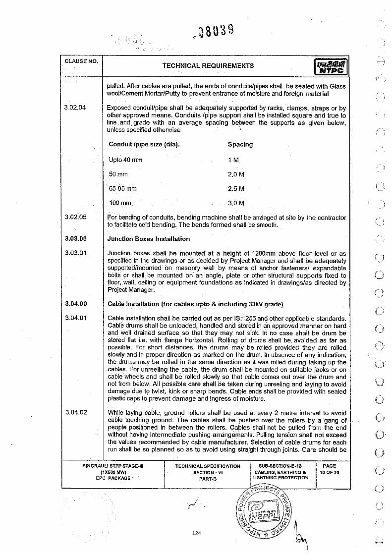
pulled. After cables are pulled, the ends of conduitslpipes shall be sealed with Glass woollCement MortarlPutty to prevent entrance of moisture and foreign material
3.02.04 Exposed conduiffpipe shall be adequately supported by racks, clamps, straps or by other approved means. Conduits lpipe support shall be installed square and true to line and grade with an average spacing between the supports as given below, unless specified otherwise
Conduit lpipe size (dia). Spacing
Upto 40 mm 1 M
50 mm 2.0 M
65-85 mm 2.5 M
3.0 M
For bending of conduits, bending machine shall be arranged at site by the contractor to facil~tate cold bending. The bends formed shall be smooth.
Junction Boxes Installation
Junction boxes shall be mounted at a height of 1200mm above floor level or as specified in the drawings or as decided by Project Manager and shall be adequately supportedlmounted on masonry wall by means of anchor fasteners1 expandable bolts or shall be mounted on an angle, plate or other structural supports fixed to floor, wall, ceiling or equipment foundations as indicated in drawingslas directed by
Cable lnstallation (for cables upto & including 33kV grade)
Cable installation shall be carried out as per 15:1255 and other applicable standards. Cable drums shall be unloaded, handled and stored in an approved manner on hard and well drained sutface so that they may not sink. In no case shall be drum be stored flat i.e. with flange horizontal. Rolling of drums shall be avoided as far as
plastic caps to prevent damage and ingress of moisture.
run shall be so planned so as to avoid using straight through joints. Care should be
SECTION - V I ABLING, EARTHING & EPC PACKAGE
124

taken while laying the cables so as to avoid damage to cables. If any particular cable is damaged, the same shall be repaired or changed to the satisfaction of Project Manager without any extra cost.
Cables shall be laid on cable trays strictly in line with cable schedule
Power and control cables shall be laid on separate tiers. The laying of different voltage grade cables shall be on different tiers according to the voltage grade of the cables. In horizontal tray stacks, H.T. cables shall be laid on top most tier and cables of subsequent lower voltage grades on lower tiers of trays. Single core cable in trefoil formation shall be laid with a distance of four times the diameter of cable bebeen trefoil center lines and clamped at every two metre. All multicore cables shall be laid in touching formation. Power and control cables shall be secured fixed to trayslsupport with self locking type nylon cable straps w~ th de-interlocking facil~ties. For horizontal trays arrangements, multicore power cables and control cables shall be secured at every five meter interval. For vertical tray arrangement, individual multicore power cables and control cables shall be secured at every one meter by nylon cable strap. After completion of cable laying work in the particular vertical tray, all the control cables shall be binded to trayslsupports by aluminium strips at every five meter interval and at every bend.
Bending radii for cables shall be as per manufacturer's recommendations and 1S:1255.
Where cables cross roadslrail tracks, the cables shall be laid in hume pipelPVC
in each cable run some extra length shall be kept at suitable point to enable one LTIlwo HT straight through joints to made, should the cable develop fault at a later stage. Control cable termination inside equipment enclosure shall have sufficient lengths so that shifting of termination in terminal blocks can be done without requiring any splicing.
3.04.08 Wherever few cables are branching out from main t ~ n k ro,u&troughs shall be used.
3.04.09 The installation work shall be carried out in a neak workman like manner & areas of work shall be cleaned of all scraps, water, etc. after the completion of work in each area every day. Contractor shall .replace RCCISteel trench covers after the Installation workin that particular area is completedor when further work is not likely to be taken up for some time.
3.04.10 Contractor shall furnish three copies of the report on work carried out in a particular week, such as cable numbers and date on which laid, actual length and roule, testing carried out, termination done alongwith the marked up copy of the cable schedule and interconnecting drawing where any modifications are made
3.04.1 1 Project Manager shall furnish two numbers of partly filled pull cards for each cable and cable way to the Contractor for laying and termination of thecablelcable way. After completing various activities like laying, testing and commissioning of a set of cables the contractor shall fill up the required information and return one filled up pull card for each cablelcable way to the Project Manager for further processing for
SlNGRAULl STPP STAGE-111 TECHNICAL SPECIFICATION SUB-SECTION-6-13. PAGE (1x500 MW) SECTION - V I CABLING, EARTHING 8 H OF 20
EPC PACKAGE PAi7T.B LIGHTNING PROTECTION
125

TECHNICAL REQUIREMENTS 1-1 billing and progress reporting. In case only a part of cabling activity could be completed at time partially filled cards may also be returned to the Project Manager. Contractor shall request and obtain a set of fresh pull cards at the time of taking further cabling activities on the same cable. One set of these pull cards shall then be completed and handed over to the Project Manager in the manner described above Payment shall be generally linked with the progress report on laying, termination, testing 8 commissioning generated from these pull card's.
Directly Buried Cables
a) Cable trenches shall be const~cted for directly buried cables. Construction of cable trench for cables shall include excavation, preparation' of sieved sand bedding, riddled soil cover, supply and installation of brick or concrete protective covers, back filling and compacting, supply and installation of route markers and joint markers. Laying of cables and providing protective covering shall be as per IS:1255 and the enclosed drawings showing cabling details.
b) RCC cable route and RCC jo~nt markers shall be provided wherever required. The voltage grade of the higher voltage cables in route shall be engraved on the marker. Locat~on of underground cable joints shall be indicated with cable marker w~th an additional inscription "Cable Joint". The marker shall project 150 mm above ground and shall be spaced at an interval of 30 meters and at every change in direction. They shall be located on both sides of road crossings and drain crossings. Top of cable markerljoint marker shall be sloped to avoid accumulation of waterldust on marker.
Cable tags shall be provided on all cables at each end (just before entering the equipment enclosure), on both sides of a wall or floor crossing, on each ductlconduit entry, and at every 20 meters in cable trayltrench runs. Cable tags shall also be provided inside the switchgear, motor control centers, control and relay panels etc. where a number of cables enter together through a gland plate. Cable tag shall be of rectangular shape for power cables and control cables. Cable tag shall be of 2 mm thick aluminum with number punched on it and securely attached to the cable by not less than two turns of 20 SWG GI wire conforming to IS:280. Alternatively, the Contractor may also provide cable tags made of nylon, cable marking ties of 'TY- CAB' or equivalent type with cable number heat stamped on the cable tags
While crossing the floors, unarmoured cables shall be protected in conduits upto a height of 500 mm from floor level if not laid in tray.
Cable Terminations & Connections
The termination and connection of cables shall be done strictly in accordance with cable termination kit manufacturer" instructions, drawings andlor as directed by Project Manager. Cable jointer shall be qualified to carryout satisfactory cable jointingltermination. Contractor shall furnish for review documentary evidencelexperience reports of the jointers to be deployed at site.
TECHNICAL SPECIFICATION SECTION - Vt 1 t,
EPC PACKAGE ", { )
[ ;
126

Work shall include all clamps, fittings etc. and clamping, fitting, fixing, plumbing, soldering, drilling, cutting, taping, preparation of cable end, crimping of lug, ~nsulated sleeving over control cable lugs, heat shrinking (where applicable), connecting to cable terminal, shorting and grounding as required to complete the job to the satisfaction of the Project Manager.
CIAUSE NO.
The equipment will be generally proided with undrilled gland plates for cables/conduit entry. The Contractor shall be responsible for punching of gland plates, painting and touching up. Holes shall not be made by gas cutting. The holes shall be true in shape. All cable entry points shall be sealed and made vermin and dust proof. Unused openings shall be effectively sealed by 2mm thick aluminium sheets.
TECHNICAL REQUIREMENTS
Control cable cores entering control panellswitchgearlMCClmiscellaneous panels shall be neatly bunched, clamped and tied with self locking type nylon cable ties with de interlocking facility to keep them in position.
All the cores of the control cable to be terminated shall have identification by providing ferrules at either end of the core, each ferrule shall be indelible, printed single tube ferrule and shall include the complete wire number and TB number as per the drawings. The ferrule shall fit tightly on the core. Spare cores shall have similar ferrules with suffix spl, sp2, --etc along with cable numbers and coiled up after end sealing.
3.05.06 All cable terminations shall be appropriately tightened to ensure secure and reliable connections.
3.05.07
1 4.00.00 / EARTHING SYSTEM
It is the responsibility of the Contractor to terminate the cables at motor terminals in correct phase sequence to ensure the proper direction of rotation.
3.05.08
3.05.09
( 4.01.00 1 Earthing system shall be in strict accordance with IS:3043 and Indian Electricity RuleslActs
Wherever specifically required by the Project Manager, the Contractor shall disconnect all cores of cable from the equipment terminals and physically dislocate from the terminals and reconnect subsequently.
. .
If the cable end box or terminal enclosure provided on the equipment is found unsuitable and requires modifications; the same shall be carried out by the Contractor as directed by the Project Manager.
The earth conductors shall be free from pitting, laminations, ntst, scale and other electrical, mechanical defects
127

4.03.00 The material of the earthing conductors shall be as follows :
CLAUSE NO.
1) Conductors above ground level and in built up - Galvanized steel trenches.
TECHNICAL REQUIREMENTS
1 2) Conductors buried in earth - Mildsteel
1 3) Earth electrodes - Mild steel rod
The sizes of earthing conductors for various electrical equipments shall be as below:
Equipment
a)
b)
I I d) I LT Motors above 125 KW I -- 1 50 x6mrn GSflat I
Earth conductor
buried in earth
Main earth grid
c)
Earth conductor above ground level & in built-up
trenches
33KVlllKV switchgear1 equipment 415V switchgear
1 1 I IKWto25KW I -- 1 25x3mm GSflat I
40 mm dia.MS rod
3.3 kV switchgear 1 415 V MCCl Distribution boards I Transformers
1 1 125KWto125KW
I I
II I Fractional House power motor I -- / 8 SWG GS wire I
65xSmm GS flat
--
-.-
65xSmm GS flat
--
25 x 6rnm GS flat
5Ox6rnm GS flat
e)
f)
g)
Control panel & control desk
I
Push button station I Junction Box
Columns, structures, cable trays and busduct enclosures
SlNGRAULl STPP STAGE-I11 (1x600 MW)
EPC PACKAGE
--
(To be terminated with suitable lugs& the price to be build up in erection cost)
25 x 3 rnrn GS flat
---
---
TECHNICAL SPECIFICATION SECTION - V1
PART.8 ,,< . i . -
8 SWG GI wire
(To be terminated with sultable lugs & the price to be build up in erection
cost)
5Ox6rnm GS flat
SUB-SECTION-6-13 CABLING, EARTHING 8
,~'UGt+T~ING PROTECTION , ~ . , ' ~ ~ , , % .
-- 'A
PAGE 14 OF 20
128

TECHNICAL REQUIREMENTS 1-11 hf Crane. rails. rail tracks & other 25x6mm GS flat I I
non-current carrying metal II ' I p a r t s ' '
Metallic frame of all electrical equipLent shali be earthed by two separate and distinct connections to earthing system, each of 100% capacity, Crane rails, tracks, metal pipes and conduits shall also be effectively earthed at two points. Steel RCC columns, metallic stairs, and rails etc. of the bullding housing electrical equipment shall be connected to the nearby earthing grid conductor by one earthing ensured by bonding the different sections of hand rails and metallic stairs. Metallic sheathslscreens, and amour of multi-core cables shall be earthed at both ends. Metallic Sheaths and amour of single core cables shall be earthed at switchgear end only unless otheiwise instructed by the Employer. Every alternate post of the switchyard fence shall be connected to earthing grid by one GS flat and gates by flexible lead to the earthed post. Railway tracks within the plant area shall be bonded across fish plates and connected to earthing grid at several locations. Portable tools, appliances and welding equipment shall be earthed by flexible insulated cable.
Each continuous laid lengths of cable tray shall be earthed at minimum two places by G.S. flats to earthing system, the distance between earthing points shall not exceed 30 metre. Wherever earth mat is not available Contractor shall do the necessary connections by driving an earth electrode in the ground. Where the trays are laid on the cable trestle, the same shall be earthed through strip along trestle leg at 30 mt (max) interval & structural footing of the trestle shall be earthed at an interval of 30 mt. (max.) with 3 mt. long 40 mm dia MS electrode.
Neutral points of HT transformer shall be earthed through NG resistors. The Contractor shall connect the NGR earthing poinffneutral point of LT transformer by two separate GI strips to two separate earth electrodes.
Neutral connections and metallic conduitslpipes shali not be used fw the equipment earthing. Lightning protection system down conductors shall not be connected to other earthing conductors above the ground level.
Connections between earth leads and equipment shall normally be of bolted type. Contact surfaces shall be thoroughly cleaned before connections. Equipment bolted connections after being tested and checked shall be painted with anti corrosive paintlcompound.
Connections between equipment earthing leads and between main earthing conductors shall be of welded type. For rust protection the welds should be treated with red tead compound and aftewards thickly coated with bitumen compound, Ail welded connections shall be made by electric arc welding.
Resistance of the joint shall not be more than the resistance of the equivalent length of conductors.
Earthing conductors buried in ground shall be laid minimum 600 mm below ground level unless otherwise indicated in the drawing. Back tilling material to be placed
129
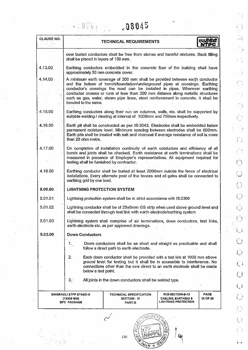
CLAUSE NO.
4.13.00
4.14.00
4.15.00
4.16.00
4.17.00
4.18.00
5.00.00
5.01.01
5.01.02
5.01.03
5.02.00
SlNGRAULl
TECHNICAL REQUIREMENTS
over buried conductors shall be free from stones and harmful mixtures. Back filling shall be placed in layers of 150 mm.
Earthing conductors embedded in the concrete floor of the building shall have approximately 50 mm concrete cover.
A minimum earth coverage of 300 mm shall be provided between earth conductor and the bottom of trenchlfoundationlunderground pipes at crossings. Earthing conductor's crossings the road can be installed in pipes. Wherever earthing conductor crosses or runs at less than 300 mm distance along metallic structures such as gas, water, steam pipe lines, steel reinforcement in concrete, it shall be bonded to the same.
Earthing conductors along their run on columns, walls, etc. shall be suppotted by suitable welding I cleating at interval of 1000mm and 750mm respectively.
Earth pit shall be const~cted as per IS:3043. Electrodes shall be embedded below permanent moisture level. Minimum spacing between electrodes shall be 600mm. Earth pits shall be treated with salt and charcoal if average resistance of soil is more than 20 ohm metre.
On completion of installation continuity of earth conductors and efficiency of all bonds and joints shall be checked. Earth resistance at earth terminat~ons shall be measured in presence of Employer's representatives. All equipment required for testing shall be furnished by contractor.
Earthing conductor shall be buried at least 2000mm outside the fence of electrical installations. Every alternate post of the fences and all gates shall be connected to earthing grid by one lead.
LIGHTNING PROTECTION SYSTEM
Lightning protection system shall be in strict accordance with 15:2309
Lightning conductor shall be of 25x6mm GS strip when used above ground level and shall be connected through test link with earth electrodelearthing system
Lightning system shall comprise of atr term~nations, down conductors, test links. earth electrode etc. as per approved drawings.
Down Conductors
1. Down conductors shall be as short and straight as practicable and shall follow a direct path to earth electrode.
2. Each down conductor shall be provided w~th a test link at 1000 mm above ground level for testing but it shall be in accessible to interference. No connections other than the one direct to an earth electrode shall be made below a test point.
3. All joints in the down conductors shall be welded type.
STPP STAGE-I11 (iX500 MW)
EPC PACKAGE
TECHNICAL SPECIFICATION SECTION - VI
PART-B LIGHTNING PROTECTION
SUB-SECTION-8-33 CABLING, EARTHING (L
PAGE 16 OF 20
130

4. Down conductors shall be cleated on outer side of building wall, at 750 mm interval or welded to outside building columns at 1000 mm interval.
CLAUSE NO.
5. Lightning conductor on roof shall not be directly cleated on surface of roof. Supporting blocks of PCCIinsulating compound shall be used for conductor fixing at an interval of 1500 mm.
TECHNICAL REQUIREMENTS
6. All metallic structures within a vicinity of two meters of the conductors shall be bonded to conductors of lightning protection system.
7. Lightning conductors shall not pass through or run inside GI Conduits.
8. Testing link shall be made of galvanized steel of size 25x 6mm.
QUALITY ASSURANCE PROGRAMME
Bidder(shal1 furnish detailed Quality Assurance Proggam and Quality Plans for all materials and accessories to be supplied and installed under the scope of the specification as per General Technical Conditions of technical specification. The Quality Plans shall include all tests1 checks as per relevant Nationalllnternational Standards and the requirements of this specification including tests listed in this section.
TESTS
All equipment to be supplied shall be of type tested design. During detatl engineering, the contractor shall submit for approval the reports of all the type tests as listed in this specification and carried out within last ten years from the date of bid opening. These reports should be for the test conducted on the equipment similar to those proposed to be supplied under this contract and the test(s) should have been either conducted at an independent laboratory or should have been w~tnessed by a client.
However if the contractor is not able to submit report of the type test(s) conducted within last ten years from the date of bid opening, or in the case of type test report(s) are not found to be meeting the specification requirements, the contractor shall conduct all such tests under this contract at no add~tional cost to the Owner either at third party lab or in presence of client/owners representative and submit the reports for approval.
All acceptance and routine tests as per the specification and relevant standards shall be carried out. Charges for these shall be deemed to be included in the equipment price.
The type test reports once approved for any projects shall be treated as reference. For subsequent projects of NTPC. an endorsement sheet will be furnished by the manufacturer confirming similarity and "No design change". Mlnor changes if any shall be highlighted on the endorsement sheet.
131

Cable termination kit and straight through joints should have been tested as per lS:13573 for above 3.3 kV class and as per VDE 0278 for 3.3 kV class.
Routinel Acceptance Tests on Cable Trays support system
Routine Tests
CLAUSE NO.
7.02.00
a) Routine tests as per specification and applicable standards shall be carried out on all equipmentslitems covered in the specification.
TECHNICAL REQUIREMENTS
Type Test reports shall be furnished for the following
b) Physical & dimensional check on all equipments as per approved drawingslstandards.
c) HVIIR as applicable.
d) Checwmeasurement of thickness of paintlzinc coatinglnickel-chrome plating as per specification & applicable standard.
Acceptance Test
a) Galvanising Tests as per applicable standards
b) Welding checks
c) Deflection tests on cable trays:
One piece each of 2.5m length of cable tray of 300mm & above shall be taken as sample from each offered lot. It shall be supported at both end 8 loaded with uniform load of 76 kglmeter along the length of cable tray. The maximum deflection at the mid-span of each size shall not exceed 7mm.
d) Proof load tests on cable tray support system
i) Tests on Main Support Channel shall be done if only C1 Channel are in scope of supply and cantilever arms shall be fitted on one side. This test shall be same as test 4 of type test.
ii) Test on Main Support Channel shall be done with C2 channel and cantilever arms fitted on both sides, if C2 channels are in scope of supply. This test shall be same as test 2A of type test. Then test (i) above shall not be done.
iii) Nut slip characteristic test (it shall support minimum load of 350kg before nut slips with a bolt torque of 65 NM). This test shall be same as test 583 of type test.
The procedure for carrying out tests at "d" above shall be as per details given in Type Tests in specification thereafter Die-Penetration test shall be carried out to check weld integrity.
SINGRAULI STPP STAGE-Ill TECHNICAL SPECIFICATION SUB-SECTION-6-13 SECTION - VI
132

CUUSE NO. TECHNICAL REQUIREMENTS
8.00.00
I 801.02 I Cables I
e) The above acceptance tests shall be done only on one sample from each offered lot.
COMMISSIONING
8.02.01
! Check for physical damage j I
The Contractor shall carry out the following commissioning tests and checks after installation at site. In addition the Contractor shall carry out all other checks and tests as recommended by the Manufacturers.
Check for insulation resistance before and after terminationljointing. I c) HT cables shall be pressure tested (test voltage as per lS:7098) before
commissioning.
d) Check of continuity of all cores of the cables.
e) Check for correctness of all connections as per relevant wiring diagrams. Any minor modification to the panel wiring like removinglinserting, shorting, change in terminal connections etc., shall b e carried out by the Contractor.
I 1 Check for correct polarity and phasing of cable connections. I 9) Check for proper earth connections for cable glands, cable boxes, cable
armour, screens, etc.
I I connections. I Check for provision of correct cable tags, core ferrules, and tightness of
/ 8.0200 / Cable trays I supports and accessories I 1) Check for proper galvanizinglpainting and identification number
of the cable trayslsupports and accessories.
2) Check for continuity of cable trays over the entire route.
3) Check that al l sharp corners, burrs, and waste materials have been removed from the trays supports.
4) Check for earth continuity and earth connection o f cable trays.
Earthing and Lightning protection system
1) Earth continuity checks.
2) Earth resistance o f the complete system as wel l as sub-system.
133

1 8.04.00 1 GENERAL COMMISSIONING CHECKS (Application to all electrical equiprnents
CLAUSE NO.
(a.) Check for name plate details according to specification.
(b.) Check for physical damage, if any.
(c.) Check for tightness of all bolts, clamps & connecting terminals.
(d.) Check for earth connection.
(e.) Check for cleanliness of insulators & bushings.
(f.) Check for lubrication of all moving parts.
(g.) Check for provision of heater.
TECHNICAL REQUIREMENTS
SECTION - VI
134

135

I I STATION LIGHTING I 1 1.00.00 1 GENERAL I
This specification covers the general description of design, manufacture and construction features, testing, supply, installation and commissioning of the Station - Lighting system equipment.
CODES AND STANDARDS
All standards and codes of pract~ce referred to herein shall be the latest edition including all applicable official amendments & revisions as on date of bid opening. In case of conflict between this specification and those (IS codes, standards etc.) referred to herein, the former shall prevail. All work shall be carried out as per the following standards & codes.
Lighting Fixtures and Accessories
IS:1913 General and safety requirements for luminaries.
132148 Flame proof enclosures of electrical apparatus.
1S:418 Tungsten filament general service electric lamps.
/ lS:l258 Bayonet lamp holders.
I 1 IS:1534 Ballast for fluorescent lamps. I
I / 1S:1569 Capacitors for use in tubular fluorescent, high pressure mercury vapour and low pressure sodium vapour discharge lamp circuit.
lS:1777 Industrial luminaire with metal reflectors.
lS:2149 Luminaire for Street lighting.
I 1 lS:2215 Starters for fluorescent lamps. I IS:241 8 Tubular fluorescent lamps for general lighting services.
IS3323 Bi-pin lamp holders for tubular fluorescent lamps.
I I lS:3324 Holders for starters for tubular fluorescent lamps. I I 1 IS:3646 Code of practice for interior illumination. 1 I 1 15:4013 Dust-tight electric lighting fittings. I 1 1 1S:6616 Ballasts for high pressure mercury vapour lamps. I
lS:8224 Electric Lighting fittings for Division 2 areas.
1 SlNGRAULl STPP STAGE.111 I TECHNICALSPECIFICATION I SUB-SECTION-B-$4 / PAGE I SECTION - VI STATION LIGHT1
136

I TECHNICAL REQUIREMENTS
1S:9900 High Pressure mercury vapour lamps.
IS39974 High Pressure Sodium vapour lamps.
IS:10276 Edison screw lamp holders.
lS:10322 Luminaires.
15:13021 AC Supplied Electronic Ballasts for tubular fluorescent lamps.
Lighting Panels, Switch-boxes, Receptacles and Junction Boxes
lS:13947 Degree of protection provided by enclosures for low-voltage switchgear and control gear.
lS:1293 Plugs & socket outlets of rated voltage upto and Including 250volts & rated current upto and including 16 Amps.
IS:2551 Danger notice plates.
1 IS:13947 Low voltage switchgear and controlgear
I IS:3854 Switches for domestic and similar purposes.
IS:6875 Control switches (switching devices for control and auxiliary circuits including contactor relays) for voltages upto and including I000 V AC and 1200 V DC.
lS:13703 Low voltage fuses for voltages not exceeding lOOOV AC or 1500V DC.
I Conduits, Pipes and Accessories I 1S:2667 Fittings for rigid steel conduit for electrical wiring. I 1 IS:3837 Accessories for rigid steel conduits for electrical wiring. I 1 IS:9537 Conduits for electrical installations. I I Lighting WiresICables I
PVC insulated cables for working voltages upto and including I lOOV
lS:3961 Recommended current ratings for cables.(PVC Insulated and PVC sheathed heavy duty cables and light duty cables).
IS:8130 Conductors for insulated electric cables and flexible cords.
1S:10810 Methods of tests for cables.
SlNGRAULl STPP STAGE-Ill TECHNICAL SPECIFICATION SUBSECTION-6-14 STATION LIGHTING
EPC PACKAGE -
137

TECHNICAL REQUIREMENTS
I Electrical Installation Practices & Miscellaneous I I 1 1S:1944 Code of practice for lighting of public thorough fare I I I lS:3646 Code of practice for interior illumination. I
Classification of Hazardous areas (other than Mines)having flammable gases and Vapours for electrical installation
lS:6665 Code of practice for industrial lighting.
National Electrical Code
Indian Electricity Rules.
Indian Electricity Act
135 Colour for ready mixed paints & enamel.
I IS:280 Mild steel wires for general engineering purposes
1S:374 Electric ceiling type fans & regulators.
IS:732 Code of practice for electrical wiring installations.
IS:1255 Code of practice for installation and maintenance of power cables Upto and including 33KV rating.
lS:2062 Steel for general structural purposes
IS:2629 Recommended practice for hot-dip galvanizing of iron and steel.
IS:2633 Methods for testing uniformity of coating of zinc coated articles.
1S:2713 Tubular steel poles for overhead power lines.
IS:3043 Code of practice for earthing
IS:5216 Guide for safety procedures and practices in electrical work.
1S:5571 Guide for selection of electrical equipments for hazardous areas
13802 Code of practice for use of structural steel in overhead transmission line towers-Fabrication Galvanising, inspection & packing.
I BS:6121 Mechanical cable glands I
138

TECHNICAL REQUIREMENTS
LIGHTING SYSTEM DESCRIPTION
The Station Lighting package covers the tllumination of various indoor and outdoor areas in the main plant and off site areas including AWRS area, buildings, equipment and road lighting for the area I yard in the scope of the contractor. The lighting system of various areas shall comprise of one or more of the following systems:
(a) Normal AC Lighting System
(b) Emergency AC Lighting System
(C) DC Lighting System
Normal AC Lighting System
Normal AC lighting system 415V, 3Phase, 4wire. will be fed from lighting panels (LPs) which in turn will be fed from the lighting distribution boards (LDBs) /Switch board MCC.
Emergency AC Lighting System I This system shall be provided for certain important areas in the main plant. The lighting fixtures connected to this system shall be normally "ON" along with the normal AC system. These will be fed from emergency lighting panels (ELP,s) which in turn will be fed 3-phase. 4-wire supply from the emergency lighting distribution boards (ELDB'S). These lights will go off for a few seconds in case of AC supply failure at Emergency Switchgear, but shall be automatically restored when Emergency Switchgear is energised by Diesel generator set.
Four (4) nos. 240V AC lighting fixtures fed from UPS shall be provided on each stacker reclaimer machine
DC Lighting System I At strategic locations in the main plant, a few lighting fixtures fed from 220 V,DC supply, shall be provided to enable safe movement of operating personnel and access to important control points during an emergency, when both the normal AC and Emergency Lighting system fail. These lighting fixtures will be fed from 220V DC LDBs which in turn will be fed from DC lighting panels.
The supply to the DC l~ghting panels shall be automatically switched ON in case of loss of AC supply at station service switch gear as well as Emergency switch-gear. The DC supply will be automatically switched OFF after about 3 minutes following the restoration of supply to normal AC or emergency AC lighting system.
For CHP areas, IOOW , 220V DC Lighting fixture shall be provided as follows: I - One (1) no. in each local control area I
SINGRAULI STPP STAGE-Ill TECHNICAL SPECIFICATION SUBSECTION-6-14 SECTION -V I STATION LIGHTING
EPC PACKAGE
139

\ 'M-
i I - Three (3) nos. in each MCCl Switchgear room and control room I
C A U S E NO.
-- -
I 1 - One ( I ) no in each oftice room and each pump house I
TECHNICAL REQUIREMENTS
. Six (6) nos. in Track hopper shed
- Twelve (1 2) nos in track hopper tunnels
I - Two (2) nos in each underground portion of TPs I - One (1) no at every 5.0m height interval in the staircases of various TPs and
buildings under contractor's scope
One (1) no in each drive floor in each TP under contractor's scope
Four (4) nos in wagon tippler tunnel
The above fixtures shall be mounted suitably on walllcolumns at strategic locations for safe movement of operating personnel and access to important control points during an emergency, when the normal AC lighting system fails. These lighting fixtures shall be fed from bidder's 220 V LDBs through DC lighting panels. Bidder's 220V LDBs shall be fed from 220V DC system for CHP area.
In auxiliary /off site buildings, emergency DC lighting is to be provided through self contained DC emergency fixture at strategic locations. The fixtures shall be switched 'ON' automatically in case of failure of AC supply.
EQUIPMENT DESCRIPTION
Lighting Fixture, Lamps & Accessories
a) All lighting fixtures and accessories shall be designed for continuous operation for its life under atmospheric conditions existing at site.
b) AC lighting fixtures and accessories shall be suitable for operation on 240 V, AC, 50 Hz supply with supply voltage variation of +/-lo%, frequency variation of +I- 5% and combined voltage and frequency variation (absolute sum ) of 10% DC lighting fixtures and accessories shall be suitable for operation on 220 V, with variation between 190 V & 240 V.
c) Power factor of fluorescent lamp fixtures shall be not less than 0.90 for FH type fixture & 0.95 with electronic ballast for other florescent fixtures and that of High Pressure Sodium Vapour and Mercury Vapour (HPSV & HPMV) lamp fixtures shall not be less than 0.85. Suitable power factor improvement capacitors shall be provided for thispurpose. Capacitors shall be hermetically sealed to prevent seepage of moisture.
d) All lighting fixtures shall be complete with lamp(s), lamp holder (s), terminal blocks, clamps, locking arrangements, fixing brackets etc. Control gears shall be provided as applicable I specified. The fixtures
I SINGRAULI STPP STAGE-Ill I TECHNICAL SPECIFICATION I SUB-SECTION-6-14 PAGE
(4x500 MW) EPC PACKAGE I SECTION - V l STATION LIGHTING
PART-B
140

CLAUSE NO.
I C
TECHNICAL REQUIREMENTS
shall be fully wired upto terminal block. The internal wiring of the fixtures shall be done with suitable thermo-plastic or silicon rubber insulated copper conductor wires of suitable size and type. However, the normal cross section of conductor shall be not less than 0.5 Sq. mm and minimum thickness of insulation shall be 0.6 mm. The wiring shall be capable of withstanding the maximum temperature to which it will be subjected under specified service conditions without deterioration and affecting the safety of the luminaire when installed and connected to the supply. All fixing hocking screws, washers, nuts, brackets, studs etc, shall be zinc plated and passivated.
e) Ail fluorescent fixtures shall be provided with terminal blocks of ELMU(- EPIor Equivalent make inside the fixture for loop in loop out at Fixture. The terminal block shall be suitable for 4 sq. mm. Wire termination.
f) All lighting fixtures shall be provided with an external, brass/GI earthing terminal suitable for connecting 14 SWG. GI earthing wire. All metal or metal enclosed parts of the housing and accessories shall be bonded and connected to the earthing terminal as so to ensure satisfactory earthing continuity through out the fixture.
g) The lighting fixtures shall be designed for minimum glare. The finish of the fixtures shall be such that no bright spots are produced either by direct light source or by reflection.
h) Generally all lighting fixtures (except for street light & post top lantern type fixture) shall be provided with 20 mm dia. Conduit knock-out for connection to the incoming supply.
i) Twin fluorescent lamp fixtures shall be wired in lead lag circuit to minimise stroboscopic effect.
j) High bay fixtures shall be suitable for pendant mounting and provided with safety chain. Flood lights shall have suitable base plate/frame/mounting brackets for mounting on structural steel members.
k) The reflectors shall be manufactured from CRCA sheet steel or aluminium as specified. The aluminium reflectors shall be made of high purity aluminium sheet, polished electrochemically brightened and anodized or proven alternate arrangement of anodizing.
I) Lamp holders for fluorescent tubes shall be of spring loaded, low contact resistance, bi-pin rotor type, resistant to wear and su~table for holding in normal position under condition of shock and vibration. Live parts of the lamp holder shall not be exposed during insertion or removal of the lamp or after the lamp has been taken out. Lamp holders for incandescent, HPMV & HPSV lamps shall be of porcelain screwed type.
m) Starters shall have bimetal electrodes and high mechanical. strength. Starters shall be replaceable without disturbing the reflector or lamps and without use of any tool. Starter shall have brass contacts and radio
SECTION - V I EPC PACKAGE
141

. ,
'= CLLVISE NO. r TECHNICAL REQUIREMENTS
i ..
interference suppressing capacitor.
I Lamps
a) Incandescent. HPMV & HPSV lamps shall be provided with screwed type caps.
b) The lamps shall be capable of withstanding small vibrations and the connections at lead-in wires and filamentslelectrodes shall not break under such circumstances.
I c) Incandescent (GLS) lamps shall be of 'clear' type unless otherwise specified. I
d) All fluorescent fixtures shall have 'T5' type fluorescent lamps except for 'FH' type. The louvers of these fixtures shall be designed for 'T5' type fluorescent lamps. All fluorescent lamps shall have 'cool day i~ght' w lor designation. The mirror optics type fluorescent f~xtures shall have no inidescence effect. The life of T5 fluorescent fixture shall be rated for 18,000 burning hours.
e) High pressure mercury vapour (HPMV) lamps shall be of ehptical shape, colour corrected type with special fluorescent coating to increase lumen out put and improve colour rendition.
f) High pressure sodium vapour (HPSV) lamps shall be of elliptical shape and provided with external ignitor for rapid restart facility. However for street light &flood light fixture type SF1 & SF4, lamps shall be of tubular shape & provided with external ignitor for rapid restart fac~lity. Halogen lamps shall be of tungsten filament, quartz glass type with ceramic base.
I 4.02.00 / Ballasts I
a) All HPSV and HPMV lamp fixtures shall be provided with wire-wound ballasts. All fluorescenffCFL fixtures except for Class-I, Div-ll fittings1 increased safety fittings (Div-IIIHazardous Area) type fixtures shall be provided with electronic ballasts.
Analog dimmable ballasffHigh frequency regulating shall be provided for CFL b, type CL-1D and halogen type DHI and shall be of proven make and
compatible w~th the offered dimming system.
c) Wire-wound Ballasts shall have annealed copper wire wound coil, electrical I grade silicon sheet steel laminations and hermetically sealed with su~table insulating compound housed in sheet steel enclosure finished stove enameled grey outside. Class of insulation shall be suitable for temp. rise of winding. End connections and taps shall be brought out in a suitable terminal block rigidly fixed to the ballast enclosure. Ballast shall be suitable for use on nominal voltage of 240 V +I- lo%, 50 Hz supply. Ballast for HPSV and HPMV
SINGRAULI STPP STAGE-Ill (1X50O MW)
EPC PACKAGE
TECHNICAL SPECIFICATION SECTION - V I
PART-B
SUB-SECTION-B-14 STATION LIGHTING
PAGE 7 OF 39
142
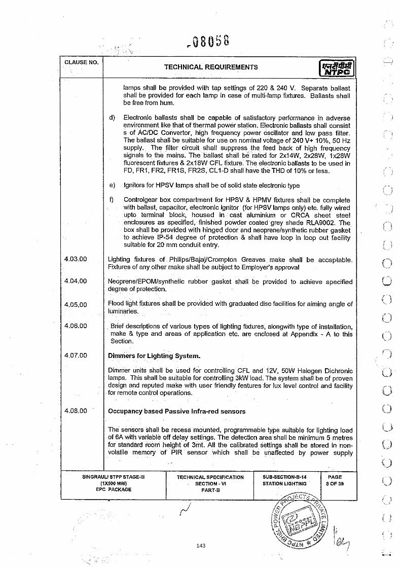
lamps shall be provided with tap settings of 220 & 240 V. Separate ballast shall be provided for each lamp in case of multi-lamp fixtures. Ballasts shall be free from hum.
CLAUSE NO.
d) Electronic ballasts shall be capable of satisfactory performance in adverse environment like that of thermal power station. Electronic ballasts shall consist s of ACIDC Convertor, high frequency power oscillator and low pass filter. The ballast shall be suitable for use on nominal voltage of 240 V+ lo%, 50 Hz supply. The filter circuit shall suppress the feed back of high frequency signals to the mains. The ballast shall be rated for 2xI4W, 2x28W, Ix28W fluorescent fixtures & 2x18W CFL fixture. The electronic ballasts to be used in FD, FRI, FR2, FRIS, FR2S, CLI-D shall have the THD of 10% or less.
TECHNICAL REQUIREMENTS
e) Ignitors for HPSV lamps shall be of solid state electronic type
f) Controlgear box compartment for HPSV & HPMV fixtures shall be complete with ballast, capacitor, electronic ignitor (for HPSV lamps only) etc. fully wired upto terminal block, housed in cast aluminium or CRCA sheet steel enclosures as specified, finished powder coated grey shade RLA9002. The box shall be provided with hinged door and neoprenelsynthetic lubber gasket to achieve IP-54 degree of protection & shall have loop in loop out facility suitable for 20 mm conduit entry.
Lighting fixtures of Philips/Bajaj/Crompton Greaves make shall be acceptable. Fixtures of any other make shall be subject to Employer's approval
Neoprene/EPOM/synthetic rubber gasket shall be provided to achieve specified degree of protection. / 4.05.00 1 Flood light fixtures shall be provided with graduated disc fac~lities for aiming angle of luminaries.
Brief descriptions of various types of lighting fixtures, alongwith type of installation. make & type and areas of application etc. are enclosed at Appendix - A to this Section.
Dimmers for Lighting System.
Dimmer units shall be used for controlling CFL and 12V, 50W Halogen Dichronic lamps. This shall be suitable for controlling 3kW load. The system shall be of proven design and reputed make with user friendly features for lux level control and facility for remote control operations.
Occupancy based Passive lnfra-red sensors
The sensors shall be recess mounted, programmable type suitable for lighting load of 6A with variable off delay settings. The detection area shall be minimum 5 metres for standard room height of 3mt. All the calibrated settings shall be stored in non- volatile memory of PIR sensor which shall be unaffected by power supply
SECTION - VI STATION LIGHTING EPC PACKAGE
143

fluctuations. Necessary 16A contactor shall be supplied alongwlth each sensor & shall be located inside the switch box.
Self Contained Emergency lighting fixtures (Type PF) shall be automatic, totally enclosed single unit suitable to receive 240 V +I- 10% AC, 50 Hz supply. The fixtures shall switch 'ON' automatically in the event of failure of AC supply. The unit shall comprise of 1.6 mm thick CRCA M.S. sheet enclosure, finished stove enameled grey outside, accommodating 6 Volt Nickel Cadmium batteries, battery charger, 2 x 10W fluorescent lamps, reflector etc. The unit shall be complete with mounting brackets suitable for mounting on walllcolumn. Nickel-Cadmium Battery shall be rated for operation of 2 x 10W fluorescent lamps continuously for 4 hours.
Fans & Regulator
Ceiling Fans, to be provided in non airconditioned off~celcontrol room area, shall be suitable for operation on 240 V, 50 Hz, AC supply comprising of class 'B' insulated copper wound single phase motor, 1200mm sweep, aerodynam~cally designed well balanced AL blades (3 Nos.), down rod, die cast aluminium housing, capacitor, suspension hook, canopies etc. finlshed in stove enameled white. Power factor of fans shall not be less than 0.9.
i. Fan regulators shall be stepped electronic type sudable for operation on 240V AC supply. Cost of regulator shall be included in cost of ce~llng fan.
4.1 1.00 1 Lighting Panels (LPs)
(a) Lighting panels shall be constructed out of 2 mm thick CRCA sheet steel. The door shall be hinged and the panel shall be gasketted to achieve specified degree of protection. The panel shall be provided with terminal blocks for incoming and outgoing circuits, earthing terminals, M.S. mounting brackets suitable for surface mounting on walllcolumnlstructure, allenkeys with bolts as locking arrangements, circuit directon, plate & c~rcuit diaqram fitted on the inside of the door etc.
I Removable gl&td plates shall b e provided for entry of cableslconduits. Canopy shall be provided slope towards the rear side of the panel.
(b) Wiring inside the panel shall be carried out with 1100 V grade. PVC insulated stranded copper wires of adequate size. On both ends of each wire engraved identification ferrules shall be provided.
(C) All MCBs/lsolators/Sw~tcheslContactors etc. shall be mounted inside the panel and a fibre glass sheet shall be provided inside the main door such that the operating knobs of MCBs etc., shall project out of ct for safe operation against accidental contact.
(d) Equipment mounted inside the panel shall be provided w~ th Individual labels with equipment designationlrating. Front of the panel shall be provided with label engraved with designation of the panel. Labels shall be made of 3 ply lamicoidlengraved PVC having white letters on black background
I SlNGRAULl STPP STAGE.111 TECHNICALSPECIFICATION I SUBSECTION-8-34 I PAGE
(1x500 MW) EPC PACKAGE I SECTION -VI I STATION LIGHTING
PART-6 1
144

(e) Terminal bocks shall be 750 V grade, clip-on stud type, moulded in melamine, suitable for terminating muhicore 35 or 70 Sq. mm. stranded aluminium conductor incoming cable and 10 Sq. mm. stranded aluminium conductor for each outgoing circuits voltage. All terminals shall be shrouded, numbered and provided with identification strip for the feeders.
(9 MCB's shall be current limiting type with magnetic and thermal release suitable for manual closing and automatic tripping under fault condition. MCB's shall have short circuit interrupting capacity of 9 KA rms. MCB knob shall be marked with ONIOFF indication. A trip free release shall be provided to ensure tripping on fault even if the knob is held in ON poatlon. MCB terminal shall be shrouded to avoid accidental contact.
(g) Isolators of AC lighting panels shall be of TPN. 63 A, continuous duty, load make-break type suitable for 415 V, 3 phase 4 wire system. Isolator knob shall be marked with ONIOFF indication. Terminals shall be shrouded to avoid accidental contact. The isolator shall be suitable for withstanding let through energy of 125 A HRC fuse.
(h) DC switches shall be rotary type, 2 pole, continuous duty, load break type, quick make quick break, suitable for 220 V DC, 2 wire system. Switch knob shall be provided with ONIOFF indication
0) Fuses shall be of HRC plug in type complete with fuse fittings. Fuse fittings shall incorporate fully insulated shrouded contacts. Visible indication of operation of fuse shall be provided.
(i) Synchronous timers shall be quartz controlled electronic type, complete with rechargeable nickel cadmium cell, 24 hours range day dial. NOINC contacts etc. and suitable for operation on 240V AC supply.
A(k) Each lighting panel (LP-3) shall be fed from a 415V142V, 3 phase-4 wire, 3 KVA transformer. The transformer shall be located inside the lighting panel itself. Transformers shall be dry type, natural air cooled with class F insulation or better. Impedance of transformer shall be 5%. Transformers shall be tested as per 1S:11171. Off-circuit tap changer with +I- 5% in steps of +I- 1.25% tapping shall be provided. One minute power frequency withstand voltage for lighting transformer shall be 2.5 KV.
The exterior side of panel, shall be powder coated with shade RAL9002 and the interior side of the panels shall also be with shade RAL9002.
SlNGRAULl STPP STAGE-Ill TECHNICAL SPECIFICATION SUB-SECTION-6-14 SECTION - VI STATION LIGHTING
145

N P E INCOMER FEEDER OUTGOING FEEDERS
r;:;.': 'i~. i.:. NO.
I . . -
LP-I lNo. 415V.63 A, TPN 18Nos.,20A, Isolator 240V MCB
TECHNICAL REQUIREMENTS
(31/2Cx70sq.mm cable)
LP-2 INo. 415V,63 A, TPN 9 Nos.,20A, Isolator 240V MCB
(31/2Cx35sq.mm cable)
LP-3 1 No., 4A fuse 3 KVA 24 Nos., 16A, transformer,40A TPN 45V MCB MCB
DETAILOFCONTENTS
415V,63AAC2 duty contactor and synchronous timer of 24 hour range IOA, 240V selector switch, fuse, etc. outdoor type and IP:55 degree of protection
415V,63A AC2 duty contactor and synchronous timer of 24 hour range I OA, 240V selector switch, fuse, elc. outdoor type and IP:55 degree of protection
IP 55 degree of protection. lncomer shall be suitable for receiving 3Cx16 sq. mm cable and outgoing circuit shall be suitable for 2Cx16 sq. mm cable.
LP-Dl 1No. 220V.32 A, DP 6Nos.,lGA, 220V,32A DC Fuse, etc. Isolator 220V DP Switch outdoor type IP:55 degree
& Fuse of protection. (2Cx35sq.mm cable)
1 4.12.00 I Switch Box I Switch boxes shall be made of 1.6. mm thick, MS sheet with 3 mm. thick decorative, perspex cover. Switchbox shall be hot dip galvanized
(a) Provided with earthing terminal, mounting holes and screws, specified number of conduit knockouts on both the top and the bottom sides etc. The switch boxes shall be suitable for surface/flush mounting.
(b) Switches shall be decorative Piano Key Type single pole, quick make quick break, suitable for oueration on 240 V AC suuulv. However for SWB5 . . * . switch board, switches with base plate shall be of modular type. These shall be of reputed make subject to employer's approval.
I SlNGRAULl STPP STAGE-Ill I TECHNICAL SPECIFICATION SUB-SECTION-6-14 (iX500 MW) SECTION -VI STATION LIGHTING
EPC PACKAGE PART-B
146

~, . . ,' j.: ., z ., , . . ,
TECHNICAL REQUIREMENTS
(c) Sockets shall be decorative and of 3 or 5pin type, suitable for 240 V AC supply. However for SWB5 switch board, sockets with base plate shall be of modular type. These shall be of reputed make subject to employer's approval.
(d) Switch box shall be adequately sized to accommodate switchlfan regulatorslsockets and terminal blocks. All switch box mounted items shall be fully wired upto terminal blocks located inside the box by 1100 V grade PVC insulated flexible copper wire.
(e) Terminal blocks provided for all incoming and outgoing wires shall be of 650 V grade, moulded in melamine, suitable for loop-in loop-out of 10 sq. mm. stranded aluminium wire and tap off of 1.5 sq.mm. copper wire.
(f) Switch boxes shall be of following types :
NTPCTYPE No. Switch Fan Regulator' Socket I SWB I 5A-2Nos . I SWB 2 5A-3Nos . 5A - 1 .No. I SWB 3' 5 A - 5 Nos. 1 5A- 1.No I SWB 4' 5 A - 7 N o s 3
SWB 5" 5 A - 5 N o s
* Space provision shall be kept for fan regulator in switch boxes. I ** Shall have the provision for mounting the 16 A contactor.
Receptacles:
a) Receptacle boxes shall be fabricated out of die-cast aluminium alloy of thickness not less than 2.5 mm. The boxes shall be provided with two nos. earthing terminals, and gasket to achieve degree of protection, terminal block for loop-in loop-out, of, wirelcable of specified size, mounting brackets suitable for surface mounting on walllcolumnlstructure, conduit entrylgland plate etc. IP-55 degree of Protection shall be applicable to receptacles Type 'RA' only.
(b) The OnlOFF switches shall be rotary type, heavy duty, double break, AC 23 category, suitable for AC supply.
SECTION - VI STATION LIGHTING EPC PACKAGE
147
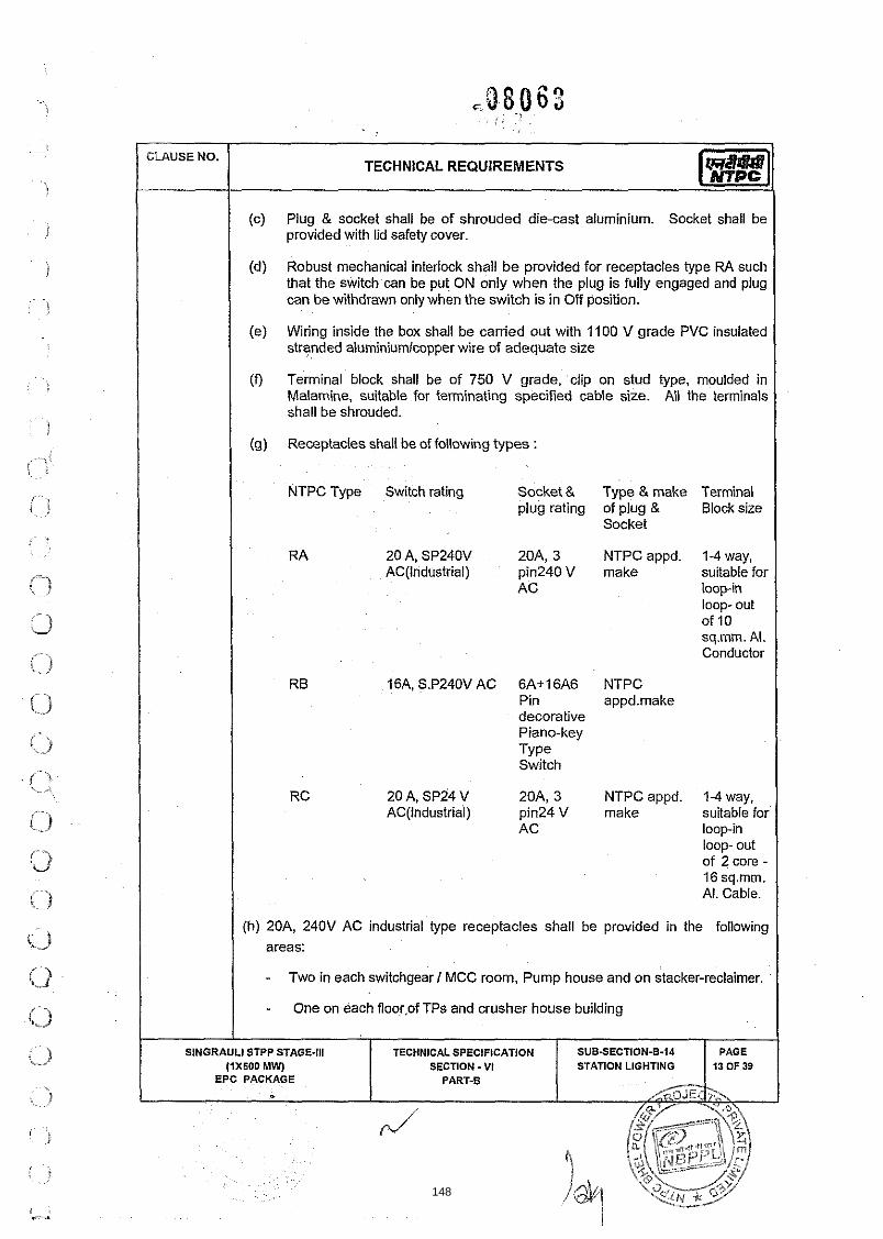
TECHNICAL REQUIREMENTS
(c) Plug & socket shall be of shrouded die-cast aluminium. Socket shall be provided with lid safety cover.
(d) Robust mechanical interlock shall b e provided for receptacles type W\ such that the switch can be put ON only when the plug is fully engaged and plug can be withdrawn only when the switch is in Off position.
(e) Wiring inside the box shall be carried out with 1100 V grade PVC insulated stranded aluminiumlcopper wire of adequate size I
(0 Tenninal block shall be of 750 V grade, clip on stud type, moulded in Malamine, suitable for terminating specified cable size. All the terminals shall be shrouded.
(g) Receptacles shall be of following types : I NTPC Type Switch rating Socket & Type & make Terminal
plug rating of plug & Block size Socket
RA 20 A, SP240V 20A, 3 NTPC appd. 1-4 way, AC(lndustria1) pin240V make suitable for
AC loop-in loop- out of 10 sq.mm. Al. Conductor
RB 16A, S.P240V AC 6A+16A6 NTPC Pin appd.make decorative Piano-key Type Switch
RC 20 A, SP24 V 20A, 3 NTPC appd. 1-4 way, AC(lndustria1) pin24 V make suitable for
AC loopin loop- out of 2 core - 16 sq.mm. Al. Cable.
(h) 20A, 240V AC industrial type receptacles shall be provided in the following areas:
- Two in each switchgear I MCC room, Pump house and on stacker-reclaimer. I - One on each floor,of TPs and crusher house building I
148

- At 30m interval on both sides of the conveyor gallery and track hopper shed. At 50m interval on one side of yard conveyor
(i) IOA, 24V AC receptacles with IP55 DOP shall be provided in the following areas.
- One in each switchgear 1 MCC room, Pump house and on stacker-reclaimer.
- One on each floor of TPs and crusher house building
- It shall not be possible to insert 24V plug into 240V receptacle
These receptacles shall be energized from light~ng pane1.Maximum three receptacles shall be connected in one circuit.
Junction boxes
Junction box shall be made of fire retardant material. Material of JB shall be Thermoplastic or thermosetting or FRP type. The box shall be provided with the terminal blocks, mounting bracket and screws etc. The cable entry shall be through galvanized steel conduits of 20mrn diameter. The JB shall have suitable knockouts on four sides of conduits or drilled during execution. The JB shall be suitable for surface mounbng on ceilinglstructures. The JB cover shall be either hinged or chain supported. The JB shall be of grey color RAL 7035. All the metal parts shall be corrosion protected. Terminal block shall be stud type suitable for loop-in loop-out of up to 2 numbers of 10 sq.mm aluminium conductors and tap off of 1.5 sq. mm copper conductors. The JB shall have internal provision to maintain earth continuity of connected metal conduits and shall have provision for lighting fixture earthing. Junction box surface should be such that it is free from crazings, blisterings, wrinkling, colour blotslstriat~ons. There should not be any mending or repair of surface. JB's will be provided with captlve screws so that screws don't fall off when cover is opened. JB's mounting brackets should be of powder coated MS. Type test reports shall be furnished for the following Type tests.
(a) Impact resistance for impact energy of 2 Joules (IK07) as per BS EN50102
(b) Thermal ageing at 70deg C for 96 hours as per lEC60068-2-2Bb.
(c) Class of protection shall be IP 55.
(d) HV test.
11. NTPC TypeNo
Terminal block size Remarks
SECTION - VI STATION LIGHTING
J F F 1No-2 way, suitable for loop-in loop-out upto 2 numbers 10 sq.mm. aluminum conductor and tap off o f 1.5 Sq. mm. Copper conductor
149

TECHNICAL REQUIREMENTS
Junction boxes for street lighting poles and lighting masts shall be made of 1.6 mm. th~ck CRCA sheet steel. The door shall be hinged and the box shall be gasketed to achieve IP: 55 degree of protection. The box shall be hot dip galvanised provided with HRC fuse units, terminal block for loop in loop out, earthing terminals, mounting brackets, allen keys with bolts as locking as arrangement, cable gland plate at bottom etc. Wiring shall be carried out with 1100 V grade PVC insulated flexible copper wire of adequate size. Top of the box shall be arranged to slope towards n?ar side of the junction box. The junction box shall be of following type :
Component I Terminal Block Description
JB-S 1-6 A HRC fuse &I- 1-4 way, stud type suitable for netural Link loop-in loop out
4CXlGSq.mm.Al. cable& tap off 2Cx2.5Sq.mm.c~. cable
JB-MI ( to be provided as part of lighting mast )
1-4 way stud type suitable for loop-in loop out of 4C x 16 sq.mm. Al. cable &tap off of 3 nos. 2C x 2.5 Sq.mm cu. wire
Fuses shall be HRC, plug in type, complete with bakelite fuse fittings. ONlOFF switch shall be TPN, rotary type, load break suit able for 415V AC system.
Terminal blocks shall be of 750 V grade clip-on, stud type moulded in melamine. The terminals shall be shrouded and numbered.
I Conduits, Fittings & Accessories I Conduits, Pipes and Accessories Galvanised heavy duty steel conduits for normal area and galvanised heavy duty steel conduits with an additional epoxy coating of minimum 50 microns thickness for corrosive area shall be offered. Alternatively glass reinforced epoxy conduits with comparable compressive and impact strength with that of heavy duty steel conduits may be offered.
I Rigid Steel Conduits I (a.) Rigid steel conduits shall be heavy duty type, hot dip galvanised conforming to
IS : 9537 Part-l & II shall be suitable for heavy mechanical stresses, threaded on both sides and threaded length shall be protected by zinc rich paint.
--Conduits shall be smooth from inside and outside. It shall be possible to pass wooden ball in a straight length of conduit. Diameter of ball shall be 2 mm less than the internal dia of conduit. Conduit shall be plugged by PVC caps for storage and transportation.
i > SlNGRAULl STPP STAGE-Ill TECHNICAL SPECIFICATION SUB-SECTION-8-14 ,.. SECTION - V I STATION LIGHTING EPC PACKAGE
; 1
> : i
( !
, - 150
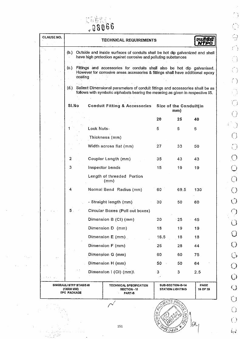
(b.) Outside and inside surfaces of conduits shall be hot dip galvanized and shall have high protection against corrosive and polluting substances
CLAUSE NO.
(c.) Fittings and accessories for conduits shall also be hot dip galvanised. However for corrosive areas accessories & fittings shall have additional epoxy coating
TECHNICAL REQUIREMENTS
(d.) Salient Dimensional parameters of conduit fittings and accessories shall be as follows with symbolic alphabets bearing the meaning as given in respective IS.
SI.No Conduit Fi t t ing 8 Accessories Size o f the Conduit( ln
mm)
20 25 40
1 Lock Nuts- 5 5 5
Thickness (mm)
Width across flat (mm) 27 33 50
2 Coupler Length (rnm) 35 4 3 43
3 Inspector bends 15 19 19
Length of threaded Portion (rnm)
4 Normal Bend Radius (mm) 60 69.5 130
- Straight length (mm) 3 0 50 60
5 Circular Boxes (Pull out boxes)
Dimension B (Ci) (rnm) 20 25 45
Dimension D (mm) 18 19 19
Dimension E (mrn)
Dimension F (mrn)
I I Dimension G (mrn) 60 60 75
I I Dimension H (rnrn) 50 50 64
Dimension I (CI) (mm)\ 3 3 2.5
SlNGRAULl STPP STAGE-Ill (iX500 MW)
EPC PACKAGE
TECHNICAL SPECIFICATION SECTION - VI
PART-B
SUB-SECTION-B-14 STATION LIGHTING
PAGE 16 OF 39
151

- TECHNICAL REQUIREMENTS
1 Saddles I Dimension A (CI) (mm) 53 60 65
Dimension B (CI) (mm) 20 25 40
Dimension C (CI) (mm) 0.71 0.71 1.22 J
D~mension D (CI) (mm) 4 4 5
Dimension E (CI) (mm) 15.5 18 20
Dimension G (CI) (mm) 40 46 67
Flexible Steel Conduits
Flex~ble condult shall be water proof and rust proof made of heat resistant lead coated steel. Conduit diameter shall be uniform throughout its length. Internal surface of the conduit shall be free form burrs and sharp edges. Conduit shall be complete w~th necessary accessories for proper termination of the conduit with junction boxes and lighting fixtures.
Pull-out Boxes
Pull out boxes shall be provided at approximately 6 (six) metre interval in a conduit run .Boxes shall be suitable for mounting on Walls, Columns, Structures, etc. The bolts, nuts, screws, etc. required for the installation shall be included in the installation rates. Pull-out boxes shall have cover with screw and shall be provided with good quality gasket lining. Pull out boxes used outdoor shall be weather proof type suitable for IP: 55 degree of protection and those used indoor shall be suitable for IP: 52 degree of protection. Pull out box & its cover shall be hot dip galvanised. Bidder shall include the cost of pull out boxes in the installation rates for condu~ts & accessories.
Lishtina Wires
Lighting Poles I The poles shall be of ERW tubes of specified lengths, stepped tubular or swaged tubular and joined together. Lighting poles shall be painted with two coats of red Oxide and Zinc chromate in Synthetic cpmpound primer on the exposed outside
152

surface and with Bituminous paint all along the inside of the pole and outside poFtion which shall be embedded in foundation at manufacturing stage.
- -
Poles shall be smooth cylindrical and swan neck or straight as specified. Poles shall be complete with base plates & taper plugs, and necessary pipe reducerltixing brackets for fixing the light fixture as per drawing enclosed.
CLAUSE NO.
Lighting poles shall be of following types I
TECHNICAL REQUIREMENTS
NTPC Overal l Overhang Appl ica t ion Pole projection
Type No. Height
I I I
A 1 l l m 1.2m For single street Light fixture.
13m 1 .Em For single street Light fixture.
1 .Em With double arm for two street Light fixtures. 1 I
1 1 C1 I TIm 1 I For flood light fixture I C 2 13m - For flood light fixture
E 1 4m For post top lanterns.
1 1 MAST I 30m I I For flood light fixture I Lighting Masts
Lighting Mast shall be of continuously tapered bo~ygonai cross section hot dip galvanised presenting a pleasing appearance. The Mast shall be of 30M height with lantern carriage to enable raisingllowering for ease of maintenance, including the Head Frame, Double Drum Winch, continuous stainless steel wire rope, in built power tool, luminaires, suitable aviation warning light, lightning alongwith necessary power cables within the mast. The mast shall be delivered only in three1 four sections & shall be jo~ned together by slip stressed fit method at site. No site welding or bolted joints shall be done on the mast.
a) The Mast together with the fixtures shall be capable of withstanding the appropriate wind loads as per lS:875. The Mast shall be fabricated from special steel plates conforming to BS-EN10-025 and folded to form a polygonal section.
b, Lantern Carriage shall be fabricated suitably and hot dip galvanised for fixing and holding flood light fixtures and their control gear boxes. Lantern carriage shall be provided with 16 nos. twin 400W HPSV flood light fixtures
SINGRAULI STPP STAGE-111 TECHNICAL SPECIFICATION SUBSECTION-614 SECTION - VI STATION LIGHTING
153

C, Carriage shall be provided with JB type MI to facilitate interconnection to lighting fixtures.
d) A suitable winch arrangement shall be provided to lower & raise the Lantern Carriage Assembly. Winch shall be of completely self sustaining type without the need for brake shoe, springs or clutches. The min. working load shall not be less than 750 kg. The winch drum shall be grooved to ensure perfect seat for stable and tidy rope lay with no chances for slippage. Winch shall be operated by an internally mounted three phase motorlpower tool with necessary reduction gear mechanism. A handle for manual operation of winch shall also be provided. An adequate door opening shall be provided at the base of the Mast.
e) Lighting mast shall be complete in all respect and shall be provided with feeder pillar complete with powerlcontrol circuit along with 32A TPN MCB, contactors, timers, MCB's, motor protections (OIL & single phase), startistop PB with indication lamps. Feeder pillar shall have provision of receiving 4Cx16 sq mm. cable. Feeder pillar shall be made up of 1.6 mm CRCA sheet steel with IP 55 degree of protection & shall be powder coated. All necessary cables between feeder pillar & JBMI & between JBMI & fixtures are also included in the scope of mast and same shall be of proven design
f) A finial (heavy duty, hot dip galvanized) with a height of 1.2M shall be provided at the centre of the head frame for providing lighting protection. It shall be solidly bolted with the mast body to provide a conducting path. Earthing terminals shall be provided for earthing the mast.
1 g) Lighting Mast shall also be provided with suitable aviation warning lights
h) Minimum six(6) nos of lighting masts shall be provided for coal stockyard illumination
Maintenance Ladders
Tower Ladder (TL)
I The ladder shall be extension type comprising of a platform with tool tray. ladder structure, MS trolley with rubber wheel and swivel casters, hand winch with wire rope, pawls and pulley for adjusting the expanding section of ladder in intermediate heights etc.
ii) The platform shall be designed for accommodation of one man and allow ample foot room for user to use both hands to attend over head lighting.
I iii) Closed height shall be 6 m and extended height shall be 10 m. The trolley base shall be min. 1.8 m x 1.2 m.
SINGRAULl STPP STAGE-Ill (1x500 MW)
EPC PACKAGE
TECHNICAL SPECIFICATION SECTION - VI
PART-B - SUBSECTION-8-14 STATION LIGHTING
PAGE 19 OF39
154

CLAUSE NO. TECHNICAL REQUIREMENTS
I I Self Supporting Ladder(SL1) I Ladder shall be extension type complete with stool type ladder, rope, pulley, safety lock, rubber shoes at bottom to obviate slipping & damage to surface etc. The ladder shall have closed height of 6 m and extended height of 10 m.
Step Ladder (SL2)
1 The ladder shall be complete with corrugated top platform, front and rear legs, cross braces and ribbed steps. The ladder shall have overall height of 2. lml 3.6m.
2 The ladders shall be manufactured from high tensile aluminium alloy free form twists. The sides of ladder shall be made of C section I channels. Rungs shall be made of non slip corrugated tubinglchannel at 250 mm interval. Width of the rungs shall be min. 400 mm.
1 4.21.00 I Painting
I. All sheet steel work for lighting panels, lighting fixtures etc. shall be treated in tanks in accordance with IS 6005. Degreasing shall be done by alkaline cleaning. Rust and scale shall be removed by pickling with acid. Afler pickPng, the parts shall be washed in running water and rinsed in slightly alkaline hot water and dried. Afler phosphattng the surfaces shall be rinsed and passivated. Treatment as per IS:6005 shall be provided followed by powder painting with final shade of RAL9002 shall be done.
II. All welds, bolt holders, wnduiVcable entry holes etc. made during installation shall be wire brushed and touched up wtth metal primer of lead oxide and zinc chromate in synthetic medium
GALVANISING
I. Galvanizing of switch boxes, junction boxes, conduits, other steel components and accessories shall conform to IS: 2629 and IS: 2633. Galvanizing shall be uniform, clean, smooth, continuous and free from acid spots. Should the galvanizing of the samples be found defective, the entire batch of steel shall have to be regalvanised at Contractor's cost afler pickling.
I The amount of zinc deposit over threaded portion of bolts, nuts, screws and washers shall be as per IS: 1367 (Part-13). The removal of extra zinc on threaded portion of components shall be carefully done to ensure that the threads shall have the required zinc coating on them
INSTALLATION
Lighting Ftxture Installation
1. Lighting fixture of appropriate type as per lighting layout drawings shall be installed by the Contractor. The type of mounting arrangement of fixtures shall be selected from the typical arrangement shown in the attached
~ . . drawings. . . The type of mounting will generally be indicated , .on the layout I
SlNGRAULl STPP STAGE-Ill
I (1x600 MW)
EPC PACKAGE
TECHNICAL SPECIFICATION SECTION - V I
PART-8
SUBSECTION-6-14 STATION LIGHTING
PAGE 20 OF 39
155

CLAUSE NO. TECHNICAL REQUIREMENTS IWlj
drawings. The exact mounting will be decided at site depending upon the actual spacelother facilities available at site. Lighting fixtures shall not be suspended directly from the junction box in the main conduit run.
Wooden plugs in walls and ceilings for fixing of lighting fixtures and accessories are not acceptable. A suitable fool-proof method preferably using nylon raw1 plug for fixing these shall be offered and this shall be subject to the Employer's approval.
Lighting fixtures installed onlunder platforms i? boiler arealpedestals (such as TG pedestals) and other structures which are subject to vibrations shall be provided with suitable vibration damperslrubber cushions to minimise the variations reaching the lighting fixtures. The arrangement shall be subject to Employer's approval.
The bracket for mounting the lighting fixtures on boiler platforms shall be fabricated at site using 40 mm dia. conduit with a reducing socket to suit the fixture and clamped to the hand rails. However, the clamping of these conduits at points of large vibrations should be avoided. The fixing shall be strong enough to withstand vibration and wind velocity. If a roof over the platform is available, the fixture will be pendant mounted and supported to the structural~members of the platform above
Flood lights shall be mounted on steel base of structures/walls Icolumnslmastslpoles. Fixing slots shall be provided to turn the fixture by about 5 deg. on both sides. Bolts shall be tightened with spring washers. Terminal connection to the flood lights shall be made through flexible- conduits
In the rooms where false ceiling is provided the lighting fixtures shall be supported separately by false ceiling grid or roof over false ceiling and not by the ceiling board.
The installation of lighting fixtures shall include the supply of all steel brackets, channels, angles, supporting, & anchoring material and hardware, steel bracketslhangers for bridging the gap above false ceiling and other accessories
To distinguish emergency AC fixtures from normal AC fixtures, red painted circular mark of lcm. Dia. shall be provided on emergency fixtures
The self contained emergency lighting fixtures shall generally be installed in off site areas on wallslcolumnslstructure as required at slte.
Fan clamps shall be rigid enough and shall be made to suit the position suitable for reinforced concrete roofs or steel structures as required. Suspension rod shall be of adequate strength to withstand the dead and impact forces imposed on it.
SlNGRAULl STPP STAGE-Ill TECHNICAL SPECIFICATION SUB-SECTlON.6-14 (1x500 MW) SECTION - VI STATDN LIGHTING
EPC PACKAGE PART-8
156

I I "' Ballasts which, produce humming sound after commissioning at site shall be replaced at free of cost by the contractor I All steel installation accessories shall be brushed-up and shall be painted with red lead primer followed by two coats of aluminium paintlenamei paint to the satisfaction of Project manager
13. The installation price of conduit wherever required for fixture mounting shall be payable separately.
1 1.01.00 1 Lighting Panel Installation I Lighting panel shall be mounted at a height of 1200 mm from floor level unless otherwise specifically mentioned) on wallslcolumnslsteel structures as indicated in the drawings by fastening to suitable studs.
1 5.01.00 / Installation of Switch Boxes, Receptacles and Junction Boxes I I. Switch boxes, Receptacles and Junction boxes shall be adequately
suppo~tedlmounted on walllcolumn by means of anchor fastenerslexpandable bolts or shall be mounted on anglelplate or other structural supports fixed to floorlwalllceiling.
II. In office areas and control rooms, switch boxes shall be flush mounted in wall and junction boxes shall be recess mounted.
Ill. Mounting height of switch boxes and receptacles from floor level shall be as follows :
Item Mounting Height Location
(a) Light control switch 1500 mm box
(b) 20 A Receptacles 500 mm Indoor location
I I (c) 611 6 A Receptacles 500 mm Indoor location
I 20 A Receptacles 900 mm Outdoor location I IV. Necessary conduit lcable entry shall be made by drillinglpunching during
installation depending on the requirement. No gas cutting shall be used.
. . . . .
SECTION - VI EPC PACKAGE
I I
157

Conduit Installation
1. In corrosive areas like Battery room, water treatment plant, etc. only epoxy coated GI conduit and accessories shall be installed for wiring purpose.
2. All accessorieslfittings required for making the installation complete shall include tees, tees, elbows, check nuts, brass or galvanised steel end caps, pull boxes, saddles, spacers and required supporting steel work.
3. Exposed conduits shall run in straight lines parallel to bullding colurnnslbeams and walls. Conduits shall be fixed by using metallic saddleslclarnp secured to suitable nylon raw1 plugs with screws or secured to the building steel at an interval of not more than 1 metre, but either side of couplers or bends or similar fittings. Saddleslclamps shall be fixed at a distance of 30 cm from the centre of such fittings.
4. In rooms with false ceiling, conduits shall be embedded in the wall. Embedded conduits shall be securely fixed in position to preclude any movement. For embedded conduits fixing of standard bends or elbows shall be avoided and all curves shall be made bending the conduits itself. Spacing of embedded conduit shall be such as to permit flow of mortar between them and in no case shall be less than 40 mm. Embedded conduits shall have a minimum mortar cover of 50 mm. Posit~oning and ensuring proper alignment during concreting by other agencies shall be the responsibility of the contractor.
All openings in the floorlwalllceiling etc, made for conduit installation shall be sealed and made water proof.
6. Size of conduit shall be selected considering no. of wires drawn in line with IS : 732 and as indicated below.
Size of the Wire Size of the Conduit (in mm)
Maximum Number of Wire
1.5 Sq.mm. 5 10 21
SINGRAULI STPP STAGE-I11 TECHNICAL SPECIFICATION SUBSECTION-6-14 (1x500 MW SECTION - VI STATION LIGHTING
EPC PACKAGE PART.5
158

For long conduit runs pull out boxes shall be provided at suitable intervals not exceeding 6 m to faciliate wiring. However pull out boxes need not to be provided whereverjunction box exists in circuit.
CLAUSE NO.
Conduits shall be securely terminated at lightlng panels, switch boxes, junction boxesllighting fixtures by proper fastening wlth a lock nut on inside and outside. The number of conduits terminating at lighting panel shall not exceed the permissible number considering the glanding area of lighting panel. Conduit termination shall be made water and vermin proof.
TECHNICAL REQUIREMENTS
Conduit lengths shall be jointed by screwed couplers. Runn~ng thread equal to twice the length of coupl~ng shall be provided on any one length to facilitate easy dismantling. The contractor shall have at site die for threading conduit. All field threaded ends shall be reamed after threading and anti-corrosive paint applied. Conduits shall be cleanly cut. The cut ends shall be within three (3) degree of square
with a conduit axis. Cut ends shall be reamed and all burrs and sharp edges removed. Conduit joints and connections shall be made thoroughly water-tight and rust-proof by application of the thread compound which will not insulate the joints.
Conduits shall be kept, wherever possible, at least 300 mm away from hot pipes, heating device etc
The entire metallic conduit system whether embedded or exposed shall be electrically continuous and thoroughly grounded. G.I. Pull wire of adequate size shall be laid in all conduits before installation
All conduits installed outdoor shali be sloped towards pull boxes, hand holeslmanholes for drainage. Low points of condu~ts not terminating in pull boxes, hand holeslmanholes shall be provided with weep holes for drainage. Care shall be taken to see that no rough edge is left around the weep holes. Where no provision for drainage can be made, both ends of conduit shall be sealed after cable is laid through. M~nimum slope of 1 in 400 shall be provided.
Each conduit run shall be marked with its designation asindicated on the drawings. identifications shall be by means of painting so located that each run of conduit is readily identified at each end. Where conduits terminate at panels, switch boxes, junction boxes, or other enclosures, the designations shall also be painted on the inside of the enclosure adjacent to the conduits. ~'
Lighting PolelMast Installation
1. installation of poles and masts shall include construction of required foundation.
2. For lighting Poles M 15 PCC foundation shall be made for planting depth of
SECTION - VI
159

1 I minimum 116TH of the pole height. I I
CLAUSE NO.
Junction box type 'JB-S' shall be fixed to the pole with 'U' clamps for wiring lighting terminating the cables. 25 mm dia holes shall be made on poles for wiring of lighting fixtures from junction box
TECHNICAL REQUIREMENTS
Junction box type 'JB-M' shall be fixed to the mast with clamps for terminating the cables. Junction box type 'MI' Shall be fixed on mast platform for fixtures.
Flood light fixtures shall be mounted on galvanised M.S base making use of shop drilled holes or by suitable clamps. No cutting or drilling of galvanised structure is permitted. For mounting flood llght fixtures on poles, required supporting frame work shall be made.
For loop-in loop out of the cables, 50 mm dia G.I. conduits with minimum 500 mm radius shall be laid along pole mast embedding in PCC foundation. Cost of supply and installation of 50 mm dia G.I. conduit is included the installation cost of pole.
7. G.S. Earthing bolt (Size M6) shall be welded to polelmast for earthing polelmast. Fixture and junction box shall be inter connected by earthing wire to polelmast earthing bolt. Earth connection between polelmast and earth electrode shall be made by 25x3 mm GS flat. Welding between GS flat and electrode shall be provided with protective coating
8. 2 C X 2.5 mm2 cable from street lighting pole JB to the lighting fixture shall be supplied laid and terminated by the Contractor. The cost of this work shall be included in the installation price of lighting polelmast.
I I 9. Lighting poles shall be painted with two coats of aluminum paint after completion of installation
Wiring Installation
Wiring installation of various areas between lighting panels, switch boxes, junction boxes, fixtures, fans, receptacles etc. shall be done in G.I. conduits. However, in fuel oil handing pump house, wiring installation shall be carried out with unarmoured cables to be routed inside the conduits
Lighting fixtures shall generally be group controlled directly from lighting panel. However, in office areas, control shall be provided through switch boxes.
A.C. normal, AC emergency and DC system wiring shall run throughout in separate conduits. Wires of different phase shall run in different conduits. However wires of same phase but of different circuit shall run in same conduit.
A junction box with two way terminal block of suitable size shall be provided near the fixture except the fluorescent fixtures and last fixture in a circuit for loop -in-loop-out and T-off connection
SECTION - VI STATION LIGHTING
160

1 505.05 1 All wires in a conduit shall be drawn simultaneously. No subsequent drawing is permissible. Call bell wiring in office area shall also be done by the Contractor
CLAUSE NO. TECHNICAL REQUIREMENTS
Receptacles and lighting circuit shall be fed from different circuits. The switch controlling these circuits shall be on the phase wire of the circuits
5.05.06
Wiring shall be spliced only at junction boxeslterminal blocks. Maximum two wires shall be connected at each terminal. In vertical run of conduit the wires shall be suitably supported by means of woodenlhard rubber plugs at each pullljunction box.
Wires shall not be pulled through more than two equivalent 90 degree bends in a single circuit run. Wherever required, suitable conduit junction boxeslpull boxes shall be provided.
For group controlled lighting fixtures, single phase receptacles and switch boxes, aluminium wire of 4/6/10 sq. mm. shall be used from lighting panel as clrcuit wiring. as applicable. However, T-off connection to the lighting fixture shall be done by 1.5 sq.mm. copper.
The wiring between switch box and lighting fixtures and fans shall be done by 1.5 sq.mm. copper wire.
All lighting wires shall be crimped using solderless crimping type tinned copper lugs suitable for the specified type of terminal block.
Ceiling Fans and Regulators
1. The contractor shall install the ceiling fans and regulators at the locations shown in the relevant drawings. The exact locations will however, be decided at site in consultation with Project manager.
2. The fan regulator shall be mounted on the lighting control switch box provided in that area.
3. Hook along with rubber bush shall be supplied and grouted in ceiling for mounting the fan. All necessary, material and hardware for installation shall be supplied by the Contractor.
. .
Foundation & Civil Works
I . Foundations, for Street lighting Poles/Flood Lighting Poles, lighting masts, panel foundation and other civil work including supply of cement, steel and other material as per relevant drawings and specification clauses shall be provided by the contractor.
2. All foundation drawings shall be subject to the ~mployer's approval. However, it shall be the responsibility of the Contractor to check these foundations before commencement . , of installation to ensure their suitability.' .
3. AII .final 'adjustment of foundation' levels, chipping and dressing of foundation surfaces, setting and grouting of anchor bolts, sills, inserts
. . . . . . .
SlNGRAULl STPP STAGE-Ill TECHNICAL SPECIFICATION SUBSECTION-6-14 SECTION - VI STATION LIGHTING fob
EPC PACKAGE
i ) -,
1 .!
' s 3
.-- 161

and fastening devices shall be carried out by the wntractor including minor modification of civil work as may be required for installation .
/ C* VLa t NO.
4. Any cutting of masonary/concrete work, which is necessary, shall be done by the contractor at his own cost and shall be made good to match the original work. The wntractor shall obtain approval of the Project manager before proceeding with any cutting of rnasonarylconcrete work.
5. The Contractor shall perform all excavation and backfilling as required for ground connections and casting foundations.
TECHNICAL REQUIREMENTS
6. Excavation shall be performed upto the required depth. Such sheeting and shorting shall be done as may be necessary for protection of the wall.
1 --- I
7. The contractor shall make use of his own arrangement for pumping out any water that may be accumulated in the excavation:
8. All excavation shall be backfilled to the original level with good consolidation.
Steel Fabrication
1. The steel structures supplied and fabricated by the contractor shall be made from standard quality steel sectionslflatslplates. The steel structures fabricated shall be free from defects, cleaned of rust, grease, oil etc., and sharp edges shall be removed.
I 2. The welds shall be wire brushed or cleaned otherwise. The holes shall be touched up with metal primer. I
3. All steel fabrications shall be painted with two coats of metals primer (lead oxide and zinc chromate in synthetic medium) followed by the two coats ~f aluminium paint.
EARTHING OF LIGHTING SYSTEM . .
Lighting panels, etc. shall be earthed by two separate and distinct connections with earthing system. Switch boxes, junction boxes, lighting fixtures, fans, single phase receptacles etc. shall be earthed by means of separate earth continuity conductor.
T h e earth continuity conductor 14 SWG GI wire shall be run alongwith each conduit run. Cable armours shall be connected to earthing system at both the ends.
Earthing conductors shall be free from pitting laminations, rust scale and othe mechanical defects. The various sizes of earthing conductor for various items shall be as follows :
I
SlNGRAULl STPP STAGE-Ill (iX500 MW)
EPC PACKAGE
TECHNICAL SPECIFICATION SECTION - VI
PART-8
SUBSECTION.814 STATION LIGHTING
PAGE 27 OF 39
162

163
TECHNICAL REQUIREMENTS
I third party lab or in presence of clienffowners representative and submit the reports for approval. I All acceptance and routine tests as per the specification and relevant standards shall be carried out. Charges for these shall be deemed to be included in fhe equipment price.
The type test reports once approved for any projects shall be treated as reference. For subsequent projects of NTPC, an endorsement sheet will be furnished by the manufacturer confirming similarity and "No design change". Minor changes if any shall be highlighted on the endorsement sheet.
Selection of samples for type test, acceptance test & routine test and acceptance criteria for all the items shall be as per relevant l.S
Type test repoits of the following items as per relevant standards shall be submitted for approval.
I 1 SL NO. DESCRIPTION I I 1 i.
Lighting panel of each type (Degree of Protection) I ii. Junction Box of each type
iii. Receptacles of each rating (Degree of Protection)
Acceptance Test and Routine Test
All lighting fixtures, lamps and other items shall be subjected to acceptance and routine test, as per relevant specified standards.
Junction boxes, switch boxes, receptacle enclosure etc. shall be subjected to physical and dimensional checks.
Galvanizing Tests
The quality of galvanizing shall be smooth, continuous, free from flux stains and shall be inspected visually.
1 8.08.02 1 In addition following tests shall be conducted as acceptance tests. I (a,) Uniformity of coating - The coating of any article shall withstand four lminute
dips in standard copper sulphate solution without the formation of an adherent red spot of metallic copper upon the basic metal.
(b.) The quality of cadmiumhinc plating on items with screw threads shall be free from visible defects such as unplated areas, blisters and modules and shall be . . inspected visually. . .
. ~.
I
SlNGRAULl STPP STAGE-Ill (1x600 MW)
EPC PACKAGE
TECHNICAL SPECIFICATION SECTION - V I
PART-B
SUBSECTION-6-14 STATION LIGHTING
- PAGE
29 OF 39
164

(c.) In addition, the plating thickness shall be determined microscopically/ chemically or electronically.
CLAUSE NO.
1 9.00.00 1 COMMISSIONING CHECKS I
TECHNICAL REQUIREMENTS
1. On completion of installation work, the Contractor shall request the Project manager for inspection and test with minimum of fourteen (14) days advance notice.
2. The Project manager shall arrange for joint inspection of the installation for completeness and correctness of the work. Any defect pointed out during such inspection shall be promptly rectified by the Contractor.
I I Project manager. I 3. The installation shall be then tested and commissioned in presence of the
I I 4. The contractor shall provide all, men material and equipment required to carry out the tests. I
5. All rectifications, repair or adjustment work found necessary during inspection, testing and commissioning shall be carried out by the Contractor without any extra cost. The handing over the lighting installation shall be effected only after the receipt of written instruction from the Employerlhis authorized representative.
6. The testing shall be done in accordance with the applicable Indian Standards and codes of practices. The following tests shall be specifically carried out for all lighting installation.
(a) Insulation Resistance.
(b) Testing of earth continuity path. I (c) Polarity test of single phase switches. I (d) Functional checks. I
7. The lighting circuits shall be tested in the following manner: I (a) - All switches ON and consuming .devices in circuit, both poles
connected together to obtain resistance to earth. I (b) .Insulation resistance between poles with lamps and other consuming
devices removed and switches ON.
SECTION - VI STATION LIGHTING
165

CLAUSE NO. TECHNICAL REQUIREMENTS
heat resistant glass, neoprene1 synthetic gasket, MS powder coated wire guard,
incandescent down
aluminium reflector comprising of lamp, galvanized I Powder wated mounting
MS powder coated
gasket, lamp, etc. complying to IP 65
166

CLAUSE NO.
SlNGRAULl
TECHNICAL REQUIREMENTS
Type No.
F B I
FC
FD
STPP STAGE-Ill
MAIN PLANT TURNKEY PACKAGE
- PART-B
Description
coated, CRCA cover plate powder mated, fitted with lamp, electronic ballast, etc.
Single 28 watts T5 type fluorescent fixture of ra~l type compris~ng CRCA channel powder coated, CRCA cover plate powder coated, fitted wlth lamp, electronic ballast, etc.
Twtn 28 watts T5 type fluorescent fixture, totally enclosed, corrosion proof, comprising ABSIPolycarbonate Canopy, CRCA sheet steel gear tray finlshed stove enameled white. Polycarbonate cover, stainless steel toggle clips & neoprene1 synthetic rubber gasket lin~ng, fitted wlth lamp. electronic ballast, etc. complying to IP 52 class of protection.
Tw~n 28 W T5 type decoratwe type mi l~or optic fluorescent fixture comprising extruded aluminium powder coated body, with mirror optic high
TECHNICAL
Type of Installation
Surface I pendent mounting
Surface I pendent mounting
Surface I pendent mounting
.
SPECIFICATION (1x600 MW) STATION LIGHTING SECTION -VI
Phiiips Type
TMS 1221 128HF
TCW 0971228 HF OR TDC 101228 HF
TCS 3981 228 HF
32 OF 33
Annexure
Bajaj Type
BTlR 128
BTI 228 FG
BTSM 228
SUB-SECTION-B-I4
- A
Crompton Type
T5GP28 EB
T51PFC 228 EB
T5CXxx22 8 EB
PAGE
167

~. . : i , ,
~. . . i j
< : , ,
: 1. ..,
C I . ; ', ?
, .. ( 1 u.,
i:!
t:- ,?
(~3 {'J
<)
c -. j
ili
LJ
; .I
: i
I
C 3 8 8 8 3 Cr - U S E NO.
TECHNICAL REQUIREMENTS - --
Annexure - A
Type Description Type of Philips Bajaj Crompton No. Installation Type Type Type
purity aluminium side reflectorllouvre fitted with lamp, electronic ballast
FH Twin 36 W, flame Surface I BJFFT EXTL 240 ** proof fluorescent pendent L240 lighting fixtures mounting suitable for division 2 hazardous area.
FI Twin 28 W T5 type Surface I TMS BTlV T5RSF228 industrial trough pendent 12Z228 228 EB type, fluorescent mounting HF & fixture comprising GMS single piece CRCA 1221228 channel, CRCA R wver plate powder coated &with MS reflector powder mated, fitted with lamp, electronic ballast, etc.
FI1 Single 28 W T5 type Surface I TMS BTlV T5RSF28 industrial trough pendent 12Z128 128 EB type, fluorescent mounting HF & fixture comprising GMS single piece CRCA 1221128 channel, CRCA R wver plate powder coated & with MS reflector powder
' . coated, fitted with lamp, electronic ballast, etc.
FI-1D Same as FI-1 but Surface Similar to -do- -do- with dimmable mounting1 FI-I ballast instead of indirect normal electronic . . lighting ballast
. .
FR 1 Twin 28 W T5 type Recess TBS BTLM T5FA228 mirror optics type mounting 6691228 228 EB fluorescent fixture (false ' ' M 2 HF
SlNGRAULl STPP STAGE-Ill TECHNICAL SPECIFICATION SUB-SECTION-6.14 PAGE (1x600 MW) SECTION - V I STATION LIGHTING 33 OF 39
MAIN PLANT TURNKEY PACKAGE PART-B
168

Annexure - A
comprising CRCA sheet steel housing powder mated, high
SlNGRAULl STPP STAGE-Ill (1x600 MW] SECTION - VI STATION LIGHTING
MAIN PLANT TURNKEY PACKAGE
CLAUSE NO. TECHNICAL REQUIREMENTS
169

fitted with lamp and integral control gear box of die cast
powder coated gray outside, aluminium
~ b b e r gasket etc., fitted with lamp and
enclosure, finished with powder coated grey outside and
170

I Annexure - A
I Description
comprising aluminim reflector, control gear housing, safety chain finished with powder coated grey outside, forged eye hook etc. fitted with lamp, ballast, ignitor , capacitor, neoprenel synthetic gasket, etc. !
Type of Installation
250 W integral type. Suspension high bay HPSV mounting lighting fixture similar to SH 1. !
Philips TY Pe
Bajaj Type
Crompton r /I SH 3 I 400 W integral Wpe. I Suspension / HPK I BJHBl 1 SHBxx401
high bay HPSV-. lighting fixture similar to SH 1.
comprising one piece cast aluminium housing for lamp & control gear compartment powder coated, with aluminium reflectors, clear acrylic bowl with hinging arrangement, neoprenel synthetic gasket, etc. fitted with lamp, ballast, ignitor, capacitor, etc. complying to IP 54 class of
mounting
I I I I I
mounting
SS 1
11 1 protection. I I I / I
150 W HPSV Street lighting fixture
SlNGRAULl STPP STAGE-Ill (rxsoo MW)
MAIN PLANTNRNKEY PACKAGE
Street light pole
, ( )
TECHNICAL SPECIFICATION SECTION -VI
PART-B
SGP 4011150
SUB-SECTION-6-14 STATION LIGHTING
BGES T 150
SSGNxxl 5iH
PAGE 3 6 0 ~ 3 9 - Gi
171
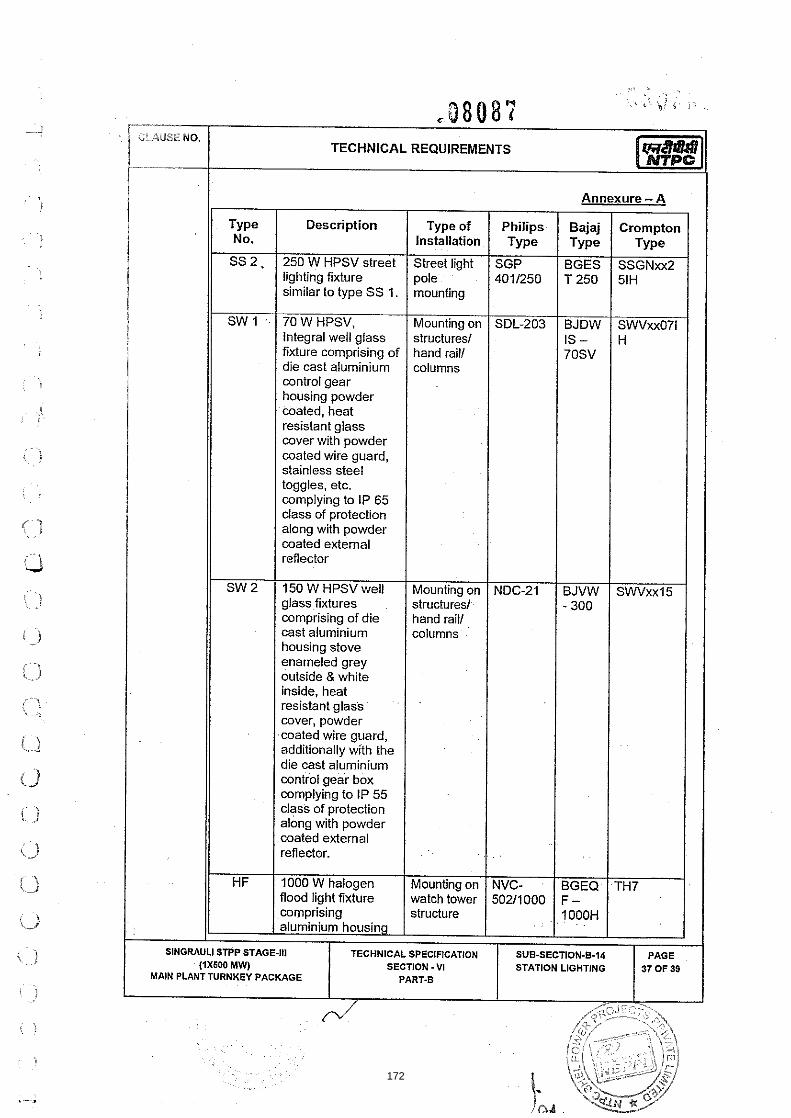
'.. ' ., . : . : 9 8 0 8 % , ,. ~.
,$' < ,. .. C r 1 CLAUSENO.
TECHNICAL REQUIREMENTS i f--.. i
Annexure - A
Type Description Type of Philips Bajaj Crompton No. Installation Type Type Type
SS 2. 250 W HPSV street Street light SGP BGES SSGNxx2 lighting fixture pole 4011250 T 250 51H similar to type SS 1. mounting
SW 1 ,- 70 W HPSV, Mounting on SDL-203 BJDW SWVxx071 Integral well glass structures1 IS- H fixture comprising of hand rail1 70SV die cast aluminium columns control gear housing powder coated, heat resistant glass cover with powder coated wire guard, stainless steel toggles, etc. complying to IP 65 class of protection along with powder coated external reflector
SW 2 150 W HPSV well Mounting on NDC-21 BJVW S W x x l 5 glass fixtures . structures1 - 300 comprising of die hand rail1 cast aluminium columns housing stove enameled grey outside & white inside, heat resistant glass .
'
cover, powder coated wire guard,^ additionally with the die cast aluminium control gear box complying to IP 55 class of protection along with powder coated external reflector.
HF 1000 W halogen Mounting on NVC- BGEQ TH7 flood light fixture watch tower 502/1000 F - ,comprising structure ~. . 1 . OOOH . . aluminium housing
SlNGRAULl STPP STAGE-Ill TECHNICAL SPECIFICATION SUB-SECTION-6-14 PAGE (1x600 MW) SECTION -VI STATION LIGHTING 37 OF 39
MAIN PLANTTURNKEY PACKAGE PART-B
172

I Annexure - A
. * ..~ . 5; . ' ~ :
Type No.
MP
PF
CLI
DHI
CLAUSE NO. TECHNICAL REQUIREMENTS
Crompton Type
Description
finished powder coated grey outside. aluminium reflector, heat resistant front glass, neoprene1 rubber gasket etc. fitted with lamp wmplying to IP 54 class of protection.
125 W HPMV post top lantern fixture comprising aluminium splgot (finished stove enameled grey outside White inside) opal acryltc diffuser I cover wmplying to IP 43 class of protection.
Self contained emergency lighting fixture with 2xlOW Fluorescent lamp with nickel cadmium battery, charger etc.
2xl8WCFL down lighters with CRCA housing, bright Aluminium reflector, white powder coated ring
lamp'downlighter with swiveling unit attached to a circular ring, bright reflector and white
Type of Installation
Pole top mounting
Wall I column mounting
Recessed
I I 1 I
SlNGRAULl STPP STAGE-Ill TECHNICAL SPECIFICATION SUB-SECTION-6-14 SECTION - VI STATION LIGHTING
Ix~OW, 12V Haloaen dichaonic
Philips Type
HPC- 1011125
**
FBH1501 218
Bajaj Type
BJDP TI - 125M V
**
BJDR 65C
218PR
Recessed DN652 - MR150CA
173

174

SUB-SECTION - B-15
FIRE PROOF CABLE PENETRATION SEALlNG
SYSTEM
175

CL-IUSE NO.
1.0"Jo
1 o.? 00
1.02.00
1.03.00
2.00.00
2.01.00
2.02.00
3.00.00
3.01.00
3.02.00
3.03.00
3.04.00
TECHNICAL REQUIREMENTS
CODES AND STANDARDS I The fire proof cable penetration (FPCP) sealing system shall conform to the requirement of latest edition including amendments of BS:476 Part-20 Fire tests on Building materials and structures.
Fire penetration seal complying with any other international standards will also be considered if it ensures performance equivalent or superior to standard listed above.
The Bidder shall clearly indicate the standards adopted and furnish a copy of the English version of the latest editions of standards alongwith the bid, and shall clearly bring out the salient features for comparison.
SYSTEM DESCRIPTION
The fire proof cable penetration sealing system shall be of the following types;
i) Type- A
Type A fire sealing system is either Silicone foam or equivalent foam system or using individual blocks for each cable along with suitable frame work rated for one hour. Type A is to be implemented at floor openings below C&l panels, control panelslBoards etc. in CER & CCR.
ii) Type-B
Type B fire sealing system is any proven fire sealing system rated for one hour. This will comprise of rest of wall and floor crossings of cableslcable trays, opening below HTILT Switchgearslboard other than those covered under Type A.
The penetration system, shall be installed immediately afler the completion of cable termination in a particular switchboardlcontrol panellarea afler clearance from the Project Manager.
GENERAL INFORMATION ..
The cables shall generally be laid in cable trayslracks, conduits, ducts. The fire proof cable penetration system shall be designed in such a way that the existing suppoiting structurelcable is not disturbed.
The penetration system shall be suitable for site condition at 5 0 0 ~ ambient temperature and relative humidity of 100%.
The penetration system of each walllfloor crossing shall be adequately designedlsized such that 20% addition of cables is possible at any later date without disturbancelwastage of material in the penetration system.
Contractor shall plan the schedule of supply of the materials in consultation with Project Manager and use the material within stipulated shelf life of material. .After. I
SlNGRAULl STPP STAGE-Ill TECHNICAL SPECIFICATION SECTION - V I
176

award of work, drawings for each penetration seal shall be prepared by the contractor after verifying the actual installation of cables at site and approval shall be taken from the Project Manager's representative before proceeding with the actual work. The requirement of tire sealing material shall be quantified accordingly.
. ', 4: , 0
C 0 fj $ 9 9 i: f; -,.. ... ,.
Fire sealing material to be supplied shall be based on the net area to be sealed, wastage, thickness, density and other parameters as per the type test report approved under this contract.
CLAUSE NO.
TECHNICAL REQUIREMENTS
TECHNICAL REQUIREMENTS
The fire proof cable penetration system shall fully comply w~th the requirements of BS:476 Part-20 and also to the requirements specified in this specification.
The penetration system shall prevent spreading of fire in cable beyond the seal system in case of tire and shall have minimum 1 hour fire resistance rating.
The penetration system shall be physically, chemically, thermally stable and shall be mechanically secure to the masonrylconcretelstructural members. The system shall be mechanically robust and capable of giving satisfactory performance under vibrations encountered in power stations. 1 4.04.00 1 The penetration system shall be capable of withstanding mechanical loads, foot traffic drop loads, vibrations, wind pressure, etc. 1 4.0500 1 The penetration system shall be completely gas and smoke tight. I
1 4.06.00 I The penetration system shall retain integrity and perform satisfactorily even after remaining in water for long period.
I 4.0700 I The materials used in FPCP sealing system shall be non-toxic and harmless to the working personnel.
I 4.08.00 I The penetration materials shall have no reaction with cable sheathlgalvanisinglpainting of structural steel.
1 4.09.00 1 The penetration materials shall have anti-rodent and anti-termite properties. I I 4.10.00 I The penetration materials shall have no shrinkage or cracking afler the setting for
the complete life of the power Plant.
Under normal load, short circuit and fire conditions, cables may be subjected to movement and vibration. The FPCP sealing system shall be designed to withstand and perform satisfactorily under these conditions.
The penetration system shall not affect the current carrying capacity of cables passing through it.
Asbestos shall not be used in the construction of fire penetration seal system.
4.14.00 The penetration system shall have life expectancy of 40 years.
SlNGRAULl STPP STAGE-Ill (1x500 MW)
EPC PACKAGE
TECHNICAL SPECIFICATION SECTION - VI
PART-B
SUB-SECTION-5-16 FIRE PROOF CABLE
PENETRATION SEALING SYSTEM
PAGE 2 0 F 8
177

CLAUSE NO.
4.36.00
4.1 7.00
5.00.00
5.01.00
6.00.00
6.01.00
6.02.00
6.03.00
6.04.00
6.05.00
6.06.00
6.07.00
TECHNICAL REQUIREMENTS I5i%Efl[ The penetration system shall not emit any corrosive or toxic fumes or smoke on the unexposed face of the barrier.
Any wastage of the compound during the process of mixing for preparing the FPCP sealing compound shall be to Contractor's account.
For foam type of systems, only the foam shall form the penetration seal of specified rating, having the damming board removed afler curing of the foam.
PACKING AND STORAGE I All materials and components of penetration system shall be supplied in packing to avoid contamination of materials due to dusffmoisture and temperature during transit and storage. All packing shall be of durable quality and the date of expily and the date of manufacture shall be printed on it.
INSTALLATION
The contractor shall take adequate care to ensure that cables are not damaged in any manner during penetration system installation.
Wherever the floorlwall opening provided in the vicinity of penetration seals larger or smaller than that required for the cable fire penetration, these opening size can be reduced or increased in an approved manner by the contractor using the same materials as provided around the opening and of the same thickness. Generally the walls in the power station comprises of brickwork and the floors are made of RCClsteel work. The Contractor shall be paid for this work at the unit rates for the respective brickwork! R.C.C.
The work to be carried out under this specification shall be done under the supervision of Project Manager's representative.
Ail work shall be carried out in accordance with the agreed "field qual~ty plan" and approved drawings. The "field quality plan" shall additionally specify the fire sealing material thickness, minimum cured density and other related parameters achieved in the approved type tests for the contract. The work shall be done to the satisfaction of the Project Manager and the same shall be subject to Project Manager's approval for acceptance.
The installation shall be carried out in a neat workmen like manner by the skilled, experienced and competent workmen.
lnstallahon work at site shall be properly coordinated with other services. I All materials being supplied or consumed during installation by the Contractor in the process of installation shall be of the best quality and according to relevant standards. All materials shall be inspected and approved by the Project Manager before the same is used for installation work. Also regarding inspection of work, the engineer shall have the right to inspect at any stage during installation, testing and commissioning.
SlNGRAULl STPP STAGE-Ill TECHNICAL SPECIFICATION SUB-SECTION-6-35 SECTION - VI FIRE PROOF CABLE
178

CLAUSE NO.
6.08.00 The drilling andwelding of building-steel or fixing supports etc. shall be carried out by contractor after taking prior approval of Project Manager.
1 60900 I Any work like chipping, breaking of existing structure like wall, floors, fabrications, any civil work etc. shall be done after taking prior approval of the Project Manager.
1 6.10.00 1 The following jobs are also in the scope of contractor's work. I I I a) Reasonable amount of drilling, cutting and welding surface preparation to fix
the fire stops.
b) Supply of necessary cement, gravel, sand etc. required for grouting necessary supports.
c) All supporting amangement.
I TYPE TESTS. ROUTINE &ACCEPTANCE TESTS
All equipment to be supplied shall be of type tested design. During detail engineering, the contractor shall submit for approval the reports of all the type tests as listed in this specification and carried out within last ten years from the date of bid opening. These reports should be for the test conducted on the equipment similar to those proposed to be supplied under this contract and the test(s) should have been either conducted at an independent laboratory or should have been witnessed by a client.
However if the contractor is not able to submit report of the type test(s) conducted within last ten years from the date of bid opening, or in the case of type test report(s) are not found to be meeting the spec~fication requirements, the contractor shall conduct all such tests under this contract at no additional cost to the Owner either at third party lab or in presence of clienffowners representative and submit the reports for approval.
I All acceptance and routine tests as per the specification and relevant standards shall be camled out. Charges for these shall be deemed to be included in the equipment I p,. I The type test reports once approved for any projects shall be treated as reference. For subsequent projects of NTPC, an endorsement sheet will be furnished by the manufacturer confirming similarity and "No design change". Minor changes if any shall be highlighted on the endorsement sheet.
1 7.0500 I Following Type test reports as per the setup and procedures given in subsequent clauses for the Fire proof cable penetration sealing system shall be submitted:
I I a) The accelerated ageing test I
I I b) Water absorption test I I 1 c Fire rating test
I I d) Hose stream test
e) . Vibration test followed by fire rating test
SINGRAULI STPP STAGE-111 (1x500 MW)
EPC PACKAGE
TECHNICAL SPECIFICATION SECTION - VI
PART-B
SUB-SECTI0N.B-IS FIRE PROOF CABLE
PENETRATION SEALING
??%-\
PAGE 4 0 F 8
179
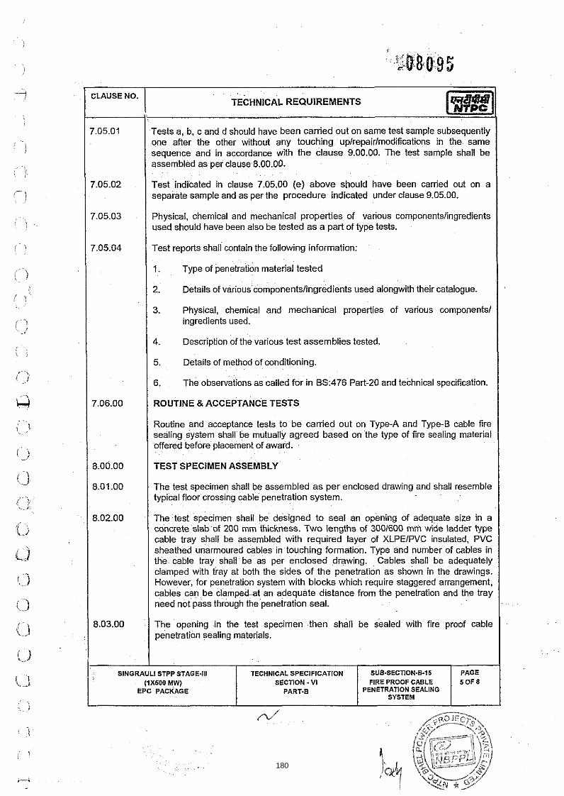
Tests a, b, c and d should have been carried out on same test sample subsequently one after the other without any touching uplrepairlmodifications in the same sequence and in accordance with the clause 9.00.00. The test sample shall be assembled as Der clause 8.00.00.
Test indicated in clause 7.05.00 (e) above should have been carried out on a separate sample and as per the procedure indicated under clause 9.05.00.
Physical, chemical and mechanical properties of various componentslingredients used should have been also be tested as a part of type tests.
1. Type of penetration material tested I 1 7.05.04 1
2. Details of various componentslingredients used alongwith their catalogue. I
Test reports shall contain the following information: I
3. Physical, chemical and mechanical properties of various components1 ingredients used. I
4. Description of the various test assemblies tested. I 5. Details of method of conditioning. I 6. The observations as called for in BS:476 Part-20 and technical specification. I ROUTINE &ACCEPTANCE TESTS I Routine and acceptance tests to be carried out on Type-A and Type-B cable fire sealing system shall be mutually agreed based on the type of fire sealing material offered before placement of award.
TEST SPECIMEN ASSEMBLY I The test specmen shall be assembled as per enclosed draw~ng and shall resemble typical floor crosslng cable penetration system.
The test specimen shall be designed to seal an opening of adequate size in a concrete slab of 200 mm thickness. Two lengths of 3001600 mm wide ladder type cable tray shall be assembled with requ~red layer of XLPEIPVC insulated. PVC sheathed unarmoured cables in touching formation. Type and number of cables in the cable tray shall be as per enclosed drawing. Cables shall be adequately clamped wlth tray at both the sides of the penetration as shown in the drawings. However, for penetration system with blocks which require staggered arrangement, cables can be clampe6at an adequate distance from the penetration and the tray need not pass through the penetration seal.
The opening in the test specimen then shall be sealed with fire proof cable penetration sealing materials.
I I sNGRA!Ll STPP STAGE*!. TECHNICAL SPECIFICATION SUB-SECTl0N.B-16 PAGE
(IXKOO MW) EPC PACKAGE
FIRE PROOF CABLE PENETRATION SEALING
SYSTEM
SECTION - V l PART-B
6 0 F 8
180

1 9.00.00 1 TEST PROCEDURES I
CLAUSE NO.
1 9.01.00 I ACCELERATED AGEING TEST I
TECHNICAL REQUIREMENTS
The test specimen assembled as per clause 8.01.00 with damming board removed shall be subjected to accelerated ageing test by storing in air furnace where the temperature of the inside air shall be maintained at 85 degree centigrade for 168 hours. The temperature controlled furnace should have 7 air changes per hour approx.
WATER ABSORPTION TEST
The test specimen shall be immersed in fresh clean water at a temperature of 20 deg. C i: 2 deg C. The test specimen must be separated from the bottom and sides of the soak tank by at least 10 mm and it shall be covered by approximately 25 mm of water. At the end of the 24 hour soak period the specimen shall be removed from water and mopped up with a damp cloth.
9.03.00 I FIRE RATING TEST I 1 9.03.01 1 The test specimen afler withstanding water absorption test shall be subjected to fire
rating test as per BS: 476 part-20.
1 903.02 I OillGas fired fumace shall be used for heating. The furnace shall have achieved standard timeltemperature characteristics for fire tests as per BS:476 part-20.
The pressure inside the furnace at the time of test shall be within 1.5 2 0.5 mm water gauge.
Cables in the test specimen shall be anchored on the hot side to a structure independent of the barrier and its penetrations. This is to ensure that any differential movement between the penetration and the cable that could occur during a fire, is produced in the type tests and the reliability of the integrity of the penetration is checked.
Cables shall be protruding between 1 to 2 metre, from the penetration face on the unexposed side and protruding into the furnace as far as it is practicable with a minimum length 750 mm. The ends of the cables shall be capped on the unexposed face to prevent gases and fumes to escape from the fumace during the tire.
The test specimen shall be subjected to fire test with surface exposed to controlled fire in the furnace confirming to timeltemperature characteristics specified in BS:476(20).
During the test the temperature of both the faces of the fire stop i.e. one which is exposed to fire and other unexposed shall be measured by calibrated theno couples afler regular interval of 5 minutes.
Atleast 3 thermo couples shall be provided for temperature measurement of each face. The results at the end of the test shall be intemreted for failure criteria as
SlNGRAULl STPP STAGE-Ill TECHNICAL SPECIFICATION SUB-SECTt0N.B-15 SECTION - VI
181

I I 1. The system is deemed to have failed to maintain stability if there is a total collapse of the fire proof seal.
2. In case cracks are seen on the face of the fire stop or cracks through which the flame1 hot gas can pass the systems deemed to have failed to maintain integrity.
I The development of crack is characterised by appearance of black soot on cotton wool held near the penetration on the unexposed surface at a distance of about 100mm.
3. Failure shall be deemed to have occurred when the mean temperature of the unexposed surface of the specimen assembly increases by more than 1 4 0 ~ ~ above the initial temperature or if the temperature of the unexposed surface is increased at any point by more than 1 8 0 0 ~ above the initial temperature.
I I During the test the specimen shall meet all the three criteria simultaneously. I Temperature measurement on the unexposed side of penetration seal shall be measured by thermocouples at a distance of 25 mm from unexposed side of fire stop.
HOSE STREAM TEST
A hose stream test shall be conducted on the test specimen immediately following a fire resistance test on that assembly. The specimen must first be removed from the furnace since the hose stream is to be applied to the exposed face. This must be done quickly since it is the intention of the test that the stream be applied to the specimen whilst it is hot.
The hose stream shall be long range narrow angle, (200 - 900 set at 300 included angle). High velocity water spray provided from a 28 mm hose discharging through an appropriate nozzle. The water pressure shall be 5 bar calculated at the base of the nonle and the minimum flow rate shall be 4.7 litreslsecond. The stream shall be supplied perpendicularly to the exposed face of the test specimen with non le 3 m away from the exposed face.
Application shall be for minimum of two and a half minutes per 9 sq.m. of the test specimen including the barrier.
VIBRATION TEST
9.05.01 he test assembly is to comprise a single ladder rack penetration in 1 m x l m high normal section of fire barrier which is securely supported. The penetration seal shall be formed in the middle of the barrier around 1 m length of 600 mm ladder rack. The tray shall be fully loaded with cables in touching formation. The penetration assembly shall3e formed symmetrically through the fire barrier as in service. The penetration sealant material shall then be allowed to cure for atleast as long as the time required for conditioning to constant mass. A vibration test shall then be conducted on the sample as set out below.
SINGRAULI STPP STAGE-Ill TECHNICAL SPECIFICATION SUB-SECnON-8-15 PAGE (1XS00 MW) SECTION - VI FIRE PROOF CABLE 7 0 F B
EPC PACKAGE PART.5 PENETRATION SEALING SYSTEM
182

CLAUSE NO.
9.05.02
.
SlNGRAULl
TECHNICAL REQUIREMENTS
The vibration shall be of 100 Hz frequency and of 0.5 mm amplitude (1.0 mm peak to peak) and this shall be applied to one mil of the ladder rack or the centre of a cross member secured to the two mils at 250 mm from the centre line of the penetration. This vibration shall be applied to the sample for the minimum period of 3 his. Immediately following this vibration test the barrier1 penetration assembly shall be successfully subjected to a fire test in accordance with clause no. 9.03.00.
~.
. ~
~.
. . . . . ,
STPP STAGE-Ill (1x600 MW)
EPC PACKAGE
r
TECHNICAL SPECIFICATION SECTION - V1
PART.6 PENETRATION SEALING SYSTEM
SUB-SECTION-8-15 FIRE PROOF CABLE
PAGE 8 0 F 8
183

184

185

186

187

188

189

190

191
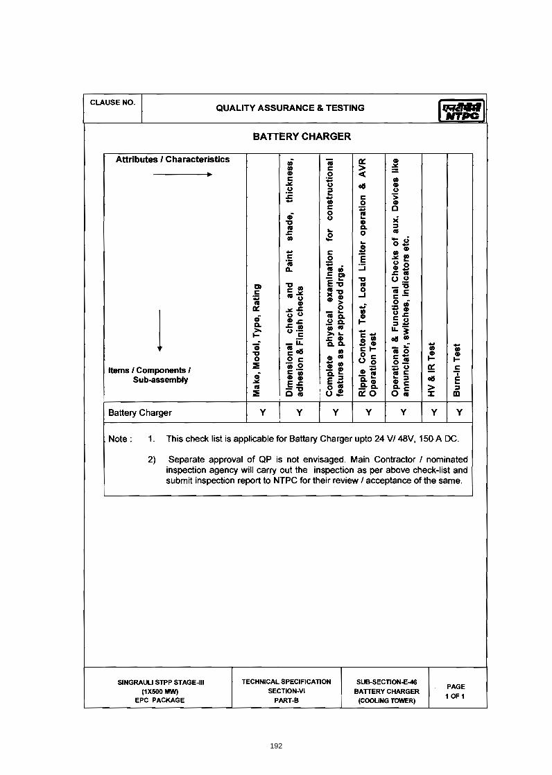
192

193
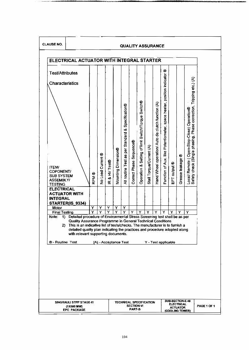
194

BHEL SPEC Rev. No.:0
1. SCO 2. MEA 3. CAB 4. ELEC 5. DATA 6. QUA
C. NO. :PE-TS-41 Dated : 11.06
SP
OPE OF C&I ASURING IN
LING PHILOCTRICAL AA SHEET
ALTY ASSUR
TEC
FGUTP
404-165-N001 .14
ECIFIC T
STRUMENT
OSOPHY ACTUATORS
RANCE
CHNICAL CONCOOLING
P STAGE‐IV (1
TECHNIC
SEC
TECHNICA
COM
TS
S
NDITIONS OF TOWER PACK1X 500 MW)
CAL SPECIFICA
CTION – C
AL REQU
PRISES O
CONTRACTKAGE AT UNCHAHA
ATION DA
C3
UIREMEN
OF
AR
DOC. NO.: NBPPA Rev. No.: 01
TS (C &I)
PL-004-103-03-P
)
P4M-
195

BHEL SPEC Rev. No.:0
1. G
The Contof entire detailed in the reqwill be brpre‐bid cprevail w
Further Bservices wcompleteand requ
In additioequipmeparts/ se
The makevendor li
In case orequirem
2. C
a) T
sc
b) C
C
D
C. NO. :PE-TS-41 Dated : 11.06
GENERAL
tractor shall IDCT systemTechnical spquirement wrought to thclarification, without any c
Bidder shall awhich may neness of the uirements of
on to requireent/ devices ctions of spe
e/model of vst. No comm
of any conflicments among
ONTROL SYS
he controls f
cope).
ontractor sh
ontractor's C
DDCMIS of ID
TEC
FGUTP
404-165-N001 .2014
INDUCED
provide comm. The requipecification ewithin the sae notice of Nthe more stcommercial
also include not be specifequipment/f the specific
ements specshall also mecification.
various instrmercial and
ct and repetg them are t
STEM
for IDCT sha
hall provide f
C&I represe
DCT system.
CHNICAL CONCOOLING
P STAGE‐IV (1
TECHNICA
1 X 500
D DRAUGHT
BIDDER'S
mplete Instrurements givenclosed in tame section NBPPL in thetringent requimplication.
in his propofically stated/systems furcation.
cified under eet other re
ruments/itemdelivery imp
tition of clauo be complie
all be realize
full support
ntative shall
NDITIONS OF TOWER PACK1X 500 MW)
AL SPECIFICAT
0 MW FGU
T COOLING
S SCOPE FO
umentation en below arthe specificanoted by thee form of preuirement as
osal and shad in the specrnished by th
this Sectionequirements
ms/systems plication in t
uses in the sped with.
d in DDCMIS
during FAT o
l be present
CONTRACTKAGE AT UNCHAHA
TION DOCRev.
UTPP
G TOWER
OR C&I
for control, re to be readation. Furthee bidder in te‐ bid clarificper interpre
ll furnish all cification buthe Bidder an
‐C3, all C&I stipulated u
shall be as pthis regard s
pecification,
S based cont
of DDCMIS f
at BHEL‐ED
AR
C. NO.: NBPPL-No.:01
(IDCT)
monitoring d in conjuncter in case of the specificacation. In abetation of NB
equipment,t are needednd for meeti
systems/ suunder other
per NTPC/Nhall be acce
, the more st
trol system (
for IDCT syst
N, Bangalore
004-103-03-P4M
and operatition with any discrep
ation, the sambsence of anBPPL shall
, devices andd for ng the inten
b‐systems/ Sub‐section
BPPL approvptable.
tringent
(not in Bidde
tem.
e during FAT
M-A
ion
ancy me y
d
nt
ns/
ved
er’s
T of
196

BHEL SPEC Rev. No.:0
c) C
C
d
d) C
in
H
M
a
e) In
co
C
3. M
ContracttemperatPressure
a) C
b) Inre
w
sy
te
C. NO. :PE-TS-41 Dated : 11.06
ontractor sh
ontractor's C
uring comm
ontractor sh
nterconnecti
HART in NTPC
MS Access et
pproved for
nterface of M
ontrol system
ONTROL SYS
MEASURING
or shall provture transm/ temperatu
omplete IDC
i. Temp
heade
ii. Temp
iii. Pressu
iv. One n
v. Temp
moun
canop
ntegral to eq
equired for c
which no P&I
ystem requir
echnical spe
TEC
FGUTP
404-165-N001 .2014
hall provide f
C&I represe
missioning of
hall furnish I
ion, JB group
C/NBPPL app
c. of these d
mat. Soft co
MCC, HT SW
m shall be a
STEM, C&I S
INSTRUMEN
vide Primaryitters emploure/flow/ lev
CT package c
erature elem
er.
erature elem
ure gauges f
no. level swit
erature elem
ting arrange
py.
quipment wh
control, mon
Ds are enclo
rements and
cifications s
CHNICAL CONCOOLING
P STAGE‐IV (1
TECHNICA
full support
ntative shall
DDCMIS of
nstrument S
ping, Annun
proved form
documents s
opy of the fo
GR, field ins
s per Drive C
pecification,
NTS
y instrumentoying HART pvel switches
comprising o
ments and te
ments and te
for each of th
tch for each
ments and te
ement etc. in
hich are not
nitoring and
osed, all the
d meeting re
ubject to Em
NDITIONS OF TOWER PACK1X 500 MW)
AL SPECIFICAT
during com
l be present
IDCT system
Schedule, I/O
ciation list, S
mat. Also reu
shall also be
rmats shall b
truments, A
Control Philo
, Section‐C3
ts like Microprotocol, the& gauges fo
of the follow
emperature
emperature
he hot wate
of the gear
emperature
n the cold w
indicated ab
operation o
instruments
edundancy a
mployer’s ap
CONTRACTKAGE AT UNCHAHA
TION DOCRev.
missioning o
at Unchaha
m.
O list, Drive l
SOE list, List
usable datab
provided by
be provided
Actuators etc
osophy enclo
of technica
processor baermocouplesor :
wing as a min
gauges for e
gauges for e
er header.
box for lube
gauges with
water channe
bove/in the
of the equipm
s shall be pr
and other req
proval.
AR
C. NO.: NBPPL-No.:01
of DDCMIS fo
ar site (for 10
list, Cable Sc
of Instrume
base format
y Contractor
d to the succ
c. with DDCM
osed in Sub
l specificatio
ased transms & RTDs, pr
nimum:
each of the H
each Gear b
e oil level.
h necessary
el for each co
tender draw
ment / plant
ovided to m
quirements
004-103-03-P4M
or IDCT syste
0 Man days)
chedule, Cab
ents/devices
like MS Exce
r in NTPC/NB
essful bidde
MIS based
Section‐
on.
mitters and ressure/diff.
Hot water
ox.
stub, fitting,
ooling tower
wings, but ar
t systems fo
meet the actu
specified un
M-A
em.
ble
s for
el,
BPPL
er.
,
r in
re
r
ual
nder
197

BHEL SPEC Rev. No.:0
c) Fo
d
o
H
sh
d) Fo
o
av
e) T
f) T
e
h
g) R
F
te
&
h) Ctr
a
Fa
C. NO. :PE-TS-41 Dated : 11.06
or Binary an
evices shall
f more than
HT Drives (fed
hall be provi
or other crit
f other equi
vailability of
Temperature
emperature
lements in t
ardware sha
ail mounted
ield Bus Com
emperature
& other erect
i. Contr
measu
Gener
measu
both e
dual in
ii. Rema
type.
iii. Head
are lo
omplete Mi
ransducers, v
ccessories fo
ans etc.)‐ 2n
TEC
FGUTP
404-165-N001 .2014
d analog inp
be provided
one equipm
d by a suppl
ided.
tical binary a
pment (e.g.
f a major equ
e elements,
transmitter
he scope of
all also be in
d/ Rack mou
mpatible tem
elements in
tion hardwa
actor shall p
urements be
rator and Ma
urement poi
elements of
nput tempe
ining tempe
mounted tra
cated in acc
croprocesso
vibration mo
or each cool
nos. vibration
CHNICAL CONCOOLING
P STAGE‐IV (1
TECHNICA
puts required
d. Binary and
ment as well
y feeder of r
and analog in
those interl
uipment etc
electronic tr
rs are to be p
the contrac
scope of co
nted (Dual in
mperature tr
n contractor'
re are to be
provide at lea
eing used in
ajor auxiliar
ints are bein
one duplex
rature trans
erature trans
ansmitters m
essible area
or based Vibr
onitor system
ing tower fo
n sensors pe
NDITIONS OF TOWER PACK1X 500 MW)
AL SPECIFICAT
d in major e
d analog inp
as protectio
ratings 3.3 k
nputs requir
ocks which
c.), triple sen
ransmitters e
provided by
tor. Compen
ontractor.
nput Field m
ansmitters f
s scope) alo
provided by
ast one dual
trip/protect
ies. E.g. whe
ng used to fo
temperatur
mitter.
smitter are t
may be prov
s as decided
ration monit
m with inter
or monitorin
er fan.
CONTRACTKAGE AT UNCHAHA
TION DOCRev.
equipment p
puts, which a
on signals fo
kV onwards)
red for prote
may result i
nsors shall be
etc. are to b
the contrac
nsating Cabl
mounted tem
for temperat
ong with its c
y the contrac
l input trans
tion/major in
en three/two
or monitorin
re element is
to be Single
vided for tem
d during deta
toring system
rconnecting
g of vibratio
AR
C. NO.: NBPPL-No.:01
rotection, tr
are, required
or important
etc., triple s
ection and in
n loss of gen
e provided.
be provided f
ctor for all th
es, JB/rack &
mperature tr
ture elemen
compensatin
ctor as per t
smitter for te
nterlock of T
o temperatu
ng one bearin
s to be conn
Input DIN ra
mperature el
ailed engine
m including
cables, junc
on of major e
004-103-03-P4M
riple‐sensing
d for protect
auxiliaries a
sensing devi
nterlock purp
neration, no
for all the ca
he temperat
& other erec
ransmitters)/
nts (for all th
ng cable, JB/
the following
emperature
Turbine
ure
ng temperat
ected to one
ail mounting
lements whi
eering.
vibration
ction boxes a
equipments
M-A
g
tion
and
ces
pose
n‐
ases.
ure
ction
/
he
/rack
gs.
ture,
e
g
ch
and
(CT
198

BHEL SPEC Rev. No.:0
i) A
C
j) In
sc
sp
k) A
G
ID
th
l) A
b
b
g
co
6
Stesh
Tfoe
m) Dd
IN
4. IN
Scope of Electrica
Cabling pSection‐C
C. NO. :PE-TS-41 Dated : 11.06
All the instrum
ontractor's s
nstrument in
cope and sh
pecification.
All instrumen
Guarantee te
DCT system s
he Mechanic
All panels, de
us. The grou
olts shall fac
round with s
onnected to
mm min., le
hield on instermination ihall be furni
he Contractoor his systemngineering.
Detailed spec
etails, Instru
NSTRUMENT
NSTRUMENT
Instrumentl Cable scop
philosophy sC3 of technic
TEC
FGUTP
404-165-N001 .2014
ments shall
scope.
nstallation an
all be as per
nts along wit
est (Pitot tub
shall be prov
cal portion o
esks, cabinet
und bus shal
ce inside of p
suitable isola
o the system
ngth as app
trumentatios required inshed on cop
or shall submm. The exact
cification of
ument instal
TS, C&I Spec
TATION CAB
ation cablese matrix in E
hall be as decal specificat
CHNICAL CONCOOLING
P STAGE‐IV (1
TECHNICA
be terminat
nd accessori
r the instrum
th accessorie
be along with
vided by Con
of the techni
ts etc. shall b
l be bolted t
panels. The s
ators. All int
ground, wh
licable).
n cables shan cabinets fupper flat form
mit with thegrounding s
instruments
lation diagra
ification, Sec
BLES & CONT
s (Screened CElectrical po
efined in Subtion.
NDITIONS OF TOWER PACK1X 500 MW)
AL SPECIFICAT
ed up to JBs
ies required
ment installat
es, installatio
h Manomete
ntractor. Det
cal specifica
be provided
to the panel
system grou
ternal compo
ich shall be
all be groundurnished undming system
offer recomscheme shal
s, VMS, JB, C
ams shall be
ction‐C3 of t
TROL CABLE
Control Cablrtion of spec
b Section‐ CA
CONTRACTKAGE AT UNCHAHA
TION DOCRev.
s by Contract
for the sam
tion diagram
on hardware
ers, Anemom
tailed specif
ation.
with a conti
structure o
und shall be
onent groun
fabricated o
ded on paneder this spec
m ground.
mmended grol be finalized
Control pane
e as defined
technical spe
ES
les) & Controcification.
ABLING PHIL
AR
C. NO.: NBPPL-No.:01
tor. JBs shal
me shall be in
ms enclosed
e required fo
meter, Psych
fication shal
inuous bare
n bottom on
isolated from
nds or comm
of copper fla
el side. Whencification, su
ounding schd during det
el etc. & Instr
in Sub Sectio
ecification.
ol cables sha
LOSOPHY, C&
004-103-03-P4M
l be in
n Contractor
in the
or Performa
hrometer etc
l be as defin
copper grou
n both sides
m the panel
mon shall be
at (size 25mm
n shielding uitable termi
heme requiretailed
rument Stub
on‐ MEASUR
all be as per
&I Specificat
M-A
r's
nce
c.) of
ned in
und
. The
m x
inals
ed
b
RING
tion,
199

BHEL SPEC Rev. No.:0
5. E
Electricainching tyControl SINTEGRA
6. TY
The typeSection‐
7. Q
ContractASSURAN
8. D
Following
a) U
b) Nc) G
9. D
DocumenDOCUMEtechnical
10. C
Mandatoin the tec
C. NO. :PE-TS-41 Dated : 11.06
LECTRICAL A
l Actuators wype valves inSystem as apAL STARTERS
YPE TEST RE
tests to be TYPE TEST R
QUALITY ASS
or shall perfNCE, C&I Spe
DOCUMENTS
g document
UPS Power Lo
No. of VMS p
Grounding Sc
DOCUMENTS
nts to be subENTS TO BE Sl specificatio
C&I MANDA
ory spares fochnical spec
TEC
FGUTP
404-165-N001 .2014
ACTUATORS
with Integran Cooling towpplicable as d, C&I Specifi
EQUIREMEN
conducted fREQUIREMEN
SURANCE
form tests ofecification, S
S TO BE SUB
s shall be su
oad for VMS
anels and th
cheme for VM
S TO BE SUB
bmitted afteSUBMITTEDon.
ATORY SPARE
or C&I items ification.
CHNICAL CONCOOLING
P STAGE‐IV (1
TECHNICA
S
l starter shawer packagedetailed outication, Sect
NT
for C&I systeNTS, C&I Spe
f C&I items/Section‐C3 o
MITTED AT
ubmitted by
S
heir sizes
MS Panels
MITTED AFT
er award of C AFTER AWA
ES
shall be as d
NDITIONS OF TOWER PACK1X 500 MW)
AL SPECIFICAT
ll be providee along witht in Sub Section‐C3 of Te
ems & equipecification, S
instrumentsf the technic
BIDDING ST
Bidder along
TER AWARD
Contract shaARD OF CON
defined in th
CONTRACTKAGE AT UNCHAHA
TION DOCRev.
ed by Contar necessary iion‐ ELECTRechnical Spe
ments shall Section‐C3 o
s/systems ascal specifica
TAGE
g the bid:
D OF CONTRA
all be as defiNTRACT, C&I
he Main Man
AR
C. NO.: NBPPL-No.:01
rctor for all onterface uniIC ACTUATOcification.
be as detailof technical S
s per Sub‐Setion.
ACT
ned in Sub SSpecificatio
ndatory spar
004-103-03-P4M
on/off and its for linkingORS WITH
ed out in SuSpecification
ction‐ QUAL
Section‐ on, Section‐C
res list enclo
M-A
g to
ub n.
LITY
C3 of
osed
200

SUB-SECTION
CONTROL SYSTEM
201

202

203

204

205
SUB-SECTION
MEASURING INSTRUMENTS
206
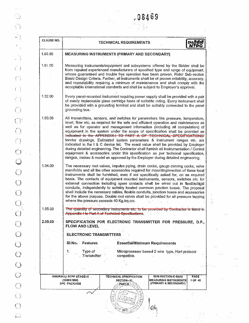
207

208

209

210

211

212

213
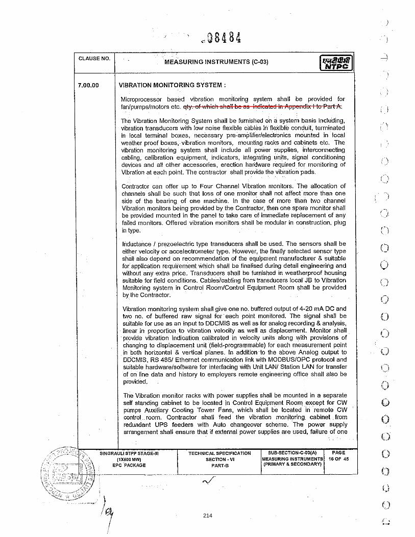
214

215
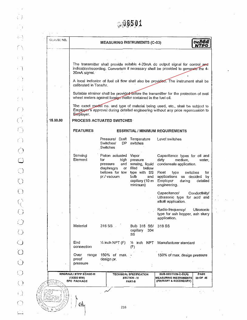
216

217

218

219

220

221

222
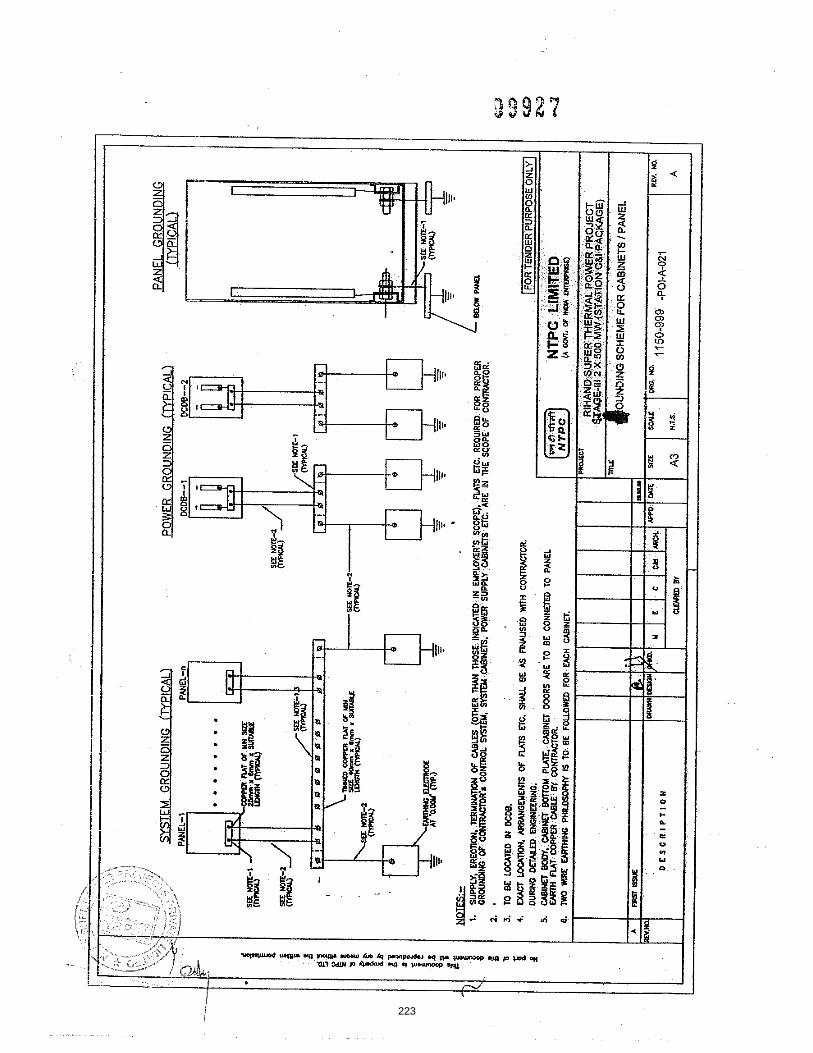
223

224

225

226

227

228

229
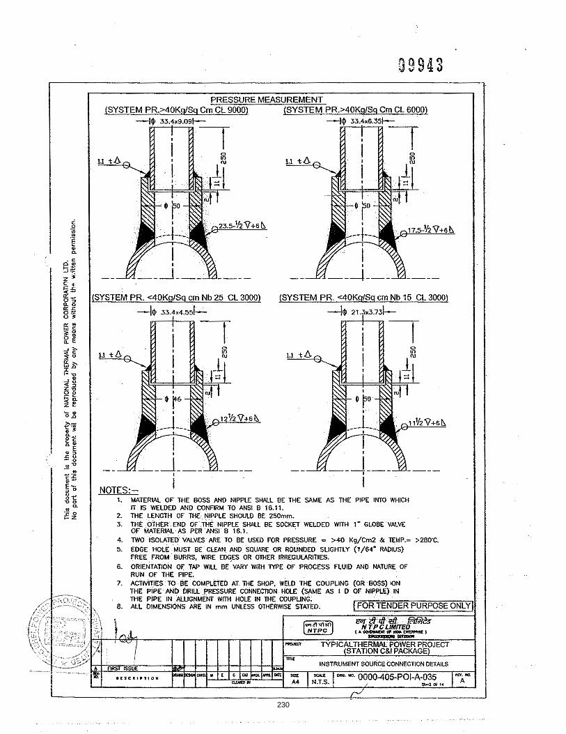
230

231

232

233
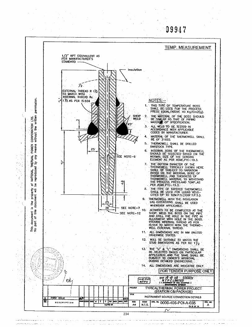
234

235

236

SUB-SECTION
CABLING PHILOSOPHY
237

238

239

240
241

242

243
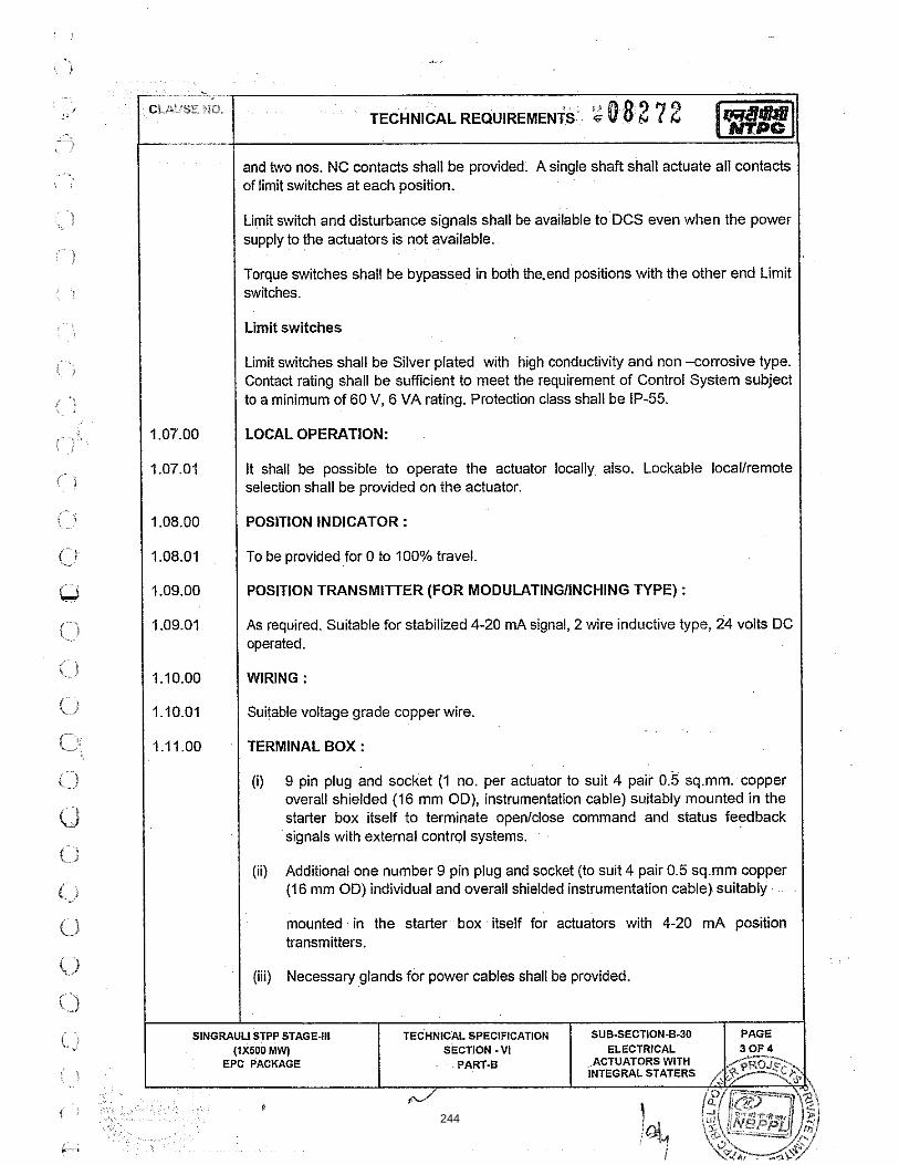
244

245

SPECIFICATION FOR
MOTORISED VALVE ACTUATOR
SPECIFICATION NO.: PE-ID-401-145-I902
VOLUME II B
SECTION D
REV. NO. 00 DATE: 25.03.14
SHEET 2 OF 5
Data Sheet A & B
DATA SHEET-A (TO BE FILLED BY PURCHASER)
DATA SHEET-B (TO BE FILLED-UP BY BIDDER)
FOR
M N
O. P
EM
-666
6-0
GENERAL*
* PROJECT 1 X 500 MW FGUTPP
OFFER REFERENCE
* TAG NO. SERVICE
* DUTY � ON / OFF � INCHING
* LINE SIZE (inlet/outlet): MATERIAL
* VALVE TYPE � GLOBE � GATE � REG. GLOBE � BUTTERFLY
* OPENING / CLOSING TIME
* WORKING PRESSURE
AMBIENT CONDITION SHALL BE SUITABLE FOR CONTINUOUS OPERATION UNDER AN AMBIENT TEMP. OF 0-55 DEG C AND RELATIVE HUMIDITY OF 0-95%
VALVE SEAT TEST PRESS BIDDER TO SPECIFY
REQUIRED VALVE TORQUE BIDDER TO SPECIFY
ACTUATOR RATED TORQUE BIDDER TO SPECIFY
CONSTRUCTION AND SIZING
CONSTRUCTION TOT ALLY ENCLOSED, WEATHER PROOF, IP:55
MECHANICAL POSITION INDICATOR TO BE PROVIDED FOR 0-100% TRAVEL
BEARINGS DOUBLE SHIELDED, GREASE LUBRICATED ANTI-FRICTION.
GEAR TRAIN FOR LIMIT SWITCH/TORQUE SWITCH OPERATION
METAL (NOT FIBRE GEARS). SELF-LOCKING TO PREVENT DRIFT UNDER TORQUE SWITCH SPRING PRESSURE WHEN MOTOR IS DE-ENERGIZED.
SIZING
OPEN/CLOSE AT RATED SPEED AGAINST DESIGNED DIFFERENTIAL PRESSURE AT 85% OF RATED VOLTAGE. FOR ISOLATING SERVICE THREE SUCCESSIVE OPEN-CLOSE OPERATIONS OR 15 MINS. WHICHEVER IS HIGHER. FOR INCHING SERVICE - 150 STARTS/HR MINIMUM &FOR REGULATING SERVICE - 600 STARTS/HR MINIMUM.
HANDWHEEL
* REQUIRED � YES � NO
* ORIENTATION � TOP MOUNTED � SIDE MOUNTED
*TO DISENGAGE AUTOMATICALLY DURING MOTOR OPERATION.
ELECTRIC ACTUATOR
ACTUATOR MAKE/MODEL BIDDER TO SPECIFY MOTOR MAKE / MODEL / TYPE / RATING (KW) BIDDER TO SPECIFY
@ MOTOR TYPE SQUIRREL CAGE INDUCTION MOTOR SUITABLE FOR DOL STARTING
ACTUATOR APPLICABLE WIRING DIAGRAM
� ENCLOSED (BIDDER TO CONFIRM) A: � DRG. NO. 3-V-MISC-24227 R00 B: � DRG. NO. 3-V-MISC-24550 R00 C: � DRG. NO. 3-V-MISC-24283 R00 D: � DRG. NO. 4-V-MISC-90271 R11 E: � For Thyristor based Integral starter, Bidder/Vendor to furnish wiring diagram
COLOUR SHADE � BLUE (RAL 5012) � …….
PAINT TYPE (## Refer Notes) �ENAMEL � EPOXY � …….
SHAFT RPM BIDDER TO SPECIFY
OLR SET VALUE BIDDER TO SPECIFY
@ STARTING / FULL LOAD CURRENT BIDDER TO SPECIFY
NO. OF REV FOR FULL TRAVEL BIDDER TO SPECIFY
@ PWR SUPP TO MTR / STARTER 415V, 3PH, AC
@ CONTROL VOLTAGE REQUIREMENT 110V AC/ 24VDC TO BE DERIVED SUITABLY FROM 415V POWER SUPPLY
246

SPECIFICATION FOR
MOTORISED VALVE ACTUATOR
SPECIFICATION NO.: PE-ID-401-145-I902
VOLUME II B
SECTION D
REV. NO. 00 DATE: 25.03.14
SHEET 3 OF 5
Data Sheet A & B
DATA SHEET-A (TO BE FILLED BY PURCHASER)
DATA SHEET-B (TO BE FILLED-UP BY BIDDER)
FOR
M N
O. P
EM
-666
6-0
@ ENCLOSURE CLASS OF MOTOR TOTALLY ENCLOSED, SELF VENTILATED IP-55 DOP
@ INSULATION CLASS CLASS B OR BETTER, TEMPERATURE RISE 70 DEG C OVER 50 DEG C AMBIENT
@ WINDING TEMP PROTECTION � THERMOSTAT (3 Nos.,1 IN EACH PHASE)
SINGLE PHASE / WRONG PHASE SEQUENCE PROTECTION REQUIRED
INTEGRAL STARTER
INTEGRAL STARTER � REQUIRED � NOT REQUIRED
TYPE OF SWITCHING DEVICE � CONTACTORS � THYRISTORS
TYPE � CONVENTIONAL � SMART (NON-INTRUSIVE) IF SMART
a) SERIAL LINK INTERFACE � INTEGRAL � FIELD MOUNTED
b) SERIAL LINK PROTOCOL � FOUNDATION FIELD-BUS � PROFI-BUS � DEVICE NET �…………
c) SERIAL LINK MEDIA � TWISTED PAIR Cu-CBL � CO-AXIAL Cu-CBL � OFC
d) HAND HELD PROGRAMMER � REQUIRED � NOT REQUIRED e) TYPE OF HAND HELD PROGRAMMER � BLUETOOTH � INFRARED �..............
f) MASTER STATION � REQUIRED � NOT REQUIRED
g) MASTER STN INTRFACE WITH DCS � MODBUS � TCP/IP
h) DETAILS OF SPECIAL CABLE � ENCLOSED � NOT REQUIRED
STEP DOWN CONT. TRANSFORMER � REQUIRED
OPEN / CLOSE PB � REQUIRED � NOT REQUIRED
STOP PB � REQUIRED � NOT REQUIRED
INDICATING LAMPS � REQUIRED � NOT REQUIRED
LOCAL REMOTE S/S �REQUIRED � NOT REQUIRED
STATUS CONTACTS FOR MONITORING � REQUIRED � NOT REQUIRED
INTEGRAL STARTER DISTURBED SIGNAL
REQUIRED (O/L RELAY OPERATED, CONT./POWER SUPPLY FAILED, S/S IN LOCAL, TORQUE SWITCH OPTD. MID WAY)
INTERPOSING RELAY/OPTO COUPLER (Applicable for integral Starter)
TYPE OF ISOLATING DEVICE � INTERPOSING RELAY � OPTO COUPLER � EITHER
QUANTITY � 2 NOs. � 3 NOs.
DRIVING VOLTAGE � 20.5 – 24V DC � _____________V DC
DRIVING CURRENT � 125mA MAX � _____________mA MAX
LOAD RESISTANCE � > 192 ohms - <25 k ohms � > _______ohms - < __________ohms
TORQUE SWITCH (Not Applicable for Smart Actuator) ($$ Refer Notes)
MFR & MODEL NO. BIDDER TO SPECIFY
OPEN / CLOSE �1 No. �2Nos. / �1 No. �2Nos
CONTACT TYPE 2 NO + 2 NC
RATING 5A 240V AC AND 0.5A 220V DC
CALIBRATED KNOBS(OPEN&CLOSE TS) REQUIRED FOR SETTING DESIRED TORQUE
ACCURACY +3% OF SET VALUE
LIMIT SWITCH (Not Applicable for Smart Actuator) ($$ Refer Notes)
MFR & MODEL NO. BIDDER TO SPECIFY
OPEN : INT : CLOSE �1 No �2 Nos. 2 Nos. (ADJ.) �1 No.
�2Nos.
CONTACT TYPE 2 NO + 2 NC
RATING (AC / DC) 5A 240V AC AND 0.5A 220V DC
247

SPECIFICATION FOR
MOTORISED VALVE ACTUATOR
SPECIFICATION NO.: PE-ID-401-145-I902
VOLUME II B
SECTION D
REV. NO. 00 DATE: 25.03.14
SHEET 4 OF 5
Data Sheet A & B
DATA SHEET-A (TO BE FILLED BY PURCHASER)
DATA SHEET-B (TO BE FILLED-UP BY BIDDER)
FOR
M N
O. P
EM
-666
6-0
POSITION TRANSMITTER
POSITION TRANSMITTER (For inching duty & other specific applications) � REQUIRED � NOT REQUIRED
MFR & MODEL NO. BIDDER TO SPECIFY
TYPE � ELECTRONIC (2 WIRE) R/I CONVERTER � ELECTRONIC (2 WIRE) CONTACTLESS
SUPPLY � 24V DC � ………
OUTPUT � 4-20mA
ACCURACY + 1% FS
SPACE HEATER
@SPACE HEATER REQUIRED
@ POWER SUPPLY (NON INTEGRAL) N. A
@ POWER SUPPLY (INTEGRAL) BI DDER TO SPECIFY
@ RATING
TERMINAL BOX
ACTUATOR/MOTOR TERMINAL BOX REQUIRED
ENCL CLASS ACTUATOR/MOTOR T.B. @� IP 68 @�IP 55
@ EARTHING TERMINAL REQUIRED TWO
PLUG & SOCKET(9 PIN)(FOR COMMD, LS/TS FEED BACK, PoT)
� REQUIRED � NOT REQUIRED � 2 NOS. � ----------------
CABLE GLANDS
@ POWER CABLE GLAND SIZE:--TO BE PROVIDED DURING DETAILED ENGINEERING
@ SPACE HEATER CABLE GLAND SIZE:----- TO BE PROVIDED DURING DETAILED ENGINEERING
OTHER CONTROL CABLE GLANDS-1 � 1No. for BFV of CW PUMP
OTHER CONTROL CABLE GLANDS-2 QUANTITY & SIZE : TO BE PROVIDED DURING DETAILED ENGINEERING
WEIGHT TOTAL WEIGHT (ACTUATOR + ACCESSORIES) BIDDER TO SPECIFY _________________ Kg.
NOTES:1. SCOPE: DESIGN, MANUFACTURE, INSPECTION, TESTING AND DELIVERY TO SITE OF ELECTRIC ACTUATOR FOR INCHING OR OPEN / CLOSE DUTY.
2. CODES & STANDARDS: DESIGN AND MATERIALS USED SHALL COMPLY WITH THE RELEVANT LATEST NATIONAL AND INTERNATION STANDARD. AS A MINIMUM, THE FOLLOWING STANDARDS SHALL BE COMPLIED WITH: IS-9334, IS-2147, IS-2148, IS-325, IS-2959, IS-4691 AND IS-4722
3. TEMPERATURE RISE SHALL BE RESTRICTED TO 70 DEG. C FOR AMBIENT TEMPERATURE OF 50 DEG C.
4. CABLE GLANDS OF DOUBLE COMPRESSION TYPE, BRASS MATERIAL SHALL BE PROVIDED.
5. THE TORQUE SWITCHES SHALL BE PROVIDED WITH MECHANICAL LATCHING DEVICE TO PREVENT OPERATION WHEN UNSEATING FROM THE END POSITIONS. THE LATCHING DEVICE SHALL UNLATCH AS SOON AS THE VALVE LEAVES THE END POSITION. IF SUCH PROVISION IS NOT POSSIBLE, THE TORQUE SWITCHES SHALL BE BYPASSED BY END-POSITION LIMIT SWITCHES WHICH OPENS ON VALVE LEAVING END POSITION.THESE LIMIT SWITCHES ARE ADDITIONAL TO THE NUMBER OF LIMIT SWITCHES SPECIFIED ELSEWHERE.
6. THE MOTOR SHALL OPERATE SATISFACTORILY UNDER THE +/- 10% SUPPLY VOLTAGE VARIATION AT RATED FREQUENCY, -5% TO +3% VARIATION INFREQUENCY AT RATED SUPPLY VOLTAGE, SIMULTANEOUS VARIATION IN VOLTAGE & FREQUENCY THE SUM OF ABSOLUTE PERCENTAGE NOT EXCEEDING 10%.
7. THE MOTOR SHALL BE SUITABLE FOR DIRECT ON LINE STARTING.
$$ TORQUE SWITCH & LIMIT SWITCH SHALL ACT INDEPENDENT OF EACH OTHER. TANDEM OPERATION IS NOT ACCEPTABLE.
## EPOXY PAINT IS RECOMMENDED FOR COASTAL AREAS.
.
PREPARED BY CHECKED BY APPROVED BY VENDOR COMPANY SEAL
NAME ANUJ WADHWA AMIT TYAGI BHARAT SINGH NAME
SIGNATURE SIGNATURE DATE 25.03.2014 25. 03.2014 25.03.2014 DATE
NOTES* = TO BE FILLED BY MPL (LEAD AGENCY). @= TO BE FILLED BY ES
248

249

250

251

252

253

254

SUB-SECTION
QUALITY ASSURANCE
255

256
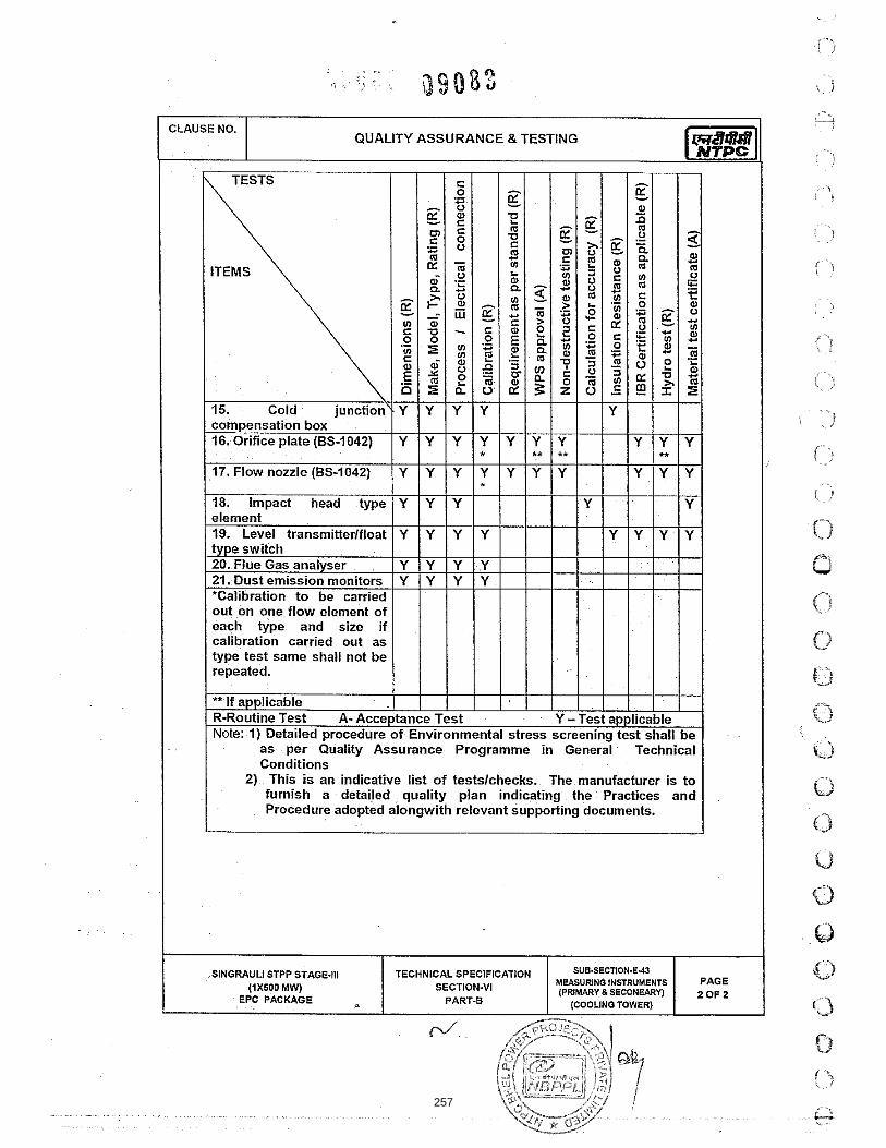
257

258

259
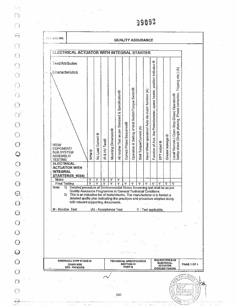
260

BHEL SPEC Rev. No.:0
1. CIVI
C. NO. :PE-TS-41 Dated : 11.06
SPE
IL WORKS
TEC
FGUTP
404-165-N001 .14
ECIFIC TE
CHNICAL CONCOOLING
P STAGE‐IV (1
TECHNIC
SEC
ECHNICA
COM
NDITIONS OF TOWER PACK1X 500 MW)
CAL SPECIFICA
CTION – C
AL REQU
PRISES O
--
CONTRACTKAGE AT UNCHAHA
ATION DA
C4
IREMENT
OF
2
AR
DOC. NO.: NBPPA Rev. No.: 01
TS (CIVIL
264 PAGES
PL-004-103-03-P
L)
S
P4M-
261
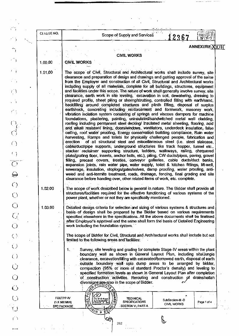
262
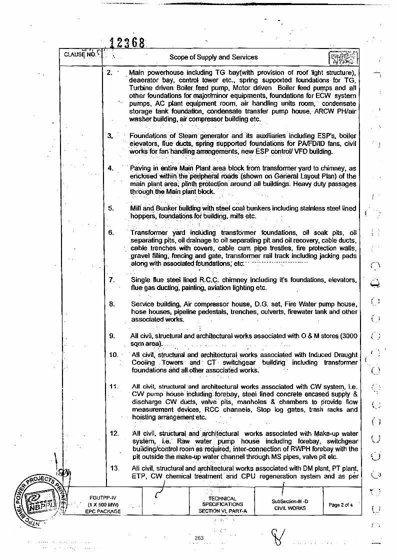
263

264

265

266

267

268
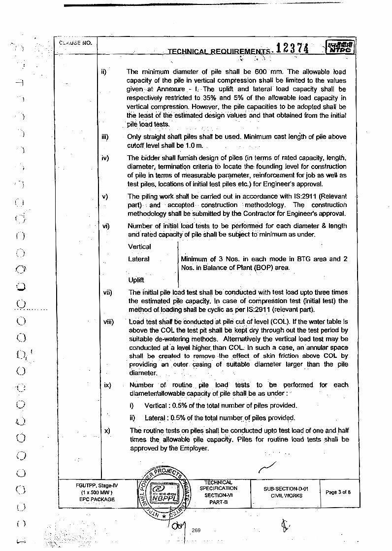
269

270

271

272
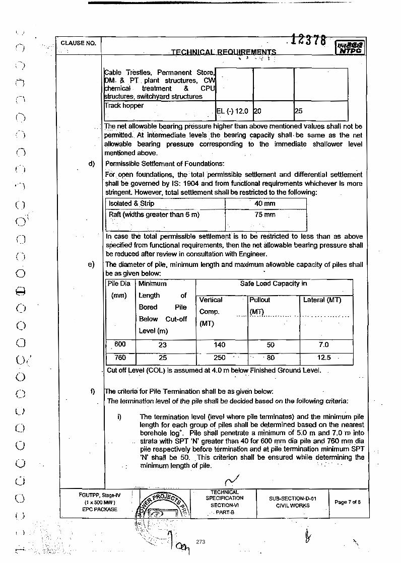
273

274
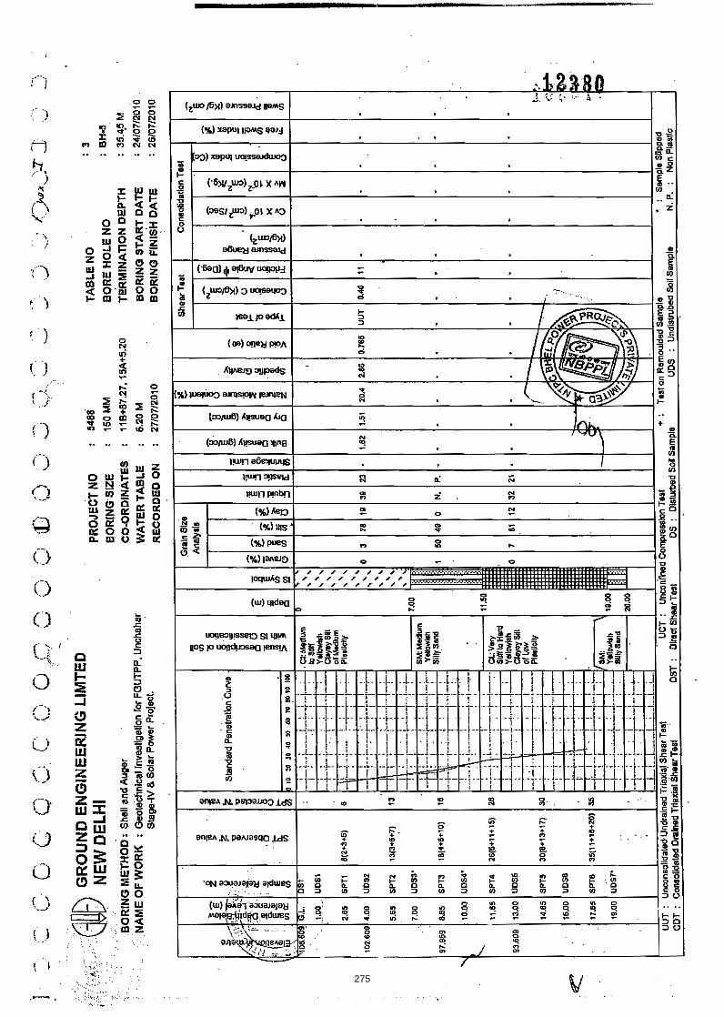
275

276

277

278

279

280

281

282

283

284

285

286

287

288

289

290

291

292

293

294

295

296

297

298

299

300

301

302

303

304

305

306
307

308

309

310

311

312

313

314

315
316
317

318

319

320

321

322

323
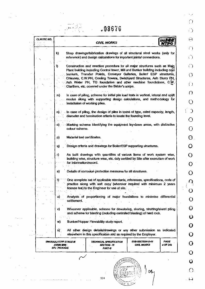
324

325

326

327

328

329

330

331
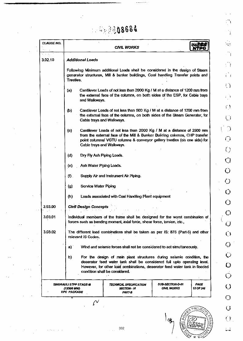
332
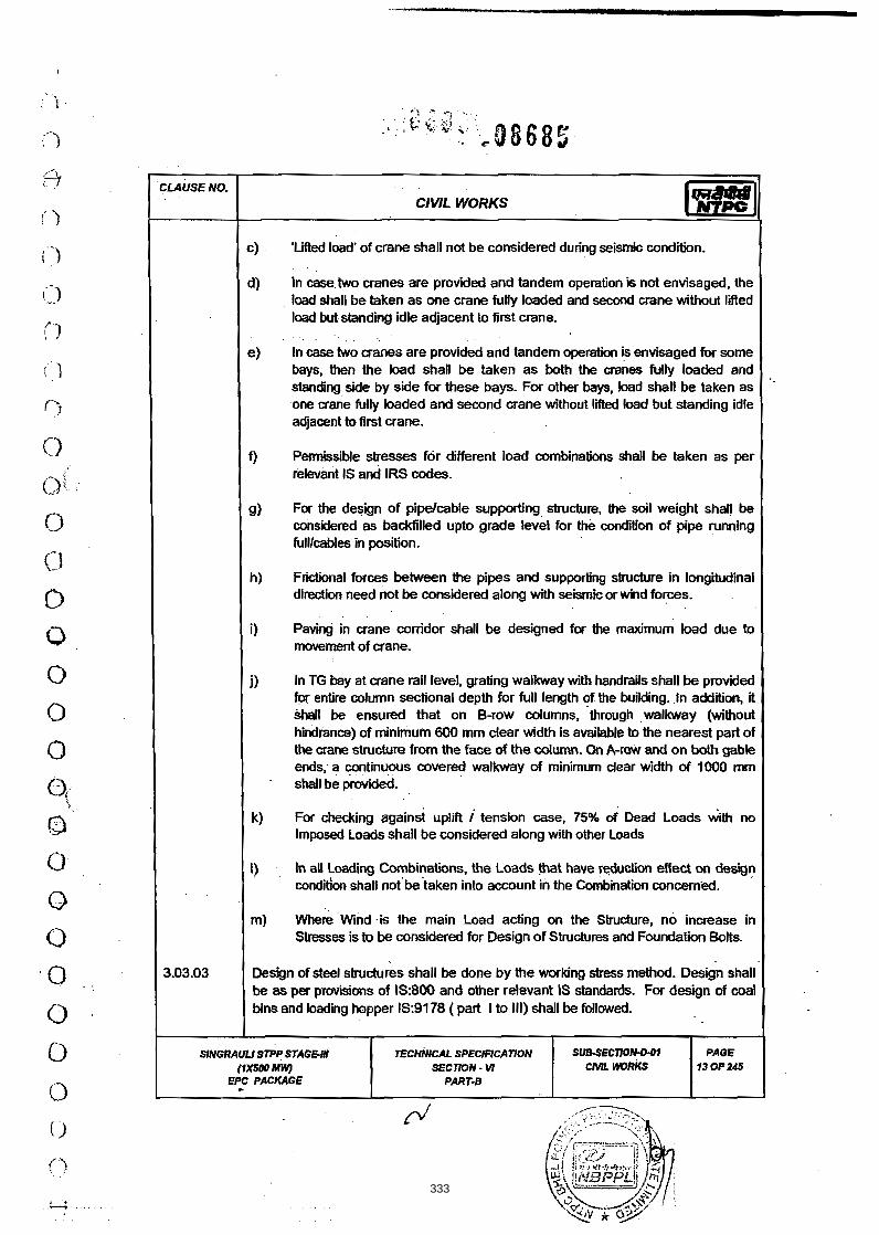
333
334

335

336

337

338

339

340

341

342

343
344

345

346

347

348

349

1 3.05.00 1 Corrosion Protection I
CLAUSE NO.
I 3.05.01 General I
CIVIL WORKS
(a) All equipments, pipes, etc. shall be painted as per the requirements specified i r i the relevant section of the specification.
(b) All Steel structures (except those embedded in Concrete) shall be provided with Painting as given below which is designed for a minimum maintenance free life of Ten (10) years (expected life, long range Ten (10) to Twenty ( 20 ) years, as per BS : 5493.
I I (c) All Paints shall be of high build constitution. I (d) All Painting shall be done as per approved Painting scheme of the Vendors I
Manufacturers, which shall be submitted by the Bidder and as approved by the Employer. Painting scheme shall also include Item codification 1 Description of all Coats of Paints for manufacturer's, from whom the Paint is intended to be procured. / 3.05.02 1 Painting of Steel Surfaces embedded in Concrete: I
(a) For the portion of Steel surfaces embedded in Concrete, the surface shall be prepared by Manual Cleaning and provided with Primer Coat of Chlorinated Rubber based Zinc Phosphate Primer of Minimum 50 Micron Dry Film Thickness (DFT).
(b) All threaded and other surfaces of foundation bolts and its materials, insulation pins, Anchor channels, sleeves, etc. shall be coated with temporary st preventive fluid and during execution of civil works, the dried film of coating shall be removed using organic solvents. I 3.05 03 ( Painting of Steel Surfacer (other than those embedded in Concrete)
(a) All Steel surfaces shall be provided with self curlng Inorganic Zinc Siltcate Primer Coat (Solid by Volume Minimum 60%) of Minimum 75 Micron Dry Ftlm Thickness (DFT) applied over blast cleaned surface to near white metal conforming to Sa 2 'A finish of Swedish standard SIS-05-5900. The Primer Coat shall be applied in Shop immediately after blast cleaning by Airless spray technique.
(b) Primer Coat shall be followed with the application of Intermediate Coat of Polyamide Cured pigmented Titanium Dioxide (Ti02) or Micaceous Iron Oxide (MIO) Epoxy based Paint (Solid by Volume Minimum 60%) of
SIMGRAULISTPP STAGE-Ill (1x500 MW)
EPC PACKAGE
TECHNICAL SPECIFICATION SECTION - M
PART-B
SUB-SECTION-0-01 CIVIL WORKS
PAGE 36 OF 245
350

Minimum 75 Micron DFT. This Coat shall be applied in Shop after an interval of Minimum overnight (from the application of Primer Coat) by Airless spray technique.
CLAUSE NO. I (c) . lntermediate Coat shall be followed with the application of Finish Coat of
Polyamide Cured colour pigmented Epoxy based Paint (Solid by Volume Minimum 60%) of Minimum 75 Micron DFT. This Coat shall be applied afler an interval of ~ i n i m u m overnight and maximum indefinite (from the application of lntermediate Coat) either before Erection by Airless spray techniqueor afler Erection by brush and 1 or spray. Colour and shade of the Coat shall be as approved by the Employer. The Finish Coat thickness of 75 Micron can be built up either in Single application at Shop or in two applications one at Shop and the other at Site.
CIVIL WORKS
(d) Finish Coat shall be followed with the application of Final Finish Coat of Polyurethane based colour pigmented Paint (Solid by Volume Minimum 40%) of Minimum 25 Micron DFT. This Coat shall be applied within Seven (7) days (from the completion of Finish Coat), afler Erection by brush and I or spray. Colour and shade of the Coat shall be as approved by the Employer.
I 3.05.04 I Touch-up Painting on damaged areas I I 1 (a) For Coatings damaged up to metal surface I
Surface preparation shall be carr~ed out by Manual Clean~ng. Min~mum 6 inches adjoining area with existing Coating shall be roughened by Wire brushing, emery paper rubbing etc., for best adhesion of patch Primer.
Over this Primer Coat, lntermediate Coat, Finish Coat and Final Finish Coal shall be applied as covered above by brush with lntermediate Coat applied within maximum seven (7) days of application of touch up Primer.
(b) For Coatings damaged upto lntermediate Coatings (i.e. where Primer Coat is intact).
Damaged area including Minimum 6 inches adjoining area with existing Coating should be roughened by wire brushing, emery paper rubbing etc., for best adhesion of patch Primer without damaging the Primer Coat.
I Touch;up Primer, Intermediate, Finish and Final Finish Coats shall be applied as specified above for Coatings damaged up to metal surface. . .
SINGRAULI STPP STAGE-IN (1x500 MW
EPC PACKAGE
P' ,,., ", 4 ' . .: ..~.. , . I;. / . . , _ ,..
~
TECHNICAL SPECIFICATION SECTION - VI
PART-B
SUB-SECTiON.DO1 CIVIL WORKS
*
PAGE 370F 245
351

- CLAUSE NO.
3.05.05
3.05.07 Coating for Mild Steel parts in contact with Water. I :
ClVlL WORKS
3.05.06
Painting of Welded areas I Painting of areas exposed after removal of temporary supports I Touch-up Painting on damaged areas Structures, where inter-connection, Welding I modification etc. has been carried out by the Bidder.
..
(a) Clean the surface to remove flux spatters and loose rust, loose Coatings in the adjoining areas of Weld seams by wire brush and emery paper.
(b) Painting procedure to be followed as mentioned above for Touch-up Painting on damaged areas.
Dry film thickness of each coat shall be checked and measured as per the procedure specified in paint application standard no. 2 by SSPC: The Society for Protective Coating. The thickness as measured shall not be less than the minimum thickness specified for the coat of paint under relevant clauses of technical specification.
(a) All mild Steel parts coming in contact with water or water vapour shall be hot dip galvanised. The Minimum Coating of Zinc shall be 610 Gms 1 Sq. M. for galvanised Structures and shall comply with IS : 4759 and other relevant Codes. Galvanising shall be checked and tested in accordance with IS : 2629.
I 3.05.08 I Gratings
'!
/ ,,i ,
i '3 . i
j . ,
* .
(3 .-,.
(b) The galvanising shall be followed by the application of an etching Primer and dipping in black bitumen in accordance with BS : 3416, unless otherwise specified.
ij - i L i.?
I 3.05.09 I Hand Railings and Ladders
All gratings shall be blast cleaned to Sa 2 % finish of Swedish standard SIS-05-5900 and shall be hot dip galvanised at the rate of 610 Gms I Sq. M.
All handrails and ladders shall be galvanised at the rate of 610 Gms I Sq. as per IS : / 4736.
; 1 f l
1 305.10 1 Sea Worthiness
I I All Steel Sections and fabricated Structures, which are required to be transported on sea, shall be provided with anti corrosive Paint before shipment to take care of sea
I worthiness.
. . . . . .
SUE-SECTION-D.07 PAGE CIVIL WORKS 38 OF 245
SINGRAULI STPP STAGE-Ill (fX500 MWJ
EPC PACKAGE
TECHNICAL SPECIFICATION SECTION - VI
PART.8
352

3.65.1; I I All structural steel members in switchyard (excluding fencing and gate) shall be hot dip galvanised as specified elsewhere.
I
CLAilSE NO.
-- - -
i) The protection for concrete sub-structure shall be provided based on aggressiveness of the soil, chemical analysis of soillsub-soil water and presence of harmful chemicals/salts.
CIVIL WORKS
3.05.12
ii) The protection to super structure shall depend on exposure condition and degree of atmospheric corrosion.
For reinforced concrete work.
This shall require use of dense and durable concrete, control of water cement ratio, increase in clear cover, use of special type of cement and reinforcement, etc.. coat~ng of concrete surface, etc.,
I I Bidder shall furnish the details of corrosion protection measures. I / 4.00.00 I FOUNDATlON SYSTEM AND GEOTECHNICAL DATA I / 4.01.00 / SOIL DATA AND FOUNDATION SYSTEM I Bearing capacity and pile capacities for design of foundations and Borelogs data are given at Annexure - I of this specification.
1 4.02.00 / Soil Data I Employer is carrying out detailed geotechnical investigation in the main plant area and balance of plant area. The detailed geotechnical investigation report comprising of Boreholes, Laboratory tests, Chemical analysis, etc. in respect of the sub-strata prevailing at site will be made available for the Bidder's study at the Employer's office, if required. The onus of correct assessment I interpretation and understanding of the existing subsoil condition I data is on the Bidder.
Foundation System
The requirements for the foundation system to be adopted are as given in subsequent clauses.
~ e n e r a l ~ e ~ u i r e m e n t s . .
(a,) All structures/equipment shall be supported either on suitable open foundations (isolated, combined, raft) or on pile foundations.
. . . .
SlNGRAULl STPP STAGE-NI (fX500 MW)
EPC PACKAGE
r /
i
TECHNICAL SPECIFICATION SECTION - VI
PART-B
SUB-SECTION.D.07 CIVIL WORKS
PAGE 39 OF 245 -
353

(b.) The roads, ground floor slabs, trenches, channelsldrains and staircase foundation with foundation loading intensity less than 5 T I M' may be supported on open / shallow foundations resting on virgin / controlled compacted filled up soil.
CLAUSE NO.
I (c.) No other foundation shall rest on the filled up ground I soil. I
ClVlL WORKS
(d.) All foundations shall be designed in accordance with relevant pads of the latest revisions of Indian Standards. The water table for design purpose shall be considered at Finished Ground Level.
(e.) A combination of open and pile foundations shall not be permitted under the same equipment 1 structure / building.
In case open foundations are adopted, following shall be adhered to.
4.03.02
(a.) The minimum width of foundation shall be 1.0 m.
(b.) The minimum depth of foundation shall be 1.0 m below natural ground level.
(c.) Minimum founding level, bearing capacity and permissible settlements shall be as given in the Annexure - 1 to this specification.
Open Foundations
Incase pile foundations are to be adopted the requirements under para "pile foundations" shall be adhered to.
i) The pile foundation shall be of RCC, Cast-in-situ bored plles as per IS:2911. Pile boring shall be done using self erecting Rotary Hydraulic Rigs. Two stage flushing of pile bore shall be ensured by airlift technique duly approved by the Employer.
4.03.03
I SINGRAULI STPP STAGE-Ni TECHNICAL SPECIFICATION SUB-SECTION-D-OI (IXSOO MW) SECTION - w CIVIL WORKS l40%%
EPC PACKAGE PART-B
Pile Foundations
In case p~ les are adopted, following shall be adhered to .
354
G 0 8 7 4 Q . ." B il
CIVIL WORKS
The minimum diameter of pile shall be 600 mm. The allowable load capacity of the pile in vertical compression shall be limited to the values given at Annexure - I. The uplift and lateral load capacity shall be respectively restricted to 30% and 5% of the allowable load capacity in vertical compression. However, the pile capacities to be adopted shall be the least of the estimated design values and that obtained from the initial pile load tests.
Only straight shaft p~les shall be used. Minimum cast length of pile above cutoff level shall be 1.0 m.
The bidder shall furnish design of piles (in terms of rated capacity, length, diameter, termination criteria to locate the founding level for construction of pile in terms of measurable parameter, reinforcement for job as well as test piles, locations of initial test piles etc.) for Engineer's approval.
The piling work shall be carried out in accordance with lS:2911 (Relevant part) and accepted construction methodology. The construction methodology shall be submitted by the Bidder for Engineer's approval.
Number of initial load tests to be performed for each diameter & length and rated capacity of pile shall be subject to minimum as under.
Vertical
Lateral Minimum of 3 Nos. in each mode in BTG area and 2 Nos. in Balance of Plant (BOP) area.
Uplift I The initial pile load test shall be conducted with test load upto three times the estimated pile capacity. In case of compression test (initial test) the method of loading shall be cyclic as per 15:2911 (relevant part).
Load test shall be conducted at pile cut of level (COL). If the water table is above the COLthe test pit'shali be kept dry through out the test period by suitable de-watering methods. Alternatively the vertical load test may be conducted at a level higher than COL. In such a case, an annular space shall be created to remove the effect of skin friction above COL by providing an outer casing of suitable diameter larger than the pile diameter.
Number of routine pile load tests to be performed for each diameter/allowable capacity of pile shall be as under :
355

i) Vertical : 0.5% of the total number of piles provided.
ii) Lateral : 0.5% of the total number of piles provided.
x) The routine tests on piles shall be conducted upto test load of one and half times the allowable pile capacity. Piles for routine load tests shall be approved by the Employer.
CLAUSE NO.
xi) In case, routine pile load test shows that the pile has not achieved the desired capacity or pile(s) have been rejected due to any other reason, then the Bidder shall install additional pile(s) as required and the pile cap design shall accordingly be reviewed and modified, if required.
xii) Testing of piles and interpretation of pile load test results shall be carried out as per 1S:2911 (Part-4). Bidder shall ensure that all t h e measuring equipment and instruments are properly calibrated at a reputed laboratory 1 institute prior to their use. Settlement I movement of the pile top shall be made by Linear Variable Differential Transducers (LVDT) having a least count of O.Olmm.
-
CIVIL WORKS
xiii) The test load on initial test piles shall be applied by means of reaction from anchor piles I rock anchors alone or combination of anchor piles I rock anchors and kentledge.
xiv) Low Strain Pile Integrity test shall be conducted on all test piles and job piles. This test shall be used to identify the routine load test and not intended to replace the use of static load test. This test is limited to assess the imperfection of the pile shafl and shall be undertaken by an independent specialist agency. The test equipment shall be of TNO or PDI make or equivalent. The process shall confirm to ASTM.
xv) Contr~bution of frictional resistance of filled up soil if any, shall not be considered for computation of frictional resistance of p~les.
Special Requirements
Details o f treatment for foundations I underground structures required to counteract soil I water chemical environment, cement type, grade of concrete, type of reinforcement, cover to reinforcement and protective coating to foundations, etc. shall be as mentioned in Annexure-I of this specification.
SINGRAULI STPP STAGE-Ill (7X500 Mw)
EPC PACKAGE
. .
TECHNICAL SPECIFICATION SECTION - W
PART-B
SUBSECTION.D.07 CIVIL WORKS
,
PAGE 42 OF 245
. *, ._
356

CIVIL WORKS l%$Fi!-l Excavation, Filling and Dewatering I For excavation works, comprehensive dewatering with well point or deep wells arrangement wherever required shall be adopted. Scheme for dewatering and design with all computations and back data for dewatering shall be submitted for the owner's information. The water table shall be maintained at 0.5m below the founding depth.
Excavation for shallow foundations shall be covered with PCC immediately after reaching the founding level. In case of any local loosening of soil or pockets are encountered at founding level during excavation the same shall be removed and compensated by PCC M 7.5. The final layer of about 300 mm thickness above the founding level shall be excavated by suitable means, so as to avoid disturbance to founding stratum.
Backfilling around foundations, pipes, trenches, sumps, pits, plinths, etc. shall be carried out with approved material in layers not exceeding 300 mm compacted thickness and each layer shall be compacted to 90% of standard proctor density for cohesive soils and to 75% of relative density for non cohesive soils.
4.05.04
/ 1.05.06 Following details shall be submitted by the Bidder before start of work at site. I
The founding level for trencheslchannels shall be decided as per functional
requirement. The bottom of excavation shall be properly compacted prior to casting of bottom slab of trenches / channels.
4.05.05
. . . . . Scheme for initial pile load tests in vertical, lateral and uplift modes along with supporting design calculations and methodology for installation of working piles and the complete piles installation data for individual pile including the pile test resultfor all piles (for reference only).
CBR tests for pavementlroad design shall be carried out by the Bidder after earth filling (if applicable) has been completed upto the formation level.
/ 4.0600 ( Sheeting & Shoring I The Bidder shall ascertain for himself the nature of materials to be excavated and difficulties, if any, likely to be encountered in excavation;executing the work. Sheet Piling, Coffer dams, sheeting and shoring, bracing and maintaining suitable slopes, draining etc. shall be provided and installed by the Bidder, to the Satisfaction of the Engineer.
. . . . . . .
PAGE 43 OF 245
SUB-SECTI0N.D-01 CIVIL WORKS
SINGRAULI STPP STAGE-Ill (7x500 MWJ
EPC PACKAGE
TECHNICAL SPECIFICATION SECTION - VI
PART4
357

CLAUSE NO.
5.00.00
CIVIL WORKS
GENERAL LAYOUTPLAN
5.01 .OO
1 I a) All Statutory requirements including safe distances between various facilities as per applicable ruleslactsllaws including local bye-laws are met.
The general layout plan proposed for the project is shown in tender drawlng. It shall form the basis for further elaboration by the Bldder for the plant faclllties, which are in hls scope. -
5.02.00
b) Face of the buildings and facilities be located in such a way so as to have an offset of mlnlmum 25m with respect to centre line of double lane road and 20 metre with respect to centre llne of single lane road.
While preparing the detailed general layout, planning the facilities in the Bidder's Scope and deciding upon the transportation and construction 1 erection strategy, and functional requirements the Bidder shall ensure the following aspects.
c) The interface requirements with the plant constructionlerect~on activities of other contract~ng agencies engaged by the Employer. These agencies engaged will be working parallely wlth the Bidder wlthin the plant premises.
d) The area for constructionlerection facilities like lay-down, pre-assembly, offices and stores is to be managed by the Bidder within the areas identified for the Project on General Layout Plan. Bidder shall have to share these areas with other contracting agencies engaged by the Employer. The final location and extent of area allocated to each Bidder shall be as directed by the Project Manager.
e) No permanent faclllty shall be located within the safety zone lim~t around the fuel Oil storage tanks, Hydrogen plant complex, etc., except those permitted by Employer
f) Transportation of all equipment and materials shall be by road as envisaged. Any other mode envisaged by the bidder may be proposed. However the same may be adopted subject to approval of the Employer.
I g) All the buildings and facilities shall be approachable by fire tenders. I
SlNGRAULl STPP STAGE-Ill TECHNICAL SPECIFICATION SUB-SECTION-0-07 PAGE (iX500 MW) SECTION - W CIVIL WORKS 74 OF 245
EPC PACKAGE PART-B
5.03.00 SITE LEVELLING . ~
A bore-holeinvestigation has been carried out and bore-logdetails are enclosed with this specification. However, these are sole^'^ for the guidance of the bidder and the Owner does not take any responsibility about the accuracy of these results and
. ~. . .
358

any variation of the said details shall not constitute a valid reason for changing the terms and conditions of the contract The Bidder shall satisfy himself about the actual nature of soillrock present at site.
.,. ,. .,. GL. .&:SE NO. I ...
A grid system of cg-ordinates has been established at site by the Owner. Permanent reference pillars have been established. It shall be the responsibility of the Bidder to protect the reference pillars at respective locations and levels until the site is finally handed over to the Owner. Any reference pillar disturbed or lost during this period for any reason whatsoever shall be replaced and re-established at the original location and level .
CIVIL WORKS
It shall be the responsibility of the Bidder that no air borne and water borne pollution should occur during all stages of his operations such, as in cutting areas, during transportation of excavated materials, during placement of fill materials, etc. It shall be the responsibility of the Bidder to undertake all measures such as water sprinkling, covering the fillldisposable materials in open trucks with tarpaulins etc. to take care of the above, if necessary.
The high grounds within the levelling boundary shall be cut to proposed formation level(s). Suitable excavated material shall be used for filling up the low grounds to proposed formation level(s) by controlled tilling.
1 I S~te levelling work will involve the following operations: I I I i) Excavation in soillrock. I I I ii) Loading, transportation and unloading of suitable material to the filling site. I
iii) Spreading of earthlrock in layers and compaction.
iv) Finishing of surfaces.
v) Sampling & testing. . .
vi) Setting out and making profiles. . .
I I The following types of materials shall not be used for filling: I I I a)
Material from swamps, marshes and bogs, I I b) Peat, logs, stumps, sod and perishable materials. I I Materials susceptible to combustion, I
affect other materials in the work.
359

Before commencement of filling, it shall be ensured that the area to be filled is clear of any vegetation, water, organic matter, slush etc. Original ground shall be compacted by rolling as directed by the Engineer subject to a minimum of six passes of 8 to 10 tonnes roller. The earth shall then be spread in horizontal layers of 500mm thickness. Each layer shall be watered and compacted with proper moisture content and with such equipment as may be required to obtain a compactionldensity of 95% of Standard Proctor's Maximum Dry Density.
CLAUSE NO.
The combined excavation and placing operations shall be such that the materials when compacted in the fill will be blended sufficiently to produce spec~fied degree of compaction.
CIVIL WORKS
Before start of filling, the Bidder shall submit to the Engineer his proposal for methodology to be adopted for compaction of fill material. The Bidder shall also carry out compaction trials to establish the proposed methodology.
The Bidder shall finalise a detailed Field Quality Assurance Programme according to the requirements of this specification. This shall include setting up of a testing laboratory, arrangement of testing apparatuslequipment, deployment of qual~fiedlexperienced manpower, preparation of format for record, Field Quality Plan etc.
The fill material shall be tested for determining optimum moisture content and maximum dry density by Standard Proctor Test as per lS:2720 (Part-ll) and (Part- VII). The fill material shall also be tested for determining moisture content before compaction as per 132720 (Part-11). For each of the above tests, one sample for every 10000 cum. of fill material shall be tested. Additional samples shall be tested, whenever there is a change in the type of fill material.
The compacted earth shall be tested for its in-situ dry density as per the procedure outlined in 1S:2720 (Part-XXIX or Part-XXVlll). Sample shall be taken at the rate of one sample for every 10,000 sq.m. area for each compacted layer. In addition random checks shall be carried out in compacted soils by means of Proctor needle penetration.
Masonry pillars shall be erected at suitable places in the area to serve as bench marks for the execution of the work. These bench marks shall be connected with GTS or any other permanent bench mark.
I 6.00.00 / MAIN PLANT, AUXILIARY BUILDINGS AND STRUCTURES I 1 6.01.00 I Main p lant shal l comprise of: I a) Main plant building shall consist of TG bay, Deaerator bay, service building I
Control room and all the auxiliary structureslfacilities located therein.
I SINGRAULI STPP STAGE-111 TECHNICAL SPECIFICATION SUB-SECllON-D-01 (1x500 MWJ SECTION - VI CIVIL WORKS
EPC PACKAGE PART-B
360

d) Patnt mater~al & its application method shall be obtained from any manufacturer who has been granted License by CECRI, Karaikudi for techn~cal know how for High Performance Moisture Compatible Corrosion Resistant Coating System. The application method of coating shall be got duly approved from CECRI, Karaikudi.
/ fO.00.00 / CW SYSTEM 8. MAKE-UP WATER SYSTEM I A cooling water pump house (CWPH) for housing coollng water pumps and Raw water pump house (RWPH) for houslng make-up water pumps shall be provided. Separate bays shall be provided for each pump by prov~dtng intermediate divid~ng plers of RCC between the pumps.
a) The pump houses shall be provided with minimum two sets of stoplogs for the respective pump bay dimensions along with electr~cally operated hoisting arrangements. Steel embedments required for stoplogs shall be provided for all the bays.
b) All bays of pump houses shall be provided with a removable trash rack including electrically operated hoisting arrangements and cleaning arrangements. Moreover, one spare trash rack of respective pump bay dimension shall also be supplied for each pump house. Steel embedments required for trashracks shall be provided for all the bays.
c) Stoplogs, trashracks and hoists shall be supplied in accordance with the specifications covered elsewhere.
The sub-structure of pump houses including their forebays shall be RCC with M-30 grade of concrete conforming to IS: 456. The superstructure of pump houses shall
'consist of structural steel frames. The pump houses shall be structurally separated from their forebays by providing an expansion joint. The pump houses shall be provided with separate maintenance bay.
The CW Pump House and Raw water Pump House shall have structural steel framed super structure with permanently colour coated metal decking as roof and permanently colour coated metal cladding on exterior face. However, brick wall cladding shall be provided up to a height of 900mm from Finished Floor Level (FFL). Above 900mm brick wall, the sheet metal cladding shall be provided with adequate overlapping with brick wall. Steel framed structure shall be made-of rolled steel section or built- up sections.
. .
. .
. , 0 f -%
rw>
i ' l
SINGRAULI STPP STAGE-I11 (7x500 MW
EPC PACKAGE
'-2
I > . I P f)l
t ( .':
, . -
- TECHNICAL SPECIFICATION
SECTION - YI PART-B
SUB-SECTION-0.01 CIVIL WORKS
PAGE 98 OF 245
361
362

363

364

365

spacing of PRV shall not exceed 5000mm. The forebay slab shall be designed against uplift due to 50% of the total water head considering ground water table upto FGL. Minimum thickness of wall at top shall be 200 mm. Hand rails with 32NB (medium) pipe shall be provided on both walls of the forebay.
CLAUSE NO.
Stoplogs and Trash Racks for CWPH 8 RWPH
CIVIL WORKS
1 10.07.01 1 Stoplog gates I Clear size of the stop logs shall be equal to the clear opening size of water inlet opening below breast wall. Number of segments of the stop log shall be decided to match the capacity of the electrically operated monorail hoist (Min 5 ton capacity) provided to handle it in the cooling water pump house and raw water pump house. Structural design of stop log shall conform to IS: 5620 and IS: 4622 (latest). Maximum water level for designing the stop logs shall be taken as maximum water level of the forebay. Top and bottom unit of stop log gates shall be designed for their respective water head, whereas the remaining interchangeable units shall be designed for the water head corresponding to the lower most interchangeable unit. The stop logs shall be operated under balanced water head and they are not to be designed for operating under flowing water. Filling valves shall be provided in the stop logs to balance the water pressure before lifting the stop log. These stop logs are used only during maintenance I inspection of pumps. The stop logs shall be operated by means of an electrically operated hoist. Suitable lifting beam shall be provided to operate the stop logs.
Trash Racks
Bar screen trash rack is to be provided at Inlet of the sump of the cooling water pump house and raw water pump house, in order to prevent ingress of timber & other floatlng particles which could damage the Pumps. Trash racks shall be with clear opening size of 50 mm. x 50mm. (max.), i.e.. the spaclng of the vertical and horizontal bars shall be 50mm.
Each bay of pump sump. shall be provided with Type - 1 trash rack (removable section rack), conforming to IS: 11388 (latest). Centre to centre spacing of trash bars shall b e 50mm (max). The trash racks shall be provided with number of interchangeable segments, to facilitate easier handling by means of a lifting beam and electrically operated hoist (Min. 5 tonne capacity). Trash bars shall be designed
- for a differential water head of 2.0m. and other structural members shall be designed for a differential water head of 1.0m. Minimum thickness of trash bars shall be 10mm. Suitable sizeof horizontal members and end members shall be provided as per design requirements, for efficient operation of trash rack.
. . . .
366

367
368
369

370

371

372

373

374

375

376

377

378

379
380
381

382

383

384

385

386

387
388

389

390

391

392

393

394

395

396

397

398

399

400

401

402

403

404

405

MATERIALS I r I~ .. .
Cement
CIVIL WORKS
Fly ash based portland pouolana cement conforming to 1S:1489 (Part-I) shall be used for all areas other thanfor the critical structures identified below. However, Engineer may allow the use of other types of cement namely, ordinary portland cement & portland slag cement conforming to IS: 269 and IS: 455 respectively under special circumstances on specific request of the bidder and prior approval of the Engineer. Minimum grade of cement shall be Grade 33. Higher grade of portland ordinary cement namely Grade 43 and Grade 53 conforming to IS:8112 and IS:12269 respectively can also be used for specific application. However the ordinary portland cement shall necessarily be used for following structures.
a) TG foundation top deck and sub-structure excluding rafl I b) Spring supported decks of all machine foundations.
c) Structures requiring grade of concrete of M25 and above
In place of fly ash based portland pozzolana cement fly ash can be added in ordinary portland cement (Grade 43). Batching plant shall be deployed for producing the concrete. Fly ash shall conform to lS:3412. Percentage of fly ash to be mixed in concrete shall be based on trial mix.
Aggregates
a) Coarse aggregate I Coarse aggregate for concrete shall be crushed stones chemically inert, hard, strong, durable against weathering of limited poros~ty and free from deleterious matenals. It shall be properly graded. It shall meet the requirements of IS: 383.
b) Fine aggregate
Sand shall be hard, durable, clean and free from adherent coatings of organic matter and clay balls or pellets. Sand, when used as fine aggregate in concrete shall conform to IS : 383. For plaster, it shall conform to IS : 1542 and for masonry work to IS : 21 16.
Reinforcement Steel
Reinforcement steel shall be of high strength deformed TMT steel bars of grade'~e- 500 and shall conform to IS:1786. . . . . .
I
SINGRAULI STPP STAGE-111 (fX500 Mw)
EPC PACKAGE
TECHNICAL SPECIFICATION SECTION - VI
PART.B
SUB-SECTlON.D.Of CIVIL WORKS
:..
PAGE 213 OF245
406

Mild steel & medium tensile steel bars and hard drawn steel wire shall conform to grade-I of 1S:432 (Part-I) or grade A of 1S:2062. Welded wire fabric shall conform to IS:1566.
CLAUSE NO.
1 23.01.00 1 Structural Steel I
CIVIL WORKS
Structural Steel (includ:ng embedded Steel) shall be straight, sound, free frorn twists. cracks. flaw, lam~natlons and all ottier defects.
( 23 04 01 ( Mild Steel
a) Rolled sectlons and plates up to and including 20mm th~ckness shall conform to grade designation E250A semi k~lled of IS: 2062. Plates beyond 20mm th~ckness and up to 40mm thickness shall conform to grade designation E250B killed and controlled rolling conforming to lS:2062 Plates beyond 40mm thickness, shall conform to grade designation E250B killed. normalizing rolling as per IS:2062. Plates beyond 40mm shall be ultrasonically tested as per ASTM-A578 level B.
I Pipes shall conform to IS: 1161. I I I c) Hollow (square and rectangular) steel sections shall be hot formed
conforming to IS: 4923 and shall be of minimum Grade Yst 240.
i
d) Chequered plate shall conform to IS 3502 and shall be minimum 6 mm thick excluding projection. Steel for chequered plate shall conform to grade E250A semi killed of IS: 2062.
( Medium and High Tensile Steel I Rolled sections and plates up to and including 20mm thickness shall conform to grade designation E350 semi killed of IS: 2062. Plates beyond 20mm thickness and up to 40mm thickness shan conform to grade designation E350 killed and controlled rolling. conforming to IS:2062. Plates beyond 40mm thickness, shall conform to. grade designation E350 killed. normalizing rolling as per 15:2062. Plates beyond 40mm shall be ultrasonically tested as per ASTM-A578 level B.
1 Bricks I Fly ash lime bilcks conforming to 1S:12894 and fly ash clay brlcks conforming to IS:13757 shall be used. The crushing strength of bricks shall be m~nimum 75 kg./sq em. Minimum percentage of fly ash shall be 25%.
SINGRAULI STPP STAGE-NI SUB.SECT1ON-0-01 CIVIL WORKS
0 'Ph
t i t
C) 6' .,'
0 ('a -. .l
{ i C.2
,- . (3
0
" 2 $~*.
9.
i-i 1
O
407
1 :.:: >"DO I Water
I I
- , ..- ,-
j i ,;* . . ,.,>ENO. 1 i .. . r
1 Statutory clearances and norms of State Pollution Control Board shall be followed. I
CIVIL WORKS
Bidder shall obtain approval of Civil/Architectural drawings from concerned authorities before taking up the construction work.
Water used for cement concrete, mortar, plaster, grout, curing, washing of coarse aggregate, soaking of bricks, etc. shall be clean and free from oil, acids, alkalis, organic matters or other harmful substances in such amounts that may impair the strength or durability of the structure. Potable water shall generally be considered satisfactory for all masonry and concrete works, including curing. When water from the proposed source is used for making the concrete, the maximum permissible impurities, development of strength and initial setting time of concrete shall meet the requirements of 1S:456.
All materials brought for incorporation in works shall be of best quality as per IS unless specified otherwise.
STATUTORY REQUIREMENTS
Bidder shall comply with all the applicable statutory rules pertaining to Factories Act, Fire Safety Rules at Tariff Advisory Committee. Water Act for pollution control, Explosives Act, etc.
Provisions of safety, health and welfare according to Factories Act shall be complied with. These shall include provision of continuous walkways along the crane - girder level on both sides of building, comfortable approach to EOT crane cabin, railing, fire escape, locker room for workmen, pantry, toilets, rest room etc.
Provisions for tire proof doors, number of staircases, fire separation wall, lath plasteringlencasing the structural members (in fire prone areas), type of glazing etc. shall be made according to the recommendations of Tarrif Advisory Committee.
24.00.00 INSPECTION, TESTING AND QUALITY CONTROL I I Sampling and testing of major items of civil works viz. earthwork, concreting, structural steel work (including welding), piling, sheeting, etc. shall be carried out in accordance-with the requirements of this specification. Wherever nothing is specified relevant Indian Standards shall be followed. In absence of Indian Standard equivalent International Standards may be used.
408

specification. This shall include frequency of sampling and testing, natureltype of test, method of test, setting of a testing laboratory, arrangement of testing apparatuslequipment, deployment of qualifiedlexperienced manpower, preparation of format for record, Field Quality Plan, etc. Tests shall be done in the field andlor at a laboratory approved by the Engineer. The Bidder shall furnish the test certificate from the manufacturer's of various materials to be used in the construction.
CLAUSE NO. CIVIL WORKS
/ 25.00.00 / PERMISSIBLE TOLERANCES
1 24.02.00 ( Workmanship and dimensional shall be checked as stipulated below.
The dimensions of concrete as cast when compared with those on the drawings shall be within the tolerances given below in mm.
25.01 .OO Cast-in-situ concrete works
I
Description of Item1 Structural Permissible element Deviation in mm (Max)
Faces of concrete in foundations and structural members against which backfill is placed + 25 - 10
Location of footing (for RCC framed structures only) + 25 - 25 Eccentricity of footing 2% of footing width in
direction of misplacement but limiting to 50mm.
Top surfaces of slabs and of concrete to receive base plates to be grouted. + 5
Alignment of beams, lintels, columns, walls, slabs, and similar structural elements.
Cross sectional dimensions of walls, slabs and similar structural elements
Deviation from specified dimensions of cross-section of columns and beams. + 12 - 6
SINGRAULI STPP STAGE-Ill TECHNICAL SPECIFICATION CIVIL WORKS
409

r " 0 8 8 8 3 CIVIL WORKS
Alignment of holding down bolts without sleeves
Alignment of holding down bolts with sleeves + 5 - 5
Level of holding down bolt assemblies. + 10 - 10
imbedded parts (in any direction). + 5 - 5
Centres of pockets or holes with greatest lateral dimension not exceeding 150mm + 10 - 10
Variation in steps:
I I Riser + 1.5 -1.5 I 1 / Tread + 3.0 -3.0 I
Plumb
Form work
Levels and heights
Plumb
3 mm for evely metre subject to a maximum of 10 mm.
3mm for every metre subject to a maximum of 10 mm.
Unevenness of any surfaces - + 3 m m
Length or breadth - + 12 mm
/ Diagonals - + 1 5 m m I In case of inclined surfaces like folded plates etc, the deviation in the alignment of inclined surfaces, shall not exceed 3 mm with reference to the theoretical alignment, for a length of 1000 mrn measured vertically, subject to a maximum of 10 rnm.
1 25.03.00 1 Masonry I All masonry shall be built true and plumb within the tolerances prescribed as below. Care shall be taken to keep the perpends properly aligned.
SlNGRAULl STPP STAGE-Ill TECHNICAL SPECIFICATION SUB-SECTION-0-01
SECTION- VI CIVIL WORKS
410

a) Deviation in verticality in total height of any wall of a building more than one storey in height shall not exceed +I-12.5mm.
, b : > r ,. 8 , *
I b) Deviation from vertical within a storey shall not exceed +I- 6mm per 3m 1
CLAUSE NO.
I height.
CIVIL WORKS
c) Deviation from the position shown on the plan of any brickwork more than one storey in height shall not exceed 12.5mm.
I I d) Relative displacement between load bearing walls in adjacent storeys intended to be in vertical alignment shall not exceed 6mm.
e) Deviation of bed joint from horizontal in any length upto 12m shall not exceed 6mm, and in any length over 12m it shall not exceed 12.5mm total.
f) Deviation from the specified thickness of bed-joints, cross joints or perpends shall not exceed +I-3 mm.
I 2504.00 1 Plastering work I I I The finished plastered surface shall not show any deviation more than 4 mm when
checked with a straight edge of 2 metre length placed against the surface.
The thickness of the plaster shall be measured exclusive of the thickness of key i.e. grooves or open joints in brickwork. The average thickness of plaster shall not be less than the specified thickness. The minimum thickness over any portion of the surface shall not be less than the specified thickness by more than 3 mm for plaster thickness above 12mm and 1 mm for ceiling plaster. Extra thickness required in dubbing behind rounding of the corner at junctions of wall or in plastering of masonry cornices etc. shall be ignored.
/ 2505.00 1 Pre-cast concrete work I a ) . Length: +I-0.1 percent subject to minimum of - 5 mm and maximum of + 10
mm.
I b) Cross-sectional dimensions: +I- 3 mm or +I-0.1 per cent whichever is greater. I
I 1 c) Straightness of Bow : 11750 of the length subject to minimum of -5mm and maximum of + IOmm.
d) Squareness: When considering the squareness of the corner, the length of the two adjacent sides being checked shall be taken as the base line. The shorter side shall not vary in length from the perpend~cular by more than
SINGRAULI STPP STAGE-NI TECHNICAL SPECIFICATION SUB-SECTION-D.07 CIVIL WORKS
411

CIVIL WORKS
e) Flatness: The maximum deviation from a 1.5m straight edge placed in any position on a nominal plane surface shall not exceed 5mm. I
Placing of reinforcement
For effective depth 200 mm or less + 10
25 riE 32
i / For effective depth more than 200 mm + I 5
Reinforcement work Description o f Item/ Permissible Deviation Structural element in mm (Max.)
Cover to reinforcement
Cutting of reinforcement
When minimum length specified + 75
When maximum length specified +75
When maximum or minimum length not specified + 75
I Between setting out point 50 mm in position & level I
25.07.00
Flanges for condenser
Tolerance in erected C. W. liners/pipes
At setting out points 25 rnrn in position & level
6 mm in position & level connections and the plane of the flanges shall be within 3 mm of the requ~red plane measured across any diameter.
6 m h in position & level & the plane of the flange shall be within 0.3% of the dia. or l m m whichever is greater, of the required plane measured across any diameter.
25.08.01 Tolerances on dimensions for fabrication of steel structures shall be according to IS:7215.
. . . . .
PAGE 219 OF245
n/
SUB-SECTION-D-01 CIVIL WORKS
SlNGRAULl STPP STAGE-IN (9x500 MWJ
EPC PACKAGE
TECHNICAL SPECIFICATION SECTION- YI
PART-B
412

CLAUSE NO.
CIVIL WORKS
25.08.02
25.08.03
25.08.04
I 26.00.00 I LIST OF CODES AND STANDARDS I
Tolerances on d~mens~ons for erection of steel structures shall be according to IS:12843.
Tests on welds shall be as per ASTM standardslls 816 and IS 9595.
Dimensional and weight tolerance of rolled steel shapes shall be as per IS 1852.
25.09.00
All applicable standards, references, specifications, codes of practice, etc., shall be the latest edition including all applicable official amendments and revisions. A complete set of all these documents shall be available at site with Bidder. List of some of the applicable Standards, in original Codes and references is as given in Annexure-I1 of this specification.
Maximum deviation of tinished pile from vertical 1 in 75 and other tolerance shall be as per IS: 291 1, (Part I).
I Z7.00.00 I CONSTRUCTION METHODOLOGY I I Construction and erection activities shall be fully mechanised from the start of the I I work.
All excavation and backfilling work shall be done using excavators, loaders, dumpers, dozers, poclains, excavator mounted rock breakers, rollers, sprinklers, water tankers, etc. Manual excavation can be done only on Isolated places with specific approval of engineer.
For controlled rock blasting specialized agency, equipped with sensors to assess the Impact of the blast on the adjoining existing structures, shall be employed.
Dewatering shall be done using the combination of electrical and standby dlesel pumps.
Pile installation equipment suitable for flushing with alr lift technique shall be used for construction of bored p~les.
For concreting, weigh batching plants, trans~t mixers, concrete pumps, hoists, etc. shall be used.
All fabrication and erection activities of structural steel shall be carried out using automatic submerged arc welding machines, cutting machines, gantry cranes. crawler mounted heavy cranes and other equipment like heavy plate bending machines, shearing machines, lathe, m~lling machines, etc. Use of derricks shall not
SINGRAULI STPP STAGE-IN (7x500 Mw)
EPC PACKAGE
/J
TECHNICAL SPECIFICATION SECTION - VI
PART-B
SUB.SECT!ON-D-07 PAGE CIVIL WORKS 220 OF 245
413

be permitted. Special enclosures, for blast cleaning of steel structure surface preparation, shall be used.
?
it 4JSE NO.
-
All handling of materials shall be with cranes. Heavy trailers shall be used for transportation.
CIVIL WORKS
Mechanized modular units of scaffolding and shuttering shall be used. I ! i
i Grouting shall be carried out using hydaulically controlled grouting equipment. I
I / Roadwork shall be done using pavers, rollers and premix plant. I All finishing items shall be installed using appropriate modern mechanical tools. Manual punching etc. shall not be permitted.
Heavy duty hoists for lifting of construction materials shall be deployed. Compressors for cleaning of foundations and other surfaces shall be used.
Field laboratory shall be provided with all modern equipment for survey, testing of soil, aggregates, concrete, welding, etc. For testing of steel works, ultrasonic testing machines, radiographic testing machines, dye penetration test equipment, destruction testing equipment, etc. shall be deployed.
All persons working at site shall be provided with necessary safety equipment and all safety aspects shall be duly considered' for each constructionl erection activity. Moreover, only the persons who are trained in the respective trade shall be employed for executing that particularwork..
. ~
. . ~ ~
~ . . . . . .
SINGRAULI STPP STAGE-Ill (fX500 M y
EPC PACKAGE
/V
TECHNICAL SPECIFICATION SECTION - VI
PART-B
SUB-SECTION-0-01 CIVIL WORKS
*
PAGE ZZI OF 245
414

LIST OF CODES AND STANDARDS
Excavation and Filling
IS :2720 Methods of test for soils(relevant parts)
1S:4701 Code of practice for earth work on canals
I I lS:9759 Guide lines for dewatering during construction. I lS:10379 Code of practice for field control of moisture and compaction of so~ls
for embankment and sub-grade.
Properties, Storage and Handling o f Common Building Materials
I I S:269 33 grade for ordinary Portland cement. I / IS:383 Coarse and f ~ n e aggregates from natural sources for concrete
1S:432 Spec~fication for mild steel and medium tensile steel bars and (Part 182) hard drawn steel wires for concrete reinforcement.
I / lS:455 Portland slag cement. I IS:702 Industrial bitumen.
IS:712 Specification for building limes.
I I 1S:1077 Common burnt clay buidling bricks. I I IS:1161 Steel tubes for structural purposes. I I Mild steel tubes, tubulars and other wronght steel fillting - MS tubes. I I IS:1363 Hexagon head bolts, screws and nuts of productions
(Part 1-3) grade - C. I
LSA364 Hexagon head bolts, screws and nuts of productions (Part 1-5) grade-A & B.
Technical supply condition for threaded fasteners.
. .
SECTION - M C l V L WORKS
415

1S:1489 Portland-pozzolana cement (Part-I) Fly ash based
1S:1542 Sand for Plaster.
- ,. ,. .,
i':. iwt" iNO,
.
I 1S:1566 Hard drawn steel wire fabric for concrete reinforcement. I
CIVIL WORKS I-1
IS:1786 High strength deformed steel bars &wires for concrete reinforcement.
lS:2062 Steel for general structural purposes.
1S:2116 Sand for masonry mortars.
IS : 2185 Hollow & solid concrete blocks. (Part 1) (Part 2) Hollow &solid light weight cancrete blocks.
lS:2386 Testing of aggregates for concrete. (Part I-VIII)
I 1S:3819 Specification for fly ash for use as pozzolona and admixture. I IS:4082 Recommendation on stacking and storage of construction materiel
and components at site
1 1S:8112 43 grade ordinary portland cement. I IS:8500 Structural steel-Microalloyed (Medium and high strength qualities). I 15:12269 53 grade ordinary portland cement. I lS:12894 Specification for fly ash lime bricks.
1S:13757 Burnt clay fly ash building bricks. I Cast in-situ Concrete and All ied Works I 1S:280 Mild steel wire for general engineering purpose
1S:456 Code of practice for plain and reinforcement concrete.
IS457 Code of practice for general construction of plain and reinforced concrete for damsand other massive structures.
IS:516 Method of test for strength of concrete. I
416

I 1 1s:1199 Methods of sampling and analysis of concrete. I
CLAUSE NO.
I I lS:1791 General requirement for batch type concrete mixers. I
CIVIL WORKS
( ( IS:1834 Hot applied sealing compound for joints in concrete. I 1 I Preformed fillers for expansion joints in concrete pavement and
structures.
I 1 lS:2438 Specification for roller pan mixers. I IS:2502 Code of practice for bending and fixing of bars for concrete
reinforcement.
1 / 1S:2505 Concrete vibrators - immersion type. I 1 1 15:2506 General requirements for screed board conwete vibrators. I
lS:2722 Specification for Portable Swing weigh batchers for concrete (single and double bucket type).
I / lS:2750 Steel scaffoldings I 1S:2751 Recommended practice for welding of mild steel plain and deformed
bars for reinforced construction.
I / 1S:ll lO Hexagonal wire netting for general purposes. I I 1 lS:3366 Specification for pan vibrators. I
iS:3370 Code of practice for concrete structures for the (Part 1-4) storage of liquids.
15:3558 Code of practice for use of immersion vibrators for consolidating concrete.
lS:4014 Code of practice for steel tubular scaffolding (Part-I &2)
IS4326 Code of practice for earth quake resistant design and construction of buildings.
lS:4656 Form vibrators for concrete.
I 1 1S:4925 Concrete batching and mixing plant. I SUB-SECTION-D-07
CIVIL WORKS
417

1 1 lS:4990 Plywood for concrete shuttering work. I
[;; -,-;-!: fiJ0,
i I IS:5256 Code of practice for sealing expansion joints in concrete lining on
1 canals. I
CIVIL WORKS [-I
I
i I IS6461 Glossary of terms relating to cement concrete. i I 1 i
155525 Recommendations for detailing of reinforcement in reinforced concrete works.
1 ( S:6509 Code of practice for installation of joints in concrete pavements. I i I
1S:7861 Code of practice for extreme weather concreting. (Part -1&2)
1S:6494 Code of practice for water proofing of underground reservoir and swimming pools.
I IS9012 Recommended practice for shotcreting.
1 1 IS:9103 Admixtures for concrete. I lS:9417 Recommendations for welding cold worked bars for reinforced
concrete construction.
I I IS:10262 Recommended guidelines for concrete mix design. I IS:11384 Code of practice for composite construction in structural steel and
concrete.
IS:12118 Two parts polysulphide based sealants.
I I IS:12200 Code of practice for provision of water stops at transverse construction joints in masonry and concrete dams.
I I IS:13311 Non destructive testing of concrete - methods of test. I I I (part1) Ultrasonic pulse velocity. I
(Part 2) Rebound hammer.
SP-16 Design codes for reinforced concrete to 1S:456-1978.
I 1 sP-23
Hand book of concrete mixes. I.
418

SP-24 Explanatory handbook on Indian standards code for plain and reinforced concrete. (IS : 456)
CLAUSE NO.
Hand book on concrete reinforcement and detailing. I
CIVIL WORKS
I Ac1-318
American Concrete Institute code for structural concrete. I I Precast Concrete Works I I I SP:7 National Building Code -Structural I I I (Part 61Sec.7) Design of prefabrication and system building. I
lS:10297 Code of practice for design and construction of floors and roofs using precast reinforcedlprestressed concrete ribbed or cored slab units.
lS:10505 Code of practice for construction of floors and roofs using pre-cast reinforced concrete waffle units.
I I Masonry & All ied Works I I 1 lS:1905 Code of practice for structural use of unreinforced masonry. I I 1S:2212 Code of practice for brick work. I I I lS:2250 Code of practice for preparation and use of masonry mortars. I I / IS:2572 Code of practice for construction of hollow concrete block masonry.
I I SP:20 Hand book on masonry design and construction. I
Sheeting Works I I 1 1S:277 Galvanised steel sheets {Plan & corrugated). I
Cold-rolled low carbon steel sheets & strips. I I 1 1S:730 Hook bolts for corrugated sheet roofing. I
1S:801 Code of practice for use of cold formed light gauge steel structural members in general building construction.
. .
lS:2527 Code of practice for fixing rain water gutters and down pipe for roof drainage.
419

1 1S:7178 Technical supply condition for tapping screw
--- C L AUiE NO.
-
1 IS8183 Bonded mineral wool.
CIVIL WORKS
/ 1S:8869 Washers for corrugated sheet roofing.
lS:12093 Code of practice for laying and fixing of sloped roof covering using plain and corrugated galvanised steel sheets.
15:12436 Preformed rigid Polyurethane (PUR) and isocyanurate (PIR) foams for thermal insulation.
lS:12866 Plastic translucent sheets made from thermosetting polyester resin (glass fibre reinforced).
I 1S:14246 Continuously pre-painted galvanised steel sheets and coils.
1 BS:5950 Code of practice for design of light gauge profiled
(Part8) steel sheeting
/ Fabrication and Erection of Structural Steel Works
IS:800 Code of practice for General Construction of steel.
( IS:813 Scheme for symbols for welding
15:814 Covered electrodes for manual metal arc welding of carbon &carbon manganese steel.
13816 Code of practice for use of metal arc welding for general construction in mild steel.
1S:1181 Qualifying tests for Metal Arc welders (engaged in welding structures other than pipes).
'
1S:1182 Recommended practice for Radiographic examinat~on of fusion welded butt joints in steel plates
IS:817 Code of practice for training and testing of metal arc welders.
IS:1024 Welding in bridges and substructured subject to dynamic.
I IS:1608 Mechanical testing of metals -tensile testing
SINGRAULI STPP STAGE-(N TECHNICAL SPECIFICATION I SUB-SECTl0N.D-Ol
(rX500 Mw) SECTION - VI CIVIL WORKS EPC PACKAGE PART-B
420

CLAUSE NO. CIVIL WORKS
IS:1852 Rolling and Cutting Tolerances for Hot rolled steel products.
1S:2016 Specification for Plain washers.
1S:2595 Code of practice for Radiographic testing
Hot dip galvanising of iron and steel
Steel chequred plate.
Acceptance tests for wire flux combinat~on for submerged arc welding.
Code of practice for liquid penetrant flaw detection. I Code of practice for ultra sonic pulse echo testing contact and immersion method
High strength structural bolts. I High strength bolts in steel structure - code of practice. I Sub merged arc welding of mild steel and low alloy steel Recommendation
Hot dip zinc coating on structural steel and other allied 1 Code of practice for magnetic particle flaw detection of welds. I General requirements for plain washers and lock washer I
IS : 6623 High strength structural nuts.
1S:6649 Hardened and tampered washers for high strength structural bolts & nuts.
IS:6911 Stainless steel plate, sheet and strip.
IS:7205 Safety code for erection of structural steel
IS:7215 Tolerances for fabrication of structural steel.
iS:7307 Approved test for welding procedures
(Part - I) Fusion welding of steel.
, I
I SINGRAULI STPP STAGE-Ill I TECHNICAL SPECIFICATION (7x500 MW) SECTION - M
EPC PACKAGE PART-8 .. ~ \,
421

CIVIL WORKS
Approval test for welders working to approval welding procedure. Fusion welding of steel
Criteria for design of steel bins for storage of bulk material.
15:9595 Recommendations for metal arc welding of carbon & carbon manganese steel.
lS:12843 Tolerances for erection of steel structures.
IS1 Hand book for structural Engineers.
Plastering and Allied Works
Code of practice for application of cement and cement lime plaster
Code of practice for external rendered finishes.
Gypsum building plaster.
Ac id a n d Alkali Resistant Lining
Ready mixed paint, brushing, bituminous, black, lead free, acid, alkali & heat resisting.
Expanded metal steel sheets for general purpose.
Code of practice for use of silica type chemical resistant mortars.
Code of practice for use of resin type chemical resistant mortars.
Method of Test for chemical resistant tiles.
Ceramic unglazed vitreous acid resisting tiles.
1~:4832 . Specification for chemical resistant mortars.
(Part - 1) Silicate type
SINGRAULI STPP STAGE-NI TECHNICAL SPECIFICATION SUB-SECTI0N.D-01
SECTION - VI CIVIL WORKS EPC PACKAGE PART-8 -
P
422

(Part - 2) Resin type
CLAUSE NO.
(Part - 3) Sulfur type
CIVIL WORKS
13:4860 Acid resistant bricks.
IS:9510 Bitumastic acid resisting grade.
Water Supply, Drainage a n d Sanitation
I I lS:458 Precast concrete pipes (with & without reinforcement). I I I Dimensions for pipe threads, where pressure tight joints are required
on the thread.
1S:651 Salt glazed stoneware pipes and fittings.
1S:774 Flushing cisterns for water closets and urinals.
lS:775 Cast iron brackets and supports for wash basins and sinks
I / lS:778 Copper alloy gate, globe and check valves for water works purposes. I IS:781 Cast copper alloy screw down bib taps & stop valves for water
seivices.
lS:782 Caulking lead.
1S:783 Code of practice for laying of concrete pipes.
1 I IS:1172 Code of basic requirements of water supply, drainage and sanitation. I 1 I IS:1230 Cast iron rain water pipes and fittings. I
lS:1239 Mild Steel tubes, tubulars and other wrought steel fittings (Part 18.2)
I 1 IS:1535 Centrifugally cast (Spun) iron pressure pipes for water. I I 1 1S:1537 Vertically cast iron pressure pipes for water, gas and sewage. I
Cast iron fittings for pressure pipe for water, gas and sewage.'
copper alloy float val& for water supply fitting.
TECHNICAL SPEClFlCATlON
423

i Cast iron manhole covers and frames.
! I
I ! ' 'ENO.
I
1S:1729 Sand cast iron spigot and socket soil, water and ventilation pipes, fittings and accessories.
CIVIL WORKS
1S:1742 Code of practice for building drainage.
1S:2064 Selection, installation and maintenance of sanitary appliances.
1 1S:2065 Code of practice for water supply in buildings. I 1S:2326 Automatic flushing cisterns for urinals.
I IS:2548 Plastic seats and covers for water closets. I lS:2556 Vitreous sanitary appliances (vitreous china).
I Code of practice for laying of cast iron pipes. I I Waste plug and its accessories for sinks and wash basins. I 1 1S:3438 Silvered glass mirrors for general purposes. I
1S:3486 Cast iron spigot and socket drain pipes,. I 1S:3589 Seamless or electric welded steel pipes for water, gas and sewage
(168.3 mm to 2032 mm outside diameter).
lS:3989 Centrifugally cast (Spun) iron spigot and socket soil, waste and ventilating pipes, fittings and accessories.
1S:4111 Code of practice for ancillary structure in sewerage system. (Part 1 to 5)
. ~ 1 IS:4127 Code of practice for laying of glazed stone ware pipes
IS:4764 Tolerance limits for sewage effluents discharged into inland surface waters.
IS34827 Electroplated coating of nickel and chromium on copper and copper alloys.
Code of practice for sanitary pipe work aboveground for buildings. I 1S:5382 Rubber sealing rings for gas mains, water mains and sewers. I
SINGRAULI STPP STAGE-IN TECHNICAL SPECIFICATION SUB-SECTION-D-07 (iX500 MWJ SECTION - VI CIVIL WORKS
EPC PACKAGE PART-B
424
1S:5822 Code of practice for laying of electrically welded steel pipes for water
supply.
1S:5961 Specification for cast iron grating for drainage purpose.
CLAUSE NO.
I I '1S:7740 Code of practice for construction and maintenance of road gullies. I
CIVIL WORKS
lS:8931 Copper alloy fancy single taps combination tap assembly and stop valves for water services.
I Polyethylene floats for float valves. I IS:10592 Industrial emergency showers, eye and face fountains and
combination units.
1S:12592 Specification for precast concrete manhole covers and frames
1S:12701 Rotational moulded polyethylene water storage tanks.
lS:13983 Stainless steel sinks for domestic purposes.
SP:35 Hand book on water supply and drainage with special emphasis on plumbing.
CPH&EEO Manual on sewage and sewage treatment
Publication - as updated.
Doors Windows and Allied Works
lS:204 Tower Bolts.
(Part 1) Ferrous metals
(Part 2) Non -ferrous metals
1S:208 Door Handles.
IS:281 Mild steel sliding door bolts for use with padlocks
Parliament Hinges.
Putty, for use on metal frames.
. . .. . . . . .
425

C
CIVIL WORKS
I IS:451 Technical supply conditions for wood screws
1S:733 Wrought aluminium and aluminium alloy bars, rods and sections for general engineering purposes.
IS:1003 Timber panelled and glazed shutters (doors shutters). (Part I)
1 1S:1003 Timber panelled and glazed shutters
door shutters.
Steel doors, windows and ventilators
Code of practice for fixing and glazing of metal (steel and aluminium) doors, windows and ventilators.
Wrought aluminium and aluminium alloy extruded round tube & hollow section (for general engineering purposes).
Steel butt hinges
Steel windows for Industrial buildings.
Floor door stoppers
Anodic coatings on Aluminium and its alloys
Wooden flush door shutters (solid core type) part~cle
board face panels and hard board face panels
'Mortice locks (vertical type)
Safety glass.
General purposes
Flat transparent sheet glass.
Code of practice for glazing in bu~ldings.
Door closers (Hydraulically regulated)
SINGRAULI STPP STAGE-Ill (iX500 Mw)
EPC PACKAGE
N
TECHNICAL SPECIFICATION SECNON - M
PART-8
SUB-SECTION-0-07 CIVIL WORKS
- PAGE
233 OF 245
426
I 1 1S:3614 Specification for fire check doors : I
CLAUSE NO.
(Part-I ) plate, metal covered and rolling type
CIVIL WORKS
(Part-2) Resistance test and performance criteria,
1S:4351 Specification for steel door frames.
I 1 155187 Flush bolts. I 1S:5437 Figured, rolled and wired glass.
IS:6248 Specification for metal rolling shutters and rolling grills
1S:6315 Specification for floor springs (Hydraulically regulated) for heavy doors.
15:7196 Hold fast.
IS:7452 Hot rolled steel sections for doors, windows and ventilators
IS:10019 Mild steel stays and fasteners. I 1 lS:10451 Steel sliding shutters (top hung type) I I 1 lS:12823 Prelaminated particle boards. I
Roof Water Proofing and Allied Works
IS:3067 code of practice for general design details and preparatory work for damp proofing and water proofing of buildings. 1 ASTM Standard specification for high solid content cold I
I I C836-89a liquid applied elastomeric water proofing membrane for use with separate wearing course.
I 1 ASTM Standard guide for high solid content cold I C898-89 liquid applied elastomeric water proofing membrane for use with
separate wearing course.
I I Floor Finishes and Allied Works I . .
lS:531 8 1 I . . Code of practice for laying offlexible PVC sheet and tile flooring. I I SINGRAULI STPP STAGE-NI TECHNICAL SPECIFICATION SUB.SECTlON-D-01
(1x500 MWJ SECTION - VI EPC PACKAGE PART-B
427

I White portland cement. I
CL4dSE NO.
1 lS:13755 Dust pressed ceramic tiles with water absorption of 3%, E 6% (Group I
CIVIL WORKS
Bl la ) .
lS:13801 Chequered cement concrete tiles.
/ Painting and Allied Works I I IS:162 Ready mixed paint, brushing fire resisting, silicate type for use on
wood, colour as required.
Distemper, oil, emulsion, colour as required. I 1 IS:1477 Code of practice for painting of terrous metals in buildings. I Pretreatment. I
I I (Part -2) Painting. I I I IS:1650 Specification for colours for building and decorative materials. I
lS:2074 Ready mixed paint, air drying, red oxide-zinc chrome, priming.
lS:2338 Code of practice for finishing of wood and wood based materials.
(Part -1) Operations and Workmanship.
(Pad -2) Schedule.
IS:2395 Code of pratice for painting concrete, masonry and plaster surfaces.
(Part-I) . . Operations and Workmanship,
(Part -2) Schedule.
I / lS:2524 Code of practice for painting of nonferrous metals in buildings. I I I (part I ) Pretreatment I I I (Part-2) Painting. I I / IS:2932 Enamel, synthetic, exterior, (a) under coating and (b) finishing. I
. ,
SINGRAULI STPP STAGE-111 SUB-SECTION-D-01 ClVlL WORKS
428

IS:4759 Hot dip zinc coatings on structural steel and other allied products.
IS:5410 Specification for cement paint.
.* ' 9 8 9 @ $ C
' . $ ;) * ;.. ; .,
1S:541 1 Plastic emulsion paint. (Part-I &2)
CLAUSE NO.
1S:6278 Code of practice for white washing and Colour washing
1S:10403 Glossary of term related to building finish.
CIVIL 'WORKS
lS:2933 Enamel exterior, (a) under coating, (b) finishing.
lS:12027 Silicone based water repellent
I 1 IS:13238 Epoxy based zinc phosphate primer (2 pack) I I I 1S:13239 Epoxy surfacer (2 pack) I 1 1S:13467 Chlorinated rubber for paints I
lS:14209 Epoxy enamel, two component glossy. I BS:5493 Code of practice for protective coating of iron and steel structures
against corrosion.
I Piling and Foundation I 1S:1080 Code of practice for design and construction of shallow foundations
on soils.
1S:1904 Code of practice for design and construction of foundation in Soils : General Requirements.
lS:2314 Steel sheet Piling sections.
1S:2911 Code of practice for design and construction of pile foundations. (Relevant Parts)
1S:2950 Code of practice for designs and const~ction of Raft foundation
(Part-1) Design
13:2974 Code of practice for design and construction of machine (Pa~t-I to 5) foundation.
SINGRAULI STPP STAGE-NI (fX500 MW
EPC PACKAGE
TECHNICAL SPECIFICATION SECTION - VI
PART-B
SUB-SECTlON.0-Of CIVIL WORKS
PAGE 236 OF 245
429

CIVIL WORKS [?ii#E!F] Code of practice for design and construction foundations for transmission line towers and poles. I
1S:6403 Code of practice for determination of Bearing capacity of Shallow foundations.
IS:8009 Code of practice for calculation of settlement of foundation.
(Part -1) Shallow foundations
(Part -2) Deep foundations.
IS:12070 Code of practice for design and construction of shallow foundations on rocks.
VIN:2056 Criteria for assessing mechanical vibrations of machines
Roads
Criteria for assessing the st of balance of rotating rigid bodies.
Helical compression spring made of round wlre and rod : calculation and design of compression .
Helical compression spring out of round wire and rod : Quality requirements for hot formed compression spring.
Flexible supporting structures for machine with rotating machines.
Standard specifications and Code of practice for road bridges, General Features of Design.
Recommended practice for 2cm thick bitumen and tar carpets
IRC:15 Standard specifications and code of practice for construction of concrete roads.
IRC:16 Specification for priming of base course with bituminous primers.
IRC:19 Standard specifications and Code of practice for water bound macadam.
IRC:21 Standard specifications and Code of practice for road bridges. (Section-Ill) Cement concrete (plain and reinforced).
SlNGRAULl STPP STAGE.111 (iX500 MWJ
EPC PACKAGE
r /
TECHNICAL SPECIFICATION SECTION - V1
PART-8
SUB-SECTlON.D.Oi CIVIL WORKS
-.-- I . . .; .\
PAGE 237 OF 245
430

IRC:34 Recommendations for road construction in water logged areas.
IRC:36 Recommended practice for the construction of earth embankments for road works.
IRC:37 Guidelines for the Design of flexible pavements.
CLAUSE NO.
IRC:56 Recommended practice for treatment of embankment slopes for erosion control.
CIVIL WORKS
I I IRC:!j8 Guidelines for the design of rigid pavements for highways. I
IRC:73 Geometr~c Design standards for rural (non-urban) h~ghways
IRC .86 Geometr~c Design standards for urban roads in plains.
I I IRC:SP:13 Guidelines forthe design of small bridges & culverts. I IRC - Ministry of Surface Transport (Road wing), Publication specifications for road and bridge works.
IS:73 Paving bitumen.
Loading
1S:875 Code of practice for design loads (other than earthquake) for (Relevant parts) buildings and structures.
I 1 Criteria for earthquake resistant design of structures. I I I IS:4091
Code of practice for design and construction of foundation for transmission line towers and poles.
IRC.6 Standard specifications & Code of practice for road bridges. (Section-ll) loads and stresses
I Safety
lS:1641 Code of practice for fire safety of buildings - General principles of fire grading and classification.
~~. .
IS:1642 Code of practice for fire safety . of . buildings - Details of construction.
SlNGRAULl STPP STAGE-Ill TECHNICAL SPECIFICATION SUB-SECi7ON-D-01 CIVIL WORKS
431

CIVIL WORKS
1S:3696 Safety code for scaffolds and ladders. (Part-l&2)
I is3764 Excavation work - code of safety. I 1S:4081 Safety code ior blasting and related drilling operations.
IS:4130 Demolition of buildings - code of safety.
1 lS:5121 Safety code for piling and other deep foundations. I I IS:5916 Safety code for construction involving use of hot bituminous
materials. I lS:7205 Safety code for erection of structural steel work. I
1 lS:7293 Safety code for working with construction machinery. I IS:7969 Safety code for handling and storage of building materials. Indian Explosives (As updated) Act 1940)
Architectural Design of Buildings I I SP:7 National Building Code of India I SP:41 Hand book on functional requirements of buildings (other than
industrial buildings)
I Miscellaneous I lS:802 Code of practice for use of structural steel in overhead trans- (Relevant parts) mission line towers.
. . IS:803 Code of practice for design, fabrication and erection of vertical
mild steel cylindrically welded in storage tanks. . .
IS:10430 Criteria for design of lined canals and guidance for selection of type of lining.
IS:11592 Code of practice for selection and design of belt conveyors.
IS:12867 PVC handrails covers.
ClRlA Design and construction of buried thin-wall pipes. Publication
. .
SECTION - VI CIVIL WORKS
11/
432

433

434

435

436

fl, ,*%
e
.> ".*
y-;$
S+gc-IUI(lXS?pM:m:-'.EBCePaokage-
, .
. ,
:MO
DIF
IED
' ..
,..
.,
, .
..
.
. .
.
,.
.
.~e
2d
:$$
~a
ftii
$$
6,d
:i~
:~~
ii~
rj~
,~i~
~ii
;f1
.:f.
.
,
.. ,
..
.
.,
.
'C?$&&
. '
', , .+
&q,
*a,.
. 'pm
STRVC~S.
In ,
..,.,::: ,.
.. ..
~ollei:a~ea,f~mpo~a~~ai~~~~sti,n~~shall
... . ...
,I .
,.
,I -.
' be
:pr
avjd
ed,:.
duri
ng
cons
twct
~o!?
l. eiek
tion
st
age.
. ,:
ii).
~~
,~~
.:a
nd
~A
f?n
D&
k
.- M$5'
- . iv
)~
~~
s~
~~
~~
~~
~~
~~
tp
~d
~c
ks
.~
f.
. ~
~G
,TD
:/F
D/p
X:F
~s,
~i~
~in
c1u
'd~
. .&
f&dt
inng
s .
~ ..
-, * g
..,
.,
.
vii)
~~
&h
er.?
etk
,
. .
- ~
35
,
'
,.
.
, ,
G),
:A&
~i*
~e:
; . .,
,~
. . g
tit$l ...
and
ifi=
ri,iz
F ~o
\\l~
vj~
iv,
.They
slump
: lly
. b
e i
he
i$hg
e&iv
enbe
low
: ,.
.
Top
dec
ks. o
f ?~,
BE
P,I
D/P
A/F
D Fa
ns, ,
Cru
sher
- l
5.0m
m to
200
:mm
...
...
Fly
ash _
. .base
d ,
,. , p
ortl
@~+
,poz
z~la
na
Cem
enti(
PPC
) 1
conf
ommg
~to~
f~14
89~~
~irt
~l):
~sha
11'~
~~~s
ed
for
/ Pag
eNo.
16
of 31
Spe
cifi
cati
ons
of S
ingr
auli
ST
PP
EX
ISTI
NG
Cof
ogr
coat
ed
and
othe
r sh
eeti
ng
w
ork
Perm
anen
tly
~o
lou
r coa
ted
shee
t .o
f ap
prov
ed s
hade
a~
.co
(ou
r usin
g ...
...
... ..
.. O
verla
p sh
al1b
a;m
ln. 1
00 rn
m o
r as
.spe
cifie
d by
man
ufac
ture
r.
COAL HANDLING STRUCTURES .IN
MAIN PLANT A
RE
A
New
cla
use
,add
ed
ii) ID
,FD
and
PA
fan
Dec
k -
M30
iv)~
ub&
ture
su
ppor
ting
top
deck
s o
f TG
,ID@
DIP
A
Fans
, M
ill
incl
udin
g,
rai'd
foot
ings
- M
30
vii)
Nevd Clause a
dded
. .
C) A
dmgx
ure
Pla
stic
ikrl
supe
rpla
stic
izer
shal
l...
and
in~
reis
~fl
ow
abil
it~
. T
hesl
umps
hall
ge
nera
lly b
e in
the
rang
e gi
ven
belo
w:
Top
dec
ks o
ET
G,B
FP,ID
/PA
/FD
Fan
s -
150m
m to
200
mm
...
...
Fly
ash
base
d po
rtla
nd
povo
lana
cem
ent
conf
orm
ing
to
IS:1
489
(Par
t-1)
shil
l be
1 Am
endm
ent N
o. 0
1
SL NO.
48
49
50
51
52
53
. Proj
ect:
Sing
auliS
TPP-
I!.l
(1x5
00 M
W
/ Doc
umen
t No.
:CS-
I 15
0-00
1-9-
~Ah&
~01
1 Pa
ckag
e: E
PC P
acka
ge
-
.- 1
Am
end
men
t No.
01
to T
echn
ical
,Pag
e no
, 19
5 of
24
5
119
of
245
174o
f 24
5
175
of
245
176
of
245
213
of
245
RE
FER
EN
CE
CL.
-No.
22
.07.
0
0
13.0
0.
00
21.0
1.
56
21.0
2.
00 c
) (ii), (iv
) &
(vii)
21.0
2.
00
23.0
1.
00
CS-
1150
-001
-9
Su
b
sec
D-0
1
I D-0
1
D-0
1
D-0
1
D-0
1
D-0
1
Sec
Vl
VI
VI
VI
VI
VI
13id
Doc
umen
tNo.
:
Part
.
B
B
B
B B
B
para
3
Lin
e no
.
437

. .
__ .,
d)
New
:Cla
use a
dded
.. .
. . . Fl
y a@
h shal
l con
form
to I
S: 3
412 ..
.
'57
Vi
B M
I 21.05
178 of
5 N
ew C
laus
e ad
ded
~~
$iy
$.k
d.i
":.~
fe.c
~~
ffib
@~
&
g&&
it:&
hai
00
245
canf
ohn
...
to G
rade
1~':o
f:IS
r2&
8$.
' ,
.,
Bid
Doc
vine
nt:N
o.: C
S-1.
90-0
0I-9
I A
men
dmen
t No.
0 1
. .
- '
1 :Fag
+No;
.~'J
fiof.8
1 Pm
ject
:'Sm
&&
i ST
PP-m
:(lx
500M
W)
/ Doc
umen
t No:
:CS-
I 15
0~00
1.~~
&M
DT
-O-0
1 . ,
., , :
, .
. ,
. .
. ,
. .
[ Pac
kage
: EPC
PBc
kage
/
1 "
..
438
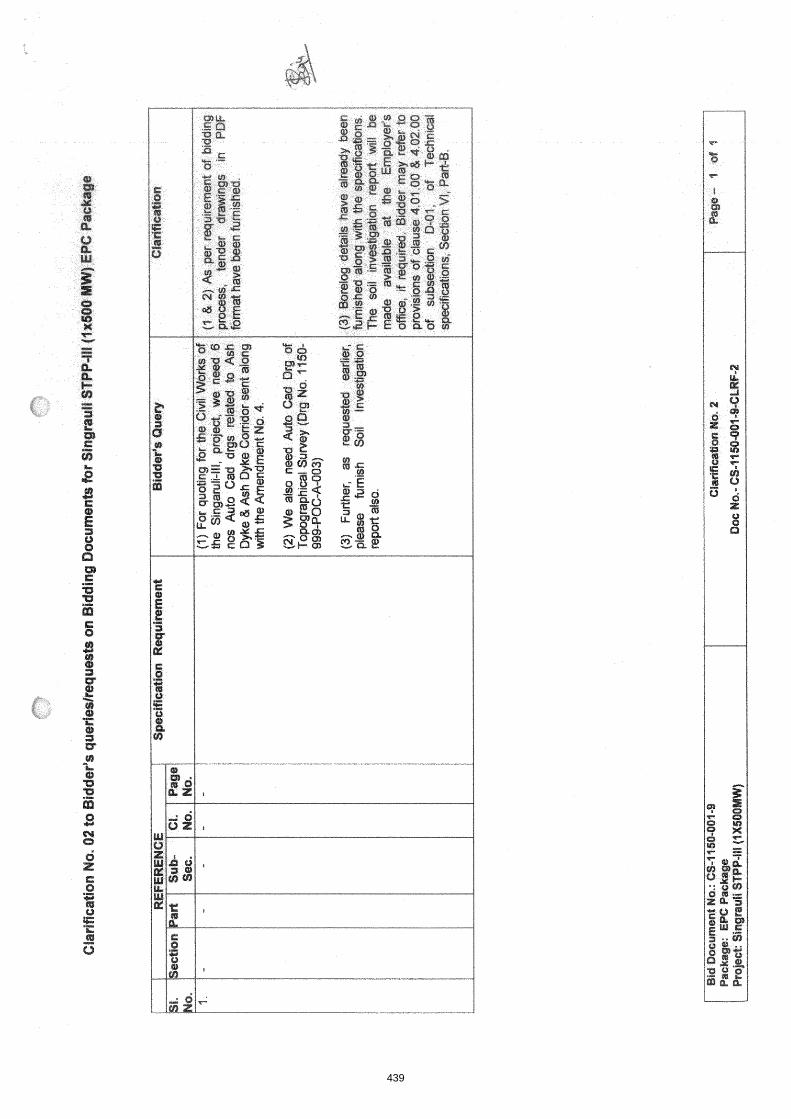
439

Am
en
dm
en
ts to
Te
chn
ica
l S
pe
cifi
cati
on
-
REF
EREN
CE-
- E
XIS
TIN
G
1 M
ODI
FIES
1
-
I
Am
dt.0
1
to
Tech
. sp
ecs
No
1.
2.
Civ
il
Mai
n pl
ant
TP's
, pr
ofile
d m
etal
dec
king
sh
eet
shal
l ne
cess
arily
be
us
ed
as
perm
anen
t sh
utte
ring.
A
ll A
ll eq
uipm
entld
rive
supp
ortin
g st
ools
sub
ject
ed to
hor
izon
tal
equi
pmen
tldriv
e su
ppor
ting
stoo
ls
subj
ecte
d to
lo
ads
shal
l be
dire
ctly
fix
ed t
o th
e m
ainl
seco
ndar
y be
ams.
ho
rizon
tal
load
s sh
all
be
dire
ctly
fix
ed
to'
the
Dec
k sh
utte
ring
shee
t sh
all
not
be c
onsi
dere
d as
stru
ctur
al
mai
nlsk
cond
ary
beam
s.
Dec
k sh
eet
shal
l no
t be
el
emen
t fo
r sl
ab
desi
gn.,
Min
imum
th
ickn
ess
of
slab
co
nsid
ered
as
st
ruct
ural
el
emen
t fo
r sl
ab
desi
gn.
excl
udin
g tro
ugh
dept
h sh
all b
e 15
0mm
. M
inim
um th
ickn
ess
of s
lab
excl
udin
g tro
ugh
dept
h sh
all
be 1
50m
m.
PAR
T V
II
A
VI I
B
1 Bidd
er s
hall
have
the
optio
n to
pro
vide
sh
ear
stud
s on
st
eel b
eam
s th
roug
h m
etal
dec
king
she
et to
tra
nsfe
r th
e la
tera
l loa
ds.fr
om s
lab.
Com
posi
te a
ctio
ns o
f ste
el b
eam
an
d sl
abs
shal
l no
t be
con
side
red
for
desi
gn.
She
ar
stud
s:
shal
l, be
in
stal
led
by
elec
tric
arc
wel
ding
m
ach
ine
~u
ri an
d sh
all c
onfir
m to
AW
S D
1 .I.
In c
ase
shea
r co
nnec
tors
&e
not
prov
ided
, flo
or b
eam
s ar
e to
be
desi
gned
con
side
ring
no l
ater
al r
estra
int
by
RC
C s
lab
and
suita
ble
plpn
bra
cing
s sh
all
be p
rovi
ded
in f
loor
'le
vel
for
trans
feiri
ng
the
horiz
onta
l lo
ads
to
perip
hera
l col
umns
. Fo
r ca
lcul
atio
n of
co
al l
oad
on m
ovin
g co
nvey
or,
a m
ultip
licat
ion
fact
or o
f 1.
6ish
all b
e us
ed to
tak
e ca
re o
f in
ertia
forc
e,.c
asua
l ov
er b
urde
n an
d im
pact
fact
or,
etc.
T
hus
coal
load
Der
uni
t len
gth
of e
ach
mov
ina
conv
evor
SE
C.
ill-D
C
ivil
Wor
ks
D-0
1 C
ivil
Wor
ks
Bid
der
shal
l ne
cess
arily
pro
vide
sh
ear
stud
s on
ste
el
beam
s th
roug
h m
etal
dec
king
she
et t
o tra
nsfe
r th
e la
tera
l lo
adsf
rom
sla
b. C
ompo
site
actio
ns o
f ste
el b
eam
and
sla
bs
shal
l no
t be
con
side
red
for
desi
gn.
She
ar s
tuds
sha
ll be
in
stal
led
by e
lect
ric
arc
wel
ding
m
achi
nelg
un
and
shal
i co
nfirm
to A
WS
D 1
.I.
Del
eted
.
3.01
.03
(vi)
&
SI.
No.
40
of
For
ca
lcul
atio
n of
co
al
load
on
m
ovin
g co
nvey
or,
a m
ultip
licat
ion
fact
or
of 1
.6 s
hall
be u
sed
to t
ake
care
of
iner
tia f
orce
, ca
sual
ove
r bu
rden
and
im
pact
fac
tor,
etc.
Th
us c
oal
load
per
uni
t le
ngth
of
each
mov
ing
conv
eyor
-
- -
- sh
all b
e sh
all b
e -
cl
I.G
x(ra
ted
caoa
citv
ofc
onve
vor s
vste
m) X
I20
0
I.Gx(
rale
d ca
paci
ty o
f con
veyo
r sys
tem
) XI1
00
NO
.
5 of
24
5
. .
-,
. .
.
. .
i
Con
veyo
r spe
ed
X.
800
I Conve
yor s
peed
X
80
0 1- 'll
Exi
stin
g C
hapt
er Il
l-D (C
ivil
Wor
ks)
RC
Cro
of o
ver p
erm
anen
t met
al d
eck
shut
terin
g sh
all b
e pr
ovid
ed o
ver A
-B b
ay o
f Mai
n P
lant
Bui
ldin
g.
For
con
cret
ing
of R
CC
floo
rs in
Mill
& B
unke
r B
uild
ing
&
I
Rep
lace
th
e en
tire
exis
ting
Cha
pter
ill
-D
(Civ
il W
orks
)
Ann
exur
e-X
XIII
I
chap
ter w
ith m
odifi
ed C
hapt
er I
ll-D
(Civ
il W
orks
) at
tach
ed a
t , I
Per
man
ent
colo
ur c
oate
d pr
ofile
d m
etal
dec
k sh
utte
ring
sh
all
be
pro
vide
d fo
r al
l R
CC
roo
fs &
flo
ors
of
Mai
n P
lant
Bui
ldin
g, M
ill &
Bun
ker
Bui
ldin
g, M
ain
plsn
t TP
's,
&o
the
r tal
l TP
's.
440

Am
en
dm
en
ts t
o T
ech
nic
al S
pe
cifi
cati
on
EX
ISTI
NG
1
MO
DIF
IED
4- N
o 7.
8.
9.
10.
11.
12.
SU
B-S
EC
TIO
N-I
(CIV
IL)
PA
GE
-3O
F8
FGU
TPP
-IV (1
x 50
0MW
) E
PC
PAC
KAG
E B
ID D
OC
UM
EN
T NO
: CS-
1450
:OO
l-9
AM
EN
DM
EN
T N
O. 1
TO
TE
CH
NIC
AL
SPEC
lFldA
TlO
NS
SE
CTI
ON
VI.
i
PA
RT-
GE
NE
RA
L &
AM
EN
DM
EN
T j
DO
CU
ME
NT
NO
: C
S-1
450-
001-
9-A
MD
T-0
1
PA
RT
VII
B
VI I
B
VI I
B
VI I
B
VI I
B
VI I
B
SEC
. D
-01
Civ
il W
orks
. .
D-0
1 C
ivil
Wor
ks
D-0
1 C
ivil
Wor
ks
D-0
1 C
ivil
Wor
ks
D-0
1 C
ivil
Wor
ks
D-0
1 C
ivil
Wor
ks
3.05
.03
(a)
: 4.
00.0
0
'8.0
3.11
pa
ra
il
9.00
.00
.
10.0
8.0
0 12.0
1.0
1, p
ara
1
NO
. 36
of
245
39-
73 o
f 24
5 85
of
245
86-
98 o
f 24
5 10
9 of
24
5
118
of
245
All
.Ste
el s
urfa
ces
shal
l be
pro
vide
d w
ith s
elf
curin
g In
orga
nic
Zin
c S
ilica
te P
rimer
Coa
t (S
olid
by
Vol
ume
Min
imum
60
%)
of
Min
imum
75
M
icro
n D
ry
Film
T
hick
ness
(D
FT
) ap
plie
d ov
er b
last
cle
aned
sur
face
to
near
whi
te m
etal
con
form
ing
to S
a 2
%fin
ish
of S
wed
ish
stan
dard
SIS
-05-
5900
. The
Prim
er C
oat s
hall
be a
pplie
d in
Sho
p im
med
iate
ly a
fter
blas
t cle
anin
g by
Airl
ess
spra
y te
chni
que.
F
OU
ND
AT
ION
SY
ST
EM
AN
D G
EO
TE
CH
NIC
AL
DA
TA
A
tem
pora
ry
light
ning
pr
otec
tion
syst
em
shal
l be
pr
ovid
ed
durin
g co
nstru
ctio
n of
th
e ch
imne
y til
l a
perm
anen
t lig
htni
ng p
rote
ctio
n sy
stem
is in
stal
led.
IND
UC
ED
DR
AU
GH
T C
OO
LIN
G T
OW
ER
S
Inta
ke s
tru
ctu
re o
n e
xist
ing
dis
char
ge c
hann
el f
or
inte
rco
nn
ect
ion
wit
h r
aw w
ater
pu
mp
ho
use
T
he w
ater
for
raw
wat
er p
ump
hous
e ha
s to
be
draw
n fro
m e
xist
ing
Sin
grau
li di
scha
rge
chan
nel
thro
ugh
RC
C
NP
3 H
ume
pipe
s. S
uita
ble
inta
ke s
truc
ture
has
to
be
prov
ided
in
th
e ex
istin
g di
scha
rge
chan
nel
for
conn
ectio
n of
the
se p
ipes
. As
the
disc
harg
e ch
anne
l is
in
ru
nnin
g co
nditi
on,
.sui
tabl
e ar
rang
emen
t lik
e te
mpo
rary
cof
fer
dam
s, s
heet
pili
ng e
tc.
as
requ
ired
shal
l be
mad
e fo
r in
terc
qnne
ctio
n of
the
se p
ipes
with
ex
istin
g di
scha
rge
chan
nel fo
r fee
ding
raw
wat
er p
ump
hous
e.
The
exi
stin
g fa
cilit
ies
for
stor
age
prov
ided
for
Hea
vy o
il (H
FO
IHP
S IL
SH
S in
Sta
ge-l
811
are
adeq
uate
to m
eet
the
addi
tiona
l req
uire
men
ts fo
r S
tage
-Ill
also
. Nec
essa
ry
inte
rcon
nect
ing
pipi
ng b
eh
ee
n e
xist
ing
HF
O a
nd L
DO
ta
nks
and
the
new
LD
d t
ank
and
the
pres
suriz
ing
pum
ps o
f S
tage
-Ill
shal
t be
pr
ovid
ed.
A
Com
bine
d
All
Ste
el
surf
aces
sh
all
be
prov
ided
w
ith
self
curin
g In
orga
nic
Zin
c S
ilica
te
Prim
er
Coa
t (S
olid
by
V
olum
e M
inim
um 6
0%)
of M
inim
um 7
5 M
icro
n D
ry F
ilm T
hick
ness
(D
FT
) ap
plie
d ov
er s
ho
t bl
ast c
lean
ed s
urfa
ce to
nea
r whi
te
met
al c
onfo
rmin
g to
Sa
2 %
fini
sh o
f S
wed
ish
stan
dard
SIS
- 05
-590
0.
The
P
rimer
C
oat
shal
l be
ap
plie
d. in
S
hop
imm
edia
tely
afte
r bl
ast c
lean
ing
by A
irles
s sp
ray
tech
niqu
e.
Rep
lace
the
ent
ire e
xist
ing
Cla
use
with
mod
ified
Cla
use
atta
ched
at
Ann
exur
e-X
XIV
A t
empo
rary
lig
htni
ng p
rote
ctio
n sy
stem
sha
ll be
pro
vide
d du
ring
cons
truc
tion
of t
he c
him
ney
till a
per
man
ent l
ight
ning
pr
otec
tion
syst
em i
s in
stal
led.
In
no
ca
se r
ein
forc
em
en
t b
ars
o
f sh
ell
sho
uld
,b
e
use
d
as
ea
rth
ing
d
ow
n
con
du
cto
rs.
Rep
lace
the
ent
ire e
xist
ing
Cla
use
with
m
odifi
ed C
laus
e at
tach
ed a
t A
nnex
ure-
XX
V
Inte
rco
nn
ect
ion
of
raw
wat
er p
um
p h
ou
se w
ith
exi
stin
g
cana
l
The
wat
er
for
raw
wat
er
pum
p ho
use
has
to
be d
raw
n th
roug
h st
eel.
lined
con
cret
e en
case
d du
cts
from
exi
stin
g m
ake-
up w
ater
ch
anne
l. S
uita
ble
cana
l in
take
st
ruct
ure
alon
g w
ith p
it ou
tsid
e th
e m
ake-
up w
ater
cha
nnel
for
pip
e in
terc
onne
ctio
n w
ill b
e do
ne b
y th
e ow
ner.
The
exi
stin
g fa
cilit
ies
for
stor
age
prov
ided
for
H
eavy
oil
(HF
O IH
PS
ILS
HS
in S
tage
-I,
11 &
Ill
are
adeq
uate
to m
eet
the
addi
tiona
l 're
quire
men
ts f
or S
tage
-IV
als
o. N
eces
sary
E-J- C,
a
inte
rcon
nect
ing
pipi
ng b
etw
een
exis
ting
HF
O a
nd L
DO
tank
s an
d th
e ne
w L
DO
tan
k an
d th
e pr
essu
rizin
g pu
mps
of
Sta
ge-I
V s
hall
be p
rovi
ded.
A C
ombi
ne'd
unl
oadi
ng c
um
R3
441
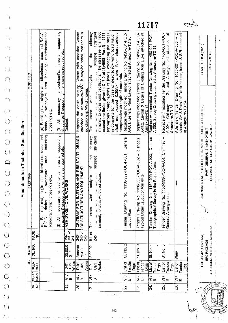
Am
en
dm
en
ts t
o T
ech
nic
al
Sp
eci
fica
tio
n
19.
245
no c
hang
e in
Win
d cr
iteria
. -1
8.02
.02
1 81 of
/ The
cros
s w
ind
anal
ysis
of
th
e ch
imne
y 1 The
cr
oss
win
d an
alys
is
of
the
chim
ney
.~
-"
RE
NC
E
--
Wor
ks
12
45
1
I
EX
ISTI
NG
-
(e)
Ear
thin
g m
at,
sing
le
lane
bi
tum
inou
s ro
ads
and
R.C
.C.
drai
ns
in
switc
hyar
d ar
ea
incl
udin
g ro
adld
rain
ltren
ch c
ross
ings
etc
.,
SI.
SE
CI
No
PA
RT
VI I
B
240-
24
5 of
......
......
......
......
..
....
....
....
..
sugg
est
stru
ctur
al
imm
unity
to c
ross
win
d os
cilla
tions
.
MO
DIF
IED
.- .-
,- *-
(e)
Ear
thin
g m
at,
sing
le l
ane
bitu
min
ous
road
s an
d R
.C.C
. dr
ains
in
sw
itchy
ard
area
in
clud
ing
road
ldra
inltr
ench
cr
ossi
ngs
etc.
.
B
....
....
....
....
....
....
....
....
..
......
.....
sugg
est
stru
ctur
al
imm
unity
to c
ross
win
d os
cilla
tions
. T
he s
tre
sse
s sh
all
.no
t ex
ceed
the
lim
its g
ive
n i
n C
1.7.0
of
1S:4
998
(Par
t-I)
- 1
975
for
vari
ous
com
bin
atio
ns
of
load
s, e
xcep
ting
the
str
ess
in
con
cret
e fo
r th
e c
ase
of
dead
loa
d* w
ind
lo
ad
wh
ich
sh
all
no
t ex
ceed
0.
30fc
k,
whe
re
fck=
ch
arac
teri
stic
SU
B-
SEC
.
D-0
1 C
ivil
CR
ITE
RIA
FOR E
AR
TH
QU
AK
E R
ES
IST
AN
T D
ES
IGN
O
F S
TR
UC
TU
RE
S A
ND
EQ
UIP
ME
NT
Civ
il W
orks
Rep
lace
the
en
tire
exis
ting
Cla
use
with
m
odifi
ed C
laus
e at
tach
ed a
t A
nnex
ure-
XX
VI.
It m
ay
be
not
ed t
hat
ther
e is
CL.
NO
.
. .
20.0
0.0
0
/ com
pres
sive
str
en
gth
of c
oncr
ete.
PA
GE
N
O.
Ten
der
Dra
win
g N
o.
1150
-999
-PO
C-F
-001
, G
ener
al
Layo
ut P
lan
23.
24.
151-
.
167 ~.
of
Rep
lace
with
mod
ified
Ten
der
Dra
win
g N
o. 1
450-
001-
PO
C-
A-0
01,
Gen
eral
Pla
nt L
ayou
t atta
ched
at A
nnex
ure-
TD
20
VI I
E
VI I
E
~
-
I 1 D
rgs
/ 1
1 I
1 Drg
s I
(f)
All
nece
ssar
y em
bedm
ent's
, in
serts
, su
ppor
ting
stru
ctur
es &
sup
port
ing
mem
bers
as
requ
ired
etc.
A
SH
DY
KE
- CIV
IL W
OR
KS
'
25.
., / ~
nn
ex
ure
-TD
2i
E
(f)
All
nece
ssar
y em
bedm
ent's
, 'in
sert
s,
supp
ortin
g st
ruct
ures
& s
uppo
rtin
g m
embe
rs a
s re
quire
d et
c.
Del
eted
.
Drg
s Li
st o
f T
ende
r D
rgs
List
of
Ten
der
i
...-
Add
ne
w T
ende
r D
raw
ina
No.
14
50-0
01-P
OC
-A-0
05 -
2
" \
VI I
E
Ten
der
FGU
TPP-
IV (1
x 50
0MW
) E
PC
PAC
KAGE
B
ID D
OC
UM
EN
T W
CS
-,4
50
-00
1-9
SI.
No.
3
SI.
No.
4
shee
ts,
GA
& D
etai
l of r
ack
hopp
er, t
unne
l & S
IR.
atta
ched
.-.----
List
of
Ten
der
Drg
s
AM
EN
DM
EN
T~N
O.
1 TO
TEC
HN
ICAL
SP
EC
IFIC
ATI
ON
S S
EC
TIO
N V
I, :
PA
RT
- GE
NE
RA
L &
AM
EN
DM
EN
T
OO
CU
ME
NT
NO
: CS
-145
0-00
1-9-
AM
DT
-01
Ten
der
Dra
win
g N
o. 1
150-
999-
PO
C-A
-002
- 2
she
ets,
T
ypic
al D
etai
l Lay
out o
f Ash
dyk
e
Ten
der
Dra
win
g N
o.
1150
-999
-PO
C-A
-003
. D
etai
led
Top
ogra
phic
al S
urve
y in
the
Pro
ject
Are
a.
at A
nnex
ure-
TD
24
SUB-
SEC
TIO
N-I (
CIV
IL)
PA
GE
- 8
OF
8
Si.
No.
5
/fR
Rep
lace
with
mod
ified
Ten
der
Dra
win
g N
o. 1
450-
001-
PO
C-
A-0
02,
Layo
ut &
Det
ails
of
Exi
stin
g A
sh D
yke
atta
ched
at
Ann
exur
e-T
D 2
1 R
epla
ce w
ith m
odifi
ed T
ende
r D
raw
ing
No.
145
0-00
1-P
OC
- A
-003
, S
urve
y D
raw
ing
atta
ched
at A
nnex
ure-
TD
22
C-a
+,.
-4
gq
-7
Ten
der
Dra
win
g N
o. 1
150-
999-
PO
C-A
-004
, C
him
ney -
Gen
eral
Arr
anae
men
t. R
epla
ce w
ith m
odifi
ed T
ende
r D
raw
ing
No.
145
0-00
1-P
OC
- A
-004
. C
him
nev
- G
ener
al
Arr
anoe
men
t at
tach
ed
at
442

( BACKGROUND
~ ~ I I M , ~ C < ~ , Y C - - Li3
Feroze Gandhi Unchahar Thermal Power Station, FGUTPS was conceived as a Load Centre coal based Power Station of 1050 MW capacity by UPSEB. The land for the project was acquired and stage-l (2x210MW) was implemented by UPSEB. The 2x210 MW Unchahar station was taken over by NTPC from Uttar Pradesh Rajya Vidyut Utpadan Nigam of Uttar Pradesh in 1992. Thereafter, NTPC implemented Stage- II (2x210 MW) and Stage-lll(1X 210 MW).
CLAUSE NO
-
The present expansion proposal is to install one additional unit of 500 MW under Stage-IV thus making the ultimate capacity of the FGUTPP 1550 MW.
LOCATION AND APPROACH
'7' ? ' ' < PROJECT INFORMATION 6 2 7 4 8
The plant is located in Raebareli district of Uttar Pradesh, having latitude and longitude of 25O54'50"N and 8lo19'50"E respectively. It is bounded by villages Khnapur, Faridpur and Khaliqpur Khurd. Mustafabad town is located at a distance of about 3 Kms from the plant. Unchahar railway station on Allahabad-Raebareli broad gauge (BG) section of Northern Railway (NR) is 2 Kms away. The nearest airport is located at Lucknow a distance of approximately 110 km from the project site.
I I Vicinity Plan of the project is placed at Annexure-I I 1.02.00 I LAND REQUIREMENT I
During the implementation of FGUTPS, Stage-I, II & Ill total area of about 2203 acres of land was acquired. The plant facilities, ash disposal and township for this expansion Stage-IV (Ix5QO MW) would be accommodated within the available land with dismantling and relocation of some buildings. No additional land has been envisaged to be acquired for this expansion project.
1 1.03.00 / WATER
As per agreement between NTPC & Irrigation department, 105 Cusec of water is supplied through S.S Canal to NTPC-Unchahar. The Stage-IV (500MW) consumptive water requirement shall be accommodated within the existing commitment of water to FGUTPP. Sharda sghayak canal and Dalmau Pump House (DPH) on Purwa Branch Canal are available sources of water for the proiect and therefore, the make up these sources.
COAL AVAILABILITY
Coal Availability
FGUTPP STAGE-IV (IXSOO MW)
EPC PACKAGE
AND TRANSPORTATION
SECTION - VI I PROJECT INFORMATION PART-A 1 'OFi2 I
443

I I The coal requirement shall be about 2.7 Million tonnes per year. I The matter has been taken up with Ministry of Coal, Govt. of lndia for Long Term Coal Linkage for Stage-IV (1x500 MW)..Coal requirement for FGUTPP, Stage-l ,I1 & Ill is being met from North Karanpura Coal fields of CCL. For FR purposes, coal from North Karanpura Coal fields of CCL has been considered.
I Coal Transportation
The envisaged mode of coal transportation from the coal mines to the power plant is by Indian Railways rakes. The rakes shall be unloaded at the track hopper.
I Coal Quality Parameters and Fuel Oil Characteristics
I CAPACITY 8 POWER EVACUATION I : I
- -
Stage- I : 2x210 MW _ Under Commercial Operation Stage-ll : 2x210 MW Under Commercial Operation Stage-Ill : 1x210 MW Under Commercial Operation
The Coal quality parameters and Fuel Oil Characteristics are enclosed as, 1 ) Annexures-11-1 and 11-2 to this subsection. I 0
1 Stage-N I x 500 MW Present proposal . .. --
I 1 1.07.00 1 PLANT WATER SCHEME
The existing capacity of plant is 1050 MW Step up/ power evacuation voltage for station is 220 KV. Presently 1000 MW is already being evacuated at 220 KV, addition of another 500 MW at 220 KV may cause overloading of 220 KV systems and lead to increase in fault levels at 220 KV system. Considering this 400 KV has been considered as step-uplpower evacuation voltage for Stage-IV. Power Generated from FGUTPP- Stage IV, 500 MW unit would be stepped up to the evacuation voltage level through suitably rated Generator Transformer.
The power generated from Stage-IV is envisaged to be absorbed by Northern Region beneficiaries. For finalisation of Associated Transmission System (ATS) of the project, the matter would be taken up with Power Grid Corporation of lndia Ltd. (PGC1L)ICEAlappropriate authority depending on the various routes/options of
r sale envisaged for the project.
GICAL DATA
Important meteorological data from nearest observatory at Allahabad is placed at Annexure - Ill.
-
0 TECHNICAL SPECIFICATION SUB-SECTION-I1
(2 EPC PACKAGE .
if
CI
0 !3 0 (3r
0 0
0
444

/ The Plant weter scheme is described below.
Source of Water
The source of water for the project is normally from the Allahabad branch canal of the Sharda Sahayak link canal. During the canal closure period, water will be drawn from the Daimau canal.
Water Requirement
Normal Make up water requirement for this project would be about 2000 Cu.Mlhr with ash water re-circulation system in operation. However, whenever ash water system needs to be operated in once thru mode, water drawl shall be of the order of 3300 cumlhr.
I 1 .OT.03 I Raw Water System 1 Raw water shall be drawn from the source by a gravity channel upto raw water pump house located inside the plant. It is envisaged to provide three (3) numbers (3 x 50 % Capacity) of raw water pumps for supplying water to Water PT Plant in the raw water pump house. In addition two (2) numbers (2 x 100% capacity) of pumps shall be provided to supply raw water for ash handling plant which shall be operated as and when required. Separate set of pipelines of carbon steel construction shall be provided from respective raw water pumps to Water treatment plant and Ash Water tanks.
The quality of Raw water and Clarified water is enclosed with this sub-section I I 108.00 / Criteria for Wind Resistant Design of Structures and Equipment . . . . . . . .
All structures and equipment of the power plant, including plant auxiliary structures and equipment, shall be designed for wind forces as given in Sub-section- 0-01, Part-B, Section-VI, i.e. Technical Specification for Civil and Structural Works.
1 1.09.00 / Criteria for Earthquake Resistant Design of Structures and Equipment I All power plant structures and equipment, including plant auxiliary structures and equipment shall be designed for seismic forces as given in Sub-section- D-01, Part- B, Section-VI, i.e. Technical Specification for Civil and Structural Works.
FGUTPP STAGE-IV (1x500 MW)
EPC PACKAGE
TECHNICAL SPECIFICATION SECTION - V I
PART-A
SUB-SECTION-II PROJECT INFORMATION
PAGE 3 OF 12
445

VICINITY PLAN
.
ANNEXURE-I 1
CLAUSE Nf&.
*: , i x~ i 5'3' , PROJECT INFORMATION
446

CLIMATOLOGICAL TABLE ANNEXURE-Ill
- ----- - -- --- --- - -
- - ..c. M" NS ->, - * y o - - ' - " *- - m o+ -- " S *D 0- " Y -I "," =.. n.r *- n s "- no - - z z 2 z z z = z - - -
-1 ^- D" D m ' - - o m - - n* -- n O ̂ /- N D '*g "3 "6 "& - = - - 3 " '. -I D % O* "i ..: z ? 2 - - - -
- - - - - - - - - --- - - - - -- -- -- - - - - - - - -
- - - - - - - - - - - - -- - - -- - - - - - . - - - - - - - - - - - -
447

CLIMATOLOGICAL TABLE
CLAUSE NO.
ANNEXURE-Ill (PAGE 2 OF 2)
, ,
1 1 7 5 9 PROJECT INFORMATION, . ; i . - i ' .
FGUTPP STAGE-IV (1x500 MW)
EPC PACKAGE
TECHNICAL SPECIFICATION SECTION - VI
PART-A
SUB-SECTION-II PROJECT INFORMATION
PAGE 12 OF 12
448
SUB-SECTION - E="141"7"
CIVIL WORKS
449

I Q U A L I N ASSURANCE AND INSPECTION FOR CIVIL WORKS I
0
/ INTRODUCTION I
QUALITY ASSURANCE
This part of the speclflcatlon covers the sampling, testing and quallty assurance requirement (including construction tolerances and acceptance criteria) for all clvil and structural works covered In thls specification.
This part of the technical specification shall be read in conjunction with other parts of the technical specifications, general technical requirements & erection conditions of the contract. Wherever IS code or standards have been referred they shall be the latest revisions.
The rate for respective items of work or price shall include the ,cost for all works, activities, equipment, instrument, personnel, material etc. whatsoever associated to comply with sampling, testing and quality assurance requirement including construction tolerances and acceptance criteria and as specified in subsequent clauses of this part of the technical specifications. The QA and QC activities in all respects as specified in the technical speciiicationsl drawings 1 data sheets I quality plans I contract documents shall be carried out at no extra cost to the owner.
The contractor shall prepare detailed construction and erection methodology scheme which shall be compatible to the requirements of the desired progress of work execution, quality measures, prior approvals if any and the same shall be got approved by the Engineer. If required, work methodology may be revisedl reviewed at every stage of execution of work at site, to suit the site conditions by the contractor at no extra cost to the owner.
The contractor shall furnish complete QA & QC programme for the work envisaged which may include the following
2.0.0
2.1 .O
O Organization structure for the management and implementation of the proposed quality assurance programme
Q U A L I N ASSURANCE PROGRAMME
The contractor shall adopt sultable Quallty Assurance Programme (QAP) to ensure that the equipments and services under the scope of contract whether manufactured or performed within contractor's works orat his sub-contractor's premises or at the NTPC's site or at any other place of work are in accordance w~ th the spec~fications. Such QAP shall be outllned by the contractor and shall be f~nally accepted by the NTPC or their authorized representative after discussions before the start of work. The QAP shall be generally In line wlth ISllSO Systems.
O Quality System Manual
I O Design Control System
SlNGRAULf STPP STAGE-Ill (tX500 MW)
EPC PACKAGE d TECHNICAL SPECiFlCATION
SECTION -V I PART-8
SUB-SECTE0N.E-tP7 QUALITY ASSURANCE
CIVIL
PAGE 1 OF 32
450

I I Q Qualification data I details for Contractor's key personnel I
CLAUSE NO.
Q The procedure for purchase of materials, parts, components and selection of sub-contractor's services including vendor analysis, source inspection, incoming raw-material inspection, verification of materials purchased, etc.
QUALIN ASSURANCE
O Documentatton and Data Control System
Q System for shop manufacturing and site erection controls including process, fabrication and assembly
I % Control of non-conforming items and system for corrective actions and resolution of deviations I
O Inspection and test procedure both for manufacture and field activities
O Control of calibration and testing of measuring testing equipment
O System for Quality Audits
I 1 Q System for identification and appraisal of inspection status 1
Q System for authorizing release of manufactured product to the NTPC I I O
System for handling, storage and delivery I I I O System for maintenance of records 1
O Quality plans for manufacturing and field activities detailing out the specific quality control procedure adopted for controlling the quality characteristics relevant to each item of work1 equipmenffcomponent.
The contractor shall nominate one overall QA coordinator for the contract deta~ling the name, designation, contact details and address at the time of post bid discussions. All correspondence related to Quality Assurance shall be addressed by the contractor's QA coordinator to NTPC. NTPC shall address all correspondence related to Quality issues to the contractor's QA coordinator. The contractor's QA coordinator shall be respons~ble for co-ordination of Quality activities between various divisions of the contractor and their sub-vendors on one hand & with NTPC on the other hand.
3.2.0 The contractor shall appoint a dedicated, experienced and competent QA&QC in- charge at site, preferably directly reporting to the Project Manager, supported as necessary by experienced personnel, to ensure the effective implementation of the approved QAP. An indicative struclure of contractor's QA&QC manpower required to
SlNGRAULl STPP STAGE-Ill (1x500 MW)
EPC PACKAGE
V ----
TECHNICAL SPECIFICATION SECTION - VI
PART-B /
SUB-SECTION-E-117 QUALITY ASSURANCE
CIVIL
PAGE 2 OF 32
451

QUALITY ASSURANCE
be deployed at site IS enclosed at Annexure-I. Based on the finalized L-2 network and the approved Fteld Qualtty plan, the contractor shall f~nalize and subm~t a deployment schedule of QA&QC personnel along w~ th the~r details to NTPC for approval1 acceptance and further shall ensure their ava~lab~lity well before the start of the concern activity.
The QA&QC in-charge shall. have the organizational freedom and authority to implement the requirements of these quality assurance arrangements, free from commercial and programme restraints. The QA&QC setup of the contractor shall consist of qualified and experienced Civil, Electrical. Mechanical Engineers and Laboratory assistants with their supporting staff both at their works and site.
The deployment of man power for QA & QC set up shall be affected on the basts of agreed manpower deployment schedule, wh~ch shall be prepared by the contractor based on the L-2 network and the same shall be submitted to the eng~neer-ln-charge for acceptance.
1 4.0.0 I SAMPLING AND TESTING OF CONSTRUCTION MATERIALS I I
The method of sampling for testing of construction materials and work I job samples shall be as per the relevant IS I standards I codes and in line with the requirements of the technical specifications 1 quality plans. All samples shall be jointly drawn, signed and sealed wherever required, by the contractor and the engineer or h ~ s authorized representative.
The contractor shall carry out testing in accordance with the relevant IS I standards I codes and in line with the requirements of the technical specifications 1 quality plans. Where no specific testing procedure is mentioned, the tests shall be carried out as per the best prevalent engineering practices and to the directions of the Engineer. All testing shall be done in the, presence of the engineer or his authorized representative.
4.3.0 Before execution of any civil work the contractor shall conduct full-scale suitability tests on various construction and building material such as fine and coarse aggregates, cement, reinforcement, construction chemicals, supplementary cementitious materials and construction water to ascertain their suitability for use and the concrete mix designs conducted from reputed institutes such as NCB- Ballabhgarh, CSMRS-Delhi, IIT's, etc. as agreed by the engineer. The test samples for such full scale testing shall be jointly sampled and sealed by the engineer and contractor, thereafter these shall be sent to the concerned laboratory through the covering letter signed by field quality assurance (FQA) representative of the engineer.
4.4.0 The contractor shall timely initiate the action with regard to the evaluation of aggregates and other building material including concrete mix design, so as to ensure completion of these tests before start of civil works a t site, thereby not affecting any project work. The test reports and recommendations forsuitability of the materials including concrete mix design shall be promptly submitted by the contractor to the engineer.
1
SINGRAULI STPP STAGE-Ill (4x500 MW) d\/
EPC PACKAGE
TECHNICAL SPECIFICATION SECTION - VI
PART-B
SUB-SECTION-E417 QUALITY ASSURANCE
CIVIL
PAGE 3 OF 32
452

QUALITY ASSURANCE
Evaluation of aggregate for potential alkali-aggregate reactivity shall be carried out as per following scope of work
A. Evaluation of Aggregates for Mechanical I Physical Properties
a) To carry out d~fferent tests on coarse aggregate sample i.e. specific gravity, water absorption, sieve analysis, deleterious material; soundness, crushing value, impact value, abrasion value, elongation index and flakiness index, as per IS: 2386.
b) To carry out different tests on fine aggregate sample i.e. speclfic grav~ty, water absorption, sieve analysis, deleterious material, soundness, sit content, clay content and organic impurities as per IS:
I c) To prepare evaluation report based on test results of a) and b) above and to advise regarding suitability of fine and coarse aggregates.
B. Evaluation of Aggregates for Potential Alkali-Aggregate Reactivity: I a) To carry out petrographic analysis and accelerated Mortar bar Test on
aggregate samples ( I N NaOH at 80 deg. Centigrade for 14 days as per ASTM 1260, or the method established1 developed by CSMRS for 22days test).
b) If rock type is limestone, alkali carbonate reactivity test shall also be carried out wherein the parameters shall be reported in conjunction with the petrographic analysis. Additionally. X-Ray diffraction test (XRD) shall be carried out to determine critical clay mineral in the rock for preliminaiyconclusions. For limestone aggregates to be used in dynamic foundations like TG, BFP, Fans, mills and crushers, repeated temperature cycle test shall also be carried out, to determine residual expansion of aggregate for concrete.
c) To prepare a report based on test results of a) and b) above and to advise regarding suitability of aggregates to be used and further testing required if any.
I LABORATORY AND FIELD TESTING I The Reld laboratory for QA and QC activitiesshall be constructed and set-up by the contractor in line with the indicative field QA&QC laboratory set-tip enclosed at Annexure-ll. The Laboratory building shall be constructed and installed with the adequate facilities to meet the, requirement of envisaged test setup. Temperature and humidity controls shall be available wherever necessary during testing of samples. The quality plan shall identify the testing equipmentsl instrument, which the contractor shall deploy and equip the field. quality laboratory for meeting the field quality plan requirements. The contractor shall furnish a comprehensive list of testing . ~. . . . .
SlNGRAULl STPP STAGE-Ill (1x500 MW)
EPC PACKAGE
TECHNICAL SPECIFICATION SECTION - VI ,+,/ PART-B
SUB-SECTION-E-117 QUALIP( ASSURANCE
CIVIL
PAGE 4 OF 32
453

0
Based on the schedule of work agreed with the engineer-in-charge and the approved FQP, the contractor shall prepare a schedule of tests and submit them to the engineer-in-charge and organize to carry out the tests as scheduled I agreed.
QUALITY ASSURANCE
equipmentsl instrument required to meet the plannedlscheduled tests for the execution of works for NTPC acceptance1 approval. The contractor shall moblllze the requisite laboratory equipment and QA&QC manpower at least 15 days prior to the planned test activity as per the schedule of tests.
All equtpments and instruments in the field shall be calibrated before the commencement of tests and then at regular lntelvals, as per the manufacturer's recommendation and as directed by the NTPC. The callbration certificates shall specify the fitness of the equipments and instruments within the limlt of tolerance for use. Contractor shall arrange for calibration of equlpments and instruments by an NABL I NPL accredited agency and the calibration report shall be subm~tted to NTPC.
The tests which cannot be carried out in the field laboratory shall be done at a laboratory of repute. This includes all IlTs, NCB, CSMRS, reputed government 1 autonomous laboratories I organizations, NITS and other reputed testing laboratories. The test samples for such test shall be jointly selected and sealed by the engineer and thereafter these shall be sent to the concerned laboratory through the covering letter signed by NTPC engineer. The test report along with the recomrnendatlons shall be obtalned from the laboratories without delay and submitted to NTPC.
1 65.0 / PURCHASE AND SERVICE I
.
The major items1 equipmentsl components to be manufactured ln the shop of the contractor i.e. in-house items and those procured from sub-vendors I sub- manufacturer I sub-contractors i.e. bought out items (BOls) shall be listed out by the contractor In thew b ~ d proposal.
An indicative list of major bought out items(not exhaus6ve)and sewices for civil works is enclosed at Annexure- Ill, for which the contractor shall submit the requisite details I lists of manufacturer's in their bid proposal. The list of manufacturers1 sub- vendors for all the BOls envisaged in contract includingshall be included in the bid proposal by the contractor which shall be discussed I reviewed by the NTPC during post bid discussions and the list of proposed manufacturers I sub-vendors for each of the BOls shall be agreed1 approved. If any item is left out or gets included during detailed' engineering, the contractor shall propose the manufacturer's I sub-vendor's details for review I approval of NTPC, prior to initiating the procurement of such materials.
Where the manufacturers are placed in details required ("DR") category, the details of the manufacturers I sub-vendors placed in the "DR" category shall be submitted to the NTPC for approval in the prescribed NTPC format no. Q A - ~ ~ - Q A I ' - P - ~ ~ I F ~ - R O (main supplier's evaluation report) and format no., QA-01-QAI-P-04lF2-RO (sub supplier questionnaire) within the period agreed at the time of post bid discussions.
I
SiNGRAULl STPP STAGE-Ill (1x500 MW)
EPC PACKAGE
r
TECHNICAL SPECIFICATION SECTION - V l / PART-8
SUB-SECT1ON.E-117 QUALITY ASSURANCE '
CIVIL
PAGE 5 OF 32
454

The contractor's proposal shall include vendor's site facllities, expertise, facllities established at the respective works, the process capab~l~ty, process stabilization, QC systems followed, experience list, etc. along with h ~ s own technical evaluation for identified sub-contractors proposed. The formats for furnishing above deta~ls shall be given to the Contractor at post bid discussion stage. Monthly progress reports on sub-contractor detail submission I approval shall be furnished on format no. QS-Ol- QAI-P-OZFI. Such manufacturers I sub-vendors approval shall not relieve the contractor from any obligation, duty or responsibility under the contract.
To facilitate advance planning of material testing1 approval of bought out items, well before the start of activity as per L-2 network, representative samples shall be procured by the contractor from approved sub-vendors and submitted to the engineer for h ~ s approval before bulk procurement at least two months prlor to start of works. In case of manufacturers test certificate (MTC) is subm~tted for acceptance, ~t shall be clearly traceable and correlated w~th the consignment received at site. MTC of all bought out items shall essentially contain all the test parameters I characteristics specified in the technical spec~fications I standards I codes. In case the manufacturer's test certificate does not mention these details, sample from each lot shall be tested for these properties at the third party lab acceptable to NTPC. Approval of material / sample by the engineer shall not relieve the contractor of his responsibility, for their conformance to the specif~cation, as well as the requisite peiformance and quality of material.
CLAUSE NO.
Structural steel supply i f in the scope of the contractor shall be procured from main steel producers like SAIL, TISCO, IISCO, RINL, Essar Steel, lspat Industries, JSW Steel. Lloyds Steel, Jindal Steel & Power. In case of non-availabil~ty of some of the sections w~th main steel producers the contractor may propose to procure the sections from the re-rollers of the main steel producers, the name of such re-rollers will have to be cleared by corporate quality assurance of NTPC for wh~ch details such as BIS approval, main steel producer's approval, past experience for production of sections of specified material, details of machines plants testing facilities etc.. Confirmation that the process control and manufacturing of steel sections by re-rollers shall be same as that of main steel producers, that billets for re-rolling will be sourced from main steel producers only shall be furnished with regard
Even after clearance of re-rollers, induction of blllets with identified and correlated M~l l test certificates (TC's) in the process of re-rolling, sampling of steel, quality checks thereof and stamping of final product for further identification and correlation with TC's prior to dispatch shall be the responsib~ilty of the contractor and these shall be performed in presence of the authorized representative of the main Contractor.
Reinforcement steel supply if in the scope of the contractor shall be procured from main steel producers like SAIL, TISCO, IISCO, RINL, Essar Steel, lspat lndustries, JSW Steel, Lloyds Steel, Jindal Steel & Power and mill test cert~ficates (TC) is to be obtained and submitted to NTPC for co-relation. In case any size /diameter specified- is not available with main steel producers and are proposed to be supplied from the conversion agent of the main steel producer the name of such conversion agent I re- roller shall have to be approved by NTPC for which details such as BIS approval, Main steel producer's approval, Past experience for production of sections of
QUALITY ASSURANCE
-
SINGRAULI STPP STAGE.111 (1x500 MW)
EPC PACKAGE
TECHNICAL SPECIFICATION SECTION - VI
P A W E J
SUB-SECTION-E-117 QUALINASSURANCE
CIVIL - PAGE
6 OF 32
455

specified material, details of machines, plants testing facilities etc., and confirmation that the process control and manufacturing of steel sections by re-rollers is the same as that of main steel producers, that billets for re-rolling are sourced from main steel producers only shall be furnished with regards to re-roller.
a
/ I G L / MANUFACTURING QUALITY PLAN AND FIELD QUALITY PLAN I -
QUALITY ASSURANCE
All materials I components and equipment covered under the scope of work, shall be procured by the contractor for the purpose of the contract, after obtain~ng the wr~tten approval of the NTPC, wh~ch are to be manufactured at shop1 factory of the vendorlsub vendor shall be covered under a comprehensive qual~ty assurance programme. The contractor's purchase specifications and lnqulrles shall call for Manufacturing Quality Plans (MQP) to be submitted by the sub-contractorl sub- supplier1 sub-vendor. The MQP called for from the sub-contractor shall detall out for all the components and equipment, various tests I inspection, to be carr~ed out as per the requirements of this specification and standards mentioned therein, quallty practices and procedures followed by contractor's I sub-contractor's I sub-supplier's quality control organization, the relevant reference documents and standards, acceptance norms, inspection documents raised etc.. during all stages of materials procurement, manufacture, assembly and final testing1 performance testlng. Such quality plans of tfie vendors I sub-vendors shall be submitted to the NTPC for approval in the prescribed format no. QS-01-QAI-P-09lF1-R1 for MQP and such approved quallty plans shall form a part of the purchase order I contract between the contractor and sub-contractor. The quality plans shall be subm~tted on electronic form e.g. CD or E-mail in addition to hard copy, for review and approval of NTPC. Afler approval the same shall be subm~tted in comp~led form on CD in addition to hard copy.
The contractor shall furnish copies of the refeience documents1 plant standards I acceptance norms1 tests and inspection procedure etc., as referred in quality plans. These quality plans and reference documentslstandards etc. w~ l l be subject to NTPC approval without which manufacturer shall not proceed. These approved documenls shall form a oart of the contract. In these ao~roved aual;tv ~ lans . NTPC shall identify customer hdld points (CHP),. i.e. test/ checks which ;halide cakied out in of-thFWTPCengin~~orhis~a~fh~r~Fd~e~presentati(realidbTyOnddwhich thTWik shall not proceed without consent of NTPC in writing. All deviations to this specification, approved quaiityplans and applicable standards must be documented and referred to NTPC along with technical justification for approval and dispositioning.
With~n three weeks of the release of the purchase orders Icontracts for such bought out items /components, a copy of the same without prlce details but together with the detailed purchase specifications, quality plans and delivery conditions shall be furnished to the NTPC for reference I record by the contractor along wlth a report of the purchase orders placed so far for the contract.
SINGRAULI STPP STAGE-111 TECHNICAL SPECIFICATION (IXSOO MW) SECTION - V l
456

specifications to be followed by the contractor at site. This FQP shall cover for all the items I activities covered in the contract 1 schedule of items required, right from material procurement to completion of the work at site. An Indicative Field Quality Plan for civil works is enclosed at Annexure - IV-A (Indicative FQP for civil works) & Annexure - IV-B (Indicative FQP for structural steel works).
CLAUSE NO. -.
QUALIN ASSURANCE ,-
I
DlSPOSlTlONlNG OF NON CONFORMITIES
, ~
7.5.0
The non-conformity for the site works on being detected I rioted shall be reported by the contractor in the standard format no. QS-01-FQA-P-08lF1-RO ( I s s ~ e 21 of NTPC
Monthly progress reports on MQP I FQP subm~ssion I approval shall be furnished by the contractor on the format No. QS-01-QAI-P-02lF1-RO. List of ~tems requiring qual~ty plans and sub-supplier approval shall be finalized with the contractor on the format no. QS-01-QAI-P-01lF3-R1 dur~ng the post bid discussions.
under the system of dispositioning of non conform~ty report (NCR) to the'engineer. The dispositioning of the NCR relating to equipment, assemblies, materials condition or process during construction 1 erection shall descr~be the proposed correction and also include the preventive I corrective action plan for future.
I QUALITY AUDIT I NTPC reserves the riaht to canv out aualitv aud~t and aualitv surveillance of the . , . A
quality management and control activities, systems and procedures of the contractor or their sub-contractor. The contractor shall provide all necessary assistance to enable the NTPC carry out such audit and surveillance. The contractor shall also take necessary measures, raise NCRs wherever required based on the audit findings I observations. I 10.0.0 I QA DOCUMENTATION PACKAGE I
GENERAL QA REQUIREMENTS
The contractor shall ensure that the works, 501s and servlces under the scope of contract whether manufactured or-performed within contractor's works or at his sub- contractor's premises or at the NTPC's site or at any other place of work are in accordance with the NTPC technical specification, applicable standards I codes, approved drawings 1 data sheets I quality plans and BOQ. All the works, 001s and sewices shall be carried out as per the best prevalent engineering practices and to the directions of the Engineer.
The contractor shall be required to submit the QA documentation in two hard copies and two CD ROMs, as identified in respective quality plan w~th tick (4) mark. Typical
contents of QA documentation pertaining to field-activ~ties as per approved MQP, FQP and other agreed manuals I procedures, prior to commiss~oning of individual system shall generally contain the Qual~ty Plan, Material m ~ l l test reports, Non- destructive examination results 1 reports, Heat Treatment CertificatelRecord, Non- conformance Reports, CHP, Certificate of conformance (COC) and MDCC.
SINGRAULI STPP STAGE-Ill TECHNICAL SPECIFICATION SUB-SECTION-E-117 PAGE (1XSOO MW) SECTION - VI QUALITV ASSURANCE 8 OF 32
EPC PACKAGE p/ PART-B CIVIL
0 8 0
457

! 1. - , j , .:,. I STORAGE AND HANDLING OF CONSTRUCTION MATERIALS I
CLAU" ".
. .
All materials shall be stacked and stored by the Contractor as per 15-4082 and as per the requirements specified in NTPC Technical Specification.
QUALITY ASSURANCE
1 1% :.2 I EXCAVATION AND FILLING WORKS I The contractor shall submit a work methodology covering various items of works for ail stages of excavation and filling works. This methodology shall broadly include the quantity wise and classification wise identification of source of excavation and filling, suitability tests as per specification requirements, method of stockpiling, transportation, placement, spreading , compaction, equipment, list of protocols, in- situ tests, third party lab test if required, acceptance checks for final clearance.
For blastinq work at site if required, the contractor shall associate themselves with
I the reputedspecialized blastin$ agency such as CMRI, NlRM for trials blasts, design blasts, blasting pattern, monitoring of blast during the blasting operations at site. The contractor shall install and operate equipment (such as tri-axial seismograph) for continuous monitoring and control of blast induced vibrations, notse level1 air pressure, dust, silica and noxious gases during all blasting operations In line with the technical specification requirements in association with the specialized blasting agency. The contractor shall submit the un-priced copy of the award on the specialized blasting agencies to NTPC, highlighting the scope of servlces I work awarded to them by contractor. The services of such specialized blastlng agency shall be available through out the period in which the blastlng work is Undertaken at site. The blasting operation shall remain in charge of a responsible, competent, authorized and experienced supervisor (man-ln-charge) and thoroughly acquainted workmen. All blasting work shall be done as per approved blasting scheme1 design1 pattern in line with the technical specification requirements and all statutory laws, rules, regulations, relevant standards pertaining to the acqulsltlon, transport, storage, handling along with use of explosives shall be strictly followed by the contractor.
Tolerance for finished surface level shall be within 20 mm of the level shown in the drawing.For an unimportant area, tolerance~up-to_+75mm shall be acceptable at the dLscretion of the engineer. However, these tolerances shall be applicabie for localized areas-only. . . . .
Acceptance criteria shall be
a) When only one set of sample is tested, then all individual samples collected and tested should pass without any deviation
I I b) For retest of any sample two additional samples shall be collected and tested, and both should pass without any deviation.
c) Where a large number of samples are tested for a particular test then 9 samples out of every 10 consecutive samples tested shall meet the specification requirement.
458

I 1 11.1.3 1 MASONRY AND ALLIED WORKS
CLAUSE NO
The execution, finishing, testing and acceptance of masonry related works shall be as per the provisions of technical specifications I relevant practices IS code. Local depressions on account of faulty workmanship, broken I chlpped edges shall not be acceptable.
All masonry shall be built true and plumb within the tolerances prescribed as below. Care shall be taken to keep the perpends properly aligned. Unless specified othenvise the tolerances in construction of masonry works shall be as below.
QUALIN ASSURANCE -
Deviation in verticality in total Shall not exceed + 12.5mm (more height of any wall of a building than one storey) I I
1 1 SI. No. Type of Check
I I I
Tolerance I I $ 6mm per 3m height (within a storey)
I I
when checked with a straight edge of 2 m length placed against the
. .
Deviation from the position shown on the plan of any brickwork
Relative displacement between load bearing walls in adjacent storeys intended to be in vertical alignment
Shall not exceed 12 5mm (more than one storey)
Shall not exceed 6mm
StNGRAULl STPP STAGE-I11 (1XS00 MW)
EPC PACKAGE
TECHNICAL SPECIFICATION SECTION - VI
PART-8
SUB-SECTION-E-117 QUALITY ASSURANCE
CIVIL
PAGE 10 OF 32
459

QUALITY ASSURANCE
-
CONCRETE WORKS
For concreting works provisions of technical specifications and IS: 456 shall apply. A detailed methodology for concrete works shall be submined by the contractor to NTPC for approval. The methodotogy may require change I modification based on the site conditions, for which suitable revisions shall be submitted. . The methodology for concrete works shall broadly contain the suitability of source of aggregates, cement, admixture, water and reinforcement steel, etc. The available concrete mix design recommended from a specialist institute, results of trial mix carried out at site, method I control of batching, mixing, transportation, layer wise placement, compaction, fixing I removal of form work, staging, fixing of water stops at appropriate locations along with specials, expansion joints, contraction joints and construction joints, cover blocks and method of curing, methodology of repair of newly placed hardened concrete, testing and sampling of concrete during production and placement and acceptance checks for final clearance.
The equipment, deployment of manpower and machinery shall arranged by the contractor to ensure the continuous rate of placement of specified grade of concrete so as to prevent segregation, bleeding, formation of cold joints, temperature control for concreting in extreme weather conditions and for mass concreting works.
Exposed surfaces of concrete shall be kept continuously in a damp or wet condition 'for at least seven days from the date of placing concrete in case of ordinary Portland cement, not be less than 10 days for concrete exposed to dry and hot weather conditions, at least 10 days or period may be extended to 14 days where mineral admixtures or blended cements are used. Approved curing compounds may be used in lieu of moist curing with the permission of engineer-in-charge.
Reinforcement steel shall conform to relevant IS codes. Lapping I spacing of reinforcement shall be so staggered that under no circumstances more than 50% of bars at any cross section shall be lapped. Corrosion resistance Steel shall be used for the foundations wherever specified in the technical specification. Sample test for 3%of the number-of-mechanicalLbarsgrips subject-toa minimum of. three, shall be carried out up to the yield strength of reinforcement of bars.
Ultrasonic pulse velocities (UPV) test as per IS 13311 Part I , fortop deck and column of T.G. foundation, to ascertain the homogeneity and integrity of concrete. Test cubes @ 150 cum of concrete, subject to minimum of 6 cubes, shall be additionally sampled for being used, for carrying out UPV test on cubes. UPV test shall be carried out bya specialized agency.
Test shall be conducted for the water tightness of the liquid retaining structures as per technical specifications, IS 3370 and IS 6494.
All the materials, equipments, processes used in pre cast concrete work shall conform to the requirements for the cast-in-situ concrete.
460
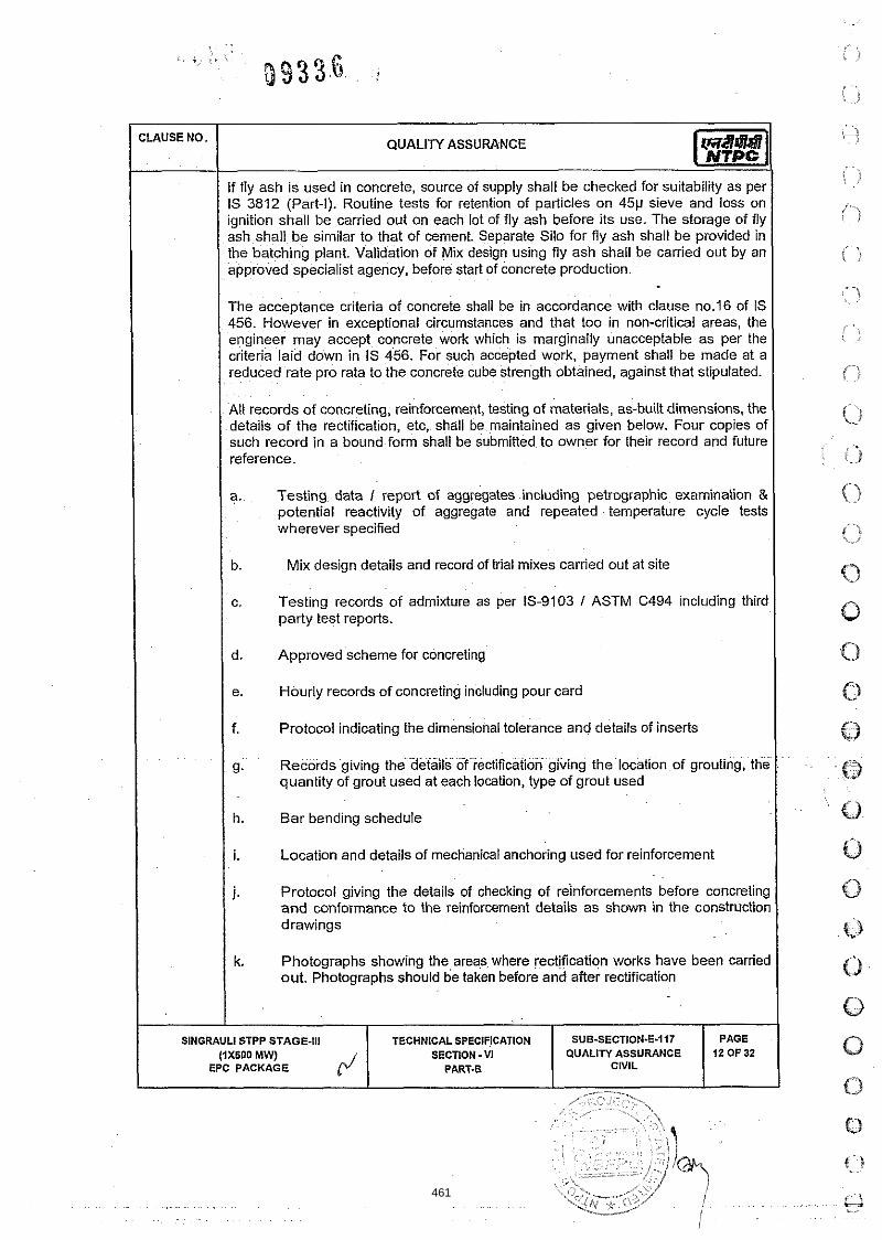
If fly ash is used in concrete, source of supply shall be checked for suitability as per IS 3812 (Part-I). Routine tests for retention of particles on 45p steve and loss on ignition shall be carried out on each lot of fly ash before its use. The storage of fly ash shall be simllar to that of cement. Separate Silo for fly ash shall be provided in the batching plant. Validation of Mix design using fly ash shall be carried out by an approved specialist agency, before start of concrete production.
CLAUSE NO.
The acceptance crlteria of concrete shall be In accordance wlth clause no.16 of IS 456. However in exceptional circumstances and that too In non-critlcal areas, the engineer may accept concrete work which is marginally unacceptable as per the criteria laid down in IS 456. For such accepted work, payment shall be made at a reduced rate pro rata to the concrete cube strength obtained, agalnst that stipulated.
QUALITY ASSURANCE
All records of concreting, reinforcement, testing of materials, as-built dimensions, the details of the rectification, etc, shall be maintained as given below. Four copies of such record in a bound form shall be submitted to owner for their record and future reference.
a. Testing data / report of aggregates including petrographic examination & potential reactivity of aggregate and repeated temperature cycle tests wherever specified
I Mix design details and record of trial mixes carried out at site I c. Testing records of admixture as per IS-9103 I ASTM C494 including third
party test reports.
I I d. Approved scheme for concreting I I I e. Hourly records of concreting including pour card I I Protocol indicating the dimensional tolerance and details of inserts I
g. Records giving the details of rectiticat~on giving the location of grouting, the quantlty of grout used at each location, type of grout used
I I h. Bar bending schedule 'I I I i. Location and details of mechanical anchoring used for reinforcement I
j. Protocol giving the details of checking of reinforcements before concreting and conformance to the reinforcement details as shown in the construction drawings
k. Photographs showing the areas where rectification works have been carried out. Photographs should be taken before and after rectification
I
SINGRAULI STPP STAGE-Ill (1x600 MW)
EPC PACKAGE r / SUB-SECTION-E-I17
QUALITY ASSURANCE CIVIL
TECHNICAL SPECIFICATION SECTION .VI
PART-B
PAGE 12 OF 32
461

Temperature control record of concrete at the time of placement if applicable I
- ?Ci
m. Details of curing, staging and fixing I removal of formwork, checklist for formwork as per Clause 9.9 and Annexure-C of IS 14687 including all machine foundations
QUALIN ASSURANCE
n. Batching Plant shall be calibrated regularly at least once in a 3 months. Computerized output shall be taken for each batch of production of concrete. For concreting works of ash pipe pedestals, mixer with weight batcher may be used. Production and supply of concrete from batching plant shall conform to the provisions of IS 4926
o. Dimensions (length, cross sectional dimensions, straightness, squareness, and flatness) and tolerances for pre cast members as per NTPC Technical Specification. Load test on Precast members (except pre- cast tiles to be laid
462

CLAUSE NO. QUALITY ASSURANCE
I TOLERANCES II Description of lteml Structural Element
8.
9.
10.
11.
12.
O Riser
O Tread
Alignment of holding down bolts with sleeves
Level of holding down bolt assemblies
Embedded Parts (in any direct~on).
13.
14.
Pre- Cast Concrete
Level of embedment for equipment support
Level of embedment for other embedded parts
17. Cross-sectional dimensions
+5
+I0
+5
Centers of pockets or holes with greatest lateral dimension not exceeding 150mm
Variation in steps
+I- 0.1 percent
11750 of the length
+I- 3 mm or +I- 0.1 percent whichever is greater
-5
-1 0
-5
+1.5
+5
0
-5
+10 -1 0
18. When considering5the squareness of the corner the length of the two adjacent sides being checked shall b~ taken as the base line. The shorter side shall not vao in length from the perpendicular by more than 5 mm.
The maximum deviation from a 1.5m straight e d g ~ placed in any position on a nominal plant surface shal not exceed 5 mm.
Squareness:
19.
I / I Placing of reinforcement and for cover
Flatness:
Clause 12.3.1 and 12.3.2 of IS
463

I TOLERANCES 11
CLAUSE NO. QUALIN ASSURANCE
Batching
Description o f Item1 Structural Element
Formwork
clause 102.2 ( of IS 456
1 11.1.5 1 STRUCTURAL STEEL WORK I
Max fmm)
For structural steel works provisions of technical specifications and IS: 800 shall apply. A detailed methodology for structural steel works shall be submitted by the contractor to NTPC for approval. The methodology may require change 1 modification based on the site conditions, for which suitable revisions shall be submitted.
Min (mm)
The contractor shall subm~t the weldlng procedures specification (WPS), heat treatment procedures, NDT procedures etc. at least ninety days before scheduled start of erect~on work at site. All weld~ng and brazing shall be submitted to the NTPC and carried out as per procedure drawn and qualified in accordance wlth requirements of ASME Section lCUBS-4870 or other lnternational equivalent standard acceptable to the NTPC.
All brazers, welders and welding operators employed on any part of the contract either in the contractor's I sub-contractor's works or at site or elsewhere shall be qualified as per AWSD1.1IASME Section-iX or BS-4871 or other equivalent lnternational Standards acceptable to the NTPC.
Clause 9.6 of IS 14687 and 11.1 of IS 456
f:weldingp~cFduie~ualification and welder qualification test results urnished to the NTPC for approval. However, where required by the NTPC; shall be conducted in presence of NTPC I authorized representative.
. .
I
No welding shall be carried out on cast iron components for repair. All the heat treatment results shall be recorded on time temperature charts and ver~fied with recommended regimes.
All Non-destructive examination shall be performed in accordance w~th written procedures as per International Standards and as mentioned elsewhere in the technical specification. The NDT operator shall be qual~fied as per SNT-TC-IA (of the American Society of non-destructive examination). NDT shall be recorded in a report, which includes details of methods and equipment used, resultlevaluation, job data and Identification of personnel employed and details of co-relation of the test
I PAGE
15 OF 32 SlNGRAULl STPP STAGE-Ill TECHNICAL SPECIFICATION
(1x500 MW) SECTION - VI EPC PACKAGE p/ PART-B
' , . :>:,. , - . .i ~- .-.; ,v .\
SUB-SECTION-E-H7 QUALITY ASSURANCE
CIVIL -
464

CLAUSE NO. - QUALIN ASSURANCE
report with the job. The records of RT (Films) and UT (inspection records or printed reports if possible) shall be documented and produced to NTPC.
The requirements of preheating shall be
)
?. .., % )
Low hydrogen electrode (AWS E-7018) for welding of H~ghlMedium tens~le steel, for M.S (IS 2062 Gr. NGr. B, IS 8500) sections thickness above 20mm shall be used. Preheating and Post weld heat treatment requirements shall be complied as specified in the technical specification I approved WPS.
Thickness of thickest Welding using other Welding using low hydrogen part at the area of than low hydrogen welding electrodes or
welding I heat affected welding electrodes submerged arc welding zone IS 2062 IS 2062
: )
I Upto 20-mm (including) I None I None I Over 20 mm to 40 mm Not allowed ZOO c
(including)
Over 40 mm to 63 mm Not allowed 66' C (includ~ng)
Over 63 mm Not allowed 1 1 0 ~ ~
I The following tests I checks shall be carried out for structural steel works
SL. I TESTS I CHECKS I QUANTUM I STANDARD
check testina in absence of MTC I I "
~ ~~ ~ ~ p~~~ ~ ~ - - ~ ~ ~ ~ ~~ . ~~ ... ~. ~- ~- ~~~~~ ~~ -~ ~~~~~
2. I Ultrasonic test on plates above 40mm I As per ASTM A435
3. Welding procedure & welders AWSD1.1lASME Sect~on-IX or qualification test BS-4871 or other eqliivalent
International Standards I I
Fillet Weld
4. Macro-etch examination on production Minimum one joint per built up test coupons for main fillet welds beams, columns and crane girder
etc.
5. tension member of crane girder Dye penetration test on 25% weld length
1 6. 1 All other fillet welds 1 DPT on 5% of weld length with 1 SlNGRAULl STPP STAGE-Ill TECHNICAL SPECIFICATION SUB.SECTION-E-117
(1x500 MWJ
J SECTION - VI 1 QUALITYASSURANCE 1 l E : 2 1
EPC PACKAGE PART-8 CIVIL
465
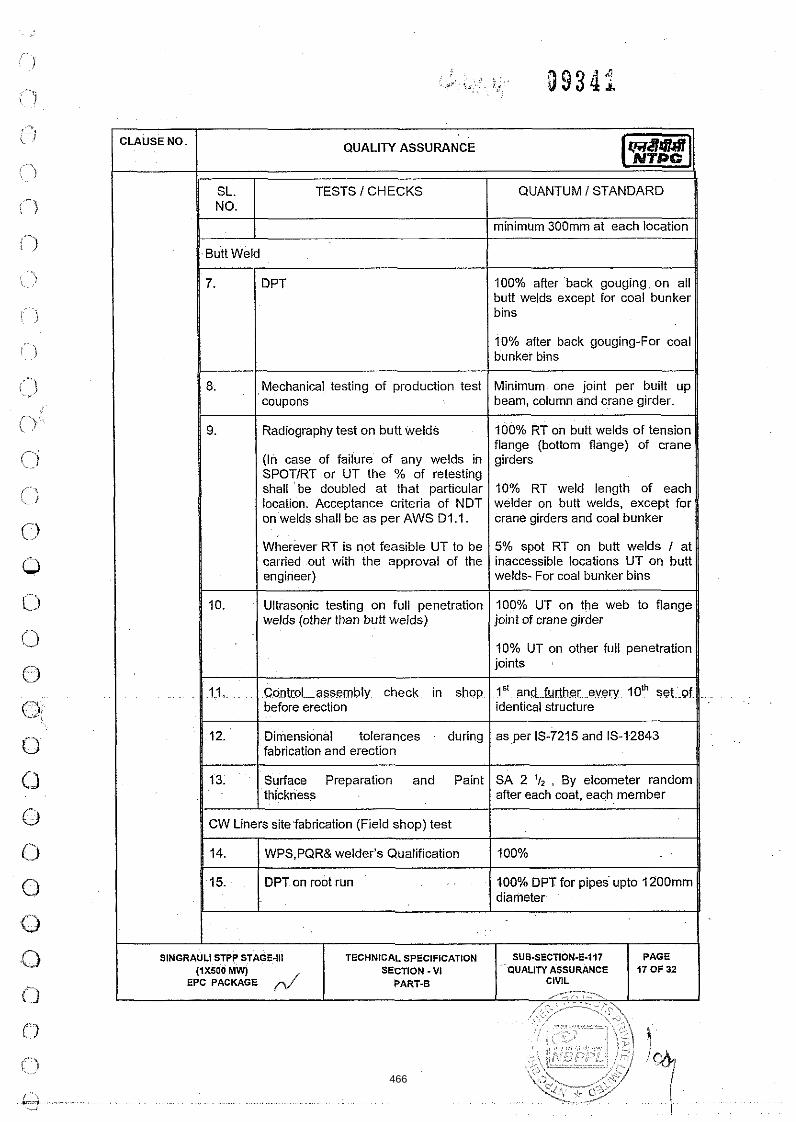
CLAUSE NO.
I minimum 300mm at each location
Butt Weld
QUALITY ASSURANCE
SL. NO.
I 100% after back gouging on all butt welds except for coal bunker I 7.
10% after back gouging-For coal bunker bins I
TESTS I CHECKS
DPT
8. Mechanical testing of production test Minimum one joint per built up coupons I beam, column and crane girder. I
QUANTUM I STANDARD
9. ( Radiography test on butt welds
(In case of failure of any welds in SPOTIRT or UT the % of retesting shall be doubled at that particular location. Acceptance criteria of NDT on welds shall be as per AWS D1.l.
Wherever RT is not feasible UT to be carried out with the approval of the engineer)
100% RT on butt welds of tension flange (bottom flange) of crane girders
10% RT weld length of each welder on butt welds, except for crane girders and coal bunker I 5% spot RT on butt welds I at inaccessible locations UT on butt welds- For coal bunker bins
Ultrasonic testing on full penetration welds (other than butt welds)
100% UT on the web to flange joint of crane girder I
I 10% UT on other full penetration joints I
Control assembly check in shop 1" and further every loth set of before erection identical structure
12. Dimensional tolerances during as per IS-7215 and 15-12843 fabrication and erection
13. Surface Preparation and Paint SA 2 . By elcometer random thickness after each coat, each member
1 CW Liners site fabrication (Field s h o ~ ) test I /I WPS,PQR& welder's Qualification
466

TESTS 1 CHECKS QUANTUM 1 STANDARD I1 16. 1 OPT after back gouging 100% DPT for pipes above
1200mm diameter I 117. 1 UT I Not recommended. 11
1 19. 1 DPT on finished butt welds 1 10% DP7
20. Hydraulic tests 1.5 times the design pressure or 2 times the working pressure which ever is higher.
CW Liners erection site test , I 1 21. 1 WPS,PQR& welder's Qualification 1 100% 1 DPT on root run 00% DPT for pipes upto 1200mm
ot recommended.
1 26. I DPT on finished butt welds 1 10% DPT 1 27. 1 Hydraulic tests
-+ Tolerances
I
STOPLOG AND TRASH RACKS
1.5 times the design pressure o r 2 times the working pressure which ever 1s higher.
In cases where hydraulic test is not possible the same may be substituted with 100°hRT
As per approved draw~ngs, as per IS : 7215 for fabrication and IS : 12843 for erection of steel structures
Structural design shall be as per IS 5620 and IS 4622 and as per details given in technical specifications.' The trash rack to be provided shall be Type-I trash rack (removable section rack), conforming to IS: 11388 (latest). Filling valves shall be provided in the. stop logs to balance the water pressure before lifting the stop,log.
I SlNGRAULl STPPSTAGE-Ill r / I TECHNICAL SPECIFICATION SUB-SECTION-E-117 (1x600 MW) SECTION - VI I WALlTYASSLlftANCE 1 1:%52
EPC PACKAGE PART-B CIVIL
467

QUALIN ASSURANCE
the technical specification. The leakage measured shall not be more than 5 liters1 minute lmeter of length of seal under maximum head. Radiographic examination or magnetic particle testing or other comparable tests shall be carried out for determining the soundness of steel castings and shall be conducted by the contractor as per the technical specification requirements. The contractor shall submit a manufacturing and field quality plans in NTPC format incorporating all the quality aspects mentioned in the technical specifications.
The lifling beam is to be tested for twice the weight of the heaviest component to be lifled by the beam. IS 13591 shall be referred for measurement of the deflection and acceptance criteria.
COAL TAR ANTI-CORROSION TAPE
Coal tar anti corrosion tape shall conform to the requirements of lS:15337. The Manufacturers test certificate for each lot of supply of the coal tar anti corrosion tape shall contain the softening point, needle penetration, filler content, breaking load in the longitudinal direction, service temperature, direct impact test, cathodic disbonding, microbiological tests and. solubility. In case the manufacturer's test certificate does not mention these details, sample from each lot shall be tested for these properties at the third party lab acceptable to NTPC.
Tests for Adhesion, holiday test, mass, thickness shall be carried out randomly at
PAINTING WORKS
Painting works shall be carried out as per the provisions of technical specifications. A detailed methodology for painting works shall be submitted by the contractor to NTPC for approval. The methodology may require change I modification based on the site conditions, for which suitable revisions shall be submitted.
used for blasting, application of primer, intermediate coat and final coat, experience of applicator, etc. testing of painting work and acceptance checks for final clearance. For PU coating works if specified, material shall be procured from NTPC approved source and the application of the PU coating shall be carried out by an experienced authorized applicator of the material supplier approved by NTPC. A separate quality plan and methodology for PU coating works shall be submitted by the contractor for approval of NTPC. Based on the approved quality plan,the tests on material and works shall be got conducted at specialist laboratories like llCT Hyderabad, CECRl
SHEETING WORKS ~ ~
468
CLAUSE NO.
11.1.8
11.1.9
SINGRAULI
QUALITY ASSURANCE
sheets shall meet the chemical & physical properties as per relevant standards I codes referred in the approved data sheet. I t shall be tested for bare metal thickness, thickness of coatings, type of coatinglpaint, hardness of painted surface as per IS14246 (2Hpencil hardness), flexibility test, bend test as per ASTM D 3281 IS 14246 at 180 degree, dimensional check after profiling of sheets, cross hatch test, salt spray test as per ASTM 8-1171 IS 9844 for minimum 1000 hrs one sample per batch at random. For true representative sampling, three samples shall be taken from each batch out of which one sample shall be sent for salt spray test as per IS14246, the samples may be chosen from the batches offered for inspection, one at the beginning of supply, another at the middle of supply and the third towards the end of the supply.
Bonded Mineral Wool Insulation shall meet the requirements of thickness, density, thermal Conductivity, all other tests as perthe technical specifications and IS-8183.
For sheet installation no gas cut opening shall be allowed at the site, whenever opening is specified these shall be properly cut in the factory and shall be filled with lipping / flashing fo i true shape / dimension etc. The sheets1 packets shall be stacked neatly clear off the ground at an angle to the ground, over a base pallet to provide drainage. Water I moisture should not be allowed to stagnate on surface, or in between layers. This can damage the coatirig, and cause corrosion.
TILE WORKS
The execution, finishing, testing and acceptance of tile works shall be as per the provisions of technical specifications. The material for tile works shall be procured from the NTPC approved brand I source. Local depressions on, account of faulty workmanship, tiles I naturalstones with cracked or broken I chipped edges shall not be acceptable.
The tests shall be carried out on acid resistant bricks I tile- water absorption, compressive strength, resistance to acid, flexural strength, dimensions and all other tests as per IS 4860 and IS 4457, bitumastic ready mixed paint as per IS 158, bitumastic as per IS 9510, potassium silicate, resin type and sulphur type mortars as per IS-4832;~paft [-llGCllr,KifaG-preparation for E r n t i n g a p e i I S 2395, epoxy painting shall be carried for required coating thickness and dry film thickness.
FIRE PROOF DOORS
Fire Proof doors shall be tested for the requirements mentioned in 13-3614 Part-l&ll andThe Technical.Specification. The type test of the doors shall be carried out at, CBRI Roorkee for minimum 2 hours fire rating and its Fabrication drawing shall also be approved by CBRI, Roorkee. DFT of paint of Fire Proof Doors and its fittings and fixtures as per BOQ shall be checked. The doors shall be finished with suitable fire retardant painting system
. .
STPP STAGE-Ill (1x600 MW)
EPC PACKAGE
TECHNICAL SPECIFICATION SECTION - VI
PART-B CIVIL
SUB-SECTION-E-117 QUALITY ASSURANCE
PAGE 20 OF 32
469

I WATER PROOFING i I
~ . . ,
; 5 NO. !
-
The execution, finishing, testing and acceptance of water proofing works shall be as per the provisions of technical specifications. The material for the works shall be procured from the NTPC approved brand I source and the works shall be executed by the authorized applicator of the supplier.
QUALITY ASSURANCE
The equipment, deployment of manpower and machinely shall be arranged by the contractor to prevent the collapse of bore hole and to ensure continuous rate of placement of specified grade of concrete.
The piling works shall be executed as per the technical spectficatlons, approved drawings, relevant codes I standards, FQP and BOQ. in addition to the requirements of technical specifications, the following shall also be ensured while execution of piling works:
Water proofing shall be tested for water tightness by creattng a pond of water minimum 25 mm height on area of 6 m x 6 m, for the period of 48 hrs on fully dried elastomer~c membrane surfaces. Minlmum 5% area of the roof shall be subjected to water tightness test. Such test necessarily be conducted on vulnerable areas like drain channel I drain head. No dampness shall be vislble on the underneath stde of roof (i.e. ceiling), parapet and well junctions etc which have been subjected for testing. The above testtng shall be carried out prlor to application of wearing course.
PILING WORK
For piling works provisions of technical specifications, approved drawings, BOQs and relevant IS codes I standards shall apply. The piling works shall be executed by the agency meeting the qualifying requirements as specified. A detailed methodology for piling works shall be submitted by the contractor to NTPC for approval. The methodology may require change I modification based on the site conditions, for which suitable revisions shall be submitted.
The methodology for piling works shall broadly contain the method of bor~ng, stabflity of bore hole, termination criteria, tests I checks for termination level, fabrication oi cage, cage lowering, concrete batching I mixing, transportation, placing, recording oi the time of construction operations, method of conducting initial and routine load tests, testing and sampling of concrete during productton and placement and acceptance checks on piles for final clearance.
a) Time gap between completion of pile boring and start of concreting should be kept to the minimum. However the maximum lime gap shall not be more than 6 hours.
b) Muck Debris should be removed from the pile bore by air lift technique(by keeping the trernie & air pipe as close as to bottom of pile bore) i.e. after completion of boring, after completion of SPT(wherever applicable), after lowering reinforcement cage, but before start of concreting.
I
SlNGRAULt STPP STAGE-Ill TECHNICAL SPECIFICATION (1x500 MW) SECTION - VI
EPC PACKAGE PART-B
SUB-SECTION-E-H7 QUALIN ASSURANCE
CIVIL
PAGE 21 OF 32
470

CLAUSE NO. QUALITY ASSURANCE
c) Density of bentonite slurry shall be checked from the sample taken from the bottom of pile bore( not at 1.0 m above the bottom of the pile bore)
d) Minimum two welding sets shall be kept ready to join the two cages of reinforcement by engaging 3 or more welders. This will ensure the lowering of RIF cage in minimum time.
e) While lowering the RIF cage into the pile bore, two hooks shall always be used to ensure balancedisymmetrical insertion of cage into the pile bore.
f) Concrete cover blocks at the junction of two RIF cage shall be ensured before lowering the second segment.
g) Surge concreting of about 1.0 cum shall be ensured at the start of concreting (i.e. in the first pour), by suddenly allowing to fall through the tremie pipe from the funnel. This will help in displacing left out muckldebris in the pile bore (by the impact).
h) Continuous feeding of concrete shall be ensured by deploying at least two transit concrete mixers (if required to be deployed) and mixing done through concrete batching plant (if deployed). Cold joints in the pile shall be avoided.
i) In a pile group, SPT shall be carried out at termination level in the pile, taken up first.
j) Bentonite slurry circulation to be ensured from start of boring to start of concreting. Flushing of bentonite slurry will only ensure maintaining of density of bentonite slut~y uniformly and will not allow bentonite jelly to settle at the bottom, whereas air lifl technique with bentonite circulation will ensure removal of muck debris from the bottom of pile bore.
k) Properties of drilling mud shall be checked prior to commencement of the piling work and thereafter, minimum once per week or as found necessary by
.. . the~engineer. One sample~consisting-of3 specimens shall be tested for the above.
I) . Low strain pile integrity test on all job piles and test piles shall'be conducted as specified in the Technical Specification. This test shall be suitably used to identify the piles for ~outine tests. High Strain dynamic test shall be done as per the technical specification. The frequency of the test shall be as per the BOQ
in) For Working Piles: Minimum one sample consisting of 6 test cubes shall-be ~
. made for first ten piles. Out of these3 shall be tested for 7 days cube strength and 3 for 28 days cube strength. Minimum one sample of 6 test cubes for every 25 nos. of piles shall be tested, out of these 3 shall be tested for 7 days cube strength and 3 for 28 days cube strength
. . . . . .
SlNGRAULl STPP STAGE-Ill TECHNICAL SPECIFICATION SUB-SECTION-E-117 PAGE (4x500 MW) SECTION - VI QUALIN ASSURANCE 22 OF 32
EPC PACKAGE r' PART-B CIVIL
471

I ( PILE LOAD TEST I
- CLAUSE NO.
Pile load testing shall conform to the requirements of IS-2911 (Part IV) and the technical specification. Initial load tests as specified in the contract documents shall be conducted to assess the safe load carrying capacity of pile before start of work. To verify the load carrying capacity of the working piles, routine load test shall be conducted.
Pile load-testing procedure and the test setup I scheme shall be submitted for approval of NTPC. The contractor shall use the test setup having arrangement for anchor piles I rock anchors alone or combination of anchor piles I rock anchors and kentledge for both vertical compression and uplift (tension) Load test (initial) on piles. The cost of reaction system I piles shall deem to be included in the cost of test piles
QUALITY ASSURANCE
All the gauges and ~nstruments shall be calibrated before the start of the tests on test plles and working plies and the callbration record shall be verified before start of execution of the test.
WATER SUPPLY, DRAINAGE & SANITATION
Material used for sanltary and plumblng fittings and fixtures shall conform to and be tested as per the requirements of relevant IS Codes specified in NTPC technical specification.
The O ~ S ~ N C ~ ~ O ~ S in sewer lines shall be checked by inserting a smooth ball, of diameter 13 mm less than the pipe bore at the high end of the sewer or drain. If absence of any obstructions, such as yarn or mortar projecting through the joints, ball shall roll down the invert of the pipe and emerge at the lower end. The straightness shall be checked by. means of a mirror at one end of the line and lamp at the other. If the pipeline is straight, the full circle of the light may be observed. The mirror will also indicate obstruction in the barrel, if the pipeline is not straight.
The service pipes shall be slowly and carefully charged with water, allowing all air to . .. .. ~~. escape avoidlng al l shock^ %r~%ater hammer: T h e service-pipe shall then be inspected under test I working condition of pressure and flow, when all draw-off taps are closed. The service pipes shall be checked for' satisfactory support and protection. from damage, corrosion and frost.
I 11.1.13 I ARCHITECTURAL & MISC. WORKS I Material used for sanitary and plumbing fittings and fixtures, floor finishes and allied work shall conform and tested as per the requirements of relevant IS Codes specified in NTPC technicaLspec~fication.
Fabricated item like metal doors, windows, ventilators, louvers, rolling shutters and grills etc. sliall be checked 'for correc'tness of locations and smoothness of operation and fixtures. All controls and locking devices shall give fault free performance. Door and window shutters shall operatewithout jamming. The clearance at head and jamb
I SINGRAULI STPP STAGE-Ill TECHNICAL SPECIFICATION SUB-SECTION-E-117 PAGE
(1x500 MW) SECTION . VI QUALIN ASSURANCE 23 OF 32 EPC PACKAGE PART-B CIVIL
472

CLAUSE NO.
11.1.14
12.0.0
SINGRAULI
QUALITY ASSURANCE
for door shutters shall not exceed 1 5 mm. For double leaf doors, the gap at the meeting sttles shall not be more than 2 5 mm.
Mater~als used in glass and glazing shall be procured from source approved by NTPC and shall conform to the requirements of the Technical Spectfication and IS Codes.
False ceiling panels shall be best quality materlal in thickness and properties called for in the specification I schedule of items. Material Test Certificate to be submitted before bulk supply.
All bought Items covered In the scope of contract shall be procured from sources approved by NTPC, and shall conform to the requirements of the technical speclfications and referred standards lcodes.
ROAD WORK
Quality Assurance and testing requirements for roadwork shall be as per the MOSRTH-Specification (Section 900), IRC specifications or CPWD speclfications as speclf~ed in the technical specifications and BOQ of the contract.
The testing and sampling shall include the checks on earth work for embankment and subgrade, sub bases and bases and bituminous constructions. The sampling and testing of concrete pavements shall be as per the respective Items of earthwork, subgrade I sub-base, concrete, etc.
SHOP TEST EOT Cranes,Other cranes & Hoist
1.0 HOOKS
1.01 ALL TESTS INCLUDING PROOF LOAD TEST AS PER RELEVANT ISlBSlDlN SHALL BE CARRIED OUT.
1.02
2.0 STEEL CASTING
2.01 DPTON MACHINED SURFACE SHALL BE CARRIED OUT.
3.0 GIRDERS, END CARRIAGE,CRAB, GEAR BOX AND ROPE DRUM
3.01 THE PLATES OF THICKNESS 25MM AND ABOVE SHALL BE ULTRASONICALLY TESTED.
3.02 NDT REQUIREMENTS O N WELDMENTS SHALL BE AS FOLLOWS:
a) BUTT WELDS IN TENSION:- 100% RT AND 100% DPT
STPP STAGE-Ill (iX500 MW)
EPC PACKAGE
TECHNICAL SPECIFICATION SECTION - VI
PART-8 CIVIL
SUB-SECTION-E-117 OUALIN ASSURANCE
PAGE 24 OF 32
473

QUALITY ASSURANCE
b) BUTT WELDS IN COMPRESSION:- 10% RT AND 100% DPT
c) BUTT WELDS IN ROPE DRUM:- 100% RT AND 100% DPT
d) FILLET WELDS:- RANDOM 10% DPT
4.0 FORGING (WHEEL, GEARS, PINIONS, AXLE, HOOKS & HOOK TRUNION)
4.01 ALL,FORGINGS GREATER THAN OR EQUAL TO 50 MM DIAMETER OR THICKNESS SHALL BE SUBJECTED TO ULTRASONIC TESTING.
4.02 DPTIMPl SHALL BE DONE AFTER HARDFACING AND MACHINING.
5.0 WIRE RPOE SHALL BE TESTED AS PER RELEVANT STANDARD.
6.0 REDUCTION GEARS SHALL BE TESTED FOR REDUCTION RATIO, BACKLASH 8 CONTACT PATTERN. GEAR BOX SHALL BE SUBJECTED TO NO-LOAD RUN TEST TO CHECK FOR OIL LEAKAGE, TEMPERATURE RISE, NOISE AND VIBRATION.
7.0 THE CRANES SHALL BE COMPLETELY ASSEMBLED AT SHOP FOR FINAL TESTING. ALL TESTS FOR DIMENSION, DEFLECTION, LOAD, OVERLOAD, HOISTING MOTION, CROSS TRAVEL ETC. AS PER 13-3177 SHALL BE CARRIED OUT AT SHOP.
8.0 ALL-ELECTRIC HOISTS SHALL BE TESTED AS PER 15-3938 AND CHAIN PULLEY BLOCKS SHALL BE TESTED AS PER 15-3832.
CATHODIC PROTECTION
Quality of cathodic protection system shall be as per given table.
. .
. .
SlNGRAULl STPP STAGE-Ill (IXSOO MW)
EPC PACKAGE r / SUB-SECTI0N.E-717
QUALITY ASSURANCE CIVIL
TECHNICAL SPECIFICATION SECTION - VI
PART4
PAGE 25 OF 32
474

CLAUSE NO. QUALITY ASSURANCE
IMPRESSED CURRENT CATHODIC PROTECTION
Transformer Rectifier Unit
Attributes1 Characteristics m 3 Y
r * m
c 0
V]
l - a Items I Components I Sub- assembly
Rectifier Transformer Y Y Y Y ( IS : 2026) Electronic Components Y Y PCB & Electronic Cards Y Y
I SlNGRAULl STPP STAGE.111 TECHNICAL SPECIFICATIONS SUB-SECTION-E-117 (1x600 MW) SECTION - VI QUALITYASSURANCE 1 1 EPC PACKAGE PART-B
475

... , i , ,
! j W J J V d
QUALITY ASSUPANCE
ANNEXURE-I
,. : 1 : ;
I_ The above organization setup is minimum however their deployment shall be as per the agreed deployment schedule. The contractor shall prepare a manpower deployment schedule in line with the finalized work' plan and the same shall be submitted to the engineer-in charge for acceptance1 approval.
2. The contractor shall mobilize the QA& QC manpower in line with the finalized manpower deployment schedule and shall ensure their availability well in advance (15 days approx.) of the beginning of the concerned activity1 work.
3. The contractor shall further mobilize required number of skilled & supporting staff and additional resources, if any to meet the work schedule.
* For concrete work -2Nos ( one for foundation work & one for~superstructure)
" For lines and levels - 1 No.
SINGRAULI STPP STAGE-Ill SUB-SECTION-E-07
/ \ i .
476

CLAUSE NO.
SlNGRAULl
QUALITY ASSURANCE
ANNEXURE - I I TYPICAL QAlQC LAB EQUIPMENT
Project: Package
e chatelier Mould
19 Measur~ng flasks 3
20 Compression test~ng machine 2 sets of 2000 kN capacity each
STPP STAGE-Ill TECHNICAL SPECIFICATION SUB-SECTION-E-117 PAGE (IXSOO MW) SECTION -VI QUALIN ASSURANCE 28 OF 32
EPC PACKAGE PART-8 r" CIVIL
477

QUALIN ASSURANCE
Party should deplo
I
PAGE 29 OF 32
SUB.SECTION-E-447 QUALITY ASSURANCE
CIVIL
SlNGRAULl STPP STAGE-Ill (IXSOO MW)
EPC PACKAGE
TECHNICAL SPECIFICATION SECTION - VI
PART.B
478
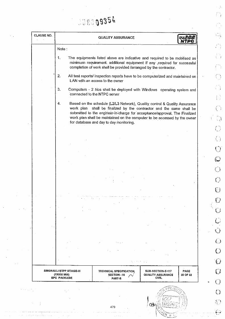
CLAUSE NO.
SINGRAULI
QUALITY ASSURANCE
Note :
1. The equipments listed above are indicative and required to be mobilised as minimum requirement. additional equipment if any ,required for successful completion of work shall be provided /arranged by the contractor.
2. All test reports1 inspection reports have to be computerized and maintained on LAN with an access to the owner
3. Computers - 2 Nos shall be deployed with Windows operating system and connected to the NTPC server
4. Based on the schedule (L21L3 Network), Quality control & Quality Assurance work plan shall be finalized by the contractor and the same shall be submitted to the engineer-in-charge for acceptance/approval. The Finalized work plan shall be maintained on the computer to be accessed by the owner for database and day to day monitoring.
. .
. . ~.
.. .
. ~
. .
. ~. . .
STPP STAGE-111 (1x600 MW)
EPC PACKAGE
TECHNICAL SPEClFlCATlO SECTION - V I
PART-B
SUB-SECTION-E-117 PAGE QUALITY ASSURANCE 30 OF 32
CIVIL
479

CLAUSE NO. QUALITY ASSURANCE
-
ANNEXURE - Ill
waterproofing, accelerators, Epoxy Resin,
Compound, Bituminous Compound, Joint
painted Coil Coated Steel System
12. . Roof Water Proofing
13. Electro-Forged Gratings
StNGRAULl STPP STAGE.111
480

CLAUSE NO.
SlNGRAULl
QUALITY ASSURANCE
Note: The Bidders are required to indicate the list of proposed manufacturers1 sub-
vendors for each of the BOI in their Bid proposal, which shall be discussed for
finalization at post bid
STPP STAGE-Ill (1x600 MW)
EPC PACKAGE
TECHNICAL SPECIFICATION SUB.SECTION-E-117 PAGE SECTION -VI QUALITY ASSURANCE 32 OF 32
PART-8 P' CIVIL
481
-.I
INDICATIVE FIELD QUALITY PLAN
. . . .
r /
-
482

483

484

485

486

487

SlN
GP
AU
Ll S
TPP
ST
AG
E-I
ll 11
X5W
MW
) E
PC
PA
CK
AG
E
TEC
HN
ICA
L S
PE
CIF
ICA
TIO
N
SE
CTI
ON
-VI.
PA
RT-
B
FIE
LD Q
UA
LIN
PLA
N
SU
B.S
EC
TIO
N-E
d18
P
age
6 of
17
488
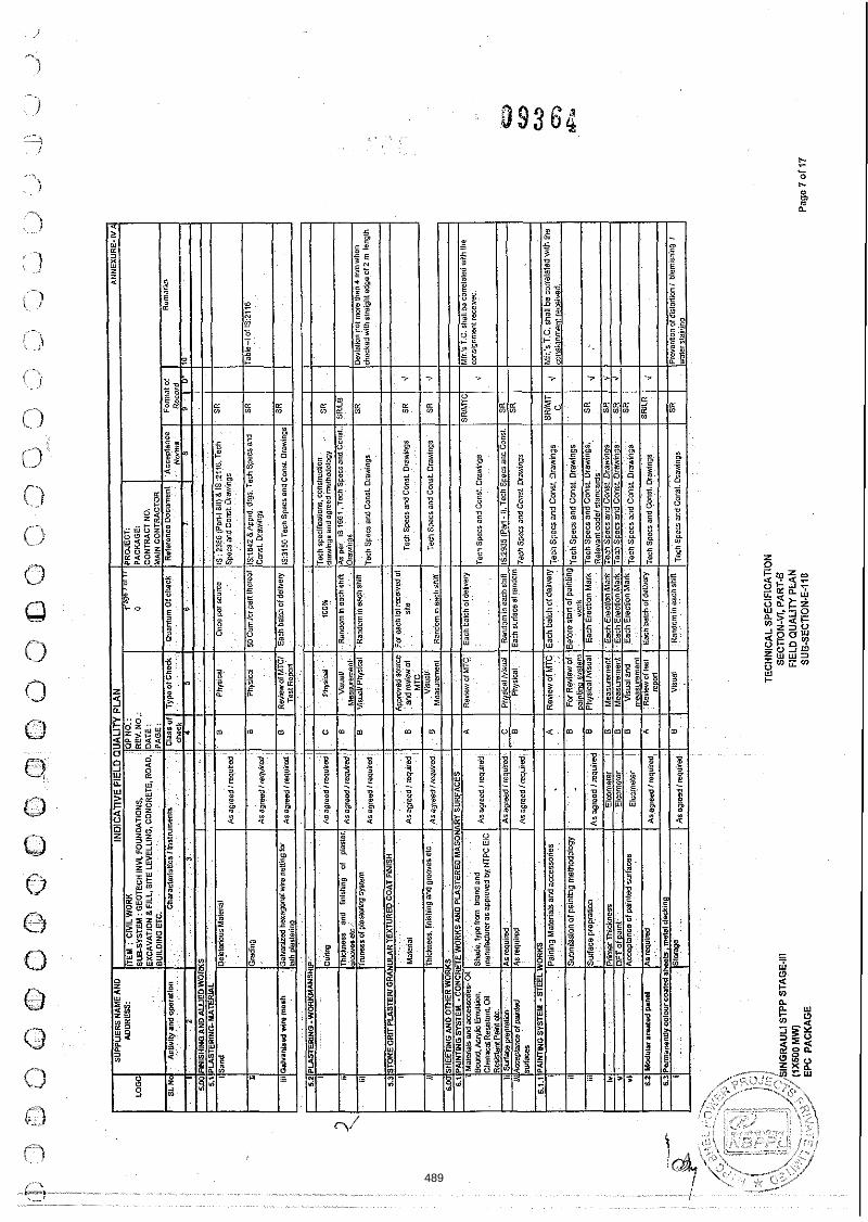
489

490
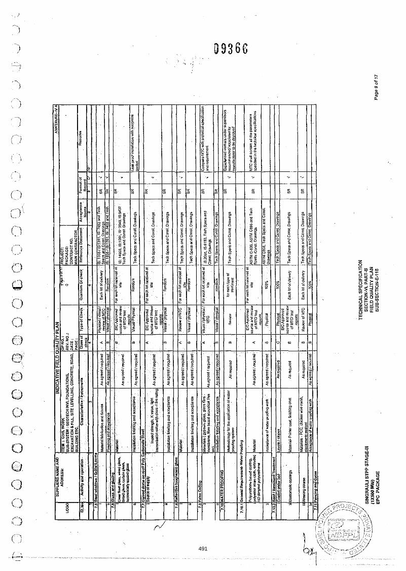
I I
I I
repo
ns
I I
! M
aIeM
I;- P
CC
. Chi
dreo
nre me4
e~er
mm
encr
eale
nt
B R
evbw
dM
TC
E
ach
lot a
! dsl
#en/
Te
ch S
~e
cr an
d C
anst
. Dm
wnBB
SR
v'
~~
p~
~a
~~
te
ip
im
fi
o~
w~
~
I Ara
gre
adiw
uir
ed I
B I
Phy
sics
I
100%
l
~e
~n
$g
em a
nd c
anst
. ore
*ing
r I
I I
I I
I I
I I
SIN
GR
AU
LI S
TPP
STA
GE
-Ill
EP
C P
AC
KA
GE
P
age
9 o
f 17
491

492

493

li I tc li h
'p
Ao
ra
pl
sn
ol
sr
d~
.
. ,o
.oA
mW
EE
OT
RE
Km
Eli
l
rpw
ery
lo
en
sum
so
c*e6
ng
leng
Ul
qu
ble
d h
l- of
lhe
Dia
mLe
r of
U
ie p
i& W
lari
hb
rc
ctat
hq
nar
.an.
~~
a(n
irlo
~d
am
~~
~w
La
biI
tya
ad
cv
palr
engt
h
Rp
md
in*g
mu
nd
ls"e
l
CiP
mm
giFl
urhi
ng d p
flt b
re
Ske
of bra
and
Dvn
ng b
nn
g of pzk
ream
mm
neni
emn!
of SPTI m
re
,n--
SIN
GR
AU
LI S
TPP
ST
AG
E-I
ll (IX
SOO
MW)
EP
C P
AC
KA
GE
~~
p~
lln
~il
ata
ta~
wa
xm
aa
xm
a~
h'p
&m.w
sed
hM
en
l Wd
dl8
Ers
sum
no
fUea
Vld
n
~n
er
mei
vmg
me
Rm
mm
en
dd
rn
h de
sign
im
m r
mia
l'al
we
nv
. I
I I
I I
I vi
il lC
em
~lt
mn
led
IA
s ,m
uid
I
B
I P
hysh
ai
IOns
eppr
sh#
lAs
per
spom
urd
dar*
in+
/ SR
IIB
I 4
[At b
slct
ing
pb
nl
W
,
TE
CH
NIC
AL
SP
EC
IFIC
AT
ION
S
EC
TIO
N.V
I. P
AR
T-B
F
IEL
D Q
UA
LIT
Y P
LA
N
SU
BS
EC
TIO
N-E
-118
A8,
eq"i
md
An
requ
ired
lurm
uir
ad
Pag
e 12
of1
7
~s
ag
ne
d~
rqu
rd
/is.g
red{
requ
id
lu..,ae
d,re."
bd
B
,,,< :,
, ,,
.. \,:a
apso
mtio
n
viii
IX
B
B B B A
vhyr
kal
vmiw
ot
cmcr
s(e
10 p
ied
am
ve
wn
sd.
PE
ele
d6
0n
em1
Ph
yri
d
Ph
~ic
als
nd
MTC
R
Ovi
ax
MB
alu
Dm
nl
VW
al
Mea
rvie
men
l
oo
e
far
each
m
ix
pm
wili
m
Asr
ep
uim
,
SPT
& G
O*
reC
MeI
Y
Ran
dam
Ran
dom
300%
Ea
chb
aim
dd
au
ve~
R8Mom
Ch,ff
ik!'r
"*
4 4 .1
iSZ
9il
a.P
e'aP
Pd
Ois
win
gsiin
d Ic
~L
ria
i s~
#d
iaii
m
As .l
p,W
Pd
OM
ng
ran
d te
Cnn
sca,
lO
aa6o
llO
n
As
pei
spp
d D
mo
gs
an
d te
chni
cal
~~
~1
10
11
10
0
NT
PC
Leth
aiec
ircat
ion
B
A
SW
LB
SW
lB
SR
RB
'"'"
""O
' I'L
I1 1-
.I,"
"V
illi
Ors
win
gs
Tach
Spe
cr a
nd C
ann.
Dc&
ngs
Tech
sp
ea
and
Can.,.
Dra
MO
BB
SNLB
Mea
sure
men
t
Soil d
ab
SR
SR
SR
d
700%
rpei
ncaU
ona
Aa
.lpr
MP
C
Ne
ce
rra
~c
oir
ec
iio
nfo
~m
~~
IIre
mIt
tnl
andw
afer
abio
rolia
n ar
caid
ing LO m
ix
dsrig
n re
com
men
da!b
n may
bec
arti
ed
ou
tdu
nn
g th
etib
i mw
As
wra
wd.
Dra
mng
aand
lsds
dica
i sw
tinca
tion
Asp
rqp
d.D
mM
ng
san
dfR
hn
id
SR
RB
SR
< 4
494

495

I TE
CH
NIC
AL
SP
EC
IFIC
ATI
ON
SIN
GiW
UI.1
S
TPP
STA
GE
-Ill
SE
CTI
ON
-VI.
PA
RT.
6 (1
x500
MW
) FI
ELD
QU
ALI
TY P
LAN
E
PC
PA
CK
AG
E
SU
B.S
EC
TlO
N-E
-1i8
P
age
14 o
f 17
496

497

498

SlN
GR
AU
Ll S
TPP
STA
GE
4II
IIX5C
UM
W)
. E
PC
PA
CK
AG
E
499

500
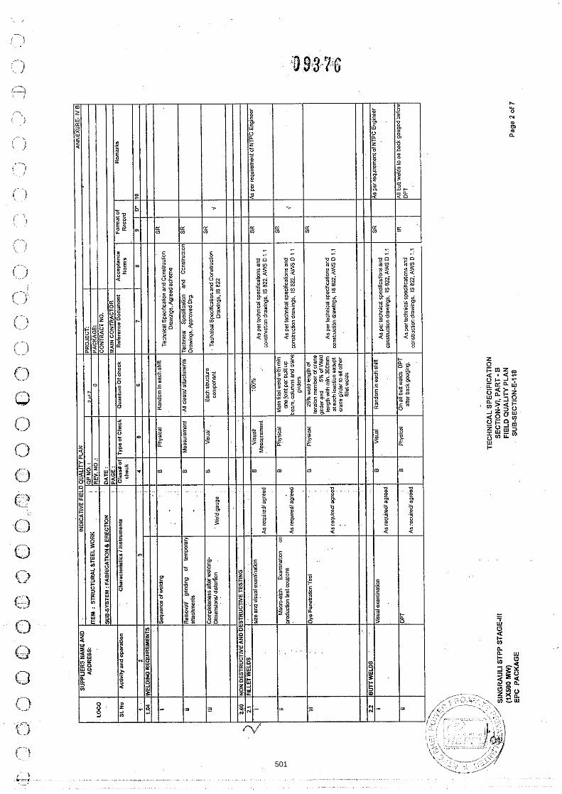
501

502
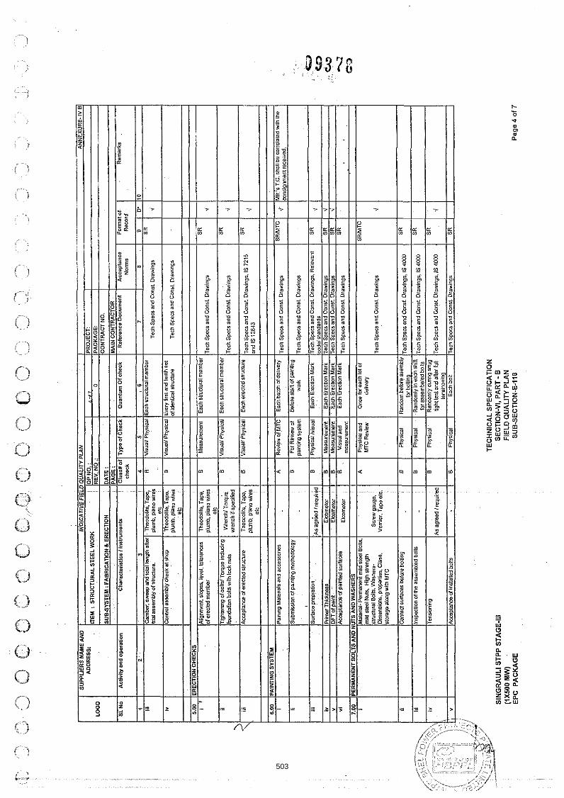
TB
C~
sp
a~
~
and
Cm
r! ~
rav
nn
gr
I I
I I
I I
I i
I1
.-
iii
I Is
~m
~~
nre
om
tio
n
,, . .
. . .I
B
I ~h
yri
cs
iiv
iru
a~
I
~a
*
~ie
sti
on
~a
rk
lie
ch
spec
s an
d C
an
s~
Dra
win
gs, R
elev
ant
I S
R
I ,
I 1
1 I
I l~
~d
elr
tan
da
rdr
1 .
. ,
.. R
I ag
reco
,req
u,re
a
iv
I I~
ime
r~h
ic~
ne
sr
I E
lmm
eter
I
B
I M
ealu
rem
ent
I E
arn
Ere
ctio
n M
sik
l~e
ch
S
pecs
and
can
rt D
raw
ings
I
Yl
I
SR
(
41
. w
I
IDFT o
f pai
nt
1 E
lmm
ere,
8
1 B
I
Mea
sure
men
t I
Ea
dl E
rect
ion
Mar
k [T
ach
Sp
ea
and
Can
st. D
~w
ing
h
I S
R
(4
1
.:, CO
YI I
IA~
~8
pta
nca
alp
ain
tsd
ru
msa
s I
~~
mm
~f
.~
I
6 .
I V
isua
l and
I
Each
Ere
ctio
n M
ark
ITerns
mea
cons
. ~,
.~
i~
~~
I
SR
/
1'
- I
I I
I ,
I . .
-
I m
ealu
rem
ent I
7 00
IP
ER
MA
NU
ITB
OLT
S
AN
D N
UTS
AN
D W
AS
HE
RS
I
I I
I I
I c3
i M
ater
ial-
Per
man
ent m
ild s
teel
oils
. A
~
hy
~c
ai
and
00-
br e
ach
lot o
r S
RlM
TC
m
id $
be1 N
u9
Hl~
h
rtre
na
h
MTC
Rev
iew
d
eli
vw
A* a
gree
d Ir
equi
ied
SIN
GR
AU
LI S
TPP
STA
GE-
I11
(rxs
ao m
w)
EP
C P
AC
KA
GE
TEC
HN
ICA
L S
PE
CIF
ICA
TIO
N
SE
CTI
ON
-VI.
PA
RT
- B
FIE
LD
QU
AL
IN P
LA
N
SU
B-S
EC
TI0N
.E-1
18
Pag
e 4
of 7
503

. . S
lNG
RA
UL
l STP
P S
TAG
E-Il
l
3-'-
(1x5
00 M
W)
EP
C P
AC
KA
GE
LO
GO
Si.
No
AN
NE
XU
RE
. iV
S
TEC
HN
ICA
L S
PE
CIF
ICA
TIO
N
SE
CTI
ON
-VI,
PA
RT
- B
SU
PP
LIE
RS
WE
A
ND
Ae
tiri
ty a
nd o
psr
atio
n
PR
OJE
CT:
P
AC
KA
GE
: C
ON
TR
AC
TN
O.
MA
IN C
ON
TRA
CTO
R
Ref
eren
ce D
o~
urn
en
t
IND
ICA
TIV
E F
IELD
QU
ALI
TY
PLA
N
iv
FIE
LD
QU
ALI
TY P
LA
N
SU
BS
EC
TIO
N-E
1q8
Pag
e 5
of 7
0
Qua
ntum
Of .
hack
ITEM
; S
TRU
CTU
RA
L S
TE
EL
WO
RK
SU
BS
YS
TE
M:
FA
BR
ICA
TIO
N &
ER
EC
TIO
N
I
~h
era
cto
rirt
iu
iinn
tru
me
n~
-c
8 A
ccep
tanc
e N
orm
s
shiw
nale
prim
er
Cw
i tar
Pro
Wc
n $p
e
Fo
rmal
of
Ros
Drd
QP
NO
. :
RE
V.
NO
.: D
AT
E :
PA
GE
:
R0U
TiN
ET
ES
TS
:-H
olid
ay
tesI
erbd
he60
ion
Tes
l,Olie
st Im
pact
(e
rl C
onai
ian
reria
lenc
a te
st
Ram
arks
C
iass
#o
f ch
eck
Ty
ps
olC
he
rk
Arr
eqd.
'
, . ,
S
Vi~
va
l B R
ando
m
NTP
C T
ach
Spe
c# i
S:1
5337
ln
rpn
Rep
on
4 o
r unc
ared
pip
er.
for o
ther
ov
ergr
ound
pip
ing
pain
ling
shal
l be
as
spea
6ed
in th
elec
hoic
ai s
wtil
icab
an.
504

AD
DR
ESS;
I I
I I
I I
iv
Che
ck o
fwil
a~
e dB
f~d
s
B
1000
3 F
~BB
Irom
l~*c
edel
ec(r
Sh
op
RB
Q~
J~W
10
.5
~~N
SP
EC
TIO
N
OF
WEL
DS I S
HO
P A
ND
FIE
LD E
RE
CTI
ON
WEL
D^
I I
I I
I I
I
I en
caw
men
tfia
m g
mvn
d rh
aii b a
s pe
r app
iave
d da
w8n
er
Tole
ranc
eOD
1 ova
lihi
~Vte
lfal
ie
I B
M
ea~u
rem
e~t 10
0%
As p
er a
ppro
ved
draw
ng
SR
10
7
HY
DR
OTE
STI
NG
O
n Fa
bnca
bon
Joln
ta
~~
di
om
~
I A
~e
akag
e test
s lo
wh
SR
\i N
TPC
bc
h se
atca
bon
of~
erb
sh
all b
e as
oei
GI. T
echn
ical
TEC
HN
ICA
L S
PE
CIF
ICA
TIO
N
SlN
GR
AU
Ll S
TPP
STA
GE-
111
SE
CTI
ON
-VI,
PA
RT
- B FI
ELD
QU
ALI
TY P
LAN
E
PC
PA
CK
AG
E
SU
BS
EC
TIO
N-E
-118
P
age
6 of
7
505

Cat
egor
y 'A
' Fa
4 E
ngin
eer i
n as
roci
stio
n w
ilh E
xecu
ting
Eng
inee
r. C
atag
ory
'w Ei
ocut
ing
Eng
inee
r,
I~
al
~~
~~
2'
Em
cuti
ng
Eng
inso
r ;S
R'S
~~
B
Reg
ird
r , T
R=T
DS
C R
ep
oti
.~fi
~~
=
~an
ufa
clu
ro<s
~e.
1 , I
I I
I si
gnah
ln,
lmis
dow
men
tsha
li be
read
in m
njun
ctio
nwib
i ow
nr
Te
a. S
pedf
icat
ions
. 800. Dra
win
gs
I RE
VIE
WE
D B
Y I A
PP
RO
VE
D B
Y A
PPRO
VALS
SEAL
SlN
GR
AU
Ll S
TPP
STA
GE
-Ill
(1x5
00 MW
EP
C P
AC
KA
GE
P
age
7 o
f 7
506

APPENDIX-E (MOE\il-QA! Page .. Lk ... of 342
MINUTES OF MEETING OF POST BID DISCUSSIONS HELD ON 08-09.02.2012 BETWEEN NTFC I T D
AND MIS NTPC- BHEL POWER PROJECTS PRIVATE LIMITED (NBPPL) REGARDING QA CIVIL
ISSUES FOR FGUTPP STAGE IV (1x500 MW) EPC PROJECT
BID DOCUMENT NO. CS 1450.001.9
PRESENT:
CQA, NTPC LTD MIS NBPPL
RAJiV K SINGH BAlS BALBIR CHAND (AGMj
PMIT TRI'JEDI ASHISH JAIN (DY MANAGER)
KRISHNA KUMAS (SS. EKGR)
ALBEST KUJUR (ENGR)
I. Deviation in Contract:
Mis NEPPL confirmed that :hey have not taken sny deviation implicit or explicit in thelr Did in reference :c Quaiit.! Assurance and Quality Control (QAhQCj, lnspection and Testing requirements as stipulated in NTPC bid documents and they shail comply with tne QAhQC, Inspection and testing requirements as contained in bid documents.
2. Quality Assurance Programme, QAP (Quality Co-ordination Procedure) :
Mis NBPPL agreed to furnish and finalize a complete QA&QC programme (QAP) for the works envisaged within 6 week from the date of LOA in line .with Chapter Sampling Testing and Quality Assurafice for Civil Works, Technical Specificatiori
3. Fie ld and Manufacturing Qualify P:an:
Mls NEPFL agreed to submit and finalize Field Qdaiitjy Plans (FOP), in NTPC-FOP or^-st ic line v-:i:': the incicatlve FQP erciosed in Techa:cal Spec!ficaiion cavering all the items of E9C ,~d! iz ! ing ai! :l?e tests including irequency of t i e tests ;&9i? E week from !ke&te of LOA.
FQPs shai! detail cut aii the quality prcce3u:es. practices and checks to be followed at site right from receipt of n-iaterial to erectioniconstruction stage of conce rn activlty. Details of storage and preseivation procedures fabrication! erection1 instal1at:eni constructic~i finishing1 monitoring, field ! E S ! ~ acceptance tests ~rocedures etc shall be furnished in FOP for civil works and structural steel :~;c;<s is iane with the Technical specifications.
In the approved FQP and MOP: NTPC shall i ck~ t i f y Cus:orner Hold Points (CUP) beyeno which work shall not proceed without the consent of W P C in wri!lnc. No materiais shai! J:s~sli;hed from Manufacturerk works before the same is accepted saksecuent to fina! inspection irc::eing ver'fication of reccrds of a!l previou~ tests an:: 1s au:?o.izi-d fc: dispatch by issue c";:~e-:s; Dispaicb ClearanceiCHP~
. . . 4. iabor i i tory and Field Test Sc.he.du1e: . . ~
M!s NBPPL further agreed that'based cn f,na.ized vdcrx scheduie (1-2 networkj and iit? iiiise quantum of work and in line with the approved FQP they sha:: submit a schedule of tesrs reskired to be conducted monthlvi Quarterly and shail hcco!dingly cepioy the manpower, ecjgiFze::;s and field laboratory facilities.
5. QABQC Laboratory Set-up:
MIS NEPPL agreed to set up fu!l-fledged OA6OC Leozraro? at site, ic i i ~ e with Techreal Specitcaticn reqiiire:nents and make them functional V i : i E o ? 4 weeks f r o ~ d a t e of L3A. Mis NBWL .Greed to deploy the mi~ imi im laboratoiy equipments in lice r.'ith thejz@mEk~cl ; ipments .. details enc,rsec 'c Techical
507

APPENDIX-E (klOb3-QAj Page .1.'?... of 342
Specification for Field QP,&QC Laboratoyi. Tne required number of sets of iabora:ory equipments and QA&QC manpower shall be deployed at least 15 days prior to the star! of concern tesff activity at site. Mis NBPPL agreed that apart from the lab equipments mentioned in the Technical specificationl the ecuipment for routine testing (Fineness, loss of ignition) of fly ash shali be mobilized in case fly ash is to be used for the production of concrete. MIS NBPPL agreed to undertake joint sampiing of ,material with NTPC site FQA for the tests proposed to be conducted at third party laboratory well in advance to ensure availability of test results 1 report well ,.,.&.. - ,!. UG,O~G ,,,a s:ai: of concern ac:i\iityi work.
6. QA&QC Manpower
Mis NYPPL agreed to furnish the QA&QC manpower deployment schedule based on the quantum of work envisaged in agreed L-2 network along with the Bio-data 1 details and number of proposed QA&QC manpower in line with the details and QABQC manpower structure, enclosed at Technical Specification. within 6 weeks from :he date of LCA for review and approval of NTPC-EIC. MIS NBPPL furtner agreed to deploy the QA&QC manpower based on the, accepted1 approved d e p l o y m ~ ~ t schedule.
7. Sob-vendors/sub-manufacturers/sub-suppliers: MIS NBPPL proposed a list of manufacturers 1 sub-vendors placed at Annexure - IA B Annexure - 18 for chimney and various BOls covered in the scope of works, which was reviewed and discussed in detail by NTPC and the approval status of maniifacturers : sub-vendors h j s been indicated in !he !is! enciosed at Annexure -IA & Annexure- IB, Mis NBPPL agree3 to c6mpiy to the approval conditions, if m y , reiated to the sub-vendorsi manufacturers of concerned bought out items (BOI), during detailed engineering stage.
M:s ?jEPPL agreed to piace the purchase orders on i.endors of BOi's. in line with the procuremen! plan1 scheduie agreed with NTPC, so as to ensure the timely a~raiiabili!y of all the BOls required to be ixcrneratea i !mplementedin the works, considering tile lead !!me required for suppiy of the material. U~pr 'ced copies of the 'purchase orders of each of ihe BOis shaii be submitted to E-I-C as a pa? c i - ,-, ,.,07 -,~~- ,.,once to the agreed procurement pian.
Fc. tne ma?gfacturers I sub-vendors identified iri ' 3 R catsgc-, liietz.!s required. as NTPC does not ka ie zny past experience with trien) :n tne above ment io~ed iist. M:s NBPPL agreed to furnish ?he dets:'s of such manufacturers i ssb-vendors aionc with their own detaiied recommendations ic the NTF.C-formats [Furnished to Mis NBPPL During Meetrng) 4 months prior to requi:emen! of that iesaecti.~e.item for NTPC review ard to enabie NTPC to assess the manufacturer 1 sub-vendor fniiing -kc!? F ~ ~ ~ ~ ~ ! ~ =f malufaci:irerz ! s ~ ~ . y ~ r ~ f r s idertLiolJ iq 'DP" rsinnnnt .>4.-a-, c b i i - .~+ , . treated 2s
w~ir:~zn/n.
M!s NSPPL agreed that the above consoiidated lrst of SOis ir,clu0es a!! the malo: items of the work cc;ercd iflheir scope of worits i supply and if 2rv !:err :s :eft out 3: gets inc!uded duri?g det;i!!ed erg'reevirg, Mis NBPPL will prcpose the manufac!u:ers i sub-vendors details is line with above, pric: +,. r .."',,. tY , ,.g :he procurement acticr
i::s 23PPL shall not propose m y additionai vendors in post-a;%art stage. except in f a ~ i w i r g c,:c~-:stances!cases:- . ~.
Where any item is added cn iist of items for verAf i apprcval or tveel design of ad te rn is changed during detsiied e ~ g i w e r i r g .
r ,, s Where NBPPL is confrontel with the s!tuation such that suppiies from already approved sources is not possibie. In such case. the cropcsa: for additional vendor shall be made by Head (Quality) of NSFPLs respecirve usit :o i iesc (?P&i) cf NTPC, iarnishing reascns and justifi~ation for such co~siaeiatior:.
. , Whereiz less than !tree 5-i: vendcrs ere icentifies I.: Acceptable a d OR category NSPFL m q propose additiczal vendors for sx!: items so !ha! ntinber of sub vendors for that item is !imited to three w l t r r :rree months cf EFFECTIVE DATE CF CONTRACT
508

Page .~.g..: cji 342 '
Mls NBPPL confirmed that the QA documents shali be ssbmitted as cer techncal sperf~csticfis within the stipulated time schedule. The QA documents shall also include copy of appro"& Data Sheet (approved drawings in absence cf Data Sheet) and CAP a'ong wits all k4ateriaI Test C~:#:icate i!v4.JITCs) CHPs Material Dispatch Clearance Ceriiiicate (MOCCs) for a!! items The !viQP sha ' ZE : .~ai i iec i? prescribed format. For any other item envisaged to be included during detailed e-5:neering. MIS NBPPL shall include them in their Quality Plan and submit the same for NTPC approvallacceptance. Mis NBPPL agreed that they shaii tie-up suiiabiy wiin manuiaciurers i sub-vendors for i iA documents for BOi's ,while finalizing the purchase c ider The same shali be reviewed by Mis NEPPL for its compieteness and only thereafter submit to NTPC. The copy of the un-priced Purcaas~ Orders shail be submitted by Mis NBPPL to NTPC for ali bought out items within a week of orders placed by them.
8. Quality Audit and Quality Surveillance:
Mls NBPPL agreed to provide a!l required facilities to NTPC to enable them to c a q o-i Quality .Systems Audit and Quality Suiveillance of their works, systems and procedures cr their sub- contractois Qualiv Management 8 Control activities.
Mis NBPPL agreed to furnish detaiis of non-conformances observed during the ixecztlc!? 3! !he contract, in ine NTPC Non Coniormance Eeport Format. Mis NBPPL agreed io submi! the proposai for disposiiioning against the raised l'ion-conformiiy for NTPC approval, prior to any furiher aci!ui:yiaction.
9. Tnird Pariy iaboratory Testing:
Mis NBPPL confirmed that in case Material Test Cer!ihcates are furnished for bought 3.t irems for civ!! works these wili be clearly correlated & be traceable with the batch no. 8 consignnierl rot&' Chailans Mls NEPPL agreed that sampies of Sougnt cot items shaii be tested at third oarty ;ai: ii rewired by NTPC Mls NBPPL informed that they propose to carry cut testrng of bought out items; maieriais as per above through the third party independent labs o i any other lab acceptable to NTPC.
10. Sanipling and testing o f materiais:
h4!s NBPPL informed that concrete Mix O~cigi?, tests o r Aggregates. Cement admixtures fly asti shall be .,-,ried --- out at NTPC acces[atit iaaoiatories i::e A;kali aggrega:~ i i i c t i v l r ~ e i u f i ~ i z p i ~ i c
examination aggregate shail be carried out at NCB, Ealiabgarh.
MIS NBPPL agreed that sampling for testing of Building materials. and ali ingredients i e . cemeni, coarse and fine aggregates, fly ash, water ncluding admixtures requireb f-r concie:irs 2nd other construction work shali be done within 3C days of LOA for conducting tests as mentioned above. Mls N B W t may get the tests and evaiuatior of Buildlr; ateri rials in the list of la3cratc:ies ~nciosi'd as Annexure - II.
Sarncling shall be done jointly with FOA engineers of NTPC. These shall be sealed and sent to the tes:vng agency: Lsborato;?i as per ine fcrra: ~ n c I 0 ~ e d st Annexure-Ill.
'vl!s 84EPPL asreed tc submit all test reports along w ih their recommendations peitainrg to mix design and s~itabiiity of use of building materis1s as mentiored above for NTPC apprcval.
, , - . . . . . . . .
12. Weiding requirements:
i.~lls NBWL ccnfirned that WPS .r, NPTC WPS-format shall be submiiied for a jproval of NTFC within 3 week prior to start of concern activity and procedures, each welder's quaiification shall be carried out as per AWSO1.1IASME Section IX prior tc star: of welding in presence of NTPC. hills NBPPi agreed that tne rI&e!i?rand of Electrodes tc be used during we!dlng shal! be as per NTPC acproved list of eleclrcdes;v~eiding corscmabies
;> a 9 .P, r / ! ,~.; ,J { \:1 ?*
L..
r . ~ " ~ 2 4 4 . & - - - <..
cr".y<; , - ,
I 509

Mis NBPPL confirmed that electrodes shali be used as per requirement of Technicai Specifications. Preheating and Post weid heat treatment requirements shail be complied as specified in the Technicai Specifications and approved LVPS.
M!s NBPPL ccniirmed that necessaiy baking arrangement for electrodes shall be made at site in line with the requirements of Technical Specification. The type of eiectrode and preheating requirement :or welding of medium and high tensile steel and stainless stee! shal! be as per approved WPS and NTPC technicai speciiication.
12. Other:
MIS NBPPL coniirmed that they shaii deploy batching plant having digitized recording system; which shall be calibrated with NABL! NPL traceabie weights. The batching plant shall have the facility of obtaining the digitized output giving details of the various constituents (cement, aggregate, water. admixtures, fly ash etc.) in each batch of concrete being produced.
Note: As per. NBPPL Proposal Vo!. - I Par! A 1 - Attachment - 5 titled 'Detaiis o i Proposed Sub- Contrastcrs i Sub - 7endois'. civil iboiks pe: Laining to eniiie EFC; Package are Likely to be Sub Contracted to many Sub - Contractors I Sub - Vendors (eg blain Plant, Switchyard. Ash Handling System, CHP: Cooiing Tower, CPU etc) and all the Clauses of this MOM shall be separately and independently applicabie to all such Sub- Contractors / Sub - Vendors~
.* .++? 5 q
- 3- MTPC LTD
Encl:
Appendix IA, IB: I! B Iil.
510
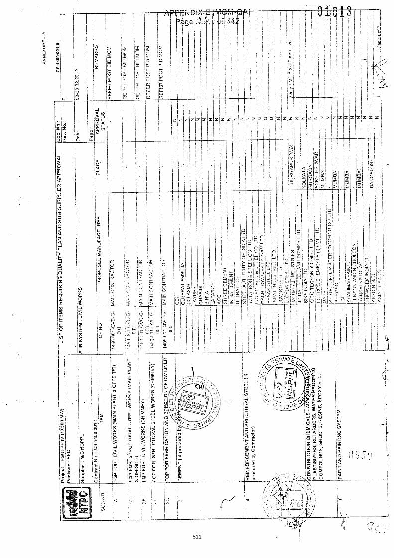
511

512

AN
NE
XU
RE
- IA
LIS
T O
F IT
EM
S R
EQ
UIR
ING
Q
U~
LIT
Y PL
AN
AN
DS
UB
-SU
PP
LIE
R
....
...
.
.............. -. .... -
SU
B-S
YS
TEM
: C
IVIL
WO
RK
S
- ....
-.
........ - - .. .- ...
(lan
trac
f No
. : C
S1
45
00
01
9
--
--
-
--
QF'
NO
T
----
P
RO
PO
StlO
MA
NU
FAC
TUR
ER
Resin
Cc
me
nc
ls 4
832
Pa
rt I
ll a
nd
,
70
2)
.
. C
IIA
MP
A
-. -.=
. -
..
..
.
.....
.. r ..
................... ........
....
t ...
.
..................
........... .................................... 1
,
. .'L,,")
......
--
PE
RFE
CT
AC
ID W
AR
E. .I
AB
ALP
IJR
-1
Z,pt
, 70
F
IRE
PR
OoF
DO
0Rs
A& L
NA
\IAIK
IN
TF
RN
AII
ON
AL
LT
l)
?.
I
513

514

PP
IV(i
X5
00
MW
) ,
,
--
......
...... - ......
....
- .
..
-
PV
C C
OA
TE
II C
HA
IN L
INK
FE
NC
ING
AN
D R
AH
RE
.........
- .......
.....
-
-
- ..
- ..
- ....
. ........
....................
.-
.
.
............... .
........
oii
C8;
inrs
i.:
iirgu
<rn
~ls
rii ~
~n
it
i>
i~
ois
i - -
.................... .......
....
515

516

'OF
IT
EM
S R
EQ
LII
RIN
G O
UA
Li'
TY
PL
AN
AN
D S
UB
-SU
PP
LIE
R
cs.1
46
0 o
nt
n .~
..
Re
v. No.:
-
.
up
pli
er : M
IS N
BP
PL
. .
..
.....
....
..
. ..
....................
I -. -
........
....... ..-.
'-.T
.-
lrE
M
Qi'
NO
1)
RO
I'OS
ED
M
AN
UF
AC
TU
RE
R
AP
PR
OV
AL
R
EM
AR
KS
T-
- -- I
i L
...... -_
.
....
L ........
... IL
EG
EN
OS
I.
SY
SrE
M S
UP
Pi.I
EI?
ISU
B-S
UP
PLI
ER
AP
PR
OV
AL
ST
AT
US
CA
TE
GO
fIY (
SH
A1.
t. B
E f:
lLLE
D B
Y N
IPC
) A
-. F
nit
hcs
c ite
ms
pm
po
sed
ven
dor
is a
rcop
tabl
e to
NT
PC
T
o h
e in
dica
ted
wllh
ik?l
lei"
A' i
n th
e lhs
t alo
nq w
ill,
1'11.
i:nnd
!iioo
nf n
ppia
val,
tf s
ny
ni< -
th~
:;e
item
s 'n
etat
is i
cqa
imd
'for
N~
PC
ie
vtew
TO
he
idcn
t\rnn
r$
with
iotfe
i 'IN
?' in
the
list
'N. N
O [
En
-. F
or l
bese
item
s ve
ndor
s ar
c ap
prov
ed b
y M
an
Siip
plie
i and
acc
epte
d bs
( NlPC w
,iho!
;t sp
er:!t
i<: v
en
tlo
r ;ii
,pra
vei
fi(lm
hiT
i'C
la h
e d
on
lifie
d w
llh N
DT
EO
I
517

APPENDIX-E jRIFOM-QA) Page 3c ... of 342
518
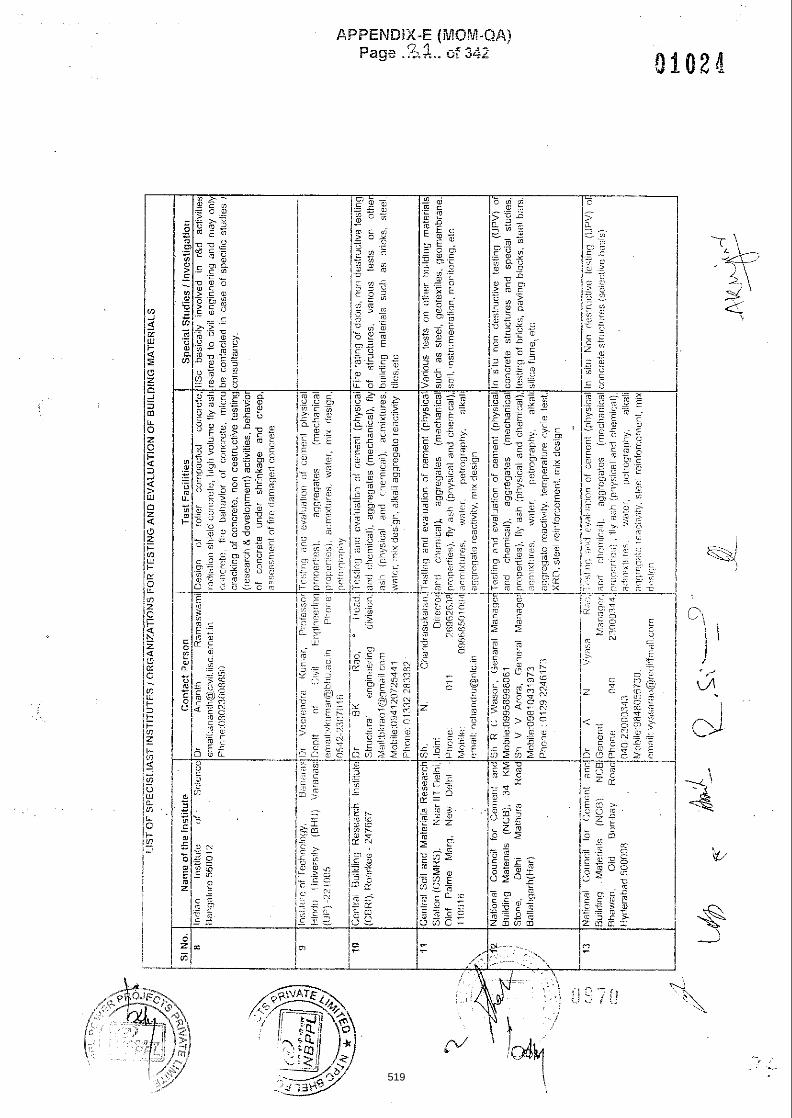
, . u
c~
is.,~
~
WU
" !~
eu
fitp:,l@
~~
!irsiih
n
.ji~w
o
'IIELYSOBPU
6 ;~ll~
lW
CbC
OU
(I'i2 OVU
519

APPENDIX-E (MQh?-QA) c 0 Fage ..:,i.. of 34.2
520

APPENDIX-E (MOP4-QA) e. 0 - , -. Fzge ,A;>.,. of 346
521

Format o f Request Letter for Evaluation of Materials
Ref: Date:
I I
Sub,: Evaluation of materials and concrete mix desiqn
We have awarded the work of ........................ on M!s .................... .vide cur LOA Nc. ............................ d a t e d . . . . . . . . . . . . . . . for execution of Civii Vv'orks. Based on provisions of contract, Mfs . . . . . . . . . . . . . . . . . . . . . are expected to get the following tests: evaluaticn done through ycu: iaboratory and accordingly the tests have been described beiow.
Mfs . . . . . . . . . . . . . . . . . . . have been advised to deposit the requisite eialcatio?: testing charges znd to deliver the :es: sa.mples a: quantities, speci:ied be low^
1. Evaluation o f Cement: a) To carry out different physicai tests on cement samples i e Elaine's flnt.?ess, init'a! and finai
se:ting Iirces soundness and compressive strength at 3, 7 ai-d 26 days as per IS 4031 acd dryicg shrinkase znd soecific gravity in case of FFC.
b j Te carry out clernicai analysis of the cement samples as per IS: 4032, including t i e total .alkali conten: cf the cemept (Na20equivalent;.
c) To advise the swtabiiiiy of cement based on the test results of a j a r d b j above
2. Evaluation of Aggregates: a ) To carpi out different tests en coarse aggregate sample i e specific gra.,!!!y, water acsorptior:.
sieve analysis. deietericus material; soundness: crushing value, impact balue, abrision value ~Iongatic~n index and f!ak:cess index, as per IS: 2386.
) To carry out di'fereqt tests on fine agsregate sample i.e, specific gravliy water absorption. sieve arziysls soundfiess. deleterious rriteral, silt ccnteqt, cia) cantent and clrganic impurities as per IS: 2286 and mica content.
c) To prepare evai3a::on report based on Lest results of a) and b) abcve acd to advise re~arding suitabiiity of fine 2nd caa:se aggregates to be used ivith the cerrert of 7 . ) above. . . . ~. . .
3. Evaluation of Aggregates for potential Alkali-Aggregate Reactivity: a: TC carry aut pe!io~:aph~c anaiysis and acce!erated Mortar bar Tes: 0- aggregate sampies
( I N NaOti at 60 d e g Centlgraae for l i days as per ASTM 1260, or the method estabiishedi developed by CSMRS for 22days test).
t) !f rock type is !Imestone. X-Ra). diffraction test :XRD) shaii be carried out to determine clay n i ~ e i a i in the rock for prei'minary conciusicns and to cary out repeated temperatiire cycle test !o dere:m:-e :€$iduai expansiofi of zggregate for concrete to be used in dynamic foundatio?s like TG, Fans, mills, crus6eis etc Additional!y, Alkali carionate reactivity test
i . . shall be carried out as per ASTM C 1105 wherein the pararne:ers shall be reported in
522

c) To prepare a report bzseo on tes! result: st a) and b) above a?d to ;70vt(ie regarcigg suitability of aggregates to be used with the ceren: of 1) above and Vurther testing required if any.
4 . Evaluation of Flyash Sample: a) To carry out various physical and chemicai tests oh f!y ash sample i e. Bla!ne's fnefiess: iime
reactivity, specific gravity, !oss on ignition and other chemical tests as per IS: 3812, conforming to grade-I.
5 ) To advise the suitability of fly ash sampie based on !he test resuits of a) above.
5. Evaluation of water: To carry cut various physical and chemical tests as per lS:456 and IS:3025.
6 , Evaluation of admixtures: To cary out various pnysicai and chemical tests 2s per !S:9?03. Note: Test certificate shal! be obtained from tke supplier to compare the values given in Table 2 of 1S:9703 i.e. uniformity requi~ements.
7. Concrete Mix Design Based on the provisions of technical specificatiori, the Foilowing may be specified by site CCDIFQA ** a) For RCC Work
i) Grade of concrete ii) Slump required, mm. .... 111; Cement- Type and grade iv) Max Size of Aggregates, mm v) Exposure conditions vij Maximum water-cement ratio vii) Minimum cement content viii) Plasticizer; admixture to be used or ict (!f yes, s ~ e c i v tile brand! tyr;e:batc'i no of
:!asticizer) ix) Fly ash to be used or not (!f yes indicate CJ, of f!y ash to be used)
o) For PCC work: Same as i) to ix) of a) 2 b o v ~ c) =or piling work!if required: Same as !j Lo ixj of a) aaove
8 Details of material sampled in order,to facilitate the st,oue menboned tests, specified quantities of sempies halie collected and seaied jointly (by NTPC-FQA and contractors' representativtj is beins teshng. The impression of sea! has also been p u ~ c k d below.
a) Quantity of material requifed :or each nix-design: --- Material Description Quantity Required
No. / - - -
.*daas(seaIed in double poiythene bags) ( i) i Cement
+OOKg of each fraction as explained beciu : Coarse Aggregates i i e g , If Maximum size o.f aggregates (lilSA) *s X m m : the
l<g each of 20-l0mm and IOmm down are required i MSA *"' is 40m-n then 10OKo each of 40-23mm iO:?Cmm a / 10mm down are required: I
Fine Aggregates 200Kg I I I
I ivj Chemical Admixtures j 2 Iitres . , I
523

APPENDIX-E (MOM-QA] Page 3k ... of 342
b) Quantity of material required for Alkali-Aggregate reactivity
7
I SI. i Material Description i Quantity Required 1 No. j I I t i i) Coarse aggregate I
I 1 I
1 I I / iij Fine aggregates i I
I -- I Cement 1 2 samples (I bag eacnj. contempiated for use in I
I ! constructicn. .-----A
c) Impression1 Punch Mark of seal:
.SF , - r - =,c rEques:~S to kindly loward UF the ies: repgrts aiong wiin the reco:nr?~e-dstio.!~ rega:di:;g the sui:abiiity of materiais tc us attSe ea:!iesf. Thznkiqg you.
jaithi.;:jy; Name:
Note:
1 Based c l 2-o:.isions oi tecnnical specification. :be fesPng cnarges for all :ne above mecbored tests 5Qail be bgice 37 ice CC"::&CT
2 . The ccntc?t of :he :et!e: is 'or guida-ce only, and r f rec-,;rer nay be SJ,'!ZS:Y noc:i,ec !c sslt the specrfic requiieme-is ci!he package in ccns-itation LV!W I.4ii-C!l.
** T C ' i tiis iine may ze deieied in t?e iftte: sent !o the institute
. .
524

BHEL SPEC Rev. No.:0
1. GEN 2. QUA
C. NO. :PE-TS-41 Dated : 11.06
STANDA
ERAL TECHALITY ASSU
TEC
FGUTP
404-165-N001 .14
ARD TEC
HNICAL REURANCE
CHNICAL CONCOOLING
P STAGE‐IV (1
TECHNIC
SEC
HNICAL SCOM
EQUIREMEN
NDITIONS OF TOWER PACK1X 500 MW)
CAL SPECIFICA
CTION D1
SPECIFICPRISES O
NTS -- --
CONTRACTKAGE AT UNCHAHA
ATION DA
1
CATION (OF
6 22
AR
DOC. NO.: NBPPA Rev. No.: 01
(ELECTR
PAGES 2 PAGES
PL-004-103-03-P
RICAL)
P4M-
525
6044549
Text Box

TECHNICAL CONDITIONS OF CONTRACT
COOLING TOWER PACKAGE FGUTPP STAGE‐IV (1X 500 MW) AT UNCHAHAR
BHEL SPEC. NO. :PE-TS-404-165-N001 Rev. No.:01 Dated : 11.06.14
TECHNICAL SPECIFICATION DOC. NO.: NBPPL-004-103-03-P4M-A Rev. No.: 01
GENERAL TECHNICAL REQUIREMENTS
FOR
LV MOTORS
SPECIFICATION NO.: PE-SS-999-506-E101 Rev 00
526

TECHNICAL CONDITIONS OF CONTRACT ELECTRICAL EQUIPMENT SPECIFICATION FOR INDUCED DRAFT COOLING TOWER
1 x 500 MW UNCHAHAR STAGE‐IV SECTION‐D
BHEL SPEC. NO. :PE-TS-404-165-N001 Rev. No.:01 Dated : 11.06.14
TECHNICAL SPECIFICATION DOC. NO.: NBPPL-004-103-03-P4M-A Rev. No.: 01
1.0 INTENT OF SPECIFIATION
The specification covers the design, materials, constructional features, manufacture, inspection and testing at manufacturer’s work, and packing of Low voltage (LV) squirrel cage induction motors along with all accessories for driving auxiliaries in thermal power station.
Motors having a voltage rating of below 1000V are referred to as low voltage (LV) motors. 2.0 CODES AND STANDARDS Motors shall fully comply with latest edition, including all amendments and revision, of following
codes and standards: IS:325 Three phase Induction motors IS : 900 Code of practice for installation and maintenance of induction motors IS: 996 Single phase small AC and universal motors IS: 4722 Rotating Electrical machines IS: 4691 Degree of Protection provided by enclosures for rotating electrical machines IS: 4728 Terminal marking and direction of rotation rotating electrical machines IS: 1231 Dimensions of three phase foot mounted induction motors IS: 8789 Values of performance characteristics for three phase induction motors IS: 13555 Guide for selection and application of 3-phase A.C. induction motors for
different types of driven equipment IS: 2148 Flame proof enclosures for electrical appliance IS: 5571 Guide for selection of electrical equipment for hazardous areas IS: 12824 Type of duty and classes of rating assigned IS: 12802 Temperature rise measurement ofr rotating electrical machnines IS: 12065 Permissible limits of noise level for rotating electrical machines IS: 12075 Mechnical vibration of rotatinf electrical machines In case of imported motors, motors as per IEC-34 shall also be acceptable.
3.0 DESIGN REQUIREMENTS 3.1 Motors and accessories shall be designed to operate satisfactorily under conditions specified in data
sheet-A and Project Information, including voltage & frequency variation of supply system as defined in Data sheet-A
3.2 Motors shall be continuously rated at the design ambient temperature specified in Data Sheet-A and
other site conditions specified under Project Information Motor ratings shall have at least a 15% margin over the continuous maximum demand of the driven equipment, under entire operating range including voltage & frequency variation specified above.
3.3 Starting Requirements 3.3.1 Motor characteristics such as speed, starting torque, break away torque and starting time shall be
properly co-ordinated with the requirements of driven equipment. The accelerating torque at any speed with the minimum starting voltage shall be at least 10% higher than that of the driven equipment.
527

TECHNICAL CONDITIONS OF CONTRACT ELECTRICAL EQUIPMENT SPECIFICATION FOR INDUCED DRAFT COOLING TOWER
1 x 500 MW UNCHAHAR STAGE‐IV SECTION‐D
BHEL SPEC. NO. :PE-TS-404-165-N001 Rev. No.:01 Dated : 11.06.14
TECHNICAL SPECIFICATION DOC. NO.: NBPPL-004-103-03-P4M-A Rev. No.: 01
3.3.2 Motors shall be capable of starting and accelerating the load with direct on line starting without exceeding acceptable winding temperature.
The limiting value of voltage at rated frequency under which a motor will successfully start and accelerate to rated speed with load shall be taken to be a constant value as per Data Sheet - A during the starting period of motors.
3.3.3 The following frequency of starts shall apply
i) Two starts in succession with the motor being initially at a temperature not exceeding the rated load temperature.
ii) Three equally spread starts in an hour the motor being initially at a temperature not exceeding
the rated load operating temperature. (not to be repeated in the second successive hour)
iii) Motors for coal conveyor and coal crusher application shall be suitable fro three consecutive hot starts followed by one hour interval with maximum twenty starts per day and shall be sutable fro mimimum 20,000 starts during the life time of the motor
3.4 Running Requirements 3.4.1 Motors shall run satisfactorily at a supply voltage of 75% of rated voltage for 5 minutes with full load
without injurious heating to the motor. 3.4.2 Motor shall not stall due to voltage dip in the system causing momentary drop in voltage upto 70% of
the rated voltage for duration of 2 secs. 3.5 Stress During bus Transfer 3.5.1 Motors shall withstand the voltage, heavy inrush transient current, mechnical and torque stress
developed due to the application of 150% of the rated voltage for at least 1 sec. caused due to vector difference between the motor residual voltage and the incoming supply voltage during occasional auto bus transfer.
3.5.2 Motor and driven equipment shafts shall be adequately sized to satisfactorily withstand transient
torque under above condition. 3.6 Maximum noise level measured at distance of 1.0 metres from the outline of motor shall not exceed
the values specified in IS 12065. 3.7 The max. vibration velocity or double amplitude of motors vibration as measured at motor bearings
shall be within the limits specified in IS: 12075. 4.0 CONSTRUCTIONAL FEATURES 4.1 Indoor motors shall conform to degree of protection IP: 54 as per IS: 4691. Outdoor or semi-indoor
motors shall conform to degree of protection IP: 55 as per IS: 4691and shall be of weather-proof construction. Outdoor motors shall be installed under a suitable canopy
4.2 Motors upto 160KW shall have Totally Enclosed Fan Cooled (TEFC) enclosures, the method of
cooling conforming to IC-0141 or IC-0151 of IS: 6362.
528
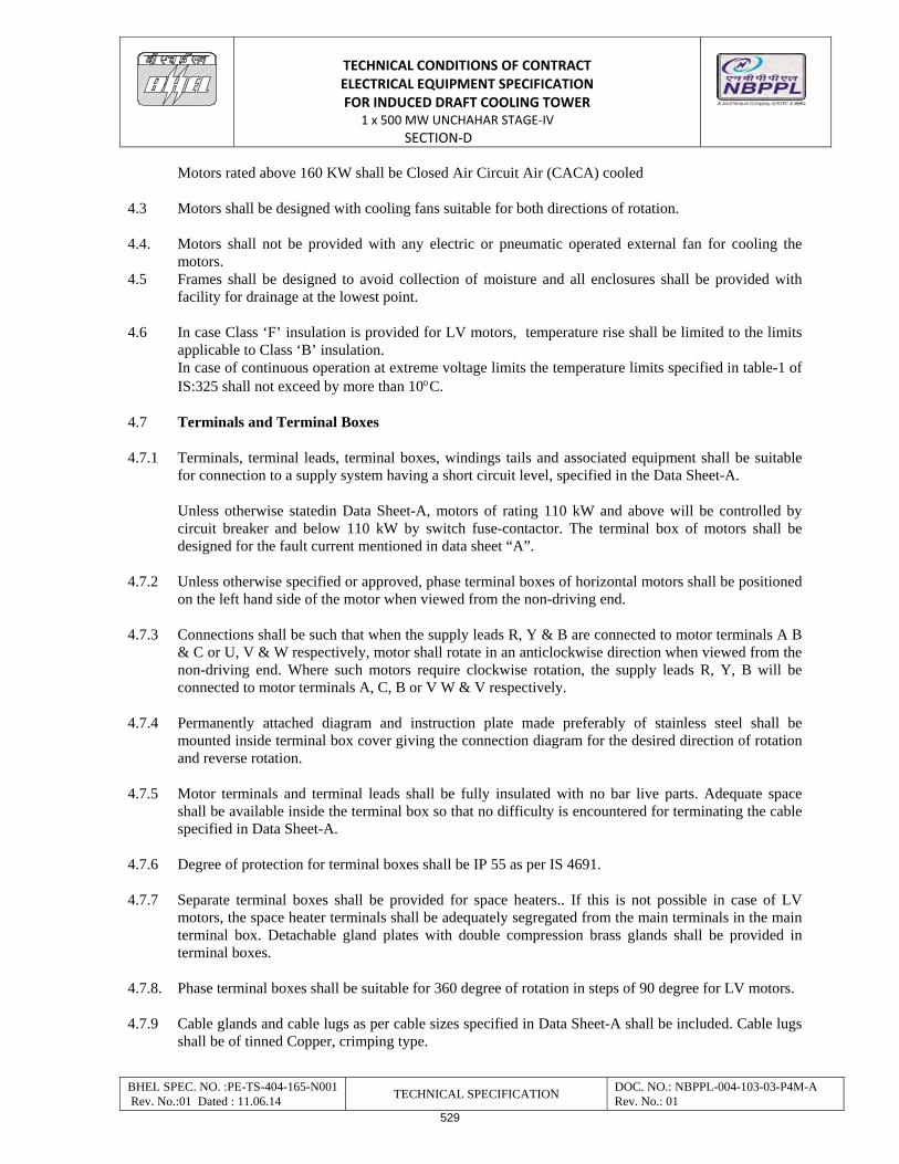
TECHNICAL CONDITIONS OF CONTRACT ELECTRICAL EQUIPMENT SPECIFICATION FOR INDUCED DRAFT COOLING TOWER
1 x 500 MW UNCHAHAR STAGE‐IV SECTION‐D
BHEL SPEC. NO. :PE-TS-404-165-N001 Rev. No.:01 Dated : 11.06.14
TECHNICAL SPECIFICATION DOC. NO.: NBPPL-004-103-03-P4M-A Rev. No.: 01
Motors rated above 160 KW shall be Closed Air Circuit Air (CACA) cooled 4.3 Motors shall be designed with cooling fans suitable for both directions of rotation. 4.4. Motors shall not be provided with any electric or pneumatic operated external fan for cooling the
motors. 4.5 Frames shall be designed to avoid collection of moisture and all enclosures shall be provided with
facility for drainage at the lowest point. 4.6 In case Class ‘F’ insulation is provided for LV motors, temperature rise shall be limited to the limits
applicable to Class ‘B’ insulation. In case of continuous operation at extreme voltage limits the temperature limits specified in table-1 of IS:325 shall not exceed by more than 10C.
4.7 Terminals and Terminal Boxes 4.7.1 Terminals, terminal leads, terminal boxes, windings tails and associated equipment shall be suitable
for connection to a supply system having a short circuit level, specified in the Data Sheet-A. Unless otherwise statedin Data Sheet-A, motors of rating 110 kW and above will be controlled by
circuit breaker and below 110 kW by switch fuse-contactor. The terminal box of motors shall be designed for the fault current mentioned in data sheet “A”.
4.7.2 Unless otherwise specified or approved, phase terminal boxes of horizontal motors shall be positioned
on the left hand side of the motor when viewed from the non-driving end. 4.7.3 Connections shall be such that when the supply leads R, Y & B are connected to motor terminals A B
& C or U, V & W respectively, motor shall rotate in an anticlockwise direction when viewed from the non-driving end. Where such motors require clockwise rotation, the supply leads R, Y, B will be connected to motor terminals A, C, B or V W & V respectively.
4.7.4 Permanently attached diagram and instruction plate made preferably of stainless steel shall be
mounted inside terminal box cover giving the connection diagram for the desired direction of rotation and reverse rotation.
4.7.5 Motor terminals and terminal leads shall be fully insulated with no bar live parts. Adequate space
shall be available inside the terminal box so that no difficulty is encountered for terminating the cable specified in Data Sheet-A.
4.7.6 Degree of protection for terminal boxes shall be IP 55 as per IS 4691. 4.7.7 Separate terminal boxes shall be provided for space heaters.. If this is not possible in case of LV
motors, the space heater terminals shall be adequately segregated from the main terminals in the main terminal box. Detachable gland plates with double compression brass glands shall be provided in terminal boxes.
4.7.8. Phase terminal boxes shall be suitable for 360 degree of rotation in steps of 90 degree for LV motors. 4.7.9 Cable glands and cable lugs as per cable sizes specified in Data Sheet-A shall be included. Cable lugs
shall be of tinned Copper, crimping type.
529

TECHNICAL CONDITIONS OF CONTRACT ELECTRICAL EQUIPMENT SPECIFICATION FOR INDUCED DRAFT COOLING TOWER
1 x 500 MW UNCHAHAR STAGE‐IV SECTION‐D
BHEL SPEC. NO. :PE-TS-404-165-N001 Rev. No.:01 Dated : 11.06.14
TECHNICAL SPECIFICATION DOC. NO.: NBPPL-004-103-03-P4M-A Rev. No.: 01
4.8 Two separate earthing terminals suitable for connecting G.I. or MS strip grounding conductor of size given in Data Sheet-A shall be provided on opposite sides of motor frame. Each terminal box shall have a grounding terminal.
4.9 General 4.9.1 Motors provided for similar drives shall be interchangeable. 4.9.2 Suitable foundation bolts are to be supplied alongwith the motors. 4.9.3 Motors shall be provided with eye bolts, or other means to facilitate safe lifting if the weight is 20Kgs.
and above. 4.9.4 Necessary fitments and accessories shall be provided on motors in accordance with the latest Indian
Electricity rules 1956. 4.9.5 All motors rated above 30 kW shall be provided with space heaters to maintain the motor internal air
temperature above the dew point. Unless otherwise specified, space heaters shall be suitable for a supply of 240V AC, single phase, 50 Hz.
4.9.6 Name plate with all particulars as per IS: 325 shall be provided 4.9.7 Unless otherwise specified, the colour of finish shall be grey to Shade No. 631 and 632 as per IS:5 for
motors installed indoor and outdoor respectively. The paint shall be epoxy based and shall be suitable for withstanding specified site conditions.
5.0 INSPECTION AND TESTING 5.1 All materials, components and equipments covered under this specification shall be procured,
manufactured, as per the BHEL standard quality plan No. PED-506-00-Q-006/0 and PED-506-00-Q-007/2 enclosed with this specification and which shall be complied.
5.2 LV motors of type-tested design shall be provided. Valid type test reports not more than 5 year shall
be furnished. In the absence of these, type tests shall have to be conducted by manufacturer without any commercial implication to purchaser.
5.3 All motors shall be subjected to routine tests as per IS: 325 and as per BHEL standard quality plan. 5.4 Motors shall also be subjected to additional tests, if any, as mentioned in Data Sheet A. 6.0 DRAWINGS TO BE SUBMITTED AFTER AWARD OF CONTRACT a) OGA drawing showing the position of terminal boxes, earthing connections etc. b) Arrangement drawing of terminal boxes. c) Characteristic curves: (To be given for motor above 55 kW unless otherwise specified in Data Sheet). i) Current vs. time at rated voltage and minimum starting voltage. ii) Speed vs. time at rated voltage and minimum starting voltage.
530

TECHNICAL CONDITIONS OF CONTRACT ELECTRICAL EQUIPMENT SPECIFICATION FOR INDUCED DRAFT COOLING TOWER
1 x 500 MW UNCHAHAR STAGE‐IV SECTION‐D
BHEL SPEC. NO. :PE-TS-404-165-N001 Rev. No.:01 Dated : 11.06.14
TECHNICAL SPECIFICATION DOC. NO.: NBPPL-004-103-03-P4M-A Rev. No.: 01
iii) Torque vs. speed at rated voltage and minimum voltage. For the motors with solid coupling the above curves i), ii), iii) to be furnished for the motors coupled with driven equipment. In case motor is coupled with mechanical equipment by fluid coupling, the above curves shall be furnished with and without coupling.
iv) Thermal withstand curve under hot and cold conditions at rated voltage and max. permissible voltage.
531
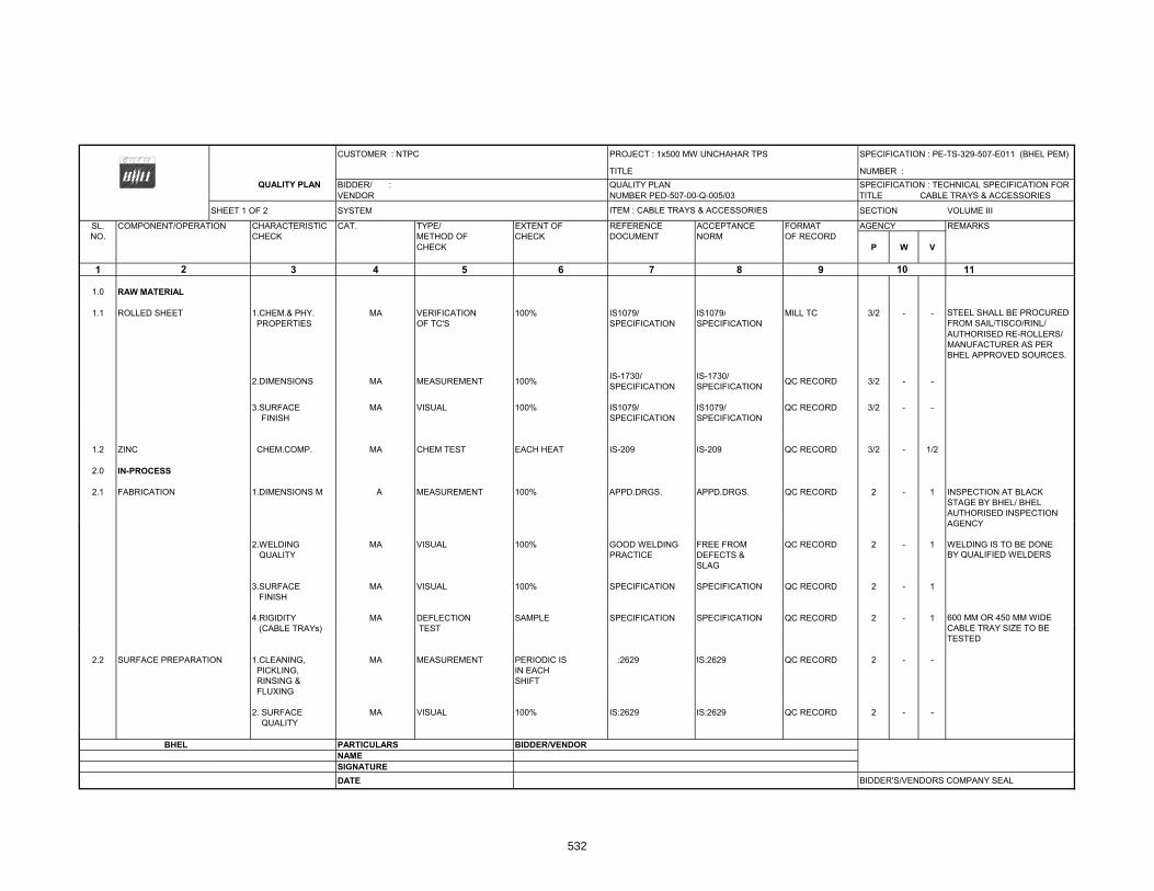
CUSTOMER : NTPC PROJECT : 1x500 MW UNCHAHAR TPS SPECIFICATION : PE-TS-329-507-E011 (BHEL PEM)
TITLE NUMBER : BIDDER/ : QUALITY PLAN SPECIFICATION : TECHNICAL SPECIFICATION FOR VENDOR NUMBER PED-507-00-Q-005/03 TITLE CABLE TRAYS & ACCESSORIES
SHEET 1 OF 2 SYSTEM SECTION VOLUME III
QUALITY PLAN
ITEM CABLE TRAYS & ACCESSORIESSHEET 1 OF 2 SYSTEM SECTION VOLUME III
SL. COMPONENT/OPERATION CHARACTERISTIC CAT. TYPE/ EXTENT OF REFERENCE ACCEPTANCE FORMAT AGENCY REMARKSNO. CHECK METHOD OF CHECK DOCUMENT NORM OF RECORD
CHECK P W V
1 3 4 5 6 7 8 9 11
1.0 RAW MATERIAL
1 1 ROLLED SHEET 1 CHEM & PHY MA VERIFICATION 100% IS1079/ IS1079/ MILL TC 3/2
2 10
ITEM : CABLE TRAYS & ACCESSORIES
STEEL SHALL BE PROCURED1.1 ROLLED SHEET 1.CHEM.& PHY. MA VERIFICATION 100% IS1079/ IS1079/ MILL TC 3/2 - - PROPERTIES OF TC'S SPECIFICATION SPECIFICATION
AUTHORISED RE-ROLLERS/MANUFACTURER AS PER BHEL APPROVED SOURCES.
2.DIMENSIONS MA MEASUREMENT 100% IS-1730/ SPECIFICATION
IS-1730/ SPECIFICATION QC RECORD 3/2 - -
3.SURFACE MA VISUAL 100% IS1079/ IS1079/ QC RECORD 3/2 - -FINISH SPECIFICATION SPECIFICATION
STEEL SHALL BE PROCUREDFROM SAIL/TISCO/RINL/
FINISH SPECIFICATION SPECIFICATION
1.2 ZINC CHEM.COMP. MA CHEM TEST EACH HEAT IS-209 IS-209 QC RECORD 3/2 - 1/2
2.0 IN-PROCESS
2.1 FABRICATION 1.DIMENSIONS M A MEASUREMENT 100% APPD.DRGS. APPD.DRGS. QC RECORD 2 - 1STAGE BY BHEL/ BHEL
AGENCYAUTHORISED INSPECTION
INSPECTION AT BLACK
AGENCY
2.WELDING MA VISUAL 100% GOOD WELDING FREE FROM QC RECORD 2 - 1 QUALITY PRACTICE DEFECTS &
SLAG
3.SURFACE MA VISUAL 100% SPECIFICATION SPECIFICATION QC RECORD 2 - 1 FINISH
4.RIGIDITY MA DEFLECTION SAMPLE SPECIFICATION SPECIFICATION QC RECORD 2 - 1
WELDING IS TO BE DONE BY QUALIFIED WELDERS
600 MM OR 450 MM WIDE CABLE TRAY SIZE TO BE (CABLE TRAYs) TEST
2.2 SURFACE PREPARATION 1.CLEANING, MA MEASUREMENT PERIODIC IS :2629 IS:2629 QC RECORD 2 - - PICKLING, IN EACH RINSING & SHIFT FLUXING
2. SURFACE MA VISUAL 100% IS:2629 IS:2629 QC RECORD 2 - - QUALITY
CABLE TRAY SIZE TO BE TESTED
BHEL PARTICULARS BIDDER/VENDORNAMESIGNATUREDATE BIDDER'S/VENDORS COMPANY SEAL
532
2980282
Text Box
NBPPL
2980282
Text Box
NBPPL/NBPPL
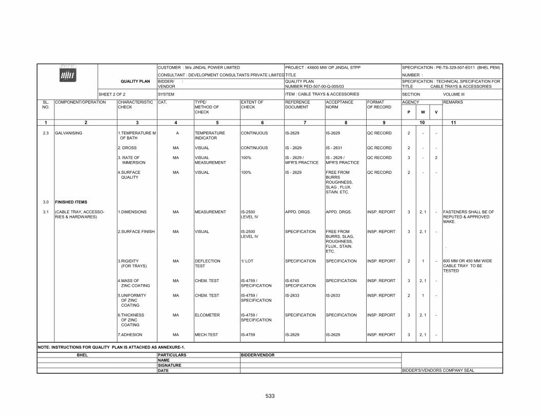
CUSTOMER : M/s JINDAL POWER LIMITED PROJECT : 4X600 MW OP JINDAL STPP SPECIFICATION : PE-TS-329-507-E011 (BHEL PEM)
CONSULTANT : DEVELOPMENT CONSULTANTS PRIVATE LIMITED TITLE NUMBER : BIDDER/ : QUALITY PLAN SPECIFICATION : TECHNICAL SPECIFICATION FOR VENDOR NUMBER PED-507-00-Q-005/03 TITLE CABLE TRAYS & ACCESSORIES
SHEET 2 OF 2 SYSTEM SECTION VOLUME III
QUALITY PLAN
ITEM : CABLE TRAYS & ACCESSORIES
SL. COMPONENT/OPERATION CHARACTERISTIC CAT. TYPE/ EXTENT OF REFERENCE ACCEPTANCE FORMAT AGENCY REMARKSNO. CHECK METHOD OF CHECK DOCUMENT NORM OF RECORD
CHECK P W V
1 3 4 5 6 7 8 9 11
2.3 GALVANISING 1.TEMPERATURE M A TEMPERATURE CONTINUOUS IS-2629 IS-2629 QC RECORD 2 - - OF BATH INDICATOR
2 10
2. DROSS MA VISUAL CONTINUOUS IS - 2629 IS - 2631 QC RECORD 2 - -
3. RATE OF MA VISUAL 100% IS - 2629 / IS - 2629 / QC RECORD 3 - 2 IMMERSION MEASUREMENT MFR'S PRACTICE MFR'S PRACTICE
4.SURFACE MA VISUAL 100% IS - 2629 FREE FROM QC RECORD 2 - - QUALITY BURRS
ROUGHNESS,SLAG , FLUX. STAIN. ETC.
3.0 FINISHED ITEMS
3.1 (CABLE TRAY, ACCESSO- 1.DIMENSIONS MA MEASUREMENT IS-2500 APPD. DRGS. APPD. DRGS. INSP. REPORT 3 2, 1 - FASTENERS SHALL BE OFRIES & HARDWARES) LEVEL IV REPUTED & APPROVED
2.SURFACE FINISH MA VISUAL IS-2500 SPECIFICATION FREE FROM INSP. REPORT 3 2, 1 -LEVEL IV BURRS, SLAG,
ROUGHNESS,
MAKE.
FLUX., STAIN.ETC.
3.RIGIDITY MA DEFLECTION 1/ LOT SPECIFICATION SPECIFICATION INSP. REPORT 2 1 - (FOR TRAYS) TEST
4.MASS OF MA CHEM. TEST IS-4759 / IS-6745 SPECIFICATION INSP. REPORT 3 2, 1 - ZINC COATING SPECIFICATION SPECIFICATION
600 MM OR 450 MM WIDE
TESTED
.
CABLE TRAY TO BE
5.UNIFORMITY MA CHEM. TEST IS-4759 / IS-2633 IS-2633 INSP. REPORT 2 1 - OF ZINC SPECIFICATION COATING
6.THICKNESS MA ELCOMETER IS-4759 / SPECIFICATION SPECIFICATION INSP. REPORT 3 2, 1 - OF ZINC SPECIFICATION COATING
7.ADHESION MA MECH.TEST IS-4759 IS-2629 IS-2629 INSP. REPORT 3 2, 1 -
BHEL PARTICULARS BIDDER/VENDORNAMESIGNATUREDATE BIDDER'S/VENDORS COMPANY SEAL
NOTE: INSTRUCTIONS FOR QUALITY PLAN IS ATTACHED AS ANNEXURE-1.
533

CUSTOMER : PROJECT SPECIFICATION :TITLE NUMBER :
QUALITY PLAN BIDDER/ : QUALITY PLAN SPECIFICATION : VENDOR NUMBER PED-506-00-Q-007, REV-03 TITLE
SHEET 1 OF 9 SYSTEM ITEM: AC ELECT. MOTORS 55 KW & ABOVE (LV & MV) SECTION VOLUME IIISL. COMPONENT/OPERATION CHARACTERISTIC CAT. TYPE/ EXTENT OF REFERENCE ACCEPTANCE FORMAT AG ENCY REMARKSNO. CHECK METHOD OF CHECK DOCUMENT NORM OF RECORD
CHECK P W V
1 3 4 5 6 7 8 9 111.0 RAW MATERIAL & BOUGHT OUT
CONTROL
1.1 SHEET STEEL, PLATES, 1.SURFACE MA VISUAL 100% - FREE FROM LOG BOOK 3 - -SECTION, EYEBOLTS CONDITION BLINKS,
CRACKS,WAVINESSETC
2.DIMENSIONS MA MEASUREMENT SAMPLE MANFR'S MANFR'S -DO- 3 - -DRG./SPEC DRG./SPEC
3.PROOF LOAD MA MECH. TEST -DO- -DO- -DO- INSPEC. 3 - 2
2 10
TEST (EYE REPORTBOLT)
1.2 HARDWARES 1.SURFACE MA VISUAL 100% FREE FROM -DO- 3 - -CONDITION CRACKS, UN-
EVENNESS ETC.
2.PROPERTY MA VISUAL SAMPLES MANFR'S RELEVENT SUPPLIERS 3 - 2 PROPERTY CLASS CLASS DRG./SPEC IS/SPEC. TC & LOG MARKING SHALL BE
BOOK CHECKED BY THEVENDOR
1.3 CASTING 1.SURFACE MA VISUAL 100% FREE FROM LOG BOOK 3 - 2CONDITION CRACKS,
BLOW HOLESETC.
2.CHEM. & MA CHEM & MECH 1/HEAT NO. MANFR'S RELEVENT SUPPLIER'S 3 - 2 HEAT NO. SHALL BEPHY. PROP. TEST DRG./SPEC IS/ TC VERIFIED
3.DIMENSIONS MA MEASUREMENT 100% MANUFR'S M ANUFR'S LOG BOOK 3 - 2DRG. DRG.
1.4 PAINT & VARNISH 1.MAKE, SHADE, MA VISUAL 100% MANFR'S MANFR'S LOG BOOK 3 - 2SHELF LIFE & CONTINUOUS DRG./SPEC DRG./SPECTYPE
BHEL PARTICULARS BIDDER/VENDORNAMESIGNATUREDATE BIDDER'S/VENDORS COMPANY SEAL
534
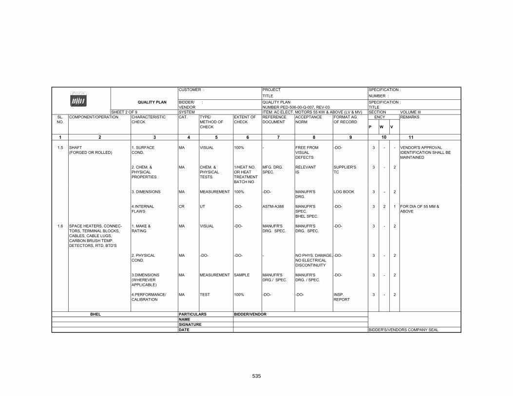
CUSTOMER : PROJECT SPECIFICATION : TITLE NUMBER :
QUALITY PLAN BIDDER/ : QUALITY PLAN SPECIFICATION : VENDOR NUMBER PED-506-00-Q-007, REV-03 TITLE
SHEET 2 OF 9 SYSTEM ITEM: AC ELECT. MOTORS 55 KW & ABOVE (LV & MV) SECTION VOLUME IIISL. COMPONENT/OPERATION CHARACTERISTIC CAT. TYPE/ EXTENT OF REFERENCE ACCEPTANCE FORMAT AG ENCY REMARKSNO. CHECK METHOD OF CHECK DOCUMENT NORM OF RECORD
CHECK P W V
1 3 4 5 6 7 8 9 11
1.5 SHAFT 1. SURFACE MA VISUAL 100% - FREE FROM -DO- 3 - - VENDOR'S APPROVAL(FORGED OR ROLLED) COND. VISUAL IDENTIFICATION SHALL BE
DEFECTS MAINTAINED
2. CHEM. & MA CHEM. & 1/HEAT NO. MFG. DRG. RELEVANT SUPPLIER'S 3 - 2PHYSICAL PHYSICAL OR HEAT SPEC. IS TCPROPERTIES TESTS TREATMENT
BATCH NO
102
3. DIMENSIONS MA MEASUREMENT 100% -DO- MANUFR'S LOG BOOK 3 - 2DRG.
4.INTERNAL CR UT -DO- ASTM-A388 MANUFR'S -DO- 3 2 1 FOR DIA OF 55 MM & FLAWS SPEC. ABOVE
BHEL SPEC.
1.6 SPACE HEATERS, CONNEC- 1. MAKE & MA VISUAL -DO- MANUFR'S MANUFR'S -DO- 3 - 2TORS, TERMINAL BLOCKS, RATING DRG. SPEC. DRG. SPEC.CABLES, CABLE LUGS,CARBON BRUSH TEMP.DETECTORS, RTD, BTD'S
2. PHYSICAL MA -DO- -DO- - NO PHYS. DAMAGE, -DO- 3 - 2COND. NO ELECTRICAL
DISCONTINUITY
3.DIMENSIONS MA MEASUREMENT SAMPLE MANUFR'S MANUFR'S -DO- 3 - 2(WHEREVER DRG./ SPEC. DRG. / SPEC.APPLICABLE)
4.PERFORMANCE/ MA TEST 100% -DO- -DO- INSP. 3 - 2CALIBRATION REPORT
BHEL PARTICULARS BIDDER/VENDORNAMESIGNATUREDATE BIDDER'S/VENDORS COMPANY SEAL
535
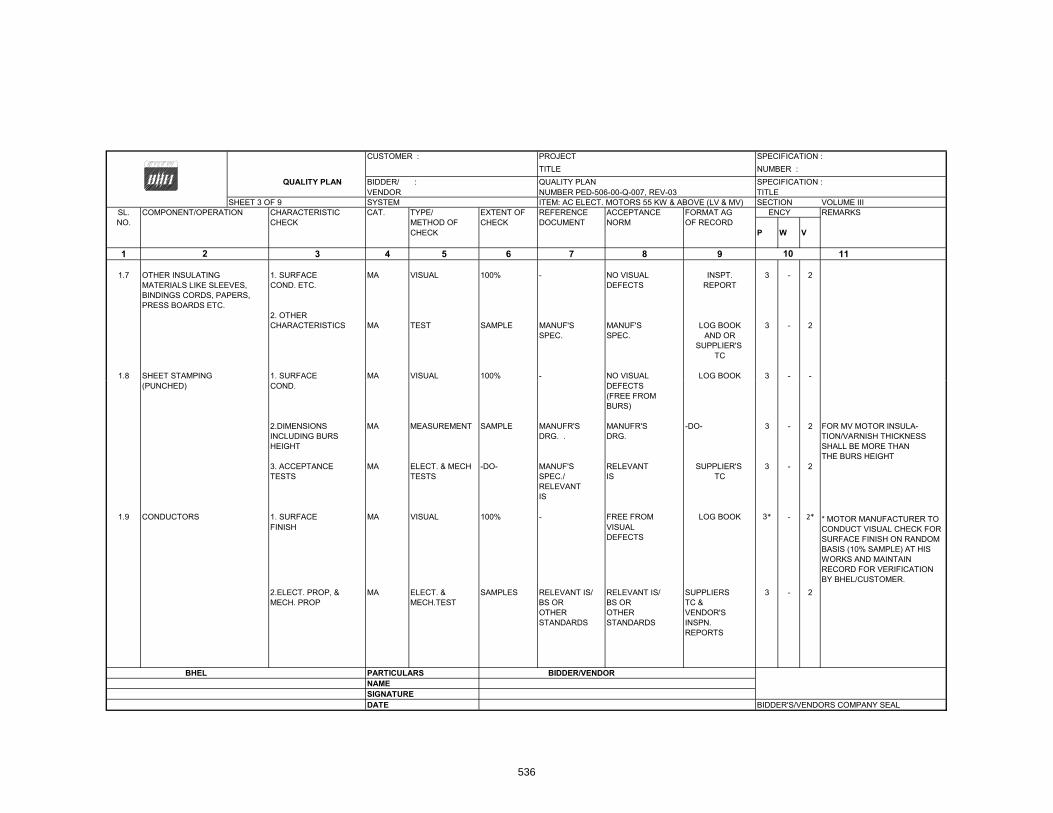
CUSTOMER : PROJECT SPECIFICATION :TITLE NUMBER :
QUALITY PLAN BIDDER/ : QUALITY PLAN SPECIFICATION : VENDOR NUMBER PED-506-00-Q-007, REV-03 TITLE
SHEET 3 OF 9 SYSTEM ITEM: AC ELECT. MOTORS 55 KW & ABOVE (LV & MV) SECTION VOLUME IIISL. COMPONENT/OPERATION CHARACTERISTIC CAT. TYPE/ EXTENT OF REFERENCE ACCEPTANCE FORMAT AG ENCY REMARKSNO. CHECK METHOD OF CHECK DOCUMENT NORM OF RECORD
CHECK P W V
1 3 4 5 6 7 8 9 11
1.7 OTHER INSULATING 1. SURFACE MA VISUAL 100% - NO VISUAL INSPT. 3 - 2MATERIALS LIKE SLEEVES, COND. ETC. DEFECTS REPORTBINDINGS CORDS, PAPERS,PRESS BOARDS ETC.
2. OTHERCHARACTERISTICS MA TEST SAMPLE MANUF'S MANUF'S LOG BOOK 3 - 2
SPEC. SPEC. AND ORSUPPLIER'S
TC
1.8 SHEET STAMPING 1. SURFACE MA VISUAL 100% - NO VISUAL LOG BOOK 3 - -
102
(PUNCHED) COND. DEFECTS(FREE FROM BURS)
2.DIMENSIONS MA MEASUREMENT SAMPLE MANUFR'S MANUFR'S -DO- 3 - 2 FOR MV MOTOR INSULA-INCLUDING BURS DRG. . DRG. TION/VARNISH THICKNESSHEIGHT SHALL BE MORE THAN
THE BURS HEIGHT3. ACCEPTANCE MA ELECT. & MECH -DO- MANUF'S RELEVANT SUPPLIER'S 3 - 2TESTS TESTS SPEC./ IS TC
RELEVANTIS
1.9 CONDUCTORS 1. SURFACE MA VISUAL 100% - FREE FROM LOG BOOK 3* - 2*FINISH VISUAL
DEFECTS
2.ELECT. PROP, & MA ELECT. & SAMPLES RELEVANT IS/ RELEVANT IS/ SUPPLIERS 3 - 2MECH. PROP MECH.TEST BS OR BS OR TC &
OTHER OTHER VENDOR'SSTANDARDS STANDARDS INSPN.
REPORTS
BHEL PARTICULARS BIDDER/VENDORNAMESIGNATUREDATE BIDDER'S/VENDORS COMPANY SEAL
* MOTOR MANUFACTURER TO CONDUCT VISUAL CHECK FOR SURFACE FINISH ON RANDOM BASIS (10% SAMPLE) AT HIS WORKS AND MAINTAIN RECORD FOR VERIFICATION BY BHEL/CUSTOMER.
536
2980282
Text Box
NBPPL/CUSTOMER

CUSTOMER : PROJECT SPECIFICATION : TITLE NUMBER :
QUALITY PLAN BIDDER/ : QUALITY PLAN SPECIFICATION : VENDOR NUMBER PED-506-00-Q-007, REV-03 TITLE
SHEET 4 OF 9 SYSTEM ITEM: AC ELECT. MOTORS 55 KW & ABOVE (LV & MV) SECTION VOLUME IIISL. COMPONENT/OPERATION CHARACTERISTIC CAT. TYPE/ EXTENT OF REFERENCE ACCEPTANCE FORMAT AG ENCY REMARKSNO. CHECK METHOD OF CHECK DOCUMENT NORM OF RECORD
CHECK P W V
1 3 4 5 6 7 8 9 11
3.DIMENSIONS MA MEASUREMENT -DO- -DO- -DO- Log Book 3 - 2
1.10 BEARINGS 1.MAKE & TYPE MA VISUAL 100%MANFR'S DRG./ APPROVED DATASHEET
MANFR'S DRG./ APPROVED DATASHEET
-DO- 3 - 2
2.DIMENSIONS MA MEASUREMENT SAMPLE BHEL DATA BHEL DATA -DO- 3 - 2SHEET SHEET BEARING
MANUF'SCATALOGUES
3.SURFACE MA VISUAL 100% - FREE FROM -DO- 3 - 2
102
3.SURFACE MA VISUAL 100% FREE FROM DO 3 2FINISH VISUAL
DEFECTS
1.11 SLIP RING 1.SURFACE MA VISUAL 100% - -DO- -DO- 3 - -(WHEREVER APPLICABLE) COND.
2.DIMENSIONS MA MEASUREMENT SAMPLE MANUF'S MANUF'S -DO- 3 - -DRG DRG
3.TEMP.WITH- MA ELECT.TEST -DO- MANUF'S MANUF'S -DO- 3 - 2
STAND CAPACITY SPEC./ BHEL SPEC. SPEC./ BHEL SPEC.
4.HV/IR MA -DO- 100% -DO- -DO- -DO- 3 - 2
1.12 OIL SEALS & GASKETS 1.MATERIAL OF MA VISUAL 100% MANUF'S MANUF'S -DO- 3 - -GASKET DRG/SPECS DRG./ SPECS.
2.SURFACE MA VISUAL 100% - FREE FROM -DO- 3 - -COND. VISUAL
DEFECTS
3.DIMENSIONS MA MEASUREMENT SAMPLE MANUF'S MANUF'S -DO- 3 - -DRG DRG
BHEL PARTICULARS BIDDER/VENDORNAMESIGNATUREDATE BIDDER'S/VENDORS COMPANY SEAL
537

CUSTOMER : PROJECT SPECIFICATION :TITLE NUMBER :
QUALITY PLAN BIDDER/ : QUALITY PLAN SPECIFICATION : VENDOR NUMBER PED-506-00-Q-007, REV-03 TITLE
SHEET 5 OF 9 SYSTEM ITEM: AC ELECT. MOTORS 55 KW & ABOVE (LV & MV) SECTION VOLUME IIISL. COMPONENT/OPERATION CHARACTERISTIC CAT. TYPE/ EXTENT OF REFERENCE ACCEPTANCE FORMAT AG ENCY REMARKSNO. CHECK METHOD OF CHECK DOCUMENT NORM OF RECORD
CHECK P W V
1 3 4 5 6 7 8 9 11
2.0 IN PROCESS
2.1 STATOR FRAME WELDING 1.WORKMANSHIP MA VISUAL 100% -DO- GOOD FINISH LOG BOOK 3/2 2 -(IN CASE OF FABRICATED & CLEANNESSSTATOR )
2.DIMENSIONS MA MEASUREMENT -DO- MANUF'S MANUF'S -DO- 2 - -DRG DRG
102
2.2 MACHINING 1.FINISH MA VISUAL 100% -DO- GOOD FINISH LOG BOOK 2 - -
2.DIMENSIONS MA MEASUREMENT -DO- MANUF'S MANUF'S -DO- 2 - -DRG DRG
3.SHAFT SURFACE MA PT -DO- RELEVENT MANUFR'S -DO- 2 - 1FLOWS SPEC./ SPEC./
ASTM-E165 BHEL SPEC./
2.3 PAINTING 1.SURFACE MA VISUAL 100% MANFR'S BHEL LOG BOOK 2 - -PREPARATION SPEC/BHEL SPEC.
SPEC./ SAME ASRELEVANT COL.7STAND
2.PAINT THICKNESS MA MEASUREMENT SAMPLE -DO- -DO- -DO- 2 - -(BOTH PRIMER & BY ELCOMETERFINISH COAT)
3.SHADE MA VISUAL -DO- -DO- -DO- Log Book 2 - -
4.ADHESION MA CROSS -DO- -DO- -DO- Log Book 2 - -CUTTING &TAPE TEST
BHEL PARTICULARS BIDDER/VENDORNAMESIGNATUREDATE BIDDER'S/VENDORS COMPANY SEAL
538

CUSTOMER : PROJECT SPECIFICATION :TITLE NUMBER :
QUALITY PLAN BIDDER/ : QUALITY PLAN SPECIFICATION : VENDOR NUMBER PED-506-00-Q-007, REV-03 TITLE
SHEET 6 OF 9 SYSTEM ITEM: AC ELECT. MOTORS 55 KW & ABOVE (LV & MV) SECTION VOLUME IIISL. COMPONENT/OPERATION CHARACTERISTIC CAT. TYPE/ EXTENT OF REFERENCE ACCEPTANCE FORMAT AG ENCY REMARKSNO. CHECK METHOD OF CHECK DOCUMENT NORM OF RECORD
CHECK P W V
1 3 4 5 6 7 8 9 11
2.4 SHEET STACKING 1.COMPLETENESS MA MEASUREMENT SAMPLE MANUFR'S MANUFR'S Log Book 2 - -SPEC. SPEC.
2.COMPRESSION MA MEASUREMENT 100% -DO- -DO- Log Book 2 - -& TIGHTENING
3.CORE LOSS & MA ELECT.TEST -DO- -DO- -DO- Log Book 2 1* 1HOTSPOT
102
(FOR MOTORS OF 2MW AND ABOVE) * ON 10% RANDOM SAMPLE
2.5 WINDING 1.COMPLETENESS CR VISUAL 100% MANUFR'S MANUFR'S Log Book 2 - -SPEC./BHEL SPEC. /BHEL SPEC. SPEC.
2.CLEANLINESS CR -DO- -DO- -DO- -DO- Log Book 2 - -
3.IR-HV-IR CR ELECT. TEST -DO- -DO- -DO- Log Book 2 - 1
4.RESISTANCE CR -DO- -DO- -DO- -DO- Log Book 2 - 1
5.INTERTURN CR -DO- -DO- -DO- -DO- Log Book 2 - -INSULATION
6.SURGE WITH CR -DO- -DO- -DO- -DO- Log Book 2 - 1 FOR MV MOTORSTAND ANDTAN. DELTATEST
2.6 IMPREGNATION 1.VISCOSCITY MA PHY. TEST AT STARTING -DO- -DO- Log Book 2 - -
2.TEMP. MA PROCESS CONTINUOUS -DO- -DO- Log Book 2 - -PRESSURE CHECKVACCUM
3.NO. OF DIPS MA -DO- -DO- -DO- -DO- Log Book 2 - 1 THREE DIPS TO BE GIVEN
BHEL PARTICULARS BIDDER/VENDORNAMESIGNATUREDATE BIDDER'S/VENDORS COMPANY SEAL
539
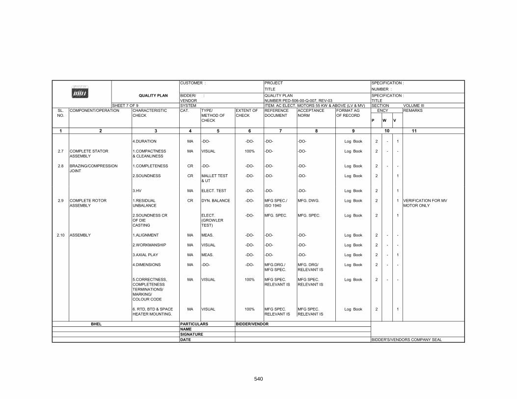
CUSTOMER : PROJECT SPECIFICATION :TITLE NUMBER :
QUALITY PLAN BIDDER/ : QUALITY PLAN SPECIFICATION : VENDOR NUMBER PED-506-00-Q-007, REV-03 TITLE
SHEET 7 OF 9 SYSTEM ITEM: AC ELECT. MOTORS 55 KW & ABOVE (LV & MV) SECTION VOLUME IIISL. COMPONENT/OPERATION CHARACTERISTIC CAT. TYPE/ EXTENT OF REFERENCE ACCEPTANCE FORMAT AG ENCY REMARKSNO. CHECK METHOD OF CHECK DOCUMENT NORM OF RECORD
CHECK P W V
1 3 4 5 6 7 8 9 11
4.DURATION MA -DO- -DO- -DO- -DO- Log Book 2 - 1
2.7 COMPLETE STATOR 1.COMPACTNESS MA VISUAL 100% -DO- -DO- Log Book 2 - -ASSEMBLY & CLEANLINESS
2.8 BRAZING/COMPRESSION 1.COMPLETENESS CR -DO- -DO- -DO- -DO- Log Book 2 - -JOINT
2.SOUNDNESS CR MALLET TEST -DO- -DO- -DO- Log Book 2 1& UT
102
3.HV MA ELECT. TEST -DO- -DO- -DO- Log Book 2 1
2.9 COMPLETE ROTOR 1.RESIDUAL CR DYN. BALANCE -DO- MFG SPEC./ MFG. DWG. Log Book 2 1 VERIFICATION FOR MVASSEMBLY UNBALANCE ISO 1940 MOTOR ONLY
2.SOUNDNESS CR ELECT. -DO- MFG. SPEC. MFG. SPEC. Log Book 2 1OF DIE (GROWLERCASTING TEST)
2.10 ASSEMBLY 1.ALIGNMENT MA MEAS. -DO- -DO- -DO- Log Book 2 - -
2.WORKMANSHIP MA VISUAL -DO- -DO- -DO- Log Book 2 - -
3.AXIAL PLAY MA MEAS. -DO- -DO- -DO- Log Book 2 - 1
4.DIMENSIONS MA -DO- -DO- MFG.DRG./ MFG. DRG/ Log Book 2 - -MFG SPEC. RELEVANT IS
5.CORRECTNESS, MA VISUAL 100% MFG SPEC. MFG SPEC. Log Book 2 - -COMPLETENESS RELEVANT IS RELEVANT ISTERMINATIONS/MARKING/COLOUR CODE
6. RTD, BTD & SPACE MA VISUAL 100% MFG SPEC. MFG SPEC. Log Book 2 1HEATER MOUNTING. RELEVANT IS RELEVANT IS
BHEL PARTICULARS BIDDER/VENDORNAMESIGNATUREDATE BIDDER'S/VENDORS COMPANY SEAL
540
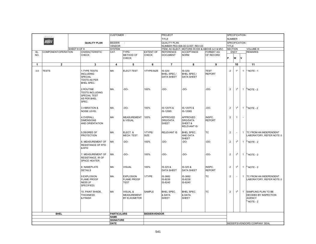
CUSTOMER : PROJECT SPECIFICATION :TITLE NUMBER :
QUALITY PLAN BIDDER/ : QUALITY PLAN SPECIFICATION : VENDOR NUMBER PED-506-00-Q-007, REV-03 TITLE
SHEET 8 OF 9 SYSTEM ITEM: AC ELECT. MOTORS 55 KW & ABOVE (LV & MV) SECTION VOLUME IIISL. COMPONENT/OPERATION CHARACTERISTIC CAT. TYPE/ EXTENT OF REFERENCE ACCEPTANCE FORMAT AG ENCY REMARKSNO. CHECK METHOD OF CHECK DOCUMENT NORM OF RECORD
CHECK P W V
1 3 4 5 6 7 8 9 11
3.0 TESTS 1.TYPE TESTS MA ELECT.TEST 1/TYPE/SIZE IS-325/ IS-325/ TEST 2 1* 1 * NOTE - 1INCLUDING BHEL SPEC./ BHEL SPEC./ REPORTSPECIAL DATA SHEET DATA SHEETTESTS AS PERBHEL SPEC.
2.ROUTINE MA -DO- 100% -DO- -DO- -DO- 2 1$ 1 $ NOTE - 2TESTS INCLUDINGSPECIAL TESTAS PER BHELSPEC.
3.VIBRATION & MA -DO- 100% IS-12075 & IS-12075 & -DO- 2 1$ 1 $ NOTE - 2NOISE LEVEL IS-12065 IS-12065
102
4.OVERALL MA MEASUREMENT 100% APPROVED APPROVED INSPC. 2 1 -DIMENSIONS & VISUAL DRG/DATA DRG/DATA REPORTAND ORIENTATION SHEET SHEET &
RELEVANT IS
5.DEGREE OF MA ELECT. & 1/TYPE/ RELEVANT IS BHEL SPEC. TC 2 - 1PROTECTION MECH. TEST SIZE AND DATA
SHEET6. MEASUREMENT OF MA -DO- 100% -DO- -DO- -DO- 2 1$ 1 $ NOTE - 2RESISTANCE OF RTD & BTD
7. MEASUREMENT OF MA -DO- 100% -DO- -DO- -DO- 2 1$ 1 $ NOTE - 2RESISTANCE, IR OF SPACE HEATER
8. NAMEPLATE MA VISUAL 100% IS-325 & IS-325 & INSPC. 2 1$ 1 $ NOTE - 2DETAILS DATA SHEET DATA SHEET REPORT
9.EXPLOSION MA EXPLOSION 1/TYPE IS-3682 IS-3682 TC 2 - 1FLAME PROOF FLAME PROOF IS-8239 IS-8239NESS (IF TEST IS-8240 IS-8240SPECIFIED)
10. PAINT SHADE, MA VISUAL & SAMPLE BHEL SPEC. BHEL SPEC. TC 2 1$ 1 SAMPLING PLAN TO BETHICKNESS MEASUREMENT & DATA & DATA DECIDED BY INSPECTION& FINISH BY ELKOMETER SHEET SHEET AGENCY
$ NOTE - 2
BHEL PARTICULARS BIDDER/VENDORNAMESIGNATUREDATE BIDDER'S/VENDORS COMPANY SEAL
TC FROM AN INDEPENDENT LABORATORY, REFER NOTE-3
TC FROM AN INDEPENDENT LABORATORY, REFER NOTE-3
541

CUSTOMER : PROJECT SPECIFICATION : TITLE NUMBER :
QUALITY PLAN BIDDER/ : QUALITY PLAN SPECIFICATION : VENDOR NUMBER PED-506-00-Q-007, REV-03 TITLE
SHEET 9 OF 9 SYSTEM ITEM: AC ELECT. MOTORS 55 KW & ABOVE (LV & MV) SECTION VOLUME IIISL. COMPONENT/OPERATION CHARACTERISTIC CAT. TYPE/ EXTENT OF REFERENCE ACCEPTANCE FORMAT AG ENCY REMARKSNO. CHECK METHOD OF CHECK DOCUMENT NORM OF RECORD
CHECK P W V
1 3 4 5 6 7 8 9 11
NOTES:
1 DEPENDING UPON THE SIZE AND CRITICALLY, WITNESSING BY BHEL SHALL BE DECIDED.
2 ROUTINE TESTS ON 100% MOTORS SHALL BE DONE BY THE VENDOR. HOWEVER, BHEL SHALL WITNESS ROUTINE TESTS ON RANDOM SAMPLES.THE SAMPLING PLAN SHALL BE MUTUALLY AGREED UPON.
3 IN CASE TEST CERTIFICATES FOR THESE TESTS ON SIMILAR TYPE, SIZE AND DESIGN OF MOTOR FROM INDEPENDENT LABORATORY ARE AVAILABLE, THESE TEST MAY NOT BE REPEATED.
102
4 WHEREVER CUSTOMER IS INVOLVED IN INSPECTION, AGENCY (1) SHALL MEAN BHEL AND CUSTOMERS BOTH TOGETHER.
Legends for Inspection agency
1. BHEL/CUSTOMER2. VENDOR (MOTOR MANUFACTURER)3. SUB-VENDOR (RAW MATERIAL/COMPONENTS SUPPLIER)
P. PERFORMW. WITNESSV. VERIFY
BHEL PARTICULARS BIDDER/VENDORNAMESIGNATUREDATE BIDDER'S/VENDORS COMPANY SEAL
542
2980282
Text Box
NBPPL/CUSTOMER
2980282
Text Box
NBPPL
2980282
Text Box
NBPPL
2980282
Text Box
NBPPL

CUSTOMER : PROJECT
TITLE NUMBER : QUALITY PLAN BIDDER/ : QUALITY PLAN SPECIFICATION
VENDOR NUMBER PED-506-00-Q-006, REV-01 TITLESHEET 1 OF 2 SYSTEM ITEM AC ELECT. MOTORS BELOW 55KW (LV) SECTION VOLUME III
SL. COMPONENT/OPERATION CHARACTERISTICS CAT. TYPE/ EXTENT OF REFERENCE ACCEPTANCE FORMAT AGENCY REMARKSNO. CHECK METHOD OF CHECK DOCUMENT NORM OF RECORD
CHECK P W V
1 3 4 5 6 7 8 9 10 11
1.0 ASSEMBLY 1.WORKMANSHIP MA VISUAL 100% MANUF'S SPEC MANUF'S SPEC -DO- 2 - -
2.DIMENSIONS MA -DO- -DO- MFG. DRG./ MFG. DRG./ -DO- 2 - -MFG. SPEC. MFG. SPEC.
3.CORRECTNESS MA VISUAL 100% MFG.SPEC./ MFG.SPEC. -DO- 2 - -COMPLETENESS RELEVANT IS RELEVANT ISTERMINATIONS/MARKING/COLOURCODE
2.0 PAINTING 1.SHADE MA VISUAL SAMPLE MANUFR'S BHEL SPEC. LOG BOOK 2 - -
SPECIFICATION :
2
SPEC/BHEL SAME ASSPEC./RELEVANT COL.7STANDARD
3.0 TESTS 1.ROUTINE MA -DO- 100% IS-325/ SAME AS TEST 2 1 NOTE -1TEST INCLUDING BHEL SPEC./ COL.7 REPORT &SPECIAL TEST DATA SHEET NOTE-3AS PER BHEL SPEC.
2.OVERALL MA MEASUREMENT 100% APPROVED APPROVED INSPN. 2 1 - NOTE -1DIMENSIONS & & DRG/DATA DRG/DATA REPORT &ORIENTATION VISUAL SHEET SHEET NOTE-3
& RELEVANT IS
BHEL PARTICULARS BIDDER/VENDORNAME
SIGNATURE
543

CUSTOMER : PROJECT QUALITY PLAN TITLE NUMBER :
BIDDER/ : QUALITY PLAN SPECIFICATION : VENDOR NUMBER PED-506-00-Q-006, REV-01 TITLE :
SHEET 2 OF 2 SYSTEM ITEM AC ELECT. MOTORS BELOW 55KW (LV) SECTION VOLUME IIISL. COMPONENT/OPERATION CHARACTERISTICS CAT. TYPE/ EXTENT OF REFERENCE ACCEPTANCE FORMAT AGENCY REMARKSNO. CHECK METHOD OF CHECK DOCUMENT NORM OF RECORD
CHECK P W V
1 3 4 5 6 7 8 9 10 11
3.NAMEPLATE MA VISUAL 100% IS-325 & IS-325 & INSPN. 2 1 -DETAILS DATA SHEET DATA SHEET REPORT
NOTES:
1 ROUTINE TESTS ON 100% MOTORS SHALL BE DONE BY THE VENDOR. HOWEVER, BHEL SHALL WITNESS ROUTINE TESTS ON RANDOM SAMPLES. THESAMPLING PLAN SHALL BE MUTUALLY AGREED UPON
SPECIFICATION :
2
SAMPLING PLAN SHALL BE MUTUALLY AGREED UPON2 WHERE EVER CUSTOMER IS INVOLVED IN INSPECTION, (1) SHALL MEAN BHEL AND CUSTOMERS BOTH TOGETHER.3 FOR EXHAUST/VENTILATION FAN MOTORS OF RATING UPTO 1.5KW , ONLY ROUTINE TEST CERTIFICATES SHALL BE FURNISHED FOR SCRUTINY.
Legends for Inspection agency
1. BHEL/CUSTOMER2. VENDOR (MOTOR MANUFACTURER)3. SUB-VENDOR (RAW MATERIAL/COMPONENTS SUPPLIER)
P. PERFORMW. WITNESSV. VERIFY
BHEL PARTICULARS BIDDER/VENDORNAMESIGNATUREDATE BIDDER'S/VENDORS COMPANY SEAL
544
2980282
Text Box
NBPPL/CUSTOMER
2980282
Text Box
NBPPL
2980282
Text Box
NBPPL

CUSTOMER : PROJECT SPECIFICATION :TITLE NUMBER :
QUALITY PLAN BIDDER/ : QUALITY PLAN SPECIFICATION : VENDOR NUMBER PED 558 00 Q 001/01 TITLEVENDOR NUMBER PED-558-00-Q-001/01 TITLE
SHEET 1 OF 3 SYSTEM ITEM :ILLUMINATION SECTION VOLUME IIISL. COMPONENT/OPERATION CHARACTERISTIC CAT. TYPE/ EXTENT OF REFERENCE ACCEPTANCE FORMAT AGENCY REMARKSNO. CHECK METHOD OF CHECK DOCUMENT NORM OF RECORD
CHECK P W V
1 3 4 5 6 7 8 9
1.0 CABLES & WIRES 1.SURFACE MA VISUAL SAMPLE BHEL SPEC. BHEL SPEC. INSPN. 3/2 2 1 TO BE PROCURED FROM
112 10
DEFECTS IS:694 IS:694 REPORT APPROVED SOURCEIS:1554 IS:1554 & TEST
REPORTFROM MANUFACTURER
2.DIMENSIONS MA MEASUREMENT SAMPLE -DO- -DO- -DO- 3/2 2 1
3 TYPE TESTS CR ELEC TESTS ONE/TYPE BHEL SPEC BHEL SPEC TEST CERT 3 2 13.TYPE TESTS CR ELEC.TESTS ONE/TYPE BHEL SPEC. BHEL SPEC. TEST CERT. 3 2 1& SIZE IS:694 IS:694
IS:1554 IS:1554
4.ACCEPTANCE MA -DO- SAMPLING -DO- -DO- -DO- 3 2 1TESTS
5.ROUTINE MA -DO- 100% -DO- -DO- -DO- 3 - 2,1TESTS
6.FRLS CR FRLS TESTS SAMPLES BHEL SPEC BHEL SPEC -DO- 3 2 1PROPS.
2.0 JUNCTION BOXES, LIGHTINGPANELS AND DISTRIBUTIONBOARDS
2.1 JUNCTION BOXES 1.DIMENSIONS MA MEASUREMENT 100% BHEL DRG. BHEL DRG. INSP. REPORT 3 - 2 COMPONENTS TO BE OFAPPROVED MAKE
2.PAINT SHADE/ MA VISUAL/MEAS. SAMPLE BHEL SPEC/DRG BHEL SPEC/DRG -DO- 3 - 2THICKNESS
3.HV/IR/HV MA ELECT.TESTS 100% 2KV AC FOR 2KV AC FOR -DO- 3 - 21 MINUTE 1 MINUTE
BHEL PARTICULARS BIDDER/VENDORBHEL PARTICULARS BIDDER/VENDORNAMESIGNATUREDATE BIDDER'S/VENDORS COMPANY SEAL
545

CUSTOMER : PROJECT SPECIFICATION : TITLE NUMBER :
QUALITY PLAN BIDDER/ : QUALITY PLAN SPECIFICATION : VENDOR NUMBER PED-558-00-Q-001/01 TITLE
SHEET 2 OF 3 SYSTEM ITEM :ILLUMINATION SECTION VOLUME IIISL COMPONENT/OPERATION CHARACTERISTIC CAT TYPE/ EXTENT OF REFERENCE ACCEPTANCE FORMAT AGENCY REMARKSSL. COMPONENT/OPERATION CHARACTERISTIC CAT. TYPE/ EXTENT OF REFERENCE ACCEPTANCE FORMAT AGENCY REMARKSNO. CHECK METHOD OF CHECK DOCUMENT NORM OF RECORD
CHECK P W V
1 3 4 5 6 7 8 9 10
4.DEGREE OF MA TEST 1/SIZE IS:2147 IS:2147 TEST CERT. - - 2,1PROTECTION
112
5.SPECIAL TESTS MA TEST 1/SIZE IS:2148 IS:2148 TEST CERT. - - 2,1IF ANY,EXPLOSIONPROOF ETC.
2.2 LIGHTING PANELS AND 1.DIMENSIONS MA MEASUREMENT SAMPLE BHEL DRG. BHEL DRG. INSPT. REPORT 3 2,1 - COMPONENTS TO BE OFLIGHTING DISTRIBUTION APPROVED MAKEBOARDS 2.PAINT SHADE/ MA VISUAL/ -DO- BHEL SPEC/DRG BHEL SPEC/DRG INSPT. REPORT 3 2,1 -
THICKNESS MEASUREMENT
3.DEGREE OF MA TESTS 1/SIZE BHEL SPEC/ BHEL SPEC/ TEST CERT - - 2,1PROTECTION RELEVANT IS RELEVANT IS(INCLUDINGEXPLOSIONPROOF IF ANY)
4.PERFORMANCE MA ELECT. 100% BHEL SPEC. BHEL SPEC. INSPT. REPORT 3 2,1 - BHEL SHALL WITNESS ON TESTS RANDOM ONE SAMPLE,
THOUGH EACH ITEM SHALL BE CHECKED BYTHE MANUFACTURER
5.HV/IR/HV MA ELECT 100% 2.5KV AC FOR 2.5KV AC FOR INSPT. REPORT 3 2,1 - -DO-1 MINUTE 1 MINUTE
6.TEMP.RISE MA ELECT 1/RATING BHEL SPEC. BHEL SPEC. -DO- 3 2 1TEST (FOR COM-S ( O COPLETE ASSEMBLED LDB)
3.0 TUNGSTEN FILAMENT LAMPS, 1. ACCEPTANCE MA TESTS SAMPLE BHEL SPEC/ BHEL SPEC/ TEST CERT 3/2 - 1TUBULAR FLUORESCENT TESTS RELEVANT IS RELEVANT ISLAMPS, HP MERCURY VAPOUR LAMPS, SODIUMVAPOUR LAMPS, BALLASTS,LUMINAIRESLUMINAIRES
BHEL PARTICULARS BIDDER/VENDORNAMESIGNATUREDATE BIDDER'S/VENDORS COMPANY SEAL
546

CUSTOMER : PROJECT SPECIFICATION :TITLE NUMBER :
QUALITY PLAN BIDDER/ : QUALITY PLAN SPECIFICATION : VENDOR NUMBER PED-558-00-Q-001/01 TITLE
SHEET 3 OF 3 SYSTEM ITEM :ILLUMINATION SECTION VOLUME IIISL. COMPONENT/OPERATION CHARACTERISTIC CAT. TYPE/ EXTENT OF REFERENCE ACCEPTANCE FORMAT AGENCY REMARKSNO. CHECK METHOD OF CHECK DOCUMENT NORM OF RECORD
CHECK P W V
1 3 4 5 6 7 8 9 10
4.0 CONDUITS 1.MATERIAL MA VISUAL,MECH, AS PER IS:9537 IS:9537 INSPT. REPORT 3 2 1& CHEMICAL SPEC./
IS 9537
112
2.DIMENSIONS MA MEASUREMENT AS PER IS:9537 IS:9537 INSPT. REPORT 3 2 1SPEC./IS 9537
3.OTHER TESTS MA TEST AS PER AS PER IS:9537 INSPT. REPORT 3 2 1SPEC./ SPEC./IS 9537 IS 9537
5.0 ELECTRIC POLES
5.1 MATERIAL 1.CHEMICAL MA CHEM. SAMPLE IS-2713 IS-2713 -DO- 3/2 - 2,1COMP. ANALYSIS IS:228 & IS:228 &
IS:1894 IS:1894
2.PHYSICAL MA PHY.TESTS -DO- -DO- -DO- -DO- 3/2 - 2,1PROP.
5.2 FINAL INSPECTION 1.WORKMANSHIP MA VISUAL & MEAS SAMPLES BHEL DRG./ BHEL DRG./ -DO- 3/2 2,1 -AND FINISH IS:2713 IS:2713
2.DIMENSIONS MA -DO- -DO- -DO- -DO- -DO- 3/2 2,1 -
3.WEIGHT MA -DO- -DO- -DO- -DO- -DO- 3/2 2,1 -
4.TESTS AS MA -DO- -DO- IS-2713 IS-2713 -DO- 3/2 2,1 -PER IS 2713PER IS-2713
NOTE:
IN CASE TYPE TEST CERTIFICATE FOR DEGREE OF PROTECTION/EXPLOSION PROOFNESS FROM INDEPENDENT LAB. IS NOT AVAILABLE, THE ITEM SHALL BE TESTED AT AN INDEPENDENT LAB.
BHEL PARTICULAR BIDDER / VENDORNAMESIGNATUREDATE BIDDER'S/VENDORS COMPANY SEAL
547

CUSTOMER PROJECT
TITLE NUMBER QUALITY PLAN BIDDER/ QUALITY PLAN SPECIFICATION
VENDOR NUMBER PED-506-00-Q-005/01 TITLESHEET 1 OF 6 SYSTEM ITEM :LCC'S / M. BOXES/ JN. BOXES SECTION VOLUME III
SL. ONENT/OPERATION CHARACTERISTIC CAT. TYPE/ EXTENT OF REFERENCE ACCEPTANCE FORMAT GENCY REMARKSNO. CHECK METHOD OF CHECK DOCUMENT NORM OF RECORD
CHECK P W V
1 2 3 4 5 6 7 8 9 10 11
1.0 RAW MATERIAL & BOUGHT OUT CONTROL
1.1 SHEET STEEL/CHANNELS 1. DUCTILITY CR BEND TEST SAMPLE IS-1079/IS-513/ IS-1079/IS-513/ LOG BOOK 3/2 - 2 FOR SHEET STEELIS-226 IS-226
2. SURFACE MA VISUAL 100% FACTORY STD NO RUSTING -DO- 3/2 - -FINISH
SPECIFICATION
FINISH DEFECTS
3. THICKNESS MA MEASUREMENT 100% BHEL SPEC./ BHEL SPEC./ -DO- 3/2 - 2IS-1730 IS-1730
1.2 WIRES 1. SURFACE MA VISUAL 100% BHEL SPEC./ BHEL SPEC./ -DO- 3/2 - - ONLY APPROVED MAKES DEFECTS. IS-1554/IS-694/ IS-1554/IS-694/ TO BE USED
RELEVANT. IS RELEVANT. IS
2. IR, HV, IR MA ELECTRICAL SAMPLE -DO- -DO- -DO- 3/2 - -
3. TYPE / MA VERIFICATION 100% -DO- -DO- MFR'S 3 - 1,2 ROUTINE OF TYPE / TEST TESTS ROUTINE CERT.
TEST CERTI-FICATE
1.3 ZINC INGOT FOR CHEM. COMP. MA CHEM. TEST EACH IS-209 IS-209 TEST CERT 3/2 - 1,2GALVANISING
BHEL PARTICULARS BIDDER/VENDORNAMESIGNATUREDATE BIDDER'S/VENDOR'S COMPANY SEAL
548

FORM NO. PEM-6041-0CUSTOMER PROJECT
TITLE NUMBER QUALITY PLAN BIDDER/ QUALITY PLAN SPECIFICATION
VENDOR NUMBER PED-506-00-Q-005/01 TITLE SHEET 2 OF 6 SYSTEM ITEM :LCC'S / M. BOXES/ JN. BOXES SECTION VOLUME III
SL. COMPONENT/OPERATION CHARACTERISTIC CAT. TYPE/ EXTENT OF REFERENCE ACCEPTANCE FORMAT AGENCY REMARKSNO. CHECK METHOD OF CHECK DOCUMENT NORM OF RECORD
CHECK P W V
1 3 4 5 6 7 8 9 10 11
1.3 ELECTRICAL COMPONENTS 1. MAKE MA VISUAL SAMPLE BHEL SPEC. BHEL SPEC. LOG BOOK 3/2 - -LIKE FUSE, SWITCHES, TYPE & BOM & BOMINDICATING LAMPS, RATINGPUSH BUTTON,TERMINALS GASKETS 2 OPERATION/ CR ELECTRICAL SAMPLE RELEVANT IS AND RELEVANT IS AND DO 3/2 2 1 2
SPECIFICATION
2
TERMINALS, GASKETS 2.OPERATION/ CR ELECTRICAL SAMPLE RELEVANT IS AND RELEVANT IS AND -DO- 3/2 2,1 2CABLE GLANDS AND FUNCTIONAL TEST CATALOGUE CATALOGUELUGS CHECK
3. IR, HV, IR MA ELECTRICAL 100% -DO- -DO- -DO- 3/2 2,1 2
2.0 IN-PROCESS CONTROL
2.1 NIBBLING/PUNCHING 1. CUTOUT MA MEASUREMENT 100% APPD. DRGS APPD. DRGS LOG BOOK 3/2 - 2,1 STANDARD CUT OUTS SIZES TO BE DONE WITH DIES &
PUNCHES ONLY
2.DEBURRING MI VISUAL 100% -DO- -DO- -DO- 3/2 - -
2.2 PANEL FABRICATION 1. DIMENSIONS MA MEASUREMENT 100% APPR. DRGS APPR. DRGS LOG BOOK 3/2 2 -
2. ALIGNMENT MA MEASUREMENT 100% MFR'S STD MFR'S STD LOG BOOK 3/2 2 -
3. WELDING MI VISUAL 100% -DO- -DO- -DO- 3/2 2 - QUALITY
PARTICULARS BIDDER/VENDORBHEL NAME
SIGNATUREDATE BIDDER'S/VENDOR'S COMPANY SEAL
549

FORM NO. PEM-6041-0CUSTOMER PROJECT
TITLE NUMBER QUALITY PLAN BIDDER/ QUALITY PLAN SPECIFICATION
VENDOR NUMBER PED-506-00-Q-005/01 TITLE SHEET 3 OF 6 SYSTEM ITEM :LCC'S / M. BOXES/ JN. BOXES SECTION VOLUME III
SL. COMPONENT/OPERATION CHARACTERISTICS CAT. TYPE/ EXTENT OF REFERENCE ACCEPTANCE FORMAT GENCY REMARKSNO. CHECK METHOD OF CHECK DOCUMENT NORM OF RECORD
CHECK P W V
1 3 4 5 6 7 8 9 10 11
2.3 SURFACE PREPARATION 1. PROCESS MA PROCESS PERIODIC BHEL SPEC., BHEL SPEC., LOG BOOK 3/2 - - IF SAND/SHOT BLASTING,AND PRE-TREATMENT PARAMETERS CHECK MFR. SPEC., MFR. SPEC., ACID PICKLINGS IS NOT(7 OR 8 TANK PROCESS) LIKE BATH TEMP, IS-6005 IS-6005 REQUIRED.
SPECIFICATION
2
( ) , Q CONCENTRATION, DIPPING/ REMOVAL TIME
2. SURFACE MA VISUAL 100% -DO- -DO- -DO- 3/2 - - QUALITY AFTER EVERY DIP
2.4 PRIMER APPLICATION 1. SURFACE MA VISUAL 100% MFR. SPEC., MFR. SPEC., LOG BOOK 3/2 - -& PAINTING FINISH IS-6005 IS-6005
& COVERAGE
2. FILM MA MEASUREMENT 100% -DO- -DO- -DO- 3/2 - 2 THICKNESS
3. SHADE MA VISUAL 100% -DO- -DO- -DO- 3/2 - 2
4. ADHESION MA SCRATCH TEMPLATE -DO- -DO- -DO- 3/2 - 2TEST / CROSSOUT TAPE
PARTICULARS BIDDER/VENDORBHEL NAME
SIGNATUREDATE BIDDER'S/VENDOR'S COMPANY SEAL
550

FORM NO. PEM-6041-0CUSTOMER PROJECT
TITLE NUMBER QUALITY PLAN BIDDER/ QUALITY PLAN SPECIFICATION :
VENDOR NUMBER PED-506-00-Q-005/01 TITLE SHEET 4 OF 6 SYSTEM ITEM :LCC'S / M. BOXES/ JN. BOXES SECTION VOLUME III
SL. ONENT/OPERATION CHARACTERISTICS CAT. TYPE/ EXTENT OF REFERENCE ACCEPTANCE FORMAT GENCY REMARKSNO. CHECK METHOD OF CHECK DOCUMENT NORM OF RECORD
CHECK P W V
1 3 4 5 6 7 8 9 10 11
2.5 WIRING, GASKET, NAME 1. WIRING LAYOUT MA VISUAL 100% APPD . DRGS & APPD . DRGS & LOG BOOK 3/2 - - PVC CHANNELS TO BEPLATE, COMPONENT SPEC. SPEC. USEDMOUNTING ETC.
2. WORKMANSHIP MA VISUAL 100% -DO- -DO- -DO- 3/2 - - AND FINISH CORRECTNESS
SPECIFICATION
2
COMPLETENESS
2.6 GALVANISATION 1. TEMP OF ZINC MA TEMP. CONTIN- IS-2629 IS-2629 QC RECORD 2 - -PROCESS BATH INDICATOR UOUS
2. DURATION OF DIP MA VISUAL -DO- MANUFACTURER MANUFACTURER -DO- 2 - -PRACTICE. PRACTICE.
3. SURFACE MA VISUAL 100% -DO- FREE FROM -DO- 2 - - QUALITY ROUGHNESS,
FLUX, STAIN ETC.
4. GROSS QUANTITY MA TESTS PERIODIC RELEVANT. IS RELEVANT. IS -DO- 2 - - & AGITATION
3 FINAL INSPECTION
3.1 COMPLETE JUNCTION 1. WORKMANSHIP MA VISUAL 100% BHEL SPEC. BHEL SPEC. INSPN 3/2 2,1 -BOX/ LCC'S & FINISH, PAINT APPD. DRG APPD. DRG REPORTMARSHALLING BOXES SHADE/GALV. RELEVANT. IS RELEVANT. IS
THICKNESS & ADHESION
PARTICULARS BIDDER/VENDORBHEL NAME
SIGNATUREDATE BIDDER'S/VENDOR'S COMPANY SEAL
551
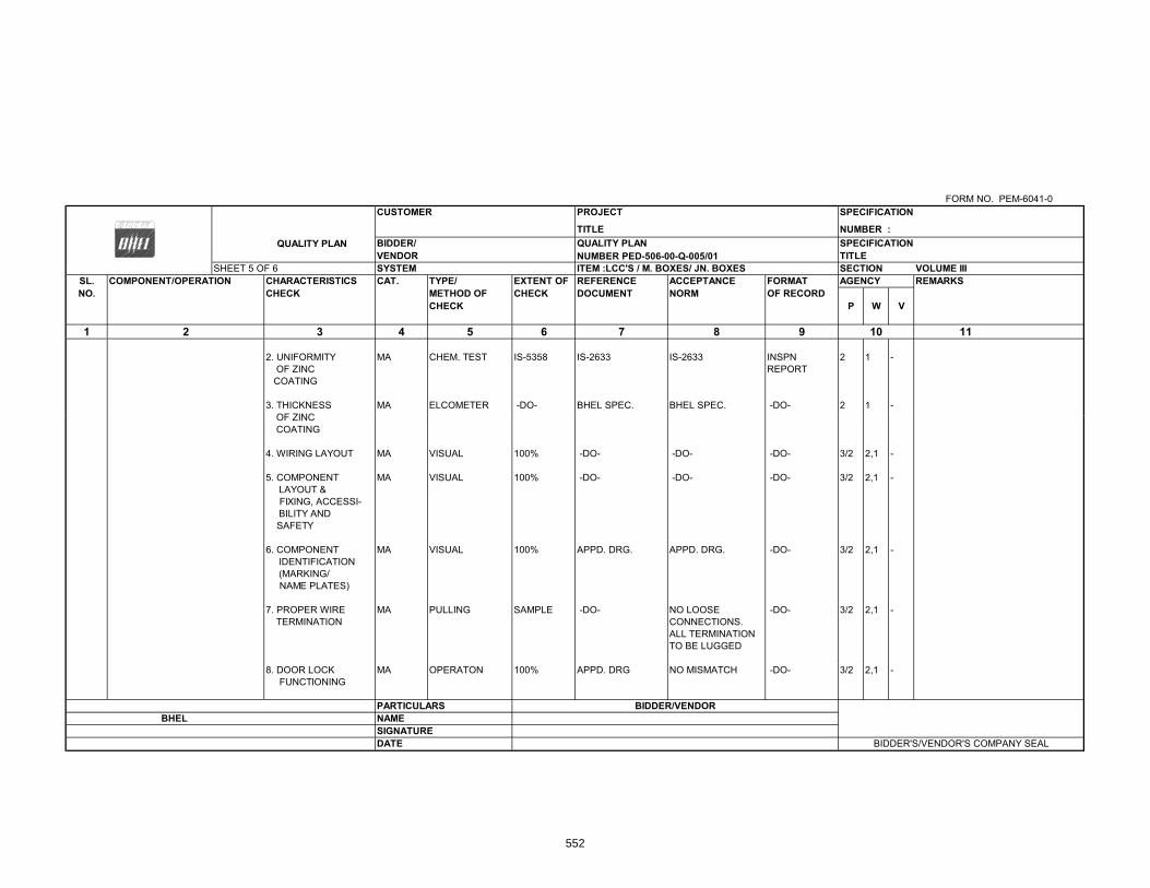
FORM NO. PEM-6041-0CUSTOMER PROJECT
TITLE NUMBER : QUALITY PLAN BIDDER/ QUALITY PLAN SPECIFICATION
VENDOR NUMBER PED-506-00-Q-005/01 TITLE SHEET 5 OF 6 SYSTEM ITEM :LCC'S / M. BOXES/ JN. BOXES SECTION VOLUME III
SL. COMPONENT/OPERATION CHARACTERISTICS CAT. TYPE/ EXTENT OF REFERENCE ACCEPTANCE FORMAT AGENCY REMARKSNO. CHECK METHOD OF CHECK DOCUMENT NORM OF RECORD
CHECK P W V
1 3 4 5 6 7 8 9 10 11
2. UNIFORMITY MA CHEM. TEST IS-5358 IS-2633 IS-2633 INSPN 2 1 - OF ZINC REPORT COATING
3. THICKNESS MA ELCOMETER -DO- BHEL SPEC. BHEL SPEC. -DO- 2 1 -OF ZINC
SPECIFICATION
2
OF ZINC COATING
4. WIRING LAYOUT MA VISUAL 100% -DO- -DO- -DO- 3/2 2,1 -
5. COMPONENT MA VISUAL 100% -DO- -DO- -DO- 3/2 2,1 - LAYOUT & FIXING, ACCESSI- BILITY AND SAFETY
6. COMPONENT MA VISUAL 100% APPD. DRG. APPD. DRG. -DO- 3/2 2,1 - IDENTIFICATION (MARKING/ NAME PLATES)
7. PROPER WIRE MA PULLING SAMPLE -DO- NO LOOSE -DO- 3/2 2,1 - TERMINATION CONNECTIONS.
ALL TERMINATIONTO BE LUGGED
8. DOOR LOCK MA OPERATON 100% APPD. DRG NO MISMATCH -DO- 3/2 2,1 - FUNCTIONING
PARTICULARS BIDDER/VENDORBHEL NAME
SIGNATUREDATE BIDDER'S/VENDOR'S COMPANY SEAL
552

FORM NO. PEM-6041-0CUSTOMER PROJECT
TITLE NUMBER QUALITY PLAN BIDDER/ QUALITY PLAN SPECIFICATION
VENDOR NUMBER PED-506-00-Q-005/01 TITLE SHEET 6 OF 6 SYSTEM ITEM :LCC'S / M. BOXES/ JN. BOXES SECTION VOLUME III
SL. COMPONENT/OPERATION CHARACTERISTICS CAT. TYPE/ EXTENT OF REFERENCE ACCEPTANCE FORMAT AGENCY REMARKSNO CHECK METHOD OF CHECK DOCUMENT NORM OF RECORD
CHECK P W V
1 3 4 5 6 7 8 9 10 11
9.OVERALL MA MEASUREMENT 100% APPD. DRG. APPD. DRG. INSPN. 3/2 2,1 - DIMENSIONS REPORT
10. CONTINUITY CR ELECTRICAL 100% APPD. DRG., APPD. DRG., -DO- 3/2 2,1 -BHEL SPEC., BHEL SPEC.,& RELEVANT IS & RELEVANT IS
SPECIFICATION
2
11. IR-HV-IR CR ELECTRICAL 100% -DO- -DO- -DO- 3/2 2,1 - IR-HV-IRTEST TO BE DONE
12.OPERATION CR ELECTRICAL 100% -DO- -DO- -DO- 3/2 2,1 - BEFORE OPERATIONAL TESTS INTERLOCKS OPERATION ETC AND FUNCTION
IN ENERGISEDCONDITION
13. TEMP RISE CR ELECTRICAL ONE/ TYPE/ BHEL SPEC. BHEL SPEC. -DO- 3/2 2,1 - (IF APPLICABLE) SIZE RELEVANT IS RELEVANT IS
14. DEGREE OF CR WATER AND ONE/ TYPE -DO- -DO- -DO- 3/2 2 - FLAME/EXPLOSION PROOF PROTECTION & DUST TESTS, TEST, IF SPECIFIED IN FLAME/ FLAME/ BHEL SPEC. EXPLOSION EXPLOSION PROOF TESTS
NOTE:
IF TC'S FOR DEGREE OF PROTECTION/EXPLOSION PROOFNESS IS AVAILABLE FROM AN INDEPENDENT LABORATORY FOR IDENTICAL DESIGN (SIZE SHALL BESMALLER THAN THAT INDICATED IN THE TC) THESE TESTS NEED NOT BE REPEATED.
PARTICULARS BIDDER/VENDORBHEL NAME
SIGNATUREDATE BIDDER'S/VENDOR'S COMPANY SEAL
553

BHEL SPEC Rev. No.:0
C. NO. :PE-TS-41 Dated : 11.06
TEC
FGUTP
404-165-N001 .14
CHNICAL CONCOOLING
P STAGE‐IV (1
TECHNIC
LIST OF
NDITIONS OF TOWER PACK1X 500 MW)
CAL SPECIFICA
SUBVEN
CONTRACTKAGE AT UNCHAHA
ATION DA
NDOR
AR
DOC. NO.: NBPPA Rev. No.: 01
PL-004-103-03-PP4M-
554

555

556

557
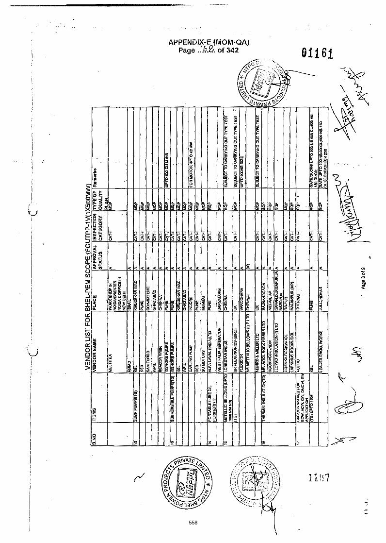
558

559

560

561

562

563

564

565

566

567

568
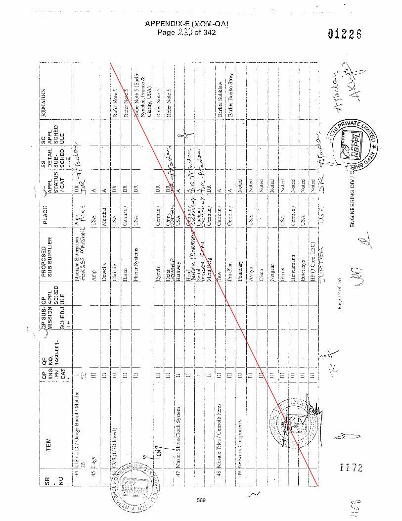
569

570

571

572

573

574

575
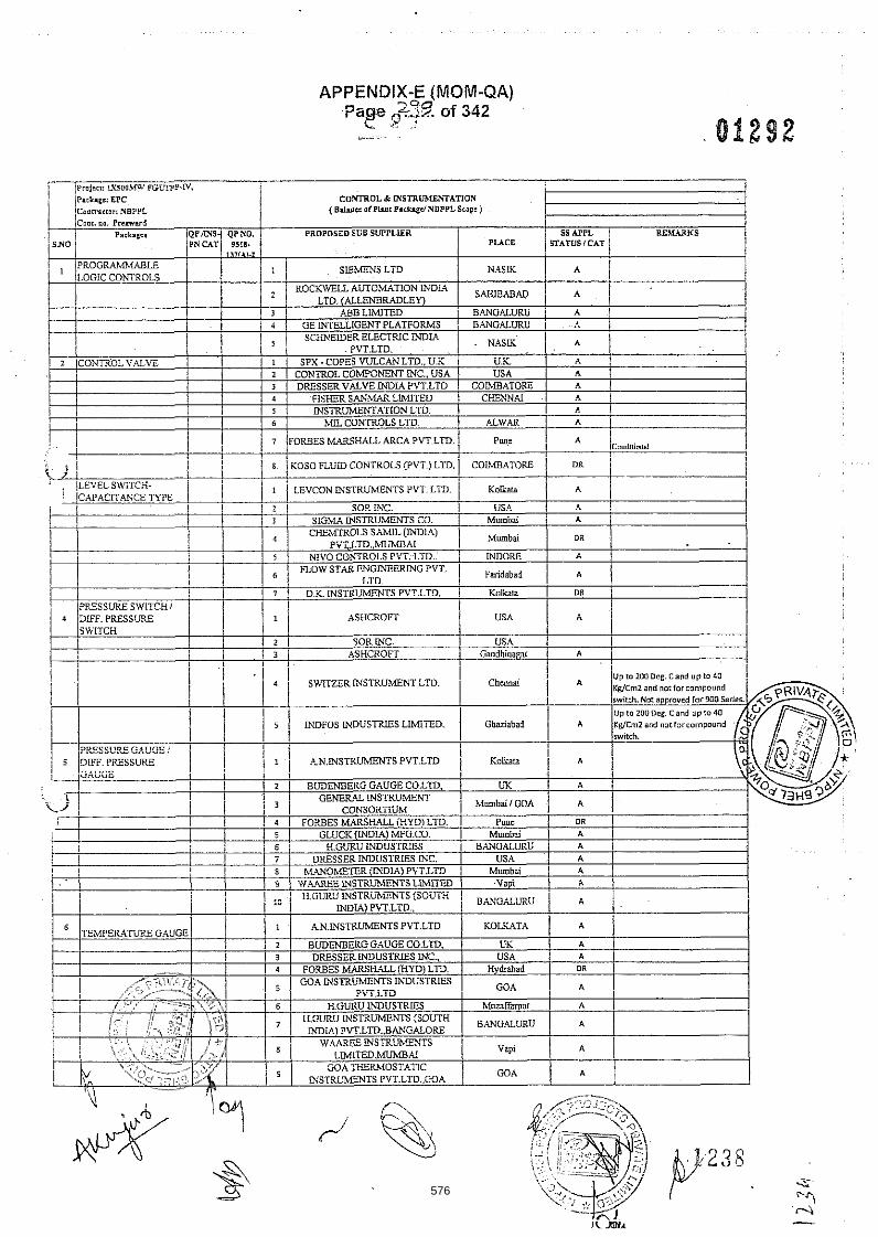
APPENDIX-E (MOM-QA) 70
Page q%d?. of 342 L <? .:
-&~~.. .
f i ~rn i~ : , : L U O U l l r . IGLTPF.3, Pxrirpe: EPC CO-DL & MSTRliMEhTATlON
( B ~ ~ ~ O ~ P L ~ ~ ~ P . ~ * . ~ ~ N B P P L S C O ~ : I
I Q ~ l m S d Q P N a PROPDSZD SOB SWPLLER R E M 1
i S N O i PROGRAWUBLZ LOGIC CONTROLS
I I
1 GEINTELLIGENTPLATFORMS I BANO.ALURU i I
SC.HNEIDERELECTRICINDIA PVT.LTD.
I il ~ ~
2 ICONTROL V.ALVE 'I 1 i SPX-COPES YULCANLTD.. U K U K A .
1 2 , CONTROL COMPONENT INC., USA 1 DRESSERVALVE m I A PVT.LTD COMBATORE. 4 FISHER SANhULLIMITED I INSTRUMENTATION L m . 6 MLLCDNTROLS L I D
I 1 / SISMAINSTRUMENTS CO.
7 D K INSTRUMENTS PVT.LTD. PRESSURE SWITCH1
ASHCROFT
SOR INC. USA ASHCROFT Gaodhioaear
P U C E PN CAT 95111. ,,,,,,.2
N.ASIK I
a SLEMENS LTD
ROCKWELL AUTOMKTION WDIA / SWABAD h
i ! ' / LTD.(ALLENBRADLEW [ I ! ,458 LIMITED i BPNOALURU A
576
6119158
Line

APPENDIX-E (MOM-QA) Page .5 ". of 342
COMROL & MSTRbW2MArIOPI Conrnnor: NBPPL (BhumIPlu i lP .chgdNBPPLE:oot 1 I ! CaoL .a er rmud I
PROPOSED SUB EUPPLLER RTDLWXS 1 P U C E I
7 !LEVEL OAUOE I
1
I 1 / SIGhL4MSTRUMPjTS CO. ! Mumbai 1 N
1 / i I TOSHNIWALBROTHERS (P)LTO. .. d j ~ s 1 N 1 CHEMTROLS S ~ M ~ L ( ~ I A I I / i i 5 i T H i i N 4OIGlCML I
B IfMWELEhEN: I
PVT.LTD..AUMB.U 1 Mumbai
I 1 I BRISTOLBABCOCKLTD. UK 1 A 1 1 5 1 BLISS I U I ~ PVTLTD. 1 D i i H i I N
i l I I
. . ENGINEEF3NGSPECLALLTIES 1 Koibara ,
I I I ! I a / MICROP8ECISIONPRODUCTS I faridebad 1 ' A 1
2
I
I
i PRIVATELTD . . 1 I . .
1 I / INSTRUMEWATION LTD. I P W d 1 A 1
1 5 STAr%MECH CONTROLS (1) PVT.LTD 1 Pun: I ' A
; . i i i i DETRIYE INSm.S ELECTRONiCS / ~ ~ b a i i A 1 I i l - I ! i j 2 1 LTD. I
i I j , i 3 1 PYRO ELECTRIC DISTXlPirEMS j GOA GOA PVT.LTD.
A
1 EMERSON PROCESS M#aAGEhGNT / Pawane j 1~ ~TP.A~SMITTERS 1 1 j / I / !IND!A)PVT.LTD. j i i / I i
! 1 1 1 2 1 SIEMENS LTD 1 -NIIL'. ! OR I I I 1 I 3 ! TATA HONE)?YELLLTD Punc 1 (i 1 i
I ' DR /
I
I m C 0 (m!.4) PRIVATE LLwTED. M A
'TEMPERATURZ SWITCH
W . 4
CONSOQ.TIUM
i
i 1 I
I GENERALINSTRUMENT
INDFoss (INDIA) LTD. I Ghaziabvd I
I I I 1 2 ! SWITZERMSTP.L%IENTLr". 1 C-L'J & /
MumSri
US,\ I li ! USA (i
~ a o d h i o a y / ii \
I ! I 1 3 ' SOR ioc
/ 4 ! ! I s
DRESSER WDUSTRLES MC.. ~rhcmR
SIGHTELOW SIGMA INSTRUMENTS CO. I I N
N
C1a3nROLS S A M I L ~ U I Mumbai N PVl.LTD..MUMBN
1 6 1 BLISS .MYAND P\'T.LTD. I DESN I N
1 13 1 I N S T R U m N R PLPE / / 1 \H'ILI-A&VPLV~ P?JV>.TS L ~ ~ T E ~ I k m s d z I f I n M G S 1 I
! I 1 I 1 PRECISION u.WGINEERWG I ivtwba; 1 ! ! INDUSTRLES ! ! I I I 1 3 I VIKASINDUSTRWPRODUCTS I Mumbai A
1 1 4 ! AURA INCORPORATED 1 Ncw Deihi I A
I I ASTEC VALVES k FITINGS PVT. .- r r o .
Mumbai
1 ii !DEFERENTIAL I ! z \ 3.*TTE?.LqSril"XZfiTiTD. ! C.SNNk. ! A / I /?RESSURESWITCH I $
1 \ ! L SORMC.. U S 4 1, A - LOCALCONTROL j ! PA??LS
8
j j 2 i PYROTECHCLECTUONICS PVT.LTD I LIDFUR 1 A
1 NDUSTRiALCONTROLSS I m m - u
APPLWCES P,LTD A
IVLNCTLON BOX I(m1
! I r I
I
i 1 hLW!S%4mTERPRISE, I
! 2 ! DEV! POL3dEP.S CWNNA! I N 1 1 3 1 SUCHITR4 m U S C R E S BANGALURU ! N
I
I
"i: $ -.
577

APPENDIX-E (MOM-QA) 7.- F Page uz .~ . . of 342
578
6119158
Line

APPENEIFE (MOM-QA) Page .!.?:$.. of 342
0 -1 u a r w
vau-1 ffl<ffl3 -- --
579