USING MAYA: ESSENTIALS
602
USING MAYA:ESSENTIALS VERSION 3
-
Upload
khangminh22 -
Category
Documents
-
view
0 -
download
0
Transcript of USING MAYA: ESSENTIALS

USING MAYA: ESSENTIALS
VERSION 3
ALIAS|WAVEFRONT ■ 210 KING STREET EAST ■ TORONTO, CANADA M5A 1J7
USING MAYA: BASICS
Copyright 2000, Alias|Wavefront, a division of Silicon Graphics Limited.Printed in U S A. All rights reserved.
The Maya 3 Documentation was created by: Steven Brooks, John Dila, Lisa Ford,Conan Hunter, Claude Macri, Susan Park, Diane Ramey, Linda Rose, and Michael Stivers.
The images in this book were created by: Andy Payne, Matt Dougan, Gary Mundell, RemoBalcells, Cris McSpurrenThe following are trademarks of Alias|Wavefront, a division of Silicon Graphics Limited:
Alias|Wavefront™ and the Alias|Wavefront logo are trademarks of Silicon Graphics, Inc. exclusively used byAlias|Wavefront, a division of Silicon Graphics Limited. Maya® is a registered trademark of Silicon Graphics, Inc.exclusively used by Alias|Wavefront, a division of Silicon Graphics Limited.
Graph Layout Toolkit Copyright 1992-1996 Tom Sawyer Software, Berkeley, California, All Rights Reserved.
Fusion™ is a trademark of eyeon Software.
Invigorator™ is a trademark of Zaxwerks.
Linux™ is a trademark of Linus Torvalds. Red Hat is a registered trademark of Red Hat, Inc.
Microsoft®, Windows® NT, and Windows® 2000 are registered trademarks of Microsoft Corporation.
SGI™ is a trademark, and IRIX® and Silicon Graphics® are registered trademarks of Silicon Graphics, Inc.
UNIX® is a registered trademark, licensed exclusively through X/Open Company, Ltd.
All other product names mentioned are trademarks or registered trademarks of their respective holders.
This document contains proprietary and confidential information of Alias|Wavefront, Inc. and is protected by Federalcopyright law. The contents of this document may not be disclosed to third parties, translated, copied, or duplicated in anyform, in whole or in part, without the express written permission of Alias|Wavefront, Inc. The information contained in thisdocument is subject to change without notice. Neither Alias|Wavefront, Inc. nor its employees shall be responsible forincidental or consequential damages resulting from the use of this material or liable for technical or editorial omissionsmade herein.
Alias® Maya Complete™ Maya Paint Effects™
Conductors™ Maya Composer™ Maya Real Time SDK™
Dynamation™ Maya ComposerLite™ Maya Unlimited™
Explore™ Maya Fur™ SuperConductors™
Kinemation™ Maya Fusion™ TraX™
IPR™ Maya Fusion Lite Edition™ Visualizer™
Maya® Maya F/X™ VizPaint2D™
Maya Artisan™ Maya Invigorator™ Wavefront™
Maya Builder™ Maya Invigorator Lite Edition™ ZaP!iT™
Maya Cloth™ Maya Live™

CONTENTS
USING MAYA: ESSENTIALS
iii
Part 1 Basic Features 29
1 WORKING IN MAYA 1
Starting Maya 2
Command line options 2
Running prior versions of Maya 3
Environment variables 3
Main window 4
Main window and floating windows 8
Maya workspace 9
Streamlining the interface 12
Working with objects 13
Object display 14
Object attributes 15
Attributes and nodes 16
Working with tools and actions 17
Using actions 17
Using tools 18
Manipulators and handles 19
MEL commands 20
Using the Hotbox 20
Displaying recent selections 22
Changing the appearance and contents of the Hotbox 23
Disabling the Hotbox 25
Using marking menus 25
Scene management 28

USING MAYA: ESSENTIALS
iv
CONTENTS
Getting help 29
2 VIEWING YOUR SCENE 31
Orienting the XYZ system 31
Changing the orientation/up axis 33
World coordinates 33
Local coordinates 33
Working with cameras 34
Creating a new camera 36
Moving the camera 36
Looking through a camera 37
Changing camera settings 38
Setting a perspective view 40
Creating new perspective views 40
Setting an orthographic view 41
Creating new orthographic views 41
Lighting your scene 42
Arranging views 43
Displaying the workspace only 45
Laying out the views 45
Marking a view 47
Creating a bookmark 47
Selecting custom bookmarks 48
Renaming a bookmark 49
Adding a bookmark to a shelf 49
Enabling and disabling nodes 49
3 EDITING OBJECTS 51

CONTENTS
USING MAYA: ESSENTIALS
v
Selecting objects 51
Selecting objects individually 52
Selecting all objects in a scene 52
Selecting objects by type 53
Selecting objects by name 55
Selecting all objects in a set 55
Selecting all objects in a display layer 55
Deleting objects 55
Deleting a single object 56
Deleting object components by type 56
Deleting all objects by type 57
Duplicating and instancing objects 58
Duplicating objects 58
Creating instances of objects 60
Working with groups 63
Grouping objects 63
Ungrouping objects 64
Creating an empty group 66
Creating object hierarchies (parenting) 66
Parenting objects 66
Unparenting objects 67
Undoing and redoing actions 68
Undoing your last action 68
Redoing and repeating actions 68
Editing object attributes 69
4 TRANSFORMING OBJECTS 71
Selecting transformation tools 72

USING MAYA: ESSENTIALS
vi
CONTENTS
Using manipulators 72
About manipulator handles 73
Using axes and pivot points 73
What are pivot points? 74
What is an axis? 78
Moving objects 79
Moving the translate pivot point 81
Choosing a coordinate system for the Move tool 82
Moving curves on surfaces 83
Moving a path animation marker 84
Rotating objects 85
Moving the rotate pivot point 86
Changing the rotation order 87
Animating rotation channels 89
Scaling objects 89
Moving the scale pivot point 90
Using the Show Manipulator tool 91
Selecting an item’s history node 92
Changing a curve’s parameter range 93
Displaying manipulators for lights and cameras 94
Using the Default Object manipulator 94
Entering numeric values 95
Using the Numeric Input field 95
Using the Command Line 97
Combining transformations 97
Using proportional modification 99
Specifying proportional modification falloff 101

CONTENTS
USING MAYA: ESSENTIALS
vii
Using the PropMod script 105
Creating locators 105
Using Measure tools 107
Using distance measures 107
Displaying parameter values 111
Measuring arc lengths 114
5 DISPLAYING OBJECTS 119
Displaying items in Maya 119
Using a grid 120
Setting grid options 121
Displaying axes, polygon count, and frame rate 122
Specifying how objects display 122
Hiding and showing objects 125
Hiding geometry 126
Hiding kinematics 127
Hiding deformers 128
Isolating selected objects or components 129
Displaying object components 131
Displaying NURBS components 132
Displaying NURBS smoothness 133
Displaying polygon components 135
Setting custom polygon options 135
Displaying camera and light manipulators 137
Displaying camera manipulator controls 137
Displaying light manipulator controls 138

USING MAYA: ESSENTIALS
viii
CONTENTS
Working with templates 139
Using display layers 139
Display layer tools 140
Creating and naming display layers 141
Assigning objects to display layers 141
Removing objects from display layers 142
Display Layer commands 143
Changing the color of the display layer: 144
Using the Layer Editor 145
Modifying display layer attributes 146
Merging display layers when importing files 147
Using render layers 147
Creating and naming render layers 148
Assigning objects to render layers 148
Removing objects from render layers 149
Render Layer commands 149
Changing the color of the render layer: 150
6 MODELING AIDS 151
Snapping 151
Snapping icons 151
Snapping hotkeys 153
Snapping along a constraint axis 154
Snapping to a curve on surface or isoparm curve 154
Snapping aligning objects 155
Limiting selections 157
Limiting selection by object type 157
Limiting selection by component type 159
Limiting selection to hierarchy items 166

CONTENTS
USING MAYA: ESSENTIALS
ix
Limiting selection to template objects 166
Limiting selection by task 167
Moving selection limitations to the shelf 168
Freezing and resetting transformations 169
Locking transform tools and manipulators 170
Using construction history 170
Making objects live 171
Creating levels of detail 173
Changing the Threshold distances 174
Re-ordering the levels 175
Adding and editing levels 175
Previewing more than one object at the same time 176
Notes about orthographic cameras and level of detail 177
7 MANAGING FILES AND PROJECTS 179
Opening a scene 180
Creating a new scene 181
Setting Open options 181
Importing files 184
Using default nodes 184
Importing files by copying 184
Importing move files 186
Importing Adobe Illustrator® and EPS files 188
Importing animation curves 188
Importing files by reference 190
Supported file formats 196
Saving files 198

USING MAYA: ESSENTIALS
x
CONTENTS
Setting save options 200
Tips for reducing file size 201
Exporting files 201
Setting export options 202
Exporting scene elements 202
Exporting move files 204
Using plug-ins for exporting 205
Exporting to Wavefront (OBJ) 205
Exporting to IGES or DXF 207
Exporting to Alias Wire 207
Exporting to RenderMan 207
Exporting animation curves 210
Optimizing scene size 212
Managing projects 213
Where Maya stores scene information 214
Using absolute and relative paths 214
Multiple project directory paths 215
Creating projects 215
Specifying the current project 217
Editing the current project 218
Mapping missing directories 218
Mapping from IRIX to NT 218
Mapping from IRIX to IRIX 219
8 SETTING ENVIRONMENT VARIABLES 221
About environment variables 221
Creating the Maya.env file 222
Rules for Maya.env 223

CONTENTS
USING MAYA: ESSENTIALS
xi
Where Maya looks for Maya.env 224
Modifying standard paths 225
Other path settings 225
Standard Maya environment variables 226
Part 2 Editors 233
9 USING MAYA EDITORS 235
Using General Editors 236
Using the Component Editor 237
Using the Attribute Spread Sheet 241
Specifying tool settings 248
Specifying performance settings 249
Loading and unloading plug-ins 251
Using the Relationship Editor 255
Setting view options 256
Displaying relationships and objects 257
Creating relationships 259
Selecting relationships, relationship members, and objects 260
Adding and removing relationship members 261
Using the Attribute Editor 262
Displaying the Attribute Editor 262
Loading object attributes into the Attribute Editor 266
Viewing attributes for different objects at the same time 268
Adding a custom attribute 269
Deleting or renaming custom attributes 271
Changing node behavior 272
Setting keys for attributes in the Attribute Editor 273

USING MAYA: ESSENTIALS
xii
CONTENTS
Linking attributes 274
Breaking connections 274
Locking attribute values 274
Launching the Expression Editor 275
Mapping a texture to an attribute value 275
Using the Color Chooser 276
Using the Channel Box 280
Displaying the Channel Box 280
Displaying object attributes 281
Adding attributes to the Channel Box 282
Displaying component attributes 283
Changing the display format 284
Entering values for attributes 285
Setting keys for attributes from the Channel Box 291
Setting breakdown keys for attributes from the Channel Box 292
Breaking connections from the Channel Box 293
Locking attribute values from the Channel Box 294
Launching the Expression Editor from the Channel Box 295
Linking attributes from the Channel Box 295
Modifying an object’s history (inputs) 295
Using the Outliner 297
Understanding scene hierarchy terminology 299
Navigating the Outliner 300
Displaying shape nodes 302
Displaying attributes 303
Displaying specific types of nodes 306
Parenting objects 306
Selecting and renaming objects 309
Reordering nodes 309

CONTENTS
USING MAYA: ESSENTIALS
xiii
Limiting the information shown in editors 311
Limiting the display 312
Showing all items not currently displayed 314
Showing all items (removing restrictions) 314
Storing your restrictions 314
Deleting stored restrictions 315
Controlling display of auxiliary nodes 316
10 USING THE HYPERGRAPH 319
Opening the Hypergraph 320
Understanding scene hierarchy terminology 322
Using the scene hierarchy 324
Expanding scene hierarchy nodes 324
Displaying special nodes and connections 326
Parenting objects 329
Rearranging scene hierarchy nodes 331
Displaying a background image with a scene hierarchy 335
Understanding the dependency graph 337
Using a dependency graph 338
Displaying render node connections 339
Displaying upstream and downstream connections 340
Dragging nodes into a dependency graph 344
Disconnecting nodes in a dependency graph 344
Connecting nodes in a dependency graph 346
Updating the layout of a dependency graph 351
Clearing the contents of a dependency graph 352
Returning to the scene hierarchy 352
Editing objects 352

USING MAYA: ESSENTIALS
xiv
CONTENTS
Selecting objects 352
Adding and selecting an IK handle 353
Renaming an object 354
Hiding an object in the workspace 355
Editing an object’s attributes 355
Creating a render node 356
Altering the view of a graph 356
Tracking the view 356
Dollying the view 356
Dollying a region 357
Fitting an entire graph in the window 358
Centering selected nodes in the window 359
Centering a hierarchy in the window 359
Centering a hierarchy branch in the window 360
Adjusting view transition speed 360
Setting graph update options 361
Undoing a view of a scene hierarchy 361
Using bookmarks for graph views 362
Displaying a graph vertically or horizontally 364
Rebuilding the graphs 365
11 SETS AND PARTITIONS 367
How you can use sets 368
Understanding sets 369
Sets you create 370
Sets created by Maya 371
Creating, selecting, and removing sets 375
Creating sets 375
Selecting sets 376
CONTENTS
USING MAYA: ESSENTIALS
xv
Removing sets 377
Creating sets for easy object selection 377
Editing set membership 378
Altering the display of sets 379
Understanding partitions 379
Partitions you create 379
Partitions created by Maya 380
Creating, displaying, and removing partitions 381
Adding sets to partitions 382
Part 3 Artisan Paint Tools 385
12 USING ARTISAN PAINT TOOLS 387
What are the Artisan paint tools 388
How Artisan paint tools work 390
Changing paint tool settings 393
Tool-specific settings 395
Common tool settings 396
Resetting tools 397
Changing brush stroke settings 397
Changing display settings 404
Changing miscellaneous tool settings 406
Creating an Artisan tool shelf 410
Defining Artisan hotkeys 410
Using Artisan marking menus 414
Snapping an Artisan paint brush to path 415

USING MAYA: ESSENTIALS
xvi
CONTENTS
Masking surfaces 416
Mapping attributes 419
Importing attribute maps 420
Exporting attribute maps 424
Working with seams 426
What is a seam? 426
Selecting common edges and corners 426
Stitching surfaces 438
Painting weights and attributes, or script painting over seams 438
13 SCRIPT AND ATTRIBUTE PAINT TOOLS 441
Painting with MEL Scripts 441
Overview of MEL script painting 441
Setting Script Paint Tool options 442
Script painting 447
Script painting on masked surfaces 454
Flooding surfaces 454
Painting attribute values 454
Painting attributes 454
Part 4 Preferences 459
14 SETTING PREFERENCES 461
Settings/Preferences menu 462
Where Maya stores preferences 462
Saving preferences using userSetup.mel 464
Preferences window 465
Interface 466

CONTENTS
USING MAYA: ESSENTIALS
xvii
UI Elements 466
Misc 467
Display 467
Kinematics 469
Manipulators 469
NURBS 470
Polygons 471
Settings 472
Dynamics 473
Files/Projects 474
Keys 475
Modeling 476
Selection 476
Snapping 478
Sound 478
Timeline 479
Undo 481
Modules 481
OpenMaya 482
Changing color settings 482
Changing default colors 482
Specifying tool settings 485
Specifying performance settings 487
Loading and unloading plug-ins 489
15 CUSTOMIZING SHELVES, MARKING MENUS, AND HOTKEYS 493
Creating and editing shelves 493
Creating and deleting shelves 495
Adding shelf items 498

USING MAYA: ESSENTIALS
xviii
CONTENTS
Removing shelf items 499
Moving and copying shelf items 500
Renaming shelves 501
Reordering the shelves 501
Changing shelf icons 502
Changing icon labels 504
Setting Shelf label options 506
Adding overlay labels 507
Changing MEL command(s) associated with an icon 507
Creating and editing marking menus 509
Creating marking menus 511
Assigning marking menus to hotkeys 515
Modifying existing marking menus 516
Adding submenus to menu items 520
Associating a MEL script with a menu item 522
Deleting marking menus 523
Assigning hotkeys 526
Assigning hotkeys to standard commands 527
Viewing hotkey lists 528
Searching for commands 529
Changing or deleting a hotkey 530
Adding commands for hotkey assignment 530
16 WORKING WITH PANELS AND LAYOUTS 533
Using the Panel Editor 533
Viewing panels 535
Modifying existing panels 535
Creating and deleting panels 537
Defining layouts 539

CONTENTS
USING MAYA: ESSENTIALS
xix
Selecting panel layouts 539
Creating layouts 540
Deleting layouts 544
Maintaining layout history 544

USING MAYA: ESSENTIALS
xx
CONTENTS

USING MAYA: ESSENTIALS
xxi
INTRODUCING MAYA: ESSENTIALS
Thank you for buying Maya—Alias|Wavefront’s award-winning computeranimation package. The following pages describe how to approach the Mayadocumentation so you can learn and use your software most effectively.
About the Essentials bookUsing Maya: Essentials provides a guide to the Maya user interface and basictools, and a general introduction to the Maya software. Using Maya:Essentials covers the following:
• Chapter 1, Working in Maya, describes how you do things in Maya. It showsyou how to use menus, shelves, hotkeys, and windows. It also introduces theHotbox and marking menus—two customizable tools for quickly accessingmenus and action.
• Chapter 2, Viewing Your Scene, describes Maya’s XYZ coordinate system. Italso includes information on the various tasks you can perform using Mayaviewing tools.
• Chapter 3, Editing Objects, describes how to edit objects in Maya. It covershow to delete, select, instance, copy, group, and parent objects. It alsodescribes Maya’s undo, redo, and repeat functions.
• Chapter 4, Transforming Objects, shows you how to scale, rotate, and moveyour objects to position them in 3D space.
• Chapter 5, Displaying Objects, describes the tools and actions you use todisplay or hide objects and attributes. You can use these tools to customizeyour working environment and reduce workspace complexity.
• Chapter 6, Modeling Aids, shows you some of the modeling features you canuse to help you build and position objects.
• Chapter 7, Managing Files and Projects, describes how to open and save files,import and export files, how to create and edit projects, and what filesformats are supported by Maya.

USING MAYA: ESSENTIALS
xxii
• Chapter 8, Setting Environment Variables, explains the use of the Maya.envfile to set environment variables. It also lists the available Maya environmentvariables.
• Chapter 9, Using Maya Editors, describes Maya editors, including: several ofthe General Editors, the Relationship Editor, the Attribute Editor, theChannel Box, and the Outliner.
• Chapter 10, Using the Hypergraph, shows you how to use the Hypergraph toview the relationship between components of a scene graphically.
• Chapter 11, Sets and Partitions, explains how to use sets (collections of objectsand components) and partitions (collections of related sets).
• Chapter 12, Using Artisan Paint Tools, introduces the paint tools included inMaya (formerly Artisan paint tools). The tools use an intuitive paint andsculpting-based interface to deliver high quality and otherwise complexresults in minimal time.
• Chapter 13, Script and Attribute Paint Tools, describes how to use theadvanced Artisan tools: Script Paint Tool and Attribute Paint Tool.
• Chapter 14, Setting Preferences, describes preferences you can set tocustomize Maya to the way you work. You can change general colordefinitions, the way manipulators display, and the appearance of the Shelf,menu bars, and panels.
• Chapter 15, Customizing Shelves, Marking Menus, and Hotkeys, describes howto tailor these tools to your own needs.
• Chapter 16, Working with Panels and Layouts, shows you how to customizeyour workspace using panels (areas in the main Maya window consisting ofinterface elements) and layouts (groups of panels).
About the Maya documentation setWhether you use Maya Unlimited, Maya Builder, or Maya Builder, youreceive a full set of documentation. Since Maya ties together several differentkinds of software, we’ve included a lot of different books to describe how touse it.
Where do I begin?The following paragraphs should help you decide where to start readingand learning about Maya.

USING MAYA: ESSENTIALS
xxiii
1 When you install Maya Complete, Maya Unlimited, or Maya Builder, referto one of the installation guides for guidance.
For example, see Installing Maya 3.0 on Windows NT if you’re installing MayaComplete or Unlimited on an NT or Windows 2000 system.
2 If you’ve used Maya before and want an overview of new features, seeWhat’s New in Maya 3.
This booklet provides a summary of new features across all modules.
Next, you may want to review the Maya 3.0 Release Notes for briefdescriptions of limitations in the software and successful ways to workaround them.
3 If you’re a first-time Maya user, see Learning Maya for a comprehensive,step-by-step tour of the Maya software before you read any otherdocumentation.
A CD included at the back of the book contains online documentation of thetutorials as well as all required image and Maya support files. Additionalcopies of this book are also available from your local technical bookstore.
The remaining documentation assumes that you have at least a workingfamiliarity with Maya, so it’s important to start with Learning Maya.
4 Now, you’re ready to move on to the Using Maya series.
The Using Maya seriesThe Using Maya books describe how you can use Maya’s user interface tocreate professional 3D graphics animations and visual effects. Each book isdevoted to a different area of the software.
Important
In response to customer requests, we’ve changed the licensing procedurein Maya 3.0, Please read the installation instructions from cover to cover,even if you have installed previous versions of Maya.

USING MAYA: ESSENTIALS
xxiv
The Using Maya series includes these books:
Essentials provides a guide to Maya’s user interface and basic tools. Using Maya:Essentials also defines a number of concepts that are common to all of Maya.Using Maya: Essentials was called Using Maya: Basics in previous releases.
NURBSModeling
describes Maya's spline modeling system and tells you how to get the mostout of it.
PolygonalModeling
describes how to interactively create, modify, and color polygonal models.
SubdivisionSurfacesModeling
describes the enhanced subdivision surfaces modeling tools which areavailable only in Maya Unlimited.
Character Setup tells how to use Maya’s deformer, skeleton, skinning, constraint, andcharacter features.
Animation describes Maya's basic animation software, which is based on keyframes andmotion paths. This book also provides information on motion capture andintroduces other Maya animation techniques, such as character setup.
Dynamics describes how to animate using natural forces. You can use dynamics tomake effects such as tumbling dice, waving flags, and exploding fireworks.
Rendering describes how to prepare for rendering, render a scene, and view yourrendered images. This book also describes how to create light, shadow, andlight effects, shade and texture surfaces. It also tells you how to set upcameras and views and create a background. The information in Using Maya:Rendering is arranged by production task.
The online book, Maya Reference: Rendering describes Maya’s rendering-related menu options, attributes, and windows. The information in this bookis organized around the user interface
Paint Effects describes how to use Paint Effects to paint real-time rendered strokes onto orbetween 3D objects or onto a 2D canvas.
Cloth describes how to create and animate realistic clothing using MayaUnlimited’s Cloth software. This book includes four tutorials to get youstarted, as well as a complete user’s guide.

USING MAYA: ESSENTIALS
xxv
The Maya Technical LibraryWhen you’re ready to use Maya to its fullest potential, you’ll want to explorethe technical library. These documents tell how to use Maya’s powerfulcommand language and expressions. They also provide information that willhelp you use Maya with other software packages.
Fur describes how to use Maya Unlimited Fur to create realistic, self-shadowingfur and short hair on multi-surface models.
Live describes how to use Live, Maya Unlimited’s automated match-moving tool.You can use Live to match Maya scenes with live footage by reconstructing3D locations and camera or object movement from a shot.
Note
The books in the Maya Technical Library are not included in a printeddocument set. However, html files for all of these documents are providedon your product CD for online viewing. PDF files are also provided unlessotherwise specified.
MEL describes how to use the Maya Embedded Language (MEL) to entercommands and write scripts.
MEL CommandReference
includes technical descriptions of the individual MEL commands. MELcommands are provided in html format only, no PDF files are supplied.
Expressions describes how to use expressions to control attributes. Expressions are idealfor controlling attributes that change incrementally, randomly, orrhythmically over time. They are also useful for linking attributes betweendifferent objects—where a change to one attribute affects the behavior of theother.
DG NodeReference
is for technical users who want more information on the DG node attributes.The DG Node Reference is provided in html format only, no PDF files are supplied.

USING MAYA: ESSENTIALS
xxvi
Using Maya’s online documentationFor your convenience, the Maya documentation is online in html format.(This help requires version 4 or higher of either Netscape Communicator orInternet Explorer.) We include the complete Maya Unlimited documentationset, no matter what version of the software you have purchased.
Printing online books
To allow you to print copies of the documentation, we’ve provided PDF filesof most documents. These files require the Adobe Acrobat reader.
To print the online books, insert your Maya CD, navigate to the pdfdirectory, and open library.pdf.
The Glossary
For 3.0, we’ve provided an online glossary so you can look up meanings ofwords you encounter which are new or confusing.
Maya File Formats is for technical users with programming experience who want to either editMaya files or write translators to or from the Maya file formats.
Maya Developer’sTool Kit
describes how to use the Maya API to load, write, and edit plug-ins. Thisbook includes instructions for creating your own plug-ins. The MayaDeveloper’s Tool Kit also features on-line links to example plug-ins.
Maya Translators is for people who are bringing data into Maya or exporting data to othersoftware packages.
Maya GameTranslators
describes how to install and use Maya game translators. Information isprovided for VRML2 and GE2, as well as the RTG file format. This book alsoincludes information on using the MDt API.
Rendering Utilities describes how to use command-line and stand-alone utilities that are part ofMaya, such as fcheck, as well as the options for the command line renderer.Rendering Utilities was called Utilities in previous releases.

USING MAYA: ESSENTIALS
xxvii
Search tools
Due to customer requests, we’ve provided an enhanced Library search toolin Maya 3.0. You can use the Library Search tool without installing thedocumentation files on a server. To access the Library Search tool, return tothe main Maya Library page and select Library Search.
A Book Search tool is also provided in the left frame of most books. Use thistool to look for an item in the book you are viewing currently.
Online indexes
When you are viewing a specific book, you can access that book’s index. Youcan also use the Global Index to view entries throughout the document set(except the MEL Command Reference and the DG Node Reference.)
Using Maya’s printed documentationA complete printed documentation set includes the followingdocumentation:
• Installing Maya — describes how to install and license your software
• Learning Maya — provides comprehensive step-by-step tutorials
• Maya Release Notes — lists limitations in the software and suggestsworkarounds for them
• What’s New in Maya — describes the new features we’ve added for thisrelease
• Maya Quick Reference Card — a guide to Maya’s most frequently usedkeyboard shortcuts. The Quick Reference Card also outlines the steps youuse to create your own hotkeys.
• Troubleshooting Rendered Images — a quick reference card to help youidentify problems with rendered images
• Books in the Using Maya series — as listed on page xxiii
• Maya Global Index for print —which provides page numbers for entries in theprinted document set. This book is different from the online index.
Printed documentation conventions
The printed documentation follows these conventions:

USING MAYA: ESSENTIALS
xxviii
• MEL commands, program code, expressions, and error messages appear incourier font:
This is computer code
• Items in cascading menus are identified by an arrow. For example, “selectParticles > Make Collide” means “select the Add Goal option from the MakeCollide menu.”

PART 1
BASIC FEATURES


USING MAYA: ESSENTIALS
1
1 WORKING IN MAYA
Throughout Maya you’ll find a consistent interface and a style of workingthat is both fast and easily customizable. This chapter presents thesemethods of working so you can quickly launch into your projects.
• “Starting Maya” on page 2
• “Main window” on page 4
• “Maya workspace” on page 9
• “Streamlining the interface” on page 12
• “Working with objects” on page 13
• “Working with tools and actions” on page 17
• “MEL commands” on page 20
• “Using the Hotbox” on page 20
• “Using marking menus” on page 25
• “Scene management” on page 28
• “Getting help” on page 29

USING MAYA: ESSENTIALS PART 1
2
WORKING IN MAYA | 1Starting Maya
STARTING MAYA
You can start Maya by either double-clicking the Maya desktop icon or bytyping maya at a command prompt. On Windows NT, you can also selectStart > Programs > Maya (Complete or Unlimited) 3.0 > Maya.
Command line optionsIf you start Maya from the command line, there are various startup optionsyou can specify. For example, you can open a file at startup using the -fileflag:
maya -file filename
To see the available startup flags, type the following:
maya -help
To execute Maya commands without the interface, use either -prompt or -batch. The -prompt flag issues a MEL prompt for you to type commands.Type quit to exit the prompt mode.
Use the -batch flag to run commands without user input, such as in shell orbatch scripts. The -batch flag starts Maya, executes any commands youspecify, and then close Maya. For example, you could create a script to opena file from a prior version of Maya in order to update it to the currentversion:
maya -batch -file someMayaFile.ma -command "file -save"
Notes
The -batch command is not used for batch rendering. Instead, use theRender command. However, -batch does check out a render-only licenseinstead of a full Maya license.
On Windows NT, type mayabatch when using the -batch flag. The mayabatchcommand runs within the command prompt window, whereas the mayacommand starts a separate window.

WORKING IN MAYA | 1Starting Maya
BASIC FEATURES USING MAYA: ESSENTIALS
3
Running prior versions of MayaIn some cases, you may want to run a prior version of Maya. On WindowsNT, simply choose the prior version from the Start menu.
On IRIX, you need to use a symbolic link pointing to the installationdirectory of the prior version. To add a symbolic link, log in as root and typethe following commands:
cd /usr/sbin
ln -s /usr/aw/mayaX.X/bin/maya maya XX
where XX is the version number. Now you can type mayaXX to run the priorversion.
Environment variablesAt startup, Maya uses a number of environment variables to set theenvironment. Many of the variables are included in the Maya program andare set automatically when you start Maya. To configure Maya further, youcan set additional environment variables. See Chapter 8, “SettingEnvironment Variables” for more information.

USING MAYA: ESSENTIALS PART 1
4
WORKING IN MAYA | 1Main window
MAIN WINDOW
Read this section for a brief summary of the main interface elements. As youread, keep in mind the following:
• The critical part of the interface is in the workspace panel; see the next topic,“Maya workspace” on page 9 for details.
• You can hide all the interface elements and instead use Maya’s quickcommand features: the Hotbox, Marking Menus, and hotkeys. For anintroduction to this topic, see “Streamlining the interface” on page 12.
Layer bar
Workspace
Time SliderRange SliderCommand LineHelp Line
Menu barStatus Line
Minibar
Title bar Shelf Channel Box

WORKING IN MAYA | 1Main window
BASIC FEATURES USING MAYA: ESSENTIALS
5
Menu BarThe menus in Maya are grouped into menu sets. Each menu set correspondsto a module of the software: Animation, Modeling, Dynamics, andRendering. Maya Unlimited has additional modules: Cloth and Live. As youswitch between menu sets, the right-hand menus change, but the leviathanmenus remain the same; these are the common menus.
To switch between menu sets, use the Status Line pull-down or hotkeys. Thehotkeys are: F2 (Animation), F3 (Modeling), F4 (Dynamics), and F5(Rendering).
Status LineThe Status Line has a variety of commands, mostly used for modeling. Forexample, the central group of buttons are used to select objects andcomponents. See “Working with objects” on page 13 for an introduction tothis topic. Also see Chapter 6, “Modeling Aids,” which describes most of theoptions on the Status Line.
... and see these menus change
... while the common menus stay the same
Select thearea you wantto work in
men
u se
lecto
r
selec
tion
mod
e
selec
tion
mas
ks
snap
mod
e
lock b
utto
n
mak
e liv
e
list o
f ope
ratio
ns
cons
tructi
on h
istor
y
open
scen
e
new sc
ene
save
scen
e
rend
er fr
ame
num
eric
input

USING MAYA: ESSENTIALS PART 1
6
WORKING IN MAYA | 1Main window
For better organization, the buttons are broken into groups that you canexpand and collapse, as shown in the following illustration.
Minibar and ShelfThe Minibar and Shelf work together. The Minibar contains common tools aswell as the currently selected tool. The Shelf is a collection of tools and othercommands that you can customize for your specific needs.
By creating custom shelves, you can organize commonly used actions andtools into groups. For example, you can create modeling, animating, andrendering shelves with appropriate tools and actions for each option. Youcan also store the same tool more than once, but with different settings. Forinformation on creating, editing, and deleting shelves, see “Creating andediting shelves” on page 493.
To switch between shelves, click the tab icon, as shown in the followingillustration.
Click the expanded bar to collapse
Click the arrow bar to expand
Click to switch between shelves
Pull down menu for shelf-related options

WORKING IN MAYA | 1Main window
BASIC FEATURES USING MAYA: ESSENTIALS
7
Layer BarLayering is a method of grouping objects so you can easily hide them fromview, use them as a template, or render them in a separate pass. The LayerBar provides the main controls for creating layers, adding objects to layers,and making layers visible or invisible. See “Using display layers” on page139 for more information.
Note that the Layer Bar is hidden by default; you can display it by choosingDisplay > UI Elements > Layer Bar.
WorkspaceThe main purpose of the workspace is to view your scene, but that’s not all.You can also display various editors and arrange the workspace panels indifferent layouts. For further discussion, see the next topic “Mayaworkspace” on page 9.
Channel BoxMost of Maya’s interface elements are common to 3D software packages, butthe Channel Box is a unique and powerful feature. It gives direct access tothe building blocks of Maya: attributes and nodes. Specifically, it shows thekeyable attributes, also known as channels. (A keyable attribute means youcan set animation keyframes for it.) For further discussion, see “Objectattributes” on page 15.
Time and Range SlidersThe two sliders are for controlling the frames in your animation. The TimeSlider includes the playback buttons (also called transport controls) and thecurrent time indicator. The Range Slider includes start and end times,playback start and end times, the Range Slider bar, the Auto Key button, andthe Animation preferences button.
For information on using the animation controls, see Using Maya: Animation.

USING MAYA: ESSENTIALS PART 1
8
WORKING IN MAYA | 1Main window
Command LineAnother powerful feature of Maya is the MEL command language, and theCommand Line is your pipeline to it. Notice that it has two halves.
The left side is where you can type MEL commands. For example, you cantype a command to quickly create a sphere with a specific name and radius.
For a longer series of commands, use the Script Editor, which you canlaunch from the icon on the far right.
The right half displays system responses, error messages, and warnings. Itcan also show echoes of all commands if you turn on Edit > Echo AllCommands from the Script Editor.
Help LineLike several other applications, you can look at the help line for descriptions,instructions, and other useful information. For full details, see “Help Line”on page 30.
Main window and floating windowsMaya has several editors that launch as floating windows separate from themain window. To manage these windows, note the following tips.
On IRIX, use Window > Raise Application Windows to display openwindows hidden by the main window.
Time Slider
Start time
Range Slider
Playback buttonsCurrent time indicator
Animation preferences button
Auto Key button
Playback start time
Current character
End time
Playback end time
Enter MEL command with required arguments Command response

WORKING IN MAYA | 1Maya workspace
BASIC FEATURES USING MAYA: ESSENTIALS
9
On Windows NT, floating windows stay on top of the main Maya windowby default. In order to bring the main window on top, you can detach eachfloating window from the main window. Click the icon in the upper-leftcorner of the floating window ( ) and turn off Attach to Main Window.
Tear-off menus
You can display menus as separate windows. This is helpful when you use amenu repeatedly. Pull down the menu and click the tear-off line at the top.The tear-off menus always display on top.
MAYA WORKSPACE
The main purpose of the workspace is to view your scene, but that’s not all.You can also display various editors and arrange the workspace panels indifferent layouts.
Most of the commands for using the workspace are on the menu bar at thetop of the workspace panel. In particular, the Panels menu containscommands for changing views, displaying editors, and arranging panellayouts.
Click here totear off menu
Drag thewindow to anew location

USING MAYA: ESSENTIALS PART 1
10
WORKING IN MAYA | 1Maya workspace
Viewing your scene
The view panel is really the view seen through a virtual camera. There arefour default views: perspective, front, side, and top. Select a view from thePanels menu.
To look around the scene, you move the camera. The main commands areshown in the following table:
Hold Drag To...
(Tumbling does not workin orthographic windows.)
AltL
Tumble
AltM
Track
Alt
L M
Dolly

WORKING IN MAYA | 1Maya workspace
BASIC FEATURES USING MAYA: ESSENTIALS
11
This navigation is available in several editors too, like the Graph Editor andHypergraph. Additional view commands are available under the Viewmenu.
Layout options
You can split the workspace into a multi-panel layout. For example, pressand release the Spacebar to switch to the default, four-panel layout. (Pressand release the Spacebar again to expand the active panel to full screen.)
In addition, you can display various editors in any panel, giving you thecapability of arranging layouts to suit a specific workflow. Default layoutsare listed under the Panels > Saved Layouts submenu. You can also use thePanels editor (Panels > Panel Editor) to create your own.
Drag right to dolly in andleft to dolly out.
Hold Drag To...
AltCtrl +L
Bounding Box Dolly

USING MAYA: ESSENTIALS PART 1
12
WORKING IN MAYA | 1Streamlining the interface
STREAMLINING THE INTERFACE
You can easily customize the Maya interface to suit your work style. One ofthe recommended ways of streamlining the interface is to hide the interfaceelements like menus and tools and devote more space to your scenewindow.
To hide or display elements, use the Display > UI Elements submenu. Youcan quickly hide all UI elements except the workspace panels by choosingDisplay > UI Elements > Hide UI Elements. For example, you can maximizethe scene view while working on detailed models.
In place of menus and toolbars, use hotkeys, the Hotbox, Marking Menus,and popup menus. The following are descriptions of each.
Hotkeys Hotkeys are also known as keyboard shortcuts. There are several defaulthotkeys, and they appear on the menu label next to the corresponding menucommand. You can change these hotkeys and assign new ones using theHotkey Editor (Window > Settings/Preferences > Hotkeys). For informationon assigning hotkeys, see “Assigning hotkeys” on page 526.
Hotbox The Hotbox is a way to quickly navigate the Maya menus without using themenu bar. It pops up when you press and hold Spacebar. It puts all of theMaya menus in quick reach, instead of at the top of the screen. Unlike themain menu bar, you can control which menu sets display in the Hotbox. Fordetails, see “Using the Hotbox” on page 20.
Marking Menus Like the Hotbox, Marking Menus are a pop-up menu that puts commands inquick reach, including commands not on menus. For example, with nothingselected, you can right-click in the workspace and choose Select All. You canalso modify Marking Menus to suit your workflow. For details, see “Usingmarking menus” on page 25.
Pop up menus Several Maya editors display popup menus when you right click in them.Typically, they include commands from that editor’s menu. For example, thepopup menu in the Outliner gives you controls for what types ofinformation display.

WORKING IN MAYA | 1Working with objects
BASIC FEATURES USING MAYA: ESSENTIALS
13
WORKING WITH OBJECTS
The scenes you create in Maya consist of objects, and objects consist ofcomponents, such as control vertices (CVs), edit points, patches, polygonalfaces, and so forth.
In Maya, you work with objects in either object or component selectionmode. Object mode is the default and is for manipulating objects as a whole.Component mode displays and lets you edit the object’s components. Youswitch between object and component mode from the Status Line. You canalso switch between modes with the hotkey F8.
The following illustration shows a torus in object mode and the same torusmodified by moving CVs in component mode.
Selection masks
To select just the object or component types you want to edit, you useselection masks, also called pick masks. Pick masks are available on the StatusLine and also as Marking Menus when you right click on an object.
For example, right click on a NURBS sphere, choose Control Vertices fromthe Marking Menu, and the CVs display for you to edit.
Object mode Component mode

USING MAYA: ESSENTIALS PART 1
14
WORKING IN MAYA | 1Working with objects
For more information, see “Limiting selections” on page 157.
Object displayBy default, objects appear in wireframe display. To view objects with shadedsurfaces, choose a shade mode from the Shading menu on the view panel.The hotkeys for these options are shown in the following table:
For NURBS objects (objects created from NURBS curves), you can alsocontrol how smooth the surface appears using the commands under Display> NURBS Smoothness. (This affects display only, not how the objectrenders.) The hotkeys are in the following table:
For more information on object display, see Chapter 5, “Displaying Objects.”
4 Wireframe
5 Smooth Shade
6 Smooth Shade with Hardware Texturing
1 Rough
2 Medium
3 Fine

WORKING IN MAYA | 1Working with objects
BASIC FEATURES USING MAYA: ESSENTIALS
15
Object attributesAll object and component characteristics are stored as attributes. When youmodel, animate, assign materials, and do any kind of manipulation onobjects, you are changing attribute values.
You can see and edit attributes directly in the Channel Box or the AttributeEditor. The Channel box contains the keyable attributes for one or moreobjects. The Attribute Editor contains all attributes for any single object.
Entering values
A simple example of working with object attributes is to change itstranslation. In the Channel box, the Translate X, Y, Z attributes appear at thetop. To quickly position an object at the coordinates 1, 1, 1, select all threeattributes, type 1, and press Enter. (In general, typed values do not go intoeffect until you press Enter or exit the field.)
Numeric Input field
An alternative way to enter values for moving, scaling, or rotating is to usethe Numeric Input field in the Status Line. Enter the numbers in the order ofX-axis, Y-axis, and Z-axis, with a space between each number. (Do not useany punctuation between the numbers.) You can enter positive and negativereal numbers.
Note
When you change values, Maya inserts characters by default. On WindowsNT, you can also overtype (replace existing characters) as you type. Pressthe Insert key for overtype mode.
Using theChannel boxto changetranslateattributes

USING MAYA: ESSENTIALS PART 1
16
WORKING IN MAYA | 1Working with objects
For more information on using the Numeric Input field with thetransformation tools, see “Entering numeric values” on page 95. Also see“Selecting objects by name” on page 55 for information on using theNumeric Input field to select objects.
Attributes and nodesAs you work with attributes, you need to be aware of Maya’s nodearchitecture. Unlike other software packages, Maya lays bare its underlyingprogramming structure. The building blocks are nodes, which are groups ofrelated attributes. For example, the attributes describing an object’stransformation are in a transform node.
Why should you care about nodes? At a minimum, simply be aware thatattributes are grouped together in this way. In general, nodes fall into one ofthese types: transform (object position), shape (component positions), input(object construction), and shading (object materials).
Numeric Input fieldon Status Line
Shapenode
Inputnode
ShadingnodeTransform
node
WORKING IN MAYA | 1Working with tools and actions
BASIC FEATURES USING MAYA: ESSENTIALS
17
With more experience, you can take advantage of nodes to make your ownconnections. For example, you could link the animation of two orbitingspheres by connecting the rotation attributes of those objects’ nodes.
For more information, see Chapter 10, “Using the Hypergraph.” (TheHypergraph graphically depicts the objects and nodes in your scene so youcan easily examine and modify connections.)
WORKING WITH TOOLS AND ACTIONS
We’ve described how you can edit object attributes by typing values, butyou’ll do most of your object manipulation using tools and actions. Anexample tool is the Move tool, which translates objects. An example action isEdit > Duplicate. The distinction is not crucial, but you should know howeach works.
Using actionsAn action refers to the standard software operation of picking an object, andselecting a menu item to perform an action. For example, if you want tocreate a revolved surface, first select the profile curve you want to use, thenselect Revolve from the Surfaces menu.
In Maya, many of the actions you perform have associated options. Forexample, you may want to set the pivot point before you revolve the curve.
To set options, first open the option box (if available). Option boxes appearas a square to the right of the menu label (❐). When you have completed theoption box, click the action button or Apply button at the bottom.
Most of the settings in option boxes correspond to object attributes, so youcan edit them later as well.
Tip
You can return to the factory option settings by choosing Edit > ResetSettings in the option box menu.

USING MAYA: ESSENTIALS PART 1
18
WORKING IN MAYA | 1Working with tools and actions
Using toolsWorking with tools in Maya is like working with a real artist’s tool. You pickthe tool and manipulate items with it until you complete the operation.There are visual cues to let you know that you have picked a tool:
• the word Tool appears on the menu label
• the tool is highlighted on the Minibar, next to the Shelf
• in most cases, the cursor changes or a manipulator appears around the object
• instructions appear on the Help Line to guide you through the operation
Tools have options you can set to control their behavior. Like actions, thereis a box to right of the menu label that opens a window with all the options.
You can also double-click icons on the Maya window’s Minibar to display asettings window for the tool represented by that icon. For instance, if youdouble-click the following icon in the Minibar, Maya displays a settingswindow for the Rotate tool:
CV Curve tool help
Double-click here to display a settings window for the Rotate tool.

WORKING IN MAYA | 1Working with tools and actions
BASIC FEATURES USING MAYA: ESSENTIALS
19
Manipulators and handlesMany tools have manipulators for modifying objects. All of the transformtools, for example, have manipulators with three handles—one for each axis.
Manipulator handles are typically used to control the direction oftransformation. For example, you can click on just one handle of the Movetool to constrain movement to that axis. This is the active handle and it iscolored yellow. For more information on transform manipulators, see “Usingmanipulators” on page 72.
Some objects have manipulators associated with them. For example, camerasand lights have manipulators to control their center of interest and othersettings. These manipulators also have a Cycling Index. You can click theCycling Index to cycle through the available manipulator controls.
Y handle
Center handle
X handleZ handle
Pivot
Center of Interest
Clipping Panes
Clipping Panes
Cycling Index

USING MAYA: ESSENTIALS PART 1
20
WORKING IN MAYA | 1MEL commands
For more information on displaying camera and light manipulators, see“Displaying camera and light manipulators” on page 137. For informationon using manipulators to modify an object’s construction history, see “Usingthe Show Manipulator tool” on page 91.
MEL COMMANDS
MEL is Maya's scripting language. Here are some examples of things youcan do with MEL:
• Use MEL commands to bypass Maya's user interface, quickly createshortcuts, and access advanced features.
• Enter exact values for attributes, bypassing any restrictions to precisionimposed by the interface.
• Customize the interface for specific scenes, changing default settings tosettings you prefer for a particular project.
• Create MEL procedures and scripts that carry out custom modeling,animation, dynamics, and rendering tasks.
There are several ways to enter MEL commands; using the Script Editor orCommand Line are the most common. You can also execute commands inscript files, .ma files, shelf icons, hotkeys, and expressions.
See Using Maya: MEL for an introduction to using MEL commands andscripts.
USING THE HOTBOX
The Hotbox is a customizable collection of menu sets that you can makeappear by holding down the Spacebar on the keyboard. Once you customizethe Hotbox, it provides quick access to the menus you use, hiding menusthat are irrelevant to your work. You can customize the Hotbox at any timeto accommodate changing needs.

WORKING IN MAYA | 1Using the Hotbox
BASIC FEATURES USING MAYA: ESSENTIALS
21
The Hotbox has five zones: North, South, East, West, and Center. They aredefined by diagonal lines.
Each zone contains marking menus. Use these menus to change selectionmasks, control panel visibility, and panel types. For information on markingmenus, see “Using marking menus” on page 25.
To display the Hotbox:
Press and hold the Spacebar. The Hotbox appears at the location of thepointer. The default Hotbox looks like the following (if you customized it, itwill look different):
South zone
North zone
West zone
Center zone
East zone
Common menus
Panel menus (dependson the active panel)
Functional menu set(s)
Recent main menuselections
Used to customizeHotbox appearance

USING MAYA: ESSENTIALS PART 1
22
WORKING IN MAYA | 1Using the Hotbox
Displaying recent selectionsThe Hotbox lets you display up to 16 previously selected menu items (alsoavailable from Window > Recent Commands). This saves working throughhierarchial or cascading menus and lets you quickly repeat a selection. (Todisplay more than 16 menu selections, use a MEL script. For moreinformation, see Using Maya: MEL.)
Note
If you press the Spacebar briefly but do not hold it down, Maya changesthe number of views displayed. For example, if you are in a perspectiveview, then press the Spacebar, Maya displays the four basic views.
Click here
Select recentcommandhere

WORKING IN MAYA | 1Using the Hotbox
BASIC FEATURES USING MAYA: ESSENTIALS
23
Changing the appearance and contents of the HotboxYou can change the appearance and the contents of the Hotbox while youare working. While pressing the Spacebar, click Hotbox Controls and drag toselect an option.
Customizing which menus show in the Hotbox
The top portion of the Hotbox Controls lets you choose which menu sets youwant to appear. For example, choose Show Animation > Show/HideAnimation to turn on or off the Animation menu set display. You can alsohide all menu sets except the one you want displayed; for example, chooseAnimation Only.
The display controls for other menus are in the bottom portion of the HotboxControls, including menus for Maya Cloth and Live.

USING MAYA: ESSENTIALS PART 1
24
WORKING IN MAYA | 1Using the Hotbox
Changing the transparency
You can make the Hotbox more or less transparent. Select HotboxControls > Set Transparency and choose a new percentage.
Changing the style of the Hotbox
Use the Hotbox Style option to change the display of the Hotbox. SelectHotbox Controls > Hotbox Style and drag to select one of the followingstyles:
Zones and Menu Rows
Make all of the menu rows visible.
Zones Only Display just the five marking menu zones. Menu sets are not available.
Center Zone Only Make only the center zone (A|W) active everywhere. North, South, East,and West Zones and menu sets will not be available.
Center Zone RMB Popups
Turn this option on to display menus for the selected menu set when youright-click on the workspace. The menu set appears as a pop-up instead of arow. Note that the functional menu sets do not display when this option ison, even if you have selected to show them.
Setting window options from the Hotbox
To increase your screen space, you can hide the main and view menu barsand use the Hotbox menus instead. Select the Hotbox Controls > WindowOptions submenu and turn off Show Main Menubar or Show PainMenubars.

WORKING IN MAYA | 1Using marking menus
BASIC FEATURES USING MAYA: ESSENTIALS
25
Disabling the HotboxYou can disable the Hotbox so it does not appear when you press theSpacebar.
To disable the Hotbox:
1 Select Window > Settings/Preferences > Hotkeys. The Hotkeys windowopens.
2 Scroll down to the Miscellaneous section (near the bottom of the window).
3 Under Miscellaneous, select Pop Hotbox, then click the Unmap Key button.Maya changes (Space) to (none) and removes the word Press from thewindow. This turns off the hotkey functionality.
4 Click the Save button, then the Close button. Now when you press theSpacebar, the Hotbox does not display.
USING MARKING MENUS
Marking menus are customizable menus that let you quickly access varioustools and actions. You can use them from any part of the Maya workspace.
You can display marking menus by doing any of the following:
• Clicking in each zone in the Hotbox. (See “To use a marking menu in theHotbox:” on page 25.)
• Pressing hotkeys and the left mouse button. (See “To use a marking menuwith a hotkey:” on page 27.)
• Clicking in the workspace with the right mouse button. (See “To use amarking menu with the right mouse button:” on page 28.)
You can customize marking menus to run scripts you have written. Forinformation, see “Creating and editing marking menus” on page 509.
To use a marking menu in the Hotbox:
1 Press and hold the Spacebar. Maya displays the Hotbox.
The Hotbox has five zones: North, South, East, West, and Center. They aredefined by diagonal lines. (For an illustration, see “Using marking menus”on page 25.)

USING MAYA: ESSENTIALS PART 1
26
WORKING IN MAYA | 1Using marking menus
2 Still holding down the Spacebar, left click in a zone then drag to select amenu item and release the Spacebar.
In each of the five zones, the Hotbox supports a different marking menu foreach mouse button. This lets you create three menus per zone, for a total offifteen marking menus and approximately 120 selections.
You can customize a marking menu using the Marking Menu editor. Formore information, see “Creating and editing marking menus” on page 509.
Default marking menus
The following marking menus are the default settings for each of the fivezones.
North zone Changes to a new window layout.
South zone Changes a view in the current panel.
East zone Turns parts of the interface display on and off.

WORKING IN MAYA | 1Using marking menus
BASIC FEATURES USING MAYA: ESSENTIALS
27
West zone Switches between preset selection masks.
Center zone Switches between views.
To use a marking menu with a hotkey:
Many hotkeys have a marking menu associated with them. For example, thedefault hotkey “w” is associated with the Move tool.
1 Select an object.
2 Press and hold the hotkey on the keyboard, then click the left mouse button.For example, when you press the w key, the following menu appears.
3 Drag to make your selection then release the hotkey.
If you choose the Translate XYZ option, the move tool’s center handle isselected. You can then move the object anywhere within the view plane. Ifyou choose the Translate X, Translate Y, or Translate Z option, the movetool’s appropriate handle (either X, Y, or Z) is selected.
For more information on using marking menus with hotkeys, see “Assigningmarking menus to hotkeys” on page 515.

USING MAYA: ESSENTIALS PART 1
28
WORKING IN MAYA | 1Scene management
To use a marking menu with the right mouse button:
1 If you have not selected an object, press the right mouse button to display apop-up menu.
2 Choose Select All.
or
If you have selected an object, press the right mouse button anywhere in theview.
The type of object you are working with determines which marking menuappears. For example, in the following illustration, a polygonal cylinder isselected.
SCENE MANAGEMENT
Throughout Maya, there are various features for organizing the elements inyour scene and for optimizing the scene file size. The following listsummarizes some of the main scene management features.
Groups You can group objects for quick selection and manipulating them as a whole.See “Working with groups” on page 63.

WORKING IN MAYA | 1Getting help
BASIC FEATURES USING MAYA: ESSENTIALS
29
Sets and Partitions Sets are like groups, but they have the advantage of working withcomponents as well. A partition is a collection of sets. It is used primarily toprevent two sets from having overlapping members. See Chapter 11, “Setsand Partitions.” Note that other Maya features, such as the Character >Create command, utilize sets as a way of grouping objects.
Layers Layering is a method of grouping objects so you can easily hide them fromview, use them as a template, or render them in a separate pass. The LayerBar provides the main controls for creating layers, adding objects to layers,and making layers visible or invisible. See “Using display layers” on page139 for more information.
Scene optimization Before you save, we recommend that you optimize scene size for improvedperformance, memory use, and reduced use of disk space (File > Optimize >Scene Size ❐). For details, see “Optimizing scene size” on page 212.
Deleting construction history (if you have it enabled) is recommended whenyou finish modeling and are ready to animate. (Construction history, as thename implies, is a record of the information used in constructing an object.)To delete it, select the object and choose Edit > Delete by Type > History.
You may want to avoid construction history altogether to optimizeperformance. To do this, click the Construction off in the Status Line.
GETTING HELP
There are various types of online help provided with Maya.
Popup Help When you pass your mouse over an icon or button, a description of itappears. This feature is on by default, but you are able to disable it (Help >Popup Help).

USING MAYA: ESSENTIALS PART 1
30
WORKING IN MAYA | 1Getting help
Help Line The Help Line at the bottom of Maya’s window shows information abouttools, menus, and objects. Like the popup help, it displays descriptions whenyou pass the mouse over icons, as well as menu items. It also displaysinstructions when you select a tool; for example:
When you transform objects, the Help Line displays the object coordinates;for example:
Product Information Choose Help > Product Information to see Maya’s version and release date.
Online Library Also under the Help menu are selections for the online documentationlibrary. This help requires version 4 or higher of either NetscapeCommunicator or Internet Explorer. Several of these documents areavailable in printable PDF format, readable from the Maya CD-ROM.
Help on... For some Maya editors, you can open help about the editor directly bychoosing Help > Help on EditorName.
Find Menu To find the location of a main menu item, choose Help > Find Menu andtype the menu item name. The search is not case-sensitive. It acceptswildcard characters (*), but if the menu was renamed or removed, type thename in full. The search is limited to the main menu selections.
X axis Y axis Z axis
USING MAYA: ESSENTIALS
31
2 VIEWING YOUR SCENE
This chapter describes Maya’s XYZ coordinate system. It also includesinformation on the various tasks you can perform using Maya viewing tools.Additionally, it explains how to hide nodes to improve Maya’s playbackspeed.
The following topics are described in this chapter:
• “Orienting the XYZ system” on page 31
• “Working with cameras” on page 34
• “Setting a perspective view” on page 40
• “Setting an orthographic view” on page 41
• “Lighting your scene” on page 42
• “Arranging views” on page 43
• “Marking a view” on page 47
• “Enabling and disabling nodes” on page 49
ORIENTING THE XYZ SYSTEM
Maya’s 3D coordinate system lets you create characters and scenes withdimensionally accurate values. In the XYZ coordinate system, the origin isthe center with coordinates 0,0,0. All points are defined by one coordinatealong the X-axis, the Y-axis, and the Z-axis. You can orient the XYZcoordinate system in either Y-up or Z-up.
Y-upA Y-up world has X set up as the horizontal and Z as the depth of the scene.This orientation is often used by animators (and games developers) whohave evolved from the 2D world of vertical (Y) and horizontal (X) to includemovement toward or away from the camera (Z).

USING MAYA: ESSENTIALS PART 1
32
VIEWING YOUR SCENE | 2Orienting the XYZ system
Z-upA Z-up world begins with a ground plane that represents the X and Ydirections, with Z representing the up direction. This orientation is used bydesigners, whose main concern is the ground plane where their plans areplaced.
Y-up character model
Z-axis
Y-axis
X-axis
Z-up character model
Z-axis
Y-axis X-axis

VIEWING YOUR SCENE | 2Orienting the XYZ system
BASIC FEATURES USING MAYA: ESSENTIALS
33
Changing the orientation/up axisYou can change the scene orientation in the preferences or with a MELcommand. Note that, along with changing the up axis, every menu action ortool has an equivalent line command.
To specify the scene orientation in the preferences:
1 Select Window > Settings/Preferences > Preferences, Settings category.
2 Under World Coordinate System, select Y or Z.
To specify the scene orientation with a MEL command:
1 To change the orientation to Z-up, enter the following in the Command line:
upAxis -ax z
2 To change the orientation to Y-up, enter the following in the Command line:
upAxis -ax y
For more information on using MEL commands, see Using Maya: MEL.
World coordinatesWorld coordinates represent space in the view. For example, when youmove a camera you move it in terms of world coordinates. The center of theworld coordinate system is located at the Origin.
World space is a coordinate system used to represent an object in terms youdefine. For example, a model car might be defined in terms of millimeters.World coordinates are also known as “modeling coordinates.”
Local coordinatesLocal coordinates represent the space around an entity. The origin of a localcoordinate system is the center of that entity.
One way to understand local coordinates is to imagine an object sittingwithin a box. All of the points on the object’s surface are then given withrespect to one corner of the box. If you pick up the entire box and move itaround the room, the coordinates of the object—with respect to the box—donot change: the coordinates of the box with respect to the room are changing.Focus on the two different descriptions: the object with respect to the box

USING MAYA: ESSENTIALS PART 1
34
VIEWING YOUR SCENE | 2Working with cameras
(the object’s local coordinates), and the box with respect to the room (theposition of the object’s coordinate system with respect to the worldcoordinate system).
WORKING WITH CAMERAS
In Maya, you are always looking through a camera for either perspective ororthographic views. Think of it as being a director on a movie set and lookingthrough a camera lens. Your field of view is restricted to what you can seethrough that lens. If you wanted to view the scene from another angle, youcould move the camera you are looking through, but then you would haveto move it back again. Instead, you could create, orient, and look through asecond camera.
It’s the same in Maya. Whatever part of a scene you see depends on thecamera you are looking through. You can also use the Look ThroughSelected option to look through a light or object. For example, if you lookthrough a light you can display its exact area of illumination. You could alsoselect an object such as a character’s eyes and animate a scene through theirview.
When setting up output resolution, aspect ratio, and image planes, youshould be aware of what each setting on the camera represents and how itrelates to the real world.
Focal length
The focal length of a lens is defined as the distance from the lens to the filmplane. The shorter the focal length, the closer the focal plane is to the back ofthe lens. Lenses are identified by their focal length. Focal length is expressedin millimeters or, on occasion, in inches (1 inch is approximately 25mm).
For every shot, you must decide how big an object is in the frame. Forexample, should a shot include an entire character or just its head andshoulders? There are two ways to make an object larger in the frame. Youcan either move the camera closer to the object or adjust the lens to a longerfocal length.
Focal length is directly proportional to the object’s size in the frame. If youdouble the focal length (keeping the distance from the camera to the objectconstant), the subject appears twice as large in the frame. The size of the

VIEWING YOUR SCENE | 2Working with cameras
BASIC FEATURES USING MAYA: ESSENTIALS
35
object in the frame is inversely proportional to the object’s distance from thecamera. If you double the distance, you reduce the size of the object by halfin the frame.
Angle of view
As you adjust the camera’s focal length, the angle of view narrows andexpands. This is what causes objects to get larger or smaller in the frame. Asyou extend the focal length, the angle of view gets narrower. As you shortenthe focal length, the angle of view gets larger.
Perspective
Since there are two ways to change the size of objects in the frame, what isthe difference between moving the camera and changing the focal length?Why choose one over the other? The answer is that by moving the camera,you change the perspective. Objects far from the camera change in relativesize at a slower rate than objects which are close to the camera. When youchange the focal length, or zoom, perspective does not change. All objects inthe frame change size at the same rate. Perspective could be thought of asthe rate that objects change in size in the frame as their distance from thecamera changes.
Camera aperture
In a real camera, aperture is the film back’s width and height in millimeters.The camera aperture relates to the focal length in that different film backshave different “normal” lenses. A normal lens has a focal length that is nottelephoto or wide angle. It closely approximates normal vision. As the size ofthe camera aperture increases, a longer focal length is required to achieve“normal” perspective. For example, a 35mm camera uses a 50mm lens as anormal lens. On a 16mm camera, the same 50mm lens appears telephoto innature. A 25mm lens is required to achieve “normal” perspective on a 16mmcamera.
This can be demonstrated in Maya by changing to different film backswithout changing the focal length. The camera appears to zoom in and outwith different film backs even though you are not changing focal length.
For more information on camera tools and settings, see Using Maya:Rendering.
USING MAYA: ESSENTIALS PART 1
36
VIEWING YOUR SCENE | 2Working with cameras
Creating a new cameraBy default, a new scene has four cameras: a perspective camera (persp), andthree orthographic cameras (top, front, side). If you change a view by eithertumbling, tracking, dollying, or zooming in and out, you are still looking atthe scene or object through the same camera. To look at the scene or objectthrough a second camera, first change the view, then create the camera(Panels > Perspective > New).
For more information on saving camera views, see “Marking a view” onpage 47.
Moving the cameraYou can move a camera to get a different view of the object without creatinga new camera. To move the current view camera, you can use theView > Camera Tools menu or the mouse with the Alt key. You can alsodisplay the camera as an object in your workspace and use the cameramanipulators to move it. For more information on camera manipulators, see“Displaying camera manipulator controls” on page 137.
To display the current camera as an object, select Display > Show > Cameras.It may be easier to work with the camera as an object when you are movingthrough a scene and you want to see the camera’s path.
Camera toolsTumble Tool Revolves the camera by varying the azimuth and elevation angles in the
perspective window. You can also press Alt and the left mouse button.
Track Tool When tracking across the display, slides the view either horizontally orvertically. You can also press Alt and the middle mouse button.
Dolly Tool Moves into or away from the view. You can also press Alt and the left andmiddle mouse buttons together. You can use the Dolly tool in both aperspective or orthographic view.
Zoom Tool Changes the focal length on a camera. Zooming in is like using a telephotolens. Zooming out is like using a wide angle lens. You can use zoom in botha perspective or orthographic view. To move in or out without changing theviewing angle, use the Dolly tool.
Roll Tool Rotates the display around its horizontal axis.

VIEWING YOUR SCENE | 2Working with cameras
BASIC FEATURES USING MAYA: ESSENTIALS
37
Azimuth Elevation Tool
Revolves the camera about the center of interest in the perspective view.
Yaw Pitch Tool Changes from an orthographic view to a perspective view.
Fly Tool The Fly Tool lets you navigate your scene as if you were playing a 3D first-person perspective game. The camera flies through your scene without beingconstrained by any geometry.
To use the Fly Tool, press-and-hold the Ctrl key, then drag with the leftmouse button. Drag up to fly forward and down to fly backward. To changethe camera direction, release the Ctrl key and drag the left mouse button.
To use a camera tool:
• Select the tool you want to use from the View > Camera Tools menu anddrag the left (or middle) mouse button.
For information on changing a tool’s properties, see “Specifying toolsettings” on page 248.
or
• Press the Alt key and drag the appropriate mouse button(s). See “Cameratools” on page 36.
Looking through a cameraIf you have more than one camera, you can switch which camera you viewyour scene through.
Note
The tumble, track, and dolly commands are available while the fly tool isactive.
Note
To select the Roll, Zoom, Azimuth Elevation, and Yaw-Pitch tools, use theView > Camera Tools menu. You cannot select these tools with the mouseand the Alt key.

USING MAYA: ESSENTIALS PART 1
38
VIEWING YOUR SCENE | 2Working with cameras
To look through a camera:
1 Select Panels > Perspective.
2 Select a camera.
3 Select Panels > Look Through Selected.
Changing camera settingsTo change camera settings, select View > Camera Settings and select one ofthe following settings:
Perspective Toggle Perspective on so that the camera uses a perspective view. Thismeans that the lines converge at infinity. If toggled off, the camera uses anorthographic view.
Journal Toggle Journal on to copy camera view actions, such as tumble, track, andzoom, to the MEL journal making the commands undoable. Normally, thecamera command view actions are not copied to the MEL journal and theyare not undoable. For more information on the MEL journal, see Using Maya:MEL.
No Gate Displays no frustrum. This is the default.
Film Gate Displays the viewable frustum according to the film back size. The aspectratio of the window (or rendering resolution) determines what you actuallysee. Also sets the camera Overscan attribute to 1.5. The following illustrationshows the film gate representing the maximum viewable (or renderable)area.
Note
You can also use the Look Through Selected command to view your scenefrom the point of view of a selected light or object.
Tip
You can also use the Hypergraph to select a view. In the Hypergraphwindow, select the name of a view, then select Panel > Look ThroughSelected. For more information, see “Using the Hypergraph” on page 319.
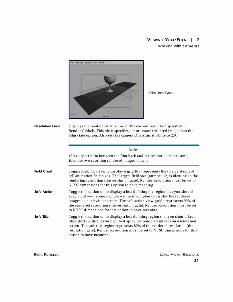
VIEWING YOUR SCENE | 2Working with cameras
BASIC FEATURES USING MAYA: ESSENTIALS
39
Resolution Gate Displays the renderable frustum for the current resolution specified inRender Globals. This often specifies a more exact rendered image than theFilm Gate option. Also sets the camera Overscan attribute to 2.0.
Field Chart Toggle Field Chart on to display a grid that represents the twelve standardcell animation field sizes. The largest field size (number 12) is identical to therendering resolution (the resolution gate). Render Resolution must be set toNTSC dimensions for this option to have meaning.
Safe Action Toggle this option on to display a box defining the region that you shouldkeep all of your scene’s action within if you plan to display the renderedimages on a television screen. The safe action view guide represents 90% ofthe rendered resolution (the resolution gate). Render Resolution must be setto NTSC dimensions for this option to have meaning.
Safe Title Toggle this option on to display a box defining region that you should keeptitles (text) within if you plan to display the rendered images on a televisionscreen. The safe title region represents 80% of the rendered resolution (theresolution gate). Render Resolution must be set to NTSC dimensions for thisoption to have meaning.
Note
If the aspect ratio between the film back and the resolution is the same,then the two resulting rendered images match.
Film Back Gate

USING MAYA: ESSENTIALS PART 1
40
VIEWING YOUR SCENE | 2Setting a perspective view
Fill Automatically selects a horizontal or vertical fit so that the selected imagefills the render frame.
Horizontal Selects a horizontal fit for the selected image in the render frame.
Vertical Selects a vertical fit for the selected image in the render frame.
Overscan Selects a slightly larger fit for the selected image in the render frame.
SETTING A PERSPECTIVE VIEW
Each workspace view is linked to a camera that “looks” at your scene. Thecamera’s position, orientation, and attributes determine what you seethrough that particular camera. This is a perspective view. Unlike anorthographic view, a perspective view shows depth.
You can switch to a perspective view and you can create new perspectiveviews.
To switch to a perspective view:
Select Panels > Perspective and select the appropriate camera view.
Creating new perspective viewsWhen building an object or scene, it is often useful to view the object fromseveral different perspectives. Use the Panels > Perspective > New option tocreate a new perspective camera.
To create a new perspective camera view:
1 Change the view of the object.
For example, if you want to tumble the display, press the Alt key and use theleft mouse button to drag the view.
2 Select Panels > Perspective > New. Maya creates a new camera in the defaulthome perspective position.
• To view through the original perspective camera, select View > PreviousView or View > Default Home.
• To view through the new perspective camera, select Panels > Perspective.and select the new perspective view.

VIEWING YOUR SCENE | 2Setting an orthographic view
BASIC FEATURES USING MAYA: ESSENTIALS
41
SETTING AN ORTHOGRAPHIC VIEW
An orthographic camera shows the 3D workspace from the top, front, andside views. These views offer the most analytical view of the world space.However, they do not show depth.
You can switch to an orthographic view and you can create neworthographic views.
To switch to an orthographic view:
Select Panels > Orthographic and select front, side, or top as the activecamera view.
Creating new orthographic viewsWhen building an object or scene, it is often useful to view the object fromthe top, front, or sides. Use the Panels > Orthographic > New option tocreate a new orthographic camera view. For example, you may want azoomed in top view.
To create a new orthographic view:
1 Select Panels > Orthographic > New and select a new view: Front, Side, orTop. Maya creates the view.
2 Select Panels > Orthographic. The view you just created appears in theOrthographic menu.
Name of the new perspective view

USING MAYA: ESSENTIALS PART 1
42
VIEWING YOUR SCENE | 2Lighting your scene
LIGHTING YOUR SCENE
Use commands on the Lighting menu to select which lights or groups oflights to use in your scene. These options include:
Use Default Lighting
Lights the scene using only a single point light situated at the camera.
Use All Lights Uses all lights in the scene, to a maximum of eight lights. This option givesyou a representation of what the lights will look like when the image isrendered.
Use Selected Lights Uses only selected lights. If you change the light selection, the lighting alsochanges respectively.
Use Previously Specified Lights
Select this option to use the lights selected with the Specify Selected Lightsoption. This option is grayed until you choose Specify Selected Lights. If youselect a different set of lights when this option is selected, the scene will stilluse the previously selected lights.
Note
This option does not include the default light.
If there are no lights in the scene, the scene renders as an all black image.
New orthographic view

VIEWING YOUR SCENE | 2Arranging views
BASIC FEATURES USING MAYA: ESSENTIALS
43
Two Sided Lighting Toggle this option on to illuminate both sides of an object. Note that Maya’sperformance may decrease on some systems.
Specify Selected Lights
Lets you use a preset selection of lights. Select the lights you want to usethen select Specify Selected Lights. Once specified, toggle on Lighting > UsePreviously Specified Lights to use this light selection. Unlike Use SelectedLights, if you change the light selection, the scene will still use thepreviously selected lights.
ARRANGING VIEWS
Use the Panels menu to change a camera view or to view a scene or objectthrough a selected camera.
Perspective Lets you change to a perspective view or create a new perspective view. Fordetails, see “Creating new perspective views” on page 40.
Orthographic Lets you change to an orthographic view or create a new orthographic view.For details, see “Creating new orthographic views” on page 41.
Look Through Selected
Lets you look through a selected camera, object, or light. For details, see“Looking through a camera” on page 37.
Note
This menu item can be turned off by picking any of the items above it.

USING MAYA: ESSENTIALS PART 1
44
VIEWING YOUR SCENE | 2Arranging views
Panel Displays a menu with the following commands.
Outliner – Opens the Outliner, where you can view objects and theirattributes hierarchically. For more information, see “Using the Outliner” onpage 297.
Graph Editor and Dope Sheet – Opens the Graph Editor and Dope Sheet,respectively, where you can edit keys, motion tangents, and animationcurves. For more information, see Using Maya: Animation.
Hypergraph – Opens the Hypergraph, which gives you an overview of yourentire scene, all objects it contains, and the relationships between thoseobjects. For more information, see “Using the Hypergraph” on page 319.
Hypershade – Opens the Hypershade, which you can use to create and editrendering nodes, and to view and edit rendering (or shading) networks. Formore information, see Using Maya: Rendering.
Visor – Opens the Visor, which you can use to show images of shadingnodes you can create, those already in your scene, and those in onlinelibraries, in a visual outline form. For more information, see Using Maya:Rendering.
Texture View – Opens the Texture View window, which you use to maptextures to a polygonal model. For more information, see Using Maya:Polygonal Modeling.
Multilister – Opens the Multilister. For more information, see Using Maya:Rendering.
Render View – Opens the Render View window, where you can test rendersingle frames and interactively tune rendering attributes. For moreinformation, see Using Maya: Rendering.
Blend Shape – Lets you create character deformations. For more information,see Using Maya: Character Setup.
Dynamic Relationships – Lets you view or edit connections betweendynamics elements such as particle emitters, collisions, etc. For moreinformation, see Using Maya: Dynamics.
Devices – Lets you use external tools and plug-ins for special devices, suchas Motion Capture.

VIEWING YOUR SCENE | 2Arranging views
BASIC FEATURES USING MAYA: ESSENTIALS
45
Relationship Editor – Opens the Relationship Editor, which you can use togroup and manipulate objects as sets and assign shading groups togeometry. For more information, see “Using the Relationship Editor” onpage 255.
Reference Editor – Opens the Reference Editor, which you can use to specifysettings for importing files by reference. For more information, see “Usingthe Reference Editor” on page 192.
Layouts Lets you specify how different camera views are arranged spatially in theMaya window.
Saved Layouts Lets you select a panel layout. For more information, see “Selecting panellayouts” on page 539.
Tear Off Moves the current camera view into a separate window. The current view isreplaced with the next view in the Panels list (to see this list, selectPanels > Panel Editor).
Tear Off Copy Copies the current camera view into a separate window.
Panel Editor Opens the Panel window, where you can create new panels, re-label existingpanels, rename layouts, and change layout configurations. For moreinformation, see “Using the Panel Editor” on page 533.
Displaying the workspace onlySelect the following options on the Display > UI Elements submenu toquickly display only the workspace.
Hide UI Elements • Temporarily hides all UI elements except the workspace panels. Forexample, you can maximize the scene view while working on detailedmodels.
Restore UI Elements •Displays the UI elements that were hidden.
Laying out the viewsBecause much of your 3D work takes place in a modeling view window, youwant to be able to view an object from the top, front, side, and inperspective. In 3D, it is sometimes difficult to see exactly where an objectlies. The four views enable you to confirm the positioning of objects frommore than one camera angle.

USING MAYA: ESSENTIALS PART 1
46
VIEWING YOUR SCENE | 2Arranging views
Use the Window > View Arrangement option to control how Maya displaysthe four basic views. The top, front, and side views are 2D orthographicviews that allow you to view your work analytically. The fourth view isperspective and allows you to view the scene in 3D. You can also access thesame view arrangement settings from the Panels > Layouts option.
You can place any tool in a view. For more information, see “Creatinglayouts” on page 540.
In the following example, the display is changed to a 3 Left Split layout.
To set the views:
Select Panels > Layouts or select Window > View Arrangement and selectthe view layout you want.
For example, if you select 3 Left Split Layout, you get the following viewlayout.

VIEWING YOUR SCENE | 2Marking a view
BASIC FEATURES USING MAYA: ESSENTIALS
47
MARKING A VIEW
You can use bookmarks to mark a view for future use. This lets you maintaina variety of camera views for any scene. Maya has four predefinedbookmarks: Perspective, Front, Top, and Side. You can change your view toany of these predefined bookmarks, or you can create your own bookmarks.
Changing the view to a predefined bookmark:
Select View > Predefined Bookmarks and select the default view you want tochange to.
Creating a bookmarkYou can create your own custom bookmarks to mark views other thanPerspective, Front, Top, and Side.
To create a new bookmark:
1 Select an object and change the view.
2 Select View > Bookmarks > Edit Bookmarks. The Bookmark Editor opens.
Notes
If you want one view to occupy the entire Maya window, select the view,then press the space bar quickly. (If you press the space bar for too long,Maya displays the HotBox.)
To rename and delete a camera, use the Outliner. See “Using the Outliner”on page 297.
Note
You cannot change positions for the predefined bookmarks.

USING MAYA: ESSENTIALS PART 1
48
VIEWING YOUR SCENE | 2Marking a view
3 In the Name box, type the new bookmark name press Enter.
4 Type a description of the view in the Description box.
5 Close the Bookmark Editor.
To delete a bookmark:
1 Select View > Bookmarks > Edit Bookmarks. The Bookmark Editor opens.
2 Select the bookmark you want to delete and click the Delete button.
Selecting custom bookmarksIf you have created custom view bookmarks, you can select them as follows.
To view custom bookmarks:
Select View > Bookmarks and select the bookmark you want to view theobject through.
Tip
To create a bookmark with a system-assigned name, selectView > Bookmarks > Edit Bookmarks and click New Bookmark.
Maya assigns the view to the first bookmark under the name cameraView1.
Type new bookmarkname here

VIEWING YOUR SCENE | 2Enabling and disabling nodes
BASIC FEATURES USING MAYA: ESSENTIALS
49
Renaming a bookmarkYou can rename custom bookmarks at any time.
To rename a bookmark:
1 Select View > Bookmarks > Edit Bookmarks. The Bookmark Editor opens.
2 Select the bookmark you want to change.
3 In the Name box, change the bookmark name then press Enter. The modifiedbookmark appears in the Bookmarks menu.
Adding a bookmark to a shelfYou can add any bookmark to a shelf for easy access.
To add a bookmark to a shelf:
1 Select the shelf you want to add the bookmark to.
2 Select View > Bookmarks > Edit Bookmarks. The Bookmark Editor opens.
3 Select the bookmark you want to add to the shelf and click the Add To Shelfbutton. The bookmark is added to the shelf. It appears as a MEL command.
ENABLING AND DISABLING NODES
You can disable animation nodes in your scene to improve playback speedwhile you view animations.
For example, suppose you create a scene that includes a keyframed bouncingball in addition to several particle emitters. Because particle emissionrequires much processing time, your animation playback may be slow. Youcan disable particle nodes to temporarily disable the emitted particles. Thismakes the animation of the bouncing ball play faster, so the ball’s motionmore closely resembles the final rendered motion.
To enable or disable nodes, select Modify > Enable Nodes or Disable Nodes.You can enable or disable the following nodes:
IK solvers See Using Maya: Character Setup for more information on inverse kinematictools.
Constraints See Using Maya: Character Setup for more information on basic constraints.

USING MAYA: ESSENTIALS PART 1
50
VIEWING YOUR SCENE | 2Enabling and disabling nodes
Expressions See Using Maya: Expressions for more information.
Particles See Using Maya: Dynamics for more information.
Rigid Bodies See Using Maya: Dynamics for more information.
Snapshots See Using Maya: NURBS Modeling for more information on AnimationSnapshots.
USING MAYA: ESSENTIALS
51
3 EDITING OBJECTS
Use the Edit menu to delete, select, instance copy, group, and parent objects.This chapter describes how you edit objects in Maya. It also describesMaya’s undo, redo, and repeat functions.
It describes the following topics:
• “Selecting objects” on page 51
• “Deleting objects” on page 55
• “Duplicating and instancing objects” on page 58
• “Working with groups” on page 63
• “Creating object hierarchies (parenting)” on page 66
• “Undoing and redoing actions” on page 68
• “Editing object attributes” on page 69
The following Edit menu options are not described in this chapter:
Keys – Displays the available keys. For more information, see Using Maya:Animation.
Sets – A set is a collection of related objects or components. Examples ofitems that can be in a set include geometric objects, NURBS, CVs, polygonalvertices, skin points, cluster points, and polygonal faces. For moreinformation, see “Sets and Partitions” on page 367.
SELECTING OBJECTS
There are several ways to select objects in Maya. You can:
• select objects individually
• select all objects in the scene
• select objects of a specified type

USING MAYA: ESSENTIALS PART 1
52
EDITING OBJECTS | 3Selecting objects
• select objects of a specified name
• select all objects in a set
• select all objects in a display layer
When you select objects, they become highlighted. Note that you can changethe highlight color. For details, see “Changing default colors” on page 482.
Selecting objects individuallyYou can select objects individually from the scene, the Outliner, theHypergraph, and the Relationship Editor.
To select an object:
• Click on the object, or click-drag a box around it.
or
• In the Outliner or Hypergraph, click on the object name. For informationabout the Outliner, see “Using the Outliner” on page 297. For informationabout the Hypergraph, see “Using the Hypergraph” on page 319.
or
• In the Relationship Editor, highlight the object and on the Edit menu, clickSelect Highlighted. For more information about the Relationship Editor, see“Using the Relationship Editor” on page 255.
To select more than one object individually:
Shift-click on each object.
Selecting all objects in a sceneUse Select All on the Edit menu to select root objects and all visibledependency nodes in a scene. You can then treat them as a virtual groupwithout actually having grouped them.
Note
To select several objects individually, Shift-click on each object. The lastselected object is highlighted with a different color than the other objects(default, green).

EDITING OBJECTS | 3Selecting objects
BASIC FEATURES USING MAYA: ESSENTIALS
53
To select all displayed objects:
Select Edit > Select All. Maya selects all objects.
When you select a transformation tool, the manipulator for that tool displayson the last selected object (the one highlighted in a different color, default,green). When you transform the selection, the selected objects move as agroup.
To deselect all objects, click anywhere on the view.
Selecting objects by typeUse Select All By Type to select all objects of a specific type. In the followingexample, we select all joints associated with the giraffe.
To select all objects by type:
1 Select the object.

USING MAYA: ESSENTIALS PART 1
54
EDITING OBJECTS | 3Selecting objects
2 Select Edit > Select All by Type > Joints. Maya selects the joints on the object.

EDITING OBJECTS | 3Deleting objects
BASIC FEATURES USING MAYA: ESSENTIALS
55
Selecting objects by nameYou can select objects and nodes by typing their name or a portion of thename. In the Numeric input field on the Status Line, choose Quick Selectionfrom the pulldown menu and type the name. Using wildcard characters(* and ?), you can select several items with the same string in their names.
Selecting all objects in a setEdit > Quick Select Set is a fast way to select all objects in a particular setwithout having to open the Relationship Editor.
To place an item into a quick selection set, select it, then select Edit > Sets >Create Quick Select Set. You can place items such as dependency graphnodes, CVs, or lattice points, in a set. Once you name and create the set, youcan select it with Edit > Quick Select Set > setName.
Selecting all objects in a display layerTo select all objects in a display layer, on the layer bar, click the ▼ Layermenu button to the left of the layer and select Select All in Layer. Forinformation about layers, see “Using display layers” on page 139.
DELETING OBJECTS
Use the Delete, Delete by Type, and Delete All by Type options on the Editmenu to:
• delete single objects
• delete object components by type
• delete all objects by type
Numeric Input fieldon Status Line
ChooseQuick Selection

USING MAYA: ESSENTIALS PART 1
56
EDITING OBJECTS | 3Deleting objects
Deleting a single objectUse Edit > Delete to delete a selected object or component.
In the following example, we delete a cylinder from the scene.
To delete an object:
1 Select the object(s) you want to delete.
To delete more than one object or component, Shift-click each object youwant to delete, or click-drag a box around the object(s).
2 Select Edit > Delete. Maya removes the object and the associated ChannelBox or Attribute Editor from the display.
Deleting object components by typeDelete by Type lets you delete objects of a particular type or characteristic(for example, channels). If many objects are selected and you select Delete byType > Channels, only the Channels attached to the selected objects aredeleted. Similarly, if you select Delete by Type > History, any history nodesattached to the selected objects are deleted.
You can delete the following component types:
• History
• Channels (channels that describe how the object’s animation parameterchanges values over time)
• Static Channels (channels that are not animated)
• Motion Paths
• Expressions
• Constraints
• Sounds
• Rigid Bodies
Tip
You can also delete selected objects with the Backspace or Delete keys onthe keyboard.

EDITING OBJECTS | 3Deleting objects
BASIC FEATURES USING MAYA: ESSENTIALS
57
To delete an object’s components:
1 Select the object with the component you want to delete.
2 Select Edit > Delete by Type > componentType.
For Channels, Static Channels and Expressions, the components are deletedaccording to the selected delete channel options.
To specify delete options:
1 Select Edit > Delete by Type > Channels ❐, Static Channels ❐, orExpressions ❐. The Delete Options window opens.
2 Set the following options and click Save.
Hierarchy To delete the component from the selected object only, choose Selected. Todelete the component from the selected object and all objects below it in theDAG hierarchy, choose Below.
Channels To delete all channels attached to all the selected object’s keyable attributes,select All Keyable. To delete channels attached to those attributes selected inthe Channel Box, select From Channel Box.
Driven Channels Toggle this option on to delete driven channels attached to the selectedobject’s set driven key attributes.
Control Points Toggle this option on to delete channels attached to lattice, polygon, andNURBS curves and surface CVs. If you select All Keyable, this isautomatically toggled on. The default is off.
Shapes Removes the object's geometry channels. If you select All Keyable, this isautomatically toggled on. The default is off.
Deleting all objects by typeUse Delete All Objects by Type to delete all occurrences of a type of object orcomponent in the scene (for example, joints).
To delete all objects by type:
Select Edit > Delete All By Type > type. This deletes all of the selected type ofcomponents or objects in the scene.
To undelete the component, select Edit > Undo.

USING MAYA: ESSENTIALS PART 1
58
EDITING OBJECTS | 3Duplicating and instancing objects
DUPLICATING AND INSTANCING OBJECTS
There are two ways to copy objects:
• With the Duplicate option—Maya actually copies the geometry or lights in ascene.
• With instances—Maya just redisplays the geometry being instanced. Copiesof the selected geometry are not created. Since instances are not actual copiesof the original geometry, they take up less system memory than actualcopies.
Duplicating objectsUse the Duplicate command to create copies of geometry or lights in a scene.You can duplicate more than one object at a time. You can duplicate objectsas many times as you like. This means that you do not have to build a newobject every time you need a copy.
To duplicate an object:
1 Select the object you want to duplicate.
If you want to duplicate more than one object, click-drag a box around theobjects or Shift-select the desired object.
2 Select Edit > Duplicate. Maya positions the copy of the object behind theoriginal object. You cannot see it until you move it.
3 To move the duplicate object from behind the original, select the Move toolfrom the Minibar. The object displays four manipulators.
4 Drag the object to move it from behind the original object. Maya deselectsthe original object.
Note
To create more than one copy of the object at the same time, selectDuplicate ❐. For more information, see “Setting duplicating options” onpage 59.

EDITING OBJECTS | 3Duplicating and instancing objects
BASIC FEATURES USING MAYA: ESSENTIALS
59
If you specified more than one copy (see “Setting duplicating options” onpage 59), click on the original with the Move tool and drag the manipulators.Repeat until all copies appear in the view.
Setting duplicating optionsUse the Duplicate Options window to position, scale, and rotate objects asyou make copies. You can also specify how may copies are made.
Setting a duplicate option:
1 Select Edit > Duplicate ❐. The Duplicate Options window opens.
2 Set the following options and click Save.
Translate, Rotate, Scale
Specify the offset values for X, Y, and Z. Maya applies these values to thecopied geometry. You can position, scale, or rotate objects as Mayaduplicates them.
Number of Copies Specify the number of copies to create. The range is from 1 to 1000.
Geometry Type Select how you want the selected object(s) duplicated.
Copy – Make a copy of the geometry being duplicated.
Instance – Create an instance of the geometry being duplicated. When youcreate an instance, you do not create actual copies of the selected geometry.Instead, Maya redisplays the geometry being instanced. For moreinformation, see “Creating instances of objects” on page 60.
Group Toggle Group on to put the duplicates under a new group node.
Note
The default for Translate and Rotate is 0.0000. The default for Scale is1.0000. With the default values, Maya places the copy on top of the originalgeometry. You can specify offset values (positive or negative floatingpoint) for translation, rotation, and scaling that are then applied to thecopied geometry.

USING MAYA: ESSENTIALS PART 1
60
EDITING OBJECTS | 3Duplicating and instancing objects
Smart Transform Toggle Smart Transform on so that when you duplicate and transform asingle copy or instance of the object (without changing the selection), Mayaapplies the same transformations to all subsequent duplicates of the selectedduplicate.
Duplicate Upstream Graph
Toggle this option on to force the duplication of all upstream nodes leadingup to the selected object. Upstream nodes are defined as all nodes withconnections feeding into selected nodes.
For example, if A, B, and C are the upstream nodes connecting to D...
A > B > C > D
...and you select D and use the Duplicate Upstream Graph option, theresultant graph will be as follows:
A1 > B1 > C1 > D1
(where A1, B1, C1, and D1 are duplicates of A, B, C, and D respectively).
Duplicate Input Connections
Toggle this option on so that in addition to duplicating the selected node, theconnections feeding into the selected node are also duplicated.
For example, if A, B, and C are connections feeding into C...
A > B > C
...and you select C and use the Duplicate Input Connections option, then theresultant graph will be as follows:
A > B > C and
A > B > C1
(where C1 is a duplicate of C).
Creating instances of objectsWhen you create an instance, you do not create actual copies of the selectedgeometry. Maya redisplays the geometry being instanced on the screen.
An instance is always identical to the original geometry, although eachobject can have a unique translation, scaling, and rotation factor applied to it.Therefore, individual instances can be picked as objects independent of oneanother.

EDITING OBJECTS | 3Duplicating and instancing objects
BASIC FEATURES USING MAYA: ESSENTIALS
61
You can create several instanced copies of the original object, rather than justcopying it. If you then make a change to the original object, all instancedcopies automatically reflect the same change.
Since instances are not actual copies of the original geometry, they take upless system memory than actual copies. In large or complex model scenes,instancing can speed up refresh time, reduce the size of data files, andimprove rendering times.
Limitations
There are a few limitations when using instancing:
• Instanced lights have no effect.
• Instances share the same shader as the original geometry and cannot beassigned independent shaders.
• Some functions, such as extrude and insert, cannot be used on instanceditems. In these cases, you must make a true copy of the instanced geometrythat you want to manipulate, then continue with the function.
• You can only apply clusters and deformation frames to the originalgeometry—you cannot assign them independently to instances. To useclusters and deformations on copies, you must make a true copy of thegeometry.
• There is always at least one non-instanced transformation node between theinstance nodes and the actual geometry nodes.
• When you create an instance of an already instanced node, Maya does notcreate a new level.
Note
If you move a CV on the original geometry, it affects the shape of allinstances of that object.
Instanced geometry does not display CVs or hull structure. The form of aninstance can only be altered from the original geometry.

USING MAYA: ESSENTIALS PART 1
62
EDITING OBJECTS | 3Duplicating and instancing objects
DAG nodes and instancing
When Maya creates an instance, the software also creates an extra DAG nodelevel. The top DAG node is the transformation node and the lower DAGlevel is the geometry node.
When Instance is toggled on in the Duplicate Options window, Maya createsan extra DAG node level to be created.
Instanced coneparented to sphere
EDITING OBJECTS | 3Working with groups
BASIC FEATURES USING MAYA: ESSENTIALS
63
WORKING WITH GROUPS
Grouping makes it easier for you to apply an action to multiple objects. Usethe Group, Ungroup, and Create Empty Group options on the Edit menu to:
• group objects
• ungroup objects
• create empty groups (groups with null objects)
Grouping objectsGrouping lets you group a number of objects into a more complex object sothat transformations can be applied to all of them at once—in effect, treatingmany objects as a single object for transformation purposes.
To group objects together:
1 Select the objects you want to group together.
2 Select Edit > Group. The objects are now part of a group, according to thedefined grouping options.
Setting grouping optionsUse the Group Options window to specify options for grouping objects. Youcan specify how the objects, as well as their pivot points, are grouped.
Setting groupings option:
1 Select Edit > Group ❐. The Group Options window opens.
2 Set the following options and click Save.
Group Under Group objects under one of the following:
Parent – Groups the selected objects under their lowest common parent inthe hierarchy. For example, selecting a single object and grouping puts thegroup node immediately above the selected object in the hierarchy.
Selecting objects that are in different hierarchies puts the group under theworld since they don’t share a common parent.

USING MAYA: ESSENTIALS PART 1
64
EDITING OBJECTS | 3Working with groups
Selecting objects in different parts of the same hierarchy puts the objectsunder their lowest common parent. If you go from each selected object, thenew group will be placed under the first node containing all the selectedobjects.
World – Puts the new group under the world (at the top level of thehierarchy).
Group Pivot Select where you want the pivot point for the group to be.
Center – Puts the new group’s pivot point at the center of the bounding boxof the grouped objects.
Origin – Puts the new group’s pivot point at the origin of the new group’scoordinate system.
Preserve Position Toggle this option on to modify the selected object’s matrix so that Mayapreserves the overall world-space position of the object. If toggled off, thematrix of grouped objects are changed and the object’s world-space positionchanges when grouped.
Ungrouping objectsUngroup lets you separate parts of a group and remove nodes from ahierarchy. You can then work with each object on an individual basis.
To ungroup objects:
1 Select a group.
Tip
If your scene is comprised of many groups, use the Hypergraph to helpyou select a group. See “Using the Hypergraph” on page 319.
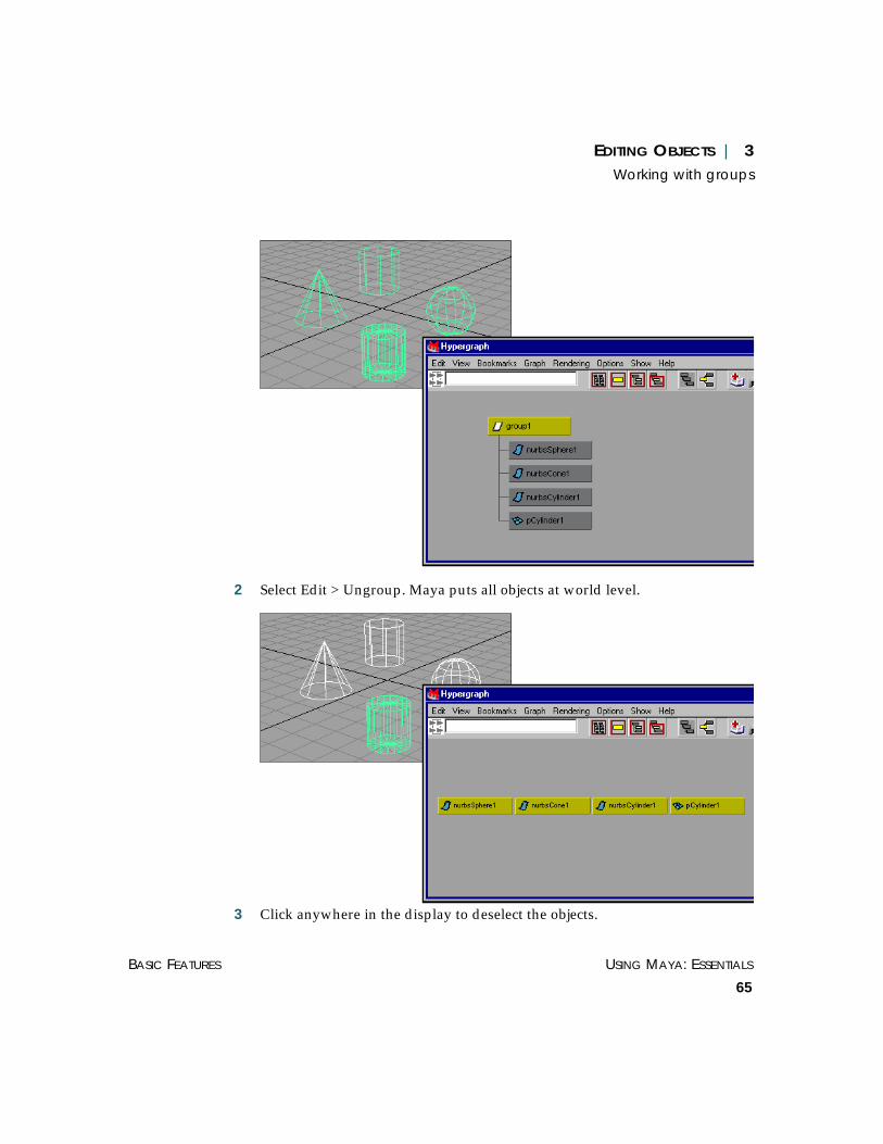
EDITING OBJECTS | 3Working with groups
BASIC FEATURES USING MAYA: ESSENTIALS
65
2 Select Edit > Ungroup. Maya puts all objects at world level.
3 Click anywhere in the display to deselect the objects.

USING MAYA: ESSENTIALS PART 1
66
EDITING OBJECTS | 3Creating object hierarchies (parenting)
Creating an empty groupSelect Edit > Create Empty Group to create a new group (transform node)without children. These empty or null objects are useful because they can beused to control other objects through expressions. Moving the unrendered,empty object triggers expressions that move other parts of the model. Inother words, they can act as constraint nodes.
CREATING OBJECT HIERARCHIES (PARENTING)You use parenting to establish a hierarchy in your scenes. The Edit menuprovides these parenting options:
Parent Moves objects from one hierarchy to another and creates instances.
Unparent Returns a parented hierarchy to its original state.
Use Parent to move objects between hierarchies and create instances.
Parenting objectsWhen you parent an object, you make it part of a hierarchy.
To create a parent:
1 Select the objects you want to make up the parent/child relationship. Selectthe children first, and the parent last.
2 Select Edit > Parent ❐. The Parent Options window opens.
3 Set the following options and click Parent.
Tip
You can also create an empty group by selecting Edit > Group with noobjects selected.
Note
In the Outliner and Hypergraph, you can drag and drop one object on topof another to parent it.

EDITING OBJECTS | 3Creating object hierarchies (parenting)
BASIC FEATURES USING MAYA: ESSENTIALS
67
Parent Method Select what you want done with the selected object:
Move Objects – Move the object from its current parent to the new parent(the last selected object).
Add Instance – Create an instance under the new group instead of movingthe object.
Preserve Position Toggle Preserve Position on to preserve the overall world-space position bychanging the parented objects’ transformation matrix.
Unparenting objectsWhen unparenting an object from a group, you can remove it from thehierarchy and put it into world space. If it is an instance, you can delete italtogether.
To unparent an object:
1 Select the child object.
2 Select Edit > Unparent ❐. The Unparent Options window opens.
3 Set the following options and click Unparent.
Unparent Method Select how you want to unparent the selected object:
Parent to World – Remove the object from its current parent and place itunder the world.
Remove Instance – Remove a particular instance instead of moving theobject.
Preserve Position Toggle Preserve Position on to preserve overall world-space position bymodifying the parented objects’ transformation matrix.
Note
If two objects are selected, the first object goes under the one selected last.

USING MAYA: ESSENTIALS PART 1
68
EDITING OBJECTS | 3Undoing and redoing actions
UNDOING AND REDOING ACTIONS
You can undo the last action you performed and redo if you change yourmind. You can also repeat your last actions.
Undoing your last actionUndo reverses the last action you performed on a selected object. It alsoreverses any action you performed from the Edit menu.
For example, you can transform an object to a new position, then return it toits original position using the Undo command.
To reverse an action:
Select Edit > Undo.
Redoing and repeating actionsSelect Edit > Redo to perform the last action that you reversed. For example,if you delete an object and then use Undo to display it, Redo deletes theobject again.
Select Edit > Repeat to echo the last menu item you selected. You can onlyrepeat selections from menus on the main Maya menu bar. You cannotrepeat selections from the shelf, channel box, or any of the secondarywindow menus.
Note
To set how many levels of Undo you want, select Window >Settings/Preferences > Preferences, Undo category, and set the Queue Size.Note that a large Queue Size slow Maya’s performance.

EDITING OBJECTS | 3Editing object attributes
BASIC FEATURES USING MAYA: ESSENTIALS
69
EDITING OBJECT ATTRIBUTES
An attribute is a characteristic of an object in a scene. There are many waysto set attributes in Maya—with the Attribute Editor, Channel Box, AttributeSpreadsheet, menu selections, and expressions. You can set attributes tocontrol virtually anything in your models and animation. For information onediting attributes, see:
• “Using the Attribute Editor” on page 262
• “Using the Channel Box” on page 280
• “Using the Attribute Spread Sheet” on page 241
• Using Maya: Expressions
• “Painting attribute values” on page 454

USING MAYA: ESSENTIALS PART 1
70
EDITING OBJECTS | 3Editing object attributes

USING MAYA: ESSENTIALS
71
4 TRANSFORMING OBJECTS
After you build your curves, surfaces, and objects, you are ready to positionthem in 3D space. This chapter describes how you scale, rotate, and moveyour objects.
It includes information on these topics:
• “Selecting transformation tools” on page 72
• “Using manipulators” on page 72
• “Using axes and pivot points” on page 73
• “Moving objects” on page 79
• “Rotating objects” on page 85
• “Scaling objects” on page 89
• “Using the Show Manipulator tool” on page 91
• “Entering numeric values” on page 95
• “Combining transformations” on page 97
• “Using proportional modification” on page 99
• “Creating locators” on page 105
• “Using Measure tools” on page 107

USING MAYA: ESSENTIALS PART 1
72
TRANSFORMING OBJECTS | 4Selecting transformation tools
SELECTING TRANSFORMATION TOOLS
The Minibar provides five basic tools: Select, Move, Rotate, Scale, and ShowManipulator. The last tool you used occupies the last position in the row.
The q, w, e, r, t, and y hotkeys correspond to the Minibar icons, as shownabove.
When you press the w key and drag with the left mouse button, a markingmenu appears for the Move manipulator. Similarly, you can display markingmenus for using the e key (for Rotate) and r key (for Scale). The markingmenu options are another way to select manipulator handles.
USING MANIPULATORS
Manipulators provide a visual and interactive way to change an object’sparameters. You use manipulators to directly position and scale objects inthe workspace.
Many tools have manipulators. Usually, a tool creates a manipulator whenyou open the tool and deletes the manipulator when you exit it. (However,there are some exceptions to this.)
When you use a manipulator to change parameter values, the Help Linedisplays the values as they change.
You can also change parameter values by entering them in the NumericInput field (at the top right of the window). For details, see “Enteringnumeric values” on page 95.
Show ManipulatorsScaleRotate
Move
Select space for the active orlast tool used
Equivalent keysq w e r t y

TRANSFORMING OBJECTS | 4Using axes and pivot points
BASIC FEATURES USING MAYA: ESSENTIALS
73
About manipulator handlesEach manipulator has several handles. You move these handles to changeparameters. For example, the Move manipulator has a center handle, plushandles you use to move it in X, Y, and Z.
If you want, you can make these handles larger or smaller using themanipulator display preferences in Window > Settings/Preferences >Preferences. For the transform manipulators, you can also use the + and -keys on the keyboard to change handle size.
The active (current) handleWhen you click-drag a manipulator handle, it becomes active. This meansyou can now use the middle mouse button to move the handle withouthaving to reselect it. If you click away from the handle and drag, it stillmoves the manipulator. The default color of the active handle is yellow.
You can keyframe the attribute that corresponds to this active handle bysetting keys on the current manipulator handle (Animation menu set,Animate > Set Key ❐). For more information, see Using Maya: Animation.
USING AXES AND PIVOT POINTS
There are various ways you can define where your objects are transformedfrom. You use the location of the pivot point or axes to transform in aspecific direction from a specific point in local or world space.
Y handle
Center handle
X handleZ handle

USING MAYA: ESSENTIALS PART 1
74
TRANSFORMING OBJECTS | 4Using axes and pivot points
What are pivot points?Objects are transformed based on a specific point in 3D space known as apivot. When you rotate a primitive, for example, the pivot point representsthe center of the rotation axis; when you scale, the pivot point represents thefixed point around which scaling occurs.
By default, the pivot point is set so that the rotational and scale pivots arelocated at the point of origin for an object (0, 0, 0). The point of origin is thecenter of the object. You can change an object's pivot and you can also pin itto a fixed location.
To quickly display an object’s pivot point:
1 Select the object, then select the transformation tool.
2 Press the Insert key on the keyboard to toggle to and from an edit mode. Editmode displays a manipulator for moving the pivot.
To display an object’s pivot point using the Attribute Editor:
1 Select the object.
2 Open the Attribute Editor (Window > Attribute Editor) and click the object’stransform tab.
3 Expand Pivots, and toggle on Display Rotate Pivot or Display Scale Pivot.
Manipulator for moving pivot

TRANSFORMING OBJECTS | 4Using axes and pivot points
BASIC FEATURES USING MAYA: ESSENTIALS
75
Moving pivot pointsYou can move the pivot point to set the point you want to move, scale, orrotate the object from. Use the Insert key on the keyboard to display thepivot point, then use any of the transformation tools. In the followingexample the Rotate transformation tool is selected.
To move pivot points:
1 Select an object active, select a transformation tool, then press the Insert key.The manipulator appears.
2 Drag the manipulator to move the pivot point.

USING MAYA: ESSENTIALS PART 1
76
TRANSFORMING OBJECTS | 4Using axes and pivot points
3 Press the Insert key again to display the rotate manipulator, drag to rotatethe object.
To move the pivot point using the Attribute Editor:
1 Select the object, open the Attribute Editor and in the Pivots section, toggleDisplay Rotate Pivot or Display Scale Pivot on, depending on which pivotyou want to move.
2 In the Local or World Space sections, enter X, Y and Z values for RotatePivot or Scale Pivot and press Enter. In the following example, the rotatepivot is moved 5.0 units in the Z direction in absolute local space. You cannow rotate the object from that pivot point location.

TRANSFORMING OBJECTS | 4Using axes and pivot points
BASIC FEATURES USING MAYA: ESSENTIALS
77
Pinning component pivot pointsMaya creates a temporary pivot point for object components you select whilein Component selection mode. The pivot point is centered with respect to theselected components. If you select additional components after moving atemporary pivot, the pivot automatically moves back to the original position.To prevent it from moving, you can “pin” the temporary pivot to a locationyou define in edit mode.
To pin a pivot point:
1 In component selection mode, select the components.
2 Press the Insert key to enter edit mode.
3 Drag the pivot point to move it to a new location.
4 Still in edit mode, click the pivot target. The pivot locks to the currentposition.
Rotate pivot pointmoved 5.0 in Z
Unpinnedpivot point
Pinnedpivot point

USING MAYA: ESSENTIALS PART 1
78
TRANSFORMING OBJECTS | 4Using axes and pivot points
What is an axis?An axis is a straight line that indicates the origin and direction. For example,by using two axes, a plane is defined: the XY plane is defined by placing Xand Y axes so they intersect at the origin. Three dimensions are defined byusing three axes: X, Y, and Z.
Displaying the axis indicatorsThere are two types of axes: the global axes, and the local axes.
The global axes display in the view. You can display the global axes at theorigin in the perspective view (Display > Heads Up Display > Origin Axis)and you can display the global axes at the bottom left of each view(Display > Axes > View Axis).
The local axes displays at the origin of the active object in all views. Todisplay the local axis, open the Attribute Editor. Click the transform tab forthe object, and in the Display section, toggle on Display Local Axis.
Note
The component pivot remains pinned in its position until you return toedit mode (using the Insert key) and unpin it.
To “unpin” (or unlock) a pivot and return it to default auto-centeringmode, click the pinned pivot manipulator.
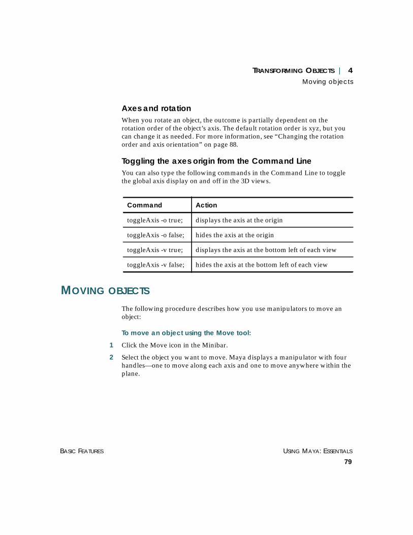
TRANSFORMING OBJECTS | 4Moving objects
BASIC FEATURES USING MAYA: ESSENTIALS
79
Axes and rotationWhen you rotate an object, the outcome is partially dependent on therotation order of the object’s axis. The default rotation order is xyz, but youcan change it as needed. For more information, see “Changing the rotationorder and axis orientation” on page 88.
Toggling the axes origin from the Command LineYou can also type the following commands in the Command Line to togglethe global axis display on and off in the 3D views.
MOVING OBJECTS
The following procedure describes how you use manipulators to move anobject:
To move an object using the Move tool:
1 Click the Move icon in the Minibar.
2 Select the object you want to move. Maya displays a manipulator with fourhandles—one to move along each axis and one to move anywhere within theplane.
Command Action
toggleAxis -o true; displays the axis at the origin
toggleAxis -o false; hides the axis at the origin
toggleAxis -v true; displays the axis at the bottom left of each view
toggleAxis -v false; hides the axis at the bottom left of each view

USING MAYA: ESSENTIALS PART 1
80
TRANSFORMING OBJECTS | 4Moving objects
3 Click-drag one of the handles, as follows. The selected handle changes colorwhen active. The default color is yellow.
• To move the object along a single axis, select and drag the handle for thataxis.
• To move the object freely along all axes, select and drag the center handle inthe middle of the manipulator.
By default, the Move manipulator moves along the plane of the view. In theperspective view, you also use it to move in the XY, YZ, or XZ planes.
• To move in the XZ plane, Ctrl-click the Y handle.
Tip
Another way to restrict movement to one axis is to press the Shift key anddrag using the middle mouse button. This is faster than clicking on themanipulator to switch between specific handles.
Tip
For all manipulators, the middle mouse button controls the activemanipulator handle.
Click-drag this handleto move in Y direction
Click-drag this handleto move in Z direction
Click-drag the center handleto move in any direction
Click-drag this handleto move in X direction

TRANSFORMING OBJECTS | 4Moving objects
BASIC FEATURES USING MAYA: ESSENTIALS
81
The “current plane” for the center handle becomes the XZ plane. The centerhandle now moves the object in the XZ plane (keeping the Y translationvalue constant).
• To move in the YZ plane, Ctrl-click the X handle
• To move in the XY plane, Ctrl-click the Z handle.
• If the current plane is the XZ plane (or YZ or XY) and you want to move inthe view plane, Ctrl-click the center handle.
When a snap mode is turned on, the manipulator center changes to a circle.This indicates that the manipulator snaps instead of moving freely in thecurrent plane.
Moving tips
Here are a few tips to help you move an object:
• The Selection Mask options window controls what types of items you canmove. For example, if CVs are toggled on and all other components aretoggled off, only CVs can be selected and moved.
• To change an object’s shape, you can move CVs independently of the objectsthey are in.
Moving the translate pivot pointWhen you transform an object, the center of the manipulator is the center ofthe current selection’s bounding box. It acts as a temporary pivot. You canmove an object’s pivot in edit mode.
To move the pivot:
1 Select the object.
2 To switch to edit mode, press the Insert key. Maya displays a Translatemanipulator that you can use to move the scale or rotation pivot.
3 Drag the manipulator to the desired area within the object.
4 Press Insert again to resume translating the object.

USING MAYA: ESSENTIALS PART 1
82
TRANSFORMING OBJECTS | 4Moving objects
Choosing a coordinate system for the Move toolUse the Tool Settings options window to specify the coordinate system forthe Move tool.
To specify an option:
1 Double-click the Move icon in the Minibar.
or
Select Modify > Transformation Tools > Move Tool ❐.
The Tool Settings window opens.
2 Select one of the following options and click Close.
Object Moves an object in object space coordinate system. Axis orientation includesrotations on the object itself. If several objects are selected, each object movesthe same amount relative to its own object space coordinate system.
Note
When you are in Component selection mode, you can “pin” the pivot pointto its new location. For information, see “Pinning component pivot points”on page 77.

TRANSFORMING OBJECTS | 4Moving objects
BASIC FEATURES USING MAYA: ESSENTIALS
83
Local Aligns the object to the rotation of the parent object. Movement isconstrained to those axes in the local space coordinate system. The object isaligned to the rotation of the parent object and does not include the rotationson the object itself. If several objects are selected, each object moves the sameamount relative to its own object space coordinate system.
World Moves in the world space coordinate system. The object is aligned to theworld space axis. This is the default.
Normal Moves selected CVs on a NURBS surface in the U or V direction of thesurface. Typically you would use this option for small sets of CVs. Themanipulator indicates the surface Normal, U, and V directions.
When you select Normal, the Update [UVN] Triad option displays. Toggledon, this option causes the manipulator orientation to reflect the movedsurface rather than the original surface. This is the default. Toggled off, themanipulator retains the orientation for the original surface.
Moving curves on surfacesCurves on surface (along with their edit points) have a special Movemanipulator. When you move a curve on surface, the manipulator constrainsthe curve on surface to the surface and allows for movement in the UVdirection separately.
Note
For quick access, you can also use the Modify > Transformation Tools >Move Normal Tool. It is the same as selecting the Normal option for theMove tool.
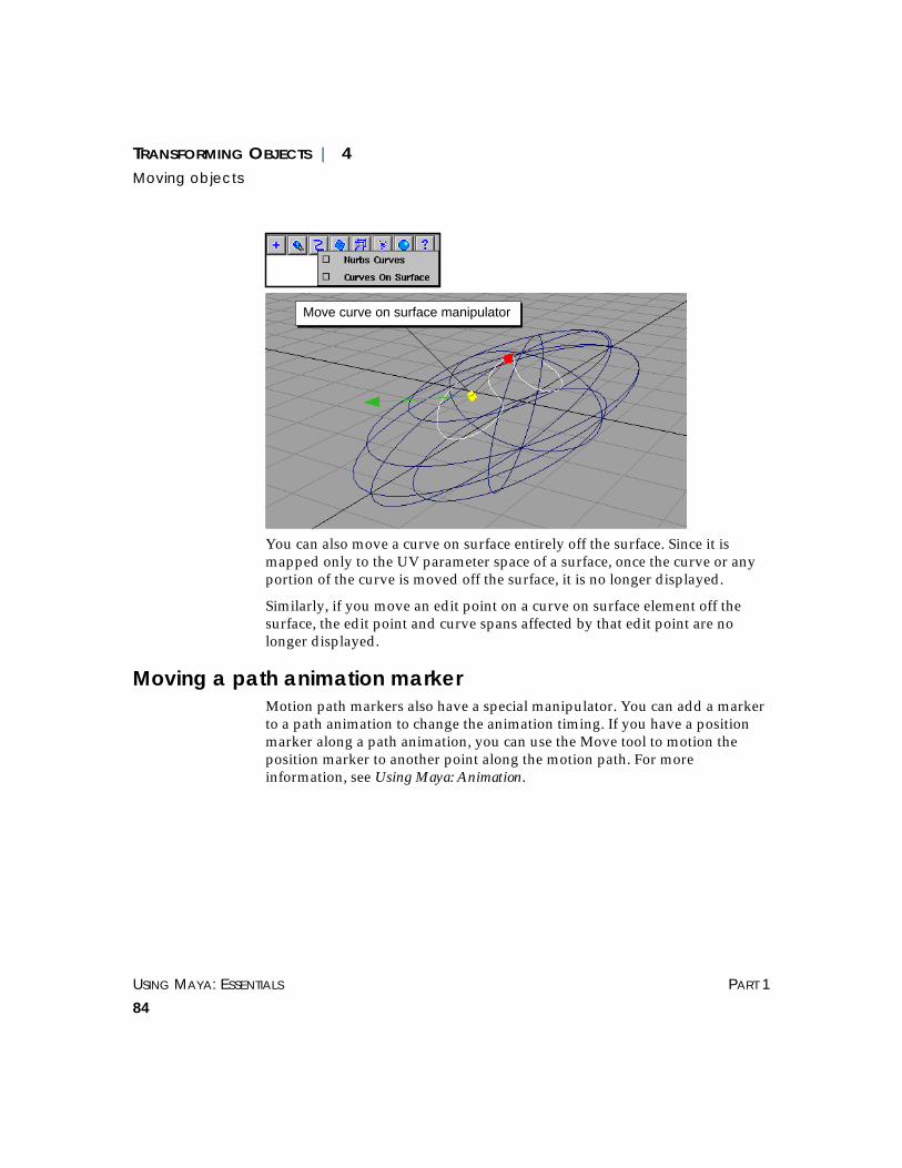
USING MAYA: ESSENTIALS PART 1
84
TRANSFORMING OBJECTS | 4Moving objects
You can also move a curve on surface entirely off the surface. Since it ismapped only to the UV parameter space of a surface, once the curve or anyportion of the curve is moved off the surface, it is no longer displayed.
Similarly, if you move an edit point on a curve on surface element off thesurface, the edit point and curve spans affected by that edit point are nolonger displayed.
Moving a path animation markerMotion path markers also have a special manipulator. You can add a markerto a path animation to change the animation timing. If you have a positionmarker along a path animation, you can use the Move tool to motion theposition marker to another point along the motion path. For moreinformation, see Using Maya: Animation.
Move curve on surface manipulator

TRANSFORMING OBJECTS | 4Rotating objects
BASIC FEATURES USING MAYA: ESSENTIALS
85
ROTATING OBJECTS
Use the Rotate tool to rotate objects. The Rotate manipulator consists of fourrings, plus a “virtual sphere” enclosed by the rings.
You use the X, Y, and Z rings to perform constrained rotations. You use theouter ring to rotate relative to the view.
For example, in the front view, the view ring rotates the object in the XYplane. The virtual sphere is used to rotate in X, Y, and Z.
Note
When you rotate a component, Maya rotates it about a temporary pivotwhich is initially set to the center of the component’s bounding box. Forinformation on moving the pivot, see “Moving the rotate pivot point” onpage 86.
Drag to rotateabout local Z-axis
Drag on virtual spherearea to rotate in X, Yand ZClick-drag to rotate
about local Y-axis
Drag to rotateabout local X-axis
Drag on outerring to rotateabout view axis

USING MAYA: ESSENTIALS PART 1
86
TRANSFORMING OBJECTS | 4Rotating objects
To rotate an object:
1 Select the Rotate icon in the Minibar.
2 Select the object you want to rotate. Maya displays a rotate manipulator inthe shape of a sphere (or arc ball).
3 Rotate the object by pressing the left mouse button and dragging.
Moving the rotate pivot pointMaya uses the rotate pivot to position the Rotate manipulator.
To move the rotate pivot:
1 To switch to edit mode, press the Insert key. Maya displays the manipulatorfor moving the pivot. This temporary pivot is initially at the center of thecomponent’s bounding box.
Note
The object’s rotational pivot point determines the effect of a rotation.
Click-drag to rotatein the Z direction
Click-drag to rotatein the Y direction
Click-drag torotate in theX direction

TRANSFORMING OBJECTS | 4Rotating objects
BASIC FEATURES USING MAYA: ESSENTIALS
87
2 Drag the manipulator to the desired area within the object.
3 Press Insert again to resume rotating the object.
Changing the rotation orderThe Rotate manipulator respects the key object’s rotation order, that is, theorder in which X, Y, and Z rotations are applied.
To change the rotation order of an object, open the Attribute Editor. Therotation order option is under the scale/rotate/translate attributes. This ismost useful with the Gimbal manipulator. See “Animating rotationchannels” on page 89.
Choosing a rotate modeYou use the Tool Settings options window to specify the behavior for theRotate tool.
To specify an option:
1 In the Minibar, double-click on the Rotate icon. The following windowopens.
Note
When you are in Component selection mode, you can “pin” the pivot pointto its new location. For information, see “Pinning component pivot points”on page 77.
Translate manipulator

USING MAYA: ESSENTIALS PART 1
88
TRANSFORMING OBJECTS | 4Rotating objects
2 Specify a rotate mode:
Local Rotates the object about the object space axes.
Global Rotates the object about the world space XYZ axes. Notice that in this modethe rings never change.
Gimbal Changes only the X, Y, or Z rotation value. In the local and global modes, theXYZ constraint rings may change more than one of the rotation XYZchannels.
Changing the rotation order and axis orientationIn the Transform Attributes section of the Attribute Editor, you can changethe rotation order of the axes for an object by selecting an order from theRotate Order pop-up menu. You can also enter values in the Rotate Axis X,Y, or Z boxes to rotate the axes in a specific direction, and to rotate the objectaround a different axis.
Keep in mind that these attributes have a combined effect with the RotateMode settings in the rotate Tool Settings.
TRANSFORMING OBJECTS | 4Scaling objects
BASIC FEATURES USING MAYA: ESSENTIALS
89
Animating rotation channelsWith the world and object space rotation manipulator, you can changemultiple rotation channels at one time, even when using one of the X, Y, or Zrings. For animation, rotations are interpolated on a per channel basis and therotation channels are not independent.
The rotation channels are applied in a specific order. This ordering impactsthe animation of these channels. (To change the rotation order, use theAttribute Editor.) For this reason, interpolating all three rotation channels ona single object usually does not result in a smoothly animated rotation.
Instead, use the gimbal rotation manipulator. It lets you change and controlindividual rotation channels without affecting the other rotation channels. Italso gives more predictable results. For modeling purposes, or withanimations that don't include rotation channels, use any of the rotatemanipulators.
When you animate components such as CVs, you are actually animatingtheir position. Rotating some CVs and setting keys does not produce an arcbecause it is the CV positions that are interpolated. In this case, it does notmatter which rotate manipulator is used.
SCALING OBJECTS
Use the Scale tool to change the size of objects by scaling proportionally inall three dimensions. You can also scale non-proportionally in onedimension at a time.
To scale an object:
1 Choose the Scale icon from the Minibar.
2 Select the object you want to scale. Maya displays a scaling manipulator thatconsists of four handles. The colors of the handles correspond to the XYZaxes.

USING MAYA: ESSENTIALS PART 1
90
TRANSFORMING OBJECTS | 4Scaling objects
3 Scale the object by click-dragging a handle.
When you scale a component, Maya scales it about a temporary pivot, whichis initially set to the center of the active component’s bounding box. Notethat for components, it is the component position that is being changed.
By default, all geometry is assigned an initial scale factor of 1.
Moving the scale pivot pointMaya uses the scale pivot to position the scale manipulator.
To move the scale and rotate pivots:
1 To switch to edit mode, press the Insert key. Maya displays the manipulatorfor moving the scale pivot.
2 Drag the manipulator to the desired area within the object.
3 Press Insert again to resume scaling.
Tip
A useful shortcut for non-proportional scaling in X, Y, or Z is to use theShift key. Hold the Shift key down, then, using the middle mouse button,drag along the direction of the axis you would like to scale in. This is fasterbecause you don't need to click directly on the specific handle to switchbetween scaling in X, Y, or Z.
Click-drag to scalein the Z direction
Click-drag to scalein the Y direction
Click-drag to scalein the X direction
Click-drag to scaleproportionally

TRANSFORMING OBJECTS | 4Using the Show Manipulator tool
BASIC FEATURES USING MAYA: ESSENTIALS
91
USING THE SHOW MANIPULATOR TOOL
Some functions display special manipulators that let you tailor a surface orcurve after a surface has been created. The Show Manipulator tool (Modify >Transformation Tools > Show Manipulator Tool) lets you edit theconstruction history of an operation or the attributes of an object itself. Inother words, this tool lets you access the input node of an object.
A manipulator is a good way to access the history of a surface created withconstruction history (such as a beveled or revolved surface). Severalmanipulators can be active at one time.
When the object is deselected, the manipulators disappear. Reselect theobject, and the manipulators reappear.
There are several ways to access and display manipulators using the ShowManipulator tool. Before you start, make sure construction history is on(click the Construction History icon on the status line).
Note
When you are in Component selection mode, you can “pin” the pivot pointto its new location. For information, see “Pinning component pivot points”on page 77.

USING MAYA: ESSENTIALS PART 1
92
TRANSFORMING OBJECTS | 4Using the Show Manipulator tool
Selecting an item’s history nodeThe Show Manipulator tool displays a manipulator for the operation’shistory node. To access the manipulator, you must select the history node.
After you revolve an object, the revolve history node is active and the ShowManipulator tool displays the Revolve manipulator. If you perform severalother operations and then want to edit the revolved surface, themanipulators are no longer displayed. You have to select them using one ofthe following methods.
To select the history node:
Select the surface then do one of the following:
• Press the a key and the left mouse button. Drag to Select All History on themarking menu that appears.
or
• From the History list menu in the Status Line, select the history node.
or
• From the Channel Box, select the history node.
In the following example, the history nodes for a revolved surface and thecurve used to construct it are selected. Click revolve1 to select the historynode for the revolved surface.

TRANSFORMING OBJECTS | 4Using the Show Manipulator tool
BASIC FEATURES USING MAYA: ESSENTIALS
93
Changing a curve’s parameter rangeYou can use the Show Manipulator tool to change the parameter range(minimum and maximum value) on a subCurve.
A subCurve is created when you select the Partial option as the Curve Rangein some options windows (for example, Revolve Options, Loft Options,Extrude Options, Boundary Options, Bevel Options, Project Curve Options).This option lets you select a minimum and maximum parameter value onthe curve; only the part of the curve between those points is used to createthe surface. Most surface operations that use a curve as input include thisoption.
A subCurve can also be the construction curve, or input curve, you use tocreate surfaces, such as revolved or extruded surfaces.
Once you select the history nodes and the Show Manipulator tool,manipulators display on the surface or the construction curve. Tointeractively edit these nodes, click-drag the manipulator handles, or changethe values in the Channel Box or the Attribute Editor.

USING MAYA: ESSENTIALS PART 1
94
TRANSFORMING OBJECTS | 4Using the Show Manipulator tool
Displaying manipulators for lights and camerasUse the Show Manipulator tool to display manipulators for editing lightsand cameras. The appropriate manipulator for the camera or light you selectdisplays.
For example, if you select a light or a camera then click the ShowManipulator tool on the Minibar, Maya displays the following manipulators:
For details, see “Displaying camera and light manipulators” on page 137.
Using the Default Object manipulatorThe Default Object manipulator is the transform tool set to be used with theShow Manipulator tool for an object. It can be the Move, Rotate, or Scaletool. Even if the object has its own manipulator (for example, a light), thetransform manipulator is shown instead.
To set the default manipulator for the Show Manipulator tool:
Select Modify > Transform Tools > Default Object Manipulator >transformTool. Set Default Object Manipulator to None to use the object’sown manipulator, rather than a transform manipulator. This is the default.
This information is saved with the scene. It is also shown in the AttributeEditor under the transform Display section.
Note
Some options windows include a Keep Original toggle (for example, EditCurves > Detach Curves). Toggle this on to access the manipulators.
Spotlight manipulators Camera manipulators
TRANSFORMING OBJECTS | 4Entering numeric values
BASIC FEATURES USING MAYA: ESSENTIALS
95
ENTERING NUMERIC VALUES
You can move, rotate, or scale an object by entering values in the NumericInput field or the Command Line.
Using the Numeric Input fieldThe Numeric Input field appears on the Status Line. You can enter absolutevalues or relative values in the Numeric Input field. When typing values, donot include commas to separate XYZ coordinates—use spaces. For example,type:
1 3 5
...not
1,3,5
You can use decimal values.
Entering absolute values
Click the pulldown menu next to the Numeric Input field and selectNumeric Input: Absolute. The button changes to abs, to indicate that Mayawill interpret the values you enter as relative.
When you enter an absolute value, Maya moves or rotates the object to theabsolute world-space coordinates that you type in, or scales the object to theabsolute size value specified for each of the three axes.
For example, if an object is positioned at XYZ coordinates (4, 2, 2) and youmove the object by entering an absolute value of:
6 3 1
...in the numeric input field, the new position of the object is (6, 3, 1).
You can omit trailing zero values. For example, you can type:
2 3 0
or
2 3
...to move an object to (2, 3, 0).

USING MAYA: ESSENTIALS PART 1
96
TRANSFORMING OBJECTS | 4Entering numeric values
To move or scale an object on only one or two of the axes without affectingthe other axis, you must re-enter the current values you don’t want to affect.For example, to move an object from its location at (2,3,1) to (4,4,1), enter theabsolute move values:
4 4 1
Similarly, if an object is scaled by a factor of 5 on all three axes and you wantto change the scale on the x-axis to a factor of 6, enter the scale factors:
6 5 5
Entering relative values
Click the pulldown menu next to the Numeric Input field and selectNumeric Input: Relative. The button changes to rel, to indicate that Mayawill interpret the values you enter as relative.
When you enter a relative value, Maya moves, rotates, or scales the object bythe specified amount on each axis, relative to the object’s current position orscale factor.
For example, to move an object from (2,3,1) to a position 2 grid positions inthe positive X direction and one grid position in the positive Y direction,enter the relative values:
2 1 0
...and press Enter.
The zero value for the z-axis results in no positional adjustment on this axis.The object moves to (4,4,1).
You can omit trailing zero values. For example, you can type:
2 3 0
...or
2 3
...to move an object from (1,1,1) to (3,4,1).
To transform an object using the Numeric Input field:
1 Click the Move, Rotate, or Scale tool in the Minibar.
2 Select the object you want to move.

TRANSFORMING OBJECTS | 4Combining transformations
BASIC FEATURES USING MAYA: ESSENTIALS
97
3 To move the object by an absolute amount (the default), type the XYZcoordinates in the Numeric Input field and press Enter, or type -a before thevalue and press Enter, for example:
-a 1 7 4
To move an object by a relative amount, click the abs button to toggle to rel,then enter the value, or type -r before the value and press Enter, for example:
-r 2 6 3
Using the Command LineThe command line appears at the bottom of the Maya main window.
To transform an object with the Command Line:
To transform objects from the Command Line, you use the move, rotate, andscale commands.
If you type -r before the numerical values on the Command Line, geometryis translated relative to its current location. (-a, for absolute world spacecoordinates, is the default.)
COMBINING TRANSFORMATIONS
You can use the combined Move/Rotate/Scale manipulator to switchbetween moving, rotating, and scaling. When you first select this tool, onlypart of each manipulator is displayed. To see the complete manipulator,click on one of its handles.
Note
If you select more than one object, Maya displays the manipulator on onlyone object. However, each object scales or rotates relative to its own pivotpoint.
Type movevalues andpress Enter

USING MAYA: ESSENTIALS PART 1
98
TRANSFORMING OBJECTS | 4Combining transformations
To move an object:
To display the full move manipulator (including the center handle), click onone of the arrow handles. Then use the handles as described in the Movetool.
• To move along a single axis, click-drag the arrows in the direction of theXYZ axes.
• To move the object freely along all axes, click one of the arrow handles tofirst display the center handle, then click-drag the center handle.
To scale an object:
• To perform a non-proportional scale, select the box handle representing theaxis and drag in that direction.
• To perform a uniform scale on the entire object, click one of the box handlesto display the center handle, then click-drag the center handle.~
Click here to movealong Z-axis
Click here to movealong X-axis
Click here to movealong Y-axis
Click here toscale in Z
Click hereto scale in Y
Click here toscale in X

TRANSFORMING OBJECTS | 4Using proportional modification
BASIC FEATURES USING MAYA: ESSENTIALS
99
To rotate an object:
1 When you first select this tool, the XYZ constraint rings are not displayed. Todisplay the arc ball, select the outer constraint ring.
2 To rotate around a single axis, select the appropriate ring and drag in thedirection of the axis.
USING PROPORTIONAL MODIFICATION
You can use the Proportional Modification (propmod) tool to transform anumber of items proportionally, based on the distance from the manipulatorhandle. Typically, you use this tool to transform CVs.
The propmod effect is usually based on the distance of the CV, or othercomponent, from the manipulator. The closest object exactly matches themanipulator’s movement. Objects further away do not. This effect iscontrolled by the Distance Cutoff setting.
Note
When you use the combined transformation tool, the transformations occurwith respect to object space only.
Click hereto scale in Y
Click here toscale in X
Click here toscale in Z
Click here to rotate inthe view plane axis
Click here to rotatealong all axes

USING MAYA: ESSENTIALS PART 1
100
TRANSFORMING OBJECTS | 4Using proportional modification
The manipulator for Proportional Modification is a combination of the move,rotate, and scale manipulators. Click on the appropriate part of themanipulator, depending on what type of transformation you want toperform.
You can reposition the manipulator in another part of the scene to achievedifferent effects on the selected objects.
Example of translating CVs:
1 Click the Select by Component Type icon and select the curves to see theCVs.
2 Shift-drag to select all the CVs in the center of the curves.
Click this icon andselect the curves tosee the CVs

TRANSFORMING OBJECTS | 4Using proportional modification
BASIC FEATURES USING MAYA: ESSENTIALS
101
3 Select Modify > Transformation Tools > Proportional Modification Tool.
Maya displays a manipulator.
4 Click-drag to position the manipulator, then drag the green handle to movethe CVs on the curves.
Specifying proportional modification falloffTo set proportional modification options, either double-click on the icon, orselect Modify > Transformation Tools > Proportional Modification Tool ❐.The options window opens.
Linear modification falloffThis is the default modification falloff. Maya performs the modification in alinear fashion and displays the Distance Cutoff option.
CVs move proportionally

USING MAYA: ESSENTIALS PART 1
102
TRANSFORMING OBJECTS | 4Using proportional modification
Distance Cutoff Objects further away than this value are ignored. The distance is measuredin 3D from the manipulator handle.
Based on distance The distance from the manipulator handle to the object directly influencesthe modification factor. The distance will be computed along the selectedaxes only. If any of these is toggled off, the distance used in the computationof the propmod effect from the handle to the point will ignore thatcomponent.
Power modification falloffUsing the Proportional Modification tool, you can set the degree to anyvalue between +5 and -5 and the falloff is non-linear (it forms a logisticcurve). However, if you set the degree to 1 the falloff is linear again.
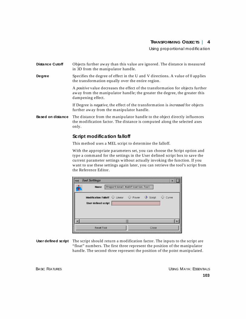
TRANSFORMING OBJECTS | 4Using proportional modification
BASIC FEATURES USING MAYA: ESSENTIALS
103
Distance Cutoff Objects further away than this value are ignored. The distance is measuredin 3D from the manipulator handle.
Degree Specifies the degree of effect in the U and V directions. A value of 0 appliesthe transformation equally over the entire region.
A positive value decreases the effect of the transformation for objects furtheraway from the manipulator handle; the greater the degree, the greater thisdampening effect.
If Degree is negative, the effect of the transformation is increased for objectsfurther away from the manipulator handle.
Based on distance The distance from the manipulator handle to the object directly influencesthe modification factor. The distance is computed along the selected axesonly.
Script modification falloffThis method uses a MEL script to determine the falloff.
With the appropriate parameters set, you can choose the Script option andtype a command for the settings in the User defined script box to save thecurrent parameter settings without actually invoking the function. If youwant to use these settings again later, you can retrieve the tool’s script fromthe Reference Editor.
User defined script The script should return a modification factor. The inputs to the script are“float” numbers. The first three represent the position of the manipulatorhandle. The second three represent the position of the point manipulated.

USING MAYA: ESSENTIALS PART 1
104
TRANSFORMING OBJECTS | 4Using proportional modification
For example, the points for which this script returns 1 will move with themanipulator handle. The points for which this script returns 0.5 will movehalf as fast as the manipulator handle.
For more information, see “Using the PropMod script” on page 105.
Curve modification falloffThis option uses an animation curve to create the falloff. An animation curveprofile can be used to produce a modification factor.
User defined anim curve
Enter the name of an existing animation curve. Its vertical direction will mapinto the modification factor. The distance maps to the anim curve time axis(in seconds).
You can use the pull-down menu to the right of the box to list and choose allthe anim curves with names starting with propModAnimCurve. You can alsocreate one of those by choosing Create New from the same pull-down menu.
Based on distance The distance from the manipulator handle to the object directly influencesthe modification factor. The distance is computed along the selected axesonly.

TRANSFORMING OBJECTS | 4Creating locators
BASIC FEATURES USING MAYA: ESSENTIALS
105
Using the PropMod scriptThe PropMod script is similar to the Move script except that it has additionalsettings for the move distance. Using the Script option, you can computeeach object’s factor individually.
The user-defined script command considers both the position of themanipulator and the object. The value returned by the script is used as amultiplying factor for a specific object.
Example
Create myPropMove.mel file as:
global proc float myPropMove(float $mx, float $my,
float $mz, float $px,
float $py, float $pz)
}
return rand (1.0)
}
...which produces a random value between 0 and 1.
If you select myPropMove as the script name, you get a randommodification factor for all selected points.
CREATING LOCATORS
A locator marks a position in world space. A locator is displayed as a smallgnomon; its lines extend in each direction along the X, Y and Z axes (like thedirectional rods of a sundial). You can use point snapping to snap to alocator position.
Use Create > Locator to create a space or curve locator.

USING MAYA: ESSENTIALS PART 1
106
TRANSFORMING OBJECTS | 4Creating locators
To create and move a locator:
1 Select Create > Locator. A locator is created at the origin.
2 Move the locator in one of the following ways:
• Use the transformation tools.
• Change the transformation values in the Channel Box.
• Click the locator# tab in the Attribute Editor and change the Transformationvalues in that section of the editor.
Repositioning the locator in local spaceYou can reposition the locator in local space from the Attribute Editor(Window > Attribute Editor).
Click the locatorShape# tab to open that section of the editor. Enter X, Y, or Zvalues in the Local Position boxes.

TRANSFORMING OBJECTS | 4Using Measure tools
BASIC FEATURES USING MAYA: ESSENTIALS
107
USING MEASURE TOOLS
The Create > Measure menu includes the Distance Tool, Parameter Tool, andArc Length Tool.
Using distance measuresUse the Create > Measure > Distance Tool to measure and display distancesbetween two specified points.
To display a distance measure:
1 Select Create > Measure > Distance Tool.
2 Click to select two points in space, or click on a curve or surface to displaythe distance measure locator.

USING MAYA: ESSENTIALS PART 1
108
TRANSFORMING OBJECTS | 4Using Measure tools
The following example shows the distance locator when two points areplaced on a surface.
This shows the distance locator when one point is placed in world space andthe other is placed on the surface.
The following shows the distance locator when two points are placed on acurve.
To snap a distance measure point:
To snap a locator to a curve or surface, use the Snap to curves icon and clickon the curve or surface. When you move the item, the distance measureupdates. This can be especially helpful if you want to measure the distancebetween two curves.
1 Click the Snap to curves icon from the Status Line.

TRANSFORMING OBJECTS | 4Using Measure tools
BASIC FEATURES USING MAYA: ESSENTIALS
109
2 Place a point on one curve and another point on the other curve.
3 Move one of the curves and the distance measure updates.
To move the distance locator:
Select the Move Tool, then click to select a locator and drag to where youwant to measure the distance between. The distance measure updatesinteractively.

USING MAYA: ESSENTIALS PART 1
110
TRANSFORMING OBJECTS | 4Using Measure tools
Editing the distance locators using the Attribute EditorYou can specify the start and points of the distance measure in X, Y and Zfrom the Attribute Editor (Window > Attribute Editor).
To specify the start and end points of the distance measure:
Click the distanceDimensionShape# tab to open that section of the editor.Enter values in the Start Point and End Point boxes to specify the start andend points of the distance measure in X, Y, and Z.
To reposition the distance locator in local space:
Click the locatorShape# tab to open that section of the editor. Enter values inthe Local Position boxes to reposition the distance measure in X, Y, or Z.

TRANSFORMING OBJECTS | 4Using Measure tools
BASIC FEATURES USING MAYA: ESSENTIALS
111
Displaying parameter valuesUse the Create > Measure > Parameter Tool to display parameter values oncurves and surfaces at a specified point. This locator also displays thedirection of the curve or surface and the normal to the curve or surface at aspecified point.
To display parameter values on a surface or curve:
1 Select Create > Measure > Parameter Tool.
2 Click-drag on a curve or surface to display the parameter values at aspecified point.
For curves, the parameter value in U at the specified point on the curvedisplays.
Normal
Surface direction
Normal
Curve direction
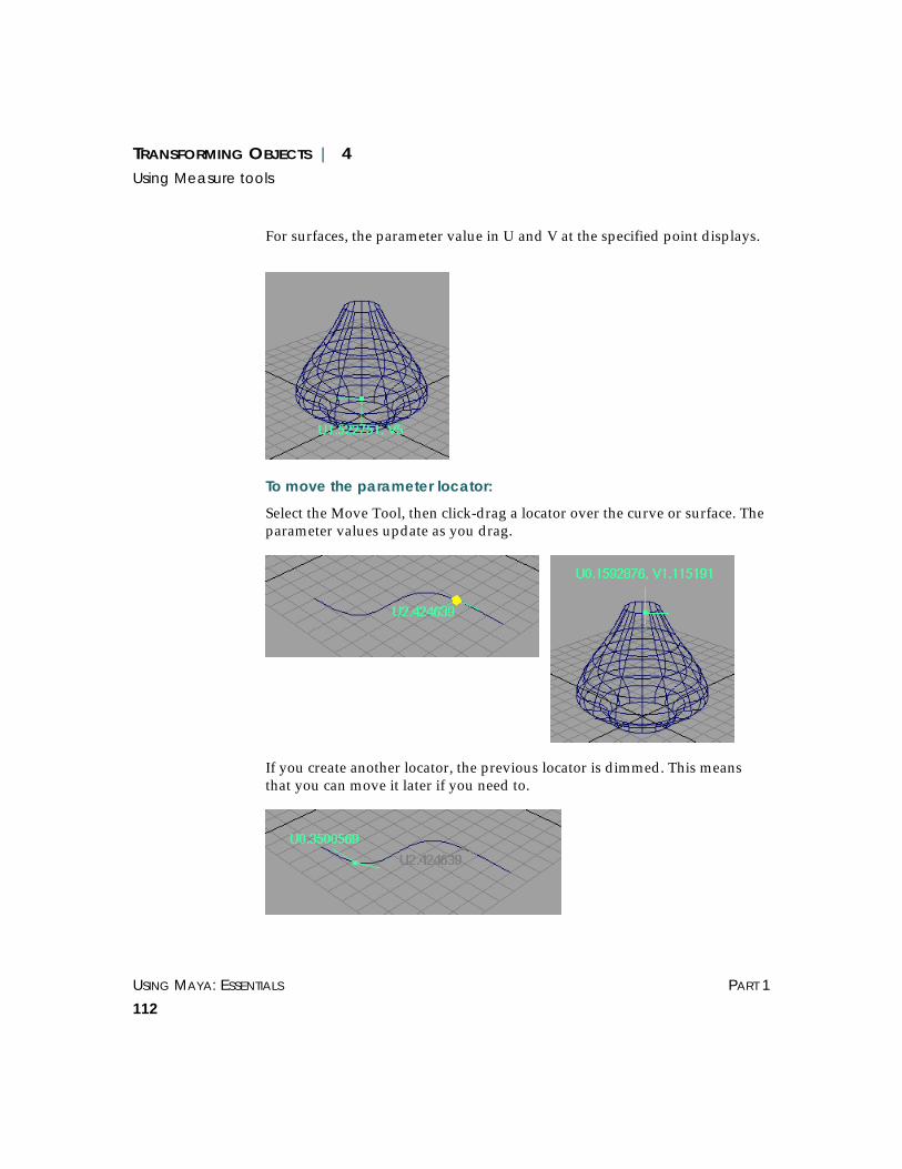
USING MAYA: ESSENTIALS PART 1
112
TRANSFORMING OBJECTS | 4Using Measure tools
For surfaces, the parameter value in U and V at the specified point displays.
To move the parameter locator:
Select the Move Tool, then click-drag a locator over the curve or surface. Theparameter values update as you drag.
If you create another locator, the previous locator is dimmed. This meansthat you can move it later if you need to.

TRANSFORMING OBJECTS | 4Using Measure tools
BASIC FEATURES USING MAYA: ESSENTIALS
113
Editing the parameter locators in the Attribute EditorYou can specify the U and V parameters values from the Attribute Editor(Window > Attribute Editor).
Click the arrow beside the Nurbs Geometry box to access the curve orsurface whose locator you want to edit.
To specify the U and V parameter values:
Click the paramDimensionShape# tab to open that section of the editor.Enter new U and V Param values.
In the following example, the first figure shows the parameter locator on asurface at the position where it was created. The second figure shows howthe locator is modified when you change the U and V Param values.

USING MAYA: ESSENTIALS PART 1
114
TRANSFORMING OBJECTS | 4Using Measure tools
Measuring arc lengthsUse the Create > Measure > Arc Length Tool to measure and display arclengths on curves and surfaces at a specified point. It also displays thedirection of the curve or surface and the normal to the curve or surface at aspecified point.
To display arc length values on a surface or curve:
1 Select Create > Measure > Arc Length Tool.
2 Click-drag over a curve or surface to display the parameter values at aspecified point.
For curves, the distance of the specified point from the start point of thecurve is measured.
Normal Normal
Surface direction Curve direction

TRANSFORMING OBJECTS | 4Using Measure tools
BASIC FEATURES USING MAYA: ESSENTIALS
115
For surfaces, the specified point from the start point in both the U and Vdirection is measured.
To move the arc length locator:
Select the Move Tool, then click-drag over the curve or surface. Theparameter values update as you drag.

USING MAYA: ESSENTIALS PART 1
116
TRANSFORMING OBJECTS | 4Using Measure tools
If you create another locator, the previous locator dims, meaning you canselect to move it later if you want.
Editing the arc length locators in the Attribute EditorIf you want, you can specify the U and V parameters values from theAttribute Editor (Window > Attribute Editor).
Click the arrow beside the Nurbs Geometry box to access the curve orsurface for which you want to edit the locator.
To specify the U and V parameter values:
Click the arcLengthDimensionShape# tab to open that section of the editorand enter new U and V Param values.
In the following example, the first figure shows the arc length locator on asurface at the position where it was created. The second figure shows howthe locator is modified when the U and V Param values are changed.

TRANSFORMING OBJECTS | 4Using Measure tools
BASIC FEATURES USING MAYA: ESSENTIALS
117

USING MAYA: ESSENTIALS PART 1
118
TRANSFORMING OBJECTS | 4Using Measure tools

USING MAYA: ESSENTIALS
119
5 DISPLAYING OBJECTS
This chapter describes the tools and actions you use to display or hideobjects and attributes. You can use these tools to customize your workingenvironment and reduce workspace complexity. Topics include:
• “Displaying items in Maya” on page 119
• “Using a grid” on page 120
• “Displaying axes, polygon count, and frame rate” on page 122
• “Specifying how objects display” on page 122
• “Hiding and showing objects” on page 125
• “Isolating selected objects or components” on page 129
• “Displaying object components” on page 131
• “Displaying NURBS components” on page 132
• “Displaying polygon components” on page 135
• “Displaying camera and light manipulators” on page 137
• “Working with templates” on page 139
• “Using display layers” on page 139
• “Using render layers” on page 147
DISPLAYING ITEMS IN MAYA
You use the Display menu to show or hide NURBS, polygons, tools,components, and attributes. When you hide or show items, it affects theworkspace globally.
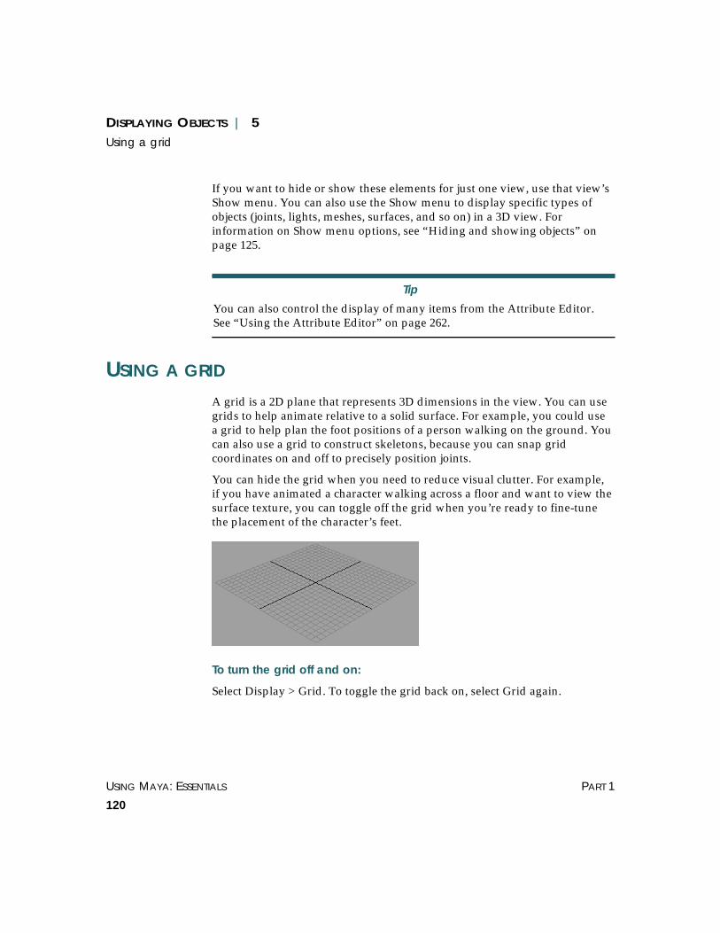
USING MAYA: ESSENTIALS PART 1
120
DISPLAYING OBJECTS | 5Using a grid
If you want to hide or show these elements for just one view, use that view’sShow menu. You can also use the Show menu to display specific types ofobjects (joints, lights, meshes, surfaces, and so on) in a 3D view. Forinformation on Show menu options, see “Hiding and showing objects” onpage 125.
USING A GRID
A grid is a 2D plane that represents 3D dimensions in the view. You can usegrids to help animate relative to a solid surface. For example, you could usea grid to help plan the foot positions of a person walking on the ground. Youcan also use a grid to construct skeletons, because you can snap gridcoordinates on and off to precisely position joints.
You can hide the grid when you need to reduce visual clutter. For example,if you have animated a character walking across a floor and want to view thesurface texture, you can toggle off the grid when you’re ready to fine-tunethe placement of the character’s feet.
To turn the grid off and on:
Select Display > Grid. To toggle the grid back on, select Grid again.
Tip
You can also control the display of many items from the Attribute Editor.See “Using the Attribute Editor” on page 262.

DISPLAYING OBJECTS | 5Using a grid
BASIC FEATURES USING MAYA: ESSENTIALS
121
Setting grid optionsUse the Grid Options window to specify how the grid looks on the screen.When you change grid options, Maya changes the display immediately.
To set grid options:
1 Select Display > Grid ❐. The Grid Options window opens.
2 Set the following options and click Apply.
Grid Specifies the size of the grid or the spacing between major grid lines. Thedefault is 5. The smaller the number, the less space there is between majorgrid lines.
Subdivisions Specifies the number of divisions between major grid lines. Setting theSubdivisions option to a value greater than 1 specifies that each main gridinterval will be subdivided by the amount specified. The default is 5.
Extent Specifies how far the grid is drawn in each direction. If the extent is 50 cm,Maya draws the grid 50 cm in the +X direction and 50 cm in the -X direction.
Style Changes the style of the grid, including:
Outline – Displays only the outline of the grid.
Axes – Displays the outline and the XZ axes.
Grid – Displays the outline, the XZ axes, and the major grid lines.
All – Displays the outline, the XZ axes, major grid lines, and subdivisions.This is the default.
To restore the options back to their original settings, click Reset.
Note
The default grid is a 24 x 24 unit grid displayed in the XZ plane.
Tip
Have at least one modeling window open when changing the Grid option.This lets you view the changes interactively.

USING MAYA: ESSENTIALS PART 1
122
DISPLAYING OBJECTS | 5Displaying axes, polygon count, and frame rate
To change the color of the grid, select Window >Settings/Preferences > Colors. For more information, see “Where Mayastores preferences” on page 462.
DISPLAYING AXES, POLYGON COUNT, AND FRAME RATE
Maya includes useful tools under the Display > Heads Up Display submenu.
View Axis Displays the global axis at the origin (0, 0, 0) within the perspective view.
Origin Axis Displays the global axis in the bottom left corner of all views. This is thedefault.
Display Poly Count Shows polygon statistics for the visible objects displayed in the view panel.This feature is useful for games development.
Frame Rate Displays the frame rate in Hertz for the current port.
SPECIFYING HOW OBJECTS DISPLAY
The Shading menu provides a number of ways to look at your scene. Thequality can range from a simple wireframe display to a smooth- shadedview.
Wireframe Draws edges for polygon meshes and isoparametric curves for surfaces. Thisis the default shading quality.
Smooth Shade All Displays all surfaces, meshes, and particles as smooth-shaded objects.
Smooth Shade Selected Items
Displays selected items as smooth-shaded objects.
Total Selected Components

DISPLAYING OBJECTS | 5Specifying how objects display
BASIC FEATURES USING MAYA: ESSENTIALS
123
Flat Shade All Displays all surfaces and meshes as flat-shaded objects.
Flat Shade Selected Items
Displays selected items as flat-shaded objects.
Bounding Box Shows objects as boxes that represent their bounding volumes. Boundingboxes speed up Maya operations and can make a significant difference forcomplex models.
The bounding box encompasses the hulls as well as the actual geometry. Asa result, the bounding box may have dimensions larger than those of thegeometry.
Points Shows objects as groupings of individual points.
Shade Options There are two display options for shaded objects.
Wireframe on Shaded – Superimposes a wireframe display on all shadedobjects in a view.
X-Ray – Displays all shaded objects as semi-transparent. This can be usefulfor seeing hidden parts of a model.
Note
To see bounding box coordinates, open the Attribute Editor, click on theshape node tab, and open the Object Display section. It shows theread-only minimum and maximum world space boundary coordinates of asurface along the X, Y, and Z axes.
Wireframe isoparmsappear over theshaded objects

USING MAYA: ESSENTIALS PART 1
124
DISPLAYING OBJECTS | 5Specifying how objects display
Interactive Shading Controls the display of objects during interactive modes (such astransformations, camera navigation, and playbacks). At the same time thenormal display can be in some sort of shaded mode. For example, thenormal display can be smooth-shaded while the interactive display isbounding box. There are four interactive shading options:
Normal – Keeps the interactive mode the same as regular display mode.
Wireframe – Displays objects in wireframe mode during the interactivemode.
Bounding Bo x – Displays objects as bounding boxes during the interactivemode.
Points – Displays objects as points during the interactive mode.
Color Index Mode On IRIX only, lets you manipulate a wireframe object in a complex scenemore quickly (for example, if you are using a full-color image plane whileworking in wireframe mode).
Dense Wireframe Acceleration
On NT only, lets you manipulate a wireframe object in a complex scenemore quickly. For example, suppose you have created a saloon scene withmany objects. When you use the Move tool to move a bottle in the scene, itmoves slowly as you drag the mouse. You can improve the interactivemanipulation of the bottle with this menu option.
Back Face Culling For objects displayed in smooth shade or flat shade mode, makes the object’sback face transparent which helps speed the display or manipulation ofobjects.
Tip
When you use the Dense Wireframe Acceleration option, be aware of thefollowing:
• Results vary with the graphics card installed in yourworkstation.
• Manipulation of wireframe objects in simple scenes isslower.
• Camera tumbling is unaffected.

DISPLAYING OBJECTS | 5Hiding and showing objects
BASIC FEATURES USING MAYA: ESSENTIALS
125
Hardware Texturing Displays a hardware rendition of the texture applied to a material shadingan object.
Apply Current to All Applies the current 3D view's shading style to all objects in the scene.
HIDING AND SHOWING OBJECTS
Use Display > Hide to hide items you aren’t using and reduce visual clutterby hiding objects you are not working on. This is handy if you want toremove an object from the view, but do not want to delete it or move it.
To redisplay items, use the Display > Show submenu, which includes thesame selections as Display > Hide. The Hide menu items are:
Hide Selection Hides selected object(s).
Hide Unselected Objects
Hides all unselected objects.
Hide Unselected CVs
To control the display of CVs, select the CVs that you want to remain visible,and then use Display > Hide > Hide Unselected CVs to hide all the otherCVs on that surface. This will affect the display of CVs in componentselection mode, as well as CVs displayed in object selection mode by the useof Display > NURBS Components > CVs.
The selective CV display function operates exclusively from other MayaHide and Show commands, and therefore menu selections such as Display >Show > All and others do not effect CVs whose display has been set usingselective CV display.
All Hides all objects, whether they are selected or not.
Hide Geometry Displays a menu that lets you select the type of geometry you want to hide.
Hide Kinematics Displays a menu that lets you select the type of kinematics you want to hide.
Tip
It is possible to use selective CV display on more than one surface at atime.

USING MAYA: ESSENTIALS PART 1
126
DISPLAYING OBJECTS | 5Hiding and showing objects
Hide Deformers Displays a menu that lets you select the type of deformers you want to hide.
Hide Cloth Available only if you have Maya Unlimited and are using Maya Cloth.Hides cloth objects. For details, see Using Maya: Cloth.
Lights Hides lights.
Cameras Hides cameras.
Texture Placements Hides texture placements.
Planes Hides planes.
Markers Hides markers.
Light Manipulators Hides light manipulators.
Camera Manipulators
Hides camera manipulators.
Hiding geometryGeometry represents the properties and relations of points, lines, surfaces,and objects. You can hide a variety of geometry components.
To hide geometry:
1 Select an object.
2 Select Display > Hide > Hide Geometry and select the geometry componentsyou want to hide. You can hide, NURBS Surfaces, NURBS Curves, PolygonSurfaces, Deforming Geometry, and Subdiv Surfaces. If you select All, allgeometry is hidden, whether it is selected or not.
Maya displays the object with the specified component hidden.
In the following illustration, the NURBS surfaces associated with a sampleobject are hidden.

DISPLAYING OBJECTS | 5Hiding and showing objects
BASIC FEATURES USING MAYA: ESSENTIALS
127
Hiding kinematicsKinematics is the study of motion without consideration to the cause of thatmotion. You can hide and show kinematic components.
For information on kinematics, see Using Maya: Character Setup.
To hide a kinematic component:
1 Select an object.
2 Select Display > Hide > Hide Kinematics and select the components youwant to hide. You can hide Joints, and IK handles. If you select All, allkinematic components are hidden, whether they are selected or not.
Maya displays the object with the specified component hidden.
In the following illustration, an object’s joints are hidden.
Before
After
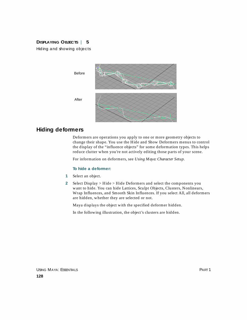
USING MAYA: ESSENTIALS PART 1
128
DISPLAYING OBJECTS | 5Hiding and showing objects
Hiding deformersDeformers are operations you apply to one or more geometry objects tochange their shape. You use the Hide and Show Deformers menus to controlthe display of the “influence objects” for some deformation types. This helpsreduce clutter when you're not actively editing those parts of your scene.
For information on deformers, see Using Maya: Character Setup.
To hide a deformer:
1 Select an object.
2 Select Display > Hide > Hide Deformers and select the components youwant to hide. You can hide Lattices, Sculpt Objects, Clusters, Nonlinears,Wrap Influences, and Smooth Skin Influences. If you select All, all deformersare hidden, whether they are selected or not.
Maya displays the object with the specified deformer hidden.
In the following illustration, the object’s clusters are hidden.
Before
After

DISPLAYING OBJECTS | 5Isolating selected objects or components
BASIC FEATURES USING MAYA: ESSENTIALS
129
ISOLATING SELECTED OBJECTS OR COMPONENTS
Use the Isolate Select feature (Show > Isolate Select > View Selected) toquickly isolate objects or components in a view panel. You simply select theitems, choose Show > Isolate Select > View Selected, and all other objectsand components in your scene become hidden.
Unlike the Display > Hide commands, which hide mostly objects, the IsolateSelect feature can also isolate components. For example, by selectingpolygonal faces, you could isolate the head of a model. Another difference isIsolate Select affects screen display only, while Display > Hide commandsalso affect rendering.
Before
After

USING MAYA: ESSENTIALS PART 1
130
DISPLAYING OBJECTS | 5Isolating selected objects or components
Isolate Select works on a per-panel basis for any view panel (perspective ororthographic). The components you can select for isolation are:
• CVs of NURBS surfaces
• faces of a polygon mesh
• faces of a subdivision surface mesh
Other components cannot be selected for isolation, such as NURBS patches,curve segments, particles, or lattice points. However, you can still see andmanipulate other component types within the items you have isolated.
Use the Show > Isolate Select menu to control the isolate select feature. Themenu options are described below.
View Selected Activates or deactivates the isolate select feature. When activated, the word“Isolate” appears at the bottom of the panel and the current selectionbecomes isolated.
Tip
Keep open at least one other workspace panel with isolate select turned offso you can select other items. Also, tearing off the Isolate Select submenugives you quick access to these commands.

DISPLAYING OBJECTS | 5Displaying object components
BASIC FEATURES USING MAYA: ESSENTIALS
131
Auto Load Selected Objects
Turn on to automatically update the isolate select panel when you changeyour selection. If turned off, you must use the Load, Add, or RemoveSelected Objects options to update the panel.
Load Selected ObjectsAdd Selected ObjectsRemove Selected Objects
If you don’t have auto load on, you can use these options to control theisolate select display. Select items from the isolate panel or another paneland then load, add, or remove them as needed. Note that Load SelectedObjects replaces the display with the current selection, while Add SelectedObjects adds the current selection to the selections already displaying.
Bookmarks Enables you to bookmark an isolated selection. To create a bookmark, chooseShow > Bookmarks > Bookmark Current Objects. Choose the option box ifyou want to name the bookmark; otherwise, a default name is used.
To view bookmarked items, choose Show > Bookmarks > BookmarkName.Choose it again to turn it off and return to the previous view. You can viewmultiple bookmarks at the same time.
Bookmarks are saved with the scene as a set. You can manage them usingthe Relationship Editor. For more information on sets, see Chapter 11, “Setsand Partitions.”
DISPLAYING OBJECT COMPONENTS
To help control screen clutter and display performance, you can toggle thedisplay of specific object components, on an object-by-object basis.
To display an object’s components:
1 Select an object.
2 Select Display > Object Components and select one of the following options:
Backfaces If you selected a polygonal object, toggles the display of the object’sbackfaces.

USING MAYA: ESSENTIALS PART 1
132
DISPLAYING OBJECTS | 5Displaying NURBS components
Lattice Points If you selected a lattice deformer (an L icon represents a lattice deformerhandle), toggles the display of the lattice points. For information on lattices,see Using Maya: Character Setup.
Lattice Shape If you selected a lattice deformer, toggles the display of the object’s latticeshape. The lattice deformer toggles between displaying its lattices and the Licon. For information on lattices, see Using Maya: Character Setup.
Local Rotation Axes Toggles the display of the object’s local rotation axes. For information onaxes, see “Using axes and pivot points” on page 73.
Rotate Pivots Toggles the display of the object’s rotate pivots. For information on pivotpoints, see “Using axes and pivot points” on page 73.
Scale Pivots Toggles the display of the object’s scale pivots. For information on pivotpoints, see “Using axes and pivot points” on page 73.
Selection Handles Toggles the display of selection handles on manipulators. For information onmanipulator selection handles, see “About manipulator handles” on page 73.
DISPLAYING NURBS COMPONENTS
Non-Uniform Rational B-Splines (NURBS) are a special type of B-spline thatcan have weighted control points. You can use these control points to createsmooth curves that Maya can read from many CAD/CAM systems. Use theNURBS Components options to display the NURBS component for aselected object.
For more information on modeling with NURBS components, see UsingMaya: NURBS Modeling.
Backfaces No backfaces

DISPLAYING OBJECTS | 5Displaying NURBS components
BASIC FEATURES USING MAYA: ESSENTIALS
133
To display a NURBS object’s components:
1 Select an object.
2 Select Display > NURBS Components and select one of the followingoptions: CVs, Edit Points, Hulls, Normals (Shaded Mode), Patch Centers,Surface Origins, or Custom.
Surface origin display
Displaying Surface Origins is helpful for alignment and placement of thesurface. The command highlights the first U and V isoparms and labels themU and V. It also draws a line indicating the surface normal direction. Thecolors used for Surface Origins are defined in Window >Settings/Preferences > Colors > Components.
Setting custom NURBS component optionsSelect Display > NURBS Components > Custom ❐. The Display ControlOptions window opens.
You can specify the scope of which NURBS objects display their componentsusing the Scope pull-down menu. The scope can be active objects, all objects,new curves, or new surfaces.
Displaying NURBS smoothnessYou can select the object’s smoothness: Hull, Rough, Medium, or Fine.
To specify a smoothness:
1 Select an object.
2 Select Display > NURBS Smoothness and select one of the following options:
Hull Shows hulls only.

USING MAYA: ESSENTIALS PART 1
134
DISPLAYING OBJECTS | 5Displaying NURBS components
Rough, Medium, Fine
Displays objects at preset levels of quality. Selecting Medium or Fine slowsthe display and interactivity, but improves image precision.
Custom Lets you customize the display quality.
In the following figure, an object’s smoothness is changed from a defaultmedium level of quality to a custom hull quality level.
Setting custom NURBS smoothness optionsSelect Display > NURBS Components > Custom ❐. The Smoothness Optionswindow opens.
Geometry To display all geometry, select Full. To display hulls only, select Hull.
Surface Div per Span USurface Div per Span V
Together, these settings subdivide the NURBS patches for display purposesto give it the appearance of a finer mesh. The range is from 0 to 32.
Curve Div per Span
Specifies the number of curve divisions per span to give the curves arougher or smoother appearance. The range is from 1 to 128.
Tip
The hotkeys for these settings are: 1 (Rough), 2 (Medium), and 3 (Fine).
Before
After

DISPLAYING OBJECTS | 5Displaying polygon components
BASIC FEATURES USING MAYA: ESSENTIALS
135
Display Render Tessellation Geometry
Turn on to see the pattern of tesselation that the renderer will use for thesurface. You must be in shade mode to see this pattern.
Shaded Surface Div per Span
Specifies the number of surface divisions per span in shaded mode. Therange is from 0 to 32.
Hull Simplification UHull Simplification V
If you have the Geometry set to Hull, you can use these settings to controlthe number of hull divisions displayed.
DISPLAYING POLYGON COMPONENTS
Polygons are shapes that consist of a sequence of line segments. You can usepolygons to construct and control objects.
Polygons are based on a standard B-Rep (Boundary Representation)structure, unlike curves and surfaces which are NURBS-based.
For more information on modeling with polygon components, see UsingMaya: Polygonal Modeling.
To display an object’s components:
1 Select an object.
2 Select Display > Polygon Components and select one of the followingoptions: Vertices, Border Edges, Soft/All Edges, Face Centers, UVs,Normals, Long Normals, Medium Normals, Short Normals.
Setting custom polygon optionsYou can customize the following polygon display options by selectingDisplay > Custom Polygon Display ❐. For more information, see UsingMaya: Polygonal Modeling.
Vertices Displays vertices.
Display – Displays vertices.
Normals – Displays vertex normals.

USING MAYA: ESSENTIALS PART 1
136
DISPLAYING OBJECTS | 5Displaying polygon components
Backculling – Backculling is used to select and only draw what is in front inthe 3D view. In effect, Maya displays vertices in areas where the normal ispointing away from the camera.
Edges Displays edges.
Standard – Displays all edges the same.
Soft/Hard – Displays soft edges as dotted lines, and hard edges as solid lines.
Only Hard – Shows hard edges only (makes soft invisible).
Highlight Changes borders.
Border Edges – Makes outside edges thicker. This makes them more visiblefor certain operations.
Texture Border – Displays a thick border to highlight the area a textureaffects per polygon or per vertex.
Border Width Enter a value or use the slider to set the polygon border width. The range isfrom 1 to 10.
Face Displays object faces.
Centers – Places a small square to indicate the facet center.
Normals – Shows the normals at the center of each polygon.
Triangles – Shows all polygons as triangles for display.
Show Item Numbers Displays how many vertices, edges, faces, or UVs an object has. Numbersdisplay on the object depending on which component type you select.
Normals Size Enter a value or use the slider to specify the normals display size. The rangeis from 1 to 10.
Texture Coordinates Displays the UVs on your object.
UV – Displays UVs.
UV Topology – Displays unshared UVs and enables you to select them.
For details, see the “Displaying texture coordinates (UVs) and UV topology”section in Using Maya: Polygonal Modeling.
Color Toggle on Color in Shaded Display to prepare for an Apply Color operation.Select a Color Material Channel from the pull-down menu to refine yourapplication. For details, see the “Coloring Polygons” chapter in Using Maya:Polygonal Modeling.

DISPLAYING OBJECTS | 5Displaying camera and light manipulators
BASIC FEATURES USING MAYA: ESSENTIALS
137
Backface Culling Backface culling is used to select and only draw what is in front in the 3Dview. Click to select an option from the pull-down menu.
Off – Toggles backface culling off. This is the default.
On – Displays backface culling, causing surfaces to appear invisible in areaswhere the normal points away from the camera. You can improveperformance on some systems by toggling on Backface Culling.
Keep Wire – Sets backface culling for all surfaces except wireframe outlines.
Keep Hard Edges – Sets backface culling for soft edges only.
DISPLAYING CAMERA AND LIGHT MANIPULATORS
If a camera or light is selected, you can toggle its manipulators on or off. Formore information on manipulators, see “Using manipulators” on page 72.
Displaying camera manipulator controlsUse the options on the Display > Camera/Light Manipulator menu todisplay manipulator components for the selected camera.
Center of Interest Toggles the display of the camera’s center of interest manipulator.
Pivot Toggles the display of the camera’s pivot.
Clipping Planes Toggles the display of the camera’s clipping planes.
Pivot
Center of Interest
Clipping Panes
Clipping Panes
Cycling Index

USING MAYA: ESSENTIALS PART 1
138
DISPLAYING OBJECTS | 5Displaying camera and light manipulators
Cycling Index Toggles the display of the camera’s cycling index. By clicking on this control,you can cycle through the available manipulator controls for the selectedcamera one at a time.
Displaying light manipulator controlsUse the options on the Display > Camera/Light Manipulator menu todisplay manipulator components for the selected light.
Center of Interest Toggles the display of a light’s center of interest manipulator.
Pivot Toggles the display of a light’s pivot.
Cone Angle Toggles the display of a light’s cone angle.
Penumbra Toggles the display of a light’s Penumbra.
Look through Barn Doors
Barn doors are doors or shutters fitted on the spotlight, which let you createa square spot effect. Shows the view through the spotlight’s barn doors.
Decay Regions Toggles the display of a light’s decay regions.
Cycling Index
PivotCenter of Interest
Penumbra
Cone Angle
Decay regions(numbered rings)

DISPLAYING OBJECTS | 5Working with templates
BASIC FEATURES USING MAYA: ESSENTIALS
139
Cycling Index Toggles the display of the light’s cycling index. By clicking on this control,you can cycle through the available manipulator controls for the selectedlight one at a time.
WORKING WITH TEMPLATES
Templates are objects that you can see but cannot select. If you make anobject into a template, you cannot accidentally select it or modify it. Youcould make a background object into a template and use it as a modelingreference (the way a grid is used)..
To make an object into a template:
1 Select the object.
2 Select Display > Object Display > Template. The object appears as a lightercolored wireframe to indicate it is a template. Any shading is turned off.
To return a template to its standard display:
1 Select the object in the Outliner.
2 On the main Maya menu bar, select Display > Object Display > Untemplate.
USING DISPLAY LAYERS
A display layer is a collection of objects that you can quickly select, hide, ortemplate separate from other, distracting objects in the scene. For example,you can:
• add a group of trees to a display layer and hide them so they don’t distractyou from viewing another part of the scene.
• create a template layer for the house of some creatures you’re modeling so thehouse is visible as a size reference, but is not selectable.
Maya also includes render layers, which work similar to display layers butapply specifically to rendering. For more information, see “Using renderlayers” on page 147.

USING MAYA: ESSENTIALS PART 1
140
DISPLAYING OBJECTS | 5Using display layers
Types of display layers
• default – Each scene has a default layer that consists of all objects that havenot been assigned to any other layer. When you remove an object from alayer, it becomes a member of the default layer.
• standard - When you create a new layer, it is standard, meaning objectsdisplay normally.
• template – Objects in a template layer are visible, but you cannot select them,nor can you snap to them.
• reference – Objects in a reference layer are visible and can be snapped to, butyou cannot select them or modify them.
Display layer toolsTypically, you use the Layer Bar to manage layers. If the Layer Bar is notdisplayed, select Display >UI Elements > Layer Bar.
As an alternative, you can choose to perform all layer management using theLayers window. For simplicity, we give instructions using the Layer Bar. Ifyou prefer the Layers window, see “Using the Layer Editor” on page 145 fordetails.
Whether you use the Layer Bar or Layers window, you must also use theRelationship Editor if you need to remove objects from a layer. See“Removing objects from display layers” on page 142.
Scroll arrowsLayer menuCreate newlayer
Color boxSwitchbetweenDisplay andRenderlayers

DISPLAYING OBJECTS | 5Using display layers
BASIC FEATURES USING MAYA: ESSENTIALS
141
Creating and naming display layersFollow these instruction to create and optionally name a layer.
To create a new layer:
1 On the Layer Bar, click the New Layer button. An icon for the new layer isadded to the Layer bar, with a default name, for example, layer1.
2 Assign objects to the layer; see the next topic “Assigning objects to displaylayers.”
To name a layer:
1 In the Layer Bar, double-click the layer you want to name.
The Rename Layer window appears.
2 Type a new layer name and click OK.
Assigning objects to display layersYou can add selected objects to a layer, and you can move an object from onelayer to another. An object can belong to only one layer at a time.
To assign selected objects to a layer:
1 Select the objects you want to assign to a layer.
2 In the Layer Bar, click the ▼ Layer menu button to the left of the target layer.
3 Select Assign Selected.
Note
You can turn on or off the Make New Layers Current when you right-clickon the Create Layer button. When this setting is on, you can add a newlayer and Maya changes it to be the current layer. When this setting is off,the default layer remains the current layer, unless you choose a differentcurrent layer in the layer attributes.
New Layer button

USING MAYA: ESSENTIALS PART 1
142
DISPLAYING OBJECTS | 5Using display layers
Assigning objects at creation timeIf you want objects you create to be automatically assigned to the currentlayer, turn on the Use Current Layer option. (The current layer is the oneshown highlighted in the Layer Bar or Layers window.) Right click theCreate Layer button on the Layer Bar and choose Use Current Layer fromthe pulldown menu.
Removing objects from display layersWhen you remove an object from a layer, it automatically becomes part ofthe default layer. You cannot remove objects from the default layer.
These instructions involve using the Relationship Editor. For moreinformation, see “Using the Relationship Editor” on page 255.
To remove an object from a layer:
1 In the workspace or Outliner, select the object you want to remove.
2 In the Layer Bar, click the ▼ Layer menu button to the left of the layer youwant to remove the object from, then select Edit Membership.
The Relationship Editor opens.
3 In the Layers panel, click the layer containing the object.
4 Select Edit > Remove Selected Items.
Note
If the selected object already belongs to a layer, the object is transferredfrom its layer to the newly assigned layer.
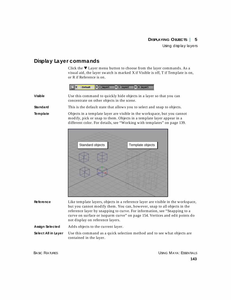
DISPLAYING OBJECTS | 5Using display layers
BASIC FEATURES USING MAYA: ESSENTIALS
143
Display Layer commandsClick the ▼ Layer menu button to choose from the layer commands. As avisual aid, the layer swatch is marked X if Visible is off, T if Template is on,or R if Reference is on.
Visible Use this command to quickly hide objects in a layer so that you canconcentrate on other objects in the scene.
Standard This is the default state that allows you to select and snap to objects.
Template Objects in a template layer are visible in the workspace, but you cannotmodify, pick or snap to them. Objects in a template layer appear in adifferent color. For details, see “Working with templates” on page 139.
Reference Like template layers, objects in a reference layer are visible in the workspace,but you cannot modify them. You can, however, snap to all objects in thereference layer by snapping to curve. For information, see “Snapping to acurve on surface or isoparm curve” on page 154. Vertices and edit points donot display on reference layers.
Assign Selected Adds objects to the current layer.
Select All in Layer Use this command as a quick selection method and to see what objects arecontained in the layer.
Standard objects Template objects

USING MAYA: ESSENTIALS PART 1
144
DISPLAYING OBJECTS | 5Using display layers
Layer Attributes Use this selection to edit the layer attributes in the Attribute Editor . See“Modifying display layer attributes” on page 146.
Edit Membership Opens the Relationship Editor for removing or adding objects to layers.
Delete Deletes the layer, but not the objects in the layer.
Changing the color of the display layer:To help you identify the objects belonging a layer, you can assign a color tothe layer. Each object in the layer will display the assigned layer color inwireframe display. You cannot change the color of objects in the defaultlayer.
To assign a layer color:
1 In the Layer Bar, double-click on the layer color box. The Layer Colorswindow opens.
2 Click on the color you want to make all objects in the layer.

DISPLAYING OBJECTS | 5Using display layers
BASIC FEATURES USING MAYA: ESSENTIALS
145
Using the Layer EditorAs an alternative to the Layer Bar, you can choose to perform all layermanagement using the Layers window. To open it, select Window >GeneralEditors > Layer Editor.
New Layer Creates a new layer with a default name, for example layer1.
Color palette Assigns a color to all objects in the currently selected layer.
Select Contents Selects all objects in the layer. Use this command as a quick selection methodand to see what objects are contained in the layer.
Assign to Current Adds selected objects to the currently selected layer.
Assign to Default Removes all objects in the currently selected layer to the default layer. Thecurrent layer becomes empty so you can assign other objects.
Layer Attributes Opens the Attribute Editor for the layer. There are some attributes in theAttribute Editor not available through the Layers editor or Layer Bar.

USING MAYA: ESSENTIALS PART 1
146
DISPLAYING OBJECTS | 5Using display layers
Edit Membership Click to remove objects from the layer. The Relationship Editor opens, whereyou can select the objects you want removed and choose Edit > RemoveSelected Items.
Visible, Invisible Turns the visibility of objects in the layer on or off.
Standard, Template, Reference
Standard allows normal selection of objects. Template and Reference restrictselection while keeping objects visible. See “Display Layer commands” onpage 143 for more information.
Rename Click to open the Rename Layer window and change the layer name.
Delete Deletes the layer, but not the objects in the layer.
Modifying display layer attributesTo further control in layers, open the Attribute Editor by clicking the▼ Layer menu button and choosing Layer Attributes.
Display Layer Type the name of the layer.
Enable Overrides Turn this option off to disable the effects of the layer. Objects in the layerwill appear and behave as though they do not belong to the layer.
Display Type Select how the layer will display.
Normal – Objects in the layer display normally, according the settings for thelayer. Objects in the layer can be selected and snapped.
Template – Objects in the layer become templates. You can see templateobjects in the workspace, but you cannot select them, nor can you snap them.
Reference – Objects in the layer can be snapped to, but you cannot selectthem or modify them.
Level of Detail Select the level of display detail for layer objects:
Full – Displays full detail for layer objects.
Bounding Box – Shows objects as boxes that represent their boundingvolumes. Bounding boxes speed up Maya operations and can make asignificant difference for complex models.
Shading Toggle on to make layer objects appear shaded when in shaded display.
Texturing Toggle on to show textures on layer objects when in shaded display.

DISPLAYING OBJECTS | 5Using render layers
BASIC FEATURES USING MAYA: ESSENTIALS
147
Playback Toggle on to animate layer objects during playback. If you have severalcharacters in a scene and want to look at each character’s animationseparately, you can place each character in its own layer and play back theanimation of each character as desired.
Visible Toggle on to make the objects in the layer visible.
Color Select the color of all objects belonging to the layer.
Number This is the number assigned to the layer.
Merging display layers when importing filesTo facilitate the merging of layers when you read in files, select Window >Settings/Preferences > Preferences, click the Display category, and in theDisplay Layer section select one of the following options:
None All layers read in will be put in a new layer, and renumbered and renamed,if necessary to preserve uniqueness.
By Number All layers read in that have the same index number as an existing layer willbe merged with that layer rather than creating a new layer.
By Name All layers read in that have the same name as an existing layer will bemerged with that layer rather than creating a new layer.
USING RENDER LAYERS
A render layer is a collection of objects that you can quickly render inseparate passes, giving you more flexibility when the shot is composited.
Once you have render layers set up, you can take advantage of the RenderLayer/Pass Control settings in the Render Globals. For more information onthese settings, see Using Maya: Rendering.
Maya also includes display layers, which work similar to render layers butapply specifically to how objects display in the scene view. For moreinformation, see “Using display layers” on page 139.

USING MAYA: ESSENTIALS PART 1
148
DISPLAYING OBJECTS | 5Using render layers
Creating and naming render layersFollow these instruction to create and optionally name a layer.
To create a new layer:
1 On the Layer Bar, click the New Layer button. An icon for the new layer isadded to the Layer bar, with a default name, for example, layer1.
2 Assign objects to the layer; see the next topic “Assigning objects to displaylayers.”
To name a layer:
1 In the Layer Bar, double-click the layer you want to name.
The Rename Layer window appears.
2 Type a new layer name and click OK.
Assigning objects to render layersYou can add selected objects to a layer, and you can move an object from onelayer to another. An object can belong to only one layer at a time.
To assign selected objects to a layer:
1 Select the objects you want to assign to a layer.
2 In the Layer Bar, click the ▼ Layer menu button to the left of the target layer.
3 Select Assign Selected.
Note
If the selected object already belongs to a layer, the object is transferredfrom its layer to the newly assigned layer.
New Layer button

DISPLAYING OBJECTS | 5Using render layers
BASIC FEATURES USING MAYA: ESSENTIALS
149
Removing objects from render layersWhen you remove an object from a layer, it automatically becomes part ofthe default layer. You cannot remove objects from the default layer.
These instructions involve using the Relationship Editor. For moreinformation, see “Using the Relationship Editor” on page 255.
To remove an object from a layer:
1 In the workspace or Outliner, select the object you want to remove.
2 In the Layer Bar, click the ▼ Layer menu button to the left of the layer youwant to remove the object from, then select Edit Membership.
The Relationship Editor opens.
3 In the Layers panel, click the layer containing the object.
4 Select Edit > Remove Selected Items.
Render Layer commandsClick the ▼ Layer menu button to choose from the layer commands.
Renderable Controls whether the objects in the layer render. This command can beuseful for performing test renders, but the main controls for rendering layersare in the Render Layer/Pass Control settings in the Render Globals. Formore information on these settings, see Using Maya: Rendering.
Assign Selected Adds objects to the current layer.
Select All in Render Layer
Use this command as a quick selection method and to see what objects arecontained in the layer.
Render Layer Attributes
This selection opens the render layer attributes in the Attribute Editor. Theseattributes are also found in the Render Layer/Pass Control settings in theRender Globals. See Using Maya: Rendering.
Edit Membership Opens the Relationship Editor for removing or adding objects to layers.
Delete Deletes the layer, but not the objects in the layer.

USING MAYA: ESSENTIALS PART 1
150
DISPLAYING OBJECTS | 5Using render layers
Changing the color of the render layer:To help you identify the objects belonging a layer, you can assign a color tothe layer. Each object in the layer will display the assigned layer color inwireframe display. You cannot change the color of objects in the defaultlayer.
To assign a layer color:
1 In the Layer Bar, double-click on the layer color box. The Layer Colorswindow opens.
2 Click on the color you want to make all objects in the layer.

USING MAYA: ESSENTIALS
151
6 MODELING AIDS
Maya has many features that help you build and position objects. Thissection describes some of those features and tells how to use them. Itincludes the following information:
• “Snapping” on page 151
• “Limiting selections” on page 157
• “Freezing and resetting transformations” on page 169
• “Locking transform tools and manipulators” on page 170
• “Using construction history” on page 170
• “Making objects live” on page 171
• “Creating levels of detail” on page 173
For a comprehensive guide to modeling features, see the Using Maya:NURBS Modeling and Using Maya: Polygonal Modeling.
SNAPPING
The snap options let you control an object or component’s position byattaching it to a grid, point, curve, or view plane. As you draw, rotate, resize,or drag the object, it snaps to the grid, point, curve, or view plane.
Snapping iconsFour icons in the Status Line control snap mode as you move or rotateobjects and create curves:

USING MAYA: ESSENTIALS PART 1
152
MODELING AIDS | 6Snapping
Snap to Grids Snaps a vertex (CV or polygonal vertex) or pivot point to a grid corner. Ifyou select Snap to Grids before you create a curve, its vertices snap to thegrid corners. For more information on CVs, see Using Maya: NURBSModeling.
Snap to Curves Snaps a vertex (CV or polygonal vertex) or pivot point to a curve or curve onsurface.
Snap to Points Snaps a vertex (CV or polygonal vertex) or pivot point to a point.
Snap to View Planes Snaps a vertex (CV or polygonal vertex) or pivot point to a view plane.
To snap an object or object component to a grid, curve, point, or viewplane:
1 To snap to a grid, select Display > Grid to display a grid in your workspace.
or
To snap to a curve, create a curve.
or
To snap to a point, create an object with several CVs or vertices (for example,a curve).
or
To snap to a view plane, select a view (perspective, top, front, or side).
2 Click the appropriate snap icon in the Status Line.
3 Select the object or object component you want to snap to the grid, curve,point, or view plane.
Snap
to G
rids
Snap
to C
urve
s
Snap
to P
oints
Snap
to V
iew P
lane
MODELING AIDS | 6Snapping
BASIC FEATURES USING MAYA: ESSENTIALS
153
If you are snapping an object component (for example, a vertex, edit point,hull, or curve on surface), use the Select by Component Type icon on thestatus line to select the component. For information on selecting bycomponent, see “Limiting selection by component type” on page 159.
Note that when you select several components, each component snaps to thesame point.
4 Select the Move tool.
When you select several components, the move manipulator is placed at thecenter of the selection’s bounding box.
5 If you are snapping to a point, right-click on the object with the vertices youare snapping to and select Control Vertex or Vertex, to display the vertices.
6 Use the middle mouse button to click and drag anywhere on the grid, curve,points, or view plane.
The object snaps to the grid, curve, points, or view plane. You can now movethe object along the grid, curve, point, or view plane.
Snapping hotkeysThe hotkeys for snapping are:
• x for grid snap
• c for curve snap
• v for point snap
To use the grid snap hotkey:
1 Select the object or component you want to snap and select the Move Tool.
2 Press and hold down the x key while click-dragging on the grid with themiddle mouse button.
To use the curve snap hotkey:
Select the object or component you want to snap and select the Move Tool.
Press and hold down the c key while click-dragging on the curve you wantto snap to with the middle mouse button.

USING MAYA: ESSENTIALS PART 1
154
MODELING AIDS | 6Snapping
To use the point snap hotkey:
1 Select the object or component you want to snap and select the Move Tool.
2 Right-click the object with vertices (CVs or polygonal) that you want to snapto (for example, a curve), and select Control Vertex or Vertex to display thevertices.
3 Press and hold down the v key and click-drag the selected object with theright mouse button to the point you want to snap to.
Snapping along a constraint axisYou can constrain object positioning along a particular axis.
If you toggle on snapping and drag a Move Tool manipulator arrow (asopposed to dragging the pivot point), Maya uses a combination of the snapand the axis constraint.
If you are using grid snap, Maya snaps to the nearest grid line along thespecified axis.
If you are using point snap and grab the end of the arrow, the manipulatorhas an initial jump because the center of the manipulator (not the tip)follows the mouse position.
It is useful to snap to an axis when you want to align a group of vertices to aparticular Y position.
Snapping to a curve on surface or isoparm curveA curve on surface is a curve you have either plotted directly onto a livesurface in UV parameter space, rather than a curve in world space orprojected onto a surface as a result of a project or intersect function.
Curves on surfaces are often used for trimming.
Tip
To minimize the initial jump, click closer to (but not on) the center of themanipulator. This is especially important if you are using a large arrow onthe manipulator.
To change the size of the manipulator arrows, press the = and - keys.

MODELING AIDS | 6Snapping
BASIC FEATURES USING MAYA: ESSENTIALS
155
You can use Snap to curves to snap to an isoparm curve or a curve onsurface. This is useful if you want to snap a pivot to the edge of a surface.But if you are moving vertices on a surface (with curve snap on) you canaccidentally snap to a curve on surface.
Snapping aligning objectsInstead of using the Move and Rotate tools, you can easily move an object toa specific point by snap aligning the object.
You can snap a point directly to any other point (where a point can be asurface point, curve intersection point, vertex, locator, etc).
If you select two points on each object, the points define an axis snap, whichmeans the object will be rotated as well as translated. This technique isuseful for orienting one object with another along some arbitrary axis.
Tip
To avoid unintentional snapping, use the c hotkey instead of the Snap tocurves icon in the Status Line. See “To use the curve snap hotkey:” on page153.
1 Select snap point
2 Select destination point
3 Snap Align ObjectsPoint to Point

USING MAYA: ESSENTIALS PART 1
156
MODELING AIDS | 6Snapping
To snap a point to another point:
1 Select the point that you want to snap to another point.
2 Select the point you want to snap the first point to.
3 Select Modify > Snap Align Objects > Point to Point. The first selected pointsnaps to the second selected point. Note that the whole object is translated,not just the select point. For example, if you used CVs as points, the selectedCV is not moved alone, but the entire surface is.
To snap two points to two points:
1 Select the first point on the snap axis.
2 Select the second point on the snap axis. This defines the snap axis.
3 Select the first point on the destination axis. The first point you selected instep number 1 will snap to this point.
4 Select the second point to define the destination axis. This defines thedestination axis.
5 Select Modify > Snap Align Objects > Two Points to Two Points. The firstselected point snaps to the third selected point, and the axis defined in steps1 and 2 lines up with the axis defined in steps 3 and 4.
1 Select snap axis
2 Select destination axis
3 Snap Align ObjectsTwo Points to Two Points
1
2
3 4
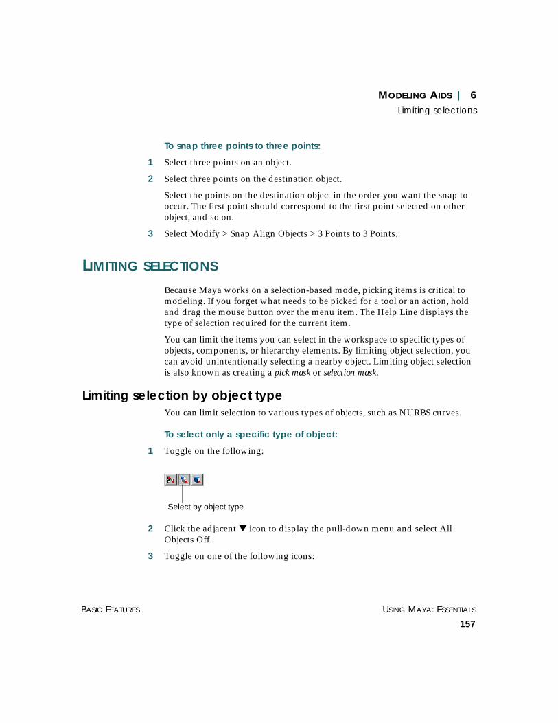
MODELING AIDS | 6Limiting selections
BASIC FEATURES USING MAYA: ESSENTIALS
157
To snap three points to three points:
1 Select three points on an object.
2 Select three points on the destination object.
Select the points on the destination object in the order you want the snap tooccur. The first point should correspond to the first point selected on otherobject, and so on.
3 Select Modify > Snap Align Objects > 3 Points to 3 Points.
LIMITING SELECTIONS
Because Maya works on a selection-based mode, picking items is critical tomodeling. If you forget what needs to be picked for a tool or an action, holdand drag the mouse button over the menu item. The Help Line displays thetype of selection required for the current item.
You can limit the items you can select in the workspace to specific types ofobjects, components, or hierarchy elements. By limiting object selection, youcan avoid unintentionally selecting a nearby object. Limiting object selectionis also known as creating a pick mask or selection mask.
Limiting selection by object typeYou can limit selection to various types of objects, such as NURBS curves.
To select only a specific type of object:
1 Toggle on the following:
2 Click the adjacent ▼ icon to display the pull-down menu and select AllObjects Off.
3 Toggle on one of the following icons:
Select by object type

USING MAYA: ESSENTIALS PART 1
158
MODELING AIDS | 6Limiting selections
To further limit the items you can select, click the right mouse button on theicon and toggle off the appropriate check boxes.
4 Select the object. You can only select the type of object you have specified.
5 To return to the default selection mask, click the left-most ▼ icon in theStatus Line and choose Initial Default.
Example
Suppose you’ve created a tubular object and want to select the joint chainwithin the object.
1 Toggle on the Select by Object Type icon.
2 Click the adjacent ▼ icon to choose All Objects Off.
3 Toggle on the Joints icon.
4 Click the object’s root joint. The root and its children become the selectedobjects.
Joints Surfaces
Rendering
Handles
CurvesDeformations
Dynamics
IK End Effectors, Locators,and Dimensions
Joint

MODELING AIDS | 6Limiting selections
BASIC FEATURES USING MAYA: ESSENTIALS
159
5 To return to Maya’s default selection mask, click the left-most ▼ icon in theStatus Line and select Initial Default.
Limiting selection by component typeYou can limit your selection to a specific type of object component, such aspolygonal vertices.
Using the selection mask to select components
To select only a type of component:
1 Select the object that has the components you want to select.
2 Toggle on the Select by Component Type icon.
3 Click the adjacent ▼ icon to select All Components Off.
4 Toggle on one of the following icons.
To further limit the items you can select, click the right mouse button on theicon and toggle off the appropriate check boxes.
5 Select the component.
If you didn’t previously select the object containing the component, theobject’s components will be displayed but not selected. Select the componentagain.
Maya selects only the specified type of component.
6 To return to Maya’s default selection mask, click the left-most ▼ icon in theStatus Line and choose Initial Default.
Select by Component Type
Points
Lines Hulls Handles
FacesPivots
Local Rotation Axesand Image Planes
Parameter Points
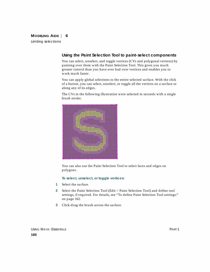
USING MAYA: ESSENTIALS PART 1
160
MODELING AIDS | 6Limiting selections
Using the Paint Selection Tool to paint-select componentsYou can select, unselect, and toggle vertices (CVs and polygonal vertices) bypainting over them with the Paint Selection Tool. This gives you muchgreater control than you have ever had over vertices and enables you towork much faster.
You can apply global selections to the entire selected surface. With the clickof a button, you can select, unselect, or toggle all the vertices on a surface oralong any of its edges.
The CVs in the following illustration were selected in seconds with a singlebrush stroke.
You can also use the Paint Selection Tool to select faces and edges onpolygons.
To select, unselect, or toggle vertices:
1 Select the surface.
2 Select the Paint Selection Tool (Edit > Paint Selection Tool) and define toolsettings, if required. For details, see “To define Paint Selection Tool settings:”on page 162.
3 Click-drag the brush across the surface.

MODELING AIDS | 6Limiting selections
BASIC FEATURES USING MAYA: ESSENTIALS
161
To select CVs along an edge of a NURBS surface:
1 Select the NURBS surface.
2 Select the Paint Selection Tool and open the Tool Settings editor (Edit > PaintSelection Tool ❐).
3 In the Edge Operation section, click a button to select the vertices along theleft edge, top edge, or right edge of the surface. Note that the edges arerelative to U/V parameterization. For information on U/V parameterization,see Using Maya: Modeling.
To select, unselect, or toggle vertices globally:
1 Select the surface.
2 Select the Paint Selection Tool and open the Tool Settings editor (Edit > PaintSelection Tool ❐).
3 In the Global Selection section, click a button to select, unselect, or toggle allthe vertices on the selected surface.
To select polygon faces:
1 Select the polygonal surface.
2 Toggle on the Select by component type button.
Surface with vertices selected Surface after clicking theToggle All button
Selected
Unselected

USING MAYA: ESSENTIALS PART 1
162
MODELING AIDS | 6Limiting selections
3 Right-click the Faces selection mask button and toggle Faces on.
4 Select the Paint Selection Tool (Edit > Paint Selection Tool) and define thetool settings (Edit > Paint Selection Tool ❐), if required.
5 Click-drag the brush across the surface.
To select polygon edges:
1 Select the polygonal surface.
2 Toggle on the Select by component type button.
3 Right-click the Lines selection mask button and toggle Poly Edges on.
4 Select the Paint Selection Tool (Edit > Paint Selection Tool) and define thetool settings (Edit > Paint Selection Tool ❐), if required.
5 Click-drag the brush across the surface.
To define Paint Selection Tool settings:
Select the Paint Selection Tool and open the Tool Settings editor (Edit > PaintSelection Tool ❐). Maya switches to component mode automatically.
Tip
You can define hotkey combinations to change most of the settings withoutopening the Tool Settings editor. For details on setting hotkeycombinations, see “Defining Artisan hotkeys” on page 410.

MODELING AIDS | 6Limiting selections
BASIC FEATURES USING MAYA: ESSENTIALS
163
Setting the stamp profile
Radius (U) If you are using a stylus, set the upper or maximum possible radius for thebrush. No matter how hard you press the stylus, the brush radius will notexceed this radius. If you are not using a stylus, this setting defines theradius for the brush.
Radius (L) If you are using a stylus, set the lowest or smallest possible radius for thebrush when pressure is applied to the stylus. If you are not using a stylus,this setting is not used.

USING MAYA: ESSENTIALS PART 1
164
MODELING AIDS | 6Limiting selections
Shape Click on the shape of the brush. This determines the shape of the areaaffected by the selection.
Choosing the selection type
In the Selection Type section, specify what you want to do with the surfacearea you paint:
Add to Current Selection
By default, this option is toggled on so that each stroke adds to the previousselection. This means you do not have to press the Shift key when you makea brush stroke to select, unselect, or toggle more vertices. If you want eachstroke to override the previous one, toggle Add to Current Selection off.
Select Selects vertices.
Unselect Unselects any selected vertices.
Note
The brush profile alignment affects how vertices are selected. For details onchanging the profile alignment, see “To set the brush stamp profilealignment:” on page 402.
Tip
To unselect selected vertices while Select is chosen, press the Ctrl key andpaint over them.

MODELING AIDS | 6Limiting selections
BASIC FEATURES USING MAYA: ESSENTIALS
165
Toggle Unselects selected vertices and selects unselected vertices.
Tip
To select unselected vertices while Unselect is selected, press the Ctrl keyand paint over them.

USING MAYA: ESSENTIALS PART 1
166
MODELING AIDS | 6Limiting selections
Limiting selection to hierarchy itemsYou can limit selection to the following hierarchy items:
• root – a heirarchy’s top object
• leaf– descendent object
For information about hierarchies, see “Understanding scene hierarchyterminology” on page 322.
To select only a hierarchy root or leaf:
1 Toggle on the Select Hierarchy and Combinations icon.
2 Toggle on the Root or Leaf icon.
or
Click the adjacent ▼ icon to select Root or Leaf.
3 Select the object. Notice you can select only a root or leaf object.
4 To return to Maya’s default selection mask, click the left-most ▼ icon andchoose Initial Default.
Limiting selection to template objectsYou can limit your selections to template objects.
To select only a template object:
1 Toggle on the Select Hierarchy and Combinations icon.
Select Hierarchyand Combinations
Root
Leaf
Select Hierarchyand Combinations

MODELING AIDS | 6Limiting selections
BASIC FEATURES USING MAYA: ESSENTIALS
167
2 Toggle on the Template icon.
Alternatively, click the adjacent ▼ icon to select Template from a menu.
3 Select the object. Maya selects only a template object.
4 To return to Maya’s default selection mask, click the left-most ▼ icon in theStatus Line and choose Initial Default.
Limiting selection by taskYou can limit your selection to the objects or components that pertain totypes of Maya tasks. For instance, you can limit selection to objects andcomponents relevant to dynamics tasks.
To limit selection by Maya task:
1 If it isn’t showing, open the Task Selection icon on the Status Line.
2 Click the pulldown icon and choose one of these categories:
• Animation
• Polygons
• NURBS
• Deformations
• Dynamics
• Rendering
This creates a selection mask that limits selection to the objects andcomponents in the chosen category.
3 Do one of the following:
• To select an object in the chosen category, drag a selection box around theobject.
• To select a component in the chosen category, click the component directly.
Template
Click the bar to expand

USING MAYA: ESSENTIALS PART 1
168
MODELING AIDS | 6Limiting selections
• You usually need to display components before you can click-select them.For example, to select CVs by clicking, first select Display > NURBScomponents > CVs to display them.
• If you display CVs on an object and the selection box surrounds any of them,you select the CVs rather than the object. Drag the selection box on the objectwhere CVs aren’t displayed.
To use the default Maya selection limitations:
Click the ▼ icon in the Status Line to choose Initial Default.
To allow selection of all objects:
Click the ▼ icon in the Status Line to choose All Objects.
Moving selection limitations to the shelfYou can put your selection limitation choices on a shelf for future use.
To move selection limitations to a shelf:
1 Select a shelf tab.
2 Toggle on the object or component selection limitation icons.
3 Click the right mouse button on individual icons to Toggle on (or off) itemcheck boxes.
Tip
You can customize the priority of object or component selection forsituations where you drag a selection box around multiple objects orcomponents.
To prioritize object selection:
1 Select Window > Settings/Preferences > Preferencesand click the Selection category.
2 Select Custom from the PreSets menu.
3 Select an item in the Priority list.
4 Enter a priority number for the item in the data box.Higher numbers have higher priority.

MODELING AIDS | 6Freezing and resetting transformations
BASIC FEATURES USING MAYA: ESSENTIALS
169
4 Click the right-most ▼ icon in the Status Line to choose Save to Shelf.
An icon labeled MEL appears on the shelf. If you click this icon, the selectionlimitations take effect. The Status Line icons show the selection limitations.
You can change the MEL icon, as described in “Changing shelf icons” onpage 502. If you want to add an icon label, see “Setting Shelf label options”on page 506.
FREEZING AND RESETTING TRANSFORMATIONS
Before animating a model you just created, you may want to reset it’stransformation, called freezing the transformations. Freezing sets the existingtranslation, rotation, or scale for selected objects to be the initial state. Theresult is that transform values change to zero (or one for scale), but the objectitself remains in place.
You can also reset an object’s transformations at any time. The resetcommand transforms the object back to the translation, rotation, and scale itwas when created or last frozen.
You can apply these operations separately for translation, rotation, or scale.
To freeze or reset an object:
1 Select one or more objects that you have moved, rotated, or resized.
2 Choose Modify > Freeze (or Reset) Transformations ❒.
3 In the option window, turn on or off Translate, Rotate, or Scale, as needed.
4 Click OK.

USING MAYA: ESSENTIALS PART 1
170
MODELING AIDS | 6Locking transform tools and manipulators
LOCKING TRANSFORM TOOLS AND MANIPULATORS
If you are going to be using a single tool on an object for a long time, you canlock the transform tools—Move, Rotate, Scale—and the Show Manipulatortools. It is also useful to lock tools when you use a stylus input device.
After you lock a tool, you can’t use the left mouse button to select objects inthe workspace. The left mouse button works the same way as the middlemouse button does during normal use of the Move, Rotate, Scale, orManipulator tools. If you need to select objects after locking a tool, use theOutliner or Hypergraph.
To lock the Move, Rotate, Scale, or Show Manipulator tool:
1 Select the object.
2 Select the tool.
3 Toggle the Lock current selection icon on in the Status Line.
To unlock the tool and return to normal mouse usage, toggle off the icon.
USING CONSTRUCTION HISTORY
When you create an object surface using deformers or certain modelingtools, Maya keeps a construction history for the object. A construction historyis a record of the options, geometry, and modeling actions that you used tocreate the object.
You can use the construction history to modify an object by making simplechanges to the original elements of the history. You don’t have to repeat allthe steps that went into the object’s creation.
Construction history adds complexity to a scene and therefore slows Mayaoperation. For this reason you might decide to toggle it off for some scenes.
You can toggle off the creation of construction history for all subsequentmodeling activities. If you do this, you won’t be able to tweak historyoptions and geometry for object surfaces you create afterwards.Alternatively, you can delete a single object’s construction history.
MODELING AIDS | 6Making objects live
BASIC FEATURES USING MAYA: ESSENTIALS
171
To toggle off construction history for all objects:
Toggle the Construction History icon off in the Status Line.
To delete an object’s construction history:
1 Select the object.
2 Select Edit > Delete by Type > History.
MAKING OBJECTS LIVE
When you “make an object live,” you can use its surface as a constructionaid. You can make NURBS surfaces, poly meshes, and construction planesinto live objects. Making a NURBS surface live is one way to create a curveon surface.
To make an object live:
1 Select the object.
2 Select Modify > Make Live or click the Make Live icon on the Status Line.
Tip
When you attach curves or animate CVs, toggle construction history off oryou may get unexpected results.
Tip
If you animate CVs on an object that was created with history, do notdelete the object’s history. The CV animation will not be correct andunexpected results will occur.
Note
Only one object can be live at a time. The live object displays in a specialgreen color in wireframe mode to indicate its status.

USING MAYA: ESSENTIALS PART 1
172
MODELING AIDS | 6Making objects live
3 To toggle off a live object, select Make Live again.
To create a curve on surface by placing it onto a live surface:
1 Select the surface.
2 Select Modify > Make Live or click the Make Live icon on the Status Line.
3 Use any curve creation tool to draw the curve directly onto the surface.
All creation tools respect a live surface. Actions do not.
You can use Make Live to place particles on an object's surface or on jointsand polygons.
When an object is live and the Move tool is the current tool, the active objectsnaps to the live object.
Trimmed surface
Trim curve

MODELING AIDS | 6Creating levels of detail
BASIC FEATURES USING MAYA: ESSENTIALS
173
CREATING LEVELS OF DETAIL
You can group geometry into a special Level of Detail group, which meansthat depending on how far the group is from the camera, a different child, orresolution, of the group is displayed.
An object can have any number of levels of detail, but typically 3 to 5 levelsare used in the creation of a game. Level 1 is drawn when the object is closestto the camera and it typically has the most geometry. Level N is drawn whenthe object is far away from the camera and has the least amount of geometry.This level can be empty.
Creating levels of detail can involve one or more artists/programmers, andtwo tasks. The first task is to create the models for each level. The secondtask is to set up the order of the models (usually by complexity) and thedistances at which each level is drawn.
To create levels of detail:
1 Create models to represent different levels of detail, in order of geometriccomplexity.
The models can be in different layers or sets, or they can be referencedobjects.
2 Position the models together in a modeling view at approximately thedistance that you want the middle object to appear in the level of detail.
Notes
• Setting up level of detail will not work if you specifyless than two levels of detail.
• Different levels can come from different sets, layers,and can be reference objects.
• Level of Detail only supports discrete levels of detail.For example, there is no blending between levels.
• You can use NURBS, polygons, or subdivision surfacesto create the different levels, and each level can use adifferent geometry type if you want.
USING MAYA: ESSENTIALS PART 1
174
MODELING AIDS | 6Creating levels of detail
Positioning the objects together helps you keep track of them in cases whereyou have multiple groups and many models in the same scene.
3 Look through the camera to which you want to associate the level of detailgroup.
4 Do one of the following:
• Select the models in the order you want them to appear in the level of detailgroup (either lowest to highest or highest to lowest), then select Edit > Levelof Detail > Group.
• Select a camera and the models in the order you want them to appear in thelevel of detail group, then select Edit Level of Detail > Group. The selectedcamera is used in the level of detail group.
The objects are grouped under a new node, called lodGroup#, which islinked to the camera you are looking through.
5 Preview the levels by zooming in and out.
Changing the Threshold distancesYou can change the distances at which the levels are switched using thechannel box.
To change a Threshold distance:
1 Select the level of detail group node in Hypergraph.
Its level of detail attributes are displayed in the Channel Box.
2 Edit the Threshold value for the object whose distance you want to change,and press Enter.
Note
Only one of the levels is visible at a time. The levels switch as you zoom inand out.

MODELING AIDS | 6Creating levels of detail
BASIC FEATURES USING MAYA: ESSENTIALS
175
Re-ordering the levelsYou can re-order the levels after you create a level of detail group.
To re-order the levels in the Outliner:
In the Outliner, use the middle mouse button to drag the object you want tomove into its new position within the group. This is the easiest way to re-order the levels.
To re-order the levels in the Hypergraph:
1 In the Hypergraph, use the middle mouse button to remove the object youwant to re-order from the group.
The other objects in the group move up the group hierarchy.
2 Use the middle mouse button to drag the removed object onto the lodGroupnode.
The object is added to the bottom of the lodGroup’s hierarchy.
Adding and editing levels
To add a new level:
1 Create a new object to add to the level of detail group.
2 Do one of the following:
• In the Hypergraph, use the middle mouse button drag the new object ontothe lodGroup node.
• In the Outliner, use the middle mouse button to drag the new object onto thegroup.
The new object is added to the bottom of the lodGroup’s hierarchy.
Tip
You can also re-order a group by selecting Edit > Level of Detail >Ungroup. Re-order the objects and create a new group.

USING MAYA: ESSENTIALS PART 1
176
MODELING AIDS | 6Creating levels of detail
Previewing more than one object at the same timeYou can preview different objects at the same time to compare them.
To view more than one object:
1 In the Hypergraph, select the level of detail group node.
The node’s attributes are displayed in the Channel Box. Each Display Levelhas three possible settings: uselod, show, and hide.
2 Use the left mouse button to click on one of the Display Level’s uselod text.
A drop-down menu with the three options is displayed.
3 Select one of the options.
You can show or hide any combination of objects.
Tip
You can also re-order a group by selecting Edit > Level of Detail >Ungroup. Re-order the objects and create a new group.
Tip
Reset the Display Levels to uselod to return to the regular level of detailbehavior.

MODELING AIDS | 6Creating levels of detail
BASIC FEATURES USING MAYA: ESSENTIALS
177
Notes about orthographic cameras and level of detailLevel of Detail displays one child of a level of detail group, depending onthe group’s distance to a camera. For perspective cameras, this meansmeasuring the distance between the camera position to the center of thebounding box of the group.
For orthographic cameras, the distance is measured differently. This isbecause zooming, panning and dollying in an ortho view does not changethe camera position, but instead changes the camera’s orthographic width. Sothe distance is measured as:
distance = (default camera distance) * (camera’sorthographic width)/(default orthographic width)
Substituting Maya’s default values in this equation results in the following:
distance = 3.333 * (camera’s orthographic width)

USING MAYA: ESSENTIALS PART 1
178
MODELING AIDS | 6Creating levels of detail

USING MAYA: ESSENTIALS
179
7 MANAGING FILES ANDPROJECTS
Maya includes many features to help you manage your files and projects.This chapter describes how to open and save files, import and export files,how to create and edit projects, and what files formats are supported byMaya.
• “Opening a scene” on page 180
• “Creating a new scene” on page 181
• “Setting Open options” on page 181
• “Importing files” on page 184
• “Supported file formats” on page 196
• “Saving files” on page 198
• “Exporting files” on page 201
• “Using plug-ins for exporting” on page 205
• “Optimizing scene size” on page 212
• “Managing projects” on page 213
• “Editing the current project” on page 218
• “Mapping missing directories” on page 218
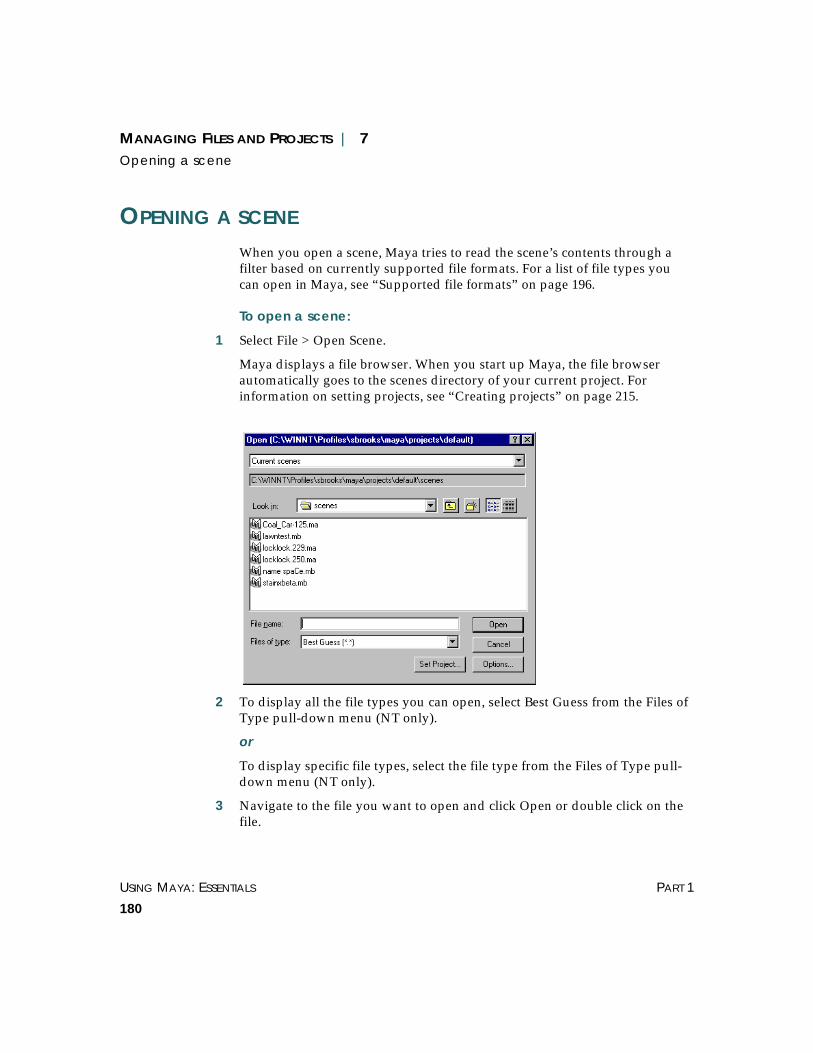
USING MAYA: ESSENTIALS PART 1
180
MANAGING FILES AND PROJECTS | 7Opening a scene
OPENING A SCENE
When you open a scene, Maya tries to read the scene’s contents through afilter based on currently supported file formats. For a list of file types youcan open in Maya, see “Supported file formats” on page 196.
To open a scene:
1 Select File > Open Scene.
Maya displays a file browser. When you start up Maya, the file browserautomatically goes to the scenes directory of your current project. Forinformation on setting projects, see “Creating projects” on page 215.
2 To display all the file types you can open, select Best Guess from the Files ofType pull-down menu (NT only).
or
To display specific file types, select the file type from the Files of Type pull-down menu (NT only).
3 Navigate to the file you want to open and click Open or double click on thefile.

MANAGING FILES AND PROJECTS | 7Creating a new scene
BASIC FEATURES USING MAYA: ESSENTIALS
181
CREATING A NEW SCENE
When you create a new scene file, the current scene file is closed and the filechanges to that of the newly opened file.
To create a new scene:
1 Select File > New Scene.
If you haven’t saved the current scene, a Confirm dialog box displays.
2 To save the contents of the current scene file, click Yes. To discard thepresent scene file, click No.
SETTING OPEN OPTIONS
The Open Scene window lets you set some general options and some optionsthat are specific to file types.
To set Open options:
1 Select File > Open Scene ❐.
or
• Select File > Open Scene and click the Options button in the Open window(NT).
• Select File > Open Scene and select Options > Options in the Open window(IRIX). The options window opens.
2 In the Open Options window, you can set the options listed below. ClickOpen to open a file or click Save to save the Open options without opening afile.
Note
Maya lists the files you have opened in the current Maya session on theRecent Files sub-menu. You can open these files at any time during thesession by selecting File > Recent Files > filename. When you close Maya,the list becomes empty.

USING MAYA: ESSENTIALS PART 1
182
MANAGING FILES AND PROJECTS | 7Setting Open options
General options
File Type Select the file format you want to use as a default for the next time you opena file.
If you have a project set up, when you open a scene, the browser points tothe directory containing files of that type. On NT, it also sets the filter todisplay only files of the selected type. See “Creating projects” on page 215for information on setting up projects.
For example, if you set File Type to DXF, when you open a scene, the Openwindow displays the contents of CurrentProject/DXF. On NT, it also setsyour filter type to DXF.
Depending on the File Type you select, various File Type Specific Optionsare displayed.
Execute Script Nodes
Script nodes contain Mel scripts in mayaAscii or mayaBinary files. You candesignate a script node to execute its script when the node is read from a file,or before or after rendering a frame. You can create and edit the script nodesusing the Expression Editor. See the chapter “Using Script Nodes” in theUsing Maya: MEL book for information on creating and editing script nodes.
User interface configuration information is stored inside the Maya scene fileas an attribute on a script node. If you disable the Execute Script Nodesoption, the UI script nodes are not executed. However, we recommenddisabling script node execution only if you have an error in your script.
Load Deferred References
Turn on Load Deferred References option to load referenced files that mayhave been unloaded. When you unload a reference, Maya removes thereference contents from the scene but “remembers” how the reference wasconnected into the scene.
If you create a scene with references, unload some of them, and then savethe scene, you have created some deferred references. If you turn on theLoad Deferred References option, the deferred reference are loaded whenyou open the scene. If you turn off Load Deferred References, the deferredreferences are not loaded when you open the scene.
Turn on Load Deferred References when rendering a scene in which theanimators were working with only part of the scene loaded when they savedthe scene.

MANAGING FILES AND PROJECTS | 7Setting Open options
BASIC FEATURES USING MAYA: ESSENTIALS
183
mayaAscii, MayaBinary, and MEL. File Type Specific Options
Use Verbose Names
Displays the full names of node attributes in the file.
For example, if you select the Use Verbose Names option, attribute namesare listed as, setAttr.translate 0 0 0 when you open the Maya ASCII file in atext editor. If you turn off the Use Verbose Names option, attribute namesare listed as setAttr .t 0 0 0.
OBJ File Type Specific Options
Create Multiple Objects
Specifies how shapes are created in OBJ files.
Select True to create individual shapes based on grouping informationspecified in the OBJ file.
Select False to create one shape for the entire file, with object setscorresponding to each of the specified groups.
You cannot have overlapping groups, If you do, Maya informs you thatoverlapping groups exist, and re-reads the file as if the option were set tofalse.
Sound File Type Specific Options
Sound File Offset Specifies the time the sound should start playing.
For example, suppose you created an animation of a bird walking atightrope, and you wanted the sound file to play after the bird reached theend of the rope. If you knew that the bird reached the end of the tightrope attime 108, you would specify a sound file offset of 108.
Move files
You must import move files (see “Importing move files” on page 186).
Anim files
You must import anim files (“Importing animation curves” on page 188).

USING MAYA: ESSENTIALS PART 1
184
MANAGING FILES AND PROJECTS | 7Importing files
IMPORTING FILES
Maya has built-in translators that let you import scenes and files created inother applications into Maya. See “Supported file formats” on page 196 tosee the types of files you can import.
There are two ways to import a file:
• You can copy the imported file into the current scene using File > Import.See “Importing files by copying” on page 184 for details.
• You can import the file by reference using File > Create Reference. Whenyou import by reference, Maya makes a link to the file rather than copying it.See “Importing files by reference” on page 190 for details.
Using default nodesDefault nodes are built-in nodes that always exist in Maya. These nodesrepresent global elements, such as camera positions, shader colors, andcurrent time frames.
When you import a file into an active scene, Maya uses the default nodes forthe active scene.
For example, if you changed a scene’s default shader color to red, thischange would be saved. However, if you imported this scene into anotherscene, Maya would ignore the changed shader color and use the currentdefault shader color instead. This is to prevent default nodes from suddenlychanging.
Since default nodes are always present in Maya, you don’t need to createthem when you open a file. Only changes made to the defaults are saved.For more information on default nodes, see Using Maya: Expressions.
Importing files by copyingImporting by copying makes it easier to transfer imported material from onescene to another. However, copying increases the file size. If also means thatyou must delete the imported objects and import the source scene again, ifyou change it.
To import by copying:
1 Select File > Import.

MANAGING FILES AND PROJECTS | 7Importing files
BASIC FEATURES USING MAYA: ESSENTIALS
185
2 Navigate to the file you want to import.
3 Double-click the name of the file you want to import.
Maya copies the contents of the specified file into the current scene.
Setting import optionsImport options are values you specify, that take effect whenever you importa file into a scene. You can override the import options for a specific session.
To set import options:
1 Select File > Import ❐. The Import Options window opens.
2 You can set the following options:
Group Specifies whether the imported objects are grouped under a single transformwhen you import the file. Grouping makes it easier to work on the nodes ofimported objects. The default is off.
Use Namespaces When you import or reference a scene with the Use Namespaces optionturned on, Maya creates a new namespace that contains the imported orreferenced data. Turning on the Use Namespaces option ensures that allnodes are uniquely named.
A namespace is a grouping of objects under a given name. Each item in anamespace is identified by its own name along with the namespace itbelongs to.
By default, the basename of the imported or referenced file is added to thebeginning of the imported or referenced object names, separated by colons.
For example, if you are importing a scene named foo.ma that contains anobject named ball, after it’s imported the ball is named foo:ball.
You can change the prefix by selecting Resolve clashing nodes with thisstring and entering a prefix.
You can create, name, parent, and remove namespaces using the namespacecommand. See the online documentation for MEL Commands forinformation on the namespace command.
Namespaces do not effect selection, the DAG, the Dependency Graph, or anyother aspect of Maya.

USING MAYA: ESSENTIALS PART 1
186
MANAGING FILES AND PROJECTS | 7Importing files
Resolve Name Clashes by
When you import a scene into another scene, naming conflicts occur if thenodes share the same name and parent nodes.
To resolve these naming conflicts, you can rename only nodes with the samename and parents (clashing nodes) or you can rename all nodes. You specifywhether to use the filename as the prefix (the default) or to create a prefixstring.
For more information on node hierarchy, see Using Maya: Expressions.
Type is Choose the file type you will be importing from the pull-down menu. If youaren’t sure what type of file you will be importing, you can use the BestGuess setting if you don’t know what type of file will be imported.
Depending on the file type you select, various file type specific options maybe displayed, see “Setting Open options” on page 181 for information onthese options.
Importing move filesWhen you import move files, you must list the attributes to import or exportin the text list in the move file option box.
The move file format is just list of numbers. No information on how thosenumbers should be used is included in the move file. Instead, each row isassumed to be a frame of data, and each column represents a single channelof data.
This is the same move file format used by the Wavefront PreView program,with the addition that comment characters (# or // ) at the beginning of aline are allowed.
Since time data is not stored with the file, when exporting a move file, theattribute’s value is written at each frame. The units of the file are yourcurrent units in Maya. When importing a move file, the current time of thescene is used as the starting point of the import.
Tip
We recommend you use namespaces to resolve naming conflicts instead ofusing the Name clash options when importing or referencing files.

MANAGING FILES AND PROJECTS | 7Importing files
BASIC FEATURES USING MAYA: ESSENTIALS
187
For both the import and export functions, all node naming clash and groupoptions are ignored.
To import a move file:
1 Select File > Import ❐. The Import Options window opens.
2 Select move from the File Type pull-down menu.
The following file type specific options apply to importing move files:
Attributes Type the name of an attribute in the Attributes box and click Add to add theattribute to the list of attributes to use when importing or exporting. If theattribute is already included in the list, a duplicate is not made. To removean attribute, type the name of the attribute and click Remove. You can addseveral attributes at one time by separating them with a space.
From Channel Box Click From Channel Box to combine all of the selected objects in Maya, in theorder of their selection, with the channels selected in the channel box andplace them in the list. For example, if sphere and cone are selected, and tx, sxare selected in the channel box, sphere.tx sphere.sx cone.tx and cone.sx areadded to the list of attribute to import and export.
Remove Selected Click Remove Selected to remove all of the attributes selected in the list.
Remove All Click Remove All to remove all of the attributes are removed from the list.
Precision This is ignored in file export. For file import, this sets the precision of the file.
When you click import or export, the move file is written or read and onlythe attributes in the list are affected.

USING MAYA: ESSENTIALS PART 1
188
MANAGING FILES AND PROJECTS | 7Importing files
Importing Adobe Illustrator® and EPS filesYou can import Illustrator and encapsulated postscript (EPS) files into Maya.With this feature, you can create 3D models based on 2D graphics, such astext or logos. Maya imports them as NURBS curves, which you can thengroup into surfaces, convert to polygons, and so forth.
Support for Illustrator files extends from version 4 up to version 8. Anyversions before 4 or after 8 are not necessarily supported.
How curves are converted
The curves from Illustrator and EPS files are actually Bezier curve segments.During import, Maya attaches the segments into a single curve. The CurveDegree is set to 3 (cubic) and the Knot Spacing is set to Multiple End Knots.
To import an Illustrator or EPS file:
1 Choose File > Import.
2 In the file browser, navigate to the Illustrator or EPS file.
3 If needed, click the Options button (NT) or choose Options > Options (IRIX)to set the following controls.
Scale Factor Allows you to control the scale of the curves producedfrom the import. It is the same operation as using the Scaletool.
Group Turn on this option to group the imported curves. It is thesame operation as using the Edit > Group option.
4 Click Import.
Importing animation curvesYou can import animation curves from an anim file. To do this, you mustfirst select the objects you want to connect to the animation curves. Ifnothing is selected the anim import will fail. Maya imports the animationcurve into the API clipboard and pastes it into the file.
To import animation curves from an anim file:
1 Select Window > Settings/Preferences > Plug-in Manager to verify that theanimImportExport plug-in is loaded.

MANAGING FILES AND PROJECTS | 7Importing files
BASIC FEATURES USING MAYA: ESSENTIALS
189
2 Open the file into which you want to import the animation curve.
3 Select the object which you want to connect to the animation curves.
4 Select File > Import.
5 Select animImport from the Read As pull-down menu (IRIX).
or
Select animImport from the Files of Type pull-down menu (NT).
6 Navigate to the file you want to import.
7 Double-click the name of the file you want to import.
Maya copies the contents of the specified file into the current scene.
To set anim import options:
1 Select File > Import ❐. The Export Selection Options window opens.
2 Select animImport from the File Type pull-down menu. The Export Optionswindow opens.
You set the following options in the Import Options window:
Time Range Start – Imports the animation information to the selected objects so that theanimation starts at the time specified in the Start Time field.
Start/End – Imports the animation information to the selected object orobjects, scaling the animation to fit into the specified time range as entered inthe Start Time and End Time fields. Animation information from the keysclipboard is either scaled or clipped depending on the setting of theClipboard Adjustment option.
Current – Imports the animation information to the selected objects so thatthe animation starts at the current time as displayed in the AnimationControls.
Clipboard – Transfers the animation information to the selected object orobjects, preserving the duration and timing of the animation information onthe keys clipboard.
Copies – Specify how many copies of the anim curves you want imported.Multiple copies are appended sequentially.
Help Images Turn on Help Images to display illustrations of the effects of the variousanim import options.

USING MAYA: ESSENTIALS PART 1
190
MANAGING FILES AND PROJECTS | 7Importing files
Clipboard Adjustment
Preserve – Pastes the contents of the clipboard into their new positions onthe curve without any changes.
Scale – Becomes enabled when Start/End is selected. The complete contentsof the clipboard curves are stretched or compressed to fit into the specifiedimport Time Range.
Fit – Becomes enabled when Start/End is selected. The contents of theclipboard are preserved (that is, not stretched or compressed) and as muchas will fit into the specified time range is pasted into the new area.
Paste Method Insert – Places the clipboard contents before any existing keys in thespecified time range. The keys from the original curve that were after thespecified time range are shifted in time by the pasted range times.
Replace – Becomes enabled when Start/End or Clipboard is selected. Theclipboard contents overwrite any existing keys in the specified time range.
Merge – The clipboard contents are added to any existing keys on the curve.In the case where a clipboard key is at the same time as an existing key, theclipboard’s key replaces the existing key.
Replace Region These buttons are enabled when Paste Method is set to Replace.
Time Range – Replace keys and curve segment information in the specifiedtime range with the contents of the keys clipboard.
Entire Curve – Is available only when the Time Range setting is Clipboard.The Entire Curve setting replaces the animation curve(s) on the importedattributes with the contents of the keys clipboard, in effect deleting anyexisting animation curves on these attributes and applying the new curvesfrom the keys clipboard.
Connect Adjusts the keys clipboard curves in value, so there’s no discontinuity in theanimation at the start of the pasted segment.
Importing files by referenceWhen you import a scene by reference, Maya makes a link from the currentscene to the source scene. This link points to the latest saved version of thescene. You cannot rename, delete, or ungroup objects from a referenced file.
MANAGING FILES AND PROJECTS | 7Importing files
BASIC FEATURES USING MAYA: ESSENTIALS
191
You can develop the referenced file while you use it in other scenes. Forexample, say you had three scenes in an animation that all used the sameprops. In one scene, the chair is beside the table. In the second, the chair ison top of the table. In the third, the chair is on the floor. If you imported thefiles by reference, three animators could use the same props, saving filespace and sharing changes made to the surface characteristics and shading ofthe objects.
To specify a referenced file:
1 Select File > Create Reference.
2 In the file browser, navigate to the file to reference and click Reference.
You can also use this window to reference files on other systems (includingIRIX) on your network.
Maya loads the selected scene into the scene you are working on.
Statements in conventional expression format work whether or not youinclude object names. The Expression Editor resolves name changes.
Setting Reference optionsYou can specify file reference options. Maya uses these options the next timeyou import by reference. You can change the options as you work tooverride existing import by reference options for only the current session.
To set reference options:
1 Select File > Create Reference ❐. The Reference Options window opens.
Note
Node names from referenced files appear red in the Hypergraph. Incontrast, node names from non-referenced files appear black.
Tip
Turn on the Use Namespaces option if you referenced expressions thatinclude statements in MEL command format that include object names.

USING MAYA: ESSENTIALS PART 1
192
MANAGING FILES AND PROJECTS | 7Importing files
2 Set the options. See “Setting import options” on page 185 for information onsetting Group, Namespaces, Name clash, and File Type options.
Using the Reference EditorYou use the Reference Editor to specify settings for importing files byreference. You can:
• Create Reference (see “Importing files by reference” on page 190).
• Import Reference (see “Importing a referenced scene” on page 193).
• Export Selection As Reference (see “Exporting a selection as a reference” onpage 193).
• Remove Reference (see “Removing a reference from a scene” on page 194).
• Select Reference Contents (see “Selecting the contents of a referenced scene”on page 194).
• Load Reference/Unload Reference (see “Loading and unloading referencefiles” on page 195.
• Replace Reference (see “Replacing reference files” on page 195).
• Clean up References (see “Cleaning up references” on page 196).
To use the Reference Editor:
1 Select File > Reference Editor. The Reference Editor opens.
MANAGING FILES AND PROJECTS | 7Importing files
BASIC FEATURES USING MAYA: ESSENTIALS
193
2 Select a referenced file.
When you select a referenced file using the Reference Editor, Maya displaysinformation about the file, called File Particulars.
File Particulars
Name Displays the name of the file.
Type Displays the file format.
Status Indicates if the file has been changed in some way.
Load Indicates is the referenced file is loaded or unloaded. See “Loading andunloading reference files” on page 195.
Sub-type Displays the sub-type of file.
I/O Indicates if the file can be changed. Referenced files are always Read Only,while files you create yourself are always Writable.
Rename Prefix Displays a prefix that can be applied to object names in the event of nameclashes or namespaces.
Importing a referenced sceneYou can import a scene that used to be referenced. This breaks the referenceconnection.
To import a referenced file:
1 Select File > Reference Editor.
2 Click the arrow next to the scene name and select the referenced file to beimported.
3 Select File > Import Reference.
Exporting a selection as a referenceThis lets you export parts of the scene you are working on as a referencedfile. Exporting a referenced file is similar to File > Export Selection.However, when exporting selections as a referenced file, the selections in theMaya window exist only as referenced objects. If you make changes to thenew referenced file, the objects in the existing scene change. For moreinformation on exporting selections, see “Exporting files” on page 201.

USING MAYA: ESSENTIALS PART 1
194
MANAGING FILES AND PROJECTS | 7Importing files
To export a referenced file:
1 Select objects in the scene file.
2 Select File > Reference Editor.
3 Select File > Export Selection as Reference.
4 Type the name of the referenced file, choose a file type from the Write Aspull-down menu, then click Export Reference.
Removing a reference from a sceneYou can remove a referenced file from a scene if you do not need it anymore.When you delete the referenced file, referenced objects disappear and allconnections are broken permanently. If you want to remove a reference andkeep the connections intact, see “Loading and unloading reference files” onpage 195.
To remove a referenced file:
1 Select File > Reference Editor.
2 Select a referenced file.
3 Select Edit > Remove Reference. Maya displays a message warning you thatthis action cannot be undone.
4 Click Remove to remove the referenced file.
Selecting the contents of a referenced sceneYou can select objects in your scene that come from a referenced file. Thislets you identify which objects exist in a referenced file without having toopen the source file.
To select objects from a referenced file:
1 Select File > Reference Editor.
2 Select a referenced file.
3 Select Edit > Select Reference Contents. The objects from the referenced fileare selected and displayed in a different color.

MANAGING FILES AND PROJECTS | 7Importing files
BASIC FEATURES USING MAYA: ESSENTIALS
195
Loading and unloading reference filesIn a scene that contains reference files, you can unload a reference file if it isnot needed while you are working on a different part of the scene. Thisimproves the interactive performance of Maya. You load it back in when youare ready for that part of the scene.
To unload a reference file:
1 Select File > Reference Editor.
2 In the Reference Editor, expand the scene name to display the reference files.
3 Highlight the reference file you want to unload.
4 Select Reference > Unload Reference.
The reference file no longer appears in the scene.
To load a reference file:
1 Select File > Reference Editor.
2 In the Reference Editor, expand the scene name to display the reference files.
3 Highlight the reference file you want to load.
4 Select Reference > Load Reference.
The reference file appears in the scene.
Replacing reference filesYou can replace a reference file with another reference file. This is useful forsubstituting high and low resolution geometry.
To replace a reference file:
1 Select File > Reference Editor.
2 In the Reference Editor, expand the scene name to display the reference files.
3 Highlight the reference file you want to replace.
4 Select Reference > Replace Reference.
5 Navigate to the replacement file and click Reference.
The reference file is replaced. All connections are maintained.
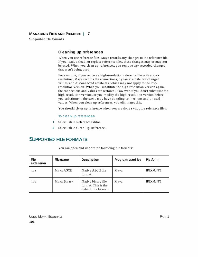
USING MAYA: ESSENTIALS PART 1
196
MANAGING FILES AND PROJECTS | 7Supported file formats
Cleaning up referencesWhen you use reference files, Maya records any changes to the reference file.If you load, unload, or replace reference files, these changes may or may notbe used. When you clean up references, you remove any recorded changesthat aren’t being used.
For example, if you replace a high-resolution reference file with a low-resolution, Maya records the connections, dynamic attributes, changedvalues, and disconnected attributes, which may not apply to the low-resolution version. When you substitute the high-resolution version again,the connections and values are restored. However, if you don’t substitute thehigh-resolution version, or you modify the high-resolution version beforeyou substitute it, the scene may have dangling connections and unusedvalues. When you clean up references, you eliminates this.
You should clean up reference when you are done swapping reference files.
To clean up references:
1 Select File > Reference Editor.
2 Select File > Clean Up Reference.
SUPPORTED FILE FORMATS
You can open and import the following file formats:
Fileextension
Filename Description Program used by Platform
.ma Maya ASCII Native ASCII fileformat.
Maya IRIX & NT
.mb Maya Binary Native binary fileformat. This is thedefault file format.
Maya IRIX & NT

MANAGING FILES AND PROJECTS | 7Supported file formats
BASIC FEATURES USING MAYA: ESSENTIALS
197
.mel MEL Maya EmbeddedLanguage, thescripting languageused by Maya.
Maya IRIX & NT
.dxf DrawingExchange File
Exchangesgeometric anddrawinginformationbetween microCADsystems.
Auto CAD IRIX & NT
.geo ExploreGeo Geometry files. Canbe imported only.Note that blobs,shaders, and groupsare not converted
Explore IRIX only
.obj object file ASCII files thatdefine geometryand other objectproperties.
AdvancedVisualizer
IRIX & NT
.iges Initial GraphicsExchangeSpecification
Standard forexchanginggeometricinformation.
CAD systems IRIX & NT
.rib RIB RIB input/output ofgeometry.
Renderman IRIX & NT
.wire aliasWire Wire files. PowerAnimator IRIX only
audio(variousextensions)
audio files suchas WAVE andaiff
Audio files forsampling in monoor stereo.
Various IRIX & NT
Fileextension
Filename Description Program used by Platform

USING MAYA: ESSENTIALS PART 1
198
MANAGING FILES AND PROJECTS | 7Saving files
SAVING FILES
You use Save and SaveAs to save the current scene, save the current sceneusing a new name, or convert a file to from Maya ASCII toe Maya Binaryand vice versa. To convert a file into formats other than Maya ASCII andMaya Binary, use the Export option (“Exporting files” on page 201).
Before you save, we recommend that you optimize scene size for improvedperformance, memory use, and reduced use of disk space (File > Optimize >Scene Size ❐). For details, see “Optimizing scene size” on page 212.
image(variousextensions)
Alias, BMP,CINEON, EPS,IFF, GIF, JPEG,Maya, RGB,RLA,SGI ,SoftImage, 24-or 32-bit Targa,TIFF, and XPM
Image files fortextures or imageplanes.
Various IRIX & NT
.avi AVI Video for WindowsMicrosoft
Various NT only
Note that thisis the onlymovie file typesupported onNT.
.mov move An ASCII file thatstores the channeldata (such as xtranslate, ytranslate, and ztranslate) from aPreView scene file.
PreView IRIX & NT
Fileextension
Filename Description Program used by Platform

MANAGING FILES AND PROJECTS | 7Saving files
BASIC FEATURES USING MAYA: ESSENTIALS
199
To save a scene file:
1 Select File > Save Scene.
If you have not specified a name for the scene, the Save As window appears:
2 Select mayaAscii or mayaBinary from the Write As pull-down menu (IRIX).
or
Select mayaAscii or mayaBinary from the Files of Type pull-down menu(NT).
This selects the format for your scene.
• Maya Binary files are usually smaller and load faster than Maya ASCII files.
• Maya ASCII files have the same information as Maya Binary files, and youcan edit them using a text editor.
Both types of files work with the IRIX operating system and the WindowsNT operating system.
3 Type the name of the new file.
See the Save Scene As option called Default File Extensions – Adds the fileextension .ma to Maya ASCII filenames and .mb to Maya Binary filenames.on page 200 for information on automatically adding file extensions to yourscene names.
4 Click Save. Maya saves the contents of the file under the specified name.
Tip
If you plan to transfer files between IRIX and Windows NT, do not putspaces in the filenames.
Note
If your scene includes referenced files, the Save and Save Scene As optionsave your current working file. The names of files you’ve imported byreference do not change.
USING MAYA: ESSENTIALS PART 1
200
MANAGING FILES AND PROJECTS | 7Saving files
To rename a scene file:
1 Select File > Save Scene As. The Save As window opens.
2 Type the name of the new file, then click Save.
Maya saves the contents of the file under the specified name.
To convert a file:
1 Open the scene file.
2 Select File > Save Scene As
3 Select mayaAscii or mayaBinary from Write As pull-down, depending onhow you want to convert the scene.
or
Select mayaAscii or mayaBinary from the Files of Type pull-down menu(NT).
4 Click Save. Maya saves the scene in the specified format.
Setting save optionsFor your convenience, you can predefine some of the options that applywhen you use Save Scene and Save Scene As. You can override thesepredefined options when you save the scene.
To set Save Scene As options:
1 Select File > Save Scene As ❐.
2 You can set the following options in the Save Scene As Options window:
File Type – Sets the File Type to mayaBinary or mayaAscii. The default ismayaBinary.
Default File Extensions – Adds the file extension .ma to Maya ASCIIfilenames and .mb to Maya Binary filenames.
Use Verbose Names – Displays the full names of node attributes. For moreinformation about using full names see, “Setting Open options” on page 181.
3 Click Save Scene As to save the scene or click Save to save the settings only.

MANAGING FILES AND PROJECTS | 7Exporting files
BASIC FEATURES USING MAYA: ESSENTIALS
201
Tips for reducing file sizeWhen you save a new scene file, Maya saves the user interface informationin the scene by default. The user interface file includes information about theinterface like the current visible window positions.
To decrease the size of files you create, you can turn the default setting off sothese user interface files are not created.
To turn user interface file creation off:
1 Select the Panels tab from the Window > UI Preferences window.
2 Set the Save File option in the Scene Configurations section to Never Save, asshown in the following figure:
3 Click Save to close the UI Preferences window and preserve your changes.
EXPORTING FILES
You export files when you want to copy all of a scene’s contents (includingreferenced files) into a single file. Export also lets you convert a file intoformats other than Maya ASCII and Maya Binary.
Export copies all of a scene’s contents into another file, regardless of how thescene is divided into segments and references. In essence, Export collapsesthe entire scene into one file. This is essential when you want to save thescene’s contents to another file type, such as an IGES file, which doesn’tsupport Maya references.
You can export scenes in several file formats depending on which exportplug-ins you have installed. For more information on export plug-ins, see“Using plug-ins for exporting” on page 205.

USING MAYA: ESSENTIALS PART 1
202
MANAGING FILES AND PROJECTS | 7Exporting files
To export the contents of a scene:
1 Select File > Export All.
2 Specify the name and file type you want to export the information to.
If Maya detects an existing file with the same name, it will ask if you want tooverwrite the existing file.
The options for exporting are the same as those you use to save a file, exceptmore export file types are available through plug-ins.
Setting export optionsYou can set the default file format for exporting by selecting File > ExportAll ❐. For Maya ASCII and Maya Binary formats, the Export All options arethe same as the Save Scene As options (see “Setting save options” on page200). File formats you export to using plug-ins have different options (see“Using plug-ins for exporting” on page 205.
Exporting scene elementsYou may want to export certain elements of a scene (for example,expressions). You can specify the scene elements that are included in theexport data.
Note
If you export selected objects to an existing scene, it will overwrite thecontents of the target file. If you want to add the contents of a scene toanother scene, you must use File > Import. For more information, see“Importing files by copying” on page 184.
When you export the contents of a scene, the entire contents of the scene,including referenced files, are written to a single file.
Note
New export file formats may be added through plug-ins. For moreinformation, see “Using plug-ins for exporting” on page 205.

MANAGING FILES AND PROJECTS | 7Exporting files
BASIC FEATURES USING MAYA: ESSENTIALS
203
To export specific elements of a file:
1 Select File > Export Selection ❐. The Export Selection Options windowopens.
2 Set the following export preferences:
File Type – Sets the File Type to mayaBinary or mayaAscii. The default ismayaBinary.
Default File Extensions – Adds the file extension .ma to Maya ASCIIfilenames and .mb to Maya Binary filenames.
Keep Only a Reference – Turn on to keep a reference to the file and move allof the selected nodes out of the current scene. You must first select theobjects in the scene.
Use Namespaces – When you reference a scene with the Use Namespacesoption turned on, Maya creates a new namespace that contains thereferenced data. Turning on the Use Namespaces option ensures that allnodes are uniquely named. For more information on Namespaces, see“Setting import options” on page 185)
Prefix with – Select the file name to use the filename as the namespace. Selectthis string and enter a name to be used for the namespace.
Include These Inputs – Turn on to include or off to exclude any of thefollowing inputs:
History – Includes or excludes construction history of the selected nodes. SeeUsing Maya: Modeling for more information on construction history.
Channels – Includes or extrudes attribute values. See Using Maya: Animationfor more information on attribute values.
Expressions – Includes or excludes expressions. See Using Maya: Expressionsfor more information on expressions.
Constraints – Includes or excludes constraints. See Using Maya: Animation formore information on constraints.
Including Texture Info – Turn on to export rendering information. The defaultis off.
Use Verbose Names – Specifies whether you want to use long flag names forMEL commands and full attribute names in the ASCII text.

USING MAYA: ESSENTIALS PART 1
204
MANAGING FILES AND PROJECTS | 7Exporting files
Exporting move filesWhen you import move files, you must list the attributes to import or exportin the text list in the move file option box.
The move file format is just list of numbers. No information on how thosenumbers should be used is included in the move file. Instead, each row isassumed to be a frame of data, and each column represents a single channelof data.
This is the same move file format used by the Wavefront PreView program,with the addition that comment characters (# or // ) at the beginning of aline are allowed.
Since time data is not stored with the file, when exporting a move file, theattribute’s value is written at each frame. The units of the file are yourcurrent units in Maya. When importing a move file, the current time of thescene is used as the starting point of the import.
For both the import and export functions, all node naming clash and groupoptions are ignored.
To export a move file:
1 Select File > Export All ❐. The Export Selection Options window opens.
2 Select move from the File Type pull-down menu. The Export Optionswindow opens.
The following file type specific options apply to importing move files:
Attributes Type the name of an attribute in the Attributes box and click Add to add theattribute to the list of attributes to use when importing or exporting. If theattribute is already included in the list, a duplicate is not made. To removean attribute, type the name of the attribute and click Remove. You can addseveral attributes at one time by separating them with a space.
From Channel Box Click From Channel Box to combine all of the selected objects in Maya, in theorder of their selection, with the channels selected in the channel box andplace them in the list. For example, if sphere and cone are selected, and tx, sxare selected in the channel box, sphere.tx sphere.sx cone.tx and cone.sx areadded to the list of attribute to import and export.
Remove Selected Click Remove Selected to remove all of the attributes selected in the list.
Remove All Click Remove All to remove all of the attributes are removed from the list.
MANAGING FILES AND PROJECTS | 7Using plug-ins for exporting
BASIC FEATURES USING MAYA: ESSENTIALS
205
Precision This is ignored in file export. For file import, this sets the precision of the file.
When you click import or export, the move file is written or read and onlythe attributes in the list are affected.
USING PLUG-INS FOR EXPORTING
Maya plug-ins provide translators for exporting to various file formats. Formore information about file conversions and file formats in general, see theonline documentation Maya File Formats and Translators.
Before you can use a plug-in, you must load it into Maya using a MELcommand or the Plug-in Manager.
To load a plug-in:
1 Select Window > Settings/Preferences > Plug-in Manager.
2 Locate the plug-in and click the loaded button.
3 After the plug-in loads, click the i button to get information on the plug-in.
Exporting to Wavefront (OBJ)The objExport plug-in lets you export Maya polygon data to the WavefrontOBJ ASCII file format. It converts:
• Maya texture coordinate and vertex normal information.
• Maya renderable set information into material names.
• Maya component set information into groups.
To export a file in OBJ format:
1 Select Window > Settings/Preferences > Plug-in Manager to verify that theobjExport plug-in is loaded.
Note
Maya plug-ins work only for the system type they were designed for.Maya NT can use only NT plug-ins; Maya IRIX can use only IRIX plug-ins.

USING MAYA: ESSENTIALS PART 1
206
MANAGING FILES AND PROJECTS | 7Using plug-ins for exporting
2 Select File > Export All or File > Export Selection.
3 Select OBJExport from the Write As pull-down menu (IRIX).
or
Select OBJExport from the Files of Type pull-down menu (NT).
To set OBJ export options:
1 Select File > Export All ❐ or File > Export Selection ❐. The Export SelectionOptions window opens.
2 Select OBJexport from the File Type pull-down menu.
3 Click to turn on or off exportation of Groups, Point groups, Materials,Smoothing, and Normals.
4 Click Export or Export All.
Note
The objExport plug-in does not export OBJ formatted curves, surfaces,smoothing groups, or point group materials. It also does not supportNURBS. Use the MayaToIgesDxf plug-in for scenes that contain NURBSsurfaces.

MANAGING FILES AND PROJECTS | 7Using plug-ins for exporting
BASIC FEATURES USING MAYA: ESSENTIALS
207
Exporting to IGES or DXFThe MayaToIgesDxf (NT) and MayaToAlias (IRIX) plug-ins let you exportMaya scene information to an IGES or DXF file, depending on which exportfile format you select. For IRIX, it also lets you export to Alias Wire format.
To export a file in IGES or DXF format:
1 Select Window > Settings/Preferences > Plug-in Manager to verify that theplug-in is loaded.
2 Select File > Export All or File > Export Selection.
3 Select IGESexport or DXFexport from the Write As pull-down menu (IRIX).
or
Select IGESexport or DXFexport from the Files of Type pull-down menu(NT).
Exporting to Alias WireMayaToAlias is a Maya plug-in (IRIX) that exports Maya scene informationto an Alias wire (version 8.1).
To export a file in Alias wire format:
1 Select Window > Settings/Preferences > Plug-in Manager to verify that theMayaToAlias plug-in is loaded.
2 Select File > Export All or File > Export Selection.
3 Select aliasWireExport from the Write As pull-down menu
Exporting to RenderManThe ribExport plug-in lets you export scenes created in Maya to the RIB(RenderMan) format.
The plug-in exports NURBS and polygonal geometry. All types of animationin Maya are supported, including keys, expressions, path, deformations, andmotion blur.
The ribExport plug-in supports ambient, directional, point, and spot lights. Itdoes not support plug-in lights

USING MAYA: ESSENTIALS PART 1
208
MANAGING FILES AND PROJECTS | 7Using plug-ins for exporting
Simple non-textured shaders are supported, although only the shader coloris exported; all other shading attributes are ignored. Phong and Blinnshaders are exported as “plastic” and Lambert shaders are exported as“matte.” Per-face shading groups are not supported; only shading groupsthat are assigned to objects or object instances are exported. Plug-in shadersand textures are not supported.
When exporting Maya scenes into RIB, note that the # character is a specialformatting character in RenderMan image names (See the RenderMan usermanual for information on its formatting capabilities). If you want to includea real # character in a RenderMan image name, you must use “##”.
The image name constructed by the ribExport plug-in includes the contentsof the “imageName” attribute of the renderable cameras. If you want toinclude the special RenderMan formatting characters in an image, theimageName attribute is the place those characters should be placed inquotes.
To export a file to RenderMan format:
1 Select Window > Settings/Preferences > Plug-in Manager to verify that theribExport plug-in is loaded.
2 Select File > Export All or File > Export Selection.
3 Select RIBexport from the Write As pull-down menu (IRIX).
or
Select RIBexport from the Files of Type pull-down menu (NT).
Note
When you create a camera in PowerAnimator, it is automatically given aname that ends with the “#” character and a number. When theAliasToMaya translator converts these cameras into Maya cameras, the “#”is kept in the imageName attribute. If you want to render these scenes withRenderMan, the cameras will need to be edited, and the “#” characters inthe imageName attributes replaced with “##”.

MANAGING FILES AND PROJECTS | 7Using plug-ins for exporting
BASIC FEATURES USING MAYA: ESSENTIALS
209
To set RenderMan export options:
1 Select File > Export All ❐ or File > Export Selection ❐. The Export SelectionOptions window opens.
2 Select RIBexport from the File Type pull-down menu. The Export Optionswindow opens.
3 You can set the following options.
Default File Extensions – Specifies whether the .rib extension will beappended to the specified file name. The .rib extension is not added if thespecified filename already contains that extension.
Single File Output – If on, each frame is written to a single file. If off, allframes are written to one file.
Extension Padding – If the Single File Output option is turned off, then thisoption specifies whether the RIB file extensions will be padded with 0’s.
Geometry Motion Blur – Specifies whether geometry motion blur informationis written to the RIB file.
Pixel Samples – Specifies the number of samples taken for each pixel. Thisvalue will be used for both the X and Y directions.

USING MAYA: ESSENTIALS PART 1
210
MANAGING FILES AND PROJECTS | 7Using plug-ins for exporting
Exporting animation curvesYou can export animation curves to an anim file. To do this, you must firstselect the objects connected to the animation curves. If nothing is selected theanim export will fail.
Maya copies the anim curve into the API clipboard and pastes it into thenew file.
To export animation curves to an anim file:
1 Select Window > Settings/Preferences > Plug-in Manager to verify that theanimImportExport plug-in is loaded.
2 Select the object whose animation curve you want to export.
3 Select File > Export All or File > Export Selection.
4 Select animExport from the Write As pull-down menu (IRIX).
or
Select animExport from the Files of Type pull-down menu (NT).
To set anim export options:
1 Select File > Export All ❐. The Export Selection Options window opens.
2 Select animExport from the File Type pull-down menu. The Export Optionswindow opens.
You set the following options in the Export Options window:
Precision Sets the precision of the numbers stored in the file. The choices are:
Float – Eight digits of precision
Double – Seventeen digits of precision
Custom – A setting between 1 and 18.
File Contents Use Node and Leaf Attribute Names – When the Use Node an Leaf Attributecheckbox is selected, The node and leaf attribute names in the clipboard arewritten to the file.
When the checkbox is not selected, only the full attribute name is written tothe file.

MANAGING FILES AND PROJECTS | 7Using plug-ins for exporting
BASIC FEATURES USING MAYA: ESSENTIALS
211
Verbose Units – When the Verbose Units checkbox is selected, long unitnames are used in the file, otherwise short unit names are used.
Hierarchy The Hierarchy setting provides control over which nodes will be copiedwithin a hierarchy. See Using Maya: Basics for information on hierarchy andgrouping of objects and nodes in Maya
Selected – Only the selected object’s animation copies to the keys clipboard.
Below – Copies the animation of the selected object and all objects below it tothe clipboard
Channels This setting is available when you want to copy only attributes selected inthe Channel Box.
All Keyable – All keyable channels of the selected object’s animation arecopied to the clipboard
From Channel Box – Only those channels selected in the Channel Box arecopied to the clipboard
Control Points This option enables or disables the copy action for all the CVs, polygonvertices, and lattice points associated with a geometry shape (or transformnode hierarchically above the geometry shape).
Normally, when a control point is copied, only the selected control point iscopied. The Control Points option enables the copying for all the controlpoints associated with an object. This is useful when you are doing controlpoint-intensive animation and don’t want to select each control point to copythe animation.
Shapes This option determines if the animation of a shape attribute of an object aswell as the animation of the associated transform attribute are copied, or ifonly the transform node’s animation is copied.
Generally, when an object is selected in a modeling window, the transformnode (above the shape hierarchically) is selected.
For example, if a camera, NURBS object, or light is selected, the associatedtransform node is selected for copying.
Time Range All – Copies all the animation information of the selected object or objects tothe keys clipboard.
Start/End – copies only the animation information in the range specified inthe Start Time and End Time fields of the selected object or objects to thekeys clipboard.

USING MAYA: ESSENTIALS PART 1
212
MANAGING FILES AND PROJECTS | 7Optimizing scene size
Help Images When checked, this option displays a diagram of the copy action, and inparticular represents graphically the two methods of copying animationinformation.
Method Keys – Copies only keys within the selected range to the keys clipboard.
Segments – Copies animation curve segments and any keys in the selectedrange to the keys clipboard. Use the Segments method when the animationinformation to be copied lies.
OPTIMIZING SCENE SIZE
You can optimize the size of your scene by removing the following.
• invalid NURBS surfaces and curves
• empty sets, partitions, and transforms
• unused animation and NURBS curves, cached data, deformers, expressions,group ID, rendering, snapshot, and unit conversion nodes, locators, pointconstraints, and referenced items
We recommend that you make a habit of optimizing scene size before yousave. Optimizing your scene size before saving can:
• improve the overall performance of Maya (the improvement can besignificant)
• improve Maya’s use of memory
• reduce unnecessary waste of disk space
To optimize scene size:
1 Open the scene.
Note
The Segments method of copying keys will create keys for the copiedanimation segment at the start and end times in order to preserve theshape of the animation curve, if keys do not already exist at those points.between keys.

MANAGING FILES AND PROJECTS | 7Managing projects
BASIC FEATURES USING MAYA: ESSENTIALS
213
2 Select File > Optimize Scene Size ❐. The Optimize Scene Size Optionswindow opens.
3 Select the items you want removed from the scene.
4 To optimize the scene using these settings, click Optimize.
5 To save the settings, click Save. When you select File > Optimize Scene Size,the saved settings are used.
MANAGING PROJECTS
A project is a collection of one or more scene files. A project also includesfiles related to the scene, such as texture files for rendering or geometry filesfor modeling. It specifies the directories for the scene data and the searchpaths to use when referencing files.
For example, if you were working on a project called Randy_the_Robot, youcould create a directory called robot to hold all the files related to that project,including scene, sound, rendering, and animation. Placing all the files in onedirectory makes it easier to manage the project, including referencing thefiles.
When you start Maya for the first time, it creates a default directory called“default.” This directory contains default settings for all the subdirectoriesunder default.
Default projectsdirectory

USING MAYA: ESSENTIALS PART 1
214
MANAGING FILES AND PROJECTS | 7Managing projects
Typically, these subdirectories contain information on all files associatedwith a specific project. For example, the sound subdirectory contains allsound files used by a scene. For more information on setting up projects, see“Creating projects” on page 215.
Where Maya stores scene informationMaya stores scene information in three locations according to the type ofinformation:
• Scene File Locations – Stores scene files.
• Project File Locations – Stores files such as textures, lights, images, sourceimages, and rendering scenes.
• Data Transfer File Locations – Stores files that are in other formats such as.mel, .dxf, .obj, and plug-ins.
Using absolute and relative pathsYou can specify either an absolute or relative path to a particular directory.
What is an absolute path?An absolute path starts at the root of a file system and works down thedirectory tree to the requested file. If you move a scene to a new directory,any absolute paths you created become unusable. You must correct the pathsbefore Maya can read the scene again.
Note that Maya also supports UNC paths, if your network supports them.
What is a relative path?Relative paths point to a directory by describing its relationship to thecurrent scene. For example, if you want to access all files in project Storm,under directory hurricane, then type hurricane\Storm .
Tip
Absolute paths must always start with a drive letter (Windows NT) orslash (IRIX). For example, C:\username\maya\projects\Storm\wind .

MANAGING FILES AND PROJECTS | 7Managing projects
BASIC FEATURES USING MAYA: ESSENTIALS
215
If you change the name of the project directory, then all you have to do ischange the name of the directory. You do not have to change the entire pathto the associated project files.
Example of a relative path
Here is an example of a relative path that goes up two levels to the projectsdirectory, then down one directory to project hurricane\Storm.
..\..\projects\hurricane\Storm\Wind
Multiple project directory pathsIf you have multiple locations for project files, including directories outsideyour project area, you can list them all in the New Project or Edit Projectwindow. Separate the directories using a colon (IRIX) or semi-colon(Windows NT). For example, you may have a local sourceimages directoryand one that is shared on the network, as shown in the following illustration.
You can mix relative and absolute paths, as the above example illustrates.The entry sourceimages is relative to the project directory, whileg:\sharedimages is absolute. Make sure to start absolute paths with either aslash (IRIX) or drive letter (Windows NT).
Creating projectsYou can structure a project file to suit the requirements of a particularproject.
To create a new project:
1 Select File > Project > New. The New Project window opens.
Tip
Normally, you should use a relative paths. Special situations require anabsolute path—for example, if you want to place all lights for all projects inthe same directory.
Multipledirectories(Windows NTexample)

USING MAYA: ESSENTIALS PART 1
216
MANAGING FILES AND PROJECTS | 7Managing projects
2 Enter the name of the new project in the Name box.
3 In the Location box., enter or browse to the directory that will contain thenew project.
4 You can click the Use Defaults button to let Maya assign the default namesfor the following locations or you can set them explicitly by typing in thelocation:
Scenes – Specifies the directory used to save scene files. This directorynormally contains only geometry information, unless you instruct Maya toput all of the information on the file into this subdirectory. You can also usethis box to enter search criteria for scene information. For more information,see “Multiple project directory paths” on page 215.
~This willchange.User interfacefield is goingaway

MANAGING FILES AND PROJECTS | 7Managing projects
BASIC FEATURES USING MAYA: ESSENTIALS
217
Project Data Locations – Specifies the directories for files containing projecttextures, lights, source images, images, and render scenes.
Data Transfer File Locations – These locations specify the paths to thedirectories containing files in formats that may require conversion.
5 Click Accept.
Specifying the current projectUse Set Project to specify the current project.
To specify a current project:
1 Select File > Project > Set. A file browser appears.
2 Select a project. Maya changes the path to the new project.
3 Click OK.
Note
The location directories can be expanded using plug-ins. Each time youadd a plug-in, the New Project window displays the addition. You canthen specify the path to the plug-in’s directory. For more information, see“Using plug-ins for exporting” on page 205.
Note
If you leave a box blank, Maya does not create a subdirectory. If you createa scene using an unspecified project setting, Maya saves the information inthe project location directory.

USING MAYA: ESSENTIALS PART 1
218
MANAGING FILES AND PROJECTS | 7Mapping missing directories
Editing the current projectIf any file location information has changed, use Edit Current to update thedirectories. For example, you may have relocated your sound files to a newdirectory and want to make sure that Maya is able to find them.
To edit a project:
1 Select File > Project > Edit Current. The following window opens.
2 Click on a triangle to open a section of directories related to the Scene,Project, or Data Transfer file locations.
3 Make changes, then click Accept. Maya updates the information on theproject file.
MAPPING MISSING DIRECTORIES
The dirmap command lets you map a missing directory to a different non-missing directory. This is most useful when you are moving scenes fromIRIX to NT.
Mapping from IRIX to NTYou can use the dirmap command to map your IRIX directory to your NTdirectory. For example, if you enter the following commands:
dirmap -enable true;
dirmap -m "/home/linda/maya" "C:/aw/maya/linda"
These commands enable dirmap and add a mapping from /home/linda/mayato C:/aw/maya/linda. Now, if you try to open the file on an NT:
file -open “/home/linda/maya/projects/default/scenes/rose.ma";
Note
You cannot change the name or location of the project file.

MANAGING FILES AND PROJECTS | 7Mapping missing directories
BASIC FEATURES USING MAYA: ESSENTIALS
219
Maya is not able to find the directory so it uses the dirmap data and triesagain using:
file -open "C:/aw/maya/linda/projects/default/scenes/rose.ma";
Mapping from IRIX to IRIXYou can also use the dirmap command to map IRIX directories to other IRIXdirectories.
For example, suppose you are running out of disk space and add a new disk,you can map your old directories to you new ones:
dirmap -enable true
dirmap -m "/home/linda/maya/projects" "/bigdisk/maya/projects";
See the dirmap command in the online MEL command documentation formore information.
Note
This works only if the original directory is missing. If the directory is therebut the file is missing, you will get a normal “file not found” error.

USING MAYA: ESSENTIALS PART 1
220
MANAGING FILES AND PROJECTS | 7Mapping missing directories

USING MAYA: ESSENTIALS
221
8 SETTING ENVIRONMENTVARIABLES
This chapter describes how to set environment variables using the Maya.envfile and lists standard Maya environment variables that you may want tomodify. It includes the following topics:
• “About environment variables” on page 221
• “Creating the Maya.env file” on page 222
• “Modifying standard paths” on page 225
• “Standard Maya environment variables” on page 226
ABOUT ENVIRONMENT VARIABLES
Environment variables are a useful way to modify the standard pathlocations and behavior used by Maya. Typical examples include:
• Setting MAYA_SCRIPT_PATH to point to a directory where you keepcustom scripts.
• Setting TEMPDIR to point to an area with more disk space so that you haveenough room for temporary render cache files.
• Setting MAYA_DISABLE_BACKSPACE_DELETE if you prefer that thebackspace key does not perform deletion.
Many of the variables used by Maya are set automatically when you startMaya. To configure Maya further, you can set additional environmentvariables.
There are two places you can set environment variables: in the Maya.env fileand in the operating system (through the IRIX command line, IRIX .cshrcfile, or NT registry). Using the Maya.env file is the recommended methodand is the subject of this chapter.

USING MAYA: ESSENTIALS PART 1
222
SETTING ENVIRONMENT VARIABLES | 8Creating the Maya.env file
The variables set in the operating system (through the IRIX command line,IRIX .cshrc file, or NT registry) take priority over the settings in theMaya.env file. However, when Maya verifies the environment settings, itmay add default settings.
CREATING THE MAYA.ENV FILE
While you can set environment variables in the operating system (such asthe IRIX .cshrc file or NT registry), you should use the Maya.env file in mostcases so you don’t clutter the standard environment settings.
Another advantage of using Maya.env occurs when you are performingdistributed rendering among several Windows NT machines. In this case,you can set up Maya.env as a roaming profile to be shared by all themachines. See your networking documentation for details on setting uproaming profiles.
To create Maya.env:
1 Create Maya.env in a text editor (such as jot or Notepad).
For IRIX, make sure to use capital M for Maya.env.
2 Set each variable on a single line in the following form:
NAME = VALUE
where NAME is the name of the environment variable, and VALUE is itsvalue. For other formatting rules, see “Rules for Maya.env” on page 223.
3 Save the file to one of the following locations.
IRIX Windows NT
~/maya/ version
or
~/maya
drive:\WinNT\Profiles\ UserName\maya\ version
or
drive:\WinNT\Profiles\ UserName\maya

SETTING ENVIRONMENT VARIABLES | 8Creating the Maya.env file
BASIC FEATURES USING MAYA: ESSENTIALS
223
Rules for Maya.env• You can set any variable, including ones that you define yourself. The only
variables you cannot set in Maya.env are MAYA_APP_DIR and eitherHOME (for IRIX) or USERPROFILE (for NT).
• For directory paths, use backslash (\) for NT and forward slash (/) for IRIX.
• To separate several paths, use semicolon (;) for NT and colon (:) for IRIX.
• You can include blank lines or lines that begin with # (comment character).
• Extra spaces around the NAME and VALUE are ignored.
• You can use variable substitution by typing either $variable (IRIX) or%variable% (NT). For example:
MAYA_PLUG_IN_PATH = $MAYA_APP_DIR/scripts/test (IRIX)
MAYA_PLUG_IN_PATH = %MAYA_APP_DIR%\scripts\test (NT)
This example uses $MAYA_APP_DIR, one of Maya’s standard environmentvariables. You can also use variables that you define yourself, either in theMaya.env file or in the operating system.
• If you define your own variable, make sure it does not contain thesecharacters: Space Tab / : * " < > |
Note
These directory locations are the default. Use can use a different directoryif you specify it in the MAYA_APP_DIR environment variable, which mustbe set outside of Maya and the Maya.env file. See “Standard Mayaenvironment variables” on page 226.
Note
Although we recommend using different formatting for NT and IRIX (suchas \ and ; for NT but / and : for IRIX), Maya does recognize bothformatting styles no matter what platform you use. It’s still best to keep aplatform-specific format to avoid possible errors.

USING MAYA: ESSENTIALS PART 1
224
SETTING ENVIRONMENT VARIABLES | 8Creating the Maya.env file
IRIX example:
The following example shows how you can define your own variable(SHARED_MAYA_DIR) and use it to set the value of other Maya variables.
SHARED_MAYA_DIR =HostName:/usr/localhome/public/maya/3.0MAYA_SCRIPT_PATH = $SHARED_MAYA_DIR/scripts:$MAYA_APP_DIR/scripts/customMAYA_PLUG_IN_PATH = $SHARED_MAYA_DIR/plug-insTMPDIR = /disk2/tempspace
Windows NT example:
This example is the same as IRIX, but with NT-specific formatting.
MAYA_SCRIPT_PATH = %MAYA_APP_DIR%\scripts\testMAYA_PLUG_IN_PATH = %MAYA_LOCATION%\devkit\plug-ins;%MAYA_LOCATION%\devkit\testTMPDIR = D:\tempspace
Where Maya looks for Maya.envMaya looks for the Maya.env file in MAYA_APP_DIR/version orMAYA_APP_DIR, which is an environment variable you may optionally setoutside of Maya and the Maya.env file. If you did not explicitly setMAYA_APP_DIR, the following directories are used:
IRIX Windows NT
~/maya/ version
or
~/maya
drive:\WinNT\Profiles\ UserName\maya\ version
or
drive:\WinNT\Profiles\ UserName\maya

SETTING ENVIRONMENT VARIABLES | 8Modifying standard paths
BASIC FEATURES USING MAYA: ESSENTIALS
225
MODIFYING STANDARD PATHS
When Maya builds all the environment variable settings into its memory, itmakes some verifications and adjustments. For several path environmentvariables, Maya adds a string of standard paths to the end of the variablesetting. The standard paths contain items Maya requires to run. The affectedenvironment variables are:
MAYA_PLUG_IN_PATH
MAYA_MODULE_PATH
MAYA_SCRIPT_PATH
XBMLANGPATH
If you set these variables, the path you give comes before the standard paths.First priority is given to settings made through the operating system,followed by Maya.env settings. Standard paths are always last. For a list ofthe standard paths, see the specific environment variable in the section“Standard Maya environment variables” on page 226.
Other path settingsFor the system PATH variable, Maya adds $MAYA_LOCATION/bin. OnIRIX, it also adds /usr/aw/com/bin.
Maya checks whether the directory specified by the HOME variable (IRIX)or USERPROFILE variable (NT) exists and is writable. If not, Maya issues aprompt for you to provide a writable home directory. Note that HOME andUSERPROFILE cannot be set in the Maya.env file.
Warning
Because your path settings take priority over standard Maya paths, aconflict may occur and Maya may fail to load. In this case, try startingMaya with only default settings by typing the following at the commandline: maya -default.

USING MAYA: ESSENTIALS PART 1
226
SETTING ENVIRONMENT VARIABLES | 8Standard Maya environment variables
STANDARD MAYA ENVIRONMENT VARIABLES
This section lists the Maya environment variables you might typically use.
MAYA_APP_DIR
This variable defines your personal Maya application directory. Thisdirectory contains your projects and other important items:
• the prefs directory
• the projects directory
• mayaRenderLog.txt
• mayaLog
• mayaJournal
• the scripts directory
• (Maya.env, if you choose to create it, can also reside in this directory)
You can only set MAYA_APP_DIR from the operating system; you cannotuse Maya.env. If you do not set it, the default values are: ~username/maya(IRIX) or drive:\WINNT\Profiles\username (NT).
MAYA_DEBUG_ENABLE_CRASH_REPORTING
When Maya encounters a fatal error, this variable writes a crash report file(.crash) in the current working directory. This file contains a detaileddescription of what Maya was doing when the failure occurred.
To enable this option, set the value equal to 1. To disable it, set the value to 0(zero) or leave it undefined.
MAYA_DISABLE_BACKSPACE_DELETE
Disables the functionality of the backspace key. To enable this option, set thevalue equal to 1. To disable it, set the value to 0 (zero) or leave it undefined.
MAYA_LOCATION
The path for the Maya installation directory. If it is not set, it defaults to /usr/aw/mayaVersionNumber (IRIX) or drive:\AW\mayaVersionNumber (NT).
MAYA_MODULE_PATH
Defines the search paths for Maya module files. A module file describes theinstall location for certain Maya components, such as subdivision surfaces.Generally, you don’t need to set this variable. But, keep in mind that for each

SETTING ENVIRONMENT VARIABLES | 8Standard Maya environment variables
BASIC FEATURES USING MAYA: ESSENTIALS
227
path extracted from the modules files, Maya appends the suffixes “plug-ins”,“scripts” and “icons” and “icons,” and then adds the appended path toMAYA_PLUG_IN_PATH, MAYA_SCRIPT_PATH, and XBMLANGPATH,respectively.
The following table lists the default paths, which will always follow anypath that you specify.
MAYA_NO_JITTER_FINAL_COLOR
If you are quantizing to 8-bit color, we apply some randomness, or jitter, tothe color. Set this variable for no jittering to occur. To enable this option, setthe value equal to 1. To disable it, set the value to 0 (zero) or leave itundefined.
MAYA_OVERRIDE_UI
If this environment variable is set, Maya won’t load the fileinitialLayout.mel, which creates the interface. You must specify an alternatefile to run (for example, MAYA_OVERRIDE_UI = test.mel). This variableshould only be specified if you want to completely replace Maya’s UI foryour own, custom-programmed interface.
MAYA_PLUG_IN_PATH
Search path for plug-ins. When a plug-in is specified by relative path name,the directories in this path will be searched for the given plug-in name. Thispath also determines which directories will be listed in the Plug-in Manager.
The following table lists the default paths, which will always follow anypath that you specify.
Default for Windows NT Default for IRIX
%MAYA_APP_DIR%\maya\3.0\modules%MAYA_APP_DIR%\maya\modulesC:\AW\Modules\maya\3.0C:\AW\Modules\maya
$MAYA_APP_DIR/maya/3.0/modules$MAYA_APP_DIR/maya/modules/usr/aw/modules/maya/3.0/usr/aw/modules/maya

USING MAYA: ESSENTIALS PART 1
228
SETTING ENVIRONMENT VARIABLES | 8Standard Maya environment variables
MAYA_PROJECT
Defines the default location of your project. You can change the location atany time by choosing File > Project. This variable simply defines the default.
MAYA_RENDERER_RT_BACKGROUND_COLOR
If you set this variable to 1, Maya includes the camera background in thecalculation of reflection and refraction rays. If you set this variable to 0 (zero)or leave it undefined, Maya ignores the background color for these rays.
MAYA_SCRIPT_PATH
Colon-separated search path for Mel scripts. If an unresolved Mel procedureis called, then this path will be searched for a script that implements it. Also,if a Mel file is sourced without giving the full path, then this path will besearched.
The following table lists the default paths, which will always follow anypath that you specify.
Default for Windows NT Default for IRIX
%MAYA_APP_DIR%\maya\3.0\plug-ins%MAYA_APP_DIR%\maya\plug-ins%MAYA_LOCATION%\bin\plug-ins
$MAYA_APP_DIR/maya/3.0/plug-ins$MAYA_APP_DIR/maya/plug-ins/usr/aw/userconfig/maya/3.0/plug-ins/usr/aw/userconfig/maya/plug-ins$MAYA_LOCATION/bin/plug-ins

SETTING ENVIRONMENT VARIABLES | 8Standard Maya environment variables
BASIC FEATURES USING MAYA: ESSENTIALS
229
MAYA_USE_V1_CAMERA
Allows you to revert to the old (Maya 1.0/1.5) camera model behavior.Starting with Maya 2.0, we have fixed how the camera behaves when lenssqueeze is not 1.0, or when the resolution’s aspect ratio is not the same as thex-resolution divided by the y-resolution. If you are in the middle of a jobstarted with Maya 1.0/1.5, you may need the old (incorrect) behavior forcontinuity.
To enable this option, set the value equal to 1. To disable it, set the value to 0(zero) or leave it undefined.
MAYA_USE_VERSION1_DISPLACEMENT
Allows you to revert to the old (Maya 1.0) displacement mapping behavior.Starting with Maya 1.5/2.0, we significantly improved displacementmapping. If you are in the middle of a job started using Maya 1.0, you mayneed the old behavior for continuity.
To enable this option, set the value equal to 1. To disable it, set the value to 0(zero) or leave it undefined.
Default for Windows NT Default for IRIX
%MAYA_APP_DIR%\maya\3.0\scripts%MAYA_APP_DIR%\maya\scripts%MAYA_APP_DIR%\maya\3.0\prefs\shelves%MAYA_LOCATION%\scripts\startup%MAYA_LOCATION%\scripts\others%MAYA_LOCATION%\scripts\AETemplates%MAYA_LOCATION%\scripts\paintEffects%MAYA_LOCATION%\scripts\cloth%MAYA_LOCATION%\scripts\live%MAYA_LOCATION%\scripts\fur
$MAYA_APP_DIR/maya/3.0/scripts$MAYA_APP_DIR/maya/scripts/usr/aw/userconfig/maya/3.0/scripts/usr/aw/userconfig/maya/scripts$MAYA_APP_DIR/maya/3.0/prefs/shelves$MAYA_LOCATION/scripts/startup$MAYA_LOCATION/scripts/others$MAYA_LOCATION/scripts/AETemplates$MAYA_LOCATION/scripts/paintEffects$MAYA_LOCATION/scripts/cloth$MAYA_LOCATION/scripts/live$MAYA_LOCATION/scripts/fur

USING MAYA: ESSENTIALS PART 1
230
SETTING ENVIRONMENT VARIABLES | 8Standard Maya environment variables
MAYA_USE_VERSION1_POLY_TANGENT
Allows you to revert to the old (Maya 1.0) polygon tangent calculationbehavior. For Maya 1.5/2.0 we significantly improved the way we calculatetangents on polygon objects. This primarily affects bump-mapping. If youare in the middle of a job started using Maya 1.0, you may need the oldbehavior for continuity.
To enable this option, set the value equal to 1. To disable it, set the value to 0(zero) or leave it undefined.
TMPDIR and TEMP
This variable specifies the directory location Maya uses for varioustemporary files, such as:
• temporary render cache files during a render
• crash files if Maya crashes
On IRIX, set TMPDIR only. On NT, set both TEMP and TMPDIR. If not set,the temporary directory is /tmp (IRIX) or C:/temp (NT).
XBMLANGPATH
For both IRIX and Windows NT, this variable specifies the location of iconfiles, such as icons used for Shelf buttons. On IRIX, the syntax is slightlydifferent then other paths. For example:
XBMLANGPATH = "./icons/%B:$HOME/dev/icons/%B"
In this example, %B is acts as a placeholder that will be replaced by Mayawith the bitmap filename.
The following table lists the default paths, which will always follow anypath that you specify.

SETTING ENVIRONMENT VARIABLES | 8Standard Maya environment variables
BASIC FEATURES USING MAYA: ESSENTIALS
231
WINEDITOR
Allows you to override the Expression Editor and use your own editor. Theeditor must be set to run in the foreground.
Default for Windows NT Default for IRIX
%MAYA_APP_DIR%\maya\3.0\prefs\icons%MAYA_APP_DIR%\maya\prefs\icons%MAYA_LOCATION%\icons%MAYA_LOCATION%\icons\paintEffects%MAYA_LOCATION%\icons\cloth%MAYA_LOCATION%\icons\live%MAYA_LOCATION%\icons\fur
$MAYA_APP_DIR/maya/3.0/prefs/icons/%B$MAYA_APP_DIR/maya/prefs/icons/%B/usr/aw/userconfig/maya/3.0/icons/%B/usr/aw/userconfig/maya/icons/%B$MAYA_LOCATION/icons/%B$MAYA_LOCATION/icons/paintEffects/%B$MAYA_LOCATION/icons/cloth/%B$MAYA_LOCATION/icons/live/%B$MAYA_LOCATION/icons/fur/%B

USING MAYA: ESSENTIALS PART 1
232
SETTING ENVIRONMENT VARIABLES | 8Standard Maya environment variables

PART 2
EDITORS


USING MAYA: ESSENTIALS
235
9 USING MAYA EDITORS
The chapter describes Maya editors, including: several of the GeneralEditors, the Relationship Editor, the Attribute Editor, the Channel Box, andthe Outliner.
General Editors are tools you can use in a number of diverse workflows. Oneof the General Editors, the Attribute Spread Sheet, lets you see and modifyattributes for multiple objects simultaneously. You use it to view and editattributes in a columnar layout, and to keyframe them.
The Relationship Editor provides a single place to work with membershipsfor sets, deformer sets, character sets, partitions, display layers, shadinggroups, and light linking. You can quickly see the relationships, and selectand remove items in those relationships.
The Attribute Editor is used to examine a particular object’s attributes inmore detail, and with a more explanatory interface. Its advantage is that it isvery detailed, and allows you to work on one object at a time. This isparticularly useful for dealing with particles.
The Channel Box is the primary, fastest, and most streamlined tool forediting object attributes. It lets you quickly set keys, and lock, unlock, orcreate expressions on attributes.
The Outliner lists the objects, lights, cameras, and other items in a scene. Thisarrangement is called the scene hierarchy.
This chapter contains the following topics:
• “Using General Editors” on page 236
• “Using the Component Editor” on page 237
• “Using the Attribute Spread Sheet” on page 241
• “Specifying tool settings” on page 248
• “Specifying performance settings” on page 249
• “Loading and unloading plug-ins” on page 251

USING MAYA: ESSENTIALS PART 2
236
USING MAYA EDITORS | 9Using General Editors
• “Using the Relationship Editor” on page 255
• “Using the Attribute Editor” on page 262
• “Using the Color Chooser” on page 276
• “Using the Channel Box” on page 280
• “Using the Outliner” on page 297
• “Limiting the information shown in editors” on page 311
Maya includes several other editors not described in this chapter. For details,refer to the following:
• Reference Editor, see “Using the Reference Editor” on page 192
• Hypergraph, see “Using the Hypergraph” on page 319
• Layer Editor, see “Using display layers” on page 139
• Rendering Editors, see Using Maya: Rendering.
• Animation Editors, see Using Maya: Animation.
• Render Globals, see Using Maya: Rendering
• Hypershade, see Using Maya: Rendering
• Visor, see Using Maya: Rendering
• Expression Editor, see Using Maya: Expressions
USING GENERAL EDITORS
General editors are grouped together because they are useful across allfunctional areas of Maya (Animation, Modeling, Dynamics, Rendering).
To select a general editor:
Select Window > General Editors and click the appropriate menu item:
Component Editor Lets you edit data assigned to components. For example, you can use theComponent Editor to modify the weights assigned to individual CVs bycluster deformers. See “Using the Component Editor” on page 237.
Attribute Spread Sheet
Lets you view and edit attributes for multiple objects at the same time. See“Using the Attribute Spread Sheet” on page 241.
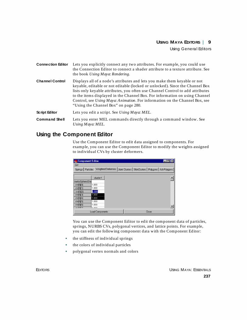
USING MAYA EDITORS | 9Using General Editors
EDITORS USING MAYA: ESSENTIALS
237
Connection Editor Lets you explicitly connect any two attributes. For example, you could usethe Connection Editor to connect a shader attribute to a texture attribute. Seethe book Using Maya: Rendering.
Channel Control Displays all of a node’s attributes and lets you make them keyable or notkeyable, editable or not editable (locked or unlocked). Since the Channel Boxlists only keyable attributes, you often use Channel Control to add attributesto the items displayed in the Channel Box. For information on using ChannelControl, see Using Maya: Animation. For information on the Channel Box, see“Using the Channel Box” on page 280.
Script Editor Lets you edit a script. See Using Maya: MEL.
Command Shell Lets you enter MEL commands directly through a command window. SeeUsing Maya: MEL.
Using the Component EditorUse the Component Editor to edit data assigned to components. Forexample, you can use the Component Editor to modify the weights assignedto individual CVs by cluster deformers.
You can use the Component Editor to edit the component data of particles,springs, NURBS CVs, polygonal vertices, and lattice points. For example,you can edit the following component data with the Component Editor:
• the stiffness of individual springs
• the colors of individual particles
• polygonal vertex normals and colors

USING MAYA: ESSENTIALS PART 2
238
USING MAYA EDITORS | 9Using General Editors
• the weights of CVs, vertices, or lattice points influenced by cluster deformers
• the weights assigned to CVs, vertices, or lattice points after smooth or rigidskinning
Editing component dataWith the Component Editor, you can find out what data is currentlyassigned to particular components, and then change that data.
To query component data:
1 Select the components whose data you want to edit.
2 Select Windows > General Editors > Component Editor. The ComponentEditor opens.
The Component Editor displays the component data for currently selectedcomponents in the workspace.
By default, the Component Editor updates dynamically as you selectcomponents in the workspace. Also, as you select components in theComponent Editor, the workspace updates dynamically.
3 Click the Springs, Particles, Polygons, AdvPolygons, Weighted Deformers,SkinClusters, and JointClusters tabs to view component data.
Springs Lists component data for springs, including stiffness and damping data.
Particles Lists component data for particles, including color or velocity data.
Click on tabs toselect componenttypes or influences
Component data is displayed forediting in a spreadsheet fashion
Componentslisted by rows
Objects influencingcomponent datalisted by column

USING MAYA EDITORS | 9Using General Editors
EDITORS USING MAYA: ESSENTIALS
239
Polygons Lists component data of polygonal vertices, including color or normal datain world space coordinates. If color or normal data are not shared at thevertex level, the column displays the word UnShared. These unsharedvalues can be viewed and edited from the AdvPolygons tab.
AdvPolygons Lists vertex face component data, including color and normal values for thevertex face.
Weighted Deformers Lists component data of CVs, vertices, or lattice points influenced by clusterdeformers (cluster weights).
SkinClusters Lists component data of CVs, vertices, or lattice points bound to a skeleton’sjoints by smooth skinning (skin cluster weights).
JointClusters Lists component data of CVs, vertices, or lattice points bound to a skeleton’sjoints by rigid skinning (joint cluster weights).
Note that if the components are organized into sets, the sets are also listed.
To modify component data:
1 In the Component Editor’s spreadsheet, click the component data box youwant to edit. Only the component whose box you selected is now selected inthe workspace.
2 Enter a new value or use the slider bar.
To modify several boxes at once:
1 In the workspace, select the components whose data you want to edit.
2 In the Component Editor’s spreadsheet, drag through the component databoxes you want to edit.
3 Enter the value you want all the boxes to have.
To modify an entire row or column (IRIX only):
1 In the workspace, select the components whose data you want to edit.
2 In the Component Editor’s spreadsheet, click one of the boxes in the row orcolumn.
3 Click the row or column heading.
Now all the boxes for the row or column are selected.
4 Enter a value for all the boxes in the row or column.
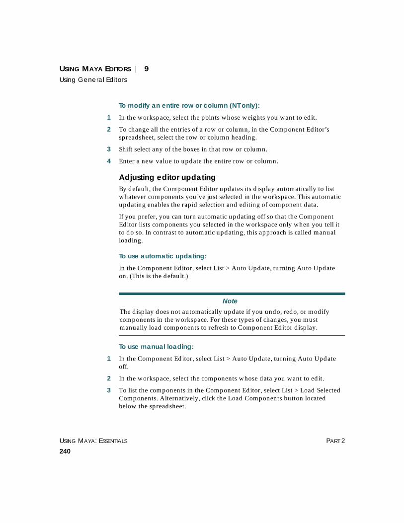
USING MAYA: ESSENTIALS PART 2
240
USING MAYA EDITORS | 9Using General Editors
To modify an entire row or column (NT only):
1 In the workspace, select the points whose weights you want to edit.
2 To change all the entries of a row or column, in the Component Editor’sspreadsheet, select the row or column heading.
3 Shift select any of the boxes in that row or column.
4 Enter a new value to update the entire row or column.
Adjusting editor updatingBy default, the Component Editor updates its display automatically to listwhatever components you’ve just selected in the workspace. This automaticupdating enables the rapid selection and editing of component data.
If you prefer, you can turn automatic updating off so that the ComponentEditor lists components you selected in the workspace only when you tell itto do so. In contrast to automatic updating, this approach is called manualloading.
To use automatic updating:
In the Component Editor, select List > Auto Update, turning Auto Updateon. (This is the default.)
To use manual loading:
1 In the Component Editor, select List > Auto Update, turning Auto Updateoff.
2 In the workspace, select the components whose data you want to edit.
3 To list the components in the Component Editor, select List > Load SelectedComponents. Alternatively, click the Load Components button locatedbelow the spreadsheet.
Note
The display does not automatically update if you undo, redo, or modifycomponents in the workspace. For these types of changes, you mustmanually load components to refresh to Component Editor display.

USING MAYA EDITORS | 9Using General Editors
EDITORS USING MAYA: ESSENTIALS
241
Using the Attribute Spread SheetAttributes (also known as channels) are qualities or characteristics that affectthe visual representation of objects (for example. position or color) orbehavior of objects (for example, the damping of a joint or magnitude of aforce). You can use the Attribute Spread Sheet to set various attributes formore than one object in a pane or for a particular node of an object. You canalso use this tool to assign various attributes from the Attribute Editor tomultiple objects or nodes.
Use the Attribute Spread Sheet to see and edit attributes for multiple objectssimultaneously. It doesn't show whether attributes are connected or locked,and it does not show multi-attributes at all.
To examine the attributes of a node in more detail, and with a moreexplanatory interface, you can use the Attribute Editor. However, theAttribute Editor can be slower than the Attribute Spread Sheet, because youcan only work on one object at a time. (The Channel Box works on allselected objects.)
Displaying the Attribute Spread SheetUse the Attribute Spread Sheet to change the attributes for an object.
To display the Attribute Spreadsheet:
1 Select the node you want to change the attributes for.
2 Select Windows > General Editors > Attribute Spread Sheet. Maya displaysthe node’s name in the Attribute Spread Sheet.
Notes
When the Attribute Spread Sheet first opens, the Keyable tab is selected.This tab displays all the keyable attributes of the selected objects. Mostother tabs display useful subsets of these attributes. The All tab displays allattributes, keyable or not.
Many attributes useful in editing an object are not stored in its main node,but rather in the shape node associated with it. Some of the tabs in theAttribute Spread Sheet (such as Shape Keyable, Tessellation, and so on)show you attributes in the associated shape.

USING MAYA: ESSENTIALS PART 2
242
USING MAYA EDITORS | 9Using General Editors
To display shorter attribute names:
When you display the Attribute Spread Sheet, Maya shows the full attributenames. You can make the column smaller by showing the short namesinstead.
To show the short attribute name, select Names > Short Attribute Names inthe Attribute Spread Sheet.
To show the long attribute name, select Names > Long Attribute Names.
Tips
If you have any problems selecting a node, select Windows > Hypergraph.For more information, see “Using the Hypergraph” on page 319.
To select all of an object’s nodes at once, drag a box around the object.
Selected node
Name of the selected node

USING MAYA EDITORS | 9Using General Editors
EDITORS USING MAYA: ESSENTIALS
243
Entering values for attributesWith a single entry from your keyboard, you can change the value of:
• a single attribute of one or more objects
• two or more attributes of the same object
• two or more attributes of multiple objects
You can set any of these combinations with one text entry.
For example, you can enter the value 5 in one text box to change the threeattributes for scaling along the X, Y, and Z axis for more than one object.
You can also change the values of several attributes by a relative amount.For example, you can add 3 to the Scale X, Scale Y, and Scale Z attributes.
Entering an exact value for object attributes
You can give one or more attributes an exact value as follows:
To change the value of a single attribute:
1 Select the object(s). The Attribute Spreadsheet displays the attributes of theobject(s).
2 In the Attribute Spreadsheet, click the attribute’s text box.
For example, click the Scale X text box.
3 Type the new entry and press Enter or the tab key.
For example, type 5 and press Enter. For a Scale X entry, this sets the X axisscaling of all selected objects to 5 grid units.
To change the value of two or more attributes:
1 Select the object(s). The Attribute Spreadsheet displays the attributes of theobject(s).
2 In the Attribute Spreadsheet, select the desired attribute text boxes.
For example, you can click the Translate X text box and drag through to theTranslate Y text box for an object, then drag down to select the Translate Xand Y boxes for other objects.
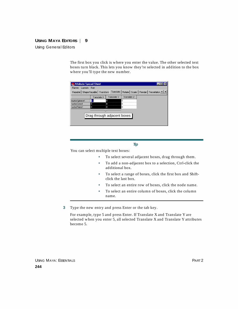
USING MAYA: ESSENTIALS PART 2
244
USING MAYA EDITORS | 9Using General Editors
The first box you click is where you enter the value. The other selected textboxes turn black. This lets you know they’re selected in addition to the boxwhere you’ll type the new number.
3 Type the new entry and press Enter or the tab key.
For example, type 5 and press Enter. If Translate X and Translate Y areselected when you enter 5, all selected Translate X and Translate Y attributesbecome 5.
Tip
You can select multiple text boxes:
• To select several adjacent boxes, drag through them.
• To add a non-adjacent box to a selection, Ctrl-click theadditional box.
• To select a range of boxes, click the first box and Shift-click the last box.
• To select an entire row of boxes, click the node name.
• To select an entire column of boxes, click the columnname.
Drag through adjacent boxes
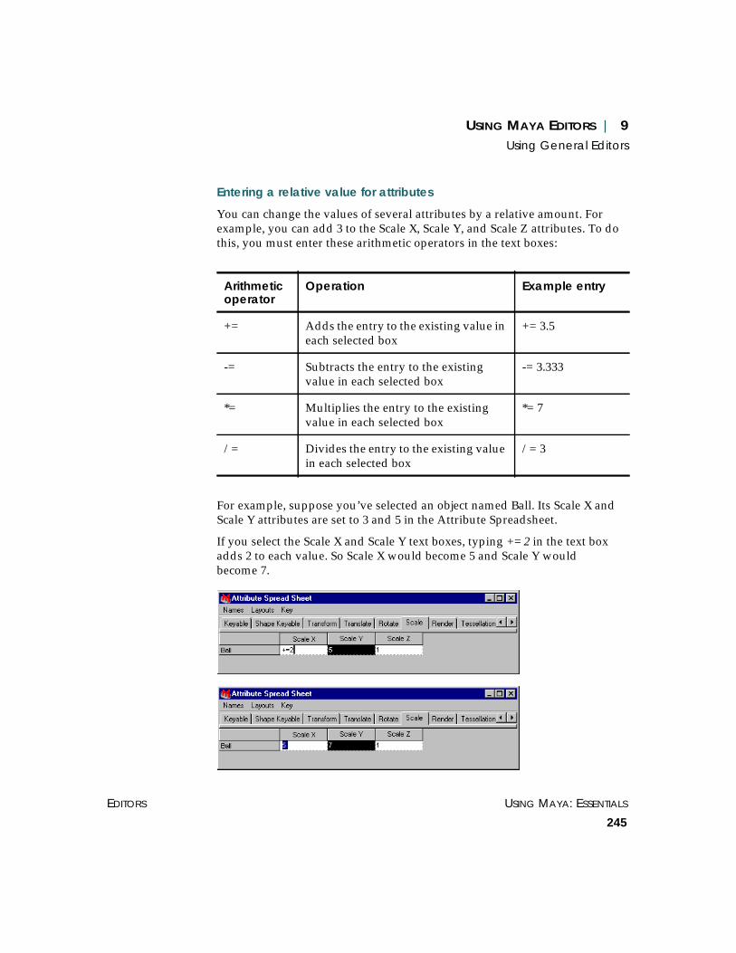
USING MAYA EDITORS | 9Using General Editors
EDITORS USING MAYA: ESSENTIALS
245
Entering a relative value for attributes
You can change the values of several attributes by a relative amount. Forexample, you can add 3 to the Scale X, Scale Y, and Scale Z attributes. To dothis, you must enter these arithmetic operators in the text boxes:
For example, suppose you’ve selected an object named Ball. Its Scale X andScale Y attributes are set to 3 and 5 in the Attribute Spreadsheet.
If you select the Scale X and Scale Y text boxes, typing += 2 in the text boxadds 2 to each value. So Scale X would become 5 and Scale Y wouldbecome 7.
Arithmeticoperator
Operation Example entry
+= Adds the entry to the existing value ineach selected box
+= 3.5
-= Subtracts the entry to the existingvalue in each selected box
-= 3.333
*= Multiplies the entry to the existingvalue in each selected box
*= 7
/= Divides the entry to the existing valuein each selected box
/= 3

USING MAYA: ESSENTIALS PART 2
246
USING MAYA EDITORS | 9Using General Editors
Managing the layout of informationThere are three ways to manage information in the Attribute Spread Sheet:
• Select Layouts > Show Selected Columns Only to display selected columnsof information. This reduces the amount of information on your display.
• Use Layouts > Remember this Layout to save a selected layout and recall itlater.
• Use Layouts > Delete Current Layout to delete a layout.
To show selected columns:
1 From the Attribute Spread Sheet, select the tab that has the attributes thatyou want to display. Each attribute occupies a column.
2 Click on the title of one of the columns you want to show. Ctrl-click to selectadditional columns, until you have selected all the attributes you areinterested in.
3 Select Layouts > Show Selected Columns Only. All the other columns arehidden, leaving only the ones you have selected. This layout persists untilyou select another tab, or close the Attribute Spread Sheet. To make the newlayout permanent, follow the next set of steps.

USING MAYA EDITORS | 9Using General Editors
EDITORS USING MAYA: ESSENTIALS
247
To remember a layout:
1 Select Layouts > Remember This Layout. The following window appears.
2 Type the name of the new layout, then click Remember. Maya adds thelayout name to the existing tabs. You can now recall the layout by clickingon the tab.
To delete a layout:
To delete a layout, select Layouts > Delete Current Layout. Maya removesthe tab from the window.
Setting attribute keys in the Attribute Spread SheetKeys are markers that represents the value of an attribute of an object at aparticular time. When the value of an attribute is different at one key fromanother, that attribute’s value will change over time as Maya calculates thevalue of the attribute in the time between the keys, and that attribute isanimated. The act of placing a key is called “setting a key” for that attributeat that time. For details, see Using Maya: Animation.
To set attribute keys in the Attribute Spread Sheet:
1 Select the cells you want to set keys for.
2 Select Key > Key Selected.
Note
You can remove Maya’s pre-defined tabs, but they will return the next timeyou open the window.
Enter name of new layout here

USING MAYA: ESSENTIALS PART 2
248
USING MAYA EDITORS | 9Using General Editors
Specifying tool settingsTool settings determine how a tool behaves. For example, if you are usingthe EP Curve Tool, you can specify whether the knot spacing is uniform orchord length.
To change a tool’s settings:
1 Do one of the following to open the Tool Settings window:
If the tool is represented by an icon on the Minibar, double-click on it withthe left mouse button.
or
If the tool is in a menu, select the check box (❐) located beside the tool.
or
Select the tool and then select Window > General Editors > Tool Settings.
2 Make the desired changes and click Close.
To return to a tool’s default settings:
In the Tool Settings window, click Reset Tool.
Duplicating a toolUsing shelves, you can have two tools with the same name but different toolsettings. For example, you can have two versions of the Particle Tool.
To duplicate a tool:
1 Select the shelf that will contain the new version of the tool.
2 Select the tool that you want to duplicate.
Tips
You cannot change the name of the tool using the Tool Settings window. Ifyou want to change the name of the tool, see “Changing icon labels” onpage 504.
To remove an icon from a shelf, drag it to the garbage can.

USING MAYA EDITORS | 9Using General Editors
EDITORS USING MAYA: ESSENTIALS
249
3 Using the middle mouse button, drag the tool icon from the Minibar to theshelf.
4 Select the new version of the tool on the shelf and open the Tool Settingswindow (Window > General Editors > Tool Settings).
5 Change the tool settings.
To test whether Maya saved the settings for each tool, select the original tooland check the settings in the Tool Settings window. Leave the Tool Settingswindow open and select the new tool on the shelf and check the settings.
6 Click Close.
Specifying performance settingsYou use the Performance Settings window to set when you want to refreshthe screen when manipulating objects and to control complex operations,such as stitching and deformation. You can use the performance settings tosuspend these complex operations during mouse interaction or tocompletely disable them. This improves performance by reducing theamount of evaluation necessary during interaction and playback.
To specify performance settings:
Select Window > Settings/Preferences > Performance Settings. ThePerformance Settings window opens.
Note
When you drag a tool from the Minibar to the Shelf, a copy of the tool ismade. If you use Ctrl-Shift to place a menu item that selects a tool on theshelf, Maya does not place a copy of a tool on the Shelf. Instead, only theaction that invokes the original tool is placed on the Shelf. For moreinformation on adding tools and actions to a shelf, see “Creating andediting shelves” on page 493.

USING MAYA: ESSENTIALS PART 2
250
USING MAYA EDITORS | 9Using General Editors
Selecting screen refresh options
To set when to refresh (or redraw the screen) when manipulating objects, inthe Dependency Graph Evaluation section, select one of the following:
Drag Refreshes the display during the drag.
Demand Refreshes the display only when you release the mouse button and click theUpdate button that appears in the bottom right of the display window.
Release Refreshes the display only when you release the mouse button.
Controlling complex operations on surfaces
To control complex operations on surfaces during mouse interaction, in theSurfaces section, select one of the following beside the surface:

USING MAYA EDITORS | 9Using General Editors
EDITORS USING MAYA: ESSENTIALS
251
On Performs complex operations during mouse interactions.
Off Completely disables complex operations during mouse interaction.
Interactive Suspends complex operations during mouse interaction.
Controlling complex operations on deformers
To control complex operations on deformers during mouse interaction, inthe Deformers section, select one of the following beside the surface:
On Performs complex operations during mouse interactions.
Off Completely disables complex operations during mouse interaction.
Interactive Suspends complex operations during mouse interaction.
Per Node For Cluster Resolution and Lattice Resolution only, improves redrawperformance for individual cluster or lattice deformations by setting the UsePartial Resolution attribute to partial and setting the Percent Resolution on aper node basis. For details, see Using Maya: Character Setup.
Global For Cluster Resolution and Lattice Resolution only, improves the redrawperformance of all cluster or lattice deformations. (You do not need to set thePercent Resolution for each cluster or lattice.)
Set Global Cluster Resolution and Global Lattice Resolution to Full, High,Medium, or Low. A Low setting corresponds to a low percentage, andtherefore more improved performance.
For more information on surfaces, see Using Maya: NURBS Modeling andUsing Maya: Polygonal Modeling. For more information on deformers, seeUsing Maya: Character Setup.
Loading and unloading plug-insA plug-in is an add-on module that extends Maya’s capabilities. Filetranslators are plug-ins you use to import and export various file formats.You can create or purchase specialty plug-ins to customize Maya for aspecific job.
Some features that can be added through plug-ins are:
• file translators
• tools
• objects (nodes)

USING MAYA: ESSENTIALS PART 2
252
USING MAYA EDITORS | 9Using General Editors
• MEL commands
• device drivers
The Plug-in Manager identifies which plug-ins are loaded into Maya. If youhave a plug-in that you use frequently, you can make sure it is always there.The Plug-in Manager automatically scans all the directories in the plug-inpath and lists available plug-in features.
Loading plug-insYou can manually load plug-ins each time you run Maya, or you can havethem load automatically when you start Maya.
To load a plug-in:
Select Window > Settings/Preferences > Plug-in Manager. The Plug-InManager window opens.
Selecting loading options
Toggle the appropriate option beside the plug-in.
Click here to loadthe plug-in
Click here to enablethe auto load feature
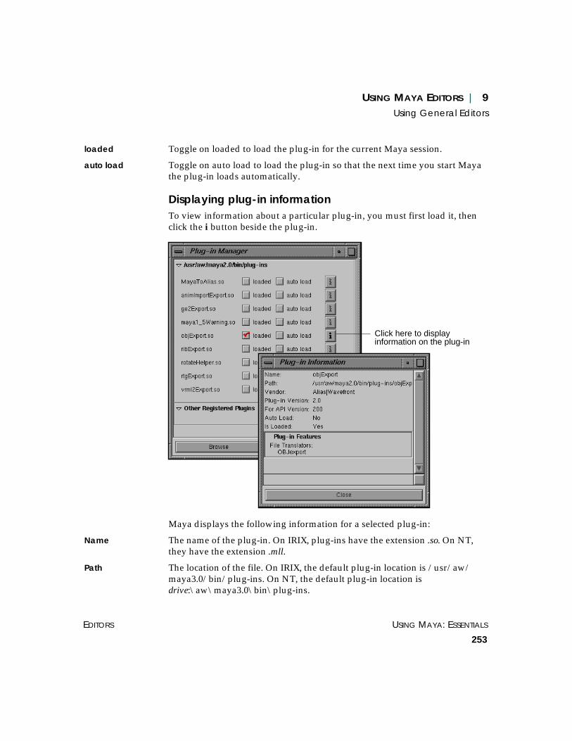
USING MAYA EDITORS | 9Using General Editors
EDITORS USING MAYA: ESSENTIALS
253
loaded Toggle on loaded to load the plug-in for the current Maya session.
auto load Toggle on auto load to load the plug-in so that the next time you start Mayathe plug-in loads automatically.
Displaying plug-in informationTo view information about a particular plug-in, you must first load it, thenclick the i button beside the plug-in.
Maya displays the following information for a selected plug-in:
Name The name of the plug-in. On IRIX, plug-ins have the extension .so. On NT,they have the extension .mll.
Path The location of the file. On IRIX, the default plug-in location is /usr/aw/maya3.0/bin/plug-ins. On NT, the default plug-in location isdrive:\aw\maya3.0\bin\plug-ins.
Click here to displayinformation on the plug-in

USING MAYA: ESSENTIALS PART 2
254
USING MAYA EDITORS | 9Using General Editors
Vendor The manufacturer of the plug-in.
Plug-in Version The version number of the plug-in.
For API Version The version of the Maya API (Application Programmer Interface) the plug-inwas compiled for.
Auto Load Indicates whether the plug-in has been marked for auto load.
Is Loaded Indicates whether the plug-in is loaded.
Plug-in Features Displays a list of the features added by the plug-in (for example, commands,dependency nodes, file translators).
To display additional plug-ins, click the triangle to open the OtherRegistered Plug-ins section.
Unloading a plug-inYou can unload a plug-in when you finish with it. To unload a plug-in,toggle off the loaded box next to it.
If you are developing a plug-in, unload it so the source code can be changed,the plug-in recompiled, and then reloaded.
Removing references to the plug-in
Before you can unload a plug-in, you must first remove all references to itfrom the Maya scene. Otherwise, Maya converts the plug-in nodes tounknown nodes. For example, if you load a shader plug-in and then unloadthat same shader plug-in without first removing the special shader node andall of its references in the scene, Maya will display an error message the nexttime you open that scene.
If you try to unload a plug-in while it is in use, a warning message willdisplay. You can then cancel the unload or force it.
Note
You cannot load a plug-in for any version of Maya that predates theversion it was compiled for.

USING MAYA EDITORS | 9Using the Relationship Editor
EDITORS USING MAYA: ESSENTIALS
255
If you force the unload of a plug-in while it is in use, you cannot reload thatplug-in’s node. Maya converts the existing nodes to unknown nodes. Whenyou reload plug-ins, you cannot change the type of these existing unknownnodes.
USING THE RELATIONSHIP EDITOR
Use the Relationship Editor to edit relationships in Maya, where arelationship is a collection or grouping of objects or components. Theserelationships include:
• sets
• deformer sets
• character sets
• partitions
• display layers
• render layers
• shading groups
• light linking (light centric and object centric)
For all these types of relationships, you can do the following in theRelationship Editor:
• specify view options (see “Setting view options” on page 256)
• select which relationships and objects display (“Displaying relationships andobjects” on page 257)
• create and delete relationships (see “Creating relationships” on page 259)
• select members of a relationship (see “Selecting relationships, relationshipmembers, and objects” on page 260)
Note
The Relationship Editor is separate from the Dynamic Relationships Editor,which is used to control relationships of particle objects. See Using Maya:Dynamics for more information.

USING MAYA: ESSENTIALS PART 2
256
USING MAYA EDITORS | 9Using the Relationship Editor
• add and remove members of a relationship (see “Adding and removingrelationship members” on page 261)
• filter which relationships and objects display in the Relationship Editor (see“Selecting which relationships and objects show” on page 258)
To open the Relationship Editor:
• From the main Maya window, select Window > Relationship Editors andselect the relationship you want to work with. (You can change this fromwithin the Relationship Editor.)
or
• From a panel, select Panels > Panel > Relationship Editor. Note that thisopens the Relationship Editor in a panel rather than a separate window.
The Relationship Editor opens.
The left side of the editor displays relationships of the type you selected,while the right side of the editor displays objects in the scene.
Setting view optionsYou can set view options for sets, partitions, characters, deformer sets, andshading groups.
You can automatically expand the relationships in the display area so youcan see the members of each relationship without having to click the plussign beside them. In the Relationship Editor, select the relationship type,then select Options > Auto Expand Frames to toggle it on.
Select the type ofrelationship you wantto work with

USING MAYA EDITORS | 9Using the Relationship Editor
EDITORS USING MAYA: ESSENTIALS
257
For shading groups, you can also automatically assign a random color tonew shading groups when you create them. In the Relationship Editor, selectOptions > Assign Color to New Groups. For details, see Using Maya:Rendering.
Displaying relationships and objectsUsing the List menu, you can control which relationships are loaded in theleft panel of the Relationship Editor, and which objects are loaded in rightpanel. By default, all relationships and objects display, but you may want tolimit the display so you can see what you’re working on more clearly.
You can also control what displays in the Relationship Editor using theShow menu. For details, see “Selecting which relationships and objectsshow” on page 258.
To display relationships:
On the left panel, select one of the following options from the List menu.
Auto Load All Toggle this on to automatically display all relationships of the selected typein the scene. This is the default.
Manual Load Toggle this on to display relationships by choosing one of the followingoptions:
Load from Selection – Display only the relationships associated with theobjects selected in the scene.
Add from Selection – Add to the display the relationships associated with theobjects selected in the scene.
Remove from Selection – Remove from the display the relationshipsassociated with the objects selected in the scene.
To display objects:
On the right side panel, select one of the following options from the Listmenu.
Auto Load All Toggle this on to automatically display all objects in the scene.
Auto Load Selection Toggle this on to automatically display objects in the relationships associatedwith the objects selected in the scene.
Manual Load Toggle this on to display objects by choosing one of the following options:

USING MAYA: ESSENTIALS PART 2
258
USING MAYA EDITORS | 9Using the Relationship Editor
Load List from Selection – Display only the selected objects.
Add Selection to List – Add to the display the objects selected in the scene.
Remove Selection from List – Remove from the display the objects selected inthe scene.
Selecting which relationships and objects showYou can display a subset of relationships and objects in the RelationshipEditor using the Show menu. What you can display depends on therelationship you are editing.
For more information, see “Limiting the information shown in editors” onpage 311.
To select which relationships show:
• In the left panel of the Relationship Editor, select Show > Objects, then selectthe types of relationships you want to show. Only the items you select willdisplay in the left panel.
or
• Type text in the Text Filter box to limit the display to items with that text.For details, see “Limiting the display to items containing specific text” onpage 312.
To show all relationships:
• In the left panel of the Relationship Editor, select Show > Objects, then toggleoff the items you now want to show.
or
• To show all types of relationships, select Show > Show All.
To select which objects show:
• In the right panel of the Relationship Editor, select Show > Objects, thenselect the types of objects you want to show. Only the items you select willdisplay in the right panel.

USING MAYA EDITORS | 9Using the Relationship Editor
EDITORS USING MAYA: ESSENTIALS
259
or
• Type text in the Text Filter box to limit the display to items with that text.For details, see “Limiting the display to items containing specific text” onpage 312.
To show all objects:
• In the right panel of the Relationship Editor, select Show > Objects, thentoggle off the items you now want to show.
or
• To show all types of objects, select Show > Show All.
Creating relationshipsFrom the Relationship Editor, you can create the following relationships:
• sets (see “Creating sets” on page 375
• partitions (see “Creating, displaying, and removing partitions” on page 381)
• characters (see Using Maya: Character Setup)
• display layers (see “Using display layers” on page 139)
• render layers (see “Using render layers” on page 147)
• shading groups (see Using Maya: Rendering)
• light sets and object sets (see Using Maya: Rendering)
You cannot create deformer sets.
In general, use the following procedure to create a new relationship.
To create a relationship in the Relationship Editor:
1 Select the objects or items in the workspace, Outliner, or elsewhere.
If you don’t select any objects or items, an empty set will be created. You canadd to it later. See “Adding and removing relationship members” on page261.
2 Open the Relationship Editor (see “To open the Relationship Editor:” onpage 256).
3 Select the type of relationship you want to create, if it isn’t already selected.

USING MAYA: ESSENTIALS PART 2
260
USING MAYA EDITORS | 9Using the Relationship Editor
4 For sets, partitions, and characters:
• On the left panel of the editor, select Edit > Create Relationship ❒, whereRelationship is the type of relationship you are creating (set, partition,character). An Options window opens.
• In the Name box, type a name for the set. For example, if you are creating aset with polygonal objects, you might call the set polyObjects.
• Click Apply.
5 For shading groups, light sets, or object sets, select Edit > Create Relationship,where Relationship is the type of relationship you are creating (shadinggroup, shading group (force), partition, character, display layer).
6 The new set appears on the left side of the Relationship Editor.
If a relationship or other item in the scene already has the specified name,the new set name will be appended with a number. For example, enteringtop results in top1, because top is the name of a camera that exists in everyscene by default.
To rename a relationship in the Relationship Editor:
Double-click the name of the relationship and type the new name.
To delete a relationship in the Relationship Editor:
In the left panel, click on the relationship you want to delete and selectEdit > Delete Highlighted.
Selecting relationships, relationship members, and objectsYou can use the Relationship Editor to quickly select relationships, membersof relationships, and objects in your scene.
When you select a relationship, it becomes active in the channel box, or theAttribute Editor.
To select a relationship:
1 In the left panel of the Relationship Editor, click the relationship(s) you wantto select. Notice that member of the set are highlighted in the Objects panel.
2 Select Edit > Select Highlighted. The relationship(s) becomes active.

USING MAYA EDITORS | 9Using the Relationship Editor
EDITORS USING MAYA: ESSENTIALS
261
To select set members:
1 In the left panel of the Relationship Editor, click the relationship(s) with themembers you want to select.
2 Select Edit > Select Set Members, The members of the highlighted set areselected in the scene.
To select objects in your scene:
1 In the right panel of the Relationship Editor, click the object(s) you want toselect in your scene.
2 Select Edit > Select Highlighted. The highlighted objects are selected in yourscene.
Adding and removing relationship membersUse the Relationship Editor to quickly add and remove objects or items froma relationship.
To add objects or items to a relationship:
1 In the left panel of the Relationship Editor, click the relationship you want toadd objects or items to.
2 In the right panel of the Relationship Editor, click on the objects or items youwant to add to the relationship.
or
In the scene, select the objects or items you want to add to the relationshipand select Edit > Add Selected Items or click the large plus sign beside therelationship type at the top left of the Relationship Editor.
To remove objects or items from a relationship:
1 In the left panel of the Relationship Editor, expand the relationship you wantto remove objects or items from by clicking the plus sign (+) beside it, if it isnot already expanded.
2 Still in the left panel, click on the object or item you want to remove from theexpanded relationship and select Edit > Remove Highlighted from Set.

USING MAYA: ESSENTIALS PART 2
262
USING MAYA EDITORS | 9Using the Attribute Editor
or
1 In the left panel of the Relationship Editor, click the relationship you want toremove objects or items from.
2 In the Object panel of the Relationship Editor, click on the highlightedobjects or items you want to remove from the relationship.
or
In the scene, select the objects or items you want to remove from therelationship and select Edit > Remove Selected Items or click the large minussign beside the relationship type at the top left of the Relationship Editor.
USING THE ATTRIBUTE EDITOR
Use the Attribute Editor to view and set the attributes for any object or node.For example, you can use the Attribute Editor to change the rotation order ofan object (that is, the rotation order under the scale/rotate/translateattributes.) You can also use the Attribute Editor to toggle many items in theDisplay menu on and off. The Attribute Editor provides access to allattributes for an object or node.
You can also use the Channel Box and the Attribute Spreadsheet to view andset attributes. The Channel Box provides access to keyable attributes only.For information on the Channel Box, see “Using the Channel Box” on page280. The Attribute Spreadsheet provides access to all attributes, and lets youchange attribute values for multiple objects at the same time. Forinformation on the Attribute Spreadsheet, see “Using the Attribute SpreadSheet” on page 241.
Displaying the Attribute EditorThe Attribute Editor displays in a separate window or in the main Mayawindow, depending on your preference settings (Window > Settings/Preferences > Preferences, Interface category).
To open the Attribute Editor:
Do one of the following:
• Select Windows > Attribute Editor.

USING MAYA EDITORS | 9Using the Attribute Editor
EDITORS USING MAYA: ESSENTIALS
263
• Press Ctrl-A in the view.
• Right click on the object or node and select it from the marking menu.
• Select Display > UI Elements > Attribute Editor.
• In the Hypergraph, select the object or node, then select Edit > Attributes.
• Double-click a node in the Hypershade, Visor, Multilister, or Outliner.
To change the default display of the Attribute Editor:
1 Select Window > Settings/Preferences > Preferences, Interface category.
2 Select one of the following options beside Open Attribute Editor:

USING MAYA: ESSENTIALS PART 2
264
USING MAYA EDITORS | 9Using the Attribute Editor
In Separate Window
Opens the Attribute Editor in a separate window.
In Main Maya Window
Opens the Attribute Editor in the Main Maya window where the Channelbox normally resides. You can switch between displaying the AttributeEditor and Channel Box from the Display > UI Elements submenu. (Youcannot display both the Attribute Editor and the Channel Box in the mainMaya window at the same time.)
Common attributes and buttons
Each tab in the Attribute Editor represents an individual node and containsall the attributes for that node. Click a tab to display and modify theattributes for that node. For details about specific attributes, refer to theappropriate Using Maya book.
The following attributes and buttons are common to most Attribute Editortabs.
• the name of the node (for example, nurbsSphere1 or lambert1)
• Input Connection button
Hold down the left mouse button on the Input Connection button to displaythe first input connection node for the currently displayed node. Hold downthe left mouse button on the Input Connection button to display a list of allinput connection nodes. You can then choose a node from this list to displayin the Attribute Editor.
• Output Connection button
Hold down the left mouse button on the Output Connection button todisplay the first output connection node for the currently displayed node.Hold down the right mouse button on the Output Connection button todisplay a list of all output connection nodes. You can then choose a nodefrom this list to display in the Attribute Editor.
• Focus button — Click this button to set the Attribute Editor focus to thisnode
• a sample image or icon that represents the node (where appropriate)
• Select button — Click this button to select the node that is currentlydisplayed in the Attribute Editor.

USING MAYA EDITORS | 9Using the Attribute Editor
EDITORS USING MAYA: ESSENTIALS
265
• Load Attributes button — Click this button to manually load the attributesof the selected object or node.
Menus
The Attribute Editor has the following menus:
List Use this menu to load attributes into the Attribute Editor and to definewhich items display in the Selected/Object menu. See “Loading objectattributes into the Attribute Editor” on page 266.
Selected/Object The Selected menu lists objects currently selected in the scene while theObject menu displays all the objects in the scene of a selected type. See“Loading attributes from the Selection/Object menu” on page 267.
Copy Use this menu to display the selected tab as a separate window. See“Viewing attributes for different objects at the same time” on page 268.
Focus This menu displays all nodes that have been selected in the scene while theAttribute Editor is open. The most recently selected node is at the top of thelist. “Loading attributes from the Focus menu” on page 268.
Add Use this menu to add extra attributes to an object or node. These appearunder the Extra Attributes section. You can also add attributes by selectingModify > Add Attribute. See “Adding a custom attribute” on page 269.
Right-click menu options
For some attributes, a pop-up menu appears when you right-click theattribute name or text box. This pop-up menu has the following options:
output connection node
If you set a key for the attribute or connect a texture to it, the resultingoutput connection node name displays as the first menu item. To load theattributes for this node into the Attribute Editor, select it.
Create New Expression
Select this option to create a new expression for the attribute. For details, see“Launching the Expression Editor” on page 275.
Set Key Select this option to set a key for the attribute. For details, see “Setting keysfor attributes in the Attribute Editor” on page 273. This options disappearsfrom the menu if you have already connected a texture to the attribute.

USING MAYA: ESSENTIALS PART 2
266
USING MAYA EDITORS | 9Using the Attribute Editor
Set Driven Key Select this option to link the attribute values. For details, see “Linkingattributes” on page 274.
Break Connection Select this option to break the connection between the attribute and a key ortexture. For details, see “Breaking connections” on page 274.
Create New Texture Select this option to connect a texture to the attribute. For details, see“Mapping a texture to an attribute value” on page 275.
Color Chooser This option displays for color attributes only. Select it to open the ColorChooser. For details, see “Using the Color Chooser” on page 276.
Lock/Unlock Attribute
Select the Lock option to lock an attribute value so that it cannot be changed.Use Unlock Attribute to unlock the value. For details, see “Locking attributevalues” on page 274.
Ignore/Don’t Ignore when Rendering
This option displays only for attributes that are connected to keys ortextures. Select the Ignore when Rendering option to ignore the connectionwhen rendering. If the attribute has a map button, the button changes toindicate that the connection will be ignored.
Select the Don’t Ignore when Rendering option to render with the setconnection. For details, see Using Maya: Rendering.
Loading object attributes into the Attribute EditorLoading attributes into the Attribute Editor makes them available to view oredit. There are three ways to load object attributes into the Attribute Editor:
• automatically when you select the object
• manually
• by selecting the object from the Attribute Editor Selected/Object menu
• by selecting the object from the Focus menu
Indicates that the connection will be ignored when rendering
Indicates that the attribute is connected to a key or texture

USING MAYA EDITORS | 9Using the Attribute Editor
EDITORS USING MAYA: ESSENTIALS
267
Loading attributes automaticallyWhen you select an object, its attributes are automatically loaded into theAttribute Editor where you can view and edit them. Each node of theselected object automatically appears as a tab. This is the default method.
To automatically load attributes for selected objects:
In the Attribute Editor, select List > Auto Load Selected Attributes to toggleit on.
Loading attributes manuallyIf Auto Load Selected Attributes is toggled off, after selecting an object, youmust manually load the object’s attributes into the Attribute Editor to viewand edit them.
To manually load attributes for selected objects:
• In the Attribute Editor, select List > Load Selected Attributes.
or
• Click the Load Attributes button at the bottom of the Attribute Editor.
Loading attributes from the Selection/Object menuBy default, the menu that appears beside the List menu is the Selectionmenu. It lists all selected objects in the scene so they are readily available forloading into the Attribute Editor. To list selected objects in the Selectionmenu, select List > Selected Items.
Instead of listing selected objects for easy availability in the Attribute Editor,you can list objects of a specified type. If you choose to do this, the menuthat appears beside the List menu becomes the Object menu. To list allobjects in the scene of a specified type, select the object category from the
Note
If you select more than one item, Maya automatically updates the mostrecently selected one (that is, the most recent one in the pick list).

USING MAYA: ESSENTIALS PART 2
268
USING MAYA EDITORS | 9Using the Attribute Editor
List menu (Dynamics, Kinematics, Deformers, Lights, Shading), then selectthe object. For example, to list all joints in the scene under the Object menu,select List > Kinematics > Joints.
To load attributes for objects in the Selected/Object menu:
In the Attribute Editor, select Selected > objectName, where objectName is thename of the object you want to load into the Attribute Editor.
Loading attributes from the Focus menuThe Focus menu displays all nodes that have been selected in the scenewhile the Attribute Editor is open. You can think of it as a history of thenodes you’ve viewed in the Attribute Editor. The most recently selectednode is at the top of the list.
Use it to redisplay the attributes for these nodes.
To redisplay node attributes:
In the Attribute Editor menu bar, select Focus, then select the node you wantto load. The attributes for the selected node appear in the Attribute Editor.
Viewing attributes for different objects at the same timeYou can simultaneously view attributes for multiple objects by openingmultiple copies of the Attribute Editor.
To view attributes for different objects at the same time:
1 Select the first object and load the attributes into the Attribute Editor. (See“Loading object attributes into the Attribute Editor” on page 266.)
2 In the Attribute Editor, select Copy > Tear Off Copy to create anotherversion of the Attribute Editor. It appears as a separate window with theattributes for the selected object loaded.
3 Select the next object and load the attributes into the original AttributeEditor. Note that the attributes for the first selected object remain loaded inthe copy of the Attribute Editor.
4 Repeat steps 2 and 3 for each other object you want to view attributes forsimultaneously.

USING MAYA EDITORS | 9Using the Attribute Editor
EDITORS USING MAYA: ESSENTIALS
269
Adding a custom attributeCustom attributes are attributes you optionally add and define from the AddAttribute window. Although custom attributes are dynamically added to anobject, we refer to them as custom to distinguish them from the built-indynamic attributes.
Custom attributes have no direct effect on any characteristic of an object inMaya. You can use them to control a combination of other attributes. Youmight also use a custom attribute as a variable—a place to store a valuetemporarily to be read by other attributes.
When you add a custom attribute to an object, it appears in the ExtraAttributes section of the Attribute Editor (and in the Channel Box, if youmake the attribute keyable).
For practical examples of when you would add extra attributes, see UsingMaya: Expressions.
For details on deleting a custom attribute, see “Deleting or renaming customattributes” on page 271.

USING MAYA: ESSENTIALS PART 2
270
USING MAYA EDITORS | 9Using the Attribute Editor
To create a new attribute definition:
1 In the Attribute Editor, select Add > Add Attributes and click the New tab.
2 Set the new attribute options as follows and click the Add button.
To view the new attribute controls, expand the Extra Attributes section inthe Attribute Editor.
Setting new attribute options
Attribute Name Type the name of the attribute you are adding.
Make Attribute Keyable
Toggle this option on to make this attribute keyable. For information aboutkeyable attributes, see Using Maya: Animation.
Data Type Select the data type for the attribute:
Vector – Creates a vector attribute consisting of three floating point values.
Float – Creates a floating point attribute.
Integer – Creates an integer attribute.

USING MAYA EDITORS | 9Using the Attribute Editor
EDITORS USING MAYA: ESSENTIALS
271
Boolean – Creates an attribute consisting of an on/off toggle.
If you select Vector or Integer, you can also set Min/Max Values.
Attribute Type Select a type:
Scalar – Creates a per object attribute that you can set to a single value thatapplies to every particle in the object. A vector scalar is considered a singlevalue with three numbers. If you select Scalar, you can specify Minimum,Maximum, and Default values for a Float or Integer attribute.
Array – Creates a per particle attribute. You can set this type of attribute todifferent values for each particle. If you select Array, you can also create acounterpart initial state attribute by turning on Add Initial State Attribute.
Add Initial State Attribute – Toggle on to create a corresponding initial stateattribute for the added attribute. Without this corresponding attribute, youcan’t save a particle object’s current attribute values for initial state usage.You must write a creation expression if you decide to initialize the customattribute’s value upon rewinding the animation. If you know you’re going towrite a creation expression for a custom attribute, you can set Add InitialState Attribute to off when you add the attribute. Otherwise, set Add InitialState Attribute to on whenever you add a custom per particle attribute.
Min/Max Values For scalar attributes, Minimum and Maximum set the lowest and highestvalues you can enter for the attribute in the Attribute Editor or Channel Box.Default sets the default value for the attribute.
Deleting or renaming custom attributesYou can delete custom (or dynamic) attributes from either the main menu(Modify > Delete Attributes) or from the Attribute Editor (Attributes >Delete Attributes). You cannot delete built-in dynamic attributes.
To change the attribute’s label, Rename Attributes from the Modify orAttributes menu.

USING MAYA: ESSENTIALS PART 2
272
USING MAYA EDITORS | 9Using the Attribute Editor
Changing node behaviorYou can improve Maya’s performance by changing node behavior settings.
To change node behavior, select the node and expand the Node Behaviorsection of the Attribute Editor.
Caching Toggle Caching on to temporarily store upstream node evaluations in thecache. When Maya needs these evaluations (as input to the node), it uses theinformation stored in the cache rather than re-evaluating the upstream node.If no changes have been made to the node, it redraws more quickly. Thecache is destroyed when you edit an attribute. Note that caching uses morememory, which could affect Maya’s performance.
Node State Changing the node state can improve performance. There are six possiblenode states:
Normal – Causes the node to behave normally, according to the definedsettings and effects. This is the default.
HasNoEffect – Disables any effects on the node so that fewer calculations arenecessary at the time of redraw. Note that the effect will not render until youreset the Node State back to Normal. Maya evaluates the nodes in the node’shistory, but not the node itself.
For example, if you translate a cluster to deform a geometry, then set theNode State of the cluster node to HasNoEffect, the geometry will appearundeformed, as though the translation had not occurred. To view the effect,change the Node State back to Normal.
Blocking – Temporarily hides the node and does not display the results ofany input (upstream evaluations) to the node. This can speed the redraw. Itis also useful when you have complex scenes and want to edit only oneaspect of a node. Blocked nodes do not render.
For example, if you have a complex revolved surface and want to edit thecurve, but don’t want to wait while the curve redraws, select Blocking andedit the curve. To display the modified revolved surface, reset the NodeState to Normal.
Note that Blocking has no effect on deformers.

USING MAYA EDITORS | 9Using the Attribute Editor
EDITORS USING MAYA: ESSENTIALS
273
Waiting-Normal – If the dependency graph refresh performance setting(Window > General Editors > Performance Setting) is set to Demand orRelease, the node will take the Normal state when in the Hypergraph youselect Update or release the mouse button.
Waiting-HasNoEffect – If the dependency graph refresh performance setting(Window > General Editors > Performance Setting) is set to Demand orRelease, the node will take the HasNoEffect state when in the Hypergraphyou select Update or release the mouse button.
Waiting-Blocking – If the dependency graph refresh performance setting(Window > General Editors > Performance Setting) is set to Demand orRelease, the node will take the Blocking state when in the Hypergraph youselect Update or release the mouse button.
Setting keys for attributes in the Attribute EditorYou can set a key for an object attribute in the Attribute Editor. For detailsabout keys, see Using Maya: Animation.
To set a key for one attribute:
1 Select the object.
2 Click the timeline frame number where you want to set the key.
3 In the Attribute Editor, select the attribute value.
4 Type the value of the attribute and press Enter.
5 Right-click the attribute name or text box and select Set Key. This sets thekey for the object attribute value.
Click the timeline
USING MAYA: ESSENTIALS PART 2
274
USING MAYA EDITORS | 9Using the Attribute Editor
Linking attributesMaya has a special type of key called a driven key that links one attributevalue to another. When you create a driven key, you specify a driverattribute value and a driven attribute value. The value of the driven attributeis locked to a corresponding value of the driver attribute.
You can link attributes from the Attribute Editor by right-clicking theattribute text box or label and selecting Set Driven Key. For details, see UsingMaya: Animation.
Breaking connectionsIn the Attribute Editor, the text box for an attribute that is connected to anexpression, key, or other attribute (for example texture attribute) is displayedin a different color, depending on your color settings.
To break a connection:
1 Select the object.
2 In the Attribute Editor, right-click the attribute name or text box and selectBreak Connections.
Locking attribute valuesYou can lock an attribute value to avoid accidentally changing it later.
To lock an attribute:
1 Select the object.
2 In the Attribute Editor, set the attribute value you want to lock.
3 Right-click the attribute name or text box and select Lock Attribute.
Tip
To set a key for all attributes, use the Channel Box. For details, see “Settingkeys for attributes from the Channel Box” on page 291.

USING MAYA EDITORS | 9Using the Attribute Editor
EDITORS USING MAYA: ESSENTIALS
275
This locks the value. The Attribute Editor displays locked attributes with agray background. (This color may not be visible while the text box isselected.)
When you’ve locked an attribute, you cannot change its value in theAttribute Editor, Channel Box, the workspace, or elsewhere.
You must unlock the attribute to change its value.
To unlock an attribute
1 Select the object.
2 In the Attribute Editor, right-click the attribute name or text box and selectUnlock Attribute.
Launching the Expression EditorYou can launch the Expression Editor for the attribute selected in theAttribute Editor.
To start the Expression Editor:
In the Attribute Editor, right-click the attribute name or text box and selectCreate New Expression. The Expression Editor opens.
For details on its use, see Using Maya: Expressions.
Mapping a texture to an attribute valueYou can map textures to non-keyed attributes in the Attribute Editor.
To map a texture to an attribute value:
• In the Attribute Editor, right-click the attribute name or text box and selectCreate New Texture.
or
• Click the map button beside the attribute .
The button changes to indicate there is a connection. Click this button toview the attributes for the connected node.
The Create Render Node window opens. For details, see Using Maya:Rendering.

USING MAYA: ESSENTIALS PART 2
276
USING MAYA EDITORS | 9Using the Color Chooser
USING THE COLOR CHOOSER
The Color Chooser is a color selection tool that launches when you click acolor attribute in the Attribute Editor. (It also opens when assigning interfacecolors in the Colors window; see “Changing color settings” on page 482 formore information.)
When you select a new color in the Color Chooser, it becomes the currentcolor, shown in the top left tile of the Color Chooser and also in the colorblock of the Colors window or Attribute Editor. You can then close the ColorChooser.
The Color chooser has several color selection tools. Review the followingillustration and topics for an explanation.
Color selection tools:
Eyedropper
Wheel (drag marker toselect color)
Sliders (RGB or HSV )
Blend box
Palette (includingAdobe palettes)
Storagetiles—to store,right-click on atile or click thearrow button
Current color

USING MAYA EDITORS | 9Using the Color Chooser
EDITORS USING MAYA: ESSENTIALS
277
Using the color wheel and storage tilesThe fastest way to select a color is to drag the selector in the color wheel.Once you have the color selected, you can drag the brightness control on theleft.
Another quick way to select a color is to left click on one of the storage tilesat the top. To store the current color on a tile, right click a tile or click thearrow button.
Using the eyedropperThe eyedropper tool lets you grab a color from anywhere on the computerscreen, including other applications. The eyedropper operates differently onWindows NT and IRIX:
• On NT, click the eyedropper button, hold down the mouse button, and dragthe eyedropper cursor to any position on your screen. Release the mouse tograb the color.
• On IRIX, click and release the eye dropper button, then position theeyedropper cursor anywhere on your screen. Click again to grab the color.
You can also type grabColor in the Command Line to grab the color underthe eyedropper cursor. On NT, this command only works within Maya-related windows.
Using the slidersFor precise color selection, you can use the color sliders. You can switchbetween RGB sliders (Red, Green, Blue) or HSV (Hue, Saturation, Value),depending on the color model you want.
HSV In this color model, Hue corresponds to the pure colors of the rainbow, suchas yellow, blue, and green. Saturation is the amount of white mixed with thehue to set the intensity of the color. Value is the amount of black mixed withthe hue to make it darker. If the Value is 0 (zero), then the color is black,regardless of the values for Hue and Saturation.
RGB This color model describes how red, green, and blue light combines atdifferent intensities to produce different colors. Using RGB, you can choosewhich value range you want:
0 to 1 – Each component color has a value from 0 to 1.

USING MAYA: ESSENTIALS PART 2
278
USING MAYA EDITORS | 9Using the Color Chooser
0 to 255 – Each component color has a value from 0 (zero intensity) to 255(full intensity). This model is useful because it relates directly to howmonitors emit light to create colors. However, it is often hard for people tofigure out what the RGB values are for a specific color.
A (alpha) slider With the A (alpha) slider, you can control the opacity or transparency of thecolor you choose. Many Maya options already have an alpha ortransparency control, but if it does not or you are calling the Color Chooserfrom the command line, you can use this slider to control the alpha channel.
Using the Blend boxThe Blend box creates a blend between colors so that you can select a newcolor from the blended gradient. The following illustration explains how touse it.
Using the PaletteIn the Palette section, you can create and save custom color palettes. You canalso open Adobe color palettes (file extension .aco), if it is in one of thefollowing formats: RGB, HSV, CMYK, Lab, or Inverted Lab. (Other formats,such as Pantone, are not supported.)
The following illustration highlights the palette components.
1. To set a blend color,click a corner. It’sreplaced with the currentcolor in memory.
2. Click anywherein the blend boxto select ablended color.

USING MAYA EDITORS | 9Using the Color Chooser
EDITORS USING MAYA: ESSENTIALS
279
To create a custom palette
1 Select a color using any of the Color Chooser tools, such as the Wheel.
2 Right click on any tile to store the current color there.
3 To create a blended gradient, select several tiles by dragging the mouse, thenclick Blend.
A color gradient is created between the first and last tiles in your selection.For example, as shown below, you may want more color gradations than inthe default palette.
4 When finished assigning colors, click Save and specify the filename.
You can save the file in any directory. It is saved in ascii format.
Choose a palettefrom the pull-down Click Blend to
create a colorgradient between agroup of cells youselectedLeft click a cell to
select a color...or...right click a cell tostore a color
Open, Save, andClose palettesOpen, Save, andClose palettes
Blended tiles

USING MAYA: ESSENTIALS PART 2
280
USING MAYA EDITORS | 9Using the Channel Box
USING THE CHANNEL BOX
Like the Attribute Editor, you use the Channel Box to modify an object’sattribute values. The Channel Box is different from the Attribute Editor inthat:
• It displays only the keyable attributes for the selected object. (You can makean object keyable, and therefore display in the Channel box by selectingWindows > Channel Control. For information on using Channel Control, seeUsing Maya: Animation.)
• You can change multiple attribute values of multiple objects (see “Enteringvalues for attributes” on page 285)
• It takes up much less space in the window.
• You can control construction history.
The information displayed in the Channel Box varies, depending on whatkind of object or component you have selected. If you haven’t selected anobject, the Channel Box region is blank.
Displaying the Channel BoxThe Channel Box appears in the Maya window only if you choose to displayit. It appears to the right of the workspace.
To display the Channel Box:
1 Select the object (or component) that has the attributes you want to modify.
2 If the Channel Box is not already displayed, turn on Display >UI Elements > Channel Box. The following example shows the attributes of aselected sphere in the Channel Box.
Note
You can display either the Channel Box or the Attribute Editor in the mainMaya window, but not both.

USING MAYA EDITORS | 9Using the Channel Box
EDITORS USING MAYA: ESSENTIALS
281
Displaying object attributesWhen you select a geometric object, the Channel Box displays these sections:
Section Usage
objectName Lists the keyable transform attributes that translate, scale,and rotate the object’s absolute position in the world space.Also shows the object’s visibility attribute.
SHAPES Lists the names of nodes that define the geometry of theobject. Other nodes, such as related particle emitters maybe found here.
INPUTS Lists the names of other nodes that affect this one.Typically, these comprise the “construction history” of thenode.
Channel BoxSelected object
Object attributes
Object attributes

USING MAYA: ESSENTIALS PART 2
282
USING MAYA EDITORS | 9Using the Channel Box
If you’ve selected two or more objects, the Channel Box displays theattributes for the last object selected only. To display the attributes in theChannel Box of another selected object, select Object > objectName.
Note that edits you make in the Channel Box will affect all selected objectsof the same type as the one displayed.
Adding attributes to the Channel BoxThe Channel Box includes keyable attributes only. To add an attribute to theChannel Box, you must make it keyable.
To make an attribute keyable:
1 Select the objects that have the attribute(s) you want to make keyable.
2 Select Window > General Editors > Channel Control and click the Keyabletab. The Channel Control window opens.
3 In the Non Keyable box, select the attributes you want to make keyable. Ctrl-or Shift-click to select more than one attribute.
4 If you selected more than one object, toggle on Change all selected objects ofthe same type to enable the editing of attributes common to the selectedobjects.
5 Click Move. The selected attributes move to the Keyable box.
6 Click Close. The attributes appear in the Channel Box.
OUTPUTS Lists the names of the output nodes (nodes that receivedata) for this node.
Note
When you set an attribute value using an expression or a Key, the attributetext box displays in a different color. (The actual color depends on whichcolor scheme you are using.)
Section Usage

USING MAYA EDITORS | 9Using the Channel Box
EDITORS USING MAYA: ESSENTIALS
283
Displaying component attributesIf you display attributes of an object component, the Channel Box displaysonly one section for shape attributes that pertain to the component.
For example, suppose you’ve created a NURBS curve with the followingCVs:
If you turn on component selection mode (in the Main menu bar) and selectthe CVs, the Channel Box displays this:
You can display the CV values in the Channel Box and enter new values. Todisplay the values, click CVs (click to show) in the Channel Box.

USING MAYA: ESSENTIALS PART 2
284
USING MAYA EDITORS | 9Using the Channel Box
Changing the display formatTo make more workspace available while you display the Channel Box, youcan display abbreviations for the attribute names.
To display attribute name abbreviations:
In the Channel Box, select Channels > Channel Names > Short.
There are three choices for names: Long displays the full, correct channelname, Short displays the abbreviation, and Nice displays the name in themost readable form.
Complete names Abbreviations

USING MAYA EDITORS | 9Using the Channel Box
EDITORS USING MAYA: ESSENTIALS
285
Entering values for attributesWith a single entry from your keyboard, you can change the value of:
• a single attribute of one or more objects
• two or more attributes of the same object
• two or more attributes of multiple objects
You can set any of these combinations with one text entry.
For example, you can enter the value 5 in one text box to change the threeattributes for scaling along the X, Y, and Z axis.
You can also change the values of several attributes by a relative amount.For example, you can add 3 to the Scale X, Scale Y, and Scale Z attributes.
Entering an exact value for object attributesYou can give one or more attributes an exact value as follows:
Tip
The Channel Box is set to only show two decimal places of precision. Youcan increase this precision up to fifteen places by entering the channelBoxcommand from the Command Line. For example, to increase the precisionto 4, use this command:
channelBox -edit -precision 4 mainChannelBox;
Tip
When you enter a value in the Channel Box, you can press the tab key orone of the Enter (or Return) keys. If you press the Enter key on the numerickeypad, the keyboard focus will stay in the Channel Box. If you press theother Enter key, the keyboard focus will go back to the last selected panel.
Object 1
Scale Y
Object 2
Scale XScale YScale Z
Object 3
Scale XScale Y
Object 4
Scale XScale Y
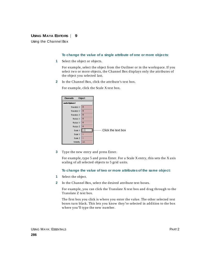
USING MAYA: ESSENTIALS PART 2
286
USING MAYA EDITORS | 9Using the Channel Box
To change the value of a single attribute of one or more objects:
1 Select the object or objects.
For example, select the object from the Outliner or in the workspace. If youselect two or more objects, the Channel Box displays only the attributes ofthe object you selected last.
2 In the Channel Box, click the attribute’s text box.
For example, click the Scale X text box.
3 Type the new entry and press Enter.
For example, type 5 and press Enter. For a Scale X entry, this sets the X axisscaling of all selected objects to 5 grid units.
To change the value of two or more attributes of the same object:
1 Select the object.
2 In the Channel Box, select the desired attribute text boxes.
For example, you can click the Translate X text box and drag through to theTranslate Z text box.
The first box you click is where you enter the value. The other selected textboxes turn black. This lets you know they’re selected in addition to the boxwhere you’ll type the new number.
Click the text box

USING MAYA EDITORS | 9Using the Channel Box
EDITORS USING MAYA: ESSENTIALS
287
3 Type the new entry and press Enter.
For example, type 5 and press Enter. If X translate, Y translate, and Ztranslate are selected when you enter 5, all three attributes become 5.
To change the value of two or more attributes of multiple objects:
1 Select the objects.
2 In the Channel Box, select the attribute’s text boxes.
3 Type the entry and press Enter.
Entering a relative value for attributesYou can change the values of several attributes by a relative amount. Forexample, you can add 3 to the Scale X, Scale Y, and Scale Z attributes. To dothis, you must enter these arithmetic operators in the text boxes:
Tip
You can select multiple text boxes:
• To select several adjacent boxes, drag through them.
• To add a non-adjacent box to a selection, Ctrl-click theadditional box.
• To select a range of boxes, click the first box and Shift-click the last box.
Drag through adjacent boxes

USING MAYA: ESSENTIALS PART 2
288
USING MAYA EDITORS | 9Using the Channel Box
For example, suppose you’ve selected an object named Ball. Its Scale X andScale Y attributes are set to 3 and 5 in the Channel Box.
If you select the Scale X and Scale Y text boxes, typing += 2 in the text boxadds 2 to each value. So Scale X would become 5 and Scale Y would become7.
Entering values using manipulatorsBy default, when you click an object’s translate, rotate, or scale attributename (such as Translate X), manipulators appear on the object in theworkspace.
Arithmeticoperator
Operation Example entry
+= Adds the entry to the existing value ineach selected box
+= 3.5
-= Subtracts the entry to the existingvalue in each selected box
-= 3.333
*= Multiplies the entry to the existingvalue in each selected box
*= 7
/= Divides the entry to the existing valuein each selected box
/= 3

USING MAYA EDITORS | 9Using the Channel Box
EDITORS USING MAYA: ESSENTIALS
289
The manipulators are the same ones displayed with the Move, Rotate, andScale tools. You can drag the manipulators directly using the left mousebutton.
If you do not want to display these manipulators, select Channels > Settings,then select either No Manips or Invisible Manips. If you select No Manips,you can only perform these operations from the Channel Box by enteringvalues in the text boxes. If you select Invisible Manips, you perform theseoperations using the mouse (see “Entering values with the mouse (channelslider)” on page 289) or by entering values in the text boxes.
You can also switch between using manipulators, no manipulators, and themouse (channel slider) using the buttons at the bottom of the Channel Box.
Entering values with the mouse (channel slider)For most attributes in the Channel Box, you can click the attribute name ortext box then drag the middle mouse button in the workspace to change itsvalue. Dragging to the right decreases the value, dragging to the leftincreases the value. You can also press the Ctrl key while dragging for finecontrol.
To use this interactive channel slider, you must set the channel box to usestandard or invisible manipulators (Channels > Settings then select StandardManips or Invisible Manips). If you select Channels > Settings > No Manips,you cannot enter attribute values with the mouse. You must enter the valuesfor these attributes in the text boxes.
When you select Channels > Settings > Invisible Manips, the cursor changesto a left and right pointing arrow when you press the middle mouse button,indicating that you are using the channel slider to change values.
You can set how quickly the channel slider responds when you drag. SelectChannels > Settings, then select Slow, Medium, or Fast or switch thesesettings using the buttons at the bottom of the Channel Box.
StandardManips
InvisibleManips
NoManips
Medium FastSlow

USING MAYA: ESSENTIALS PART 2
290
USING MAYA EDITORS | 9Using the Channel Box
You can also specify whether the attribute values change linearly as youdrag (values increase steadily as you drag), or hyperbolically (valuesincrease more sharply as you drag). Toggle off Channels > Settings >Hyperbolic to change the values linearly, and on to change valueshyperbolically, or switch the settings using the buttons at the bottom of theChannel Box.
Entering values for attributes with a pop-up menuFor some attributes, a pop-up menu appears when you click the mouse in itstext box. You can choose from the selections displayed by dragging themouse over the desired choice.
Example
Suppose you add the predefined Node State attribute to a NURBS sphere’skeyable attributes. (You can do this with Windows > GeneralEditors > Channel Control.) Node State appears in the list of attributes belowthe transform attributes.
If you click in the Node State text box, a pop-up menu appears with sixchoices: Normal, HasNoEffect, Blocking, Waiting-Normal, Waiting-HasNoEffect, Waiting-Blocking. Drag the mouse over the desired selection.For information on these states, see “Changing node behavior” on page 272.
Linear Hyperbolic

USING MAYA EDITORS | 9Using the Channel Box
EDITORS USING MAYA: ESSENTIALS
291
Setting keys for attributes from the Channel BoxYou can set a key for one or more object attributes in the Channel Box. Fordetails about keys, see Using Maya: Animation.
To set a key for one attribute:
1 Select the object.
2 Click the timeline frame number where you want to set the key.
3 Click the attribute name to select it.
For example, click Translate X.
4 Type the value of the attribute and press Enter.
For example, enter 10 and press Enter.
5 In the Channel Box, choose Channels > Key Selected.
or
Right-click the attribute name or text box and select Key Selected.
This sets the key for the object attribute value you specified.
Setting a key for all attributes
1 Click the timeline frame number where you want to set the key.
2 Enter values for the desired attributes in the Channel Box. Press Enter afterentering the attributes.
3 In the Channel Box, select Channels > Key All.
or
Right-click the attribute name or text box and select Key All.
Click the timeline

USING MAYA: ESSENTIALS PART 2
292
USING MAYA EDITORS | 9Using the Channel Box
This sets the key for all the object attribute values displayed in theChannel Box.
To copy keyed attribute values:
1 Select the object.
2 In the Channel Box, select the desired attributes. (You can select either theattribute name, or the attribute text boxes.)
3 Select Channels > Copy Selected.
or
Right-click the attribute name or text box and select Copy Selected.
4 Select the attributes you want to paste the keyframed values to.
5 Select Channels > Paste Selected.
or
Right-click the attribute name or text box and select Paste Selected.
Setting breakdown keys for attributes from the Channel BoxBreakdowns are a type of key that maintains a proportional relationshipwith adjacent keys. You can set a breakdown key for an attribute from theChannel Box. For information about breakdowns, see Using Maya: Animation.
To set a breakdown for selected attributes:
1 Select the object.
2 Click the timeline frame number where you want to set the breakdown.
Note
You can key the same attribute value for two or more objects. Select theobjects, click the frame, enter the value in the text box, then selectChannels > Key Selected.
You can also key multiple attribute values for multiple objects. Follow theinstructions in the previous paragraph, only select several attribute textboxes using Ctrl- or Shift-click before typing the numerical entry.

USING MAYA EDITORS | 9Using the Channel Box
EDITORS USING MAYA: ESSENTIALS
293
3 Select the attributes you want to set breakdowns for.
4 Enter the values of the attributes.
5 Select Channels > Breakdown Selected.
or
Right-click the attribute name or text box and select Breakdown Selected.
To set breakdowns for all attributes:
1 Select the object.
2 Click the timeline frame number where you want to set the breakdowns.
3 Enter the values of the attributes.
4 In the Channel Box, select Channels > Breakdown All.
or
Right-click the attribute name or text box and select Breakdown All.
Breaking connections from the Channel BoxIn the Channel Box, the text box for an attribute that is connected to anexpression, key, or other attribute (for example texture attribute) is displayedin a different color, depending on your color settings.
To break a connection:
1 Select the object.
2 In the Channel Box, select the connected attribute (click the attribute name ortext box).
3 Select Channels > Break Connections.
or
Right-click the attribute name or text box and select Break Connections.

USING MAYA: ESSENTIALS PART 2
294
USING MAYA EDITORS | 9Using the Channel Box
Locking attribute values from the Channel BoxYou can lock an attribute value to avoid accidentally changing it later.
To lock an attribute:
1 Select the object.
2 In the Channel Box, click the attribute name.
3 If you need to set the attribute value before locking it, type a value and pressEnter.
4 In the Channel Box, select Channels > Lock Selected.
or
Right-click the attribute name or text box and select Lock Selected.
This locks the value. The Channel Box displays locked attributes with a graybackground. (This color may not be visible while the text box is selected.)
When you’ve locked an attribute, you cannot change its value in the ChannelBox, the workspace, or elsewhere.
You must unlock the attribute to change its value.
To unlock an attribute
1 Select the object.
2 In the Channel Box, click the attribute name.
3 In the Channel Box, select Channels > Unlock Selected.
or
Right-click the attribute name or text box and select Unlock Selected.
Tip
You can lock two or more attributes at the same time. Ctrl- or Shift-clickthe attribute names to select them, then select Channel > Lock Selected (orright-click the attribute names and select Lock Selected).

USING MAYA EDITORS | 9Using the Channel Box
EDITORS USING MAYA: ESSENTIALS
295
Launching the Expression Editor from the Channel BoxYou can launch the Expression Editor for the attribute selected in theChannel Box.
To start the Expression Editor:
• In the Channel Box, select Channels > Expressions.
or
• Right-click the attribute name or text box and select Expressions.
The Expression Editor appears. See Using Maya: Expressions for details on itsuse.
Linking attributes from the Channel BoxMaya has a special type of key called a driven key that links one attributevalue to another. When you create a driven key, you specify a driverattribute value and a driven attribute value. The value of the driven attributeis locked to a corresponding value of the driver attribute.
You can link attributes from the Channel Box by selecting the attribute andthen selecting Channels > Set Driven Key (or by right-clicking the attributename or text box and selecting Set Driven Key). For details, see Using Maya:Animation.
Modifying an object’s history (inputs)Use the INPUTS component of the Channel Box to modify an object’sconstruction history. Since all objects in Maya can be created with “HistoryOn,” you can change initial parameters after the fact.
In the following example, we change the object’s radius from 0.5 to 0.8, itsheight from 1 to 2, and its X, Y, and Z subdivisions from 20, 1, and 8 to 18, 2,and 5, respectively.
To modify an object’s history:
1 Select the object you want to modify.

USING MAYA: ESSENTIALS PART 2
296
USING MAYA EDITORS | 9Using the Channel Box
2 Type the new information in the respective boxes and press Enter. Each timeyou change part of the object’s history, Maya changes the object.
Click here todisplay the boxes

USING MAYA EDITORS | 9Using the Outliner
EDITORS USING MAYA: ESSENTIALS
297
3 To return to the original setting for Subdivision Z, select Edit > Undo orpress Ctrl-Z. The object returns to its original scale for Subdivision Z.
4 Repeat for the other boxes.
USING THE OUTLINER
You can use the Outliner to do these tasks:
• Examine the structure and components of the scene. See “Navigating theOutliner” on page 300.
• Display shape nodes, connections, and attributes. See “Displaying shapenodes” on page 302.
• Make an object the child of a parent object. A child adopts attribute changesmade to the parent. See “Parenting objects” on page 306.

USING MAYA: ESSENTIALS PART 2
298
USING MAYA EDITORS | 9Using the Outliner
• Select and rename an object. See “Selecting and renaming objects” on page309.
• Reorder nodes. Reordering a node’s position in the Outliner affects Maya’sevaluation order for the object. See “Reordering nodes” on page 309.
You can open the Outliner in its own window or in a workspace panel. Ifyou display it in a workspace panel, you see the Maya user interface and theOutliner at the same time without having to reposition the windows.
To open the Outliner in its own window:
From the menu bar or Hotbox, select Window > Outliner. The Outlineropens.
Scale and move the window as needed.
Tip
If your scene has many objects or it contains character skeletons, considerusing the Hypergraph instead of the Outliner. The Hypergraph displaysthe scene hierarchy in a graphical format that’s more convenient forcomplex scenes.
Menu bar
Scenehierarchy

USING MAYA EDITORS | 9Using the Outliner
EDITORS USING MAYA: ESSENTIALS
299
To open the Outliner in a workspace panel:
From a workspace panel, select Panels > Panel > Outliner.
Outliner panel items
The Outliner’s menu bar selections control what types of objects and otheritems are displayed in the scene hierarchy. A scene hierarchy is sometimesreferred to as a DAG (for Directed Acyclic Graph).
The Outliner lists invisible objects, such as the perspective, top, front, andside cameras, in blue text. In a new, empty scene, the Outliner lists onlythese objects and the default light and object sets. As you add objects to thescene, they appear in the Outliner.
Understanding scene hierarchy terminologyA common technique in modeling, rendering, and animating is to work withobjects in a hierarchical relationship. To work with a hierarchy you mustunderstand the terminology for describing the relationship of objects.
We use the following figure to define common hierarchy terminology:
Parent An object or other item that controls attributes of one or more children. Aparent can also be the child of another parent.
USING MAYA: ESSENTIALS PART 2
300
USING MAYA EDITORS | 9Using the Outliner
In the figure, InnerSolarSystem is a parent of Sun. Sun is a parent ofMercury, Venus, Earth, and Mars. Earth is a parent of Moon.
Child An object whose attributes are controlled by its parent. A child can be theparent of other children. A child is connected to its parent by an indentedright angle line.
Sun is a child of InnerSolarSystem. Mercury, Venus, Earth, and Mars arechildren of Sun. Moon is a child of Earth.
Node A parent, child, or independent object or item.
InnerSolarSystem, Sun, Moon, persp, top, and all other entries in theexample are nodes.
Hierarchy The arrangement of all connected nodes that make up a scene or object.
The scene hierarchy is made of all nodes in the figure. The Earth hierarchyconsists of Earth and Moon.
Transform node A node that contains an object’s transformation attributes—values for itstranslation, rotation, and scale. It also holds information on any parent-childrelationships it has with other nodes. Transform nodes are also called DAGobjects.
InnerSolarSystem, Sun, Moon, and all other entries in the example aretransform nodes.
Shape node A node that holds an object’s geometry attributes or attributes other than theobject’s transform node attributes. A shape node is always a child of atransform node.
Shape nodes do not appear in the Outliner by default. To display shapenodes, see “Displaying shape nodes” on page 302.
Navigating the OutlinerAs you examine a scene with many objects, you must scroll or expand theOutliner panel. You’ll also need to expand or collapse the display of nodes.You expand a node to see the child node below it. You collapse a node tosimplify your view of the hierarchy.
To expand a node:
Click the plus sign ( ) to its left.
The plus sign ( ) changes to a minus sign ( ).

USING MAYA EDITORS | 9Using the Outliner
EDITORS USING MAYA: ESSENTIALS
301
As a quick way of expanding several collapsed hierarchies, you can selectthem, expand one of them, and they all expand.
To collapse a node:
Click minus sign ( ) to its left.
The minus sign ( ) changes to a plus sign ( ). Note that Hierarchies becomehighlighted if they are collapsed but contain an item that is selected.
To expand a node’s entire hierarchy:
Shift-click the plus sign ( ) to its left.
The plus sign ( ) changes to a minus sign ( ).
If your scene has many objects in a complex hierarchy, you might need toexpand many nodes to find a child. To find the node quickly, you can selectthe object in the workspace and choose a menu entry to expand all nodesnecessary to list the object.
To display a child not currently listed in the Outliner:
1 Select the object in the workspace.
2 In the Outliner, select Display > Selected.
To split the Outliner window:
You can split the Outliner window in order to see either end of a long list. Tosplit the window, click the separator at the bottom of the window and dragit up. Restore full display by dragging the separator back to the bottom. Asvisual cue, moving your cursor over the separator bar changes it to:
(IRIX) or (Windows NT).
Tip
To select Outliner menus more conveniently from a pop-up menu, click theright mouse button in the Outliner window.

USING MAYA: ESSENTIALS PART 2
302
USING MAYA EDITORS | 9Using the Outliner
Displaying shape nodesBy default, the Outliner displays only DAG objects in the scene. DAG objectsare transform nodes. You can also display shape nodes, the nodes that holdan object’s geometry attributes or attributes other than the object’s transformnode attributes.
To display shape nodes:
In the Outliner, toggle on Display > Shapes.
Example
Suppose you select Create > NURBS Primitives > Sphere to create a sphere.Maya creates a transform node and a shape node.
If you toggle on Display > Shapes and expand the nurbsSphere1 node, theshape node appears underneath.
Maya gives the nodes the default names shown in the figure. ThenurbsSphere1 is the transform node; nurbsSphereShape1 is the shape node.If you rename the transform node, for example, as Bubble, Maya renamesthe shape node BubbleShape.
If you rename the shape node, Maya does not rename the transform node.Maya doesn’t transmit a child’s attribute changes up to its parent.
Drag the separatorbar to split the outliner

USING MAYA EDITORS | 9Using the Outliner
EDITORS USING MAYA: ESSENTIALS
303
Displaying attributesYou can display attributes of the nodes shown in the Outliner. To simplifythe Outliner’s appearance, you can also limit the display of attributes to thefollowing categories:
• keyable attributes
• translate, scale, and rotate attributes
• attributes connected to an animation curve or expression
• attributes connected to any controlling node
To display all attributes:
1 Select Display > Attributes (Channels) to toggle it on. (Make sure you are notshowing only selected items by selecting Show > Show All.)
A plus symbol ( ) appears to the left of each node.
2 Click ( ) to display the node’s attributes.
The ( ) changes to a minus symbol ( ) when the node’s attributes areexpanded. You can click the minus symbol to collapse the attributes.
Some attributes also appear with ( ) to the left. These are compoundattributes consisting of two or more attributes. Click ( ) for a compoundattribute to see its component attributes. For example, the compoundTranslate attribute is made of Translate X, Translate Y, and Translate Zattributes.
You can’t use the Outliner to change attributes’ values. You can set them inthe Channel Box, Attribute Editor, or Attribute Spreadsheet. Note also thatyou use those tools to set the value of noncompound attributes only. Youcan set compound attributes (to set the component attributes) only withMEL commands.
Note
The Display and Show menu settings are saved with a scene file. The menusettings are not saved when you open a new or different scene.

USING MAYA: ESSENTIALS PART 2
304
USING MAYA EDITORS | 9Using the Outliner
To display only keyable attributes:
1 Select Display > Attributes (Channels) to toggle it on.
2 Select Show > Attributes > Keyable to toggle it on.
To display only translate, scale, and rotate attributes:
1 Select Display > Attributes (Channels) to toggle it on.
2 Select Show > Attributes and toggle on one of these:
Rotate Displays only Rotate attributes.
Scale Displays only Scale attributes.
Scale Rotate Translate
Displays only Scale, Rotate, and Translate attributes.
Translate Displays only Translate attributes.
3 Click ( ) to expand the compound Translate, Rotate, or Scale attributes intothe component attributes.
For example, if you expand the compound Translate attribute, the Outlinerdisplays Translate X, Translate Y, and Translate Z attributes.
To display only attributes connected to a controlling node:
1 Select Display > Attributes (Channels) to toggle it on.
2 Click ( ) to display the node’s attributes.
3 Select Display > Connections to toggle it on.
This displays only the attributes whose value is connected to the followingtypes of controlling nodes:
Tips
To open the Attribute Editor for a node, double-click the icon beside thenode name.
You can double-click a noncompound attribute to start the ExpressionEditor with the attribute automatically selected.

USING MAYA EDITORS | 9Using the Outliner
EDITORS USING MAYA: ESSENTIALS
305
• keys
• set driven key
• constraint
• motion path
• expression
• any other direct connection
Example
Suppose you create a NURBS sphere named Ball and a NURBS cone namedCone. You write an expression to assign the value of Ball’s translateYattribute to Cone’s translateY attribute.
If you select Cone, toggle on Display > Attributes (Channels) andDisplay > Connections, then expand Cone and the Translate attribute, theOutliner displays the following:
To display only attributes connected to anim curves or expressions:
Select Show > Attributes and toggle on one of these:
Driven by Anim Curve
Displays only attributes with an animation curve. This includes attributesanimated with keys, set driven keys, constraints, and motion paths.
Driven by Expression
Displays only attributes controlled by expressions.
To display all attributes again:
Select Show > Attributes > Clear Below.
Only connected attributesare displayed in the list ofattributes

USING MAYA: ESSENTIALS PART 2
306
USING MAYA EDITORS | 9Using the Outliner
Displaying specific types of nodesTo simplify the Outliner’s appearance, you can limit node display to variouscategories.
To display only specific types of nodes:
1 Toggle on Display > Shapes or Display > Dag Objects Only, as appropriate.
2 Select Show > Objects > and the type of node.
To display all nodes again:
Select Show > Objects > Clear Below.
Parenting objectsYou can make an object the child of a parent object. The child adopts someor all attribute changes made to the parent.
For example, suppose you animate a planet to orbit the center of theworkspace. If you make a moon the child of the planet, it follows the motionof the planet.
Though the moon is the child of the planet, you can also give the moonmotion that’s independent of the planet. For example, you can make it orbitthe planet. If you later change the orbiting motion of the planet, the mooncontinues to follow the planet’s motion, but stills retains its original orbitingmotion.
To control multiple objects with one node, you can also create an emptygroup and make several objects its children. By grouping objects under onenode, you can move, shade, apply texture, and do many other actions to allthe objects by working with the group node.

USING MAYA EDITORS | 9Using the Outliner
EDITORS USING MAYA: ESSENTIALS
307
Example
To parent an object in the Outliner:
1 Make sure both objects are visible in the Outliner.
If you can’t see both nodes at the same time even after maximizing andscrolling the Outliner, use Edit > Parent in Maya’s main menu bar. In theOutliner, Ctrl-click the children first, then Ctrl-click the parent, then selectEdit > Parent.
2 In the Outliner, use the middle mouse button to drag the child node onto theparent node.
To parent several objects to a new group node:
1 From the main menu bar, choose Edit > Create Empty Group. A new groupnode appears in the Outliner named null1. This node is an invisible, emptyobject.
1. Create original objects.
2. Create empty node and name it Tires.
4. Move, rotate, shade Tires.
3. Group objects under Tires.
FrontTire
Tires
BackTire
BackTire
Tires
FrontTire
Moon is now a child of Planet
Use the middle mousebutton to drag Moon

USING MAYA: ESSENTIALS PART 2
308
USING MAYA EDITORS | 9Using the Outliner
2 Use the middle mouse button to drag an object node onto the null1 node.The object becomes a child of the null1 node.
3 Repeat this step for other objects to be children of the group.
4 Rename the null1 node to something more meaningful.
For example, you might rename a group with four flower petals as flower.The Outliner displays the objects parented to the group node.
If you modify the group node attributes, its corresponding member’sattributes are also modified. For example, if you decrease the Y scaleattribute for a flower group node, the Y scale attributes of the four petalsdecrease also.
To break the relationship between parent and child:
1 Select the child.
2 From the Maya main menu bar, select Edit > Unparent.
Prefixing hierarchy namesYou can give the same prefix to all objects within a hierarchy. For example, ifyou select a parent object and give it a prefix, all objects under that parentwill now have the same prefix name.
To assign prefix hierarchy names:
1 Select the parent.
2 From the Maya main menu bar, select Modify > Prefix Hierarchy Names.
3 Enter a prefix name in the Prefix Hierarchy window and click OK.

USING MAYA EDITORS | 9Using the Outliner
EDITORS USING MAYA: ESSENTIALS
309
Selecting and renaming objectsYou can select and rename objects and other nodes in the Outliner. Selectingan object in the Outliner is useful when the workspace is crowded withobjects.
You can give two nodes the same name, but only if each has a differentparent (as in the following example).
To select an object:
1 Scroll to find the node that represents the object or component.
2 Click the node to select it. The node is highlighted in the scene to indicate itis selected.
To deselect an object:
Click an empty spot in the Maya workspace. (You can also click below thelast item in the Outliner.)
When you deselect a node, its highlighting turns off.
To rename an object:
1 Double-click the name of the object in the Outliner.
2 Enter the name in the text box.
Reordering nodesYou can reorder the position of nodes in the Outliner, for example, to makethe node’s Outliner position correspond to its spatial position in theworkspace.
Be aware that reordering an object’s position in the Outliner might mayaffect its behavior or appearance in your scene. Reordering a node’s positionin the Outliner affects Maya’s evaluation order for the object. Maya evaluatesobjects as listed from top to bottom in the Outliner.

USING MAYA: ESSENTIALS PART 2
310
USING MAYA EDITORS | 9Using the Outliner
For example, Maya typically renders nodes in the order they appear in theOutliner. Changing this order changes their rendering order. However, if anode has transparency, Maya puts the node in a delayed render queue.Maya renders objects in the queue after all opaque objects.
To reorder a node in the Outliner:
Use the middle mouse button to drag the node to another position.
As you drag, a horizontal line appears in the Outliner that indicates wherethe dragged node will be positioned. Release the mouse button at thedesired position.
Example
Suppose you created a scene containing several of the solar system’s planets,including earth. As you add each planet, the Outliner adds a noderepresenting the planet.
Maya puts each new node in the Outliner below existing nodes. The locationof the planet nodes in the Outliner might not represent the spatialrelationship of the planets in the workspace as in this example:
Here, earth sits further from mercury than mars. In the actual solar system,and in your workspace, this is not true.
To make the Outliner reflect the positioning of the earth in the workspace,use the middle mouse button to drag the earth above mars.
Maya positions earth below venus and above mars.
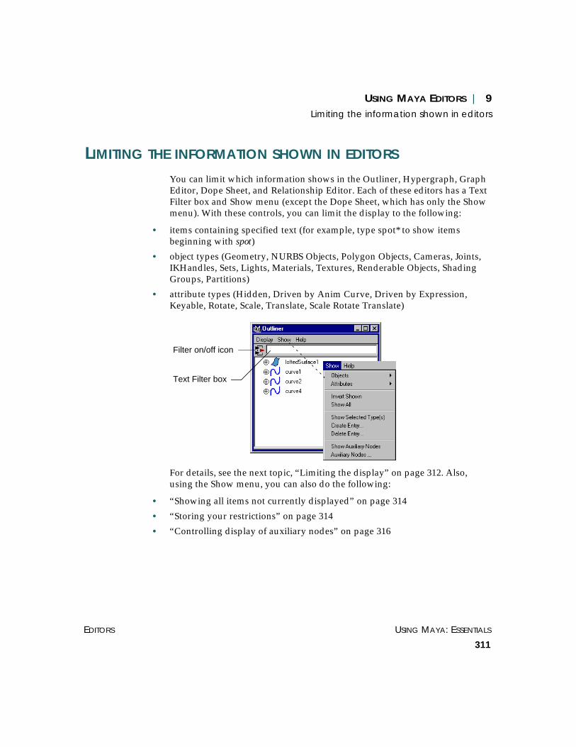
USING MAYA EDITORS | 9Limiting the information shown in editors
EDITORS USING MAYA: ESSENTIALS
311
LIMITING THE INFORMATION SHOWN IN EDITORS
You can limit which information shows in the Outliner, Hypergraph, GraphEditor, Dope Sheet, and Relationship Editor. Each of these editors has a TextFilter box and Show menu (except the Dope Sheet, which has only the Showmenu). With these controls, you can limit the display to the following:
• items containing specified text (for example, type spot* to show itemsbeginning with spot)
• object types (Geometry, NURBS Objects, Polygon Objects, Cameras, Joints,IKHandles, Sets, Lights, Materials, Textures, Renderable Objects, ShadingGroups, Partitions)
• attribute types (Hidden, Driven by Anim Curve, Driven by Expression,Keyable, Rotate, Scale, Translate, Scale Rotate Translate)
For details, see the next topic, “Limiting the display” on page 312. Also,using the Show menu, you can also do the following:
• “Showing all items not currently displayed” on page 314
• “Storing your restrictions” on page 314
• “Controlling display of auxiliary nodes” on page 316
Filter on/off icon
Text Filter box

USING MAYA: ESSENTIALS PART 2
312
USING MAYA EDITORS | 9Limiting the information shown in editors
Limiting the displayYou can limit the amount of information shown in the Outliner,Hypergraph, Graph Editor, and Relationship Editor by selecting the objecttypes and attribute types you want shown. You can show items containingspecified strings. You can also store your selections for later use. When youlimit the display in the editor, the icon beside the Text Filter box changes.
When you have a filter active, you can revert to showing all objects byclicking the filtered display icon ( ).
Limiting the display to items containing specific textUse the Text Filter box to limit the display to all objects and attributes withnames containing the text string you type. Type the string in the box andclick Enter. This box is case sensitive. For example, typing nurbs will yielddifferent results than typing NURBS.
Use the asterisk (*) wildcard to match any number of characters in the string.For example, to show all items with names starting with nurbs, type nurbs* inthe text filter box and press Enter.
Use the question mark (?) wildcard to match a single character. For example,to show items bodyFur and bodyfur (remember, the box is case sensitive), typebody?ur and press Enter.
Limiting the display to selected objectsYou can limit the display to any combination of the following objects:Geometry, NURBS Objects, Polygon Objects, Cameras, Joints, IKHandles,Sets, Lights, Materials, Textures, Renderable Objects, Shading Groups, andPartitions.
To limit the display to objects of a specified type:
Select Show > Objects, then select the items you want to display (toggle themon). Only the items you select will display. If you do not want an object typeto show, toggle it off.
All objects and attributes show
Filtered display (only objects and attributes of selected types or containingspecified text show)

USING MAYA EDITORS | 9Limiting the information shown in editors
EDITORS USING MAYA: ESSENTIALS
313
To clear the list so that no restrictions are placed on what displays (in effect,you are removing the object filter), select Show > Clear Below.
Limiting the display to selected attributesYou can limit the display to any combination of the following attributes:Hidden, Driven by Anim Curve, Driven by Expression, Keyable, Scale,Rotate, Translate, and Scale Rotate Translate.
In the Relationship Editor you can limit the display of attributes of a specifictype when character editing only.
In the Outliner, you can limit the display of attributes of a specific type onlyif Display > Attributes (Channels) is toggled on.
You cannot limit the attribute display in the Hypergraph.
To limit the display of attributes of a specified type:
Select Show > Attributes, then select the items you want to display (togglethem on). Only the items you select will show. If you do not want anattribute type to show, toggle it off.
To clear the list so that all attributes display (in effect, you are removing theattribute filter), select Show > Clear Below.
Limiting the display of object or attribute types based onthe selected itemsInstead of limiting the display using the Objects and Attributes menus, youcan limit the display to all objects or attributes of the same type as theselected (highlighted) objects or attributes by selecting Show > ShowSelected Type(s). You must first select objects or attributes (in the Outliner orworkspace) to make this command available.
Applying custom display restrictionsIf you saved your display restrictions (see “Storing your restrictions” onpage 314), it appears on the Show > Objects menu or Show > Attributesmenu, (depending on the type of items selected). To apply it, simply select itfrom the appropriate menu (toggle it on).

USING MAYA: ESSENTIALS PART 2
314
USING MAYA EDITORS | 9Limiting the information shown in editors
Showing all items not currently displayedYou can quickly toggle the display to show all items that are not currentlydisplayed. To do this, select Show > Invert Shown to toggle it on.
Showing all items (removing restrictions)To quickly remove all restrictions so that all objects and attributes show,click the filtered display icon ( ) or select Show > Show All.
Storing your restrictionsYou can store your display restrictions for later use. Restrictions that youstore in one editor are available for use in the other editors.
To store your restrictions:
1 In the Outliner or workspace, select the objects and attributes that are thetype you want to show.
2 Select Show > Show Selected Type(s). The editor shows all objects andattributes that are the same type as the selected objects.
3 Select Show > Create Entry. The Create Entry window opens.

USING MAYA EDITORS | 9Limiting the information shown in editors
EDITORS USING MAYA: ESSENTIALS
315
If you selected only objects in step #1, only the Objects section appears onthe Create Entry window. Similarly, if you selected only attributes in step #1,only the Attributes section appears.
4 In the Objects section (if there is one), toggle Entry name on and type a namefor the selection list in the adjacent box. This name will appear on theShow > Objects menu.
5 In the Attributes section (if there is one), toggle Entry name on and type aname for the selection list in the adjacent box. This name will appear on theShow > Attributes menu.
6 Click Save.
Deleting stored restrictionsDeleting a stored restrition removes it from the Show > Objects orShow > Attributes menu.
To delete a stored restriction:
1 Select Show > Delete Entry. The Delete Entry window opens.
2 To delete Object selection list, click the Objects tab, then click the entries youwant to delete.
To delete Attributes selection list, click the Attributes tab, then click theentries you want to delete.
3 Click Delete.

USING MAYA: ESSENTIALS PART 2
316
USING MAYA EDITORS | 9Limiting the information shown in editors
Controlling display of auxiliary nodesBy default, there are several auxiliary nodes, such as unitConversion, that donot show in the Outliner and other editors. These nodes are hidden toreduce clutter. If you need them to show or you want to hide additionalnodes, you can use the Show menu selections: Show Auxiliary Nodes andAuxiliary Nodes.
Your Auxiliary Node settings are saved immediately in your preferences, sothey affect all editors. They are loaded whenever you start Maya.
To show a hidden auxiliary node:
• To see all auxiliary nodes, choose Show > Show Auxiliary Nodes.
or
• To selectively show an auxiliary node, choose Show > Auxiliary Nodes toopen the Auxiliary Nodes window. From the list of auxiliary nodes, selectthe ones you want to show and click Remove From List To Show.
To hide a node:
1 Choose Show > Auxiliary Nodes to open the Auxiliary Nodes window.
2 Click the Add To List tab.
3 Either turn on All Node Types or turn on Selected Node Types.
Auxiliary Nodeswindow

USING MAYA EDITORS | 9Limiting the information shown in editors
EDITORS USING MAYA: ESSENTIALS
317
The Selected Node Types option lets you select the node in the Outliner,Hypergraph, or other panel.
4 Click Add To List To Hide.
USING MAYA: ESSENTIALS PART 2
318
USING MAYA EDITORS | 9Limiting the information shown in editors
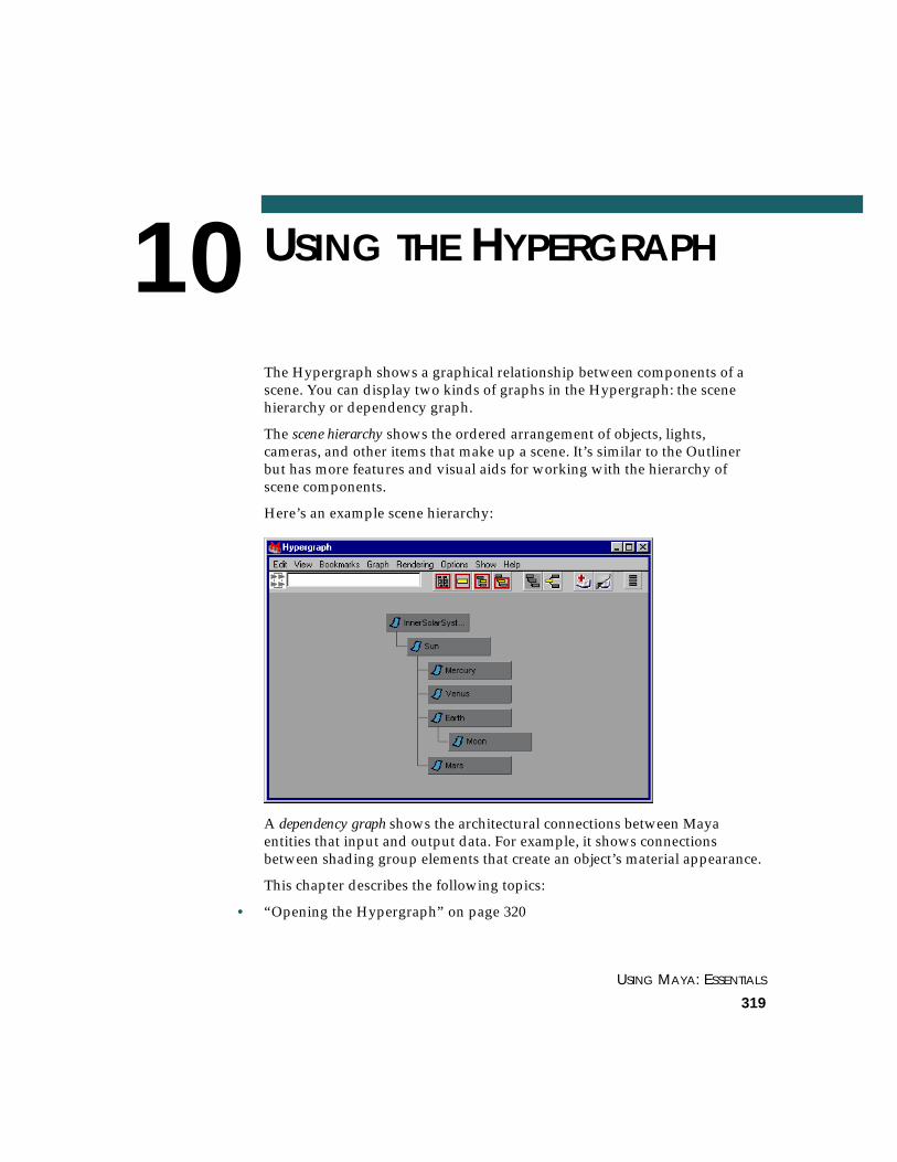
USING MAYA: ESSENTIALS
319
10 USING THE HYPERGRAPH
The Hypergraph shows a graphical relationship between components of ascene. You can display two kinds of graphs in the Hypergraph: the scenehierarchy or dependency graph.
The scene hierarchy shows the ordered arrangement of objects, lights,cameras, and other items that make up a scene. It’s similar to the Outlinerbut has more features and visual aids for working with the hierarchy ofscene components.
Here’s an example scene hierarchy:
A dependency graph shows the architectural connections between Mayaentities that input and output data. For example, it shows connectionsbetween shading group elements that create an object’s material appearance.
This chapter describes the following topics:
• “Opening the Hypergraph” on page 320

USING MAYA: ESSENTIALS PART 2
320
USING THE HYPERGRAPH | 10Opening the Hypergraph
• “Understanding scene hierarchy terminology” on page 322
• “Using the scene hierarchy” on page 324
• “Understanding the dependency graph” on page 337
• “Using a dependency graph” on page 338
• “Editing objects” on page 352
• “Altering the view of a graph” on page 356
OPENING THE HYPERGRAPH
You can open the Hypergraph in its own window or in a workspace panel.Displaying it in a workspace panel has the advantage of letting you see theMaya user interface and the Hypergraph without having to reposition thewindows.
To open the Hypergraph in its own window:
From the menu bar or Hotbox, select Window > Hypergraph. TheHypergraph opens.
Scale and move the window as needed.
Menu bar
Tool bar

USING THE HYPERGRAPH | 10Opening the Hypergraph
EDITORS USING MAYA: ESSENTIALS
321
To open the Hypergraph in a workspace panel:
From a workspace panel, select Panels > Panel > Hypergraph.
When you display the Hypergraph the first time, the scene hierarchydisplays. In subsequent displays of the Hypergraph, the scene hierarchy ordependency graph appears, depending on which was displayed theprevious time you closed the window. Note that a scene hierarchy is alsoreferred to as a DAG (directed acyclic graph).
If you display the scene hierarchy for a new, empty scene, you’ll see nograph.
If you display the scene hierarchy, invisible objects such as the perspective,top, front, and side cameras do not appear in the graph by default. Incontrast, the Outliner shows the default cameras unless you choose not todisplay them.
Hypergraph menu bar
The Hypergraph menu bar has entries for working with the scene hierarchyor dependency graph.
Hypergraph toolbar
The tool bar has icons for commonly used Hypergraph menu bar selections.To see the selection that an icon represents, move the mouse pointer over theicon. If popup help is toggled on (Help > Popup Help), the name of theselection appears in a yellow popup. Otherwise, look in the help line at thebottom of the Maya window.
Note
Unless instructions in this chapter state otherwise, make all menu choicesfrom the Hypergraph menu bar.

USING MAYA: ESSENTIALS PART 2
322
USING THE HYPERGRAPH | 10Understanding scene hierarchy terminology
UNDERSTANDING SCENE HIERARCHY TERMINOLOGY
A common technique in modeling, rendering, and animation is to work withobjects in a hierarchical relationship. To work with a hierarchy you mustunderstand the terminology for describing the relationship of objects.
The following figure illustrates a scene hierachy.
Parent An object or other item that controls attributes of one or more children. Aparent can also be the child of another parent.
In the figure, InnerSolarSystem is a parent of Sun. Sun is a parent ofMercury, Venus, Earth, and Mars. Earth is a parent of Moon.
Child An object having attributes controlled by its parent. A child can be theparent of other children. A child in the graph is connected to its parent by anindented right angle line.
Sun is a child of InnerSolarSystem. Mercury, Venus, Earth, and Mars arechildren of Sun. Moon is a child of Earth.
Node A parent, child, or independent item. This refers generally to any box in thegraph.
InnerSolarSystem, Sun, Moon, and all other boxes in the graph are nodes.
Subnode Any node below another node in the hierarchy.
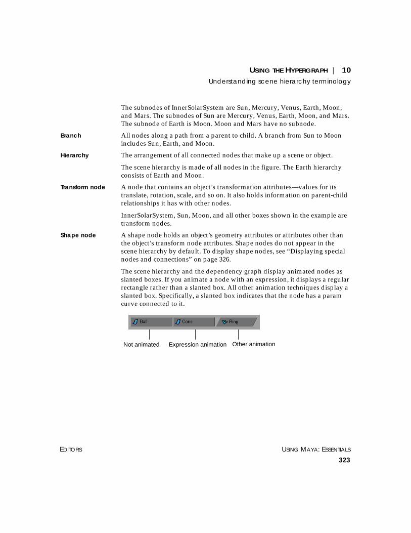
USING THE HYPERGRAPH | 10Understanding scene hierarchy terminology
EDITORS USING MAYA: ESSENTIALS
323
The subnodes of InnerSolarSystem are Sun, Mercury, Venus, Earth, Moon,and Mars. The subnodes of Sun are Mercury, Venus, Earth, Moon, and Mars.The subnode of Earth is Moon. Moon and Mars have no subnode.
Branch All nodes along a path from a parent to child. A branch from Sun to Moonincludes Sun, Earth, and Moon.
Hierarchy The arrangement of all connected nodes that make up a scene or object.
The scene hierarchy is made of all nodes in the figure. The Earth hierarchyconsists of Earth and Moon.
Transform node A node that contains an object’s transformation attributes—values for itstranslate, rotation, scale, and so on. It also holds information on parent-childrelationships it has with other nodes.
InnerSolarSystem, Sun, Moon, and all other boxes shown in the example aretransform nodes.
Shape node A shape node holds an object’s geometry attributes or attributes other thanthe object’s transform node attributes. Shape nodes do not appear in thescene hierarchy by default. To display shape nodes, see “Displaying specialnodes and connections” on page 326.
The scene hierarchy and the dependency graph display animated nodes asslanted boxes. If you animate a node with an expression, it displays a regularrectangle rather than a slanted box. All other animation techniques display aslanted box. Specifically, a slanted box indicates that the node has a paramcurve connected to it.
Not animated Expression animation Other animation

USING MAYA: ESSENTIALS PART 2
324
USING THE HYPERGRAPH | 10Using the scene hierarchy
USING THE SCENE HIERARCHY
You can use the scene hierarchy to:
• display special nodes and connections
You can display shape, invisible, and underworld nodes. You can also showexpression, constraint, and deformer connections that link nodes. See“Displaying special nodes and connections” on page 326.
• make an object the child of a parent object (known as parenting)
A child adopts attribute changes made to the parent. See “Parenting objects”on page 329.
• reorder the position of nodes (see “Rearranging scene hierarchy nodes” onpage 331)
• create a free-form graph of the hierarchy that suits your visual preference(see “Creating a free-form hierarchy” on page 333)
• select, rename, and hide objects, and edit attributes of an object (see “Editingobjects” on page 352)
• examine the structure of the scene
The Outliner lists the components of a scene as an indented list. TheHypergraph shows the relationship of the objects of the scene graphically.See “Altering the view of a graph” on page 356 for details on navigating theview of the graph.
Expanding scene hierarchy nodesAs you examine a scene hierarchy, you can expand or collapse the display ofnodes. Collapsing nodes is helpful for lessening clutter in a hierarchy. Youexpand a node to see nodes below it.
For a selected node, you can display:
• subnodes one level below the node
• all subnodes below a node
When you know where a node is in the workspace but you’re not sure of itsgraph position, you can select the node in the workspace and expand allnodes necessary to display and highlight it.
A selected node is yellow in the scene hierarchy.
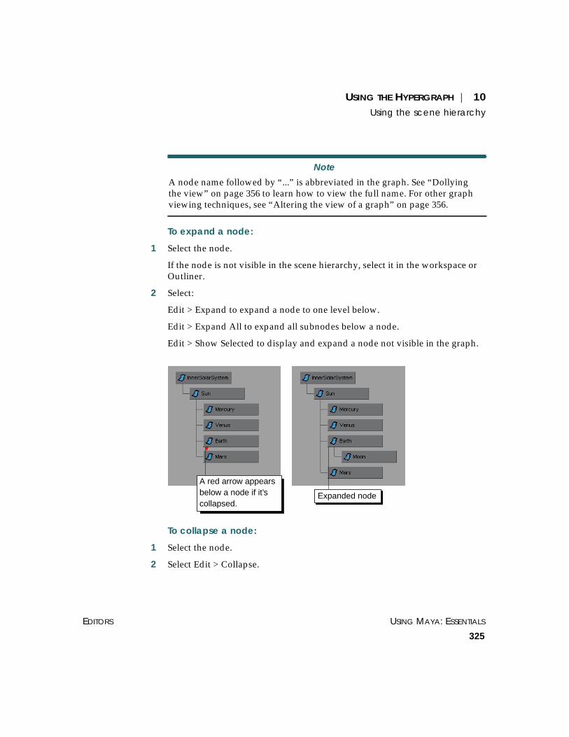
USING THE HYPERGRAPH | 10Using the scene hierarchy
EDITORS USING MAYA: ESSENTIALS
325
To expand a node:
1 Select the node.
If the node is not visible in the scene hierarchy, select it in the workspace orOutliner.
2 Select:
Edit > Expand to expand a node to one level below.
Edit > Expand All to expand all subnodes below a node.
Edit > Show Selected to display and expand a node not visible in the graph.
To collapse a node:
1 Select the node.
2 Select Edit > Collapse.
Note
A node name followed by “...” is abbreviated in the graph. See “Dollyingthe view” on page 356 to learn how to view the full name. For other graphviewing techniques, see “Altering the view of a graph” on page 356.
Expanded node
A red arrow appearsbelow a node if it’scollapsed.

USING MAYA: ESSENTIALS PART 2
326
USING THE HYPERGRAPH | 10Using the scene hierarchy
Displaying special nodes and connectionsYou can display shape, invisible, and underworld nodes in the scenehierarchy. You can also display expression, constraint, and deformerconnections that link different nodes.
Shape, invisible, and underworld nodesBy default, the scene hierarchy does not display shape nodes, invisiblenodes, or underworld nodes. It displays only transform nodes—nodes thathold attributes and other information on an object’s transformation andparent-child relationships.
A shape node holds an object’s geometry attributes or attributes other than theobject’s transform node attributes. A shape node is a child of a transformnode. A transform node has only one shape node.
An invisible node is any object you have hidden using Display > Hide fromMaya’s menu bar. The default cameras top, front, side, and persp are alsoinvisible nodes.
An underworld node is a pair of nodes below a shape node. When you create acurve on a NURBS surface, Maya generates an underworld transform nodeand shape node below the shape node of the surface. The CV positions ofunderworld nodes have UV coordinates on the surface rather thancoordinates in world or local space.
Tips
• To expand or collapse a node, double-click it.
• To quickly select Hypergraph menus, click the rightmouse button in an empty part of the Hypergraphwindow.
• To display context-sensitive Hypergraph menus, movethe mouse over a node and click the right mousebutton. These menus are also available from the mainHypergraph menus, but they apply only to theselected node.
• For details on navigating the view of the graph, see“Altering the view of a graph” on page 356.

USING THE HYPERGRAPH | 10Using the scene hierarchy
EDITORS USING MAYA: ESSENTIALS
327
To display invisible nodes, object shape nodes, or underworld nodes:
Toggle on these options:
• Options > Display > Shape Nodes
• Options > Display > Invisible Nodes
• Options > Display > Underworld Nodes
Invisible nodes display with the text grayed.
Underworld nodes appear only if you also display shape nodes in the graph.
A dotted line in the scene hierarchy indicates a connection to an underworldnode. Connections to instanced objects are also indicated by dotted lines.
Example
Suppose you select Create > NURBS Primitives > Sphere to create a sphere.Maya creates a transform node and a shape node.
The sphere’s shape node holds the mathematical description of the sphere’sshape. The sphere’s transform node holds the sphere’s position, scaling,rotation, and so on. The shape node is the child of the transform node.
If you select Options > Display > Shape Nodes in the Hypergraph, the scenehierarchy shows these nodes for the sphere:
Maya gives the nodes the default names shown in the preceding figure. Thetransform node is nurbsSphere1, the shape node is nurbsSphereShape1. Ifyou rename the transform node, for example, to Bubble, Maya renames theshape node to BubbleShape.
Note
Hypergraph option settings are saved with a scene file. The options are notsaved for Maya globally.

USING MAYA: ESSENTIALS PART 2
328
USING THE HYPERGRAPH | 10Using the scene hierarchy
If you rename the shape node, Maya does not rename the transform node.Maya doesn’t transmit a child’s attribute changes up to its parent.
Example
Suppose you select Create > NURBS Primitives > Sphere to create a sphere.Maya creates a transform node and a sphere node. Suppose you then selectModify > Make Live, then use the Create > CV Curve Tool to draw a curveon the surface of the sphere.
If you turn on the display of shape nodes and underworld nodes, the scenehierarchy appears as follows:
Maya gives the nodes the default names shown. The transform node isnurbsSphere1, the shape node is nurbsSphereShape1. The curve1 andcurveShape1 nodes are underworld nodes for the curve created on thesphere’s surface.
When a curve-on-surface is hard to select in the workspace because ofcrowding or complex geometry, you can select it easily in the scenehierarchy with underworld nodes displayed.
Expression, constraint, and deformer connectionsYou can display color-coded lines in the scene hierarchy that illustrate nodesconnected by an expression, constraint, or deformer.
To display nodes connected by an expression, constraint, or deformer:
Toggle on any or all of these options:
• Options > Display > Expression Connections
• Options > Display > Constraint Connections
• Options > Display > Deformer Connections

USING THE HYPERGRAPH | 10Using the scene hierarchy
EDITORS USING MAYA: ESSENTIALS
329
To hide these connections, toggle off the appropriate options.
Example
Suppose you create a NURBS sphere named Ball and a NURBS cone namedCone. You write an expression to assign the value of Ball’s translateYattribute to Cone’s translateY attribute.
The expression links the two values. When you move Ball up or down in theworkspace (in a Y-axis direction), Cone moves up or down the same amount.
If you select Options > Display > Expression Connections, the scenehierarchy displays this:
Parenting objectsYou can make an object the child of a parent object. The child adopts someor all attribute changes made to the parent.
For example, suppose you animate a planet to orbit the center of theworkspace. If you make a moon the child of the planet, it follows the motionof the planet.
Though the moon is the child of the planet, you can also give the moonmotion that’s independent of the planet. For example, you can make it orbitthe planet. If you later change the orbiting motion of the planet, the mooncontinues to follow the planet’s motion, but stills retains its original orbitingmotion.
Tip
You can change the color-coding of the connection lines and otherimportant entities by selecting Window > Settings/Preferences > Colorsfrom Maya’s main menu bar and expanding Hypergraph/Hypershade.
This line means attributes in thetwo nodes are connected, for

USING MAYA: ESSENTIALS PART 2
330
USING THE HYPERGRAPH | 10Using the scene hierarchy
To control multiple objects with one node, you can also create an emptygroup and make several objects its children. By grouping objects under onenode, you can move, shade, apply texture, and do many other actions to allthe objects by working with the group node.
Example
To parent an object:
In the scene hierarchy, use the middle mouse button to drag the child nodeon the parent node.
If the parent node is not visible in the window, drag the child toward in thedirection of the parent. The graph view scrolls as you drag into theHypergraph’s window border.
To parent several objects to a new node:
1 From the Maya main menu bar, select Edit > Create Empty Group. A newnode appears in the scene hierarchy named null1. This node is an invisible,empty object.
1. Create original objects.
2. Create empty node and name it Tires.
4. Move, rotate, shade Tires.
3. Group objects under Tires.
FrontTire
Tires
BackTire
BackTire
Tires
FrontTire
Use the middle mouse buttonto drag Moon onto Planet.
Moon is now achild of Planet.

USING THE HYPERGRAPH | 10Using the scene hierarchy
EDITORS USING MAYA: ESSENTIALS
331
2 Use the middle mouse button to drag an object node onto the null1 node.The object becomes a child of the null1 node.
3 Repeat this step for other objects to be children of the group.
4 Rename the null1 node to something more meaningful.
For example, you might rename a group containing four flower petals asflower. See “Renaming an object” on page 354.
The scene hierarchy displays the objects parented to the group node:
If you modify the group node attributes, its corresponding member’sattributes also are modified. For example, if you scale down a flower groupnode, the four petals scale down also.
To break the relationship between parent and child:
With the middle mouse button, drag the child node to an empty spot in theworkspace.
Rearranging scene hierarchy nodesYou can rearrange the position of nodes in a scene hierarchy to suit yourpreferences as follows:
• Move a node’s relative position.
• Create a free-form scene hierarchy.
• Display the graph vertically or horizontally. See “Displaying a graphvertically or horizontally” on page 364.
Note that Maya updates the scene hierarchy as you modify a scene.

USING MAYA: ESSENTIALS PART 2
332
USING THE HYPERGRAPH | 10Using the scene hierarchy
Changing a node’s relative positionYou can move a node’s relative position vertically or horizontally in a scenehierarchy. You might want to do this, for example, to make the node’s graphposition correspond to its spatial position in the workspace.
Be aware that rearranging an object’s position in the Hypergraph might alterits behavior or appearance in your scene. Reordering a node’s position in thegraph affects Maya’s evaluation order for the object. The evaluation orderoccurs from left to right and top to bottom for a scene hierarchy displayed inautomatic layout.
For example, Maya typically renders nodes in the order they appear in thescene hierarchy. Changing this order changes their rendering order. If anode has transparency, however, Maya puts the node in a delayed renderqueue. Maya renders this queue after all opaque objects.
To see the evaluation order for a graph currently in free-form layout, selectOptions > Layout > Automatic Layout. To return to the free-form layout,select Options > Layout > Freeform Layout.
To move a node in the graph:
Use Ctrl-middle mouse button to drag the node on top of another node.
In a horizontal graph, the dragged node replaces the other node’s position.The other node’s position gets pushed to the right.
In a vertical graph, the dragged node replaces the other node’s position. Theother node’s position gets pushed downward.
Example
Suppose you created a scene containing several of the solar system’s planets,including earth. As you add each planet, the scene hierarchy puts a noderepresenting the planet in the graph.
Maya puts each new node in the graph to the right of existing nodes. Thelocation of the planet nodes in the graph might not represent the spatialrelationship of the planets in the workspace, as in this example:

USING THE HYPERGRAPH | 10Using the scene hierarchy
EDITORS USING MAYA: ESSENTIALS
333
Here, Earth sits further from mercury than mars. In the actual solar systemand in your workspace, this is not true.
To make the graph reflect the positioning of the earth in the workspace, useCtrl-middle mouse button to drag the Earth on top of Mars.
Maya positions the node to the right of Venus and to the left of Mars.Thereafter, you’ll know where to look for Earth in the scene hierarchy.
Creating a free-form hierarchyMaya lets you select a free-form layout for the scene hierarchy to suit yournode position preferences. By doing so, you can make the graph’sappearance resemble the appearance of characters or other complex objectsin your scene. This helps you find and select components from the hierarchymore quickly.
For example, suppose you modeled a human hand. You can customize thegraph so the location of its nodes resembles the arrangement of the jointsthat represent the fingers and palm:

USING MAYA: ESSENTIALS PART 2
334
USING THE HYPERGRAPH | 10Using the scene hierarchy
To make a free-form graph:
1 Select Options > Layout > Freeform Layout.
2 Drag nodes to the desired positions in the graph.
If the spot where you want to put a node is not visible in the window, dragthe node past the edge of the window. The window scrolls in the directionyou drag.
To drag two or more nodes to another position, click the first node, Shift-click the second node and any other nodes, then drag to the desired position.
To drag a parent but not its children, Ctrl-Shift-click the node and drag tothe desired position.
To return to the automatically generated layout:
Select Options > Layout > Automatic Layout.
You can return to your previous free-form graph arrangement by selectingOptions > Layout > Freeform Layout.
To reset the free-form graph:
If you create a free-form graph and you decide you no longer like itsappearance, you can reset the graph to the automatic layout.
1 Select Edit > Reset Freeform Layout.
2 Click Yes when asked to confirm your selection.
Important
Move as few nodes as necessary. When you drag a node to a new positionin the graph, you increase the scene’s file size and the Maya processingtime needed to work with the scene.
When you move a parent node, Maya automatically moves its childrenwith it. Automatically moved children do not increase the file size andprocessing time.

USING THE HYPERGRAPH | 10Using the scene hierarchy
EDITORS USING MAYA: ESSENTIALS
335
Displaying a background image with a scene hierarchyYou can display a single image of your choice as the background for a scenehierarchy. This is helpful if you want to create a free-form hierarchy that letsyou identify and select a character’s joints and nodes more easily.
For example, suppose you modeled a human character. Suppose further yourendered an image of the character or used a snapshot utility to capture animage of the character’s skeleton in the workspace.
You can display the image in the background of a free-form hierarchy, thenposition nodes and joints to match the character skeleton. This helps youidentify scene hierarchy components more quickly.

USING MAYA: ESSENTIALS PART 2
336
USING THE HYPERGRAPH | 10Using the scene hierarchy
The character skeleton exists behind the scene hierarchy. With thisarrangement, you can quickly find nodes, for example, that represents thecharacter’s feet and ankles.

USING THE HYPERGRAPH | 10Understanding the dependency graph
EDITORS USING MAYA: ESSENTIALS
337
To import the background image:
1 Switch to freeform layout, if you are not already in it (Options > Layout >Freeform Layout).
Note that you can import an image for the free-form layout only. Having abackground image for the automatic layout has no practical purpose. Thenode positions for the automatic layout are fixed.
2 Select View > Load Background Image. A file browser appears.
3 Select and load the image. The image appears in the scene hierarchy.
4 Dolly or track to bring the image into view.
5 Move nodes to positions on top of the image.
Whenever you display the scene hierarchy in the Hypergraph (in freeformlayout), the image appears behind the nodes.
To turn the display of the background image off or on:
Toggle Options > Display > Background Image (in free-form) on or off.
You can display the image in the background of a free-form hierarchy.
UNDERSTANDING THE DEPENDENCY GRAPH
The dependency graph displays connections between nodes in Maya thatinput and output data. A dependency graph node can represent an object’sgeometry, for example, a NURBS sphere. A node can also represent a Mayaoperation such as a deformer. Inputs and outputs are the connectionsbetween nodes, including direction of influence.
A dependency graph has no parent-child relationships, only data flow. Youcan display a dependency graph, for example, to see the data flow betweennodes that make up an object’s construction history or shading.
All nodes in a scene hierarchy also can be displayed in a dependency graph.However, not all nodes in a dependency can be displayed in a scene graph.
For example, a NURBS sphere’s transform and shape nodes appear in ascene graph and therefore can be displayed in a dependency graph. Ashading group node or deformer operation node that appears in adependency graph never appears in a scene hierarchy.

USING MAYA: ESSENTIALS PART 2
338
USING THE HYPERGRAPH | 10Using a dependency graph
A dependency graph node takes input data from one or more other nodesand uses the input to create output data. When you create models, deformobjects, animate, process audio, and so on, dependency graph nodes workwith the data involved.
Although we refer to a dependency graph as a singular graph, be aware youcan display two or more independent graphs of connected nodes in the samewindow. We refer to each independent graph also as a dependency graph.Maya updates the dependency graph as you modify a scene.
USING A DEPENDENCY GRAPH
The dependency graph is a tool for programmers who extend Mayacapabilities. If you’re an advanced Maya user, you’ll also find it useful to:
• examine render node connections (see “Displaying render nodeconnections” on page 339)
• examine other node connections (see “Displaying upstream and downstreamconnections” on page 340)
• disconnect rendering nodes and other nodes (see “Disconnecting nodes in adependency graph” on page 344)
• connect rendering nodes and other nodes (see “Connecting nodes in adependency graph” on page 346)
Avoid disconnecting and connecting nodes unless you have anunderstanding of Maya’s architecture. You’ll spare yourself frustrationtracking down resulting problems.
See “Editing objects” on page 352 and “Altering the view of a graph” onpage 356 for additional details on working with a dependency graph.
Tip
As a new user of the Hypergraph, you might be unsure whether you’relooking at the scene hierarchy or a dependency graph. If you see arrowsbetween nodes, you’re looking at a dependency graph. If Scene Hierarchyunder the Graph menu is grayed, you’re looking at the scene hierarchy.

USING THE HYPERGRAPH | 10Using a dependency graph
EDITORS USING MAYA: ESSENTIALS
339
Displaying render node connectionsYou can show connections to shading groups, materials, textures, and lights.See Using Maya: Rendering for details.
To display render node connections:
Select one of these options:
• Rendering > Show Shading Groups
• Rendering > Show Materials
• Rendering > Show Textures
• Rendering > Show Lights
Example
Suppose you create a NURBS sphere, then use the Hypershade to create andassign a Phong shading group to it. Next you use the Hypershade to create a2D checker texture and assign it to the Phong node.
The Hypershade displays the following contents:
The following dependency graph appears when you selectRendering > Show Shading Groups in the Hypergraph.
Connection line

USING MAYA: ESSENTIALS PART 2
340
USING THE HYPERGRAPH | 10Using a dependency graph
The connection lines between nodes show connection direction. Theconnection line originates at a node that outputs data, and the line points toa node receiving the data as input.
The preceding figure shows that the flow of output goes from the phong1SGshading group to the renderPartition.
Although you can see most of the same nodes in the Hypershade, thedependency graph shows the nodes in a flow diagram. This makes it easy tosee the connections between the nodes that make up a shading group.
If you move your mouse pointer over a connection line, small white boxesappear next to the input node and output node. The white box next to aninput node shows the node’s name and attribute that receives the input.
The white box next to an output node shows the node’s name and attributethat provides the output. Each node name and attribute is separated by aperiod, for example, checker1.outColor and phong1.color. In the precedingfigure, the outColor attribute of checker1 is output to the color attribute ofphong1.
In many cases, you must be familiar with Maya internal operation details tounderstand the node and attribute names you see in the white boxes.
Displaying upstream and downstream connectionsYou can show upstream and downstream connections to a selected node. Anupstream connection is a node that provides input to the selected node. Adownstream connection is a node that receives input from the selected node.
To see connections to most objects, you must select the shape node of theobject rather than the transform node.
To select a node and display its connections:
1 Select the node.
To select a shape node from the scene hierarchy, make sureOptions > Display > Shape Nodes is toggled on.
phong1.colorchecker1.outColor
Mouse pointer

USING THE HYPERGRAPH | 10Using a dependency graph
EDITORS USING MAYA: ESSENTIALS
341
2 Select one of the following:
• Graph > Up and Downstream Connections
• Graph > Upstream Connections
• Graph > Downstream Connections
When you display upstream connections for a node, you see the chain ofnodes that provide input to each other all the way to the selected node.
When you display downstream connections for a node, you see the chain ofnodes that output to each other, all the way through to the end receivingnode.
Example
Suppose you create a wine glass surface by revolving a NURBS curve. Thefollowing dependency graph appears when you select the revolved surface’sshape node and select Graph > Up and Downstream Connections:
Tip
You can select an object’s shape node in the scene hierarchy withoutshowing shape nodes. Select the object’s transform node, put the mousepointer in the Maya or Hypergraph window, then press your keyboard’sdown arrow key.
Selecting a shape node with this technique is useful for scenes havingmany nodes, where displaying all shape nodes in the scene hierarchy takesup much panel space.
Press the up arrow key to return to the transform node.

USING MAYA: ESSENTIALS PART 2
342
USING THE HYPERGRAPH | 10Using a dependency graph
Note that the graph is shown with a vertical orientation to make theillustration fit on this page. By default, a dependency graph has a horizontalorientation. See “Displaying a graph vertically or horizontally” on page 364.
The connection lines between nodes show connection direction. Theconnection line originates at a node that outputs data, and the line points toa node receiving the data as input. For information on the connection linecolors, see “Connection line colors” on page 343.
The example graph shows that a curve provides input to the revolveoperation node. The revolve operation generates a revolved shape—the wineglass. The revolved shape is connected to initialShadingGroup, which setsthe default color of all geometric shapes created in Maya.
If you move your mouse pointer over a connection line, small white boxesappear next to the input node and output node. The white box next to aninput node shows the node’s name and attribute that receives the input.
The white box next to an output node shows the node’s name and attributethat provides the output. Each node name and attribute is separated by aperiod.
In many cases, you must be familiar with Maya internal operation details tounderstand the node and attribute names you see in the white boxes.
Note that the dependency graph and scene hierarchy display animatednodes as slanted boxes. If you animate a node with an expression, it displaysa regular rectangle rather than a slanted box. All other animation techniquesdisplay a slanted box. Specifically, a slanted box indicates Ball has a paramcurve connected to it.

USING THE HYPERGRAPH | 10Using a dependency graph
EDITORS USING MAYA: ESSENTIALS
343
Example
Suppose you keyframe the translateX attribute of a NURBS sphere namedBall. If you select Ball’s transform node and display all upstream anddownstream connections, this graph appears:
The slanted box indicates Ball’s transform node has been animated. Thegraph doesn’t indicate which type of animation technique controls theattribute.
Connection line colorsThe connection lines are color-coded to indicate the type of attribute that isconnecting the nodes. In this case, attribute types are single, double, triple,data, and array. See the following table for an explanation.
These colors are the default. You can change them in the Colors window(Window > Settings/Preferences > Colors).
Also note that a dotted line in the scene hierarchy indicates a connection toan underworld node or an instanced object.
Default Color Attribute Type Example Attributes
Blue Single transform.translateX,makeNurbsSphere.radius
Cyan Double file.repeatUV,cameraShape.cameraAperature
Green Triple transform.translate, lambert.color
Magenta Data nurbsSurface.create,makeNurbsSphere.outputSurface
Red Array particleShape.position,particleShape.velocity

USING MAYA: ESSENTIALS PART 2
344
USING THE HYPERGRAPH | 10Using a dependency graph
Dragging nodes into a dependency graphYou can drag one or more nodes from the Outliner or Hypershade into thedependency graph to display the dependency graph of the node or nodes.This is ideal for keeping irrelevant nodes out of view when you’re creatingand assigning rendering nodes.
Any dependency graphs previously in the display remain there.
1 To clear out all graphs from the display, select Edit > Clear View.
2 Click Yes to confirm.
Note that you can also drag a node into the dependency graph from any partof Maya that lets you drag icons.
To drag the node into the dependency graph:
Use the middle mouse button to drag the node or nodes into theHypergraph panel.
Disconnecting nodes in a dependency graphYou can use the dependency graph to disconnect nodes.
To disconnect nodes:
1 Click the connection line representing the connection in the dependencygraph. The connection line turns yellow to indicate it’s selected.
2 Press your keyboard’s Backspace key. The connection line disappears,indicating you disconnected the connection.
To update the graph’s layout to display the disconnected nodes moreappropriately, select Graph > Layout.
Example
Suppose you create a NURBS sphere named Ball. You then use theHypershade to create a Phong E material with red color and assign theresulting phongE1SG shading group node to Ball.
The Hypershade displays the following contents.

USING THE HYPERGRAPH | 10Using a dependency graph
EDITORS USING MAYA: ESSENTIALS
345
The following dependency graph appears when you selectRendering > Show Shading Groups, then select the phongE1SG node andselect Graph > Up and Downstream Connections.
The graph shows that an attribute of the BallShape node (that representsBall’s geometry) is input to the phongE1SG shading group node. Ball gets itscolor from the phongE1SG node.
To stop the phongE1SG node from setting Ball’s color, do the following:
1 Click the connection line leading from BallShape to phongE1SG. Theconnection line turns yellow to indicate it’s selected.
2 Press the Backspace key on your keyboard.
The connection line disappears, indicating you disconnected the nodes. ThephongE1SG no longer controls Ball’s color.
Ball keeps its previous shading group attribute values. In other words, itstays red and doesn’t become the default gray. If you alter attributes ofphongE1SG, though, the changes are not passed to Ball.
You can reconnect BallShape to another shading group node to make itcontrol Ball’s shading. For example, you can use the middle mouse button todrag BallShape from the Outliner onto initialShadingGroup.
Ball’s color becomes the default gray color set in the initialShadingGroupnode. Note that each geometric object you create is connected to theinitialShadingGroup node, by default, until you connect it to anothershading group.

USING MAYA: ESSENTIALS PART 2
346
USING THE HYPERGRAPH | 10Using a dependency graph
Connecting nodes in a dependency graphThe dependency graph offers convenient ways to connect nodes while youexamine the graph. In the dependency graph, you can:
• launch the Connection Editor
• launch a window that displays input or output attributes you can connect to
• connect a node’s default output attribute to a node’s default input attribute
To launch the Connection Editor:
Use Shift-middle mouse button to drag from an output node to an inputnode.
The Connection Editor appears. The Outputs side of the Connection Editordisplays the dragged node and its attributes. The Inputs side displays theattributes of the destination node. See Using Maya: Rendering for details onthe Connection Editor.
To create a default connection:
Use the middle mouse button to drag the output node onto the input node.
Maya connects the default output attribute from the output node to thedefault input attribute of the input node. Usually, the default input andoutput attributes are the attributes you would most likely want to connect.
If the attributes aren’t compatible, no connection occurs and the ConnectionEditor appears instead.
Example
Suppose you create a NURBS sphere and cone named Ball and Cone. Youuse the Hypershade to create a Phong E material with red color, and a Blinnmaterial with blue color. You assign the resulting phongE1SG shading groupnode to Ball, and the blinn1SG shading group to the Cone.
The Hypershade displays the following contents:

USING THE HYPERGRAPH | 10Using a dependency graph
EDITORS USING MAYA: ESSENTIALS
347
The following dependency graph appears when you selectRendering > Show Shading Groups, select the phongE1SG and blinn1SGshading groups and select Graph > Up and Downstream Connections.
The graph shows ConeShape connected to the blinn1SG shading group, andBallShape connected to the phongE1SG shading group.
You can swap the colors of Ball and Cone by reversing their connections tothe shading groups.
To reverse connections:
1 Use the middle mouse button to drag ConeShape onto phongE1SG. Thisreconnects the default output attribute of the ConeShape node to the defaultinput attribute of the phongE1SG node. Cone becomes red.
2 Use the middle mouse button to drag BallShape onto blinn1SG. Thisreconnects the default output attribute of the ConeShape node to the defaultinput attribute of the phongE1SG node. Ball becomes blue.
Tip
Select Rendering > Create Render Node to create a new material, texture,or light. You can then connect to the new node using the dependencygraph.

USING MAYA: ESSENTIALS PART 2
348
USING THE HYPERGRAPH | 10Using a dependency graph
Example
Suppose you create a NURBS sphere named Ball. You then use theHypershade to create a Phong E material with blue color and assign thecorresponding phongE1SG shading group node to Ball to color it blue.
You then create a black and white 2D checker texture, but you haven’tassigned it to an object.
The Hypershade displays the following contents.
To replace Ball’s blue color with the checker texture, you must use themiddle mouse button to drag the texture node onto the shading group.
If you select Rendering > Show Shading Groups, you’ll see the shadinggroups in the scene, but not the textures.

USING THE HYPERGRAPH | 10Using a dependency graph
EDITORS USING MAYA: ESSENTIALS
349
If you select Rendering > Show Textures, you’ll see the textures created inthe scene, but not the shading groups.
To drag the checker1 texture onto the phongE1SG shading group, you needto display them in the graph at the same time. Do the following steps:
1 While the checker1 node is displayed in the dependency graph, use themiddle mouse button to drag the phongE1SG shading group node from theHypershade into the Hypergraph window.
2 Select the checker1 and phongE1SG nodes and select Graph > Upstream andDownstream Connections.
The dependency graph for the phongE1SG node appears as follows.
3 Use the middle mouse button to drag the checker1 node onto thephongE1SG or PhongE1 node. Maya makes a connection from checker1 tophongE1 and draws a connection line representing the connection:

USING MAYA: ESSENTIALS PART 2
350
USING THE HYPERGRAPH | 10Using a dependency graph
Ball shows a black and white checkerboard texture, rather than blue color.Turn on Shading > Smooth Shade All and Shading > Hardware Texturing todisplay shading and textures of objects in your workspace.
4 To redraw the graph with better organization of connection lines, selectGraph > Layout.
5 Dolly and track to bring the reorganized graph into view:
6 Move the mouse pointer over the connection line between checker1 andphongE1.
White boxes appear next to the nodes. They show that the default outputoutColor attribute of checker1 connects to the default input color attribute ofphongE1.

USING THE HYPERGRAPH | 10Using a dependency graph
EDITORS USING MAYA: ESSENTIALS
351
Because of this connection, the black and white checker1 texture providesthe material color for the phongE1 node and therefore the phongE1SGshading group. An object connected to the phongE1SG shading groupreceives the black and white checker1 texture.
To launch the display of input or output attributes:
1 Drag a connection line to a node.
If you drag the side of the line closer to the original output node, you displayoutput attributes of the destination node. If you drag the side of the linecloser to the original input node, you display input attributes of thedestination node.
After you drag a connection line to a node, a pop-up menu displays listingeither of the appropriate attributes you can connect to, either input oroutput. The part of the connection line you drag determines whether youdisplay the node’s input or output attributes.
2 Click the attribute you want to connect to.
Updating the layout of a dependency graphWhen you add or connect nodes in a scene, the dependency graph mightplace the nodes in a position that isn’t easy to read. If you don’t like thepositioning of the added node, you can update the graph’s layout to adefault reorganized layout.
To update the dependency graph’s layout:
1 Select Graph > Layout. A window opens and asks you to confirm yourchoice.
2 Click Yes.
To return to the scene hierarchy from the dependency graph:
Select Graph > Scene Hierarchy.

USING MAYA: ESSENTIALS PART 2
352
USING THE HYPERGRAPH | 10Editing objects
Clearing the contents of a dependency graphYou can clear the display of the dependency graph from the Hypergraphwindow. This is helpful when you’re looking at connections for one or morenodes, but want to look at unrelated nodes without the clutter of the existingnodes.
To clear the contents of the dependency graph:
1 Select Edit > Clear View. A window requesting confirmation appears.
2 Click Yes.
Returning to the scene hierarchyWhile examining a dependency graph, you can return to the view of thescene hierarchy.
To return to the view of the scene hierarchy:
Select Graph > Scene Hierarchy.
EDITING OBJECTS
There are several ways to edit objects as you’re examining the scenehierarchy or dependency graph. You can:
• select objects
• add and select an IK handle
• rename objects
• hide objects
• edit a selected node’s attributes
• add a render node
Selecting objectsThe scene hierarchy and dependency graph offer a convenient way to selectobjects or other items in a scene. This is useful when items in the workspaceare crowded and overlapping.
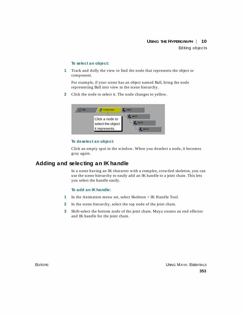
USING THE HYPERGRAPH | 10Editing objects
EDITORS USING MAYA: ESSENTIALS
353
To select an object:
1 Track and dolly the view to find the node that represents the object orcomponent.
For example, if your scene has an object named Ball, bring the noderepresenting Ball into view in the scene hierarchy.
2 Click the node to select it. The node changes to yellow.
To deselect an object:
Click an empty spot in the window. When you deselect a node, it becomesgray again.
Adding and selecting an IK handleIn a scene having an IK character with a complex, crowded skeleton, you canuse the scene hierarchy to easily add an IK handle to a joint chain. This letsyou select the handle easily.
To add an IK handle:
1 In the Animation menu set, select Skeleton > IK Handle Tool.
2 In the scene hierarchy, select the top node of the joint chain.
3 Shift-select the bottom node of the joint chain. Maya creates an end effectorand IK handle for the joint chain.
Click a node toselect the objectit represents.

USING MAYA: ESSENTIALS PART 2
354
USING THE HYPERGRAPH | 10Editing objects
To select an IK handle:
Click the IK handle icon to the right of the end effector node. The IK handlenode and icon turn yellow to indicate you selected it.
If you make the IK handle node the child of another node, its location mightbe hard to find in the graph. The IK handle icon to the right of the endeffector at the bottom of the joint chain makes it easy to find.
Renaming an objectYou can rename an object or other item in the scene hierarchy ordependency graph. You can give two nodes the same name, but only if eachhas a different parent.
IK handle icon
FrontTire BackTire
This is allowed.
This is not allowed.
RoadBike
FrontTire BackTire
MountainBike
Tire Tire
Bike
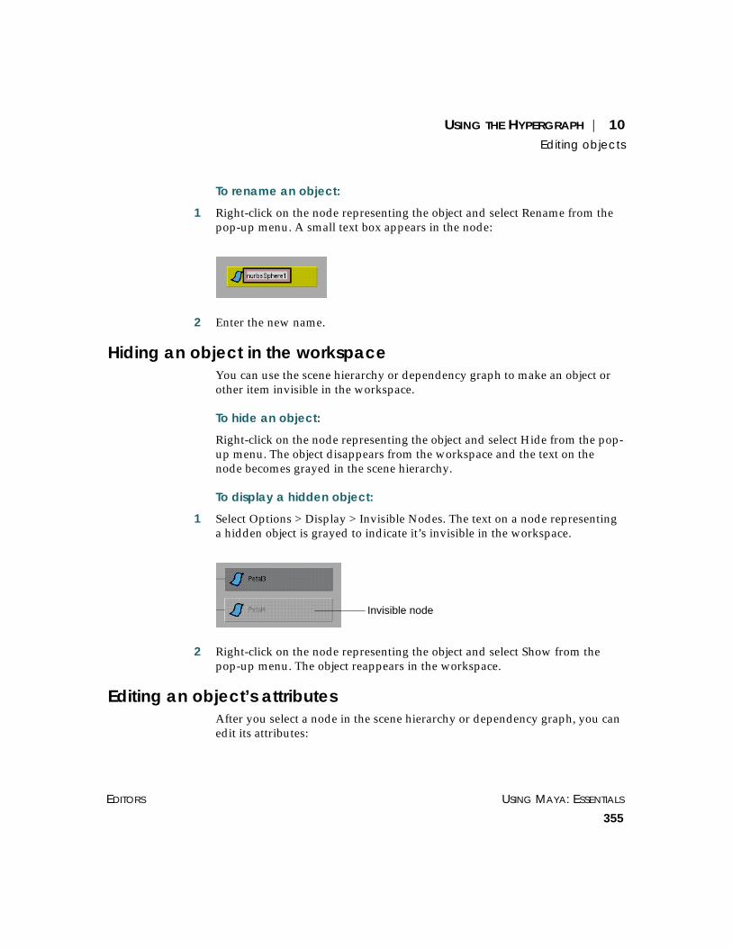
USING THE HYPERGRAPH | 10Editing objects
EDITORS USING MAYA: ESSENTIALS
355
To rename an object:
1 Right-click on the node representing the object and select Rename from thepop-up menu. A small text box appears in the node:
2 Enter the new name.
Hiding an object in the workspaceYou can use the scene hierarchy or dependency graph to make an object orother item invisible in the workspace.
To hide an object:
Right-click on the node representing the object and select Hide from the pop-up menu. The object disappears from the workspace and the text on thenode becomes grayed in the scene hierarchy.
To display a hidden object:
1 Select Options > Display > Invisible Nodes. The text on a node representinga hidden object is grayed to indicate it’s invisible in the workspace.
2 Right-click on the node representing the object and select Show from thepop-up menu. The object reappears in the workspace.
Editing an object’s attributesAfter you select a node in the scene hierarchy or dependency graph, you canedit its attributes:
Invisible node

USING MAYA: ESSENTIALS PART 2
356
USING THE HYPERGRAPH | 10Altering the view of a graph
To edit a node’s attributes:
1 Select the node in the graph.
2 Select Edit > Attributes. The attributes for the selected node load into theAttribute Editor.
Creating a render nodeYou can launch the Create Render Node window to create a new material,texture, and light. This is convenient when you’re examining thedependency graph for a rendering node.
The Create Render Node window is the same window that appears whenyou select Create > Create Render Node from the Hypershade.
To create a render node:
Select Rendering > Create Render Node. The Create Render Node windowopens. For details, see Using Maya: Rendering.
ALTERING THE VIEW OF A GRAPH
A scene hierarchy or dependency graph covers lots of screen space forcomplex scenes. For example, you might create a detailed kinematiccharacter that results in thousands of nodes.
The following pages describe general navigation techniques for examining agraph. You can use the techniques with a scene hierarchy or dependencygraph, unless otherwise noted.
Tracking the viewYou can move the view of the graph up, down, or sideways.
To track the view:
In the graph view, use Alt-middle mouse button to drag in the desireddirection.
Dollying the viewYou can enlarge or shrink the view of the graph.
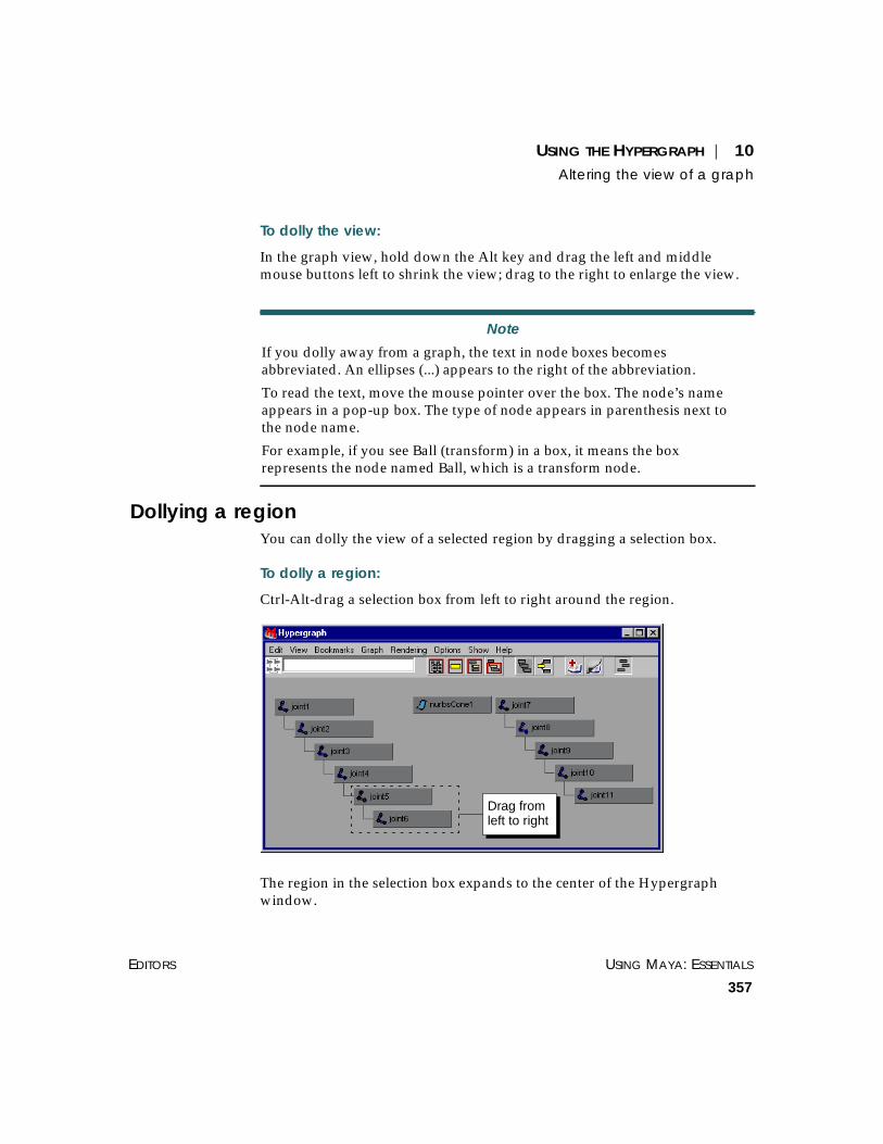
USING THE HYPERGRAPH | 10Altering the view of a graph
EDITORS USING MAYA: ESSENTIALS
357
To dolly the view:
In the graph view, hold down the Alt key and drag the left and middlemouse buttons left to shrink the view; drag to the right to enlarge the view.
Dollying a regionYou can dolly the view of a selected region by dragging a selection box.
To dolly a region:
Ctrl-Alt-drag a selection box from left to right around the region.
The region in the selection box expands to the center of the Hypergraphwindow.
Note
If you dolly away from a graph, the text in node boxes becomesabbreviated. An ellipses (...) appears to the right of the abbreviation.
To read the text, move the mouse pointer over the box. The node’s nameappears in a pop-up box. The type of node appears in parenthesis next tothe node name.
For example, if you see Ball (transform) in a box, it means the boxrepresents the node named Ball, which is a transform node.
Drag fromleft to right

USING MAYA: ESSENTIALS PART 2
358
USING THE HYPERGRAPH | 10Altering the view of a graph
To dolly away from a selection:
Ctrl-Alt-drag a selection box from right to left around the region.
Fitting an entire graph in the windowYou can fit an entire graph in the Hypergraph window. This is helpful if youwant to see the general organization of nodes.
To fit the entire scene graph in the window:
Select View > Frame All.

USING THE HYPERGRAPH | 10Altering the view of a graph
EDITORS USING MAYA: ESSENTIALS
359
In a large graph, the node names will be too small to read. You’ll need todolly and track this view to read the names.
Centering selected nodes in the windowYou can center and expand the view of selected nodes in the Hypergraphwindow. You might want to do this, for example, when you’re looking atdistant, unreadable view of the graph, and you want to read the name of thecurrently selected object.
To center selected nodes in the window:
1 Click the node or nodes in the graph. You can also select a node in the Mayaworkspace or from the Outliner.
2 Select View > Frame Selection.
Here’s an example display.
Centering a hierarchy in the windowYou can center a selected node’s hierarchy in the Hypergraph window. Thisis useful when you want to focus on a group of related nodes above andbelow the selected node. This option works only in the scene hierarchy, notin the dependency graph.
Selected node

USING MAYA: ESSENTIALS PART 2
360
USING THE HYPERGRAPH | 10Altering the view of a graph
To center a hierarchy in the window:
1 Click the node in the graph. You can also select a node in the Mayaworkspace or from the Outliner.
2 Select View > Frame Hierarchy.
Centering a hierarchy branch in the windowYou can center the branch descending from a node in the Hypergraphwindow. This is useful when you want to focus on the related nodes below aselected node. This option works only in the scene hierarchy, not in thedependency graph.
To center a branch in the window:
1 Click the node in the graph. You can also select a node in the Mayaworkspace or from the Outliner.
2 Select View > Frame Branch.
Adjusting view transition speedWhen you change the panel view of a graph, for example, by selectingView > Previous View, Maya dollies from one view to anotherinstantaneously, by default. You can slow Maya’s transition speed betweenviews to make the view change action easier to see.
To adjust the transition speed between views:
1 Toggle on Options > Transitions > Animate Transitions.
2 Select Options > Transitions > and select one of these speeds:
• 5 Frames
• 10 Frames
• 15 Frames
• 20 Frames
20 Frames dollies slowest, 5 Frames dollies fastest.
To return to the default transition speed between views:
Toggle off Options > Transitions > Animate Transitions.

USING THE HYPERGRAPH | 10Altering the view of a graph
EDITORS USING MAYA: ESSENTIALS
361
Setting graph update optionsWhenever you add or delete an object, rendering node, or other item in thescene, the Hypergraph updates the scene hierarchy and dependency graph,by default.
When you select an object in the scene hierarchy or dependency graph, theobject is also selected in the workspace, Outliner, and elsewhere in Maya.Also, when you select an object in the workspace, Outliner, and elsewhere inMaya, the object becomes selected in the scene hierarchy or dependencygraph.
These updates slow Maya operation when you work with a complex sceneor when you’re examining nodes or dragging nodes to new positions in afree-form hierarchy. You can toggle off updating to improve operationspeed.
To turn off graph updates for created nodes:
Toggle off Options > Update > On Nodes Creation.
If you toggle this option on later, the graph displays all previously addedand deleted nodes.
To turn off Hypergraph selection updates:
Toggle off Options > Update > On Selection.
Undoing a view of a scene hierarchyAs you track, dolly, and make other changes to the view of a scenehierarchy, you may want to return to a previous view. Maya keeps thehistory of your view changes and lets you return to one or more previousviews.
After you display a previous view, you can move forward again to otherview.
To change to a previous view:
Select View > Previous View.
To see the view before this one, select View > Previous View again.

USING MAYA: ESSENTIALS PART 2
362
USING THE HYPERGRAPH | 10Altering the view of a graph
To see the view ahead:
Select View > Next View.
This works only after you use View > Previous View. To see another viewahead, select View > Next View again.
Using bookmarks for graph viewsYou can bookmark the view of a graph to return to it later. For instance,suppose you dolly the view to see a group of nodes, then bookmark theview. If you dolly to a different view of the scene, you can select thebookmarked view to return to it.
Note that the layout of the nodes in a previously bookmarked view changeswhen you modify a scene as follows:
• add or delete objects.
• reposition nodes in a free-form hierarchy
• expand or collapse nodes
• display invisible, shape, or underworld nodes
If a node was selected and entirely visible in the view at the time ofbookmarking, when you return to the bookmarked view, the node appearsin the same position regardless of how you altered the graph.
If no node was selected or if a selected node was only partly visible in theview, returning to the bookmarked view shows the previously displayedregion in the graph.
Depending on how you altered the graph, the previously displayed nodesmight not appear in the bookmarked region anymore. You’ll likely need tocreate a new bookmark.
As you add or delete nodes in a scene, Maya updates the layout of the scenehierarchy and dependency graph. Don’t be alarmed if you notice a nodedisappears from a previously bookmarked view of the dependency graph.This is usually the result of Maya conforming with its default graph layout.

USING THE HYPERGRAPH | 10Altering the view of a graph
EDITORS USING MAYA: ESSENTIALS
363
To bookmark a view:
1 Track and dolly the view as desired.
2 Select Bookmarks > Create Bookmark. The bookmarked view gets a defaultname, for example, hyperView1. The name appears at the bottom of theBookmarks menu.
To name a view before bookmarking it:
1 Track and dolly the view as desired.
2 Select Bookmarks > Create Bookmark ❒. A window opens and prompts forthe bookmark name.
3 Enter a bookmark name.
To return to a bookmarked view:
Select Bookmarks and the name of the bookmark at the bottom of the menu.
For example, select Bookmarks > MonsterHead.
To delete a bookmarked view:
1 Select Bookmarks > Bookmark Editor. The Bookmarks window opens,showing all bookmarks you added.
2 Click the name of the bookmark.
3 Select Edit > Delete Bookmark. The name of the bookmark is deleted.
Tip
You can ensure that a bookmarked view displays a node even after youreposition, add, or delete nodes in the scene. To do so, select the node andmake sure its entire outline is visible in the view before creating thebookmark.
If you select two or more nodes, the bookmarked view displays the firstnode selected.

USING MAYA: ESSENTIALS PART 2
364
USING THE HYPERGRAPH | 10Altering the view of a graph
To rename a bookmarked view:
1 Select Bookmarks > Bookmark Editor. The Bookmarks window opens,showing all bookmarks you added.
2 Click the name of the bookmark.
3 Select Edit > Rename Bookmark. A window opens and prompts for thebookmark name.
4 Enter the new name.
You can also rename a bookmark by selecting Bookmarks > name ❒, wherename is the name of the bookmark. A prompt window opens and lets youenter the new name.
Displaying a graph vertically or horizontallyThe scene hierarchy and dependency graph have a horizontal layout bydefault.
If you prefer to look at a graph upright, you can change to a vertical layout.

USING THE HYPERGRAPH | 10Altering the view of a graph
EDITORS USING MAYA: ESSENTIALS
365
To display the graph vertically:
Select Options > Orientation > Vertical.
To display the graph horizontally:
Select Options > Orientation > Horizontal.
Rebuilding the graphsIf your scene hierarchy or dependency graph doesn’t seem up to date, youcan rebuild the graphs. For example, if you add an object to a scene and itdoesn’t appear in the scene hierarchy, rebuild the graphs to make the scenehierarchy aware of the object’s presence.
To rebuild the graph:
Select Graph > Rebuild.

USING MAYA: ESSENTIALS PART 2
366
USING THE HYPERGRAPH | 10Altering the view of a graph

USING MAYA: ESSENTIALS
367
11 SETS AND PARTITIONS
A set is a collection of objects or components. For example, a set mightinclude geometric objects, NURBS CVs, polygonal vertices, lattice points,polygonal facets, or other items. Any item you can select can be in a set.
In some instances, Maya creates sets for you as you work with objects. Forexample, when you add a cluster to several CVs of a NURBS cone, Mayamakes a set of the CVs. You can edit and tune such sets to control the areaaffected by deformation.
You can also create a custom set so you can work on its items with a singleaction. For instance, you can create a set of NURBS objects, then hide ordisplay them as a single entity.
This chapter has the following topics:
• “How you can use sets” on page 368
• “Understanding sets” on page 369
• “Creating, selecting, and removing sets” on page 375
• “Editing set membership” on page 378
• “Editing set membership” on page 378
You can edit and tune sets tocontrol deformation of one ormore objects.

USING MAYA: ESSENTIALS PART 2
368
SETS AND PARTITIONS | 11How you can use sets
• “Altering the display of sets” on page 379
• “Understanding partitions” on page 379
• “Creating, displaying, and removing partitions” on page 381
• “Adding sets to partitions” on page 382
HOW YOU CAN USE SETS
Here are the ways you can use sets:
• adjusting deformer, skin, and flexor deformation
• adjusting the weight of cluster, cluster flexor, and skin points
• simplifying selection of objects or components that you regularly select orhave difficulty selecting in the workspace.
• assigning objects to shading groups for rendering
• moving objects from one layer to another
If you apply a deformer or skin to a geometric object, Maya creates a set forthe geometry’s CVs, vertices, or points. You can add or remove set membersto alter the effect of the deformer or skin. See Using Maya: Character Setup fordetails on deformers and skins.
For clusters and cluster flexors, you can apply different weights to the setmembers to increase or decrease deformations at specified points.
For skin, you can apply different weights to the set members to increase ordecrease skin deformation around the joints.
You can create your own set of objects or components for easier selectionand transformation. For instance, suppose you need to repeatedly select thesame few CVs around the eye of a cyclops to animate the eye. Rather thanstruggle to select the CVs with a selection box, you might create a set namedcyclops_eye for the CVs, then select the set by clicking the set name in aconvenient set editing tool named the Relationship Editor.
When you create a shading group with the Hypershade, Maya creates a setthat represents the shading group. You can work with such sets rather thanthe Hypershade to conveniently assign shading groups to objects. See UsingMaya: Rendering for details on shading groups.

SETS AND PARTITIONS | 11Understanding sets
EDITORS USING MAYA: ESSENTIALS
369
When you create a layer, Maya creates a set that represents it. You can workwith sets rather than layer menu entries to quickly move members from onelayer to another.
When you add a field to vertices, CVs, or edit points, Maya creates a setnamed after the field, for instance, uniformFieldShape1Set. The set membersare the vertices, CVs, or edit points to which you added the field. You canadd or remove the set members to alter the effect of the field. See UsingMaya: Dynamics for details on fields.
UNDERSTANDING SETS
It’s easiest to learn about sets by examining the display of the RelationshipEditor, the main tool for working with sets. You can launch the RelationshipEditor by selecting it from the main menu or with other common techniquessuch as the Hotbox. For more information about the Relationship Editor, see“Using the Relationship Editor” on page 255.
To open the Relationship Editor:
From the main Maya menu, choose Window > Relationship Editors > Sets.The Relationship Editor opens.

USING MAYA: ESSENTIALS PART 2
370
SETS AND PARTITIONS | 11Understanding sets
Scale and move the window as needed.
You can also display the Relationship Editor in a workspace panel bychoosing Panels > Panel > Relationship Editor. This lets you see the Mayauser interface and the Relationship Editor without having to reposition thewindows.
Sets you createWhen you create a set, the Relationship Editor displays the set’s name andcontents. You can apply an operation to a set to affect all its members.
Example
Suppose you create three NURBS spheres. You can put the spheres in a setas follows:
Note
Unless instructions in this chapter state otherwise, make all menu choicesfrom the Relationship Editor’s menu bar.

SETS AND PARTITIONS | 11Understanding sets
EDITORS USING MAYA: ESSENTIALS
371
1 Select the spheres in the workspace, Outliner, or elsewhere.
2 In the Sets panel of the Relationship Editor, select Edit > Create Set. TheRelationship Editor displays the newly created set.
By default, Maya gives the set the name set1 or something similar. To useyour own name rather than the default, choose Edit > Create Set ❒.
3 Click the plus sign (+) next to the set to expand its contents.
The set contains nurbsSphere1, nurbsSphere2, and nurbsSphere3. Itemsindented below a set name are its members. You can select the set to dooperations on each of its members.
4 To select the objects in the set, click the set name and select Edit > Select SetMembers.
This selects the three spheres that are members of the set. With the spheremembers selected, you can do operations such as:
• hide them from the workspace view
• translate, rotate, and scale
• start the Attribute Editor, so all three spheres are available for editing there
Subsequent topics provide more details on working with sets.
Sets created by MayaA new empty scene has the following default sets:
• defaultLightSet
• defaultObjectSet (not used)
• defaultLayer

USING MAYA: ESSENTIALS PART 2
372
SETS AND PARTITIONS | 11Understanding sets
• Shading group sets (initialShadingGroup, initialParticleSE)
In addition to the default sets, Maya creates sets automatically when youcreate shaders. It also creates sets automatically when you create deformers,flexors, or when you bind skin (Deformer and skin point sets).
defaultLightSetWhen you add a light to the scene, the light becomes a member of thedefaultLight set by default. Maya keeps all lights in these set, even when youassign a light to another set.
defaultLayerEach scene has a default display layer that consists of all objects that havenot been assigned to any other layer. When you remove an object from alayer, it becomes a member of the default layer.
Shading group setsA new, empty scene has two shading group sets by default:initialShadingGroup and initialParticleSE. These sets control the defaultshading of objects added to the scene.
When you add a geometric object to the scene, the object becomes a memberof the initialShadingGroup set by default. The shading group colors itsmembers a dull gray. (You can see the default gray color of such objects inthe workspace by choosing Shading > Smooth Shade All.)
If you create a sphere, for instance, Maya adds the sphere to theinitialShadingGroup set. (To see these sets, you must select Shading GroupsEditing from the drop-down list in the Relationship Editor.)
Member of the setinitialShadingGroup

SETS AND PARTITIONS | 11Understanding sets
EDITORS USING MAYA: ESSENTIALS
373
Maya keeps a newly added geometric object in the initialShadingGroup setuntil you create and assign a different shader to the object. Maya thenrelocates the object to a set it creates for the shading group you created. Youtypically won’t do anything directly with the initialShadingGroup set. It’sfor Maya’s internal use as you make shading choices.
Example
Suppose you use the Hypershade to create a Phong material. When youcreate the node, Maya creates a set named phong1SG. This set represents thePhong shading group.
Suppose further you use the Hypershade to assign phong1SG to a geometricobject named nurbsSphere1. Maya moves the object from theinitialShadingGroup to the phong1SG set.
The object receives its surface shading from the options you set in theAttribute Editor for the phong1SG node.
If you were to add a particle object to a scene, it would become part of theinitialParticleSE shading group set. This set has the same purpose asinitialShadingGroup, only it controls the default shading characteristics ofparticles rather than geometry.
An object can be part of only one shading group set—whetherinitialShadingGroup, the initialParticleSE, or one you create.
By looking at the members of the shading group sets, you can see whichobjects are shaded by the shading groups you’ve added to your scene. To tryout various shaders on different objects, use the middle-mouse button todrag objects from one shading group set to another.
For more details on working with shading groups, see Using Maya:Rendering.
Member ofphong1SG

USING MAYA: ESSENTIALS PART 2
374
SETS AND PARTITIONS | 11Understanding sets
Deformer and skin point setsWhen you attach a deformer to an object, Maya creates a set from theobject’s points. When you bind skin to a skeleton, Maya creates two or moresets for the skin points attached to the joints. (To see these sets, you mustselect Deformer Set Editing from the drop-down list in the RelationshipEditor.) See Using Maya: Character Setup for details on deformers and skinpoints.
Example
Suppose you create a NURBS cone, select several CVs, then chooseDeform > Create Cluster from the Animation menu to apply a cluster.
Maya creates a set named cluster1Set or something similar by default.
The set contains the points in the cone controlled by the cluster. In such sets,you can alter deformations by adding and removing points or by editingpoint weights of existing members.
Apply cluster tothese points
Applying a clustercreates a set

SETS AND PARTITIONS | 11Creating, selecting, and removing sets
EDITORS USING MAYA: ESSENTIALS
375
For example, you can add corresponding points from a newly added cone inthe scene. The added points deform with the existing points as you translate,rotate, or scale the cluster handle.
CREATING, SELECTING, AND REMOVING SETS
The following topics describe how to create, select, and remove a set. Notethat binding skin or adding a deformer or flexor to an object automaticallycreates one or more sets. You need not create a set for such objects. See “Setscreated by Maya” on page 371 for details.
Creating setsYou can create a set of geometric objects, CVs, vertices, polygonal faces, orother items.
To create a set with a default name:
1 Select the objects or items in the workspace, Outliner, or elsewhere.
For example, use the Artisan Paint Selection Tool (Modify > Paint SelectionTool) to select CVs.
If you don’t select any objects, an empty set will be created in the next step.You can add to an empty set later.
2 From Maya’s main menu, choose Edit > Sets > Create Set.
or
From the Relationship Editor, select Set Editing from the drop-down list andselect Edit > Create Set in the Sets panel.
The set appears with a default name in the Relationship Editor.
To create a set and name it:
1 Select the objects or items in the workspace, Outliner, or elsewhere.

USING MAYA: ESSENTIALS PART 2
376
SETS AND PARTITIONS | 11Creating, selecting, and removing sets
2 From Maya’s main menu, choose Edit > Sets > Create Set ❒.
or
From the Relationship Editor, select Set Editing from the drop-down list andselect Edit > Create Set ❒ from the Sets panel.
The Create Set Options menu opens.
3 Enter the name of the set in the Name text box.
For example, enter nurbsObjects.
Other options in the window let you add the set to a partition. See “Addingsets to partitions” on page 382 for details.
4 Click Apply. The set appears with the chosen name in the RelationshipEditor.
If a set or other item in the scene already has the specified name, the new setname will be appended with a number. For example, entering top results intop1, because top is the name of a camera that exists in every scene bydefault.
Selecting setsYou can select a set or the contents of a set. You must select a set to removeor rename the set. You must select the contents of the set to apply an actionto each member of the set.

SETS AND PARTITIONS | 11Creating, selecting, and removing sets
EDITORS USING MAYA: ESSENTIALS
377
To select a set:
1 In the left panel of the Relationship Editor, click the name of the set andchoose Select > Highlighted.
You can also select the set in the Outliner or Hypergraph’s dependencygraph view.
To display set members in the Outliner so you can select them, toggle onDisplay > Set members.
To display sets in the Hypergraph’s dependency graph view, select theobject shape node associated with the set and choose Graph > Up andDownstream Connections.
To select a set’s contents only:
1 In the left panel of the Relationship Editor, click the name of the set.
2 Select Edit > Select Set Members. This selects the contents of the set, but notthe set.
Removing setsIf you are no longer using a set, you can remove it without removing itsmembers.
To remove a set, but not its members:
1 In the Relationship Editor, select Set Editing from the drop-down list.
2 Click the name of the set in the left panel.
3 Select Edit > Delete Highlighted.
Creating sets for easy object selectionYou can create a set of joints, geometry, CVs, materials, or other items forquick selection in the main menu. You might want to do this, for instance, soyou can select different animation characters quickly without having to startthe Relationship Editor. This is also useful for selecting items not visible inthe workspace, for instance, invisible objects.
To create a quick set:
1 Select the objects or items.

USING MAYA: ESSENTIALS PART 2
378
SETS AND PARTITIONS | 11Editing set membership
2 From the main Maya menu bar, select Edit > Sets > Create Quick Select Set.A window prompts for a set name.
3 Enter the set name for the items and click OK. This creates the set and putsits name in the cascading menu to the right of Edit > Quick Select Set in themain Maya window.
To select items in the quick set:
From the main Maya menu bar, select Edit > Quick Select Set and the nameof the set.
This selects the items in the set, not the set itself.
EDITING SET MEMBERSHIP
You can add or remove members of a set with the Relationship Editor, thePaint Set Membership Tool, or the Edit Membership Tool.
The advantage of the Relationship Editor is that it:
• includes a formatted list of set members and associated objects
• displays U and V parameters of NURBS curve and surface CVs
• lets you edit the weight of cluster, cluster flexor, and skin points
For information on using the Relationship Editor to add and remove setmembers, see “Adding and removing relationship members” on page 261.
The advantage of the Paint Set Membership Tool is that you can modifywhich of a deformable object’s points (for example, CVs or vertices) belongto multiple deformer sets by painting the points you want added to,transferred to, or removed from the set, directly on the object. Colorfeedback makes sets easy to identify. See Using Maya: Character Setup fordetails.
The advantage of the Edit Membership Tool is that you can add and removeset members in the workspace without using another window or panel. Thisis ideal for quickly altering membership of sets Maya creates for deformersand skin. See Using Maya: Character Setup for details.
SETS AND PARTITIONS | 11Altering the display of sets
EDITORS USING MAYA: ESSENTIALS
379
ALTERING THE DISPLAY OF SETS
You can display all sets in your scene (including character sets, deformersets, shading groups, and layers) in the Relationship Editor. For informationon the options for narrowing or broadening which sets display, so youspend less time scrolling and expanding sets, see the following:
• “Displaying relationships and objects” on page 257
• “Setting view options” on page 256
• “Selecting which relationships and objects show” on page 258
UNDERSTANDING PARTITIONS
A partition is a collection of related sets. The sets in a partition can have nooverlapping members.
As you create shading groups, bind skin, and do a few other tasks, Mayacreates partitions. It does this to keep the sets separate where an operationwould be hindered by overlapping members. You can also create custompartitions to keep your own sets separate.
Partitions you createWhen you use the Create Set menu item to create a set, its members can, bydefault, exist in any other set you’ve created. In some instances, you mightwant to prevent two sets from having overlapping members. You can do thisby creating a partition and putting the sets in it.
Example
Suppose you’re animating a cartoon character’s nose as he smiles andlaughs. You added a cluster to several CVs for adjusting the nose as hesmiles and another cluster to different CVs for adjusting the nose as helaughs.
Creating the two clusters creates a set for each group of CVs. Occasionallyyou want to move CVs from one set to the other, to alter the deformationsthat occur as you transform the clusters.

USING MAYA: ESSENTIALS PART 2
380
SETS AND PARTITIONS | 11Understanding partitions
When you move the CVs from one set to the other set, they remain in thefirst set. You might not want the CVs in the first set because they addundesirable deformations as you transform the cluster.
To avoid this problem, you can create a partition and put both sets in it. Thepartition prevents one set from having members of another set. When youmove the CVs from the first set to the second set, they’re automaticallyremoved from the first set.
You can also add a partition to prevent clusters from having overlappingmembers when you add the cluster with Deform > Create Cluster ❒. SeeUsing Maya: Character Setup for details.
Partitions created by MayaMaya creates partitions in cases where objects or items must be kept separatefor correct operation. A new scene has two partitions by default:
• characterPartition
• renderPartition
The LaughCVs and SmileCVssets in the NoseParts partitioncannot have overlappingmembers.

SETS AND PARTITIONS | 11Creating, displaying, and removing partitions
EDITORS USING MAYA: ESSENTIALS
381
The characterPartition contains the character sets for each character youcreate. With all the character sets in the same partition, you can be sure thatthe attributes in one character set will not be in some other character set.
The renderPartition contains the shading group sets explained in “Shadinggroup sets” on page 372.
Because you can apply only one shading group per object or per polygonalfacet, the rendering partition ensures you can’t accidentally render a singleobject or polygonal facet with two shading groups.
If you rigid bind skin to a skeleton, Maya also creates a partition. Thepartition has the name joint1skinPartition or something similar. It containsall the skin point sets in your scene. The partition prevents you fromassigning skin points to two different joints, which would result inundesirable skin deformations when you manipulate a skeleton.
If create a deformer with the Exclusive option, Maya creates a partitionnamed deformPartition by default. The partition contains all deformer pointsets in your scene. It prevents you from assigning points to two differentsets, which might result in undesirable deformations when you manipulatethe deformers.
Because Maya creates partitions for you when it makes sense to do so, you’llrarely need to create your own partitions. Still, if you find a situation whereyou need create one, you can do so as described in the next topic.
CREATING, DISPLAYING, AND REMOVING PARTITIONS
The following procedures describe how to create, display, and removepartitions.
To create a partition with a default name:
1 Make sure no objects or other items are selected.
2 Select any sets you want to put in the partition. See “Selecting sets” on page376 for details.
3 To create a partition with a default name, select Edit > Sets > Create Partitionon the main Maya menu bar. (This completes the procedure.)
USING MAYA: ESSENTIALS PART 2
382
SETS AND PARTITIONS | 11Adding sets to partitions
or
In the Relationship Editor, select Partition Editing from the drop-down listand select Edit > Create Partition in the Partitions panel.
To display partitions:
In the Relationship Editor, select Partition Editing from the drop-down list.The partitions appear in the left panel.
To see the sets a partition contains, click the plus sign (+) beside the partitionname.
To remove a partition, but not its sets:
1 In the Relationship Editor, select Partition Editing from the drop-down listand click the name of the partition in the left panel.
2 Select Edit > Delete Highlighted.
This removes the partition, but not the sets within the partition.
To remove a set from a partition:
1 In the Relationship Editor, select Partition Editing from the drop-down list.
2 In the Partitions panel, expand the partition to see the set.
3 Click the set you want to remove and select Edit > Remove Highlightedfrom Partition.
ADDING SETS TO PARTITIONS
The following procedures describe how to add and move sets to partitions:
Note
To name the partition when you create it, replace step #3 with:
Select Edit > Sets > Create Partition ❐ in the main Maya menu bar or in theRelationship Editor, select Edit > Create Partition ❐.
Enter the name of the partition in the Name text box of the PartitionOptions menu and click Apply.

SETS AND PARTITIONS | 11Adding sets to partitions
EDITORS USING MAYA: ESSENTIALS
383
To add a set to an existing partition when you create the set:
1 Select the objects or items to be put in the set.
2 From Maya’s main menu, choose Edit > Sets > Create Set ❒.
or
In the Relationship Editor, select Set Editing from the drop-down list andselect Edit > Create Set ❒ in the left panel.
The Create Set Options window opens.
3 Enter the name of the set in the Name text box.
4 To add the set to a partition toggle on Try to Add or Force to Add.
If the partition already has a set containing elements of the selected object,when you select Try to Add, Maya doesn’t add the member and insteaddisplays a warning message to the Script Editor.
If you select Force to Add, Maya adds the member to the set after removingthe member from the set it’s already part of.
5 After you toggle on either option in the prior step, select the name of thepartition from the Partition menu.
6 Click the Apply button.
Maya puts the set in the selected partition.
To add a set to a partition:
1 In the Relationship Editor, select Partition Editing from the drop-down list.
2 In the Partitions panel, click the partition you want to add to.
3 In the Objects panel, click the set to be added into the partition.
or
Select the set in the Outliner and select Edit > Add Selected Items in theRelationship Editor.

USING MAYA: ESSENTIALS PART 2
384
SETS AND PARTITIONS | 11Adding sets to partitions

PART 3
ARTISAN PAINT TOOLS


USING MAYA: ESSENTIALS
387
12 USING ARTISAN PAINTTOOLS
Artisan was previously an add-on module to Maya that provided tools fordetailing surfaces. These tools are now part of Maya. The tools use anintuitive paint and sculpting-based interface to deliver high quality andotherwise complex results in minimal time.
This chapter provides an overview of the Artisan tools. It includes thefollowing topics:
• “What are the Artisan paint tools” on page 388
• “Changing paint tool settings” on page 393
• “Creating an Artisan tool shelf” on page 410
• “Defining Artisan hotkeys” on page 410
• “Using Artisan marking menus” on page 414
• “Snapping an Artisan paint brush to path” on page 415
• “Masking surfaces” on page 416
• “Mapping attributes” on page 419
• “Working with seams” on page 426

USING MAYA: ESSENTIALS PART 3
388
USING ARTISAN PAINT TOOLS | 12What are the Artisan paint tools
WHAT ARE THE ARTISAN PAINT TOOLS
There are nine Artisan paint tools that all work like a paint brush. You canuse your graphics tablet and stylus for greater control when you paint usingthese tools.
Sculpt Surfaces Tool (for NURBS surfaces)
Use the Sculpt Surfaces Tool (Modeling menu set, Edit Surfaces > SculptSurfaces Tool) to push and pull CVs on a NURBS surface. The effect is likesculpting clay—push and the surface depresses, pull and the surface raises.For details, see Using Maya: NURBS Modeling.
Sculpt Polygons Tool
Use the Sculpt Polygons Tool (Modeling menu set, Edit Polygons > SculptPolygons Tool) to push and pull vertices on a polygonal surface. The effect issimilar to sculpting clay. For details, see Using Maya: Polygonal Modeling.
Paint Selection Tool
Use the Paint Selection Tool (Edit > Paint Selection Tool) to select vertices ona NURBS or polygonal surface by painting on the surface with the tool. Thiscontrol quickly provides results that previously required painstakingmanipulation of individual vertices. You can also use the Paint SelectionTool to select faces and edges on polygons. For details, see “Using the PaintSelection Tool to paint-select components” on page 160.
Paint Weights Tool
Use the Paint Weights Tool (Animation menu set, Deform > Paint WeightsTool) to paint weights on vertex clusters. For details, see Using Maya:Character Setup.
Script Paint Tool
Use the Script Paint Tool (Modify > Script Paint Tool) to paint a surface witha texture or attribute defined in a Maya MEL script. For example, you canpaint soft body goal weights or particle emitters on your surfaces like youwould paint a color or texture in a painting program. Maya includes sampleMEL paint scripts to apply to your surfaces. For details, see “Painting withMEL Scripts” on page 441.

USING ARTISAN PAINT TOOLS | 12What are the Artisan paint tools
ARTISAN PAINT TOOLS USING MAYA: ESSENTIALS
389
Attribute Paint Tool
Use the Attribute Paint Tool (Modify > Attribute Paint Tool) to paint anyregistered attributes on any object. For details, see “Painting attributevalues” on page 454.
Paint Set Membership Tool
Use the Paint Set Membership Tool (Animation menu set, Deform > PaintSet Membership Tool) to paint the set membership of vertices instead ofhaving to individually select them. For details, see Using Maya: CharacterSetup.
Paint Skin Weights Tool
By smooth binding skin to an object, you can create reasonable skin-likedeformations. In effect, all the vertices belong to all the joint clusters. Use thePaint Skin Weights Tool (Animation menu set, Skin > Edit SmoothSkin > Paint Skin Weights Tool) to modify the weights of these clusters at thejoints. For details, see Using Maya: Character Setup.
Paint Vertex Color Tool (for polygons only)
Use the Paint Color Per Vertex Tool (Modeling menu set, EditPolygons > Colors > Paint Vertex Color Tool) to paint a specified color valueand alpha onto polygon vertices. For details, see Using Maya: PolygonalModeling.
Paint Textures
Use the Paint Textures tool (Rendering menu set, Lighting/Shading > PaintTextures Tool) to paint the following texture attributes: color, transparency,incandescence, bump, specular color, and reflectivity. This tool operatessimilar to other Artisan paint tools; however, some tool settings are unique,such as Blend Mode. For details, see Using Maya: Rendering.
Typically, you create your model in Maya, then use these tools to detail andmodify it. By changing the settings for Artisan tools, you can also do thefollowing:
• sculpt and paint over seams (see “Working with seams” on page 426)
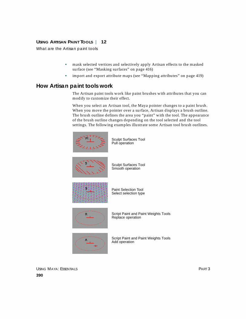
USING MAYA: ESSENTIALS PART 3
390
USING ARTISAN PAINT TOOLS | 12What are the Artisan paint tools
• mask selected vertices and selectively apply Artisan effects to the maskedsurface (see “Masking surfaces” on page 416)
• import and export attribute maps (see “Mapping attributes” on page 419)
How Artisan paint tools workThe Artisan paint tools work like paint brushes with attributes that you canmodify to customize their effect.
When you select an Artisan tool, the Maya pointer changes to a paint brush.When you move the pointer over a surface, Artisan displays a brush outline.The brush outline defines the area you “paint” with the tool. The appearanceof the brush outline changes depending on the tool selected and the toolsettings. The following examples illustrate some Artisan tool brush outlines.
Sculpt Surfaces ToolPull operation
Sculpt Surfaces ToolSmooth operation
Paint Selection ToolSelect selection type
Script Paint and Paint Weights ToolsReplace operation
Script Paint and Paint Weights ToolsAdd operation

USING ARTISAN PAINT TOOLS | 12What are the Artisan paint tools
ARTISAN PAINT TOOLS USING MAYA: ESSENTIALS
391
Clicking the brush on a surface creates a stamp. A stroke is made up ofmany overlapping stamps.
Each brush has a stamp profile that you can modify. The stamp profileincludes:
• brush radius
• brush opacity (for the Script Paint Tool, Attribute Paint Tool, Sculpt SurfacesTool, Sculpt Polygons Tool, Paint Weights Tool, and Paint Skin WeightsTool)
• brush value (for the Script Paint, Attribute Paint Tool, Paint Weights Tool,Paint Skin Weights Tool only)
• brush shape
Stamp Stroke

USING MAYA: ESSENTIALS PART 3
392
USING ARTISAN PAINT TOOLS | 12What are the Artisan paint tools
Brush radiusBy increasing or decreasing the radius of a brush stamp, you increase ordecrease its area of influence. If the brush stamp compensation mode is setto None, the radius is expressed as a percentage of the surface. Otherwise,the brush radius is measured in the working units set for Maya. For detailson selecting the stamp compensation mode, see “Selecting the stampcompensation mode” on page 408. For details on setting units, see “Linear”on page 472.
If you use a graphics tablet and stylus, you can set an upper and lower rangefor the radius. No matter how much or how little pressure you apply to thestylus, the brush radius will not be larger or smaller than the set limits.
Brush opacityBrush opacity refers to the fraction of the maximum displacement or brushvalue (depending on the selected tool) to apply to each brush stamp within astroke.
Only the following tools have an opacity setting: Script Paint Tool, AttributePaint Tool, Sculpt Surfaces Tool, Sculpt Polygons Tool, Paint Weights Tool,and Paint Skin Weights Tool.
Brush valueBrush value refers to something different for each Artisan tool.
Paint Weights Tool Brush value refers to the cluster weights.
Paint Skin Weights Tool
Brush value refers to joint cluster weights.
Fraction of maximum displacement(Sculpt Surfaces Tool)
Fraction of value(Paint Weights Tool)
High opacity Low opacity High opacity Low opacity

USING ARTISAN PAINT TOOLS | 12Changing paint tool settings
ARTISAN PAINT TOOLS USING MAYA: ESSENTIALS
393
Script Paint Tool Depends on the script.
For the emitterPaint script, brush value refers to the operation set for thescript (for example, speed).
For the geometryPaint script, brush value refers to the size of the geometricobjects
For the softBodyPaint script, brush value refers to the goal weight.
Attribute Paint Tool Brush value refers to the value of the attribute you are painting.
Brush shapeYou can choose from several brush shapes to provide flexibility as you paint.The area affected by the stamp corresponds with the selected shape. Notethat the shape of the brush outline does not change to reflect your selection.
CHANGING PAINT TOOL SETTINGS
Artisan uses the Maya Tool Settings editor to set tool properties. The mostcommon ways to open the Tool Settings editor are:
• Click the ❐ beside the tool on its menu (for example, Edit > Paint SelectionTool ❐).
• Double-click the selected tool on the Minibar.
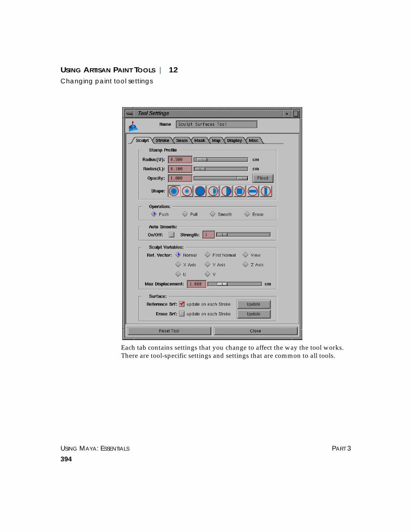
USING MAYA: ESSENTIALS PART 3
394
USING ARTISAN PAINT TOOLS | 12Changing paint tool settings
Each tab contains settings that you change to affect the way the tool works.There are tool-specific settings and settings that are common to all tools.
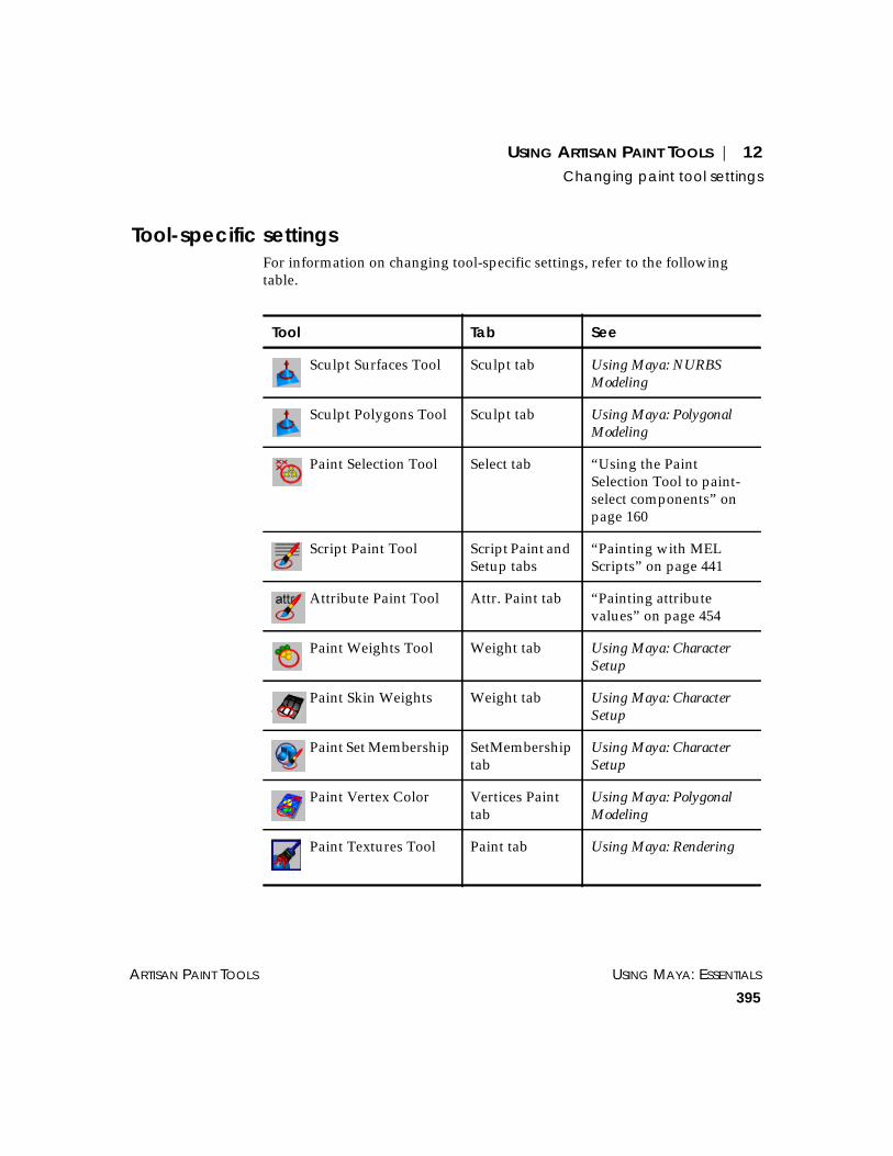
USING ARTISAN PAINT TOOLS | 12Changing paint tool settings
ARTISAN PAINT TOOLS USING MAYA: ESSENTIALS
395
Tool-specific settingsFor information on changing tool-specific settings, refer to the followingtable.
Tool Tab See
Sculpt Surfaces Tool Sculpt tab Using Maya: NURBSModeling
Sculpt Polygons Tool Sculpt tab Using Maya: PolygonalModeling
Paint Selection Tool Select tab “Using the PaintSelection Tool to paint-select components” onpage 160
Script Paint Tool Script Paint andSetup tabs
“Painting with MELScripts” on page 441
Attribute Paint Tool Attr. Paint tab “Painting attributevalues” on page 454
Paint Weights Tool Weight tab Using Maya: CharacterSetup
Paint Skin WeightsTool
Weight tab Using Maya: CharacterSetup
Paint Set MembershipTool
SetMembershiptab
Using Maya: CharacterSetup
Paint Vertex ColorTool
Vertices Painttab
Using Maya: PolygonalModeling
Paint Textures Tool Paint tab Using Maya: Rendering

USING MAYA: ESSENTIALS PART 3
396
USING ARTISAN PAINT TOOLS | 12Changing paint tool settings
Common tool settingsFor information on changing common tool settings, refer to the followingtable.
Tab Description of Settings See
Stroke Define how the brush movesacross the selected surface
“Changing brushstroke settings” onpage 397
Seam Define how you want surfacesto join
“Working with seams”on page 426
Mask Define which vertices, if any,you want masked when youuse an Artisan paint tool on asurface
“Masking surfaces” onpage 416
Map Import or export attribute(texture) maps
“Mapping attributes”on page 419
Display Define how the brush andscreen displays
“Changing displaysettings” on page 404
Misc Define less frequently usedtool settings
“Changingmiscellaneous toolsettings” on page 406

USING ARTISAN PAINT TOOLS | 12Changing paint tool settings
ARTISAN PAINT TOOLS USING MAYA: ESSENTIALS
397
Resetting toolsIf you do not want to keep the changes you made to the settings in the ToolSettings editor, click the Reset Tool button. This returns the settings on allthe tabs for the selected tool to their default values.
Note that the default settings for tools on a shelf are the settings that weresaved with the shelf.
Changing brush stroke settingsBrush stroke settings define how the selected Artisan brush moves across thesurface. They are defined on the Stroke tab of the Tool Settings editor.
You can change the following brush stroke settings for all Artisan tools:
• reflect paint
• stylus pressure (if you are using a graphics tablet and pen)
• stroke profile alignment
Tips
Leave the Tool Settings editor open as you work in Artisan. When youswitch tools, the settings change to reflect the selected tool.
If you do not want to leave the Tool Settings editor open, define hotkeysor use the Artisan marking menus to change commonly used settings foreach of the tools. For details, see “Defining Artisan hotkeys” on page 410and “Using Artisan marking menus” on page 414.
Tailor the settings for your tools and save them to a shelf for easy access.For details, see “Creating an Artisan tool shelf” on page 410.
Tip
You can make more accurate brush strokes on a surface, or have an effecton the same surface’s area again and again by snapping the cursor to thecurve or a curve on the surface. For details, see “Freezing and resettingtransformations” on page 169.

USING MAYA: ESSENTIALS PART 3
398
USING ARTISAN PAINT TOOLS | 12Changing paint tool settings
Reflected paintingYou can set Artisan tools so that your brush strokes are mirrored or reflectedin the axis of your choice as you paint. This is useful when you want tocreate a symmetrical effect.
To reflect your brush stroke:
1 Select the surface you are painting.
2 Select the Artisan tool you want to use and open the Tool Settings editor.
3 Click on the Stroke tab.
4 In the Reflect Paint section, modify the settings as follows:
Note
If you are painting on polygonal surfaces in projective paint mode, youcannot reflect paint. To reflect paint, you must be in UV texture paint modeand the UVs on the polygon must be evenly distributed, symmetrical, andnot overlapping. For information on setting the paint mode, see “ProjectivePaint” and “UV Texture Paint” on page 409.

USING ARTISAN PAINT TOOLS | 12Changing paint tool settings
ARTISAN PAINT TOOLS USING MAYA: ESSENTIALS
399
Reflection To reflect paint, toggle Reflection on.
Selecting the axis for reflection
U Dir, V Dir You can restrict the reflection along the U or V direction of a single surface.
The following examples show the Sculpt Surfaces brush stamp reflectedalong the U and V directions (or isoparms).
V
U
Reflection alongU direction (or isoparm)
V
U
Reflection alongV direction (or isoparm)

USING MAYA: ESSENTIALS PART 3
400
USING ARTISAN PAINT TOOLS | 12Changing paint tool settings
In the adjacent box, type the relative position of the axis along the surface.By default, reflections along the U or V direction (or isoparm) occur at 0.5,the midpoint of the surface.
To reset the axis to the midpoint, click the Reset button.
Multiple Surf When you reflect on multiple surfaces, the reflected brush stamp moves tothe same U/V position on the other surfaces.
To reflect your stroke on multiple surfaces, follow the instructions on page398, making sure you select all the surfaces in step 1. For NURBS surfaces,the number of U patches and V patches, or sections and spans must beidentical on each surface. For polygonal surfaces, the number of subdivisionsmust be the identical on each surface.
Note
When you reflect paint on a surface, it may appear as though the reflectionis not symmetrical...
V
U UV
Reflection on another surface
... but in fact, the brush is reflected onthe other side of the object.

USING ARTISAN PAINT TOOLS | 12Changing paint tool settings
ARTISAN PAINT TOOLS USING MAYA: ESSENTIALS
401
Invert Reference Vector
This option is available for the Sculpt Surfaces and Sculpt Polygons Toolsonly. Toggle Invert Reference Vector on to invert the direction of thereference vector of the reflected brush. For details on setting referencevectors, refer to the sculpting information in Using Maya: NURBS Modelingand Using Maya: Polygonal Modeling. The following example show the effectof reflect painting using the Sculpt Surfaces Tool along the V direction, andthen with the reference vector inverted.
Setting stylus pressureWith a real paint brush, pressing harder makes the brush wider and appliesthe paint more thickly. You can achieve a similar effect with a stylus inArtisan by specifying the effect of pressure on the Artisan tool.
To set stylus pressure:
1 Select the Artisan tool you want to define the stylus pressure for.
2 Open the Tool Settings editor and click on the Stroke tab.
3 In the Stylus Pressure section, select the pressure option you want to use.
Tip
You can create a hotkey to modify the reflection isoparm without openingthe Tool Settings editor. For details, see “Defining Artisan hotkeys” onpage 410.
Reflection along V isoparm withreference vector inverted
Reflection along V isoparm

USING MAYA: ESSENTIALS PART 3
402
USING ARTISAN PAINT TOOLS | 12Changing paint tool settings
None No effect on the stylus pressure.
Opacity Increases the opacity of the brush stamp as you add pressure to the stylus.
Radius Increases the radius of the brush stamp as you add pressure to the stylus.
Both Increases both the opacity and radius of the brush stamp as you addpressure to the stylus.
Setting the brush stamp profile alignmentThe profile alignment of the brush determines the alignment of the brushshapes that are not uniformly round:
To set the brush stamp profile alignment:
1 Select the Artisan tool you want to define the profile for.
2 Open the Tool Settings editor and click the Stroke tab.
3 In the Profile Alignment section, select the alignment you want for the brushstamp. Note that you select the brush stamp on the first tab (Sculpt, Select,Script Paint, Weight, Attr. Paint, Vertices Paint, SetMembership, Skin Paint).
U Tangent Aligns the stamp shape along the U tangent (V direction).
Note
If you set the stylus pressure to Opacity or Both, you will not be able topaint with your mouse, although you will be able to click with it.

USING ARTISAN PAINT TOOLS | 12Changing paint tool settings
ARTISAN PAINT TOOLS USING MAYA: ESSENTIALS
403
V Tangent Aligns the stamp shape along the V tangent (U direction).
Up Vector Aligns the stamp shape relative to the up vector. The stamp shape retains itsorientation when you change the view.
Path Direction Aligns the stamp shape relative to the direction you move the brush.
V
U
V
U

USING MAYA: ESSENTIALS PART 3
404
USING ARTISAN PAINT TOOLS | 12Changing paint tool settings
Changing display settingsYou can specify the display settings for the objects you are painting and theArtisan tool brush stamps. For the Paint Weights, Attribute Paint, Paint SetMembership, Paint Skin Weights Tool, and Script Paint Tools, you can alsoselect to display color feedback.
To customize display settings:
1 Select an Artisan tool and open the Tool Settings editor.
2 Click the Display tab and modify the settings as follows:
Toggling surface settings
Draw Outline Displays the brush stroke outline when you move the pointer on the selectedsurface. If you do not toggle this option on, you only see the brush pointerand you will not be able to draw brush feedback or outline trails.
Draw Brush Feedback
Displays additional information on the brush outline indicating theoperation the brush is set to perform.
Draw Outline Trail Displays a trail of brush outlines as you paint.
No brush feedback Brush feedback(Sculpt Surfaces Tool –Pull operation)
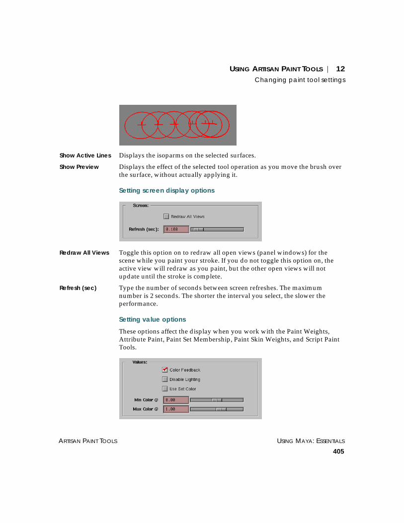
USING ARTISAN PAINT TOOLS | 12Changing paint tool settings
ARTISAN PAINT TOOLS USING MAYA: ESSENTIALS
405
Show Active Lines Displays the isoparms on the selected surfaces.
Show Preview Displays the effect of the selected tool operation as you move the brush overthe surface, without actually applying it.
Setting screen display options
Redraw All Views Toggle this option on to redraw all open views (panel windows) for thescene while you paint your stroke. If you do not toggle this option on, theactive view will redraw as you paint, but the other open views will notupdate until the stroke is complete.
Refresh (sec) Type the number of seconds between screen refreshes. The maximumnumber is 2 seconds. The shorter the interval you select, the slower theperformance.
Setting value options
These options affect the display when you work with the Paint Weights,Attribute Paint, Paint Set Membership, Paint Skin Weights, and Script PaintTools.

USING MAYA: ESSENTIALS PART 3
406
USING ARTISAN PAINT TOOLS | 12Changing paint tool settings
Color Feedback Toggle this option on to display surface attributes, for example, clusterweights, as grayscale values. This helps you see the area as you paint andhelps identify what the values are (smaller values are darker, larger valuesare lighter). To display color feedback, you must turn on smooth shading inMaya.
Display Active Vertices
For the Paint Set Membership Tool only, toggle this option on to display theactive vertices of a selected set. If this option is toggled off, when you select aset on the SetMembership tab, the vertices for that set will be active, but youwill not be able to see that they are.
Disable Lighting For the Paint Weights, Attribute Paint, Paint Skin Weights, or Script PaintTools only, toggle this on to remove lighting from the scene. Disablinglighting provides you with a truer representation of the grayscales, making iteasier to identify the values.
Use Set Color For the Paint Weights and Paint Skin Weights Tools only, toggle this optionon to use the color associated with the cluster set. This is particularly usefulwhen you are working with skeletons.
Min Color @ For the Paint Weights, Attribute Paint, Paint Skin Weights, or Script PaintTools only, use the slider to set the value at which the minimum colordisplays. This is useful if your paint values are very close to each other,making the color feedback display too subtle to detect.
Max Color @ For the Paint Weights, Attribute Paint, Paint Skin Weights, or Script PaintTools only, use the slider to set the value at which the maximum colordisplays. This is useful if your paint values are very close to each other,making the color feedback display too subtle to detect.
Changing miscellaneous tool settingsThere are some Artisan tool settings you will find useful, although you mayrarely change them. You can find these settings on the Misc tab in the ToolSettings editor. These settings include:
• Multiple surface detection
Artisan detects layered and intersecting surfaces and projects the effects ofthe brush stroke to each surface relative to the camera view.
• Stamp compensation
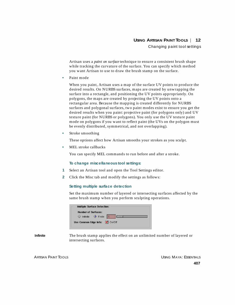
USING ARTISAN PAINT TOOLS | 12Changing paint tool settings
ARTISAN PAINT TOOLS USING MAYA: ESSENTIALS
407
Artisan uses a paint on surface technique to ensure a consistent brush shapewhile tracking the curvature of the surface. You can specify which methodyou want Artisan to use to draw the brush stamp on the surface.
• Paint mode
When you paint, Artisan uses a map of the surface UV points to produce thedesired results. On NURBS surfaces, maps are created by unwrapping thesurface into a rectangle, and positioning the UV points appropriately. Onpolygons, the maps are created by projecting the UV points onto arectangular area. Because the mapping is created differently for NURBSsurfaces and polygonal surfaces, two paint modes exist to ensure you get thedesired results when you paint: projective paint (for polygons only) and UVtexture paint (for NURBS or polygons). You only use the UV texture paintmode on polygons if you want to reflect paint (the UVs on the polygon mustbe evenly distributed, symmetrical, and not overlapping).
• Stroke smoothing
These options affect how Artisan smooths your strokes as you sculpt.
• MEL stroke callbacks
You can specify MEL commands to run before and after a stroke.
To change miscellaneous tool settings:
1 Select an Artisan tool and open the Tool Settings editor.
2 Click the Misc tab and modify the settings as follows:
Setting multiple surface detection
Set the maximum number of layered or intersecting surfaces affected by thesame brush stamp when you perform sculpting operations.
Infinite The brush stamp applies the effect on an unlimited number of layered orintersecting surfaces.

USING MAYA: ESSENTIALS PART 3
408
USING ARTISAN PAINT TOOLS | 12Changing paint tool settings
Finite The brush stamp applies the effect only on the number of layered orintersecting surfaces you specify.
Use Common Edge Info
Toggle Use Common Edge Info on to treat surfaces with common edges asone surface.
Selecting the stamp compensation mode
None No stamp compensation. Without stamp compensation, the brush tends tostretch into odd shapes on complicated surfaces.
Linear This is an efficient (computationally) form of compensation adequate forsmoothly curved surfaces.
Grid This is the most sophisticated form of compensation and also requires themost computations. Increasing the grid size increases the density of the grid,and thus the number of compensation calculations. Grid compensationmode provides the most consistent brush shape, but also slows Artisan’sperformance. You may find it useful when painting areas with unevenparameterization (for example, at the poles of a sphere).
Setting the paint mode
Maya detects two surfaces and appliesbrush settings to both

USING ARTISAN PAINT TOOLS | 12Changing paint tool settings
ARTISAN PAINT TOOLS USING MAYA: ESSENTIALS
409
Projective Paint Select Project Paint if you are painting polygonal surfaces. You cannot reflectpaint in this paint mode. To reflect paint on polygons, see UV Texture Paint,next.
UV Texture Paint Select this paint mode if you are painting NURBS surfaces or if you arepainting polygonal surfaces and want to reflect paint. To use UV TexturePaint mode on a polygon, the surface must have UVs that are evenlydistributed, symmetrical, and do not overlap. You can check the surfaceusing the Texture View (Edit Polygons > Textures > Texture View).
Setting stroke smoothing options
These options affect the sculpting operations you perform.
Texture Space Reads the points from the tablet or mouse, transforms them to parameterspace, then smooths the resulting path. This is the fastest stroke smoothingoption.
Screen Space Smooths the path before determining where the points are in parameterspace. Although this method provides more accurate smoothing and doublesthe rate of the tablet, the amount of surface operations are also doubled,therefore slowing Artisan’s performance.
Divisions Indicate the number of divisions used to smooth a stroke. By increasing thenumber of divisions, you can draw straighter, smoother lines, but you alsoslow the performance.
Setting MEL stroke callback
Before Stroke Cmd Type the MEL command and parameters you want to run when you begin astroke, before the stroke actually starts. For example, for the Sculpt SurfacesTool, you can specify a command that changes the display smoothness forthe selected object to fine:
displaySmoothness -full -du 2 -dv 2 -pw 16 -ps 4

USING MAYA: ESSENTIALS PART 3
410
USING ARTISAN PAINT TOOLS | 12Creating an Artisan tool shelf
After Stroke Cmd Type the MEL command and parameters you want to run immediately aftercompleting a stroke. For example, for the Paint Selection Tool, you canspecify a command that subdivides faces after you select them, as follows:
1 Select a polygon.
2 Select Edit > Paint Selection Tool ❐.
3 On the Select tab, toggle off Add to Current Selection.
4 Change the pick mask to Poly Faces.
5 Click the Misc tab.
6 In the After Stroke Cmd box, enter:
polySubdivideFacet -dv 1 -m 0 -ch 1
7 Paint the faces you want to subdivide. Each painted face subdividesautomatically into four faces when you release the mouse button.
CREATING AN ARTISAN TOOL SHELF
To make your Artisan tools more convenient to access, you can create anArtisan shelf and put the Artisan tools on it. Another advantage is that toolson the shelf are saved with your specific tool settings. For details on shelves,see “Creating and editing shelves” on page 493.
DEFINING ARTISAN HOTKEYS
You can use hotkeys to change some Artisan tool settings without openingthe Tool Settings editor.
You can set three types of Artisan hotkeys:
• hotkeys that display marking menus
• hotkeys that toggle or select options or actions
• interactive hotkeys that change option settings when you click-drag or usethe arrow keys (for example the brush stamp radius or displacement)

USING ARTISAN PAINT TOOLS | 12Defining Artisan hotkeys
ARTISAN PAINT TOOLS USING MAYA: ESSENTIALS
411
Hotkeys that display marking menus
By default, the hotkey combination u + left mouse button displays theoperation marking menu for the selected Artisan tool. For details, see “UsingArtisan marking menus” on page 414.
If you are running out of available keys, or you have created too manyhotkeys to remember, you can consolidate your Artisan hotkeys into a singlemarking menu. Create a hotkey for Set Modify Target, with Marking Menuand another for Activate/Deactivate Modify Target, with Marking Menu.
When you press the hotkey for Set Modify Target, with Marking Menu, amarking menu appears for the selected tool. For details, see “Using Artisanmarking menus” on page 414. Select the option you want to modify. Thenhold down the hotkey for Activate Modify Target, and click-drag to modifythe settings.
You can also define hotkeys for marking menus you define yourself. Fordetails on defining marking menus, see “Creating marking menus” on page511.
Hotkeys that toggle or select options or actions
These hotkeys are straightforward—press the key to toggle an option on oroff or to select an option or action. You can set hotkeys for the followingoptions or actions:
Option or Action Default Hotkey
Flood with the current value Press Alt f
Toggle Reflection ON/OFF Press Alt r
Toggle Active Lines ON/OFF Press Alt a
Toggle Show Preview ON/OFF none
Toggle Masking CVs ON/OFF none
Toggle Common Edges Display Mode none
Toggle Common Corners Display none

USING MAYA: ESSENTIALS PART 3
412
USING ARTISAN PAINT TOOLS | 12Defining Artisan hotkeys
Interactive hotkeys
You can define interactive hotkeys for Artisan operations using the activate/deactivate pairs listed in the Hotkeys editor.
These interactive hotkeys work by pressing the hotkey and doing one of thefollowing:
• click-dragging left or right, or up and down
The setting appears as part of the brush outline and changes as you drag. Forexample, the following brush outline appears when you use an interactivehotkey to modify the brush stamp radius.
Stitch Surfaces none
Update Erase Surface none
Update Reference Surface none
Toggle Color Feedback ON/OFF Press Alt c
~Increase Brush Radius none
Decrease Brush Radius none
Increase Maximum Displacement none
Decrease Maximum Displacement none
Option or Action Default Hotkey
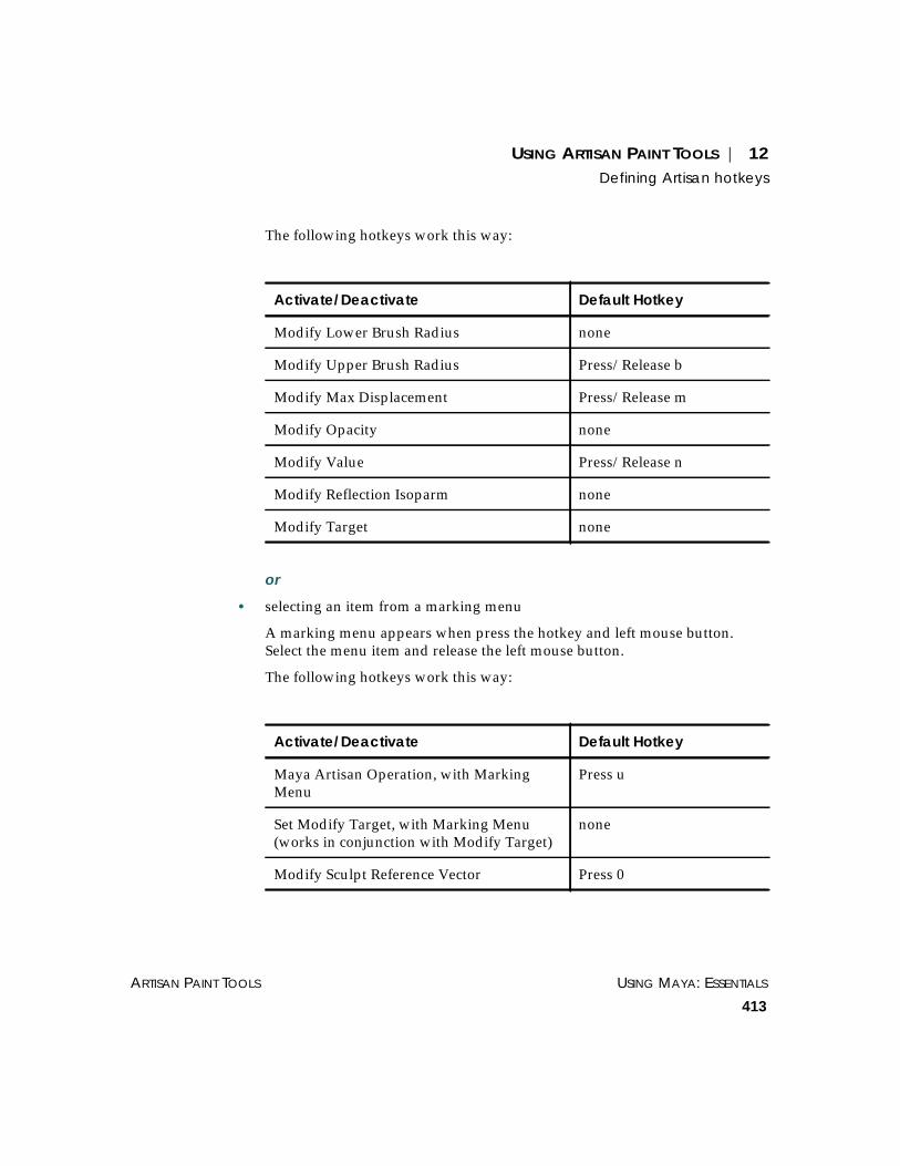
USING ARTISAN PAINT TOOLS | 12Defining Artisan hotkeys
ARTISAN PAINT TOOLS USING MAYA: ESSENTIALS
413
The following hotkeys work this way:
or
• selecting an item from a marking menu
A marking menu appears when press the hotkey and left mouse button.Select the menu item and release the left mouse button.
The following hotkeys work this way:
Activate/Deactivate Default Hotkey
Modify Lower Brush Radius none
Modify Upper Brush Radius Press/Release b
Modify Max Displacement Press/Release m
Modify Opacity none
Modify Value Press/Release n
Modify Reflection Isoparm none
Modify Target none
Activate/Deactivate Default Hotkey
Maya Artisan Operation, with MarkingMenu
Press u
Set Modify Target, with Marking Menu(works in conjunction with Modify Target)
none
Modify Sculpt Reference Vector Press 0

USING MAYA: ESSENTIALS PART 3
414
USING ARTISAN PAINT TOOLS | 12Using Artisan marking menus
or
• clicking a cluster, set, or surface area using the arrow pointer
You can set interactive hotkeys for the following options or actions:
For information on defining hotkeys, see “Assigning hotkeys” on page 526.
USING ARTISAN MARKING MENUS
Artisan marking menus give you quick access to tools and actions normallyaccessed from the Tool Settings editor. You can use three types of markingmenus in Artisan:
• tool operation marking menus
• target operation marking menus
• user-defined marking menus
Tool operation marking menus
By default, the hotkey combination u + left mouse button displays theoperation and brush stroke marking menu for the selected Artisan tool.
Activate/Deactivate Default Hotkey
Pick Color Mode
(Use with the Paint Set Membership, PaintWeights, Attribute Paint, and Paint ColorPer Vertex Tools.)
Press/Release /
Select Cluster Mode
(Use with the Paint Weights Tool.)
Press/Release ’

USING ARTISAN PAINT TOOLS | 12Snapping an Artisan paint brush to path
ARTISAN PAINT TOOLS USING MAYA: ESSENTIALS
415
Target operation marking menus
When you hold down the hotkey for Set Modify Target, with MarkingMenu, and press the left mouse button, a marking menu appears for theselected tool. For details on defining hotkeys, see “Defining Artisan hotkeys”on page 410. Select the option you want to modify. You can now hold downthe hotkey for Activate Modify Target, and click-drag to modify the settings.
User-defined marking menus
You can define your own marking menus. For example, you could define amarking menu with each of the Artisan tools on it. For details on definingmarking menus, see “Creating marking menus” on page 511.
To use a marking menu:
1 Select the tool.
2 Press and hold the hotkey for the marking menu.
3 Click-drag the left mouse button to select the marking menu option.
SNAPPING AN ARTISAN PAINT BRUSH TO PATH
You can make more accurate brush strokes on a surface, or have an effect onthe same surface’s area again and again by snapping the cursor to the curveor a curve on the surface.
To snap the brush to an isoparm:
1 Select the surface you want to paint.
2 Select the Artisan paint tool.
3 Press and hold down the c key on your keyboard while you do thefollowing:
• Move the center of the brush outline directly over the path you want thebrush to snap to.
• Click-drag the brush in the direction you want to paint.

USING MAYA: ESSENTIALS PART 3
416
USING ARTISAN PAINT TOOLS | 12Masking surfaces
To snap the brush to a curve:
1 Create the curve on the surface as follows:
• Select the surface you want to paint with an Artisan paint tool.
• Click the Make Live button on the Status Line to make the surface live.
• Select the appropriate curve tool (for example, CV Curve Tool) and createthe curve on the surface.
• Click the Make Live button on the Status Line again.
2 Select the surface.
3 Select the appropriate Artisan paint tool.
4 Press and hold down the c key on your keyboard while you do thefollowing:
• Move the center of the brush outline directly over the path you want thebrush to snap to.
• Click-drag the brush in the direction you want to paint.
MASKING SURFACES
Masking blocks off an area on a surface so it is not affected by the Artisanoperations you apply to it. In Artisan, you can use selected or unselectedvertices (NURBS or polygonal) on your surface as a mask.
In the following example, if you masked the X, the positions, weights, orscripted attributes would not be affected when you painted over them withthe Sculpt Surfaces, Sculpt Polygons, Script Paint, Attribute Paint, PaintVertex Color, Paint Weights, or Paint Skin Weights Tools. The areas outsidethe X would be affected.

USING ARTISAN PAINT TOOLS | 12Masking surfaces
ARTISAN PAINT TOOLS USING MAYA: ESSENTIALS
417
To mask a surface:
1 Select the vertices on the surface. For details, see “Using the Paint SelectionTool to paint-select components” on page 160.
2 Select one of the Sculpt Surfaces, Sculpt Polygons, Script Paint, AttributePaint, Paint Vertex Color, Paint Weights, or Paint Skin Weights Tools, andopen the Tool Settings editor.
3 Click the Mask tab.
4 Select a masking mode:
Off – No masking takes place.
Selected Vertices – Selected vertices act as a mask. The selected vertices willnot change position, weight, or attribute when you apply Artisan brushstrokes to them.
Unselected Vertices – Unselected vertices act as a mask. The unselectedvertices will not change position, weight, or attribute when you applyArtisan brush strokes to them.

USING MAYA: ESSENTIALS PART 3
418
USING ARTISAN PAINT TOOLS | 12Masking surfaces
5 By default, Artisan displays masked vertices while your surface is in objectmode. To hide masked vertices, toggle Display Vertices off.
6 Paint the surface with the selected Artisan tool. Any brush strokes you makeover the mask will have no effect on the masked vertices.
In the following example, the masked surface was sculpted using the SculptSurfaces Tool.

USING ARTISAN PAINT TOOLS | 12Mapping attributes
ARTISAN PAINT TOOLS USING MAYA: ESSENTIALS
419
MAPPING ATTRIBUTES
An attribute map is a two-dimensional image with values that correspond,or map, to attributes of points on a three-dimensional surface. This mappingis relative to the U/V parameterization of the surface.
You can import image files created in other programs and use their alphachannel values or luminance values as attribute maps. The alpha channel isthe channel in an image that contains the opacity information. Not all imageshave an alpha channel. Luminance refers to the intensity or brightness of theimage.
Attribute map values are represented by grayscales, with black representinga value of 0 and white representing a value of 1.
You can also export the values on your Artisan surfaces into image files.
You can import and export attribute maps in file format supported by Maya.For a list of these file formats, see “Supported file formats” on page 196.
Alpha channel Luminance
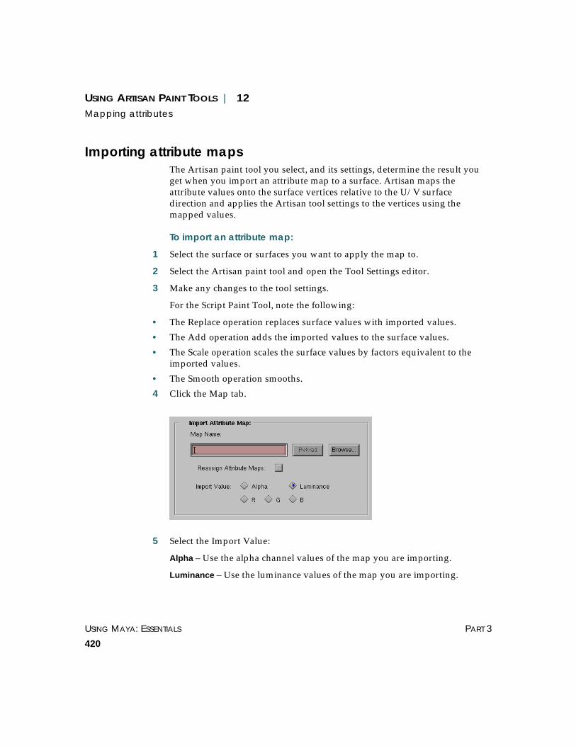
USING MAYA: ESSENTIALS PART 3
420
USING ARTISAN PAINT TOOLS | 12Mapping attributes
Importing attribute mapsThe Artisan paint tool you select, and its settings, determine the result youget when you import an attribute map to a surface. Artisan maps theattribute values onto the surface vertices relative to the U/V surfacedirection and applies the Artisan tool settings to the vertices using themapped values.
To import an attribute map:
1 Select the surface or surfaces you want to apply the map to.
2 Select the Artisan paint tool and open the Tool Settings editor.
3 Make any changes to the tool settings.
For the Script Paint Tool, note the following:
• The Replace operation replaces surface values with imported values.
• The Add operation adds the imported values to the surface values.
• The Scale operation scales the surface values by factors equivalent to theimported values.
• The Smooth operation smooths.
4 Click the Map tab.
5 Select the Import Value:
Alpha – Use the alpha channel values of the map you are importing.
Luminance – Use the luminance values of the map you are importing.

USING ARTISAN PAINT TOOLS | 12Mapping attributes
ARTISAN PAINT TOOLS USING MAYA: ESSENTIALS
421
R, G, B – Use only the Red, Green, or Blue values of the map you areimporting.
RGB – For the Paint Vertex Color Tool only, use each of the RGB channelvalues of the map you are importing.
RGBA – For the Paint Vertex Color Tool only, use the RGB and alpha channelvalues of the map you are importing.
6 If you selected the Paint Selection Tool, enter a value for the Threshold. Thisthreshold defines the minimum value to be affected by the tool selectiontype. For example, if you set the selection type to be Select and the Thresholdto be 0.5, Artisan selects vertices that are mapped with an imported valueequal to or greater than 0.5.
7 If you are importing a map that was created in Artisan from multiplesurfaces, toggle on Reassign Attribute Maps. For details, see “ImportingArtisan attribute maps to multiple surfaces” on page 422.
8 Click in the Map Name box, then click the Browse button to select the file.The Import window opens.
(Alternatively, you can type the directory location and file name in the MapName box and press Enter to import an image, skipping the last two steps.)
9 On IRIX only, to preview the image before importing it, select it, then clickthe See Image button. The grayscales represent the values, where whiterepresents a value of 1 and black represents a value of 0.
10 Select the image and click the Import button. Artisan applies the values tothe selected surface(s) using the selected tool settings.
In the following example, the Paint Selection Tool is set to select controlvertices and the Threshold is set to 0.5.
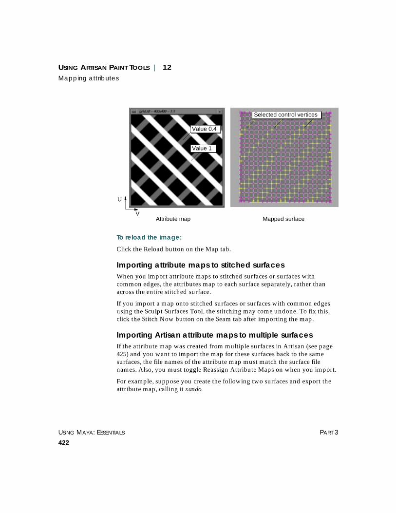
USING MAYA: ESSENTIALS PART 3
422
USING ARTISAN PAINT TOOLS | 12Mapping attributes
To reload the image:
Click the Reload button on the Map tab.
Importing attribute maps to stitched surfacesWhen you import attribute maps to stitched surfaces or surfaces withcommon edges, the attributes map to each surface separately, rather thanacross the entire stitched surface.
If you import a map onto stitched surfaces or surfaces with common edgesusing the Sculpt Surfaces Tool, the stitching may come undone. To fix this,click the Stitch Now button on the Seam tab after importing the map.
Importing Artisan attribute maps to multiple surfacesIf the attribute map was created from multiple surfaces in Artisan (see page425) and you want to import the map for these surfaces back to the samesurfaces, the file names of the attribute map must match the surface filenames. Also, you must toggle Reassign Attribute Maps on when you import.
For example, suppose you create the following two surfaces and export theattribute map, calling it xando.
V
U
Attribute map Mapped surface
Value 0.4
Value 1
Selected control vertices

USING ARTISAN PAINT TOOLS | 12Mapping attributes
ARTISAN PAINT TOOLS USING MAYA: ESSENTIALS
423
Artisan creates two files, xando_nurbsPlane1_nurbsPlaneShape1 andxando_nurbsSphere1_nurbsSphereShape1. It saves the attribute maps separatelyfor each surface in these files.
To import these maps back to the same surfaces, follow steps 1 through 6under “To import an attribute map:” on page 420. For step 7, import eitherthe base file (xando) or one of the files associated with the surface(xando_nurbsPlane1_nurbsPlaneShape1 orxando_nurbsSphere1_nurbsSphereShape1). Artisan automatically maps each fileto the appropriate surface.
In the following example, the attribute was imported with the SculptSurfaces Tool selected and set to Push.
If you do not toggle Reassign Attribute Maps on, the imported file maps toeach selected surface.
nurbsPlaneShape1 nurbsSphereShape1
nurbsPlaneShape1nurbsSphereShape1

USING MAYA: ESSENTIALS PART 3
424
USING ARTISAN PAINT TOOLS | 12Mapping attributes
Exporting attribute mapsYou can export attribute maps created with the Paint Selection, Script Paint,Attribute Paint, Paint Vertex Color, Paint Weights, and Paint Skin WeightsTools. The values you paint with these tools become the either the luminancevalues or alpha values in the attribute map (except for the Paint Vertex ColorTool, from which you can export RGB and RGBA values).
To export an attribute map:
1 Create surface values using one of the Artisan tools (Paint Selection, ScriptPaint, Attribute Paint, Paint Weights, Paint Vertex Color, Paint SkinWeights).
2 Select the surface or surfaces with values you want to export, then open theTool Settings editor.
3 Click the Map tab.
4 Select the Export Value.
Alpha – Export the alpha channel values.
Luminance – Export the luminance values.
RGB – For the Paint Vertex Color Tool only, export each of the RGB channelvalues.
USING ARTISAN PAINT TOOLS | 12Mapping attributes
ARTISAN PAINT TOOLS USING MAYA: ESSENTIALS
425
RGBA – For the Paint Vertex Color Tool only, export the RGB and alphachannel values.
5 Set the Map Size in the X and Y direction. The default is 256 pixels.
6 Toggle Keep Aspect Ratio on to maintain the height to width ratio of theattribute map when you export it.
7 Select the format you want to save the image in.
8 Click in the Map Name box, then click the Browse button to select thedirectory location. The Export window opens.
(Alternatively, you can type the directory location and file name in the MapName box and press Enter, skipping the next steps.)
9 In the Export window, select the directory location, type the file name, thenclick the Export button.
If you select more than one surface in step 2, Artisan concatenates the nameyou type with each surface name and creates a file for each surface.
For example, suppose you select two surfaces called nurbsSphereShape1 andnurbsSphereShape2, and type checker for the map name. Artisan saves theattributes of nurbsSphereShape1 in the filechecker_nurbsSphere1_nurbsSphereShape1 and the attributes ofnurbsSphereShape2 in the file checker_nurbsSphere2_nurbsSphereShape2. If youinclude the file name extension (for example, checker.rgb) Artisan appendsthe extension to the concatenated names (for example,checker_nurbsSphereShape1.rgb and checker_nurbsSphereShape2.rgb).
To import these attribute files, the surfaces you import them to must havethe same name as the surfaces with the original attributes.
For more information on importing attribute maps, see “Importing Artisanattribute maps to multiple surfaces” on page 422.
To resave a surface:
Click the Resave button on the Map tab.

USING MAYA: ESSENTIALS PART 3
426
USING ARTISAN PAINT TOOLS | 12Working with seams
WORKING WITH SEAMS
This section describes how to use Artisan tools on the seams of NURBSsurfaces that are stitched together. It includes the following topics:
• “What is a seam?” on page 426
• “Selecting common edges and corners” on page 426
• “Stitching surfaces” on page 438
• “Painting weights and attributes, or script painting over seams” on page 438
What is a seam?In Maya, you can stitch two surfaces together so that they join along theircommon edges to become one surface. The seam is defined by the commonedges and the corners of the common edges.
If you want Artisan to treat two surfaces joined by a seam as one surface,you need to select the common edges before using the Artisan tool on theseam. This prevents the seam from unstitching.
You can also use Artisan to stitch your own seams.
You can paint with the following Artisan tools: Paint Selection Tool, ScriptPaint Tool, Attribute Paint Tool, Sculpt Surfaces Tool, Paint Weights Tool,Paint Skin Weights Tool. You can stitch seams with the Sculpt Surfaces Tool.
Selecting common edges and cornersArtisan tools will treat two surfaces as one at the seam as long as youidentify the common edges. There are two ways to do this:
Seam (common edgesSeam (common edges)
Common corners

USING ARTISAN PAINT TOOLS | 12Working with seams
ARTISAN PAINT TOOLS USING MAYA: ESSENTIALS
427
• let Artisan automatically select common edges
• select your own common edges using common edge manipulators
Selecting common edges before you use Artisan tools on a seamed surfaceprevents the seam stitching from coming undone.
Common edges display as highlighted lines. Common corners display ashighlighted dots. You can change the highlighted color by changing theComponent color in the Colors editor (select Window >Settings/Preferences > Colors, click the Active tab and expand Components).
Selecting common edges and corners automaticallyBy default, Artisan selects common edges and corners that are within 0.5 cmof each other and edges that are at least 0.05 cm long (or whatever unit youhave Maya set to use). You can modify these settings.
To modify automatic common edge and corner selection:
1 Select the Artisan tool you intend to use on your stitched surface and openthe Tool Settings editor. (Paint Selection Tool, Script Paint Tool, AttributePaint Tool, Sculpt Surfaces Tool, Paint Weights Tool, Paint Skin WeightsTool.)
2 Click the Seam tab and adjust the settings in the Seam Auto-creation section.
Note
Maya detects common edges and corners very precisely. To ensure that thecommon seam is detected, try increasing the Seam Tolerance (for example,to 0.7).

USING MAYA: ESSENTIALS PART 3
428
USING ARTISAN PAINT TOOLS | 12Working with seams
Multi Surfaces
Seam Tolerance Set how close the edges and corners must be before Artisan detects them ascommon. If edges and corners do not appear to join, try increasing thisvalue.
Min. Length Set the minimum length the edges must be before they are detected ascommon edges.
Single Surface
Seam & Pole Tol. Set how close the vertices must be along an edge, and how close the edgeson the same surface must be to each other before they are detected ascommon. This is most commonly used to detect poles on surfaces likespheres.
Selecting common edges using manipulatorsIf you want greater control over common edges, you can use manipulatorsto select them. Using manipulators, you can make your common edge asegment of the surface edge.
When you select common edges using manipulators, the common cornersare not automatically selected. This means the corners will not stitchtogether when you stitch seams. For details on selected common corners, see“Selecting common corners using manipulators” on page 434.
To select common edges using manipulators:
1 Select the surfaces you want to have common edges.
2 Select the Artisan tool you intend to use on your stitched surface and openthe Tool Settings editor.
3 Click the Seam tab.
4 In the Brush Mode section select Select Edges, then follow the prompts onthe Help Line, as follows.
5 Click-drag across a surface to the edge you want to make common. Whenyou select the edge successfully, it becomes highlighted.
6 Press Enter to confirm the selection. The reference manipulator appearsalong the selected edge.

USING ARTISAN PAINT TOOLS | 12Working with seams
ARTISAN PAINT TOOLS USING MAYA: ESSENTIALS
429
Notice that the operation handle is ADD, because the selected edge does notyet have a common edge.
7 If you want the common edge to be a segment of the surface edge, slide theblue dots to increase or decrease the length of the common edge.
8 Click ADD and click-drag to select another common edge. When you selectthe edge successfully, it becomes highlighted.
9 Press Enter. Another reference manipulator appears on the second selectededge.

USING MAYA: ESSENTIALS PART 3
430
USING ARTISAN PAINT TOOLS | 12Working with seams
10 Slide the blue dots to increase or decrease the length of the common edge.Typically, you want common edges to be the same length, or close to thesame length. If you are stitching the common edges, huge discrepancies inlength will produce “puckered” seams, which you probably do not want.
11 To confirm the addition of the common edge, click the dot between the redarrows.

USING ARTISAN PAINT TOOLS | 12Working with seams
ARTISAN PAINT TOOLS USING MAYA: ESSENTIALS
431
Notice that the operation handle is DEL, because the selected edge now has acommon edge. You can delete the common edge by clicking DEL.
12 Press Enter to confirm the common edge.
13 Change the Brush Mode to Paint Surfaces. You can now stitch the edgestogether to create a seam.
Selecting multiple common edge segments – an example
The following example shows how you can select common edge segmentson two surface edges. It describes how to stitch two segments of the surfaceedges together, leaving the middle segment unstitched. The end result looksas follows:
Notes
You can exit this procedure at any time by pressing Enter.
To deselect common edges, select another tool.

USING MAYA: ESSENTIALS PART 3
432
USING ARTISAN PAINT TOOLS | 12Working with seams
As you follow the example, notice that you use the arrows on the referencemanipulator to navigate between segments.
1 Create two NURBS planes and position them side-by-side, leaving a gapbetween the surfaces.
2 Select the planes.
3 Select the Sculpt Surfaces Tool and open the Tool Settings editor.
4 Click the Seam tab.
5 In the Brush Mode section select Select Edges, then follow the prompts onthe Help Line, as follows.
6 Click-drag across a surface to the edge you want to make common. Whenyou select the edge successfully, it becomes highlighted.
7 Press Enter to confirm the selection. The reference manipulator appearsalong the selected edge.
8 Decrease the length of the common edge by sliding the blue dots.

USING ARTISAN PAINT TOOLS | 12Working with seams
ARTISAN PAINT TOOLS USING MAYA: ESSENTIALS
433
9 Click ADD and click-drag to select another common edge. When you selectthe edge successfully, it becomes highlighted.
10 Press Enter to confirm the selection.
11 Decrease the length of the common edge by sliding the blue dots.
12 To select the common edge segment and add another segment, click theright red arrow.
Click to add anothersegment

USING MAYA: ESSENTIALS PART 3
434
USING ARTISAN PAINT TOOLS | 12Working with seams
13 Click ADD and click-drag to select another common edge segment. Whenyou select the edge successfully, it becomes highlighted.
14 Press Enter to confirm the selection.
15 Resize the common edge segments by sliding the blue dots to the right.
16 Press Enter to confirm the selection. You now have two common edgesegments selected along the two surface edges.
17 In the Stitching Mode section of the Seam tab, click Stitch Now.
Selecting common corners using manipulatorsIf you want greater control over common corners, you can use manipulatorsto select them.

USING ARTISAN PAINT TOOLS | 12Working with seams
ARTISAN PAINT TOOLS USING MAYA: ESSENTIALS
435
To select common corners using manipulators:
1 Select the surfaces you want to have common corners.
2 Select the Artisan tool you intend to use on your stitched surface and openthe Tool Settings editor.
3 Click the Seam tab.
4 In the Brush Mode section select Select Corners, then follow the prompts onthe Help line, as follows.
5 Click-drag across a surface to a corner you want to make common. Whenyou select the corner successfully, the edges become highlighted and ahighlighted dot displays on the corner.
6 Press Enter to confirm the selection. Notice that the operation handledisplays ADD. This is the master handle that you use to add all commoncorners.
7 Click ADD and click-drag to select another common corner. When you selectthe corner successfully, it becomes highlighted.
8 Press Enter. Another reference manipulator appears on the second selectededge.

USING MAYA: ESSENTIALS PART 3
436
USING ARTISAN PAINT TOOLS | 12Working with seams
Notice that the operation handle on the new common corner displays DEL.To delete this corner, click DEL.
9 Repeat steps 7 and 8 above until you have added all the common cornersyou want.
Tip
After adding the first common corner, you do not need to click ADD toadd other common corners. Simply click-drag across the surface to thecorner, then press Enter.
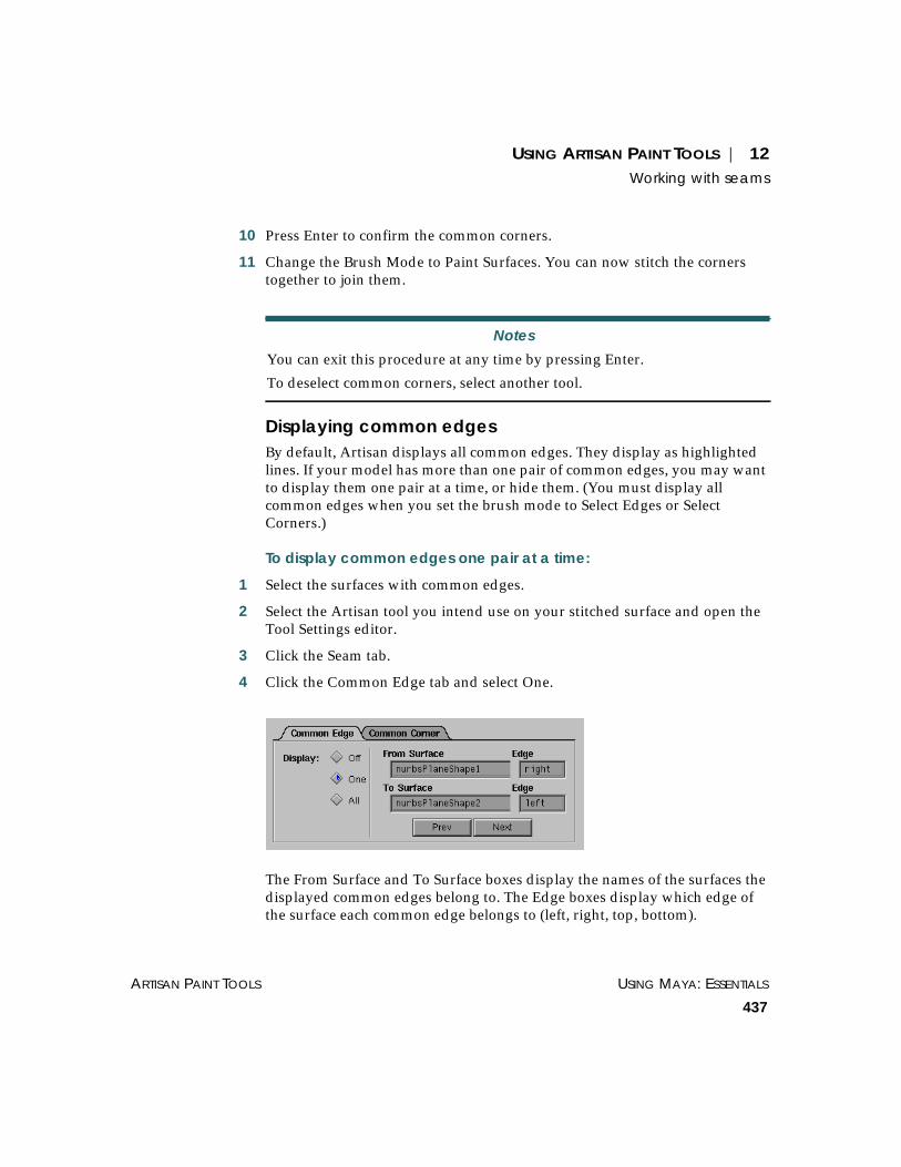
USING ARTISAN PAINT TOOLS | 12Working with seams
ARTISAN PAINT TOOLS USING MAYA: ESSENTIALS
437
10 Press Enter to confirm the common corners.
11 Change the Brush Mode to Paint Surfaces. You can now stitch the cornerstogether to join them.
Displaying common edgesBy default, Artisan displays all common edges. They display as highlightedlines. If your model has more than one pair of common edges, you may wantto display them one pair at a time, or hide them. (You must display allcommon edges when you set the brush mode to Select Edges or SelectCorners.)
To display common edges one pair at a time:
1 Select the surfaces with common edges.
2 Select the Artisan tool you intend use on your stitched surface and open theTool Settings editor.
3 Click the Seam tab.
4 Click the Common Edge tab and select One.
The From Surface and To Surface boxes display the names of the surfaces thedisplayed common edges belong to. The Edge boxes display which edge ofthe surface each common edge belongs to (left, right, top, bottom).
Notes
You can exit this procedure at any time by pressing Enter.
To deselect common corners, select another tool.

USING MAYA: ESSENTIALS PART 3
438
USING ARTISAN PAINT TOOLS | 12Working with seams
5 To display the next common edge pair, click the Next button. To display theprevious common edge pair, click the Prev button.
Displaying common cornersBy default, Artisan displays all common corners. They display as yellowdots. You can turn off the display of common corners. (You must display allcommon corners when you set the brush mode to Select Edges or SelectCorners.)
To turn off the display of common corners:
1 Select the surfaces with common corners.
2 Select the Artisan tool you intend use on your stitched surface and open theTool Settings editor.
3 Click the Seam tab.
4 Click the Common Corner tab and select Off.
Stitching surfacesYou can stitch surfaces together using the Sculpt Surfaces Tool. There aretwo ways to do this:
• Sculpt across the common edges and common corners. The edges andcorners stitch together automatically to create a seam.
• Use the Stitch Now button in the Stitching Mode section of the Seam tab.
For details, see Using Maya: NURBS Modeling.
Painting weights and attributes, or script painting over seamsYou can paint weights and skin weights over seams using the Paint WeightsTool and Paint Skin Weights Tool respectively, script paint over them usingthe Script Paint Tool, and paint attributes over them using the AttributePaint Tool. To ensure that the values you specify when painting across a
Note
To hide all common edges, select Off on the Common Edge tab.
To display all common edges, select All.

USING ARTISAN PAINT TOOLS | 12Working with seams
ARTISAN PAINT TOOLS USING MAYA: ESSENTIALS
439
seam remain the same at the seam, toggle Averaging Seam on in theCommon Edge Value Averaging section of the Seam tab. To ensure that thevalues you specify when painting across a pole remain the same, toggle onAveraging Pole CVs.
USING MAYA: ESSENTIALS PART 3
440
USING ARTISAN PAINT TOOLS | 12Working with seams

USING MAYA: ESSENTIALS
441
13 SCRIPT AND ATTRIBUTEPAINT TOOLS
This chapter describes the advanced Artisan tools: Script Paint Tool andAttribute Paint Tool. It includes the following topics:
• “Painting with MEL Scripts” on page 441
• “Painting attribute values” on page 454
These tools involve setting up custom MEL scripts. For information onsetting up the MEL scripts for these tools, see Using Maya: MEL.
PAINTING WITH MEL SCRIPTS
This section describes how to paint with MEL scripts using the Script PaintTool. It includes the following topics:
• “Overview of MEL script painting” on page 441
• “Setting Script Paint Tool options” on page 442
• “Script painting” on page 447
• “Script painting on masked surfaces” on page 454
• “Flooding surfaces” on page 454
Overview of MEL script paintingA MEL script is a file that contains MEL commands, MEL procedures, orboth. Typically, you use a MEL script to create custom effects. Using Artisanpaint tools, you can paint these effects on your surfaces the same way youpaint weights. There are four sample scripts for you to try:

USING MAYA: ESSENTIALS PART 3
442
SCRIPT AND ATTRIBUTE PAINT TOOLS | 13Painting with MEL Scripts
• geometryPaint – Use this script to select predefined objects in your scene andthen paint them on a selected surface. For example, if the object is a cone,you can paint cones on the surface using the geometryPaint script. The ScriptPaint Tool settings determine the size, position, angle, and density of thecones.
• spherePaint – Use this script to paint spheres on a selected NURBS surface.This is a customized version of the geometryPaint script.
• emitterPaint – Use the emitterPaint script to paint emitters on surfaces.Emitters generate particles. The attributes of the emitter control the position,direction, quantity, and initial velocity of the emitted particles when they areborn. After the particle is born, the attributes of the particle object that theemitter is connected to control the particle’s appearance. For more detailsabout emitters, see Using Maya: Dynamics.
• softBodyPaint – Use this script to set the goal weights on a soft body bypainting on the soft body surface. For details about soft bodies, see UsingMaya: Dynamics.
These scripts are stored on the /usr/aw/maya3.0/scripts/others directory(IRIX), or drive:\aw\Maya3.0\scripts\others directory (NT).
You might find these examples helpful when you are writing your own MELscripts. Note that these scripts have not been thoroughly tested and thereforeare not supported. For details on creating your own scripts, see the UsingMaya: MEL online documentation.
Setting Script Paint Tool optionsBefore you script paint, set options for the Script Paint Tool. The settingsdetermine the effect you will achieve when you paint with the tool. You candefine the following tool settings:
• brush stamp profile
• script paint operation
• value range
• clamping options
You can save your tool settings by adding the tool to a shelf. For details, see“Creating an Artisan tool shelf” on page 410.

SCRIPT AND ATTRIBUTE PAINT TOOLS | 13Painting with MEL Scripts
ARTISAN PAINT TOOLS USING MAYA: ESSENTIALS
443
To define Script Paint Tool settings:
Select the Script Paint Tool and open the Tool Settings editor(Modify > Script Paint Tool ❐).
Tip
You can define hotkey combinations to change most of the settings withoutopening the Tool Settings editor. For details on setting hotkeycombinations, see “Defining Artisan hotkeys” on page 410.

USING MAYA: ESSENTIALS PART 3
444
SCRIPT AND ATTRIBUTE PAINT TOOLS | 13Painting with MEL Scripts
Setting the brush stamp profile
Radius (U) If you are using a stylus, set the upper or maximum possible radius for thebrush. No matter how hard you press the stylus, the brush radius will notexceed this radius. If you are not using a stylus, this setting defines theradius for the brush.

SCRIPT AND ATTRIBUTE PAINT TOOLS | 13Painting with MEL Scripts
ARTISAN PAINT TOOLS USING MAYA: ESSENTIALS
445
Radius (L) If you are using a stylus, set the lowest or smallest possible radius for thebrush when you apply pressure to the stylus. If you are not using a stylus,this setting is not used.
Opacity Set the fraction of the Value to apply to each brush stamp within a stroke.Vertex values build up when stamps overlap. Stamps overlap when youpaint over the same area.
Using the Opacity setting, you can produce more gradual changes to achievemore subtle effects.
Note that when you set Opacity to 0, your brush stroke has no effect.
Value Set the value to apply when you perform any of the script paintingoperations. The value has a different meaning depending on the script. Forexample:
For the geometryPaint script, Value refers to the size of the geometry. Thesize of the original geometry has a value of 1.
For the emitterPaint script, Value refers to the percentage of the selectedscript operation.
For the softBodyPaint script, value refers to the goal weight on the soft body.The soft body should be set to have an initial goal weight value of 1.
Shape Click on the shape of the brush. This determines the shape of the areaaffected by the brush action.
For brush shapes that are not uniformly round, you can change the profilealignment. For details, see “To set the brush stamp profile alignment:” onpage 402.
Selecting the operation
Notice that the brush stamp changes to reflect the operation.
To remove the letters and gradient marking from the brush stamp, open theTool Settings editor, click on the Display tab and toggle Draw BrushFeedback off.
Replace Add Scale Smooth

USING MAYA: ESSENTIALS PART 3
446
SCRIPT AND ATTRIBUTE PAINT TOOLS | 13Painting with MEL Scripts
Replace For the geometryPaint script, replaces the vertex values you paint over withthe specified Value and Opacity.
For the emitterPaint script, replaces the characteristics of the painted emitterby the Value and Opacity settings and replaces the painted emitters withemitters that have these new characteristics. For example, if the selectedoperation is Speed, the emitter speed is factored by the Value and Opacitysettings.
For the softBodyPaint script, replaces goal weights by a factor of the originalgoal weight.
Add For the softBodyPaint script, adds the specified Value and Opacity to thecurrent vertex values you paint over. If the Paint Offset is negative, the valueactually decreases.
For the emitterPaint script, adds to the defined characteristics of paintedemitters by the Value and Opacity factors.
For the softBodyPaint script, adds to the goal weight.
Scale For the softBodyPaint script, scales the current vertex values you paint overby the Value and Opacity factors.
For the emitterPaint script, scales the defined characteristics of paintedemitters by the Value and Opacity factors.
For the softBodyPaint script, scales the goal weight.
Smooth For the softBodyPaint script, changes the vertex values to be the averagevalues of the surrounding vertices.
For the emitterPaint script, changes the values of the painted emitters to theaverages of the characteristics.
For the softBodyPaint script, changes the goal weights to the averages of theadjacent goal weights.
Setting the value range
Paint Offset Set the factor you want to offset the Value by. This setting is most usefulwhen you want to change the range of paint values from the default, 0-1. Forexample, if you want to paint objects with values between 4 and 5 using thegeometryPaint script, set Paint Offset to 4.
The default Paint Offset is 0, which has no effect on script paintingoperations.

SCRIPT AND ATTRIBUTE PAINT TOOLS | 13Painting with MEL Scripts
ARTISAN PAINT TOOLS USING MAYA: ESSENTIALS
447
Paint Mult. Set the factor you want Value multiplied by.
Setting clamping options
In the Clamping section, select whether you want to clamp the values withina specified range, regardless of the Value set when you paint. You can setclamping to Lower, Upper, Both, or None.
For example, if you clamp Lower and set Clamp Lower to 0.5, the values youpaint will never be less than 0.5, even if you set Value to 0.25. Similarly, ifyou clamp Upper and set Clamp Upper to 0.75, the values you paint willnever be greater than 0.75, even if you set Value to 1.
Script paintingYou script paint by selecting a script and applying brush strokes to thesurface with the Script Paint Tool.
To script paint:
1 Make sure that the script you want to paint with is in the script directory:
~username/maya/3.0/scripts (IRIX)drive:\WINNT\Profiles\username\maya\3.0\scripts (NT)drive:\Documents and Settings\username\maya\3.0\scripts (Windows 2000)
2 Select the surface you want to script paint on.
Tip
To help you differentiate paint values when you script paint (for example,with the softBodyPaint script), set Min Color @ and Max Color @ tocorrespond with the Paint Offset and Paint Mult values, respectively. Fordetails, see “Changing display settings” on page 404.
Tip
To maximize the range of values that display when you script paint (forexample, with the softBodyPaint script), set Min Color @ and Max Color @to correspond with the Clamp Lower and Clamp Upper values,respectively. For details, see “Changing display settings” on page 404.

USING MAYA: ESSENTIALS PART 3
448
SCRIPT AND ATTRIBUTE PAINT TOOLS | 13Painting with MEL Scripts
3 Select the Script Paint Tool (Modify > Script Paint Tool) and define toolsettings, if required. For details on defining tool settings, see “Setting ScriptPaint Tool options” on page 442.
4 Click the Setup tab.
5 In the Tool Setup Cmd box, type the name of the MEL script (without the.mel extension) and any required parameters, and then press Enter.
This box is case sensitive. For example, for the sample scripts typegeometryPaint, emitterPaint, softBodyPaint goalPP.
A script window may open, depending on the script.
6 Change any settings in the script window then click-drag the brush acrossthe surface.

SCRIPT AND ATTRIBUTE PAINT TOOLS | 13Painting with MEL Scripts
ARTISAN PAINT TOOLS USING MAYA: ESSENTIALS
449
geometryPaint settings
Geometry Type the names of the objects you want to paint, separating each with aspace. The objects must be in your scene. If you type more than one objectname, Maya paints them randomly.
Identifier Type a name to identify the layer the painted objects belong to. By paintingon different layers, you can modify the objects on one layer without affectingthe objects on a different layer. For example, if you type Layer1 in this box,then paint cones, then type Layer2 in the box and paint spheres, when yougo back to Layer1 and paint, the spheres in Layer2 will be unaffected.
If you cannot remember a layer name, or identifier, open the Outliner andselect an object belonging to the layer. The identifier name is part of theobject name.
Selecting an operation
Create/Modify Creates new objects, and modifies the objects you paint over using thesettings in this window and on the Script Paint tab.
Modify Modifies the objects you paint over using the settings in this window and onthe Script Paint tab.
Remove Removes the objects you paint over.

USING MAYA: ESSENTIALS PART 3
450
SCRIPT AND ATTRIBUTE PAINT TOOLS | 13Painting with MEL Scripts
Setting grid options
Grid Turn Grid on to use the grid you set in the U Grid Size and V Grid Sizeboxes to place the geometries. If you do not turn Grid on, Maya uses thevertex position to place geometries.
For each surface you paint, do not change the grid size. Changing the gridsize while you paint produces undesirable results.
Also, keep in mind that your grid settings are interpreted in part by the UVmapping technique used on the surface. Make sure the UVs are correctlyprojected on the surface.
Jitter Grid Toggle Jitter Grid on to randomize the position of the painted objects on thegrid.
U Grid Size V Grid Size
Select the desired U and V Grid Size. Artisan paints the geometry on the gridpoint of the U and V grid you specify here, regardless of the isoparm densityyou set for the surface. The larger the grid size, the denser the geometries.
In the following example, the isoparm density of the surface is 40, but the Uand V Grid Size are both set to 10 in the Geometry Paint Settings window.
Selecting controls
These controls define how painted objects are transformed. Do not selectboth scale and rotation controls at the same time.
X, Y and Z Scale Reduces object values by the factor set in the Value box of the Script Painttab.
X, Y and Z Rot Rotates objects based on the Value set in the Script Paint tab. A Value of 1rotates objects 360 degrees.

SCRIPT AND ATTRIBUTE PAINT TOOLS | 13Painting with MEL Scripts
ARTISAN PAINT TOOLS USING MAYA: ESSENTIALS
451
X, Y and Z Trans Moves objects along the surface in the X, Y, and/or Z direction based on theValue set in the Script Paint tab. A Value of 1 moves objects 1 grid position.
Selecting paint options
Proportional Distributes changes proportionally across all painted attributes rather thanreplacing them all with the new value.
Attach Attaches the objects to their position so they move with the surface whenyou modify the surface (for example, when you sculpt or translate it).
Duplicate Creates copies rather than instances of the original objects.
Group Groups the painted objects together on one identifier, or layer.
Isolate Isolates scale, rotate, and translate transformations, so they remainindependent of each other. With Isolate toggled on, you can return objects toa base position by selecting the control and flooding with a Value of 0 forrotation and translation, or 1 for scale.
Align Aligns objects along the surface normal.
Assigning a jitter value
Enter a jitter value to apply to the selected controls when Jitter Grid istoggled on, where 0 results in no jitter, and 1 results in maximum jitter.
Align toggled off Align toggled on

USING MAYA: ESSENTIALS PART 3
452
SCRIPT AND ATTRIBUTE PAINT TOOLS | 13Painting with MEL Scripts
emitterPaint settings
U Grid Size V Grid Size
Select the desired U and V Grid Size. Artisan paints the emitters on the gridpoints of the U and V grid you specify, regardless of the isoparm densityyou set for the surface. The larger the grid size, the denser the emitters.
Selecting grid options
Jitter Randomizes the position of the painted emitters.
Dither Concentrates emitters at the center of the brush stamp, with few emitters atthe edge. If you do not toggle this option on, the emitters concentrateuniformly on the stamp.
Selecting an operation
Create Creates emitters.

SCRIPT AND ATTRIBUTE PAINT TOOLS | 13Painting with MEL Scripts
ARTISAN PAINT TOOLS USING MAYA: ESSENTIALS
453
Remove Removes emitters.
Modify Emitter Attr. Changes the value of the selected attribute (Rate, Spread, Speed, Min Dist, orMax Dist) to the value set under Creation Options.
Modify Particle Attr. Changes the value of the selected attribute (Lifespan, Opacity, Point Size,Line Width, Tail Fade, Tail Size, Radius, Multi Count, Multi Radius) to thevalue set under Stamp Profile on the Script Paint tab.
Modify Render Type Changes the particle render type to the selected type (Multi-Point, Multi-Streak, Numeric, Points, Spheres, Sprites, Streak, or Blobby (s/w)).
Selecting a type
Omni-directional Sets the type of emitter to be an omnidirectional point emitter. This emitsparticles in all directions.
Directional Sets the type of emitter to be a directional point emitter.
Setting creation options
Rate Set the rate at which particles are emitted. The rate is particles per unit oftime.
Speed Set the speed multiple of the emission. The velocity of the emitted particlesis multiplied by this amount.
You can enter a value of 0 or greater.
Spread Set the spread angle for the emitted particles, along the specified emissiondirection. Particles are randomly distributed within the spread angle andaround the base of a cone between 0 and 360 degrees. This option is valid fordirectional emitters only.
You can enter a value between 0 and 1. A value of 1 means 180 degrees.
Min Dist Set the minimum distance from the emitter at which emission starts. You canenter a value of 0 or greater.
Particles get emitted at a random distance uniformly distributed between theMin Distance and Max Distance.
Max Distance Set the maximum distance from the emitter at which emission ends. You canenter a value of 0 or greater.
Particles Toggle on Per Emitter to create a separate particle shape for each emitter.Toggle this option off to share one particle shape between all emitters. PerEmitter must be toggled on to paint Particle Attr. or Render Type.

USING MAYA: ESSENTIALS PART 3
454
SCRIPT AND ATTRIBUTE PAINT TOOLS | 13Painting attribute values
Script painting on masked surfacesYou can create a mask on your surface that is unaffected by any scriptpainting you do. When you apply brush strokes over the mask, the verticeson the masked area remain unchanged, regardless of the script paintoperation.
For details on masking surfaces, see “Masking surfaces” on page 416.
Flooding surfacesFlooding a surface is like taking a huge brush and applying its settings to theentire surface. The result depends entirely on the brush settings definedwhen you perform the flood.
PAINTING ATTRIBUTE VALUES
The Attribute Paint Tool allows advanced users to create new paint tools.You can use the Attribute Paint Tool to paint any paintable attribute value ona surface. A paintable attribute is one that has been registered in Maya.Cluster weights and soft body particle attributes (goal weights, opacity, RGBand velocity) are already registered as paintable. For information on makingan attribute paintable, see Using Maya: MEL.
The Paint Vertex Color Tool and the Paint Skin Weights Tools are actuallycustomized Attribute Paint Tools.
Painting attributesYou paint attributes by selecting surfaces with paintable attributes that areregistered in Maya, selecting which paintable object(s) you want to paint,and then applying brush strokes to the surface with the Attribute Paint Tool.
To paint attributes:
1 Make sure that the attributes you want to paint are registered.
2 Select the surface you want to paint attribute values on.

SCRIPT AND ATTRIBUTE PAINT TOOLS | 13Painting attribute values
ARTISAN PAINT TOOLS USING MAYA: ESSENTIALS
455
3 Select the Attribute Paint Tool (Modify > Attribute Paint Tool) and definetool settings, if required. (For details on defining tool settings, see “SettingScript Paint Tool options” on page 442. The settings on the Attr. Paint tab arethe same as the settings on the Script Paint tab.)
4 Do one of the following:
• Right-click on the surface and select Paint > objectType > paintableAttribute.The Attribute Paint Tool automatically detects paintable attributes on thesurface and displays them.
In the following example, the Attribute Paint Tool detects that the surface isa soft body with a cluster (both attribute types are paintable).
or
• In the Tool Settings window, click the Attr tab. The Attribute Paint Toolautomatically detects paintable attributes on the surface and displays themin the Paintable Object Type box.

USING MAYA: ESSENTIALS PART 3
456
SCRIPT AND ATTRIBUTE PAINT TOOLS | 13Painting attribute values
• Click the plus sign (+) or Expand button to expand the object type and seewhat attributes are paintable.
• Click the paintable attribute. All selected objects that are paintable appearunder the Selection section in the Paintable Object List.
The name of the paintable attribute appears in the Selected Paintable Attr.Type box. This is the attribute you will be painting.
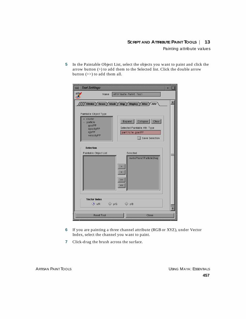
SCRIPT AND ATTRIBUTE PAINT TOOLS | 13Painting attribute values
ARTISAN PAINT TOOLS USING MAYA: ESSENTIALS
457
5 In the Paintable Object List, select the objects you want to paint and click thearrow button (>) to add them to the Selected list. Click the double arrowbutton (>>) to add them all.
6 If you are painting a three channel attribute (RGB or XYZ), under VectorIndex, select the channel you want to paint.
7 Click-drag the brush across the surface.

USING MAYA: ESSENTIALS PART 3
458
SCRIPT AND ATTRIBUTE PAINT TOOLS | 13Painting attribute values

PART 4
PREFERENCES


USING MAYA: ESSENTIALS
461
14 SETTING PREFERENCES
You can use preferences to customize Maya to the way you work. You canchange general color definitions, the way manipulators display, and theappearance of the Shelf, menu bars, and panels.
This chapter describes how to set preferences in Maya It includes:
• “Settings/Preferences menu” on page 462
• “Where Maya stores preferences” on page 462
• “Saving preferences using userSetup.mel” on page 464
• “Preferences window” on page 465
• “Changing color settings” on page 482
• “Specifying tool settings” on page 485
• “Specifying performance settings” on page 487
• “Loading and unloading plug-ins” on page 489
USING MAYA: ESSENTIALS PART 4
462
SETTING PREFERENCES | 14Settings/Preferences menu
SETTINGS/PREFERENCES MENU
The Window > Settings/Preferences menu gives you access to the variousMaya preferences windows, including:
Preferences See “Preferences window” on page 465 in this chapter.
Tool Settings Opens the settings for the current tool. See “Specifying tool settings” on page485 in this chapter. Also see information on the specific tool.
Performance Settings
See “Specifying performance settings” on page 487 in this chapter.
Hotkeys Displays the Hotkey Editor to let you create and edit your own hotkeycombinations. See “Assigning hotkeys” on page 526.
Colors Displays the Colors window to let you specify the color of variouscomponents of Maya, including the Hypergraph and the Multilister. See“Changing color settings” on page 482 in this chapter.
Marking Menus Displays the Marking Menu Editor to let you edit the marking menus. See“Creating and editing marking menus” on page 509.
Shelves Displays the Shelves window to let you create and edit shelves. See“Creating and editing shelves” on page 493.
Panels Displays the Panels window to let you create and edit your own panels. See“Working with Panels and Layouts” on page 533.
Plug-in Manager Opens the Plug-in Manager to let you load and unload plug-in software andMaya modules. See “Loading and unloading plug-ins” on page 489.
WHERE MAYA STORES PREFERENCES
Many of the settings that define the Maya user interface are stored in .melfiles in the the following directory:
~username/maya/3.0/prefs (IRIX)drive:\WINNT\Profiles\username\maya\3.0\prefs (NT)drive:\Documents and Settings\username\maya\3.0\prefs (Windows 2000)
Shelves are stored in the shelves subdirectory and icons are stored in theicons subdirectory.

SETTING PREFERENCES | 14Where Maya stores preferences
PREFERENCES USING MAYA: ESSENTIALS
463
When you customize Maya, your new settings are stored in user preferencefiles, so that each time you open Maya, your settings are used instead of theMaya default settings. If you delete a preference file, Maya uses the defaultsettings.
Color and hotkey files
The following .mel files store settings you have customized using the Colorswindow and Hotkey Editor.
• userColors.mel – Contains preferences defined on the Active and Inactivetabs of the Colors window.
• userRGBColors.mel – Contains preferences defined on the General tab of theColors window.
• paletteColors.mel – Defines the colors (RGB) making up the index palette inthe Active and Inactive tabs of the Colors window.
• userHotkeys.mel – Contains any hotkeys you have assigned in the Hotkeyswindow.
• userNamedCommands.mel – Contains all the commands that have hotkeysassigned to them.
Default hotbox marking menus
The following files define the default Hotbox marking menus.
• menu_ChangePanelLayout.mel – North
• menu_ChangePanelType.mel – South
• menu_ChangeSelectionMask.mel – West
• menu_CommonModelingPanes.mel – Center
• menu_ControlPaneVisibility.mel – East
User preferences
The following files define user preferences.
• userPrefs.mel – Contains preferences defined in the General Preferenceswindow (Window > Settings/Preferences > Preferences).
• windowPrefs.mel – Defines the default size and position of Maya windows.
USING MAYA: ESSENTIALS PART 4
464
SETTING PREFERENCES | 14Saving preferences using userSetup.mel
SAVING PREFERENCES USING USERSETUP.MEL
While you save most Maya user preferences through the user interface, youcan also store preferences not stored through the user interface by creatingthe file userSetup.mel in the following directory:
~username/maya/3.0/scripts (IRIX)drive:\WINNT\Profiles\username\maya\3.0\scripts (NT)drive:\Documents and Settings\username\maya\3.0\scripts (Windows 2000)
Whenever you launch Maya, the MEL commands in this file run. Forexample, you could put the following command in the userSetup.mel file:
alias djs jointDisplayScale;
This creates an alias named djs, that lets you set the joint size without usingthe Display > Joint Size menu or typing jointDisplayScale. You can enter thedjs alias with a joint size in the Command Line or Script Editor:
djs 1.5;
In this example, the joint size is set to 1.5.
For details about writing MEL scripts, see Using Maya: MEL.
Important
The scene is cleared of all objects after the commands in the userSetup.melfile are run. Therefore, any scene elements created using the userSetup.melfile will have been removed when Maya comes up.
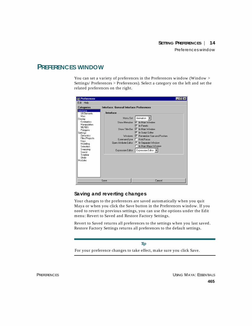
SETTING PREFERENCES | 14Preferences window
PREFERENCES USING MAYA: ESSENTIALS
465
PREFERENCES WINDOW
You can set a variety of preferences in the Preferences window (Window >Settings/Preferences > Preferences). Select a category on the left and set therelated preferences on the right.
Saving and reverting changesYour changes to the preferences are saved automatically when you quitMaya or when you click the Save button in the Preferences window. If youneed to revert to previous settings, you can use the options under the Editmenu: Revert to Saved and Restore Factory Settings.
Revert to Saved returns all preferences to the settings when you last saved.Restore Factory Settings returns all preferences to the default settings.
Tip
For your preference changes to take effect, make sure you click Save.

USING MAYA: ESSENTIALS PART 4
466
SETTING PREFERENCES | 14Preferences window
InterfaceMenu Set This determines which menu set displays in the main Maya menu bar on
start-up. The default is Animation.
Show Menubar Hides or displays the menu bar.
Show Title Bar Hides or displays the title bar. The title bar includes window control buttonsfor expanding and collapsing the application.
Windows Turn on Remember Size and Position so that Maya restores the size andposition of all windows when closed and re-opened. If toggled off, Mayawindows always display in the center of the screen upon opening.
Command Line Toggle on Hold Focus if you want the cursor to stay in the Command Lineafter you press Enter. Otherwise, the cursor returns to the current window.
Open Attribute Editor
Use this option to specify how the Attribute Editor displays when you openit (such as pressing Ctrl+A). To open the Attribute Editor in a separatewindow, select In Separate Window. To open the Attribute Editor in themain Maya window, select In Main Maya Window. Note that the AttributeEditor always displays in the main Maya window when you chooseDisplay > UI Elements > Attribute Editor.
Expression Editor Select an Expression Editor for editing text.
UI ElementsVisible UI Elements Hides or displays UI elements. You can also control this display from the
Display > UI Elements menu.
Toggle on any components you want displayed in the Maya main window.
Note
You cannot display both the Channel Box and the Attribute Editor in themain Maya window at the same time. If you toggle Attribute Editor off,when you open the Attribute Editor, it will display according to the optionselected on the Windows tab. See “Open Attribute Editor” on page 466.

SETTING PREFERENCES | 14Preferences window
PREFERENCES USING MAYA: ESSENTIALS
467
MiscWindow Selection Select whether Maya uses the existing help browser window (Use an
Existing Help Browser Window) or creates a new one (Create a New HelpBrowser Window for Maya Help) when you select a Help menu item.
Window Visibility Select whether an html browser appears when you select Help > Library,Global Index, Search, Maya Basics, or MEL. The default is on.
New Scene Config Select the view configuration to use the next time you open a new scene.
New File Select whether the current panel configuration (Use Existing) or a specifiedpanel configuration (Use Specified) is used when creating a new file.
Open File Select whether the saved panel configuration (Use Saved) or a specifiedpanel configuration (Ignore Saved) is used when opening a file.
Save File Select whether to save the panel configuration automatically when you savethe scene file (Always Save), or never (Never Save).
DisplayFast Interaction Toggle Fast Interaction on to improve performance by displaying fewer
geometric entities (such as polygons). Off is the default setting.
Axes Displays one or both of the XYZ coordinates (view and origin axes). If youdisable both choices, no XYZ coordinates appear.
View Axis – Displays the XYZ coordinates in the bottom left corner of theview. This is the default.
Origin Axis – Displays the XYZ coordinates at coordinates 0, 0, 0.
Grid Plane Displays or hides the grid plane. The grid is a 2D plane that represents 3Ddimensions in the view. It is useful when you want to animate motionrelative to a solid surface. Select Hide to hide the grid.
This setting overrides the Display > Grid setting described in “Using a grid”on page 120.
Active Object Pivots Specify whether to display pivot points.
Affected Highlighting
Turns highlighting display on or off. An object associated with or affected bya selected object is highlighted in a different color.

USING MAYA: ESSENTIALS PART 4
468
SETTING PREFERENCES | 14Preferences window
Wireframe on Shaded
Select how you want to display the wireframe on shaded objects.
Full – Displays normal resolution wireframes on shaded objects. This is thedefault.
Reduced – Displays fewer wires on shaded objects.
None – Displays no wires on shaded objects. Performance is enhanced if youselect None.
Region of Effect This option lets you turn on or off the region of effect display. Region ofeffect is the part of an object that will potentially change as a result ofmoving selected CVs. Note that curves show the region of effect as well assurfaces.
Shade Templates If on, templated objects appear shaded in shaded view. If off, the templatedobjects appear as wireframes while all other objects appear shaded.
Note
You can edit this highlight color by selecting Window > Settings/Preferences > Colors, clicking the Active tab, expanding General, andmodifying Active Affected.
Region ofEffect on
Region ofEffect off

SETTING PREFERENCES | 14Preferences window
PREFERENCES USING MAYA: ESSENTIALS
469
KinematicsJoint Size Changes the display size of skeleton joint sizes. The range is from 0.01 to 5.0.
IK Handle Size Changes the display size of IK handles. The range is from 0.01 to 5.0.
ManipulatorsGlobal Scale Specifies the size of the manipulators. The range is from 0.10 to 10.00. The
default is 10.00.
Handle Size Specifies the size of the handle. The range is from 4 to 100.
Line Size Specifies the line thickness size of the rotate manipulator’s rings.

USING MAYA: ESSENTIALS PART 4
470
SETTING PREFERENCES | 14Preferences window
Line Pick Size Determines the line thickness used when picking the rotate manipulatorrings. The pick size should be the same as line size, so you can identifywhich handle will be picked by the size of the ring.
Previous State Size Controls the size of the points drawn for a previous feedback. For example,for the Move Tool, an axis is drawn to indicate the previous position, withsquare points at the end of the axes. This controls the size of the squares.
Rotate and scale manipulators also have previous state feedback. This typeof feedback is shown only when you drag; it disappears as soon as yourelease the mouse.
NURBSNew Curves, New Surfaces
Select whether you want Edit Points, Hulls, and/or CVs on new curves ornew surfaces:
Surface Divisions Controls the smoothness of an object in a view. It also affects the renderingof newly created surfaces. Enter a value or use the slider. The range is from 0to 64. The higher the value, the smoother the surface.
Note
These options work only on new curves or surfaces, not existing items.

SETTING PREFERENCES | 14Preferences window
PREFERENCES USING MAYA: ESSENTIALS
471
Curve Divisions Controls the smoothness of a curve in a view. Enter a value or use the slider.The range is from 1 to 128. The higher the value, the smoother the curve.
Shaded Divisions Controls how smooth your smooth-shaded object looks. The greater thenumber, the smoother the smooth-shaded object. Enter a value or use theslider. The range is from 1 to 64.
PolygonsVertices Specify how you want vertices to display:
Display – Toggles the display of vertices on or off.
Normals – Displays vertex normals on or off.
Backculling – Makes vertices invisible in areas where the normal is pointingaway from the camera.
Edges Specify how you want edges to display:
Standard – Displays all edges the same (hard or soft).
Soft/Hard – Displays soft edges as dotted lines and hard edges as solid lines.
Only Hard – Displays hard edges only (makes soft invisible).
Highlight Specify how you want highlight polygons:
Border Edges – Displays thicker outside edges to make them more visible forcertain operations.
Texture Border – Displays a thick border to highlight the area a textureaffects per polygon or per vertex.
Border Width Specify the width of the polygon border. The range is from 1 to 10.
Faces Specify how you want faces to display:
Centers – Displays a small square to indicate the face center.
Normals – Shows the normals at the center of each polygon.
Triangles – Displays all polygons as triangles for display.
Show Item Numbers Specify where you want item numbers displayed: at each vertex (Vertices),at each edge (Edges), or on each face (Faces).
Normals Size Specifies the display size of the normals. The range is from 1 to 10.

USING MAYA: ESSENTIALS PART 4
472
SETTING PREFERENCES | 14Preferences window
Color Toggle Colored Shading on to use the Apply Color operation (EditPolygons > Colors > Apply Color). For details, see “Coloring polygons”, inUsing Maya: Polygonal Modeling.
Color Material These menu options override any existing material channels and replacethem with the vertex colors you assign. For all options other than None,lighting affects the object’s shading.
None – None of the material properties of the shader(s) assigned to the objectare used. In this case lighting is also disabled.
Ambient – The ambient material channel of the assigned shader(s) isoverridden by the vertex color.
Ambient+Diffuse – The ambient and diffuse material channels of the assignedshader(s) are overridden by the vertex color.
Diffuse – The diffuse material channel of the assigned shader(s) is overriddenby the vertex color.
Specular – The specular material channel of the assigned shader(s) isoverridden by the vertex color.
Emission – The emission material channel of the assigned shader(s) isoverridden by the vertex color.
Backface Culling Specify the display for backface culling:
Off – No backface culling occurs. This is the default.
On – Surfaces become invisible in areas where the normal is pointing awayfrom the camera.
Keep Wire – Displays wireframe outlines, but any areas where the normal ispointing away from the camera are hidden.
Keep Hard Edges – Sets backface culling for soft edges only. See Using Maya:Polygonal Modeling for more information on polygonal modeling.
SettingsUp Axis Sets the up axis to Y or Z. The default is Y. See “Orienting the XYZ system”
on page 31.
Linear Sets the unit of measure for operations that use linear values, for example,moving and scaling. The default unit for measuring linear values iscentimeters.

SETTING PREFERENCES | 14Preferences window
PREFERENCES USING MAYA: ESSENTIALS
473
Angular Sets the unit of measure for operations that use an angular value, forexample, rotation. The default unit for measuring angular values is degrees.
Time Sets Maya’s internal representation of what one “second” is. For example, ina dynamics simulation, which relies on real world timings, the resultingsimulation will produce keys which represent one second as 24 frames(Maya’s default value).
It also allows you to compensate for intermediate output devices (forexample, Abekas, etc.) which may have different frame rates to your finaloutput (for example, Film). When changed, your animation keys will movein time to match that range. This is only while your time units are on thatalternate setting. Returning the time units to your creation setting will returnyour keys to their original location.
The default for measuring time is Film 24fps (24 frames per second).
Tolerance
The Tolerance value determines the degree of accuracy that is maintainedbetween the original and fit (or interpolated) curves. This setting appliesglobally to Maya. You can change it on a case-by-case basis. Set thefollowing tolerance options:
Positional Set the degree of accuracy between the actual positions of the original andinterpolated curves.
Tangential Set the degree of accuracy required to determine if two NURBS objects are tobe made tangent across a shared edge or point.
DynamicsAuto Create Rigid Body
Toggle this option on to automatically create active rigid bodies when youconnect an object to a field (apply a field’s influence to geometry).
Note
Be sure you set your preferred time unit for a particular session, beforecreating any animation. This will ensure correct timing of your keyframes,for the final output and final fps setting.

USING MAYA: ESSENTIALS PART 4
474
SETTING PREFERENCES | 14Preferences window
Run Up To Current Time
If you click a frame in the Time Slider, the correct state of all dynamic objectsin the scene is displayed only if Maya performs run-up to calculate eachframe prior to that frame. Toggle this option on if you want to click framesin the Time Slider. Note that run-up also occurs for hidden objects.
Leave run-up toggled off if you want to prevent Maya from calculatingdynamics when you click in the Time Slider. This is useful in a scene that hasboth nondynamic objects and complex dynamic objects, where you want thestate of nondynamic objects to appear promptly after you click the TimeSlider. If you are keying dynamic objects, it’s also useful leave run-uptoggled off to avoid waiting for run-up calculations that are irrelevant toyour keying activities.
Run Up From Select one of the following options:
Previous Time – If you click a frame higher than the current frame, run-upstarts from the prior current time and ends at the frame you click. Select thisoption if you won’t be changing any attributes of a dynamic object in thescene. This setting lessens the time you’ll spend waiting for run-up. If youclick a frame lower than the current frame, run-up starts from the beginningof the animation.
Start Time – Run-up starts from the start frame regardless of where you clickin the Time Slider. Select this option if you plan to change any attributes of adynamic object in the scene. This ensures that you see the correct objectstates when you click in the Time Slider after modifying an object’sdynamics.
Save Startup Cache for Particles
When this option is turned on (the default), Maya automatically saves thestart-up cache for all your particles every time you save the file. Unlikeparticle disk caches, you don't have to create the start-up cache explicitlyevery time. See Using Maya: Dynamics for more information.
Files/ProjectsDefault Projects Directory,Always Start in This Project
Use these settings to set up a default projects directory when you create newprojects and on startup.

SETTING PREFERENCES | 14Preferences window
PREFERENCES USING MAYA: ESSENTIALS
475
On File Save Specify the compression mode you want to use when saving an ASCII file:
Compressed — Saves files in compressed mode. File compression reducesthe sizes of large files so they do not occupy as much space on your harddrive.
Uncompressed — Saves files in uncompressed mode.
As Is — Keeps files in their original compression mode rather thancompressing or uncompressing them. As Is is the default.
File Import Merge Specify how you want the Display Layer merged when you import a file.
None – All layers read in are put in a new layer, renumbered, and renamed,if necessary to preserve uniqueness.
By Number – Rather than creating a new layer, all layers read in that have thesame index number as an existing layer are merged with that layer.
By Name – Rather than creating a new layer, all layers read in that have thesame name as an existing layer are merged with that layer.
KeysAuto Key Toggle Auto Key on to automatically set keys on any keyable attributes of an
animated object (including lights, shaders, textures, cameras, and so on).
Weighted Tangents Toggle Weighted Tangents on to give animation curve tangents weight. Thedefault is toggled off, which means the tangents are non-weighted.
Default In Tangent, Default Out Tangent
Set the default In and Out Tangents to:
Spline – Creates an animation curve that is smooth between the key beforeand the key after the selected key.
Linear – Creates an animation curve as a straight line joining two keys.
Clamped – Creates an animation curve which has the characteristics of linearand spline curves.
Flat – Sets the in and out tangents of the key to be horizontal (with a slope of0 degrees).
Stepped – Creates an animation curve whose out tangent is a flat curve.

USING MAYA: ESSENTIALS PART 4
476
SETTING PREFERENCES | 14Preferences window
ModelingOutput Geometry As These settings determine the type of geometry created from modeling
actions such as Revolve, Loft, Extrude, Fillet Blend, and so forth. Setting ithere affects all applicable modeling actions. Otherwise, select Mixed to usethe individual settings of each modeling action.
Interaction Mode Specify whether you want certain NURBS modeling commands to behavelike actions or tools. An action performs a discreet function on selectedobjects. A tool lets you manipulate objects until you complete the operation.You may want to change actions to tools as you become proficient at Maya’sNURBS modeling, or it you are accustomed to Power Animator tools.
To globally change the applicable modeling tools, choose Everything is aTool or Everything is an Action. To individually set each command, chooseMixed.
Selection
Modifiers
Modifiers control Maya selection operations. They work with masks tocontrol what is displayed when you select items. You can toggle on one ormore of the following:
Single Marquee Select
Selects the first object in a hierarchy.
Click Drag Select Lets you perform one-step click-dragging with the transformation tools. Youcan move one object using the Move tool, then click on a second object andthe Move tool displays. This means you do not have to select the object andthe Move tool again—you can keep using the Move tool on any subsequentselected object.
Affects Active If you change from object to component selection mode, the selected object isnot affected. This option lets you select objects and components at the sametime. This is toggled on by default.
Allow Highlight Select
Highlights components when you switch from object to component selectionmode. This is toggled on by default.

SETTING PREFERENCES | 14Preferences window
PREFERENCES USING MAYA: ESSENTIALS
477
Ignore Selection Priority
Treats all objects with the same priority. The selection order does not matter.This is toggled on by default.
Popup Menu Selection
When objects overlap in the view, lets you display a pop list of the objects soyou can select them. Left-click on the overlap area to display the menu.
Expand Popup List If you toggled on Expand Popup List, displays all the pop list of objects andeverything underneath it in the hierarchy.
Click Box Size This option controls the size of the selection area around the mouse pointer,or click box. If you are having problems with selecting objects or components,try adjusting this option. For example, a higher click box size might make iteasier to select curves. Increasing the click box size is also useful if you havea high resolution screen display.
Polygon Selection
Select Faces with Specify how you want to select polygonal faces:
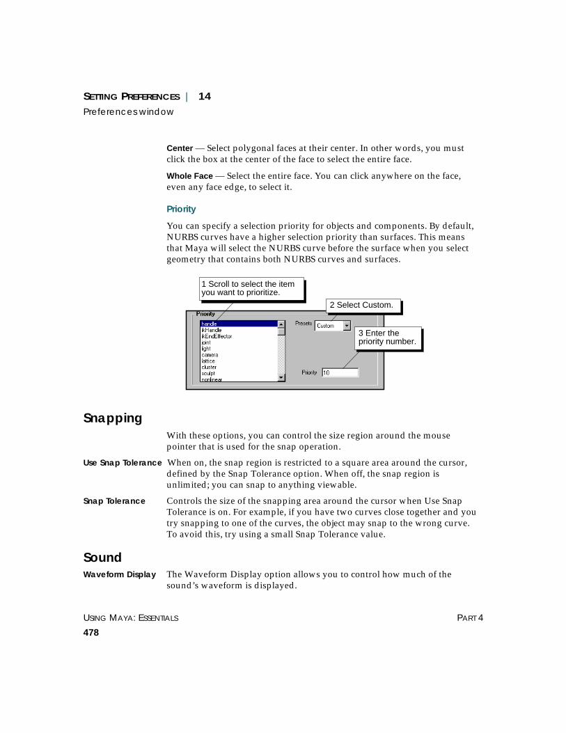
USING MAYA: ESSENTIALS PART 4
478
SETTING PREFERENCES | 14Preferences window
Center — Select polygonal faces at their center. In other words, you mustclick the box at the center of the face to select the entire face.
Whole Face — Select the entire face. You can click anywhere on the face,even any face edge, to select it.
Priority
You can specify a selection priority for objects and components. By default,NURBS curves have a higher selection priority than surfaces. This meansthat Maya will select the NURBS curve before the surface when you selectgeometry that contains both NURBS curves and surfaces.
SnappingWith these options, you can control the size region around the mousepointer that is used for the snap operation.
Use Snap Tolerance When on, the snap region is restricted to a square area around the cursor,defined by the Snap Tolerance option. When off, the snap region isunlimited; you can snap to anything viewable.
Snap Tolerance Controls the size of the snapping area around the cursor when Use SnapTolerance is on. For example, if you have two curves close together and youtry snapping to one of the curves, the object may snap to the wrong curve.To avoid this, try using a small Snap Tolerance value.
SoundWaveform Display The Waveform Display option allows you to control how much of the
sound’s waveform is displayed.
1 Scroll to select the itemyou want to prioritize.
3 Enter thepriority number.
2 Select Custom.
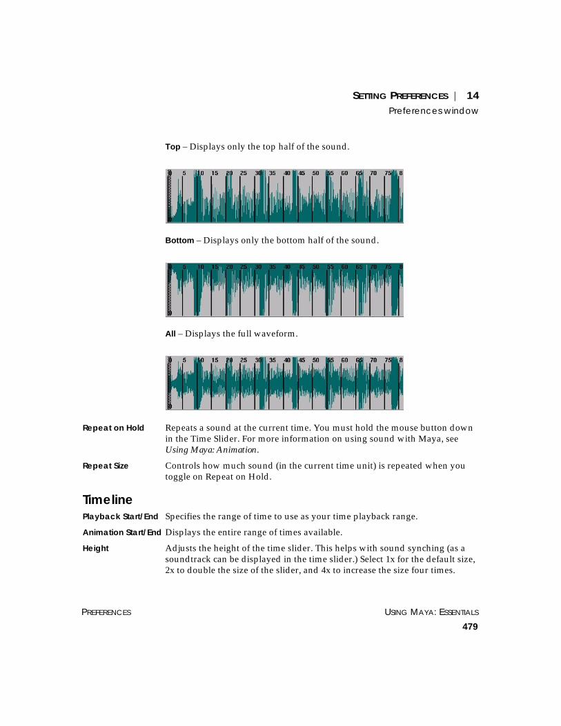
SETTING PREFERENCES | 14Preferences window
PREFERENCES USING MAYA: ESSENTIALS
479
Top – Displays only the top half of the sound.
Bottom – Displays only the bottom half of the sound.
All – Displays the full waveform.
Repeat on Hold Repeats a sound at the current time. You must hold the mouse button downin the Time Slider. For more information on using sound with Maya, seeUsing Maya: Animation.
Repeat Size Controls how much sound (in the current time unit) is repeated when youtoggle on Repeat on Hold.
TimelinePlayback Start/End Specifies the range of time to use as your time playback range.
Animation Start/End Displays the entire range of times available.
Height Adjusts the height of the time slider. This helps with sound synching (as asoundtrack can be displayed in the time slider.) Select 1x for the default size,2x to double the size of the slider, and 4x to increase the size four times.

USING MAYA: ESSENTIALS PART 4
480
SETTING PREFERENCES | 14Preferences window
Key Ticks Keyframe ticks show the location of keys along the time slider. Select Noneto turn the key tick display off, Active to display only active keys, orChannel Box to display only those keys in the Channel Box.
Options Toggle the following options on or off:
Timecode – Changes the default display of time to video standard timecode.Enables the Timecode Offset box so you can supply timecodes to match thetiming from videotape.
Snapping – Toggles key snapping on or off. When on, the time indicatorshows integer values only.
Timecode Offset The Timecode Offset lets you specify how time 0 on the Time Slider appearswhen displaying in Timecode mode. For example, if the Timecode Offset isset to three hours (a value of 03:00:00:00), the Timecode Display would read03:00:00:00 at time 0,
Update View Specifies whether Maya plays back an animation in All modeling views oronly in the active view. The default is Active.
Looping Specifies how you want Maya to play back an animation. Select Once to playan animation once, then stop. Select Oscillate to play an animation forwardsand backwards continuously. Select Continuous to play an animationcontinuously. This is the default setting.
Playback Speed Specifies the frame rate for playback.
Free – Displays all the frames of your animation. Each frame is updatedcompletely before proceeding to the next one. Specify the exact rate in thePlayback by box. This rate reflects your system’s ability to draw youranimation on screen and is not necessarily a real-time playback mode. This isthe default setting.
Normal (24 fps) – Plays your animation in real-time. Some frames may bedropped (not displayed) to execute this in real-time. This depends on yoursystem’s capabilities, the complexity of your scenes, and the display modefor the playback.
Half (12 fps) – Plays back at exactly half the speed of real time.
Twice (48 fps) – Plays back at twice real-time speed.
Other – Enables the Other box so you can enter an exact ratio of playbackrate to real-time.

SETTING PREFERENCES | 14Preferences window
PREFERENCES USING MAYA: ESSENTIALS
481
Playback by If you select Free for the Playback Speed, specify the exact rate in this box.This rate reflects your system’s ability to draw you animation on screen andis not necessarily a real-time playback mode. The default setting is 1.0.
UndoUndo Select On if you want to be able to undo operations. This is the default. See
“Selecting objects” on page 51.
Queue Select Infinite to perform an unlimited number of undo operations. Thisoption uses a lot of memory. Select Finite to limit the number of times youcan perform undo operations (specified in the Queue Size box). The defaultis Finite.
Queue Size If Finite is the selected Queue setting, specify how many times you canperform an undo operation here. The higher the number, the more memoryis needed. The default is 10.
ModulesMaya includes a number of different software modules. Each time you startMaya, the software loads all the available licensed modules.
Disabling packages to free up RAMLoading several modules can use a lot of RAM and thus increase the start-uptime. To avoid this, you can disable one or more of the modules. You canstill load a disabled module by selecting it from the main menu bar.
Disabling modules based on tasksYou can also disable various modules based on the specific tasks you areperforming. For example, if you are only rendering, you can improve systemresponse time by disabling Dynamics.
Note
If you enable or disable a module, you must exit Maya and restart thesoftware for the changes to take effect.

USING MAYA: ESSENTIALS PART 4
482
SETTING PREFERENCES | 14Changing color settings
OpenMayaLoading Controls how plug-ins are loaded. In Lazy Binding mode, references to
functions that cannot be resolved at load time will not be considered anerror. In Bind Now mode, unresolved references do issue an error.
Old Plugin Warning Determines whether or not Maya issues a warning when you load a plug-inthat was compiled against an older, and possibly incompatible, Mayarelease.
CHANGING COLOR SETTINGS
You may want to make certain components stand out from a scene or object.
Changing default colorsYou can change the default colors used by Maya in the Colors window
To open the Colors window:
Select Window > Settings/Preferences > Colors. The Colors window opens.
Tips
Use lighter colors for active components and darker colors for inactivecomponents.
If you have made changes to the color settings for a tool and want torestore the original settings, select Edit > Reset to Factory in the Colorswindow.

SETTING PREFERENCES | 14Changing color settings
PREFERENCES USING MAYA: ESSENTIALS
483
The Colors window has three tabs. Each tab allows you to change the defaultcolors for a different set of components.
General tab Use the General tab to change the default colors for components in theseareas: 3D Views, User Defined, Animation, Animation Editors, Multilister,Hypergraph / Hypershade, and Outliner.
Active tab Use the Active tab to change the default colors for components in theseareas: General, Objects, Components, Deformers, Manipulators, andAnimation.
Inactive tab Use the Inactive tab to set the colors for objects that are not selected. TheInactive tab lets you change the default colors in the following areas or tools:General, Modeling, Objects, Components, Deformers, and Animation.
To change a default color:
1 Open the Color window (Window > Settings/Preferences > Colors) and clickthe appropriate tab (General, Active, or Inactive).
2 Expand the component type for the item you want to change.
3 Click on a component’s color to open the Color Chooser.
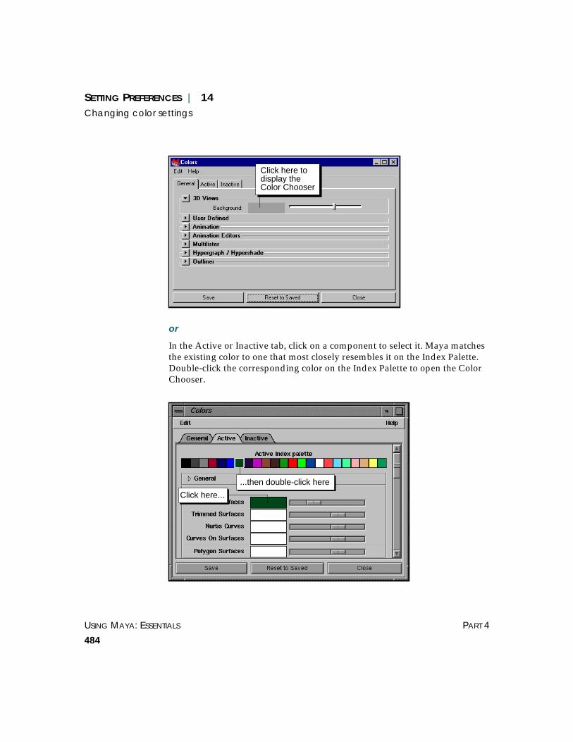
USING MAYA: ESSENTIALS PART 4
484
SETTING PREFERENCES | 14Changing color settings
or
In the Active or Inactive tab, click on a component to select it. Maya matchesthe existing color to one that most closely resembles it on the Index Palette.Double-click the corresponding color on the Index Palette to open the ColorChooser.
Click here todisplay theColor Chooser
Click here...
...then double-click here

SETTING PREFERENCES | 14Specifying tool settings
PREFERENCES USING MAYA: ESSENTIALS
485
4 Select the color in the Color Chooser. See “Using the Color Chooser” on page276.
SPECIFYING TOOL SETTINGS
Tool settings determine how a tool behaves. For example, if you are usingthe EP Curve Tool, you can specify whether the knot spacing is uniform orchord length.
To change a tool’s settings:
1 Do one of the following to open the Tool Settings window:
If the tool is represented by an icon on the Minibar, double-click on it withthe left mouse button.
or
If the tool is in a menu, select the check box (❐) located beside the tool.
or
Select the tool and then select Window > Settings/Preferences > ToolSettings.
2 Make the desired changes and click Close.
To return to a tool’s default settings:
In the Tool Settings window, click Reset Tool.
Duplicating a toolUsing shelves, you can have two tools with the same name but different toolsettings. For example, you can have two versions of the Particle Tool.
Note
You can change the color value in the Colors window by dragging theslider beside the component color.

USING MAYA: ESSENTIALS PART 4
486
SETTING PREFERENCES | 14Specifying tool settings
To duplicate a tool:
1 Select the shelf that will contain the new version of the tool.
2 Select the tool that you want to duplicate.
3 Using the middle mouse button, drag the tool icon from the Minibar to theshelf.
4 Select the new version of the tool on the shelf and open the Tool Settingswindow (Window > Settings/Preferences > Tool Settings).
5 Change the tool settings.
To test whether Maya saved the settings for each tool, select the original tooland check the settings in the Tool Settings window. Leave the Tool Settingswindow open and select the new tool on the shelf and check the settings.
6 Click Close.
Tips
You cannot change the name of the tool using the Tool Settings window. Ifyou want to change the name of the tool, see “Changing icon labels” onpage 504.
To remove an icon from a shelf, drag it to the garbage can.
Note
When you drag a tool from the Minibar to the Shelf, a copy of the tool ismade. If you use Ctrl-Shift to place a menu item that selects a tool on theshelf, Maya does not place a copy of a tool on the Shelf. Instead, only theaction that invokes the original tool is placed on the Shelf. For moreinformation on adding tools and actions to a shelf, see “Creating andediting shelves” on page 493.

SETTING PREFERENCES | 14Specifying performance settings
PREFERENCES USING MAYA: ESSENTIALS
487
SPECIFYING PERFORMANCE SETTINGS
You use the Performance Settings window to set when you want to refreshthe screen when manipulating objects and to control complex operations,such as stitching and deformation. You can use the performance settings tosuspend these complex operations during mouse interaction or tocompletely disable them. This improves performance by reducing theamount of evaluation necessary during interaction and playback.
To specify performance settings:
Select Window > Settings/Preferences > Performance Settings. ThePerformance Settings window opens.

USING MAYA: ESSENTIALS PART 4
488
SETTING PREFERENCES | 14Specifying performance settings
Selecting screen refresh options
To set when to refresh (or redraw the screen) when manipulating objects, inthe Dependency Graph Evaluation section, select one of the following:
Drag Refreshes the display during the drag.
Demand Refreshes the display only when you release the mouse button and click theRefresh button that appears in the bottom right of the display window.
Release Refreshes the display only when you release the mouse button.
Controlling complex operations on surfaces
To control complex operations on surfaces during mouse interaction, in theSurfaces section, select one of the following beside the surface:
On Performs complex operations during mouse interactions.
Off Completely disables complex operations during mouse interaction.
Interactive Suspends complex operations during mouse interaction.
Controlling complex operations on deformers
To control complex operations on deformers during mouse interaction, inthe Deformers section, select one of the following beside the surface:
On Performs complex operations during mouse interactions.
Off Completely disables complex operations during mouse interaction.
Interactive Suspends complex operations during mouse interaction.
Per Node For Cluster Resolution and Lattice Resolution only, improves redrawperformance for individual cluster or lattice deformations by setting the UsePartial Resolution attribute to partial and setting the Percent Resolution on aper node basis. For details, see Using Maya: Character Setup.
Global For Cluster Resolution and Lattice Resolution only, improves the redrawperformance of all cluster or lattice deformations. (You do not need to set thePercent Resolution for each cluster or lattice.)
Set Global Cluster Resolution and Global Lattice Resolution to Full, High,Medium, or Low. A Low setting corresponds to a low percentage, andtherefore more improved performance.

SETTING PREFERENCES | 14Loading and unloading plug-ins
PREFERENCES USING MAYA: ESSENTIALS
489
For more information on surfaces, see Using Maya: NURBS Modeling andUsing Maya: Polygonal Modeling. For more information on deformers, seeUsing Maya: Character Setup.
LOADING AND UNLOADING PLUG-INS
A plug-in is an add-on module that extends Maya’s capabilities. Filetranslators are plug-ins you use to import and export various file formats.You can create or purchase specialty plug-ins to customize Maya for aspecific job.
Some features that can be added through plug-ins are:
• file translators
• tools
• objects (nodes)
• MEL commands
• device drivers
The Plug-in Manager identifies which plug-ins are loaded into Maya. If youhave a plug-in that you use frequently, you can make sure it is always there.The Plug-in Manager automatically scans all the directories in the plug-inpath and lists available plug-in features.
Loading plug-insYou can manually load plug-ins each time you run Maya, or you can havethem load automatically when you start Maya.
To load a plug-in:
Select Window > Settings/Preferences > Plug-in Manager. The Plug-InManager window opens.

USING MAYA: ESSENTIALS PART 4
490
SETTING PREFERENCES | 14Loading and unloading plug-ins
Selecting loading options
Toggle the appropriate option beside the plug-in.
loaded Toggle on loaded to load the plug-in for the current Maya session.
auto load Toggle on auto load to load the plug-in so that the next time you start Mayathe plug-in loads automatically.
Displaying plug-in informationTo view information about a particular plug-in, you must first load it, thenclick the i button beside the plug-in.
Click here to loadthe plug-in
Click here to enablethe auto load feature

SETTING PREFERENCES | 14Loading and unloading plug-ins
PREFERENCES USING MAYA: ESSENTIALS
491
Maya displays the following information for a selected plug-in:
Name The name of the plug-in. On IRIX, plug-ins have the extension .so. On NT,they have the extension .mll.
Path The location of the file. On IRIX, the default plug-in location is /usr/aw/maya3.0/bin/plug-ins. On NT, the default plug-in location isdrive:\aw\maya3.0\bin\plug-ins.
Vendor The manufacturer of the plug-in.
Plug-in Version The version number of the plug-in.
For API Version The version of the Maya API (Application Programmer Interface) the plug-inwas compiled for.
Click here to displayinformation on the plug-in

USING MAYA: ESSENTIALS PART 4
492
SETTING PREFERENCES | 14Loading and unloading plug-ins
Auto Load Indicates whether the plug-in has been marked for auto load.
Is Loaded Indicates whether the plug-in is loaded.
Plug-in Features Displays a list of the features added by the plug-in (for example, commands,dependency nodes, file translators).
To display additional plug-ins, click the triangle to open the OtherRegistered Plug-ins section.
Unloading a plug-inYou can unload a plug-in when you finish with it. To unload a plug-in,toggle off the loaded box next to it.
If you are developing a plug-in, unload it so the source code can be changed,the plug-in recompiled, and then reloaded.
Removing references to the plug-in
Before you can unload a plug-in, you must first remove all references to itfrom the Maya scene. Otherwise, Maya converts the plug-in nodes tounknown nodes. For example, if you load a shader plug-in and then unloadthat same shader plug-in without first removing the special shader node andall of its references in the scene, Maya will display an error message the nexttime you open that scene.
If you try to unload a plug-in while it is in use, a warning message willdisplay. You can then cancel the unload or force it.
If you force the unload of a plug-in while it is in use, you cannot reload thatplug-in’s node. Maya converts the existing nodes to unknown nodes. Whenyou reload plug-ins, you cannot change the type of these existing unknownnodes.
Note
You cannot load a plug-in for any version of Maya that predates theversion it was compiled for.
USING MAYA: ESSENTIALS
493
15 CUSTOMIZING SHELVES,MARKING MENUS, ANDHOTKEYS
This chapter provides detailed information about Maya’s shelves, markingmenus, and hotkeys. This information is for advanced users.
Shelves are user-customizable areas to hold the actions and tools you usemost often. Marking menus are an innovative way of selecting various menuitems with the right mouse button. Hotkeys are keyboard shortcuts forcommands.
This chapter describes the following topics:
• “Creating and editing shelves” on page 493
• “Creating and editing marking menus” on page 509
• “Assigning hotkeys” on page 526
CREATING AND EDITING SHELVES
You use shelves to put all the tools or action icons you use in one place. Youcan drag tools, options, and actions onto a shelf from the Minibar, a menu, orthe Script Editor.
From the Maya main window, you can perform the following tasks:
• add shelf items (see “Adding shelf items” on page 498)
• remove shelf items (see “Removing shelf items” on page 499)
• move and copy shelf items (see “Moving and copying shelf items” on page500)

USING MAYA: ESSENTIALS PART 4
494
CUSTOMIZING SHELVES, MARKING MENUS, AND HOTKEYS | 15Creating and editing shelves
You can use the Shelves window to:
• create and delete shelves (see “Creating and deleting shelves” on page 495and “Reordering the shelves” on page 501)
• change shelf icons (see “Changing shelf icons” on page 502)
• change icon labels (see “Changing icon labels” on page 504)
• add overlay labels (see “Setting Shelf label options” on page 506)
• change MEL commands associated with an icon (see “Changing MELcommand(s) associated with an icon” on page 507)
To open the Shelves window:
Select Window > Settings/Preferences > Shelves.
Shelves Click the Shelves tab to display existing shelves. From here you can createand delete shelves and change their order. For details, see “Creating anddeleting shelves” on page 495 and “Reordering the shelves” on page 501.
Shelf Contents Click the Shelf Contents tab to display the contents of a specific shelf. Fromhere you can move and delete shelf items, change an item’s label and changeits icon. For details, see “Changing shelf icons” on page 502, “Changing iconlabels” on page 504, “Setting Shelf label options” on page 506, “Changingshelf icons” on page 502.

CUSTOMIZING SHELVES, MARKING MENUS, AND HOTKEYS | 15Creating and editing shelves
PREFERENCES USING MAYA: ESSENTIALS
495
Edit Commands Click the Edit Commands tab to view and edit the MEL code associated witha tool or action. For details, see “Changing MEL command(s) associated withan icon” on page 507.
Label Specify a brief description of the tool. This description appears with the iconin the icon or text modes. For details, see “Changing icon labels” on page504. (Where it appears is determined by Options menu settings. For details,see “Setting Shelf label options” on page 506).
Overlay Label Type a label for the icon. This text appears on top of the icon to distinguish itfrom other items that use the same icon. For details, see “Setting Shelf labeloptions” on page 506.
Save All Shelves Click Save All Shelves to save all changes immediately and write theinformation to the user shelves directory. The file name for a shelf file hasthe prefix shelf_.
Close Click Close to accept your changes but not write them to the diskimmediately. If your UI preference is to save shelf changes only whenexplicitly requested, the changes will stay in effect only for the currentsession. Otherwise your changes will be saved the next time you save a fileor quit the application. For information on changing this preference, see“Setting Shelf label options” on page 506.
Creating and deleting shelvesIn addition to using the default shelves, you can create custom shelves. Usecustom shelves to group common or frequently used tools, menucommands, or MEL commands for easy access.
To create a shelf:
1 Open the Shelves window (Window > Settings/Preferences > Shelves) andclick the Shelves tab. Maya displays the names of all existing shelves.
2 Click New Shelf. Maya displays a default name for the new shelf in theName box and adds a new shelf tab in the main Maya window.

USING MAYA: ESSENTIALS PART 4
496
CUSTOMIZING SHELVES, MARKING MENUS, AND HOTKEYS | 15Creating and editing shelves
3 Double-click in the Name box or press the Tab key to select the text in theName box.
4 Type the new shelf name (for example, Kinematics), then press Enter. Mayaadds the name of the new shelf to the Shelves window and the Mayawindow.
Default namefor new shelf
Default namefor new shelf

CUSTOMIZING SHELVES, MARKING MENUS, AND HOTKEYS | 15Creating and editing shelves
PREFERENCES USING MAYA: ESSENTIALS
497
5 Click Save All Shelves or Close.
To delete a shelf:
1 Open the Shelves window (Window > Settings/Preferences > Shelves) andclick the Shelves tab. Maya displays all existing shelves.
2 Select the shelf you want to delete, then click the Delete Shelf button. (Youdo not have to delete any of the associated icons before deleting the shelf.)
You are prompted to confirm the deletion.
3 Click OK. Maya removes the shelf from the list of existing shelves and fromthe Maya window.
Name of thenew shelf

USING MAYA: ESSENTIALS PART 4
498
CUSTOMIZING SHELVES, MARKING MENUS, AND HOTKEYS | 15Creating and editing shelves
Adding shelf itemsYou can add menu commands, MEL commands, and tools to shelves fromthe Minibar, a menu, or the Script Editor.
You can also save multiple versions of the same tool to the shelf withdifferent settings. For example, add a Sculpt Surfaces Tool with the Pushoption selected and another Sculpt Surfaces Tool with the Pull operationselected.
To add a tool from the Minibar:
Using the middle mouse button, drag the tool to the shelf.
This creates an editable tool on the shelf. If you select this tool from the shelfand change any settings in the Tool Settings window, the settings for theshelf item also change. These new settings become the default for the shelftool.
Note
You cannot undo a delete command. However, Maya retains the shelfinformation in the file shelf_NAME.mel.deleted in the user shelvesdirectory:
~username/maya/3.0/prefs/shelves (IRIX)drive:\WINNT\Profiles\username\maya\3.0\prefs\shelves (NT)drive:\Documents and Settings\username\maya\3.0\shelves (2000)
So if you want to restore a deleted shelf, rename the file toshelf_NAME.mel, then restart Maya.
CUSTOMIZING SHELVES, MARKING MENUS, AND HOTKEYS | 15Creating and editing shelves
PREFERENCES USING MAYA: ESSENTIALS
499
To add a menu item to a shelf:
Press Ctrl-Shift-Alt (IRIX), Ctrl-Shift (NT), then select the item from theappropriate menu. Maya places the item on the shelf. This adds the base toolto the shelf. Any changes you make to the tool settings will be reflected inthe shelf tool also.
To add a MEL command to a shelf from the Script Editor:
1 In the Script Editor (Windows > General Editors > Script Editor), highlightthe MEL command text that you want to add to a shelf.
2 Using the middle mouse button, drag the selected text to the shelf andrelease. This places a MEL icon on the shelf. When you click the icon, Mayaruns the command(s).
For example:
1 Open the Script Editor window (Windows > General Editors > Script Editor).
2 In the Modeling menu set, select Create > NURBS Primitives > Sphere. Asphere appears at the origin.
3 Select the Move tool and drag a manipulator arrow to move the sphere.
The MEL command move -r 5.315 0 0; ( with your own coordinates), appearsin the upper pane of the Script Editor.
4 Highlight the MEL command text in the upper pane of the Script Editor.
5 Using the middle mouse button, drag the selected text to the shelf andrelease. This places a MEL icon on the shelf. When clicked, the icon executesthe move -r 5.315 0 0; command again.
Removing shelf itemsThere are two ways you can delete a shelf item. You can use the middlemouse button to drag items to the garbage can directly on the shelf or youcan use the Shelves window.
To remove a shelf item directly from a shelf.
Use the middle mouse button to drag the icon to the garbage can.

USING MAYA: ESSENTIALS PART 4
500
CUSTOMIZING SHELVES, MARKING MENUS, AND HOTKEYS | 15Creating and editing shelves
Maya removes the tool or action icon from the shelf tab.
To remove a shelf item using the Shelves window:
1 Open the Shelves window (Window > Settings/Preferences > Shelves).
2 Click the Shelves tab, then select the shelf containing the tool or action youwant to delete. The selected shelf becomes active in the main Maya window.
3 Click the Shelf Contents tab.
4 Select the description of the icon you want to delete, then click Delete Item.Maya removes the icon from the shelf.
5 Click Save All Shelves or Close.
Moving and copying shelf itemsYou can move shelf items to change the order they appear and you canmove shelf items between shelf tabs.
You can also copy shelf items. For example, you can add the same tool to ashelf more than once, but with different settings. The original tool must havebeen added to the shelf from the Minibar (see “To add a tool from theMinibar:” on page 498).
To change the order of shelf items:
• On the shelf, use the middle mouse button to drag the icon to the desiredposition.
or
1 Open the Shelves window (Window > Settings/Preferences > Shelves) andclick the Shelf Contents tab.
2 Select the item you want to move and click the Move Up or Move Downbutton until the item appears where you want it to appear.
3 Click Save All Shelves or Close.

CUSTOMIZING SHELVES, MARKING MENUS, AND HOTKEYS | 15Creating and editing shelves
PREFERENCES USING MAYA: ESSENTIALS
501
To move an item between shelf tabs.
1 Use the middle mouse button to drag the icon onto the other shelf tab. Theicon is removed from the current shelf.
2 Click the shelf tab on which you dropped the icon. The icon is visible on thenew shelf.
To copy an existing item on the shelf.
Press the Ctrl key and use the middle mouse button to drag the icon to itsnew position. A copy of the icon appears on the shelf.
Renaming shelvesYou can change the name of a shelf at any time to something moremeaningful (for example from ShelfLayout1 to Dynamics).
To rename a shelf:
1 Open the Shelves window (Window > Settings/Preferences > Shelves) andclick the Shelves tab.
2 Select the shelf you want to rename. Maya displays the name of the selectedshelf in the Name box.
3 In the Name box, double-click on the name of the shelf.
4 Change the name, then press Enter. Maya displays the new name in the listof existing shelves and in the Maya window.
You cannot use spaces or special characters (for example, !,@,#,$,%) in shelfnames.
5 Click Save All Shelves or Close.
Reordering the shelvesYou can reorder the shelves that you use frequently. This is especiallyhelpful if you have more shelves than Maya can display at once.
To reorder the shelves:
1 Open the Shelves window (Window > Settings/Preferences > Shelves) andclick the Shelves tab. Maya displays all available shelves in the order theyappear in the Maya window.

USING MAYA: ESSENTIALS PART 4
502
CUSTOMIZING SHELVES, MARKING MENUS, AND HOTKEYS | 15Creating and editing shelves
2 Select the shelf you want to move, then click the Move Up or Move Downbutton until the selected shelf appears where you want it to appear.
3 Click Save All Shelves or Close.
Changing shelf iconsOn IRIX, Maya uses xpm (IRIX) images for the shelf button icons. Maya NTuses bitmap (bmp) images and xpm images. You can assign a new image toa shelf button to more accurately reflect the button’s function. If you want touse an icon design other than a Maya default images, you must create yourown image file. You cannot modify Maya’s default shelf button icons.
To create a new icon image
Use any available 2D image program to create new image files. The imagefile size must be 32 x 32 pixels to fit within the shelf button. Typically, youplace the image in your user icons directory:
~username/maya/3.0/prefs/icons (IRIX)drive:\WINNT\Profiles\username\maya\3.0\prefs\icons (NT)drive:\Documents and Settings\username\maya\3.0\prefs\icons (2000)

CUSTOMIZING SHELVES, MARKING MENUS, AND HOTKEYS | 15Creating and editing shelves
PREFERENCES USING MAYA: ESSENTIALS
503
If you use a different directory, you should specify it in theXBMLANGPATH environment variable. See Chapter 8, “SettingEnvironment Variables.”
To change an icon’s image:
1 Open the Shelves window (Window > Settings/Preferences > Shelves) andclick the Shelves tab.
2 Select the shelf containing the tool you want to change.
3 Click the Shelf Contents tab.
4 Select the description of the shelf item you want to change, then click theChange Image button. A file browser window opens with the imagesdirectory selected.
On IRIX, the browser is called the Pixmap Selector. The browser defaults to/usr/aw/maya3.0/icons, the location of Maya’s default icons.
On NT, the default icons are stored in drive:\AW\Maya3.0\extras\icons.
5 Select a Maya default image or navigate to a new user-created image (it musthave the file extension .xpm or .bmp).
Description of icon
Tool’s icon
USING MAYA: ESSENTIALS PART 4
504
CUSTOMIZING SHELVES, MARKING MENUS, AND HOTKEYS | 15Creating and editing shelves
6 On IRIX, click Apply to see your change in the main Maya window withoutclosing the Pixmap Selector. Click Done to apply your change and close thePixmap Selector.
On NT, click Open.
7 Click Save All Shelves or Close.
Changing icon labelsYou can change the label of a tool or action icon if you:
• Want to make it more indicative of the function it performs.
• Have changed the options and want to change the name to reflect changes.
For example, if you modify a copy of the sphere action so that it now createsa hemisphere, you can change both the label and icon to reflect this change.
Note
Maya stores the image as a reference file. If you move it, you must specifythe new location by using the Shelves editor or by setting theXBMLANGPATH variable.
Note
On IRIX, you can modify existing images and create new ones from thePixmap Selector.
To modify an existing image (but not a Maya default shelf button icon),select it and click the Modify button to launch the xpaint application. Makeyour changes and save them.
To create a new image, click the New button, type a name for the new file,then click OK to create a blank image in the icons directory. Select the newimage and modify it.

CUSTOMIZING SHELVES, MARKING MENUS, AND HOTKEYS | 15Creating and editing shelves
PREFERENCES USING MAYA: ESSENTIALS
505
To change an icon’s label:
1 Open the Shelves window (Window > Settings/Preferences > Shelves) andclick the Shelves tab
2 Select the shelf that contains the icon you want to rename. The selected shelfbecomes active in the main Maya window.
3 Click the Shelf Contents tab, then click the name of the icon you want torelabel.
4 Enter the new name of the icon in the Label box, then press Enter.
Maya changes the tool name in the Shelves window and on the shelf in themain Maya window.
Note
Before you start, select Window > UI Preferences and click the Shelf tab.Click Icon/Text Below. This displays descriptive text below the icon.
New name ofthe Sphereaction

USING MAYA: ESSENTIALS PART 4
506
CUSTOMIZING SHELVES, MARKING MENUS, AND HOTKEYS | 15Creating and editing shelves
5 Click Save All Shelves.
When you move the cursor over the renamed icon, Maya displays the newname on the Help Line and in the popup help.
Setting Shelf label optionsUse the Options menu in the Shelves window to specify the appearance ofthe Shelf labels options.
Icon Only Displays only the icon.
Icon/Text Below Displays descriptive text below the icon.
Icon/Text Beside Displays descriptive text beside the icon.
Note
To change the overlay label of the tool, see “Setting Shelf label options” onpage 506.

CUSTOMIZING SHELVES, MARKING MENUS, AND HOTKEYS | 15Creating and editing shelves
PREFERENCES USING MAYA: ESSENTIALS
507
Adding overlay labelsMaya uses families of icons to represent related tools and actions.
You can create an overlay label to distinguish individual icons. For example,if you have several MEL command icons on your shelf, they all look thesame because they all use the same default icon. You can use overlay labelsto distinguish between these MEL buttons as shown in this illustration.
You use the Shelves window to assign an overlay label to a tool or action.
To assign an overlay label to an icon:
1 Select Option > Settings/Preferences > Shelves and click the Shelves tab.
2 Select the shelf containing the tool you want to rename. The selected shelfbecomes active in the main Maya window.
3 Click the Shelf Contents tab, then select a tool or action.
4 Enter the label in the Overlay Label box, then press Enter. Maya adds anoverlay label in the shelf.
5 Click Save All Shelves.
Changing MEL command(s) associated with an iconAll actions on the shelf consist of a single or series of MEL commands. Youcan change these commands to change the behavior of the action.
In the following example, we modify the MEL code for a move command tochange the action’s behavior.
To modify an action’s MEL code:
1 Open the Shelves window (Window > Settings/Preferences > Shelves) andclick the Shelves tab.
Overlay label on aMEL command icon

USING MAYA: ESSENTIALS PART 4
508
CUSTOMIZING SHELVES, MARKING MENUS, AND HOTKEYS | 15Creating and editing shelves
2 Select the shelf containing the item you want to edit. The selected shelfbecomes active in the main Maya window.
3 Click the Shelf Contents tab and select the item you want to edit.
4 Click the Edit Commands tab. The commands for the shelf item appear inthe text area.
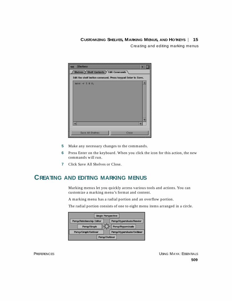
CUSTOMIZING SHELVES, MARKING MENUS, AND HOTKEYS | 15Creating and editing marking menus
PREFERENCES USING MAYA: ESSENTIALS
509
5 Make any necessary changes to the commands.
6 Press Enter on the keyboard. When you click the icon for this action, the newcommands will run.
7 Click Save All Shelves or Close.
CREATING AND EDITING MARKING MENUS
Marking menus let you quickly access various tools and actions. You cancustomize a marking menu’s format and content.
A marking menu has a radial portion and an overflow portion.
The radial portion consists of one to eight menu items arranged in a circle.

USING MAYA: ESSENTIALS PART 4
510
CUSTOMIZING SHELVES, MARKING MENUS, AND HOTKEYS | 15Creating and editing marking menus
Each menu item represents a command you have added to that markingmenu. You can use the Marking Menus window to add, change, or delete amenu item or command. For more information on using the Marking Menuswindow, see “Modifying existing marking menus” on page 516.
The overflow portion (or linear portion) has one or more menu items. Theoverflow items are arranged in a column below the radial items.
Marking menus can be hierarchal. In other words, any menu item can have asubmenu.
You can use the Marking Menus window to:
• create marking menus (see “Creating marking menus” on page 511)
• attach a marking menu to a hotkey (see “Assigning marking menus tohotkeys” on page 515)
• modify existing marking menus (see “Modifying existing marking menus”on page 516)
• add submenus to marking menu items (see “Adding submenus to menuitems” on page 520)
• add MEL scripts to marking menus (see “Associating a MEL script with amenu item” on page 522)
• delete marking menus (see “Deleting marking menus” on page 523)
To display the Marking Menus window:
Select Window > Settings/Preferences > Marking Menus.
Note
Each menu and submenu can contain a maximum of 38 menu items.

CUSTOMIZING SHELVES, MARKING MENUS, AND HOTKEYS | 15Creating and editing marking menus
PREFERENCES USING MAYA: ESSENTIALS
511
Creating marking menusYou can modify the default marking menus or use the Marking Menuswindow to create new marking menus.
You can add the following items to marking menus:
• text from the Script Editor
• tool icons and action icons from a shelf
• the Select, Translate, Rotate, Scale, and Show Manipulator icons in theMinibar
You can associate your marking menu with a zone or mouse button in theHotbox, or a specific hotkey to the marking menu.
The Hotbox can support a different menu for each mouse button in each ofthe Hotbox’s five zones. You can create three menus per zone, for a total of15 marking menus (3 menus x 5 zones) with eight commands per markingmenu. This gives you approximately 120 total commands (3 menus x 5 zonesx 8 commands).
Marking menu defaults Zone Associated mouse buttons

USING MAYA: ESSENTIALS PART 4
512
CUSTOMIZING SHELVES, MARKING MENUS, AND HOTKEYS | 15Creating and editing marking menus
To create a marking menu:
1 Select Window > Settings/Preferences > Marking Menus. The MarkingMenus window opens.
2 Click Create Marking Menu. The Create Marking Menu window opens.
3 Use the middle mouse button to drag tools or actions to the Create MarkingMenu window.
Place tool or actionicons here
Enter name of themarking menu

CUSTOMIZING SHELVES, MARKING MENUS, AND HOTKEYS | 15Creating and editing marking menus
PREFERENCES USING MAYA: ESSENTIALS
513
For example, to add the Add Points tool, select (from the Modeling menuset) Edit Curves > Add Points Tool. The tool displays in the minibar. Usingthe middle mouse button, drag the Add Points tool from the minibar to theCreate Marking Menu window.
4 Repeat step 3 for any additional tools.
Note
You can also add MEL commands to the Marking Menus window. Fordetails, see “Associating a MEL script with a menu item” on page 522.
Tips
To delete an icon, place the pointer on the icon, press the right mousebutton, and select Delete Menu Item.
To create a submenu, see “Adding submenus to menu items” on page 520.This is useful if you want to increase the number of menu items you canaccess from a marking menu.

USING MAYA: ESSENTIALS PART 4
514
CUSTOMIZING SHELVES, MARKING MENUS, AND HOTKEYS | 15Creating and editing marking menus
5 Enter the name of the new menu in the Menu Name box.
6 To move a tool’s position, use the middle mouse button to drag the icon to anew position within the Create Marking Menu window.
7 When you are satisfied with the position of every tool in the marking menu,click Save and close the Create Marking Menu window.
8 Set the following options and click Apply Settings, then Close.
Tip
If a tool has an option box, you can make changes to the options.
Click here totest the markingmenu format
Enter name of thenew menu here
Click here to changethe tool’s options

CUSTOMIZING SHELVES, MARKING MENUS, AND HOTKEYS | 15Creating and editing marking menus
PREFERENCES USING MAYA: ESSENTIALS
515
Use Marking Menu in
Specify whether the marking menu is linked to the Hotbox or a hotkey. Forinformation on linking a marking menu to a hotkey, see “Assigning markingmenus to hotkeys” on page 515.
Hotbox region If you selected Hotbox for Use Marking Menu in, select the Hotbox zone themarking menu occupies: North, South, East, West, or Center.
Mouse button(s) Select the left, middle, or right mouse button used to display the markingmenu. You can select one, two, or three mouse buttons.
Assigning marking menus to hotkeysIn addition to adding or customizing marking menus in the Hotbox, you canassign a marking menu to a specific hotkey. Each time you press the hotkeyand the left mouse button, the associated marking menu appears. Forexample, the q key is associated with the Select marking menu.
You display marking menus by pressing the left mouse button and theappropriate hotkey. The following hotkeys bring up marking menus.
Note
A marking menu/hotkey combination will not work in a tear-off window.
Hotkey Action on Marking Menu
a Select All History, Disable All Future, Select All Future, andEnable All Future
d High, Medium, and Low Quality Display
e Rotate X, Y, and Z

USING MAYA: ESSENTIALS PART 4
516
CUSTOMIZING SHELVES, MARKING MENUS, AND HOTKEYS | 15Creating and editing marking menus
For more information on setting hotkeys, see “Assigning hotkeys” on page526.
Modifying existing marking menusUse the Edit Marking Menu button in the Marking Menus window tomodify existing marking menus. You can add, edit, or delete individualmenu items in a marking menu.
You can also add submenus to add more tools and actions to a markingmenu. For details, see “Adding submenus to menu items” on page 520.
Each icon in the Edit Marking Menu window corresponds to a menu item ina marking menu.
For information on adding menu items to an existing marking menu, see“Creating marking menus” on page 511.
h Modeling, Animation, Dynamics, Rendering
q Select Mask (see previous illustration)
r Scale X, Y, Z and Scale XYZ
w Translate X, Y, Z and Translate XYZ
Hotkey Action on Marking Menu

CUSTOMIZING SHELVES, MARKING MENUS, AND HOTKEYS | 15Creating and editing marking menus
PREFERENCES USING MAYA: ESSENTIALS
517
To delete a menu item:
1 Open the Marking Menus window (Window > Settings/Preferences > Marking Menus).
2 Select an existing marking menu.
3 Click Edit Marking Menu. The Edit Marking Menu appears with each iconcorresponding to a menu item.
4 Right-click on the menu icon you want to delete and select Delete Menu Itemfrom the pop-up menu.

USING MAYA: ESSENTIALS PART 4
518
CUSTOMIZING SHELVES, MARKING MENUS, AND HOTKEYS | 15Creating and editing marking menus
5 Select Save or Close.
To edit a menu item:
1 Open the Edit Marking Menu window.
2 Right click on the menu icon you want to edit and select Edit Menu Itemfrom the pop-up menu.
The Edit window appears according to the position of the icon (for example,Edit North, Edit North East, Edit East, Edit South East, Edit South, etc.).

CUSTOMIZING SHELVES, MARKING MENUS, AND HOTKEYS | 15Creating and editing marking menus
PREFERENCES USING MAYA: ESSENTIALS
519
3 Set the following options, Click Save and Close or Close, then close the EditMarking Menu window.
Label Enter the name of the marking menu item.
Icon Filename Enter the name of the icon file. For more information, see Using Maya: MEL.
Command(s) Enter the MEL script used as the command for the menu item. You can dragthe MEL script from the Script Editor’s bottom panel with the middle mousebutton.
Check Box Displays a check box beside the marking menu item.
Radio Button Displays a toggle box beside the marking menu item.
Neither Displays nothing beside the marking menu item.
Option Box Toggle Option Box on to display the option box ❐ beside the menu item soyou can change a tool’s options from the marking menu. For moreinformation, see “Specifying tool settings” on page 248.

USING MAYA: ESSENTIALS PART 4
520
CUSTOMIZING SHELVES, MARKING MENUS, AND HOTKEYS | 15Creating and editing marking menus
Option Box Command(s)
Enter the MEL script to use as the command for the menu item’s option box.
Adding submenus to menu itemsLike the main pull-down menus, menu items in a marking menu can havesubmenus. These submenus let you add extra tools and actions to a markingmenu.
In the following example, there are four menu items associated with onesubmenu.
Note
If the tool or action does not have an options window, you must use MELcode to create the box. Once the box is created, you must write MEL codeto invoke the option window. For more information on MEL commands,see Using Maya: MEL.
Note
If you create submenus under an overflow menu item, the submenuscannot contain any radial items.

CUSTOMIZING SHELVES, MARKING MENUS, AND HOTKEYS | 15Creating and editing marking menus
PREFERENCES USING MAYA: ESSENTIALS
521
Adding a submenu:
In the following example, a submenu is associated with an icon.
1 Open the Marking Menus window (Window > Settings/Preferences > Marking Menus).
2 Select the marking menu that has the menu item you want to add asubmenu to.
3 Click Edit Marking Menu.
4 Position the cursor on the icon you want to add a submenu to.
5 Press the right mouse button and select Popup Submenu from the pop-upmenu. The icon changes shape indicating that a submenu is associated withit and the Submenu Editor dialog opens.
6 Using the middle mouse button, drag tools or actions to the SubmenuEditor.
7 Close the Submenu Editor window.
8 To test the submenu, click in the Click Here to Test box.
Menu item iconchanges to this

USING MAYA: ESSENTIALS PART 4
522
CUSTOMIZING SHELVES, MARKING MENUS, AND HOTKEYS | 15Creating and editing marking menus
9 Click Save or Close.
Associating a MEL script with a menu itemIf you have written a script to perform a particular task, you can associate itwith a menu item in a marking menu. In the following example a MEL scriptis added to an existing marking menu.
To associate a script with an menu item:
1 Open the Marking Menus window (Window > Settings/Preferences > Marking Menus).
2 Select the marking menu that has the menu item you want to add asubmenu to and click Edit Marking Menu.
or
Click Create Marking Menu to create a new marking menu. For moreinformation, see “Creating marking menus” on page 511.
3 Open the Script Editor (Window > General Editors > Script Editor).
4 With the left mouse button, highlight the MEL script you want to associatewith a marking menu.
5 Press and hold the middle mouse button over the highlighted text. An iconappears.

CUSTOMIZING SHELVES, MARKING MENUS, AND HOTKEYS | 15Creating and editing marking menus
PREFERENCES USING MAYA: ESSENTIALS
523
6 Using the middle mouse button, drag the icon to the marking menu’s menuitem in the Edit or Create Marking Menu window.
7 Place the cursor over the new MEL icon and use the right mouse button toselect Edit Menu Item.
8 Assign a label for the menu item.
For more information, see “Modifying existing marking menus” on page516.
Deleting marking menusYou can use the Marking Menus window to delete marking menus. Whenyou delete a marking menu you can create a backup file which allows you torestore the menu.
To delete a marking menu:
1 Open the Marking Menus window (Window > Settings/Preferences > Marking Menus).
2 Select the marking menu, then click Delete Marking Menu. The followingdialog appears.
Icon representing theMEL script

USING MAYA: ESSENTIALS PART 4
524
CUSTOMIZING SHELVES, MARKING MENUS, AND HOTKEYS | 15Creating and editing marking menus
3 If you want to delete the marking menu but keep a backup copy of it, selectCreate Backup.
Maya stores the backup file in the user prefs directory with a file extensionof .bak. For information on how to recover the marking menu, see “Torestore a marking menu backup:” on page 524.
or
If you want to delete the marking menu without creating a backup file, clickDo Not Backup.
Maya removes the marking menu from the Marking Menus window.
4 Click Close.
To restore a marking menu backup:
Note
You cannot recover a marking menu after you select Do Not Backup.
Note
You must exit Maya before restoring a deleted marking menu.
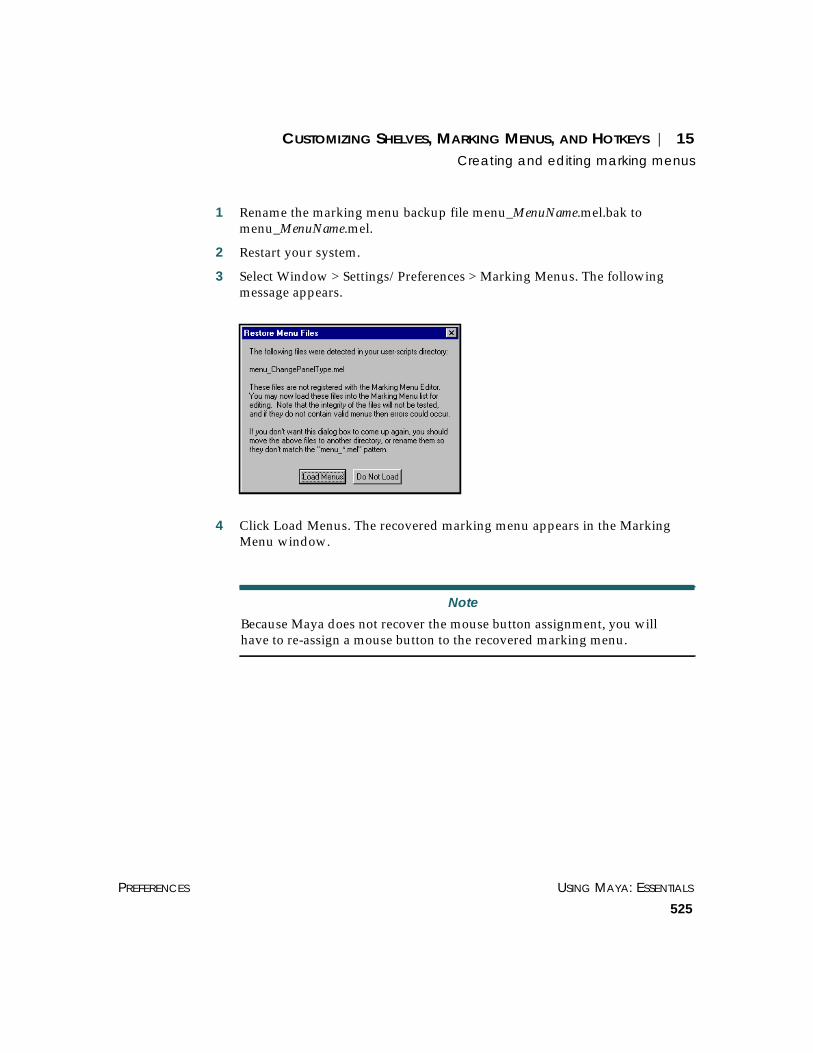
CUSTOMIZING SHELVES, MARKING MENUS, AND HOTKEYS | 15Creating and editing marking menus
PREFERENCES USING MAYA: ESSENTIALS
525
1 Rename the marking menu backup file menu_MenuName.mel.bak tomenu_MenuName.mel.
2 Restart your system.
3 Select Window > Settings/Preferences > Marking Menus. The followingmessage appears.
4 Click Load Menus. The recovered marking menu appears in the MarkingMenu window.
Note
Because Maya does not recover the mouse button assignment, you willhave to re-assign a mouse button to the recovered marking menu.

USING MAYA: ESSENTIALS PART 4
526
CUSTOMIZING SHELVES, MARKING MENUS, AND HOTKEYS | 15Assigning hotkeys
ASSIGNING HOTKEYS
If you use a selection frequently, you may want to assign it to a hotkey. Forexample, if you select File > Import frequently, you can assign a hotkey to it.This decreases your reliance on the main menu.
You assign hotkeys in the Hotkey Editor (Window > Settings/Preferences >Hotkeys) window. It lists most menu items in the main menus, as well ascommonly-used operations, such as Display Wireframe (hotkey 4). Also, youcan assign hotkeys to your own MEL scripts or to commands thataccompany plug-in software.
Select acommandhere...
You can adda customcommandhere so youcan assign ita hotkey
...assign thehotkey here

CUSTOMIZING SHELVES, MARKING MENUS, AND HOTKEYS | 15Assigning hotkeys
PREFERENCES USING MAYA: ESSENTIALS
527
Hotkeys on menu labelsWhen you assign a hotkey to a menu item, the change appears on the mainmenu label. (This feature does not apply to menu labels in the hotbox.)
How hotkeys are savedMaya saves your custom hotkey preferences so that they do not interferewith the default Maya hotkey settings. Your preferences will not beoverwritten when you upgrade to the next Maya version.
The file names containing hotkey preferences are userHotkeys.mel anduserNamedCommands.mel under user prefs directory:
~username/maya/3.0/prefs (IRIX)drive:\WINNT\Profiles\username\maya\3.0\prefs (NT)drive:\Documents and Settings\username\maya\3.0\prefs (Windows 2000)
Assigning hotkeys to standard commandsUse the top half of the Hotkey Editor to assign hotkeys to a menu selectionor standard command. To help you choose hotkeys, you can also view a listof mapped and unmapped keys.
To assign a hotkey:
1 Choose Window > Settings/Preferences > Hotkeys.
2 Select the category and command.
There are categories for all of the main menus and for several othercommands. Menu commands for plug-ins, including Live and Fur, are underthe User category. If you have trouble finding a command, click Search (see“Example—creating a hotkey for a view menu option:” on page 530).
3 In the Assign New Hotkey area, specify the key combination and othersettings. You can see a list of which keys are unmapped by clicking List All.
Hotkeys shownbeside menuselections

USING MAYA: ESSENTIALS PART 4
528
CUSTOMIZING SHELVES, MARKING MENUS, AND HOTKEYS | 15Assigning hotkeys
Key Enter the key you want to assign to the selected command.Enter a letter from A to Z (upper and lower case aredifferent keys) or a number from 0 to 9. You cannot usemore than one letter or number.
Or, choose a special key from the pull-down list. Forexample, if you want the right arrow key to act as thetrigger, assign it here.
Modifier Select either Alt or Ctrl for the hotkey modifier.
Direction Use Press or Release to associate a command with thepress or a release of a key. For example, you can create ahotkey to instruct Maya to snap to a curve when you pressa key, then turn off the snapping when you release it.
If you added a key to an operation ending with (Press) or(Release), add the same key to the corresponding (Release)or (Press) operation.
Repeatable Turn on so that this hotkey is repeatable using the Edit >Repeat command. Turn off to prevent repeating thehotkey using Edit > Repeat.
Query Click Query to determine whether the specified keysettings have already been assigned to a command.
Find Clicking Find highlights the category and command forthe key you enter in the Key field.
4 Click Assign.
The new hotkey should appear in the Current Hotkeys list.
Viewing hotkey listsClick List All to view a list of mapped and unmapped keys. This opens awindow that allows you to sort the keys in various ways.
To print the hotkeys list to a file, click Save to File button and specify adestination directory.

CUSTOMIZING SHELVES, MARKING MENUS, AND HOTKEYS | 15Assigning hotkeys
PREFERENCES USING MAYA: ESSENTIALS
529
No Modifiers Lists only single hotkeys, without Ctrl or Alt.
Ctrl Lists only hotkeys with a Ctrl + key combination.
Alt Lists only hotkeys with an Alt + key combination.
List All Lists all hotkeys.
Ignore Release Turn on to ignore the hotkeys that activate when you release the key, versuswhen you press the key. Turn off to see all hotkeys, including the onesactivated when you release the key.
Searching for commandsClick the Search button at the bottom of the Hotkey Editor to perform asearch through all existing commands. For example, you may want toperform a search if you know part of a command name, but not the category.Or, if you are adding a new command, you can first search for commandsthat are related.

USING MAYA: ESSENTIALS PART 4
530
CUSTOMIZING SHELVES, MARKING MENUS, AND HOTKEYS | 15Assigning hotkeys
In the Search for Command window, you type a case-sensitive string. Theprogram searches for that string in the command names and commandsyntax. You can use * to represent any character or characters. You can alsouse brackets to enclose both capital and lower-case letters, such as: [aA].
Changing or deleting a hotkeyIf you want to alter or delete an existing hotkey, select it from the CurrentHotkeys list and click Remove. You can then assign a different hotkey asneeded. You cannot restore a hotkey after you have deleted it; you mustreassign it.
Adding commands for hotkey assignmentIf there is a MEL command or script you want to enact with a hotkey, youcan add that command and then assign it a hotkey. This capability is alsouseful for assigning hotkeys to the selections on the panel menu bar: View,Shading, Lighting, Show, and Panels (see “Example—creating a hotkey for aview menu option:” on page 530).
To add a new command for hotkey assignment:
1 Click New.
2 Complete the Name and Description.
These fields are for future reference. They only appear in the Hotkey Editor.
3 Select a category from the Category pop-up menu.
4 Enter the MEL command into the Command box.
5 Click Accept.
The command should appear under the chosen category. You can nowassign a hotkey to this command.
Example—creating a hotkey for a view menu option:
1 In the Hotkey Editor, click New.
2 Complete the Name, Description, and Category.
For the Command, you will cut and paste from the Script Editor.
3 Open the Script Editor (Window > General Editors > Script Editor).

CUSTOMIZING SHELVES, MARKING MENUS, AND HOTKEYS | 15Assigning hotkeys
PREFERENCES USING MAYA: ESSENTIALS
531
4 In the Script Editor, select Edit > Echo All Commands.
This instructs Maya to display all MEL commands used to execute any menuoptions.
5 In the view menu bar, select the menu item you want to create a hotkey for(for example, Shading > Smooth Shade Selected Items).
6 Select the echoed MEL command from the Script Editor window.
7 Copy and paste the command into the Command box in the Hotkeyswindow. On IRIX, use the middle mouse. On Windows NT, use Ctrl+C(copy) and Ctrl+V (paste).
8 Click Accept in the Hotkeys window.
Select textfrom here...
... to here

USING MAYA: ESSENTIALS PART 4
532
CUSTOMIZING SHELVES, MARKING MENUS, AND HOTKEYS | 15Assigning hotkeys
The command should appear under the chosen category. You can nowassign a hotkey to this command.

USING MAYA: ESSENTIALS
533
16 WORKING WITH PANELSAND LAYOUTS
You can use panels and layouts to customize your workspace.
Panels consist of interface elements, such as graphs, camera views, editors,and Outliners, that you can view within the main window. Layouts aregroups of panels.
This chapter describes how you work with panels and layouts:
• “Using the Panel Editor” on page 533
• “Viewing panels” on page 535
• “Defining layouts” on page 539
USING THE PANEL EDITOR
You use the Panel Editor to assign panels and layouts to your workspace.The Panel Editor also lists the existing layouts and panels.
To display the Panel Editor:
• On the Maya menu bar, select Window > Settings/Preferences > Panels.
or
• On the view menu bar, select Panels > Panel Editor.

USING MAYA: ESSENTIALS PART 4
534
WORKING WITH PANELS AND LAYOUTS | 16Using the Panel Editor
You can select the following Panel Editor tabs:
Panels Displays existing panels you can rename or delete. See “Modifying existingpanels” on page 535.
New Panel Displays the types of panels that you can create. See “Creating and deletingpanels” on page 537.
Layouts Displays existing panel layouts. See “Creating layouts” on page 540.
Edit Layouts Displays the current panel layout. See “Defining layouts” on page 539.
History Displays the history of the panels you used. See “Maintaining layouthistory” on page 544.
WORKING WITH PANELS AND LAYOUTS | 16Viewing panels
PREFERENCES USING MAYA: ESSENTIALS
535
VIEWING PANELS
A panel is a collection of interface display elements. You can view panelswithin the main window or tear them off so they exist in a separate window.Panels can consist of a single element, such as a camera view in a Modelingpanel, or multiple elements, such as the Multilister with its many buttonsand tabs. Panels have their own menu bars for their specific options.
Modifying existing panelsYou rename or delete existing panels using the Panel Editor.
To rename a panel:
1 Select Panels > Panel Editor.
2 Select the panel you want to rename.
Note
You cannot rename the Top, Side, Front, or Persp view panels.

USING MAYA: ESSENTIALS PART 4
536
WORKING WITH PANELS AND LAYOUTS | 16Viewing panels
3 Type the new name in the Label box, then press Enter. Maya changes thename of the panel in the list of existing panels.
4 To make sure that the renamed panel appears in the list of available panels,select Panels > Panel.
Type the new name ofthe view here

WORKING WITH PANELS AND LAYOUTS | 16Viewing panels
PREFERENCES USING MAYA: ESSENTIALS
537
Creating and deleting panelsSometimes an object or scene is too big to fit in a window. When thishappens, you may want to create a second panel.
For example, if you created a skeleton and wanted to use the Outliner tolook at two different parts of the object at the same time, you could create asecond Outliner. Since the Outliner cannot display all of the nodes of theskeleton, you could use the second Outliner to view different parts of theobject.
New name of the view

USING MAYA: ESSENTIALS PART 4
538
WORKING WITH PANELS AND LAYOUTS | 16Viewing panels
To create a new panel:
1 Select Panels > Panel Editor and click the New Panel tab.
2 If you have more than one view open, select the view where you want thenew panel to appear.
3 Select a panel (such as the Outliner), then click Make New Panel. Mayacreates a new panel and lists it before the selected view. The name of thenew panel appears in the Panels tab.
4 To view a second Outliner, select Windows > Outliner. Both Outlinerwindows now appear in the view.
You can now make changes to the Outliners so they display differentinformation about the scene.
Note
Not all panels can be duplicated. For example, only one Hypergraph panelis allowed. If you try to display multiple Hypergraph panels, Mayadisplays an alert message.

WORKING WITH PANELS AND LAYOUTS | 16Defining layouts
PREFERENCES USING MAYA: ESSENTIALS
539
To delete a panel:
Once you have deleted a panel, you cannot restore it.
1 Select Panels > Panel Editor.
2 On the Panels tab, select the panel you want to delete, then select Delete. Aconfirmation dialog appears.
3 To confirm the deletion, click OK. Maya removes the panel from the display.
DEFINING LAYOUTS
You often work with the same combinations of panels, depending on thetask you are working on. When you render, you might want to work withthe Multilister, RenderView and a perspective view. When you edit models,you might use the Outliner and a perspective view. Panel layouts providethese kinds of configurations.
A number of predefined layouts are provided in Maya, but you can alsocreate your own.
Selecting panel layoutsThere are three ways to select panel layouts:
• from the main Maya window
• from a view panel
• from the Panel Editor
To select a panel layout from the main Maya window:
On the main Maya menu bar, select Window > Saved Layouts, then selectthe layout you want to use.
To select a panel layout from a view panel:
On the view menu bar, select Panels > Saved Layouts, then select the layoutyou want to use.
To select a panel layout from the Panel Editor.
1 Select Panels > Panel Editor and click the Layouts tab.

USING MAYA: ESSENTIALS PART 4
540
WORKING WITH PANELS AND LAYOUTS | 16Defining layouts
2 Select one of the layouts.
Selecting any item from the list applies that panel layout to the mainwindow. Try a few of them. Some panels take a moment to load the firsttime you use them.
3 To return to the original panel layout, select Current Layout from the list.
To add a layout to a shelf:
1 Select a shelf by clicking the shelf tab.
2 Select Panels > Panel Editor and click the Layouts tab.
3 Select the layout, then click Add to Shelf.
To add a name to the layout shelf button (it displays as a MEL icon), see“Setting Shelf label options” on page 506.
Creating layoutsBy default, any new panel layouts you create are saved with your preferencefile. This allows you to use them with any of your scene files. You can alsocreate and save panel layouts that are only available with a specific scene.
To create a layout:
1 Select Panels > Panel Editor and click the Layouts tab.
2 Select a layout such as the Single Perspective View then click the NewLayout button.
3 Tab to the Name box and rename the layout.
4 Click the Edit Layouts tab.
Layout added to the Shelf

WORKING WITH PANELS AND LAYOUTS | 16Defining layouts
PREFERENCES USING MAYA: ESSENTIALS
541
Maya displays two additional sub-tabs:
Configurations – Use this tab to change the configuration and proportions ofthe views in your window.
Contents – Use this tab to change which panels appear in which views.
5 From the Configuration pull-down menu, select the panel configurationrequired (in this example, 3 Pane Right Split).
6 Resize the panes by dragging the borders in the thumbnail view of thelayout. The main window changes to reflect your changes.

USING MAYA: ESSENTIALS PART 4
542
WORKING WITH PANELS AND LAYOUTS | 16Defining layouts
7 Click the Contents tab.
8 Select whether you want layout to be scene independent or associated withthe scene.
Click-drag here to changethe width of the display.
Click-drag here to changethe height of the display
Click here to displayavailable panel types

WORKING WITH PANELS AND LAYOUTS | 16Defining layouts
PREFERENCES USING MAYA: ESSENTIALS
543
Scene Independent – Scene independent layouts are available for all scenes.Their contents are defined by panel types.
If you have multiple panels of the same type in a scene, it is not certainwhich panels show up when you select your layout. This is not a problem inmost cases; however, if you are working in a particular scene a great deal,we recommend developing layouts that you can save specifically with thatscene.
Associated with scene – These layouts are only usable with the current scene.You can specify a particular panel if you have more than one of the sametype.
9 From the Select Panel by Type menus, select layouts for your panes.
For example, select the Outliner, Render Window, and Hypershade panelsfor panes 1, 2, and 3, respectively.
10 Click the Layouts tab.
11 Select another layout. The main window changes to show the selectedlayout.
12 Select the layout you just created.
Your new panel layout displays in the main window. Your layout alsoappears in the Panels > Saved Layouts menu and the Windows > SavedLayouts menu.
To save the current layout:
1 Select Window > Save Current Layout. The Save Panel Arrangementwindow opens.
2 Enter a name for the new layout and click OK. The layout appears in thePanels > Saved Layouts menu and the Windows > Saved Layouts menu.
Note
If you want to look through cameras other than the built-in persp, top,front, or side cameras, create another model panel for use in your panellayout. The Top View, Front View, Side View, and Persp View layouts usetheir respective built-in cameras as defaults.

USING MAYA: ESSENTIALS PART 4
544
WORKING WITH PANELS AND LAYOUTS | 16Defining layouts
Deleting layoutsAt some point, you may no longer need layouts you created.
To delete a layout:
1 Select Window > Settings/Preferences > Panels.
2 Click the Layouts tab, select the layout you want to delete, then click Delete.A confirmation dialog appears.
3 Click OK to remove the layout.
To remove a layout icon from the shelf:
Use the middle mouse button to drag the icon to the garbage can.
Maintaining layout historyMaya keeps a record of panel layout changes. This lets you step forward orback through each view. This is helpful if you are moving between twolayouts and cannot remember their names.
To display panel history:
Select Panel > Panel Editor and click the History tab.
Note
When you delete a layout, you only delete the named panel configuration,not the constituent panels.

WORKING WITH PANELS AND LAYOUTS | 16Defining layouts
PREFERENCES USING MAYA: ESSENTIALS
545
History Depth Specify the number of configurations you want stored in the history.
Wrap History Toggle this on to return you to the first view or the most recent viewconfiguration when you reach the end of recorded history.
Clear History Click this button to delete the record of all the panels you have used.
Previous Layout Click this button to browse back through the panel layouts.
Next Layout Click this button to browse forward through the panel layouts.

USING MAYA: ESSENTIALS PART 4
546
WORKING WITH PANELS AND LAYOUTS | 16Defining layouts

USING MAYA: ESSENTIALS
547
AN
IMA
TIO
N
Aabsolute
path 214values 95, 97
actionsdefined 17redoing 68undoing 68
active lines, showing 405Add Attributes option, Attribute
Editor 269Add Instance option 66Add to Current Selection brush
option 164Advanced Visualizer file
format 197Affects Active modifier
option 476After Stroke Cmd 409aiff file format 197aliasWire format 197aligning
brush profile 402objects, snapping 155vertices 154
All Components Off option 159Allow Highlight Select modifier
option 476alpha channel 419, 420Angle of view 35Angular units option 472anim file
exporting 210importing 188
animated nodes 323, 342animating
rotation channels 89transitions (of view) 360
animationcontinuous play option 480controls 479curves
exporting 210importing 188using to createfalloff 104
key options 475menus 5nodes 49oscillating 480playback options 480preferences button 7
Animation Start/Endoption 479
animImportExport plug-in 188,210
aperture 35API, version for plug-ins 253,
490applications, importing files
from 184Apply Current to All option 125Arc Length Tool 114arc lengths
locators 115, 116measuring 114
Array Cloning. See DuplicateOptions window 59
Artisanattribute maps 422paint tools 387, 388
ASCII file 199format 196, 197, 198
Assign Selection option 141, 148
Attribute Editor 235, 262arc length locator 116axis display 78breaking connections 274compared to Attribute SpreadSheet 241
custom attributes,adding 269
displaying 262distance locators 110linking attributes 274loading attributes into 266locators 106locking attribute values 274mapping textures toattributes 275
node behavior 272opening multiple copies 268parameter locators 113pivot points 74, 76right-click menu options 265rotation order 87setting keys 273
attribute maps 420Attribute Paint Tool 454Attribute Spread Sheet 235, 241
layout 246names, shortening 242option 236, 241
INDEX

USING MAYA: ESSENTIALS
548
INDEX
attributesadding to Channel Box 282Attribute Editor 266Attribute Spread Sheet 241breakdown keys, setting 292changing multiplevalues 243, 286
Channel Box 281components, displaying inChannel Box 283
compound 303connections, breaking 274,293
custom 269default input and output 350defined 241deleting custom 271displaying 303editing 69, 241, 355editing multiple 236, 241exporting maps 424handles 73ignoring whenrendering 266
importing maps (painttools) 420
keying 247, 273, 291linking 274, 295locking values 274, 294mapping textures to 275, 419painting 454relative values, entering 245,287
showing for just oneview 119
unlocking 275, 294values 203, 243, 285
audio file format 197Auto Key
animation option 475button 7
auto load plug-in option 252,490
Autodesk file format 197Autom Create Rigid Body
dynamics option 473automatic graph layout 334automatically created sets 367auxiliary nodes 316Averaging option 438avi file format 198axes
changing from commandline 79
constraint, snapping 154description 78displaying 78global 78grid 121local 78orientation 88outline 121reflected painting 398restricting object movementto 80
rotation order 88snap 155
Axes option 78Azimuth Elevation Tool 37
Bbackculling 135Backculling display option 471Backface Culling option 124,
137, 472backfaces
culling, display 472displaying and hiding 131
background imageimporting to scenehierarchy 335
Backspace key 56backup copies of marking
menus 523, 524Based on distance option 101,
102, 104Before Stroke Cmd 409binary file format 196bitmap images for shelf
icons 502Blend box 278Bookmark Editor 47bookmarks 47
adding to shelf 49automatic view change 362creating 47, 363deleting 48, 363predefined 47renaming 49, 364returning to 363selecting custom 48
Boomarks option 48Border Edges option 136, 471Border Width option 136, 471borders
changing 136displaying 136edges 471
Bounding Box option 123branches 323
centering in view 360breakdown keys, setting 292breaking parent-child
relationship 308, 331
INDEX
USING MAYA: ESSENTIALS
549
brushfeedback 404opacity 392outline trail 404outline, drawing 404outlines 390radius 392shape 393stamp profile 402stroke settings 397value 392
Ccaching 272CAD system file format 197Camera Settings option, View
menu 38Camera Tools option, View
menu 36, 37Camera/Light Manipulator
option 137, 138
cameras 40aperture 35center of interest 37, 137changing settings 38clipping planes 137creating 36cycling index 138default display of 299, 321displaying 36dollying 36field chart 39fill 40film gate 38frustrum 38gate 38hiding 126horizontal 40journal 38looking through 37manipulators 94, 126, 137moving 36orthographic 41oversan 40overview 34perspective 38resolution gate 39revolving 36, 37rolling 36safe action 39safe title 39tools 36tracking 36tumbling (NT) 124yaw pitch 37zooming 36
categoriesof projects 214
Center of Interest option 137,138
Center polygon selectionoption 477
Center zone marking menu 27
centering nodes in view 359Channel Box 235, 280
adding attributes to 282attribute components 283attribute values,entering 285
attributes 281breakdown keys, setting 292breaking connections 293custom attributes,deleting 271
displaying 280Expression Editor,launching 295
format, changing 284history 295history node, selecting 92keys, setting 291linking attributes 295locking attribute values 294manipulators 288name abbreviations 284pop-up menus in 290precision 285values, entering withmouse 289
Channel Controloption 237, 280
channel slider 289channelBox command 285channels
data file format 198defined 241deleting 57material, overriding 472
Channels delete option 57Channels option 203characterPartition 380Check Box option 519check boxes in marking
menus 519

USING MAYA: ESSENTIALS
550
INDEX
children 300, 306, 322, 329breaking relationship 308displaying 301
Clamped animation option 475clamping options, Script Paint
Tool 447cleaning up referenced files 196clearing graph display 352Click Box Size 477Click Drag Select modifier
option 476Click Here to Test box 521Clipping Planes option 137Clone. See Duplicate option 58clusters 368
sets 374collapsing
nodes 300, 324sets 371
Color Chooser window 276Color Feedback option 406Color in Shaded display
option 136Color Index Mode option
(IRIX) 124Color Material option 472Color Shading option 472color wheel 277colors
changing 482default, changing 482feedback (paint tools) 406layer 144min and max (painttools) 406
render layer 150selection 276swapping object 347value 277
Colors customize UI option 482
Colors window 482combined transformations 97
rotating 99scaling 98
command lineabsolute values 97axis origin, changing 79focus, default 466moving, rotating, or scalingfrom 97
relative values 97Command Shell option 237Command(s) option 519commands
adding to shelf from ScriptEditor 499
adding to shelves 498common edges, detecting 408complex
models, displaying 123scenes, displayperformance 124
Component Editor 237modifying data 239option 236querying data 238updating data 240
Component selection modepivot points, pinning 77
componentsdeleting by type 56editing 237limiting selection 157, 159paint-selecting 160querying data 238selecting using selectionmask 159
selection mode 476compound attributes 303Compressed option 475
compression mode 475Cone Angle option 138configuring workspace 539connecting
default output to input 346nodes 346
Connection Editorlaunching from dependencygraph 346
option 237connection lines
in dependency graph 340in scene hierarchy 328
connectionsbreaking 274, 293creating default 346direction of 340displaying 328
constraining rotations 85constraint
axis, snapping along 154constraints 203
connections, displaying 328Constraints option 203construction curve 93construction history 203
deleting 171effect on speed 170manipulators 91turning off 170tweaking 170
continuous play option 480controlling node, attributes
connected to 304coordinates
local 33system 31, 33world 33

INDEX
USING MAYA: ESSENTIALS
551
copyingfiles 184, 190objects 58shelf items 500
cornersdisplaying common 438selecting common 426selecting common usingmanipulators 434
Create Display Layerwindow 141, 148
Create Empty Group option 66Create Layer option 141, 148Create Marking Menu
option 512Create Multiple Objects
option 183Create Partition option 381Create Quick Select Set 377Create Reference option 184,
191, 192Create Render Node window
launching 356Create Set option 375Create Set Options window 383creating
new materials, textures, orlights 356
new projects 215projects 213scene file 181
culling, backface 472current
layer 139project, editing 218
Curve Div per Span option 134Curve Divisions option 470curve on surface
creating 172snapping to 154
curvesarc lengths, measuring 114constraining on surface 83construction 93divisions per span 134input 93interpolated, settingtolerance 473
isoparm, snapping to 154modification falloff 104new, display options 470on surface, moving 83on surface, snapping to 152,154
parameter range 93parameter values,displaying 111
smoothness, controlling 470snapping to 152
custom attributes, deleting 271Custom Polygon Display
Options window 135CVs
displaying and hiding 133displaying on new curves orsurfaces 470
modifyingproportionally 100
moving 81paint-selecting 160selecting 160, 164selection type 164transformingproportionally 99
unselecting 160, 164CVs, hiding 125Cycling Index option 138, 139
DDAG nodes, instancing 62
Data Transfer File Locations 214Decay Regions option 138default
input and outputattributes 350
layer 139nodes, importing 184
Default File Extensionsoption 203, 209
Default Home option 40Default In/Out Tangent
animation options 475Default Object manipulator 94Default Object Manipulator
option 94defaultLayer 371defaultLightSet 371defaultObjectSet 371Deferred References 182deformers
adjusting operation of 368complex operations,controlling 251, 488
connections, displaying 328geometry, hiding 126hiding 126, 128sets 368, 374skin 368
deformPartition 381Degree option 102Delete All Objects by Type
option 57Delete by Type option 56Delete Current Layout
option 246Delete key 56Delete Marking Menu
option 523Delete Shelf option 497

USING MAYA: ESSENTIALS
552
INDEX
deletingby type 56channels 57hotkeys 530icons 513marking menu items 517marking menus 523objects 55objects by type 57options, setting 57plug-ins 254, 492referenced files 194shelves 497
Dense Wireframe Accelerationoption (NT) 124
dependency graph 319displaying lights 339displaying textures 339how to use 338materials 339rebuilding 350shading groups 339types of nodes 337understanding the 337
device drivers, plug-ins 251, 489directories, mapping
missing 218Disable Lighting option 406Disable Nodes command 49disabling
Hotbox 25modules 481
displayquality 133
Display Active Verticesoption 406
Display Control Optionswindow 133
Display Layer Optionswindow 141, 148
display layers 139assigning objects to 141, 148attributes 146color, changing 144creating 141, 148default 372import options 475index number 475merge options 147, 475object appearance 146options 141, 148removing objects from 142,149
renaming 141, 148selecting all objects in 55
Display Level attribute 176Display Local Axis option 78Display menu 119display performance 124
improving 123, 131Display Polygon Count 122Display Render Tesselation
Geometry option 135Display Rotate Pivot option 74Display Scale Pivot option 74displaying
edges 136entire graph in view 358grid 120hard edges only 136hidden objects 355horizontal graph 364NURBS components 132objects 119, 122objects as semi-transparent 123
up and downstreamconnections 340
vertical graph 364vertices 135
distancelocators 107, 109, 110measuring 107point, snapping 108start and end points,specifying 110
Distance Cutoff option 101, 102Distance Tool 107Divisions option 409divisions per span, curve 134divisions stroke smoothing 409Dolly Tool 36dollying
cameras 36graph view 356selected region 357
Don’t Ignore when Renderingoption 266
downstream connections 340dragging
node from Outliner orMultilister 344
to reconnect nodes 349Draw Brush Feedback
option 404Draw Outline option 404Draw Outline Trail option 404Drawing Exchange File file
format 197Driven by Anim Curve show
option 305Driven by Expression show
option 305driven keys 274, 295Duplicate Input Connections
option 59Duplicate option 58Duplicate Options window 59Duplicate Upstream Graph
option 59

INDEX
USING MAYA: ESSENTIALS
553
duplicatingobjects 58options 59tools 248, 485
DXFexporting 207file format 197file format, exporting filein 207
dynamicsmenus 5
EEast zone marking menu 26echoing last action 68edges
common info, using 408common, selecting 426common, selecting usingmanipulators 428
displaying 136displaying common 437hard 136hard, displaying 471numbering 136, 471paint-selecting 160, 162selecting 162selecting CVs along 161soft 136, 471
Edges display option 471Edit Bookmarks option 47Edit Commands tab 494Edit Marking Menu button 516Edit Membership option 142,
149Edit Membership Tool 378Edit menu 51Edit Menu Item option 518edit mode 74, 75, 77, 81, 86, 90
edit pointsdisplaying and hiding 133displaying on new curves orsurfaces 470
editing objects 352editors 235
Attribute 235Attribute Spread Sheet 241Channel Box 280Color Chooser 276Component 237Connection 237Expression 275, 295general 235limiting informationdisplayed in 311
Outliner 297Performance Settings 249,487
Plug-in Manager 251, 489Relationship 235Tool Settings 393
ellipses (...) in graph 357emitterPaint script 441empty groups 66
nodes 307, 330Enable Nodes command 49environment variables
setting 221EPS file import 188evaluation order, position in
Outliner 309Execute Script Nodes option 182Expand Popup List modifier
option 477expanding
nodes 300, 324set contents 371
Explore file format 197ExploreGeo file format 197
Export All option 202, 207Export Selected As Reference
option 192Export Selection option 193,
202, 207exporting
animation curves 210attribute maps (painttools) 424
DXF 207files 207IGES 207move files 204obj file format 205plug-ins 205referenced files 193rendering information 203RenderMan 207scene contents 202wire 207
Expression Editor 236default, selecting 466opening from AttributeEditor 275
opening from ChannelBox 295
expressions 203connections, displaying 328delete options 57
Expressions option 203Extension Padding option 209Extent option 121eyedropper tool 277

USING MAYA: ESSENTIALS
554
INDEX
Ffaces
centers, displaying 471display options 471displaying 136normals, displaying 471numbering 136, 471paint-selecting 160, 161subdividing automaticallyafter selection 410
falloffcurve modification 104linear modification 101power modification 102Proportional Modificationtool 101
script modification 103Fast Interaction option 467feedback
brush 404color (paint tools) 406
Field Chart option 39file formats
avi 198movie 198
File Type option 182, 200, 203
filesabsolute paths 214exporting in IGES orDXF 207
for shelf button icons 504formats 184, 197, 198importing 184, 190management 179naming 199Particulars 193reference options 191referenced 191, 193, 194,195
relative paths 214saving 198searching for 215size, reducing 201transferring 199translators, plug-ins 251,489
Fill option 40Film Gate option 38filters 311
moving to shelf 168Fine option 134Finite option 408Flat animation option 475Flat Shade options 123flooding, Script Painting
Tool 454Fly Tool 37focal length 34focus, command line 466Force to Add option 383Frame Rate 122frame rate, playback 480Free playback option 480free-form hierarchy 335, 337
creating 333
Freeze Transformationsoption 169
Freeze. See Templatesoption 139
freezing transformations 169frustrum 38
renderable 39
Ggarbage can 499gate 38General
Preferences option 73General Editors 235
Attribute Spreadsheet 241option 236Performance Settings 249,487
Plug-in Manager 251, 489selecting 236tools settings 248, 485
geo file format 197geometry
file format 197hiding 125, 126
Geometry Motion Bluroption 209
geometryPaint script 441Gimbal manipulator 87Gimbal rotate mode 87Gimbal rotation manipulator 89global axis 78
changing from commandline 79
global rotate mode 87Global Scale manipulator
option 469grabColor command 277

INDEX
USING MAYA: ESSENTIALS
555
Graph Editor, limitinginformation displayedin 311
graphics card, Dense WireframeAcceleration option 124
graphsclearing display 352dollying view 356navigation techniques 356rebuilding 365tracking 356turning off updates 361viewing 356
gridcorners, snapping to 152default 121displaying 120extent 121hiding 120options 121size 121snapping to 152specifying appearance 121stamp compensation 408style 121subdivisions 121
Grid option 120, 121, 408Grid Options window 121ground plane 32Group option 185Group option. Hierarchies (3D
Studio Max). See Groupoption 63
Group Options window 63Group Pivot option 63Group Under option 63
groupsediting 255empty 66imported objects 185nodes 306, 329objects 63options 63
HHalf (12 fps) playback
option 480Handle Size manipulator
option 469handles
active 80active or current 73attributes 73color 73keyframing active 73manipulator 73scale manipulator 89selecting common cornerswith 434
selecting common edgeswith 428
size, specifying 469sizing 73
hard edgesbackface culling option 472displaying 471displaying as solid lines 136
Hardware Texturing option 125Height animation option 479help 29
browser options 467popup 29
hidden objects 355Hide Cloth option 126Hide Deformers option 126, 128
Hide Geometry option 125, 126Hide Kinematics option 125,
127Hide menu 125Hide Selection option 125Hide Unselected CVs 125Hide Unselected Objects 125hiding
camera manipulators 126light manipulators 126markers 126objects 125texture placements 126
Hierarchies (3D Studio Max). SeeUngroup option 64
hierarchy 235centering node in view 359creating 66limiting selection to 166names, prefixing 308removing objects from 67terminology 299
Hierarchy List. See Outliner 235Highlight option 136highlighting
colors, changing 482polygons 471
historyaccessing 91construction 203modifying 295node, selecting 92
History option 203Hold Focus command line
option 466horizontal layout of graph 342,
364Horizontal option 40

USING MAYA: ESSENTIALS
556
INDEX
Hotbox 512appearance, changing 23disabling 25displaying 21hiding menubars 24making transparent 24marking menus 511menus, changing 23region option 512Style option 24style, changing 24turning off 25using 20using marking menu in 25zones 21, 25, 26
hotkeysassigning 526customizing 493deleting 530marking menus 27, 512, 515paint tools 410snapping 153transformations 72
Hotkeys option 25Hotkeys window 25, 526
categories 530HSV color model 277html browser 467Hull Simplification options 135hulls
displaying and hiding 133displaying on new curves orsurfaces 470
Hypergraph 319layout, updating 351limiting informationdisplayed in 311
menu bar 321opening 320tool bar 321using to select a view 38
IIcon Filename option 519icons
bitmap images 502changing on shelves 502deleting from markingmenu 513
images on shelves 502xpm images 502
IGESexporting 207exporting file in 207file format 197
IgnoreSelection Priority modifieroption 477
when Rendering option 266IK Handle Size kinematics
option 469IK handles
adding 353display size, setting 469hiding 127selecting 353
Illustrator file import 188image
displaying asbackground 335
file format 198icon 502
Import option 184, 185Import Reference option 192
importing 420animation curves 188attribute maps 422files 184
by copying 190by reference 192merging layers 147
move files 186plug-in 205
improving speed,Hypergraph 361
In Main Maya Windowoption 264
In Separate Window option 264In Tangents, default 475Include These Inputs option 203Including Texture Info
option 203Infinite option 407information, plug-ins 253, 490Initial Default option 158Initial Graphics Exchange
Specification format 197initialParticleSE 371initialShadingGroup 371, 372input
curve 93nodes 340
INPUTS 281instance 60
DAG nodes 62deleting from hierarchy 67limitations 61
interactivedisplay 124hotkeys (paint tools) 412
Interactive Shading option 124interface
panels 535turning parts off or on 26

INDEX
USING MAYA: ESSENTIALS
557
interpolated curvestolerance, setting 473
intersecting surfaces 407intialParticleSE 372Invert Reference Vector
option 401invisible
nodes 326objects 355
Invisible Manips option 288isoparms
curve, snapping to 154displaying 405
JJoint Size
kinematics option 469joint1skinPartition 381joints
display size, setting 469hiding 127
Journal option 38
KKeep Hard Edges option 472Keep Only a Reference
option 203Keep Original option 93Keep Wire option 472Key Selected option 247Key Ticks option 480Keyable tab, Attribute
Spreadsheet 241
keysattribute, setting 273, 291creating 247options 475snapping option 480
kinematicshiding 125, 127
LLabel option 519Label tab 494labels
icon 504overlay 507
latticeshiding 128points, displaying andhiding 132
shape, displaying andhiding 132
Layer Attributes option 146Layer Bar, displaying 140Layer Editor, displaying 145layered surfaces 407layers 139, 146
assigning objects to 141, 148attributes 146color, changing 144creating 141, 148import options 475index number 475merge options 147, 475moving sets to 369removing objects from 142,149
renaming 141, 148selecting all objects in 55
layouts 539adding to shelf 540associated with scene 540Attribute Spread Sheet 246changes to 544configuring 540creating 540deleting 544history, maintaining 544Scene Independent 540selecting 539updating graph 351
Layouts option 45Layouts option, Panels menu 45leaf, selecting only 166lens 34level of detail 173
adding a level 175changing thresholddistances 174
creating 173Display Level attribute 176orthographic cameras 177previewing severalobjects 176
re-ordering levels 175Threshold attribute 174
lighting 42disabling (paint tools) 406
Lighting menu 42
USING MAYA: ESSENTIALS
558
INDEX
lightsbarn doors 138center of interest 138cone angle 138cycling index 139decay regions 138dependency graph 339hiding 126manipulators 94, 137, 138manipulators, hiding andshowing 126
penumbra 138pivot 138
limiting selectionby object type 157by task 167object and component 157to hierarchy items 166to template objects 166
Line Pick Size manipulatoroption 469
Line Size manipulatoroption 469
linearmodification falloff 101stamp compensation 408
Linear animation option 475Linear units option 472lines
dotted 136solid 136thickness, manipulators 469
live, making objects 171Load Deferred References,
option 182Load Menus option 524Loaded
plug-in option 252, 490loading
plug-ins 205referenced files 195
localaxis 78coordinates 33rotate mode 87rotation axes, displaying andhiding 132
space, distance locator 110space, Move tool 82
Local Space option, pivotpoints 76
locationof projects 214
locatorsarc length 114creating 105distance 107, 110distance, moving 109moving 105parameter values 111parameter, moving 112repositioning from AttributeEditor 106
transforming 106Lock current selection icon 170locking
attribute values 274, 294pivot points 77transform tool ormanipulator 170
LOD 173lod 173Long Attribute Names option,
Attribute Spreadsheed 242Look through Barn Doors
option 138Look Through Selected option,
Panels menu 37Looping animation option 480luminance 419, 420
Mma file format 196Make Live option 171Make New Layers Current 141managing files 179manipulators 72
active 80camera 94
displaying 137hiding 126
Channel Box 288color 73combined Move/Rotate/Scale 97
default object 94displaying 137Gimbal 87, 89handles 73
displaying andhiding 132
light 94displaying 137hiding 126
locking 170Move curve on surface 83Move tool 83pivot point 74rotate 86Rotate tool 85scale tool 89selecting
common cornerswith 434common edgeswith 428
Show Manipulator tool 91sizing handles 73snapping 154thickness 469
mapping attributes 419

INDEX
USING MAYA: ESSENTIALS
559
Mapping missingdirectories 218
markeranimation path 84hiding 126
marking menusbackup files for 523creating 511customizing 493, 509default 26deleting 523deleting icons from 513Hotbox 25, 463hotkeys 27, 515MEL scripts on 522modifying 516paint tools 414restoring backups of 524right mouse button 28submenus, adding 520using 25zones 512
Marking Menus window 510marking views 47masked surfaces, script
painting 454material channels,
overriding 472materials dependency
graph 339Maya
ASCII file format 196Binary file format 196Embedded Language fileformat 197
projects 213scene information 214version and release date 30
MayaToAlias 207MayaToIgesDxf plug-in 206,
207
Measure menu 107measure tools 107measuring arc lengths 114Medium option 134MEL 103
file format 197plug-ins 251, 489Script Paint Tool 441script painting 447
MEL commands 237adding to markingmenu 519, 522
adding to shelf 499customizing on shelf 507scene orientation 33
MEL scriptsadding to markingmenu 519, 522
adding to shelf 499customizing on shelf 507painting 441propMod script 103, 105stroke callback 409
membership editing 235memory, improving use of 212menu bars
hiding 24Hypergraph 321Outliner 299
menu optionsadding to shelves 498option boxes 17
Menu Set preference 466menu sets 5
Hotbox 20menu_ChangePanelLayout.mel
463menu_ChangePanelType.mel 46
3
menu_ChangeSelectionMask.mel 463
menu_CommonModelingPanes.mel 463
menu_ControlPaneVisibility.mel463
menuscontext sensitive 326Hotbox 23option boxes 17quick access 20selecting 5
merging display layers 147, 475microCAD systems file
format 197min and max color (paint
tools) 406Min Color @ option 406Min. Length option 428Minibar 18, 72, 79, 87, 89
adding tool to shelf 498mirrored painting 398mirroring brush strokes 398modeling
aids 151menus 5
models, complex 123Modifier Stack. See construction
history 203Modifiers (3D Studio Max). See
deformers 126modules
disabling 481options 481selecting 5
motion path markers 84

USING MAYA: ESSENTIALS
560
INDEX
mouseentering values in ChannelBox 289
marking menu buttons 28,512
suspending complexoperations duringinteraction 249, 487
Mouse button(s) option 512move command 97move files 198
exporting 204importing 186
Move manipulator 83Move tool 72, 79, 82, 170
coordinate system 82motion path markers 84restricting movement 80tips 81
Move Up and Down shelfbuttons 501
Move/Rotate/Scale tool 97movement, restricting to one
axis 80moving
numeric values 95, 97selection limitations toshelf 168
Multiple Surf option 400multiple surface detection 406,
407
Nnamespaces 185native
ASCII file format 196binary file format 196
Never Save option 201New Curves option 470
New File panel option 467New Layer button 141, 148New Scene Config panels
option 467New Surfaces option 470next view 362No Gate option 38No Manips option 288node state 272
nodes 300, 322animated 323, 342attribute names independency graph 340, 342
behavior, changing 272child 300, 306, 322, 329collapsing 300, 324connecting 346containing paramcurves 323, 342
controlling 304DAG 62default 184displaying underworld 326dragging from Outliiner orMultilister 344
dragging to reconnect 349empty group 307, 330enabling and disabling 49expanding 300, 324framing in Hypergraphview 359
group 306, 329history, selecting 92input 340invisible 325, 326moving relative position 332output 340parent 299, 306, 322, 329plug-ins 251, 489renaming 309, 354reordering in outliner 309selecting 309, 352shape 300, 302, 323, 326slanted boxes 323, 342subnodes 322, 324transform 300, 323types 306
nonlinears, hiding 128Normal (24 fps) playback
option 480

INDEX
USING MAYA: ESSENTIALS
561
normalsdisplaying and hiding 133size 136size on polygons 471vertex 135
Normals Size option 136North zone, marking menu 26numbering
edges 471faces 471vertices 471
numeric input field 15moving, rotating, or scalingfrom 95
numeric valuesabsolute and relative 95
NURBScomponents, displaying andhiding 132
curves, hiding 126display options 470display quality 133smoothness 133surfaces, hiding 126
NURBS Components option 132NURBS Smoothness option 133NURBS Smoothness Options
window 134
Oobj file format 197
exporting to 199, 200, 205Object Components option 131objectName 281
objectsassigning to layers 141, 148attributes 69, 355components, displaying andhiding 131
deleting 55displaying 119, 122duplicating 58editing 51, 352editing attributes of 355file format 197grouping 63, 185hiding 125, 355invisible 355layer apearance 146limiting selection 157live 171moving 79, 97parenting 66, 306plug-ins 251, 489removing from hierarchy 67removing from layers 142,149
rotating 85scaling 89selecting 51, 352selection
mode 476priorities 168
shape, changing 81showing for just oneview 119
smoothness, controlling 470snapping to grid, curve,point, or view plane 152
space coordinate system,Move tool 82
templates 139, 166transforming 72ungrouping 64unparenting 67untemplating 139
objExport plug-in 206On File Save compression
option 475Only Hard option 136opacity
brush 392Script Paint Tool 445stylus pressure 402
Opacity option 445Open File panel option 467Open Scene option 181opening
Expression Editor 275, 295scene file 180scene files 181
operations, complex,supsending 249, 487
Optimize Scene Size option 212Optimize Scene Size Options
window 212optimizing scene size 212Option Box Command(s)
option 520option boxes 17options 101Orbit Camera. See Tumble
Tool 36order
rotation 87rotation channels 89
orientation, changing 33origin
setting transformationsto 169
Origin Axis 122Origin option 78Orthographic option, Panels
menu 41

USING MAYA: ESSENTIALS
562
INDEX
orthographic view 34creating 41
Oscillate animation option 480Out Tangents, default 475Outliner 235, 297
attributes, displaying in 303children, displaying 301limiting informationdisplayed in 311
menu bar 299navigating 300nodes
displaying in 306renaming 309reordering 309selecting 309
opening 298panel 298
output nodes 340OUTPUTS 281overlapping set members,
preventing 379Overlay Label tab 494overlay labels 507Overscan camera attribute 39Overscan option 40
Ppackages
disabling 481options 481
paint mode 406, 408Paint Mult option 447paint offset
Script Paint Tool 446Paint Offset option 446paint preview, showing 405
Paint Selection Tool 160options 162radius, brush 163selection type 164settings 162shape, brush 164
Paint Set Membership Tool,editing sets 378
paint tools 387Artisan, customizing 393brush
outlines 390stroke settings 397
display, customizing 404multiple surfacedetection 406
paint mode 406profile alignment 402reflected painting 398resetting 397settings, common 396stamp compensation 406stylus pressure 401value options 405
paint-selecting components 160palette in Color Chooser 278paletteColors.mel 463Panel Editor 533Panel option 44Panel tab 201panels 535
arrangements, saving 539arranging 540configuration options 467creating 537deleting 539layouts, selecting 539renaming 535viewing 535
Panels menu 43, 44panes, resizing 540
param curves 323, 342parameter
locators, editing 113range, changing 93values, displaying 111
Parameter Tool 111Parent option 66Parent Options window 66Parent to World option 67parents 299, 306, 322, 329
breaking relationship 308,331
creating 307, 330object hierachies 307object hierarchies 66removing object from 67
Partial curve range option 93partitions 379
adding sets to 383created by Maya 380created by you 379creating 381default 380defined 379displaying 382removing 382sets, removing from 382
pathabsolute 214animation marker,moving 84
direction, aligning brushstamp profile 403
plug-ins 253, 490Path Direction option 403Penumbra option 138performance improvements 212Performance Settings 249, 487
window 249, 487

INDEX
USING MAYA: ESSENTIALS
563
performance, improving 124,131, 249, 272, 467, 487
perspective 35, 40creating view 40view 40
Perspective option 37, 38, 40perspective view 34pick mask 157pinning pivot points 77Pivot camera option 137Pivot light option 138pivot points 76, 81
defined 74displaying 74, 132displaying and hiding 132manipulator 74moving 75, 86pinning 77scale, moving 90temporary 77translate tool 81unpinning or unlocking 78World Space 76
Pixel Samples option 209placements, texture 126planes
hiding 126view 152
playbackbuttons 7frame rate, setting 480range, setting 479
Playback Speed option 480Playback Start/End options 479
plug-insAPI version 253, 490auto loading 252, 490features 253, 490importing 205information about 253, 490loading 252, 489manager 251, 489MayaToIges 206MayatoIges 207objExport 206path 253, 490references, removing 254,492
unloading 254, 492version 253, 490
point snap hotkey 153Point to Point option 155points
cluster 374measuring distancebetween 107
snapping 152, 155snapping to 152
Points option 123Pole Tolerance option 428Polygon Components
option 135polygon count 122
polygonsborder width 471components, displaying 135display options 471displaying as triangles 471faces, displaying 471normal size, specifying 471numbering faces, edges, orvertices 471
paint mode 408painting on usingArtisan 407
surfaces, hiding 126texture border, thickeningdisplay 471
Pop HotBox hotkey 25popup help 29popup menu
Channel Box 290Popup Menu Selection modifier
option 477Popup Submenu option 521Positional tolerance option 473power modification falloff 102PowerAnimator file formant 197Predefined Bookmarks
option 47pre-defined tabs, Attribute
Spreadsheet 247preferences
files 462, 463saving usinguserSetup.mel 464
setting 461stored location 462user interface 201
Prefix with option 203Preserve Position option 63, 66,
67pressure, stylus 401

USING MAYA: ESSENTIALS
564
INDEX
PreView file format 198Previous State Size manipulator
option 469Previous View option 40previous view, returning to 361priority
for object selection 168priority preference 478profile
alignment 402projective paint 407Projective Paint option 408projects
categories and locations 214creating new 215definition of 213directories 213editing 218setting 217
propmod 99propMod script 103, 105Proportional Modification
tool 99, 101proportional scaling 89proportional transformations 99
falloff 101
Qquality
display 133shading 122
querying component data 238Queue option 481Queue Size option 68, 481Quick Select Set option 55, 377
RRadio Button option 519radio buttons in marking
menus 519radius
brush (paint tools) 392Paint Selection Tool 163Script Paint Tool 444stylus pressure 402
Radius option 444RAM, freeing 481Range Slider 7
options 479range, parameter 93rebuilding graph 350, 365Recent Commands
option 22Recent Files 181Redo option 68redoing actions 68Redraw All Views option 405redraw options 250, 488reference
layers 139vector, inverting 401
Reference Editor 192, 194Reference option 191referenced files 191
cleaning up 196exporting 193, 201importing 193, 201loading/unloading 195removing 194replacing 195selecting objects from 194
referencesdeferred 182plug-in 254, 492
reflected painting 398non-symmetrical 400polygons 409
Reflection option 399Refresh option 405refresh options 250, 488Region of Affect 468region, dollying 357Relationship Editor 235, 255
creating relationships 259editing sets 378limiting display 258limiting informationdisplayed in 311
objects, displaying 257opening 256, 369relationships, displaying 257sets 375view options, setting 256
Relationship Editors option 369relationships 260
adding members 261creating 259displaying 257editing 255removing members 261selecting members 260
relative paths of files 214relative values
command line 97entering 96, 245, 287
release date 30Remember this Layout
option 246Remove Instance option 67Remove Reference option 192removing referenced files 194Rename Layer window 141, 148

INDEX
USING MAYA: ESSENTIALS
565
renaminglayers 141, 148nodes 309, 354
Render File Locations 214rendering
exporting information 203menus 5resolution 38
RenderManexporting 207format 197
renderPartition 380reordering
nodes in Outliner 309shelves 501
Repeat on Hold soundoption 478
Repeat Size sound option 478repeating actions 68replacing referenced files 195resetting transformations 169Resolution Gate option 39resolution, wireframe 468Resolve Name Clashes by
option 186restoring backup marking
menus 524reversing actions 68revolve history node 92revolving cameras 36RGB color model 277RGB, RGBA options 420RIB file format 197ribExport plug-in 207right mouse button, marking
menus 28Roll Tool 36rolling cameras 36root, selecting only 166
rotateaxis 88channels, animating 89combinedtransformations 99
command 97modes 87numeric values 95, 97objects 85order 87, 88pivot point, moving 86pivot points, displaying 132
Rotate tool 72, 85, 170manipulators 86
Rough option 134Run Up From dynamics
option 473Run Up To Current Time
dynamics option 473
SSafe Action option 39Safe Title option 39Save All Shelves button 494Save All Shelves option 501Save File option 201Save File panel option 467saving
Attribute Spread Sheetlayouts 246
files 198scene information 214
scalecombined transformation 98command 97numeric values 95, 97objects 89pivot point 90pivot points 132proportionally 89
Scale tool 72, 89manipulator 89Show Manipulator tool 170
Scene Configurations 201scene file
creating 181opening 180
Scene File Locations 214scene hierarchy 324
automatic layout 334creating free-form 333defined 319displaying backgroundimage 335
displaying special nodes andconnections 326
parenting 329rearranging nodes 331terminology 299, 322
Scene Independent layouts 540scenes
display performance 124exporting 202hierarchy 235importing 184lighting 42opening 181optimizing size 212panel configuration options,setting 467
referencing 190saved information 214too big to fit window 537

USING MAYA: ESSENTIALS
566
INDEX
Schematic window. SeeHypergraph 319
screenrefresh options 250, 488refreshing (paint tools) 405space stroke smoothing 409
Screen Space option 409Script Editor option 237Script Editor, adding command
to shelf 499Script Nodes 182Script Paint Tool 441, 447
add operation 446flooding 454opacity 445options 442paint offset 446radius 444replace operation 446scale operation 446shape 445smooth operation 446value 445
script painting 447masked surfaces 454seams 438
scripts 237customizing on shelf 507modification falloff 103on marking menus 519, 522propMod 103, 105
sculpt objects, hiding 128Seam & Pole Tol. option 428Seam Tolerance option 428seams (paint tools) 426
attribute painting 438defined 426script painting 438tolerance 428weight painting 438
searching for files 215Select All by Type option 53Select All History option 92Select All option 52Select brush option 164Select Corners option 435Select Edges option 428Select Hierarchy and
Combinations icon 166Select Reference Contents
option 192Select tool 72selecting 260
components 159, 160CVs 160, 161, 164IK handles 353multiple text boxes 244, 287nodes in Outliner 309objects 51, 53, 352, 368template objects 166vertices 160, 164
selectionhandles, displaying 132limiiting by object type 157limiting by component 159limiting by task 167masks 27, 157priority 168, 478type 164
Selection Mask optionswindow 81
set color, using (paint tools) 406Set Driven Key option 274, 295Set Named Selection. See Quick
Select Set option 55Set Project option 217

INDEX
USING MAYA: ESSENTIALS
567
setsaddiing to partitions 383adding members 378automatically created 367cluster 368collapsing 371created
by Maya 371by you 370
creating 375creating for easy objectselection 377
default naming of 371defaultLayer 371defaultLightSet 371defaultObjectSet 371defined 367deformer 368, 374displaying in RelationshipEditor 379
editing 255expanding a set’scontents 371
explained 369indentation 371initialShadingGroup 372intialParticleSE 372member weights 368membership, editing 378overlapping members,preventing 379
quick select 377removing 377
from partition 382members 378
selecting 376all objects in 55contents only 371quickly 377
shading group 371, 372simplifying selectionwith 368
skin point 368, 374user-created 367, 368uses 368
settingkey attributes 273performance 249, 487project 217
Shade options 123Shaded Divisions option 470shaded objects
smoothness, controlling 470wireframe on 468
Shaded Surface Div per Spanoption 135
shadingapplying to all objects 125interactive 124quality 122
shading groupschanging selected 348display example 339displaying in dependencygraph 339
sets 371, 372sets Maya creates 372
Shading menu 122shape
brush 393Paint SelectionTool 164Script Paint Tool 445
shape nodes 300, 323displaying 326displaying in Outliner 302
Shape option 445SHAPES section 281Shelf Contents tab 494
shelvesbookmarks, adding 49commands, adding to 499copying items 500creating 493, 495customizing 493deleting 497duplicating tools 248, 485editing 493icons, changing 502items, adding to 498layouts adding to 540MEL commands,customizing 507
moving filters to 168moving items between 500removing items from 499renaming 501reordering 501reordering items on 500using 6
Shelves tab 494Shelves window, opening 494Short Attribute Names option,
Attribute Spreadsheet 242Show Active Lines option 405Show All Panes option 45Show Auxiliary Nodes 316Show Item Numbers option 136Show Manipulator tool 72, 91
default manipulator 94history node 92lights and cameras 94
Show menu 119, 311Show Only Viewing Panes
option 45Show Preview option 405Show Selected Columns Only
option 246Show Text box 311

USING MAYA: ESSENTIALS
568
INDEX
shutters on spotlight 138simplification, hull 135Single File Output option 209Single Marquee Select modifier
option 476size
handles 469IK handle 469joints 469manipulators 469scene, optimizing 212
skin pointssets 368, 374
slanted boxes 323, 342Smart Transform option 59Smooth Shade options 122smooth skin influences
hiding 128smoothing stroke options 409smoothness
NURBS 133setting 470
Snapto Curves option 152to Grids option 152to Points option 152to View Planes option 152
Snap Align Objects option 155snap axis 155Snap to curves icon
for distance measure 108Snap Tolerance 478
snapping 151aligning objects 155along a constraint axis 154animation option 480distance measure point 108hotkeys 153icons 151to a curve on surface 154to a curve or curve onsurface 152
to a point 152to a view plane 152to an isoparm curve 154to grid corners 152
soft edgesbackface culling 472displaying 471displaying as dottedlines 136
softBodyPaint script 441sound 183
animation options 478File Offset option 183repeating on hold 478
sound synching 479South zone
marking menu 26space bar 20Specify Selected Lights
option 43speed of Hypergraph,
mproving 361spherePaint script 441Spline animation option 475spread sheet, attribute 235Spreadsheet window. See
Attribute Spread Sheet 241
stamp 391compensation 406compensation mode 408profile 163, 444profile alignment 402
Standard Manips option 288Static Channels, delete
options 57Stepped animaton option 475stitching
importing attributemaps 422
surfaces 438stroke 391
callback 409outline trail 404outlines 404reflecting 398settings, paint tools 397smoothing 406smoothing options 409
Style option 121stylus pressure 401subCurve 93subdivisions
faces, automatically afterselection 410
grid 121option 121
Submenu Editor 521submenus, adding to marking
menus 520subnodes 322, 324Sudivision surfaces, hiding 126Surface Div per Span
options 134Surface Divisions option 470surface history 91

INDEX
USING MAYA: ESSENTIALS
569
surfacesarc lengths, measuring 114complex operations,controlling 250, 488
detection 407flooding 454intersecting 407making live 171moving curves on 83new, display options 470parameter values,displaying 111
smoothness, controlling 470stitching 438
suspending complexoperations 249, 487
symmetrical painting 398
Ttabs
pre-defined, AttributeSpreadsheet 247
Tangential tolerance option 473tangents, weighted 475Tape. See Measure menu 107task, limiting selection to 167Tear Off Copy option, Panels
menu 45Tear Off option, Panels menu 45template objects
creating 139limiting selection to 166returning to standarddisplay 139
untemplating 139templates
layer 139Templates option 139
text boxesselecting multiple 244, 287
texture borderthickening display 471
Texture Border option 136, 471Texture Coordinates option
UV topology 136texture paint 407, 409Texture Placements option 126Texture Space option 409textures
displaying in dependencygraph 339
graph display example 349mapping to attributes 275
Threshold attribute 174TIFF file format 198time ranges, setting 479Time Slider 7time slider
height, adjusting 479key ticks option 480options 479
time to video standard timecode,default 480
Time units option 472Timecode animation option 480Timecode Offset option 480timecodes
matching timing fromvideotape 480
Toggle brush option 165toggling CV selection 165toggling vertice selection 165tolerances
pole 428seam 428
tool bar, Hypergraph 321tool settings 248, 485
Tool Settings option 248, 485Tool Settings window 82, 393tools 72
adding to shelf 498adding to shelves 498Artisan 388camera 36defined 18dragging to shelf 493duplicating 248, 485duplicating on shelf 500Minibar 72paint 388plug-ins 251, 489setting options 248, 485
tooltips 29Track Tool 36tracking
cameras 36graph view 356
transferring objects tolayers 141, 148
transformationscombining 97freezing and resetting 169Move/Rotate/Scale tool 97nodes 300, 323pivot points 74rotate attributes 88tools, locking 170using Numeric Input field 96
transforming objectsfrom command line 97Move tool 79moving tips 81restricting movement 80rotation 85
transition speed, changing 360translate pivot point 81triad option 83
USING MAYA: ESSENTIALS
570
INDEX
triangles, displaying polygonsas 471
Truck Camera. See Track Tool 36Try to Add option 383Tumble Tool 36tweaking construction
history 170Twice (48 fps) playback
option 480Two Points to To Points
option 155Two Sided Lighting option 43type
deleting object componentsby 56
deleting objects by 57selecting by 53
Type Is option 186
UU Dir or V Dir option 399U Tangent option 402U tangent, aligning brush stamp
profile 402UI Preferences
window 201Uncompressed option 475underworld nodes,
displaying 326undo
actions 68setting number of 481
Undo option 68, 481Ungroup option 64ungrouping
objects 64Units options 472units preferences 472
unloadingplug-ins 254, 492referenced files 195
unlockingattributes 275, 294pivot points 78tools 170
Unmap Key button 25unparenting objects 67unpinning pivot points 78Unselect brush option 164unselected objects, hiding 125unselecting
CVs 160, 164vertices 160, 164
untemplate 139Up Axis coordinate system
option 472up axis, changing 33Up Vector option 403up vector, aligning brush stamp
profile 403update options,
Hypergraph 361Update View animation
option 480upstream and downstream
connections 340Use All Lights option 42Use Common Edge Info
option 408Use Current Layer option 142Use Default Lighting option 42Use Marking Menu in
option 512Use Namespaces option 185,
203Use Previously Specified Lights
option 42
Use Selected Lights option 42Use Set Color option 406Use Verbose Names option 183,
200Use Verbose Names options 203User defined anim curve
option 104User defined script option 103user interface
file, turning off creation 201preferences files 463
userColors.mel 463user-created sets 367, 368userHotkeys.mel 463userNamedCommands.mel 463userPrefs.mel 463userRGBColors.mel 463userSetup.mel 464UV Texture Paint option 408Update 83UVs, numbering 136
VV Tangent option 403V tangent, aligning brush stamp
profile 403Value option 445values
absolute 97brush 392numeric, entering 95range 446relative 97Script Paint Tool 445
versionand release date 30
vertex normals, displaying 135,471

INDEX
USING MAYA: ESSENTIALS
571
vertical layout of graph 342, 364Vertical option 40vertices 164
aligning 154display options 471displaying 135numbering 136, 471paint-selecting 160selecting 160, 164unselecting 160, 164
Vertices option 471view
centering branch 360centering nodehierarchy 359
centering nodes 359changing transistionspeed 360
dollying graph 356history 361next 362returning to prior 361tracking graph 356
View Arrangement option,Window menu 45
View Axis 122view menu bars, hiding 24view planes, snapping to 152views
arranging 43changing in current panel 26displaying 45laying out 45marking 47saving in layouts 540selecting withHypergraph 38
switching between 27
Wwalk throughs 37WAVE file format 197Waveform Display sound
option 478waveform, displaying 478Wavefront, exporting to 205weight painting seams 438Weighted Tangents key
option 475weights, set member 368West zone marking menu 27white boxes in dependency
graph 340, 342Whole Face polygon selection
option 477Window Options option,
Hotbox 24Window Selection help browser
option 467Window Visibility help browser
option 467windowPrefs.mel 463windows
changing layout 26wire
exporting 207file format 197
wireframebackface culling 137, 472displaying 123displaying on shadedobjects 468
option 122resolution 468shade option 123
Wireframe on Shadedoption 468
working units options 472
World Coordinate Systemoption 33
world space 33Move tool 82
World Space option 76wrap influences, hiding 128
Xxpm images for shelf icons 502X-ray shade option 123XYZ coordinate system 31
YYaw Pitch Tool 37yellow nodes 353Y-up orientation 31
Zzones
Hotbox 21marking menu 512marking menu defaults 26
Zoom Tool 36zooming cameras 36Z-up orientation 32

USING MAYA: ESSENTIALS
572
INDEX