USER MANUAL - Media Resources
171
USER MANUAL For VisionSuite Version 3.1
-
Upload
khangminh22 -
Category
Documents
-
view
1 -
download
0
Transcript of USER MANUAL - Media Resources

USER MANUALFor
VisionSuiteVersion 3.1


Hamilton Digital Designs Ltd.
Copyright © 2007
June 2007
Document Revision 1.00
Ref #: MN06002B


TA B L E O F C O N T E N T S
Introduction...................................................................................................................................... 1A brief description of the VisionSuite applications.
Getting Started................................................................................................................................. 5A 10-Step process for setting up a sign and getting a simple messageplaying.
Vision Setup .................................................................................................................................. 11A detailed description of how to setup, test, and maintain a sign.
Vision Edit...................................................................................................................................... 41A detailed description of the use and features of the pixel-by-pixel bitmapediting package.
Vision Quick Text ........................................................................................................................... 63A detailed description of the use and features of the row-by-row text editorapplication.
Vision Schedule ............................................................................................................................. 75A detailed description of the use and features of the drag & dropscheduling application.
Vision Setup Wizard....................................................................................................................... 89A detailed description of the use and features of wizard-based setupapplication.
Vision Update ................................................................................................................................ 93A detailed description of the core application for sending schedules andmessages to a sign.
Vision Step2Sign Wizard............................................................................................................... 103A detailed description of how to use the wizard that allows a simple 3-stepapproach for creating messages and a schedule, and to update a sign.
Vision Instant Message Lite........................................................................................................... 121A detailed description of the application used to display messages“instantly” on a display.
Vision DVD ................................................................................................................................... 129A detailed description of the application used to play DVDs on a VideoSystem.
Vision File Converter..................................................................................................................... 133A detailed description of the application used to convert MSG files to VEDfiles.
Vision Quick Text Converter.......................................................................................................... 137A detailed description of the application used to convert old Quick Textfiles to new Quick Text files.

Vision Server ................................................................................................................................ 141A detailed description of the application used to interface with networkedcomputers to play content on a Video System.
Vision Viewer ................................................................................................................................ 145A detailed description of the application used to play content on a VideoSystem.
Vision Viewer Updater................................................................................................................... 149A detailed description of the application used update and schedulecontent on a remote computer attached to a Video System.
Appendices ..................................................................................................................................153
Recommended Computer System ...........................................................................................153Advanced Topics .................................................................................................................... 155Error Codes ............................................................................................................................ 159

OV E R V IEW
Version 3.1 1
OVERVIEW
The VisionSuite application and subsequent applicationshave been developed for ease of use and ease ofmanageability for your message or video sign system.
Your sign, whether it is a small mono-colored messagecenter or a large multi-colored video system (or something inbetween), can be controlled, configured and maintained viathe applications within the VisionSuite. Depending upon yoursign’s features, you can use many or all of the applications onmost Windows™ based computer systems. (SeeRecommended Computer System for more details.)
The main VisionSuite window is shown above. As you moveyour mouse over the buttons or change the selection withinthe list, the information region to the right portion of thewindow updates.
The list to the left contains the applications that are available to you. The four buttons at the bottom of the window arethe HTML Help, the Tutorial, the Options Dialog, and Exit.
The Options dialog allows some minor customization for themain VisionSuite application.
By changing the pull-down list, you can select theapplications that appear in the main window’s list.
The “Custom” selection allows you to specify the exactapplications that you see within the main window.
For a basic understanding of how VisionSuite works, followthe step-by-step explanations within the Tutorial. It will guideyou through the process of setting up a sign to sending a newschedule to a sign.

Overview VisionSuite User Manual
2 Version 3.1
THE APPS
As stated, VisionSuite is a series of applications that aredesigned to make the process of designing messages,developing a schedule, and updating a sign as easy aspossible. Due to the various requirements of our customers, itwas decided to develop a variety of applications to meet thevariety of needs.
Here is the current list of applications for VisionSuite 3.1:
Vision Edit – An application for pixel-by-pixel control of animage for message design. Bitmap & Text control, importing,and effects are available.
Vision Quick Text – An application for row-by-row textcontrol message design. Unique text control on a row-by-rowbasis exists with full frame effects control.
Vision Schedule – An application for pick-and-placescheduling of messages. Special graphical time/date controland view of messages allow for ease of use and quick setup of a schedule.
Vision Update – An application for the update of schedules and messages to any selected sign. The new BatchControl permits updating of multiple signs at any specified time.
Vision Setup – An application for the control and maintenance of displays. Special tools are available forcommunication tests and sign diagnostics.
Vision Step2Sign Wizard – A step-by-step wizard for message design, schedule design, and updating a sign — anall-in-one application.
Vision Instant Message Lite – A special application designed for use within sport venues. This is a package withmessage library control and instant message display on the sign.
Vision Quick Text Converter – A converting tool to convert older Vision Quick Text files into newer versions.
Vision Setup Wizard – An application to easily set up the most common types of displays.
Vision DVD – An application for playing DVDs on a Video System.
Vision File Converter – An application to convert MSG files to VED files.
Vision Viewer – An application to display content on a Video System.
Vision Viewer Updater – An application to update content on a Sign PC to which a Video System is connected.
Vision Server – An application running on a Sign PC that accepts requests from Remote PCs running Vision ViewerUpdater.
HISTORY
The VisionSuite 1.0/1.1 tools were developed in 2002/2003 for the Hamilton Digital Designs (hereinafter will bereferred to as HDD) product line of signs. It is a software replacement to all standard versions of the DOS H1020software.

User Manual VisionSuite Overview
Version 3.1 3
For 2004, version 2.0/2.1 tools were enhanced with improved interfaces and faster communication to/from the sign.Besides the enhancements and improvements of the applications, version 2.0/2.1 of VisionSuite offered a new wizardto facilitate basic needs of some customers.
For 2006/2007, version 3.0/3.1 tools have been enhanced with faster communications, easier to use interfaces, andmore features for the brand new multi-shaded signs.
BACKWARD COMPATIBILITY
The VisionSuite tools have been designed to be compatible with the following HDD signs: all New Signs, all H21Controller based Message Centers, and all H20 Controller based Message Centers (connection via modem only).


GE T T IN G ST A R T E D
Version 3.1 5
INTRODUCTION
"Getting Started" will take you through 10 simple steps from setting up a new sign to updating the messages at thesign. Once the steps are completed, you will have updated the sign with new messages.
It is assumed that the VisionSuite software has already been installed onto the computer. If the sign has not beeninstalled yet, you can still follow the steps to setup a new sign.
These steps also assume that the sign is a standard Message Centre display with an RS-485 connection to the PC,with a Temperature/Photocell, and a matrix size of 80 x 16 (pixels).
STEP 1: START VISIONSUITE
When starting VisionSuite for the first time, the followingmessage will appear. The message simply indicates that youneed to setup (configure) a sign so that you can use theapplications within VisionSuite
Select Vision Setup from the main window (within the left-side list) and then double-click the mouse to start VisionSetup.

Getting Started VisionSuite User Manual
6 Version 3.1
STEP 2: STARTING VISION SETUP
When Vision Setup starts for the first time, it will appear blank(as shown).
Simply select New Sign from the File Menu at the top left ofthe window.
STEP 3: ENTER GENERAL DATA FOR THE SIGN
When setting up a sign, there are a few basic parameters thatneed to be entered.
The Sign Name and the Type of Sign are required items.For a standard Message Centre that has multiple shades,select Vision MAX - H22, otherwise, select Vision MAX - H21.For this example, it will be assumed that you selected VisionMAX - H22.
The Location and Notes section exist to allow you to clarifythe sign's location and/or settings.
Once completed, select the Communications item (in the liston the left).

User Manual VisionSuite Getting Started
Version 3.1 7
STEP 4: ENTER COMMUNICATION VALUES
There are a wide range of connection possibilities from thePC to the sign.
For this example, it will be assumed that the sign is wiredfrom the PC via a long cable and an RS-485 converter.
The Port refers to the serial port on the PC that the converteris connected to. For this example, assume that it is COM1and that the Baud Rate is 115.2 kB.
The Address refers to a setting within the sign. For now,assume that it is ZERO.
Once completed, select the Settings item on the left.
STEP 5: ENTER MATRIX SIZE AND SETTINGS VALUES
For this example, let's assume the sign is 80 pixels wide and16 pixels high. This is also referred to as the sign's matrix.
As mentioned earlier, let's set the Color setting to MonoRed: 256 Shades .
Once completed, select the Intensities item on the left.

Getting Started VisionSuite User Manual
8 Version 3.1
STEP 6: ENTER INTENSITY VALUES & APPLY
As mentioned earlier, let's assume that the sign has aTemperature/Photocell probe. This device allows the sign toautomatically adjust its intensity when it gets dark. So, selectAutomatic and leave the percentages to default values.
Once completed, select the Apply button at the bottom. Thiswill save the sign that has just been setup. The software willprompt you with a simple message that indicates the sign isnow saved.
Press OK within that message and OK again within the NewSign window.
STEP 7: UPDATE SIGN PARAMETERS
If the sign is attached to the PC and powered on, then VisionSetup will automatically try to connect to it.
Once connected, the sign's parameters may need to beupdated. If there is a COMPARISON section appearing withinthe Status list, then these parameters are different than whatis set at the sign. It is important to update the sign.
To udpate the sign, go to Actions, then Options, then UpdateAll Parameters. Press the Update button in the UpdateParameters window.

User Manual VisionSuite Getting Started
Version 3.1 9
STEP 8: VERIFY COMMUNICATIONS
If the sign is attached to the PC and powered on, then it'srecommended that you test the connection to the sign.
From the main Vision Setup window, select the TestConnection button at the bottom-left.
Vision Setup will automatically perform continuous basiccommunication tests to the sign. This verifies that the sign isworking properly and that the PC can communicate to thesign.
Once completed, simply close Vision Setup.
STEP 9: GO TO VISION STEP2SIGN WIZARD
When Vision Setup closes, the main VisionSuite window willopen. From there, select Vision Step2Sign Wizard in the liston the left.
Vision Step2Sign is a simple step-by-step application forcreating messages & schedules and updating a sign.
When it opens, simply select the 12 Hour Time.vmg item inthe Common Messages and then press the Add button. Thisadds the Time message to the schedule. Also add theTemperature message to the schedule list.
Once completed, press the NEXT button at the bottom.
The next window is simply a SAVE schedule window. Pressthe SAVE button. This will automatically step you to the next window.
STEP 10: UPDATE THE SIGN
When the "Update the Sign" step appears, Vision Step2Signwill automatically connect to the sign. After it connects, theSEND button will become available.
Press the SEND button. The messges and new schedule willbe automatically sent to the sign.
You can now close Vision Step2Sign.

Getting Started VisionSuite User Manual
10 Version 3.1
DONE!!!
You have successfully configured a new sign and updated the sign's messages and schedule.
ADDITIONAL INFORMATION
For further information about the applications, please refer to the User Manual or the Tutorial. The documents areavailable in PDF format (for printing) or via HTML Help and Tutorial selections within the VisionSuite application.

V IS IO N SE T U P
Version 3.1 11
OVERVIEW
The Vision Setup application allows you to initially configurethe sign settings and to directly access the sign for diagnostic& maintenance purposes.
Vision Setup is the first application that must be run after youinstall VisionSuite. You must first configure a New Sign inorder for the other applications to be properly initialized. It isalso highly recommended to initially test yourcommunications to the sign.
VisionSuite is designed to work with many types of signs.Therefore, it is very important to verify that you have setupVisionSuite properly by ensuring that the sign communicateswith the VisionSuite applications.
Vision Setup is designed for setting up and maintaining bothMessage and Video signs.
HOW VISION SETUP WORKS
When Vision Setup is used for the first time, the window will appear mostly blank and grayed-out. You can then usethe New Sign selection in the File menu to configure a new sign. Once created, you can then test the communicationsto the sign and initialize the signs settings. The main window is designed to give you information about the sign and toprovide a means to diagnose and maintain your sign.
Nevertheless, once the sign is initially setup, you may not need Vision Setup’s capabilities. In most normal situations,the default settings within the other communication applications (Vision Update, Vision Step2Sign Wizard, and VisionInstant Message) will handle most basic maintenance requirements.
The menu items give you access to various functions to manage sign and to setup default settings.
To get a quick understanding of the basic features of Vision Setup, please review the Examples below or go throughthe Tutorial.

Vision Setup VisionSuite User Manual
12 Version 3.1
OPENING VISION SETUP
When either more than one sign has been configured for yourPC or with a specific application option set, you will see thisdialog each time you open a VisionSuite application.
Once the sign has been selected, Vision Setup willautomatically attempt to connect to the sign. When no signshave been configured, a blank Vision Setup window willappear with most items disabled. When the selected sign isnot available or OFFLINE, a normal window will appearindicating that the sign is OFFLINE.
When CANCEL is pressed, the default blank Vision Setupwindow will appear.
THE MAIN WINDOW (FIRST TIME)
When Vision Setup is open for the first time, there will be nosigns configured.
All of the regions within the main window will be grayed-outand the title bar will not have a sign name shown.
You will need to enter a New Sign. From the File menu,select New Sign. Below is a complete explanation of the NewSign window.

User Manual VisionSuite Vision Setup
Version 3.1 13
THE MAIN WINDOW (ONLINE)
When connecting to an ONLINE sign, the main window will fillwith the parameters from the sign. When initially connectingto the sign, the Communication Status region (the bottom-right) will update with connection information.
There are several regions within the main window.
The Settings region displays most of the information setduring the sign’s setup.
The Status region displays the current information from thesign. Within this region, there may be a Comparison section.This will show any important differences between the settingsat the sign and those on the PC.
The Common Buttons region which allows you access to avariety of controls (Connect, Reconfigure, TestCommunications, Run Test Pattern, and ManagePasswords).
The Communication Status region shows connectioninformation.
Settings Region
The left side of the main window displays various items about the sign;General Information, Sign Settings, Intensity Settings, Connection, andOther Settings.
The various parameters and values shown within these sectionsrepresent the majority of the main settings for the sign. These values areread from a special file stored on the PC for the sign’s settings.
If the sign is setup properly, these settings should match thecorresponding settings stored at the sign.

Vision Setup VisionSuite User Manual
14 Version 3.1
Status Region
The right side of the main window displays various active items at thesign: Current State, Operational Time, and Comparison.
The Current State section displays the main items about the sign:
• The current schedule playing
• The current message playing
• The date and time setting at the sign
• The total memory available at the sign for message files
• The current version of the Operating System at the sign
• The current reading of the Temperature at the sign
• The current reading of the Photocell (used for automatic intensitycontrol)
The Operational Time section displays the amount of time leftfor the sign before an Authorization Code must be entered.
Ten days (and less) before the “time” expires, a messagebox will appear whenever the user connects to the sign.Once the time expires, the sign will no longer resp ond toupdates and the current schedule will stop running.
The Comparison section indicates any “differences” that mayexist between the settings on the PC and within the Sign’smemory. The values that are evaluated are:
• Intensity
• Sign Size
• Color Control
• Temperature Offset
Common Buttons Region
There are several buttons in this region that give you access to differentfeatures.
The Disconnect/Connect button (as the name indicates) allows you todisconnect from a sign that is currently ONLINE and connect to a sign thatis not currently ONLINE.
The Reconfigure button allows you to change various settings within the

User Manual VisionSuite Vision Setup
Version 3.1 15
sign’s definition file stored on the PC.
The Test Communications button allows you to run more complicated communication tests between the PC and thesign.
The Run Test Pattern button runs a low-level test pattern at the sign. It will indicate if the basic operations and wiring ofthe sign are working properly.
The Password button allows the setting of Hardware and Authorization passwords for the sign.
Test Communications
Pressing the “Test Communications” button displays thedialog shown to the right. When the dialog opens, itautomatically begins transmitting test signals to the sign.
For proper communications, you should see a 100% passrate in the basic communications test. If you see morethan 10% failure, you should investigate why this ishappening. For more information on determining why youmight have a high failure rate in the communications,please refer to the Troubleshooting section below.
Pressing the “Options” button within the “TestCommunications” dialog, will give you access to severalsettings.
The “Number of Items to Save” is a number representing thenumber of items recorded within the final report.
The “Type of Communication Test” states the type of testused for the test. The selections are:
• Basic – Obtains simple status information about thesign.
• Intermediate – Obtains the file folder information fromthe sign. Depending on the number of files at thesign, this can take far more time that the basic test.
• Advanced – Transmits a selected file to the sign and then deletes it at the sign. Large files should notbe used for this test.
When “View final test report” is selected, Vision Setup will produce a report on the communications test.
When “Allow comments to be entered…” is selected, you can add in a small comment to the end of the report.

Vision Setup VisionSuite User Manual
16 Version 3.1
The comment can be of any length that you wish.
The final report that is made is an HTM file. This type offile can be imported into such packages as MicrosoftWord™. The file (named TestComm.htm) is stored in themain VisionSuite folder on your computer. The file is onlya temporary file and is replaced each time the TestCommunications report is generated. If you want to storethe file for later use, you can use the Save As selectionunder the File menu when you view the report. You canalso use Windows Explorer to copy the file to anotherlocation on your computer.
Password
A Hardware Password can be set by you (the user) inorder to add extra security to the sign. When thepassword is set, it will have to be entered each time youconnect to the sign.
WARNING: It is very important to record your passwords.If a “Hardware Password” is lost, a Service Call may berequired to clear the password and restore normaloperations of the sign.
When clearing the password, you must first enter it withthe SET button. After the sign's electronic controller hasconfirmed the password, you can come back to thiswindow to press the CLEAR button. The CLEAR buttonwill only be activated if the password has been confirmedby the sign's electronic controller.
The Authorization Code can be entered via the Actions menu.
When the “Set” button is pressed for the “Hardware Password”,the dialog shown to the right appears.
Simply enter your password twice and press the OK button.Upon return to the “Hardware Passwords” dialog, press the OKbutton. The sign will now be set with the new Sign Password.
If the “Set” button is pressed for the “Hardware Password” whenthe password has already been set (when the “Active” indicatoris shown), the standard “Password Entry” dialog is shown.
Simply enter the set password and press OK. Access will begranted to the sign if the password is correct.

User Manual VisionSuite Vision Setup
Version 3.1 17
If the “Clear” button is pressed for the “HardwarePassword” when the password has already been set(when the “Active” indicator is shown), the dialog to theright is displayed.
Press YES to clear the password.
NOTE: In order to clear the password, you must firstenter it with the “Set” button and press OK to inform thesign that you have “permission” to change or clear thepassword .
Communication Status Region
At the bottom-right of the main window is the Communication Statusregion that indicates the current state of the connection between thecomputer and the sign.
During the initial connection between the computer and the sign, VisionSetup will obtain the sign’s parameters and file information. Dependingupon the link between the computer and the sign, this process can takefrom a few seconds to a few minutes.
Error messages and other communication events are also displayed within this region. For a complete list of themeaning of particular error messages, please refer to the List of Communication Errors.
During the transfer of files, the “Abort” button will be enabled and visible. By pressing the “Abort” button, the transfer ofthe file and all subsequent events for the file transfer will be cancelled.
FILE MENU
The File menu gives you access to four items:
New Sign allows you to create a new sign.
Select Sign allows you to select a new sign. If you have several different signs, thenyou can use this function to access the Sign Selection dialog. Once selected, VisionSetup will disconnect from the current sign and reconnect to the new sign.
Print Summary displays an HTML file with information about the sign. This file can beprinted to most standard printers.
Exit closes Vision Setup.

Vision Setup VisionSuite User Manual
18 Version 3.1
New Sign
The New Sign window has been totally redesigned from theprevious versions. On the left side of the window is a list ofsections. Each section allows access to a set of features thatcan be adjusted.
Once the sign has been setup, press the Apply button to savethe values to a file on the PC. Afterwards, these saved valueswill be used to update the sign itself.
The Summary button will produce a simple report showingmost of the settings for the sign. Cancel will return you to themain Vision Setup window. OK will also return you to themain Vision Setup window, but it will also automatically try toconnect to the sign.
WARNING: Various settings can seriously effect theoperation of VisionSuite and the communications to thesign. Please do not change these values without a clear understanding of the settings.
New Sign – General
The General section contains the basic information aboutthe sign. You can set the following items:
• Name – The name of the sign should besomething clear and meaningful. It must be lessthan 64 characters in length.
• Location – The location is useful when morethan one sign exists. It can describe the generallocation of the sign with respect to the othersigns. It must be less than 64 characters inlength.
• Notes – The notes section is where you canfurther describe the sign or the connection to thesign. It must be less than 256 characters inlength.
• Type of Sign – The VisionSuite software can connect with many different types of signs. This settingdescribes how the software should communicate to the sign and what range of capabilities thesoftware should allow the user to have access to. DO NOT CHANGE this setting without instructionsfrom a qualified technician.
• Version – This setting is a sub-setting for the “type of sign”. It further specifies the connection to thesign. DO NOT CHANGE this setting without instructions from a qualified technician.

User Manual VisionSuite Vision Setup
Version 3.1 19
New Sign – Communications
The Communications section contains the specificationsthat describe how the PC is connected to the sign. Thissection is split into three parts.
The top portion shows the five major connectionmethods. The middle portion shows the various settingspossible for each connection method. The bottom portionis a summary of the settings.
Standard Serial (RS232)
With a standard serial connection setting, one is normallygoing through a short cable (less than 20 feet) directly tothe sign or to a converter. In addition, a standard serialconnection only has two settings: Port and Baud Rate.The baud rate is limited to the type of sign that is beingused and the method of communications.
Serial converters come in many forms: RF Transceivers,Ethernet Servers, USB, etc. These are only a smallsample of the converters available.
Industrial Serial (RS485)
With an industrial serial connection setting, one isnormally wired from the PC through a short cable (lessthan 20 feet) to a RS485 converter and then a long wire(less than 4000 feet) to the sign. An industrial serialconnection has three settings; Port, Baud Rate andAddress. The baud rate is limited to the type of sign thatis being used and the method of communications. Theaddress reflects a physical setting in the sign’selectronics. This setting is used when there is more than1 sign connected in a “RS485 Network” of signs. Theaddress designates one sign from another .

Vision Setup VisionSuite User Manual
20 Version 3.1
Modem (General)
With a modem setting, one is normally wired from the PCthrough a short cable (less than 6 feet) to an externalmodem. The modem is then connected to the phone line.At the sign, there is either a land-line modem or a cell-phone modem. A modem connection has several settingsthat define/control the modem at the PC and thecommunication requirements for the type of modem atthe sign: Port, Baud Rate, Address, AT Mode, TAPIMode, and “More”. The baud rate is limited to the type ofsign that is being used and the method ofcommunications. The address reflects a physical settingin the sign’s electronics. The AT and TAPI modes are twodifferent types of “processes” used to communicatethrough a modem. The More button will allow you tosetup the various settings for each mode.
The AT mode refers to the use of AT commands forsetting up and processing modem communications. The TAPI mode refers to use of Windows’ Telephony APIfor setting up and processing modem communications. Depending upon the type of modem, the version ofWindows, and the link to the sign, one mode may be better than the other.
For cell modem communications, it is recommended to use AT-Mode. It has been experimentally shown thatthis mode works more reliably than the TAPI-Mode.
Modem – AT Mode
When setting up your connection with a modem in AT-Mode, all you may need to do is enter the exact phonenumber into the control as shown. Spaces and dashmarks are not needed. If you need to enter in a “9” to getan outside line, you can enter it in here or within the “AT-Command Settings” section.
The “Allow Automatic Connection” selection specifies thatthe VisionSuite software can automatically connect to thesign when the user selects the sign (within certainapplications). For instance, this can be very useful whenusing the BATCH MODE within Vision Update.
There are several standard AT-Command Settings thathave been predefined. If you need to change the defaultsettings for your situation, then select Custom andchange the values.
When altering the AT commands for a particular modemor phone system requirement, you should have exactknowledge of the AT command or change that is required. Ifyou double-click on any AT Command setting, a dialogsimilar to the one to the right will appear.
For a more detailed explanation of these settings, contactTechnical Support for assistance.

User Manual VisionSuite Vision Setup
Version 3.1 21
Modem – TAPI Mode
In setting up a modem, the modem must be installedcorrectly within Windows. If your modem does not appearin the list in Step 1, then Windows does not recognize themodem properly. Simply reinstalling the modem maycorrect the problem. (Refer to Troubleshooting for moreassistance.)
Once the modem has been selected, set the countrycode, the area code and the specific phone number thatthe sign is located at. If more settings are required due toyour location, select the “Advanced Settings” button.
The “Allow Automatic Connection” selection specifies thatthe VisionSuite software can automatically connect to thesign when the user selects the sign (within certainapplications). For instance, this can be very useful whenusing the BATCH MODE within Vision Update.
The “Advanced Settings” button will give you access tothe standard “Phone and Modem Options” dialog. This isthe standard dialog provided within Windows. This dialogcan also be accessed via the standard Windows’ ControlPanel.
You can setup any number of special settings for yourmodem and the connection to the sign via this dialog andthe following 3 dialogs.
NOTE: The dialog shown to the right is specific toWindows XP Pro. Yours may look slightly different due toyour version of Windows.

Vision Setup VisionSuite User Manual
22 Version 3.1
Whether you press New or Edit, you will see a dialogsimilar to the one shown to the right.
It is composed of 3 tabs. Some modems do provideadditional settings than the ones being shown.
The General tab allows you to setup parameters for yourcurrent location. If you require a special number to gainan “outside” line, you enter it in this tab.
Depending upon your location and the sign’s location,you may require special Area Code rules. In someplaces, the Area Code is dialed along with the normalphone number even with local calls. If this is yoursituation, you can set the number appropriately.

User Manual VisionSuite Vision Setup
Version 3.1 23
Finally, some users may utilize Calling Cards (e.g. whenthey are on-the-road with a laptop).
For proper settings, please contact your Internet serviceprovider and/or your local phone company.
For more information on these modem settings, pleaserefer to your Windows manual and/or the manual that hascome with your modem.
RF Transceivers
With an RF (or Radio Frequency) Transceiver connectionsetting, one is normally wired from the PC through a shortcable (less than 6 feet) to a RF Transceiver and then awireless link (less than 10000 feet {dependent upon thetype of antenna used}) to the sign. The RF Transceiverswork as a pair of devices that must be in a Line of Sightof each another. Depending upon the type of RF device,the device can be affected by other wireless devices,tinted windows, walls, trees, and weather (orenvironmental) conditions.
An RF Transceiver connection normally has four settings;Port, Baud Rate, Address, and Dynamic Linking. Thebaud rate is limited to the type of sign that is being usedand the method of communications. The address reflectsa physical setting in the sign’s electronics.
The dynamic link is not available for VisionSuite 3.0.

Vision Setup VisionSuite User Manual
24 Version 3.1
TCP/IP
With a TCP/IP connection setting, one is normally wiredfrom the PC through a network cable to the network ofthe company. The sign or appropriate sign software isalso connected to the network. The sign or sign softwaremust be behind the company’s Firewall protectioninfrastructure.
A TCP/IP connection normally has two settings: RouterPort, and IP Address.
The TCP/IP is not available for VisionSuite 3.0 .
New Sign – Settings
The Settings section contains the specifications thatdescribe the sign’s size, color capability, and pairing. Thevarious items within this section are dependent on thetype of sign. Therefore, some items may not beaccessible.
The following items can be set in this section:
• Width – The sign’s width in pixels (or columns).The value must be greater than or equal to 8.
• Height – The sign’s height in pixels (or rows).The value must be greater than or equal to 7.
• Number – The number of signs connected to thesign’s electronic controller. This value shouldnormally be 1.
• Color – This value is highly dependent upon the type of sign and the LEDs used duringmanufacturing.
• Type – This value is only for certain legacy systems.
• Mono Color Control – With certain types of signs, the sign’s electronic controller can emulate RGBcolor for certain types of Monochromatic sign configurations.
• Primary Controller – This value indicates that the sign’s electronic controller is the main device in aseries of controllers.
• Multi-Mode Operation – This value is normally used to specify that more than one sign share acommon communication link (such as a modem). When selected, the “Companion Signs” buttonbecomes enabled.
• Companion Sign – This button allows you to specify the other signs that share the commoncommunication link.

User Manual VisionSuite Vision Setup
Version 3.1 25
New Sign – Intensities
The Intensities section contains the specificationsrequired for controlling the intensity & contrast of the sign.The various items within this section are dependent onthe type of sign. Therefore, some items may not beaccessible.
The following items can be set in this section:
• Manual/Automatic – These control how the signadapts to light. When the sign has a “photocell”device attached to it, this setting should be inautomatic mode.
• Daytime – For the manual mode, this is therequested intensity level. For the automaticmode, this specifies the overall daytime intensitylevel of the sign. The daytime intensity occurswhen the ambient light goes above the “threshold” value.
• Nighttime – For the automatic mode, this specifies the overall nighttime intensity level of the sign. Thenighttime intensity occurs when the ambient light goes below the “threshold” value.
• Threshold – The level that specifies when day and night values are used. Only available in automaticmode.
• Contrast – The contrast of light and dark intensities for the sign.
• RGB Overall Settings – These control the overall intensity values for the red, green, and blue LEDswithin the sign.
• Panel Control – Only available for qualified Service personnel.
New Sign – Timing
The Timing section contains the specifications forcontrolling certain timing constraints in thecommunication link from the PC to the sign. The variousitems within this section are HIGHLY dependent on thetype of sign and the connection link. These items shouldonly be changed by a qualified Technician or withinstructions from Tech Support.
There is several default settings already predefined. Ifyou need to alter the settings, select “Customized” fromthe pull-down list.

Vision Setup VisionSuite User Manual
26 Version 3.1
When Customized is first selected, a dialog (shown to theright) appears so that you can copy values from a specificpredefined setting or load it from a specific file.
Once selected, you can alter the timing parameter by double-clicking on the entry within the list. The “Set Timing Parameter”dialog will appear (shown to the right). Only the Setting parametercan be altered.
New Sign – Operations
The Operations section contains a few parameters thatcontrol how the PC connects to the sign and how theuser “sees” the sign within the software.
The following items can be set in this section;
• Synchronize – This setting allow the sign tohave its internal timing reset every time theschedule and messages are sent to the sign.
• Optimize – This setting instructs the sign’selectronic controller to optimized its file storagememory compacted every time the schedule andmessages are sent to the sign.
• Restart Time – This is the length of time forvarious software applications to wait when thesign’s electronic controller is restarted via software control.
• Log File – When there are separate log files for each sign, this section allows you to specify the logfile name for the sign.
• Image File – You can assign a bitmap file (BMP) to this specific sign. It can be a visual cue to whichsign you need to select within the Sign Selection dialog.

User Manual VisionSuite Vision Setup
Version 3.1 27
New Sign – Offsets
The Offsets section allows control on the offset andscaling of Temperature and Photocell readings at thesign.
These values are dependent upon the type of sign andthe type of Temperature/Photocell Probe that is attachedto the sign .
New Sign – Wiring
The Wiring section is only available for certain type ofsigns and can only be accessed with a password.
When accessible, there are 16 predefined “WiringPatterns” and 2 predefined “Module Types”. Whenchanging the Wiring Pattern, the image at the bottom-right will update to show the type of pattern.
A custom wiring pattern can also be defined.
Exit
You can exit the application by one of two methods. First, youcan select “Exit” from the File menu. Second, you can press the“X” (close) button at the top right of the application. In thesecond case, a similar dialog as shown to the right appears toensure that you want to close. By purposely selecting the “Exit”from the File menu, you can bypass this dialog.
VIEW MENU
The View menu gives you access various information.

Vision Setup VisionSuite User Manual
28 Version 3.1
Previous “Test Communication” will display the results shown in the TestComm.htm file located in the VisionSuitemain folder.
Communications Log File will display the current log file. The Log file will only be generated if the Log Options isenabled (see the Options section below for more information).
ACTIONS MENU
The first part of the Actions menu is basically identical to the buttonsat the bottom-left of the main window.
The Password & Code submenu displays separate selections forHardware and Authorization password entry.
The Refresh selection only updates the Status section on the mainwindow.
The Options submenu displays more actions that may possibly beperformed upon the sign.
Actions - Password & Code
The Options selection shows an extended list of features for theONLINE sign.
• Hardware Password – Allows a user to set, enter, orclear a password for the sign.
• Authorization Code – Allows a user to clear anAuthorizationCode that has been set duringmanufacturing.
Actions - Hardware Password
A Hardware Password can be set by you (the user) inorder to add extra security to the sign. When thepassword is set, it will have to be entered each time youconnect to the sign.
WARNING: It is very important to record your passwords.If a “Hardware Password” is lost, a Service Call may berequired to clear the password and to restore normaloperation of the sign.
When clearing the password, you must first enter it withthe SET button. After the sign's electronic controller hasconfirmed the password, you can come back to thiswindow to press the CLEAR button. The CLEAR buttonwill only be activated if the password has been confirmedby the sign's electronic controller.

User Manual VisionSuite Vision Setup
Version 3.1 29
When the “Set” button is pressed for the “Hardware Password”,the dialog shown to the right appears.
Simply enter your password twice and press the OK button.Upon return to the “Hardware Passwords” dialog, press the OKbutton. The sign will now be set with the new Sign Password .
If the “Set” button is pressed for the “Hardware Password” whenthe password has already been set (when the “Active” indicatoris shown), the standard “Password Entry” dialog is shown.
Simply enter the set password and press OK. Access will begranted to the sign if the password is correct .
If the “Clear” button is pressed for the “HardwarePassword” when the password has already been set(when the “Active” indicator is shown), the dialog to theright is displayed.
Press YES to clear the password.
NOTE: In order to clear the password, you must firstenter it with the “Set” button and press OK to inform thesign that you have “permission” to change or clear thepassword .
Actions -Authorization Code
The Authorization Code is used to add & remove a“time limit ” to the sign. The time limit is normally set bythe manufacturer or Sign Company that you bought yoursign from. If the time limit expires, you will no longerbe able to update your sign .

Vision Setup VisionSuite User Manual
30 Version 3.1
A warning message will be displayed 10 days (and less)prior to the expiration time. Before the time expires, youshould contact your Sign Provider for assistance.
When the “Set ” button is pressed, the “AuthorizationPassword ”dialog shown to the right appears.
Simply enter the “Authorization Password” (provided bythe Sign Company that you bought your sign from) intothe “Enter Password” control. Press the “Tab” key onyour keyboard to proceed to the next field. You must thenre-enter the password again. Press the “Tab” key again,and the OK button will become enabled .
Press the OK button and then the OK button in the “SetHardware Passwords” dialog. The sign will then be updated.The “Time Limit ” (or “Time Expired ”) entry will disappear.
When the AuthorizationCode is not entered properly or doesnot match the one set in the sign controller, you will see thewarning message as shown to the right.
Actions - Options
The Options selection shows an extended list of features forthe ONLINE sign.
• Stop/Start Schedule – Allows a user to stop andstart the schedule at the sign.
• Manage File – This action will display a dialog toallow one to view or delete the files at the sign.
• Toggle Video Inputs – Allows a user to toggle avideo input for a video system remotely.
• Compact Memory – Allows a user to manuallyoptimize the file system memory on a sign’selectronic controller.
• Update Time – Allows a user to manually update the time at the sign.
• Update Operating System – This action transmits a copy of the operating system to the sign’s electroniccontroller.
• Update All Parameters – This action will transmit all of required settings for the sign’s electronic controller(that are saved on the PC) to the sign.
• View All Live Settings – This action allows the user to view the settings at the sign.

User Manual VisionSuite Vision Setup
Version 3.1 31
• Advanced Features – Depending upon the type of sign, certain advanced features are available.
Actions - Manage Files
The Files dialog allows you to view the files that arecurrent in the sign’s electronic controller’s file memory.
• File Structure – The list of files at the signseparated off by the type of file.
• System Memory – Displays the total andavailable memory at the sign.
• File Information – Displays the size, data, andtime of each file at the sign. Some types of signsdo not display all of the values.
• Delete – Allows you to delete a selected file.
• View – Allows you to view a selected file. Not allfiles can be viewed.
• Delete All – Allows you to delete all files at thesign.
• Print – Produces a simple report of the file structure. The report can be printed or emailed.
Actions - Compact Memory
Normally, the operating system at the sign willdynamically optimize the memory when it determines thatit’s necessary. However, you can force the operatingsystem to perform the memory optimization with this tool.
Depending upon the amount of memory in your sign, thismay take anywhere from a few seconds to severalminutes.
Actions - Update Time
The updating of the Time & Date at the sign is a simpleoperation and does not affect the files at the sign.
The Time/Date that is sent to the sign is obtained fromthe PC. If the clock (or time) on your PC is not workingproperly, you should use a different PC to update thetime.

Vision Setup VisionSuite User Manual
32 Version 3.1
Actions - Update Operating System
The updating of the OS (operating system) at the sign isan advanced procedure and should only be done whenneeded.
The sending of the OS to the sign can take severalminutes depending upon the connection link to the sign.Once the OS has been sent and the sign parametersupdated (this process is automatic), the sign will reboot.Depending upon the speed of the sign controller, VisionSetup may see the sign go OFFLINE for a few minutes.You can wait or restart Vision Setup.
Actions - Update All Parameters
This dialog allows you to view differences in the majorsettings between the values at the sign and on the PC.
The displayed values will differ for each type of sign.
Press the Update button to update the sign. If thesoftware shows the sign as OFFLINE, you can either waitfor a few minutes or close Vision Setup.
Actions - View All Live Settings
This dialog only displays the settings and current statusof the sign. This is a complete list of all settings at thesign. Only a few of them are normally displayed on themain window.
Press OK when finished reviewing the data.

User Manual VisionSuite Vision Setup
Version 3.1 33
Actions - Advanced Features
This dialog shows a list of all advanced features available for the particularsign.
Shown at the right, the “Clear File System” feature will delete all files at thesign .
TOOLS MENU
The Tools menu gives you access to a few basic functions.
Sign Manager allows a user to activate, archive, or delete thesign definition files stored on the PC.
Convert Sign Description File tool will convert sign descriptionfiles from previous versions of VisionSuite into a form that can beused with this version.
Scan for Sign tool allows one to scan through a list of serial portsfor a specified type of sign.
TS Tool (Tech Support Tool) is an undocumented feature.
Admin Password is where the Administrator Password can be entered.
Options is where various features for Vision Setup and other applications are maintained.

Vision Setup VisionSuite User Manual
34 Version 3.1
Sign Manager
When more than one sign exists, there may be a need toarchive or delete a previously generated sign definition file.The features of this tool are the following:
• List of Signs – The list of signs with the given setting(i.e. active or archived).
• Active/Archive (pull-down list) – Controls the list ofsigns display.
• Delete – This will permanently delete a selected sign.
• Active (button) – Allows you set a selected sign toactive.
• Archive (button) – Allows you set a selected sign toarchive.
• General Information – The General informationabout the sign.
Convert Sign Description Files
When moving from a previous version of VisionSuite to thenewest version, some additional parameters have beenadded to the sign description (or sign definition) files.
This tool can select the previous sign description file andconvert it to a newer version.

User Manual VisionSuite Vision Setup
Version 3.1 35
Scan for Sign
In some situations, during the installing of a new sign, it may be unclear as to whichserial port on the PC that the sign is connected. This utility allows the user to scanmultiple serial ports for the sign.
The features of this tool are as follows:
• Type – Specify the type of sign to scan for.
• Speed – Specify the speed of communications that the serial port should beset at for the test.
• COM Ports – Specify the start and stop port to scan.
• Address – Specify the range of addresses that the sign may be set to.
• Results – Displays all of the results of the scanning process.
• Search – Starts the scanning process.
• Stop – Stops the scanning process.
Options
The Options for Vision Setup have been greatly enhancedfrom the previous versions. The list on the left indicate all ofthe sections of control that are available. Some of thesesections only apply to Vision Setup; some, to otherapplications within VisionSuite.
The sections are as follows:
• General – Basic control of certain operationalfeatures of the interface.
• Software Passwords – Allows for the settings of anAdministrative Password for VisionSuite.
• Connection – Settings for overall-general operationof VisionSuite communication applications.
• Logging – Allows you setup logging.
• Reports – Allows you select certain report options.
• Prompts – Allows you to enable/disable certain common user prompts.

Vision Setup VisionSuite User Manual
36 Version 3.1
Options - General
The General section allows the user to set the followingitems:
• Automatic Load – The last selected sign isautomatically loaded the next time the applicationis used. The Sign Selection dialog is not shown.
• Show Sign Selection – The Sign Selectiondialog will automatically appear when theapplication is launched.
• Show Sign Selection when one – Normallywhen there is only one sign description file, theSign Selection dialog will automatically select thesign and not show the dialog.
• Show Sign Name – Display the sign name in the title bar of the application.
• Show Online – Display the ONLINE state of the sign in the title bar of the application .
Options – Software Passwords
The Software Passwords section allows a user to set anAdministration Password. Once set, only theAdministration Password must be entered in order to gainaccess to certain feature of the application.
It is very important to keep a record of the password. Ifthe password is forgotten, then a special process must beundertaken to remove the password.
Options – Connection
The Connection section allows the user to set thefollowing items:
• Automatic Disconnect – If the connection to thesign exceeds the maximum number of“reattempts”, then the software will automaticallydisconnect from the sign. It is useful to have thisselected when initially installing a new sign. It willgive a visual cue to whether or not the sign isresponding properly.
• Automatic Reconnect – If the sign is initiallyconnected and then the connection drops forsome reason, the application will automaticallyreconnect to the sign after “Reconnect Interval”seconds.

User Manual VisionSuite Vision Setup
Version 3.1 37
• Online Test – There are three online tests; Basic, Intermediate, and Advanced. It is recommended toleave it set to Intermediate.
• Online Test Interval – Specifies how often the sign is tested for online state.
• Error Pause – The number of seconds that a communication error message will appear in theCommunication Status region. Note, that this is a maximum time and not a minimum time. If anothermessage comes along, then the error message will disappear. The Logging Feature can be used toexamine recent errors.
• Do not retrieve … - This setting is useful when trying to connect to a sign with a large number ofmessages. As the number of messages at the sign increase so does the time it takes to read the fileinformation .
Options – Logging
The Logging section allows the user to set the followingitems:
• Enable Logging – This button enables ordisables logging for all signs.
• Use one – Normally, one logging file is morethan necessary.
• Allow for separate – When many signs exist,then it may be useful to separate the log file foreach sign. When this is set, the Log File settingshould be altered within each sign description.
• Level – Specifies what type of events are goingto be recorded.
• Maintenance – Specifies how the events are added to the log file.
• Days/Number – Specifies the number of days or events to retain in the log file.
• Delete Log – Automatically deletes all log files.
The log files are all stored in the LOGS subfolder of the main VisionSuite installation folder.
Options – Reports
The Reports section allows the user to set the followingitems;
• Use Form 1 – This specifies that the “Form 1”will be used when generating a report for TestCommunications.
• Archive Test Results – When selected, all testreports that are generated will be stored into anarchive folder.
• View Archive – Shows a list of all of the archivedtest results. One can use the list to view the

Vision Setup VisionSuite User Manual
38 Version 3.1
reports.
• Clear Archive – Clear all of the archive files from the archive folder.
The Test Communication archive files are all stored in the CommTests subfolder of the main VisionSuiteinstallation folder.
Options – Prompts
The Prompts section allows the user to enable and disablecertain prompts within the applications.
When you want to change a prompts state, double-click theitem in the list and the Prompt Control dialog will appear.
The Prompt Control dialog gives a description of the promptand allows for the enable/disable of the state.
FAST KEYS
Below is a list of all of the acceleration keys for access to various features.
CTRL+N New Sign
CTRL+O Select a new sign
CTRL+P Print Summary
CTRL+SHIFT+C Connect to the sign
CTRL+SHIFT+D Disconnect from the sign

User Manual VisionSuite Vision Setup
Version 3.1 39
CTRL+SHIFT+T Run the Test Communications
F5 Refresh ONLINE Status information
F9 Show Files or Scan for File Information
CTRL+SHIFT+U Update All Parameters
CTRL+SHIFT+V View All Live Settings
CTRL+A Show the Advanced Features dialog
TROUBLESHOOTING
I cannot seem to see my modem in the modem list dur ing setup.
This indicates that your version of Windows does not see the modem properly. You may have to update thedriver for the modem or reinstall the modem entirely. Depending upon the version of the Windows that you’reusing, a simple reboot of the computer may resolve the problem. If the problem persists, contact themanufacturer or reseller of the modem for assistance.
How do I setup my older sign?
If your sign is pre-1997, it may be based on a H20 controller. In this case, you can only connect to the sign viaa modem. Direct connection via the parallel port is not available.
My sign is always OFFLINE. Where is the problem?
When a sign is OFFLINE, the problem may be in one of three areas.
1. Problem with the PC or the configuration of the sign within Vision Setup.2. Problem with the link between the PC and the sign.3. Problem within the sign itself.
Listing all of the possible PC problems is beyond this “Troubleshooting” section. In general, if your PC hasbeen working properly and you have not been experiencing any “flakiness” with you PC, then we can generallyrule out PC problems as a cause.
The most common Vision Setup mistake which can lead to an OFFLINE status for the sign is setting the SerialPort to the wrong port. Many PCs have two serial ports. In this case, try changing the Serial Port setting toanother port.
Link problems can be very complex. However, there are some very common issues that can be examined.
• If your link is via a modem to a “cell-modem connected” sign, the problem may be a very poor cell siteconnection. This may have something to due with problems within the local cell site or problems withinthe cell-modem hardware located within the sign.
• If your link is a RS485 converter, then the problem may be in the converter. For certain converters,there are 2 LED lights on them (for Receive and Transmit). If one or both of these lights are constantlyON, then you may have a faulty converter.
• If your link is a wireless device, make sure you have a direct line-of-sight to the sign. Most wirelesssystem will not work through concrete wall or through tinted windows.
• The final common link issue is a broken or cut cable. The cable may be able to be spliced or replaceddepending upon the damage.

Vision Setup VisionSuite User Manual
40 Version 3.1
Finally, a problem within the sign can occur. When a large electrical storm passes, a sign may get damageddue to lightning strikes. Even when lightning strikes occur a distance away, the shear power of the lightningcan cause serious problems to many electrical devices. The LED sign is no exception. No level of electricalprotection can protect a sign from a direct lightning strike. Although this type of scenario is rare, it hasoccurred. The more common sign problem is simple hardware failure due to vibration damage during shipmentor installation. This may be as simple as a dislodged connector or a more serious broken board.
In order to determine what the exact problem may be, it is recommended that you do the following;
• Note down when the problem started. Try to recall any “new” events (such as storms or nearbyelectrical work) in the area.
• Note down the general details about the sign. For instance, when it was purchased, where it’s located,and how the sign is connected to the PC.
• Finally, contact your Service Technician provider. Talking through some of these details with aqualified Service Technician will quickly resolve your communication problems.
My sign is showing that it is ONLINE. However, I’m getting an error when I connect and none of the con trolsare available. What’s happening?
With H20/H21 based signs, the most common situation is that the sign has been powered off for more than aweek. The operating system at the sign has been lost and must be resent to the sign.
When you connect to the sign, the only button that should be available is the “Update” button next to the OS.Press the Update button and allow the OS to be resent to the sign.
I have forgotten the Hardware Password that I’ve se t. What can I do?
It is VERY important to always record the hardware password that you set. The password is not known to thesign distributor, installer, or the manufacturer.
The password is stored within the electronics of the sign and cannot be reset from your PC without knowingwhat it is. Therefore, you will require a qualified Service Technician to service the sign and to manually resetthe electronics to clear the password. Please contact the company you bought the sign from for furtherassistance.
Where do I enter my “Authorization Code”?
When connected to your ONLINE sign, from the Actions menu item, select the“Password & Code” andthen“Authorization Code”. Enter the password that has been provided, press the TAB key, and enter thepassword again. PressTAB again and then select OK. The “Time Limit” (or Time Expired)setting will becleared and you’ll be able to use you sign again.
The Time Left entry is showing “Require Authorization Password” even though I know I have several days le ftbefore I need to enter in the Authorization Code.
The sign has not expired. You have set a “Hardware Password” and you have not yet entered it. Go to the“Hardware Password” dialog and enter your password. Once completed, the time limit will display as expected.

V IS IO N ED IT
Version 3.1 41
OVERVIEW
Vision Edit is the full-featured message editor. It allows you tocreate virtually any type of LED message, from basic text andline drawing messages, to full blown multimedia messagesthat include up to date movie technologies and web pagecontent. It allows you to create messages that contain anynumber of keyframes of content, and to arrange this contentin a manner that ensures your message is intelligentlyorganized for eventual scheduling on the sign. Once yourmasterpiece has been saved, you may preview the message,or send the message to Vision Schedule for scheduling andexporting to your actual sign hardware.
HOW VISION EDIT WORKS
This contains a basic list of key features and a brief explanation of them.
• Vision Edit can create messages of mixed content. Messages consist of one or more keyframes, which consistof these types of data:
• Bitmap (image) data, which may be imported from sources like movie clips or HTML web pages.
• Time / temperature / news data for live information display on the remote sign.
• Links to external media such as movie clips or web pages.
These three basic keyframe types allow you to create messages from all sorts of existing media, or start freshwith your own custom message data.
• Industry standard bitmap editing tools allow for easy image maintenance in Vision Edit. If you can use theMicrosoft Paint™ program, you can use Vision Edit!
• Vision Edit is capable of importing existing HDD message files from older HDD software. These files typesinclude the 16-bit HDDVision Editor VED files, and the H1020 based MSG files. These files are imported andautomatically converted to Vision Edit VED files and allow you to maintain those messages in their new format,hence, your investment in time for older messages is preserved.
• Vision Edit allows for easy insertion, reordering, removal or copy/paste of message content from one messageto another. Built in thumbnail mode allows for easy browsing of keyframes in a given message. Intuitive editing

Vision Edit VisionSuite User Manual
42 Version 3.1
windows allow for multiple message files to be edited simultaneously, giving you the freedom to merge contentfrom many different message files into exciting new messages without recreating them from scratch.
• Vision Edit uses an innovative AVI based preview capability. No longer do you have to distribute specialtysoftware in order to preview your messages prior to approval for use at a remote sign. AVI files are industrystandard, hence, upon preview, you may choose to save the AVI file for later use, allowing for easy distributionof preview files in an industry standard format.
• Vision Edit uses the custom “One Touch Scheduling” system, which allows a message to be inserted into afresh schedule in Vision Schedule with the touch of one toolbar button.
To get a quick understanding of the basic features of Vision Edit, please review the Examples below or go through theTutorial.
Vision Edit has “pixel-by-pixel” control and is designed for graphics, animations, and basic text control. In comparison,Vision Quick Text is for the entering of text files and the control of each row. Depending upon your requirements,Vision Quick Text may be a better choice for you.
OPENING VISION EDIT
When more than one sign is configured for your computer,Vision Edit starts up with an empty workspace, as shownbelow. Upon startup, you may click the NEW toolbar icon tocreate a fresh message, or click the OPEN toolbar icon toload an existing message. All other application options aredisabled until an editing session begins.
Vision Edit can create a blank, fresh message. Since amessage must have some basic properties associated withthe stored content, the first task is to specify the sign type youare designing for. Note that the specific sign you select isn’trecorded in the Vision Edit .VED output file. Instead, threeimportant sign characteristics are obtained.
• Sign width in pixels.
• Sign height in pixels.
• Sign color palette characteristics.
These three pieces are obtained by clicking the NEWmessage toolbar icon, or selecting File | New from the mainmenu. The standard VisionSuite Sign Selector will appear.

User Manual VisionSuite Vision Edit
Version 3.1 43
Choose an existing sign that matches the characteristics you wish to design for.
When only one sign is configured, Vision Edit automaticallystarts a new editing session for you with the sign’s settings.
When the editing session begins, the status bar to display thecurrent sign width & height and a blank keyframe list willappear.
Vision Edit will also display the X-Y position of the mouse andthe extents of objects such as circles, rectangles and otherobjects that have a width and height associated with them,which is helpful in placing graphical content at an exact spotin your bitmap.
CREATING A MESSAGE
Vision Edit is designed to allow you to add multiple keyframes(or frames) to one message (or file). The “Keyframe List forthis Message” section (shown to the right) will display a list ofall of the keyframes that you add to this message.
You can add keyframes by pressing the INSERT key on yourkeyboard, or by clicking either the APPEND or INSERTimages on the toolbar as shown in the main user interfaceimage above.

Vision Edit VisionSuite User Manual
44 Version 3.1
When you append or insert a new frame, the New KeyframeSelection dialog will appear as shown.
A keyframe can be selected from one of the followingchoices:
A Bitmap Keyframe allows you to create virtually anygraphical content, including arbitrary text that lies on top of animage.
A Time/Temp/News Keyframe allows you to create amessage that includes live information, such as the currenttime and date, the current temperature that the remote sign ismeasuring, or in the case of a higher end video board, liveaccess to news or financial sources.
An Animation Keyframe allows you to manage theanimation of a series of bitmaps that may be merged togetherto create a simple movie. Animations are useful formonochrome signs, which are not well suited to the display of MPG or AVI movie clips.
The Import Keyframe options above allow you to create a new bitmap keyframe, with the information in the keyframealready preset by the data you are importing.
The Link To External Keyframe options above are useful if you wish to insert into a message all of the framesavailable in a movie clip (AVI or MPG) or if you wish to link to a web page that may contain content such as Flash orShockwave. By adjusting the duration of the linked web page, you are able to eventually export the captured contentinto your outgoing messages to the LED signage. This will be discussed further below.
The comment section allows you to enter a unique description for each keyframe. This is optional.
Once you have inserted or appended a keyframe, you willnotice that the list of keyframes will automatically expand. Itwill show either a thumbnail bitmap for your image basedkeyframes, or an icon showing the nature of the other typesof keyframes, so that you can get a feel for your messagecontent at a glance. You can open the correspondingkeyframe editing window by double clicking on any keyframein the list.
You may append or insert messages based on the currentlyselected keyframe in the keyframe list. Insert will put newkeyframes in front of the currently selected element, whereasappend will place the new keyframe after the currentlyselected element.
At any time, you may shuffle keyframe elements around thelist using the UP and DOWN arrow buttons in the keyframeview.
You can delete a keyframe from the list by clicking the DELETE button on the toolbar, or by hitting the DEL key onyour keyboard. The deletion cannot be undone, so take care you do not select this option by mistake.
You can also use the Edit menu to Cut, Copy or Paste keyframes into the keyframe list. This allows easy manipulationof the keyframe list using Windows standard clipboard operations. You may also cut or copy frames betweenmessages, which allows you to build new messages based on previously created content quickly and efficiently.

User Manual VisionSuite Vision Edit
Version 3.1 45
You can toggle the icon or thumbnail view by clicking on View menu and selecting the Thumbnails In Keyframe Listoption. A checkmark will indicate whether thumbnails are currently active or not.
When you are satisfied with a message, you may click the SAVE toolbar button, which will pop open the Save-As fileselector where you may choose to overwrite an existing file, or to create a new file. You will be prompted if the nameyou have chosen already exists in your output folder.
Note that Vision Edit has no restrictions on where you wish to save your content. You are advised to choose an easyto remember location on your hard disk to save your work, for example, C:\HDD\MESSAGES.
Once you’ve saved your work, you will need to re-save your work whenever you make a change to your message.Changes include the order of keyframes in the list, adding or removing keyframes, making changes to the bitmappedcontents of a keyframe, or adjusting the time duration and/or effects of any keyframe. The software will prompt you tosave if you attempt to exit with unsaved data, and you may choose to ignore the warnings to exit a message withoutsaving. This is useful if you have “messed up” a message and wish to reload a fresh copy of the original message.
BITMAP KEYFRAMES
Bitmap keyframes give you pixel-by-pixel control of the imagethat will appear on the sign.
Vision Edit contains a fully featured bitmap editor that allowsfor virtually any kind of basic image manipulation, includingthe ability to paste bitmap data in the clipboard directly intoyour message. When you open a bitmap keyframe, you willsee a window as shown on the right.
As you can see, the current effect selection and total timeduration values are visible in the top left corner of the editingwindow. You are able to adjust the zoom level of the bitmaparea so that you can zero in on detailed image information ifyou like. As your cursor moves about the bitmap editingsurface, you will notice that the position indicator will showyou the current co-ordinates. Position [1, 1] is in the upper leftcorner of the window, and the position identified by thebitmap width, height will be shown when you are in the lower rightcorner.
Bitmap keyframes enable the bitmap tools that are normally docked to the left on the bitmapwindow.
These controls are identical to the controls within Microsoft Paint™.
The following table shows a mapping of the icons shown in the Draw Tools control to the right.
Depending upon the capabilities of your sign and the pixel resolution of your sign, the selectionand “smoothness” of the various controls will change.
As one can imagine, a sign that is 640x480 pixels in size can produce a much smoother-lookingcircle than a sign that is only 100x32 pixels in sign.
Foreground and BackgroundColor Selector
Line ThicknessSelector
Clipping Tool Eye-Dropper Tool Eraser Tool

Vision Edit VisionSuite User Manual
46 Version 3.1
Fill Tool Freehand Tool Brush Tool
Line Tool Airbrush Tool Text Tool
OutlinedRectangle Tool
Outlined RoundedRectangle Tool
Outlined EllipseTool
Outlined/FilledRectangle Tool
Outlined/FilledRounded Rectangle
Tool
Outlined/FilledEllipse Tool
Filled RectangleTool
Filled RoundedRectangle Tool
Filled EllipseTool
When you select the color control, the appropriate color selection dialog will appear.
When the sign is monochromatic (one color), the colorselection is very basic. The color selection dialog will show alist of colors and the percentage of RED, GREEN, and BLUEused for the color.
Shown to the right is the two color selection for a RedMonochrome sign.
For a 16 Color LED sign, the number of colors that canchosen from increases. Correspondingly, the list grows.
The color selections do not necessarily represent the exactcolors that the sign will display. The exact colors displayedmay be slightly different due to the color wavelength of theLEDs used within the sign.
Nevertheless, the selection is “representative” of the colorsthat the sign will show.

User Manual VisionSuite Vision Edit
Version 3.1 47
The new 256-Shade signs have the capability of displaying256 unique shades.
You select the desired color by moving the mouse cursor tothe location on the horizontal color-bar and clicking themouse. You can also enter a value manually within the Valuecontrol.
The control shown to the right is for an Amber sign with 256shades.
When your sign is a full color sign, the color selection is vast.The color selection dialog, shown to the right, is the standardWindows color selector. By default, there are 48 predefinedcolors, 16 custom colors, and 16+ million other colors fromwhich to select.
The selection capability within this Windows dialog is basedon the color capability of your PC’s graphics card andmonitor. If your computer can only display 256 colors, thiscolor selection will not be as extensive. Nevertheless, it maybe adequate for your sign.
It is recommended that your PC has full color capabilities inorder to have full color selection.
When entering text with the Text Control (i.e. the “A”), thefollowing window is displayed. Within this dialog you can:
• Enter text within the control on the left.
• Control the position of the text within your selectedregion with the 9-buttons at the bottom-right.
• Select a Windows or Raster font. {Note: Raster fontsare useful for small matrix signs.}
• With multi-color signs, you can select “Advanced” toapply an effect to the font.

Vision Edit VisionSuite User Manual
48 Version 3.1
The Advanced button opens the “Font Effect Options” dialog.
The following items can be adjusted:
• Ignore Options – This enables/disables the font effects.
• Color – By clicking the rectangular region, you will gainaccess to the color control. This will allow you to set theeffect color.
• Shadowed Text – Enables the shadowing text effect. Thefour buttons below this selection control the direction of theeffect.
• Outlined Text – Enables the outlined text effect.
• Blurred Text – Enables the blurred text effect.
• Depth – Controls how many pixels “deep” the effect isgenerated.
As with other existing VisionSuite applications, a keyframewill have an ON effect, a HOLD effect, and an OFF effect.Effects are selected using the appropriately named E button.
The COMMENTS button in the bitmap window allows you toinsert a commentary string for the current keyframe. This hasno playback connotation – it simply is used to help describeindividual keyframes from the main keyframe list perspective.By using a simple descriptive string, the main keyframe listcan be read easily to help you get a feel for the overallmessage content at a glance.
The Zoom Level controls the size of the drawing region.Scrollbars will appear if the region becomes larger than thebitmap window.
The Effects Selection dialog allows you to control the ON,HOLD, and OFF effects for this frame.
There are more than 50 effects to choose from. By default,the selection is “CHANGE”, “HOLD”, and “NONE” for the ON,HOLD, and OFF effects respectively.
Depending upon the sign, the duration of the certain effectscan be altered. For the H20/H21 controller based signs, boththe ON and OFF effects have fixed durations. However, in allcases, the HOLD effect’s duration can be changed.

User Manual VisionSuite Vision Edit
Version 3.1 49
When you double-click the mouse over the duration for theHOLD effect, the “Enter Duration” dialog will appear. You cancontrol the effects time by seconds and milliseconds. Thefineness of this control is dependent upon the sign’s controllerand the select effect.
From the main bitmap editing window, you will see the MODEREGION button. This is useful if you wish to restrict the effect to a smallerarea than the entire keyframe width and height. By default, a givenkeyframe will have its effect operate over the entire bitmap region. WithMODE REGION, you can adjust the area to a smaller rectangle, as wellindicate if the image will be blended with a background keyframe (for theON effect) or with a foreground keyframe (for the OFF effect). Using theabove concepts, very sophisticated visual effects can be generated.
Because at design time you may be referencing a keyframe for aforeground or background effect that does not yet exist, no error checking isperformed at design time. However, once you schedule and export themessage with this keyframe data, the rendering software will do an integritycheck to ensure that the keyframe specified for foreground or backgrounddoes indeed exist, and return with an error message to ensure there is noinvalid information being generated.
When you’re in a bitmap keyframe, the items within the Image menubecome enabled. For more information on these features, please refer to the Image menu section below.
TIME/TEMP/NEWS KEYFRAMES
When the “New Time/Temp/News Keyframe” is selected fromthe New Keyframe Selection, a window similar to the oneshown to the right is displayed.
Although similar to Bitmap Keyframes in several ways,Time/Temp/News Keyframe editing window allows you toinsert a predefined “object” that instructs the operatingsystem within the sign (or sign computer) to automaticallyinsert a Time, Temperature, or News item. These items areautomatically generated.
The familiar effect selection and overall time displays arevisible in the top left corner of the TTN editing window. As was the case with the bitmap editor you can click on theeffect selector to choose the ON, HOLD, and OFF effects for this TTN keyframe. You can click on the time duration toadjust the hold time, as was the case with the Bitmap Keyframe.
As with Bitmap Keyframes, TTN data can be superimposed on top of abackground frame. This can be adjusted by clicking the BK FRAME display.Again, a dialog will appear that will ask you for the keyframe number thatyou wish to use. As documented above, no error checking is performed atdesign time. The export from Vision Schedule will indicate if the backgroundnumber is invalid, and export will be aborted before an error can occur.

Vision Edit VisionSuite User Manual
50 Version 3.1
The most notable difference with the TTN editor is that you have a drop-list selection of a number of live dataelements. These include the follow;
• 12 hour time
• 24 hour time
• Celsius temperature
• Fahrenheit temperature
• Date
• Day of the week
Note that 24-bit HDDVision (i.e. VISCONT controlled) signage will not support “e” or “f” from the above list .
When you wish to insert a given element, click the ADD button. A Details dialog will appear as shown.
When you add an element, you can make a selection fromone of the six TTN data types. You can adjust the font andcolor of the object with this dialog box. The percentage red,green and blue will be shown after selecting the color. You willsee that the TTN object selection you make will adjust thesimulated text. Each object has a simulation that is used forjustification purposes.
As you can see, you can also “quick adjust” the justification ofthe object, based on its pre-programmed simulated text. Notethat this is a close approximation of how the justification willappear, and the target sign controller may make slightadjustments to the display if the data shown doesn’t quitematch the simulated text. For example, if the temperature is “-22C”, and you right justify the text, you may find that the signcontroller may lop the “C” off of the display, because there isone additional character in the display compared to thesimulated text. It is impossible to predict the actual valuesdisplayed at design time, hence, use this feature with thisinformation in mind. When you choose “custom” justification,you will be able to place the object anywhere you wish usingthe mouse, when you exit this dialog box.
The selection of a font is limited by the type of sign. Forinstance, most standard message centers are limited to Raster Fonts for Time/Temp/News keyframes. If you use aWindows font (or True-Type Font), it will be automatically substituted with a 4x5 Raster Font .

User Manual VisionSuite Vision Edit
Version 3.1 51
When selecting a Raster Font, you will see the followingdialog. For multi-shaded signs, you will be able to select anadequate shade color and the effect for any Time andTemperature setting.
The Advanced button takes you to a screen that adjusts anumber of low level features for TTN display, such as thecharacter spacing, leading plus symbol, or leading zero flags.
When editing a Time/Temp/News Keyframe, the window isalmost identical except that the “Add New Object” will changeto an Edit button when the object is selected.
Therefore, to edit a currently existing TTN element, just selectthe object with the mouse and then press the Edit button. Thedialogs shown above will display without control over theobject “type”. If you wish to change an element from a time todate object, remove the element and then add a new object.
You are allowed up to 100 TTN elements in a singlekeyframe (some older signs are limited to only 10 elements).This should be more than ample for even the most ambitious live information display. It is recommended that you usethis feature sparingly, as having too much content is detrimental to getting your message out to your intendedaudience.
WARNING
At the time of writing, export to 24 bit HDDVision compatible signage will not contain Time/Temp/News

Vision Edit VisionSuite User Manual
52 Version 3.1
keyframes. Therefore, any TTN elements created using this tool for eventual export to a 24 bit HDDVision signwill not be available in the exported VPY content for that type of sign.
Workaround
Vision Schedule contains a built in “hook” that allows for the insertion of predefined VPY export files into aschedule. These predefined VPY files are built using the original 16-bit VisEdit program (distributed with your24-bit HDDVision signage). There are hooks to support the display of Time and Temperature in bothFahrenheit and Celsius. You will be able to build the look and feel of these TTN messages using the oldersoftware, and be able to schedule them into Vision Schedule as if they were messages exported from VisionEdit. Consult the Vision Schedule notes for further details on this workaround.
ANIMATION KEYFRAMES
When the “New Animation Keyframe” is selected from theNew Keyframe Selection, a window similar to the one shownto the right is displayed.
Vision Edit provides a very basic editor for creatinganimations. The animation feature has been included in orderto support backward compatibility with older systems.
Users of the H1020 software will be familiar with this concept.An animation keyframe consists of one or more non-playablekeyframes, which will be merged up to ten layers deep. Eachlayer can have its own unique keyframe, at its own unique Xand Y position, so that the merged series of keyframes create the illusion of movement from keyframe to keyframe.
As this facility has been provided solely for backward compatibility with existing users, other customers should beusing more modern animation concepts, such as AVI or MPG linked files to provide animated content for their signage.Although it is possible to build animations using this facility, it is based on an animation concept that is very outdatedby today’s standards, and hence, should be avoided unless you must maintain backward compatible animation data.
For more information on how to use this feature, please refer to the animation example.
IMPORT KEYFRAME OPTIONS
There are several Import Option selections which allow you toimport a specific frame within an animation file (AVI orMPEG), a non-animation bitmap file (BMP, JPEG, GIF, etc.),or a portion of an HTML page (from a file or URL).

User Manual VisionSuite Vision Edit
Version 3.1 53
Vision Edit can import an HTML page either via filename onthe local hard drive or from a remote site via URL.
This importing process grabs a snapshot of the HTML page.Once obtained, the image becomes equivalent to a BitmapKeyframe. The standard Bitmap Keyframe features andsettings then apply.
This feature is useful for large signs. Smaller signs may nothave the resolution to adequately display the images fromHTML sources .
When importing an MPEG or AVI animation keyframe, youcan step to the specific frame within the file and then “Import”the single frame.
This importing process extracts only the selected frame.Once obtained, the image becomes equivalent to a BitmapKeyframe. The standard Bitmap Keyframe features andsettings then apply.

Vision Edit VisionSuite User Manual
54 Version 3.1
When importing a standard BITMAP file type, such as BMP,JPEG, and GIF, you will first select the compatible file andthen see the Import Image dialog (as shown to the right). Youcan either crop the image (top-left corner of the image) orresize it to the size of the sign.
This importing process converts the file to a standard BitmapKeyframe. The standard Bitmap Keyframe features andsettings then apply.
LINK TO EXTERNAL KEYFRAME OPTIONS
You can also link to an HTML page, AVI files, and MPG files.These are ideal for linking to animation files created in otherapplications.
Since Vision Edit can link to an HTML file either via filenameon the local hard drive, or to a remote site via URL, the HTMLLink Editor allows for basic adjustment of how this linkage willoccur. When you open this editor, you will be presented witha simple window that shows the duration of the keyframe, theHTML page itself, along with the familiar COMMENTS button.

User Manual VisionSuite Vision Edit
Version 3.1 55
To adjust the time duration, simply click on the time value andyou can enter a new number of seconds and milliseconds forfractional duration. There is a small button with the familiar“refresh” icon. Click the REFRESH button to ensure that theHTML information displayed is correctly updated in the eventthat the HTML file didn’t load as expected, or is changingexternally to Vision Edit. If a bottom scrollbar appears, youcan tell Vision Edit to force the removal of this bottomscrollbar, which sometimes improves the appearance of theweb page within the width, height dimensions of your LED sign.
Note that the web page in question (entered within the HTML Import dialog) will be converted to an animation offrames for the sign type you are scheduling for. Hence, Vision Schedule will render this linked file into a sequence offrames that will be stored in the exported version of your message, and the exported message will then play backcorrectly on the remote sign. Hence, do not worry if your remote sign has no Internet access. The linked keyframe isnot accessed live on the sign, only the “captured” data will be played on the sign.
Note that you cannot adjust the zoom level of a web page. Only MPG and AVI linkages will allow for the zoomedappearance of their content.
This feature is useful for large signs. Smaller signs may not have the resolution to adequately display the images fromHTML sources.
In a similar fashion, Vision Edit can link to external movie clip,either in AVI or MPG format. A similar editing window willappear to show you the raw movie footage you haveselected. Again, do not be concerned that the remote signcannot normally access this type of data. Vision Schedule willensure that the exported data contains a converted copy ofthe movie clip, in the native format of the sign you areexporting to. Thus, as a pair of examples, an MPG file will beconverted into a MSG file if exporting for the standardmessage center system and an AVI file will be converted to aVPY file if exporting for the 24-bit (or better) video system.
As before, you may adjust the comments and time duration ofthe movie clip.

Vision Edit VisionSuite User Manual
56 Version 3.1
FILE MENU
The File menu gives you access to the basic functions that control &maintain the file that you are working on.
New allows you to create a new Vision Edit file.
Open allows you to open an already existing Vision Edit file.
Import allows you to open an already existing Vision Quick Text fileor a rendered file (MSG files for standard message centers).
Open for Rescale allows you to open an already existing Vision Editfile and readjust its resolution.
Close allows you to close the current Vision Edit file without exitingthe application.
Save allows you to save the file you’re currently working on.
Save As allows you to save the file you’re currently working on as adifferent name.
Print allows you to print a basic report on the various keyframeswithin the file.
Preview allows you to preview the file that you’re currently working on.
One Touch Scheduling will automatically launch Vision Schedule and place the current Vision Edit file into theschedule list.
Most Recently Used file list allows you to select one of the previous four files that you have been working on.
Exit closes Vision Edit.
Open/Save/Save As
Whether you use Open, Save or Save As, the common FileDialog will appear (shown to the right). The title and thebutton will be named appropriately.
Note that all Vision Edit files have the file extension of VED.

User Manual VisionSuite Vision Edit
Version 3.1 57
Open for Rescale
This is handy when you need to take an existing message for alower resolution sign, and reuse it on a higher resolution sign.
The operation is simple: when you choose this option, the fileselector will appear, asking you to for the VED file to load. Uponselection, the sign selector dialog will appear, similar to how youwould choose a sign type for a new message. Upon selection of thesign type, a new dialog will appear as shown.
This dialog allows you to adjust the original file’s bitmap data intothe new resolution for the sign type chosen. The default is to placethe original data in the top left corner (crop). This means that if thenew sign is larger, the original message bitmap data will be placedinto the top left corner of the new message’s bitmaps. Theremaining “crop” options simply select the location of where theoriginal data will be placed.
If the new resolution is smaller than the previous message resolution, then the “crop” operations will take only thecorrect number of pixels from the original message’s bitmaps. For example it would take the top left corner of theoriginal message bitmaps to the maximum resolution of the new sign type.
The final option will allow you to rescale (stretch or shrink) the original message bitmap data into the new matrix. Thismay generate either “pixelated” or “blocky” images when stretching, or pixels may be missing when shrinking.However, the original message data will be fully stretched or shrunk into the new resolution, thus keeping the entiremessage intact.
Upon completion of this dialog, the new message will appear, with a blank filename. You must perform a SaveAsoperation to save this cropped/rescaled message as a file.
Preview
When selecting Preview for the first time, you will see the VideoCompression dialog. Although several “compressor” types may existon your computer, it is recommended that you use “Full Frames(Uncompressed)”.
After selecting this the first time, the dialog will not be shown again.
When the Preview window opens, the message willautomatically start playing. You can move around themessage, pause it, and even save it (if needed). When you’refinished previewing the message, simply press the Donebutton to close the window.

Vision Edit VisionSuite User Manual
58 Version 3.1
Exit
You can exit the application by one of two methods. First, you can select“Exit” from the File menu. Second, you can press the “X” (close) button atthe top right of the application or current file. In either case, you will see oneof the dialogs shown to the right.
EDIT MENU
The Edit menu gives you access to functions that control the “how”you edit objects within list of keyframes or within a keyframe itself.
Undo allows you to undo a current change. This feature only appliesto certain changes. Most features are not undoable.
Cut, Copy, Paste, and Delete selections are the standard functionsthat exist within most editing applications.
Select All will select all the objects within a keyframe.
VIEW MENU
The View menu gives you access to user interface features.
Toolbar shows you a set of small icons at the top portion of the mainwindow. These icons are short cuts to various features within VisionEdit.
Status Bar shows you a variety of information at the bottom of themain window. This can be especially useful during editing of bitmapkeyframes.
Drawing Tools is the standard bitmap drawing tools shown to the left on the main window.
Thumbnails are “images” of the keyframe items within the keyframe list.

User Manual VisionSuite Vision Edit
Version 3.1 59
Toolbar
When the Toolbar is not “docked” (to the top of the main window), the Toolbar canappear as shown to the right. In order from left to right (and top-down), the iconsrepresent the following features:
• New File
• Open File
• Save File
• Toggle Drawing Tools
• Cut
• Copy
• Paste
• Delete
• Undo
• Add Keyframe After
• Insert Keyframe
• One Touch Schedule
• Preview
• About Vision Edit.
IMAGE MENU
The Image menu gives you access to image alteration features.These mainly deal with altering Bitmap Keyframe images.
Skew allows you to skew a selected section of a bitmap.
Stretch allows you to stretch a selected section of a bitmap.
Flip / Rotate allows you to flip or rotate a selected section of abitmap.
Invert Colors allows you to invert the color a selected section of a bitmap.
When within the Bitmap Keyframe, you can use CTRL+A to select the entire bitmap region or use the select tool withinthe Drawing Tools to select a specific region.
Skew

Vision Edit VisionSuite User Manual
60 Version 3.1
A horizontal skew is similar to making a letter “A” italic (i.e. A).In this case, the selected image gets “tilted” in the horizontaldirection. Both horizontal and vertical skew are available forbitmaps.
Stretch
This tool can be very useful if you want to shrink or expand aparticular object.
Flip / Rotate
The Horizontal and Vertical Flip features are just a specificexample of rotation. This is very useful if you want to create amirror image of an object.
When rotating a selected object by anything other than 90degree increments, the object may get severely distorted.Remember that the more resolution you have within your sign,the better the rotation will appear.
KEYFRAME MENU
The Keyframe menu gives you access to features that mainlycontrol the Keyframe List.
Each item is self-explanatory.
The “Select Keyframe Effect” item can only be used within akeyframe in order to have menu access to the effects.
FAST KEYS
Below is a list of all of the acceleration keys for access to various features.
CTRL+N New
CTRL+O Open
CTRL+S Save
CTRL+P Print

User Manual VisionSuite Vision Edit
Version 3.1 61
CTRL+Z Undo
CTRL+X Cut
CTRL+C Copy
CTRL+V Paste
DEL Delete selection or Delete keyframe
CTRL+A Select All
CTRL+K Skew
CTRL+T Stretch
CTRL+F Flip / Rotate
CTRL+I Invert Colors
INS Insert Keyframe Before Selection
F2 Add Keyframe After Selection
F3 Duplicate Keyframe
F4 Select Keyframe Effect
TROUBLESHOOTING
No exported data from Vision Edit message.
This can be generated in a couple of ways. The Vision Edit file itself may have no keyframes of content.Without content, there can be no exported data for the remote sign!
Another potential issue here is that the keyframe effect may be a combination of “NONE” for the ON effect, ora HOLD duration of ZERO seconds. Since these values are a signal to the remote sign that nothing is to beplayed for the keyframe in question, this may cause an export attempt to not create any exported content.Simply adjust the ON effect and/or duration to nominal values and try your export again.
Note that the ON effect of NONE is used to indicate that a keyframe has no visual appearance. This is aconvenient way to indicate that a given keyframe will be used as either an animation frame (thus controlled viathe animation editor), or as a background or foreground frame to be used with another bitmap effect or a TTNframe.
Creating a message that contains only TTN keyframes and exporting this message for a 24-bit HDDVisionsign will generate no exported data due to the restrictions documented earlier. Consult the Vision Scheduledocumentation for details on how to work around this restriction.
A Vision Edit message does not stop for a long time , or does not play the duration indicated.
This may be caused by a duration that is very long. Since each keyframe has its own independent duration,the combination of many keyframes in a single message could easily create a single message that may take

Vision Edit VisionSuite User Manual
62 Version 3.1
minutes to play on the remote sign. This is in of itself not a problem. However, it may be an unexpectedconsequence of a complex Vision Edit message.
Note that some effects, such as SPELL or ZIP may take longer than the nominal 2 second ON/OFF effectduration, as their effect speed is dependent on how many “spell” or “zip” cells are located. Because of this, usethe time duration values shown only as an estimate. Future HDD hardware will have stricter timing control thenolder hardware, and hence, have exact time duration values available for scheduling purposes.
Importing or Pasting bitmap data causes colors to “d isappear”.
Again, this is not a software error, but a desirable feature based on the sign characteristics chosen at the timeyou created the Vision Edit file.
As an example, let us assume that you have created a monochrome message 96 pixels wide by 64 pixels tall.If you paste a full color image of a human face from Corel Draw into a bitmap keyframe, you cannot expectthat all the shades from Corel Draw will be transposed into a monochrome image! Instead, the software will tryto create an approximation of the original bitmap, using only red and black, as these are the only two colorsavailable on a monochrome sign.
Hence, you will only see red and black pixels after the paste or importation.
Again, this is not an error, but the only reasonable operation to perform, apart from simply disallowing anyimage data that has color, which is almost impossible to pull in from external sources in today’s day and age ofmultimedia data.
Preview doesn’t show the effects exactly.
The preview facility is designed to be “sign independent”. How a given effect plays on an H21 versus a 24-bitVideo board is dependent on the software that drives each of these hardware components. Thus, it isimpossible to create a perfect emulation of either of these two hardware platforms. Instead, a rendition of theeffect is generated in an AVI file, which gives you an approximation of how the effect will appear on anyexternal sign.
Again this is simply an approximation. Subtle differences will exist, however, the content will render correctlyon the remote sign based on the effect selected, as the real work of rendering the message to the LEDs isdone by the remote sign software.
Note that future signage built by HDD will better reflect the look and feel generated by the AVI preview, as thepreview rendering will also be used to construct the exported data used by future signage.

V IS IO N QU IC K TE XT
Version 3.1 63
OVERVIEW
Vision Quick Text is an application that gives row-by-row textcontrol. It’s WYSIWYG (What You See Is What You Get)design gives you an immediate view of the frame that you’reworking on. It’s designed to compliment the bitmap-orientedVision Edit application. Although you can still enter text andposition it wherever you wish within Vision Edit, Vision QuickText provides an easy-to-use and structured row system thatallows you to type basic messages.
Vision Quick Text is designed as a basic text editing packagefor both Message and Video signs.
HOW VISION QUICK TEXT WORKS
Once the main window has opened, you will have a user interface that will allow you to enter text with a “row-by-row”control. The entering of text is done within the Text Rows region. The remaining controls on the left-side of the mainwindow will give you access to the basic features for the row that you’re working on.
The menu items give you access to various functions that can affect various aspects of each row, the frame, and eventhe entire message file.
To get a quick understanding of the basic features of Vision Quick Text, please review the Examples below or gothrough the Tutorial.
Vision Quick Text sole purpose is for the entering of text files and the control of each row. It is not intended foranimation files or graphics of any kind. In comparison, Vision Edit has “pixel-by-pixel” control and is designed forgraphics, animations, and basic text control. Depending upon your requirements, Vision Edit may be a better choice foryou.

Vision Quick Text VisionSuite User Manual
64 Version 3.1
OPENING VISION QUICK TEXT
When more than one sign has been configured for your PC,you will see this dialog each time you open a VisionSuiteapplication. If you only have one sign configured for your PC,then it will automatically load as the sign to use. Therefore,you will not see this dialog.
Once the sign has been selected, all of its capabilities areautomatically loaded into Vision Quick Text. The uniquenessof the sign is taken into account and the applicationcustomizes its interface for the sign.
When CANCEL is pressed, Vision Quick Text will open with a“default sign” which may not be compatible with your currentsign.
THE MAIN WINDOW
The main Vision Quick Text window has several regions.
The view region is the large black area to the right. It willdisplay the text that you type.
The control region on the left have several areas. The TextRows region is where you type your text; the Font/Colorregion is where you can alter your row’s font and colors; theSpacing region allows control spacing between letters andlines; the Justification region is where you can justify eachrow; the Effects region allows for control of the “travel mode”and view of the current effects; the Frames region is whereyou navigate between each frame; and finally, the SignSummary region is where you can view the type and size ofsign that you’re working on.
Text Rows Region
The Text Rows region has up to 6 rows enabled for largersigns. The maximum number of enabled rows is dependentupon the height of your sign. When there are 2 or more enabled rows, you can togglebetween the rows by either pressing the circle-button to the left of the text control, clickthe mouse inside the text control, use the menu controls to toggle to the next (orprevious) row, or use a fast key.
When you select a particular row, the other controls within the control region willautomatically update with the row’s features.

User Manual VisionSuite Vision Quick Text
Version 3.1 65
Font/Color Region
The Font/Color region allows you to see & change the current font and color settings.The font button will either open the Raster Font selection or the TrueType Fontselection (Windows Fonts) depending upon the Edit menu selection.
The color button will open a selection control (shown below). From there, you cancontrol the text and background colors. These colors are shown in the color boxes tothe right of the color button.
Font Selection
When the Edit menu has “Raster Fonts” selected, thedialog shown on the right will appear when the font buttonis pressed.
The fonts that are displayed are part of the raster fontdatabase within the FONT subfolder where VisionSuitewas installed.
When the Edit menu has “TrueType Fonts” selected, thedialog shown on the right will appear when the font buttonis pressed.
The fonts that are displayed are part of the TrueTypeFonts that are installed on your computer. The listing offonts is controlled by Windows. For more information onthe installation and removal of Windows fonts, pleaserefer to your Windows documentation.
Color Selection
When the color button is pressed, the Color Selection dialog will appear.Press either button to select the color for text or the background color forthe current row.

Vision Quick Text VisionSuite User Manual
66 Version 3.1
When the sign is monochromatic (one color), the colorselection is very basic. The color selection dialog willshow a list of colors and the percentage of RED, GREEN,and BLUE used for the color.
Shown to the right is the two color selection for a RedMonochrome sign.
For a 16 Color LED sign, the number of available colorsincreases. Correspondingly, the list grows.
The color selections do not necessarily represent theexact colors that the sign will display. The exact colorsdisplayed may be slightly different due to the colorwavelength of the LEDs used within the sign.
Nevertheless, the selection is “representative” of thecolors that the sign will show.
The new 256-Shade signs have the capability ofdisplaying 256 unique shades.
You select the desired color by moving the mouse cursorto the location on the horizontal color-bar and clicking themouse. You can also enter a value manually within theValue control.
The control shown to the right is for an Amber sign with256 shades.

User Manual VisionSuite Vision Quick Text
Version 3.1 67
When your sign is a full color sign, the color selection isvast. The color selection dialog, shown to the right, is thestandard Windows color selection. By default, there are48 predefined colors, 16 custom colors, and 16+ millionother colors to select from.
The selection capability within this Windows dialog isbased on the color capability of your PC’s graphics cardand monitor. If you have a computer that only has 256colors, this display will not be as extensive. Nevertheless,it may be adequate for your sign.
It is recommended that your PC has full color capabilitiesin order to have full color selection.
Spacing Region
The Spacing region allows you to adjust the spacing of thetext within a row. Horizontal spacing controls the spacing between each character.Increasing the value will the characters further apart. Vertical spacing controls thespace above and below the text with the row. This can be used to push the text up ordown within a row.
Justification Region
The Justification region allows you to position (or justify) the text within a row. The 9-button control indicates the location where the text will be justified within the row. WhenCustom Justification is used, you can control where text is placed within the sign basedon pixel location.
When “Travel Mode” is enabled for a particular row, 6 of the circle-buttons are disabledand only vertical justification is available.
Effects Region
The final region is the Effects region.
Here you can view the “Effects” for the entire frame and control the “Travel Mode” forthe current row.
Travel mode is a row-by-row effect. The other effects are only for the entire frame.
Frame & Sign Summary Regions
The Frames region allows you to move between the variousframes within the message. Since Vision Quick Text allowsyou to create multiple frame messages, you can togglebetween the frames with these buttons.
In order from left to right, the buttons are “Go to First Frame”, “Go to Previous Frame”, “Go to Next Frame”, “Go to LastFrame”, “Insert a new ‘normal’ frame after the current frame”, and “Delete current frame”.
For additional, inserts and frame controls, refer to the Edit menu features.
The Sign Summary information is simply a visual reminder about the sign for which you’re designing a message.

Vision Quick Text VisionSuite User Manual
68 Version 3.1
FILE MENU
The File menu gives you access to the basic functions that control & maintain thefile you are working on.
New creates a new Vision Quick Text file.
Open opens an existing Vision Quick Text file.
Save saves the file you’re currently working on.
Save As saves the file you’re currently working on as a different name.
One Touch Scheduling will automatically launch Vision Schedule and place theVision Quick Text file (also referred to as the message file or simply themessage) into the schedule list.
Preview allows you to preview the file that you’re currently working on.
Most Recently Used file list allows you to select one of the previous four files that you have been working on.
Exit closes Vision Quick Text.
Open/Save/Save As
Whether you use Open, Save or Save As, the common FileDialog will appear (shown to the right). The title and thebutton will be named appropriately.
Note that all Vision Quick Text files have the file extension ofVMG.
Preview
When selecting Preview for the first time, you will see the VideoCompression dialog. Although several “compressor” types may existon your computer, it is recommended that you use “Full Frames(Uncompressed)”.
After selecting this the first time, the dialog will not be shown again.

User Manual VisionSuite Vision Quick Text
Version 3.1 69
When the Preview window opens, the message willautomatically start playing. You can move around themessage, pause it, and even save it (if needed). When you’refinished previewing the message, simply press the Donebutton to close the window.
Exit
You can exit the application by one of two methods. First, youcan select “Exit” from the File menu. Second, you can press the“X” (close) button at the top right of the application. In thesecond case, a similar dialog as shown to the right appears toensure that you want to close. By purposely selecting the “Exit”from the File menu, you can bypass this dialog.
EDIT MENU
The Edit menu gives you access to functions that control the “how” you edittext within the control regions.
Font Types allows you to switch between Raster Fonts (useful for low-resolution signs) and True Type Fonts (useful for high-resolution signs).
Rows allows you to select the number of rows to be shown & editable withina frame. The maximum row selection is limited by the matrix size of yoursign.
Clear All Rows will clear all of the rows within the current frame.
Go To items allow you to move between frames.
Insert Frame allows you to insert a new frame before or after the currentframe. The type of frame can also be selected.
Delete Frame deletes the current frame.
Move Frame allows you to move the current frame to a different location inthe sequence of frames for this message.
Next & Previous Row items allow you to move between rows within the current frame.
Text gives you access to the “Custom Justification” feature.
Invert Color inverts the text and background colors for the currently select row.
Effect gives you access to the Effect Selection dialog. This allows you to set the effects for the frame.
Travel gives you access to the Travel Settings dialog. This allows you to set the travel speed and direction for thisframe.

Vision Quick Text VisionSuite User Manual
70 Version 3.1
Inserting a Frame
When inserting a new frame, you can add a Normal frame(for normal text entry) or a Time/Temp frame. A Time/Tempframe can be one of the following; 12 Hour Time, 24 HourTime, Temperature in Celsius, Temperature in Fahrenheit,Date, and Day of the week.
When a Time/Temp frame is added, certain control becomedisabled (such as, Travel, Invert Colors, Custom Justification,and Multiple Rows). Each Time/Temp frame will display a“Textual Placeholder” that will represent what will bedisplayed on the sign. The sign’s electronics and operatingsystem will dynamically place the appropriate value into these“placeholders” when the message is being played.
Custom Justification
When using “Custom Justification”, certain features becomedisabled (namely “travel mode”). This feature is designed toallow you to enter varied fonts within row.
Effects Selection
The Effects Selection dialog allows you to control the ON,HOLD, and OFF effects for this frame.
There are more than 50 effects to choose from. By default,the selection is “CHANGE”, “HOLD”, and “NONE” for the ON,HOLD, and OFF effects respectively.
Depending upon the sign, the duration of the certain effectscan be altered. For the H20/H21 controller based signs, boththe ON and OFF effects have fixed durations. However, in allcases, the HOLD effect’s duration can be changed.

User Manual VisionSuite Vision Quick Text
Version 3.1 71
When you double-click the mouse over the duration for theHOLD effect, the “Enter Duration” dialog will appear. You cancontrol the effects time by seconds and milliseconds. Thefineness of this control is dependent upon the sign’s controllerand the select effect.
Travel Settings
The Travel Effect Settings dialog allows you to control thetravel speed and direction for a frame. The Travel Mode can be set ornot set per row. However, the speed and direction of travel is commonfor all rows within the frame.
There are several predefined speed selections. These are accessed byselecting “Normal Selection” and then choosing one of the speedswithin the pull-down list.
If you wish to set the speed to another value, then select “AdvancedSelection” and choose the distance of each travel step and the time tohold the image at each step. The speed is shown as a guideline to howfast the text will travel.
VIEW MENU
The View menu gives you access to the functions that control theview region and the view of the selected sign’s information.
Zoom Level allows you to set the “size” of the view region.There are 6 preset zoom levels that are enabled based on thescreen resolution of your monitor and the size of the sign. The“Auto” level is a maximum zoom level.
Line Divider allows you to toggle the presence of a “yellow line”within the view region. The line can assist you in “viewing” therow regions within the sign. The yellow line will not appear withinthe message when displayed on the sign.
Sign Info displays information about the sign.

Vision Quick Text VisionSuite User Manual
72 Version 3.1
Sign Info
As shown on the right, basic information about the sign isdisplayed in the Sign Information dialog. The informationdisplayed is equivalent to the information set when the signwas created in Vision Setup.
For more information on the setting up of a sign, please referto the main Vision Setup help.
TOOLS MENU
The Tool menu gives you access to “tools” for Vision Quick Text.
File Convert launches the new Vision Quick Text Converter. It allows you toconvert one version of a VMG file to another.
Options allows you control over certain default settings for Vision Quick Text.

User Manual VisionSuite Vision Quick Text
Version 3.1 73
Options
The Options dialog now has two sections; General andDefaults.
The General section allows you to control the basic operationand display of Vision Quick Text.
The Defaults section allows you to preset the default settingsfor each frame. When a new frame is generated, thesesettings will automatically be used.
It should be noted that the “Travel Settings” preset only setthe speed for the traveling effect for each new frame. Thetravel mode must still be set for a row for these settings totake affect.
These settings are only the initial settings. They can bechanged manually for each and every frame.
Below is a list of all of the acceleration keys for access tovarious features.
FAST KEYS
CTRL+N New
CTRL+O Open
CTRL+S Save
CTRL+P Preview
CTRL+SHIFT+F8 Clear All
F8 Next Row
SHIFT+F8 Previous Row
F7 Invert Colors (for current row)
CTRL+E Effects (display Effect dialog)

Vision Quick Text VisionSuite User Manual
74 Version 3.1
CTRL+T Travel (display Travel Settings dialog)
CTRL+L Line Divider (toggle on/off)
CTRL+I Sign Info (display Sign Info dialog)
CTRL+7 Top-Left Justification (for current row)
CTRL+4 Middle-Left Justification (for current row)
CTRL+1 Bottom-Left Justification (for current row)
CTRL+8 Top-Center Justification (for current row)
CTRL+5 Middle-Center Justification (for current row)
CTRL+2 Bottom-Center Justification (for current row)
CTRL+9 Top-Right Justification (for current row)
CTRL+6 Middle-Right Justification (for current row)
CTRL+3 Bottom-Right Justification (for current row)

V IS IO N SC H E D U LE
Version 3.1 75
OVERVIEW
Vision Schedule is the drag and drop message scheduler. Itallows you to assemble a schedule of any type of LEDmessage for a specific sign type, and export the messages tothat sign for download to the sign itself. Vision Scheduleallows you to schedule simple main loop content, as well astime restricted content that play only on specific days of theweek, or specific date ranges or time ranges. When yourschedule is ready, you can export the schedule in a formatthat is applicable to the specific sign you’ve chosen, andallow Vision Update to transfer the exported content to thesign.
HOW VISION SCHEDULE WORKS
The following is a list of key features and a brief explanation of them:
• Vision Schedule utilizes Vision Edit and Vision Quick Text files (extensions VED and VMG, respectively) asinput media to schedule. These media elements can then be arranged in a number of different manners:
• Continuous : each media element in a continuous section will automatically run in a loop unlessinterrupted by a time restricted schedule.
• Time Restricted : each media element in a time-restricted section will loop only during its prescribedexecution time and/or date range. Time restrictions include days of the week, a date range, or a timerange.
• Vision Schedule will also allow for interaction with the sign itself, to perform operations such as switchingbetween digital content (VED or VMG messages) or live video content (from a camera or video source). VisionSchedule will also allow for the ability to schedule automated reboots of the remote sign computer as well asthe ability to brighten or dim the display at the remote sign via easy to use configuration options.
• Schedules can be printed so that hard copies of scheduled content can be generated.

Vision Schedule VisionSuite User Manual
76 Version 3.1
• Vision Schedule allows messages to be previewed prior to use. This allows you to ensure that the messageyou wish to use has been edited appropriately before adding it to a schedule.
• Vision Schedule uses simple drag and drop technology, allowing you to insert messages from the file list-boxinto the schedule as often as required.
To get a quick understanding of the basic features of Vision Schedule, please review the Examples below or gothrough the Tutorial .
OPENING VISION SCHEDULE
Vision Schedule starts up with an empty workspace, asshown below. Upon startup, you may click the NEW toolbaricon to create a fresh schedule, or click the OPEN toolbaricon to load an existing schedule. All other application optionsare disabled until an editing session begins.
Vision Schedule can create a blank, fresh schedule. Since aschedule must be designed to accept media elements thatmatch the basic characteristics of a given sign, the first taskis to specify the sign type you are designing a schedule for.Note that the specific sign you select isn’t recorded in theVision Schedule .VSF output file. Instead, three importantsign characteristics are obtained.
• Sign width in pixels.
• Sign height in pixels.
• Sign color palette characteristics.
These three pieces are obtained by clicking the NEWmessage toolbar icon, or selecting File | New from the mainmenu. The standard VisionSuite Sign Selector will appear.Choose an existing sign that matches the characteristics youwish to design for.
Once you’ve selected the sign’s properties that you wish to design for, a blank schedule editor window will appear.
Note that if you have only one sign type, the above dialog will not appear, as there is no need to request a sign type inthis situation. This is a simplification to help streamline the software.

User Manual VisionSuite Vision Schedule
Version 3.1 77
CREATING A SCHEDULE
The schedule editor window is broken into two main workingareas:
• The file listing box (top half of window), and
• The drag and drop scheduler (bottom half ofwindow).
Vision Schedule will display the files of a given folder, fromthe selection you make in the folder selector portion of theVision Schedule editing window. Click the “…” button to opena folder browser, and locate the folder that contains yourmessages. Vision Schedule will always open the folder youlast selected. The file listing will only show files that match thecharacteristics of the sign you are scheduling. Thus, if youare working on an 80x16 red monochrome sign, only VEDand VMG files that match that specification will be shown, asobviously, it makes no sense to schedule inappropriatemedia.
Once a folder has been selected, you may see a displaysimilar to the one shown to the right.
It is useful at this point to save your work if you haven’talready done so. Choose the SAVE button on the toolbar, or choose File | Save to invoke the save operation. If theschedule has never been saved before, you will be prompted for a new filename. Type in the name and select thefolder you wish to save the schedule to, for example, C:\HDD\MESSAGES and click OK to save after the first save,subsequent save operations will no longer ask for a filename. You can change the name of the file at any time by usingFile | Save As and entering a new name or destination.
You cannot add new files to the file listing manually. If you need to refresh the display, open the folder browser andlocate the same folder again.
Once you’ve saved your work, you will need to re-save your work whenever you make a change to your schedule.Changes include the adding, removing or adjusting the order of elements in the schedule.
LOADING A SCHEDULE
Vision Schedule can also load an existing schedule forediting. Select the OPEN button on the toolbar, or use theFile | Open menu to select an existing Vision Schedule file(VSF).
Upon loading a schedule, a window will appear showing thefile listing of the currently selected folder, and any scheduledelements already in their correct order.
As above, all of the schedule-editing features are available,including cut, copy, paste, and of course, saving your efforts.

Vision Schedule VisionSuite User Manual
78 Version 3.1
EDITING A SCHEDULE
Once the file listing is showing the media elements you wishto work with, you may begin to populate a schedule.
As described earlier in this document, there are two mainscheduling approaches:
• Continuous schedule: all elements in this section ofthe schedule will loop repeatedly from first to lastelement, unless superseded by a time/date restrictedelement.
• Time/Date Restricted schedule: all elements in agiven time/date restriction will only play according tothe rules you provide.
The schedule is automatically pre-populated with oneelement by default: a marker indicating the start of theContinuous schedule section. This element cannot beremoved or edited, as every schedule must contain acontinuous section.
To populate this schedule, drag any of the file listingelements into the schedule, wherever you see the “arrow”marker. The arrow indicates the direction the schedule flows,and when the schedule reaches the last element in a givensection, it will loop back to the first element in that sectionand repeat again. As you move the drag cursor overtop ofthese arrows, when you have located a valid insertion point,the drag cursor will change from a circle with a line through it,to a “plus” symbol indicating that the element can be added tothe schedule at this point. If you decide to not drop theelement, or you wish to cancel the insertion, simply move thecursor off of the arrow icons marking the insertion points, andrelease your left mouse button to abort the insertion.
You may also shuffle any of the elements in the schedule.Simply click and drag any element and locate an insertionpoint where you would like to drop the element. Oncedropped, the schedule will remember the new order of theelements.
As elements are either inserted or moved, the drag-dropeditor will always attempt to keep the highlighted currentelement in the visible portion of the editor. This is donebecause it is more than likely the next element for a schedule will be added either in front of or after highlightedelement.
You can click once on any schedule element to make it the “current element”, or you can also use your arrow keyswhen the drag-drop editor has the keyboard focus to move the highlight bar to locate a new “current scheduleelement”. Once an element is deemed “current”, you can use the keyboard DELETE key, or the Edit menu to remove,

User Manual VisionSuite Vision Schedule
Version 3.1 79
cut, copy or paste elements at this spot in the schedule. You may also use the REMOVE ELEMENT button in thescheduling window to remove the currently highlighted element. As indicated earlier, the Continuous element cannotbe removed.
Each section will be denoted visually through the use of analternating light gray or dark gray bar placed vertically at theleft edge of the drag-drop editor. When you add a newtime/date restriction into a schedule, the visual indicator willflip to visually illustrate at a glance that the media elementsthat follow belong to a different schedule section.
To add a new schedule restriction, locate an appropriateinsertion spot to add a new schedule element to theschedule. The schedule element will be added after thecurrently highlighted element, thus, it’s more than likely thatnew schedule elements are going to be added to the end of aschedule, however, this is not enforced.
Remember that any media elements added after thisschedule element will all exhibit the restrictions imposed bythis schedule element. Hence, you can have any number ofmedia elements that will play within the restriction imposed bythis schedule element. To edit the time and date restrictions,highlight a schedule element, and select the EDITSCHEDULE ELEMENT button, or simply double click on theappropriate schedule element itself.
There are two types of scheduling; Block and Continuousmodes. By default, Block mode will appear in the ConfigureTime/Date Restrictions dialog.
Block mode , as the top-right icon indicates, means that theevent is schedule every day between specific times.Continuous mode means that the event is schedule fromstart time & date to end time & date. Depending upon how you want to schedule events, one method may be betterthan the other.

Vision Schedule VisionSuite User Manual
80 Version 3.1
One has control over the following items;
• Days of the week.
• Start and End Date
• Start and End Time
The image to the right is showing the Continuous mode; theprevious image above shows Block mode.
Note that you can remove a schedule element by simplyhighlighting it, and using the REMOVE button, or using yourDELETE key on your keyboard.
Continue to populate the drag-drop schedule editor with bothmedia elements and schedule elements until you feel youhave the schedule set up appropriately. At any time, feel freeto use the File | Print option to generate a web based reportof your schedule, which you can then save as an HTML fileon disk, or print as a hard copy. This allows you to distributea report of your schedule to other people by simply using theweb browser’s “Send” option to email or save the file toanother destination.

User Manual VisionSuite Vision Schedule
Version 3.1 81
Next to the schedule listing, you will find an area that indicates where messages areto be selected from; the Current Folder . By default, Vision Schedule will always startup in the [InstallFolder]\MESSAGES, where messages are normally saved by VisionEdit or Vision Quick Text.
By clicking the “…” button, Vision Schedule will pop up the standard Windows folderbrowser. You may select any drive/folder combination where VisionSuite compatiblemessages may be stored.
When you OK your folder selection, the Current Folder selector will display the driveand folder name you have chosen. In addition, the hopper will reload the availablecompatible messages for the sign type you are scheduling for. Thus, if you arescheduling for a 32x16 Red Monochrome sign, only messages in the selected folderthat match that sign type will appear in the hopper. This ensures that you are onlyable to schedule messages that are appropriate for the current sign type.
SPECIAL ELEMENTS
Vision Schedule is also capable of scheduling three othertypes of elements:
• Reboot of sign computer
• Switch to Live Video
• Adjustment of sign computer visual properties suchas brightness, etc.
These elements are mostly intended for higher-end videosystems.
These elements can be displayed in the file selector byensuring that files by these extensions appear in the currentlyselected folder:
[filename].RB – this is a reboot file. It is a trigger that canbe used to force the remote sign controller to reboot on ascheduled basis. Note that none of the currentlysupported sign types for HDD can use this feature, as it ismeant for future compatibility.
[filename].LV – this is a live video file. It contains simple text configuration data as follows:
[config]duration=30
The above shows the Windows INI style configuration for the live video. It indicates that this object will force aswitch to live video, and run the live video for a total of 30 seconds.
[filename].DC – this is a Display Control file, and can be used to specify brightness and contrast settings forthe sign controller. As with the live video object, you can use a Windows INI file specification as follows:

Vision Schedule VisionSuite User Manual
82 Version 3.1
[config]duration=1brightness=75contrast=60extra=
The values shown above are percentage of their full values, with a minimum to maximum range of 0 to 100%.Note that you do not need to specify the percent symbol, as the percentage is implied. The extra field will allowfor expansion of this capability in the future.
As with Vision Edit and Vision Quick Text media elements, simply drag and drop these elements into the schedule sothat they will perform their operations at the desired time. Obviously, elements such as a Reboot element should beused only sparingly and at off-hours, to avoid visual interruptions on the remote sign computer and to avoid having achance that many observers will witness the restart of the computer.
FILE MENU
The File menu gives you access to the basic functions thatcontrol & maintain the file that you are working on.
New allows you to create a new Vision Schedule file.
Open allows you to open an already existing Vision Schedulefile.
Save allows you to save the file you’re currently working on.When Export with Save is checked off, the schedule and mediafiles will also be exported.
Save As allows you to save the file you’re currently working onas a different name.
Close allows you to close the current Vision Schedule filewithout exiting the application.
Export Schedule and Media will cause Vision Schedule torender the appropriate schedule and message files for theselected sign. The rendered files will automatically be storedinto a special folder on your PC for Vision Update to refer towhen you update your sign.
One Touch Update will automatically launch Vision Update and connect you to the sign that you’ve assigned for thecurrent schedule.
Print allows you to print a basic report on the various elements within the schedule.
Preview Schedule allows you to preview the schedule on a specific time and date.
Most Recently Used file list allows you to select one of the previous four files that you have been working on.
Exit closes Vision Schedule.

User Manual VisionSuite Vision Schedule
Version 3.1 83
Open/Save/Save As
Whether you use Open, Save or Save As, the common FileDialog will appear (shown to the right). The title and thebutton will be named appropriately.
Note that all Vision Schedule files have the file extension ofVSF.
Export Schedule and Media
Vision Schedule builds schedule information, however itcannot talk directly to the remote sign, because each HDDremote sign product has their own particular communicationsschemes and requirements. Part of these requirements is thenecessity to convert VisionSuite data into files that arebackward or forward compatible with the hardware you wishto send data to. Thus, Vision Schedule is required to performone final processing step on your scheduled data: EXPORT.
When you are ready to convert your scheduled information to data applicable to your remote signage, choose the File |Export Schedule and Media menu option. This option will first request you for a specific sign type that matches thecharacteristics of the schedule you have designed for. Note that if you only have one sign type that matches thecharacteristics of schedule; no dialog will appear asking you for the sign. This final step will extract from the signdatabase all of the export knowledge that will be needed by Vision Suite to ensure that Vision Schedule schedules,and Vision Edit and Vision Quick Text media elements can be converted correctly into outgoing data for the sign itself.
Once a sign is established, a series of dialogs will appear indicating the process of the export. If any errors aredetected, warning dialogs will appear indicating what the problems may be.
If all is successful, no error or warning messages will appear. In a future version, Vision Schedule will immediatelylaunch Vision Update so that this data can be transferred to the sign after export is completed. Currently, if all is well,you will have to use the Vision Suite startup window to launch Vision Update. The exported content is not required forthe operation of Vision Edit, Vision Quick Text or Vision Schedule. It is only required for Vision Update to send to theremote sign.
By default, Vision Schedule will always automatically do an export when you save your work. This feature can beenabled or disabled using the File | Export With Save menu selection. A checkmark will appear to indicate whether thefeature is on or off at any given moment.
If you have multiple sign types with similar characteristics, you will be required to select the sign type for exportpurposes. If this is the case, you may wish to disable the Export With Save option to avoid unnecessary sign typeselection whenever you save your work, however, you will then need to manually select the Export option to generatedata compatible with the physical signage.

Vision Schedule VisionSuite User Manual
84 Version 3.1
One Touch Update
Vision Schedule contains the ability to automatically updateyour desired signage with the schedule you are currentlyediting. First, save and export your current work. When thistask is completed to your satisfaction, and you haveoptionally previewed your schedule to ensure it is what youdesire, you may choose the File | One Touch Update option(or choose the One Touch Update toolbar button, locatedbeside the Help icon on the toolbar).
This feature will automatically invoke the Vision Updateprogram and begin the job of transferring the exportedschedule and media files to the sign designated by the exportoperation. This minimizes the effort for VisionSuiteconsiderably, as you are now easily able to navigate frommessage creation straight through to sign updates using thispath:
Vision Edit è One Touch Scheduleè Vision ScheduleèAutomatic Export è One Touch Updateè Vision Update
Note that One Touch Update may request for the sign you are updating if multiple signs of the same characteristics asthe schedule exist. This is the same process you follow when performing an export.
Preview Schedule
Vision Schedule has a handy feature that will simulate what the expectedmessage loop will be at any given day and time. Click the File menu, andchoose Preview Schedule. A dialog box similar to the one to the right isshown.
This dialog will allow you to choose the day of the year, as well as the timeof day for the simulation.

User Manual VisionSuite Vision Schedule
Version 3.1 85
Based on the selection, Vision Schedule will scan theschedule and its internal time restrictions, and determine theminimum list of files that will play at the date and timeselected. You will then see a dialog box similar to the one onthe right.
From this dialog box, you can select to preview all of the filesin Vision Preview. The preview window will show eachmessage one at a time, and loop back to the start of the playlist when complete. You will note that the Preview window willhave a “skip” button to allow you to jump to the next messagein the play list to quickly scan through your messages.
You can select how much of the list is previewed by enteringa value in the edit box. Note that you cannot preview zeromessages, or more than the total in the list. Vision Schedulewill correct your values and proceed to preview the entire listfor you.
Note that you may be faced with a situation where no files areavailable for preview. This may be due to a schedule that hasno continuously playing members, with schedule restrictionsthat prevent messages from playing at specific times of theday. Since the real LED sign will show black at this time, itisn’t useful to generate a “black” preview, and hence, awarning message will appear informing you of this situation.This warning is invoked to ensure that you are aware of thissituation and that if the schedule was built erroneously, that you will have an opportunity to correct this schedule beforeexporting.
Note that reboot, live video and display control members of this list cannot be previewed, as they have no apparentvisual connotation in terms of message playback. Thus, do not be surprised if the preview window displays warningsabout missing message content in that situation! .
Exit
You can exit the application by one of two methods. First, youcan select “Exit” from the File menu. Second, you can pressthe “X” (close) button at the top right of the application orcurrent file. In either case, you will see one of the dialogsshown to the right.

Vision Schedule VisionSuite User Manual
86 Version 3.1
EDIT MENU
The Edit menu gives you access to functions that control the“how” you edit objects within list of scheduled items.
Cut, Copy, Paste, and Delete selections are the standardfunctions that exist within most editing applications.
Edit Object will automatically launch Vision Edit or Vision QuickText for the appropriate media file that you have just selected.For other special elements, the appropriate dialog box will opento allow you to edit the items.
Preview Object will automatically launch the preview thewindow for the selected file.
VIEW MENU
The View menu gives you access to user interface features.
Toolbar shows you a set of small icons at the top portion of themain window. These icons are short cuts to various featureswithin Vision Schedule.
Status Bar shows you a variety of information at the bottom of the main window .
SETTINGS MENU
The Settings menu gives you access to certain special features.
Export With Save will cause Vision Schedule to export theschedule and media files when the current schedule is saved.By default, this is checked.
Dither/Halftone During Rendering will instruct the rendering process to generate "dithered" colors when generatingmessages for monochromatic signs. This may be useful if your sign is a high-resolution monochromatic display andyou wish to display colored images.
FAST KEYS
Below is a list of all of the acceleration keys for access to various features:
CTRL+N New
CTRL+O Open
CTRL+S Save
CTRL+E Export schedule and media
CTRL+U One Touch Update

User Manual VisionSuite Vision Schedule
Version 3.1 87
CTRL+P Print
CTRL+Z Undo
CTRL+X Cut
CTRL+C Copy
CTRL+V Paste
DEL Delete selection object from schedule list
CTRL+D Edit Object
SUPPORT FOR 24-BIT HDDVISION TIME/TEMP ELEMENTS
As noted in the Vision Edit documentation, VisionSuite will not export TTN keyframes when exporting for the 24bitHDDVision brand of signage.
To get around this particular limitation, the following work around will apply.
• Use the original 16-bit VisEdit message editor supplied with your HDDVision signage to create 3 specific filesof these filenames:
• VPYTIME.VPY - a message that contains ONLY a time TTN element
• VPYTEMPC.VPY - a message that contains ONLY a Celsius temperature
• VPYTEMPF.VPY - a message that contains ONLY a Fahrenheit temperature
• Save these VPY files into the folder ASSETS, located inside your installation folder for VisionSuite (forexample, C:\HDD\ASSETS). These files are essentially deemed as “pre-exported” data for 24-bit HDDVisionsign exports.
• Now that you have TTN elements available as pre-exported data, you can insert media elements into yourschedule that will “tie in” with these assets. Use Vision Edit to create 3 dummy (empty) VED files with thesefilenames:
• VPYTIME.VED - this ties in with the VPYTIME.VPY file above
• VPYTEMPC.VED - this ties in with the VPYTEMPC.VPY file above
• VPYTEMPF.VED - this ties in with the VPYTEMPF.VPY file above
Save these files wherever you normally save your VED files (in the MESSAGES folder, for example). They willnow become files you can drag and drop as normal.
• When you drag and drop any of these 3 filenames into the schedule, Vision Schedule will automatically copythe pre-exported VPY files from above into the EXPORT folder, thus, giving 24-bit HDDVision signage the TTNelements it requires.
• You are free to change the look and feel of the pre-exported VPY files using the older 16-bit VisEdit editor.However, only these 3 special files are used, and there will be no provision for further expansion of this

Vision Schedule VisionSuite User Manual
88 Version 3.1
capability as 24-bit HDDVision signage will be phased out and replaced by more powerful video signage in thefuture.
TROUBLESHOOTING
Vision Schedule is a robust drag & drop capable editor that completely simplifies the day to day control of schedulingcontent on a remote sign computer. Modern techniques are employed to ensure that you do not need a large amountof training to perform scheduling operations, however, from time to time, certain issues or problems may arise. Notethat these are not errors per-se, however, to the novice user, they may appear as errors, and hence, this section willhighlight common editing issues.
No exported data from Vision Edit message.
Vision Schedule does not verify the contents of any media element, hence, it may be possible to schedule anelement that has no exportable content!
This can be generated in a couple of ways. The Vision Edit file itself may have no key-frames of content.Without content, there can be no exported data for the remote sign!
Another potential issue here is that the key-frame effect may be a combination of “NONE” for the ON effect, ora HOLD duration of ZERO seconds. Since these values are a signal to the remote sign that nothing is to beplayed for the key-frame in question, this may cause an export attempt to not create any exported content.Simply adjust the ON effect and/or duration to nominal values and try your export again.
Note that the ON effect of NONE is used to indicate that a key-frame has no visual appearance. This is aconvenient way to indicate that a given key-frame will be used as either an animation frame (thus controlledvia the animation editor), or as a background or foreground frame to be used with another bitmap effect or aTTN frame.
A similar issue may arise with Vision Quick Text data. If the effect or time duration settings for a VMG file aresuch that nothing can be exported, warnings will be issued to inform of such an event.
Remember that Vision Edit and Vision Quick Text messages with TTN data being exported for 24bitHDDVision signage will not generate TTN keyframes in the export, therefore use the workaround discussedearlier in this document to work around this issue.
How can I set my schedule to only run one day a wee k at lunchtime?
As discussed earlier, a time/date restriction will be required. Since there is no date range associated with thisrestriction, set the calendar date range to start at the beginning of the year and end at the end of the year.Current HDD hardware does not use calendar year information, hence, this approach ensures that every weekof the year will be covered using a start/end date of the two extremes of the year. Similarly, if a file is meant torun from the start to the end of a given day, set the time range from midnight to 11:59PM to ensure coveragefor the entire day.
The remote sign computer is rebooting continuously.
More than likely, you have inadvertently set up a REBOOT object to run as part of the continuous schedule.Create a time/date restriction, and set up the reboot object to run in a very narrow time range. For example, ifyou wish the remote sign computer to reboot daily at 4:00 AM (when hopefully there are very few peoplearound to witness the reboot), set up a time/date restriction to run on a daily basis, each day of the year, andset the time restriction to 4:00AM to 4:01AM. This ensures that when this time is reached, the sign computercan trigger a reboot. The rebooting process will always take a couple of minutes to achieve, hence, a 1-minuteduration is more than sufficient to trigger such an event. Ensure that your current folder has a reboot file (a fileending with .RB) and drag it after the newly created time/date restriction. The reboot will now occur at thespecified time .

V IS IO N SE T U P W I ZA R D
Version 3.1 89
INTRODUCTION
'Vision Setup Wizard' allows one to set up a sign in a simple, step-by-step manner. 'Vision Setup Wizard' is meantto handle the most common types of signs. If the sign to be setup is older or very specialized, it is possible that itscharacteristics will not be covered by the options presented in this Wizard. In that case, it will be necessary to run'Vision Setup' (press 'Cancel' at any time to exit 'Vision Setup Wizard' ).
Before commencing, it would be helpful to gather information about the sign. Read through this section to get an ideaof what information is required.
WELCOME TO VISION SETUP WIZARD
This preliminary step describes how to use the Wizard.
Pressing 'Next' will advance to the next step of the Wizard. Theprogram will alert you if any of the information is missing orincorrect.
Pressing 'Back' will go back to the previous step of the Wizard.
Pressing 'Cancel' at any time allows you to exit the programwithout setting up the sign.

Vision Setup Wizard VisionSuite User Manual
90 Version 3.1
STEP 1: IDENTIFICATION
In this step you must give the sign a name and identify its type.
Sign Name - Give the sign a name. Note: the program disablescharacters not allowed in a name.
Sign Type - There are two options for sign type:
Choose 'Vision Max - H21' (the most common type) unless thesign can display 256 shades of one color or full color (i.e., millionsof colors). In that case, choose 'Vision Max - H22' .
STEP 2: CHARACTERISTICS
In this step you must specify the number of pixels wide and high,and the pixel color(s).
Model Number - This information is optional. If you enter themodel number of the sign, for example 18HDD72X16, the Wizardwill automatically extract the number of pixels wide and high.
Width in Pixels - Enter the number of pixels the sign has fromleft to right.
Height in Pixels - Enter the number of pixels the sign has fromtop to bottom.
Color Scheme - Choose the option that describes the color orcolors the sign can display.

User Manual VisionSuite Vision Setup Wizard
Version 3.1 91
STEP 3: CONNECTION TYPE
In this step you must specify how the sign is connected to yourcomputer.
Standard Serial (RS-232) - Choose this option if the sign isconnected directly to your computer via an RS-232 serial port. AnRS-232 serial port is usually a nine-pin connector found on theback of your computer. Alternately, the sign could be connectedvia an RS-232 converter connected to a USB port.
Industrial Serial (RS-485) - Choose this option if the sign isconnected to your computer via an RS-485 connection. Thismethod of connection is used when the distance to the sign isgreater than 20 feet. If the sign is connected via RS-485, thecable coming from the sign will be attached to a small beige box.The box in turn will be connected to the computer. The box willbe labeled 'Transio Moxa A53' or something similar.
Modem - If the sign is connected via a telephone line, choose this option.
RF Transceiver (Wireless) - If there is a wireless connection to the sign, choose this option. Somewhere in the vicinityof the computer will be a small box with an antenna attached.
STEP 4: CONNECTION DETAILS
In this step you must give further details about the connection tothe sign. Note: depending on the type of connection that waspreviously selected, some of the options below might not bepresent.
Serial Port - No matter what connection type was selected in theprevious step, all must eventually connect to the computer via aserial port. If you are unsure which 'COM' port to select, select'COM1' . If you are using a Serial-to-USB converter, select thehighest available 'COM' port. If the selection is incorrect, it canalways be changed later by running 'Vision Setup' .
Baud Rate - 'Baud Rate' is the connection speed to the sign. Inmost cases, there will only be one available baud rate. If there ismore than one selection and you are unsure which to choose,select the lowest baud rate.
Address - If more than one sign is connected to a port on the computer, each sign must have a different address. Theaddress of a sign is set at the factory or during installation. If a sign is addressed, it will display its address briefly whenfirst powered on. Enter that number here. If there is only one sign connected, leave the address at '0' .
Phone Number - If the sign is connected via modem, enter its phone number here. Brackets and dashes are notrequired (however, be sure to enter a '1' and/or the area code if required).
Land Line/Cell Modem - Select the appropriate option for the type of phone connection to the sign.

Vision Setup Wizard VisionSuite User Manual
92 Version 3.1
STEP 5: PHOTOCELL
In this step you must specify whether or not a photocell isconnected to the sign.
A photocell allows the sign to dim during the night for both clarityand power savings. Most signs have photocells attached, so ifunsure, select 'Yes' .
FINAL STEP: SUMMARY
After the steps have been completed, a summary of all signinformation will be shown. Take this opportunity to verify thateverything is correct. If not, press 'Back' one or more times toreach the step in question and correct the settings as needed.
If all information is correct, press 'Finish' . The sign will be savedfor use with other applications in 'VisionSuite' .

V IS IO N UP D A T E
Version 3.1 93
OVERVIEW
Vision Update is the core application for updating your signwith new messages and a new schedule. Vision Updateprovides a straightforward user interfaces to quickly view thesign’s current messages, examine the new schedule, viewthe list of messages, and to update the sign appropriately.
Vision Update is designed as an updating system for onlyMessage signs. Updating Video Systems is accomplished byother means due to the uniqueness of the video systems.
HOW VISION UPDATE WORKS
When the main window is opening, Vision Update will automatically connect the sign that you’ve selected and willautomatically scan the Export folder where the “to be sent” files are located. Once you are connected to the sign, youcan update the sign by simply pressing a Send button. Depending upon the type of communication connection youhave to the sign, the rate of updating the sign will vary.
The menu items give you access to various functions to examine the schedule and message list, the files at the sign,and entering passwords for control & access to the sign.
To get a quick understanding of the basic features of Vision Update, please review the Examples below or go throughthe Tutorial.
Vision Update's sole purpose is for updating the sign with new messages and a new schedule. It is not intended forcomplex diagnostics or sign maintenance. For more advanced sign control, please refer to the main Vision Setup help.

Vision Update VisionSuite User Manual
94 Version 3.1
OPENING VISION UPDATE
When more than one sign has been configured for your PC,you will see this dialog each time you open a VisionSuiteapplication. If you only have one sign configured for your PC,then it will automatically load as the sign to use. Therefore,you will not see this dialog.
Once the sign has been selected, all of its capabilities areautomatically loaded into Vision Update. The characteristicsof the sign are taken into account and the applicationcustomizes its interface for the sign.
Vision Update can be launched in two different ways. First, byselecting the Vision Update button from within the mainVisionSuite window. Second, by selection “One TouchUpdate” within Vision Schedule. When One Touch Update isselected, you will not see the Sign Selection dialog sinceVision Update automatically knows which sign your schedulefile has been created for.
When CANCEL is pressed, Vision Update will not open andyou will be returned to the main VisionSuite window.
THE MAIN WINDOW
The main Vision Update window has several regions.
The Update region shows the name of the new schedule, thetype of update process, and the status of the update.
The Status region displays the file information on theschedule and messages that need to be sent, the currentlyplaying schedule & message, the current time and date at thesign, and the memory of the sign.
The Send (or Start) button which allows you to start thetransmission of the files to the sign.
The Communication Status region which displaysinformation about the transmissions between the PC and thesign.

User Manual VisionSuite Vision Update
Version 3.1 95
Update Region
The Update region states the name of the sign, the name of the new schedule, thetype of update method (manual or batch modes), the type of “send” operation(currently defaults to SEND ALL FILES), and the status of the update process.Some sign systems will have additional information after these core items.
Status Region
This region shows the number of files to be sent, the amount of memoryrequired to send the files, the currently playing schedule & message, thecurrent date & time, and the total & available memory at the sign’selectronic controller.
This information is useful for diagnostic purposes:
• Is there enough memory at the sign for the message?
• Is the sign currently running?
• Does the number of files seem reasonable given the schedulethat I just saved?
When sending the data, the software will only validate the size of thefiles. The information provided will verify that you’re updating the signwith the correct files.
The Operational Time section contains the amount of time leftfor the sign before an AuthorizationCode must be entered.
Ten days (and less) before the “time” expires, a messagebox will appear whenever the user connects to the sign.Once the time expires, the sign will no longer resp ond toupdates and the current schedule will stop running.

Vision Update VisionSuite User Manual
96 Version 3.1
Send/Start Button Region
Vision Update operates in two modes; Manual and Batchmodes. The button will be labeled as “SEND” when in Manualmode. You can enter into Batch mode by selecting BatchUpdates from the Tools menu (see below for moreinformation). When in Batch mode the Send button isrenamed to “Start”.
Vision Update will update the sign in the following manner:
• Stop the Current Schedule
• Delete all files (or specific files)
• Transmit the New Schedule
• Start the New Schedule
• Transmit the New Messages
• Obtain the New File Information
Using this methodology, the sign will start playing the first message that arrives at the sign. This means that the sign isblank for the minimum amount of time.
Communication Status Region
As in Vision Setup, this section displays the status of the connection fromthe PC to the sign. For more information, please refer to the Vision Setuphelp.
FILE MENU
The File menu gives you access to two items:
Select Sign allows you to select a new sign. If you have several different signs (differentmatrix size and/or color), then you can use this function to access the Sign Selection dialog.Once selected, Vision Update will disconnect from the current sign and reconnect to the newsign. The new schedule file from the appropriate Export folder will also be read.
Exit closes Vision Update.

User Manual VisionSuite Vision Update
Version 3.1 97
Exit
You can exit the application by one of two methods. First, youcan select “Exit” from the File menu. Second, you can press the“X” (close) button at the top right of the application. In thesecond case, a similar dialog as shown to the right appears toensure that you want to close. By purposely selecting the “Exit”from the File menu, you can bypass this dialog.
VIEW MENU
The View menu gives you access to various information.
Schedule will display the “text version” of the schedule that will be transmittedto the sign.
Messages will display a list of the files within the Export folder that will betransmitted to the sign.
Sign Parameters displays the current information about the sign.
Sign Settings displays the some of the sign’s settings saved within Vision Setup.
Messages
As shown on the right, the list of files is displayed in a very basic manner.
Notice that the names are not the same as those within Vision Schedule.During the “export” of the schedule, the message names are truncated forcertain types of signs. Some signs have a limit of 8 characters for messageand schedule file names.

Vision Update VisionSuite User Manual
98 Version 3.1
Sign Parameters
As shown on the right, the current settings of the ONLINEsign are displayed. This is a much more detailed list ofinformation compared to the information shown in the mainwindow.
For more information on the setting up of a sign, please referto the main Vision Setup help.
Sign Settings
As shown on the right, most of the basic information aboutthe sign is displayed. The information displayed is equivalentto the information set when the sign was created in VisionSetup.
For more information on the setting up of a sign, please referto the main Vision Setup help.

User Manual VisionSuite Vision Update
Version 3.1 99
TOOLS MENU
The Tool menu gives you access to the following items:
Batch Updates : Select signs to update at some time in thenear future.
Exit Batch Mode : Exits from batch mode so that VisionUpdate goes back to the behaviour of updating one selectedsign when "Send" is pressed.
Connect to Sign : Connect to an OFFLINE sign.
Disconnect from Sign : Disconnect from the current ONLINEsign.
View List of Files on Sign : Presents a list of all files on theselected sign, including schedule and content.
Hardware Password : Enter the hardware password for thesign. This value has also been setup in Vision Setup andsaved to the sign.
Test Communications : Run the standard Test Communications tool in order to verify connection to the sign.
Refresh : Update the “Status” region information on the main window.
Options : Control the options for this application.
Batch Updates
The Batch mode is a new feature to VisionSuite 3.0. It hasbeen designed for updating signage at times that are moreconvenient for the user.
You can setup a time and date to run the batch process. Youcan update as many signs as required. Each sign isprocessed one at a time. If a sign fails to update, the batchprocess will continue to the next sign.
Press Add to select a new sign for the batch process. MoveUp and Move Down will change the order of the signs. Deletewill remove the sign from the list.
It is very important to make sure that the schedule andmessages have been saved properly prior to running theBatch Setup.
Pressing File then Save Batch File saves the currentlyselected signs and schedules for later recall. Pressing File then Load Batch File loads a previously saved batch file.

Vision Update VisionSuite User Manual
100 Version 3.1
Pressing Edit then Clear List clears the list of signs. Previous versions of Vision Update could not update signs inbatch mode when the signs had hardware passwords. This has been remedied in the latest version, thereby providinggreater security. Pressing Edit then Enter Hardware Passwords sets hardware passwords for selected signs.
Once the Batch mode signs have been selected, the SENDbutton on the main window has changed to START.
By pressing the START button, the dialog on the right willappear.
The current time will update once every 5 seconds until the“Scheduled” time occurs.
Afterward, the batch of updates will be processed. The Statuscolumn will indicate that the sign is being updated. Once theupdate is finished, Vision Update will automaticallydisconnect from the sign.
The Batch Update window will remain open until the CANCELor OK button is pressed.
Admin or Hardware Passwords
If the Hardware password is set, press “Hardware Password” buttonand the “Password Entry” dialog will appear. The OK buttonremains disabled until a password is entered. If the password isincorrect, an appropriate message is displayed.
Test Communications
As in Vision Setup, the Test Communications dialog can beused to test the connection to the sign.
For more information on the setting up of a sign, please referto the main Vision Setup help.

User Manual VisionSuite Vision Update
Version 3.1 101
Options
The Options selections have been greatly enhanced from theprevious versions. The list on the left indicate all of thesections of control that are available.
The sections are as follows:
• General – Basic control of certain operationalfeatures of the interface.
• Sending – Basic control on how files are sent to thesign.
Options - General
The General section allows the following controls:
• Sign Name – Display the sign name in the titlebar as well as within the Update region.
• Show ONLINE – Display the sign’s ONLINEstatus within the title bar.
• Automatically Close – When in Manual mode,close the application once the update hasfinished.
Options - Sending
The Sending section allows the following controls:
• Send All Files – This will force the software toautomatically delete all files at the sign and copyall new files to the sign.
• Send only Selected – This will disable thedeletion of all files at the sign. Only the selectedfiles will be sent to the sign.
FAST KEYS
Below is a list of all of the acceleration keys for access to various features.

Vision Update VisionSuite User Manual
102 Version 3.1
CTRL+O Select a new sign
CTRL+SHIFT+V View the list of Sign Parameters
CTRL+SHIFT+C Connect to the sign
CTRL+SHIFT+D Disconnect from the sign
CTRL+SHIFT+T Run the Test Communications
F5 Refresh data within the Status Region
TROUBLESHOOTING
When Vision Update starts, it always shows that my sign is OFFLINE. What is wrong?
Several items could be wrong. Please refer to the “Troubleshooting” section within Vision Setup for moreinformation on this problem.
I cannot update my sign’s operating system from the Vision Update dialog.
Updating the sign’s operating system can only be performed within Vision Setup. For more information, pleaserefer to the main Vision Setup help.
Where do I enter my “Authorization Code”?
Entering your AuthorizationCode (in order to turn-off the “time left” display) is done within Vision Setup. Formore information, please refer to the main Vision Setup help.
The Time Left entry is showing “Expired” even though I know I have several days left before I need to en ter inthe Authorization Code.
The sign has not expired. You have set a “Hardware Password” and you have not yet entered it. Go to the“Hardware Password” dialog and enter your password. Once completed, the time limit will display as expected.

V IS IO N ST E P2S IGN W I ZA R D
Version 3.1 103
OVERVIEW
Vision Step2Sign Wizard is an application that steps youthrough the process of creating messages, creating aschedule, and updating the sign. You may use Step2Sign forall of your messaging needs or use it in combination with theother VisionSuite applications.
Vision Step2Sign Wizard is designed as an updating systemfor only Message signs. Updating Video Systems isaccomplished by other means due to the uniqueness of videosystems.
HOW VISIONSTEP2SIGN WIZARD WORKS
When the first window opens, Vision Step2Sign Wizard steps you through the process of creating & saving a scheduleand updating a sign. A simplified method of creating messages is also available. Next and Back buttons are present toallow you to move between the four major steps within the Wizard.
The menu items give you access to various functions to create messages and groups of messages, access the signfeatures, and setup options.
To get a quick understanding of the basic features of Vision Step2Sign Wizard, please review the Examples below orgo through the Tutorial.
For more advanced message creating and scheduling, please refer to the main help for Vision Edit, Vision Quick Text,and Vision Schedule.

Vision Step2Sign Wizard VisionSuite User Manual
104 Version 3.1
OPENING VISIONSTEP2SIGN WIZARD
When more than one sign has been configured for your PC,you will see this dialog each time you open a VisionSuiteapplication. If you only have one sign configured for your PC,then it will automatically load as the sign to use. Therefore,you will not see this dialog.
Once the sign has been selected, all of its capabilities areautomatically loaded into Vision Quick Text. Thecharacteristics of the sign are taken into account and theapplication customizes its interface for the sign.
When CANCEL is pressed, Vision Quick Text will not openand you will be returned to the main VisionSuite window.
THE MAIN WINDOW - STEP 1: CREATING A SCHEDULE
When Vision Step2Sign Wizard opens, the first step is thecreation of a schedule.
This window has several regions; the Common Messagesshow the auto-generated messages; the Messages show theuser created messages; the Groups shows the user createdgroups of messages; the “Add Time/Date Restriction ”button for adding new time/date ranges; the OperationButtons for adding, removing, and moving messages; andfinally, the Active Schedule which shows the list ofmessages and time ranges.
Press the Next button to proceed to the saving of theschedule.
Common Messages
The list of Common Messages is automatically generated the first time you openVision Step2Sign Wizard for the particular sign. These messages can be alteredwithin the Wizard.
Therefore, when you first get your sign, you will able to use these messages to createa schedule and update the sign.

User Manual VisionSuite Vision Step2Sign Wizard
Version 3.1 105
Messages
The list of Messages is generated by the user when any messages are created oradded to Vision Step2Sign Wizard.
This list of messages resides in a special folder dedicated for the Wizard. Alteringany original “added” message will not change the file that has been added to theWizard.
Groups
The list of Groups is generated by the user when a new group is created (via theEdit menu).
By pressing the “…” button, the View Group Listing dialog appears. Asshown, you can quickly view the list of files that have been added to theselected group.
If you wish to edit the group, select the group name within the Groups listand select the “Edit a File” from the Edit menu.

Vision Step2Sign Wizard VisionSuite User Manual
106 Version 3.1
Add Time/Date Restriction
By pressing the “Add Time/Date Restriction” button, you willget the “Configure Time/Date Restrictions” dialog which willallow you to enter a new time/date section to the schedule.
The top 7 checkmark buttons indicate the days of the weekyou want the messages to play.
There are two types of scheduling: Block and Continuousmodes. By default, Block mode will appear in the ConfigureTime/Date Restrictions dialog.
Block mode, as the top-right icon indicates, means that theevent is scheduled every day between specific times.Continuous mode means that the event is schedule from astart time & date to an end time & date. Depending on howyou want to schedule events, one method may be better thanthe other.
For more information, refer to the Vision Schedule help.
Operation Buttons
These four buttons allow you to add & remove files from theActive Schedule and move files up & down the Active Schedule list.
Depending upon which file you have selected, the button automatically become enabled or disabled.
ACTIVE SCHEDULE
As within Vision Schedule, the first element within the schedule list is a“Play Continuously” Time/Date restriction. This entry cannot be changed.All messages underneath this entry (up to the next Time/Date restriction)will play all the time.
The other Time/Date restriction shown in the image to the right shows therestriction in an abbreviated format. This selection is controlled within theOptions dialog under the Tools menu.
The Time/Date restriction shows the start & end date, the days of theweek, and the start & end time within each day.
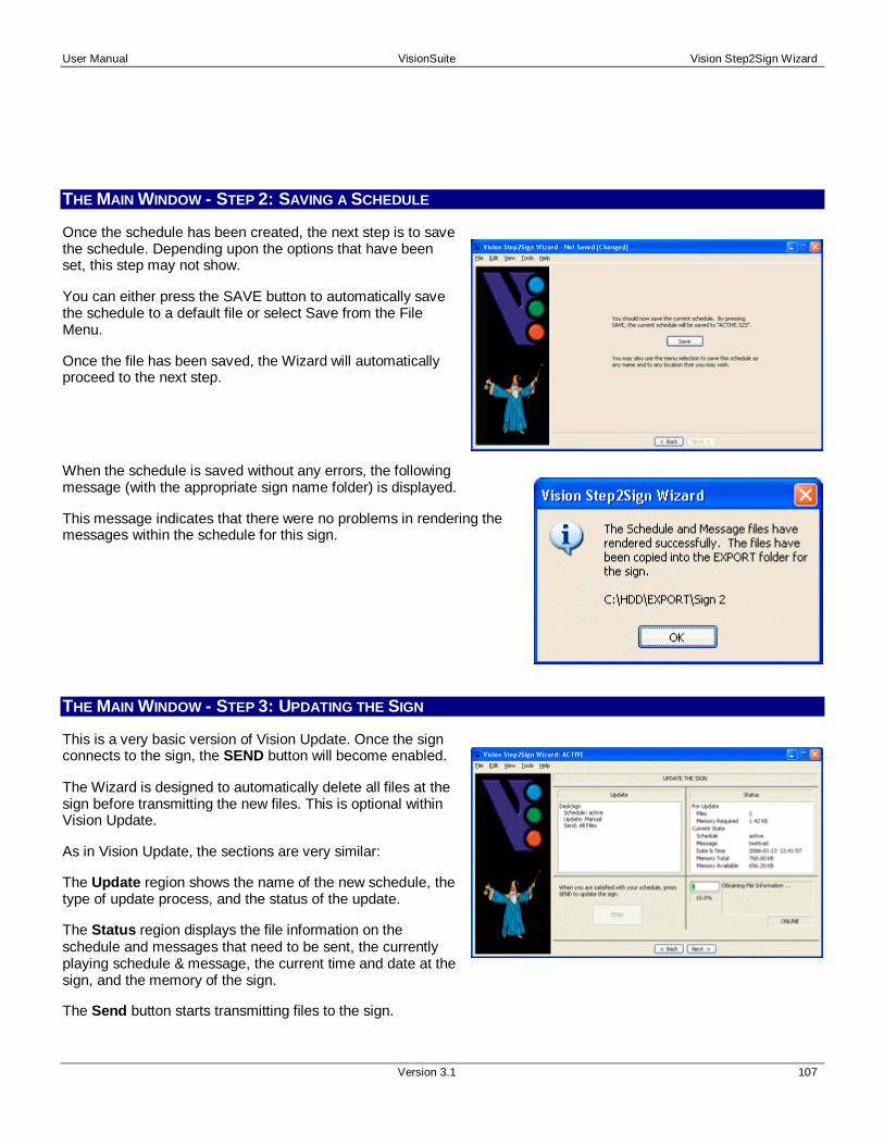
User Manual VisionSuite Vision Step2Sign Wizard
Version 3.1 107
THE MAIN WINDOW - STEP 2: SAVING A SCHEDULE
Once the schedule has been created, the next step is to savethe schedule. Depending upon the options that have beenset, this step may not show.
You can either press the SAVE button to automatically savethe schedule to a default file or select Save from the FileMenu.
Once the file has been saved, the Wizard will automaticallyproceed to the next step.
When the schedule is saved without any errors, the followingmessage (with the appropriate sign name folder) is displayed.
This message indicates that there were no problems in rendering themessages within the schedule for this sign.
THE MAIN WINDOW - STEP 3: UPDATING THE SIGN
This is a very basic version of Vision Update. Once the signconnects to the sign, the SEND button will become enabled.
The Wizard is designed to automatically delete all files at thesign before transmitting the new files. This is optional withinVision Update.
As in Vision Update, the sections are very similar:
The Update region shows the name of the new schedule, thetype of update process, and the status of the update.
The Status region displays the file information on theschedule and messages that need to be sent, the currentlyplaying schedule & message, the current time and date at thesign, and the memory of the sign.
The Send button starts transmitting files to the sign.

Vision Step2Sign Wizard VisionSuite User Manual
108 Version 3.1
The Communication Status region displays information about transmissions between the PC and sign.
Batch Updating is not available within the Wizard.
Update Region
The Update region states the name of the sign, the name of the new schedule, thetype of update method (manual or batch modes), the type of “send” operation(currently defaults to SEND ALL FILES), and the status of the update process.Some sign systems will have additional information after these core items.
Status Region
This region shows the number of files to be sent, the amount of memoryrequired to send the files, the currently playing schedule & message, thecurrent date & time, and the total & available memory at the sign’selectronic controller.
This information is useful for diagnostic purposes, e.g.:
• Is there enough memory at the sign for the message?
• Is the sign currently running?
• Does the number of files seem reasonable given the schedulethat I just saved?
When sending the data, the software will only validate the size of thefiles. The information provided will verify that you’re updating the signwith the correct files.
The Operational Time section displays the amount of time leftfor the sign before an Authorization Code must be entered.
Ten days (and less) before the “time” expires, a messagebox will appear whenever the user connects to the sign.Once the time expires, the sign will no longer resp ond toupdates and the current schedule will stop running.
Once the sign has been updated, the Wizard displays thefollowing message.
If anything goes wrong during the transmission of the newschedule and messages, errors will display within the statusregion of the window.
If errors persist, then use Vision Setup to diagnose the communications.

User Manual VisionSuite Vision Step2Sign Wizard
Version 3.1 109
Once the sign has been updated, you can press the Next button toproceed to the final step.
THE MAIN WINDOW - STEP 4: START AGAIN OR EXIT
The final step is very simple. By pressing Start , you willreturn to the first step. You can reconnect to a different signor even redo the schedule.
Pressing Exit will close the application and disconnect fromthe sign.
FILE MENU
The File menu gives you access to the basic functions for the current schedule:
New Schedule clears the current schedule.
Load Schedule opens a new Step2Sign Wizard schedule file.
Save Schedule saves the current schedule.
Save As New Schedule saves the current schedule as a different name.
Export Library exports the entire Vision Step2Sign Wizard library to anotherfolder.
Select Sign selects a new sign. If you have several different signs (differentmatrix size and/or color), then you can use this function to access the SignSelection dialog.
Preview File previews the currently selected file.
Most Recently Used file list allows you to select one of the previous four files that have been worked on.
Exit closes Vision Step2Sign Wizard.
Note that some of these selections become disabled within steps 2, 3 and 4.

Vision Step2Sign Wizard VisionSuite User Manual
110 Version 3.1
Open/Save/Save As
Whether you use Open, Save or Save As, the common FileDialog will appear (shown to the right). The title and thebutton will be named appropriately.
Note that all Vision Step2Sign Wizard schedule files have thefile extension of S2S.
Export Library
The purpose of this feature is to allow you to migrate from thebasic capabilities of the Wizard to the more advancedfeatures within Vision Edit, Vision Quick Text, and VisionSchedule.
The export process will copy all message files within the S2Sfolders into desired export folder. Group messages will not beexported since they are only a combination of othermessages.
Preview
When selecting Preview for the first time, you will see the VideoCompression dialog. Although several “compressor” types may existon your computer, it is recommended that you use “Full Frames(Uncompressed)”.
After selecting this the first time, the dialog will not be shown again.
When the Preview window opens, the message willautomatically start playing. You can move around themessage, pause it, and even save it (if needed). When you’refinished previewing the message, simply press the Donebutton to close the window.

User Manual VisionSuite Vision Step2Sign Wizard
Version 3.1 111
Exit
You can exit the application by one of two methods. First, youcan select “Exit” from the File menu. Second, you can press the“X” (close) button at the top right of the application. In thesecond case, a similar dialog as shown to the right appears toensure that you want to close. By purposely selecting the “Exit”from the File menu, you can bypass this dialog.
EDIT MENU
The Edit menu gives you access to tools for managing your files andschedule.
Create allows you to create a New Message or a New Group.
Add Existing File allows you to select and add previously created VisionEdit or Vision Quick Text message files.
Edit a File allows you to edit the currently selected file.
Delete a File allows you to delete the currently selected file.
Schedule allows you to add, remove, or move files within the schedule list.
Refresh Library allows you to refresh the list of files shown in the various lists within Step 1.
Note that some of these selections become disabled within steps 2, 3, and 4.
Create a New Message
The Create a New Message window is a simplified version ofthe Vision Quick Text application. You can only enter text andyou only have limited row control.
The text that is entered is automatically centered vertically.You have control over the horizontal justification by selectingthe Left, Center, and Right buttons.
When entering text (inside the “Enter Text” control), you canpress “CTRL+ENTER” to add a new line of text. You do nothave row-by-row control as within Vision Quick Text.

Vision Step2Sign Wizard VisionSuite User Manual
112 Version 3.1
Font Selection
The font selection can be either “Raster Fonts” or “TrueType Fonts”. This is chosen from the Menu.
When “Raster Fonts” is chosen, the dialog shown on theright will appear.
The fonts that are displayed are part of the raster fontdatabase within the FONT subfolder where VisionSuitewas installed.
When “True Type Fonts” is chosen, the dialog shown onthe right will appear.
The fonts that are displayed are part of the True TypeFonts that are installed on your computer. The listing offonts is controlled by Windows. For more information onthe installation and removal of Windows fonts, pleaserefer to your Windows documentation.
Effects Selection
When the “Select Effects” button is pressed, the dialogshown on the right will appear.
The Effects Selection dialog allows you to control the ON,HOLD, and OFF effects for this frame.
There are more than 50 effects to choose from. Bydefault, the selection is “CHANGE”, “HOLD”, and “NONE”for the ON, HOLD, and OFF effects respectively.
Depending on the sign, the duration of the certain effectscan be altered. For the H20/H21 controller based signs,both the ON and OFF effects have fixed durations.However, in all cases, the HOLD effect’s duration can bechanged.

User Manual VisionSuite Vision Step2Sign Wizard
Version 3.1 113
When you double-click the mouse over the duration forthe HOLD effect, the “Enter Duration” dialog will appear.You can control the effects time by seconds andmilliseconds. The fineness of this control is dependentupon the sign’s controller and the select effect.
Once you’ve entered in a name for the new message, youcan press Save to save the file to the library.
The Message menu item allows for Saving and Previewing of the file.
The Font menu item allows for selecting Raster or True Type fonts and theselection of the actual font. Select will show the appropriate font dialog for fontselection.
The Effects menu item allows for selection of Travel Mode and control ofnormal Effects, Travel Options and Color control.
Travel Settings
The Travel Effect Settings dialog allows you to control the travelspeed and direction for a frame. The Travel Mode can be set or notset per row. However, the speed and direction of travel is commonfor all rows within the frame.
There are several predefined speed selections. These areaccessed by selecting “Normal Selection” and then choosing one ofthe speeds within the pull-down list.
If you wish to set the speed to another value, then select “AdvancedSelection” and choose the distance of each travel step and the timeto hold the image at each step. The speed is shown as a guidelineto how fast the text will travel.

Vision Step2Sign Wizard VisionSuite User Manual
114 Version 3.1
Color Selection
When the color button is pressed, the Color Selection dialog will appear.Press either button to select the color for text or the background color forthe current row.
When the sign is monochromatic (one color), the color selection is verybasic. The color selection dialog will show a list of colorsand the percentage of RED, GREEN, and BLUE used forthe color.
Shown to the right is the two color selection for a RedMonochrome sign.
For a 16 Color LED sign, the number of available colorsincreases. Correspondingly, the list grows.
The color selections do not necessarily represent theexact colors that the sign will display. The exact colorsdisplayed may be slightly different due to the colorwavelength of the LEDs used within the sign.
Nevertheless, the selection is “representative” of thecolors that the sign will show.
The new 256-Shade signs have the capability ofdisplaying 256 unique shades.
You select the desired color by moving the mouse cursorto the location on the horizontal color-bar and clicking themouse. You can also enter a value manually within theValue control.
The control shown to the right is for an Amber sign with256 shades.

User Manual VisionSuite Vision Step2Sign Wizard
Version 3.1 115
When your sign is a full color sign, the color selection isvast. The color selection dialog, shown to the right, is thestandard Windows color selection. By default, there are48 predefined colors, 16 custom colors, and 16+ millionother colors to select from.
The selection capability within this Windows dialog isbased on the color capability of your PC’s graphics cardand monitor. If you have a computer that only has 256colors, this display will not be as extensive. Nevertheless,it may be adequate for your sign.
It is recommended that your PC has full color capabilitiesin order to have full color selection.
Create a New Group
When the window appears, you will have all the messagefiles within “Common Messages” and “Messages” lists shownon the left of the window.
By pressing the right-arrow button, you can add a selectedfile to the “New Group Files” list. Press the left-arrow buttonto remove selected files from the group list.
Once a name is given to this new group of messages, youcan press the OK button to save the group.
Edit a File
When “Edit a File” is selected, either the “Create a New Message” or the“Create a New Group of Messages” dialog will appear (with a differentwindow title).
The name of the file will not be able to be changed. Nevertheless, otherfile attributes can be altered and the file saved.
Schedule
Add, Remove, Move Up and Move Down items are identicalto the four buttons in the middle of the Step 1 window.

Vision Step2Sign Wizard VisionSuite User Manual
116 Version 3.1
VIEW MENU
The View menu gives you access to various information.
Sign Parameters displays the current information about the sign.
Sign Settings display the some of the sign’s settings saved within VisionSetup .
Sign Parameters
As shown on the right, the current settings of the ONLINEsign are displayed. This is a much more detailed list ofinformation compared to the information shown in the mainwindow.
For more information on the setting up of a sign, please referto the main Vision Setup help.

User Manual VisionSuite Vision Step2Sign Wizard
Version 3.1 117
Sign Settings
As shown on the right, most of the basic information aboutthe sign is displayed. The information displayed is equivalentto the information set when the sign was created in VisionSetup.
For more information on the setting up of a sign, please referto the main Vision Setup help.
TOOLS MENU
The Tool menu gives you access to the following items.
Connect to Sign allows the connection to an OFFLINE sign.
Disconnect from Sign allows the disconnection from the currentONLINE sign.
Admin Password allows the entering of an AdministratorPassword that has been setup within Vision Setup.
Hardware Password allows the entering of the hardwarepassword for the sign. This value has also been setup in Vision Setup and saved to the sign.
Options controls the options for this application .

Vision Step2Sign Wizard VisionSuite User Manual
118 Version 3.1
Admin or Hardware Passwords
If either the Admin or Hardware passwords are set, just press theappropriate “Enter Password” button and the “Password Entry”dialog will appear. The OK button remains disabled until apassword is entered. If the password is incorrect, an appropriatemessage is displayed .
Options
The Options selections have been greatly enhanced from theprevious versions. The list on the left indicate all of thesections of control that are available. The sections are thefollowing;
• General – Basic control of certain operationalfeatures of the interface.
• Defaults – Basic control on settings for messagecreation.
Options - General
The General section allows the following controls:
• Auto Load … – Automatically load the last savedS2S file when starting the application.
• Auto Save … Exiting – Automatically save thecurrent S2S file upon exiting the application.
• Auto Save … Step 3 – Automatically save thecurrent schedule before going to Step 3. This willmake Step 2 invisible to the user.
• Show Sign Name … – Display the name of theactive sign within the title bar.
• Show Sign State … – Display whether-or-not thesign is ONLINE or OFFLINE within the title bar.
• Show Schedule … – Display the name of the schedule within the title bar.
• Show Abbreviated … – Display an abbreviated version of the Time/Date Restriction within theSchedule list in Step 1.
• Show “Success Render” … – Display a simple message showing that the new schedule has beenproperly rendered for the current sign.

User Manual VisionSuite Vision Step2Sign Wizard
Version 3.1 119
Options - Defaults
The Defaults section allows the following settings for allnew Messages created within Vision Step2Sign:
• Rows – This control is grayed-out in order toillustrate that Vision Step2Sign does NOT haverow control greater than 1 row.
• Colors – These indicators and the correspondingbutton allow the control of colors.
• Font – Select between Raster and True TypeFonts.
• Raster – Select the default Raster font.
• True Type – Select the default True Type Font.
• Travel – Select the travel speed.
• Effects – Select the effects (modes).
FAST KEYS
Below is a list of all of the acceleration keys for access to various features.
CTRL+O Load a new schedule file.
CTRL+S Save the current schedule file.
CTRL+P Preview a selected file.
CTRL+M Display the Create a New Message window
CTRL+G Display the Create a New Group window
CTRL+A Add a selected file to the schedule
CTRL+X Remove a selected file from the schedule
CTRL+Up Arrow Move item in schedule up one line
CTRL+Down Arrow Move item in schedule down one line
CTRL+SHIFT+V View the list of Sign Parameters
CTRL+SHIFT+C Connect to the sign

Vision Step2Sign Wizard VisionSuite User Manual
120 Version 3.1
CTRL+SHIFT+D Disconnect from the sign
TROUBLESHOOTING
When Vision Step2Sign Wizard steps to the Update Sig n step, it always shows that my sign is OFFLINE. Wh atis wrong?
Several items could be wrong. Please refer to the “Troubleshooting” section within Vision Setup for moreinformation on this problem. .
Where do I enter my “Authorization Code”?
Entering your Authorization Code (in order to turn-off the “time left” display) is done within Vision Setup. Formore information, please refer to the main Vision Setup help.
The Time Left entry is showing “Expired” even though I know I have several days left before I need to en ter inthe Authorization Code.
The sign has not expired. You have set a “Hardware Password” and you have not yet entered it. Go to the“Hardware Password” dialog and enter your password. Once completed, the time limit will display as expected.

V IS IO N IN S T A N T ME S S A GE L I T E
Version 3.1 121
OVERVIEW
Vision Instant Message Lite is an application that allows auser to update a DVI-Based LED Video Display. Theapplication allows one to configure two unique lists of mediafiles for instant viewing and a third list that will playuninterrupted (schedule).
Vision Instant Message Lite is designed as simplified versionof Vision Instant Message PRO.
HOW VISION INSTANT MESSAGE LITE WORKS
When the computer is connected to our DVI-Based signage, Vision Instant Message Lite can be configured to displayan “image” (a playing media file) anywhere on the video card’s display area. Once configured, the user can then select& play any file within the first two columns and play the whole list of files within the third column.
In normal operation, a user can either double-click on a media file or press the “Play” button beneath the file’s column.The user can preview the file before playing it and even setup 2 unique files to display logos or default images.
The menu items give you access to various features to adjust the list of media files within the columns and the generaloperation and appearance of the main window.
Vision Instant Message Lite (or PRO) provides an operator with the ability to play any media file quickly during a sportsevent.

Vision Instant Message Lite VisionSuite User Manual
122 Version 3.1
OPENING VISION INSTANT MESSAGE LITE (FOR THE FIRST TIME)
When Vision Instant Message Lite (or Vision Viewer) isopened for the first time, a majority of the application isdisabled. The installer or user must obtain an “Access Code”(also referred to as the “Authorization Code” and “ActivationCode”).
Technical Support will step a user through the process ofsaving the Installation Code and emailing it. Once received,the Technician will email back an Access Code. Onceverified, the Access Code will activate the application andgive authorization to the user to use the features within theapplication.
This activation may be time limited due to contractualagreements.
THE MAIN WINDOW
The main Vision Instant Message Lite window has severalregions:
The Blanking the Display region allows a user to choose atype of image to “blank” the sign.
The Preview region allows a user to preview a selectedmedia file.
The Time Limit region at the bottom is an indication of “TimeRemaining” until the application is deactivated. If this regionis blank, there is no time limit in effect.
The Instant Message region is composed of two columns ofuser specified/selected media files.
The Schedule (or Loop) region contains the media files that can be played in succession.
At the top-portion of the window is the name of the current file playing.
Blanking the Display
The user can blank the sign with three different images. The standard BLACK SCREEN isdefault and always available. Via the Options selection, the user can also specify two uniqueBITMAP files. For example, these files could be logos or advertisements.

User Manual VisionSuite Vision Instant Message Lite
Version 3.1 123
Preview
This region allows a user to preview a selected media file. The media file can only be selectedwithin the Instant Message columns (the two left-most columns).
Time Limit (Access Code)
The Time Limit section displays the amount of time left beforethe application stops working and an Access Code must beentered.
Ten days (and less) before the “time” expires, a messagebox will appear whenever the user connects to the sign. Oncethe time expires, the sign and software will no longer respondto updates and the currently playing schedule/message willstop being displayed.
Please see Vision Instant Message Lite - Installation forinformation on entering an authorization code.
Instant Message
There are two columns available to the user to place mediafiles. Via the Edit menu selection, the user can add, delete,and sort messages from the lists.
When enabled, the user can display a specific media file byeither;
• Double-clicking the mouse on the media file willinstantly play the media file once.
• Select the media file and then press the PLAY buttonbeneath the column. The Play button will allow theentering of N iterations. The file will play N times.
The playing of a media file will be stopped if the user selectsanother media file or presses Activate for Blanking theDisplay.
There is no limit to the number of files that can be placedwithin the lists. However, it is recommended that number ofmessages is kept to a manageable number.

Vision Instant Message Lite VisionSuite User Manual
124 Version 3.1
Schedule or Loop
The third column can be used to play a set of media files in a continuous loop.
The media files can be added, deleted, and sorted via the Edit Menu.
Once the PLAY button is pressed, the other PLAY buttons are disabled. To STOP theplaying of the media files, one can either press the STOP button or press Activate forBlanking the Display.
There is no limit to the number of files that can be added to the list. The files areplayed in succession and continuously (until stopped).
If one changes the list of media files for the schedule (or loop), one needs to “GenerateLoop Schedule” (see Edit Menu for more information).
FILE MENU
The File menu gives you access to one item.
Exit closes Vision Instant Message Lite.
Exit
You can exit the application by one of two methods. First, youcan select “Exit” from the File menu. Second, you can press the“X” (close) button at the top right of the application. In thesecond case, a similar dialog as shown to the right appears toensure that you want to close. By purposely selecting the “Exit”from the File menu, you can bypass this dialog.
EDIT MENU
The Edit menu gives you access to two items.
Manage Lists will allow one to manage the media files containedwithin the three lists.
Generate Loop Schedule will generate a new schedule file for thefiles contained within the LOOP list. Although this is automaticallydone for the user each time the user presses the PLAY button, this menu selection is here so that more advancedusers can inspect the generated schedule file.

User Manual VisionSuite Vision Instant Message Lite
Version 3.1 125
Manage Lists
For each list of media files, the File Manager window willallow for the adding, deleting, and sorting of files.
The Move Up and Move Down buttons allow one to sort themedia files into a particular order. This is useful when onehas many files. The most commonly used files can be kept tothe top of the list.
The Add button allows one to add a new file; Delete willremove a selected file; and Edit displays the “Media FileParameters” dialog.
When adding a new file, one can add MPEG, AVI, BMP,JPEG, and HTML files. Once selected, the “Media FileParameters” dialog will appear to display certain informationabout the file.
Media File Parameters
This dialog displays the location of a file, the type of file, andits duration. Obviously, changing the duration will affect howlong the file is displayed. Bitmap files have a default timeduration set within the Options window. Movie or Animationfiles are automatically determined from the media file itself.
TOOLS MENU
The Tools menu gives you access to the following item:
Options – Control the options for this application.

Vision Instant Message Lite VisionSuite User Manual
126 Version 3.1
Options
The Options selections have been greatly enhanced from theprevious versions. The list on the left indicate all of thesections of control that are available.
The sections are the following;
• General – Basic control of certain operationalfeatures of the interface.
• Main Window – Basic control on the look and feel ofthe main window.
• Text Format – Control on how media files arereferenced within the application.
• Content Player – Control the location of the contentplayer on the video card display.
• Installation – Control on the Installation Code and Access Code for application Authorization (also referred toas the “Authorization Code”).
Options - General
The General section allows the following controls;
• Disable the double-click operation within the InstantMessage columns (A & B).
• The default reference time for any BMP, JPEG, andHTML files added to a column. The value can beover-ridden when adding the file (refer to Media FileParameters).
• The Play button at the bottom of columns A and Bcan either automatically play the selected file once orallow the user to enter in a number of iterations.
• When media file is playing, the complete pathnamecan be shown.
Options - Main Window
The Main Window section allows the following controls;
• One can enter in a specific heading for all threecolumns.
• One can select two BMP files for displaying as a“Blanking” image. Within the Main Window you canselect between BLACK and the two files.

User Manual VisionSuite Vision Instant Message Lite
Version 3.1 127
Options - Text Format
The Text Format section allows the following controls;
• Basic – This will force a predefined format for all files.The format is the file name and extension. (e.g.filename.ext)
• Custom – This will allow one to control what isdisplayed. The file name is always displayed. Onecan select from the following: Show the fileextension, Show the file type, Show the file durationin seconds, Show the name in capitals.
Options - Content Player
The Content Player section allows one to enter in the exactlocation on the PC computer screen where the “contentplayer” will be located.
This location will be used by the DVI-Based video system toshow the media files onto the sign.
Options - Installation

Vision Instant Message Lite VisionSuite User Manual
128 Version 3.1
The Installation section shows the Installation and Activationcodes. The activation (or “access”) code provides unlimited ortime limited access to the display of the media files.
The “…” button next to the Installation Code allows one toSAVE the Installation Code.
The “…” button next to the Activation Code allows one toLOAD the Activation Code.
The process of Loading the Activation Code is as follows:
• Save the Installation Code and send it to TechnicalSupport. They will generate an “Activation” code foryou.
• Upon receiving the code file, load the ActivationCode file.
• Press the “Verify” button.
One of the two messages, shown to the right, will appearonce the code has been verified.
FAST KEYS
Below is a list of all of the acceleration keys for access to various features.
F1 HTML Help File.

V IS IO N DVD
Version 3.1 129
INTRODUCTION
Vision DVD is an application that allows a user to play a DVD on a DVI-Based LED Video Display (DVI stands for"Digital Video Interface", a type of port used to connect video displays to computers). It requires a computer with aDVD drive and an available DVI port. The application allows one to specify two different areas of the screen on whichto display the DVD content. This allows, for example, one to preview/cue a DVD on the computer monitor beforedisplaying on the remote LED display.
GENERAL USE
To use Vision DVD, the host computer must be capable of driving two monitors, forexample, a desktop computer with two monitor ports or a laptop computer with anexternal monitor port. The LED Video Display is connected to the second monitorport.
When a computer has two monitors connected, there are afew basic ways to setup what gets shown on each monitor:
1. the entire display can be spread across monitor 1and monitor 2
2. monitor 2 can be set to mirror monitor 1
3. monitor 2 can be treated as a separate display
When using Vision DVD, monitor 1 and monitor 2 must besetup in either configuration 1 or 2 above.
Vision DVD allows video to be displayed in one of twolocations: Location 1 and Location 2 . Location 1 is where the DVD is cued and previewed. Location 2 maps towhere the video is played on the LED Video Display.
Once the locations have been setup, the user can control the DVD using the buttons located on the bottom right-handside of the application. The buttons mimic those found on traditional DVD remote controls, e.g., PLAY , PAUSE, andSTOP.
SETTING THE VALUES FOR LOCATION 1 AND LOCATION 2
The values for Location 1 and Location 2 depend upon how the two monitors are setup:

Vision DVD VisionSuite User Manual
130 Version 3.1
The Display is Spread Across both Monitors
When the display is spread across both monitors, theLED Video Display will be situated to the right of thecomputer monitor. Therefore, if the computer monitorhas a resolution of 1024x768, the upper left-handcorner of the LED Video Display will be mapped to the'x' and 'y' co-ordinates of '1024' and '0'.
Assuming, then, that the resoution of the computermonitor is 1024x768, complete the following steps:
1. Select Options from the Tools menu
2. Enter a value of 0 for both X Offset and YOffset under Location 1
3. Enter a value of 100 for both Width andHeight under Location 1
4. Enter a value of 1024 for X Offset underLocation 2
5. Enter a value of 0 for Y Offset underLocation 2
6. Enter the width in pixels of the LED Video Display for Width under Location 2
7. Enter the height in pixels of the LED Video Display for Height under Location 2
8. Press OK
Location 1 (the location for previewing/cueing) will now be at the top left-hand corner of the computer monitor.Location 2 (the location for the actual LED Video Display) will be setup in the correct position, i.e., to the rightof the computer monitor.
Now, when Location 1 is selected, the DVD will play in the upper left-hand corner of the computer monitor.When Location 2 is selected, the DVD will play on the LED Video Display.
Note: Since the entire display is spread across both monitor 1 and 2, if the mouse is moved all the way to theright, it might appear on the LED Video Display

User Manual VisionSuite Vision DVD
Version 3.1 131
Monitor 2 Mirrors Monitor 1
When monitor 2 mirrors monitor 1, the LED VideoDisplay mirrors what is displayed on the upper left-hand corner of the computer monitor.
Therefore, complete the following steps:
Change the background color of the desktop to black ifthe LED Video Display must be blank when no DVD isplaying (recommended)
1. Select Options from the Tools menu
2. Enter a value of 0 for both X Offset and YOffset under Location 2
3. Enter the width in pixels of the LED VideoDisplay for Width under Location 2
4. Enter the height in pixels of the LED VideoDisplay for Height under Location 2
5. Enter values for X Offset and Y Offset underLocation 1 such that they do not interfere withthe position of either the Vision DVD program or Location 2
6. Press OK
Now, when Location 1 is selected (the location for previewing/cueing), the DVD will play in a "safe" area of themain display. When Location 2 is selected (the location for the actual LED Video Display), the DVD will play inthe upper left-hand corner of the main display. This is the correct position for the "mirrored" LED VideoDisplay.
Note: If the mouse or any other window is moved into the area occupied by Location 2 (the location of theexternal display), the image of the mouse or window will appear on the LED Video Display.
MENU ITEMS
File
Exit - exits the Vision DVD.
View
Render Status Info - displays technical information about the DVD device present on the PC. Used mainly fortechnical support purposes.
Tools
Options - sets the default settings for Vision DVD.
Location 1 - sets the location and size of Location 1 . See General Use above.
Location 2 - sets the location and size of Location 2 . See General Use above.
Defaults/Location - sets the initial location where video is played when Vision DVD launches.
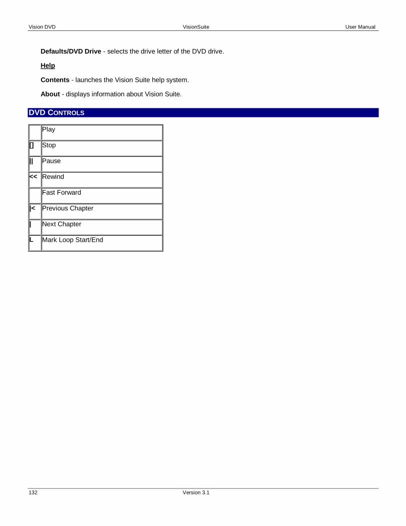
Vision DVD VisionSuite User Manual
132 Version 3.1
Defaults/DVD Drive - selects the drive letter of the DVD drive.
Help
Contents - launches the Vision Suite help system.
About - displays information about Vision Suite.
DVD CONTROLS
Play
[] Stop
|| Pause
<< Rewind
Fast Forward
|< Previous Chapter
| Next Chapter
L Mark Loop Start/End

V IS IO N F I LE CO N V E R T E R
Version 3.1 133
INTRODUCTION
Vision File Converter is an application that converts renderedMSG files into VED files. The resulting files can be edited inVision Edit.
SINGLE FILE CONVERSION
To convert a single MSG file, select MSG to VED: SingleFile Conversion and press Next to continue.

Vision File Converter VisionSuite User Manual
134 Version 3.1
In the Source File area of the dialog box, pressing ... willbring up the standard Windows Open File dialog box. Selectthe desired source file and press OK. The Width , Height ,and Color values are set according to the properties of thesource file.
In the Destination File area of the dialog box, pressing ... willbring up the standard Windows Open File dialog box. Selector enter the name of the desired destination file and pressOK. The Width , Height , and Color values are set accordingto the properties of the selected source file.
Press Next to convert the selected file.
The program will then proceed to convert the selected file.The Status region will display information related to theconversion process. When the file has been converted,DONE!! will be displayed on the bottom of the dialog. PressExit to exit the program.
MULTIPLE FILE CONVERSION
Vision File Converter can convert all MSG files in a singledirectory to VED files. To convert multiple files, select MSGto VED: Multiple Files - Folder Conversion and press Nextto continue.

User Manual VisionSuite Vision File Converter
Version 3.1 135
In the Source Folder area of the dialog box, pressing ... willbring up the standard Windows Select Folder dialog box.Select the desired source folder that contains the MSG filesthat are to be converted and press OK.
In the Destination Folder area of the dialog box, pressing ...will bring up the standard Windows Select Folder dialog box.Select or enter the name of the desired destination folderwhere the converted VED files will go and press OK.
Press Next to convert the files in the selected folder.
The program will then proceed to convert the files. TheStatus region will display information related to theconversion process. When the files have been converted,DONE!! will be displayed on the bottom of the dialog. PressExit to exit the program.


V IS IO N QU IC K TE XT CO N V E R T E R
Version 3.1 137
INTRODUCTION
Vision Quick Text Converter is an application that convertsold-format VMG files to new-format VMG files. In the processof conversion, attributes such as width, height, and color canbe changed. As well, the program can convert new-formatVMG files to new-format VMG files with changed width,height, and color attributes.
CONVERTING A FILE
To select the VMG file to be converted, press ... in theSource File area of the dialog box. This will bring up thestandard Windows Open File dialog box. Select the file to beconverted and press OK.

Vision Quick Text Converter VisionSuite User Manual
138 Version 3.1
SETTING THE DESTINATION FILE AND ATTRIBUTES
Naming the Destination File
Vision Quick Text Converter can automatically name thedestination file. If this is desired, select Use Auto NamedDestination File under the Selection menu. A checkmarkbeside this menu item will indicate that this option is selected.The file will be saved in the same folder as the source file.
To specify the name and location of the destination file,deselect Use Auto Named Destination File under theSelection menu. If there is no checkmark beside this menuitem, this will indicate that the option is deselected. Pressing... will bring up the standard Windows Save File dialog box.Specify the name and location of the destination file andpress OK.
Specifying the Attributes of the Destination File
Vision Quick Text Converter can automatically specify theattributes of the destination file based upon sign-type. If thisis desired, select Use Sign Definition File under theSelection menu. A checkmark beside this menu item willindicate that this option is selected. Next, select Select Signfrom the Selection menu. The standard VisionSuite SignSelection dialog will appear. Select the sign with the desiredwidth, height, and color attributes and press Select .
To specify the width, height, and color attributes of thedestination file, deslect Use Sign Definition File under theSelection menu. If there is no checkmark beside this menuitem, this will indicate that the option is deselected. Enter thedesired width and height in the appropriate places and selecta color from the available selections.
CONVERTING THE FILE
Press Convert to convert the file. Upon completion a dialogwill be displayed indicating the name and location of theconverted file. Press OK to dismiss the dialog. Anotherconversion can be performed, if desired.

User Manual VisionSuite Vision Quick Text Converter
Version 3.1 139
EXITING
To exit from Vision Quick Text Converter, select Exit from the File menu or press the x button in the upper-right handcorner of the dialog.


V IS IO N SE R V E R
Version 3.1 141
INTRODUCTION
Using Vision Server, a number of remote computers connected via a network or modem can send media files fordisplay on a single Video System. For more information on how to set up such a configuration, please see VisionPROSystems and Updating Content Remotely.
VISION SERVER REFERENCE
Main Dialog
Status
The status area displays status messages relating toserver activities.
Clear List
Clears the status messages
Start Server
Starts the server. Note, that depending upon variousoptions (described later), the server may already bestarted upon program launch.
File Menu
Exit
Exits Vision Server
Tools Menu
Options

Vision Server VisionSuite User Manual
142 Version 3.1
General
Start Server-Listening at Start-up.
Automatically starts the server when the VisionServer is launched. This is equivalent to pressingthe Start Server button.
Minimize Application at Start-up.
Automatically minimizes Vision Server when theprogram is launched.
Launch Vision Viewer at Start-up.
Automatically starts Vision Viewer when VisionServer is launched.
Network Settings
Router Port Settings
The port on which Vision Server listens forincoming messages.
Security
Administration Password
This is used to set a password so that all VisionServer operations are password-protected. Toset a password, check the box and click the ...button. Enter a password, press tab, enter itagain, then press OK. To cancel, press Cancel .Exit and relaunch Vision Server for password-protection to be in effect. It is recommended toset a password!
IP Access List
To restrict access to requests from specific IPaddress, check the box and click Add to add anIP address. To delete an IP address, select theaddress and press Delete . It is highly recommended to restrict access to only specific IP address!

User Manual VisionSuite Vision Server
Version 3.1 143
Maintenance
Log Network Communciations
This is used to log network communications fortroubleshooting purposes.
View Log
If logging has been enabled, press this to viewthe log.
Delete Log
If a log exists, press this to delete the log.


V IS IO N V IEW E R
Version 3.1 145
INTRODUCTION
Vision Viewer is an application that plays scheduled AVI, MPEG, and BMP files on a Video System. It is used inconjuction with Vision Server, Vision Viewer Updater, or a program such as Symantec pcAnywhere. For moreinformation on setting up a Video System, please see VisionPRO Systems and Updating Content Remotely.
INSTALLATION AND ACTIVATION
To install and activate Vision Server, please see the example Entering an Authorization Code
ADDING A NEW LAYOUT
In order to play content on a video system using Vision Viewer, a Layout and Content Player must be created. Pleasesee the example Setting up a Content Player for more information.
VISION VIEWER REFERENCE
Main Dialog
Settings Area
The area on the left of the main dialog displays thesettings for the current Content Player Layout.
Content Player Area
The area on the right of the main dialog displays thesettings for the selected Content Player. The drop-downlist is used to select the Content Player.
Play/Stop
This button is used to play and stop the content. If it isgreyed-out, the software needs to be activated. Pleasesee "Installation and Activation" above.
Show/Hide
This button is used to show and hide the content. If it is greyed-out, the software needs to be activated. Pleasesee "Installation and Activation" above.

Vision Viewer VisionSuite User Manual
146 Version 3.1
File Menu
Exit
Exits Vision Viewer
Tools Menu
Options
General
Show Content Player Layout Name in Title Bar
If this is selected, the name of the currently selectedContent Player is displayed in the Title Bar of theprogram.
Minimize Application at Start-up
If this is selected, when Vision Viewer is started, itwill be automatically minimized.
Content Players
Layouts Drop-Down List
Selects the current Content Player Layout. Checkingthe box sets the current Layout as the default. Theattributes of the currently selected layout are listedunderneath the drop-down list.
Add
Adds a new layout. See "Adding a New Layout"above for more details
Edit
Edits the currently selected layout.
Delete
Deletes the currently selected layout.

User Manual VisionSuite Vision Viewer
Version 3.1 147
File Transfers
Enable File Transfer Feature
Allows Vision Viewer to refresh the content from filestransferred via a remote PC running a program suchas pcAnywhere.
File Transfer Location
Sets the location where transferred files are stored.
Optimize Hard Drive Space
Optimizes the space taken up by the transferred files.
Installation
Please see the example Entering an Authorization Codefor more information.
Advanced
Launch DVI Setup Application
This launches the Vision DVI-LINK Utility.
Launch Video Tester
This launches the Vision Video Tester Utility.


V IS IO N V IEW E R UP D A T E R
Version 3.1 149
INTRODUCTION
Vision Viewer Updater is used to update content on a SignPC (Video System) running Vision Server and Vision Viewer.For more information on setting up a Video System, pleasesee VisionPRO Systems and Updating Content Remotely.
SETTING UP VISION VIEWER UPDATER
For information on setting up Vision Viewer Updater, please see the example Setting up Vision Viewer Updater.
VISION VIEWER UPDATER REFERENCE
Main Dialog
Send - Sends the content ot the Sign PC.

Vision Viewer Updater VisionSuite User Manual
150 Version 3.1
File Menu
Exit - Exits Vision Viewer Updater
View Menu
Viewer Status - Views the status of the Sign PC.
Viewer Layouts - Views the Vision Viewer Layoutsavailable on the Sign PC.
Tools
Convert Schedule - Converts a schedule created byVision Schedule to a format usable by Vision Viewer.
Connect to Vision Server - Connects to Vision Serverrunning on the Sign PC.
Disconnect to Vision Server - Disconnects from VisionServer running on the Sign PC.
Start Vision Viewer Layout - Starts content playing on the Sign PC using the currently selected Vision ViewerLayout.
Stop Vision Viewer Layout - Stops content playing on the Sign PC.
Options
General
Auto-connect to Vision Server at start-up.
Automatically connects to Vision Server runningon the Sign PC when the program is launched.
Auto-select Layout when there is only one.
When there is only one Layout available in VisionViewer on the Sign PC, selects this Layout.
Auto-stop the playing of media during an update.
When the content is updated by pressing "Send",stops Vision Viewer on the Sign PC from playingcontent.

User Manual VisionSuite Vision Viewer Updater
Version 3.1 151
Network
IP Address
The IP Address of the Sign PC.
Router Port
The port on the Sign PC on which Vision Serverlistens for incoming messages.
Folders
Export Folder
The folder where Vision Schedule places aschedule and content.
Folder Type
Either Single or Multiple Content Players.Currently only one Content Player per VisionViewer Layout is supported.
Secure file transmission.
Currently not supported.
Unsecure file copy.
Copies content files to the Sign PC as they are.
Destination Folder
The folder where content is copied to on the Sign PC.


AP P E N D I X I - RE C O M ME N D E D SY S T E MS
Version 3.1 153
OVERVIEW
As the world of technology changes, so does the demand placed on computers. VisionSuite is no exception.VisionSuite has many more capabilities than the previous version of software that have allowed users to editmessages and control signs. To this end, VisionSuite requires more computer capabilities than previous generations.
REQUIREMENTS
The VisionSuite applications have been developed for systems with the following configurations:
Windows™ Operating System Windows 2000-SP4 / XP (Pro/Home) – SP2 / Vista - SP1
Processor Pentium IV (or Better)
RAM 256 MB (minimum)
Hard Drive Space 40 MB (minimum)
Video Card 24-bit Color (minimum) for Message Centers32-bit Color (minimum) for Video Systems
Video Resolution 800 x 600 (minimum)
I/O Standard Serial port for Message CentersExtra DVI port on video card for new Video SystemsPCI-2 card for older Video Systems
Standard Components Mouse, Keyboard, Color Monitor, CD-ROM, and Floppy Drive
The more complex the image file handling that has to be performed, the more advanced the computer system must befor any realistic performance.
Although any computer running a modern operating system may work, it is always recommended that you contact yoursales representative to obtain up-to-date information on computer and operating system compatibility.
WINDOWS VERSIONS
VisionSuite is designed to work on the following operating systems:
• Windows Vista with SP1
• Windows XP Home and Pro
• Windows 2000

Appendix I – Recommended Systems VisionSuite User Manual
154 Version 3.1
ADDITIONAL INFORMATION
Requirements for VisionSuite can change. It is recommended to consult your Sales or Service Representative for thelatest information.

AP P E N D I X II - AD V A N C E D TO P IC S
Version 3.1 155
FOLDER STRUCTURE OF VISIONSUITE
When VisionSuite is installed with to its default folder (C:\HDD), the following folder structure will exist.
C:\HDD
\ASSETS\CommTests\EXPORT\FONTS\HELPDOCS\INI\Logs\MESSAGES\OS\SIGNDESC\S2S\TEMP\VIM
The ASSETS folder contains interim files for older Video systems for backward compatibility.
The CommTests folder contains the archived communication test results. An option must be set within Vision Setupfor the files to appear within this folder.
The EXPORT folder will eventually contain subfolders whose names are the names of your signs. Within thesesubfolders, Vision Schedule will export the schedule and messages for a given sign.
The FONTS folder contains the Raster Fonts (from HDD) for your text message creation.
The HELPDOCS folder contains all of the HTML files that compose the Help and Tutorial system.
The INI folder contains all of the initialization files for the main applications.
The Logs folder contains one or more log files. An option must be set within Vision Setup for the file(s) to appearwithin this folder.
The MESSAGES folder is initially created for you to place your new VED, VMG, and VSF files (created from VisionEdit, Vision Quick Text, and Vision Schedule, respectively). This folder is made for you convenience. You may storeyour files anywhere.
The OS folder is the location where the sign’s operating system image files are stored.
The SIGNDESC folder contains two types of files: your sign description (or definition) files and a small data base forcolor references for the various sign types. The sign description files are denoted with a file extension of INI.
The S2S folder contains the files and folders for the Vision Step2Sign Wizard application.

Appendix II – Advanced Topics VisionSuite User Manual
156 Version 3.1
The TEMP folder is a “scratch” folder for VisionSuite. The folder can contain various files depending upon theapplication that writes to (or reads from) this folder. You should not place anything into this folder since its contents areconsidered to be temporary and can be deleted at any time.
WARNING: Do not use the C:\HDD\TEMP folder to store your files. The folder’s contents can be deleted atany time.
The VIM folder contains the files and folders for the Vision Instant Message application. A specialized library of files iscreated within the VIM folder when messages are added or created within the application.
USING THE H1020 SOFTWARE ON A WINXP COMPUTER
One of the many reasons for developing the new VisionSuite was to create a suite of applications that would be fullyWindows™ compatible. The older H1020 software was originally developed for the DOS environment. The newerWindows operating systems (Win2k/WinXP) have a different communication port control methodology than within DOSor Win95/98. In the newer versions of Windows, the operating system can take control of the various communicationports (i.e. the serial and parallel ports) in order to maintain system integrity (on various levels). The H1020 softwarewas never designed for this scenario and cannot connect to the signs.
In addition, there are also various graphics issues that can interfere with the proper operation of the H1020 software.These can be numerous and are beyond the scope of this topic.
However, there is a way to connect to a sign and use the old H1020 software while using your WinXP computer (forexample). If you reboot your computer with a DOS diskette, you should be able to run the old H1020 software directlyfrom a diskette. This process will bypass the entire Windows operating system.
The process is the following;
• Create a DOS bootable diskette.
• Copy the H1020 software from the CD onto another diskette.
• Place the DOS bootable diskette into the floppy drive and reboot the PC.
• Once at the DOS prompt, place the H1020 diskette into the floppy drive.
• Run the MOUSE batch file by typing MOUSE and then pressing enter.
• Run the main H1020 application by typing H10MAIN and then pressing enter.
• Use the H1020 software as you have done in the past.
There are several items that might interfere with this process.
• If you have a unique monitor or video card that requires advanced Windows drivers to work properly, then thisprocess might not work for you.
• You need to store your messages on the floppy diskette. If you have too many messages (or too large) for thefloppy, then this process might not work for you.
• If you have a newer sign system that is not supported with the old H1020 software, then this process might notwork for you.

User Manual VisionSuite Appendix II – Advanced Topics
Version 3.1 157
EXTRAS ON THE CD
With the installation CD, there are several extra items that have been included. On the CD, you will notice the followingfolder (and subfolder) structure.
D:\Extras
\H1020\Library\PDF Manual
The H1020 folder contains a copy for the old H1020 software suite for communication to all older sign systems that arenot longer supported in the new VisionSuite.
NOTE: The older H1020 software will not communicate with newer electronic control devices (e.g. H22, DVI-LINK, and VPU based signage).
The Library folder contains a set of pre-created files for your use in making messages.
The PDF Manual folder contains the latest manuals for VisionSuite in PDF format.
USB CONNECTION TO MESSAGE SIGNS
In a few situations, you may not have a serial port in your computer. Instead, you may only have USB ports. (Note:This can be quite common on mid-high performance laptops.)
You can connect to a standard H21-based message sign via a USB port by using a USB-RS232 converter. Manymanufacturers for these converter devices exist. They can be purchased from a wide variety of computer stores. Thedevice normally comes with a Windows driver.
Simply connect the USB-RS232 device to the USB port on your computer. Windows should automatically see thedevice and ask for a driver. After the USB-RS232 converter has been installed, go to the Device Manager anddetermine the COM port the USB device references. Go to Vision Setup and change the serial port to the appropriateCOM port.
USB-RS485 converters work in the same manner.
MODEM COMMUNICATIONS
Within Windows, there are two methods of connecting to modems (either internal or external versions): use ATcommands or Windows’ TAPI method. The VisionSuite 2.1 (and greater) applications now allow for both modes.
The TAPI method depends greatly on the version of Windows and the modem being used. The AT command methodrequires extensive knowledge of the modem’s internal AT commands and is a more low-level approach to the modemcommunications.
Due to the various modems available and backward compatibility issues, it was decided to implement both modes.


AP P E N D I X III - ER R O R CO D E S
Version 3.1 159
The following is the list of current error messages that could occur during communications to the sign. Possiblereasons are also noted when appropriate.
MOST COMMON ERROR
31000 Maximum number of reattempts has exceeded.
Possible Reason: The most common reason for this error occurs when the connection between the PC and the signhas been interrupted. The sign has either been powered off, the connection is down (or broken, or powered off), or thesign’s electronics are not responding.
GENERAL ERRORS
21002 CRC verification failed.
Possible Reason: The connection to the sign has dropped due to a poor connection with a modem or cell phone. Fordirect-connect systems, the cable may have been damaged and might require replacing.
21003 Invalid data structure.
Possible Reason: An older version of the software is being used with a newer communications DLL. A reinstall of thesoftware should resolve this problem.
21004 Data structure has an invalid size.
Possible Reasons: An older version of the software is being used with a newer communications DLL. A reinstall of thesoftware should resolve this problem.
The Hardware Password that you have entered is incorrect and all subsequent communications between the sign andthe PC will generate this error message. You are trying to CLEAR your old Hardware Password. However, you havenot yet SET your current Password. Enter the current Hardware Password and then return to the Password dialog toCLEAR the set password.
21005 Unsupported data structure.
Possible Reason: An older version of the software is being used with a newer communications DLL. A reinstall of thesoftware should resolve this problem.
21006 Invalid header structure.
Possible Reason: An older version of the software is being used with a newer communications DLL. A reinstall of thesoftware should resolve this problem.
21007 One or more arguments are invalid.
Possible Reason: An older version of the software is being used with a newer communications DLL or the access tothe DLL does not match with the current design. A reinstall of the software should resolve this problem.

Appendix III – Error Codes VisionSuite User Manual
160 Version 3.1
22000 General negative acknowledgement.
MODEM: TAPI COMMUNICATION ERRORS
21203 Unable to allocate memory for the TAPI process.
21300 No Modem
21301 No TAPI registered devices available.
21302 TAPI device is not available.
21303 TAPI connection is not available.
21304 TAPI Communication Event translation error.
21305 TAPI Communication Read error.
21306 TAPI Communication Write error.
21307 Windows Modem Communications Dialog is not available.
21308 TAPI thread has not been created.
21309 The TAPI's selected line doesn't support VOICE and/or DATA capabilities.
21310 The TAPI's selected line doesn't support DATA MODEM and/or DIGITAL DATA capabilities.
21311 Unknown error occurred during TAPI initialization.
21312 Error on TAPI Requested line.
21313 Line is already in use by a non-TAPI application or by another TAPI Service Provider.
21314 Cannot use TAPI device. Unable to use Line.
21315 lineDeallocateCall unhandled error.
21316 lineClose unhandled error.
21317 lineGetTranslateCaps unhandled error.
21318 lineGetCountry unhandled error.
21319 The values in the INI file are invalid.
21320 There is a problem with your Telephony device driver.
21321 Reinitialize Connection - Shutting Down TAPI.
21322 Remove one of your copies of your Telephony driver.
21323 Out of memory. Canceling action.
21324 The TAPI operation failed.
21325 A TAPI resource is unavailable at this time.
21326 LINE CALLSTATE: Unknown device ID

User Manual VisionSuite Appendix III – Error Codes
Version 3.1 161
21327 Unhandled LINECALLSTATE message.
21328 lineGetDevCaps unhandled error
21329 LocalAlloc failed in CheckAndReAllocBuffer.
21330 LocalSize returned 0 in CheckAndReAllocBuffer.
21331 lineGetAddressCaps unhandled error.
21332 lineMakeCall unhandled error.
21333 lineDial unhandled error.
21334 lineTranslateAddress unhandled error.
21335 lineGetID unhandled error.
21336 lineShutdown unhandled error.
Possible Reason: These set of errors indicate a problem with the modem device. Ensure that the modem is TAPIcompliant (or Windows 2000/XP compliant) and that it has been installed properly. Go to the Windows’ Control Paneland test the modem. If communications does not occur reliably, then either the modem does not work properly or thedriver for the modem does not work properly under the version of Windows that you are using. Contact the modemmanufacturer (or reseller) for assistance.
MODEM:AT-COMMAND COMMUNICATION ERRORS
21400 Unknown/unsupported error from the modem communications.
Possible Reason: Either the modem or the connection to the sign has produced an error that is not supported. Themost common reason for this error occurs when the modem at the PC is not working properly.
21401 No carrier detected.
Possible Reason: The most common reason for this error occurs when the phone line connected to the modem at thePC is not working properly.
21402 No dial tone detected.
Possible Reason: The most common reason for this error occurs when the phone line connected to the modem at thePC is not working properly.
21403 No answer.
Possible Reason: The most common reasons for this error are:
• the modem at the sign is not functioning properly,
• the phone line to the sign is not working properly,
• the sign’s electronic controller is not working properly, or
• the sign is powered off.
21404 Busy signal received.

Appendix III – Error Codes VisionSuite User Manual
162 Version 3.1
Possible Reason: The most common reason for this error occurs when someone else is already connected to the sign.
21405 General communications error.
Possible Reason: This is a general error that occurs when the modem at the PC is not working properly. It is a veryrare error.
21406 Connection attempt to sign has timed out.
Possible Reason: The most common reason for this error occurs when modem at the sign is not picking up. This iseither a sign that the modem is damaged or that the phone line to the modem Is damaged.
21410 Modem is not responding.
Possible Reason: The most common reason for this error occurs when the modem at the PC is not turned on.
H21 SPECIFIC COMMUNICATION ERRORS
22001 Invalid password. (NAK)
22002 File not found. (NAK)
22003 File Memory is FULL. (NAK)
22004 Requested file is in use. (NAK)
22005 Sign is running. (NAK)
22006 Sign is stopped. (NAK)
22007 Requested command is not supported. (NAK)
22008 Transmitted data is invalid. (NAK)
22009 No files exist on the controller. (NAK)
22010 Remote system is busy. (NAK)
22011 File already exists. (NAK)
22012 Authorization password is invalid. (NAK)
22013 Requested sign number is not supported. (NAK)
22014 Transmission packet is corrupt. (NAK)
Possible Reason: These set of errors are generated by the controller within the sign. These errors can occur for a widerange of issues. If any of these errors occur, you may wish to contact Technical Support for further information andassistance.
H22-SPECIFIC COMMUNICATION ERRORS
23001 CRC error within the header.
23002 CRC error within the data block.
23003 Invalid command.

User Manual VisionSuite Appendix III – Error Codes
Version 3.1 163
23004 Invalid data.
23005 Invalid sign number.
23006 Invalid password.
23007 Invalid authorization.
23008 Sign is busy.
23009 Sign is inactive.
23010 Command is not complete.
23011 Invalid memory.
23020 Bad packet sequence.
23021 Bad address.
23022 Memory is full.
23023 Transmission is too large.
23024 Multi-packet is not complete.
23025 Invalid version number.
23040 Software general error.
23060 Test of flash has failed.
23061 Test of RAM has failed.
23062 Access to the FPGA has failed.
23063 Temperature / Photocell probe is not responding properly.
23064 DIP switch read error has occurred.
23080 General FPGA hardware error.
23100 File CRC error.
23101 File name is invalid.
23102 No space for file to be stored into memory.
23103 File deletion failed.
23104 File system failure.
23105 File not found.
23106 File in use.
23107 File already exists.
23108 File size is invalid.

Appendix III – Error Codes VisionSuite User Manual
164 Version 3.1
Possible Reason: These set of errors are generated by the controller within the sign. These errors can occur for a widerange of issues. If any of these errors occur, you may wish to contact Technical Support for further information andassistance.
GENERAL OPERATIONAL ERRORS
27000 Invalid password within verification process.
Possible Reason: This is a highly unusual error and indicates that VisionSuite and communications to the sign are notcompatible.
GENERAL DATA TRANSMISSIONERRORS
28000 Write buffer is too large.
28001 Read process is taking too much time.
Possible Reason: These set of errors are generated by the controller within the sign. These errors usually indicate thatVisionSuite and communications to the sign are not responding properly. If any of these errors occur, you may wish tocontact Technical Support for further information and assistance.
GENERAL FILE ERRORS (AT THE PC)
29000 File could not be found within the system.
29001 File does not have read permission.
29002 Error occurred while trying to read the file.
29003 File does not have write permission.
29004 Error occurred while trying to write the file.
29005 Invalid file type.
29006 File information is not available.
Possible Reason: These set of errors are usually generated within VisionSuite applications when the user tries toaccess files on the PC that are not accessible by the user. This may be an indication that the user needs special fileaccess permissions in order to use the files.
SERIOUS ERRORS
30000 General serious error.
30001 Cannot create an application thread.
30002 Connection exists to device.
30003 Invalid thread version.
30004 Invalid communication type; not supported within the software.
30005 Invalid device mask; not supported within the software.

User Manual VisionSuite Appendix III – Error Codes
Version 3.1 165
30006 Communications Thread cannot terminate due to unexpected Windows operation.
30007 Invalid operation code generated.
30008 Write request has exceeded parameter limits.
30200 Unable to create handle.
30201 Unable to access Windows communication state for serial port.
30202 Unable to set Windows communication state for serial port.
30203 Unable to set Windows communications buffer for serial port.
30204 Unable to set Windows communication timing device for serial port.
30205 Unable to close handle.
30308 Unable to create TAPI device thread.
Possible Reason: This set of errors are serious errors and usually indicate that the PC and Windows is not workingproperly. If any of these errors occur, contact your local IT Personnel for immediate computer assistance.
WINDOWS™ GENERATED ERRORS
The error numbers returned (shown) are greater than ZERO. The following represent the most likely errors returned byWindows.
32 The process cannot access the file because it is being used by another process.
Possible Reason: This can be returned when a file is being accessed by more than one user or application.
87 The parameter is incorrect.
Possible Reason: This can be returned when the serial port communications within Windows has been set to an “odd”state. Simply reboot the PC and the problem should disappear. If the problem persists, please contact TechnicalSupport for assistance.