Untitled - Testbook.com
68
-
Upload
khangminh22 -
Category
Documents
-
view
1 -
download
0
Transcript of Untitled - Testbook.com


173
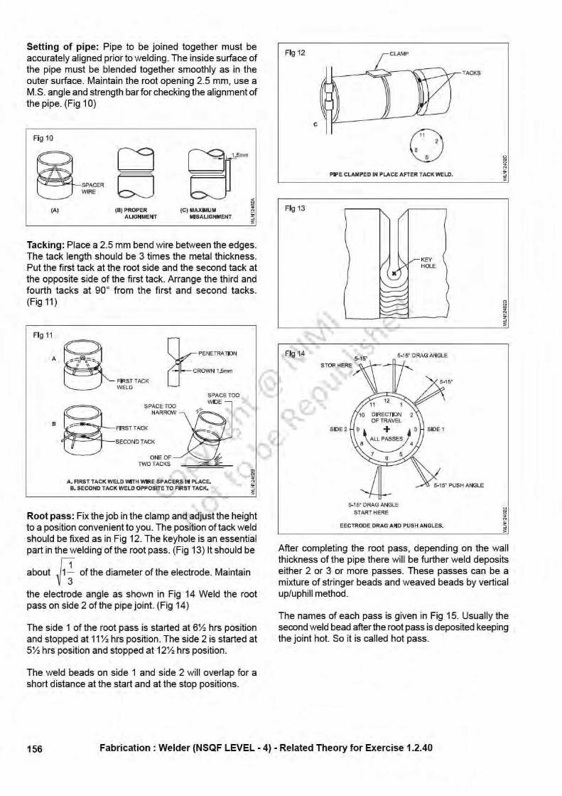
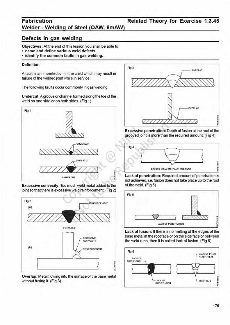
Definition of filler rod: A filler rod is a metallic wire madeout of ferrous or non-ferrous metal to deposit the requiredmetal in a joint or on the base metal.
Types of filler rods: The following types of filler rods areclassified in gas welding.
– Ferrous filler rod
– Non-Ferrous filler rod
– Alloy type filler rod for ferrous metals
– Alloy type filler rod for non-ferrous metals
A ferrous type filler rod has a major % of iron.
The ferrous type filler rod contains iron, carbon, silicon,sulphur and phosphorous.
Filler rod and its necessity: Pieces of wires or rods ofstandard diameter and length used as filler metal in thejoint during gas welding process are called filler rods orwelding rods.
To obtain best results, high quality filler rods should beused.
The actual cost of welding rods, is very small comparedwith cost of job, labour, gases and flux.
Good quality filler rods are necessary to:
- reduce oxidation (effect of oxygen)
- Control the mechanical properties of the depositedmetal
- Metal caused by fusion.
While welding, a cavity or depression will be formed at thejoints of thin section metals. For heavy/thick plates agroove is prepared at the joint. This groove is necessaryto get better fusion of the full thickness of the metal, so asto get a uniform strength at the joint. This groove formedhas to be filled with metal. For this purpose a filler rod is
necessary. Each metal requires a suitable filler rod.
Sizes as per IS: 1278 - 1972)
The size of the filler rod is determined from the diameteras: 1.00, 1.20. 1.60, 2.00, 2.50, 3.15, 4.00, 5.00 and6.30mm. For leftward technique filler rods upto 4mm dia.are used. For rightward technique upto 6.3 mm dia. isused. For C.l welding filler rods of 6mm dia. and aboveare used. Length of filler rod:-500mm or 1000mm.
Filler rods above 4mm diameter are not used often forwelding of mild steel.
The usual size of mild steel filler rods used are 1.6mmand 3.15mm diameter. All mild steel filler rods are given athin layer of copper coating to protect them from oxidation(rusting) during storage. So these filler rods are calledcopper coated mild steel (C.C.M.S) filler rods.
All types of filler rods are to be stored in sealed plasticcovers until they are used.
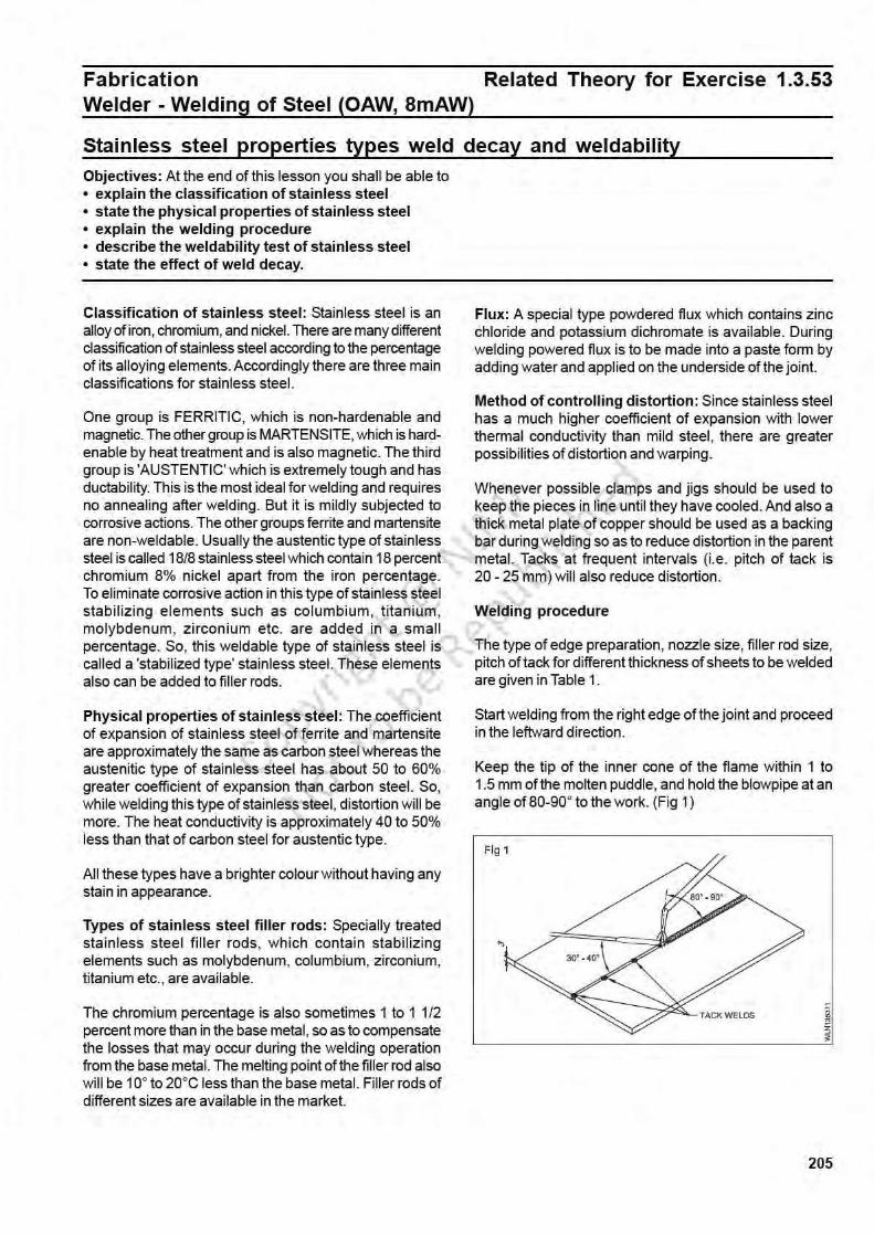
Different types of filler rods used in gas weldingObjectives: At the end of this lesson you shall be able to• define a filler rod• specify and state the different types of ferrous, non-ferrous and alloy filler rods• explain the method of selection of filler rod in respect to the metal to be welded.
FabricationWelder - Welding Techniques Related Theory for Exercise 1.2.44
Filler rods for gas weldingObjectives: At the end of this lesson you shall be able to• state the necessity of filler rods and name the different types of filler rods and their sizes• select filler rods for the jobs to be welded by gas.
The alloy type filler contains iron, carbon, silicon and anyone or many of the following elements such as manganese,nickel, chromium, molybdenum, etc.
The non-ferrous type filler rod which contains elements ofnon-ferrous metals. The composition of non-ferrous typefiller rods is similar to any non-ferrous metal such ascopper, aluminium. A non-ferrous alloy type filler rodcontains metals like copper, aluminium, tin, etc. alongwithzinc, lead, nickel, manganese, silicon, etc.
Selection of the correct filler rod for a particular job is avery important step for successful welding. Cutting out astrip from the material to be welded is not always possibleand even when it is possible, such a strip cannot replacea recommended welding filler materials. Composition of afiller metal is chosen with special consideration to themetallurgical requirement of a weldment. A wrong choice
Copyrigh
t @ NIM
I
Not to be Republish
ed

174
due to either ignorance or a false consideration of economymay lead to costly failures. IS: 1278-1972* specifiesrequirements that should be met by filler rods for gaswelding. There is another specification IS: 2927-1975*which covers brazing alloys. It is strongly recommendedthat filler material confirming to these specifications is used.In certain rare cases, it may be necessary to use fillerrods of composition not covered by these specifications;in such cases filler rods with well established performancesshould be used.
To select a filler rod in respect to the metal to be welded,the filler rod must have the same composition with respectto the base metal to be welded.
Factors to be considered for selection of filler rod are:
a. the type and composition of base metal
b. the base metal thickness
c. the type of edge preparation
d. the weld is deposited as root run, intermediate runs orfinal covering run
e. welding position
f. whether there is any corrosion effect or loss of materialfrom the base metal due to welding.
Care and maintenance
Filler rods should be stored in clean, dry condition to preventdeterioration.
Do not mix different types of filler rods.
Ensure that packages and their labels are in order for easyand correct selection.
Where it is not practicable to store filler rods under heatedconditions, an absorbent for moisture such as silico-gelmay be used in the storage area.
Ensure the rod is free from contamination such as rust,scale, oil, grease and moisture.
Ensure the rod is reasonably straight to assist manipula-tion during welding.
Each metal requires a suitable filler rod. Referto IS : 1278 - 1972 and IS : 2927 - 1975 attached.(Table 1: Filler metals and fluxes for gaswelding.)
Fabrication : Welder (NSQF LEVEL - 4) - Related Theory for Exercise 1.2.44
Copyrigh
t @ NIM
I
Not to be Republish
ed
175
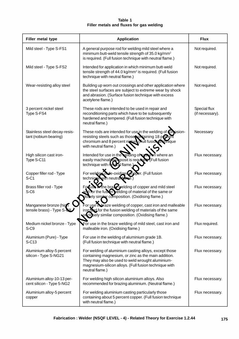
Table 1Filler metals and fluxes for gas welding
Filler metal type Application Flux
Mild steel - Type S-FS1 A general purpose rod for welding mild steel where a Not required.minimum butt-weld tensile strength of 35.0 kg/mm2
is required. (Full fusion technique with neutral flame.)
Mild steel - Type S-FS2 Intended for application in which minimum butt-weld Not required.tensile strength of 44.0 kg/mm2 is required. (Full fusiontechnique with neutral flame.)
Wear-resisting alloy steel Building up worn out crossings and other application where Not required.the steel surfaces are subject to extreme wear by shockand abrasion. (Surface fusion technique with excessacetylene flame.)
3 percent nickel steel These rods are intended to be used in repair and Special fluxType S-FS4 reconditioning parts which have to be subsequently (if necessary).
hardened and tempered. (Full fusion technique withneutral flame.)
Stainless steel decay-resis- These rods are intended for use in the welding of corrosion- Necessarytant (nobium bearing) resisting steels such as those containing 18 percent
chromium and 8 percent nickel. (Full fusion techniquewith neutral flame.)
High silicon cast iron- Intended for use in the welding of cast iron where an Flux necessary.Type S-C11 easily machinable deposit is required. (Full fusion
technique with neutral flame.)
Copper filler rod - Type For welding of de-oxidized copper. (Full fusion Flux necessary.S-C1 technique with neutral flame.)
Brass filler rod - Type For use in the braze welding of copper and mild steel Flux necessary.S-C6 and for the fusion welding of material of the same or
closely similar composition. (Oxidising flame.)
Manganese bronze (high For use in braze welding of copper, cast iron and malleable Flux necessary.tensile brass) - Type S-C8 iron and for the fusion welding of materials of the same
or closely similar composition. (Oxidising flame.)
Medium nickel bronze - Type For use in the braze welding of mild steel, cast iron and Flux required.S-C9 malleable iron. (Oxidising flame.)
Aluminium (Pure) - Type For use in the welding of aluminium grade 1B. Flux necessary.S-C13 (Full fusion technique with neutral flame.)
Aluminium alloy-5 percent For welding of aluminium casting alloys, except those Flux necessary.silicon - Type S-NG21 containing magnesium, or zinc as the main addition.
They may also be used to weld wrought aluminium-magnesium-silicon alloys. (Full fusion technique withneutral flame.)
Aluminium alloy-10-13 per- For welding high silicon aluminium alloys. Also Flux necessary.cent silicon - Type 5-NG2 recommended for brazing aluminium. (Neutral flame.)
Aluminium alloy-5 percent For welding aluminium casting particularly those Flux necessary.copper containing about 5 percent copper. (Full fusion technique
with neutral flame.)
Fabrication : Welder (NSQF LEVEL - 4) - Related Theory for Exercise 1.2.44
Copyrigh
t @ NIM
I
Not to be Republish
ed
176
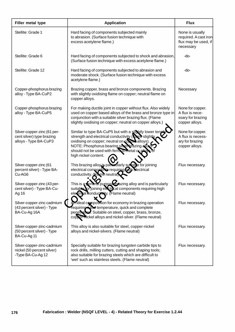
Filler metal type Application Flux
Stellite: Grade 1 Hard facing of components subjected mainly None is usuallyto abrasion. (Surface fusion technique with required. A cast ironexcess acetylene flame.) flux may be used, if
necessary
Stellite: Grade 6 Hard facing of components subjected to shock and abrasion, -do-(Surface fusion technique with excess acetylene flame.)
Stellite: Grade 12 Hard facing of components subjected to abrasion and -do-moderate shock. (Surface fusion technique with excessacetylene flame.)
Copper-phosphorus brazing Brazing copper, brass and bronze components. Brazing Necessaryalloy - Type BA-CuP2 with slightly oxidising flame on copper; neutral flame on
copper alloys.
Copper-phosphorus brazing For making ductile joint in copper without flux. Also widely None for copper.alloy - Type BA-CuP5 used on copper based alloys of the brass and bronze type in A flux is nece-
conjunction with a suitable silver brazing flux. (Flame ssary for brazingslightly oxidising on copper; neutral on copper alloys.) copper alloys.
Silver-copper-zinc (61 per- Similar to type BA-CuP5 but with a slightly lower tensile None for copper.cent silver) type brazing strength and electrical conductivity (flame slightly A flux is necess-alloys - Type BA-CuP3 oxidising on copper; neutral on copper alloys). ary for brazing
NOTE: Phosphorus bearing silver brazing alloys copper alloys.should not be used with ferrous metal or alloys ofhigh nickel content.
Silver-copper-zinc (61 This brazing alloy is particularly suitable for joining Flux necessary.percent silver) - Type BA- electrical components requiring high electricalCu-AG6 conductivity. (Flame neutral)
Silver-copper-zinc (43 per- This is a general purpose brazing alloy and is particularly Flux necessary.cent silver) - Type BA-Cu- suitable for joining electrical components requiring highAg 16 electrical conductivity. (Flame neutral)
Silver-copper-zinc cadmium An ideal composition for economy in brazing operation Flux necessary.(43 percent silver) - Type requiring a low temperature, quick and completeBA-Cu-Ag 16A penetration. Suitable on steel, copper, brass, bronze,
copper-nickel alloys and nickel-silver. (Flame neutral)
Silver-copper-zinc-cadmium This alloy is also suitable for steel, copper-nickel Flux necessary.(50 percent silver) - Type alloys and nickel-silvers. (Flame neutral)BA-Cu-Ag 11
Silver-copper-zinc-cadmium Specially suitable for brazing tungsten carbide tips to Flux necessary.nickel (50 percent silver) rock drills, milling cutters, cutting and shaping tools;-Type BA-Cu-Ag 12 also suitable for brazing steels which are difficult to
'wet' such as stainless steels. (Flame neutral)
Fabrication : Welder (NSQF LEVEL - 4) - Related Theory for Exercise 1.2.44
Copyrigh
t @ NIM
I
Not to be Republish
ed
178
When containers, such as fuel tanks, have been weldedand parts are inaccessible for the hot water scrubbingmethod, use a solution of nitric and hydrofluoric acids.To each 5.0 liters of water add 400 ml of nitric acid(specific gravity 1.42) followed by 33 ml of hydrofluoricacid (40 percent strength). The solution used at roomtemperature will generally completely remove the fluxresidue in 10 minutes, producing a clean uniformlyetched surface, free from stains. Following this treatmentthe parts should be rinsed with cold water and finishedwith a hot water rinse. The time of immersion in hotwater should not exceed three minutes, otherwisestaining may result; after this washing with hot waterthe parts should be dried. It is essential when usingthis treatment that rubber gloves be worn by the operatorand the acid solution should preferably be contained inan aluminium vessel.
– Magnesium alloys - Wash in water followed quickly bystandard chromating. Acid chromate bath isrecommended.
– Copper and brass - Wash in boiling water followed bybrushing. Where possible, a 2 percent solution of nitricor sulphuric acid is preferred to help in removing theglassy slag, followed by a hot water wash.
– Stainless steel - Treat in boiling 5 percent caustic sodasolution, followed by washing in hot water. Alternatively,use a de-scaling solution of equal volume of hydrochloricacid and water to which is added 5 percent of the totalvolume of nitric acid with 0.2 percent of total volume ofa suitable restrainer.
– Cast iron - Residues may be removed easily by achipping hammer or wire brush.
– Silver brazing - The flux residue can be easily removedby soaking brazed components in hot water, followedby wire brushing. In difficult cases the work pieceshould be immersed in 5 to 10 percent sulphuric acidsolution for a period of 2 to 5 minutes, followed by hotwater rinsing and wire brushing.
Fabrication : Welder (NSQF LEVEL - 4) - Related Theory for Exercise 1.2.44
Copyrigh
t @ NIM
I
Not to be Republish
ed
181
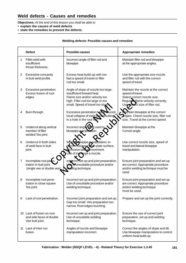
Weld defects - Causes and remediesObjectives: At the end of this lesson you shall be able to• explain the causes of weld defects• state the remedies to prevent the defects.
Welding defects: Possible causes and remedies
Defect Possible causes Appropriate remedies
1 Fillet weld with Incorrect angle of filler rod and Maintain filler rod and blowpipeinsufficient blowpipe. at the appropriate angles.throat thickness.
2 Excessive concavity Excess heat build-up with too Use the appropriate size nozzlein butt weld profile. fast a speed of travel or filler and filler rod with the correct
rod too small. speed of travel.
3 Excessive penetration. Angle of slope of nozzle too large. Maintain the nozzle at the correctExcess fusion of root Insufficient forward heat. speed of travel.edges. Flame size and/or velocity too Select correct nozzle size.
high. Filler rod too large or too Regulate flame velocity correctly.small. Speed of travel too slow. Use correct size of filler rod.
4 Burn through. Excessive penetration has produced Maintain blowpipe at the correctlocal collapse of weld pool resulting angles. Check nozzle size, filler rodin a hole in the root run. size. Travel at the correct speed.
5 Undercut along vertical Incorrect angle of tilt used in Maintain blowpipe at themember of filler blowpipe manipulation. Correct angle.welded Tee joint.
6 Undercut in both sides Wrong blowpipe manipulation; in- Use correct nozzle size, speed ofof weld face in butt correct distance from plate surface, travel and lateral blowpipejoint. excessive lateral movement. manipulation.
Use of too large a nozzle.
7 Incomplete root pene- Incorrect set up and joint preparation. Ensure joint preparation and set uptration in butt joint Use of unsuitable procedure and/or are correct. Appropriate procedure (single vee or double vee). welding technique. and/or welding technique must be
used.
8 Incomplete root pene- Incorrect set up and joint preparation. Ensure joint preparation and set uptration in close square Use of unsuitable procedure and/or are correct. Appropriate procedureTee joint. welding technique. and/or welding technique
must be used.
9 Lack of root penetration. Incorrect joint preparation and set up. Prepare and set up the joint correctly.Gap too small. Vee preparation toonarrow. Root edges touching.
10 Lack of fusion on root Incorrect set up and joint preparation. Ensure the use of correct jointand side faces of double Use of unsuitable welding preparation, set up and weldingVee butt joint. technique. technique.
11 Lack of inter-run Angles of nozzle and blowpipe Correct the angles of slope and tilt.fusion. manipulation incorrect. Use blowpipe manipulation to control
uniform heat build-up.
Fabrication : Welder (NSQF LEVEL - 4) - Related Theory for Exercise 1.3.45
Copyrigh
t @ NIM
I
Not to be Republish
ed

182
Defect Possible causes Appropriate remedies
Overlap
12 Weld face cracks in Use of incorrect welding procedure. Use correct procedure and fillerbutt and fillet welds. Unbalanced expansion and rod. Ensure uniform heating and
contraction stresses. cooling. Check suitability andPresence of impurities. surface preparation of materialUndesirable chilling effects. before welding. Avoid draughtsUse of incorrect filler rod. and use appropriate heat treatment.
13 Surface porosity and Use of incorrect filler rod and Clean plate surfaces. Use correctgaseous intrusions. technique. Failure to clean filler rod and technique. Make
surfaces before welding. sure the flame setting is correctAbsorption of gases due to to avoid gas contamination.incorrectly stored fluxes,unclean filler rod.Atmospheric contamination.
14 Crater at end of weld Neglect to change the angle of Reduce the angle of the blowpiperun. Small cracks blowpipe, speed of travel or progressively with speed of travel tomay be present. increase the rate of weld metal lower the heat input and deposit, and
deposition as welding is completed deposit sufficient metal to maintainat the end of the seam. the toe of the weld pool at the
correct level until it has completelysolidified.
Fabrication : Welder (NSQF LEVEL - 4) - Related Theory for Exercise 1.3.45
Copyrigh
t @ NIM
I
Not to be Republish
ed
184
Basic or hydrogen-controlled electrodes: Basic orhydrogen controlled electrode coatings are based oncalcium fluoride or calcium carbonate. This type ofelectrode is suitable for welding high-strength steelswithout weld cracks and the coating have to be dried. Thisdrying is achieved by backing at 450°C holding at 300°Cand storing at 150°C until the time of use. By maintainingthese conditions it is possible to achieve high strengthweld deposits on carbon, carbon manganese and lowalloyed steels. Most electrodes in this group deposit weldswith easily removable slags, producing acceptable weldshape in all positions. Fumes given off by this electrodeare greater than with other types of electrodes.
Iron powder electrodes: Iron powder electrodes get theirname from the addition of iron powders to the coating whichtend to increase efficiency of the electrode. For example,if the electrode efficiency is 120%, 100% is obtained fromthe core wire and 20% from the coating. Deposited weldsare very smooth with an easily removable slag; weldingpositions are limited to horizontal, vertical fillet welds andflat or gravity position fillet and butt welds.
Composition/Characteristics Flux
Composition/characteristics flux: The coating of thewelding electrodes consists of a mixture of the followingsubstances.
Alloying substances: These substances compensate forthe burning of manganese, ferro-silicon. The alloyingsubstances are:
– ferro-manganese
– ferro-silicon
– ferro-titanium.
Arc stabilizing substances: These are carbonates knownas chalk and marble. These are used for the stabilisationof the arc.
Deoxidizers: These substances prevent porosity andmake the welds stronger. The deoxidising substances areiron oxide, lamitite, magnetite.
Slag forming substances: These substances melt andfloat over the molten metal and protect the hot depositedweld metal from the atmospheric oxygen and nitrogen.Also due to the slag covering, the weld metal is preventedfrom fast cooling. The slag forming substances are clay,limestone.
Fluxing/cleaning substances: These substances removeoxides from the edges to be welded and controls the fluidityof the molten metal. The cleaning substances are limestone, chlorides, fluorides.
Gas forming substances: These substances form gaseswhich aid the transfer of metal. They also shield the weldingarc and weld pool. The substances are: wood flour dixtorineand cellulose.
Binding and plasticizing substances: These sub-stances help the applied coating to grip firmly around thecore wire of the electrode.
These are: sodium and potassium silicates.
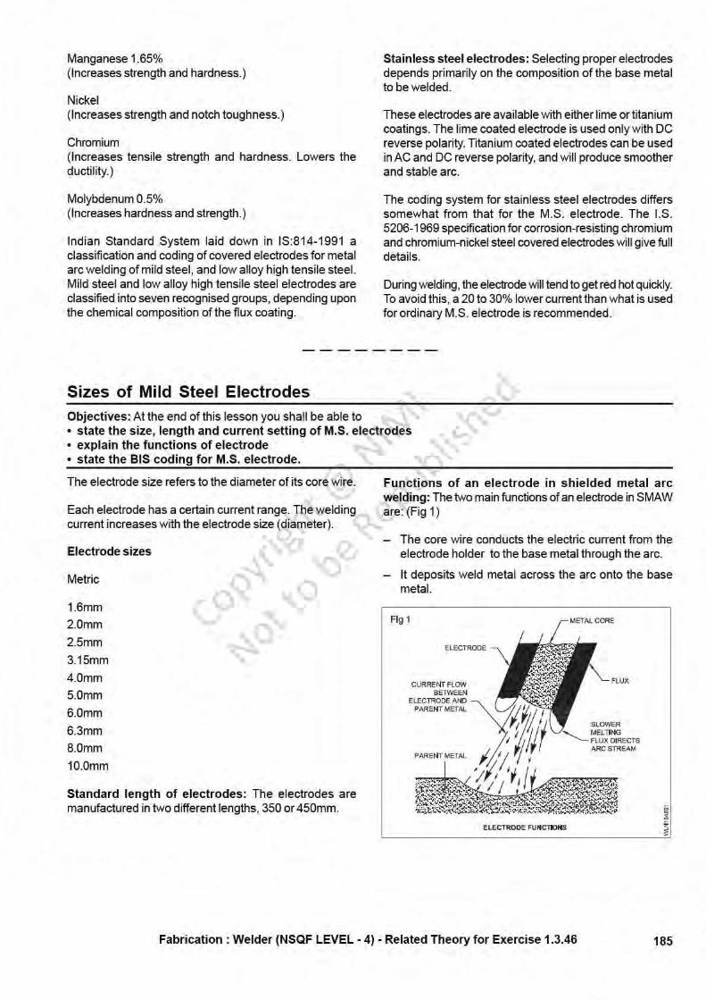
Purpose or function of flux coating: During welding,with the heat of the arc, the electrode coating melts andperforms the following functions.
– It stabilizes the arc.
– It forms a gaseous shield around the arc which protectsthe molten weld pool from atmospheric contamination.
– It compensates the losses of certain elements whichare burnt out during welding.
– It retards the rate of cooling of the deposited metal bycovering with slags and improves its mechanicalproperties.
– It helps to give good appearance to the weld andcontrols penetration.
– It makes the welding in all positions easy.
– Both AC and DC can be used for the welding.
– Removes oxide, scale etc. and cleans the surfaces tobe welded.
– It increases metal deposition rate by melting theadditional iron powder available in the flux coating.
Types of electrodes for ferrous and alloy metals
Mild steel electrode: Mild steel is characterized by carboncontent not exceeding 0.3%. Mild steel electrode corewire contains various alloying elements.
Carbon 0.1 to 0.3%(Strengthening agent)
Keep carbon as low as possible.
Silicon above 0.5%(Deoxidizes, prevents weld metal porosity.)
Fabrication : Welder (NSQF LEVEL - 4) - Related Theory for Exercise 1.3.46
Copyrigh
t @ NIM
I
Not to be Republish
ed
187
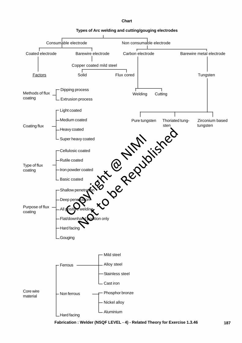
Chart
Types of Arc welding and cutting/gouging electrodes
Consumable electrode Non consumable electrode
Coated electrode Barewire electrode Carbon electrode Barewire metal electrode
Copper coated mild steel
Factors Solid Flux cored Tungsten
Welding CuttingMethods of fluxcoating
Dipping process
Extrusion process
Pure tungsten Thoriated tung- Zirconium based sten tungstenCoating flux
Light coated
Medium coated
Heavy coated
Super heavy coated
Type of fluxcoating
Cellulosic coated
Rutile coated
Iron powder coated
Basic coated
Purpose of fluxcoating
Shallow penetration
Deep penetration
All positive welding
Flat/downhand position only
Hard facing
Gouging
Core wirematerial
Mild steel
Alloy steel
Stainless steel
Cast iron
Phosphor bronze
Nickel alloy
Aluminium
Ferrous
Non ferrous
Hard facing
Fabrication : Welder (NSQF LEVEL - 4) - Related Theory for Exercise 1.3.46
Copyrigh
t @ NIM
I
Not to be Republish
ed
188
Coding of Electrodes as per BIS, AWS and BSObjectives: At the end of this lesson you shall be able to• explain the necessity of coding electrodes• describe the electrode coding as per BIS, AWS and BS.
Necessity of coding electrodes: Electrodes with differentflux covering gives different properties to the weld metal.Also electrodes are manufactured suitable for welding withAC or DC machines and in different positions. Theseconditions and properties of the weld metal can beinterpreted by the coding of electrodes as per IndianStandards.
The chart shown at the end of this lesson gives thespecification of a particular electrode and also shows whateach digit and letter in the code represents. By referringto this chart any one can know whether an electrode witha given specification can be used for welding a particularjob or not.
Classification of electrodes shall be indicated by the IS:814-1991 coding system of letters and numerals to indicatethe specified properties or characteristics of the electrode.
Main coding: It consists of the following letters andnumerals and shall be followed in the order stated:
a) a prefix letter 'E' shall indicate a covered electrode formanual metal arc welding, manufactured by extrusionprocess;
b) a letter indicating the type of covering;
c) first digit indicating the ultimate tensile strength incombination with the yield stress of the weld metaldeposit;
d) second digit indicating the percentage elongation incombination with the impact values of the weld metaldeposited;
e) third digit indicating welding position(s) in which theelectrode may be used and
f) fourth digit indicating the current condition in which theelectrode is to be used.
Additional coding: The following letters indicating theadditional properties of the electrodes may be used, ifrequired:
a) letters H1, H2, H3 indicating hydrogen controlledelectrodes.
b) letters J, K and L indicating increased metal recoveryas 'Effective Electrode Efficiency' as per IS: 13043:91.
J = 110 - 129 percent;K = 130 - 149 percent; andL = 150 percent and above.
c) letter 'X' indicating the radiographic quality.
Different standards used in coding of electrodes
They are:
1 I.S. (814 - 1991)
2 A.W.S.
3 B.S.
INDIAN SYSTEM OF CODING OF ELECTRODESACCORDING TO IS: 814-1991
Type of covering: The type of covering shall be indicatedby the following letters.
A - Acid
B - Basic
C - Cellulosic
R - Rutile
RR - Rutile, heavy coated
S - Any other type not mentioned above
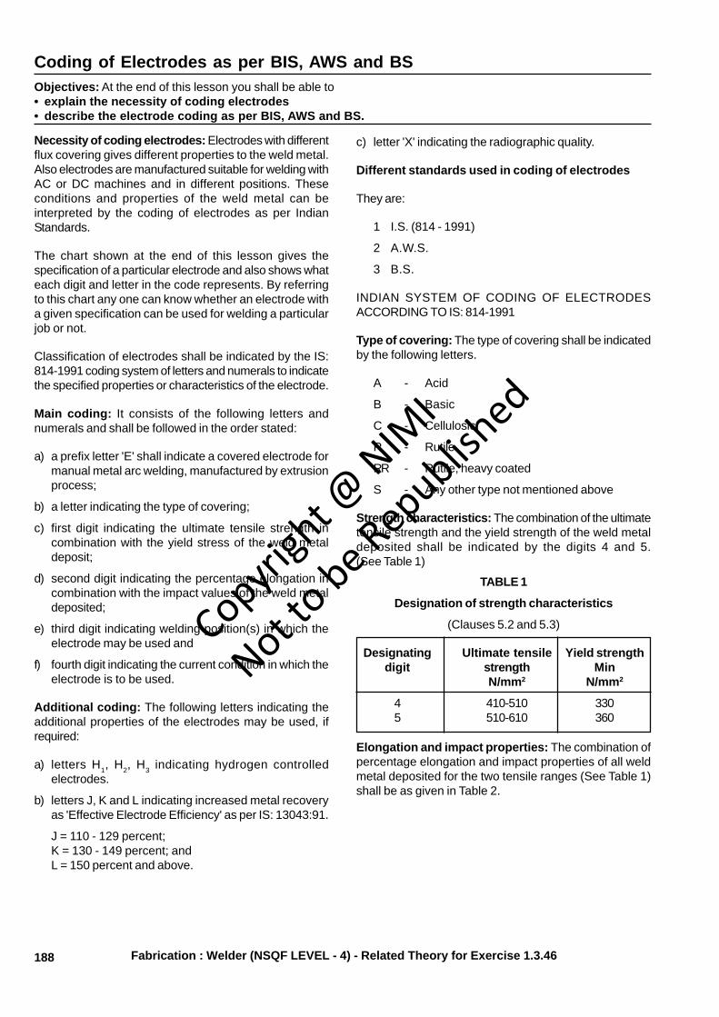
Strength characteristics: The combination of the ultimatetensile strength and the yield strength of the weld metaldeposited shall be indicated by the digits 4 and 5.(See Table 1)
TABLE 1
Designation of strength characteristics
(Clauses 5.2 and 5.3)
Designating Ultimate tensile Yield strengthdigit strength Min
N/mm2 N/mm2
4 410-510 3305 510-610 360
Elongation and impact properties: The combination ofpercentage elongation and impact properties of all weldmetal deposited for the two tensile ranges (See Table 1)shall be as given in Table 2.
Fabrication : Welder (NSQF LEVEL - 4) - Related Theory for Exercise 1.3.46
Copyrigh
t @ NIM
I
Not to be Republish
ed
189
Welding position: The welding position or positions onwhich the electrodes can be used as recommended bythe manufacturer shall be indicated by the appropriatedesignating digits as follows.
1 All positions
2 All positions except vertical down
3 Flat butt weld, flat fillet weld and horizontal/vertical filletweld
4 Flat butt weld and flat fillet weld
5 Vertical down, flat butt, flat fillet and horizontal andvertical fillet weld
6 Any other position or combination of positions nitclassified above
Where an electrode is coded as suitable for vertical andoverhead position it may be considered that sizes largerthan 4 mm are not normally used for welding in thesepositions.
An electrode shall not be coated as suitable for particularwelding position unless it is possible to use it satisfactorilyin the position to comply with test requirements of thiscode.
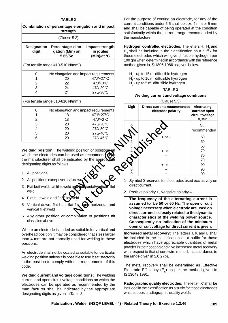
Welding current and voltage conditions: The weldingcurrent and open circuit voltage conditions on which theelectrodes can be operated as recommended by themanufacturer shall be indicated by the appropriatedesignating digits as given in Table 3.
For the purpose of coating an electrode, for any of thecurrent conditions under 5.5 shall be size 4 mm or 5 mmand shall be capable of being operated at the conditionsatisfactorily within the current range recommended bythe manufacturer.
Hydrogen controlled electrodes: The letters H1, H2 andH3 shall be included in the classification as a suffix forthose electrodes which will give diffusible hydrogen per100 gm when determined in accordance with the referencemethod given in IS:1806:1986 as given below.
H1 - up to 15 ml diffusible hydrogenH2 - up to 10 ml diffusible hydrogenH3 - up to 5 ml diffusible hydrogen
TABLE 3Welding current and voltage conditions
(Clause 5.5)Digit Direct current: recommended Alternating
electrode polarity current: open circuit voltage,
V, Min
0 – Not recommended
1 + or – 502 – 503 + 504 + or – 705 – 706 + 707 + or – 908 – 909 + 90
1 Symbol 0 reserved for electrodes used exclusively ondirect current,
2 Positive polarity +, Negative polarity –.
The frequency of the alternating current isassumed to be 50 or 60 Hz. The open circuitvoltage necessary when electrode are used ondirect current is closely related to the dynamiccharacteristics of the welding power source.Consequently no indication of the minimumopen circuit voltage for direct current is given.
Increased metal recovery: The letters J, K and L shallbe included in the classification as a suffix for thoseelectrodes which have appreciable quantities of metalpowder in their coating and give increased metal recoverywith respect to that of core wire melted, in accordance tothe range given in 5.0.2 (b).
The metal recovery shall be determined as 'EffectiveElectrode Efficiency (EE) as per the method given inIS 13043:1991.
Radiographic quality electrodes: The letter 'X' shall beincluded in the classification as a suffix for those electrodeswhich deposit radiographic quality welds.
Fabrication : Welder (NSQF LEVEL - 4) - Related Theory for Exercise 1.3.46
TABLE 2
Combination of percentage elongation and impactstrength
(Clause 5.3)
Designation Percentage elon- Impact strengthdigit gation (Min) on in joules
5.65/So (Min)/at °C
(For tensile range 410-510 N/mm2)
0 No elongation and impact requirements1 20 47J/+27°C2 22 47J/+0°C3 24 47J/-20°C4 24 27J/-30°C
(For tensile range 510-610 N/mm2)
0 No elongation and impact requirements1 18 47J/+27°C2 18 47J/+0°C3 20 47J/-20°C4 20 27J/-30°C5 20 27J/-40°C6 20 27J/-46°C
Copyrigh
t @ NIM
I
Not to be Republish
ed
190
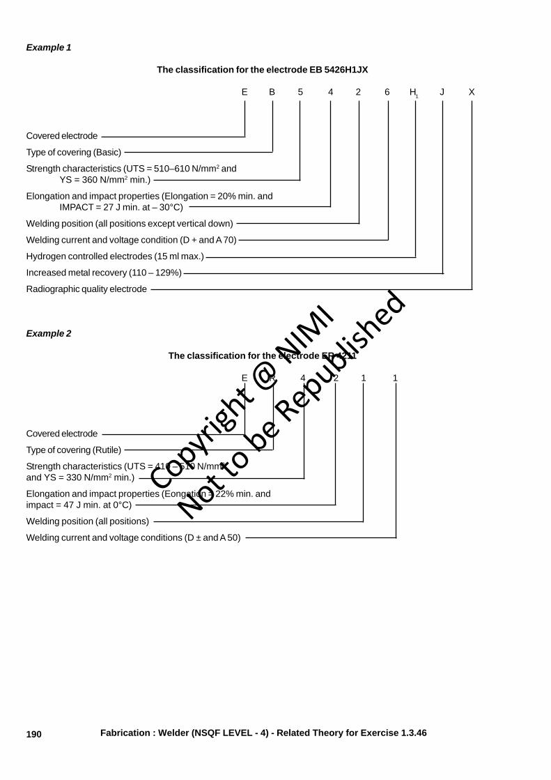
Example 1
The classification for the electrode EB 5426H1JX
E B 5 4 2 6 H1 J X
Covered electrode
Type of covering (Basic)
Strength characteristics (UTS = 510–610 N/mm2 andYS = 360 N/mm2 min.)
Elongation and impact properties (Elongation = 20% min. andIMPACT = 27 J min. at – 30°C)
Welding position (all positions except vertical down)
Welding current and voltage condition (D + and A 70)
Hydrogen controlled electrodes (15 ml max.)
Increased metal recovery (110 – 129%)
Radiographic quality electrode
Example 2
The classification for the electrode ER 4211
E R 4 2 1 1
Covered electrode
Type of covering (Rutile)
Strength characteristics (UTS = 410 – 510 N/mm2
and YS = 330 N/mm2 min.)
Elongation and impact properties (Eongation = 22% min. andimpact = 47 J min. at 0°C)
Welding position (all positions)
Welding current and voltage conditions (D ± and A 50)
Fabrication : Welder (NSQF LEVEL - 4) - Related Theory for Exercise 1.3.46
Copyrigh
t @ NIM
I
Not to be Republish
ed
191
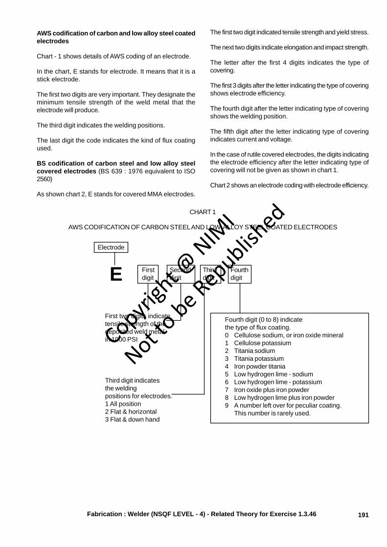
AWS codification of carbon and low alloy steel coatedelectrodes
Chart - 1 shows details of AWS coding of an electrode.
In the chart, E stands for electrode. It means that it is astick electrode.
The first two digits are very important. They designate theminimum tensile strength of the weld metal that theelectrode will produce.
The third digit indicates the welding positions.
The last digit the code indicates the kind of flux coatingused.
BS codification of carbon steel and low alloy steelcovered electrodes (BS 639 : 1976 equivalent to ISO2560)
As shown chart 2, E stands for covered MMA electrodes.
The first two digit indicated tensile strength and yield stress.
The next two digits indicate elongation and impact strength.
The letter after the first 4 digits indicates the type ofcovering.
The first 3 digits after the letter indicating the type of coveringshows electrode efficiency.
The fourth digit after the letter indicating type of coveringshows the welding position.
The fifth digit after the letter indicating type of coveringindicates current and voltage.
In the case of rutile covered electrodes, the digits indicatingthe electrode efficiency after the letter indicating type ofcovering will not be given as shown in chart 1.
Chart 2 shows an electrode coding with electrode efficiency.
CHART 1
AWS CODIFICATION OF CARBON STEEL AND LOW-ALLOY STEEL COATED ELECTRODES
Electrode
E Firstdigit
Seconddigit
Thirddigit
Fourthdigit
First two digits indicatetensile strength of thedeposited weld metalin 1000 PSI
Third digit indicatesthe weldingpositions for electrodes.1 All position2 Flat & horizontal3 Flat & down hand
Fourth digit (0 to 8) indicatethe type of flux coating.0 Cellulose sodium, or iron oxide mineral1 Cellulose potassium2 Titania sodium3 Titania potassium4 Iron powder titania5 Low hydrogen lime - sodium6 Low hydrogen lime - potassium7 Iron oxide plus iron powder8 Low hydrogen lime plus iron powder9 A number left over for peculiar coating.
This number is rarely used.
Fabrication : Welder (NSQF LEVEL - 4) - Related Theory for Exercise 1.3.46
Copyrigh
t @ NIM
I
Not to be Republish
ed
192
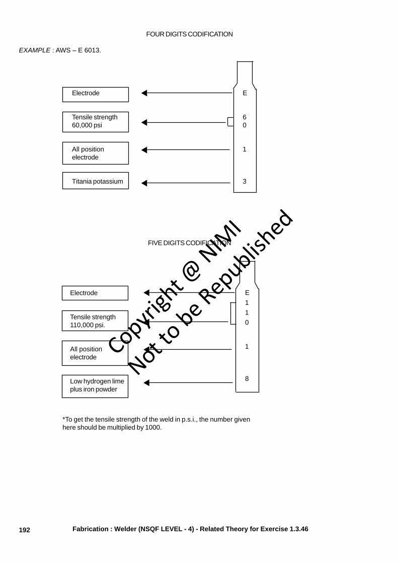
FOUR DIGITS CODIFICATION
EXAMPLE : AWS – E 6013.
Electrode
Tensile strength60,000 psi
All positionelectrode
Titania potassium
Electrode
Tensile strength110,000 psi.
All positionelectrode
Low hydrogen limeplus iron powder
FIVE DIGITS CODIFICATION
E
60
1
3
E110
1
8
*To get the tensile strength of the weld in p.s.i., the number givenhere should be multiplied by 1000.
Fabrication : Welder (NSQF LEVEL - 4) - Related Theory for Exercise 1.3.46
Copyrigh
t @ NIM
I
Not to be Republish
ed

193
CHART 2 (BS 639 : 1976 equivalent to ISO 2560)
STRENGTH 2
Electrode Tensile Minimum yielddesignation strength stress. N/mm2
N/mm2
E43 430.550 330E51 510.650 360
COVERING 4
A Acid (iron oxide)AR Acid (rutile)B BasicC CellulosicO OxidisingR Rutile (medium coated)RR Rutile (heavy coated)S Other types
ELECTRODEEFFICIENCY
5
% recoveryto nearest10% (> 110)
(H) 8
Indicateshydrogencontrolled(> 15mg/100g)
Example (b) E 51 33 B 160 2 0 (H)
1 2 3 4 5 6 7 8PROCESS
1
CoveredMMAelectrode
WELDING POSITION 61 All positions2 All positions except vertical down3 Flat and, for fillet welds, horizontal vertical4 Flat5 Flat, vertical down and, flat fillet welds, horizontal
vertical6 Any position or combination of positions not
classified above.
ELONGATION 3
First Minimum Temperature forDigit elongation, % impact value of
E43 E51 28J, °C
0 Not specified Not specified1 20 18 +202 22 18 03 24 20 -204 24 20 -305 24 20 -40
IMPACT 3
Second Minimum Impact properties
Digit elongation, % Impact value, J Tempera-
E43 E51 E43 E51 ture °C
0 Not specified Not specified1 22 22 47 47 +202 22 22 47 47 03 22 22 47 47 -204 Not 18 Not 41 -306 relevant 18 relevant 47 -50
CURRENT / VOLTAGE 7
Code Direct current Alternating current
Recommended Minimum openelectrode circuit voltage,polarity V.
Polarity asrecommended Not suitableby manu- for use on A C
0 facturer
1 + or - 502 - 503 + 50
4 + or - 705 - 706 + 70
7 + or - 908 - 909 + 90
Fabrication : Welder (NSQF LEVEL - 4) - Related Theory for Exercise 1.3.46
Copyrigh
t @ NIM
I
Not to be Republish
ed
194
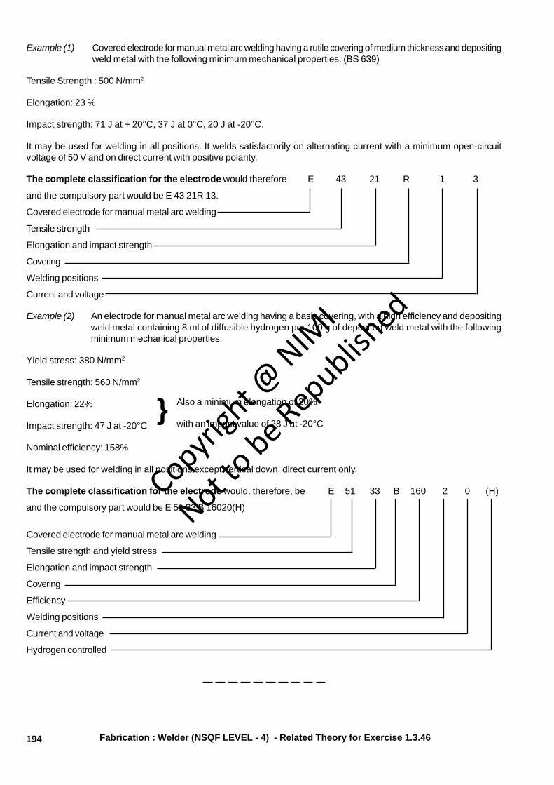
Example (1) Covered electrode for manual metal arc welding having a rutile covering of medium thickness and depositingweld metal with the following minimum mechanical properties. (BS 639)
Tensile Strength : 500 N/mm2
Elongation: 23 %
Impact strength: 71 J at + 20°C, 37 J at 0°C, 20 J at -20°C.
It may be used for welding in all positions. It welds satisfactorily on alternating current with a minimum open-circuitvoltage of 50 V and on direct current with positive polarity.
The complete classification for the electrode would therefore E 43 21 R 1 3
and the compulsory part would be E 43 21R 13.
Covered electrode for manual metal arc welding
Tensile strength
Elongation and impact strength
Covering
Welding positions
Current and voltage
Example (2) An electrode for manual metal arc welding having a basic covering, with a high efficiency and depositingweld metal containing 8 ml of diffusible hydrogen per 100 g of deposited weld metal with the followingminimum mechanical properties.
Yield stress: 380 N/mm2
Tensile strength: 560 N/mm2
Elongation: 22%
Impact strength: 47 J at -20°C
Nominal efficiency: 158%
It may be used for welding in all positions except vertical down, direct current only.
The complete classification for the electrode would, therefore, be E 51 33 B 160 2 0 (H)
and the compulsory part would be E 51 33 B 16020(H)
Covered electrode for manual metal arc welding
Tensile strength and yield stress
Elongation and impact strength
Covering
Efficiency
Welding positions
Current and voltage
Hydrogen controlled
Also a minimum elongation of 20%
with an impact value of 28 J at -20°C}
Fabrication : Welder (NSQF LEVEL - 4) - Related Theory for Exercise 1.3.46
Copyrigh
t @ NIM
I
Not to be Republish
ed

196
Special purpose electrodes and their applications
Objectives: At the end of this lesson you shall be able to• state the types of special purpose electrodes• explain the applications of special purpose electrodes.
– Deep penetration electrodes
– Contact electrodes or iron powder electrodes
– Cutting and gouging electrodes
– Underwater welding and cutting electrodes
– Low hydrogen electrodes
Deep penetration electrodes: These electrodes are usedto get deep penetration in the joints. Deep penetrationoccurs because of the very strong stream of gas producedby the burning of the cellulosic materials in the flux coating.
Butt joints on heavy sections are welded without edgepreparation using these electrodes.
The depth of the penetration will be more than to the corewire diameter of the electrode used.
Contact electrodes (Iron powder): These electrodescontain a large amount of iron powder in their coatings.Therefore the arc ignites very easily. These electrodes arealso called 'touch type' electrode. While using this type ofelectrode a large amount of weld metal is deposited perunit time.
Cutting and gouging electrodes: The cutting electrodesare of a tubular type. While cutting, air is sent through thecentre at high pressure to cut ferrous metals. The gougingelectrode can make 'U' grooves on the ferrous metals.
Underwater welding and cutting electrodes: Theseelectrodes are used to cut and weld metals under thewater. The coating having an external coating of varnishby 'lacquer' polishing or 'celluloid' helps to insulate andprotect the electrode when immersed in water for weldingor cutting purpose.
Low hydrogen electrodes: hydrogen controlledelectrodes shall be such that the diffusible hydrogen contentof the deposited metal will be low. This electrode is usedwith DC reverse polarity and can be used in all weldingpositions. These electrodes help to get a weld withoutcracks.
Fabrication : Welder (NSQF LEVEL - 4) - Related Theory for Exercise 1.3.47
Copyrigh
t @ NIM
I
Not to be Republish
ed

197
Fabrication Related Theory for Exercise 1.3.48Welder - Welding of Steel (OAW, 8mAW)
Weldability of metalsObjective: At the end of this lesson you shall be able to• explain the effects of weldable quality on ferrous and non-ferrous metals.
Weldability:
• The ferrite and Martin site structure on carbon steelsare not suitable for welding. But, the crystal finestructure enables brazing.
• Austenitic steels are suitable for welding. In presentdays all types of steels are welded using inert gasshielded arc process.
Weldability of cast Iron:
Cast Iron is welded after performing preheating to atemperature of 200°C-210°C. On completion of first layerof welding, the same preheating is repeated to maintainthe re-inforcement of weld. Next, the whole job is evenlyheated. This is called post-heating.
The job is cooled slowly, by covering under a heap of limeor ash or dry sand.
Weldability of copper:
99.9% pure copper with 0.01 to 0.08% oxygen in the formof cuprous oxide is known as electrolyte copper and thisis not weldable.
A small quantity of phosphorous added to electrolytecopper to de-oxidise, so as to make it weldable.
The surface of the base metal is preheated to a fairly hightemperature resulting in peacock neck blue colour; beforethe actual welding started.
Once the metal is cooled after welding, to reduce the grainsize and locked up stresses, the pressuring is done.
Copyrigh
t @ NIM
I
Not to be Republish
ed


200
Fabrication Related Theory for Exercise 1.3.50Welder - Welding of Steel (OAW, 8mAW)
Classification of steelsObjectives: At the end of this lesson you shall be able to• state the main classification of steels• explain the effect of carbon content in steel• describe the uses of various types of carbon steel.
Classification of steel: The classification of steel is mainlybased on the chemical composition of various elementslike traces of sulphur, phosphorus, silicon, manganesewith a percentage of less than 1% carbon content in steel.
Thus, the steel is classified as follows,
1) Carbon steel
2) Alloy steel
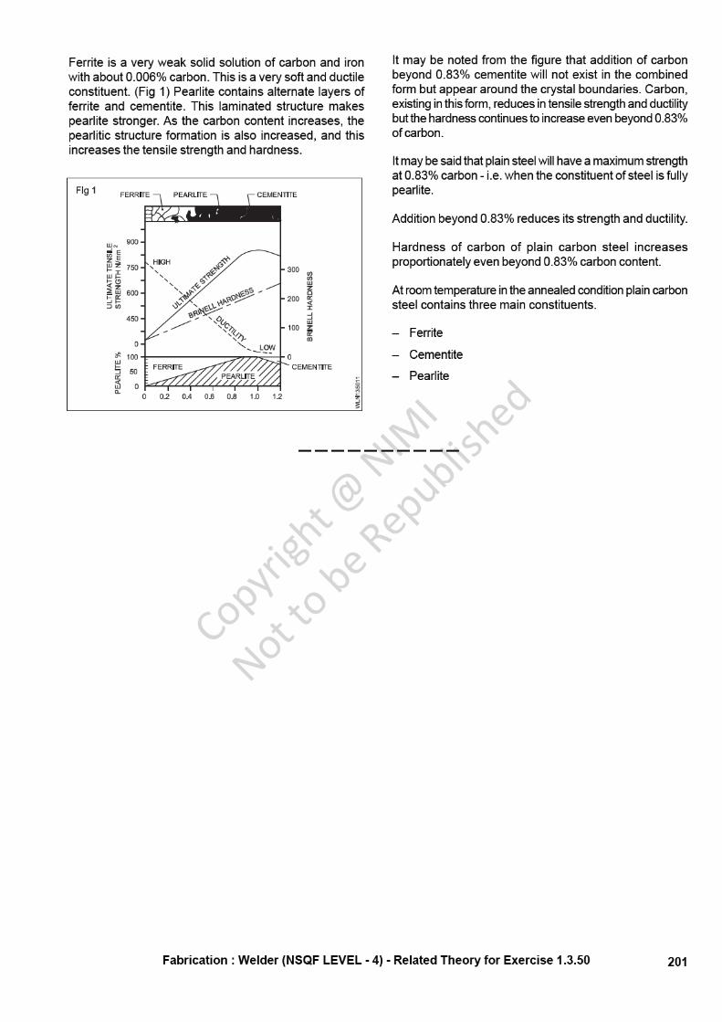
Effects of carbon content in steel: Steel can be definedas an alloy of carbon and iron, in which carbon is in acombined state. The carbon content is a very importantfactor to get the desired properties of steel.
Carbon: Carbon is a very important constituent of steel.
The addition of carbon at varying proportions modifies thecharacteristics of iron and makes it harder, stronger andof greater use in the engineering industry. Slight variationsin the carbon content of steel lead to great differences inthe properties of steel. Depending upon the properties it isput to different uses. (Table 1)
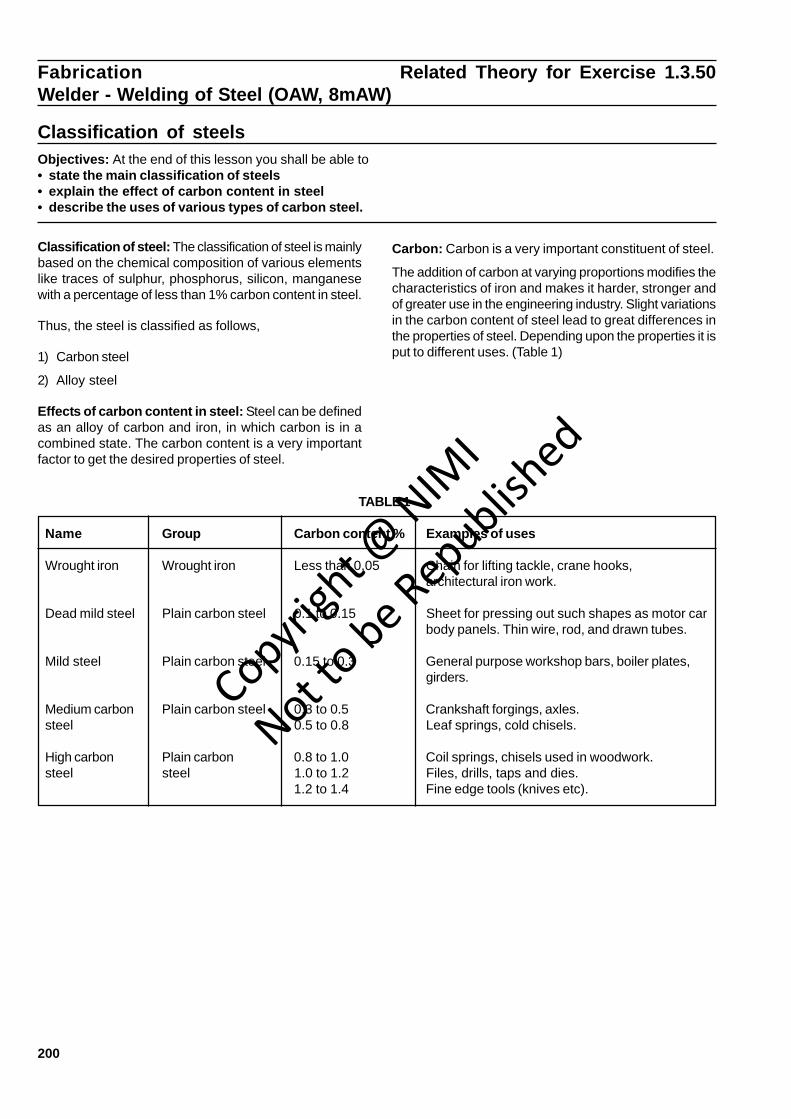
TABLE 1
Name Group Carbon content % Examples of uses
Wrought iron Wrought iron Less than 0.05 Chain for lifting tackle, crane hooks,architectural iron work.
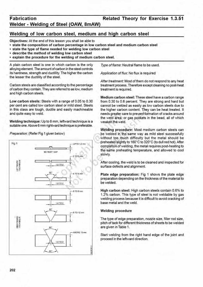
Dead mild steel Plain carbon steel 0.1 to 0.15 Sheet for pressing out such shapes as motor carbody panels. Thin wire, rod, and drawn tubes.
Mild steel Plain carbon steel 0.15 to 0.3 General purpose workshop bars, boiler plates,girders.
Medium carbon Plain carbon steel 0.3 to 0.5 Crankshaft forgings, axles.steel 0.5 to 0.8 Leaf springs, cold chisels.
High carbon Plain carbon 0.8 to 1.0 Coil springs, chisels used in woodwork.steel steel 1.0 to 1.2 Files, drills, taps and dies.
1.2 to 1.4 Fine edge tools (knives etc).
Copyrigh
t @ NIM
I
Not to be Republish
ed
204
Fabrication Related Theory for Exercise 1.3.52Welder - Welding of Steel (OAW, 8mAW)
Alloying elements and their functions on steelObjectives: At the end of this lesson you shall be able to• state the necessity of alloying elements• identify the common alloying elements• describe the effects of each such element.
Necessity of alloying elements: Certain elements areadded to increase the mechanical properties of metals.
Common alloying elements: The following are somecommon alloying elements.
Carbon
Manganese
Sulphur
Phosphorus
Silicon
Chromium
Nickel
Tungsten
Vanadium
Molybdenum
Effects:
Carbon: With the addition of a small amount of carbon topure iron, significant changes in the mechanical propertiesof iron will take place. An increase in hardness and areduction in its melting point are the more significant ofthe changes.
Manganese: This promotes soundness and eliminatesgas holes. It gives a higher tensile strength and hardnessto the metal without affecting the ductility. It controls thesulphur content.
Sulphur: Sulphur forms sulphide which makes steel varybrittle at high temperatures and controls hot shortness.
Phosphorus: The presence of phosphorus in steel varybrittle at high temperature and controls hot shortness.
Silicon: This does not directly affect the mechanicalproperties of the metal. It is generally present in smallquantities up to 0.4% and combines with oxygen in thesteel to form silicon dioxide. This floats to the top of themolten pool during production, thereby removing oxygenand other impurities from steel.
Chromium: Chromium is added to steel to increasehardness and abrasion resistance. Increases resistanceto corrosion.
Nickel: This metal is added for shock resistance and isused with chromium to form a wide variety of stainlesssteel groups.
Tungsten: Tungsten increases hardness and toughnessand will not change even at high temperature.
Vanadium: This increases hardness and toughness.
Molybdenum: Molybdenum gives hardness, toughnessand anti-shock properties to steel.
Copyrigh
t @ NIM
I
Not to be Republish
ed


211
Brazing problems and remedies
Problem Remedy
The filler metal 'balls up' Add more flux. Ensure pickling or additional mechanicaldoes not melt and flow into cleaning to remove oxides, oils, or other surface coatings.the joint. Use fresh flux. Also check for contaminated pickling acid of
'dirty' grinder wheels that could spread impurities instead ofremoving them.
The filler metal melts but Increase the preheating period. The base metal may not be hotdoes not flow completely enough. Ensure thorough cleaning. Try a wider or narrower jointthrough the joint. gap. Joint must not be too tight or too loose. Also check for gaps
or spaces where capillarity is interrupted. Apply more flux to bothfiller rod and base metal. If not successful use a different fluxcompound. Improper flux may be breaking down due to too much heat.
The filler metal runs out Reposition (tilt) the joint, so that gravity helps the filler joint.instead of into the joint. Make a small reservoir in the joint to start the capillary action.
Feed the filler metal into the joint from above rather thanhorizontally or from below.
The filler metal melts but Ensure additional cleaning of the filler metal to remove the oxides.does not flow. Use more flux on both the filler rod and the base metals.
Fabrication : Welder (NSQF LEVEL - 4) - Related Theory for Exercise 1.3.56
Copyrigh
t @ NIM
I
Not to be Republish
ed


223
COMPOSITION OF EACH TYPE
S-C4
Copper 57 to 63%Silicon 0.15 to 0.3%Manganese 0.05 to 0.25%Iron 0.1 to 0.5 %Balance % zinc
Melting point of this filler rod is 870° to 900°C
S-C Fabrication : Welder - Exercise 1.1.01Fabrication : Welder - Exercise 1.1.015
Tin 0.5% maxManganese 0.5% maxIron 0.5% maxCopper 45 to 53%Melting point 970° to 980°CSilicon 0.15 to 0.5%Nickel 8 to 11%
S-C6
Copper 41 to 45%Silicon 0.2 to 0.5%Nickel 14 to 16%Tin 1.00% maxManganese 0.2 % max }
} OptionalIron - 0.3% max }Zinc balance
S-C8
Manganese bronze or high tensile brass.
S-C9
High nickel bronze (High tensile nickel brass)
S-C10
High nickel bronze (High tensile nickel brass)
FUNCTIONS OF EACH ELEMENT
Phosphorus
De-oxidiser
Tin
Improves the strength and corrosion resistance and wearresistance.
Nickel
Improves corrosion resistance, ductility.
Manganese
De-oxidiser, improves wear resistance.
Silicon
Improves fluidity.
Removes impurities.
Fabrication : Welder (NSQF LEVEL - 4) - Related Theory for Exercise 1.3.61
Copyrigh
t @ NIM
I
Not to be Republish
ed