
Untitled - Renew Membership Portal
68
-
Upload
khangminh22 -
Category
Documents
-
view
5 -
download
0
Transcript of Untitled - Renew Membership Portal


Issue Number 32/33 October 1989.
What’s Inside...Double Issue Nimbin Edition
Nimbin Soft Technology 13Editorial introduction.
Nimbin Soft Tech. 13 John Hutchinson’s Low-head CommunityHydro 15
Community Hydro 15
A detailed report on this well-built system by Ian Scales.Community Power Loops for Electricity Dis-tribution 27
Karl McLaughlin describes this low-cost extra-low volt-age alternative to mains electricity.
32 Volt Household Power Systems 32Greg Clitheroe describes his approach to 32 Volt ap-pliance conversions.
Small Propeller Turbines 40Karl McLaughlin discusses the design parameters forbuilding an efficient low-head unit.
Dunlite Blade Retrofit 44 Better Windmills 44, 49Chris Kelman describes how he souped-up his 4-bladeDunlite windmill.
Peter Pedals Personal Power Production 46Peter Pedals talks about his new Pelton wheel.
Flood Damage to Small Water Turbines 48What happens in a big flood, by Ian Scales.
Greenhouse Solutions 11Bill Keepin presents a compelling argument for energyconservation on economic grounds.
Power Point Tracking for Windmills 49Karl McLaughlin and Ian Scales investigate windmillelectrics with an aim to higher efficiency and lower cost.
Solar Water Heater Buying Guide 54Part Two of a 2-part article that tells you what’s on themarket.
Turbine Design 40
Rainforest Timbers 59A list of timbers to boycott, and some alternatives.
Energy Flashes 4New Products 8ATA Report 61Editor’s Notes 62Book Reviews 63Letters 66
Solar Hot Water 54
Page 3 Soft Technology Number 32/33

Bicycle Motors Legalin VictoriaThe Victorian Government hasrecently brought in changes to theRoad Safety Act (1986) allowing amotor up to 200W to be fitted to abicycle. The relevant change wasgazetted in the 1st March 1988 Vic-torian Government Gazette.
It says that the following class of motorvehicles are not motor vehicles for thepurposes of the Act: “Pedal cycles towhich are attached one or moreauxiliary propulsion motors having anaggregate maximum power output notexceeding 200 watts.”
(Electric Vehicle Assoc. News, Sept)
SA Wind EnergyProgramElectricity generated by wind farmsand delivered to the ETSA gridwould still not be competitive withenergy delivered by conventionalfossil fuelled power stations in theforeseeable future, according to therecently released South AustralianWind Energy Program Report.
However, the cost of electricitygenerated from wind turbines is onlyslightly more expensive than the currentcost of electricity produced by dieselgenerators in some remote areas and,with the cost of diesel fuel expected torise in real terms, wind energy shouldbecome competitive with diesel genera-tion in some isolated locations.
On the basis of these results, an ap-plication had been made to theCommonwealth’s National EnergyResearch Development andDemonstration Council for part-fundingof a 300 Ki lowat t wind turb inedemonstration facility at Coober Pedy.
(SA Energy News)Tasmanian WavePower ProjectAustralia’s first wave powergenerating station is to bedeveloped at King island in Tas-mania at a cost of A$7 million andhave a capacity of around 1.3MW.
All necessary technical and financialdata is being assembled both in
Page 4 Soft Technology Number 32/33

Australia and overseas and is based ona wave power prototype that has al-ready been built in Norway by NorwaveA.S. The station will take about threeyears to build. It is to be funded by theTasmanian HEC and Norwave.
Tasmania ConsideringWind PowerThe Tasmanian Government hasjust promoted windpower to thirdplace in their list of energy produc-ing options. The decision to adoptwind as a third viable option followsa study carried out with the Nation-al Energy Research Demonstrationand Development Counci l(NERDDC).
The HEC and NERDDC is satisfiedthat wind machines are both reliableand made by reputable manufacturers.The area required for a wind farm isregarded as the only real drawback -they estimate that to generate 120MWrequires a coastal strip 70km long and2km deep. They aren’t used to thinkingsmall, are they?
Australia is SolarLeaderAustralia is still ahead in commer-cial solar technology, according toProfessor Martin Green of theSchool of Electrical Engineering atthe University of N.S.W.
Australia is the fourth largest tradition-al solar cell manufacturer in the worldand in GNP terms, the world’s largestmanufacturer of the traditional solar celltype.
“We just happen to be working on thetype of cell which is dominant in com-mercial technology and we hold all therecords made in that particular field,”said Green. (Electrical World, June)
Access to SunlightNow a Planning IssueSouth Australia’s new Urban Con-solidation policy seeks to allowhouses to be closer together, andsupports some medium-rise hous-ing in suitable locations. Shadows
cast by new housing will havepotential to cause problems in thisscheme.
The plan recognises the difficultieswhich can be caused by shadowing andaccordingly allows the impact of suchshadows to play a part in any planningapproval. In addition to referring to solarenergy systems under its objectives,the plan also includes a principle whichenables planning approval to be deniedif access to incident solar radiation isunreasonably impaired.
As a general policy it puts solar ac-cess on the planning agenda. Accord-ingly, there is now an opportunity formore specific “shadowing” policies tobe developed by individual Councils,tailor-made to local circumstan-ces. (S.A. Energy News)
New AustralianAerosol PropellantAerosol cans could be soon usingnitrogen as their propellant insteadof CFC’s. However, nitrogen has tobe kept at a very high pressure tokeep it in its liquid form, and it is fartoo expensive to strengthen thewhole can.
An Australian company, OverseasTechnology, has found an economicalsolution to the problem. it is a can thatstores liquid nitrogen in a small metalcontainer, similar to the bulbs used insoda syphons. The bulb and its valvetransfer nitrogen evenly to the liquid inthe can.
According to Overseas Technology,manufacturers should easily be able toincorporate bulbs into their cans withoutdisrupting their production lines toomuch. (New Scientist, July)
Australian ElectricVehicles for LosAngeles?The Los Angeles City Council(LACC) hopes to have 3,000electric vehicles on the road by1991, and 10,000 by 1995. AnAustralian company, Elroy En-gineering, is one of the 5 finalists fora contract to supply the city withelectric cars, vans and buses.
Elroy Engineering has developed 17models of electric vehicle, ranging fromlarge buses to commuter vans and cars.The company’s vehicles use the con-
Soft Technology Number 32/33 Page 5

Stirling Engine
ventional lead acid type of battery. Thedesigner of the cars, Roy Leembrug-gen, explained that this is because leadacid batteries are the only proven, com-mercially available, and economicallyviable batteries.
Despite this, Mr Leembruggen, saysthat his company’s Townmobilevehicles easily meet the LACC stand-ard of a 90km/h road speed and 90kmoperating range. He described the at-titude of Australian governments toelectric vehicles as one of“apathy”. (Aust. Electric Vehicle Assoc.News, Sept.)
Power Politics inTasmaniaApparently Tasmania’s energypolicy is about to be renovated forthe first time in years now that theGreen Independents have thebalance of political power firmly intheir grasp (incidentally the third in-stance world wide that enviromen-talists have won the right to controlparlimentary proceedings).
The Independent’s energy policy in-cludes:
1) an increased use of solar waterheating
2) the establishment of a greenhousecar registration scheme
3) the establishment of a centre for ap-propriate technology and an inter-mediate technology developmentgroup
Their intention is also to make greateruse of natural resources - such aswood, gas and coal, to place greateremphasis on energy conservation andco-generation (already enjoying somesuccess in Victoria), and to thoroughlyinvestigate all sources of alternateenergy. (Electrical World, June)
Stirling Engine NowLooks PracticalThe Stirling external-combustionengine runs equally well ongasolene, kerosene, ethanol or vir-tually any other combustible liquid.After a decade of research byNASA and its contractor Mechani-cal Technology Incorporated (MTI),
one may finally be commercially vi-able. It is an alternative to internalcombustion, but until now has notbeen available at a reasonableprice or performance level.
According to MTI, the new Mod.II Stirl-ing engine is competitive in size, weightand performance with conventionalspark-ignition engines. Experimentalengines installed in U.S. Air Force vanshave logged more than 18,000 milesburning a variety of fuels, and they haveshown consistently good performance.
( Scientific American, Jan.)
PetrolheadsSmokescreen BicyclesThere are 270 million bicycles inChina; some 50,000 people onbikes have been counted passing atraffic checkpoint in the city of Tian-jin in one hour. Yet the World Bankcan produce a report on traffic inChina without once mentioning thebicycle.This is not the case for WorldwatchMagazine, which in its August 1988issue had an article by Marcia DLowe giving facts and statistics inan easy-to-read style on bicycletransportation around the world, in-cluding these:
In Japan the city of Kasukabe has a12 story parking tower; The Nether-lands has 9,000 ‘miles of bikeways;20,000 bicycle rickshaws have beenconfiscated in Jakarta, Indonesia toreduce traffic (and make way for cars);and in the United States, statistics onbicycles are gathered only as their usefor toys. (Tranet)
Page 6 Soft Technology Number 32/33

Los Angeles May BanPetrol CarsCars fuelled by petrol could bebanned from much of southernCalifornia by the year 2007, accord-ing to new proposals for cleaning upthe notorious Los Angeles smog.The measures, by which stand agood chance of being implemented,will replace petrol with methanol.They are likely to become ablueprint for other American citieswith smogs.
There will be heavy fines for com-panies that do not introduce compul-s o r y c a r - p o o l i n g a m o n g t h e i remployees, a limit on the number ofcars that each family can own, and anend to free parking. Cars will be re-quired to have radial tyres becausethese throw less dust into the air. By1993, all fleet vehicles, including rentedcars, should run on fuels, such asmethanol, that burn cleanly. The two bigAmerican car makers, Ford andGeneral Motors, are expected to beproducing up to 100,000 cars that runon methanol by that date.
The cost of the measures during thefirst five years will be about $2.8 billiona year. Air pollution is estimated to costsouthern California $13 billion a year inhealth expenses and damage to cropsand property. By 1998, 40% of all cars,70% of freight vehicles and all busesmust convert to cleaner fuels. By 2007,all cars are to be converted to run onclean-burning fuels or electric power.
(New Scientist, April)
Sunlight DestroysDangerous Chemicals.In a joint program researchers atthe Solar Energy Research Institute(SERI) laboratory and at SandiaNational Laboratories in the U.S.are developing ways to destroytoxic chemicals in industrial wasteor groundwater using solar collec-tors.
At Sandia, Craig E. Tyner is testing aprocess that purifies water con-taminated with organic chemicalssuch as trichloroethylene. The water ismixed with titanium dioxide, which ser-ves as a catalyst, and is pumpedthrough Pyrex tubes at the focus ofparabolic trough-shaped mirrors.
Solar toxic waste destruction
The ultraviolet energy in the sunlightgenerates reactive hydroxyl radicalsand peroxide ions that convert a third ofthe contaminants into benign substan-ces during a 20 second pass over a mir-ror 120 feet long and 7 feet wide. Thetitanium dioxide is easily filtered out forre-use. Passing the polluted waterthrough the trough a few times canreduce contaminants present in parts-per- million quantities to levels of parts-per-billion, according to Tyner, who isundertaking larger-scale experimentswith groups of mirrors.
Still in its early stages is a processbeing developed by Jim D. Fish of San-dia for converting waste organic chemi-cals into fuels. The process relies on thesun’s heat rather than on its ultravioletrays. A catalyst (rhodium is under study)is supported in a chamber at the focusof a dish-shaped reflector. The focusingyields temperatures between 800 and1,000 degrees C., high enough for thecatalyst to convert organic chemicalsthat are pumped through the chamberinto such gases as carbon monoxideand hydrogen. The gases can then bemade to react, producing methanol forfuel.
The process is being tested withmethane as a raw material, but Fishhopes to make fuels out of chlorinatedhydrocarbons, which are strongly toxicpollutants. The waste chlorine could beconverted into hydrochloric acid, whichis a raw material for many industrialprocesses.
A further technique, by John P.Thornton of SERI, is a solar furnacewhere light is focussed at an intensity of300 suns on a quartz vessel containing
a form of dioxin. The sunlight quicklybreaks down 99.99% of the dioxin intorelatively harmless compounds. Ac-cording to Thornton, the ultravioletenergy in sunlight ensures that dioxin iseffectively destroyed at temperaturesas low as 750 degrees C, hundreds ofdegrees less than must be attained inan incinerator.
(Scientific American, June)
U.S. Exports Rubbish(!)Power, Water and Waste, a Britishcompany has held initial talks withwaste disposal and planning offi-cials from Cornwall County Councilabout importing almost 2 milliontons of domestic refuse a year fromthe U.S.
The garbage will be used to generatelarge quantities of landfill gas, sufficientto power 25 Megawatt generating sta-tion.
(ACTA Newsletter)
Recycling Popular.Aluminium now sells as scrap at$1.20 a kilogram in the U.S. Lastyear California lost $200,000 worthof roadsigns and guardrails to high-way robbers.
Airforce bomber parts, irrigation pipesand aluminium siding taken from ad-jacent homes have also been stolen aswell as scaffolding from building sites.Light poles knocked down in accidentsalso disappear rapidly.
(ACTA Newsletter)

New Range oflnvertersPower Conversions Pty. Ltd. havereleases the latest in their range ofsine wave DC-AC ultra-lightweight in-verters, a true 500 watt continuous(1000 watt peak) output and a true1200 watt continuous (2000 wattpeak) output power converter (in-verter).
Power Conversions now also offer apower supply and system customdesign service in addition to their rangeof standard inverters. Using a techniquepatented by Power Conversions, theseinverters are ultralightweight (5kg and11 kg respectively), compact, quiet, effi-cient (up to 87% and 90% respectively,72% and 78% at 10% load) and verycompetitively priced.
Features include: High efficiency(documentation available), crystal lock-ed 50Hz frequency, sine wave outputless than 2% distortion, output voltageregulation +/- 1% from 5% to 100% loadfull current limiting, full transient protec-tion, input over and under voltageprotection, over temperature cutout, +/-0.9 power factor loads, 19 inch rackmount (3U for 1200 watt unit, 2U for 500watt unit), foolproof operation, fully iso-lated to 2kV, reverse polarity protection.
All Power Conversions products havea one year warranty, guaranteed perfor-mance and are backed by a free, ongo-ing product/installation consultationservice.
For further information contact the dis-tributor: Ann Cooke ph. (03) 459 7963
Power Point Trackerfor PhotovoltaicsAustralian Energy ResearchLaboratories have released a low-cost maximum-power-point trackerwhich offers high efficiency andreliability. It automatically maxi-mises the electrical power output ofall PV systems.
It is designed to solve the problem ofextracting maximum available powerfrom PV solar panels. To use amechanical analogy, the power-point-tracker is like a gearbox.
The “Maximizer”, as it is called, ismanufactured in 8 models; 4 models ofvarious power ratings (300, 600, 900and 1200W) for water pumping ap-plications and 4 models of similar power
Power Conversions inverters
ratings for battery charging applica-tions. For battery charging, the‘Maximizer' will increase the averagedaily system operating efficiency by upto 15%. For water pumping, it doublesoutput of Positive Displacement pumpsand boosts output of other types ofpumping systems. Output voltage fromthe unit can be set at any level below160V introducing flexibility to the sys-tem.’
For further information contact Rain-bow Power Company, 70 Cullen St.Nimbin, NSW 2480; phone (066) 891430.
Low Speed Generatorfor Savonius WindMachineFiscar, a company in Victoriamarkets a Savonius wind generator
The ‘Maximizer’
Page 8 Soft Technology Number 32/33

producing one kilowatt from adirectly driven generator revolvingat 130 rpm.
A complete system with inverter bat-teries etc. costs $15,000. Cut-in speedis 30 rpm and generator efficiency is95%. The generator weighs 85kilograms, uses permanent magnetsand sells for about $6,000.
Fiscar can be contacted on (03)758.2324 or 2 Oaklands Avenue,Ferntree Gully Victoria, 3156.
ComputerSpreadsheets forDesigning PV andWind Energy SystemsA package of computer spread-sheets for use with LOTUS 123,release 2, is now available to speedup the design of photovoltaic (PV)
These spreadsheets have beendeveloped by Trevor Berrill who hasover 8 years experience in the designof RAPSS. The spreadsheets are prac-tical, user friendly tools for renewableenergy technologists and educators. Atthis stage the package includes:
Load Sizing Spreadsheet - Thisspreadsheet calculates the electricalload for a typical day in each month fora RAPSS. It allows the user to input ap-pliance power rating, time of use, andinverter efficiency.
This data is then combined withclimatic data such as mean monthlytemperature and heating and coolingdegree hours to predict the averagedaily load per month. The spreadsheetwill allow the designer to select the mosteconomical and energy efficient com-bination of electrical appliances.
PV Sizing SpreadsheetThis spreadsheet calculates the num-
ber of PV modules required for a
This includes the cost of back-upenergy from petrol or diesel generators.It allows the user to input load data,component efficiences, PV modulespecifications, site insolation andtemperature data, battery capacity andcomponent cost information. The ef-fects of varying input data can be ex-amined.
Wecs Spreadsheet - This spread- sheet calculates the size and charac-teristics of a suitable wind generator fora RAPSS.
The spreadsheet analyses site windspeed data and calculates batterycapacity and average battery state ofcharge for each month.
The spreadsheet allows the user toinput load data, site wind speed data,tower height, surface roughness,temperature inversion and speed-upfactors, WECS characteristics andpower curve data, battery capacity andcomponent cost information. The ef-
and wind energy- conversion sys- RAPSS. It calculates the battery fects of varying input data can then betems (WECS) for remote area capacity, predicts the average state of examined.power supply systems (RAPSS). charge of the batteries for each month Cost of the RAPSS spreadsheet
and then costs the system. package including computer disc and
Mains Power From A Battery !TRUE SINE WAVE DC-AC INVERTERS
Indigenous Industries - distributors for Power Conversions Pty. Ltd.‘s high efficiency and ultra lightweight true sinewave inverters.
O N E Y E A R W A R R A N T Y
Power Conversions guarantee the performance and efficiency of their inverters. All products are fully supported bya free of charge installation and usage advisory service from qualified engineers.
All inverters feature compact, lightweight design withquiet operation and have: Input reverse polarity protec-tion, full output voltage regulation, battery over andunder voltage protection, short circuit proof, autostart(except 500W unit) - less than 1 watt power drain, fulltransient protection, over temperature protection.500W and 1200W 19 inch rack mounted inverters havecrystal locked 50Hz output frequency and fullprimary/secondary isolation up to 2kV RMS.CUSTOM DESIGN SERVICE AVAILABLE
(From top: 300W, 500W, 1200W inverters)Designed (patent pending) and manufactured in Australia.
INDIGENOUS INDUSTRIES2 Fay Street, Heidelberg, Vic. 3084. Phone: (03) 459 7965
Soft Technology Number 32/33 Page 9

instruction manual is $79.00 pluspostage.
For further information, contact TrevorBerrill, Ithaca College of TAFE, FulcherRd. Red Hill, Qld. 4059 ph. (07) 369-9011
Micro-hydro-electricGeneratorThe Rainbow Power Company hasbegun marketing its electronicallyregulated Pelton Wheel rated for upto 300 watt output. It operates be-tween heads of 12 and 90 metresand is suited to low-flow situations(0.3 to 2.3 litres/second).
The unit will produce 1.5 amps fromas little as 0.4 litres per second at 20metres head (30 psi with a 3/16” noz-zle) and up to 20 amps at 12 volts (10amps at 24 volts) when both pressureand flow rate are sufficient.
Flow rate is controlled by a choice ofnozzle sizes. These nozzles can bechanged by the customer very easily.Seasonal variation of flow is catered forby the use of two nozzles. This allowsthree levels of water consumption andpower production, adjusted by two gatevalves.
The heart of the machine is a very ef-ficient 3-phase induction generator. Rainbow Power Co. Pelton wheel
Performance of the R.P.C. Pelton Wheel
Having no slip-rings or carbon brushes,the machine is virtually maintenance-free. A feature of the regulating systemis that the machine may be manuallyadjusted for optimal operation at theparticular turbine site.
The unit also incorporates a batterycharger which converts the generatoroutput into a form suitable for either 12V or 24V battery banks. This designuses high efficiency MOSFET technol-ogy. The unit has an inbuilt automaticvoltage regulator, reducing the chargerate as the batteries reach their fullcharge. Excess power is burnt off in anonboard load dump.
Power transmission over a distance ispossible because the generator putsout a high voltage before being trans-formed to a low voltage.
The unit is made of corrosion-resistantand mechanically strong materialsthroughout for robustness in rugged ter-rain.
For more information, contact theRainbow Power Company, 70 CullenSt, Nimbin 2480; ph. (066) 89 1430.
Page 10 Soft Technology Number 32/33

NUCLEAR SOLUTIONTO THE
GREENHOUSE EFFECT?By Bill Keepin.
Energy conservation is a farcheaper path by which to ad-dress the problem of green-house warming when com-pared to its main rival‘solution’, nuclear power; evenif we accept the most optimis-tic economic projections of thenuclear power industry.
A Nuclear FutureIt is clear from the energy futures
literature that without con-siderable improvement in energyefficiency, future energy growthwill be substantial. In this context,we begin our analysis by selectingstate-of-the-art scenarios thatspan a range from moderate tohigh energy growth (published bythe National Academy of Scien-ces and the Department of Ener-gy).
Next, we assume conditions thatwould be highly favourable to anuclear solution to the green-house problem:
(1) large nuclear power plantscould be built in just 6 years ratherthan the usual 10 or 12;
(2) Nuclear power would be rela-tively inexpensive (we adopt themost optimistic cost projectionsavailable from nuclear proponentsand (3) all the problems associated withnuclear power would be readily solvedor would simply disappear in the future.
Thus in utmost optimism, we specifi-cally exclude any consideration ofnuclear waste treatment and storage,all health and safety concerns, decom-missioning of retired plants, and thepossible impact on the proliferation ofnuclear weapons. Finally, since coal isthe most carbon-intensive fossil fuel,
" ... each dollar investedin improved energyefficiency displaces
nearly seven times asmuch carbon as a dollarinvested in new nuclear
power.”
and given that an early carbonreduction means a greateramelioration of global warming-we assume that nuclear powerwould displace all coal useworldwide by the year 2025.
These hypothetical assump-tions are extreme indeed, buttaken together, they embracethe nuclear dream and its besthope for solving the green-house problem. What are theimplications? It turns out that wemust build a new large nuclearpower plant every 1 to 3 daysfor the next 37 years, costing anaverage $500 to $800 billionper year.
Nuclear programs on such ascale are clearly unfeasible,especially in developingcountries that would have todouble their current debt bur-den just to build the requiredplants. But, for the sake of argu-ment, suppose that such aprogram could be implemented.What would happen to futureCO2 emissions? Answer: globalcarbon dioxide emissions fromfossil fuel combustion wouldcontinue to grow, remaining ator above today’s levels formany decades hence! This isdue to the expansion of oil andnatural gas in these scenarios.Hence, in the absence of sub-stantial energy efficiency im-provement, even massive ex-
pansion of nuclear power on a globalscale to absurd proportions would notprevent future CO2 emissions fromgrowing, and climactic warming wouldcontinue nevertheless.
These startling results follow from twosimple factors. First, nuclear powertoday provides only a few percent of theworld’s energy supply, and so it wouldhave to expand dramatically to increaseits share substantially. Second, nuclearpower is practical only for electricity
Soft Technology Number 32/33 Page 11

generation, which is responsible for justone- third of fossil fuel consumption.Thus nuclear power’s scope for reduc-ing fossil fuel dependence is fundamen-tally limited.
The rationalapproach: EnergyEfficiency.
In contrast, improvements in energyefficiency are available for the full rangeof fossil fuel uses. A quiet revolution hasbeen steadily developing since the firstoil crisis in 1973, substituting ingenuityfor energy. The results are dramatic: acompact fluorescent light bulb con-sumes only 18 watts but produces asmuch light as a standard 75 watt incan-descent bulb. Thus over its 10 year lifetime, a single such bulb prevents theburning of 400 pounds of coal, andeliminates the release into the atmos-phere of 10 to 12 pounds of sulphurdioxide which is linked to acid rain. Automanufacturers have developedprototype four-passenger automobileswith composite urban-highway fuel ef-ficiencies between 73 and 124 milesper gallon (mpg). Volvo has a 71 mpgprototype that withstands impacts moresevere than many production models,has better acceleration than theaverage new American car, and couldbe mass produced for about the samecost as today’s subcompacts.
“...(If we are to opt forthe nuclear solution), wemust build a new large
nuclear power plantevery 1 to 3 days for the
next 37 years...”
In the United States it costs no moreto build an energy efficient office build-ing than an inefficient one, and yet ifthese commercial building improve-ments were adopted now, then over thenext 50 years, the construction of 85new power plants and the equivalent oftwo Alaskan pipelines could beavoided. Detailed studies frommainstream research institutions showthat by investing in energy efficiency,the U.S. could cut its energy consump-tion in half - reducing CO2 emissionsand acid rain accordingly - with annualsavings of $220 billion and no com-
promise in lifestyle (see “Energy Effi-cient Buildings”, Scientific American,April 1988).
Comparison of theTwo Strategies
The U.S. is the single largest sourceof CO2 emissions in the world. There-fore it is of particular interest to compareefficiency and nuclear investments forabatement of carbon emissions in theU.S. Given today’s average costs fornew nuclear power (13.5 cents perkilowatt-hour) and electric end-use ef-ficiency (2 cents/kWh), a dollar investedin efficiency displaces nearly seventimes more CO2 than a dollar investedin nuclear power. Proponents of nuclearpower argue that building standardisedplants in a stable regulatory environ-ment would greatly reduce the cost ofnuclear electricity, while others arguethat electric efficiency would also costmuch less. In any case, even under themost optimistic cost projections fornuclear power, electric efficiency stilldisplaces 2.5 to 10 times more CO2 perdollar invested.
Many people have assumed that, likeit or not, nuclear power will ultimately bethe only practical response to thegreenhouse problem. However,analysis shows that without substantialimprovement in energy efficiency, evencolossal worldwide expansion ofnuclear power cannot prevent futureC O2 emissions from growing.Moreover, each dollar invested in im-proved energy efficiency displacesnearly seven times as much carbon asa dollar invested in new nuclear power.In short, not only would a nuclearresponse to the greenhouse effect notsucceed, but its pursuit would likely ex-acerbate global warming by divertingfunds and attention away from the mostpromising abatement strategies.
In the greenhouse debate, as with somany other crises facing modern tech-nological culture, a narrow problemdefinition has created conceptualblindspots.
" ... a dollar invested inefficiency displaces
nearly seven times moreCO2 than a dollarinvested in nuclear
power."
The dilemma has been portrayed asmerely a question of where to gettomorrow’s pollution-free energy. If webroaden this scope to ask what theenergy is to be used for, and how wecan best provide these same servicesin a pollution-free manner, a whole newsolution becomes visible - one in whichthe greenhouse problem is greatlydiminished and billions of dollars aresaved.
“... in the absence ofsubstantial energy
efficiency improvement,even massive expansionof nuclear power on aglobal scale to absurdproportions would not
prevent future CO2
emissions fromgrowing...”
Just five compact fluorescent lightbulbs in a single household create thesame rich and cozy light as their incan-descent ancestors, and yet they leavetwo thousand pounds of coal sitting inthe ground. The key to reducing futurecarbon dioxide emissions from the com-bustion of fossil fuels is to improve theenergy efficiency of the globaleconomy.
This article is based on a detailedanalysis entitled “Greenhouse Warm-ing: Comparative Analysis of Nuclearand Efficiency Abatement Strategies”published in Energy Policy, December1988.
Dr. William Keepin is an environmen-tal consultant living in Berkeley, Califor-nia, and an adjunct scholar of the RockyMountains Institute in Snowmass,Colorado, which was founded byElmwood Peers Amory and HunterLovins.
His published works on greenhousewarming include detailed reviews ofglobal energy/carbon dioxide projec-tions, and comparative analyses ofpolicies to abate greenhouse warming.
Reprinted from the ElmwoodNewsletter, Vol. 4 No. 4, 1988.
Copyright 1988, by Dr. WilliamKeepin.
Page 12 Soft Technology Number 32/33

Nimbin Soft Technologyeditorial introduction
This issue of Soft Technology is toa large extent given over to alterna-tive technology developmentsaround the Nimbin district of Nor-thern New South Wales. I visitedNimbin earlier this year, and spoketo a number of people about whatthey had been doing recently, par-ticularly in the field of renewableenergy.
ContextNimbin is a picturesque sub-tropical
rural locality famous as the site of oneof Australia’s most famous radicalevents, the Aquarius Festival of 1973.The festival was fuelled by a now-fabulous optimism for the coming ofpost-industrial paradise.
Many of those present stayed on toform communities; they have made lifemore comfortable over the years byadopting low-cost and home- madetechnologies such as low-voltage light-ing and appliance systems fed by tinypelton wheel water turbines orphotovoltaic panels (cheaper than themains!), and owner-built housing.These improvements are found
throughout the region, lending a flavourof autonomy - and not least in a sym-bolic sense. In urban cosmology Nim-bin stands for the hint of a future wherethe market has once again becomesubservient to myriad alternative socialexchanges that involve community,rather than corporations.
The Nimbin landscape is surely moreoptimistic than that to which it stands inpastoral counterpoint -the ‘late modern’city on which it is, in reality, economical-ly dependent.
Alternative TechnologyAround Nimbin can be found plenty of
examples following the precepts of thealternative technology movement asexpounded during the early 1970’s byfigures such as Schumacher. Suchtechnologies are small scale,decentralised, under community con-
The editortrol, understood by the users themsel-ves, economically feasible and environ-mentally safe.
Historically, it is possible to charac-terise the alternative technology of theregion into an earlier stage of rudimen-tary technology utilising the basic prin-
ciples, and a later stage of moreelaborate construction.
Very rudimentary technology,epitomised by the pelton wheel made ofold soup spoons by Peter Pedals, wasinefficient but proved an important pointthat needed to be made: the principlesof modern technology could be appliedin a rough and approximate manner byanyone willing to improvise, with a satis-factory result.
This proved beyond doubt that ordi-nary people can appropriate the powerof modern technology from the tech-nocrats, and so become producers oftheir own destiny rather than mystifiedconsumers of whatever the tech-nocratic State judges suitable.
That point being made, however,leaves one the option of improving on‘in principle’ designs and recognisingthat there are in fact often enoughresources around to be quite sophisti-cated. However this is keeping in mindwhere such designs are coming fromand retains the hallmarks of smallnessof scale and the bricolage technique,where the final nature of the design is
The ACTA flagship
Soft Technology Number 32/33 Page 13

to some extent dictated by the particularmaterials already on hand.
Remote Area PowerSchemes
Nimbin is a high rainfall area, and thisis reflected in the fact that when itcomes to local renewable energy sour-ces, the novel developments are main-ly in the field of water power. Manypeople have their low-voltage lightingsystem driven by a small pelton wheelfed through plastic poly-pipe from aremote dam high up on a little tributarystream in this hilly area, while someothers are supplied by a low-head, high-flow turbine located down in a largerstream.
These developments tend to over-shadow wind turbine technology (thedistrict is not on average very windy);and although solar panels are quitecommon, these are a commercial tech-nology and as such fairly straightfor-ward.
A.T. in the CommunityThe Nimbin region people set up the
Appropriate Community TechnologyAssociation to further the developmentand awareness of alternative technol-ogy in the region. This was set up about1984, had ongoing monthly meetingsand remained about two dozen stronguntil the last year or two, when interesthas waned.
However, ACTA has in many waysacheived its purpose, that is to bringawareness of alternative technologiesto the region, and raise awareness ofthe destructive effects of conventionaltechnological thinking. Not only arethere many living examples of renew-able stand-alone power systems in thearea, but a number of ACTA membershave gone on to form the RainbowPower Company.
Local BusinessInitiatives
A small business has developed inNimbin to cater for the market in these‘remote area power’ technologies, sup-plying mainly low-voltage domesticequipment and photovoltaic panels.This is the Rainbow Power Company,set up in mid-1987 by local enthusiastscreating and buying shares in the com-pany.
The company aims for worker controlof company decisions by encouraging
Rainbow Power outdoor market
all workers to become shareholders other localities in Australia and over-and restricting voting rights to those seas.shareholders who are directly involveda t the day- to -day leve l . Mos tshareholderslive in thevicinity.
Recently thecompany hasbegun manufac-ture of Peltonwheel units aftera long period oflocal develop-ment; and theirshop also sells anumber of otherlocal innova-tions in low-volt-age electronicequipment.
Possibly thereal strength ofthe companywil l be in in-digenous tech-nology, becausethere is a con-centration of ex-pertise in thedistrict and thepractical incen-t i ve to app lythese devices toeveryday situa-tions; and at thesame time thetechnology hasgood potentialfor diffusion to
Page 14 Soft Technology Number 32/33

John Hutchinson’s Low-headCommunity Hydro
Reported by Ian Scales
Earlier this year I visited a smallrural community hidden away in thebush near Nimbin which is poweredby a small hydraulic turbine. Im-pressed by the design and standardof construction I spoke to JohnHutchinson, the community mem-ber who, with friends, designed andbuilt the turbine and its distributionsystem around the community.
Basic LayoutThe turbine is a low-head propeller
type, designed to supply about 1 kW ofelectrical power to the communal build-ing and individual houses, of whichthere are eight at present. Power isused to charge household batterybanks, and is consumed in typical low-voltage (12 volt) systems.
Hydraulic SystemThe creek is subject to seasonal varia-
tion, but it was decided to design a sys-tem with a flow rate of 100 litres/secondfrom a head of about 2 metres. Thewater is delivered to the turbine througha pipe from a small dam about 40metres upstream. The turbine itself issheltered behind a large rock which of-fers protection from debris duringfloods, which occasionally submergethe entire unit.
The water enters the supply pipe(penstock) via a trashrack covering theentrance, preventing debris from enter-ing the turbine. Water then passesthrough a butterfly valve which regu-lates supply to the turbine (on or off).
The hydraulic machinery itself comesnext, consisting of a set of fixed guidevanes inside the pipe that impart a swirl-ing motion to the water; and, directly fol-lowing, the propeller-shaped turbinerunner. The water is then directed backto the creek through a gradually widen-
ing tube (draft tube) which terminates runner is transferred via a shaft and pul-beneath the stream surface at the out- leys to an induction generator. This islet. an unmodified induction motor rated at
2.2 kW. Mechanical power is converted
Electrical System by the generator into 3-phase alternat-
Mechanical power gained by the ac-tion of the swirling water on the turbine
ing current at 240 volts.Wires take this power to a creek-side
overload-protection “dump”. From
Soft Technology Number 32/33 Page 15

there the power lines are laid under-ground. The power is fed to trans-formers located around the community,each of which steps the voltage downfrom the phase voltage of 240V toabout 30 or 40V. The power is then fedto each house, where the power is fedinto a switching regulator whichautomatically charges the householdbatteries.
John despondent after recent flood
HYDRAULIC SYSTEM
Runner DesignThe runner and guide vanes were
designed by assuming some initialparameters (head, f low, runnerdiameter, hub diameter, shaft speed,number of blades, inlet guide vaneangles, lift and drag coefficients, andangle of attack. From these were calcu-lated the blade angles and chordlengths of the blades at each of five radiispaced equidistantly from hub to bladetips. This was done by a local engineerfriend using a simple computer program(although could equally well have beendone with a small calculator).
There are two main problems with theprogram that was used. Firstly, thereare too many variables to be initially as-sumed, and some such as the inletguide vane (IGV) angles should be cal-culated from other variables within thecomputation sequence. Secondly, theprogram does not make full allowancefor the hydraulic efficiency of the tur-bine, particularly the runner, which af-fects all the design parameters. Hencethe program gave somewhat erroneousresults. A different, more completedesign sequence will be published nextissue.
The blade angles are plotted on full-scale velocity diagrams; then these areincorporated with the chord lengths toproduce cross-sectional diagrams. Thediagrams so drawn become templatesfor the actual blade profiles at each ofthe five radial sections (see diagram).The blade profile was then sketched inas a smooth curve. The inlet and outletangles are tangents to this curve. Thecurvature was determined by the re-quirement of constant deceleration.The first two thirds of the blade length isfor power, and the last third is tostraighten out flow. Hence the curveflattens out toward the trailing edge.
Runner FabricationWith the principle dimensions of the
blades being known, John then set
Page 16 Soft Technology Number 32/33
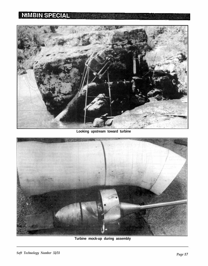
Looking upstream toward turbine
Turbine mock-up during assembly
Soft Technology Number 32/33 Page 17

Cross-section of turbineabout making the runner itself. Hedecided to cast from zinc; this had al-ready been tried successfully in morerudimentary turbines of the same typein the area.
At first, John made a complete waxmodel of the runner, poured a mouldaround it and attempted to cast the run-ner in one piece using the lost wax tech-nique. This failed, which he attributes to
the difficulty of getting the temperatureof the mould right.
For his second attempt, John decidedto cast individual blades and attachthem to a separately-cast hub. Aprototype blade was pattern made from3 mm aluminium sheet. This wascurved to the right shape with a rubbermallet over an anvil, and then filed to ob-tain the airfoil profile.
Turbine runner
To make the blade root pattern, Johnstarted by turning a big blob of waxdown on a lathe to hub diameter, and ofthe same axial length as the hub. Thenhe marked out this wax cylinder for eightblades, and made a template of theblade positions as they attach to the hub(see diagram). Next he drew two paral-lel lines enclosing 1/8 of the cylindersurface, which is just the space allo-cated to each blade root. Then hecarved a slot between these lines to thedepth of the blade root (about 8 mm) -enough for the finished blade root to bestrong - then filled that with automotivepanel filler (bog), into which thealuminium blade was set.
When the bog had set, the result wasthe exact pattern of the runner blade asit was to be cast. The process didn’twork perfectly because as the bog setit melted the wax (bog heats up as itsets). This didn’t matter because thetolerances of the union of the blade seg-ments to the runner spider (cylindricalcentral hub support) were low.
Metal CastingThe blade pattern was then used to
cast two sets of three-piece concretemoulds. This was done in two stages:first, a set of plaster-of-paris mouldswere made, these in effect being nega-tives of the exact concrete mould piecesneeded. The aluminium - and - bog pat-
Page 18 Soft Technology Number 32/33

tern was used for these along with wax
When the concrete moulds were cast,
plugs used to fill up the spaces destinedto become sprue channels, down which
fine sand was used in the mix nearest
the molten metal is poured. Zinc is soheavy it tends to expel air easily, so only
the plaster blade pattern. That there
one vent was needed. The sprue chan-nel and vent were located at the blade
were no air pockets was ensured by
root end so that the thinnest section ofthe blade is cast first. The sprue chan-
pressing the cement in. The rest of the
nel extended right along the leadingedge of the blade, to minimise the riskthat the metal wouldn’t fill the entiremould, especially where the blade wasthinnest. The sprue is ground off thecast blade later.
Site mapmould was filled in using a normal mixtaking no special care, filling up the
About twice as many blades as
space within the wooden former thatformed the outer surface of the concrete
needed were cast, allowing the best
mould. The blades were then cast inthese.
castings to be selected later. No release
During blade casting, the concretemould was wired together and sat in
agent was used, it was only necessary
sand so any leaks were contained. Theconcrete moulds have a limited life, be-
to have a smooth surface on the mould.
cause there are stresses, particularly atthe blade root, where the odd grain ofsand pulls free of the mould. From thispoint the casting surface quickly disin-tegrates.
The zinc came from melted-down cardecorations and door handles. Zinc hasa low enough melting point to usewithout special equipment: the zinc wasmelted in a big steel soup ladle placedin among the burning wood in a fuelstove.
Tailcone and RunnerHub
A tailcone was also cast from zinc.This was cast as a shell with a wallthickness of about 6 mm, reinforcedwith three arms radiating from a thickcentral spindle; the whole tailconebeing cast in one piece. The shaft wasthreaded to take this, and it wassecured with grub screws as well.
Soft Technology Number 32/33 Page 19

Results of the computer calculation
Page 20 Soft Technology Number 32/33

The hub spider was cast fromaluminium, the result being veryporous; this did not matter at all be-cause the loading on it is very low inuse. After casting, the spider was turnedto the correct diameter. A hole throughthe middle for the shaft was bored out,and a keyway made for attachment tothe shaft.
Runner AssemblyTo attach the cast blade segments, six
to eight holes were drilled through eachblade root flange, one in each corner ofthe flange and one on each side of theblade in the middle, and countersunk.The blades were then set around thehub spider and corresponding holesdrilled into the spider. The blades werethen attached with 25mm, 8-gaugestainless steel self-tapping screws, andflashed off.
There were still spaces between theblades and the hub spider. Instead ofleaving them there, John blocked off thebottom, taped up the joints between theblades and flooded the assembly withfibreglass resin. The runner was thencentered in a lathe and the blade tipsfaced off to make the tip diameter the
Velocity diagram for mid-radius
The runner as calculated
Soft Technology Number 32/33 Page 21
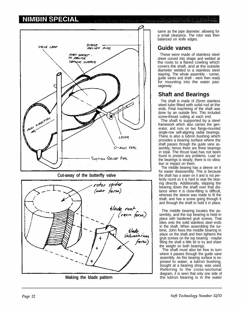
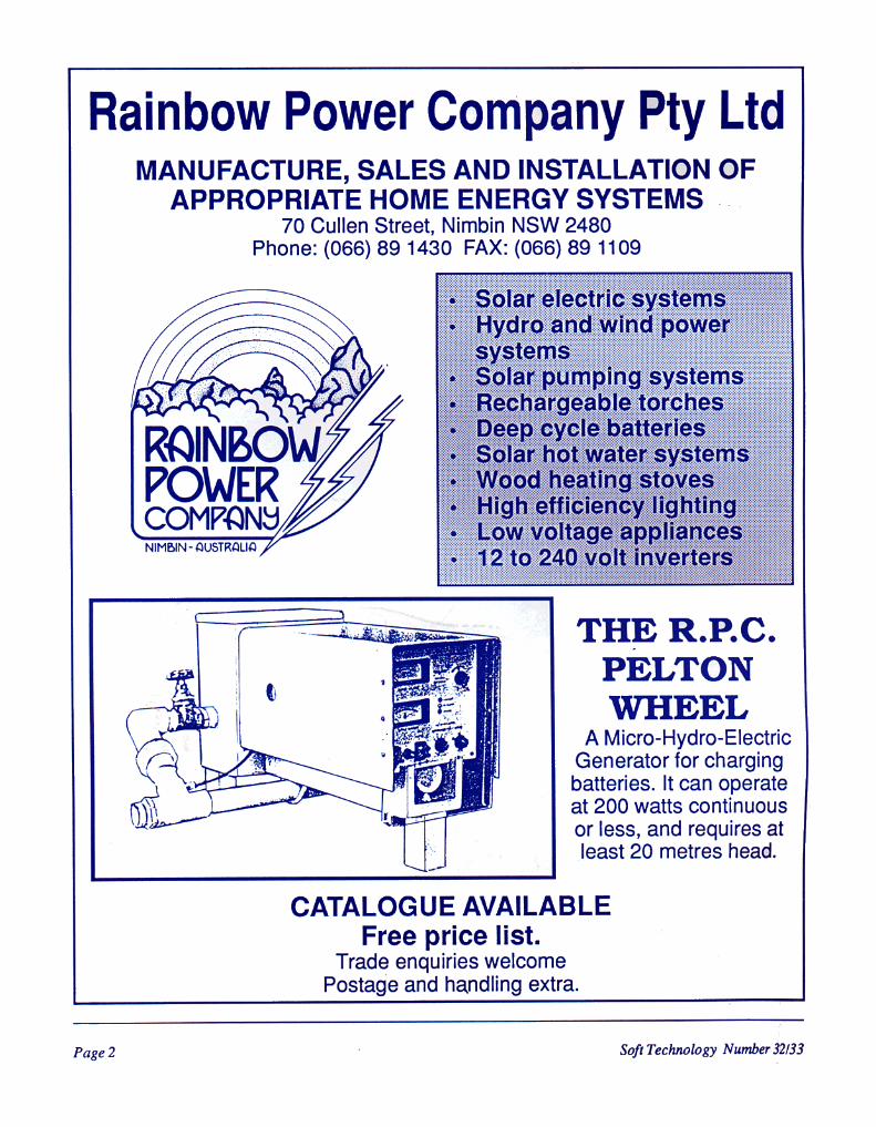
Cut-away of the butterfly valve
Making the blade pattern
same as the pipe diameter, allowing fora small clearance. The rotor was thenbalanced on knife edges.
Guide vanesThese were made of stainless steel
sheet curved into shape and welded atthe roots to a flared cowling whichcovers the shaft, and at the outsidediameter welded to a stainless steelstayring. The whole assembly - runner,guide vanes and shaft - were then readyfor mounting into the water pas-sageway.
Shaft and BearingsThe shaft is made of 25mm stainless
steel tube fitted with solid rod at theends. Final machining of the shaft wasdone by an outside firm. This includedscrew-thread cutting at each end.
The shaft is supported by a steelframework which also carries the gen-erator, and runs on two flange-mountedsingle-row self-aligning radial bearings.There is also a lubron bushing whichprovides a bearing surface where theshaft passes through the guide vane as-sembly; hence there are three bearingsin total. The thrust load has not beenfound to present any problems. Load onthe bearings is steady, there is no vibra-tion or impact on them.
The middle bearing has a sleeve on itfor easier disassembly. This is becausethe shaft has a seam on it and is not per-fectly round so it is hard to seat the bear-ing directly. Additionally, slipping thebearing down the shaft over that dis-tance when it is close-fitting is difficult,whereas the sleeve was made to fit theshaft, and has a screw going through itand through the shaft to hold it in place.
The middle bearing locates the as-sembly, and the top bearing is held inplace with hardened grub screws. Thatbites onto the solid stainless steel endsin the shaft. When assembling the tur-bine, John fixes the middle bearing inplace on the shaft and then tightens thegrub screws on the top bearing - maybelifting the shaft a little bit to try and sharethe weight on both bearings.
The shaft must also be free to turnwhere it passes through the guide vaneassembly. As this bearing surface is ex-posed to water, a lubron bushing,bought at a bearing shop, was used.Referring to the cross-sectionaldiagram, it is seen that only one side ofthe lubron bearing is in the water
Page 22 Soft Technology Number 32/33

stream. To encourage the passage ofwater across the bearing as a lubricant,the other side of the bearing is at atmos-pheric pressure.
Hence the bulk of the shaft where itdisappears into the penstock is actual-ly enveloped by a tube that joins thepenstock wall at one of its ends, flaresout at the other end to present the waterwith a shockless approach to the guidevanes, and joins onto the guide vanehub. The tube is thus open to the atmos- phere.
At the generator end of the shaft aretwo pulley wheels mounted in tandem,about 8” diameter which run a dual V-belt to 3.5” diameter pulley wheelsmounted on the generator shaft, to givea ratio of about 1:2 speed increase.
Butterfly ValveA butterfly rather than a gate valve
was built because a gate valve is toohard to seal. The butterfly valve leaf(see diagram) is made of 0.5 mm stain-less steel sheet in two layers, onearound each side of the 5/8” stainless-steel shaft. It has brass spacers insideit which packs it out to almost 25 mm inthe middle, and the two halves thatmake the leaf wrap around that so it hasgot some shape, which gives it strength.Stainless steel ribs have been weldedon the inside for additional strength.
The shaft runs through brass collarsbrazed to the leaf, and is attached to thecollars with grub screws. O-rings sealthe valve where the shaft penetrates thepipe wall on each side so it doesn’t leak.The valve can be removed if necessaryvia a hatch.
The valve leaf butts up against pipeends for sealing when in the closedposition. This is achieved by locatingthe valve at the junction of two lengthsof pipe that comprise the water pipe.These are joined with a slight offset sothat when the valve is closed, the leafbutts up against the pipe end-surfacesexposed by the slight offset for an effec-tive seal. Silicon was applied to thesesurfaces (while the valve was in theclosed position) to make the seal com-plete. The whole assembly works well;
Water HammerThere are two pressure relief pipes
made of 2” PVC pipe, one on each sideof the valve, which relieve transientpressure when the valve is opened orclosed. On the downstream side is asuction pipe and upstream of the valve
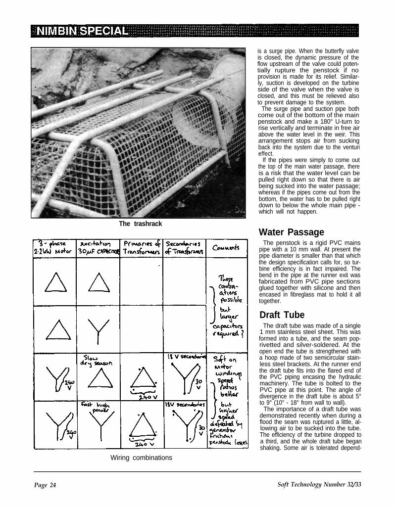
The trashrack
is a surge pipe. When the butterfly valveis closed, the dynamic pressure of theflow upstream of the valve could poten-tially rupture the penstock if noprovision is made for its relief. Similar-ly, suction is developed on the turbineside of the valve when the valve isclosed, and this must be relieved alsoto prevent damage to the system.
The surge pipe and suction pipe bothcome out of the bottom of the mainpenstock and make a 180° U-turn torise vertically and terminate in free airabove the water level in the weir. Thisarrangement stops air from suckingback into the system due to the venturieffect.
If the pipes were simply to come outthe top of the main water passage, thereis a risk that the water level can bepulled right down so that there is airbeing sucked into the water passage;whereas if the pipes come out from thebottom, the water has to be pulled rightdown to below the whole main pipe -which will not happen.
Water PassageThe penstock is a rigid PVC mains
pipe with a 10 mm wall. At present thepipe diameter is smaller than that whichthe design specification calls for, so tur-bine efficiency is in fact impaired. Thebend in the pipe at the runner exit wasfabricated from PVC pipe sectionsglued together with silicone and thenencased in fibreglass mat to hold it alltogether.
Draft TubeThe draft tube was made of a single
1 mm stainless steel sheet. This wasformed into a tube, and the seam pop-rivetted and silver-soldered. At theopen end the tube is strengthened witha hoop made of two semicircular stain-less steel brackets. At the runner endthe draft tube fits into the flared end ofthe PVC piping encasing the hydraulicmachinery. The tube is bolted to thePVC pipe at this point. The angle ofdivergence in the draft tube is about 5°to 9° (10° - 18° from wall to wall).
The importance of a draft tube wasdemonstrated recently when during aflood the seam was ruptured a little, al-lowing air to be sucked into the tube.The efficiency of the turbine dropped toa third, and the whole draft tube beganshaking. Some air is tolerated depend-
Wiring combinations
Page 24 Soft Technology Number 32/33

ing on the situation, but always a loss ofefficiency is experienced.
Turbine InstallationThe turbine is supported on a gal-
vanised 3/4” water-pipe structure. Allthe joints were brazed to prevent therusting associated with welding, and thewhole frame was painted with a heavy‘galvanising’ paint. The framework isanchored onto the rock base withdynabolts. These were ordinary steeldynabolts and have begun to rust -stainless steel types will be used as re-placements. The framework has alsobegun rusting where it sits in the tail-water. This goes to show that anythingpermanently wet should be made ofstainless steel.
Part-flow EfficiencyPower is only developed if the
penstock is filled. If there is any air in thepipe no power will be developed. Sincethe turbine can’t be run at part-flow, itwould be best to have a way ofautomatically operating the butterflyvalve to shut off the flow once the waterlevel in the weir falls below a criticallevel, and then when the water levelbuilds up as the storage is replenished,to open the valve again. This may bebest achieved mechanically, using
hydraulic pressure to drive the valvemechanism.
FloodingIf the turbine floods the generator
windings need to be dried out. This isdone by taking off the ends and remov-ing the runner. The bearings must alsobe c leaned out . The turbine isprevented from running during floods,and the butterfly valve is shut off.
ELECTRICAL SYSTEM
GeneratorThe generator is an unmodified three-
phase 2.2 kW star-wound inductionmotor run above synchronous speed.The generator is 4-pole so its ratedsynchronous speed at 50 Hz is 1500rpm. In this case, it is run at about 40Hz, (this is approximate - speeddepends on the water level in the creek)so its synchronous speed is cor-respondingly lower, and generator ac-tion occurs at about 1400 rpm. The gen-erator needs to be oversize for efficien-cy considerations.
The generator is connected to three3 0 m i c r o f a r a d p o l y p r o p y l e n ecapacitors, one in parallel across eachof the field coils. These can be con-nected in either star or delta, which al-lows some adjustment of the electrical
system to seasonal flow variation. Forslow running during the dry season, thecapacitors are wired in delta; and forfast, high power operation they arewired in star.
John’s practical experience has unfor-tunately been that use of the high-speed option is limited because fasterflow through the penstock leads togreater friction losses in the pipe. Thisresults in a situation where the higherflow lowers the head as seen by the tur-bine. A larger pipe cross-sectional areais planned for this reason.
The capacitors are mounted on thecreek bank above flood level along witha three-phase bridge rectifier, made ofsix lN4007 diodes and a very bigpolypropylene capacitor for filtering,feeding a shunt regulator.
The 1kW shunt regulator is an over-load protection device. It measures theDC voltage from the rectifier. If the volt-age exceeds a set level, a power tran-sistor is turned on, which dumps excesspower into a 240V heating element atthe bottom of a 40 gallon water tank. Allthese creek-side electrics are housed ina weatherproof box.
A circuit diagram of the shunt regulatoris reproduced, but treat this with cautionfor the following reasons. This was theprototype circuit, and was not totallyreliable. The BUX80 power transistorwas operating at its specified limit, and
Circuit of 1kW shunt regulator for generator

was prone to melt. For this reason, laterversions use power FETs. The conse-quence of this is that all the drive cir-cuitry must be altered. The circuit layoutis also important - heavy current flowsand high frequencies in some parts ofthe circuit must not be picked up by thesensitive CMOS circuitry.
tap types. The latter were used to allowa more even distribution of power. Morewindings on the secondary are usedwhere the consumer is a long way fromthe transformer box, so compensatingfor voltage drop in the line. The poweris then rectified and filtered before beingpassed onto consumers at 30 to 40volts DC; the farthest consumers being
Distribution System given higher voltage.
The cables are buried beneath road-
The community is fed by a three-phase, three-wire star-connected sys-
ways for easy location. Because thesystem is three-wire, there is no earth
tem with six step-down transformer
conductor and so voltage can floatabove ground potential. The argument
boxes connected in parallel. The trans-
is that this system is potentially saferbecause current is limited if there is a
mission cables are laid underground in
short to ground.A lot of transformers were used, be-
poly-pipe at a depth of 300 to 600 mm.
cause each transformer box requiresthree transformers, one for each phase.The transformers are ordinary off-the-shelf 6A, 18V types, or 12-22V multi-
weatherproof boxes made of ferroce-The transformers are housed in
ment (chickenwire and concrete), witha peaked roof that lifts off like a cap forservicing. The boxes are raised upabout 1.5 metres on a pole. All wiring isconcealed.
Switching RegulatorsA switching regulator at each house
converts the 30V DC to 12V for batterycharging, which it regulates automati-cally. They use a cheap low-voltageFET. The performance and efficiencyare both good. There is no instability inthe current or voltage feedback loop,but the unit produces some RFI whenthe mark-space ratio is reduced.
Note that there is a Mock diagram ofjust such a switching regulator in theCommunity Power Loops article else-where in this issue.
Auxiliary PowerDuring the dry season, the turbine
cannot be relied on to fully cater to thecommunity’s power needs. Individualconsumers can install solar panels toprovide electricity during this sunniesttime of the year.
EconomicsThe system was built between 1985
and 1987, and at that time the manufac-turing cost for parts etc. came to about$2000 for the hydro assembly, andabout $5400 for the power reticulation.The project took an estimated 150hours of voluntary labour for manufac-ture of the hydro system, a further 200hours to install the reticulation systemincluding the DC-DC converters(switching regulators), and another 150hours work ‘down at the creek’.
Schematic of distribution system
Page 26 Soft Technology Number 32/33

Community Power Loopsfor
Electricity Distributionby Karl McLaughlin
Extra-low voltage electrical dis-tribution can be set up at the com-munity scale, and offers both a de-gree of autonomy and cost benefitsto users.
Community power loops are a low-voltage alternative to ElectricityAuthority mains networks for poweringsmall communities. They can be builtand operated safely by the communitymembers themselves.
This is the transcript of an interviewconducted with Karl, who is familiar witha number of distribution set-ups aroundthe Nimbin district.
Introduction
munity is that it is that it is incrediblycost-effective. One big prime-mover ischeaper and inherently more efficient.For example, one 3hp diesel genset ismuch more cost effective both to runand to buy than 5 little petrol ones. Aswell as that the noise isn’t the sameproblem.
Community distribution is also ab-solutely necessary where the power forthe area might for example be a low-head turbine, which can only be put inone place, so there is no questionwhatever that the power has to be dis-tributed around a neighbourhood.
You’ve always got the trade off be-tween the inherent efficiency of acentralised system versus the inherentchaos of having to communicate be-tween neighbours, and co-operate in aproject. I see the whole of life in theseterms!
The basic reason for choosing low- The other main area where com-voltage distribution around a com- munity power distribution is useful is
where the cost of connection of 240Vreticulation is very high (as it usually is!),or where there is some covenant that isa problem; for example we had in-credible difficulty making the NorthernRivers Electric put the power under-ground. They will not believe our com-munity resolution, which is that powerlines must go underground. And that issufficient reason for the power to berouted at low voltage. Also putting 240Vunderground is often prohibitively ex-pensive.
So for environmental and economicreasons it is often out of the question toprovide 240V to each house. The costto one community here was $70,000 todo a 240V reticulation to the door ofabout 10 houses. Also the standards ofthe 240V supply tend to be ridiculous-ly high in terms of voltage maintenance;they make you buy a transformer foreach house. They expect you to be ableto use the full 10kW per household all
Series DC Distribution System
Soft Technology Number 32/33 Page 27

the time, and all at the same time, withonly 10 volts drop. So their sizing ofwires, particularly for underground, canbe astronomical. More than 50mm2 ofcopper was being demanded for oneconsumer.
If you take the soft option of having avery low energy source, say 4mm2 wirecoming at 100V in a community sys-tem, you have a switching regulator, abattery bank and an inverter, and youcan often end up with an equivalent volt-age maintenance with something like10% of the cost.
Alternating or DirectCurrent?
I guess the basic underlying idea torepresent is the compromise betweenlegality and electric shock, and energyloss in low-voltage transmission. Thereal difference is that AC electrocutesyou a lot better than DC, at least in lowvoltage. 100V AC is very painful be-cause it jangles your nerves up, and itsalso much worse for causing heart at-tack, because the 50 cycle/secondpower sets the heart into fibrillation.With 100V DC you get one heavythump on contact, then the effect fadesas your skin polarises, and nerves be-come desensitised. Of course if you jaba live wire into your flesh, your skinresistance becomes irrelevant!
In terms of legal considerations, youcan’t go above 32 volts AC without get-ting out of extra-low voltage regulations.You can’t go over 110 volts DC.
Losses must also be considered. Adefect of AC is the pulsating nature ofthe power flow. You get back to mainshum in Hi-fi systems and ripple in bat-tery charge currents. Using 3-phase ACis much kinder on generators and bat-tery chargers. It would seem easier atthe receiving end to use AC, as ordinarytransformers can be used rather thanhigh frequency DC-DC converters. Inpractice though, 32V AC systems Iknow of rectify the AC to DC, then useDC-DC converters anyway! Thereasons for this are:
1. 32V transformers are hard to get,and don’t work if frequency is under 50Hz (my generator runs at 30 Hz).
2. Voltage regulation requires phaseshift control and tends to instability andnoise.
3. Small transformers for 50Hz are in-efficient.
As for line losses, AC and DC areequally good for travelling through wire.
Your line losses are the same. That is apoint many people are confused about.You’re limited to 32V with AC thereforeyou’ve got lots of copper loss. You needvery thick wire. DC up around 100Vtravels quite well. So within the law thebest way of transmitting energy per cop-per is at 100V DC.
The trouble with this is twofold really.100 volts DC is pretty useless to useand even at 100V DC you can’t usemuch peak load without running out ofjuice - you could run a system like that,but its a lot of batteries to pile up.
D.C. ParallelDistribution
If you’re going to use less batteries,say a 24 or 32 volt system, you’ve got tohave a way of reducing the voltage backdown to charge them. Because its DCyou can’t just use a transformer, so youhave to use a switching regulator. Byswitching regulator I mean a high fre-quency DC-DC-down converter whichis able to change its ratio of conversionaccording to what the battery needs.
In a sense this is convenient, becauseif you’re going to have a switchingregulator you can make it do a lot ofother functions as well. You can make itautomatically float the voltage of thebattery at the correct level to maintainthat energy store, you can make itautomatically limit current so if you’vegot several consumers using the line,and you can to some extent share outthe power between them, so they can’thog it.
It can also give isolation from ground,which is a problem for DC systems. Youcan get a lot of line drop in the negativeline, so the earth at one place is differentto earth at another. You can get up to 25V difference between the negative ofthe system and ground. That has beena problem in a lot of systems becauseif you use electric motors, say rewoundcar generators that have got one brushriveted onto the chassis, then you endup with the chassis of the machine con-nected to negative. It makes it all rathertingly if you’re totally covered in waterand leeches.
The switching regulator can giveDC isolation as well as voltageregulation. There is an optical feedbackfrom the battery side to the brains side.So using one of these black boxes, aswitching regulator, isolates betweenthe distribution line which is owned bythe community, and the individual
person’s battery electrics. That’s oneway of distributing power, which iscalled the parallel system.
D.C. SeriesDistribution
Another way to do it is to connect allthe consumers in series, to have all theirbattery systems simply arranged fromhead to tail, adding up to roughly 100volts, which would require about eightconsumers of 12V each.
You can’t have more than about eightbecause you go over voltage. But ifyou’re up to eight you can just connecteveryone in series, which means youare already splitting the current be-tween the consumers - by definition thecurrent is absolutely identical foreverybody and you don’t have to useany switching regulators. It is an ex-tremely low-tech sort of solution. But itsactually a harder sort of system tooperate than you might think.
First of all, because everyone doesget equal amounts of power, it is actual-ly wasteful because consumers in-evitably go on holidays or aren’t thereor need different amounts of power, soyou haven’t got the flexibility. If one per-son has got 5 visitors and three of theother people are away, there is no waythey can use their power.
There are ways of developing a muchmore sophisticated form of series sys-tem, but I won’t go into them yet. Youcan use switching regulators on a seriessystem as well, but that is complex. Soin the simple arrangement, everyonegets the same charge, they have todump it in shunt regulators in order toregulate their batteries and they eachget the same current, the same power.If they don’t use it they have to throw itaway. If they want more they can’t getit, even if someone else is throwing itaway in their shunt regulator.
System MaintenanceThe other real problem with the series
system is maintenance. It is very hardto find a fault in a system like that be-cause if there is any fault anywhere thewhole system stops. And it is not im-mediately apparent where that fault is.You can’t just find out who’s got powerstill and who hasn’t in order to find outwhere the break must be. In the paral-lel system you simply go to the last per-son who has power and start looking.You can find the break in the next leg of
Page 28 Soft Technology Number 32/33

Parallel D.C. Distribution Systemthe system. Yet in the series system It depends a bit on what sort of primeyou’ve got no idea of where to start. mover you’ve got. The ones we’re using Electrolysis
As a means of trying to find out whereto start, we’ve developed the idea ofconnecting the negative end of the loopto an earth stake driven into the ground.The beauty of this is that it just makes iteasier to think about. It means that thenegative end of the system is earth.That means you can actually find faultsin the system by measuring the voltagebetween the loop wire and ground.
You stick one end of the multimeterinto the ground, or hang onto it whenyou’re covered in water and leeches.Then you touch the other end of themultimeter to the wire, and if it goes upin nice logical 12 volt increments witheach battery then you know the wire isintact. When it suddenly doesn’t, youknow there is a break in the wire.
are all induction generators, andthey’ve got the characteristic of rising tothe maximum legal open-circuit voltagewhich is 135 volts, and just sitting therewhile there is a break in the wire anddumping all the power into a block ofconcrete (concrete-encased resistor).
As you go around downwire from thegenerator, it will keep dropping by 12volt increments as it goes through eachbattery, and suddenly where the breakis there will be 50 Volts or so across thetwo ends. So you find there is a suddenanomalous jump of 50 volts or so as yougo past the break. That is the normalway we go about finding breaks, whichin practice is the worst thing about theseries system.
All of these DC systems are probablyworse than AC systems to maintain be-cause of electrolysis. If you get a breakin the insulation somewhere wherethere is an earth contact, you get cur-rents to earth, and damp water in be-tween acts as an electrolyte. There is anice little aphorism I say: ‘water pluselectricity equals acid’. That is exactlythe way things behave.
You can get 4mm2 wire eaten awayin a week if you have got contact withgroundwater and you’ve got voltage ap-plied to it. It just fizzles away until thereis no copper left. That is worse than al-ternating current. Alternating current toground causes a wastage of power, butyou get a sort of an oxidisation of thesurface of the wire, which to some ex-tent reduces corrosion. With DC it justquietly dissolves off into the dirt.
The powerline, if people do it proper-ty, is placed inside poly-pipe or someconduit and the double insulation af-forded is enough to stop that sort ofthing from happening. Alternatively youcan hang it off the ground on insulators.
But the worst thing possible is to leaveit on the ground, particularly in thekikuyu. It gets broken up by cows bend-ing it backwards and forwards, andmakes little cracks in the insulation andthen it is in contact with soil moisture,so you get an electric path out of the
Usually your fingers are more usethan a voltmeter because you get ashock every time you hit a fault. Andusually a spark is more use than an am-meter because you just touch the endstogether and if you get a decent sparkyou know you have got current flowing.So a pair of pliers and fingers seems tobe all you need, and a roll of plastic tapeis a good idea. One detail is make sureyour wire-stripping pliers have gotdecent plastic on their handles. Thereis nothing worse than pulling a wire tostrip it and you reach a spot on thehandle where the plastic has burnt off.
Another problem with the series sys-tem is the person’s battery is not sittingat ground potential, which means if theyhave anything connected to the nega-tive wire of the battery that is metal, theyget a bit of a shock to ground, at leastan uncomfortable tingle. There is noeasy way of doing isolation.
In some systems there are actuallytwo loops because you have more thaneight consumers. In that case you needthe prime mover switched between thetwo loops in a regular fashion. All thatswitchgear, hopefully automatic, needspeople to look at it occasionally.
Soft Technology Number 32/33 Page 29
conductor through the cracks to theground.
You can get the copper eaten away in-side the insulation so you can’t evenrealise it’s not there. The only way youcan find these things is by running yourhand along the wire and getting a littleshock when you get to the place wherethe wire has been eaten through. In-sulation breaks are a continuing main-tenance problem. It is a major nuisance,and as I was saying it is made worse bythe fact it is a DC system.
ConnectionsI used to solder them all and silicon
them all, but I’m not that convinced thatit is really that necessary. Twistedtogether seems to work. So long as youtape it all over the top and keep it off theground. Locating the joints and findingthem all later seems to be an importantthing, because you get lantana andweeds growing all over everything andyou can’t find where the join was.
Even if they’re up off the ground,groundwater coming up by way ofweeds, and sap of weeds, is just as ef-ficient at causing electrolysis. So you’vegot to keep all the vegetation off thejoints. We drive stakes into the ground,tie the wire to it, and then keep the jointsup underneath a bottle. The beauty ofthis is that you keep the rain out.Ultraviolet also attacks the insulation atthat point, so it keeps it out of the sun,keeps the rain off and ties it all togetherneatly.
Aluminium is more available than cop-per and works fine if you use twice thecross-section. Cable clamps or screwconnectors both work fine for contacts.Drop wires to houses can often bebought at scrap yards for $2 a kilo.
Protection ofEquipment
Where there is a major bit of circuitry,for switching or fusing or something likethat, we have found it absolutely dis-astrous to leave it out in the weather. Itis also not good to connect it to the out-side of people’s houses, because theyalways end up changing the housesand building rooms over the top of it andall sorts of amazing things. It is reallyyukky crawling under houses lookingfor connections of power lines. It is alsoprobably a fire hazard.
It’s really nice if you can build a littlechook shed. The smallest type of back-
yard gal. garden shed is something wellworth having. You can keep equipmentin it like voltmeters. Voltmeters will notstand being in the rain, neither will am-meters, nor pressure gauges. You cankeep information and explanationsheets stuck onto the side of the shed.lt can be a place where all the equip-ment to do with keeping the powerlinetogether can be centralised. In thecases where they have had that in acommunity grid it has been extremelybeneficial.
It’s even more the case if you’ve got aprime mover of some sort, either a pel-ton wheel or an engine or a batterycharger or something like that. It’s real-ly great if its got a proper little shed tolive in so it doesn’t get harassed byeverybody and it keeps animals out.
I’m surprised how many damages tothe line are caused by animals. Ratschewing them, wallabies knocking themover. Cows - they’re the horror of my life.They’re funny animals. They’ll inves-tigate things, and harass things and tripover things. Trying to keep anythingtogether near a cow paddock is reallydifficult. So keeping everything in a littleshed is a really good start to keepingeverything organised that is likely to bedamaged.
LayingExtra-low-voltageLines
You can either put it through conduitor poly-pipe, or double-insulated stuffjust buried. Nail it onto cliffs. Myfavourite way of laying cable throughthe forest is to hang it on insulators atabout the four-foot level. lt is easy to getat and it actually works better thanhaving it up over head height. Thereason being is that when branches falloff trees they don’t break the line theyjust pull it to the ground. Then you goalong and relieve it by cutting thebranches away and you haven’t doneany damage, whereas if you have it upat 10 feet, it is snapped when a branchfalls and pulls it to the ground.
Up off the ground makes an enormousdifference, You can afford to have barecopper and it won’t necessarily geteaten away by electrolysis. You can getaway with an amazing amount just solong as it is up above the ground.
Threading WireThrough Poly-pipe
To lay cable in poly-pipe, you basical-ly first thread fishing line or somethinglike that first on a weight. You straightenout the pipe across a paddock and youhave a hump. Then you move the humpacross the paddock, and you have theweight sliding down the little hill all theway, pulling the fishing line behind it.
The problem is not getting the threadthrough as you might imagine, theproblem is getting the wire through.PVC has got a fairly high co-efficient offriction, and it is cumulative. After thefirst 30 or 40 metres, it gets very difficultto pull the wire through. The fewer thewires at once the easier, and thestraighter they are the better. lf youlubricate the poly-pipe first with gearboxoil or something like that, it makes anenormous difference.
It is not easy to pull the wire through.People I know have pulled the poly-pipestraight, usually downhill, and thenyou’ve got gravity helping you. You geta windlass effect, where the more kinksyou've got, then they all add up, andafter a certain number of wriggles andobstructions and so on, it is just impos-sible to pull the wire through any further,no matter how hard you pull. I think it isquite a problem pulling wire throughpoly-pipe, but it does give the wiremechanical protection.
AC TransmissionYou’ve got the option, if you’ve got to
do a really long distance, of running along leg, say 2km or so at 240V AC,break it down to the legal limit of 32Vthrough a transformer in the middle of acluster of houses and reticulate out fromthat point. I like it personally becauseAC doesn’t cause corrosion of the wiresto the same extent.
Power SourcesA common system around here is to
use a pelton wheel on a high head or apropeller turbine on low head con-nected to an induction generator as theprime mover.
It could be a diesel generator as well.Diesel generators are very cost-effec-tive. But they are pretty horrible. Henceat least one big improvement is, ratherthan everyone having one of their own,to have just one in a central quiet place. . . or it was quiet, beforehand! It is alsobetter because it can be loaded more
Page 30 Soft Technology Number 32/33

Switching Regulator for a Parallel Type Community Gridheavily most of the time. Charging up allthe batteries gives it some work to do.So a community distribution systemwould justify itself there as well.
Legal ConsiderationsTheoretically anyone needs to be
qualified to do electrical work, low volt-age or not. Technically I think it doesn’tmake any difference whether you con-nect it to a hydro generator, or windmill,or a big battery charger plugged into themains. I think all of this would have tocount as permanent wiring, and that iswhat the rules depend on, not thesource of the energy.
I guess the main legal out if you’regoing to connect it to a mains system isto say that basically it is an appliance, abattery charger. So long as the batterycharger complies with ASA standards,your system is going to be safe from 240V, it’s not going to be a shock hazardfrom the 240V side.
CommunicationBetween UsersThis is the biggest problem in the
thing, actually. It seems to be one of thelaws of nature that people think thatother people are stealing their power.They first think that other people aregetting more power than them, andsecondly they contrive some unlikelytheory that other people can stealpower out of their battery.
Now it can’t happen at all in a parallelsystem through switching regulatorsbecause they are a one-way powerflow. It can only happen in a series sys-tem if the non-return diodes fail. Nonreturn-diodes are usually built into thealternator at the prime mover end, or therectifier in a battery charger type arran-gement. So again unless the system isbroken you can’t get power going in theopposite direction.
People also have unbelievable dif-ficulty in comprehending that batteryvoltages add up. It means they can’t findwire breaks through any logic, so theydo it just by mechanical inspection.
The other communication problem - ormore a problem with responsibilitydelegation - is that there is alwayssomebody who gets the job of linesper-son. It is a very undesirable job, be-cause you’ve got to crash aroundthrough the bush at the worst possibletimes, trying to find line faults.
If you’ve got a prime mover to main-tain you need to communicate about themaintenance of that. People near it in-herently have got to do it more often, ifyou’ve got an engine that is going to re-quire very regular maintenance.
As I was saying, it is difficult to get anasty shock off the system, but ofcourse you can get fires because thebattery has enough stored energy to setup enormous currents to start fires.
There is a demarcation between thecommunity distribution network and theindividual consumer’s electrics. Thathas got to be made clear. This is hard,
though, because you find that people’shouse electrics start re-organising thecommunity 100V line, and the two getall intrinsically mixed up together. Youoften can’t fix the community systemwithout re-organising people’s in-dividual house electrics which are oftenvery irrational.
I prefer the parallel system whereeveryone has a switching regulator,simply because there is a clear demar-cation line. There is DC isolation andthere is no question whatever, the inputand output defines the line betweenpersonal electrics, which can be goodor bad, and the community system.
SummaryParallel arranged 100V DC distribu-
tion systems have proved the mostpractical, but at the expense of the hi-tech fix of switching regulators. Thesehave proved efficient and reliable for 10years so far. Parallel systems areflexible in that power can be added andwithdrawn anywhere, the layout can bealtered easily, and heavier wires can beput in sectors which see more current.Also fault finding is easier, and derelictnon-used parts of the grid do not com-promise the functioning of good parts.
The switching regulators we use are a60 watt flyback transformer circuitoperating at 20 kHz. They use CMOSfor most functions and consume lessthan a watt on idle. Efficiency is betterthan 80% across load range. If there isdemand I will publish the fullschematics.
Soft Technology Number 32/33 Page 31
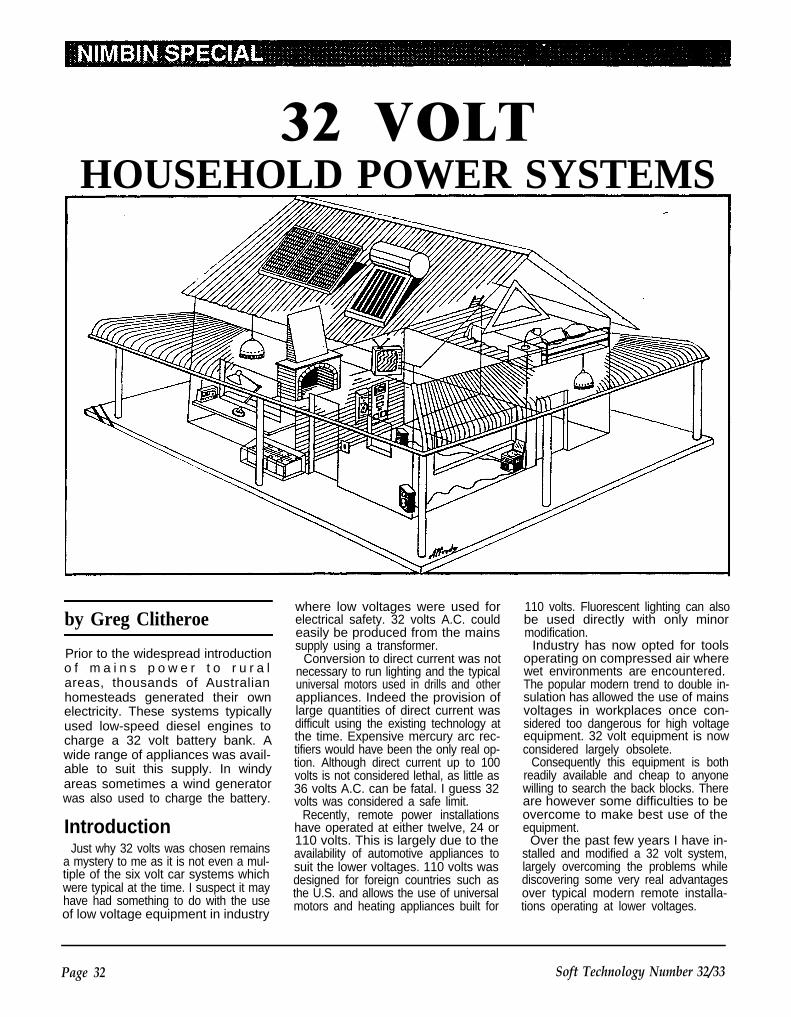
32 VOLTHOUSEHOLD POWER SYSTEMS
by Greg Clitheroe
Prior to the widespread introductiono f m a i n s p o w e r t o r u r a lareas, thousands of Australianhomesteads generated their ownelectricity. These systems typicallyused low-speed diesel engines tocharge a 32 volt battery bank. Awide range of appliances was avail-able to suit this supply. In windyareas sometimes a wind generatorwas also used to charge the battery.
IntroductionJust why 32 volts was chosen remains
a mystery to me as it is not even a mul-tiple of the six volt car systems whichwere typical at the time. I suspect it mayhave had something to do with the useof low voltage equipment in industry
where low voltages were used forelectrical safety. 32 volts A.C. couldeasily be produced from the mainssupply using a transformer.
Conversion to direct current was notnecessary to run lighting and the typicaluniversal motors used in drills and otherappliances. Indeed the provision oflarge quantities of direct current wasdifficult using the existing technology atthe time. Expensive mercury arc rec-tifiers would have been the only real op-tion. Although direct current up to 100volts is not considered lethal, as little as36 volts A.C. can be fatal. I guess 32volts was considered a safe limit.
Recently, remote power installationshave operated at either twelve, 24 or110 volts. This is largely due to theavailability of automotive appliances tosuit the lower voltages. 110 volts wasdesigned for foreign countries such asthe U.S. and allows the use of universalmotors and heating appliances built for
110 volts. Fluorescent lighting can alsobe used directly with only minormodification.
Industry has now opted for toolsoperating on compressed air wherewet environments are encountered.The popular modern trend to double in-sulation has allowed the use of mainsvoltages in workplaces once con-sidered too dangerous for high voltageequipment. 32 volt equipment is nowconsidered largely obsolete.
Consequently this equipment is bothreadily available and cheap to anyonewilling to search the back blocks. Thereare however some difficulties to beovercome to make best use of theequipment.
Over the past few years I have in-stalled and modified a 32 volt system,largely overcoming the problems whilediscovering some very real advantagesover typical modern remote installa-tions operating at lower voltages.
Page 32 Soft Technology Number 32/33

Photo 1. Ronaldson Tippet 3.5 hp diesel
The difficulties included the provisionof twelve volts to operate low voltageappliances such as a portabletelevision and radio. You will noticethere is no easy way to divide a 32 voltsupply to get a multiple of twelve. Nohigh-efficiency lighting is available for32 volts and the system was largely de-pendent on incandescent types.
The simplest way around this wouldbe to reduce the system to 24 volts butthis would have reduced the capacity ofthe motors powering the washingmachine, Mixmaster and vacuumcleaner. It would have also rendered
useless the 150 watt electric solderingiron. Furthermore the output of the gen-erator would have been reduced bysome 25 percent and the transmissionefficiency by nearly 45 percent. Ratherthan this I chose to tackle the problems.
Renewable PowerOnce contributing to the production of
electricity was a Dunlite 750 watt windgenerator of 1948 vintage. It is one ofthe old four-bladed models. The bladeswere damaged in a storm some timeago when the tail furling stop broke al-
lowing the tail to foul the blades. Even-tually the blades cracked at the root asa result. I have since acquired parts ofthe later three-bladed governor modeland hope one day to repair themachine using these later parts.
Three Arco solar modules in seriesalso provide about three amps when thesun shines. The panels nominallycharge a twelve volt battery and conse-quently three panels should charge into36 volts. However the output of solarpanels is not critically affected by thereduced voltage. Indeed they will hap-pily dump their current into a dead short.
Ideally I would like to install a turbineon a nearby seasonal creek. I feel thethree renewable energy sources wouldprovide a reasonably reliable electricitysupply with minimal use of the dieselengine.
Diesel Back-upThe generator is a robust Dunlite 40
volt, 30 amp compound-wound type.Compound winding automatically com-pensates the field strength as the out-put changes resulting in a fairly stableoutput current with minimum attention(figure 1). It is driven by a Ronaldson-Tippet 3.5hp watercooled diesel en-gine.
This engine is a particularly elegantexample of the engineering of the early1950s. It is of extremely rugged con-struction weighing over 250 kilograms.I recently rebuilt the engine and I wasvery impressed by the design. Both thecrankshaft and camshaft are carried inheavy-duty opposed tapered rollerbearings. The crank is two inches indiameter and supports a massiveflywheel. Maximum operating speed is900 rpm. The valves are designed toallow their rotation while opening, thusextending their service life considerab-ly. This machine is built to last.
Parts such as piston rings and valvesare still available from F.W. Jarky En-gineering in Sydney and I had the big-end bearings rebuilt in Brisbane.
The engine is started by motoring thegenerator while operating thedecompression lever. Note howeverthat the series field winding must bereversed while motoring. The installa-tion of the generator caused someheadaches as there was no informationprovided with the machine as to how itwas to be connected. Furthermore alocal engineering firm contracted toturn the commutator appeared to haveinadvertantly switched some of the
Soft Technology Number 32/33 Page 33
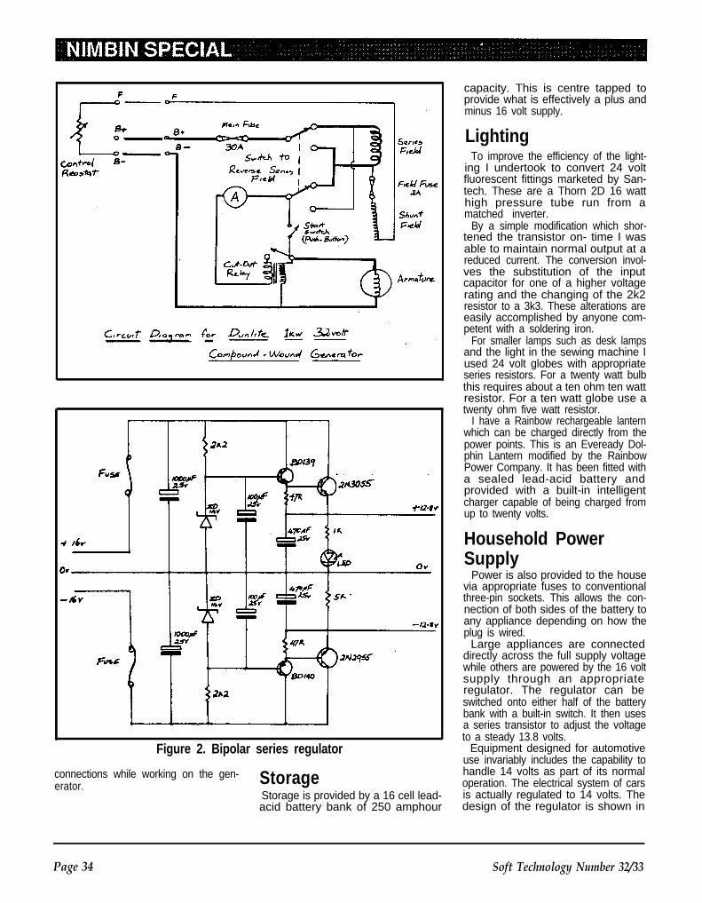
Figure 2. Bipolar series regulator
connections while working on the gen-erator. Storage
Storage is provided by a 16 cell lead-acid battery bank of 250 amphour
capacity. This is centre tapped toprovide what is effectively a plus andminus 16 volt supply.
LightingTo improve the efficiency of the light-
ing I undertook to convert 24 voltfluorescent fittings marketed by San-tech. These are a Thorn 2D 16 watthigh pressure tube run from amatched inverter.
By a simple modification which shor-tened the transistor on- time I wasable to maintain normal output at areduced current. The conversion invol-ves the substitution of the inputcapacitor for one of a higher voltagerating and the changing of the 2k2resistor to a 3k3. These alterations areeasily accomplished by anyone com-petent with a soldering iron.
For smaller lamps such as desk lampsand the light in the sewing machine Iused 24 volt globes with appropriateseries resistors. For a twenty watt bulbthis requires about a ten ohm ten wattresistor. For a ten watt globe use atwenty ohm five watt resistor.
I have a Rainbow rechargeable lanternwhich can be charged directly from thepower points. This is an Eveready Dol-phin Lantern modified by the RainbowPower Company. It has been fitted witha sealed lead-acid battery andprovided with a built-in intelligentcharger capable of being charged fromup to twenty volts.
Household PowerSupply
Power is also provided to the housevia appropriate fuses to conventionalthree-pin sockets. This allows the con-nection of both sides of the battery toany appliance depending on how theplug is wired.
Large appliances are connecteddirectly across the full supply voltagewhile others are powered by the 16 voltsupply through an appropriateregulator. The regulator can beswitched onto either half of the batterybank with a built-in switch. It then usesa series transistor to adjust the voltageto a steady 13.8 volts.
Equipment designed for automotiveuse invariably includes the capability tohandle 14 volts as part of its normaloperation. The electrical system of carsis actually regulated to 14 volts. Thedesign of the regulator is shown in
Page 34 Soft Technology Number 32/33
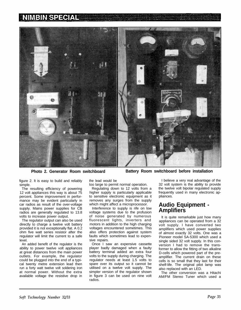
Photo 2. Generator Room switchboard Battery Room switchboard before installation
figure 2. lt is easy to build and reliablysimple.
The resulting efficiency of powering12 volt appliances this way is about 75percent. Some improvement in perfor-mance may be evident particularly incar radios as result of the over-voltagesupply. Mains power supplies for CBradios are generally regulated to 13.8volts to increase power output.
The regulator output can also be useddirectly to charge a twelve volt batteryprovided it is not exceptionally flat. A 0.2ohm five watt series resistor after theregulator will limit the current to a safelevel.
An added benefit of the regulator is theability to power twelve volt appliancesat great distances from the main poweroutlets. For example, the regulatorcould be plugged into the end of a typi-cal twenty metre extension lead thenrun a forty watt twelve volt soldering ironat normal power. Without the extraavailable voltage the resistive drop in
the lead would betoo large to permit normal operation.
Regulating down to 12 volts from ahigher supply is particularly applicableto sensitive electronic equipment as itremoves any surges from the supplywhich might affect a microprocessor.
Interference to supply is rife on lowvoltage systems due to the profusionof noise generated by numerousfluorescent lights, inverters andmotors in addition to the high chargingvoltages encountered sometimes. Thisalso offers protection against systemfaults which sometimes lead to expen-sive repairs.
Once I saw an expensive cassetteplayer badly damaged when a faultybattery terminal added an extra fourvolts to the supply during charging. Theregulator needs at least 1.5 volts tospare over its output so it cannot beutilised on a twelve volt supply. Thesimpler version of the regulator shownin figure 3 can be used on nine voltradios.
I believe a very real advantage of the32 volt system is the ability to providethe twelve volt bipolar regulated supplyfrequently used in many electronic ap-pliances.
Audio Equipment -Amplifiers
lt is quite remarkable just how manyappliances can be operated from a 32volt supply. I have converted twoamplifiers which used power suppliesof almost exactly 32 volts. One was aPioneer model SA-5300 which used asingle sided 32 volt supply. In this con-version I had to remove the trans-former to allow the fitting of two alkalineD-cells which powered part of the pre-amplifier. The current drain on thesecells is so small that they last for theirshelf-life. The original pilot lamp wasalso replaced with an LED.
The other conversion was a HitachiAM/FM Stereo Tuner which used a
Soft Technology Number 32/33 Page 35

plus and minus 15 volt supply. This isconnected using all three pins of thepower plug. Both of these amplifiersare around 20 watts per channel.
Powering conventional amplifiersdirectly from the battery has sub-stantial advantages over using themin conjunction with an inverter. First-ly it is much more efficient. Secondlythe performance of the amp is im-proved because the battery supplyvoltage is sustained at peak loadingwhereas the 240 volt supply is limitedby its storage capacitors. Thirdly thereis none of the troublesome hum oftengenerated when inverters are usedwith hi-fi equipment.
This method also compares favourab-ly with the use of automotive audioequipment as it is substantially more ef-ficient. The power output of anamplifier is limited by two criteria. Theimpedance of the speaker system andthe output voltage govern the totalpower available. A twelve volt supplylimits this to modest levels despite theuse of low impedance speakers. High-
Figure 3. Simple voltage regulator
powered automotive equipment over-comes this limit by converting thesupply to a higher voltage with a con-siderable efficiency penalty.
In addition to these conversions I havestudied the power supplies of manyamplifier/tuners and they seem to begrouped from about 18 volts to 32volts. A 100 watt per channel amplifierused a bipolar 28 volt supply. I expect
This figure shows a drill c o n s t r u c t e dfrom the demister blower of a FordFalcon.A t l e f t i s s h o w n t h e f i n a l s t e p i nmaking the chuck adapter in a drillpress . This method insures alignmentof the chuck and motor shaft. Theother end o f the adapter is f i rstdr i l led and tapped s imi lar ly .
A short length o f po lythene pipeand a motorcycle handgrip completesthe handle. I u s e d a r o l l p i n t o f i xthe chuck adapter to the motor shaft.
Figure 4. Low-cost electric drill
it would operate though at reducedoutput when supplied at a lower volt-age. Machines requiring lower vol-tages may be easily regulated by theuse of simple series regulators asshown in figures 2 to 4.
Tape DeckA Sony TC-FX220 tape deck which
I converted operated on a plus andminus 12 volt supply. This machine Iam particularly proud of as I broughtit home from the tip. It was verybadly damaged having beendropped on its corner. The circuitboard was broken and the transport
mechanism badly twisted. In a coupleof hours I managed to straighten themechanism and solder some twentywire bridges across broken PCB tracks.
The power supply was regulated inthis machine so it was possible to con-nect it directly to the house supply. Al-lowing for a drop of two volts across theregulators and another half volt acrossthe rectifiers this brings the nominalinput voltage up to nearly fifteen volts.
Considering that the regulators aredesigned to supply in excess of an ampthey are probably capable of dissipat-ing the extra power involved in such alow powered appliance as a tape deck.For peace of mind a low resistancecalculated to drop a volt or two at fullload can be installed in the inputleads.
For larger appliances it is better to usepre-regulators. If there is any doubtmonitor the heatsink temperature withyour finger for the first test. Make thistest at full charging voltage which in thecase of the 32 volt system is about 38volts.
Audio ConversionsWhen making conversions such as
these it is very important that the earthpotentials of each machine be checkedfor correspondence. A plus and minussystem is earthed to the centre-tapwhile a single sided system is earthedto one side of the full supply. Any at-tempt to connect say the Sony deckwith the Pioneer amp could destroy theequipment. The Sony and the Hitachimay be connected as they both sharetheir earth at the centre tap, (this is notto say all machines of these brandscan be connected nor even within thesame brand). A simple check with a
Page 36 Soft Technology Number 32/33
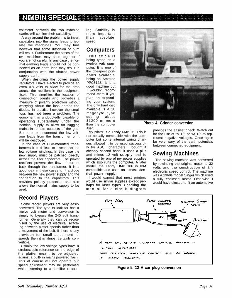
voltmeter between the two machineearths will confirm their suitability.
A way around the problem is to insertcapacitors into the signal leads to iso-late the machines. You may findhowever that some distortion or humwill result. Furthermore the cases of thetwo machines may short together ifyou are not careful. In any case the nor-mal earthing leads should not be con-nected as an earth loop may result inconjunction with the shared powersupply earth.
When designing the power supplyregulators I have elected to provide anextra 0.8 volts to allow for the dropacross the rectifiers in the equipmentitself. This simplifies the location ofconnection points and provides ameasure of polarity protection withoutworrying about the loss across thediodes. In practise however the smallloss has not been a problem. Theequipment is undoubtedly capable ofoperating substantially under thenominal supply to allow for saggingmains in remote outposts of the grid.Be sure to disconnect the low-volt-age leads from the transformer or itwill be destroyed.
In the case of PCB-mounted trans-formers it is difficult to disconnect thelow voltage windings. In this case thenew supply must be patched directlyacross the filter capacitors. The powerrectifiers prevent the flow of currentback through the transformer. It is agood idea in these cases to fit a diodebetween the new power supply and theconnection to the capacitors. Thisprovides polarity protection and alsoallows the normal mains supply to beused.
ing. Stability ismore importantthan absolutespeed.
ComputersThis art ic le is
being typed on atwelve volt com-puter. It is one ofthe cheapest port-ables availablebeing an AmstradPPC512S. It is agood machine butI wouldn’t recom-mend them if youplan on expand-ing your system.The only hard discavailable is a 20megabyte typecosting about$1200 or morethan the computeritself.
Photo 4. Grinder conversion
My printer is a Tandy DMP105. This isnot actually compatible with the com-puter but some internal wiring chan-ges allowed it to be used successful-ly for ASCII characters. I bought it
provides the easiest check. Watch outfor the use of “N 12” or “M 12” to rep-resent negative voltages. Once againbe very wary of the earth potentialsbetween connected equipment.
cheaply second hand. lt uses a plusand minus 12 volt supply and is Sewing Machinesoperated by one of my power supplieswhich also runs the computer. A latermodel, the Tandy DMP 106 is IBMcompatible and uses an almost iden-tical power supply.
I would expect that most printerswould use similar supplies except per-haps for laser types. Checking them a n u a l f o r a c i r c u i t d i a g r a m
The sewing machine was convertedby rewinding the original motor to 32volts and the construction of a nelectronic speed control. The machinewas a 1960s model Singer which useda fully enclosed motor. Otherwise Iwould have elected to fit an automotive
Record PlayersSome record players are very easily
converted. The type to look for has atwelve volt motor and conversion issimply to bypass the 240 volt trans-former. Generally they can be recog-nised by the use of electrical switch-ing between platter speeds rather thana movement of the belt. If there is anyprovision for small adjustment tospeeds then it is almost certainly con-vertible.
Usually the low voltage types have astroboscopic reference on the edge ofthe platter meant to be adjustedagainst a built- in mains powered flash.This of course will not operate butspeed adjustment may be performedwhile listening to a familiar record- Figure 5. 12 V car plug conversion
Soft Technology Number 32/33 Page 37

type from a demister b lower orwindscreen wiper.
The controller l built was a pulse-width-modulated type which providesexcellent control and good startingtorque. High starting torque is achievedbecause the full supply voltage is inter-mittently switched across the motor.Resistive controllers such as are typi-cally standard in old machines are lessefficient and poorer at starting buteasier to construct.
I used a resistive controller in the fieldcircuit of my drill press to provide higherspeeds. To construct this I replaced theoriginal resistive wire in an old sewingmachine controller with stainless steelwire sold for bee hive frames. The wireI used had a resistance of about threeohms per metre.
Washing MachinesThe electric motors used in the wash-
ing machine is a 32 volt type using aframe and mounting compatible withthe typical Crompton Parkinson 1/3horsepower AC motors supplied inwashing machines for many years. Thewashing machine itself is an old wringertype.
Al though wr ingers are not myfavourite means of removing excesswater, the agitator tub is excellent.The larger diameter of these old tubsprovides much more efficient use ofenergy than recent machines designedto fit in pokey modern laundries.
MotorsTwelve volt automotive generators
such as was used on Holdens up toabout 1963 can also be used as motorson 32 volts. The use of thesemachines is thoroughly explained inmy book “Backyard Electrical Systems”where I described their use on 24 voltsupplies. I would be reluctant to sub-ject the field windings to a 32 volt supp-ly but rather they should be connectedto the centre tap at 16 volts. The arma-ture is quite happy with 32 volts.Powered in this way the machines gosomewhat faster.
I used the blower motor from a FordFalcon to make a 12 volt electric drill.Some detail of this is shown in Figure 5.
TelevisionsAt the time of writing the only 12 volt
colour television available had a small10 inch screen. Although some older
models manufactured by General arearound, most people tend to hang on tothem.
Importation of low voltage sets wascurtailed some years ago due to the im-position of higher tax rates on portablesets. This forced the price of the al-ready expensive DC models to prohibi-tive levels. Large scale integration ofelectronic components has led to areturn to competitive pricing. I expectthat new larger low-voltage sets are tobe imported sometime soon but theywill be substantially more expensivethan equivalent mains poweredmodels.
Current ly we are operat ing amonochrome television from a 12 voltregulator. We have recently bought aJVC 14 inch, mains-powered colourtelevision. A quick look at the powersupply revealed some important points.The mains supply is immediately rec-tified and filtered to produce a high volt-age DC supply. This kind of powersupply produces a large transient atswitch-on due to the charging of the fil-ter capacitor. This easily overloads asmall inverter which would otherwise beadequate.
The use of a larger inverter would bean alternative solution to the problembut with a loss of efficiency. For bestoperation the inverter should be operat-ing close to maximum output. Anotheralternative is to use a smaller inverterand turn it on softly. This means bring-ing the output voltage up slowly.
Intent on this approach I have ordereda 40 watt inverter kit available fromAltronics in Perth to provide the drivecircuitry. This kit is provided with a com-plete circuit diagram and operationdescription making any modificationsmuch simpler. Instead of the suppliedtransformer I will fit an appropriatetransformer removed from one of theamplifiers; this is suitable with theonly modification necessary being analteration to the low voltage winding.
I also hope to locate the low voltagesupplies to the microprocessor andpower these directly from the battery.This will allow the operation of presentvolume levels, station settings andautomatic switch-on information whichwould otherwise be lost when the in-verter was turned off. Furthermore, if Ican tap into the power on/off outputfrom the remote sensing circuits I coulduse this to switch the inverter. Thiswould allow the inverter to be operatedfrom the remote control unit.
Video Recorders12V videos are available but none are
capable of recording as they areprimarily manufactured for the vehicularmarket. We wanted the ability to recordlate night videos and so chose a SharpVCR with programmable recordingfacilities. This could easily be operatedon an inverter but any automatic off-airrecording would involve leaving the in-verter on to maintain the operation ofthe electronic control and clock. InsteadI chose to investigate conversion to DCoperation.
The conversion of this machine isquite involved. I don’t have the circuitdiagram but I measured three powersupplies below 12 volts. lt appears thatthese supply all of the power for motorsand RF circuitry. In any case just whatthe supplies are for is unimportant asthey are easily obtained from the housesystem.
Both the microprocessor and clockare timed by the mains frequency. I builta small oscillator to provide the clocktiming and this allowed the machine tooperate except for the display.
More difficult to cope with is a 100 voltAC supply which operates the electro-luminescent display. This display isquite mysterious and I am only begin-ning to manage some tentative ex-planation of its operation. However, it isclear that the logic in the clock driver ispowered by a 45 volt bipolar supplyderived via regulators from the 100 voltAC line. These high voltage circuitsconsume minimal current but even sotheir power consumption on a 24 hourbasis warrants their being switched ononly when necessary.
With this in mind I reasoned that thedisplay was usually necessary onlywhile the TV was in operation. As luckwould have it, the transformer I hadselected for the TV inverter wasprovided with the needs of the video dis-play. Since the main power consumersare the low voltage circuits, the con-verted appliance will still be substantial-ly more efficient and much more con-venient than using an inverter tooperate the video via its normal powersupply.
As you can see, not all appliancesare suited to conversion by inex-perienced people but I can assure youthat a good many are. My advice is toavoid the very modern machines withclocks and automatic controls andespecially electro-luminescent dis-plays.
Page 38 Soft Technology Number 32/33

Vacuum CleanerThe vacuum cleaner has a story of
its own. Some years ago a particular-ly keen Electrolux salesman went pastthe end of the grid. My friend pointedout to him that the house had no 240volt power and asked if he had any 32volt models. To this he replied negative-ly but insisted that the vacuum cleanerhe wished to demonstrate wouldoperate since the house was wiredwith conventional three-pin sock-ets. Rather than argue he was allowedto try. Of course it didn’t work andhe went off disappointed.
Some years later he returned. Ap-parently in his travels someone hadtraded in their old 32 volt Electrolux ona new mains model. He rememberedhis experience here and so the machinewas duly presented for inspection. Itworked perfectly. One can be lucky!
Power OutletsOn the subject of the use of conven-
tional sockets I realise that it is probab-ly not the best practice to use thesetypes in a low-voltage system be-cause of the danger of mixing applian-ces. Until recently 240 volts was notavailable in the house and so the onlyway anyone was likely to be injured byapplying mains potential to a low-volt-age device was after a theft. Frankly Ifind it hard to be sympathetic
However we recently acquired an oldA.W.A. 500 watt inverter and thisprompted me to think about theproblem. The easiest solution Ifound was to use round-earth-pinplugs and sockets on the low voltage.These cost the same as conventionalconnectors and are readily available. Alocal electrical contractor uses them forprotected supplies in computer installa-tions.
A better though more difficult to ob-tain option would be to use fittingsfrom the United Kingdom. These are avery robust three-pin type using roundpins. They are available with a built- infuse in the plug and are ideally suitedto the heavy currents necessary forlow-voltage systems. This would en-sure no mistaken connections.
Other DevicesPerhaps the most unusual device I
have converted is a hair removing toolcalled an Epilady. lt tears out leg hairsusing a moving coil spring operating in
much the way the springs of a tram-poline achieve the same result.
It normally runs via a plug-packpowering a four watt DC. motor ratedfrom nine to twelve volts. The plug-pack is capable of limited current andso reduces the speed when under fullload. This prevents burnout of themotor and provides some measure ofpity when reluctant hairs are en-countered. I powered it from the 13.8volt regulator using a twelve ohmseries resistor. This five watt ceramictype fits neatly within the body of thecigarette lighter plug of the special leadI made up. To provide sufficient spaceI bent the earth contact of the plug asshown in the figure 6. This arrange-ment emulated the supply provided bythe plug pack.
Conclusion
As I have at-t emp ted moreconversions I feelmore confidentthat just aboutanything can ber u n f r o m t h i sversatile system.Despite early dif-ficulties I now feelthat I would againchoose a 32 voltsystem if I was toset up a remotepower supply formyself in anotherhome.
Most of the ad-vantages such asregulated powersupplies could beachieved using a28 volt system ifthat waspreferred. If thiswas attemptedthe solar com-p o n e n t c o u l dp r o b a b l y b eprovided usingonly two modulesin series as longa s t h e y w e r eh igh poweredmonocrystallinetypes.
Anyone wishingto set up a similar
system should feel free to contact mewith any questions you may haveregarding conversion of appliances orthe installation of generating equip-ment. I would be more than pleased toassist.
ReferenceGreg Clitheroe 1987. Backyard
Electrical Systems. Appropriate Com-munity Technology Association, Lis-more.
Photo 5. Drill press conversion
Soft Technology Number 32/33 Page 39
SMALL PROPELLER
TURBINESby Karl McLaughlin
Small propeller turbines arepromising appropriate technologyfor many parts of the world. Theywork wherever there is a good flowand a possibility of constructing asmall dam with a wall one or moremetres high, or where rapids givesufficient fall.
Here is a transcript of an interview withKarl McLaughlin, based on his practicalexperiences of small (up to 1kW) low-head propeller turbines around the Nim-bin area, as told to Ian Scales.
SPECIFIC SPEEDThere are two styles of turbine. First-
ly, one in which the guide vanes impartvery little swirl to the water, so don’t im-part much kinetic energy at all. Thewater moves relatively slowly, and yourturbine runs at a very high “specificspeed”. This could basically be con-sidered as a pressure-reducing discthrough which the water flows, and thewater at no stage builds up to a kineticenergy of very much fraction of its head.
The opposite type of turbine is onewhere the water is sped up to an angleof about 30° through the guide vanes. Ifyou didn’t have a turbine below, theguide vanes would act like a nozzle; infact you could have a large proportionof the head being converted into kineticenergy at that point.
Now imagine the turbine after it. In-stead of working like a crossflow tur-bine where the water catches on asingle curved blade (another exampleis a pelton wheel), the turbine runneruses all the blades to catch the waterfrom the guide vanes, decelerate it anddrop it out with almost no pressure left.This is the extreme other end of
propeller turbine design, with a very lowspecific speed; it is almost getting to animpulse turbine.
So the issue is how much of the headis converted into kinetic energy directlyafter the guide vanes. With a Kaplan tur-bine (a propeller turbine with varyingblade angles) you can move betweenextremes depending on whether youwant high power or low water consump-tion. The steep, curved blades of a lowspecific speed turbine are predominant-ly moved by deceleration forces fromthe water, whereas the flat shallow pitchblades of a high specific speed turbineare predominantly moved by lift forces,like an aeroplane wing.
Blade Angles AndSpecific Speed
It makes an enormous difference whatyour turbine speed is compared with thewater. One way to go would be to havea runner with a high blade angle (i.e.tending towards an axial, straight-through alignment) at the inlet, eg. 60°and about 20° at the runner exit. This isa low specific speed turbine, the bladetip speed being about the same as thewater, i.e. a relative speed betweenblades and water of about 1. A morenormal water turbine, such as the com-mercial bigger ones, would have ablade tip speed/water speed ratio (‘tip-speed’ ratio) of 3 or 4.
The advantage of having a relativelyslow running turbine with very steepangles is that the passages can be big-ger, and there’s less tip leakage for theamount of water consumed, which ismuch higher for a low specific speedrotor of the same diameter.
Note that the actual speed of the run-ner is not necessarily any different withsteep or shallow blades as the waterspeed is slower with a high specificspeed runner. Kaplan turbines varyblade pitch to control power, not speed.
Blade tip leakage is a critical factor insmall turbines as tolerances are moredifficult, and sand in the water doesmore damage.
Going for a very high specific speedturbine would require a very shallowangle of the blade, much faster blades,and you’re chopping up the water intosmaller parcels. Another advantage oflow specific speed turbines is that theaxial thrust which the shaft has to trans-mit is much less than with shallowerblades. Rubber couplings directly ontothe generator thus become possible.
Another detail is that with a lowspecific speed runner there is a muchgreater difference between the angle ofentrance and the angle of departure; sothere is a big change in the rotationalspeed of the water as it deceleratesacross the turbine. Whereas with a highspeed turbine, not only do the bladeshave a high tip-speed ratio but there’salso less difference in the angle be-tween the entrance and the exit, be-cause the rotational energy of the wateris relatively small compared with theaxial, so it is more like a pressure discwhile the low speed runners are morelike an impulse turbine.
With a low speed runner, the guidevanes have to be very curved: theyhave to take the water and spin it up toa very high degree of rotational energy.
General ConsiderationsWorking out blade angles is not a
problem. It is basic trigonometry andinlet velocity angles, although guessed,are not crucial because this only affectsspeed; i.e. the angular velocity of theturbine which is not crucial because thespeed of generator shaft can bemediated by pulleys.
Because the angle graduallydecreases as the blade trailing edge isapproached, the force will be con-tinuous on the blade because the water
Page 40 Soft Technology Number 32/33

is decelerating the whole way. That isthe basic idea of the curved duct. Theblade has to change the rotation of thewater. At the runner entrance it comesin with maximum rotation and as itcomes out it has minimum rotation; sothe water’s axial velocity is unchanged,but it does change its rotation velocityas it goes through the turbine.
If you look at a turbine runner, you cansee there is much more curvature of theblade near the hub; that indicates thehigher forces needed at the hub be-cause the speed of the water is less, itis a much more “lifty” sort of anhydrofoil.
Relationships BetweenGuide Vanes and Runner
If you have a very high specific speedrunner, you’re going to have a very “lowspecific speed” set of guide vanes, soto speak, because you don’t need to im-part very much spin to the water.
It is interesting that you always get theopposite type of problem in the guidevanes compared with the runner. If youhave a very high specific speed runner,you end up with a very large blade areain the guide vanes, which don’t have toimpart very much circulation. If youhave a runner which is of relatively lowspecific speed, you’re going to have toimpart a lot of circulation to the water upfront.
Note that the number of guide and run-ner blades are different, usually a co-prime number. This reduces cogging ef-fects and smooths torque. ‘Co-prime’needs some explanation - this might be4 blades on either the runner or theguide vanes and 5 blades on the other,or 6 on one and 7 on the other. Avoidusing the same number of blades onboth assemblies, and avoid multiples.
SOLIDITYOne of my attempts at turbine design
didn’t have sufficient solidity for the cor-responding specific speed, and the for-ces on the blade that were being at-tempted were just not able to be carriedby the amount of water at that velocity.
Worked out as a wing, I was trying toget a lift coefficient of about 2, which isjust absolutely stupid. So what was hap-pening, the wing was just stalling, thewater was not conforming to the path ofthe blade at all, it was just going straightthrough. So there must be enough areaof blade to carry the forces. The forces
are related to both the lift, because ofthe profile of the blade, but also the for- Design Solutionces are related to the momentum I think you have to work it out in termschange. It is a trade off between shear of loading per unit area, just like in anfriction and the water failing to conform aeroplane. If you try to load a wing orto the hydrofoil section. any hydrofoil surface too much then
you’re going to get stalling or theequivalent of it.
Karl checking his local turbine
Soft Technology Number 32/33 Page 41

You’ve got to choose a lift figure some-where in the middle; it probably doesn’tmatter too much to get it dead right. Itsnot going to work if you go for a lift coef-ficient of 2, and if you go for too low alift, you’re going to start clocking up fric-tion forces.
Solidity and RadiusThere is a big difference between the
area required near the tip as opposedto the root of the blade, and dependingon the angle there is enormous varia-tion.
Particularly near the hub where thewater is slower, you need a much big-ger hydrofoil area to create anequivalent force to counteract the headforce: this is why the root needs to bemuch thicker. The forces on the bladerelate to the square law of the fluidvelocity. The fluid is a bit slower near thehub, so you need quite a lot more areato generate enough force.
As we progress radially across theblade toward the tip, the velocity of thewater increases; therefore the bladechord needs to decrease. ‘You don’tneed it wide at the tip, and decreasingthe chord helps reduce friction. Youwant the power per volume of water toremain constant along the blade.
Runner FormIf you’re going to have a high solidity
rotor, you’re going to have more bladesunless the blades are extremely longaxially, so you could either have lots ofblades and a hub which is short in theaxial direction, or just a few blades andhave the hub longer in the axial direc-tion if you want high solidity.
lf you have a runner that is very longin the axial direction then the passagesbetween blades are going to be verylong and you’re going to have to havethe section of pipe relatively long so youget more friction against the walls of it,the blades and the hub.Friction losses appear to be thereason why runners are designed withshort blades, i.e. with a short axiallength. The velocity of the water is in-tentionally increased before the runner,and as friction increases with highervelocity, friction may be a considerableloss, when considered over the in-creased length of an axially long tur-bine.
Guide Vane SolidityThe first turbine I built also failed be-
cause the guide vanes didn’t have suf-ficient area. They simply failed to guidethe water. The water went straight pastand treated them as a minor obstruction- it didn’t spin up at all.
That was particularly bad becauseyou can think you’ve got enough bladesto make the water conform to the newdirection, but because the water isslower there, you need much biggerblades. So you need the same solidityeven though the blades seem so muchbigger, you still need the same solidityat the bigger diameter.
TURBINE DIAMETERThere is a good reason for having a
high velocity through the runner. If youdon’t have very much of the energy con-verted into kinetic energy, that meansyou have to have a relatively big turbineto pass the water at low speed and youhave to have a shallow blade angle,high specific speed turbine (unless youintend to have yet another set of guidevanes after the runner!).
The trouble with that is that you haveto have that much more clearance gapperimeter, between the blade tips andthe tube. With everything being biggerit is harder to control this gap and itsalso simply bigger so there is more ofthe clearance. So by getting the turbinesmaller you increase the speed,decrease the tip losses, i.e. the leakagearound the tips, and so get a higherrotational speed for electrical genera-tion with a low-pole machine, with lessgearing up.
Hub and Tip DiameterIf the hub is too small, then the
geometry of the blade root gets very dif-ficult because you then need an enor-mous area of the blade root which hasto go right around the hub and it won’tfit compared with the width of the tip.You’ve got to have the tip thinner com-pared with the root - the chord’s got tobe much less because the blade tendsto stall at the hub where the velocity ismuch lower.
So you want an enormous blade rootbut a thin blade tip, which means it be-comes very difficult to get the correctconditions right across the blade. You’regoing to need a big swirl space at theentrance; the pressure has to remainconstant across the whole circum-
ference of the blade, which is hard tocalculate; and basically it lengthens thewhole thing in an axial direction so youneed a long runner space. So you mightas well have a shorter runner with a big-ger hub. If the hub is too big then thepassages between the hub and the out-side start getting thin again so you’regetting more friction.
Another advantage of having a bighub is that the amount of change in thegeometry of the blade - recalling that itsfunction dictates a doubly-curved sur-face that is difficult to manufacturecheaply - is relatively little. Smaller hubsrequire blades with a lot of blade twist.
BLADE PROFILEThe only reason for having a profile in
a water turbine is to reduce the shockloss effect, You don’t seem to have tohave a profile the way you do with a freewing in an aeroplane. The flow is prettywell constrained as it goes between thecascade of blades anyway. The waterhas little option but to go in the rightdirection. So you don’t get such badstall characteristics as you do with asingle wing.
You mainly need a carefully controlledairfoil section in a single wing becauseof the danger of stall. That danger isvery much reduced where you’ve got awhole cascade. So the real problem istrying to make it desensitised to shocklosses which might occur at the leadingedge.
CLOGGINGI tend to favour a turbine that converts
a fairly high proportion of the inlet waterinto kinetic energy of rotation becauseit has big passages. I like the big pas-sages because they don’t clog up soeasily. In practice I have found the big-gest operating difficulty of low head tur-bines is sticks between the blades. It isthe most common fault - not to mentionsnakes and eels, and I got a crayfishonce. This is particularly the case whereyou have an open flume or don’t main-tain the trashrack.
Where you want a certain solidity andhave to choose between short and longducts, the long ducted design requiresless blades and so the water pas-sageways are larger. A frog, for ex-ample could travel through the latter butperhaps not the former in a small tur-bine, rather than getting jammed.
Page 42 Soft Technology Number 32/32

Swirl Space,In terms of the same consideration the
swirl space between the guide vanesand the main rotor vanes is important.If the swirl space is too narrow, as wellas getting tufting of the vortices off thetrailing edges, (causing vibrationswhich probably don’t matter in small tur-bines), you can get frogs and eelscaught between the runner and theguide vanes.
Guide VanesGuide vanes tend to be located before
the water has reached maximumspeed, in other words before the finalacceleration of water into the throat.The guide vanes have to be a lot biggerto be further forward. It appears they areplaced so as to give more swirl.
The real point seems to be that it ismuch better, from a clogging point ofview to have a bigger set of guide vanesfurther up the tube where the velocity islower, because the pipe is bigger.
SEASON & FLOWVARIATION
This is difficult. The Kaplan turbinemaintains constant speed by changingboth blade angle and guide vane angle,
do an optimal design but you can get areasonably good flow range. With astand-alone system you’ve got anotheroption, and this is actually what we do:
You can reduce water consumptionsimply by reducing the speed of the run-ner. From the minimum to maximumspeed of the runner you can get a 2:1,change in the water consumption. Thisis done by reducing the load, changingthe excitation of the generator or chang-ing a pulley. To make it change speedideally, you’d change the guide vaneangle and change the generator speed,and not try to change the rotor dimen-sions.
It is very important to be able to run theturbine at low water. I am tempted tothink it would be good to havea second turbine with half the throatarea; you can either use one, the otheror both depending on flow conditions.This also allows you to optimise thegenerator for lower power. You need toalter excitation current and voltage ofthe machine.
If the complication of a second turbineis too much, another option is a change-over shallow pitch runner to fit duringthe dry season. Reduced speed and ashallow pitch runner would improve ef-ficiency for low flow. Another idea manypeople use is to allow the dam to fill forpart of the day, and then turbine on until
Volute centrifugal pumps and evenDavey pumps work badly in reverse (ef-ficiency is less than 50%), but axial flowpumps work nearly as well as speciallydesigned turbines. Unfortunatelypumps I have seen tend to be highspecific speed units to match betweenhigh shaft speed and low head lifts. Arange of runners is however available.Prices vary from $100 to $400 for a 6”unit. Blade cross- section is almost thesame for water flowing in either direc-tion, but the guide vane cross section israther bad when used in the turbinemode. Some adjustment is probablyeasy with an angle grinder and ham-mer!
SUMMARYTo reiterate, the important thing is to
have the right blade area. That’s theone thing you can do very wrong.You’ve got to work out your angles of
course and your speed (using a vectordiagram) - that is just so you don’t getshock loss. The section (airfoil shape)doesn’t seem to be so important.
The big problem is to determine bladearea, i.e. rotor solidity. This is crucial toefficiency and is the essence of the
so you don’t get any-shock conditions the water level comes down. design process.between the two. The curvature of the A cheap option for propeller turbinesblades can’t be changed so you can’t is to use axial flow pumps as turbines.
Turbine detail (cut away)
High specific speed guide vanes and runner. Low specific speed assembly
Soft Technology Number 32/33 Page 43

Dunlite BladeRETROFIT
by Chris Kelman
Chris Kelman is a Nimbin Regionresident who has successfully in-stalled a 1kW Dunlite. Here is atape transcript of his experience inimproving the blade performance ofthis machine.
Initial AttemptWhen I received the windmill I had just
one blade as a sample, a 1000 wattDunlite. So I took it into town and got alocal tinsmith to bend up some fairlythick galvanised sheet, to try and ap-proximate the airfoil and to try and make
them a little bit thinner at the tip. Unfor-tunately he didn’t put any twist into theblades at all and I didn’t realise this erroruntil I had them up on the tower andfound that they wouldn’t spin. Theywere alright in a low windspeed - theyhad quite a high torque but as soon asthey got up in a high wind they weren’table to pick up speed because the tip ofthem had far too great an angle of at-tack, and produced a lot of drag.
Design methodReferring to “The Wind Power Book”
by Jack Park (Cheshire, Palo Alto 1981Appendix 3-III) I decided to try andremodel the blades. The first thing to dowas to follow his calculations step-by-
step - without fully understanding themI must admit - and work out variouscriteria; angles of attack and so forth.
I made a guess on the sort of airfoil Iwas going to use, and a guess on its lift-drag performance, which I have to saywas a complete guess and more or lessmodelled out of a typical wind turbineblade which Jack Park quotes in hisbook.
Anyway I worked out all the angles ac-cording to his calculations which meantchanging the angle of attack of theblade considerably ranging from about15° at the root down to about 1° at thetip. So this required quite a lot of bend-ing of the blade. Unfortunately most ofthe twist occurs at the blade root wherethe blade is thickest and the torsion box
1kW Dunlite hub

effect of having a thick blade at thatpoint made it very hard to bend. So ul-timately the twist is a bit of an ap-proximation, being formed by usingangled blocks of wood on the floor anda former and weights to hold its newposition.
The calculations that he gives youalso give you an idea of the chord widthof the blade as well, which can beworked out. This was also somewhatdifferent from the standard blade whichhas an equal chord width all the way outto the tip. So I found I was able to cutthe trailing edge of the blade off, out intoa more tapered blade. This also givesyou a more accurate airfoil as well.
MetalworkThe secret of getting a twist in is to
have the trailing edges folded over andtouching each other but not pinned atany point. You find that when you twistthe blade the top moves forward on one andback on the other and it is actually quiteeasy to twist it, but not very easy to twistexactly how you want. You need to getit into shape weighted down on the floorand then you start drilling holes andriveting it. But as soon as you put a rivetin the possibilities of twisting it becomereduced. This also means that becauseit tends to move the chord thickness canbe affected too.
You don’t trim down to correct size atthat stage though because the edgesobviously move over each other so youmaybe leave an extra 2 centimetres or
so, then rivet it, then maybe trim it againand maybe you’d have to move someof the rivets.
The other thing you have to do is flat-ten the section down a bit towards thetip because if its just been folded in ametal folding machine it’ll be of equalthickness all the way out to the tip, soyou’ve got to use a rubber mallet andbash that down, until you get it ap-proximately the right thickness. It is verymuch guess-work.
I tried to use approximately the samethickness of galvanised steel that Dun-lite had used in their original model. It’sfairly heavy gauge, and it actuallymakes quite a rigid blade when you rivetit all together.
Mounting
got to try and get the blades mounted
As for the internal construction, theway Dunlite make it is to have a smallspar which maybe goes only a quarter
so they follow the same path in a circle,
of the blade length, which is just another
which means your axles have got to be
piece of even heavier galvanised ironbent into the shape of the airfoil andpushed into the wing which has a veryshort, maybe only 15cm-20cm castaluminium former which fits inside it,which has the stub axle bolted on to it.So I also copied that in the tin-plate andfitted that in.
In fact, that was the most difficult partof the job because after you’ve done theblade folding and trimming, you’ve then
straight, no bends allowed. You’ve gotto get the hub formers bolted in exactlythe right place, and I found that very dif-ficult, and I still had maybe an inch outof true when the blades were spinning.
BalancingYou’ve also got to try and balance the
blades, which requires accurate scales
ficult part.
and lots of patience otherwise you geta lot of vibration which can destroy themachine and the tower. To balance theblades by mounting them into their huband allowing gravity to determineweight difference would be alright, butyou would have to have a room with afairly high ceiling, you couldn’t do it out-side unless there was no wind, and itspretty hard to mount them, they’re notlight - its probably about 40-50 kg by thetime you’ve got them on the hub with thefurling mechanism and so on.
So I found I couldn’t do that, I had noplace to do it. But that would be the bestplace to do it, possibly to mount theblades on the hub with only one screw,then mount them onto the centralmechanism, put that on the wall orsomething, and then fit the final screwsafter you had put the blades in their rightpositions. This is because I found thatafter I had put all the screws in at themounting formers, I couldn’t move theblades and I couldn’t change their track-ing. So I think that’s really the most dif-
Soft Technology Number 32/33 Page 45

Peter PedalsPersonal Power
Production
by Peter Pedals charge into a 12 volt battery bank of Power Company 12 volt 1/4 hp motor, aabout 15 amps continuous. 1400 watt rotary and a 250 watt sine
This Pelton Wheel is the single big- wave inverter, an IBM compatible lap-
I want to tell you about my latest ad- gest improvement in my power supply top computer with printer and the pos-
dition to my power system. It is a system yet, it puts me into the big sibility of running a wide range of power
Rainbow Power Company Pelton league (4 kilowatt-hours in one day) in tools etc.
wheel micro-hydro-electric one single jump, provided the water
generating system. It is designed assupply keeps up with my demand forpower. I now have a refrigerator and Supply
a battery charging system and iscapable of producing a constant
freezer (12 volt compressor motor I am running the Pelton Wheel ontype), an agitator type washing machine about 220 feet (66 metres) of head andconverted to 12 volt using a Rainbow have placed it on top of a 2000 gallon
Page 46 Soft Technology Number 32/33

water tank which supplies water to sixhouseholds below me. The overflowfrom the tank takes the water back tothe creek from whence it came, only fur-ther downstream.
The tank that I get my water supplyfrom is uphill from me and will be filledby another Pelton wheel in the sameway as my Pelton wheel fills a tank.There is enough of a drop below me torun another similar Pelton wheel whichprovides both water and electricity forsix households. This process couldpossibly be continued by people onneighbouring properties.
RegulationI have two float valves in the tank, one
of which can be used to turn the Peltonwheel on and off, depending on whetherthe tank needs filling. The tank has afloat valve half-way up the tank so thatif the people below me should requirewater at a faster rate than the Peltonwheel provides, the float valve comeson. When there is plenty of water avail-able I can operate the Pelton wheel con-tinuously with a separate gate valve.
If I am operating the Pelton wheel viaits own float valve I find it works bestwhen I allow the level of the water in thetank to go down by at least several feetbefore turning the Pelton wheel floatvalve on to refill the tank. The float valvecan then come into its own and turn thePelton wheel off when the tank is fullagain. The reason for using thisstrategy is that when the float valve ishalf off it does not allow enough waterthrough to operate the Pelton wheel andif the people below me are not usingwater at a fast enough rate the Peltonwheel may not be producing any powereven though water is passing through it.
Another solution to this problem wouldbe to use an electrical switch operatedby a float and have an electricallyoperated solenoid valve. This methodintroduces significantly higher costs,more power consumption and moretechnology that can break down.
In the photograph you can see that Ihave my Pelton wheel filling two tanks,one is a community tank and the otheris my private tank. Between the twotanks I intend to build a concrete bathand put a roof over the whole lot. Onewall of my bathroom will then be madeup largely of two concrete tanks.
The other photograph is of a 3/4” floatvalve with a brass outlet soldered ontoit. I have 1.5” pipe connected to bothends of the float valve to keep friction to
The Float Valve
a minimum (other than that produced bythe float valve).
TechnicalSpecifications
The Rainbow Power Company’smicro-hydro-electric generator repre-sents a revolution in the production inthe production of electricity from smallstreams. It has been designed entirelyby the technical staff of the company to
meet specifications arrived at throughmore than a decade of personal ex-perience in the field. The unit incor-porates state of the art design andmaterials throughout, resulting in amachine with an exceptional service lifebut requiring minimal maintenance. TheRainbow Power Company Peltonwheel require at least 20 metres of headbut as you increase your head you canget the same amount of power out of thePelton wheel with a lesser flow rate.
Pelton Wheel Runner
Soft Technology Number 32/33 Page 47

Flood Damageto Small Water Turbines
by Ian Scales
Severe flooding around northernNew South Wales recently providedan ideal opportunity to observe theeffects of a “once in 50 years” floodon the turbines looked at elsewherein this issue of Soft Technology.
T h e p h o t o g r a p h i s o f K a r lMcLaughlin’s turbine in Tuntable Creek(see his article starting page 40). Youcan see that although the penstock wastorn away during the height of the flood,which covered the whole turbine, theturbine itself remains. Only the weathercover over the generator needs fixing.
A lot of this is to do with the ferroce-ment cowling built to deflect debris. It isa shell about 1.5 cm thick, made of afew layers of chicken wire and balingwire with strong cement forced throughit. (This ferrocement technique will becovered in a future article).
Another disused turbine near this onewas washed away completely - theproblem was that it was not fastened tothe rock well, and it presented a largedrag surface to the torrent.
John Hutchinson’s turbine, featuredon page 15, survived well, only requir-ing the generator and bearings to bedried out. This illustrates the virtue of in-stalling the whole turbine behind a bigrock.
Lessons LearntTurbines can survive floods if you do
it right. lt has more chance of survivingif bolted to the rock in the creek bed.One fault: pipes not bolted down may liftoff in a flood. Pipes and penstock cross-ing the creek will be washed away.Keep the installation out of the floodpath. lt is probably better if the penstockis not connected to the turbine housingwith reinforcing rod and concrete - thisis so the penstock can rip out withouttaking the turbine with it.
Bedraggled turbine, minus penstock, after flooding
Page 48 Soft Technology Number 32/33

Power Point Trackingfor
Windmillsby Karl McLaughlin andIan Scales.
Wind is a particularly difficultnatural energy source to use be-cause of its irregularity. Most of thetime winds are light, but when theyare strong the energy contained isenormous. The fundamental designproblem of wind generators is touse both light and strong winds ef-ficiently. The authors have con-ducted a novel experiment to inves-tigate optimum generator operatingpo in ts across a range ofwindspeeds.
The Problem:Generator Efficiency
The rotor efficiency stays high overthe range of windspeed, so long as itsspeed is able to vary in proportion towindspeed or, less ideally, the bladepitch can be made to vary - an optionentailing more expense and less ef-ficiency.
The generator, however, has moretrouble in maintaining efficiency acrossthe range of useful windspeed, which isfrom 3m/s to 15m/s, as the powervaries in a ratio of 1:125!! The need forshaft speed to vary with windspeed (tokeep the propeller happy) makes thingseven worse for the generator. Fromcut-in to rated speed the ratio of gener-ator shaft speed is at least 1:3.
Take for example the Dunlite 1000(fitted with a 1000 Watt D.C. dynamo):a venerable machine and not state ofthe art, but still not a bad performer. The
1kW Dunlite Wind Generator
Soft Technology Number 32/33 Page 49

Figure 1.1 kW Dunlite Loss Analysis (McLaughlin 1987)
Figure 3. Dunlite at different voltages
performance of th is machine isanalysed in figure 1 and its overall ef-ficiency sketched in figure 2. The ef-ficiency of this machine has beenanalysed more fully in McLaughlin1987.
In region A of figure 2, efficiency is badbecause too much power is being usedcreating the large magnetic fieldneeded to achieve battery voltage atsuch slow speed. At cut-in, 50 watt isneeded before any current flows (90watt is needed if the machine is run intoa 32 V battery rather than 24 V as in thiscase).
In region B efficiency is indirectly badbecause the rotor has to spill wind toprevent excessive current in the gener-ator windings (and brush burningcaused by excessive cross-magnetisa-tion), both effects of running themachine at high current.
So at region A there is too much volt-age for efficient operation, and in regionB more voltage and less current wouldyield far more power.
This problem besets any generator oralternator, not just a D.C. dynamo. Allgenerators at high windspeed havepower limited by high current heatingthe windings (l*R) or distorting the mag-netic flux in the machine.
All generators at low windspeed usedisproportionate power to create theirmagnetic fields, except the permanentmagnet machine which has other intrin-sic problems (cogging, low specificpower, cost, regulation difficulty).
Poor efficiencies in low and highwinds are really caused by operatingthe machine at non-ideal voltage. At lowspeed, excitation losses predominate,and at high wind, copper resistance lossand overheating prevail. Switching tod i f fe ren t vo l tages a t d i f fe ren twindspeeds will solve this problem. Inother words, we need power point track-ing.
The Solution: PowerPoint Tracking
To give an example of power pointtracking, the Dunlite 1000 on 12, 24 and48 volt would have the efficiency curvesshown in figure 3. You can see that byusing this arrangement high efficiencyis maintained even as windspeedvaries. Ideally the voltage would slideup continously as the windspeed in-creases so as to follow the peak ef-ficiency point of these curves, but ac-tually clunking the wingenerator into dif-
Page 50 Soft Technology Number 32/33

Figure 2. Dunlite Efficiency
Figure 4. Power output of matched rotor
ferent voltage battery banks has beensuccessfully done with relays.
An Experiment
wound induction machine) at variouspoints on the windspeed/power curve.As you may know, rotor power variesproportionally to the cubic power ofwindspeed. We tested points on this so-
To ascertain the best relationship be-tween voltage and windspeed the
called 'maximum power curve’ to simu-
authors measured the efficiency of alate a windmill rotor. Figure 4 illustrates
generator (a 3-phase 0.55 kW star-approximately the rotor characteristics
that would match with the generator wewere testing.
We were interested in the appropriatevoltage at which the generator shouldoperate at the different windspeeds.The method used to measure efficien-cy was to measure no-load losses atvarious voltages and speeds, then toadd the load losses calculated from thecurrents flowing in each case. The ex-perimental set-up we developed isshown in figure 5.
Frequencies from 15 to 50Hz and vol-tages from 70 to 500V were set up. Get-ting the induction motor to run from theinduction generator was rather tricky.An induction generator will not start asimilar machine running as a motor be-cause when stalled the motor appearsas an enormous load. A stalled induc-tion motor takes about ten times the fullload current and about five times thatwhich a similar induction generator candeliver. The same problem occurs whenrunning induction motors from invertersor portable petrol gensets. The solutionis simple: spin up the motor before ap-plying power. A starter motor of somesort can be used, but a piece of stringaround the pulley or shaft is sufficient!You must of course spin the motor in thecorrect direction, which is not alwaysobvious in three phase systems.
In the setup in figure 5 it is not neces-sary to disconnect the wires, but thegenerator must be driven at a speedgreater than that indicated by half of thecapacitors connected as half are usedto resonate each machine. (Whether itis a motor or generator makes little dif-ference), then the motor must be spunto more than this speed. Surprisinglyenough, stable operation results.
Identical motor and generator, andcapacitor banks were used to avoidpower factor measurements. Powerflowing to the induction motor quantifiedall losses of motor running light at thatspeed and voltage.
ResultsThe results are summarised below.
Results are plotted in figure 6, and inmore detail in figure 7. The results indi-cate that voltage should rise with the 4/3power (approximately) of generatorshaftspeed in r.p.m. (i.e. windspeed,where the ratio of windspeed to rotorspeed (the ‘tip-speed ratio’) is con-stant). This relationship can be writtenas:
Soft Technology Number 32/33 Page 51
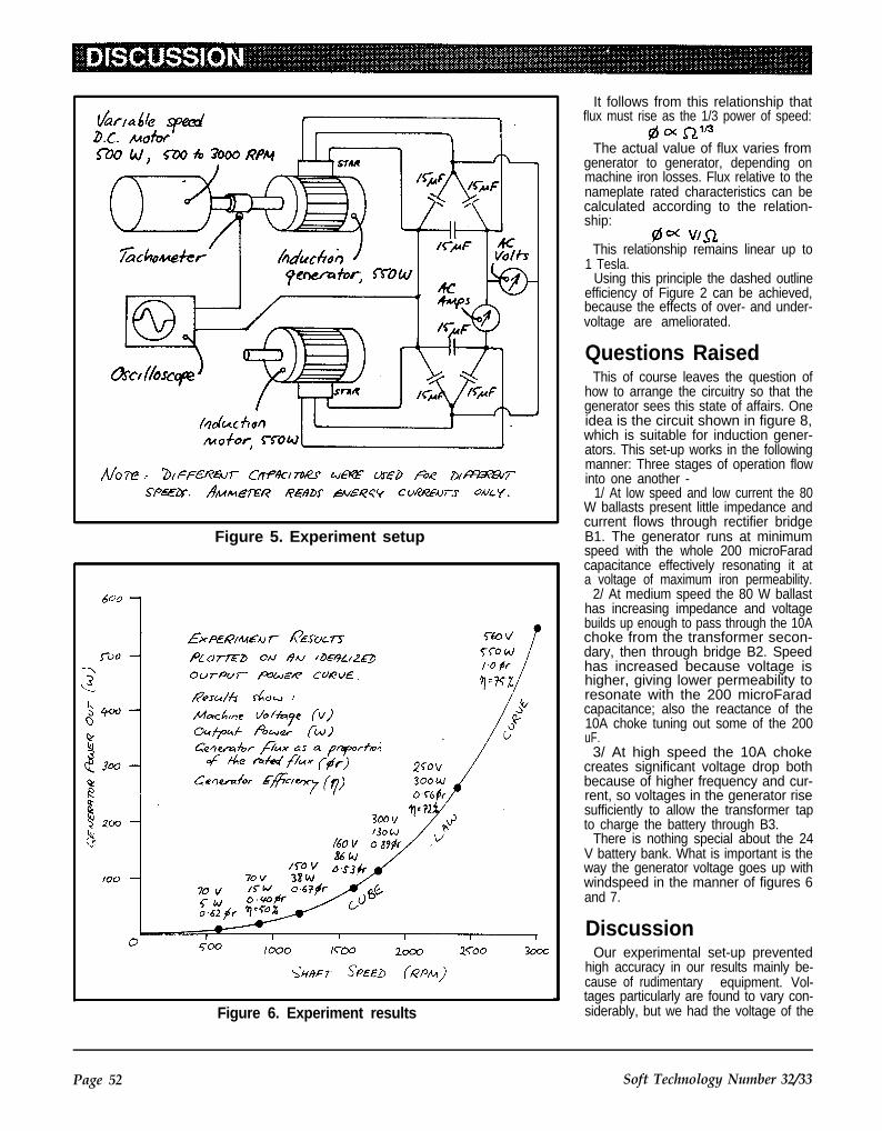
Figure 5. Experiment setup
Figure 6. Experiment results
It follows from this relationship thatflux must rise as the 1/3 power of speed:
The actual value of flux varies fromgenerator to generator, depending onmachine iron losses. Flux relative to thenameplate rated characteristics can becalculated according to the relation-ship:
This relationship remains linear up to1 Tesla.
Using this principle the dashed outlineefficiency of Figure 2 can be achieved,because the effects of over- and under-voltage are ameliorated.
Questions RaisedThis of course leaves the question of
how to arrange the circuitry so that thegenerator sees this state of affairs. Oneidea is the circuit shown in figure 8,which is suitable for induction gener-ators. This set-up works in the followingmanner: Three stages of operation flowinto one another -
1/ At low speed and low current the 80W ballasts present little impedance andcurrent flows through rectifier bridgeB1. The generator runs at minimumspeed with the whole 200 microFaradcapacitance effectively resonating it ata voltage of maximum iron permeability.
2/ At medium speed the 80 W ballasthas increasing impedance and voltagebuilds up enough to pass through the 10Achoke from the transformer secon-dary, then through bridge B2. Speedhas increased because voltage ishigher, giving lower permeability toresonate with the 200 microFaradcapacitance; also the reactance of the10A choke tuning out some of the 200uF.
3/ At high speed the 10A chokecreates significant voltage drop bothbecause of higher frequency and cur-rent, so voltages in the generator risesufficiently to allow the transformer tapto charge the battery through B3.
There is nothing special about the 24V battery bank. What is important is theway the generator voltage goes up withwindspeed in the manner of figures 6and 7.
DiscussionOur experimental set-up prevented
high accuracy in our results mainly be-cause of rudimentary equipment. Vol-tages particularly are found to vary con-siderably, but we had the voltage of the
Page 52 Soft Technology Number 32/33

Flgure 7. Experiment results in detail
Figure 8. Electrical arrangement for induction generators
machine running at rated speed as adefinite point, and could calculate aconstant k for this point and use that tofind the other valid points. We regardthe results as a good estimate only.Publication of results from a well-equipped laboratory would be valuable.
While illustrating the characteristics ofany generator operated with varyingshaft speeds, the results are particular-ly interesting in connection with induc-tion generators. Indeed, our initialreason for performing the tests was tounderstand how induction generatorscould be used in building economicalwindmills for remote-area power sup-plies.
A thorough literature review ofpublished engineering papers on induc-tion generators for windpower applica-tions showed that there is an estab-lished assumption that the voltageproduced by the machine shouldremain constant over the operatingrange. The consequence of this as-sumption is that complicated electroniccircuitry is required to control the electri-cal characteristics of the machine.
For D.C. loads, this is usuallyachieved by using a thyristor rectifierwith variable firing-angle control to con-tinuously vary the capacitive VArs (seefor example Milner and Watson 1985and Raina and Malik 1983). We wishedto consider a scheme avoiding suchcomplications. Although standard re-search assumes that an induction gen-erator with fixed capacitance excitershas a limited usefulness to wind powerapplications, we have begun here to ex-plore the idea of using a fixed-valuecapacitance with rising voltage, yieldingvarying inductances between the gen-erator and load (figure 8). We hope thisinitial study is taken up by others.
ReferencesKarl McLaughlin 1987. Low speed
economy from a Dunlite 1000 Wwindgenerator. South wind 21/22,pp.32-34.
Milner, I.P. and Watson, D.B., 1985.Autonomous wind powered generationsystem. Journal of Electrical andElectronics Engineering Australia, vol.5 no. 4, pp. 297-305.
Ralna, G. and Malik, O.P., 1983.Wind Energy Conversion using a self-excited induction generator. IEEETransactions on Power Apparatus andSystems, vol.102 no. 12, pp. 3933-3936.
Soft Technology Number 32/33 Page 53

SOLARWATER HEATER
BUYING GUIDEIn the last issue of Soft Tech-nology we had a look at theimportant issues you shouldconsider when looking atbuying a Solar Water Heater.In this issue we will have alook at the specific brands ofsolar water heater which areavailable.
But before we look at these,lets go over some of the keythings to remember whenbuying.
When you are looking at thesolar water heating panel andtank there are a number of fea-tures which improve the efficien-cy and in some cases the life ofthe panel.
T h e b e s t p a n e l s u s etoughened, low iron glass. Cop-per with a good quality selectivesurface is the best as far as theconstruction of the panel itself goes.
If these features are included in thepanel the efficiency of the panel can besignificantly higher than a panel withstandard glass, and an aluminium platewith black paint. This means the actualpanel size could be smaller than that ofthe less efficient panels.
As far as the tank goes gravity feedcopper tanks last longer than the mainspressure equivalents. However is youare going for mains pressure stainlesssteel is best.
A general comment on mains pres-sure versus gravity feed. There hasbeen a strong move over recent yearsto mains pressure hot water units.
The gravity feed units have probablylost favour because with old or poorlyinstalled plumbing the pressure fromthese units can drop off. Also, a numberof the major water heater manufac-turers have aggressively marketed themains pressure units.
However a properly installed gravityfeed heater will supply your hot waterneeds just as well as mains pressureunit, it will last a lot longer and it is easierto use in conjunction with wood heatingand other fuels.
The extra life and flexibility make thembetter value for money, but make cer-tain the installation is correct.
In this guide we are looking at onemodel from each` of the manufacturers.So as to be comparing apples with ap-
ples we are looking a waterheaters which would supply theheating needs of a family ofaround four people.
When looking at solar waterheater costs remember to takeinstallation into account. For asimple installation, the costcould be around $300 to $400.For a more complex job the costcould be much higher.
Be aware that the waterheaters we have concentratedon for this buying guide may notnecessarily be suitable for yourneeds. They are a good mediumpoint for comparison, but youmay need to look at a differentmodel.
For example some water heat-ing systems are designed forthe warmer parts of Australiaand hence have no frost protec-tion and may use a smaller area
of panels or even less efficient panels.Using one of these systems in thecolder areas would be a disaster, youwouldn’t get enough hot water and yourpipes would burst when it got too farbelow freezing point. Instead you wouldneed a system with frost protection andhigh efficiency panels. So look beforeyou leap and buy to suit your individualneeds.
We have made every effort that the in-formation in this guide is correct at thetime of publication, but if some featuresare different, we cannot be held respon-sible.
Now lets have a look at what is on themarket.
Page 54 Soft Technology Number 32/33

Make: Beasley.
Model: 5M
The CollectorArea: 2 x 1.5 m2 = 3 m2.Cover: Low iron.Absorber surface: Amcro, Selective
Surface.Absorber material: Copper.
The tankCapacity: 370 Litre.Lining: CopperBoosting: Gas, electric or solid fuelPressure: Gravity Feed, (low pres-
sure)
Other models: 26S300; (300 litre,close coupled, stainless steel tank).26R 160; (Smaller close coupled, withenamel lined tank. 300 litre version also
Beasley 5M
available). 26C 440L; (Larger closecoupled with stainless steel tank).
Features: Large range of models to Make: EdwardsC340FC; Remote mains pressure tank
suit all situations. All copper construc-
with pumped circulation. Solamatic 5M;tion in collectors.
(a range of gravity feed models, with theWarranty: Six years on tank, seven Model: L 305
tank located in the roof. Sizes availablefrom 280L capacity to 450L. Stove con-
years on panel.Price: $1,656 The Collector
Edwards L305
nections optional. Area: 2 x 2 m2 = 4 m2.Cover: Standard or tempered glass.Absorber surface:Absorber material: Aluminium or
copper
The tankCapacity: 300 Litre.Lining: Stainless steelBoosting: Gas, Electric or solid fuelPressure: Mains Pressure
Other Models: Roof mounted unitsvary in capacity from 180 litres, (ModelL180) up to 600 litre, (Model L600). Theseries 250 and 500 are designed forsolar, wood fired systems. Anothermodel the GEM/300 uses a Glycol HeatExchange system. Edwards can alsosupply roof mounted gravity feed tanks.They can also supply a range of waterheating panels to suit individual needs.
Features: Like Beasley a large rangeof options available to suit most applica-tions. Roof mounted units come in avariety of colours.
Warranty: 7 YearsPrice: $1,662
Soft Technology Number 32/33 Page 55

Make: Rheem
Model: Highline 300L
The CollectorArea: 2 x 1.81 m2 = 3.62 m2.Cover: Annealed, (toughened glass,
optional).Absorber surface: Chrome black
selective surface.Absorber material: Copper
The tankCapacity: 300 Litre.Lining: Vitreous enamel coated mild
steel.Boosting: Electric.Pressure: Mains Pressure.
Other Models: 52F 300; This is thesame as the 52T 300 except that it hasfrost protection.
Features:Warranty: 5 yearsPrice: $1,600
Rheem Highline 300L
Make: Siddons,(Raypak).Model: Solarplus,Solar boosted heat
Siddons Solarplus
Pump.The Collector
Area: 4 m2.Cover: No cover required.Absorber surface: Aircraft grade
epoxy enamel.Absorber material: Aluminium
The tankCapacity: 270 LitresLining: Vitreous enamel.Boosting: Not requiredPressure: Mains Pressure
Other Models: There is a larger 340litre model which costs an additional$150.
Features: Uses completely differentprinciple from the other heaters listed inthis buying guide. It uses a heat pumplike that in your fridge and will functioneffectively even when there is no sun orit is quite cold. Even though an enamellined tank is used the life should begood because there are no hot spotsfrom heating elements and the systemdoes not run up to high temperatures aswith systems with flat plate collectors.
Warranty: 5 yearsPrice: $1,914.
Page 56 Soft Technology Number 32/33

Solartherm ST L305
Make: Solarhart
Model: J
The CollectorArea: 2 x 2 m2 = 4m2.Cover: Toughened low iron glass.Absorber surface: Black power coat-
ing.Absorber material: Aluminium
The tankCapacity: 300 LitresLining: Vitreous enamelled steel.Boosting: Electric, (Gas option)Pressure: Mains Pressure
Other Models: There is a smaller 180litre version of the J model. The L modeldoes not have frost protection, but is alittle cheaper. A combination of the Kmodel collector, (with selective sur-face), and J model tank gives a unitsuited to cold locations at a slightlyhigher cost.
Features: A range of colours areavailable. Solarhart is one of largestcompanies and has a strong trackrecord.
Warranty: 7 years.Price: $1,715
Make: Solartherm
Model: ST L305
The CollectorArea: 1 x 3 m2.Cover: Low iron glass.Absorber surface: Copper Oxide
Selective surface.Absorber material: Copper.
The tankCapacity: 305 Litre.Lining: Stainless Steel.Boosting: Electric.Pressure: Mains Pressure.
Other Models: A range of other sizesare available including L 180, (180Litres), L 440 (440 Litres), and L 600(600 Litres). Other models are suitablefor commercial applications such as theP 305 which can be gas or electricallyboosted for use in laundries andcaravan parks, and the Mx500 to Mx3,000 which are designed for hightemperature recovery.
Features: Stainless steel tank forresistance to corrosion. Silver andbeige colours available.
Warranty: 7 yearsPrice: $1,625
Solarhart J
Soft Technology Number 32/33Page 57

Make: Somer Solar.
Model: Nova 4/335C
The CollectorArea: 2 x 1.8 m2Cover: Toughened, low iron, textured
glass.Absorber surface: Nickel black
selective surface.Absorber material: Aluminium
The tankCapacity: 335 litreLining: CopperBoosting: Electric and solid fuel.Pressure: Gravity feed.
Other Models: A range of models areavailable including a number of differentsized systems. Panels can be con-nected to a standard Rheem tank by theuse of a pump and controller. Anotheroption is the Nova Squat with a 400 litretank. Stove connections are optional.
Warranty: 5 yearsPrice: $1,456.
Somer Solar Nova 4/335C
Waterco Solarlink
Make: Waterco.
Model: Solarlink, pre-heating system.
The CollectorArea: Varies according to require-
mentCover: Unglazed or PolycarbonateAbsorber surface: N.A.Absorber material: EPDM or TPR
The tankCapacity: 6,000 l, 10,000 I, 15,000 I
or larger.Lining: Synthetic.Boosting: Heat exchanger allows the
use of different form of boostingPressure: Mains Pressure
Features: Produces large quantitiesof low grade heated water, with aflexible absorber size that can betailored to suit the building. This systemis frequently use in commercial applica-tions such as caravan parks, serviceclubs, etc.
Warranty: 12 monthsPrice: Price on application.
Page 58 Soft Technology Number 32/33

Rainforest Timbersand some alternatives
At present, rainforest timbers are mainly from Malaysia, Indonesiaused extensively in the building and and the Philippines.furniture industries in Australia. Inrecent years supplies of local rain- The best way to stop the destructionforest timbers have decreased, and of rainforests for timber is to stemimports have increased. We now demand for these products. Alterna-import over $1.6 billion worth of tim- tives do exist, and it is also possible to
ber annually. About 1/4 of the total grow some rainforest species in planta-
originates in tropical rainforest,
Imported RainforestTimbers- use notrecommended
Following is a list of imported rain-forest timbers. Often a single name, likeMeranti, Phillipine Mahogany, Kapurand Ramin, can include variousspecies.
It should be noted that most importsfrom Taiwan, Hong Kong, Singapore,South Korea and Japan containingwood in any form are made from thesetimbers, in particular species of theShorea genus.
Alan (=Batu)Almon (=Phillippine Mahogany)Amboyna wood (=Narra)Apitong (=Keruing)Balau (=Batu)Balam (=Nyatoh)BalsaBangtikan (=Phillippine Mahogany)BatuBaygo (=Ramin)Betis (=Nyatoh)Beech, New GuineaBitis (=Nyatoh)Borneo Camperwood (=Kapur)CalantasDjelutong (=Jelutong)Gahara Buaja (=Ramin)GmelinaIpil (=Merbau)IrokoJelutongKalantas (=Calantas)Kapoer (=Kapur)Keroewing (=Keruing)KeruingKetiau (=Nyatoh)KotoKwila (=Murbau)Lauan (=Meranti)Lanutan (=Ramin)Mahogany, AfricanMangasinoro (=Batu)MarfimMayapis (=Phillippine Mahogany)
Soft Technology Number 32/33 Page 59

Mavota (=Ramin)Melawis (=Ramin)MenkulangMeranti (=Pacific Maple)MerawanMerbauNarraNew Guinea BeechNyatohOba Suluk (=Meranti)PadaukPalaquiumPhillipine MahoganyRaminRed Lauan (=Phillipine Mahogany)Rosewood (=Narra)Selangan Kacha (=Batu)Seraya (=Meranti)Tanguile (=Phillipine Mahogany)TeakVesi (=Merbau)
Australian RainforestTimbers-use not recommended
The following is a list of local rainforesttimbers. These should not be used un-less specifically grown for the purpose.To date hoop Pine and a very smallquantity of Bunya Pine are the onlyAustralian rainforest timbers beinggrown here in plantations.
Alder (Caldcluvia, Slovanea spp.)Ash (Flindersia spp.)Backhousia, Stony (Backhousia
hughesii)Basswood (Tieghemopanax spp.)Bean, Black (Castanospermum
australe)Bean, Red (Dysoxylum muelleri)Beech (Polyalthia, Citronella,
Gmelina spp.)Birch, White (Schizomera ovata)Bollywood (Litsea spp.)Booyong (Argyrodendon spp.)Bonewood (Emmenosperma al-
phitoniodes)Boxwood (Xanthophyllum octandrum
& Planchonella pohimaniana)Butternut, Rose (Blepharocarya in-
volcrigera)Candlenut (Aleurites moluccana)Carabeen (Sloanea spp.)Cedar (Toona, Palaquium, Melia spp.)Cheesewood, White (Alstonia
scholaris)Coachwood (Ceratoptalum apetalum)Cudgerie (Canarium australasicum)Damson (Terminalia sericocarpa)Euodia (Euodia spp.)Foambark (Jagera pseudorhus)
Flametree (Brachychiton acerifolius)Ivorywood (Siphonodon australis)Jackwood (Cryptocarya glaucescens)Magnolia (Galbulimima belgraveana)Mahogany (Gessois, Dysoxium spp.)Maple (Flindersia & Cryptocarya spp.)Mararie (Pseudoweinmannia lach-
nocarpa)Oak (Carnavonia, Darlingia,
Musgravea, Neorites, Orites, Cardwel-lia, Stenocarpus, Grevillea, Buckin-ghamia, Argodendron spp.)
Penda, Brown (Xanthostemonchrysanthus)
Pepperwood (Cinnamomum laubatii)Pine, Black and Brown (podocarpus
spp.)Pine, Hoop (Araucaria cunninghamii)Pine, Putts (Flindersia acuminata)Plumwood (Endiandra spp.)Quandong (Elaeocarpus spp.)Saffronheart (Halfordia kendack)Salwood (Acacia aulococarpa)Sassafras (Doryphora spp.)Satinash (Eugenia & Syzygium spp.)Satinheart, Green (Genera salicifolia)Silkwood (Cryptocarya, Palaquium,
Flindersia spp.)Siris (Albizia spp.)Sycamore (Ceratopetalum & Cryp-
tocarya spp.)Teak, Australian (Flindersia australis)Touriga, Red (Calophylum costalum)Walnut (Beilschmeidia & Endiandra
spp.)Yellowwood (Flindersia xanthoxyla)Brushbox (Lophostemon confertus)
grows commonly in and on the edge ofrainforest and in the moister eucalyptforests. Many believe that brushboxshould not be logged as it is a rainforesttimber. Where it does occur outside arainforest it is usually in an area whichwas once rainforest and would return torainforest if allowed and encouraged todo so. Its use is not recommended.
Uses of the MostCommonly ImportedRainforest Timbers
Batu (Shorea spp.) House posts,wharfage, ship building.
Calantas (Toona calantas) Furni-ture, boatbuilding, joinery and carving.
Jelutong (Dyera costulafa) Carving,pattern making, toys.
Keruing (Dipterocarpus spp.) Struc-tural work, poles, beams.
Kapur (Dryobalanops spp.) Doorand window frames, window sills,joinery, furniture, shelving.
Menkulang (Hiritiera spp.) Usually inplywood imported from Malaysia.
Merantl (Shorea spp.) Door and win-dow frames, doors (especially louvre),internal joinery, mouldings.
Merbau (Intsia bijunga) Furniture,floorings, sills, boatbuilding and veneer.
Narra (Pterocarpus Indicus) Fur-niture, turning and panelling
Nyatoh (Sapotoceae spp.) Plywood,architraves, mouldings and furniture,Interior only.
Phillipine Mahogany (Shorea andParashorea spp.) Furniture, plywood,boatbuilding and joinery.
Ramin (Gonostylus spp.) Plywood,blondewood articles fashionable 20years ago, picture frames, mouldings,dowelling.
Teak (Tectona grandis) Furniture,veneer, marine decking.
Cabinet TimberImported furniture from ASEAN
countries and Taiwan is produced main-ly with timber from SE. Asian rain-forests. Taiwan is the single largest sup-plier and about 75% of its timber comesfrom rainforests.
AlternativesDesign re-thinking is the first step. The
challenge for designers lies in minimis-ing environmental impact, in choosingthe right materials for the job and inusing them to their full potential.
Composite boards, particle boardsand plywoods are good choices be-cause they utilise lower grade materialand residues than traditional sawmill-ing, leading to more efficient use of theresource. Note that plywoods oftencome with rainforest timber veneers,but domestically produced veneersutilising radiata pine, hoop pine andeucalypt veneer facings are available.
Recycling used timber is also an op-tion. It has the advantage of being wellseasoned and stable, although moredifficult to work than new timber.
Alternative materials, such as steel,aluminium and plastic are worth con-sidering. Concrete may also besuitable.
Further Information:Rainforest lnformation Centre, P.O.
Box 368, Lismore, N.S.W., tel. (066) 218505;
The Good Wood Advisory Centre,GPO Box 3217 GG, Melbourne 3001,tel. (03) 654 4833, fax (03) 650 5684.
Page 60 Soft Technology Number 32/33

ATA ReportThe ATA AnnualGeneral Meeting.The AGM was attended by 26members who mainly camealong to hear Karl McLaughlindown from Nimbin to talk on theRainbow Power Company -which was very interesting.
At the meeting the Presidentreported on the CAE courses wehave held on Welding and Lathework, which were a success.
Work on the educational displaytrailer has progressed with the helpof a $3,000 VSEC grant which hasbeen used to upgrade models.VSEC will help plan and prepareeducational kits to prepare it for usewith school visits.
Requests were made for people tohelp process mail as the public’sconcern about the Greenhouse Ef-fect have led to more requests forinformation coming from studentsand other interested people. Wehave bought our own computer andthat should help us keep mem-bership and word processing up todate.
lt was reported that combined mem-bership and Soft Technology sub-scribers has increased to around 1,000.
Mick Harris and Karl McLaughlin areusing the Solar Workshop to constructa windmill and waterwheel for theBrunswick Electric Supply’s EnergyPark. Karl commented favourably onthe workshop and said it was better thananything they had up around Nimbin.
Bill Keepin came to Australia fromthe U.S. to spread the word on Ener-gy Conservation and DemandManagement, as the answer toenergy growth and fossil fuel emis-sions.
New CommitteeThe new committee is as follows :-
PRESIDENT Mick HarrisTREASURER Eva FabianSECRETARY Herb Wildes“OFFICIAL” COMMITTEE MEM-
BERS Alan Hutchinson, Noel Jef-fery, Chris Moss, Andrew Barker
COMMITTEE MEMBERS Bob Kealy,Jeff Hilder, Chris Harkin
As the Constitution allows for sevencommittee members in total, the firstseven members are “Official” and therest unofficial and will not appear on thelist going to Corporate Affairs. In the
event of any constitutional matter need-ing to be decided only official memberswill be allowed to vote. Otherwise therewill be no difference between them.
Energy ConservationEfforts In the last few months the Green-house Effect issue has jumped tothe forefront of many peoplesminds.
The ATA is the only community basedenergy group in Victoria and as suchhas had a lot of work and involvement informulating an anti-nuclear, pro-con-servation and renewable energyresponse to the problem.
We have produced a booklet, entitled“The Renewable Solution", whichsets out a renewable energy path forVictoria. This was produced speciallyfor the Bill Keepin tour of Australia. lt isour reply to the various reports and draftpolicies on the Greenhouse Effect, andwill be used as a basis for submissionsto State and Federal Government.
Around 1000 people turned up to the public meeting in Melbourne ona cold July night at CollingwoodTown Hall. They were met at theentrance by a spotlit and fairy lightbedecked Solar trailer and the usualstall, selling magazines and givingaway membership forms. A lot of in-terest was shown and about 80copies of “The Renewable Solution”were sold.
Around and AboutAt last we received some grantmoney, to finish the trailer anddo some policy work. Mick Har-ris and Jeff Hilder have workedhard to get the trailer ready forthe Bill Keepin tour and we havebought new equipment to gowith it.
Because of the amount of workfacing us and the perilous financial
situation we have got into in the lastyear or so, we made an appeal formoney in July. The response wasgratifying with sums of up to $1,000received for which we are most grate-ful. It is a time when we can really in-fluence other groups and the Govern-ment and convince people that there isan alternative to the economic treadmillthat we are currently on.
In the spring term, the ATA held CAE.courses in metal working, welding andPowering your home without the SEC.These were held at the SolarWorkshop, and were very well at-tended.
Eva Moss has come to help out as of-fice worker and has brought the booksup to date for the AGM. Not an easytask.
Brendan English and Tony Murphyhave been very busy around the SolarWorkshop. They have opened theWorkshop almost every day for quite afew weeks, adding to the general bustleof the CERES site. Very encouraging.
Soft Technology Number 32/33 Page 61

EDITOR’S NOTESGovernment Kills OffRenewable EnergyThe Federal Government hasdecided to completely withdrawfunding from the CSIRO’s Renew-able Energy Index. This is the onlycomprehensive, regularly updatedbibliography of renewable energyresearch in the Australia - Pacificregion.
The first volume of the index waspublished in 1981 and the final, 31st,volume is being produced now. One ofthe small group of workers describedthe project to me as a ‘dead duck’. Ofcourse, there will now be no way tocoordinate research in the field, leavingeveryone blind as to what others aredoing.
News of such subtle sabotage is un-likely to reach the public, and contrastsstarkly with the Government’s rhetoricalblather about their ‘concern’ for the en-vironment.
Take up thy magazineand flog...Fancy yourself in the wonderfulworld of promotions and market-ing? Soft Technology needs a littlehelp in that direction -we figure thatwe could increase circulation simplyby telling people we exist. Morereaders will eventually mean moreinput and better articles.
Take a copy of Soft Tech along to yourlocal greenie-alternatives shop or new-sagent . . if they’ll take copies of SoftTechnology, please let us know! Askyour school or local library to subscribe.Give us a ring if you’d like to help at thisend.
Soft Technology getsits BearingsIn England, the first thrust bearingswere developed for windmills in thelate eighteenth century.
The radial ball bearing began itsdevelopment with the introduction of thebicycle in the middle of the nineteenth
century. (from ‘Balland Roller Bearings’,Engineering Equipment Users Assoc.1958)
Your Name in PrintWe would like to get articlestogether on the following topics. Ifyou think you can contribute (com-plete articles, participation in agroup effort, or information and/orcontacts you know will be useful),write to us or ring the editorial hot-line now!
-Women in Alternative Technology-Permaculture Concepts-Urban House Design-Energy Conservation-Composting Toilets-Hazardous Household Chemicals-Electronics for RAPSS-Energy storage-Solar Ponds-Wave, Tidal, OETC Energy-Ergonomic Design-Spatial concepts for community
layoutOf course, we’re still looking for ar-
ticles about your latest project!
Brain FoodHere are a few things definitelyworth pointing out -
“How Green is the Wind” NewScientist May 27 1989. This articleraises a number of issues involved inplanning a contribution of 10 - 20% of(Britain’s) electricity from windpower.The considerations apply to usalso "Energy Efficient Buildings”,Scientific American April 1988. Greatarticle reviewing energy conservationand its implementation in the U.S. atpresent.
“All gas and garbage”, New Scien-tist 3 June 1989. Again expertly written,this article gives details of (mainlyBritish) experience with biogas electric
Here are some of our ideas (can you generation from rubbish tips.think of others? Let us know):
Want to be aSUCCESSFUL owner builder?
l l Plans l Money saving ideas l l AdviceAll from the only Australian magazine designed for people
building their own homes.Mailed to you six times a year for $19, or from your newsagent.
The Australian home builders’ magazineP.O. Box 974, Bendigo 3550
Page 62 Soft Technology Number 32133

BOOK REVIEWSThe RenewableSolution
by Alan Hutchinson, Chris Mossand Ian Scales.
Alternative Technology Associa-tion, 1989.
A5 format, 20 pp., illustrated.Reviewed by R. Feynman
The front cover says it all. It hasthe longest subtitle I’ve seen fora long time: "Energy and theGreenhouse Effect; how we canstop using fossil fuels withoutgoing nuclear; a sustainableenergy future for Victoria".
The booklet aims to present thecase for energy conservation andthe substitution of fossil-fuels withrenewable sources, all with the in-tention of averting the greenhouseeffect. It was inspired by the pioneer-ing study by Bill Keepin and GregoryKats in the U.S., in which nuclearpower and energy conservationwere compared for economic merit.Their study demonstrated a clear,quantitative victory for conservation,As Bill Keepin said in his recent talk inMelbourne: “If you want to take a bathand the bath is full of holes you can doeither of two things: keep pouring inmore water or plug the holes.” Quite.
“The Renewable Solution” takes upthis lead by gathering together recentGovernment figures for energy use inVictoria: it then looks at where energyuse can be made more efficient by cur-rent cost-effective means, and asses-ses the quantitative impact a concertedeffort to adopt these measures wouldmake in the commercial, industrial anddomestic sectors. Unfortunately thebooklet does not address issues ofurban planning or transport policy, bothof which affect energy use in transport.
With this information an assessmentof energy demand under a conservationscenario is made. Then a quantitativeestimate of how much energy could besupplied by non-polluting cost-effectivecurrent renewable energy technologiesis calculated. Interestingly, the authorsconclude that given the contraction ofdemand (with no loss in ‘living stand-ards’) that would come from a conser-vation program, it is entirely feasible to
supply the majority of heating andelectricity needs by renewable meanssuch as so la r , hyd ro -e lec t r i c ,windpower etc.
Criticism of present attitudes andpolicy are made, comparisons made
with other countries of our current(poor) performance in energy con-servation; the conclusions are sum-marised and recommendations for-mulated. One beauty of the bookletis that all these assessments havebeen made with an economy of Ian- guage and the authors come to thepoint quickly. Sometimes pithy, veryinformative, and succinct.
Available from the ATA, $2.80 bymail
WindpumpingHandbook
by Sarah Lancashire, JeffKenna and Peter Frankel.
Intermediate Technology Publica-tions, London, 1987.
Reviewed by Mick Harris.This is another of the series ofexcellent practical books fromthe Intermediate TechnologyDevelopment Group. It is writtento provide decision makers andpotential users of windpumpswith the basic information
needed in the selection of awindpump for a particular use.
In particular it covers windpump his-tory, principles of operation, site evalua-tion, how to go about purchasing thewindpump, installation and main-tenance.
The book also has a section whichquestions whether a windpump is thebest option at all. lts refreshing to seethat rather than just promoting thewindpump as the solution to yourproblems and telling you how to goabout s iz ing and instal l ing thewindpump, this book also deals with thehard question of whether this technol-ogy is really appropriate to the needswhich are at hand.
The format of the windpump hand-book is clear and concise and the orderof the chapters help the reader build upa good basic understanding of the tech-nology and the factor that should beconsidered in planning a windpump in-stallation.
Like most Intermediate Technologypublications this book is primarily in-tended for those working in developingcountries. But also like most LT. publi-
Soft Technology Number 32/33 Page 63

“The Homebuilt Dynamo”
cations this does not dominate thebook, and there are plenty of facts and The Homebuiltfigures that are relevant to all potential Dynamowindpump users.
The book does not cover recondition-ing or repair of windmills and itscoverage of installation and main-tenance is brief. However if you want agood grounding in the principles ofwindpump operation and designingsystems to suit your own particularneeds this book could make a good in-vestment.
Copy Supplied by Second Back RowPress, Katoomba, N.S.W.
Price: $9.50
Alfred T. Forbes.Todd-Forbes Publishing, Oratia,
Auckland, New Zealand 1987,182 pp., over 300 illustrations.Reviewed by Tony Murphy.
This book describes the design andconstruction of a low speed per-manent magnet alternator. Thethree phase output passes througha built-in full-wave rectifier, giving arated maximum 1000 watts, 36 V at740 rpm.
Essential reading if you’re planning onbuilding a permanent magnet alter-nator! If you’re designing a wind, wateror pedal power system, this book wouldbe worth a look too.
Most of the illustrations are goodquality black and white photos, so youcan see exactly what the author is talk-ing about. The book is suitable forpeople who have little knowledge aboutelectricity, as the author explains every-thing well. The step-by-step instructionsguide you through the complicatedareas of construction and assembly. Nowelding or even soldering is needed.With the exception of some lathe workon the rotor hub and some spacers, allthe construction can be completed withjust hand tools, as is shown in the book.However, some of the stages of con-struction would be speeded up if youhave access to power tools.
The design is simple and rugged.Strontium-ferrite magnets are attachedto the rotor which spins past the station-ary coils in which the electricity isgenerated. So there are no brushes tocause friction and wear. The only main-tenance needed is grease applied to thetwo main shaft bearings occasionally.
An appendix deals with scaling up thesize of the alternator - for example dou-bling the size gives a bit over 8 kW atbelow 700 rpm. There is some discus-sion of design and theory as well.
The only reservation I have about thebook is its high price. It is printed on veryhigh quality paper and it is well boundin hard cover - I suppose that explainsit. I think the book would have a highercirculation among experimenters andalternative technology enthusiasts if itwas cheaper.
A highly recommended book, and theauthor says he is willing to work by mailwith anyone who wants to tackle theproject.
Available from Todd-Forbes Publish-ing, PO Box 3919, Auckland, NewZealand. $85 Aust. by airmail.
Local Experience withMicro-HydroTechnology
Ueli MeierSKAT/ATOL (Swiss Centre for Ap-
propriate Technology/ Study andDocumentation Centre, Belgium), 3rded., 1985.
169 pp, many figures, tables, graphicsand photographs.
Reviewed by Noel Jeffery
Page 64 Soft Technology Number 32/33
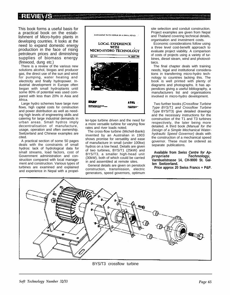
This book forms a useful basis fora practical book on the estab-lishment of Micro-hydro plants indeveloping countries. It looks at theneed to expand domestic energyproduction in the face of risingpetroleum prices and diminishingsupplies of biomass energy(firewood, dung etc.)
There is a review of the various newsolutions alcohol, biogas and producergas, the direct use of the sun and windfor pumping, water heating andelectricity and finally hydropower. In-dustrial development in Europe oftenbegan with small hydroplants untilsome 80% of potential was used com-pared with less than 20% in Asia andAfrica.
Large hydro schemes have large riverflows, high capital costs for constructionand power distribution as well as need-ing high levels of engineering skills andcatering for large industrial demands inurban areas. Small hydros implydecentralisation of manufacture,usage, operation and often ownership.Switzerland and Chinese examples arecited.
A practical section of some 50 pagesdeals with the constraints of smallhydros: lack of hydrological data forsmall streams, load factors, cost ofGovernment administration and con-struction compared with local manage-ment and construction. Various types ofturbines are examined and explainedand experience in Nepal with a propel-
ler-type turbine driven and the need fora more versatile turbine for varying flowrates and river loads noted.
The cross-flow turbine (Michell-Banki)invented by an Australian in 1903shows promise for versatility and easeof manufacture in small (under 100kw)hydros on a low head. Details are givenof two turbines, BYS/T1 (25kW) andBYS/T3, a smaller high-head unit(30kW), both of which could be carriedin and assembled at remote sites.
General details are given on penstockconstruction, transmission, electricgenerators, speed governors, optimum
site selection and conduit construction.Project examples are given from Nepaland Thailand covering technical details,organisation and investment costs.
Economic considerations follow usinga three level cost-benefit approach toevaluate project viability. A comparisonof costs of projects using a variety of tur-bines, diesel steam, wind and photovol-taics.
The final chapter deals with trainingneeds, legal and institutional considera-tions in transferring micro-hydro tech-nology to countries lacking this. Thebook is well printed with plenty ofdiagrams and photographs. It has ap-pendices giving a useful bibliography, amanufacturers list and organisationsinvolved in micro-hydro development.
Two further books (Crossflow TurbineType BYS/T1 and Crossflow TurbineType BYS/T3) give detailed drawingsand the necessary instructions for theconstruction of the T1 and T3 turbinesrespectively, the later being moredetailed. A third book (Manual for theDesign of a Simple Mechanical Water-hydraulic Speed Governor) deals withthe construction of a mechanical speedgovernor. These must be ordered asseparate publications.
Available from Swiss Centre for Ap-propriate Technology,Varnbuelstrasse 14, CH-9000 St. Gal-len Switzerland.
Price approx 20 Swiss Francs + P&P.
BYS/T3 crossflow turbine
Soft Technology Number 32/33 Page 65

LETTERS TO THE EDITORPhysics and PerpetualLifeThank you Stephen Downing for
working at more than 100% efficiency.
your letter in the last issue expound-ing clearly the laws of physics asthey have been since 1824 on thesubject of heat engines.
I weekly get STD calls fromproponents of perpetual motionmachines. Usually these are based ongenerators, motors, pumps or turbines
Peopleget ideas which seem intuitive-ly credible but they don’t bother withworking models or calculations. Theseideas don’t ever come to terms with thesubtlety of the second law of ther-modynamics, or the vagaries of cost ef-fectiveness or practicality. They failsimply on conservation of energy laws.
The “no free lunch” law really irritatespeople. Why should the physicists havesuch authority while in politics,economics, even marital affairs thereARE free lunches! Surely scientists, asthe high priests of this materialistic age,have held this credibility by suppressingheresy, inventing their own language
and even creating reality by believing init! Perhaps serendipity works the otherway around: laws of physics are createdby people doing experiments. It doeswork like that sometimes in medicine.
The problem, I suggest, is in humanpersonality. People have alwaysbelieved in everlasting life and the
l l l l l l l l l l l l l l l l
Send 4 stamps forcatalogue. Listareas of interestand name of this
publication.l l l l l l l l l l l l l l l l
DEPT 1 AGRICULTUREBeekeeping Equipment.Vegetable & Herb Seeds.Horto Paper (Mulch).
DEPT 2 PUBLICATIONSBooks & Magazines on awide range of subjects.
DEPT3 GASGas Hot Water Services.Gas Refrigerators.Gas Room Heaters.Gas Log Fires.
DEPT 4 ELECTRICITY
Solar Panels.Batteries.Inverters.Regulators.
Battery Chargers.Change Over Switches,Control Panels, andhigh efficiency lightsparts and appliances.
DEPT 5 FOODStone Flour Mills.Burr MillsHand JuicersBread Tins & Yeast.Sprouting Tubes & Trays.Twinings Tea.
DEPT 6 SOLAR HOT WATER
Quality BeasleySystems includ-ing Constant &Mains Pressure.
SAVE ON WATER HEATING
DEPT 7 WOOD STOVESA range of quality spacewood heaters: Coonara,Arrow, Nectre, Jotul,and Maxiheat.
DEPT 8 WATER PUMPINGFloating Dam Pumps.Borehole Pumps.12v Domestic Pumps.
DEPT 9 SHELTERMud Brick Moulds& Presses.Bio Paints & Varnishes.Seagrass Insulation.
Page 66 Soft Technology Number 32/33

growth economy. Sustainability is aBORING CONCEPT, and entropy in-creasing is inherently depressing. It isironic that the physics of entropy gaveus the industrial and the informationrevolutions, and the concept of sus-tainability, if it can be enacted, offersperpetual life to our civilisation! Mostlifeforms acting freely seem to grow ex-ponentially until they run out of reasonsor suffocate on their products, be theybacteria or people. Only when there areconstraints, interaction and competitionis there stability.
Long live GAIA,Karli McLaughlin.
Gearbox inventionDear Sir/Madam,
Between 7 and 10 years ago, when Iwas living in New Zealand, the NZ.Broadcasting Commission TV had aprogramme on called The Inventors. Itwas a programme for ordinary NewZealanders to show off what they hadinvented. One of the inventors was aman who had invented a gear box that
had only a few moving parts. The prin-ciple was that you had a swivelling gearin front of another fixed gear. The de-gree of swivel of the front gear changedthe ratio of the rear drive. The principleof the gearbox is shown in the drawingbelow.
The engine (E) drives a shaft onto acoin-like (A) plate with rounded meshtype gears on it. The plate A can swivel
Gearbox concept
and the more it swivels the lower theratio is. The face of (A) is designed tomesh in with the face of (B) no matterwhat the swivel of A is. The gear box hassuch a huge range of ratios that youcould connect up a very small electricmotor to the gearbox and lift a house upwith it. What we could do is buy a videofilm of the particular programme, tostudy of the ideas behind the gearbox.If it is not possible to get a video copy
of the programme which could be usedas the basis for an article in “Soft Tech-nology”, would it be possible to get thename and address of the inventor.
Yours SincerelyW.T. WadsworthNorthcote VIC(Can anyone help? - Ed.)
SUNPOWER forSUNPOWER forREMOTE HOMESREMOTE HOMES
WATER PUMPINGWATER PUMPING
CARAVANS and BOATSCARAVANS and BOATS
SOLAR ELECTRIC
PANELS AND
MEGAWATT PVPOWER PLANTS
FROM
SOLAR CELLSAUSTRALIAA CLEAN ENERGY
FUTURE FOR
AUSTRALIA !
382 CANTERBURY ROADSURREY HILLS VICPH: (03) 836 9966
3l27
FAX: (03) 836 6743
Soft Technology Number 32/33 Page 67