![United States Patent [19]](https://static.fdokumen.com/doc/165x107/631a8ca4c51d6b41aa04dfa4/united-states-patent-19-1674659621.jpg)
United States Patent [191
13
United States Patent [191 Abe et al. 4,792,007 Dec. 20, 1988 [11] Patent Number: [45] Date of Patent: [54] MECHANISM FOR STEERING FRONT AND REAR WHEELS OF FOUR-WHEEL VEHICLE [75] Inventors: Masaru Abe; Masami Ogura; Tsuyoshi Sato, all of Saitama, Japan Honda Giken Kogyo Kabushiki Kaisha, Tokyo, Japan [21'] App1.No.: 88,908 [22] Filed: Aug. 24, 1987 [73] Assignee: Related US. Application Data [63] Continuation-in-part of Ser. No. 10,177, Feb. 2, 1987, Pat. NO. 4,758,012. [30] Foreign Application Priority Data Aug. 22, 1986 [JP] Japan .............................. .. 61-196702 [51] Int. Cl.4 ............................................. .. B62D 5/00 [52] US. Cl. ..................................... .. 180/140; 280/91 [58] Field of Search ......................... .. 280/91; 180/140 [56] References Cited U.S. PATENT DOCUMENTS 4,467,885 8/1984 Furukawa et a1. ................. .. 280/91 4,557,493 12/1985 Sano et a1. .......................... .. 280/91 4,582,334 4/1986 Tashiro et a1. ...................... .. 280/91 4,601,357 7/1986 Miyoshi et a1. ................... .. 180/140 FOREIGN PATENT DOCUMENTS 59-70259 4/ 1984 Japan . 59-70260 4/1984 Japan . 61-181776 8/1986 Japan . 61-181777 8/1986 Japan . Primary Examiner—Kenneth R. Rice Attorney, Agent, or Firm—Irving M. Weiner; Joseph P. Carrier; Pamela's. Burt [57] ABSTRACT A mechanism for steering the front and rear wheels of a four-wheel-steerable vehicle includes a front wheel steering device operatively coupled to a steering wheel and having at least a rack-and-pinion gear mechanism having a nonlinear gear ratio, a rear wheel steering device, a linkage shaft operatively connecting the front wheel steering device and the rear wheel steering de vice to each other, and at least one steering force assist ing device disposed in a steering force transmitting path comprising the front wheel steering device, the rear wheel steering device, and the linkage shaft. 7 Claims, 7 Drawing Sheets
-
Upload
khangminh22 -
Category
Documents
-
view
0 -
download
0
Transcript of United States Patent [191

United States Patent [191 Abe et al.
4,792,007 Dec. 20, 1988
[11] Patent Number:
[45] Date of Patent:
[54] MECHANISM FOR STEERING FRONT AND REAR WHEELS OF FOUR-WHEEL VEHICLE
[75] Inventors: Masaru Abe; Masami Ogura; Tsuyoshi Sato, all of Saitama, Japan
Honda Giken Kogyo Kabushiki Kaisha, Tokyo, Japan
[21'] App1.No.: 88,908 [22] Filed: Aug. 24, 1987
[73] Assignee:
Related US. Application Data
[63] Continuation-in-part of Ser. No. 10,177, Feb. 2, 1987, Pat. NO. 4,758,012.
[30] Foreign Application Priority Data Aug. 22, 1986 [JP] Japan .............................. .. 61-196702
[51] Int. Cl.4 ............................................. .. B62D 5/00 [52] US. Cl. ..................................... .. 180/140; 280/91 [58] Field of Search ......................... .. 280/91; 180/140
[56] References Cited U.S. PATENT DOCUMENTS
4,467,885 8/1984 Furukawa et a1. ................. .. 280/91 4,557,493 12/1985 Sano et a1. .......................... .. 280/91
4,582,334 4/1986 Tashiro et a1. ...................... .. 280/91 4,601,357 7/1986 Miyoshi et a1. ................... .. 180/140
FOREIGN PATENT DOCUMENTS
59-70259 4/ 1984 Japan . 59-70260 4/1984 Japan .
61-181776 8/1986 Japan . 61-181777 8/1986 Japan .
Primary Examiner—Kenneth R. Rice Attorney, Agent, or Firm—Irving M. Weiner; Joseph P. Carrier; Pamela's. Burt
[57] ABSTRACT A mechanism for steering the front and rear wheels of a four-wheel-steerable vehicle includes a front wheel steering device operatively coupled to a steering wheel and having at least a rack-and-pinion gear mechanism having a nonlinear gear ratio, a rear wheel steering device, a linkage shaft operatively connecting the front wheel steering device and the rear wheel steering de vice to each other, and at least one steering force assist ing device disposed in a steering force transmitting path comprising the front wheel steering device, the rear wheel steering device, and the linkage shaft.
7 Claims, 7 Drawing Sheets
U.S.i Patent Dec. ‘20, 1988 Sheet 1 of7 4,792,007

us. Patent M10, 1988 Sheet 2 of 7 4,792,007

US. Patent Dec. 20, 1988 Sheet 3 of 7 4,792,007
FIG. 3 *
2
r5 4Y‘II///////////////////,\ ////////////////|,
' \ I\3
F/G.5 STEERING WHEEL FRONT WHEEL TURNING ANGLE STEERING DEVICE
'
® ” D. I- . D
0 K v FRoNT WHEEL
/ INPUT TURNING ANGLE
' D L p.
8 INPUT \V/'\ REAR WHEEL
\ TURNING ANGLE
REAR WHEEL STEERING DEVICE
US. Patent Dec. 20, 1988 Sheet 4 0f 7 4,792,007
US. Patent Dec. 20, 1988 Sheet 5 of7 4,792,007
F/G.6 E (A)
$5’ a /,,/ F/G.6 c b
(B) F/G.6§§
. (C) F/G.6 (D)
STEERING WHEEL TURNING ANGLE

US. Patent Dec. 20, 1988 Sheet 6 of7 v4,792,007
FIG. 7 (A) ASSISTIVE
STEERING FORCE
FRONT WHEEL FRONT AND REAR SUBSTANTIVE STEERING FORCE WHEELS STEERING FORCE STEERING FORCE STEERING STEERING STEERING FORCE FORCE FORCE
TURNING TURNING TURNING ANGLE ANGLE ANGLE
STEERING FORCE
TURNING ANGLE
REAR WHEEL STEERING FORCE
FRONT WHEEL ‘ SUBSTANTIVE
STEERING FORCE STEERING FORCE STEERING STEERING FORCE FORCE
TURNING TURNING ANGLE ANGLE
ASSISTIvE , STEERING FORCE
B OR o
STEERING FORCE
TURNING ANGLE
REAR WHEEL STEERING FORCE
US. Patent Dec.20, 1988 I Sheet 7 of 7 4,792,007
FIG. 7 (c) A
ASSISTIVE STEERING FORCE
FRONT WHEEL FRONT AND REAR SUBSTANTIVE STEERING FORCE WHEELS STEERING FORCE STEERING FORCE STEERING STEERING STEERTNG FORCE FORCE FoRcE
TURNING TURNING TURNING ' ANGLE ANGLE ANGLE
ASSISTIVE STEERING FORCE
B OR C STEERING FORCE
TURNING ANGLE
73a?
REAR WHEEL STEERING FORCE
4,792,007 1
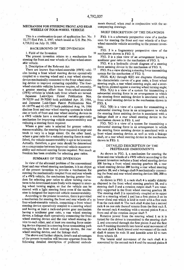
MECHANISM FOR STEERING FRONT AND REAR WHEELS OF FOUR-WHEEL VEHICLE
This is a continuation-in-part of application Ser. No. 10,177 ?led Feb. 2, 1987, which issued as US. Pat. No. 4,758,012 on July 19, 1988.
BACKGROUND OF THE INVENTION
1. Field of the Invention The present invention relates to a mechanism for
steering the front and rear wheels of a four-wheel-steer able vehicle.
2. Description of the Relevant Art There are known four-wheel-steerable (4W5) vehi
cles having a front wheel steering device operatively coupled to a steering wheel and a rear wheel steering device mechanically connected to the front wheel steer ing device to improve cornering capability. The four wheel-steerable vehicles however require, of necessity, a greater steering effort than front-wheel-steerable (2W8) vehicles in which only front wheels are turned.
Japanese Laid-Open Patent Publication Nos. 59-70259 and 59-70260 both published Apr. 20, 1984, and Japanese Laid-Open ‘ Patent Publications Nos. 61-181776 and 61-181777 both published Aug. 14, 1986 disclose front and rear wheel steering systems in which one or both of front and rear wheel steering devices in a 4WS vehicle have a mechanical variable-gear-ratio mechanism for improving vehicle maneuverability and reducing a steering force required. Where a gear ratio is selected for greater vehicle
maneuverability, the steering force required is large and tends to vary to a large extent. On the other hand, where a gear ratio for a reduced steering force is estab lished, the vehicle maneuverability is apt to be lowered. Actually, therefore, a gear ratio should be determined on a compromise between improved vehicle maneuver~ ability and reduced steering forces required. Not much freedom has been available for selecting gear ratios.
SUMMARY OF THE INVENTION
In view of the aforesaid problem of the conventional front and rear wheel steering mechanism, it is an object of the present invention to provide a mechanism for steering the mechanically coupled front and rear wheels of a 4WS vehicle, the mechanism having greater free dom for selecting gear ratios to allow turning curva tures to be determined more freely with respect to steer ing wheel turning angles, so that the vehicle can be steered with a light steering force even if the mecha nism is designed for improved vehicle maneuverability. According to the present invention, there is provided
a mechanism for steering the front and rear wheels of a four-wheel-steerable vehicle, comprising a front wheel steering device operatively coupled to a steering wheel and having at least a rack-and-pinion gear mechanism having a nonlinear gear ratio, a rear wheel steering device, a linkage shaft operatively connecting the front wheel steering device and the rear wheel steering de~ vice to each other, and at least one steering force assist ing device disposed in a steering force transmitting path comprising the front wheel steering device, the rear wheel steering device, and the linkage shaft. The above and further objects, details and advantages
of the present invention will become apparent from the following detailed description of preferred embodi
l0
15
25
35
40
45
55
65
2 ments thereof, when read in conjunction with the ac companying drawings.
BRIEF DESCRIPTION OF THE DRAWINGS
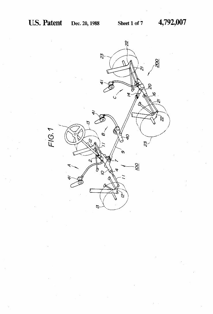
FIG. 1 is a schematic perspective view of a mecha nism for steering the front and rear wheels of a four wheel-steerable vehicle according to the present inven tion; FIG. 2 is a fragmentary perspective view of the
mechanism shown in FIG. 1; FIG. 3 is a plan view of an arrangement having a
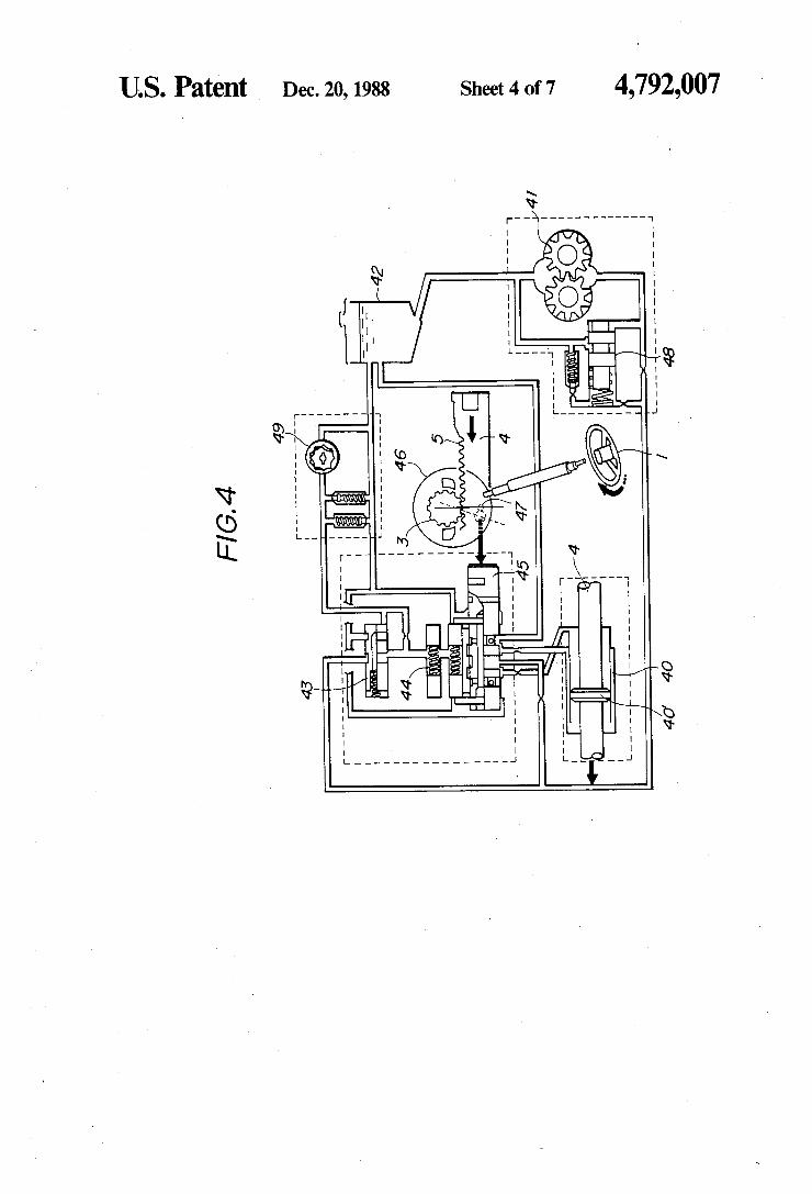
nonlinear gear ratio in the mechanism of FIG. 1; FIG. 4 is a hydraulic circuit diagram of a steering
force assisting device in the mechanism of FIG. 1; FIG. 5 is a view showing a steering force transmitting
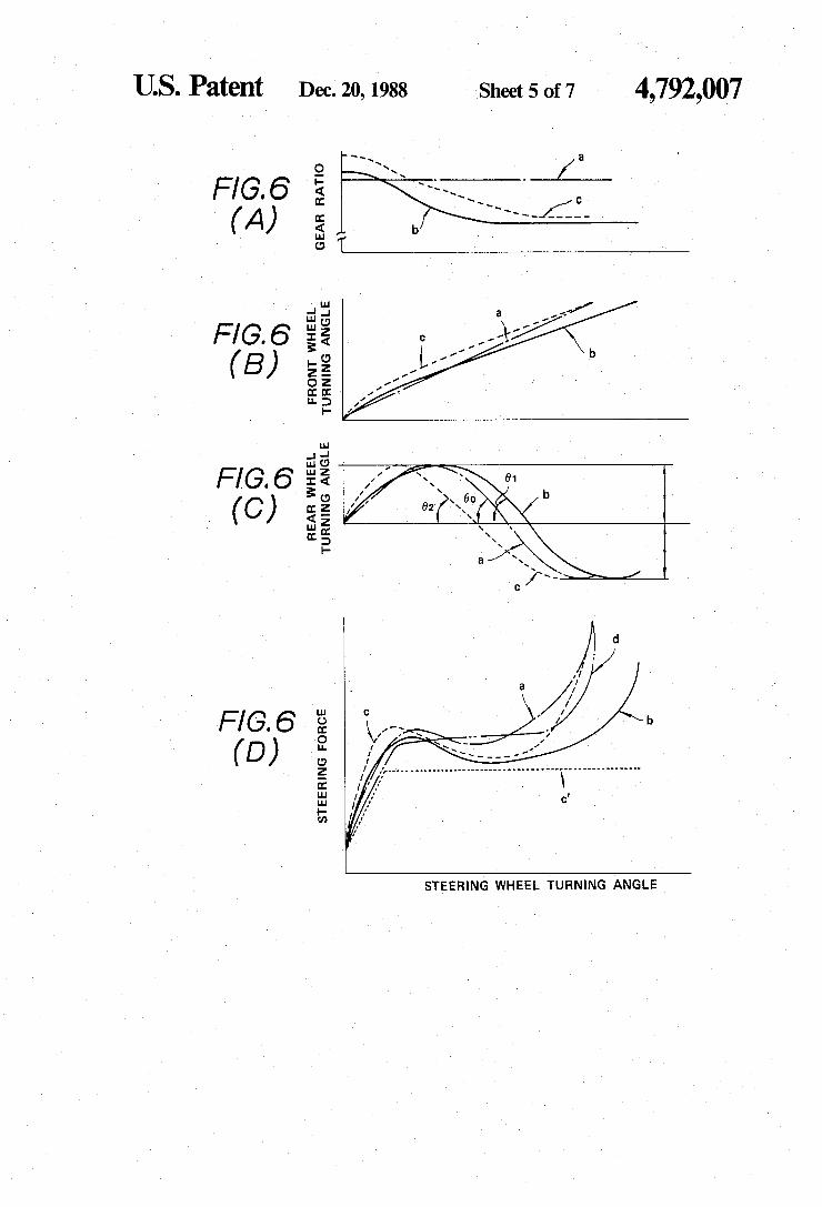
system for the mechanism of FIG. 1; FIGS. 6(A) through 6(D) are diagrams illustrating
the characteristic curves of a gear ratio, a front wheel steering angle, a rear wheel steering angle, and a steer ing force, plotted against a steering wheel turning angle; FIG. 7(A) is a view of a system for transmitting a
substantial steering force in an arrangement in which the steering force assisting device is associated with a front wheel steering device in the mechanism shown in FIG. 1; FIG. 7(B) is a view of a system for transmitting a
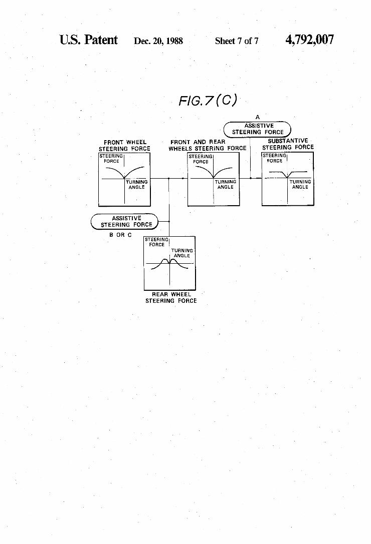
substantial steering force in an arrangement in which the steering force assisting device is associated with a linkage shaft or a rear wheel steering device in the mechanism shown in FIG. 1; and FIG. 7(C) is a view of a system for transmitting a
substantial steering force in an arrangement in which the steering force assisting device is associated with a front wheel steering device, as well as with a linkage shaft, or a rear wheel steering device in the mechanism shown in FIG. 1.
DETAILED DESCRIPTION OF THE ' PREFERRED EMBODIMENTS
As shown in FIG. 1, a mechanism for steering the front and rear wheels of a 4W8 vehicle according to the present invention includes a front wheel steering device 100 having a front wheel steering gearbox 10, a rear wheel steering device 200 having a rear wheel steering gearbox 20, and a linkage shaft 9 mechanically connect ing the front and rear wheel steering devices 100, 200 to each other. As shown in FIG. 2, a rack shaft 4 is axially slidably
disposed in the front wheel steering gearbox 10, and a steering shaft 2 and a rotation output shaft 7 are rotat ably supported in the front wheel steering gearbox 10. The steering shaft 2 is operatively coupled at its upper end to a steering wheel 1 and has a ?rst pinion 3 on its lower distal end which is held in mesh with a ?rst rack 5 on the rack shaft 4. The rack shaft 4 also has a second rack 6 on one side thereof remote from the ?rst rack 5, the second rack 6 meshing with a second pinion 8 on a front end of the rotation output shaft 7.
Rotative power from the steering wheel 1 as it is turned by the driver is transmitted to the steering shaft 2, and converted through the ?rst pinion 3 and the ?rst rack 5 meshing therewith into lateral axial movement of the rack shaft 4. Such lateral axial movement of the rack shaft 4 causes tie rods 11 and knuckle arms 12 to turn front wheels 13. The lateral axial movement of the rack shaft 4 is
converted by the second rack 6 and the second pinion 8

4,792,007 3
meshing therewith into rotation of the rotation output shaft 7. The front wheel steering device 100 is generally con
structed as described above. The rear end of the rota tion output shaft 7 is operatively connected to the link age shaft 9, so that the rotative power from the rotation output shaft 7 can be transmitted through the linkage shaft 9 to the rear wheel steering device 200. A rotation input shaft 14 coupled to the rear end of
the linkage shaft 9 is rotatably supported in the rear wheel steering gearbox 20. A joint rod 16 is longitudi nally slidably supported in the rear wheel steering gear box 20. The rear end of the rotation input shaft 14 has a crank-shaped eccentric shaft 15 with its rear end slid ably riding in a vertical groove 18 de?ned in a slider 17 ?xed to the joint rod 16.
In response to rotation of the rotation input shaft 14 about its own axis, the eccentric shaft 15 is angularly moved around the axis of the rotation input shaft 14. Such angular movement of the eccentric shaft 15 is converted by the vertical groove 18 of the slider 17 to lateral axial movement of the joint rod 16, causing tie rods 21 and knuckle arms 22 to turn a pair of rear wheels 23. The rear wheel steering device 200 is gener ally constructed as described above.
In the illustrated embodiment, the ratio of the turning angle of the front wheels 13 to the turning angle of the steering wheel 1 is variable according to the turning angle of the steering wheel 1. More speci?cally, the front wheel steering device 100 has a nonlinear gear ratio arrangement (or a variable gear ratio arrangement) for turning only the front wheels 13 in nonlinear rela tion to the turning angle of the steering wheel 1. Such a non-linear gear ratio arrangement is achieved by the ?rst rack 5 (FIG. 3) which has different tooth pitches that provide, as shown in FIG. 6(A), a gear ratio char acteristic curve (b) for reducing the steering force or a gear ratio characteristic curve (c) for improving the vehicle maneuverability, these gear ratio characteristic curves (b), (c) being different from a gear ratio charac teristic curve (a) which would be provided by a uni form-pitch rack. FIGS. 6(B) and 6(C) show the front and rear wheel turning angles, respectively, with re spect to the respective gear ratio characteristic curves (a), (b), and (c), plotted against the steering wheel turn ing angle. FIG. 6(C) indicates that as the steering wheel turning angle increases, the rear wheels 23 are ?rst turned in the same direction as that of the front wheels 13 and then turned in the opposite direction to that of the front wheels 13. The front wheel steering device 100 also includes a
steering force assisting device A. The steering force assisting device A has a hydraulic
circuit as shown in FIG. 4. The steering force assisting device A comprises an oil pump mechanism mainly comprising an oil tank 42, an oil pump 41, a relief valve 48, a cutoff valve 43, a hydraulic reaction chamber 44, a four-way valve 45, and a vehicle speed sensor 49. The oil pump 41 is actuated by an engine (not shown)
to supply oil under pressure from the oil tank 42 through the cutoff valve 43 and the hydraulic reaction chamber 44 to the four-way valve 45. The steering shaft 2 further has a pinion holder 46 on which the ?rst pinion 3 is eccentrically supported. The pinion holder 46 has a pin 47 on its lower surface which engages the four-way valve 45. As the steering wheel 1 is turned, the pinion holder 46 is also turned to move the pin 47 around the
10
25
35
45
55
60
65
4 axis of the pinion holder 46 for thereby effecting switch ing action of the four-way valve 45. The front wheel steering gearbox 10 houses therein a
power cylinder 40 in which there is slidably ?tted a piston 40’ mounted on the rack shaft 4. The power cylinder 40 communicates with the four-way valve 45. Upon switching action of the four-way valve 45,
controlled oil under pressure is supplied to and dis’ charged from the power cylinder 40 to move the piston 40' slidably in the power cylinder 40, thus producing an assistive force to move the rack shaft 4 in the axial direction. Therefore, the manual steering effort re quired by the driver to turn the front wheels 13 can be reduced. Where the nonlinear gear ratio characteristic curve
(0) (shown in FIG. 6(A)) is employed for the ?rst rack 5 of the front wheel steering device 100, i.e., a nonlinear gear ratio arrangement for improved vehicle maneuver ability is employed in the front wheel steering device 100, the front and rear wheels 13, 23 are turned accord ing to turning angle characteristics as shown in FIG. 5. As shown in FIG. 6(C), the steering wheel turning
angles include a crossover angle 0 across which the rear wheel steering action changes from the range in which the rear wheels 23 are turned in the same direction as that of the front wheels 13 into the range in which the rear wheels 23 are turned in the opposite direction to that of the front wheels 13. The crossover anlge 92 for the gear ratio characteristic curve (c) for improved vehicle maneuverability is smaller than the crossover angle 00 for the gear ratio characteristic curve (a) of the uniform gear pitch rack and the crossover angle 01 for the gear ratio characteristic curve (b) for reduced steer ing forces. Assuming that the 4WS vehicle is running along a
circular path at a constant speed V, that a lateral accel eration (lateral G) is negligibly small as the speed V is sufficiently low with respect to the radius R of the turning circle, and that the cornering force developed with respect to the slip angles of the front and rear tires is linear, i.e., the cornering power has a straight gradi ent, then the radius R of the turning circle can generally be expressed by the following equation:
R = 1(1 i KVZ) (i) 6f — 6r
where l is the wheel base, K is a stability factor, 8f is the front wheel turning angle, L1‘ is the rear wheel turning angle. The stability factor K is given by:
K _ Crb — Cfa m (ii)
where Cf is the front wheel cornering power, Cf is the rear wheel cornering power, a is the distance between the axle of the front wheels and the center of gravity of the vehicle, b is the distance between the axle of the rear wheels and the center of gravity of the vehicle, m: the weight of the vehicle.
It can be understood from the equation (i) that the radius R of the turning circle is inversely proportional to the difference (8f- 8r) between the front and rear wheel turning angles.
4,792,007 5
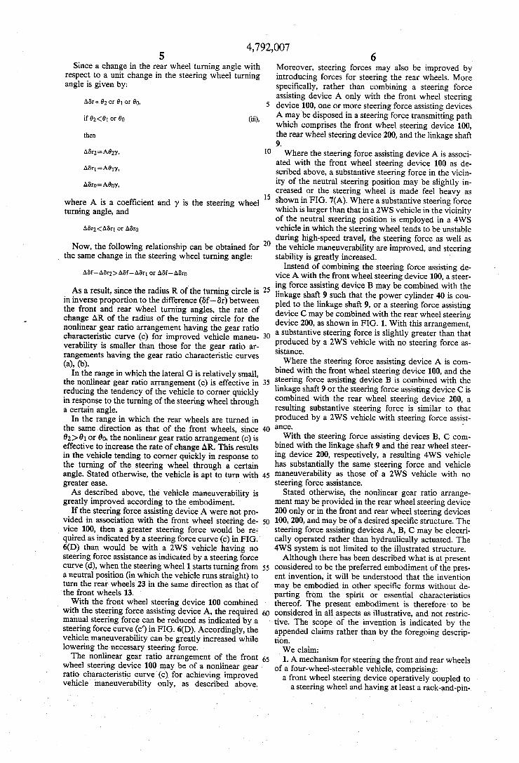
Since a change in the rear wheel turning angle with respect to a unit change in the steering wheel turning angle is given by:
if 02<01 or 00 (iii),
where A is a coef?cient and 'y is the steering wheel turning angle, and
Now, the following relationship can be obtained for the same change in the steering wheel turning angle:
As a result, since the radius R of the turning circle is in inverse proportion to the difference (6f-- 6r) between the front and rear wheel turning angles, the rate of change AR of the radius of the turning circle for the nonlinear gear ratio arrangement having the gear ratio characteristic curve (c) for improved vehicle maneu verability is smaller than those for the gear ratio ar rangements having the gear ratio characteristic curves (a), (b)
In the range in which the lateral G is relatively small, the nonlinear gear ratio arrangement (0) is effective in reducing the tendency of the vehicle to corner quickly in response to the turning of the steering wheel through a certain angle.
In the range in which the rear wheels are turned in the same direction as that of the front wheels, since 0;) 01 or 00, the nonlinear gear ratio arrangement (c) is effective to increase the rate of change AR. This results in the vehicle tending to corner quickly in response to the turning of the steering wheel through a certain angle. Stated otherwise, the vehicle is apt to turn with greater case. As described above, the vehicle maneuverability is
greatly improved according to the embodiment. If the steering force assisting device A were not pro
vided in association with the front wheel steering de vice 100, then a greater steering force would be re-; quired as indicated by a steering force curve (c) in FIG. 6(D) than would be with a 2W5 vehicle having no steering force assistance as indicated by a steering force curve (d), when the steering wheel 1 starts turning from a neutral position (in which the vehicle runs straight) to turn the rear wheels 23 in the same direction as that of the front wheels 13. With the front wheel steering device 100 combined
with the steering force assisting device A, the required manual steering force can be reduced as indicated by a steering force curve (c') in FIG. 6(D). Accordingly, the vehicle maneuverability can be greatly increased while lowering the necessary steering force. The nonlinear gear ratio arrangement of the front
wheel steering device 100 may be of a nonlinear gear ratio characteristic curve (0) for achieving improved vehicle maneuverability only, as described above.
15
20
25
45
55
65
6 Moreover, steering forces may also be improved by introducing forces for steering the rear wheels. More speci?cally, rather than combining a steering force assisting device A only with the front wheel steering device 100, one or more steering force assisting devices A may be disposed in a steering force transmitting path which comprises the front wheel steering device 100, the rear wheel steering device 200, and the linkage shaft 9. Where the steering force assisting device A is associ
ated with the front wheel steering device 100 as de scribed above, a substantive steering force in the vicin~ ity of the neutral steering position may be slightly in creased or the steering wheel is made feel heavy as shown in FIG. 7(A). Where a substantive steering force which is larger than that in a 2WS vehicle in the vicinity of the neutral steering position is employed in a 4WS vehicle in which the steering wheel tends to be unstable during high-speed travel, the steering force as well as the vehicle maneuverability are improved, and steering stability is greatly increased.
Instead of combining the steering force assisting de vice A with the front wheel steering device 100, a steer ing force assisting device B may be combined with the linkage shaft 9 such that the power cylinder 40 is cou pled to the linkage shaft 9, or a steering force assisting device C may be combined with the rear wheel steering device 200, as shown in FIG. 1. With this arrangement, a substantive steering force is slightly greater than that produced by a 2WS vehicle with no steering force as sistance. Where the steering force assisting device A is com
bined with the front wheel steering device 100, and the steering force assisting device B is combined with the linkage shaft 9 or the steering force assisting device C is combined with the rear wheel steering device 200, a resulting substantive steering force is similar to that produced by a 2WS vehicle with steering force assist ance. '
With the steering force assisting devices B, C com bined with the linkage shaft 9 and the rear wheel steer ing device 200, respectively, a resulting 4WS vehicle has substantially the same steering force and vehicle maneuverability as those of a 2WS vehicle with no steering force assistance.
Stated otherwise, the nonlinear gear ratio arrange ment may be provided in the rear wheel steering device 200 only or in the front and rear wheel steering devices 100, 200, and may be of a desired speci?c structure. The steering force assisting devices A, B, C may be electri cally operated rather than hydraulically actuated. The 4WS system is not limited to the illustrated structure. Although there has been described what is at present
considered to be the preferred embodiment of the pres ent invention, it will be understood that the invention may be embodied in other specific forms without de parting from the spirit or essential characteristics thereof. The present embodiment is therefore to be considered in all aspects as illustrative, and not restric tive. The scope of the invention is indicated by the appended claims rather than by the foregoing descrip tion. We claim: 1. A mechanism for steering the front and rear wheels
of a four-wheel-steerable vehicle, comprising: a front wheel steering device operatively coupled to
a steering wheel and having at least a rack-and-pin

4,792,007 7
ion gear mechanism having a nonlinear gear ratio which improves vehicle maneuverability;
a rear wheel steering device; a linkage shaft operatively connecting said front wheel steering device and said rear wheel steering device to each other; and
at least one steering force assisting device disposed in a steering force transmitting path comprising said front wheel steering device, said rear wheel steer ing device, and said linkage shaft.
2. A mechanism according to claim 1, wherein said steering force assisting device is combined with said front wheel steering device for assisting a steering force to turn front wheels.
3. A mechanism according to claim 2, wherein said front wheel steering device comprises:
a front wheel gearbox; a steering shaft rotatably supported in said front wheel gearbox and having an end end coupled to a steering wheel and an opposite end having a ?rst pinion;
a rotation output shaft rotatably supported in said front wheel gearbox and having an end end cou pled to said linkage shaft and an opposite end hav ing a second pinion; and
a rack shaft slidably supported in said front wheel gearbox and including a ?rst rack meshing with said ?rst pinion and having a nonlinear gear pitch and a second rack meshing with said second pinion, said rack shaft being longitudinally movable through said ?rst pinion and said ?rst rack.
5
15
25
30
35
40
50
55
65
8 4. A mechanism according to claim 3, wherein said
steering power assisting device comprises: a power cylinder disposed in said front wheel gear
box; a piston slidably fitted in said power cylinder and mounted on said rack shaft; and
an oil pump mechanism communicating with said power cylinder for controlling oil supply thereto in response to rotation of said steering shaft.
5. A mechanism according to claim 1, wherein said rear wheel steering device comprises:
a rear wheel gearbox; a rotation input shaft rotatably supported in said rear wheel gearbox and having an end coupled to an end of said linkage shaft and an opposite end hav ing an eccentric shaft; and
a joint rod slidably supported in said rear wheel gear box and having a slider having a groove in which an end of said eccentric shaft slidably rides, said joint rod being longitudinally movable through said eccentric shaft and said groove.
6. A mechanism according to claim 1, wherein said at least one steering force assisting device is disposed in a steering force transmitting path comprising said linkage shaft and said rear wheel steering device for assisting a steering force to turn rear wheels.
7. A mechanism according to claim 6, further includ ing a second steering force assisting device combined with said front wheel steering device for assisting a steering force to turn front wheels.
* * * * *
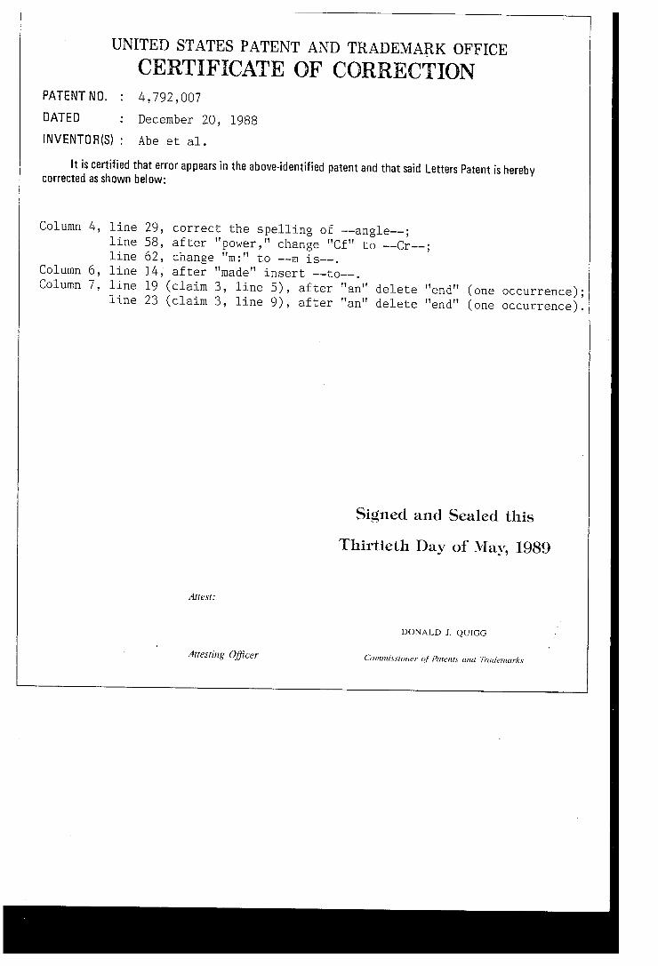
UNITED STATES PATENT AND TRADEMARK OFFICE
CERTIFICATE OF CORRECTION PATENT NO.
DATED
INVENTOMS) :
4,79
It is certified that error appears in the above-identified corrected as shown below:
Column 4, line 29, line 58, line 62,
Column 6, line l4, Column 7, line 19
line 23
2,007
December 20, 1988
Abe et al.
patent and that said Letters Patent is hereby
correct the spelling of -—angle—-; after I'power," change "Cf" to ——Cr——; change "m:" to ——m is—-. after "made" insert ——to——. (claim 3, line 5) , after "an" delete "end" (one occurrence); (claim 3, line 9) , after "an" delete "end" (one occurrence).
Signed and Sealed this
Thirtieth Day of May, 1989
Arresr:
DONALD J. QUIGG
Arresting O?icer Comm[.sxx'irmer of Pmcnrx and Trudemur/cs