
Uncontrolled when printed or emailed - Bases Conversion ...
177
Construction of Connector Road from MacArthur Highway to New Clark City Airport Road SECTION VI TECHNICAL SPECIFICATIONS (IN SEPARATE VOLUME) Uncontrolled when printed or emailed
-
Upload
khangminh22 -
Category
Documents
-
view
0 -
download
0
Transcript of Uncontrolled when printed or emailed - Bases Conversion ...

Construction of Connector Road from MacArthur Highway to New
Clark City Airport Road
SECTION VI TECHNICAL SPECIFICATIONS
(IN SEPARATE VOLUME)
Uncon
trolle
d whe
n prin
ted or
ed
TECHNICAL SPECIFICATIONS AND SCOPE OF WORKS
The construction procedures shall be done in accordance with the DPWH Standard Specifications for Highways Bridges and Airports 2013 Edition, and in full compliance with the approved plans and specifications.
Pertinent notes appearing in the Contract Plans or Drawings shall also be considered as part and parcel of the technical specifications. Such notes shall take precedence over the General Specifications.
PART A
PARTB
PARTC
Item 100
Item 102
Item 103
Item 104
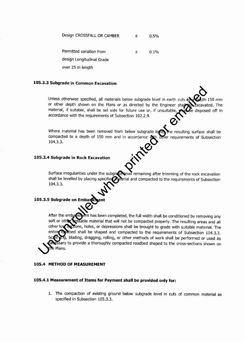
Item 105
PARTD
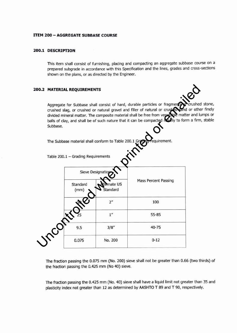
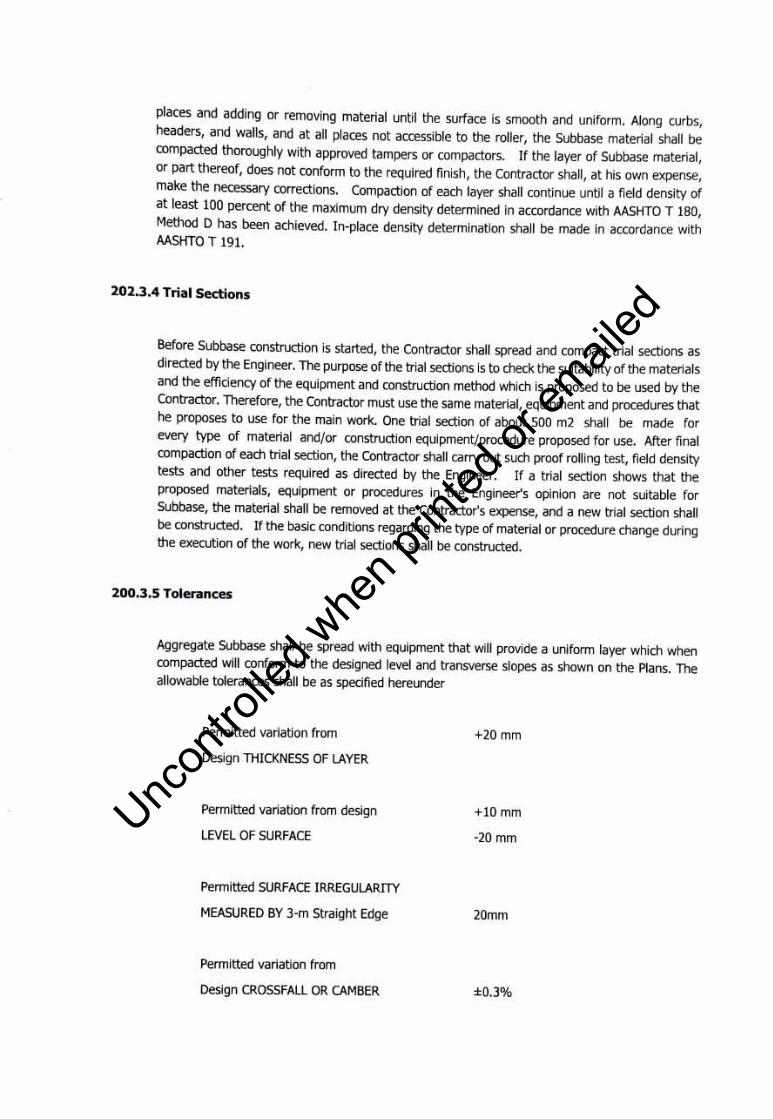
Item 200
PARTE
Item 311
PARTF
Item 404
Item 405
TABLE OF CONTENTS
FACILITIES FOR THE ENGINEER
OTHER GENERAL REQUIREMENTS
EARTHWORKS
Clearing and Grubbing
Excavation
Structure Excavation
Embankment from Site/from Source
Subgrade Preparation
SUBBASE AND BASE COURSE
Aggregate Subbase Course
SURFACE COURSES
Portland Cement Concrete Pavement (PCCP)
ROAD CONSTRUCTION
Reinforcing Steel
Structural Concrete
~!\·~Clark Development Corporation CONNECTOR ROAD FROM MACARTHUR HIGHWAY TO NEW CLARK CITY AIRPORT ROAD SECTION V. TECHNICAL SPECIACATIONS AND SCOPE OF WORKS
81
Uncon
trolle
d whe
n prin
ted or
ed

PARTG
Item 500
Item 502
Item 509
PARTH
Item 600
Item 602
Item 603
Item 605
Item 607
Item 610
Item 612
PARTK
Section 16001
Section 16002
Item SPL-1
Item SPL-2
Item SPL-3
Item SPL-4
Item SPL-4 (2)
DRAINAGE AND SLOPE PROTECTION STRUCTURES
Pipe Culverts and Storm Drains
Manholes, Inlets and Catch Basins
Sheet Piles
MISCELLANEOUS STRUCTURES
Curb and/or Gutter
Monuments, Markers and Guide Posts
Guardrail
Road Signs
Reflective Pavement Studs
Sodding
Reflectorized Thermoplastic Pavement Markers
STREET LIGHTS AND AREA LIGHTINGS
Electrical Special Conditions
Scope of Works
Raceway and Boxes
Wires and Power Cables
Panel Boards
Luminaires and Accessories
Grounding System
~ .~.Jt clark Development Corporation CONNECTOR ROAD FROM MACARTHUR HIGHWAY TO NEW CLARK CITY AIRPORT ROAD SECTION V. TECHNICAL SPECIFICATIONS AND SCOPE OF WORKS
82
Uncon
trolle
d whe
n prin
ted or
ed
PART A - FACILITIES FOR ENGINEER
~ J!t,clarl< Development Corporation CONNECTOR ROAD FROM MACARTHUR HIGHWAY TO NEW CLARK CITY AIRPORT ROAD
SECTION V. SPEGAL CONDITTONS OF CONTRACT
83
Uncon
trolle
d whe
n prin
ted or
ed

PART A - FACILITIES FOR THE ENGINEER
1.1. SCOPE OF WORK
This section shall include the equipment, materials and employee to the site; construction and maintenance of Engineer's staff house and compliance with the contract requirements, and provision for the health/safety and environmental protection during the entire project duration.
This section shall include the furnishing of labor, materials, transportation, tools, supplies, equipment and appurtenances to complete satisfactory the construction of the proposed project.
1.2. PROGRESS PHOTOGRAPHS
The Contractor shall provide record photographs taken as, when and where directed by the Engineer at intervals of not more than one month. The photographs shall be sufficient in number and location to record the exact progress of the Works. The Contractor shall provide one proof print of each photograph taken, and the negative and ten copies, not less than 254 mm x 203 mm and printed on glossy paper, of any of the photographs by the Engineer. The photographs retained by the Engineer will become the property of the Government and the Contractor shall supply approved albums to accommodate them. Two copies are to be signed by the Contractor, one of which will be signed by the Engineer and returned to the Contractor.
1.3. SERVICE VEHICLE
The Contractor shall provide within thirty (30) calendar days after notice to commence work, the vehide for exclusive use of the Engineer and Engineer's representative, payment of which shall be on a monthly basis.
The vehicle shall comply in all respects with all relevant Philippine national or local laws, statutes and regulations. All vehicles shall carry or be lifted with accessories as may be prescribed by laws and comprehensive insurance.
1.4. OFFICE EQUIPMENT
This shall include the furnishing of branded desktop computer, core i&HQ, 8th• Gen. with 32 GB RAM and 4GB Video Card (minimum). This shall also include licensed Operating System, licensed MS Office latest version, and licensed Autodesk AutoCAD latest version with a minimum of three (3) years subscription.
1.5. GENERAL OPERATION AND MAINTENANCE MANUAL
Uncon
trolle
d whe
n prin
ted or
ed

The contractor shall produce and supply to the Engineer two (2) hard bound copies and two (2) disk copies (MS word and MS Excel) of an operation and maintenance manual within fifteen (15) days after the target completion date for the contract.
No separate payment to the Operation and Maintenance Manual as this is deemed to be included as incidental to other items of work.
1.6. AS-BUILT DRAWINGS
The Contractor shall produce and supply to the Engineer two (2) good hard copies of a full set of"As-built" drawings and one (1) reproducible medium in Mylar film at Al size. Provide electronic file (in PDF format) in USB flash drive. The Engineer may allow up to 15 days after target completion date for delivery of some of these drawings, but otherwise they shall be due on the completion date. These shall include correctly amended version of all Contract Drawings to freely and accurately describe the As-built condition of all elements of the project within the Contractor's scope of work, to the approval of the Engineer. All drawings shall be clearly marked "AS BUILT".
No separate payment for the As-built Drawings as this is deemed to be included as incidental to other items of work.
1.7. METHOD OF MEASUREMENT
1.7.1. Progress Photographs
This item consists of the supply of equipment and materials necessary to undertake photographic progress activities of the project and of all costs incidental to undertake the preparation and submission of photographs. The quantities for photographs shall be each photographs per month and provided as "Progress Photographs". Unit measurement and payment shall be "each".
1.7.2. Service Vehicle
The quantities for the provision of service vehicles, slightly used, for the Engineer and Engineer's Representative shall be the number of days the vehicle will be rented including comprehensive insurance of the vehicles.
Payment of which shall be on a rental basis C'Vehicle-Month'') from the date the Contractor is supplied with each type of vehicle until the completion of the project.
1.7 .3. Office Equipment
Uncon
trolle
d whe
n prin
ted or
ed
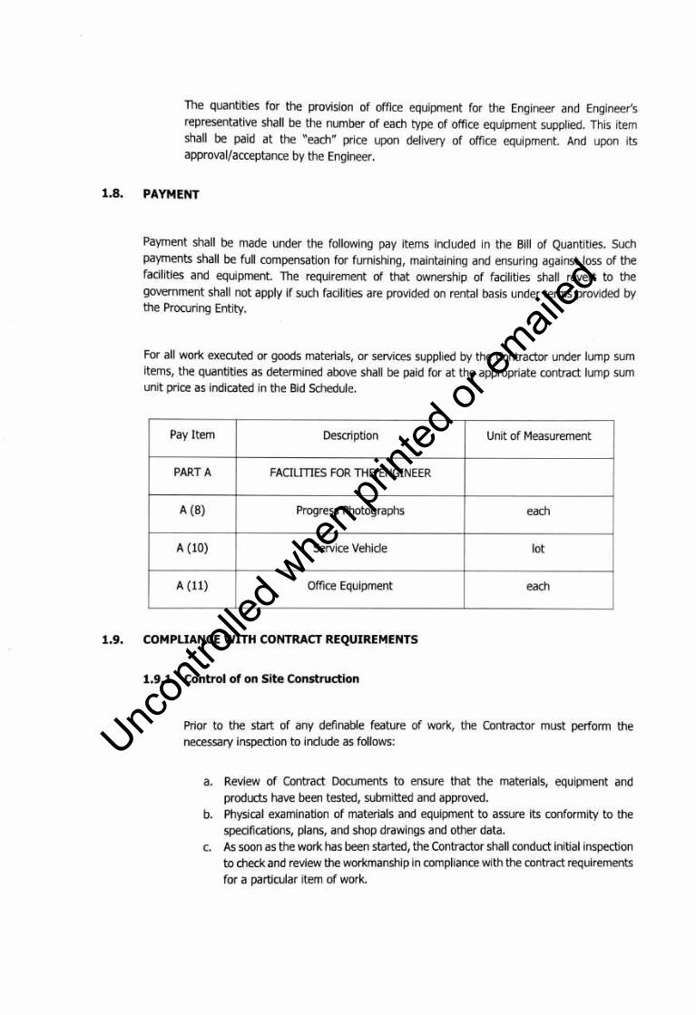
Toe quantities for the provision of office equipment for the Engineer and Engineer's representative shall be the number of each type of office equipment supplied. This item shall be paid at the "each" price upon delivery of office equipment. And upon its approval/acceptance by the Engineer.
1.8. PAYMENT
Payment shall be made under the following pay items included in the Bill of Quantities. Such payments shall be full compensation for furnishing, maintaining and ensuring against loss of the facilities and equipment. The requirement of that ownership of facilities shall revert to the government shall not apply if such facilities are provided on rental basis under terms provided by the Procuring Entity.
For all work executed or goods materials, or services supplied by the Contractor under lump sum items, the quantities as determined above shall be paid for at the appropriate contract lump sum unit price as indicated in the Bid Schedule.
Pay Item Description Unit of Measurement
PART A FACILmES FOR THE ENGINEER
A (8) Progress Photographs each
A (10) Service Vehicle lot
A (11) Office Equipment each
1.9. COMPLIANCE WITH CONTRACT REQUIREMENTS
1.9.1. Control of on Site Construction
Prior to the start of any definable feature of work, the Contractor must perform the necessary inspection to include as follows:
a. Review of Contract Documents to ensure that the materials, equipment and products have been tested, submitted and approved.
b. Physical examination of materials and equipment to assure its conformity to the specifications, plans, and shop drawings and other data.
c. As soon as the work has been started, the Contractor shall conduct initial inspection to check and review the workmanship in compliance with the contract requirements
for a particular item of work.
Uncon
trolle
d whe
n prin
ted or
ed

d. The contractor shall perform these inspections on a regular basis to assure
continuing compliance with the contract requirements until completion of a
particular type of work.
1.9.2. Preconstruction Meetings
Prior to the start of construction, Contractor's material men or vendors whose presence are
required, must attend preconstruction meetings as directed for the purposed of discussing
the execution of work.
1.9.3. Progress Meetings
Progress meeting shall be called upon by the following for the purpose of discussing the
implementation of the work.
When called upon by the Engineer for the purpose of discussing the execution of work
Contractor's material men whose presence is necessary or requested must attend progress
meetings. Each of such meeting shall be held at the time and place designated by the
Engineer. Decisions and instruction agreed on these meetings shall be binding and
conclusive on the contract. Minutes of meeting shall be recorded and reasonable number
of copies shall be furnished to the Contractor to the Contractor for distribution to various
materials men involved.
The Contractor may also call for a progress meeting for the purpose of coordinating,
expediting and scheduling of work. In such meeting, Contractor's material men whose
presence is necessary or requested to attend
1.9.4. Progress Reports
The Contractor shall faithfully prepare and submit progress reports to the Engineer every
thirty (30) days after the start of the project up to its completion, showing the work
completed, work remaining to be done, the status of construction equipment and materials
at the site.
1.9.5. Survey Data
The Contractor shall layout his work from established based lines and bench marks
indicated in the drawings and shall be responsible for all measurement in connection
therewith. The Contractor shall furnish, at his expense, all stakes, templates, platforms,
equipment, tools, materials and labors as may be required In laying out any part of the
work, out of established base lines and bench marks. It shall be the responsibility of the
Contractor to maintain and preserve all stakes and other marks until he authorized to
Uncon
trolle
d whe
n prin
ted or
ed
remove them. If such marks are destroyed by the Contractor through his negligence prior
to the authorized removal, they shall be replaced at the expense of the Contractor.
1.9.6. Shop Drawings
The Contractor shall submit and furnish drawings and samples accompanied with
transmittal forms in accordance with the provisions of the Conditions of Contract. The term
"Shop Drawings" as used herein shall be understood to indude detailed design calculations,
construction drawings, lists, graphs, and others.
1.9.7. Cleaning -up
The Contractor shall at all times keep the construction area induding storage area used by
him free from accumulations of waste material or rubbish. Upon completion of construction,
the Contractor shall leave the work and premises in a clean, neat and workmanlike
conditions satisfactory to the Engineer.
1.9.8. Documents to be Submitted
The following documents shall be submitted by the Contractor to the Engineer prior to final
payment and before issuance of final certificate of payment in accordance with provisions
of the conditions of contract.
a. The guarantee required by the Conditions of Contract and any other extended
guarantees stated in the technical sections of specifications.
b. A set of As-Built drawings shall be submitted showing accurate record of changes
or deviations from the Contract Documents and the shop drawings indicating the
work as actually installed. Records shall be arranged in order, in accordance with
the various sections of the specifications and properly indexed with certifications
of endorsement thereof, that each of the revised print of the drawings and
specifications are complete and accurate. Prior to the application for final payment,
and as a condition to its approval by the Engineer, the Contractor shall deliver the
records, drawings, and specifications arranged on proper order, indexed and
endorsed herein specified. Uncon
trolle
d whe
n prin
ted or
ed

Uncon
trolle
d whe
n prin
ted or
ed
Uncon
trolle
d whe
n prin
ted or
ed
Uncon
trolle
d whe
n prin
ted or
ed

Uncon
trolle
d whe
n prin
ted or
ed

Uncon
trolle
d whe
n prin
ted or
ed

Uncon
trolle
d whe
n prin
ted or
ed
Uncon
trolle
d whe
n prin
ted or
ed

Uncon
trolle
d whe
n prin
ted or
ed
Uncon
trolle
d whe
n prin
ted or
ed
Uncon
trolle
d whe
n prin
ted or
ed
Uncon
trolle
d whe
n prin
ted or
ed

Uncon
trolle
d whe
n prin
ted or
ed

Uncon
trolle
d whe
n prin
ted or
ed

Uncon
trolle
d whe
n prin
ted or
ed

Uncon
trolle
d whe
n prin
ted or
ed
Uncon
trolle
d whe
n prin
ted or
ed

Uncon
trolle
d whe
n prin
ted or
ed
Uncon
trolle
d whe
n prin
ted or
ed

Uncon
trolle
d whe
n prin
ted or
ed

Uncon
trolle
d whe
n prin
ted or
ed
Uncon
trolle
d whe
n prin
ted or
ed
Uncon
trolle
d whe
n prin
ted or
ed
Uncon
trolle
d whe
n prin
ted or
ed
Uncon
trolle
d whe
n prin
ted or
ed

Uncon
trolle
d whe
n prin
ted or
ed

Uncon
trolle
d whe
n prin
ted or
ed

Uncon
trolle
d whe
n prin
ted or
ed
Uncon
trolle
d whe
n prin
ted or
ed

Uncon
trolle
d whe
n prin
ted or
ed
Uncon
trolle
d whe
n prin
ted or
ed
Uncon
trolle
d whe
n prin
ted or
ed

Uncon
trolle
d whe
n prin
ted or
ed
Uncon
trolle
d whe
n prin
ted or
ed

Uncon
trolle
d whe
n prin
ted or
ed
PART E - SURFACE COURSES
Uncon
trolle
d whe
n prin
ted or
ed
ITEM 311 - PORTLAND CEMENT CONCRETE PAVEMENT
311.1 DESCRIPTION
This Item shall consist of pavement of Portland Cement Concrete, with or without reinforcement, constructed on the prepared base in accordance with this Specification and in conformity with
lines, grades, thickness and typical cross-section shown on the Plans.
311.2 MATERIAL REQUIREMENTS
311.2.1 Portland Cement
It shall conform to the applicable requirements of AASHTO M85 (ASTM C150). Only Type I
Portland Cement shall be used unless otherwise provided for in the Special Provisions. Different brands or the same brands from different mills shall not be mixed nor shall they be used alternately unless the mix is approved by the Engineer. However, the use of Portland Pozzolan Cement Type
IP meeting the requirements of AASHTO M 240/ ASTM C 595, Specifications for Blended Hydraulic Cement shall be allowed, provided that trial mixes shall be done and that the mixes meet the concrete strength requirements, the AASHTO/ ASTM provisions pertinent to the use of Portland
Pozzolan Type IP shall be adopted.
Cement which for any reason, has become partially set or which contains lumps of caked cement will be rejected. Cement salvaged from discarded or used bags shall not be used. Samples of Cement shall be obtained in accordance with AASHTO T 127.
311.2.2 Fine Aggregate
It shall consist of natural sand, stone screenings or other inert materials with similar characteristics, or combinations thereof, having hard, strong and durable particles. Fine aggregate from different
sources of supply shall not be mixed or stored in the same pile nor used alternately in the same class of concrete without the approval of the Engineer.
It shall not contain more than three (3) mass percent of material passing the 0.075 mm (No. 200 sieve) by washing nor more than one (1) mass percent each of clay lumps or shale. Toe use of
beach sand will not be allowed without the approval of the Engineer.
If the fine aggregate is subjected to five (5) cycles of the sodium sulfate soundness test, the
weighted loss shall not exceed 10 mass percent.
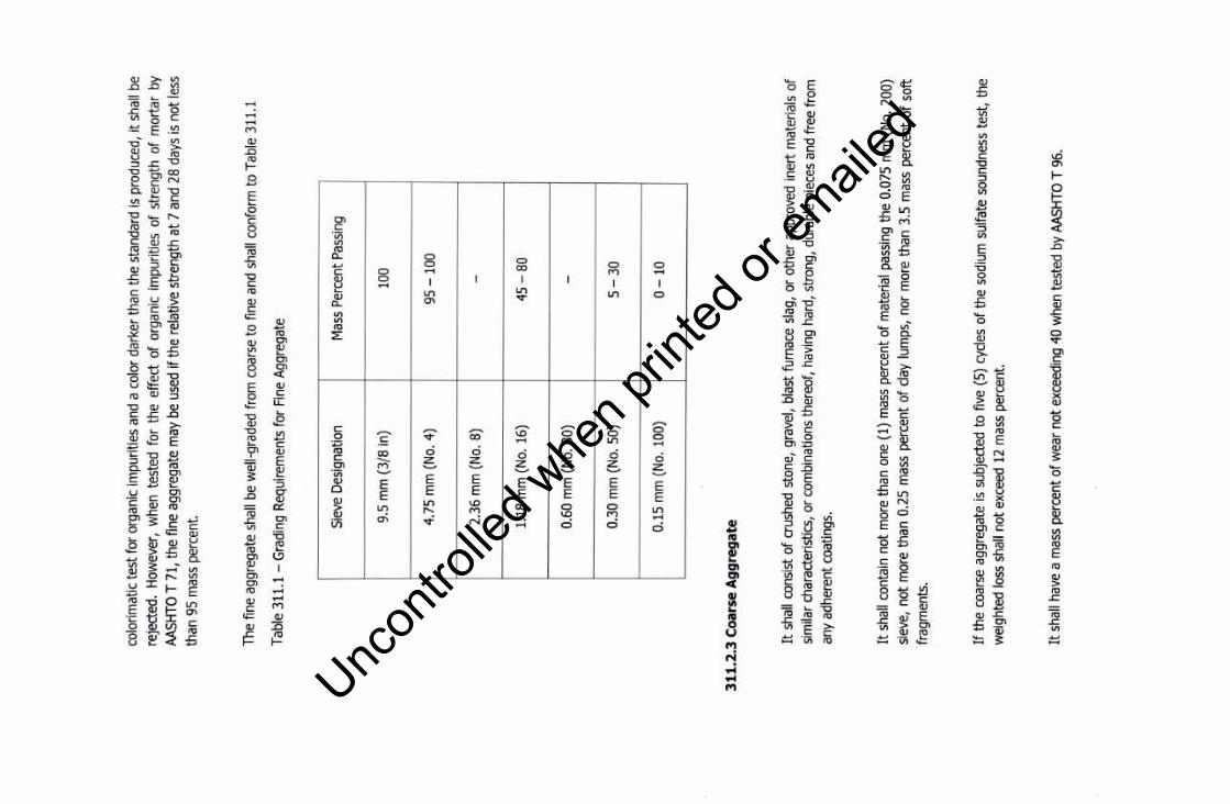
Toe fine aggregate shall be free from injurious amounts of organic impurities. If subjected to the
Uncon
trolle
d whe
n prin
ted or
ed
colo
rimat
ic te
st fo
r or
gani
c Im
purit
ies
and
a co
lor
dark
er th
an t
he s
tand
ard
Is pr
oduc
ed,
it sh
all b
e re
ject
ed.
How
ever
, w
hen
test
ed f
or t
he e
ffect
of
orga
nic
impu
ritie
s of
stre
ngth
of
mor
tar
by
AASH
TO T
71,
the
fine
agg
rega
te m
ay b
e us
ed i
f the
rel
ativ
e st
reng
th a
t 7 a
nd 2
8 da
ys is
not
less
th
an 9
5 m
ass
perc
ent.
The
fine
aggr
egat
e sh
all b
e w
ell-g
rade
d fro
m c
oars
e to
fin
e an
d sh
all c
onfo
rm t
o Ta
ble
311.
1
Tabl
e 3
11
.1-
Gra
ding
Req
uire
men
ts f
or F
ine
Agg
rega
te
Siev
e D
esig
natio
n M
ass
Per
cent
Pas
sing
9.5
mm
(3/
8 in
) 10
0
4.75
mm
(N
o. 4
) 95
-1
00
2.36
mm
(N
o. 8
) -
1.18
mm
(N
o. 1
6)
45
-80
0.60
mm
(N
o. 3
0)
-
0.30
mm
(N
o. S
O)
5-3
0
0.15
mm
(N
o. 1
00)
0-1
0
31
1.2
.3 C
oars
e A
gg
reg
ate
It s
hall
cons
ist
of c
rush
ed s
tone
, gr
avel
, bl
ast
furn
ace
slag
, or
oth
er a
ppro
ved
iner
t m
ater
ials
of
sim
ilar c
hara
cter
istic
s, o
r co
mbi
natio
ns th
ereo
f, ha
ving
har
d, s
trong
, du
rabl
e pi
eces
and
fre
e fro
m
any
adhe
rent
coa
tings
.
It s
hall
cont
ain
not m
ore
than
one
(1)
mas
s pe
rcen
t of m
ater
ial p
assi
ng t
he 0
.075
mm
(N
o. 2
00)
siev
e, n
ot m
ore
than
0.2
5 m
ass
perc
ent
of c
lay
lum
ps,
nor
mor
e th
an 3
.5 m
ass
perc
ent
of s
oft
fragm
ents
.
If th
e co
arse
agg
rega
te is
sub
ject
ed t
o fiv
e (5
) cy
cles
of t
he s
odiu
m s
ulfa
te s
ound
ness
tes
t, th
e w
eigh
ted
loss
sha
ll no
t exc
eed
12 m
ass
perc
ent.
It sh
all h
ave
a m
ass
perc
ent o
f wea
r no
t exc
eedi
ng 4
0 w
hen
test
ed b
y AA
SHTO
T 9
6.
Uncon
trolle
d whe
n prin
ted or
ed

If the slag is used, its density shall not be less than 1120 kg/m3 (70 lb./cu. ft.). The gradation of
the coarse aggregate shall conform to Table 311.2. Only one grading specification shall be used from any one source.
Table 311.1- Grading Requirements for Fine Aggregate
Sieve Designation Mass Percent Passing
Standard Alternate
Grading Grading Grading U.S.
mm Standard
A B C
75.0 3 in. 100 - -
63.0 2-1/2 in. 90-100 100 100
50.0 2 in. - 90-100 95-100
37.5 1-1/2 in. 25-60 35-70 -
25.0 1 in. - 0-15 35-70
19.0 ¾in. 0-10 - -
12.5 ½in. 0-5 0-5 10-30
4.75 No. 4 - - 0-5
311.2.4 Water
Water used in mixing, curing or other designated application shall be reasonably clean and free of
oil, salt, acid, alkali, grass or other substances injurious to the finished product. Water will be tested in accordance with and shall meet the requirements of Item 714, Water. Water which is drinkable
may be used without test. Where the source of water is shallow, the intake shall be so enclosed as
to exclude silt, mud, grass or other foreign materials.
311.2.5 Reinforcing Steel
It shall conform to the requirements of Item 404, Reinforcing Steel. Dowels and tie bars shall
conform to the requirements of AASHTO M 31 or M 42, except that rail steel shall not be used for tie bars that are to be bent and re-straightened during construction. Tie bars shall be
Uncon
trolle
d whe
n prin
ted or
ed

deformed bars. Dowels shall be plain round bars. Before delivery to the site of work, one-half of the length of each dowel shall be painted with one coat of approved lead or tar paint. The sleeves for dowel bars shall be metal of approved design to cover 50 mm (2 inches), plus or minus 5 mm (1/4 inch) of the dowel, with a closed end, and with a suitable stop to hold the end of the sleeve at least 25 mm (1 inch) from the end of the dowel. Sleeves shall be of such design that they do not collapse during construction.
311.2.6 loint Fillers
Poured joint fillers shall be mixed asphalt and mineral or rubber filler conforming to the applicable requirements of Item 705, Joint Materials.
Preformed joint filler shall conform to the applicable requirements of Item 705. It shall be punched to admit the dowels where called for in the Plans. The filler for each joint shall be furnished in a single piece for the full depth and width required for the joint.
311.2.7 Admixtures
Air-entraining admixture shall conform to the requirements of AASHTO M 154.
Chemical admixtures, if specified or permitted, shall conform to the requirements of AASHTO M 194.
Fly Ash, if specified or permitted as a mineral admixture and as 20% partial replacement of Portland cement in concrete mix shall conform to the requirements of ASTM C 618.
Admixture should be added only to the concrete mix to produce some desired modifications to the properties of concrete where necessary, but not as partial replacement of cement.
311.2.8 Curing Materials
Curing materials shall conform to the following requirements as specified:
a) Burlap cloth b) Liquid membrane forming compounds c) Sheeting (film) materials
Cotton mats and water-proof paper can be used.
AASHTO M 182 AASHTO M 148 AASHTO M 171
Uncon
trolle
d whe
n prin
ted or
ed

311.2.9 Calcium Chloride/Calcium Nitrate
It shall conform to AASHTO M 144, if specified or permitted by the Engineer, as accelerator.
311.2.10 storage of Cement Aggregate
All cement shall be stored, immediately upon delivery at the Site, in weatherproof building which
will protect the cement from dampness. The floor shall be raised from the ground. The buildings
shall be placed in locations approved by the Engineer. Provisions for storage shall be ample, and
the shipments of cement as received shall be separately stored in such a manner as to allow the
earliest deliveries to be used first and to provide easy access for identification and inspection of
each shipment. Storage buildings shall have capacity for storage of a sufficient quantity of cement
to allow sampling at least twelve (12) days before the cement is to be used. Bulk cement, if used,
shall be transferred to elevated air tight and weatherproof bins. Stored cement shall meet the test
requirements at any time after storage when retest is ordered by the Engineer. At the time of use,
all cement shall be free-flowing and free of lumps.
The handling and storing of concrete aggregates shall be such as to prevent segregation or the
inclusion of foreign materials. The Engineer may require that aggregates be stored on separate
platforms at satisfactory locations.
In order to secure greater uniformity of concrete mix, the Engineer may require that the coarse
aggregate be separated into two or more sizes. Different sizes of aggregate shall be stored in
separate bins or in separate stockpiles sufficiently removed from each other to prevent the material
at the edges of the piles from becoming intermixed.
311.2.11 Proportioning, Consistency and Strength of Concrete
The Contractor shall prepare the design mix based on the absolute volume method as outlined in
the American Concrete Institute (ACI) Standard 211.1, "Recommended Practice for Selecting
Proportions for Normal and Heavyweight Concrete".
It is the intent of this Specification to require at least 364 kg of cement per cubic meter of concrete
to meet the minimum strength requirements. The Engineer shall determine from laboratory tests
of the materials to be used, the cement content and the proportions of aggregate and water that
will produce workable concrete having a slump of between 40 and 75 mm (1-1/2 and 3 inches) if
not vibrated or between 10 and 40 mm (1/2 and 1-1/2 inches) if vibrated, and a flexural strength
of not less than (550 psi and 700 psi) when tested by the third-point method at fourteen (14) days
and 28 days respectively in accordance with AASHTO T97. Slump shall be determined using
AASHTO T 119.
The designer shall consider the use of lean concrete (econocrete) mixtures using local materials
Uncon
trolle
d whe
n prin
ted or
ed
or specifically modified conventional concrete mixes in base course and in the lower course composite, monolithic concrete pavements using a minimum of 75 mm (3 inches) of conventional concrete as the surface course.
Toe mix design shall be submitted to the Engineer for approval and shall be accompanied with certified test data from an approved laboratory demonstrating the adequacy of the mix design. A change in the source of materials during the progress of work may necessitate a new design mix.
311.3 CONCRETE REQUIREMENTS
311.3.1 Quality Control of Concrete
1. General
Toe Contractor shall be responsible for the quality control of all materials during the handling, blending, and mixing and placement operations.
2. Quality Control Plan
Toe Contractor shall furnish the Engineer a Quality Control Plan detailing his production control procedures and the type and frequency of sampling and testing to insure that the concrete produces complies with the Specifications. Toe Engineer shall be provided free access to recent plant production records, and if requested, informational copies of mix design, materials certifications and sampling and testing reports.
3. Qualification of Workmen
Experienced and qualified personnel shall perform all batching or mixing operation for the concrete mix, and shall be present at the plant and job site to control the concrete productions whenever the plant is in operation. They shall be identified and duties defined as follows:
a. Concrete Batcher. Toe person performing the batching or mixing operation shall be capable of accurately conducting aggregate surface moisture determination and establishing correct scale weights for concrete materials. He shall be capable of assuring that the proportioned batch weights of materials are in accordance with the mix design.
b. Concrete Technician. Toe person responsible for concrete production control and sampling and testing for quality control shall be proficient in concrete technology and shall have a sound knowledge of the Specifications as they relate to concrete production. He shall be capable of conducting tests on concrete and concrete materials in accordance with these Specifications. He shall be capable of adjusting concrete mix designs for improving workability and Specification compliance and preparing trial mix designs. He shall be qualified to act as the concrete batcher in the batcher's absence.
Uncon
trolle
d whe
n prin
ted or
ed

4. Quality Control Testing
The Contractor shall perform all sampling, testing and inspection necessary to assure quality
control of the component materials and the concrete.
The Contractor shall be responsible for determining the gradation of fine and coarse
aggregates and for testing the concrete mixture for slump, air content, water-cement ratio
and temperature. He shall conduct his operations so as to produce a mix conforming to the
approved mix design.
5. Documentation
The Contractor shall maintain adequate records of all inspections and tests. The records shall indicate the nature and number of observations made, the number and type of deficiencies found, the quantities approved and rejected, and nature of any corrective action taken. The
Engineer may take independent assurance samples at random location for acceptance
purposes as he deems necessary.
311.3.2 Equipment
Equipment and tools necessary for handling materials and performing all parts of the work shall be approved by the Engineer as to design, capacity and mechanical condition. The equipment shall be at the jobsite sufficiently ahead of the start of construction operations to be examined
thoroughly and approved.
1. Batching Plant and Equipment
a. General. The batching shall include bins, weighing hoppers, and scales for the fine aggregate and for each size of coarse aggregate. If cement is used in bulk, a bin, a hopper, and separate scale for cement shall be included. The weighing hopper shall be properly sealed and vented to preclude dusting operation. The batch plant shall be equipped with a suitable non-resettable batch counter which will correctly indicate the number of batches proportioned.
b. Bins and Hoppers. Bins with adequate separate compartments for fine aggregate and for each size of coarse aggregate shall be provided in the batching plant.
c. Scales. Scales for weighing aggregates and cement shall be of either the beam type or the springless-dial type. They shall be accurate within one-half percent (0.5%) throughout the range of use. Poises shall be designed to be locked in any position and to prevent unauthorized change.
Uncon
trolle
d whe
n prin
ted or
ed

Scales shall be Inspected and sealed as often as the Engineer may deem necessary to assure their continued accuracy.
d. Automatic Weighing Devices. Unless otherwise allowed on the Contract, batching plants shall be equipped with automatic weighing devices of an approved type to proportion aggregates and bulk cement.
2. Mixers
a. General. Concrete may be mixed at the Site of construction or at a central plant, or wholly or in part in truck mixers. Each mixer shall have a manufacturer's plate attached in a prominent place showing the capacity of the drum in terms of volume of mixed concrete and the speed of rotation of the mixing drum or blades.
b. Mixers at Site of Construction. Mixing shall be done in an approved mixer capable of combining the aggregates, cement and water into a thoroughly mixed and uniform mass within the specified mixing period and discharging and distributing the mixture without segregation on the prepared grade. Toe mixer shall be equipped with an approved timing device which will automatically lock the discharge lever when the drum has been charged and released it at the end of the mixing period. In case of failure of the timing device, the mixer may be used for the balance of the day while it is being repaired, provided that each batch is mixed 90 seconds. Toe mixer shall be equipped with a suitable nonresettable batch counter which shall correctly indicate the number of the batches mixed.
c. Truck Mixer and Truck Agitators. Truck mixers used for mixing and hauling concrete, and truck, agitators used for hauling central-mixed concrete, shall conform to the requirements of AASHTO M 157.
d. Non-Agitator Truck. Bodies of non-agitating hauling equipment for concrete shall be smooth, mortar-tight metal containers and shall be capable of discharging the concrete at a satisfactory controlled rate without segregation.
3. Paving and Finishing Equipment
Toe concrete shall be placed with an approved paver designed to spread, consolidate, screed and float finish the freshly placed concrete in one complete pass of the machine in such a manner that a minimum of hand finishing will be necessary to provide a dense and homogeneous pavement in conformance with the Plans and Specifications. The finishing machine shall be equipped with at least two (2) oscillating type transverse screed.
Vibrators shall operate at a frequency of 8,300 to 9,600 impulses per minute under load at a maximum spacing of 60 cm.
4. Concrete Saw
Uncon
trolle
d whe
n prin
ted or
ed
The Contractor shall p'rovide sawing equipment in adequate number of units and power to complete the sawing with a water-cooled diamond edge saw blade or an abrasive wheel to the required dimensions and at the required rate. He shall provide at least one (1) stand-by saw in good working condition and with an ample supply of saw blades.
5. Forms
Forms shall be of steel, of an approved section, and of depth equal to the thickness of the pavement at the edge. The base of the forms shall be of sufficient width to provide necessary stability in all directions. The flange braces must extend outward on the base to not less than 2/3 the height of the form.
All forms shall be rigidly supported on bed of thoroughly compacted material during the entire operation of placing and finishing the concrete. Forms shall be provided with adequate devices for secure setting so that when in place, they will withstand, without visible spring or settlement, the impact and vibration of the consolidation and finishing or paving equipment.
311.3.3 Preparation of Grade
After the subgrade of base has been placed and compacted to the required density, the areas which will support the paving machine and the grade on which the pavement is to be constructed shall be trimmed to the proper elevation by means of a properly designed machine extending the prepared work areas compacted at least 60 cm beyond each edge of the proposed concrete pavement. If loss of density results from the trimming operations, it shall be restored by additional compaction before concrete is placed. If any traffic is allowed to use the prepared subgrade or base, the surface shall be checked and corrected immediately ahead of the placing concrete.
The subgrade or base shall be uniformly moist when the concrete is placed.
311.3.4 Setting Forms
1. Base Support
The foundation under the forms shall be hard and true to grade so that the form when set will be firmly in contact for its whole length and at the specified grade. (Any roadbed, which at the form line is found below established grade, shall be filled with approved granular materials to grade in lifts of three (3) cm or less, and thoroughly rerolled or tamped.) Imperfections or variations above grade shall be corrected by tamping or by cutting as necessary.
2. Form Setting
Uncon
trolle
d whe
n prin
ted or
ed
Forms shall be set sufficiently in advance of the point where concrete is being placed. After
the forms have been set to correct grade, the grade shall be thoroughly tamped, mechanically or by hand, at both the inside and outside edges of the base of the forms. The forms shall not
deviate from true line by more than one (1) cm at any point.
3. Grade Alignment
The alignment and grade elevations of the forms shall be checked and corrections made by
the Contractor immediately before placing the concrete. Testing as to crown and elevation,
prior to placing of concrete can be made by means of holding an approved template in a
vertical position and moved backward and forward on the forms.
When any form has been disturbed or any grade has become unstable, the form shall be reset
and rechecked.
311.3.5 Conditioning of Subgrade or Base Course
When side forms have been securely set to grade, the subgrade or base course shall be brought
to proper cross-section. High areas shall be trimmed to proper elevation. Low areas shall be filled
and compacted to a condition similar to that of surrounding grade. The finished grade shall be
maintained in a smooth and compacted condition until the pavement is placed. Unless waterproof
subgrade or base course cover material is specified, the subgrade or base course shall be uniformly
moist when the concrete is placed. If it subsequently becomes too dry, the subgrade or base course shall be sprinkled, but the method of sprinkling shall not be such as to form mud or pools
of water.
311.3.6 Handling, Measuring and Batching Materials
The batch plant site, layout, equipment and provisions for transporting material shall be such as
to assure a continuous supply of material to the work. Stockpiles shall be built up in layers of not
more than one (1) meter in thickness. Each layer shall be completely in place before beginning
the next which shall not be allowed to "cone" down over the next lower layer. Aggregates from
different sources and of different grading shall not be stockpiled together. All washed aggregates
and aggregates produced or handled by hydraulic methods, shall be stockpiled or binned for
draining at least twelve (12) hours before being batched.
When mixing is done at the side of the work, aggregates shall be transported from the batching
plant to the mixer in batch boxes, vehicle bodies, or other containers of adequate capacity and
construction to properly carry the volume required. Partitions separating batches shall be adequate
and effective to prevent spilling from one compartment to another while in transit or being
dumped. When bulk cement is used, the Contractor shall use a suitable method of handling the
cement from weighing hopper to transporting container or into the batch itself for transportation
to the mixer, with chute, boot or other approved device, to prevent loss of cement, and to provide
Uncon
trolle
d whe
n prin
ted or
ed
positive assurance of the actual presence in each batch of the entire cement content specified.
Bulk cement shall be transported to the mixer in tight compartments carrying the full amount of cement required for the batch. However, if allowed in the Special Provisions, it may be transported between the fine and coarse aggregate. When cement is placed in contact with the aggregates, batches may be rejected unless mixed within 1-1/2 hours of such contact. Cement in original shipping packages may be transported on top of the aggregates, each batch containing the number of sacks required by the job mix. The mixer shall be charged without loss of cement. Batching shall be so conducted as to result in the weight to each material required within a tolerance of one (1) percent for the cement and two (2) percent for aggregates.
Water may be measured either by volume or by weight. The accuracy of measuring the water shall be within a range of error of not over than one (1) percent. Unless the water is to be weighed, the water-measuring equipment shall include an auxiliary tank from which the measuring tank shall be equipped with an outside tap and valve to provide checking the setting, unless other means are provided for readily and accurately determining the amount of water in the tank. The volume of the auxiliary tank shall be at least equal to that of the measuring tank.
311.3.7 Mixing of Concrete
The concrete may be mixed at the site of the work in a central-mix plant, or in truck mixers. The mixer shall be of an approved type and capacity. Mixing time will be measured from the time all materials, except water, are in the drum. Ready-mixed concrete shall be mixed and delivered in accordance with requirements of AASHTO M 157, except that the minimum required revolutions at the mixing speed for transit-mixed concrete may be reduced to not less than that recommended by the mixer manufacturer. The number of revolutions recommended by the mixer manufacturer shall be indicated on the manufacturer's serial plate attached to the mixer. The Contractor shall furnish test data acceptable to the Engineer verifying that the make and model of the mixer will produce uniform concrete conforming to the provision of AASHTO M 157 at the reduced number of revolutions shown on the serial plate.
When mixed at the site or in a central mixing plant, the mixing time shall not be less than fifty (50) seconds nor more than ninety (90) seconds, unless mixer performance tests prove adequate mixing of the concrete is a shorter time period.
Four ( 4) seconds shall be added to the specified mixing time if t iming starts at the instant the skip reaches its maximum raised positions. Mixing time ends when the discharge chute opens. Transfer time in multiple drum mixers is included in mixing time. The contents of an individual mixer drum shall be removed before a succeeding batch is emptied therein.
The mixer shall be operated at the drum speed as shown on the manufacturer's name plate attached on the mixer. Any concrete mixed less than the specified time shall be discarded and disposed off by the Contractor at his expense. The volume of concrete mixed per batch shall not exceed the mixer's nominal capacity in cubic meter, as shown on the manufacturer's standard
Uncon
trolle
d whe
n prin
ted or
ed

rating plate on the mixer, except that an overload up to ten (10) percent above the mixer's nominal capacity may be permitted provided concrete test data for strength, segregation, and uniform consistency are satisfactory, and provided no spillage of concrete takes place.
The batches shall be so charged into the drum that a portion of the mixing water shall be entered in advance of the cement and aggregates. Toe flow of water shall be uniform and all water shall be in the drum by the end of the first fifteen (15) seconds of the mixing period. The throat of the drum shall be kept free of such accumulations as may restrict the free flow of materials into the drum.
Mixed concrete from the central mixing plant shall be transported in truck mixers, truck agitators or non-agitating truck specified in Subsection 311.3.2, Equipment. Toe time elapsed from the time water is added to the mix until the concrete is deposited in place at the Site shall not exceed forty five ( 45) minutes when the concrete is hauled in non-agitating trucks, nor ninety (90) minutes when hauled in truck mixers or truck agitators, except that in hot weather or under other conditions contributing to quick hardening of the concrete, the maximum allowable time may be reduced by the Engineer.
In exceptional cases and when volumetric measurements are authorized for small project requiring less than 75 cu.m. of concrete per day of pouring, the weight proportions shall be converted to equivalent volumetric proportions. In such cases, suitable allowance shall be made for variations in the moisture condition of the aggregates, including the bulking effect in the fine aggregate. Batching and mixing shall be in accordance with ASTM C 685, Section 6 through 9.
Concrete mixing by chute is allowed provided that a weighing scales for determining the batch weight will be used.
Re-tempering concrete by adding water or by other means shall not be permitted, except that when concrete is delivered in truck mixers, additional water may be added to the batch materials and additional mixing performed to increase the slump to meet the specified requirements, if permitted by the Engineer, provided all these operations are performed within forty-five (45) minutes after the initial mixing operation and the water-cement ratio is not exceeded. Concrete that is not within the specified slump limits at the time of placement shall not be used. Admixtures for increasing the workability or for accelerating the setting of the concrete will be permitted only when specifically approved by the Engineer.
311.3.8 Limitation of Mixing
No concrete shall be mixed, placed or finished when natural light is insufficient, unless an adequate and approved artificial lighting system is operated.
During hot weather, the Engineer shall require that steps be taken to prevent the temperature of mixed concrete from exceeding a maximum temperature of 90°F (32°C).
Uncon
trolle
d whe
n prin
ted or
ed

Concrete not in place within ninety (90) minutes from the time the ingredients were charged into the mixing drum or that has developed initial set shall not be used. Re-tempering of concrete or mortar which has partially hardened, that is remixing with or without additional cement, aggregate, or water, shall not be permitted.
In order that the concrete may be properly protected against the effects of rain before the concrete is sufficiently hardened, the Contractor will be required to have available at all times materials for the protection of the edges and surface of the unhardened concrete.
311.3.9 Placing of Concrete
Concrete shall be deposited in such a manner to require minimal re-handling. Unless truck mixers or non-agitating hauling equipment are equipped with means to discharge concrete without segregation of the materials, the concrete shall be unloaded into an approved spreading device and mechanically spread on the grade in such a manner as to prevent segregation. Placing shall be continuous between transverse joints without the use of intermediate bulkheads. Necessary hand spreading shall be done with shovels, not rakes. Workmen shall not be allowed to walk in the freshly mixed concrete with boots or shoes coated with earth or foreign substances.
When concrete is to be placed adjoining a previously constructed lane and mechanical equipment will be operated upon the existing lane, that previously constructed lane shall have attained the strength for fourteen (14) day concrete. If only finishing equipment is carried on the existing lane, paving in adjoining lanes may be permitted after three (3) days.
Concrete shall be thoroughly consolidated against and along the faces of all forms and along the full length and on both sides of all joint assemblies, by means of vibrators inserted in the concrete. Vibrators shall not be permitted to come in contact with a joint assembly, the grade, or a side form. In no case shall the vibrator be operated longer than fifteen (15) seconds in any one location.
Concrete shall be deposited as near as possible to the expansion and contraction joints without disturbing them, but shall not be dumped from the discharge bucket or hopper into a joint assembly unless the hopper is well centered on the joint assembly. Should any concrete material fall on or be worked into the surface of a complete slab, it shall be removed immediately.
311.3.10 Test Specimens
As work progresses, at least one (1) set consisting of three (3) concrete beam test specimens, 150 mm x 150 mm x 525 mm or 900 mm shall be taken from each 330 m2 of pavement, 230 mm depth, or fraction thereof placed each day. Test specimens shall be made under the supervision of the Engineer, and the Contractor shall provide all concrete and other facilities necessary in making the test specimens and shall protect them from damage by construction operations. Cylinder samples shall not be used as substitute for determining the adequacy of the strength of
Uncon
trolle
d whe
n prin
ted or
ed
concrete.
The beams shall be made, cured, and tested in accordance with AASHTO T 23 and T 97.
311.3.11 Strike-off of Concrete and Placement of Reinforcement
Following the placing of the concrete, it shall be struck off to conform to the cross-section shown on the Plans and to an elevation such that when the concrete is properly consolidated and finished, the surface of the pavement will be at the elevation shown on the Plans. When reinforced concrete pavement is placed in two (2) layers, the bottom layer shall be struck off and consolidated to such length and depth that the sheet of fabric or bar mat may be laid full length on the concrete in its final position without further manipulation. The reinforcement shall then be placed directly upon the concrete, after which the top layer of the concrete shall be placed, struck off and screeded. Any portion of the bottom layer of concrete which has been placed more than 30 minutes without being covered with the top layer shall be removed and replaced with freshly mixed concrete at the Contractor's expense. When reinforced concrete is placed in one layer, the reinforcement may be firmly positioned in advance of concrete placement or it may be placed at the depth shown on the Plans in plastic concrete, after spreading by mechanical or vibratory means.
Reinforcing steel shall be free from dirt, oil, paint, grease, mill scale and loose or thick rust which could impair bond of the steel with the concrete.
311.3.12 Joints
Joints shall be constructed of the type and dimensions, and at the locations required by the Plans or Special Provisions. All joints shall be protected from the intrusion of injurious foreign material until sealed.
1. Longitudinal Joint
Deformed steel tie bars of specified length, size, spacing and materials shall be placed perpendicular to the longitudinal joints, they shall be placed by approved mechanical equipment or rigidly secured by chair or other approved supports to prevent displacement. Tie bars shall not be painted or coated with asphalt or other materials or enclosed in tubes or sleeves. When shown on the Plans and when adjacent lanes of pavement are constructed separately, steel side forms shall be used which will form a keyway along the construction joint. Tie bars, except those made of rail steel, may be bent at right angles against the form of the first lane constructed and straightened into final position before the concrete of the adjacent lane is placed, or in lieu of bent tie bars, approved two-piece connectors may be used.
Longitudinal formed joints shall consist of a groove or cleft, extending downward from and normal to, the surface of the pavement. These joints shall be effected or formed by an
Uncon
trolle
d whe
n prin
ted or
ed
approved mechanically or manually operated device to the dimensions and line indicated on the Plans and while the concrete Is in a plastic state. The groove or cleft shall be filled with either a pre-molded strip or poured material as required.
The longitudinal joints shall be continuous, there shall be no gaps in either transverse or longitudinal joints at the intersection of the joints.
Longitudinal sawed joints shall be cut by means of approved concrete saws to the depth, width and line shown on the Plans. Suitable guide lines or devices shall be used to assure cutting the longitudinal joint on the true line. The longitudinal joint shall be sawed before the end of the curing period or shortly thereafter and before any equipment or vehicles are allowed on the pavement. The sawed area shall be thoroughly cleaned and, if required, the joint shall immediately be filled with sealer. Longitudinal pavement insert type joints shall be formed by placing a continuous strip of plastic materials which will not react adversely with the chemical constituent of the concrete.
2. Transverse Expansion Joint
The expansion joint filler shall be continuous from form to form, shaped to subgrade and to the keyway along the form. Preformed joint filler shall be furnished in lengths equal to the pavement width or equal to the width of one lane. Damaged or repaired joint filler shall not be used. The expansion joint filler shall be held in a vertical position. An approved installing bar, or other device, shall be used if required to secure preformed expansion joint filler at the proper grade and alignment during placing and finishing of the concrete. Finished joint shall not deviate more than 6 mm from a straight line. If joint fillers are assembled in sections, there shall be no offsets between adjacent units. No plugs of concrete shall be permitted anywhere within the expansion space.
3. Transverse Contraction Joint/Weakened Joint
When shown on the Plans, it shall consist of planes of weakness created by forming or cutting grooves in the surface of the pavement and shall include load transfer assemblies. The depth of the weakened plane joint should at all times not be less than 50 mm, while the width should not be more than 6 mm.
a. Transverse Strip Contraction Joint. It shall be formed by installing a parting strip to be left in place as shown on the Plans.
b. Formed Groove. It shall be made by depressing an approved tool or device into the plastic concrete. The tool or device shall remain in place at least until the concrete has attained its initial set and shall then be removed without disturbing the adjacent concrete, unless the device is designed to remain in the joint.
c. Sawed Contraction Joint. It shall be created by sawing grooves in the surface of the
Uncon
trolle
d whe
n prin
ted or
ed
pavement of the width not more than 6 mm, depth should at all times not be less than 50
mm, and at the spacing and lines shown on the Plans, with an approved concrete saw.
After each joint is sawed, it shall be thoroughly cleaned including the adjacent concrete
surface.
Sawing of the joint shall commence as soon as the concrete has hardened sufficiently to
permit sawing without excessive ravelling, usually 4 to 24 hours. All joints shall be sawed
before uncontrolled shrinkage cracking takes place. If necessary, the sawing operations
shall be carried on during the day or night, regardless of weather conditions. The sawing
of any joint shall be omitted if crack occurs at or near the joint location prior to the time
of sawing. Sawing shall be discounted when a crack develops ahead of the saw. In general
all joints should be sawed in sequence. If extreme condition exist which make it impractical
to prevent erratic cracking by early sawing, the contraction joint groove shall be formed
prior to initial set of concrete as provided above.
4. Transverse Construction Joint
It shall be constructed when there is an interruption of more than 30 minutes in the concreting
operations. No transverse joint shall be constructed within 1.50 m of an expansion joint,
contraction joint, or plane of weakness. If sufficient concrete has been mixed at the time of
interruption to form a slab of at least 1.5 m long, the excess concrete from the last preceding
joint shall be removed and disposed off as directed.
5. Load Transfer Device
Dowel, when used, shall be held in position parallel to the surface and center line of the slab
by a metal device that is left in the pavement. The portion of each dowel painted with one
coat of lead or tar, in conformance with the requirements of Item 404, Reinforcing Steel, shall
be thoroughly coated with approved bituminous materials, e.g., MC-70, or an approved
lubricant, to prevent the concrete from binding to that portion of the dowel. The sleeves for
dowels shall be metal designed to cover 50 mm plus or minus 5 mm (1/4 inch), of the dowel,
with a watertight closed end and with a suitable stop to hold the end of the sleeves at least
25 mm (1 inch) from the end of the dowel. In lieu of using dowel assemblies at contraction
joints, dowel may be placed in the full thickness of pavement by a mechanical device approved
by the Engineer.
311.3.13 Final Strike-off (Consolidation and Finishing)
1. Sequence
The sequence of operations shall be the strike-off and consolidation, floating and removal of
laitance, straight-edging and final surface finish. Work bridges or other devices necessary to
provide access to the pavement surface for the purpose of finishing straight-edging, and make
corrections as hereinafter specified, shall be provided by the Contractor.
Uncon
trolle
d whe
n prin
ted or
ed
In general, the addition of water to the surface of the concrete to assist in finishing operations will not be permitted. If the application of water to the surface is permitted, it shall be applied as fog spray by means of an approved spray equipment.
2. Finishing Joints
The concrete adjacent to joints shall be compacted or firmly placed without voids or segregation against the joint material assembly, also under and around all load transfer devices, joint assembly units, and other features designed to extend into the pavement. Concrete adjacent to joints shall be mechanically vibrated as required in Subsection 311.3.9, Placing Concrete.
After the concrete has been placed and vibrated adjacent to the joints as required in Subsection 311.3.9, the finishing machine shall be brought forward, operating in a manner to avoid damage or misalignment of joints. If uninterrupted operation of the finishing machine, to over and beyond the joints causes segregation of concrete, damage to, or misalignment of the joints, the finishing machine shall be stopped when the front screed is approximately 20 cm (8 inches) from the joint. Segregated concrete shall be removed from in front of and off the joint. The front screed shall be lifted and set directly on top of the joint and the forward motion of the finishing machine resumed. When the second screed is close enough to permit the excess mortar in front of it to flow over the joint, it shall be lifted and carried over the joint. Thereafter, the finishing machine may be run over the joint without lifting the screeds, provided there is no segregated concrete immediately between the joint and the screed or on top of the joint.
3. Machine Finishing
a. Non-vibratory Method. The concrete shall be distributed or spread as soon as placed. As soon as the concrete has been placed, it shall be struck off and screeded by an approved finishing machine. The machine shall go over each area of pavement as many times and at such intervals as necessary to give the proper compaction and leave a surface of uniform texture. Excessive operation over a given area shall be avoided. The tops of the forms shall be kept clean by an effective device attached to the machine and the travel of the machine on the forms shall be maintained true without wobbling or other variation tending to affect the precision finish.
b. During the first pass of the finishing machine, a uniform ridge of concrete shall be maintained ahead of the front screed in its entire length.
c. Vibratory Method. When vibration is specified, vibrators for full width vibration of concrete paving slabs, shall meet the requirements in Subsection 311.3.2, Equipment. If uniform and satisfactory density of the concrete is not obtained by the vibratory method at joints, along forms, at structures, and throughout the pavement, the Contractor will be required to furnish equipment and method which will produce pavement conforming to the Specifications. All provisions in item (a) above not in conflict with the provisions for the vibratory method shall govern.
Uncon
trolle
d whe
n prin
ted or
ed

4. H
and Finishing
Hand finishing m
ethods may only be used under the follow
ing conditions:
a. In
the event of breakdow
n of the m
echanical equipment, hand m
ethods may be used to
finish th
e concrete already deposited on the grade.
b. In
narrow w
idths or areas o
f irregular dimensions w
here operations of the m
echanical equipm
ent is impractical, hand m
ethods may be used.
Concrete, as soon as placed, shall be struck off and screeded. A
n approved portable screed shall be used.
A second
screed shall be provided fo
r striking off the bottom
layer of
concrete if reinforcement is used.
The screed for the surface shall be a
t least 60 cm (2 feet) longer than the m
aximum
wid
th
of the slab to be struck off. It shall be o
f approved design, sufficiently rigid to retain its
shape, and constructed either of m
etal or other suitable m
aterial shod with
metal.
Consolidation
shall be
attained by
the use
of suitable
vibrator o
r o
the
r approved
equipment.
In operation, the screed shall be m
oved forward on the form
s with a com
bined longitudinal and transverse shearing m
otion, moving alw
ays in the direction in which th
e w
ork is
progressing and so manipulated th
at neither end is raised from
the
side forms during th
e
striking off process. If necessary, this shall be repeated until the surface is o
f uniform
texture, true to grade and cross-section, and free from
porous areas.
5. F
loating
After th
e concrete has been struck off and consolidated, it shall be fu
rthe
r smoothed, tru
ed
, and consolidated by m
eans of a longitudinal float, either by hand o
r mechanical m
ethod.
a. H
and Method. T
he hand-operated longitudinal float shall be n
ot less than 365 cm
(12
feet) in length and
15 cm
(6 inches) in width, properly stiffened to
prevent flexibility and w
arping. The longitudinal float, operated from
foo
t bridges resting on the
side forms and
spanning bu
t no
t touching the concrete, shall be worked w
ith a saw
ing motion w
hile held in a floating position parallel to
the road center line, and moving gradually from
one side o
f the pavement to
the other. Movem
ent ahead along the
center line of th
e pavem
ent shall be in successive advances o
f no
t more than one-half th
e length o
f the
float. Any
excess water o
r soupy material shall be w
asted over the
side forms on each pass.
b. M
echanical Method. T
he mechanical longitudinal float shall be o
f a design approved by the E
ngineer, and· shall be in good w
orking condition. The tracks from
which th
e flo
at
Uncon
trolle
d whe
n prin
ted or
ed
operates shall be accurately adjusted to the required crown. Th
e float shall be accurately
adjusted and coordinated with the adjustm
ent of the transverse finishing mach ine so that
a small am
ount of mortar is carried ahead of the float at all tim
es. The forw
ard screed
shall be adjusted so that the float will lap the distance specified by the E
ngineer on each
transverse trip. The float shall pass over each areas of pavement at least tw
o times, but
excessive operation over a given area will not be perm
itted. Any excess w
ater or soupy
material shall be w
asted over the side forms on each pass.
c. A
lternative Mechanical M
ethod. As an alternative, the C
ontractor may use a m
achine com
posed of a cutting and smoothing float or floats suspended from
and guided by a rigid
frame. The fram
e shall be carried by four or more visible w
heels riding on, and constantly
in contact with the side form
s. If necessary, following one of the preceding m
ethod of floating, long handled floats having blades not less than 150 cm
(5 feet) in length and 15
cm (6 inches) in w
idth may be used to sm
ooth and fill in open-textured areas in the pavem
ent. Long-handled
floats shall
not be
used to
float the
entire surface
of the pavem
ent in lieu of, or supplementing, one of the preceding m
ethods of floating. When
strike off and consolidations are done by the hand m
ethod and the crown of the pavem
ent w
ill not permit the use of the longitudinal float, the surface shall be floated transversely
by means of the long-handled float. C
are shall be taken not to work the crow
n out of the
pavement during the operation. A
fter floating, any excess water and laitance shall be
removed from
the surface of the pavement by a 3-m
straight-edge or more in length.
Successive drags shall be lapped one-half the length of the blade.
6. S
traight-Edge testing and S
urface Correction
After the floating has been com
pleted and the excess water rem
oved, but while the concrete
is still plastic, the surface of the concrete shall be tested for trueness with a 300 cm
long straight-edge.
For this purpose, the Contractor shall furnish and use an accurate 300-cm
straight-edge sw
ung from handles 100 cm
(3 feet) longer than one-half the w
idth of the slab. The straight-edge shall be held in contact w
ith the surface in successive positions parallel to the road center line and the w
hole area gone over from one side of the slab to the other as
necessary. Advances along the road shall be in successive stages of not m
ore than one-half the length o
f the straight-edge. Any depressions found shall be imm
ediately filled with freshly
mixed concrete, struck off, consolidated and refinished. H
igh areas shall be cut down and
refinished. Special attention shall be given to assure that the surface across joints meets the
requirements for sm
oothness. Straight-edge testing and surface corrections shall continue
until the entire surface is found to be free from observable departures from
the straightedge and the slab conform
s to the required grade and cross-section.
7. Final Finish
If the surface texture is broom finished, it shall applied w
hen the water sheen has practically
disappeared. The broom shall be draw
n from the center to the edge of the pavem
ent with
adjacent strokes slightly overlapping. The brooming operation should be so executed that the
corrugations produced in the surface shall be uniform in appearance and not m
ore than 1.5 m
m in depth. B
rooming shall be com
pleted before the concrete is in such condition that the surface w
ill be unduly roughened by the operation. The surface thus finished shall be free
Uncon
trolle
d whe
n prin
ted or
ed

from rough and porous areas, irregularities, and depressions resulting from
improper handling
of the broom. B
rooms shall be of the quality size and construction and be operated so as to
produce a surface finish meeting the approval of the E
ngineer. Subject to satisfactory results
being obtained and approval of the Engineer, the C
ontractor will be perm
itted to substitute m
echanical brooming in lieu of the m
anual brooming herein described.
If the surface texture is belt finished, when straight-edging is com
plete and water sheen has
practically disappeared and just before the concrete becomes non-plastic, the surface shall be
belted with 2-ply canvass belt not less than 20 cm
wide and at least 100 cm
longer than the pavem
ent w
idth. H
and belts
shall have
suitable handles
to perm
it controlled,
uniform
manipulation. The belt shall be operated w
ith short strokes transverse to the center line and w
ith a rapid advances parallel to the center line.
If the surface texture is drag finished, a drag shall be used which consists of a seam
less strip of dam
p burlap or cotton fabric, which shall produce a uniform
of gritty texture after dragging it longitudinally along the full w
idth of pavement. For pavem
ent 5 m or m
ore in width, the
drag shall be mounted on a bridge w
hich travels on the forms. The dim
ensions of the drag shall be such that a strip of burlap or fabric at least 100 cm
wide is in contact w
ith the full w
idth of pavement surface w
hile the drag is used. The drag shall consist of not less than 2 layers of burlap w
ith the bottom layer approxim
ately 15 cm w
ider than the layer. The drag shall be m
aintained in such condition that the resultant surface is of uniform appearance and
reasonably free from grooves over 1.5 m
m in depth. D
rag shall be maintained clean and free
from encrusted m
ortar. Drags that cannot be cleaned shall be discarded and new
drags be substituted.
Regardless of the m
ethod used for final finish, the hardened surface of pavement shall have
a coefficient of friction of 0.25 or more. C
ompleted pavem
ent that is found to have a coefficient of friction less than 0.25 shall be grounded or scored by the C
ontractor at his expense to provide the required coefficient of friction.
8. E
dging at Forms and Joints
After the final finish, but before the concrete has taken its initial set, the edges of the pavem
ent along each side of each slab, and on each side of transverse expansion joints, form
ed joints, transverse construction joints, and em
ergency construction joints, shall be worked w
ith an approved tool and rounded to the radius required by the Plans. A
well -defined and continuous
radius shall be produced and a smooth, dense m
ortar finish obtained. The surface of the slab shall not be unduly disturbed by tilting the tool during the use.
At all joints, any tool m
arks appearing on the slab adjacent to the joints shall be eliminated by
brooming the surface.
In doing this, the rounding of the corner of the slab shall not be
disturbed. All concrete on top of the joint filler shall be completely rem
oved.
All joints shall be tested with a straight-edge before the concrete has set and correction m
ade
Uncon
trolle
d whe
n prin
ted or
ed
if one edge of the joint is higher than the other.
311.3.14 Surface Test
As soon as the concrete has hardened sufficiently, the pavement surface shall be tested w
ith a 3-m
straight-edge or other specified device. Areas show
ing high spots of m
ore than 3 mm
but not exceeding 12 m
m in 3 m
shall be marked and im
mediately ground dow
n with an approved grinding
tool to an elevation where the area or spot w
ill not show surface deviations in excess o
f 3 mm
w
hen tested with 3 m
straight-edge. Where the departure from
correct cross-section exceeds 12 m
m, the pavem
ent shall be removed and replaced by and at the expense o
f the Contractor.
Any area or section so rem
oved shall be not less than 1.5 m in length and not less than the full
width o
f the lane involved. When it is necessary to rem
ove and replace a section of pavem
ent, any rem
aining portion of the slab adjacent to the joints that is less than 1.5 m
in length, shall also be rem
oved and replaced.
311.3.15 Curing
Imm
ediately after the finishing operations have been completed and the concrete has sufficiently
set, the entire surface of the new
ly placed concrete shall be cured in accordance with either one
of the methods described herein. Failure to provide sufficient cover m
aterial of w
hatever kind the C
ontractor may elect to use, or the lack of w
ater to adequately take care of both curing and other
requirements, shall be a cause for im
mediate suspension of concreting operations. The concrete
shall not be left exposed for more than ½
hour between stages o
f curing or during the curing period.
In all congested places, concrete works should be designed so that the designed strength is
attained.
1. C
otton of B
urlap Mats
The surface of the pavem
ent shall be entirely covered with m
ats. The mats used shall be o
f such length ( or w
idth) that as laid they will extend at least tw
ice the thickness of the pavement
beyond the edges of the slab. The m
at shall be placed so that the entire surface and the edges of the
slab are completely covered.
Prior to being
placed, the
mats shall
be saturated thoroughly w
ith water. The m
at shall be so placed and weighted dow
n so as to cause them to
remain in intim
ate contact with the covered surface. The m
at shall be maintained fully w
etted and in position for 72 hours after the concrete has been placed unless otherw
ise specified.
2. W
aterproof Paper
The top surface and sides of the pavement shall be entirely covered w
ith waterproof paper,
the units shall be lapped at least 45 cm. The paper shall be so placed and w
eighted down so
as to cause It to remain in intim
ate contact with the surface covered. The paper shall have
Uncon
trolle
d whe
n prin
ted or
ed

such dimension but each unit as laid w
ill extend beyond the edges of the slab at least tw
ice the thickness of the pavem
ent, or at pavem
ent width and 60 cm
strips of paper for the edges.
If laid longitudinally, paper not manufactured in sizes w
hich will provide this w
idth shall be securely sew
ed or cemented together, the joints being securely sealed in such a m
anner that they do not open up or separate during the curing period. U
nless otherwise specified
, the covering shall be m
aintained in place for 72 hours after the concrete has been placed. The surface o
f the pavement shall be thoroughly w
etted prior to the placing of the paper.
3. S
traw C
uring
When this type o
f curing is used, the pavement shall be cured initially w
ith burlap or cotton m
ats, until after final set of the concrete or, in any case, for 12 hours after placing the concrete. As soon as the m
ats are removed, the surface and sides of the pavem
ent shall be thoroughly w
etted and covered with at least 20 cm
of straw or hay, thickness of w
hich is to be measured
after wetting. If the straw
or hay covering becomes displaced during the curing period, it shall
be replaced to the original depth and saturated. It shall be kept thoroughly saturated with
water for 72 hours and thoroughly w
etted down during the m
orning of the fourth day, and
the cover shall remain in place until the concrete has attained the required strength.
4. Im
pervious Mem
brane Method
The entire surface of the pavem
ent shall be sprayed uniformly w
ith white pigm
ented curing com
pound imm
ediately after the finishing of the surface and before the set of the concrete
has taken place, or if the pavement is cured initially w
ith jute or cotton mats, it m
ay be applied upon rem
oval of the m
ass. The curing compound shall not be applied during rain
.
Curing com
pound shall be applied under pressure at the rate 4 L to not more than 14 m
2 by m
echanical sprayers. The spraying equipment shall be equipped w
ith a wind guard
. At the
time o
f use, the compound shall be in a thoroughly m
ixed condition with the pigm
ent uniformly
dispersed throughout
the vehicle.
During
application, the
compound
shall be
stirred continuously by effective m
echanical means. H
and spraying of odd w
idths or shapes and concrete surface exposed by the rem
oval of form
s will be perm
itted. Curing com
pound shall not be applied to the inside faces of joints to be sealed, but approved m
eans shall be used to insure proper curing at least 72 hours and to prevent the intrusion o
f foreign material into the
joint before sealing has been completed. The curing com
pound shall be of such character that the film
will harden w
ithin 30 minutes after application
. Should the film
be damaged from
any cause w
ithin the 72 hour curing period, the damaged portions shall be repaired im
mediately
with additional com
pound.
5. W
hite Polyethylene S
heet
The top surface and sides o
f the pavement shall
be entirely covered w
ith polyethylene
sheeting. The units used shall be lapped at least 45 cm. The sheeting shall be so placed and
weighted dow
n so as to cause it to remain intim
ate contact with the surface covered. The
sheeting as prepared for use shall have such dimension that each unit as laid w
ill extend
Uncon
trolle
d whe
n prin
ted or
ed

beyond the edges of the slab at least tw
ice the thickness of the pavem
ent. Unless otherw
ise
specified, the covering shall be maintained in place for 72 hours after the concrete has been
placed.
31
1.3
.16
Rem
oval o
f Forms
After form
s for concrete remained in place undisturbed for not less than tw
enty four (24) hours
after concrete pouring. In the removal of form
s, crowbars should be used in pulling out nails and
pins. Care should be taken so as not to break the edges o
f the pavement. In
case portions of the
concrete are spalled, they shall be imm
ediately repaired with fresh m
ortar mixed in the proportion
of one part o
f Portland C
ement and tw
o parts fine aggregates. Major honeycom
b areas will be
considered as defective work and shall be rem
oved and replaced at the expense of the Contractor.
Any area or section so rem
oved shall not be less than the distance between w
eakened plane joint
nor less than the full width of the lane involved.
31
1.3
.17
Sealin
g Jo
ints
Joints shall be sealed with asphalt sealant soon after com
pletion of the curing period and before
the pavement is opened to traffic, including the C
ontractor's equipment. Just prior to sealing, each
joint shall be thoroughly cleaned of all foreign materials including m
embrane curing com
pound
and the joint faces shall be clean and surface dry when the seal is applied.
The sealing material shall be applied to each joint opening to conform
to the details shown on the
Plans or as directed by the Engineer. M
aterial for seal applied hot shall be stirred during heating
so that localized overheating does not occur. The pouring shall be done in such a manner that the
material w
ill not be spilled on the exposed surfaces of the concrete. The use o
f sand or similar
material as a cover for the seal w
ill not be permitted.
Preform
ed elastomeric gaskets for sealing joints shall be of th
e cross-sectional dim
ensions shown
on the Plans. Seals shall be installed by suitable tools, w
ithout elongation and secured in placed
with an approved lubricant adhesive w
hich shall cover both sides of the concrete joints. The seals
shall be installed in a compressive condition and shall at tim
e of placement be below
the level of
the pavement surface by approxim
ately 6 mm
. The seals shall be in one piece for the full w
idth
of each transverse joint.
31
1,3
.18
Pro
tection
of P
avemen
t
The Contractor shall protect the pavem
ent and its appurtenances against both public traffic and
traffic caused by his own em
ployees and agents. This shall include watchm
en to direct traffic and
the erection of and maintenance o
f warning signs, lights, pavem
ent bridges or crossovers, etc.
The Plans or Special P
rovisions will Indicate the location and type of device or fa
cility required to
protect the work and provid
e adequately for traffic.
Uncon
trolle
d whe
n prin
ted or
ed
All boreholes after thickness and/or strength determinations of new
ly constructed asphalt and concrete pavem
ents shall be imm
ediately filled/restored with the prescribed concrete/asphalt m
ix after com
pletion of the drilling w
orks. A
ny damage to the pavem
ent, occurring
prior to final acceptance, shall be repaired or the pavem
ent be replaced.
31
1.3
.19
Co
ncrete P
avemen
t shall-S
lip Form
Meth
od
:
If the Contract calls for the construction of pavem
ent without the use of fixed form
s, the following
provisions shall apply:
1. G
rade
After the grade or base has been placed and com
pacted to the required density, the areas w
hich will support the paving m
achine shall be cut to the proper elevation by means of a
properly designed machine. The grade on w
hich the pavement is to be constructed shall then
be brought to the proper profile by means of properly designed m
achine. If the density of the
base is disturbed by the grading operation, it shall be corrected by additional compaction
before concrete is placed. The grade should be constructed sufficiently in advance of the placing of the concrete. If any traffic is allow
ed to use the prepared grade, the grade shall be checked and corrected im
mediately before the placing of concrete.
2. P
lacing of Concrete
The concrete shall be placed with an approved slip-form
paver designed to spread, consolidate, screed and float-finish the freshly placed concrete in one com
plete pass of the machine in
such a manner that a m
inimum
of hand finish will be necessary to provide a dense and
homogenous pavem
ent in conformance w
ith the Plans and Specifications. The m
achine shall vibrate the concrete for the full w
idth and depth of the strip of pavement being placed. S
uch vibration shall be accom
panied with vibrating tubes or arm
s working in the concrete or w
ith a vibrating screed or pan operating on the surface of the concrete. The sliding form
s shall be rigidly held together laterally to prevent spreading of the form
s. The forms shall trail behind
the paver for such a distance that no appreciable slumping of the concrete w
ill occur, and that necessary final finishing can be accom
plished while the concrete is still w
ithin the forms. A
ny edge slum
p of the pavement, exclusive of edge rounding, in excess of 6 m
m shall be corrected
before the concrete has hardened.
The concrete shall be held at a uniform consistency, having a slum
p of not m
ore than 40 mm
(1-12/ inches). The slip form
paver shall be operated with as nearly as possible a continuous
forward m
ovement and that all operations of m
ixing, delivering and spreading concrete shall be coordinated so as to provide uniform
progress with stopping and starting of the paver held
to a minim
um. If, for any reason, it is necessary to stop the forw
ard movem
ent of the paver the vibratory and tam
ping elements shall also be stopped im
mediately. N
o tractive force shall be applied to the m
achine, except that which is controlled from
the machine.
Uncon
trolle
d whe
n prin
ted or
ed
3. Finishing
The surface smoothness and texture shall m
eet the requirements of S
ubsections 311.3.13 and
311.3.14.
4. C
uring
Unless otherw
ise specified, curing shall be done in accordance with one of the m
ethods
included in Subsection 311.3.15. The curing m
edia shall be applied at the appropriate time
and shall be applied uniformly and com
pletely to all surfaces and edges of the pavement.
5. Joints
All joints shall be constructed in accordance with Subsection 311.3.12.
6. P
rotection Against R
ain
In order that the concrete may be properly protected against rain before the concrete is
sufficiently hardened, the Contractor w
ill be required to have available at all times, m
aterials
for the protection of the edges and surface of the unhardened concrete. Such protective
materials shall consist of standard m
etal forms or w
ood planks having a nominal thickness of
not less than 50 mm
(2 inches) and a nominal w
idth of not less than the thickness of the
pavement at its edge for the protection of the pavem
ent edges, and covering material such
as burlap or cotton mats, curing paper or plastic sheeting m
aterials for the protection of the
surface of the pavement. W
hen rain appears imm
inent, all paving operations shall stop and
all available personnel shall begin placing form
s against the sides of the pavement and
covering the surface of the unhardened concrete with the protective covering.
311.3.20 Acceptance o
f Concrete
Toe strength level of the concrete will be considered satisfactory if the averages of all sets of three
(3) consecutive strength test results equal or exceed the specified strength, fc' and no individual
strength test result is deficient by more than 15%
of the specified strength, fc'. C
oncrete deemed
to be not acceptable using the above criteria may be rejected unless the C
ontractor can provide
evidence, by means o
f core tests, that the quality of concrete represented by failed test results is
acceptable in place. At least three (3) representative cores shall be taken from
each mem
ber or
area of concrete in place that is considered deficient. The location of cores shall be determ
ined by
the Engineer so that there w
ill be at least impairm
ent of strength of the structure. Toe obtaining
and testing of drilled cores shall be in accordance w
ith AASHTO
T 24.
Concrete in the area represented by the cores w
ill be considered adequate if the average strength
Uncon
trolle
d whe
n prin
ted or
ed
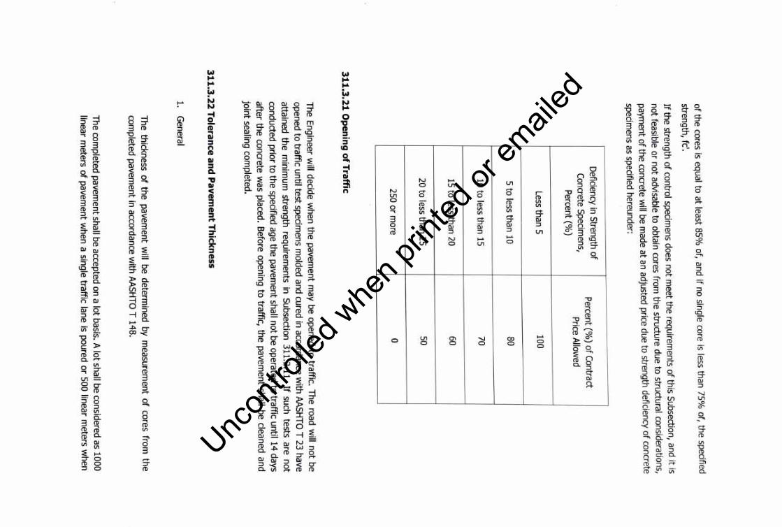
of the cores is equal to at least 85%
of, and if no single core is less than 75% of, the specified
strength, fc'.
If the strength of control specim
ens does not meet the requirem
ents of this S
ubsection, and it is
not feasible or no
t advisable to obtain cores from the structure due to structural considerations,
payment o
f the concrete will be m
ade at an adjusted price due to strength deficiency o
f concrete
specimens as specified hereunder:
Deficiency in S
trength of
Pe
rcen
t(%) o
f Contract
Concrete S
pecimens,
Price A
llowed
Pe
rcen
t(%)
Less than 5 100
5 to less than 10 80
10 to less than 15 70
15 to less than 20 60
20 to less than 25 50
250 or more
0
31
1.3
.21
Op
enin
g o
f Traffic
The E
ngineer will decide w
hen the pavement m
ay be opened to traffic. T
he road will n
ot be
opened to tra
ffic until test specimens m
olded and cured in accordance with
AA
SH
TO T
23 have
attained the
minim
um strength requirem
ents in
Subsection 311.2.11. If such
tests are no
t
conducted prior to the specified age the pavem
ent shall not be operated to tra
ffic until 14 days
afte
r the concrete was placed. B
efore opening to traffic, th
e pavem
ent shall be cleaned and
join
t sealing completed.
31
1.3
.22
To
lerance an
d P
avemen
t Th
ickness
1. G
eneral
The thickness o
f the pavement w
ill be determined
by measurem
ent of cores from
the
completed pavem
ent in accordance with
AA
SH
TO T
148.
The com
pleted pavement shall be accepted on a lo
t basis. A lo
t shall be considered as 1000
linear meters o
f pavement w
hen a single traffic lane is poured o
r 500 linear meters w
hen
Uncon
trolle
d whe
n prin
ted or
ed
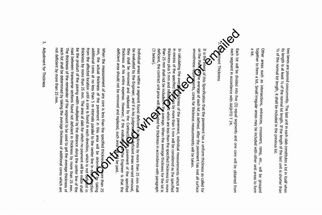
two
lanes are poured concurrently. The last u
nit in each slab constitutes a lot in itself w
hen its length is a
t least ½ o
f the normal lo
t length. If the length of the last u
nit is shorter than
½ o
f the
normal lo
t length, it shall be included in the
previous lot.
Other areas
such as
intersections, entrances,
crossovers, ram
p, etc.,
will
be grouped
tog
eth
er to
form
a lot. Sm
all irregular areas may be included w
ith other un
it areas to form
a lot.
Each lo
t will be divided in
to five (5
) equal segments and one core w
ill be obtained from
each segm
ent in accordance with
AA
SH
TO T
24.
2. P
avement T
hickness
It is the inte
nt o
f this Specification th
at the pavem
ent has a uniform thickness as called fo
r on th
e P
lans for th
e average o
f each lot as defined. After the pavem
ent has me
t all surface sm
oothness requirements, cores fo
r thickness measurem
ents will be taken.
In calculating th
e average thickness o
f the pavement, individual m
easurements w
hich are in excess o
f the
specified thickness by more than 5 m
m w
ill be considered as the specified thickness plus 5 m
m and m
easurement w
hich are less than the specified thickness by m
ore than 25 m
m shall n
ot be included in the average. W
hen the average thickness for the lo
t is deficient, th
e contract u
nit price w
ill be adjusted for thickness in accordance with paragraph
(3 below).
Individual areas with
in a segm
ent found deficient in thickness by more than 25 m
m shall
be evaluated by th
e E
ngineer, and if in his judgment, the deficient areas w
arrant removal,
the
y shall be removed and replaced b
y the Contractor w
ith pavem
ent of th
e specified
thickness at his entire expense.
How
ever, if the evaluation of the E
ngineer is tha
t the
deficient area should n
ot be rem
oved and replaced, such area will n
ot be paid.
When the m
easurement o
f any core is less than the
specified thickness by more than 25
mm
, the actual thickness o
f the
pavement in
this area w
ill be determined
by taking additional cores a
t no less than 5 m intervals parallel to
the center line in each direction from
the
affected location until a core is found in each direction, which is n
ot deficient in
thickness by m
ore
than 25 mm
. The area o
f slab for w
hich no payment w
ill be made shall
be the
pro
du
ct of th
e paving w
idth
multiplied by the distance along the center line o
f the road betw
een transverse sections found no
t deficient in thickness by more than 25 m
m.
The thickness o
f the remainder o
f the segment to
be used to g
et the average thickness o
f each lo
t shall be determined b
y taking the average thickness of additional cores w
hich are n
ot d
eficie
nt b
y more th
an
25 mm
.
3. A
djustment fo
r Thickness
Uncon
trolle
d whe
n prin
ted or
ed
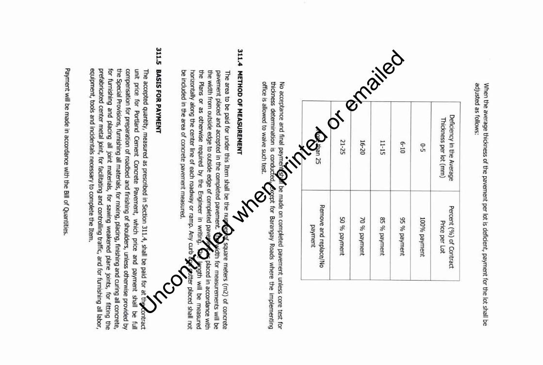
When the average thickness of the pavem
ent per lot is deficient, payment for the lot shall be
adjusted as follows:
Deficiency in the Average
Percent (%
) of Contract
Thickness per lot (mm
) Price per Lot
0-5 100%
payment
6-10 95 %
payment
11-15 85 %
payment
16-20 70 %
payment
21-25 50 %
payment
More than 25
Rem
ove and replace/No
payment
No acceptance and final paym
ent shall be made on com
pleted pavement unless core test for
thickness determination is conducted, except for B
arangay Roads w
here the implem
enting office is allow
ed to waive such test.
31
1.4
M
ETH
OD
OF M
EA
SU
RE
ME
NT
Toe area to be paid for under this Item shall be the num
ber of square meters (m
2) of concrete
pavement placed and accepted in the com
pleted pavement. Toe w
idth for measurem
ents will be
the width from
outside edge to outside edge of completed pavem
ent as placed in accordance with
the Plans or as otherwise required
by the Engineer in w
riting. Toe length will
be measured
horizontally along the center line of each roadway or ram
p. Any curb and gutter placed shall not be included in the area o
f concrete pavement m
easured.
31
1.5
B
AS
IS FO
R P
AY
ME
NT
Toe accepted quantity, measured as prescribed in S
ection 311.4, shall be paid for at the contract
unit price for
Portland
Cem
ent C
oncrete P
avement,
which
price and
payment
shall be full
compensation for preparation o
f roadbed and finishing of shoulders, unless otherwise provided by
the Special P
rovisions, furnishing all materials, for m
ixing, placing, finishing and curing all concrete, for furnishing and placing all joint m
aterials, for sawing w
eakened plane joints, for fitting the prefabricated center m
etal joint, for facilitating and controlling traffic, and for furnishing all labor, equipm
ent, tools and incidentals necessary to complete the Item
.
Paym
ent will be m
ade in accordance with the Bill o
f Quantities.
Uncon
trolle
d whe
n prin
ted or
ed
PAR
T F -
RO
AD
CO
NS
TR
UC
TIO
N
Uncon
trolle
d whe
n prin
ted or
ed

ITE
M 4
04
-R
EIN
FO
RC
ING
STE
EL
40
4.1
D
ES
CR
imO
N
This Item shall consist of furnishing, bending, fabricating and placing of steel reinforcem
ent of the type, size, shape and grade required in accordance w
ith this Specification and in conform
ity with
the requirements show
n on the Plans or as directed by the Engineer.
40
4.2
MA
TE
RIA
LS
RE
QU
IRE
ME
NT
S
Reinforcing shall be deform
ed and shall meet PNS 49 W
eldable/ASTM A706.
The minim
um yield
strength shall be as follows
:
For 12 mm
dia. and smaller:
fy = 276 M
Pa (40 Ksi)
For 16 mm
dia. and larger:
fy = 414 M
Pa (60 Ksi)
Modulus of E
lasticity, Es = 200,000 M
Pa
40
4.3
CO
NS
TR
UC
TIO
N R
EQ
UIR
EM
EN
TS
40
4.3
.1 O
rder List
Before materials are ordered, all order lists and bending diagram
s shall be furnished
by the C
ontractor, for approval of the Engineer. The approval of order lists and bending diagrams by the
Engineer shall in no way relieve the C
ontractor of responsibility for the correctness of such lists and diagram
s. Any expense incident to the revisions of materials furnished in accordance w
ith such lists and diagram
s to make them
comply w
ith the Plans shall be borne by the Contractor.
40
4.3
.2 P
rotectio
n o
f Material .
Steel reinforcement shall be stored above the surface of the ground upon platform
s, skids, or other supports and
shall be
protected as
far as
practicable from
m
echanical injury
and surface
deterioration caused
by exposure
to conditions
producing rust.
When
placed in
the w
ork, reinforcem
ent shall be free from dirt, detrim
ental rust, loose scale, paint, grease, oil, or other
Uncon
trolle
d whe
n prin
ted or
ed
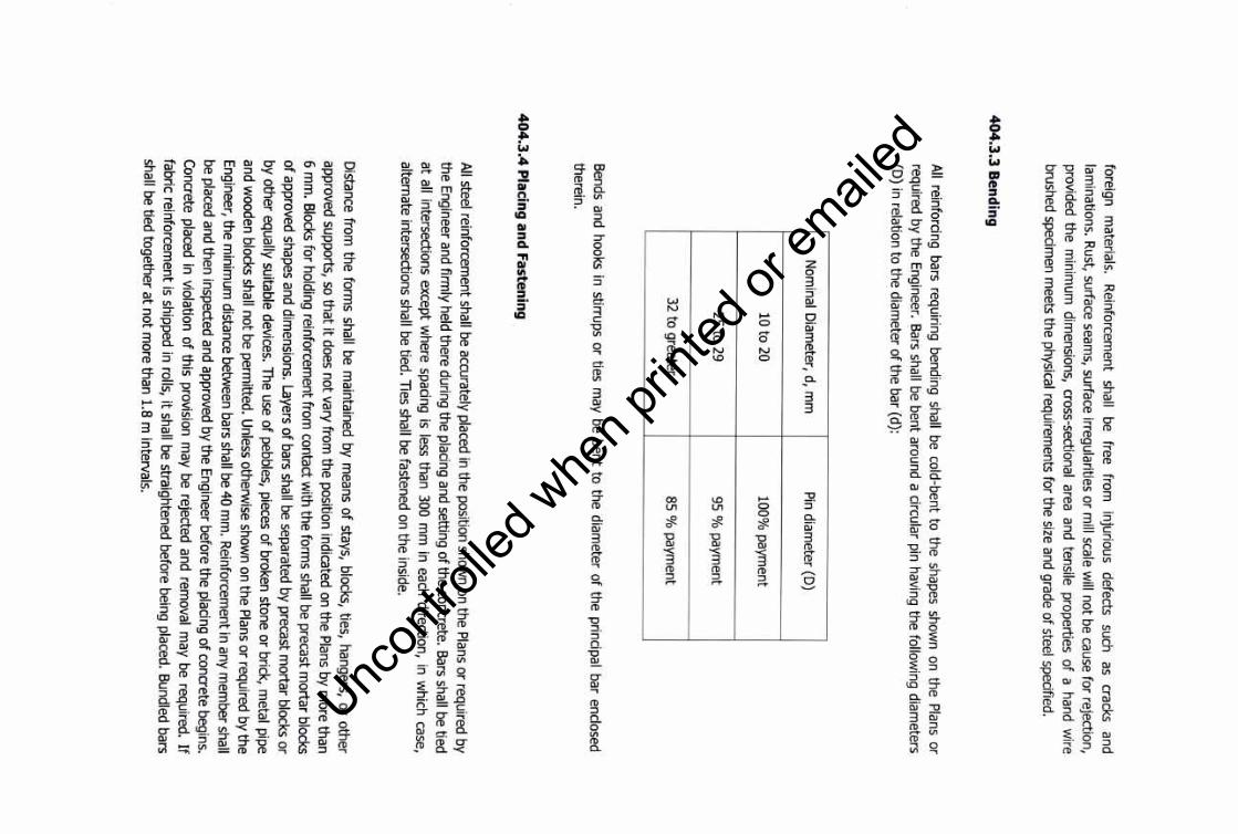
foreign m
aterials. R
einforcement
shall be
free from
injurious
defects such
as cracks
and lam
inations. Rust, surface seam
s, surface irregularities or mill scale w
ill not be cause for rejection, provided the m
inimum
dimensions, cross-sectional
area and tensile properties of a hand wire
brushed specimen m
eets the physical requirements for the size and grade of steel specified.
40
4.3
.3 B
end
ing
All reinforcing bars requiring bending shall be cold-bent to the shapes shown on the Plans or
required by the Engineer. Bars shall be bent around a circular pin having the follow
ing diameters
(D) in relation to the diam
eter of the bar (d):
Nom
inal Diam
eter, d, mm
Pin diam
eter (D)
10 to 20 100%
payment
25 to 29 95 %
payment
32 to greater 85 %
payment
Bends and hooks in stirrups or ties may be bent to the diam
eter of the principal bar enclosed therein.
40
4.3
.4 P
lacing and
Fasten
ing
.
All steel reinforcement shall be accurately placed in the position show
n on the Plans or required by the E
ngineer and firmly held there during the placing and setting of the concrete
. Bars shall be tied at all intersections except w
here spacing is less than 300 mm
in each direction, in which case,
alternate intersections shall be tied. lies shall be fastened on the inside
.
Distance from
the forms shall be m
aintained by means of stays, blocks, ties, hangers, or other
approved supports, so that it does not vary from the position indicated on the Plans by m
ore than 6 m
m. Blocks for holding reinforcem
ent from contact w
ith the forms shall be precast m
ortar blocks of approved shapes and dim
ensions. Layers of bars shall be separated by precast mortar blocks or
by other equally suitable devices. The use of pebbles, pieces of broken stone or brick, metal pipe
and wooden blocks shall not be perm
itted. Unless otherw
ise shown on the Plans or required by the
Engineer, the m
inimum
distance between bars shall be 40 m
m. R
einforcement in any m
ember shall
be placed and then inspected and approved by the Engineer before the placing of concrete begins.
Concrete placed in violation of this provision m
ay be rejected and removal m
ay be required. If fabric reinforcem
ent is shipped in rolls, it shall be straightened before being placed. Bundled bars
shall be tied together at not more than 1.8 m
intervals.
Uncon
trolle
d whe
n prin
ted or
ed
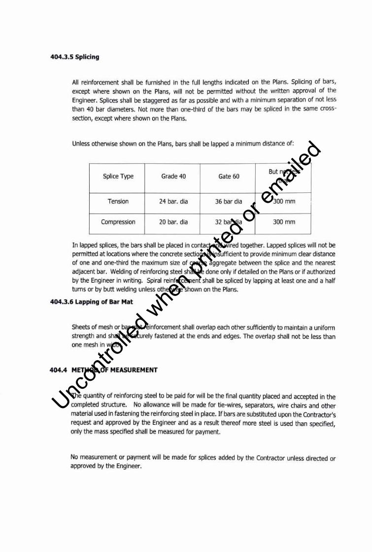
404.3.5 Splicing
All reinforcement shall be furnished In the full lengths Indicated on the Plans. Splicing of bars, except where shown on the Plans, will not be permitted without the written approval of the Engineer. Splices shall be staggered as far as possible and with a minimum separation of not less than 40 bar diameters. Not more than one-third of the bars may be spliced in the same crosssection, except where shown on the Plans.
Unless otherwise shown on the Plans, bars shall be lapped a minimum distance of:
Splice Type Grade 40 But not less
Gate 60 than
Tension 24 bar. dia 36 bar dia 300 mm
Compression 20 bar. dia 32 bar dia 300 mm
In lapped splices, the bars shall be placed in contact and wired together. Lapped splices will not be permitted at locations where the concrete sections is insufficient to provide minimum clear distance of one and one-third the maximum size of coarse aggregate between the splice and the nearest adjacent bar. Welding of reinforcing steel shall be done only if detailed on the Plans or if authorized by the Engineer in writing. Spiral reinforcement shall be spliced by lapping at least one and a half turns or by butt welding unless otherwise shown on the Plans.
404.3.6 Lapping of Bar Mat
Sheets of mesh or bar mat reinforcement shall overlap each other sufficiently to maintain a uniform strength and shall be securely fastened at the ends and edges. The overlap shall not be less than one mesh in width.
404.4 METHOD OF MEASUREMENT
The quantity of reinforcing steel to be paid for will be the final quantity placed and accepted in the completed structure. No allowance will be made for tie-wires, separators, wire chairs and other material used in fastening the reinforcing steel in place. If bars are substituted upon the Contractor's request and approved by the Engineer and as a result thereof more steel is used than specified, only the mass specified shall be measured for payment.
No measurement or payment will be made for splices added by the Contractor unless directed or approved by the Engineer.
Uncon
trolle
d whe
n prin
ted or
ed

When there is no item for reinforcing steel in the Bill of Quantities, costs will be considered as incidental to the other items in the Bill of Quantities.
404,5 BASIS OF PAYMENT
The accepted quantity, measured as prescribed in Section 404.4, shall be paid for at the contract unit price for Reinforcing Steel which price and payment shall be full compensation for furnishing and placing all materials, including all labor, equipment, tools and incidentals necessary to complete the work prescribed in this Item.
Payment will be made in accordance with the Bill of Quantities.
Uncon
trolle
d whe
n prin
ted or
ed
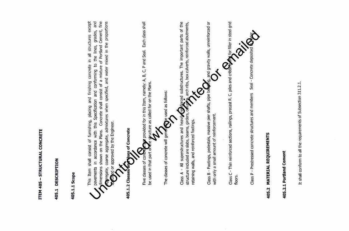
ITE
M 4
05
-S
TRU
CTU
RA
L C
ON
CR
ETE
40
5.1
D
ES
CR
IPT
ION
40
5.1
.1 S
cop
e
This
Ite
m
shal
l co
nsis
t of
fur
nish
ing,
pl
acin
g an
d fin
ishi
ng
conc
rete
in
al
l st
ruct
ures
ex
cept
pave
men
ts
in
acco
rdan
ce
with
th
is
Spe
cific
atio
n an
d co
nfor
min
g to
th
e lin
es,
grad
es,
and
dim
ensi
ons
show
n on
the
Pla
ns.
Con
cret
e sh
all
cons
ist
of a
mix
ture
of
Por
tland
Cem
ent,
fine
aggr
egat
e, c
oars
e ag
greg
ate,
adm
ixtu
res
whe
n sp
ecifi
ed,
and
wat
er m
ixed
in
the
prop
ortio
ns
spec
ified
or
appr
oved
by
the
Eng
inee
r.
40
5.1
.2 C
lass
es a
nd
Use
s o
f C
on
cret
e
Five
cla
sses
of c
oncr
ete
are
prov
ided
for
in th
is I
tem
, na
mel
y: A
, B,
C,
P an
d Se
al.
Each
cla
ss s
hall
be u
sed
in t
hat
part
of th
e st
ruct
ure
as c
alle
d fo
r on
the
Plan
s.
The
clas
ses
of c
oncr
ete
will
gene
rally
be
used
as
follo
ws:
Cla
ss A
-Al
l su
pers
truct
ures
and
hea
vily
rei
nfor
ced
subs
truct
ures
. Th
e im
porta
nt p
arts
of
the
stru
ctur
e in
clud
ed a
re s
labs
, bea
ms,
gird
ers,
col
umns
, arc
h rib
s, b
ox c
ulve
rts, r
einf
orce
d ab
utm
ents
,
reta
inin
g w
alls
, an
d re
info
rced
foo
tings
.
Cla
ss B
-Fo
otin
gs,
pede
stal
s, m
assi
ve p
ier s
hafts
, pi
pe b
eddi
ng,
and
grav
ity w
alls
, un
rein
forc
ed o
r
with
onl
y a
smal
l am
ount
of r
einf
orce
men
t.
Cla
ss C
-Th
in r
einf
orce
d se
ctio
ns,
railin
gs,
prec
ast R
. C.
pile
s an
d cr
ibbi
ng a
nd f
or fi
ller
in s
teel
grid
floor
s.
Cla
ss P
-P
rest
ress
ed c
oncr
ete
stru
ctur
es a
nd m
embe
rs
Seal
-C
oncr
ete
depo
site
d in
wat
er.
40
5.2
M
AT
ER
IAL
RE
QU
IRE
ME
NT
S
40
5.2
.1 P
ort
lan
d C
emen
t
It s
hall
conf
orm
to
all t
he r
equi
rem
ents
of S
ubse
ctio
n 31
1.2.
1.
Uncon
trolle
d whe
n prin
ted or
ed
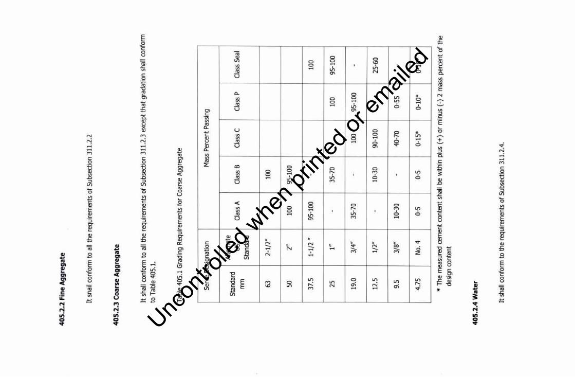
40
5.2
.2 F
ine
Ag
gre
gat
e
It s
nail
conf
orm
to
all t
he r
equi
rem
ents
of S
ubse
ctio
n 31
1.2.
2
40
5.2
.3 C
oars
e A
gg
reg
ate
It s
hall
conf
orm
to
all t
he r
equi
rem
ents
of S
ubse
ctio
n 31
1.2.
3 ex
cept
that
gra
datio
n sh
all c
onfo
rm
to T
able
405
.1.
Tabl
e 40
5.1
Gra
ding
Req
uire
men
ts fo
r C
oars
e A
ggre
gate
Serv
e D
esig
natio
n M
ass
Per
cent
Pas
sing
Sta
ndar
d A
ltern
ate
us
Cla
ss A
C
lass
B
Cla
ss C
C
lass
P
Cla
ss S
eal
mm
S
tand
ard
63
2-1/
2"
100
50
2"
100
95-1
00
37.5
1-
1/2
" 95
-100
-
100
25
1"
-35
-70
100
95-1
00
19.0
3/
4"
35-7
0 -
100
95-1
00
-
12.5
1/
2"
-10
-30
90-1
00
-25
-60
9.5
3/8"
10
-30
-40
-70
0-55
-
4.75
N
o. 4
0-
5 0-
5 0-
15*
0-10
* 0-
10*
* Th
e m
easu
red
cem
ent
cont
ent
shal
l be
with
in p
lus
( +)
or m
inus
( -)
2 m
ass
perc
ent
of th
e de
sign
con
tent
40
5.2
.4 W
ater
It s
hall
conf
orm
to
the
requ
irem
ents
of S
ubse
ctio
n 31
1.2.
4.
Uncon
trolle
d whe
n prin
ted or
ed

40
5.2
.5 R
ein
forc
ing
Ste
el
It s
hall
conf
orm
to
the
requ
irem
ents
of I
tem
404
, re
info
rcin
g S
teel
.
40
5.2
.6 A
dm
ixtu
res
Adm
ixtu
res
shal
l con
form
to
the
requ
irem
ents
of S
ubse
ctio
n 31
1.2.
7.
40
5.2
. 7 C
uri
ng
mat
eria
ls
Cur
ing
mat
eria
ls s
hall
conf
orm
to
the
requ
irem
ents
of S
ubse
ctio
n 31
1.2.
8.
40
5.2
.8 E
xpan
sio
n J
oin
t M
ater
ial
Exp
ansi
on jo
int m
ater
ials
sha
ll be
:
1.
Pre
form
ed S
pong
e R
ubbe
r an
d C
ork,
con
form
ing
to A
ASH
TO M
153
. 2.
H
ot-P
oure
d E
last
ic T
ype,
con
form
ing
to A
ASH
TO M
173
. 3.
P
refo
rmed
Fille
rs,
conf
orm
ing
to A
ASH
TO M
213
.
40
5.2
.9 E
last
om
eric
Co
mp
ress
ion
Jo
int
Sea
ls
Thes
e sh
all c
onfo
rm t
o AA
SHTO
M 2
20.
40
5.2
.10
Ela
sto
mer
ic P
ads
Thes
e sh
all c
onfo
rm t
o AA
SHTO
M 2
51 o
r Ite
m 4
12 -
Ela
stom
eric
Bea
ring
Pads
40
5.2
.11
Sto
rag
e o
f C
emen
t an
d A
gg
reg
ates
Sto
rage
of c
emen
t and
agg
rega
tes
shal
l con
form
to
all t
he r
equi
rem
ents
of S
ubse
ctio
n 31
1.2.
10.
40
5.3
SA
MP
LIN
G A
ND
TE
ST
ING
OF
STR
UC
TUR
AL
CO
NC
RE
TE
Uncon
trolle
d whe
n prin
ted or
ed

As w
ork
prog
ress
es, a
t lea
st o
ne (
1) s
ampl
e co
nsis
ting
of t
hree
(3)
con
cret
e cy
linde
r tes
t spe
cim
ens,
15
0 x
300
mm
(6
x 12
inch
es),
shal
l be
tak
en f
rom
eac
h se
vent
y fiv
e (7
5) c
ubic
met
res
of e
ach
clas
s o
f con
cret
e or
frac
tion
ther
eof p
lace
d ea
ch d
ay.
Com
plia
nce
with
the
req
uire
men
ts o
f th
is S
ectio
n sh
all
be d
eter
min
ed i
n ac
cord
ance
with
the
fo
llow
ing
stan
dard
met
hods
of A
ASH
TO:
Sam
plin
g o
f Fre
sh C
oncr
ete
Wei
ght p
er c
u. m
. an
d ai
r co
nten
t (G
ravi
0Met
ric)
of c
oncr
ete
Sie
ve a
naly
sis
of f
ine
and
coar
se a
ggre
gate
s
Slu
mp
of P
ortla
nd c
emen
t agg
rega
te.
Spe
cific
Gra
vity
and
abs
orpt
ion
of th
e fin
e ag
greg
ate
Test
s fo
r st
reng
th s
hall
be m
ade
in a
ccor
danc
e w
ith t
he f
ollo
win
g:
Mak
ing
and
curin
g co
ncre
te c
ompr
essi
ve
and
flexu
ral t
ests
spe
cim
ens
in t
he fi
eld
Com
pres
sive
stre
ngth
of m
olde
d co
ncre
te c
ylin
ders
40
5.4
PR
OD
UC
TIO
N R
EQ
UIE
ME
NT
S
40
5.4
.1 P
rop
ort
ion
ing
an
d S
tren
gth
of S
tru
ctu
ral C
on
cret
e
T 1
41
T 1
21
T 2
7
T 1
19
T8
4
T 2
3
T 2
2
The
conc
rete
mat
eria
ls s
hall
be p
ropo
rtion
ed in
acc
orda
nce
with
the
requ
irem
ents
for
eac
h cl
ass
of
conc
rete
as
spec
ified
in T
able
405
.2, u
sing
the
abso
lute
vol
ume
met
hod
as o
utlin
ed in
the
Am
eric
an
Con
cret
e In
stitu
te (
AC
I) S
tand
ard
211.
1, "
Rec
omm
ende
d P
ract
ice
for
Sel
ectin
g P
ropo
rtion
s fo
r N
orm
al a
nd H
eavy
wei
ght C
oncr
ete"
. ot
her
met
hods
of p
ropo
rtion
ing
may
be
empl
oyed
in
the
mix
de
sign
with
prio
r ap
prov
al o
f the
Eng
inee
r. Th
e m
ix s
hall
eith
er b
e de
sign
ed o
r ap
prov
ed b
y th
e E
ngin
eer.
A c
hang
e in
the
sou
rce
of m
ater
ials
dur
ing
the
prog
ress
of w
ork
may
nec
essi
tate
a n
ew
mix
des
ign.
The
stre
ngth
req
uire
men
ts f
or e
ach
clas
s o
f con
cret
e sh
all b
e as
spe
cifie
d in
Tab
le 4
05.2
.
Tabl
e 40
5.2
-C
ompo
sitio
n an
d S
treng
th o
f Con
cret
e fo
r us
e in
Stru
ctur
es
Cla
ss o
f M
inim
um
Max
imum
C
onsi
sten
cy
Des
igna
ted
Min
imum
C
oncr
ete
Cem
ent
rang
e in
Si
ze o
f Coa
rse
Com
pres
sive
C
onte
nt p
er
Wat
er/
Slu
mp
mm
A
ggre
gate
S
treng
th o
f m
3kg
C
emen
t (in
ch)
Squ
are
150x
300
mm
(b
ag**
) R
atio
kg/
kg
conc
rete
cy
linde
r
Uncon
trolle
d whe
n prin
ted or
ed
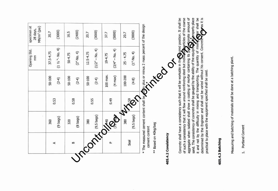
Ope
ning
Std
. sp
ecim
en a
t
mm
28
day
s,
MN
/m2
(psi
)
360
50-1
00
37
.5-4
.75
2
0.7
A
0.5
3 (9
ba
gs)
(2
-4)
(1 ½
"-N
o.
4)
(30
00
)
320
50-1
00
50
-4.7
5 1
6.5
B
0.58
(8
ba
gs)
(2
-4)
(2"-
No.
4)
(24
00
)
380
50-1
00
12.5
-4.7
5 2
0.7
C
0.55
(9
.5 b
ags)
(2
-4)
(1/2
" -
No.
4)
(30
00
)
440
100
max
. 19
-4.7
5 3
7.7
p
0.49
(1
1 ba
gs)
(4 m
ax)
(3
/4"
-N
o. 4
) (5
00
0)
380
100-
200
25 -
4.75
2
0.7
Sea
l 0.
59
(9.5
bag
s)
(4-8
) (1
"-N
o.
4)
(30
00
)
* Th
e m
easu
red
cem
en
t co
nte
nt
shal
l be
with
in p
lus
or
min
us 2
mas
s p
erc
en
t o
f th
e d
esig
n
cem
en
t co
nte
nt
** B
ased
on
40
kg/b
ag
40
5.4
.2 C
on
sist
ency
Con
cret
e sh
all
ha
ve a
con
sist
ency
suc
h th
at
it w
ill b
e w
orka
ble
in t
he
req
uire
d po
sitio
n. I
t sh
all
be
of s
uch
a co
nsis
tenc
y th
at it
will
flo
w a
roun
d re
info
rcin
g st
eel
bu
t ind
ivid
ual
part
icle
s o
f th
e c
oars
e
aggr
egat
e w
he
n i
sola
ted
shal
l sh
ow a
coa
ting
of
mo
rta
r co
ntai
ning
its
pro
po
rtio
na
te a
mo
un
t o
f
sand
. T
he c
onsi
sten
cy o
f con
cret
e sh
all b
e ga
uged
by
the
ab
ility
of t
he
eq
uip
me
nt t
o p
rop
erl
y pl
ace
it a
nd n
ot
by
the
diff
icu
lty i
n m
ixin
g an
d tr
an
spo
rtin
g.
Th
e q
ua
nti
ty o
f m
ixin
g w
ate
r sh
all
be
de
term
ine
d b
y th
e E
ngin
eer
and
shal
l n
ot
be v
arie
d w
ith
ou
t hi
s co
nsen
t. C
oncr
ete
as d
ry a
s it
is
prac
tical
to
pla
ce w
ith t
he
eq
uip
me
nt
spec
ified
sha
ll be
use
d.
40
5.4
.3 B
atch
ing
Mea
surin
g an
d b
atc
hin
g o
f m
ater
ials
sha
ll be
do
ne
at
a ba
tchi
ng p
lan
t.
1.
Por
tland
Cem
ent
Uncon
trolle
d whe
n prin
ted or
ed

Eith
er s
acke
d or
bul
k ce
men
t may
be
used
. N
o fra
ctio
n o
f a s
ack
of c
emen
t sha
ll be
use
d in
a
batc
h of
con
cret
e un
less
the
cem
ent
is w
eigh
ed.
All
bulk
cem
ent
shal
l be
wei
ghed
on
an
appr
oved
wei
ghin
g de
vice
. Th
e bu
lk c
emen
t w
eigh
ing
hopp
er s
hall
be p
rope
rly s
eale
d an
d ve
nted
to
prec
lude
dus
ting
oper
atio
n. T
he d
isch
arge
chu
te s
hall
not
be s
uspe
nded
fro
m t
he
wei
ghin
g ho
pper
and
sha
ll be
so
arra
nged
that
cem
ent w
ill n
eith
er b
e lo
dged
in i
t nor
leak
from
it.
Acc
urac
y of
bat
chin
g sh
all b
e w
ithin
plu
s ( +
) or
min
us (
-) 1
mas
s pe
rcen
t.
2.
Wat
er
Wat
er m
ay b
e m
easu
red
eith
er b
y vo
lum
e or
by
wei
ght.
The
accu
racy
of m
easu
ring
the
wat
er
shal
l be
with
in a
rang
e of
err
or o
f not
mor
e th
an 1
per
cent
.
3.
Agg
rega
tes
Sto
ckpi
ling
of a
ggre
gate
s sh
all
be i
n ac
cord
ance
with
Sub
sect
ion
311.
2.10
. Al
l ag
greg
ates
w
heth
er p
rodu
ced
or h
andl
ed b
y hy
drau
lic m
etho
ds o
r w
ashe
d, s
hall
be s
tock
pile
d or
bin
ned
for
drai
ning
for
at l
east
12
hour
s pr
ior t
o ba
tchi
ng.
Rai
l shi
pmen
t req
uirin
g m
ore
than
12
hour
s w
ill be
acc
epte
d as
ade
quat
e bi
nnin
g on
ly i
f th
e ca
r bo
dies
per
mit
free
drai
nage
. If
the
ag
greg
ates
con
tain
hig
h or
non
-uni
form
moi
stur
e co
nten
t, st
orag
e or
sto
ckpi
le p
erio
d in
exc
ess
of 1
2 ho
urs
may
be
requ
ired
by th
e E
ngin
eer.
Bat
chin
g sh
all
be c
ondu
cted
as
to r
esul
t in
a 2
mas
s pe
rcen
t m
axim
um t
oler
ance
for
the
re
quire
d m
ater
ials
.
4.
Bins
and
Sca
les
The
batc
hing
pla
nt s
hall
incl
ude
sepa
rate
bin
s fo
r bu
lk c
emen
t, fin
e ag
greg
ate
and
for
each
si
ze o
f coa
rse
aggr
egat
e, a
wei
ghin
g ho
pper
, and
sca
les
capa
ble
of d
eter
min
ing
accu
rate
ly th
e m
ass
of e
ach
com
pone
nt o
f the
bat
ch.
Scal
es s
hall
be a
ccur
ate
to o
ne-h
alf (
0.5)
per
cent
thro
ugho
ut th
e ra
nge
used
.
5.
Bat
chin
g
Whe
n ba
tche
s ar
e ha
uled
to
the
mix
er,
bulk
cem
ent
shal
l be
tra
nspo
rted
eith
er in
wat
erpr
oof
com
partm
ents
or
betw
een
the
fine
and
coar
se a
ggre
gate
. W
hen
cem
ent
is p
lace
d in
con
tact
w
ith m
oist
agg
rega
tes,
bat
ches
will
be re
ject
ed u
nles
s m
ixed
with
in 1
-1/2
hou
rs o
f suc
h co
ntac
t. S
acke
d ce
men
t may
be
trans
porte
d on
top
of t
he a
ggre
gate
s.
Uncon
trolle
d whe
n prin
ted or
ed

Bat
ches
sha
ll be
del
iver
ed t
o th
e m
ixer
sep
arat
e an
d in
tact
. E
ach
batc
h sh
all b
e du
mpe
d cl
eanl
y in
to t
he
mix
er w
itho
ut
loss
, an
d, w
hen
mor
e th
an o
ne b
atch
is
carr
ied
on t
he t
ruck
, w
ithou
t sp
illin
g o
f m
ater
ial
from
one
bat
ch c
ompa
rtm
ent
into
ano
ther
.
6.
Adm
ixtu
res
The
C
ontr
acto
r sh
all
follo
w
an
appr
oved
pr
oced
ure
for
addi
ng
the
spec
ified
a
mo
un
t of
ad
mix
ture
to
eac
h ba
tch
and
will
be
resp
onsi
ble
for
its u
nifo
rm o
pera
tion
du
ring
the
pro
gres
s o
f th
e w
ork.
H
e sh
all p
rovi
de s
epar
ate
scal
es f
or
the
adm
ixtu
res
whi
ch a
re t
o b
e p
rop
ort
ione
d by
wei
ght,
and
accu
rate
mea
sure
s fo
r th
ose
to b
e pr
opor
tione
d by
vol
ume.
A
dmix
ture
s sh
all
be m
easu
red
into
the
mix
er w
ith a
n ac
cura
cy o
f plu
s o
r m
inus
thr
ee (
3) p
erce
nt.
The
use
of C
alci
um C
hlor
ide
as a
n ad
mix
ture
will
no
t be
per
mitt
ed.
40
5,4
.4 M
ixin
g a
nd
Del
iver
y
Con
cret
e m
ay b
e m
ixed
at t
he s
ite o
f con
stru
ctio
n, a
t a c
entr
al p
oint
or b
y a
com
bina
tion
of c
entr
al
poin
t and
tru
ck m
ixin
g o
r by
a c
ombi
natio
n o
f cen
tral
poi
nt m
ixin
g an
d tr
uck
agi
tatin
g. M
ixin
g an
d de
liver
y o
f co
ncre
te s
hall
be i
n ac
cord
ance
with
the
app
ropr
iate
req
uire
men
ts o
f A
AS
HTO
M 1
57
exce
pt a
s m
odifi
ed in
the
fol
low
ing
para
grap
hs o
f thi
s se
ctio
n, f
or
tru
ck m
ixin
g o
r a
com
bin
atio
n of
ce
ntra
l p
oin
t an
d tr
uck
mix
ing
or
truc
k ag
itatin
g. D
eliv
ery
of
conc
rete
sha
ll be
reg
ulat
ed s
o th
at
plac
ing
is a
t a
cont
inuo
us r
ate
unle
ss d
elay
ed b
y th
e pl
acin
g op
erat
ions
. T
he i
nter
vals
bet
wee
n de
liver
y o
f ba
tche
s sh
all
no
t be
so
grea
t as
to
allo
w t
he c
oncr
ete
in p
lace
to
har
den
part
ially
, an
d in
no
case
sha
ll su
ch a
n in
terv
al e
xcee
d 30
min
utes
.
In e
xcep
tiona
l cas
es a
nd w
hen
volu
met
ric m
easu
rem
ents
are
aut
horiz
ed,
for
smal
l pro
ject
requ
iring
le
ss t
han
75 c
u.m
. pe
r da
y o
f po
urin
g, t
he w
eigh
t pr
opor
tions
sha
ll be
con
vert
ed t
o e
quiv
alen
t vo
lum
etric
pr
opor
tions
. In
suc
h ca
ses,
su
itabl
e al
low
ance
sha
ll be
m
ade
for
varia
tions
in
the
m
oist
ure
cond
ition
of
the
aggr
egat
es,
incl
udin
g th
e bu
lkin
g ef
fect
in t
he
fin
e ag
greg
ate.
Bat
chin
g an
d m
ixin
g sh
all
be in
acc
orda
nce
with
AS
TM C
685
, S
ectio
n 6
thro
ugh
9.
Con
cret
e m
ixin
g, b
y ch
ute
is a
llow
ed p
rovi
ded
tha
t a
wei
ghin
g sc
ales
fo
r de
term
inin
g th
e b
atch
w
eigh
t will
be
used
.
For
batc
h m
ixin
g a
t the
site
of c
onst
ruct
ion
or
at a
cen
tral
poi
nt,
a ba
tch
mix
er o
f an
appr
oved
typ
e sh
all
be u
sed.
Mix
er h
avin
g a
rate
d ca
paci
ty o
f le
ss t
han
a on
e-ba
g ba
tch
shal
l n
ot
be u
sed
. T
he
vo
lum
e o
f con
cret
e m
ixed
per
bat
ch s
hall
no
t exc
eed
the
mix
er's
nom
inal
cap
acity
as
show
n on
th
e
man
ufac
ture
r's s
tand
ard
ratin
g pl
ate
on t
he
mix
er e
xcep
t th
at
an o
verlo
ad u
p to
lO
pe
rce
nt a
bove
th
e m
ixer
's
nom
inal
ca
paci
ty
may
be
pe
rmitt
ed,
prov
ided
co
ncre
te
test
da
ta
for
stre
ngth
, se
greg
atio
n, a
nd u
nifo
rm c
onsi
sten
cy a
re s
atis
fact
ory
and
prov
ided
no
spill
age
of
conc
rete
tak
es
plac
e. T
he b
atch
sha
ll be
so
char
ge in
to th
e d
rum
th
at a
por
tion
of t
he
wa
ter
shal
l en
ter
in a
dvan
ce
of
the
cem
ent
and
aggr
egat
es.
The
flo
w o
f w
ate
r sh
all
be u
nifo
rm a
nd a
ll w
ate
r sh
all
be i
n th
e dr
um b
y th
e e
nd o
f th
e f
irst
15
seco
nds
of t
he m
ixin
g pe
riod.
Mix
ing
time
sha
ll be
mea
sure
d fr
om
Uncon
trolle
d whe
n prin
ted or
ed
the
time
all m
ater
ials
, ex
cept
wat
er,
are
in th
e dr
um.
Mix
ing
time
shal
l not
be
less
than
60
seco
nds
for
mix
ers
havi
ng a
cap
acity
of
1.S
m3
or le
ss.
For
mix
ers
havi
ng a
cap
acity
gre
ater
than
1.5
m3,
th
e m
ixin
g tim
e sh
all n
ot b
e le
ss th
an 9
0 se
cond
s. I
f tim
ing
star
ts,
the
inst
ant t
he s
kip
reac
hes
its
max
imum
rai
sed
posi
tion,
4 s
econ
ds s
hall
be a
dded
to
the
spec
ified
mix
ing
time.
Mix
ing
time
ends
w
hen
the
disc
harg
e ch
ute
open
s.
The
mix
er s
hall
be o
pera
ted
at th
e dr
um s
peed
as
show
n on
the
man
ufac
ture
r's n
ame
plat
e on
the
mix
er.
Any
con
cret
e m
ixed
less
tha
n th
e sp
ecifi
ed t
ime
shal
l be
dis
card
ed a
nd d
ispo
sed
off b
y th
e C
ontra
ctor
at h
is o
wn
expe
nses
.
The
timin
g de
vice
on
stat
iona
ry m
ixer
s sh
all
be e
quip
ped
with
a b
ell
or o
ther
sui
tabl
e w
arni
ng
devi
ce a
djus
ted
to g
ive
a cl
early
aud
ible
sig
nal e
ach
time
the
lock
is r
elea
sed.
In
case
of f
ailu
re o
f th
e tim
ing
devi
ce, t
he C
ontra
ctor
will
be p
erm
itted
to c
ontin
ue o
pera
tions
whi
le i
t is
bein
g re
paire
d,
prov
ided
he
furn
ishe
s an
app
rove
d tim
epie
ce e
quip
ped
with
min
ute
and
seco
nd h
ands
. If
the
timin
g de
vice
is n
ot p
lace
d in
goo
d w
orki
ng o
rder
with
in 2
4 ho
urs,
fur
ther
use
of t
he m
ixer
will
be
proh
ibite
d un
til r
epai
rs a
re m
ade.
Ret
empe
ring
conc
rete
will
not b
e pe
rmitt
ed.
Adm
ixtu
res
for
incr
easi
ng th
e w
orka
bilit
y, fo
r re
tard
ing
the
set,
or fo
r ac
cele
ratin
g th
e se
t or
impr
ovin
g th
e pu
mpi
ng c
hara
cter
istic
s o
f the
con
cret
e w
ill b
e pe
rmitt
ed o
nly
whe
n sp
ecifi
cally
pro
vide
d fo
r in
the
Con
tract
, or
aut
horiz
ed i
n w
ritin
g by
the
E
ngin
eer.
1.
Mix
ing
Con
cret
e: G
ener
al
Con
cret
e sh
all
be t
horo
ughl
y m
ixed
in a
mix
er o
f an
appr
oved
siz
e an
d ty
pe t
hat w
ill in
sure
a
unifo
rm d
istri
butio
n o
f the
mat
eria
ls th
roug
hout
the
mas
s.
All
conc
rete
sha
ll be
mix
ed i
n m
echa
nica
lly o
pera
ted
mix
ers.
Mix
ing
plan
t an
d eq
uipm
ent
for
trans
porti
ng a
nd p
laci
ng c
oncr
ete
shal
l be
arra
nged
with
an
ampl
e au
xilia
ry i
nsta
llatio
n to
prov
ide
a m
inim
um s
uppl
y o
f con
cret
e in
cas
e o
f bre
akdo
wn
of m
achi
nery
or i
n ca
se th
e no
rmal
supp
ly o
f con
cret
e is
dis
rupt
ed.
The
auxi
liary
sup
ply
of c
oncr
ete
shal
l be
suffi
cien
t to
com
plet
e th
e ca
stin
g o
f a s
ectio
n up
to
a co
nstru
ctio
n jo
int t
hat w
ill m
eet t
he a
ppro
val o
f the
Eng
inee
r.
Equ
ipm
ent
havi
ng c
ompo
nent
s m
ade
of
alum
inum
or
mag
nesi
um a
lloys
, w
hich
wou
ld h
ave
cont
act
with
pla
stic
con
cret
e du
ring
mix
ing,
tra
nspo
rting
or
pum
ping
of
Por
tland
Cem
ent
conc
rete
, sh
all
not b
e us
ed.
Con
cret
e m
ixer
s sh
all
be e
quip
ped
with
ade
quat
e w
ater
sto
rage
and
a d
evic
e of
acc
urat
ely
mea
surin
g an
d au
tom
atic
ally
con
trolli
ng t
he a
mou
nt o
f wat
er u
sed.
Mat
eria
ls s
hall
be m
easu
red
by w
eigh
ing.
The
app
arat
us p
rovi
ded
for
wei
ghin
g th
e ag
greg
ates
and
cem
ent
shal
l be
sui
tabl
y de
sign
ed a
nd c
onst
ruct
ed f
or t
his
purp
ose.
The
acc
urac
y o
f al
l w
eigh
ing
devi
ces
exce
pt th
at fo
r wat
er s
hall
be s
uch
that
suc
cess
ive
quan
titie
s ca
n be
mea
sure
d
Uncon
trolle
d whe
n prin
ted or
ed

to w
ithin
one
per
cent
of t
he
des
ired
amou
nts.
The
wat
er m
easu
ring
devi
ce s
hall
be a
ccur
ate
to
plu
s o
r m
inus
0.5
mas
s pe
rcen
t. A
ll m
easu
ring
devi
ces
shal
l be
sub
ject
to
the
app
rova
l o
f th
e E
ngin
eer.
Sca
les
and
mea
surin
g de
vice
s sh
all
be t
este
d a
t th
e ex
pens
e o
f the
Con
trac
tor
as f
requ
ently
as
the
Eng
inee
r m
ay d
eem
ne
cess
ary
to i
nsur
e th
eir
acc
urac
y.
We
ighi
ng
equi
pmen
t sh
all
be i
nsul
ated
aga
inst
vib
ratio
n o
r m
ovem
ent
of
othe
r op
erat
ing
equi
pmen
t in
th
e p
lant
. W
hen
the
entir
e pl
ant i
s ru
nnin
g, t
he s
cale
rea
ding
at c
ut-
off
sha
ll n
ot v
ary
from
the
w
eig
ht
desi
gnat
ed b
y th
e E
ngin
eer
mor
e th
an o
ne m
ass
perc
ent
for
cem
ent,
1-1/
2 m
ass
perc
ent f
or
any
size
of a
ggre
gate
, o
r one
(1
) m
ass
perc
ent f
or
the
tota
l agg
rega
te in
any
bat
ch.
2.
Mix
ing
Con
cret
e a
t Site
Con
cret
e m
ixer
s m
ay b
e o
f the
rev
olvi
ng d
rum
or
the
revo
lvin
g bl
ade
type
and
th
e m
ixin
g dr
um
or
blad
es s
hall
be o
pera
ted
unifo
rmly
at t
he
mix
ing
spee
d re
com
men
ded
by th
e m
anuf
actu
rer.
T
he p
ick-
up a
nd t
hro
w-o
ver
blad
es o
f m
ixer
s sh
all
be r
esto
red
or
repl
aced
whe
n an
y p
art
or
sect
ion
is w
orn
20 m
m o
r m
ore
belo
w t
he o
rigin
al h
eigh
t of t
he m
anuf
actu
rer's
des
ign.
Mix
ers
and
agita
tors
whi
ch h
ave
an a
ccum
ulat
ion
of
hard
con
cret
e or
mor
tar
shal
l n
ot b
e us
ed.
Whe
n bu
lk c
emen
t is
use
d an
d vo
lum
e o
f th
e b
atch
is
0.5
m3
or
mor
e, t
he
sca
le a
nd w
eigh
ho
pper
fo
r P
ortla
nd C
emen
t sh
all
be s
epar
ate
and
dist
inct
fro
m
the
aggr
egat
e ho
pper
or
hopp
ers.
The
dis
char
ge m
echa
nism
of
the
bul
k ce
men
t w
eigh
hop
per
shal
l be
int
erlo
cked
ag
ains
t ope
ning
bef
ore
the
full
amou
nt o
f cem
ent i
s in
th
e h
oppe
r. T
he d
isch
argi
ng m
echa
nism
sh
all
also
be
in
terlo
cked
ag
ains
t op
enin
g w
hen
the
amou
nt o
f ce
men
t in
th
e
hopp
er i
s un
derw
eigh
t by
mor
e th
an o
ne (
1)
mas
s pe
rcen
t o
r ov
erw
eigh
t b
y m
ore
than
3 m
ass
perc
ent
of t
he
am
ount
spe
cifie
d.
Whe
n th
e a
ggre
gate
con
tain
s m
ore
wat
er th
an t
he q
uant
ity n
eces
sary
to
pro
duce
a s
atur
ated
su
rfac
e dr
y co
nditi
on,
repr
esen
tativ
e sa
mpl
es
shal
l be
ta
ken
and
the
m
oist
ure
con
ten
t de
term
ined
fo
r ea
ch k
ind
of a
ggre
gate
.
The
bat
ch s
hall
be s
o ch
arge
d in
to t
he m
ixer
th
at s
ome
wat
er w
ill e
nter
in a
dvan
ce o
f cem
ent
and
aggr
egat
e. A
ll w
ater
sha
ll be
in
the
drum
by
the
end
of
the
fir
st q
uart
er o
f th
e s
peci
fied
mix
ing
time.
Cem
ent s
hall
be b
atch
ed a
nd c
harg
ed i
nto
the
mix
er s
o th
at i
t will
no
t res
ult
in lo
ss o
f cem
ent
due
to th
e e
ffec
t of w
ind,
or
in a
ccum
ulat
ion
of c
emen
t on
surf
ace
of c
onve
yors
or
hopp
ers,
or
in o
the
r co
nditi
ons
whi
ch r
educ
e or
var
y th
e re
quire
d qu
antit
y o
f ce
men
t in
th
e c
oncr
ete
mix
ture
.
Th
e e
ntir
e co
nten
t o
f a
batc
h m
ixer
sha
ll be
rem
oved
fro
m t
he
dru
m b
efor
e m
ater
ials
fo
r a
succ
eedi
ng b
atch
are
pla
ced
ther
ein.
The
mat
eria
ls c
ompo
sing
a b
atch
exc
ept
wa
ter
shal
l be
de
posi
ted
sim
ulta
neou
sly
into
th
e m
ixer
.
Uncon
trolle
d whe
n prin
ted or
ed

All
conc
rete
sha
ll be
mix
ed f
or a
per
iod
of n
ot l
ess
than
1-1
/2 m
inut
es a
fter
all
mat
eria
ls,
incl
udin
g w
ater
, ar
e in
the
mix
er.
Dur
ing
the
perio
d of
mix
ing,
the
mix
er s
hall
oper
ate
at t
he
spee
d fo
r w
hich
it
has
been
des
igne
d.
Mix
ers
shal
l be
ope
rate
d w
ith a
n au
tom
atic
tim
ing
devi
ce t
hat
can
be l
ocke
d by
the
Eng
inee
r.
The
time
devi
ce a
nd d
isch
arge
mec
hani
cs s
hall
be s
o in
terlo
cked
tha
t du
ring
norm
al o
pera
tion
no p
art o
f the
bat
ch w
ill be
cha
rged
unt
il th
e sp
ecifi
ed m
ixin
g tim
e ha
s el
apse
d.
The
first
bat
ch o
f co
ncre
te m
ater
ials
pla
ced
in t
he m
ixer
sha
ll co
ntai
n a
suffi
cien
t ex
cess
of
cem
ent,
sand
, an
d w
ater
to c
oat t
he in
side
of t
he d
rum
with
out
redu
cing
the
req
uire
d m
orta
r co
nten
t of
the
mix
. W
hen
mix
ing
is to
cea
se f
or a
per
iod
of o
ne h
our
or m
ore,
the
mix
er s
hall
be t
horo
ughl
y de
aned
.
3.
Mix
ing
Con
cret
e at
Cen
tral
Pla
nt
Mix
ing
at c
entra
l pla
nt s
hall
conf
orm
to
the
requ
irem
ents
for
mix
ing
at th
e si
te.
4.
Mix
ing
Con
cret
e in
Tru
ck
Truc
k m
ixer
s, u
nles
s ot
herw
ise
auth
oriz
ed b
y th
e E
ngin
eer,
shal
l be
of th
e re
volv
ing
drum
type
, w
ater
-tigh
t, an
d so
con
stru
cted
tha
t the
con
cret
e ca
n be
mix
ed to
insu
re a
uni
form
dis
tribu
tion
of m
ater
ials
thr
ough
out
the
mas
s. A
ll so
lid m
ater
ials
for
the
con
cret
e sh
all
be a
ccur
atel
y m
easu
red
and
char
ged
into
the
dru
m a
t th
e pr
opor
tioni
ng
plan
t. E
xcep
t as
sub
sequ
ently
pr
ovid
ed, t
he tr
uck
mix
er s
hall
be e
quip
ped
with
a d
evic
e by
whi
ch th
e qu
antit
y of
wat
er a
dded
ca
n be
rea
dily
ver
ified
. Th
e m
ixin
g w
ater
may
be
adde
d di
rect
ly to
the
bat
ch,
in w
hich
cas
e a
tank
is n
ot r
equi
red.
Tru
ck m
ixer
s m
ay b
e re
quire
d to
be
prov
ided
with
a m
eans
of w
hich
the
m
ixin
g tim
e ca
n be
rea
dily
ver
ified
by
the
Eng
inee
r.
The
max
imum
size
of b
atch
in tr
uck
mix
ers
shal
l not
exc
eed
the
min
imum
rat
ed c
apac
ity o
f the
m
ixer
as
stat
ed b
y th
e m
anuf
actu
rer
and
stam
ped
in m
etal
on
the
mix
er.
Truc
k m
ixin
g, s
hall,
un
less
oth
erw
ise
dire
cted
be
cont
inue
d fo
r no
t les
s th
an 1
00 r
evol
utio
ns a
fter
all
ingr
edie
nts,
in
clud
ing
wat
er,
are
in th
e dr
um. T
he m
ixin
g sp
eed
shal
l not
be
less
than
4 rp
m,
nor
mor
e th
an
6 rp
m.
Mix
ing
shal
l be
gin
with
in 3
0 m
inut
es a
fter
the
cem
ent
has
been
add
ed e
ither
to
the
wat
er o
r ag
greg
ate,
but
whe
n ce
men
t is
char
ged
into
a m
ixer
dru
m c
onta
inin
g w
ater
or
surfa
ce w
et
aggr
egat
e an
d w
hen
the
tem
pera
ture
is a
bove
32°
C,
this
lim
it sh
all b
e re
duce
d to
15
min
utes
. Th
e lim
itatio
n in
tim
e be
twee
n th
e in
trodu
ctio
n of
the
cem
ent
to t
he a
ggre
gate
and
the
be
ginn
ing
of th
e m
ixin
g m
ay b
e w
aive
d w
hen,
in th
e ju
dgm
ent o
f the
Eng
inee
r, th
e ag
greg
ate
is su
ffici
ently
free
fro
m m
oist
ure,
so
that
ther
e w
ill be
no
harm
ful e
ffect
s on
the
cem
ent.
Uncon
trolle
d whe
n prin
ted or
ed
Whe
n a
truc
k m
ixer
is u
sed
for
trans
porta
tion,
the
mix
ing
time
spec
ified
in S
ubse
ctio
n 40
5.4
.4
(3)
at a
sta
tiona
ry m
ixer
may
be
redu
ced
to 3
0 se
cond
s an
d th
e m
ixin
g co
mpl
eted
in
a tru
ck
mix
er.
The
mix
ing
time
in t
he t
ruck
mix
er s
hall
be a
s sp
ecifi
ed f
or t
ruck
mix
ing
.
5.
Tra
nspo
rting
Mix
ed C
oncr
ete
Mix
ed c
oncr
ete
may
onl
y be
tran
spor
ted
to th
e de
liver
y po
int
in t
ruck
agi
tato
rs o
r tru
ck m
ixer
s op
erat
ing
at th
e sp
eed
desi
gnat
ed b
y th
e m
anuf
actu
rers
of t
he e
quip
men
t as
agi
tatin
g sp
eed,
or
in n
on-a
gita
ting
haul
ing
equi
pmen
t, pr
ovid
ed t
he c
onsi
sten
cy a
nd w
orka
bilit
y of
the
mix
ed
conc
rete
up
on
disc
harg
e at
th
e de
liver
y po
int
is
suita
ble
for
adeq
uate
pl
acem
ent
and
cons
olid
atio
n in
pla
ce.
Truc
k ag
itato
rs s
hall
be l
oade
d no
t to
exc
eed
the
man
ufac
ture
r's g
uara
ntee
d ca
paci
ty.
They
sh
all
mai
ntai
n th
e m
ixed
con
cret
e in
a th
orou
ghly
mix
ed a
nd u
nifo
rm m
ass
durin
g ha
ulin
g.
No
addi
tiona
l mix
ing
wat
er s
hall
be in
corp
orat
ed in
to th
e co
ncre
te d
urin
g ha
ulin
g or
afte
r arr
ival
at
the
deliv
ery
poin
t.
The
rate
of
disc
harg
e of
mix
ed c
oncr
ete
from
tru
ck m
ixer
s or
agi
tato
rs s
hall
be c
ontro
lled
by
the
spee
d of
rota
tion
of th
e dr
um in
the
disc
harg
e di
rect
ion
with
the
disc
harg
e ga
te f
ully
ope
n.
Whe
n a
truck
mix
er o
r agi
tato
r is
used
for t
rans
porti
ng c
oncr
ete
to th
e de
liver
y po
int,
disc
harg
e sh
all b
e co
mpl
eted
with
in o
ne h
our,
or b
efor
e 25
0 re
volu
tions
of t
he d
rum
or
blad
es, w
hich
ever
co
mes
fir
st,
afte
r th
e in
trodu
ctio
n of
the
ce
men
t to
th
e ag
greg
ates
. U
nder
, co
nditi
ons
cont
ribut
ing
to q
uick
stif
feni
ng o
f th
e co
ncre
te o
r w
hen
the
tem
pera
ture
of
the
conc
rete
is
30°C
, or
abo
ve,
a tim
e le
ss th
an o
ne h
our
will
be r
equi
red.
6.
Del
iver
y of
Mix
ed C
oncr
ete
The
Con
tract
or s
hall
have
suf
ficie
nt p
lant
cap
acity
and
tra
nspo
rtatio
n ap
para
tus
to i
nsur
e co
ntin
uous
del
iver
y at
the
rat
e re
quire
d. T
he r
ate
of d
eliv
ery
of c
oncr
ete
durin
g co
ncre
ting
oper
atio
ns s
hall
be s
uch
as t
o pr
ovid
e fo
r th
e pr
oper
han
dlin
g, p
laci
ng a
nd f
inis
hing
of
the
conc
rete
. The
rat
e sh
all b
e su
ch th
at th
e in
terv
al b
etw
een
batc
hes
shal
l not
exc
eed
20 m
inut
es.
The
met
hods
of d
eliv
erin
g an
d ha
ndlin
g th
e co
ncre
te s
hall
be s
uch
as w
ill fa
cilit
ate
plac
ing
of
the
min
imum
han
dlin
g.
40
5.5
M
ET
HO
DS
OF
ME
AS
UR
EM
EN
T
The
quan
tity
of s
truct
ural
con
cret
e to
be
paid
for
will
be t
he f
inal
qua
ntity
pla
ced
and
acce
pted
in
the
com
plet
ed s
truct
ures
. N
o de
duct
ion
will
be m
ade
for
the
volu
me
occu
pied
by
pipe
less
tha
n 10
0 m
m (
4 in
ches
) in
dia
met
er o
r by
rei
nfor
cing
ste
el, a
ncho
rs,
cond
uits
, w
eep
hole
s or
exp
ansi
on
join
t mat
eria
ls.
Uncon
trolle
d whe
n prin
ted or
ed
40
5.6
B
AS
IS O
F P
AY
ME
NT
Toe
acce
pted
qua
ntiti
es,
mea
sure
d as
pre
scrib
ed in
Sec
tion
405.
5, s
hall
be p
aid
for
at t
he c
ontra
ct
unit
pric
e fo
r ea
ch o
f the
Pay
Ite
ms
liste
d be
low
tha
t is
incl
uded
in t
he B
ill of
Qua
ntiti
es.
Pay
men
t sha
ll co
nstit
ute
full
com
pens
atio
n fo
r fu
rnis
hing
, pl
acin
g an
d fin
ishi
ng c
oncr
ete
incl
udin
g al
l lab
or,
equi
pmen
t, to
ols
and
inci
dent
als
nece
ssar
y to
com
plet
e th
e w
ork
pres
crib
ed in
the
item
.
Pay
men
t will
be m
ade
in a
ccor
danc
e w
ith t
he B
ill of
Qua
ntiti
es.
Uncon
trolle
d whe
n prin
ted or
ed
PA
RT
G -
DR
AIN
AG
E A
ND
SLO
PE
PR
OT
EC
TIO
N S
TR
UC
TU
RE
S
Uncon
trolle
d whe
n prin
ted or
ed

ITE
M 5
00
-P
IPE
CU
LVE
RTS
AN
D S
TOR
M D
RA
INS
50
0.1
D
ES
CR
IPT
ION
This Ite
m shall consist o
f the construction or reconstruction o
f pipe culverts and storm drains,
hereinafter referred to as "co
nd
uit" in accordance w
ith this S
pecification and in con
form
ity with
the lines and grades show
n on the
Plans o
r as established by the
Engineer.
50
0.2
M
AT
ER
IAL
S R
EQ
UIR
EM
EN
TS
Materials shall m
ee
t the
requirements specified in the follow
ing specifications:
Zinc coated (galvanized) corrugated
Iron
or steel culverts and underdrains
Cast iron culvert pipe
Concrete sew
er, storm drain and
Reinforced concrete culvert,
storm drainage and sew
er pipe
Bitum
inous coated corrugated metal
culve
rt pipe and pipe arches
Reinforced concrete arch culvert
storm drain and sew
er pipe
Asbestos cem
ent pipe for culverts
and storm
drains
AASHTO
M36
AASHTO
M64
AASHTO
M86
AASHTO
M170
AASHTO
M190
AASHTO
M206
AASHTO
M217
Join
t Mortar -
Join
t mo
rtar fo
r concrete pipes shall consist of 1 p
art, by volum
e of P
ortland Cem
ent and tw
o (2
) parts of approved sand w
ith w
ate
r as necessary to obtain th
e required consistency.
Portland C
ement and sand shall conform
to th
e requirem
ents of Ite
m 405, S
tructural Concrete.
Mo
rtar shall be used w
ithin
30 minutes a
fter its preparation.
Uncon
trolle
d whe
n prin
ted or
ed
Rubber gaskets
AA
SH
TO M
173
Oakum
-O
akum fo
r join
ts in bell and spigot pipes shall be made from
hemp (C
annavis Sativa) line
or B
enares Sunn fiber o
r from a com
bination of these fibers.
The oakum
shall be thoroughly corded
and finished and practically free from lum
ps, dirt and extraneous m
atter.
Hot poured jo
int sealing com
pound A
AS
HTO
M 173
Bedding m
aterial shall conform to the requirem
ents of S
ubsection
50
0.3
.2 B
edd
ing
Backfill m
aterial shall conform to
the requirements o
f Subsection 500.
50
0.3
.6 B
ackfilling
When the location o
f manufacturing plants allow
s, the plants will
be inspected periodically for
compliance
with
specified m
anufacturing m
ethods, and
material
samples
will
be obtained
for
laboratory testing for compliance w
ith materials quality requirem
ents. T
his shall be the basis for
acceptance of m
anufacturing lots as to quality .
Prior to
and during incorporation of m
aterials in the work, these m
aterials will be subject to
the latest inspection and approval o
f the Engineer.
50
0.3
C
ON
ST
RU
CT
ION
RE
QU
IRE
ME
NTS
50
0.3
.1 E
xcavation
Trenches
shall be
excavated in
accordance w
ith the
requirements
of
Item
103,
Structure
Excavation, to
a width sufficient to
allow for proper jointing o
f the conduit and thorough compaction
of the bedding and backfill m
aterials under and around the conduit. W
here feasible, trench walls
shall be vertical.
The com
pleted trench bottom shall be firm
for its full length and width.
Where required, in the
case of crop drains, the trench shall have a longitudinal cam
ber of the m
agnitude specified.
When so specified on the P
lans, the excavation for conduits placed in embankm
ent fill, shall be m
ade afte
r the embankm
ent has been completed to the specilfied or directed height above the
designed grade of the conduit.
Uncon
trolle
d whe
n prin
ted or
ed

50
0.3
.2 B
edding
The conduit shall conform to one of the classes specified.
When no bedding class is specified, the
requirements for C
lass C bedding shall apply.
Class A
bedding shall consist of a continuous concrete cradle conforming to the plan details.
Class B
bedding shall consist of bedding the conduit to a depth of not less than 30 percent of the vertical outside diam
eter of the conduit. The m
inimum
thickness of bedding material beneath the
pipe shall be 100 mm
. The bedding m
aterial shall be sand or selected sandy soil all of which passes
a 9.5 mm
sieve and not more than 10 percent of w
hich passes a 0.075 mm
sieve. The layer of
bedding material shall be shaped to fit the conduit for at least 15 percent of its total height.
Recesses in the trench bottom
shall be shaped to accomm
odate the bell when bell and spigot type
conduit is used.
Class C
bedding shall consist of bedding the conduit to a depth of not less than 10 percent of its total height. The foundation surface, com
pleted in accordance with Item
103, Structure E
xcavation, shall be shaped to fit the conduit and shall have recesses shaped to receive the bells, if any.
For flexible pipe, the bed shall be roughly shaped and a bedding blanket of sand or fine granular m
aterial as specified above shall be provided as follows:
Pipe Corrugation D
epth M
inimum
Bedding D
epth
10mm
25 m
m
25mm
SO m
m
SO mm
75m
m
For large diameter structural plate pipes the shaped bed need not exceed the w
idth of bottom
plate.
50
0.3
.3 Laying C
on
du
it
Uncon
trolle
d whe
n prin
ted or
ed
The conduit laying shall begin a
t the downstream
end of the conduit line.
The low
er segment o
f
the conduit shall be in contact with the shaped bedding throughout its full length.
Bell o
r groove
ends of rigid conduits and outside circum
ferential laps of flexible conduits shall be placed facing
upstream.
Flexible conduit shall be placed w
ith the major axis w
ithin 5 degrees of a vertical plane
through the longitudinal axis of the conduit.
Paved o
r partially-lined conduit shall be laid such tha
t the longitudinal center line of the paved
segment coincides w
ith th
e floor line.
Elliptical and elliptically reinforced conduits shall be placed
with the m
ajo
r axis within 5 degrees o
f a vertical plane through the longitudinal axis of the conduit.
50
0.3
.4 Jo
intin
g C
on
du
it
Rigid conduits m
ay either be of bell and spigot or tongue and groove design unless another type is
specified. T
he method o
f joining conduit sections shall be such tha
t the ends are fully entered and
the inner surfaces are reasonably flush even.
Joints shall be m
ade with (a) P
ortland C
ement m
ortar, (b) P
ortland Cem
ent grout, (c) rubber
gaskets, (d) oakum
mortar, (e) oakum
and join
t compound (f) plastic sealing com
pound, or by a
combination o
f these types, or any o
the
r type, as may be specified.
Mortar jo
ints shall be m
ade
with an excess o
f mortar to
form a continuous bead around the outside o
f the conduit and finished
smooth on th
e inside.
For grouted joints, molds or runners shall be used to
retain the poured
grout. R
ubber ring gaskets shall be installed so as to form
flexible wa
ter-
tigh
t seal. W
here oakum
is used, the join
t shall be called with this m
aterial and then sealed with the specified m
aterial.
When P
ortland Cem
ent mixtures are used, the com
pleted joints shall be protected against rapid
drying by any suitable covering material.
Flexible conduits shall be firm
ly joined by coupling bands.
Conduits shall be inspected before any backfill is placed.
Any pipe found to
be ou
t of alignm
ent,
unduly settled, or dam
aged shall be taken up and relaid or replaced.
500.3.5 Field Stru
tting
When required by the P
lans, vertical diameter o
f round flexible conduit shall be increased 5 percent
by shop elongation or by m
eans of jacks applied a
fter the entire line o
f conduit has been installed
on the bending bu
t before backfilling. T
he vertical elongation shall be maintained by m
eans of sills
and struts or by horizontal ties w
hen so specified. O
nly horizontal ties shall be used on paved
inve
rt pipe.
Uncon
trolle
d whe
n prin
ted or
ed

Ties and struts shall be 300 mm
in place until the embankm
ent is completed and com
pacted, unless otherw
ise shown on the Plans.
These construction specifications shall also apply in the case of relaid conduits. In addition, all
conduits salvaged for relaying shall be cleaned of all foreign materials prior to reinstallation.
50
0.3
.6 B
ackfilling
Materials for backfilling on each side of the conduit for the full trench w
idth to an elevation of 300 m
m above the tope of the conduit shall be fine, readily com
pactible soil or granular material selected
from excavation or from
a source of the Contractor's choice, and shall not contain stones that w
ould be retained on a 50 m
m sieve, chunks of highly plastic clay, or other objectionable m
aterial. G
ranular backfill material shall have not less than 95 percent passing a 12.5 m
m sieve and not less
than 95 percent retained on a 4. 75 mm
sieve. O
versized material, if present, shall be rem
oved at the source of the m
aterial, except as directed by the Engineer.
When the top of the conduit is flushed w
ith or below the top of the trench, backfill m
aterial shall be placed at or near optim
um m
oisture content and compacted in layers not exceeding 150 m
m
(compacted) on both sides to an elevation 300 m
m above the top of the conduit.
Care shall be
exercised to thoroughly compact the backfill under the haunches of the conduit.
The backfill shall be brought up evenly on both sides of the conduit for the full required length.
Except w
here negative projecting em
bankment-type installation is specified, the backfill m
aterial shall be placed and com
pacted for the full depth of the trench.
When the top of the conduit is above the top of the trench, backfill shall be placed at or near
optimum
moisture content and com
pacted in layers not exceeding 300 mm
(compacted) and shall
be brought up to evenly on both sides of the conduit for its full length to an elevation 300 mm
above the top of the conduit.
The width of the backfill on each of the conduit for the portion above
the top of the trench shall be equal to tw
ice the diameter of the conduit or 3.5 m
, whichever is
less. The backfill m
aterial used in the trench section and the portion above the top of the trench for a distance on each side of the conduit equal to the horizontal inside the diam
eter and to 300 m
m above the top of the conduit shall conform
to the requirements for backfill m
aterials in this S
ubsection. The rem
ainder of the backfill shall consist of materials from
excavation and borrow
that is suitable for embankm
ent construction.
Com
paction to the density specified in Item
104,
Em
bankment,
shall be achieved
by use of
mechanical tam
pers or by rolling.
All conduits after being bedded and backfill as specified in this Subsection shall be protected by
one metre cover of fill before heavy equipm
ent is permitted to cross during construction of the
roadway.
500.3.7 Imp
erfect Trench
Uncon
trolle
d whe
n prin
ted or
ed
Under
this m
ethod, for
rigid conduit,
the em
bankment
shall be
completed
as described
in S
ubsection 500.3.6, Backfilling, to a height above the conduit equal to the vertical outside diam
eter of the conduit plus 300 m
m.
A trench equal to the outside horizontal diam
eter of the conduit and to the length show
n on the Plans or as directed by the Engineer shall then be excavated to w
ithin 300 m
m of the top of the conduit, trench w
alls being as nearly vertical as possible. The trench
shall be loosely fillled with highly com
pressible soil. S
traw, hay, corn stalks, leaves brush or saw
dust m
aybe used to filll the lower one-fourth to one-third of the trench.
Construction of em
bankment
above shall then proceed in a normal m
anner.
50
0.4
M
ET
HO
D O
F ME
:AS
UR
EM
EN
T
Conduit of the different types and sizes, both new
and relaid, will be m
easured by the linear metre
in place. C
onduit: with sloped or skew
ed ends will be m
easured along the invert.
Each section will be m
easured by the number of units installed.
Branch connection and elbow
s will be included in the length m
easurement for conduit, or they m
ay be m
easured by the number of units installed.
Class B
bedding material placed and approved shall be m
easured by the cubic meter in place.
When the Bid S
chedule contains an estimated quantity for "Furnishing and P
lacing Backfill M
aterial, Pipe C
ulverts", the quantity to be paid for will be the num
ber of cubic meter com
plete in place and accepted, m
easui-ed in final position between lim
its as follows:
1. M
easuremenlt shall include backfill m
aterial in the trench up to the top of the original ground line but w
ill 111ot include any material placed outside of vertical planes 450 m
m up to outside of
and parallel to the inside wall of pipe at its w
idest horizontal dimension.
2. W
hen the orii~inal ground lines is less than 300 mm
above the top of the pipe, the measurem
ent w
ill also include the placing of all backfill materials, above the original ground line adjacent to
the pipe for a height of 300 mm
above the top of pipe and for a distance on each side of the pipe not greaiter than the w
idest horizontal dimension of the pipe.
3. The m
easurement shall include the placing of backfill m
aterial in all trenches of the imperfect
trench method.
Materials re-excavated for im
perfect trench construction will be m
easured for paym
ent under Item 102, E
xcavation.
500.S
BA
SIS
OF P
AY
ME
NT
Uncon
trolle
d whe
n prin
ted or
ed

Toe
accepted quantities
of
conduit, determ
ined as
provided in
Section
500.4, M
ethod o
f M
easurement, shall be paid fo
r at the contract unit price per linear metre for the conduit o
f the types
and sizes
specified com
plete in
place. End
sections and,
when
so specified,
branch connections and elbow
s, shall be paid for the contract unit price per piece for the kind and size
specified completed in place.
Excavation
for culverts and
storm
drains, including
excavation below
flow line gra
de and
for im
perfect trench, shall be measured and paid for as provided in Ite
m 103, S
tructure Excavation
.
Concrete fo
r Class A
bedding will be paid for under Ite
m 405, S
tructural Concrete.
When the B
id Schedule does not contain an estim
ated quantity for "F
urnishing and P
lacing Backfill
Material, P
ipe Culvert", paym
ent for placing backfill material around pipe culverts w
ill be considered as included in the paym
ent for excavation of the backfill m
aterial.
Paym
ent will be m
ade in accordance with the B
ill of Q
uantities.
Uncon
trolle
d whe
n prin
ted or
ed

ITE
M 5
02
-M
AN
HO
LES
, INL
ET
S A
ND
CA
TCH
BA
SIN
S
50
2.1
D
ES
CR
IPT
ION
This Item shall consist o
f the construction. reconstruction or adjustment o
f manholes, inlets and
catch basins in accordance with this S
pecification and in conformity w
ith the lines and grades shown
on the approved Plans and Draw
ings.
50
2.2
M
AT
ER
IAL
RE
QU
IRE
ME
NT
S
Concrete for these structures shall m
eet the requirements o
f Item 405, S
tructural Concrete (D
PW
H
Standard S
pecification). Other m
aterials shall meet the follow
ing specifications:
Concrete M
asonry Units (C
oncrete Hollow
Blocks)
The units shall conform to the approved P
lans and Draw
ings, dimension and to the ASTM
C129-11
Non-load bearing C
oncrete Masonry U
nits.
Com
pressive Strength fc'= 600psi (m
inimum
) average of three units, com
puted to minim
um net
area.
Absorption =
18 lbs/ft 3 average of three units.
Corrugated M
etal Units -
The units shall conform to Plan dim
ensions and the metal to AASH
TO M
36. B
ituminous coating, w
hen specified, shall conform to ASTM
D 1187, A
sphalt-base E
mulsion for
use as Protective C
oating for Metal.
Sew
er and manhole brick
(Made from
clay or shale)
Building brick (S
olid masonry
Units m
ade from clay or shale
AASHTO
M 91
AASHTO
M 114
Joint Mortar -U
nless otherwise indicated on the P
lans, joints mortal shall be com
posed of one part
Portland C
ement and tw
o parts fine aggregate by volume to w
hich hydrated lime has been added
in an amount equal to 10 percent o
f the cement by w
eight. All materials for m
ortar shall meet the
requirements o
f Item 405, S
tructural Concrete.
Uncon
trolle
d whe
n prin
ted or
ed

Frames, G
ratings, Covers and Ladder R
ungs -Metal units shall conform
to the plan dimensions and
to the following specification requirem
ents for the designated materials.
Metal gratings and covers w
hich are to rest on frames shall bear on them
evenly. They shall be
assembled before shipm
ent and so marked that the sam
e pieces may be reassem
bled readily in the sam
e position w
hen installed. Inaccuracy of bearings shall
be corrected by m
achining if
necessary. A fram
e and a grating or cover to be used with it shall constitute one pair.
All castings shall be uniformly coated w
ith asphalt-base emulsion m
eeting the requirements of
ASTM D
1187, Asphalt-base E
mulsion for use as P
rotective Coating for M
etal.
Sam
ples of the material in casting shall be taken during the casting of the units and shall be
separate casting poured from the sam
e material as the casting they represent.
Gray iron casting
Mild to m
edium-strength
carbon steel castings for
general application
Structural steel
Galvanizing, w
here specified
for these units, shall conform
to the requirements of
Reinforcing S
teel
AASHTO
M 105
AASHTO
M 103
AASHTO
M 183
AASHTO
M 111
AASHTO
M 31
Pre-cast C
oncrete Units -These units shall be cast in substantial perm
anent steel forms. S
tructural concrete used shall attain a m
inimum
28-day compressive strength of 20.682 M
Pa (3,000 psi). The pre-cast units shall be cured in accordance w
ith AASHTO
M 171. W
ater absorption of individual cores taken from
such units shall not exceed 7 percent. Additional reinforcem
ent shall be provided as necessary to provide for handling of the pre-cast units.
A sufficient num
ber of cylinders shall be cast from the concrete for each unit to perm
it compression
tests at 7, 14 and 28 days, and to allow for at least 3 cylinders for each test. If the strength
requirement is m
et at 7 or 14 days, the units shall be certified for use 14 days from the date of
casting. If the strength is not met for 28 days, all units m
ade from that batch or load w
ill be rejected.
Cracks in units, honeycom
bed or patched areas In excess of 2,000 square millim
etres, excessive w
ater absorption and failure to meet strength requirem
ents shall be the causes for rejection. Pre-
Uncon
trolle
d whe
n prin
ted or
ed
cast reinforced concrete manhole risers and tops shall conform
to the requirements of AASH
TO M
199.
The plants will be inspected periodically for com
pliance with specified m
anufacturing methods, and
material sam
ples, will be obtained for laboratory testing for com
pliance with
material quality
requirements. This m
ay be the basis for acceptance of manufacturing lots as the quality.
All materials shall be subject to inspection for acceptance as to condition at the latest practicable
time the E
ngineer has the opportunity to check for compliance prior to or during incorporation of
materials into the w
ork.
50
2.3
C
ON
ST
RU
CT
ION
RE
QU
IRM
EN
TS
Concrete construction shall conform
to the requirements for Item
405, Structural C
oncrete of DPW
H
standard. Metal fram
es shall be set in full mortar bed. Pipe sections shall be flushed on the inside
of the structure wall and projected outside sufficiently for proper connection w
ith next pipe section.
Masonry shall fit neatly and tightly around the pipe.
When grade adjustm
ent on existing structures is specified, the frames, covers and gratings shall
be removed and the w
alls reconstructed as required. The cleaned frames shall be reset at the
required elevation. Upon com
pletion, each structure shall be cleaned of any accumulations of silt,
debris, or foreign matter of any kind and shall be kept clear of such accum
ulation until final
acceptance of the work.
Excavation and backfill shall be done in accordance w
ith Item 103, S
tructure Excavation.
50
2.4
M
ET
HO
D O
F ME
AS
UR
EM
EN
T
Standard m
anholes, inlets and catch basins, both new and reconstructed as applicable, w
ill be
measured by the unit. A
ny additional concrete, reinforcing steel, or masonry required for authorized
increases in heights of structures paid of under this Item and in excess of the standard height
shown on the Plans w
ill be measured and paid for under Item
405, Structural C
oncrete and Item
404. Reinforcing S
teel, as applicable, Structures noted on the Plans as "junction boxes" w
ill be
measured for paym
ent as manholes.
The number of concrete covers, pairs of m
etal frames and gratings, and pairs of m
etal frames and
covers will be m
easured as acceptably completed
.
The number of existing m
anholes, inlets and catch basins adjusted as directed will be m
easured as
acceptably completed.
Uncon
trolle
d whe
n prin
ted or
ed

502.5 BASIS OF PAYMENT
The accepted quantities, determined as provided in Section 502.4, Method of Measurement of the
Pay Items in the Bill of Quantities will be paid for at the contract unit prices, which shall constitute
full compensation for furnishing and placing all materials and for all labor, equipment tools and
incidentals necessary to complete the Item.
Excavation and backfill will be measured and paid for as provided in Item 103, Structure Excavation.
Payment will be made in accordance with the Bill of Quantities.
Uncon
trolle
d whe
n prin
ted or
ed

ITEM 509 - SHEET PILES
509.1 DESCRIPTION
This Item shall consist of the furnishing, driving and cutting off of sheet piling covered by this Specification.
509.2 MATERIAL REQUIREMENTS
Steel sheet piles shall be of the type, weight and Section Modulus indicated on the Plans or Special Provisions, and shall conform to the requirement of the Item 400, Piling, Subsection 400.2.7, Sheet Piles, Painting shall conform to the requirements for Item 411, Paint, Subsection 411.6.2, Painting Structural Steel.
509.3 CONSTRUCTION REQUIREMENTS
Sheet piles shall be driven to elevation shown on the Plans or as directed by the Engineer. Where impractical to drive to plan elevation due to subsurface conditions, the driving of piles may be stopped at a higher elevation with the written permission of the Engineer. However, before granting such permission, the Engineer shall ascertain that the Contractor has adequate equipment for the required driving and that the piles can be driven to the plan elevation with the proper use of this equipment.
The top of the piling shall be driven or cut-off to a straight line at the elevation indicated on the Plans
Toe requirements governing the installation of sheet piling shall conform in general to those governing bearing piles as set forth under Item 400, Piling.
509.4 METHODS OF MEASUREMENTS
Sheet piling will be measured by the linear meter of sheet piling as shown on the Plans or as directed in writing by the Engineer, complete in place and accepted. However, measurement of piling which has been delivered to plan length and cannot be driven according to plan or directed elevation because of subsurface condition shall be measured as if driven to that elevations.
509.S BASIS OF PAYMENTS
Uncon
trolle
d whe
n prin
ted or
ed
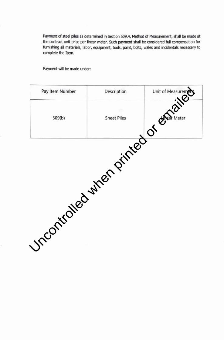
Payment of steel piles as determined in Section 509.4, Method of Measurement, shall be made at . the contract unit price per linear meter. Such payment shall be considered full compensation for furnishing all materials, labor, equipment, tools, paint, bolts, wales and incidentals necessary to complete the Item.
Payment will be made under:
Pay Item Number Description Unit of Measurement
509(b) Sheet Piles Linear Meter
Uncon
trolle
d whe
n prin
ted or
ed

PART H - MISCELLANEOUS
STRUCTURES
Uncon
trolle
d whe
n prin
ted or
ed
ITEM 600- CURB AND/OR GUTTER
600.1 DESCRIPTION
This item shall consist of the construction of curb and gutter either cast in place, made of concrete in accordance with this Specification at the location, and in conformity with the lines, grades, dimensions and design, shown on the Plans or as required by the Engineer.
600.2 MATERIALS REQUIREMENTS
600.2.1 Material for Bed Course
Bed course materials as shown on the Plans shall consist of cinders, sand, slag, gravel, crushed stone, or other approved porous material of such grading that all particles will pass through 12.5 mm (1/2'1 sieve.
600.2.2 Concrete
Concrete shall be of the class indicated on the Plans and shall conform to the requirements of Item 405, Structural Concrete.
600.2.3 Expansion Joint Filler
Expansion joint filler shall conform to the requirements of AASHTO M 153.
600.2.4 Cement Mortar
Cement mortar shall consist of one part of Portland cement and two parts of fine aggregates with water added as necessary to obtain the required consistency. Toe mortar shall be used within 30 minutes of preparation.
602.5 Bonding Compound
Where bonding compound is used, it shall conform to AASHTO M 200.
600.3 CONSTRUCTION REQURIEMENTS
Uncon
trolle
d whe
n prin
ted or
ed
600.3.1 Bedding
Excavation shall be made to the required depth and the base upon which the curb and/or gutter is
to be set shall be compacted to a firm and even surface. All soft and unsuitable material shall be
removed and replaced with suitable material.
Bed course material shall be placed and compacted to form a bed of the required thickness as
shown on the Plans.
600.3.2 Cast in Place Curb and Gutter
600.3.2.1 Placing
Forms shall conform to the requirements of Item 407, Concrete Structures. Metal forms shall be of
an approved section.
Forms to hold the concrete shall be built and set-in-place as described in Item 407, Concrete
Structures. Forms for at least 50 m of curb and gutter shall be in-placed and checked for alignment
and grade before concrete is placed. Curbs and gutter constructed on curves shall be accurately
shaped to the curvature shown on the Plans.
Mixing, placing, finishing and curing of concrete shall conform to the requirements of Item 405,
Structural Concrete, as modified by the requirements below.
The concrete shall be placed in the forms in layers of 100 or 125 mm each, and to the depth
required. It shall be tamped and spaded until mortar entirely covers the top and surfaces of the
forms. The top of the concrete shall be finished to a smooth and even surface and the edges
rounded to the radii shown on the Plans. Before the concrete is given the final finishing, the surface
of the gutter shall be tested with a 3-m straight-edge and any irregularities of more than 10 mm in
3 m shall be corrected.
The curb and gutter shall be constructed in uniform sections of not more than 50 min length except
where shorter sections are required to coincide with the location of weakened planes or construction
joints of the concrete pavement, or for closures, but no section shall be less than 2 m long. The
sections shall be separated by sheet templates set perpendicular to the face and top of the curb
and gutter. The templates shall be approximately 5 mm in thickness and of the same width as that
of the curb and/or gutter and not less than 50 mm deeper than the depth of the curb and/or gutter.
Templates shall be set carefully and held firmly during the placing of the concrete and shall remain
in place until the concrete has set sufficiently to holds its shape but shall be removed while the
forms are still in place. A preformed joint filler approved by the Engineer may be used in lieu of the
sheet template mentioned above. In this event the fiber board shall be pre-cut to the shape of the
curb so that its outer edge will be flushed with the abutting curb and/or gutter.
Uncon
trolle
d whe
n prin
ted or
ed

Expansion joints shall be forms at intervals shown on the Plans. Where a curb is placed next to a concrete pavement, expansion joints In the curb shall be located opposite expansion joints in the pavement.
Toe form shall be removed within 24 hours after the concrete has been placed. Minor defects shall be repaired with mortar containing one part of Portland Cement and two parts of fine aggregate. Plastering shall not be permitted and all rejected portions shall be removed and replaced at the Contractor's expense. Toe exposed surface shall be finished while the concrete is still fresh by rubbing the surfaces with a wetted soft brick or wood until they are smooth. Toe surfaces shall be wetted thoroughly, either by dipping the brick or wood in water, or by throwing water on the surfaces with a brush. After the concrete has been rubbed smooth using water, it shall then be rubbed with a thin grout containing one part of Portland Cement and one part of fine aggregates. Rubbing with grout shall continue until uniform color is produced. When completed, the concrete shall be covered with suitable material and kept moist for a period of 3 days, or a membrane forming material may be applied as provided in Item 405, Structural Concrete. Toe concrete shall be suitably protected from the weather until thoroughly hardened.
After the concrete has set sufficiently, the spaces on the back of the curb which were excavated for placing the curb shall be refilled to the required elevation with suitable material which shall be tamped in layers of not more than 150 mm until consolidated.
600.3.3 Precast Curb and Gutter
600.3.3.1 Placing
Toe precast concrete curb and gutter shall be set in 20 mm of cement mortar as specified in 600.2.4 to the line level and grade as shown on the approved Plans.
Toe precast curb shall not be more than 20 cm in width at the top portion and not be more than 25 cm at the base. The precast curb and gutter shall be 1.0 m in length and shall be put side by side consecutively with joint in between.
Joints between consecutive curb and gutter shall be filled with mortar to the full section of curb and gutter. Expansion joints shall be formed at intervals shown on the Plans. Where a curb and gutter is placed next to a concrete pavement, expansion joints in the curb and gutter shall be located opposite expansion joints in the pavement.
Minor defects shall be repaired with mortar containing one part of Portland Cement and two parts of fine aggregates. Plastering shall not be permitted and all rejected portions shall be removed and replaced at the Contractor's expense. Toe exposed surface shall be finished by rubbing the surfaces with a wetted soft brick or wood until they are smooth. Toe surfaces shall be wetted thoroughly, either by dipping the brick or wood In water, or by throwing water on the surfaces with a brush.
Uncon
trolle
d whe
n prin
ted or
ed
After the concrete has been rubbed smooth using water, it shall then be rubbed with a thin grout
containing one part of Portland Cement and one part of the aggregate. Rubbing with grout shall
continue until uniform color is produced.
600.3.3.2 Handling Precast Curb and Gutter
a. In preparation for the handling of precast curb and gutter, all fabricated curb and gutter of one
(1) meter in length shall be provided or inserted with 2-1"0 PVC pipes for fitting at their required locations. The PVC pipes shall be placed 25 mm from both edge during the fresh concrete is in
plastic state.
b. Precast curb and gutter shall be lifted on upright position and not at the points of support and
shall be the same during transporting and storage.
c. Extreme care shall be exercised in handling and moving precast curb and gutter to avoid
cracking.
d. No precast curb and gutter shall be used that does not reach its final position in the forms with
the required time stipulated prior to installation.
e. Precast curb and gutter shall be transferred to the construction site. Fresh curb and gutter shall
not be placed against in-situ concrete which has been in a position for more than 30 minutes.
f. Precast curb and gutter may only be transported to the delivery point in truck agitators or truck
mixer operating at the speed designated by the manufacturer of the equipment, provided that the consistency and workability of the mix concrete upon discharge at the delivery point is
suitable for adequate placement.
600.4 METHOD OF MEASUREMENT
The length of curb and gutter to be paid for shall be the number of linear meters of curb and gutter (cast in place) or the number of pieces of precast curb and gutter of the required dimensions shown
on the Plans measured along its front face in-place, completed and accepted. No deductions shall be made for flattening of curbs at entrances and no additional allowances shall be made for curbs
and gutters constructed on curves.
600.5 BASIS OF PAYMENT
The length of curb and gutter determined in part 4, Method of Measurement, shall be paid for at
the contract unit price per linear meter for Curb and Gutter which price and payment shall constitute full compensation for furnishing and placing all materials for concrete, reinforcing steel if required
on the Plans, expansion joint materials, forms for drainage openings, excavation for curb and
Uncon
trolle
d whe
n prin
ted or
ed

gutter, backfilling, dumping and disposal of surplus materials, and for all labor equipment, tools and incidentals necessary to complete the Item.
Payment will be made in accordance with the Bill of Quantities.
Uncon
trolle
d whe
n prin
ted or
ed

ITEM 602 - MONUMENTS, MARKERS AND GUIDE POSTS
602.1 DESCRIPTION
This Item shall consist of right-of-way monuments, maintenance marker posts, kilometer posts and/or guide posts, furnished and installed in accordance with this Specification at the locations, and in conformity with the sizes, dimensions and design, shown on the Plans, or as required by the Engineer.
602.2 MATERIAL REQUIREMENTS
Reinforcing steel shall conform to the requirements of Item 404, Reinforcing Steel.
Timber shall be of the species and grade shown on the Plans. Treated timber, if required, shall conform to the requirements of Item 410, Treated and Untreated Timber.
The metal material shall conform to the requirements shown on the Plans, or as stipulated in the Special Provisions.
Paints, if required, shall conform to the requirements shown on the Plans, or as stipulated in the Special Provisions.
Warning reflectors, if required, shall conform to the requirements shown on the Plans, or as stipulated in the Special Provisions.
602.3 CONSTRUCTION REQUIREMENTS
Construction or fabrication and installation of monuments and posts shall be as shown on the Plans or in the Special Provisions and shall include the attaching of warning reflectors and the painting of posts, if required. Each monument and post shall be set accurately at the required location and elevation and in such manner as to insure its being held firmly in place. In constructing precast monuments, the forms shall not be removed until after the concrete has hardened. Monuments that are warped shall be rejected. The exposed surface of the finished monuments shall be uniform, of even texture, and shall be free from holes, cracks and chipped edges. The precast monuments shall not be transported to the work until the concrete has been cured.
602.4 METHOD OF MEASUREMENT
The quantities to be paid for shall be the actual number of right-of-way monuments, maintenance marker posts, kilometer posts and/or guide posts furnished, placed and accepted.
Uncon
trolle
d whe
n prin
ted or
ed

602.S BASIS OF PAYMENT
The quantities determined as provided in Subsection 602.4, Method of Measurement, shall be paid
for at the contract price per unit of measurement respectively, for each of the particular Pay Item listed below and as shown in the Bid Schedule, which price and payment shall constitute full
compensation for furnishing and placing all materials, including all labor, equipment, tools and
incidentals necessary to complete the work prescribed in this Item.
Payment will be made in accordance with the Bill of Quantities.
Uncon
trolle
d whe
n prin
ted or
ed

ITEM 603 - GUARDRAIL
603.1 DESCRIPTION
This item shall consist of furnishing and constructing posts and guardrails of the types called for in the contract and in accordance with this Specification, at the locations, and in conformity with the lines and grades shown on the Plans, or as required by the Engineer.
603.2 MATERIAL REQUIREMENTS
Materials for the desired type of guardrail shall meet the requirements specified in the following specifications:
1. Wire rope or wire cable 2. Chain link fabric 3. Metal beam rail
AASHTO M 30 AASHTO M 181 AASHTO M 180
4. limber rail, unless otherwise indicated in the Plans or Special Provisions, any of the following first group Philippine limber shall be used: Ipil, Malave, lindalo or Yacal. Only one species of timber shall be used in the construction of any one continuous length of guardrail.
Guardrail Hardware. Offset brackets of the resilient and non-resilient types shall be of the type specified, or as shown on the Plans, and shall meet the strength requirements specified.
Splices and end connections shall be of the type and design specified or as shown on the Plans, and shall be of such strength as to develop the full design strength of the rail elements.
Unless otherwise specified, all fittings, bolts, washers and other accessories shall be galvanized in accordance with the requirements of AASHTO M 111 or ASTM A 153, whichever may apply. All galvanizing shall be done after fabrication.
Guardrail Post. Posts shall be of either wood, steel, or concrete, as may be specified. Only one kind of post shall be used for any one continuous guardrail.
Wood post shall be fabricated from an approved or specified timber specie and shall be of the quality, diameter or section and length as specified, or as shown on the Plans.
Steel post shall be of the section and length as specified, or as shown on the Plans. They shall be of a copper bearing steel when so specified. Steel shall conform to the requirements of AASHTO M 183 for the grade specified. The posts shall be galvanized or shop painted as may be specified.
Uncon
trolle
d whe
n prin
ted or
ed
Pre-cast reinforced concrete posts shall be of a section and length as specified or as shown on the Plans. Concrete shall conform with the requirements of Item 405, Structural Concrete, for class specified. Reinforcement shall conform with the requirements of AASHTO M 31 Grade 60. All bars shall be of the deformed type.
Concrete deadmen for end anchorages shall be as specified, or as shown on the Plans. Concrete and reinforcement shall conform to the requirements as stated above the precast reinforced concrete posts.
Paints for steel and wood shall be specified and conform to the requirements specified in Item 411, Paint.
603.3 CONSTRUCTION REQUIREMENTS
603.3.1 Posts
Posts shall be set vertically in the position shown on the Plans and, where embedded in a concrete foundation block, shall remain undisturbed for a minimum of 48 hours. The space around the post shall be backfilled to the ground line with approved material in layers not exceeding 100 mm and each layer shall be moistened and thoroughly compacted.
603.3.2 Rail Elements
Rail elements shall be erected in a manner resulting in a smooth continuous installation. All bolts, except adjustment bolts, shall be drawn tight. Bolts shall be of sufficient length to extend beyond the nuts at least 5 mm but not more than 10 mm.
Where painting of railing components is specified, any damage to the shop coat of paint shall be corrected by an application of an approved rust-inhibitive primer prior to further painting. Any surface inaccessible to painting after erection shall be given the specified number of coats of paint uniformly applied by thorough brushing using an approved pressure spray.
Galvanized surfaces which have been abraded so that the base material is exposed, threaded portions of all fittings and fasteners and cut ends of bolts shall be protected in a manner as may be specified or directed.
The surfaces and sawed edges of untreated or salt-treated guardrail shall be painted with three coats of white paint to within 200 mm of the ground line. The first 200 mm of posts above the ground shall be painted with two coats of black paint. Painting shall be done only when the timber is dry and clean. Each coat of paint shall be thoroughly dry before the next coat is applied. Paint shall be applied in heavy coats, completely covering every part of the surface and shall be worked
Uncon
trolle
d whe
n prin
ted or
ed

well into the joints and open spaces. It shall be thoroughly and evenly spread that no excess paint
collects at any point.
Guardrail and posts, after erection has been completed, shall be stained with two applications of
approved creosote stain, covering the rails and the exposed portions of the posts. The wood shall
be dry before being stained. The first coat shall be thoroughly dry before the second is applied.
Stain shall not be applied in damp weather.
For beam type guardrails, metal works not galvanized shall be given one shop coat of red lead, zinc
chromate paint or an approved fast-drying rust-inhibitive primer and two field coats of white or
aluminum paint. Untreated wood posts shall be given three coats of paints of the color indicated
on the Plans, or as specified. Painting shall conform to the requirements of Item 411, Paint.
603.4 METHOD OF MEASUREMENT
Guardrail shall be measured by linear meter from center to center of end posts, except where end
connections are made on masonry or steel structures, in which case measurement will be to the
face of such structures.
End anchorages and terminal sections will be measured as units of each kind shown in Bid Schedule.
If no pay item for anchorages or terminal sections appear in the Bid Schedule, measurement
therefore shall be included in the linear meter measurement for completed guardrail.
603.5 BASIS OF PAYMENT
The accepted quantities of guardrail, determined in Subsection 603.4, Method of Measurement,
shall be paid for at the contract unit price per linear meter for the type specified, complete in place,
which price and payment shall be full compensation for furnishing and placing all materials,
including all labor, equipment, tools and incidentals necessary to complete the Item. When so
specified, end anchorages and terminal sections will be paid for at the contract unit price for each
of the kind specified and completed in place.
Payment will be made in accordance with the Bill of Quantities. Uncon
trolle
d whe
n prin
ted or
ed
ITEM 605 - ROAD SIGN
605.1 DESCRIPTION
This item shall consist of furnishing and installing road signs in accordance with this Specification and to the details shown on the Plans, or as required by the Engineer.
The road signs shall comply in all respects with the "Philippine International Road Signs Manual" published by the Department of Public Works and Highways, Manila. The categories of road signs are designated in the Manual, namely, danger warning signs, regulatory signs and informative signs, or guide signs. These are referred to in the Contract as warning signs and informatory signs, respectively.
Road signs shall be dassified as standard or non-standard. Standard signs consist of all warning signs, regulatory signs and informatory signs with the exception of direction signs, place identification signs and the line. Non-standard signs consist of all informatory signs which are not classified as standard signs.
The size of warning and regulatory signs is the length of the side of triangular signs (measured from the points of intersection of the extension of the edges), the horizontal width of octagonal signs and the diameter of circular signs.
605.2 MATERIAL REQUIREMENTS
605.2.1 Sign Panels
Sign panels for warning, regulatory, and informatory signs shall be manufactured from aluminum sheeting at least 3 mm thick.
605.2.2 Reflective Sheeting
The reflective sheeting used on the road signs shall consist of spherical lens elements embedded within a transparent plastic having a smooth, flat surface with a protected pre-coat adhesive which shall be pressure sensitive for manual application, or tack free heat activated for mechanical vacuum-heat application. The minimum reflective brightness values of the reflective sheeting as compared to a magnesium oxide (MgO) shall be as given in Table 605.1. The brightness of the reflective sheeting totally wet by rain shall not be less than 90% of the given values.
Table 605.1 - Reflective Brightness of Traffic Signs Surfaces
Uncon
trolle
d whe
n prin
ted or
ed
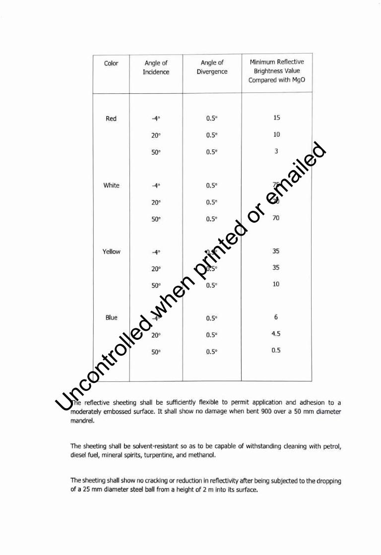
Color Angle of Angle of Minimum Reflective
Incidence Divergence Brightness Value Compared with MgO
Red -40 0.5° 15
20° 0.5° 10
50° 0.5° 3
White _40 0.5° 75
20° 0.5° 70
50° 0.5° 70
Yellow -40 0.5° 35
20° 0.5° 35
50° 0.5° 10
Blue _40 0.5° 6
20° 0.5° 4.5
50° 0.5° 0.5
The reflective sheeting shall be sufficiently flexible to permit application and adhesion to a moderately embossed surface. It shall show no damage when bent 900 over a 50 mm diameter mandrel.
The sheeting shall be solvent-resistant so as to be capable of withstanding cleaning with petrol, diesel fuel, mineral spirits, turpentine, and methanol.
The sheeting shall show no cracking or reduction in reflectivity after being subjected to the dropping of a 25 mm diameter steel ball from a height of 2 m into Its surface.
Uncon
trolle
d whe
n prin
ted or
ed

The adhesive shall permit the reflective sheeting to adhere accurately 48 hours after application of
temperatures of up 900.
The reflective material shall be weather-resistant and, following cleaning in accordance with
manufacturer's recommendations, shall show no discoloration, cracking, blistering, peeling or any
dimensional change. •
Samples of reflective sheeting shall be submitted to the Engineer for approval.
605.2.3 Post and Frames
Wide flange posts and frames shall be fabricated from structural steel conforming to ASTM A 283
Grade D. In lieu of wide flange steel posts, the Contractor may use tubular steel posts conforming
to ASTM A 501. All posts shall be thoroughly cleaned, free from grease, scale and rust and shall be
given one coat of rust-inhibiting priming paint and two coats of gray paint in accordance with Item
411, Paint.
605.2.4 Nuts and Bolts
Nuts, bolts, washers and other metal parts shall be hot-dip galvanized after fabrication in
accordance with the requirements of AASHTO M 111.
605.2.5 Concrete Foundation Blocks
The concrete for the foundation blocks shall be Class A in accordance with Item 405, Structural
Concrete and shall be on the size shown on the Plans.
605.3 CONSTRUCTION REQUIREMENTS
605.3.1 Excavation and Backfilling
Holes shall be excavated to the required depth to the bottom of the concrete foundation as shown
on the Plans.
Backfilling shall be carried out by using suitable material approved by the Engineer and shall be
compacted in layers not exceeding 150 mm in depth. Surplus excavated material shall be disposed
of by the Contractor as directed by the Engineer.
605.3.2 Erection Posts
Uncon
trolle
d whe
n prin
ted or
ed
The posts shall be erected vertically in position inside the formwork of the foundation block prior to the placing of the concrete and shall be adequately supported by bracing to prevent The posts shall be erected vertically in position inside the formwork of the foundation block prior to the placing of the concrete and shall be adequately supported by bracing to prevent.
605.3.3 Sign Panel Installation
Sign panels shall be installed in accordance with the details shown on the Plans. Any chipping or bending of the sign panels shall be considered as sufficient cause to require replacement of the panels at the Contractor's expense.
The exposed portion of the fastening hardware on the face of the signs shall be painted with enamels matching the background color.
All newly erected traffic road signs shall be covered until ordered removed by the Engineer.
605.4 METHOD OF MEASUREMENT
The quantities of standard reflective warning and regulatory road signs shall be the number of such signs of the size specified, including the necessary posts and supports erected and accepted.
The quantities for standard reflective informatory signs and non-standard reflective informatory signs shall be the number of such, including the necessary posts and supports, erected and accepted.
605.5 BASIS OF PAYMENT
The quantities measured as determined in Subsection 605.4, Method of Measurement, shall be paid for at the contract unit price for the Pay Items shown in the Bid Schedule which price and payment shall be full compensation for furnishing and installing road signs, for excavation, backfilling and construction of foundation blocks, and all labor, equipment, tools and incidentals necessary to complete the Item.
Payment will be made in accordance with the Bill of Quantities.
Uncon
trolle
d whe
n prin
ted or
ed
ITEM 606 - PAVEMENT MARKINGS
606.1 DESCRIPTION
This item shall consist of placing markings on the finished pavement. The work shall include the furnishing of premixed reflectorized traffic paint or reflectorized pavement marking paint conforming to the requirements of AASHTO M 248, whichever is called for in the Contract, sampling and packing, preparing the surface, and applying the paint to the pavement surface, all in accordance with this Specification.
The paint shall be applied to the size, shape and location of the markings shown on the Plans, or as required by the Engineer.
606.2 PREMIXED REFLECTORIZED TRAFFIC PAINTS
Premixed reflectorized traffic paint is a paint in which the glass beads are mixed in the paint during the process of manufacture, so that upon application and drying, the paint line is capable of retroreflection of the light beams.
Premixed reflectorized traffic paints which are available in both white and yellow are paints that provide reflective marking for concrete, bituminous, bricks or stone surface of highways, bridges, tunnels, streets, parking lots and airports.
606.2.1 Classification
Premixed reflectorized traffic paint shall be classified according to the following types based on the vehides used:
Type I - Alkyd
Type II - Chlorinated Rubber Alkyd
606.2.2 Material Requirements
The paint shall consist of pigments, vehicles and glass beads so combined as to produce a paint that will conform to the following requirements.
a. Condition in container - The packaged material shall be free from lumps and mixed readily to
a smooth homogenous state.
Uncon
trolle
d whe
n prin
ted or
ed
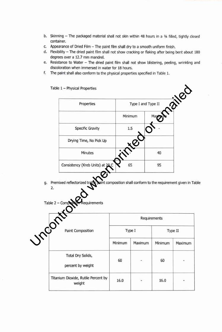
b. Skinning - The packaged material shall not skin within 48 hours in a ¾ filled, tightly closed container.
c. Appearance of Dried Film - The paint film shall dry to a smooth uniform finish. d. Flexibility - The dried paint film shall not show cracking or flaking after being bent about 180
degrees over a 12.7 mm mandrel. e. Resistance to Water - The dried paint film shall not show blistering, peeling, wrinkling and
discoloration when immersed in water for 18 hours. f. The paint shall also conform to the physical properties specified in Table 1.
Table 1 - Physical Properties
Properties Type I and Type II
Minimum Maximum
Specific Gravity 1.5 -
Drying Time, No Pick Up
Minutes - 40
Consistency (Kreb Units) at 20 C 65 95
g. Premixed reflectorized traffic paint composition shall conform to the requirement given in Table 2.
Table 2 - Composition Requirements
Requirements
Paint Composition Type I Type II
Minimum Maximum Minimum Maximum
Total Dry Solids, 60 - 60 -
percent by weight
Titanium Dioxide, Rutile Percent by 16.0 - 16.0 -
weight
Uncon
trolle
d whe
n prin
ted or
ed

Medium Chrome Yellow, 13.0 - 13.0 -
Percent by weight 17.0 - 17.0
Non-volatile Content
(based on the vehicle percent by 40 - 41 -
weight)
Glass Beads, 31.0 35.0 31.0 35.0
percent by weight
h. Glass Spheres or Beads Requirements:
Quantity: The amount of glass beads to be mixed with the paint shall be 500 grams per liter of paint.
Beads Diameter: The percentage of beads that will pass through the US Standard Sieves shall be as follows:
Sieve No. (um) Mass Percent Passing
70 (212 - um) - 0.850 100
80 (186 - um) - 0.600 85-100
140 (106 - um) - 0.300 15-55
230 (63 - um) - 0.150 0-10
Index of Refraction: The index of refraction of the beads shall be within the range of 1.50 to 1.60 when tested by the liquid immersion method at 29oC.
Appearance: The glass beads shall be transparent, colorless and the sum of particles that are fused, plane, angular and colored and contains bubble shall not exceed 20 percent.
606.2.3 Construction Requirements
Uncon
trolle
d whe
n prin
ted or
ed
The painting of lane markers and traffic strips shall include the cleaning of the pavement surfaces,
the application, protection and drying of the paint coatings, the protection of pedestrians, vehicular
or other traffic, the protection of all parts of the road structure and its appurtenances against
disfigurement by spatters, splashes or smirches of paints or of paint materials, and the supplying
of all tools, labor and traffic paint necessary for the entire work.
The paint shall not be applied during rain or wet weather or when the air is misty, or when in the
opinion of the Engineer, conditions are unfavorable for the work. Paint shall not be applied upon
damp pavement surfaces, or upon pavement which has absorbed heat sufficient to cause the paint
to blister and produce a porous film of paint.
The application of paint shall preferably be carried out by a machine specially made for this purpose
but where brushes are used, only round or oval brushes not exceeding 100 mm in width will be
permitted. The paint shall be so applied as to produce a uniform, even coating in close contact
with the surface being painted.
Traffic paint shall be applied to the pavement at the rate of 0.33 L /m2 and shall dry sufficiently to
be free from cracking in from 15 to 30 minutes.
All markings shall present a clean cut, uniform and workmanlike appearance. Markings that fail to
have a uniform, satisfactory appearance either by day or night, shall be corrected by the Contractor
in a manner acceptable to the Engineer and at no cost to the Government.
606.2.4 Sampling
The paint shall be sampled in accordance with PNS 484/ISO 1512 or other Philippine Standard
Method of Sampling Paints and Varnishes.
606.2.5 Test Methods
The paints shall be tested in accordance with the methods specified in PNS 461 or other Philippine
Standard Method of Tests for Paints and Varnishes.
606.2.6 Packing, Packaging and Marking
The paints shall be packed, packaged and marked in accordance with PNS 140.
606.3 METHOD OF MEASUREMENTS
Uncon
trolle
d whe
n prin
ted or
ed
The quantity of pavement markings to be paid for shall either be the length as shown on the Plans of painted traffic line of the stated width or the area as shown on the plans of symbols, lettering, hatchings, and the like, completed and accepted. Separate items shall be provided for premixed reflectorized traffic paint and reflectorized thermoplastic pavement markings.
606.4 BASIS OF PAYMENT
The quantities measured as determined in Section 606.4, Method of Measurement, shall be paid for at the appropriate contract unit price for the Pay Items shown in the Bid Schedule which price and payment shall constitute full compensation for furnishing and placing all materials, sampling and packing, for the preparation of the surface, and for all labor, equipment, tools and incidentals necessary to complete the Item.
Payment will be made in accordance with the Bill of Quantities.
Uncon
trolle
d whe
n prin
ted or
ed
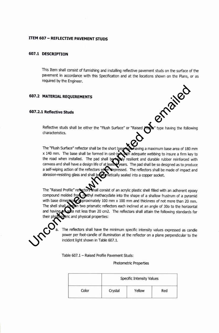
ITEM 607 - REFLECTIVE PAVEMENT STUDS
607 .1 DESCRIPTION
This Item shall consist of furnishing and installing reflective pavement studs on the surface of the pavement in accordance with this Specification and at the locations shown on the Plans, or as required by the Engineer.
607 .2 MATERIAL REQUIREMENTS
607 .2.1 Reflective Studs
Reflective studs shall be either the "Flush Surface" or "Raised Profile" type having the following characteristics.
The "Flush Surface" reflector shall be the short base type having a maximum base area of 180 mm x 140 mm. The base shall be formed in cast-iron with adequate webbing to insure a firm key to the road when installed. Toe pad shall be highly resilient and durable rubber reinforced with canvass and shall have a design life of at least 5 years. The pad shall be so designed as to produce a self-wiping action of the reflectors when depressed. The reflectors shall be made of impact and abrasion-resisting glass and shall be hermetically sealed into a copper socket.
The "Raised Profile" reflectors shall consist of an acrylic plastic shell filled with an adherent epoxy compound molded from methyl methacyclate into the shape of a shallow frustrum of a pyramid with base dimensions approximately 100 mm x 100 mm and thickness of not more than 20 mm. Toe shell shall contain two prismatic reflectors each inclined at an angle of 300 to the horizontal and having an area not less than 20 cm2. Toe reflectors shall attain the following standards for their photometric and physical properties:
a. The reflectors shall have the minimum specific intensity values expressed as candle power per foot-candle of illumination at the reflector on a plane perpendicular to the incident light shown in Table 607.1.
Table 607.1- Raised Profile Pavement Studs:
Photometric Properties
Specific Intensity Values
Color Crystal Yellow Red
Uncon
trolle
d whe
n prin
ted or
ed
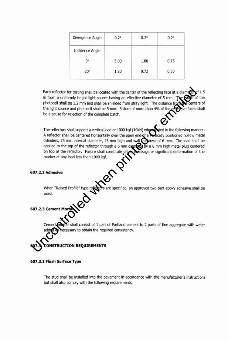
Divergence Angle 0.2° 0.2° 0.2°
Incidence Angle
oo 3.00 1.80 0.75
20° 1.20 0.72 0.30
Each reflector for testing shall be located with the center of the reflecting face at a diameter of 1.5 m from a uniformly bright light source having an effective diameter of 5 mm. The width of the photocell shall be 1.2 mm and shall be shielded from stray light. The distance from the centers of the light source and photocell shall be 5 mm. Failure of more than 4% of the reflective faces shall be a cause for rejection of the complete batch.
The reflectors shall support a vertical load or 1000 kgf (lOkN) when tested in the following manner. A reflector shall be centered horizontally over the open end of a vertically positioned hollow metal cylinders, 75 mm internal diameter, 25 mm high and wall thickness of 6 mm. The load shall be applied to the top of the reflector through a 6 mm diameter by a 6 mm high metal plug centered on top of the reflector. Failure shall constitute either breakage or significant deformation of the marker at any load less than 1000 kgf.
607 .2.2 Adhesive
When "Raised Profile" type reflectors are specified, an approved two-part epoxy adhesive shall be used.
607 .2.3 Cement Mortar
Cement mortar shall consist of 1 part of Portland cement to 2 parts of fine aggregate with water added as necessary to obtain the required consistency.
607 .3 CONSTRUCTION REQUIREMENTS
607 .3.1 Flush Surface Type
The stud shall be installed into the pavement in accordance with the manufacturer's instructions but shall also comply with the following requirements.
Uncon
trolle
d whe
n prin
ted or
ed
Cavities in the pavement shall be clearly cut to the dimensions of the pavement stud and shall allow a clearance of 10 mm around the stud base. The longitudinal centerline axis of the cavity shall be the same as that required for the pavement stud when laid to the correct line and direction.
The walls of the cavity shall be splayed back at the angle of approximately 300 to the vertical to facilitate a "dove-tail" joint after the mortar has set. The bottom of the cavity shall be levelled with asphalt concrete prior to placing the stud base which shall be pounded into position with a pounder foot attached to the pneumatic drill.
The depth of the activity shall be such that when the stud base and reflectors have been installed the elevation of the floor of the lens socket shall not be greater than 2.0 mm or less than 1.0 mm above the pavement surface.
When the studs are installed into a cement concrete pavement, the stud shall be grouted into position with asphalt concrete containing fine aggregate only or with a cement mortar as described in Subsection 607.2.3 above.
607.3.2 Raised Profile Type
The pavement studs shall be installed in accordance with the manufacturer's instructions.
607 .4 METHOD OF MEASUREMENT
The quantity of reflectorized pavement studs to be paid for shall be the number of reflectorized pavement studs of either the flush surface type or the raised profile type, whichever is called for in the Contract, installed complete and accepted.
607.5 BASIS OF PAYMENT
Toe quantities measured as described in Subsection 607.4, Method of Measurement, shall be paid for at the contract unit price of the Pay Items shown in the Bid Schedule, which payment shall constitute full compensation for furnishing and placing all materials, excavating cavities, preparation of surfaces, applying adhesive and mortar and for all labor, equipment, tools and incidentals necessary to complete the Item.
Payment will be made in accordance with the Bill of Quantities.
Uncon
trolle
d whe
n prin
ted or
ed

ITEM 610 - SODDING
610.1 DESCRIPTION
This Item shall consist of the furnishing and laying of live sod on the shoulders, slopes, ditches, or other locations as designated, construction of sod ditch checks or similar appurtenances, as shown on the Plans or as ordered and laid out in the field by the Engineer, all in accordance with this Specification.
610.2 MATERIAL REQUIREMENTS
Toe sod shall consist of healthy, dense, well-rooted growth of permanent and desirable grasses indigenous to the general locality where it is to be used and shall be free from weeds or undesirable grasses. At the time the sod is cut, the grasses on the sod shall have a length of approximately 50 mm (if longer, the grass shall be cut to approximately this length) and the sod shall have been raked free from debris.
Toe sod shall be cut into uniform squares approximately 300 mm x 300 mm, but not larger than is convenient for handling and transporting.
Toe thickness of the sod shall be uniform as possible approximately 40 mm or more depending on the nature of the sod, so that practically all of the dense root system of the grasses will be retained, but exposed, in the sod strip and that the sod can be handled without undue tearing or breaking.
In the event the sod to be cut is in a dry condition as to cause scrumbling or breaking during cutting operations, the Contractor, at his own expenses, shall apply water in sufficient quantities at least 12 hours before cutting to provide a well-moistened condition of the sod to the depth to which it is to be cut. Sods shall be subject to the approval of the Engineer.
610.3 CONSTRUCTION REQUIREMENTS
610.3.1 Preparation of the Earth Bed
The area to be sodded shall be constructed to the required cross-section and contour, and the tops and bottoms of the slopes shall be rounded as shown in the typical roadway sections.
Toe areas to be sodded shall be free from stones, roots or other undesirable foreign materials.
Toe soil on the area to be sodded shall be loosened and brought to a reasonably fine texture to a
Uncon
trolle
d whe
n prin
ted or
ed

depth of not less than 30 mm by means of equipment on hand methods adapted for the purpose.
610.3.2 Placing the Sod
The earth bed upon which the sod is to be placed shall be moistened to the loosened depth, if not naturally sufficiently moist, and the sod shall be placed thereon within 24 hours after the same has been cut.
Unless otherwise required, the sod on slopes shall be laid on horizontal strips beginning at the bottom of the slope and working upwards. When placing sod in ditches, or in the construction of sod ditch checks or similar appurtenances, the length of the strips shall be laid at right angles to the direction of the flow of the water.
Sod shall be laid so that the joints caused by abutting ends of sod strip are not continuous. Each sod strip shall be so laid as to abut snugly against the strip previously laid.
As the sod is being laid it shall be lightly tamped with suitable wooden or metal tampers sufficiently to set or press the sod into the underlying soil.
At points where it is anticipated that water may flow over a sodded area, the upper edges of the sod strips shall be turned into the soil to be below the adjacent area and a layer of earth place over this juncture and thoroughly compacted. At the limits of sodded areas, the end strips shall be turned in and treated similarly.
610.3.3 Staking the Sod
On all slopes steeper than one vertical to four horizontal, sod shall be pegged with stakes 200-300 mm in length, spaced as required by the nature of the soil and steepness of slope. Stakes shall be driven into the sod at right angles to the slope until flush with the bottom of the grass blades.
610.3.4 Top Dressing
After staking has been completed, the surface shall be cleared of loose sod, excess soil or other foreign material, whereupon a thin layer of topsoil shall be scattered over the sod as a top dressing and the areas shall then be thoroughly moistened by sprinkling with water.
Uncon
trolle
d whe
n prin
ted or
ed
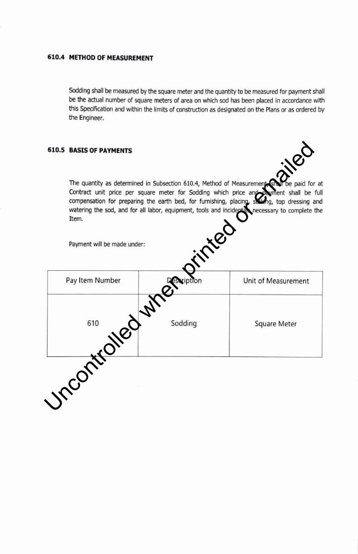
610.4 METHOD OF MEASUREMENT
Sodding shall be measured by the square meter and the quantity to be measured for payment shall be the actual number of square meters of area on which sod has been placed in accordance with this Specification and within the limits of construction as designated on the Plans or as ordered by the Engineer.
610.5 BASIS OF PAYMENTS
The quantity as determined in Subsection 610.4, Method of Measurement, shall be paid for at Contract unit price per square meter for Sodding which price and payment shall be full compensation for preparing the earth bed, for furnishing, placing, staking, top dressing and watering the sod, and for all labor, equipment, tools and incidentals necessary to complete the Item.
Payment will be made under:
Pay Item Number Description Unit of Measurement
610 Sodding Square Meter
Uncon
trolle
d whe
n prin
ted or
ed
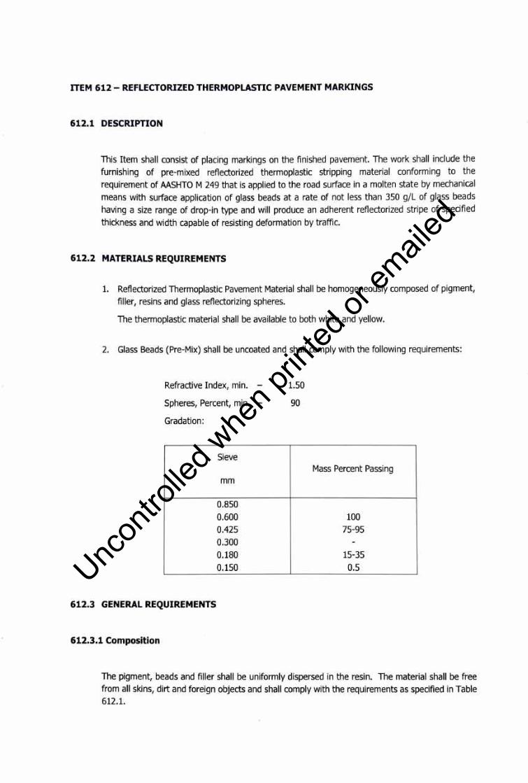
ITEM 612 - REFLECTORIZED THERMOPLASTIC PAVEMENT MARKINGS
612.1 DESCRIPTION
This Item shall consist of placing markings on the finished pavement. The work shall include the
furnishing of pre-mixed reflectorized thermoplastic stripping material conforming to the
requirement of AASHTO M 249 that is applied to the road surface in a molten state by mechanical
means with surface application of glass beads at a rate of not less than 350 g/L of glass beads
having a size range of drop-in type and will produce an adherent reflectorized stripe of specified
thickness and width capable of resisting deformation by traffic.
612.2 MATERIALS REQUIREMENTS
1. Reflectorized Thermoplastic Pavement Material shall be homogeneously composed of pigment,
filler, resins and glass reflectorizing spheres.
The thermoplastic material shall be available to both white and yellow.
2. Glass Beads (Pre-Mix) shall be uncoated and shall comply with the following requirements:
Refractive Index, min. - 1.50
Spheres, Percent, min. - 90
Gradation:
Sieve Mass Percent Passing
mm
0.850
0.600 100
0.425 75-95
0.300 -0.180 15-35
0.150 0.5
612.3 GENERAL REQUIREMENTS
612.3.1 Composition
The pigment, beads and filler shall be uniformly dispersed in the resin. The material shall be free
from all skins, dirt and foreign objects and shall comply with the requirements as specified in Table 612.1.
Uncon
trolle
d whe
n prin
ted or
ed
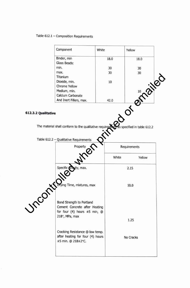
Table 612.1 - Composition Requirements
Component White Yellow
Binder, min 18.0 18.0 Glass Beads: min. 30 30 max. 30 30 Titanium Dioxide, min. 10 Chrome Yellow Medium, min. 10 Calcium Carbonate And Inert Fillers, max. 42.0 42.0
612.3.2 Qualitative
The material shall conform to the qualitative requirements as specified in table 612.2
Table 612.2 - Qualitative Requirements
Property Requirements
White Yellow
Specific Gravity, max. 2.15
Drying Time, mixtures, max 10.0
Bond Strength to Portland Cement Concrete after Heating for four ( 4) hours ±5 min, @
218°, MPa, max 1.25
Cracking Resistance @ low temp. after heating for four (4) hours No Cracks ±5 min. @ 218±2°C.
Uncon
trolle
d whe
n prin
ted or
ed
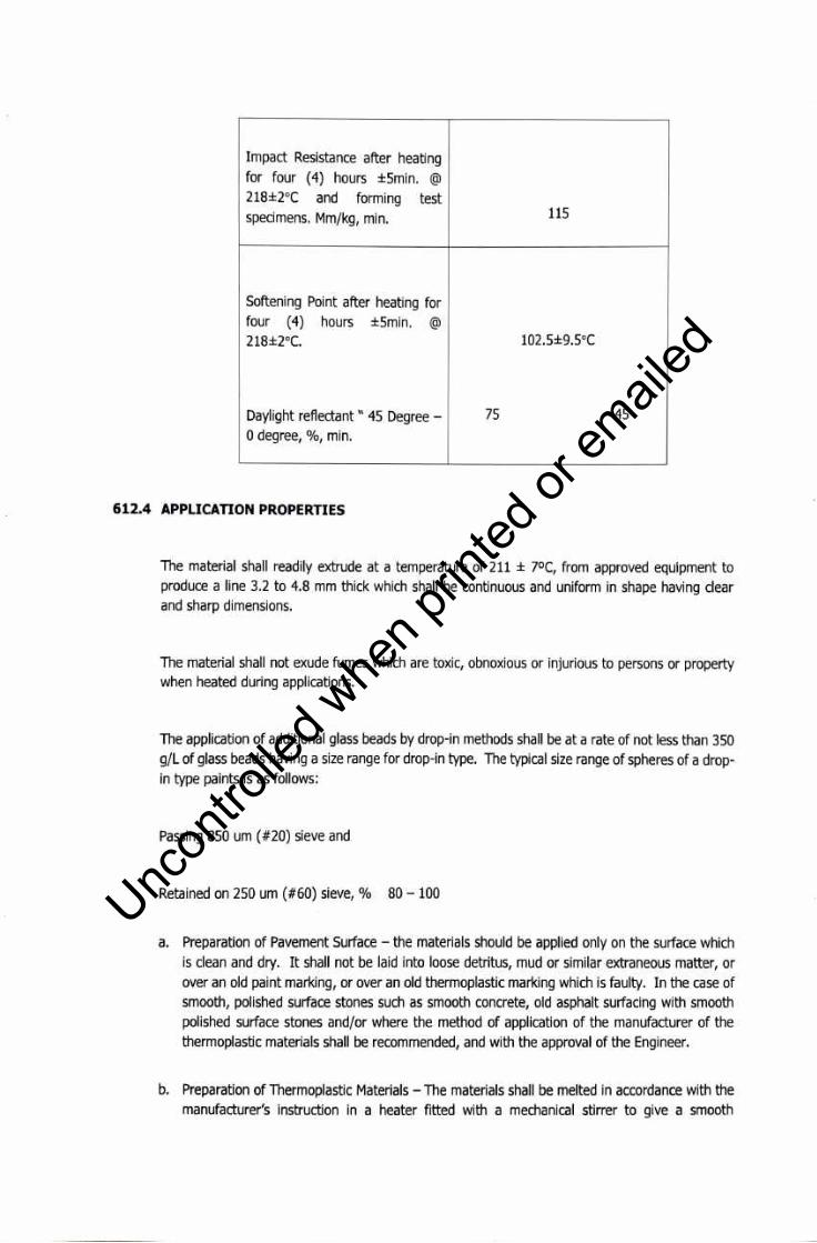
Impact Resistance after heating for four (4) hours ±5min. @
218±2°( and forming test specimens. Mm/kg, min. 115
Softening Point after heating for four (4) hours ±5min. @
218±2°C. 102.5±9.5°(
Daylight reflectant " 45 Degree - 75 45
0 degree, %, min.
612.4 APPLICATION PROPERTIES
The material shall readily extrude at a temperature of 211 ± 7°C, from approved equipment to produce a line 3.2 to 4.8 mm thick which shall be continuous and uniform in shape having clear and sharp dimensions.
The material shall not exude fumes which are toxic, obnoxious or injurious to persons or property when heated during applications.
The application of additional glass beads by drop-in methods shall be at a rate of not less than 350 g/L of glass beads having a size range for drop-in type. The typical size range of spheres of a dropin type paints is as follows:
Passing 850 um ( #20) sieve and
Retained on 250 um ( #60) sieve, % 80 - 100
a. Preparation of Pavement Surface - the materials should be applied only on the surface which is clean and dry. It shall not be laid into loose detritus, mud or similar extraneous matter, or over an old paint marking, or over an old thermoplastic marking which is faulty. In the case of smooth, polished surface stones such as smooth concrete, old asphalt surfacing with smooth polished surface stones and/or where the method of application of the manufacturer of the thermoplastic materials shall be recommended, and with the approval of the Engineer.
b. Preparation of Thermoplastic Materials - The materials shall be melted in accordance with the manufacturer's instruction in a heater fitted with a mechanical stirrer to give a smooth
Uncon
trolle
d whe
n prin
ted or
ed

consistency to the thermoplastic and such the local overheating shall be avoided. The temperature of the mass shall be within the range specified by the manufacturer and shall on no account be allowed to exceed the maximum temperature stated by the manufacturer. The molten material shall be used as expeditiously as possible and for thermoplastics which have natural resin binders or otherwise sensitive to prolong heating the materials shall not be maintained in a molden condition for more than 4 hours.
c. Laying - Center lines, lane lines and edges lines shall be applied by approved mechanical means and shall be laid in regular alignment. Other markings may be applied by hand - screed, hand propelled machine or by self-propelled machine approved or directed by the Engineer. After transfer to the laying apparatus the materials shall be maintained within the temperature range specified by the manufacturer and stirred to maintain the right consistency for laying.
In the case of screen application, the material shall be laid to a thickness of not less than 3 mm or more than 6 mm unless authorized by the Engineer when laid over an existing marking. In the case of sprayed application, the material shall be laid to thickness of not less than 1.5 mm unless authorized by the Engineer. In all cases the surface produced shall be uniform and appreciably free from bubbles and steaks. Where the Contractor Documents require or the Engineer direct that ballotini shall be applied to the surface of the markings, these shall be applied uniformly to the surface of hot thermoplastic immediately after laying such that the quality of ballotini firmly embedded and retained in the surface after completion complies with the requirements of Sub-section 606.2.2, Material Requirements.
Road markings of a repetitive nature, other center lines, lane lines, etc., shall unless otherwise directed by the Engineer be set out with stencils which comply with the size and spacing requirements shown on the Plans.
d. Re-use of Thermoplastic Materials - At the end of day's as much as possible the material remaining in the heater and/or laying apparatus shall be removed. This may be broken and used again provided that the maximum heating temperature has not been exceeded and that the total time during which it is a molden condition does not exceed the requirements of Subsection 606.2.3, Construction Requirements.
612.4.1 Defective Materials or Workmanship
Materials which are defective or have been applied in an unsatisfactory manner or to incorrect dimensions or in a wrong location shall be removed, the road pavement shall be made good and materials replaced, reconstructed and/or properly located, all at the Contractor's expenses and to the satisfaction of the Engineer.
612.4.2 Protection of the Traffic
Uncon
trolle
d whe
n prin
ted or
ed

Toe Contractor shall protect pedestrians, vehicles and other traffic adjacent to the working area against damage or disfigurement by construction equipment, tools and materials or by spatters, splashes and smirches or paint or other construction materials and during the course of the work, provide and maintain adequate signs and signals for the warning and guidance of traffic.
612.5 SAMPLING
A minimum weight of 10 kg. of Reflectorized Thermoplastic paint shall be taken for every 100 bags or fraction thereof.
612.6 TEmNG
Toe material shall be tested in accordance with AASHTO T 250 or with the appropriate method in ASTM designation.
612.7 PACKING AND MARKING
Toe material shall be packaged in a suitable container to which it will not adhere during shipment and storage. The blocks of cast thermoplastic material shall be approximately 300 x 915 by 51 mm and shall weigh approximately 23 kg. Each container label shall designate the color, manufacturer's name, batch number and date of manufacture. Each batch manufactured shall have its own separate number. Toe label shall warn the user that the material shall be heated to 211 ± 7°C
during application.
612.8 METHOD OF MEASUREMENT
Toe quantity of pavement markings to be paid for shall be the area as shown on the Plans of painted traffic line of the stated width and the area as shown on the plans of symbols, lettering,
hatching and the like, completed and accepted.
Toe quantity shown in the Bill of Quantities represents the approximate quantity in square meter of pavement markings, with width as shown applied at the centerline of the road pavements to which may be increased or decreased depending on the Engineer's decision whether to require additional markings or delete parts of it. Other markings representing symbols, lettering, hatching and others in locations where they maybe required by the Engineer shall, likewise, be implemented by the Contractor using reflectorized thermoplastic pavement markings as approved and directed.
612.9 BASIS OF PAYMENT
Uncon
trolle
d whe
n prin
ted or
ed

The quantities measured as determined in Section 612.8, Method of Measurement, shall be paid for at the appropriate contract unit price for the Pay Items shown in the Bid Schedule which price and payment shall constitute full compensation for furnishing and placing all materials, sampling and packing, for the preparation of the surface, and for all labor, equipment, tools and incidentals necessary to complete the Item.
Payment will be made in accordance with the Bill of Quantities.
Uncon
trolle
d whe
n prin
ted or
ed

PART K-STREETLIGHTS AND AREA LIGHTINGS
Uncon
trolle
d whe
n prin
ted or
ed

SECTION 16001 - ELECTRICAL SPECIAL CONDITIONS
I. GENERAL
A. Description
The General and Supplementary Conditions accompanying these Specifications are hereby made as part of the requirements for the work under this Division of the Specification.
The work to be done under this Division of the Specifications consists of the fabrication, furnishing, delivery and installation, complete in all details of the Electrical System, at the project premises and all work materials incidental to the proper completion of the installation, except those portions of the work which are expressly stated to be done by others. All works shall be in accordance with the governing Codes and Regulations and with the specifications, except those where same shall conflict with such Codes, etc., where the latter shall then govern. The requirements with regards to materials and workmanship, specify the required standards for the finishing of all labor, materials, and appliances necessary for complete installation of the work specified herein and indicated in the drawings. The Specifications are intended to provide a broad outline of the required equipment, and are not intended to include all details of design and construction.
B. Site of Work
Clark North Area, Pampanga
C. Work Included
1. Under this section of the specification, provide all labor, materials and equipment and perform all the work necessary for the complete execution of all the Electrical System as shown on Electrical Drawings.
2. Provide labor and materials required to install, testing and commissioning to complete the electrical system for operational as called for in the Contract Documents, and according to applicable codes and regulations.
3. Supply and install labor, materials, apparatus, equipment and appliances essential to the complete function of the systems described and/or indicated herein, or which may be reasonably implied as essential whether mentioned in the Contract Drawings and Specifications or not.
D. Submittals
Items requiring submittals shall be as specified and shop drawings shall be submitted and approved according compliance to the specifications prior to procurement, fabrication or delivery of such item to the job site. Partial submittal will not be acceptable; such submittals will be returned without review.
1. Manufacturer's Data
Uncon
trolle
d whe
n prin
ted or
ed
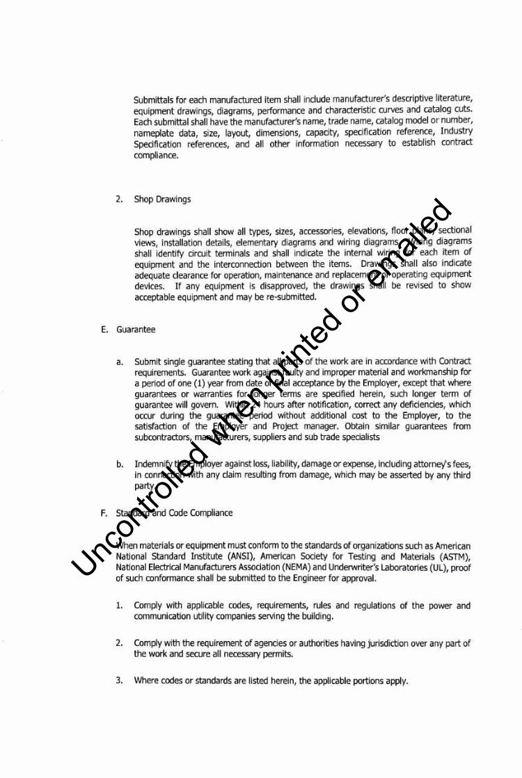
Submittals for each manufactured item shall include manufacturer's descriptive literature, equipment drawings, diagrams, performance and characteristic curves and catalog cuts. Each submittal shall have the manufacturer's name, trade name, catalog model or number, nameplate data, size, layout, dimensions, capacity, specification reference, Industry Specification references, and all other information necessary to establish contract compliance.
2. Shop Drawings
Shop drawings shall show all types, sizes, accessories, elevations, floor plans, sectional views, installation details, elementary diagrams and wiring diagrams. Wiring diagrams shall identify circuit terminals and shall indicate the internal wiring for each item of equipment and the interconnection between the items. Drawings shall also indicate adequate clearance for operation, maintenance and replacement of operating equipment devices. If any equipment is disapproved, the drawings shall be revised to show acceptable equipment and may be re-submitted.
E. Guarantee
a. Submit single guarantee stating that all parts of the work are in accordance with Contract requirements. Guarantee work against faulty and improper material and workmcmship for a period of one (1) year from date of final acceptance by the Employer, except that where guarantees or warranties for longer terms are specified herein, such longer term of guarantee will govern. Within 24 hours after notification, correct any deficiencies, which occur during the guarantee period without additional cost to the Employer, to the satisfaction of the Employer and Project manager. Obtain similar guarantees from subcontractors, manufacturers, suppliers and sub trade specialists
b. Indemnify the Employer against loss, liability, damage or expense, including attorney's fees, in connection with any claim resulting from damage, which may be asserted by any third party.
F. Standard and Code Compliance
When materials or equipment must conform to the standards of organizations such as American National Standard Institute (ANSI), American Society for Testing and Materials (ASTM), National Electrical Manufacturers Association (NEMA) and Underwriter's Laboratories (UL), proof of such conformance shall be submitted to the Engineer for approval.
1. Comply with applicable codes, requirements, rules and regulations of the power and communication utility companies serving the building.
2. Comply with the requirement of agencies or authorities having jurisdiction over any part of the work and secure all necessary permits.
3. Where codes or standards are listed herein, the applicable portions apply.
Uncon
trolle
d whe
n prin
ted or
ed

4.
5.
6.
7.
Plans specifications codes and standards are minimum requirements. Where requirements , , differ, apply the more stringent.
Execute all works in strict accordance with the best practices of the trades in a thorough, substantial workmanlike manner by competent workmen. Provide a competent, experienced full-time Professional Electrical Engineer who is authorized to make decisions.
All equipment shall meet or exceed minimum requirements the following:
NEC
PEC
ANSI
ASTM
EPA
m IEEE
IPCEA
NEMA
NFPA
OSHA
UL
Definitions
National Electric Code
Philippine Electrical Code
American National Standards Institute
American Society for Testing and Materials
Environmental Protection Agency
Electrical Testing Laboratories, Inc.
Institute of Electrical and Electronic Project manager
International Power Cable Project manager Association
National Electrical Manufacturers Association
National Fire Protection Association
Occupational Safety and Health Administration
Underwriters Laboratories
a. "PROVIDE" means to furnish and install. b. "FURNISH" means to purchase and supply all materials, labor, equipment, testing
apparatus, controls, tests, accessories and all other items customarily required for the proper and complete application for the particular work referred to.
c. "INSTALL" means to join, unite, fasten, link, attach, set up otherwise connect together before testing and turning over to Employer, complete and ready for regular operation, the particular work referred to.
d. "CONCEALED" means concealed or embedded in masonry or other installations -installed behind wall furring or within double partitions, or installed within hung ceiling or shafts.
e. "AS DIRECTED" means as directed by the Employer or by His representative. f. "SUBMIT" means submit to Employer or Project Manager for review.
JI. PRODUCTS
A. Equipment and Materials
1. Products and materials that are specified or indicated on the Drawings for a specific item or system, use the specified products or materials. If products or materials are not specified in either plans or specifications, use first class products or materials. Those products or materials are subject for approval of the Employer or Project manager.
2. Provide products or materials that are brand new, clean, free from defects, damage and
Uncon
trolle
d whe
n prin
ted or
ed

corrosion.
3. All products and materials shall not contain asbestos, PCBs, or any other hazardous material prohibited by the Environmental Protection Agency (EPA), Department of Environment and Natural Resources (DENR), or any other agency having jurisdiction.
4. Replace product and materials of less than specified quality.
5. Provide name/data plates on all components of equipment with manufacturer's name, model number, serial number, capacity data and electrical characteristics.
6. Installation of equipment, materials and devices shall be supervised by qualified engineer or specialty trade personnel.
7. Maintain single or uniformity of brand or manufacturer of product, materials and equipment used in similar applications and sizes.
8. Applicable equipment, materials and devices must be listed by Underwriter's Laboratories (UL) and manufactured in accordance with ANSI standards and as approved by local authorities having jurisdiction.
9. Fully lubricate equipment when installed.
10. Locate all floor-mounted equipment and panels at concrete pad. Concrete works to be provided by another trade. Concrete pads shall be 150mm high unless otherwise indicated, with steel reinforcing and necessary bolts, anchors, etc. Where concrete pad is set directly on concrete floor, provide dowels in floor to tie base to floor. Pads shall be extended at least 200mm beyond the equipment outline on all four sides. Coordinate size, locations, anchor bolts, etc to the Main Contractor.
11. Secure equipment with bolts, washers and locknuts of ample size to support equipment. Embedded anchor bolts to have bottom plate and pipe sleeves. Grout machinery set in concrete under the entire bearing surface. After grout has set, remove wedges, shims and jack bolts and fill space with grout.
12. Follow manufacturer's instructions for installing, connecting, and adjusting equipment and devices. Provide one copy of such instructions to the Project manager before installing any equipment. Provide a clear copy of such instructions and properly attached to the equipment during work on the equipment.
13. Where factory testing of equipment to ascertain performance and attendance by the Employer's representative and the Project manager is required to witness such tests, all associated travel and accommodation costs and subsistence shall be borne by the Contractor.
14. Equipment capacities, etc., are scheduled or specified for job site operating conditions. Equipment sensitive to altitude shall be derated with the method of derating identifies on shop drawings.
B. Shop Drawings, Product Data And Samples
Uncon
trolle
d whe
n prin
ted or
ed

1. Within one (1) month after notice to proceed by the Employer or Employer's Representative, or after execution of Employer/Contractor, Agreement, submit to the Employer or Employer's representative for review, a complete list of all electrical equipment manufacturers and material or devices suppliers as well as names of all subcontractors.
2. Materials and equipment requiring samples, catalogue, data, shop drawings and manufacturer's certification shall be as indicated in the specifications.
3. Within two (2) months after notice to proceed by the Employer or Employer's Representative, prepare an index of all submittals for the project. Include a submittal identification number, a cross-reference to the Specification sections or Drawing number, and an item description. Prefix the submittal identification number by the Specification sections to which they apply. Indicate on each submittal, the submittal identification number in addition to the other data specified. All subcontractors will utilize the assigned submittal identification number.
4. After the Contract is awarded, obtain complete shop drawings, product data and samples from the manufacturers, suppliers, vendors, and all subcontractors, for all materials and equipment specified in the various sections of the specification. Submit data and details of such materials and equipment for review by the Employer or Project manager, review and certify that these items are in compliance with the Contract Documents. Check all materials and equipment upon their arrival on the job site and verify their compliance with the Contract Documents. Modification of any work which proceeds prior to receiving accepted shop drawings as required to comply with the Contract Documents and the shop drawings, shall be at of contractor and without any claim of additional cost to the Employer.
5. Prior to fabrication or installation of any work, completely coordinate all works to all trades and prepare a complete set of Construction Composite Drawings.
C. Reviews
1. The Employer's or employer's representative review is for general compliance with the design concept and contract documents. Markings or comments or the lack thereof does not relieve the Contractor from compliance with the project plans and specifications. The Contractor remain solely responsible for details and accuracy, for confirming and correlating all quantities and dimensions, for selecting fabrication processes, for techniques of construction, for performing his work in a safe manner, and for coordinating his work with that of other trades.
2. A maximum period of seven (7) working days, exclusive of transmittal time, will be required in the Project manager's office each time a complete shop drawing, product data and/or samples are submitted for review. This time period must be considered by the Contractor when scheduling his work.
3. Quantity of submittals shall be three (3) sets of clear white print for shopdrawings, catalogue, manufacturers' certification, etc.
4. Submittals shall be reviewed and returned with stamped "A", "B", "C" or "D" action. The review action are as follows:
Uncon
trolle
d whe
n prin
ted or
ed

a. "A" - means approval subject to contract requirements. b. "B" - means approved subject to corrections noted and contract requirement. c. "C"- means returned with no action taken, resubmittal required. See notation hereon. d. "D" - means disapproved, resubmittal required. See notations hereon.
D. Alternative Materials And Equipment
1. Contract Documents are based on materials specified and on equipment manufacturers indicted on the Drawings or Specifications. Approval by the Employer or Employer's representative of equipment manufacturers other than specified does not relieve Contractor of any responsibility to provide equipment and materials which will meet the perfonnance as stated or implied by the Contract Documents.
2. Only those equipment manufacturers listed in individual sections are acceptable and subject to requirements of contract documents.
3. Submit proposals to supply alternative materials or equipment, in writing to the Employer or Project manager with sufficient lead time, for review by the Employer or Project manager, prior to the date equipment must be ordered to maintain project schedule. Contractor submitting alternative will reimburse Employer for all costs associated with the review of the proposed alternative whether alternative is accepted or rejected. Include the following information with the proposal.
a. A description of the difference between the contract requirements and that proposed alternative, the comparative features of each, and the effect of the change on the end result performance. Include the impact of all changes on other contractors and acknowledge the inclusion of implementation costs.
b. A list of the contract requirements that must be revised if the change is accepted, including any suggested specification revisions.
c. Include a description and estimate of costs the Employer may incur in implementing the change, such as test, evaluation, operating and support costs.
d. A projection of any effects the proposed change would have on collateral costs to the Employer.
e. A statement of the time by which a contract modification accepting the change must be issued, noting any effect on the contract completion time or the delivery schedule.
f. A statement indicating the effect to the contract price if the Employer accepts the change.
4. Include all revisions required to adapt alternatives such proposals, including revisions by other trades. No increase in the contract price will be considered to accommodate the use of alternative equipment.
5. Wherever operating results such as quantity delivered or pressure obtained are scheduled, or when the make and size of apparatus, for which such quantities are readily determinable,
Uncon
trolle
d whe
n prin
ted or
ed

is specified, the substitution being proposed must conform substantially to the quantities specified or implied. The substitution must fit into available space conditions and must function properly in coordination with the rest of the system.
Ill. EXECUTION
A. Fees
1. Pay all required fees, excluding cost of deposits for the local electric utility companies. 2. Pay royalties or fees required in connection with the use of patented devices and systems. 3. Provide controlled inspection where required by local authorities or by these specifications.
B. Drawings and Product Data
1. Submit materials and equipment by manufacturer, trade name and model number. Include copies of applicable brochure or catalog material. Maintenance and operating manuals are not suitable substitutes for shop drawings.
2. Identify each sheet of printed submittal pages (using arrows, underlining or circling, mark or highlighted) to show applicable sizes, types, model numbers, ratings, capabilities and options actually being proposed. Cross out or remove non-applicable information. Note special features that being offered.
3. Include dimensional data for roughing in and installation, technical data sufficient to verify that equipment meets requirements of drawings and specifications. Include wiring, conduiting and service connection data, motor sizes complete with voltage ratings and schedules.
4. Maintain a complete set of reviewed and stamped shop drawings and product data on site.
5. Prepare and submit detailed shop drawings for critical areas such as power center, electrical rooms, distribution services and areas with conflict with other trades in a scale not less than 1:S0mts.
6. For each room or area of the building containing transformer, generator sets, switchboards, panelboards, UPS, busducts, etc. The following are required to submit for review and approval.
a. Floor Plans:
Plan views (including sections and elevations when requested) of the equipment indicated in the exact location in which it is intended to be installed. These plans shall be of a scale not less than 1:lO0mts. They shall be prepared in the following manner:
1) Indicate the physical boundaries of the space including door swings and ceiling heights and ceiling types (as applicable).
2) Illustrate all electrical equipment proposed to be contained therein. Include top & bottom elevations of all electrical equipment. The drawings must be prepared utilizing the dimensions contained in the Individual equipment submittals.
Uncon
trolle
d whe
n prin
ted or
ed
3) Illustrate all other equipment therein such as panels, raceways, devices, luminaries, pull boxes, structural elements, etc.
4) Note the operating weight of each piece of equipment.
5) Note the heat release from each piece of electrical equipment. This information shall be provided and forwarded to mechanical for ventilation requirement. Indicated maximum normal allowable operating temperature for each piece of equipment
6) Illustrate all concrete pads, curbs, etc.
7) Note all code clearances and dimension from all equipment and walls.
b. Equipment Removal Routes:
1) Indicate on floor plans by means of arrows, the complete path for equipment removal.
2) Where equipment will be required to be hung temporarily from a slab or beam, note same on the submission including the weight of the equipment to be hung and the weight of the equipment to be hung and the weight of the hoisting equipment.
3) Note all heights of conduits, ductwork, link beams, doorways, piping, etc. in the proposed path assuring that adequate headroom is provided.
7. The Contractor is not relieved of the responsibility for dimensions or errors that may be contained on submissions reviewed by the Project manager, or for deviations from requirements in the Contract Documents. Understand clearly that the Project manager's noting some errors but overlooking others does not grant the Contractor permission to proceed in error. Regardless of any information contained in the shop drawings, product data and samples, the Contract Documents govern the work and are neither waived nor superseded in any way by the review of shop drawings, product data and samples.
8. Inadequate or incomplete shop drawings, product data and/or samples will not be reviewed by the Project manager and will be returned to the Contractor for re-submittal.
9. Indicate in the lower right hand corner of each shop drawing, and each product data brochure on the front cover, the following: a. The submittal identification number. b. Title of the sheet or brochure. c. Name and location of the Project. d. Project manager, e. Contractor, f. Subcontractor, g. Manufacturer, supplier, and vendor, h. Date of submittal; and the date of each correction and revision. i. Number all pages and drawings in product data brochures consecutively from
beginning to end. j. Unless the above information is included, the submittal will be returned for
resubmission. Include with resubmittals of product data or brochures a cover letter
Uncon
trolle
d whe
n prin
ted or
ed
summarizing the corrections made in response to the review comments and the submittal page numbers, which were revised.
C. Contractor's Coordination Drawings
1. Prepare a complete set of Construction Composite Drawings indicating the size of purchased equipment and the exact routing for all lines such as piping, bus way, conduit, ductwork, etc., including conduit embedded in concrete. Use the sheet metal shop drawings as the base drawings to which all other contractors will add their work. Complete each Composite Drawing and have signed-off by the other subcontractors and the General Contractor prior to the installation of the work in the area covered by the specific drawing.
2. Indicate structural loads and support points for all racked conduit and bus way, and submit to the Structural for review and approval. Indicate the elevation, location, support points, static, dynamic and expansion forces and loads imposed on the structure at support, anchor points, and size of all lines. Indicate all size of conduit that penetrate to beam and slab. Indicate all work routed underground or embedded in concrete by dimensions to column and building lines.
3. Work installed which may interferes with work of any other trade as a result non coordination shall be corrected at no cost to the Employer.
D. Coordination Of Work
1. Toe electrical drawing shows the general arrangement of equipment and appurtenances. Follow those drawings as closely as the actual construction and the work of other trades will permit. Provide offsets, fittings, and accessories which may be required but not shown on the drawings. Investigate the site, structural and finish ground conditions affecting the work, and arrange the work accordingly. Provide such work and accessories as may be required to meet such conditions at no additional cost to the Employer.
2. Toe locations of lighting fixtures outlets, panels and other requirement indicated on the drawings are approximately but they are for final verification with Architect or Interior Design.
3. Exercise particular caution with reference to the exact location of panels, outlets, switches, etc., and have precise and definite location approved by the Project manager before proceeding with the installation.
4. Toe drawings show only the general run of raceways and approximate location of outlets. Any significant changes in location of outlets, cabinets, etc., necessary in order to meet field conditions shall be brought to the immediate attention of the Project manager and receive his approval before such alterations are made. All such modifications shall be made without additional cost to the Employer.
s. Obtain from the Project manager in the field the location of such outlets or equipment not definitely located on the drawings.
6. Circuit "tags" in the form of numbers are used where shown to indicate the circuit designation numbers in electrical panels. Show the actual circuit numbers on the finished record tracing and on a typed panel directory card. Where circuiting is not indicated, electrical trade must provide required circuiting in accordance with the loading indicated
Uncon
trolle
d whe
n prin
ted or
ed
on the drawings and/or as directed.
7. Wherever work interconnects with work other trades, coordinate with other trades to insure that they have the information necessary so that they may properly install the necessary connections and equipment.
8. Identify items (remote ballast, pull boxes, etc.) and areas requiring access in order that the Ceiling Trade will know where to install access doors and panels.
9. Consult with other trades regarding equipment so that, wherever possible, controls and distribution equipment are of the same manufacture.
10. Furnish and set of block out or sleeves for busduct and conduits penetration through structural masonry and concrete walls and floors and elsewhere as will be required for the proper protection of each bus duct and conduit passing through building surfaces. Provide fire stooping or sealant to all penetrations.
11. Provide fire stopping or sealant around all pipes, conduits, ducts sleeves, etc., which pass through rated walls, partitions and floors.
12. Provide required supports and hangers for conduit and equipment, designed so as not to exceed allowable loadings of structures. Coordinate properly to Structural Engineer.
13. Examine and compare the contract drawings and specifications with the drawings and specifications of other trades, and report any discrepancies between to the Project manager and obtain from him written instructions for changes necessary in the work. Install and coordinate the work in cooperation with other related trades. Before installation, make proper provisions to avoid interferences.
14. Contractor shall furnish services of an qualified and experienced Professional Engineer, who shall be in constant charge of all work, and who shall coordinate his work with the work of other trades. No work shall be installed before coordinating with other trades.
15. Coordinate with Meralco as to their requirements for service connections and provide all necessary drawings, materials, equipment, and labor and testing.
16. Coordinate, with contractors for work under other Divisions of this specification, for all work necessary to accomplish this contractor's work.
E. Cutting and Patching
1. Lay out the work in advance, fully coordinated with other trades. Where cutting, channeling, chasing or drilling of floors, walls, partitions, ceiling or other surfaces is necessary for the proper installation, support or anchorage of conduits or other equipment, do the work carefully so as not to damage adjacent work. Repair any damage to the building, piping, equipment or defaced finish plaster, woodwork, metalwork, etc. using skilled mechanics of the trades involved at no additional cost to the Employer.
2. Do no cutting, channeling, chasing or drilling of unfinished masonry, tile, etc., unless permission from the Employer is first obtained. If permission is granted, perform this work
Uncon
trolle
d whe
n prin
ted or
ed

in a manner approved by the Employer.
3. Provide slots, chases, openings and recesses through floors, walls, ceilings, and roofs as required to properly install work. Be responsible to properly locate such openings and provide for any cutting and patching caused by the neglect to do so.
F. Painting
1. All manufactured electrical equipment such as equipment, switchgear, lighting fixtures, etc., shall have factory-applied finished.
2. All other uncoated steel items such as boxes, support, hangers, rods, etc., shall be galvanized or have a shop coat of paint applied. Normally, shop coats shall be an approved primer containing at least 50 percent rust inhibitive pigment, applied before assembling the different parts.
3. Where conduits or equipment are mounted on a painted finished surface or a surface to be painted, the equipment or conduits must be painted to match the finish surface.
4. Include painting and retouching of:
a. Prefinished enclosures of switchgear, unit substations, panelboards, transformers, switches, wire ways, bus ducts, etc., where the paint finish has been slightly damaged during transit or installation.
b. Fixture hangers, except those received from manufacturers that are pre-finished. c. Miscellaneous steel hangers, brackets and supports.
G. Equipment Pad And Anchor Bolts
1. Furnish and install galvanized anchor bolts for all equipment places on concrete equipment pads, inertia blocks, or on concrete slabs. Provide bolts of the size and number recommended by the manufacturer of the equipment and locate by means of suitable templates. When equipment is placed on vibration isolators, secure the equipment to the isolator and to the floor, pad or support as recommended by the vibration isolation manufacturer.
2. Where control panels, controllers, etc., are mounted on gypsum board partitions, the mounting screws will pass through the gypsum board and be securely attached to the partitions studs. At the Contractor's option, the mounting screws may pass through the gypsum boards and be securely attached to 150mm square, 18 gauge galvanized metal back plates which are attached to the gypsum board with an approved non-flammable adhesive. Toggle bolts installed in gypsum board partitions will not acceptable.
H. Delivery, Drayage and Hauling
Uncon
trolle
d whe
n prin
ted or
ed
1. Include all drayage, hauling, hoisting. Shoring and placement in the building of equipment specified herein. Be responsible for the timely delivery and introduction of equipment to the project as required by the construction schedule for this project. If any item equipment is received prior to the time it is required, it is the responsibility of the contractor for its proper storage and protection until such time as it may be required. Pay for all costs of demurrage or storage.
2. Equipment and material shall be properly stored and adequately protected and carefully handled to prevent damage before and during installation. Equipment and materials shall be handled, stored and protected in accordance with the manufacturer's recommendations and as approved by the Employer or Project Manager. Cables shall be sealed, stored and handled carefully to avoid damage to the outer covering or insulation and damage from moisture and weather. Damaged or defective items shall be replaced with new items at no cost to the Employer.
3. If any item or equipment is not delivered or timely as required by the project construction schedule, be solely responsible for disassembly, re-assembly, manufacturer's supervision, shoring, general construction modification, delays, overtime costs, etc. No additional cost or delays to be incurred by the Employer.
I. Mounting Heights
1. Unless otherwise noted or required because of special conditions, locate outlets as follows:
a. Mounting heights shall conform to Architect and Interior Designer requirements.
b. Heights listed are from finished floor to center of device unless otherwise indicated. Verify exact locations with the Project manager before installation.
1) Convenience: 300 millimeters unless otherwise noted. 2) Lighting Switches: 1370 millimeters (maximum 1520mm). 3) Disconnect Switches and panelboard: 1820 millimeters from the top. 4) Exit Lights: 50 millimeters above top of door to bottom.
J. Equipment and Material Protection
1. Protect all works, equipment and materials from damage and rectify damages without any additional cost to the Employer.
2. Be responsible for all works, materials and equipment until finally inspected, tested and accepted by the Employer; protect work against theft, injury or damage. Close open ends of work with temporary covers or plugs during construction to prevent entry of obstructing material. Cover and protect in an acceptable manner to the Employer, all equipment and materials from damage due to water, spray-on fireproofing, construction debris, etc.
3. Provide adequate means for fully protecting finished parts of the materials and equipment against damage from whatever cause during the progress of the work until final acceptance. Protect materials and equipment in storage and during construction in such a manner that no finished surfaces will be damaged or marred, and moving parts kept clean and dry. If items are damaged, do not install, but take immediate steps to obtain replacement or repair without any additional cost to the Employer.
K. Electrical Equipment and Electrical Room Precautions
Uncon
trolle
d whe
n prin
ted or
ed
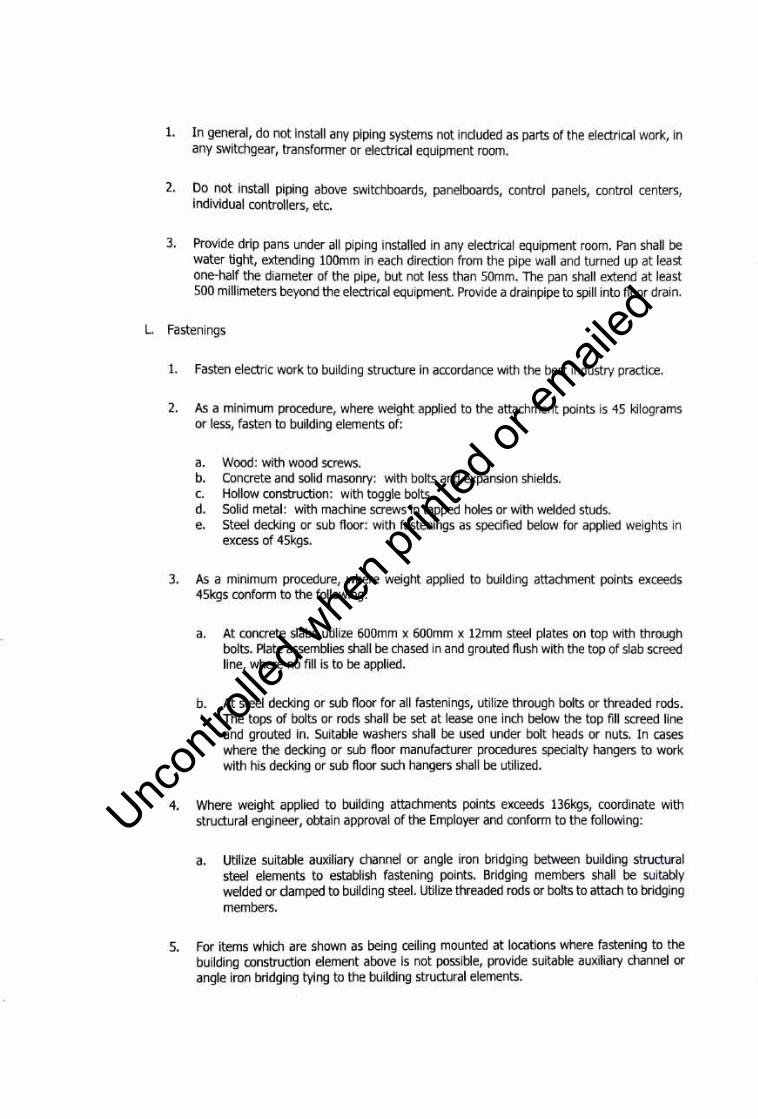
1. In general, do not install any piping systems not included as parts of the electrical work, in any switchgear, transformer or electrical equipment room.
2. Do not install piping above switchboards, panelboards, control panels, control centers, individual controllers, etc.
3. Provide drip pans under all piping installed in any electrical equipment room. Pan shall be water tight, extending 100mm in each direction from the pipe wall and turned up at least one-half the diameter of the pipe, but not less than 50mm. The pan shall extend at least 500 millimeters beyond the electrical equipment. Provide a drainpipe to spill into floor drain.
L. Fastenings
1. Fasten electric work to building structure in accordance with the best industry practice.
2. As a minimum procedure, where weight applied to the attachment points is 45 kilograms or less, fasten to building elements of:
a. Wood: with wood screws. b. Concrete and solid masonry: with bolts and expansion shields. c. Hollow construction: with toggle bolts. d. Solid metal: with machine screws in tapped holes or with welded studs. e. Steel decking or sub floor: with fastenings as specified below for applied weights in
excess of 45kgs.
3. As a minimum procedure, where weight applied to building attachment points exceeds 45kgs conform to the following :
a. At concrete slabs utilize 600mm x 600mm x 12mm steel plates on top with through bolts. Plate assemblies shall be chased in and grouted flush with the top of slab screed line, where no fill is to be applied.
b. At steel decking or sub floor for all fastenings, utilize through bolts or threaded rods. The tops of bolts or rods shall be set at lease one inch below the top fill screed line and grouted in. Suitable washers shall be used under bolt heads or nuts. In cases where the decking or sub floor manufacturer procedures specialty hangers to work with his decking or sub floor such hangers shall be utilized.
4. Where weight applied to building attachments points exceeds 136kgs, coordinate with structural engineer, obtain approval of the Employer and conform to the following:
a. Utilize suitable auxiliary channel or angle iron bridging between building structural steel elements to establish fastening points. Bridging members shall be suitably welded or damped to building steel. Utilize threaded rods or bolts to attach to bridging members.
5. For items which are shown as being ceiling mounted at locations where fastening to the building construction element above is not possible, provide suitable auxiliary channel or angle iron bridging tying to the building structural elements.
Uncon
trolle
d whe
n prin
ted or
ed
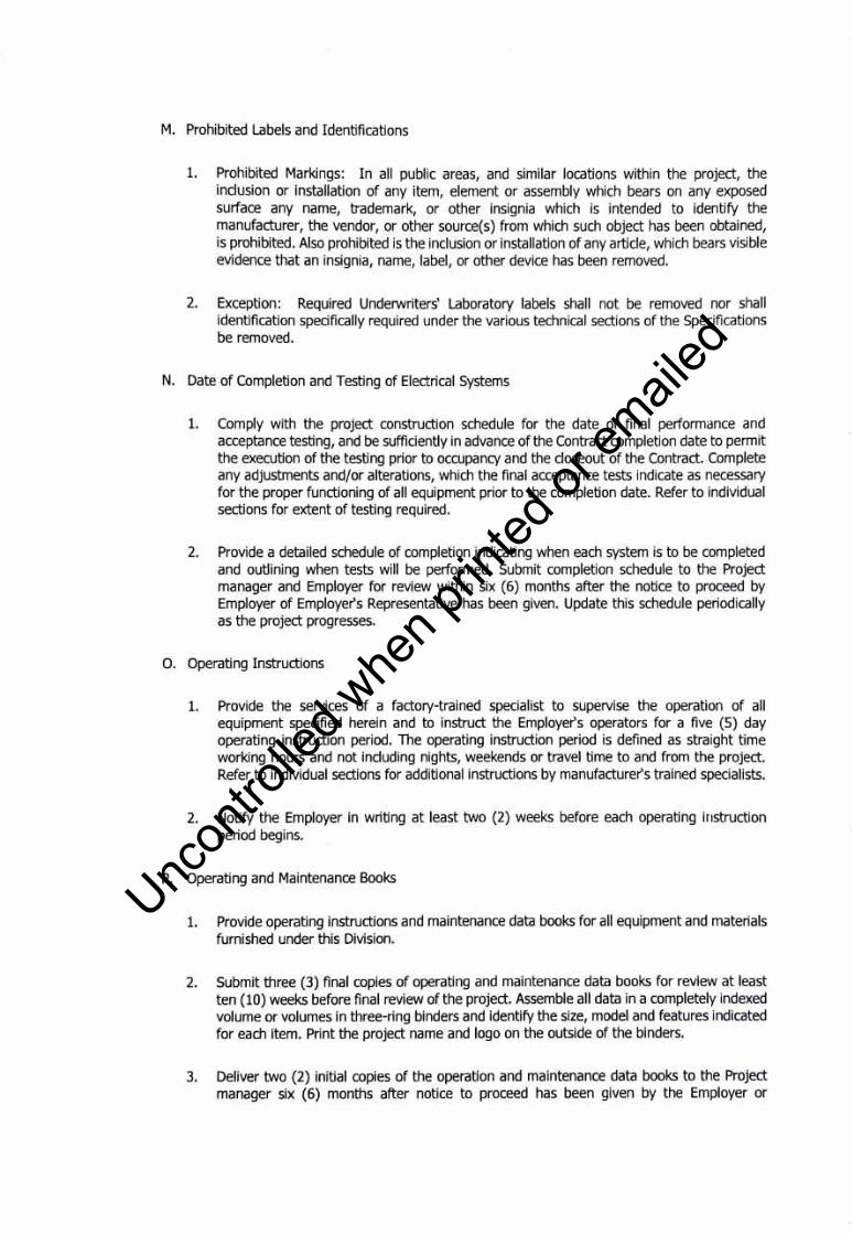
M. Prohibited Labels and Identifications
1. Prohibited Markings: In all public areas, and similar locations within the project, the inclusion or installation of any item, element or assembly which bears on any exposed surface any name, trademark, or other insignia which is intended to identify the manufacturer, the vendor, or other source(s) from which such object has been obtained, is prohibited. Also prohibited is the inclusion or installation of any article, which bears visible evidence that an insignia, name, label, or other device has been removed.
2. Exception: Required Underwriters' Laboratory labels shall not be removed nor shall identification specifically required under the various technical sections of the Specifications be removed.
N. Date of Completion and Testing of Electrical Systems
1. Comply with the project construction schedule for the date of final performance and acceptance testing, and be sufficiently in advance of the Contract completion date to permit the execution of the testing prior to occupancy and the closeout of the Contract. Complete any adjustments and/or alterations, which the final acceptance tests indicate as necessary for the proper functioning of all equipment prior to the completion date. Refer to individual sections for extent of testing required.
2. Provide a detailed schedule of completion indicating when each system is to be completed and outlining when tests will be performed. Submit completion schedule to the Project manager and Employer for review within six (6) months after the notice to proceed by Employer of Employer's Representative has been given. Update this schedule periodically as the project progresses.
0. Operating Instructions
1. Provide the services of a factory-trained specialist to supervise the operation of all equipment specified herein and to instruct the Employer's operators for a five (5) day operating instruction period. The operating instruction period is defined as straight t ime working hours and not including nights, weekends or travel time to and from the project. Refer to individual sections for additional instructions by manufacturer's trained specialists.
2. Notify the Employer in writing at least two (2) weeks before each operating instruction period begins.
P. Operating and Maintenance Books
1. Provide operating instructions and maintenance data books for all equipment and materials furnished under this Division.
2. Submit three (3) final copies of operating and maintenance data books for review at least ten (10) weeks before final review of the project. Assemble all data in a completely indexed volume or volumes in three-ring binders and identify the size, model and features indicated for each Item. Print the project name and logo on the outside of the binders.
3. Deliver two (2) initial copies of the operation and maintenance data books to the Project manager six (6) months after notice to proceed has been given by the Employer or
Uncon
trolle
d whe
n prin
ted or
ed

Employer's Representative.
4. Maintenance instruction manuals to include complete oiling, cleaning, and servicing data compiled in clearly and easily understandable form. Show all model numbers of each piece of equipment, complete lists of replacement parts, motor ratings, and actual loads.
5. Include the following information where applicable:
a. Identifying name and mark number. b. Locations (where several similar items are used, provide a list). c. Complete nameplate data. d. Certified Record Drawings and Final Reviewed Shop Drawings. e. Parts list. f . Performance curves and data. g. Wiring diagrams. h. Manufacturer's recommended operating and maintenance. i. List of spare parts recommended for normal service requirements. j. Assembly and disassembly instructions with exploded view drawings where
available. k. Trouble shooting diagnostic instructions where applicable.
Q. Record Drawings
1. Maintain on a daily basis at the project site a complete set of As-Built Drawings, reflecting an accurate dimensional record of all deviations between construction drawings and that of actually installed.
2. Record dimensions dearly and accurately to delineate the work as installed; suitably identify locations of all equipment by at least two dimensions to permanent structures. In addition, mark the Record Drawings to show the precise location of concealed work and equipment, including concealed or embedded piping and all changes or deviations in the electrical works from that shown on the Contract Documents. This requirement is not construed as authorization for the Contractor to make changes in the layout or work without written instructions from the Project Manager.
3. Upon completion of the installation, obtain from the Project manager, a complete set of Mylar transparencies on heavy gauge film with Project manager's seal and firm name removed. Enter thereon, in a neat and accurate manner, a complete record of all revisions of the original drawings, as actually installed. Bear the cost for transparencies and for making required changes. Submit one (1) set of black and white prints of these revised transparencies to the Project manager for review of completeness. After review by the Project manager, make necessary changes to transparencies and then deliver them to the Project manager for transmittal to the Employer. Project manager will not review these drawings for accuracy nor will the Project manager bear any responsibility for accuracy or completeness.
4. Mark all As-Built Drawings on the front lower right hand corner with a rubber stamp impression that states the following:
"AS-BUILT DRAWINGS"
"To be used for recording Field Deviations and Dimensional Data Only"
5. The Record Drawings will also consist of a set of prints of the final Signed Off Contractor's
Uncon
trolle
d whe
n prin
ted or
ed

Composite Drawings prepared by the Subcontractors.
R. Certification
1. Any certifications required by the Specifications, in addition to those required for shop drawings, product data, equipment and other items, are to be so certified by the Employer, a Partner, or a Corporate Officer of the firm required to provide the Certification, or by another person duly authorized to sign binding agreements for and in behalf of the Employer, Partner or Corporation.
S. Final Review
1. At a time designated by the Employer, the entire system will be reviewed for compliance with the Contract Drawings and Specifications.
2. Demonstrate to the Employer and to the Project manager's personnel prior to the Final Review that all systems and all equipment have been properly tested and commissioned and are in compliance with the requirements of the Contract Documents. After these demonstration tests are satisfactorily completed, but prior to the Final review field visit, the Contractor will submit to the Project manager a written certification that:
a. Attests to the Contract Document compliance for this Project prior to the Project manager's Final Review field visit.
b. Certifies that the equipment and materials installed in this project under this Division contain no asbestos or PCBs.
3. Certificates and Documents required herein to be in order and presented to the Employer at least two (2) weeks prior to the Final Review.
4. After the review, any changes or corrections noted as necessary for the work to comply with these specifications and the Drawings to be accomplished without delay in order to secure final acceptance of the work.
T. Early Occupancy
1. Be responsible for completing those systems, which are necessary to allow partial occupancy of the buildings even if systems in the unoccupied areas are incomplete.
2. Verify with the . local Building Department or authority having jurisdiction for any requirements for the temporary occupancy.
Uncon
trolle
d whe
n prin
ted or
ed

SECTION 16002 - SCOPE OF WORKS
IV. GENERAL
A. Description
3. Provide the work included in accordance with the Contract Documents.
B. Works Included
1. Provide all labor, materials, equipment, tools, appliances, auxiliaries, services, hoisting, scaffolding, support, supervision, and Project Record Drawings, and perform all operations for the furnishing and installing of the complete electrical system, including but not limited to the work described hereinafter.
2. The electrical work is shown schematically on the Drawings to indicate the general system arrangement and configuration. The work of this Division shall include coordination with the work of other Divisions of the Specifications and the Contract Documents so as to provide a complete and operations system capable of being readily operated and maintained, including approved rearrangement of the systems and equipment and rerouting of distribution services to enable the complete system to fit within the confines of the allotted electrical spaces, all to the satisfaction of the Employer or as directed by the Employer.
3. Under this section of the specification, provide all labor, materials and equipment and perform all the work necessary for the complete execution of all the Electrical System as shown on Electrical Drawings. Scope of Work shall include but not be limited to the following principal items of work:
a. Furnish and install all conduits in concrete encasement and manholes for power service entrance and distribution feeders.
b. Furnish and install complete distribution for lighting and power system to include conduits, wiring and wiring devices as required on the plans.
c. Furnish and install all feeder wires and conduit complete with support and other related accessories as indicated in the plan.
d. Furnish and install complete grounding and lightning protection systems.
e. Application of electric power connection including preparation of all necessary plans, forms and related documents, payment of all required fees and charges and coordination with other authorities or person involved in the procedure.
f. Equipment and miscellaneous steel supports for electrical equipment to include field painting. Sealing of sleeves and other electrical openings
Uncon
trolle
d whe
n prin
ted or
ed

K.
g.
h.
i.
j.
Perform all terminations to include testing, load balancing and commissioning.
Preparation of as-built plans and drawings in reproducible tracing and electronic files in Auto CADD.
All work materials, equipment, fittings, support, etc. which are necessary for the completion of the works must be included in this division of work.
All other items or works specified in other section of this specifications
STREET LIGHTS AND AREA LIGHTINGS
ITEM 103(3) STRUCTURE EXCAVATION (STREETLIGHT CONCRETE PEDESTAL AND TRENCH)
This item shall consist of the necessary excavation for foundation of footing pedestals for new posts, and other structures not otherwise provided for in the Specifications. Except as otherwise provided for pipe culverts, the backfilling of completed structures and the disposal of all excavated surplus materials, shall be in accordance with these Specifications and in reasonably close conformity with the Plans or as established by the Engineer.
This item shall also include necessary diverting of live streams, bailing, pumping, draining, sheeting, bracing, and the placing of all necessary backfill.
Prior to starting excavation operations in any area, all necessary clearing and grubbing in that area shall have been performed in accordance with item 100, Clearing and Grubbing.
Trenches or foundation pits for structures or structure footings shall be excavated to the lines and grades or elevations shown on the approved plan or as staked by the Engineer. They shall be of sufficient size to permit the placing of structures or structure footings of the full width and length shown. Any excavation carried beyond the limits shown or described on the drawings or specifications or beyond the dimension resulting from adjustments made by the Engineer shall be backfilled with materials acceptable and as directed by the Engineer.
The volume of excavation to be paid for will be the number of cubic meters measured in original position of material acceptably excavated in conformity with the plans or as directed by the Engineer.
ITEM SPL- 1000-1 CONSTRUCTION OF STEEL POLE CONCRETE PEDESTAL INCLUDING REBAR, FURNISHING AND INSTALLATION OF ANCHOR BOLT, ITEM SPL- 1000-1 (2)
Uncon
trolle
d whe
n prin
ted or
ed
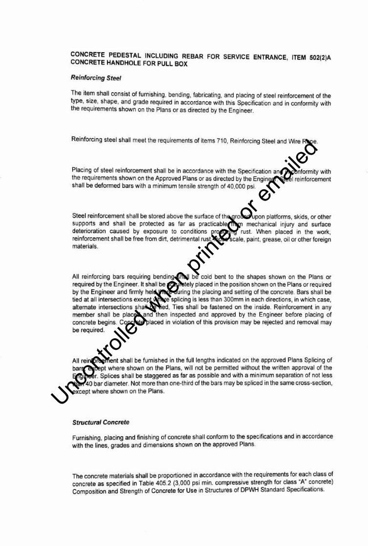
CONCRETE PEDESTAL INCLUDING REBAR FOR SERVICE ENTRANCE, ITEM 502(2)A CONCRETEHANDHOLEFORPULLBOX
Reinforcing Steel
The ite_m shall consist of furnishing, bending, fabricating, and placing of steel reinforcement of the type, s1z~, shape, and grade required in accordance with this Specification and in conformity with the requirements shown on the Plans or as directed by the Engineer.
Reinforcing steel shall meet the requirements of items 710, Reinforcing Steel and Wire Rope.
Placing of steel reinforcement shall be in accordance with the Specification and in conformity with the requirements shown on the Approved Plans or as directed by the Engineer. Steel reinforcement shall be deformed bars with a minimum tensile strength of 40,000 psi.
Steel reinforcement shall be stored above the surface of the ground upon platforms, skids, or other supports and shall be protected as far as practicable from mechanical injury and surface deterioration caused by exposure to conditions producing rust. When placed in the work, reinforcement shall be free from dirt, detrimental rust, loose scale, paint, grease, oil or other foreign materials.
All reinforcing bars requiring bending shall be cold bent to the shapes shown on the Plans or required by the Engineer. It shall be accurately placed in the position shown on the Plans or required by the Engineer and firmly held there during the placing and setting of the concrete. Bars shall be tied at all intersections except where splicing is less than 300mm in each directions, in which case, alternate intersections shall be tied, Ties shall be fastened on the inside. Reinforcement in any member shall be placed and then inspected and approved by the Engineer before placing of concrete begins. Concrete placed in violation of this provision may be rejected and removal may be required.
All reinforcement shall be furnished in the full lengths indicated on the approved Plans Splicing of bars, except where shown on the Plans, will not be permitted without the written approval of the Engineer. Splices shall be staggered as far as possible and with a minimum separation of not less than 40 bar diameter. Not more than one-third of the bars may be spliced in the same cross-section, except where shown on the Plans.
Structural Concrete
Furnishing, placing and finishing of concrete shall conform to the specifications and in accordance with the lines, grades and dimensions shown on the approved Plans.
The concrete materials shall be proportioned in accordance with the requirements for each class of concrete as specified in Table 405.2 (3,000 psi min. compressive strength for class "_A" c?ncrete) Composition and Strength of Concrete for Use in Structures of DPWH Standard Spec1ficatIons.
Uncon
trolle
d whe
n prin
ted or
ed

Concrete shall have a consistency such that it will be workable in the required position . It shall be
of such a consistency that it will flow around reinforcing steel but individual particles of the coarse
aggregate when isolated shall show a coating of mortar containing its appropriate amount of sand .
ITEM SPL 1100-1 STEEL POST, GALVANIZED, 35'-HIGH, DOUBLE-ARM
Poles
Provide steel poles designed for wind loading of 250 kilometers per hour determined in accordance
with AASHTO L TS-2 while supporting luminaires having effective projected areas indicated. Poles
shall be anchor-based types designed for use with underground supply conductors.
Provide hot-dipped, galvanized steel poles having minimum 4.5-mm thick steel , tapered 8inches
diameter base and 3 inches diameter at top and a height of 35 feet, with minimum yield/strength of
227 MPa and hot dipped galvanized finish inside and outside.
Provide anchor bases with hot-dipped, galvanized steel anchor bolts with double nut and washer,
threaded at the top end and bend 90 degrees at the bottom end. Provide galvanized nuts, washer,
and ornamental covers for anchor bolts. Galvanizing shall be in accordance with the requirements
of ASTM A-120 for the poles and A-153 for the fittings.
ITEM SPL-1 - RACEWAY AND BOXES
(SPL - 1 CONDUITS, SPL - 1(1) IMC, 32MM0, SPL-1(2) PVC, 32MM0)
I. GENERAL
A. Description
Provide raceway systems and boxes in accordance with the Contract.
B. Work Included
1. Rigid Steel Conduit 2. Intermediate Metallic Conduit 3. Electrical Metallic Tubing 4. Flexible Metallic Conduit 5. Liquid-Tight Metallic Conduit 6. Non-Metallic Conduit
Uncon
trolle
d whe
n prin
ted or
ed

7. Conduit Fittings 8. Wireway and Auxiliary Gutter 9. Outlet, Junction and Pull Boxes 10. Identification Labels
C. Submittals
1. Shop Drawings
a. Submit full erection drawings where raceways and/or auxiliary gutters are applied. Drawings to include plan, views, elevations, sizes of raceways, type and quantity of conductors proposed to be installed therein, etc.
2. Product Data
a. Submit dimensioned drawings for boxes exceeding 600 millimeters for any one dimension.
b. Submit manufacturer's catalog/brochures and specifications.
D. Quality Assurance
1. Except as modified by governing codes and by the Contract Documents, comply with the latest applicable provisions and latest recommendations of the following:
a. Rigid Steel Conduit (RSC)
1) U.L. Standard UL-6 2) ANSI CS0-1.
b. Intermediate Metallic Conduit (IMC)
1) U.L. Standard UL-1242.
c. Electrical Metallic Tubing (EMT)
1) U.L. Standard UL-797. 2) ANSI CS0-3
d. Flexible Metallic Conduit (FMC)
Uncon
trolle
d whe
n prin
ted or
ed

1) U. L. Standard UL-1.
e. Liquid Tight Flexible Metallic Conduit (LTFMC)
1) U.L. Standard UL-360.
f. Non-Metallic Conduit:
1) ANSI Standard F512. 2) NEMA Standard TC-2
g. Wireways and Auxiliary Gutters:
1) U.L. Standard UL-870.
E. Rigid Steel Conduit (RSC)
1. Rigid conduit, heavy wall, galvanized.
F. Intermediate Metallic Conduit
1. Light weight rigid steel conduit.
G. Electrical Metallic Tubing
1. Continuous, seamless tubing galvanized or sheradized on exterior, coated on interior with smooth hard finish of lacquer, varnish or enamel.
H. Flexible Metallic Conduit
1. Single strip, continuous, flexible interlocked double-wrapped steel, galvanized inside and outside forming smooth internal wiring channel.
I. Liquid-Tight Flexible Conduit
1. Same as flexible steel conduit except with tough, inert watertight plastic outer jacket. 2. Acceptable Manufacturers
a. U.L. listed and labeled products by any manufacturer meeting the performance requirements specified herein may be utilized.
Uncon
trolle
d whe
n prin
ted or
ed
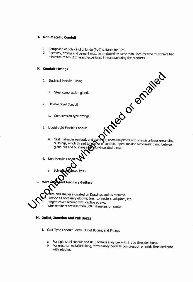
J. Non-Metallic Conduit
1. Composed of poly-vinyl chloride (PVC) suitable for 90°C. 2. Raceway, fittings and cement must be produced by same manufacturer who must have had
minimum of ten (10) years' experience in manufacturing the products.
K. Conduit Fittings
1. Electrical Metallic Tubing
a. Steel compression gland.
2. Flexible Steel Conduit
b. Compression-type fittings.
3. Liquid-tight Flexible Conduit
a. Cast malleable iron body and gland nut, cadmium plated with one-piece brass grounding bushings, which thread to interior of conduit. Spiral molded vinyl-sealing ring between gland nut and bushing and nylon-insulated throat.
4. Non-Metallic Conduit
a. Solvent cemented type.
L. Wireways And Auxiliary Gutters
1. Sizes and shapes indicated on Drawings and as required. 2. Provide all necessary elbows, tees, connectors, adaptors, etc. 3. Hinged cover secured with captive screws. 4. Wire retainers not less than 300 millimeters on center.
M. Outlet, Junction And Pull Boxes
1. Cast Type Conduit Boxes, Outlet Bodies, and Fittings
a. For rigid steel conduit and IMC, ferrous alloy box with inside threaded hubs. b. For electrical metallic tubing, ferrous alloy box with compression or inside threaded hubs
with adapter.
Uncon
trolle
d whe
n prin
ted or
ed

c. Covers: Cast or sheet metal unless otherwise required. d. Tapered threads for hubs. e. Acceptable Manufacturers:
1) U.L. listed and labeled products by any manufacturer meeting the performance requirements specified herein may be utilized.
2. Galvanized Pressed Steel Outlet Boxes
a. General: Pressed steel, galvanized or cadmium-plated, minimum of 4 inches octagonal or square with galvanized cover or extension ring as required.
b. Concrete Box: 100mm octagon with removable backplate and 100mm fixture stud, if required. Depth of box shall allow for minimum of 25mm of concrete to be poured above the backplate.
c. Switch and Receptacle Box, Indoors: Nominal 100mm square, 38mm or 54mm deep as required with raised cover unless otherwise indicated on Drawings.
d. Lighting Fixture Box:
1) 100mm octagon with 10mm fixture stud. 2) For suspended ceiling work, 100mm octagon with removable backplate where
required, and two parallel bar for securing to cross-furring channels and extend flexible conduit to each fixture.
3. Sheet Steel Boxes Indoors
a. No. 12 USS gauge sheet steel for boxes with maximum side less than 1000 millimeters, and maximum area not exceeding 25 meters riveted or welded 20 millimeters flanges at exterior corners.
b. No. 10 USS gauge sheet steel for boxes with maximum side 1000 to 1500 millimeters, and maximum area 20 millimeters to 38. lsquare meters; riveted or welded 20 millimeters flanges at exterior corners.
c. No. 10 USS gauge sheet steel riveted or welded to 38mm by 38mm by 6 millimeters welded angle iron framework for boxes with maximum side exceeding 1500 millimeters and more than 38.1 square meters in area.
d. Covers:
1) Same gauge steel as box. 2) Subdivided single covers so no section of cover exceeds 50 pounds.
Uncon
trolle
d whe
n prin
ted or
ed

3) Machine bolts, machine screws threaded into tapped holes or sheet metal screws
as required; maximum spacing 300 millimeters.
e. Paint: Rust inhibiting primer, ANSI No. 61 light gray finish coat.
4. Pull and Splice Boxes, Outdoors
a. Aluminum reinforced, with removable covers secured by brass machine screws.
5. Junction Box, Sidewalk Type
a. Cast iron, hot-dipped galvanized with threaded conduit entrance hubs, flanged,
reinforced checkered cover, gasketed with pry bar slots and countersunk stainless steel
screws.
6. Floor Boxes
a. General:
1) Class I, watertight, normal depth cast iron construction Type I, fully adjustable, for use in concrete.
2) Single Gang: Round type. 3) Multiple Gang or Combination: Rectangular type: partitions for separating power
form communication sections.
b. Floor Box Covers :
1) Rugged construction, impervious to cleaning detergents. 2) Compatible with floor covering. 3) Brass or bronze for flush mounting. 4) Providing continuous ground path to box.
N. Identification Labels
1. Plasticized Cloth
a. Non-conductive b. Waterproof c. capable of withstanding continuous temperatures of 235°F and intermittent
temperatures to 300°F. d. Overcoating for protection against oil, solvents, chemicals, moisture, abrasion and dirt.
Uncon
trolle
d whe
n prin
ted or
ed

2. Heavy, thermo-resistant industrial grade adhesive for adhesion of label to any surface without curling, peeling, or falling off.
3. Legends: Sharp, bold-face, two inch black letters on Alert orange background.
4. Label Designations; Nominal System Voltages
a. 230 volts b. 400 volts c. 460 volts d. 34,500 volts
Uncon
trolle
d whe
n prin
ted or
ed
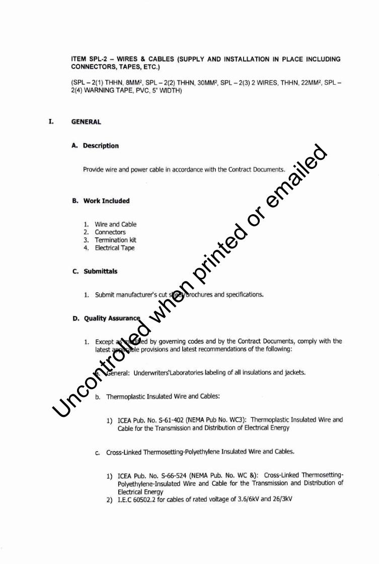
ITEM SPL-2 - WIRES & CABLES (SUPPLY AND INSTALLATION IN PLACE INCLUDING CONNECTORS, TAPES, ETC.)
(SPL - 2(1) THHN, 8MM2, SPL - 2(2) THHN, 30MM2, SPL - 2(3) 2 WIRES, THHN, 22MM2, SPL -2(4) WARNING TAPE, PVC, 5" WIDTH)
I. GENERAL
A. Description
Provide wire and power cable in accordance with the Contract Documents.
B. Work Included
1. Wire and Cable 2. Connectors 3. Termination kit 4. Electrical Tape
C. Submittals
1. Submit manufacturer's cut sheet/brochures and specifications.
D. Quality Assurance
1. Except as modified by governing codes and by the Contract Documents, comply with the latest applicable provisions and latest recommendations of the following:
a. General: Underwriters'Laboratories labeling of all insulations and jackets.
b. Thermoplastic Insulated Wire and Cables:
1) ICEA Pub. No. S-61-402 (NEMA Pub No. WC3): Thermoplastic Insulated Wire and cable for the Transmission and Distribution of Electrical Energy
c. Cross-Linked Thermosetting-Polyethylene Insulated Wire and Cables.
1) ICEA Pub. No. 5-66-524 (NEMA Pub. No. WC &) : Cross-Linked ThermosettingPolyethylene-Insulated Wire and cable for the Transmission and Distribution of Electrical Energy
2) I.E.C 60502.2 for cables of rated voltage of 3.6/6kV and 26/3kV
Uncon
trolle
d whe
n prin
ted or
ed

3) I.E.C 60502.1 for cables of rated voltage of 0.6kV/lkV
d. Terminal Blocks
1) u. L. 1059
e. Insulation Thicknesses for Individual Conductors
1) NEC Table 310-13: Conductor Application and Insulations
II. PRODUCTS
A. Wire and Cable
1. General
a. Provide wire and cables with a minimum rating of 600 volts, except for wire used in 50 volts or below applications. For control or signal systems use 300 volt minimum or 600 volt where permitted to be incorporated with other wiring systems. All wires and cables shall be color coded or as required.
2. Conductors
a. Electrical grade, annealed copper, tinned if rubber insulated, and fabricated in accordance with ASTM standards.
3. Stranding and Number of Conductors
a. 3.5mm 2 and below shall be solid. b. Cables larger than number 5.5mm 2 shall be stranded and in accordance with ASTM
Class B stranding designations. c. Control wires stranded in accordance with ASTM Class B stranding designations. d. Cables, multi-conductor unless otherwise noted for low tensions systems.
4. Insulated Single Conductors
a. Type THWN - Thermoplastic insulation suitable for use in wet locations up to 75°C b. Type THHN - Flame Retardant : Heat-resistant thermoplastic insulation, nylon jacket
rated for 90°C operation
5. Multi-Core or Single-Core Insulated Power Cable
Uncon
trolle
d whe
n prin
ted or
ed
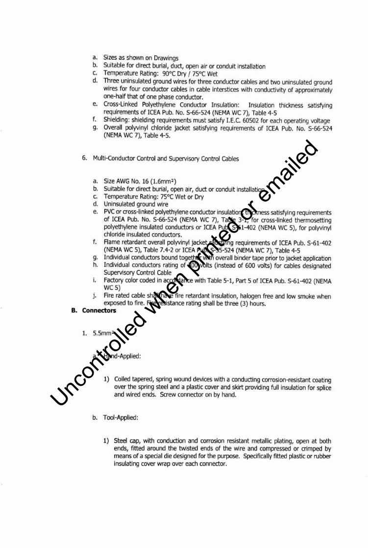
a. Sizes as shown on Drawings b. Suitable for direct burial, duct, open air or conduit installation c. Temperature Rating: 90°C Dry/ 75°C Wet d. Three uninsulated ground wires for three conductor cables and two uninsulated ground
wires for four conductor cables in cable interstices with conductivity of approximately one-half that of one phase conductor.
e. Cross-Linked Polyethylene Conductor Insulation: Insulation thickness satisfying requirements of ICEA Pub. No. S-66-524 (NEMA WC 7), Table 4-5
f. Shielding: shielding requirements must satisfy I.E.C. 60502 for each operating voltage g. Overall polyvinyl chloride jacket satisfying requirements of ICEA Pub. No. S-66-524
(NEMA WC 7), Table 4-5.
6. Multi-Conductor Control and Supervisory Control Cables
a. Size AWG No. 16 (l.6mm2)
b. Suitable for direct burial, open air, duct or conduit installation c. Temperature Rating: 75°C Wet or Dry d. Uninsulated ground wire e. PVC or cross-linked polyethylene conductor insulation; thickness satisfying requirements
of ICEA Pub. No. S-66-524 (NEMA WC 7), Table 3-1, for cross-linked thermosetting polyethylene insulated conductors or ICEA Pub. S-61-402 (NEMA WC 5), for polyvinyl chloride insulated conductors.
f. Flame retardant overall polyvinyl jacket satisfying requirements of ICEA Pub. S-61-402 (NEMA WC 5), Table 7.4-2 or ICEA Pub. S-55-524 (NEMA WC 7), Table 4-5
g. Individual conductors bound together with overall binder tape prior to jacket application h. Individual conductors rating of 300 volts (instead of 600 volts) for cables designated
Supervisory Control Cable i. Factory color coded in accordance with Table 5-1, Part 5 of ICEA Pub. 5-61-402 (NEMA
WC 5) j. Fire rated cable shall have fire retardant insulation, halogen free and low smoke when
exposed to fire. Fire resistance rating shall be three (3) hours. B. Connectors
1. 5.5mm2
a. Hand-Applied:
1) Coiled tapered, spring wound devices with a conducting corrosion-resistant coating over the spring steel and a plastic cover and skirt providing full insulation for splice and wired ends. Screw connector on by hand.
b. Tool-Applied:
1) Steel cap, with conduction and corrosion resistant metallic plating, open at both ends, fitted around the twisted ends of the wire and compressed or crimped by means of a special die designed for the purpose. Specifically fitted plastic or rubber insulating cover wrap over each connector.
Uncon
trolle
d whe
n prin
ted or
ed

2) Hydraulic tool of same manufacturer as lug which shall emboss on the connector the proper die number inspection.
3) Anti-oxide inhibitor for aluminum terminations.
C. Electrical Tape
Specifically designed for use as insulating tape
Uncon
trolle
d whe
n prin
ted or
ed

ITEM SPL-3 - PANELBOARDS (SUPPLY AND INSTALLATION IN PLACE INCLUDING BRACKETS, BOLTS, NUTS, ETC.)
(SPL - 3(1) POWER SUPPLY (Panel LP, with digital timer, magnetic contactor switches, NEMA 4X)
I. GENERAL
A. Description
Provide panelboards in accordance with the Contract Documents.
B. Work Included
1. Panelboards 2. Circuit Breakers
C. Submittals
1. Shop Drawings
a. Submit complete shop drawings showing main devices and lug sizes; branch circuit device rating and arrangement; busbar rating and ampacities; dimensions and construction; gutter and panel box dimensions; nameplate and legend; protective coating; and all other pertinent details of panel, enclosure, cover, and method of securing cover and lock.
2. Product Data
a. Submit manufacturer's catalog data for all circuit breakers.
D. Quality Assurance
1. Except as modified by governing codes and by the Contract Documents, comply with the latest applicable provisions and recommendations of the following:
a. Panelboard
1) U. L. Standard #50 and #67 2) Federal Standard W-C-375a Amendment No. 4 and W-C 375b 3) NEMA Standard PB-1-1971 4) Philippine Electrical Code
Uncon
trolle
d whe
n prin
ted or
ed
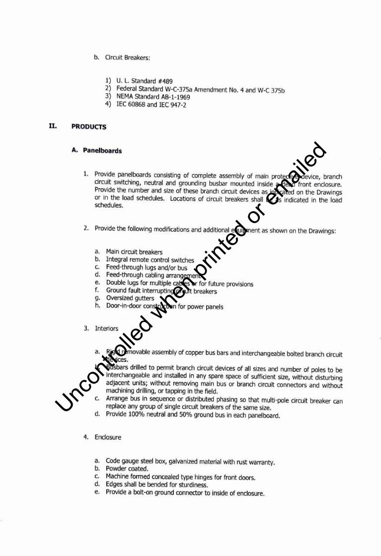
b. Circuit Breakers:
1) U. L. Standard #489 2) Federal Standard W-C-375a Amendment No. 4 and W-C 375b 3) NEMA Standard AB-1-1969 4) IEC 60868 and IEC 947-2
II. PRODUCTS
A. Panelboards
1. Provide panelboards consisting of complete assembly of main protective device, branch circuit switching, neutral and grounding busbar mounted inside a dead front enclosure. Provide the number and size of these branch circuit devices as indicated on the Drawings or in the load schedules. Locations of circuit breakers shall be as indicated in the load schedules.
2. Provide the following modifications and additional equipment as shown on the Drawings:
a. Main circuit breakers b. Integral remote control switches c. Feed-through lugs and/or bus d. Feed-through cabling arrangement e. Double lugs for multiple cables or for future provisions f. Ground fault interrupting circuit breakers g. Oversized gutters h. Door-in-door construction for power panels
3. Interiors
a. Rigid removable assembly of copper bus bars and interchangeable bolted branch circuit devices.
b. Busbars drilled to permit branch circuit devices of all sizes and number of poles to be interchangeable and installed in any spare space of sufficient size, without disturbing adjacent units; without removing main bus or branch circuit connectors and without machining drilling, or tapping in the field.
c. Arrange bus in sequence or distributed phasing so that multi-pole circuit breaker can replace any group of single circuit breakers of the same size.
d. Provide 100% neutral and 50% ground bus in each panelboard.
4. Enclosure
a. Code gauge steel box, galvanized material with rust warranty. b. Powder coated. c. Machine formed concealed type hinges for front doors. d. Edges shall be bended for sturdiness. e. Provide a bolt-on ground connector to inside of enclosure.
Uncon
trolle
d whe
n prin
ted or
ed
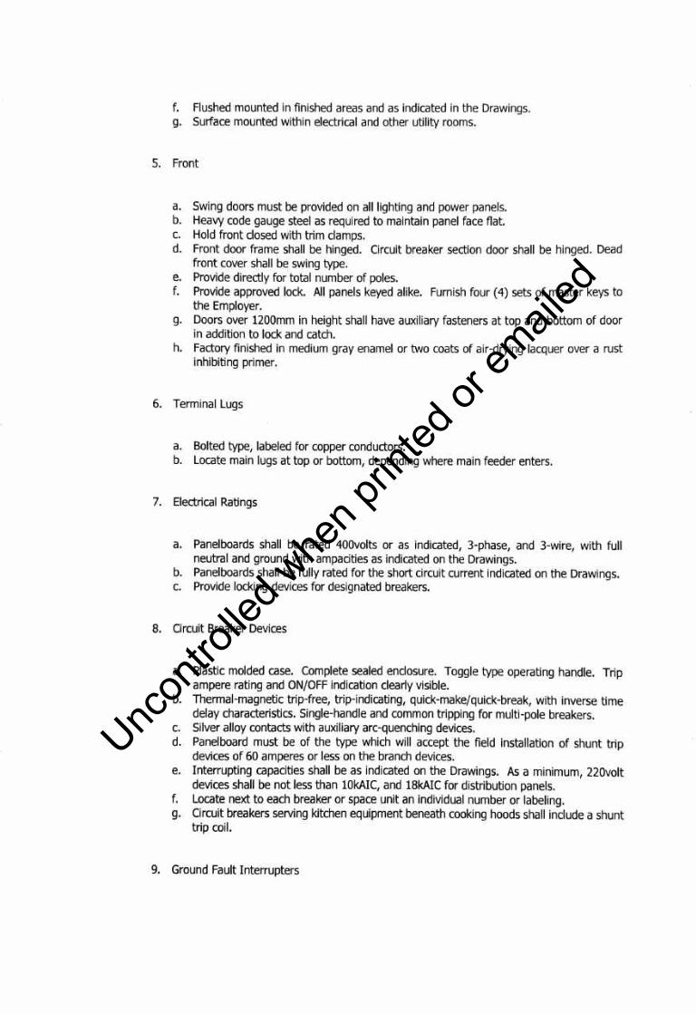
f. Flushed mounted In finished areas and as indicated in the Drawings. g. Surface mounted within electrical and other utility rooms.
5. Front
a. Swing doors must be provided on all lighting and power panels. b. Heavy code gauge steel as required to maintain panel face flat. c. Hold front closed with trim clamps. d. Front door frame shall be hinged. Circuit breaker section door shall be hinged. Dead
front cover shall be swing type. e. Provide directly for total number of poles. f. Provide approved lock. All panels keyed alike. Furnish four (4) sets of master keys to
the Employer. g. Doors over 1200mm in height shall have auxiliary fasteners at top and bottom of door
in addition to lock and catch. h. Factory finished in medium gray enamel or two coats of air-drying lacquer over a rust
inhibiting primer.
6. Terminal Lugs
a. Bolted type, labeled for copper conductors. b. Locate main lugs at top or bottom, depending where main feeder enters.
7. Electrical Ratings
a. Panelboards shall be rated 400volts or as indicated, 3-phase, and 3-wire, with full neutral and ground with ampacities as indicated on the Drawings.
b. Panelboards shall be fully rated for the short circuit current indicated on the Drawings. c. Provide locking devices for designated breakers.
8. Circuit Breaker Devices
a. Plastic molded case. Complete sealed enclosure. Toggle type operating handle. Trip ampere rating and ON/OFF indication clearly visible.
b. Thermal-magnetic trip-free, trip-indicating, quick-make/quick-break, with inverse time delay characteristics. Single-handle and common tripping for multi-pole breakers.
c. Silver alloy contacts with auxiliary arc-quenching devices. d. Panelboard must be of the type which will accept the field installation of shunt trip
devices of 60 amperes or less on the branch devices. e. Interrupting capacities shall be as indicated on the Drawings. As a minimum, 220volt
devices shall be not less than lOkAIC, and 18kAIC for distribution panels. f. Locate next to each breaker or space unit an individual number or labeling. g. Circuit breakers serving kitchen equipment beneath cooking hoods shall include a shunt
trip coil.
9. Ground Fault Interrupters
Uncon
trolle
d whe
n prin
ted or
ed

a. Ground fault interrupter branch circuit breakers shall be as indicated on the Drawings. Circuit breakers shall be circuit interrupting which will operate manually for normal switching functions and automatically under overload, short circuit, and 0.005 amp lineto-ground fault conditions. The operating mechanism shall be entirely trip-free so that contact cannot be held close against an abnormal overcurrent, short circuit, or ground fault condition. The device shall be bolt-on type with insulated case construction and shall be interchangeable with standard single pole breakers utilized in the panelboard.
III. EXECUTION
A. Not used
Uncon
trolle
d whe
n prin
ted or
ed
ITEM SPL-4 - Equipment (supply and installation including all accessories to complete and make operational)
(SPL -4(1) LUMINAIRES (Lighting Fixture, die-cast, 120watts, LED lamps)
I. GENERAL
A. Description
Provide complete testing of equipment and systems throughout in accordance with the Contract Documents.
B. Work Included
1. Luminaires and Accessories
C. Submittals
1. Shop Drawings
a. Provide detailed scaled and dimensioned drawings of all luminaire types, except where specified fixtures are standard, unmodified, catalogued units. For catalogued units, fully detailed catalog information may be substituted for shop drawings. Provide full size cross sections for major luminaries and all custom designed luminaries. Indicate finished dimensions, metal thickness and gauges, material finished, electrical and mechanical connections, fasteners, welds, joints and provisions for the work of others.
b. Submit fixtures data with mounting details that include appropriate mounting accessories.
2. Product Data
a. The luminaire shall be designed to meet recommended luminance and illuminance requirements for local, collector and major roadway/street classification.
b. The luminaire shall be in die-cast enclosing incorporating casting integral heatsink transfer. It shall meet 3G vibration per ANSI C136.31-2010 ..
c. It shall have structured LED array for optimized roadway photometric distribution. The light engine shall consist of reflective technology designed to optimized application efficiency and minimized glare. It shall utilize high brightness LEDs, 70CRI at 4000K, typical.
Uncon
trolle
d whe
n prin
ted or
ed
3. Samples
a. Provide samples as called for in the Contract Documents. Supply a completely operable fixture with a plug and cord for standard 230volt service. Provide lamps and component parts as specifically requested by Employer or Project manager. Provide samples for all custom designed luminaries and modified standard luminaries.
b. In addition to the above, submit to Project manager:
► Samples of any lens, louvers, or diffusers as requested. A 50 millimeter by 100 millimeter sample is the minimum size acceptable.
► Samples of any colors or finishes as requested. ► Where a sample is submitted or requested, do not fabricate or purchase that fixture
type until the sample is accepted and approved. Resubmit samples unit accepted. ► Tag samples with the name of the project, referenced specification paragraph or
drawing number, the fixture type, and any other identifying data. After review, the sample shall be shipped to Project manager. Do not install any sample fixtures in project unless otherwise instructed.
► If samples are not accepted by Project manager, samples will be returned to Contractor, at his expense. Upon receipt of unacceptable sample, immediately make a new submission of samples meeting the contract requirements.
c. Mockups
► If specifically called for in the fixture descriptions, temporarily install, connect and adjust the specified number of fixtures at no additional cost to Employer. Place the mockup fixtures where and when directed. Remove and store mockup fixtures when accepted at Contractor's expense.
4. Quality Assurance
a. Except as modified by governing codes and by the Contract Documents, comply with the latest applicable provisions and latest recommendations of the following:
► Underwriters Laboratories (U.L.) ► Philippine Electric Code (P.E.C.) ► National Fire Protection Agency (N.F.P.A.) ► Certified Ballast Manufacturers Association (C.B.M.) ► Illuminating Engineering Society (I.E.S.) ► American Society for Testing and Materials (A.S.T.M.) ► American National Standards Institute (A.N.S.I.) ► National Electrical Manufacturers Association (N.E.M.A.)
II. PRODUCTS
A. Luminaire Specifications
Uncon
trolle
d whe
n prin
ted or
ed

1. Toe initial lamp lumens level shall be 13,800 lumens.
2. Mounting shall be through slip-fitter with +/- 5 degree of adjustment for levelling,
withintegral die-cast mounting pipe stop feature.
3. Finish shall be gray color corrosion resistant polyester powder paint.
B. Electrical Specifications
1. 120-277 volts, 120 watts
2. System factor >90% and THO <20%
3. Class "A" sound rating
4. Surge protection per ANSI Cl36.2-2015
a. Standard 6KV/3KA "Basic: 120 Strikes"
b. Secondary 10KV/5KA "Enhance: 40 Strikes"
5. EMI: Title 47 CFR Part 15 Class A
C. Ratings
1. UL listed suitable for wet locations per UL 1598
2. Standard optical enclosure rated per ANSI Cl36.25-2009:IP66
3. -4o0c to 50°c UL ambient typical
4. Upward light output ratio = O
5. Compliant with the material restriction requirements of RoHS
III. Execution
Not Used.
Uncon
trolle
d whe
n prin
ted or
ed

GROUNDING SYSTEM
I. GENERAL
A. Description
Provide a low impedance grounding system in accordance with the Contract
B. Works Included
1. Ground Connectors and Clamps; Grounding, Bushing and Locknuts 2. Welding Type Ground Connectors 3. Compression Type Grid Connectors 4. Ground Rods and Clamps 5. Bonding Jumpers for Hinged Joints in cable Tray 6. Electrical Insulating Tape 7. Compound for Compression Connectors
C. Submittals
1. Shop Drawings a. Provide a complete set of shop drawings showing service grounding methods as called
for on the Contract Documents.
2. Testing Reports a. Submit test reports certifying resistance values for buried or driven grounds and water
pipe grounds.
D. Quality Assurance
1. Except as modified by governing codes and by the Contract Documents, comply with the latest applicable provisions and latest recommendations of the following: a. Underwriters Laboratory Standard No. U.L. 467 b. ANSI C-11978 c. IEEE Standard No. 142-1982 d. National Electrical Safety Code e. Philippine Electric Code
II. PRODUCTS
~ J.~,.aark Development Corporation CONNECTOR ROAD FROM MACARTHUR HIGHWAY TO NEW CLARK CITY AIRPORT ROAD SECTION VI. TECHNICAL SPECIFICATIONS AND SCOPE OF WORKS
4
Uncon
trolle
d whe
n prin
ted or
ed

A. Materials
1. Ground Cables: Bare or green color coded, insulated, annealed stranded tinned copper wire as indicated on Drawings; Insulated wire to conform to requirements of another section herein.
2. Mechanical Connectors: Tin-plated aluminum alloy, U.L. approved and stamped for use with aluminum or copper conductors.
3. Ground Rods a. Copper-dad steel fabricated by molten welding process b. Diameter: 25mm c. Length: 3000mm, except ad modified by the Contract Documents.
4. Ground Lugs and Connectors for cable Tray: Tin-plated aluminum alloy, suitable for use with aluminum or copper conductors.
III. EXECUTION
A. General
1. Purpose of Grounding System a. Adequate path for ground fault currents b. Safety to personnel from accidental electric shock hazards c. Prevention of hazardous discharge of static electricity.
2. Whether or not indicated on Drawings, provide continuous ground path for all electrical circuits from point of utilization back to source through ground wires, bonded metallic conduit runs, grounded cable trays, and related items.
B. Grounding Methods
1. Ground rods shall be copper-clad steel not less than 25mm in diameter, and three (3) meters long, driven full length into the earth. The maximum resistance shall not exceed 5 ohms. If this resistance cannot be obtained with a single rod, additional rods shall be installed not less than 1.8 meters on center. If sectional type rods are used, two additional sections may be coupled and driven with the first rod.
2. A metal underground water piping system used for grounding shall be in direct contact with the earth for 3 meters or more and shall be electrically continuous. Provide bonding jumpers at water meter and at insulating joints.
~ '~'~'•Clark Development Corporation CONNECTOR ROAD FROM MACARTHUR HIGHWAY TO NEW CLARK CITY AIRPORT ROAD SECTION VI. TECHNICAL SPECIFICATIONS AND SCOPE OF WORKS
5
Uncon
trolle
d whe
n prin
ted or
ed

3. Steel reinforcing bars used for grounding shall be encased by at least 50mm of concrete, located within and near the bottom of a concrete foundation or footing that is in direct contact with the earth. Reinforcing bars shall be minimum 13mm diameter and consisting of six (6) meters of one or more steel reinforcing bars.
4. All bonding jumpers for the above grounding systems shall be sized in accordance with NEC Section 250-94 and the PEC.
5. Cold Water Pipe Grounding
a. Make connection with damp type fitting; do not damage water pipe. b. Bond ground conductor and its conduit to water pipe. c. Install 100mm2 bonding jumper with ground clamps around water meter.
6. Ground Conductors
a. Size as shown on Drawings or as required in accordance with Philippine Electrical Code (PEC).
b. Where ground cables are required, install insulated copper ground conductors in steel conduit or as indicated.
c. Where ground cable is protected by metallic conduit, bond cable to conduit both ends. d. Connect ground conductors in cables and in conduit to appropriate ground buses (as
in switchboards, and distribution panelboards) or directly to metallic enclosure if no ground bus is provided.
7. Conduit Attachment to Electrical Equipment
a. Ground conduits to metal framework of electrical equipment with double locknuts or grounding bushings and bonding jumpers unless otherwise noted.
b. Install bonding jumpers at all electrical equipment to provide continuous ground return path through conduit.
c. Install PEC approved bonding jumpers across expansion fittings between conduit sections for ground path continuity.
d. Where motors or other utilization equipment are connected to electrical system with flexible conduit, ground by one of the following : ► Flexible metal conduit alone if length is 1800mm or less, conduit is terminated in
fitting approved for purpose, and circuit conductors contained therein are protected by overcurrent devices rated 20 amperes or less.
► External jumper across flexible conduit. ► Flexible conduit containing integral ground wire.
8. Panelboards
a. Install bonding jumpers inside all panelboards to bond feeder conduit to panelboards, except for panelboards containing branch circuits each having less than 150 amperes current carrying capacity, with two standard locknuts and bushings, one inside and one outside, run up wrench tight.
.&t"IARK ~ ,,,,.."·Clark Development Corporation 6 CONNECTOR ROAD FROM MACARTHUR HIGHWAY TO NEW CLARK CITY AIRPORT ROAD SECTION VI. TECHNICAL SPECIFICATIONS AND SCOPE OF WORKS
Uncon
trolle
d whe
n prin
ted or
ed
SPL-5 TESTING AND COMMISSIONING
Test and Guarantee
Upon completion of the electrical construction work, the contractor shall provide all test equipment and personnel and to submit written copies of all test results.
The contractor shall guarantee the electrical installation are done and in accordance with the approved plans and specifications. The contractor shall guarantee that the electrical systems are free from all grounds and from all defective workmanship and materials and will remain so for a period of one year from date of acceptance of works. Any defects shall be remedied by the contractor at his own expense.
Method of Measurement
The whole work under this item will be paid for each of the items provided in the Bill of Quantities. Payments shall be full compensation or for all materials, labor, plant, equipment, tools and incidentals, including all necessary tests electrical permits that may be required and all other incidentals to put the whole electrical lighting system and each individual luminaire as detailed in the project drawings .
.it'LARK . ~ 1" '1'"'Clark Development Corporation CONNECTOR ROAD FROM MACARTHUR HIGHWAY TO NEW CLARK CITY AIRPORT ROAD SECTION VI. TECHNICAL SPECIFICATIONS AND SCOPE OF WORKS
7
Uncon
trolle
d whe
n prin
ted or
ed