Ubiquitous Computing Ubiquitous Computing Project - The Weather Bowl Group L
13
Ubiquitous Computing Ubiquitous Computing Project - The Weather Bowl Group L David Björkman Lian Duan Sara Mansouri Selçuk Çavdar Alejandro Valenzuela
-
Upload
independent -
Category
Documents
-
view
4 -
download
0
Transcript of Ubiquitous Computing Ubiquitous Computing Project - The Weather Bowl Group L

Ubiquitous ComputingUbiquitous Computing Project - The Weather BowlGroup L
David BjörkmanLian Duan
Sara MansouriSelçuk Çavdar
Alejandro Valenzuela

IntroductionIntroduction
Nowadays Internet can provide us any information we need, but sometimes it seemsnot good to start the computer to check just a little piece of information, like theweather broadcast, considering the convience and energy consumption factors.Instead, a ubiquitous way is more acceptable. In this project, we developed aweather bowl that displays the weather in the current or future time, in a calmmanner. Now instead of having to go to the computer and search, you just have toglance at the weather bowl to see what weather it will be.
BackgroundBackground
Mark Weiser's vision on Ubiquitous Computing [1] is one in which computers areomnipresent, embedded into everyday utensils in order to augment these utensils'functionality.The paper "The coming age of calm technology", by Weiser and Seely [2] statesanother of the guidelines to an ubiquitous computing future: having technology thatdoes not demand continuously our attention, in other words, Calm Technology. It isour opinion that these augmented everyday utensils should be able to operatewithout demanding significantly more attention than they already do.Finally we also consider that to be truly ubiquitous, the device we created should beable to reasonably fit in any current household: it should look aesthetically pleasingand not look out of place.
With the previous guidelines in mind, we decided to propose ideas that could berealised in the alloted time (about 6 weeks).To propose our ideas, we employed the brainstorm design technique [3]. As anextra, we were instructed by the lecturer to propose a solution based in one of thetwo characters created by other groups for a design exercise. After our ideas hadbeen proposed, we commented on the pros and cons of each idea and thenproceeded to discard the ones we perceived the least feasible.
Among our ideas, we had:• Weather matching wardrobe: an intelligent wardrobe that suggests the
appropriate clothes to wear depending on the weather and temperature.• iSee: Wearable sensor system to aid blind people. It detects obstacles
nearby and conveys their closeness and location by means of vibration indifferent parts of the body.
• Psychologist bear: This project was proposed as the solution for one of thecharacters designed by the other teams. A simplified version of this conceptcould have been created as a virtual/physical pet.

• Weather ball: Later renamed the Weather Bowl, a spherical glass object thatexpresses the weather through light colour and moving particles in its interior.
Why did we choose the Weather Bowl?Consulting the weather is a fairly common thing to do before going out. We considerthat by making this information instantly available as opposed to being forced to turnon a computer and browse a web page it would be very convenient. It is also adevice that can become invisible once the novelty wears off, and be decorative anduseful at the same time.
ConceptConcept
This project is divided into two parts, the input part and the output part. For the input,we employ a PC, and an Arduino with a wireless module. The PC gets weatherinformation from the Yahoo weather site on the internet and transfers it to an Arduinothrough USB cable, afterward the Arduino sends the data through the air to anotherArduino. The output is that we make use of the Arduino output pins to control theLEDs and fan to show displays on the surface of the bowl.(See figure 1)
Figure 1 Overview of the system
Additionally, moving particles are employed to convey snowy or rainy weather, theyare designed to be blown by the fan on the bottom of the bowl, and circulated aroundinside. Users are able to see the shadows on the surface of the bowl. As weemployed 3-colour-LEDs, with the colour of red, green and blue, we used some ofthe colour and combined colours. For example, red was combined with green tocreate yellow, white is made of red, green and blue. Then we make colour codes and

fan work like this: yellow is sunny, white means cloudy, light yellow stand for partlysunny, rainy is represented by blue with flakes circling, snowy is composed withwhite colour and flakes circling as well.
Figure 2: Comparison between Sunny, Cloudy and Rainy.
RealisationRealisation
SoftwareSoftware
For getting weather information from the Internet and communicating data betweenthe Arduinos we developed several programs.
The user interface requests a city and a day (today or tomorrow) from the user. Thisinterface is a PHP web page residing in Chalmers's web server facilities for students,which stores the data of the user in a file for the weather reader program. The weatherreader program which is written in Java and runs in the user's computer, uses thestored data of the interface and sends a request to the yahoo weather forecastingwebsite to get the weather condition of the city in today or tomorrow.
Processing is used to invoke the reader method of the weather reader every fewseconds and get the type of weather from the Yahoo! public weather API; this data isclassified in simpler categories such as snowy, rainy, sunny, cloudy and partly cloudyweather. Then this simplified data is sent to the Arduino that is connected to the PCwhich has a RF Transmitter Module. The program running on this Arduino sends theweather type of the selected city to the other Arduino embedded on the weather bowl.After that the changing the colors of led and running the fan is performed in theembedded Arduino program.
The wireless communication code as well as the LED driving code was written inC/C++; the Arduino connected to the computer sends the data and waits severalseconds for confirmation. As the RF modules do not support any particular networkprotocol, if confirmation is not received it will just re-send it.When the Arduino embedded in the bowl receives new weather data, it verifieswhether this data differs from the data in its current state; if so, it performs a smoothfade out effect, updates the colour values in the LEDs and then performs fade-in.Pulse-width modulation is already implemented in the standard Arduino library; this

method was used to provide different brightness levels in the LEDs.
We had an issue with the data transmission - since there is no transport controlprotocol involved whatsoever, the receiving Arduino needs to be free in order tohandle the data; otherwise the information might become corrupted or ignored. Wesolved the issue by making the transmitter send all the data in one continuous stringwith delays between each byte that comprises the data, and instructing the receiverArduino to wait until this continuous string is ended. Only afterwards is the receiverArduino instructed to perform the light updating operations in one step (that wasmade as swift as possible).
HardwareHardware
The hardware consists of a bowl and a base box. The bowl is of glass and has awhite diffusive surface with a leaf pattern on it. We tried out couple of different sizesand shapes of the bowl before we found the final version. One was a quite smallplastic light cover. It was round and had a difusive surface, but was too small for ourliking and the thick plastic was preventing the light to go through. We allso tried abigger white paper cover, but it was to simply too big. The bowl that we chose in theend was in the middle of these two extremes.The base box originally was an old speaker housing. It was already covered withsilver paint, and had room for the Arduino, the circuit board, fan and the heat sink forthe voltage regulator.
Selecting the right fan for the job was a bit tricky. We began with a small 4x4 cm fanthat resulted in a quite weak air flow. When we found the base box and realized thatwe had room for a bigger fan, we tried an old computer chassis fan that was 8x8cm. It was made from blue semitransparent plastic and was just a little too small forthe hole in the base box. The fan had 4 small blue LEDs that we removed beforeattaching the fan to the base box. After testing it was clear that the blue plastic wasaffecting the colour projected by our LEDs. We then had to replace it, and found annice processor fan that we bought. It was made from clear transparent plastic andhad a big heat sink attached. After removing the heat sink and upon inserting it in thehole of the base box, we found out that it fitted perfectly, and that we couldn't havegot a better fan.
To improve the LEDs light intensity we added aluminium foil in a cylinder shapearound the LEDs.To improve the speed of the fan we increased the recommended 12V input to about17V.

ELECTRONICS
Figure 3: The light circuit
Choice of LEDs
The standard LEDs were not bright enough for our intended use and we needed tohave a compact system because of the small area we have for the circuit. Thisrequired us to have low number of leds that have high power. For this reason wechose LEDs that integrate several colours in the same casing, which is also usefulbecause the required area is reduced and the circuitry is slightly simplified. Thenumber of LEDs our circuit used was limited by the area of the hole in the base boxdescribed in the previous section.
Functionality of the electrical circuitThe circuit which distributes power to the LEDs and fan required its own powersource because the current required was too high for the Arduino to supply.Additionally, the LEDs operate at a different voltage (5 volts) than the fan, so thiswas solved by using a voltage regulator.
DESIGN PROCESS AND CRITICAL DESIGN DECISIONSDESIGN PROCESS AND CRITICAL DESIGN DECISIONS
To display the weather, several aesthetic cues were proposed:
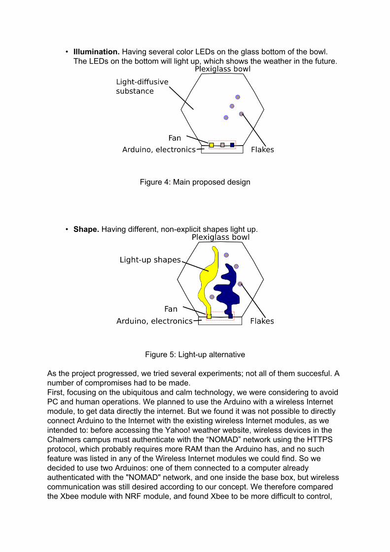
• Illumination. Having several color LEDs on the glass bottom of the bowl.The LEDs on the bottom will light up, which shows the weather in the future.
Figure 4: Main proposed design
• Shape. Having different, non-explicit shapes light up.
Figure 5: Light-up alternative
As the project progressed, we tried several experiments; not all of them succesful. Anumber of compromises had to be made.First, focusing on the ubiquitous and calm technology, we were considering to avoidPC and human operations. We planned to use the Arduino with a wireless Internetmodule, to get data directly the internet. But we found it was not possible to directlyconnect Arduino to the Internet with the existing wireless Internet modules, as weintended to: before accessing the Yahoo! weather website, wireless devices in theChalmers campus must authenticate with the “NOMAD” network using the HTTPSprotocol, which probably requires more RAM than the Arduino has, and no suchfeature was listed in any of the Wireless Internet modules we could find. So wedecided to use two Arduinos: one of them connected to a computer alreadyauthenticated with the "NOMAD" network, and one inside the base box, but wirelesscommunication was still desired according to our concept. We therefore comparedthe Xbee module with NRF module, and found Xbee to be more difficult to control,

than NRF. Thus the NRF module is more feasible for our project and decided to useit.
Second, instead of the idea of difussing the LED light by liquid in the bowl, weemployed a lampshade with frosted surface. Our original idea was to find a light-difussive substance filling inside a transparent glass bowl. We did some experimentscomparing light diffusion between water, soap, and different concentrations of milk,and found diluted milk is what best suits our needs ( see figure 6), but we realised itcould not last for a long time without refrigeration.
Figure 6: Light difussion in water (left) compared to milk (right)
Although we searched for and found some interesting materials in online shops, itwas still a risk for us to order them before testing. The water-proof and leak-prevention measures were other tough issues we hadn`t solved. Also we had toconsider about how to set a pump to create a vortex to move the flakes around thebowl. To avoid these problems and difficulties, we decided to use air instead of aliquid.
Third, as the weather display employs in 3 colours, yellow, blue, and white, here weneed a large number of LEDs in different colours. But we found a 3-colour-LED, thatis red, blue and green. Then we combined red and green to form yellow, andcombined red, blue and green to form white. After doing some experiments, wefound it acceptable, although not perfect. So instead of many LEDs of differentindividual colours. In fact, 8 3-colour-LEDs are our final design.
Fourth, to meet our goals of having the device be as non-intrusive as possible, werefrained from employing textual information such as numbers. This limited theamount of information we could convey but results in a more aesthetic device.
Finally, the colours were chosen to resemble the natural colours of weather assuggested in Envisioning Information [4].

EvaluationEvaluation
In the Background section we established our goals for the project:• To be invisible in the ubiquitous sense, according to Mark Weiser [2].• To be calm technology.• To be aesthetically pleasing.• To convey information in an understandable way.
We consider that we have been able to meet most of our goals:• We took special care in finding a lamp screen that could diffuse light in a soft
way as well as implementing fade-out and fade-in effects in light.• The device had a diameter of approximately 25 centimeters, which is
adequate for placing it on a table.• It only requires the power cable. The data is obtained wirelessly, eliminating
the need for it to be placed very near to a computer, for example.• It does not emit any sound, therefore it will remain in the sensorial periphery.
While we do not have any numerical measures, during the exhibition we receivedmany positive comments from the public on the appereance and functionality of thedevice.
We had, however, some difficulty in conveying the weather using colours. The mainissues were:
• The LEDs we used were sufficient for indoor, relatively low light conditions.However external illumination affects the perceived intensity and evenperceived colour of the light emitted by the LEDs. In our tests we found thefluorescent illumination present in the exhibition site to contain a verysignificant red component, for which we had to compensate.
• Also due to external illumination, but also to the difussion of light when ittraverses the glass screen of the weather bowl, it is quite difficult to tell apartcolours that on a computer screen would be very different. This limited thenumber of colours we could effectively use for similar weather types. Forinstance, partly sunny and sunny were significantly different intensities ofyellow - at least in the instructions sent to the LED - but the public hadtrouble differentiating between them.
• People could not always relate the colours to weather immediately, thoughonce they knew what each colour code meant, they did not have problems inrecognising them (except for the case listed above, where the colours weretoo similar).
In summary, we are satisfied with the results, though there is room for improvement.
Discussion
The first two issues can be solved by using stronger LEDs which exist but were notavailable to us. This would likely require a modification of the circuit board to handlethe additional power that these stronger LEDs need.

During the exhibition we found that many people expected the device to convey thetemperature. The lack of this feature was a design decision to simplify theelectronics, appearance and interaction. We have thought of a few solutions for thisbut were unable to implement them due to time constraints:
• Having 2 different sections for displaying temperature and weather type• Having another bowl exclusively to convey the temperature, i.e. "The
Temperature Bowl"• Having a filament whose lit section changes length according to the
temperature.• Having a moving, physical scale around the bowl.
We had also suggestions by the public to employ, for instance, an LCD screendisplaying the temperature in numbers. We still think that this would result in a lessappealing device on the long run.
AppendixAppendix
Our project's implementation will be based around the Arduino.
We plan to use an Arduino Wi-fi shield to connect to the Internet and obtain the datafrom weather websites such as Yahoo's RSS weather feed or the National WeatherService of the United States.
The Arduino will drive the LEDs or lighting shapes, as well as the motor to stir theparticles inside and convey the weather based on the information obtained from theInternet.
Components and Operating Logic of the Board

In order to obtain the functions described above we needed 1 voltage regulator, 1heat sink, 4 transistors, 1 relay , 1 diode, resistors and 8 three-colour leds. We usedthe 7805 voltage regulator which can supply up to 1.5A for converting 12V into 5V sowe directly gave the adaptors output to the fan (from the voltage regulator leg that isconnected to the adaptor) and the Arduino and got the power supply of the leds fromthe 5V leg of the voltage regulator.
We observed the need to attach also an effective heat sink to the voltage regulatoras the excess voltage is converted to heat and needs to be dissipated. If we didn’tdraw large amounts of power from the voltage regulator that it can barely support wewouldn’t use the heat sink but the 3 colour leds need 40ma each and can draw up to80ma so that we draw at least 320ma up to 640ma for them from the voltageregulator.We used bd677A transistors which can operate in up to 1.5A. The base leg of thetransistor is attached to Arduino’s output pins and a resistor which is 15K so that wecan control the connection between the emitter and the collector. In 3 of thetransistors that are used for leds the emitter leg is connected to ground. And thecollector is connected to +5V(that is taken from the voltage regulator), a 100ohmresistor and all of the led’s 1 leg that is specific for 1 color.

With this configuration when you give 5V to the transistors’ base from the Arduinooutput you can turn on all of the colors in leds that you want depending on whichtransistor you play with as you connect and disconnect the connection of the leds toground(as the leds are always connected to +5V they need only ground connectedto turn on).To clarify, all of the transistors are dedicated to control one specific color of the 8leds. As these leds have 4 legs which are for red, green, blue and +5V, for exampleall leds legs which are responsible of red led is connected to just one of thetransistors. So the other 2 transistors control blue and green. And these 8 leds 3different color leds are like connected to seperate circuits but the same color onesare connected in series between each other(As it is dangerous to connect them inparallel). The 4th transistor is connected to a relay HJR1.We couldn’t directly connect the Arduino output to the relay's input directly becausethe relay requires more current to operate than can be supplied from the Arduino; sowe used a transistor turn the relay on and off. This relay has 8 legs. 2 of the legs arefor the +12V and ground of it for power supply. We take the +5V and ground directlyfrom the +5V and ground leg of the voltage regulator when the 4th transistor is on.There are 2 seperate switches in the relays that has 3 legs each.Before power is given to the relay the 1st and the 2nd legs are connected to eachother (in one of the separate switches, same is valid for the other switch) and whenpower is given the 3rd leg is connected to the 1st leg. We use only one switch circuitof the relay. The 1st leg is connected to +12V of the voltage regulator and the 3rd legis connected to +leg of the fan. The fan ground is always connected so when therelay is turned on the fan starts to work. Lastly we used the diode 1N4148 forpreventing the back voltage of the relay and the fan from the circuit and Arduino.
Project plan
47 (16-20 Nov.)After getting the bowl, we do some experiments on it, so that to decide which idea tochoose, with or without liquid in, or what kind of liquid.Equip it with fans, LEDs, wires and so on.48 (23-27 Nov.)Deal with the input parts. Make a decision on which method will we use, Arduinoconnected to computer, or a module on Arduino connected to internet, in wireless, orsomething else, depending on the budget.49 (30 Nov-4 Dec.)Deal with the input parts. Programming on getting data of weather from internet, anduploading programming to Arduino.50 (7-11 Dec.)Test the project, sweep the remaining problems and implement the finally design.51 (14-18 Dec.)Project report

References
1. Weiser, Mark. "The computer for the 21st Century", United States ofAmerica, 1999
2. Weiser, Mark and Seely, John. "The coming age of Calm Technology",United States of America, 2003
3. Chris Jones, John, "Design Methods", 2nd Edition, John Wiley & Sons,United States of America, 1970.
4. Tufte, Edward, "Envisioning Information", CT: Graphics Press, United Statesof America, 1990