TMI EXAM 02102000 - Nuclear Regulatory Commission
680
11.2.05.179 Revision 0 11/29/1999 TMI-1 OPERATOR TRAINING REQUALIFICATION PROGRAM JOB PERFORMANCE MEASURE POSITION: SRO/RO/AO Shutdown Margin Calculation 0010040101 EVALUATION METHOD: EVALUATION LOCATION: APPROXIMATE COMPLETION TIME: IMPORTANCE RATING (TIF): TOOLS AND EQUIPMENT: EXAMINEE REFERENCES: 10CFR55.41: PERFORM: X SIMULATOR:_ SIMULATE:_ IN-PLANT:_ CONTROL ROOM: X Minutes: 20 NRC 2.8 K/A 2.1.25 TMI 2.6 Calculator and Ruler OP 1103-15A Rev. 28 OP 1103-15A Shutdown Margin and Reactivity Balance Rev. 28 (a) (10). Page 1 of 5 TITLE: TASK NUMBER: SIGNATURE DATE Submitted By: A z Validated By: Reviewed by: Lead Instructor, Operator Training OR Lead Instructor, Simulator Training / Operations Training Manager __ _ __ _ __ _ __ _ / Approved By: Plant Operations Director
-
Upload
khangminh22 -
Category
Documents
-
view
1 -
download
0
Transcript of TMI EXAM 02102000 - Nuclear Regulatory Commission

11.2.05.179 Revision 0 11/29/1999
TMI-1 OPERATOR TRAINING REQUALIFICATION PROGRAM
JOB PERFORMANCE MEASURE
POSITION: SRO/RO/AO
Shutdown Margin Calculation
0010040101
EVALUATION METHOD:
EVALUATION LOCATION:
APPROXIMATE COMPLETION TIME:
IMPORTANCE RATING (TIF):
TOOLS AND EQUIPMENT:
EXAMINEE REFERENCES:
10CFR55.41:
PERFORM: X
SIMULATOR:_
SIMULATE:_
IN-PLANT:_ CONTROL ROOM: X
Minutes: 20
NRC 2.8 K/A 2.1.25 TMI 2.6
Calculator and Ruler OP 1103-15A Rev. 28
OP 1103-15A Shutdown Margin and Reactivity Balance Rev. 28
(a) (10).
Page 1 of 5
TITLE:
TASK NUMBER:
SIGNATURE DATE
Submitted By: A z Validated By:
Reviewed by: Lead Instructor, Operator Training OR Lead Instructor, Simulator Training /
Operations Training Manager __ _ __ _ __ _ __ _ /
Approved By: Plant Operations Director

11.2.05.179 Revision 0 11/29/1999
SIMULATOR CONDITIONS:
EXAMINER PREVIEW:
TASK STANDARDS:
The sequence of events which should be followed in the conduct of this JPM is as follows:
1. Read or otherwise inform the Examinee of the information contained in the "EXAMINEE PREVIEW" section of this JPM.
2. Inform the Examinee of the TASK CONDITIONS. 3. Begin the cueing sequence as described in the EXAMINER CUES
section.
A certain amount of liberty (questioning or cueing beyond the bounds of
the "EXAMINER CUES") may be taken by the Examiner in trying to
extract the requisite information from the Examinee, however, care must be taken to ensure that you do not COACH the Examinee.
To complete this task successfully, the Examinee must complete each
critical element (an element of the task which, if omitted or performed incorrectly, would result in a failure to meet the "TASK STANDARD") correctly.
Examinee Calculates the SDM within tolerances described within this JPM.
Page 2 of 5
(
N/A

EXAMINEE PREVIEW:
TASK CONDITIONS:
This sheet is available for the examinee to review
For this event you are assigned the duties of the third CRO. The instructor/examiner will act as the SS.
When you are told to begin, you will respond to the cues or indications which the Examiner will provide to you either verbally or by the simulator.
The reactor is at 100% Power.
400 EFPD
Group 8 rod position: 30% WD
RCS Boron: 770 ppm
Boron Depletion factor: 1.0
PPC Xenon: -2.4% Ak/k
It has been determined that Group 7 Rod 4 is stuck at 92% WD and cannot be moved.
Page 3 of 5

11.2.05.179 Revision 0 11/2911999
EXAMINER CUES
Instruct the examinee to calculate a Shutdown Margin for the current plant conditions.
Examinee does not have to complete Enclosure 4 for this JPM.
EXAMINEE ACTIONS
"*1. Examinee obtains a copy of OP 1103-15A and using Enclosure I calculates the SDM.
STANDARD
1. The examinee calculates the SDM within the allowable tolerances provided with this JPM.
SAT
NOTE: Allowances
± 0.1% Ak/k ± 0.005%Ak/k ± 0.25ppmB/%Ak/k
Max Error ±0.355% Ak/k
JPM may be terminated after completion of calculation.
(*) Denotes Critical Element.
EVALUATION: SAT: UNSAT:
Page 4 of 5
Fig. 1 Fig. 2A Fig. 3
(
I

11.2.05.179 Revision 0 11/29/1999
JPM CHANGE HISTORY PAGE
REVISION DATE REFERENCE DESCRIPTION TITLE (Include Al # if Appropriate)
I i 4
1. 4
4. I +
4 I +
J. I
I + I
I I 4.
I. I4
_ _I_ I1 i
4 I +
1 4 1
_ _ _ _ _ _ I - - I
Page 5 of 5

K
ENCLOSURE I
Shutdown Margin Calculation Data Sheet
NOTE
Refer to attached Enclosure 1 Instructions to complete the Data Sheet.
I. CALCULATION IS FOR A SDM AT: DATE TIME
1. TAVE (Assume TAVE = 532°F) 532 "F
1-0C EFPD2. CYCLE BURNUP
3. a. MEASURED BORON CONCENTRATION 7 7 0 ppmB b. BORON DEPLETION CORRECTION FACTOR f7
(NAS, Control Room Log, Nuclear Engineering) C. CORRECTED BORON CONCENTRATION (3a x 3b) =27Z70 ppmB
4. CONTROL ROD GROUP 8 POSITION
5. EXCESS REACTIVITY
6. CRG 8 REACTIVITY WORTH
.L'. / % Ak/k(FIG. 1)
(FIG. 2A)
7. BORON REACTIVITY WORTH 7a. HZP Inverse Boron Worth (FIG. 3) 7b. Boron Worth
[(ppmB)I(HZP Inverse Boron Worth)] * (-1)#3c #7a
- '), 2-ý2 % Ak/k
/ ?3, • ppmB/%Ak/k
4 % Ak/k
8. XENON REACTIVITY WORTH (PPC, Nuclear Engr, FIG. 4)
9. SAMARIUM AND PLUTONIUM BUILDUP REACTIVITY WORTH (FIG. 5) 9a. If shutdown: Time since last shutdown " HRS 9b. Reactivity due to samarium and plutonium buildup
10. INOPERABLE CONTROL RODS THAT ARE NOT FY LLY INSERTED 1Oa. No. of known inoperable rods (>0%WD) I 10b. Total inoperable rod worth (Enclosure 4)
(Figure 1 includes stuck rod as required by T.S.)
11. SHUTDOWN MARGIN EXCESS + CRG 8 + BORON + XENON + SAM + INOP ROD =
#5 #6 #7b #8 #9b #10b
0/6%Ak/k
%Ak/k
-4 7- %Ak/k
"ý4LCULATED BY DATE/TIME
DATE/TIME.ROVED (SRO) BY
Send to Operations Engineer for filing: Copy to Manager, Shift Engineering
7
1103-15A Revision 28
Page 1 of 3
I/
,S %vWD

11.2.05.180 Revision 0 11/i29/1ggg
(
TITLE:
TASK NUMBER:
EVALUATIOI METHOD:
EVALUATIOI LOCATION:
APPROXIMA COMPLETIO TIME:
IMPORTANC RATING (TIF
TOOLS AND EQUIPMENT
EXAMINEE REFERENCE
10CFR55.45
TMI-1 OPERATOR TRAINING REQUALIFICATION PROGRAM
JOB PERFORMANCE MEASURE
POSITION: SROIRO/AO
RCS PPC Computer Leak Rate Calculation
0020010201
PERFORM: X SIMULATE:_
SIMULATOR: X IN-PLANT: CONTR(
TE N
;E
ES:
)L ROOM:.
Minutes: 70 Minutes
TMI: RO 2.49
NRC K/A 2.1.19 RO 3.0
Plant Process Computer
1303-1.1 Reactor Coolant System Leak Rate Rev. 35
(a) (12).
Page 1 of 7
SIGNATURE DATE
Submitted By:
Validated By:
Reviewed by: Lead Instructor, Operator Training OR Lead Instructor, Simulator Training
Operations Training Manager ,/.m
Approved By: Plant Operations Director

11.2.05.180 Revision 0 11/24/1999
SIMULATOR CONDITIONS:
IC16 MOC Set makeup tank level to obtain approximately 87" @ 33 psig using monitor point MUMMT = 28,000, immediately, MUT pressure should be approximately 33 psig
Insert Malfunction TH02A at 1% severity, immediately.
Turn on PPC Printer GPU Tag 17528
EXAMINER PREVIEW:
TASK STANDARDS:
The sequence of events which should be followed in the conduct of this JPM is as follows:
1. Read or otherwise inform the Examinee of the information contained in the "EXAMINEE PREVIEW" section of this JPM.
2. Inform the Examinee of the TASK CONDITIONS. 3. Allow the Examinee 2-3 minutes to scan the Console. 4. Begin the cueing sequence as described in the EXAMINER CUES
section.
A certain amount of liberty (questioning or cueing beyond the bounds of the "EXAMINER CUES") may be taken by the Examiner in trying to extract the requisite information from the Examinee, however, care must be taken to ensure that you do not COACH the Examinee.
To complete this task successfully, the Examinee must complete each critical element (an element of the task which, if omitted or performed incorrectly, would result in a failure to meet the "TASK STANDARD") correctly.
Examinee successfully uses the PPC to enter a RCS leak rate and print the results with the RCS unidentified leak rate approximately 2.1 GPM. The examinee identifies that this leak rate value is in excess of Tech Spec limits (TS 3.1.6.2).
Page 2 of 7

EXAMINEE PREVIEW:
TASK CONDITIONS:
This sheet is available for the examinee to review
For this event you are assigned the duties of the third CRO.
The instructor/examiner will act as the primary/secondary CRO and the
SF. The auxiliary instructor is available to act as Auxiliary Operators on the
radio or page system.
When you are told to begin, you will respond to the cues or Indications
which the Examiner will provide to you either verbally or by the simulator.
You are to respond as you would in the plant for a real condition.
Plant is at 100% power MOC, with an unidentified RCS leak in
containment.
Page 3 of 7

11.2.05.180 Revision 0 11/24/1999
EXAMINER CUES EXAMINEE ACTIONS STANDARD
As the Shift Foreman, direct the Examinee to enter an RCS leak rate into the PPC for a time length of 1 Hour using Automatic Mode and identify any leakage in excess of Tech Spec limits.
1. The examinee obtains a copy of 1303-1.1 RCS Leak Rate.
1. Examinee obtains a copy of 1303-1.1 RCS Leak Rate.
Provide the examinee a copy of 1303-1.1 RCS Leak Rate if the examinee request.
*2. At the PPC the 2. A system performance
examinee depresses calculation menu will the System appear on the CRT. Performance Calculation Menu Function on the CRT SAT keypad.
*3. The examinee selects 3. The RCS leak rate
the Reactor Coolant screen appears. Leak Rate Calculation by entering 11' in the area designated "Enter SAT Area No.".
If the examinee identifies *4. The examinee enters '1' 4. The examinee enters
that the RCS leak rate hour for the time '1' hour for time limit.
should be entered for 2 interval. hours, due to plant conditions the SS wants the RCS leak rate to be SAT calculated for 1 hour.
If the examinee made an error in any entry he/she should be allowed to correct the error in accordance with the procedure "NOTE".
*5 The examinee tabs to position the cursor to the Call Back entry and enters '1' to select automatic mode and depresses Execute function key.
5. The examinee enters a '1' in the Call back entry and depresses execute function key. A message "Please Wait" will appear At the bottom of the CRT.
SAT
Page 4 of 7

11.2.05.180 Revision 0
11124/1999
EXAMINER CUES EXAMINEE ACTIONS STANDARD
Option 1: If other JPMs are to be performed in the simulator, they should be performed while waiting for the RCS leak rate calculation.
Option 2: If the examinee successfully entered the RCS leakrate proceed to step 7.
If the examinee made an error in any entry, he/she should be allowed to correct the error in accordance with the procedure "NOTE".
6. At the end of the selected time interval the examinee will enter the following information and press the Execute function key.
RCS/MUT Inventory Change: 0 Gal.
RCDT change: 0 Lbm
Identified Leak rate: 0
Lbm/Min
OTSG Leak rate: 0 Lbm/Min
6. Using the Tab forward function key, repositions the cursor and enter the appropriate data in the correct field.
RCS/MUT Inventory Change: 0 Gal.
RCDT change: 0 Lbm
Identified Leak rate: 0
Lbm/Min
OTSG Leak rate: 0
Lbm/Min
Examinee depresses the execute function key.
The message "Hard Copy Being Made to the Line Printer" will appear on the CRT.
The examiner should provide the RCS leak rate results if option 2 was used in this JPM.
7. The examinee obtains a hard copy from the line printer for examiner to evaluate the results.
7. The examinee obtains a hard copy of the RCS leak rate. Unidentified RCS leak rate is approximately 2.1 GPM
Page 5 of 7

11.2.05.180 Revision 0 11/24/1999
EXAMINER CUES EXAMINEE ACTIONS
As the SF, ask the examinee if the RCS leakage is in excess of any Tech Spec allowable leakage.
Tech Spec Section No. is not required.
*8. Using Tech Specs, the examinee identifies that Tech Spec 3.1.6.2 Unidentified RCS leakage is in excess of I GPM.
8. The examinee identifies that the 2.1 GPM RCS leak rate is In excess of the Tech Spec limit for unidentified RCS leakage (1GPM)
SAT
After the examinee completes the leak rate and identifies that the leakage is in excess of the Tech Spec allowed limit the JPM may be terminated.
(*) Denotes Critical Element.
EVALUATION: SAT: UNSAT:
Page 6 of 7

11.2.05.180 Revision 0 I11/24/1999
JPM CHANGE HISTORY PAGE
REVISION DATE REFERENCE DESCRIPTION TITLE (Include Al # if Appropriate)
4 4
4. 4 1*
4 1 t
4. I +
_ _I_ I1 i
I 4. 1
______ 1 4.
1 4. 4
4. 4
_ _I_ I 1
4 I +
I I
_______ I ______ J
Page 7 of 7

THREE MILE ISLAND NUCLEAR STATION UNIT NO. 1 SURVEILLANCE PROCEDURE 1303-1.1
S 11/24/1999 REACTOR COOLANT SYSTEM LEAK RATE
T- 07:48:51
NOTE: YOU MUST ENTER A DECIMAL POINT WITH THE LEAKAGE VALUES. IF RCS INVENTORY IS INCREASED THE DATA ENTRY MUST BE NEGATIVE.
SELECTED INTERVAL (1-8 HOURS): ENTERED RCS OR MUT INVENTORY CHANGE FROM DATA SHEET 5 ENTERED RCDT CHANGE FROM DATA SHEET 5 ENTERED IDENTIFIED LEAK RATE FROM DATA SHEET 4 ENTERED OSTG LEAKAGE FROM SP1301-1
POINT ID:
POINT ID:
A0510 A0510
A0508 A0508
A0513 A0513
A0509 A0509
1 HOURS
C1720 C1720
TIME TCA THA TCB THB TAVE PRZR LVL (F) (F) (F) (F) (F) (IN)
07:48:52 556.178 601.538 556.362 601.577 578.914 218.540 08:48:52 556.063 601.480 556.294 601.531 578.842 217.556
.000 GAL .000 LBM
.000 LBMZMIN
.000 LBM/MIN
A0426 A0426
A0835 A0835
MUTK LVL RCDT L (IN) (IN)
82.758 95.67 78.344 96.00
MAX MIN
RCDT LVL MUTK LVL (IN) (IN)
96.021 82.886 95.695 78.042
"K'(AGE PLUS LOSSES (MUST BE LESS THAN 30 GPM) RCS LEAK RATE (MUST BE LESS THAN 10 GPM)
NET UNIDENTIFIED LEAK RATE (MUST BE LESS THAN 1 GPM) :
OPERATOR:
APPROVED:
DATE/TIME:
DATE/TIME:
NOTE: ATTACH ALL APPROPRIATE DATA SHEETS
FRWD
2.3131 2.1219
2.1219

THREE MILE ISLAND NUCLEARSTATION
UNIT NO. 1 SURVEILLANCE PROCEDURE 1303-1.1
REACTOR'COOLANT SYSTEM LEAK RATE
SELECTED INTERVAL (1-8 HOURS); ENTERED RCS OR HUT INVENTORY CHANGE FROM DATA SHEET S ENTERED RCDT CHANGE FROM DATA SHEET S ENTERED IDENTIFIED LEAK RATE FROM DATA SHEET 4
ENTERED OSTG LEAKAGE FROM SP1301-1
11/24/99 08:58:29
HOURSSHOURS * Gee .000 0Gee 00Ge
TIME
POINT ID:
07 : 48s: 52
POINT ID:
08 : 48 : 52
TIME
POINT ID:
07 : 48s: 52
POINT ID:
:48: 2
TCA (F)
AeSIO
SS6.178
AGs10
556.063
RCDT LVL (IN)
A083S
95 .678
A0835
96.006
THA TCB THB TAVE PRZR LVL (F) (F) (F) (F) (IN)
A0508 A0513 Aos09 C1720
601.s38 SS6.362 601.577 578.914 218.540
AoSOs AOS13 A0509 01720
601.480 ss6.294 601.531 578.842 217.SS6
RCS PRESS (PSIG)
2ISS.46
2158.11
RODT LVL MAX/MIN (IN)
MAX 96.021
MIN 9s.695
MUTK LVL (IN)
A042S6
82.758
A0426
78.344
MUTK LVL MAX/MIN (IN)
82.s86
7S .042
LEAKAGE PLUS LOSSES (MUST BE LESS THAN 30 GPM)
TOTAL RCS LEAK RATE (MUST BE LESS THAN 10 GPM)
NET UNIDENTIFIED LEAK RATE (MUST BE LESS THAN 1 GPM) - --• -- U -
2.3131
2.1219
2.1219 ••-• --
dýipm

11.2.05.181 Revision 0 11/29/1999
TMI-1 OPERATOR TRAINING REQUALIFICATION PROGRAM
JOB PERFORMANCE MEASURE
POSITION: SRO/RO/AO
TITLE:
TASK NUMBER:
EVALUATION METHOD:
EVALUATION LOCATION:
APPROXIMATE COMPLETION TIME:
IMPORTANCE RATING (TIF):
TOOLS AND EQUIPMENT:
EXAMINEE REFERENCES:
10CFR55.
Verification of Emergency Diesel ES Standby
0640010101
PERFORM: X SIMULATE:_
SIMULATOR: X IN-PLANT:_ CONTROL ROOM:
15 Minutes
TMI: RO 2.61 NRC: K/A 2.2.12, RO 3.0
None
Surveillance Procedure 1303-4.16 Emergency Power System Rev. 84
(a)(41.10, 45.13).
Page 1 of 7
SIGNATURE DATE
Submitted By:
Validated By:
Reviewed by: Lead Instructor, Operator Training OR Lead Instructor, Simulator Training _ _ _ _ _ _ _ /
Operations Training Manager / / • / /-•
Approved By: Plant Operations Director

11.2.05.181 Revision 0 11/29/1999
( SIMULATOR IC 86 or any 100% Power IC CONDITIONS: EDG 1A is shutdown following a 1 hour surveillance run.
Verify Remote Functions:
EGR07 Speed Droop C 70%
EGR09 Unit/Parallel selected to Parallel
EGR28 Fuel Rack - Tripped
EGR05 Exciter - Norm
Verify Panel Controls:
Manual Voltage Control @ 0
Starting Switch in Manual
Exciter in Manual
EXAMINER PREVIEW: The sequence of events which should be followed in the conduct of this
( JPM is as follows:
1. Read or otherwise inform the Examinee of the information contained
in the "EXAMINEE PREVIEW" section of this JPM.
2. Inform the Examinee of the TASK CONDITIONS.
3. Allow the Examinee 2-3 minutes to scan the Console.
4. Begin the cueing sequence as described in the EXAMINER CUES
section.
A certain amount of liberty (questioning or cueing beyond the bounds of
the "EXAMINER CUES") may be taken by the Examiner in trying to
extract the requisite information from the Examinee, however, care
must be taken to ensure that you do not COACH the Examinee.
To complete this task successfully, the Examinee must complete each
critical element (an element of the task which, if omitted or performed
incorrectly, would result in a failure to meet the "TASK STANDARD")
correctly.
TASK STANDARDS: EDG 1A is in ES standby lAW 1303-4.16, Emergency Power System
Page 2 of 7

EXAMINEE PREVIEW:
TASK CONDITIONS:
This sheet is available for the examinee to review
For this event you are assigned the duties of the Primary CRO. The instructor/examiner will act as the Secondary CRO and the SF. The auxiliary instructor is available to act as Auxiliary Operators on the radio or page system.
When you are told to begin, you will respond to the cues or indications which the Examiner will provide to you either verbally or by the simulator.
You are to respond as you would in the plant for a real condition.
EDG 1A has just completed a 1 hour test run and must be placed In ES standby.
Page 3 of 7

11.2.05.181 Revision 0 I11/29/1~999
EXAMINER CUES
As the SF direct the examinee to place EDG-1A into ES standby lAW 13034.16 Emergency Power System, Section 8.5
As applicable in-plant steps have already been completed as noted by initials on appropriate steps.
EXAMINEE ACTIONS
"*1, Examinee verifies in the control room the following switch positions or settings:
Exciter switch: AUTO
Generator Manual Voltage Controller set at 45%.
Starting Switch: AUTO
1. Exciter Switch indicates AUTO
Generator Manual Voltage Controller is at 45%
Starting Switch is in AUTO. The speed control Idle lamp goes out and In approximately 3 minutes, the speed control High Lamp goes 'on'.
SAT
ICO: Using Remote Functions
EGR07 Speed Droop to 0
EGR09 Unit/Parallel to Unit.
*2. The examinee directs the Aux operator to position the SPEED DROOP to 0% and the UNIT/PARALLEL switch to UNIT.
1. The examinee directs the Aux operator to position the following:
Speed droop to 0%
Unit/Parallel Switch to Unit.
After completion notify the SAT control room that you and another AO have verified required positions.
Note: Examiner may sign as independent verifier for these steps.
*3. The examinee verifies the following:
U-1 Diesel Fuel Tank Full Light, 'on'.
Govenor Speed Control "HIGH" Lamp 'on'.
3. The examinee verifies the following on CR:
U-1 Diesel Fuel Tank Full Light, 'on'.
Govenor Speed Control "HIGH" Lamp 'on'.
SAT
Page 4 of 7

11.2.05.181 Revision 0 11/29/1999
EXAMINER CUES The ICO, when directed by the examinee, performs the following:.
a. Using Remote Function EGR28, Reset the fuel racks.
b. Simulate depressing the Exciter RESET PB.
c. Using remote Function EGRO5 RESET Exciter.
d. Simulate SDR & 5A Relay are de-energized.
e. Using remote function ANR02 Reset/Clear local alarms.
Examiner: If steps performed correctly, you may initial steps for independent verification.
EXAMINEE ACTIONS *4. The examinee has the
Aux Operator at the diesel perform the following steps:
a. Reset the fuel rack.
b. Depress the Exciter RESET pushbutton at the EMMSB.
c. Depress the RESET Pushbutton at the EMIP.
d. Verify the SDR & 5A relays are deenergized.
e. Verify local alarms are clear.
*5 The examinee verifies the following alarms
are clear:
Diesel Gen 1A
Trouble(A-1 -2)
Diesel Gen 1A Blocked(A-2-1)
Diesel Gen Bkr Trip(A1-3)
STANDARD 4. The examinee in
communications has the Aux Operator performs the following steps:
a. Reset the fuel rack.
b. Depress the Exciter RESET pushbutton at the EMMSB.
c. Depress the RESET Pushbutton at the EMIP, and reset A-2-1.
d. Verify the SDR & 5A relays are deenergized.
e. Verify local alarms
are clear.
SAT
5. The examinee verifies the following alarms are clear Main Annunciator Panel A
Diesel Gen 1A Trouble
Diesel Gen 1A Blocked
Diesel Gen Bkr Trip
SAT
*6. The examinee verifies the following computer alarms are clear:
L2428 Diesel Fuel Tank Storage Tank Level MIN.
L2429 Diesel Fuel Inventory below MIN.
6. The examinee verifies the following computer alarms are clear:
L2428 Diesel Fuel Tank Storage Tank Level MIN.
L2429 Diesel Fuel Inventory below MIN.
SAT
Page 5 of 7

11.2.05.181 Revision 0 11/2911999
ICV aAtKjlI k "e Ar tra t•lJ .: RTANDARD
7. The examinee notifies the SF that the surveillance is complete.
7. The examinee notifies the SF that the EDG surveillance is complete lAW 13034.16 Declare EG-Y-1A Operable.
Terminate Respective time clocks.
Make appropriate closeout logbook entries.
After the SF is notified the JPM may be terminated.
(*) Denotes Critical Element.
EVALUATION: SAT: UNSAT:_
Page 6 of 7
A IKICC At%'rf Kj-4Z . _q7,AM1Nrtj UUC2 F- ̂wt.I I iJtllPR ^t lPf'•

11.2.05.181 Revision 0 11/29/19ggg
JPM CHANGE HISTORY PAGE
REVISION DATE REFERENCE DESCRIPTION TITLE (Include Al # If Appropriate)
_____ L I I
I I
_____ 1 1. I
I I I
_____ 1 4
_____ I I +
______________ _____________ _______________________ _______________________________________________IPage 7 of 7

11.2.05.183 Revision 0
12/14/1~99
TMI-1 OPERATOR TRAINING REQUALIFICATION PROGRAM
JOB PERFORMANCE MEASURE
POSITION: SRO/RO/AO
Conduct Equipment Tagout in a High Radiation Area
1190120301
EVALUATION METHOD:
EVALUATION LOCATION:
APPROXIMATE COMPLETION TIME:
IMPORTANCE RATING (TIF):
TOOLS AND EQUIPMENT:
EXAMINEE
REFERENCES:
10CFR55.41:
PERFORM:
SIMULATOR:
SIMULATE: X
IN-PLANT: X CONTROL ROOM:_
Minutes: 15
NRC K/A 2.3.1 RO 2.6 TMI 3.86
TLD, Simulated Tags and Switching Order
AP 1002, Switching Order
(a)(12).
Page 1 of 6
TITLE:
TASK NUMBER:
SIGNATURE DATE
Submitted By:
Validated By:
Reviewed by: Lead Instructor, Operator Training OR Lead Instructor, Simulator Training • ____,, ,__
Operations Training Manager
Approved By: Plant Operations Director I? ! D

11.2.05.183Revision 0' 12/14/1999
SIMULATOR CONDITIONS:
EXAMINER PREVIEW:
TASK STANDARDS:
This task deals with the requirement to hang safety tags on components within a locked high radiation area per AP 1002, taking ALARA concerns into consideration.
The sequence of events which should be followed in the conduct of this JPM is as follows:
1. Read or otherwise inform the Examinee of the information contained in the "EXAMINEE PREVIEW" section of this JPM.
2. Inform the Examinee of the TASK CONDITIONS. 3. Begin the cueing sequence as described in the EXAMINER CUES
section.
A certain amount of liberty (questioning or cueing beyond the bounds of
the "EXAMINER CUES*) may be taken by the Examiner in trying to
extract the requisite information from the Examinee, however, care
must be taken to ensure that you do not COACH the Examinee.
To complete this task successfully, the Examinee must complete each
critical element (an element of the task which, if omitted or performed
incorrectly, would result in a failure to meet the "TASK STANDARD") correctly.
For In-Plant JPMs additional safety gear may be required. The
Examinee should inform the Examiner that additional gear is required.
The Examiner will then specify if the additional safety gear is to be
donned, or to be simulated after the Examinee specifies what equipment is required and where it would be located.
Failure to use the proper safety equipment is immediate grounds for failure.
The examinee properly hangs red tags for components in a High Rad
area lAW AP 1002 Switching & Tagging. This procedure allows tags to
be hung on outside entrance of Locked High Rad Area when the prerequisites are met.
Page 2 of 6
N/A

This sheet is available for the examinee to review
EXAMINEE PREVIEW:
TASK CONDITIONS:
You are to respond as you would in the plant for a real condition.
For this event you are assigned the duties of the Extra CRO. The instructor/examiner will act as the Console CRO and the SF.
When you are told to begin, you will respond to the cues or indications which the Examiner will provide to you verbally.
Unless otherwise informed, you are to SIMULATE all actions taken.
You are expected to maintain proper communications with the Control Room as you would in the plant for a real condition.
It is very Important that you describe to the instructor/examiner the
physical details of the actions that you would be taking if you were actually performing the manipulations required to complete this task.
Failure to adequately describe your actions could result in a failure to meet the task standard.
You are to respond as you would in the plant for a real condition.
You are expected to wear all required safety gear in accordance with plant procedures and policies. If during a simulated task additional safety gear is required you should notify the Examiner.
Failure to use the proper safety equipment is immediate grounds for failure.
- You are assigned the task of completing a switching order on valves located in the Makeup Pre-filter Enclosure.
Page 3 of 6

11.2.05.183 Revision 0 12/14/1999
EXAMINER CUES
As the duty Shift Foreman, direct the examinee to carry out the assigned switching order.
Provide the following information:
CUE: The valves are located in a Locked High Rad Area and you have permission to hang tags outside the area lAW 1002.
CUE: If examinee asks for confirmed position of the valves as required by 1002, inform examinee that the valves on the switching order have been confirmed CLOSED.
NOTE: A change in plant conditions may require an RWP for this area (281' elevation of Fuel Handling Building, Makeup Pre-filter and Laundry Waste Tank area, and the examinee should sign on the RWP lAW Rad Con procedures.
EXAMINEE ACTIONS
1. In the Control Room, the examinee accepts the task of performing a switching order.
The 'examinee may refer to AP 1002 to ascertain if the requirements for affixing tags to components in a High Rad Area are met.
2. The examinee reports to the HP Control Point in the Auxiliary Building.
If an RWP is required, the examinee signs on the RWP lAW TMI Rad Con procedures.
STANDARD
1. Examinee accepts and reviews the switching order.
Examinee ascertains that the valves on the switching order have been confirmed to be CLOSED as required by the switching order and AP 1002.
2. Examinee determined if an RWP is required for the area in which he/she is required to hang tags.
If required, the examinee signs on the RWP.
3. The examinee proceeds 3. Examinee is at the with switching order and gate to MU Pre-filter tags to the MU Pre-filter cubicle. (Across from cubicle, 281' elevation of Laundry Waste Storage Fuel Handling Building. Tank)
*4. The examinee completes 4. Examinee name and
the required information time are filled in on the on the red tags: OPR and two red tags. TIME.
SAT
Page 4 of 6

EXAMINER CUES EXAMINEE ACTIONS
CUE: If the examinee ask if adequate indications of equipment exist for placing the tags on the gate, answer in the affirmative.
*5. The examinee affixes the two red tags to the enclosure (gate) at the entrance of the MU Prefilter cubicle.
5. The two red tags are conspicuously affixed on the gate (entrance) to the Makeup Pre-Filter cubicle.
SAT
NOTE: The examinee is not required to report to control room to sign off switching order.
6. The examinee notifies the Control Room that the Switching Order has been completed.
G.' Control Room is notified that the switching order has been completed.
When the Control Room is notified of switching order completion, the JPM may be terminated.
EXAMINER: IMMEDIATLEY REMOVE TAGS FROM GATE
(*) Denotes Critical Element.
EVALUATION: SAT: UNSAT:
Page 5 of 6
11.2.05.183 Revision 0 12/14/1999

11.2.05.183 Revision 0 12/14/1999
JPM CHANGE HISTORY PAGE
p 1 DESCRI PTION
REVISION DATE REFERENCE TITLE
I__________________ I
__________________ L
________________ J.
__________________________________I
_____ 1 4 1
DESCRIPTION (include Al # If Appropriate)
Page 6 of 6
11.2.05.183 Revision 0
1211411999TITLE
I -- I -

TMI SWITCHING ORDER
STATION (1 2' 6M7i'e •S g.
ORDER NO. 2000 - 0001 DATE -Totiay
ORDER OF SWITCHING
Grounding Oevic. Location~: N/A
Regtoretin only, arm groundling devwce removedC yves 0: tio_______ Initial Initial
1 RED TAGGED CLOSED MU-V-199B INLhET ISOLATION TO MEJ-F-2B
2 RED TAGGED CLOSED MU-V-200B OUTLET ISOLATION TO MU-F-2B
3
4
5
6
7
11
12
13
14
Order writen bV 0i , C we
*Order vorfied by Signature
Switchzing executed by
*Switching verffied by
*For Es or EF d meetuedon.e terves, e. .
rune
lrone CaffMptad
N42066 402-961

•O XA/7 Pizf'se~ CA/LY'
STATION _____ __ DATE______________
TAGGED FOR c~AT IRS
OPR ORDERED-ON:B 2A 4 ),Z6
DEVICEUMBER.... ... ..
ORNAME .
POSITON OF DEVICE. -OPEIml COSD
OFF AT HR. AT
ORORDERED-OfFBY - ..
aPR.__________________
STATION______________
TAGGEDFOR TFO ]'eA-AJC..
-T . HRS.,
OPR, ORDERED ON. 8-:-i;. -..
DEVICENUMBER. . OR NAME f-- -- )
POSITION OF DEVICE _E D.EIi..'
OFF AT HRS. - RS.
__________________ORDEREOF ." .- "
O P R . _........... ......... . .. ...__ _-_

11.2.05.182 Revision 0
11/30/99
TMI-1 OPERATOR TRAINING REQUALIFICATION PROGRAM
JOB PERFORMANCE MEASURE - TIME CRITICAL
POSITION: SROIRO/AO
Emergency Notifications and Call Outs
5010045003
EVALUATION METHOD:
EVALUATION LOCATION:
APPROXIMATE COMPLETION TIME:
IMPORTANCE RATING (TIF):
TOOLS AND EQUIPMENT:
EXAMINEE
REFERENCES:
1 OCFR55.45:
PERFORM: SIMULATE: X
SIMULATOR: X IN-PLANT:. CONTROL ROOM:.
Minutes: 15
NRC: K/A 2.4.43 RO 2.8 TMI: RO 2.9
EP Pager Call Out Phone Notification Line ENS Telephone
EPIP-TMI-03 Emergency Notification and Call Outs
(a)(13).
SIGNATURE DATE
Submitted By: /
Validated By: /46/4'?
Reviewed by: Lead Instructor, Operator Training OR Lead Instructor, Simulator Training
Operations Training Manager , /aL /h
Approved By: /C)Plant Operations Director
Page 1 of 8
TITLE:
TASK NUMBER:

11.2.05.182 Revision 0 11/30/99
SIMULATOR CONDITIONS:
EXAMINER PREVIEW:
TASK STANDARDS:
The sequence of events which should be followed in the conduct of this
JPM is as follows:
1. Read or otherwise inform the Examinee of the information contained
in the "EXAMINEE PREVIEW" section of this JPM.
2. Inform the Examinee of the TASK CONDITIONS.
3. Begin the cueing sequence as described in the EXAMINER CUES section.
A certain amount of liberty (questioning or cueing beyond the bounds of
the "EXAMINER CUES") may be taken by the Examiner in trying to
extract the requisite information from the Examinee, however, care
must be taken to ensure that you do not COACH the Examinee.
To complete this task successfully, the Examinee must complete each
critical element (an element of the task which, if omitted or performed
incorrectly, would result in a failure to meet the "TASK STANDARD") correctly.
Perform all emergency notifications Per EPIP-TMI-.03, Exhibit 2,
ALERT Checklist. Exhibit 2, Step 3 must be completed within 15
minutes of event declaration.
Page 2 of 8
N/A

EXAMINEE PREVIEW:
TASK CONDITIONS:
This sheet is available for the examinee to review
For this event you are assigned the duties of the third CRO. The instructor/examiner will act as the Emergency Director. The auxiliary instructor is available to act as Auxiliary Operators on the radio or page system.
When you are told to begin, you will respond to the cues or indications
which the Examiner will provide to you either verbally or by the simulator.
You are to respond as you would in the plant for a real condition.
An ALERT was declared due to a Security Event A7.1, Bomb discovered
inside the Vital Area, at TMI.
Emergency Notifications are required to be performed.
You are the On-shift ECC Communication Coordinator.
Page 3 of 8

11.2.05.182 Revision 0
11/0/9
EXAMINER CUES
As the Emergency Director give the examinee the Emergency Report Form part 1 and 2.
Direct the examinee to make the required emergency notifications per EPIP-TMI-.03. Give the examinee a copy of the procedure.
2. As examiner provide the
2. As examiner provide the following CUES:
a. Dial tone is heard.
EXAMINEE ACTIONS
1. The examinee obtains the Emergency Report Form Part 1 and 2 and proceeds to the SS office.
*2. The examinee activates the group pagers.
b. After the examinee pushes the GROUP PAGE button inform the examinee he hears: "Please enter your caller password".
c. After the examinee enters LEVEL 2, wait 15 seconds and inform the examinee he hears: "Thank You ".
STANDARD
1. The examinee, with Emergency Report Form Parts 1 and 2, reports to the Simulator SS office, behind H&V panel.
SAT
2. The examinee activates the group pagers.
a. Lifts the EP Pager Call Out Phone Receiver.
b. Examinee pushes the GROUP PAGE button.
c. The examinee hears
"Please Enter your
caller password", and presses the designated LEVEL button, LEVEL 2.
d. After the examinee hears the voice prompt 'Thank You', he/she hangs up.
SAT
3. Examiner: If the examinee performs the step correctly provide the following CUES:
*3. Examinee performs the 15 minute notifications.
3. Examinee picks up the Notification Line and confirms a dial tone.
Dial tone is present.
Page 4 of 8

11.2.05.182 Revision 0
11/30/99
EXAMINER CUES EXAMINEE ACTIONS STANDARD
a. Toggle Switch is on 'OVERRIDE'.
a. Examinee moves Toggle Switch UP to OVERRIDE.
SAT
b. Examinee Dials '91"a. Calling tone is
heard.SAT
b. Toggle Switch is 'NORMAL'.
c. After the examinee hears the calling tone, he/she places Toggle Switch down to NORMAL.
SAT
c. Hello this is: (Answer as appropriate.)
PEMA Dauphin County Cumberland County Lancaster County Lebanon County York County
d. Repeat above (d.) as necessary.
d. As the agencies answer the examinee states: "This is Three Mile Island Nuclear Station, Standby for an emergency message."
SAT
e. The examinee ask each agency if it is on the line and checks each off in the procedure.
SAT
f. After the examinee verifies each agency is on the line, he/she states: ' Please stay on the line after the following message to provide a name or dispatcher number and to confirm receipt".
SAT
Page 5 of 8

Revision 0 11/30/99
EXAMINER CUES EXAMINEE ACTIONS STANDARD
h. As asked respond as follows:
PEMA: No. 100 Dauphin No. 101 Cumberland No. 102 Lancaster No. 103 Lebanon No. 104 York No. 105
i. Inform examinee dial tone is heard.
g. The examinee reads "Emergency Report Form Part 1 and enters time when notification is completed.
SAT
h. The examinee request confirmation Name or Number) from:
PEMA Dauphin County Cumberland County Lancaster County Lebanon County York County
SAT
i. The examinee: Flash the Hook Switch until a dial tone is heard and hangs up.
As the examiner, play the *4. Examinee directs an 4. The examinee directs
part of an ECC ECC communicator to an ECC communicator
Communicator and accept perform Exhibit 9 of to perform Exhibit 9 of
Part 2 of the Emergency this procedure and this procedure and
Report Form and you are provide Part 2 of the provides him Part 2 of
performing Exhibit 9. Emergency Report the Emergency Report Form. Form.
SAT
Examiner: Examinee may 5. The examinee pins on 5. The examinee pins on
simulate this step. the ECC the ECC Communication Communication Coordinator Button Coordinator Button
*6. The examinee verifies ERDS activation.
As the STA ERDS has been activated.
6. The examinee verifies activation of ERDS by the Shift Engineer.
SAT
Page 6 of 8
Examiner CUE:

EXAMINER CUES
Examiner: As the examinee successfully complete each step provide the following CUES:
a. Dial tone and the phone has been successfully dialed. "Hello this is the NRC Emergency Notification Line', Mr. Robert Nelson.
b. NRC Listens and acknowledges report.
c. If requested provide the name of the NRC contact. Mr Robert Nelson.
EXAMINEE ACTIONS
*7. The examinee notifies the NRC using the Emergency Notification System (ENS) in the SS office or Control Room. (Simulator)
STANDARD
7. The examinee informs the NRC using the ENS by:
a. Dialing the ten digit number attached on the ENS telephone.
SAT
b. Examinee reads the Emergency Report Form.
SAT
c. Examinee records the person contacted in the procedure.
SAT
d. Examinee remains on the line with the NRC.
SAT
After the examinee has notified the NRC the JPM may be terminated.
(*) Denotes Critical Element.
EVALUATION: SAT: UNSAT:
Page 7 of 8
11.2.05.182 Revision 0
11/30/99

1 1.2.05.182 Revision 0
11/30/99
JPM CHANGE HISTORY PAGE
REVISION DATE. REFERENCE TITLE
I I I
I I I
DESCRIPTION (Include Al # if Appropriate)
Page 8 of 8
DATE, REFERENCE TITLE
IREVISION
11.2.05.182 Revision 0 11/30/99
I I

11.2.05.177 Revision 0 10/08/1999
TMI-1 OPERATOR TRAINING REQUALIFICATION PROGRAM
JOB PERFORMANCE MEASURE - ALTERNATE PATH
POSITION: SRO/RO
Perform a Safety Group Withdrawal
0010180101
EVALUATION METHOD:
EVALUATION LOCATION:
APPROXIMATE COMPLETION TIME:
IMPORTANCE RATING (TIF):
TOOLS AND EQUIPMENT:
EXAMINEE
REFERENCES:
I OCFR55.45:
PERFORM: X
SIMULATOR: X
25 Minutes
TM1=2.84
SIMULATE:_
IN-PLANT:_ CONTROL ROOM:
NRC=3.4 K4.13
None
OP 1105-9 (sections 3.2.2, 3.2.3, and 3.2.5 attached for examiner)
(a)(1), (3), (12).
Page 1 of 8
TITLE:
TASK NUMBER:
SIGNATURE DATE
Submitted By: & / #
Validated By: _______ - .
Reviewed by: Lead Instructor, Operator Training OR Lead Instructor, Simulator Training_ _
Operations Training Manager /0
Approved By: rations o1/99 Plant Operations Director
W-\WORD971LP\OT\JPM\1 1205177.DOC

11.2.05.177 Revision 0 10/08/1999
SIMULATOR CONDITIONS: IC05 Hot Shutdown, MOC, no xenon
On RPPC center console monitor, display Group 10, Area
On CRD panel, turn GROUP POSITION SELECTOR switch to SAFETY.
Transfer CRG-4 to auxiliary power supply and insert CRG-4 to 75%.
Event Trigger #1: RDSGP(4)>0.95, Event Command: imf RD0201.
Event Trigger #2: RDSGP(4)>0.98, Event Command: dmf RD0201.
EXAMINER PREVIEW: This task deals with performing safety group-4 withdrawal from 75% to
its group out-limit to establish conditions necessary for reactor startup.
It is considered an alternate path JPM because one rod in group-4 Will
NOT reach its individual out limit, requiring alternate actions delineated in 1105-9 to obtain the individual rod out limit.
Obtain current revision of 1105-9 sections 3.2.2, 3.2.3, and 3.2.5 for
reference during the JPM.
The sequence of events which should be followed in the conduct of this JPM is as follows:
1. Read or otherwise inform the Examinee of the information contained
in the "EXAMINEE PREVIEW" section of this JPM. 2. Inform the Examinee of the TASK CONDITIONS. 3. Allow the Examinee 2-3 minutes to scan the Console. 4. Begin the cueing sequence as described in the EXAMINER CUES
section.
A certain amount of liberty (questioning or cueing beyond the bounds of
the "EXAMINER CUES") may be taken by the Examiner in trying to
extract the requisite information from the Examinee, however, care
must be taken to ensure that you do not COACH the Examinee.
To complete this task successfully, the Examinee must complete each
critical element (an element of the task which, if omitted or performed
incorrectly, would result in a failure to meet the "TASK STANDARD") correctly.
TAS K
STANDARDS: Safety group-4 at group out limit (red lamp on CRD panel) and all eight
group-4 rods at individual rod out limits (red lamps on PI panel), and all
eight group-4 rods on the hold bus (none on auxiliary power supply).
WAWORD97\LP\OT\JPM\1 1205177.DOC Page 2 of 8

This sheet is available for the examinee to review
EXAMINEE PREVIEW:
TASK CONDITIONS:
For this event you are assigned the duties of the primary CRO.
The instructor/examiner will act as the shift foreman, secondary CRO, and STA.
The auxiliary instructor is available to act as Auxiliary Operators on the radio or page system.
When you are told to begin, you will respond to the cues or indications which the Examiner will provide to you either verbally or by the simulator.
You are to respond as you would in the plant for a real condition.
The plant is at hot shutdown, 300 EFPD, no xenon.
RCS boron is 1600 ppm
Preparations are in progress for plant restart following a turbine trip and reactor trip from 100% power four days ago.
Control rod safety groups 1,2, and 3 are fully withdrawn.
Control rod safety group 4 is currently 75% withdrawn on the auxiliary
power supply, awaiting results of I/M plot for which stable counts has already been obtained.
Your task will be to complete safety group 4 withdrawal to its full out position, and then transfer group 4 back to the DC hold bus per 1105-9.
Page 3 of 8

11.2.05.177 Revision 0 10/08/1999
EXAMINER CUES
As the Shift Foreman, inform examinee that redundant 1/M plots indicate it is safe to
pull control rod group-4 (CRG-4) to 100%. Direct examinee to withdraw CRG-4 to 100%, then transfer CRG-4 back to the DC hold bus.
EXAMINEE ACTIONS
1. Examinee reviews 1105-9 section 3.2.5 to determine current applicable step.
STANDARD
1. Examinee has found current place in 1105-9 as evidenced by his/her report that CRG-4 will be withdrawn.
*2. Examinee manipulates CRD panel control handle to WITHDRAW position and monitors CRG-4 position meter on CC, PI panel on PC, and computer to verify out motion.
3. Examinee monitors source range nuclear instruments, NI-11 and 12, as positive reactivity is added by CRG-4.
2. CRG-4 is withdrawing2. CRG-4 is withdrawing as evidenced by
increasing CRG-4 position on CC, PC, and computer.
SAT
3. Source range NI's3. Source range Ni's being monitored during
CRG-4 withdrawal as evidenced by examinee actions.
*4. Examinee withdraws CRG-4 to 100% then releases CRD control handle to neutral position when CRG-4 red OUT LIMIT lamp is illuminated on CRD panel.
4. CRG-4 is at its out limit as indicated by the red CRG-4 OUT LIMIT lamp illuminated on CRD panel.
SAT
As Shift Foreman, acknowledge any report
from examinee concerning rod positions and/or lamp status.
*5. Examinee checks PI panel on PC for all eight CRG-4 red OUT LIMIT lamps on, and recognizes that rod 4-4 OUT LIMIT lamp is off.
5. Rod 4-4 recognized as5. Rod 4-4 recognized as not at its individual out
limit on PI panel, as evidenced by report from examinee.
SAT
6. Examinee performs a lamp check of red OUT LIMIT lamps on PI panel, by depressing the white OUT LIMIT lamp check button on top left of PI panel.
6. All P1 panel red OUT6. All PI panel red OUT LIMIT lamps checked
good as evidenced by all 69 red lamps illuminating when OUT LIMIT lamp check button is depressed.
W :\WORD97\LP\OT\JPM \ 11205177. DOC Page 4 of 8

11.2.05.177 Revision 0 10/08/1999
EXAMINER CUES EXAMINEE ACTIONS
7. Examinee selects JOG on SPEED SELECTOR switch on CRD panel.
STANDARD
7. CRD speed selector switch on CRD panel in JOG position.
*8. Examinee inserts CRG-4 by manipulating CRD control handle forward to INSERT position until red CRG-4 OUT LIMIT lamp on CRD panel goes off, and then releases CRD control handle prior to CRG-4 individual rod OUT LIMIT lamps on P1 panel going off except rod 4-4.
8. CRG-4 OUT LIMIT lamp on CRD panel is off, and all CRG-4 individual rod OUT LIMIT lamps on PI panel are still on except rod 4-4.
SAT
Refer to attached section *9. Examinee transfers 9. All CRG-4 rods are on
3.2.3 of 1105-9 for actions CRG-4 back to its hold hold bus as evidenced
to transfer CRG-4 back to bus per section 3.2.3 of by: white TR CF and
its hold bus. 1105-9 (attached). CRG-4 CONTROL ON lamps on CRD panel off, and all eight CRG-4 white CONTROL ON lamps on PI panel are off.
SAT
Refer to attached section *10. Examinee transfers 10. Control rod 4-4 is on
3.2.2 of 1105-9 for actions to control rod 4-4 only to auxiliary power supply as
transfer control rod 4-4 to the auxiliary power evidenced by: GROUP
the auxiliary power supply. supply per section 3.2.2 SELECT SWITCH on CRD of 1105-9 (attached). panel selected to CRG-4,
SINGLE SELECT SWITCH on CRD panel selected to rod 4, white TR CF and CRG-4 CONTROL ON lamps on CRD panel are on, and control rod 4-4 white CONTROL ON lamp on PI panel is on.
SAT
11. Examinee selects JOG on SPEED SELECTOR switch on CRD panel.
11. CRD speed selector switch on CRD panel in JOG position.
W:\W0RD97\LPOT\JPM\1 1205177.DOC Page 5 of 8

11.2.05.177 Revision 0 10/08/1999
EXAMINER CUES EXAMINEE ACTIONS STANDARD
"*12. Examinee withdraws rod 4-4 by manipulating CRD control handle to WITHDRAW position until rod 4-4 red OUT LIMIT lamp on PI panel comes on, then releases CRD control handle to vertical neutral position prior to obtaining CRG-4 red OUT LIMIT lamp on CRD panel.
12. Control rod 4-4 is at its individual out limit as evidenced by rod 4-4 red OUT LIMIT lamp on PI panel on.
SAT
Refer to attached section 3.2.3 of 1105-9 for actions to transfer rod 4-4 back to its hold bus.
"*13. Examinee transfers rod 4-4 back to the hold bus per section 3.2.3 of 1105-9 (attached).
13. All CRG-4 rods are on hold bus as evidenced by: white TR CF and CRG-4 CONTROL ON lamps on CRD panel off, and all eight white CRG-4 rod CONTROL ON lamps on PI panel are off.
SAT
Refer to attached section 3.2.2 of 1105-9 for actions to transfer CRG-4 to the auxiliary power supply.
"*14. Examinee transfers CRG-4 to the auxiliary power supply per section 3.2.2 of 1105-9 (attached).
14. All eight CRG-4 rods on auxiliary power supply as evidenced by: GROUP SELECT SWITCH on CRD panel selected to CRG-4, SINGLE SELECT SWITCH on CRD panel selected to ALL, white TR CF and CRG-4 CONTROL ON lamps on CRD panel are on, and all eight CRG-4 white CONTROL ON lamps on PI panel are on.
SAT
15. Examinee selects RUN 15. CRD speed selector on SPEED SELECTOR switch on CRD panel in
switch on CRD panel. RUN position.
W:\WORD97\LP\OT\JPM\1 1205177. DOC Page 6 of 8

11.2.05.177 Revision 0 10/0811999
EXAMINER CUES EXAMINEE ACTIONS STANDARD
"*16. Examinee withdraws CRG-4 to 100% by manipulating CRD control handle to WITHDRAW position, then releases CRD control handle to neutral position when CRG-4 red OUT LIMIT lamp is illuminated on CRD panel.
16. CRG-4 is at its out limit as indicated by the red CRG-4 OUT LIMIT lamp illuminated on CRD panel, and all eight CRG-4 rods are at their individual out limits as indicated by all eight CRG-4 red OUT LIMIT lamps illuminated on PI panel.
SAT
Refer to attached section *17. Examinee transfers 17. All CRG-4 rods are on 3.2.3 of 1105-9 for actions CRG-4 back to its hold hold bus as evidenced to transfer CRG-4 back to bus per section 3.2.3 of by: white TR CF and its hold bus. 1105-9 (attached). CRG-4 CONTROL ON
lamps on CRD panel off, and all eight CRG-4 white CONTROL ON lamps on PI panel are off.
SAT
If examinee inquires about 18. Examinee leaves CRD 18. CRD panel in manual final status of CRD panel, panel in manual mode mode as indicated on
as Shift Foreman direct following transfer of CRD panel by white examinee to leave CRD CRG-4 back to hold bus. MAN lamp on and red
panel in manual. AUTO lamp off.
(*) Denotes Critical Element.
EVALUATION: SAT: UNSAT:
WAWORD97\LP\OT\JPM%1 1205177. DOC Page 7 of 8

11.2.05.177 Revision 0 10/08/1999
JPM CHANGE HISTORY PAGE
REVISION DATE REFERENCE DESCRIPTION TITLE (Include Al # if Appropriate)
______ I 4
I. 4 i
______ 1 4
4 I 4
4 4 1
II. i
I + 1
_ _I_ I 4
_ _ _ _ _ I _ _ I
WAWORD97\LP\OT\JPM\1 1205177.DOC Page 8 of 8

11.2.05.119 Revision 10 10/05/1999
TMI-1 OPERATOR TRAINING REQUALIFICATION PROGRAM
JOB PERFORMANCE MEASURE
POSITION: SRO/RO
Perform a Recovery from High Temperature Letdown Isolation.
004C010101
EVALUATION METHOD:
EVALUATION LOCATION:
APPROXIMATE COMPLETION TIME:
IMPORTANCE RATING (TIF):
TOOLS AND EQUIPMENT:
EXAMINEE REFERENCES:
1 OCFR55.45:
PERFORM: X
SIMULATOR: X
15 Minutes
TM1=3.19
SIMULATE:_
IN-PLANT:_ CONTROL ROOM:
NRC=3.6 A4.06
OP 1104-2, Makeup and Purification System
OP 1104-2, Makeup and Purification System Alarm Response Procedure D-2-1
(a)(4), (6).
W:\WORD97\LP\OT\JPM\1 12051-19.DOC
TITLE:
TASK NUMBER:
Signature Date
Submitted By:
Validated By:
Reviewed By: Lead Inst., Ops. Training or Lead Inst., Sim. Training
Operations Training Manager
Approved By:
Plant Operations Director
Page 1 of 7

11.2.05.119 Revision 10 10/05/1999
( SIMULATOR CONDITIONS: Initialize at IC15, 16, or 17, and go to RUN.
Place IC-P-1A and 1B extension controls in pull-to-lock until MU-V-3
closes on high temperature interlock then restart IC-P-1A.
Insert the following overrides "ON* to simulate high temperature closure
of MU-V-2A, 2B and MU-V-3:
08A9S19-ZDISSMUV2A(1)CLS PCR MU-V-2A RC LD FROM CLR CS
08A9S12-ZDISSMUV2B(1)CLS PCR MU-V-2B RC LD FROM CLR CS
02A5S56-ZDIPBCMUV3 ON CC MU-V-3 CLOSE PUSHBUTTON
EXAMINER PREVIEW: This task deals with restoring normal letdown flow following high
letdown temperature isolation of MU-V-2A, 2B, and MU-V-3.
The sequence of events which should be followed in the conduct of this
JPM is as follows:
1. Read or otherwise inform the Examinee of the information contained
in the "EXAMINEE PREVIEW" section of this JPM. 2. Inform the Examinee of the TASK CONDITIONS. 3. Allow the Examinee 2-3 minutes to scan the console. 4. Begin the cueing sequence as described in the EXAMINER CUES
section.
A certain amount of liberty (questioning or cueing beyond the bounds of
the "EXAMINER CUES") may be taken by the Examiner in trying to
extract the requisite information from the Examinee, however, care
must be taken to ensure that you do not COACH the Examinee.
To complete this task successfully, the Examinee must complete each
critical element (an element of the task which, if omitted or performed
incorrectly, would result in a failure to meet the "TASK STANDARD") correctly.
TASK
STANDARDS: Normal RCS letdown flowpath through both letdown coolers, block
orifice (MU-V-4), and a makeup demineralizer (MU-K-1) has been
established with sustained flow of 50±5 gpm. MU-V-5 and MU-V-70A
are closed.
W:\WORD97\LP\OT\JPM\1 1205119.DOC Page 2 of 7

This sheet is available for the examinee to review
EXAMINEE PREVIEW:
TASK CONDITIONS:
For this event you are assigned the duties of the Primary CRO.
The instructor/examiner will act as the Secondary CRO and the SF.
The auxiliary instructor is available to act as Auxiliary Operators on the
radio or page system.
When you are told to begin, you will respond to the cues or indications
which the Examiner will provide to you either verbally or by the
simulator.
You are to respond as you would in the plant for a real condition.
The Reactor is at 100% power.
MU-V-2A, 2B and MU-V-3 automatically closed on high letdown
temperature due to temporary loss of ICCW system flow.
ICCW system flow has been returned to normal.
Your task will be to restore letdown flow to normal via the block orifice
and MU-K-1A in accordance with 1104-2.
Page 3 of 7

11.2.05.119 Revision 10 10/0511999
EXAMINER CUES
As the Shift Foreman, direct examinee to reestablish normal letdown flow lAW 1104-2.
EXAMINEE ACTIONS
"*1. Examinee closes MU-V-6A/B by depressing the CLOSE pushbutton on CC.
STANDARD
1. MU-V-6A and 6B closed as indicated by their green CLOSE lights illuminated on CC.
SAT
ICO-ROLEPLAY as AO: *2. Examinee directs AO to 2. MU-V-70A is open as
When directed by examinee, open MU-V-70A. reported by AO using
use MUR01 to open radio or page. MU-V-70A, and inform examinee when it is open. SAT
3. Examinee verifies 3. Normal ICCW system normal ICCW system flow (650-1300 gpm) flow restored to letdown indicated on IC-5-Fl coolers. (CR), and IC-V-1A and
IC-V-1B are open (CC).
ICO-ROLEPLAY: *4. Examinee directs AO to 4. MU-V-2A/B High When directed by examinee place MU-V-2A/B High Temperature Interlock
to place MU-V-2A/B High Temperature Interlock is in 'BYPASS' as
Temperature Interlock in in *BYPASS" on 1B ES reported by AO "=BYPASS', delete active Valves MCC, Unit SD; overrides on MU-V-2A and and place MU-V-3 High SAT 2B. Then, inform examinee Temperature interlock that task is completed. in 'BYPASS' on T-85.
ICO-ROLE PLAY: MU-V-3 High When directed by examinee Temperature interlock to place MU-V-3 High is in "BYPASS" as
Temperature interlock in reported by AO. "BYPASS', delete active override on MU-V-3. Then, SAT inform examinee that task is completed.
*5. Examinee closes 5. MU-V-4 is closed as
MU-V-4 by depressing indicated by its green the CLOSE pushbutton CLOSE light on CC, and sets illuminated on CC, and MU-V-5 demand at 0% MU-V-5 demand is at by rotating the 0%, as indicated on thumbscrew on the CC controller. Bailey Controller on CC. MU-V-4 SAT
MU-V-5 SAT
W:\WORD97\LP\OT\JPM\1 120511 9.DOC Page 4 of 7

11.2.05.119 Revision 10 10/05/1999
EXAMINEE ACTIONS
*6. Examinee opens MU-V-2A and MU-V-2B by rotating their control switches on PCR to 'OPEN* and then releasing.
*7. Examinee pushes and
holds MU-V-3 OPEN pushbutton (on CC) and simultaneously sets MU-V-5 demand at 10% by rotating the thumbscrew on its Bailey Controller (on CC).
EXAMINER CUES
MU-V-S SAT
*8. Examinee releases MU-V-3 pushbutton when the high temperature alarm, MAP D-2-1, clears.
8. MU-V-3 remains open as indicated by its red OPEN light illuminated on CC, and sustained letdown flow (10 gpm) indicated on MU-4FI on CC.
SAT
9. Examinee increases the demand on MU-V-5 at a rate which results in an increase in letdown flow of < 2.5 gpm/min on MU-4FI.
9. Letdown flow increased to 50±5 gpm, at < 2.5 gpm/min as read on MU-4FI on CC.
Following demonstration of ability to control letdown flow through MU-V-5, allow examinee to increase letdown flowrate to 50±5 gpm without a rate limit.
"*10. When letdown flow equals 50±5 gpm, examinee reopens MU-V-4 by pressing its OPEN pushbutton on CC, and concurrently closes MU-V-5 by reducing its controller demand to zero (0) on CC.
10. MU-V-4 open as10. MU-V-4 open as indicated by red OPEN
light illuminated on CC, and MU-V-5 closed as indicated by zero (0) demand on CC.
MU-V-4 SAT
MU-V-5 _ SAT
W:\WORD97\LP\OT\JPM\11205119.DOC Page 5 of 7
STANDARD
6. MU-V-2A and 2B are open as indicated by red status lamps on CC and yellow status lamps on PCR.
MU-V-2A - SAT
MU-V-2B SAT
7. MU-V-3 is OPEN as indicated by its red OPEN light illuminated on CC.
MU-V-5 demand at 10%, as indicated on CC.
MU-V-3 SAT

11.2.05.119 Revision 10 10/05/1999
EXAMINER CUES
If examinee inquires as to which MU-K-1 to place in service, direct examinee to place MU-K-1A back in service.
EXAMINEE ACTIONS
"*11. Examinee places the isolated demineralizer back in service by depressing the MU-V-6A OPEN pushbutton on CC.
STANDARD
11. MU-V-6A open as indicated by its red OPEN light illuminated on CC.
SAT
ICO-ROLEPLAY: *12. Examinee directs AO to 12. MU-V-70A is closed as
When directed use MUR01 close MU-V-70A. reported by AO over
to close MU-V-70A. then radio or page.
inform examinee when it is closed.
SAT
13. Examinee adjusts ICCW 13. Letdown temperature is
system temperature maintained <125°F as
using NR-V-15A/B on CR indicated on MUS-TI on as necessary to maintain CC. letdown temperature <125°F on MU5-TI.
ICO-ROLE PLAY: When directed to return MU-V-2A/B and MU-V-3 High Temperature Interlock bypass switches back to "NORMAL," after one minute report task complete.
14. Examinee directs AO to return MU-V-2A/B and MU-V-3 High Temperature Interlock bypass switches back to "NORMAL."
14. MU-V-2A/B and MU-V-3 High Temperature Interlock bypass switches back to *NORMAL" as reported by AO over radio or page.
JPM may be terminated at this time.
(*) Denotes Critical Element.
EVALUATION: SAT: UNSAT:
W:\WORD97\LP\OT\JPM\1 1205119.DOC Page 6 of 7

11.2.05.119 Revision 10 10/05/1999
JPM CHANGE HISTORY PAGE
REVISION DATE REFERENCE DESCRIPTION TITLE (Include Al # if Appropriate)
1 10/25/89 N/A Removed Examinee temperature adjustment of IC coolers.
2 10/12/90 N/A Removed followup questions, modified for current critical task standards.
3 12/19/90 N/A Updated to new format for summary page.
4 1/23/91 N/A Modified examiner preview section and changed to "<" 2.5GPM.
5 3/11/91 N/A Removed critical task #6.
6 11/18/91 N/A Alarm reformat change.
7 8/11/94 N/A Remove alarm from critical step #5.
8 12/17/97 PCR to OP 1104-2 Al #97-330, modified for MU-V-3 operational changes.
9 11/24/98 1998 JPM Upgrade Numerous editorial changes made. Project Updated format. Revised wording of
TASK STANDARD.
10 10/05/99 Ops. Trng. Handout ETTS #24070: Added MU-V-2A & 2B to 3210-99-067 also close using overrides, and improved
JPM editorially per NUREG 1021.
4. F +
_ _ _ I I i
I I I
I I
4. 1
*1 +
______ ______ I ____________________
W:\WORD97\LP\OT\JPM\1 1205119.DOC Page 7 of 7

11.2.05.178 Revision 010/07/1999
TMI-1 OPERATOR TRAINING REQUALIFICATION PROGRAM
JOB PERFORMANCE MEASURE - ALTERNATE PATH
POSITION: SRO/RO
Respond to decreasing or low RCS pressure.
0008350501
EVALUATION METHOD:
EVALUATION LOCATION:
APPROXIMATE COMPLETION TIME:
IMPORTANCE RATING (TIF):
TOOLS AND EQUIPMENT:
EXAMINEE REFERENCES:
10CFR55.45(a):
(
PERFORM: X
SIMULATOR: X
12 Minutes
TM1=3.33 NRC=3.9
SIMULATE:_
IN-PLANT:_ CONTROL ROOM:
A2.02
None
1202-29, Pressurizer System Failures H-3-2, SASS Mismatch
(3), (4), (6), (12)
Page 1 of 6
TITLE:
TASK NUMBER:
SIGNATURE DATE
Submitted By: /6-7-7
Validated By: _ _ _ _ _ _ _ _ _ _ _
Reviewed by: Lead Instructor, Operator Training OR Lead Instructor, Simulator Training __
Operations Training Manager _________
Approved By: Plant Operations Director
W:\WORD97\LP\OT\JPM\ 11205178. DOC

11.2.05.178 Revision 0 10/07/1999
SIMULATOR
CONDITIONS: IC15, 16, or 17 100% power, steady-state, core age optional.
Place A-RPS channel in manual bypass.
Insert 02A2S03-ZDIRC3BPTI ON CC-RC3BPT1 NR PRESS. SEL S with value of 'OFF* to prevent manual selection of RC3B-PT1.
Insert N127A at 100% severity over 600 second ramp to fail high (2500 psig) selected RCS pressure transmitter, RC3A-PT1.
After RC-V-1 opens in auto, insert RC29 to fail RC-V-1 at 40%.
FREEZE simulation immediately after inserting RC29 and prior to receiving G-3-8 alarm.
EXAMINER PREVIEW: This task deals with responding to decreasing RCS pressure due to
automatic RCS pressure control system response to a failed RCS pressure transmitter with complete SASS channel failure. It is considered alternate path because RC-V-1 will not close when demanded, requiring its isolation per 1202-29.
The sequence of events which should be followed in the conduct of this ( JPM is as follows:
1. Read or otherwise inform the Examinee of the information contained in the "EXAMINEE PREVIEW" section of this JPM.
2. Inform the Examinee of the TASK CONDITIONS. 3. Allow the Examinee 2-3 minutes to scan the Console. 4. Begin the cueing sequence as described in the EXAMINER CUES
section.
A certain amount of liberty (questioning or cueing beyond the bounds of the "EXAMINER CUES") may be taken by the Examiner in trying to extract the requisite information from the Examinee, however, care must be taken to ensure that you do not COACH the Examinee.
To complete this task successfully, the Examinee must complete each critical element (an element of the task which, if omitted or performed incorrectly, would result in a failure to meet the "TASK STANDARD") correctly.
TASK
STANDARDS: RC-V-1 isolated (RC-V-3 closed) and RC-RV-2 isolated (RC-V-2 closed),
to prevent reactor trip on low RCS pressure (1900 psig).
WAWORD97\LP\OT\JPM\1 1205178.DOC Page 2 of 6

EXAMINEE PREVIEW:
TASK CONDITIONS:
This sheet is available for the examinee to review
For this event you are assigned the duties of the primary CRO.
The instructor/examiner will act as the shift foreman, secondary CRO, and STA.
The auxiliary instructor is available to act as Auxiliary Operators on the radio or page system.
When you are told to begin, you will respond to the cues or indications
that the Examiner will provide to you either verbally or by the simulator.
You are expected to perform the required immediate actions of any EP/APIATP from memory, but then you may refer to the applicable procedure(s) to verify proper completion of those actions.
You are to respond as you would in the plant for a real condition.
Plant is at 100% power, equilibrium xenon, _ EFPD.
A-RPS channel is in manual bypass for its monthly surveillance.
No maintenance is currently in progress.
A SASS mismatch has just occurred on the RCS pressure channel.
Your task will be to respond to the SASS mismatch and its affects on the plant.
Page 3 of 6

11.2.05.178 Revision 0 10/07/1999
EXAMINER CUES
ICO-Place simulation in RUN.
As Shift Foreman, direct examinee to respond to the SASS mismatch on the RCS pressure channel.
EXAMINEE ACTIONS
1. Examinee compares all console and panel indications of RCS pressure, and recognizes that RC3A-PT1 disagrees with all other indications.
STANDARD
1. RC3A-PT1 recognized as different than all other indications of RCS pressure, as reported by examinee.
As Shift Foreman, 2. Examinee attempts to 2. Failure of RCS pressure
acknowledge all reports select alternate RCS SASS selector system
from examinee concerning pressure transmitter, recognized as indicated
failing pressure RC3B-PTI, by depressing by white lamp remaining
transmitter, failure of its SASS selector illuminated for RC3A
SASS selector system, and pushbutton on CC, and PTI. failure of RC-V-1 to close recognizes its failure to in manual. operate.
3. Examinee transfers 3. RC-V-1 mode control RC-V-1 mode control switch on CC is in MAN switch on CC to MAN. position.
4. Examinee depresses and 4. RC-V-1 recognized as holds RC-V-1 CLOSE failed open by both its pushbutton on CC, and green (CLOSE) and red recognizes failure of RC- (OPEN) lamps lit on V-1 to close as indicated CC, and continued RCS by both green (CLOSE) pressure decrease. and red (OPEN) lamps lit.
*5. Examinee closes RC-V-3 5. RC-V-3 is closed as
by depressing its CLOSE indicated by its green pushbutton on CC, and CLOSE lamp on and its verifies RC-V-3 closes as red OPEN lamp off on indicated by its green CC. CLOSE lamp on and its red OPEN lamp off. SAT
6. Examinee operates PZR 6. Pressurizer heater banks heater control switches 1, 2, 3, 4, and/or.5 for Banks 4 and/or 5 on energized and RCS CR, and/or PZR pressure pressure decrease has controller demand for stopped. Banks 1,2,3 on CC as necessary to stop RCS pressure decrease.
W:WORD97\LP\OT\JPM\i 1205178.DOC Page 4 of 6

11.2.05.178 Revision 0 10/07/1999
EXAMINER CUES
If examinee requests permission to block PORV (close RC-V-2) prior to or after its opening, as Shift Foreman grant that permission.
EXAMINEE ACTIONS
7. Examinee recognizes that PORV will open if RC3A-PT1 continues to fail above 2450 psig; or, examinee diagnoses PORV open by alarms G-1-6, G-1-7, and panel indication DPI-921 when RC3A-PT1 has failed "above 2450 psig.
STANDARD
7. Impending or actual PORV opening is recognized by examinee, as indicated by examinee report or actions to block PORV.
*8. Examinee depresses RC-V-2 CLOSE pushbutton on CC and verifies RC-V-2 closes as indicated by its green CLOSE lamp on and its red OPEN lamp off, and as indicated by no more flow through PORV on DPI-921.
8. RC-V-2 is closed as indicated by its green CLOSE lamp on and its red OPEN lamp off on CC, and PORV flow is terminated as indicated by alarms G-1-6, G-1-7 clearing.
SAT
JPM may be terminated when examinee has RCS pressure under control or after reactor trips.
(*) Denotes Critical Element.
EVALUATION: SAT: UNSAT:
W\WORD97\LP\OT\JPM\1 1205178.DOC Page 5 of 6

11.2.05.178 Revision0 10/07/1999
JPM CHANGE HISTORY PAGE
REVISION DATE REFERENCE DESCRIPTION TITLE (Include Al # if Appropriate)
_ _ _ _ I I. i
1. .1
I. I -
4. I
4 1 1
I I.
______ 1 .1. 4
______ 4. 4. +
4. I
_______ .1 1
Page 6 of 6W:%WORD97\LP\OT\JPM\1 1205178. DOC

FILE. COPYRevision 4 12/23/1 998>'
TMI-1 OPERATOR TRAINING REQUALIFICATION PROGRAM
JOB PERFORMANCE MEASURE
POSITION: SRO/RO
Transfer Main Feedwater Pump Control between ICS H/A Controller
and Full Range Motor Speed Control. (ICS to MSC)
0598060401
EVALUATION METHOD:
EVALUATION LOCATION:
APPROXIMATE COMPLETION TIME:
IMPORTANCE RATING (TIF):
TOOLS AND EQUIPMENT:
EXAMINEE REFERENCES:
1 OCFR55.45:
PERFORM: X
SIMULATOR: X
SIMULATE:
IN-PLANT:_ CONTROL ROOM:
10 Minutes
3.30 NRC = 3.2 K1. 07
None.
OP 1106-3, Feedwater System
(a)(4), (6)
W \WORD97\LP'OT\JPM\11205116 DOC
GPU Nuclear Inc M icddlelOwn PA Copyrigf•t 1991
TITLE:
TASK NUMBER:
I I.�AJ�J.I IU
Page 1 of 6

11.2.05.116 Revision 4 12/23/1998
SIMULATOR CONDITIONS: Initialize the trainer at IC15, 16, or 17.
Go to RUN.
EXAMINER PREVIEW:
TASK STANDARDS:
W :\WR0D97\LP\OT\JPM\1 12051
This JPM deals with transferring FW-P-1A speed control from the ICS
controller ("ICS-36A") to the Motor Speed Changer ("Governor"), as a "planned evolution."
The trainer will be turned over to the Examinee in a condition with the
reactor operating at full power. The Examinee will be given direction
from the examiner acting as the Shift Foreman to transfer FW-P-1A speed control from the ICS controller (ICS-36A) to the motor speed
changer ("governor"), to support subsequent maintenance on the ICS controller.
The sequence of events which should be followed in the conduct of this
JPM is as follows:
1. Read or otherwise inform the Examinee of the information
contained in the "EXAMINEE PREVIEW" section of this JPM.
2. Inform the Examinee of the TASK CONDITIONS.
3. Allow the Examinee 2-3 minutes to scan the Console.
4. Begin the cueing sequence as described in the EXAMINER CUES section.
A certain amount of liberty (questioning or cueing beyond the bounds of
the "EXAMINER CUES") may be taken by the Examiner in trying to
extract the requisite information from the Examinee, however, care
must be taken to ensure that you do not COACH the Examinee.
To complete this task successfully, the Examinee must complete each
critical element (an element of the task which, if omitted or performed
incorrectly, would result in a failure to meet the "TASK STANDARD") correctly.
FW-P-1A is under full range Motor Speed Changer control, NOT under
ICS control, and no reactor trip occurred as a result of improper transfer or FW-P-1A speed control by examinee.
16. DOC 6GPU Nuclear. Inc.
Page 2 of 6 Middletown. PA Copyright 1998

This sheet is available for the examinee to review
EXAMINEE PREVIEW:
TASK CONDITIONS:
For this event you are assigned the duties of the Secondary CRO.
The instructor/examiner will act as the Primary CRO and SF.
The auxiliary instructor is available to act as Auxiliary Operators on the
radio or page system.
When you are told to begin, you will respond to the cues or indications
which the Examiner will provide to you either verbally or by the
simulator.
You are to respond as you would in the plant for a real condition.
The Reactor is at power.
There is no surveillance activity in progress at this time that could
affect plant operations.
Maintenance is planning repairs on the E/P converter for the ICS speed
control system for FW-P-1A.
GPU Nuclear. Inc. Page 3 of 6 Middl.,ow,. PA
Copyright 1998

11.2.05.116 Revision 4 12/23/1 998
EXAMINER CUES
Inform Examinee that in order to support maintenance on the E/P converter for FW-P-1 A, it is desirable to transfer speed control of FW-P-1A to its Motor Speed Changer. There is an AO standing by FW-P-lA speed control cabinet with a radio to support you.
EXAMINEE ACTIONS
1. Examinee directs AO to observe the FW-P-1A motor speed changer (MSC) handwheel for movement.
STANDARD
1. AO directed to observe the FW-P-1A motor speed changer (MSC) handwheel to confirm movement.
AO responds that he is in
position to observe the MSC handwheel for FWP-1A.
ROLEPLAY: As the Shift Foreman, direct Examinee to perform this planned evolution.
NOTE: This step may result in a speed decrease which is acceptable for the next step (3).
ICO-ROLEPLAY: As the AO at FW-P-1A, when examinee inquires about MSC handwheel movement, inform examinee that the MSC handwheel moved.
NOTE: The amount of speed decrease on FW-P1A must be sufficient to ensure MSC controller has control, but must not be significant enough to cause a main feedwater transient that results in an
automatic reactor trip.
2. Examinee places the "1A FPT GOVERNOR" control switch (MSC) on CL in the "SLOW LOWER" position for a short time (5-10 seconds) while AO confirms the MSC handwheel responds to the signal. Examinee may observe a small speed decrease.
*3. Examinee places and holds the "lA FPT GOVERNOR" (MSC) control switch on CL in "SLOW LOWER" position until a small decrease in speed (50-100 rpm) is observed on FW-P-1A speed recorder or PPC point A0320.
2. "1A FPT GOVERNOR" control switch (MSC) on CL is placed in the "SLOW LOWER" position for a short time (5-10 seconds) to confirm movement.
Confirmation of MSC handwheel is received from the AO at FW-P-1A.
3. "1A FPT GOVERNOR" control switch on CL is placed and held in "SLOW LOWER" position until a small decrease in speed is observed on FW-P-1A speed recorder or PPC point A0320.
SAT
*4. Examinee depresses the HAND button on the ICS controller for FW-P-1A to place the controller in HAND.
4. FW-P-1A ICS controller transferred to HAND, as indicated by white HAND lamp illuminated and red AUTO lamp off on the ICS station.
SAT
GPU Nuclear. Inc.
W:\W0R097\LP\OT\JPM\1 1205116.DOC Page 4 of 6 Middletown. PA Copyright 1998

EXAMINER CUES
NOTE: Operation of the "1A FPT GOVERNOR" (MSC) control switch may not be necessary as the ICS controller demand is raised. This would indicate complete transfer of FW-P-1A speed control from ICS to the MSC.
EXAMINEE ACTIONS
5. Examinee slowly raises demand on FW-P-1A ICS
controller using its toggle switch, and provides "SLOW LOWER" signals on the "lA FPT GOVERNOR" (MSC) control switch as necessary to hold FW-P
"1A speed fairly constant.
STANDARD
5. FW-P-1A speed control completely transferred from ICS to Motor Speed Changer control as evidenced by no further increase in FW-P-1A speed as ICS demand is increased.
SAT
6. Examinee raises FW-P1A ICS station demand to 100% using its toggle switch.
6. FW-P-1A ICS station demand raised to 100% as indicated on ICS station demand meter.
ICO-ROLE PLAY: If examinee asks, as AO at FW-P-1A inform examinee that you heard a "click" in the area of the MSC handwheel.
ROLEPLAY:
As the Shift Foreman, direct examinee to control FW-P-1A speed as necessary to adjust flows between the main feedwater pumps to within 1E6 Ibm/hr of each other, while maintaining lowest main feedwater valve D/P
at 35 ± 10 psid.
*7. Examinee turns the switch for "FP A TURBINE FULL RANGE MANUAL SPEED CONTROL" to "ON".
7. Switch for "FP A TURBINE FULL RANGE MANUAL SPEED CONTROL" in the "ON" position.
SAT
8. Examinee manipulates "1A FPT GOVERNOR" (MSC) control switch as necessary to adjust FW-P-1A/B flows and lowest main feedwater valve D/P within limits specified by Shift Foreman.
8. "1A FPT GOVERNOR" (MSC) control switch manipulated to the "SLOW RAISE" and/or "SLOW LOWER" position as necessary to obtain values specified by Shift Foreman for: pump flows indicated on FW-FI-7 and FW-FI-8 on CL, and lowest main feedwater valve D/P indicated on SP-11A/B-PI on CL.
JPM may be terminated when: examinee has exhibited MSC control of FW-P-1A, or lack of MSC control of FW-P-1A; or the reactor trips as a result of improper examinee actions.
(*) Denotes Critical Element.
EVALUATION: SAT: UNSAT:_
W \WO8D97\LP\OT\J : 205116 DOC
GPU Nuclear, Inc. Middletowr "A Copyright ; 18
11*.2.05.116 Revision 4 12/23/1998
Page 5 of 6

JPM CHANGE HISTORY PAGE
REFERENCE TITLE
1998 JPM Upgrade Project
F ]DESCRIPTIONDESCRIPTION
(Include Al # if Appropriate)
Converted to WORD97 & upgraded format.
Al 98-156: Changed task elements
considerably to conform with new method
for "planned" changes in MFW pump speed control.
W \W O RD97\LP\OT 11205116.DOC
GPU Nuclear Inc. Middleto , PA Copyrig" ?98
P tc rE
:EVISION
4
DATE
12/23/98
I
CR 1-OS-98-0304 OP 1106-3,
ev.78
Page 6 of 6
11.2.05.116 Revision 4 12/23/1998
|
I
GPU Nuclea! nc.

11.2.05.079 Revision 2
11/30/1999
TMI-1 OPERATOR TRAINING REQUALIFICATION PROGRAM
JOB PERFORMANCE MEASURE - ALTERNATE PATH
POSITION: SRO/RO
Perform the required actions if high Containment temperature cannot
be controlled within specific limits.
TASK NUMBER:
EVALUATION METHOD:
EVALUATION LOCATION:
APPROXIMATE COMPLETION TIME:
IMPORTANCE RATING (TIF):
TOOLS AND EQUIPMENT:
EXAMINEE REFERENCES:
10CFR55.45:
0220070401
PERFORM: X SIMULATE: -
SIMULATOR: X IN-PLANT:_
15 Minutes
TM1=3.17 NRC=3.2
CONTROL ROOM:
A4.02
Copy of 1104-38, section 3.2.
1104-38, Reactor Building Emergency Cooling Water System
(a)(4), (6), (8).
Submitted By:
Validated By:
Reviewed by: Lead Instructor, Operator Training OR Lead Instructor, Simulator Training
Operations Training Manager-I-
Approved By: Plant Operations Director
IGNATURE DATE
�, I /�z4Z�L�
ACA
W:\WORD97\LP\OT\JPN' '05079.DOC
TITLE:
Page 1 of 7
I I
Sp4GATUR DATE-y

11.2.05.079 Revision 2 11/30/1999
( SIMULATOR Initialize to IC15, 16, or 17. CONDITIONS:
Insert Malfunction MS02A at 0.2% severity.
Insert Malfunction RW08 at 0% severity to fail RR-V-6.
EXAMINER This JPM deals with responding to high containment temperatures due
PREVIEW: to a small secondary steam leak, requiring initiation of RB Emergency Cooling per 1104-38.
This JPM is considered alternate path because RR-V-6 is failed closed, so RR-V-5 must be used to establish RR cooling flow and control cooler
outlet pressures.
The sequence of events which should be followed in the conduct of this
JPM is as follows:
1. Read or otherwise inform the Examinee of the information contained in the "EXAMINEE PREVIEW" section of this JPM.
2. Inform the Examinee of the TASK CONDITIONS. 3. Allow the Examinee 2-3 minutes to scan the Console. 4. Begin the cueing sequence as described in the EXAMINER CUES
section.
A certain amount of liberty (questioning or cueing beyond the bounds of
the "EXAMINER CUES") may be taken by the Examiner in trying to
extract the requisite information from the Examinee, however, care
must be taken to ensure that you do not COACH the Examinee.
To complete this task successfully, the Examinee must complete each
critical element (an element of the task which, if omitted or performed
incorrectly, would result in a failure to meet the "TASK STANDARD") correctly.
TASK
STANDARDS: RB Emergency Cooling has been initiated in accordance with 1104-38
as follows:
* RR-P-1A is running.
* RR-V-1A is open.
* RR-V-3A and 3B are open.
* RR-V-4A and 4B are open.
+ RR-V-5 is throttled open.
* RR-PI-224 and 225 read 55-60 psig.
* PPC points A1049 and A1050 (Area 18, Group 4) indicate >0 gpm.
W:\WORD97\LP\OT\JPM' 35079.DOC Page 2 of 7

EXAMINEE PREVIEW:
TASK CONDITIONS:
This sheet is available for the examinee to review
For this event you are assigned the duties of the 3 rd CRO.
The Instructor/Examiner will act as the Console CROs and the SF.
The Auxiliary Instructor is available to act as Auxiliary Operators on the radio or page system.
When you are told to begin, you will respond to the cues or indications that the Examiner will provide to you either verbally or by the Simulator.
You are to respond as you would in the Plant for a real condition.
The Plant is at 100% power. ICS is in full AUTO.
There is a small steam leak suspected inside containment that is causing an increase in RB temperature and pressure.
Your task will be to initiate RB Emergency Cooling with RR-P-1A and the "Alpha" and "Bravo" coolers per 1104-38, section 3.2.
The Plant Operations Director has approved RB Emergency Cooling system operation, and both trains of the system have been verified aligned for ES standby.
Page 3 of 7

11.2.05.079 Revision 2 11/30/1999
EXAMINER CUES
EXAMINER-ROLE PLAY: As the SF, instruct the examinee to initiate RB Emergency Cooling, with RR-P-1A and the "Alpha" and "Bravo" coolers.
EXAMINEE ACTIONS
1. Examinee recognizes that steps 3.2.1.1, 3.2.1.2, and 3.2.2.1 have been initialed as completed.
STANDARD
1. Steps 3.2.1.1,.3.2.1.2, and 3.2.2.1 recognized as completed and initialed.
Provide examinee with a copy of 1104-38, section 3.2, with steps 3.2.1.1, 3.2.1.2 and 3.2.2.1 initialed for trains A & B.
ICO-ROLE PLAY: 2. Examinee directs AO to 2. NS-V-85 and NS-V-8
When directed, use CCR32 close NS-V-85 and are closed as
to close NS-V-85, and use verify NS-V-8 is closed, reported by AO.
CCR31 to verify NS-V-8 closed. Then after 60 - 90 seconds, report task is complete to control room.
*3. Examinee starts 3. RR-P-1A running as
RR-P-1A on CC by indicated by its red rotating the extension breaker status lamp
NOTE: RR-V-10A opens control in the clockwise on, and its green
automatically when RR-P-1A direction and verifying breaker status lamp
is started. RR-V-10A opens by its off, on CC. status indication on PCR. RR-P-1A _ SAT
RR-V-10A open as indicated by its amber ES status lamp illuminated on PCR.
NOTE: RR-V-3's are normally 4. Examinee verifies open 4. RR-V-3A and 3B are
open for ES standby. RR-V-3A and 3B using open as indicated by their pushbutton lamps their red OPEN lamps on CR. on, and green CLOSE
lamps off, on CR.
*5. Examinee opens RR-V-4A and 48 by depressing their OPEN pushbuttons on CR.
5. RR-V-4A and 48 are open as indicated by their red OPEN lamps on, and green CLOSE lamps off, on CR.
RR-V-4A _ SAT
RR-V-4B _ SAT
W:\WORD97\LP\OT\JP1, 2 1205079, DOC Page 4 of 7

11.2.05.079 Revision 2 11/30/1999
EXAMINER CUES
EXAMINER-ROLE PLAY: Inform examinee that ISPH water level is >277' as indicated on SR-LI-1172.
EXAMINEE ACTIONS
*6. Examinee opens RR-V-IA
by depressing its OPEN pushbutton on CR, and verifies that RR-V-10A closes using its status indication on PCR.
NOTE: RR-V-10A automatically closes when RR-V-1A is full open.
STANDAR-D
6. RR-V-IA is open as indicated by its red OPEN lamp on, and its green CLOSE lamp off, on CC.
RR-V-IA SAT
RR-V-1OA closed as indicated by its blue ES status lamp illuminated on PCR.
NOTE: Due to RR-V-6 being failed closed, there will be no flow through RB emergency coolers when RR-V-4A, 4B, and 1A are opened.
7. Examinee recognizes very high pressure on outlets of 'Alpha" and "Bravo" RB emergency coolers (>60 psig), as read on RR-PI-224 and 225 on CR.
7. OAlpha" and "Bravo" RB emergency coolers outlet pressures as read on RR-PI-224 and 225 on CR are recognized as much higher than 60 psig.
ICO-ROLE PLAY: If examinee requests local status of RR-V-6, after a 30 second time delay inform examinee that RR-V-6 indicates closed. If directed to manually open RR-V-6, after a 60 second time delay inform examinee that RR-V-6 is bound shut and cannot be opened.
EXAMINER-ROLE PLAY: *8. Examinee throttles open 8. RR-V-5 throttled open,
If at any time examinee RR-V-5 by depressing its and RR-PI-224 and
requests RR cooler outlet OPEN and CLOSE 225 on CR indicate
flow rates from PPC, pushbuttons on CR as 55-60 psig.
inform examinee of actual necessary to obtain 55
indicated flows on PPC 60 psig on RR-PI-224 SAT
points A1049 and A1050. and 225.
Page 5 of 7W:\WORD97\LP\OT\JPM0 1205079.DOC

EXAMINER CUES
EXAMINER-ROLE PLAY: If examinee inquires as to whether additional RR cooling is needed with RRP-1B and "Charlie" cooler, state that time is needed with two coolers in service to evaluate their effectiveness on limiting RB pressure and temperature.
EXAMINEE ACTIONS
9. Examinee monitors RR cooler outlet flows on PPC points A1049 and A1050 (Area 18,Group 4), and verifies total flow on RR-P-1A is less than or equal to 5800 gpm.
9. PPC points A1049 and A1050 indicate flow through *Alpha' and "Bravo" RB emergency coolers, and total flow is less than or equal to 5800 gpm.
JPM may be terminated when examinee reports task complete.
(*) Denotes Critical Element.
EVALUATION: SAT: UNSAT:
Page 6 of 7
11.2.05.079 Revision 2
11130/1999
W:\WORD97\LP\OT\," 11 205079. DOC

JPM CHANGE HISTORY PAGE
REVISION
I
2
DATE
03/10/99
11/30/99
REFERENCE TITLE
N/A
1104-38, rev. 40, 07/30/99
I I I
T
DESCRIPTIONDESCRIPTION (include Al # if Appropriate)
Deleted grade sheet, upgrade Simulator terminology, formatted preview sheet, and
converted to word97. A new Section was
added to address AP 1001G requirements for use of OP 1104-38 during the performance. A subsequent review, and
approval of these actions are required by
a Licensed Operator.
1. Numerous editorial Improvements.
2. Added requirement to place "A" and
"B" emergency coolers in service.
_ _ _ _ I I__ _ _ _ _ I _ _ _ _ _ _ _ _ _ _ _
W:\WORD97\LP\OT\Jr 11205079.DOC Page 7 of 7
11.2.05.079 Revision 2a11/30/1999'
I

11.2.05.064 Revision 5 11/22/1999
TMI-1 OPERATOR TRAINING REQUALIFICATION PROGRAM
JOB PERFORMANCE MEASURE
POSITION: SRO/RO
Return an Engineered Safeguards Bus (4160) to its Normal Supply
0620080101
EVALUATION METHOD:
EVALUATION LOCATION:
APPROXIMATE COMPLETION TIME:
IMPORTANCE RATING (TIF):
TOOLS AND EQUIPMENT:
EXAMINEE REFERENCES:
10CFR55.45(a):
PERFORM: X
SIMULATOR: X
SIMULATE:_
IN-PLANT:.
12 Minutes
TMI=3.50 NRC=3.1
Copy of 1202-2, Attachment 4
1202-2, Loss of Station Power
(2), (3), (6), (12), (13)
CONTROL ROOM:_
A2.09
W:\WORD97\LP\OT\. '.11205064 DOC
TITLE:
TASK NUMBER:
Page 1 of 7

11.2.05.064 Revision 5 11/2211999
SIMULATOR CONDITIONS:
EXAMINER PREVIEW:
TASK STANDARDS:
Initialize at IC15, 16, or 17.
Start EG-Y-1A by depressing its START pushbutton on CR.
Synchronize G1-02 with 1D 4160V bus, and close G1-02.
Open 1SB-D2.
Turn synchroscope off.
Acknowledge and reset all EG-Y-1A trouble alarms.
This task deals with returning the 1D 4160V bus back to its normal
power supply, the 18 auxiliary transformer. The examinee must
manipulate the necessary diesel and breaker controls to accomplish this task.
The sequence of events which should be followed in the conduct of this JPM is as follows:
1. Read or otherwise inform the Examinee of the information contained
in the "EXAMINEE PREVIEW" section of this JPM.
2. Inform the Examinee of the TASK CONDITIONS. 3. Allow the Examinee 2-3 minutes to scan the Console.
4. Begin the cueing sequence as described in the EXAMINER CUES section.
A certain amount of liberty (questioning or cueing beyond the bounds of
the "EXAMINER CUES") may be taken by the Examiner in trying to
extract the requisite information from the Examinee, however, care
must be taken to ensure that you do not COACH the Examinee.
To complete this task successfully, the Examinee must complete each
critical element (an element of the task which, if omitted or performed
incorrectly, would result in a failure to meet the "TASK STANDARD") correctly.
The 1D 4160V bus is energized by the 1B auxiliary transformer via
breaker 1SB-D2, G1-02 breaker is open, and EG-Y-1A is running with no
load. During the transfer of power supplies, no 1D 4160V bus under
voltage occurred due to operator error.
W:\WORD97\LP\OT\JPM\11205064. DOC Page 2 of 7

This sheet is available for the examinee to review
EXAMINEE PREVIEW:
TASK CONDITIONS:
For this event you are assigned the duties of the third CRO.
The instructor/examiner will act as the primary CRO and the SF.
The auxiliary instructor is available to act as auxiliary operators on the
radio or page system.
When you are told to begin, you will respond to the cues or indications
that the Examiner will provide to you either verbally or by the simulator.
You are to respond as you would in the plant for a real condition.
The plant is at 100% power, steady-state, ... EFPD.
The 1D 4160V bus is currently energized by EG-Y-1A after a previous
fault pressure relay trip of the 1B auxiliary transformer.
The 11B auxiliary transformer has been returned to service, and all BOP
buses were hot bus transferred back to their normal power supply.
Your task will be to transfer the 1D 4160V bus back to the 1B auxiliary
transformer in accordance with 1202-2, Attachment 4.
EG-Y-1A will not be shut down as part of this task.
Page 3 of 7

11.2.05.064 Revision 5 11/22/1999
EXAMINER CUES EXAMINEE ACTIONS STANDARD
As the Shift Foreman, provide examinee with a copy of 1202-2, Attachment 4, and direct examinee to transfer the 1D 4160V bus back to the 1B auxiliary transformer.
1. Examinee verifies that the Diesel Generator 1A "Manual Voltage Controller" is set at 45%.
1. Diesel Generator 1A "=Manual Voltage Controller" on CR is verified to be set at 45% as indicated on the controller pot.
NOTE: *2. Examinee places Diesel 2. Diesel Generator IA Generator 1A "Exciter" "Exciter" selector switch
All control room controls and selector to the MANUAL is in the MANUAL
indicators for EG-Y-1A are position. position as indicated at
on console right (CR). the switch.
SAT
3. Examinee maintains 1D 3. 1D 4KV bus voltage
4KV bus voltage at reads 4-4.3 kilovolts
4000 - 4300 volts using as indicated on the
the Diesel Generator 4KV Bus 1D Kilovolt 1A "Manual Voltage meter. Controller."
ICO-ROLE PLAY: *4. Examinee directs AO at 4. EG-Y-1A unit/parallel
As AO at EG-Y-1A, when EG-Y-1A to place local droop switch is in the
directed to place the "unit/parallel droop PARALLEL position as
unit/parallel droop switch switch" in the PARALLEL reported by the AO.
in the parallel position, use position. EGRO9. Then report that the task is complete. SAT
ICO-ROLE PLAY: *5. Examinee directs AO to 5. EG-Y-IA governor speed
As AO at EG-Y-1A, when slowly increase EG-Y-1A droop is slowly raised to
directed to slowly increase local governor speed 70% as reported by AO,
governor speed droop droop setting to 70%, and as EG-Y-1A speed and
setting, insert EGR07 over examinee adjusts EG-Y- frequency is maintained
120 second ramp to 70%. 1A speed to maintain 900 at 900 ± 50 rpm and 59
When the final value of rpm and 60Hz frequency 61 hertz as indicated on
EGR07 is 70%, report that during the speed droop Diesel Generator IA
the task is complete. setting adjustment. speed and frequency meters.
900 ± 50 rpm SAT
59-61 hertz SAT
W:\WORD97\LP\OT\JPV - .205064 OC Page 4 of 7

11.2.05.064 Revision 5 11/22/1999
EXAMINER CUES
NOTE:
All control room controls and indicators for EG-Y-1A are on console right (CR).
EXAMINEE ACTIONS
*6. Examinee places the
synchroscope into operation by placing the switch to immediate right of "1SB-D2 Bus ID Feeder" control switch to the ON position.
STANDARD
6. Synchroscope for ISBD2 breaker is ON, as indicated by scope needle movement and its white lamps cycling bright to dim as it rotates.
SAT
*7. Examinee adjusts the Diesel Generator 1A "Manual Voltage Controller" to match 1D bus voltage with system voltage by -0 to +50 volts, as indicated by the two digital voltmeters on the immediate left of the synchroscope.
7. 1D 4160V bus voltage is adjusted to within -0 to +.05 kilovolts of system voltage, as indicated by the two digital voltmeters on the immediate left of the synchroscope.
SAT
*8. Examinee adjusts the 8. Diesel Generator IA
Diesel Generator 1A speed is adjusted such "Governor" control to that the synchroscope adjust diesel speed needle is moving until the synchroscope slowly in the "FAST" is moving slowly in the (clockwise) direction. "FAST" (clockwise) direction. SAT
*9. Examinee closes 1SB- 9. 1SB-D2 breaker is
D2 breaker using its closed as indicated by control switch, when its red breaker status the synchroscope lamp on and its green needle indicates 1155 breaker status lamp to 1200 on the dial. off.
SAT
10. Examinee reduces 10. Diesel Generator 1A Diesel Generator IA megawatt load is governor setting to shift reduced as indicated load from Diesel by decreasing value Generator IA to the IB on Diesel Generator Auxiliary Transformer. 1A Megawatt meter.
W:\WORD97\LP\OT\JPM\1 1205064 0 POCPage 5 of 7

11.2.05.064 Revision 5 11/22/1999
EXAMINER CUES
NOTE:
All control room controls and indicators for EG-Y-1A are on console right (CR).
EXAMINEE ACTIONS
11. Examinee de-energizes synchroscope by placing its control switch to immediate right of "ISB-D2 Bus 1D Feeder" control switch to the OFF position.
STANDARD
11. Synchroscope on console right is off as indicated by its control switch to immediate right of "ISB-D2 Bus ID Feeder" control switch being in the OFF position.
"*12. Examinee reduces Diesel 12. Diesel Generator 1A
Generator 1A governor load is -0.3 MW as
setting to obtain =0.3 MW indicated on Diesel load as indicated on Generator 1A Megawatt Diesel Generator 1A meter. Megawatt meter.
_____SAT
"*13. Examinee opens G1-02 13. G1-02 breaker is open
breaker using its control as indicated by its switch. green breaker status
lamp on and its red breaker status lamp off.
SAT
JPM may be terminated upon successful completion of task or if operator causes 1D 4160V bus undervoltage at any time during the task.
(*) Denotes Critical Element.
EVALUATION: SAT: UNSAT:
W:\WORD97\LP\OT\JPN, 1205064.DOC Page 6 of 7

11.2.05.064 Revision 5 11/22/1999
JPM CHANGE HISTORY PAGE
)ATE REFERENCE DESCRIPTION TITLE (Include Al # if Appropriate)
/22/99 Updated JPM format and simulator function terminology.
_______________________________ 4.
-
_______________________________ 4
W:\WORD97\LPOT\JP' 1205084 DOC
I
I
I
I -
Page 7 of 7

11.2.05.153 Revision 8 11/15/1999
TMI-1 OPERATOR TRAINING REQUALIFICATION PROGRAM
JOB PERFORMANCE MEASURE
POSITION: SRO/RO
Energize the Reactor Protection System
0120010101
EVALUATION METHOD:
EVALUATION LOCATION:
APPROXIMATE COMPLETION TIME:
IMPORTANCE RATING (TIF):
TOOLS AND EQUIPMENT:
EXAMINEE REFERENCES:
1 OCFR55.45:
PERFORM: X
SIMULATOR: X
7 Minutes
TMI=3.08
SIMULATE:
IN-PLANT:
NRC=3.6
CONTROL ROOM:_
A2.02
Copy of OP 1107-2, Enclosure 6, with steps 3.h.1. - 3.h.4 signed off.
OP 1107-2, Emergency Electrical System (rev. 97)
(a)(3), (4), (6).
W:%WORD971LP\OTJPMX1120. 53.DOC
TITLE:
TASK NUMBER:
SIGNATURE DATE
Validated By: _____
Reviewed by: Lead Instructor, Operator Training OR Lead Instructor, Simulator Training
Operations Training Manager _____/' /' b/ Approved By: 1ý. Plant Operations Director I7"('-t 9
Page 1 of 7

11.2.05.153 Revision 8 11/1511999
( SIMULATOR CONDITIONS:
EXAMINER PREVIEW:
TASK STANDARD:
Initialize the trainer at IC15, 16, or 17.
Perform the following in the D-RPS cabinet:
1. Insert Manual Bypass key (#6) and turn it clockwise 90 degrees.
2. Open and then re-close the system AC power breaker to the right
of the "AVAILABLE" lamp.
3. Select "OFF" on both power supplies for NI-4, and one for NI-8.
4. Select "OFF" on the RC Pump Contact Monitor power supply.
5. Open the (2) DC Power Supply breakers (per bakelite tags).
6. Open the System AC Supply breaker (per bakelite tag).
7. Remove the Shutdown Bypass Key if installed.
The following REMOTE FUNCTIONS will be used during the JPM:
RDR81, 3 and 4, to reset CB3 and CB4.
This JPM deals with re-energizing the "D" RPS cabinet.
The examinee will be told that power was lost to VBD last shift and has
now been restored. The examinee will be instructed to re-energize the
D-RPS channel and place it in normal service.
The sequence of events which should be followed in the conduct of this
JPM is as follows:
1. Provide examinee with the information contained in the "EXAMINEE
PREVIEW" section of this JPM.
2. Inform the examinee of the TASK CONDITIONS. 3. Allow the examinee 2-3 minutes to scan the Console.
4. Begin the cueing sequence as described in the EXAMINER CUES section.
A certain amount of liberty (questioning or cueing beyond the bounds of
the "EXAMINER CUES") may be taken by the Examiner in trying to
extract the requisite information from the Examinee, however, care
must be taken to ensure that you do not COACH the Examinee.
To complete this task successfully, the examinee must complete each
critical element - an element of the task which, if omitted or performed
incorrectly, would result in a failure to meet the "TASK STANDARD.*
D-RPS channel and its subsystem trip relay are energized (MAP alarm
G-1-2 clear), both NI-4 and NI-8 power supplies are energized (MAP
alarm G-2-4 clear), and D-RPS channel is NOT in Manual Bypass (MAP
alarm G-3-1 clear).
W:\WORD97\LP\OT\JPM\112- !'53. DOC Page 2 of 7

This sheet is available for the examinee to review
EXAMINEE PREVIEW:
TASK CONDITIONS:
For this event you are assigned the duties of the third CRO.
The instructor/examiner will act as the Console CRO and the SF.
The auxiliary instructor is available to act as Auxiliary Operators on the
radio or page system.
When you ere told to begin, you will respond to the cues or indications
that the Examiner will provide to you either verbally or by the simulator.
You are to respond as you would in the plant for a real condition.
The plant is at 100% power.
During the last shift, power to VBD was lost due to D-Inverter failure.
D-Inverter and VBD have been restored.
D-RPS channel was secured per 1107-2, Enclosure 6, steps 3.h.1-4.
It has been placed in Manual Bypass.
MAP alarms are as indicated.
Your task will be to re-energize and reset the D-RPS channel and restore it to normal operation.
There is a CRO available in the Relay Room to support you as needed.
Page 3 of 7

EXAMINER CUES
Provide examinee a copy of 1107-2, Enclosure 6, with steps 3.h.1 through 4 completed and signed off.
As the Shift Foreman, direct examinee to re-energize and reset the D-RPS channel and return it to normal operation.
EXAMINEE ACTIONS
1. Examinee verifies the following items:
Power available light on.
System AC Power Breaker closed.
Fan Breakers closed.
STANDARD
1. The following items verified and signed off in procedure:
* Power available light on
* System AC Power Breaker closed
* Fan Breakers closed
*2. Examinee closes both 2. Both DC power supply
DC power supply breakers (2) are closed breakers - one in each as indicated by breaker subassembly - as positions. labeled with bakelite tags. SAT
EXAMINER: *3. Examinee closes the 3. AC power supply Acknowledge/reset MAP AC system power breaker is closed as alarms only if requested by supply breaker as indicated by: breaker examinee. labeled with bakelite position, all D-RPS
tag. modules having power restored, MAP alarm G-1-2 clearing, and MAP alarm G-3-1 alarming.
SAT
ICO/ROLE-PLAY: 4. Examinee directs CRO 4. CB3 and CB4 closed Use REMOTE FUNCTION in Relay Room to close locally as indicated by RDR81 3 and 4 to close CB3 and CB4 locally by MAP Alarm G-1-3 CB3 and CB4 when pressing their CLOSE clearing. directed by examinee. pushbuttons.
EXAMINER: Acknowledge/reset MAP alarms only if requested by examinee.
5. Examinee presses the 5. "F" Electronic Trip FAULT RESET push- reset as indicated by button on the CRD PROGRAMMER LAMP panel (CC) to reset the FAULT B light out on "F" Electronic Trip. CRD panel (CC).
w:%word97\lpot\jpmX1r 1205153 doc
11.2.05.153 Revision 8 11/115/1 999
Page 4 of 7

11.2.05.153 Revision 8 11/15/1999
EXAMINER CUES
EXAMINER: Acknowledge/reset MAP alarms only if requested by examinee.
EXAMINEE ACTIONS
*6. Examinee re-energizes
NI-4 and NI-8, by turning ON the power supply switches and depressing the RESET toggle switches for both NI-4 power supplies and the one NI-8 power supply.
STANDARD
6. NI-4 and NI-8 energized as indicated by voltage on all three power supplies (two for NI-4, one for NI-8), normal NI indications in D-RPS cabinet and on console center, and MAP Alarm G-2-4 clear.
SAT
*7. Examinee re-energizes 7. Contact Monitor power
the RCP contact monitor supply energized as power supply by turning indicated by the ON its power supply CONTACT MONITOR switch and depressing the CONTACT STATE RESET toggle switch on lights (4) being dim. the power supply module.
___SAT
EXAMINER: *8. Examinee resets all 8. All bistables in the
Inform examinee that you bistables in the RPS D-RPS cabinet are reset
may inform him/her of the cabinet by depressing as indicated by their
bright/dim status of any the RESET toggle individual OUTPUT
lamp on RPS. switches and the STATE lamps being dim. OUTPUT MEMORY toggle switches on all tripped bistables in the SAT cabinet.
*9. Examinee resets the 9. The RB Pressure
RB Pressure Contact Contact Monitor is Monitor in the RPS reset as indicated by cabinet by depressing its CONTACT BUFFER the TEST RESET red INPUT STATE light switch on the HIGH being off. BLDG. PRESS. RESET module. SAT
EXAMINER: *10. Examinee removes 10. The D-RPS channel is
Acknowledge/reset MAP D-RPS channel from removed from Manual
alarms only if requested by manual bypass by turning Bypass as indicated by
examinee. the Manual Bypass Key in MAP alarm G-3-1 the Reactor Trip module clearing. 900 counter-clockwise, then removing the key. SAT
w:\word97\lp\ot~jpm\1 12051 53.doc Page 5 of 7

11.2.05.153 Revision 8 11/15/1999
EXAMINER CUES EXAMINEE ACTIONS STANDARD
EXAMINER: Acknowledge/reset MAP alarms only if requested by examinee.
11. Examinee verifies D-RPS channel is reset by verifying MAP alarm G-1-2 remains clear after removing channel from manual bypass.
11. D-RPS channel is reset as evidenced by subsystem trip lamp dim on all four RPS channels and MAP alarm G-1-2 clear.
JPM may be terminated at (*) Denotes Critical
this time. Element.
EVALUATION: SAT: UNSAT:
wAword97\Ip\ot\jpm\f 1 205153.doc Page 6 of 7

JPM CHANGE HISTORY PAGE
REVISION DATE REFERENCE DESCRIPTION TITLE (Include Al # if Appropriate)
1 10/31/89 NA Modified the 'Simulator Conditions' and "Examinee Preview" sections to follow procedural guidance.
2 11/04/90 NA Decreased 'Completion Time' to 7 minutes, added Remote Functions used, modified format to existing standard, removed follow-up questions.
3 01/23/91 NA Updated to current standard, added "Tools and Equipment", modified Examiner Cue #1.
4 11/20/91 NA Updated for Alarm Reformat.
5 10/26/93 NA Modified JPM step order due to procedure change.
6 09/11/96 PCR for OP 1107-2 Al 96-071, changed enclosure number, added new verification step #1.
7 11/04/98 Converted to Word97, deleted grading sheet, corrected typos, updated simulator terminology, and changed to D-RPS channel.
8 11/15/99 1107-2, rev. 97. Updated JPM to revision 97 of 1107-2.
__________ _________ ________________ L _________________________________
Page 7 of 7
11.2.05.153 Revision 8 11/15/1999
w:\word97\lIp~otkjprn\112051 53.doc

11.2.05.109 Revision 1 12/15/1999
TMI-1 OPERATOR TRAINING REQUALIFICATION PROGRAM
JOB PERFORMANCE MEASURE
POSITION: SROIRO/AO
Perform and/or verify emergency boration lineup. (RBAT)
TASK NUMBER:
EVALUATION METHOD:
EVALUATION LOCATION:
APPROXIMATE COMPLETION TIME:
IMPORTANCE RATING (TIF):
TOOLS AND EQUIPMENT:
EXAMINEE
REFERENCES:
I OCFR55.45(a):
009A010204
PERFORM:_
SIMULATOR:_
10 Minutes
TM1=2.86
SIMULATE: X
IN-PLANT: X CONTROL ROOM:
NRC=3.8 A2.14
None
1103-4, Soluble Poison Concentration Control, Revision No. 50
(6), (8), (12)
Page 1 of 6
(
TITLE:
'.
__GNATURE DATE
Submitted By: l-2 -
Validated By:
Reviewed by: Lead Instructor, Operator Training OR Lead Instructor, Simulator Training , '4
Operations Training Manager )c./1' ,
Approved By: Plant Operations Director / b
(
w:wo R D97\L P\OT\J PM\I 1 205109. DOC

11.2.05.109 Revision 1 12/15/1999
(• SIMULATOR CONDITIONS: N/A
EXAMINER PREVIEW: This task deals with aligning the A-RBAT (WDL-T-7A) at Rad Waste
panel in auxiliary building for emergency boration.
If this JPM is conducted on a licensed operator, realism would be enhanced if EXAMINEE PREVIEW is conducted in the control tower, and preferably just outside control room.
The sequence of events which should be followed in the conduct of this JPM is as follows:
1. Read or otherwise inform the Examinee of the information contained in the "EXAMINEE PREVIEW" section of this JPM.
2. Inform the Examinee of the TASK CONDITIONS. 3. Allow the Examinee to ask questions about the JPM. (In-Plant) 4. Begin the cueing sequence as described in the EXAMINER CUES
section.
A certain amount of liberty (questioning or cueing beyond the bounds of the "EXAMINER CUES") may be taken by the Examiner in trying to extract the requisite information from the Examinee, however, care must be taken to ensure that you do not COACH the Examinee.
To complete this task successfully, the Examinee must complete each critical element (an element of the task which, if omitted or performed incorrectly, would result in a failure to meet the "TASK STANDARD") correctly.
For In-Plant JPMs additional safety gear may be required. The Examinee should inform the Examiner that additional gear is required. The Examiner will then specify if the additional safety gear is to be donned, or to be simulated after the Examinee specifies what equipment is required and where it would be located. (In-Plant)
Failure to use the proper safety equipment is immediate grounds for failure.
TASK
STANDARDS: WDL-P-13A running.
WDL-V-89 and WDL-V-49 open.
WDL-V-93 closed.
W:\WORD97\LP\OT\JPM%1 1205109.DOC Page 2 of 6

EXAMINEE PREVIEW:
TASK CONDITIONS:
This sheet is available for the examinee to review
For this event you are assigned the duties of the Extra CRO or the Primary AO.
The instructor/examiner will act as the Console CRO and/or SF.
When you are told to begin, you will respond to the cues or indications that the Examiner will provide to you verbally.
Unless otherwise informed, you are to SIMULATE all actions taken.
You are expected to maintain proper communications with the Control Room as you would in the plant for a real condition.
It is very important that you describe to the instructor/examiner the physical details of the actions that you would be taking if you were actually performing the manipulations required to complete this task. Failure to adequately describe your actions could result in a failure to meet the task standard.
You are to respond as you would in the plant for a real condition.
You are expected to wear all required safety gear in accordance with plant procedures and policies. If during a simulated task additional safety gear is required you should notify the Examiner.
Failure to use the proper safety equipment is immediate grounds for failure.
The reactor has just tripped due to a turbine trip from 100% power.
Two control rods are.stuck at 100% withdrawn, requiring emergency
boration which is currently in progress from the BWST.
The control room crew has just completed 1210-1 immediate actions.
RCS and makeup system inventory is becoming a problem due to makeup from BWST with stable RCS temperature.
With the BAMT out of service, WDL-T-7A (A-RBAT) is the alternate emergency boration source.
WDL-P-13A is OFF, and all valves operated from Rad Waste panel are
currently closed.
The control room operator has performed the following in control room: opened WDL-V-61, reset and started batch controller, and opened MU-V-1 0.
Page 3 of 6

11.2.05.109 Revision 1 12/15/1999
EXAMINER CUES
As shift foreman or CRO, direct examinee to align the A-RBAT for emergency boration per 1103-4.
EXAMINEE ACTIONS
1. Examinee proceeds to Rad Waste panel on 305' elevation of auxiliary building.
STANDARD
1. Examinee is at Rad Waste panel on 305' elevation of auxiliary building.
Provide examinee with a copy of 1103-4, Section 3.11, signed off through and including step 3.11.2.3.
NOTE: All actions are performed at the Rad Waste panel on 305' elevation of auxiliary building.
INITIAL CONDITION CUE: If examinee inquires as to the initial status of WDL-V89, inform examinee that WDL-V-89 is CLOSED.
POSITIVE CUE: If step 2 performed correctly, inform examinee that WDL-V89 red OPEN lamp is on and its green CLOSE lamp is off.
NEGATIVE CUE: If step 2 is performed incorrectly or incorrect valve is manipulated, provide examinee with appropriate cue for action performed.
*2. Examinee opens WDL-V89, suction valve for WDL-P-13A, by depressing WDL-V-89 red OPEN pushbutton.
2. WDL-V-89 is open as evidenced by its red OPEN lamp on and its green CLOSE lamp off.
SAT
INITIAL CONDITION CUE: If examinee inquires as to the initial status of WDL-V49, inform examinee that WDL-V-49 is CLOSED.
*3. Examinee opens WDL-V49, WDL-P-13A discharge to WDL-V-61, by depressing WDL-V-49 red OPEN pushbutton.
3. WDL-V-49 is open as evidenced by its red OPEN lamp on and its green CLOSE lamp off.
POSITIVE CUE: If step 3 performed correctly, inform examinee that WDL-V49 red OPEN lamp is on and its green CLOSE lamp is off.
NEGATIVE CUE: If step 3 is performed incorrectly or incorrect valve is manipulated, provide examinee with appropriate cue for action performed.
W:�WORD97�LP�OT�JPM'1 1205109.0CC Page 4 of 6
SAT
W:\WORDO7\MPOTJP M1I 1205109. DOC Page 4 of 6

11.2.05.109 Revision 1 12/1511999
EXAMINER CUES
INITIAL CONDITION CUE: If examinee inquires. as to the initial status of WDL-V93, inform examinee that WDL-V-93 is CLOSED.
POSITIVE CUE: If step 4 performed correctly, inform examinee that WDL-V93 OPEN lamp is off and its green CLOSE lamp is on.
EXAMINEE ACTIONS
4. Examinee closes or verifies closed WDL-V93, WDL-P-13A recirc to WDL-T-7A, by depressing WDL-V-93 green CLOSE pushbutton, or verifying WDL-V-93 green CLOSE lamp is on and its red OPEN lamp is off.
STANDARD
4. WDL-V-93 Is closed as evidenced by its red OPEN lamp off and Its green CLOSE lamp on.
NEGATIVE CUE: If step 4 Is performed incorrectly or incorrect valve is manipulated, provide examinee with appropriate cue for action performed.
INITIAL CONDITION CUE: If examinee inquires as to the initial status of WDL-P13A, inform examinee that WDL-P-13 is OFF.
POSITIVE CUE: If step 5 performed correctly, inform examinee that WDL-P-13A red breaker status lamp is ON, and its green breaker status lamp is OFF.
*5. Examinee starts WDLP-13A by rotating its extension control to the START position, and verifies WDL-P-13A is running as indicated by its red breaker status lamp on and its green lamp off.
5. WDL-P-13A is running as indicated by its red breaker status lamp on, and its green breaker status lamp off.
SAT
NEGATIVE CUE: If step 5 is performed incorrectly or incorrect pump control is manipulated, provide examinee with appropriate cue for action performed.
6. Examinee notifies control 6. Control room notified that room that A-RBAT is A-RBAT is aligned for aligned for emergency emergency boration. boration.
After Control Room is notified of task completion the JPM may be terminated.
(*) Denotes Critical Element.
EVALUATION: SAT: UNSAT:
Page 5 of 6
(
W:AW ORD97\LPOTWJPM%,I 1205109. DOC

11.2.05.109 Revision 1 12115/1999
JPM CHANGE HISTORY PAGE
DATE REFERENCE DESCRIPTION
TITLE (Include Al # if Appropriate)
10/15/99 Converted to WORD97.
Changed Task Conditions so that WDL-T-13A is NOT on recirc. Initially.
Improved JPM overall to make more examiner friendly and updated format.
____________________________________________________i
4.
+
i
W:\WORDg7\LP\OT\JPM\I 1205109. DOC Page 6 of 6

11.2.05.067 Revision 6 12/15/1999
TMI-1 OPERATOR TRAINING REQUALIFICATION PROGRAM
JOB PERFORMANCE MEASURE
POSITION: SRO/RO/AO
TITLE:
TASK NUMBER:
EVALUATION METHOD:
EVALUATION LOCATION:
APPROXIMATE COMPLETION TIME:
IMPORTANCE RATING (TIF):
TOOLS AND EQUIPMENT:
EXAMINEE REFERENCES:
I OCFR55.45:
Respond to a Loss of "A" DC Distribution System
0000580504
PERFORM:__ SIMULATE: X
SIMULATOR: IN-PLANT: X
12 Minutes
TMI=4.34 NRC=4.0
CONTROL ROOM:__
AK3.02
None
EP 1202-9A, Loss of "A" DC Distribution System
(a)(6), (8)
W:\word97\lp\ot\jpm\l 1205067.doc
Signature Date
Submitted By: 7 '4 _ __
Validated By: _ _ _ _ _ _ _ _ _ _ _ _
Reviewed By: Lead Inst., Ops. Training or Lead Inst., Sim. Training I a, / Operations Training Manager // '
Approved By: Plant Operations z Director
Page I of 6

11.2.05.067 Revision 6 12/1511999
SIMULATOR CONDITIONS: NA
EXAMINER PREVIEW: This JPM deals with responding to a loss of the "A" DC distribution
system - specifically two in-plant immediate manual actions: securing
EG-Y-IA, and- transferring the Alterrex Excitation System DC power
supply to B-DC.
NOTE: If this JPM is commenced from the Control Room or nearby,
it may be started at Step 6 due to the necessity of obtaining a key
and the geographical locations of each task. It is NOT critical to
secure EG-Y-1A prior to transferring exciter control power.
The sequence of events which should be followed in the conduct of this
JPM is as follows:
1. Read or otherwise inform the Examinee of the information contained
in the "EXAMINEE PREVIEW" section of this JPM.
2. Inform the Examinee of the TASK CONDITIONS. 3. Allow the Examinee to ask questions about the JPM.
4. Begin the cueing sequence as described in the EXAMINER CUES
section.
A certain amount of liberty (questioning or cueing beyond the bounds of
the "EXAMINER CUES") may be taken by the Examiner in trying to
extract the requisite information from the Examinee, however, care
must be taken to ensure that you do not COACH the Examinee.
To complete this task successfully, the Examinee must complete each
critical element (an element of the task which, if omitted or performed
incorrectly, would result in a failure to meet the "TASK STANDARD") correctly.
TASK STANDARDS: EG-V-15A is closed, EG-Y-1A fuel rack is tripped, and the Alterrex
Excitation System DC power supply is transferred to "B" side DC power.
W:\word97\lp\ot\jpm\l 1205067.doc Page 2 of 6

This sheet is available for the examinee to review
EXAMINEE PREVIEW:
(
TASK CONDITIONS:
For this event you are assigned the duties of the Extra CRO or Secondary AO.
The instructor/examiner will act as the Console CRO and the SF.
When you are told to begin, you will respond to the cues or indications that the examiner will provide to you verbally.
Unless otherwise informed, you are to SIMULATE all actions taken.
You are expected to maintain proper communications with the Control Room as you would in the plant for the real condition.
It is very important that you describe to the instructor/examiner the physical details of the actions that you would be taking if you were actually performing the manipulations required to complete this task. Failure to adequately describe your actions could result in a failure to meet the task standard.
You are to respond as you would in the plant for a real condition.
You are expected to wear all required safety gear in accordance with plant procedures and policies. If during a simulated task additional safety gear is required you should notify the Examiner.
Failure to use the proper safety equipment is immediate grounds for failure.
Plant is at 100% power, steady-state.
A loss of the "A" DC distribution system has occurred.
1202-9A immediate manual actions are in progress.
Your task will be to perform the 1202-9A immediate manual actions associated with securing EG-Y-1A and swapping main generator exciter control power.
Page 3 of 6
(

11.2.05.067 Revision 6 12/1511999
EXAMINER CUES
EXAMINER-ROLE PLAY: As the Shift Foreman, direct examinee to respond to EG-Y-1A and perform the following: 1) close EG-V-15A, 2) verify starting air
pressure on EMIP decreases to 0 psig, and
3) trip EG-Y-1A fuel rack.
POSITIVE CUE: If step 2 is performed correctly, inform examinee that EG-V-15A is closed and the starting air receivers are repressurizing.
EXAMINEE ACTIONS
1. Examinee responds to EG-Y-1A (red diesel) located in the Diesel Generator Building, northwest room, and locates EG-V-15A on the north side of engine, to the outside of and below the inspection skid.
*2. Examinee closes valve labeled EG-V-15A by turning its valve handle 90°, so the handle is perpendicular to the pipe.
STANDARD
1. Examinee at EG-Y-1A and EG-V-15A located by examinee.
2. EG-V-15A Is closed as indicated by its valve handle being perpendicular to the pipe, and starting air receivers repressurizing.
SAT NEGATIVE CUE:
If step 2 is not performed correctly, inform examinee that starting air receivers are not yet repressurizing.
POSITIVE CUE: If examinee performed step 2 correctly (EG-V-15A is closed) and locates EG-PI535A/B, inform examinee that "Starting Air Pressure" gauges read 0 psig.
3. Examinee checks "Starting Air Pressure" gauges, EG-PI-535A/B, mounted on EMIP, and verifies they decrease to zero (0) psig.
3. "Starting Air Pressure" gauges, EG-PI-535A/B, mounted on EMIP, decrease to zero (0) psig.
. NEGATIVE CUE: If step 2 was not performed correctly, inform examinee that "Starting Air Pressure" on EG-PI-535AIB is NOT decreasing.
POSITIVE CUE: *4. Examinee trips EG-Y-1A 4. EG-Y-1A fuel racks If examinee correctly fuel racks by depressing tripped as indicated by performs step 4, inform the "FUEL RACKS TRIP" EG-Y-1A speed examinee that the noise knob located on the decreasing to zero (0). level from the Diesel and southwest corner of the its speed are decreasing. engine. SAT
NEGATIVE CUE: If step 4 was not performed correctly, inform examinee that diesel noise level and speed have not changed.
W:\word97\lp\ot\jpm\11205067.doc
5. Examinee informs control room that EG-Y-IA tasks are complete - the diesel is shutdown.
5. Control room informed that EG-Y-1A is tripped.
Page 4 of 6
(

11.2.05.067 Revision 6 12/15/1999
EXAMINER CUES
EXAMINER-ROLE PLAY: As the SF, direct examinee to obtain Key #22, respond to the Alterrex Cabinet for the Main Generator, and transfer Excitation Control to "B" side DC power.
POSITIVE CUE: If steps 6 & 7 are performed correctly, inform examinee that the Alterrex Cabinet door is open.
NEGATIVE CUE: If steps 6 & 7 are NOT performed correctly, inform examinee that Alterrex Cabinet door is NOT open.
POSITIVE CUE: If step 8 is performed correctly, inform examinee that the Alterrex power supply switch is in the "B" DC position.
EXAMINEE ACTIONS
6. Examinee proceeds with Key #22 to the Alterrex Cabinet located in the BOP switchgear room at the south end of the 2nd floor of the Turbine Building, just north and across from the east end of IC 4KV BOP Bus.
7. Examinee opens the Alterrex Excitation cabinet using Key #22.
*8. Examinee transfers the Alterrex Excitation system DC power supply to "B" side DC Power by rotating the 43 SS clockwise.
STANDARD
6. Examinee reports to the BOP switchgear room, and locates the Alterrex cabinet.
7. Alterrex Excitation cabinet door is open.
8. Alterrex power on "B" side DC as Indicated by 43SS pointing to "B 125VDC".
SAT
NEGATIVE CUE: Inform the Examinee that the Alterrex power supply switch is still in the "A" DC position.
9. Examinee informs control 9. Examinee calls the room that Excitation Control Room and Control power has been informs the Control transferred to B-DC Room personnel of supply. their actions.
JPM may be terminated when examinee reports both tasks completed.
EVALUATION:
W:\word97\lp\ot\jpm\1 1205067.doc
(*) Denotes Critical Element.
SAT:
Page 5 of 6
UNSAT:

11.2.05.067 Revision 6 12/15/1999
JPM CHANGE HISTORY PAGE
REVISION DATE REFERENCE DESCRIPTION TITLE (Include Al # if Appropriate)
1 10/31/89 NA Modified step #2 to non-sequence critical, deleted step #3.
2 10/02/90 NA Added steps to include tripping open of Main Generator Field Breaker, deleted follow-up questions.
3 01/17/91 NA Modified Examiner Cues sections to include positive and negative cues.
4 12/26/95 PCR for EP Al 95-286, Modified JPM to delete 1202-9A performance of tripping Main Generator
Field Breaker and added transfer of Alterrex Excitation power due to plant modification.
5 07/23/96 NRC 71001 Al 96-117, Upgraded JPM by removing Inspection step #2 critical task, comment from Lopez
during NRC 71001 inspection. Added cue to step #7 for starting air pressure due to procedure change.
6 12/15/99 Updated format & converted to WORD97.
Improved JPM editorially throughout.
Swapped order of tasks to match priority in 1202-9A; i.e. diesel tripped then exciter power supply swapped.
No technical changes.
4 4. 9
4 I- 9
4 1-
4-
I J a
W:\word97XIp\ot\jpm\l 1205067.doc
(
(
Page 6 of 6

11.2.05.045 Revision 4 10/05/1999
TMI-1 OPERATOR TRAINING REQUALIFICATION PROGRAM
JOB PERFORMANCE MEASURE - ALTERNATE PATH
POSITION: SRO/ROIAO
TITLE:
TASK NUMBER:
EVALUATION METHOD:
EVALUATION LOCATION:
APPROXIMATE COMPLETION TIME:
IMPORTANCE RATING (TIF):
TOOLS AND EQUIPMENT:
EXAMINEE REFERENCES:
10CFR55.45:
Manually Actuate the Relay Room CO 2 System
086A090104
PERFORM:
SIMULATOR:_
5 Minutes
TM1=3.73
None
None
(a)(3), (12).
SIMULATE: X
IN-PLANT: X CONTROL ROOM:•
NRC=3.0 K4.06
SIGNATURE DATE
Submitted By:
Validated By: __ __ _
Reviewed by: Lead Instructor, Operator Training OR Lead Instructor, Simulator Training/
/ Operations Training Manager S.L2
Approved By: Plant Operations Director
I/P71ý
Page 1 of 5
--aW:\WORD97\LP\OT\JPM\1 1205045. DOC

11.2.05.045 Revision 4 10105/1999
( SIMULATOR CONDITIONS: N/A
EXAMINER This JPM requires the examinee to manually actuate the relay room
PREVIEW: cardox (CO 2 ) system due to a fire in the relay room without automatic
CO 2 system actuation. This JPM is considered alternate path because
the normal method of manual actuation will not function, requiring the
alternate method of manual actuation per 1104-45F.
The Examinee Preview should be conducted in the Control Room.
The sequence of events which should be followed in the conduct of this
JPM is as follows:
1. Read or otherwise inform the Examinee of the information contained
in the "EXAMINEE PREVIEW" section of this JPM.
2. Inform the Examinee of the TASK CONDITIONS.
3. Allow the Examinee to ask questions about the JPM. (In-Plant)
4. Begin the cueing sequence as described in the EXAMINER CUES
section.
A certain amount of liberty (questioning or cueing beyond the bounds of
the "EXAMINER CUES") may be taken by the Examiner in trying to
extract the requisite information from the Examinee, however, care
must be taken to ensure that you do not COACH the Examinee.
To complete this task successfully, the Examinee must complete each
(" critical element (an element of the task which, if omitted or performed
incorrectly, would result in a failure to meet the "TASK STANDARD")
correctly.
For In-Plant JPMs additional safety gear may be required. The
Examinee should inform the Examiner that additional gear is required.
The Examiner will then specify if the additional safety gear is to be
donned, or to be simulated after the Examinee specifies what equipment
is required and where it would be located.
Failure to use the proper safety equipment is immediate grounds for
failure.
TASK STANDARDS: CO 2 discharged into Relay Room for at least 3 minutes using manual
pilot valve outside relay room patio entrance.
W:WORD97\LP\OT\PM\1 1205045. DOC Page 2 of 5

This sheet is available for the examinee to review
EXAMINEE PREVIEW:
(to be conducted in Control room)
TASK CONDITIONS:
For this event you are assigned the duties of an AO/CRO/SRO.
The instructor/examiner will act as the Shift Foreman or Supervisor.
When you are told to begin, you will respond to the cues or indications that the examiner will provide to you verbally.
Unless otherwise informed, you are to SIMULATE all actions taken.
You are expected to maintain proper communications with the Control Room as you would in the plant for a real condition.
It is very important that you describe to the instructor/examiner the physical details of the actions that you would be taking if you were actually performing the manipulations required to complete this task. Failure to adequately describe your actions could result in a failure to meet the task standard.
You are to respond as you would in the plant for a real condition.
You are expected to wear all required safety gear in accordance with plant procedures and policies. If during a simulated task additional safety gear is required you should notify the Examiner.
Failure to use the proper safety equipment is immediate grounds for failure.
The reactor has been manually tripped due to a fire in the Relay Room. The Control Room is being evacuated for the same reason.
Indications are that the Relay Room CO 2 system did not automatically actuate as designed.
Page 3 of 5

11.2.05.045-, Revision 4 1010511999
( EXAMINEE ACTIONS
1. Examinee proceeds to the 3 rd floor of the control tower, ESAS cabinet room, and manually actuates the Relay Room CO 2 System by opening the hinged cover and depressing the pushbutton.
STANDARD
1. Examinee simulates actuating the Relay Room CO 2 system by opening the hinged cover and depressing the pushbutton on the manual actuation station in ESAS cabinet room.
*2. Examinee proceeds to 2. Examinee locates the
the Control Tower Patio alternate Relay Room at the east wall across CO 2 System Pilot from the CRDM Control Cabinet outside Inductrol units, to the relay room entrance alternate CO 2 Pilot from patio. Control Cabinet.
SAT
POSITIVE CUE: *3. Examinee breaks the 3. Glass on Relay Room CO 2 If the Examinee describes glass, and rotates the System Pilot Control this action correctly, chrome handle % turn Cabinet is broken. inform the Examinee that a up in the counterrushing noise can be heard clockwise direction to SAT in the Relay Room and a the open position for 3 slight Wintergreen odor minutes. can be detected. Chrome handle is rotated
1/ turn up in the counter
NEGATIVE CUE: clockwise direction and If the Examinee does not position maintained for at describe this action least three (3) minutes. correctly or in sufficient detail, inform Examinee SAT that *nothing has happened'.
POSITIVE CUE: 4. Examinee returns 4. Chrome handle in If reclosure of pilot valve chrome handle in Relay Relay Room CO 2
is described correctly, Room CO 2 System Pilot System Pilot Control inform Examinee that CO 2 Control Cabinet to its Cabinet is returned to flow noise has stopped. original closed position its original closed
after 3 minutes. position after 3 minutes.
(*) Denotes Critical Element.
EVALUATION: SAT: UNSAT:
Page 4 of 5
EXAMINER CUES
As the Shift Foreman, direct the Examinee to manually actuate the Relay Room CO 2 System using the pushbutton station in ESAS cabinet room.
NEGATIVE CUE: Inform the Examinee that 'nothing has happened' "there is no evidence that the CO 2 system has actuated.*
W:\WO RD97\LP\OT\JPM\111205045. DOC

JPM CHANGE HISTORY PAGE
REVISION DATE REFERENCE DESCRIPTION TITLE (Include Al # if Appropriate)
3 01/08/99 N/A Specified standard on 2 nd method of initiating CO 2 . Modified preview page, deleted grading sheet, converted to Word97.
4 10/05/99 Converted to alternate path JPM: normal (electrical) manual actuation station will not function - must use pilot valve.
I. I&
+
I. .I
I1 .4 i
________ .1 4-
Page 5 of 5
11.2.05.045 Revision 4 10/05/1999
- I - I
W:\WORD97\LP\OT\JPMX1 1205045. DOG

OPERATING TEST NO.: Day-1
Applicant Evolution Minimum Scenario Number Type Type Number 1 1 2 2
RO BOP RO BOP
Reactivity 1 1 (3) 1 (5) 1 (2)
Normal 1 1 (1) 1 (1)
RO Instrument 2 1 (2) 1 (4) 1 (7) 1 (3)
Component 2 3 (2,3,7) 1 (6) 2 (8,9) 1 (6)
Major 1 1 (5) 1 (5) 1(4) 1 (4)
Instructions: (1) Enter the operating test number and Form for each evolution type.
ES-D-1 event numbers
(2) Reactivity manipulations may be conducted under normal or controlled abnormal conditions (refer to Section D.4.d) but must be significant per Section C.2.a of Appendix D.
Author:
Chief Examiner:
11/1/99 3:19 PM
(
Transient and Event Checklist Form ES-301-5ES-301
NRC2000RO
ýDjjvtjc NJ E

ES-301 Transient and Event Checklist Form ES-301-5
OPERATING TEST NO.: Day-2
Instructions:
Author:
Chief Examin
(1) Enter the operating test number and Form for each evolution type.
ES-D-1 event numbers
(2) Reactivity manipulations may be conducted under normal or controlled abnormal conditions (refer to Section D.4.d) but must be significant per Section C.2.a of Appendix D.
7
er:
'013? IC Ni
11/1/99 3:19 PM NRC2000RO.-77 -r
(Applicant Evolution Minimum Scenario Number
Type Type Number 3 3 4 4
RO BOP RO BOP
Reactivity 1 1(2) 1 (1)
Normal 1 1 (1) 1(3) 1(2)
RO Instrument 2 1 (2) 1 (3) 1 (1) 1 (3)
Component 2 2 (2,6) 2 (5) 2 (4,6) 2 (5)
Major 1 1(4) 1(4) 1(6) 1(6)
(
Form ES-301-5Transient and Event ChecklistES-301
I

tl
Chief Examiner:
Cor � P � r .� T �
11/2/99 2:19 PM
Applicant #1 Applicant #2 Applicant #3 RO RO RO
Competencies SCENARIO SCENARIO SCENARIO 1 2 2 1 1 2
RO BOP RO BOP RO BOP
Understand and Interpret 2,3,5, 3,4 4,7,8 4,5,6, 2,3,5, 3, 4
Annunciators and Alarms 8 8
Diagnose Events 2,3,5, 3,4,6 4,7,8, 4,5,6, 2,3, 5, 3, 4, 6
and Conditions 7, 8 9 8 7, 8
Understand Plant 2,3,5, 1,2,3, 4,5,7, 4,5,6, 2, 3, 5, 1,2, 3,
and System Response 8 6 8,9 8 8 6
Comply With and 2,3,5, 1,2,3 4,5,7, 1, 4, 5, 2,3,5, 1,2,3
Use Procedures (1) 7, 8 9 6, 8 7, 8
Operate Control 2,3,5, 1, 2, 3, 4, 5,7, 1,4,5. 2,3,5, 1,2,3,
Boards (2) 7,8 6 8, 9 6, 8 7,8 6
Communicate and 2,3,5, 1,2,3, 4,5,7, 1,4,5, 2,3,5, 1,2,3,
Interact With the Crew 7,8 6 8,9 6,8 7,8 6
Notes: (1) Includes Technical Specification compliance for an RO. (2) Optional for an SRO-U.
Instructions:
Circle the applicant's license type and enter one or more event numbers that will allow the examiners to evaluate every applicable competency for every applicant.
Author:
(
(
Form ES-301-6Competencies ChecklistES-301
NRC2000RO

(
( ..
Chief Examiner: C- Y�1A�
i- 2 V
D U P LC TE
11/2/99 2:19 PM
Applicant #4 Applicant #5 Applicant #6 RO RO RO
Competencies SCENARIO SCENARIO SCENARIO 2 1 1 2 2 1
RO BOP RO BOP RO BOP
Understand and Interpret 4, 7, 8 4, 5, 6, 2, 3, 5, 3, 4 4, 7, 8 4, 5, 6, Annunciators and Alarms 8 8 8
Diagnose Events 4,7,8, 4,5,6, 2, 3,5, 3,4,6 4,7,8, 4,5,6,
and Conditions 9 8 7,8 9 8
Understand Plant 4,5,7, 4,5,6, 2,3,5, 1,2,3, 4,5,7, 4,5,6, and System Response 8, 9 8 8 6 8, 9 8
Comply With and 4,5,7, 1,4,5, 2,3,5, 1,2,3 4,5,7, 1,4,5, Use Procedures (1) 9 6,8 7, 8 9 6, 8
Operate Control 4,5,7, 1,4,5. 2,3,5, 1,2,3, 4,5,7, 1,4,5. Boards (2) 8,9 6,8 7,8 6 8,9 6,8
Communicate and 4,5,7, 1,4,5, 2,3,5, 1,2,3, 4,5,7, 1,4,5, Interact With the Crew 8,9 6,8 7,8 6 8,9 6,8
Notes: (1) Includes Technical Specification compliance for an RO. (2) Optional for an SRO-U.
Instructions:
Circle the applicant's license type and enter one or more event numbers that will allow the examiners to evaluate every applicable competency for every applicant.
Author:
ES-301 Competencies Checklist Form ES-301-6
z1a_
NRC2000RO

ES-301 Competencies Checklist Form ES-301-6
Competencies
Understand and Interpret Annunciators and Alarms
Diagnose Events and Conditions
Understand Plant and System Response
Comply With and Use Procedures (1)
Operate Control Boards (2)
Communicate and Interact With the Crew
Applicant #7RO
SCENARIO 3 4
RO BOP 2,4 3,5,6
2,4,6 3,5,6
1,2,4, 6
1,2,4, 6
1,2,4, 6
1,2,4, 6
2,3,5, 6
2,3,5, 6
2,3,5, 6
2,3,5, 6
Applicant #8 RO
SCENARIO
4 O3RO
4,5,6BOP
3,4
Applicant #9 RO
SCENARIO 3 4
RO BOP 2,4 3,5,6
1,4,5, 3,4,5 2,4,6 3,5,66
1,4,5, 6
1,4,5, 6
2,3,4, 5
2,3,4, 5
1,4,5, 3,4,5
1,4,5, 6
2,3,4, 5
1,2,4, 6
1,2,4, 6
1,2,4, 6
1,2,4, 6
2,3,5, 6
2,3,5, 6
2,3,5, 6
2,3,5, 6
Notes: (1) Includes Technical Specification compliance for an RO.
(2) Optional for an SRO-U.
Instructions:
Circle the applicant's license type and enter one or more event numbers that will allow
the examiners to evaluate every applicable competency for every applicant.
Author:
Chief Examiner:
NRC2000RO
C
(-
(11/2/99 2:19 PM
6

F-2
ES-401-7 Report Written Exam Quality Checklist
TMI-1 February 2000 CRO License Examination
1. Questions and answers are technically accurate and applicable to facility.
2. a. NRC K/As are referenced for all questions. b. Facility leaaming objectives are referenced as available.
3. RO/SRO overlap is no more than 75 percent, and SRO questions are appropriate per
Section D.2.d of ES-401.
RO/SRO Questions in this Exam = 100
4. No more than 25 questions are duplicated from practice exams, quizzes, and the last 2 NRC licensing exams.
Program Quiz Questions Duplicated in this Exam = 0
Questions Duplicated From Last 2 TMI NRC Exams = 17
5. No (less than 5%) question duplication from the license screening/audit exam (if independently written).
Audit Exam Questions Duplicated in this Exam = 0
( 6. Bank use meets limits (no more than 50% from the bank, at least 10% new, and the rest modified).
New Questions in this Examination = 80
TMI Exam Bank Questions in this Exam = 0
Modified TMI Exam Bank Questions in this Exam = 3
7. Between 50 and 60 percent of the questions on the exam (including 10 new questions) are written at the comprehension/analysis level:
Comprehension/Analysis Level Questions in this Exam = 54
8. References/handouts provided do not give away answers.
9. Question distribution meets previously approved examination guideline; deviations are justified.
10. Question psychometry quality and format meet ES, Appendix B guidelines.
11. The exam contains 100, one-point, multiple choice items, the total is correct and agrees with value on cover sheet.
Monday, Dece•ber 20, 1999

ES-401 PWR RO Examination Outline Form ES-401-4
Facility: Three Mile Island Date of Exam: February 2000 Exam Level: RO
Tier Group K/A Category PointsPon Tier Group APon K K K K K K A A A AG Total 1 2 3 4 5 6 1 2 3$ * I
1. 4 3 3 2 16 Emergency &
Abnormal Plant 2 1 1 2 6 61 Evolutions 3 2 1 3
Totals 6 5 1 10821 3
1 4 2 1 3 3 1 2 3 2 11 23 2.
Plant 2 2 - 1 4 1 1 2 1 1 5 2 20 Systems 3 --- 2 - - 2 1 - 2 1 a
Tier Totals 6 2 2 9 4 2 6 5 3 8 4 51
3. Generic Knowledge and Abilities Cat I Cat 2 Cat 3 Cat 4 13
5 4 2 2
Note: 1. Ensure that at least two topics from every K/A category are sampled within each tier (i.e., the "Tier Totals" in each K/A category shall not be less than two).
2. Actual point totals must match those specified in the table. 3. Select topics from many systems; avoid selecting more than two or three K/A
topics from a given system unless they relate to plant-specific priorities. 4. Systems/evolutions within each group are identified on the associated outline. 5. The shaded areas are not applicable to the category/tier. 6. * The generic K/As in Tiers 1 and 2 shall be selected from Section 2 of the K/A
Catalog, but the topics must be relevant to the applicable evolution or system. 7. On the following pages, enter the K/A numbers, a brief description of each
topic, the topics' importance ratings for the RO license level, and the point totals for each system and category. K/As below 2.5 should be justified on the basis of plant-specific priorities. Enter the tier totals for each category in the table above.
33 of 45 NUREG-1021, Revision 8
C O ?
(
i

1 3 Examination Outline ES-401-4 Emergency and Abr, - lant Evolutions - Tier I/Group 1
EIAPE # / Name / Safety Function Ki K2 K3 Al A2 G K/A Topic(s) Imo.. Points AKI1.01 Page 4.2-6 CFR41.8 Q # 001
000005 Inoperable/Stuck Control Rod 1 1 .02 Operational Implications of quadrant power tift. 3.1 1.0 . AA1.02 Page 4.2-11 CFR41.7 Q 9 002
000015/17 RCP Malfunctions / 4 .02 Ability to operatelmonitor oil reservoir level levelalarms. 2.8 1.0 -EK22 Pagre 4.-15 CFR41.7 Q U O0
BW/E096 CE/AI W•: 9E10 Naturl Circ. 14 .2 Heat removal systems o erational interrelationships. 4.0 1.0 AA1.26 Page 4.2-15 CFR41.7 Q # 004
000024 Emergency Boration /1 -- .2:..6 Operate/Monltor Boric Aci Mix Tank level. 3.3 1.0 AK2.02 Page 4.2-19 CFR45.13 Q#005
000026 __ ofrComponent Cooling Water / 8 .02 ID cause of possible loss 6f ICCW/NSCCW system. 2.9 1.0 oooo Pressurer ressure Control System AK2.03 Page 4.2-20 CFR41.7 09006 Malfunction / 3 .03 Predict/monitor/control effects of Pzr pressure control malfunction 2.6 1.0 (transmitter falls low).
W40 (BW 'M F-.W 1 te LiAK1.05 Page 4.2-31 CFR41.8 Q # 007 Rupture - Excessive Heat /ransfer /4 .05 _Reactivity effects of excessive C/D on Steam Une Break. 4.1 1.0 CEIAl 1 ; W/EOS RCSOvercooling - P I / 14 .... 000051 Loss of Condenser Vacuum 1 4
AK1, 04 Page 4.2-37 CFR41.8 Q # 008 000056 Station Blackout / 6 .04 Definition of saturated water conditions. .3.1 1.0
AK3.01 Page 4.2-41 CFR41.5 0 # 009 000057 Loss of Vital AC Elec. Inst. Bus /6 .01 EP actions for loss of instrumentation bus (Auto or Hand/Auto 4.1 1.0
Power). AK3.03 Page 4.2-49 CFR41.4 0 #010
000062 Loss of Nuclear Service Water/ 4 .03 Actions for loss of NR coolina system. 4.0 1.0 AA2.05 Page 4.2-53 CFR45.13 0 #011
I00D67 Plant Fire On-site / 9 .05 Actions to secure ventilation to area affected by a fire. 3.2 1.0 .AAl23 Page 4.2-55 CFR41.7 Q#012
000068 BW/A06 Control Room Evac. /8 .23 Manual tri of reactor & turbine on CR evacuation. 4.3 1 000069 aV/E141 Loss of FTTIneRMt 000074 (W//E0&F_.07) Inad. Core Cooling /14
2.2.2 Page 2-5 CFR45.2 0 #013 BW/E03 Inadequate Subcoollina Margin / 4 2.2 Control manipulations during Inanduate core cooling. 4.0 1.0
AK2.01 Page 4.2-58 CFR41.7 0 #014 000076 High Reactor Coolant Activity / 9 .01 RMS response to high RCS activity. 2.6 1.0
AK3.2 Page 4.3-29 CFR41.5,.10 Q#015 BW/A02&A03 Loss of NNI-X/Y /7 (HAND POWER) .2 Loss of NNI Hand Power EP lAs. 3.7 1.0
R00040 (BW/E_05;.CE.E0; W/El2) Steam Line AK2.01 Page 4.2-31 CFR41.7 Q #016 Rupture - Excssive HeatTransfer / 4 .01 HSPS Valve response to Main Steam line rupture, 2L.6 1.0
K/A Category Totals: 3 4 3 3 2 1 Group Point Total: 16 16
NUREG-1021, Revision 8 34 of 45

I1 ES-401-4• ). ExamInation Outline Emergency and Abn, ,8lant Evolutions - Tier I /Group 2
EIAPE # / Name / Safety Function K1 K2 K3 Al A2 G K/A Topic(*) Imp. Points AA2.03 Page 4.2-3 CFR45.13 0#017
000001 Continuous Rod Withdrawal I 1 .01 Indications of Rx trip breaker status following manual trip for 4.2 1.0 continuous rod withdrawal with high startup rate.
000003__ ___ -rope -Rod / 1 2.4.1 Page 2-11 CFR41.10 Q 1 # -0
000003 Dropped Control ROd/i __ 4.1 Dropped control or safety rod EP entry conditions, actions. 4.3 1.0 000007 (BW/E02&E10; CE/EO2) Reactor Trip - EA1 2Page4.3-19 CFR41.7 ?Q 019
Stabilization - Recovery/ 1 .2 Operate/monitor operating behavior characteristics for Rx rip. 3.5 1.0 IAAI.I Paea 4.3-27 t CFR41.7 00#020 BW/AOl Plant Runback / 1 .1 Actions for falure of I 2 run ooccur. 01 3.7 1.0
BWAI. PTurbineTrip/4 W. age 4.3-33 CFR41.7 0#021 BW/A04 Turbine Tdp / 4 .1 Operate/monitor turbine trip interlocks. 3.5 1.0
AA2.30 Page 4.2-9 CFR45.13 0 # 022 000008 Pressurizer Vapor Space Accident/ 3 0 ID Ion of SCM - Inadequate coolina on Pzr steam space leak. 4.3 1.0
EK2.03 PaPae4.1-4 CFR41.5/10 Q # 023 000009 Small Break LOCA /3 .03 ID why PSHT Is required on Small Break LOCA. 3.0 1.0
EK3.17 Page 4.1-4 CFR41.4/10 Q # 024 .17 Containment Isolation Interlocks on Small Break LOCA. 4.0 1.0
EA2-11 Page 4.1-8 CFR45.13 0#025 000011 Large Break LOCA / 3 .11 ID requiremen•Tfor throttling HPI flow. 3.9 1.0 W/E04 LOCA Outside Containment / 3 btW/hUW WILU LI,.;A rooidoWrniuepress. /4 W/E1 I Loss of Emergency Coolant Recirc. / 4 W/EO1 & E02 Rediagnosis & SI Termination / 3
AAI.01 Pair 4.2-13 CFR41.7 0 # 026 000022 Loss of Reactor Coolant Makeup / 2 .06 MUP ammetersdindlcatori during loss of MU. 2.9 1.0
PI3) Pie 4.2-16 CF%411.5/10 09#027 000025 Loss of RHR System / 4 .02 ID reason for ui•-v'i PHe 402"1I----- . 33027 .0&DresnfoD-- 1-V2 400# interlocks 3.3 1.0
001U29 Anticipated I ranslent W/o scram I I U=uuU- LOSS Or PourCe mange NI I 7 UUU=J LOSS of Intermediate Kange NI i f 00037 AA2.12 Page 4.2-30 CFR45.13 0 # 028 000033 Steam Generator Tube LeakRt 3 .12 Analyze data to determine value of OTSG Tube Leak flow rate. 3.3 1.0
uu •eam (neraor Iue tup ure/ AA2.03 Page 4.2-36 CFR45.13 Q # 029
000054 (CFE06) Loss of Main Feadwater / 4 .03 ID conditions/reasons for EFW start following (LOFW) loss of FPs. 4.1 1.0 EK1C.2 Pa0e 403-7
/E04; W/I05 iadesuste Heat Transfer - Loss of El R" eare ur4.0 1.0 econdary meat nk /.2 __ 1 e 4 ___ ain. _____r
00058 Lo Sof DC Power / 6 AAI.01 Page 4.2-43 CFR41.7 0 # 031 .01 ID basis for AC/DC breaker ops during charger restoration 3.4 1.0
followina loss of DC. I oUUUJb ACCidental LiquidI Hadwaste H(el. / t9__
000060 Accidental Gaseous RadWaste Rel. / 9 AA2.05 Page 4.2-47 CFR45.13 0 # 032 00006 AccientalGaseos Radasteel. 9.05 Automatic RMS actions for accidental radioactive gas release. 3.7 1.0
00061 ARM System Alarms / 7 . AAA.01 Page 4.2-48 CFR41.7 0 # 033 .01 Automatic RMS (RM-A-X) Interlock. 3.6 1.0
W/E16 High Containment Radiation/9 CE/E09 Functional Recovery
K/A Category Point Totals: 1 1 2 6 6 1 Group Point Total: 17 17 ----- 1
35 of 45 NUREG-1021, Revision 8
-10
I
I

A r., . 3 Examination Outline SI .,I A•kn,. Olil•n' I~,nh Itilne TinTI lr A iES-401-4
L.I*llHI! ll --IIlI•. -!•IIILI. V•, V 11 -i1
E/APE # / Name I Safety Function K1 K2 K3 Al A2 G K/A Toplc(s) Imp. Points AA1.03 Page 4.2-23 .CF.R41.7 0 # 034
000028 Pressurizer Level Malfunction / 2 .03 Operation of RCP Seal Iniection during Pzr Level Control malf. 2.9 1.0 ue an (BWIAi5) Fuel Handling AccidentI_
_
000056 Loss of OTT-site Power / u 00006b Loss of Instrument Air, 8 -5-21F-03
EKi .2 Page 4.3-21 CFR4 810 Q #035 BW/E13&EI 4 EOP Rules and Enclosures .2 1210-10 ATOG Rule/Guideline Question. 3.0 1.0
AK2.1 Page 4.3-34 CFR41.7 Q#036 BW/A05 Emergency Diesel Actuation / 6 .2 OP/EP regardina actuation of EDGs. 4.0 1.0
BW/A07 Floodina /8
CEA16 Excess RCS Leakaae / 2
W/EI 3 Steam Generator Over-pressure / 4
W/E15 Containment Floodina / 5
1-1
t-rtt
TT
K/A Category Point Totals: 2 1 Group Point Total: 3 3
NUREG-1021, Revision 8 36 of 45
0M

1 PlatWR i Te *lnatlonutin 1SA~-~~~ I, a I , ~ P~ Wf y -P-
,..A ,. t Ito I AA •AA I.. 0t.Svuem 0 / Name RI KZ *• 1 i %% I I Ma M•L UP rVrM YIVIRI
K4.15 Page 3.14 CFR41.7 Q0037 001 Control Rod Drive .15 ODainof latch controls- 2.72 A
K6.11 Page 3.1-8 CFR41.7 Q#038 001 Control Rod Drive .11 Asymmetric rod fault detection/alarms. 2.9 1.0
1K2.02 Page 3.4-6 CFR41.7 Q # 039 003 Reactor Coolant Pump .02 ICCW pmpm PS8. 2.5 1.0
A1.05 Pae 3.48CFR41.5 0 # 040 003 Reactor Coolant Pump .05 RCP - -A ow protection. 3.4 1.0 1
A1I.09 Page 3.2-12 CFR41.5 Q #_041
004 Chemical and Volume Control .09 MU Sws. ovs to orevent RCS over P/IT. 3.6 1.0 A3.02 Page3.2-14 CFR41.7 Q9 042
004 Chemical and Volume Control .02- Automatic RCS letdown Isolation. 3.6 1.0 K1.03 Page 3.2-24 CFR41..2-.9 Q #043
013 Engineered Safety Features Actuation .03- COS rLoonse to ESAS actuation, 3.8 1.0 A2.01 Page 3.2-26 CFR41.5 Q # 044
013 Engineered Safety Features Actuation .01 - ESAS LOCA response. 4.6 1.0 K4.11 Page 3.2-25 CFR41.7 0 #045
013 Engineered Safety Features Actuation .11 ESAS Interlocks which provide for vital 3.2 1.0 D cower load control.
1K3.04 Page 3.7-5 CFR41.7 Q # 046 015 Nuclear Instrumentation .04 - Effect of loss of Ni sl•onal to ICS at Dower. 3.4 1.0
K4 00 Page 3.7-6 CFR41.7 Q # 047 015 Nuclear Instrumentation .08 , &N" error rod motion command signal. 3.4 1.0
K15.02 Page 3.7-11 CFR41.5 Q # 048 017 In-core Temperature Monitor .02 _ ; Use of ITC to determine SCM. 3.7 1.0
A2.04 Page 3.5-6 CFR41.5 09049 022 Containment Cooling .04 Instrument accuracy effects due to post- 2.9 1.0
_ _.... ---- LOCA atmosohere. 025 Ice condenser-------------------------------- A2.04 Page 3.4-39 CFR41.5 0 # 050 056 Condensate .04 Impact of'1oss of Cond. pump at low 2.6 1.0
-ower level, -K1.03 Page 3.4-36 CFR41.2-.9 Q0051
056 Condensate .03 MFW/Condensate System Interrelations. 2.6 1.0 K1.07 Page 3.4-41 CFR41.2-.9 Q 0 052
059 Main Feedwater .07 MFW/1CS InterrelatIons. 3.2 1.0 2.1.30 Page 2-4 CFR41.7 0 # 053
059 Main Feedwater 1.30 Local/manual Main FW controls. 3.9 1.0 K2.02 Page 3.4-45 CFR41.7 Q # 054
061 Auxlliary/Emeraency Feedwater .02 EF-P-2A/B ower Ipl les. 3.7 1.0 K5.01 Page 3.4-46 CFR41.5 0 # 055
061 AuxilIary/Emergency Feedwater .01 RCS heat transfer using EFW. 3.6 1.0 .A4.02 Page 3.9-4 CFR4.1.7 # 056
068 Liquid Radwaste .02 Montor/conrol liquid rad. Release. 3.2 1.0 K5.04 Page 3.9-6 CFR41.59 0#057
071 Waste Gas Disposal .04 H(02 flammability concentratlons. 20. J., K1.04 Page 3.7-13 CFR41.2-.9 0#058
072 Area RadIation Monitoring .04- Control Brda ventilation RMS Interlocks. 3,3 1.0 A3.01 Page 3.7-14 CFR41.7 Q # 059
072 Area Radiation Monitorina .01 RMS ventilation alianment chan•es. 2.9 1 1.0
K/A Category Point Totals: 4 2 1 3 3 1 2 3 2 1 1 Group Point Total: 23 23
'.pr
NUREG-1021, Revision 8
E.S-401-4I PWR, ,mination Outline
m...
I/IA "r• b,•le\
I
CM 37 of 45

ES-401 PWR RO Examination Outline Plsant -Tsr2cru2
Form ES-401-4
System # I Name K1 K2 K03 K4 KS K6 Al A2 A3 A4 G KJA Tolc(s) Iml Pts K5.11 Page 3.4-3 CFR41.5 Q#060
002 Reactor Coolant .11 Primary to Secondary Heat Transfer B-C Cooling 4.0 1.0 *--vation requiremen.
A4.06 Page 3.2-20 CFR41.7 Q#061 006 Emeraencv Core Coolina .06 ESAS manual ontrols. *.4 1.0
4.49 2.4.49 Page 2-16 CFR41.10 O # 062 010 Pressurizer Pressure Control R toW failure low. 4.0 1.0
K6.03Page3.2-22 CFR41.7 O#063 011 Pressurizer Level Control .03 - Pz' level Ingr. failure effect on heater cutout Intlk. . 1.0
KI .03 Page 3.7-2 CFR41.2-.9 Q # 064 012 Reactor Protection .03 RPS-CRD System Interface. 3.7 1.0
A1.02 Page 3.1-22 CFR41.5 QfQ#065 014 Rod Position Indication .02 ID actions required to prevent violation of rod 3.2 1.0
insertion Index lH- , K4.03 Page 3.7-10 CFR41.7 0 # 066 016 Non-nuclear Instrumentation .03 NNI Ir utto control evstems. - 2,8 10.
A4.01 Page 3.5-13 CFR41.7 Q # 067 026 Containment Spray .0-1 Manul o•oeratlon of RB Sorav System. 4.5 1.0
K4.03 Page 3.8-6 CFR 41.7 Q 9 068 029 Containment Purge .03 RB Purae automatic isolation Interlocks. 3.2 1.0
A3.02 Page 3.8-10 CFR41.7 Q # 069 033 Spent Fuel Pool Coolina .02 SF Cooling response to sent fuel leak/rupture. 2.9 1,0
A1.01 Page 3.4-16 CFR 41.5 Q # 070 035 Steam Generator .01 OTSG LLL control on plant SU/SD with 3 RCPs. 3.6 1.0
A4.04 Page 3.4-22 CFR41.7 Q X 071 039 Main and Reheat Steam .04 EF-P-1 auto/manual operaton. 3.8 1.0
K1.06 Page 3.4-33 CFR 41.2-.9 Q # 072 055 Condenser Air Removal .06 Condenser off-giWRMS relationship for low 2.6 1.0
vacuum w/ADW o9en, A4.02 Page 3.6-5 CFR 41.7 0 # 073
062 AC Electrical Distribution-.02 CS.2 liht status th BDDs In various postions. _ 2&. 1.0 K4.01 Page 3.6-6 CFR4t.7 0 # 074
063 DC Electrical Distribution .01 1 M DC Bus automatic transfer interlocks. 2.7 1.0 2.1.30 Page 2-4 CFR41.7 a # 075
064 Emeraency Diesel Generator 1.30 Oerate EDG, 3.9 11.0 A4.02 Page 3.7-16 CFR41.7 0 # 076
073 Process Radiation Monitoring .02 Manually operabe/back-up RMS auto Interlocks. 3.7 1.0 A2.03 Page 3.8-16 CFR41.5 Q # 077
075 Circulatina Water .03 Auto/manual acqdons for loss of CW/Iow vacuum. 2.5 1.0 K4.01 Page 3.8-21 CFR41.7 Q 0 078
079 Station Air .01 Service Air to Instrument Air cross-tie. 2.9 1.0 K3.01 Page 3.8-23 CFR=41.7 Q # 079
086 Fire Protection .01 Shutdown capability w/redundant equipment 2.7 1.0 followina failure of Fire Protection System.
- -A Cat-gr P- Tier - roup 2t 2
K/A Category Point Totals: 2 - 1 4 1 1 2 1 1 5 2 1Group Point Total: 20 20j
38 of 45NUREG-1021, Revision 8 •0

ES-401 PWR RO Examination Outline PI~n u~tai@ -Tuar91/trnii
Form ES-401-4
System 0 / Name Ki K2 K3 K4 K5 K6 Al A2 A3 A4 G K/A Topc(s) Imo Its AZ..o Pa e34-1; K - 41.? w w u~u 005 Residual Heat Removal .04 Predlcti/mitgate Im ct of DHR valve failure. 2.9 1.0
007 PresurIzer Relief/Quench Tank--- I . UBT
008 Component Coolina Water .09 IC'-1 1B automatic standby start interlock. 27 .0 _________________-- -- --- -- -- --- -- -- -- A4.U'ZPage 3,1• .I-R41.7 .,3 F U• 027 Containment Iodine Reoval 0.Uo .on- .0 10
027CotanmntIoin Rmoal.02 Kidney filter Iodine remova system operation - 2.8 1.0 ________________ ---- --- --- --- --- --- charcoal fifter irotectimon.
028 H2 Recombiner/Purge Control AlU Pange a .- R41. U. - -I
034 Fuel Handling Equipment .02 FH actions for Refuelin Canal low level. 2.9 1.0 A4.ou Page -.4-2b U1r141.7 UI054
041 Steam Dump/'BV Control .06 Manual Atmoepheflc Dump Valve control. 2.9 1.0 ' K4.4[Page .4-ZV U-M41. u2tio•
045 Main Turbine Generator .47 Source of turbne nal from reactor . 4.0 1.0 _______________ --- -- -- -- - - - -Al AJU- Page 3.4-,50 C;1-'41 .b (2U=
076 Service Water .02 Loss of WSys effects on SCCS temperatures. 2.6 1.0
078 Instrument Air 4.4 Use symotoms to ID reaulred entry to EOP/AbP. .0 1.0
103 Containment
K/A Category Point Totals: 2 1 - 8 Grop Porn Total: 8
Plant-Specific Priorities
System / Topic Recommended Replacement for. Reason Points
Plant-Specific Priority Total: (limit 10)
39 of 45 NURE..(-1021, lReVlson 8•

ES-401 Generic Knowledge and Abilities Outline (Tier 3) Form ES-401-5
Facility: Three Mile Island Date of Exam: February 2000 Exam Level: RO
Category K/A # Topic Imp. Points Page 2- 4 CFR 41.10 Q#088
2.1.29 Performance of valve lineup, independent verification. 3.4 1.0 Page 2-1 CFR 41.10 Q # 089
2.1.2 Control Room Operator responsibilities - trip Rx if ... 3.0 1.0 Conduct of Page 2-1 CFR = 41.10 Q#090 Operations 2.1.1 Conduct of Operations question. 3.7 1.0
Page 2-3 CFR = 41.10 Q # 091 2.1.25 Given plant operational data, interpret graph to 2.8 1.0
determine low gas pressure T-G load limit. Page 2-4 CFR = 41.7 Q # 092
2.1.30 MOV local manual operations requirements - AP 1029. 3.9 1.0
Total 5 Page 2-6 CFR = 41.10 Q#093
2.2.11 Documentation and approval requirements for 2.5 1.0 temporary valve lineup changes.
Page2-6 CFR-41.10 Q # 094 2.2.12 Actions required when surveillance procedure 3.0 1.0
Equipment acceptance criteria is not met. Equipment 2.2.13 Page2-6 CFR=41.10 Q # 095 Control Approval requirements for operation of blue-tagged 3.6 1.0
equipment. Page2-6 CFR=41.10 Q # 096
2.2.13 Clearance requirements for maintenance to work on 3.6 1.0 tagged equipment.
Total 4 Page 2-9 CFR = 41.12 Q # 097
2.3.1 Approval requirements for emergency condition 2.6 1.0 Radiation exposures over normal limits. Control Page 2-9 CFR = 41.12 Q # 098 2.3.2 KnowIedge of facility ALARA program. 2.5 1.0
Total 2 Page 2-11 CFR = 41.7 Q # 099
2.4.2 Given setpoints, interlocks, automatic actions, enter 3.9 1.0
Emergency correct EOP.
Procedures/ Page 2-14 CFR =41.10 Q # 100 Plan 2.4.31 Use of alarms/indicators to identify EP entry is required. 3.3 1.0
Total 2
Tier 3 Point Total (RO) 13
NUREG-1021, Revision 8 40 of 45
C 0 PY

(. NRC Cognitive Level Rating Distribution (50 - 60 are REQUIRED to be at the ComprehensionAnalysis Level)
1=46 2=36 3=18
(,7:
Monday, December 20, 1999

New Exam Questions Report NRC CRO Licensing Examination Three Mile Island Nuclear Station
February 2000
Q # NRC Cognitive Level
001 3 002 1 003 3 004 2 005 1 006 2 007 2 008 2 009 1 010 1 011 1 012 1 013 2 014 1 015 3 016 3
017 2 018 2 020 3 021 2 022 3 023 1 024 1 025 3 026 2
027 1
028 2 029 2
031 1 033 1 034 2 036 1 037 2 038 2
Q # NRC Cognitive Level
078 1 079 1
081 2 082 1
083 1 084 1 085 1
086 2 089 2 094 1 096 1
098 2
Monday, 1)ecember 20, 1999 Page 1 of I
Q # NRC Cognitive Level
039 1
040 1 041 1 042 2 043 1 044 3 045 2 046 2 047 2 048 2 050 3 053 2 054 2 056 1 057 1 058 1 059 1 060 3 061 2 062 2 063 1 064 2 065 2 066 3
067 2 068 1
069 1 070 2
071 1 072 2 073 2 074 1 075 1 076 1
Monday, December 20, 1999 Page I of 1

Nuclear Regulatory Commission CRO Licensing Examination
Three Mile Island Nuclear Station February 2000
Answer Distribution Report A=22 B=27 C=24 D=27
A B C D 007 006 002 001
009 008 003 004
010 021 011 005
015 022 014 012
016 031 017 013
019 032 018 020
025 035 024 023
026 038 030 027
028 040 034 042
029 045 037 043
033 047 046 044
036 050 048 053
039 051 049 054
041 052 057 056
058 055 060 066
061 059 069 072
064 062 074 073
068 063 075 076
070 065 084 077
071 067 088 080
087 078 091 081
099 079 092 083
082 094 085
086 095 090
089 093
097 096
100 098
Monday, December 20, 1999 Page 1 of 1

( Modified TMI Exam Bank Questions Report NRC CRO Licensing Examination Three Mile Island Nuclear Station
February 2000
030 From the list below, identify the ONE (1) statement that describes the basis for the procedural
requirement to trip all operating Reactor Coolant Pumps under saturated coolant conditions.
A. Increase High Pressure Injection flow.
B. Protect the Reactor Coolant Pump Motor.
C. Minimize the rate of RCS mass inventory loss.
D. Prevent Reactor Coolant Pump #1 Seal damage.
Correct Answer C
Parent Question: QR5EO2-02-QO1
Parent Identify the reason for tripping all Reactor Coolant Pumps on a loss of 25 degrees Question F Subcooling Margin: Text A. To protect the Reactor Coolant Pump Motor.
B. To protect the Reactor Coolant Pump from cavitation damage. C. To increase HPI flow. D. To minimize the rate of RCS inventory loss.
ANSWER: D
Question Changed stem conditions to address saturated coolant conditions, and Modification changed wording to identify basis for required actions. Description Replaced original distracter B.
Comments Parent question QR5E-02-QO1 was not used on program quizzes or Audit Exams.
Monday, December 20, 1999 Page 1 of 3

( Modified TMI Exam Bank Questions Report NRC CRO Licensing Examination Three Mile Island Nuclear Station
February 2000
091 Plant conditions: - Maximum Generation Emergency declared. - Reactor power is 100%. - Generator MVAR loading is 460 MVARS OUT. - Main Generator Hydrogen pressure is 60 psig.
Refer to the attached Figure B-2B from OP 1106-1. From the list of values provided below, identify the MAXIMUM GENERATOR MEGAWATT OUTPUT CAPABILITY for these conditions.
A. 0MW.
B. 600 MW.
C. 800 MW.
D. 870 MW.
Correct Answer. C
Parent Question: QR4C09-20-Q01
Parent Plant Conditions: Question - Plant operating at 100% power Text - Main Generator H2 leak has occurred
- Generator machine gas pressure is 30 psig and H2 leak secured - Plant MVAR loading is +180 MVAR
From the list of values below, choose the MAXIMUM generator megawatt output allowed for these plant conditions (select ONE):
A. 725 MW B. 775 MW C. 825 MW D. 875 MW
ANSWER: B (1.0) (Actual limit is 800 MW lAW Figure B-2B)
Question Stem no longer includes hydrogen gas leak (effects of low generator gas Modification pressure). Description All 3 distracters were changed.
New value for correct answer.
Comments Parent question was not used during program quizzes nor Audit Exams.
Monday, December 20, 1999 Page 2 of 3

Modified TMI Exam Bank Questions Report NRC CRO Licensing Examination Three Mile Island Nuclear Station
February 2000
099 From the list below, identify the ONE (1) condition that requires entry into
EP 1202-33, Tornado/High Winds.
A. A Tornado Watch has been issued by the National Weather Service.
B. Wind Speed Recorder (NWS-R-501E) indicates sustained wind speed of 45 mph.
C. Wind Speed Recorder (NWS-R-501 E) indicates sustained wind speed of 40 mph with gusts up to 55 mph.
D. System Dispatcher identifies unstable grid conditions due to a storm in the Philadelphia area.
Correct Answer A
Parent Question: SR5D15-01-Q01
Parent What condition, that can be monitored from the Control Room, would require entry Question into EP 1202-33 (Tornado/High Winds) procedure? (Answer must include Text appropriate value.)
ANSWER: Wind speed indicates sustained (0.5) > or equal to 50 mph on the wind speed recorder. (0.5) OR Wind speed indicates sustained (0.5) > or equal to 50 mph on the Plant Computer (0.5) OR Tornado/High wind storm WATCH or WARNING issued by National Weather Service (1.0)
Note: If Examinee states (> 50 MPH only) with no = sign, deduct .1
Question Modified stem, added distracters - parent question SR5D15-01-Q01 is an Modification essay question which asks examinee to identify procedure entry conditions Description from memory.
Comments Parent question SR5D15-01-Q01 was used on Program Quizzes dated 5/13/99 and 5/18/99. SR5D15-01-Q01 was not used in either Audit exam.
Monday, Dccember 20,1999 Page 3 of 3

( Previously Used NRC Exam Questions NRC CRO Licensing Examination Three Mile Island Nuclear Station
February 2000
Q # TMI NRC Exam Date
052 1995 TMI RO
087 1995 TMI RO
090 1995 TMI RO
092 1995 TMI RO
019 1998 TMI SRO
032 1998 TMI SRO
035 1998 TMI SRO
049 1998 TMI SRO
051 1998 TMI SRO
055 1998 TMI SRO
077 1998 TMI SRO
( 080 1998 TMI SRO
088 1998 TMI SRO
093 1998 TMI SRO
095 1998 TMI SRO
097 1998 TMI SRO
100 1998 TMI SRO
Monday, Deember 20, 1999 Page 1 of 1

Nuclear Regulatory Commission CRO Licensing Examination
Three Mile Island Nuclear Station February 2000
Examination Question Source Report001
002
003
OO4
005
006
007
008
009
010
011
012
013
014
015
016
017
018
019
020
021
022
023
024
025
026
027
028
029
New.
New.
New.
New.
New.
New.
New.
New.
New.
New.
New.
New.
New.
New.
New.
New.
New.
New.
1998 TMI SRO Exam Question 48 (QR 5E04-07QII).
New.
New.
New.
New.
New.
New.
New.
New.
New.
New.
030
031
032
033
034
035
036
037
038
039
040
041
042
043
044
045
046
047
048
049
050
051
052
053
054
055
056
057
058
Monday, December 20, 1999
(
'I
Modified QR5EO2-02-QO1
New.
1998 TMI SRO Exam Question 65.
New.
New.
1998 TMI SRO Exam Question 87.
New.
New.
New.
New.
New.
New.
New.
New.
New.
New.
New.
New.
New.
1998 TMI SRO Exam Question 37.
New.
1998 TMI SRO Exam Question 29.
1995 TMI RO Exam Question 1.
New.
New.
1998 TMI SRO Exam Question 82.
New.
New.
New.
Page 1 of 2

Nuclear Regulatory Commission CRO Licensing Examination
Three Mile Island Nuclear Station February 2000
Examination Question Source Report 059 New. 088 1998 TMI SRO Exam Question 33.
060 New. 089 NEW (ANO 1998 RO Exam Question#J.
061 New. 090 1995 TM RO Exam Question 18.
062 New. 091 MODIFIED QR4C09-20-Q01.
063 New. 092 1995 TMI RO Exam Question 20.
064 New. 093 1998 TMI SRO Exam Question 49.
065 New. 094 New.
066 New. 095 1998 TMI SRO Exam Question 11 (AL5AO1-02
067 New. Q04).
096 New. 068 New. 097 1998 TMI SRO Exam Question 6. 069 New.
098 New. 070 New.
099 MODIFIED SR5D15-01-QOI. . 071 New.
100 1998 TM! SRO Exam Question 22 (SR5D16-02072 New. Q02).
073 New.
074 New.
075 New.
076 New.
077 1998 TMI SRO Exam Question 69.
078 New.
079 New.
080 1998 TM! SRO Question 32 (AL4B01-13-Q01).
081 New.
082 New.
083 New.
084 New.
085 New.
086 New.
087 1995 TMI RO Exam Question 63.
Monday, December 20, 1999 Page 2 of 2

Authorized Open References Nuclear Regulatory Commission
CRO Ucensing Examination Three Mile Island Nuclear Station
February 2000
Q # Authorized Open Reference Justification
019 Steam Tables.
022 Steam Tables.
025 Steam Tables.
TMI Obj. # V.E.04.07 Given plant conditions determine if entry is required into ATP 1210-4, Lack of Heat Transfer, and state the required immediate actions.
TMI Obj. # V.G.04.05 Explain Pressurizer level indication response when the RCS is saturated (PORV open or dosed).
TMI Obj. # V.E.10.08 Given plant condition/status determine what "Rules" of ATP 1210-10 Abnormal Transient Rules, Guides and Graphs, apply and what actions are required to be taken.
TMI Obj. # V.B.13.06
Perform a primary to secondary "HAND" mass balance calculation lAW alarm response procedure C-1-1.
TMI Obj. # V.E.10.08 Given plant condition/status determine what "Rules" of ATP 1210-10 Abnormal Transient Rules, Guides and Graphs, apply and what actions are required to be taken.
TMI Obj. # IV.G.04.04 Describe the mechanical interlocks associated with racking in and out 7KV, 4KV, and 480 VAC circuit breakers.
TMI Obj. # IV.C.09.20
Explain the relationship between main generator H2 pressure and allowable generator electrical load.
028 ARP MAP C-1-1, Radiation Level Hi, Rev. 20, Page 13.
048 Steam Tables.
073 SS-208-138, Rev. 3.
091 OP 1106-1, Turbine Generator, Rev. 94, Figure B-2B (Rev. 94), Page 59.
Monday, December 20, 1999
(
(
Page I of 1

Examination References Report - Composite Listing Nuclear Regulatory Commission
CRO Ucensing Examination Three Mile Island Nuclear Station
February 2000
Reference Doce D a # Reference Doc ID Q #
TS Table 2.3-1, Page 2-10, Amendment 184. ATP 1210-1, Reactor Trip, Rev. 40, Page 2.
TS Basis for 3.1.12.3b Amendment 216, Page 3.18f, Amendment 186.
TS 2.3.1b, Page 2-7, Amendment 184.(
089
041
SS-208-138, Rev. 3.
SP 1301-1, Shift and Daily Checks, Rev. 134, Pages 10 & 19. AP 1001J, Technical Specification Surveillance Testing Program, Rev. 21, Sections 4.3 and 4.3.1, Pages 7 through 10.
040
OS-24, ATOG Theory and Practice, Rev. 1, Page 5.
TMI-1 FSAR, Chapter 6, Engineered Safeguards, Page 6.1-12 (34), Update-14 dated 4/98.
Steam Tables.
SS-209-050, Rev. 3.
024
OPM Section N-08, Safety Analysis, Rev. 3, Pages 33 and 34.
022OPM Section M-02, Instrument & Control Air System, Rev. 18, Page 17.
074
SS-208-213, Rev. 6. SS-208-216, Rev. 9.
026
OPM Section 1-01, Emergency Feedwater, Rev. 12, Page 12.
Monday, December 20, 1"9
073
094
023
007
078
071
Page 1 of 9

Examination References Report - Composite Listing Nuclear Regulatory Commission
CRO Ucensing Examination Three Mile Island Nuclear Station
February 2000
Reference Doc ID Q # Reference Doc ID Q 9
OPM Section G-01, Condensate System, Rev. 13, Page 7.
OPM Section F-02, Reactor Protection System, Rev 8 Page 117
OPM Section B-10, Intermediate Closed Cooling Water System, Rev. 8, Page 9.(
051 OPM Section A-01, BOP and I E Electrical Distribution (Including Substation), Rev. 18, Page 83.
017Operations Training Handout 3210-99-067, High Temperature Isolation of Letdown Une, dated 8/13/99.
081
OP 1107-3, Diesel Generator, Rev. 90, Pages 7 and 25.
OPM Section B-09, Reactor Building Spray, Rev. 4, Page 5.
OPM Section B-06, Decay Heat Removal System, Rev. 16, Page 6.
OPM Section B-04, Once Through Steam Generator, Rev. 8, Page 10.
067
027
055
OP 1107-3, Diesel Generator, Rev. 90, Page 22.
OP 1107-2, Emergency Electrical System, Rev. 72, Page 20.
OP 1106-1, Turbine Generator, Rev. 94, Figure B2B (Rev. 94), Page 59.
Monday, December 20, 1999
(
054
042
036
075
031
091
Page 2 of 9

Examination References Report - Composite Listing Nuclear Regulatory Commission
CRO Ucensing Examination Three Mile Island Nuclear Station
February 2000
Reference Doc ID Q # Reference Doc ID Q #
OP 1105-9, Control Rod Drive System, Rev. 56, Page 48. OPM Section F-01, Control Rod Drive System, Rev. 7, Page 87. OPM Section F-03, Integrated Control System, Rev. 9, Page 46.
047 OP 1105-3, Safeguards Actuation System, Rev. 40, Page 19.
OP 1104-29S, Transfers from the Waste Evaporator Condensate Storage Tanks, Rev. 54, Page 14.
OP 1105-4, Integrated Control System, Rev. 60, Page 44.
OP 1105-3, Safeguards Actuation System, Rev. 40, Pages 15 & 16.
084
OP 1104-27, Waste Disposal Gaseous, Rev. 63, Page 4.
061
OP 1103-4, Soluble Poison Concentration Control, Rev. 50, Page 21.
OP 1105-3, Safeguards Actuation System, Rev. 40, Page 23. OPM Section B-10, Intermediate Closed Cooling Water System, Rev. 8, Page 6.
OP 1105-3, Safeguards Actuation System, Rev. 40, Page 22.
043
OP 1102-4, Power Operation, Rev. 84, Page 8.
OP 1102-1, Plant Heatup to 525 Degrees F, Rev. 152, Pages 9 & 28. Condensate Pump Flow vs. Dynamic Head Curve, Rev. 4.
005
Monday, December 20, 1999
(
068
056
(057
004
065
050
Page 3 of 9

Examination References Report - Composite Listing Nuclear Regulatory Commission
CRO Ucensing Examination Three Mile Island Nuclear Station
February 2000
Reference Doc ID Q # Reference Doc ID Q #
On-Une Maintenance Risk Management Document #107.
GET Radiation Worker Training Handout, Rev. 5, Page 14.
LP 11.2.01.211, ATP 1210-2 Loss of 25 Degrees Subcooled Margin, Rev. 11, Page 4.
ICS Print D553731, Feedwater Control Analog Logic, Rev. 0. ICS Print D553733, Steam Generator - Feedwater Control Digital Logic, Rev. R.
ICS Print D553731, Feedwater Control Analog Logic, Rev. Q.
(i
030EP 1202-9B, Loss of B DC Distribution System, Rev. 40, Page 4. OP 1105-4, Integrated Control System, Rev. 60, Page 16. ICS Print D553731, Feedwater Control Analog Logic, Rev. Q.
070
EP 1202-9B, Loss of B DC Distribution System, Rev. 40, Page 3.
052
EP 1202-8, CRD Equipment Failure, Rev. 53, Pages 3 to 8.
ICS Print D553731, Feedwater Control Analog Logic, Rev. Q.
GET Radiation Worker Training Handout, Rev. 5, Page 19.
066
EP 1202-8, CRD Equipment Failure, Rev. 53, Page 9.
098EP 1202-8, CRD Equipment Failure, Rev. 53, Page 8.
Monday, Decenber 20, 19"9 Page 4 of 9
(
097
053
013
001
018
037
039

Examination References Report - Composite Listing Nuclear Regulatory Commission
CRO Ucensing Examination Three Mile Island Nuclear Station
February 2000
Reference Doc ID a # Reference Doc ID Q #
EP 1202-8, ORD Equipment Failure, Rev. 53, Page 3.
EP 1202-42, Total or Partial Loss of ICS/NNI Auto Power, Rev. 34, Page 3.
EP 1202-41, Total or Partial Loss of ICS/NNI Hand Power, Rev. 30, Page 3.
EP 1202-38, Nuclear Services River Water Failure, Rev. 37, Page 3. C-302-202, River Water System, Rev. 57.
EP 1202-38, Nuclear Services River Water Failure, Rev. 37, Page 2.
EP 1202-37, Cooldown from Outside the Control Room, Rev. 52, Pages 3, 4, 8 & 11. Training Lesson Plan 11.2.01.262, Remote Shutdown, Rev. 8, Pages 23 & 24.
038 EP 1202-37, Cooldown From Outside the Control Room, Rev. 52, Page 2.
009EP 1202-36, Loss of Instrument Air, Rev. 29, Pages 6 and 8.
015EP 1202-36, Loss of Instrument Air, Rev. 29, Pages 2 & 10.
010
045
EP 1202-35, Loss of Decay Heat Removal System, Rev. 33, Page 4.
EP 1202-33, Tornado/High Winds, Rev. 20, Page 2.
EP 1202-29, Pressurizer System Failure, Rev. 54, Pages 5 and 7.079
AMond•y, December 20,1999
C
012
080
087
100
099
006
Page 5 of 9

Examination References Report - Composite Listing Nuclear Regulatory Commission
CRO Ucensing Examination Three Mile Island Nuclear Station
February 2000
Reference Doc ID Q # Reference Doc ID Q #
EP 1202-29, Pressurizer System Failure, Rev. 54, Page 11.
EP 1202-29, Pressurizer System Failure, Rev. 54, Page 11.
EP 1202-2, Loss of Station Power, Rev. 49, Page 6.
EP 1202-12, Excessive Radiation Levels, Rev. 45, Page 13.
EP 1202-12, Excessive Radiation Levels, Rev. 45, Page 12. ARP MAP C-1-1, Radiation Level Hi, Rev. 72, Page 19.
034
063
EP 1202-12, Excessive Radiation Levels, Rev. 45, Pages 9 & 13.
EP 1202-11, High Activity in Reactor Coolant, Rev. 25, Page 2.
008 ATP 1210-4, Lack of Primary to Secondary Heat Transfer, Rev. 21, Page 2. Steam Tables.
033
ATP 1210-10, Abnormal Transients Rules, Guides and Graphs, Rev. 37, RCS Natural Circulation Verification Guideline 2.8, Page 11.032
ATP 1210-10, Abnormal Transients Rules, Guides and Graphs, Rev. 37, Page 9.
EP 1202-12, Excessive Radiation Levels, Rev. 45, Page 12.
059
ATP 1210-10, Abnormal Transients Rules, Guides and Graphs, Rev. 37, Page 4. Steam Tables.
Monday, December 20, 1999
076
014
019
003
049
025
Page 6 of 9

Examination References Report - Composite Listing Nuclear Regulatory Commission
CRO Ucensing Examination Three Mile Island Nuclear Station
February 2000
Reference Doc ID Q # Reference Doc ID Q 0
ATP 1210-10, Abnormal Transients Rules, Guides and Graphs, Rev. 37, Page 4. Steam Tables.
ATP 1210-10, Abnormal Transients Rules, Guides and Graphs, Rev. 37, OTSG Level Rule 1.6, Pages 5 & 6.
048 ARP MAP N-1-6, Mn Cond Vacuum Lo, Rev. 15, Pages 1 & 2.
ARP MAP K-1-1, Turbine Trip, Rev. 18, Page 1.060
ARP MAP J-1-3, OTSG A EFW Actuated, Rev. 15.
ATP 1210-10, Abnormal Transients Rules, Guides and Graphs, Rev 37, Page 11.
ATP 1210-10 Abnormal Transients Rules, Guides and Graphs, Rev. 37, OTSG Level Rule 1.6, Pages 5 & 6. ATP 1210-1, Reactor Trip, Rev. 40, Step 2.7, Page 4.
035
ARP MAP H-1-1, ICS Runback, Rev. 19, Page 2.
016
ARP MAP G-2-3, CRD Outmotion Inhibit, Rev. 6, Pages I & 2. ARP MAP H-1-4, Neutron XLimit to FW, Rev. 12, Page 1.
ATP 1210-1, Reactor Trip, Rev. 40, Page 4. ATP 1210-10, Abnormal Transients Rules, Guides and Graphs, Rev. 37, Page 7.
044 ARP MAP G-1-7, PORV Open (Acoustic), Rev. 8, Pages 1 & 2. ARP LWDS-1-4, R. C. Drain Tnk. Press. Hi, Rev. 10, Page 1.
K
Monuday, December 20, 1999 Page 7 of 9
(
(
077
021
029
020
046
062

Examination References Report - Composite Listing Nuclear Regulatory Commission
CRO Ucensing Examination Three Mile Island Nuclear Station
February 2000
Reference Doc ID Q # Reference Doc ID Q #
ARP MAP G-1-1, Reactor Trip, Rev. 12, Pages I & 2. ARP MAP G-1-2, RPS Channel Trip, Rev. 10, Page 1. ARP MAP A-1-6, Inverter Failed, Rev. 13, Page 1.
ARP MAP G-1-1, Reactor Trip, Rev. 12, Pages 1 & 2.
064 ARP HVB-1-6, Air Tunnel FireSmoke, Rev. 7, Pages I & 2.
AP 1067, Independent Verification Program, Rev. 28, Page 5.
AP 1029, Conduct of Operations, Rev. 71, Page 28.
085
ARP MAP C-1-1, Radiation Level Hi, Rev. 20, Page 53.
ARP MAP C-1-1, Radiation Level Hi, Rev. 20, Page 2 (RM-A-1).
ARP MAP C-1-1, Radiation Level Hi, Rev. 20, Page 13.
069
AP 1029, Conduct of Operations, Rev. 71, Page 20.
058
AP 1002, Rules for Protection of Employees Working on Electrical and Mechanical Apparatus, Rev. 85, Page 9.
028
ARP HVB-6-9, Rx Bldg Kidney Filter Trouble (Hi Temp), Rev. 8, Page 1.
082
AP 1002, Rules for Protection of Employees Working on Electrical and Mechanical Apparatus, Rev. 85, Page 27.
Monday, Decemb 20, 1999
Oil
088
092
090
095
096
Page 8 of 9

Examination References Report - Composite Listing Nuclear Regulatory Commission
CRO Licensing Examination Three Mile Island Nuclear Station
February 2000
Reference Doc ID Q # Reference Doc ID Q #
AP 1001A, Procedure Review and Approval, Rev. 39, Page 19.
AbP 1203-43, Transfer Canal Seal Plate Gasket Failure/Level Loss, Rev. 6, Page 2.
AbP 1203-21, SSCC System Failure, Rev. 14, Page 2.
AbP 1203-16, Reactor Coolant Pump and Motor Malfunction, Rev. 40, Page 7.
6610-PLN-4200.02, TMI Emergency Dose Calculation Manual (EDCM), Rev. 10, Page 51.
093
083
086
002
072
Monday, Iecember 20, 1999 Page 9 of 9
I
(

For E-Ao - 0*S-Q# 001-
* n.
KA # APE 005 AK1.02 Page 4.2-6 Tier #
ROISRO Importance Rating 3.1 3.8 Group#
Knowledge of the operational implications of quadrant power tilt applicable to operation with inoperable/stuck control rods.
.. ...... ....... ... .. D
Sequence of events: - Plant STARTUP in progress (4 RCPs operating). - Power escalation stopped at 69% re~actor power.
- Group 7 Rod #1 mechanically stuck, 10 inches below the rest of Group 7. - Group 7 Absolute Group Average position indication = 55% withdrawn.
- 90 minutes later - Rod #1 is unstuck, withdrawn and re-aligned with remaining Group 7 rods. - Power escalation to 100% is resumed at 30% per hour.
Identify the ONE (1) statement below that describes IF and WHY the above actions are procedurally ACCEPTABLE or UNACCEPTABLE in accordance with EP 1202-8, CRD Equipment Failure. A. Actions are ACCEPTABLE; adverse power peaking will not occur - the stuck rod was re-aligned with its
group within two (2) hours.
B. Actions are ACCEPTABLE; adverse power peaking will not occur - the stuck rod was re-aligned with its group while the group was less than 60% withdrawn.
C. Actions are UNACCEPTABLE; adverse power peaking could occur - the rate of power escalation was too rapid after the stuck rod was re-aligned with its group.
D. Actions are UNACCEPTABLE; adverse power peaking could occur - the stuck rod was (withdrawn) re( aligned with Group 7 with reactor power greater than 60%.
EP 1202-8, CRD Equipment Failure, Rev. 53, Pages 3 to 8.
SV.D.03.04 Given a misaligned control rod and time since misalignment determine the steps to be taken to re-align the rod and explain the bases for those actions per EP 1202-8.
El Used in Audit
66 New El TMI Bank TMI Question #
El Modified TMI Bank Parent Question #
E] Used in Last Two TMI NRC Exams Exam Date
Exam El Used in Training Program Quiz Date
El Memory or Fundamental Knowledge
W Comprehension or Analysis
W 55.41 .8, .10 El 55.43 [ 55.45 .3
A Plausible since EP 1202-8 actions for stuck rod allow two (2) hours to reduce reactor power below 60% (4 RCPs are operating).
B Plausible since EP 1202-8 allows asymmetric rod recovery if greater than one (1) hour - only if reactor power is less than 60%.
C Plausible since EP 1202-8 limits power escalation to 3% per hour following recovery from an asymmetric rod condition for greater than 24 hours.
D Correct answer.
None.
TMI CRO Exam - February 2000
fffi4 l.W
Form ES-401-6
to:
D
a # 001
m eas- tj r 6 rhe* n t:
Thursday, December 16, 1999
LIP M
*I .^W

Fort EX-A- +l- Q -002
* M S "ro s-Rfre-" e
KA 0 APE 015/1
RO/SRO Importan4
7 AA1.02 Page 4.2-11 Tier # I
re Rating 2.8 2.7 Group # 1
Ability to operate and/or monitor RCP oil reservoir level and alarm indicators applicable to Reactor Coolant Pump Malfunctions (Loss of RC Flow).
- cPlant conditions:
- Reactor power is 100%. - PPC Point A0961, RC-P-IA UPPER OIL POT LOW alarm actuates.
From the list below, identify the ONE (1) condition that would require the operator to secure RC-P-IA as
conditions continue to degrade.
A. RCP Backstop Oil Flow Low Alarm actuates.
B. Motor Thrust Bearing temperature = 192 degrees F.
C. Motor Radial Bearing temperature = 188 degrees F.
D. Motor Stator temperature = 140 degrees C (284 degrees F).
Z fa AbP 1203-16, Reactor Coolant Pump and Motor Malfunction, Rev. 40, Page 7.
�1EL Used in Audit
LFRM* RIII*
V.C.06.03 State the immediate manual actions required for the following RCP malfunctions per AP 1203-16: e. Lube oil emergency
[ New [] TMI Bank TMI Question #
L] Modified TMI Bank Parent Question #
[E Used in Last Two TMI NRC Exams Exam Date
Exam EI Used in Training Program Quiz Date
N -T Memory or Fundamental Knowledge
[I Comprehension or Analysis
W 55.41 .7 El 55.43 W 55.45 .5, .6
A Plausible since this parameter is monitored for Lube Oil Emergency.
B Plausible since this parameter is monitored for trip criteria.
C Correct answer.
D Plausible since this parameter is monitored for trip criteria.
* - None.
TMI CRO Exam - February 2000
Form ES-401-4
Tku~rsday, December 16, 1999
Q # 002
............ 140't. F R:ý on ant

Form ES-40146 Q# 003
KA 0 BWE09 EK2.2
ROISRO Importance Rating 4 4
Page 4.3-13 Tier 0 IGroup # I
Knowledge of the interrelations between natural circulation cooldown and the facility's heat removal systems, including primary coolant, emergency coolant, the decay heat removal systems, and relations between the proper operation of these systems to the operation of the facility.
..rpo. sd O&sti .n C
Sequence of events: - Reactor power 100%. - Loss of station power. - Emergency systems respond as designed, except EF-P-1 TRIPS. - Main Condenser vacuum is broken. - Turbine Gland Sealing Steam is ISOLATED. - RCS Subcooled margin has been maintained.
Identify the ONE (1) set of secondary plant conditions below that, if sustained, will result in LOSS OF RCS NATURAL CIRCULATION with the plant conditions described above.
A. OTSG levels at 15% on Operating Range and slowly increasing; EFW flows throttled to 100 gpm to each OTSG; Atmospheric dump valves open 20% with OTSG pressures slowly decreasing.
B. OTSG levels at 15% on Operating Range and slowly increasing; EFW flows throttled to 250 gpm to each OTSG; Atmospheric dump valves closed with OTSG pressures slowly decreasing.
C. OTSG levels maintained at 55% on Operating Range; EFW flows throttled to 0 gpm to each OTSG; Atmospheric dump valves closed with OTSG pressures constant.
D. OTSG levels maintained at 55% on Operating Range; EFW flows throttled to 100 gpm to each OTSG; Atmospheric dump valves 20% open with OTSG pressures constant.
ATP 1210-10, Abnormal Transients Rules, Guides and Graphs, Rev. 37, RCS Natural Circulation Verification Guideline 2.8, Page 11.
III.C.07.05 Explain how Natural Circulation flow is verified lAW ATP 1210-10.
lo m ... .... New E] TMI Bank
RI Modified TMI Bank
TMI Question # Parent Question #
El Used in Last Two TMI NRC Exams Exam Date
F1 Used in Audit Exam El Used in Training Program
El Memory or Fundamental Knowledge
W Comprehension or Analysis
60 55.41 .7 El 55.43
A Plausible because OTSG levels are low and EFW is throttled, but heat is being removed by feeding and steaming.
B Plausible because OTSGs are not being steamed, but EFW spray effectiveness is removing heat.
C Correct answer - these conditions do NOT promote natural circulation because no heat is being removed from OTSGs.
(
4?
Quiz Date
66 55.45 .7
00'06ft'An
..... ....
... .. ........ ... ...... ..
.: . ., ratww: am :. .ets ý "I'll
TMI CRO Exam - February 2000 Tkursday, December 16, 1999

Form ES-4014 MZI8X -- Q# 003
D Plausible because there is no EFW flow, but heat is being removed by steaming with adequate levels in OTSGs.
None.
TMI CRO Exam - February 2000
(
(
Tkursday, Decmber 16, 1999
1COM:::' m**.*'** e*** nk 1ý
I l l I I

Form.....4.. .... ....
E. Sa MS in -.onO t
KA # APE 024 AA1.26
ROISRO Importance Rating
Page 4.2-15
3.3 3.3
Tier #
Group # 1
Ability to operate and/or monitor the boric acid storage tank as applied to emergency boration.
RCS Emergency boration has been initiated from the Boric Acid Mix Tank (BAMT) via MU-V-51. From the list below, identify the ONE (1) indication that can be used to satisfy the PROCEDURAL REQUIREMENT to verify flow from the BAMT.
A. CA P-1AJIB Control Room breaker RED LIGHTS ENERGIZED.
B. MU System Batch Controller TOTALIZER INCREASING.
C. CA-P-1l1AB STROKE COUNTERS OPERATING.
D. Indication of BAMT LEVEL DECREASING.
-I- ---------- OP 1103-4, Soluble Poison Concentration Control, Rev. 50, Page 21.
l. ,..• IV.A.09.25 Describe the methods of RCS emergency boration.
66l[ New E TMI Bank TMI Question #
F1 Modified TMI Bank Parent Question #
F|L1 Used in Last Two TMI NRC Exams Exam Date
El Used in Audit Exam EI Used in Training Program Quiz Date
EL Memory or Fundamental Knowledge
W Comprehension or Analysis
El 55.41 .7 El 55.43 W 55.45 .5, .6
Plausible distracter since this indicates that CA-P-1A/B is operating, but is not positive indication of flow.
Plausible distracter if the emergency boration flowpath is misunderstood - MU-V-51 bypasses the Batch Controller.
Plausible distracter since this indicates that CA-P-1A/B is operating, but is not positive indication of flow.
Correct answer.
None.
TMI CRO Exam - February 2000
(I
C
A B
C
D
t..xxtpkrl..t
Q# 004Form ES-401-6
meas: , We' M*At
7Tkursday, Decmbe 16, 1999
5 - W A a
11#109-7- M
cr M St h-ants D A ý d1tv"

.. .. .. .. . .. . .. ...... ............. 005
KA # APE 026 AA2.02
RO/SRO Importance Rating 2.9 3.5
Page 4.2-19 Tier i
Group # 1
Ability to determine and interpret the cause of a loss of CCW as it applies to the Loss of Component Cooling Water. ID cause for loss of ICCWINSCCW system flow.
1 Sop.. M * e* d:0q S[ - ... ..
Plant conditions: - Reactor power initially is 100%. - Large Break LOCA occurs at RCP-1C suction.
Based on expected plant response, identify the ONE (1) actuation signal that would result in ISOLATION of
NSCC to the Reactor Building.
A. Reactor Trip Isolation.
B. 1600 psig RCS Pressure ESAS.
C. 4 psig RB Pressure ESAS.
D. 30 psig RB Pressure ESAS.
OP 1105-3, Safeguards Actuation System, Rev. 40, Page 22.
qM1,*11i IV.B.05.10 Identify/describe the effects of an ESAS actuation (1600#, 4#, 30#) on the NSCCW system, with or without an undervoltage condition on the ES buses.
S T * II New El TMI Bank TMI Question #
El Modified TMI Bank Parent Question #
El Used in Audit Exam
MI Used in Last Two TMI NRC Exams
EL Used in Training Program
V Memory or Fundamental Knowledge
EL Comprehension or Analysis
El 55.41 El 55.43
Exam Date Quiz Date
955.45 .13
A Plausible misconception on Reactor Trip Isolation effect on NSCC.
B Plausible misconception for RCS 1600 psig ES actuation effect on NSCC.
C Plausible misconception for RB 4 psig ES actuation effect on NSCC.
D Correct answer.
KA catalog does not address 10 CFR 55.41 for this measurement. GPU feels 10 CFR 55.41 is applicable to this KA Catalog item.
2Thwusdfy, December 16, 1999
K:1.
D
r
Sco MM.en
Form ES-401-4 Q # 005
TMI CRO Exam - February 2000
............... .. T e C h'"**

F.. .- ... .. .. .. .. .. .... ...... ... .....- .. ..... ... . Q 0
KA # APE 027 AK2.03 Page 4.2-20 Tier # 1
RO/SRO Importance Rating 2.6 2.8 Group S 1
Knowledge of the interrelations between the Pressurizer Pressure Control Malfunctions and the controllers and positioners: Predict/monitor/control effects of Pressurizer pressure control malfunction.
1S.p. 6 ed0 SretAsw. B
Sequence of events: - Initial reactor power = 90%. - FW-P-1A trips and an automatic ICS runback is in progress. - At 2225 psig RCS pressure (still increasing), the selected RCS pressure transmitter
fails low (SASS DOES NOT ACTUATE). - NO manual operations have been performed.
From the list below, identify the ONE (1) group of automatic actions (LISTED IN CHRONOLOGICAL ORDER) if this plant situation continues and the operator does NOT intervene with manual actions.
A. RC-V-1 CLOSES; Pressurizer heaters ENERGIZE; Reactor trips on LOW RCS pressure.
B. RC-V-1 CLOSES; Pressurizer heaters ENERGIZE; Reactor trips on HIGH RCS pressure.
C. RC-V-1 remains OPEN; Pressurizer heaters DE-ENERGIZE; Reactor trips on HIGH RCS pressure.
D. RC-V-1 remains OPEN; Pressurizer heaters DE-ENERGIZE; Reactor trips on LOW RCS pressure.
EP 1202-29, Pressurizer System Failure, Rev. 54, Pages 5 and 7.
,eV.D.1 1.03 Given a list of symptoms, identify the event, determine what Immediate Automatic Actions will occur and what Immediate Manual Actions are required lAW EP 1202-29.
SNew r-1 TMI Bank TMI Question #
El Modified TMI Bank Parent Question #
LI Used in Audit Exam
El Used in Last Two TMI NRC Exams
El Used in Training Program
El Memory or Fundamental Knowledge
V Comprehension or Analysis
V 55.41 .7 El 55.43
Exam Date
Quiz Date
66 55.45 .7
A Plausible because all actions listed occur in response to an actual decrease in RCS pressure.
B Correct answer. The first two actions result in the third action.
C Plausible because all actions listed occurin response to an actual increase in RCS pressure.
D Plausible because first two actions occur in response to an actual increase in RCS pressure.
TMC2 None. TMI CRO Exam - February 20D0
(
C
(
19T "to M11 "'ITS "M
Form E-401-
WWO
Tku~rsday', December 16, 1999
Q# 006

................. .S4 0 - .. .0 0 7 ............ .. .
.. R; f
KA # APE 040 AK2.01
ROISRO Importance Rating
Page 4.2-31
4.1 4.4
Tier #
Group # 1
Knowledge of the operational implications of reactivity effects of cooldown as applicable to Steam Line Rupture.
Pro 06*b Ou stb A
Plant conditions: - Hot Shutdown. - 650 EFPD.
From the list below, identify the ONE (1) statement that correctly describes the BASIS for the difference between Hot Shutdown Boron Concentration requirements for normal OTSG Level (25 inches) and FLOODED NOZZLE conditions.
A. Offset reactivity effects of additional RCS Cooldown in the event of a Steam Line Rupture.
B. Boron differential reactivity worth (delta-K/K per 100 PPM) decreases as the concentration is increased.
C. Additional mass and stored energy in the OTSGs (secondary) will decrease RCS cooldown rate in the event of a LOCA into the RB.
D. Additional mass and stored energy in the OTSGs (secondary) will decrease tube leak rate in the event of an OTSG Tube Rupture.
kip-MIX "I' 1 :15-j OPM Section N-08, Safety Analysis, Rev. 3, Pages 33 and 34.
*, V.B.05.05 Explain the purpose of raising RCS boron concentration to the "Flooded
Nozzle" value prior to commencing a plant cooldown.
6ý] New El TMI Bank TMI Question #
El Modified TMI Bank Parent Question #.. ... ........ El Used in Last Two TMI NRC Exams Exam Date
Quiz Date
El Memory or Fundamental Knowledge
V Comprehension or Analysis
V 55.41 .8, .10 El 55.43 V 55.45 .3
A Correct answer.
B Plausible distracter since boron differential reactivity worth decreases as boron concentration increases. Stem does not state whether flooded boron concentration is higher or lower than normal low level values.
C Plausible misconception since reverse heat transfer from (filled) OTSGs would reduce the RCS cooldown rate during a LOCA, thus reducing the rate of reactivity change due to the temperature reduction. Stem does not state whether flooded nozzle boration concentration is higher or lower.
D Plausible misconception regarding elevation effects of OTSG tube leaks.
None.
TMI CRO Exam - February 2000
I
(
L- Used in Audit Exam [: Used in Training Program
Q# 007Form ES.401-6
f*ý-- An S* W*er
Mrsday, Decentbff 16,1999
am00
[oil
------- --- -- -- ------

Form ES-401-6
* -
KA # APE 056 AK1.04 Page 4.2-37 Tier # 1
ROISRO Importance Rating 3.1 3.2 Group# 1
- Knowledge of the operational implications of the definition of saturation conditions, implications for the systems as applicable to Loss of Offsite Power
.,.o I4 se *u6~i C4'O ' - nS -e1 B
Plant conditions: - A loss of station power has occurred. - Only the 1D 4KV bus has been re-energized. - Pressurizer heaters have NOT been energized. - Pressurizer level is being maintained at 100 inches. - OTSG levels are being maintained at 50% operating range. - RCS natural circulation has been obtained and verified. - RCS Subcooled margin is 50 degrees F. - Core cooldown rate is 5 degrees F/hour.
From the list below, identify the ONE (1) statement that describes expected RCS Subcooled margin response.
A. Increase as core temperatures decrease.
B. Decrease as Pressurizer temperature decreases.
C. Remain fairly constant with constant Pressurizer level.
D. Remain faidy constant with constant core cooldown rate.
EP 1202-2, Loss of Station Power, Rev. 49, Page 6.
-IV.A.01.06 Describe how RCS pressurizer pressure is maintained to include:
a. Heaters and their setpoints.
W] New El TMI Bank TMI Question #
El Modified TMI Bank Parent Question #
EL Used in Audit Exam
EL Used in Last Two TMI NRC Exams
EL Used in Training Program
EL Memory or Fundamental Knowledge
W Comprehension or Analysis
W 56.41 .8, .10 EL 55.43
Exam Date
Quiz Date
W 55.45 .3
A Plausible because with constant pressure, SCM increases as temperature decreases.
B Correct answer.
C Plausible if Pressurizer heaters were available to maintain Pressurizer temperature.
D Plausible if Pressurizer heaters were available to maintain Pressurizer temperature.
* None.
TMI CRO Exam - February 2000
(
Form ........... 008 -.*...0...a ..
Thursday, December 16, 1999
a # 008 •

Formif ESEi- 0""00''tP
*
KA# APE 057A
ROISRO Importan
., I
.K3.01 Page 4.2-41 Tier # 1
:e Rating 4.1 4.4 Group # I.
Knowledge of the reasons for actions contained in EOP for loss of vital AC electrical instrument bus as applicable to the Loss of Vital AC Instrument Bus.
A
Initial plant conditions: - Reactor power is 100%. - ICS in FULL AUTOMATIC.
Event: - Total loss of ICS/NNI AUTO POWER due to loss of 120V AC Panel ATA.
From the list below, identify the ONE (1) means of OTSG/steam pressure control that would NOT be available
to the operator if the plant remains on-line in this situation.
A. MAIN TURBINE CONTROL VALVES, using the Main Turbine ICS Hand/Auto station.
B. MAIN TURBINE CONTROL VALVES, using the DTCS Operator Work Station (OWS).
C. TURBINE BYPASS VALVES, using their ICS Hand/Auto stations.
D. ATMOSPHERIC DUMP VALVES, using the Backup Manual Loaders.
EP 1202-42, Total or Partial Loss of ICS/NNI Auto Power, Rev. 34, Page 3.
V.D.22.04 Given a list of symptoms, identify the event, determine what immediate automatic actions will occur and what immediate manual actions are required lAW EP 1202-42.
R New
E- Used in Audit Exam
El TMI Bank TMI Question #
El Modified TMI Bank Parent Question #
El Used in Last Two TMI NRC Exams Exam Date
El Used in Training Program Quiz Date
W Memory or Fundamental Knowledge
[] Comprehension or Analysis
W 55.41 .5, .10 El 55.43 W 55.45 .13
A Correct answer.
B Plausible since this means of control is available.
C Plausible since this means of control is available.
D Plausible since this means of control is available.
None.
Thursday, December 16, 1999
(
C,.. *
.. . . . .
Q# 009Form ES.401-6
TMI CRO Exam - February 2000
Em#00
........ .. ýtt:Answ er 1co"r, ''** ** * '

i x w e- Twoef"h
1E•aminai on l. t*i ih eSo S SRfrence
Form ES-401-4
(
El Used in Audit
* a - *
IV.D.22.09 Describe how secondary service heat exchanger river flow is manually adjusted, and explain what conditions would require manual flow adjustment.
V New El TMI Bank TMI Question #
El Modified TMI Bank Parent Question #
El Used in Last Two TMI NRC Exams Exam Date
Exam El Used in Training Program Quiz Date
V Memory or Fundamental Knowledge
El Comprehension or Analysis
6655.41 .4, .8 El 65.43 6d 55.45 .7
A Correct answer.
B Plausible because SR-V-2 does isolate the SR heat exchangers.
C Plausible due to misconception that SR-V-2 isolates NR system also.
D Plausible because SR-V-2 does not isolate the SR heat exchangers.
.. .......... .. None.
TMI CRO Exam - February 2000
Q# 010
4
KA # APE 062 AK3.03 Page 4.2-49 , r.
ROISRO Importance Rating 4 4.2 Group # .
Knowledge of the reasons for guidance contained in EOP for Loss of Nuclear Service Water. actions/pressure control dunng cross tie with SRW system.
Plant conditions: - Reactor power is 100%. - Loss of the 1 R 480V bus results in a loss of all three Nuclear River Water pumps. - Secondary River Water system is cross-tied with the Nuclear River Water system
per EP 1202-38. - SR-P-1B and SR-P-1C are operating.
Under these conditions, EP 1202-38 requires that SR-V-2 (River Water Supply Isolation) be throttled to maintain Secondary River pump discharge header pressure greater than 21 psig as read on SR-PI-1 34 (Console Left).
From the list below, identify the ONE (1) reason for throttling SR-V-2 under these conditions.
A. To prevent pump runout of the Secondary River pumps.
B. To limit Secondary River flow to the less critical secondary heat loads.
C. To limit Secondary River flow to the less critical Nuclear River system heat loads.
D. To increase Secondary River flow to the more critical Nuclear River System components.
EP 1202-38, Nuclear Services River Water Failure, Rev. 37, Page 3. C-302-202, River Water System, Rev. 57.(
'qlPIA D ,IS
Monday, Deane 20, 1999

Form ES-401-
W41*111 "I WIR!* 0E
KA # APE 067 AA2.05
RO/SRO Importance Rating 3 3.6
.. .. ....a. .
Page 4.2-53 Tier #
Q# 011
1
Group # I
Ability to determine and interpret ventilation alignment necessary to secure affected area as applicable to a Plant Fire on Site: actions to secure ventilation to area affected by a fire.
set *t S S C
Plant conditions: - Refueling Shutdown mode with core reload in progress. - Fire occurs in a trailer just south of the Unit-1 Air Supply Tunnel. - EP 1202-31, Fire, has been implemented and the Fire Brigade is on the scene. - Smoke enters the Unit-1 Air Supply Tunnel and causes numerous alarms on H&V
panel including: - HVB-1 -6, AIR SUPPLY TUNNEL FIRE-SMOKE
From the list below, identify the ONE (1) fan that, if operating, should have tripped based on these conditions.
A. Control Building Second Floor Booster Fan, AH-E-95A.
B. Control Building Emergency Recirculation Fan, AH-E-18A.
C. Auxiliary and Fuel Handling Building Supply Fan, AH-E-10.
D. Control Building Supply Fan, AH-E-17A.
II Mart W. I V -1-ARP HVB-1 -6, Air Tunnel Fire-Smoke, Rev. 7, Pages 1 & 2.
C.
El Used in Audit
V.C.12.04 Given a list of symptoms, identify the event, determine what immediate Automatic actions will occur lAW AP 1203-34.
W New [E TMI Bank TMI Question #
El Modified TMI Bank Parent Question #
El Used in Last Two TMI NRC Exams Exam Date
Exam EL Used in Training Program Quiz Date
W Memory or Fundamental Knowledge
[: Comprehension or Analysis
0I 55.41 V 55.43 .5 W 55.45 .13
A Plausible because of the location of the fan.
B Plausible because emergency ventilation supply to control building.
C Correct answer.
D Plausible since these are the normal supply to control building.
* None.
TMI CRO Exam - February 2000
[¾
606 ammeas:Urerr*4
Tkursday, December 16, 1999

Formt E'n401 Q#Q 012m. -e oh-ofh~t
MM. flS -
KAD APE08AJ,23 Page 4.2-55 Tier # 1
ROISRO Importance Rating 4.3 4.4 Group i 1
Ability to operate and/or monitor manual trip of reactor and turbine as applicable to the Control Room Evacuation.
I .Prop ise OusioDScrrc Anw -
Plant conditions: - Reactor power Is 100%. - FIRE IN THE CONTROL ROOM requires rapid, immediate evacuation.
Due to degrading Control Room conditions, time is not available to complete ALL Immediate Actions of ATP 1210-1.
From the list below, identify the ONE (1) statement that describes the action(s) procedurally REQUIRED to be completed PRIOR TO LEAVING THE CONTROL ROOM, in accordance with EP 1202-37, Cooldown Outside the Control Room.
A. Start a second Makeup Pump AND Open MU-V-217.
B. Verify Safety System Status.
C. Verify Subcooling Margin exists.
D. Manually trip the Turbine.
ýCWR ie EP 1202-37, Cooldown From Outside the Control Room, Rev. 52, Page 2.
(
r I Use "I [] Used in Audit
11 CM Pa 5 *06to
V.D.18.02 State and explain the immediate manual actions required for a control room evacuation per EP 1202-37, Cooldown from Outside the Control Room.
6d New [E TMI Bank TMI Question #
El Modified TMI Bank Parent Question #
El Used in Last Two TMI NRC Exams Exam Date
Exam EL Used in Training Program Quiz Date
| Memory or Fundamental Knowledge
E] Comprehension or Analysis
5 55.41 .7 El 55.43 56 55.45 .5, .6
A Plausible distracter since this is an Immediate Action contained in 1210-1.
B Plausible distracter since this is an Immediate Action contained in 1210-1.
C Plausible distracter since this is an Immediate Action contained in 1210-1.
D Correct answer.
S None.
TMI CRO Exam - February 2000
(
Form ES-401-4 Q# 012
Frida, December 17, 1999

Formf ES40- Q#I" 013 -
Exmiaf*h ufid: aorh~
KA # 22.2 Page 2-5 Tier # 1
RO/SRO Importance Rating 4 Group # I
jý Manipulation of controls during inadequate core cooling. Ability to manipulate the console controls as required to operate the facility between shutdown and designated power levels.
DP rop U 16
Initial plant conditions: - Reactor power was 100%.
Sequence of events: - Loss of entire lB 125-250 Volt DC Electrical Distribution System. - Manual Reactor Trip due to Main Feedwater control problems. - Loss of RCS Subcooled Margin.
From the list below, identify the ONE (1) statement that describes how to secure the RCPs under these conditions.
A. Trip ALL 4 RCPs using their associated extension controls (4) on Console Center.
B. Trip RC-P-1A and RC-P-1C using extension controls on Console Center. Stop RC-P-1 B and RC-P-1 D by de-energizing I B 6900 Volt Buses at Panel PR.
C. Trip RC-P-1B and RC-P-1D using extension controls on Console Center. Stop RC-P-1A and RC-P-1C by de-energizing 1A 6900 Volt Buses at Panel PR.
D. Stop ALL 4 RCPs by de-energizing 1A and 1 B 6900 Volt Buses.
I FRI", T T -,N VIM. EP 1202-9B, Loss of B DC Distribution System, Rev. 40, Page 3.
fl
EL Used in Audit
* - a
V.E.02.02 State and explain the Immediate Action(s) of ATP 1210-2, Loss of 25f
Subcooled Margin.
W New El TMI Bank TMI Question #
EL Modified TMI Bank Parent Question N
EL Used in Last Two TMI NRC Exams Exam Date
Exam El Used in Training Program Quiz Date
I Il Memory or Fundamental Knowledge
W Comprehension or Analysis
EL 55.41 El 55.43 W 55.46 .2
A Plausible distracter if control power scheme for RCPs is misunderstood.
B Plausible distracter if control power scheme for RCPs is misunderstood.
C Plausible distracter if control power scheme for RCPs is misunderstood.
D Correct answer.
None.
Tkursday, December 16, 1999
(
Q# 013Form ES-401-4
.............. C. 0 .it .& f Answe"r
TMI CRO Exam - February 2000
E#01
............. Ic M- M*6*i"Wý:'

Form ES-401-6
.. * C --.
KA# APE 076A
RO/SRO Importanc
1K2.01 Page 4.2-58 Tier #
..................... .. ........... ......... . ........... .:- :.: ̀i .... ...................
... .... .. ........ .. ..... ..... . .. ... Xaffi, Sh Uest '0
eRating 2.6 3 uroup W I
Knowledge of the interrelations between the High Reactor Coolant Activity and the process radiation monitors: RMS response to high RCS activity.
-- --------a C
Plant conditions: - Reactor power is 100%. - Significant increase in RCS activity causes high alarms on RM-L-1 and
RM-L-1 Low.
Identify the ONE (1) statement below that describes the expected automatic action(s) for these plant conditions.
A. MU-V-3 closes.
B. MU-V-IA AND MU-V-1B close.
C. MU-V-2A AND MU-V-2B close.
D. MU-V-2A, MU-V-2B, AND MU-V-3 close.
(Li Used in Audit
SEP 1202-11, High Activity in Reactor Coolant, Rev. 25, Page 2.
IV.A.09.11 State the interlocks associated with the following MU&P system components:
b. MU-V-2A/2B
WI New El TMI Bank TMI Question #
El Modified TMI Bank Parent Question #
EL Used in Last Two TMI NRC Exams Exam Date
Exam EL Used in Training Program Quiz Date
W Memory or Fundamental Knowledge
EL Comprehension or Analysis
W 55.41 .7 El 55.43 W 55.45 .7
A Plausible because MU-V-3 closes on high letdown temperature.
B Plausible because interlock isolates RCS letdown.
C Correct answer.
D Plausible because MU-V-2A, MU-V-2B, and MU-V-3 close on high-high letdown temperature.
a None.
TMI CRO Exam - February 2000
(
Q# 014
1_
Thursday, December 16, 1999
...... ... ... . ... ...... .......
110 F R*****

Form ES-401-4
2A'T ma S .
KA # EPE E02A
ROISRO Importanc
X3.2 Page 4.3-29 Tier #
..... ......... .
Writtan'' Ex''a''m Questio- '0' s-h-
eRating 3.7 4 uroup IF
Knowledge of the reasons for normal, abnormal and emergency operating procedures associated with Loss of NNI Hand Power.
a. .. .......... C * S. t:nw r A
Plant conditions: - Reactor Power is 42%. - ICS Stations in HAND due to ICS automatic control problems:
FW-P-1A, FW-P-1B FW-V-16A, FW-V-16B FW-V-17A, FW-V-17B
- All other ICS controls are in AUTOMATIC.
LOSS OF ICS HANDPOWER occurs, followed immediately by a TURBINE TRIP.
Identify the ONE (1) statement below that describes procedurally required operator action(s) for this situation.
A. Trip the reactor AND trip both Main Feedwater Pumps.
B. Stabilize reactor power equal to Main Feedwater flow.
C. Transfer control of BOTH Feedwater Pumps to the Motor Speed Changers in the Control Room.
D. Transfer BOTH Main Feedwater Pumps to LOCAL SPEED CONTROL at the feedwater pump control panel.
: EP 1202-41, Total or Partial Loss of ICS/NNI Hand Power, Rev. 30, Page 3.
C"
El Used in Audit
W , I n
V.D.21.03 State the Immediate Manual Actions required for a Total or Partial Loss of ICSINNI Hand power per EP 1202-41.
W New EL TMI Bank TMI Question #
[E Modified TMI Bank Parent Question #
El Used in Last Two TMI NRC Exams Exam Date
Exam El Used in Training Program Quiz Date
* - aIE Memory or Fundamental Knowledge
W Comprehension or Analysis
El 55.43 W 55.45 .6, .13
A Correct answer.
B Plausible since this action would attempt to balance heat production with heat removal.
C Plausible since this is an alternate method of Feedwater pump control but not an immediate manual action allowed by the procedure.
D Plausible since this is an alternate method of Feedwater pump control but not an immediate manual action prescribed by the procedure.
I - None.
TMI CRO Exam - February 2000
C'
Q# 015
E
W] 55.41 .5, .10
T~unday, Deembr 16, 1999

............ .. ........ I ... ... ..... 7 1 rift xaml de: n0-1 1: 'he 0 S.
KA # APE 040 AK2.01 'ROISRO Importance Rating 2.6 2.5
Page 4.2-31 Tier # 1Group# .1
Knowledge of the interrelations between the Steam Line Rupture and valves: valve response to Main Steam line rupture.
,.* qsec Q . to A
Sequence of events: - Reactor power is initially 100%. - Steam Une Rupture in the Intermediate Building, upstream of MS-V-1C. - HSPS actuates. - OTSG I B depressurzes to 40 psig.
RCS Subcooling Margin is maintained throughout this event. No operator action has been taken to isolate OTSG lB.
Identify the ONE (1) statement below that describes the response of EF-V-30A-D under these conditions.
A. EF-V-30A and EF-V-30D remain closed in automatic; EF-V-30B and EF-V-30C control OTSG 1 B level at 25 inches in the Startup Range.
B. EF-V-30A and EF-V-30D remain closed in automatic; EF-V-30 B and EF-V-30C control OTSG I B level at 50% in the Operating Range.
C. EF-V-30A and EF-V-30D control OTSG 1A level at 25 inches in the Startup Range; EF-V-30B and EF-V-30C remain closed due to HSPS (low pressure) actuation.
D. EF-V-30A and EF-V-30D control OTSG 1A level at 25 inches in the Startup Range; EF-V-30B and EF-V-30C control OTSG 1 B level at 25 inches in the Startup Range.
ATP 1210-10 Abnormal Transients Rules, Guides and Graphs, Rev. 37, OTSG Level Rule 1.6, Pages 5 & 6. ATP 1210-1, Reactor Trp, Rev. 40, Step 2.7, Page 4.
S*IV.C.05.26 Given a set of plant conditions, determine whether the EFW system has
responded correctly.
LOW 6 New E TMI Bank TMI Question #
El Modified TMI Bank Parent Question #
- 0 - El Used in Last Two TMI NRC Exams
El Used in Audit Exam El Used in Training Program
Exam Date
Quiz Date
El Memory or Fundamental Knowledge
W Comprehension or Analysis
66 55.41 .7 El 55.43 W 55.45 .7
A Correct answer.
B Plausible distracter if actuation setpoint is misunderstood.
C Plausible distracter if actuation setpoint and HSPS isolation is misunderstood.
D Plausible distracter if HSPS isolation is misunderstood.
None.
TMI CRO Exam - February 2000
(
(
Form ES-401-8 Q# 016
........ ...... . Offect Answer
C nlca:: e erence.
i
Tiursday, December 16, 1999
NO "T MEMO - -
1 MIM"Wralloam
OMMMOMS'.

Form ..4 - .. ..... ... a 1
MR *mr two %
KA U APE 001 AA2.01 Page 4.2-3 Tier # 1
ROISRO Importance Rating 4.5 4.8 Group 2
Ability to determine and interpret the following as they apply to the Continuous Rod Withdrawal: Reactor Trip Breaker Indication.
9pp. C. is. e9 ueto 9oi .f , -- C
Events and Conditions: - A RPS Channel is in Manual Bypass - Plant startup in progress with reactor power at 5E-7 amps on intermediate range. - A continuous, uncontrollable CRG-7 rod withdrawal occurs. - A high startup rate is indicated on both source and intermediate range indicators.
The Control Room Operator MANUALLY trips the reactor.
Given the above plant conditions, identify the one method below that confirms that ALL the CRD breakers have OPENED.
A. Alarm: G-1-1 Reactor Trip.
B. Alarms: G-1-3 CRD DC Trip Brkr Open AND G-1-4 CRD AC Trip Brkr Open.
C. RPS Breaker Trip Lights on ALL 4 RPS Cabinets are energized.
D. RPS Protective Subsystem Lights on ALL 4 RPS Cabinets are energized.
E H I OPM Section F-02, Reactor Protection System, Rev 8 Page 117
(
El Used in Audit
-. ... .. ..
IV.E.14.10 Given the RPS cabinet status and/or CRD Breaker status, determine if a
reactor trip has occurred and/or which control rod groups have tripped.
WJ New L] TMI Bank TMI Question #
El Modified TMI Bank Parent Question #
El Used in Last Two TMI NRC Exams Exam Date
Exam EH Used in Training Program Quiz Date
ElI Memory or Fundamental Knowledge
W Comprehension or Analysis
EL 55.41 W 55.43 .5 W 55.45 .13
A Plausible misconception that this alarm confirm that all CRD breakers have opened.
B Plausible misconception that this alarm combination confirm that all breakers associated with each alarms have opened.
C Correct answer.
D Plausible misconception that the RPS Protective Trip lights indicate the associated breaker has opened.
l ***"**""*'"" "" " *--' None.
TMI CRO Exam - February 2000
Form ES-401-6 Q # 017
Thursday, December 16, 1999

Form ES-40148. . .. ... . ... ...* . . . . . .
' o C) W .C -
KA# 2.4.1
RO/SRO Importan
Page 2-11 Tier #
Q# 018
1
e Rating 4.3 0 uroup W A
Knowledge of EOP entry conditions and immediate action steps: dropped control rod.
...... .. -nswe C
Plant conditions: - Reactor power is 58% on NI-5. - 3 RCPs operating. - All ICS HAND-AUTO stations and tbe Diamond Control Panel are in AUTO. - G-2-1 CRD Pattern Asymmetrical alarm is actuated. - Group In Limit Lamp for Safety Group 2 energized on the Diamond Control Panel. - Asymmetric Rod Fault Lamp energized on the Diamond Control Panel.
From the list below, identify the ONE (1) statement that describes the required immediate manual action(s) for
this situation.
A. Monitor Quadrant Power Tilt AND reduce power as necessary to maintain tilt limitations.
B. Verify that the highest reading NI Channel is less than 60%.
C. Manually reduce power to less than 45% using the ULD.
D. Compare API to RPI to validate rod position.
SEP 1202-8, CRD Equipment Failure, Rev. 53, Page 9.
El Used in Audit
V.D.03.03 Given a list of symptoms identify the event, determine what Immediate Automatic Actions will occur and what Immediate Manual Actions are required lAW EP 1202-8.
W New [1 TMI Bank TMI Question #
El Modified TMI Bank Parent Question #
[] Used in Last Two TMI NRC Exams Exam Date
Exam El Used in Training Program Quiz Date
EL Memory or Fundamental Knowledge
W Comprehension or Analysis
W 55.41 .10 W 55.43 .5 66 55.45 .3, .13
A Plausible since QPT must be monitored, but it's a 2 hour action.
B Plausible since this is the maximum allowable power for 4 RCP operation.
C Correct answer.
D Plausible since this is an immediate action for an asymmetric rod.
4 - None.
TMI CRO Exam - February 2000 Tkwsday, December 16, 1999
.... ... ... ... ... ...

.......... -.. -............. ............ .. -.... .. ... ...... ... ...... ........... W ritt 6A ....... .. .. ... - . she
KA# BWE10EA1.2
RO/SRO Importance Rating 3.5
Page 4.3-19
4
Ability to operate and/or monitor operating characteristics of the facility as applicable to Post Trip Stabilization:
C b tS A A
Plant conditions: - Time is ten minutes after reactor trip due to loss of both Main Feedwater Pumps. - EF-P-2A is operating, EF-P-1 and EF-P-2B are not operating. - T-hot is 5850 F and slowly increasing. - RCS pressure is 2300 psig and slowly increasing. - All RCPs are operating. - OTSG IA level is 25 inches. - OTSG 1 B level is 0 inches. - OTSG 1A pressure is stable at 1010 psig. - OTSG I B pressure is 800 psig and decreasing. - RCS heat up rate is +750 F/Hr.
From the list below, identify the ONE (1) required action concerning operation of the Reactor Coolant Pumps.
A. Stop 1 RCP per loop.
B. Stop 3 RCPs.
C. Stop 4 RCPs.
D. Continue to operate 4 RCPs.
ATP 1210-4, Lack of Primary to Secondary Heat Transfer, Rev. 21, Page 2. Steam Tables.
Steam Tables.
V.E.04.07 Given plant conditions determine if entry is required into ATP 1210-4, Lack of Heat Transfer, and state the required immediate actions.
El New El TMI Bank
El Modified TMI Bank
LI Used in Audit Exam [1 Used in Training Program
TMI Question # Parent Question #
[L Memory or Fundamental Knowledge
W Comprehension or AnalysisWSM "MMITI*
W 55.41 .7 El 55.43 W55.4 .5, .6
A Correct answer.
B Plausible distracter since this reduces heat input (by the RCPs) into the RCS during conditions of inadequate heat transfer while still maintaining forced flow through the reactor core which is the preferred method of core cooling.
C Plausible distracter since this maximizes the reduction of heat input (by the RCPs) into the RCS during conditions of inadequate heat transfer.
D Plausible distracter since this maintains maximum possible flow through the reactor core during conditions of inadequate heat transfer.
Sc--" *' 1998 TMI SRO Question 48 (QR5E04-07-Q! I).
TMI CRO Exam - February 2000
(Tier #
1ribS..*ed0*S sti
1
Group # 2
.C
ro" *
W Used in Last Two TMI NRC Exams Exam Date 1998 TMI SRO
Quiz Date
Q# 019Form ES-401-8
mebsu ram.
ro ".. in W ME in- 9.192010 BMW
Tnurday, December 16, 1999

-it ' Rr1 0 .Form~e-l ES414QI 2
. t As IC - *'
KA# BWA01 AAI.1 Page 4.3-27 Tier# I
ROISRO Importance Rating 3.7 3.7 Group# 2
Ability to operate and/or monitor components, and functions of control and safety systems, including instrumentation, signals, intedocks, failure modes, and automatic and manual features as applicable to a Plant Runback: actions for ICS Runback failure.
Sequence of events: - Reactor power 85%. - FW-P-1A tipped concurrent with a total loss of ICS Hand Power. - ICS Runback failed to occur. - The following alarms are actuated:
- ICS IN TRACK - ICS HIGH LOAD LIMITED
o& ns .S D
From the list below, identify the ONE (1) statement that describes required operator action(s) for this condition.
A. Trip the Reactor/Turbine AND go to ATP 1210-1.
B. Place FW-P-1 B in HAND AND increase feedwater flow.
C. Reduce the ULD setpoint to 68% (585 MWe) AND verify the plant runs back.
D. Place the SG/Rx Master in HAND AND reduce power to 68% (585 MWe).
|1gj|• • ARP MAP H-1-1, ICS Runback, Rev. 19, Page 2.
- *IV.E.27.60 Given a set of plant conditions, determine the correct ICS response and
any actions that must be taken if the ICS response is incorrect.
W] New El TMI Bank TMI Question #
EH Modified TMI Bank Parent Question #
*ElI Used in Last Two TMI NRC Exams Exam Date
H Used in Audit Exam El Used in Training Program Quiz Date
EH Memory or Fundamental Knowledge
66 Comprehension or Analysis
W 55.41 .7 El 55.43 WI 55.46 .5, .6
A Plausible distracter since this would result in a reduction in turbine output.
B Plausible distracter since this would attempt to match reactor power and feedwater flow.
C Plausible distracter since this would normally result in a plant power reduction except when ICS Track Alarm is present.
D Correct answer.
* - None.
TMI CRO Exam - February 2000
(
Form ES-401-4
Timrsday, December 16, 1•999
Q # 020 •
Im =10ar
........... ......... I ...... OW: on 0"t .. .........

FormnEx ,SA~- Qm 021QesinW o.s
! ,;l~i l •ia Cii, ross- eferit cei
(
(:
El Used in Audit
*P n * * ~ .i=
IV.E.03.08 Given a specific main turbine trip, explain its operation including control signal(s) monitored, setpoint(s) for actuation and any applicable logic to cause the actuation.
WJ New E] TMI Bank TMI Question #
E] Modified TMI Bank Parent Question #
El Used in Last Two TMI NRC Exams Exam Date
Exam [] Used in Training Program Quiz Date
S[El Memory or Fundamental Knowledge
W Comprehension or Analysis
W 55.41 41.7 El 55.43 W 55.45 .5, .6
A Plausible if misconception that turbine will not automatically trip on generator fault.
B Correct answer.
C Plausible because there is a 30 second delay generator trip following turbine trip.
D Plausible because this is normal turbine control.
hi0 None.
TMI CRO Exam - February 2000
KA S BWA04 AAI.1 Page 4.3-33 IMF*
ROISRO Importance Rating 3.5 12 Group# 2
Ability to operate and/or monitor components, and functions of control and safety systems, including instrumentation, signals, interlocks, failure modes, and automatic and manual features as applicable to a Turbine Trip: actions for turbine trip at low power.
Plant conditions: - Reactor power is 35%, during plant startup. - All ICS stations in auto EXCEPT FW-P-1A.
Considering these plant conditions, from the list below identify the ONE (1) statement that describes the status of the MAIN TURBINE if the main generator breakers trip due to a generator ground fault.
A. Must be manually tripped.
B. Will immediately trip automatically.
C. Will trip automatically after a 30 second time delay.
D. Will revert to Speed Control and remain at 1800 RPM.
II -5 MW I V-.-'1ARP MAP K-1-1, Turbine Trip, Rev. 18, Page 1.
6o ".: inz *
Form ES-401.4 Q # 021
"flA-- .•
Tkumrday, December 16, 1999

F oUm"Enr41'-Q . .. 22
KA # APE 008 AA2.30 Page 4.2-9 Tier #
RO/SRO Importance Rating 4.3 4.7 Group# 2
A bility to determine and interpret inadequate core cooling as applied to the Pressurizer Vapor Space Accident.
5So*p C~ iS~S B
Plant conditions: - Reactor is tripped due to a loss of all main and emergency feedwater. - PORV is manually opened and flow has been confirmed. - RCS pressure is currently 2000 psig. - All 4 RCPs have been stopped. - RB pressure is 0.2 psig and rising at 0.05 psig per minute. - Pressurizer level is 220 inches. - Average of the 5 highest incore thermocouples is 640 degrees F. - Pressurizer temperature is 616 degrees F.
Identify ONE (1) statement below that describes why current Pressurizer level indication is NOT providing
accurate indication of RCS inventory conditions.
A. Mass transport through the Pressurizer PORV.
B. Voids are forming in the RCS.
C. Pressurizer temperature is low.
D. Level sensor reference leg fluid is flashing.
LI1 Used in Audit
Steam Tables.
Steam Tables.
V.G.04.05 Explain Pressurizer level indication response when the RCS is saturated (PORV open or closed).
W New E] TMI Bank TMI Question #
El Modified TMI Bank Parent Question #
[] Used in Last Two TMI NRC Exams Exam Date
Exam El Used in Training Program Quiz Date
* l Memory or Fundamental Knowledge
R Comprehension or Analysis
W 55.43 .5 [] 55.45 .13
A Plausible misconception of effects of turbulent flow through the Pressurizer.
B Correct answer - RCS is at saturated conditions.
C Plausible misconception that level indication is temperature calibrated rather than compensated.
D Plausible misconception regarding reference leg conditions and dynamics.
0 None.
2Twusday, Decether 16, 1999
C
EL 65.41
Form ES.401.6 00# 022
TMI CRO Exam - February 2000

Form~r eSn'-6. :am Q 2
M ".1 MS I' IWS M-ý
(
EL Used in Audit Exam
LI Used in Last Two TMI NRC Exams
EL Used in Training Program
W Memory or Fundamental Knowledge
F- Comprehension or Analysis
W 55.41 .7 El 55.43
Exam Date
Quiz Date
[] 55.45 .7
A Plausible because EF-P-1 may be required for PSHT.
B Plausible because this is desired, but is a function of RCS break size.
C Plausible because core cooldown should be maintained, but NOT greater than I OOF/hour.
D Correct answer.
.. ......... None.
TMI CRO Exam - February 2000
KA # EPE 009 EK2.03 Page 4.1-4 Tier# I
RO/SRO Importance Rating 3 3.3 Group# #
Knowledge of the interrelations between the small break LOCA and SIGs: ID why PSHT is required for SBLOCA.
From the list below, identify the ONE (1) statement that describes the reason for the Abnormal Transient Procedure requirement to obtain primary to secondary heat transfer even under small break LOCA conditions with core cooling provided by high pressure injection.
A. Maintain main steam supply to EF-P-1.
B. Expedite recovery of at least 25 degrees F Subcooled margin.
C. Achieve and maintain core cooldown rate greater than 100 degrees F per hour.
D. Ensure core cooling is maintained if HPI cooling flow is insufficient.
-- • OS-24, ATOG Theory and Practice, Rev. 1, Page 5.
SV.E.1 1.06 Explain the assumed operator practices for each of the following items: - Maintaining OTSGs available as heat sinks
W] New [ TMI Bank TMI Question #
E) Modified TMI Bank Parent Question #
Form ES-401-4 Q #023
Tkursday, Decanber 16, 1999

Form ES-4014
u nero
KA# EPE 009E
ROISRO Importanc
M, "M MO
K3.17 Page 4.1-4 Tier #
,QUO$ ton W .Written
eRating 4 4.3 Group # 2
Knowledge of the reasons for automatic isolation of containment applicable to a small break LOCA: containment isolation interlocks on SBLOCA.
W • , ; J C
Plant conditions: - A small break LOCA has occurred, concurrent with a makeup line break downstream of MU-V-18 inside containment.
- 1600# and 4# ESAS components have actuated, including MU-V-18 closure.
From the list below, identify the ONE (1) statement that describe the basis for MU-V-18 closure.
A. Prevent release of radioactivity from containment.
B. Prevent makeup pump runout if only one train of HPI is available.
C. Ensure sufficient HPI flow into core if only one train of HPI is available.
D. Ensure sufficient NPSH for makeup pumps taking suction from BWST.
TMI-1 FSAR, Chapter 6, Engineered Safeguards, Page 6.1-12 (34), Update-14 dated 4/98.
S . p
IV.A.09.36 Given a specific set of conditions, determine if any Makeup and Purification System interlocks are in effect and determine expected system response.
Sd New El TMI Bank TMI Question #
El Modified TMI Bank Parent Question #
EL Used in Audit Exam
EL Used in Last Two TMI NRC Exams
El Used in Training Program
W Memory or Fundamental Knowledge
LI Comprehension or Analysis
W 55.41 .5, .10 EI 55.43
Exam Date
Quiz Date
W 55.45 .6, .13
A Plausible because other containment isolation valves close to prevent release of activity.
B Plausible because of high flow concem if a makeup line break occurred.
C Correct answer.
D Plausible because of high flow concern if a makeup line break occurred, but makeup pumps take suction from BWST during ESAS operation.
...... . None.
TMI CRO Exam - February 2000
(
(
Q# 024
E
Tkursday, December 16, 1999

.. ... .... ... ...... .. ....... .... . ........ .. ... ........ . .... . ...... ............. .r n xam'Q st! shoet W. de ow ......de.k."...M'"W"M "
KA# EPE 011 EA2.11 Page 4.1-8 Tier# #
ROISRO Importance Rating 3.9 4.3 Group# 2
Ability to determine or interpret conditions for throttling or stopping HPI applicable to a large break LOCA: ID requirement to throttle HPI flow.
P_- . _ Ill II A
Plant conditions: - Large break LOCA. - Following ES actuation, DH-P-1A tripped and could not be restarted. - RB pressure is now 18 psig, decreasing from peak of 35 psig. - RCS pressure indication is 100 psig, slowly decreasing. - Incore thermocouples indicate 345 degrees, slowly decreasing. - 2 HPI pumps are delivering COMBINED FLOW of 1100 gpm. - DH-P-1 B is delivering 500 gpm FLOW TO EACH LPI LOOP.
Identify the ONE (1) ATOG rule below that requires (or permits) HPI THROTTLING with these conditions.
A. HPI MUST be throttled to prevent pump runout.
B. HPI MAY be throttled for subcooling margin concerns.
C. HPI MUST be throttled to prevent exceeding Reactor Vessel P-T limits.
D. HPI MAY be throttled because LPI flow is greater than ATOG minimum requirements.
ATP 1210-10, Abnormal Transients Rules, Guides and Graphs, Rev. 37, Page 4. Steam Tables.
lqý "V-1 -,I I
11 MR 1 11111
RT ME I Fort Orm
OMEN= Fý Used in Audit
- Steam Tables.
V.E.10.08 Given plant condition/status determine what "Rules" of ATP 1210-10 Abnormal Transient Rules, Guides and Graphs, apply and what actions are required to be taken.
W New IZ TMI Bank TMI Question #
El Modified TMI Bank Parent Question #
EL Used in Last Two TMI NRC Exams Exam Date
Exam EL Used in Training Program Quiz Date
I El Memory or Fundamental Knowledge
66 Comprehension or Analysis
El 55.41 6955.43 .5 W 55.45 .13
A Correct answer.
B Plausible distracter since ATOG criteria considers subcooling margin.
C Plausible distracter since this is another ATOG HPI throttling criteria.
D Plausible misconception that LPI minimum flow requirement is 1000 gpm total rather than for each of two loops.
P " None.
TMI CRO Exam - February 2000
(
Form ES-401-4 Q # 025
ýCorc •Answr•
Tkursday, Decembff 16, 1999
.1.. . .1 .... I - ........... - ...... ..... I.. ... .. ......... ..... ....................... 1:0

Fo.m .............. ........ ......
21 W I. Ia
KA # APE 022 AA1.01
RO/SRO Importance Rating
-esu-emn3.4
Page 4.2-13 Tier # IGroup # 2
Ability to operate and/or monitor CVCS letdown and charging during loss of Reactor Coolant Makeup: operation of letdown/charging on loss of Makeup Pumps MU-P-1A/1B.
proose Oueti 9 ScrodAse A
Sequence of events: - Reactor trip from 100% power. - LOSS OF STATION POWER. - EG-Y-1A and EG-Y-1B loaded onto their respective 4160V buses. - MU-P-1A was started during performance of ATP 1210-1. - MU-P-1A and MU-P-1C are ES selected. - EG-Y-1A tripped 30 seconds after MU-P-1A manual start.
Under these conditions, from the list below identify the ONE (1) statement that describes MU-P-1A breaker
status light indication on Console Center.
A. MU-P-1A breaker RED light energized.
B. MU-P-1A breaker GREEN light energized.
C. MU-P-1A breaker RED AND AMBER lights energized.
D. MU-P-1A breaker GREEN AND AMBER lights energized.
SS-208-213, Rev. 6. SS-208-216, Rev. 9.
9 ........IV.E.24.09 Describe or compare the sequence of events that take place given the following conditions:
a. ESAS signal followed by an undervoltage condition d. Loss of one or both diesels. Include in your description or comparison the effects on: a. Block loading, diesel generator operation, ES and non ES
equipment response, 27/86 lockout relays, auto transfer of ICES valves and DC bus I M.
V New E] TMI Bank
[] Modified TMI Bank
TMI Question # Parent Question #
F=Mfl
[] Used in Last Two TMI NRC Exams
F-] Used in Audit Exam El Used in Training Program
Exam Date
Quiz Date
El Memory or Fundamental Knowledge
W Comprehension or Analysis
66 55.41 .7 El 55.43 W 55.45 .5, .6
-! 1 Ma ME S. I M
A Correct answer.
B Plausible due to misconception of operation of breaker indicating lights.
C Plausible due to misconception of operation of breaker indicating lights.
D Plausible due to misconception of operation of breaker indicating lights.
None.
TMI CRO Exam - February 2000
(
"(
. . . . . . . . . . .
Form ES-401-4 Q # 026 "•
IT 0*0 ------------
10, --- P- 0- 'n'':' ... E ... Of,
Elie12:41ioý-t~t'll ~f!
Tkunday, Decmber 16, 1999

....... ...... ... ...... ........... ......... ..... ................ .............. ...... W X", 'h... ift n-*Ex"*a"': oek::':
+l~xamina,. . Olfi* | '.= o""'-.e- r t e
KA # APE 025 AK3.02 Page 4.2-16 IMF*
RO/SRO Importance Rating 3.3 3.7 Group #
Knowledge of the reasons for isolation of RHR low pressure piping prior to pressure increase above specified level as applied to the Loss of Residual Heat Removal System: reason for DH-V-1, DH-V-2 400# automatic closure interlocks.
II.l OD From the list below, identify the ONE (1) statement that describes the basis for the RCS 400 psig interlock for valves DH-V-1 and DH-V-2.
A. Ensures that the discharge pressure of the Decay Heat pumps does not violate RV-PT concerns.
B. Ensures that the operating temperatures of the Decay Heat system falls within design basis.
C. Ensures that the RCS fluid void fraction is within acceptable limits to prevent vortexing.
D. Ensures that the Decay Heat Pump suction piping is protected from overpressure.
12MI• M-91 V|-1. OPM Section B-06, Decay Heat Removal System, Rev. 16, Page 6.
WNW llqlý 4 W h1421112al
row,
ro"Ll Used in Audit
IV.A.11.06 Describe how the Decay Heat Removal system is protected from overpressure.
W New EZ TMI Bank TMI Question #
El Modified TMI Bank Parent Question #
0] Used in Last Two TMI NRC Exams Exam Date
Exam L1 Used in Training Program Quiz Date
W Memory or Fundamental Knowledge
E] Comprehension or Analysis.. .. .. .. ..
W 55.41 .5, .10 0I 55.43 W 55.45 .6, .13
A Plausible since operation of the DH system may be restricted by Pressure limitations.
B Plausible since there are temperature limitations associated with the DH system.
C Plausible since void fraction is a design consideration for operation.
D Correct answer.
SNone.
T rsday, Deceber 16, 199
(
I
Form ES.40`1- Q # 027
TMI CRO Exam - February 2000

. .......... ...... .. ..... .. .. .... ... . .. W.. i'a -M:ý ues .n 'Work h.Ex*a*'-*'-'**-* shedt
l; mint.1 i o Outlin• 0 ; ** n•r en
KA # APE 037 AA2.12
RO/SRO Importance Rating
Page 4.2-303.3 4.1
TIer #
Group # 2
Ability to determine and interpret Flow rate of leak as applicable to Steam Generator Tube leak: analyze data to determine value of OTSG tube leak flow rate.
APrpoe Ou t o- 4
Plant conditions: - Plant cooldown in progress due to OTSG lB tube leak. - $8 has requested leak rate calculation per ARP MAP C-1-1. - There is NO makeup to the Makeup Tank during this time. - Shrink/expansion coefficient for RCS volume/temperature ratio is 45 gal/degree F.
Time Pzr Level MU Tank Level RCS Tavg (AO5066)
1300 140 inches
71 inches 405 degrees F
1310 125 inches 68 inches
400 degrees F
Using Page 13 (Note 1) of ARP MAP C-1-1 (supplied) and the operational data above, identify the ONE (1) value below that represents OTSG I B leak rate.
A. 4.5 gpm.
B. 18 gpm.
C. 45 gpm.
D. 180 gpm.
ARP MAP C-1-1, Radiation Level Hi, Rev. 20, Page 13.
,*-LiARP MAP C-1-1, Radiation Level Hi, Rev. 20, Page 13.
W. , . V.B.13.06 Perform a primary to secondary "HAND" mass balance calculation lAW alarm response procedure C-1-1.
SNew [ TMI Bank TMI Question #
El Modified TMI Bank Parent Question #
E []Used in Last Two TMI NRC Exams Exam Date
EI Used in Audit Exam [1 Used in Training Program Quiz Date
r[ Memory or Fundamental Knowledge
W Comprehension or Analysis
"'--0:::'`6%F .:'f *5 -a o El 55.41 W 55.43 .5
A Correct answer ((15 x 12) + (3 x 30) - (5 x 45))/10 = 4.5.
B Plausible distracter if incorrect volume/temp coefficient is used.
C Plausible distracter if divide by 10 is not performed.
D Plausible distracter if incorrect volume/temp coefficient is used and divide by 10 is not used.
None.
TMI CRO Exam - February 2000
:1.
(
66 55.45 .13
Form ES.401-4 Q # 028
I melasurafrtent
ThursAsy, December 16, 1"9
lCorroct Ans
...................... ............. -........ * 0*'*' * ' " M` ' ' ' M", ' ' 0* A.-

CONTROLLED COPY
TMI Alarm Response Procedure
Number
MAP C
Title Revision No.
Main Annunciator Panel C 72 Applicability/Scope Responsible Office Effective Date
TMI Division Plant Operations Dir. 09/07/99
This document is within QA plan scope LX Yes L_ No Safety Reviews Required X IYes_ No TRAINING DEPT.
C-1-1 C-1-2 C-1-3 C-1-4 C-1-5 C-1-6 C-1-7 C-1-8 Rev. 20 Rev. 12 Rev. 10 Rev. 9 Rev. 8 Rev. 7 Rev. 9 Rev. 11 09/07/99 02/27/98 02/27/98 02/27/98 02/27/98 02/27/98 02/27/98 10/23/98
C-2-1 C-2-2 C-2-3 C-2-4 C-2-5 C-2-6 C-2-7 C-2-8 Rev. 32 Rev. 8 Rev. 10 Rev. 11 CANCELLED CANCELLED Rev. 9 Rev. 9 02/27/98 02/27/98 02/27/98 02/27/98 11/01/91 11/01/91 02/27/98 02/27/98
C-3-1 C-3-2 C-3-3 C-3-4 C-3-5 C-3-6 C-3-7 C-3-8 Rev. 10 Rev. 12 CANCELLED CANCELLED CANCELLED CANCELLED Rev. 7 Rev. 8 02/27/98 02/27/98 11/01/91 11/01/91 11/01/91 11/01/91. 02/27/98 02/27/98
Originator
Procedure Owner 2 - "7
PRG 6-13'
kpprover 4L1 Ph____0 __±
(
GU NUCL EAR
4
(
/

COTOLE COPY UTMI Number
NUCLEAR Alarm Response Procedure MAP C
Title Revision No.
Main Annunciator Panel C (See Cover Page)
Revision 20
MANUAL ACTION REQUIRED: (Cont'd) TRAINING DEPT. NOTE I
Once a plant shutdown is initiated, any change in the PRI-SEC leakrate could be masked by the additional makeup required to compensate for the RCS cooldown (i.e., cooling Tavg down 1 OF requires 95 gal. of makeup). Therefore, it may be difficult to determine if a leak that was < 10 gpm increases to > 10 gpm to the condenser which would require implementation of the E-Plan classification. Evaluation of any leakage should be compared to the E-Plan EALs. The only method available to the crew in this situation is the "hand" mass balance calculation. The person doing the mass balance must be sensitive to the correlation between the apparent leakrate and the RCS cooldown rate. In order to standardize the method to be used for performing a "hand" mass balance calculation the following guidelines should be followed:
a. The longer the time interval between collecting data points, the more reliable the leakrate estimate will be. Therefore, leakrates should not be calculated for a time interval of < 5 minutes.
b. In order to collect data points at the same time, the required plant parameters should be put on the same computer group so they can be printed out and then used in the calculation.
c. A standardized formula should be used. The following formula is the preferred one to use:
(AP L ")*(t2 pal/'} + (AM T L ")*(30 qalP) - (ATavI OFl"(95 QalPF)
(TIME minutes)
- gal/minutes leakrate
A = Differential as determined by (initial value - final value) P L = Pressurizer Level (Computer Point C4017) M T L = Makeup Tank Level (Computer Point A0498) Tavg = RCS Average Temperature (Computer Point A5066)
NOTE 2
The coefficient of 95 galI°F for cooldown applies when Tavg is 5790F. To determine the coefficient for other values of Tavg refer to Figure 2 of 1210-10. Note that on Figure 2 of 1210-10, the values on the Y-Axis (- the shrink/expansion coefficient) are given in terms of GPM/*F/hr. These values must be multiplied by 60 to get the gaL/F value used in the above equation.
Page 13 of 57

Form ES-al- Q#io 029lh ... ... I ... ..
.. * S - a,
KA # APE 054 AA2.03 Page 4.2-36 Tier # 1
ROISRO Importance Rating 4.1 4.2 Group 0 2
i Ability to determine and interpret conditions and reasons for AFW pump startup: ID conditions/reasons for EFW start following LOFW.
asa -S S -* a aW A
Plant conditions: - Reactor power is 40%. - FW-P-1A is operating. - FW-P-1B is reset at minimum speed on governor (motor speed changer).
FW-P-1A trips due to low oil pressure, followed by a turbine and reactor trip.
Assuming NO operator action, identify the ONE (1) statement below that describes the expected response for EF-P-1, EF-P-2A, and EF-P-2B.
A. Eventually start on OTSG low level.
B. Eventually start on OTSG low pressure.
C. Immediately start due to the Feedpump trip.
D. Immediately start due to the turbine and reactor trip.
ARP MAP J-1-3, OTSG A EFW Actuated, Rev. 15.
t
El Used in Audit
IV.C.05.11 State the plant conditions and interlocks which cause the Emergency Feedwater system to actuate.
WI New ED TMI Bank TMI Question X
El Modified TMI Bank Parent Question #
[I Used in Last Two TMI NRC Exams Exam Date
Exam LI Used in Training Program Quiz Date
El Memory or Fundamental Knowledge
W Comprehension or Analysis
El 55.41 W] 55.43 .5 6 65.45 .13
A Correct answer.
B Plausible misconception on EFW auto start criteria vs. HSPS actuation.
C Plausible misconception the with no flow from FW-P-1 B, EFW will auto start.
D Plausible misconception on EFW auto start criteria.
..M &`'is None.
TMI CRO Exam - February 2000
(
Form ES-401-4 Q #029
mE
/7...sdara, December 16,1Z999
"h .. . " -o'.. . .. . . .. . .
E
.... ....... :onto", ............. ........ .

Form ES-A.......0.0.
KA # BWE04 EK1.2 Page 4.3-7 Tier # I
RO/SRO Importance Rating 4 4.2 Group # 2
Knowledge of the operational implications of normal, abnormal and emergency operating procedures associated with (Inadequate Heat Transfer): explain actions for loss of SCM.
6 - C
From the list below, identify the ONE (1) statement that describes the basis for the procedural requirement to trip all operating Reactor Coolant Pumps under saturated coolant conditions.
A. Increase High Pressure Injection flow.
B. Protect the Reactor Coolant Pump Motor.
C. Minimize the rate of RCS mass inventory loss.
D. Prevent Reactor Coolant Pump #1 Seal damage.
,i LP 11.2.01.211, ATP 1210-2 Loss of 25 Degrees Subcooled Margin, Rev. 11, Page4.
lo'6S.n.:*Xa:M*`4 4 6
El Used in Audit I:.- M- I
16CWIi5" h- *
V.E.02.02 State and explain the Immediate Actions of ATP 1210-2, Loss of 25 Degrees F Subcooled Margin.
El New Li TMI Bank TMI Question #
W Modified TMI Bank Parent Question # QR5EO2-02-Q01
E3 Used in Last Two TMI NRC Exams Exam Date
Exam El Used in Training Program Quiz Date
W Memory or Fundamental Knowledge
EL Comprehension or Analysis
W 55.41 .8, .10 EL 55.43 W 55.45 .3
A Plausible distracter related to RCS pressure response when stopping all RCPs, automatic actuation of EFW, and raising OTSG levels.
B Plausible answer since motors would be operating in LOCA environment.
C Correct answer.
D Plausible misconception for this situation since RCPs are tripped if #1 Seal fails.
SIParent question QR5E-02-Q 01 was not used on program quizzes or Audit Exams.
TMI CRO Exam - February 2000 Monday, December 20, 1999
(
( .
Form ES-401-6 Q# 030
M .M

Form ES-4014
lIxamintiioi OlS i Cross • Reeec '
KA# APE 058A
RO/SRO Importanc
MENEM
KI01 Page 4.2-43 Tier #
........... .......... 'W xam: ups. ion
beRating 2.8 3.1 Woup V
Knowledge of the operational implications of battery charger equipment and instrumentation as applicable to Loss of DC Power.
W Ma 6ý afl ff_% -1Plant conditions:
- Reactor power is 100%. - Loss of B Train DC distribution system. - Battery Charger 1 D has been returned to service. - Battery Charger I B is being returned to service.
From the list below, identify the ONE (1) statement that explains why the DC output breaker on FRONT OF
THE CHARGER is required to be dosed BEFORE the AC input breaker.
A. Satisfy a closing interlock for the AC breaker.
B. Prevent damage to the rectifier stack and/or blowing a rectifier anode fuse.
C. Provide a reference voltage for the battery charger regulator control circuit.
D. Ensure the charger is immediately placed in service in order to minimize the loading on Battery Charger 1 D.
| OP 1107-2, Emergency Electrical System, Rev. 72, Page 20.
([] Used in Audit
-. ..... ...
V.G.10.03 Explain the basic function and operation of the static inverters and
battery chargers during both normal and emergency (UV) operation.
66 New [E TMI Bank TMI Question #
El Modified TMI Bank Parent Question #
El Used in Last Two TMI NRC Exams Exam Date
Exam EL Used in Training Program Quiz Date
66 Memory or Fundamental Knowledge
El Comprehension or Analysis
l] 55.43 W 55.45 .3
A Plausible distracter since there is a closing interlock for the AC supply breakers to chargers 'E' and 'F' AC breakers.
B Correct answer.
C Plausible distracter since output voltage is regulated.
D Plausible distracter since the charger will be in service when the breaker is closed.
1 I None.
TMI R0 xam-Febuary000Thursday, December 16, 1999
(
Q# 031
1.
W 55.411 .8, .10
TMI CRO Exam - February 2000

Form ES.401-4
* - 9. .. S
KA # APE 060 AA2.05
ROISRO Importance Rating
Page 4.247 Tier #
Group 9
1 a
Ability to determine and interpret that the automatic safety actions have occurred as a result of a high ARM system signal: Automatic RMS actions for accidental radioactive gas release.
Waste Gas Decay Tank relief valve, WDG-V-36, has opened due to high tank pressure. This valve is now FAILED OPEN.
From the list below, identify the ONE (1) statement that describes automatic action(s) initiated by the Radiation Monitoring system related to this accidental gaseous release.
A. Trips AH-E-14A/C (B/D).
B. Trips AH-E-10 AND AH-E-11.
C. Trips AH-E-10 ONLY.
D. Trips AH-E-11 ONLY.
EP 1202-12, Excessive Radiation Levels, Rev. 45, Page 12. ARP MAP C-1-1, Radiation Level Hi, Rev. 72, Page 19.
-C
IV.E.06.02 Identify the radiation monitoring channels by letter/number designation and the system/area monitored by each channel.
El New Ri TMI Bank TMI Question #
El Modified TMI Bank Parent Question #rofMp 1. ".3
EL Used in Audit Exam p *. ,. " --
V Used in Last Two TMI NRC Exams
Li Used in Training Program
EL Memory or Fundamental Knowledge
60 Comprehension or Analysis
EL 55.41 V 55.43 .5
Exam Date 1998 TMI SRO
Quiz Date
W 55.45 .13
A Plausible misconception that reduction of ventilation exhaust flow will terminate or reduce gaseous radwaste releases.
B Correct answer. C Plausible distracter since this is the supply fan for the Fuel Handling Building.
D Plausible distracter since this is the supply fan for the Auxiliary Building, where this accidental release originates.
Co . *e 1998 TMI SRO Exam Question 65.
TMI CRO Exam - February 2000
(
,.
.................. ........... ........ ... .................. destiO Wo sheet :...W rt , t .ten x*"a'm**'*'*Q*
M'6ý9 , U .. rett'*` f it
j~*t*hhk $-'; .... 66ý
T/hursday, December 16, 1999

Fo.. ........ .... 3
JE•_Iin*ts Ou•e Cross-Referenc'e
KA # APE 061
RO/SRO Impoftanc
A1.01 Page 4.2-48 Tier # 1
:eRating 3.6 3.6 uroup w A
Ability to operate and/or monitor automatic actuation as applicable to the Area Radiation Monitoring (ARM) System Alarms: Automatic (RM-A-X) interlocks.
From the list below, identify the ONE (1) set of automatic actions that will occur if RM-G-1 8 (RCS Sample Une Monitor) High Alarm actuates.
A. CA-V-2 AND CA-V-13 CLOSE.
B. CA-V-4A AND CA-V-5A CLOSE.
C. WDL-V-534 AND WDL-V-535 CLOSE.
D. WDL-V-303 AND WDL-V-304 CLOSE.
A
EP 1202-12, Excessive Radiation Levels, Rev. 45, Page 13.
IV.E.06.04 Given an RMS channel, state the interlocks associated with a channel in the Radiation Monitoring system.
W New LD TMI Bank TMI Question #
El Modified TMI Bank Parent Question #
EL Used in Last Two TMI NRC Exams Exam Date
Exam EL Used in Training Program Quiz Date
9 Memory or Fundamental Knowledge
EL Comprehension or Analysis
W 55.41 .7 El 55.43 V 55.45 .5, .6
A Correct answer.
B Plausible since this isolates OTSG A sample lines.
C Plausible since this isolates the RB sump.
D Plausible since this isolates the RC Drain Pump.
So m-e None.
TMI CRO Exam - February 2000
(
c 1at RefM6
6.-:E~'* M 46r~t1e
(i Li Used in Audit
* S *6
t ,. � * *
Form ES4014 Q # 033
A ..... JI A
T/ursday,, December 16, 1#999

Form ES-4014....a..a..a......
.4 .... . Q# 034
t S S * - -
KA # APE 028 AA1 .03 Page 4.2-23 TierS 1
RO/SRO Importance Rating 2.9 2 Group # 3
Ability to operate and/or monitor RCP and seal water system as applicable to the Pressurizer Level Control Malfunction.
I4rpsd u!Ab Scdt "Ase C
Plant conditions: - Reactor power is 100%. - MU-P-1 B is operating in normal makeup system alignment. - MU-V-17 is in AUTO with makeup flow at 22 gpm. - MU-V-32 is in HAND for maintenance with seal injection flow at 38 gpm.
The selected Pressurizer temperature transmitter suddenly fails low.
From the list below, identify the ONE (1) statement that describes makeup and seal injection flow responses to this condition, with no operator action.
A. Makeup flow to decrease and seal injection flow to increase.
B. Makeup flow to decrease, but seal injection flow will not change.
C. Makeup flow to increase and seal injection flow to decrease.
D. Makeup flow to increase, but seal injection flow will not change.
'I
L0 Used in Audit
EP 1202-29, Pressurizer System Failure, Rev. 54, Page 11.
V.D.11.01, State the Immediate Automatic Actions that occur for the following V.D.1 1.03 Pressurizer System Failures per EP 1202-29:
d. Malfunction in Pressurizer Level Indication or Control. Given a list of symptoms, identify the event, determine what Immediate Automatic Actions will occur and what Immediate Manual Actions are required lAW EP 1202-29.
66 New El TMI Bank TMI Question #
F1 Modified TMI Bank Parent Question #
El Used in Last Two TMI NRC Exams Exam Date
Exam El Used in Training Program Quiz Date
- El Memory or Fundamental Knowledge
EZ Comprehension or Analysis
W 55.41 .7 El 55.43 W 55.45 .5, .6
ifill 0ifil. l ['Mi[R M •-i A Plausible because of misconception that PZR level will increase causing MU-V-1 7 to close, and seal
injection flow would increase if makeup flow decreased.
B Plausible because of misconception that PZR level will increase causing MU-V-1 7 to close, and that seal injection flow would not change with MU-V-32 in HAND.
C Correct answer because MU-V-1 7 will open causing makeup flow to increase and seal injection flow to decrease with MU-V-32 in HAND.
D Plausible because MU-V-17 will open causing makeup flow to increase, and misconception that seal injection flow would not change with MU-V-32 in HAND.
* None.
TMI CRO Exam - February 2000
(¾
10 CFA.", a
T77s4ad, December 16, 1999

F o.. .S4 1 Q... .. 0 35.. ........I.. ......: . . . . .
19"M Mefff"-ýýI
KA# BWE13EKI.2
ROISRO Importance Rating
Page 4.3-21 Tier 0 IGroup# 3
Knowledge of the operational implications of normal, abnormal and emergency operating procedures associated with (EOP Rules): 1210-10 question.
Poa.e 0465-. 4 0c . -c Ase
A reactor trip from 100% power has occurred. - All RCPs were tripped 60 minutes ago. - Steam flow and feedwater flow have been verified. - Incore thermocouples are tracking T-hot.
From the list below, identify the ONE (1) set of plant conditions that indicates natural circulation is occurring.
A. OTSG pressure is 700 psig, and decreasing; RCS Cold Leg temperature is 5400 F, and increasing; RCS Hot Leg temperature is 5500 F, and stable.
B. OTSG pressure is 750 psig, and stable; RCS Cold Leg temperature is 513* F, and stable; RCS Hot Leg temperature is 5450 F, and decreasing.
C. OTSG pressure is 800 psig, and stable; RCS Cold Leg temperature is 550" F, and decreasing; RCS Hot Leg temperature is 5700 F, and increasing.
D. OTSG pressure is 940 psig, and increasing; RCS Cold Leg temperature is 5400 F, and increasing; RCS Hot Leg temperature is 6000 F, and stable.
ATP 1210-10, Abnormal Transients Rules, Guides and Graphs, Rev 37, Page 11.
V.E.10.01 Without the use of ATP 1210-10 Abnormal Transient Rules, Guides and Graphs, be able to recite and explain the rules and the basis of the rules contained in the procedure.
L] New M d TMI Bank El Modified TMI Bank
TMI Question #
Parent Question #
W Used in Last Two TMI NRC Exams Exam Date 1998 TMI SRO
LI Used in Audit Exam LI Used in Training Program Quiz Date
LI Memory or Fundamental Knowledge
W Comprehension or Analysis
W 55.41 .8, .10 El 55.43 66 55.45 .3
A Plausible distracter since conditions presented indicate natural circulation cooling is not occurring per ATP 1210-10 Natural Circulation Verification guidelines.
B Correct answer. C Plausible distracter since conditions presented indicate natural circulation cooling may be starting, but do
not yet meet ATP 1210-10 Natural Circulation Verification guidelines.
D Plausible distracter since conditions presented indicate natural circulation cooling has not yet been established. Loop delta-T is excessive in accordance with ATP 121 0-10 Natural Circulation Verification guidelines.
1998 TMI SRO Exam Question 87.TMI CRO Exam - February 2000
(
B
II
[0MI g9-3'M
.. .....
Form ES-401-6 Q# 035
t[!ý -ý* • ý*oll
Thursday, December 16, 1999

.. ........ ............ ... ........ .......... ...... . u n W-r-Itto n. Ek'am'-0- - t' , .0 S 0014RSSR' * 8 a ,
KA # BWA05 AK1.2 Page 4.3-34 Tier#
ROISRO Importance Rating 3.3 4 Group #
SKnowledge of the operational implications of normal, abnormal and emergency operating procedures associated with Emergency Diesel Actuation.
W ff*l *M A
The procedure for restoration of ES Components following inadvertent ES actuation requires the diesels to be loaded to at least 2 MWe for at least 20 minutes if they have been run unloaded for greater than 5 minutes.
From the list below, identify the ONE (1) statement that describes the basis for this procedural requirement.
A. Reduce engine exhaust system fire hazard.
B. Repressurize the starting air system.
C. Prevent generator field damage.
D. Refill fuel oil day tank.
(NTT UeIt'll i•n A.ut
El Used in Audit
-. ..
OP 1107-3, Diesel Generator, Rev. 90, Pages 7 and 25.
IV.G.08.06 Given a set of diesel generator operating parameters, determine if these parameters are in the allowable bands and what action, if any, is required.
W New El TMI Bank TMI Question #
EH Modified TMI Bank Parent Question #
EL Used in Last Two TMI NRC Exams Exam Date
Exam EH Used in Training Program Quiz Date
SMemory or Fundamental Knowledge
EL Comprehension or Analysis
Hl 55.43 W 56.45 .3
A Correct answer.
B Plausible misconception regarding starting air system compressor operation.
C Plausible distracter, since operation of the exciter voltage regulator at reduced rpms could result in generator field damage.
D Plausible misconception regarding diesel fuel supply system operation.
.. '... .. . . . . . None.
TMI CRO Exam - February 2000
Form ES-401-6 0Q#036 •
W] 55.41 .8, .10
7t/ursday, Decmbe 16, 1999

Form... .S 1 0. 037..... a. . .. .. *. . . . . . .. . .........
ý.Wrift- .e :Xa*'l:QU0$t1* hW1 U :':'6
w -,tm I wmlflm..- E
KA # SYSTEM 001 K4.15
RO/SRO Importance Rating
Page 3.1-42.7 3
Tier # 2Group S 1
Knowledge of CRDS design feature(s) and/or interlock(s) which provide for operation of latch controls.
*se Ups I on EZnIM 66m ........ - .. C
Initial conditions: - Reactor power is 100%. - Control rod index is 293%. - The following ICS stations are in HAND or MANUAL for CRD breaker testing:
- SG/Rx Master, Reactor Demand, both FW Loop Masters, and Diamond. - Diamond Control Panel is in SEQUENCE mode of operation. - GROUP AND SINGLE ROD SELECT switches are BOTH selected to OFF.
Sequence of events: - When the CRD breaker is tripped for testing, a rod in Group 7 drops into the core. - Main annunciator alarms and CRD PI panel indicate an asymmetric rod condition. - The asymmetric rod fault lamp on the Diamond panel energizes.
From the list below, identify the ONE (1) statement that describes MINIMUM required operator actions under
these plant conditions in order to insert Group 7 to reduce reactor power.
A. Go to INSERT on the CRD Insert/Withdraw switch.
B. Select SEQUENCE OVERRIDE AND go to INSERT on the CRD Insert/Withdraw switch.
C. Depress the LATCH pushbutton AND go to INSERT on the CRD Insert/Withdraw switch.
D. Select GROUP 7 on Group Select switch AND go to INSERT on the CRD Insert/Withdraw switch.
EP 1202-8, CRD Equipment Failure, Rev. 53, Page 8.
IL ***rn q.* a6etv
ro"I..
IV.E.13.24 State and explain the function/operation of the following controls on the CRD control panel:
e. Latch Pushbutton/Indicator
New EL TMI Bank TMI Ques EL Modified TMI Bank Parent Qt
El Used in Last Two TMI NRC Exams
EL Used in Audit Exam El Used in Training Program
tion # aestion #
Exam Date
Quiz Date
- Bfý.- .[: Memory or Fundamental Knowledge
60 Comprehension or Analysis
W 55.41 .7 El 55.43 W 55.45 .7
I -"
A Plausible because this would work without a Group-7 in-limit.
B Plausible if misconception that Sequence Override mode will bypass in-limit.
C Correct answer.
D Plausible if misconception that selecting Group-7 will bypass in-limit.
.. .. .. ..- .. None.
TMI CRO Exam - February 2000
(K
f1
Form ES-401-4 Q # 037
Imeasu
T
Thurday, D~ecembff 16, 1999

... ... .. .... .... ..... .. .. .. . .. . ...... 0 3
KA# SYSTEM 001 K6.11
ROISRO Importance Rating 3.1 3.3Page 3.1-8 Tier #
Group# S 1
Knowledge of the effect of a loss or malfunction on location and operation of CRDS fault detection (trouble alarms) and reset system, including rod control annunciator, effect of CRD fault detection.
Pro -. ci0•T 'b. e Tt ion W,6 B
Plant conditions: - Reactor power is 90%. - ICS in FULL AUTOMATIC. - RPI is inadvertently selected to RELATIVE at the CRD position indication panel. - STP for Control Rod Testing has been started.
Group 7 control rod insertion (using the ICS ULD toggle switch) was terminated 8% below the original position; it was discovered that Rod #1 was stuck at its original position (initially aligned with the rest of the group).
Due to a fault detection circuit malfunction, no overhead alarms actuated, and no CRD fault lights energized during Group 7 insertion. From the list below, identify the ONE (1) automatic action that SHOULD HAVE OCCURRED under these conditions.
A. ICS Asymmetric Rod RUNBACK.
B. Actuate CRD OUT-INHIBIT.
C. Actuate CRD MOTOR FAULT interlock.
D. Energize CRD SYSTEM FAULT lights.
-C-: : ....... EP 1202-8, CRD Equipment Failure, Rev. 53, Page 3.
IV.E.13.22 Given a set of conditions associated with the CRD system, determine if one of the following conditions exists:
a. Out-Inhibit b. Sequence Inhibit c. Auto Inhibit
W New El TMI Bank
El Modified TMI Bank
TMI Question # Parent Question #
El Used in Last Two TMI NRC Exams Exam Date
El Used in Audit Exam El Used in Training Program Quiz Date
El Memory or Fundamental Knowledge
W Comprehension or Analysis
W 55.41 .7 El 55.43 W 55.45 .7
Plausible misconception regarding ICS Asymmetric Rod Runback logic.
Correct answer - power is greater than 60% with an asymmetric rod.
Plausible misconception regarding CRD Motor Fault detection circuit.
D Plausible misconception regarding System Fault logic circuits.
None.
TMI CRO Exam - February 2000
2
(IL 64
IS M " 0 l 'mr
A
B
C
Form ES.401-4 Q # 038
77
.... .............
POW, xam:... Otero" 0:
Thunday, December 14, 1999
NOT.. . I MV,111 MORE f ffll

Form ES-4014 W. * n* o a a v re n' E C.'m"' s k
. ... -*r ,nc
KA # SYSTEM 0 RO/SRO Importanc
03 K2.02 Page 3.4-6Ti
Rating 2.5 2.6 U
Knowledge of bus power supplies to CCW pumps: IC-P-1 A/I B.
.... �. .
or# 2 roup# I
S C -
Sequence of events: - MU-P-IA is placed in service for normal makeup and seal injection. - IC-P-1 B is started and IC-P-IA is secured per the On-Line Risk Maintenance Document. - MU-P-1 B is secured for maintenance.
From the list below, identify the ONE (1) phrase that correctly completes the following statement:
IC-P-1A and IC-P-1B are shifted for this makeup pump configuration change to prevent trip of RC Pumps if and the standby IC pump fails to start.
A. Loss of the 1D 4KV bus occurs.
B. Loss of the 1E 4KV bus occurs.
C. Loss of station power occurs.
D. Emergency Safeguards actuates.
On-Line Maintenance Risk Management Document #107.
(
El Used in Audit
IV.A.09.22 Explain the method of shifting in-service MU Pumps.
W New F] TMI Bank TMI Question #
El Modified TMI Bank Parent Question #
El Used in Last Two TMI NRC Exams Exam Date
Exam El Used in Training Program Quiz Date
SMemory or Fundamental Knowledge
LI Comprehension or Analysis
6d 55.41 .7 El 55.43 El 55.45
1:11.,11 M.
A Correct answer.
B Plausible because IC-P-I B is powered from 1 E 4KV bus.
C Plausible because loss of station power results in UV on 1D & I E 4KV buses.
D Plausible because this could trip IC-P-I B if 1 E bus undervoltage occurred.
.... ....... . . . None.
TMI CRO Exam - February 2000
Q # 039
A
Thursday, December 16, 1999
..- W01''R "'fomnCe ITIedin" '':*A0-*I-"**'%. ......... .......... ...... -.1 ... ......... .. ........... ............ ................. ....... 0 0 e n E Xa'* -M", R 0**'f 0 'r"e' n"" ' G"*'e

Form ES401-6-, - --- --- --
.. . C - -
KA # SYSTEM C
RO/SRO Importan
03 A1.05 Page 3.4-8
Q#040
MMTier #
eRating 3.4 3.5 Group # 1
Ability to predict and/or monitor changes in parameters (to prevent exceeding design limits) associated with operating the RCPs controls including RCS flow: RPS loss of RCP low flow protection.
*** -*J-e
From the list below, identify the ONE (1) statement that describes the basis for the RPS automatic trip based on FLUX-TO PUMPS.
A. Prevent challenges to the PORV while maintaining Code Safety Valve capability.
B. Prevent the minimum core DNBR from decreasing below design limits.
C. Prevent excessive core coolant temperature in the operating range.
D. Prevent exceeding power peaking Kw/ft limits.
Irim-AJi•'s W. EMTS 2.3.1 b, Page 2-7, Amendment 184.
El Used in Audit
V.F.01.04 Identify the bases for the Reactor Core and Reactor Coolant system
Safety Limits found in Section 2.0 of TMI-1 Tech. Specs.
W New El TMI Bank TMI Question #
[E Modified TMI Bank Parent Question #
[E Used in Last Two TMI NRC Exams Exam Date
Exam El Used in Training Program Quiz Date
W Memory or Fundamental Knowledge
El Comprehension or Analysis
655.41 .5 El 55.43 W 55.46 .5
A Plausible since this is a RPS trip basis.
B Correct answer.
C Plausible since this is a RPS trip basis.
D Plausible since this is a RPS trip basis.
Purge TS material if TSs are provided as a reference.
TMI CRO Exam - February 2000
(
(
Tkursday, December 16, 1999
. ..........

Form ES-4014..... ....... :60 ; .......
rT M ,71 W IRM..1
KA # SYSTEM 004 A1.09
RO/SRO Importance Rating 3.8Page 3.2-12 Tier #
Group # I
Ability to predict and/or monitor changes in parameters (to prevent exceeding design limits) associated with operating the CVCS controls, including RCS pressure and temperature: MU system operations to prevent exceeding RCS P/T limit curve.
9.,a *. .Si ,
During a plant cooldown, MU-V-18AIB/C/D are CLOSED and the breakers tagged OPEN pror to cooling down below 332 degrees F. Identify the ONE (1) statement below that describes the basis for this step.
A. Prevent potential severe over pressurization of the RCS.
B. Prevent makeup pump runout at lower RCS pressures.
C. Prevent challenging the PORV when NDTT protection is in effect.
D. Remove the HPI system from service since it is no longer required by Tech Specs.
Tehnr-d.efN ne TS Basis for 3.1.12.3b Amendment 216, Page 3.18f, Amendment 186.
*4' *
V.B.06.09 State the temperature requirement for closing MU-V217, 16A, 16B, 16C and 16D and opening and tagging their breakers.
W New El TMI Bank TMI Question #
El Modified TMI Bank Parent Question #
* * E] Used in Last Two TMI NRC Exams Exam Date
[] Used in Audit Exam DI Used in Training Program Quiz Date
* Memory or Fundamental Knowledge
LI Comprehension or Analysis
W 55.41 .5 El 55.43 66 55.45 .5
A Correct answer.
B Plausible since higher makeup pump flow rates are available at lower RCS pressures.
C Plausible since the PORV will be placed in service during the cooldown.
D Plausible since HPI is a TS related system.
S None.
TMI CRO Exwm - February 2000
Q# 041
(ro ".W "MVM9.1
3. 17 ri L0.-T 1
Imeaso-rdm-en .t
Tuesday, Decmeber 21, 19"9
R -T 9 t", M IT -W
ORM187,0071 ffl
joii

Form ............. 4
"t w"TO1;WR- *. - NMI
KA # SYSTEM 004 A3.02
ROISRO Importance Rating
Page 3.2-143.6 3.6
Tier # Group# 1
Ability to monitor automatic operation of the CVCS letdown isolation.
U Orr t D
Plant conditions: - Reactor power is 100%. - RCS Letdown flow is 45 gpm.
From the list below, identify the ONE (1) condition that will result in AUTOMATIC TERMINATION of RCS
letdown flow in the event of a LETDOWN LINE RUPTURE at the RB outside wall penetration.
A. Low Pressurizer level.
B. Reactor Trip Isolation.
C. Low Makeup Tank level.
D. High letdown line temperature.
Operations Training Handout 3210-99-067, High Temperature Isolation of Letdown Line, dated 8/13/99.
IV.A.09.1 1 State the interlocks associated with the following MU&P system components:
b. MU-V-2A12B
50 New E] TMI Bank
LI Modified TMI Bank
TMI Question # Parent Question #
El Used in Last Two TMI NRC Exams
El Used in Audit Exam El Used in Training Program
Exam Date
Quiz Date
El Memory or Fundamental Knowledge
66 Comprehension or Analysis
SO 55.41 .7 0I 55.43 W 55.45 .5
A Plausible misconception since RCS mass inventory loss would eventually result in low Pressurizer level, and there are other automatic interlocks based on this parameter.
B Plausible distracter since RTI did automatically isolate letdown flow in the past, prior to plant modification.
C Plausible misconception since low Makeup Tank level interlock transfers bleed/feed valve MU-V-8 to the THRU position.
D Correct answer.
Recent plant modification was installed to address letdown line rupture isolation.
f'
TMI CRO Exam - February 2000
r
*
0 Q# 042Form ES-401-4
I
measu-ionlent
I .. . ..
Monday, Decemiff 20,1]999
P* E*X,:,:",: a" M- 9 e* *' tko'ps MR
row fflwrmý
a *
VO MEI •IiI I* ý-,[:lI!i

.......... ........ ....... .. ..... . .. ......... ..... . ... W rit' E :": .... ted Xam. Que*s,, t16" 0. ý: S-Pet
(
L] Used in Audit
L t so ý 0
IV.B.03.07 Describe the effects of Line Break Isolation on the ICCW system to include:
1. Actuation signal
6a New El TMI Bank TMI Question #
El Modified TMI Bank Parent Question #
EL Used in Last Two TMI NRC Exams Exam Date
Exam EL Used in Training Program Quiz Date
R-Iff W Memory or Fundamental Knowledge
EL Comprehension or Analysis
5 65.41 .2 to .9 EL 55.43 V 55.45 .7 to .8
A Plausible since an ES signal is required to initiate LBI.
B Plausible since 30 psig ES actuation closes the same valves.
C Plausible misconception that RTI and Low Surge tank would cause LBI.
D Correct answer.
.. ... . None.
TMI CRO Exam - February 2000
KA# 0SYSTEM 013 K1.03 Page 3.2-24 Tier# 2
RO/SRO Importance Rating 3.8 4.1 Group #
Knowledge of the physical connections and/or cause-effect relationships between the ESFAS and CCS: CCS response to ESAS actuation.
Identify the ONE (1) statement below that describes the signal(s) that will actuate ES LINE BREAK ISOLATION
on Nuclear Services Closed Cooling System.
A. 1600 psig RCS ES Actuation.
B. 30 psig RB HI HI ES Actuation.
C. Reactor Trip Isolation (RTI) concurrent with NSCC System Low Surge Tank Level.
D. 4 psig RB ES Actuation concurrent with NSCC System Low Surge Tank Level.
OP 1105-3, Safeguards Actuation System, Rev. 40, Page 23. OPM Section B-10, Intermediate Closed Cooling Water System, Rev. 8, Page 6.
C
r;ramp, "tAW111!
Form ES-401-4
T/kw'sday, December 16, 1999
Q# 043
M1
.... ........ .I .... .... ... .. .......... C F-R... P

Form E-A~lS-E 'Q *Q 4
-:. n 'rs -Re.
KA# SYSTEM 013A2.01
ROISRO Importance Rating
Page 3.2-26
4.6 4.8
Ability to (a) predict the impact of a LOCA on the ESFAS, and (b) based on those predictions, use procedures to correct, control, or mitigate the consequences; ESAS response to a LOCA - sequence of actuations.
,ro.o -C * : CO~tb.. .. .. . D
Plant conditions: - Small Break LOCA is in progress. - RCS pressure is 1500 psig and decreasing. - Pressurizer level is 120 inches and decreasing. - Reactor Building pressure is 1.9 psig and increasing. - MU-P-1A and MU-P-1B are operating. - MU-V-217 is THROTTLED OPEN. - Makeup flow rate is 300 gpm.
Identify the ONE (1) statement below that describes required operator actions for this condition.
A. Fully open MU-V-217.
B. Start MU-P-1C AND open MU-V-16A/B/C/D.
C. Depress Train B manual 1600 psig ESAS button.
D. Depress Train A AND Train B 1600 psig ESAS manual actuation buttons.
(
row-
EL Used in Audit Exam
ATP 1210-1, Reactor Trip, Rev. 40, Page 4. ATP 1210-10, Abnormal Transients Rules, Guides and Graphs, Rev. 37, Page 7.
IV.E.24.20 Using console indication, demonstrate or describe the method for manually actuating HPI, RB isolation and cooling or RB high-high pressure ESAS actuation.
[ New El TMI Bank TMI Question #
LI Modified TMI Bank Parent Question #
EL Used in Last Two TMI NRC Exams
[I Used in Training Program
[] Memory or Fundamental Knowledge
9 Comprehension or Analysis
Exam Date Quiz Date
W 55.43 .5 W 55.45 .3, .13
A Plausible since this would increase inventory, per ATP-1210-1, Reactor Trip.
B Plausible since this would increase inventory, but wouldn't satisfy HPI or ES line up requirements.
C Plausible since this would initiate I train of HPI, therefore starting MU-P-Ic and opening MU-V-1 C/D.
D Correct answer.
.. . ... . . None.
TMI CRO Exam - February 2000
Tier# 2
Group # 1
W 55.41 .5
-- -------- -----------
Form ES.401-4 0# 04
meas'urem. t
Tkursday, December 16, 1999
T. "'n
........... iope.Rý tXaM`:: 404'060:

Form ES-4014 .... .. . . . . .
a. . . . . . . . . . ..... ...
,- Ml M- fl
KA * SYSTEM 0
RO/SRO Importans
.. S -ý.1pooe Qeto
13 K4.11 Page U-2-5 Tier #
Q0 045
Sm 2.
eRating U 3.8 Group # 1
Knowledge of ESAS design feature(s) and/or interlock(s) which provide for vital power load control (Non-ES NR-P trip on ES actuation).
B
Initial conditions: - Reactor power was 100%. - NR-P-1A and NR-P-IC were running (both are ES selected). - NR-P-1B powered from IT 480V bus and in standby (normal after stop).
Sequence of events: - Small break LOCA. - Reactor trip. - ESAS Actuations: 1600* AND 4#. - No safety systems have been bypassed or defeated.
From the list below identify the ONE (1) statement that describes NR-P-1 B status if NR-P-IA trips under these
conditions.
A. NR-P-1 B will automatically start.
B. NR-P-1 B can be manually started.
C. NR-P-1 B will only start if it is ES selected on I R 480V bus.
D. NR-P-iB will only start if it is powered from the IR 480V bus.
LI Used in Audit
-- --------
EP 1202-38, Nuclear Services River Water Failure, Rev. 37, Page 2.
V.D.19.01, State Immediate Automatic Actions that occur for a failure of the Nuclear V.D.19.02 Services River Water system per EP 1202-38.
State the Immediate Manual Actions required for a failure of the Nuclear Services River Water per EP 1202-38.
V New El TMI Bank TMI Question #
[] Modified TMI Bank Parent Question #
EL Used in Last Two TMI NRC Exams Exam Date
Exam LI Used in Training Program Quiz Date
EL Memory or Fundamental Knowledge
W Comprehension or Analysis
W 55.41 .7 El 55.43 El 55.45
-4" 'MA! , t - I I a
A Plausible because it would automatically start with no ES signal present.
B Correct answer. C Plausible because of ES signal present and NR-P-IA was on 1 R 480V bus.
D Plausible because NR-P-IA was powered from I R 480V bus.
.. ... .. None.
TMI CRO Exam - February 2000 Monday, December 20, 1999
(
'7
Coffi&ct AnSw&
ý 1

Form ES-401-6
Mr. 29S S
KA # SYSTEM 0
ROISRO Importanc
'15 K3.04 Page 3.7-5 Tier #
A n. X"a"' "-"e aow o
e Rating 3.4 4 Group #
Knowledge of the effect that a loss or malfunction of the NIS will have on the ICS: Effect of loss of NI signal input to ICS.
Prop b- S'ed06M~' S C
Plant conditions: - Reactor power is 60%, following response to an asymmetric (dropped) rod in
Group 5. - Reactor power channel SASS mismatch is present due to the dropped rod. - All ICS stations are in AUTO. - NI-5 is selected for ICS control.
With no operator action, from the list below identify the ONE (1) set of events that will initially result if NI-5 output fails to 0%.
A. Control rods will NOT insert/withdraw, AND feedwater flow will DECREASE.
B. Control rods will NOT insert/withdraw, AND feedwater flow will NOT change.
C. Control rods will WITHDRAW, AND feedwater flow will DECREASE.
D. Control rods will WITHDRAW, AND feedwater flow will INCREASE.
-i U ý ý ARP MAP G-2-3, CRD Outmotion Inhibit, Rev. 6, Pages I & 2. ARP MAP H-1-4, Neutron X-Limit to FW, Rev. 12, Page 1.
* IV.E.27.60 Given a set of plant conditions, determine the correct ICS response and
any actions that must be taken if the ICS response is incorrect.
N - W New El TMI Bank TMI Question # E] Modified TMI Bank Parent Question X
[O--i'o n* it-*'"v El Used in Last Two TMI NRC Exams
El Used in Audit Exam E] Used in Training Program
Exam Date
Quiz Date
LP = 1If-711 El Memory or Fundamental Knowledge
V Comprehension or Analysis
V 55.41 .7 Dl 55.43 WI 55.45 .6
A Plausible because of actual reactor power being at 60% (auto out inhibit), and neutron cross-limits will cause FW to decrease.
B Plausible because of actual reactor power being at 60% (auto out inhibit), and misconception that FW will also not change.
C Correct answer because indicated power (NI-5) will be less than 60% causing large positive neutron error, and neutron cross-limits will cause FW to decrease.
D Plausible because indicated power (NI-5) will be less than 60% causing large positive neutron error, and misconception that FW will change in same direction.
M* en" "" None.
TMI CRO Exam - February 2000 Monday, December 20, 1999
Q# 046
2
K
A.

Form ES-401-6
E*'iain006 Cro - r onc
KA # SYSTEM 0
RO/SRO Importan
115 K4.08 Page 3.7-6 Tier #
riften Xam ups ion.l. q.. sh" 4
e Rating 3.4 3.7 uroup W 1
Knowledge of NIS design feature(s) and/or interlock(s) that provide automatic rod motion on demand signals: neutron error rod motion command signal.
Prpsed Q. 46 Co* ' - n w i' B
Plant conditions: - Reactor power is 85% following a failure in ICS SG/Rx Master. - ICS stations in HAND:
- SG/Rx Master. - Reactor Demand. - BOTH FW Loop Masters.
- All other stations, including the Diamond Rod Control Panel, are in AUTO. - Control rod index is 275%.
The reactor operator inserts Group 8 rods from 30% to 20% to adjust core power imbalance. This action adds negative reactivity to the core and causes a decrease in reactor power.
From the list below identify the ONE (1) statement that describes Control Rod
Group 7 response during the insertion of Group 8 rods under the conditions described above.
A. Insert due to a negative ICS neutron error.
B. Withdraw due to a positive ICS neutron error.
C. Not move because Group-8 is being inserted.
D. Not move because neutron error will be zero (0).
OP 1105-9, Control Rod Drive System, Rev. 56, Page 48. OPM Section F-01, Control Rod Drive System, Rev. 7, Page 87. OPM Section F-03, Integrated Control System, Rev. 9, Page 46.
* *
EL Used in Audit
IV.E.27.60 Given a set of plant conditions, determine the correct ICS response and any actions that must be taken if the ICS response is incorrect.
V New El TMI Bank TMI Question #
El Modified TMI Bank Parent Question #
LI Used in Last Two TMI NRC Exams Exam Date
Exam EL Used in Training Program Quiz Date
El Memory or Fundamental Knowledge
W Comprehension or Analysis
W 55.41 .7 EL 55.43 El 55.45
A Plausible if misconception that negative neutron error will result.
B Correct answer.
C Plausible because Group-8 is being inserted.
D Plausible because Reactor Demand station is in HAND (but Diamond remains in AUTO).
None.
TMI CRO Exam - February 2000
.
,
*
Q# 047
a
Thursday, Decemsber 16, 1999

Form nS41 IQam#048WWO. . . . . ..-- -- -- -
C~aiaio"ufn Crs -Rfre
KA # SYSTEM 017 K5.02
ROISRO Importance Rating
Page 3.7-11 Tier # 2Group # 1A
Knowledge of the operational implications of saturation and subcooling of water concepts applicable to the Incore Temperature Monitor (ITM) system: use of incore thermocouples to determine RCS subcooling margin.
C.,~pse =0u 0 stj~ lcbr.r.ba ns e**` C
Plant conditions: - Reactor Trip following LOSS OF STATION POWER. - Current plant parameters:
- Loop A SCM meter indication = 7 F Loop B SCM meter indication = 12 F. - Loop A T-Hot 460 F Loop B T-Hot 455 F. - Loop A T-Cold 425 F Loop B T-Cold 425 F. - RCS Wide Range Pressure (PI-949A) = 485 psig. - Average of the 5 highest operable incore thermocouples (Pt. C4006) = 440 F.
From the list below, identify the ONE(l) correct value for RCS subcooling margin under these conditions.
A. 7 degrees F.
B. 12 degrees F.
C. 27 degrees F.
D. 42 degrees F.
* :ATP 1210-10, Abnormal Transients Rules, Guides and Graphs, Rev. 37, Page 4. Steam Tables.
* Steam Tables.
I•j•,fl• Z *. V.E.10.08 Given plant condition/status determine what "Rules" of ATP 1210-10 Abnormal Transient Rules, Guides and Graphs, apply and what actions are required to be taken.
SMI.9V New El TMI Bank TMI Question X
RI Modified TMI Bank Parent Question #
* El| []Used in Last Two TMI NRC Exams
[1 Used in Audit Exam EL Used in Training Program
Exam Date
Quiz Date
51M0011 1173 El Memory or Fundamental Knowledge
66 Comprehension or Analysis
V 55.41 .5 El 55.43
A Plausible if 460 degrees F is incorrrectly used to determine SCM. B Plausible if 455 degrees F is incorrectly used to determine SCM.
C Correct answer.
D Plausible if 425 degrees F is incorrectly used to determine SCM.
C None.
TMI CRO Exam - February 2000
(
66 55.45 .7
------- --------
Form ES-401-4 Q# 048
Thursday, December 16, 1"9

Formn"*Ex***t**n''usio:W. ES-414 QA04
KA # SYSTEM 022 A2.04 Page 3.5-6 Tier #
ROISRO Importance Rating 2.9 3.2 Group # 1.
Ability to predict impact(s) of loss of service water or operations on the CCS and (b) based on those predictions, use procedures to correct, control, or mitigate the consequences of those malfunctions or operations.
Plant conditions: - Reactor trp from 100% power. - Large break LOCA. - ATOG immediate actions have been completed. - RR-P-1A tripped, and can not be restarted. - RR-P-1 B is operating. - RB pressure and temperature are elevated. - Pressurizer level indication = 18 inches.
.f AS C
Identify the ONE (1) statement below that describes the EFFECT AND CAUSE for erroneous Pressurizer Level indication under these plant conditions.
A. Level indicates high due to RB depressurization effects by RB spray.
B. Level indicates low due to RB depressurization effects by RB spray.
C. Level indicates high due to boiling in the reference leg.
D. Level indicates low due to boiling in the reference leg.
¼ ATP 1210-10, Abnormal Transients Rules, Guides and Graphs, Rev. 37, Page 9.
"WRIN EMNON
[] Used in Audit
C _ "'NOW . M.
:a. i::5 : a.- on I
IV.E.09.02 Given an NNI instrument and a failure mode, identify how the instrument will respond and what interlock(s) or control function(s) will be affected, including effects on system/component operation.
Li New El TMI Bank TMI Question #
[] Modified TMI Bank Parent Question N
W Used in Last Two TMI NRC Exams Exam Date 1998 TMI SRO
Exam El Used in Training Program Quiz Date
LI Memory or Fundamental Knowledge
W Comprehension or Analysis
W 55.41 .5 W 55.43 .5 66 55.45 .13
A- CO mis r dinfut
A Plausible misconception regarding effect of RB depressurization after a LOCA.
B Plausible midsconception regarding effect of RB depressurization after a LOCA. C Correct answer.
D Plausible misconception (opposite effect) of reference leg boiling on level indication.
S1 1998 TMI SRO Exam Question 37.
TMI CRO Exam - February 2000
(
(
7 N't I Me, "M "M
Form ES-401-4
Tkursday,, December 16, 1"99
Q# 049)

Form ES6 Q 05" oft '
KA # SYSTEM 056 A2.04
ROISRO Importance Rating 2.6 2.8
Page 3.4-39 Tier # 2
Group # I
Ability to (a) predict the impacts of loss of condensate pumps or operations on the Condensate System and (b) based upon those predictions, use procedures to correct, control, or mitigate the consequences of those malfunctions or operations: impact/actions on loss of Condensate pumps.
Proose 0*0'e9* f B
Plant conditions: - Plant heatup in progress, RCS temperature is 428 degrees F. - OTSG IA/IB pressures are both 330 psig. - OTSG 1A/lB levels are both 25" on Startup Range. - FW-V-16A and FW-V-16B are in hand control. - Startup Feedwater Flow is 0.1E6 Ibm per hour to each OTSG. - CO-P-IA is running, CO-P-1 B and CO-P-1C are in Normal After Stop. - CO-P-2A is operating, CO-P-2B is Out-of-Service, CO-P-2C is in Normal After Stop - FW-P-1AlIB are both tripped.
From the list below, identify the ONE (1) statement that describes initial startup feedwater flow response if
CO-P-2A trips and CO-P-2C does not auto start.
A. Decrease to 0 Ibm/hr due to automatic trip of CO-P-1A.
B. Decrease to 0 Ibm/hr due to condensate pump operating characteristics.
C. Remain the same.
D. Increase.
OP 1102-1, Plant Heatup to 525 Degrees F, Rev. 152, Pages 9 & 28. Condensate Pump Flow vs. Dynamic Head Curve, Rev. 4.
IV.C.02.11 Describe the interface between the Condensate System and the following system: a. Feedwater
W New El TMI Bank
E] Modified TMI Bank
I~ "T 9
TMI Question # Parent Question #
nI Used in Last Two TMI NRC Exams Exam Date
LI Used in Audit Exam DI Used in Training Program
El Memory or Fundamental Knowledge
W Comprehension or Analysis
W 55.41 .5 W55.43 .5 W 55.45 .3, .13
A Plausible misconception on the pump counting circuit.
Correct answer. Plausible misconception that CO-P-IA will maintain sufficient flow.
Plausible misconception if examinee thinks CO-P-1B will auto start due to failure of CO-P-2C to start.
None.
Tkhwsday, December 16, 1999
(.
4:
Quiz Date
B C
D
Q#0 050Form ES-401-4
lCorrect Ans
lTsc::ýn'tca :: oe'ren"Ce
OpenExamA40"'rente
TMI CRO Exam - February 2000
11 11 a ý

Form ES-4014 W i .. __- ....E -- tteh am : I" U*' -1 -'" 'W '' -
MRI" , "Wo
KA SYSTEM0
ROISRO Important
156 K1.03 Page 3.4-38
Q # 051
M1ETier X
Rating 26 2.6 uroup w 1
Knowiedge of the physical connections and/or cause-effect relationships between the Condensate System and Main Feedwater System: MFW/Condensate System interrelations.
I * Prpoe Ou st C et nwr. B
Initial plant conditions: - Reactor power Is 100%. - CO-P-1A and CO-P-1B are running, CO-P-1C is in Normal-After-Stop. - CO-P-2A and CO-P-2B are running, CO-P-2C is in Normal-After-Stop. - CO-P-1 B breaker trips on an electrical fault. - After a period of two (2) seconds, CO-P-IC automatically starts.
From the list below, identify the ONE (1) statement that describes the plant response for these conditions.
A. One condensate booster pump will trip, both main feed pumps remain running, with an ICS runback.
B. One condensate booster pump and one main feed pump will trip, with an ICS runback.
C. One main feed pump will trip, both condensate booster pumps remain running, with an ICS runback.
D. Both main feed pumps trip, one condensate booster pump trips and the reactor trips.
OPM Section G-01, Condensate System, Rev. 13, Page 7.
IV.C.02.10 State the interlocks associated with the condensate and condensate booster pumps.
ED New El TMI Bank TMI Question #
El Modified TMI Bank Parent Question #
( S Smý
L] Used in Audit Exam
I ;iA 3 " N - - • *
W Used in Last Two TMI NRC Exams Exam Date 1998 TMI SRO
DI Used in Training Program Quiz Date
DI Memory or Fundamental Knowledge
W Comprehension or Analysis
W 55.41 .2 to .9 El 55.43 W 55.45 .7 to .8
A Plausible misconception regarding extremely complicated condensate-condensate booster pump counting circuit.
B Correct answer.
C Plausible misconception regarding extremely complicated condensate-condensate booster pump counting circuit.
D Plausible misconception regarding extremely complicated condensate-condensate booster pump counting circuit.
... .. .. 1998 TMI SRO Exam Question 29.
Tkhusday, December 16, 1999TMI CRO Exam - February 20D0

Form ES-401-
* 0 •S -•- !fel
KA S SYSTEM 0 ROISRO Importanc
59 K1.07 Page 3A.4-1 Tier #
Writteft E X-a'ffi: ýQue'stlon.::ý d th*0 .. ....... ............... .- ....... -.- ... ...
cRating 3.2 3.2 Group # I
Knowledge of the physical connections and/or cause-effect relationships between the MFW and ICS systems.
I* Prpoed * uPlant conditions:
- Reactor power is 90%. - ICS is in full automatic. - A high pressure feedwater heater string has just been removed from service.
From the list below, identify the ONE (1) statement that describes the expected ICS response to these conditions.
A. Steam Generator BTU limits would be reached AND the unit would be placed in TRACK.
B. The Feedwater Demand signal would be modified to DECREASE feedwater flow.
C. Feedwater to Reactor Crosslimits would be reached AND the unit would be placed in TRACK.
D. The Feedwater Demand signal would be modified to INCREASE feedwater flow.
S- -.• ICS Print D553731, Feedwater Control Analog Logic, Rev. Q.
IV.E.27.22 Predict the effect of a feedwater temperature change (increase or decrease) on the total feedwater demand signal.
EH New El TMI Bank TMI Question #
El Modified TMI Bank Parent Question #
W Used in Last Two TMI NRC Exams Exam Date 1995 TMI RO
Exam E] Used in Training Program Quiz Date
Ei Memory or Fundamental Knowledge
W Comprehension or Analysis
11 p~i' Own W 55.41 .2 to.9 lI 55.43 6d 55.45 .7 to .8
A Plausible distracter if BTU limit operation is misunderstood.
B Correct answer.
C Plausible distracter if cross limit operation is misunderstood.
D Plausible distracter if FW temperature effects are misunderstood.
* 1995 TMI RO Exam Question 1.
TMI CRO Exam - February 2000
C
*o t' nwr B
(I] Used in Audit
-- --- ---- ----- -05052
Tkun~day, December 16, 1999

Wrtm Exam o s . 053
'.xaiato Oun Cross-ee
KA # 2..3ae 2- Tier#
ROISRO Importance Rating 3.9 3.4 Group 1
Ability to locate and operate components, including local controls: Main FW controls.
I Propos *cre' Answe D
Plant conditions and events: - A loss of B-DC power occurs while at 100% power. - Power is reduced to 65% and stabilized. - Main FW valve differential pressure is stable at 35 psid. - FW-P-1A ICS station is transferred to HAND due to speed oscillations. - FW-P-1B vibrations begin to increase above operating limits. - The shift foreman orders you to reduce FW-P-1B speed and flow. - FW-P-IB ICS station will NOT transfer to HAND.
Under these conditions, from the list below identify how FW-P-1 B speed and flow can be reduced FROM THE
CONTROL ROOM.
A. Lower FW-P-1 B motor speed changer setting.
B. Lower FW-P-1B ICS demand using FW-P-1A bias control.
C. Raise FW-P-1A ICS demand using FW-P-1A bias control.
D. Raise FW-P-1A ICS demand using its ICS station.
-g-EP 1202-9B, Loss of B DC Distribution System, Rev. 40, Page 4. OP 1105-4, Integrated Control System, Rev. 60, Page 16. ICS Print D553731, Feedwater Control Analog Logic, Rev. 0.
l*-*ii- IV.C.04.07 Describe how Main Feedwater Pump speed is controlled at the pump,
manually from the control room and automatically by the ICS.
WI,] New E TMI Bank TMI Question #
El Modified TMI Bank Parent Question #
El Used in Audit Exam
r -I R N 7 M•M*V9
El Used in Last Two TMI NRC Exams
ll Used in Training Program
El Memory or Fundamental Knowledge
W Comprehension or Analysis
W 55.41 .7 DI 55.43
Exam Date
Quiz Date
W 55.45 .7
A Plausible because this is normally an altemative method of speed control.
B Plausible if FW-P-1A was in AUTO.
C Plausible if FW-P-1A was in AUTO.
D Correct answer.
. .. . . . .
None.
TMI CRO Exam - February 2000
(
Form ES.401-4 00053
Im
Thurday, December 16, 1999
vim OM

Form ES-401-4
W. IN SM MR
KA # SYSTEM 061 K2.02 Page 3.4-45 Tier
ROISRO Importance Rating 3.7 3.7 Group 0 1
g Knowledge of bus power supplies to the AFW electric driven pumps: EF-P-2A12B power supplies.
During operation at 100% power, Auxiliary Transformer lB develops a fault and is automatically isolated by protective relay operation.
From the list below identify the ONE (1) source of power that would NOT be available to support operation of EF-P-2A.
A. SBO Diesel.
B. Auxiliary Transformer IA.
C. A Emergency Diesel Generator.
D. B Emergency Diesel Generator.
OPM Section A-01, BOP and 1 E Electrical Distribution (Including Substation), Rev. 18, Page 83.
S.El Used in Audit
in rei *1 Cal
IV.C.05.19 State the power supplies to EF-P-2A/B.
W New El TMI Bank TMI Question #
Li Modified TMI Bank Parent Question #
El Used in Last Two TMI NRC Exams Exam Date
Exam El Used in Training Program Quiz Date
[j Memory or Fundamental Knowledge
W Comprehension or Analysis
W 55.41 .7 El 55.43 El 55.45
AI E Plusbl sefinc• i ftcan suppyIDf-4- 0V us A Plausible since it can supply ID 4160V Bus.
B Plausible since it can supply 1D 4160V Bus.
C Plausible since it can supply ID 4160V Bus. D Correct answer.
None.
TMI CRO Exam - February 2000
Form~ ...01 Q..054Q # 064
M1
Tkunday, December 16, 1999

F o r .... ....... ... ... 5... .. ...
* S
( KA # SYSTEM 061 K5.01 Page 3.4-46\
[] Used in Audit ---------------
IV.A.08.11 State the purpose of the emergency feedwater nozzles of the OTSG.
El New EL TMI Bank TMI Question # El Modified TMI Bank Parent Question #
W Used in Last Two TMI NRC Exams Exam Date 1998 TMI SRO
Exam [1 Used in Training Program Quiz Date
I6 Memory or Fundamental Knowledge
EL Comprehension or Analysis
10 CF A .t 66 55.41 .5 El 55.43 W 55.45 .7
A Plausible distracter since MFW nozzles are not used for cold EFW (and therefore stress is reduced). Reduction in upper tube sheet stress is also plausible misconception.
B Correct answer. Includes considerations for natural circulation heat removal and stress considerations due to cold water effects on lower tubesheet.
C This is the correct reason for EFW injection high in the tube bundle, but it reduces stresses In the lower shell rather than the upper OTSG shell.
D This correctly addresses reduction of stress on the lower tube sheet, but it includes the plausible misconception that the upper tube sheet can withstand greater stress than the lower tube sheet.
* - 1998 TMI SRO Exam Question 82.
TMI CRO Exam - February 2000
Tier #
(
Form ES-401-6 Q #556
M Em.
ROISRO Importance Rating 3.6 3.9 wroup W j
Knowledge of the operational implications of the relationship between AFW flow and RCS heat transfer as they apply to AFW: RCS heat transfer using EFW.
From the list below, identify the ONE (1) statement that explains the reason(s) EFW is injected into the OTSG near the top of the tube bundle.
A. Reduce the thermal stress on the upper tubesheet AND MFW nozzles.
B. Reduce the thermal stress on the lower tubesheet AND elevate the thermal center of the OTSG.
C. Reduce the thermal stress on the upper shell (steam exit region) AND elevate the thermal center of the OTSG.
D. Reduce the thermal stress on the lower tubesheet since the upper tubesheet can withstand a higher thermal stress than the lower tube sheet.
OPM Section B-04, Once Through Steam Generator, Rev. 8, Page 10.
T/ursday, December 16,1]999

F orm... .....1 ........*
KA # SYSTEM 068 A4.02 Page I Tier #
Form ES-401-4
(
0 *
El Used in Audit I
.. .. .. .. .
IV.B.09.04 Describe how to perform an authorized release of a W.E.C.S.T. to the effluent of the MDCT. Include all interlocks and automatic protection associated with discharges to the environment.
[ New El TMI Bank TMI Question #
El Modified TMI Bank Parent Question #
El Used in Last Two TMI NRC Exams Exam Date
Exam El Used in Training Program Quiz Date
V Memory or Fundamental Knowledge
El Comprehension or Analysis
V 55.41 .7 El 55.43 R55.45 .5 to .8
T
A Plausible parameter monitored in control room.
B Plausible parameter monitored in control room. C Plausible parameter monitored in control room.
D Correct answer.
None.
TMI CRO Exam - February 2000
ROISRO Importance Rating 3.2 0 uroup W I
Ability to manually operate and/or monitor remote liquid radwaste release in the control room.
Identify the ONE (1) parameter associated with a radioactive liquid release to the river that can be monitored ONLY OUTSIDE THE CONTROL ROOM.
A. RM-L-7, Plant Effluent radiation monitor.
B. SR-FR-146, Plant Effluent flowrate to river.
C. RM-L-6, Radwaste Release radiation monitor.
D. WDL-FR-84, Radwaste Release Flowrate to Plant Effluent.
S . . OP 1104-29S, Transfers from the Waste Evaporator Condensate Storage Tanks, Rev. 54, Page 14.
(
.......
Q# 056
z
niur, day, December 16, 1999
L

Fo..m.......1. Q. .5 aVrte -a~eto - tie'aa
N 119 Me Me#-
(
El Used in Audit
1 3.3. * 0
*OP 1104-27, Waste Disposal - Gaseous, Rev. 63, Page 4.
IV.B.08.07 Explain the operator actions for the following Waste Gas Disposal system events:
a. high hydrogen gas concentration b. high oxygen gas concentration
V New L TMI Bank TMI Question #
El Modified ThI Bank Parent Question #
El Used in Last Two TMI NRC Exams Exam Date
Exam El Used in Training Program Quiz Date
V Memory or Fundamental Knowledge
EL Comprehension or Analysis
W 55.41 .5 El 55.43 V 55.45 .7
A Plausible since minimizing gas volumes will limit release frequency.
B Plausible since these gases are monitored for confined space entry.
C Correct answer.
D Plausible since nitrogen is used to purge the system to minimize concentrations.
... ... . None.
A
ThUday, December 16, 1999
KA # SYSTEM 071 K5.04 Page 3.9-6 Tier # 2
RO/SRO Importance Rating 2.5 3.1 Group # 1
Knowledge of the operational implication of the relationship of hydrogen/oxygen concentrations to flammability as they apply to the Waste Gas Disposal System: Hydrogen/Oxygen flammability concentrations.
* * * *. *• [ c Identify the ONE (1) reason below that Hydrogen/Oxygen levels are monitored and controlled In the Waste Gas System during normal plant operation.
A. Minimize the number of radioactive gas releases.
B. Prevent the need for a Confined Space Permit for personnel entry.
C. Prevent reaching explosive gas concentrations in the Waste Gas Delay Tank.
D. Minimize excessive use of Nitrogen to reduce H2102 concentrations during a release.
Form ES-401-4 Q# 057
TMI CRO Exam - February 20D0

Form ES-4014
l~xmintio ''uln rs-eeec
KA# 0SYSTEM 0
RO/SRO Importa~n
I. Prpse Ousti
172 K1.04 Page 3.7-13 Tier #
.......... ...... ........... :Wn nE W: Oee X am:. Que'stic .. ......... .
aeRating 3.3 3.5 %SoUP W I
Knowledge of the physical connections and/or cause-effect relationships between the Area Radiation Monitoring (ARM) system and control room ventilation: Control Building ventilation RMS interlocks.
A
Plant conditions: - Control Building ventilation system In normal operation. - AH-E-17A and AH-E-19A, normal control building supply and return fans, are
running.
From the list below, identify the ONE (1) statement that describes the automatic action(s) that will result from a
High alarm on the Control Room RM-A-1 Gas radiation monitoring channel.
A. AH-E-17A, Control Building Supply Fan, trips:
B. AH-E-18B, Control Building Emergency Recirculation Fan, starts.
C. AH-E-17A, Control Building Supply Fan, trips, AND AH-E-18A, Control Building Emergency Recirculation Fan, starts.
D. AH-E-17A, Control Building Supply Fan, trips, AND AH-E-18B, Control Building Emergency Recirculation Fan, starts.
ARP MAP C-1-1, Radiation Level Hi, Rev. 20, Page 2 (RM-A-1).
(1SU 11116j * -
L] Used in Audit I
ro",W Mr "11.Wf
IV.F.01.13 Given specific plant/system conditions, identify the effects of interlocks on the following control building H&V components:
a. supply fans b. return (exhaust) fans g. emergency recirc fans
W New El TMI Bank TMI Question #
E] Modified TMI Bank Parent Question #
El Used in Last Two TMI NRC Exams Exam Date
Exam [] Used in Training Program Quiz Date
W ] Memory or Fundamental Knowledge
[] Comprehension or Analysis
110 '9-. ". I 3 "++. I W 55.41 .2 to .9 El 55.43 W 55.45 .7 to .8
A Correct answer.
B Plausible because this fan would be manually started.
C Plausible because an AH-E-1 8 fan would be manually started.
D Plausible because an AH-E-18 fan would be manually started.
' "n None.
TMI CRO Exam - February 2000
(
Q# 058
2
lcorrect
Tech n**&ýW- re' -
Tkuday, December 16, 1999'

Form ES-401-6*. ....... .
-S eet
(
(.•
Di Used in Audit
. . .. . . .
EP 1202-12, Excessive Radiation Levels, Rev. 45, Page 12.
IV.F.02.06 Given any plant condition, identify Reactor Building Ventilation System functions and responses to high alarms conceming the following RMS instruments.
j. AH-E-6A/6B purge supply fans start/stop controls k. AH-E-7Af7B purge exhaust fans start/stop controls I. AH-V-1/A1 B/1C/1 D RB purge supply and exhaust valves
open/close controls
[ New El TMI Bank TMI Question #
EL Modified TMI Bank Parent Question #
EL Used in Last Two TMI NRC Exams Exam Date
Exam EL Used in Training Program Quiz Date
W Memory or Fundamental Knowledge
EL Comprehension or Analysis
W 55.41 .7 El 55.43 W 55.45 .5
A Plausible since dampers close when the fan trips.
B Correct answer.
C Plausible since dampers close when the fan trips.
D Plausible since dampers close when the fan trips.
None.
TMI CRO Eam - February 2000
KA # SYSTEM 072 A3.01 Page 3.7-14 TIer # 2
ROISRO Importance Rating 2.9 3.1 Group # .
Ability to monitor automatic operation of the Area Radiation Monitoring (ARM) system, including changes in ventilation alignment: RMS interlocks which provide ventilation alignment changes.
From the list below, identify the ONE (1) statement that describes Reactor Building Purge System response to a
High alarm condition on RM-A-9G, Reactor Building Purge Duct monitor.
A. Purge supply fans AH-E-6A/B trip.
B. Purge supply and exhaust isolation valves AH-V-1AIB/C/D cdose.
C. Purge exhaust fans AH-E-7A/B trip AND purge exhaust isolation valves AH-V-1A/B close.
D. Purge exhaust fans AH-E-7A/B trip AND purge supply and exhaust isolation valves AH-V-1A/B/C/D close.
Q# 059
113M.W8, MR
T~ursday,, D~ecanber 16, 199
.... ....... 1COMM 0., n", ft

Form.xu,,,r E 1 she'
* C - *
(
ATP 1210-10, Abnormal Transients Rules, Guides and Graphs, Rev. 37, OTSG Level Rule 1.6, Pages 5 & 6.
. .6t i.a .M
El Used in Audit
* 55C htbh4
V.E.10.12 Explain the principles of Boiler Condenser mode of heat transfer and how the ATOG addresses it.
W New El TMI Bank TMI Question #
El Modified TMI Bank Parent Question #
[E Used in Last Two TMI NRC Exams Exam Date
Exam El Used in Training Program Quiz Date
El Memory or Fundamental Knowledge
W Comprehension or Analysis
W 55.41 .5 El 55.43 5 65.45 .7
A Plausible distracter since this a normal post trip control level.
B Plausible distracter since this is a normal control level post trip with a loss of RCPs.
C Correct answer.
D Plausible distracter since this value is the maximum post trip SG level.
ScM6f None.
TMI CRO Exam - February 2000
KA# SYSTEM 002'K5.11 Page 3.4-3 Tier#
RO/SRO Importance Rating 4 4.2 Group 0 2
Knowledge of the operational implications of the relationship between effects of the primary coolant system and the secondary coolant system: Primary-to-Secondary Heat Transfer.
From the list below, identify the ONE(l) value for MINIMUM OTSG level required to establish RCS BoilerCondenser Cooling.
A. 25 inches on Startup Range.
B. 50% on Operating Range.
C. 75% on Operating Range.
D. 97.5% on Operating Range.
(
Q# 060
m MForm ES-401-6
Tech n'l t** .MAeferelft1e6
T7,ursda, December 16, 1999

L*rtel ka a*:': a- e* $00 a,~
l..into Oufn Cr ss
KA # SYSTEM C ROISRO Importan
06 A4.06 Page 12-20 Tier # 2eRfiU 4.__4 4.4 Group# 0
Ability to manually operate and/or monitor in the control room, ESF control panel.
I Propoec Ousto I - cr .,•ect Answer A
Sequence of events: - Reactor trip from 100%. - LOCA occurs resulting in 1600 psig RCS and 4 psig RB ES actuations. - The plant stabilizes at the following parameters:
- RCS pressure is 1850 psig. - RB pressure is 6 psig.
- Shift Supervisor orders 1600 psig and 4 psig ES actuations cleared so HPI can be throttled.
From the list below, identify the ONE (1) statement that describes pushbuttons required to be depressed in order to clear both the 1600 psig and 4 psig actuation signals on both ES train A & B.
A. The three 1600 psig ENABLE & CHANNEL RESET pushbuttons AND two 4 psig DEFEAT pushbuttons.
B. The three 1600 psig ENABLE & CHANNEL RESET pushbuttons AND two 4 psig ENABLE pushbuttons.
C. The three 1600 psig BYPASS pushbuttons AND two 4 psig DEFEAT pushbuttons.
D. The three 1600 psig BYPASS pushbuttons AND two 4 psig ENABLE pushbuttons.
M OP 1105-3, Safeguards Actuation System, Rev. 40, Pages 15 & 16.
"*L••• IV.E.24.16 Using console indication, demonstrate or describe how to bypass, reset or defeat an ESAS auto actuation. This is to include HPI, LPI, RB isolation and cooling, RB high high pressure and reactor trip isolation.
W] New El TMI Bank TMI Question #
El Modified TMI Bank Parent Question #
* -* []Used in Last Two TMI NRC Exams
EL Used in Audit Exam [] Used in Training Program
Exam Date
Quiz Date
-5--9ý El Memory or Fundamental Knowledge
W Comprehension or Analysis
SO 55.41 .7 0I 55.43 66 55.45 .5 to .8
dI- St
Correct answer. Plausible misconception that 4 psi can be enabled at 6 psi RB pressure. Plausible misconception that 1600 psig can be bypassed at 1850 psi following an actuation. Plausible misconception 1600 psig can be bypassed at 1850 psi following an actuation and 4 psi can be enabled at 6 psi RB pressure.
None.
TMI CRO Exam - February2000
(
C
A
B C D
*
Form S401 09#061
TWursday, December 16, 1999

Form ES-401-6
KA# 2.4.49
RO/SRO Importance Rating
-esrri.n
*4* �O S
Page 2-164 4
Tier # 2Group # a
Ability to perform without reference to procedures those actions that require immediate operation of system components and controls: Pressuizer Pressure Control - EP 1202-29 lAs for pressure control malfunction (PORV).
.. .... - --- --- - - - B
Initial plant conditions: - Cooldown in progress. - RCS temperature is 430 degrees F. - RCS pressure is 690 psig. - RC-P-1A and RC-P-IC are operating. - PORV NDTT switch is in AUTO. - Pressurizer level control is in AUTO maintaining 100 inches.
Sequence of events: - Plant cooldown was stopped in order cycle CF-V-1A and CF-V-1 B. - All plant parameters were stabilized. - Loop A Wide Range T-cold signal FAILED LOW.
From the list below, identify the ONE (1) statement that describes plant response to this situation.
A. RC-PIA AND RC-P-IC BOTH TRIP.
B. RCDT cooling valve IC-V-20 OPENS.
C. Pressurizer level control valve MU-V-17 OPENS.
D. Loop A Subcooling Margin Meter indication INCREASES.
a .. -. ARP MAP G-1-7, PORV Open (Acoustic), Rev. 8, Pages I & 2. ARP LWDS-1-4, R. C. Drain Tnk. Press. Hi, Rev. 10, Page 1.
jx. IV.A.01.08 State the following concerning the PORV: a. Setpoints both high and low pressure. b. NDT switch operation and interlocks. c. Indication available to the operator to determine PORV position. d. Function/Purpose of the PORV.
New ED TMI Bank
El Modified TMI Bank
TMI Question X Parent Question #
El Used in Last Two TMI NRC Exams Exam Date
RI Used in Audit Exam EL Used in Training Program
NMTM* =ff
knon~.F.M*
EL Memory or Fundamental Knowledge
W Comprehension or Analysis
W 58.41 .10 V 55.43 .2
A Plausible misconception that RCPs would automatically trip due to the low temperature signal. There IS a fourth pump STARTING interlock affected by this signal failure.
B Correct answer.
C Plausible misconception that Pressurizer level would decrease.
D Plausible misconception that T-cold is used to compute SCM, rather than T-hot.
TMI CRO Exam - February 2000
(
(
raw-m.I*
Quiz Date
V 55.45 ,6
.. ... . ... .. .. . .. . . .
FormedE~M, ES-4014't Q#o 0,.62.,Q# 062
.... ..... D OWE:xam:Re erefte
Thursday, December 16, 1999

Form ES-4014 ..... *.a...* . Wrfe E- r CQu*:*e"sto
TMI CRO Exam - February 2000
Q# 062
None.
(
I;
Tkrsda, December 16, 1999
lcomme

Fo r m' ' hQ"r
on C enc
KA # SYSTEM 0
ROISRO Importanc
11 K6.03 Page 3.2-22 Tier # 2
eRating 2.9 3.3 %roup W
Knowledge of the effect of a loss or malfunction on the relationship between PZR level and PZR heater control circuit: pressurizer level instrument failure effect on heater cut-off Interlock.
Identify the Pressurizer level setpoint for Pressurizer heater automatic cutout.
A. 100*
B. 80"
C. 66"
B
D. 20"
l- EP 1202-29, Pressurizer System Failure, Rev. 54, Page 11.
[* • IV.A.01.06 Describe how RCS pressurizer pressure is maintained to include: a. Heaters and their setpoints.
L 6d New El TMI Bank TMI Question #
El Modified TMI Bank Parent Question #... . . . . .
El Used in Last Two TMI NRC Exams
EL Used in Audit Exam EL Used in Training Program
* �- * S.
* - St *
Exam Date
Quiz Date
Memory or Fundamental Knowledge
E: Comprehension or Analysis
5d 55.41 .7 0I 55.43
A Plausible as this is level control setpoint following reactor trip.
B Correct answer.
C Plausible as this is level when heaters become uncovered.
D Plausible as this level at which HPI must be initiated after reactor trip.
S None.
TMI CRO Exam - February 200c
4;
V 55.46 .7
Form ES.401-4 Q# 063
Thursda, December 16, 1•999

Form ES-4014 ritnEam- Ce io .=.o
Ixa iaio'. Ouln Sr~s*R*eeeKA # SYSTEM 0
ROISRO Importarw
Uj-F. R17.
12 K1.03 Page 3.7-2 Tier #
Q# 064
2
Rating 3.7 3.8 Group 0
Knowledge of the physical connections and/or cause-effect relationships between the RPS and CRDS: RPS-CRD interface.
A
Plant conditions: - Reactor power is 100%. - B RPS Channel is in MANUAL BYPASS for monthly surveillance testing. - The following ICS stations are in HAND for CRD breaker testing:
- SG/Rx Master. - Reactor Demand. - Both FW Loop Masters. - Diamond Rod Control Panel.
- CRD Breaker #11 is now open.
From the list below, identify the ONE (1) event that, if occurring under these conditions, would result in an
automatic reactor trip.
A. Inverter 1C failure.
B. Inverter ID failure.
C. A-RPS channel trip.
D. C-RPS channel trip.
ARP MAP G-1-1, Reactor Trip, Rev. 12, Pages 1 & 2. ARP MAP G-1-2, RPS Channel Trip, Rev. 10, Page 1. ARP MAP A-1-6, Inverter Failed, Rev. 13, Page 1.
I
El Used in Audit
IV.E.14.07 Given a set of plant conditions and RPS status, determine what trip(s) if any should occur.
66 New El TMI Bank TMI Question #
El Modified TMI Bank Parent Question #
El Used in Last Two TMI NRC Exams Exam Date
Exam El Used in Training Program Quiz Date
[] Memory or Fundamental Knowledge
W Comprehension or Analysis
11 tFI P. * 5 65.41 .2 to .9 El 56.43 W 65.45 .7 to .8
A Correct answer because loss of VBC will cause breakers CB1 & CB2 to trip.
B Plausible because loss of VBD will cause breakers CB3 & CB4, but all primary CRD power is still available.
C Plausible because of possible misconception that A RPS channel trip will cause breaker #10 to trip.
D Plausible because of possible misconception that C RPS channel trip will cause breakers CB1 & CB2 to trip.
.. ...... None.
CR2Travy,, December 16, 1"9TMI CRO Exam - February 2000
ý re .te pen X**aM:1Re*f**

a m s .E. ..........
�. C - *� -
KA # SYSTEM 014 A1.02
ROISRO Importance Rating
Page 3122
Ability to predict and/or monitor changes in parameters (to prevent exceeding design limits) associated with operating the RPIM controls, including control rod position indication on control room panels: actions for exceeding rod insertion limits.
BPos 0
Initial plant conditions: - Reactor power was 100%. - 100 EFPD.
Sequence of events: - (Time = 1800) #1 Seal for RC-P-1 D failed. - (Time = 1830) Power reduced to 60% AND RCP-1 D was tripped.
Current plant conditions: - RCS Average Temperature 579 degrees F. - APSRs are at 30% withdrawn. - Imbalance is -10% and within acceptable limits. - Group 7 control rods are 8% BELOW the Rod Insertion Limit in the
RESTRICTED OPERATING REGION for the current power and RCP combination.
From the list below, identify the ONE (1) statement that describes required operator actions to attain acceptable
control rod position AND maintain plant parameters within normal ranges.
A. Drive APSRs IN.
B. Borate to drive Group 7 control rods out.
C. Reduce power to 50% by Group 7 control rod insertion.
D. Initially dilute RCS boron then borate to follow the Xenon transient.
-. a. OP 1102-4, Power Operation, Rev. 84, Page 8.
V.B.04.02 Describe what action must be taken to move the control rods back within the operating band if they are below the insertion limits per OP 1102-4.
W New El TMI Bank
[] Modified TMI Bank
TMI Question #
Parent Question #
El Used in Audit Exam El Used in Training Program
* 4 #4 [I Memory or Fundamental Knowledge
V Comprehension or Analysis
W 55.41 .5 V 55.43 .5 66 55.45 .3, .13
-MTI
A Plausible if plant response to APSR manipulation is misunderstood.
B Correct answer.
C Plausible since RIL decreases as power decreases.
D Plausible since this will maintain plant parameters during the Xenon transient.
None.
TMI CRO Exam - February 2000
Tier #
Group # 2
(
C" -. El Used in Last Two TMI NRC Exams Exam Date
Quiz Date
4c,6i : 6: :t
Form ES-401-4 00045
Measure At
...... .... .
Tiumd4y, December 16, 19"9

Form ES-401-6
E a in fo* Ou]ieCos-eoec
KA # SYSTEM 0 RO/SRO Importanc
Page 3.7-10 Tier #
........... Wrift E:':'*"": 11. Xam .,::::Quo $ 1` 0 n"**W 'ek-
aeRating 2.8 Z2. roup #
Knowledge of NNIS design feature(s) and/or interlock(s) which provide input to control systems.
p •ue,,[ i, n [CS~ nw * D
Initial plant conditions: - Reactor power is 100%. - ICS is in FULL AUTOMATIC.
RCS Loop A flow is slowly failing low and a SASS Mismatch alarm occurs but there is NO SASS actuation. Total RCS Flow signal to ICS is normal.
From the list below, identify the ONE (1) set of ICS Hand/Auto Stations that is required to be transferred to hand to mitigate the consequence of this event.
A. A Feedwater Pump AND A Startup & Main Feedwater Valves.
B. A & B Feedwater Loop Masters.
C. A & B Main AND Startup Feedwater Valves.
D. A & B Feedwater Pumps AND A & B Main & Startup Feedwater Valves.
I-* ICS Print D553731, Feedwater Control Analog Logic, Rev. Q.
L] Used in Audit
* - pq
IV.E.27.60 Given a set of plant conditions, determine the correct ICS response and any actions that must be taken if the ICS response is incorrect.
[ New El TMI Bank TMI Question #
EL Modified TMI Bank Parent Question #
El Used in Last Two TMI NRC Exams Exam Date
Exam EL Used in Training Program Quiz Date
E) Memory or Fundamental Knowledge
W Comprehension or Analysis
W 55.41 .7 El 55.43 El 55.45
A Plausible misconception since the failure is an 'A' input to lOS.
B Plausible misconception that Feedwater Loop Masters would eliminate the bad signal.
C Plausible misconception that controlling the feedwater valves would mitigate the event.
D Correct answer.
STT None.
4
TMI CRO Exam - February 2000
()16 K4.03
Q# 066
2
Tkuda, Deceme 16,199
ia ffol

ittoenm Exam'') Q 0-
,. , U V -
a
(
t * W 55.41 .7 El 55.43 W 55.45 .5 to .8
A Plausible since RB pressure at 30 psi does start the BS pumps if block 4 is loaded
B Correct answer.
C Plausible misconception on the affect of pushing the 30 psi ES manual pushbutton
D Plausible misconception that the BS spray valves are closed
None.
TMI CRO Exam - February 2000
KA # SYSTEM 026 A4.01 Page 3.5-13 1 re
ROISRO Importance Rating 4.5 4.3 Group #
Ability to manually operate and/or monitor Containment Spray System (CSS) controls in the control room: manual operation of the RB Spray system.
.1. 3 ,
Sequence of events: - Reactor trp. - Large Break LOCA. - ESAS Actuations:
- 1600 psig RCS pressure. - 4 psig RB pressure.
- Current RB pressure is 20 psig. - 1600 psi ES has been bypassed and 4 psi ES actuation has been placed in defeat. - No ES component positions have been changed. - The leak in the RCS gets larger resulting in RB pressure rising to 35 psig.
From the list below, identify the status of the Reactor Building Spray pumps under these conditions.
A. Will automatically start.
B. Must be manually started using the BS pump extension control switch.
C. Must be started by pushing the manual ES 30 psi actuation pushbuttons.
D. Must be secured since their suction and discharge valves are closed.
OPM Section B-09, Reactor Building Spray, Rev. 4, Page 5.
W. _ IV.A.15.11 Describe the Reactor Building Spray system response to: a. 4 psig RB pressure signal b. 30 psig RB pressure signal c. Manual initiation
[.W New E TMI Bank TMI Question #
L] Modified TMI Bank Parent Question #
*E[ L]Used in Last Two TMI NRC Exams Exam Date
El Used in Audit Exam [E Used in Training Program Quiz Date
LOW El Memory or Fundamental Knowledge
W Comprehension or Analysis
(
Form ES-401-4
Tkursday, Deember 16; 1999
Q# 067

Forme"E'a ES-s 6" Q#s068
lxm. iIn. a tinSi.n rosRf'~nc
KAf SYSTEMO
RO/SRO Importarc
29 K4.03 Page 3." Tier #
Ratng 3.2 3.5 uroup V
Knowledge of design feature(s) and/or interlock(s) which provide automatic purge isolation.
From the list below, identify the ONE (1) condition that will cause Reactor Building Purge valve, AH-V-1A, to dose.
A. Reactor Trip Isolation.
B. 1600 psig ESAS Actuation.
C. RM-A-2, RB Radiation Monitor, in HIGH Alarm.
D. RM-G-6, RB Main Fuel Handling Bridge, in HIGH Alarm.
12-9 .•_• EM OP 1105-3, Safeguards Actuation System, Rev. 40, Page 19.
IV.E.24.06 State or identify those components which are effected by the following ESAS signals:
f. RTI (Reactor trip isolation)
W New El TMI Bank TMI Question #
E] Modified TMI Bank Parent Question #
W- "M"
[] Used in Audit Exam
LO M R 111PU
EL Used in Last Two TMI NRC Exams
El Used in Training Program
&d Memory or Fundamental Knowledge
El Comprehension or Analysis
W 55.41 .7 El 55.43
Exam Date Quiz Date
W 55.45 .6
A Correct answer.
B Plausible if ESAS signals which isolate the RB are misunderstood.
C Plausible since this is a high rad condition in the RB.
D Plausible since this is a high rad condition in the RB.
m e .`*- None.
TMI R0 Eam Febuary000Tkursday, December 16, 199"
(
(
Form ES-401-4 Q# Des
A
TMI CRO Exam - February 2000

Form E........Q..
.Ea . *iain OuhC c#o Ree.r - nd
KA # SYSTEM 033 A3.02
ROISRO Importance Rating
Page 3.8-10
Z2.
Tier # 2Group# 23.1
Ability to monitor automatic operation of the Spent Fuel Pool Cooling System including spent fuel leak or rupture.
Prps ed Questo 4rot 4 -w
Plant conditions: - Reactor power is 100%. - SF-P-1A Spent Fuel Cooling Pump is operating in recirc mode. - SF-P-2 Borated Water Recirc Pump is operating for Pool A (LWDS) cleanup. - Spent fuel assembly rack location change in progress in Spent Fuel Pool A.
Due to equipment failure, the spent fuel assembly is dropped - lying on top of the fuel racks in Pool A. Fuel pin clad rupture has resulted in significant activity release to the spent fuel pool water.
Identify the ONE (1) statement below that describes plant design response to RM-L-5 indication pegs high due
to the increase in radioactivity described above.
A. SF-P-2 trips.
B. SF-P-IA tdps.
C. MAP C-1-1 RADIATION LEVEL HIGH actuates.
D. MAP C-1-1 RADIATION LEVEL HIGH actuates AND Fuel Handling Building Supply Fan, AH-E-10, trips.
N"; I * *
IARP MAP C-1-1, Radiation Level Hi, Rev. 20, Page 53.
IV.E.06.04 Given an RMS channel, state the interlocks associated with a channel in the Radiation Monitoring system.
Jew El TMI Bank
El Modified TMI Bank
TMI Question # Parent Question X
E] Used in Last Two TMI NRC Exams
El Used in Audit Exam EL Used in Training Program
Exam Date
Quiz Date
MR -ORM MO4 M
0702.3
&M Memory or Fundamental Knowledge
El Comprehension or Analysis
5665.41 .7 El 55.43
A Plausible misconception that LWDS cleanup flow should be automatically terminated to minimize plant personnel radiation exposures due to contamination of LWDS cation demineralizer resins.
B Plausible misconception that liquid flow out of the spent fuel pool should be terminated to limit curie transport out of the spent fuel pool in order to minimize plant personnel radiation exposures.
C Correct answer.
D Plausible misconception that air flow out of the spent fuel handling area should be minimized to reduce plant personnel radiation exposures.
.. ..... None.
TMI CRO Exam - February 2000
K
C
(!
W 55.45 .5
Q# 069Form ES-401-4
Measuremnt
W h
Tkwrsday, December 16, 19"

F ori Er C n Q 0
- .. * *
, . M
KA S SYSTEM 035 A1.01 Page 3.4-16 '
ROISRO Importance Rating 3.6 3.8 Group # 0
•. Ability to predict and/or monitor changes in parameters (to prevent exceeding design limits) associated with operating the S/GS controls including S/G wide and narrow range level during startup, shutdown, and normal operations: OTSG low level limit control during SUI/SD - RCP trip.
AI .. a*003
Sequence of events: - Reactor power was reduced to 70%. - RC-P-IA was manually tripped. - Delta T-C is currently 0 degrees F.
Plant shutdown is now in progress.
From the list below, identify the ONE (1) statement that describes how long Delta T-C will be controlled at 0
degrees F during the plant shutdown, considering the events and conditions described above.
A. Until OTSG IA reaches Low Level Limits.
B. Until OTSG 1 B reaches Low Level Umits.
C. Until both OTSG 1A AND OTSG 1B reach Low Level Limits.
D. Until both OTSG 1A AND OTSG 1B reach High Level Limits.
im- . ICS Print D553731, Feedwater Control Analog Logic, Rev. Q. ICS Print D553733, Steam Generator - Feedwater Control Digital Logic, Rev. R.
Us:
LI Used in Audit
UI *! ..tt, !!l l ~~
-p.. *
IV.E.27.60 Given a set of plant conditions, determine the correct ICS response and any actions that must be taken if the ICS response is incorrect.
W New E] TMI Bank TMI Question #
[I Modified TMI Bank Parent Question #
F- Used in Last Two TMI NRC Exams Exam Date
Exam [] Used in Training Program Quiz Date
*.[t [E Memory or Fundamental Knowledge
W Comprehension or Analysis
W 55.41 .5 El 55.43 W 55.45 .5
A Correct answer.
B Plausible misconception on which OTSG reaches low level limits first.
C Plausible misconception that ICS will maintain Delta T-C at 0 F.
D Plausible misconception if both OTSG levels did increase.
None.
Thuwsday, December 16, 1999
C
Form ES-401-6
c6ft'l-56, f Answer
TMI CRO Exam - February 2000
Q # 070

Form1 .. i . .#. 0...
ra" .ifif 0WRM
El Used in Audit
NIa.
* ..... ....
IV.C.05.10 State and explain the purpose of MS-V-6. Describe the turbine driven EFW pump main steam overpressure protection.
[ New El TMI Bank TMI Question #
EL Modified TMI Bank Parent Question #
El Used in Last Two TMI NRC Exams Exam Date
Exam EL Used in Training Program Quiz Date
W Memory or Fundamental Knowledge
EL Comprehension or Analysis
W 55.41 .7 El 55.43 W 55.45 .5 to .8
A Correct answer.
B Plausible if operation of MS-V-6 is misunderstood.
C Plausible since EF-P-1 is supplied from main steam.
D Plausible if operation of EF-P-1 is misunderstood.
..... None.
TMI CRO Exam - February 2000
4:
Form ES-401-4
KA # SYSTEM 039 A4.04 Page 3,422 Tier 5
ROISRO Importance Rating 3.8 3.9 Group 2
*Ability to manually operate and/or monitor emergency feedwater pump turbines in the control room: EF-P-1 manual operation.
W - O= A MS-V-13SA and MS-V-1 3B sequentially open on an EFW actuation signal. From the list below, identify the ONE (1) statement that describes the basis for this sequential valve operation.
A. Ensures that the pressure controller for MS-V-6 can control steam chest pressure of EF-P-I during startup.
B. Ensures that MS-VW will not be pressure locked on its closed seat during the starting transient.
C. Ensures that high initial steam flow will not result in excessive RCS cooling.
D. Ensures that excessive EFW flow is not introduced to the OTSGs.
OPM Section 1-01, Emergency Feedwater, Rev. 12, Page 12.
Monday, December 20, 1999
Q # 071
Im

Form~.. ...... Q #07
KA # SYSTEM 055 K1.06
ROISRO Importance Rating 22.
Page 3.4-33
Knowledge of the physical connections and/or cause-effect relationships between the Condenser Air Removal System (CARS) and the Process Radiation Monitoring (PRM) System: Condenser off-gas/RMS relationship (low vacuum conditions).
DI *4 13rpoe Queti
Plant conditions: - Reactor tripped from 100% power. - LOSS OF STATION POWER has occurred. - Primary and secondary parameters are being maintained in the P-T Plot post trip stability windows. - NO increase in RCS activity following trip. - Mass balance calculations indicate the existence of 5 gpm RCS leakage. - 1210-1 Immediate Actions are being performed.
Considering the conditions above, identify the ONE (1) instrument below that, if evaluated alone, would support a valid determination that OTSG tube leakage exists.
A. RM-A-2 (RB Atmospheric Monitor).
B. RM-A-5 (Condenser Off-Gas Monitor).
C. RM-G-25 (Condenser Off-Gas Monitor).
D. RM-G-26 (Main Steam Line Monitor).
6610-PLN-4200.02, TMI Emergency Dose Calculation Manual (EDCM), Rev. 10, Page 51.
PenEX- * M" e-*O :1
V.E.11.02 Concerning the ATOG Symptom & OTSG Tube leakage condition: - State the "Symptoms" in order of priority - Explain the concerns associated with each symptom - Describe the relative priority of the symptoms
66 New L] TMI Bank
Li Modified TMI Bank
TMI Question X Parent Question #
El Used in Last Two TMI NRC Exams
E] Used in Audit Exam EL Used in Training Program
Exam Date Quiz Date
N* * .4
I IN 1 M* TO1
EL Memory or Fundamental Knowledge
V Comprehension or Analysis
5 65.41 .2 to .9 El 55.43
A Plausible misconception since this monitor would indicate the existence or absence of RCS leakage into the RB, but does not in itself exclude the existence of OTSG tube leakage.
B Plausible misconception because this monitor would indicate the existence of OTSG tube leakage - in the presence of condenser off-gas flow.
C Plausible misconception because this monitor would indicate the existence of OTSG tube leakage - in the presence of condenser off-gas flow.
D Correct answer because it monitors main steam line, not condenser off-gas activity.
I ... ... . None.
TMI c0 Em-Feruar2000Thwsdgay, December 16, 1"99
Tier # 2Group # 2
r*T
R 55.45 .7 to .8
Q # 072Form ES.401-6
IMeasurernent
I Corr "*t Answer I
IT o'ti*6***!*ýý,a,:*:,:Ik;,e,:fer-',"e"'n""c**e
TMI CRO Exm -February2000

Formr tx40- Q # 07
.. 4 .
KA# SYSTEM C
ROISRO Importanc
62 A4.02 Page 3.6-5 Tier #
Se Rating 2.5 2.8 %sroup W
Ability to manually operate and/or monitor in the control room remote racking in and out of breakers: Control switch, breaker status lights while in test position.
Use the attached copy of SS-208-138 to identify the ONE (1) condition, from the list below, when CONTROL ROOM 4 KV ES motor feeder breaker status lights (red/green) are (operable) capable of providing Control Room indication of breaker position.
A. BDD FULLY RACKED OUT position with BOTH close and trip fuses installed.
B. BDD in TEST (disconnected) position with BOTH close and trip fuses installed.
C. BDD RACKED IN (connected) position with close fuse installed - trip fuse removed.
D. BDD RACKED IN (connected) position with trip fuse installed - close fuse removed.
, -F SS-208-138, Rev. 3.
rer M'.-1 TV'RE SS-208-138, Rev. 3.
If R.; ME IV.G.04.04 Describe the mechanical interlocks associated with racking in and out 7KV, 4KV, and 480 VAC circuit breakers.
_ , , [] New E] TMI Bank TMI Question #
[] Modified TMI Bank Parent Question #
*El [] Used in Last Two TMI NRC Exams Exam Date
El Used in Audit Exam EL Used in Training Program Quiz Date
El Memory or Fundamental Knowledge
W Comprehension or Analysis
I * 11o::FR::P:T~t W 55.41 .7 El 55.43 W 55.45 45.5 to .8
A Plausible misconception since both fuses are installed.
B Plausible misconception since both fuses are installed in the distracter.
C Plausible misconception since the close fuse is installed in the distracter - lights are on 30A trip fuse circuit only.
D Correct answer.
Open Reference Justification: Distracters do not conform to AP 1002 guidance regarding fuse removal requirements during BDD rack in/rack out operations.
TMI CRO Exam - February 2000
(
(i
,Si
Form ES-401-4 Q0# 073
Monday, December 20, 1999

SIlE[ I 1ol 127 & -130 Nuclear MhE TROPOLITAN EDISON CO.IPANY
HI VIJ)FOIN(•O)IN • i TIIRFFII F ISLAND NUCIFOA STATION UNIT #1 ,....- -. ,- . . . I
__-__RP _ GILBERT ASSOCIATES, INC. 2ELP ENGINEERS AND CONSULTANTS
.Q .1--.~tlN INh
"NO T E j I 1CI IILECrRICAL ELE,,ILNIARY DIAGRAMS -. W-I-4192 ..-.-- 3 1. CONTACT 2 --2C FOP G9 SWITCH . . ..Nc _ Jw-_SS 4192 ISS-208-138 3
TYP AS S__oFO•PO , T•IS CLETAENTARY REV DRAFT C ..... S11 -to ( S .
EXCEPT FOR BS-P-IA COTAT REVISION
--E:--S-D. . /3'.i) iCA L.tS BUS MOTOR FEEDER BREAKER INTERNAL DIAGRAM fI[ I Pr1DV SWIIITE I 7DICATING liGHT IS TYPICAL FOR ALL (SHOWN IN CONNECTED POSITION)
$AJP UNIT O EXCEPT TDI COPY 19A -. - - --l - - I - -
7 - 1 T F-I I I I
2 IDA ,-ln->o
Cs
b
REMOTE CIRCUITS SHOWN DOTTED
33 - TRUCK OPERATED CELL SWITCH 51X - MOTOR OVEILOA[ AUX REHAY W /ING 6 50 51 83 - W it COM .5 RELAYSi CONTINUED ON 50G - W ITT) RELAY J SS 200 130 CS - CONTACITOR SWITCH SR - SPRING RELEASE COIL ICSL - INIDICATING CONTACTOR SWITCH ICST - INI1CATING CONTACTOR SWITCH
I. 'Il CUTS OFF MIOTOR WAUEN SPRING IS FULLY CHARGED L.Ia - PERMIITS CLOSING WHEN SPRING IS FULLY CHARGED Lu. . LATCII CIIHECK -I fCH ," SPRING CIIARGING MOTOR Nuclear
REVISED TO INCORP C I FCN- CIO 1719 I sE•I C lt~ ./_z I/-15 S s
I REV I DRAFT I CHECK I APPROVED I DATE I APP I
_____________________________________________________I_ REVISIONI
(2 K)
r z 0
a:ý (93 z uJ
Q: 0
Q CC
uj Q:
CC I4 0
z
0 In
0 0.
a: Q.
'.-4-
(U>
t
F-

I ____
RL IF RECS 1
SHEET 001 127. -130 LWLJ Nuclear'NOTE
I. CONTACT 2 , 2C FOP 695 SWIICH TYP AS SHOwtI FOP, THIS ELEIAENTAR.Y EXCEPT FOR BS-P-IA CONTACTS
2. WHITE INDICATIII,, LI1-l1I I' TYPICAL FOR ALL I- ',W f UNITS EXCEPT IDIO .
30A 1
IOA
METROPOLITAN EDISON COMPANY
R REVISED__O INCORP1 TIiREE MILE ISLAND NUCLEAR STATION UNIT //I 3 CNC06 1 ELECTRICAL ELEMENTARY DIAGRAMS JW4H
FR!-I [D L-f--,RAFT IC•EK I A- -P 0 1 GOV. SWI TCtIGEAR ( E. S. I .
[REVISION 1
GILBERT ASSOCIATES, INC. ENGINEERS AND CONSULTANTS
AtADINQ. PtNNA.
4192 ISS-208-138 3
I -. " - . AT1 I
1"'1 iCAL L.S. BUS MOTOR FEEDER BREAKER INTERNAL DIAGRAM fld lI.cF PornP (SHOWN IN CONNECTED POSITION) CIPI
-3P
Cs
b
REMOTE CIRCUITS SHOWN DOTTED
33 - TRUCK OPERATED CELL SWITCII 51X M010TR OV[0ROAIl AUX RflAlY w /816,1 C 50.51 R3 . W I/ CUMl. RELAYS CONTINUID ON S G W_ d 1 II1 REJAY S 708 .130
1;; :11111IACIOR !W 111:l1
SR - SPRIM{; RELEASE COIL I CSL I1NO1I CAI ING CIINIACIDR SWI I C I CSI IIIIICAIIN(; I;!)IIIACTOR SWI MRl1
LSIi - CUTS OFF MOTOR WIIEN SPRING IS FULLY CRARGED I--;o PIRMITS CLOSING WIIEN SPRING IS FUlLY CHARGED L0. LATCII CII[CK ., I I
SPRING CUARGING MOTOR [J ]Nuclear__ R�IRE -T V-i) o I- ---P
2 FCN CI(o-719
R-EV DiRAF C CI(IE APROE A CAT APP
S
II VI-V1ION
(2
I
2 0
I
z 0 Ol
r
7
Z: z wL
0ý 0
Lu t:
I 0
-A
• r r r • r ii • r • • I i i I
I
I1 I I I II
. I ! . ' - - -
-.. RP°
A,1-\
( !
I

HEFETR0E1CES " SHEE T 00 1 127, & - 130 LAdi Nuclear METROPOLITAN EDISON COMPANY
I R VISED 10 INCORP -j IRFE MRIE ISLAND NUCLEAR STATION UNIT 'II
AD[ RP GILBERT ASSOCIATES, INC. _ F B ENGINEERS AND CONSULTANTS
, C-,C IR DINO. PENN
'NOTE FIrCIN--CIOU•, - II ELEC'TRICAL ELEM4ENTARY DIAGRAMS c, 01" JWH 4192 ISS-208-138 3 ŽN" •-[l- -4-4l•_•_ 4" 2.e4'L ..... o .SwH__Tl 4192AISS-E0B-138 . 1. CONTACT 2 'ý 2C FOP 6~9 SWITCH RVIDRAFT CHECK I APPROVED D ATE APP -1OV 7-70 HGOAR (*,S.)
TYP AS SHOWN FOP,- THiS ELEIAENTAF.Y REVISION REV. CH•, APP M A
EXCEPT FOR BS-P-IA CONTACTS
,-E-R VED . TFVI CAL L.S. BUS MOTOR FEEDER BREAKER INTERNAL DIAGRAM ("2. WRITE INDICA-TING UCRT IS fYPICAL FOR ALL • /_.•\(SHOWN IN CONNECTED POSITION) ,-----1J
REFEREN CEI S SHtEET O01l 127. &- -130 Nuclear METROPOLITAN EDISON COMPANY
SREVISED TO INCORP THREE MILE ISLAND NUCLEAR STATION UNIT qll
t RP - GILBERT ASSOCIATES, INC. C.' F B ENGINEERS AND CONSULTANTS
.0o C, GC /,,ONO. P.N,,
OTE r -iNM--- IU( L -j , Z ELECTRICAL ELEL IENTARY DIAGRAMS J 4 I. CONFCT-2 2 FO I-o 1WV...... JfLV.A.__.I - 192 Iss-2o8-438 3 R. CONTACT 2 L 2C FOP Do)DATEHAPPOV S\lTCtiGAR ( E. S. . -17.70 AP.. ROVED [DTI ........ RV "
TYP AS SHOWN FOP. THIS ELEMENTAR.Y REVISION H A
EXCEPT FOR BS-P-IA CONTACTS -,_,CV1 C ,.D , ,' L-IV .CA_ L.IJ. BUS MOIOR FILDER BREAKER INTERNAL DIAGRAM
2. WHITE EXOCATiNC L.T IS TYPICAL FOR ALL j (SHOWN IN CONNECTED POSITION) IofholLL.U COPY SWGR UNITS EXCEPT IDIO. r-- - - - - ---- T--
T - CT T T T I T
CS
REMOTE CIRCUITS SHOWN DOTTED
33 - TRUCK OPERATED CELL SWlICII 51X - MOTOR OVERLOAU AUX RELTY W 'IIlG 6 50-51-83 - W I/ COlA 5 REIAYSj CONTINUED ON 50G - W If ITH RELAY SS 208 130 CS - CONTACTOR SWITIC SR - SPRING RETLEASE COIL I (:SL INOI)CATII1 ; C11NIAClOR SWITCHl ICSI - INUICATIING CTIJIMITOR SWITCII
LSI) - CUTS OFF MOTOR WHEN SPRING IS FULLY CHARGED. L *s PERMITS CLOSING WHEN SPRING IS FULLY CHARGED LL - LATCHI CHECK .d EfCUi
SPRING CIHARGING MOTOR Nuclear I REVISED TO INCORP I2FCN-CiO&H9
RVIDATICHECK r APPROVED I ATE APP
_____________________________________ ____________________________REIVISION
C I
U
-3
A
4-
S S ,
!

�2�REFERENCES
SIHEET 001 127. & -130 l[I Nuclear I METROPOLITAN EDISON COMPANY A.. P I GILBERT ASSOCIATES, INC. I". 0 FINBO E GNGNERS AND CONSULTANTS R•-• • EVISED -TO -N-CORP I-- HREE MILE ISLAND NUCLEAR STATION UNIT ,, . ./1 ,R..............'NOTE " tAN[I- CtI--(0 oIo ELECTRICAL ELEMENTARY DIAGRAMS CF ... JWH 4192 ISS-208-138 1. CONTACT 2 IIi -- ý .I Ioov SWI2CIGEAR OE. S.( IC , 0Rm; •---- I------ - 138 3
CHECKA~j~ ArPROVAf DATE jAPP ______Cw 6"t ______________ -4
TYP AS ShOW N FOp TIllS ELEIAEMTAKY -7F J i .Atv l.IE
EXCEPT FOR BS-P.IA CONTACTS HI VI ION___
8l-P,-._iiE.D ,CAL L.S. BUS MOTOR FEEDER BREAKER INTERNAL DIAGRAM f lf PY 2. TE INDICATING ICG_ T IIS TYPICAL FOR ALL - (SHOWN IN CONNECTED POSITION)
WR UNIT5 EXCEPT I PTO . POSITION) 'K
10A F TI -' __DT<<_ s• t .1 I IIiS JI I
CS
b
REMOTE CIRCUITS SHOWN. DOTTED
33 - TRUCK OPERATED CELL SWITICH 5IX - MOTOR OVERLOAU AUX RELlY W 'IMRG U 50-51-83 - W u COM-5 RELAYS CONTINUEO ON 5OG - W # RTH RELAY SS 200 130 CS - CONTACTOR SWITCH SR - SPRING RELEASE COIL ICSL -- INDICATING CON;ACTOR SWITCiI ICST - INDICATING CONIACTOR SWITClI
LSh. CUTS OFF MOTOR WIIEN SPRING IS FULLY CHARGED L.a . PERMITS CLOSING WHEN SPRING IS FULLY CIIARGED LL, -LATCHi CHECK .,fd (Ct ,,. - SPRING CIIARGING MOTOR
REVISED TO INCORP 2 N-C•rD'19 .
__________________________________________________________________RE\ISION
z
0 Iu
a
00.
z
co
ar 0: z to
Q: 0
u
Ot
UJ I'C 0
�u)
I REV I DRAFT I CHECK I APPROVED I DATE I APP I
S S S

Form ES.4014
( KA # SYSTEM 063 K4,01 Pae 3.6-6 Tier #
T ? . ... -+ : +- ............. ° .
S.
El Used in Audit] * #
10 c 1 .Pa it6. *:-0n 8"1
IV.E.24.09 Describe or compare the sequence of events that take place given the following conditions:
a. ESAS signal followed by an undervoltage condition b. Undervoltage condition followed by an ESAS signal c. ESAS signal & undervoltage condition simultaneously
Include in your description or comparison the effects on: a. Block loading, diesel generator operation, ES and non ES equipment
response, 27/86 lockout relays, auto transfer of ICES valves and DC bus 1M.
66 New LI TMI Bank TMI Question 9
El Modified TMI Bank Parent Question 9
El Used in Last Two TMI NRC Exams Exam Date
Exam El Used in Training Program Quiz Date
6. Memory or Fundamental Knowledge
[] Comprehension or Analysis
W 55.41 .7 El 55.43 DI 55.45
A li cpti o uto tran A Plausible misconception on auto transfer capabilities vs. manual transfer capabilities with an ES signal. B Plausible misconception on auto transfer capabilities vs. manual transfer capabilities with an ES signal.
C Correct answer.
D Plausible misconception on auto transfer capabilities vs. manual transfer capabilities with an ES signal.
None.
TMI CRO Exam - February 2000
Q # 074
2I
RO/SRO Importance Rating 2. 3 Group # 2
SKnowledge of DC electrical system design feature(s) and/or interlock(s) which provide for manual/automatic transfers of control: IM DC Bus automatic transfer interlocks.
From the list below, identify the ONE (1) statement that describes the status of the power transfer scheme for IM DC Distribution Panel following a RCS 1600 psig ES actuation.
A. Automatic transfer is blocked but the manual transfer is operable.
B. Manual transfer is blocked but the automatic transfer is operable.
C. Automatic AND manual transfer is blocked.
D. Manual AND automatic transfer is operable.
l -, ,- SS-209-050, Rev. 3.
.. . ......... 100mm. a Aft
T7surday, December 16, 19"9

Form ES-40146
..ainto Ouln.r .sRf ec
KA # 2.3
RO/SRO Importance Rating
Page 2-434
Tier #
Group #
.... ....... ...... .... .. ..
Writteh týxam*'QU'e-'S"tlOn W01*-S
PrpoedO
Ability to locate and operate components, including local controls: operate EDG.
m CPlant conditions:
- Loss of Station Power has occurred. - EG-Y-1 B diesel had to be started manually from the Control Room using the
Manual Start Pushbutton. - EG-Y-1 B generator Ready to Load light is DE-ENERGIZED.
All other Control Room controls associated with EG-Y-1B were in the normal STANDBY line-up when the diesel was started.
From the list below, identify the ONE (1) action that would ENERGIZE the Ready to Load light under these conditions.
A. Place the 1A and I B Aux Transformer supply breakers to the 1 E 4160V bus in PTL.
B. Adjust the manual voltage controller on CR to obtain an output voltage of 4.1 KV.
C. Adjust the local voltage regulator to obtain an output voltage of 4.1KV.
D. Energize the synchroscope for EG-Y-1 B generator output breaker, G11-02.
OP 1107-3, Diesel Generator, Rev. 90, Page 22.
El Used in Audit - - - - - - -- - - - - -- - - - -
IV.G.08.05 List the normal operating parameters on Control Room indications for the Emergency Diesel Generators, and the action required if these parameters are not in allowable band.
W New El TMI Bank TMI Question #
El Modified TMI Bank Parent Question #
El Used in Last Two TMI NRC Exams Exam Date
Exam EL Used in Training Program Quiz Date
-•• [ Memory or Fundamental Knowledge
EL Comprehension or Analysis
5 65.41 .7 [E 55.43 5 5.45 .7
A Plausible since the breakers need to be opened for auto closure of the EDG output breaker.
B Plausible since this would adjust voltage if the VR was in Manual.
C Correct answer.
D Plausible since this interlock allows the EDG output breaker to be paralleled to an energized bus.
C M None.
TMI CRO Exam - February2000D
(
Q 0 075
2 2
Friday, December 17?,19"
110 GFR Part 765;C6ntent

F o r. ....-0 1 Q. .0 7
.. . S
KA # SYSTEM 073 A4.02 Page 3.7-16 Tier 0
ROISRO Importance Rating 3.7 3.7 Group# 2
&A bility to manually operate and/or monitor radiation monitoring system control panel in the control room: manually operate/back-up RMS auto interlocks.
Irpsed Que sto I D
Plant Conditions: - Reactor power is 100%. - Liquid Release is in progress from A WECST. - IWTS release Is in progress.
A high alarm is received from RM-L-6 Radioactive Waste Water Discharge Monitor, however RM-L6 Enable/Defeat switch is in Defeat.
From the list below, identify the ONE (1) statement that describes required operator action(s) for this condition.
A. Close IW-V-73, IWTS Effluent valve on the Control Room LWDS panel.
B. Close WDL-V-257, Liquid Release Effluent Valve, on the Control Room LWDS panel.
C. Place RM-L6 to Enable AND verify IW-V-73, IWTS Effluent valve, closes.
D. Place RM-L6 to Enable AND verify WDL-V-257, Liquid Release Effluent Valve, closes.
i. . EP 1202-12, Excessive Radiation Levels, Rev. 45, Pages 9 & 13.
(
LI Used in Audit .SI _ .. I i+
0:0- 0 ` *`:
IV.B.09.04 Describe how to perform an authorized release of a W.E.C.S.T. to the effluent of the MDCT. Include all interlocks and automatic protection associated with discharges to the environment.
66 New El TMI Bank TMI Question X
[] Modified TMI Bank Parent Question #
El Used in Last Two TMI NRC Exams Exam Date
Exam El Used in Training Program Quiz Date
* ] Memory or Fundamental Knowledge
[] Comprehension or Analysis
W 55.41 .7 El 55.43 W5S.45 .5 to .8
A Plausible since IW-V-73 closes on high radiation but from RM-L12 but is not operable from LWDS panel. B Plausible since WDL-V-257 closes on high radiation from RM-L6 but is not operable from LWDS panel.
C Plausible since taking RM-L-6 to Enable would activate the interlock but does not close IW-V-7.
D Correct answer.
10 f% None.
TMI CRO Exam - February 2000
(
Form ES-401-4 Q0# 076
1cot4"t Answer:
Tkarsday, December 16, 1999

........ ...... ... . .. .. .......... I .. .. ...... . o*i* " NO ritten xa uestlonft"" S 0 ...........
KA 9 SYSTEM 075 A2.02
RO/SRO Importance Rating 2.7Page 3.816 Tier #
Group 0 a
Ability to predict impacts of loss of circulating water pumps on the circulating water system, and (b) based on those predictions, use procedures to correct, control or mitigate the consequences of those malfunctions or operations: auto/manual actions for loss of CWJIow vacuum.
DP*%606,.i 0.
Current plant conditions: - Reactor is operating at 100% power. - Main Generator output = 870 MW. - 6 CW Pumps are operating. - Winter weather conditions (outside air temperature is 20 degrees F).
Considering these conditions, and in the absence of any automatic turbine or reactor trip, identify the ONE (1)
situation below that would require the CRO to initiate a MANUAL TURBINE TRIP.
A. Loss of one CW Pump.
B. Loss of the Gland Steam Exhauster.
C. Condenser pressure is 7.7 inches Hg absolute.
D. Condenser pressure is 8.7 inches Hg absolute.
ARP MAP N-1-6, Mn Cond Vacuum Lo, Rev. 15, Pages I & 2.
- * ** IV.D.04.12 Describe operator actions in response to decreasing main or auxiliary condenser vacuum.
Li New El TMI Bank
Di Modified TMI BankNT R*76I"nfl
TMI Question # Parent Question #
W Used in Last Two TMI NRC Exams Exam Date 1998 TMI SRO
El Used in Audit Exam El Used in Training Program
R* 1 MR
Memory or Fundamental Knowledge
Li Comprehension or Analysis
W 55.41 .5 W 55.43 .5 50 55.46 .3, .13
A Plausible distracter considering summer time operations. Question stem establishes winter conditions, when we often run with 4 pumps.
B Plausible distracter due to connections with Turbine Gland Seal system.
C Plausible misconception that setpoint is 7.5 inches rather than 8.5 inches Hg Absolute (power level dependent).
D Correct answer. Automatic setpoint is 8.5 inches Hg Absolute if >75% power, 7.5 inches Hg Absolute if <75% power.
1998 TMI SRO Exam Question 69.
4
TMI CRO Exam - February 2000
( 2
(C
Quiz Date
IQ# 077Form ES-401-8
Imeasurame t
IC6 i .tbtt: Answer
Thursday,, December 16,19"
...... .....
. ..............

Form ES-4014
. S - S.
KA # SYSTEM 079 K4,01 Page 3.821 Tier #
....... ......... .. ..... .... .. . . .............. .... .... ... ........ ........
.....
- 1 am UOS ion Wo* l*--h
ROISRO Importance Rating 2.9- 32 uroup Y Knowledge of Station Air System (SAS) design feature(s) and/or interlock(s) which provide cross-connect with the Instrument Air System (lAs): Service Air to Instrument Air Cross-tie.
From the list below, identify the ONE (1) value that correctly completes the following statement regarding operation of IA-V-1, Service Air to Instrument Air Backup, during a loss of Instrument Air.
IA-V-1 starts to open when Primary Instrument Air pressure drops below
A. 90psig. B. 80 psig. C. 70 psig.
D. 60 psig.
(,LI Used in Audit
M I i .s ±]
10CFtat:- C n. t* e'
OPM Section M-02, Instrument & Control Air System, Rev. 18, Page 17.
V.D.17.03 Given a list of symptoms, identify the event, determine what Immediate Automatic Actions will occur and what Immediate Manual Actions are required lAW EP 1202-36.
66 New E] TMI Bank TMI Question # El Modified TMI Bank Parent Question #
El Used in Last Two TMI NRC Exams Exam Date
Exam EL Used in Training Program Quiz Date
66 Memory or Fundamental Knowledge
EL Comprehension or Analysis
W 55.41 .7 El 55.43 0I 55.46! i1WRT.•tif NWi,,]lil IFflm, 1=1I11(li;.i
A Plausible if operation of IA-V-1 is misunderstood (setpoint for IA-P-1A/B when in LEAD). B Correct answer. C Plausible if operation of IA-V-1 is misunderstood (setpoint for supplying BUIA to IA). D Plausible if operation of IA-V-1 is misunderstood (setpoint for IA-V-26).
None.
TMI CRO Exam - Febnrary 2000Monday, December 20, 1999
Q # 078
2

Form en-01 Qej ' S*079
* * ,.
KA# SYSTEM 086 K3.01
RO/SRO Importance Rating
Page 3.8-23
2.7
Tier # 2
Group # 2
Knowledge of the affect that a loss or malfunction of the FPS will have on shutdown capability with redundant equipment.
S.. ** -- S B""
Plant conditions: - Reactor tripped. - Fire Protection System failed to extinguish a fire in the Relay Room. - EP 1202-37, Cooldown Outside the Control Room, immediate actions complete. - All REMOTE TRANSFER SWITCHES have been selected to EMERGENCY. - SS has established control of the plant at the Remote Shutdown Area.
If RC-V-1 (automatically) opens due to a high impedance fault, identify the ONE (1) statement below that
describes use of redundant equipment to isolate Pressudzer spray flow, considering current plant conditions.
A. Close RC-V-1 at the Remote Shutdown Panel.
B. Close the Pressurizer spray block valve, RC-V-3, at the Remote Shutdown Panel.
C. Close RC-V-1, using the keyswitch located on the front of the RC-V-1 breaker at the 480 VAC motor control center. I
D. Close RC-V-3, using the keyswitch located on the front of the RC-V-3 breaker at the 480 VAC motor control center.
EP 1202-37, Cooldown from Outside the Control Room, Rev. 52, Pages 3, 4, 8 & 11. Training Lesson Plan 11.2.01.262, Remote Shutdown, Rev. 8, Pages 23 & 24.
V.D.18.05 Given a component identified in the follow up actions of EP 1202-37, Cooldown from Outside the Control Room, explain how that component is operated and monitored from outside the control room.
t,
lew LI TMI Bank
EL Modified TMI Bank
TMI Question # Parent Question #
EL Used in Last Two TMI NRC Exams
El Used in Audit Exam EL Used in Training Program
-ep . .- A V Memory or Fundamental Knowledge
[L Comprehension or Analysis
V 55.41 .7 0I 55.43
A Plausible misconception that RC-V-1 can be controlled from this location.
B Correct answer.
C Plausible misconception that RC-V-1 can be controlled from this location. This switch, in fact, does not exist.
D Plausible misconception that RC-V-3 can be controlled from this location. This switch, in fact, does not exist.
None.
TMI CRO Exam - February 2000
(,
ro. A1fl* ý
Exam Date Quiz Date
50 55.45 .6
!Q # 079Form ES-401-4
imeall; ' klrenl*nt
V N
i
Monday, December 20, 1999
M",...

Form des01- 1.6 o0s80
KA # SYSTEM 005 A2.04 Page 3.4-13 Tier #
ROISRO Importance Rating 2.9 2.9 Group# 3
Ability to (a) predict the impacts of RHR valve malfunction or operations on the RHRS, and (b) based on these predictions, use procedures to correct, control, or mitigate the consequences of those malfunctions or operations: DH-V failure.
Propse Oue--sto' S~r tn ~r D
Plant conditions: - Reactor Is at cold shutdown condition. - Decay Heat Removal Train A is operating. - Decay Heat Closed Cooling flow through the Decay Heat Removal cooler is
throttled to maintain the RCS at 1300 F. - Total loss of Instrument Air (0 psig) occurred.
From the list below, identify the ONE (1) statement that describes the response of the cooling system and
subsequent effect on RCS temperature for this situation.
A. Closure of DC-V-65A (Cooler bypass) AND DC-V-2A (Cooler inlet) results in RCS heatup.
B. Opening of DC-V-65A (Cooler bypass) AND DC-V-2A (Cooler inlet) results in RCS cooldown.
C. Closure of DC-V-2A (Cooler inlet) results in RCS heatup.
D. Opening of DC-V-2A (Cooler inlet) results in RCS cooldown.
EP 1202-36, Loss of Instrument Air, Rev. 29, Pages 6 and 8.
t
EL Used in Audit
IV.B.01.13 Describe the Decay Closed Cooling Water system response to a loss of instrument air.
EL New LI TMI Bank TMI Question #
[I Modified TMI Bank Parent Question #
66 Used in Last Two TMI NRC Exams Exam Date 1998 TMI SRO
Exam El Used in Training Program Quiz Date
a EL Memory or Fundamental Knowledge
66 Comprehension or Analysis
10ilFl -P t* V 55.41 .5 V 55.43 .5 66 55.45 .3, .13
A. Plausible distracter since closure of both valves (incorrect response for loss of Instrument Air) will result in loss of cooling and therefore RCS heatup.
B Plausible distracter since opening both valves (incorrect response for loss of Instrument Air) could possibly result in RCS cooldown.
C Plausible distracter since closure of DC-V-2A (incorrect response for loss of Instrument Air) would result in RCS heatup.
D Correct answer.. . . 1998 TMI SRO Exam Question 32.
Thurnday, December 16, 1999
(MRS"It", wort MIN 1" R-REM -ýý
Form ES.401-4 Q#0M
EX .am'R of ý60
TMI CRO Exam - February 2000

F * ' Q#i081
Exath- .OS• ,i]ross-Referehc
KA SYSTEM 0
RO/SRO Impoftanc
TI " So[ ,•s i
Page 3.8-3 Tier ## 01
2ieRating 2.7 2.9 %MUoP V 9.
Knowledge of Component Cooling Water System (CCWS) design feature(s) and/or intedock(s) which provide the standby feature of the CCW pumps: IC-P-1A/1 B standby pump automatic start interlocks.
D
Plant conditions: - Reactor power is 100%. - IC-P-1A is operating. - IC-P-1B is in Normal-After-Stop.
From the list below, identify the ONE (1) plant situation that will result in IC-P-1B starting, with no operator
action.
A. Intermediate Closed flow to the CRDMs drops below 100 gpm.
B. IC Cooler Outlet temperature goes above 160 degrees F.
C. Loss of Nuclear Services River Water.
D. RB pressure exceeds 30 psig.
OPM Section B-10, Intermediate Closed Cooling Water System, Rev. 8, Page g.
IV.B.03.05, Describe the Intermediate Closed Cooling Water system interlocks IV.B.03.06 associated with the following:
2) ICCW total system flow Describe the effects of an ESAS actuation (both with and without undervoltage conditions) on the Intermediate Closed Cooling Water system.
V New El TMI Bank TMI Question #
El Modified TMI Bank Parent Question #
(
NMI Rim 10
j!o t ?a0t &3_
MI Used in Audit Exam
ISM 3.1 7r *V
FI Used in Last Two TMI NRC Exams Exam Date
FI Used in Training Program Quiz Date
EL Memory or Fundamental Knowledge
SO Comprehension or Analysis
W 55.41 .7 El 55.43 El 65.45
A Plausible since this is a flow interlock to reset CRD breakers #10 and #11.
B Plausible since this is an interlock associated with the IC system and the MU system.
C Plausible since starting a second IC pump is a follow up manual action for a loss of IC cooling.
D Correct answer - automatic valve closures due to 30# line break isolation actuation result in less than 550 gpm total flow (automatic pump starting interlock).
None.
TMI CRO Exam - February 2000
ox 081Form ES-401-4
)08 1<4.09
Friday, Dec~wtr 17, 1999
I•l-£rict An"swer-
... 1 .0 ..4 -.4, ý :: i:: ý:i:::: ITe'. 61c"a, 0 erence[ -lo p t* e K I,•+. iiiaM ::R e ](er i lr
ldommenw

F o... .. .... .... . .
(
[0 Used in Audit
10O a S *
IV.D.37.11 Describe the fire protection provided for the Reactor Building Kidney Filter System including: a. Water source b. Pressure source c. Initiation setpoints
66 New El TMI Bank TMI Question #
rI Modified TMI Bank Parent Question #
EL Used in Last Two TMI NRC Exams Exam Date
Exam EL Used in Training Program Quiz Date
6J Memory or Fundamental Knowledge
EL Comprehension or Analysis
W 55.41 .7 0i 55.43 V 55.45 45.5 to 45
A Plausible since a flow switch provides an alarm for low flow conditions.
B Correct answer.
C Plausible since indication is provided at the local control panel.
D Plausible since indication is provided at the local control panel.
ac*M,, 'Mots None.
Tkunday, Decembe? 16, 1"9
KA # SYSTEM 027 A4.02 Page 3.5-15 Tier # 2
ROISRO Importance Rating 2.8 3 Group #
g Ability to manually operate and/or monitor remote operation of the Containment Iodine Removal System (CIRS) In the control room and handling of iodine filters: kidney filter operation.
Identify the parameter associated with the Reactor Building Kidney Filter System that can be monitored from
the CONTROL ROOM. (Exclude alarm indications.)
A. Charcoal Filter flow rate.
B. Charcoal Filter temperature.
C. Charcoal Filter differential pressure.
D. Fan AH-E-1 01 running indication light.
I ARP HVB-8-9, Rx Bldg Kidney Filter Trouble (Hi Temp), Rev. 8, Page 1.
Oro ý it
Form ES.401-6 Q# 082
TMI CRO Exam - February 2000

Form Er .. .. .. Q 0..
l~xminti. 0ufn Cos
KA# SYSTEMB ROISRO Importain
)34 A1.02 Page 3.8-13 Tier # 2
SRating 2.9 3.7 uroup W !
Ability to predict andlor monitor changes in parameters (to prevent exceeding design limits) associated with operating the Fuel Handling System controls, including water level In the refueling canal: FH actions for refueling canal low level.
A fuel assembly has just been lifted from the up ender and is transitioning to the core to be placed in core position H-8. The assembly Is currently 2 feet away from the up ender when spent fuel pool level is observed do be dropping at 10 inches per minute.
From the list below, identify the ONE (1) statement that describes the procedurally required disposition of the
fuel assembly.
A. Placed in core position H-8.
B. Placed in the nearest available core location.
C. Placed in the up ender to be returned to the Spent Fuel Pool.
D. Lowered between the plenum and the up ender until it just touches the floor.
([] Used in Audit
OR MO 1FIR*0
07093WITI
AbP 1203-43, Transfer Canal Seal Plate Gasket Failure/Level Loss, Rev. 6, Page 2.
V.C.16.02 State the required Immediate Manual Actions for a failure of the fuel transfer canal seal plate per AP 1203-43.
66 New El TMI Bank TMI Question #
EL Modified TMI Bank Parent Question #
EL Used in Last Two TMI NRC Exams Exam Date
Exam EL Used in Training Program Quiz Date
6d Memory or Fundamental Knowledge
El Comprehension or Analysis
W 55.41 .5 El 55.43 W 55.45 .5
A Plausible since this is where the assembly belongs.
B Plausible since this is an immediate action if the assembly is closer to the core.
C Plausible since the Spent Fuel Pool is an alternate storage location.
D Correct answer.
.. ....... None.
TMI CRO Exam- FOWruNy2000
Form ES.4014 Q# 083
i
Thud,, Dec.ar 16, 19

F m .. . .a m ........ r
Examini on r Ou tl ine l,.i s-R..-*",re[*ws__&
KA# SYSTEM041 A4.06 Page 3.4-25 ,
RO/SRO Importance Rating 2.9 3 Group #
Ability to manual operate and/or monitor atmospheric relief valve controllers in the control room: Steam Dump System/Turbine Bypass Control - manual Atmospheric Dump Valve control.
C9I,, po-sei O st o I. I
Plant conditions: - Reactor power is 100%. - All ICS Stations in Auto EXCEPT Turbine Bypass Valves, which are in HAND.
Identify the ONE (1) plant condition that automatically transfers the Atmospheric Dump Valve Control to the ICS
Hand/Auto Control Station.
A. Loss of ICS Auto Power.
B. Loss of ICS Hand Power.
C. Loss of Condenser Vacuum.
D. OTSG pressure at 1040 psi or greater.
I -M MW OP 1105-4, Integrated Control System, Rev. 60, Page 44.
F971 M-1 i i f 91•_ Al f -Wl• i[•it -
(11'fi , li li ffil~l =~iT
llO~T M-"I I WEl Mi,,''I]i'
E] Used in Audit
RON 3-•2-
IV.C.01.05 Explain the operation of the atmospheric dump valves (MS-V-4 A/B), including controls, setpoints and relief capacity.
EZ New ED TMI Bank TMI Question #
[r] Modified TMI Bank Parent Question #
E] Used in Last Two TMI NRC Exams Exam Date
Exam EL Used in Training Program Quiz Date
W Memory or Fundamental Knowledge
[3 Comprehension or Analysis
66 55.41 .7 El 55.43 66 55.45 .5 to .8
A Plausible since on loss of ICS auto control transfers to the manual backup loaders in the control room.
B Plausible misconception on affects of loss of ICS Hand Power.
C Correct answer.
D Plausible misconception on the purpose and operation of the 1040 psi circuit.
' 9 'n None.
TMI CRO Exam - February 2000
(
Form ES-401-4 Q# 08
icorrett Answer I
lWanday, Decembff 16, 1"9

Form ES-401-6
l..into Ouln Cross
KA # SYSTEM0
ROISRO Importan
MS K4.47 Pape 3429 Tier #
ceRating 4 4.3 rUp IF .
Knowledge of the MT/G system design feature(s) and/or interlock(s) which provide for turbine trip upon reactor trip: source of main turbine-generator trip signal from reactor trip.
From the list below, identify the ONE (1) signal used to automatically trip the Main Turbine when the reactor trips.
A. RPS channel trip relays.
B. RPS channel under-voltage coil status.
C. Control Rod Groups I through 7 In-Umit relays.
D. Reactor trip confirm relay from CRD breaker positions.
El Used in Audit
ARP MAP G-1-1, Reactor Trip, Rev. 12, Pages 1 & 2.
IV.E.03.08 Given a specific main turbine trip, explain its operation including control signal(s) monitored, setpoint(s) for actuation and any applicable logic to cause the actuation.
W New El TMI Bank TMI Question #
El Modified TMI Bank Parent Question #
El Used in Last Two TMI NRC Exams Exam Date
Exam El Used in Training Program Quiz Date
I•M w Memory or Fundamental Knowledge
El Comprehension or Analysis
W 58.41 .7 El 65.43 El 55.46
IWI MI7 "Et -M
A Plausible because used for 2-out-of-4 trip logic to CRD breakers.
B Plausible because used to actually trip CRD breakers and used for RTI relays.
C Plausible because these relays provide input to reactor reset logic.
D Correct answer.
C 'M None.
TMI C0 Exm-Feruar2000Tkursday, December 16~, 1.9f
(
Form ton...4 pith'
TMI CRO Exam - February 2000
0 #0ON

Fo.. .. ..... Q. 0. .
l~xamknat'..l r•. i l t C .ss-i
KA # SYSTEM 076 A1.02 Page 3.4-50 , A
ROISRO Impodrte Rating 2.6 2.6 Group # a
Ability to predict and/or monitor changes in parameters (to prevent exceeding design limits) associated with operating the SWS controls, including reactor and turbine building closed cooling water temperatures: Loss of RW system effects on SCCW temperatures.
50M/ B
Identify the ONE (1) AUTOMATIC action that could occur as a result of increasing Secondary Services Closed Cooling system temperature due to loss of the Secondary River Water pumps.
A. Main Turbine tdp due to high turbine bearing lube oil temperature.
B. Main Turbine-Generator runback on high stator cooling temperature.
C. Main Generator breaker(s) trip on high Bus Duct Cooling air temperature.
D. Main Feedwater Pump(s) trip on high pump bearing lube oil temperature.
- -l*.��i -AbP 1203-21, SSCC System Failure, Rev. 14, Page 2. ,0.-
El Used in Audit C!!~•[Il~iilIf !-
IV.D.28.13 Describe the automatic and manual actions occurring on a loss of stator cooling.
66 New El TMI Bank TMI Question #
El Modified TMI Bank Parent Question #
0l Used in Last Two TMI NRC Exams Exam Date
Exam El Used in Training Program Quiz Date
:. •-El Memory or Fundamental Knowledge
66 Comprehension or Analysis
10 ,. R PAA* onim 66 55.41 .5 0355.43
I ..IfiiiiiMi it - a
A Plausible because this condition will result but no automatic trip.
B Correct answer. C Plausible because this condition will result but no automatic trip.
D Plausible because this condition will result but no automatic trip.
. ..... ... None.
TMI CRO Exam - February 2000
(V 55.45 .5
Form ES-401-4
"riAm Jilt
Q9 O86
Tkwsda, December 16,1•999

Form ES.401-4
KA 0 Instrument Air EP 2.4.4
RO/SRO Importance Rating 0
I-.sueenl
Page 2-11 Tier #
Group #
Ability to recognize abnormal indications for system operating parameters which are entrylevel conditions for emergency and abnormal operating procedures: containment systems use symptoms to ID required entry to Loss of Instrument Air EP.
A66 Prpoe Ousto I
Plant conditions: - Reactor power is 100%. - EF-P-1 has automatically started. - RCP seal injection valve MU-V-20 and seal return valve MU-V-26 have dosed. - Reactor Building penetration temperatures are increasing.
From the list below, identify the ONE (1) cause for these conditions.
A. Loss of Instrument Air.
B. Emergency Safeguards Blocks I through 4 have actuated.
C. HSPS Channels I through 4 have actuated.
D. 30 psig RB Pressure Isolation has actuated.
EP 1202-36, Loss of Instrument Air, Rev. 29, Pages 2 & 10.
|I.V.D.17.03 Given a list of symptoms, identify the event, determine what Immediate Automatic Actions will occur and what Immediate Manual Actions are required lAW EP 1202-36.
rOJ [,9,,•1•( [] New 1: TMI Bank TMI Question #
F1 Modified TMI Bank Parent Question #
* l- | = WUsed in Last Two TMI NRC Exams
[] Used in Audit Exam El Used in Training Program
Exam Date 1995 TMI RO
Quiz Date
El Memory or Fundamental Knowledge
W Comprehension or Analysis
5 56.41 .10 SA 55.43 .2 55 65.46 .4
A Correct answer.
B Plausible misconception regarding ESAS interlocks.
C Plausible misconception regarding. HSPS interlocks.
D Plausible misconception regarding 30# ESAS interlocks.
1995 TMI RO Exam Question 63.
TMI CRO Exam - February 2000
(
C
* * #6
0 *ffd-t;
F o r m-.:7 ':771.Q 07 -p : 5 a W rite' i ...... ..'b 'n W O sh~ Q# 087
lCormci Answe .r -
i
Friday, Decmsber 17,19"

FoW ES-'401-6n .. 0 0 QUO 088
KAU Conduct of Operations 2.1.29 Page 2-4 Tieri
ROISRO Importance Rating 3.4 3.3 Group# 1
Knowledge of how to conduct and verify valve lineups: performance of valve lineup independent verification of valve position.
From the list below, identify the ONE (1) statement that describes the requirements for performing an
Independent Verification for an open valve (located In a HIGH RADIATION AREA) that is required to be dosed.
A. One individual doses the valve, SECOND individual verifies from an independent remote position DEMAND indicator that the valve dosed.
B. One individual doses the valve, SAME individual independently uses a remote position DEMAND Indicator to verify valve is closed.
C. One individual closes valve, SECOND individual independently verifies the valve is dosed locally.
D. One individual closes valve locally, SAME individual verifies from an independent remote POSITION indicator that the valve is closed.
AP 1067, Independent Verification Program, Rev. 28, Page 5.
El Used in Audit
V.J.01.02 State how valve position must be verified for valves without remote position indication/ and state when valve position may be verified by remote indication - according to AP 1067 Independent Verification.
[] New M] TMI Bank TMI Question #
M] Modified TMI Bank Parent Question #
66 Used in Last Two TMI NRC Exams Exam Date 1998 TMI SRO
Exam EL Used in Training Program Quiz Date
- ] Memory or Fundamental Knowledge
EL Comprehension or Analysis
W 55.41 .10 El 55.43
A Plausible distracter since two individuals are used but includes misconception that use of DEMAND indication is an acceptable means of verification.
B Plausible distracter since this provides two independent means of position verification (misconception that use of DEMAND indication is acceptable) is employed - even though performed by the same individual.
C Correct answer.
D Plausible distracter since this provides two valid independent means of position verification (misconception that this is acceptable even though performed by the same individual).
* i 1998 TMI SRO Exam Question 33.
TMI CRO Exam - February 2000
W WR W! "- rz I I -M -
Form ES.401-4
W] 66.45 .1- 12
Tkursa, December 16, 19f
Q008o
, ,!!,,, nl r

F. .. ........... ... ... ..a ..Q 6
1Eam .tii Ouln CB U-eerec
KA # Conduct of Ogerations 2.1.2
ROISRO Importance Rating 3Pag 2-A Tier 0 3
GroupU 14
Knowledge of operator responsibilities during all modes of plant operation: CRO is responsible to trip reactor if ....
From the list below, Identify the ONE (1) plant condition that would require the operator to IMMEDIATELY Initiate a MANUAL REACTOR TRIP.
A. 15% power, Pressurizer level decreasing from 120 inches at 3 inches/minute.
B. 60% power, loss of 1A 6900 V Bus.
C. 75% power, confirmed OTSG I B tube leak rate =60 gpm.
D. 100% power, verified INADVERTANT ESAS actuation, with HPI flow initiated to the RCS.
l l __n i a _ ........... TS Table 2.3-1, Page 2-10, Amendment 184. ATP 1210-1, Reactor Trip, Rev. 40, Page 2.
1*pen Ea .Ree if
( -- MR M0 in Audit
V.A.10.10 Identify the steps which should be taken when an incident or abnormal condition is discovered which places the plant or personnel in an unsafe condition, per AP 1029.
W New El TMI Bank TMI Question #
EL Modified TMI Bank Parent Question #
EL Used in Last Two TMI NRC Exams Exam Date 1998 TMI SRO
Exam F-1 Used in Trainina Proaram Quiz Date
Ing, V' " EL Memory or Fundamental Knowledge
W Comprehension or Analysis
W 58.41 .10 El 55.43 [] 55.45 .13
I s. ..il;an a d1tv-StatemeA
B
C
D
Plausible distracter since this condition requires a manual trip if power is greater than 25%.
Correct answer - loss of this bus trips two (2) RCPs (RPS trip should occur if >55% power.
Plausible distracter since this condition requires plant shutdown.
Plausible misconception of procedural requirements for an inadvertent ESAS actuation with HPI flow to the RCS.
Modified question from 1998 ANO RO Exam.
TMI CRO Exam - February 2000 D
(.
l m
Form ES-401-6 Q # 089
I measuiernent I
M [lend in Audit
Thrso, D~ember 16, 19"

Form ES......Q..0.
1E~mintio Ouin Crs -Reee ~
KA # Conduct of Operations 2.1.1 Page 2--1 1 r IF
ROISRO Impodance Rating 3.7 3.8 Group 2
Knowledge of conduct of operations: AP 1029 question.
You are the only licensed person in the Control room. From the list below, identify the ONE (1) condition that is permissible for you to be the SOLE NRC LICENSED PERSON IN THE CONTROL ROOM.
A. Reactor power is 100% power, There is one additional CRO (NOT LICENSED) in the Control Room.
B. Plant is In Hot Shutdown condition; The Shift Technical Advisor (NOT UCENSED) is in the Control Room.
C. RCS temperature is 210 degrees F; The SS (LICENSED) is in the Shift Supervisor Office.
D. RCS temperature is 189 degrees F; The SS (LICENSED) is in the Operations Office Building.
*- ,AP 1029, Conduct of Operations, Rev. 71, Page 20.
C.- -
(LI Used in Audit
rm 0 0 r
V.A.10.08 Identify or state the shift manning requirements as described in AP 1029.
[1 New E] TMI Bank TMI Question #
El Modified TMI Bank Parent Question #
W Used in Last Two TMI NRC Exams Exam Date 1995 TMI RO
Exam El Used in Training Program Quiz Date
m W Memory or Fundamental Knowledge
El Comprehension or Analysis
i 566.41 .10 [] 55.43 66 65.45 .13
A Plausible misconception that requirement is for other licensed personnel to be ON SITE rather than IN THE CONTROL ROOM.
B Plausible misconception since reactor is shutdown, at least 1% subcritical by Tech Spec definition of Hot Shutdown.
C Plausible misconception since plant is shutdown and cold, and licensed SS can observe the Control Room through the glass window.
D Correct answer.
1995 TMI RO EXAM Question 18.
Tkansda, December16, ,199
Form ES-401-4
•IA-- .mE
TMI CRO Exam - February 2000
Q# 09)0

Form ES-4014 *W it h** Wrteea q, lo o -
;I9• iio 'Outline Crs-ReferTlZ- I
Q# 091
KA# , Conduct of Operations 2.1.25 Page L-3 2
ROISRO Importance Rating 3.1 Group # 1
SAbility to obtain and interpret station reference materials such as graphs, monographs, and tables which contain performance data: given plant operational data (generator hydrogen pressure and VARs), interpret graph to determine Main Generator MW load limit.
9,vi QMC - ~ C
Plant conditions: - Maximum Generation Emergency declared. - Reactor power is 100%. - Generator MVAR loading is 460 MVARS OUT. - Main Generator Hydrogen pressure is 60 psig.
Refer to the attached Figure B-2B from OP 1106-1. From the list of values provided below, Identify the
MAXIMUM GENERATOR MEGAWATT OUTPUT CAPABILITY for these conditions.
A. 0MW.
B. 600 MW.
C. 800 MW.
D. 870 MW.
(:i7
El Used in Audit C! 9 9 ~-tt[]itll t .•t
110 *, • .- *
OP 1106-1, Turbine Generator, Rev. 94, Figure B-2B (Rev. 94), Page 59.
OP 1106-1, Turbine Generator, Rev. 94, Figure B-2B (Rev. 94), Page 59.
IV.C.09.20 Explain the relationship between main generator H2 pressure and allowable generator electrical load.
F- New [] TMI Bank TMI Question #
V Modified TMI Bank Parent Question # QR4C09-20-Q01
El Used in Last Two TMI NRC Exams Exam Date
Exam EL Used in Training Program Quiz Date
El Memory or Fundamental Knowledge
5Z Comprehension or Analysis
Sd 55.41 .10 R 55.43 .5 W 55.45 .5, .12
1101M 1 m '9 "I
A This is the correct answer for -460 MVARS.
B This is the correct answer using the wrong (45 psig) curve.
C Correct answer.
D This is rated load for the unit.
* Parent question was not used during program quizzes nor Audit Exam.
TMI CRO Exam - February 2000 TkursAry, December 16,1999

C - . . ri• > .•-0-PV OCCCPYic
NUCLEARTMI
Operating Procedure
Number
1106-1Title Revision No.
Turbine Generator 94 Applicability/Scope Responsible Office Effective Date
TMI Division Plant Operations Dir. 11/04/99
This document is within QA plan scope X Yes LJNo Safety Reviews Required [ Yes No * )T
List of Effective Pages
Page
1
2 3 4 5 6 7 8 9
10 11 12 13 14 15
16 17 18 19 20
Revision
94 94 94 94 94 94 94 94 94 94 94 94 94 94 94 94 94 94 94 94
Paqe
21 22 23 24 25 26 27 28 29 30 31 32 33 34 35 36 37 38 39 40
Revision
94 94 94 94 94 94 94 94 94 94 94 94 94 94 94 94 94 94 94 94
Page
41 42 43 44 45 46 47 48 49 50 51 52 53 54 55 56 57 58 59 60
Revision
94 94 94 94 94 94 94 94 94 94 94 94 94 94 94 94 94 94 94 94
Signature
Page
61 62 63 64 65 66 67 68 69 70 71 72 73 74 75 76 77 78 79 80
q -
Date
Originator
Procedure Owner CC ___ __
PRG /
)rover
( //
1
:'.•..•. ..... *.... . .-. ;-.*..." .-- '... ,,.......*:. . .....
Revision
94 94 94 94 94 94 94 94 94 94 94 94 94 94 94 94 94 94 94 94

1106-1 Revision 94
FIGURE B-2B Page 1 of 1
GENERATOR REACTIVE CAPABILITY CURVE
ATB 4 POLE 1037900 KVA 1800 RPM 19000 VOLTS 0.94 PF
0.55 SCR 60 PSIG HYDROGEN PRESSURE 470 VOLTS EXCITATION 12 0 0 .. .. ... . . . . . . .... . ... .. .. . .. . -... .. . ... .. . . .. . .. . ... .. .
1000
800
0.050 P S60 PSIG / 0.70
600 0"8 0/8
4 0
"400 15 U.I
-J
200 0.981
U,
" 0 •~10070 KIO A00"8
-20
0.8
.i) 10/27/97
i 484HA324-R5
-800
59

lform=Xa ES-01 on Wo 092'
KA # Conduct of Operations 2.1.30
ROISRO Importan
Page 2-4 Tier # x .. ..p J
:eRating 3.9 3.4 uroup V I
Ability to locate and operate components, including local controls: Conduct of operations local manual operation of MOV.
Wma cM From the list provided, identify the ONE (1) witness required when hand-cranking a motor operated ESAS valve.
A. Ucensed Reactor Operator.
B. Member of Plant Engineering staff.
C. Shift Supervisor I Shift Foreman.
D. Shift Technical Advisor.
AP 1029, Conduct of Operations, Rev. 71, Page 28.
S.- -
[0 Used in Audit
ro" "41 ..
V.A.10.16 Identify/explain the requirements for hand cranking motor operated valves to stop valve seat or stem leakage, as delineated in AP 1029, Conduct of Operations.
ED New El TMI Bank TMI Question #
EL Modified TMI Bank Parent Question #
W Used in Last Two TMI NRC Exams Exam Date 1995 TMI RO
Exam EL Used in Training Program Quiz Date
W Memory or Fundamental Knowledge
EL Comprehension or Analysisl......... ..w..
Wil 5 $5.41 .7 EL 55.43 5 65.45 .7
A Plausible misconception since this person holds an active NRC license.
B Plausible misconception regarding systems engineering SME support.
C Correct answer.
D Plausible misconception regarding shift engineering support.
SM 1995 TMI RO Exam Question 20.
i
ThursdAy, December1 6, 199
(
(
Form ES.401-6
TMI CRO Exem -February 2000
Q # 092
I~ehica Ref er• ++]I [ en cei +,,.

Form ES401-6 r t -a-- - - ai " ah- a
.t mi 5lf.
KA # Eauiment Control 2.2.11
ROISRO Importance Rating 2.5 3.4
Pnge 2M Tier I
Group l 2
Knowledge of the process for controlling temporary changes: documentation/approval requirements for temporary valve lineup changes.
io. e 9.T "I V IRJ D
To support plant start-up, the valve line-up of a system is required to be modified until work is completed on
that system. From the list below, identify the ONE (1) correct description of approval(s) required to permit this valve line up change, in accordance with AP 1001A.
A. Two Licensed CROs.
B. Shift Supervisor with an SRO Ucense.
C. One Ucensed CRO AND the on-shift STA.
D. One licensed CRO AND one Shift Supervisor/Shift Foreman with an SRO license.
, AP 1001A, Procedure Review and Approval, Rev. 39, Page 19.
*i V.A.02.04 Explain the requirements for making temporary changes to valve line-ups perAP 1001A.
.[ ¢-1 El New El TMI Bank TMI Question #
El Modified TMI Bank Parent Question #
I] Used in Audit Exam
[l•; t - ,itil I. iJ*tl~ l
9 Used in Last Two TMI NRC Exams
El Used in Training Program
W Memory or Fundamental Knowledge
El Comprehension or Analysis
5 65.41 .10 W 55.43 .3
Exam Date 1998 TMI SRO
Quiz Date
W 55.45 .13
A Plausible since both CROs are licensed.
B Plausible since the SS is the senior shift management representative responsible for all operations.
C Plausible misconception since this incorrect answer involves two individuals concurring independently.
D Correct answer.
.. .. . . . 1998 TMI SRO Exam Question 49.
TMI CRO Exam - February 2000
(
Q# 093
(
imeasuren*nti
"mrda, December 16,1999#

Written ESa1 ... Q i , Q#094
. 0 - e.
KA # Eguioment Control 2.2.12 Page 2-& Tier #
RO/SRO Importance Rating 2.5 3.4 Group #
Knowledge of surveillance procedures: Equipment control - actions required when surveillance test procedure acceptance criteria is not satisfied.
Plat ondQuietinsti: I C
Plant conditions: - Reactor power is 100%.
During performance of SP 1301-1, Shift and Daily Checks, RM-A-4P failed to respond to the source check.
Identify the ONE (1) statement that describes PROCEDURALLY REQUIRED reactor operator actions.
A. Apply a CAUTION TAG to RM-A-4P.
B. Apply a DO NOT OPERATE TAG to RM-A-4P.
C. Complete a SDR (Surveillance Deficiency Report) sheet.
D. Notify the Radcon Department that RM-A-4P is inoperable.
I -. SP 1301-1, Shift and Daily Checks, Rev. 134, Pages 10 & 19. AP 1001J, Technical Specification Surveillance Testing Program, Rev. 21, Sections 4.3 and 4.3.1, Pages 7 through 10.
(
El Used in Audit
* * #5
* n *
V.A.04.15 Given a situation or condition which could arise during Tech. Spec. surveillance testing, properly document any deficiencies on a Surveillance Deficiency Report (SDR) perAP-1001J, Technical Specification Surveillance Testing Program.
66 New El TMI Bank TMI Question #
El Modified TMI Bank Parent Question #
EL Used in Last Two TMI NRC Exams Exam Date
Exam [] Used in Training Program Quiz Date
W Memory or Fundamental Knowledge
[] Comprehension or Analysis
W 55.41 .10 66 55.43 .3 W 55.45 .13
A PIl ausible misconception regarding application of Caution Tags.
B Plausible misconception regarding application of DN0o Tags.
C Correct answer.
D Plausible misconception regarding sampling requirements.
S None.
t
TMI CRO Exwa - February 2000
(
Form ES-401-6
Correct Answer
Tkursday, December 16, 199
0# 094

F.... ........ . .
0
KA # Eauipment Control 2.2.13 Page " Tier 3
RO/SRO Importance Rating 3.6. 3.8 Group 0 2
Knowledge of tagging and clearance procedures: equipment control - approval requirements for operation of blue-tagged equipment.
... Mo C
In addition to the person having clearance, Identify ONE (1) specific person whose approval is required prior to changing the condition or position of BLUE tagged ES equipment (SINGLE manipulation).
A. Director, Operations and Maintenance.
B. Plant Operations Director.
C. Duty Shift Supervisor/Shift Foreman.
D. Licensed Control Room Operator.
l• -J, AP 1002, Rules for Protection of Employees Working on Electrical and Mechanical Apparatus, Rev. 85, Page 9.
El Used in Audit
* a. . / ! *n fr* 5 *
V.A.01.02 State whose permission is required to change the position/condition of blue tagged equipment lAW AP 1002.
El New El TMI Bank TMI Question #
El Modified TMI Bank Parent Question #
W Used in Last Two TMI NRC Exams Exam Date 1998 TMI SRO
Exam El Used in Training Program Quiz Date
V Memory or Fundamental Knowledge
El Comprehension or Analysis
60 55.41 .10 El 55.43 V 55.45 .13
A A plausible misconception as this is a senior management official.
B A plausible misconception as this is a senior management official.
C Correct answer.
D Plausible misconception since this individual is licensed by the NRC.
r i 1998 TMI SRO Exam Question 11.
TMI CRO Exam- Febrary 2000
twmýýý
Form ES.401-6 Q# 095
I
i
Thursday, December 16,1IJ9"

... .. .. ... ... ... ... .. 0 Wrte Sx ... Q ,:",**,, io 'h am: Ue Io 0 eU
* * -
(
1 ' * .... ýS **- .4 W 55.41 .10 El 55.43 W 55.45 .13
A Plausible misconception regarding the authority vested in this maintenance director position. B Plausible misconception regarding the authority vested in this director position.
C Plausible misconception since this member of management holds a current NRC license.
D Correct answer. ,- - - -- - - None.
TMI CRO Exam - February 2000
KA # Eauioment Control 2.2.13 Page 2-6 Tier 3
ROISRO Importance Rating 3.6 0 Group #
a Knowledge of tagging and clearance procedures: equipment control - clearance requirements for maintenance to perform work on tagged equipment.
* 0! .- D
A mechanical maintenance repairman did not report clear/tags to remain prior to leaving the site, and he cannot be contacted.
From the list below, identify the ONE (1) person authorized per AP 1002 to report the repairman clear with tags to remain -YES.
A. Plant Maintenance Director.
B. Plant Operations Director.
C. SS/SF knowledgeable of job status.
D. Shift Maintenance Foreman knowledgeable of job status.
AP 1002, Rules for Protection of Employees Working on Electrical and Mechanical Apparatus, Rev. 85, Page 27.
*V.A.01.25 Given information conceming a tagging application, be able to identify any conditions, limitations, exceptions, or special directions that are applicable to the tagging application.
5"'-• 66 New E TMI Bank TMI Question #
El Modified TMI Bank Parent Question #
* . LI Used in Last Two TMI NRC Exams Exam Date
El Used in Audit Exam El Used in Training Program Quiz Date
ro ,. I - -. W Memory or Fundamental Knowledge
Li Comprehension or Analysis
t
Form ES-401-4 Q# 096
M
Tkursnay, Dcem/m" 16, 1999

Form ES-4014.. .. . ... ... .. -.. ... .. .. ....
0 " -9. -
KA # Radiation
ROISRO Importan
Control 2.3.1 Page 2- Tier #
SRating 2.6 3 Group # a
Knowledge of 10 CFR 20 and related facility radiation control requirements: radiation control - approval requirements for emergency condition exposures in excess of normal limits.
- I IB
Identify the ONE (1) statement that describes the requirement(s) for an individual to be allowed to receive a TEDE dose greater than 4000 mRem per year, excluding a planned special exposure.
A. A special RWP is written covering the individual to be permitted to exceed 4000 mRem.
B. Approvals from the Radcon/Environmental Health & Safety Director AND the Site Director.
C. Approval from the President of the Company.
D. Notification of the NRC.
GET Radiation Worker Training Handout, Rev. 5, Page 14.
*9�� -
0 Used in Audit
III.F.02.01 State the Federal and TMI-1 Administrative Umits on Radiation Exposure at TMI-1 for whole body, skin and extremities.
E] New El TMI Bank TMI Question #
LI Modified TMI Bank Parent Question #
W Used in Last Two TMI NRC Exams Exam Date 1998 TMI SRO
Exam EL Used in Training Program Quiz Date
i Memory or Fundamental Knowledge
[: Comprehension or Analysis
M 55.41 .12 V 55.43 .4 W 55.45 .9, .10
A Plausible misconception that a special RWP would permit additional exposure.
B Correct answer.
C Plausible misconception since this individual is required to pre-approve exposures in excess of 4500 mRem.
D Plausible misconception that the NRC could authorize additional exposure.
9C M *ent. 1998 TMI SRO Exam Question 6.
TMI CRO Exam - February 2000
(
Q# 097
(
S -'9-t
Tnursdsy, December 16, 1"99
ITecl-mital Referib nce,

For n,-01 Q# 098Qeti--W'A'h
-l r *
KA # Radiation Control 2.3.2 Page
ROISRO Importance Rating 2.5 0
lý iKnowledge of facility ALARA program.
Tier #
Group U
A job is to be performed in an area that has a general radiation dose rate of 60 mRern/hr. Installation of temporary shielding to reduce the dose rate to 10 mRem/hr will require a total dose of 30 mRem (for Installation and removal).
From the list below, Identify the ONE (1) option that will meet ALARA expectations for the entire job process.
A. 2 workers each taking 35 minutes to perform the job.
B. I worker taking 60 minutes to perform the job.
C. Utilize temporary shielding, 2 workers each taking 35 minutes to perform the job.
D. Utilize temporary shielding, 1 worker takes 60 minutes to perform the job.
EMi J-•- -. GET Radiation Worker Training Handout, Rev. 5, Page 19.
tLI Used in Audit
0=3., .
III.F.01.08, Explain the ALARA program used at TMI-1. III.F.01.09 Explain how time, distance and shielding can be used to minimize
radiation exposure.
V New El TMI Bank TMI Question #
El Modified TMI Bank Parent Question #
LI Used in Last Two TMI NRC Exams Exam Date
Exam El Used in Training Program Quiz Date
Li[ Memory or Fundamental Knowledge
66 Comprehension or Analysis
IT: 9 55.41 .12 66 55.43 .4 W 55.45 .9, .10
-A -- -70 mM to a . A 70 mRemn total. B 60 mRem total.
C 30 + 11.6 = 41.6 mRem total.
D Correct answer (30 + 10 = 40 mRem total).
None.
TMI CRO Exam-February 2000
Form ES-401-4 Q# 098
Tluwsday, December 16, 1"9#
1COMM+OntS*

Wor rS41 QUOW* xa*m u-d'tio o"r'
"I..I -0 MR
KA # Emeraencv Procedures/Plan 2.4.2 Page 2-11 Tier # 3
RO/SRO Importance Rating 3.9 4.1 Group 0 4
Knowledge of system setpoints, interlocks and automatic actions associated with EOP entry conditions: Emergency procedures/plan - given setpoints, interlocks, automatic actions, enter correct EOP.
*0, M- A From the list below, Identify the ONE (1) condition that requires entry into EP 1202-33, Tornado/High Winds.
A. A Tornado Watch has been issued by the National Weather Service.
B. Wind Speed Recorder (NWS-R-501 E) indicates sustained wind speed of 45 mph.
C. Wind Speed Recorder (NWS-R-501 E) Indicates sustained wind speed of 40 mph with gusts up to 55 mph.
D. System Dispatcher identifies unstable grid conditions due to a storm in the Philadelphia area.
El Used in Audit
IltF Of 66Cntn
* EP 1202-33, Tomado/High Winds, Rev. 20, Page 2.
V.D.15.01 Identify the conditions that require implementation of the Tornado/High Winds procedure per EP 1202-33.
[] New El TMI Bank TMI Question #
W Modified TMI Bank Parent Question # SR5D15-01-Q01
El Used in Last Two TMI NRC Exams Exam Date
Exam El Used in Training Program Quiz Date
W Memory or Fundamental Knowledge
[I Comprehension or Analysis
5566.41 .7 0 5,5.43 W 55.45 .7, .8
A Correct answer. B Plausible distracter since this parameter is monitored for entry conditions. C Plausible distracter since this parameter is monitored for entry conditions. D Plausible distracter since this inclement weather can cause grid disturbances.
ME = Parent question SR5DI5-01-Q01 was used on Program Quizzes dated 5/13/99 and 5/18/99.
TMI CRO Exam - February 2000Friday, December 17, 1999
Form ES-401-6
= M

........ . . . .. . ......
I . I-- -" ý'.J ------------ - ' I - * ':' i " "' "
* S
KA # Emeraencv Procedures/Plan 2.4.31 Page 2-14 Tier #
RO/SRO Importance Rating 3.4 Group #
Knowledge of annunciators, alarms and indications, and use of the response Instructions: emergency procedures/plan - use of symptoms to ID required entry to EP.
BI g P *-ed Oust
Plant conditions: - Pump down of RCS is in progress. - DH-P-1A is In service. - Low DH Pump Flow annunciator C-1-7 is actuated. - RCS temperature is Increasing. - Discharge pressure for DH-P-1A is unstable. - Motor amperage indication for DH-P-1A is unstable. - Noise is reported in DH-P-1A vault.
From the list below, identify the ONE (1) statement that describes required operator actions for this situation.
A. Place Loop B Decay Heat Removal System in service, AND trip DH-P-1A.
B. Trip DH-P-1A, AND do NOT restart this pump until appropriate actions have been completed.
C. Place Loop B Decay Heat Removal System in service, AND leave DH-P-1A running until conditions stabilize.
D. Start one Makeup Pump and do NOT trip this pump until Incore Thermocouple temperatures stabilize.
- - EP 1202-35, Loss of Decay Heat Removal System, Rev. 33, Page 4.
E=-I.;- ii-I 1MAZ
Lo " seO n A D] Used in Audit
*j::F Pi 56,:'
V.D.16.02 Given a list of symptoms, identify the event and determine what Immediate Manual Actions are required per EP 1202-35.
El New 11 TMI Bank TMI Question #
W Modified TMI Bank Parent Question # QR5D16-02-Q01
W Used in Last Two TMI NRC Exams Exam Date 1998 TMI SRO
Exam LI Used in Training Program Quiz Date
S[]Memory or Fundamental Knowledge
W Comprehension or Analysis
S55.41 .10 El 55.43 W 55.45 .3
A Plausible misconception to start altemate cooling system.
B Correct answer.
C Plausible misconception to start alternate cooling system.
D Plausible misconception to initiate altemate cooling method.
S1998 TMI SRO Exam Question 22 (CEBS Question SR5D16-02-Q02). Parent CEBS Question (QR5DI6-02-Q01) was used on 11/10/99 Audit Exam - Question 73.
TMI CRO Exmm-February2000
Form E&-40-6 Q# 100
lcorr"t Answer
T/uurs~w, Decanberk 16, 199.9

Jan. 7, 2000
TMI EXAM (2/00) REVIEW COMMENTS Form ES-401-9
ES-401 Review Workshet6
3. sycomtri Flws4. Job Content Flaws 5
2. Ce P sychometric Explanation
TeStem orCisu atos conai cues (iec uesnseifcdteries phaigwegh t
The answe choce are L fo I t is this information required to bteae memorized by
the operators as Part Of SATaondt_.isncrb
One or more dBackwards logicm sted a on th arety tran dicted stem)
3 H t apDoes the procedurepropriateoboxifrafjobncontentderroriisid
T q c d May e overly simplistic setpoint question in-galons)
F 2?E Stem needs revision - incomplete thought
6 H 3 Basis question hot shutdown boro conc....
7 F ? S xplin why thisase s orc does not look correct. .___
Instructions
[Refer to Appendix B for additional information regarding each of the following concepts.]
1. Enter the level of knowledge (LOK) of each question as either (Flundamental or (H)igher cognitive level. aeacpal)
2. Enter the level of difficulty (LOD) of each question using a 1 - 5 (easy - difficult) rating scale (questions in the 2 - 4 range aeacpal)
3. Ceck he apropiateboxif a psychometric flaw is identified: wer (e -. unclear intent more information is needed, or too much needless information).
CekTheP ste lacks su =fficient focus to elii he .. ........ nfideterminers, phrasmn, egt, et)
3. • I~~The stem ordistractors contain cues (i.e rcl~eIues fasse saeens i,...otcnraitdbyse
T h e a n sw e r c h o i~c e _s . re b e.. . . . , n t r n a k u s a e dss
a re a c o lle cu tio, o u re a d tr e f a s state m e nts .,• ,
Monre= than one distractor is not ce il. u p-,,n" thatoc aere not co trdite by stem)..
4. Ch ek r th e datrctr is ;e identfied .... .uta written, is not operational in content).
irpit b • ifajbcntent error vs hdtf e q . ue.stion has a valid K/A but as - '" ti o eurdt ekonfo emory).
e quston ist not inke toth job . ~uirements (i.e., Ih q- - l.... sed reference test mode (.e. , -- " "isn t requiedstio~nown frlons)M
4. . Th qesto sn..... a aliof kno ledgel ofacuacy ost P...r inconsistent units (e-g., panel mete
app queston r nequire the realof knwlde tha itoo specific fro the c ,rcen_,wanelqmeseronnipegallons),
Th qu sin cotan darta wit , a. "n "ia o c m ae d t u o,, th jo re ur m ns
5. as~ Ted questio rq e quir:es, rees te logicstor asp rtep U~acpae(eurn repair or replacement), in need of (E,-ioria ........... meTeueonoqtasdevertoncre• ctovOprdtoheobeure ns.......=,nhne
nt, or (S)atisfactory?
NUREG-1021, Revision 8 4 f4

V,

ExplanatiOn
Minhor edit.
-o C.' (inc.._reasing and decreasLing)? plausible distractorS for "C" (increasing and decreasing)? IBases questtion..,.and siOMplsi._
NUREG-10 2 1, Revision 8
45 of 45
Explanation

1 6 F -2
61 Fn coodown was stopped in order "to cycle .....PI
62 H 3•lsi setpoint question, doesn't discrimi ae
64 H 3 SAnswer appears obvious - plausible distractors?_____ ---
65 H 2 xS For "D", reverse Main and Startup to correspond with "A _.____
68 F 2 S minor Edit (indication "that" pegs high?) --- -
703
ES-401
Form ES-401-9

Explanation
B e n. "B" also be a correct answer? "NOBases question. fCoulltýowig
J•• -i^'• Isthi statement in the stem really necessary.__?
""NO increase ...... following trip" isti
NUREG-1021, Revision 8
45 of 45

Form ES-401-9
indard allows 50 max. My initial impression is that the test needs to be geared up a bit with more higher order questions.
t questions and several other overly simplistic questions.
I -j

TMI EXAM (2/00) REVIEW COMMENTS Jan. 7,2000
ES-401 Written Examination Form ES-401-9
Review Worksheet
1 2. 3. Psychometric Flaws 4. Job Content Flaws 5. 6.
Q# LOK LOD c I - -i6.
(F/H) (1-5) Stem ,Cues T/F Cred. Partial Job- Minutia #/ Back- U/EIS Explanation
Focu Dist. Link units ward
1 F 3 S
2 F 2 S Why both F and C for #2.D temp? Is this information required to be memorized by
the operators as part of SAT.
3 H 3 X S Backwards logic.
4 F 2 S Does the procedure specify how to verify tank level decreasing?
5 F 2? S Maybe overly simplistic setpoint question
6 H 3 E Stem needs revision - incomplete thought.
7 F 2? S Basis question hot shutdown boron conc.
8 H 3 S Explain why this answer is correct - does not look correct.
F 2 X S Backwards logic.
10 F 2 S
Instructions
[Refer to Appendix B for additional information regarding each of the following concepts.]
1. Enter the level of knowledge (LOK) of each question as either (F)undamental or (H)igher cognitive level.
2. Enter the level of difficulty (LOD) of each question using a 1 - 5 (easy - difficult) rating scale (questions in the 2 - 4 range are acceptable).
3. Check the appropriate box if a psychometric flaw is identified: * The stem lacks sufficient focus to elicit the correct answer (e.g., unclear intent, more information is needed, or too much needless information).
The stem or distractors contain cues (i.e., clues, specific determiners, phrasing, length, etc).
The answer choices are a collection of unrelated true/false statements. More than one distractor is not credible. One or more distractors is (are) partially correct (e.g., if the applicant can make unstated assumptions that are not contradicted by stem).
4. Check the appropriate box if a job content error s dentified: • The quest on s not Inked to the job requirements (i.e., the question has a valid K/A but, as written is not operational in content).
The question requires the recal of knowedge that s too specific for the closed reference test mode (i e., it is not required to be known from memory).
The question contains data with an unrealistic level of accuracy or inconsistent units (e.g., panel meter in percent with question in gallons).
* The question requires reverse logic or application compared to the job requirements.
5. Based on the reviewer's judgment, is the question as written (U)nacceptable (requiring repair or replacement), in need of (E)ditorial enhancement, or (S)atisfactory?
6. For any "U" ratings, at a minimum, explain how the Appendix B pschometric attributes are not being met.
44 of 45NUREG-1021, Revision 8

NRC Written Examination Changes NRC Comments - January 11-12. 2000
Q # Change 006 Editorial changes. 012 Editorial changes. 015 Editorial changes. 016 Editorial changes. 021 Editorial changes. 034 Editorial changes. 038 Editorial changes. 039 Editorial changes. I . alho 044 Editorial changes - NRC has not seen the changes yet. F1 t 1i 10i
045 Editorial changes - NRC has not seen the changes vet. 4 049 Editorial changes. 050 Editorial changes. 062 Editorial changes. 066 Editorial changes. 069 Editorial changes. 083 Editorial changes. 088 Editorial changes. 092 Editorial changes. 095 Editorial changes. 017 Replace with higher cognitive level question. NRC underestimated the complexity of the original
question. Distracter A was replaced, and the question was approved following clarification. 010 Replace question - too similar to question # 25 (also addresses pump runout concerns.) 057 Replace with higher cognitive level question. 060 Replace with higher cognitive level question. 063 Replace with higher cognitive level question. 078 Replace with higher cognitive level question. 082 Replace with higher cognitive level question.
Approved Replacement Questions from 1998 SRO Exam 004 Replacement for CRO # 010, as written. 014 Approved with editorial changes. 020 Replacement for CRO #057 (approved with editorial changes). 031 Approved as written. 061 Approved with editorial changes. 067 Approved as written.
AmergenEnergy Changes 008 CRO validation/review comment: Eliminate opposing RCS cooldown effects on SCM. 015 Specified FWP flows are initially matched. 020 Specified ICS is initially in full automatic. 031 Replaced missing question stem. 035 Inserted stem bullet to specify adequate Subcooled Margin exists. Also corrected Amergen
enabling objective, TIF. 048 Editorial changes. Approved by NRC on 1/12/00. 061 Specified procedural actions to clear automatic actuation signals. 095 Editorial changes: updated two titles in distracters. 097 Specified minimum and 4100 mRem in the question stem.
h

Q# 006Form ES-4014
RM9.I M MM
KA# APE 027_AK203 RO1SRO Importance Rating
Page 4.2-20
21-1Tier 0 1
Group# 0 1
�*1I
Pro 1* 6 e uet
Knowledge of the interrelations between the Pressurizer Pressure Control Malfunctions and the controllers and positioners: Predict/monitor/control effects of Pressurizer pressure control malfunction.
B
Sequence of events: - Initial reactor power = 90%. - FW-P-1A trips and an automatic ICS runback is in progress. - At 2225 psig RCS pressure (still increasing), the selected RCS pressure transmitter
fails low (SASS DOES NOT ACTUATE). - NO manual operations have been performed.. --M- IV, I 0r,"
From the list below, Identify the ONE (1) group of automatic actions .-... _. - -=- -- ' if this plant situation continues and the operator des NOT int...... ".i.h "an-"-actions..-rE 4 4-coa,<
A. RC-V-1 CLOSES; Pressurizer heaters ENERGIZE; Reactor trips on LOW RCS pressure.
B. RC-V-1 CLOSES; Pressurizer heaters ENERGIZE; Reactor trips on HIGH RCS pressure.
C. RC-V-1 remains OPEN; Pressurizer heaters DE-ENERGIZE; Reactor trips on HIGH RCS pressure.
D. RC-V-1 remains OPEN; Pressurizer heaters DE-ENERGIZE; Reactor trips on LOW RCS pressure.
...EP 1202-29, Pressurizer System Failure, Rev. 54, Pages 5 and 7.
V.D.11.03 Given a list of symptoms, identify the event, determine what Immediate Automatic Actions will occur and what Immediate Manual Actions are required lAW EP 1202-29.
VI New D1 TMI Bank
[E Modified TMI BankTMI Question # Parent Question #
El Used in Last Two TMI NRC Exams
0I Used in Audit Exam LI Used in Training Program
Exam Date
Quiz Date
LI Memory or Fundamental Knowledge
W Comprehension or Analysis
66 55.41 .7 0I 55.43 V 55.45 .7
A Plausible because all actions listed occur in response to an actual decrease in RCS pressure.
B Correct answer. The first two actions result in the third action.
C Plausible because all actions listed occur in response to an actual increase in RCS pressure.
D Plausible because first two actions occur in response to an actual increase in RCS pressure.
None.TMI CRO Exam - February 2000 Monday, December 20, 1"99
I X ,II*I *a001.TlIm
j:x :.:.7
titte" Exam. Quostion.w.
Corr"t Answer
V M- .1•rrh';-
6'

ýEamnaio 0 fn~rs-R ,6
KA# APE ROISRO Impoftan
K1,04 Page 4.2-37 Tier #
Form ES-4014
m Rating 3.1 3.2 uroup V I
Knowledge of the operational implications of the definition of saturation conditions, implications for the systems as applicable to Loss of Offsite Power.
BI S Prpoe O* st
Plant conditions: - A loss of station power has occurred. - Only the ID 4KV bus has been re-energized. - Pressurizer heaters have NOT been energized. - Pressurizer level is being maintained at 100 inches. - OTSG levels are being maintained at 50% operating range. - RCS natural circulation has been obtained and verified. - RCS Subcooled margins 50 degrees F. - Core cooldown rate degrees F/hour.
From the list below, identify the ONE (1) statement that describes expected RCS Subcooled margin response.
A. Increase as core temperatures decrease.
B. Decrease as Pressurizer temperature decreases.
C. Remain fairly constant with constant Pressurizer level.
D. Remain fairly constant with constant core cooldown rate.
( "ro " I". TMI,
[] Used in Audit
10 56.
ir EP 1202-2, Loss of Station Power, Rev. 49, Page 6.
IV.A.01.06 Describe how RCS pressurizer pressure is maintained to include: a. Heaters and their setpoints.
66 New LI TMI Bank TMI Question #
EL Modified TMI Bank Parent Question #
El Used in Last Two TMI NRC Exams Exam Date
Exam El Used in Training Program Quiz Date
nI Memory or Fundamental Knowledge
SM Comprehension or Analysis
W 55.41 .8, .10 El 55.43 W 55.45 .3
A Plausible because with constant pressure, SCM increases as temperature decreases.
B Correct answer.
C Plausible if Pressurizer heaters were available to maintain Pressurizer temperature.
D Plausible if Pressurizer heaters were available to maintain Pressurizer temperature.
None.
TMI CRO Exam - February 2000
. . .. . .. . . .. . . .
rite ''xa Qusio. or Q#008
1
Monda, December 20, 19"9
It•-o • . F- et . - "dt ,J Answe

F or ........... .... 1
KA # APE08A&L23
ROISRO Importance Rating 4.3 4.4
Page 4,2-55Group # 1
Ability to operate and/or monitor manual trip of reactor and turbine as applicable to the Control Room Evacuation.
Plant conditions:
FIRE IN THE CONTROL ROOM requires 01, immediate evacuation.
Due to degrading Control Room conditions, time is not available to complete ALL Immediate Actions of ATP 1210-1.
From the list below, identify the ONE (1) statement that describes the action(s) procedurally REQUIRED to be completed PRIOR TO LEAVING THE CONTROL ROOM, in accordance with EP 1202-37, Cooldown Outside the Control Room.
A. Start a second Makeup Pump AND Open MU-V-217.
B. Verify Safety System Status.
C. Verify Subcooling Margin exists.
D. Manually trip the Turbine.
S- =EP 1202-37, Cooldown From Outside the Control Room, Rev. 52, Page 2.
, * V.D.18.02 State and explain the immediate manual actions required for a control room evacuation per EP 1202-37, Cooldown from Outside the Control Room.
W[] New, E TMI Bank TMI Question # Li Modified TMI Bank Parent Question #
LI Used in Audit Exam
I n *G11 *m =3
El Used in Last Two TMI NRC Exams
0] Used in Training Program
W Memory or Fundamental Knowledge
El Comprehension or Analysis
W 55.41 .7 El 55.43
Exam Date
Quiz Date
W 55.45 .5, .6
I. 0"M. rlark In = A Plausible distracter since this is an Immediate Action contained in 1210-1. B Plausible distracter since this is an Immediate Action contained in 1210-1. C Plausible distracter since this is an Immediate Action contained in 1210-1. D Correct answer.
0 " " 'n,'"S None.
TMI CRO Exam - February 2000Monday, December 20, 1999
Tier# 1
(
Form ES-4101-4 Q# 012
iMeasurement]

Form ES-401-6 #
KA # EPE E02 AK3.2 Page 4.3-29 Tier # 1
(RO/SRO Importance Rating 3.7 4 Group # 1
Knowledge of the reasons for normal, abnormal and emergency operating procedures associated with Loss of NNI Hand Power.
Plant conditions: - Reactor Power is 42%. - The following ICS Stations are in HAND due to ICS automatic control problems:
FW-P-1A, FW-P-1B c con ,,
FW-V-16A, FW-V-16B FW-V-17A, FW-V-17B
- All other ICS controls are in AUTOMATIC.
LOSS OF ICS HANDPOWER occurs, followed immediately by a TURBINE TRIP.
Identify the ONE (1) statement below that describes procedurally required operator action(s) for this situation.
A. Trip the reactor AND trip both Main Feedwater Pumps.
B. Stabilize reactor power equal to Main Feedwater flow.
C. Transfer control of BOTH Feedwater Pumps to the Motor Speed Changers in the Control Room.
D. Transfer BOTH Main Feedwater Pumps to LOCAL SPEED CONTROL at the feedwater pump control panel.
SEP 1202-41, Total or Partial Loss of ICS/NNI Hand Power, Rev. 30, Page 3.
• •• .V.D.21.03 State the Immediate Manual Actions required for a Total or Partial Loss of ICS/NNI Hand power per EP 1202-41.
R1 I] New ED TMI Bank TMI Question #
ED Modified TMI Bank Parent Question #
.... E Used in Last Two TMI NRC Exams Exam Date
El Used in Audit Exam Ej Used in Training Program Quiz Date
• [l Memory or Fundamental Knowledge
*1 Comprehension or Analysis
.�* 55.41 .5, .10 El 55.43 [] 55.45 .6, .13
A Correct answer.
B Plausible since this action would attempt to balance heat production with heat removal.
C Plausible since this is an alternate method of Feedwater pump control but not an immediate manual action allowed by the procedure.
D Plausible since this is an alternate method of Feedwater pump control but not an immediate manual action prescribed by the procedure.
None.
TMI CRO Exam - February 2000Friday, January 14, 2000

Form ES-4014-
l~amnaio Ouln Crs:Reoec
KA # EP.EE02.AI, 2 RO/SRO Importance Rating
P : S S
Tier #
4
Q#0 15
1.
Group # _
Knowledge of the reasons for normal, abnormal and emergency operating procedures associated with Loss of NNI Hand Power.
I Pro e u w~m W A
Plant conditions: - Reactor Power is 42%. - ICS Stations IANMD dueWoCS automatic control problems:
FW-V-16A, FW-V-16B6 FW-V-17A, FW-V-17B
- All other ICS controls are in AUTOMATIC.
LOSS OF ICS HANDPOWER occurs, followed immediately by a TURBINE TRIP.
Identify the ONE (1) statement below that describes procedurally required operator action(s) for this situation.
A. Trip the reactor AND trip both Main Feedwater Pumps.
B. Stabilize reactor power equal to Main Feedwater flow.
C. Transfer control of BOTH Feedwater Pumps to the Motor Speed Changers in the Control Room.
D. Transfer BOTH Main Feedwater Pumps to LOCAL SPEED CONTROL at the feedwater pump control panel.
EP 1202-41, Total or Partial Loss of ICS/NNI Hand Power, Rev. 30, Page 3.
(
LI Used in Audit
V.D.21.03 State the Immediate Manual Actions required for a Total or Partial Loss of ICS/NNI Hand power per EP 1202-41.
W New El TMI Bank TMI Question #
13 Modified TMI Bank Parent Question #
EL Used in Last Two TMI NRC Exams Exam Date
Exam El Used in Training Program Quiz Date
nI Memory or Fundamental Knowledge
66 Comprehension or Analysis
*:o 0 .ft: W 55.41 .5, .10 E3 55.43 56 65.45 .6, .13
A Correct answer.
B Plausible since this action would attempt to balance heat production with heat removal.
C Plausible since this is an altemate method of Feedwater pump control but not an immediate manual action allowed by the procedure.
D Plausible since this is an alternate method of Feedwater pump control but not an immediate manual action prescribed by the procedure.
None.
TMI CRO Exam - February 2000
Page 4.3-29
Monday, Decensber 20, 1999
1correct Answeee*r
::A
.. ......... -.,%-.-.-..-- .... ....... C'M

Form ES-401-4
Exainaio aufn rs -eeec'
KA# APE 040 A
RO/SRO Importanc
Page 4.2-31 Tier #
.......... ..... ... . .. .. .......
Written Exam Q*ueýýtl'**O**"',*n*'Woýks'he6t
Ratig 2& 2U Group # 1
Knowledge of the interrelations between the Steam Line Rupture and valves: valve response to Main Steam line rupture.
4I P ro p p -s e d O -. t i A
Sequence of events: - Reactor power is initially 100%. - Steam Line Rupture in the Intermediate Building, upstream of MS-V-1C. - HSPS actuates. - OTSG 18 depressurizes to 40 psig.
RCS Subcooling Margin is maintained throughout this event. No operator action has been taken to isolate OTSG lB. V3A e Vy- 5(•n)
Identify the ONE (1) statement below that describes the response of EF-V-30A-D under these conditio
A. EF-V-30A and EF-V-30D remain closed in automatic; EF-V-30B and EF-V-30C control OTSG 1B level at 25 inches in the Startup Range.
B. EF-V-30A and EF-V-30D remain closed in automatic; EF-V-30 B and EF-V-30C control OTSG 1 B level at 50% in the Operating Range.
C. EF-V-30A and EF-V-30D control OTSG 1A level at 25 inches in the Startup Range; EF-V-30B and EF-V-30C remain closed due to HSPS (low pressure) actuation.
D. EF-V-30A and EF-V-30D control OTSG 1A level at 25 inches in the Startup Range; EF-V-30B and EF-V-30C control OTSG I B level at 25 inches in the Startup Range.
IRK M.- I MT Ftt Twol IN La IM4
"R! R t! f "4*If, a -p11 t * fl
El Used in Audit
I6C P *r 55c Sý
nt ATP 1210-10 Abnormal Transients Rules, Guides and Graphs, Rev. 37, OTSG Level Rule 1.6, Pages 5 & 6. ATP 1210-1, Reactor Trip, Rev. 40, Step 2.7, Page 4.
IV.C.05.26 Given a set of plant conditions, determine whether the EFW system has responded correctly.
W New E] TMI Bank TMI Question #
EZ Modified TMI Bank Parent Question #
El Used in Last Two TMI NRC Exams Exam Date
Exam El Used in Training Program Quiz Date
S-El Memory or Fundamental Knowledge
V Comprehension or Analysis
W 55.41 .7 El 55.43 W 55.45 .7
A Correct anser. B Plausible distracter if actuation setpoint is misunderstood. C Plausible distracter if actuation setpoint and HSPS isolation is misunderstood. D Plausible distracter if HSPS isolation is misunderstood.
.. ..... ... None.
TMI CRO Exam - February2000Monday, December 20, 1999
Q# 016
1iK2,01
!•l-oJ[ec A-nswe"rV*T

Form ES-401-6,-, �-
Q # 10171 V,,
11,.... � d1
(
Li Used in Audit Exam
Li Used in Last Two TMI NRC Exams
[I Used in Training Program
Exam Date
Quiz Date
�E [Memory or Fundamental Knowledge
W Comprehension or Analysis
k•iT'h Ta- N -'lIOZ%;•M-711 li 55.41 W 55.43 .5 W1 55.45 .13
A Plausible misconception that all CRD breakers are required to be open in order for the rods to be deenergized and drop into the core.
B Plausible misconception that this alarm combination confirms that all breakers associated with each alarms have opened. Alarm actuation logic does not require ALL breakers to be open.
C Correct answer.
D Plausible misconception that the RPS Protective Trip lights indicate the associated breaker has opened. These lights energize when the RPS Subsystem Reactor Trip module actuates - rather than actual operation (opening) of CRD breakers.
-MWU KA catalog does not address 10 CFR 55.41 for this measurement. Amergen feels 10 CFR 55.41 is applicable to this KA Catalog item for TMI.
TMI CRO Exam - February 2000
KA # APE 001 AA2.01 Page 4.2-3 1"=1 I
ROiSRO Importance Rating 4.5 4.8 Group # 2
Ability to determine and interpret the following as they apply to the Continuous Rod Withdrawal: Reactor Trip Breaker Indication.
Plant con tions a)d eve ts: ) - RPS •hanne A is in anual Bypass.
CpPlan startu In pro ess withfteactor ower at 5E-7/amps on ti Antermedi te Rang Nls. - Co inuous/uncopn ollable ~RD Gr p 7 ron i~aa c~ - High startu rate i indicate on th'NI startup/e indicato /
The Control Room Operator MANUALLY trips the reactor,.,
-v, t,,= abov plant ............ dentify the ONE (1) situation below that confirms ALL the CRD breakers have OPENED.
A. All rods in CRD Groups 1-7 drop, fully inserted into the core.
B. Alarms G-1-3 (CRD DC Trip Brkr Open) AND G-1-4 (CRD AC Trip Brkr Open) actuate.
C. RPS Breaker Trip Lights on ALL 4 RPS Cabinets are energized.
D. RPS Protective Subsystem Lights on ALL 4 RPS Cabinets are energized.
OPM Section F-02, Reactor Protection System, Rev 8 Page 117
- IV. E.14.10 Given the RPS cabinet status and/or CRD Breaker status, determine if a
reactor trip has occurred and/or which control rod groups have tripped.
• [W New El TMI Bank TMI Question #
Li Modified TMI Bank Parent Question #
(
L9=1
Monday, January 10, 2000
M
f

Form ES-4014
KA# B WA01Aj,1 *
ROMSRO Importance Rating 3.7 3.7
Page 4.3-27 Tier #
.... ....... . • ~ ~ ~ ~ A -:-::- 'hee. l • "ITe" "
Group# 2
Ability to operate and/or monitor components, and functions of control and safety systems, including instrumentation, signals, interlocks, failure modes, and automatic and manual features as applicable to a Plant Runback: actions for ICS Runback failure.
D
Reactor power 85%. 1 in A 4 - FW-P-1A tripped codcurrent with a total loss of ICS Hand Power. - 1GB Runback failed to occur. - The following alarms are actuated:
- ICS IN TRACK - ICS HIGH LOAD LIMITED
From the list below, identify the ONE (1) statement that describes required operator action(s) for this condition.
A. Trip the Reactor/Turbine AND go to ATP 1210-1.
B. Place FW-P-1'B ND increase feedwater flow.
C. Reduce the ULD ntY6%(585 MWe) AND verify the plant runs back.
D. Place the SG/Rx Master in HAND AND reduce power to 68% (585 MWe).
ARP MAP H-1-1, ICS Runback, Rev. 19, Page 2.
* * * L IV.E.27.60 Given a set of plant conditions, determine the correct ICS response and
any actions that must be taken if the ICS response is incorrect.
V] New D TMI Bank TMI Question # E] Modified TMI Bank Parent Question #
EL Used in Audit Exam
Li Used in Last Two TMI NRC Exams
El Used in Training Program
El Memory or Fundamental Knowledge
W Comprehension or Analysis
W 55.41 .7 El 55.43
Exam Date
Quiz Date
W 66.45 .5, .6
A Plausible distracter since this would result in a reduction in turbine output.
B Plausible distracter since this would attempt to match reactor power and feedwater flow.
C Plausible distracter since this would normally result in a plant power reduction except when ICS Track Alarm is present.
D Correct answer.
None.
TMI CRO Exam - February 2000 Monday, December 20, 1999
Q # 020
I
*asur
C6r-r-0'*C*t Ans dr
ITechn'tc .a* I f`R. e f e n* " c" e
C

F oq- X.].l- 77. 021.... .... ..... -........
KA # BWA04 AA1.I Page 4.3-33 Tier # 1
ROISRO Importance Rating 3.5 3.3 Group #
Ability to operate and/or monitor components, and functions of control and safety systems, including instrumentation, signals, interlocks, failure modes, and automatic and manual features as applicable to a Turbine Trip: actions for turbine trip at low power.
Plant conditions: - Reactor power is 35%, during plant startup.
S - B
- All ICS stations in auto EXCEPT FW-P-1A.
Considering these plant conditions, from the list below identify the ONE (1) statement that describes the of the MAIN TURBINE if the main generator breakers trip due to a generator ground fault.
A. Must be manually tripped.
B. Will iWmediately trip automatically. &)/LiA ett- Af. 1.e .
C. Will trip automatically after a 30 second time delay.
D. Will revert to Speed Control and remain at 1800 RPM.
1 -. - ARP MAP K-1-1, Turbine Trip, Rev. 18, Page 1.
C
El Used in AuditI
IV.E.03.08 Given a specific main turbine trip, explain its operation including control signal(s) monitored, setpoint(s) for actuation and any applicable logic to cause the actuation.
W New El TMI Bank TMI Question #
E] Modified TMI Bank Parent Question #
[] Used in Last Two TMI NRC Exams Exam Date
Exam El Used in Training Program Quiz Date
El Memory or Fundamental Knowledge
W Comprehension or Analysis
em -Uv m w. W 55.41 41.7 El 55.43 W 55.45 .5, .6
A Plausible if misconception that turbine will not automatically trip on generator fault.
B Correct answer.
C Plausible because there is a 30 second delay generator trip following turbine trip.
D Plausible because this is normal turbine control.
SCMI. e - None.
TMI CRO Exam - February 2000
(Imm. I-TOMMMM
Form ES-401-4 00#021
M1 M
Monday, December 20, 1999

Form ES.4014
Exinaliont Buthne ll op.
KA# APE 058A
RO/SRO Importanc
K1.0 Page 4.2-43 Tier #
W ritte ... ... ieto ' If h
eRating 2.8 3.1 .,UP V &
Knowledge of the operational implications of battery charger equipment and instrumentation as applicable to Loss of DC Power.
A. Satisfy a closing Interlock for the AC breaker. M k j *I
B. Prevent damage to the rectifier stack and/or blowing a rectifier anode fuse.
C. Provide a reference voltage for the battery charger regulator control circuit.
D. Ensure the charger Is immediately placed in service in order to minimize the loading onAttery Charger I.
*I OP 1107-2, Emergency Electrical System, Rev. 72, Page 20.
9 R: W ITI M
El Used in Audit I
ro "'p WT "Ifl
V.G.10.03 Explain the basic function and operation of the static inverters and battery chargers during both normal and emergency (UV) operation.
W New El TMI Bank TMI Question #
[E Modified TMI Bank Parent Question #
El Used in Last Two TMI NRC Exams Exam Date
Exam El Used in Training Program Quiz Date
W M. &M Memory or Fundamental Knowledge
El
10 -3 F* at0 0ý
Comprehension or Analysis
5 65.41 .8, .10 El 55.43 W 55.45 .3
A Plausible distracter since there is a closing interlock for the AC supply breakers to chargers 'E' and 'F' AC breakers.
B Correct answer.
C Plausible distracter since output voltage is regulated.
D Plausible distracter since the charger will be in service when the breaker is closed.
Ic0 "6,* h*. a:9' None.
TMI CRO Exam - February 2000
(
Q# 031
1
Monday, December 20, 1999

F o r. .....1 ... ........ Q 0 3
'. . S -
KA # A P age 4.2-23 Tier #
RO/SRO Importance Rating 2.9 2.9 Group# #
Ability to operate and/or monitor RCP and seal water system as applicable to the Pressurizer Level Control Malfunction.
9, ' -9 5 0 co'r t9AnS C
Plant conditions: - Reactor power is 100%. - MU-P-1 B is operating in normal makeup system alignment. - MU-V-17 Is in AUTO with makeup flow at 22 gpm. - MU-V-32 Is In HAND for maintenance with seal injection flow at 38 gpm.
The selected Pressurizer temperature transmitter suddenly fails low.
From the list below, Identify the ONE (1) stateme describes makeup and seal injection flow responses to this condition, with o pperator action.
A . M a ke u p fibo ce a se a nd se al inje cti n fl o dwj1 n das ..
B. Makeup flo• crease, but seal injecti n flow will ot change.
C. Makeup fio in ase and seal injection owtoecrease.
D. Makeup fo crease, but seal injection flow-wi11 not change.
lr . EP 1202-29, Pressurizer System Failure, Rev. 54, Page 11.
01en ,.-:
S , ,.
El Used in Audit Exam
---------
,M
V.D.11.01, State the Immediate Automatic Actions that occur for the following V.D.11.03 Pressurizer System Failures per EP 1202-29:
d. Malfunction in Pressurizer Level Indication or Control. Given a list of symptoms, identify the event, determine what Immediate Automatic Actions will occur and what Immediate Manual Actions are required lAW EP 1202-29.
[ New E] TMI Bank TMI Question #
Ei Modified TMI Bank Parent Question #
El Used in Last Two TMI NRC Exams Exam Date
El Used in Training Program Quiz Date
EL Memory or Fundamental Knowledge
W Comprehension or Analysis
W 55.41 .7 El 55.43 66 55.45 .5, .6
A Plausible because of misconception that PZR level will increase causing MU-V-1 7 to close, and seal injection flow would increase if makeup flow decreased.
B Plausible because of misconception that PZR level will increase causing MU-V-17 to close, and that seal injection flow would not change with MU-V-32 in HAND.
C Correct answer because MU-V-1 7 will open causing makeup flow to increase and seal injection flow to decrease with MU-V-32 in HAND.
D Plausible because MU-V-17 will open causing makeup flow to increase, and misconception that seal injection flow would not change with MU-V-32 in HAND.
C.-h td*' None.
TMI CRO Exwn - February 2000
(
(
Form ES-401-4 Q# 034
Monday, December 20, 1999

Form ES-"014 Write ExmQ* to*ofheý
KA# BWE13E1.2 ROISRO Importance Rating
Page 4.3-21
Knowledge of the operational implications of normal, abnormal and emergency operating procedures associated with (EOP Rules): 1210-10 question.
I rpsdoeto B
A reactor trip from 100% power has occurred. - All RCPs were tripped 60 minutes ago. - Steam flow and feedwater flow have been verified. - Incore thermocouples are tracking T-hot.
From the list below, Identify the ONE (1) set of plant conditions that indicates natural circulation is occurring.
A. OTSG pressure Is 700 psig, and decreasing; RCS Cold Leg temperature is 540 F, and increasing; RCS Hot Leg temperature is 550* F, and stable.
B. OTSG pressure is 750 psig, and stable; RCS Cold Leg temperature is 5130 F, and stable; RCS Hot Leg temperature is 5450 F, and decreasing.
C. OTSG pressure is 800 psig, and stable; RCS Cold Leg temperature is 550* F, and decreasing; RCS Hot Leg temperature is 570* F, and increasing.
D. OTSG pressure is 940 psig, and increasing; RCS Cold Leg temperature is 540° F, and increasing; RCS Hot Leg temperature is 6000 F, and stable.
* ATP 1210-10, Abnormal Transients Rules, Guides and Graphs, Rev 37, Page 11.
V. Without the use of A'P 10-1 0 AbnorealT~an•l'nt Rules, GWides and Graphs, be able to re'e and explain thf( es and the basis 9 rules contained in the pi4cedure.
LI New El TMI Bank
El Modified TMI BankTMI Question # Parent Question N
W Used in Last Two TMI NRC Exams Exam Date 1998 TMI SRO
El Used in Audit Exam [: Used in Training Program
El Memory or Fundamental Knowledge
W Comprehension or Analysis
W 55.41 .8, .10 El 55.43
A Plausible distracter since conditions presented indicate natural circulation cooling is not occurring per ATP 1210-10 Natural Circulation Verification guidelines.
B Correct answer.
C Plausible distracter since conditions presented indicate natural circulation cooling may be starting, but do not yet meet ATP 1210-10 Natural Circulation Verification guidelines.
D Plausible distracter since conditions presented indicate natural circulation cooling has not yet been established. Loop delta-T is excessive in accordance with ATP 1210-10 Natural Circulation Verification guidelines.
.. . ..... .... 1998 TMI SRO Exam Question 87.TMI CRO Exam - February 2000
Q# 035
Tier # IGroup# :3
C
C--.tiif * .**u*"d6
Quiz Date
5 55.45 .3
I Measurement
Answer
Monday, December 20, 1•99

F. ... .. . . . .........
W. 4 8l KA# SYSTEM 001 K6.11 ROISRO Importance Rating 3.1
Page 3.1-8 Tier #
Group # I!
Knowledge of the effect of a loss or malfunction on location and operation of CRDS fault detection (trouble alarms) and reset system, including rod control annunciator effect of CRD fault detection.
B14**se 0O 8Plant conditions:
- Reactor power is 90%. - ICS in FULL AUTOMATIC. - RPI is inadvertently selected to RELATIVE at the CRD position indication panel. - STP for Control Rod Testing has been started.
Group 7 control rod insertion (using the ICS ULD toggle witch) was terminated 8% below the original position; it was discovered that Rod #1 was stuck at its original position (initially aligned with the rest of the group).
Due to a fault detection circuit malfunction, no overhead alarms actuated, and no CRD fault lights energized during Group 7 insertion. From the list below, identify the ONE (1) automatic action that.ZH bI- HAVE OCCURRED under these conditions. LjouI4)
A. ICS Asymmetric Rod RUNBACK.
B. Actuate CRD OUT-INHIBIT.
C. Actuate CRD MOTOR FAULT interlock.
D. Energize CRD SYSTEM FAULT lights.
EP 1202-8, CRD Equipment Failure, Rev. 53, Page 3.
"• •1, 101 . IV.E.13.22 Given a set of conditions associated with the CRD system, determine if one of the following conditions exists:
a. Out-Inhibit b. Sequence Inhibit c. Auto Inhibit
6] New [] TMI Bank TMI Question #
El Modified TMI Bank Parent Question N
[E Used in Last Two TMI NRC Exams
El Used in Audit Exam [] Used in Training Program
Exam Date
Quiz Date
El Memory or Fundamental Knowledge
W Comprehension or Analysis
W 55.41 .7 El 55.43 W 55.45 .7
A Plausible misconception regarding ICS Asymmetric Rod Runback logic.
B Correct answer - power is greater than 60% with an asymmetric rod.
C Plausible misconception regarding CRD Motor Fault detection circuit.
D Plausible misconception regarding System Fault logic circuits.
None.
TMI CRO Exam - February 2000
2
(
8 4
* 4
10 0 -'M *M'* "
Q#0 038Form ES-401-6'
Measurerr*nt
1co I rr , "t Answer
Monday, December 20,1999
Technic OF144ferenc, 0:ý

Form ES-401-4
I~~ Exmnto *meCos
KA # SYSTEM 003 K2.02 Page 3.4-6
RO/SRO Importance Rating 2.5 2&. Gi
r • Knowledge of bus power supplies to CCW pumps: IC-P-IA/I B.
orw Anw:eII Propose 0
er#
roup#
..... ........ ... ........ ......... ..... .. .. Writt4n Exam Ques 0 0.rkshoot..ý"
A
Sequence of events: - MU-P-1A is placed in service for normal makeup and seal injection. - IC-P-1B is started and IC-P-1A is secured per the On-Une Risk Maintenance Document. - MU-P-1 B is secured for maintenance.
From the list below, identify the ONE (1) phrase that correctly completes the following statement: a_
IC-P-1A and IC-P-1B are shifted for this makeup pump configuration change to prevent trip of RC Pumps if Kai) and the standby IC pump fails to start.
A. Loss of the 1D 4KV bus occurs.
B. Loss of the IE 4KV bus occurs.
C. power occurs.
-[ • On-Line Maintenance Risk Management Document #107.
R",ffa ~tI FR -
(Li Used in Audit
W-f-fr
IV.A.09.22 Explain the method of shifting in-service MU Pumps.
W New El TMI Bank TMI Question #
El Modified TMI Bank Parent Question #
Ei Used in Last Two TMI NRC Exams Exam Date
Exam El Used in Training Program Quiz Date
IM V Memory or Fundamental Knowledge
E) Comprehension or Analysis
6a 55.41 .7 El 55.43 El 55.45
5. F 4R RZ=
A Correct answer.
B Plausible because IC-P-1 B is powered from I E 4KV bus.
C Plausible because loss of station power results in UV on 1D & 1 E 4KV buses.
D Plausible because this could trip IC-P-1B if IE bus undervoltage occurred.
None.
TMI CRO Exam - February 2000 Monday, December 20, 1999
Q # 039
1

Form ES-4014
! ;xainti o ut lie. Cross-
KA# SYSTEM 0 RO/BRO Importanc
13 A2.01 Page 3.2-26 Tier #
............................ :.:w r:.k: Wr I itt 1 0:11, hee U 0' $':: t k:o:::: ... * **'
eRating 4.6 4.8 ±prop .
Ability to (a) predict the impact of a LOCA on the ESFAS, and (b) based on those predictions, use procedures to correct, control, or mitigate the consequences; ESAS response to a LOCA - sequence of actuations.
D.l", s d. iO utionl
Plant conditions: - Small Break LOCA is in progress. - RCS pressure is 1500 psig and decreasing. - Pressurizer level is 120 inches and decreasing. - Reactor Building pressure Is 1.9 psig and increasing. - MU-P-IA and MU-P-1B are operating. - MU-V-217 Is THROTTLED OPEN. - Makeup flow rate is 300 gpm.
Identify the ONE (1) statement below that describes required operator actions for this condition.
A. Fully open MU-V-217.
B. Start MU-P-1C AND open MU-V-16lIB/C/D.
C. Depress Train B manual $W psig ESAS button.
D. Depress Train A AND Train B 1600 psig ESAS manual actuation buttons.
ATP 1210-1, Reactor Trp, Rev. 40, Page 4. ATP 1210-10, Abnormal Transients Rules, Guides and Graphs, Rev. 37, Page 7.
....... . ....
LI Used1n A
[] Used in Audit
IV.E.24.20 Using console indication, demonstrate or describe the method for manually actuating HPI, RB isolation and cooling or RB high-high pressure ESAS actuation.
W New 11 TMI Bank TMI Question #
[] Modified TMI Bank Parent Question #
LI Used in Last Two TMI NRC Exams Exam Date
Exam El Used in Training Program Quiz Date
Ela Memory or Fundamental Knowledge
W Comprehension or Analysis
W 55.43 .5 V 55.45 .3, .13
A Plausible since this would increase inventory, per ATP-1210-1, Reactor Trip.
B Plausible since this would increase inventory, but wouldn't satisfy HPI or E•line up requirements.
C Plausible since this would initiate 1 train of HPI, therefore starting MU-P- ýnd opening MU-V-1C/D.
D Correct answer.
*c None.
TMI CRO Exam - Februwy 2000
t7
* W 55.41 .5
Q# 044
IL EM Z
Monday, December 20, 199
lcorref~nsii
... ........ .......... ITO- C*:,h, "' ̀ ... - ::*" nk: 0' FRO eo'e' hbe:

Foimn'ia ES-*401n 0# 045
KA# SYSTEM 013 K4.11
RO/SRO Importance Rating 3.8
-eauren
Page 3.2-25 Tier # 2
Group # 1
Knowledge of ESAS design feature(s) and/or interlock(s) which provide for vital power load control (Non-ES NR-P trip on ES actuation).
I IIII .IInitial conditions:
- Reactor power was 100%. - NR-P-1A and NR-P-IC were running (both are ES selected). - NR-P-IB powered from IT 480V bus and in standby (normal after stop).
C.... , .n a^4! /ne 44-A
- Small break LOCA. - Reactortrip. - ESAS Actuations: 1•00# AND 4#. - No safety systems have been bypassed or defeated.
/iy
From the list below identify the ONE (1) statement that describes NR-P-I B status if NR-P-1A trisnder these conditions. T 7 dr hs
A. NR-P-IB will automatically stars. p_/"-,,I4A(._ B. NR-P-IB can be manualv ,0 " " /
fit -- edBon 1R 480V bus. cv D. NR-P-1 B wakonlystartrit is ObWeed-frem thei1R 480V bus. ________
EP 1202-38, Nuclear Services River Water Failure, Rev. 37, Page 2.
V.D.19.01, State Immediate Automatic Actions that occur for a failure of the Nuclear V.D.19.02 Services River Water system per EP 1202-38.
State the Immediate Manual Actions required for a failure of the Nuclear Services River Water per EP 1202-38.
V New El TMI Bank TMI Question #
El Modified TMI Bank Parent Question #rpm il0 I 0 -
0I Used in Last Two TMI NRC Exams
El Used in Audit Exam El Used in Training Program
Exam Date
Quiz Date
El Memory or Fundamental Knowledge
V Comprehension or Analysis
W 55.41 .7 El 55.43 El 55.45
! 11"Modr, RAW MEN= A Plausible because it would automatically start with no ES signal present.
B Correct answer.
C Plausible because of ES signal present and NR-P-IA was on 1R 480V bus.
D Plausible because NR-P-1A was powered from 1 R 480V bus.
ic*0- " `0 None.
TMI CRO Exam-February 2000
(
Q#N045Form ES-Q41-
Monday, December 20, 1999
1correct Answer
1 .a V R e f = 0 *t ;'
pen Exa* m**'.R

Form ES401-6.....
KA# SYSTEM 017 K5.02 Page 3.7-11 Tier# 2
ROiSRO Importance Rating 3.7 4 Group # 1
*� nowledge of the operational implications of saturation and subcooling of water concepts
applicable to the Incore Temperature Monitor (ITM) system: use of incore thermocouples to determine RCS subcooling margin.
Plant conditions: - Reactor Trip following LOSS OF STATION POWER. - Current plant parameters:
- Loop A SCM meter indication = 7 F Loop B SCM meter indication = 12 F. - Loop A T-Hot 460 F Loop B T-Hot 455 F. - Loop A T-Cold 425 F Loop B T-Cold 425 F. - RCS Wide Range Pressure (PI-949A) = 485 psig. - Average of the 5 highest operable incore thermocouples (Pt. C4006) = 440 F.
K4Natural circulation coolinn has NOT been confirmed.) From the list below, identify the ONE(l) correct value for
RCS subcooling margin under these conditions. - A
A. 7 degrees F. Nev 4-f+c tr- 4 e4 Am 16J B. 12 degrees F.
C. 27 degrees F. 2r2Ž/
D. 42 degrees F.
ýV'N.. I ATP 1210-10, Abnormal Transients Rules, Guides and Graphs, Rev. 37, Page 4.
Steam Tables.
Steam Tables.
V.E.10.08 Given plant condition/status determine what "Rules" of ATP 1210-10 Abnormal Transient Rules, Guides and Graphs, apply and what actions are required to be taken.
S"f New ED TMI Bank TMI Question #
D] Modified TMI Bank Parent Question #
F71 El Used in Last Two TMI NRC Exams Exam Date
El Used in Audit Exam El Used in Training Program Quiz Date
-IFF R . -PRIZ . [LI Memory or Fundamental Knowledge
VJ Comprehension or Analysis
W 55.41 .5 0l 55.43 W 55.45 .7
A Plausible if 460 degrees F is incorrrectly used to determine SCM.
B Plausible if 455 degrees F is incorrectly used to determine SCM.
C Correct answer.
D Plausible if 425 degrees F is incorrectly used to determine SCM.
& - , None.
TMI CRO Exam - February 2000
(.
-1-
Form ES-401-6
Monday, January 10, 2000
QI # U• ILýl

Fo-- ES-401E4a Qu 049t. 0'' A he
T s, e.IMeVW R, R-1
KA # SYSTEM 022 A2.04 Page 3.5-" Tier #
RO/SRO Importanoe Rating 3.2 Group# 1
Aý bility to predict impact(s) of loss of service water or operations on the CCS and (b) based on those predictions, use procedures to correct, control, or mitigate the consequences of those malfunctions or operations.
,~qcsed Ouest C
Plant conditions: - Reactor trip from 100% power. - Large break LOCA. - ATOG immediate yo e been cot - RR-P-1A tdpped,- Am!can no be restr - RR-P-1 B is operating.'• ( - RB pressure and temperature are ele'8a6 - Pressurizer level indication = 18 inches.
Identify the ONE (1) statement below that describes the EFFECT AND CAUSE for erroneous Pressurizer Level indication under these plant conditions.
A. Level indicates high due to RB depressurization effects by RB spray.
B. Level indicates low due to RB depressurization effects by RB spray.
C. Level indicates high due to boiling in the reference leg.
D. Level indicates low due to boiling in the reference leg.
"•- ATP 1210-10, Abnormal Transients Rules, Guides and Graphs, Rev. 37, Page 9.
El Used in Audit
10 *F P-t*60"" ."
IV.E.09.02 Given an NNI instrument and a failure mode, identify how the instrument will respond and what interlock(s) or control function(s) will be affected, including effects on system/component operation.
El New 11 TMI Bank TMI Question #
[] Modified TMI Bank Parent Question #
W Used in Last Two TMI NRC Exams Exam Date 1998 TMI SRO
Exam El Used in Training Program Quiz Date
ELI Memory or Fundamental Knowledge
W Comprehension or Analysis
66 55.41 .5 W 55.43 .5 W 55.45 .13
Ik a 4 urn. =
A Plausible misconception regarding effect of RB depressurization after a LOCA.
B Plausible misconception regarding effect of RB depressurization after a LOCA.
C Correct answer.
D Plausible misconception (opposite effect) of reference leg boiling on level indication.
1998 TMI SRO Exam Question 37.
TMI CRO Exam - February 2000 Monday, December 20, 1999
Formn ES-401-6 Q# 049
Corroct Answ6r I

For ES.1 am 9 : * a*-Qhe050
Il•alii t| io O tlineCoss-RefermII.J
KA # SYSTEM 056 A2.04 Page 3.4-39 1 M1r & ,
RO/SRO Importance Rating U 2a Group # 1
Ability to (a) predict the impacts of loss of condensate pumps or operations on the Condensate System and (b) based upon those predictions, use procedures to correct, control, or mitigate the consequences of those malfunctions or operations: impact/actions on loss of Condensate pumps.
Plant conditions: - Plant heatup in progress, RCS temperature is 428 degrees F. - OTSG 1A/lB pressures are both 330 psig. - OTSG IA/lB levels are both 25" on Startup Range. - FW-V-16A and FW-V-16B are In hand control. - Startup F low is 0.1E6 ibm per hour to each OTSG. - CO-P-1A* runni P-1B and CO-P-IC are in Normal After Stop. - CO-P-2A p CO-P-2B OIst-of-Se rice, CO-P-2C is in Normal After Stop -FW-P-1A/1Bar ttn
From the list below, identify the ONE (1) statemen that describes initial startup feedwater flow response if
CO-P-2A trips and CO-P-2C does not auto start.
A. Decrease to 0 Ibm/hr due to automatic trip of CO-P-1A.
B. Decrease to 0 Ibm/hr due to condensate pump operating characteristics.
C. Remain the same.
D. Increase.
OP 1102-1, Plant Heatup to 525 Degrees F, Rev. 152, Pages 9 & 28. Condensate Pump Flow vs. Dynamic Head Curve, Rev. 4.
IV.C.02.11 Describe the interface between the Condensate System and the following system: a. Feedwater
W New L] TMI Bank TMI Question #
[E Modified TMI Bank Parent Question #
E] Used in Audit Exam
r ti "WRI0 "Iil- -Ml
"U 87 .. a*,1-,M I
El Used in Last Two TMI NRC Exams Exam Date
El Used in Training Program Quiz Date
LI Memory or Fundamental Knowledge
W Comprehension or Analysis
5 66.41 .5 W 65.43 .5
A Plausible misconception on the pump counting circuit.
B Correct answer.
C Plausible misconception that CO-P-1A will maintain sufficient flow.
D Plausible misconception if examinee thinks CO-P-1B will auto start due to failure of CO-P-2C to start.
None.
TMI CRO Exam - February 2000
(
W 55.45 .3, .13
Form ES-401-4m
Q# 050
row M-1911WITO
ff" fflfffflqý
Monday, D".emý 20,1999

Kamm ES-401 Q#08
ExainationI~. Otiel 0tL'T i h--ie
Page 3220 Tier #
ce Rating 4.4 4.4 "roup W &
Ability to manually operate and/or monitor in the control room, ESF control panel.
A
Sequence of events: - Reactor trip from 100%. - LOCA occurs resulting in 1600 psig RCS and 4 psig RB ES actuations. - The plant stabilizes at the following parameters:
- RCS pressure is 1850 psig. - RB pressure Is 6 paig.
- Shift Supervisor orders 1600 psig and 4 psig ES actuations cleared so HPI can be throttled.
From the list below, identify the ONE (1) statement that describes requirad/," • . _ep,...,- in
.rl to clear both the 1600 psig and 4 psig act atorsignals on both ES train A & B. AAV t 1Ti 1ET p A
A,{e three 1600 psig ENABLE & CHANNEL RESET pushbuttons AND two 4 psig DEFEAT pushbuttons.
B.,FThe three 1600 psig ENABLE & CHANNEL RESET pushbuttons AND two 4 psig ENABLE pushbuttons.
C.7,(fie three 1600 psig BYPASS pushbuttons AND two 4 psig DEFEAT pushbuttons. D./,A1e three 1600 psig BYPASS pushbuttons AND two 4 psig ENABLE pushbuttons.
OP 1105-3, Safeguards Actuation System, Rev. 40, Pages 15 & 16.
I * IV.E.24.16 Using console indication, demonstrate or describe how to bypass, reset or defeat an ESAS auto actuation. This is to include HPI, LPI, RB isolation and cooling, RB high high pressure and reactor trip isolation.
f•lff ffl.-jtlflýl W] New E TMI Bank TMI Question #
[] Modified TMI Bank Parent Question #
r* [Eli Used in Last Two TMI NRC Exams
El Used in Audit Exam E] Used in Training Program
Exam Date Quiz Date
El Memory or Fundamental Knowledge
W Comprehension or Analysis
W 55.41 .7 El 65.43 W 55.45 .5 to .8
A Correct answer.
B Plausible misconception that 4 psi can be enabled at 6 psi RB pressure.
C Plausible misconception that 1600 psig can be bypassed at 1850 psi following an actuation.
D Plausible misconception 1600 psig can be bypassed at 1850 psi following an actuation and 4 psi can be enabled at 6 psi RB pressure.
None.
TMI CRO Exam - Fbruay 2000
KA # SYSTEM0
RO/SRO Impotw
!Popse I
(
eb~
Form ES-401-4 Q#0061
*6 A4,06
Monday, December 20,199,9
li (I•1 !e I.t '; Anwe
[Technkaf Referihc`e

Form ES-401.6 Q# 062
KA# 2.4.49 Page 2-16 Tier 2
RO1BRO Importance Rating 4 4 Group #
Ability to perform without reference to procedures those actions that require immediate operation of system components and controls: Pressurizer Pressure Control - EP 1202-29 lAs for pressure control malfunction (PORV).
BI 4 Prpoe Oust
Initial plant conditions: - Cooldown In progress. - RCS temperature is 430 degrees F. - RCS pressure is 690 psig. - RC-P-1A and RC-P-1C are operating. - PORV NDTT switch is in AUTO. - Pressurizer level control is in AUTO maintaprig 100 inches.
Sequence of events: tV - Plant cooldown was stopped in order' 7cle C~'-V-1A and CF-V-1B. - All plant parameters were stabilized.A
- Loop A Wide Range T-cold signal FAILED LOW.
From the list below, identify the ONE (1) statement that describes plant response to this situation.
A. RC-PIA AND RC-P-1C BOTH TRIP.
B. RCDT cooling valve IC-V-20 OPENS.
C. Pressurizer level control valve MU-V-17 OPENS.
D. Loop A Subcooling Margin Meter indication INCREASES.
||-•ARP MAP G-1-7, PORV Open (Acoustic), Rev. 8, Pages 1 & 2. ARP LWDS-1-4, R. C. Drain Tnk. Press. Hi, Rev. 10, Page 1.
FI Used in Audit --- -------- -- - - -- - ----
110 C .`a it
IV.A.01.08 State the following concerning the PORV: a. Setpoints both high and low pressure. b. NDT switch operation and interlocks. c. Indication available to the operator to determine PORV position. d. Function/Purpose of the PORV.
66 New E] TMI Bank TMI Question #
ED Modified TMI Bank Parent Question #
El Used in Last Two TMI NRC Exams Exam Date
Exam El Used in Training Program Quiz Date
El Memory or Fundamental Knowledge
SO Comprehension or Analysis
M 55.41 .10 id 66.43 .2 V 65.45 A6
A Plausible misconception that RCPs would automatically trip due to the low temperature signal. There IS a fourth pump STARTING interlock affected by this signal failure.
B Correct answer.
C Plausible misconception that Pressurizer level would decrease.
D Plausible misconception that T-cold is used to compute SCM, rather than T-hot.
TMI CRO Exn - February 2000
(
/
-M -R IR ME M-
Form ES-ý41- Q# 062
ýC f'c Answe1r
Monday, December 20, 199
Forml�.. .....- Q..0.
None.
(
TMI CRO Exam - February 2000
Q # 062Form ES-4014
Monday, Deege 20, 1999
Fcom IES-4+01-6s

Formt 'S41 "'XA' 066 i
KA # SYSTEM 016 K4.03
ROISRO Importae Rating 28 29Page 3.7-10 Tier #
Group # 2
Knowledge of NNIS design feature(s) and/or interlock(s) which provide input to control systems.
DI Proposed [ei-. tI
Initial plant conditions: - Reactor power is 100%. - ICS is in FULL AUTOMATIC.
RCS Loop A flow is slowly failing low and a SASS Mismatch alarm occurs but there is NO SASS actuation. Total RCS Flow signal to ICS is normal.
From the list below, identify the ONE (1) set of ICS Hand/Auto Stations that is required to be transferred to hand to mitigate the consequence of this event.
A. A Feedwater Pump AND A Startup & Main Feedwater Valves.
B. A & B Feedwater Loop Masters.
C. A& 0Main" at eedwater as.
D. A & B Feedwater Pumps ANDA&B6ln artu Feedwater Valves.
iEffi-.T - ICS Print D553731, Feedwater Control Analog Logic, Rev. Q.
l*i*l* . IV.E.27.60 Given a set of plant conditions, determine the correct ICS response and any actions that must be taken if the ICS response is incorrect.
Wl[ New E TMI Bank TMI Question #
[E Modified TMI Bank Parent Question #
El Used in Audit Exam
- el ~tii,]it~i itiglii.-~
*il n -i * •i,-•iti]Lt
El Used in Last Two TMI NRC Exams
[] Used in Training Program
El Memory or Fundamental Knowledge
W Comprehension or Analysis
66 56.41 .7 El 55.43
!VR IIWM Mir•iilliTti'l l!1[t li-.it's.
A Plausible misconception since the failure is an 'A' input to ICS.
B Plausible misconception that Feedwater Loop Masters would eliminate the bad signal.
C Plausible misconception that controlling the feedwater valves would mitigate the event.
D Correct answer.
00- mn:: :* , - None.
TMI CRO Exam - February 2000
2
(,
Exam Date Quiz Date
El 55.45
Q# 066Form ES-401-6
Monday, Dwme 20, 1999
Imeasurermnt I
1correct Answer I

.... ....... .... ... Q
l~xmintio Ouln0rs Rfrne
KA # SYSTEM 033 A3.02
RO/SRO Importance Rating
Page 3810 Tier # 2Group # 2.11
Ability to monitor automatic operation of the Spent Fuel Pool Cooling System including spent fuel leak or rupture.
I . Prpoe Quest C
Plant conditions: - Reactor power is 100%. - SF-P-1A Spent Fuel Cooling Pump is operating in recirc mode. - SF-P-2 Borated Water Recrc Pump is operating for Pool A (LWDS) cleanup. - Spent fuel assembly rack location change in progress in Spent Fuel Pool A.
Due to equipment failure, "'Sp uel assembly is dropped - lying on top of the fuel racks in Pool A. Fuel pin clad rupture has resulted in significant activity release to the spent fuel pool water. l A • P
Identify the ONE (1) statement below that describes plant design response to RM-L-5 indication pegs high due
to the increase in radioactivity described above. "
A. SF-P-2 trips.
B. SF-P-IA trips.
C. MAP C-1-1 RADIATION LEVEL HIGH actuates.
D. MAP C-1-1 RADIATION LEVEL HIGH actuates AND Fuel Handling Building Supply Fan, AH-E-10, trips.
ARP MAP C-1-1, Radiation Level Hi, Rev. 20, Page 53.7777
IV.E.06.04 Given an RMS channel, state the interlocks associated with a channel in the Radiation Monitoring system.
W New E] TMI Bank
D Modified TMI Bank
! . *!
TMI Question # Parent Question #
0] Used in Last Two TMI NRC Exams
[] Used in Audit Exam [] Used in Training Program
* .. . ,q *
- w *
W Memory or Fundamental Knowledge
El Comprehension or Analysis
66 55.41 .7 El 55.43
A Plausible misconception that LWDS cleanup flow should be automatically terminated to minimize plant personnel radiation exposures due to contamination of LWDS cation demineralizer resins.
B Plausible misconception that liquid flow out of the spent fuel pool should be terminated to limit curie transport out of the spent fuel pool in order to minimize plant personnel radiation exposures.
C Correct answer.
D Plausible misconception that air flow out of the spent fuel handling area should be minimized to reduce plant personnel radiation exposures.
None.*cfi' a.
TMI CRO Exam -Februay2000
Exam Date
Quiz Date
W 55.45 .5
Q# 069Form ES4,014
I Measurement I
Ic birett Answer
T-e-c-h-n-jc I* Rlef e r*:e`:::n:*:;
Monday, December 20, 1999

F m .. ....... 1i ' Q 0"
..ainto . ulit S os -Reern
KA yTEM034A1.02 Page 3-13 r &
ROMRO Imorance Rating 29 3.7 Group # a
Ability to predict and/or monitor changes in parameters (to prevent exceeding design limits) associated with operating the Fuel Handling System controls, including water level in the refueling canal: FH actions for refueling canal low level.
* W= D
A fuel assembly has just been lifted from the •) and iansitioning to the core to be placed in core position H-8. The assembly is currently 2 fee rem thTup Aendewhen spent fuel pool level is observed do be dropping at 10 inches per minute.
From the list below, identify the ONE (1) statement that describes the procedurally required disposition of the
fuel assembly.
A. Placed In core position H-8.
B. Placed in the nearest available core location.
C. Placed in the elo be returned to the Onp Fuel Pool.
D. Lowered between the plenum and th T!ýý ntil it just touches the floor.
I MIff.•l. - AbP 1203-43, Transfer Canal Seal Plate Gasket Failure/Level Loss, Rev. 6, Page 2.
(El Used in Audit
Ni, *I6,-1111i1ffl
V.C.16.02 State the required Immediate Manual Actions for a failure of the fuel
transfer canal seal plate per AP 1203-43.
[ New El TMI Bank TMI Question #
El Modified TMI Bank Parent Question #
E] Used in Last Two TMI NRC Exams Exam Date
Exam El Used in Training Program Quiz Date
6d Memory or Fundamental Knowledge
El Comprehension or Analysis
P1 55.41 .5 0I 55.43 W 55.45 .5
A Plausible since this is where the assembly belongs.
B Plausible since this is an immediate action if the assembly is closer to the core.
C Plausible since the Spent Fuel Pool is an alternate storage location.
D Correct answer.
6 None.
TMI CRO Exam- February 2000
Form ES.401-4 Q# O83
Mmoday, Dwwnb" 20,1999

the list below, identify the ONE (1) statement that describes the requirements for performing
an Independent Verification for an easily accessible manual valve that is required to be closed.
a. One individual closes the valve, second individual verifies from an independent remote
position DEMAND indicator that the valve closed.
b. One individual closes the valve, second individual independently uses a remote POSITION
indicator to verify the valve is closed.
c. One individual closes the valve, second individual independently verifies the valve is closed
by physically turning in the closed direction.
d. One individual closes the valve, while the second individual visually observes the first
individual closing the valve.
a. Plausible misconception that use of DEMAND indication is an acceptable means of position
verification.
b. Plausible misconception that use of remote position indication is acceptable for manual
valves with easy access.
( c. Correct answer.
d. Plausible distracter since this is procedurally acceptable for valves which are not easily
accessed.

Formt ES-40 Qe-"-8""8"*:Wo-"r •hee :
l~xmintio Ouln * s-eeet
KA # Conduct of Ooerations 2.1.29 Page 2-4
RO/SR Impora Rating 3.4 3.
Knowledge of how to conduct and verify valve independent verification of valve position.
Tier #
Group # I
performance of valve lineup -
From the list below, Identify ONE (1) statement that desci the requirements for performing an Independent Verification for open valve (located in a HIGH IATION AREA) that is required to be dosed.
A. One Individual closes the v ye, SECOND individual veril from an independent remote position DEMAND Indicator that the v ye closed.
B. One individual closes the valve, SAME individual inde dently uses a remote position DEMAND indicator to verify valve Is dosed.
C. One individual coses valve, SEC D individual i pendently verifies the valve is dosed locally.
D. One individual doses valve locally, S E idiv at verifies from an independent remote POSITION indicator that the valve is closed.
AP 1067, Indepe Verification Program, Rev. 28, Page 5.
. . V.J.01.02 State ow va e position must be verified for valves without remote pos* n indica n/ and state when valve position may be verified by re te indicatio - according to AP 1067 Independent Verification.
STMI Question # El odified TMI Bank Parent Question #
Used in Last Two TMI NilC Exams Exam Date 1998 TMI SRO
El Used in Audit Exam Used in Training Progra Quiz Date
66 Memory or Fundamenta Kwledge
El Comprehension or Analysis
W55.41 .10
I~"PIM
El 55.43
A Plausible distracter (nce two individuals are used but includes misconception that use of DEMAND indication is an aca ;ptable means of verification.
B Plausible distracZr since this provides two independent means of position verification (misconception that use of DEMANO indication is acceptable) is employed - even though performed by the same individual.
C Correct answer.
D Plausible distracter since this provides two valid independent means of position verification (misconception that this is acceptable even though performed by the same individual).
S-1998 TMI SRO Exam Question 33.
TMI CRO Exmm - February 2000 Monday, Decmber 20, 1999
-9 Form ES-41- Q#0On
inM
W] 66.45 .1, .12

Form ES-4.....Q...0..
4 * 0.
KA # Conduct of Operations 2.1.30 Page Z-4 Tier#
RO/SRO Importance Rating 3.9 3A Group # 1
Ability to locate and operate components, including local controls: Conduct of operations local manual operation of MOV.
"4 '"' c
From the listRH9I .the ONE (1) witness required when hand-cranking a motor operated ESAS valve.
A. Ucensed Re~ctor Operdt&.
B. Member of Plant Engineering staff.
C,.M2 Sp,•m.....: Shift Foreman.
D. Shift Technical Advisor.
El Used in Audit
] AP 1029, Conduct of Operations, Rev. 71, Page 28.
V.A.10.16 Identify/explain the requirements for hand cranking motor operated valves to stop valve seat or stem leakage, as delineated in AP 1029, Conduct of Operations.
El New El TMI Bank TMI Question #
El Modified TMI Bank Parent Question #
W Used in Last Two TMI NRC Exams Exam Date 1995 TMI RO
Exam El Used in Training Program Quiz Date
W Memory or Fundamental Knowledge
El Comprehension or Analysis
* Pri 5 Co W 56.41 .7 El 66.43 V 56.45 .7
A Plausible misconception since this person holds an active NRC license.
B Plausible misconception regarding systems engineering SME support.
C Correct answer.
D Plausible misconception regarding shift engineering support.
S- 1995 TMI RO Exam Question 20.
TMI CRO Exam - February 2000
(
Form ES-401 -6 09# 092
Monday, Dwwnber 20, 1999

Friten Exam01 e R * a a Q# 095hee
;lxam-natio•.l] Oline h •ss--T1 r 8 1
KA # Eauioment Control 2.2.13 Page Z& ' 9
ROlSRO Impoitano Ratng 3.6 3. Group 0 U
Knowledge of tagging and clearance procedures: equipment control - approval requirements for operation of blue-tagged equipment.
* I.4 - 0 C
In addition to the person having clearance, Identify ONE (1) specific person whose approval is required prior to tagged ES equipment (SINGLE manipulation).
aind Maintenance.
C. Duty Shift Supervisor/Slft-6waxn-0 D. Licensed Control Room Operator.
r •- AP 1002, Rules for Protection of Employees Working on Electrical and Mechanical Apparatus, Rev. 85, Page 9.
0..H
4
LD Used in Audit i
MR 4R II 4.. fl
11 -F Par .4'c e
V.A.01.02 State whose permission is required to change the position/condition of blue tagged equipment lAW AP 1002.
0I New El TMI Bank TMI Question #
El Modified TMI Bank Parent Question #
V Used in Last Two TMI NRC Exams Exam Date 1998 TMI SRO
Exam El Used in Training Program Quiz Date
V Memory or Fundamental Knowledge
[] Comprehension or Analysis
V 55.41 .10 El 65.43 5 65.45 .13
A A plausible misconception as this is a senior management official.
B A plausible misconception as this is a senior management official.
C Correct answer.
D Plausible misconception since this individual is licensed by the NRC.
-1998 TMI SRO Exam Question 11.
TMI CRO Exam - February 2000
"Form ES-401-4 ON 095
Monday, December 20, 1999
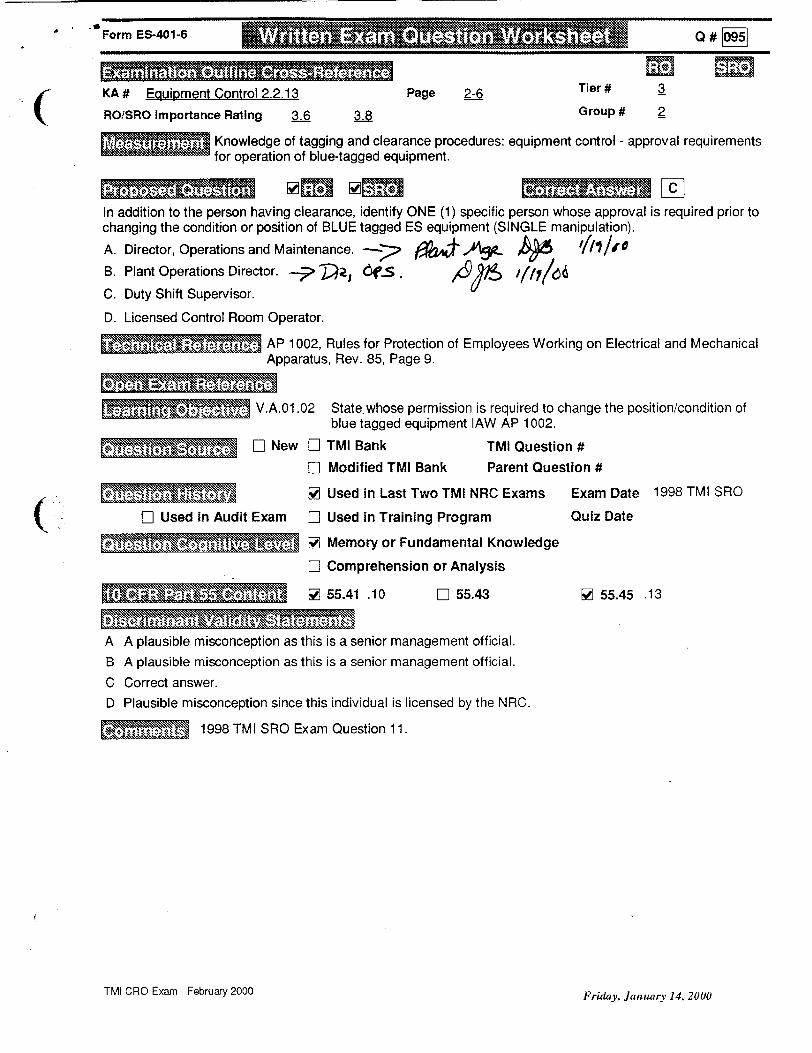
_ , Form ES-401-6 .... .... .. .. .. .. .. . U S ... . . . Q # 0O-95
KA # Equipment Control 2.2.13 Page 2-6 Tier # 3
ROISRO Importance Rating 3-6 3.8 Group # 2
Knowledge of tagging and clearance procedures: equipment control - approval requirements for operation of blue-tagged equipment.
In addition to the person having clearance, identify ONE (1) specific person whose approval is required prior to changing the condition or position of BLUE tagged ES equipment (SINGLE manipulation).
A. Director, Operations and Maintenance. ---.- O9 i.A Ap- i/n/t
B. Plant Operations Director. p T , Ct.., ,.9y /(7/'6
C. Duty Shift Supervisor.
D. Licensed Control Room Operator.
AP 1002, Rules for Protection of Employees Working on Electrical and Mechanical Apparatus, Rev. 85, Page 9.
O .M V.A.01.02 State.whose permission is required to change the position/condition of
blue tagged equipment lAW AP 1002.
VV* A7I D New El TMI Bank TMI Question #
[] Modified TMI Bank Parent Question #
17 Used in Audit Exam
V Used in Last Two TMI NRC Exams
EH Used in Training Program
Exam Date 1998 TMI SRO
Quiz Date
W Memory or Fundamental Knowledge
EH Comprehension or Analysis
EH 55.43 V 55.45 .13
A A plausible misconception as this is a senior management official. B A plausible misconception as this is a senior management official.
C Correct answer. D Plausible misconception since this individual is licensed by the NRC.
4 . 1998 TM! SRO Exam Question 11.
TMI CRO Exam- February 2000 Friday, January 14, 2000
(
[..NNW -MMUMNEW
I• •• . [] Vs5.41 .10

Writte Exam1- Q#stoný 097het
KA# Radiation Control 2.3.1 Page Z2- Tier#
ROISRO Impoitana Rating 2.& . Group #
Knowledge of 10 CFR 20 and related facility radiation control requirements: radiation control - approval requirements for emergency condition exposures In excess of normal limits.
ia plrsný B Identify the ONE (1) statement that describes the requirernd(s) for an individual to be allowed to receive a TEDE dose ectsJk - AAR-' mRem per year, excluding a planned special exposure. A. A special RWP is written oovering the Individual to be permitted to exceed 4000 mRem.
B. Approvals from the Radcon/Environmental Health & Safety Director AND the Site Director.
C. Approval from the President of the Company.
D. Notification of the NRC.
GET Radiation Worker Training Handout, Rev. 5, Page 14.
El Used in Audit
III.F.02.01 State the Federal and TMI-1 Administrative iUmits on Radiation Exposure at TMi-1 for whole body, skin and extremities.
ED New El TMI Bank TMI Question #
LI Modified TMI Bank Parent Question #
60 Used in Last Two TMI NRC Exams Exam Date 1998 TMI SRO
Exam [] Used in Training Program Quiz Date
W Memory or Fundamental Knowledge
El Comprehension or Analysis
10 CF R *'t56Cn~ 5 65.41 .12 V5 5.43 .4 5 56.46 .9, .10
A Plausible misconception that a special RWP would permit additional exposure. B Correct answer.
C Plausible misconception since this individual is required to pre-approve exposures in excess of 4500 mRem.
D Plausible misconception that the NRC could authorize additional exposure.
1998 TMI SRO Exam Question 6.
TMI CRO Exam - February 2000
Form E"1:41- 0 # 097
ITechnical Refereil Ce
'I
Monday, Dwmb" 20, 19"
10pe ExmRfrn'L L c.
lcommenfi*

Form ES-401-6 Q #0
KA # 2.4.49 Page 2-16 Tier # 2
ROISRO Importance Rating 4 4 Group # 2
Ability to perform without reference to procedures those actions that require immediate operation of system components and controls: Pressurizer Pressure Control - EP 1202-29 lAs for pressure control malfunction (PORV).
Initial plant conditions: - Cooldown in progress. - RCS temperature is 430 degrees F. - RCS pressure is 690 psig. - RC-P-1A and RC-P-1C are operating. - PORV NDTT switch is in AUTO. - Pressurizer level control is in AUTO maintaining 100 inches.
Sequence of events: - Plant cooldown was stopped in order to cycle CF-V-1A and CF-V-1B. - All plant parameters were stabilized. - Loop A Wide Range T-cold signal FAILED LOW.
From the list below, identify the ONE (1) statement that describes plant response to this situation.
A. RC-PlA AND RC-P-1C BOTH TRIP.
B. RCDT cooling valve IC-V-20 OPENS.
C. Pressurizer level control valve MU-V-17 OPENS.
D. Loop A Subcooling Margin Meter indication INCREASES.
ARP MAP G-1-7, PORV Open (Acoustic), Rev. 8, Pages 1 & 2. ARP LWDS-1-4, R. C. Drain Tnk. Press. Hi, Rev. 10, Page 1.
• IV.A.01.08 State the following concerning the PORV: a. Setpoints both high and low pressure. b. NDT switch operation and interlocks. c. Indication available to the operator to determine PORV position. d. Function/Purpose of the PORV.
t 'N' New 0 TMI Bank TMI Question #
El Modified TMI Bank Parent Question #
ED Used in Last Two TMI NRC Exams Exam Date
D Used in Audit Exam El Used in Training Program Quiz Date
ElD Memory or Fundamental Knowledge
W Comprehension or Analysis
-l -- 55.41 .10 [] 55.43 .2 SZ 55.45 ,6
A Plausible misconception that RCPs would automatically trip due to the low temperature signal. There IS a fourth pump STARTING interlock affected by this signal failure.
B Correct answer. C Plausible misconception that Pressurizer level would decrease. D Plausible misconception that T-cold is used to compute SCM, rather than T-hot.
TMI CRO Exam - February 2000 Friday, January 14, 2000

Form ES-401-6
RUM!:3
K~if7f1 0BN
None.
TMI CRO Exam - February 2000Friday, January 14, 2000
0 # 06721
(

rorm -4UIb Q #1066Q 'I166
KA# SYSTEM 016 K4.03 Page 3.7-10 Tier# 2
RO/SRO Importance Rating 2.8 2.9 Group # 2
Knowledge of NNIS design feature(s) and/or interlock(s) which provide input to control systems.
Initial plant conditions: - Reactor power is 100%. - ICS is in FULL AUTOMATIC.
RCS Loop A flow is slowly failing low and a SASS Mismatch alarm occurs but there is NO SASS actuation. Total RCS Flow signal to ICS is normal.
From the list below, identify the ONE (1) set of ICS Hand/Auto Stations that is required to be transferred to
hand to mitigate the consequence of this event.
A. A Feedwater Pump AND A Startup & Main Feedwater Valves.
B. A & B Feedwater Loop Masters.
C. A & B Startup AND Main Feedwater Valves.
D. A & B Feedwater Pumps AND A & B Startup & Main Feedwater Valves.
SICS Print D553731, Feedwater Control Analog Logic, Rev. Q.
#•• . IV.E.27.60 Given a set of plant conditions, determine the correct ICS response and any actions that must be taken if the ICS response is incorrect.
•M , M W] New El TMI Bank TMI Question #
El Modified TMI Bank Parent Question #
* El Used in Last Two TMI NRC Exams Exam Date
El Used in Audit Exam El Used in Training Program Quiz Date
""1 El Memory or Fundamental Knowledge
W Comprehension or Analysis
El 55.43 El 55.45
A Plausible misconception since the failure is an 'A' input to ICS. B Plausible misconception that Feedwater Loop Masters would eliminate the bad signal. C Plausible misconception that controlling the feedwater valves would mitigate the event. D Correct answer.
SNone.
TMI CRO Exam - February 2000 Friday, January 14, 2000
(
F-ormn ES-401-6 1 1 1 1 : : : : 1 : : 0M &I W X': i : 10
•....,••-.•;..L ME 55.41 .7
Q # 10661
MO

Form ES-401-6 Q # O 9
KA # SYSTEM 033 A3.02 Page 3.8-10 Tier # 2
ROiSRO Importance Rating 2.9 3.1 Group # 2
Ability to monitor automatic operation of the Spent Fuel Pool Cooling System including spent fuel leak or rupture.
Plant conditions: - Reactor power is 100%. - SF-P-1A Spent Fuel Cooling Pump is operating in recirc mode. - SF-P-2 Borated Water Recirc Pump is operating for Pool A (LWDS) cleanup. - Spent fuel assembly rack location change in progress in Spent Fuel Pool A.
Due to equipment failure, a spent fuel assembly is dropped - lying on top of the fuel racks in Pool A. Fuel pin clad rupture has resulted in significant activity release to the spent fuel pool water.
Identify the ONE (1) statement below that describes plant design response to RM-L-5 indication, which pegs
high due to the increase in radioactivity described above.
A. SF-P-2 trips.
B. SF-P-iA trips.
C. MAP C-1-1 RADIATION LEVEL HIGH actuates.
D. MAP C-1-1 RADIATION LEVEL HIGH actuates AND Fuel Handling Building Supply Fan, AH-E-10, trips.
W ARP MAP C-1-1, Radiation Level Hi, Rev. 20, Page 53.
I��-. IV.E.06.04 Given an RMS channel, state the interlocks associated with a channel in the Radiation Monitoring system.
a". M P New El TMI Bank TMI Question #
II Modified TMI Bank Parent Question #
ll [ Used in Last Two TMI NRC Exams Exam Date
D] Used in Audit Exam E] Used in Training Program Quiz Date
W Memory or Fundamental Knowledge
[I Comprehension or Analysis
55.41 .7 El 55.43 [ 55.45 .5
A Plausible misconception that LWDS cleanup flow should be automatically terminated to minimize plant personnel radiation exposures due to contamination of LWDS cation demineralizer resins.
B Plausible misconception that liquid flow out of the spent fuel pool should be terminated to limit curie transport out of the spent fuel pool in order to minimize plant personnel radiation exposures.
C Correct answer.
D Plausible misconception that air flow out of the spent fuel handling area should be minimized to reduce plant personnel radiation exposures.
P••'••-'•No ne.
TMI CRO Exam - February 2000 Friday, January 14, 2000

Form ES-401-6
KA # SYSTEM 034 A1.02 Page 3.8-13 Tier # 2
RO/SRO Importance Rating 2.9 3.7 Group # 3
-� bility to predict and/or monitor changes in parameters (to prevent exceeding design limits) associated with operating the Fuel Handling System controls, including water level in the refueling canal: FH actions for refueling canal low level.
A fuel assembly has just been lifted from the upender and is transitioning to the core to be placed in core position H-8. The assembly is currently 2 feet away from the upender when spent fuel pool level is observed do be dropping at 10 inches per minute.
From the list below, identify the ONE (1) statement that describes the procedurally required disposition of the fuel assembly.
A. Placed in core position H-8.
B. Placed in the nearest available core location.
C. Placed in the upender to be returned to the Spent Fuel Pool.
D. Lowered between the plenum and the upender until it just touches the floor.
AbP 1203-43, Transfer Canal Seal Plate Gasket Failure/Level Loss, Rev. 6, Page 2.
• V.C.16.02 State the required Immediate Manual Actions for a failure of the fuel
transfer canal seal plate per AP 1203-43.
ý - M1 W] New LD TMI Bank TMI Question #
ED Modified TMI Bank Parent Question #
El] Used in Last Two TMI NRC Exams Exam Date
1- Used in Audit Exam Dj Used in Training Program Quiz Date
W Memory or Fundamental Knowledge
ED Comprehension or Analysis
6e 55.41 .5 El 55.43 Wl 55.45 .5
A. Plausible since this is where the assembly belongs.
B Plausible since this is an immediate action if the assembly is closer to the core.
C Plausible since the Spent Fuel Pool is an alternate storage location.
D Correct answer.
r , ,•: ... None.
TMI CRO Exam - February 2000Friday, January 14, 2000

Form •S-401-6
KA # Conduct of Operations 2.1.29 Page 2-4 Tier # 3
ROiSRO Importance Rating 3.4 3.3 Group # 1
• Knowledge of how to conduct and verify valve lineups: performance of valve lineup independent verification of valve position.
From the list below, identify the ONE (1) statement that describes the requirements for performing an Independent Verification for an easily accessible manual valve that is required to be closed. A. One individual closes the valve, second individual verifies from an independent remote position DEMAND
indicator that the valve closed.
B. One individual closes the valve, second individual independently uses a remote POSITION indicator to verify the valve is closed.
C. One individual closes the valve, second individual independently verifies the valve is closed by physically turning in the closed direction.
D. One individual closes the valve, while the second individual visually observes the first individual closing the valve.
AP 1067, Independent Verification Program, Rev. 28, Page 5.
V.J.01.02 State how valve position must be verified for valves without remote position indication/ and state when valve position may be verified by remote indication - according to AP 1067 Independent Verification.
• D] New D TMI Bank TMI Question #
El Modified TMI Bank Parent Question #
' • d"•7-• A Used in Last Two TMI NRC Exams Exam Date 1998 TMI SRO
F-1 Used in Audit Exam E] Used in Training Program Quiz Date
W Memory or Fundamental Knowledge
El Comprehension or Analysis
•••,''• []55.41 .10 ED 55.43 W 55.45 .1, .12
A Plausible misconception that use of DEMAND indication is an acceptable means of position verification.
B Plausible misconception that use of remote position indication is acceptable for manual valves with easy access.
C Correct answer.
D Plausible distracter since this is procedurally acceptable for valves which are not easily accessed.
1998 TMI SRO Exam Question 33.
TMI CRO Exam - February 2000 Friday, January 14, 2000
(
. _ • - -- t• -" • • •" - • Q "# --881O # 10881

Form ES-401-6 _#0
KA # Conduct of Operations 2.1.30 Page 2-4 Tier # 3
(ROiSRO Importance Rating 3.9 3.4 Group # 1
Ability to locate and operate components, including local controls: Conduct of operations local manual operation of MOV.
From the list below, identify the ONE (1) witness required when hand-cranking a motor operated ESAS valve.
A. Licensed Reactor Operator.
B. Member of Plant Engineering staff.
C. Shift Foreman.
D. Shift Technical Advisor.
AP 1029, Conduct of Operations, Rev. 71, Page 28.
V.A.10.16 Identify/explain the requirements for hand cranking motor operated valves to stop valve seat or stem leakage, as delineated in AP 1029, Conduct of Operations.
* " L New El TMI Bank TMI Question#
El Modified TMI Bank Parent Question #
VJ Used in Last Two TMI NRC Exams Exam Date 1995 TMI RO
EL Used in Audit Exam Li Used in Training Program Quiz Date
"- V [ Memory or Fundamental Knowledge
EL Comprehension or Analysis
S55.41 .7 Li 55.43 [ 55.45 .7
A Plausible misconception since this person holds an active NRC license. B Plausible misconception regarding systems engineering SME support.
C Correct answer. D Plausible misconception regarding shift engineering support.
• 1995 TMI RO Exam Question 20.
TMI CRO Exam - February 2000 Friday, January 14, 2000
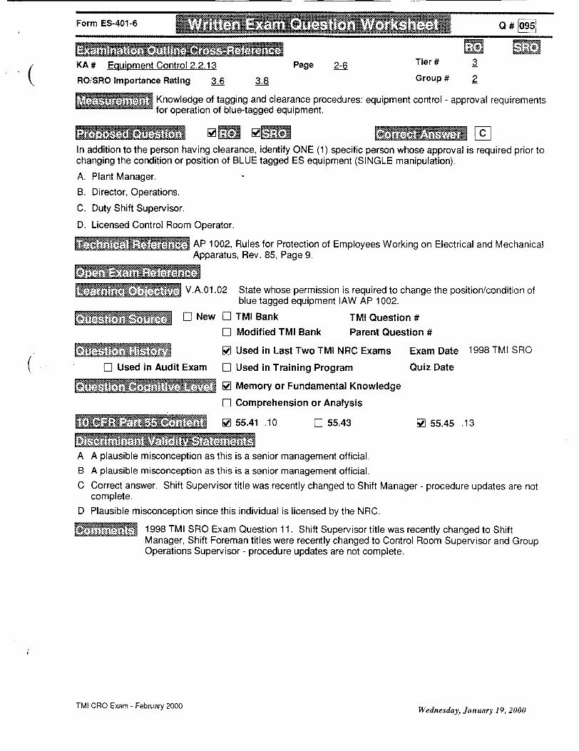
Form ES-401-6 Q #
KA # Equipment Control 2.2.13 Page 2-6 Tier # 3
RO/SRO Importance Rating 3.6 3.8 Group # 2
Knowledge of tagging and clearance procedures: equipment control - approval requirements for operation of blue-tagged equipment.
In addition to the person having clearance, identify ONE (1) specific person whose approval is required prior to changing the condition or position of BLUE tagged ES equipment (SINGLE manipulation).
A. Plant Manager.
B. Director, Operations.
C. Duty Shift Supervisor.
D. Licensed Control Room Operator.
AP 1002, Rules for Protection of Employees Working on Electrical and Mechanical Apparatus, Rev. 85, Page 9.
. . V.A.01.02 State whose permission is required to change the position/condition of blue tagged equipment lAW AP 1002.
E. ] New EL TMI Bank TMI Question #
El Modified TMI Bank Parent Question #
Va- [ Used in Last Two TMI NRC Exams Exam Date 1998 TMI SRO
LI Used in Audit Exam El Used in Training Program Quiz Date
W Memory or Fundamental Knowledge
DI Comprehension or Analysis
S[W 55.41 .10 LI 55,43 [ 55.45 .13
A A plausible misconception as this is a senior management official. B A plausible misconception as this is a senior management official. C Correct answer. Shift Supervisor title was recently changed to Shift Manager - procedure updates are not
complete. D Plausible misconception since this individual is licensed by the NRC.
1998 TMI SRO Exam Question 11. Shift Supervisor title was recently changed to Shift Manager, Shift Foreman titles were recently changed to Control Room Supervisor and Group Operations Supervisor - procedure updates are not complete.
TMI CRO Exam - February 2000 Wednesday, January 19, 2000

Form ES-401-6 . . .. Q#o97
KA # Radiation Control 2.3.1 Page 2-9 Tier # 3
ROiSRO Importance Rating 2.6 3 Group # 3
- Knowledge of 10 CFR 20 and related facility radiation control requirements: radiation control - approval requirements for emergency condition exposures in excess of normal limits.
Identify the ONE (1) statement that describes the MINIMUM requirement(s) for an individual to be allowed to receive a TEDE dose of 4100 mRem per year, excluding a planned special exposure.
A. A special RWP is written covering the individual to be permitted to exceed 4000 mRem. B. Approvals from the Radcon/Environmental Health & Safety Director AND the Site Director.
C. Approval from the President of the Company.
D. Notification of the NRC.
GET Radiation Worker Training Handout, Rev. 5, Page 14.
•'.. III.F.02.01 State the Federal and TMI-1 Administrative Limits on Radiation
Exposure at TMI-1 for whole body, skin and extremities.
*E] New D TMI Bank TMI Question # EH Modified TMI Bank Parent Question #
V Used in Last Two TMI NRC Exams Exam Date 1998 TMI SRO
Hj Used in Audit Exam Hj Used in Training Program Quiz Date
66] Memory or Fundamental Knowledge
EH Comprehension or Analysis
S[ 55.41 .12 [] 55.43 .4 [J 55.45 .9, .10
A Plausible misconception that a special RWP would permit additional exposure. B Correct answer. C Plausible misconception since this individual is required to pre-approve exposures in excess of 4500 mRem. D Plausible misconception that the NRC could authorize additional exposure.
* 1998 TMI SRO Exam Question 6. 1/19/00 - Edited question stem to specify MINIMUM requirements and 4100 mRem exposure. This positively eliminated distracter C as a potentially correct answer. This individual COULD approve this exposure in the absence of the individuals in the normally correct answer (B). This individual is REQUIRED to approve exposures in excess of 4500 Mrem.
TMI CRO Exam - February 2000 Wednesday, January 19, 2000

Form ES-401-6 Q # 00 6
KA # APE 027 AK2.03 Page 4.2-20 Tier # 1
(ROiSRO Importance Rating 2.6 2.8 Group # 1
K nowledge of the interrelations between the Pressurizer Pressure Control Malfunctions and the controllers and positioners: Predict/monitor/control effects of Pressurizer pressure control malfunction.
Sequence of events: - Initial reactor power = 90%. - FW-P-1A trips and an automatic ICS runback is in progress. - At 2225 psig RCS pressure (still increasing), the selected RCS pressure transmitter
fails low (SASS DOES NOT ACTUATE). - NO manual operations have been performed.
From the list below, identify the ONE (1) group of automatic actions that will occur if this plant situation continues and no operator actions are taken.
A. RC-V-1 CLOSES; Pressurizer heaters ENERGIZE; Reactor trips on LOW RCS pressure.
B. RC-V-1 CLOSES; Pressurizer heaters ENERGIZE; Reactor trips on HIGH RCS pressure.
C. RC-V-1 remains OPEN; Pressurizer heaters DE-ENERGIZE; Reactor trips on HIGH RCS pressure.
D. RC-V-1 remains OPEN; Pressurizer heaters DE-ENERGIZE; Reactor trips on LOW RCS pressure.
EP 1202-29, Pressurizer System Failure, Rev. 54, Pages 5 and 7.
• .~.'-- ; ~ V.D.1 1.03 Given a list of symptoms, identify the event, determine what Immediate Automatic Actions will occur and what Immediate Manual Actions are required lAW EP 1202-29.
MITM• M ] New ED TMI Bank TMI Question #
El Modified TMI Bank Parent Question #
SM I Used in Last Two TM I NRC Exam s Exam Date E] Used in Audit Exam El Used in Training Program Quiz Date
" El Memory or Fundamental Knowledge
[I Comprehension or Analysis W 55.41 .7 El 55.43 6e 55.45 .7
A Plausible because all actions listed occur in response to an actual decrease in RCS pressure. B Correct answer. The first two actions result in the third action. C Plausible because all actions listed occur in response to an actual increase in RCS pressure. D Plausible because first two actions occur in response to an actual increase in RCS pressure.
• '- None. TMI CRO Exam - February 2000 Friday, January 14, 2000

Form ES-401-6 Q #00
KA # APE 056 AKi1.04 Page 4.2-37 Tier # 1
RO/SRO Importance Rating 3.1 32 Group # 1
Knowledge of the operational implications of the definition of saturation conditions, implications for the systems as applicable to Loss of Offsite Power:
Plant conditions: - A loss of station power has occurred. - Only the 1 D 4KV bus has been re-energized. - Pressurizer heaters have NOT been energized. - Pressurizer level is being maintained at 100 inches. - OTSG levels are being maintained at 50% operating range. - RCS natural circulation has been obtained and verified. - RCS Subcooled margin is 50 degrees F. - Core cooldown rate is 0 degrees F/hour.
From the list below, identify the ONE (1) statement that describes expected RCS Subcooled margin response.
A. Increase as core temperatures decrease.
B. Decrease as Pressurizer temperature decreases.
C. Remain fairly constant with constant Pressurizer level.
D. Remain fairly constant with constant core cooldown rate.
EP 1202-2, Loss of Station Power, Rev. 49, Page 6.
I- V.A.01.06 Describe how RCS pressurizer pressure is maintained to include: a. Heaters and their setpoints.
- I] New ED TMI Bank TMI Question #
ED Modified TMI Bank Parent Question #
ED Used in Last Two TMI NRC Exams Exam Date
F1 Used in Audit Exam El Used in Training Program Quiz Date
E lI Memory or Fundamental Knowledge
91 Comprehension or Analysis
.l 55.41 .8, .10 El 55.43 66 55.45 .3
A Plausible because with constant pressure, SCM increases as temperature decreases.
B Correct answer.
C Plausible if Pressurizer heaters were available to maintain Pressurizer temperature. D Plausible if Pressurizer heaters were available to maintain Pressurizer temperature.
�� �1/19/00 - Changed last bullet in stem from 5 degrees per hour cooldown rate to 0 degrees per hour to eliminate compound (opposite) effects on RCS Subcooled Margin - pressurizer ambient losses due to loss of Pressurizer Heaters (decreases subcooled margin) and decreasing Thot (increases subcooled margin) with constant Pressurizer level.
TMI CRO Exam - February 2000 Wednesday, January 19, 2000
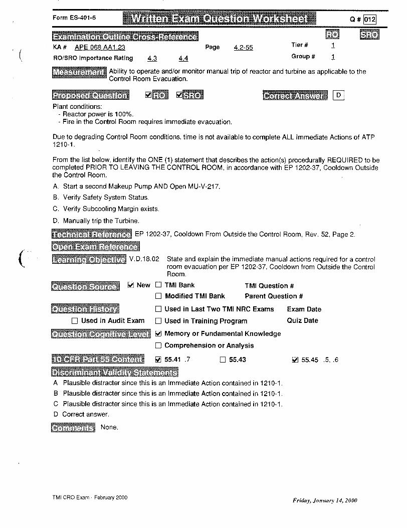
Form ES-401-6 Q# 01
KA # APE 068 AA1.23 Page 4.2-55 Tier # 1
(RO/SRO Importance Rating 4.3 4.4 Group # 1
Ability to operate and/or monitor manual trip of reactor and turbine as applicable to the Control Room Evacuation.
Plant conditions: - Reactor power is 100%. - Fire in the Control Room requires immediate evacuation.
Due to degrading Control Room conditions, time is not available to complete ALL Immediate Actions of ATP 1210-1.
From the list below, identify the ONE (1) statement that describes the action(s) procedurally REQUIRED to be completed PRIOR TO LEAVING THE CONTROL ROOM, in accordance with EP 1202-37, Cooldown Outside the Control Room.
A. Start a second Makeup Pump AND Open MU-V-217.
B. Verify Safety System Status.
C. Verify Subcooling Margin exists.
D. Manually trip the Turbine.
EP 1202-37, Cooldown From Outside the Control Room, Rev. 52, Page 2.
V.D.18.02 State and explain the immediate manual actions required for a control
room evacuation per EP 1202-37, Cooldown from Outside the Control Room.
' New LI TMI Bank TMI Question #
El Modified TMI Bank Parent Question #
WU U. El Used in Last Two TMI NRC Exams Exam Date
DI Used in Audit Exam EL Used in Training Program Quiz Date
M- RE22 LZR Memory or Fundamental Knowledge
El Comprehension or Analysis
WI 55.41 .7 LI 55.43 [ 55.45 .5, .6
LaI d sai n A Plausible distracter since this is an Immediate Action contained in 1210-1.
B Plausible distracter since this is an Immediate Action contained in 1210-1. C Plausible distracter since this is an Immediate Action contained in 1210-1.
D Correct answer.
None.
TMI CRO Exam - February 2000Friday, January 14, 2000

Form ES-401-6 Q _[
KA # EPE E02 AK3.2 Page 4.3-29 Tier # 1
(ROiSRO Importance Rating 3.7 4 Group #
Knowledge of the reasons for normal, abnormal and emergency operating procedures associated with Loss of NNI Hand Power.
Plant conditions: - Reactor Power is 42%. - The following ICS Stations are in HAND due to ICS automatic control problems:
FW-P-1A, FW-P-1B (FWP flows are matched). FW-V-16A, FW-V-16B. FW-V-17A, FW-V-17B.
- All other ICS controls are in AUTOMATIC.
LOSS OF ICS HAND POWER occurs, followed immediately by a TURBINE TRIP.
Identify the ONE (1) statement below that describes procedurally required operator action(s) for this situation.
A. Trip the reactor AND trip both Main Feedwater Pumps.
B. Stabilize reactor power equal to Main Feedwater flow.
C. Transfer control of BOTH Feedwater Pumps to the Motor Speed Changers in the Control Room.
D. Transfer BOTH Main Feedwater Pumps to LOCAL SPEED CONTROL at the feedwater pump control panel.
EP 1202-41, Total or Partial Loss of ICS/NNI Hand Power, Rev. 30, Page 3.
i V.D.21.03 State the Immediate Manual Actions required for a Total or Partial Loss of ICS/NNI Hand power per EP 1202-41.
S[ INew ED TMI Bank TMI Question #
El Modified TMI Bank Parent Question #
ElD Used in Last Two TMI NRC Exams Exam Date
LI Used in Audit Exam Ei Used in Training Program Quiz Date
F_] Memory or Fundamental Knowledge
66 Comprehension or Analysis
• 55.41 .5, .10 0i 55.43 [] 55.45 .6, .13
A Correct answer.
B Plausible since this action would attempt to balance heat production with heat removal.
C Plausible since this is an alternate method of Feedwater pump control but not an immediate manual action allowed by the procedure.
D Plausible since this is an alternate method of Feedwater pump control but not an immediate manual action prescribed by the procedure.
I••-• 1/19/00 - Edited stem to specify initial FWP flows are matched to avoid ambiguity regarding FP responses due to loss of Hand Power.
TMI CRO Exam - February 2000Wednesday, January 19, 2000

Form ES-401-6 QMR #
KA # APE 040 AK2.01 Page 4.2-31 Tier # 1
ROiSRO Importance Rating 2.6 2.5 Group # 1
Knowledge of the interrelations between the Steam Line Rupture and valves: valve response to Main Steam line rupture.
Sequence of events: - Reactor power is initially 100%. - Steam Line Rupture in the Intermediate Building, upstream of MS-V-1 C. - HSPS actuates. - OTSG 1 B depressurizes to 40 psig.
RCS Subcooling Margin is maintained throughout this event. No operator action has been taken to isolate OTSG 1B.
Identify the ONE (1) statement below that describes the response of EF-V-30A, EF-V-30B, EF-V-30C and EF-V30D under these conditions.
A. EF-V-30A and EF-V-30D remain closed in automatic; EF-V-30B and EF-V-30C control OTSG 1 B level at 25 inches in the Startup Range.
B. EF-V-30A and EF-V-30D remain closed in automatic; EF-V-30 B and EF-V-30C control OTSG 1 B level at 50% in the Operating Range.
C. EF-V-30A and EF-V-30D control OTSG 1A level at 25 inches in the Startup Range; EF-V-30B and EF-V-30C remain closed due to HSPS (low pressure) actuation.
D. EF-V-30A and EF-V-30D control OTSG 1A level at 25 inches in the Startup Range; EF-V-30B and EF-V-30C control OTSG 1 B level at 25 inches in the Startup Range.
ATOG ATP 1210-10 Abnormal Transients Rules, Guides and Graphs, Rev. 37, OTSG Level Rule 1.6, Pages 5 & 6. ATP 1210-1, Reactor Trip, Rev. 40, Step 2.7, Page 4.
ME. ,V.C.05.26 Given a set of plant conditions, determine whether the EFW system has responded correctly.
-, lNew ED TMI Bank TMI Question #
ED Modified TMI Bank Parent Question #
- • "•. • D[E Used in Last Two TMI NRC Exams Exam Date
ED Used in Audit Exam ED Used in Training Program Quiz Date
.. L Memory or Fundamental Knowledge
WI Comprehension or Analysis
S[] 55.41 .7 El 55.43 [ 55.45 .7
A Correct answer.
B Plausible distracter if actuation setpoint is misunderstood.
C Plausible distracter if actuation setpoint and HSPS isolation is misunderstood. D Plausible distracter if HSPS isolation is misunderstood.
• None.
TMI CRO Exam - February 2000 Friday, January 14, 2000

Form ES-401-6 Q #
KA # APE 001 AA2.01 Page 4.2-3 Tier # 1
RO/SRO Importance Rating 4.5 4.8 Group # 2
- Ability to determine and interpret the following as they apply to the Continuous Rod Withdrawal: Reactor Trip Breaker Indication.
The Control Room Operator MANUALLY trips the reactor. Identify the ONE (1) situation below that confirms ALL the CRD breakers have OPENED.
A. All rods in CRD Groups 1-7 drop, fully inserted into the core. B. Alarms G-1-3 (CRD DC Trip Brkr Open) AND G-1-4 (CRD AC Trip Brkr Open) actuate.
C. RPS Breaker Trip Lights on ALL 4 RPS Cabinets are energized. D. RPS Protective Subsystem Lights on ALL 4 RPS Cabinets are energized.
SOPM Section F-02, Reactor Protection System, Rev 8 Page 117
IV.E.14.10 Given the RPS cabinet status and/or CRD Breaker status, determine if a
reactor trip has occurred and/or which control rod groups have tripped. • .•-" [] New [I TMI Bank TMI Question #
El Modified TMI Bank Parent Question #
[El Used in Last Two TMI NRC Exams Exam Date
ElI Used in Audit Exam El Used in Training Program Quiz Date
V Comprehension or Analysis
S55.41 [ 55.43 .5 [ 55.45 .13
A Plausible misconception that all CRD breakers are required to be open in order for all the rods to be deenergized and drop into the core.
B Plausible misconception that this alarm combination confirms that all breakers associated with each alarms have opened. Alarm actuation logic does not require ALL breakers to be open.
C Correct answer. D Plausible misconception that the RPS Protective Trip lights indicate the associated breaker has opened.
These lights energize when the RPS Subsystem Reactor Trip module actuates - rather than actual operation (opening) of ORD breakers.
KA catalog does not address 10 CFR 55.41 for this measurement. Amergen feels 10 CFR 55.41 is applicable to this KA Catalog item for TMI.
TMI CRO Exam - February 2000 Friday, January 14, 2000

harm t±S-4U1-� In9n�
KA# BWA01 AA1.1 Page 4.3-27 Tier # 1
ROiSRO Importance Rating 3.7 3.7 Group # 2
Ability to operate and/or monitor components, and functions of control and safety systems, including instrumentation, signals, interlocks, failure modes, and automatic and manual features as applicable to a Plant Runback: actions for ICS Runback failure.
Plant conditions: - Reactor power 85%. - ICS in full automatic.
Sequence of events: - FW-P-1A tripped concurrent with a total loss of ICS Hand Power. - ICS Runback failed to occur. - The following alarms are actuated:
- ICS IN TRACK - ICS HIGH LOAD LIMITED
From the list below, identify the ONE (1) statement that describes required operator action(s) for this condition.
A. Trip the Reactor/Turbine AND go to ATP 1210-1.
B. Place FW-P-1B in HAND AND increase feedwater flow.
C. Reduce the ULD output demand to 68% (585 MWe) AND verify the plant runs back.
D. Place the SG/Rx Master in HAND AND reduce power to 68% (585 MWe).
ARP MAP H-1-1, ICS Runback, Rev. 19, Page 2.
IV.E.27.60 Given a set of plant conditions, determine the correct ICS response and
any actions that must be taken if the ICS response is incorrect.
S] INew El TMI Bank TMI Question #
El Modified TMI Bank Parent Question #
El Used in Last Two TMI NRC Exams Exam Date
Li Used in Audit Exam Li Used in Training Program Quiz Date
El Memory or Fundamental Knowledge
[ Comprehension or Analysis
W 55.41 .7 EL 55.43 W 55.45 .5, .6
A Plausible distracter since this would result in a reduction in turbine output. B Plausible distracter since this would attempt to match reactor power and feedwater flow. C Plausible distracter since this would normally result in a plant power reduction except when ICS Track Alarm
is present.
D Correct answer.
1/19/00 - Edited question stem to specify ICS initially in full automatic. This removes ambiguity regarding initial ICS status, and improves plausibility of distracter C. Edited distracter C, replacing ULD setpoint with ULD output demand to clarify this (incorrect) action.
TMI CRO Exam - February 2000 Wednesday, January 19, 2000
(
In fi
Form ES-401-6 n • lngnl
FD I

Form ES-401-6 #
KA # BWA04 AA1.1 Page 4.3-33 Tier # 1
ROiSRO Importance Rating 3.5 3.3 Group # 2
Ability to operate and/or monitor components, and functions of control and safety systems, including instrumentation, signals, interlocks, failure modes, and automatic and manual features as applicable to a Turbine Trip: actions for turbine trip at low power.
Plant conditions: - Reactor power is 35%, during plant startup. - All ICS stations in auto EXCEPT FW-P-1A.
Considering these plant conditions, from the list below identify the ONE (1) statement that describes the
operational status of the MAIN TURBINE if the main generator breakers trip due to a generator ground fault.
A. Must be manually tripped.
B. Will trip automatically without a time delay.
C. Will trip automatically after a 30 second time delay.
D. Will revert to Speed Control and remain at 1800 RPM.
7 ARP MAP K-1-1, Turbine Trip, Rev. 18, Page 1.
IV.E.03.08 Given a specific main turbine trip, explain its operation including control signal(s) monitored, setpoint(s) for actuation and any applicable logic to cause the actuation.
(,.. • •'•,, [] New D] TMI Bank TMI Question #
D Modified TMI Bank Parent Question #
E _] Used in Last Two TMI NRC Exams Exam Date
El Used in Audit Exam D Used in Training Program Quiz Date
E El Memory or Fundamental Knowledge
[ Comprehension or Analysis
. [] 55.41 41.7 ED 55.43 Sd 55.45 .5, .6
A Plausible if misconception that turbine will not automatically trip on generator fault.
B Correct answer.
C Plausible because there is a 30 second delay generator trip following turbine trip.
D Plausible because this is normal turbine control.
• None.
TMI CRO Exam - February 2000 Friday, January 14, 2000

Form ES-401-6 We S t I., In, FF f S. enw. .............. ýýil f
(
("-
TMI CRO Exam - February 2000Thursday, January 20, 2000
KA # APE 028 AA1.03 Page 4.2-23 Tier # 1
RO/SRO Importance Rating 2.9 2.9 Group # 3
Ability to operate and/or monitor RCP and seal water system as applicable to the Pressurizer Level Control Malfunction.
Plant conditions: - Reactor power is 100%. - MU-P-1 B is operating in normal makeup system alignment. - MU-V-17 is in AUTO with makeup flow at 22 gpm. - MU-V-32 is in HAND for maintenance with seal injection flow at 38 gpm.
The selected Pressurizer temperature transmitter suddenly fails low.
From the list below, identify the ONE (1) statement that describes makeup and seal injection flow responses to this condition, with no operator action.
A. Makeup flow will decrease and seal injection flow will increase.
B. Makeup flow will decrease, but seal injection flow will not change.
C. Makeup flow will increase and seal injection flow will decrease.
D. Makeup flow will increase, but seal injection flow will not change.
EP 1202-29, Pressurizer System Failure, Rev. 54, Page 11.
. V.D.11.01, State the Immediate Automatic Actions that occur for the following V.D.1 1.03 Pressurizer System Failures per EP 1202-29:
d. Malfunction in Pressurizer Level Indication or Control. Given a list of symptoms, identify the event, determine what Immediate Automatic Actions will occur and what Immediate Manual Actions are required lAW EP 1202-29.
] New [] TMI Bank TMI Question #
El Modified TMI Bank Parent Question #
•ll Used in Last Two TMI NRC Exams Exam Date
El Used in Audit Exam II Used in Training Program Quiz Date
E IE Memory or Fundamental Knowledge
[ Comprehension or Analysis
WI 55.41 .7 II 55.43 66 55.45 .5, .6
A Plausible because of misconception that PZR level will increase causing MU-V-1 7 to close, and seal injection flow would increase if makeup flow decreased.
B Plausible because of misconception that PZR level will increase causing MU-V-17 to close, and that seal injection flow would not change with MU-V-32 in HAND.
C Correct answer because MU-V-17 will open causing makeup flow to increase and seal injection flow to decrease with MU-V-32 in HAND.
D Plausible because MU-V-17 will open causing makeup flow to increase, and misconception that seal injection flow would not change with MU-V-32 in HAND.
• , ~None.
Q #0
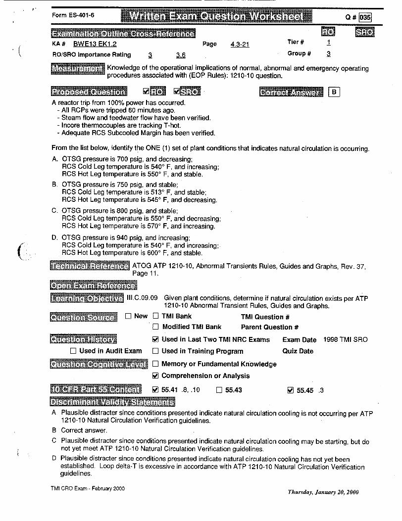
Form ES-401-6 Q # 03
KA# BWE13 EK1.2 Page 4.3-21 Tier# 1
ROiSRO Importance Rating 3.6 Group # 3
- Knowledge of the operational implications of normal, abnormal and emergency operating procedures associated with (EOP Rules): 1210-10 question.
A reactor trip from 100% power has occurred. - All RCPs were tripped 60 minutes ago. - Steam flow and feedwater flow have been verified. - Incore thermocouples are tracking T-hot. - Adequate RCS Subcooled Margin has been verified.
(/
TMI CRO Exam - February 2000Thursday, January 20, 2000
From the list below, identify the ONE (1) set of plant conditions that indicates natural circulation is occurring.
A. OTSG pressure is 700 psig, and decreasing; RCS Cold Leg temperature is 5400 F, and increasing; RCS Hot Leg temperature is 5500 F, and stable.
B. OTSG pressure is 750 psig, and stable; RCS Cold Leg temperature is 5130 F, and stable; RCS Hot Leg temperature is 5450 F, and decreasing.
C. OTSG pressure is 800 psig, and stable; RCS Cold Leg temperature is 5500 F, and decreasing; RCS Hot Leg temperature is 5700 F, and increasing.
D. OTSG pressure is 940 psig, and increasing; RCS Cold Leg temperature is 5400 F, and increasing; RCS Hot Leg temperature is 6000 F, and stable.
ATOG ATP 1210-10, Abnormal Transients Rules, Guides and Graphs, Rev. 37, Page 11.
II1.C.09.09 Given plant conditions, determine if natural circulation exists per ATP
1210-10 Abnormal Transient Rules, Guides and Graphs.
S[L New El TMI Bank TMI Question # El Modified TMI Bank Parent Question #
W Used in Last Two TMI NRC Exams Exam Date 1998 TMI SRO
El Used in Audit Exam El Used in Training Program Quiz Date
"- l Memory or Fundamental Knowledge
W Comprehension or Analysis
W WI 55.41 .8, .10 El 55.43 [I 55.45 .3
A Plausible distracter since conditions presented indicate natural circulation cooling is not occurring per ATP 1210-10 Natural Circulation Verification guidelines.
B Correct answer. C Plausible distracter since conditions presented indicate natural circulation cooling may be starting, but do
not yet meet ATP 1210-10 Natural Circulation Verification guidelines. D Plausible distracter since conditions presented indicate natural circulation cooling has not yet been
established. Loop delta-T is excessive in accordance with ATP 1210-10 Natural Circulation Verification guidelines.
. ..............

.. ...... ... ................................... of amu ............. ....... .. ......... .. .... ......1998 TMI SRO Exam Question 87. 1/20/00 - Added bullet to question stem to specify RCS Subcooled Margin exists, to satisfy ATOG Guideline 2.8. Without this an argument could be made that there is no correct answer provided.
TMI CRO Exam - February 2000Thursday, January 20, 2000
(
(
a # §ýýForm ES-401-6

Form ES-401-6 #62
KA# 2.4.49 Page 2-16 Tier # 2
ROISRO Importance Rating 4 4 Group # 2
- Ability to perform without reference to procedures those actions that require immediate operation of system components and controls: Pressurizer Pressure Control - EP 1202-29 lAs for pressure control malfunction (PORV).
Initial plant conditions: - Cooldown in progress. - RCS temperature is 430 degrees F. - RCS pressure is 690 psig. - RC-P-1A and RC-P-1C are operating. - PORV NDTT switch is in AUTO. - Pressurizer level control is in AUTO maintaining 100 inches.
Sequence of events: - Plant cooldown was stopped in order to cycle CF-V-1 A and CF-V-1 B. - All plant parameters were stabilized. - Loop A Wide Range T-cold signal FAILED LOW.
From the list below, identify the ONE (1) statement that describes plant response to this situation.
A. RC-P1A AND RC-P-1C BOTH TRIP.
B. RCDT cooling valve IC-V-20 OPENS.
C. Pressurizer level control valve MU-V-1 7 OPENS.
D. Loop A Subcooling Margin Meter indication INCREASES.
ARP MAP G-1-7, PORV Open (Acoustic), Rev. 8, Pages 1 & 2. ARP LWDS-1 -4, R. C. Drain Tnk. Press. Hi, Rev. 10, Page 1.
. ~ IV.A.01.08 State the following concerning the PORV: a. Setpoints both high and low pressure. b. NDT switch operation and interlocks. c. Indication available to the operator to determine PORV position. d. Function/Purpose of the PORV.
S[] New El TMI Bank TMI Question #
El Modified TMI Bank Parent Question #
[El Used in Last Two TMI NRC Exams Exam Date
El Used in Audit Exam F1 Used in Training Program Quiz Date
El Memory or Fundamental Knowledge
S6 Comprehension or Analysis
W 55.41 .10 5Z 55.43 .2 [ 55.45 ,6
A Plausible misconception that RCPs would automatically trip due to the low temperature signal. There IS a fourth pump STARTING interlock affected by this signal failure.
B Correct answer.
C Plausible misconception that Pressurizer level would decrease.
D Plausible misconception that T-cold is used to compute SCM, rather than T-hot.
TMI CRO Exam - February 2000 Friday, January 14, 2000

Form ES-401-6
f -:,
~kfl rm Li ~W~It IhT j!'T I
None.
TMI CRO Exam - February 2000
Q # 10621
Friday, January 14, 2000

Form ES-401-6 Q #
KA# SYSTEM 016 K4.03 Page 3.7-10 Tier # 2
ROiSRO Importance Rating 2.8 2.9 Group # 2
Knowledge of NNIS design feature(s) and/or interlock(s) which provide input to control systems.
Initial plant conditions: - Reactor power is 100%. - ICS is in FULL AUTOMATIC.
RCS Loop A flow is slowly failing low and a SASS Mismatch alarm occurs but there is NO SASS actuation. Total RCS Flow signal to ICS is normal.
From the list below, identify the ONE (1) set of ICS Hand/Auto Stations that is required to be transferred to
hand to mitigate the consequence of this event.
A. A Feedwater Pump AND A Startup & Main Feedwater Valves.
B. A & B Feedwater Loop Masters.
C. A & B Startup AND Main Feedwater Valves.
D. A & B Feedwater Pumps AND A & B Startup & Main Feedwater Valves.
ICS Print D553731, Feedwater Control Analog Logic, Rev. Q.
SIV.E.27.60 Given a set of plant conditions, determine the correct ICS response and any actions that must be taken if the ICS response is incorrect.
..] .. New ED TMI Bank TMI Question #
El Modified TMI Bank Parent Question #
E• [l Used in Last Two TMI NRC Exams Exam Date
LI Used in Audit Exam El Used in Training Program Quiz Date
S: ,,', Memory or Fundamental Knowledge
[] Comprehension or Analysis
66 55.41 .7 E] 55.43 EL 55.45
A Plausible misconception since the failure is an 'A' input to ICS.
B Plausible misconception that Feedwater Loop Masters would eliminate the bad signal.
C Plausible misconception that controlling the feedwater valves would mitigate the event.
D Correct answer.
SNone.
TMI CRO Exam - February 2000Friday, January 14, 2000

Form ES-401-6 Q # F-9 ... .......... .
KA # SYSTEM 033 A3.02
ROISRO Importance Rating 2.9
Page 3.8-10
3.1
Tier #
Ability to monitor automatic operation of the Spent Fuel Pool Cooling System including spent fuel leak or rupture.
Plant conditions: - Reactor power is 100%. - SF-P-1A Spent Fuel Cooling Pump is operating in recirc mode. - SF-P-2 Borated Water Recirc Pump is operating for Pool A (LWDS) cleanup. - Spent fuel assembly rack location change in progress in Spent Fuel Pool A.
Due to equipment failure, a spent fuel assembly is dropped - lying on top of the fuel racks in Pool A. Fuel pin clad rupture has resulted in significant activity release to the spent fuel pool water.
Identify the ONE (1) statement below that describes plant design response to RM-L-5 indication, which pegs
high due to the increase in radioactivity described above.
A. SF-P-2 trips.
B. SF-P-iA trips.
C. MAP C-1-1 RADIATION LEVEL HIGH actuates.
D. MAP C-1-1 RADIATION LEVEL HIGH actuates AND Fuel Handling Building Supply Fan, AH-E-10, trips.
'. mARP MAP C-1-1, Radiation Level Hi, Rev. 20, Page 53.
SIV.E.06.04 Given an RMS channel, state the interlocks associated with a channel in the Radiation Monitoring system.
C
W New LI TMI Bank
F- Modified TMI Bank
TMI Question # Parent Question #
E• M[11MC MN Used in Last Two TMI NRC Exams Exam Date
F1 Used in Audit Exam EZ Used in Training Program Quiz Date
•. l [ Memory or Fundamental Knowledge
ED Comprehension or Analysis
"___ _ [] 55.41 .7 El 55.43 W- 55.45 .5
A Plausible misconception that LWDS cleanup flow should be automatically terminated to minimize plant personnel radiation exposures due to contamination of LWDS cation demineralizer resins.
B Plausible misconception that liquid flow out of the spent fuel pool should be terminated to limit curie transport out of the spent fuel pool in order to minimize plant personnel radiation exposures.
C Correct answer.
D Plausible misconception that air flow-out of the spent fuel handling area should be minimized to reduce plant personnel radiation exposures.
None.
TMI CRO Exam - February 2000
2
Group # 2
Friday, January 14, 2000

Form ES-401-6 Q # IIIII
KA # SYSTEM 034 A1.02 Page 3.8-13 Tier # 2
ROiSRO Importance Rating 29 3.7Group 3
Ability to predict and/or monitor changes in parameters (to prevent exceeding design limits) associated with operating the Fuel Handling System controls, including water level in the refueling canal: FH actions for refueling canal low level.
A fuel assembly has just been lifted from the upender and is transitioning to the core to be placed in core
position H-8. The assembly is currently 2 feet away from the upender when spent fuel pool level is observed do
be dropping at 10 inches per minute.
* From the list below, identify the ONE (1) statement that describes the procedurally required disposition of the
fuel assembly.
A. Placed in core position H-8.
B. Placed in the nearest available core location.
C. Placed in the upender to be returned to the Spent Fuel Pool.
D. Lowered between the plenum and the upender until it just touches the floor.
AbP 1203-43, Transfer Canal Seal Plate Gasket Failure/Level Loss, Rev. 6, Page 2.
N 2 V.C.16.02 State the required Immediate Manual Actions for a failure of the fuel
transfer canal seal plate per AP 1203-43.
( W lNew EL TMI Bank TMI Question #
.3 Modified TMI Bank Parent Question #
• .* • * Used in Last Two TMI NRC Exams Exam Date
F1 Used in Audit Exam El Used in Training Program Quiz Date
S W Memory or Fundamental Knowledge
El Comprehension or Analysis
• .' [ 55.41 .5 LI 55.43 66 55.45 .5
A. Plausible since this is where the assembly belongs.
B Plausible since this is an immediate action if the assembly is closer to the core.
C Plausible since the Spent Fuel Pool is an alternate storage location.
D Correct answer.
• • f. None.
TMI CRO Exam - February 2000 Friday, January 14, 2000

Form ES-401-6 Q# 08
KA # Conduct of Operations 2.1.29 Page 2-4 Tier #
( RO/SRO Importance Rating 3.4 3.3 Group # 1
Knowledge of how to conduct and verify valve lineups: performance of valve lineup independent verification of valve position.
From the list below, identify the ONE (1) statement that describes the requirements for performing an Independent Verification for an easily accessible manual valve that is required to be closed.
A. One individual closes the valve, secbnd individual verifies from an independent remote position DEMAND indicator that the valve closed.
B. One individual closes the valve, second individual independently uses a remote POSITION indicator to verify the valve is closed.
C. One individual closes the valve, second individual independently verifies the valve is closed by physically turning in the closed direction.
D. One individual closes the valve, while the second individual visually observes the first individual closing the valve.
SAP 1067, Independent Verification Program, Rev. 28, Page 5.
__V.J.01.02 State how valve position must be verified for valves without remote position indication/ and state when valve position may be verified by remote indication - according to AP 1067 Independent Verification.
(' ; E [E New El TMI Bank TMI Question #
F-1 Modified TMI Bank Parent Question #
W [ Used in Last Two TMI NRC Exams Exam Date 1998 TMI SRO
F-1 Used in Audit Exam [I Used in Training Program Quiz Date
W Memory or Fundamental Knowledge
II Comprehension or Analysis
________W 55.41 .10 El 55.43 [] 55.45 .1, .12
A Plausible misconception that use of DEMAND indication is an acceptable means of position verification.
B Plausible misconception that use of remote position indication is acceptable for manual valves with easy access.
C Correct answer.
D Plausible distracter since this is procedurally acceptable for valves which are not easily accessed.
, - 1998 TMI SRO Exam Question 33.
TMI CRO Exam - February 2000Friday, January 14, 2000

Form ES-401-6 Q#
KA # Conduct of Operations 2.1.30 Page 2-4 iler i'
RO/SRO Importance Rating 3.9 3.4 Group # 1
Ability to locate and operate components, including local controls: Conduct of operations local manual operation of MOV.
From the list below, identify the ONE (1) witness required when hand-cranking a motor operated ESAS valve.
A. Licensed Reactor Operator.
B. Member of Plant Engineering staff.
C. Shift Foreman.
D. Shift Technical Advisor.
AP 1029, Conduct of Operations, Rev. 71, Page 28.
SV.A.10.16 Identify/explain the requirements for hand cranking motor operated valves to stop valve seat or stem leakage, as delineated in AP 1029, Conduct of Operations.
- * New El TMI Bank TMI Question #
El Modified TMI Bank Parent Question #
OF. I ! Used in Last Two TMI NRC Exams Exam Date 1995 TMI RO
El Used in Audit Exam El Used in Training Program Quiz Date
SMemory or Fundamental Knowledge
El Comprehension or Analysis
S55.41 .7 LI 55.43 [] 55.45 .7
A Plausible misconception since this person holds an active NRC license. B Plausible misconception regarding systems engineering SME support. C Correct answer. D Plausible misconception regarding shift engineering support.
. 1995 TMI RO Exam Question 20.
TMI CRO Exam - February 2000 Friday, January 14, 2000
M M

Form ES-401-6
KA # Equipment Control 2.2.13 Page 2-6 Tier # 3
ROISRO Importance Rating 3.6 3.8 Group # 2
- Knowledge of tagging and clearance procedures: equipment control - approval requirements for operation of blue-tagged equipment.
In addition to the person having clearance, identify ONE (1) specific person whose approval is required prior to changing the condition or position of BLUE tagged ES equipment (SINGLE manipulation).
A. Plant Manager.
B. Director, Operations.
C. Duty Shift Supervisor.
D. Licensed Control Room Operator.
AP 1002, Rules for Protection of Employees Working on Electrical and Mechanical Apparatus, Rev. 85, Page 9.
S.V.A.01.02 State whose permission is required to change the position/condition of blue tagged equipment lAW AP 1002.
S. D New EL TMI Bank TMI Question# El Modified TMI Bank Parent Question #
S[] Used in Last Two TMI NRC Exams Exam Date 1998 TMI SRO
H[ Used in Audit Exam El Used in Training Program Quiz Date
" = R Memory or Fundamental Knowledge
El Comprehension or Analysis
6Z] 55.41 .10 El 55.43 [] 55.45 .13
A A plausible misconception as this is a senior management official. B A plausible misconception as this is a senior management official.
C Correct answer. Shift Supervisor title was recently changed to Shift Manager - procedure updates are not complete.
D Plausible misconception since this individual is licensed by the NRC.
1998 TMI SRO Exam Question 11. Shift Supervisor title was recently changed to Shift Manager, Shift Foreman titles were recently changed to Control Room Supervisor and Group Operations Supervisor - procedure updates are not complete.
TMI CRO Exam - February 2000 Wednesday, January 19, 2000
------ Q -- -- --
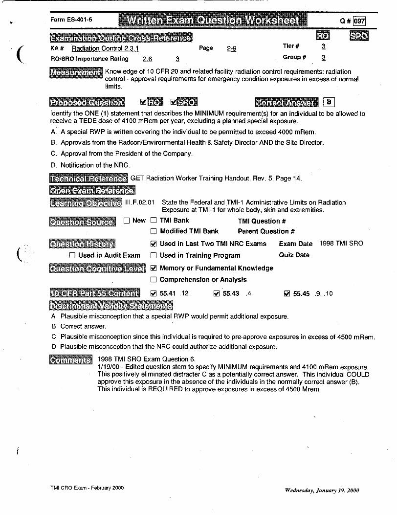
Form ES-401-6 AM .......A ---- Q # F0971
KA # Radiation Control 2.3.1 Page 2-9 Tier # 3
RO/SRO Importance Rating 2.6 3 Group# a Knowledge of 10 CFR 20 and related facility radiation control requirements: radiation control - approval requirements for emergency condition exposures in excess of normal limits.
Identify the ONE (1) statement that describes the MINIMUM requirement(s) for an individual to be allowed to receive a TEDE dose of 4100 mRem per year, excluding a planned special exposure.
A. A special RWP is written covering the individual to be permitted to exceed 4000 mRem.
B. Approvals from the Radcon/Environmental Health & Safety Director AND the Site Director.
C. Approval from the President of the Company.
D. Notification of the NRC.
� GET Radiation Worker Training Handout, Rev. 5, Page 14.
II.F.02.01 State the Federal and TMI-1 Administrative Limits on Radiation
Exposure at TMI-1 for whole body, skin and extremities.
T. * El New EH TMI Bank TMI Question # El Modified TMI Bank Parent Question #
•J Used in Last Two TMI NRC Exams Exam Date 1998 TMI SRO
F1 Used in Audit Exam El Used in Training Program Quiz Date
V,..•.• rý M V Memory or Fundamental Knowledge
EH Comprehension or Analysis
•.te ,- • . • [ 55.41 .12 W 55.43 .4 W 55.45 .9, .10
A Plausible misconception that a special RWP would permit additional exposure. B Correct answer.
C Plausible misconception since this individual is required to pre-approve exposures in excess of 4500 mRem. D Plausible misconception that the NRC could authorize additional exposure.
1998 TMI SRO Exam Question 6. 1/19/00 - Edited question stem to specify MINIMUM requirements and 4100 mRem exposure. This positively eliminated distracter C as a potentially correct answer. This individual COULD approve this exposure in the absence of the individuals in the normally correct answer (B). This individual is REQUIRED to approve exposures in excess of 4500 Mrem.
f
TMI CRO Exam - February 2000
C
Wednesday, January 19., 2000

Form ES-401-6
KA # 000015 K5.02 Tiero#
ROiSRO Importance Rating 2.90 Group #
The reactor is super critical and just entering the intermediate range (4000 cps on the Source Range) when
detector compensating voltage to NI-3 is lost. Which ONE (1) statement explains the effect this loss of
compensating voltage will have on NI-3 indication?
A. NI-3 would be unaffected at this low power level.
B. NI-3 would indicate higher than NI-4.
C. NI-3 would come on scale some time after NI-4.
D. NI-3 would go off scale low before NI-4 if a reactor trip occurred while at 1 E-8 amps.
- OPM F-04 Nuclear Instrumentation Sys., Rev 9, Figure 4, Page 22.
None.
IV.E.11.09
70 W] TMI Bank TMI Question #
E] New L- Modified TMI Bank Parent Question #
I Il Used in Last Two TM! NRC Exam Exam Date
LR Used in Audit Exam LI Used in Training Program Quiz Date
[• .•E L Memory or Fundamental Knowledge
VI Comprehension or Analysis (c')
• EL 55.41 17 55.43
,R4E1 1-09-005
[Ntg ýA ' • , •- z--- A Plausible misconception since this is a correct response for higher reactor power conditions.
B Correct answer.
C This is a plausible distracter since this is a possible correct effect for overcompensation rather than
undercompensation..
D This is a plausible distracter since it describes the effects of overcompensation during a reactor trip situation.
E None. . , I I. L -s-, ,-_'+
s~ysTCbx OVS f Ashg- 3.7 -- 7
W4.0X2-a4.. w Ailjsl s A or +/"\ft f ci-5 .
Page 5 of 101TMI SRO Exam - August 1998
(
4F 1 (3S
AMe~c- 5 -F1101-P5

Replacement for RO Questn# (Old SRO 2-wfk
Plant conditions require a manual reactor trip. The Reactor Trip AND DSS pushbuttons have been depressed. During the performance of the Immediate Actions of 1210-1, the following plant conditions exist:
All RCPs ate operating Turbine Stop Valve, SV-2, is open Turbine Stop Valves SV-1, SV-3 and SV-4 are closed. Turbine Control Valves are Open Reactor power is stable at 22% OTSG levels are 10% on the Operating range and stable OTSG Pressures are stable at 1042 psig RCS hot leg temperatures are 584F and stable RCS Pressure is 2025 and rising slowly
,j,, Identify the procedurally required action for these conditions.
A. Place the EHC pump control switches in P-T-L and open EHC-FV-1.
S)B. Secure 1 RCP in each loop.
C. Initiate HPI and maintain primary to secondary heat transfer until power level is less than 10%.
D. Transfer ICS FW stations to manual to control OTSG levels.
Correct Answer: C
a. Plausible distracter since this is a remedial action for failure of the turbine to trip.
b. Plausible misconception since this action would reduce heat input to the RCS.
c. Correct Answer
d. Plausible distracter since this is a remedial action in the Reactor Trip ATP.

Form ES-401-6 ." , ..............
II
KA# 000029 EK3.12 Tier #
RO/SRO Importance Rating 4.70 Group #
Plant conditions require manual reactor trip. Upon depressing the Trip AND DSS pushbuttons, the reactor does not trip (reactor power remains at 100%). Which ONE (1) statement describes the required action?
A. Place the EHC pump control switches in P-T-L and open EHC-FV-1. vo I1)'
-- B. Place the diamond rod control station in manual and reduce reactor power.
C. Initiate HPI and maintain primary to secondary heat transfer until power level is less than 10%.
D. Transfer FW to manual to control OTSG levels.
ATP 1210-1 Reactor Trip Rev 37, Page 2.0.
None.
V.E.01.06
ED TMI Bank TMI Question # W New El Modified TMI Bank Parent Question #
El Used in Last Two TMI NRC Exam Exam Date
El Used in Audit Exam F1 Used in rTram Quiz Date
or undamen o edge V Cmprhension or Analysis•C
(/: •"='•" " • *-55.41 Fj55.43
A Plausible distracter since this is a remedial action for failure of the turbine to trip. B Plausible misconception since this action would reduce reactor power. C Correct answer. D Plausible distracter since this is a remedial action in the Reactor Trip ATP.
S~None.
41 3S2 /4.1v P O jI,-KS----
T REa g I A
TMI SRO Exam - August 1998 Page: 21 of 101

Form ES-401-6
KA # 000037 AK1.02 Tier #
ROISRO Importance Rating 3.90 uroup 0 S--
The crew has 9 d., -e to minimize subcooling margin in accordance with ATP 1210-5, OTSG Tube Leakage. Which ONE (1) statement describes the reason for minimizing subcooling margin?
A. Minimize RO, I e -, - x• e ....... igk... OTOG tubz. 44P 'i-W41 p-e2lwe B. Minimize time required for cooldown of the RCS. bOpT A'" ,,* .
C. Minimize potential of lifting Main Steam safety valves.
D. Minimize tensile stresses on affected OTSG tubes.
.. • Abnormal Transient Procedure, 1210-5, OTSG Tube Leakage, Rev 28, Page 2.
El Used in Aud
x None.
V.E.05.05
El TMI Bank TMI Question #
F1 New WI Modified TMI Bank Parent Question # SR5EO5-05-Q03
E] Used in Last Two TMI NRC Exam Exam Date
lit Exam El Used in Training Program Quiz Date
D Memory or Fundamental Knowledge
WJ Comprehension or Analysis
~~ lI 55.41 nI 55.43
A Correct answer.
B Plausible since depressurization of RCS is required during cooldown.
C Plausible since lowering RCS pressure reduces maximum OTSG pressure if affected OTSG is filled to solid condition.
D Plausible since RCS pressure reduction reduces stress on affected OTSG tubes
SNone.
11
VeL. .,lyr~ieAj
~o CL} 3qo /IK ~ (JPA
TMI SRO Exam - August 1998
C.
Y'-\u4ý AaP-Vof+
ige 62 of 101
ii i n i# i n l l l i i iif"'J'I IJ-
OJý-
e-^ -r be- 4'ýry'. -NO V

rorm S-U ii-i
KA # 000039 K1.01 Tier #
RO/SRO Importance Rdting 3.20 Group #
Sequence of events: - Reactor is operating at 35% power. - FW-P-1A is in operation; FW-P-1B trip has not been reset. - Steam line rupture occurs upstream of Main Steam Isolation Valve MS-VIA. - The reactor and turbine trip. - Main Turbine Stop Valves 1-4 fail to close.
Which ONE (1) statement describes why only one OTSG depressurizes as a direct result of the steam line break?
A. HSPS isolates Main Feedwater to OTSG 1A. B. MS-V-1A and MS-V-1B are stop check valves that prevent back flow from
OTSG lB.
C. Closure of turbine Control Valves 1-4 results in separation of the two steam generators.
D. Automatic open command for EF-P-1 steam supply valve MS-V-1 3B is delayed for 40 seconds following MS-V-13A automatic operation.
' C-302-011, Rev. 56, Main Steam.
None.
IV.C.01.03
E3 TMI Bank TMI Question # W New El Modified TMI Bank Parent Question #
ElI Used in Last Two TMI NRC Exam Exam Date
MI Used in Audit Exam El Used in Training Program Quiz Date
. El Memory or Fundamental Knowledge
W Comprehension or Analysis (3
El 55.41 EL 55.43
A Plausible distracter since this is a true statement for this situation. * B Correct answer.
C Plausible misconception that closure of Main Turbine Control Valves separates the two OTSGs. D Plausible distracter since this is a true statement. MS-V-13B opening is delayed to allow-MS-_V-6 control
prevent EF-P-1 overspeed, and to prevent steam pipe over-pressurization. ..I None.
E - 4 j .7 -41.9 / s 1 - 4 ~ -
(
(cn~s O/r C-ce
7~kiv~S~be tSC
TMI SRO Exam - August 1998
(
S. .. .. .. " 1 . . . . .. .. .. .. .
Q# M & -->
Page 68 of 101

Form ES-401-6 am
KA # 000003 3.10 Tier #
ROiSRO Importance Rating 3.20 Group #F - r/
Current plant conditions: - Reactor is operating at 100% power. - RCS Tavg is constant at 57 9Q F. - Make up tank level is decreasing slowly - MU-V-17 is in MANUAL control. - Letdown flow has been constant at 45 gpm. - RCP total seal injection flow is 38 gpm (,lacwl- MU-V-32 is in AUTO. - RCP labyrinth seal DP indicators show low off-scalTe,,j J - Auxiliary Building airborne activity is increasing.
Which ONE (1) statement describes the cause for the abnormal conditions?
A. RCP seal #1 leak-off flow is aligned to the Auxiliary Building sump.
B. RCP total seal injection flow transmitter has failed.
C. RCP seal injection flow is not reaching the RCPs.
D. RCP seal #1 leak-off flow has been isolated by closure of MU-V-26.
Abnormal Procedure 1203-15, Loss of R.C. Makeup/Seal Injection, Rev 22, Page 2.
CEl Used in Aud
SNone.
IV.A.05.04
El TMI Bank TMI Question #
VJ New El Modified TMI Bank Parent Question #
El Used in Last Two TM! NRC Exam Exam Date
lit Exam El Used in Training Program Quiz Date
E] Memory or Fundamental Knowledge
c 0omprehension or Analysis (3)
S[D 55.41 El 55.43
A Plausible misconception since the question stem provides leak indications in the same plant building. B Plausible misconception since the question stem provides leak indications in the same plant building.
C Correct answer.
D Plausible misconception since the question stem ng. Plausible misconception since the question stem r(A• w .C ,'e e4A" ct" ; • ng.
SNone.
r- 47 IV- 7 -ee r.cQ
41-7 - d-d-
TMI SRO Exam - August 1998
POE MT MTMOii iii f
3age 15 of 101

Form ES-401-6
KA # 000008 AA1.01 Tier #
RO/SRO Importance Rating 4.00 Group
Current plant conditions: - Reactor is operating at 100% power. - RCS pressure is 2155 psig. - CRO closed RC-V-2 one minute ago due to suspected PORV leakage. - RC Drain Tank pressure is 5.0 psig.
0Lfl
#
If the PORV is leaking, what is the expected tailpipe temperature?
A. 1620 F.
B. 2120 F.
C. 2280 F.
D. 2670 F.
SSteam Tables.
Steam Tables. S~II1.C.02.12
El TMI Bank TMI Question # W New El Modified TMI Bank Parent Question #
- H Used in Last Two TMI NRC Exam Exam Date
El Used in Audit Exam EL Used in Training Program Quiz Date
• [] Memory or Fundamental Knowledge
R] Comprehension or Analysis (5)
[7155.41 [:155.43
A Plausible distracter since this is the correct answer for 5 psia rather than 5 psig in case the examinee forgets to convert.
B Plausible distracter since this is the correct answer for atmospheric pressure in case the examinee fails to consider the positive pressure in the Reactor Coolant Drain Tank.
C Correct answer. D This is a plausible distracter since this is the correct answer for 20 psig rather than 20 psia.
jNone. u• , -"I
4aP5"i VAPJS9 AL
TMI SRO Exam - August 1998
......... ... .......... W ...................... .......
...... n or Xg .....
Page 32 of 101

Form ES-401-6 Q#O1O
KA# 000015 K5.02 Page 3.7-6 Tier#
(ROiSRO Importance Rating 2.9 Group #
The reactor is super critical and just entering the intermediate range (4000 cps on the Source Range) when detector compensating voltage to NI-3 is lost. Identify the ONE (1) statement that describes the effect this loss of compensating voltage will have on NI-3 indication.
A. NI-3 would be unaffected at this low power level.
B. NI-3 would indicate higher than NI-4.
C. NI-3 would come on scale some time after NI-4.
D. NI-3 would go off scale low before NI-4 if a reactor trip occurred while at 1 E-8 amps.
OPM F-04 Nuclear Instrumentation System, Rev 9, Figure 4, Page 22.
a - IV.E.1 1.09 Describe or identify the affects of improper discriminator or compensating voltage settings on the source and intermediate range Nuclear Instrumentation channels.
- E H New D] TMI Bank TMI Question # Li Modified TMI Bank Parent Question #
• •.• [] Used in Last Two TMI NRC Exams Exam Date 1998 TMI SRO
( . Used in Audit Exam ED Used in Training Program Quiz Date
ElH Memory or Fundamental Knowledge
[ Comprehension or Analysis
H 55.41 El 55.43 EL 55.45
A Plausible misconception since this is a correct response for higher reactor power conditions. B Correct answer. C This is a plausible distracter since this is a possible correct effect for overcompensation rather than
undercompensation. D This is a plausible distracter since it describes the effects of overcompensation during a reactor trip situation.
* NRC approved question replacement - different from original examination submittal.
TMI CRO Exam - February 2000 Friday, January 14,2000

CONTROLLED COPYSECTION F-4 REVISION 9
( TMI OPERATIONS PLANT MANUAL NUCLEAR INSTRUMENTATION SYSTEM4
Table of Effective Pages
PAGE REVISION
1.0 2.0 3.0 4.0 5.0 6.0 7.0 8.0 9.0 10.0 11.0 12.0 13.0 14.0 15.0 16.0 17.0 18.0 19.0 20.0 21.0 22.0 23.0 24.0 25.0 26.0 27.0 28.0 29.0 30.0
PAGE REVISION
31.0 32.0 33.0 34.0 35.0 36.0 37.0 38.0
PAGE REVISION PAGE REVISION
7 9 7 7 7 7 7 8
Concur
Owner Date __-?- F6D
Operations Training D ___
Manager, TMI Z2 Date •-*z Dt
Training Coordinator, TMI -Dat"e_
Approved
Plant Operations Director TMI Date - 7!"
1.0
(,
(

SECTION F-4
REVISION 7
FIGURE 4 - TYPICAL GAMMA COMPENSATED CURVE FOR A COMPENSATED ION CHAMBER
w
w ,Lu
uJ
I
w
0
2J 0S
104
10-.
10-6
10"8
10-9
10410
10-11
10-12
0 2 4 6 8 10 12 14 16 18 20 22 24
TIME AFTER REACTOR SHUTDOWN (MINUTES)
I
22.0
( I

Form ES-401-6 #
KA # Page Tier #
RO/SRO Importance Rating Group #
Initial plant conditions: - Reactor power 100%. - ICS in full automatic.
Plant conditions require a manual reactor trip. After the CRO depresses the Manual Reactor Trip and DSS pushbuttons, the following plant conditions exist:
- Reactor power is stable at 22%. - All 4 RCPs are operating. - RCS hot leg temperatures are stable at 584 degrees F. - RCS pressure is 2025 psig and rising slowly. - Turbine Stop Valve SV-2, is open. - Turbine Stop Valves SV-1, SV-3, and SV-4 are closed. - Turbine Control Valves CV-1, CV-2, CV-3, and CV-4 are open. - OTSG levels are 10% on the Operating Range and stable. - OTSG pressures are stable at 1042 psig.
From the list below, identify the ONE (1) statement that describes the procedurally required action(s) for these conditions.
A. Secure 1 RCP in each loop.
B. Transfer ICS FW stations to manual to control OTSG levels.
C. Place the EHC pump control switches in P-T-L and open EHC-FV-1.
D. Initiate HPI and maintain primary to secondary heat transfer until power level is less than 10%.
ATOG ATP 1210-1, Reactor Trip, Rev. 40, Page 2.
V.E.01.06 State and explain the steps of ATP 1210-1, Reactor Trip which deal with an ATWS event.
ElI New FI TMI Bank TMI Question # [] Modified TMI Bank Parent Question #
ElI Used in Last Two TMI NRC Exams Exam Date
El Used in Audit Exam EL Used in Training Program Quiz Date
- LI Memory or Fundamental Knowledge
WI Comprehension or Analysis
EL 55.41 LI 55.43 0I 55.45
A Plausible distracter since this reduces heat input to the RCS.
B Plausible distracter since this is a remedial action in the reactor trip ATP.
C Plausible distracter since this is a remedial action for failure of the turbine to trip.
D Correct answer.
NRC approved replacement question - different from the original exam submittal.
TMI CRO Exam - February 2000 Friday, January 14,2000

CONTROLLED COPYTMI
Abnormal Transient Procedure
Number
1210-1Title Revision No.
Reactor Trip 40 Applicability/Scope' Responsible Office Effective Date
TMI Division Plant Operations Dir. 10/19/99 This document is within QA plan scope X Yes No Safety Reviews Required X Yes No SIMULATOR ROOM
List of Effective Pages FILE COY
Page Revision Page Revision Paqe Revision Pae Revision
1 40 2 40 3 40 4 40 5 40 6 40 7 40
Signature Date
Originator
Procedure Owner
/// PRG
ýkpprover7?/)~- 9
( //
1
GU NUCL EAR

6�s'7
GU NUCLEAR
TMI Abnormal Transient Procedure
Number
1210-1Title Revision No.
Reactor Trip 40
1.0 ENTRY CONDITION - Any condition requiring an automatic or manual trip signal or a symptom of core cooling upset occurs while shutdown prior to DHR operation.
2.0 IMMEDIATE ACTIONS - (Vital System Action, Status Verification, and Remedial Action).
2.1 Manually trip Reactor by depressing the Trip AND DSS pushbuttons.
Verify Groups 1-7 rods on bottom
IF power is not less than 10% power;
IF one or more rods are stuck out.
THEN initiate HPI, AND maintain primary to secondary heat transfer.
THEN emergency borate.
2.2 Manually trip Turbine.
Verify T/G stop valves closed.
IF T/G stop valves are not closed;
Verify Generator/Field Breakers open.
IF Generator/field breakers remain closed;
IF Generator output is zero or negative MWe;
THEN place EHC-P-1A&B in pull-to-lock AND open EHC-FV-1 (bypass valve at EHC).
THEN Verify that generator output is zero or negative MWe.
THEN Manually trip GB1-12, GBI-02 AND the field breaker.
2
NOTE
The following sequence represents a predetermined pdoritization of immediate actions. Although some or all steps may be performed in parallel it is essential that all immediate actions be performed at least once and within several minutes.
CAUTION
1. If the Reactor is not less than 10% power, do not perform any of the following steps which would reduce the balance of primary to secondary heat transfer.
2. During the blowdown phase of a large break LOCA, the nuclear instrumentation may indicate erroneously high due to increased thermal neutron leakage. If the assessment is made that indicated NI power is not accurate, do not stop at this point.

( KA # 000037 AK1.02 Page 4.2-29 Tier #
ROiSRO Importance Rating 3.9 Group #
The crew has taken action to minimize subcooling margin in accordance with ATP 1210-5, OTSG Tube Leakage. Identify the ONE (1) statement below that describes the reason for minimizing subcooling margin in this situation.
A. Minimize the differential pressure between the OTSG and RCS.
B. Minimize time required for cooldown of the RCS.
C. Minimize potential of lifting Main Steam safety valves.
D. Minimize tensile stresses on affected OTSG tubes.
SATOG ATP 1210-5, OTSG Tube leakage, Rev. 31, Page 2.
SV.E.05.05 Describe the methods available in ATP 1210-5, OTSG Tube Leakage, for
limiting integrated OTSG tube leakage.
S[] New El TMI Bank TMI Question #
WJ Modified TMI Bank Parent Question #
•E li Used in Last Two TMI NRC Exams Exam Date 1998 TMI SRO E
El Used in Audit Exam Li Used in Training Program Quiz Date
*_-; }_ Li Memory or Fundamental Knowledge
WJ Comprehension or Analysis
E li 55.41 Ri 55.43 El 55.45
A Correct answer.
B Plausible since depressurization of RCS is required during cooldown.
C Plausible since lowering RCS pressure reduces maximum OTSG pressure if affected OTSG is filled to solid condition.
D Plausible since RCS pressure reduction reduces stress on affected OTSG tubes.
NRC approved replacement question - different from the original exam submittal.
TMI CRO Exam - February 2000 Friday, January 14,2000
Form ES-401-6 I•F orm--------- -----
i # iý -
r Q# r n

NLPU NUCLEAR
CONTROLLED COPY
TMI Abnormal Transient Procedure
Number
1210-5Title Revision No.
OTSG Tube Leakage 31 Applicability/Scope Responsible Office Effective Date
TMI Division Plant Operations Dir. 10/15/99
nis document is within QA plan scope [I. Yes L No Safety Reviews Required Yes No TRAINING DEPT.
List of Effective Pages
Page
1 2 3 4 5
.6 7 8 9
Revision Page Revision Page Revision Pagqe Revision
31 31 31 31 31 31 31 31 31
Signature . -- -..-- Dat.:--
Originator 9--
Procedure Owner 4/
PRG
Approver
C1
I

GU NUCLEAR
TMI Abnormal Transient Procedure
1.0 ENTRY CONDITION: Identified OTSG tube leakage greater than 1 gpm.
2.0 IMMEDIATE ACTIONS
2.1 Close MU-V-3 as needed AND increase makeup as needed to maintain PZR level.
3.0 FOLLOW-UP ACTION
CAUTION
Adhere to Pressurizer Level Guide ATP 1210-10, Guideline 2.1.
3.1 IF the reactor is NOT tripped: THEN shut down the plant (refer to OP 1102-10, "Plant Shutdown") at a rate specified by the Shift Supervisor to minimize the risk of a MS Safety Valve lifting.
3.2 If any Emergency Action Levels (EAL's) listed in Attachment 1 have been exceeded, implement EPIP-TMI-.01, "Emergency Classification", and additional implementing procedures as required.
3.3 Determine affected OTSG by sampling OTSG steamlines, surveying steam lines, observation of OTSG levels and feed rates.
2
I
,
OTSG Tube Leakage
4
OBJECTIVE: The objective of this procedure is to:
a Shut down the reactor without intentionally lifting the MSSVs.
b Steam both OTSG's to cool down the RCS to less than 540°F (MSSV's set point SAT TEMP).
c. Depressurize RCS to less than 1000 psig consistent with maintaining desired minimum SCM.
d. Establish RCS controlled cooldown with acceptable tube-to-shell DT.
e. Maintain OTSG steaming and avoid OTSG isolation unless:
1. RCS (Th or incore temp.) < 540°F and (pressure) < 1000 psig, and
a. BWST Level < 21 ft., or b. Projected or Actual dose rates offsite approach 50 mr/hr total
W.B. dose (TEDE) or 250 mr/hr child thyroid organ dose (CDE), or
c. Severe equipment damage is projected (i.e., steam line water hammer).
f. Stop the leakage by depressurizing and cooling down to DHR system operation and draining RCS as necessary.
w

Form ES-401-6 #
i "M
(Tier #
Group #
From the list below, identify the ONE (1) statement that describes why only one OTSG depressurizes as a direct result of the steam line.
A. HSPS isolates Main Feedwater to OTSG 1A.
B. MS-V-1A and MS-V-1 B are stop check valves that prevent back flow from OTSG lB.
C. Closure of turbine Control Valves 1-4 results in separation of the two steam generators.
D. Automatic open command for EF-P-1 steam supply valve MS-V-13B is delayed for 40 seconds following MS-V-13A automatic operation.
' C-302-011, Main Steam, Rev. 56.
S • IV.C.01.03 State what kind of valve MS-V-1 A, B, C, D are and explain why was this type chosen.
Eli New El TMI Bank TMI Question #
Li Modified TMI Bank Parent Question #
* • [ Used in Last Two TMI NRC Exams Exam Date 1998 TMI SRO E
L- Used in Audit Exam El Used in Training Program Quiz Date
i tE Memory or Fundamental Knowledge
WI Comprehension or Analysis
E li 55.41 EL 55.43 El 55.45
A Plausible distracter since this is a true statement for this situation.
B Correct answer.
C Plausible misconception that closure of Main Turbine Control Valves separates the two OTSGs.
D Plausible distracter since this is a true statement. MS-V-13B opening is delayed to allow MS-V-6 control prevent EF-P-1 overspeed, and to prevent steam pipe over-pressurization.
SNRC approved replacement question - different from original exam submittal.
TMI CRO Exam - February 2000
KA# 000039 K1.01 Page 3.2-22
RO/SRO Importance Rating 3.2
Sequence of events: - Reactor is operating at 35% power. - FW-P-1 A is in operation; FW-P-1 B trip has not been reset. - Steam line rupture occurs upstream of Main Steam Isolation Valve MS-V1A. - The reactor and turbine trip. - Main Turbine Stop Valves 1-4 fail to close.
lx"e!
Friday, January 14, 2000

p
II
�jI� V r '-B
0, 0

Fo m S 40q QX. .078
KA # SYSTEM 003 K6.02 Page 3.4-7 Tier #
ROiSRO Importance Rating 2.7 3.1 Group #
Knowledge of the effect of a loss or malfunction on RCP seals and seal water supply will have on the RCPs.
.. ... ....
Current plant conditions: - Reactor is operating at 100% power. - RCS Tavg is constant at 579 degrees F. - Make up tank level is decreasing slowly - MU-V-17 is in MANUAL control. - Letdown flow has been constant at 45 gpm. - RCP total seal injection flow is 38 gpm - MU-V-32 is in AUTO. - RCP labyrinth seal DP indicators show low off-scale. - Auxiliary Building airborne activity is increasing.
From the list below, identify the ONE (1) statement that describes the cause for the abnormal conditions.
A. RCP seal #1 leak-off flow is aligned to the Auxiliary Building sump.
B. RCP total seal injection flow transmitter has failed.
C. RCP seal injection flow is not reaching the RCPs.
D. RCP seal #1 leak-off flow has been isolated by closure of MU-V-26.
E C-302-661, Makeup & Purification System, Rev. 51.
SIV.A.05.04
Usiu New
F1 Used in Audit Exam
El El V
El El V D]
D]
Given a cross section of the reactor coolant pump seal package label the major components and show flow paths and flow rates.
TMI Bank TMI Question # Modified TMI Bank Parent Question #
Used in Last Two TMI NRC Exams Exam Date 1998 TMI SRO E
Used in Training Program Quiz Date
Memory or Fundamental Knowledge
Comprehension or Analysis
S55.41 .7 El 55.43 W 55.45 .5
A Plausible misconception since the question stem provides leak indications in the same plant building. B Plausible misconception since the question stem provides leak indications in the same plant building.
C Correct answer. D Plausible misconception since the question stem provides leak indications in the same plant building.
NRC approved replacement question - different from original exam submittal.
(.
TMI CRO Exam - February 2000 Wednesday, January 19, 2000
(
(
Form ES-401-6
.. ............. . M

itt
Ii~e t
I I __ __
i t - - - -- - -- - - - - - -
I-- -- --- ---
11 I I. -r

Form. ......... .... 082.
KA # 0000027 AA1.01 Page 3.5-15 Tier #
ROiSRO Importance Rating 4 Group #
Current plant conditions: - Reactor is operating at 100% power. - RCS pressure is 2155 psig. - CRO closed RC-V-2 one minute ago due to suspected PORV leakage. - RC Drain Tank pressure is 5.0 psig.
From the list below, identify the value for expected tailpipe temperarure if the PORV is leaking under these conditions.
A. 1620 F.
B. 2120 F.
C. 2280 F.
D. 2670 F. amTables.
Steam Tables.
& •. III.C.02.12 Solve problems involving throttling process utilizing a Mollier diagram and/or steam tables.
E INew Il TMI Bank TMI Question #
EL Modified TMI Bank Parent Question #
W ] Used in Last Two TMI NRC Exams Exam Date 1998 TMI SRO E
El Used in Audit Exam Li Used in Training Program Quiz Date
S[L0 Memory or Fundamental Knowledge WI Comprehension or Analysis
E []55.41 El 55.43 F1 55.45
A Plausible distracter since this is the correct answer for 5 psia rather than 5 psig in case the examinee forgets to convert.
B Plausible distracter since this is the correct answer for atmospheric pressure in case the examinee fails to consider the positive pressure in the Reactor Coolant Drain Tank.
C Correct answer. D This is a plausible distracter since this is the correct answer for 20 psig rather than 20 psia.
NRC approved replacement question - different from original exam submittal.
( E
TMI CR0 Exam - February 2000 Friday, January 14, 2000
(
Form ES-401-6
-OEM=SA
I ==
o #F68

ES-301 Control Room Systems and Facility Walk-Through Test Outline Form ES-301-2
Facility: TMI Date of Examination: Week of 2/14/2000 Exam Level: RO Operating Test Number:.
System / JPM Title Type Safety
Code* Function
B.1 Control Room Systems
a. 001 / Perform a safety group withdrawal N, A, S, L I
(TMI task #0010180101; K/A = K4.13, RO = 3.4) JPM #177
b. 004 / Perform recovery from high temp. letdown isolation ** M, S 2
(TMI task #004C010101; K/A = A4.06, RO = 3.6) JPM #119
c. 010 / Respond to decreasing or low RCS pressure N, A, S 3
(TMI task #0008350501; K/A = A2.02, RO = 3.9) JPM #178
d. 059 / Transfer MFW pump control between ICS and motor D, S 4 speed changer JPM #116
(TMI task #0598060401; K/A = K1.07, RO = 3.2)
e. 022 / Perform required actions if containment temperature D, A, S 5 cannot be controlled within specified limits JPM #079
(TMI task #0020070401; K/A = A4.02, RO = 3.2)
f. 064 / Return 4KV ES bus to its normal power supply ** D, S, L 6
(TMI task #0620080101; K/A = A2.09, RO = 3.1) JPM #064
g. 012 / Energize and reset RPS channel ** D, S 7
(TMI task #0120010101; K/A = A2.02, RO = 3.6) JPM #153
B.2 Facility Walk-Through
a. 004 / Perform emergency boration lineup. D, L, R 1
(TMI task #009A01 0204; K/A = A2.14, RO = 3.8) JPM #109
b. 063 / Respond to loss of A-DC D 6
(TMI task #0000580504; K/A = AK3.02, RO = 4.0) JPM #067
c. 086 / Manually actuate relay room CO2 system M, A, L 8
(TMI task #0868040101; K/A = K4.06, RO = 3.0) JPM #045
* Type Codes: (D)irect from bank, (M)odified from bank, (N)ew, (A)ltemate path, (C)ontrol room, (S)imulator, (L)ow-Power, (R)CA
** 119 and 153 may be performed simultaneously -** 064 and 116 may be performed simultaneously
12/17/99 7:08 AM C 0 P Y
I-

ES-301 Administrative Topics Outline Form ES-301-1
Facility: TMI-1 kU Exam Date of Examination: 02/14/2000 Examination Level (circle one): RO /SRO Operating Test Number:
Administrative Describe method of evaluation: Topic/Subject 1. ONE Administrative JPM, OR Description 2. TWO Administrative Questions
Conduct o JPM: RO is tasked to calculate Shutdown Margin given plant A. 1 Operations: conditions that will involve one inoperable control rod.
Shutdown Margin Calculation K/A 2.1.25 RO 2.8 TMI Task 0010040101 RO 2.6 Conduct of JPM: Given a RCS leak the RO is tasked to perform a RCS leak rate Operations: calculation using the plant process computer and then evaluate the Computer Leakrate results against Technical Specifications. Calculation K/A 2.1.19 RO3.0 TMI Task 0020010201 RO 2.49 Eauipment Control: JPM: RO is tasked to verify / place an emergency diesel generator in
A.2 Verify EDG ES standby following a surveillance for a test run. Operability K/A 2.2.12 RO 3.0 Note: NRC K/A was incorrect on original submittal. TMI Task 0640010101 RO 2.61 Radiation Control: JPM: RO is tasked to hang red tags on manual valves located in a
A.3 Tagging manual high radiation area IAW AP 1002, which allows tagging at entrance operated valves in a of High Rad Area. High Rad Are& Rev. 1 K/A 2.3.1 RO 2.6 TMI Task 1190120301 RO 3.86 Emergency Plan: JPM: RO is tasked to perform the required offsite notifications
A.4 Emergency following an Emergency Plan Declaration. Communications K/A 2.4.43 RO 2.8 TMI Task 5010045003 RO 2.90
21 of 26
12/14/99 10:12 AM
NUREG-1021, Revision 8
C 0 P Y
C
(

Appendix D Scenario Outline Form ES-D-1
Facility: TMI
Examiners:
Scenario No. 1 (70 minutes) Op-Test No.: DAY-1
Operators:
Objectives: To evaluate applicants' ability to: transfer ICS stations back to automatic per 1105-4; diagnose and respond to a loss of RC pump seal injection flow per 1203-15, and then an RC pump #1 seal failure per 1203-16; reduce reactor power and secure the RC pump; diagnose and respond to an RCS leak in containment per alarm responses; respond to a reactor trip with failure of the main turbine to automatically trip per 1210-1; respond to an ES actuation with failure of B-train HPI pump to automatically start per 1210-1 and 1210-10; and diagnose and respond to an increase in RCS leakrate and loss of 250 F subcooled margin per 1210-2 and 1210-6.
Initial Conditions: IC15 (100% power, BOC), with RR-P-1A out of service, and the following ICS stations in hand: SG/Rx master, both FW loop masters, all four FW valve stations, both FW pump stations, and delta-Tc station with demand at zero (0).
Turnover: Plant is at 100% power, BOC, with RR-P-1A out of service for shaft bearing replacement (4 hours into 16 hour estimated work time).
The following ICS stations are in hand: SG/Rx master, both FW loop masters, all four FW valve stations, both FW pump stations, and delta-Tc. Maintenance has been completed on the FW ratio and BTU limit circuits, and ICS must be returned to full automatic.
Event Action Event Event
No. No. Type* Description
1 N/A N (BOP) Return ICS to full automatic.
2 AOR** I (RO) MU-FT-42, RCP seal injection flow fails high (80 gpm) **02A3M05-ZAOMU42FI FLO MU-42FI.
MU07 Q (RO) MU-V-32, RCP seal injection flow control valve closes.
3 MU19A C (RO) RC-P-1A #1 seal failure; 100% severity (50 gpm) over 60 R (RO) seconds. Reduce power to 70% and secure RC-P-1A.
4 RC08B I (BOP) RC5A-TE3 (selected loop-A T-cold) fails; 0% severity (5200 F) ramped in over 30 seconds when RC-P-1A is secured. Event Trigger: THA0427<5.0
5 TH06 M (ALL) LOCA at RC-P-1A; 0.15% severity (1500 gpm) ramped in over 100 seconds.
6 TC02 C (BOP) Main turbine fails to automatically trip when reactor trips.
7 MU23C C (RO) MU-P-1C fails to automatically start on ES signal.
8 N/A M (ALL) Loss of 250F RCS subcooled margin and small break LOCA cooldown.
* (N)ormal, (R)eactivity, (I)nstrument, (C)omponent, (M)ajor
10/28/99 2:13 PM 0 R I G I N A L NRC2000RO

Appendix D Scenario Outline Form ES-D-1
Facility: TMI
Examiners:
Scenario No. 2 (80 minutes) Op-Test No.: DAY-1
Operators:
Objectives: To evaluate applicants' ability to: synchronize and load turbine/generator per 1106-1, and continue plant startup per 1102-2; respond to an OTSG tube leak per 1210-5; perform a plant and reactor shutdown per 1210-5 and 1102-10; respond to a makeup pump trip per alarm response; respond to a failed pressurizer level transmitter per 1202-29; respond to a turbine bypass valve failure after turbine trip; and reduce subcooled margin per 1210-5 with failure of the pressurizer spray valve to open.
Initial Conditions: IC12, 14% reactor power, 300 EFPD, during a xenon-free plant startup with main turbine hot at 1800 rpm, ready to synchronize and load. MFW pump on MS.
Turnover: Reactor is at 14% power during a xenon-free plant startup at 300 EFPD, with main turbine hot at 1800 rpm, ready to synchronize and load. The plant tripped 80 hours ago due to a main generator relay failure. Continue plant startup by synchronizing and loading turbine-generator and increasing power per 1102-2. MFW pump and gland steam on MS.
Event Action Event Event No. No. Type* Description
1 N/A N (BOP) Synchronize and load turbine generator per 1106-1.
2 N/A R (BOP) Increase reactor power per 1102-2 and place turbine in auto.
3 MS01A I (BOP) Selected turbine header pressure instrument fails low with main turbine in automatic. (0% severity over 20 seconds)
4 TH16A M (ALL) Tube Leak on A-OTSG; 0.3% severity (45 gpm)
5 N/A R (RO) Plant & reactor shutdown per 1210-5 & 1102-10.
6 MS09D C (BOP) MS-V-3D (turbine bypass valve) fails open after turbine trip. Event Trigger TC:TRIP
7 RC04A I (RO) Selected PZR level fails high; 0% severity over 600 seconds.
8 MU01A C (RO) MU-P-1A trips after start. Event trigger MUPDISA>1000. 9 **DIOR C (RO) RC-V-1 does not open to reduce RCS subcooled margin per
1210-5; must use PZR vent and/or PORV. **02A5S06-ZDIPBORCV1 OPN CC RC-V-1 OPEN PB
* (N)ormal, (R)eactivity, (I)nstrument, (C)omponent, (M)ajor
10/28/99 2:06 PM 0 R 1 IN A L NRC2000RO

Appendix D Scenario Outline Form ES-D-1
Facility: TMI
Examiners:
Scenario No. 3 (70 minutes) Op-Test No.: DAY-2
Operators:______________
Objectives: To evaluate the applicants' ability to: swap operating makeup pumps per 1104-2; respond to a makeup system leak per alarm responses; perform a plant shutdown per 1102-10; secure a MFW pump per 1106-3; respond to a turbine trip while less than ARTS per K-1-1; respond to a main steam line break and excessive primary to secondary heat transfer per 1210-3; and stabilize plant following termination of excessive primary to secondary heat transfer per 1210-3.
Initial Conditions: IC16 (100% power MOC), IA-P-4 out of service, IA-P-1A running in hand.
Tumover. Plant at 100% power, MOC, IA-P-4 out of service, IA-P-1A running in hand. MU-P-1 B must be removed from service for an oil system inspection - expected duration is two hours. DCCW loop-A will be sampled while running.
Event Action Event Event
No. No. Type* Description
1 N/A N (RO) Operating makeup pumps are swapped per 1104-2.
2 MU14 C (RO) Makeup system leak (50%=50 gpm) downstream of makeup AOR** I (RO) valve, and low range makeup flow transmitter, MU-FT-24A,
R (RO) fails low. The makeup system leak requires normal makeup N (BOP) line isolation and management will order plant shutdown.
**02A3M06-ZAOMU24FI FLO (0% with 120 second delay)
3 N (BOP) As FW-P-1A is removed from service per 1102-10/1106-3, FW06B I (BOP) the selected B-train MFW valve d/p transmitter, SP 11B
DPT2 fails low (0% severity over 15 seconds) Trigger = FWFDFWP(1)<416
4 EG03 M (ALL) Main generator and turbine trips at about 40% power, and a MS03A main steam line break on A-SG occurs outside containment
(100% severity ramped in over 300 seconds).
5 FW13A C (BOP) FW-V-5A breaker trips as it is commanded to close, causing MS10, main feedwater block valve to be failed 95% open. And, SGA, HSPS isolation of FW-V-16A and 17A (train-A) on low SG
TRN B pressure will fail to actuate. Trigger = FWVFWV5A<0.95
6 DOR*** C (RO) MU-V-16C will not close by pushbutton on panel when required to secure HPI. ***03A4S35-ZDIPBCMUV16C ON CR MU-V-16C CLOSE PUSHBUT
* (N)ormal, (R)eactivity, (I)nstrument, (C)omponent, (M)ajor
10/28/99 2:17 PM NRC2000RO
ORIGINAL

Appendix D Scenario Outline Form ES-D-1
Facility: TMI
Examiners:
Scenario No. 4 (70 minutes) Op-Test No.: DAY-2
Operators:.
Objectives: To evaluate the applicants' ability to: manually increase reactor power per 1102-2; transfer MFW pump steam supplies per 1106-3; respond to a loss of RC makeup and seal injection per 1203-15; respond to a loss of main feedwater per alarm responses; respond to an EFW actuation failure per 1210-10; respond to a SG tube rupture per 1210-5; and respond to a loss of 25°F subcooled margin per 1210-2.
Initial Conditions: IC08, reactor critical at 1 E-8 amps during a plant startup at MOC. All operating ventilation fans transferred to A-train.
Tumover: Reactor is critical at I E-8 amps during a plant startup at MOC. Critical data has been obtained and 1103-8 has been closed out. FW-P-1A and gland steam is currently supplied from the auxiliary steam system. B-RCBT is on sample recirc.
Event Action Event Event No. No. Type* Description
1 R (RO) Reactor power is increased to 5% power using CRD panel in accordance with 1102-2.
N119A I (RO) NI-5 (selected power range NI) will not increase above 0% as reactor power is increased into power range flux level.
2 MSR19 N (BOP) FW-P-1A is transferred from auxiliary steam to main steam per 1106-3 prior to 5% reactor power per 1102-2.
3 RC23A I (BOP) At ,5% power, selected B-SG startup level transmitter (LT-1 054) fails low (0% over 300 seconds), causing FW-V16B to open in auto.
4 ED02D C (RO) 1A auxiliary transformer trips, causing trip of MU-P-1 B and loss of RC makeup/seal injection.
5 DOR** C (BOP) FW-P-1A speed control fault causes loss of main feedwater. **01A5S07-ZDIMSCA(3) SLOLO FW-P-1A MSC SWITCH
ICRO3 C (BOP) EF-V-30B/C do not automatically open for EFW to B-SG.
6 TH15B M (ALL) A tube rupture occurs on B-SG that results in loss of 25°F subcooled margin. (20% severity over 100 seconds)
DOR*** C (RO) RC-P-1 B does not trip using its normal control switch. ***02A3SI6-ZDICSRCPIB(1) PTL RC-P-1B CS, and
02A3S16-ZDICSRCP1 B(2) STP RC-P-1 B CS
* (N)ormal, (R)eactivity, (I)nstrument, (C)omponent, (M)ajor
10/28/99 2:23 PM NRC2000RO
ORIGINAL

ORIGINALC.nntrnl Pnnm � �nrI F�i-iIitv Wa!k-Thrni ,nh TARt CThtIinA Form FS-301-2
Facility: TMI Date of Examination: Week of 2/14/2000
Exam Level: RO Operating Test Number.
System / JPM Title Type Safety
Code* Function
B. 1 Control Room Systems
a. 001 / Perform a safety group withdrawal N, A, S. L 1
(TMI task #0010180101; K/A = K4.13, RO = 3.4) JPM #177
b. 004 / Perform recovery from high temp. letdown isolation ** M, S 2
(TMI task #004C010101; K/A= A4.06, RO = 3.6) JPM #119
c. 010 / Respond to decreasing or low RCS pressure N, A, S 3
(TMI task #0008350501; K/A = A2.02, RO = 3.9) JPM #178
d. 059 / Transfer MFW pump control between ICS and motor D, S 4 speed changer *** JPM #116
(TMI task #0598060401; K/A = K1.07, RO = 3.2)
e. 022 / Perform required actions if containment temperature D, A, S 5 cannot be controlled within specified limits JPM #079
(TMI task #0020070401; K/A = A4.02, RO = 3.2)
f. 064 / Return 4KV ES bus to its normal power supply *** D, S, L 6
(TMI task #0620080101; K/A = A2.09, RO = 3.1) JPM #064
g. 012 / Energize and reset RPS channel ** D, S 7
(TMI task #0120010101; K/A = A2.02, RO = 3.6) JPM #153
B.2 Facility Walk-Through
a. 004 / Perform emergency boration lineup. D, L, R 1
(TMI task #009A010204; K/A = A2.14, RO = 3.8) JPM #109
b. 063 / Respond to loss of A-DC D 6
(TMI task #0000580504; K/A = AK3.02, RO = 4.0) JPM #067
c. 086 / Manually actuate relay room C02 system M, A, L 8
(TMI task #0868040101; K/A = K4.06, RO = 3.0) JPM #045
Type Codes: (D)irect from bank, (M)odified from bank, (N)ew, (A)lternate path, (C)ontrol room, (S)imulator, (L)ow-Power, (R)CA
** 119 and 153 may be performed simultaneously *** 064 and 116 may be performed simultaneously
10/28/99 2:31 PM
I= •.."•J31

ES-301 Administrative Topics Outline Form ES-301-1
Facility: TMI-1 ý Exam Date of Examination: 02/14/2000 Examination Level (circle one): .. / SRO Operating Test Number:
Administrative Describe method of evaluation: Topic/Subject 1. ONE Administrative JPM, OR Description 2. TWO Administrative Questions
Conduct of JPM: RO is tasked to calculate Shutdown Margin given plant A. 1 Operations: conditions that will involve one inoperable control rod. Shutdown Margin Calculation K/A 2.1.25 RO 2.8 TMI Task 0010040101 RO 2.6 Conduct of JPM: Given a RCS leak the RO is tasked to perform a RCS leak rate Operations: calculation using the plant process computer and then evaluate the Computer Leakrate results against Technical Specifications. Calculation K/A 2.1.19 Re 3.0 TMI Task 0020010201 RO 2.49 Equipment Control: JPM: RO is tasked to verify / place an emergency diesel generator in
A.2 Verify EDG ES standby following a surveillance for a test run. Operability K/A 2.2.14 RO 2.5 TMI Task 0640010101 Re 2.61 Radiation Control: JPM: RO is tasked to enter and exit a radiological area. This task
A.3 RWP Entry & Exit includes reviewing the RWP and Survey Map. Requirements Survey Map K/A 2.3.1 RO 2.6
Emergency Plan: JPM: RO is tasked to perform the required offsite notifications A.4 Emergency following an Emergency Plan Declaration.
Communications K/A 2.4.43 RO 2.8 TMI Task 5010045003 RO 2.90
21 of 26 NUREG-1021, Revision 8
ORIGINAL10/29/99 12:51 PM

NRCROSSI Revision 0 12113/1999
NRC RO OPERATIONAL SIMULATOR SCENARIO No. 1
RC PUMP SEAL FAILURE, SMALL BREAK LOCA, & LOSS OF SUBCOOLIED MARGIN
DEVELOPED BY/DATE:
REVIEWED BY/DATE:
APPROVED BY/DATE:
AJ�
O A T I N
(OPERATIONS TRAINING MANAGER)
NRCROSSI.DOC
/, 131cý
NRC200OROPage I of 18

NRCROSS1 Revision 0 12/1311999
NRC RO OPERATIONAL SIMULATOR SCENARIO No. I
SCENARIO CHANGE HISTORY PAGE
REVISION DATE REFERENCE TITLE DESCRIPTION (Include All # if appropriate)
______ ______ +
I I. +
I. +
I. I I
J. I I
_____________ _______________________________________ I
NRC200RONRCROSS1.DOC Page 2 of 18

NRCROSSI Revision 0 12/13/1999
NRC RO OPERATIONAL SIMULATOR SCENARIO No. 1
1.0 GENERAL DESCRIPTION OF SCENARIO
Plant at 100% power, MOC, with RR-P-1A out of service, and the following ICS stations In HAND:
SG/Rx Master, both FW Loop Masters, all four FW Valve stations, both FW Pump stations, and
Delta-Tc station.
ICS Is returned to full automatic.
RC Pump seal injection flow transmitter causes MU-V-32 closure and loss of seal injection.
RC-P-1A experiences a #1 seal failure.
When RC-P-1A is secured, selected RCS Loop-A T-cold fails low.
A small break LOCA (1500 gpm) occurs at RC-P-1A.
The main turbine fails to automatically trip when reactor trips.
MU-P-1C fails to automatically start on ES actuation.
Loss of 25OF subcooled margin requires a small break LOCA cooldown.
Estimated scenario time - 70 minutes. 3 Critical Tasks
2.0 REFERENCES
A. 10 CFR 55.45 Operating Tests, (a) Content (3), (4), (5), (6), (7), (8), (9), (12), (13)
B. PROCEDURES
1105-4 Integrated Control System
1203-15 Loss of RC Makeup/Seal Injection
1203-16 Reactor Coolant Pump and Motor Malfunction
1103-6 Reactor Coolant Pump Operation
1210-1 Reactor Trip (copies required for examiners)
1210-2 Loss of 250F Subcooled Margin
1210-6 Small Break LOCA Cooldown
1210-10 Abnormal Transients Rules, Guides, and Graphs
Alarm Responses
NRC2000RONRCROSSI.DOC Page 3 of 18

NRCROSSI Revision 0 12/13/1999
NRC RO OPERATIONAL SIMULATOR SCENARIO No. I
3.0 TASKS 0150040101
0008210501
0008180401
0158020401
3418000101
0030030101
0150030101
0000070501
0000080501*
0130020101
0618000501
0008360501
OOC190501"
000C230501
0130030101
0130040101
004C040101'
Transfer ICS stations to automatic
Respond to loss of RCP seal injection
Respond to high RCP seal #1 leakoff
Respond to a SASS mismatch/actuation
Perform plant power changes
Perform a normal reactor coolant pump shutdown
Operate the ICS in hand
Respond to a reactor trip as the primary CRO
Respond to a reactor trip as the secondary CRO
Manually initiate the ESAS
Respond to an emergency feedwater actuation
Throttle emergency feedwater
Respond to loss of 25°F subcooled margin
Respond to a small break LOCA
Reset an ES channel
Bypass or defeat an ES channel
Throttle high pressure injection
* Critical Task
NRC2000RONRCROSSI.DOC Page 4 of 18

NRCROSSI Revision 0 12/13/1999
NRC RO OPERATIONAL SIMULATOR SCENARIO No. I
4.0 SIMULATOR INITIALIZATION
A. IC16 100% power, steady-state, MOC.
Place simulation in RUN and perform the following:
1. Red tag RR-P-IA extension control on CC in pull-to-lock.
2. Place red sticker tag on RR-P-1A OPEN pushbutton on CC.
3. Verify or align 1C ES Valves MCC to the IS Bus.
4. Transfer the following ICS stations to HAND:
SG/Rx Master, both FW Loop Masters, all four FW Valves, both FW Pumps, and Delta-Tc
5. Reduce Delta-Tc station demand to zero (0).
B. EVENT TRIGGERS
#4 THA0427<5.0
Command: IMF RC08B 0 30
C. MALFUNCTIONS
MU07 MU-V-32 failure; insert at 0% severity over 10 second ramp on Event #2.
MU19A RC-P-IA #1 seal failure; insert at 100% severity over 60 second ramp on Event #3.
TH06 LOCA at RC-P-IA; insert at 0.15% severity over 100 second ramp on Event #5.
TC02 Main Turbine auto trip failure; insert immediately.
MU23C MU-P-IC auto start failure; insert immediately.
D. REMOTE FUNCTIONS
RWR07 RR-P-1A breaker, insert OUT immediately to rack out RR-P-IA breaker.
RWR24 RR-V-IA breaker, insert OPEN immediately to open RR-V-IA breaker.
E. OVERRIDES
02A3M05-ZAOMU42FI FLO MU-42FI; insert at 100% severity over 10 second ramp on Event #2.
F. MONITOR
Set MSK2609A = 14.7 immediately (auxiliary steam pressure).
NRCROSS1.DOC
*
NRC200OPage 5 of 18

NRCROSSI Revision 0 12/13/1999
NRC RO OPERATIONAL SIMULATOR SCENARIO No. I
5.0 SCENARIO PREVIEW
A. EXAMINER PREVIEW
Plant at 100% power, MOC, with RR-P-1A out of service and the following ICS stations in HAND:
SG/Rx Master, both FW Loop Masters, all four FW Valves, both FW Pumps, and Delta-Tc.
Delta-Tc demand is at zero (0) from previous maintenance on module.
1. Secondary CRO must return ICS to full automatic per 1105-4.
2. MU-FT-42, RCP Seal Injection flow fails high over 10 seconds, causing MU-V-32 to
automatically close. Primary CRO must respond to the loss of RC Pump seal injection per
1203-15, by reopening MU-V-32 in HAND.
3. RC-P-1A #1 seal failure requires power to be reduced to less than 75% and pump to be
secured per 1203-16.
4. When RC-P-1A is secured, RC5A-TE3 (selected RCS loop-A T-cold) fails low to 520OF
over 30 seconds, causing SASS mismatch and high RCS delta-Tc. The secondary CRO
must respond to the SASS mismatch per H-3-2 and control ICS feedwater loop masters to
re-ratio main feedwater per 1203-16, then return FW loop masters back to AUTO.
5. A small break LOCA at RC-P-1A ramps in over 100 seconds, eventually resulting in an
automatic reactor trp if not tripped manually per 1210-10 Pressurizer Level Guide. The
CROs must respond to the increased RB radiation levels per C-1-1 and 1202-12, and to
the reactor trip per 1210-1.
6. The main turbine will not automatically trip when the reactor trips, requiring the secondary
CRO to manually trip the turbine per 1210-1 when reactor power is less than 10%. (CT)
7. MU-P-1 C will not automatically start on any ESAS signal, requiring the primary CRO to
manually start MU-P-1C per 1210-10.
8. 250F subcooled margin is lost, requiring the primary CRO to secure remaining RC pumps
per 1210-2 (CT). The secondary CRO must verify EFW actuation and eventually throttle
EFW flows per 1210-10. When subcooled margin is regained, ESAS signals must be
cleared and the primary CRO must throttle HPI per 1210-10 for PTS concerns (CT).
A small break LOCA cooldown will be commenced per 1210-6.
NRCROSS1.DOC NRC2000ROPage 6of 18

NRCROSS1 Revision 0 12/13/1999
( NRC RO OPERATIONAL SIMULATOR SCENARIO No. 1
B. SHIFT BRIEFING
1. Plant is at 100% power, steady-state, 300 EFPD.
2. RR-P-1A is out of service for shaft beanng replacement. It has been out of service 4
hours into its 16 hour estimated completion time. (See On-line Maintenance Risk
Management document)
3. The following ICS stations are still in HAND following completed maintenance on the FW
ratio and BTU limit circuits: SG/Rx Master, both FW Loop Masters, all four FW Valves,
both FW Pumps, and Delta-Tc.
4. Orders for this shift include transferring ICS back to full automatic, and maintaining 100%
power operation.
NRCROSS1.DOC NRC200)0ROPage 7 of IS

NRCROSSI Revision 0 12/13/1999
NRC RO OPERATIONAL SIMULATOR SCENARIO No. 1
6.0 SEQUENCE OF EVENTS
Examiner Notes and Actions Expected Ooerator Actions
* ICO: Initialize the simulator per Section 4.0.
* IPOI: Assign team positions and conduct the + Assume assigned team positions.
SHIFT BRIEFING per Section 5.B.
* Take turnover and review plant status.
* Allow crew 3-5 minutes to take turnover and
assume the watch. * Assume the watch and inform examiner.
1. SHIFT FOREMAN: Direct secondary CRO to
transfer ICS back to full automatic per 1105-4.
1.1 BOP - Reviews guidelines for returning ICS
stations to AUTO per 1105-4, Appendix 7.
NOTE: Delta-Tc station demand is initially at
zero (0) as left following mantenance.
1.2 BOP - Checks errors across all ICS stations in
HAND, and recognizes error on FW loop
masters.
1.3 BOP - Raises Delta-Tc station demand to 50%
to zero errors across FW loop masters.
1.4 BOP - Transfers the ICS stations back to AUTO
per 1105-4 in following order:
a. FW-V-17A and 17B
b. FW-V-16A and 16B
c. FW Loop Masters A and B
d. Delta-Tc
e. FW-P-1A and 1B
f. SG/Rx Master
1.5 BOP - Verifies ICS Track alarm H-2-1 clears
after SG/Rx Master is in AUTO.
NRCROSS1.DOCNRC2000ROPage 8 of" 18

NRCROSS1 Revision 0 12/13/1999
NRC RO OPERATIONAL SIMULATOR SCENARIO No. I
Examiner Notes and Actions Expected Operator Actions
2. ICO: Approximately one (1) minute after ICS is
in full AUTO, or when directed by Eiaminer,
activate EVENT #2 to cause MU-FT-42 failure
high, and MU-V-32 to close in AUTO.
NOTE: RCP total seal injection flow may still be
monitored on PPC.
2.1 RO - Recognizes RCP seal injection flow
transient by the following alarms and Indications
on CC:
* Alarms F-1-5, F-1-6
* RC-18-DPI-1/2/4 off-scale low
* MU-42-FII indicates 80 gpm
* MU-V-32 station demand = zero (0)
2.2 RO - Diagnoses actual loss of RCP seal
injection caused by MU-V-32 closure.
SHIFT FOREMAN: After RO has diagnosed
MU-V-32 closure as cause for loss of RCP seal
injection, implement 1203-15 verify immediate
actions, and direct follow-up actions.2.3 RO - Transfers MU-V-32 station to HAND, and
raises demand to restore RCP seal injection
flow as directed by SRO per 1203-15.
2.4 RO - Monitors RCP seal parameters (RC-18
DPI-1 /214) and #1 seal water temperatures as
seal injection is being restored.
2.5 RO - Limits seal injection flow increase to limit
cooldown rate on radial bearings to :51F per
minute per 1203-15.
2.6 RO - Obtains approximately 38 gpm RCP seal
injection flow as indicated on PPC, but leaves
MU-V-32 in HAND until MU-FT-42 is fixed.
Page 9 of 18 NRC2000RONRCROSS1 .DOC

NRCROSSI Revision 0 12/13/1999
NRC RO OPERATIONAL SIMULATOR SCENARIO No. I
Examiner Notes and Actions Expected Operator Actions
3. ICO: Approximately one (1) minute after RCP
seal injection flow has been restored to normal,
or when directed by Examiner, activate EVENT
#3 to cause #1 seal failure on RC-P-1A.
NOTE: When MU-V-33A is closed, alarm F-1-4
will clear and MU-13-DPI-1 (CC) will go high.
SHIFT FOREMAN: Implement 1203-16 and
direct primary CRO to reduce reactor power to
70% at 5% per minute per the manual actions.
3.1 RO - Diagnoses symptoms of RCP #1 seal
failure on RC-P-1A by the following:
* Alarms F-1-6, F-1-4, F-1-3, D-2-2, and
LWDS-1-5 (delayed)
* RC-18-DPI-1 (CC) off-scale low
* MU-13-DPI-1 (CC) goes low
* RC-P-1A seal leakoff flow high (>12 gpm)
on PC recorder and PPC
3.2 RO - Closes MU-V-33A on CC per 1203-18.
3.3 RO - Recognizes requirement to reduce power
and secure RC-P-1A within 30 minutes per
1203-16.
3.4 RO - Sets ULD rate of change setpoint at 50
(5%/minute), and lowers ULD to approximately
60 (600 MW) to effect the power reduction.
3.5 ROIBOP - Monitor critical parameters during
the power reduction.
3.6 RO/BOP - Verify that reactor power stabilizes at
target power level (70%) and report to SF.
SHIFT FOREMAN: Direct primary CRO to
secure RC-P-1A.3.7 RO - Secures RC-P-1A using its control switch
on CC per 1103-6.
Page 10 of 18 NRC2000RONRCROSS1.DOC

NRCROSSI Revision 0 12/13/1999
NRC RO OPERATIONAL SIMULATOR SCENARIO No. 1
Examiner Notes and Actions Expected Operator Actions
4. ICO: When RC-P-1A is secured, verify EVENT 4.1 BOP - Monitors for automatic ICS re-ratio of
#4 inserts RCO8B at 0% severity over 30 main feedwater when RC-P-1A is secured.
seconds to fail RC5A-TE3.
4.2 BOP - Recognizes SASS mismatch on RCS
loop-A T-cold by alarm H-3-2 and indication on
CC.
4.3 BOP - Acknowledges high delta-Tc alarm H-2-4
and sustained RCS delta-Tc on CC indicator.
4.4 RO - Responds to RCS temperature and
pressure transient by verifying proper automatic
operation of pressurizer heaters (CR) and spray
valve, RC-V-1 (CC).
4.5 BOP - Responds to SASS mismatch per H-3-2:
+ Transfers both FW Loop Masters to HAND
+ Selects alternate RCS loop-A T-cold,
RC5A-TE1 by depressing its SASS selector
pushbutton on CC
SHIFT FOREMAN: After secondary CRO
diagnoses and initially responds to the SASS
mismatch, implement H-3-2 alarm response
and verify/direct actions as necessary.
4.6 BOP - Adjusts ICS FW Loop Master demands
(decreases A-loop & increases B-loop) as
necessary to obtain zero (0) degrees delta-Tc,
while maintaining correct total FW flow for
reactor power.
EXAMINERS: If reactor trips due to improper
FW control, proceed to Event #6.
NRC2000RONRCROSS1.DOC Page I I of 18

NRCROSSI Revision 0 12/13/1999
NRC RO OPERATIONAL SIMULATOR SCENARIO No. I
Examiner Notes and Actions Expected Operator Actions
EXAMINERS: It is not necessary for FW Loop
Masters to be returned to AUTO prior to
proceeding with next Event #5.
5. ICO: After RCS temperatures are stable with
zero (0) delta-Tc, or when directed by
Examiner, activate EVENT #5 to insert TH06 at
0.15% severity (1500 gpm) over 100 seconds.
4.7 BOP - After correct FW flows have been
obtained, checks for zero (0) error across FW
Loop Masters and transfers both stations back
to AUTO.
4.8 BOP - Performs follow-up actions of H-3-2 as
directed by the SRO for the SASS mismatch.
5.1 RO/BOP - Diagnose RCS leak into containment
by the following indications:
+ Increased RB radiation levels (PRF) and
RMS alarms (C-1-1)
+ Decreasing pressurizer level (CC)
+ Decreasing makeup tank level (CC)
+ Increasing RB temperatures & pressures
5.2 RO - Operates makeup system to provide more
makeup flow to maintain pressurizer level:
*Starts MU-P-1A, DC-P-1A, and DR-P-1A
using their control switches on CC
+ Opens MU-V-217 using its pushbutton on
CC to augment normal makeup line flow
5.3 RO/BOP - Recommend reactor trip or manually
trip reactor based upon quickly degrading plant
conditions and impending safety system
actuations (RPS,ESAS).
SHIFT FOREMAN: If either CRO recommends
or initiates manual reactor trip due to quickly
degrading plant conditions, concur with their
action or recommendation.
NRC2000RONRCROSSI.DOC Page 12 of 18

NRCROSSI Revision 0 12/13/1999
NRC RO OPERATIONAL SIMULATOR SCENARIO No. I
Examiner Notes and Actions Expected Operator Actions
NOTE: MU-P-IC will fail to automatically start
on any ESAS actuation. See Event #7 for
expected RO actions.
EXAMINERS: Refer to copy of 1210-1.
6. NOTE: The main turbine will fail to
automatically trip when reactor trips.
NOTE: 6.2 is a Critical Task.
5.4 RO - With pressurizer level dropping below
150" and reactor power greater than 25%,
Implements 1210-10 Pressurizer Level Guide
as follows:
* Manually trips reactor by depressing both
trip pushbuttons on CC, and
* Manually initiates HPI by depressing 1600#
or 4# manual ESAS pushbuttons for both
trains on CC and CR
5.5 RO/BOP - Perform immediate manual actions
of 1210-1 for the reactor trip.
6.1 BOP - Recognizes failure of main turbine to
automatically trip when reactor trips by:
* No K-1-1 alarm (Turbine Trip)
* Turbine stop valves open on CL
6.2 BOP - Verifies reactor power is less than
10% on CC digital indicators, and manually
trips main turbine by depressing its trip
pushbutton on CL.
6.3 BOP - Verifies main turbine is tripped per 1210
1 by verifying the turbine stop valves are closed
and generator and field breakers open (CC).
6.4 BOP/RO - Continue immediate actions of
1210-1 for the reactor trip. (see attached)
NOTE: If the reactor tripped automatically
during Event #4, then following Event #6 go to
and insert Event #5.
NRC200ORONRCROSS1.DOC Page 13 of 18

NRCROSSI Revision 0 12/13/1999
NRC RO OPERATIONAL SIMULATOR SCENARIO No. 1
Examiner Notes and Actions Expected Operator Actions
7. NOTE: MU-P-IC will fail to automatically start
on any ESAS actuation.
SHIFT FOREMAN: Following all 1210-1
immediate actions by CROs, announce to team
and commence 1210-1 immediate action
verification.
8. NOTE: The LOCA size will eventually result in
loss of 25°F subcooled margin.
4
7.1 RO - Monitors ESAS component status on
ESAS panel (PCR) to verify proper safety
system response per 1210-1.
7.2 RO - Diagnoses failure of MU-P-IC to
automatically start as required for ES, by its
green breaker status lamp on CR or its amber
ES status lamp on PCR.
7.3 RO - Manually starts MU-P-IC using its control
switch on CR, per 1210-1 and 1210-10.
7.4 RO - Verifies MU-P-1C starts by its red breaker
status indication on CC and its blue ES status
lamp on PCR.
7.5 RO - Verifies A and B train HPI flows exist on
all four lines using their indicators, MU-FI-1 126
and 1127 on CC, MU-FI-1128 and 1129 on CR.
7.6 RO/BOP - Verify 1210-1 immediate actions with
Shift Foreman as read by Shift Foreman, and
continue to monitor plant conditions.
8.1 BOP/RO - Diagnose loss of 25OF subcooled
margin by the following indications:
* Alarm G-1-8
+ One or both Margin to Saturation meters on
PCL indicate less than 250F
NRC2000RONRCROSSI.DOC Page 14 of 18

NRCROSSI Revision 0 12/13/1999
NRC RO OPERATIONAL SIMULATOR SCENARIO No. 1
Examiner Notes and Actions
NOTE: 8.2 is a Critical Task.
SHIFT FOREMAN: After 1210-2 immediate
actions have been performed by CROs,
transition from 1210-1 to 1210-2, verify
immediate actions of 1210-2, and direct CROs
in 121 0-2 follow-up actions.
Page 15 of 18NRCROSS1.DOC
Expected Operator Actions
8.2 RO - Performs 1210-2 immediate actions for
loss of 25°F subcooled margin as follows:
*Secures RC-P-IB, RC-P-1C, and RC-P-1D
using their control switches on CC
* Verifies HPI flow on all four HPI flow
meters MU-FI-1126 and 1127 on CC, and
MU-FI-1128 and 1129 on CR.
8.3 BOP - Performs 1210-2 immediate actions for
loss of 250F subcooled margin as follows:
+ Verifies EF-P-1, EF-P-2A, and EF-P-2B
start by indications of speed, breaker status
lamps, and pump discharge pressures (on
CL and CC)
+ Verifies EFW flow to both SGs as indicated
on EF-FI-779/788 for A-SG, and on EF-FI
782/791 for B-SG (on CL and CC)
+ Verifies SG levels increasing toward 75
85% on operating range level indications
LI-1 103 for A-SG and LI-1 105 for B-SG
(both on CC)
8.4 RO/BOP - Verify 1210-2 immediate actions as
read by Shift Foreman, and perform 1210-2
follow-up actions as directed by SF.
8.5 RO - Operates RC and MU system valves from
CC as directed by the Shift Foreman per 1210-2
follow-up actions.
NRC2000RO

NRCROSS1 Revision 0 12/13/1999
NRC RO OPERATIONAL SIMULATOR SCENARIO No. I
Examiner Notes and Actions Expected Operator Actions
8.6 BOP - Recognizes requirement to throttle EFW
flows per 1210-10 EFW Throttling Criteria, due
to SG pressure response to the EFW flow.
8.7 BOP - Throttles EFW flows per 1210-10 as
follows:
* Transfers EF-V-30A, 30B, 30C, and 30D
controllers to manual (CL and CC)
* Operates EF-V-30A/D and EF-V-30B/C
controllers as necessary to throttle EFW
flows, while ensuring both SG levels are still
increasing toward 75-85% setpoint with
RCS subcooled margin < 250F
SHIFT FOREMAN: Continue to direct 1210-2 8.8
and 1210-6 follow-up actions, and direct HPI
throttling for PTS considerations when at least
250F subcooled margin has been regained.
NOTE: When ESAS trains A and B are clear, 2 8.9
of 3 sets of block loading sequence blue lamps
will be extinguished for each train on PCR.
BOP - Continues to feed and steam both steam
generators as necessary to maintain them as
heat sinks per 1210-", and attempts to develop
RCS natural circulation per 1210-10.
RO/BOP - When directed by Shift Foreman,
clear ESAS signals for HPI throttling as follows:
* Bypass 1600# auto channels, 3 on train-A
and 3 on train-B, by depressing their bypass
pushbuttons on CC and CR
* Defeat 4# auto channels, 2/3 on train-A and
2/3 on train-B, by depressing their defeat
pushbuttons on CC and CR
* Defeat and reset 1600# manual channels 3
on train-A and 3 on train-B, by depressing
their defeat/enable pushbuttons on CC and
CR
NRC2000RONRCROSS1.DOC Page 16 of 18

NRCROSSI Revision 0 12/1311999
NRC RO OPERATIONAL SIMULATOR SCENARIO No. 1
Examiner Notes and Actions Expected Ooerator Actions
NOTE: 8.10 is a Critical Task.
SHIFT FOREMAN: Direct primary CRO to
throttle HPI and control RCS subcooled margin
between 30OF and 700F, to comply with
1210-10 PTS Guideline.
SHIFT FOREMAN: Continue to direct CROs in
1210-6 follow-up actions for the small break
LOCA cooldown.
8.10 RO - When directed by Shift Foreman,
throttles HPI for PTS concerns per 1210-10
as follows:
* Verifies that at least 25°F subcooled
margin has been regained as indicated
by PPC point C4006
* Operates MU-V-I6A, 16B, 16C, and 16D
using their pushbuttons on CC and CR
as necessary to control HPI flows
* Reopens MU-V-36 and MU-V-37 using
their pushbuttons on CC prior to
throttling below 100 gpm/HPI pump as
indicated on MU-FI-1126 and 1127 on CC
for MU-P-1A, and MU-FI-1128 and 1129
on CR for MU-P-1C
8.11 RO/BOP - Perform 1210-6 follow-up actions as
directed by the Shift Foreman for the small
break LOCA cooldown.
NOTE: RCP Restart Criteria of 1210-10 will not
be met during this scenario.
NRC2000RONRCROSS1 .DOC Page 17 of 18

NRCROSSI Revision 0 12/13/1999
NRC RO OPERATIONAL SIMULATOR SCENARIO No. 1
7.0 TERMINATION POINT
When all of the following conditions exist:
1. Examinees had opportunity to perform all critical tasks as designed.
2. RCS pressure (subcooled margin) is being controlled by HPI throttling.
3. Small break LOCA cooldown at approximately 100°F/hour has commenced per 1210-6.
4. Examiners agree to terminate.
NRC2000RONRCROSS1.DOC Page 18 of 18

FOR TRAINING ONLY
ON-LINE MAINTENANCE RISK MANAGEMENT
ON-LINE RISK# 58 Rev : 0
RISK EVALUATION SUMMARY - RR-P-1A
Risk Achievement Worth (RAW) is the factor increase in core damage frequency resulting when the structure, system, or component (SSC) is determined to be continuosly failed.
Assumptions:
RR-P- 1 A will be removed from service for shaft bearing replacement. Duration is scheduled for approximately 16 hours.
1. LIST THE TYPE OF RISK CONCERNS EVALUATED
Reduction in energy removal from containment post accident conditions. Failure of containment post accident.
2. LIST IMPORTANT SSCs WHICH NEED TO BE MAINTAINED OPERABLE
RB Emergency Cooling Train "B" Building Spray Trains "A" and "B" DC Power Trains "A" and "B" AC Power Trains "A" and "B"
3. LIST IMPORTANT MANUAL ACTIONS WHICH SHALL BE BRIEFED WITH THE APPROPRIATE PERSONNEL
Verify or align IC ES Valves MCC to the 1S Bus
If an ES actuation occurs direct immediate restoration of Emergency Cooling Train "A".
FOR TRAINING ONLY

FOR TRAINING ONLY
4. IDENTIFY CONTINGENCY PLANS OR COMPENSATORY ACTIONS USED TO REDUCE RISK
COMPENSATORY ACTIONS (PRIOR TO/IN PREPARATION FOR OUTAGE):
Verify of align 1 C ES Valves MCC to the IS Bus
CONTINGENCY ACTIONS:
5. EVALUATION APPROVALS
o 1. Risk found acceptable 0 2. Risk found acceptable with contingencies identified O 3. Risk unacceptable,
Signature of FOR TRAINING on 02/13/2000 Evaluator:
Signature of Director: FOR TRAINING on 02/13/2000
CC: Job Package Shift Supervisor Clipboard Operations Department General Files STA
FOR TRAINING ONLY

NRCROSS2 Revision 0 12/15/1999
NRC RO OPERATIONAL SIMULATOR SCENARIO No. 2
MAIN GENERATOR PLACED ON UNE DURING PLANT STARTUP, AND SECONDARY PRESSURE TRANSIENT CAUSING OTSG TUBE LEAK
WITH PRIMARY INVENTORY & PRESSURE CONTROL FAILURES
DEVELOPED BY/DATE:
REVIEWED BY/DATE:
APPROVED BY/DATE:
*1
(OPERATIONS TRAINING MANAGER)
NRCROSS2.DOC NRC20DXDROPage I of 20

NRCROSS2 Revision 0 12/1511999
NRC RO OPERATIONAL SIMULATOR SCENARIO No. 2
SCENARIO CHANGE HISTORY PAGE
REVISION DATE REFERENCE TITLE DESCRIPTION (Include Al # if appropriate)
_____ 1 4
_____ 1 4
4. I I
4 I 1
II 1-
_____ 1. +
1 4
_____ 4 1 1
4. 1 I
4 I I
______ L
NRC2000RONRCROSS2.DOC Page 2 of 20

NRCROSS2 Revision 0 12115/1999
NRC RO OPERATIONAL SIMULATOR SCENARIO No. 2
1.0 GENERAL DESCRIPTION OF SCENARIO
Reactor at 14% power, 300 EFPD, during a xenon-free plant startup.
Main turbine-generator is synchronized and loaded.
Power is increased and main turbine is placed in auto.
Turbine header pressure instrument fails low causing SASS mismatch and secondary pressure transient.
A 45 gpm tube leak occurs on A-SG.
Plant shutdown is performed per 1210-5.
One turbine bypass valve fails open when main turbine is tripped.
Pressurizer level transmitter fails high as RCS temperature is reduced during reactor shutdown.
MU-P-1A trips upon start.
RC-V-1 does not open to reduce subcooled margin per 1210-5.
Plant cooldown is commenced after subcooled margin is minimized.
Estimated scenario time - 80 minutes. 3 Critical Tasks
2.0 REFERENCES
A. 10 CFR 55.45 Operating Tests, (a) Content (3), (4), (5), (6), (7), (8), (9), (12), (13)
B. PROCEDURES
1102-2 Plant Startup (sign-off copy required for crew)
1106-1 Turbine Generator (sign-off copy required for crew, and copy required for examiner)
1106-2 Condensate System (sign-off copy required for crew)
1106-3 Feedwater System (sign-off copy required for crew)
1104-2 Makeup and Purification System
1210-5 OTSG Tube Leakage
1102-10 Plant Shutdown
1202-12 Excessive Radiation Levels
1202-29 Pressurizer System Failure
1210-1 Reactor Trip (copies required for examiners)
Alarm Responses
NRCROSS2.DOCNRC2000ROPage 3 of 20

NRCROSS2 Revision 0 12/15/1999
NRC RO OPERATIONAL SIMULATOR SCENARIO No. 2
3.0 TASKS
0450050101
0450060101
341 C0201 01
0150030101
0150040101
0158020401
000C220501"
0000610501
3418000101
0450100101
0450120101
0008370501*
0010290101"
0008140401
0000070501
0000080501
0130040101
Synchronize and load turbine generator
Increase load on turbine generator
Perform a plant startup
Operate the ICS in hand
Transfer ICS stations to automatic
Respond to a SASS mismatch/actuation
Respond to OTSG tube leak
Respond to excessive radiation levels
Perform plant power changes
Unload turbine generator
Shutdown the turbine generator
Isolate affected OTSG during excessive heat transfer
Operate the CRD system to shutdown the reactor
Respond to a malfunction in PZR level indication or control
Respond to a reactor trip as the primary CRO
Respond to a reactor trip as the secondary CRO
Bypass or defeat an ES channel
* Critical Task
NRCROSS2.DOC NRC200DROPa•ge 4 of 20

NRCROSS2 Revision 0 12/1511999
NRC RO OPERATIONAL SIMULATOR SCENARIO No. 2
4.0 SIMULATOR INITIALIZATION
A. IC12 14% reactor power, MOC, xenon-free, main turbine at 1800 rpm.
Ensure MSK2609A = 214.7, then place simulation in RUN and ensure the following:
1. Main Feedwater Pump is running on main steam (AS-V-5A closed)
2. Gland steam is supplied by main steam (AS-V-8 closed)
B. EVENT TRIGGERS
#6 TC:TRIP
Command: IMF MS09D 100
#7 CRQCRNRM<0.1
Command: IMF RC04A 0 600
#8 MUPDISA>1000
Command: IMF MU01A
#9 RD:CFTRP
C. MALFUNCTIONS
MS01A MS1OA-PT1 failure; insert at 0% seventy over 20 second ramp on Event #3.
TH16A A-SG tube leak; insert at 0.3% severity (45 gpm) on Event #4.
D. REMOTE FUNCTIONS
None
E. OVERRIDES
02A5S06-ZDIPBORCV1 OPN CC RC-V-1 OPEN PB; insert OFF on Event #9.
F. MONITOR
Set MSK2609A = 214.7 immediately (auxiliary steam pressure).
NRC2000RONRCROSS2.DOC Page 5 of 20

NRCROSS2 Revision 0
12115/1999
NRC RO OPERATIONAL SIMULATOR SCENARIO No. 2
5.0 SCENARIO PREVIEW
A. EXAMINER PREVIEW
Plant at 14% power, during xenon-free plant startup at MOC. Main Turbine is at 1800 rpm.
1. Secondary CRO will synchronize and load turbine-generator per 1106-1.
2. Secondary CRO will increase reactor power using Reactor Demand to obtain 579OF T-ave,
then transfer ICS stations to auto, including main turbine.
3. Selected turbine header pressure transmitter (MS1OA-PT1) fails low over 20 seconds. The
secondary CRO must respond to the SASS mismatch per H-3-2 by assuming hand control
of main turbine and selecting good transmitter.
4. A 45 gpm tube leak occurs on A-SG. The team must respond to the excessive radiation
levels per 1202-12, and to the tube leak per 1210-5.
5. The primary CRO must operate ICS stations and control rods to shutdown reactor per
1210-5. (CT)
6. When the main turbine is tripped at 15% reactor power, MS-V-3D (A-SG) fails 100% open
and must be isolated locally. The secondary CRO must then control A-SG pressure. (CT)
7. At 10% reactor power during the shutdown, selected pressurizer level transmitter (RCI
LT1) fails to 400" indicated level over 600 seconds. The primary CRO must respond per
1202-29 to control RCS makeup in hand, then select alternate pressurizer level
instrument.
8. MU-P-1A trips when it is started for augmented makeup flow during reactor shutdown or
after reactor trip per 1210-1. The primary CRO must start MU-P-IC and use HPI as
necessary to maintain RCS inventory.
9. Following reactor shutdown when RCS subcooled margin is reduced per 1210-5, RC-V-1
will not manually open. The primary CRO must operate pressurizer vent and/or PORV as
necessary to reduce subcooled margin. (CT)
af . ., NRC2000RONRCROSS2.O(. .W. .

NRCROSS2 Revision 0
12115/1999
NRC RO OPERATIONAL SIMULATOR SCENARIO No. 2
B. SHIFT BRIEFING
1. Reactor is at 14% power during a xenon-free startup at 300 EFPD.
2. The main turbine is at 1800 rpm and ready to load.
3. The plant tripped 80 hours ago due to a main generator relay failure.
4. FW-P-1 A and gland steam are currently supplied by main steam per 1102-2.
5. Continue plant startup by synchronizing and loading main turbine-generator, and
increasing power per 1102-2.
NRCROSS2.DOC NRC200DROPage 7 of 20

NRCROSS2 Revision 0 12/15/1999
NRC RO OPERATIONAL SIMULATOR SCENARIO No. 2
6.0 SEQUENCE OF EVENTS
Examiner Notes and Actions Expected Operator Actions
ICO: Initialize the simulator per Section 4.0.
* IPOI: Assign team positions and conduct the
SHIFT BRIEFING per Section 5.B.
+ Provide Shift Foreman with sign-off copies of
1102-2, 1106-1, 1106-2, and 1106-3.
* Allow crew 3-5 minutes to take turnover and
assume the watch.
1 . SHIFT FOREMAN: Direct secondary CRO
actions to synchronize and initially load main
turbine-generator per 1106-1.
EXAMINER: Refer to a copy of 1106-1 to follow
specific control manipulations.
• Assume assigned team positions.
* Take turnover and review plant status.
* Assume the watch and inform examiner.
1.1 BOP - Operates main generator excitation
controls on CL to establish main generator
voltage per 1106-1.
1.2 RO - Operates ICS Reactor Demand station on
CC as necessary to maintain reactor power
during turbine-generator initial loading.
1.3 BOP - Operates Digital Turbine Control System
(DTCS), main generator breakers, and main
generator voltage controls (all on CL) to
synchronize and load main generator to
minimum load (40MW) per 1106-1.
NRC200DRONRCROSS2.DOC Page 8 of 20

NRCROSS2 Revision 0
12/15/1999
NRC RO OPERATIONAL SIMULATOR SCENARIO No. 2
Examiner Notes and Actions Expected Operator Actions
2. SHIFT FOREMAN: After turbine-generator is
loaded to 40 MW, direct CROs to continue
power escalation at less than 30% power per
hour (MMRs) per 1102-2.
2.1 BOP - Operates Reactor Demand station (CC),
to create positive neutron error such that control
rods pull and reactor power increases.
SHIFT FOREMAN: Direct primary CRO to
maintain pressurizer level within Figure 1 of
1102-2, bleeding to C-RCBT as necessary.
Provide Figure 1 to primary CRO.
2.2 RO - Operates the following makeup and
LWDS system components as necessary to
( maintain pressurizer level increase within
Figure 1 as T-ave increases, and to maintain
makeup tank level within Figure 1 of 1104-2:
* MU-V-1 7 ICS station setpoint (CC)
* Bleed Tank Select switch on LWDS
* MU-V-8 (THRU/BLEED) pushbuttons (CC)
* MU-V-5 demand setpoint (CC)
SHIFT FOREMAN: Direct secondary CRO in
operation of ICS controls per 1102-2 when RCS
T-ave reaches 579 0F.
2.3 BOP - Transfers Reactor Demand station to
auto when T-ave reaches 5790F, per 1102-2.
2.4 BOP - Increases demand on SG/Rx Master
ICS station (CC) until CRD out motion is
obtained, then transfers SG/Rx Master to auto
per 1102-2.
2.5 BOP - Operates turbine ICS station (CL) to
increase load until turbine bypass valves (MS
V-3s) close, then transfers turbine to auto.
IIfll.-fl=dC.J&.P- - nf 20 NRC2000RO

NRCROSS2 Revision 0 12/155/1999
NRC RO OPERATIONAL SIMULATOR SCENARIO No. 2
Examiner Notes and Actions Expected Operator Actions
3. ICO: Approximately one (1) minute after turbine
is in auto, or when directed by Examiner,
activate EVENT #3 to cause selected turbine
header pressure transmitter, MSIOA-PTI, to fail
low (600 psig) and cause SASS mismatch.
3.1 BOP - Responds to SASS Mismatch alarm
(H-3-2), and diagnoses mismatch on turbine
header pressure recorder on CC.
NOTE: Large header pressure error for greater
than 10 seconds will cause turbine ICS station
to revert to HAND, and cause alarm H-3-3.
3.2 BOP - Diagnoses main turbine ICS station (CL)
reverted to HAND, by alarm H-3-3 and white
lamp illuminated on turbine ICS station.
3.3 BOP - Assumes hand control of main turbine
ICS station to control header pressure and
return it to 885 psig per H-3-3.
SHIFT FOREMAN: Implement H-3-2 and H-3-3
after secondary CRO performs initial manual
actions, and verify/direct the actions therein.
3.4 RO - Responds to OTSG pressure transient
effects on RCS temperature, pressure,
inventory, and reactor power.
* Verifies automatic response of MU-V-1 7
* Verifies automatic response or RC-V-1
(pressurizer spray on CC)
* Verifies automatic response of PZR heaters
on CR
3.5 BOP - Selects alternate turbine header
pressure instrument per 1-13-2, by depressing its
SASS pushbutton on CC.
NRCROSS2.DOC NRC2DX)0ROPage 10 of 20
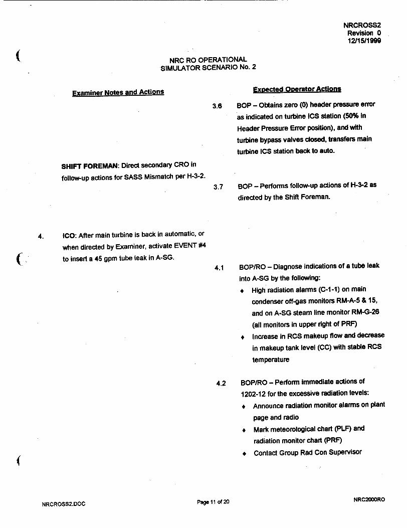
NRCROSS2 Revision 0 12/15/1999
NRC RO OPERATIONAL SIMULATOR SCENARIO No. 2
Examiner Notes and Actions Expected Operator Actions
3.6 BOP - Obtains zero (0) header pressure error
as indicated on turbine ICS station (50% in
Header Pressure Error position), and with
turbine bypass valves closed, transfers main
turbine ICS station back to auto.
SHIFT FOREMAN: Direct secondary CRO in
follow-up actions for SASS Mismatch per H-3-2.
3.7 BOP - Performs follow-up actions of H-3-2 as
directed by the Shift Foreman.
4. ICO: After main turbine is back in automatic, or
when directed by Examiner, activate EVENT #4
Sto insert a 45 gpm tube leak in A-SG.
4.1 BOP/RO - Diagnose indications of a tube leak
into A-SG by the following:
* High radiation alarms (C-1-1) on main
condenser off-gas monitors RM-A-5 & 15,
and on A-SG steam line monitor RM-G-26
(all monitors in upper right of PRF)
* Increase in RCS makeup flow and decrease
in makeup tank level (CC) with stable RCS
temperature
4.2 BOP/RO - Perform immediate actions of
1202-12 for the excessive radiation levels:
* Announce radiation monitor alarms on plant
page and radio
+ Mark meteorological chart (PLF) and
radiation monitor chart (PRF)
(* Contact Group Rad Con Supervisor
... .o, NRC2000RONRCROSS2.DOC -d'

NRCROSS2 Revision 0 12/15/1999
NRC RO OPERATIONAL SIMULATOR SCENARIO No. 2
Examiner Notes and Actions Expected Operator Actions
SHIFT FOREMAN: Following CRO actions for
the excessive radiation levels, implement
1202-12 and C-1-1 and verifyldiret actions.4.3 RO - Performs actions of C-1-1 to validate and
quantify tube leak.
4.4 RO - When tube leak is validated, recommends
plant shutdown per 1210-5, and may close
MU-V-3 (CC) to isolate letdown if necessary for
RCS inventory control.
5. SHIFT FOREMAN: After primary CRO
validates and quantifies SG tube leakage,
implement 1210-5 and direct primary CRO to
commence plant/reactor shutdown per 1210-5
at 3-5% per minute.
NOTE: 5.1 is a Critical Task. 5.1 RO - Effects plant shutdown by performing
the following per 1210-5:
+ Sets ULD rate of change at 30-40%
* Reduces ULD input to reduce reactor
power
+ When OTSGs reach low level limits
(alarms H-14-6 and H-4-7), transfers
SG/Rx Master and Reactor Demand
stations to HAND
* Transfers the Diamond Rod Control
panel to manual, and inserts control
rods to continue reactor shutdown
NRCROSS2.DOC NRC2000ROPage 12 of 20

NRCROSS2 Revision 0 12/15/1999
( NRC RO OPERATIONAL SIMULATOR SCENARIO No. 2
Examiner Notes and Actions Expected Operator Actions
SHIFT FOREMAN: If primary CRO requests
which RC bleed tank to select for feed, direct
primary CRO to use B-RCBT.
5.2 RO - Operates makeup system and LWDS
controls as necessary to maintain RCS and
makeup system inventory during reactor power
and T-ave reduction with 45 gpm leak:
* Opens MU-V-217 using its pushbutton on
CC to augment normal makeup line flow
through MU-V-17
* Operates Feed Tank Select and Feed
Pump Select switches on LWDS to align
selected RC bleed tank & pump for feed
( * Operates makeup system batch controller
(CC) and opens MU-V-10 (CC) to enable a
batch feed
* Operates Waste Transfer (feed) Pump
control on LWDS to start batch feed to
makeup tank
* Operates makeup batch controller and/or
MU-V-14A (CC) as necessary to maintain
makeup tank within limits of 1104-2,
Figure 1
5.3 BOP - Operates FW-P-1A ICS station demand
(CL) as necessary to maintain at least 25" main
feedwater valve delta-p on SP-1 1A/B-DPT2.
SHIFT FOREMAN: Continue to direct 1210-5
actions to shut down plant and reactor, and at
15% reactor power direct secondary CRO to
unload and trip main turbine.
NRCROSS2.DOC Page 13 of 20 NRC200DRO

NRCROSS2 Revision 0 12/15/1999
NRC RO OPERATIONAL SIMULATOR SCENARIO No. 2
Examiner Notes and Actions Expected Operator Actions
5.4 BOP - Secures main turbine at 15% power as
follows: (controls on CL)
* Transfers main turbine ICS station to hand
* Decreases turbine ICS demand to unload
generator to 0 MW, while verifying that
turbine bypass valves control SG pressures
* Manually trip main turbine by depressing
turbine TRIP button
6. ICO: When the main turbine is tripped, verify
EVENT #6 activates to cause MS-V-3D to fail
100% open.
NOTE: This MS-V-3D failure may not be
diagnosed until lower in reactor power during
reactor shutdown, or possibly not until MS-V-3
ICS stations are taken to hand for reactor trip
per 1210-5.
6.1 BOP - Recognizes lower demand on ICS station
for MS-V-3D/E/F as compared to demand for
MS-V-3A/B/C on B-SG, and/or notices MS-V-3E
and 3F closed but MS-V-3D open.
6.2 BOP - Diagnoses failure of MS-V-3D by:
* Zero (0) demand on ICS station for
MS-V-3D/E/F (CC)
+ Red open indication for MS-V-3D (CC)
* A-SG pressure decreasing below desired
pressure.
NOTE: 6.3 is a Critical Task. 6.3 BOP - Respond to MS-V-3D failure by
directing auxiliary operator to locally isolate
or manually close MS-V-3D.
NRC2000RONRCROSS2.DOC Page 14 of 20

NRCROSS2 Revision 0 12/1511999
NRC RO OPERATIONAL SIMULATOR SCENARIO No. 2
Examiner Notes and Actions Expected Operator Actions
ICO-ROLE PLAY: As AO if directed to locally
isolate MS-V-3D, after a 2-3 minute time delay
use MSR10 to close MS-V-1ID.
If directed to manually close MS-V-3D, after a
2-3 minute time delay: insert MSR36 at 100%,
change MSR35 to MANUAL, then insert MSR36
at 0% over 30 second ramp.
After the appropriate task is complete, report
task complete to control room.
6.4 BOP - Recognize MS-V-3D isolation by proper
A-SG pressure control by MS-V-3E/F.
Recognize MS-V-3D manual closure by green
position indication on CC, and proper A-SG
pressure control by MS-V-3E/F.
5.5 RO - Operates CRD panel as necessary to
reduce reactor power until T-ave = 5450F.
ICO: When reactor power is less than 10%
(CRQCRNRM<0.1), verify EVENT #7 activates
to fail selected pressurizer level transmitter to
400" over 600 seconds.
7.1 RO - Diagnose decreasing makeup flow (CC) to
RCS and increasing makeup tank level (CC),
and recognize increase in pressurizer level
RC1-LT1 on recorder (CC), with decrease In
pressurizer level on digital, LI-777A (CC).
7.2 RO - Diagnose probable failure of RC1-LT1 on
pressurizer level recorder by conflicting
indications of:
+ Increase on RC1-LT1 recorder level (CC)
but decrease on LI-777A digital level (CC)
* Increase on RCI-LT1 recorder level but
decreasing RCS temperature and pressure
eDll 1r vlF % NRC2000ROkiwi-na, -w-"MIMiQ .

NRCROSS2 Revision 0 12115/199M
NRC RO OPERATIONAL SIMULATOR SCENARIO No. 2
Examiner Notes and Actions Expected Operator Actions
7.3 RO - Respond to failure of RCI-LTI per
1202-29, Section D as follows:
* May dose MU-V-3 (CC) to Isolate RCS
letdown if not previously done per 1210-5
* Transfer MU-V-17 controller to HAND (CC),
and increase MU-V-17 demand to obtain
required makeup flow and maintain real
pressurizer level on LI-777A
* Select alternate pressurizer level for
recorder, RCI-LT3 (CC)
* Select altemate pressurizer temperature,
RC2-TE2 (CC)
SHIFT FOREMAN: After primary CRO has
performed 1202-29, Section D immediate
manual actions, implement 1202-29, Section D
and verify/direct the immediate actions.
7.4 RO - Verify or perform immediate actions for
RC1-LT1 failure as read by Shift Foreman.
7.5 RO - Following selection of RCI-LT3, check
level error on MU-V-17 controller, and with zero
error at appropriate level setpoint, transfer
MU-V-1 7 back to auto.
SHIFT FOREMAN: Continue to direct CRO
actions per 1210-5 to shutdown (trip) reactor
and control SG pressures to prevent MSSV lift.
5.6 BOP - Transfers turbine bypass valve (MS-V-3)
ICS stations on CC to hand prior to reactor trip,
per 1210-5.
EXAMINERS: Refer to copy of 1210-1 for 5.7 RO - At 5450F T-ave, manually trips reactor per
required operator actions. 1210-5 and commences 1210-1 immediate
actions.
NRCROSS2.DOC NRC2000ROPage 16 of 20

NRCROSS2 Revision 0 12115/1999
NRC RO OPERATIONAL SIMULATOR SCENARIO No. 2
Examiner Notes and Actions Expected Operator Actions
EXAMINER: When RO starts MU-P-1A per
1210-1 immediate actions, it will trip. See
EVENT #8 for operator actions. 5.8 BOP - Operates turbine bypass valve ICS
stations in HAND to stabilize SG pressures and
prevent MSSV lift (at >1040 psig).
5.9 BOP - Performs 1210-1 immediate actions for
the reactor trip: verifies turbine tripped, and
ensures main feedwater controlling SG levels at
25" on startup range indications (CC).
8. ICO: When MU-P-1A is started, verify it trips by 8.1 RO - Starts MU-P-1A, DC-P-1A, and DR-P-1A
EVENT #8 activation, using their extension controls on CC, per
1210-1 immediate actions.
8.2 RO - Diagnoses MU-P-1A trip by the following
alarms and indications:
* Alarms B-1-2 and B-2-2
* Green and amber lamps for MU-P-1A
breaker status above its control switch on
CC
* Zero (0) amps indicated on MU-P-1A
ammeter above its control switch on CC
8.3 RO - Starts MU-P-IC, DC-P-1B, and DR-P-lB
using their extension controls on CR.
8.4 RO - Opens HPI valves MU-V-16C/D using
their pushbuttons on CR, to provide additional
makeup flow to RCS as necessary to maintain
pressurizer level per 1210-1.
_R _4_ 2.OCa 7 -f II NRC2000ROa-clf IIwIavNRCROSS2.DOC

NRCROSS2 Revision 0 12/15/1999
NRC RO OPERATIONAL SIMULATOR SCENARIO No. 2
Examiner Notes and Actions Expected Operator Actions
EXAMINERS: Refer to copy of 1210-1 for
required operator actions.
5.10 RO/BOP - Perform remaining immediate
actions for reactor trip per 1210-1.
SHIFT FOREMAN: Following all 1210-1
immediate actions by CROs, announce to team
and commence 1210-1 immediate action
verification.
5.11 RO/BOP - Verify 1210-1 immediate actions as
read by Shift Foreman, and continue to monitor
plant conditions.
SHIFT FOREMAN: Transition back to 1210-5
from 1210-1, and continue directing CROs in
1210-5 follow-up actions after reactor trip.
5.12 BOP - Operates MS-V-3 ICS controllers (CC)
as necessary to steam both OTSGs and reduce
RCS T-hot below 540OF per 1210-5.
ICO: Verify EVENT #9 activated when reactor
was tripped, to fail RC-V-1 OPEN pushbutton.
9. SHIFT FOREMAN: Direct primary CRO to
secure pressurizer heaters and commence
maximum pressurizer spray to reduce RCS
subcooled margin below 700F, but not lower
than 400F.
9.1 RO - Secures all pressurizer heaters by turning
control switches for Banks 1, 2, 3, 4, and 5 to
OFF on CR.
9.2 RO - Transfers RC-V-1 control on to MAN, and
depresses OPEN pushbutton for RC-V-1 (CC).
NRCROSS2.DOC Page 18 of 20 NRC2000RO

NRCROSS2 Revision 0 12115/1999
NRC RO OPERATIONAL SIMULATOR SCENARIO No. 2
Examiner Notes and Actions Expected Operator Actions
9.3 RO - Diagnoses and reports failure of RC-V-1 to
open as indicated by no OPEN red lamp
illuminated when pushbutton was depressed.
SHIFT FOREMAN: When primary CRO reports
RC-V-1 failure to open, direct primary CRO to
use pressurizer vent and/or PORV to reduce
RCS subcooled margin.
NOTE: 9.4 is a Critical Task. 9.4 RO - Operate pressurizer vent valves RC-V
"44 (PC) and RC-V-28 (CC), and/or PORV (CC)
to reduce RCS subcooled margin to
between 40OF and 70OF as indicated on
Margin To Saturation meters on PCL: TI-977
and TI-978.
SHIFT FOREMAN: Direct CROs to bypass
1600# ESAS channels when BYPASS
PERMITS are obtained during RCS pressure
reduction.
9.5 RO/BOP - When 1600# ESAS channel bypass
permits are obtained as indicated by the white
BYPASS PERMIT lamps illuminated for
channels RC-1A, 2A, and 3A (CC) and RC-1B,
2B, and 3B (CR), perform the following:
* Depress BYPASS pushbuttons for RC-IA,
2A, and 3A on CC, and verify yellow
BYPASS lamps illuminate
* Depress BYPASS pushbuttons for RC-1 B,
2B, and 3B on CR, and verify yellow
BYPASS lamps illuminate
NRCROSS2.DOC NRC200OROPage 19 of 20

NRCROSS2 Revision 0 12/15/1999
NRC RO OPERATIONAL SIMULATOR SCENARIO No. 2
7.0 TERMINATION POINT
When all of the following conditions exist:
1. Examinees had opportunity to perform all critical tasks as designed.
2. RCS subcooled margin has been minimized (<700F), and 1600# ESAS channels are bypassed.
3. Crew is preparing to commence plant cooldown per 1210-5.
4. Examiners agree to terminate.
NRCROSS2.DOC NRC2000ROPage 20 of 20

NRCROSS3 Revision 0 12/16/1999
NRC RO OPERATIONAL SIMULATOR SCENARIO No. 3
MAKEUP PUMPS SHIFTED, MAKEUP SYSTEM LEAK REQUIRING PLANT SHUTDOWN,
TURBINE TRIP AT 40% POWER, AND MAIN STEAM UNE BREAK OUTSIDE CONTAINMENT
CAUSING EXCESSIVE PRIMARY TO SECONDARY HEAT TRANSFER
DEVELOPED BY/DATE:
REVIEWED BY/DATE:
APPROVED BY/DATE:
J64�,� 4 ,.i�/j/ 7,
(OPERATIONS TRAINING MANAGER)
NRC2000RONRCROSS3.DOC Page I of 20

NRCROSS3 Revision 0 12/16/i999
NRC RO OPERATIONAL SIMULATOR SCENARIO No. 3
- --- a - -. a� � I � � S�a � a a.- a .-.. �. --
REVISION DATE REFERENCE TITLE DESCRIPTION (Include Al # if appropriate)
1 4 4
1. 4
4. 1 I
_____ 4 I
1 4
I 4 1�
____ 4 +
_____ J. 1 1
4. I I
_____ I I I
_____ 1 .1. 1*
I 4 4
4. I I
_____ 4 I
_ LI I
NRC2000RONRCROSS3.DOC
Q1p l1d~ili/V l"l•.l=•n ~ r n -gpIG., Ikl II, li,./llr I •-H J]•d! i• fl]-"•, I [ IR !- V•iI•L•IE
Page 2 of 20

NRCROSS3 Revision 0 12/16/1999
NRC RO OPERATIONAL SIMULATOR SCENARIO No. 3
1.0 GENERAL DESCRIPTION OF SCENARIO
Plant at 100% power, MOC, with IA-P-4 out of service.
Operating makeup pumps are shifted to remove MU-P-1 B from service.
A makeup system leak occurs downstream of MU-V-17 and MU-FT-24A fails low.
Normal makeup line must be isolated, and management orders plant shutdown.
As FW-P-1A Is unloaded to secure it, the selected B-train MFW valve d/p transmitter fails low.
The main generator and turbine trips at 40% power.
A main steam line break on A-SG occurs outside containment in Intermediate Building.
The reactor will trip automatically if not tripped manually.
FW-V-5A breaker trips and HSPS fails to close FW-V-1 6A and 17A on low SG pressure.
MU-V-16C will not close upon demand to secure HPI.
Plant will be stabilized with A-SG isolated.
Estimated scenario time - 70 minutes. 3 Critical Tasks
2.0 REFERENCES
A. 10 CFR 55.45 Operating Tests, (a) Content (3), (4), (5), (6), (7), (8), (9), (12), (13)
B. PROCEDURES
1104-25 Instrument and Control Air System
1104-2 Makeup and Purification System
1102-10 Plant Shutdown
1106-3 Main Feedwater
1203-24 Steam Leak
1210-1 Reactor Trip (copies required for examiners)
121 0-3 Excessive Primary to Secondary Heat Transfer (copies required for examiners)
1210-10 Abnormal Transients Rules, Guides, and Graphs
Alarm Responses
NRCROSS3.DOC Page 3 of 20 NRC2000RO

NRCROSS3 Revision 0 12/18/1999
NRC RO OPERATIONAL SIMULATOR SCENARIO No. 3
3.0 TASKS
004C020101
0000590501*
3418000101
0150030101
0598050101
0158020401
0008310501
0000400501
0000070501
0000080501
0008370501*
000C200501
0618000501
0130040101
004C040101*
Perform shifting of makeup pumps
Respond to accidental liquid radioactive water release (RCS)
Perform plant power changes
Operate the ICS in hand
Manually operate a main feedwater pump
Respond to a SASS mismatch/actuation
Respond to a turbine trip below the anticipatory trip setpoint
Respond to a steam leak
Respond to a reactor trip as the primary CRO
Respond to a reactor trip as the secondary CRO
Isolate the affected OTSG during excessive primary to secondary heat transfer
Respond to excessive primary to secondary heat transfer
Respond to an emergency feedwater actuation
Bypass or defeat an ES channel
Throttle high pressure injection
* Critical Task
NRCROSS3.DOC Page 4 of 20 NRC2000RO

NRCROSS3 Revision 0 12/16/1999
NRC RO OPERATIONAL SIMULATOR SCENARIO No. 3
4.0 SIMULATOR INITIALIZATION
A. IC16 100% power, steady-state, MOC.
Place simulation in RUN and perform the following to remove IA-P-4 from service per 1104-25:
1. Start IA-P-1A in HAND using IAR01.
2. Verify or place IA-P-1 B in AUTO using IAR02.
3. OPEN IA-V-2104A/B Bypass using IAR08.
4. Start SA-P-1A in HAND using IAR03.
5. CLOSE IA/SA Cross-connect Valves using IAR10.
6. Red tag IA-P-4 extension control on PLF in pull-to-lock.
B. EVENT TRIGGERS
#3 FWFDFWP(1)<416
Command: IMF FW06B 0 15
#5 FWVFWV5A<0.95
Command: IMF FW13A
C. MALFUNCTIONS
IA01C IA-P-4 trip; insert immediately.
MU14 Makeup line leak; insert at 50% severity (50 gpm) on Event #2.
EG03 Main generator trip; insert on Event #4.
MS03A MSLB outside RB; insert at 100% severity with 300 second ramp on Event #4.
MS10,SGA,TRN B HSPS SG-A Train-B failure; insert immediately.
D. REMOTE FUNCTIONS
Per 4.A. above.
E. OVERRIDES
02A3M06-ZAOMU24FI FLO; insert at 0% severity with 120 second delay on Event #2.
03A4S35-ZDIPBCMUV16C ON CR MU-V-16C CLOSE PUSHBUT; insert OFF immediately.
F. MONITOR
Set MSK2609A = 14.7 immediately (auxiliary steam pressure).
NRC2000RONRCROSS3.DOC Page 5 of 20

NRCROSS3 Revision 0 12/16/1999
NRC RO OPERATIONAL SIMULATOR SCENARIO No. 3
5.0 SCENARIO PREVIEW
A. EXAMINER PREVIEW
Plant at 100% power, MOC, with IA-P-4 out of service. IA and SA systems are aligned for service
per 1104-25 as required by the On-Line Maintenance Risk document..
1. The RO will place MU-P-1A in service and secure MU-P-1B per 1104-2.
2. A makeup system leak occurs downstream of MU-V-1 7 and the low range makeup flow
transmitter (MU-FT-24A) fails low. The RO must isolate the normal makeup line to isolate
the leak, and HPI must be used to control RCS inventory. (CT)
One hour time compression will be used, and *plant management will order a plant
shutdown. The plant shutdown will be performed per 1102-10.
3. As FW-P-1A is removed from service per 1102-10 and 1106-3 by the BOP operator, the
selected B-train main feedwater valve d/p transmitter fails low causing SASS mismatch
but no actuation. The BOP operator must assume hand control of FW-P-1 B and select
the alternate main feedwater valve d/p transmitter per H-3-2.
4. At 35-40% reactor power, the main generator and turbine trips without reactor trip, causing
a main steam line rupture on A-SG in intermediate building. The reactor will eventually
trip automatically if not tripped manually per 1203-24. BOP and RO operators must
respond to the reactor trip per 1210-1. The RO must start MU-P-1 C and use HPI to
maintain pressurizer level per 1210-1.
5. Component and safety system failures on the feedwater system will require the BOP
operator to manually isolate main and emergency feedwater to the A-SG per 1210-3. (CT)
The BOP operator must then control B-SG feeding and steaming to control RCS
temperatures and minimize reheat per 1210-3.
6. When the RCS excessive cooling is terminated, the RO must control (terminate) HPI to
control RCS inventory and pressure per 1210-3. However, MU-V-16C will not close on
demand from control room, requiring RO to secure MU-P-IC to secure B-train HPI. (CT)
7. The crew will perform all follow-up actions of 1210-3 and transition back to 1210-1.
NRCROSS3.DOC NRC2000ROPage 6 of 20

NRCROSS3 Revision 0 12/16/1999
NRC RO OPERATIONAL SIMULATOR SCENARIO No. 3
B. SHIFT BRIEFING
1. Plant is at 100% power, steady-state, 300 EFPD.
2. IA-P-4 is out of service for inspection, maintenance, and cleaning. The compressor is
currently disassembled, and maintenance is awaiting arrival of vendor representative to
perform further inspection and cleaning. (See On-Line Maintenance Risk document)
3. The Instrument and Service Air systems are aligned for service per 1104-25, while
IA-P-4 is out of service, per the On-Line Maintenance Risk document.
4. Maintenance and Engineering must perform an inspection of MU-P-1 B lube oil system
while it is shutdown. A switching order is being prepared. Expected duration of the
inspection will be 1-2 hours, after which MU-P-1B will be returned to service.
5. DCCW loop-A will be sampled while in service for MU-P-1A operation.
6. Orders for this shift include shifting from MU-P-1B to MU-P-1A in operation, and
maintaining 100% power operation.
NRC2000RONRCROSS3.DOC Page 7 of 20

NRCROSS3 Revision 0 12/1611999
NRC RO OPERATIONAL SIMULATOR SCENARIO No. 3
6.0 SEQUENCE OF EVENTS
Examiner Notes and Actions Expected Operator Actions
* ICO: Initialize the simulator per Section 4.0.
* IPOI: Assign team positions and conduct the * Assume assigned team positions.
SHIFT BRIEFING per Section 5.B.
• Take turnover and review plant status.
* Allow crew 3-5 minutes to take turnover and
assume the watch. * Assume the watch and inform examiner.
1. SHIFT FOREMAN: Direct primary CRO actions
per 1104-2 to place MU-P-1A in service for less
than 4 hour run, and secure MU-P-1 B.
1.1 RO - Starts DC-P-1A, DR-P-1A, and MU-P-1A
using their extension controls on CC.
1.2 RO - Monitors makeup and RCP seal injection
parameters on CC to ensure stability.
1.3 RO - Secures MU-P-1 B using its extension
control on CR.
SHIFT FOREMAN: Direct RO to start IC-P-1 B
and secure IC-P-1A per the On-line
Maintenance Risk document for MU-P-1 B.
1.4 RO - Starts IC-P-1 B using its extension control
on CR, and secures IC-P-1A using its extension
control on CR.
I V. NRC2000ROraw 0 01NRCROSS3.DOC

NRCROSS3 Revision 0 12/16/1999
NRC RO OPERATIONAL SIMULATOR SCENARIO No. 3
Examiner Notes and Actions Expected Operator Actions
2. ICO: Approximately one (1) minute after IC-P
1A is secured, or when directed by Examiner,
activate EVENT #2 to cause makeup line leak
and 120 seconds later, MU-FT-24A fails low.
2.1 RO - Diagnose symptoms of primary system
leak in Auxiliary Building by the following
alarms and indications:
* Pressurizer level decrease (CC) with
MU-V-1 7 controller demand increase (CC)
* Makeup flow increase on MU-FI-24A and
24B (CC) and eventually D-3-1 alarm
* Makeup tank level and pressure decrease
and eventually alarms D-3-2 & D-3-3
* Auxiliary Building sump level increase
(LWDS recorder) and eventually LWDS-1-1
alarm
SHIFT FOREMAN: Implement alarm response
procedures as they occur or as requested by
RO.
2.2 BOP/RO - Dispatch personnel to Auxiliary
Building to search for leaks.
2.3 RO - Closes MU-V-3 by depressing its CLOSE
pushbutton on CC to isolate letdown and
conserve RCS inventory per D-3-1.
2.4 RO - Recognize failure of MU-FT-24A by its
indication on CC meter dropping to zero (0),
with flow still indicated on MU-FI-24B.
ICO-ROLE PLAY: As auxiliary operator looking
for leak in auxiliary building, report a bad leak in
overhead of 281' elevation just outside makeup
valve alley.
NRCROSS3.DOC Page 9 of 20 NRC200RO

NRCROSS3 Revision 0 1211611999
S~ NRC RO OPERATIONAL
SIMULATOR SCENARIO No. 3
Examiner Notes and Actions Expected Operator Actions
SHIFT FOREMAN: If RO inquires as to which
RC Bleed Tank to use for feed to makeup
system, direct RO to use B-RCBT.
2.5 RO - Operates the following LWDS and
makeup system controls to initiate feed to
makeup tank per D-3-2:
* Selects B-RCBT using FEED TANK
SELECT switch on LWDS
* Selects a waste transfer pump using FEED
PUMP SELECT switch on LWDS
* Operates makeup batch controller and
MU-V-10 on CC to enable a batch feed
* Starts selected waste transfer pump on
t .LWDS to initiate batch feed to makeup tank
* Operates makeup batch controller as
necessary to maintain makeup tank level
and pressure within limits of 1104-2,
Figure 1
SHIFT FOREMAN: Based upon report from
field, direct the primary CRO to isolate makeup
to the RCS - more specifically, close MU-V-17
and MU-V-18.
NOTE: 2.6 is a Critical Task. 2.6 RO - Closes MU-V-17 by transferring its
controller (CC) to HAND and decreasing the
demand to zero (0), and closes MU-V-18 by
depressing its CLOSE pushbutton on CC.
ICO-ROLE PLAY: Monitor the makeup system
mimic on the Instructor Station, and when
MU-V-17 and MU-V-217 both indicated closed,
report to control room that the leak outside
makeup valve alley has stopped.
NRCROSS3.DOCNRC2000RO
Page 10 of 20

NRCROSS3 Revision 0 12/16/1999
NRC RO OPERATIONAL SIMULATOR SCENARIO No. 3
Examiner Notes and Actions Expected Ooerator Actions
2.7 RO - Operates MU-V-16A or MU-V-16B using
their OPEN, CLOSE, and STOP pushbuttons
on CC, as needed to restore and maintain
pressurizer level.
EXAMINER: After pressurizer level and
makeup tank level are under control and stable
with the makeup leak isolated, inform crew that
after one (1) hour of time compression, plant
management has ordered a plant shutdown to
repair the leak.
SHIFT FOREMAN: Implement 1102-10 and
direct primary CRO to commence plant
shutdown at 5% per minute.
2.8 RO - Commences plant shutdown by:
* Setting ULD rate of change at 50% (CC)
* Lowering ULD setting to reduce power (CC)
SHIFT FOREMAN: Direct CRO actions for plant
shutdown per 1102-10.
2.9 BOP/RO - Monitor critical parameters during
plant shutdown.
2.10 BOP - Secures moisture separator drain pumps
(MO-P-IA-F) using their extension controls on
CL, when directed by Shift Foreman.
SHIFT FOREMAN: Direct primary CRO to stop
power reduction at approximately 40%, to secure
FW-P-1A and HD-P-1C.
2.11 RO - Operates ULD (CC) as necessary to stop
plant power reduction at approximately 40% as
directed by Shift Foreman.
NRC2000RONRCROSS3.DOC Page I11 of 20
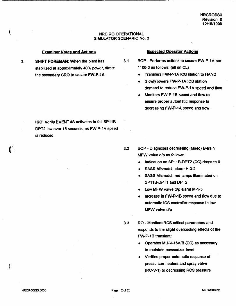
NRCROSS3 Revision 0 12116/1999
NRC RO OPERATIONAL SIMULATOR SCENARIO No. 3
Examiner Notes and Actions Expected Operator Actions
3. SHIFT FOREMAN: When the plant has
stabilized at approximately 40% power, direct
the secondary CRO to secure FW-P-IA.
3.1 BOP - Performs actions to secure FW-P-1A per
1106-3 as follows: (all on CL)
* Transfers FW-P-1A ICS station to HAND
* Slowly lowers FW-P-1A ICS station
demand to reduce FW-P-1A speed and flow
* Monitors FW-P-1 B speed and flow to
ensure proper automatic response to
decreasing FW-P-1A speed and flow
ICO: Verify EVENT #3 activates to fail SP 113B
DPT2 low over 15 seconds, as FW-P-1A speed
is reduced.
3.2 BOP - Diagnoses decreasing (failed) B-train
MFW valve d/p as follows:
* Indication on SP1 1 B-DPT2 (CC) drops to 0
+ SASS Mismatch alarm H-3-2
* SASS Mismatch red lamps illuminated on
SP11B-DPT1 and DPT2
* Low MFW valve d/p alarm M-1-5
* Increase in FW-P-1B speed and flow due to
automatic ICS controller response to low
MFW valve d/p
3.3 RO - Monitors RCS critical parameters and
responds to the slight overcooling effects of the
FW-P-1 B transient:
* Operates MU-V-16AtB (CC) as necessary
to maintain pressurizer level
* Verifies proper automatic response of
pressurizer heaters and spray valve
(RC-V-1) to decreasing RCS pressure
NRCROSS3,DOC NRC2000ROPage 12 of 20

NRCROSS3 Revision 0 12/18/1999
NRC RO OPERATIONAL SIMULATOR SCENARIO No. 3
Examiner Notes and Actions Expected Operator Actions
3.4 BOP - Responds to failed MFW valve d/p
instrument per H-3-2 as follows: (on CC)
+ Transfers FW-P-1B ICS station to HAND
* Adjusts FW-P-1 B ICS station demand as
necessary to stabilize MFW flows
* Selects altemate B-train MFW valve d/p
transmitter, SPI I B-DPT1, by depressing Its
SASS selector pushbutton
SHIFT FOREMAN: After secondary CRO has
diagnosed MFW valve d/p instrument failure
and initiated corrective action to control FW-P
IB, implement H-3-2 alarm response and verify
or direct actions as necessary. 3.5 BOP - Performs or verifies actions per H-3-2 as
directed by the Shift Foreman.
3.6 BOP - Following selection of SP1 1 B-DPT1,
may transfer FW-P-1 B back to auto at 35 psid
on lower MFW valve d/p (zero error on FW-P
1B ICS station; or, may leave FW-P-1B in
HAND for remainder of plant shutdown.
SHIFT FOREMAN: Continue plant shutdown
per 1102-10 by directing secondary CRO to
secure HD-P-1C. 3.7 BOP - Secures HP-P-1C using its extension
control on CL as directed by the Shift Foreman.
SHIFT FOREMAN: Continue plant shutdown by
directing primary CRO to lower reactor power to
approximately 25%. 3.8 RO - Lowers ULD setting as necessary to obtain
reduction in plant power level as directed by the
Shift Foreman.
NRC2000RONRCROSS3.DOC Page 13 of 20

NRCROSS3 Revision 0 12116/1999
NRC RO OPERATIONAL SIMULATOR SCENARIO No. 3
Examiner Notes and Actions Expected Operator Actions
4. ICO: When reactor power is between 35 and
40%, or when directed by Examiner, activate
EVENT #4 to cause main generator-turbine trip
and initiate a main steam line break on A-SG in
Intermediate Building.
4.1 BOP/RO - Diagnose turbine trip without reactor
trip by alarm K-1-1 and numerous other panel
indications (no alarm G-1-1).
4.2 BOP/RO - Respond to the turbine trip without
reactor trip per K-1-1 as follows:
* Verify ICS goes in TRACK (alarm H-2-2)
* Monitor power range digitals on CC, and
verify control rod insertion (CRD panel and
average control rod position on CC) to
automatically decrease reactor power to
minimum ICS demand (15%)
4.3 BOP - Controls FW-P-1 B ICS controller if in
HAND as necessary to maintain MFW valve d/p
for sufficient main feedwater flow, due to initial
SG pressure increase.
4.4 RO - Monitors RCS critical parameters and
responds to the RCS cooldown and shrink as
reactor power decreases:
* Operates MU-V-16A/B (CC) as necessary
to maintain pressurizer level
* Verifies proper automatic response of
pressurizer heaters and spray valve
(RC-V-1) to decreasirig RCS pressure
S4. A, 1 1n x NRC2000RONRCRUbS.UUO -a-r l~l&

NRCROSS3 Revision 0 12/18/1999
NRC RO OPERATIONAL SIMULATOR SCENARIO No. 3
Examiner Notes and Actions Expected Ooerator Actions
4.5 BOP - Recognizes abnormal A-SG pressure
response during power reduction and after
reactor trip, by the following Indications:
* A-SG pressure lower than B-SG pressure
(CC and PCL)
* Demand on MS-V-3D/ElF ICS controller Is
lower than the demand for MS-V-3A/B/C
controller
NOTE: Reactor may automatically trip due to
numerous failures combined with main steam
line break.
SHIFT FOREMAN: After allowing time for
CROs to respond and diagnose abnormal
pressure response in A-SG, or if recommended
by either CRO, direct RO to manually trip
reactor due to steam leak per 1203-24.
4.6 RO/BOP - Manually trips reactor by depressing
TRIP and DSS pushbuttons on CC.
EXAMINERS: Refer to copy of 1210-1 for
expected operator actions.
4.7 RO - Verifies reactor is tripped per 1210-1 and
commences 1210-1 immediate actions.
4.8 BOP - Verifies main turbine is tripped per
1210-1.
EXAMINER: See Step 5.2 for actions expected 4.9 BOP - Controls main feedwater per 1210-1 by
to mitigate FW-V-5A failure to close, controlling FW-P-1 B in HAND as necessary,
and recognizes FW-V-5A has no control power.
NRCROSS3.DOC Page 15 of 20 NRC2000RO

NRCROSS3 Revision 0 12/116/1999
NRC RO OPERATIONAL SIMULATOR SCENARIO No. 3
Examiner Notes and Actions Exoected Oo~erator Actions
4.10 RO - Performs 1210-1 action to start a second
makeup pump and maintain pressurizer level as
follows:
* Starts MU-P-1C, DC-P-1B, and DR-P-1B
using their extension controls on CR
+ Operates MU-V-16A/B/C/D (CC/CR) as
necessary to maintain pressurizer level
above 80 inches (CC - recorder and digital)
+ Opens MU-V-14A/B (CC) if makeup tank
level drops below 55 inches (CC digital)
* If pressurizer level drops below 20 Inches,
manually initiates HPI by depressing 1600#
or 4# ES Manual Actuation pushbuttons on
CC for Train-A and on CR for Train-B
5. ICO: Verify EVENT #5 activates to trip FW-V
5A breaker as it starts to close on reactor trip.
SHIFT FOREMAN: After providing secondary
CRO sufficient time to initiate A-SG isolation on
his/her own, if necessary direct secondary CRO
to isolate A-SG per 1210-3.
NOTE: 5.2 Is a Critical Task.
5.1 BOP/RO - Diagnose A-SG blow-down causing
excessive primary to secondary heat transfer by
following indications:
* Rapid drop in A-SG pressure (CC & PCL)
+ Decreasing RCS temperatures below
normal post-trip values (CC & PCL)
* Decreasing RCS pressure below normal
post-trip value (CC & PCL)
5.2 BOP - Performs actions necessary to Isolate
feedwater to A-SG per 1210-1 and 121043:
* Transfers FW-V-17A and 16A ICS
controllers (CC) to HAND and decreases
demands to zero (0)
* Closes FW-V-92A by depressing its
CLOSE pushbutton on CC
+ Controls or trips FW-P-1 B (CL)
NRCROSS3.DOC NRC2000ROPage 16 of 20

NRCROSS3 Revision 0 12/18/1999
NRC RO OPERATIONAL SIMULATOR SCENARIO No. 3
Examiner Notes and Actions Expected Operator Actions
NOTE: Emergency feedwater will automatically
actuate at less than 10 inches in A-SG as it
steams down with MFW isolated, and EF-V
30A/D will automatically open to control A-SG
level at 25 inches on startup range.
NOTE: Closing EF-V-30A and 30D is part of
the Critical Task to isolate A-SG.
5.3 BOP - Performs actions to completely
isolate A-SG per 1210-3 as follows:
* Closes or verifies dosed MS-V-3D/E/F and
MS-V-4A with their ICS controller on CC in
HAND at zero (0) demand
* Closes MS-V-1A and lB by depressing their
CLOSE pushbuttons on CC
* Closes MS-V-2A by depressing its CLOSE
pushbutton on CC
* Transfers EF-V-30A and EF-V-30D
controllers on CL to MANUAL, and sets
their demands to zero (0)
* May direct AO to locally close FW-V-5A
ICO-ROLE PLAY: If directed to close FW-V-5A
locally, display FWVFWV5A on MONITOR and
set its value to zero (0) in 0.1 increments over a
one minute ramp.
When FW-V-5A is closed, report task complete
to the control room.
NOTE: When A-SG blows dry and no longer
removes heat from RCS, the RCS will begin to
reheat and repressurize until control of B-SG
and HPI is assumed by the operators to
stabilize RCS temperature & pressure.
NRCROSS3.DOCNRC2000ROPage 17 of 20

NRCROSS3 Revision 0 12116/1999
NRC RO OPERATIONAL SIMULATOR SCENARIO No. 3
Examiner Notes and Actions Expected Operator Actions
5.4 BOP - When A-SG blows dry, performs actions
necessary to establish B-SG as an adequate
heat sink to minimize RCS reheat as follows:
+ Adjusts (lowers) turbine header pressure
setpoint (CC) to open MS-V-3A/B/C in auto,
or transfers MS-V-3A/B/C ICS controller on
CC to HAND and adjusts (raises) their
demand, to lower B-SG pressure such that
it becomes a heat sink and stabilizes RCS
T-cold
* Provides main or emergency feedwater to
B-SG as necessary to maintain sufficient
level for heat transfer (> 25" startup level)
6. SHIFT FOREMAN: Direct operators to clear
ESAS signals as necessary to gain control of
high pressure injection components, and direct
prmary CRO to control HPI as necessary to
stabilize RCS pressure with at least 40OF
subcooled margin.
NOTE: When ESAS trains A and B are clear, all 6.1
3 sets of block loading sequence blue lamps will
be extinguished for each train on PCR.
RO/BOP - When directed by Shift Foreman,
clear ESAS signals as necessary for HPI
throttling as follows:
* Bypass or reset 1600# auto channels, 3 on
train-A and 3 on train-B, by depressing their
bypass or reset pushbuttons on CC and CR
* Defeat and re-enable 1600# manual
channels 3 on train-A and 3 on train-B, by
depressing their defeat/enable pushbuttons
on CC and CR
NRCROSS3.DOC Page IS of 20 NRC2OOOR

NRCROSS3 Revision 0 12/16/1999
NRC RO OPERATIONAL SIMULATOR SCENARIO No. 3
Examiner Notes and Actions Expected Operator Actions
NOTE: 6.2 is a Critical Task.
NOTE: MU-V-16C will NOT close upon demand
by its CLOSE pushbutton on CR.
SHIFT FOREMAN: Following all immediate
actions to isolate A-SG and actions necessary
to stabilize the plant, announce to team and
commence 1210-1 verification. When required,
announce to team and transition to 1210-3.
EXAMINERS: Refer to copy of 1210-1.
EXAMINERS: Refer to copy of 1210-3.
SHIFT FOREMAN: Direct crew in follow-up
actions of 121 0-3, then when appropriate,
announce to team and transition back to 1210-1.
6.2 RO - Operates makeup (HPI) system valves
and pumps as necessary to control HPI:
* Closes or throttles as necessary MU-V
16A, 16B, 16C, and 16D If open
* Reopens MU-V-36 and 37 on CC prior to
throttling below 100 gpm on MU-P-IA or
MU-P-IC
* If open, recognizes MU-V-16C failure to
close as indicated by its red OPEN lamp
on CR
* Secures MU-P-IC using its extension
control on CR to terminate B-train HPI
flow if MU-V-16C is open
* Operates MU-V-16A/B as necessary to
maintain stable pressurizer level
6.3 RO/BOP - Verify 1210-1 immediate actions as
read by Shift Foreman, and continue to monitor
plant conditions.
6.4 BOP - Verifies 1210-3 immediate actions as
read by Shift Foreman, and continue to monitor
plant conditions.
6.5 RO/BOP - Perform applicable follow-up actions
of 1210-3 as directed by Shift Foreman.
NRCROSS3,DOC Page 19 of 20 NRC200WOO

NRCROSS3 Revision 0 12/16/1999
NRC RO OPERATIONAL SIMULATOR SCENARIO No. 3
7.0 TERMINATION POINT
When all of the following conditions exist:
1. Examinees had opportunity to perform all critical tasks as designed.
2. Crew has transitioned back to 1210-1 from 1210-3.
3. Examiners agree to terminate.
M . . . IV % NRC2000RONRCROSS.IDOC ar

FOR TRAINING ONLY
ON-LINE MAINTENANCE RISK MANAGEMENT
ON-LINE RISK # 149 Rev: 0
RISK EVALUATION SUMMARY - IA-P-4 System Outage
IAW AP 1070 the Instrument Air has a Risk Ranking of High (RAW of 18).
Risk'Achievement Worth (RAW) is the factor increase in core damage frequency resulting when the structure, system, or component (SSC) is determined to be continuosly failed.
Assumptions:
IA-P-4 will be removed from service for fan motor replacement, vendor cleaning, and inspection of the compressor cooling system. Work is scheduled for the week of 2/14/2000.
1. LIST THE TYPE OF RISK CONCERNS EVALUATED
None provided that IA-P- I A/B, IA-Q- I and SA-P- 1A/B are placed in service and function properly. Infrequently run equipment may not support demands.
2. LIST IMPORTANT SSCs WHICH NEED TO BE MAINTAINED OPERABLE
IA-P- 1A IA-P-1B SA-P-lA SA-P-IB IA-Q-1
FOR TRAINING ONLY

FOR TRAINING ONLY
3. LIST IMPORTANT MANUAL ACTIONS WHICH SHALL BE BRIEFED WITH THE APPROPRIATE PERSONNEL
IA system will be supplied by IA-P- IA/B, and SA system will be supplied by SA-P- lA/B per 1104-25, Instrument and Control Air System, and 1104-42, Station Service Air, respectively.
IA-P-1 A/B and SA-P- lA/B maintain the air systems at a slightly lower pressure than IA-P-4 (85# vs. 100#). Monitor IA and SA system pressures more frequently while IA-P-4 is OOS.
4. IDENTIFY CONTINGENCY PLANS OR COMPENSATORY ACTIONS USED TO REDUCE RISK
COMPENSATORY ACTIONS (PRIOR TO/IN PREPARATION FOR OUTAGE):
IA-P- lA/B and SA-P-1A/B will be placed in service and made to carry plant air loads for a period of at least 4 hours prior to disabling IA-P-4 and IA-Q-2.
IA-P-4 will be removed from service in accordance with 1104-25. Maintenance work will be performed, and IA-P-4 will be returned to service per 1104-25 at the completion of scheduled work.
CONTINGENCY ACTIONS:
5. EVALUATION APPROVALS
o 1. Risk found acceptable 0 2. Risk found acceptable with contingencies identified o 3. Risk unacceptable,
Signature of FOR TRAINING on 02/13/2000 Evaluator:
Signature of Director: FOR TRAINING on 02/13/2000
CC: Job Package Shift Supervisor Clipboard Operations Department General Files STA
FOR TRAINING ONLY

NRCROSS4 Revision 0 12117/1999
NRC RO OPERATIONAL SIMULATOR SCENARIO No. 4
REACTOR STARTUP CONTINUES FROM 1E4 AMPS, LOSS OF IA AUXILIARY TRANSFORMER, LOSS OF MAIN FEEDWATER,
AND OTSG TUBE RUPTURE CAUSING LOSS OF SUBCOOLED MARGIN
DEVELOPED BY/DATE:
REVIEWED BY/DATE:
APPROVED BY/DATE:
(OPERATIONS TRAINING MANAGER)
NRCROSS4.DOC NRC2000ROPage 1 of 21

NRCROSS4 Revision 0 12/17/1999
NRC RO OPERATIONAL SIMULATOR SCENARIO No. 4
SCENARIO CHANGE HISTORY PAGE
REVISION DATE REFERENCE TITLE DESCRIPTION (Include Al # if appropriate)
4 4
£ 1 4
I I I
NRCROSSA.DOC
i i i
Page 2 of 21 NRC2000RO

NRCROSS4' Revision 0
12117/1999
NRC RO OPERATIONAL SIMULATOR SCENARIO No. 4
1.0 GENERAL DESCRIPTION OF SCENARIO
Reactor at IE-8 amps during a xenon-free plant startup at MOC.
Reactor power is increased to 5%.
NI-5 (selected) fails to come on scale.
FW-P-1A is transferred from auxiliary to main steam prior to 5% power.
At 5% power, selected B-SG startup level transmitter fails low, causing FW-V-16B to open.
1A auxiliary transformer trips causing loss trip of MU-P-1B and loss of RC makeup/seal injection.
FW-P-IA motor speed changer malfunction causes loss of main feedwater.
EF-V-30B/C do not automatically open to supply B-SG with emergency feedwater.
A tube rupture occurs on B-SG resulting in loss of required RCS subcooled margin.
RC-P-1 B can not be secured by its extension control on CC.
RCS subcooled margin will be regained
RCS natural circulation must be established.
Plant cooldown is commenced per 1210-5.
Estimated scenario time - 70 minutes. 3 Critical Tasks
2.0
A. 10 CFR 55.45 Operating Tests, (a) Content (3), (4), (5), (6), (7), (8), (9), (12), (13)
B. PROCEDURES
1102-2 Plant Startup (sign-off copy required for crew)
1106-1 Turbine Generator (sign-off copy required for crew)
1106-2 Condensate System (sign-off copy required for crew)
1106-3 Feedwater System (sign-off copy required for crew)
1203-15 Loss of RC Makeup/Seal Injection
1202-38 Nuclear Services River-Water Failure
1203-19 River Water System Failure (DR/SR)
1203-20 Nuclear Services Closed Cooling System Failure
1210-5 OTSG Tube Leakage
1202-12 Excessive Radiation Levels
1210-1 Reactor Trip (copies required for examiners)
1210-2 Loss of 25°F Subcooled Margin (copies required for examiners)
1210-10 Abnormal Transients Rules, Guides, and Graphs
Alarm Responses
NRCROSS.D3OC NRC2000ROPage 3 of 21

NRCROSS4 Revision 0 12/17/1999
NRC RO OPERATIONAL SIMULATOR SCENARIO No. 4
3.0 TASKS 0010250101
341 C0201 01
3418000101
0000340501
0598040101
0158020401
0590050101
0008320501
0000220501
0008210501
0000540501
0610010401*
000C220501
0000610501
0000070501
0000080501
OOOC190501'
0020100101
0130040101
004C0401 01"
Operate control rods manually at power
Perform a plant startup
Perform plant power changes
Respond to a loss of power range nuclear instrument
Shift steam supply to FW-P-1A/B between auxiliary and main steam
Respond to a SASS mismatch/actuation
Operate the feedwater regulating valves in manual and automatic
Respond to loss of a 4160V bus
Respond to a loss of reactor coolant makeup
Respond to loss of RCP seal injection
Respond to a loss of main feedwater
Perform required actions if EFW system does not operate properly
Respond to OTSG tube leak
Respond to excessive radiation levels
Respond to a reactor trip as the primary CRO
Respond to a reactor trip as the secondary CRO
Respond to loss of 25°F subcooled margin
Establish natural circulation
Bypass or defeat an ES channel
Throttle high pressure injection flow
* Critical Task
NRCROSS4.DOC NRC2000ROPage 4 of 21

NRCROSS4 Revision 0 12/17/1999
NRC RO OPERATIONAL SIMULATOR SCENARIO No. 4
SIMULATOR INITIALIZATION
A. IC08 Reactor critical at I E-8 amps, MOC, xenon-free.
Ensure MSK2609A = 214.7, then place simulation in RUN and ensure the following:
1. Main Feedwater Pump is running on auxiliary steam (AS-V-5A open)
2. Gland steam is supplied by auxiliary steam (AS-V-8 open)
3. Transfer all operating ventilation fans on H&V panel to A-train.
B. EVENT TRIGGERS
None
C. MALFUNCTIONS
NI19A NI-5 linear amp fails low; insert immediately.
RC23A B-SG startup level transmitter (LT-1 054) failure; insert at 0% severity over 300
second ramp on EVENT #3.
ED02D Auxiliary transformer IA fault; insert on EVENT #4.
TH15B B-SG tube leak; insert at 20% severity over 100 second ramp on EVENT #6.
D. REMOTE FUNCTIONS
ICRO3 EF-V-30B/C startup level setpoint; insert value of zero (0) immediately.
E. OVERRIDES
01A5S07-ZDIMSCA(3) SLOLO FW-P-1A MSC SWITCH; insert ON on EVENT #5.
02A3S16-ZDICSRCPIB(1) PTL RC-P-1B CS; insert OFF immediately.
02A3S16-ZDICSRCPIB(2) STP RC-P-1B CS; insert OFF immediately.
F. MONITOR
Set MSK2609A = 214.7 immediately (auxiliary steam pressure).
NRCROSS4.DOC
4.0
Page 5 of 21 NRC2000RO

NRCROSS4 Revision 0 12/17/1999
NRC RO OPERATIONAL SIMULATOR SCENARIO No. 4
5.0 SCENARIO PREVIEW
A. EXAMINER PREVIEW
Reactor critical at IE-8 amps during a xenon-free plant startup at MOC. Startup to continue.
1. Primary CRO will operate control rods to increase reactor power to 5% per 1102-2.
NI-5 will not come on scale as power is increased into power range, requiring NI-6 to be
selected for ICS control per H-3-2 prior to transfer of Diamond to auto per 1102-2.
2. Prior to reaching 5% reactor power per 1102-2, the secondary CRO will transfer FW-P-1A
turbine steam supply from auxiliary to main steam per 1106-3.
3. Selected B-SG startup level transmitter (LT-1 054) fails low (0") over 300 seconds, causing
FW-V-16B to open in auto and eventually a SASS mismatch alarm. The secondary CRO
must respond to the SASS mismatch per H-3-2, by assuming hand control of FW-V-16B,
selecting a good level transmitter, then transferring FW-V-16B back to auto.
4. A failed fault pressure switch trips 1A auxiliary transformer and 230KV bus #8, causing
fast transfer of BOP buses, under-voltage on 1 E 4160V ES bus, and trip of numerous
components including MU-P-1 B. The primary CRO must respond to the loss of RC
makeup and RCP seal injection per 1203-15. Both CROs must respond to other
component trips per the appropriate procedure.
5. An electrical short in the motor speed changer for FW-P-1A will cause it to run off line,
resulting in a loss of main feedwater. When EFW actuates, EF-V-30B/C will not
automatically open and control level in B-SG. The secondary CRO must manually initiate
and control EFW flow to B-SG to provide adequate heat transfer. (CT)
6. A multiple tube failure occurs in B-SG, resulting in a loss of 25OF subcooled margin. The
primary CRO must secure reactor coolant pumps per 1210-1/1210-2, but RC-P-1B
extension control will not function. The primary CRO must de-energize I B 6900V bus to
secure RC-P-1B. (CT)
7. Eventually RCS subcooled margin will be regained, requiring the primary CRO to throttle
HPI per 1210-10. (CT)
The secondary CRO will establish RCS natural circulation core cooling, and a plant
cooldown per 1210-5 will be commenced.
NRCROSS4.DOC Page 6 of 21 NRC2000RO

NRCROSS4 Revision 0
12/17/1999
( NRC RO OPERATIONAL SIMULATOR SCENARIO No. 4
B. SHIFT BRIEFING
1. Reactor is critical at I E-8 amps during a xenon-free startup at 300 EFPD.
2. Critical data has been obtained and 1103-8, Approach to Criticality, is complete.
3. The plant tripped 80 hours ago due to a main generator relay failure.
4. FW-P-1A and gland steam are currently supplied by the auxiliary steam system.
5. B-RCBT is on sample recirculation at this time.
5. Continue plant startup by increasing power reactor power per 1102-2.
NRCROSS4,DOC Page 7 of 21 NRC2000RO

NRCROSS4 Revision 0 12117/1999
( NRC RO OPERATIONAL SIMULATOR SCENARIO No. 4
6.0 SEQUENCE OF EVENTS
Examiner Notes and Actions Exoected Operator Actions
* ICO: Initialize the simulator per Section 4.0.
* IPOI: Assign team positions and conduct the . Assume assigned team positions.
SHIFT BRIEFING per Section 5.B.
* Provide Shift Foreman with sign-off copies of * Take turnover and review plant status.
1102-2, 1106-1, 1106-2, and 1106-3.
* Allow crew 3-5 minutes to take turnover and * Assume the watch and inform examiner.
assume the watch.
I 1. SHIFT FOREMAN: Direct primary CRO to
increase reactor power to 5% per 1102-2.
Remind prmary CRO that power ramp limit is
30%/hour per 1102-2, Enclosure 4.
1.1 RO - Operates CRD panel (CC) to withdraw
control rods and increase reactor power while:
* Monitoring power level and startup rate on
NI-3 and NI-4 (intermediate range) (CC)
* Monitoring RCS critical parameters
* Complying with MMRs (<30%/hour)
NOTE: Point of adding heat occurs between
1E-7 and 1E-6 amps on NI-3 and NI-4.
1.2 RO - Recognizes and announces when point of adding heat is reached as indicated by:
* Decrease in startup rate on NI-3/4 (CC)
* Increase in RCS temperatures (CC & PCL)
* Increase in pressurizer and makeup tank
levels (CC)
+ Decrease in RCS makeup flowrate (CC)
NRCROSS4.DOC Page 8 of 21 NRC2000RO

NRCROSS4 Revision 0
12/1711999
NRC RO OPERATIONAL SIMULATOR SCENARIO No. 4
Examiner Notes and Actions Expected Operator Actions
1.3 BOP - Monitors secondary critical parameters
as reactor power is increased, and:
* Verifies automatic response of MS-V-3s to
control SG pressures at 895 psig (CC)
* Verifies automatic response of FW-V-16s
to control SG levels at 25" (CC)
* Operates FW-P-1A ICS station demand to
maintain > 35 psid MFW valve d/p (CL)
SHIFT FOREMAN: Direct primary CRO to
maintain pressurizer level within Figure 1 of
1102-2, bleeding to C-RCBT as necessary.
Provide 1102-2, Figure I to primary CRO.
1.4 RO - Operates the following makeup and
LWDS system components as necessary to
maintain pressurizer level increase within
Figure I as T-ave increases, and to maintain
makeup tank level within Figure 1 of 1104-2:
* MU-V-17 ICS station setpoint (CC)
* Bleed Tank Select switch on LWDS
* MU-V-8 (THRU/BLEED) pushbuttons (CC)
* MU-V-5 demand setpoint (CC)
NOTE: NI-5 will NOT come on scale when
reactor power increases into power range.
1.5 RO - Recognizes and reports failure of NI-5 to
come on scale as indicated by comparison to
NI-6, 7, and 8.
SHIFT FOREMAN: When primary CRO
identifies and reports NI-5 problem, inform CRO
that you will evaluate Tech. Specs.
Then, after reading Tech. Spec. requirement for
NI operability, direct primary CRO to select NI-6
for control and continue power escalation.
NRC2000RONRCROSS4.DOC Page 9 of 21

NRCROSS4 Revision 0 12117/1999
NRC RO OPERATIONAL SIMULATOR SCENARIO No. 4
Examiner Notes and Actions Expected Operator Actions
NOTE: As reactor power is increased to 5%, a
SASS mismatch will eventually occur (H-3-2)
on the NI channel.
1.6 RO - Selects NI-6 for ICS control by depressing
its SASS select pushbutton on CC, prior to
transferring Diamond panel to auto per H-3-2.
SHIFT FOREMAN: Direct secondary CRO to
place A-RPS channel in Manual Bypass due to
NI-5 failure.
Direct third CRO to make a log entry for the
RPS channel to manual bypass.
1.7 BOP - Places A-RPS in manual bypass:
* Obtains RPS manual bypass key from
controlled key locker
* Opens left door on A-RPS cabinet
* Inserts manual bypass key into reactor trip
module and turns key 900 clockwise
1.8 RO - Operates control rods to continue reactor
power increase towards 5% on NI-6, 7, 8.
2. SHIFT FOREMAN: As reactor power is
increased but prior to 5%, direct secondary
CRO to transfer FW-P-1A steam supply from
auxiliary to main steam per 1106-3.
2.1 BOP - Transfers FW-P-1A steam supply per
1106-3 as follows:
* Directs auxiliary operator to slowly close
AS-V-5A in plant
* Monitors MFW valve d/p (CL) and FW-P
IA control valve positions (PLF)
* Controls FW-P-1A ICS station demand as
necessary to maintairn MFW valve d/p
greater than 70 psid per 1106-3
NRCROSS4.DOC NRC2000ROPage 10 of 21

NRCROSS4 Revision 0 12/17/1999
"( NRC RO OPERATIONAL SIMULATOR SCENARIO No. 4
Examiner Notes and Actions Expected Operator Actions
3. ICO: When reactor power is approximately 5%,
or when directed by Examiner, activate EVENT
#3 to cause selected B-SG startup level
instrument (LT-1 054) to fail low (0") over 300
seconds.
3.1 BOP - Recognizes increase in B-SG feed flow
(CC) and real startup level on digital (CC).
3.2 BOP - Recognizes increase in demand on
FW-V-16B ICS station and valve position (CC).
NOTE: Eventually a SASS mismatch (H-3-2)
will occur on the B-SG startup level channel.
3.3 BOP - Transfers FW-V-16B ICS station (CC) to
( HAND, and controls demand as necessary to
control B-SG feed flow and return startup level
to 25" on CC digital.
SHIFT FOREMAN: Implement H-3-2 after
secondary CRO performs initial manual actions,
and verify/direct the actions therein. 3.4 RO - Responds to the MFW flow transient
effects on RCS temperature, pressure,
inventory, and reactor power.
* Verifies automatic response of MU-V-1 7
+ Verifies automatic response or RC-V-1
(pressurizer spray on CC)
* Verifies automatic response of PZR heaters
on CR
3.5 BOP - Selects alternate B-SG startup level
instrument per H-3-2, by depressing its SASS
pushbutton on CC.
3.6 BOP - Obtains zero (0) error and transfers
FW-V-16B ICS station back to auto.
Page 11 of 21 NRC200DRONRCROSS4.DOC

NRCROSS4 Revision 0 12/17/1999
NRC RO OPERATIONAL SIMULATOR SCENARIO No. 4
Examiner Notes and Actions Expected Operator Actions
SHIFT FOREMAN: Direct secondary CRO in
follow-up actions for SASS Mismatch per H-3-2.
3.7 BOP - Performs follow-up actions of H-3-2 as
directed by the Shift Foreman.
4. ICO: After FW-V-16B is back in automatic, or
when directed by Examiner, activate EVENT #4
to cause 230KV bus-8 trip, fast transfer of BOP
buses, under-voltage on I E 4160V bus, and trip
of numerous B-train components including:
MU-P-1 B, NS-P-1C, NR-P-1C, & SR-P-1B.
4.1 BOP/RO - Diagnose loss of 230KV bus-8 and
1 E 4160V bus under-voltage by the following:
* Alarms B-1-1, B-2-1, NN-I-1, & others
* One set of control room overhead lights
goes off for 10 seconds
+ Numerous component trips
4.2 BOP/RO - Recognize by panel indications and
overhead lights re-energizing that EG-Y-1 B has
re-energized the 1 E 4160V bus.
4.3 RO - Diagnoses MU-P-1B trip by alarms and
panel indications, and responds to the loss of
RC makeup and seal injection per 1203-15:
* Transfer MU-V-32 (seal injection flow
control valve) control station on CC to
HAND, and reduce its demand to zero to
close MU-V-32
* Start MU-P-1A, DC-P-1A, and DR-P-1A
using their extension controls on CC
* Reopen MU-V-32 by raising its controller
demand to re-establish RCP seal injection
flow on MU42-FI (CC)
NRCROSS4.DOC NRC2000OROPage 12 of 21

NRCROSS4 Revision 0 12117/1999
NRC RO OPERATIONAL SIMULATOR SCENARIO No. 4
Examiner Notes and Actions Expected Operator Actions
4.4 RO - Obtains 38 gpm seal injection flow on
MU42-FI, checks MU-V-32 control station error
at zero, and transfers MU-V-32 control station
back to AUTO.
4.5 BOP - Recognizes trip of SR-P-1 B by its
breaker status lamps above itsextension
control on CL (green and amber lamps), and
verifies or starts SR-P-1 B or 1C per 1203-19.
4.6 RO - Recognizes trip of NR-P-1C and NS-P-1C
by their breaker status lamps above their
extension controls on CR (green and amber
lamps), and verifies start of NR-P-1 B (CR) per
1202-38, and verifies start of NS-P-1 B (CC) per
1203-21.
SHIFT FOREMAN: After sufficient time for the
CROs to have performed immediate actions of
1203-15, 1202-38, 1203-19, and 1203-20,
implement each procedure and verify or direct
the actions.
4.7 BOP/RO - Perform verification of applicable
emergency and abnormal procedures as read
by Shift Foreman.
4.8 BOP/RO - Perform follow-up actions of
applicable emergency and abnormal
procedures as directed by the Shift Foreman.
SHIFT FOREMAN: Implement appropriate
alarm response procedures and direct CRO 4.9 BOP/RO - Perform actions of alarm responses
actions. as directed by Shift Foreman.
NRCROSS4.DOC NRC2000ROPage 13 of 21

NRCROSS4 Revision 0 1211711999
NRC RO OPERATIONAL SIMULATOR SCENARIO No. 4
Examiner Notes and Actions Expected Ooerator Actions
5. ICO: After all emergency and abnormal
procedure actions have been verified for loss of
230KV bus-8, or when directed by Examiner,
activate EVENT #5 to cause FW-P-1A motor
speed changer short and loss of main
feedwater.
5.1 BOP - Diagnose FW-P-1A problem and loss of
main feedwater by the following:
* Low MFW valve d/p alarm M-1-5
* Decreasing speed and discharge pressure
on FW-P-1A (CL)
* Low SG levels and alarms J-2-3 & J-2-4
* No MFW flow to SGs indicated on CC
5.2 RO - Responds to the reduced RCS heat
removal as follows:
• Monitors increase in RCS temperature and
pressure (CC and PCL)
* Verifies automatic response of pressurizer
spray valve, RC-V-1, to open (CC)
+ Transfers RC-V-1 to MAN using its mode
selector switch on CC, and fully opens RC
V-1 using its OPEN pushbutton on CC per
G-3-8
+ Transfers RC-V-1 back to AUTO using its
mode selector switch on CC
NOTE: Unless FW-P-1A is manually tripped,
EFW will only actuate on low-low OTSG levels
(10"). But, EF-V-30B and 30C will not open
automatically to provide EFW flow to B-SG.
NRCROSS4.DOC Page 14 of 21 NRC200DRO

NRCROSS4 Revision 0 12/1711999
NRC RO OPERATIONAL SIMULATOR SCENARIO No. 4
Examiner Notes and Actions Expected Operator Actions
5.3 BOP - Responds to EFW actuation per 1210-10
as follows:
* Verifies EF-P-2A, 2B and EF-P-1 start by
indications of breaker status lamps above
EF-P-2A/2B extension controls (CL & CC),
and EF-P-1 speed indication on CC
* Verifies EF-P-2A, 2B, and EF-P-1
discharge pressures (CC) are greater than
SG pressures (CC & PCL)
* Verifies EF-V-30A/D and EF-V-30B/C open
as required to provide EFW flow to both
steam generators (CL & CC)
NOTE: Step 5.4 is a Critical Task. 5.4 BOP - Diagnoses no EFW flow to B-SG (CC)
and responds per 1210-10:
* Transfers EF-V-30B or EF-V-30C
controller to manual (CC)
+ Increases EF-V-30B or 30C controller
demand to open at least one valve and
supply EFW flow to B-SG
SHIFT FOREMAN: If reactor is not manually
tripped by CROs, or when either CRO
recommends a manual reactor trip, direct the
primary CRO to manually trip the reactor.
5.5 RO - Manually trips reactor by depressing TRIP
and DSS pushbuttons on CC, and commences
1210-1 immediate actions.
EXAMINERS: Refer to copy of 1210-1.
5.6 BOP - Commences 1210-1 immediate actions
for the reactor trip.
NRCROSS4.DOC NRC2DOOROPage 15 of 21

NRCROSS4 Revision 0 12/17/1999
NRC RO OPERATIONAL SIMULATOR SCENARIO No. 4
Examiner Notes and Actions Expected Operator Actions
6. ICO: After reactor is tripped or when directed by
examiner, activate EVENT #6 to initiate a large
tube rupture in B-SG which will eventually result
in loss of required subcooled margin.
6.1 RO/BOP - Diagnose large RCS leak In B-SG by
the following indications:
* Radiation monitor alarms (C-1-1) on
RM-A-5/15/5G-Hi, and RM-G-27 (PRF)
* Rapid loss of pressurizer level (CC) and
drop in RCS pressure (CC & PCL)
• High makeup flowrate (CC) & D-3-1
°• Increase in B-SG level (CC)
6.2 RO - Performs actions in response to low
pressurizer level per 1210-1 as follows, or
verifies automatic 1600# ESAS actuation:
* Opens MU-V-217, MU-V-16A/16B using
their OPEN pushbuttons on CC
+ Starts MU-P-1C, DC-P-1B, and DR-P-1B
using their extension controls on CR
* Opens MU-V-16C/I16D using their OPEN
pushbuttons on CR
+ Manually initiates full HPI by depressing
1600# or 4# Manual ES pushbuttons on CC
for Train-A and on CR for Train-B, if
pressurizer level drops below 20 inches.
NOTE: 1210-5 allows A-SG to be preferentially
fed for loss of subcooled margin as long as HPI
exists and the affected B-SG level is rising due
to the tube rupture.
6.3 BOP - Operates EF-V-30B/C controllers (CC)
as necessary to terminate EFW flow to B-SG as
its level increases due to tube rupture (CC).
NRC2000RONRCROSS4.DOC Page 16 of 21

NRCROSS4 Revision 0 1211711999
NRC RO OPERATIONAL SIMULATOR SCENARIO No. 4
Examiner Notes and Actions
NOTE: Step 6.4 is a Critical Task.
Expected Operator Actions
6.4 RO - Diagnoses loss of 25°F subcooled
margin by alarm G-18 and PCL meters, and
responds per 1210-2:
* Secures RC-P-1A, IB, IC, and ID using
their extension controls on CC
* Recognizes failure of RC-P-1 B to trip by
its extension control, and de-energizes
I B 6900V bus by opening breaker ISB
02 using its extension control on PR
* Verifies or manually initiates full HPI as
indicated on MU-FI-1126 & 1127 (CC) and
MU-FI 1128 & 1129 (CR)
6.5 BOP - Responds to loss of subcooled margin
per 1210-2:
* Verifies EF-V-30A or 30D responds in auto
to provide EFW flow to A-SG to raise its
level towards 75-85%, or
+ Manually controls EF-V-30A or 30D to
provide EFW flow to A-SG and raise its
level to 75-85%
SHIFT FOREMAN: After 121 0-1 and 121 0-2
immediate actions have been performed by
CROs, verify 1210-1 and 1210-2 immediate
actions, then commence and direct 121 0-2
follow-up actions.
6.6 RO/BOP - Verify 1210-1 and 1210-2 immediate
actions as led by Shift Foreman.
EXAMINERS: Refer to copy of 1210-2 for
follow-up actions.
NRCROSS4.DOC Page 17 of 21 NRC2000RO

NRCROSS4 Revision 0 12117/1999
S~ NRC RO OPERATIONAL
SIMULATOR SCENARIO No. 4
Examiner Notes and Actions Expected Operator Actions
6.7 RO - Operates valve controls (CC) as directed
by Shift Foreman to isolate possible sources of
leakage per 1210-2 follow-up step 2.2.
SHIFT FOREMAN: If secondary CRO is still
feeding B-SG with EFW, direct the CRO to stop
feeding B-SG as long as its level Is rising due to
the tube rupture.
6.8 BOP - Preferentially feeds A-SG with EFW as
B-SG level rises due to tube rupture, and as
long as HPI flow exists, per 1210-2; and stops feeding B-SG with EFW by closing EF-V-30B/C.
SHIFT FOREMAN: Announce and transition
from 1210-2 follow-up actions to 1210-5 at the
appropriate point.
6.9 RO/BOP - Perform 1210-5 follow-up actions as
directed by the Shift Foreman.
6.10 BOP - Per 1210-5: Operates MS-V-3 ICS
controllers (CC) as necessary to steam both
OTSG's to reduce incore temperatures below
5400F, and to maintain B-SG level < 85% on
the operating range (CC).
6.11 BOP - Secures EF-P-1 when directed by Shift
Foreman per 1210-5 as follows:
*Defeats any active HSPS-EFW actuation signals using ENABLE/DEFEAT switches
for Train-A on CL and for Train-B on CC
* Closes MS-V-13A and 13B by depressing
their CLOSE pushbuttons on CC
NRCROSS4.DOC Page 18 of 21 NRC2000RO

NRCROSS4 Revision 0 12/17/1999
S~ NRC RO OPERATIONAL
SIMULATOR SCENARIO No. 4
Examiner Notes and Actions Expected Operator Actions
NOTE: As RCS pressure decreases toward
B-SG pressure, the tube leakrate will decrease
and RCS subcooled margin will be regained.
SHIFT FOREMAN: When at least 25°F
subcooled margin has been regained, direct
CROs to clear ESAS signals for throttling HPI.
6.12 RO/BOP - When directed by Shift Foreman,
clear ESAS signals for HPI throttling as follows
(assuming only 1600# auto and manual ES
actuation signals are present):
* Bypass 1600# auto channels, 3 on train-A
(I and 3 on train-B, by depressing their bypass
pushbuttons on CC and CR
* Defeat and reset 1600# manual channels,
3 on train-A and 3 on train-B, by depressing
their defeat/enable pushbuttons on CC and
CR
NOTE: When ESAS trains A and B are clear,
all 3 sets of block loading sequence blue lamps
will be extinguished for each train on PCR.
SHIFT FOREMAN: Direct primary CRO to
throttle HPI and control RCS subcooled margin
between 30°F and 700F, to comply with
1210-10 PTS Guideline.
NRCROSS4.DOC Page 19 of 21 NRC2000RO

NRCROSS4 Revision 0 12117/1999
NRC RO OPERATIONAL SIMULATOR SCENARIO No. 4
Examiner Notes and Actions
NOTE: Step 6.13 Is a Critical Task.
Expected Operator Actions
6.13 RO - When directed by Shift Foreman,
throttles HPI for PTS concerns per 1210-10
as follows:
* Verifies that at least 25OF subcooled
margin has been regained as indicated
by PPC point C4006
* Operates MU-V-16A, 16B, 16C, and 16D
using their pushbuttons on CC and CR
as necessary to control HPI flows
+ Reopens MU-V-36 and MU-V-37 using
their pushbuttons on CC prior to
throttling below 100 gpm/HPI pump as
indicated on MU-FI-1126 and 1127 on CC
for MU-P-1A, and MU-FI-1128 and 1129
on CR for MU-P-IC
SHIFT FOREMAN: Direct CROs to stabilize
RCS pressure and control incore temperatures,
and prepare to commence plant cooldown per
1210-5.6.14 BOP - Performs actions necessary to obtain
RCS natural circulation via A-SG and control
incore temperatures If possible:
* Operates EF-V-30A or 30D controller (CL)
to continue A-SG level increase toward
required level setpoint (50% if at least 25°F
subcooled margin is regained)
* Operates MS-V-3 ICS controllers (CC) to
steam both steam generators enough to
maintain then as heat sinks relative to RCS
temperatures
6.15 RO - Throttles HPI as necessary to stabilize
RCS pressure with 30-70OF subcooled margin.
NRCROSS4.DOC NRC2000ROPage 20 of 21

NRCROSS4' Revision 0 12117/1999
NRC RO OPERATIONAL SIMULATOR SCENARIO No. 4
7.0 TERMINATION POINT
When all of the following conditions exist:
1. Examinees had opportunity to perform all critical tasks as designed.
2. RCS pressure and core temperatures are under control.
3. Crew is preparing to commence plant cooldown per 1210-5.
4. Examiners agree to terminate.
NRCROSS4.DOC NRC2000ROPage 21 of 21

Test Item 2.
Accept answers 'B' and 'C' as correct answers based on the following information.
Q: Plant conditions:
Reactor power is 100%
PPC Point A0961, RC-P-1A UPPER OIL POT LOW alarm actuates
From the list below, identify the ONE (1) condition that would require the operator to secure RC-P- 1 A as
conditions continue to degrade.
A. RCP Backstop Oil Flow Alarm actuates.
B. Motor Thrust Bearing temperature = 192 degrees F.
C. Motor Radial Bearing temperature = 188 degrees F.
D. Motor Stator temperature = 140 degrees C (284 degrees F).
The answer key identified C as the correct answer based on section 5.2.B.2 of 1203-16, Reactor Coolant
Pump and Motor Malfunction. The section states that "If high motor bearing temps (Radial > 1850, thrust
> 195°F) are being approached, reduce power to 50 - 75 Percent and tripped the affected pump".
Response C, "Motor Radial Bearing temperature = 188 degrees F" exceeds this criteria and warrants
tripping the RCP. Therefore, 'C' is a correct response.
Response 'B', "Motor Thrust Bearing temperature = 192 degrees F", also meets the criteria for reducing
power and tripping the RCP. The stem requires that the examinee identify" ONE (1) condition that would
require the operator to secure RC-P-1A as conditions continue to degrade". In this case, distracter 'B' also
falls well within the guidance provided in 1203-16 that require tripping the pump as conditions continue to
degrade.
Distracter A is an alarm on the PPC and does not provide operational guidance.
Distracter D is a component cooled by NSCW, and is not affected by the loss of lube oil. In addition, the
guidance for tripping the RCP for high Motor Stator Temperature, section 2.2.B. 1.a, requires that the
temperature actually exceed 150C prior to taking action.
b0

- *-�1
NUCLEAR
I �,
TMI Abnormal Procedure
Number
1203-16
Title Revision No.
Reactor Coolant Pump and Motor Malfunction 40 Applicability/Scope Responsible Office Effective Date
TMI Division Plant Operations Dir. 10/12/99
This document is within QA plan scope ! X Yes j No Safety Reviews Required X I Yes No
List of Effective Pages
Revision Page Revision Pacle Revision Page Revision
40 40 40 40 40 40 40 40
Originator
Procedure Owner z -, 999
Approver
/ 7-/ Z -99
1
Page
1
2 3 4 5 6 7 8

Number
G NUC ETM I NUCLEAR Abnormal Procedure 1203-16
Title Revision No.
Reactor Coolant Pump and Motor Malfunction 40
NOTE
If ATP 1210-8 Superheat requires operation of a RCP, the instruction in
1210-8 supercedes the requirements in this procedure.
1.0 SEAL FAILURE
1.1 Symptoms
a. RCP Labyrinth Seal DIP Lo Alarm < 10" for RCP-1A, 1B, 1D only (F-1-6).
b. RCP Seal No. 1 Leakoff Flow Hi/Lo Alarm Hi > 5 gpm*; Lo < 0.86 gpm (F-1-3).
*or as set lAW 1101-2, Plant Setpoints
NOTE
If No. 1 seal leakoff has gradually increased over a period of time, a No. 1
seal leakoff of greater than 8 gpm may not be indicative of seal damage.
In these circumstances, Plant Engineering should be consulted. Continued pump operation with No. 1 seal leakoff greater than 8 gpm (but
within measurable range) may be authorized. Refer to follow-up actions for additional guidance.
c. RCP Seal No. 1 Inlet Water Temperature Hi Computer Alarm Pts. A0525, A0526, A0527,
A0528.
d. High Stand Pipe Level Computer Alarm Pts. L2755, L2757, L2759, L2127.
e. Excessive vibration Computer Alarm Pts. L3122, L3123, L3124, L3125.
f. Excessive pump shaft or motor stand vibration indicated on PLF.
g. RCDT level rate of increase abnormal.
1.2 Immediate Action
A. Automatic Action
1. None
B. Manual Action
1. No. 1 Seal failure - as determined by uncontrolled No. 1 seal leakoff and
sustained Lab seal AP for RCP-1A/1 B/1D < 10" H 20 (seal injection still in operation) with normal radial Brg temps.
a. Close No. 1 Seal Leakoff within 5 minutes. (MU-V-33A-D)
2

Number
(GP TMI NUCLEAR Abnormal Procedure 1203-16
Title Revision No.
Reactor Coolant Pump and Motor Malfunction 40
b. Reduce power to between 50 - 75 Percent and secure the affected pump within 30 minutes.
2. No. 2 Seal failure - as determined by high standpipe level; excessive RC Drain Tank level increase, and abnormal vibration (< limits of Section 3).
a. Reduce power to between 50 - 75% and secure the affected pump within 24 hrs.
1.3 Follow-up Action
Objective:To stabilize RCP seal performance in a manner to either permit continued operation or permit a shutdown and cooldown with minimal damage to the seal package.
1.3.1 If a No. 1 or No. 2 seal failure has been mitigated by securing No. 1 seal leakoff and RCP shutdown, continued Power Operation may be authorized by the Plant Operations Director at power levels up to 75 Percent. Do not attempt to restart the idle RCP without permission of Plant Operations with concurrence from Plant Engineering Directors.
1.3.2 If No. 1 or No. 2 Seal Degradation has occurred as determined by abnormal seal performance developing over a period of days, the Plant Ops Director with concurrence from Plant Engineering may authorize continued operation under these circumstances, additional monitoring requirements and extended limits provided by the Plant Operations Director shall be observed.
The following considerations should determine when an RCP should be secured under these degraded conditions:
a. Without loss of seal injection, if Lab seal AP remains < 20" H 2 0 for a sustained period of time, reverse flow thru the radial bearing should be suspected. This indication is available for RCP-1A/1B/1D only. Continued operation in this mode is not recommended. If lab AP is unstable, its value is negative and with increasing radial Brg temps. then closure of No. 1 Seal leakoff isolation valve (MU-V-33A-D) is required.
NOTE
The conditions in (a) may also be an indication of turning vane diffuser bolt failure (Ref. Westinghouse Advisory 88-508).
b. If #1 seal leakoff (SLO) exceeds 8 gpm continuously, degradation of #1 seal is to the extent that a subsequent loss of seal injection (SI) has the potential to cause overheating of the radial bearing and seal package in a relatively short period of time. Continued operation of up to two reactor coolant pumps with sustained SLO > 8 gpm (up to a maximum of 14 gpm) is allowable as long as:
1. SLO has degraded gradually over a period of time and the response and associated parameters of the seal continues to indicate an otherwise normal performance.
3

Number
(GOU TMI NUCLEAR Abnormal Procedure 1203-16
Title Revision No.
Reactor Coolant Pump and Motor Malfunction I 40
2. Increased monitoring of SLO flow is performed as specified by the Plant Operations Director.
3. Additional precautions are taken to insure that a standby makeup pump is available to provide seal injection in the case where the operating makeup pump would trip.
c. RC Drain Tank level control considerations may restrict continued operation with No. 2 Seal degradation. Limiting aspects of RC Drain Tank control include level, temperature and maintaining additional tank capacity to receive what must be rejected from the RC Drain Tank.
d. If No. 1 Seal leakoff is low and below the recommendations of OP 1103-6, it rriay be indicative of either an abnormally tight No. 1 seal or most likely an abnormally open No. 2 Seal. A bucket check of No. 1 seal leakoff per OP 1103-6 is recommended under these circumstances. Continued operation of the RCP within the guidance provided above can be expected.
2.0 LOSS OF RCP MOTOR COOLING WATER
2.1 Symptoms
1. Loss of N.S.
a. Motor air temp. Hi computer alarm Pts. A0699, A0705, A071 1, A0717.
b. RCP stator temp. Hi computer alarm Pts. A0704, A0710, A0716, A0722.
c. Motor upper guide bearing temp. Hi computer alarm Pts. A0702, A0708, A0714, A0720. Motor lower guide bearing temp. Hi computer alarm Pts. A0703, A0709, A0715, A0721.
d. Motor up thrust bearing temp. Hi computer alarm Pts. A0701, A0707, A0713, A0719. Motor down thrust bearing temp. Hi computer alarm Pts. A0700, A0706, A0712, A0718.
2.2 Immediate Action
A. Automatic Action
None
B. Manual Action
1. On loss of N.S., if any of the following temperatures are exceeded, reduce power to 50-75 Percent and trip the affected pump.
a. Motor Stator > 1500C. (3020F).
4

Number
(0"G U' TMI NUCLEAR Abnormal Procedure 1203-16
Title Revision No.
Reactor Coolant Pump and Motor Malfunction 40
5
b. Motor Radial Bearings > 185 0F.
c. Motor Thrust Bearings > 195 0F.
2.3 Follow-up Action
Objective: To prevent damage to RCP due to excessive temperature.
1. Re-establish cooling water flow.
3.0 PUMP AND MOTOR VIBRATION
3.1 Symptoms
NOTE
Pump shaft vibration alarms are Alert: 15 mils, Danger: 20 mils.
Motor stand vibration alarms are Alert: 3 mils, Danger: 7 mils. Setting
the toggle switch to Trip Multiply" on PLF doubles the alarm limits and causes the red bypass lights to flash.
a. Excessive pump shaft or motor stand vibration indicated on PLF.
b. High vibration computer alarm points L3122, L3123, L3124, L3125.
3.2 Immediate Action
A. Automatic Action
1. None
B. Manual Action
1. Reset alarms:
a. Reset for motor stand vibration on Bently Nevada System on PLF.
b. Reset for shaft vibration on Bently Nevada System on PLF.
2. If vibration alarms reoccur immediately, reduce power to 50 - 75 Percent and
trip affected RCP.
3.3 Follow-up Action
Objective: To prevent damage to RCP due to excessive vibration.
1. Determine cause and repair.

NUCLEARTMI
Abnormal Procedure
Number
1203-16
Title Revision No.
Reactor Coolant Pump and Motor Malfunction 40
4.0 REVERSE ROTATION
4.1 Symptoms
a. Excessive vibration due to backstop failure.
b. Computer points L2875, L2876, L2877 or L2878 for applicable RC pump in alarm.
4.2 Immediate Action
A. Automatic Action
1. None
B. Manual Action
1. Start the oil lift systems on the affected pump.
4.3 Follow-up Actions
Objective: To place the plant in a safe condition and prevent further damage to the RCP.
1. Upon orders from the SS/SF, commence a Normal Plant Shutdown and Cooldown of the
RCS per 1102-10 and 1102-11.
2. Stop all the Reactor Coolant Pumps, as soon as possible, in accordance with the Plant
Cooldown Procedure 1102-11.
3. Determine the cause and repair.
5.0 LUBE OIL EMERGENCY
5.1 Symptoms
a. Low lift pump discharge oil pressure alarm 1750 psig on computer and affected RCP
trouble ann. alarm (F-2-1, 2, 3, 4).
b. High bearing temp. alarms on computer
RCP A B C D
Upper Guide A0702 A0708 A0714 A0720
Lower Guide A0703 A0709 A0715 A0721
Up Thrust A0701 A0707 A0713 A0719
Down Thrust A0700 A0706 A0712 A0718
6

TMI Abnormal ProcedureNUCLEAR
Number
1203-16
Title Revision No.
Reactor Coolant Pump and Motor Malfunction 40
c. Levels on upper and lower oil pots on computer
RCP A B C D
Upper Oil Pot A0961 A0963 A0965 A0967
Lower Oil Pot A0962 A0964 A0966 A0968
d. RCP lube oil flow Hi/Lo, thrust runner pump discharge Hi 12.7 gpm Ann. Affected RCF trouble alarm Lo 7 gpm computer (F-2-1, 2, 3, 4).
e. RCP Backstop oil flow Lo computer alarm Pts L2784, L2795, L2806, L2817.
5.2 Immediate Action
A. Automatic Action
1. D.C. oil lift pump starts on low oil press. 1750 psig, if RC pump breaker is open.
B. Manual Action
1. Verify auto start of D.C. oil lift pump. If not, start manually.
2. If high motor bearing temps (Radial >1850, thrust > 1950F) are being approached, reduce reactor power to 50 - 75 Percent and trip affected pump.
5.3 Follow-up Action
Objective: To prevent damage to RCP due to loss of oil to bearings.
1. If low flow exists on lift and/or backstop system, start lift and/or backstop pumps on
affected RCP.
2. If Hi/Lo levels exist in oil pots, reduce reactor power to 75 Percent and secure affected
pump.
3. A possibility of oil fire exists if the oil systems have ruptured in case of oil fire. The plant
will be shutdown and cooled down to < 400°F which is the flash point of oil used in system.
4. Determine cause and repair.
6.0 PUMP MOTOR SEPARATION - DROPPED IMPELLER
6.1 Symptoms
a.
b.
Low motor current ind. above RCP C/S.
Low R.C.S. flow ind. on Console "CC".
7

GU NUCLEAR
TMI Abnormal Procedure
Number
1203-16Title Revision No.
Reactor Coolant Pump and Motor Malfunction 40
C. Hi vibration:
1.
2.
6.2 Immediate Action
Motor stand on computer, Pts L3122, L3123, L3124, L3125.
Shaft - Bently Nevada Sys. - Alarm lights.
A. Automatic Action
1. Possible reactor trip on power to flow.
B. Manual Action
1. Commence Plant Shutdown.
2. Secure affected RCP.
6.3 Follow Up Action
Objective: To place the plant in a safe condition.
1. Proceed to cold shutdown per OP 1102-11.
2. Determine cause and repair.
8

ES-401 PWR RO Examination Outline Form ES-401-4
Facility: Three Mile Island Date of Exam: February 2000 Exam Level: RO
K/A Category Points
K K K K K K A A A AG Total
1. 1 343 3 2 1 16 Emergency &
Abnormal Plant 2 1 1 2 6 6 1 17 Evolutions 3 2 -- 1. 3
Tier Totals 6 5 5 10 8 2 36
1 4 2 1 3 3 1 2 3 2 1 1 23 2.
Plant 2 2 -- 1 4 1 1 2 1 1 52 20 Systems 3 2 . . 2 1 -- 2 1 8
Tier Totals 6 2 2 9 4 2 6 5 3 8 4 51
3. Generic Knowledge and Abilities Cat 1 Cat 2 Cat 3 Cat 4 13 5 I 4 2
Note: 1. Ensure that at least two topics from every K/A category are sampled within each tier (i.e., the "Tier Totals" in each K/A category shall not be less than two).
2. Actual point totals must match those specified in the table. 3. Select topics from many systems; avoid selecting more than two or three K/A
topics from a given system unless they relate to plant-specific priorities. 4. Systems/evolutions within each group are identified on the associated outline. 5. The shaded areas are not applicable to the category/tier. 6. * The generic K/As in Tiers 1 and 2 shall be selected from Section 2 of the K/A
Catalog, but the topics must be relevant to the applicable evolution or system. 7. On the following pages, enter the K/A numbers, a brief description of each
topic, the topics' importance ratings for the RO license level, and the point totals for each system and category. K/As below 2.5 should be justified on the basis of plant-specific priorities. Enter the tier totals for each category in the table above.
33 of 45 NUREG-1021, Revision 8
ORIGINAL

ES-401 PWR RO Examination Outline Form ES-401-4
Emergencv and Abnormal Plant Evolutions - Tier I/Group I ,
E/APE # / Name / Safety Function KI K2 K3 Al A2 G K/A Topic(s) rImp. Points
AK1.01 Page 4.2-6 CFR41.8 Q # 001
000005 Inoperable/Stuck Control Rod / 1 .02 Operational implications of quadrant power tilt. 3.1 1.0
AA1.02 Page 4.2-11 CFR41.7 Q # 002
000015/17 RCP Malfunctions / 4 - .02 Ability to operate/monitor oil reservoir level level/alarms. 2.8 1.0 EK2.2 Page 4.3-115 CFR41.7 Q # 003
BW/E09; CE/A 3: W/E09&E1 0 Natural Circ. /4 .2 Heat removal systems operational interrelationships. 4.0 1.0
A_ .26 Page 4.2-15 CFR41.7 Q # 004
000024 Emergency Boration / 1 .26 Operate/Monitor Boric Acid Mix Tank evel. 3.3 1.0 - -AK2.02 Page 4.2-19 CFR45.13 Q # 005
000026 Loss of Component Cooling Water / 8 .02 ID cause of possible loss of ICCW/NSCCW system. 2.9 1.0
000027 Pressurizer Pressure Control System AK2.03 Page 4.2-20 CFR41.7 0 #006
Malfunction / 3 .03 Predict/monitor/control effects of Pzr pressure control malfunction 2.6 1.0 -afu-ct-I - - (transmitter fails low).
000040 (BW/EO5, CE/E0; W/E12) Steam Line AK1.05 Page 4.2-31 CFR41.8 Q # 007
Rupture - Excessive Heat Transfer / 4 .05 - Reactivity effects of excessive C/D on Steam Line Break. 4.1 1.0
CEA 1; 08 RCS Overcooling - PQS /4 000051 LOSS of Condenser Vacuum / 4
AKI.04 Page 4.2-37 CFR41.8 Q #008
000056 Station Blackout / 6 .04 Definition of saturated water conditions. 3.1 1.0 AK3.01 Page 4.2-41 CFR41.5 Q # 009
000057 Loss of Vital AC Elec. Inst. Bus / 6 .01 EP actions for loss of instrumentation bus (Auto or Hand/Auto 4.1 1.0 Power).
AK3.03 Page 4.2-49 CFR41.4 Q #010
000062 Loss of Nuclear Service Water / 4 .03 Actions for loss of NR cooling system. 4.0 1.0
-site / - AA2.05 Page 4.2-53 CFR45.13 Q#011
000067 Plant Fire On-site /9 .05 Actions to secure ventilation to area affected by a fire. 3.2 1.0
- - - -l 23 Page 4.2-55 CFR41.7 Q #012
000068 (BW/A06) Control Room Evac. / 8 .23 Manual trip of reactor & tubine on CR evacuation. 4.3 1.0
0 0 0 6 o /E 14 L o++ naM7 (V core Cooing I_______________________
2.2.2 Page 2-5 CFR45.2 Q#013 BW/E03 Inadequate Subcooling Margin / 4 2.2 Control manipulations during inadequate core cooling. 4.0 1.0
AK2.01 Page 4.2-58 CFR41.7 Q#014
000076 High Reactor Coolant Activity / 9 .01 RMS response to high RCS activity. 2.6 1.0
AK3.2 Page 4.3-29 CFR41.5, .10 Q #015
BW/A02&A03 Loss of NNI-X/Y/ 7 (HAND POWER) .2 _- - Loss of NNI Hand Power EP lAs. 3.7 1.0
000040 /E05; CE/EO5; WI 2) Steam Line AK2.01 Page 4.2-31 CFR41.7 Q#016
Rupture-Excessive Heat Transfer / 4 - .01 HSPS Valve response to Main Steam line rupture. 2.6 1.0
K/A Category Totals: 3]4] 3 2 1 Group Point Total: 16 16
NUREG-1021, Revision 8 34 of 45
0RIGINA L

ES-401 PWR RO Examination Outline Form ES-401-4 Emergency and Abnormal Plant Evolutions - Tier 1/Group 2
E/APE # / Name I Safety Function KI K2 K3 Al A2 G K/A Topic(s) Imp. Points
AA2.03 Page 4.2-3 CFR45.13 Q#017 000001 Continuous Rod Withdrawal / 1 .01 Indications of Rx trip breaker status following manual trip for 4.2 1.0
continuous rod withdrawal with high startup rate. 2.4.1 Page 2-11 CFR41.10 Q #018
000003 Dropped Control Rod I 1 4.1 Dropped control or safety rod EP entry conditions, actions. 4.3 1.0
000007 (BW/E02&E10; CE/E02) Reactor Trip - EA1.2 Page 4.3-19 CFR41.7 Q # 019
Stabilization - Recovery /1 .2 Operate/monitor operating behavior characteristics for Rx Trip. 3.5 1.0
_______PlantRunb- - - - --IlAA1.1 Page 4.3-27 CFR41.7 Q # 020
BW/A0l Plant Runback /1 - .1 Actions for failure of ICS runback to occur. 3.7 1.0
AA1.1 Page 4.3-33 CFR41.7 Q # 021 BW/A04 Turbine Trip / 4 .1 Operate/monitor turbine trip interlocks. 3.5 1.0
0 z o Sc -n 3AA2.30 Page 4.2-9 CFR45.13 0 # 022 000008 Pressurizer Vapor Space Accident /3 - .30 ID loss of SCM - inadequate cooling on Pzr steam space leak. 4.3 1.0
000009 Small Break LOCA / 3-EK2.03 Page 4.1-4 CFR41.5/10 Q # 023 000009 Small Break LOCA /3 .03 ID why PSHT is required-on Small Break LOCA. 3.0 1.0
EK3.17 Page 4.1-4 CFR41.4/10 Q # 024
.17 Containment isolation interlocks on Small Break LOCA. 4.0 1.0
000011 Large Break LOCA / . EA2.11 Page 4.1-8 CFR45.13 Q # 025 .11 ID requirement for throttling HPI flow. 3.9 1.0
W/E04 LOCA Outside Containment / 3 "iWVV/-LW WIMEW LULA Cooldown/Lepress. / 4
WEI 1 Loss of Emergency Coolant Recirc. / 4 W/EO1 & E02 Rediagnosis & SI Termination /3 -3-F
000022 Loss of Reactor Coolant Makeup / 2 .06 MUP ammeterstinoicators auring loss of MU. 2.9 1.0
AK3.02 P•ae 4.2-16 CFR41.5110 Q # 027 000025 Loss of RHR System / 4 .02 ID reason for DH-V-1 & DaH-V-2 400# interlocks. 3.3 1.0
000029 Anticipated T ransient w/o Scram -1
00--J2 LOSS oT Source R~ange NII ( O00OJJ Loss of Intermediate Range NI /1 71 000037 Steam Generator Tube Leak / 3 AA2.12 Page 4.2-30 CFR45.13 Q # 028
.12 Analyze data to determine value of OTSG Tube Leak flow rate. 3.3 1.0
DOWu%0 Steam Gienerator I ube Rupture I .i S - - f MAA2.03 Page 4.2-36 CFR45.13 Q # 029
000054 (CE/E06) Loss of Main Feedwater / 4 .03 ID conditions/reasons for EFW start following (LOFW) loss of FPs. 4.1 1.0
EK1 .2 Page 4.3-7 CFR41.8/10 Q # 030 BW/E04" W/E05 Inadequate Heat Transfer - Loss of Explain why RCPs are required to be tripped if RCS superheated. 4.0 1.0 Secondary Heat Sink/4 .2
000058 Loss of DC Power / 6 AA1.01 Page 4.2-43 CFR41.7 Q # 031 .01 ID basis for AC/DC breaker ops during charger restoration 3.4 1.0
following loss of DC. U000b9 Accidental Liquid RadWaste Rel. 1 9
AA2.05 Page 4.2-47 CFR45.13 0 # 032 000060 Accidental Gaseous RadWaste Rel. /9 .05 Automatic RMS actions for accidental radioactive gas release. 3.7 1.0
000061 ARM System Alarms-17-AA1.01 Page 4.2-48 CFR41.7 Q # 033 00061 ARM System Alarms / 7 - .01 Automatic RMS. (RM-A-X) interlock. 3.6 1.0
W/E16 High Containment Radiation /9
CE/E09 Functional Recovery
K/A Category Point Totals: 1 1 1 Group Point Total: 17 17
35 of 45 NUREG-1021, Revision 8
ORIG A L

ES-401 PWR RO Examination Outline Form ES-401-4 E-0Emergency and Abnormal Plant Evolutions - Tier 1/Group 3
E/APE # / Name / Safety Function KI K2 K3 Al A2 G K/A Topic(s) Imp. Points AA1.03 Page 4.2-23 CFR41.7 Q # 034
000028 Pressurizer Level Malfunction / 2 .03 Operation of RCP Seal Injection during Pzr Level Control malf. 2.9 1.0
00=36 1BW/A08) Fuel HandlincJ Accident /__ 000056 Loss of Otf-site Power /6 000065 Loss of instrument Air / 8
EK1 .2 Page 4.3-21 CFR41.8/10 0 # 035 BW/E13&E14 EOP Rules and Enclosures .2 1210-10 ATOG Rule/Guideline Question. 3.0 1.0
AK2.1 Page 4.3-34 CFR41.7 Q # 036 BW/A05 Emergency Diesel Actuation / 6 .2 OP/EP regarding actuation of EDGs. 4.0 1.0
BW/A07 Flooding / 8
CE/Al6 Excess RCS Leakage / 2
W/E13 Steam Generator Over-pressure /4
W/E15 Containment Flooding / 5
I-I-I 1-1-+-1 t I
________________________________________ 1-1-I I-�-4-4 1 1
I-I-I I I-f-I� I I1-4-4 1-I*-+ 1 1
I-I-I-I 4-1-4 t 1
T1tT
444.4�. I-I f-f
K/A Category Point Totals: 2 1 L Group Point Total: 3 3
NUREG-1021, Revision 8 36 of 45
0RIGINA[

ES-401 PWR RO Examination Outline Form ES-401-4 Plant Systems - Tier 2/Group I III
System # / Name K1 K2 K3 K4 K5 K6 Al A2 A3 A4 G K/A Topic(s) IMP Pts K4.15 Page 3.1-4 CFR41.7 Q # 037
001 Control Rod Drive .15 O- eration of latch controls. 2.7 1.0 K6.11 Page3.1-8 CFR41.7 Q#038
001 Control Rod Drive .11 Asymmetric rod fault detection/alarms. 2.9 1.0 K-2.02 Page 3.4-6 CFR41.7 Q # 039
003 Reactor Coolant Pump .02 - ICCW pumr P5s. 2.5 1.0 A1.05 Page 3.4-8 CFR 41.5 Q # 040
003 Reactor Coolant Pump .05 RCP low flow protection. 3.4 1.0 IA1.09 Page 3.2-12 CFR41.5 Q # 041
004 Chemical and Volume Control .09 MU Sys. ops to prevent RCS over PIT. 3.6 1.0 A3.02 Page3.2-14 CFR41.7 Q # 042
004 Chemical and Volume Control .02 ,Automatic RCS letdown isolation. 3.6 1.0 K1 03 Page 3.2-24 CFR41.2-.9 Q #043
013 Enaineered Safety Features Actuation .03 1 CCS response to ESAS actuation. 3.8 1.0 EFA2.01 Page 3.2-26 CFR41.5 Q # 044
013 Engineered Safety Features Actuation .01 ESAS LOCA response. 4.6 1.0 K4.11 Page 3.2-25 CFR41.7 Q #045
013 Engineered Safety Features Actuation .t1 ESAS interlocks which provide for vital 3.2 1.0 power load control. K3.04 Page 3.7-5 CFR41.7 Q # 046
015 Nuclear Instrumentation .04 Effect of loss of NI signal to ICS at power. 3.4 1.0 - -408 Page 3.7-6 CFR41.7 Q # 047
015 Nuclear Instrumentation .08 -- 1" error rod motion command signal. 3.4 1.0
K<5.02 Page 3.7-11 CFR41.5 Q # 048
017 In-core Temperature Monitor .02 Use of ITC to determine SCM. 3.7 1.0 A2.04 Page 3.5-6 CFR41.5 Q # 049
022 Containment Cooling .04 Instrument accuracy effects due to post- 2.9 1.0 LOCA atmosphere.
025lce Condenser -
A2.04 Page 3.4-39 CFR41.5 Q # 050 056 Condensate .04 Impact of loss of Cond. pump at low 2.6 1.0
power level.- K1.03 Page 3.4-36 CFR41.2-.9 Q#051
056 Condensate .03 MFW/Condensate System interrelations. 2.6 1.0 K1.07 Pale 3.4-41 CFR41.2-.9 Q # 052
059 Main Feedwater .07 - MFW/ICS-interrelations. 3.2 1.0 2.1.30 Page 2-4 CFR41.7 Q # 053
059 Main Feedwater 1.30 Local/manual Main FW controls. 3.9 1.0 K2.02 Page 3.4-45 CFR41.7 Q # 054
051 Auxiliary/Emergency Feedwater .02 EF-P-AB power supplies. 3.7 1.0 1K5.01 Page 3.4-46 CFR41.5 Q # 055
051 Auxiliary/Emergency Feedwater .01 RCS heat transfer using EFW. 3.6 1.0
A4.02 Page 3.9-4 CFR41.7 Q # 056
068 Liquid Radwaste .02 Monitor/control liquid rad. Release. 3.2 1.0 K5.04 Page 3.9-6 CFR41 .5 Q # 057
071 Waste Gas Disposal .04 H,/O, flammability concentrations. 2.5 1.0
072_AreaRadiationMonitoring _ .04 K1,04 Page 3.7-13 CFR41.2-.9 Q#058 072 Area Radiation Monitodng .04 Control Bgd ventilation RMS interlocks. 3.3 1.0
A3.01 Page 3.7-14 CFR41.7 Q #059
072 Area Radiation Monitoring .01 RMS ventilation alqnment changes. 2.9 1.0
KIA Category Point Totals: 4 1 2 i ]3 3 11 2 3 2 1 1 1 GroupPointTotal:23 23]
37 of 45 NUREG-1021, Revision 8
f4' R I ( -1 1 N A L

ES-401 PWR RO Examination Outline Form ES-401-4 ES-40-1= Plant Systems - Tier 2/Group 2
System # / Name K1 K2 K3 1K4 K5 K6 Al A2 A3 A4 G K/A Topic(s) Imp Pts K5.11 Page 3.4-3 CFR41.5 Q # 060
002 Reactor Coolant .11 Primary to Secondary Heat Transfer B-C Cooling 4.0 1.0 elevation requirements.
A4.06 Page 3.2-20 CFR41.7 Q # 061 006 Emergency Core Cooling .06 ESAS manual controls. 4.4 1.0
4.49 2.4.49 Page 2-16 CFR41.10 Q #062 010 Pressurizer Pressure Control I Response to WR Tn failure low. 4.0 1.0
K6.03 Page 3.2-22 CFR41.7 Q # 063
011 Pressurizer Level Control .03 Pzr level instr. failure effect on heater cutout intlk. 3.3 1.0 K1.03 Page 3.7-2 CFR41.2-.9 Q # 064
012 Reactor Protection .03 RPS-CRD System interface. 3.7 1.0 A1,02 Page3.1-22 CFR41.5 QQ#065
014 Rod Position Indication .02 ID actions required to prevent violation of rod 3.2 1.0 insertion index limit.
-16 -on-nclea -n-tuK4.03 Page 3.7-10 CFR41.7 Q # 066 016 Non-nuclear Instrumentation .03 NNI input to control systems. 2.8 1.0
A4.01 Page 3.5-13 CFR41.7 Q # 067 026 Containment Spray .01 Manual operation of RB Spray System. 4.5 1.0
K4.03 Page 3.8-6 CFR 41.7 Q # 068
029 Containment Purge .03 RB Purge automatic isolation interlocks. 3.2 1.0 A3.02 Page 3.8-10 CFR41.7 Q # 069
033 Spent Fuel Pool Cooling .02 SF Cooling response to spent fuel leak/rupture. 2.9 1.0 Al.01 Page 3.4-16 CFR 41.5 Q #070 035 Steam Generator .01 ___OTSG LLL control on plant SU/SD with 3 RCPs. 3.6 1.0
A4.04 Page 3.4-22 CFR41.7 Q # 071 039 Main and Reheat Steam .04 EF-P-1 auto/manual operation. 3.8 1.0
K1.06 Page 3.4-33 CFR 41.2-.9 Q # 072 055 Condenser Air Removal .06 Condenser off-gas/RMS relationship for low 2.6 1.0
vacuum w/ADVs open. A4.02 Page 3.6-5 CFR 41.7 Q # 073
062 AC Electrical Distribution .02 CS. light status with BDDs in various positions. 2.5 1.0 K4.01 Page 3.6-6 CFR41 .7 Q # 074
063 DC Electrical Distribution .01 1 M DC Bus automatic transfer interlocks. 2.7 1.0 2.1.30 Page 2-4 CFR41.7 Q # 075
064 Emergency Diesel Generator 1.30 Operate EDG. 3.9 1.0 A4.02 Page 3.7-16 CFR41.7 Q # 076
073 Process Radiation Monitoring .02 Manually operate/back-up RMS auto interlocks. 3.7 1.0 A2.03 Page 3.8-16 CFR41.5 0 # 077
075 Circulating Water .03 Auto/manual actions for loss of CW/Iow vacuum. 2.5 1.0 K4.01 Page 3.8-21 CFR41.7 Q # 078
079 Station Air .01 Service Air to Instrument Air cross-tie. 2.9 1.0 K3.01 Page 3.8-23 CFR=41.7 Q # 079
086 Fire Protection .01 Shutdown capability w/redundant equipment 2.7 1.0 following failure of Fire Protection System.
K/A Category Point Totals: 21 1 141 1 1 J 2 i1 1] 5 2 Group Point Total: 20 20
NUREG-1021, Revision 8 38 of 45
ORG IN 1 L

ES-401 PWR RO Examination Outline Form ES-401-4
Plant Systems - Tier 2/Group 3
System # / Name K1 K2 K3 K4 K5 K6 Al A2 A3 A4 G 1A Topics Im Pts S...... ~A2.04 "a e 3.-13'4NR41.b Q S U•
005 Residual Heat Removal .04 Predict/mitigate i pact of DHR valve failure. 2.9 1.0
007 Pressurizer Relief/Quench Tank K4.09Paqe;ai-J ClN41.1 U#Ul1
008 Component Cooling Water .09 IC-P-1 All B automatic standby start interlock. 2.7 1.0 A4.0.Page3.b-l. .i-h41./ .NJM72
027 Containment Iodine Removal .02 K.dney fifter iodine removal system operation - 2.8 1.0 charcoal filter protection.
028 H2 Recombiner/Purqe Control A1.0__aqe__"-1J GI-K41.b ____
034 Fuel Handling Equipment .02 FH actions for Reuelinq Canal low level. 2.9 1.0 - - -- __ -A4.06 Page .. 4-2b CI-R41.71 U # 0W4
041 Steam Dump/TBV Control .06 1 Manual Atmosphenc Dump Valve control. 2.9 1.0 K4.4(Pace .4-29 CI-R41.7 Q# U# Sb
045 Main Turbine Generator .47 Source of turbine trip signal from reactortrip. 4.0 1.0 AI.W 2Page S.4-5c3 CI-R=41.b Q!u _
076 Service Water .02 Loss of RW Sys effects on SCCS temperatures. 2.6 1.0 Z.4.4 Page 2-11 %iRK41.1U U#UO(
078 Instrument Air 4.4 Use symptoms to ID required entry to EOP/AbP. 4.0 1.0
103 Containment I
K/A Cateory Point Totals: 2 -- I -- 2 I 2 11 GroupPointTotal:8 8
Plant-Specific Priorities
System/ Topic Recommended Replacement for. Reason Points
Plant-Specific Priority Total: (limit 10)
39 Of 4b
ORfIG INI i4
INUI-r- -IU2 I, Revision o

ES-401 Generic Knowledge and Abilities Outline (Tier 3) Form ES-401-5
Facility: Three Mile Island Date of Exam: February 2000 Exam Level: RO
Category K/A # Topic Imp. Points Page2-4 CFR41.10 Q #088
2.1.29 Performance of valve lineup, independent verification. 3.4 1.0 Page 2-1 CFR 41.10 Q # 089
2.1.2 Control Room Operator responsibilities - trip Rx if ... 3.0 1.0 Conduct of Page 2-1 CFR = 41.10 Q # 090 Operations 2.1.1 Conduct of Operations question. 3.7 1.0
Page2-3 CFR=41.10 Q#091 2.1.25 Given plant operational data, interpret graph to 2.8 1.0
determine low gas pressure T-G load limit. Page 2-4 CFR = 41.7 Q # 092
2.1.30 MOV local manual operations requirements - AP 1029. 3.9 1.0
Total 5 Page 2-6 CFR = 41.10 Q # 093
2.2.11 Documentation and approval requirements for 2.5 1.0 temporary valve lineup changes.
Page2-6 CFR=41.10 Q # 094 2.2.12 Actions required when surveillance procedure 3.0 1.0
Equipment acceptance criteria is not met.
Control 2.2.13 Page 2-6 CFR = 41.10 Q # 095 Approval requirements for operation of blue-tagged 3.6 1.0 equipment.
Page 2-6 CFR =41.10 Q # 096 2.2.13 Clearance requirements for maintenance to work on 3.6 1.0
tagged equipment.
Total 4 Page 2-9 CFR=41.12 Q#097
2.3.1 Approval requirements for emergency condition 2.6 1.0 Radiation exposures over normal limits. Control Page 2-9 CFR = 41.12 Q # 098
2.3.2 Knowledge of facility ALARA program. 2.5 1.0
Total 2 Page 2-11 CFR = 41.7 Q # 099
2.4.2 Given setpoints, interlocks, automatic actions, enter 3.9 1.0 Emergency correct EOP.
Procedures/ Page 2-14 CFR = 41.10 Q # 100 Plan 2.4.31 Use of alarms/indicators to identify EP entry is required. 3.3 1.0
Total 2
Tier 3 Point Total (RO) 13
NUREG-1021, Revision 8 40 of 45
ORIGINAL

ORIGINAL
ES-301 Control Room Systems and Facility Walk-Through Test Outline Form ES-301-2
Facility: TMI Exam Level: RO
Date of Examination: Week of 2/14/2000
Operating Test Number:
System / JPM Title Type Safety
Code* Function
B.1 Control Room Systems
a. 001 I Perform a safety group withdrawal
(TMI task #0010180101; K/A = K4.13, RO = 3.4)
b. 004 / Perform recovery from high temp. letdown isolation
(TMI task #004C010101; K/A = A4.06, RO = 3.6)
c. 010 / Respond to decreasing or low RCS pressure
(TMI task #0008350501; K/A = A2.02, RO = 3.9)
N, A, S, L
JPM #177
M,S
JPM #119
N,A,S
JPM #178
d. 059 / Transfer MFW pump control between ICS and motor speed changer **
(TMI task #0598060401; K/A = K1.07, RO = 3.2)
e. 022 / Perform required actions if containment temperature cannot be controlled within specified limits
(TMI task #0020070401; K/A = A4.02, RO = 3.2)
f. 064 / Return 4KV ES bus to its normal power supply
(TMI task #0620080101; K/A = A2.09, RO = 3.1)
g. 012 / Energize and reset RPS channel **
(TMI task #0120010101; K/A = A2.02, RO = 3.6)
B.2 Facility Walk-Through
a. 004 / Perform emergency boration lineup.
(TMI task #009A010204; K/A = A2.14, RO = 3.8)
b. 063 / Respond to loss of A-DC
D, S JPM #116
1
2
3
4
D,A,S 5
JPM #079
D, S, L
JPM #064
D,S
JPM #153
D,L,R
JPM #109
D
6
7
6
(TMI task #0000580504; K/A = AK3.02, RO = 4.0) JPM #067
c. 086 / Manually actuate relay room C02 system M, A, L 8
(TMI task #0868040101; K/A = K4.06, RO = 3.0) JPM #045
* Type Codes: (D)irect from bank, (M)odified from bank, (N)ew, (A)lternate path, (C)ontrol
room, (S)imulator, (L)ow-Power, (R)CA
** 119 and 153 may be performed simultaneously *** 064 and 116 may be performed simultaneously
10/28/99 2:31 PM
I
I
-77

ES-301 Administrative Topics Outline Form ES-301-1
Facility: TMI- 1 Son Exam Date of Examination: 02/14/2000
Examination Level (circle one): R / SRO Operating Test Number:
Administrative Describe method of evaluation:
Topic/Subject 1. ONE Administrative JPM, OR
Description 2. TWO Administrative Questions
Conduct of JPM: RO is tasked to calculate Shutdown Margin given plant A. 1 Operations: conditions that will involve one inoperable control rod.
Shutdown Margin Calculation K/A 2.1.25 RO 2.8 TMI Task 0010040101 RO 2.6 Conduct of JPM: Given a RCS leak the RO is tasked to perform a RCS leak rate Operations: calculation using the plant process computer and then evaluate the Computer Leakrate results against Technical Specifications. Calculation K/A 2.1.19 RO 3.0 TMI Task 0020010201 RO 2.49
Equipment Control: JPM: RO is tasked to verify / place an emergency diesel generator in
A.2 Verify EDG ES standby following a surveillance for a test run.
Operability K/A 2.2.14 RO 2.5 TMI Task 0640010101 RO 2.61 Radiation Control: JPM: RO is tasked to enter and exit a radiological area. This task
A.3 RWP Entry & Exit includes reviewing the RWP and Survey Map. Requirements Survey Map K/A 2.3.1 RO 2.6
Emervencv Plan: JPM: RO is tasked to perform the required offsite notifications
A.4 Emergency following an Emergency Plan Declaration. Communications K/A 2.4.43 RO 2.8 TMI Task 5010045003 RO 2.90
21 of 26 NUREG-1021, Revision 8
ORIGINAL
10/29/99 12:51 PM

Appendix D Scenario Outline Form ES-D-1
Facility: TMI Scenario No. 1 (70 minutes) Op-Test No.: DAY-1
Examiners: Operators:
Objectives: To evaluate applicants' ability to: transfer ICS stations back to automatic per 1105-4; diagnose and respond to a loss of RC pump seal injection flow per 1203-15, and then an RC pump #1 seal failure per 1203-16; reduce reactor power and secure the RC pump; diagnose and respond to an RCS leak in containment per alarm responses; respond to a reactor trip with failure of the main turbine to automatically trip per 1210-1; respond to an ES actuation with failure of B-train HPI pump to automatically start per 1210-1 and 1210-10; and diagnose and respond to an increase in RCS leakrate and loss of 250 F subcooled margin per 1210-2 and 1210-6.
Initial Conditions: IC15 (100% power, BOC), with RR-P-IA out of service, and the following ICS stations in hand: SG/Rx master, both FW loop masters, all four FW valve stations, both FW pump stations, and delta-Tc station with demand at zero (0).
Turnover: Plant is at 100% power, BOC, with RR-P-1A out of service for shaft bearing replacement (4 hours into 16 hour estimated work time).
The following ICS stations are in hand: SG/Rx master, both FW loop masters, all four FW valve stations, both FW pump stations, and delta-Tc. Maintenance has been completed on the FW ratio and BTU limit circuits, and ICS must be returned to full automatic.
Event Action Event Event No. No. Type* Description
I N/A N (BOP) Return ICS to full automatic.
2 AOR** I (RO) MU-FT-42, RCP seal injection flow fails high (80 gpm) **02A3M05-ZAOMU42FI FLO MU-42FI.
MU07 C (RO) MU-V-32, RCP seal injection flow control valve closes.
3 MU19A C (RO) RC-P-1A #1 seal failure; 100% severity (50 gpm) over 60 R (RO) seconds. Reduce power to 70% and secure RC-P-1A.
4 RC08B I (BOP) RC5A-TE3 (selected loop-A T-cold) fails; 0% severity (5200 F) ramped in over 30 seconds when RC-P-1A is secured. Event Trigger: THA0427<5.0
5 TH06 M (ALL) LOCA at RC-P-1A; 0.15% severity (1500 gpm) ramped in
over 100 seconds.
6 TC02 C (BOP) Main turbine fails to automatically trip when reactor trips.
7 MU23C C (RO) MU-P-1C fails to automatically start on ES signal.
8 N/A M (ALL) Loss of 25°F RCS subcooled margin and small break LOCA cooldown.
* (N)ormal, (R)eactivity, (I)nstrument, (C)omponent, (M)ajor
10/28199 2:13 PM 0 R I G I N A L NRC2000RO

Annencdix D ODerator ActionsFomED2
Op-Test No.: DAY-1 Scenario No.: 1 Event No.: 1 Page 1 of 9
Event Description: When directed by SRO, the following ICS stations are returned to auto per
1105-4: SG/Rx master, both FW loop masters, all four FW valve stations, both FW pump
stations, and delta-Tc station.
Time Position Applicant's Actions or Behavior
BOP Reviews guidelines for returning ICS stations to auto during power operation per 1105-4, Appendix 7.
BOP Checks error on all stations in hand, and notes error on FW loop masters.
BOP Raises delta-Tc station demand to 50% to zero errors on FW loop master stations.
BOP Transfers ICS stations back to auto per 1105-4 as follows:
"* FW-V-17A/B
"* FW-V-16A/B
"* FW Loop Masters A and B
"* Delta-Tc
"• FW-P-1A/B
"* SG/Rx Master
BOP Verifies ICS Track alarm, H-2-1, clears.
I I
I- I
I_ _ I.
I. I
I_ _ I
I_ _ I _ _ _
I_ _ _ _ _
NRC2000RO10/13199 11:59 AM ORIGINAL
Form ES-D-2Ann•ndiY t3

FE-"r) ,•,rtr Ac.tions.Form.ESn ,jf,,,- m n,{{
Op-Test No.: DAY-1 Scenario No.: I Event No.: 2 Page 2 of 9
Event Description: Following ICS return to full auto, MU-FT-42 RCP seal injection flow
indication fails high (80 gpm) over 10 seconds, causing MU-V-32 RCP seal injection flow
control valve to close in auto resulting in loss of RCP seal injection. RCP seal injection must
be restored per 1203-15.
Time Position Applicant's Actions or Behavior
RO Recognize RCP seal injection flow transient by the following alarms and indications:
* F-1-5, F-1-6
* RC-18-DPI-1/2/314 off-scale low
* MU-42-FI indicates 80 gpm
* MU-V-32 station demand indicates zero (0)
RO Diagnose actual loss of RCP seal injection as indicated by low RCP
labyrinth seal delta-p indications (RC-18-DPI-1/2/3/4) off-scale low and alarm F-1-6, caused by MU-V-32 closure.
RO Transfer MU-V-32 station to hand, and increase demand to reopen MU-V-32 and restore RCP seal injection flow as directed by SRO per 1203-15.
RO Monitor RCP seal parameters (RC-18-DPI-1/2/3/4) to verify RCP seal injection flow is being re-established.
RO Monitor RCP radial bearing temperatures on PPC to ensure temperatures do not decrease faster than IOF per minute as RCP seal injection flow is restored per 1203-15.
RO Obtain 38 gpm RCP seal injection flow as indicated on PPC.
RO Recognize that MU-V-32 station must remain in hand.
1 1 ORIGINAL
Form ES-D-2('3n•r•fnr Antinn•l
NRC2000RO10/13/99 11:57 AM

Aorendix D Or�erator Actions Form ES-D-2
Op-Test No.: DAY-1 Scenario No.: 1 Event No.: 3 Page 3 of 9
Event Description: After RCP seal injection flow has been restored to 38 gpm, RC-P-1A #1 seal fails open over 60 seconds (50 gpm leakage). Immediate actions of 1203-16 must be performed to limit the leakage, reduce reactor power, and secure RC-P-1A.
Time Position Applicants Actions or Behavior
RO Diagnose symptoms of RCP #1 seal failure on RC-P-1A:
"* Alarms F-1-6, F-1-4, F-1-3, D-2-2, LWDS-1-5 (delayed)
"* RC-18-DPI-1 off-scale low
"* MU-13-DPI-1 goes low
"* Increased vibration on Bentley-Nevada
"* RC-P-1A seal leakoff flow high (>12 gpm) on recorder and PPC
RO Close MU-V-33A, seal return isolation valve, per 1203-16.
RO Recognize requirement to reduce power and secure RC-P-1A per 1203-16.
RO Operate ICS Unit Load Demand and Rate of Change controls to effect a power reduction as directed by SRO.
BOP/RO Monitor critical parameters during the reactor power reduction to the
reactor power specified by SRO.
BOP/RO Verify reactor power stabilizes at target power level.
RO Manipulate RC-P-1A controls per 1103-6 to secure the pump when directed by the SRO.
I I
=1_1
NRC2000RO10/13/99 11:57 AM ORIGINAL
Form ES-D-2ADoendix D Op~erator Actions

ADDendix D ODerator Actions Form ES-D-2
Op-Test No.: DAY-1 Scenario No.: I Event No.: 4 Page 4 of 9
Event Description: When RC-P-1A is secured, selected RCS loop-A T-cold, RC5A-TE3, fails low to 520°F over 30 seconds. This failure results in a SASS mismatch and inhibits ICS re-ratio of MFW to correct RCS delta-Tc. FW Loop Masters must be adjusted in hand to obtain zero delta-Tc.
Time Position Applicant's Actions or Behavior
BOP Monitor automatic ICS re-ratio of MFW when RC-P-1A is secured, to correct RCS delta-Tc induced by RCS flow transient.
BOP Recognize SASS mismatch on RCS loop-A T-cold by alarm H-3-2 and panel indications.
BOP Acknowledge high delta-Tc alarm H-2-4 and sustained RCS delta-Tc
on panel indication.
BOP Respond to SASS mismatch per H-3-2 as follows:
"* Transfer ICS FW Loop Masters to hand
"* Select alternate RCS loop-A T-cold instrument, RC5A-TE1
BOP Adjust ICS FW Loop Master demands as necessary to obtain zero (0) delta-Tc while maintaining correct total FW flow for reactor power.
BOP Obtain zero errors on FW Loop Master stations and transfer both stations back to auto.
BOP Perform follow-up actions of H-3-2 as directed by SRO for SASS mismatch.
1 ORIGINAL
Appendix D Op~erator Actions Form ES-D-2
10/13/99 11:57 AM NRC2000RO

Annendix Dl Operator ActionsFomED-
Op-Test No.: DAY-1 Scenario No.: I Event No.: 5 Page 5 of 9
Event Description: After RCS delta-Tc is returned to zero and during follow-up actions of H-3-2, a 1500 gpm RCS leak at RC-P-1A into containment ramped in over 100 seconds, causes significant loss of RCS inventory and high containment pressure and temperature. The loss of RCS inventory will result in an automatic reactor trip if not tripped manually on 1210-10 Pressurizer Level Guide, and automatic ESAS actuations.
Time Position Applicant's Actions or Behavior
BOP/RO Diagnose RCS leak into containment by the following indications:
0 Increased RB radiation levels and RMS alarms (C-1-1)
* Decreasing pressurizer level and increasing RCS makeup flow
* Decreasing makeup tank level
0 Increased RB temperatures and pressure
RO Operate makeup system in attempt to maintain pressurizer level:
"* Start MU-P-1A, DC-P-1A, and DR-P-1A
"* Open MU-V-217 to augment normal makeup line via MU-V-17
BOP/RO Based upon quickly degrading plant conditions and impending safety system actuations (RPS, ESAS) recommend manual reactor trip.
RO With pressurizer level decreasing below 150" and power >25%, implement 1210-10 Pressurizer Level Guide as follows:
0 Manually trip reactor
* Manually initiate 1600# ESAS actuation
4- 1
4- V-
I. 4
J. 4-
10/13/99 11:57 AM NRC2000ROORIGINAL
Form ES-D-2Ann•_ndiY 13 Ooerator Actions

A nnclniv r) r)nerntor-ActionsFom S-2
Op-Test No.: DAY-I Scenario No.: 1 Event No.: 6 Page 6 of 9
Event Description: When the reactor trips, the main turbine fails to automatically trip and must be manually tripped per 1210-1.
Time Position Applicants Actions or Behavior
BOP Recognize failure of main turbine to automatically trip when reactor trips, as indicated by lack of turbine trip indications:
"* No K-1-1 alarm
"* Turbine stop valves indicating open on CL
BOP Monitor reactor power after reactor trip, and manually trip (CT) turbine after verifying reactor power less than 10%, per 1210-1.
BOP Verify turbine tripped per 1210-1 by verifying turbine stop valves closed and generator and field breakers open.
1. I
I1 4-
.1. +
4
I 4
I 4
__ _ _ I I
__ _ _I I
1 4
________ ___________ I
0/R/I G1I5 AM NARL
I I
I I
b
Form ES-D-2t, nn,•nHiY n (3n•.r•tnr.Actions
NRC2000RO10/13/99 11:57 AM
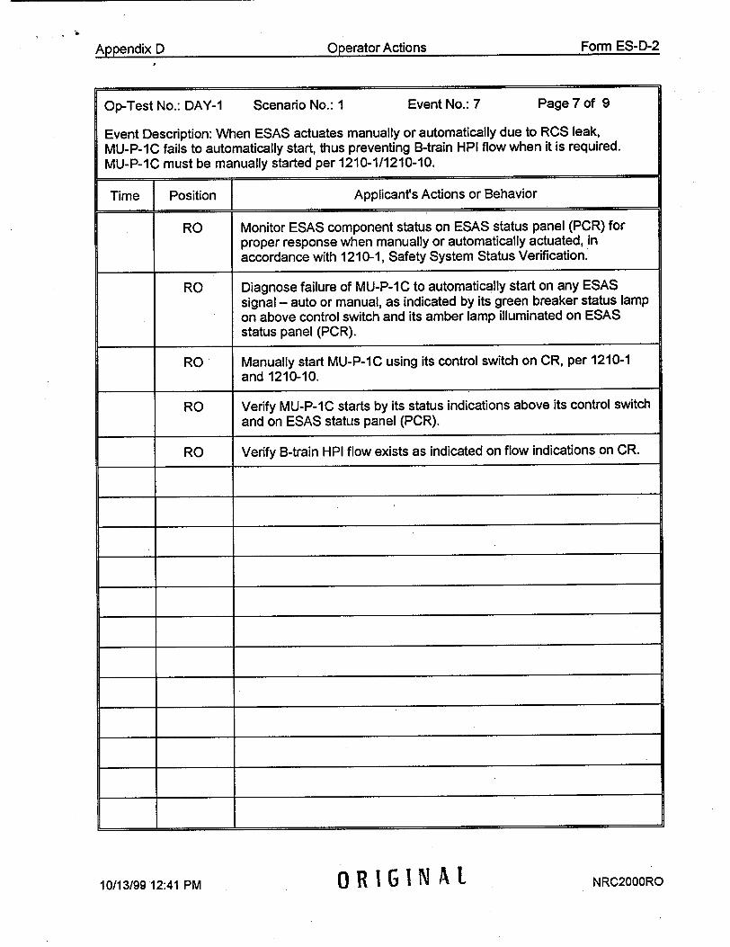
"".........Operator ActionsForm......
Op-Test No.: DAY-1 Scenario No.: I Event No.: 7 Page 7 of 9
Event Description: When ESAS actuates manually or automatically due to RCS leak, MU-P-1C fails to automatically start, thus preventing B-train HPI flow when it is required. MU-P-IC must be manually started per 1210-1/1210-10.
Time Position Applicant's Actions or Behavior
RO Monitor ESAS component status on ESAS status panel (PCR) for proper response when manually or automatically actuated, in accordance with 1210-1, Safety System Status Verification.
RO Diagnose failure of MU-P-IC to automatically start on any ESAS signal - auto or manual, as indicated by its green breaker status lamp on above control switch and its amber lamp illuminated on ESAS status panel (PCR).
RO Manually start MU-P-IC using its control switch on CR, per 1210-1 and 1210-10.
RO Verify MU-P-IC starts by its status indications above its control switch and on ESAS status panel (PCR).
RO Verify B-train HPI flow exists as indicated on flow indications on CR.
4-
I. I
I1 I.
I_ _ I__ _ 4
I_ _ I1_ _ _
4 4
4 4
____ I ______ 4-
/G I:P NAL
Form ES-D-2AnnAncliY I') Operator Actions
NRC2000RO10113/99 12:41 PM

A " .ndi. D O .erator ActionsFormE...
Op-Test No.: DAY-I Scenario No.: 1 Event No.: 8 Page 8 of 9
Event Description: RCS inventory loss due to leak results in loss of 250F subcooled margin, and the crew must respond per 1210-2 and 1210-6 for the small break LOCA.
Time Position Applicant's Actions or Behavior
BOP/RO Diagnose loss of 250F subcooled margin by the following indications:
"* Alarm G-1-8
"* One or both Margin to Saturation meters on panel center left (PCL) indicate <25 0F
RO Perform 1210-2 immediate actions for loss of 25°F subcooled
margin: (CT)
"* Secure RC-P-1B, RC-P-IC, and RC-P-ID using controls on CC
"* Verify HPI flow on all four HPI flow meters MU-FI-1126 and
1127 on CC, and MU-FI-1128 and 1129 on CR
BOP Perform 1210-2 immediate actions for loss of 250 F subcooled margin:
"* Verify EF-P-1, EF-P-2A, and EF-P-2B start by indications of speed, breaker status, and discharge pressures on CL and CC
"* Verify EFW flow to both SG's as indicated on EF-FI-779/788 for A-SG and EF-FI-782/791 for B-SG
"• Verify SG levels increasing toward 75-85% on operating range level indications LI-1 103 for A-SG and LI-1 105 for B-SG
BOP When required as indicated by SG pressure response to EFW flow, throttle EFW per 1210-10 EFW Throttling Criteria as follows:
"* Transfer EF-V-30A, 30B, 30C, and 30D controllers to manual
"* Operate EF-V-30A/D and EF-V-30B/C as necessary to throttle EFW flow to each SG
"* Ensure that both SG levels are still increasing toward 75-85%
BOP Feed and steam both steam generators as necessary to maintain them as heat sinks per 1210-6, and attempt to develop RCS natural circulation per 1210-10.
1 ORIGINAL
Form ES-D-2Annnndi• l"3
NRC2000RO10/13/99 12:42 PM
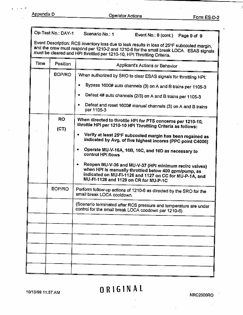
Appendix D Operator Actions Form ES-D-2
up-Test No.: DAY-1 Scenario No.: I Event No.: 8 (cont.) Page 9 of 9
Event Description: RCS inventory loss due to leak results in loss of 250F subcooled margin, and the crew must respond per 1210-2 and 1210-6 for the small break LOCA. ESAS signals must be cleared and HPI throttled per 1210-10, HPI Throttling Criteria.
I - - -
ORIGINAL10/13/99 11:57 AMNRC2000RO
When authorized by SRO to clear ESAS signals for throttling HPI:
* Bypass 1600# auto channels (3) on A and B trains per 1105-3
* Defeat 4# auto channels (2/3) on A and B trains per 1105-3
* Defeat and reset 1600# manual channels (3) on A and B trains per 1105-3
When directed to throttle HPI for PTS concerns per 1210-10, throttle HPI per 1210-10 HPI Throttling Criteria as follows:
"* Verify at least 25OF subcooled margin has been regained as indicated by Avg. of five highest incores (PPC point C4006)
"* Operate MU-V-16A, 16B, 16C, and 16D as necessary to control HPI flows
" Reopen MU-V-36 and MU-V-37 (HPI minimum recirc valves) when HPI is manually throttled below 400 gpm/pump, as indicated on MU-FI-1126 and 1127 on CC for MU-P-IA, and MU-Fl-1128 and 1129 on CR for MU-P-IC
Perform follow-up actions of 1210-6 as directed by the SRO for the small break LOCA cooldown.
(Scenario terminated after RCS pressure and temperature are under control for the small break LOCA coodown per 1210-6)
BOP/RO
RO
(CT)
BOP/RO
Time Position } Applicant's Actions or Behavior

Appendix D Scenario Outline Form ES-D-1
Facility: TMI
Examiners:
Scenario No. 2 (80 minutes) Op-Test No.: DAY-1
Operators:
Objectives: To evaluate applicants' ability to: synchronize and load turbine/generator per
1106-1, and continue plant startup per 1102-2; respond to an OTSG tube leak per 1210-5;
perform a plant and reactor shutdown per 1210-5 and 1102-10; respond to a makeup pump
trip per alarm response; respond to a failed pressurizer level transmitter per 1202-29; respond to a turbine bypass valve failure after turbine trip; and reduce subcooled margin per
1210-5 with failure of the pressurizer spray valve to open.
Initial Conditions: IC12, 14% reactor power, 300 EFPD, during a xenon-free plant startup
with main turbine hot at 1800 rpm, ready to synchronize and load. MFW pump on MS.
Turnover: Reactor is at 14% power during a xenon-free plant startup at 300 EFPD, with
main turbine hot at 1800 rpm, ready to synchronize and load. The plant tripped 80 hours ago
due to a main generator relay failure. Continue plant startup by synchronizing and loading
turbine-generator and increasing power per 1102-2. MFW pump and gland steam on MS.
Event Action Event Event No. No. Type* Description
1 N/A N (BOP) Synchronize and load turbine generator per 1106-1.
2 N/A R (BOP) Increase reactor power per 1102-2 and place turbine in auto.
3 MS01A I (BOP) Selected turbine header pressure instrument fails low with main turbine in automatic. (0% severity over 20 seconds)
4 TH16A M (ALL) Tube Leak on A-OTSG; 0.3% severity (45 gpm)
5 N/A R (RO) Plant & reactor shutdown per 1210-5 & 1102-10.
6 MS09D C (BOP) MS-V-3D (turbine bypass valve) fails open after turbine trip.
Event Trigger: TC:TRIP
7 RC04A I (RO) Selected PZR level fails high; 0% severity over 600 seconds.
8 MU01A C (RO) MU-P-1A trips after start. Event trigger: MUPDISA>1000.
9 **DIOR C (RO) RC-V-1 does not open to reduce RCS subcooled margin per
1210-5; must use PZR vent and/or PORV. **02A5SO6-ZDIPBORCV1 OPN CC RC-V-1 OPEN PB
* (N)ormal, (R)eactivity, (I)nstrument, (C)omponent, (M)ajor
10/28/99 2:06 PM OR I GINA L NRC2000RO
ii

Appendix D Operator Actions Form ES-D-2
Op-Test No.: DAY-1 Scenario No.: 2 Event No.: 1 Page 1 of 9
Event Description: As directed by SRO, excite, synchronize, and load main turbine-generator to minimum load per 1106-1.
Time Position Applicant's Actions or Behavior
BOP Operate main generator excitation controls on CL to establish main generator voltage per 1106-1.
RO Operate ICS Reactor Demand station as necessary to maintain reactor power per 1102-2.
BOP Operate Digital Turbine Control System (DTCS), main generator breakers, and main generator voltage controls on CL, to synchronize and load main generator to minimum load (40MW) per 1106-1.
i i
I i
I I
i I
I I
I I
I I
J. I
_____________ j
0OR IG I NNARL
I I
NRC2000RO10/13/99 1:04 PM

A ".ndi D. Oerator Actions.Form...
Op-Test No.: DAY-1 Scenario No.: 2 Event No.: 2 Page 2 of 9
Event Description: After turbine-generator is loaded, increase reactor power to obtain T-ave
of 579°F (23% power), transfer Reactor Demand and SG/Rx Demand stations to auto, and place main turbine in auto per 1102-2.
Time Position Applicant's Actions or Behavior
BOP Operate Reactor Demand ICS station to increase reactor power within MMR's (< 30%per hour) until T-ave = 5790F per 1102-2.
RO Operate RCS makeup system and LWDS controls to maintain pressurizer level increase per Figure 1 of 1102-2, as reactor power and RCS T-ave increase.
BOP Transfer Reactor Demand station to auto at 5790F T-ave per 1102-2.
BOP Increase demand on SG/Rx Master until it has reactor control, then transfer SG/Rx Master to auto per 1102-2.
BOP Operate ICS main turbine control station to increase main turbinegenerator load until turbine bypass valves (MS-V-3's) indicate closed, and transfer main turbine to auto per 1102-2.
I I
I I
1. I
I4.
4 4-
4 4"
I I
4" 4"
NRC2000RO10/13/99 1:04 PM ORIGINAL
I I
Form ES-D-2Ann•.ndix i'1

Ann".... ..d.........O.erator ActionsF
Op-Test No.: DAY-1 Scenario No.: 2 Event No.: 3 Page 3 of 9
Event Description: After main turbine is in auto, selected main turbine header pressure instrument (MS-1OA-PT1) fails low (600 psig) over 30 seconds, causing SASS mismatch The main turbine control valves initially close in automatic response to the instrument faildre. The turbine will automatically transfer to manual on high header pressure error. OTSG pressures will increase and turbine bypass valves (MS-V-3's) may eventually open as required at 960 psig.
Time Position Applicant's Actions or Behavior
BOP Respond to SASS Mismatch alarm (H-3-2) and diagnose mismatch on turbine header pressure instrument on CC.
BOP Diagnose main turbine transfer to manual by alarm H-3-3 and indications on ICS turbine control station (red and white lamps on).
BOP Assume hand control of turbine at ICS station to control header pressure and return it to 885 psig per H-3-3.
RO Respond to OTSG pressure transient effects on RCS temperature,
pressure, inventory, and reactor power.
* Verify automatic response of pressurizer spray valve, RC-V-1.
BOP Select good turbine header pressure instrument per H-3-2.
BOP Transfer main turbine back to auto at ICS station with zero header pressure error and turbine bypass valves are closed if open in response to OTSG pressure increase.
BOP Perform follow-up actions of H-3-2 as directed by SRO.
0 1 ORIGINAL
Form ES-D3-2Ann•.ndix D
NRC2000RO10/13/99 1:04 PM

Appendix D O.erator ActionsForm....
Op-Test No.: DAY-1 Scenario No.: 2 Event No.: 4 Page 4 of 9
Event Description: After main turbine is back in auto and during H-3-2 follow-up actions, a primary to secondary tube leak of 45 gpm develops on A-OTSG. The team must respond to excessive radiation levels per 1202-12, and to the tube leakage per 1210-5 and alarm response procedures. A plant shutdown will be performed to comply with 1210-5 and Tech. Specs (Event 4).
Time Position Applicants Actions or Behavior
BOP/RO Recognize indications of the tube leak on the A-SG:
* high radiation alarm (C-1-1) due to alarms on condenser off-gas monitors RM-A-5 & 15, and A-SG steam line monitor RM-G-26
* increase in RCS makeup flow and decrease in makeup tank level
BOP/RO Respond to excessive radiation levels per 1202-12:
"• Announce radiation alarms on plant page & radio
"• Mark meteorological and radiation monitor charts
"* Contact Group Rad Con Supervisor (GRCS)
RO Perform actions of alarm response C-1-1 to validate tube leak, and implement 1210-5.
RO May close MU-V-3 per 1210-5 to isolate RCS letdown if deemed necessary to maintain pressurizer level.
I1 I.
4. +
i v
4 i
1 I.
4 4.
I _______
0 1 ORIGINAL
Form ES-D-2Annondi• 13
NRC2000RO10/13/99 1:04 PMV

An .nr.y r) Onerator ActionsForm.....
Op-Test No.: DAY-1 Scenario No.: 2 Event No.: 5 Page 5 of 9
Event Description: Operation of ICS and CRD controls to effect plant and reactor shutdown per 1210-5 and 1210-1.
Time Position Applicant's Actions or Behavior
RO Effect plant shutdown by performing the following per 1210-5:
(CT) 0 Reduce Unit Load Demand until OTSG's reach low level limits
"* Transfer SGIRx Demand, Reactor Demand, and CRD stations to manual
"* Operate CRD system to reduce reactor power at rate specified by SRO
RO Operate RCS makeup system and LWDS as necessary to maintain RCS inventory during the reactor power and T-ave reduction.
BOP Operate FW-P-1A ICS station in hand as necessary to maintain MFW valve delta-p per 1102-10.
BOP Secure main turbine at <15% power per 1210-5 as follows:
"* Transfer main turbine ICS station to hand
"* Unload turbine-generator to zero (0) MW
"* Trip main turbine
RO Operate the control rod drive system as necessary to reduce reactor
power until T-ave = 5450F per 1210-5.
BOP Transfer turbine bypass valve stations to hand prior to reactor trip.
RO Manually trip reactor per 1210-5.
BOP Operate turbine bypass valve stations in hand to stabilize OTSG pressures and prevent MSSV lift per 1210-5.
BOP/RO Perform immediate actions of 1210-1 for the reactor trip.
NRC2000ROS0 ORIGINAL
Form ES-D-2A nn•nttiY I•
10/13/99 1:04 PM

0'lrtor ActionsForm-E.....
Op-Test No.: DAY-1 Scenario No.: 2 Event No.: 6 Page 6 of 9
Event Description: When main turbine is manually tripped at 15% power per 1210-5,
MS-V-3D (turbine bypass valve) on A-SG fails open and must be isolated per 1210-3.
Applicants Actions or Behavior
Verify turbine bypass valves open and control SG pressures after main turbine is tripped.
May recognize reduced or lower demand on ICS station for MS-V3D/E/F as compared to demand for MS-V-3A/B/C on B-SG.
As reactor power is reduced or after reactor is tripped per 1210-5,
recognize failure of MS-V-3D by:
"* zero (0) demand on ICS station for MS-V-3D/E/F
"* red open indication for MS-V-3D
"* A-SG pressure decreasing below desired pressure
Direct AO over page or radio to locally isolate or manually close MS-V-3D.
Operate MS-V-3D/E/F ICS station as necessary to reassume A-SG pressure control at desired pressure.
0 RIGINAL NRC2000RO10/13/99 1:04 PMV
Form ES-D-2•n•r•tor Actions& r•r-,,',nHiv I"1

Arpni Orerator Actions Form ES-D-2
Op-Test No.: DAY-1 Scenario No.: 2 Event No.: 7 Page 7 of 9
Event Description: At 10% power during the plant shutdown, selected pressurizer level transmitter, RCI-LT1, fails to 400" indicated level (over 10 minutes), causing closure of MU-V-17 if in automatic as false level increases above pressurizer level setpoint.
Time Position Applicant's Actions or Behavior
RO Diagnose decreasing makeup flow to RCS and increasing makeup tank level, due to decreasing demand on MU-V-17.
RO Recognize increase in pressurizer level on RC1-LT1, with decrease in pressurizer level on RC-LI-777A.
RO Diagnose probable failure of RC1-LT1 by conflicting indications of:
"* Increase in RC1-LT1 level with decreasing RCS temperature and loss of RCS inventory due to tube leak
"• Increase in RC1-LT1 level with decrease on RC-LI-777A level
RO Respond to failure of RC1-LT1 per 1202-29 as follows:
• Assume hand control of MU-V-17 and adjust demand (open) as necessary to maintain required RCS inventory
* Select alternate pressurizer level and temperature instruments
• May close MU-V-3 to isolate RCS letdown if not already closed
RO May transfer MU-V-17 back to automatic at appropriate pressurizer level setpoint per 1210-5.
SORiGINAl RG-NA
0 . V .
Armendix D Form ES-D-2
10/13/99 1:04 PM NRC2000RO

ap diDQO~erator Actions F~nrm F~f~
Op-Test No.: DAY-I Scenario No.: 2 Event No.: 8 Page 8 of 9
Event Description: When MU-P-1A is manually started for augmented RCS makeup during plant shutdown or after reactor is tripped, MU-P-IA trips, thus reducing normal makeup capability.
Time Position Applicant's Actions or Behavior
RO Start MU-P-1A, DC-P-1A, and DR-P-1A when necessary for augmented RCS makeup flow to maintain RCS inventory, or as required for reactor trip response per 1210-1.
RO Diagnose MU-P-1A trip by the following alarms and indications:
* Alarms B-1-2 and B-2-2
* Green and amber lamps for MU-P-1A breaker status
* Zero (0) amps indicated for MU-P-1A motor
RO Start MU-P-1C, DC-P-1B, and DR-P-1B; and open MU-V16C/D as necessary for additional RCS makeup to maintain pressurizer level per 1210-1.
t I-
1* I
I i
i t
t 1*
t I
9 1 ORIGINAL NRC2000RO
I i
Appendix D •'nrm I=.•.rt.')
10/13/99 1:04 PM

Appendix D(I ar2nr 1A t.fm.n
Op-Test No.: DAY-1 Scenario No.: 2 Event No.: 9 Page 9 of 9
Event Description: Pressurizer spray valve, RC-V-1, will not manually open when required by 1210-5 to reduce RCS pressure and subcooled margin, requiring use of pressurizer vent and/or PORV to reduce RCS presssure.
Time Position Applicant's Actions or Behavior
RO When directed by SRO per 1210-5 follow-up actions, perform the following actions to minimize RCS subcooled margin:
* secure pressurizer heaters
* transfer to manual and open pressurizer spray valve, RC-V-1
RO Diagnose failure of RC-V-1 to open by no open (red) indication when open pushbutton is depressed with RC-V-1 mode switch in manual.
RO Operate pressurizer vent (RC-V-44 and RC-V-28) andlor PORV (CT) (RC-V-2) as directed by SRO to minimize RCS subcooled margin.
BOP/RO Bypass ESAS 1600# channels when directed by SRO per 1210-5.
(scenario is terminated after RCS subcooled margin is minimized and crew commences plant cooldown per 1210-5)
I
I t
t t.
I I
t I
I
t 1-
10/13/99 2:27 PM ORIGINAL A2L
V I . .
t•ln•r•f•r APf;•ne
NRC2000RO

Appendix D Scenario Outline Form ES-D-1
Scenario No. 3 (70 minutes)Facility: TMI
Examiners:
Op-Test No.: DAY-2
Operators:
Objectives: To evaluate the applicants' ability to: swap operating makeup pumps per 1104-2; respond to a makeup system leak per alarm responses; perform a plant shutdown per 1102-10; secure a MFW pump per 1106-3; respond to a turbine trip while less than ARTS per K-1-1; respond to a main steam line break and excessive primary to secondary heat transfer per 1210-3; and stabilize plant following termination of excessive primary to secondary heat transfer per 1210-3.
Initial Conditions: IC16 (100% power MOC), IA-P-4 out of service, IA-P-1A running in hand.
Turnover: Plant at 100% power, MOC, IA-P-4 out of service, IA-P-1A running in hand. MU-P-1 B must be removed from service for an oil system inspection - expected duration is two hours. DCCW loop-A will be sampled while running.
Event Action Event Event
No. No. Type* Description
1 N/A N (RO) Operating makeup pumps are swapped per 1104-2.
2 MU14 C (RO) Makeup system leak (50%=50 gpm) downstream of makeup AOR** I (RO) valve, and low range makeup flow transmitter, MU-FT-24A,
R (RO) fails low. The makeup system leak requires normal makeup N (BOP) line isolation and management will order plant shutdown.
**02A3M06-ZAOMU24FI FLO (0% with 120 second delay)
3 N (BOP) As FW-P-1A is removed from service per 1102-10/1106-3, FW06B I (BOP) the selected B-train MFW valve d/p transmitter, SP 11B
DPT2 fails low (0% severity over 15 seconds) Trigger = FWFDFWP(1)<416
4 EG03 M (ALL) Main generator and turbine trips at about 40% power, and a MS03A main steam line break on A-SG occurs outside containment
(100% severity ramped in over 300 seconds).
5 FW13A C (BOP) FW-V-5A breaker trips as it is commanded to close, causing MS10, main feedwater block valve to be failed 95% open. And, SGA, HSPS isolation of FW-V-16A and 17A (train-A) on low SG
TRN B pressure will fail to actuate. Trigger = FWVFWV5A<0.95
6 DOR*** C (RO) MU-V-16C will not close by pushbutton on panel when required to secure HPI. ***03A4S35-ZDIPBCMUV16C ON CR MU-V-16C CLOSE PUSHBUT
* (N)ormal, (R)eactivity, (I)nstrument, (C)omponent, (M)ajor
10/28/99 2:17 PM NRC2000RO
ORIGINAL

Appendix D Operator Actions Form ES-D-2
Op-Test No.: DAY-2 Scenario No.: 3 Event No.: 1 Page 1 of 6
Event Description: When directed by the SRO, operating makeup pumps are swapped from
MU-P-1B to MU-P-1A per 1104-2 and the On-line Risk Document. MU-P-1B is then secured for inspection.
Time__ Position Applicant's Actions or Behavior
RO Performs actions of 1104-2 as directed by SRO as follows:
"" Starts DC-P-IA
"" Starts DR-P-1A
"• Starts MU-P-1A
"* Monitors makeup and seal injection parameters for stability
"* Secures MU-P-1 B
RO Starts IC-P-1B and secures IC-P-IA per On-line Risk Document
I I
I I
1. 4-
4 4
I I.
I_ _ 1
I_ _ 1
______ II
I I
I I
10/13/99 2:18 PM NRC2000RO
ORIGINAL
I

Appendix D .Oerator ActionsFo....
Op-Test No.: DAY-2 Scenario No.: 3 Event No.: 2 Page 2 of 6
Event Description: After MU-P-1 B is secured, a makeup system leak (50 gpm initially) develops between the normal makeup control valve (MU-V-17) and containment isolation valve (MU-V-1 8). Shortly after leak begins, the low range makeup flow transmitter (MU-FT24A) fails low. The makeup system leak must be isolated by closing MU-V-17. Following time compression (1 hour), plant management will order a plant shutdown to repair leak.
Time Position Applicant's Actions or Behavior
RO Diagnose symptoms of primary leak into Auxiliary Building by: "* Pressurizer level decrease and MU-V-17 demand increase "* Makeup flow increase and possibly D-3-1 alarm "* Makeup tank level and pressure decrease with alarms "* Auxiliary Building sump level increase and LWDS-1-1 alarm "" Report by primary auxiliary operator
RO Operate LWDS and makeup systems to establish feed to makeup tank from selected RC bleed tank, per 1104-2 and D-3-2.
RO Recognize failure of MU-FT-24A by indication on meter dropping to zero with flow still indicated on wide range MU-FT-24B.
RO Close MU-V-3 per D-1-3 to isolate RCS letdown and conserve PZR level. Operate NR-V-15A and 15B to control ICCW system temperature when letdown is isolated.
RO Operate makeup system valves (MU-V-17, MU-V-18) as directed (CT) the by SRO to isolate the leak.
RO Operate MU-V-16A or MU-V-16B as needed to restore and maintain normal pressurizer level (220").
RO Commence plant shutdown per 1102-10 as directed by SRO: * Operate makeup system components as directed • Set ULD rate of change at 3-5% per minute (30-50%) • Reduce ULD input to initiate plant power reduction
RO/BOP Monitor critical parameters during power reduction.
BOP Secure moisture separator drain pumps as directed by SRO.
RO Stop power reduction and stabilize plant at approx. 40% power to secure FW-P-IA and HD-P-IC.
10/13/99 2:18 PM NRC2000ROORIGINAL
Form ES-D-2Aooendix D

Appendix D O..erator ActionsForm.
Op-Test No.: DAY-2 Scenario No.: 3 Event No.: 3 Page 3 of 6
Event Description: When reactor power is approximately 40% per 1102-10, FW-P-1A is removed from service per 1106-3. As speed and flow are reduced on FW-P-1A (less than 1.5E6 Ibm/hr), selected B-train MFW valve d/p transmitter (SPI 1 B-DPT2) fails low over 15 seconds and causes SASS mismatch. FW-P-1B will automatically respond to false low MFW valve d/p by increasing in speed and flow.
Time Position Applicant's Actions or Behavior
BOP Perform actions to secure FW-P-1A per 1106-3 as directed: * Transfer FW-P-1A ICS station to hand 0 Slowly reduce ICS demand to reduce pump speed and flow • Monitor FW-P-1 B and verify proper auto response
BOP Diagnose decreasing or failed B-train MFW valve d/p as follows: "• Indication on SP11B-DPT2 decreasing to zero "* SASS mismatch alarm H-3-2 "• SASS mismatch lamps on SP1 1 B-DPT1 & 2 "• Low MFW valve d/p alarm M-1-5 "• Increase in speed and pressure on MFW pump in auto
RO Monitor primary critical parameters response to effects of MFW flow transient (lower T-ave, PZR level, pressure).
RO Operate MU-V-16A/B as necessary to maintain PZR level. Verify proper operation of PZR heaters and spray.
BOP Respond to failed instrument per H-3-2 as follows: "* Transfer FW-P-1 B ICS station to hand "• Adjust loaded FW-P-1 B demand to stabilize MFW flows "• Select alternate B-train MFW valve d/p, SP11B-DPT1 • VedfySP11B-DPT1 reads as expected
BOP Perform follow-up actions of H-3-2 as directed by SRO.
i i
i i
-ii
______ I I
10/13/99 2:18 PM NRC2000ROORIGINAL
Form ES-D-2Aooendix D

Armendix D Or~erator ActionsFomE-2
Op-Test No.: DAY-2 Scenario No.: 3 Event No.: 4 Page 4 of 6
Event Description: During follow-up actions of H-3-2 for the FW valve d/p mismatch, the main turbine-generator trips below ARTS (at 35 - 40% power) due to generator excitation relay failure, and a main steam line rupture occurs (ramped over 300 seconds) on A-SG outside containment The reactor will most likely automatically trip on high or low RCS pressure, but may also be manually tripped due to plant instability.
Time Position Applicants Actions or Behavior
BOP/RO Diagnose main turbine trip by K-1-1 and panel indications, with reactor power less than ARTS (45%).
BOP/RO Respond to the turbine trip without reactor trip per K-1-I as follows: "* Verify ICS trips to Track (H-2-2) "* Monitor and verify reactor power is decreasing
RO Monitor and control RCS inventory and pressure control systems as necessary during RCS temperature increase.
BOP Recognize abnormal A-SG pressure response during power reduction and after reactor trip, by the following indications: "* A-SG pressures indicate lower than B-SG "" Demand on MS-V-3D/E/F ICS controller is lower than expected
BOP/RO Diagnose and respond to reactor trip per 1210-1.
BOP Verify MFW is under control per 1210-1, and recognize FW-V-5A has no lamps illuminated. (see Event No. 5 actions)
RO Start MU-P-IC, DC-P-1B, and DR-P-lB per 1210-1 (2"d makeup pump), and operate MU-V-16A/B/C/D as necessary to maintain pressurizer level above 80".
BOP/RO Diagnose excessive primary to secondary heat transfer causing abnormally low RCS temperature and pressure.
RO Respond to RCS shrink due to excessive cooling as follows: * Open MU-V-1 6A/B/C/D as necessary to maintain PZR level above
80 inches * Manually initiate full HPI if PZR level drops below 20 inches per
1210-1, or verify 1600# ESAS actuation per 1210-10
10/13/99 2:18 PM NRC2000RO
ORIGINAL
Form ES-D-2APPendix D

Appendix D Operator Actions Form ES-D-2
Op-Test No.: DAY-2 Scenario No.: 3 Event No.: 5 Page 5 of 6
Event Description: When the reactor trips and during A-SG blowdown, the breaker for FW-V-5A trips the valve stops at 95% open; and HSPS train-B low SG pressure actuation will not automatically occur at less than 600 psig to close FW-V-16A and 17A. This combination of failures requires operator action to manually isolate MFW to A-SG, in addition to manually isolating EFW to A-SG to terminate the excessive primary to secondary heat transfer per 1210-3.
Time Position Applicants Actions or Behavior
BOP Perform actions to isolate MFW to A-SG per 1210-1 and 1210-3: (CT) 0 Manually close or verify closed FW-V-17A, FW-V-16A, and
FW-V-92A; recognize FW-V-5A breaker tripped 0 Control or trip MFW pumps if necessary
BOP Perform actions to isolate A-SG completely per 1210-3 as follows: (CT) • Close or verify closed MS-V-3D/E/F and MS-V-4A
* Close MS-V-IA and 1B * Close MS-V-2A 0 Transfer to manual and close EF-V-30A and EF-V-30D
BOP Perform actions necessary to control RCS temperatures as directed by SRO after A-SG blows dry and excessive heat transfer stops: "* Transfer MS-V-3A/B/C to hand or adjust turbine header pressure
setpoint as required, to steam B-SG and control RCS T-colds "* Provide main or emergency feedwater to B-SG as required to
maintain sufficient level for heat transfer (25" start-up level)
BOP Perform applicable follow-up actions of 1210-3 as directed by SRO.
1 1
I 4
I 4
4 4
4 -�
= �
*1�
10/13/99 2:18 PM NRC2000ROORIGINAL
Appendix D Operator Actions Form ES-D-2

ApedxDOperator Arctionc ^mer1.
Op-Test No.: DAY-2 Scenario No.: 3 Event No.: 6 Page 6 of 6
Event Description: When it becomes necessary after the excessive cooling is terminated, the RO throttles or terminates HPI flow to the RCS to minimize the RCS re-pressurization, but MU-V-16C will not close on demand by its pushbutton on CR. The alternative is to secure MU-P-1C. ESAS signals must be bypassed or defeated as necessary to control ESAS components.
Time Position Applicant's Actions or Behavior
RO/BOP Bypass/defeat/reset all three ESAS channels on both trains when directed by SRO.
RO Operate makeup (HPI) system valves and pumps as necessary to (CT) control (terminate) HPI flow to RCS when directed by SRO:
* Close MU-V-16A, 16B, 16C, and 16D as necessary * Recognize MU-V-16C failure to close on demand * Secure MU-P-IC to terminate B-train HPI flow
RO Perform applicable follow-up actions of 1210-3 as directed by SRO
RO Operate MU-V-16A/16B as necessary to maintain stable pressurizer level during recovery actions of 1210-3.
(scenario is terminated when 1210-3 follow-up actions direct crew back to 1210-1)
1� t
t 1-
i
10/13/99 2:18 PM 0 R I G I N A L NRC2000RO
Appendix D Oner-atnr A •.fin n_• l=',,•,'rn l=i•_l•_e)

Appendix D Scenario Outline Form ES-D-1
Facility: TMI Scenario No. 4 (70 minutes) Op-Test No.: DAY-2
Examiners: Operators:_______________
Objectives: To evaluate the applicants' ability to: manually increase reactor power per 1102-2; transfer MFW pump steam supplies per 1106-3; respond to a loss of RC makeup and seal injection per 1203-15; respond to a loss of main feedwater per alarm responses; respond to an EFW actuation failure per 1210-10; respond to a SG tube rupture per 1210-5; and respond to a loss of 250 F subcooled margin per 1210-2.
Initial Conditions: IC08, reactor critical at 1 E-8 amps during a plant startup at MOC. All operating ventilation fans transferred to A-train.
Turnover: Reactor is critical at 1E-8 amps during a plant startup at MOC. Critical data has been obtained and 1103-8 has been closed out. FW-P-1A and gland steam is currently supplied from the auxiliary steam system. B-RCBT is on sample recirc.
Event Action Event Event No. No. Type* Description
1 R (RO) Reactor power is increased to 5% power using CRD panel in accordance with 1102-2.
NI19A I (RO) NI-5 (selected power range NI) will not increase above 0% as reactor power is increased into power range flux level.
2 MSR19 N (BOP) FW-P-1A is transferred from auxiliary steam to main steam per 1106-3 prior to 5% reactor power per 1102-2.
3 RC23A I (BOP) At -.5% power, selected B-SG startup level transmitter (LT-1054) fails low (0% over 300 seconds), causing FW-V16B to open in auto.
4 ED02D C (RO) 1A auxiliary transformer trips, causing trip of MU-P-1B and loss of RC makeup/seal injection.
5 DOR** C (BOP) FW-P-1A speed control fault causes loss of main feedwater. **O0A5SO7-ZDIMSCA(3) SLOLO FW-P-1A MSC SWITCH
ICRO3 C (BOP) EF-V-30B/C do not automatically open for EFW to B-SG.
6 TH15B M (ALL) A tube rupture occurs on B-SG that results in loss of 250F subcooled margin. (20% severity over 100 seconds)
DOR*** C (RO) RC-P-1 B does not trip using its normal control switch. ***02A3S16-ZDICSRCP1B(1) PTL RC-P-1B CS, and
02A3S1 6-ZDICSRCP1 B(2) STP RC-P-1 B CS
* (N)ormal, (R)eactivity, (I)nstrument, (C)omponent, (M)ajor
10/28/99 2:23 PM NRC2000RO
ORIGINAL

"Aendix D O.erator ActionsForm....
Op-Test No.: DAY-2 Scenario No.: 4 Event No.: 1 Page 1 of 7
Event Description: When directed by SRO, reactor power is increased above point of adding heat and into power range, but power range detector NI-5 does not come on scale due to latent failure of its summer amplifier.
Time Position Applicants Actions or Behavior
RO Raise reactor power to 5% per 1102-2: 0 Operate CRD panel to withdraw control rods 0 Monitor nuclear instrumentation • Monitor and control RCS critical parameters • Monitor rate of power increase and comply with mechanical
maneuvering recommendations (Enclosure 4)
RO Recognize failure of NI-5 to come on scale as compared to NI-6, 7, 8: * Inform SRO * Recognize and flag Tech. Spec. concern * Select NI-6 as controlling NI to ICS using SASS selector
pushbutton, prior to transferring CRD panel to auto at 5% power
RO Control RCS inventory during power and T-ave increase per 1102-2: * Monitor and control pressurizer level per Figure 1
* Operate MU-V-17 control station setpoint * Monitor and control makeup tank level per Figure 1 of 1104-2
a Operate MU-V-8 and LWDS panel controls to bleed
BOP Monitor secondary critical parameters during reactor power increase: "* Verify automatic response of MS-V-3s to control SG pressures "* Verify automatic response of FW-V-16s to control SG levels "" Operate FW-P-1A ICS station to maintain FW vlv d/p per 1106-3
BOP Place A-RPS channel in manual bypass if directed by SRO.
1 ORIGINAL
Aooendix D Form ES-D-2
NRC2000RO10/13/99 2:47 PMV

Appendix D Operator Actions Form ES-D-2
Op-Test No.: DAY-2 Scenario No.: 4 Event No.: 2 Page 2 of 7
Event Description: After reaching point of adding heat and prior to 5% reactor power, FW-P-IA turbine steam supply is transferred from auxiliary to main steam.
Time Position Applicant's Actions or Behavior
BOP Transfer FW-P-1A steam supply per 1106-3 prior to 5% power. • Direct auxiliary operator to operate AS-V-5A in plant * Monitor FW valve d/p and FW-P-1A control valve positions 0 Operate FW-P-1A ICS station demand as necessary to maintain
FW valve d/p above 70#
4
4 +
4 +
+ +
+ *4.
4 4
t 1-
t I
1� I
I* I
t I
4 4
4 4
4 4
4 4
4 &
10/13/99 2:47 PM NRC2000ROOR I G IN AL

A .nd. D O.erator ActionsFo.....
Op-Test No.: DAY-2 Scenario No.: 4 Event No.: 3 Page 3 of 7
Event Description: After FW-P-IA is on main steam and at $5% reactor power, selected B-SG startup level transmitter (LT-1054) fails low over 300 seconds, causing FW-V-16B to open in auto and eventually a SASS mismatch alarm.
Time Position Applicant's Actions or Behavior
BOP Recognize increase in B-SG feed flow and startup level by panel indications.
BOP Recognize increase in FW-V-16B demand and position indication.
RO Monitor RCS critical parameters and respond to increased RCS heat removal: "* Verify automatic pressurizer level control by MU-V-17 "* Verify automatic RCS pressure control by pressurizer heaters
BOP Transfer FW-V-16B to hand and control demand as necessary to
return B-SG feed flow and level to normal.
BOP Acknowledge SASS mismatch alarm H-3-2 due to B-SG startup level, and recognize failing B-SG startup level on recorder.
BOP Select alternate B-SG startup level transmitter using SASS pushbutton per H-3-2.
BOP Check error across FW-V-16B controller and transfer FW-V-16B back to auto when its error is zero (0).
I BOP Perform follow-up actions of H-3-2 as directed by SRO.
4- i
I. I-
4- 4-
I- I-
I1 I.
4. 4-
4 4
=4. 4.
10/13/99 2:47 PM NRC2000RO
ORIGINAL
Form ES-D-2Ann•.ndix B
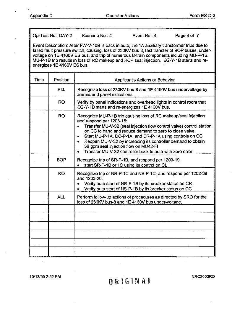
Appendix D Operator Actions Form ES-D-2
Op-Test No.: DAY-2 Scenario No.: 4 Event No.: 4 Page 4 of 7
Event Description: After FW-V-16B is back in auto, the 1A auxiliary transformer trips due to failed fault pressure switch, causing: loss of 230KV bus-8, fast transfer of BOP buses, undervoltage on 1 E 4160V ES bus, and trip of numerous B-train components including MU-P-1 B. MU-P-1B trip results in loss of RC makeup and RCP seal injection. EG-Y-1B starts and reenergizes 1 E 4160V ES bus.
Time Position Applicant's Actions or Behavior
ALL Recognize loss of 230KV bus-8 and I E 4160V bus undervoltage by alarms and panel indications.
RO Verify by panel indications and overhead lights in control room that EG-Y-1B starts and re-energizes 1E 4160V bus.
RO Recognize MU-P-1B trip causing loss of RC makeup/seal injection and respond per 1203-15: * Transfer MU-V-32 (seal injection flow control valve) control station
on CC to hand and reduce demand to zero to close valve • Start MU-P-1A, DC-P-1A, and DR-P-1A using controls on CC 0 Reopen MU-V-32 by increasing its controller demand to obtain
38 gpm seal injection flow on MU42-FI 0 Transfer MU-V-32 controller back to auto with zero error
BOP Recognize trip of SR-P-1 B, and respond per 1203-19: • start SR-P-1B or 1C using its control on CL
RO Recognize trip of NR-P-1C and NS-P-IC, and respond per 1202-38 and 1203-20: "* Verify auto start of NR-P-1B by its breaker status on CR "" Verify auto start of NS-P-1B by its breaker status on CC
ALL Perform follow-up actions of procedures as directed by SRO for the loss of 230KV bus-8 and 1E 4160V bus under-voltage.
10/13/99 2:52 PM NRC2000RO
ORIGINAL
Appendix D Operator Actions Form ES-D-2
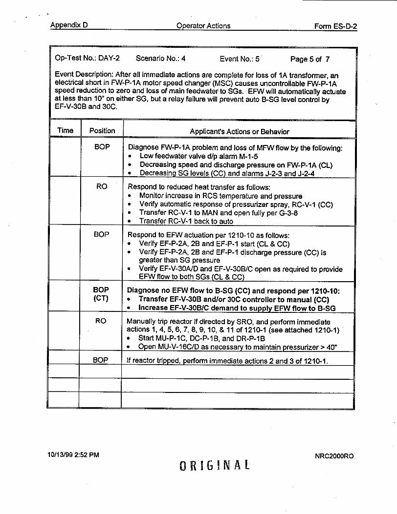
ApedxDODerator Actions Form ES-fl-2
Op-Test No.: DAY-2 Scenario No.: 4 Event No.: 5 Page 5 of 7
Event Description: After all immediate actions are complete for loss of 1A transformer, an electrical short in FW-P-IA motor speed changer (MSC) causes uncontrollable FW-P-1A speed reduction to zero and loss of main feedwater to SGs. EFW will automatically actuate at less than 10" on either SG, but a relay failure will prevent auto B-SG level control by EF-V-30B and 30C.
Time J Position Applicant's Actions or Behavior
BOP Diagnose FW-P-IA problem and loss of MFW flow by the following: "* Low feedwater valve d/p alarm M-1-5 "* Decreasing speed and discharge pressure on FW-P-IA (CL) "" Decreasing SG levels (CC) and alarms J-2-3 and J-2-4
RO Respond to reduced heat transfer as follows: "* Monitor increase in RCS temperature and pressure 0 Verify automatic response of pressurizer spray, RC-V-1 (CC) "* Transfer RC-V-1 to MAN and open fully per G-3-8 "" Transfer RC-V-1 back to auto
BOP Respond to EFW actuation per 1210-10 as follows: "* Verify EF-P-2A, 2B and EF-P-1 start (CL & CC) "* Verify EF-P-2A, 28 and EF-P-1 discharge pressure (CC) is
greater than SG pressure "* Verify EF-V-30A/D and EF-V-30B/C open as required to provide
EFW flow to both SGs (CL & CC)
BOP Diagnose no EFW flow to B-SG (CC) and respond per 1210-10: (CT) 0 Transfer EF-V-30B and/or 30C controller to manual (CC)
* Increase EF-V-30B/C demand to supply EFW flow to B-SG
RO Manually trip reactor if directed by SRO, and perform immediate actions 1, 4, 5, 6, 7, 8, 9, 10, & 11 of 1210-1 (see attached 1210-1) "* Start MU-P-1C, DC-P-1B, and DR-P-1B "" Open MU-V-16C/D as necessary to maintain pressurizer > 40"
BOP If reactor tripped, perform immediate actions 2 and 3 of 1210-1.
10/13/99 2:52 PM
0RIGINALNRC2000RO
Appendix D Form I::R-D-2

Appendix D,1 .m•fnrv , Ar*-f ',, 'eI I %-U %
Op-Test No.: DAY-2 Scenario No.: 4 Event No.: 6 Page 6 of 7
Event Description: When desired by examiner, multiple tubes rupture in B-SG (over 100 seconds) resulting in eventual loss of 25°F subcooled margin. RC-P-1 B control switch will not function to secure pump when required per 1210-2.
Time j Position Applicant's Actions or Behavior
ALL Diagnose primary to secondary leak in B-SG by the following: * Radiation monitor alarms (C-1-1) on RM-G-27, RM-A-5/15/5G hi • Rapid reduction in pressurizer level and RCS pressure * High normal makeup flow • Increase in B-SG level
RO Perform actions in response to low pressurizer level: * Open MU-V-217, MU-V-16A, MU-V-16B 0 Start MU-P-IC, DC-P-1B, DR-P-1B * Open MU-V-16C, MU-V-16D * Manually initiate full HPI (1600# ESAS - trains A & B) if
pressurizer level drops to 20" after reactor trip RO Verify or manually trip reactor, and perform immediate actions 1, 4, 5,
6, 7, 8, 9, 10, & 11 of 1210-1 (see attached 1210-1) BOP When reactor trips, perform immediate actions 2 and 3 of 1210-1.
BOP Operate EF-V-30B/C as necessary to terminate EFW flow to B-SG as level increases due to tube rupture.
RO Diagnose loss of 250F subcooled margin by alarm G-1-8 and PCL (CT) indication, and respond per 1210-2:
"* Secure RC-P-1A, IB, 1C, and 1D "* Recognize failure of RC-P-1 B control switch to secure pump,
and de-energize 1B 6900V bus by opening breaker ISB-02 on PR
* Verify or manually initiate HPI (1600# ESAS) to obtain: a MU-P-1A and 1C running • MU-V-14A and 14B open 0 MU-V-16A, 16B, 16C, and 16D open • M U-V-3, 18, 36, and 37 closed 0 Maximum HPI flow indicated on CC and CR
BOP Respond to loss of 250F subcooled margin per 1210-2: SVerify EF-V-30A/D respond in auto to provide EFW flow to A-SG and raise level towards 75-85%
10/13/99 2:52 PM NRC2000ROORIGINAL

Aopendix 0 Operator Actions Form ES-D-2
Op-Test No.: DAY-2 Scenario No.: 4 Event No.: 6 (cont) Page 7 of 7
Event Description: Multiple tubes rupture in B-SG (over 100 seconds) resulting in eventual loss of 250F subcooled margin. RC-P-1 B control switch will not function to secure pump when required per 1210-2.
Time Position Applicant's Actions or Behavior
RO/BOP Verify immediate actions of 121 0-1 and 1210-2 as led by SRO.
RO Perform follow-up actions of 1210-2 as directed by SRO: _ Operate valves per step 2.2
BOP Operate EF-V-30A/D to throttle EFW to A-SG per 1210-10, while ensuring A-SG level increases toward required setpoint.
BOP/RO Perform follow-up actions of 1210-5 as directed by the SRO.
BOP/RO Bypass/defeat/reset ESAS channels on trains A and B as directed by SRO to allow HPI throttling.
RO Throttle HPI per 1210-10 when directed by SRO:
(CT) 0 Verify at least 250F subcooled margin has been recovered
"* Operate MU-V-1 6A. 16B, 16C, and 16D as necessary to throttle HPI and control subcooled margin as directed by SRO, and prevent MSSV lift on B-SG at >1040 psig
"* Reopen MU-V-36 and 37 if HPI is throttled below 400 gpm on either MU-P-1A or IC.
BOP Operate EF-V-30A/D as necessary to raise A-SG level and provide sufficient EFW flow to promote RCS natural circulation.
BOP Secure EF-P-1 per 1210-5 follow-up actions when directed by SRO:
"* Defeat HSPS-EFW actuation signals
"* Close MS-V-13A and 13B to isolate main steam to EF-P-1
(scenario is terminated when RCS pressure and temperature are under control and crew commences plant cooldown per 1210-5)
10/13/99 2:52 PM NRC2000RO
ORIGINAL
Form ES-D-2AD)•endix D Op~erator Actions

NRCROSS1 Revision 0 12/13/1999
NRC RO OPERATIONAL SIMULATOR SCENARIO No. I
RC PUMP SEAL FAILURE, SMALL BREAK LOCA, & LOSS OF SUBCOOLED MARGIN
DEVELOPED BY/DATE:
REVIEWED BY/DATE:
APPROVED BY/DATE:
(OPERATIONS TRAINING MANAGER)
4
"Page I of 18 NRC2000RONRCROSSI.DOC
/, 13/c/9

NRCROSSI Revision 0 12/13/1999
NRC RO OPERATIONAL SIMULATOR SCENARIO No. I
SCENARIO CHANGE HISTORY PAGE
REVISION DATE REFERENCE TITLE DESCRIPTION (Include Al # if appropriate)
I. I I.
____ 1. 4 1
_ _ _ I i
____ .1
_ _ _ II i
I_ _ I. - 1
_ _ _ I I -
I i
II
NRC2000RONRCROSSI.DOC ,Page 2of 18
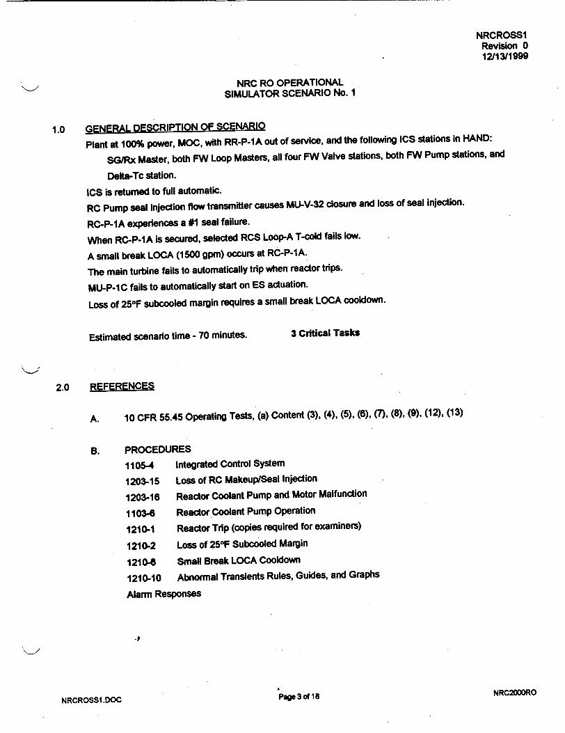
NRCROSS1 Revision 0 12/13/1999
NRC RO OPERATIONAL SIMULATOR SCENARIO No. I
1.0 GENERAL DESCRIPTION OF SCENARIO
Plant at 100% power, MOC, with RR-P-1A out of service, and the following ICS stations in HAND:
SG/Rx Master, both FW Loop Masters, all four FW Valve stations, both FW Pump stations, and
Delta-Tc station.
ICS is returned to full automatic.
RC Pump seal injection flow transmitter causes MU-V-32 closure and loss of seal injection.
RC-P-IA experiences a #1 seal failure.
When RC-P-1A is secured, selected RCS Loop-A T-cold fails low.
A small break LOCA (1500 gpm) occurs at RC-P-1A.
The main turbine fails to automatically trip when reactor trips.
MU-P-IC fails to automatically start on ES actuation.
Loss of 25°F subcooled margin requires a small break LOCA cooldown.
Estimated scenario time - 70 minutes. 3 Critical Tasks
2.0 REFERENCES
A. 10 CFR 55.45 Operating Tests, (a) Content (3), (4), (5), (6), (7), (8), (9), (12), (13)
B. PROCEDURES
1105-4 Integrated Control System
1203-15 Loss of RC Makeup/Seal Injection
1203-16 Reactor Coolant Pump and Motor Malfunction
1103-6 Reactor Coolant Pump Operation
1210-1 Reactor Trip (copies required for examiners)
1210-2 Loss of 25°F Subcooled Margin
1210-6 Small Break LOCA Cooldown
1210-10 Abnormal Transients Rules, Guides, and Graphs
Alarm Responses
" .... NRC2000ROI'a• U1O IQNRCROSS1,DOC

NRCROSS1 Revision 0 12/13/1999
NRC RO OPERATIONAL SIMULATOR SCENARIO No. 1
3.0 TASK 0150040101
0008210501
0008180401
0158020401
3418000101
0030030101
0150030101
0000070501
0000080501*
0130020101
0618000501
0008360501
000C190S01"
000C230501
0130030101
0130040101
004C040101"
Transfer ICS stations to automatic
Respond to loss of RCP seal injection
Respond to high RCP seal #1 leakoff
Respond to a SASS mismatch/actuation
Perform plant power changes
Perform a normal reactor coolant pump shutdown
Operate the ICS in hand
Respond to a reactor trip as the primary CRO
Respond to a reactor trip as the secondary CRO
Manually initiate the ESAS
Respond to an emergency feedwater actuation
Throttle emergency feedwater
Respond to loss of 25°F subcooled margin
Respond to a small break LOCA
Reset an ES channel
Bypass or defeat an ES channel
Throttle high pressure injection
* Critical Task
Page 4 of 18NRCROSS1.DOCNRC2000RO

NRCROSSI Revision 0 12/13/1999
NRC RO OPERATIONAL SIMULATOR SCENARIO No. 1
4.0 SIMULATOR INITIALIZATION
A. ICI6 100% power, steady-state, MOC.
Place simulation in RUN and perform the following:
1. Red tag RR-P-1A extension control on CC in pull-to-lock.
2. Place red sticker tag on RR-P-IA OPEN pushbutton on CC.
3. Verify or align IC ES Valves MCC to the IS Bus.
4. Transfer the following ICS stations to HAND:
SG/Rx Master, both FW Loop Masters, all four FW Valves, both FW Pumps, and Delta-Tc
5. Reduce Delta-Tc station demand to zero (0).
B. EVENT TRIGGERS
#4 THA0427<5.0
Command: IMF RC08B 0 30
C. MALFUNCTIONS
MU07 MU-V-32 failure; insert at 0% severity over 10 second ramp on Event #2.
MU19A RC-P-IA #1 seal failure; insert at 100% severity over 60 second ramp on Event #3.
TH06 LOCA at RC-P-1A; insert at 0.15% severity over 100 second ramp on Event #5.
TC02 Main Turbine auto trip failure; insert immediately.
MU23C MU-P-IC auto start failure; insert immediately.
I
D. REMOTE FUNCTIONS
RWRO7 RR-P-IA breaker;, insert OUT immediately to rack out RR-P-1A breaker.
RWR24 RR-V-1A breaker;, insert OPEN immediately to open RR-V-IA breaker.
E. OVERRIDES
02A3M05-ZAOMU42FI FLO MU-42FI; insert at 100% severity over 10 second ramp on Event #2.
F. MONITOR
Set MSK2609A = 14.7 immediately (auxiliary steam pressure).
NRC200DRONRCROSSI.DOC Page 5 of 18
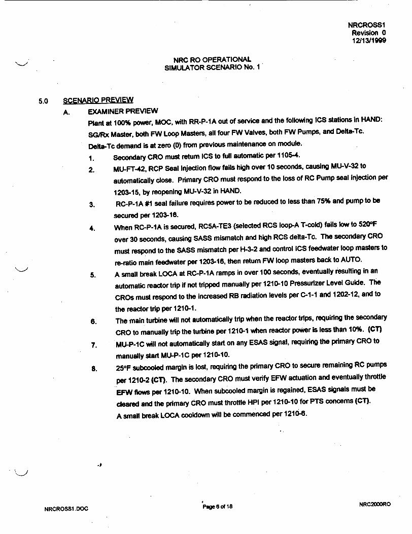
NRCROSSI Revision 0
12/13/1999
NRC RO OPERATIONAL SIMULATOR SCENARIO No. 1
5.0 CENARIO PREVIW
A. EXAMINER PREVIEW
Plant at 100% power, MOC, with RR-P-1A out of service and the following ICS stations In HAND:
SG/Rx Master, both FW Loop Masters, all four FW Valves, both FW Pumps, and Delta-Tc.
Delta-Tc demand Is at zero (0) from previous maintenance on module.
1. Secondary CRO must return ICS to full automatic per 1105-4.
2. MU-FT-42, RCP Seal Injection flow fails high over 10 seconds, causing MU-V-32 to
automatically close. Primary CRO must respond to the loss of RC Pump seal injection per
1203-15, by reopening MU-V-32 in HAND.
3. RC-P-1A #1 seal failure requires power to be reduced to less than 75% and pump to be
secured per 1203-16.
4. When RC-P-1A is secured, RC5A-TE3 (selected RCS loop-A T-cold) fails low to 5200F
over 30 seconds, causing SASS mismatch and high RCS delta-Tc. The secondary CRO
must respond to the SASS mismatch per H-3-2 and control ICS feedwater loop masters to
re-ratio main feedwater per 1203-16, then return FW loop masters back to AUTO.
5. A small break LOCA at RC-P-1A ramps in over 100 seconds, eventually resulting In an
automatic reactor trip if not tripped manually per 1210-10 Pressurizer Level Guide. The
CROs must respond to the increased RB radiation levels per C-1-1 and 1202-12, and to
the reactor trip per 1210-1.
6. The main turbine will not automatically trip when the reactor trips, requiring the secondary
CRO to manually trip the turbine per 1210-1 when reactor power is less than 10%. (CT)
7. MU-P-IC will not automatically start on any ESAS signal, requiring the primary CRO to
manually start MU-P-IC per 1210-10.
8. 25OF subcooled margin is lost, requiring the primary CRO to secure remaining RC pumps
per 1210-2 (CT). The secondary CRO must verify EFW actuation and eventually throttle
EFW flows per 1210-10. When subcooled margin is regained, ESAS signals must be
cleared and the primary CRO must throttle HPI per 1210-10 for PTS concerns (CT).
A small break LOCA cooldown will be commenced per 1210-6.
....... ,I * U4* NRC2000RONRCROSSI .DOG

NRCROSSI Revision 0 121131199g
NRC RO OPERATIONAL "SIMULATOR SCENARIO No. I
B. SHIFT BRIEFING
1. Plant is at 100% power, steady-state, 300 EFPD.
2. RR-P-1A is out of service for shaft bearing replacement. It has been out of service 4
hours into its 16 hour estimated completion time. (See On-line Maintenance Risk
Management document)
3. The following ICS stations are still in HAND following completed maintenance on the FW
ratio and BTU limit circuits: SG/Rx Master, both FW Loop Masters, all four FW Valves,
both FW Pumps, and Delta-Tc.
4. Orders for this shift include transferring ICS back to full automatic, and maintaining 100%
power operation.
NRCROSSI.DOC Page 7 o0 18 NRC2000RO

NRCROSS1 Revision 0 12/13/1999
NRC RO OPERATIONAL SIMULATOR SCENARIO No. 1
6.0 SEQUENCE OF EVENTS
Examiner Notes and Actions Expected Oi)erator Actions
+ ICO: Initialize the simulator per Section 4.0.
+ IPOI: Assign team positions and conduct the + Assume assigned team positions.
SHIFT BRIEFING per Section 5.B.
* Take turnover and review plant status.
* Allow crew 3-5 minutes to take turnover and
assume the watch. • Assume the watch and Inform examiner.
I1. SHIFT FOREMAN: Direct secondary CRO to
transfer ICS back to full automatic per 1105-4.
1.1 BOP - Reviews guidelines for returning ICS
stations to AUTO per 1105-4, Appendix 7.
NOTE: Delta-Tc station demand is initially at
zero (0) as left following mantenance.
1.2 BOP - Checks errors across all ICS stations in
HAND, and recognizes error on FW loop
masters.
1.3 BOP - Raises Delta-Tc station demand to 50%
to zero errors across FW loop masters.
1.4 BOP - Transfers the ICS stations back to AUTO
per 1105-4 in following order.
a. FW-V-17A and 17B
b. FW-V-16A and 168
c. FW Loop Masters A and B
d. Delta-Tc
e. FW-P-1A and 1B
-' f. SG/Rx Master
1.5 BOP - Verifies ICS Track alarm H-2-1 clears
after SG/Rx Master is in AUTO.
NRC2000RONRCROSS1.DOC Page 8 of IS

NRCROSSI Revision 0 12/13/1999
NRC RO OPERATIONAL SIMULATOR SCENARIO No. I
Examiner Notes and Actions Exoected Operator Actions
2. ICO: Approximately one (1) minute after ICS is
in full AUTO, or when directed by Examiner,
activate EVENT #2 to cause MU-FT-42 failure
high, and MU-V-32 to close in AUTO.
NOTE: RCP total seal injection flow may still be
monitored on PPC.
2.1 RO - Recognizes RCP seal injection flow
transient by the following alarms and indications
on CC:
* Alarms F-1-5, F-1-6
* RC-18-DPI-1/2/4 off-scale low
* MU-42-FI1 indicates 80 gpm
* MU-V-32 station demand = zero (0)
2.2 RO - Diagnoses actual loss of RCP seal
injection caused by MU-V-32 closure.
SHIFT FOREMAN: After RO has diagnosed
MU-V-32 closure as cause for loss of RCP seal
injection, implement 1203-15 verify immediate
actions, and direct follow-up actions.2.3 RO - Transfers MU-V-32 station to HAND, and
raises demand to restore RCP seal injection
flow as directed by SRO per 1203-15.
2.4 RO - Monitors RCP seal parameters (RC-18
DPI-1/2/4) and #1 seal water temperatures as
seal injection is being restored.
2.5 RO - Limits seal injection flow increase to limit
cooldown rate on radial bearings to <1OF per
minute per 1203-15.
-P
NRCROSSI.DOC
2.6 RO - Obtains approximately 38 gpm RCP seal
injection flow as indicated on PPC, but leaves
MU-V-32 in HAND until MU-FT-42 is fixed.
Page 9 of 18 NRC2000RO

NRCROSS1 Revision 0 12/13/1999
NRC RO OPERATIONAL SIMULATOR SCENARIO No. 1
Examiner Notes and Actions Expected Operator Actions
3. ICO: Approximately one (1) minute after RCP
seal injection flow has been restored to normal,
or when directed by Examiner, activate EVENT
#3 to cause #1 seal failure on RC-P-1A.
3.1 RO - Diagnoses symptoms of RCP #1 seal
failure on RC-P-1A by the following:
*Alarms F-1-6, F-1-4, F-1-3, D-2-2, and
LWDS-1-5 (delayed)
*RC-18-DPI-1 (CC) off-scale low
* MU-13-DPI-1 (CC) goes low
* RC-P-1A seal leakoff flow high (>12 gpm)
on PC recorder and PPC
3.2 RO - Closes MU-V-33A by depressing its
CLOSE pushbutton on CC within 5 minutes per
1203-16.
NOTE: When MU-V-33A is closed, alarm F-1-4
will clear and MU-13-DPI-1 (CC) will go high.
3.3 RO - Recognizes requirement to reduce power
and secure RC-P-1 A within 30 minutes per
1203-16.
SHIFT FOREMAN: Implement 1203-16 and .
direct primary CRO to reduce reactor power to
70% at 5% per minute per the manual actions.
3.4 RO - Sets ULD rate of change setpoint at 50
(5%/minute), and lowers ULD to approximately
60 (600 MW) to effect the power reduction.
3.5 RO/BOP - Monitor critical parameters during
the power reduction.
3.6 RO/BOP - Verify that reactor power stabilizes at
target power level (70%) and report to SF.
SHIFT FOREMAN: Direct primary CRO to
secure RC-P-1A. _P 3.7 RO - Secures RC-P-1A using its control switch
on CC per 1103-6.
NRCROSS1 .DOC PMage 10 of 18 NRC2000RO

NRCROSS1 Revision 0 12/13/1999
NRC RO OPERATIONAL SIMULATOR SCENARIO No. 1
Examiner Notes and Actions Expected Operator Actions
4. ICO: When RC-P-1A is secured, verify EVENT 4.1 BOP - Monitors for automatic ICS re-ratio of
#4 inserts RC08B at 0% severity over 30 main feedwater when RC-P-1A Is secured.
seconds to fail RC5A-TE3.
4.2 BOP - Recognizes SASS mismatch on RCS
loop-A T-cold by alarm H-3-2 and Indication on
CC.
4.3 BOP - Acknowledges high delta-Tc alarm H-2-4
and sustained RCS delta-Tc on CC indicator.
4.4 RO - Responds to RCS temperature and
pressure transient by verifying proper automatic
operation of pressurizer heaters (CR) and spray
valve, RC-V-1 (CC).
4.5 BOP - Responds to SASS mismatch per H-3-2:
* Transfers both FW Loop Masters to HAND
* Selects alternate RCS loop-A T-cold,
RC5A-TE1 by depressing its SASS selector
pushbutton on CC
SHIFT FOREMAN: After secondary CRO
diagnoses and initially responds to the SASS
mismatch, implement H-3-2 alarm response
and vetify/direct actions as necessary.
4.6 BOP - Adjusts ICS FW Loop Master demands
(decreases A-loop & increases B-loop) as
necessary to obtain zero (0) degrees delta-Tc,
while maintaining correct total FW flow for
reactor power.
EXAMINEMS: If reactor trips due to improper
FW control, proceed to Event #6.
...... DC... NRC2000ROrage I I IoaNRCROSSI .DOC

NRCROSS1 Revision 0 12/13/1999
NRC RO OPERATIONAL SIMULATOR SCENARIO No. I
Examiner Notes and Actions Expected Ooerator Actions
EXAMINERS: It is not necessary for FW Loop
Masters to be returned to AUTO prior to
proceeding with next Event #5.
5. ICO: After RCS temperatures are stable with
zero (0) delta-Tc, or when directed by
Examiner, activate EVENT #5 to insert THOS at
0.15% severity (1500 gpm) over 100 seconds.
4.7 BOP - After correct FW flows have been
obtained, checks for zero (0) error across FW
Loop Masters and transfers both stations back
to AUTO.
4.8 BOP - Performs follow-up actions of H-3-2 as
directed by the SRO for the SASS mismatch.
5.1 RO/BOP - Diagnose RCS leak into containment
by the following indications:
* Increased RB radiation levels (PRF) and
RMS alarms (C-1-1)
* Decreasing pressurizer level (CC)
* Decreasing makeup tank level (CC)
* Increasing RB temperatures & pressures
5.2 RO - Operates makeup system to provide more
makeup flow to maintain pressurizer level:
* Starts MU-P-1A, DC-P-1A, and DR-P-1A
using their control switches on CC
* Opens MU-V-217 using its pushbutton on
CC to augment normal makeup line flow
5.3 RO/BOP - Recommend reactor trip or manually
trip reactor based upon quickly degrading plant
conditions and impending safety system
actuations (RPS,ESAS).
SHIFT FOREMAN: If either CRO recommends
or initiates man0al reactor trip due to quickly
degradind'plant conditions, concur with their
action or recommendation.
NRC2000ROPage 12 of 18NRCROS1S.DOC

NRCROSS1 Revision 0 12/13/1999
NRC RO OPERATIONAL SIMULATOR SCENARIO No. 1
Examiner Notes and Actions Expected Operator Actions
NOTE: MU-P-1 C will fail to automatically start
on any ESAS actuation. See Event #7 for
expected RO actions.
EXAMINERS: Refer to copy of 1210-1.
6. NOTE: The main turbine will fail to
automatically trip when reactor trips.
NOTE: 6.2 is a Critical Task.
5.4 RO - With pressurizer level dropping below
150" and reactor power greater than 25%,
implements 1210-10 Pressurizer Level Guide
as follows:
* Manually trips reactor by depressing both
trip pushbuttons on CC, and
* Manually initiates HPI by depressing 1600#
or 4# manual ESAS pushbuttons for both
trains on CC and CR
5.5 RO/BOP - Perform immediate manual actions
of 1210-1 for the reactor trip.
6.1 BOP - Recognizes failure of main turbine to
automatically trip when reactor trips by:
* No K-1-1 alarm (Turbine Trip)
* Turbine stop valves open on CL
6.2 BOP - Verifies reactor power is less than
10% on CC digital indicators, and manually
trips main turbine by depressing its trip
pushbutton on CL
6.3 BOP - Verifies main turbine is tripped per 1210
1 by verifying the turbine stop valves are closed
and generator and field breakers open (CC).
6.4 BOP/RO - Continue immediate actions of
1210-1 for the reactor trip. (see attached)
NOTE: If the reactor tripped automatically
during Event #4, then following Event #6 go to
and insert Event #5.
NRC2000RONRCROSSI.DOC ?•age 13 of 18

NRCROSSI Revision 0 12/13/1999
NRC RO OPERATIONAL SIMULATOR SCENARIO No. I
Examiner Notes and Actions Expected Operator Actions
7. NOTE: MU-P-1 C will fall to automatically start
on any ESAS actuation.
SHIFT FOREMAN: Following all 1210-1
immediate actions by CROs, announce to team
and commence 1210-1 immediate action
verification.
8. NOTE: The LOCA size will eventually result in
loss of 250 F subcooled margin.
r-ap 1'4 % IQNRCROSS1 .DOC
7.1 RO - Monitors ESAS component status on
ESAS panel (PCR) to verify proper safety
system response per 1210-1.
7.2 RO - Diagnoses failure of MU-P-1C to
automatically start as required for ES, by its
green breaker status lamp on CR or its amber
ES status lamp on PCR.
7.3 RO - Manually starts MU-P-1C using its control
switch on CR, per 1210-1 and 1210-10.
7.4 RO - Verifies MU-P-IC starts by its red breaker
status indication on CC and Its blue ES status
lamp on PCR.
7.5 RO - Verifies A and B train HPI flows exist on
all four lines using their indicators, MU-FI-1 126
and 1127 on CC, MU-FI-1128 and 1129 on CR.
7.6 RO/BOP - Verify 1210-1 immediate actions with
Shift Foreman as read by Shift Foreman, and
continue to monitor plant conditions.
8.1 BOP/RO - Diagnose loss of 250F subcooled
margin by the following indications:
* Alarm G-1-8
* One or both Margin to Saturation meters on
PCL indicate less than 25OF
NRC2000RO

NRCROSS1 Revision 0 12/13/1999
NRC RO OPERATIONAL SIMULATOR SCENARIO No. 1
Examiner Notes and Actions
NOTE: 8.2 is a Critical Task.
SHIFT FOREMAN: After 1210-2 immediate
actions have been performed by CROs,
transition from 1210-1 to 1210-2, verify
immediate actions of 1210-2, and direct CROs
in 1210-2 follow-up actions.
4
Expected Operator Actions
8.2 RO - Performs 1210-2 immediate actions for
loss of 25°F subcooled margin as follows:
*Secures RC-P-1 B, RC-P-1C, and RC-P-1 D
using their control switches on CC,
within 2 minutes per 1210-10 rule.
*Verifies HPI flow on all four HPI flow
meters MU-FI-1 126 and 1127 on CC, and
MU-FI-1128 and 1129 on CR.
8.3 BOP - Performs 1210-2 immediate actions for
loss of 25°F subcooled margin as follows:
* Verifies EF-P-1, EF-P-2A, and EF-P-2B
start by indications of speed, breaker status
lamps, and pump discharge pressures (on
CL and CC)
* Verifies EFW flow to both SGs as indicated
on EF-FI-779/788 for A-SG, and on EF-FI
782/791 for B-SG (on CL and CC)
* Verifies SG levels increasing toward 75
85% on operating range level indications
LI-1103 for A-SG and LI-1105 for B-SG
(both on CC)
8.4 RO/BOP - Verify 1210-2 immediate actions as
read by Shift Foreman, and perform 1210-2
follow-up actions as directed by SF.
8.5 RO - Operates RC and MU system valves from
CC as directed by the Shift Foreman per 1210-2
follow-up actions.
NRC2000RONRCROSS1.DOC Page 15 of 18

NRCROSSI Revision 0 12/13/1999
NRC RO OPERATIONAL SIMULATOR SCENARIO No. I
Examiner Notes and Actions Expected Operator Actions
8.6 BOP - Recognizes requirement to throttle EFW
flows per 1210-10 EFW Throttling Criteria, due
to SG pressure response to the EFW flow.
8.7 BOP - Throttles EFW flows per 1210-10 as
follows:
* Transfers EF-V-30A, 30B, 30C, and 30D
controllers to manual (CL and CC)
* Operates EF-V-30A/D and EF-V-30B/C
controllers as necessary to throttle EFW
flows, while ensuring both SG levels are still
increasing toward 75-85% setpoint with
RCS subcooled margin < 25°F
SHIFT FOREMAN: Continue to direct 1210-2 8.5
and 1210-6 follow-up actions, and direct HPI
throttling for PTS considerations when at least
250F subcooled margin has been regained.
NOTE: When ESAS trains A and B are clear, 2 8.9
of 3 sets of block loading sequence blue lamps
will be extinguished for each train on PCR.
Page 16of 1NRCROSSI .DOC
BOP - Continues to feed and steam both steam
generators as necessary to maintain them as
heat sinks per 1210-6, and attempts to develop
RCS natural circulation per 1210-10.
RO/BOP - When directed by Shift Foreman,
clear ESAS signals for HPI throttling as follows:
* Bypass 1600# auto channels, 3 on train-A
"and 3 on train-B, by depressing their bypass
pushbuttons on CC and CR
* Defeat 4# auto channels, 2/3 on train-A and
2/3 on train-B, by depressing their defeat
pushbuttons on CC and CR
* Defeat and reset 1600# manual channels 3
on train-A and 3 on train-B, by depressing
their defeat/enable pushbuttons on CC and
CR
18 NRC2000RO
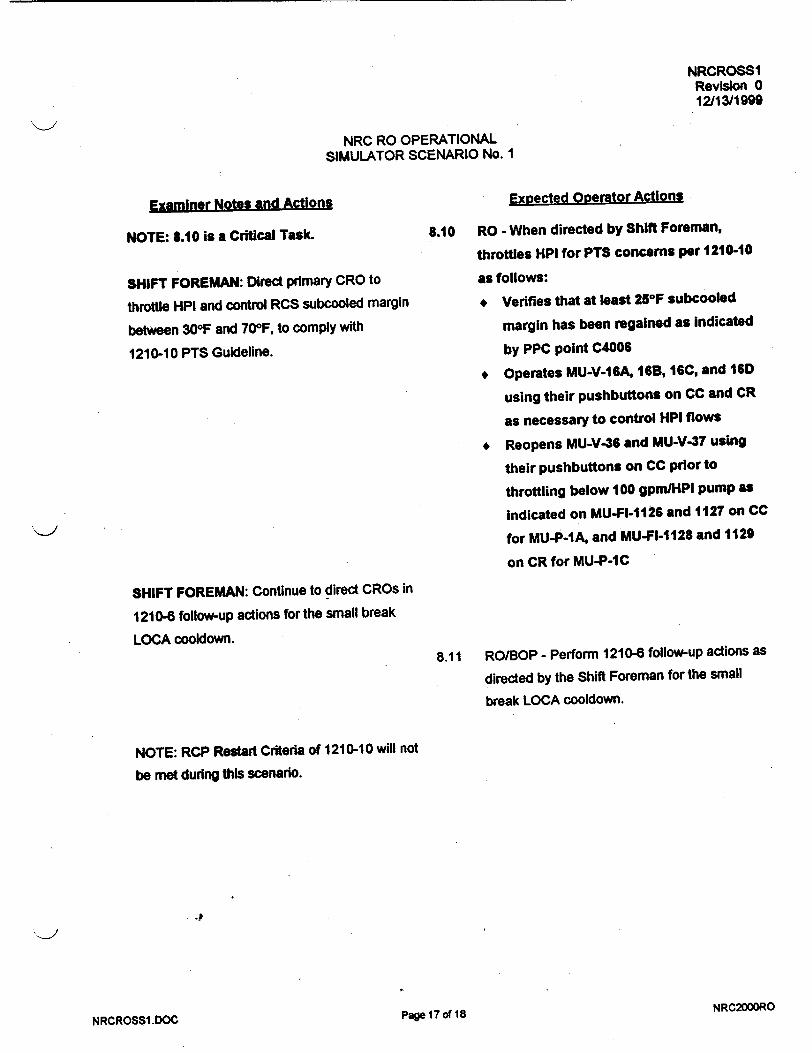
NRCROSS1 Revision 0 12/13/1999
NRC RO OPERATIONAL SIMULATOR SCENARIO No. 1
Examiner Notes and Actions Expected Operator Actions
NOTE: 8.10 is a Critical Task.
SHIFT FOREMAN: Direct primary CRO to
throttle HPI and control RCS subcooled margin
between 30OF and 700F, to comply with
1210-10 PTS Guideline.
SHIFT FOREMAN: Continue to direct CROs in
1210-8 follow-up actions for the small break
LOCA cooldown.
8.10 RO - When directed by Shift Foreman,
throttles HPI for PTS concerns per 1210-10
as follows:
+ Verifies that at least 25OF subcooled
margin has been regained as indicated
by PPC point C4006
* Operates MU-V-I6A, 16B, 16C, and 16D
using their pushbuttons on CC and CR
as necessary to control HPI flows
+ Reopens MU-V-36 and MU-V-37 using
their pushbuttons on CC prior to
throttling below 100 gpm/HPI pump as
Indicated on MU-FI-1126 and 1127 on CC
for MU-P-1A, and MU-FI-1128 and 1129
on CR for MU-P-IC
8.11 RO/BOP - Perform 1210-6 follow-up actions as
directed by the Shift Foreman for the small
break LOCA cooldown.
NOTE: RCP Restart Criteria of 1210-10 will not
be met during this scenario.
NRC2000ROPage 17 of 18NRCROSSI.DOC

NRCROSSI Revision 0 12/13/1999
NRC RO OPERATIONAL SIMULATOR SCENARIO No. I
7.0 TERMINATION POINT
When all of the following conditions exist:
1. Examinees had opportunity to perform all critical tasks as designed.
2. RCS pressure (subcooled margin) is being controlled by HPI throttling.
3. Small break LOCA cooldown at approximately 100°F/hour has commenced per 1210-6.
4. Examiners agree to terminate.
NRC2000RONRCROSS1 .DOC page is o 18

FOR TRAINING ONLY
ON-LINE MAINTENANCE RISK MANAGEMENT
ON-LINE RISK # 58 Rev: 0
RISK EVALUATION SUMMARY - RR-P-IA
Risk Achievement Worth (RAW) is the factor increase in core damage frequency resulting when the structure,
system, or component (SSC) is determined to be continuosly failed.
Assumptions:
RR-P-1 A will be removed from service for shaft bearing replacement. Duration is
scheduled for approximately 16 hours.
1. LIST THE TYPE OF RISK CONCERNS EVALUATED
Reduction in energy removal from containment post accident conditions.
Failure of containment post accident.
2. LIST IMPORTANT SSCs WHICH NEED TO BE MAINTAINED OPERABLE
RB Emergency Cooling Train "B" Building Spray Trains "A" and "B" DC Power Trains "A" and "B" AC Power Trains "A" and "B"
3. LIST IMPORTANT MANUAL ACTIONS WHICH SHALL BE BRIEFED WITH THE
APPROPRIATE PERSONNEL
Verify or align IC ES Valves MCC to the IS Bus
If an ES actuation occurs direct immediate restoration of Emergency Cooling Train "A".
FOR T13AINING ONLY

FOR TRAINING ONLY
4. IDENTIFY CONTINGENCY PLANS OR COMPENSATORY ACTIONS USED TO
REDUCE RISK
COMPENSATORY ACTIONS (PRIOR TO/IN PREPARATION FOR OUTAGE):
Verify of align 1C ES Valves MCC to the IS Bus
CONTINGENCY ACTIONS:
5. EVALUATION APPROVALS
o 1. Risk found acceptable
* 2. Risk found acceptable with contingencies identified
o 3. Risk unacceptable,
Signature of FOR TRAINING on 02/13/2000
Evaluator:
Signature of Director: FOR TRAINING on 02/13/2000
CC: Job Package Shift Supervisor Clipboard Operations Department General Files STA
FOR TRAINING ONLY

NRCROSS2 Revision 0 12/15/1999
NRC RO OPERATIONAL SIMULATOR SCENARIO No. 2
MAIN GENERATOR PLACED ON LINE DURING PLANT STARTUP,
AND SECONDARY PRESSURE TRANSIENT CAUSING OTSG TUBE LEAK
WITH PRIMARY INVENTORY & PRESSURE CONTROL FAILURES
4DEVELOPED BY/DATE: <'75/ I
7
REVIEWED BY/DATE:
APPROVED BY/DATE:
(OPERATIONS TRAINING MANAGER)
-4
PagelI of 20 NRC2000RONRCROSS2.DOC
K>
m -- -- n•- • w --a2- -ZZ,

NRCROSS2 Revision 0 12/15/1999
NRC RO OPERATIONAL SIMULATOR SCENARIO No. 2
SCENARIO CHANGE HISTORY PAGE
REVISION DATE REFERENCE TITLE DESCRIPTION (Include Al # if appropriate)
4 t
i 4.
I. 4 +
4 I
I__ _ I s
_____ _____ I
J
NRCROSS2.DOC p• •2 NRC2000RO

NRCROSS2 Revision 0
12/15/1999
NRC RO OPERATIONAL SIMULATOR SCENARIO No. 2
1.0 GENERAL DESCRIPTION OF SCENARIO
Reactor at 14% power, 300 EFPD, during a xenon-free plant startup.
Main turbine-generator is synchronized and loaded.
Power is increased and main turbine is placed in auto.
Turbine header pressure instrument fails low causing SASS mismatch and secondary pressure transient.
A 45 gpm tube leak occurs on A-SG.
Plant shutdown is performed per 1210-5.
One turbine bypass valve fails open when main turbine is tripped.
Pressurizer level transmitter fails high as RCS temperature is reduced during reactor shutdown.
MU-P-1A trips upon start.
RC-V-1 does not open to reduce subcooled margin per 1210-5.
Plant cooldown is commenced after subcooled margin is minimized.
Estimated scenario time - 80 minutes. 3 Critical Tasks
2.0 REFERENCES
A. 10 CFR 55.45 Operating Tests, (a) Content (3), (4), (5), (6), (7), (8), (9), (12), (13)
B. PROCEDURES
1102-2 Plant Startup (sign-off copy required for crew)
1106-1 Turbine Generator (sign-off copy required for crew, and copy required for examiner)
1106-2 Condensate System (sign-off copy required for crew)
1106-3 Feedwater System (sign-off copy required for crew)
1104-2 Makeup and Purification System
1210-5 OTSG Tube Leakage
1102-10 Plant Shutdown
1202-12 Excessive Radiation Levels
1202-29 Pressurizer System Failure
1210-1 Reactor Trip (copies required for examiners)
Alarm Responses
49
NRC2000RONRCROSS2.DOC P o 3 of 20

NRCROSS2 Revision 0 12/15/1999
NRC RO OPERATIONAL SIMULATOR SCENARIO No. 2
3.0 TASKS
0450050101
0450060101
341C020101
0150030101
0150040101
0158020401
000C220501*
0000610501
3418000101
0450100101
0450120101
0008370601*
0010290101*
0008140401
0000070501
0000080501
0130040101
Synchronize and load turbine generator
Increase load on turbine generator
Perform a plant startup
Operate the ICS in hand
Transfer ICS stations to automatic
Respond to a SASS mismatch/actuation
Respond to OTSG tube leak
Respond to excessive radiation levels
Perform plant power changes
Unload turbine generator
Shutdown the turbine generator
Isolate affected OTSG during excessive heat transfer
Operate the CRD system to shutdown the reactor
Respond to a malfunction in PZR level indication or control
Respond to a reactor trip as the primary CRO
Respond to a reactor trip as the secondary CRO
Bypass or defeat an ES channel
Critical Task
NRC2000RONRCROSS2.DOC sag 4 of 20
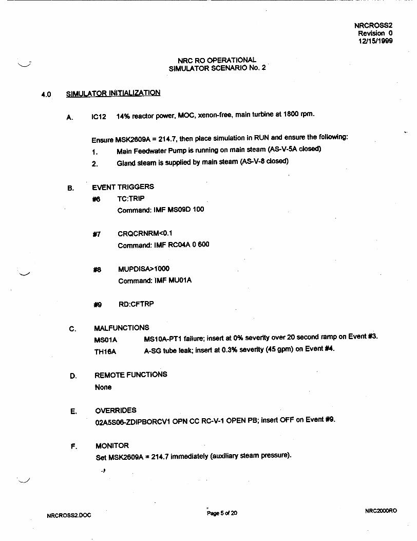
NRCROSS2 Revision 0 12/15/1999
NRC RO OPERATIONAL SIMULATOR SCENARIO No. 2
4.0 SIMULATOR INITIALIZATION
A. IC12 14% reactor power, MOC, xenon-free, main turbine at 1800 rpm.
Ensure MSK2609A = 214.7, then place simulation in RUN and ensure the following:
1. Main Feedwater Pump is running on main steam (AS-V-5A closed)
2. Gland steam is supplied by main steam (AS-V-8 dosed)
B. EVENT TRIGGERS
#6 TC:TRIP
Command: IMF MS09D 100
#7 CRQCRNRM<0.1
Command: IMF RC04A 0 600
#8 MUPDISA>1000
Command: IMF MU01A
#9 RD:CFTRP
C. MALFUNCTIONS
MS01A MS1OA-PTI failure; insert at 0% severity over 20 second ramp on Event #3.
TH16A A-SG tube leak; insert at 0.3% severity (45 gpm) on Event #4.
D. REMOTE FUNCTIONS
None
E. OVERRIDES
02A5S06-ZDIPBORCVI OPN CC RC-V-1 OPEN PB; insert OFF on Event #9.
F. MONITOR
Set MSK2609A = 214.7 immediately (auxiliary steam pressure).
_P
NRC2000RONRCROSS2.DOC
I Page 5 of 20

NRCROSS2 Revision 0 12/15/1999
NRC RO OPERATIONAL SIMULATOR SCENARIO No. 2
5.0 SCENARIO PREVIEW
A. EXAMINER PREVIEW
Plant at 14% power, during xenon-free plant startup at MOC. Main Turbine is at 1800 rpm.
1. Secondary CRO will synchronize and load turbine-generator per 1106-1.
2. Secondary CRO will increase reactor power using Reactor Demand to obtain 579OF T-ave,
then transfer ICS stations to auto, including main turbine.
3. Selected turbine header pressure transmitter (MS1OA-PT1) fails low over 20 seconds. The
secondary CRO must respond to the SASS mismatch per H-3-2 by assuming hand control
of main turbine and selecting good transmitter.
4. A 45 gpm tube leak occurs on A-SG. The team must respond to the excessive radiation
levels per 1202-12, and to the tube leak per 1210-5.
5. The primary CRO must operate ICS stations and control rods to shutdown reactor per
1210-5. (CT)
6. When the main turbine is tripped at 15% reactor power, MS-V-3D (A-SG) fails 100% open
and must be isolated locally. The secondary CRO must then control A-SG pressure. (CT)
7. At 10% reactor power during the shutdown, selected pressurizer level transmitter (RCI
LTI) fails to 400' indicated level over 600 seconds. The prmary CRO must respond per
1202-29 to control RCS makeup in hand, then select alternate pressurizer level
instrument.
8. MU-P-1A trips when it is started for augmented makeup flow during reactor shutdown or
after reactor trip per 1210-1. The primary CRO must start MU-P-1C and use HPI as
necessary to maintain RCS inventory.
9. Following reactor shutdown when RCS subcooled margin is reduced per 1210-5, RC-V-1
will not manually open. The prmary CRO must operate pressurizer vent and/or PORV as
necessary to reduce subcooled margin. (CT)
4)
NRC2000RONRCROSS2.DOC Pne 6 of 20

NRCROSS2 Revision 0 12/15/1999
NRC RO OPERATIONAL SIMULATOR SCENARIO No. 2
B. SHIFT BRIEFING
1. Reactor is at 14% power during a xenon-free startup at 300 EFPD.
2. The main turbine is at 1800 rpm and ready to load.
3. The plant tripped 80 hours ago due to a main generator relay failure.
4. FW-P-1A and gland steam are currently supplied by main steam per 1102-2.
5. Continue plant startup by synchronizing and loading main turbine-generator, and
increasing power per 1102-2.
NRC2000RONRCROSS2.DOC Page 7 of 20

NRCROSS2 Revision 0 12/15/1999
NRC RO OPERATIONAL SIMULATOR SCENARIO No. 2
SEQUENCE OF EVENTS
Examiner Notes and Actions
* ICO: Initialize the simulator per Section 4.0.
+ IPOh Assign team positions and conduct the
SHIFT BRIEFING per Section 5.B.
* Provide Shift Foreman with sign-off copies of
1102-2, 1106-1, 1106-2, and 1106-3.
+ Allow crew 3-5 minutes to take turnover and
assume the watch.
SHIFT FOREMAN: Direct secondary CRO
actions to synchronize and initially load main
turbine-generator per 1106-1.
EXAMINER: Refer to a copy of 1106-1 to follow
specific control manipulations.
Expected Operator Actions
* Assume assigned team positions.
* Take turnover and review plant status.
* Assume the watch and inform examiner.
1.1 BOP - Operates main generator excitation
controls on CL to establish main generator
voltage per 1106-1.
1.2 RO - Operates ICS Reactor Demand station on
CC as necessary to slowly raise reactor power
during turbine-generator initial loading.
1.3 BOP - Operates Digital Turbine Control System
(DTCS), main generator breakers, and main
generator voltage controls (all on CL) to
synchronize and load main generator to
minimum load (40MW) per 1106-1.
_P
NRC2000RONRCROSS2.DOC
6.0
- 1.
Page 8 of 20

NRCROSS2 Revision 0 12/15/1999
NRC RO OPERATIONAL SIMULATOR SCENARIO No. 2
Examiner Notes and Actions Expected Operator Actions
2. SHIFT FOREMAN: After turbine-generator is
loaded to 40 MW, direct CROs to continue
power escalation at less than 30% power per
hour (MMRs) per 1102-2.
SHIFT FOREMAN: Direct primary CRO to
maintain pressurizer level within Figure 1 of
1102-2, bleeding to C-RCBT as necessary.
Provide Figure 1 to primary CRO.
2.1 RO - Operates Reactor Demand station (CC),
to create positive neutron error such that control
rods pull and reactor power increases.
BOP - Operates Turbine ICS station (CL) to
increase main generator load, and operates
FW-P-1A ICS station (CL) to maintain main
feedwater valve d/p at > 35 psid.
2.2 RO - Operates the following makeup and
LWDS system components as necessary to
maintain pressurizer level increase within
Figure 1 as T-ave increases, and to maintain
makeup tank level within Figure 1 of 1104-2:
* MU-V-17 ICS station setpoint (CC)
* Bleed Tank Select switch on LWDS
* MU-V-8 (THRU/BLEED) pushbuttons (CC)
* MU-V-5 demand setpoint (CC)
SHIFT FOREMAN: Direct CROs in operation
of ICS controls per 1102-2 when RCS T-ave
reaches 5790F.
2.3 BOP/RO - Transfers Reactor Demand ICS
station (CC) to auto when T-ave reaches 5790 F.
2.4 BOP/RO - Increases demand on SG/Rx Master
ICS station (CC) until CRD out motion is
obtained, then transfers SG/Rx Master to auto.
2.5 BOP - Operates turbine ICS station (CL) to
increase load until turbine bypass valves (MS
V-3s) close, then transfers turbine to auto.
NRCROSS2.DOC NRC2000ROPage 9 of 20

NRCROSS2 Revision 0 12/15/1999
NRC RO OPERATIONAL SIMULATOR SCENARIO No. 2
Examiner Notes and Actions Expected Ooerator Actions
3. ICO: Approximately one (1) minute after turbine
is in auto, or when directed by Examiner,
activate EVENT #3 to cause selected turbine
header pressure transmitter, MS1OA-PTI, to fail
low (600 psig) and cause SASS mismatch.
3.1 BOP - Responds to SASS Mismatch alarm
(H-3-2), and diagnoses mismatch on turbine
header pressure recorder on CC.
NOTE: Large header pressure error for greater
than 10 seconds will cause turbine ICS station
to revert to HAND, and cause alarm H-3-3.
3.2 BOP - Diagnoses main turbine ICS station (CL)
reverted to HAND, by alarm H-3-3 and white
lamp illuminated on turbine ICS station.
3.3 BOP - Assumes hand control of main turbine
ICS station to control header pressure and
return it to 885 psig per H-3-3.
SHIFT FOREMAN: Implement H-3-2 and H-3-3
after secondary CRO performs initial manual
actions, and venfyldirect the actions therein.
3.4 RO - Responds to OTSG pressure transient
effects on RCS temperature, pressure,
inventory, and reactor power.
* Verfies automatic response of MU-V-17
* Verifies automatic response or RC-V-1
(pressurizer spray on CC)
* Verifies automatic response of PZR heaters
on CR
3.5 BOP - Selects alternate turbine header
pressure instrument per H-3-2, by depressing its
SASS pushbutton on CC.
NRCROSS2.DOC Page 10 of 20 NRC2000RO

NRCROSS2 Revision 0 12/15/1999
NRC RO OPERATIONAL SIMULATOR SCENARIO No. 2
Examiner Notes and Actions Expected Operator Actions
3.6 BOP - Obtains zero (0) header pressure error
as indicated on turbine ICS station (50% in
Header Pressure Error position), and with
turbine bypass valves closed, transfers main
turbine ICS station back to auto.
SHIFT FOREMAN: Direct secondary CRO in
follow-up actions for SASS Mismatch per H-3-2.
3.7 BOP - Performs follow-up actions of H-3-2 as
directed by the Shift Foreman.
4. ICO: After main turbine is back in automatic, or
when directed by Examiner, activate EVENT #4
to insert a 45 gpm tube leak in A-SG. 4.1 BOP/RO - Diagnose indications of a tube leak
into A-SG by the following:
* High radiation alarms (C-1-1) on main
condenser off-gas monitors RM-A-5 & 15,
and on A-SG steam line monitor RM-G-26
(all monitors in upper right of PRF)
* Increase in RCS makeup flow and decrease
in makeup tank level (CC) with stable RCS
temperature
4.2 BOP/RO - Perform immediate actions of
1202-12 for the excessive radiation levels:
* Announce radiation monitor alarms on plant
page and radio
* Mark meteorological chart (PLF) and
radiation monitor chart (PRF)
* Contact Group Rad Con Supervisor
NRCROSS2.DOC Page 11 of 20 NRC2000RO

NRCROSS2 Revision 0 12/15/1999
NRC RO OPERATIONAL SIMULATOR SCENARIO No. 2
Examiner Notes and Actions Expected Operator Actions
SHIFT FOREMAN: Following CRO actions for
the excessive radiation levels, implement
1202-12 and C-1-1 and verify/direct actions. 4.3 RO - Performs actions of C-1-1 to validate and
quantify tube leak.
4.4 RO - When tube leak is validated, recommends
plant shutdown per 1210-5, and may close
MU-V-3 (CC) to isolate letdown if necessary for
RCS inventory control.
5. SHIFT FOREMAN: After prmary CRO
validates and quantifies SG tube leakage,
implement 1210-5 and direct primary CRO to
commence plant/reactor shutdown per 1210-5
at 3-5% per minute.
NOTE: 5.1 is a Critical Task. 5.1 RO - Effects plant shutdown by performing
the following per 1210-5:
* Sets ULD rate of change at 30-60%
* Reduces ULD input to reduce reactor
power
* When OTSGs reach low level limits
(alarms H-1-6 and H-1-7), transfers
SG/Rx Master and Reactor Demand
stations to HAND
• Transfers the Diamond Rod Control
panel to manual, and inserts control
rods to continue reactor shutdown
NRC2000RONRCROSS2.DOC
Page 12 of 20

NRCROSS2 Revision 0 12/15/1999
NRC RO OPERATIONAL SIMULATOR SCENARIO No. 2
Examiner N-otes and Actions Expected Operator Actions
SHIFT FOREMAN: If primary CRO requests
which RC bleed tank to select for feed, direct
primary CRO to use B-RCBT.
5.2 RO - Operates makeup system and LWDS
controls as necessary to maintain RCS and
makeup system inventory during reactor power
and T-ave reduction with 45 gpm leak:
* Opens MU-V-217 using its pushbutton on
CC to augment normal makeup line flow
through MU-V-17
+ Operates Feed Tank Select and Feed
Pump Select switches on LWDS to align
selected RC bleed tank & pump for feed
* Operates makeup system batch controller
(CC) and opens MU-V-10 (CC) to enable a
batch feed
* Operates Waste Transfer (feed) Pump
control on LWDS to start batch feed to
makeup tank
* Operates makeup batch controller and/or
MU-V-14A (CC) as necessary to maintain
makeup tank within limits of 1104-2,
Figure 1
5.3 BOP - Operates FW-P-1A ICS station demand
(CL) as necessary to maintain at least 25" main
feedwater valve delta-p on SP-1 1A/B-DPT2.
SHIFT FOREMAN: Continue to direct 1210-5
actions to .shut down plant and reactor, and at
15% react(r power direct secondary CRO to
unload and trip main turbine.
Page 13 of 20 NRC200OROMKWDd1"! RV I •t VVViI.. W V v

NRCROSS2 Revision 0 12/15/1999
NRC RO OPERATIONAL SIMULATOR SCENARIO No. 2
Examiner Notes and Actions Expected Operator Actions
5.4 BOP - Secures main turbine at 15% power as
follows: (controls on CL)
* Transfers main turbine ICS station to hand
* Decreases turbine ICS demand to unload
generator to 0 MW, while verifying that
turbine bypass valves control SG pressures
* Manually trip main turbine by depressing
turbine TRIP button
6. ICO: When the main turbine is tripped, verify
EVENT #6 activates to cause MS-V-3D to fail
100% open.
NOTE: This MS-V-3D failure may not be
diagnosed until lower in reactor power during
reactor shutdown, or possibly not until MS-V-3
ICS stations are taken to hand for reactor trip
per 1210-5. 6.1 BOP - Recognizes lower demand on ICS station
for MS-V-3D/E/F as compared to demand for
MS-V-3AIBIC on B-SG, and/or notices MS-V-3E
and 3F closed but MS-V-3D open.
6.2 BOP - Diagnoses failure of MS-V-3D by:
* Zero (0) demand on ICS station for
MS-V-3D/E/F (CC)
* Red open indication for MS-V-3D (CC)
* A-SG pressure decreasing below desired
pressure.
NOTE: G.; is a Critical Task. 6.3 BOP - Respond to MS-V-3D failure by
directing auxiliary operator to locally isolate
or manually close MS-V-3D.
NRCROSS2.DOC Page 14 of 20 NRC2000RO

NRCROSS2 Revision 0 12/15/1999
NRC RO OPERATIONAL SIMULATOR SCENARIO No. 2
Examiner Notes and Actions Expected Operator Actions
ICO-ROLE PLAY: As AO if directed to locally
isolate MS-V-3D, after a 2-3 minute time delay
use MSR10 to close MS-V-I D.
If directed to manually close MS-V-3D, after a
2-3 minute time delay: insert MSR36 at 100%,
change MSR35 to MANUAL, then insert MSR36
at 0% over 30 second ramp.
After the appropriate task is complete, report
task complete to control room. 6.4 BOP - Recognize MS-V-3D isolation by proper
A-SG pressure control by MS-V-3E/F.
Recognize MS-V-3D manual closure by green
position indication on CC, and proper A-SG
pressure control by MS-V-3E/F.
5.5 RO - Operates CRD panel as necessary to
reduce reactor power until T-ave = 5450F.
ICO: When reactor power is less than 10%
(CRQCRNRM<0.1), verify EVENT #7 activates
to fail selected pressurizer level transmitter to
400" over 600 seconds.
7.1 RO - Diagnose decreasing makeup flow.(CC) to
RCS and increasing makeup tank level (CC),
and recognize increase in pressurizer level
RC1-LT1 on recorder (CC), with decrease in
pressurizer level on digital, LI-777A (CC).
7.2 RO - Diagnose probable failure of RCI-LTI on
pressurizer level recorder by conflicting
indications of:
* Increase on RCI-LTI recorder level (CC)
but decrease on LI-777A digital level (CC)
* Increase on RCI-LT1 recorder level but
decreasing RCS temperature and pressure
NRCROSS2.DOC Page 15 of 20 NRC2000RO

NRCROSS2 Revision 0 12/15/1999
NRC RO OPERATIONAL SIMULATOR SCENARIO No. 2
Examiner Notes and Actions Expected Operator Actions
7.3 RO - Respond to failure of RCI-LT1 per
1202-29, Section D as follows:
* May close MU-V-3 (CC) to isolate RCS
letdown if not previously done per 1210-5
* Transfer MU-V-1 7 controller to HAND.(CC),
and increase MU-V-17 demand to obtain
required makeup flow and maintain real
pressurizer level on LI-777A
* Select alternate pressurizer level for
recorder, RCI-LT3 (CC)
* Select alternate pressurizer temperature,
RC2-TE2 (CC)
SHIFT FOREMAN: After primary CRO has
performed 1202-29, Section D immediate
manual actions, implement 1202-29, Section D
and verify/direct the immediate actions.
7.4 RO - Verify or perform immediate actions for
RCI-LT1 failure as read by Shift Foreman.
7.5 RO - Following selection of RCI-LT3, check
level error on MU-V-17 controller, and with zero
error at appropriate level setpoint, transfer
MU-V-17 back to auto.
SHIFT FOREMAN: Continue to direct CRO
actions per 1210-5 to shutdown (trip) reactor
and control SG pressures to prevent MSSV lift.
5.6 BOP - Transfers turbine bypass valve (MS-V-3)
ICS stations on CC to hand prior to reactor trip,
per 1210-5.
EXAMINERS: Refer to copy of 1210-1 for 5.7 RO - At 5450F T-ave, manually trips reactor per
required operator actions. 1210-5 and commences 1210-1 immediate
actions.
NRCROSS2.DOC F6 16 of 20 NRC200DRO

NRCROSS2 Revision 0 12/15/1999
NRC RO OPERATIONAL SIMULATOR SCENARIO No. 2
Examiner Notes and Actions Expected Operator Actions
EXAMINER: When RO starts MU-P-1A per
1210-1 immediate actions, it will trip. See
EVENT #8 for operator actions. 5.8 BOP - Operates turbine bypass valve ICS
stations in HAND to stabilize SG pressures and
prevent MSSV lift (at >1040 psig).
5.9 BOP - Performs 1210-1 immediate actions for
the reactor trip: verifies turbine tripped, and
ensures main feedwater controlling SG levels at
25" on startup range indications (CC).
8. ICO: When MU-P-1A is started, verify it trips by 8.1 RO - Starts MU-P-1A, DC-P-1A, and DR-P-1A
EVENT #8 activation, using their extension controls on CC, per
1210-1 immediate actions.
8.2 RO - Diagnoses MU-P-1A trip by the following
alarms and indications:
* Alarms B-1-2 and B-2-2
* Green and amber lamps for MU-P-1A
breaker status above its control switch on
CC
* Zero (0) amps indicated on MU-P-IA
ammeter above its control switch on CC
8.3 RO - Starts MU-P-1C, DC-P-1S, and DR-P-1B
using their extension controls on CR.
8.4 RO - Opens HPI valves MU-V-16C/D using
their pushbuttons on CR, to provide additional
makeup flow to RCS as necessary to maintain
pressurizer level per 1210-1.
NRCROSS2.DOC Page 17 of 20 NRC200ORC

NRCROSS2 Revision 0 12/15/1999
NRC RO OPERATIONAL SIMULATOR SCENARIO No. 2
Examiner Notes and ActionS
EXAMINERS: Refer to copy of 1210-1 for
required operator actions.
SHIFT FOREMAN: Following all 1210-1
immediate actions by CROs, announce to team
and commence 1210-1 immediate action
verification.
SHIFT FOREMAN: Transition back to 1210-5
from 1210-1, and continue directing CROS in
1210-5 follow-up actions after reactor trip.
ICO: Verify EVENT #9 activated when reactor
was tripped, to fail RC-V-1 OPEN pushbutton.
9. SHIFT FOREMAN: Direct primary CRO to
secure pressurizer heaters and commence
maximum pressurizer spray to reduce RCS
subcooled margin below 700F, but not lower
than 400F.
-P
pae 18 of 20NRCROSS2.DOC
Expected Ooerator Actions
5.10 RO/BOP - Perform remaining Immediate
actions for reactor trip per 1210-1.
5.11 RO/BOP - Verify 1210-1 immediate actions as
read by Shift Foreman, and continue to monitor
plant conditions.
5.12 BOP - Operates MS-V-3 ICS controllers (CC)
as necessary to steam both OTSGs and reduce
RCS T-hot below 540OF per 121 0-5.
9.1 RO - Secures all pressurizer heaters by turning
control switches for Banks 1, 2, 3, 4, and 5 to
OFF on CR.
9.2 RO - Transfers RC-V-1 control on to MAN, and
depresses OPEN pushbutton for RC-V-I (CC).
NRC2000RO

NRCROSS2 Revision 0
12/15/1999
NRC RO OPERATIONAL SIMULATOR SCENARIO No. 2'
Examiner Notes and ActionsExpected Operator Actions
9.3 RO - Diagnoses and reports failure of RC-V-1 to
open as indicated by no OPEN red lamp
illuminated when pushbutton was depressed.
SHIFT FOREMAN: When primary CRO reports
RC-V-1 failure to open, direct primary CRO to
use pressurizer vent and/or PORV to reduce
RCS subcooled margin.
NOTE: 9.4 is a Critical Task.9.4 RO - Operate pressurizer vent valves RC-V
"44 (PC) and RC-V-28 (CC), and/or PORV (CC)
to reduce RCS subcooled margin to
between 40OF and 70OF as Indicated on
Margin To Saturation meters on PCL: T1-977
and TI-978.
SHIFT FOREMAN: Direct CROs to bypass
1600# ESAS channels when BYPASS
PERMITS are obtained during RCS pressure
reduction.
4
"-I
NRCROSS2.DOC
9.5 RO/BOP - When 1800W ESAS channel bypass
permits are obtained as indicated by the white
BYPASS PERMIT lamps illuminated for
channels RC-1A, 2A, and 3A (CC) and RC-1B,
2B, and 3B (CR), perform the following:
* Depress BYPASS pushbuttons for RC-1A,
2A, and 3A on CC, and verify yellow
BYPASS lamps illuminate
# Depress BYPASS pushbuttons for RC-1B,
2B, and 3B on CR. and verify yellow
BYPASS lamps illuminate
Page 19 of 20 NRC2000RO

NRCROSS2 Revision 0 12/15/1999
NRC RO OPERATIONAL SIMULATOR SCENARIO No. 2
7.0 TERMINATION POINT
When all of the following conditions exist:
1. Examinees had opportunity to perform all critical tasks as designed.
2. RCS subcooled margin has been minimized (<700F), and 1600# ESAS channels are bypassed.
3. Crew is preparing to commence plant cooldown per 1210-5.
4. Examiners agree to terminate.
NRC2000RONRCROSS2.DOC ýa 20of 20

NRCROSS3 Revision 0 12/18/1999
NRC RO OPERATIONAL SIMULATOR SCENARIO No. 3
MAKEUP PUMPS SHIFTED, MAKEUP SYSTEM LEAK REQUIRING PLANT SHUTDOWN,
TURBINE TRIP AT 40% POWER, AND MAIN STEAM UNE BREAK OUTSIDE CONTAINMENT
CAUSING EXCESSIVE PRIMARY TO SECONDARY HEAT TRANSFER
DEVELOPED BY/DATE:
REVIEWED BY/DATE:
APPROVED BY/DATE:
(OPERATIONS TRAINING MANAGER
NRC2OOORONRCROSS3.DOC
K1
m
'Page I of 20

NRCROSS3 Revision 0 12/16/g1999
NRC RO OPERATIONAL SIMULATOR SCENARIO No. 3
SCENARIO CHANGE HISTORY PAGE
DESCRIPTION (include Al # if appropriate)
NRCROSS3.DOC Page 2 of 20 NRC20XDRO
I
REISO
-REVISIONREFERENCE TiYLFDATE REFERENCE TITLE

NRCROSS3 Revision 0 12/16/1999
NRC RO OPERATIONAL SIMULATOR SCENARIO No. 3
1.0 GENERAL DESCRIPTION OF SCENARIO
Plant at 100% power, MOC, with IA-P-1A out of service.
Operating makeup pumps are shifted to remove MU-P-1B from service.
A makeup system leak occurs downstream of MU-V-17 and MU-FT-24A fails low.
Normal makeup line must be isolated, and management orders plant shutdown.
As FW-P-1A is unloaded to secure it, the selected B-train MFW valve d/p transmitter fails low.
The main generator and turbine trips at 40% power.
A main steam line break on A-SG occurs outside containment in Intermediate Building.
The reactor will trip automatically if not tripped manually.
FW-V-5A breaker trips and HSPS fails to close FW-V-1 6A and 17A on low SG pressure.
MU-V-16C will not close upon demand to secure HPI.
Plant will be stabilized with A-SG isolated.
Estimated scenario time - 70 minutes. 3 Critical Tasks
2.0 REFERENCES
A. 10 CFR 55.45 Operating Tests, (a) Content (3), (4), (5), (6), (7), (8), (9), (12), (13)
B. PROCEDURES
1104-2 Makeup and Purification System
1102-10 Plant Shutdown
1106-3 Main Feedwater
1203-24 Steam Leak
1210-1 Reactor Trip (copies required for examiners)
1210-3 Excessive Primary to Secondary Heat Transfer (copies required for examiners)
1210-10 Abnormal Transients Rules, Guides, and Graphs
Alarm Responses
N=c^sy o vi ,v NRC2000ROrage• 3 lNRCROSS3.DOC

NRCROSS3 Revision 0 12116/1999
NRC RO OPERATIONAL SIMULATOR SCENARIO No. 3
3.0 TASKS 004C020101
0000590501"
3418000101
0150030101
0598050101
0158020401
0008310501
0000400501
0000070501
0000080501
0008370501*
000C200501
0618000501
0130040101
004C040101"
Perform shifting of makeup pumps
Respond to accidental liquid radioactive water release (RCS)
Perform plant power changes
Operate the ICS in hand
Manually operate a main feedwater pump
Respond to a SASS mismatch/actuation
Respond to a turbine trip below the anticipatory trip setpoint
Respond to a steam leak
Respond to a reactor trip as the primary CRO
Respond to a reactor trip as the secondary CRO
Isolate the affected OTSG during excessive primary to secondary heat transfer
Respond to excessive primary to secondary heat transfer
Respond to an emergency feedwater actuation
Bypass or defeat an ES channdel
Throttle high pressure injection
*Critical Task
-4
NRC2000RONRCROSS3.DOC hage 4 of 20

NRCROSS3 Revision 0 12/16/1999
NRC RO OPERATIONAL SIMULATOR SCENARIO No. 3
4.0 SIMULATOR INITIALIZATION
A. IC16 100% power, steady-state, MOC.
Place simulation in RUN and perform the following to remove IA-P-1A from service:
1. Red tag IA-P-1 A extension control on PLF in pull-to-lock.
B. EVENT TRIGGERS
#3 FWFDFWP1(1)<416
Command: IMF FW06B 0 15
#5 FWVFWV5A<0.95
Command: IMF FW13A
C. MALFUNCTIONS
IA01A IA-P-1A trip; insert immediately to simulate breaker open for tag-out.
MU14 Makeup line leak; insert at 50% severity (50 gpm) on Event #2.
EG03 Main generator trip; insert on Event #4.
MS03A MSLB outside RB; insert at 100% severity with 300 second ramp on Event #4.
MS10,SGA,TRN B HSPS SG-A Train-B failure; insert immediately.
D. REMOTE FUNCTIONS
Per 4.A. above.
E. OVERRIDES
02A3M06-ZAOMU24FI FLO; insert at 0% severity with 120 second delay on Event #2.
03A4S35-ZDIPBCMUV16C ON CR MU-V-16C CLOSE PUSHBUT; insert OFF immediately.
04A2DS03-ZLOIAP1A(1) GRN IA-P-1A; insert OFF immediately.
04A2DS04-ZLOIAP1A(2) RED IA-P-1A; insert OFF immediately.
F. MONITOR
Set MSK2609A = 14.7 immediately (auxiliary steam pressure).
NRC2000RONRCROSS3.DOC Page 5 of 20

NRCROSS3 Revision 0 12/16/1999
NRC RO OPERATIONAL SIMULATOR SCENARIO No. 3
5.0 SCENARIO PREVIEW
A. EXAMINER PREVIEW
Plant at 100% power, MOC, with IA-P-1A out of service.
1. The RO will place MU-P-1A in service and secure MU-P-1B per 1104-2.
2. A makeup system leak occurs downstream of MU-V-17 and the low range makeup flow
transmitter (MU-FT-24A) fails low. The RO must isolate the normal makeup line to isolate
the leak, and HPI must be used to control RCS inventory. (CT)
One hour time compression will be used, and plant management will order a plant
shutdown. The plant shutdown will be performed per 1102-10.
3. As FW-P-1A is removed from service per 1102-10 and 1106-3 by the BOP operator, the
selected B-train main feedwater valve d/p transmitter fails low causing SASS mismatch
but no actuation. The BOP operator must assume hand control of FW-P-1 B and select
the alternate main feedwater valve d/p transmitter per H-3-2.
4. At 35-40% reactor power, the main generator and turbine trips without reactor trip, causing
a main steam line rupture on A-SG in intermediate building. The reactor will eventually
trip automatically if not tripped manually per 1203-24. BOP and RO operators must
respond to the reactor trip per 1210-1. The RO must start MU-P-1 C and use HPI to
maintain pressurizer level per 1210-1.
5. Component and safety system failures on the feedwater system will require the BOP
operator to manually isolate main and emergency feedwater to the A-SG per 1210-3. (CT)
The BOP operator must then control B-SG feeding and steaming to control RCS
temperatures and minimize reheat per 1210-3.
6. When the RCS excessive cooling is terminated, the RO must control (terminate) HPI to
control RCS inventory and pressure per 1210-3. However, MU-V-16C will not close on
demand from control room, requiring RO to secure MU-P-1C to secure B-train HPI. (CT)
7. The crew will perform all follow-up actions of 1210-3 and transition back to 1210-1.
NRC2000RONRCROSS3.DOC
Page 6 of 20

NRCROSS3 Revision 0 12/16/1999
NRC RO OPERATIONAL SIMULATOR SCENARIO No. 3
B. SHIFT BRIEFING
1. Plant is at 100% power, steady-state, 300 EFPD.
2. IA-P-1A is out of service for inspection and overhaul. The compressor is currently
disassembled, and maintenance is awaiting arrival of vendor representative to perform
further inspection and cleaning. (See On-Line Maintenance Risk document)
3. Maintenance and Engineering must perform an inspection of MU-P-1 B lube oil system
while it is shutdown. A switching order is being prepared. Expected duration of the
inspection will be 1-2 hours, after which MU-P-1B will be returned to service.
4. DCCW Ioop-A will be sampled while in service for MU-P-1A operation.
5. Orders for this shift include shifting from MU-P-1B to MU-P-1A in operation, and
maintaining 100% power operation.
.... NNRC2000RONRCROSS3.DOC Page I OT 4,0'

NRCROSS3 Revision 0 12/16/1999
NRC RO OPERATIONAL SIMULATOR SCENARIO No. 3
6.0 SEQUENCE OF EVENTS
Examiner Notes and Actions Expected Operator Actions
* ICO: Initialize the simulator per Section 4.0.
* IPOI: Assign team positions and conduct the * Assume assigned team positions.
SHIFT BRIEFING per Section 5.B. . Take turnover and review plant status.
* Allow crew 3-5 minutes to take turnover and
assume the watch. * Assume the watch and inform examiner.
1. SHIFT FOREMAN: Direct prmary CRO actions
per 1104-2 to place MU-P-1A in service for less
than 4 hour run, and secure MU-P-1 B.
1.1 RO - Starts DC-P-1A, DR-P-1A, and MU-P-1A
using their extension controls on CC.
1.2 RO - Monitors makeup and RCP seal injection
parameters on CC to ensure stability.
1.3 RO - Secures MU-P-1 B using its extension
control on CR.
SHIFT FOREMAN: Direct RO to start IC-P-1 B
and secure IC-P-1A per the On-line
Maintenance Risk document for MU-P-1 B.
1.4 RO - Starts IC-P-1 B using its extension control
on CR, and secures IC-P-1A using its extension
control on CR.
"NRC2000RONRCROSS3.DOC 1" Of XV&'

NRCROSS3 Revision 0 12116/1999
NRC RO OPERATIONAL SIMULATOR SCENARIO No. 3
Examiner Notes and Actions Expected Operator Actions
2. ICO: Approximately one (1) minute after IC-P
1A is secured, or when directed by Examiner,
activate EVENT #2 to cause makeup line leak
and 120 seconds later, MU-FT-24A fails low.
2.1 RO - Diagnose symptoms of primary system
leak in Auxiliary Building by the following
alarms and indications:
* Pressurizer level decrease (CC) with
MU-V-1 7 controller demand increase (CC)
* Makeup flow increase on MU-FI-24A and
24B (CC) and eventually D-3-1 alarm
* Makeup tank level and pressure decrease
and eventually alarms D-3-2 & D-3-3
* Auxiliary Building sump level increase
(LWDS recorder) and eventually LWDS-1-1
alarm
SHIFT FOREMAN: Implement alarm response
procedures as they occur or as requested by
RO. 2.2 BOP/RO - Dispatch personnel to Auxiliary
Building to search for leaks.
2.3 RO - Closes MU-V-3 by depressing its CLOSE
pushbutton on CC to isolate letdown and
conserve RCS inventory per D-3-1.
2.4 RO - Recognize failure of MU-FT-24A by its
indication on CC meter dropping to zero (0),
with flow still indicated on MU-FI-24B.
ICO-ROLE PLAY: As auxiliary operator looking
for leak in auxiliary building, report a bad leak in
overhead of 281' elevation just outside makeup
valve alley.
NRCROSS3.DOC "Page 9 of 20 NRC2000RO

NRCROSS3 Revision 0 12/16/1999
NRC RO OPERATIONAL SIMULATOR SCENARIO No. 3
Examiner Notes and Actions Expected Operator Actions
SHIFT FOREMAN: If RO inquires as to which
RC Bleed Tank to use for feed to makeup
system, direct RO to use B-RCBT. 2.5 RO - Operates the following LWDS and
makeup system controls to initiate feed to
makeup tank per D-3-2:
* Selects B-RCBT using FEED TANK
SELECT switch on LWDS
* Selects a waste transfer pump using FEED
PUMP SELECT switch on LWDS
* Operates makeup batch controller and
MU-V-10 on CC to enable a batch feed
* Starts selected waste transfer pump on
LWDS to initiate batch feed to makeup tank
+ Operates makeup batch controller as
necessary to maintain makeup tank level
and pressure within limits of 1104-2,
Figure 1
SHIFT FOREMAN: Based upon report from
field, direct the primary CRO to isolate makeup
to the RCS - more specifically, close MU-V-17
and MU-V-18.
NOTE: 2.6 Is a Critical Task. 2.6 RO - Closes MU-V-17 by transferring its
controller (CC) to HAND and decreasing the
demand to zero (0), and closes MU-V-13 by
depressing its CLOSE pushbutton on CC.
ICO-ROLE PLAY: Monitor the makeup system
mimic on the Instructor Station, and when
MU-V-17 q MU-V-217 both indicated dosed,
report to control room that the leak outside
makeup valve alley has stopped.
NRCROSS3.DOC Pag 10 of 20 NRC20D)RO

NRCROSS3 Revision 0 12/16/1Mgg
NRC RO OPERATIONAL SIMULATOR SCENARIO No. 3
Examiner Notes and Actions Expected Operator Actions
2.7 RO - Operates MU-V-16A or MU-V-16B using
their OPEN, CLOSE, and STOP pushbuttons
on CC, as needed to restore and maintain
pressurizer level.
EXAMINER: After pressurizer level and
makeup tank level are under control and stable
with the makeup leak isolated, inform crew that
after one (1) hour of time compression, plant
management has ordered a plant shutdown to
repair the leak.
SHIFT FOREMAN: Implement 1102-10 and
direct primary CRO to commence plant
shutdown at 5% per minute. 2.8 RO - Commences plant shutdown by:
* Setting ULD rate of change at 50% (CC)
* Lowering ULD setting to reduce power (CC)
SHIFT FOREMAN: Direct CRO actions for plant
shutdown per 1102-10. 2.9 BOP/RO - Monitor critical parameters during
plant shutdown.
2.10 BOP - Secures moisture separator drain pumps
(MO-P-1A-F) using their extension controls on
CL, when directed by Shift Foreman.
SHIFT FOREMAN: Direct primary CRO to stop
power reduction at approximately 40%, to secure
FW-P-1A and HD-P-1C. 2.11 RO - Operates ULD (CC) as necessary to stop
"plant power reduction at approximately 40% as
directed by Shift Foreman.
OSS3.DOC Page 11 of 20 NRC2000RONRCR
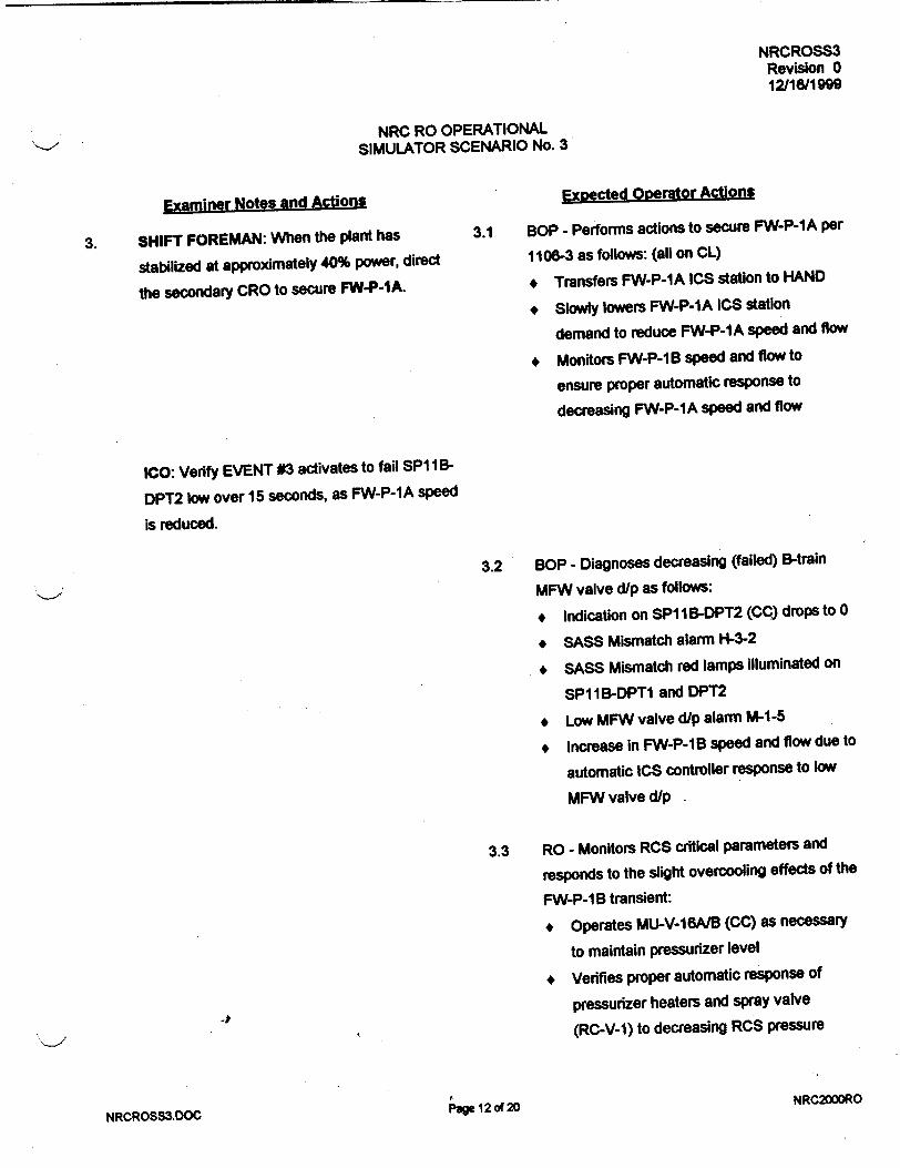
NRCROSS3 Revision 0 12/16/1999
NRC RO OPERATIONAL SIMULATOR SCENARIO No. 3
Examiner Notes and Actions
3. SHIFT FOREMAN: When the plant has
stabilized at approximately 40% power, direct
the secondary CRO to secure FW-P-IA.
Exoected Operator Actions
3.1 BOP - Performs actions to secure FW-P-1A per
1106-3 as follows: (all on CL)
* Transfers FW-P-1A ICS station to HAND
*Slowly lowers FW-P-1A ICS station
demand to reduce FW-P-1A speed and flow
* Monitors FW-P-1 B speed and flow to
ensure proper automatic response to
decreasing FW-P-1A speed and flow
1CO: Verify EVENT #3 activates to fail SP 11B
DPT2 low over 15 seconds, as FW-P-1A speed
is reduced.
3.2 BOP - Diagnoses decreasing (failed) B-train
MFW valve d/p as follows:
* Indication on SPI I B-DPT2 (CC) drops to 0
* SASS Mismatch alarm H-3-2
* SASS Mismatch red lamps illuminated on
SP11B-DPT1 and DPT2
* Low MFW valve d/p alarm M-1-5
* Increase in FW-P-1B speed and flow due to
automatic ICS controller response to low
MFW valve dip
3.3 RO - Monitors RCS critical parameters and
responds to the slight overcooling effects of the
FW-P-1 B transient:
* Operates MU-V-16A/B (CC) as necessary
to maintain pressurizer level
* Verifies proper automatic response of
pressurizer heaters and spray valve
(RC-V-1) to decreasing RCS pressure
NRC2000ROPae 12 or 20
NRCROSS3.DOC

NRCROSS3 Revision 0 12/1611999
NRC RO OPERATIONAL SIMULATOR SCENARIO No. 3
Examiner Notes and Actions Expected Operator Actions
3.4 BOP - Responds to failed MFW valve dip
instrument per H-3-2 as follows: (on CC)
* Transfers FW-P-1 B ICS station to HAND
* Adjusts FW-P-1B ICS station demand as
necessary to stabilize MFW flows
* Selects alternate B-train MFW valve d/p
transmitter, SPI 1 B-DPT1, by depressing its
SASS selector pushbutton
SHIFT FOREMAN: After secondary CRO has
diagnosed MFW valve dip instrument failure
and initiated corrective action to control FW-P
IB, implementH-3-2 alarm response and verify
or direct actions as necessary. 3.5 BOP - Performs or verifies actions per H-3-2 as
directed by the Shift Foreman.
3.6 BOP - Following selection of SPI I B-DPT1,
may transfer FW-P-1B back to auto at 35 psid
on lower MFW valve d/p (zero error on FW-P
1 B ICS station; or, may leave FW-P-1 B in
HAND for remainder of plant shutdown.
SHIFT FOREMAN: Continue plant shutdown
per 1102-10 by directing secondary CRO to
secure HD-P-IC. 3.7 BOP - Secures HP-P-1C using its extension
control on CL as directed by the Shift Foreman.
SHIFT FOREMAN: Continue plant shutdown by
directing primary CRO to lower reactor power to
approximately 25%. 3.8 RO - Lowers ULD setting as necessary to obtain
"reduction in plant power level as directed by the
Shift Foreman.
NRC2000RO rug._ 4'2Au 4"wb
NRCROSS3.DOC r1we la %A
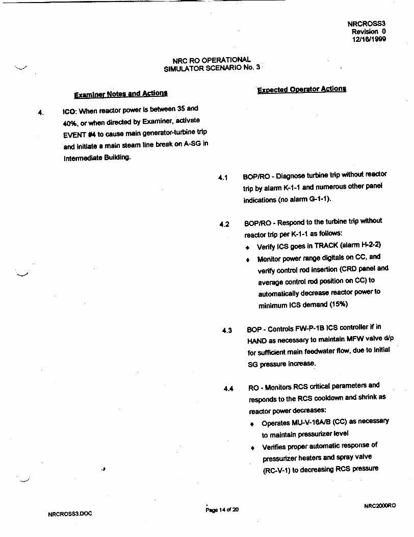
NRCROSS3 Revision 0 12/16/1999
NRC RO OPERATIONAL SIMULATOR SCENARIO No. 3
Examiner Notes and Actions Expected Operator Actions
4. ICO: When reactor power is between 35 and
40%, or when directed by Examiner, activate
EVENT #4 to cause main generator-turbine trip
and initiate a main steam line break on A-SG in
Intermediate Building.
4.1 BOP/RO - Diagnose turbine trip without reactor
trip by alarm K-I-I and numerous other panel
indications (no alarm G-1-1).
4.2 BOP/RO - Respond to the turbine trip without
reactor trip per K-1-1 as follows:
* Verify ICS goes in TRACK (alarm H-2-2)
* Monitor power range digitals on CC, and
verify control rod insertion (CRD panel and
average control rod position on CC) to
automatically decrease reactor power to
minimum ICS demand (15%)
4.3 BOP - Controls FW-P-1 B ICS controller if in
HAND as necessary to maintain MFW valve dip
for sufficient main feedwater flow, due to initial
SG pressure increase.
4.4 RO - Monitors RCS critical parameters and
responds to the RCS cooldown and shrink as
reactor power decreases:
* Operates MU-V-16A/B (CC) as necessary
to maintain pressurizer level
* Verifies proper automatic response of
pressurizer heaters and spray valve
(RC-V-1) to decreasing RCS pressure
NRCROSS3.DOC Page 14 of 20
NRC200DRO

NRCROSS3 Revision 0 12/16/1999
NRC RO OPERATIONAL SIMULATOR SCENARIO No. 3
Examiner Notes and Actions Exoected Operator Actions
4.5 BOP - Recognizes abnormal A-SG pressure
response during power reduction and after
reactor trip, by the following indications:
* A-SG pressure lower than B-SG pressure
(CC and PCL)
* Demand on MS-V-3D/E/F ICS controller is
lower than the demand for MS-V-3A/B/C
controller
NOTE: Reactor may automatically trip due to
numerous failures combined with main steam
line break.
SHIFT FOREMAN: After allowing time for
CROs to respond and diagnose abnormnal
pressure response in A-SG, or if recommended
by either CRO, direct RO to manually trip
reactor due to steam leak per 1203-24.
4.6 RO/BOP - Manually trips reactor by depressing
TRIP and DSS pushbuttons on CC.
EXAMINERS: Refer to copy of 1210-1 for
expected operator actions.
4.7 RO - Verifies reactor is tripped per 1210-1 and
commences 1210-1 immediate actions.
4.8 BOP - Verifies main turbine is tripped per
1210-1.
EXAMINER: See Step 5.2 for actions expected 4.9 BOP - Controls main feedwater per 1210-1 by
to mitigate bFW-V-5A failure to close. controlling FW-P-1 B in HAND as necessary,
and recognizes FW-V-5A has no control power.
NRCROSS3.DOC page 15 of 20 NRC2000RO

NRCROSS3 Revision 0 12/16/1999
NRC RO OPERATIONAL SIMULATOR SCENARIO No. 3
Examiner Notes and Actions Expected Operator Actions
4.10 RO - Performs 1210-1 action to start a second
makeup pump and maintain pressurizer level as
follows:
+ Starts MU-P-1C, DC-P-1B, and DR-P-1B
using their extension controls on CR
+ Operates MU-V-1 6A/B/C/D (CC/CR) as
necessary. to maintain pressurizer level
above 80 inches (CC - recorder and digital)
+ Opens MU-V-14A/B (CC) if makeup tank
level drops below 55 inches (CC digital)
* If pressurizer level drops below 20 inches,
manually initiates HPI by depressing 1600#
or 4# ES Manual Actuation pushbuttons on
CC for Train-A and on CR for Train-B
ICO: Verify EVENT #5 activates to trip FW-V
5A breaker as it starts to close on reactor trip.
SHIFT FOREMAN: After providing secondary
CRO sufficient time to initiate A-SG isolation on
his/her own, if necessary direct secondary CRO
to isolate A-SG per 1210-3.
NOTE: step 5.2 is a Critical Task.
NOTE: FW-V-92A will automatically close by
HSPS at less than 600 psig in A-SG, and this
will isolate FW-V-16A.
NRCROSS3.DOC
5.1 BOP/RO - Diagnose A-SG blow-down causing
excessive primary to secondary heat transfer by
following indications:
* Rapid drop in A-SG pressure (CC & PCL)
* Decreasing RCS temperatures below
normal post-trip values (CC & PCL)
* Decreasing RCS pressure below normal
post-trip value (CC & PCL)
5.2 BOP - Performs actions necessary to isolate
feedwater to A-SG per 1210-1 and 1210-3:
+ Transfers FW-V-17A ICS controller (CC)
to HAND and closes it by decreasing its
demand to zero, or
* Reduces FW-P-1 B speed using its motor
speed changer (CL), or trips FW-P-1 B
using its TRIP pushbutton (CL)
NRC2000RO
5.
Rage 16,f•A• 4

NRCROSS3 Revision 0 12/16/1999
NRC RO OPERATIONAL SIMULATOR SCENARIO No. 3
Examiner Notes and Actions
NOTE: Emergency feedwater will automatically
actuate at less than 10 inches in A-SG as it
steams down with MFW isolated, and EF-V
3OA/D will automatically open to control A-SG
level at 25 inches on startup range.
NOTE: Closing EF-V-30A and 30D is part of
the Critical Task to isolate A-SG.
Expected Operator Actions
5.3 BOP - Performs actions to completely
isolate A-SG per 1210-3 as follows:
* Closes or verifies closed MS-V-3D/E/F and
MS-V-4A with their ICS controller on CC in
HAND at zero (0) demand
* Closes MS-V-1A and 1B by depressing their
CLOSE pushbuttons on CC
* Closes MS-V-2A by depressing Its CLOSE
pushbutton on CC
* Transfers EF-V-3OA and EF-Vo-30D
controllers on CL to MANUAL, and sets
their demands to zero (0)
* May direct AO to locally close FW-V-5A
ICO-ROLE PLAY: If directed to close FW-V-5A
locally, display FWVFWV5A on MONITOR and
set its value to zero (0) in 0.1 increments over a
one minute ramp.
When FW-V-5A is dosed, report task complete
to the control room.
NOTE: When A-SG blows dry and no longer
removes heat from RCS, the RCS will begin to
reheat and repressurize until control of B-SG
and HPI isassumed by the operators to
stabilize RCS temperature & pressure.
NRCROSS3.DOC Page 17 of 20
NRC2000RO

NRCROSS3 Revision 0 12/16/1999
NRC RO OPERATIONAL SIMULATOR SCENARIO No. 3
Examiner Notes and ActionsExpected Operator Actions
5.4 BOP - When A-SG blows dry, performs actions
necessary to establish B-SG as an adequate
heat sink to minimize RCS reheat as follows:
* Adjusts (lowers) turbine header pressure
setpoint (CC) to open MS-V-3A/B/C in auto,
or transfers MS-V-3A/B/C ICS controller on
CC to HAND and adjusts (raises) their
demand, to lower B-SG pressure such that
it becomes a heat sink and stabilizes RCS
T-cold
+ Provides main or emergency feedwater to
B-SG as necessary to maintain sufficient
level for heat transfer ( 25" startup level)
6. SHIFT FOREMAN: Direct operators to clear
ESAS signals as necessary to gain control of
high pressure injection components, and direct
primary CRO to control HPI as necessary to
stabilize RCS pressure with at least 40°F
subcooled margin.
NOTE: When ESAS trains A and B are clear, all 6.1
3 sets of block loading sequence blue lamps will
be extinguished for each train on PCR.
page 18 of 20NRCROSS3.DOC
RO/BOP - When directed by Shift Foreman, clear ESAS signals as necessary for HPI
throttling as follows:
* Bypass or reset 16000 auto channels, 3 on
train-A and 3 on train-B, by depressing their
bypass or reset pushbuttons on CC and CR
# Defeat and re-enable 1600# manual
channels 3 on train-A and 3 on train-B, by
depressing their defeat/enable pushbuttons
on CC and CR
NRC2000RO

NRCROSS3 Revision 0 12/16/1999
NRC RO OPERATIONAL SIMULATOR SCENARIO No. 3
ExamLiner Notes and Actions
NOTE: 6.2 is a Critical Task.
NOTE: MU-V-16C will NOT close upon demand
by its CLOSE pushbutton on CR.
N'-,
SHIFT FOREMAN: Following all immediate
actions to isolate A-SG and actions necessary
to stabilize the plant, announce to team and
commence 1210-1 verification. When required,
announce to team and transition to 1210-3.
EXAMINERS: Refer to copy of 1210-1.
Expected Operator Actions
6.2 RO - Operates makeup (HPI) system valves
and pumps as necessary to control HPI:
* Closes or throttles as necessary MU-V
16A, 168, 16C, and 16D if open
* Reopens MU-V-36 and 37 on CC prior to
throttling below 100 gpm on MU-P-IA or
MU-P-1C
* If open, recognizes MU-V-16C failure to
close as indicated by its red OPEN lamp
on CR
* Secures MU-P-IC using its extension
control on CR to terminate B-4rain HPI
flow if MU-V-16C is open
* Operates MU-V-16A/B as necessary to
maintain stable pressurizer level
6.3 RO/BOP - Verify 1210-1 immediate actions as
read by Shift Foreman, and continue to monitor
plant conditions.
EXAMINERS: Refer to copy of 1210-3.
SHIFT FOREMAN: Direct crew in follow-up
actions of 1210-3, then when appropriate,
announce4o team and transition back to 1210-1.
6.4 BOP - Verifies 1210-3 immediate actions as read by Shift Foreman, and continue to monitor
plant conditions.
6.5 RO/BOP - Perform applicable follow-up actions
of 1210-3 as directed by Shift Foreman.
NRC2000ROPg 19 of 20NRCROSS3.DOC
K>

NRCROSS3 Revision 0 12/16/1999
NRC RO OPERATIONAL SIMULATOR SCENARIO No. 3
7.0 TERMINATION POINT
When all of the following conditions exist:
1. Examinees had opportunity to perform all critical tasks as designed.
2. Crew has transitioned back to 1210-1 from 1210-3.
3. Examiners agree to terminate.
NRC2000RONRCROSS3.DOC raw " %A aw
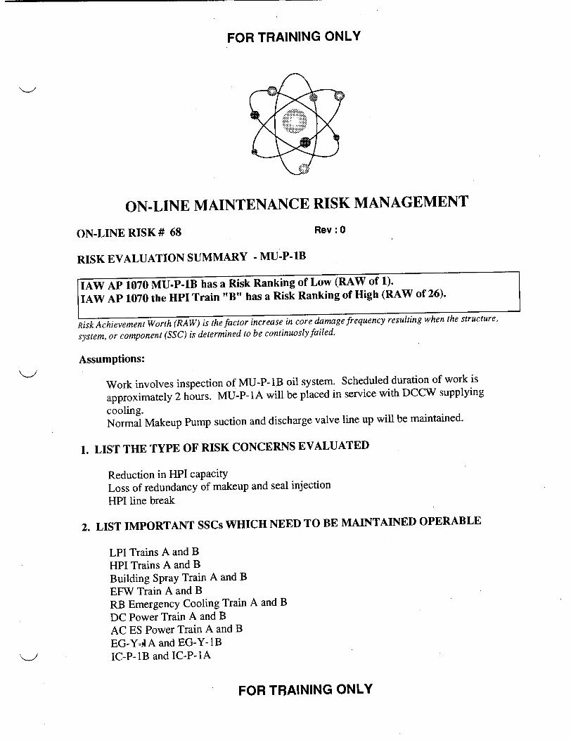
FOR TRAINING ONLY
0
ON-LINE MAINTENANCE RISK MANAGEMENT
ON-LINE RISK # 68 Rev: 0
RISK EVALUATION SUMMARY - MU-P-lB
IAW AP 1070 MU-P-lB has a Risk Ranking of Low (RAW of 1).
IAW AP 1070 the HPI Train "B" has a Risk Ranking of High (RAW of 26).
Risk Achievement Worth (RAW) is the factor increase in core damage frequency resulting when the structure,
system, or component (SSC) is determined to be continuosly failed.
Assumptions:
Work involves inspection of MU-P-lB oil system. Scheduled duration of work is
approximately 2 hours. MU-P-lA will be placed in service with DCCW supplying
cooling. Normal Makeup Pump suction and discharge valve line up will be maintained.
1. LIST THE TYPE OF RISK CONCERNS EVALUATED
Reduction in HPI capacity Loss of redundancy of makeup and seal injection HPI line break
2. LIST IMPORTANT SSCs WHICH NEED TO BE MAINTAINED OPERABLE
LPI Trains A and B HPI Trains A and B Building Spray Train A and B EFW Train A and B RB Emergency Cooling Train A and B DC Power Train A and B AC ES Power Train A and B EG-Y- A and EG-Y-IB IC-P-lB and IC-P-1A
FOR TRAINING ONLY

FOR TRAINING ONLY
ICCW RCP Seal Cooling Function
3. LIST IMPORTANT MANUAL ACTIONS WHICH SHALL BE BRIEFED WITH THE
APPROPRIATE PERSONNEL
MU-P-i A will be started and supply seal injection. There is no backup seal injection
pump.
MU cross connects MU-V-76A and 76B will remain locked closed. It will be necessary to
open these valves if MU-P-IC is started for seal injection.
If MU-P-IC must be started and the MU-P-lA/1C discharge cross connect valves open to
provide seal injection, a 72 hour time clock will be in effect. IC/Makeup pump
combination is to be evaluated with potential transfer of ICCW to IC-P-1A.
4. IDENTIFY CONTINGENCY PLANS OR COMPENSATORY ACTIONS USED TO
REDUCE RISK
COMPENSATORY ACTIONS (PRIOR TO/IN PREPARATION FOR OUTAGE):
IC-P-1B will be placed in service to address vulnerability to loss of ID 4160 Bus.
CONTINGENCY ACTIONS:
If MU-P-lB requires repair and will be out of service beyond the scheduled duration, and
it is desired to provide backup seal injection capability, obtain Plant Operations Direlctor or
Director 0 & M approval, open the discharge cross connects, and commence a 72 hour TS
time clock.
5. EVALUATION APPROVALS
o 1. Risk found acceptable
* 2. Risk found acceptable with contingencies identified
O 3. Risk unacceptable,
Signature of FOR TRAINING on 02/14/2000
Evaluator:
Signature of Director: FOR TRAINING on 02/14/2000
CC: Job Package
FOR TRAINING ONLY

FOR TRAINING ONLY
ON-LINE MAINTENANCE RISK MANAGEMENT
ON-LINE RISK # 22 Rev : 0
RISK EVALUATION SUMMARY - IA-P-1A
Risk Achievement Worth (RAW) is the factor increase in core damage frequency resulting when the structure,
system, or component (SSC) is determined to be continuosly failed.
Assumptions:
IA-P-1 A will be removed from service for annual inspection/maintenance
1. LIST THE TYPE OF RISK CONCERNS EVALUATED
None provided that IA-P-4 remains in service and functions properly.
Infrequently run equipment may not support demands.
2. LIST IMPORTANT SSCs WHICH NEED TO BE MAINTAINED OPERABLE
IA-P-4 IA-P-lB SA-P-1A SA-P-lB IA-Q-1
3. LIST IMPORTANT MANUAL ACTIONS WHICH SHALL BE BRIEFED WITH THE
APPROPRIATE PERSONNEL
None
FOR TRAINING ONLY

FOR TRAINING ONLY
4. IDENTIFY CONTINGENCY PLANS OR COMPENSATORY ACTIONS USED TO
REDUCE RISK
COMPENSATORY ACTIONS (PRIOR TO/IN PREPARATION FOR OUTAGE):
Verify IA and SA systems are aligned for normal operation, prior to removing IA-P-1A
from service.
CONTINGENCY ACTIONS:
5. EVALUATION APPROVALS
* 1. Risk found acceptable
o 2. Risk found acceptable with contingencies identified
3o . Risk unacceptable,
Signature of FOR TRAINING on 02/14/2000
Evaluator:
Signature of Director: FOR TRAINING on 02/14/2000
CC: Job Package Shift Supervisor Clipboard Operations Department General Files STA
FOR TRAINING ONLY
NRCROSS4 Revision 0 12/17/1999
NRC RO OPERATIONAL SIMULATOR SCENARIO No. 4
REACTOR STARTUP CONTINUES FROM IE-8 AMPS, LOSS OF IA AUXILIARY TRANSFORMER, LOSS OF MAIN FEEDWATER,
AND OTSG TUBE RUPTURE CAUSING LOSS OF SUBCOOLED MARGIN
DEVELOPED BY/DATE:
REVIEWED BY/DATE:
A-
APPROVED BY/DATE:
(OPERATIONS TRAINING MANAGER)
4,'._
NRCROSS4.DOC NRC200D0O
/=;?--n-ý ?
PageI of 21

NRCROSS4 Revision 0 1211711999
NRC RO OPERATIONAL SIMULATOR SCENARIO No. 4
SCENARIO CHANGE HISTORY PAGE
REVISION DATE REFERENCE TITLE DESCRIPTION (Include Al # if appropriate)
_____ 1. 4
I I t
4
4 1
I_ _ I 4i
I +
- - I It
_____ 4 4 1-
4 4
I. Im
4 1 *1
-p
NRCROSS4.DOC Papg 2 of 21 NRC2000RO

NRCROSS4 Revision 0 12/17/1999
NRC RO OPERATIONAL SIMULATOR SCENARIO No. 4
1.0 GENERAL DESCRIPTION OF SCENARIO
Reactor at 1 E-8 amps during a xenon-free plant startup at MOC.
Reactor power Is increased to 5%.
NI-5 (selected) fails to come on scale.
FW-P-1A is transferred from auxiliary to main steam prior to 5% power.
At 5% power, selected B-SG startup level transmitter fails low, causing FW-V-16B to open.
IA auxiliary transformer trips causing loss trip of MU-P-1B and loss of RC makeup/seal injection.
FW-P-1A motor speed changer malfunction causes loss of main feedwater.
EF-V-30B/C do not automatically open to supply B-SG with emergency feedwater.
A tube rupture occurs on B-SG resulting in loss of required RCS subcooled margin.
RC-P-1B can not be secured by its extension control on CC.
RCS subcooled margin will be regained
RCS natural circulation must be established.
Plant cooldown is commenced per 1210-5.
Estimated scenario time - 70 minutes. 3 Critical Tasks
2.0 REFERENCES
A. 10 CFR 55.45 Operating Tests, (a) Content (3), (4), (5), (6), (7), (8), (9), (12), (13)
B. PROCEDURES
1102-2 Plant Startup (sign-off copy required for crew)
1106-1 Turbine Generator (sign-off copy required for crew)
1106-2 Condensate System (sign-off copy required for crew)
1106-3 Feedwater System (sign-off copy required for crew)
1203-15 Loss of RC Makeup/Seal Injection
1202-38 Nuclear Services River.Water Failure
1203-19 River Water System Failure (DR/SR)
1203-20 Nuclear Services Closed Cooling System Failure
1210-5 OTSG Tube Leakage
1202-12 Excessive Radiation Levels
1210-1 Reactor Trip (copies required for examiners)
1210-2. Loss of 250F Subcooled Margin (copies required for examiners)
1240-10 Abnormal Transients Rules, Guides, and Graphs
Alarm Responses
NRCROSS4.DOC PVV 3 of 21 NRC2000RO

NRCROSS4 Revision 0 12/1711999
NRC RO OPERATIONAL SIMULATOR SCENARIO No. 4
3.0 TAKS
0010250101
341 C020101
3418000101
0000340501
0598040101
0158020401
0590050101
0008320501
0000220501
0008210501
0000540501
0610010401*
000C220501
0000610501
0000070501
0000080501
000C190601*
0020100101
0130040101
004C040101"
Operate control rods manually at power
Perform a plant startup
Perform plant power changes
Respond to a loss of power range nuclear instrument
Shift steam supply to FW-P-IAJB between auxiliary and main steam
Respond to a SASS mismatch/actuation
Operate the feedwater regulating valves in manual and automatic
Respond to loss of a 4160V bus
Respond to a loss of reactor coolant makeup
Respond to loss of RCP seal injection
Respond to a loss of main feedwater
Perfonr required actions if EFW system does not operate properly
Respond to OTSG tube leak
Respond to excessive radiation levels
Respond to a reactor trip as the prmary CRO
Respond to a reactor trip as the secondary CRO
Respond to loss of 250F subcooled margin
Establish natural circulation
Bypass or defeat an ES channel
Throttle high pressure injection flow
* Critical Task
-P
NRC2000RONRCROSS4.DOC
Page 4 of 21

NRCROSS4 Revision 0 12/17/1999
NRC RO OPERATIONAL SIMULATOR SCENARIO No. 4
4.0 SIMULATOR INITIALIZATION
A. IC08 Reactor critical at I E-8 amps, MOC, xenon-free.
Ensure MSK2609A = 214.7, then place simulation in RUN and ensure the following:
1. Main Feedwater Pump is running on auxiliary steam (AS-V-5A open)
2. Gland steam is supplied by auxiliary steam (AS-V-8 open)
3. Transfer all operating ventilation fans on H&V panel to A-train.
B. EVENT TRIGGERS
None
C. MALFUNCTIONS
NI19A NI-5 linear amp fails low; insert immediately.
RC23A B-SG startup level transmitter (LT-1 054) failure; insert at 0% severity over 300
second ramp on EVENT #3.
ED02D Auxiliary transformer 1A fault; insert on EVENT #4.
TH15B B-SG tube leak; insert at 20% severity over 100 second ramp on EVENT #6.
D. REMOTE FUNCTIONS
ICRO3 EF-V-30B/C startup level setpoint; insert value of zero (0) immediately.
E. OVERRIDES
01A5S07-ZDIMSCA(3) SLOLO FW-P-1A MSC SWITCH; insert ON on EVENT #5.
02A3S16-ZDICSRCPIB(1) PTL RC-P-1B CS; insert OFF immediately.
02A3S16-ZDICSRCP1 B(2) STP RC-P-1 B CS; insert OFF immediately.
F. MONITOR
Set MSK2609A = 214.7 immediately (auxiliary steam pressure).
NRC200DRONRCROSS4.DOC
r Page 5 of 21

NRCROSS4 Revision 0 12/1711999
NRC RO OPERATIONAL SIMULATOR SCENARIO No. 4
5.0 SCENARIO PREVIEW
A. EXAMINER PREVIEW
Reactor critical at 1E-8 amps during a xenon-free plant startup at MOC. Startup to continue.
1. Primary CRO will operate control rods to increase reactor power to 5% per 1102-2.
NI-5 will not come on scale as power Is increased into power range, requiring NI-6 to be
selected for ICS control per H-3-2 prior to transfer of Diamond to auto per 1102-2.
2. Prior to reaching 5% reactor power per 1102-2, the secondary CRO will transfer FW-P-1 A
turbine steam supply from auxiliary to main steam per 1106-3.
3. Selected B-SG startup level transmitter (LT-1054) fails low (0") over 300 seconds, causing
FW-V-16B to open in auto and eventually a SASS mismatch alarm. The secondary CRO
must respond to the SASS mismatch per H-3-2, by assuming hand control of FW-V-16B,
selecting a good level transmitter, then transferring FW-V-16B back to auto.
4. A failed fault pressure switch trips IA auxiliary transformer and 230KV bus #8, causing
fast transfer of BOP buses, under-voltage on I E 41 0V ES bus, and trip of numerous
components including MU-P-1 B. The primary CRO must respond to the loss of RC
makeup and RCP seal Injection per 1203-15. Both CROs must respond to other
component trips per the appropriate procedure.
5. An electrical short in the motor speed changer for FW-P-1A will cause it to run off line,
resulting in a loss of main feedwater. When EFW actuates, EF-V-30BIC will not
automatically open and control level in B-SG. The secondary CRO must manually initiate
and control EFW flow to B-SG to provide adequate heat transfer. (CT)
6. A multiple tube failure occurs in B-SG, resulting in a loss of 25OF subcooled margin. The
primary CRO must secure reactor coolant pumps per 1210-1/1210-2, but RC-P-1B
extension control will not function. The primary CRO must de-energize lB 6900V bus to
secure RC-P-1B. (CT)
7. Eventually RCS subcooled margin will be regained, requiring the primary CRO to throttle
HPI per 1210-10. (CT)
The secondary CRO will establish RCS natural circulation core cooling, and a plant
cooldown per 1210-5 will be commenced.
NRC2000RONRCROSS4.DOC Page 6 of 21

NRCROSS4 Revision 0
12/17/1999
NRC RO OPERATIONAL SIMULATOR SCENARIO No. 4
B. SHIFT BRIEFING
1. Reactor is critical at I E-8 amps during a xenon-free startup at 300 EFPD.
2. Critical data has been obtained and 1103-8, Approach to Criticality, is complete.
3. The plant tripped 80 hours ago due to a main generator relay failure.
4. FW-P-1A and gland steam are currently supplied by the auxiliary steam system.
5. B-RCBT is on sample recirculation at this time.
5. Continue plant startup by increasing power reactor power per 1102-2.
4)
NRCROSS4.DOC Page7 of 21 NRC2000RO

NRCROSS4 Revision 0 12/17119M9
NRC RO OPERATIONAL SIMULATOR SCENARIO No. 4
6.0 SEQUENCE OF EVENTS
Examiner Notes and Actions
* ICO: Initialize the simulator per Section 4.0.
* IPOI: Assign team positions and conduct the
SHIFT BRIEFING per Section 5.B.
* Provide Shift Foreman with sign-off copies of
1102-2, 1106-1, 1106-2, and 1106-3.
* Allow crew 3-5 minutes to take turnover and
assume the watch.
1 . SHIFT FOREMAN: Direct prmary CRO to
increase reactor power to 5% per 1102-2.
Remind prmary CRO that power ramp limit is
30%/hour per 1102-2, Enclosure 4.
ExDected Operator Actions
* Assume assigned team positions.
* Take turnover and review plant status.
* Assume the watch and inform examiner.
1.1 RO - Operates CRD panel (CC) to withdraw
control rods and increase reactor power while:
* Monitoring power level and startup rate on
NI-3 and NI-4 (Intermediate range) (CC)
* Monitoring RCS critical parameters
* Complying with MMRs (<30%/hour)
NOTE: Point of adding heat occurs between
IE-7 and IE-6 amps on NI-3 and NI-4.
NRCROSS4.DOC
1.2 RO - Recognizes and announces when point of
adding heat is reached as indicated by:
* Decrease in startup rate on NI-3/4 (CC)
* Increase in RCS temperatures (CC & PCL)
* Increase in pressurizer and makeup tank
levels (CC)
* Decrease in RCS makeup flowrate (CC)
Page 8 of 21 NRC2000RO

NRCROSS4 Revision 0 12/17/1999
NRC RO OPERATIONAL SIMULATOR SCENARIO No. 4
Examiner Notes and Actions Exoected Operator Actions
1.3 BOP - Monitors secondary critical parameters
as reactor power is increased, and:
* Verifies automatic response of MS-V-3s to
control SG pressures at 895 psig (CC)
* Verifies automatic response of FW-V-16s
to control SG levels at 25- (CC)
* Operates FW-P-1A ICS station demand to
maintain > 35 psid MFW valve d/p (CL)
SHIFT FOREMAN: Direct primary CRO to
maintain pressurizer level within Figure I of
1102-2, bleeding to C-RCBT as necessary.
Provide 1102-2, Figure 1 to primary CRO.
1.4 RO - Operates the following makeup and
LWDS system components as necessary to
maintain pressurizer level increase within
Figure I as T-ave increases, and to maintain
makeup tank level within Figure 1 of 1104-2:
* MU-V-17 ICS station setpoint (CC)
* Bleed Tank Select switch on LWDS
* MU-V-8 (THRU/BLEED) pushbuttons (CC)
* MU-V-5 demand setpoint (CC)
NOTE: NI-5 will NOT come on scale when
reactor power Increases into power range.
1.5 RO - Recognizes and reports failure of NI-5 to
come on scale as indicated by comparison to
NI-6, 7, and 8.
SHIFT FOREMAN: When primary CRO
identifies and reports NI-5 problem, inform CRO
that you will evaluate Tech. Specs.
Then, after reading Tech. Spec. requirement for
NI operability, direct primary CRO to select NI-6
for control and continue power escalation.
OSS4.DOC Page 9 of 21 NRC2000R 0NRCR(

NRCROSS4 Revision 0 12/17/1999
NRC RO OPERATIONAL SIMULATOR SCENARIO No. 4
Examiner Notes and Actions Expected Operator Actions
NOTE: As reactor power is increased to 5%, a
SASS mismatch will eventually occur (H-3-2)
on the NI channel.
1.6 RO - Selects NI-6 for ICS control by depressing
its SASS select pushbutton on CC, prior to
transferring Diamond panel to auto per H-3-2.
SHIFT FOREMAN: Direct secondary CRO to
place A-RPS channel in Manual Bypass due to
NI-5 failure, and direct third CRO to make a log
entry for the RPS channel to manual bypass.
1.7 BOP - Places A-RPS in manual bypass:
+ Obtains RPS manual bypass key from
controlled key locker
* Opens left door on A-RPS cabinet
* Inserts manual bypass key into reactor trip
module and turns key 900 clockwise
* Acknowledges alarm G-3-1
1.8 RO - Operates control rods to continue reactor
power increase towards 5% on NI-6, 7, and 8.
2. SHIFT FOREMAN: As reactor power is
increased but prior to 5%, direct secondary
CRO to transfer FW-P-1A steam supply from
auxiliary to main steam per 1106-3.
2.1 BOP - Transfers FW-P-1 A steam supply per
1106-3 as follows:
* Directs auxiliary operator to slowly close
AS-V-5A in plant
* Monitors MFW valve d/p (CL) and FW-P
1A control valve positions (PLF)
* Controls FW-P-1A ICS station demand as
+4 necessary to maintain MFW valve d/p
greater than 70 psid per 1106-3
NRC2000RONRCROSS4.DOC Plage 10 of 21

NRCROSS4 Revision 0 12/17/1999
NRC RO OPERATIONAL SIMULATOR SCENARIO No. 4
Examiner Notes and Actions Exoected Operator Actions
3. ICO: When reactor power is approximately 5%,
or when directed by Examiner, activate EVENT
#3 to cause selected B-SG startup level
instrument (LT-1054) to fail low (0") over 300
seconds. 3.1 BOP - Recognizes increase in B-SG feed flow
(CC) and real startup level on digital (CC).
3.2 BOP - Recognizes increase in demand on
FW-V-16B ICS station and valve position (CC).
NOTE: Eventually a SASS mismatch (H-3-2)
will occur on the B-SG startup level channel.
3.3 BOP - Transfers FW-V-16B ICS station (CC) to
HAND, and controls demand as necessary to
control B-SG feed flow and return startup level
to 25" on CC digital.
SHIFT FOREMAN: Implement H-3-2 after
secondary CRO performs initial manual actions,
and verify/direct the actions therein. 3.4 RO - Responds to the MFW flow transient
effects on RCS temperature, pressure,
inventory, and reactor power.
* Verifies automatic response of MU-V-17
* Verifies automatic response or RC-V-1
(pressurizer spray on CC)
* Verifies automatic response of PZR heaters
on CR
3.5 BOP - Selects alternate B-SG startup level
instrument per H-3-2, by depressing its SASS
pushbutton on CC.
3.6 BOP - Obtains zero (0) error and transfers
FW-V-16B ICS station back to auto.
NRCROSS4.DOC Pog 11 of 21 NRC2000RO

NRCROSS4 Revision 0 12/17/1M99
NRC RO OPERATIONAL SIMULATOR SCENARIO No. 4
Examiner Notes and Actions Expected Operator Actions
SHIFT FOREMAN: Direct secondary CRO in
follow-up actions for SASS Mismatch per H-3-2.
3.7 BOP - Performs follow-up actions of H-3-2 as
directed by the Shift Foreman.
4. ICO: After FW-V-16B is back in automatic, or
when directed by Examiner, activate EVENT #4
to cause 230KV bus-8 trip, fast transfer of BOP
buses, under-voltage on IE 4160V bus, and trip
of numerous B-train components including:
MU-P-1B, NS-P-1C, NR-P-1C, & SR-P-1B.
4.1 BOP/RO - Diagnose loss of 230KV bus-8 and
1E 4160V bus under-voltage by the following:
* Alarms B-1-1, B-2-1, NN-1-1, & others
* One set of control room overhead lights
... goes off for 10 seconds
* Numerous component trips
4.2 BOP/RO - Recognize by panel indications and
overhead lights re-energizing that EG-Y-1B has
re-energized the 1E 4160V bus.
4.3 RO - Diagnoses MU-P-1 B trip by alarms and
panel indications, and responds to the loss of
RC makeup and seal injection per 1203-15:
* Transfer MU-V-32 (seal injection flow
control valve) control station on CC to
HAND, and reduce its demand to zero to
close MU-V-32
* Start MU-P-1A, DC-P-1A, and DR-P-1A
using their extension controls on CC
* Reopen MU-V-32 by raising its controller
"demand to re-establish RCP seal injection
flow on MU42-FI (CC)
NRCROSS4.DOC 4P 12 o0 21 NRC2000RC:)

NRCROSS4 Revision 0 12/17/1999
NRC RO OPERATIONAL SIMULATOR SCENARIO No. 4
Examiner Notes and Actions Exoected Operator Actions
4.4 RO - Obtains 38 gpm seal injection flow on
MU42-FI, checks MU-V-32 control station error
at zero, and transfers MU-V-32 control station
back to AUTO.
4.5 BOP - Recognizes trip of SR-P-1 B by its
breaker status lamps above its extension
control on CL (green and amber lamps), and
verifies or starts SR-P-1B or IC per 1203-19.
4.6 RO - Recognizes trip of NR-P-1C and NS-P-1C
by their breaker status lamps above their
extension controls on CR (green and amber
lamps), and verifies start of NR-P-1B (CR) per
1202-38, and verifies start of NS-P-1B (CC) per
1203-21.
SHIFT FOREMAN: After sufficient time for the
CROs to have performed immediate actions of
1203-15, 1202-38, 1203-19, and 1203-20,
implement each procedure and verify or direct
the actions.
4.7 BOP/RO - Perform verification of applicable
emergency and abnormal procedures as read
by Shift Foreman.
4.8 BOP/RO - Perform follow-up actions of
applicable emergency and abnormal
procedures as directed by the Shift Foreman.
SHIFT FOREMAN: Implement appropriate
alarm respbnse procedures and direct CRO 4.9 BOP/RO - Perform actions of alarm responses
actions. as directed by Shift Foreman.
SS4.DOC 089e 13 of 21 NRC2000RCNRCRO
:)

NRCROSS4 Revision 0 12/17/1999
NRC RO OPERATIONAL SIMULATOR SCENARIO No. 4
Examiner Notes and Actions Expected Operator Actions
5. ICO: After all emergency and abnormal
procedure actions have been verified for loss of
230KV bus-8, or when directed by Examiner,
activate EVENT #5 to cause FW-P-1A motor
speed changer short and loss of main
feedwater.
5.1 BOP - Diagnose FW-P-1A problem and loss of
main feedwater by the following:
* Low MFW valve d/p alarm M-1-5
* Decreasing speed and discharge pressure
on FW-P-1A (CL)
* Low SG levels and alarms J-2-3 & J-2-4
+ No MFW flow to SG's indicated on CC
5.2 RO - Responds to the reduced RCS heat
removal as follows:
• Monitors increase in RCS temperature and
Spressure (CC and PCL)
* Verifies automatic response of pressurizer
spray valve, RC-V-1, to open (CC)
* Transfers RC-V-1 to MAN using its mode
selector switch on CC, and fully opens RC
V-1 using its OPEN pushbutton on CC per
G-3-8
* Transfers RC-V-1 back to AUTO using its
mode selector switch on CC
NOTE: Unless FW-P-1A is manually tripped,
EFW will only actuate on low-low OTSG levels
(10"). But, EF-V-30B and 30C will not open
automatically to provide EFW flow to B-SG.
NRC2000RONRCROSS4.DOC Pag 14 of 21
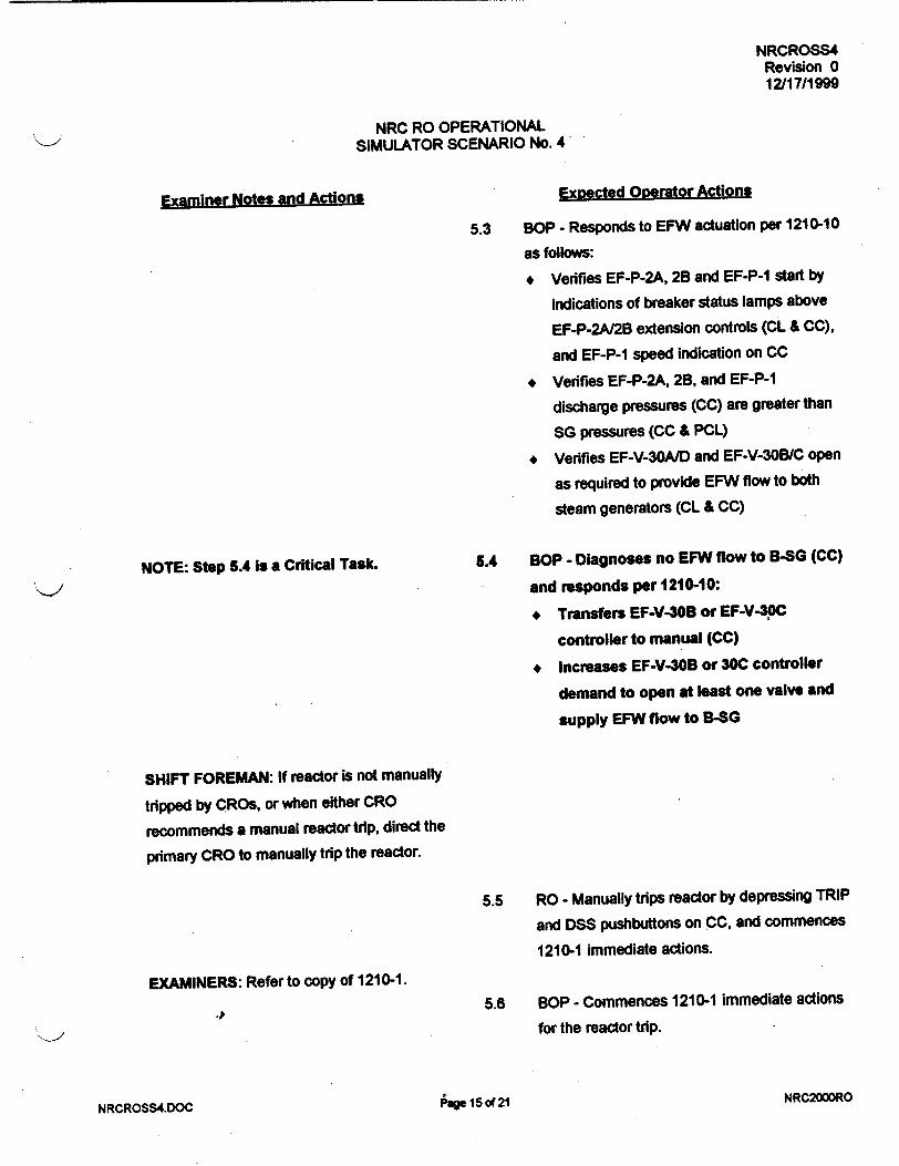
NRCROSS4 Revision 0 12/17/1999
NRC RO OPERATIONAL SIMULATOR SCENARIO No. 4
Exsected Operator Actions
NOTE: Step 5.4 is a Critical Task.
5.3 SOP - Responds to EFW actuation per 1210-10
as follows:
* Verifies EF-P-2A, 2B and EF-P-1 start by
indications of breaker status lamps above
EF-P-2A/2B extension controls (CL & CC),
and EF-P-1 speed indication on CC
* Verifies EF-P-2A, 2B, and EF-P-1
discharge pressures (CC) are greater than
SG pressures (CC & PCL)
* Vedfies EF-V-30A/D and EF-V-30B/C open
as required to provide EFW flow to both
steam generators (CL & CC)
5.4 BOP - Diagnoses no EFW flow to B-SG (CC)
and responds per 1210-10:
+ Transfers EF-V-30B or EF-V-3)C
controller to manual (CC)
+ Increases EF-V-30B or 30C controller
demand to open at least one valve and
supply EFW flow to B-SG
SHIFT FOREMAN: If reactor is not manually
tripped by CROs, or when either CRO
recommends a manual reactor trip, direct the
primary CRO to manually trip the reactor.
EXAMINERS: Refer to copy of 1210-1.
j
5.5 RO - Manually trips reactor by depressing TRIP
and DSS pushbuttons on CC, and commences
1210-1 immediate actions.
5.6 SOP - Commences 1210-1 immediate actions
for the reactor trip.
Ige 15 of 21 NRC2000RONRCROSS4.DOC
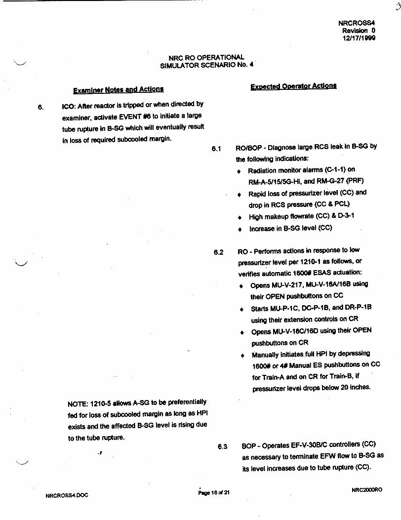
NRCROSS4 Revision 0 12/17/1M
NRC RO OPERATIONAL SIMULATOR SCENARIO No. 4
Examiner Notes and Actions Expected Operator Actions
6. ICO: After reactor is tripped or when directed by
examiner, activate EVENT #6 to initiate a large
tube rupture In B-SG which will eventually result
in loss of required subcooled margin. 6.1 RO/BOP - Diagnose large RCS leak In B-SG by
the following Indications:
* Radiation monitor alarms (C-1-1) on
RM-A-5115/5G-Hi, and RM-G-27 (PRF)
* Rapid loss of pressurizer level (CC) and
drop in RCS pressure (CC & PCL)
* High makeup flowrate (CC) & D-3-1
* Increase in B-SG level (CC)
6.2 RO - Performs actions in response to low
pressurizer level per 1210-1 as follows, or
verifies automatic 1800W ESAS actuation:
* Opens MU-V-217, MU-V-16A/16B using
their OPEN pushbuttons on CC
* Starts MU-P-IC, DC-P-lB, and DR-P-1B
using their extension controls on CR
* Opens MU-V-16C/16D using their OPEN
pushbuttons on CR
* Manually initiates full HPI by depressing
1600# or 4# Manual ES pushbuttons on CC
for Train-A and on CR for Train-B, if
pressurizer level drops below 20 inches.
NOTE: 1210-5 allows A-SG to be preferentially
fed for loss of subcooled margin as long as HPI
exists and the affected B-SG level is rising due
to the tube rupture. 6.3 BOP - Operates EF-V-30B/C controllers (CC)
as necessary to terminate EFW flow to B-SG as
its level increases due to tube rupture (CC).
NRCROSS4.DOC Page 16 of 21 NRC2000RO

NRCROSS4 Revision 0 12/17/1999
NRC RO OPERATIONAL SIMULATOR SCENARIO No. 4
Examiner Notes and Actions
NOTE: Step 6.4 is a Critical Task.
Expected Operator Actions
6.4 RO - Diagnoses loss of 25°F subcooled
margin by alarm G-1-8 and PCL meters, and
responds per 1210-2:
* Secures RC-P-1A, 1B, 1C, and 1D using
their extension controls on CC, within 2
minutes per 1210-10 rule.
* Recognizes failure of RC-P-1 B to trip by
its extension control, and de-energizes
1B 6900V bus by opening breaker 1SB
02 using its extension control on PR
+ Verifies or manually initiates full HPI as
indicated on MU-FI-1126 & 1127 (CC) and
MU-Fl 1128 & 1129 (CR)
6.5 BOP - Responds to loss of subcooled margin
per 1210-2:
* Verifies EF-V-30A or 30D responds in auto
to provide EFW flow to A-SG to raise its
level towards 75-85%, or
* Manually controls EF-V-30A or 30D to
provide EFW flow to A-SG and raise its
level to 75-85%
SHIFT FOREMAN: After 1210-1 and 1210-2
immediate actions have been performed by
CROs, verify 1210-1 and 1210-2 immediate
actions, then commence and direct 1210-2
follow-up actions.
6.6 RO/BOP - Verify 1210-1 and 1210-2 immediate
actions as led by Shift Foreman.
EXAMINES: Refer to copy of 1210-2 for
follow-up actions.
NRC2000ROrdage 17 of 21NRCROSS4.DOC

NRCROSS4 Revision 0 12/17/1999
NRC RO OPERATIONAL SIMULATOR SCENARIO No. 4
Examiner Notes and Actions Expected Operator Actions
6.7 RO - Operates valve controls (CC) as directed
by Shift Foreman to isolate possible sources of
leakage per 1210-2 follow-up step 2.2.
SHIFT FOREMAN: If secondary CRO is still
feeding B-SG with EFW, direct the CRO to stop
feeding B-SG as long as its level is rising due to
the tube rupture. 6.8 BOP - Preferentially feeds A-SG with EFW as
B-SG level rises due to tube rupture, and as
long as HPI flow exists, per 1210-2; and stops
feeding B-SG with EFW by closing EF-V-308/C.
SHIFT FOREMAN: Announce and transition
from 1210-2 follow-up actions to 1210-5 at the
appropriate point.
6.9 RO/BOP - Perform 1210-5 follow-up actions as
directed by the Shift Foreman.
6.10 BOP - Per 1210-5: Operates MS-V-3 ICS
controllers (CC) as necessary to steam both
OTSG's to reduce incore temperatures below
5400F, and to maintain B-SG level <85% on
the operating range (CC).
6.11 BOP - Secures EF-P-1 when directed by Shift
Foreman per 1210-5 as follows:
* Defeats any active HSPS-EFW actuation
signals using ENABLE/DEFEAT switches
for Train-A on CL and for Train-B on CC
"* Closes MS-V-13A and 13B by depressing
their CLOSE pushbuttons on CC
"•,' •. IPage 18 of 21 NRC2000RCUk101%0
)• vv

NRCROSS4
Revision 0 12/17/1999
NRC RO OPERATIONAL SIMULATOR SCENARIO No. 4.
Examiner Notes and Actions Expected Operator Actions
NOTE: As RCS pressure decreases toward
B-SG pressure, the tube leakrate will decrease
and RCS subcooled margin will be regained.
SHIFT FOREMAN: When at least 25°F
subcooled margin has been regained, direct
CROs to clear ESAS signals for throttling HPI.
6.12 RO/BOP - When directed by Shift Foreman,
clear ESAS signals for HPI throttling as follows
(assuming only 1600# auto and manual ES
actuation signals are present):
* Bypass 1600# (and 500# if Bypass Permits
exist) auto channels, 3 on train-A and 3 on
train-B, by depressing their BYPASS
pushbuttons on CC and CR
* Defeat and reset 1600# manual channels,
3 on train-A and 3 on train-B, by depressing
their DEFEAT/ENABLE pushbuttons on CC
and CR
NOTE: When ESAS trains A and B are clear,
all 3 sets of block loading sequence blue lamps
will be extinguished for each train on PCR.
SHIFT FOREMAN: Direct primary CRO to
throttle HPI and control RCS subcooled margin
between 30°F and 700F, to comply with
1210-10 PTS Guideline.
NRC2000RONRCROSS4.DOC raget I1U 0-

NRCROSS4 Revision 0 12/17/1999
NRC RO OPERATIONAL SIMULATOR SCENARIO No. 4
Examiner N0ot_$ and Actions
NOTE: Step 6.13 Is a Critical Task.
SHIFT FOREMAN: Direct CROs to stabilize
RCS pressure and control incore temperatures,
and prepare to commence plant cooldown per
1210-5.
Expected Oberator Actions
6.13 RO - When directed by Shift Foreman,
throttles HPI for PTS concerns per 1210-10
as follows:
* Verifies that at least 26°F subcooled
margin has been regained as Indicated
by PPC point C4006
* Operates MU-V-IGA, 16B, 16C, and 160
using their pushbuttons on CC and CR
as necessary to control HPI flows
* Reopens MU-V-36 and MU-V-37 using
their pushbuttons on CC prior to
throttling below 100 gpm/HPI pump as
indicated on MU-FI-1126 and 1127 on CC
for MU-P-IA, and MU-FI-1128 and 11211
on CR for MU-P-IC
6.14 BOP - Performs actions necessary to obtain
RCS natural circulation via A-SG and control
incore temperatures If possible:
* Operates EF-V-30A or 30D controller (CL)
to continue A-SG level increase toward
required level setpoint (50% if at least 25°F
subcooled margin is regained)
* Operates MS-V-3 ICS controllers (CC) to
steam both steam generators enough to
maintain then as heat sinks relative to RCS
temperatures
6.15 RO - Throttles HPI as necessary to stabilize
RCS pressure with 30-70OF subcooled margin.
S. . ..i N R C 200 0 R O
NRCROSS4.DOC page 2D of 21Z

NRCROSS4 Revision 0 12/17/199g
NRC RO OPERATIONAL SIMULATOR SCENARIO No. 4
7.0 "ERMINATI PWO-INT
When all of the following conditions exist:
1. Examinees had opportunity to perform all critical tasks as designed.
2. RCS pressure and core temperatures are under control.
3. Crew is preparing to commence plant cooldown per 1210-5.
4. Examiners agree to terminate.
NRCROSS4.DOC Page 21 of 21
NRC2000RO

11.2.05.179 Revision 0 11/29/1999
TMI-1 OPERATOR TRAINING REQUALIFICATION PROGRAM
JOB PERFORMANCE MEASURE
POSITION: SRO/RO/AO
Shutdown Margin Calculation
0010040101
EVALUATION METHOD:
EVALUATION LOCATION:
APPROXIMATE COMPLETION TIME:
IMPORTANCE RATING (TIF):
TOOLS AND EQUIPMENT:
EXAMINEE
REFERENCES:
10CFR55.41:
PERFORM: X SIMULATE:_
SIMULATOR: IN-PLANT: CONTROL ROOM: X
Minutes: 20
NRC 2.8 K/A 2.1.25 TMI 2.6
Calculator and Ruler OP 1103-15A Rev. 28
OP 1103-15A Shutdown Margin and Reactivity Balance Rev. 28
(a)(10).
Page 1 of 5
TITLE:
TASK NUMBER:
SIGNATURE DATE
Submitted By:
Validated By: / I'd
Reviewed by: Lead Instructor. Operator Training OR Lead Instructor, Simulator Training /,1*
Operations Training Manager _ _ _ _'__ _ _ _ /
Approved By-,? [Plant Operations Director

11.2.05.179 Revision 0 11/29/1999
SIMULATOR CONDITIONS:
EXAMINER PREVIEW:
TASK STANDARDS:
N/A
The sequence of events which should be followed in the conduct of this JPM is as follows:
1. Read or otherwise inform the Examinee of the information contained
in the NEXAMINEE PREVIEW" section of this JPM.
2. Inform the Examinee of the TASK CONDITIONS. 3. Begin the cueing sequence as described in the EXAMINER CUES
section.
A certain amount of liberty (questioning or cueing beyond the bounds of
the "EXAMINER CUES") may be taken by the Examiner in trying to
extract the requisite information from the Examinee, however, care
must be taken to ensure that you do not COACH the Examinee.
To complete this task successfully, the Examinee must complete each
critical element (an element of the task which, if omitted or performed
incorrectly, would result in a failure to meet the "TASK STANDARD.) correctly.
Examinee Calculates the SDM within tolerances described within this JPM.
Page 2 of 5

This sheet is available for the examinee to review
EXAMINEE PREVIEW:
TASK CONDITIONS:
For this event you are assigned the duties of the third CRO.
The instructor/examiner will act as the SS.
When you are told to begin, you will respond to the cues or indications
which the Examiner will provide to you either verbally or by the simulator.
The reactor is at 100% Power.
400 EFPD
Group 8 rod position: 30% WD
RCS Boron: 770 ppm
Boron Depletion factor: 1.0
PPC Xenon: -2.4% Ak/k
It has been determined that Group 7 Rod 4 is stuck at 92% WD and cannot be moved.
4
Page 3 of 5

11.2.05.179 Revision 0 1 1/29/1999
EXAMINER CUES
Instruct the examinee to calculate a Shutdown Margin for the current plant conditions.
Examinee does not have to complete Enclosure 4 for this JPM.
EXAMINEE ACTIONS
"*1. Examinee obtains a copy of OP 1103-15A and using Enclosure I calculates the SDM.
STANDARD
1. The examinee calculates the SDM within the allowable tolerances provided with this JPM.
SAT
NOTE: Allowances
Fig. I Fig. 2A Fig. 3
S0.31% Ak/k ±0.005%Ak/k ±0.25ppmBI%Ak/k
Max Error ±0.355% Ak/k
JPM may be terminated after completion of calculation.
(*) Denotes Critical Element.
EVALUATION: SAT: UNSAT:
4
Page 4 of 5

11.2.05.179 Revision 0 11129/1999
JPM CHANGE HISTORY PAGE
REVISION DATE REFERENCE TITLE
I I
I I I
I I
I I I
I I I
I I I
I I_ _ _ _ _ _ 1 I
DESCRIPTION (Include Al # if Appropriate)
4
Page 5 of 5
IDATE I

1103-15A Revision 28
Page 1 of 3ENCLOSURE 1
Shutdown Margin Calculation Data Sheet
NOTE
Refer to attached Enclosure I Instructions to complete the Data Sheet.
CALCULATION IS FOR A SDM AT: DATE TIME
1. TAVE (Assume TAVE = 5320F)
2. CYCLE BURNUP
532 OF
'-00 EFPD
3. a. MEASURED BORON CONCENTRATION 7 70 ppmB
b. BORON DEPLETION CORRECTION FACTOR J,,6
(NAS, Control Room Log, Nuclear Engineering) c. CORRECTED BORON CONCENTRATION (3a x 3b) = 7 70 _ppmB
4. CONTROL ROD GROUP 8 POSITION
5. EXCESS REACTIVITY
6. CRG 8 REACTIVITY WORTH
(FIG. 1)
(FIG. 2A)
7. BORON REACTIVITY WORTH 7a. HZP Inverse Boron Worth (FIG. 3) 7b. Boron Worth
[(ppmB)/(HZP Inverse Boron Worth)] * (-1) #3c #7a
%D WD
',j2/ % Ak/k
•.p ppmB/%Ak/k
- 0 Ak/k
8. XENON REACTIVITY WORTH (PPC, Nuclear Engr, FIG. 4)
9. SAMARIUM AND PLUTONIUM BUILDUP REACTIVITY WORTH (FIG. 5)
9a. If shutdown: Time since last shutdown D HRS
9b. Reactivity due to samarium and plutonium buildup
10. INOPERABLE CONTROL RODS THAT ARE NOT FYLLY INSERTED
10a. No. of known inoperable rods (>0%WD) 10b. Total inoperable rod worth (Enclosure 4)
(Figure 1 includes stuck rod as required by T.S.)
11. SHUTDOWN MARGIN EXCESS + CRG 8 + BORON + XENON + SAM + INOP ROD
#5 #6 #7b #8 #9b #10b
CALCULATED BY
' RAOVED (SRO) BY
L % Ak/k
0/6Ak/k
7ZAk/k
DATE/TIME
DATE/TIME
Send to Operations Engineer for filing: Copy to Manager, Shift Engineering
7

11.2.05.180 Revision 0 11/29/1999
TMI-1 OPERATOR TRAINING REQUALIFICATION PROGRAM
JOB PERFORMANCE MEASURE
POSITION: SRO/RO/AO
RCS PPC Computer Leak Rate Calculation
0020010201
EVALUATION METHOD:
EVALUATION LOCATION:
APPROXIMATE COMPLETION TIME:
IMPORTANCE RATING (TIF):
TOOLS AND EQUIPMENT:
EXAMINEE
REFERENCES:
I OCFR55.45:
PERFORM: X
SIMULATOR: X
SIMULATE:
IN-PLANT: CONTROL ROOM:
Minutes: 70 Minutes
TMI: RO 2.49 NRC K/A 2.1.19 RO 3.0
Plant Process Computer
1303-1.1 Reactor Coolant System Leak Rate Rev. 35
(a)(12).
,Page I of 7
TITLE:
TASK NUMBER:

11.2.05.180 Revision 0 11124/1999
SIMULATOR CONDITIONS:
EXAMINER PREVIEW:
TASK STANDARDS:
IC16 MOC Set makeup tank level to obtain approximately 87" @ 33 psig using
monitor point MUMMT = 28,000, immediately, MUT pressure should be
approximately 33 psig
Insert Malfunction TH02A at 1% severity, immediately.
Turn on PPC Printer GPU Tag 17528
The sequence of events which should be followed in the conduct of this JPM is as follows:
1. Read or otherwise inform the Examinee of the information contained
in the "EXAMINEE PREVIEW" section of this JPM.
2. Inform the Examinee of the TASK CONDITIONS. 3. Allow the Examinee 2-3 minutes to scan the Console.
4. Begin the cueing sequence as described in the EXAMINER CUES section.
A certain amount of liberty (questioning or cueing beyond the bounds of
the "EXAMINER CUES") may be taken by the Examiner in trying to
extract the requisite information from the Examinee, however, care
must be taken to ensure that you do not COACH the Examinee.
To complete this task successfully, the Examinee must complete each
critical element (an element of the task which, if omitted or performed
incorrectly, would result in a failure to meet the "TASK STANDARD") correctly.
Examinee successfully uses the PPC to enter a RCS leak rate and print
the results with the RCS unidentified leak rate approximately 2.1 GPM.
The examinee identifies that this leak rate value is in excess of Tech
Spec limits (TS 3.1.6.2).
-P
Page 2 of 7

EXAMINEE PREVIEW:
TASK CONDITIONS:
This sheet is available for the examinee to review
For this event you are assigned the duties of the third CRO.
The Instructorlexaminer will act as the primary/secondary CRO and the
SF. The auxiliary instructor is available to act as Auxiliary Operators on the
radio or page system.
When you are told to begin, you will respond to the cues or indications
which the Examiner will provide to you either verbally or by the simulator.
You are to respond as you would in the plant for a real condition.
Plant is at 100% power MOC, with an unidentified RCS leak in containment.
4
Page 3 of 7

C
THREE MILE ISLAND NUCLEAR STATION
UNIT NO. 1 SURVEILLANCE PROCEDURE 1303-1.1
REACTOR COOLANT SYSTEM LEAK RATE
11/29/99 08:58:25
SELECTED INTERVAL (1-8 HOURS): ENTERED RCS OR MUT INVENTORY CHANGE FROM DATA SHEET 5
ENTERED RCDT CHANGE FROM DATA SHEET 5 ENTERED IDENTIFIED LEAK RATE FROM DATA SHEET 4
ENTERED OSTG LEAKAGE FROM SP1301-1
TIME
POINT ID:
07! 98: 52
POINT ID:
0G: 48: 52
TIME
POINT ID:
07:T 8:52
POINT ID:
es; 8 : 52
TCA (F)
ASS 10
556.178
ASS10
556.063
THA (F)
AOsOs
601.538
AoSOs
601.480
RCOT LVL (IN)
A083S
9S. 67:8
A083S
96.006
TOB (F)
AGS13
5S6.362
AIS13
S56.294
RCS PRESS (PSIG)
2155.96
2158.11
THB (F)
AOSS09
601.577
AI0509
601.S31
TAVE PRZR LVL (F) (IN)
01720
S78.914 218.S90
01720
578.892 217.SS6
RCDT LVL MAX/MIN (IN)
MAX 96.021
MIN 95.69s
MUTK LVL (IN)
A0926
82.7s8
A0426
78. 344
MUTK LVL MAX/MIN (IN)
82.886
78 . 092
LEAKAGE PLUS LOSSES (MUST BE LESS THAN 30 GPM)
TOTAL RCS LEAK RATE (MUST BE LESS THAN 10 GPM)
NET UNIDENTIFIED LEAK RATE (MUST BE LESS THAN 1 GPM)
mm " willffu-sm
( C
HOURS1HOURS .000
.000
.000
.000
2.3131 2.1219

11.2.05.180 Revision 0 11/2411999
As the Shift Foreman, direct the Examinee to enter an RCS leak rate into the PPC for a time length of 1 Hour using Automatic Mode and identify any leakage in excess of Tech Spec limits.
EXAMINEE ACTIONS
1. The examinee obtains a copy of 1303-1.1 RCS Leak Rate.
STANDARD
1. Examinee obtains a copy of 1303-1.1 RCS Leak Rate.
Provide the examinee a copy of 1303-1.1 RCS Leak Rate if the examinee request.
*2. At the PPC the examinee depresses the System Performance Calculation Menu Function on the CRT keypad.
*3. The examinee selects the Reactor Coolant Leak Rate Calculation by entering 1' in the area designated "Enter Area No.*.
2. A system performance calculation menu will appear on the CRT.
SAT
3. The RCS leak rate3. The RCS leak rate
screen appears.
SAT
If the examinee identifies that the RCS leak rate should be entered for 2 hours, due to plant conditions the SS wants the RCS leak rate to be calculated for 1 hour.
If the examinee made an error in any entry he/she should be allowed to correct the error in accordance with the procedure "N6TE".
*4. The examinee enters '1hour for the time interval.
4. The examinee enters4. The examinee enters
'1' hour for time limit.
SAT
*5 The examinee tabs to position the cursor to the Call Back entry and enters '1' to select automatic mode and depresses Execute function key.
5. The examinee enters a5. The examinee enters a '1' in the Call back
entry and depresses execute function key. A message "Please Wait" will appear At the bottom of the CRT.
SAT
Page 4 of 7

11.2.05.180 Revision 0 11/24/1999
EXAMINER CUES EXAMINEE ACTIONS
Option 1: If other JPMs are to be performed in the simulator, they should be performed while waiting for the RCS leak rate calculation.
Option 2: If the examinee successfully entered the RCS leakrate proceed to step 7.
If the examinee made an error in any entry, he/she should be allowed to correct the error in accordance with the procedure "NOTE".
6. At the end of the selected time interval the examinee will enter the following information and press the Execute function key.
RCSI!MUT Inventory Change: 0 Gal.
RCDT change: 0 Lbm
Identified Leak rate: 0
Lbm/Min
OTSG Leak rate: 0 Lbm/Min
6. Using the Tab forward function key, repositions the cursor and enter the appropriate data in the correct field.
RCS/MUT Inventory Change: 0 Gal.
RCDT change: 0 Lbm
Identified Leak rate: 0
Lbm/Min
OTSG Leak rate: 0
Lbm/Min
Examinee depresses the execute function key.
The message "Hard Copy Being Made to the Line Printer" will appear on the CRT.
The examiner should provide the RCS leak rate results if option 2 was used in this JWM.
7. The examinee obtains a hard copy from the line printer for examiner to evaluate the results.
7. The examinee obtains a hard copy of the RCS leak rate. Unidentified RCS leak rate is approximately 2.1 GPM
Page 5 of 7

11.2.05.180 Revision 0 11/24/1999
EXAMINER CUES
As the SF, ask the examinee if the RCS leakage is in exceSs of any Tech Spec allowable leakage.
Tech Spec Section No. is not required.
EXAMINEE ACTIONS
*8. Using Tech Specs, the examinee identifies that Tech Spec 3.1.6.2 Unidentified RCS leakage is In excess of I GPM.
8. The examinee identifies that the 2.1 GPM RCS leak rate is in excess of the Tech Spec limit for unidentified RCS leakage (1GPM)
SAT
After the examinee completes the leak rate and identifies that the leakage is in excess of the Tech Spec allowed limit the JPM may be terminated.
(*) Denotes Critical Element.
EVALUATION: SAT: UNSAT:
4
Page 6 of 7

11.2.05.180 Revision 0 11/24/1999
JPM CHANGE HISTORY PAGE
REVISION DATE REFERENCE TITLE
I I
I I
I I I
- I - I i
DESCRIPTION (Include Al # if Appropriate)
4
Iage 7 of 7
IDATE
II

THREE MILE ISLAND NUCLEAR STATION UNIT NO. 1 SURVEILLANCE PROCEDURE 1303-1.1
REACTOR COOLANT SYSTEM LEAK RATE / 11/24/1999
T 07:48:51
NOTE: YOU MUST ENTER A DECIMAL POINT WITH THE LEAKAGE VALUES.
IF RCS INVENTORY IS INCREASED THE DATA ENTRY MUST BE NEGATIVE.
SELECTED INTERVAL (1-8 HOURS): ENTERED RCS OR MUT INVENTORY CHANGE FROM DATA SHEET 5
ENTERED RCDT CHANGE FROM DATA SHEET 5 ENTERED IDENTIFIED LEAK RATE FROM DATA SHEET 4
ENTERED OSTG LEAKAGE FROM SP1301-1
POINT ID:
POINT ID:
A0510 A0510
A0508 A0508
A0513 A0513
A0509 A0509
1 HOURS
C1720 C1720
TIME TCA THA TCB THB TAVE PRZR LVL
(F) (F) (F) (F) (F) (IN)
07:48:52 556.178 601.538 556.362 601.577 578.914 218.540
08:48:52 556.063 601.480 556.294 601.531 578.842 217.556
.000 GAL .000 LBM
.000 LBM/MIN
.000 LBM/MIN
A0426 A0426
MUTK LVL (IN)
82.758 78.344
A0835 A0835
RCDT L (IN)
95.67 96.00
MAX MIN
RCDT LVL MUTK LVL (IN) (IN)
96.021 82.886 95.695 78.042
Tr1(AGE PLUS LOSSES (MUST BE LESS THAN 30 GPM) :
K. jRCS LEAK RATE (MUST BE LESS THAN 10 GPM) :
NET UNIDENTIFIED LEAK RATE (MUST BE LESS THAN 1 GPM) :
OPERATOR:
APPROVED:
NOTE: ATTACH ALL APPROPRIATE DATA SHEETS
DATE/TIME:
DATE/TIME:
FRWD
-p
2.3131 2.1219
2.1219

TMI-1 OPERATOR TRAINING REQUALIFICATION PROGRAM
JOB PERFORMANCE MEASURE
POSITION: SRO/RO/AO
TITLE:
TASK NUMBER:
EVALUATION METHOD:
EVALUATION LOCATION:
APPROXIMATE COMPLETION TIME:
IMPORTANCE RATING (TIF):
TOOLS AND EQUIPMENT:
EXAMINEE
REFERENCES:
10CFR55.
Verification of Emergency Diesel ES Standby
0640010101
PERFORM: X
SIMULATOR: X
SIMULATE:
IN-PLANT: CONTROL ROOM:.
15 Minutes
TMI: RO 2.61 NRC: K/A 2.2.12, RO 3.0
None
Surveillance Procedure 1303-4.16 Emergency Power System Rev. 84
(a)(41.10, 45.13).
page 1 of 7
11.2.05.181 Revision 0 11/29/1999

11.2.05.181 Revision 0 1 I129/1999
SIMULATOR IC 86 or any 100% Power IC
CONDITIONS: EDG 1A is shutdown following a 1 hour surveillance run.
Verify Remote Functions:
EGR07 Speed Droop @ 70%
EGR09 Unit/Parallel selected to Parallel
EGR28 Fuel Rack - Tripped
EGR05 Exciter - Norm
Verify Panel Controls:
Manual Voltage Control Q 0
Starting Switch in Manual
Exciter in Manual
EXAMINER PREVIEW: The sequence of events which should be followed in the conduct of this
JPM is as follows:
1. Read or otherwise inform the Examinee of the information contained
in the "EXAMINEE PREVIEW" section of this JPM.
2. Inform the Examinee of the TASK CONDITIONS.
3. Allow the Examinee 2-3 minutes to scan the Console.
4. Begin the cueing sequence as described in the EXAMINER CUES
section.
A certain amount of liberty (questioning or cueing beyond the bounds of
the E•XAMINER CUES") may be taken by the Examiner in trying to
extract the requisite information from the Examinee, however, care
must be taken to ensure that you do not COACH the Examinee.
To complete this task successfully, the Examinee must complete each
critical element (an element of the task which, if omitted or performed
incorrectly, would result in a failure to meet the "TASK STANDARD")
correctly.
TASK STANDARDS: EDG 1A is in ES standby lAW 1303-4.16, Emergency Power System
-pJ
Page 2 of 7

EXAMINEE PREVIEW:
TASK CONDITIONS:
This sheet is available for the examinee to review
For this event you are assigned the duties of the Primary CRO.
The instructor/examiner will act as the Secondary CRO and the SF.
The auxiliary instructor is available to act as Auxiliary Operators on the
radio or page system.
When you are told to begin, you will respond to the cues or indications
which the Examiner will provide to you either verbally or by the simulator.
You are to respond as you would in the plant for a real condition.
EDG 1A has just completed a 1 hour test run and must be placed in ES
standby.
4
Page 3 of 7

11.2.05.181 Revision 0 11129/1999
EXAMINER CUES
As the SF direct the examinee to place EDG-1A into ES standby lAW 13034.16 Emergency Power System, Section 8.5
As applicable in-plant steps have already been completed as noted by initials on appropriate steps.
EXAMINEE ACTIONS
"*1, Examinee verifies in the control room the following switch positions or settings:
Exciter switch: AUTO
Generator Manual Voltage Controller set at 45%.
Starting Switch: AUTO
STANDARD
1. Exciter Switch indicates AUTO
Generator Manual Voltage Controller is at 45%
Starting Switch is in AUTO. The speed control idle lamp goes out and in approximately 3 minutes, the speed control High Lamp goes 'on'.
ICO: Using Remote Functions
EGR07 Speed Droop to 0
EGRO9 Unit/Parallel to Unit.
*2. The examinee directs the Aux operator to position the SPEED DROOP to 0% and the UNIT/PARALLEL switch to UNIT.
1. The examinee directs the Aux operator to position the following:
Speed droop to 0%
Unit/Parallel Switch to Unit.
After completion notify the SAT control room that you and another AO have verified required positions.
Note: Examiner may sign as independent verifier for these steps.
*3. The examinee verifies the following:
U-1 Diesel Fuel Tank Full Light, 'on'.
Govenor Speed Control "HIGH" Lamp 'on'.
3. The examinee verifies the following on CR:
U-1 Diesel Fuel Tank Full Light, 'on'.
Govenor Speed Control "HIGH" Lamp 'on'.
-p
?age 4 of 7
SAT
SAT
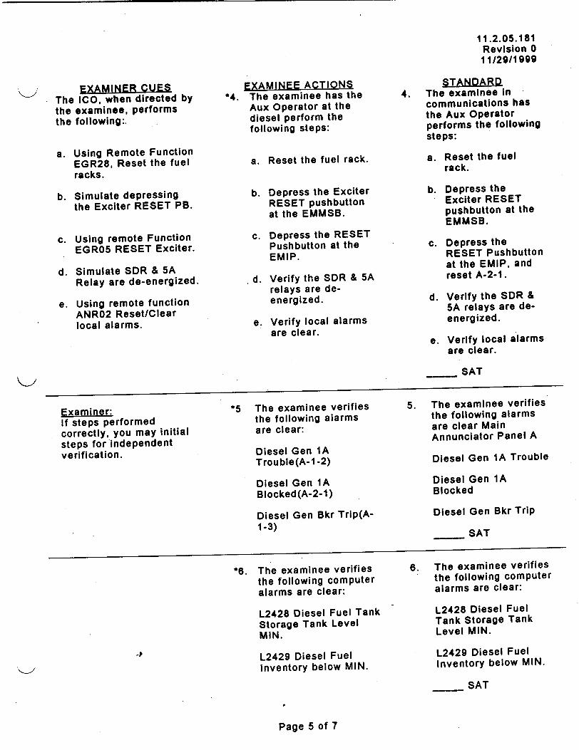
11.2.05.181 Revision 0 11/29/1999
EXAMINER CUES The ICO, when directed by the examinee, performs the following:.
a. Using Remote Function EGR28, Reset the fuel racks.
b. Simulate depressing the Exciter RESET PB.
c. Using remote Function EGROS RESET Exciter.
d. Simulate SDR & 5A Relay are de-energized.
e. Using remote function ANR02 Reset/Clear local alarms.
Examiner: If steps performed correctly, you may initial steps for independent verification.
EXAMINEE ACTIONS *4. The examinee has the
Aux Operator at the diesel perform the following steps:
a. Reset the fuel rack.
b. Depress the Exciter RESET pushbutton at the EMMSB.
c. Depress the RESET Pushbutton at the EMIP.
d. Verify the SDR & 5A relays are deenergized.
e. Verify local alarms are clear.
*5 The examinee verifies the following alarms
are clear:
Diesel Gen 1A
Trouble(A-1 -2)
Diesel Gen 1A
Blocked(A-2-1)
Diesel Gen Bkr Trip(A1-3)
STANDARD4. The examinee in communications has the Aux Operator performs the following steps:
a. Reset the fuel rack.
b. Depress the Exciter RESET pushbutton at the EMMSB.
c. Depress the RESET Pushbutton at the EMIP, and reset A-2-1.
d. Verify the SDR & 5A relays are deenergized.
e. Verify local alarms are clear.
SAT
5. The examinee verifies the following alarms are clear Main Annunciator Panel A
Diesel Gen 1A Trouble
Diesel Gen 1A Blocked
Diesel Gen Bkr Trip
SAT
*6. The examinee verifies the following computer
alarms are clear:
L2428 Diesel Fuel Tank Storage Tank Level MIN.
L2429 Diesel Fuel Inventory below MIN.
6. The examinee verifies the following computer alarms are clear:
L2428 Diesel Fuel Tank Storage Tank Level MIN.
L2429 Diesel Fuel Inventory below MIN.
SAT
Page 5 of 7
4

11.2.05.181 Revision 0 11/2911999
�YALAti�JFF ACTIONS - -,' .. s..� - . - - -
7. The examinee notifies the SF that the surveillance is complete.
STANDARDI
7. The examinee notifies the SF that the EDG surveillance is complete lAW 13034.18 Declare EG-Y-oA Operable.
Terminate Respective time clocks.
Make appropriate closeout logbook entries.
After the SF is notified the JPM may be terminated.
(*) Denotes Critical Element.
EVALUATION: SAT: UNSAT:
4
Page 6 of 7
EXAMINE•R Su-i• r .... ,r-,-r. ..

11.2.05.181 Revision 0 11/29/1999
JPM CHANGE HISTORY PAGE
REVISION DATE REFERENCE DESCRIPTION .• ~TITLE (include Al # if Appropriate)._.
I I
I+4
J
Page 7 of 7
I
I
I

QUESTIONS A.3.1 Revision 0
01/07/2000 TMI-1 OPERATOR TRAINING INITIAL TRAINING PROGRAM
ADMINISTRATIVE REQUIREMENTS QUESTIONS
POSITION: SRO/RO
ADMIN SECTION
TASK STATEMENT
TASK NUMBER
A.3.1
N/A
N/A
TERMINAL OBJECTIVE
Define, identify the. postings, and state the requirements to enter each of the following radiological areas: Contaminated Area, Radiation Area
Explain how time may be used to reduce dose, and state methods to implement this ALARA factor.
EVALUATION METHOD
EVALUATION LOCATION
APPROXIMATE TIME
IMPORTANCE RATING (TIF)
TOOLS AND EQUIPMENT
REFERENCES
1 OCFR55.45(A)
ORAL EXAMINATION
SIMULATOR: IN-PLANT: CONTROL ROOM:
2 Minutes
N/A
NONE
GET Radiation Worker Training Manual, Rev. 5
(10)
SIGNATURE DATE
Submitted By: '24 11211-00
Validated By: &
Reviewed By: Lead Instructor, Operator Training OR Lead Instructor, Simulator Training
Operations Training Managery...-/ __/ ___
Approved By: ln / 4z< / IPlant Operations Director /______
Page 1 of 5 AMERGEN, LLC Middletown, Pa. Copyright 2000

QUESTIONS A.3.1 Revision 0 01/07/2000
EXAMINER INSTRUCTIONS
Sequence for administration of Administrative Requirements questions:
1. Provide the Examinee with a copy of the Administrative Requirements Question Sheet.
2. Inform the Examinee of the PLANT CONDITIONS, and AUTHORIZED OPEN
REFERENCES, if appropriate as delineated on the cover sheet.
3. Allow the Examinee to ask clarification questions regarding the questions. Questions and
clarifications provided should be annotated in the Examiner Comments section of the
Question Sheet.
4. If needed, allow the Examinee 2-3 minutes to develop solutions to the questions prior to
answering.
5. Instruct the Examinee to DOCUMENT ANSWERS on the Question Sheet.
6. Instruct the Examinee to inform you when the answers are complete.
7. Do not inform the Examinee whether answers are correct or incorrect.
8. Retrieve the Question Sheet from the Examinee after answers have been documented and
the Examinee has signed.
9. Do not grade the answers in the presence of the Examinee.
10. Use the Examiner's Reference Sheet to grade the answers.
AMERGEN, LLC Page 2 of 5 Middletown, Pa.
Copyright 2000

Administrative Requirements Question Sheet
QUESTIONS A.3.1 Revision 0 01/07/2000
PLANT You are a licensed CRO and have been directed to go to DH-V-12B to
CONDITIONS support work on DH-V-12B.
ADMINISTRATIVE REQUIREMENTS QUESTION
ADMINISTRATIVE REQUIREMENTS QUESTION
QUESTION The Control Room has notified you that there will be a 30 minute delay until work can
commence. Identify on the accompanying Radiological Survey Map where ALARA
expectations can be met while awaiting permission to commence work.
RESPONSE
EXAMINEE: - DATE:
EXAMINER COMMENTS
EVALUATION SAT: UNSAT:
EXAMINER: - DATE:_ _ _
Page 3 of 5AMERGEN, LLC Middletown, Pa. Copyright 2000
QUESTION Using the accompanying Radiological Survey Map, identify the posting requirements for
the area where DH-V-12B is located.
RESPONSE

EXAMINER REFERENCE SHEET
QUESTION ANSWER STANDARD
Question 1 Using the accompanying Radiological Survey Map, identify the posting requirements for the area where DH-V-12B is located.
Question 2 The Control Room has notified you that there will be a 30 minute delay until work can commence. Identify on the accompanying Radiological Survey Map where ALARA expectations can be met while awaiting permission to commence work.
Radiation Area Contaminated Area
Words to the effect: "Standby in the area where the radiation level is 1 mrem/hr (lower right hand corner of the survay map)."
Correct answer provided without the use of references.
Ref: GET Rad Worker Handout, page 56 and 58.
Correct answer provided without the use of references.
Ref: GET Rad Worker Handout, page 17.
4
Page 4 of 5AMERGEN, LLC Middletown, Pa. Copyright 2000

ADMIN QUESTION CHANGE HISTORY PAGE
P 1 .. .- .�s,' u� I rvr I f� �i
DATE REFERENCE TITLE (include Al # if Appropriate)
I I i
I I I
. ... ......... [- -..... -
I I I I
I I I
I I
I I I
I I
I *I I
I I
____ ____ I _______ j _______________
Page 5 of 5AMERGEN, LLC Middletown, Pa. Copyright 2000
REVISION

ou :3
c 4
c c

11.2.05.182 Revision 0
11/30/99
TMI-1 OPERATOR TRAINING REQUALIFICATION PROGRAM
JOB PERFORMANCE MEASURE - TIME CRITICAL
POSITION: SRO/RO/AO
Emergency Notifications and Call Outs
5010045003
EVALUATION METHOD:
EVALUATION LOCATION:
APPROXIMATE COMPLETION TIME:
IMPORTANCE RATING (TIF):
TOOLS AND EQUIPMENT:
EXAMINEE
REFERENCES:
1 OCFR55.45:
PERFORM:
SIMULATOR: X
SIMULATE: X
IN-PLANT: CONTROL ROOM:
Minutes: 15
NRC: K/A 2.4.43 RO 2.8 TMI: RO 2.9
EP Pager Call Out Phone Notification Line ENS Telephone
EPIP-TMI-03 Emergency Notification and Call Outs
(a)(13).
SIGNATURE DATE
Submitted By: E Validated By: /c,4/4v
Reviewed by: Lead Instructor, Operator Training OR Lead Instructor, Simulator Training _ _ _ _ _ _ _ _ _ _ _ _ _
Operations Training Manager _ . _ _ _ _ _ _ _ _ _ _ _ _ _ _ _
Approved By: -7/) Plant Operations Director
Rage 1 of 8
TITLE:
TASK NUMBER:

11.2.05.182 Revision 0
11/30/99
SIMULATOR CONDITIONS:
EXAMINER PREVIEW:
TASK STANDARDS:
N/A
The sequence of events which should be followed in the conduct of this JPM is as follows:
1. Read or otherwise inform the Examinee of the information contained in the "EXAMINEE PREVIEW" section of this JPM.
2. Inform the Examinee of the TASK CONDITIONS. 3. Begin the cueing sequence as described in the EXAMINER CUES
section.
A certain amount of liberty (questioning or cueing beyond the bounds of the "EXAMINER CUES") may be taken by the Examiner in trying to extract the requisite information from the Examinee, however, care must be taken to ensure that you do not COACH the Examinee.
To complete this task successfully, the Examinee must complete each critical element (an element of the task which, if omitted or performed incorrectly, would result in a failure to meet the "TASK STANDARD") correctly.
Perform all emergency notifications Per EPIP-TMI-.03, Exhibit 2, ALERT Checklist. Exhibit 2, Step 3 must be completed within 15 minutes of event declaration.
Page 2 of 8

EXAMINEE PREVIEW:
TASK CONDITIONS:
K-,
4
Page 3 of 8
This sheet is available for the examinee to review
For this event you are assigned the duties of the third CRO. The instructor/examiner will act as the Emergency Director. The auxiliary instructor is available to act as Auxiliary Operators on the radio or page system.
When you are told to begin, you will respond to the cues or indications which the Examiner will provide to you either verbally or by the simulator.
You are to respond as you would in the plant for a real condition.
An ALERT was declared due to a Security Event A7.1, Bomb discovered
inside the Vital Area, at TMI.
Emergency Notifications are required to be performed.
You are the On-shift ECC Communication Coordinator.

11.2.05.182 Revision 0
11/30/99
EXAMINER CUES EXAMINEE ACTIONS STANDARD
As the Emergency Director give the examinee the Emergency Report Form part 1 and 2.
Direct the examinee to make the required emergency notifications per EPIP-TMI-.03. Give the examinee a copy of the procedure.
2. As examiner provide the
2. As examiner provide the following CUES:
a. Dial tone is heard.
1. The examinee obtains the Emergency Report Form Part 1 and 2 and proceeds to the SS office.
*2. The examinee activates the group pagers.
b. After the examinee pushes the GROUP PAGE button inform the examinee he hears: "Please enter your caller password".
c. After the examinee enters LEVEL 2, wait 15 seconds and inform the examinee he hears: "Thank You ".
1. The examinee, with Emergency Report Form Parts 1 and 2, reports to the Simulator SS office, behind H&V panel.
SAT
2. The examinee activates the group pagers.
a. Lifts the EP Pager Call Out Phone Receiver.
b. Examinee pushes the GROUP PAGE button.
c. The examinee hears
"Please Enter your
caller password", and presses the designated LEVEL button, LEVEL 2.
d. After the examinee hears the voice prompt "Thank You', he/she hangs up.
SAT
3. Examiner: If the examinee performs the step correctly provide the following CUES:
*3. Examinee performs the 15 minute notifications.
3. Examinee picks up the Notification Line and confirms a dial tone.
Dial tone is present. -4
15age 4 of 8

11.2.05.182 Revision 0 11/30/99
EXAMINER CUES
a. Toggle Switch is on 'OVERRIDE'.
EXAMINEE ACTIONS_ STANDARD
a. Examinee moves Toggle Switch UP to OVERRIDE.
SAT
b. Examinee Dials 091"
a. Calling tone is heard.
b. Toggle Switch is 'NORMAL'.
c. After the examinee hears the calling tone, he/she places Toggle Switch down to NORMAL.
c. Hello this is: (Answer as appropriate.)
PEMA Dauphin County Cumberland County Lancaster County Lebanon County York County
d. Repeat above (d.) as necessary.
d. As the agencies answer the examinee states: "This Is Three Mile Island Nuclear Station, Standby for an emergency message."
SAT
e. The examinee ask each agency if it is on the line and checks each off in the procedure.
SAT
f. After the examinee verifies each agency is on the line, he/she states: " Please stay on the line after the following message to provide a name or dispatcher number and to confirm receipt".
.1
Page 5 of 8
SAT
SAT
SAT

EXAMINER CUESEXAMINEE ACTIONS STANDARD
h. As asked respond as follows:
g. The examinee reads "Emergency Report Form Part 1 and enters time when notification is completed.
SAT
h. The examinee request confirmation Name or Number) from:
PEMA Dauphin County Cumberland County Lancaster County Lebanon County York County
PEMA: No. 100 Dauphin No. 101 Cumberland No. 102 Lancaster No. 103 Lebanon No. 104 York No. 105
SAT
i. Inform examinee dial tone is heard.
i. The examinee: Flash the Hook Switch until a dial tone is heard and hangs up.
Step 4.0 of the procedure:
As the examiner, play the part of an ECC Communicator and accept Part 2 of the Emergency Report Form and you are performing Exhibit 9.
Step 4.1 Log Receipt confirmation may be left blank or N/A by examinee
*4 Examinee directs an 4. The examinee directs*4. Examinee directs an
ECC communicator to perform Exhibit 9 of this procedure and provide Part 2 of the Emergency Report Form.
4. The examinee directs an ECC communicator to perform Exhibit 9 of
this procedure and provides him Part 2 of
the Emergency Report Form.
SAT
StelD 5 of proc-edure l&C Turnover N/A for examinee.
Flage 6 of 9
11.2.05.182 Revision 0
11/30/99

11.2.05.182 Revision 0 11/30/99
E X A M IN E R L ,C u E S r- - . . . . . . . .=,YAMINFF: ACTIONS
Step 7 of procedure
Examiner: Examinee may simulate this step.
5. The examinee pins on the ECC Communication Coordinator Button
5. The examinee pins on the ECC Communication Coordinator Button
Examiner CUE:
As the STA inform the examinee that ERDS has been activated.
Step 8.1 and 8.2 of prMoed ur e:* Providing Exhibit 6 & completing exhibit 8 Not Applicable (N/A)
Examiner: As the examinee successfully complete each step provide the following CUES:
*6. The examinee verifies*6. The examinee verifies
ERDS activation.
*7. The examinee notifies the NRC using the Emergency Notification System (ENS) in the SS office or Control Room. (Simulator)
a. Dial tone and the phone has been successfully dialed. "Hello this is the NRC Emergency Notification Line", Mr. Robert Nelson.
b. NRC Listens and acknowledges report.
c. If requested provide the name of the NRC contact. Mr Robert Nelson.
6. The examinee verifies6. The examinee verifies activation of ERDS by
the Shift Engineer.
SAT
7. The examinee informs the NRC using the ENS by:
a. Dialing the ten digit number attached on the ENS telephone.
SAT
b. Examinee reads the Emergency Report Form.
SAT
c. Examinee records the person contacted in the procedure.
d. Examinee remains on the line with the NRC.
SAT
Page 7 of 9
S.... . .. ipr'l h I I1"('•l
SAT

11.2.05.182 Revision 0
11/30/99
EXAMINER CUES EXAMINEE ACTIONS STANDARD
~, After the examinee has notified the NRC the JPM may be terminated.
(*) Denotes Critical Element.
EVALUATION: SAT: , UNSAT:
rage 8 of 9

11.2.05.182 Revision 0 11/30/99
JPM CHANGE HISTORY PAGE
REFERENCE TITLE
.. ..... .....
I I I
I I I
I I
I I
I I
I I
I *I I
I I iI I I
DESCRIPTION (Include Al # if Appropriate)
I ___
4
r~age 9 of 9
REVISION DATEI I
I - I

NOTIFICATION OF A NUCLEAR POWER PLANT INCIDENT
EMERGENCY NOTIFICATION REPORT CONFIRMATION FROM - TMI
This is a drill. This is a drill.
1. This is the Emergency Director at Three Mile Island.
The call back number is 717-948-2078.
2. EMERGENCY CLASSIFICATION An Alert has been declared at hours on
This represents an Initial Classification Status.
3. BRIEF NON-TECHNICAL DESCRIPTION OF EVENT
Emergency Action Level : A 7.1 - Confirmed Security Event Potentially Affecting Safety
Related Equipment.
'An Alert is declared because of a confirmed security event which degrades the safety
level of the power plant. This event involves: A bomb discovered inside the Vital Area.
The Vital Area includes buildings where Safety Related Equipment is located. Damage
to this equipment would reduce the ability to protect the public's health and safety.
,-O A- ! ^ , stle Pe Foc in' ; do thc&. rrctczt• Af;, &. T 1 F",1 ,ttd Aet ....... . ... j,,
.planttmskotreuc like thz ~urifig n ibmedng t1at arc protootod b4reurt -fo • a" d t. . ...hip'-I. .--.S ' i_" 11 wu. The plant mode is: Power Operation
4. There is no release to the environment as a result of this emergency.
6. Wind direction is FROM 337 degrees and the wind speed is 17.3 miles per hour.
This is a drill. This is a drill.
Approved by Daryl L Wilt
_P

Part 1 Part 1 of 4 Call out/Notification
EMERGENCY REPORT FORM - TMI
CALL OUT: Level 2
NOTIFICATIONS: Instruction - Read Message - slowly and clearly.
This is a drill. This is a drill.
(Instruction) This section to be completed by the communicator.
This is at TMI. The time is now
communicator -your name My phone number is 717-948-2078.
An Alert has been declared at hours on
This.represents an Initial Classification Status.
Event type :A 7.1 - Confirmed Security Event Potentially Affecting Safety Related
Equipment. (EAL #) - (EAL itle)
The plant Mode is: Power Operation
There is no release to the environment as a result of this emergency.
Wind direction is FROM 337 degrees and the wind speed is 17.3 miles per hour.
This is a drill. This is a drill.
Approved by Daryl L Wilt
4

Part 2 Part 2 of 4 Contact
EMERGENCY REPORT FORM - TMI
Instruction - Read Message - Slowly - Clearly.
This is a drill. This is a drill.
An Alert has been declared at hours on
This represents an Initial Classification Status.
A 7.1 - Confirmed Security Event Potentially Affecting Safety Related Equipment.
'An Alert is declared because of a confirmed security event which degrades the safety
level of the power plant. This event involves: A bomb discovered inside the Vital Area.
The Vital Area includes buildings where Safety Related Equipment is located. Damage
to this equipment would reduce the ability to protect the public's health and safety.
OR- I Hoctilc Fcro i*Side thc Pr-te"t@' Arpa. The Pro-'toctod Ar-a i"""c^mo
-plant struwro l-,*Fik044 thoturbiRO and 6 rieB buildinlgS th@Aaftý arFerteoc E4b, a ourt
-ccc4 n c tmhacea ccnrolTIV. ý4JA*
The plant mode is : Power Operation
There is no release to the environment as a result of this emergency.
This is a drill. This is a drill.
Approved by Daryl L Wilt

11.2.05.177 Revision 0 10/08/1999
TMI-1 OPERATOR TRAINING REQUALIFICATION PROGRAM
JOB PERFORMANCE MEASURE - ALTERNATE PATH
POSITION: SRO/RO
TITLE:
TASK NUMBER:
EVALUATION METHOD:
EVALUATION LOCATION:
APPROXIMATE COMPLETION TIME:
IMPORTANCE RATING (TIF):
TOOLS AND EQUIPMENT:
EXAMINEE REFERENCES:
i0CFR55.45:
Perform a Safety Group Withdrawal
0010180101
PERFORM: X SIMULATE:
SIMULATOR: X IN-PLANT:
25 Minutes
TM1=2.84
CONTROL ROOM:_
NRC=3.4 K4.13
None
OP 1105-9 (sections 3.2.2, 3.2.3, and 3.2.5 attached for examiner)
(a)(1). (3), (12).
W:\WORD97\LP\OT\JPM%1 1205177. DOC
SIGNATURE DATE
Submitted By: //V
Validated By: ~
Reviewed by: Lead Instructor, Operator Training OR Lead Instructor, Simulator Training
Operations Training Manager ,/
Approved By!. ½ ____
Plant Operations Director
Page 1 of Y i PU

11.2.05.177 Revision 0 10/08/1999
SIMULATOR
CONDITIONS: IC05 Hot Shutdown, MOC, no xenon
On RPPC center console monitor, display Group 10, Area 24.
On CRD panel, turn GROUP POSITION SELECTOR switch to SAFETY.
Transfer CRG-4 to auxiliary power supply and insert CRG-4 to 75%.
Event Trigger #1: RDSGP(4)>0.95, Event Command: imf RD0201.
Event Trigger #2: RDSGP(4)>0.98, Event Command: dmf RD0201.
EXAMINER PREVIEW: This task deals with performing safety group-4 withdrawal from 75% to
its group out-limit to establish conditions necessary for reactor startup. It is considered an alternate path JPM because one rod in group-4 will
NOT reach its individual out limit, requiring alternate actions delineated in 1105-9 to obtain the individual rod out limit.
Obtain current revision of 1105-9 sections 3.2.2, 3.2.3, and 3.2.5 for reference during the JPM.
The sequence of events which should be followed in the conduct of this JPM is as follows:
1. Read or otherwise inform the Examinee of the information contained in the "EXAMINEE PREVIEW" section of this JPM.
2. Inform the Examinee of the TASK CONDITIONS. 3. Allow the Examinee 2-3 minutes to scan the Console. 4. Begin the cueing sequence as described in the EXAMINER CUES
section.
A certain amount of liberty (questioning or cueing beyond the bounds of
the "EXAMINER CUES") may be taken by the Examiner in trying to extract the requisite information from the Examinee, however, care must be taken to ensure that you do not COACH the Examinee.
To complete this task successfully, the Examinee must complete each
critical element (an element of the task which, if omitted or performed incorrectly, would result in a failure to meet the "TASK STANDARD") correctly.
TASK
STANDARDS: Safety group-4 at group out limit (red lamp on CRD panel) and all eight
group-4 rods at individual rod out limits (red lamps on PI panel), and all
eight group-4 rods on the hold bus (none on auxiliary power supply).
W:\WORD97\LP\OT\JPM\1 1205177.DOC Ptige 2 of 14

EXAMINEE PREVIEW:
TASK CONDITIONS:
This sheet is available for the examinee to review
For this event you are assigned the duties of the primary CRO.
The instructor/examiner will act as the shift foreman, secondary CRO, and STA.
The auxiliary instructor is available to act as Auxiliary Operators on the radio or page system.
When you are told to begin, you will respond to the cues or indications which the Examiner will provide to you either verbally or by the simulator.
You are to respond as you would in the plant for a real condition.
The plant is at hot shutdown, 300 EFPD, no xenon.
RCS boron is 1600 ppm
Preparations are in progress for plant restart following a turbine trip and reactor trip from 100% power four days ago.
Control rod safety groups 1,2, and 3 are fully withdrawn.
Control rod safety group 4 is currently 75% withdrawn on the auxiliary power supply, awaiting results of 1/M plot for which stable counts has already been obtained.
Your task will be to complete safety group 4 withdrawal to its full out position, and then transfer group 4 back to the DC hold bus per 1105-9.
Page 3 of 14

11.2.05.177 Revision 0 10/08/1999
EXAMINER CUES
As the Shift Foreman, inform examinee that redundant 1/M plots indicate it is safe to pull control rod group-4 (CRG-4) to 100%. Direct examinee to withdraw CRG-4 to 100%, then transfer CRG-4 back to the DC hold bus.
EXAMINEE ACTIONS
1. Examinee reviews 1105-9 section 3.2.5 to determine current applicable step.
STANDARD
1. Examinee has found current place in 1105-9 as evidenced by his/her report that CRG-4 will be withdrawn.
*2. Examinee manipulates CRD panel control handle to WITHDRAW position and monitors CRG-4 position meter on CC, PI panel on PC, and computer to verify out motion.
2. CRG-4 is withdrawing as evidenced by increasing CRG-4 position on CC, PC, and computer.
SAT
3. Examinee monitors source range nuclear instruments, NI-11 and 12, as positive reactivity is added by CRG-4.
3. Source range Ni's being monitored during CRG-4 withdrawal as evidenced by examinee actions.
*4. Examinee withdraws CRG-4 to 100% then releases CRD control handle to neutral position when CRG-4 red OUT LIMIT lamp is illuminated on CRD panel.
4. CRG-4 is at its out limit as indicated by the red CRG-4 OUT LIMIT lamp illuminated on CRD panel.
SAT
W \WORD97\LP\OT\JPM\11205177
.DOC
-P
1-1/
Page 4 of 14

11.2.05.177 Revision 0 10/08/1999
EXAMINER CUES
S. As Shift Foreman, acknowledge any report from examinee concerning rod positions and/or lamp status.
EXAMINEE ACTIONS
*5. Examinee checks PI
panel on PC for all eight CRG-4 red OUT LIMIT lamps on, and recognizes that rod 4-4 OUT LIMIT lamp is off.
STANDARD
5. Rod 4-4 recognized as not at its individual out limit on P1 panel, as evidenced by report from examinee.
SAT
6. Examinee performs a lamp check of red OUT LIMIT lamps on PI panel, by depressing the white OUT LIMIT lamp check button on top left of PI panel.
6. All P1 panel red OUT LIMIT lamps checked good as evidenced by all 69 red lamps illuminating when OUT LIMIT lamp check button is depressed.
7. Examinee selects JOG 7. CRD speed selector
on SPEED SELECTOR switch on CRD panel in switch on CRD panel. JOG position.
*8. Examinee inserts CRG-4 8. CRG-4 OUT LIMIT lamp
by manipulating CRD on CRD panel is off, and
control handle forward to all CRG-4 individual rod
INSERT position until red OUT LIMIT lamps on PI
CRG-4 OUT LIMIT lamp panel are still on except
on CRD panel goes off, rod 4-4. and then releases CRD control handle prior to - SAT CRG-4 individual rod OUT LIMIT lamps on PI panel going off except rod 4-4.
W :\WORD97\LP\OT\JPM\1 1205177.DOC Page 5 of 14

11.2.05.177 Revision 0 10/08/1999
EXAMINER CUES
SNOTE: CRD panel will
already be in MANUAL and SEQ-OR (sequence override) mode, with ALL Group-4 rods selected on the SINGLE and GROUP SELECT SWITCHES.
NOTE: There is no need to transfer CRD panel back to SEQ and RUN mode because of forthcoming rod transfer operations.
EXAMINEE ACTIONS
*9. Examinee transfers
CRG-4 back to its hold bus per section 3.2.3 of 1105-9 as follows: + Depresses
GROUP/AUXIL pushbutton and verifies AUXIL lamp illuminates
# Selects JOG on SPEED SELECTOR switch
* Verifies SY (synch) lamp illuminates
# Depresses CLAMP pushbutton and verifies amber CLAMP lamp illuminates
+ Depresses MAN TRANS pushbutton, and verifies TR CF lamp goes off, and verifies individual Group-4 rod CONTROL ON lamps (white) on PI panel (PC) go off
*Depresses CLAMP REL pushbutton and verifies green CLAMP REL lamp illuminates
* Depresses GROUP/AUXIL pushbutton and verifies GROUP lamp illuminates
+Selects OFF on GROUP SELECT SWITCH
#Selects OFF on SINGLE SELECT SWITCH
+ Depresses TRANS RESET pushbutton and verifies white CONTROL ON lamp for Group-4 on CRD panel goes off, and verifies TRANS RESET lamp illuminates
STANDARD
9. All CRG-4 rods are on hold bus as evidenced by: white TR CF and CRG-4 CONTROL ON lamps on CRD panel off, and all eight CRG-4 white CONTROL ON lamps on PI panel are off.
SAT
-P
W :\WOR097\LP\OT\JPM\1 1205177.DOC P&ge 6 of 14

11.2.05.177 Revision 0 10/08/1999
EXAMINER CUES
NOTE: CRD panel should already be in MAN mode.
NOTE: Selecting SEQ and AUTO mode on CRD panel is not desired in this case.
EXAMINEE ACTIONS
"*10. Examinee transfers
control rod 4-4 only to the auxiliary power supply per section 3.2.2 of 1105-9 as follows: * Verifies CRD in
manual (MAN lamp on) *Verifies GROUP lamp
on * Verifies or selects
SEQ-OR mode and lamp on
+Selects Group-4 on GROUP SELECT SWITCH
# Selects Rod-4 on SINGLE SELECT SWITCH
*Depresses TRANS RESET pushbutton
* Depresses GROUP/AUXIL pushbutton and verifies AUXIL lamp on
*Verifies white CONTROL ON lamp for Group-4 on CRD panel is on
*Selects JOG on SPEED SELECTOR switch
+Verifies SY (synch) lamp illuminates
# Depresses CLAMP push-button and verifies amber CLAMP lamp on
# Depresses MAN TRANS pushbutton, verifies TR CF lamp on, and verifies individual Rod 4-4 white CONTROL ON lamp on PI panel (PC) is on
+ Depresses CLAMP REL pushbutton and verifies green CLAMP REL lamp illuminates
# Depresses GROUP/AUXIL pushbutton and verifies GROUP lamp illuminates
STANDARD
10. Control rod 4-4 is on auxiliary power supply as evidenced by: GROUP SELECT SWITCH on CRD panel selected to CRG-4, SINGLE SELECT SWITCH on CRD panel selected to rod 4, white TR CF and CRG-4 CONTROL ON lamps on CRD panel are on, and control rod 4-4 white CONTROL ON lamp on P1 panel is on.
SAT
W :\WORD97\LP\OT\JPM\11205177.DOC
I, _
Page 7 of 14

11.2.05.177 Revision 0 10/08/1999
EXAMINER CUES EXAMINEE ACTIONS
11. Examinee selects JOG on SPEED SELECTOR switch on CRD panel.
STANDARD
11. CRD speed selector switch on CRD panel in JOG position.
"*12. Examinee withdraws rod 4-4 by manipulating CRD control handle to WITHDRAW position until rod 4-4 red OUT LIMIT lamp on PI panel comes on, then releases CRD control handle to vertical neutral position prior to obtaining CRG-4 red OUT LIMIT lamp on CRD panel.
12. Control rod 4-4 is at its individual out limit as evidenced by rod 4-4 red OUT LIMIT lamp on PI panel on.
SAT
-P
W \WORD97\LP\OT\JPM\1 1205177.DOC Page 8 of 14

11.2.05.177 Revision 0 10/08/1999
EXAMINER CUES
NOTE: CRD panel will already be in MANUAL and SEQ-OR (sequence override) mode, with Group-4 and Rod-4 selected on GROUP and SINGLE SELECT SWITCHes.
NOTE: There is no need to transfer CRD panel back to SEQ and RUN mode because of forthcoming rod transfer operations.
EXAMINEE ACTIONS
"*13. Examinee transfers rod
4-4 back to the hold bus per section 3.2.3 of 1105-9 as follows: # Depresses
GROUP/AUXIL pushbutton and verifies AUXIL lamp illuminates
# Selects JOG on SPEED SELECTOR switch
+Verifies SY (synch) lamp illuminates
# Depresses CLAMP push-button and verifies amber CLAMP lamp illuminates
+ Depresses MAN TRANS pushbutton, and verifies TR CF lamp goes off, and verifies individual rod 4-4 CONTROL ON lamp (white) on PI panel (PC) goes off
*Depresses CLAMP REL pushbutton and verifies green CLAMP REL lamp illuminates
# Depresses GROUP/AUXIL pushbutton and verifies GROUP lamp illuminates
*Selects OFF on GROUP SELECT SWITCH
*Selects OFF on SINGLE SELECT SWITCH
+ Depresses TRANS RESET pushbutton and verifies white CONTROL ON lamp for Group-4 on CRD panel goes off, and verifies TRANS RESET lamp illuminates
STANDARD
13. All CRG-4 rods are on hold bus as evidenced by: white TR CF and CRG-4 CONTROL ON lamps on CRD panel off, and all eight white CRG-4 rod CONTROL ON lamps on PI panel are off.
SAT
W \WORD97\LP\OT\JPM\1 1205177.DOC
a
Page 9 of 14

11.2.05.177 Revision 0 10/08/1999
EXAMINER CUES
S. NOTE: CRD panel should already be in MAN mode.
NOTE: Selecting SEQ and AUTO mode on CRD panel is not desired in this case.
EXAMINEE ACTIONS
"*14. Examinee transfers
Group-4 to the auxiliary power supply per section 3.2.2 of 1105-9 as follows: * Verifies CRD in manual
(MAN lamp on) *Verifies GROUP lamp
on *Verifies or selects SEQ
OR mode and lamp on *Selects Group-4 on
GROUP SELECT SWITCH
+Selects ALL on SINGLE SELECT SWITCH
+ Depresses TRANS RESET pushbutton
* Depresses GROUP/AUXIL pushbutton and verifies AUXIL lamp on
* Verifies white CONTROL ON lamp for Group-4 on CRD panel is on
+ Selects JOG on SPEED SELECTOR switch
+Verifies SY (synch) lamp illuminates
+Depresses CLAMP pushbutton and verifies amber CLAMP lamp on
+ Depresses MAN TRANS pushbutton, verifies TR CF lamp on, and verifies all eight Group4 rod white CONTROL ON lamps on P1 panel (PC) are on
#Depresses CLAMP REL pushbutton and verifies green CLAMP REL lamp illuminates
* Depresses GROUP/AUXIL pushbutton and verifies GROUP lamp illuminates
STANDARD
14. All eight CRG-4 rods on auxiliary power supply as evidenced by: GROUP SELECT SWITCH on CRD panel selected to CRG-4, SINGLE SELECT SWITCH on CRD panel selected to ALL, white TR CF and CRG-4 CONTROL ON lamps on CRD panel are on, and all eight CRG-4 white CONTROL ON lamps on P1 panel are on.
SAT
W :\WORD97\LP\OT\JPM\1 1205177.DOC Page 10 of 14

11.2.05.177 Revision 0 10/08/1999
EXAMINER CUES EXAMINEE ACTIONS
15. Examinee selects RUN on SPEED SELECTOR switch on CRD panel.
STANDARD
15. CRD speed selector switch on CRD panel in RUN position.
"*16. Examinee withdraws CRG-4 to 100% by manipulating CRD control handle to WITHDRAW position, then releases CRD control handle to neutral position when CRG-4 red OUT LIMIT lamp is illuminated on CRD panel.
16. CRG-4 is at its out limit as indicated by the red CRG-4 OUT LIMIT lamp illuminated on CRD panel, and all eight CRG-4 rods are at their individual out limits as indicated by all eight CRG-4 re.d OUT LIMIT lamps illuminated on PI panel.
SAT
W -\WORD97\LP\OT\JPM\1 1205177.DOC Parge 11 of 14

11.2.05.177 Revision 0 10/08/1999
EXAMINER CUES
NOTE: CRD panel will already be in MANUAL and SEQ-OR (sequence override) mode, with ALL Group-4 rods selected on the SINGLE and GROUP SELECT SWITCHES.
NOTE: It is not required to transfer CRD panel back to SEQ and RUN mode, and it is not desired to select AUTO mode.
EXAMINEE ACTIONS
"*17. Examinee transfers
CRG-4 back to its hold bus per section 3.2.3 of 1105-9 as follows: # Depresses
GROUP/AUXIL pushbutton and verifies AUXIL lamp illuminates
*Selects JOG on SPEED SELECTOR switch
* Verifies SY (synch) lamp illuminates
* Depresses CLAMP pushbutton and verifies amber CLAMP lamp illuminates
+Depresses MAN TRANS pushbutton, and verifies TR CF lamp goes off, and verifies individual Group-4 rod CONTROL ON lamps (white) on PI panel (PC) go off
*Depresses CLAMP REL pushbutton and verifies green CLAMP REL lamp illuminates
* Depresses GROUP/AUXIL pushbutton and verifies GROUP lamp illuminates
*Selects OFF on GROUP SELECT SWITCH
*Selects OFF on SINGLE SELECT SWITCH
* Depresses TRANS RESET pushbutton and verifies white CONTROL ON lamp for Group-4 on CRD panel goes off, and verifies TRANS RESET lamp illuminates
+Depresses SEQ pushbutton
+ Selects RUN on SPEED SELECTOR switch
STANDARD
17. All CRG-4 rods are on hold bus as evidenced by: white TR CF and CRG-4 CONTROL ON lamps on CRD panel off, and all eight CRG-4 white CONTROL ON lamps on PI panel are off.
SAT
4p
W:\WORD97\LP\OT\J PM\1 12051 77.DOC Parge 12 of 14

11.2.05.177 Revision 0 10/08/1999
EXAMINER CUES
,> If examinee inquires about desired final status of CRD panel, as Shift Foreman direct examinee to leave CRD panel in manual.
EXAMINEE ACTIONS
18. Examinee leaves CRD panel in manual mode following transfer of CRG-4 back to hold bus.
STANDARD
18. CRD panel in manual mode as indicated on CRD panel by white MAN lamp on and red AUTO lamp off.
(*) Denotes Critical Element.
EVALUATION: SAT: UNSAT:
-P
W:\WORD97\LP\OT\JPM\1 1205-177.DOC Parge 13 of 14

11.2.05.177 Revision 0 10/08/1999
JPM CHANGE HISTORY PAGE
REVISION DATE REFERENCE DESCRIPTION TITLE (Include Al # if Appropriate)
______ 1. .1. I
I I
4 1
______ I I +
_____ 1 4 I
_ _ _ _ I I- m
_____ 1. 4 I
4 I I
______ I ______ I
J
W:\WORD97\LP\OT\JPM\1 1205177.DOC Parge 14 of 14

11.2.05.119 Revision 10 10/05/1999
TMI-1 OPERATOR TRAINING REQUALIFICATION PROGRAM
JOB PERFORMANCE MEASURE
POSITION: SRO/RO
Perform a Recovery from High Temperature Letdown Isolation.
004C010101
EVALUATION METHOD:
EVALUATION LOCATION:
APPROXIMATE COMPLETION TIME:
IMPORTANCE RATING (TIF):
TOOLS AND EQUIPMENT:
EXAMINEE REFERENCES:
1 OCFR55.45:
PERFORM: X
SIMULATOR: X
15 Minutes
TM1=3.19
SIMULATE:_
IN-PLANT: CONTROL ROOM:_
NRC=3.6 A4.06
OP 1104-2, Makeup and Purification System
OP 1104-2, Makeup and Purification System Alarm Response Procedure D-2-1
(a)(4), (6).
W:\WORD97\LP\OT\JPM\I 1205119. DOC
TITLE:
TASK NUMBER:
Signature Date
Submitted By:
Validated By:
Reviewed By: Lead Inst., Ops. Training or7 Lead Inst., Sim. Training
Operations Training
Manager
Approved By: Plant Operations I Director-#i
page I of 7

11.2.05.119 Revision 10 10105/1999
SIMULATOR CONDITIONS: Initialize at IC15, 16, or 17, and go to RUN.
Place IC-P-1A and 1B extension controls in pull-to-lock until MU-V-3
closes on high temperature interlock then restart IC-P-1A.
Insert the following overrides "ON' to simulate high temperature closure
of MU-V-2A, 2B and MU-V-3:
08A9S19-ZDISSMUV2A(1)CLS PCR MU-V-2A RC LD FROM CLR CS
08A9S12-ZDISSMUV2B(1)CLS PCR MU-V-2B RC LD FROM CLR CS
02A5S56-ZDIPBCMUV3 ON CC MU-V-3 CLOSE PUSHBUTTON
EXAMINER PREVIEW: This task deals with restoring normal letdown flow following high
letdown temperature isolation of MU-V-2A, 2B, and MU-V-3.
The sequence of events which should be followed in the conduct of this
JPM is as follows:
1. Read or otherwise inform the Examinee of the information contained
in the "EXAMINEE PREVIEW" section of this JPM.
2. Inform the Examinee of the TASK CONDITIONS. 3. Allow the Examinee 2-3 minutes to scan the console.
4. Begin the cueing sequence as described in the EXAMINER CUES
section.
A certain amount of liberty (questioning or cueing beyond the bounds of
the "EXAMINER CUES") may be taken by the Examiner in trying to
extract the requisite information from the Examinee, however, care
must be taken to ensure that you do not COACH the Examinee.
To complete this task successfully, the Examinee must complete each
critical element (an element of the task which, if omitted or performed
incorrectly, would result in a failure to meet the "TASK STANDARD")
correctly.
TASK
STANDARDS: Normal RCS letdown flowpath through both letdown coolers, block
orifice (MU-V-4), and a makeup demineralizer (MU-K-1) has been
established with sustained flow of 50±5 gpm. MU-V-5 and MU-V-70A
are closed.
W:\WORD97\LP\OT\J PM\I 1205119. DOC Page 2 of 7
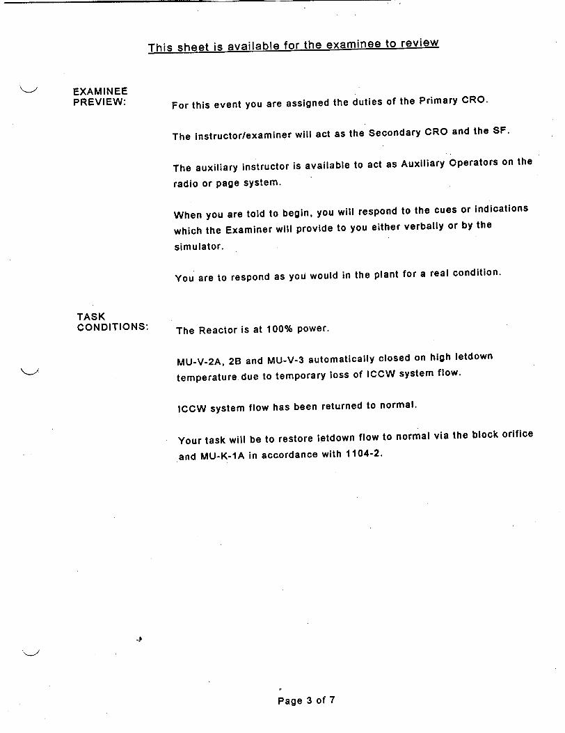
This sheet is available for the examinee to review
EXAMINEE PREVIEW:
TASK CONDITIONS:
For this event you are assigned the duties of the Primary CRO.
The instructor/examiner will act as the Secondary CRO and the SF.
The auxiliary instructor is available to act as Auxiliary Operators on the
radio or page system.
When you are told to begin, you will respond to the cues or indications
which the Examiner will provide to you either verbally or by the
simulator.
You are to respond as you would in the plant for a real condition.
The Reactor is at 100% power.
MU-V-2A, 2B and MU-V-3 automatically closed on high letdown
temperature due to temporary loss of ICCW system flow.
ICCW system flow has been returned to normal.
Your task will be to restore letdown flow to normal via the block orifice
and MU-K-1A in accordance with 1104-2.
Page 3 of 7

11.2.05.119 Revision 10 10/05/1999
EXAMINER CUES
As the Shift Foreman, direct examinee to reestablish normal letdown flow IAW 1104-2.
EXAMINEE ACTIONS
"*1. Examinee closes MU-V-6A/B by depressing the CLOSE pushbutton on CC.
STANDARD 1. MU-V-6A and 8B
closed as indicated by their green CLOSE lights illuminated on Cc.
___SAT
ICO-ROLEPLAY as AO: When directed by examinee, use MUR01 to open MU-V-70A, and inform examinee when it is open.
*2. Examinee directs AO to open MU-V-70A.
2. MU-V-70A is open as reported by AO using radio or page.
SAT
3. Examinee verifies normal ICCW system flow restored to letdown coolers.
3. Normal ICCW system flow (650-1300 gpm) indicated on IC-5-FI (CR), and IC-V-1A and IC-V-1B are open (CC).
ICO-ROLEPLAY: When directed by examinee to place MU-V-2A/B High Temperature Interlock in "•BYPASS", delete active overrides on MU-V-2A and 2B. Then, inform examinee that task is completed.
*4. Examinee directs AO to place MU-V-2A/B High Temperature Interlock in "BYPASS" on lB ES Valves MCC, Unit 5D; and place MU-V-3 High Temperature interlock in "BYPASS" on T-85.
4. MU-V-2A/B High4. MU-V-2AIB High Temperature Interlock
is in "BYPASS' as reported by AO
SAT
ICO-ROLE PLAY: When directed by examinee to place MU-V-3 High Temperature interlock in "OBYPASS', delete active override on MU-V-3. Then, inform examinee that task is completed.
MU-V-3 High Temperature interlock is in "BYPASS' as reported by AO.
SAT
*5. Examinee closes MU-V-4 by depressing the CLOSE pushbutton on CC, and sets MU-V-5 demand at 0% by rotating the thumbscrew on the Bailey Controller on CC.
5. MU-V-4 is closed as indicated by its green CLOSE light illuminated on CC, and MU-V-5 demand is at 0%, as Indicated on. CC controller.
MU-V-4 _ SAT
MU-V-5 SAT
W:WORD97\LP\OT\JPM\1 120511 9.DOC •Page 4 of 7

11.2.05.119 Revision 10 10/05/1999
EXAMINEE ACTIONS
*8. Examinee opens MU-V-2A
and MU-V-2B by rotating their control switches on PCR to "OPEN' and then releasing.
STAND~ARD 6. MU-V-2A and 2B are
open as indicated by red status lamps on CC and yellow status lamps on PCR.
MU-V-2A -SAT
MU-V-2B -SAT
*7. Examinee pushes and holds MU-V-3 OPEN pushbutton (on CC) and simultaneously sets MU-V-5 demand at 10% by rotating the thumbscrew on its Bailey Controller (on CC).
7. MU-V-3 is OPEN as indicated by its red OPEN light illuminated on CC.
MU-V-5 -demand at 10%, as indicated on CC.
MU-V-3 _ SAT
MU-V-5 - SAT
*8. Examinee releases MU-V-3 pushbutton when the high temperature alarm, MAP D-2-1, clears.
8. MU-V-3 remains open as indicated by its red OPEN light illuminated on CC, and sustained letdown flow (10 gpm) indicated on MU-4FI on CC.
9. Examinee increases the demand on MU-V-5 at a rate which results in an increase in letdown flow of < 2.5 gpm/min on MU-4FI.
9. Letdown flow increased9. Letdown flow increased to 50±5 gpm, at < 2.5
gpm/min as read on MU-4FI on CC.
Following demonstration of ability to control letdown flow through MU-V-5, allow examinee to increase letdown flowrate to 50±5 gpm without a rate limit.
*10. When letdown flow 10. MU-V-4 open as"*10. When letdown flow
equals 50±5 gpm, examinee reopens MU-V-4 by pressing its OPEN pushbutton on CC, and concurrently closes MU-V-5 by reducing its controller demand to zero (0) on CC.
10. MU-V-4 open as indicated by red OPEN light illuminated on
CC, and MU-V-5 closed as indicated by
zero (0) demand on
CC.
MU-V-4 SAT
MU-V-5 -
W:\WORD97\LP\OT\JPM\11205119.DOC Page 5 of 7
EXAMINER CUES
SAT
SAT

11.2.05.119 Revision 10 10105/1999
EXAMINER-Q CUE
If examinee inquires as to which MU-K-1 to place in service, direct examinee to place MU-K-1A back in service.
ICO-ROLEPLAY: When directed use MUR01 to close MU-V-70A. then inform examinee when it is
A-uu
EXAMINEE ACTIONS
"*11. Examinee places the isolated demineralizer back in service by depressing the MU-V-6A OPEN pushbutton on CC.
.-- - ,- � �
*12 Examinee directs AO to 12. MUV!UA IS �IU�U
"12. Examinee directs AO to close MU-V-70A.
11. MU-V-6A open as indicated by Its red OPEN light illuminated on CC.
SAT
12. MU-V-7UA is closed as, reported by AO over radio or page.
13. Examinee adjusts ICCW system temperature using NR-V-15A/B on CR as necessary to maintain letdown temperature <1250 F on MU5-TI.
13..Ltdow tempraiu u .
13. Letdown temperature is• maintained <1250 F as indicated on MU5-TI on
CC.
ICO-ROLE PLAY: When directed to return MU-V-2A/B and MU-V-3 High
S Temperature Interlock bypass switches back to *NORMAL,* after one minute report task complete.
14. Examinee directs AO to return MU-V-2A/B and MU-V-3 High Temperature Interlock bypass switches back to *NORMAL."
14. MU-V-2A/B and MU-V-314. MU-V-2A/B and MU-V-3 High Temperature
Interlock bypass switches back to "8NORMAL* as reported by AO over radio or
page.
JPM may be terminated at this time.
EVALUATION:
(*) Denotes Critical Element.
UNSAT:SAT:
-P
.Page 6 of 7W:\WORD97\LP\OT\JPM\I 12051 19.DOC
SAT
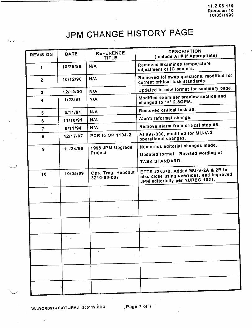
11.2.05.119 Revision 10 10/05/1999
JPM CHANGE HISTORY PAGE
DATE
10/25/89
REFERENCEREFERENCE
TITLE
N/A
2 1 10/12/90 N/A
F
1/23/91 1 N/A
3/111/91
11/18/91
8/11194
12/17/97
N/A
N/A
N/A
PCR to OP 1104-2
1998 JPM Upgrade
Project
Ops. Trng. Handout 3210-99-067
9 11/24/98
10 10/05/99
I I I
I I I
I ~____
EVISION
W:\WORD97\LP\OT\JPM\l 120511 9.Doc
3 12/19/90 N/A
1
4
5
6
7
8
,Page 7 of 7
DESCRIPTION (Include Al # if Appropriate)
Removed Examinee temperature
adjustment of IC coolers.
Removed followup questions, modified for
current critical task standards.
Removed critical task #6.
Alarm reformat change.
Remove alarm from critical step #5.
Al #97-330, modified for MU-V-3
operational changes.
Numerous editorial changes made.
Updated format. Revised wording of
TASK STANDARD.
ETTS #24070: Added MU-V-2A & 2B to
also close using overrides, and improved JPM editorially per NUREG 1021.
I

11.2.05.178 Revision 0 10/07/1999
TMI-1 OPERATOR TRAINING REQUALIFICATION PROGRAM
JOB PERFORMANCE MEASURE - ALTERNATE PATH
POSITION: SRO/RO
Respond to decreasing or low RCS pressure.
0008350501
EVALUATION METHOD:
EVALUATION LOCATION:
APPROXIMATE COMPLETION TIME:
IMPORTANCE RATING (TIF):
TOOLS AND EQUIPMENT:
EXAMINEE REFERENCES:
1 OCFR55.45(a):
PERFORM: X
SIMULATOR: X
12 Minutes
TMI=3.33
SIMULATE:
IN-PLANT:
NRC=3.9
CONTROL ROOM:
A2.02
None
1202-29, Pressurizer System Failures H-3-2, SASS Mismatch
(3), (4), (8), (12)
Page 1 of 6
TITLE:
TASK NUMBER:
SIGNATURE DATE
Submitted By: 7- 7
Validated By:
Reviewed by: Lead Instructor, Operator Training OR Lead Instructor, Simulator Training 0,
Operations Training Manager _/_/_ m
Aptproved By, Plant Operations Director
W:\WOR D97\LP\OT\JPM1 11205178. DOC

11.2.05.178 Revision 0 10/0711999
SIMULATOR
CONDITIONS: IC15, 16, or 17 100% power, steady-state, core age optional.
Place A-RPS channel in manual bypass.
Insert 02A2S03-ZDIRC3BPT1 ON CC-RC3BPT1 NR PRESS. SEL S with
value of "OFF' to prevent manual selection of RC3B-PT1.
Insert N127A at 100% severity over 600 second ramp to fail high (2500
psig) selected RCS pressure transmitter, RC3A-PT1.
After RC-V-1 opens in auto, insert RC29 to fail RC-V-1 at 40%.
FREEZE simulation immediately after inserting RC29 and prior to
receiving G-3-8 alarm.
EXAMINER PREVIEW: This task deals with responding to decreasing RCS pressure due to
automatic RCS pressure control system response to a failed RCS
pressure transmitter with complete SASS channel failure. It Is
considered alternate path because RC-V-1 will not close when
demanded, requiring its isolation per 1202-29.
The sequence of events which should be followed in the conduct of this
JPM is as follows:
1. Read or otherwise inform the Examinee of the information contained
in the "EXAMINEE PREVIEW" section of this JPM.
2. Inform the Examinee of the TASK CONDITIONS.
3. Allow the Examinee 2-3 minutes to scan the Console.
4. Begin the cueing sequence as described in the EXAMINER CUES
section.
A certain amount of liberty (questioning or cueing beyond the bounds of
the "EXAMINER CUESN) may be taken by the Examiner in trying to
extract the requisite information from the Examinee, however, care
must be taken to ensure that you do not COACR the Examinee.
To complete this task successfully, the Examinee must complete each
critical element (an element of the task which, if omitted or performed
incorrectly, would result in a failure to meet the "TASK STANDARD")
correctly.
TASK
STANDARDS: RC-V-1 isolated (RC-V-3 closed) and RC-RV-2 isolated (RC-V-2 closed),
to prevent reactor trip on low RCS pressure (1900 psig).
46
WA:WORD97TLP\OT\JPM\I 12 0 5 178. DOC Page 2 of 6

This sheet is available for the examinee to review
EXAMINEE PREVIEW:
TASK CONDITIONS:
For this event you are assigned the duties of the primary CRO.
The instructor/examiner will act as the shift foreman, secondary CRO, and STA.
The auxiliary instructor Is available to act as Auxiliary Operators on the radio or page system.
When you are told to begin, you will respond to the cues or indications
that the Examiner will provide to you either verbally or by the simulator.
You are expected to perform the required immediate actions of any
EP/AP/ATP from memory, but then you may refer to the applicable procedure(s) to verify proper completion of those actions.
You are to respond as you would in the plant for a real condition.
Plant is at 100% power, equilibrium xenon, _ EFPD.
A-RPS channel is in manual bypass for its monthly surveillance.
No maintenance is currently in progress.
A SASS mismatch has just occurred on the RCS pressure channel.
Your task will be to respond to the SASS mismatch and its affects on the plant.
-P
Page 3 of 6

11.2.05.178 Revision 0 10/07/1999
EXAMINER CUES
ICO-Place simulation in RUN.
As Shift Foreman, direct examinee to respond to the SASS mismatch on the RCS pressure channel.
EXAMINEE ACTIONS
1. Examinee compares all console and panel indications of RCS pressure, and recognizes that RC3A-PT1 disagrees with all other indications.
STANDARD
1. RC3A-PT1 recognized as different than all other indications of RCS pressure, as reported by examinee.
As Shift Foreman, acknowledge all reports from examinee concerning failing pressure transmitter, failure of SASS selector system, and failure of RCV-1 to close in manual.
2. Examinee attempts to select alternate RCS pressure transmitter, RC3B-PT1, by depressing its SASS selector pushbutton on CC, and recognizes its failure to operate.
2. Failure of RCS pressure SASS selector system recognized as indicated by white lamp remaining illuminated for RC3APT1.
3. Examinee transfers RC-V-1 mode control switch on CC to MAN.
4. Examinee depresses and holds RC-V-1 CLOSE pushbutton on CC, and recognizes failure of RCV-1 to close as indicated by both green (CLOSE) and red (OPEN) lamps lit.
3. RC-V-1 mode control switch on CC is in MAN position.
4. RC-V-1 recognized as failed open by both its green (CLOSE) and red (OPEN) lamps lit on CC, and continued RCS pressure decrease.
*5. Examinee closes RC-V-3 by depressing its CLOSE pushbutton on CC, and verifies RC-V-3 closes as indicated by its green CLOSE lamp on and its red OPEN lamp off.
5. RC-V-3 is closed as indicated by its green CLOSE lamp on and its red OPEN lamp off on CC.
SAT
If at any time the examinee requests that you (as Shift Foreman) implement 1202-29, direct the examinee to refer to the procedure as he/she desires.
*6. Examinee operates PZR heater control switches for Banks 4 and/or 5 on CR, and/or PZR pressure controller demand for Banks 1,2,3 on CC as necessary to stop RCS pressure decrease.
6. Pressurizer heater banks 1, 2, 3, 4, and/or 5 energized and RCS pressure decrease has stopped.
SAT
4
W:\WORD97\LP\OT\JPM\11205178.DOC
b
P~age 4 of 6

11.2.05.178 Revision 0 10/07/1999
EXAMINER CUES
If examinee requests permission to block PORV (close RC-V-2) prior to or after its opening, as Shift Foreman grant that permission.
EXAMINEE ACTIONS
7. Examinee recognizes that.PORV will open if RC3A-PT1 continues to fail above 2450 psig; or, examinee diagnoses PORV open by alarms G-1-6, G-1-7, and panel indication DPI-921 when RC3A-PT1 has failed above 2450 psig.
STANDARD
7. Impending or actual PORV opening is recognized by examinee, as indicated by examinee report or actions to block PORV.
If at any time the examinee *8. Examinee depresses 8. RC-V-2 is closed as
requests that you (as Shift RC-V-2 CLOSE indicated by its green
Foreman) implement 1202-29, pushbutton on CC and CLOSE lamp on and its
direct the examinee to refer verifies RC-V-2 closes as red OPEN lamp off on
to the procedure as he/she indicated by its green CC, and PORV flow is
desires. CLOSE lamp on and its terminated as indicated
red OPEN lamp off, and by alarms G-1-6, G-1-7
as indicated by no more clearing. flow through PORV on DPI-921. SAT
JPM may be terminated KL.' when examinee has RCS
pressure under control or after reactor trips.
(*) Denotes Critical Element.
EVALUATION: SAT:_ _ UNSAT:
.1
W-\WORD97\LP\OT\JPM\11205178.DOC Page 5 of 6

11.2.05.178 Revision 0 10/07/1999
JPM CHANGE HISTORY PAGE
REVISION DATE REFERENCE DESCRIPTION TITLE (Include Al # if Appropriate)
I. .1 1
41t
4 i -i - ~ - - - I
I I
I I I
I t
I I__ _ __ _ .Li
_____ .1 ____ I ________
-p
page 6 of 6
- I m I
W:\WOR D97\LP\OT\JPM\11205178.DOC

FILE COPY
I I.�AJ�.I 0
Revision 4 12/23/1998
TMI-1 OPERATOR TRAINING REQUALIFICATION PROGRAM
JOB PERFORMANCE MEASURE
POSITION: SRO/RO
Transfer Main Feedwater Pump Control between ICS H/A Controller
and Full Range Motor Speed Control. (ICS to MSC)
0598060401
EVALUATION METHOD:
EVALUATION LOCATION:
APPROXIMATE COMPLETION TIME:
IMPORTANCE RATING (TIF):
TOOLS AND EQUIPMENT:.
EXAMINEE REFERENCES:
1 OCFR55.45:
PERFORM: X
SIMULATOR: X
SIMULATE:_
IN-PLANT:_ CONTROL ROOM:
10 Minutes
3.30 NRC = 3.2 KI. 07
None.
OP 1106-3, Feedwater System
(a)(4), (6)
___________________ -- I S I � NATURE LJI� I �
__ _ _ _I. i. .
Submitted By: f4A�A# Al
Validated By: 7
Reviewed By: Lead Inst. - Ops. Training Or LeadtInst. -_Sim._Training J
Reviewed By: Operations Training Manager
Approved By: Plant Operations Director
-P
W :\WORD97\LP\OT\JPM\11205116.DOCGPU Nuclear tnc Middletow n PA
Copyrig ht 1998
TITLE:
TASK NUMBER:
ý,, 4ý;,,
Lj/AI r0RIMNATUPR-
IAI,=31ýr
Page 1 of 6

11.2.05.116 Revision 4 12/23/1998
SIMULATOR CONDITIONS: Initialize the trainer at IC15, 16, or 17.
Go to RUN.
EXAMINER PREVIEW:
TASK STANDARDS:
This JPM deals with transferring FW-P-1A speed control from the ICS
controller ("ICS-36A") to the Motor Speed Changer ("Governor"), as a "planned evolution."
The trainer will be turned over to the Examinee in a condition with the
reactor operating at full power. The Examinee will be given direction
from the examiner acting as the Shift Foreman to transfer FW-P-1A
speed control from the ICS controller (ICS-36A) to the motor speed
changer ("governor"), to support subsequent maintenance on the ICS controller.
The sequence of events which should be followed in the conduct of this
JPM is as follows:
1. Read or otherwise inform the Examinee of the information
contained in the "EXAMINEE PREVIEW" section of this JPM.
2. Inform the Examinee of the TASK CONDITIONS.
3. Allow the Examinee 2-3 minutes to scan the Console.
4. Begin the cueing sequence as described in the EXAMINER CUES section.
A certain amount of liberty (questioning or cueing beyond the bounds of
the "EXAMINER CUES") may be taken by the Examiner in trying to
extract the requisite information from the Examinee, however, care
must be taken to ensure that you do not COACH the Examinee.
To complete this task successfully, the Examinee must complete each
critical element (an element of the task which, if omitted or performed
incorrectly, would result in a failure to meet the "TASK STANDARD")
correctly.
FW-P-1A is under full range Motor Speed Changer control, NOT under
ICS control, and no reactor trip occurred as a result of improper transfer or FW-P-1A speed control by examinee.
4
W:\WORD97\LP\OT\JPM\11205116.DOC 2GPU Nuclear. Inc. Middletown. PA
Copyright 1998Page 2 of 6

This sheet is available for the examinee to review
EXAMINEE PREVIEW:
TASK CONDITIONS:
For this event you are assigned the duties of the Secondary CRO.
The instructor/examiner will act as the Primary CRO and SF.
The auxiliary instructor is available to act as Auxiliary Operators on the
radio or page system.
When you are told to begin, you will respond to the cues or indications
which the Examiner will provide to you either verbally or by the
simulator.
You are to respond as you would in the plant for a real condition.
The Reactor is at power.
There is no surveillance activity in progress at this time that could
affect plant operations.
Maintenance is planning repairs on the E/P converter for the ICS speed
control system for FW-P-1A.
-P
,Page 3 of 6GPU Nuclear, Inc. Middletown, PA
Copyright 1998

11.2.05.11611.2.05.116 Revision 4 12/23/1998
EXAMINER CUES
Inform Examinee that in order to support maintenance on the E/P
converter for FW-P-1A, it
is desirable to transfer speed control of FW-P-1A to its Motor Speed Changer. There is an AO
standing by FW-P-1A speed control cabinet with
a radio to support you.
EXAMINEE ACTIONS
1. Examinee directs AO to
observe the FW-P-1A motor speed changer (MSC) handwheel for movement.
STANDARD
1. AO directed to observe the FW-P-1A motor speed changer (MSC) handwheel to confirm
movement.
AO responds that he is in position to observe the
MSC handwheel for FW
P-1A.
ROLEP LAY: As the Shift Foreman, direct Examinee to perform this planned evolution.
NOTE: This step may result in a speed decrease which is acceptable for the
next step (3).
ICO-ROLEPLAY: As the AO at FW-P-1A, when examinee inquires about MSC handwheel movement, inform examinee that the MSC handwheel moved.
NOTE: The amount of
speed decrease on FW-P1A must be sufficient to
ensure MSC controller has
control, but must not be
significant enough to
cause a main feedwater transient that results in an
automatic reactor trip.
2. Examinee places the "1A FPT GOVERNOR" control switch (MSC) on CL in
the "SLOW LOWER" position for a short time
(5-10 seconds) while AO confirms the MSC handwheel responds to
the signal. Examinee may observe a small speed decrease.
*3� Examinee places and*3. Examinee places and
holds the "lA FPT GOVERNOR" (MSC) control switch on CL in "SLOW LOWER" position until a small decrease in speed (50-100 rpm) is observed on FW-P-1A speed recorder or PPC point A0320.
2. "IA FPT GOVERNOR" control switch (MSC) on
CL is placed in the "SLOW LOWER" position
for a short time (5-10 seconds) to confirm movement.
Confirmation of MSC handwheel is received from the AO at FW-P-1A.
3. 'IA FPT GOVERNOR"3. "lIA FPT GOVERNOR" control switch on CL is
placed and held in "SLOW LOWER" position until a small decrease in speed is observed on FW-P-1A speed recorder or PPC point A0320.
*4. Examinee depresses the
HAND button on the ICS controller for FW-P-1A to place the controller in HAND.
4. FW-P-1A ICS controller4. FW-P-1A ICS controller transferred to HAND, as
indicated by white HAND lamp illuminated and red AUTO lamp off on the ICS station.
GPU Nuclear. Inc.
CyPage 6 Middletown, PA
W:\WRD97LP\T\JP\112511DOC ofCopyright 1998
-A SAT
SAT

11.2.05.116 Revision 4 12/23/1998
EXAMINER CUES
*NOTE: Operation of the "1A FPT GOVERNOR" (MSC) control switch may
not be necessary as the
ICS controller demand is
raised. This would indicate complete transfer of FW-P-1A speed control from ICS to the MSC.
EXAMINEE ACTIONS
*5. Examinee slowly raises
demand on FW-P-1A ICS controller using its toggle
switch, and provides "SLOW LOWER" signals on the "lA FPT GOVERNOR" (MSC) control switch as
necessary to hold FW-P1A speed fairly constant.
STANDARD
5. FW-P-1A speed control completely transferred from ICS to Motor Speed
Changer control as evidenced by no further
increase in FW-P-1A speed as ICS demand is increased.
SAT
6. Examinee raises FW-P1A ICS station demand to 100% using its to~ggle switch.
6. FW-P-1A ICS station6. FW-P-1A ICS station demand raised to 100%
as indicated on ICS station demand meter.
ICO-ROLE PLAY: If examinee asks, as AO at
FW-P-1A inform examinee that you heard a "click" in
the area of the MSC handwheel.
ROLEPLAY:
As the Shift Foreman, direct examinee to control FW-P-1A speed as necessary to adjust flows
between the main feedwater pumps to within 1E6 Ibm/hr of each other,
while maintaining lowest main feedwater valve D/P
at 35 ± 10 psid.
*7. Examinee turns the switch for "FP A TURBINE FULL RANGE MANUAL SPEED CONTROL" to "ON".
7. Switch for "FP A7. Switch for "FP A TURBINE FULL RANGE
MANUAL SPEED CONTROL" in the "ON" position.
8. Examinee manipulates "1A FPT GOVERNOR" (MSC) control switch as
necessary to adjust FW-P-1A/B flows and lowest main feedwater valve D/P within limits specified by Shift Foreman.
8. "lA FPT GOVERNOR"8. "1A FPT GOVERNOR" (MSC) control switch
manipulated-to the "SLOW RAISE" and/or
"SLOW LOWER" position as necessary to obtain
values specified by Shift
Foreman for: pump flows indicated on FW-FI-7 and FW-FI-8 on CL, and lowest main feedwater valve D/P indicated on
SP-11A/B-PI on CL.
JPM may be terminated when: examinee has exhibited MSC control of FW-P-1A, or lack of MSC control of FW-P-1A; or the reactor trips as a result of improper examinee actions. (*) Denotes Critical
Element.
SAT:_EVALUATION:UNSAT:
W:\WORD97\LP\OT\JPM\l 1205116DOGC
GPU Nuclear. Inc. Middletown, PA Copyright 1998,Page 5 of 6
SAT

11.2.05.116 Revision 4 12/23/1998
JPM CHANGE HISTORY PAGE
REFERENCE TITLE
1998 JPM Upgrade Project
PCR 1-OS-98-0304 to OP 1106-3, rev.78
FrEVISION
4
DESCRI PT IONDESCRIPTION (Include Al # if Appropriate)
Converted to WORD97 & upgraded format.
Al 98-156: Changed task elements
considerably to conform with new method
for "planned" changes in MFW pump speed control.
GPU Nuclear. Inc.
W:\WORD97\LP\OT\JPM\11205116.DOC ,Page 6 of 6 Middletown. PA
Copyright 1998
1
I I
DATE
12/23/98
I I

11.2.05.079 Revision 2 11/30/1999
TMI-1 OPERATOR TRAINING REQUALIFICATION PROGRAM
JOB PERFORMANCE MEASURE - ALTERNATE PATH
POSITION: SRO/RO
Perform the required actions if high Containment temperature cannot be controlled within specific limits.
0220070401
EVALUATION METHOD:
EVALUATION LOCATION:
APPROXIMATE COMPLETION TIME:
IMPORTANCE RATING (TIF):
TOOLS AND EQUIPMENT:
EXAMINEE REFERENCES:
I OCFR55.45:
PERFORM: X SIMULATE:
SIMULATOR: X IN-PLANT:
15 Minutes
TMI=3.17 NRC=3.2
CONTROL ROOM:_
A4.02
Copy of 1104-38, section 3.2.
1104-38, Reactor Building Emergency Cooling Water System
(a)(4), (6), (8).
WAWORD97\LP\OTJPM\1 1205079. DOC
TITLE:
TASK NUMBER:
_NATURE DATE
Submitted By:
Validated By: '
Reviewed by: Lead Instructor, Operator Training OR Lead Instructor, Simulator Training
Operations Training Manager
Approved By:' ' Plant Operations Director I .- (1
Page I of 7

11.2.05.079 Revision 2 11/30/1999
SIMULATOR Initialize to IC15, 16, or 17. CONDITIONS:
Insert Malfunction MS02A at 0.2% severity.
Insert Malfunction RW08 at 0% severity to fail RR-V-6.
EXAMINER This JPM deals with responding to high containment temperatures due
PREVIEW: to a small secondary steam leak, requiring initiation of RB Emergency Cooling per 1104-38.
This JPM is considered alternate path because RR-V-6 is failed closed,
so RR-V-5 must be used to establish RR cooling flow and control cooler
outlet pressures.
The sequence of events which should be followed in the conduct of this
JPM is as follows:
1. Read or otherwise inform the Examinee of the information contained
in the "EXAMINEE PREVIEW" section of this JPM. 2. Inform the Examinee of the TASK CONDITIONS. 3. Allow the Examinee 2-3 minutes to scan the Console. 4. Begin the cueing sequence as described in the EXAMINER CUES
section.
A certain amount of liberty (questioning or cueing beyond the bounds of
the "EXAMINER CUES") may be taken by the Examiner in trying to
extract the requisite information from the Examinee, however, care
must be taken to ensure that you do not COACH the Examinee.
To complete this task successfully, the Examinee must complete each
critical element (an element of the task which, if omitted or performed
incorrectly-, would result in a failure to meet the "TASK STANDARD") correctly.
TASK
STANDARDS: RB Emergency Cooling has been initiated in accordance with 1104-38
as follows:
# RR-P-1A is running.
* RR-V-1A is open.
+ RR-V-3A and 3B are open.
# RR-V-4A and 4B are open.
* RR-V-5 is throttled open.
* RR-PI-224 and 225 read 55-60 psig.
* PPC points A1049 and A1050 (Area 18, Group 4) indicate >0 gpm.
4
W:\WORD97\LP\OTJPM\1 I 205079,DOC PPage 2 of 7

EXAMINEE PREVIEW:
TASK CONDITIONS:
This sheet is available for the examinee to review
For this event you are assigned the duties of the 3 rd CRO.
The Instructor/Examiner will act as the Console CROs and the SF.
The Auxiliary Instructor is available to act as Auxiliary Operators on the radio or page system.
When you are told to begin, you will respond to the cues or indications
that the Examiner will provide to you either verbally or by the Simulator.
You are to respond as you would in the Plant for a real condition.
The Plant is at 100% power. ICS is in full AUTO.
There is a small steam leak suspected Inside containment that is causing an increase in RB temperature and pressure.
Your task will be to initiate RB Emergency Cooling with RR-P-1A and
the "Alpha" and "Bravo" coolers per 1104-38, section 3.2.
The Plant Operations Director has approved RB Emergency Cooling
system operation, and both trains of the system have been verified aligned for ES standby.
4
Page 3 of 7

11.2.05.079 Revision 2 11/30/1999
EXAMINER CUES
EXAMINER-ROLE PLAY: As the SF, instruct the examinee to initiate RB Emergency Cooling, with RR-P-1A and the mAlpha" and "Bravo" coolers.
EXAMINEE ACTIONS
1. Examinee recognizes that steps 3.2.1.1, 3.2.1.2, and 3.2.2.1 have been initialed as completed.
S}TANDARD
1. Steps 3.2.1.1, 3.2.1.2, and 3.2.2.1 recognized as completed and initialed.
Provide examinee with a copy of 1104-38, section 3.2, with steps 3.2.1.1, 3.2.1.2 and 3.2.2.1 initialed for trains A & B.
ICO-ROLE PLAY: 2. Examinee directs AO to 2. NS-V-85 and NS-V-8
When directed, use CCR32 close NS-V-85 and are closed as
to close NS-V-85, and use verify NS-V-8 is closed, reported by AO.
CCR31 to verify NS-V-8 closed. Then after 60 - 90 seconds, report task is complete to control room.
*3. Examinee starts 3. RR-P-1A running as
RR-P-1A on CC by Indicated by its red rotating the extension breaker status lamp
NOTE: RR-V-10A opens control in the clockwise on, and its green
automatically when RR-P-1A direction and verifying breaker status lamp
is started. RR-V-10A opens by its off, on CC. status indication on PCR. RR-P-1A _ SAT
RR-V-10A open as indicated by its amber ES status lamp illuminated on PCR.
NOTE: RR-V-3's are normally 4. Examinee verifies open 4. RR-V-3A and 3B are
open for ES standby. RR-V-3A and 3B using open as Indicated by their pushbutton lamps their red OPEN lamps on CR. on, and green CLOSE
lamps off, on CR.
*5. Examinee opens RR-V-4A and 4B by depressing their OPEN pushbuttons on CR.
4
5. RR-V-4A and 4B are open as indicated by their red OPEN lamps on, and green CLOSE lamps off, on CR.
RR-V-4A - SAT
RR-V-4B SAT
W:\WORD97\LP\OT\JPM\1 1205079.DOC Page 4 of 7

11.2.05.079 Revision 2 11/30/1999
EXAMINER CUES
EXAMINER-ROLE PLAY: Inform examinee that ISPH water level is >277' as indicated on SR-LI-1172.
EXAMINEE ACTIONS
*6. Examinee opens RR-V-1A by depressing its OPEN pushbutton on CR, and verifies that RR-V-10A closes using its status indication on PCR.
NOTE: RR-V-10A automatically closes when RR-V-1A is full open.
STANDlARD
6. RR-V-1A is open as indicated by its red OPEN lamp on, and its green CLOSE lamp off, on CC.
RR-V-IA _ SAT
RR-V-1OA closed as indicated by its blue ES status lamp illuminated on PCR.
NOTE: Due to RR-V-6 being failed closed, there will be no flow through RB emergency coolers when RR-V-4A, 4B, and 1A are opened.
ICO-ROLE PLAY: If examinee requests local status of RR-V-6, after a 30 second time delay inform examinee that RR-V-6 indicates closed. If directed to manually open RR-V-6, after a 60 second time delay inform examinee that RR-V-6 is bound shut and cannot be opened.
7. Examinee recognizes very high pressure on outlets of "Alpha" and "Bravo" RB emergency coolers (>60 psig), as read on RR-PI-224 and 225 on CR.
7. *Alpha' and "Bravo" RB emergency coolers outlet pressures as read on RR-PI-224 and 225 on CR are recognized as much higher than 60 psig.
EXAMINER-ROLE PLAY: If at any time examinee requests RR cooler outlet flow rates from PPC, inform examinee of actual indicated flows on PPC points A1049 and A1050.
*8. Examinee throttles open RR-V-5 by depressing its OPEN and CLOSE pushbuttons on CR as necessary to obtain 5560 psig on RR-PI-224 and 225.
8. RR-V-5 throttled open, and RR-PI-224 and 225 on CR indicate 55-60 psig.
SAT
4
WAWORD97\LP\OT\JPM\1 1205079.DOC Page 5 of 7

11.2.05.079 Revision 2 11/30/1999
EXAMINER CUES
EXAMINER-ROLE PLAY: If examinee Inquires as to whether additional RR cooling is needed with RRP-1B and "Charlle" cooler, state that time is needed with two coolers in service to evaluate their effectiveness on limiting RB pressure and temperature.
EXAMINEE ACTIONS
9. Examinee monitors RR cooler outlet flows on PPC points A1049 and A1050 (Area 18,Group 4), and verifies total flow on RR-P-1A is less than or equal to 5800 gpm.
STANDARD
9. PPC points A1049 and A1050 indicate flow through "Alphan and "Bravo" RB emergency coolers, and total flow is less than or equal to 5800 gpm.
JPM may be terminated when examinee reports task complete.
(*) Denotes Critical Element.
EVALUATION: SAT: UNSAT:
4
page 6 of 7W:\WORD97%LP\OT\JPM\11 205079.DOC

11.2.05.079 Revision 2 11/3011999
JPM CHANGE HISTORY PAGE
REVISION DATE REFERENCE DESCRIPTION TITLE (Include Al # If Appropriate)
03/10/99 N/A Deleted grade sheet, upgrade Simulator terminology, formatted preview sheet, and converted to word97. A new Section was added to address AP 1001G requirements for use of OP 1104-38 during the performance. A subsequent review, and approval of these actions are required by a Licensed Operator.
2 11/30/99 1104-38, rev. 40, 1. Numerous editorial improvements.
07/30/99 2. Added requirement to place NA" and
"B" emergency coolers in service.
_ _ _ _ I I. 4
1 I. +
_ _ _ _I_ i
J. .�
4 4 I
I _ _ _ I i
WAWORDg7\LP1OT\JPM%1 1205079.DOC P, age 7 of 7

11.2.05.064 Revision 5 11/22/1999
TMI-1 OPERATOR TRAINING REQUALIFICATION PROGRAM
JOB PERFORMANCE MEASURE
POSITION: SRO/RO
Return an Engineered Safeguards Bus (4160) to its Normal Supply
0620080101
EVALUATION METHOD:
EVALUATION LOCATION:
APPROXIMATE COMPLETION TIME:
IMPORTANCE RATING (TIF):
TOOLS AND EQUIPMENT:
EXAMINEE
REFERENCES:
10CFR55.45(a):
PERFORM: X
SIMULATOR: X
12 Minutes
TMI=3.50
SIMULATE:_
IN-PLANT:_
NRC=3.1
CONTROL ROOM:
A2.09
Copy of 1202-2, Attachment 4
1202-2, Loss of Station Power
(2), (3). (6), (12), (13)
W:\WORDO7\LP\OT\PM\1 1205064. DOC
TITLE:
TASK NUMBER:
SIGNATURE DATE
Submitted By:
Validated By:_ __ _ _ ___
Reviewed by: Lead Instructor, Operator Training OR Lead Instructor, Simulator Training
Operations Training Manager
Approved Byý# . .-., / Plant Operations Director
Page 1 of 7

11.2.05.064 Revision 5 11/22/1999
SIMULATOR CONDITIONS:
EXAMINER PREVIEW:
TASK STANDARDS:
Initialize at IC15, 16, or 17.
Start EG-Y-1A by depressing its START pushbutton on CR.
Synchronize Gl-02 with 1D 4160V bus, and close GI-02.
Open ISB-D2.
Turn synchroscope off.
Acknowledge and reset all EG-Y-1A trouble alarms.
This task deals with returning the 1D 4160V bus back to its normal
power supply, the 1B auxiliary transformer. The examinee must
manipulate the necessary diesel and breaker controls to accomplish this task.
The sequence of events which should be followed in the conduct of this JPM is as follows:
1. Read or otherwise inform the Examinee of the information contained in the "EXAMINEE PREVIEW" section of this JPM.
2. Inform the Examinee of the TASK CONDITIONS. 3. Allow the Examinee 2-3 minutes to scan the Console. 4. Begin the cueing sequence as described in the EXAMINER CUES
section.
A certain amount of liberty (questioning or cueing beyond the bounds of
the "EXAMINER CUES") may be taken by the Examiner in trying to
extract the requisite information from the Examinee, however, care
must be taken to ensure that you do not COACH the Examinee.
To complete this task successfully, the Examinee must complete each
critical element (an element of the task which, if omitted or performed incorrectly, would result in a failure to meet the "TASK STANDARD") correctly.
The 1D 4160V bus is energized by the 1B auxiliary transformer via
breaker 1SB-D2, G1-02 breaker is open, and EG-Y-1A is running with no
load. During the transfer of power supplies, no 1D 4160V bus undervoltage occurred due to operator error.
Page 2 of 7W:1WORD97\LP\OT\JPM\ 11205064. DOC

This sheet is available for the examinee to review
EXAMINEE PREVIEW:
TASK CONDITIONS:
For this event you are assigned the duties of the third CRO.
The instructor/examiner will.act as the primary CRO and the SF.
The auxiliary instructor is available to act as auxiliary operators on the
radio or page system.
When you are told to begin, you will respond to the cues or indications
that the Examiner will provide to you either verbally or by the simulator.
You are to respond as you would in the plant for a real condition.
The plant is at 100% power, steady-state, _.. EFPD.
The 1D 4160V bus is currently energized by EG-Y-1A after a previous
fault pressure relay trip of the 1B auxiliary transformer.
The 1B auxiliary transformer has been returned to service, and all BOP
buses were hot bus transferred back to their normal power supply.
Your task will be to transfer the ID 4160V bus back to the 1B auxiliary
transformer in accordance with 1202-2, Attachment 4.
EG-Y-1A will not be shut down as part of this task.
Page 3 of 7

11.2.05.064 Revision 5 11/22/1999
EXAMINER CUES
•' As the Shift Foreman, provide examinee with a copy of 1202-2, Attachment 4, and direct examinee to transfer the ID 4160V bus back to the 1 B auxiliary transformer.
EXAMINEE ACTIONS
1. Examinee verifies that the Diesel Generator 1A "Manual Voltage Controller" is set at 45%.
STANDARD
1. Diesel Generator 1A "Manual Voltage
Controllern on CR is verified to be set at 45% as indicated on the controller pot.
NOTE: *2. Examinee places Diesel 2. Diesel Generator 1A Generator IA "Exciter" "Exciter" selector switch
All control room controls and selector to the MANUAL is in the MANUAL
indicators for EG-Y-1A are position. position as indicated at
on console right (CR). the switch.
SAT
3. Examinee maintains 1D 4KV bus voltage at 4000 - 4300 volts using the Diesel Generator 1A "Manual Voltage Controller."
3. 1D 4KV bus voltage reads 4-4.3 kilovolts as indicated on the 4KV Bus 1D Kilovolt meter.
ICO-ROLE PLAY: As AO at EG-Y-IA, when directed to place the unit/parallel droop switch in the parallel position, use EGRO9. Then report that the task is complete.
*4. Examinee directs AO at EG-Y-1A to place local "unit/parallel droop switch" in the PARALLEL position.
4. EG-Y-1A unit/parallel droop switch is in the PARALLEL position as reported by the AO.
SAT
ICO-ROLE PLAY: As AO at EG-Y-1A, when directed to slowly increase governor speed droop setting, insert EGR07 over 120 second ramp to 70%. When the final value of EGR07 is 70%, report that the task is complete.
*5. Examinee directs AO to slowly increase EG-Y-IA local governor speed droop setting to 70%, and examinee adjusts EG-YIA speed to maintain 900 rpm and 60Hz frequency during the speed droop setting adjustment.
5. EG-Y-IA governor speed droop is slowly raised to 70% as reported by AO, as EG-Y-1A speed and frequency is maintained at 900 ± 50 rpm and 5961 hertz as indicated on Diesel Generator 1A speed and frequency meters.
900 ± 50 rpm SAT
59-61 hertz SAT
-F
Page 4 of 7W:\WORD97\LP\OT\JPM\11205084.• DOC

11.2.05.064 Revision 5 11/22/1999
EXAMINER CUES
NOTE:
All control room controls and indicators for EG-Y-1A are on console right (CR).
EXAMINEE ACTIONS
*6. Examinee places the
synchroscope into operation by placing the switch to immediate right of "ISB-D2 Bus 1D Feeder" control switch to the ON position.
STANDARD
6. Synchroscope for 1SBD2 breaker is ON, as indicated by. scope needle movement and its white lamps cycling bright to dim as it rotates.
SAT
*7. Examinee adjusts the Diesel Generator IA "Manual Voltage Controller" to match 1D bus voltage with system voltage by -0 to +50 volts, as indicated by the two digital voltmeters on the immediate left of the synchroscope.
7. ID 4160V bus voltage is adjusted to within -0 to +.05 kilovolts of system voltage, as indicated by the two digital voltmeters on the immediate left of the synchroscope.
SAT
*8. Examinee adjusts the 8. Diesel Generator 1A
Diesel Generator 1A speed is adjusted such "Governor" control to that the synchroscope adjust diesel speed needle is moving until the synchroscope slowly in the "FAST" is moving slowly in the (clockwise) direction. "FAST" (clockwise) direction. SAT
*9. Examinee closes 1SBD2 breaker using its control switch, when the synchroscope needle indicates 1155 to 1200 on the dial.
9. 1SB-D2 breaker is closed as indicated by its red breaker status lamp on and its green breaker status lamp off.
SAT
10. Examinee reduces Diesel Generator IA governor setting to shift load from Diesel Generator IA to the lB Auxiliary Transformer.
10. Diesel Generator IA megawatt load is reduced as indicated by decreasing value on Diesel Generator IA Megawatt meter.
Page 5 of 7
4
W:\WORD97\LP\OT\JPM\1 1205064,DOC

11.2.05.064 Revision 5 11/22/1999
EXAMINER CUES
NOTE:
All control room controls and indicators for EG-Y-1A are on console right (CR).
EXAMINEE ACTIONS
11. Examinee de-energizes synchroscope by placing its control switch to immediate right of "ISB-D2 Bus 1D Feeder" control switch to the OFF position.
STANDARD
11. Synchroscope on console right is off as indicated by its control switch to immediate right of "ISB-D2 Bus 1D Feeder" control switch being in the OFF position.
"*12. Examinee reduces Diesel 12. Diesel Generator 1A
Generator 1A governor load is =0.3 MW as
setting to obtain ,0.3 MW indicated on Diesel load as indicated on Generator 1A Megawatt Diesel Generator 1A meter. Megawatt meter. SAT
"*13. Examinee opens GI-02 13. Gl-02 breaker is open
breaker using its control as indicated by its switch. green breaker status
lamp on and its red breaker status lamp off.
SAT
JPM may be terminated upon successful completion of task or if operator causes 1D 4160V bus undervoltage at any time during the task.
(*) Denotes Critical Element.
EVALUATION: SAT: UNSAT:
4
Page 6 of 7W:\WORDg7\LP\OT\JPM\1 1205064. DOC

11.2.05.064 Revision 5 11/2211999
JPM CHANGE HISTORY PAGE
REVISION DATE REFERENCE DESCRIPTION TITLE I (Include Al # if Appropriate)
11/22/99
4 I I
4 1-
4- -I- r
I T
I t I
I4 4 I
I I
_ _ _ _I__ _P1I
________________________ I I
Updated JPM format and simulator function terminology.
-P
W:%WORD97\LPOT\JPM\1 1205064.DOC
5
Rage 7 of 7

11.2.05.153 Revision 8 11/15/1999
TITLE:
TASK NUMBER:
EVALUATION METHOD:
EVALUATION LOCATION:
APPROXIMATE COMPLETION TIME:
IMPORTANCE RATING (TIF):
TOOLS AND EQUIPMENT:
EXAMINEE
K REFERENCES:
1 OCFR55.45:
TMI-1 OPERATOR TRAINING REQUALIFICATION PROGRAM
JOB PERFORMANCE MEASURE
POSITION: SRO/RO
Energize the Reactor Protection System
0120010101
PERFORM: X SIMULATE:
SIMULATOR: X IN-PLANT: CONTROL ROOM:_
7 Minutes
TMI=3.08 NRC=3.6 A2.02
Copy of OP 1107-2, Enclosure 6, with steps 3.h.1. - 3.h.4 signed off.
OP 1107-2, Emergency Electrical System (rev. 97)
(a)(3), (4), (6).
Page 1 of 7
SIGNATURE DATE
Submitted By:/
Validated By: _ _ _ _ _ _ _ _ _ _ _ _ _
Reviewed by: Lead Instructor, Operator Training OR Lead Instructor, Simulator Training _____
Operations Training Manager _ _ _ _ _
Approved By: -:
Plant Operations Director "7--3/19
W:\WORD97\LP\OT\JPM\11205153. DOC

11.2.05.153 Revision 8 11/15/1999
SIMULATOR
CONDITIONS: Initialize the trainer at IC15, 16, or 17.
Perform the following in the D-RPS cabinet:
1. Insert Manual Bypass key (#6) and turn it clockwise 90 degrees.
2. Open and then re-close the system AC power breaker to the right of the "AVAILABLE" lamp.
3. Select "OFF" on both power supplies for NI-4, and one for NI-8.
4. Select "OFF" on the RC Pump Contact Monitor power supply.
5. Open the (2) DC Power Supply breakers (per bakelite tags).
6. Open the System AC Supply breaker (per bakelite tag).
7. Remove the Shutdown Bypass Key if installed.
The following REMOTE FUNCTIONS will be used during the JPM: RDR81, 3 and 4, to reset CB3 and CB4.
EXAMINER PREVIEW: This JPM deals with re-energizing the "D" RPS cabinet.
The examinee will be told that power was lost to VBD last shift and has now been restored. The examinee will be instructed to re-energize the D-RPS channel and place it in normal service.
The sequence of events which should be followed in the conduct bf this JPM is as follows:
1. Provide examinee with the information contained in the "EXAMINEE PREVIEW" section of this JPM.
2. Inform the examinee of the TASK CONDITIONS. 3. Allow the examinee 2-3 minutes to scan the Console. 4. Begin the cueing sequence as described in the EXAMINER CUES
section.
A certain amount of liberty (questioning or cueing beyond the bounds of
the "EXAMINER CUES") may be taken by the Examiner in trying to extract the requisite information from the Examinee, however, care must be taken to ensure that you do not COACH the Examinee.
To complete this task successfully, the examinee must complete each critical element - an element of the task which, if omitted or performed incorrectly, would result in a failure to meet the "TASK STANDARD."
TASK STANDARD: D-RPS channel and its subsystem trip relay are energized (MAP alarm
G-1-2 clear), both NI-4 and NI-8 power supplies are energized (MAP "P' alarm G-2-4 clear), and D-RPS channel is NOT in Manual Bypass (MAP
alarm G-3-1 clear).
WAWORD97\LP\OT\JPM\1 1205153. DOC Page 2 of 7

This sheet is available for the examinee to review
EXAMINEE PREVIEW:
TASK CONDITIONS:
For this event you are assigned the duties of the third CRO.
The instructor/examiner will act as the Console CRO and the SF.
The auxiliary instructor is available to act as Auxiliary Operators on the radio or page system.
When you are told to begin, you will respond to the cues or indications that the Examiner will provide to you either verbally or by the simulator.
You are to respond as you would in the plant for a real condition.
The plant is at 100% power.
During the last shift, power to VBD was lost due to D-Inverter failure.
D-Inverter and VBD have been restored.
D-RPS channel was secured per 1107-2, Enclosure 6, steps 3.h.1-4.
It has been placed in Manual Bypass.
MAP alarms are as indicated.
Your task will be to re-energize and reset the D-RPS channel and
restore it to normal operation.
There is a CRO available in the Relay Room to support you as needed.
Page 3 of 7

11.2.05.153 Revision 8 11/1511999
EXAMINER CUES
Provide examinee a copy of 1107-2, Enclosure 6, with steps 3.h.1 through 4 completed and signed off.
As the Shift Foreman, direct examinee to re-energize and reset the D-RPS channel and return it to normal operation.
EXAMINEE ACTIONS
1. Examinee verifies the
following items:
Power available light on.
System AC Power Breaker closed.
Fan Breakers closed.
STANDARD
1. The following items verified and signed off in procedure:
* Power available light on
* System AC Power
Breaker closed
* Fan Breakers closed
*2. Examinee closes both 2. Both DC power supply
DC power supply breakers (2) are closed breakers - one in each as indicated by breaker subassembly - as positions. labeled with bakelite tags. SAT
EXAMINER: *3. Examinee closes the 3. AC power supply Acknowledge/reset MAP AC system power breaker is closed as
alarms only if requested by supply breaker as indicated by: breaker
examinee. labeled with bakelite position, all D-RPS tag. modules having power
restored, MAP alarm G-1-2 clearing, and MAP alarm G-3-1 alarming.
SAT
ICO/ROLE-PLAY: 4. Examinee directs CRO 4. CB3 and CB4 closed
Use REMOTE FUNCTION in Relay Room to close locally as indicated by
RDR81 3 and 4 to close CB3 and CB4 locally by MAP Alarm G-1-3
CB3 and CB4 when pressing their CLOSE clearing.
directed by examinee. pushbuttons.
EXAMINER: Acknowledgelteset MAP alarms only if requested by examinee.
5. Examinee presses the FAULT RESET pushbutton on the CRD panel (CC) to reset the "F" Electronic Trip.
-I
5. "F' Electronic Trip reset as indicated by PROGRAMMER LAMP FAULT B light out on CRD panel (CC).
w:\word97\lp\ot\jpm\1 1205153.doc Page 4 of 7

11.2.05.153 Revision 8 11/15/1999
EXAMINER CUES EXAMINEE ACTIONS STANDARD
EXAMINER: Acknowledge/reset MAP alarms only if requested by examinee.
*6. Examinee re-energizes NI-4 and NI-8, by turning ON the power supply switches and depressing the RESET toggle switches for both NI-4 power supplies and the one NI-8 power supply.
6. NI-4 and NI-8 energized as indicated by voltage on all three power supplies (two for NI-4, one for NI-8), normal NI indications in D-RPS cabinet and on console center, and MAP Alarm G-2-4 clear.
SAT
-7. Examinee re-energizes 7. Contact Monitor power
the RCP contact monitor supply energized as power supply by turning Indicated by the ON its power supply CONTACT MONITOR switch and depressing the CONTACT STATE RESET toggle switch on lights (4) being dim. the power supply module. SAT
EXAMINER: *8. Examinee resets all 8. All bistables in the
Inform examinee that you bistables in the RPS D-RPS cabinet are reset
may inform him/her of the cabinet by depressing as indicated by their
bright/dim status of any the RESET toggle individual OUTPUT
lamp on RPS. switches and the STATE lamps being dim. OUTPUT MEMORY toggle switches on all tripped bistables in the SAT cabinet.
*9. Examinee resets the 9. The RB Pressure
RB Pressure Contact Contact Monitor is Monitor in the RPS reset as indicated by cabinet by depressing its CONTACT BUFFER the TEST RESET red INPUT STATE light switch on the HIGH being off. BLDG. PRESS. RESET module. SAT
EXAMINER: Acknowledge/reset MAP alarms only if requested by examinee.
"10. Examinee removes D-RPS channel from manual bypass by turning the Manual Bypass Key in the Reactor Trip module 900 counter-clockwise, then removing the key.
10. The D-RPS channel is removed from Manual Bypass as indicated by MAP alarm G-3-1 clearing.
SAT
Page 5 of 7r
w:\word97\tp~ot~j pml 1205153.doc

11.2.05.153 Revision 8 11/15/1999
EXAMINER CUES
EXAMINER: Acknowledge/reset MAP alarms only if requested by examinee.
EXAMINEE ACTIONS
11. Examinee verifies D-RPS channel is reset by verifying MAP alarm G-1-2 remains clear after removing channel from manual bypass.
STANDARD
11. D-RPS channel is reset as evidenced by subsystem trip lamp dim on all four RPS channels and MAP alarm G-1-2 clear.
JPM may be terminated at (*) Denotes Critical
this time. Element.
EVALUATION: SAT: UNSAT:
4
w:\word97\lpot~jpm\1 12051 53.doc Page 6 of 7

11.2.05.153 Revision 8 11/15/1999
JPM CHANGE HISTORY PAGE
REVISION DATE REFERENCE DESCRIPTION TITLE (Include Al # if Appropriate)
1 10/31/89 NA Modified the 'Simulator Conditions" and mExaminee Preview' sections to follow procedural guidance.
2 11/04/90 NA Decreased "Completion Time" to 7 minutes, added Remote Functions used, modified format to existing standard, removed follow-up questions.
3 01/23/91 NA Updated to current standard, added "Tools and Equipmentu, modified Examiner Cue #1.
4 11/20/91 NA Updated for Alarm Reformat.
5 10/26/93 NA Modified JPM step order due to procedure change.
6 09/11196 PCR for OP 1107-2 Al 96-071, changed enclosure, number, added new verification step #1.
7 11/04/98 Converted to Word97, deleted grading sheet, corrected typos, updated simulator terminology, and changed to D-RPS channel.
8 11/15/99 1107-2, rev. 97. Updated JPM to revision 97 of1107-2.
4p
wAword97%Ip~ot~jpm\1 1205153.doc Page 7 of 7

TMI-1 OPERATOR TRAINING REQUALIFICATION PROGRAM
JOB PERFORMANCE MEASURE
POSITION: AO
TITLE:
TASK NUMBER:
EVALUATION METHOD:
EVALUATION LOCATION:
APPROXIMATE COM PLETION TIME:
IMPORTANCE RATING (TIF):
TOOLS AND EQUIPMENT:
SEXAMINEE
REFERENCES:
1 OCFR55.45:
W \WOROgT\LPM.OT'JPM\1 1205100 DOC
Pressurize the core flood tanks
006A010104
PERFORM:_ SIMULATE: X
IN-PLANT: X SIMULATOR:- CONTROL ROOM:
15 Minutes
3.0.
Copy of OP 1104-1 and 1104-26
OP 1104-1, Core Flooding System OP 1104-26 Nitrogen Supply System
N/A
Page 1 of 7
11.2.05.100 Revision 1
12/20/1999
SIGNATURE DATE
Submitted By: ~~
Validated By: / ,2 02o,.-6j
Reviewed by: Lead Instructor, Operator Training OR Lead Instructor, Simulator Training
Operations Training Manager
Approved By: Plant Operations Director
As
GPU Nudow. ft ' PA
CcWigh 1996

11.2.05.100 Revision 1
12/20/1999
".IMULATOR > ,ONDITIONS: N/A
EXAMINER PREVIEW: This JPM deals with aligning to pressurize the core flood tanks.
The sequence of events which should be followed in the conduct of this JPM is as
follows:
1. Read or otherwise inform the Examinee of the information contained in the
"EXAMINEE PREVIEW' section of this JPM.
2. Inform the Examinee of the TASK CONDITIONS. 3. Allow the Examinee to ask questions about the JPM.
4. Begin the cueing sequence as described in the EXAMINER CUES section.
A certain amount of liberty (questioning or cueing beyond the bounds of the
"EXAMINER CUES") may be taken by the Examiner in trying to extract the requisite
information from the Examinee, however, care must be taken to ensure that you do not
COACH the Examinee.
To complete this task successfully, the Examinee must complete each critical element
(an element of the task which, if omitted or performed incorrectly, would result in a
failure to meet the 'TASK STANDARD") correctly.
For In-Plant JPMs additional safety gear may be required. The Examinee should inform
the Examiner that additional gear is required. The Examiner will then specify if the
additional safety gear is to be donned, or to be simulated after the Examinee specifies
what equipment is required and where it would be located.
Failure to use the proper safety equipment is immediate grounds for failure.
TASK STANDARDS: The core flood tanks are aligned for pressurization.
GPU Nuclea, Ic W %WORD97\LP\OWPK 1205100-DOC Page 2 of 7 M•,d . PA
Copynght 1996
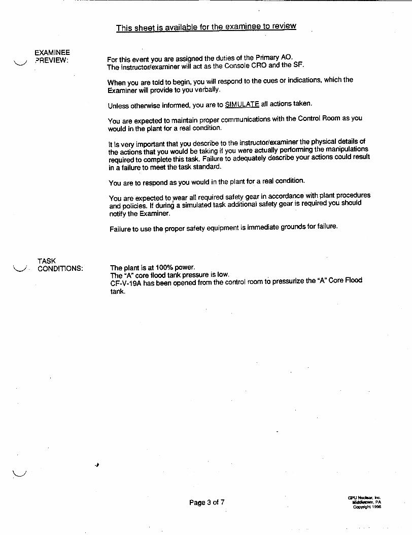
This sheet is available for the examinee to review
EXAMINEE ?REVIEW:
TASK "-.> CONDITIONS:
For this event you are assigned the duties of the Primary AO. The instructor/examiner will act as the Console CRO and the SF.
When you are told to begin, you will respond to the cues or indications, which the
Examiner will provide to you verbally.
Unless otherwise informed, you are to SIMULATE all actions taken.
You are expected to maintain proper communications with the Control Room as you
would in the plant for a real condition.
It is very important that you describe to the instructor/examiner the physical details of
the actions that you would be taking if you were actually performing the manipulations
required to complete this task. Failure to adequately describe your actions could result in a failure to meet the task standard.
You are to respond as you would in the plant for a real condition.
You are expected to wear all required safety gear in accordance with plant procedures
and policies. If during a simulated task additional safety gear is required you should notify the Examiner.
Failure to use the proper safety equipment is immediate grounds for failure.
The plant is at 100% power. The "A" core flood tank pressure is low. CF-V-19A has been opened from the control room to pressurize the "A" Core Rood tank.
4
Page 3 of 7GPU Nucbr, km MiddgWiin. PA
Copywight 19

11.2.05.100 Revision 1 S12/20/1999
EXAMINER CUES /
,^s the SF, instruct the Examinee to align the Core Flood Tanks for pressurization.
EXAMINEE ACTIONS
1. Examinee simulates logging the CF N2 addition in the primary log.
STANDARD
1. Log entry simulated at primary A.O. center 305 Aux. Bldg lAW AP 1012.
Examiner provides the Examinee with a copy of OP 1104-1 and OP 1104-26. Examiner informs the Examinee the N2 is aligned from the high pressure Nitrogen banks, NI-T-1A/B to the 650 psig header.
*2. Examinee opens CF-V-10 2. CF-V-10 is open.
by rotating the handwheel in the counter clockwise SAT.
direction.
ROLEPLAY: If the Examinee fails to report to the NI-V-25 location, Examinee CANNOT complete this task.
*3. Examinee proceeds to the Auxiliary Building 305' elevation across from 1A ESV MCC and opens NI-V-25 by rotating the handwheel in the counter clockwise direction.
SAT.
POSITIVE CUE: Inform Examinee that NI-V-25 is aligned per their instruction.
ROLEPLAY: If the examinee contacts the Control Room tell the examinee that you are monitoring level and pressure.
ROLEPLAY: If the examinee contacts the Control Room tell the examinee that you have opened CF-V-1 9A. (Was listed as open in initial conditions.)
ROLEPLAY: If the examinee contacts the Control Room or outbuildings tell the examinee that NI-V-1 37 is open. N2 was listed av lined up
the 650# header in step 1.
4. The Examinee contacts the control room to monitor Core Flood Tank level and pressure.
5. The Examinee contacts the Control Room to open CF-V- 19A.
6. The Examinee contacts the Control Room or outbuildings to line up the High Pressure bottle banks.
4. Examinee contacts the control room.
5. Control Room contacted to open CF-V-19A.
6. High pressure banks inservice.
GPU Nuclear, Inc.
WNWORDg7\LP\'TPM\1 1205100-DOC Pag'e 4 of 7 Middeom, PA Copyrght 1996
3. NI-V-25 is open.

EXAMINER CUES EXAMINEE ACTIONS STANDARD
*7. Examinee proceeds to the Chem. Addition room and Verifies open NI-V-1 38 by rotating the handwheel in the counter clockwise direction.
7. NI-V-138 isopen.
SAT.
*8. Examinee slowly opens 8. NI-V-139 is open.
NI-V-139 by rotating the handwheel in the counter SAT. clockwise direction.
*9. Examinee slowly opens 9. NI-V-141 is open.
NI-V-141 by rotating the handwheel in the counter SAT. clockwise direction.
"*10. Examinee opens NI-V-98A by rotating the handwheel in the counter clockwise direction.
11. Examinee opens NI-V-98B by rotating the handwheel in the counter clockwise direction.
10. NI-V-98A is open.
SAT.
11. NI-V-98B is open.
NOTE: *12. Examinee slowly opens 12. NI-V-99 is open. Critical only if the B regulator is to NI-V-99 by rotating the be used. handwheel in the counter SAT.
clockwise direction.
"*13. Examinee opens the 650 psig inlet valve (NI-V-81 A or B) for the regulator by rotating the handwheel in the counter clockwise direction.
13. NI-V-81A or B is open and Lo side 650 # N2 regulator gauge indicates _> 650#
SAT.
POSITIVE CUE: If Examinee performs crit ical steps 6-12 correctly inform them that N2 pressure is at least 650#.
NEGATIVE CUE: 'ixaminee does Not perform ps 6-12 correctly, inform them
wiat N2 pressure is not reading > 650#.
11.2.05.100 Revision 1
12/20/1999
GPU Nudear, Wnc Mi . PA Copynght 1996Pa'e 5 of 7WN:WORD97\LP\OT\JPM\1 1205100.DOC

11.2.05.100 Revision 1 12/20/1999
EXAMINER CUES /
NOTE: To use NI-V-79B, NI-V-99 must have been opened above and the B regulator placed inservice.
EXAMINEE ACTIONS
"*14. Examinee slowly opens the
650 psig outlet valve (NI-V-79A & 1011) or 79B for the regulator by rotating the handwheel in the counter clockwise direction.
STANDARD
14. NI-V-79A & 1011 or NI-V-79B is open and Lo side 650 # N2
regulator gauge indicates >_ 650#
SAT.
15. Examinee contacts the control room to inform them N2 is lined up to the "A" Core Flood tank.
15. Control room contacted
POSITIVE CUE: If Examinee performs the critical steps above correctly, inform them that N2 pressure is rising on CF-T-1 A.
NEGATIVE CUE: If Examinee does not properly perform critical steps properly, inform them that you see no rise in pressure on the "A" Core Flood ",rik.
JPM may be terminated at this time.
(*)Denotes Critical Element.
EVALUATION: SAT:_ UNSAT:
4
W:WORD97"LP\O1\JPM\1 1205100.1OCGPU Nuclear. Inc. Middleo.w, PA
copynght 1996Page 6 of 7

11.2.05.100 Revision 1
12/20/1999
JPM CHANGE HISTORY PAGE
REVISION DATE REFERENCE DESCRIPTION TITLE (Include Al # if Appropriate)
0 4/11/96 Upgraded AO JPM to LOR standards and incorporated into LOR bank. Deleted existing AO JPM. Previous AO JPM #11.2.07.036
1 12/20/99 Formatted examinee page as preview page. Upgraded to Word97. Deleted Grading sheet. Made editorial changes. Significant rewrite because of the NI mod that installed NI banks and liquid tank added logging requirement as step 1.
_____ .1. 1 4
I_ _ I i
_____ I 4. I
1. 4 1�
4. *1
4 I .1
_____ I I. I
4 1*
1. 4 +
_____ 4 1 1
4
_____ _____ I _________ I
W:\WORD97\LP\OT'U-JPM\1 1205100.DOC
GPU NudeaC, kc. MiddletovW PA CopynqW 1996
I I F
SPade 7 of 7

11.2.05.067 Revision 6 12/1511999
TMI-1 OPERATOR TRAINING REQUALIFICATION PROGRAM
JOB PERFORMANCE MEASURE
POSITION: SRO/RO/AO
TITLE:
TASK NUMBER:
EVALUATION METHOD:
EVALUATION LOCATION:
APPROXIMATE COMPLETION TIME:
IMPORTANCE RATING (TIF):
TOOLS AND EQUIPMENT:
EXAMINEE REFERENCES:
I 0CFR55.45:
Respond to a Loss of "A" DC Distribution System
0000580504
PERFORM:_ SIMULATE: X
SIMULATOR: IN-PLANT: X CONTROL ROOM:
12 Minutes
TMI=4.34 NRC=4.0 AK3.02
None
EP 1202-9A, Loss of "A" DC Distribution System
(a)(6), (8)
W:\word97\lp\ot\jpm\ 1205067.doc
Signature Date
Submitted By: /e; " i• -- ?'5
Validated By:
Reviewed By: Lead Inst., Ops. Training or Lead Inst., Sim. Training a e-r • f Lle, a41'
Operations Training Manager _ _ __il_
Approved BI: Plant Operations Director
Page I of 6

11.2.05.067 Revision 6 12/15/1999
SIMULATOR CONDITIONS: NA
EXAMINER PREVIEW: This JPM deals with responding to a loss of the "A" DC distribution
system - specifically two in-plant immediate manual actions: securing EG-Y-1A, and transferring the Alterrex Excitation System DC power supply to B-DC.
NOTE: If this JPM is commenced from the Control Room or nearby, it may be started at Step 6 due to the necessity of obtaining a key and the geographical locations of each task. It is NOT critical to secure EG-Y-1A prior to transferring exciter control power.
The sequence of events which should be followed in the conduct of this JPM is as follows:
1. Read or otherwise inform the Examinee of the information contained in the "EXAMINEE PREVIEW" section of this JPM.
2. Inform the Examinee of the TASK CONDITIONS. 3. Allow the Examinee to ask questions about the JPM. 4. Begin the cueing sequence as described in the EXAMINER CUES
section.
A certain amount of liberty (questioning or cueing beyond the bounds of the "EXAMINER CUES") may be taken by the Examiner In trying to extract the requisite information from the Examinee, however, care must be taken to ensure that you do not COACH the Examinee.
To complete this task successfully, the Examinee must complete each critical element (an element of the task which, if omitted or performed incorrectly, would result in a failure to meet the "TASK STANDARD") correctly.
TASK STANDARDS: EG-V-15A is closed, EG-Y-1A fuel rack is tripped, and the Alterrex
Excitation System DC power supply is transferred to "B" side DC power.
W:\word97\lp\ot\jpm\1 1205067.doc Page 2 of 6

This sheet is available for the examinee to review
N.-, EXAMINEE PREVIEW:
TASK CONDITIONS:
4
Page 3 of 6
For this event you are assigned the duties of the Extra CRO or Secondary AO.
The instructor/examiner will act as the Console CRO and the SF.
When you are told to begin, you will respond to the cues or indications that the examiner will provide to you verbally.
Unless otherwise informed, you are to SIMULATE all actions taken.
You are expected to maintain proper communications with the Control Room as you would in the plant for the real condition.
It is very important that you describe to the instructor/examiner the physical details of the actions that you would be taking if you were actually performing the manipulations required to complete this task. Failure to adequately describe your actions could result in a failure to meet the task standard.
You are to respond as you would in the plant for a real condition.
You are expected to wear all required safety gear in accordance with plant procedures and policies. If during a simulated task additional safety gear is required you should notify the Examiner.
Failure to use the proper safety equipment is immediate grounds for failure.
Plant is at-100% power, steady-state.
A loss of the NAN DC distribution system has occurred.
1202-9A immediate manual actions are in progress.
Your task will be to perform the 1202-9A immediate manual actions associated with securing EG-Y-1A and swapping main generator exciter control power.

11.2.05.067 Revision 6 12/15/1999
EXAMINER CUES
EXAMINER-ROLE PLAY: As the Shift Foreman, direct examinee to respond to EG-Y-1A and perform the following: 1) close EG-V-15A, 2) verify starting air
pressure on EMIP decreases to 0 psig, and
3) trip EG-Y-1A fuel rack.
POSITIVE CUE: If step 2 is performed correctly, inform examinee that EG-V-15A is closed and the starting air receivers are repressurizing.
EXAMINEE ACTIONS
1. Examinee responds to EG-Y-1A (red diesel) located in the Diesel Generator Building, northwest room, and locates EG-V-15A on the north side of engine, to the outside of and below the inspection skid.
*2. Examinee closes valve labeled EG-V-15A by turning its valve handle 900, so the handle is perpendicular to the pipe.
STANDARD
1. Examinee at EG-Y-1A and EG-V-15A located by examinee.
2. EG-V-15A is closed as indicated by its valve handle being perpendicular to the pipe, and starting air receivers repressurizing.
SAT NEGATIVE CUE:
If step 2 is not performed correctly, inform examinee that starting air receivers are not yet repressurizing.
POSITIVE CUE: If examinee performed step 2 correctly (EG-V-15A is closed) and locates EG-PI535A/B, inform examinee that "Starting Air Pressure" gauges read 0 psig.
3. Examinee checks "Starting Air Pressure" gauges, EG-PI-535A/B, mounted on EMIP, and verifies they decrease to zero (0) psig.
3. "Starting Air Pressure" gauges, EG-PI-535A/B, mounted on EMIP, decrease to zero (0) psig.
NEGATIVE CUE: If step 2 was not performed correctly, inform examinee that "Starting Air Pressure" on EG-PI-535A/B is NOT decreasing.
POSITIVE CUE: *4. Examinee trips EG-Y-1A 4. EG-Y-1A fuel racks If examinee correctly fuel racks by depressing tripped as indicated by performs step 4, inform the "FUEL RACKS TRIP" EG-Y-1A speed examinee that the noise knob located on the decreasing to zero (0). level from the Diesel and southwest corner of the its speed are decreasing. engine. SAT
NEGATIVE CUE: If step 4 was not performed correctly, inform examinee that diesel noise level and speed have not changed.
W:\word97\lp\ot\jpm\1 1205067.doc
5. Examinee informs control room that EG-Y-1A tasks are complete - the diesel is shutdown.
5. Control room informed that EG-Y-1A is tripped.
Page 4 of 6

11.2.05.067 Revision 6 12/15/1999
EXAMINER CUES
EXAMINER-ROLE PLAY: As the SF, direct examinee to obtain Key #22, respond to the Alterrex Cabinet for the Main Generator, and transfer Excitation Control to "B" side DC power.
POSITIVE CUE: If steps 6 & 7 are performed correctly, inform examinee that the Alterrex Cabinet door is open.
EXAMINEE ACTIONS
6. Examinee proceeds with Key #22 to the Alterrex Cabinet located in the BOP switchgear room at the south end of the 2nd floor of the Turbine Building, just north and across from the east end of IC 4KV BOP Bus.
7. Examinee opens the Alterrex Excitation cabinet using Key #22.
STANDARD
6. Examinee reports to the BOP switchgear room, and locates the Alterrex cabinet.
7. Alterrex Excitation cabinet door is open.
NEGATIVE CUE: If steps 6 & 7 are NOT performed correctly, inform examinee that Alterrex Cabinet door is NOT open.
POSITIVE CUE: If step 8 is performed correctly, inform examinee that the Alterrex power supply switch is in the "B" DC position.
*8. Examinee transfers the Alterrex Excitation system DC power supply to "B" side DC Power by rotating the 43 SS clockwise.
8. Alterrex power on "B" side DC as Indicated by 43SS pointing to "B 125VDC".
SAT
NEGATIVE CUE:. Inform the Examinee that the Alterrex power supply switch is still in the "A" DC position.
9. Examinee informs control 9. Examinee calls the room that Excitation Control Room and Control power has been informs the Control transferred to B-DC Room personnel of supply. their actions.
JPM may be terminated when examinee reports both tasks completed.
(*) Denotes Critical Element.
EVALUATION: SAT: UNSAT:
W:\word97\lp\ot\jpm\1 1205067.doc Page 5 of 6

11.2.05.067 Revision 6 12/15/1999
JPM CHANGE HISTORY PAGE
REVISION DATE REFERENCE DESCRIPTION TITLE (Include Al # if Appropriate)
1 10/31/89 NA Modified step #2 to non-sequence critical, deleted step #3.
2 10/02/90 NA Added steps to include tripping open of Main Generator Field Breaker, deleted follow-up questions.
3 01/17/91 NA Modified Examiner Cues sections to include positive and negative cues.
4 12/26/95 PCR for EP Al 95-286, Modified JPM to delete 1202-9A performance of tripping Main Generator
Field Breaker and added transfer of Alterrex Excitation power due to plant modification.
5 07/23/96 NRC 71001 Al 96-117, Upgraded JPM by removing Inspection step #2 critical task, comment from Lopez
during NRC 71001 inspection. Added cue to step #7 for starting air pressure due to procedure change.
6 12/15/99 Updated format & converted to WORD97.
Improved JPM editorially throughout.
Swapped order of tasks to match priority in 1202-9A; i.e. diesel tripped then exciter power supply swapped.
No technical changes.
W:Xword97\lp\ot\jpm\1 1205067.doP Page 6 of 6

11.2.05.045 Revision 4 10/05/1999
TMI-1 OPERATOR TRAINING REQUALIFICATION PROGRAM
JOB PERFORMANCE MEASURE - ALTERNATE PATH
POSITION: SRO/RO/AO
Manually Actuate the Relay Room CO 2 System
086A090104
EVALUATION METHOD:'
EVALUATION LOCATION:
APPROXIMATE COMPLETION TIME:
IMPORTANCE RATING (TIF):
TOOLS AND EQUIPMENT:
EXAMINEE
REFERENCES:
10CFR55.45:
PERFORM:
SIMULATOR:_
5 Minutes
TM1=3.73
SIMULATE: X
IN-PLANT: X CONTROL ROOM:_
NRC=3.0 K4.06
None
None
(a)(3), (12).
W:\WORD97LP\OT\JPM\1 I 205045.DOC
TITLE:
TASK NUMBER:
IGNATURE DATE
Submitted By: /f)."- 7
Validated By:
Reviewed by: Lead Instructor, Operator Training OR Lead Instructor, Simulator Training __
Operations Training Manager /
Approved By. Plant Operations Director
Rage 1 of 5
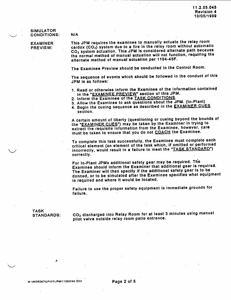
11.2.05.045 Revision 4 10/05/1999
SIMULATOR CONDITIONS: N/A
EXAMINER This JPM requires the examinee to manually actuate the relay room
PREVIEW: cardox (C0 2) system due to a fire in the relay room without automatic
C02 system actuation. This JPM is considered alternate path because the normal method of manual actuation will not function, requiring the
alternate method of manual actuation per 1104-45F.
The Examinee Preview should be conducted in the Control Room.
The sequence of events which should be followed in the conduct of this JPM is as follows:
1. Read or otherwise inform the Examinee of the information contained
in the "EXAMINEE PREVIEW" section of this JPM. 2. Inform the Examinee of the TASK CONDITIONS. 3. Allow the Examinee to ask questions about the JPM. (In-Plant)
4. Begin the cueing sequence as described in the EXAMINER CUES section.
A certain amount of liberty (questioning or cueing beyond the bounds of
the "EXAMINER CUES") may be taken by the Examiner in trying to
extract the requisite information from the Examinee, however, care must be taken to ensure that you do not COACH the Examinee.
To complete this task successfully, the Examinee must complete each
critical element (an element of the task which, if omitted or performed incorrectly, would result in a failure to meet the "TASK STANDARD") correctly.
For In-Plant JPMs additional safety gear may be required. The Examinee should inform the Examiner that additional gear is required.
The Examiner will then specify if the additional safety gear is to be
donned, or to be simulated after the Examinee specifies what equipment .is required and where it would be located.
Failure to use the proper safety equipment is immediate grounds for failure.
TASK STANDARDS: C02 discharged into Relay Room for at least 3 minutes using manual
pilot valve outside relay room patio entrance.
W:\WORD97\LP\OT\JPM11 1205045. DOC Page 2 of 5

This sheet is available for the examinee to review
EXAMINEE PREVIEW:
(to be conducted in Control room)
TASK CONDITIONS:
For this event you are assigned the duties of an AOICRO/SRO.
The instructor/examiner will act as the Shift Foreman or Supervisor.
When you are told to begin, you will respond to the cues or indications
that the examiner will provide to you verbally.
Unless otherwise informed, you are to SIMULATE all actions taken.
You are expected to maintain proper communications with the Control
Room as you would in the plant for a real condition.
It is very important that you describe to the Instructor/examiner the
physical details of the actions that you would be taking if you were
actually performing the manipulations required to complete this task.
Failure to adequately describe your actions could result in a failure to meet the task standard.
You are to respond as you would in the plant for a real condition.
You are expected to wear all required safety gear in accordance with
plant procedures and policies. If during a simulated task additional
safety gear is required you should notify the Examiner.
Failure to use the proper safety equipment is immediate grounds for failure.
The reactor has been manually tripped due to a fire in the Relay Room. The Control Room is being evacuated for the same reason.
Indications are that the Relay Room CO 2 system did not automatically actuate as designed.
4
Page 3 of 5

11.2.05.045 Revision 4 10/05/1999
EXAMINER CUES
As the Shift Foreman, direct the Examinee to manually actuate the Relay Room CO 2 System using the pushbutton station in ESAS cabinet room.
NEGATIVE CUE: Inform the Examinee that "nothing has happened' "there is no evidence that the CO 2 system has actuated.*
EXAMINEE ACTIONS
1. Examinee proceeds to the 3 rd floor of the control tower, ESAS cabinet room, and manually actuates the Relay Room CO 2 System by opening the hinged cover and depressing the pushbutton.
STANDARD
1. Examinee simulates actuating the Relay Room CO 2 system by opening the hinged cover and depressing the pushbutton on the manual actuation station in ESAS cabinet room.
*2. Examinee proceeds to 2. Examinee locates the
the Control Tower Patio alternate Relay Room at the east wall across CO 2 System Pilot from the CRDM Control Cabinet outside Inductrol units, to the relay room entrance alternate CO 2 Pilot from patio. Control Cabinet.
SAT
POSITIVE CUE: *3. Examinee breaks the 3. Glass on Relay Room CO 2
If the Examinee describes glass, and rotates the System Pilot Control
this action correctly, chrome handle %4 turn Cabinet is broken.
inform the Examinee that a up in the counterrushing noise can be heard clockwise direction to SAT
in the Relay Room and a the open position for 3 slight Wintergreen odor minutes. can be detected. Chrome handle is rotated
4 turn up in the counter
NEGATIVE CUE: clockwise direction and
If the Examinee does not position maintained for at
describe this action least three (3) minutes.
correctly or in sufficient detail, inform Examinee SAT that 'nothing has happenedo.
POSITIVE CUE: 4. Examinee returns 4. Chrome handle in
If reclosure of pilot valve chrome handle in Relay Relay Room CO 2
is described correctly, Room CO 2 System Pilot System Pilot Control
inform Examinee that CO 2 Control Cabinet to its Cabinet is returned to
flow noise has stopped. original closed position its original closed after 3 minutes. position after 3
minutes.
(*) Denotes Critical Element.
EVALUATION:
WA\WORD97\LPOT\JPM\1 1205045.DOC
SAT:
15age 4 of 5
UNSAT:

11.2.05.045 Revision 4 10/05/1999
JPM CHANGE HISTORY PAGE
REVISION DATE REFERENCE DESCRIPTION TITLE (include Al # if Appropriate)
3 01/08/99 N/A Specified standard on 2 "d method of initiating CO 2. Modified preview page, deleted grading sheet, converted to Word 97.
4 10/05/99 Converted to alternate path JPM: normal (electrical) manual actuation station will not function - must use pilot valve.
J
Page 5 of 5
K>
w:\woRD97MLPOTUJM\ 11205045.DOC

I-
Docket No. 50-289
",o0 UNITED STATES NUCLEAR REGULATORY COMMISSION
REGION I 475 ALLENDALE ROAD
"KING OF PRUSSIA, PENNSYLVANIA 19406-1415
March 3, 2000
Mr. Randy E. Hess Director - Training AmerGen Energy Company, LLC Three Mile Island Nuclear Station P. 0. Box 480 Middletown, PA 17057
Dear Mr. Hess:
The purpose of this letter is to inform you of the individual examination results for your applicants on the initial examination conducted on February 10, 2000 and February 14-18, 2000, at your facility. This meets the intent of section E. 1 of the Examiner Standards (ES 501) in NUREG 1021. Nine individuals were administered the examination, eight passed and one failed. This information is considered to be "proprietary" in accordance with 10 CFR 2.790 and it supplements the information contained in the related examination report for your facility which will be issued shortly.
Enclosure 1 is the completed ES-501-2, Power Plant Licensing Examination Results Summary, and is a summary of overall examination results.
Enclosure 2 contains the individual results ES-303-1 and 303-2, Operator License Examination Report, for the applicant. Contained therein are the deficiencies noted for
each applicant. In accordance with your Systems Approach to Training (SAT) Program, we
expect that you will review these results and provide appropriate remedial training for the individual independent of the overall pass status. The applicant has authorized the release of this information to your facility by signing Block 19A of NRC Form 398.
Enclosure 3 is a copy of the licenses and denial letter
Thank you for your cooperation in this matter. Please refer any questions you have to me at 610-337-5183.
Sincerely,
Richard J. Cont hief Operational Safety Branch Division of Reactor Safety

Mr. Randy E. Hess
Enclosures: 1. ES-501-2, Power Plant Licensing Examination Results Summary 2. ES-303-1 and 303-2, Individual Examination Results 3. Licenses and denial letter
cc w/o encls:
J. B. Cotton, Vice President PUBLIC