
The realization of sub-nanosecond pump and probe experiments at the ESRF

1
Nuclear Instruments and Methods in Physics Research A, 1997. 398: p. 69-84.
Time-resolved structures of macromolecules at the ESRF: Single-pulse Laue diffraction, stroboscopic data collection and
femtosecond flash photolysis
Michael Wulff*, Friedrich Schotte, Graham Naylor, Dominique Bourgeois, Keith Moffat§ and Gerard Mourou§§
The European Synchrotron Radiation Facility, B.P. 220, 38043 Grenoble, France
§ Department of Biochemistry and Molecular Biology and the Consortium for Advanced Radiation Sources,
University of Chicago, 920 East 58th Street, Chicago, IL 60637, USA §§ Center for Ultrafast Optical Science, University of Michigan, 2200 Bonisteel Blvd, Ann Arbor, MI
48109-2099, USA
Abstract. We review the time structure of synchrotron radiation and its use for fast time-resolved diffraction experiments in macromolecular photo-cycles using flash photolysis to initiate the reaction. The source parameters and optics for ID09 at ESRF are presented together with the phase-locked chopper and femtosecond laser. The chopper can set up a 900 Hz pulse train of 100 ps pulses from the hybrid bunch-mode and, in conjunction with a femtosecond laser, it can be used for stroboscopic data collection with both monochromatic and polychromatic beams. Single-pulse Laue data from Cutinase, a 22 kD lipolic enzyme, are presented which show that the quality of single-pulse Laue patterns is sufficient to refine the excited state(s) in a reaction pathway from a known ground state. The flash photolysis technique is discussed and an example is given for heme proteins. The radiation damage from a laser pulse in the femto and picosecond range can be reduced by triggering at a wavelength where the interaction is strong. We propose the use of microcrystals between 25-50 µm for efficient photolysis with femto and picosecond pulses. The performance of circular storage rings is compared with the predicted performance of an X-ray free electron laser(XFEL). The combination of micro beams, a gain of 105 photons per pulse and an ultrashort pulse length of 100 fs is likely to improve pulsed diffraction data very substantially. It may be used to image coherent nuclear motion at atomic resolution in ultrafast uni-molecular reactions.
1. INTRODUCTION The aim of this article is to describe the time structure of the radiation from a third generation synchrotron such as the European Synchrotron Radiation Facility(ESRF), the Advanced Photon Source(APS) and SPring8 and how it can be used to determine the spatial organization of macromolecules down to ca. 100 ps when it is combined with laser flash photolysis and spectroscopy. The beamline for structural kinetics at the ESRF is ID09 and we will describe its insertion devices, focusing optics, phase-locked chopper and fs laser. The control of reaction initiation by flash photolysis is also discussed and illustrated by calculations of the release of O2 in Myoglobin. Firstly, this information should enable researchers to evaluate new opportunities(and limitations) for time-resolved experiments using X-ray diffraction and spectroscopy. Secondly, the

2
performance of circular storage rings for time-resolved experiments will be compared with the expected performance of a free electron laser(XFEL). The instrumentation for time-resolved experiments on ID09 was developed initially for single-shot Laue diffraction. The key components are the synchronization electronics setting the delay between the photolysing laser and the probing X-ray pulse[1]. The first reversible macromolecular reaction in a crystal which was studied using single-pulse Laue diffraction was the kinetics of the CO-photocycle in carbonmonoxy myoglobin[2]. Using the focused polychromatic beam from a wiggler, Laue images before and after photolysis were recorded on a 170 ps single pulse from a 15 mA bunch of electrons in the storage ring, operated in the single bunch mode. Difference maps of the electron density were extracted for times between 4 ns to 2 ms after photolysis. They show the departure of CO from its original Fe-CO site, an ultrafast displacement of the iron out of the heme plane and more subtle relaxations in the heme pocket[2]. Apart from the biological results, the experiment is important since it shows that fast reaction initiation in a crystal is possible under carefully controlled conditions and that single-pulse Laue data can produce difference maps of atomic resolution with a potential time resolution of 100 ps. Time-resolved diffraction techniques may therefore be able to determine intermediate states in other biological reactions such as the production and storage of energy in the photo synthetic reaction center[3], the speed and pathway of ligand binding in heme proteins[4] and time-resolved recognition and discrimination. The best static structure determinations of macromolecules are produced by X-ray diffraction from crystallized samples. In a majority of cases this gives physiologically meaningful results despite the constrains imposed by the intermolecular contacts in the crystal. It is less clear however to what extend these constraints modify the time course or even the nature of a reaction. Moreover to what extent does the laser pulse bias the results and which parameters can one use to reduce the side effects from a short pulse? Are there any fundamental limits for the obtainable time resolution imposed by the cross section of photolysis and the magnitude of the electric field in a short pulse? We will discuss these questions at the end of this article.
2. THE STORAGE RING AND INSERTION DEVICES
In a third generation synchrotron highly focused electrons or positrons are accelerated to an energy in the 6-8 GeV range and then sent into a low emittance storage ring. As the electrons arc through the bending magnets they emit synchrotron radiation along the direction of motion in a narrow cone with a polychromatic spectrum. The opening angle of the cone is 1/γ = mc2/E, where m is the mass of the electron, E is its energy and c is the speed of light. The radiation from a bending magnet is confined within a narrow cone of opening angle ca 0.1 mrad in the vertical direction but spread out horizontally over several degrees as the electrons sweep through the bending magnets. The advantage of new synchrotrons is the use of undulators and wigglers, which raise the intensity over that of bending magnets by several orders of magnitude[5]. The devices are inserted in straight sections between the bending magnets and consist of linear arrays of dipoles with alternating polarity. These devices, also called insertion devices, may be up to 5 m long and may contain hundreds of poles. As an electron

3
traverses an insertion device, the Lorenz force directs the electrons into a slalom motion with photon emission near the turning points, see figure 1. Undulators and wigglers have the same magnetic construction but produce different types of radiation. The difference is expressed by the deflection parameter K, which is a measure of the maximum deflection angle of the electron in units of 1/γ K=0.0934 B0 (T )λ m (mm) , (1) where B0 is the peak magnetic field in the dipole array and λm is its period. The fundamental energy is : Ef = 0. 950 E2(GeV ) / (λm (mm) + K2 / 2 ) . (2) When K ≥ 1, the electron path swings outside the radiation cone, the radiation adds incoherently and the device is said to be a wiggler. The spectrum is an energy-shifted version of a bending magnet, but it is brighter by a factor roughly equal to the number of poles. By contrast an undulator is a device where K < 1. Here the electron does not move outside the radiation cone, so that the radiation from successive bends overlaps and interferes coherently. The radiation spectrum is characterized by a sharp peak at the fundamental wavelength, with less intense peaks at higher harmonics nof the fundamental. The fundamental wavelength is tunable by changing the size of the gap of the magnetic array. The radiation characteristics are summarized in table 1. The third generation synchrotrons designed for hard X-rays are the 6 GeV ESRF in Grenoble, the 7 GeV APS at Argonne National Laboratory and the 8 GeV SPring-8 in Harima Science Garden City near Osaka. The ESRF is an electron
-10
-5
0
5
10
-250 -150 -50 50 150 250
orbi
t am
plitu
de(µ
m)
wiggler length(mm)
1/ γ
Figure 1. The trajectory of a single electron filament in a K=5 wiggler on a 70 mm period. The circles show the positions of spontaneous emission. Note that the emission is tangential and concentrated near the turning points where the acceleration is greatest. The ESRF straight sections may accommodate up to three insertion devices each 1.6 m long.

4
ring while the APS and SPring-8 rings have a positron option which is expected to prolong the life time of the beam. Such an option was also considered at the ESRF but later dropped due to the very good life time of ca 50 h with electrons. The circumference of the rings are 844, 1104 and 1436 m respectively and their emittance(transverse electron-positron phase space) is practically identical. In principle the higher energy rings have the advantage of a larger undulator tunability and higher angular power but recent advances in minigap undulators make the difference less important[6]. TABLE 1. Radiation formulae for undulators and wigglers. Ef is the undulator fundamental, Ec is the critical energy, the midpoint of the power distribution. The angular power Pang is the power per unit space-angle in the center of the beam. The length of the insertion device is L and B0 is the peak field which can vary from 0.2-1.8 T depending on the magnet technology and the gap.
K 0.0934 Bo(T) λm(mm)
Ef(keV) 0.95 E2(GeV)/ (λm(mm)(1+K2/ 2))
Ec(keV) 0.665 E2(GeV) Bo(T)
Pang(kW/mrad2) 10.84 E4(GeV) Bo(T) N I(A)
P(kW) 0.633 E2(GeV) Bo2(T) L(m) I(A) From table 1 it is seen that the angular power Pang of an insertion device increases as E4. This relativistic focusing of the beam in high energy machines can only be fully exploited if the monochromators and focusing optics can handle this power density without geometrical distortion[7,8]. These heat load problems were a great challenge at the ESRF where wigglers may produce up to 10 kW on the monochromator crystal. They are now generally solved by the use of liquid nitrogen cooled silicon monochromators which take advantage of the very small thermal expansion of silicon around 100 K[9,10].
3. THE X-RAY TIME STRUCTURE AT THE ESRF The storage ring is not filled uniformly but has a bunch structure which arises in the following way. An electron in orbit emits synchrotron radiation and the energy loss makes it drift towards the center of the ring. To compensate for the energy loss, radio frequency(RF) oscillator sets up a tangential field at a harmonic of the ring frequency f= c/l, where c is the speed of light and l is the circumference. The harmonic number determines the number of bunches which can be stored. The RF at the ESRF operates at 352.2 MHz and the machine can store up to 992 bunches evenly spaced along its 844 m circumference. The time separation of adjacent bunches is 2.84 ns. In the steady state storage ring mode, the electrons arrive in the RF cavity while the field is increasing. The electrons in the head of the bunch receive therefore a smaller enery than electrons in the tail. The head electrons will concentrate on the inner radius of the orbit and visa versa and the bunch is

5
consequently compressed. The length of the bunch is 18-60 mm corresponding to a 60-200 ps X-ray pulse, see figure 2.
0
50fwhm
pul
se d
urat
ion(
ps)
100
150
current per bunch(mA)
200
0 5 10 15 20
FIGURE 2. The pulse length of a bunch measured by an optical streak camera. In the single-bunch mode, the current is typically 10-20 mA and the pulse length 150-190 ps. In the multi-bunch mode, a higher total current, a longer life time and lower emittance are produced by distributing the current over 332 consecutive bunches in 1/3 of the ring. The stored current can here reach 200 mA with 0.6 mA per bunch(with permission from Kees Scheidt, ESRF). The bunch structure is an advantage for fast time resolved experiments in the 100 ps to 1µs range where the time structure of the sample, the excitation pump, the shutter and detector may be optimized by a unique pulse structure. The most commonly used bunch structures are shown in figure 3. The exposure time of an n-pulse experiment is :
τ = (n −1) δτ ib + δτb (3)
where δτib is the inter-bunch separation and δτb is the bunch length. The intensity in one pulse is in most cases insufficient to obtain satisfactory data and the exposure time is determined by the long dark period between pulses. But for those experiments where there is sufficient intensity in one exposure, the exposure time is reduced to the pulse length itself. The exposure time increases thus from ca 0.1 ns to 2.9 ns in going from a one- to a two-pulse exposure. An interesting possibility exists in time-resolved experiments of reversible phenomena where the sample excitation can be repeated over and over until sufficient intensity is collected by the detector. Laue diffraction is the prime example of a single-pulse experiment performed in the single bunch mode. In this experiment the polychromatic beam is focused onto a stationary crystal and the diffracted intensities are recorded on an integrating area detector. The single-bunch revolution time of 2.82 µs is sufficiently long to allow isolation of a single pulse by a mechanical chopper. The storage ring at the ESRF is normally operated by default in a 200 mA mode where 1/3(332) of the buckets are filled and 2/3 empty. Many experiments only use the average intensity and it turns out that distributing the current over many

6
bunches has the advantage of lowering the electron "evaporation " caused by the repulsive electron-electron interaction, an effect called the Touschek effect [11-13]. In the low density 1/3 filling, the lifetime is bremsstrahlung-limited to about 52 hours for a vacuum of 10-9 torr whereas a 10 mA bunch has a Touschek lifetime of 11 hours. A suitable compromise is made by placing a single bunch opposite the center of the 1/3 pattern which is called the hybrid mode. In this way a phase-locked chopper can isolate a 100 ps pulse while other beamlines take full advantage of the high average intensity from the 1/3 filling pattern.
single bunch mode 16 bunch mode
1/3 filling(332 bunch mode)
hybrid mode(333 bunch mode)
FIGURE 3. : The most frequent bunch structures at the ESRF. The default mode is the 1/3 filling which produces a high current(200mA), a long life time(50h) and a low emittance. The 16 bunch mode is used for nuclear diffraction and spectroscopy. The single-bunch and hybrid mode are used for pulsed experiments on the µs, ns and ps time scale. The storage ring at the ESRF is normally operated by default in a 200 mA mode where 1/3(332) of the buckets are filled and 2/3 empty. Many experiments only use the average intensity and it turns out that distributing the current over many bunches has the advantage of lowering the electron "evaporation " caused by the repulsive electron-electron interaction, an effect called the Touschek effect [11-13]. In the low density 1/3 filling, the lifetime is bremsstrahlung-limited to about 52 hours for a vacuum of 10-9 torr whereas a 10 mA bunch has a Touschek lifetime of 11 hours. A suitable compromise is made by placing a single bunch opposite the center of the 1/3 pattern which is called the hybrid mode. In this way a phase-locked chopper can isolate a 100 ps pulse while other beamlines take full advantage of the high average intensity from the 1/3 filling pattern.
4. THE INSERTION DEVICES ON ID09
At the ESRF the straight sections between bending magnets can accommodate up to three insertion devices each 1.6 m long. In this way one beamline can do very different experiments. In a Laue experiment one sends a polychromatic beam on

7
to a stationary crystal and records the diffraction pattern on an area detector. The number of spots is proportional to the bandwidth and the best insertion device is a wiggler with a smooth spectrum and high intensity. A much broader class of experiments needs monochromatic beams. In cases where the tunability range is limited, one can use an undulator with essentially only one harmonic. To show how an insertion device can be tailor made for a specific experiment, we will briefly outline how the magnetic period for the Laue wiggler was determined. Ideally one would like to insert as many magnetic poles per unit length as possible but closely spaced poles weaken the field. Specifically, an array of alternating dipoles produces a sinusoidal vertical field with a peak field[14] : B0 = B1 exp(−π
gλ m
) (4)
where g is the gap of the insertion device and λm is the magnetic period. B1 is a material parameter which is 2.31T for the NdFeB magnets used at the ESRF. It is seen that the field increases with increasing period; a strong field wiggler has therefore fewer poles than an undulator. The angular power in the forward direction per unit length is(see table 1) : Pang(kW / mrad2 ) = 21.68
B0(T )λm (mm)
E4 (GeV) I(A) (5)
where the function exp(-π g/λm) /λm has a maximum at λm =π g which we shall call the wundulator period[15-17]. The properties of wundulators are summarized in table 2. Note that the wundulator period is a geometrical property of the array. The line integral of the power collected in the forward direction is here optimal. The wundulator period is independent of the electron energy whereas the deflection parameter and critical energy depend on both E and B1. Note that at 20 mm gap, NdFeB magnets on a 62.8 mm period produce a K= 5 wiggler with a critical energy of 20.6 keV. Such a device is ideal for Laue diffraction where it is important to have a broad and smooth spectrum. The gap was originally 20 mm at the ESRF. It is presently 16 mm with the aim of reaching 11 mm in 1997. At 10 mm gap, the angular power is doubled while the critical energy and total power are unchanged. Moreover the heat load on the mirror - measured by the critical energy - is unchanged. Note that wundulators become more undulator-like at lower gaps with a K =2.5 at 10 mm. The spectral smoothness is determined by the density of harmonics 1/Ef which is proportional to λm(1+K2/2). Mini gap wundulators therefore need a taper option or a sligthly varying period to produce a variation in K along the length of the device. TABLE 2. Insertion devices for optimal power density optimized at 10 and 20 mm gap. The magnet technology is NdFeB(B1=2.31 T) and the current is 100 mA.
Wundulator Optimum g=10mm g=20mm λm(mm) π g(mm) 31.4 62.8 K 0.108 B1(T) g(mm) 2.5 5.0 εc(keV) 0.245 E2(GeV) B1(T) 20.6 20.6

8
Pang(kW/mrad2) 1.269 E4(GeV) B1(T) L(m) I(A)/ g(mm) 62.4 31.2 P(W) 0.085 E2(GeV) B12(T) L(mm) I(A) 2648 2648
Presently we are using two wigglers(or wundulators) on a 46 mm(K =2.72) and 70 mm(K =5.40) period and a single-line undulator on a 26 mm(K =0.65) period. The source parameters are summarized in table 3 and the polychromatic spectra shown in figure 4. The source size of a wiggler is defined as the virtual image on a screen in the center of the wiggler waist. The image is broadened by the divergence of the beam over the half-length of the insertion device. In a coherent line source on the other hand, the photon tracks with the electron and the cone becomes gradually more collimated. The beam dimensions at the exit determine the source size and the distance to the focusing optics. TABLE 3. The calculated source parameters of the U26 mono-harmonic undulator and the U46 and W70 wigglers on a low b site in the electron beam. The insertion devices have 129, 71 and 43 poles respectively. Note the sub mm source size which is ideal for protein crystallography, high pressure research and liquid scattering. The magnetic gaps are 20.1 mm for W70, 16.2 mm for U26 and U46. The powers are quoted at 100 mA. Source dimensions are fwhm.
ID Ef(keV) Ec(keV K P(kW) Pang(kW/mr2) Sx(µm) Sz(µm) Sx'(mr) Sz'(mr)
U26 11.02 6.5 0.65 0.276 24.86 195 117 0.31 0.117
U46 1.60 15.4 2.72 1.516 32.50 241 117 0.62 0.117
W70 0.32 20.0 5.40 2.370 25.63 331 117 1.01 0.117
0.0 10 0
5.0 10 6
1.0 10 7
1.5 10 7
2.0 10 7
2.5 10 7
phot
ons/
bunc
h/0.
1% b
w
aver
age
flux(
ph/s
ec/0
.1%
bw)3.0 10 7
3.5 10 7
4.0 10 7
0
2.0 10 13
4.0 10 13
6.0 10 13
8.0 10 13
1.0 10 14
1.2 10 14
1.4 10 14
0 5 10 15 20energy(keV)
25
U26
U46
W70
FIGURE 4. The pulsed flux in the focal spot from the three insertion devices from a single-bunch of 10 mA. The focus is formed by a Pt coated toroidal mirror placed 29.7 m from the source. The entrance slit is here 20 mmh and 1.0 mmv and the mirror is at 2.32 mrad glancing angle. The average flux is shown on the right at 100 mA. In the single bunch mode all three insertion devices can operate simultaneously.

9
5. OPTIMIZATION OF THE TOROIDAL AND PARABOLIC
MIRROR The large radius of the new storage rings makes it necessary to install the first optical components far from the source point in order to free the photon optics from the electron beam. Thus the first pair of slits at ESRF are installed 27.0 m from the source. The long distance combined with the high heat load make the design of focusing optics a challenge in order to preserve the brilliance and guarantee a stable beam. The first mirror on ID09 is toroidal and the second is plane. Both mirrors are mounted in a bender for bending in the vertical plane. Both mirrors reflect vertically and are cooled to withstand the polychromatic beam. The toroidal mirror is used for focused Laue diffraction and the plane mirror for microfocusing in one direction. The toroidal mirror is also used as a premirror for the Laue-Bragg monochromator. It focuses the monochromatic beam sagittally whereas the vertical focusing is accomplished naturally by a Laue wafer in 1:1 focusing mode. The monochromator is protected by a graphite prefilter which lowers the heatload to a level suitable for water cooling. The trade-off is a poor throughput at low energies which limits the energy range to 12-40 keV. The mirrors are mounted in a three-point bender. The mirror rests on four piezoes at the corners which lift the mirror against four reaction points 100 mm away. In addition a piezo is mounted under the mirror to compensate the gravity sag. The water cooling is accomplished by spring-loaded Cu plates which float against the mirror sides using a layer of InGa to ensure good thermal contact. The mirror parameters are summarized in table 4.

10
A mirror can be considered a low pass filter. It reflects and focuses an energy band E < Emax, where Emax is a function of the incidence angle. By displacing the beam out of the orbital plane, which is contaminated by highly penetrating 6 GeV bremsstrahlung, the background is reduced which is of importance in experiments using integrating detectors such as image plates and CCDs. The meridional (or in-plane) radius Rm and the sagittal (or out-of-plane) radius rs are related to the distance p between the source and the mirror and the distance q between the mirror and the focal spot : Rm =
2 pq( p +q) sinθ , rs =
2 pq sin θ( p +q) (6)
where θ is the incidence angle. Since rs is fixed, changing the incidence angle induces a change in q : q =
p rs
rs − 2 p sinθ . (7)
Raising the angle brings therefore the focus nearer while reducing the bandwidth. The toroidal and parabolic surfaces deviate significantly from the ideal elliptical shape at strong defocusing and produce aberrations and therefore loss of intensity. The stroke of the figure error is reduced on the other hand. In the meridional focusing case, which applies to the parabolic mirror here, we have found an expression for the fwhm vertical spot size[16] :
TABLE 4. Toroidal and parabolic mirror parameters item mirror 1 mirror 2 shape cylindrical(toroidal) plane(parabolic) sagittal radius(mm) 64.53 - bender three-point actuator three-point actuator dimensions : L x W x H(mm3) 1000 x 130 x 100 1200 x 100 x 50 material SiC on graphite Si crystal coating Pt Pt rms surface roughness(Å) 1.8 1.0 rms longitudinal slope error(µrad) 8.4§ 6.0 p(m) 31.3 35.5 demagnifications used 0.36, 0.57, 0.83 §§ 0.2-0.5 incidence angles (mrad) 3.86, 2.83, 2.28 §§ 1.25-5.0 energy range(keV) 5.0-21.5, 5.0-29.7, 5.0-37.1 §§ 5.0-55.0 gravity sag(km) 4.7 6.9 Rm bending range(km) 1.8-4.7 1.5-6.9 Rm pushing range(km) 4.7-12.4 6.9-20.0 §4.1 µrad over 380 mm in the center §§for the optical tables T1, T2 and T3

11
Fz = (38
L2 θp
(1−M 2 )M
+Sz M+ Sz (M +1)L
4 p)2 +(2 ( 2.235α ) M p)2 (8)
where L is the length of the mirror, Sz is the vertical source size and α is the rms longitudinal slope error. The optimal defocusing Mopt and its associated focal size is found by solving dFz/dM =0 giving the optimal defocusing :
Mopt ≈ L3 θ
64α p2 4 L Sz + 16 p Sz − 3 L2 θ (9)
which shows that greater α implies greater optimal defocusing. The focal spot size for the parabolic mirror on ID09 is shown in fig. 5 together with the intensity vs defocusing for a toroidal mirror at 2.0 mrad incidence angle. Note that in both cases one benefits from working in the range 0.15 ≤ M ≤ 0.7 provided that the experiment can accept the larger divergence of the beam. In any case the advantage of working with great defocusing is that the beamline becomes shorter and therefore less expensive, and also less sensitive to thermal drifts.
0
0.1
0.2
0.3
0.4
0.5
0.6
fwhm
F z (mm
)
0.7
0 0.2 0.4 0.6
(a) demagnification M
ata 3
0.8 1
α = 6.0 µrad
α = 0 µrad
0
0.05
0.1
0.15
0.2
0.2 0.4
fract
iona
l tra
nsm
issi
on
0.6 0.8 1 1.2
(b) demagnification M FIGURE 5. The optimal defocusing of an insertion device is a competition between aberrations and the figure error. (a) the optimal defocusing of a parabolic mirror is 0.15 for a slope error of 6.0 µrad rms. (b) the optimal defocusing of a toroidal mirror is non analytical and a ray tracing simulation of the flux through a 0.2 x 0.2 mm2 pinhole is shown for a = 3.0 µrad rms. The incidence angle is in both cases 2.0 mrad.
6. THE CHOPPER AND PULSED MONOCHROMATOR
In order to select one or a set of X-ray single or super pulses, a fast shutter system has been designed, whose opening time and frequency match the time structure of the storage ring as well as the desired timing sequence of the experiment. The most efficient shutter design[1,17] consists in using a channel-cut rotating device,

12
synchronized to the RF bunchclock, mounted in series with a magnetic preshutter. Rotation of the chopper about an axis perpendicular to the X-ray beam provides the best performance in terms of x-ray absorption and opening time. In such a configuration, the opening time τ and the opening profile (of trapezoidal shape) p(t) are given by, see figure 6 :
τ =a
2 πR f 1− (h /R)2 (10)
and
p(t ) =0 if Abs[θ(t) ] ≥ θmin
Min 1, 2 RS
sin(θmin −θ(t ))� � �
� � �
if Abs[θ(t) ]≤ θmin
� �
(11)
where a is the height of the channel, R the chopper radius, h the channel offset, f the rotation frequency,
θmin = Arc sin(a / 2R) and θ(t ) = 2π f t , (12) and S is the beam size. In principle, for a given τ, the best choice consists in retaining as high a rotation frequency as possible. Indeed, this allows at the same time, (i) a higher repetition rate for the case of stroboscopic selection of X-ray pulses, (ii) a larger channel section, which is desirable if a large beam size is used and to aid alignment procedures, and (iii) a more compact chopper size, which is more practical and makes accurate drilling of the channel (for example with the spark erosion technique) much easier. However, a high rotation frequency results in significant mechanical stress, and the material as well as the chopper shape must be carefully chosen without compromising the X-ray absorption capability of the device. A propeller-shaped titanium chopper is presently under construction, see figure 6. The parameters are : a = 0.8 mm, R = 97 mm, h = 25.5 mm, fmax = 900 Hz, τmin = 1.47 µs. The velocity at the chopper periphery can reach 548.5 m/s thus exceeding the speed of sound so that the device must be run in vacuum. The overall repetition rate of the chopper can be reduced by suitable manipulation of the magnetic preshutter, down to the selection of a single X-ray pulse. The minimum opening time of the preshutter must be smaller than 2/f (2.2 ms in the ESRF case). The selected pulse train from the ESRF hybrid mode is shown in figure 7.
RS
a hbeam
ωωωω
FIGURE 6. The phase-locked chopper rotates at supersonic speed and is kept in vacuum. It can rotate at 900 Hz. When it is used for single-bunch selection in the hybrid

13
mode, it locked to the 391840 subharmonic of the RF at 898.84 Hz. The base-line of the opening window is here 1.47 µsec. The high repetition frequency matches the frequency of the femtosecond laser. Chopper synchronization is necessary to avoid partial chopping of the X-ray beam and selection of inadvertent double pulses. It can be performed in two ways. An "electronic" synchronization can be obtained by monitoring the phase drift between an asynchronous chopper and the X-ray clock(RF clock). By assuming short term stability of the chopper rotation frequency (say, over a few turns), the conditions of phase matching can be predicted a few milliseconds ahead of time, which suffices to decide when the magnetic preshutter should be opened. This elegant solution, proposed by LeGrand et al has the advantage of requiring limited mechanical precision, therefore reducing the cost of the device[17]. However, this is achieved at the expense of repetition rate, which in practice is limited to a few Hz due to the rather rare occurrence of satisfactory phase matching. The best performance of a chopper system is obtained by mechanical phase locking. By making use of magnetic bearings and high precision speed control electronics, mechanical locking with less than 100 ns jitter relative to the X-ray clock can be achieved. This costly solution was adopted since it will allow to run stroboscopic experiments at a frequency of 900 Hz, thus dramatically improving the duty cycle of the device for those experiments which can run at high frequency. The chopper was mainly designed for white beam experiments such as single-bunch Laue diffraction but we expect many applications in stroboscopic monochromatic data collection. A simple way of producing a pulsed monochromatic beam is accomplished by using the chopper in the focused white beam and sending the selected pulse train on to a channel-cut monochromator just before the sample. In the hybrid mode with a 150 mA super-bunch and a 15 mA single-bunch, one can extract the single bunch at 898.84 Hz. The chopper accepts thus 1:395 of the single bunches(and totally eliminates the super bunch). The heatload on the monochromator is consequently equivalent to an average current of 38µA. In addition, the heat pulse in a single 100 ps pulse is so short that the net planes in the monochromator have no time to react. In this way one has a 100 % efficient pulsed monochromator can be obtained without external cooling. This was illustrated by an experiment on the photo cycle of bacteriorhodopsin in which a chopper was run synchronously of the bunch clock at 10 Hz which reduced the heatload by a factor of 780 from 45 W to 58 mW. The chopper was run by a stepper motor at 10 Hz, which produced 115 µs polychromatic pulses which were loaded on to a Si(111) channel-cut monochromator. The monochromator gave its full theoretical flux over the 115 µs window as measured by a PIN diode(figure 8);. the focal spot is shown in figure 9.

14
-0
0.2
0.4
0.6
0.8
1
1.2
-5
Geo
met
rical
tran
smis
ssio
n
0 5
1.113 msec
||
time(µsec)
0
2
4
6
8
10
12
-5C
urre
nt /
bunc
h0 5 10 15
sing
le b
unch
supe
r bun
ch
time(µsec)
FIGURE 7. The time structure of the hybrid mode(above) and the geometrical acceptance of the chopper(below). The base-line of the opening window is1.47 µs and the top-line is 0.94 µs for a vertical beam of 0.3 mm.
0.0 10 5
5.0 10 5
1.0 10 6
1.5 10 6
2.0 10 6
2.5 10 6
0 10 8
ph/ 1
15 µ
s/ 1
00 m
A
ph/(1
0 m
A bu
nch)
2 10 8
4 10 8
6 10 8
8 10 8
1 10 9
8 9 10 11 12 13 14Energy(keV)
FIGURE 8. The flux in the Ø180 µm focal spot from the U26 fundamental in a single-pulse of 150 ps. The beam is monochromatized by a Si(111) channel-cut monochromator. In the experiment on the Bacteriorhodopsin photocycle, the polychromatic beam was chopped into 115 µs pulses at 10 Hz and the measured flux per pulse is shown on the right.

15
FIGURE 9. The monochromatic focus at 11.16 keV of the U26 undulator. The horizontal and vertical focal dimensions are 0.15 mm and 0.10 mm respectively. The incidence angle is 2.32 mrad and the defocusing 0.83.
7. THE ELECTRON DENSITY FROM SINGLE-BUNCH LAUE DATA
To examine the quality of Laue electron density maps from single-bunch patterns, we have collected data from the small enzyme Fusarium solani Cutinase, a 22 kD fungal enzyme responsible for the degradation of Cutin[18]. Cutinase crystallizes in a monoclinic space group with lattice parameters a =35.2 Å, b =67.3 Å, c =37.1 Å, α = γ = 90.0° and β =94.1°. The ESRF was operated in single-bunch mode was operated at 13 mA which produces ca 150 ps X-ray pulses. The flux was increased by using two insertion devices in series, the 43-pole wiggler(K=5.4) and the 71-pole wiggler(K=2.7). In this configuration 3.3 x 10¹⁰ photons over 8-32 keV could be delivered to the crystal in a single pulse. The purity and intensity of the pulses were monitored with an avalanche diode placed close to the sample. The images were recorded with a Ø220 mm image intensifier coupled to a slow scan CCD camera[19]. This detector is particularly efficient at detecting very weak diffraction patterns(DQE ~ 50%). A Laue pattern based on three X-ray pulses accumulated on the CCD detector is shown in figure 10. The crystal was mounted on a horizontal spindle axis and 19 Laue images were recorded between 0-180°. The crystal was thus exposed to the beam for 8.5 ns and no direct sign of radiation damage was observed. Each image contains ca 5000 reflections and the completeness is 71.7 % up to 1.5 Å resolution. The Laue pattern have been indexed, integrated and merged and their intensity distribution vs resolution is shown in figure 11. Note that the strongest reflections, which are typically multiplets of the form (h, k, l) and (2h, 2k, 2l) etc. diffract up to 3 x 10⁴ photons per pulse. With two insertion devices in series, the available flux was sufficient to refine a model of native Cutinase with Rcryst = 19.3% and Rfree = 24.2%, the starting model for the refinement being the R196E mutant[18]. A similar situation is encountered in time-resolved experiments where the excited state of the protein has to be refined from a model of the ground state.

16
FIGURE 10. Laue pattern a Cutinase enzyme recorded on three 170 ps pulses accumulated on an image intensifier. The pattern was recorded with the two insertion devices U46 and W70 in series and 3.3 x 10¹⁰ photons per pulse could be delivered to the 0.3x0.4x0.4 mm3 sample at 13.6 mA. The crystal was supplied by Sonia Longhi and Christian Cambillau, CNRS Marseilles. The first single-bunch Laue experiment at the ESRF was performed by Keith Moffat and his colleagues[2]. In a study of the photocycle of myoglobin carbonmonoxide(MbCO), the CO ligand was detached from the Fe atom by a 7 ns laser pulse at 635 nm and the movements of CO, Fe and the molecules in the heme pocket could be followed with ns resolution. Several effects were observed : a geminate recombination of the CO molecule where CO recombines with its parent Fe atom on the sub ns scale, a short-lived "docking site" some 4 Å from the initial position with a life time of 10-100 ns and a slower back diffusion of CO through the protein on the 100 µs scale. The Fe atom was also seen to move out of the heme plane by a small amount ~ 0.2 Å. For each time-point a new crystal was used and the power of the laser was carefully adjusted by monitoring the jump in the optical density to avoid unnecessary radiation damage. The crystal was rotated in steps of 4° over 0-184° with three exposures of the ground state and three exposures of the excited state for a given delay between the laser and the X-rays. The radiation damage during the 282 exposures seemed to be so small that complete time-points could be collected on one crystal. The synchronization of the laser, X-ray chopper and the CCD detector is described in[1].

17
FIGURE 11. The intensity distribution of 19 Laue frames from the Cutinase enzyme integrated to 1.5 Å. The decrease in intensity at low d-spacing is due to the atomic form factor, finite temperature and disorder. The total exposure time for the 75000 reflections was 8.5 ns.
8. FLASH PHOTOLYSIS OF FAST MACROMOLECULAR REACTIONS
In a time-resolved experiment one needs a way of initiating the reaction which is faster than all subsequent reactions of interest and which is otherwise free of artefacts[20]. Some reactions may be initiated chemically in a flow cell by delivering an activator or inhibitor to the crystal. The time scale is here limited by the speed of diffusion into and through the crystal which typically requires tens of seconds. Primary reactions in biology such as electron or proton transfer and the formation and breakage of bonds take place on the fs to ms scale and here one is forced to work with either naturally photo-sensitive reactions or reactions which can be made photo-sensitive artificially. Reversible photo-reactions are convenient because they can be repeated and diffraction patterns accumulated to satisfy a given precision and resolution. By varying the delay between the laser and the X-rays, one can produce a series of three-dimensional stills of the electron density which has been thought of as a movie[21]. In this movie, the time scale of a given phenomenon is the convolution of the intrinsic time scale and the laser and X-ray pulse lengths :

18
τ movie
2 = τ int2 + δτlaser
2 + δτx −ray2 , (13)
where we neglect the finite sample dimension(which becomes important on the sub ps scale). Consequently the time resolution of ultra fast phenomena can not be resolved beyond the X-ray pulse length of ca 100 ps with pump probe techniques on a third generation synchrotron. Will the use of picosecond or even femtosecond laser pulses make it possible to reach this 100 ps time-resolution with observable changes in the diffraction intensities? Since photolysis of macromolecular crystals with ultra short pulses has never been tried, we will look into this problem for liquids and crystals. The main difference between crystals and liquids is that the transmission of light is anisotropic or dichroic in crystals and has to be measured carefully. In deciding the photolysis strategy, one may start by considering the available crystal and focal dimensions. In a single pulse experiment on radiation sensitive molecules, the X-ray intensity takes priority and the crystal should be smaller than the focal spot minimizing transverse gradients. Consider now a laser pulse of intensity I0 impinging on a flat crystal. If the cross section for the event under consideration (eg. release of CO in MbCO) is σ, the inverse absorption length is : µ (λ , τ ) = n σ(λ , τ ) , (14) where n is the concentration of scatterers, λ the laser wavelength and τ the time after photolysis. If the pulse is shorter than the time scale of the change in absorption and the photolysis is below saturation, the absorbed photon density (or photolysis density) is : Iabs = I0 (1− exp(−µ t )) , (15) the decay in a linear differential system. It is seen that if the crystal size is µ-1, the longitudinal variation is e-1=36.8%. A longitudinal photolysis gradient may be acceptable since non-photolysed unit cells cancel out in a difference map(while lowering δI/I). One may however split the laser beam and photolyse from both sides. This will not only boost the degree of photolysis but also lower the longitudinal gradient. In practice one should choose a crystal size between 0.25 ≤ µt ≤ 0.5 to minimize the thermal bending and spot broadening from the longitudinal temperature profile. Moreover, it is important that the laser follows the crystal rotation to ensure that the photolysed volume is constant throughout a data collection. The intensity I0 needed to saturate the initial layer 0 ≤ t ≤ dt of the crystal is determined by : I0 µ dt =ndt (16)
from which we get the saturation limit : I0 =σ−1 . (17)

19
It follows that the energy saturation limit is :
ε sat =h cσ λ
, (18)
which numerically is εsat(mJ/mm2) = 1.987 x 10⁻¹³/( σ(mm2) λ(nm)). So apart from the energy term, εsat depends on the interaction σ only and not on the density of scatters. The wavelength dependence of εsat for heme containing proteins is therefore a generic function. In a crystal, σ is a function of the relative angle between the absorbing molecule and the polarization and finding the best angle between the crystal and the polarization could be important if one needs to work with larger crystals. Despite the simplified treatment, the above formula is a useful rule of thumb. Note that σ may differ substantialy from the value inferred from absorption measurements; the ratio is the quantum yield Q. To illustrate the photolysis requirements, we will examine the release of O2 in MbO2 . The absorption cross section σabs, derived from data in solution[22], is shown in figure 12 and the density of heme for the monoclinic(P21) and hexagonal(P6) unit cells is listed in table 5. The absorption length µ-1 for monoclinic MbO2 is shown in figure 13. It is seen that the only wavelengths which match the focal size on ID09 is 620-635 nm where 400≤ µ-1 ≤ 600 µm. But the price of the high penetration is a high εsat of 3.8 mJ/mm2 at 620 nm, see figure 14. Alternatively, triggering at 500 nm brings εsat down to 0.50 mJ/mm2 but an absorption length of µ-1 = 40 µm requires micro crystals and focusing. TABLE 5. Lattice parameters for MbCO in its monoclinic P21 and hexagonal P6 state. The concentration of Fe sites is also listed. sample a(Å) b(Å) c(Å) a(deg
) b(deg)
g(deg)
V/Fe(Å3) c(mMol) N(Fe/mm3)
MbCO(P21) 64.60 31.10 34.80 90.0 105.5 90.0 33686 49.3 2.97x 10¹⁶ MbCO(P6) 90.25 90.25 45.31 90.0 90.0 120.0 53268 31.2 1.88x 10¹⁶

20
0.0
5.0 10 -15
1.0 10 -14
1.5 10 -14
2.0 10 -14
2.5 10 -14
250 350
σ abs (m
m 2 /hem
e)
450 550 650wavelength(nm)
αβ
γ
MbO2 deoxy Mb
FIGURE 12. The absorption cross section of one heme unit in MbO2 and deoxy Mb. The data are derived from measurements in solution and neglects crystalline anisotropy[22].
1
10
100
1000
250 350 450 550 650
αβ
γ
µ -1 abso
rptio
n
leng
th(µ
m)
wavelength(nm)
FIGURE 13. The absorption length for monoclinic MbO2. To illuminate a volume comparable with the X-ray focal spot, one has to work in between 610- 635 nm, a range which can be covered by a Cr:fosterite femto second laser[23]. Alternatively one may use microcrystals at 500 nm.

21
The behavior of the absorption spectrum during the pulse is an important issue. In figure 12 it is seen that the absorption in the deoxy state increases at 620 nm. It is therefore likely that the tail of the pulse is obstructed by the effect of the head, an effect called anti-bleaching. The photolysis and temperature gradient are thus greater than exponential. The homogeneity would be improved by choosing the α band where the absorption goes down in the photolysed state but a µ-1 of 15 µm is difficult to use. Precise information on the time dependence of the absorption spectrum is therefore vital for a carefully planned experiment. The photolysis parameters of a 200 µm thick MbO2 crystal photolysed at 620 nm, are summarized in table 6. The adiabatic temperature jump is calculated by
∆T =E
cp M, (19)
where E is the absorbed energy, cp the specific heat of water and M the mass of the crystal. Note the fairly modest temperature rise of less than 1 K. It should be emphasized that the above calculations assume that the O2 release efficiency or quantum yield is 1 which is difficult to verify since the transient absorption spectra have not yet been measured. The energy densities mentioned in figure 14 are therefore lower limits.
0.01
0.1
1
10ε sat (m
J/m
m
2 )
250 300 350 400 450 500 550wavelength(nm)
600 650
FIGURE 14. The energy density for complete photolysis of heme proteins in solution. The quantum yield is here assumed 1.

22
Having calculated εsat, one needs to compress this energy into a pulse compatible with the time resolution of the experiment without damaging the crystal. The electric field scales as (εsat/τ)1/2, where τ is the pulse length.
FIGURE 15. The maximum degree of photolysis in heme proteins as a function of the laser pulse length. A quantum yield of 1.0 is assumed. Two cases are shown: a microcrystal of 40 µm thickness triggered at 500 nm where εsat =0.50 mJ/mm2 and a 400 µm thick crystal triggered at 620 nm where εsat =3.8 mJ/mm2. Making optimal use of the finite electric field tolerated by the crystal, one should trigger at a strongly absorbing wavelength. In return the crystal has to be very thin. So in going to shorter pulses, the electric field diverges and reaches eventually a breakdown point, sometimes called the fluence threshold, where ionization and continium creation takes place. The limit for myoglobin in solution is 30 µJ/mm2 for 100 fs pulses[24] and it increases as √τ for longer pulses[25]. It is shown in figure 15 that the photolysis threshold is 0.8% at 100 fs and 100 % at 1.5 ns. The calculated δI/I of a reflection of median intensity in MbCO has been shown to be ~ 10% at 100% photolysis[1] thus scaling down δI/I to 8 x 10⁻⁴ at 100 fs, which is impossible to measure by Laue diffraction. At this level, one may use modulation techniques with lock-in amplification and measure reflections one by one. One way out of this dilemma may be to go to microcrystals combined with microfocusing on the 25-50 µm scale. Specifically, photolysing at 500 nm, µ-1 is
TABLE 6. The photolysis of monoclinic and hexagonal MbO2 crystals. The adiabatic temperature rise is calculated using the heat capacity of water.
MbCO(P21) MbCO(P6) density(bonds/mm3) 2.969 x 10¹⁶ 1.877 x 10¹⁶ trigger wavelength(nm) 620 620 µ-1(mm) 0.40 0.64 εsat(mJ/mm2) 3.8 3.8 t(mm) 0.2 0.32 Pabs(mJ) 1.5 1.5 <∆T>(K) 0.89 0.55
0
20
40
60
80
100
degr
ee o
f pho
toly
sis(
%)
fluen
ce
0
0.5
1
1.5
2
2.5
3
3.5
4
0.1 1
laser pulse length(ps)
10 100 1000
40 µm @ 500 nm 400 µm @ 620 nm
23
40 µm and εsat is 0.45 mJ/mm2. At this wavelength the sample could be fully photolysed by a 20 ps pulse which is nicely matched the present X-ray pulse length 60-200 ps.
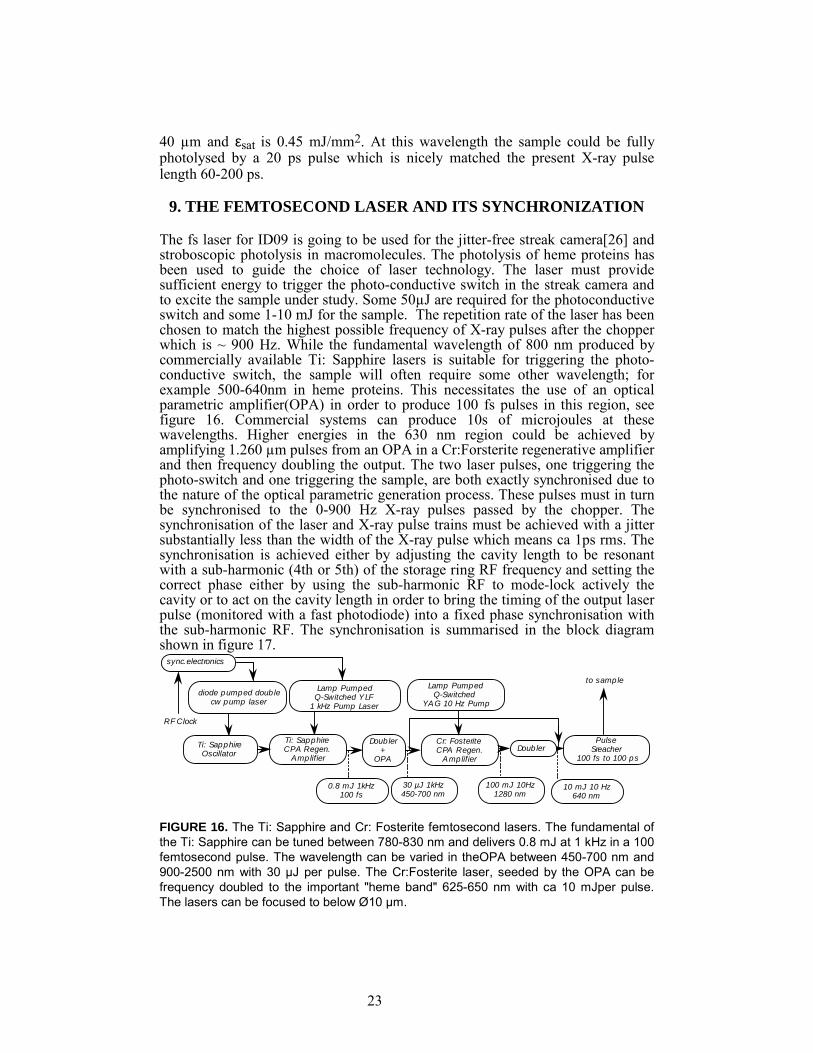
9. THE FEMTOSECOND LASER AND ITS SYNCHRONIZATION
The fs laser for ID09 is going to be used for the jitter-free streak camera[26] and stroboscopic photolysis in macromolecules. The photolysis of heme proteins has been used to guide the choice of laser technology. The laser must provide sufficient energy to trigger the photo-conductive switch in the streak camera and to excite the sample under study. Some 50µJ are required for the photoconductive switch and some 1-10 mJ for the sample. The repetition rate of the laser has been chosen to match the highest possible frequency of X-ray pulses after the chopper which is ~ 900 Hz. While the fundamental wavelength of 800 nm produced by commercially available Ti: Sapphire lasers is suitable for triggering the photo-conductive switch, the sample will often require some other wavelength; for example 500-640nm in heme proteins. This necessitates the use of an optical parametric amplifier(OPA) in order to produce 100 fs pulses in this region, see figure 16. Commercial systems can produce 10s of microjoules at these wavelengths. Higher energies in the 630 nm region could be achieved by amplifying 1.260 µm pulses from an OPA in a Cr:Forsterite regenerative amplifier and then frequency doubling the output. The two laser pulses, one triggering the photo-switch and one triggering the sample, are both exactly synchronised due to the nature of the optical parametric generation process. These pulses must in turn be synchronised to the 0-900 Hz X-ray pulses passed by the chopper. The synchronisation of the laser and X-ray pulse trains must be achieved with a jitter substantially less than the width of the X-ray pulse which means ca 1ps rms. The synchronisation is achieved either by adjusting the cavity length to be resonant with a sub-harmonic (4th or 5th) of the storage ring RF frequency and setting the correct phase either by using the sub-harmonic RF to mode-lock actively the cavity or to act on the cavity length in order to bring the timing of the output laser pulse (monitored with a fast photodiode) into a fixed phase synchronisation with the sub-harmonic RF. The synchronisation is summarised in the block diagram shown in figure 17.
FIGURE 16. The Ti: Sapphire and Cr: Fosterite femtosecond lasers. The fundamental of the Ti: Sapphire can be tuned between 780-830 nm and delivers 0.8 mJ at 1 kHz in a 100 femtosecond pulse. The wavelength can be varied in theOPA between 450-700 nm and 900-2500 nm with 30 µJ per pulse. The Cr:Fosterite laser, seeded by the OPA can be frequency doubled to the important "heme band" 625-650 nm with ca 10 mJper pulse. The lasers can be focused to below Ø10 µm.
sync.electronics
diode pumped doub le cw pump laser
Lamp Pumped Q-Switched YLF
1 kHz Pump Laser
Ti: Sapphire Oscillator
Ti: Sapphire CPA Regen.
Amplifier
Doub ler +
OPA
Lamp Pumped Q-Switched
YAG 10 Hz Pump
Cr: Fosterite CPA Regen.
Amplifier
0.8 mJ 1kHz 100 fs
30 µJ 1kHz 450-700 nm
100 mJ 10Hz 1280 nm
10 mJ 10 Hz 640 nm
Pulse Sreacher
100 fs to 100 ps
RF Clock
Doubler
to sample

24
The RF frequency used to accelerate the electron bunches in the storage ring is 352.2Mhz and defines the possible positions of the electron bunches in the ring. The revolution frequency of the storage ring is 355kHz. With a single bunch in the storage ring, the X-ray pulses produced by the insertion device on a particular straight section will therefore propagate down the beam line at a repetition frequency of 355kHz. The sample cannot however be excited by the laser at this frequency as it would overheat. The X-ray pulses are therefore chopped to a repetition frequency up to 900 Hz. A master laser oscillator is synchronised to the RF signal (which defines the timing of the electron bunches) at 88Mhz. There is in practice a drift of several picoseconds between the RF used to accelerate the electrons and the position of the electron bunch during the decay of the stored electron current. This is compensated by re-adjusting the RF phase by monitoring the exact position of the electron bunch with pick up electrodes. This compensated RF timing must then be distributed to the laser electronics some hundreds of meters away using a cable of low temperature coefficient dielectric in a temperature controlled environment. Single laser pulses are then selected from this train of pulses and amplified in a regenerative laser amplifier. The correct laser pulse corresponding to the X-ray pulse passed by the chopper is selected by opening and closing pockels cells in the regenerative amplifier cavity. The two pulse trains are brought into synchronisation on the 10s of picosecond time scale by adjusting the phase of the RF used to lock the laser oscillator while monitoring the relative timing with a fast photodiode. The synchronisation is then adjusted on the picosecond time scale by adjusting optical path lengths of the laser while monitoring using the streak camera itself. The relative timing of the optical excitation of the sample and the laser triggering of the streak tube is adjusted using a further optical delay line to the photo-conductor. The correct timing of the optical excitation of the sample will be verified by placing a doubling crystal in
Frequency Dividor(RF/4) Cavity Length & Phase Adjust Laser Oscillator
DIvide by 97960
Divide by 1-100
Adjustable Delay
Adjustable Delay
Pockels Trigger Electronics
CPA Regen AmplifierYLF Pump
Wavelength Conversion
AutocorrellatorChopper
Oscillo. PDCamera Optical Delay Line
Sample
RF : 352 MHz
X-rays(1-900 Hz)X-rays(352 MHz)
88 MHz
88 mHz900 Hz
Optical Delay Line
FIGURE 17. The synchronization of the Ti: Sapphire laser to the RF. The streak camera operation requires setting the delays between the the x-ray pulse, the photolysing pulse and the camera trigger.

25
the excitation path of the sample and allowing a small amount of the scattered light to fall on the entrance slit of the camera.
10. OUTLOOK ON THE FUTURE FOR TIME-RESOLVED STRUCTURAL KINETICS
It appears that time-resolved crystallography can be conducted using existing techniques and apparatus[1] down to a time-resolution of a few hundred picoseconds, but that better time resolution require that the problem of the fluence threshold be separately confronted. Smaller crystals may offer some advantages(Figure 15) but they of course diffract more weakly and require a longer total X-ray exposure to accumulate a good diffraction pattern. New problems arise if even better time-resolution is required, of less than a typical bunch length and no clearly suitable, two dimensional detector exists. We here propose how a zero-dimensional streak camera could be used to identify the synchronization problems, but it will clearly require substantial effort to test these proposals. The recent observation of coherent nuclear motion in bacterial reaction centers up to 3 ps after photolysis [27] and in smaller molecules such as HgI2 up to 10 ps[28], makes it important to examine whether such phenomena can be resolved by diffraction or spectroscopy on existing X-ray sources. The shortest X-ray pulse length at the ESRF, obtained in a special low-α momentum compaction configuration, is 32 ps(fwhm) which is close to the theoretical limit for circular machines[29]. So knowing that there is interesting new physics on the 10 ps scale, we are developing a jitter-free streak camera in which the electron sweep is initiated by the same optical pulse used to trigger the sample[26]. Recent tests have demonstrated 1 ps jitter free accumulation[30] and it is possible that later versions with pulsed photo-cathodes may reach 200 fs. The low DQE of the photo cathode(1-4% @ 1 Å) is going to prolong the exposure time which may not always possible on protein samples. Nevertheless, the intensity distribution from the single-pulse Cutinase study in figure 11 looks very promising with low resolution reflections collection up to 3 x 10⁴ ph/pulse. We expect that the streak camera will enable us to measure small oscillations in the diffracted intensity which are gradually damped out beyond 10 ps. It is of great importance to extend diffraction measurements to this regime which so far has only been accessible to laser spectroscopy which does not probe the nuclear positions directly. The reconstruction of a 3D potential energy landscape of coherent motion will not only be very important but also make a direct link to theoretical kinetics calculations of proteins. The quasi zero-dimensional nature of a streak camera is clearly a limitation but one should note that on the shortest time scales, only a few atoms have time to move. A small data set of say 100 time-resolved reflections may define a sufficient set of boundary conditions on the local environment near the reaction center. Guided by theory, one may be able to reconstruct the potential energy landscape in real time. The radiation damage from a fs pulse indicates that one has to reduce the power and work with small perturbations δI/I. In fast reversible reactions one may take advantage of the low heat load per pulse and step up the frequency. It seems feasible for example to illuminate a crystal with 1W/mm2 comprising 898.8 laser pulses per second. The X-ray pulse train is extracted by the phase-locked chopper and has a well-defined delay with respect to the laser pulse train. The sample is rotated through a small angle as in conventional monochromatic crystallography.

26
But the exposure time is going to be long using conventional monochromators. Specifically, the reduction in average intensity associated with a 898.8 Hz extraction of the 15 mA single bunch opposite the 150 mA super bunch is 4345. The rotation speed for small proteins at the ESRF is 1° per second but this is due to the too narrow monochromaticity of δE/E =1.33 x 10⁻⁴ for Si(111) monochromators. Increasing the bandwidth using a Be(002) mosaic monochromator(δE/E =2 x 10⁻³) or perhaps a 50-200 period multilayer with δE/E =1 x 10⁻² and a reflectivity of 50% may be the solution. It is thus straightforward to reduce the exposure time by a factor ca 35. The broadening of the diffraction spots arising from the rotation of the lattice planes through this quasi-white beam is smaller than 6.6 mrad for δE/E =1 x 10⁻² at 12.4 keV and a resolution limit of 1.5 Å. This seems acceptable for small unit cell proteins. The Free Electron Laser(XFEL) proposed at DESY in Hamburg will in addition to short pulses of 100 fs, produce near optics-free beamlines with a beam size of 10 µm and a flux of 2 x 10¹² ph/pulse over a 0.1% bandwidth[31], see table 7 for a comparison between ID09 and a XFEL. One can thus work with micro crystals and trigger heme proteins at 450 nm where the absorption length is 10 µm and εsat only 150 µJ/mm2. Narrow bandwidth Laue and monochromatic data collection should become possible down to the bunch limit of 100 fs. The gain in intensity of 1 x 10⁵ is likely to improve the data substantially and probably allow imaging of coherent motion in an enzyme directly. The structural kinetics community is still very small in Europe and in order to strengthen the scientific case for a free electron laser, we strongly encourage interested people to join the efforts at the ESRF, APS and SPring8. Exploring the picosecond range will lay the foundation for things to come.
ACKNOWLEDGEMENTS The authors wish to express their gratitude for informative discussion with V. Srajer, T.-Y. Teng, W. Schildkamp ,C. Pradervand, J. Hajdu, R. Neutze, W.
TABLE 7. Comparison between the U26 undulator on a low beta position(sx = 0.044 mm, sz = 0.007 mm, s'x = 0.087 mrad and s'z = 0.003 mrad) and the predicted performance of a free electron laser(XFEL) based on a 250 GeV linac. - ESRF XFEL fwhm bunch length(s) 150 x 10-12 200 x 10-15 photons per bunch in 0.1% bw 4.0 x 10⁷ § 0.2-50 x 1012 photons per bunch 1.4 x 10¹⁰ § ? peak flux (ph/sec/0.1% bw) 2.7 x 10¹⁷ § 1-270 x 1024 average flux (ph/sec/0.1% bw) 1.4 x 10¹⁴ §§ 0.2-150 x 1016 peak brilliance of the source (ph/s/mm2/mr2/0.1%bw)
2.3 x 1027 §§§ 1-100 x 1032
average brilliance of the source (ph/s/mm2/mr2/0.1%bw)
3.9 x 10¹⁸ §§§ 0.1-50 x 1024
§ measured in focal spot from a 10 mA single-bunch of 150 ps §§ measured in focal spot at 100 mA §§§ calculated values for the source

27
Bürmeister, J. Helliwell, P. Bösecke, M. Hanfland, P. A. Anfinrud, Y. Gauduel, M.-C. Bellissent-Funel, P. Trommsdorff, K. Scheidt and C Cambillau. We would also like to thank ESRF directors J.-L. Laclare, C.-I. Brändén, C. Künz and Y. Petroff for moral and financial support.
REFERENCES
1. Bourgeois D, Ursby T, Wulff M, Pradervand P, Legrand A, Schildkamp W, Labouré S, Srajer V, Teng T.-Y, Roth M and Moffat K, "Feasibility and Realization of Single Pulse Laue Diffraction on Macromolecular Crystals at ESRF", J. Synch. Rad, 3, 65 (1996) 2. Srajer V, Teng T.-Y, Ursby T, Pradervand C, Ren Z, Adachi S, Schildkamp W, Bourgeois D, Wulff M and Moffat K, "Nanosecond Time-Resolved Macromolecular Crystallography", Accepted by Science September 1996 3. Youvan D C and Marrs B L, "Photosynthetic Reaction Centers", Scientific American, 256, 42 (1987) 4. Lim M, Jackson T A, Anfinrud P A, "Binding of CO to Myoglobin from Heme Pocket Docking Site to Form Linear Fe-C-O", Science, 269, 962 (1995) 5. Elleaume P, "Insertion devices for the ESRF", Rev. Sci. Instr, 63(1), 321 (1992) 6. Elleaume P, "Spectral Shimming and Minigap Undulators", The ESRF News Letter, 23, 10 (1995) 7. Batterman B, Bilderback D, "X-ray Monochromator and Mirrors", Handbook on Synchrotron Radiation, Vol edited by G. Brown and D. Moncton, Elsevier Science Publisher B.V. (1991) 8. Susini J, "Design Parameters for Hard x-ray Mirrors" : The European Synchrotron Radiation Facility Case, Optical Engineering, 34(2), 361 (1995) 9. Rogers C S, Mills D M, Lee W, Knapp G, Freund A, Wulff M, Holmberg J, Rossat M Hanfland M and Yamaoka H(1995), "High Heat Load Performance of a Liquid Nitrogen Cooled Thin Silicon Crystal Monochromator on a High-Power Focused Wiggler Synchrotron Beam", Rev. Sci. Instr., 66, 6 (1995) 10. Yamaoka H, Freund A K, Holmberg J, Rossat M, Wulff M, Hanfland M, Lee K W, and D.M. Mills, "Experience from a Cryogenically Cooled Diamond Crystal Monochromator", Nuclear Instruments and Methods in Physics Research A, 364, 581 (1995) 11. Farvacque L, "Beam Life Time", Internal Report ESRF, (1995) 12. Piwinsky A, "Beam Losses and Life Times", Proc of the CERN Accelerator School, CERN, 19, 1984 13. Evans L R and Gareyte J, "Beam-beam Effects", Proc CERN Accelerator School , CERN, 87 (1985) 14 Halbach K, "The Magnetic Assembly of Insertion Devices", Nucl. Instrum. Methods , 187 (1981) 109 15. Wulff M, "The Optimization of Mirror Focusing of X-ray Sources : a Test Case at the ESRF", Proceedings on High Heat Flux Engineering, Spie, 1739, 576, (1992) 16. Susini J and Wulff M (1993), "Study of the Design Parameters Governing the Performance of Synchrotron Mirrors", Proceedings on High Heat Flux Engineering II, Spie 1997, 278 (1993)

28
17. LeGrand A D, Schildkamp W and Blank B, Nuclear Instruments and Methods in Physics Research A, 275, 442 (1989), and LeGrand A D, Pradervand C and Schildkamp W, in preparation 18. Bourgeois D, Longhi S, Wulff M and Cambillau C, "Accuracy of Structural Information Obtained at the ESRF from very Rapid Laue Data Collection on Macromolecules", Accepted for publication in J. Appl. Cryst., August 1996 19. Moy J-P, Nuclear Instruments and Methods, A348, 641 (1994) 20. Moffat K(1995), "Macromolecular crystallography on the millisecond to nanosecond time domain", SPIE Proceedings on Time-Resolved Electron and X-ray Diffraction, 13- 14 July, San Diego, 2521, 182 (1995) 21. Hajdu J and Andersson I, "Fast X-ray Crystallography and Time-Resolved Structures", Annual Review of Biophysics and Biomolecular Structure, 22, 467 (1993) 22. Antonini E and Brunori M, Hemoglobin and Myoglobin in their Reactions with Ligands, North Holland Publishing Company, 1971 23. Alfano M(1993), "The Cr:Fosterite Laser", Optics Letters, 18, 891 (1993) 24. Anfinrud P A, private communication 25. Du D, Liu X, Korn G, Squier J and Mourou G, Appl. Phys. Lett. 54(23), 3071 (1994) 26. Mourou G, Naylor G, Scheidt K and Wulff M, "Jitter-free Accumulating Streak Camera with Femto-Second Time Resolution", The ESRF Newsletter, 26, 32 (1996) 27. Vos M H, Rappaport F, Lambry J-C, Breton J and Martin J-L "Visualization of coherent nuclear motion in a membrane protein by femtosecond spectroscopy", Nature, 363, 320 (1993) 28. "Relaxation of the product state coherence generated through the photolysis of HgI2 in solution", Pugliano N, Szarka N K, Hochstrasser R M, J. Chem. Phys., 104 (1996) in press 29. Limborg C and Laclare J-L, ESRF, private communication 30. Cote C Y, Kieffer J C, Gallant P, Rebuffie J C, Goulmy C, Maksimchuk A, Mourou G, Kaplan D and Bouvier M, "Development of a subpicosecond Large-Dynamic Range X- ray Streak Camera",22nd Int. Congress on High Speed Photography and Photonics, SPIE Proceedings, (1996) 31. Rossbach J, "Coherent X-Ray Sources as a Part of a Linear Collider Design", Internal report, DESY, Hamburg, (1996)
Copyright © 2022 FDOKUMEN