T5040 -- T5050 -- T5060 TRACTORS SERVICE MANUAL
10
T5030 -- T5040 -- T5050 -- T5060 TRACTORS SERVICE MANUAL SECTIONS GENERAL GUIDELINES 00 ...................................................... ENGINE 10 ..................................................................... CLUTCH 18 ..................................................................... TRANSMISSIONS 21 ............................................................ DRIVE LINES 23 ................................................................ FRONT MECHANICAL TRANSMISSION 25 ........................................ REAR MECHANICAL TRANSMISSION 27 ......................................... POWER TAKE- OFF 31 .......................................................... BRAKES 33 ..................................................................... HYDRAULIC SYSTEMS 35 ....................................................... STEERING 41 ................................................................... AXLE AND WHEELS 44 .......................................................... CAB AIR CONDITIONING SYSTEM 50 ............................................ ELECTRICAL SYSTEM 55 ........................................................ PLATFORM, CAB, BODYWORK 90 ............................................... S E R V I C E
-
Upload
khangminh22 -
Category
Documents
-
view
3 -
download
0
Transcript of T5040 -- T5050 -- T5060 TRACTORS SERVICE MANUAL

T5030 -- T5040 -- T5050 -- T5060
TRACTORS
SERVICE MANUALSECTIONSGENERAL GUIDELINES 00. . . . . . . . . . . . . . . . . . . . . . . . . . . . . . . . . . . . . . . . . . . . . . . . . . . . . .ENGINE 10. . . . . . . . . . . . . . . . . . . . . . . . . . . . . . . . . . . . . . . . . . . . . . . . . . . . . . . . . . . . . . . . . . . . .CLUTCH 18. . . . . . . . . . . . . . . . . . . . . . . . . . . . . . . . . . . . . . . . . . . . . . . . . . . . . . . . . . . . . . . . . . . . .TRANSMISSIONS 21. . . . . . . . . . . . . . . . . . . . . . . . . . . . . . . . . . . . . . . . . . . . . . . . . . . . . . . . . . . .DRIVE LINES 23. . . . . . . . . . . . . . . . . . . . . . . . . . . . . . . . . . . . . . . . . . . . . . . . . . . . . . . . . . . . . . . .FRONT MECHANICAL TRANSMISSION 25. . . . . . . . . . . . . . . . . . . . . . . . . . . . . . . . . . . . . . . .
REAR MECHANICAL TRANSMISSION 27. . . . . . . . . . . . . . . . . . . . . . . . . . . . . . . . . . . . . . . . .POWER TAKE-OFF 31. . . . . . . . . . . . . . . . . . . . . . . . . . . . . . . . . . . . . . . . . . . . . . . . . . . . . . . . . .BRAKES 33. . . . . . . . . . . . . . . . . . . . . . . . . . . . . . . . . . . . . . . . . . . . . . . . . . . . . . . . . . . . . . . . . . . . .HYDRAULIC SYSTEMS 35. . . . . . . . . . . . . . . . . . . . . . . . . . . . . . . . . . . . . . . . . . . . . . . . . . . . . . .STEERING 41. . . . . . . . . . . . . . . . . . . . . . . . . . . . . . . . . . . . . . . . . . . . . . . . . . . . . . . . . . . . . . . . . . .AXLE AND WHEELS 44. . . . . . . . . . . . . . . . . . . . . . . . . . . . . . . . . . . . . . . . . . . . . . . . . . . . . . . . . .CAB AIR CONDITIONING SYSTEM 50. . . . . . . . . . . . . . . . . . . . . . . . . . . . . . . . . . . . . . . . . . . .ELECTRICAL SYSTEM 55. . . . . . . . . . . . . . . . . . . . . . . . . . . . . . . . . . . . . . . . . . . . . . . . . . . . . . . .PLATFORM, CAB, BODYWORK 90. . . . . . . . . . . . . . . . . . . . . . . . . . . . . . . . . . . . . . . . . . . . . . .
S E R V I C E

SECTION 10 -- ENGINE -- CHAPTER 1 15
87679925A -- 12 -- 2007
ENGINE R.I.
DANGER
Lift and handle all heavy parts using suitable liftingequipment.Make sure that assemblies or parts are supported bymeans of suitable slings and hooks. Ensure thatno--one is in the vicinity of the load to be lifted.
ATTENTION
Use suitable tools to align the holes. NEVER USEFINGERS OR HANDS.
1. Remove the bonnet (1) as described, seesection 90.
2. Disconnect the battery negative cable.
3. Drain the oil from the transmission--gearboxhousing. 1
4. Remove the retaining bolts (1) and the guard (2)on the right--hand side of the fan, then remove thefour bolts retaining the mechanical batterycut--out switch (1) from the guard.
25. Unscrew the control unit memory fuse power
cable (1) with the related positive cables (2) fromthe battery cut--out switch.

16 SECTION 10 -- ENGINE -- CHAPTER 1
87679925A -- 12 -- 2007
6. Detach the fitting (3) of the return pipe (2) for thecoolant from the cab heater radiator connected tothe underside of the coolant pump (1) and drainoff the engine coolant.
37. Remove the catch (2) and detach the toolbox (1).
48. Remove the split pins, retaining pin and front
ballast assembly (1) from the support.
59. Unscrew the front central and rear retaining bolts
on the front axle shaft guard, then remove theguard (1).
25038
1
6
SECTION 10 -- ENGINE -- CHAPTER 1 17
87679925A -- 12 -- 2007
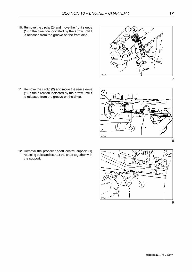
10. Remove the circlip (2) and move the front sleeve(1) in the direction indicated by the arrow until itis released from the groove on the front axle.
25039
1 2
7
11. Remove the circlip (2) and move the rear sleeve(1) in the direction indicated by the arrow until itis released from the groove on the drive.
25040
1
2
8
12. Remove the propeller shaft central support (1)retaining bolts and extract the shaft together withthe support.
1
25041
9

18 SECTION 10 -- ENGINE -- CHAPTER 1
87679925A -- 12 -- 2007
13. Remove the retaining bolts (1) of the draw pipe(2) of the lift pump.On the same side of the machine, on the left,unscrew the underlying oil pipes and, if there areclamps on them screwed onto the frame,unscrew them to free the pipes from the frame.
-- Unscrew the nozzle oil delivery pipe on thehigh--pressure pump.
-- On the power steering pump, unscrew the oilhose delivering oil to the power steering controlvalve.
-- Again on the left--hand side behind theconnection between the clutch casing andengine, on the control valve of the gearbox (ifthere is a hydraulic gearbox) or on the servicescontrol valve, unscrew the delivery and returnpipes to the cooler and the supply pipe to thecontrol valve.
-- Still in the area of the latter, unscrew the secondpart of the front differential lock pipe.
10
14. Remove the two metal clamps (2) and the rigidpipe (1) for drawing oil from the transmission viathe pumps of the lift and power steering, removethe pipe.On the same side of the machine, on the right,unscrew the underlying oil pipes and, if there areclamps on them screwed onto the frame,unscrew them to free the pipes from the frame.
-- High pressure user supply pipe, remove the pipe.-- On the gearbox filter, remove the delivery to the
gearbox control valve and extract the pipe, thenremove the filter too.
-- Again on the gearbox filter, remove the powersteering outlet hose to the filter (in the case of thehydraulic transmission) or remove the supplypipe to the services control valve (in the case ofthe mechanical transmission) then remove thepipe. 11
15. Extract the plastic fasteners (2) and detach thediesel recovery pipe (3) and delivery pipe (4) tothe diesel pump (1).
12

SECTION 10 -- ENGINE -- CHAPTER 1 19
87679925A -- 12 -- 2007
16. Disconnect the electrical connections (1) of theengine main cable from the cab cable.
1317. Disconnect all the electrical connections (1)
located on the cabmain cable and connect on theengine users.
1418. Disconnect the two power steering oil delivery
and return hoses (1), remove the pipe.
1519. Remove the front differential lock union (1) and
the hose (2) together with the pipe disconnectedin the operation 13.
16

20 SECTION 10 -- ENGINE -- CHAPTER 1
87679925A -- 12 -- 2007
20. Remove the retaining clips (1) and detach theflexible cables governing the hand throttle (5) andpedal throttle (4).
21. Remove the retaining clip (3) and detach thethrottle control tie--rod (2) connected to theinjection pump.
1722. Detach the clamp (1) and the cab heater delivery
pipe (2).
1823. Take out the three exhaust silencer rear retaining
bolts (1).
1924. Remove the clamp (1), the air filter dust ejector
pipe (2) and the four nuts (3) securing thesilencer to the exhaust manifold.
20

SECTION 10 -- ENGINE -- CHAPTER 1 21
87679925A -- 12 -- 2007
25. Remove the silencer (2) together with theexhaust pipe (1).
2126. Remove the two clips (2) for retaining to the
support (3) and the brake fluid reservoir (1).
2227. Remove the two retaining bolts (1) and the
support (2) together with the relays (3) protectingthe system.
2328. Remove the two retaining bolts (1) and the
support together with the fuse--holder box (2).
24
22 SECTION 10 -- ENGINE -- CHAPTER 1
87679925A -- 12 -- 2007
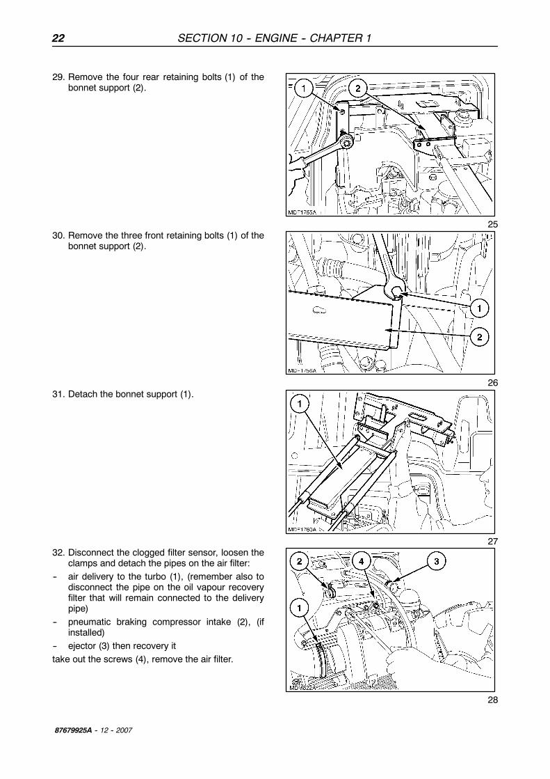
29. Remove the four rear retaining bolts (1) of thebonnet support (2).
2530. Remove the three front retaining bolts (1) of the
bonnet support (2).
2631. Detach the bonnet support (1).
2732. Disconnect the clogged filter sensor, loosen the
clamps and detach the pipes on the air filter:-- air delivery to the turbo (1), (remember also to
disconnect the pipe on the oil vapour recoveryfilter that will remain connected to the deliverypipe)
-- pneumatic braking compressor intake (2), (ifinstalled)
-- ejector (3) then recovery ittake out the screws (4), remove the air filter.
28

Thank you very much for your reading. Please click here to buy After you pay. Then, you can download the complete manual instantly. No waiting.