Synthesis of new olefin chalcone derivatives as antitumor, antioxidant and antimicrobial agents
Upload
khangminh22Category
view
4download
0
PART I: SYNTHESIS AND STUDY OF NONACENE DERIVATIVES;
PART II: OPTOELECTRONIC PROPERTIES OF
METAL-SEMICONDUCTOR NANOCOMPOSITES IN STRONGLY COUPLED REGIME
Dmitriy Khon
A Dissertation
Submitted to the Graduate College of Bowling Green State University in partial fulfillment of
the requirements for the degree of
DOCTOR OF PHILOSOPHY
August 2011 Committee: Douglas C. Neckers, Advisor
Mikhail Zamkov, Co-advisor
George S. Bullerjahn, Graduate Faculty Representative
Ksenija Glusac
Thomas H Kinstle

© 2011
Dmitriy Khon
All Rights Reserved
III
ABSTRACT
Douglas C. Neckers, Advisor
Mikhail Zamkov, Co-advisor
Acenes are polycyclic aromatic hydrocarbons (PAHs) consisting of linearly fused
benzene rings. In the recent past, acenes have been of interest from fundamental and
applied perspectives. Smaller acenes such as benzene, naphthalene, and anthracene are
among the most studied organic compounds and their properties are well explored.
Pentacene has received considerable attention as the most promising active
semiconductor for use in organic thin film transistors (TFT) because of its high charge-
carrier mobility; however, poor environmental stability is one of the problems limiting its
practical application. As the number of rings increases, the members of the acene family
become increasingly reactive.
The successful synthesis of heptacene developed by Mondal et al used the Strating-
Zwanenberg photodecarbonylation reaction. The lesser stability of the tetracene moieties
in the nonacene photoprecursor compared to the anthracene moieties of the heptacene
process make its synthesis more challenging. The latter scheme requires 2,3-
dibromoanthracene as one of the starting materials. Besides the poor solubility of 2,3-
dibromoanthracene, failure was also due to insufficient formation of anthracyne upon
treatment of 2,3-dibromoanthracene with n-BuLi. Although the initial idea didn’t work
we used the same scheme replacing 2,3-dibromoanthracene with 7,8-dibromo-1,4-
dihydroanthracene. The reaction of the latter with 5,6,7,8-
tetramethylenebicyclo[2.2.2]oct-2-ene gave 1,4,7,8,9,12,15,18,19,20-octadecahydro-

IV
8,19-diethenononacene albeit in low yield. Multiple attempts to dehydrogenate the non-
aromatic rings using DDQ and other reagents under various conditions failed to produce
the desired compound.
Recently Miller reported the synthesis of relatively stable heptacene derivatives having a
combination of arylthio and o‐dialkylphenyl substituents. Miller’s scheme used
1,2,4,5-tetrakis(bromomethyl)-3,6-bis(4’-t-butylthiophenyl)benzene as the core
precursor. Another synthetic approach has been undertaken that employs Miller’s
1,2,4,5‐tetrakis(bromomethyl)‐3,6‐bis(4’‐t‐butylthiophenyl)benzene in its core.
First attempts to react the latter with 1,4‐anthraquinone to produce nine linearly
fused ring system were unsuccessful. Interestingly in both approaches we used, a
dienophile benzyne‐type and quinone‐like with more than one fused ring were
unreactive in subsequent Diels‐Alder reactions. So similarly to the prior scheme, a
dienophile with terminal nonaromatic ring (6,7,8,9‐tetrahydro‐1,4‐anthraquinone)
was used along with 1,2,4,5‐tetrakis(bromomethyl)‐3,6‐bis(4’‐t‐
butylthiophenyl)benzene to yield a nine‐ring backbone structure which was treated
with mesityl magnesium bromide followed by reduction to yield 1,2,3,4,12,13,14,15-
Octahydro-8,19-bis(4'-t-butylphenylthio)nonacene. Unfortunately this compound
wasn’t isolated or properly characterized.
Combining metal and semiconductor domains in a single nanocrystal offer a unique
opportunity for the development of hybrid nanoscale composites with functionalities that
extend beyond those of isolated materials. The presence of powerful carrier confinement
in these nanoparticles joint with tunable geometry of the semiconductor-metal interface
gives rise to novel optoelectronic properties that can potentially add up to a wide range of

V
applications. Recently, Au/CdS and Au/CdSe heterostructures containing gold domains
grown onto cadmium chalcogenide semiconductor nanorods (NRs) have come forward as
a model system for studying such hybrid nanomaterials.
In this work we have developed several chemical routes to CdSe/CdS core-shell
nanocrystals (NCs) with each of them leading to different shape of nanocrystals. Also a
simple chemical method for growing Au domains onto CdS nanorods and CdSe/CdS NCs
in oleylamine was developed. The size of Au NCs can be precisely tuned by adjusting the
temperature of the reaction mixture, while the shape of Au/CdS nano-composites
(matchstick or barbells) is controllable via the reaction rate. All of the aforementioned
nanocomposites had semiconductor emission quenched and further study is necessary to
determine whether a significantly wider band gap shell material can prevent fast transfer
of excited carriers from semiconductor into metal domains.
VI
ACKNOWLEDGMENTS
First, I would like to thank Dr. Douglas C. Neckers for the support, guidance, and
patience extended towards me as a graduate student. I am grateful for his time, effort,
continuous encouragement, and trust in my abilities.
I am truly thankful to Dr. Thomas H. Kinstle, my organic chemistry teacher as well as
one of my committee members, for his invaluable support and passion for teaching,
which has been partially passed on to me.
I must thank Dr. Mikhail Zamkov for introducing me to the field of nanochemistry and
giving me an opportunity to work in his group. I highly appreciate his professionalism,
support, and optimism.
I would like to thank Dr. Ksenija Glusac and Dr. George S. Bullerjahn for serving in my
committee and for their inspiration to maintain the good work.
I am truly greatful to Dr. Rajib Mondal, and Dr. Yuewei Zhao for mentoring,
encouraging, criticizing and reviewing my work at the beginning of my graduate studies.
It is my pleasure to thank former and present members of Dr. Neckers’ group for
stimulating and friendly environment namely Ravi, Thilini, Kelechi, Sujeewa, Zhao, Cai,
Hannah, Leandro, Alexey, Erandi, Nadeeka, Puran, and others who have been great help
both inside and outside the lab for the past few years.
I would like to thank all members of Dr. Zamkov’s group especially Anna and Krishna
for their priceless help in the field of nanochemistry.
Also I would like to thank Nora and Alita for their administrative help at the department
and Romanowicz, Chen, and Doug for their technical support.

VII
At last but not least I would like to thank my family for their enormous support and
especially my sister Elena who never let me relax too much and for her invaluable help in
Dr. Zamkov’s lab.
VIII
Table of Contents
Chapter 1. Acenes: Structure, Reactivity, and Synthesis ..............................1
Introduction............................................................................................................1
Structure and Reactivity .......................................................................................2
Synthesis .................................................................................................................7
References.............................................................................................................15
Chapter 2. Attempted Synthesis of Parent Octacene and Nonacene ......18
Introduction..........................................................................................................18
Synthesis ...............................................................................................................19
Conclusion ............................................................................................................23
Experimental Section...........................................................................................25
References.............................................................................................................30
Chapter 3. Synthesis of Heptacene/Nonacene Derivative ...........................32
Introduction..........................................................................................................32
Synthesis ...............................................................................................................33
Experimental Section...........................................................................................39
References.............................................................................................................44
IX
Chapter 4. Exciton-Plasmon Interaction in Metal/Semiconductor
Nanocomposites ...........................................................................................................46
The morphology of Au/CdS(Se) colloidal nanocomposites ..............................46
Exciton-plasmon interaction in Au/CdS nanocomposites................................50
References.............................................................................................................57
Chapter 5. Synthesis and Optoelectronic Properties of Au/CdS and
Au/CdSe/CdS Nanocomposites ..............................................................................61
Au/CdS Nanocomposites .....................................................................................61
Au/CdSe/CdS Nanocomposites...........................................................................70
Experimental Section...........................................................................................74
References.............................................................................................................80
X
List of Figures
CHAPTER 1
Figure 1 Structure of Acene 2
Figure 2 Computed S0-T1 energy gaps for polyenes, acenes, and cyclacenes 3
Figure 3 Clar’s Sextet concept 4
Figure 4 Correlation of the activation (Ea) versus the reaction (ΔE) energies of acetylene addition to acene ring 5
Figure 5 Herringbone (left) and π-stacking (right) arrangements of pentacene 6
Figure 6 Persistent nonacene derivative 10 13
CHAPTER 2 Figure 2.1 Attempt to form nonacene backbone structure (2.12) 21
Figure 2.2 Formation and reactivity of “benzynes” from 1,2-Dibromobenzene to 2,3-Dibromoanthracene towards Diels-Alder reaction 21
Figure 2.3 Products of addition reaction of compound 2.6 with compound 2.10 22
CHAPTER 3 Figure 3.1 Attempt to couple compound 3.4 with 1,4-anthraquinone 35
Figure 3.2 Attempted aromatization of compound 3.10 36
Figure 3.3 MALDI-MS spectrum showing peak for compound 3.12 38
CHAPTER 4 Figure 4.1 (a,b). HAADF-STEM images of Au/CdS heterostructures showing the color contrast between gold (bright) and semiconductor (dark) domains. (c, d). TEM images of the two areas shown in (a) and (b) 48
Figure 4.2 Evaporation-induced assembly of Au/CdS nano-composites into (a) end-to-end “chains” and (b) two-dimensional superlattices 49
Figure 4.3 Depiction of Plasmon Resonance in Au nanocrystal 51

XI
Figure 4.4 (a) Steady-state absorption of Au/CdS heterostructures comprising 15.7-nm Au domains. A representative TEM image is shown in the insert. (b) Transient absorption spectra of 15.7-nm-Au/CdS nanocomposites resulting from the excitation at λ=400 nm with 120 fs pump pulses 53
Figure 4.5 Plasmon suppression in Au/CdS nanocomposites 54
Figure 4.6 Energy diagram showing the effect of strong inter-domains coupling on electronic energies in Au/CdS heterostructures 55
CHAPTER 5 Figure 5.1 TEM images of Au/CdS nano-composites fabricated using various synthetic conditions 63
Figure 5.2 TEM images and statistical size distributions of Au/CdS nano-composites grown at five different temperatures 65
Figure 5.3 Evolution of the Au/CdS absorption spectra during the synthesis 67
Figure 5.4 Au/CdS nano-composites synthesized from low-aspect-ratio nanocrystals 69
Figure 5.5 CdSe/CdS core-shell nanocrystals synthesized by method A 71
Figure 5.6 CdSe/CdS core-shell nanocrystals synthesized by method B 72
Figure 5.7 Au/CdSe/CdS nanocomposites with CdSe/CdS core-shell nanocrystals synthesized by method C 72
Figure 5.8 Au/CdSe/CdS nanocomposites with CdSe/CdS core-shell nanocrystals synthesized by method A 73
XII
List of Schemes
CHAPTER 1 Scheme 1 Photogeneration of Heptacene 2 in PMMA matrix 7
Scheme 2 Synthesis of 7,16-silylethynylheptacenes 8
Scheme 3 Synthesis of heptacene derivatives 6a-c 9
Scheme 4 Synthesis of heptacene derivatives 7a,b and 8a,b 11
Scheme 5 Synthesis of heptacene derivative 9 12
Scheme 6 Synthesis of Octacene 11 and nonacene 12 14
CHAPTER 2 Scheme 2.1 Synthesis of 5,6,7,8-tetramethylenebicyclo[2.2.2]oct-2-ene (2.6) 19
Scheme 2.2 Synthetic scheme for nonacene photoprecursor 20
Scheme 2.3 Synthesis of 2,3-Dibromoanthracene (2.11) 20
Scheme 2.4 Modified synthetic scheme for nonacene photoprecursor 22
Scheme 2.5 Synthetic scheme for octacene photoprecursor 23
Scheme 2.6 Bettinger’s synthesis of octacene and nonacene photoprecursors 24
CHAPTER 3 Scheme 3.1 Proposed Synthetic scheme for substituted nonacene derivative 33
Scheme 3.2 Synthesis of intermediate 3.4 34
Scheme 3.3 Revised synthetic scheme for substituted nonacene 34
Scheme 3.4 Synthesis of compound 3.9 35
Scheme 3.5 Modified organometallic reaction step for Miller’s synthesis of substituted heptacene 36
Scheme 3.6 Synthetic scheme to obtain compound 3.12 37
XIII
List of Abbreviations
OFET
Organic field-effect transistor
HOMO
Highest occupied molecular orbital
LUMO
Lowest unoccupied molecular orbital
DFT Density functional theory
eV Electron volt
Ea Activation energy
kcal Kilocalorie
mol Mole
nm
Nanometer
PMMA
Polymethylmethacrylate
h
Hour
NMR
Nuclear magnetic resonance
NIR Near infra red
W
Watt
UV/Vis Ultra violet/ visible
IR Infra red
n-BuLi n-Butyllithium
GC Gas chromatography
DDQ Dichlorodicyanoquinone
NMO 4-methylmorpholin-N-oxide
TLC Thin layer chromatography
XIV
GCMS Gas chromatography mass spectrometry
MALDI Matrix assisted laser desorption ionization
ml Milliliter
g Gram
Å Angstrom
THF Tetrahydrofuran
TsCl Tosyl chloride
DIP Direct insertion probe
DMSO Dimethyl sulfoxide
mmol Millimole
sat. Saturated
aq. Aqueous
M Molar
mg Milligram
DMF Dimethylformamide
NBS N-Bromosuccinimide
AIBN Azobisisobutyronitrile
RT Room temperature
NR Nano rods
DDAB Dodecyldimethylammonium bromide
DDA Dodecylamine
TEM Transmission electron microscopy
STEM Scanning transmission electron microscopy
SP Surface plasmons
M-S Metal-semiconductor
XV
NC Nano crystal
fs Femtosecond
ODE 1-Octadecene
OA Oleic acid
TOP Tri-n-octylphosphine
TOPO Tri-n-octylphosphine oxide
ODPA n-Octadecylphosphonic acid
ODA Octadecylamine
PL Photoluminescence
Part I: Synthesis and Study of Nonacene Derivatives
1
Chapter 1. Acenes: Structure, Reactivity, and Synthesis
Introduction
Acenes are polycyclic aromatic hydrocarbons consisting of linearly fused benzene rings.1
The smallest acenes, benzene, naphthalene, and anthracene, are among the most studied
organic molecules, while pentacene and its derivatives has received much attention as an
active layer material in organic field-effect transistors (OFETs)2 due to its high charge-
carrier mobility3. Interest in the synthesis of acenes larger than pentacene has been
largely increased in the last decade, since increased conjugation length in acenes is
expected to be beneficial for some applications in organic electronics, and significant
efforts have been devoted to the development of appropriate synthetic methodology3.
However, the synthesis of larger stable acenes is a difficult and challenging task because
of their very low solubility, poor stability in the presence of light and oxygen, and high
reactivity towards Diels-Alder reaction and dimerization, in addition to the difficult
multistep synthetic approaches required. Therefore, successful experimental studies on
larger acenes are very limited. In recent years significant progress has been made in the
synthesis of larger acenes, and stable and fully characterized heptacene derivatives were
synthesized4,5,6,7,8. Acenes can be considered to be building blocks of carbon nanotubes
and graphene, and studies on larger acenes may add to understanding of their properties.
For example, the chirality of carbon nanotubes can be described as arising from different
arrangements of the acene chains that are responsible for its metallic or semiconducting
electronic properties9. Although there are numerous studies on the electronic properties of
larger acenes using computational techniques3, their electronic structure, aromaticity, and

2
HOMO–LUMO gaps are still not completely understood.
Structure and Reactivity
The acenes can be represented by few limiting valence bond structures as shown in
(Figure 1a, 1b and 1c)10. Electronic properties depend on the preferred structure.
Valence-bond theory suggests all three structures are energetically similar and 1a has the
lowest energy 11. The stability of acene depends on a number of factors and calculations
favoring the stability of all three structures are reported3. The cis-distorted form is more
stable than the trans-form, while long range Coulomb interactions were considered. Non
interacting models conclude the trans-form the most stable form while the undistorted
structure is preferred10. According to Houk et al., larger acenes consist of two fully
delocalized non-alternating ribbons joined by relatively longer bonds (Figure 1b)10. The
energy levels are discrete in case of a particular finite acene and the HOMO-LUMO gap
(ΔE) decreases with the increase in number of rings for larger acenes.
Figure 1 Structure of Acene
3
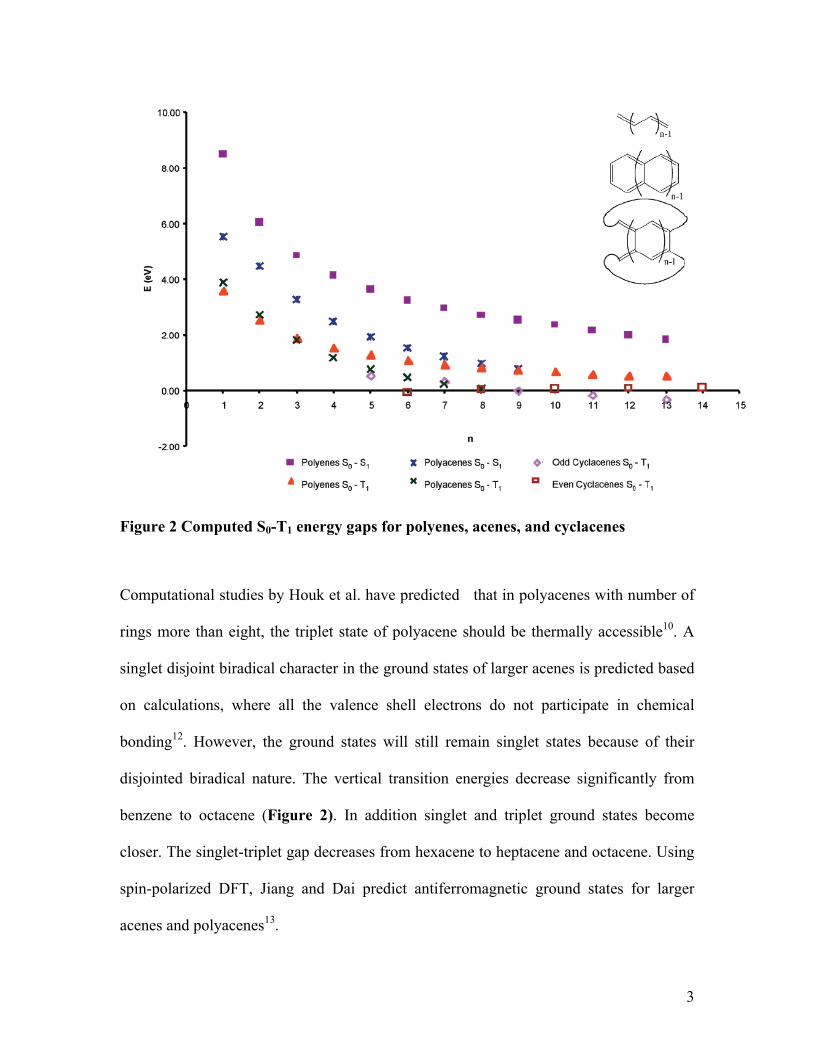
Figure 2 Computed S0-T1 energy gaps for polyenes, acenes, and cyclacenes
Computational studies by Houk et al. have predicted that in polyacenes with number of
rings more than eight, the triplet state of polyacene should be thermally accessible10. A
singlet disjoint biradical character in the ground states of larger acenes is predicted based
on calculations, where all the valence shell electrons do not participate in chemical
bonding12. However, the ground states will still remain singlet states because of their
disjointed biradical nature. The vertical transition energies decrease significantly from
benzene to octacene (Figure 2). In addition singlet and triplet ground states become
closer. The singlet-triplet gap decreases from hexacene to heptacene and octacene. Using
spin-polarized DFT, Jiang and Dai predict antiferromagnetic ground states for larger
acenes and polyacenes13.
4
There are at least three families of fused benzenoid compounds, including acenes,
phenacenes with zig-zag type condensation, and helicenes with ortho-condensation.
Compounds of the latter family are found to be more stable in comparison with
corresponding isomers in the former families14. Increasing the number of rings in acenes
not only decreases the band gap, but also increases the proton and electron affinities, and
reduces the ionization potential15 therefore reducing the stability of this class of
compounds.
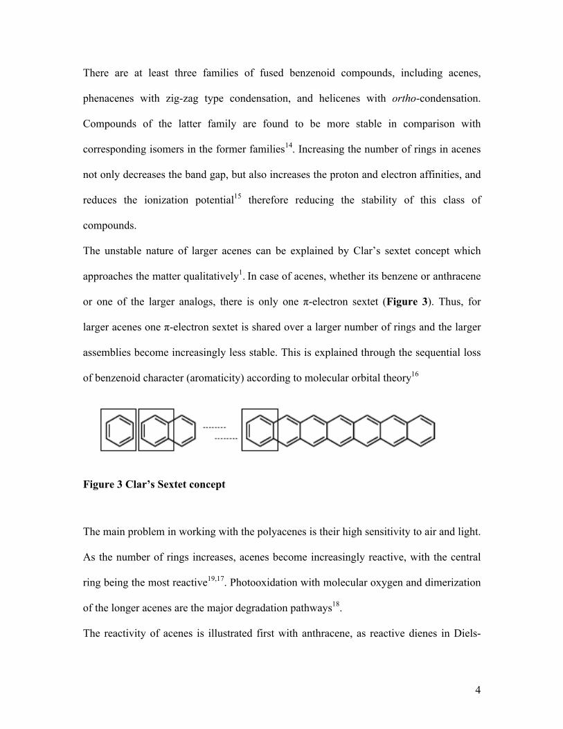
The unstable nature of larger acenes can be explained by Clar’s sextet concept which
approaches the matter qualitatively1. In case of acenes, whether its benzene or anthracene
or one of the larger analogs, there is only one π-electron sextet (Figure 3). Thus, for
larger acenes one π-electron sextet is shared over a larger number of rings and the larger
assemblies become increasingly less stable. This is explained through the sequential loss
of benzenoid character (aromaticity) according to molecular orbital theory16
Figure 3 Clar’s Sextet concept
The main problem in working with the polyacenes is their high sensitivity to air and light.
As the number of rings increases, acenes become increasingly reactive, with the central
ring being the most reactive19,17. Photooxidation with molecular oxygen and dimerization
of the longer acenes are the major degradation pathways18.
The reactivity of acenes is illustrated first with anthracene, as reactive dienes in Diels-
5
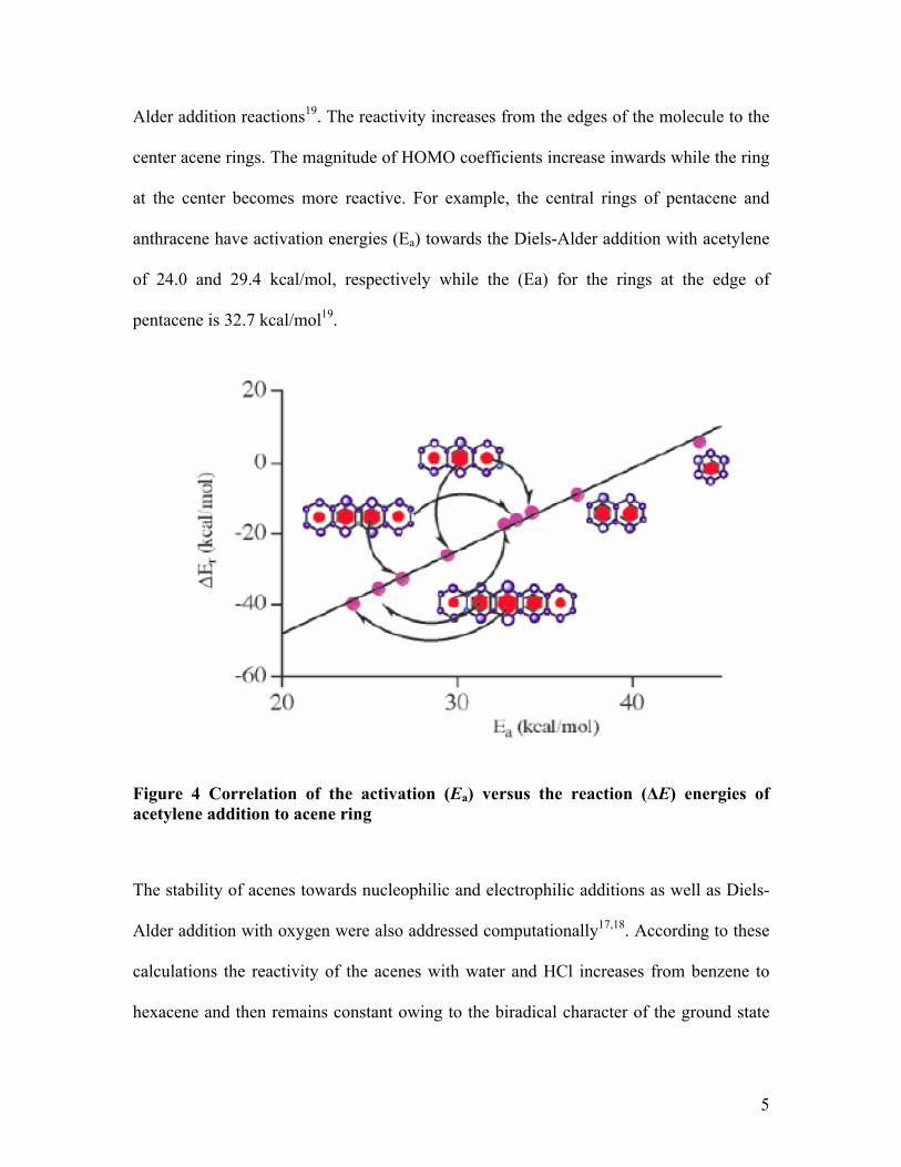
Alder addition reactions19. The reactivity increases from the edges of the molecule to the
center acene rings. The magnitude of HOMO coefficients increase inwards while the ring
at the center becomes more reactive. For example, the central rings of pentacene and
anthracene have activation energies (Ea) towards the Diels-Alder addition with acetylene
of 24.0 and 29.4 kcal/mol, respectively while the (Ea) for the rings at the edge of
pentacene is 32.7 kcal/mol19.
Figure 4 Correlation of the activation (Ea) versus the reaction (ΔE) energies of acetylene addition to acene ring
The stability of acenes towards nucleophilic and electrophilic additions as well as Diels-
Alder addition with oxygen were also addressed computationally17,18. According to these
calculations the reactivity of the acenes with water and HCl increases from benzene to
hexacene and then remains constant owing to the biradical character of the ground state
6
of higher acenes. These reactions are calculated to be exothermic with the activation
barrier (Ea) for HCl addition being lower (~27 kcal/mol) than that for the addition of
water. The addition of HCl to benzene has (Ea) of 44 kcal/mol, whereas it is only 16-18
kcal/mol for pentacene-nonacene18. The (Ea) value for singlet oxygen addition to acenes,
is in the same region as that of HCl addition. This value for benzene, anthracene, and
pentacene is about 48, 29, and 20 kcal/mol, respectively with singlet oxygen18. Both
triplet and singlet oxygen react with acenes and give the same products (endoperoxides).
Concerted20 as well as biradical stepwise mechanisms, starting from anthracene,17 for the
addition of oxygen have been suggested.
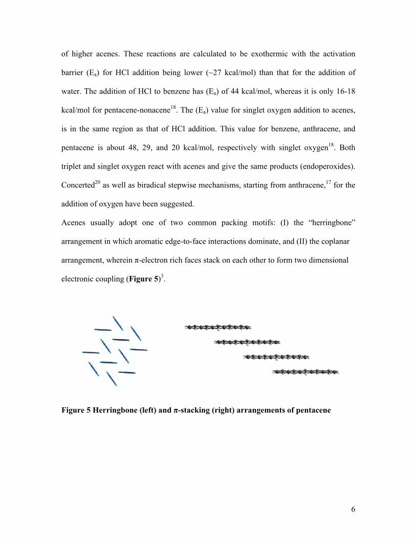
Acenes usually adopt one of two common packing motifs: (I) the “herringbone”
arrangement in which aromatic edge-to-face interactions dominate, and (II) the coplanar
arrangement, wherein π-electron rich faces stack on each other to form two dimensional
electronic coupling (Figure 5)3.
Figure 5 Herringbone (left) and π-stacking (right) arrangements of pentacene
7
Synthesis
Clar first claimed the synthesis of heptacene in 194221, but it was questioned in later
reports in 194322 and 195523. It was finally withdrawn in 195724. Until 1986 there was no
significant progress made in this area, when Fang reported the synthesis of larger acenes
in his PhD dissertation, which was written under the supervision of Chapman at UCLA25.
Thermolysis of the heptacene dimer was reported to produce heptacene25. However,
heptacene samples were always contaminated with heptacene dimer and
dihydroheptacene and pure heptacene was not obtained. Heptacene formation was
confirmed by accurate mass measurement (using mass spectrometry) and by the λmax
value for the highest wavelength absorption band in the sublimed film (968 nm) and in 1-
methylnaphthalene solution (at 220ºC, 752 nm)25.
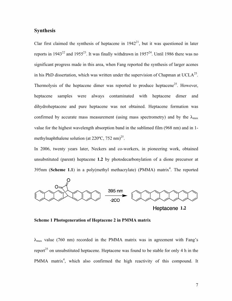
In 2006, twenty years later, Neckers and co-workers, in pioneering work, obtained
unsubstituted (parent) heptacene 1.2 by photodecarbonylation of a dione precursor at
395nm (Scheme 1.1) in a poly(methyl methacrylate) (PMMA) matrix4. The reported
Scheme 1 Photogeneration of Heptacene 2 in PMMA matrix
λmax value (760 nm) recorded in the PMMA matrix was in agreement with Fang’s
report25 on unsubstituted heptacene. Heptacene was found to be stable for only 4 h in the
PMMA matrix4, which also confirmed the high reactivity of this compound. It
8
immediately converts into the oxygen adduct (mainly endoperoxides) in the presence of
air in solution4. Heptacene that lacks protecting groups is highly unstable at room
temperature26, thus to stabilize the larger acenes protecting groups are required.
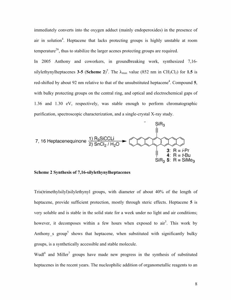
In 2005 Anthony and coworkers, in groundbreaking work, synthesized 7,16-
silylethynylheptacenes 3-5 (Scheme 2)5. The λmax value (852 nm in CH2Cl2) for 1.5 is
red-shifted by about 92 nm relative to that of the unsubstituted heptacene4. Compound 5,
with bulky protecting groups on the central ring, and optical and electrochemical gaps of
1.36 and 1.30 eV, respectively, was stable enough to perform chromatographic
purification, spectroscopic characterization, and a single-crystal X-ray study.
Scheme 2 Synthesis of 7,16-silylethynylheptacenes
Tris(trimethylsilyl)silylethynyl groups, with diameter of about 40% of the length of
heptacene, provide sufficient protection, mostly through steric effects. Heptacene 5 is
very soluble and is stable in the solid state for a week under no light and air conditions;
however, it decomposes within a few hours when exposed to air5. This work by
Anthony_s group5 shows that heptacene, when substituted with significantly bulky
groups, is a synthetically accessible and stable molecule.
Wudl6 and Miller7 groups have made new progress in the synthesis of substituted
heptacenes in the recent years. The nucleophilic addition of organometallic reagents to an

9
acene quinone, followed by dehydroxylation, is the most common synthetic route to
functionalized acenes3. A different synthetic method to functionalized heptacenes has
been established by Wudl et al. It utilizes double Diels–Alder cycloaddition between a
“bisanthracyne” and dienes, followed by reduction to give stable substituted heptacene
derivatives (Scheme 3)6. When substituents with the alkoxy side chains were
Scheme 3 Synthesis of heptacene derivatives 6a-c
employed the solubility significantly improved but compound 6b turned out to be too
reactive to be isolated or characterized completely. The aryl groups in the central ring
were replaced by triisopropylsilylethynyl groups to further improve stability, forming 6c.
Compound 6c is stable for over three weeks to the atmosphere oxygen and light when
coated in mineral oil and for 41 h when kept in degassed toluene solution. The bulky
substituents effectively prevent dimerization and polymer formation even after
recrystallization over three weeks6. Although the reactivity of heptacene derivatives may
10
be due to a singlet diradical character in the ground state which is supported by
calculations12, this is not detectable spectroscopically (1H NMR signals show sharp
splitting and narrow linewidths)5,6. Trialkylsilylethynyl groups red-shift the NIR
absorption of 6c by approximately 20 nm (863 nm in toluene) relative to 6b. The optical
HOMO–LUMO gap of 6c (1.35 eV,) matches the electrochemical HOMO–LUMO gap
(1.38 eV) very well6. This report by the Wudl group6 greatly expands the synthetic
methodologies available for the synthesis of large acenes and describes a substance that is
sufficiently stable to enable potential electronic applications.
Additional significant progress was recently accomplished by Miller’s group7. In their
study of a substituent effect for a large series of pentacene derivatives, they concluded
that steric effects, electronic effects, and the position of the substituents are all important
factors for determining photooxidative resistances and HOMO–LUMO gaps27. Miller et
al. prepared persistent heptacene derivatives using 2,6-dimethylphenyl and thioaryl
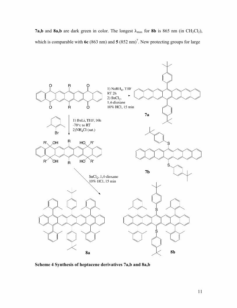
substituents (Scheme 4)7. Ortho-Alkyl-substituted phenyl groups are superior to phenyl
substituents in enhancing photooxidative resistance: the ortho-alkyl groups lie directly
over and under acene’s π system, thus providing better steric hindrance7. Thus thioalkyl
and thioaryl substituents enhance photooxidative resistance more than silylethynyl
substituents27. Consistent with the impressive substituent effects of arylthio substituents,
heptacene derivative 7b is even longer lived than 8a. Compound 8b is as an especially
persistent heptacene derivative with a small HOMO–LUMO gap (1.37 eV) comparable
with those of 5 and 67. Heptacene derivative 8b is soluble in a variety of solvents and
stable for weeks in solid state, for 1–2 days in solution if kept away from light and air,
and for several hours in solution when directly exposed to both light and air. All solids
11
7a,b and 8a,b are dark green in color. The longest λmax for 8b is 865 nm (in CH2Cl2),
which is comparable with 6c (863 nm) and 5 (852 nm)7. New protecting groups for large
Scheme 4 Synthesis of heptacene derivatives 7a,b and 8a,b

12
acenes were successfully introduced, significantly improving the possible opportunities
for larger acenes7.
Chi and co-workers recently reported another stable substituted heptacene8. Although
structurally it is very similar to compound 6c, and differs only in electron withdrawing
trifluoromethyl substituent on phenyls, the synthetic methodology used isonaphthofuran
precursors in a Diels-Alder reaction with benzoquinone followed by reduction to yield
the corresponding heptacene quinone which was treated with triisopropylsilylethynyl
magnesium chlride followed by another reduction to give compound 9 (Scheme 5)8.
Compound 9 has a yellow-green color and a NIR absorption maxima at 870 nm. The
Scheme 5 Synthesis of heptacene derivative 9
photostability of deoxygenated toluene solutions of 9 towards ambient light, white light,
and UV light (4W) was monitored and estimated half-lives of 1950, 200, and 100 min.
respectively were obtained. When a toluene solution of 9 was exposed to both ambient
light and air it could still be detected after 47 h, which is more stable then 6c6, this is due
to electron withdrawing groups on phenyls8. An electrochemical energy gap of 1.32 eV is
obtained for 9, which is in agreement with the optical band gap. Interestingly in the

13
absence of trifluoromethyl substituents there is an upshift of about 0.1 eV for both
HOMO and LUMO levels as reported in Wudl’s heptacene derivative, which has a
HOMO at -4.8 eV and LUMO at -3.5 eV6.
In 2010 two very important developments in the field of larger acenes were reported,
which significantly increase the synthetically accessible limit of larger acenes. Persistent
substituted nonacene has been reported by Miller’s group28. Nonacene 10 (Figure 6) has
a very small HOMO–LUMO gap and is stable as a solid in the dark for at least six weeks.
It was characterized by 1H NMR, 13C NMR, laser-desorption mass spectroscopy,
UV/Vis/NIR, and fluorescence techniques28, although its degree of purity cannot be
Figure 6 Persistent nonacene derivative 10
assessed. The synthetic approach to 10 was very similar to one that was employed to
obtain 7a,b and 8a,b with the development of thioaryl substituted “dienophile” to ensure
stability of formed nonacene. The HOMO–LUMO gap of 10 obtained from the onset of
the longest-wavelength absorption is 1.12 eV, which is the smallest experimentally
14
measured HOMO–LUMO gap for any acene28. Nonacene 10 was computationally
predicted to be a closed-shell species because of the special arrangements of its thioaryl
substituents, which contribute greatly to its stability.
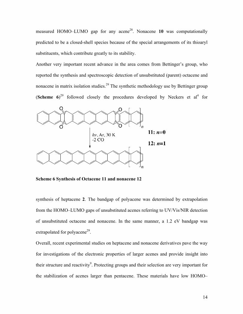
Another very important recent advance in the area comes from Bettinger’s group, who
reported the synthesis and spectroscopic detection of unsubstituted (parent) octacene and
nonacene in matrix isolation studies.29 The synthetic methodology use by Bettinger group
(Scheme 6)29 followed closely the procedures developed by Neckers et al4 for
Scheme 6 Synthesis of Octacene 11 and nonacene 12
synthesis of heptacene 2. The bandgap of polyacene was determined by extrapolation
from the HOMO–LUMO gaps of unsubstituted acenes referring to UV/Vis/NIR detection
of unsubstituted octacene and nonacene. In the same manner, a 1.2 eV bandgap was
extrapolated for polyacene29.
Overall, recent experimental studies on heptacene and nonacene derivatives pave the way
for investigations of the electronic properties of larger acenes and provide insight into
their structure and reactivity9. Protecting groups and their selection are very important for
the stabilization of acenes larger than pentacene. These materials have low HOMO–
15
LUMO gaps and it is expected that future efforts will not only increase the understanding
of the electronic structure of larger acenes, but could also lead to their application in
organic electronic devices9.
References
1. a) Clar, E. Polycyclic Hydrocarbons; Academic Press: London and New York, 1964;
Vols. 1,2; b) Harvey, R. G. Polycyclic Aromatic Hydrocarbons, Wiley-VCH, New York,
1997; c) Geerts, Y.; Klärner, G.; Müllen K. Electronic Materials: The Oligomer
Approach, (Eds.: Müllen, K.; G. Wegner), Wiley-VCH, Weinheim, 1998, 1 – 103.
2. a) Dimitrakopoulos, C. D.; Malenfant, P. R. L. Adv. Mater. 2002, 14, 99 – 117; b)
Murphy, A. R.; Fréchet, J. M. J. Chem. Rev. 2007, 107, 1066 – 1096.
3. a) Bendikov, M.; Wudl, F.; Perepichka, D. F. Chem. Rev. 2004, 104, 4891 – 4945; b)
Anthony, J. E. Chem. Rev. 2006, 106, 5028 – 5048; c) Anthony, J. E. Angew. Chem.
2008, 120, 460 – 492; Angew. Chem. Int. Ed. 2008, 47, 452 – 483.
4. Mondal, R.; Shah, B. K.; Neckers, D. C. J. Am. Chem. Soc. 2006, 128, 9612 – 9613.
5. Payne, M. M.; Parkin, S. R.; Anthony, J. E. J. Am. Chem. Soc. 2005, 127, 8028 – 8029.
6. Chun, D.; Cheng, Y.; Wudl, F. Angew. Chem. 2008, 120, 8508–8513; Angew. Chem.
Int. Ed. 2008, 47, 8380 – 8385.
7. Kaur, I.; Stein, N. N.; Kopreski, R. P.; Miller, G. P.; J. Am. Chem. Soc. 2009, 131,
3424 – 3425.
16
8. Qu H.; Chi C. Org. Lett., 2010, 12 (15), 3360–3363
9. Zade S. S.; Bendikov M. Angew. Chem. Int. Ed. 2010, 49, 4012 – 4015
10. Houk, K.N.; Lee, P.S.; Nendel, M.J. J.Org.Chem 2001, 66, 5517-5521.
11. Garcia-Bach, M.A.; Penaranda, A.; Klein, D.J. Phys. Rev. B 1992, 45, 10891-10901.
12. Bendikov, M.; Duong, H. M.; Starkey, K.; Houk, K. N.; Carter, E. A.; Wudl, F. J.
Am. Chem. Soc. 2004, 126, 7416.
13. Jiang, D.; Dai, S. J. Phys. Chem. A 2008, 112, 332 – 335.
14. Portella, G.; Poater, J.; Bofill, J. M.; Alemany, P.; Solá, M. J. Org. Chem., 2005, 70,
2509.
15. (a) Rienstra-Kiracofe, J. C.; Barden, C. J.; Brown, S. T.; Schaefer, H. F., J. Phys.
Chem. A. 2001, 105, 524; (b) Deleuze, M. S.; Claes, L.; Kryachko, E. S.; François, J.-P.
J. Chem. Phys. 2003, 119, 3106.
16. Suresh, C. H.; Gadre, S. R. J. Org. Chem. 1999, 64, 2505.
17. Reddy, A. R.; Bendikov, M. Chem. Commun. 2006, 1179 – 1181.
18. Reddy, A. R.; Fridman-Marueli, G.; Bendikov, M. J. Org. Chem. 2007, 72, 51 – 61.
19. Schleyer, P. v. R.; Manoharan, M.; Jiao, H.; Stahl, F. Org. Lett. 2001, 3, 3643-3646.
20. Chien, S. -H.; Cheng, M. -F.; Lau, K. -C.; Li, W, -K. J. Phys. Chem. A 2005, 109,
7509.
21. Clar, E. Ber. Dtsch. Chem. Ges. B 1942, 75, 1330 – 1338
22. Marschalk, C. Bull. Soc. Chim. 1943, 10, 511 – 512
23. Bailey, W. J.; Liao, C.-W. J. Am. Chem. Soc. 1955, 77, 992 – 993
24. Boggiano, B.; Clar, E. J. Chem. Soc. 1957, 2681 – 2689.
25. Fang, T. Heptacene, Octacene, Nonacene, Supercene and Related Polymers, Ph.D.

17
Dissertation, University of California, Los Angeles, CA, 1986.
26. Mondal, R.; Tönshoff, C.; Khon, D.; Neckers, D. C.; Bettinger, H. F. J. Am. Chem.
Soc. 2009, 131, 14281 – 14289.
27. Kaur, I.; Jia, W.; Kopreski, R. P.; Selvarasah, S.; Dokmeci, M. R.; Pramanik, C.;
McGruer, N. E.; Miller, G. P. J. Am. Chem. Soc. 2008, 130, 16274 – 16286.
28. Kaur, I.; Jazdzyk, M.; Stein, N. N.; Prusevich, P.; Miller, G. P. J. Am. Chem. Soc.
2010, 132, 1261 – 1263.
29. Tönshoff, C.; Bettinger H. F . Angew. Chem. Int. Ed. 2010, 49, 4125 –4128
18
Chapter 2. Attempted Synthesis of Parent Octacene and Nonacene
Introduction
Acenes are linear polycyclic aromatic hydrocarbons. The most common way to
synthesize smaller acenes (up to pentacene) is by reduction of the corresponding
quinones. A similar approach used for higher acenes proved to be unsuccessful since the
quinones were overreduced to hydrogenated acenes123. Other synthetic methods for larger
acenes also failed for almost half a century. This is because of their higher reactivity
towards Diels-Alder additions, which ultimately result in formation of either dimers, or
oxygen adducts (endoperoxides)4.
Clar first claimed5 the synthesis of heptacene, octacene, and nonacene, but it was
questioned in later reports6,7 and then it was finally withdrawn8. Later in 1986 Fang
reported synthesis of octacene and nonacene4 but the products lacked proper
characterization, were always contaminated with dimers and the overall work was never
completed. In 2006 Mondal, Neckers et al. reported synthesis of unsubstituted (parent)
heptacene using Strating-Zwanenberg photodecarbonylation9. The Strating group, while
seeking the dimer of carbon monoxide, employed this decarbonylation. First in 196910.
An impressive attribute of this reaction is that it cleanly produced an acene following the
expulsion of two molecules of carbon monoxide. A semirigid polymer matrix and inert
gas matrices was employed by Mondal et al9,11 to reduce the reactivity of heptacene,
record its thermal decomposition, and subsequently to record its UV-vis-NIR absorption,
as well as, its IR spectra.
19
After the report on synthesis of unsubstituted heptacene by Mondal, Neckers et al9 a
group from Germany led by Dr. Holger Bettinger offered a collaboration to study
photostability of higher acenes in solid noble gas matrix. This collaborative work yielded
a publication on photochemistry and stability of pentacene, hexacene, and heptacene11.
Soon after that Bettinger group started undertaking a similar synthesis of octacene and
nonacene photoprecursors that were used in Strating-Zwanenberg photodecarbonylation
and matrix isolation studies12.
In this chapter attempted synthesis of octacene and nonacene photoprecursors following
synthetic methodologies developed by Mondal, Neckers et al9 will be discussed.
Synthesis
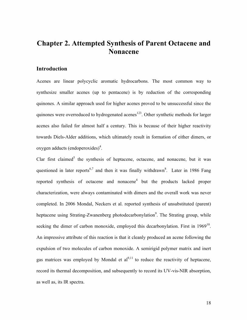
All the synthetic schemes for both nonacene and octacene photoprecursors required the
crucial starting material, 5,6,7,8-tetramethylenebicyclo[2.2.2]oct-2-ene. This was
synthesized (Scheme 2.1) following modified reported procedures13,14. Nonacene was
Scheme 2.1 Synthesis of 5,6,7,8-tetramethylenebicyclo[2.2.2]oct-2-ene (2.6)
20
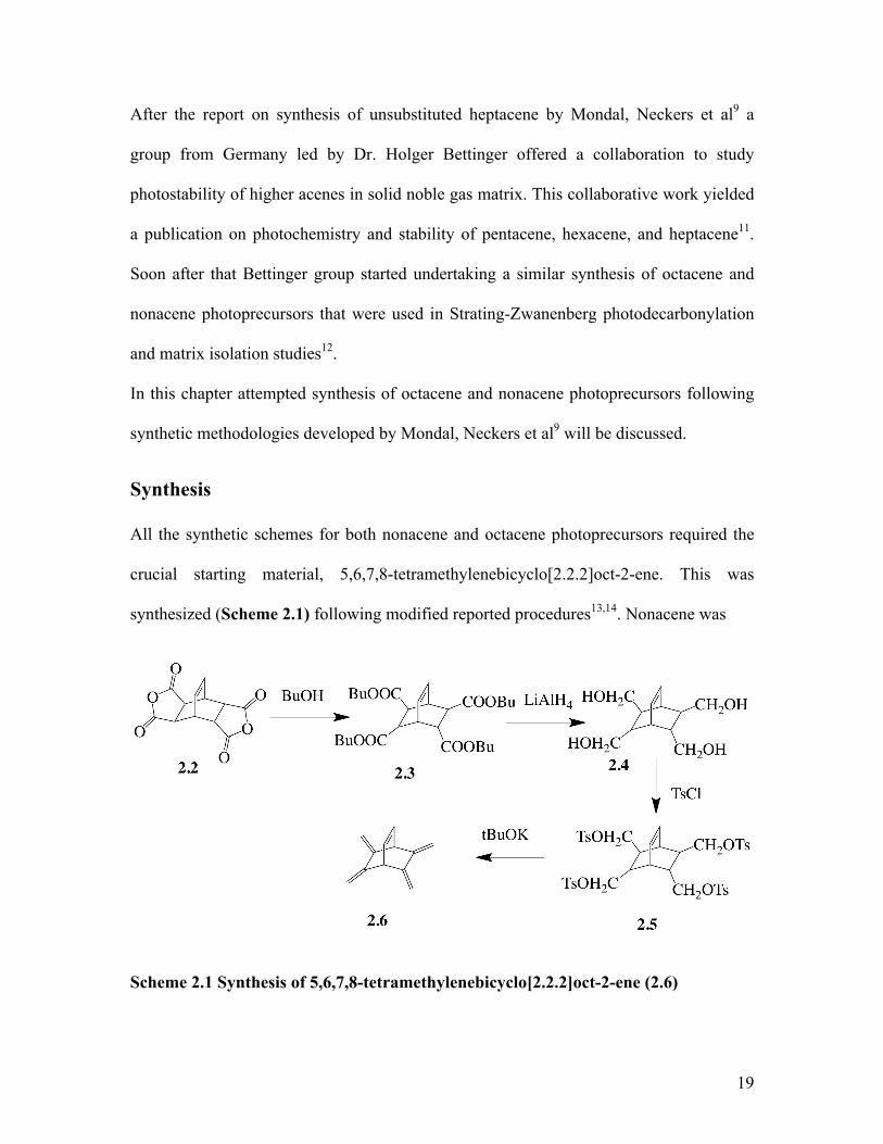
first chosen as a primary synthetic target because it is symmetric from the synthetic
prospective and requires fewer steps to synthesize when compared to octacene. The
synthetic approach initially developed for nonacene (Scheme 2.2), though
straightforward, was also expected to be more challenging because of potential solubility
problems and lesser stability of the tetracene moieties in
Scheme 2.2 Synthetic scheme for nonacene photoprecursor
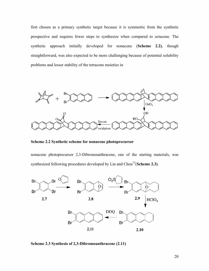
nonacene photoprecursor 2,3-Dibromoanthracene, one of the starting materials, was
synthesized following procedures developed by Lin and Chou15(Scheme 2.3).
Scheme 2.3 Synthesis of 2,3-Dibromoanthracene (2.11)
21
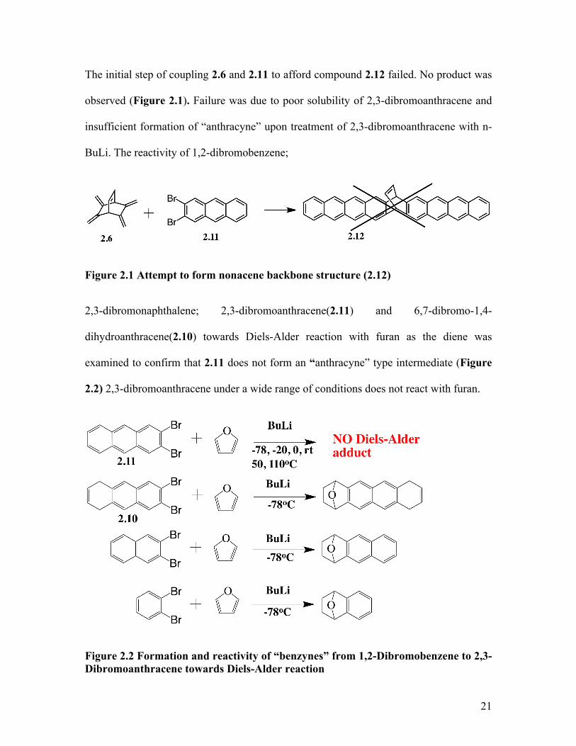
The initial step of coupling 2.6 and 2.11 to afford compound 2.12 failed. No product was
observed (Figure 2.1). Failure was due to poor solubility of 2,3-dibromoanthracene and
insufficient formation of “anthracyne” upon treatment of 2,3-dibromoanthracene with n-
BuLi. The reactivity of 1,2-dibromobenzene;
Figure 2.1 Attempt to form nonacene backbone structure (2.12)
2,3-dibromonaphthalene; 2,3-dibromoanthracene(2.11) and 6,7-dibromo-1,4-
dihydroanthracene(2.10) towards Diels-Alder reaction with furan as the diene was
examined to confirm that 2.11 does not form an “anthracyne” type intermediate (Figure
2.2) 2,3-dibromoanthracene under a wide range of conditions does not react with furan.
Figure 2.2 Formation and reactivity of “benzynes” from 1,2-Dibromobenzene to 2,3-Dibromoanthracene towards Diels-Alder reaction
22
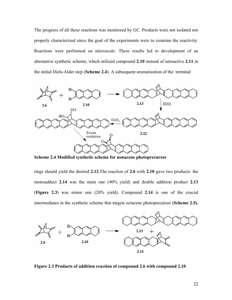
The progress of all these reactions was monitored by GC. Products were not isolated nor
properly characterized since the goal of the experiments were to examine the reactivity.
Reactions were performed on microscale. These results led to development of an
alternative synthetic scheme, which utilized compound 2.10 instead of unreactive 2.11 in
the initial Diels-Alder step (Scheme 2.4). A subsequent aromatization of the terminal
Scheme 2.4 Modified synthetic scheme for nonacene photoprecursor
rings should yield the desired 2.12.The reaction of 2.6 with 2.10 gave two products: the
monoadduct 2.14 was the main one (40% yield) and double addition product 2.13
(Figure 2.3) was minor one (20% yield). Compound 2.14 is one of the crucial
intermediates in the synthetic scheme that targets octacene photoprecursor (Scheme 2.5).
Figure 2.3 Products of addition reaction of compound 2.6 with compound 2.10
23
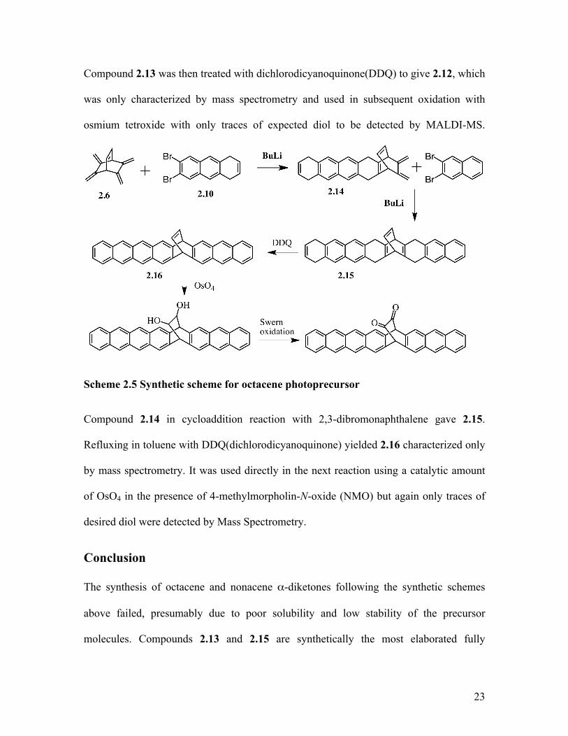
Compound 2.13 was then treated with dichlorodicyanoquinone(DDQ) to give 2.12, which
was only characterized by mass spectrometry and used in subsequent oxidation with
osmium tetroxide with only traces of expected diol to be detected by MALDI-MS.
Scheme 2.5 Synthetic scheme for octacene photoprecursor
Compound 2.14 in cycloaddition reaction with 2,3-dibromonaphthalene gave 2.15.
Refluxing in toluene with DDQ(dichlorodicyanoquinone) yielded 2.16 characterized only
by mass spectrometry. It was used directly in the next reaction using a catalytic amount
of OsO4 in the presence of 4-methylmorpholin-N-oxide (NMO) but again only traces of
desired diol were detected by Mass Spectrometry.
Conclusion
The synthesis of octacene and nonacene α-diketones following the synthetic schemes
above failed, presumably due to poor solubility and low stability of the precursor
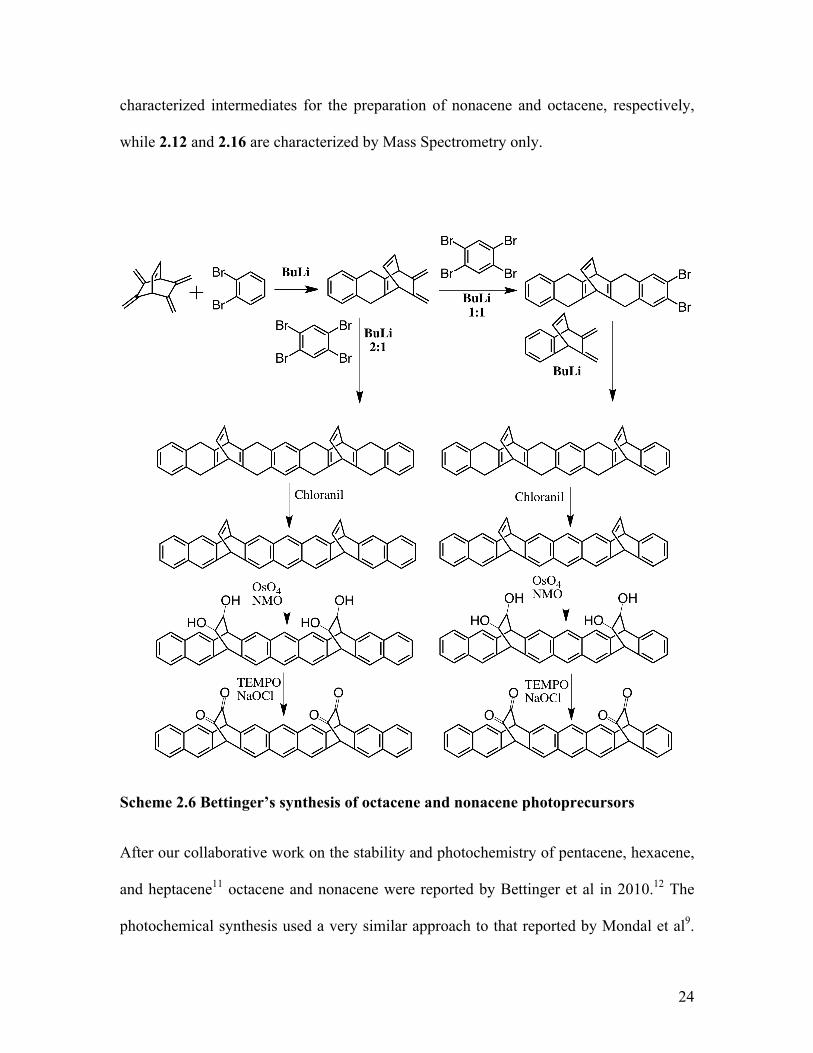
molecules. Compounds 2.13 and 2.15 are synthetically the most elaborated fully
24
characterized intermediates for the preparation of nonacene and octacene, respectively,
while 2.12 and 2.16 are characterized by Mass Spectrometry only.
Scheme 2.6 Bettinger’s synthesis of octacene and nonacene photoprecursors
After our collaborative work on the stability and photochemistry of pentacene, hexacene,
and heptacene11 octacene and nonacene were reported by Bettinger et al in 2010.12 The
photochemical synthesis used a very similar approach to that reported by Mondal et al9.
25
Octacene and nonacene α-diketones (Scheme 2.6) were used, and the crucial difference
was the use of two bridged α-diketones per molecule of photoprecursor. Their synthetic
approach was considered at the the beginning of my project but was intentionally not
developed in Bowling Green since it had already been undertaken by our collaborators in
the Bettinger group.
Experimental Section
General Procedures. The starting materials 1,2,4,5-tetrabromobenzene and
bicyclo[2.2.2]oct-7ene-exo2,3,5,6-tetracarboxylic-2,3,5,6-dianhydride (2.2) were
purchased from Aldrich and used as received. Organic solvents were either spectroscopic
grade or purified by distillation and dried before use with proper drying reagents. TLC
and silica gel(230-400 mesh) were purchased from Sorbent Technologies Co. NMR
spectra were recorded from a BRUKER Avance 300MHz NMR spectrometer using TMS
as internal standard. Mass spectra were recorded on SHIMADZU GCMS-QP5050A gas
chromatograph mass spectrometer (GCMS) or BRUKER DALTONICS OMNIFLEX
matrix assisted laser desorption ionization mass spectrometer (MALDI-MS). Progress of
reactions was monitored either by TLC or GCMS.
Synthesis:
(±)-Exo-2, endo-3, exo-5, endo-6-Tetrakis(ethoxycarbonyl)bicyclo[2.2.2] oct-7-ene
(2.3)13,14. Anhydride 2.2 (25 g, 0.1 mole) and 0.25 g p-toluenesulfonic acid in a mixture
of 150 ml EtOH and 100 ml toluene was heated under reflux in reactor fitted with a
Soxlet extractor containing 10 g of molecular sieves (3-4 Å) for 3 days. The molecular
26
sieves were renewed every 12 hours. After cooling a suspension of sodium hydride (0.4
g, 55% in oil 0.01 mol) in 7 ml of ethanol was added. The mixture was heated at 125-
130ºC for 6 h. After completion of the reaction the mixture was cooled somewhat and
additional sodium hydride in batches of 0.1g (55% in oil) was added slightly, followed by
heating for 3 hours. The mixture was rotary evaporated and the liquid residue is used as
such in the next step. 1H NMR(CDCl3): 6.4(t, 2H), 4.2(m, 8H), 3.5 (m, 2H), 3.1 (m, 4H),
1.3 (m, 12H) ; MS(EI): 396(0.8), 350(15), 276(20), 177(32), 175(20), 15(100), 150(33),
149(22).
(±)-Exo-2, endo-3, exo-5, endo-6-tetrakis(hydroxymethyl)bicyclo[2.2.2] oct-7-ene
(2.4).13,14 A solution of crude 2.3 (40 g, 0.1 mol) in 150 ml of THF was added dropwise
to saturated suspension of lithium aluminum hydride (7.2 g, 0.2 mol) in 300 ml of THF
under argon over period of 3 hours. After heating under reflux for 2 days, and then
cooling to room t, 40 ml of a saturated solution of Na2SO4 in water was added
portionwise. After again heating to the boiling the mixture was filtered rapidly over SiO2
(40g) and the SiO2 + salts were extracted with hot EtOH(2×300 ml, 2 hours heating under
reflux and hot filtration). The extract was evaporated to yield: 17.4 g (75%) racemic
mixture of both isomers of 2.4; 1H NMR (D2O): 6.2(m, 2H), 4.6(s, OH), 3.6(m, 2H),
3.4(br.s, 2H), 3.2(br.s, 2H), 3.13(br.s, 2H), 2.54(m, 2H), 1.41(m, 2H), 1.06(m, 2H); MS
(EI): 229(14), 212(12), 211(55), 194(89), 181(11), 175(100), 145(87).
(±)-Exo-2, endo-3, exo-5, endo-6-tetrakis(p-toluenesulfonylmethyl) bicyclo[2.2.2] oct-
7-ene (2.5) . 13,14 To a the mechanically stirred solution of tetrol 2.4 (17.4 g, 0.076 mol) in
150 ml anhydrous pyridine TsCl (72 g, 0.38 mol) was added portionwise at 0ºC. The
mixture was stirred for an additional 5 hours at 0ºC and then extracted with CH2Cl2
27
(3×100 ml) and the organic phases washed with sat. NaHCO3 (2×150 ml) then with 3N
HCl(3×100 ml) and finally dried (Mg SO4). The solution was evaporated to dryness to
yield 51.1 g (80%) dark yellow resin. MS (DIP): 844(0.96), 534(20), 379(31), 224(84),
196(100). 1H NMR (CDCl3): 7.8-8.0(m, 16H), 6.4(m, 2H), 3.2-3.9(m, 8H), 3.0(m, 2H),
1.4-1.8(m, 4H), 1.67(s, 12H).
5,6,7,8-Tetramethylenebicyclo[2.2.2]oct-2-ene (2.6). t-BuOK (33 g, 0.3 mol) was added
portionwise to the solution of 51.1 g (0.06 mol) of tosylate 2.5 in 100 ml of DMSO while
stirring mechanically at 0ºC. The mixture was stirred for an additional 2 hours at room
temperature, after which reaction mixture was poured onto 100 g of ice. The mixture was
extracted with hexanes (3×100 ml). The extract was then dried and evaporated. The light
yellowish residue was purified on a silica gel column using hexanes as eluent to afford
6.3 g (67%) colorless crystals. 1H NMR (CDCl3): 6.4(dd, 2H), 5.15(s, 4H), 4.95(s, 4H),
3.85(dd, 2H); MS (EI): 156(88), 141(83), 128(39), 115(61), 104(100), 91(12), 78(24).
6,7-Dibromo-1,4-epoxynaphthalene (2.8). n-BuLi (2.5 M in hexane) 0.5 ml (1.25
mmol) was added dropwise to a solution of 4 g (1 mmol) 1,2,4,5-tetrabromobenzene and
1 ml (∼10 mmol) of furan in 150 ml of THF at -78 ºC. The mixture was stirred at -78 ºC
for 3 h and then allowed to warm to rt. The excess n-BuLi was quenched with methanol.
Solvents were removed by rotary evaporation to yield 2.3 g (75%) of crude 2.8, which
was used in the next step without further purification.
6,7-Dibromo-9,10-epoxy-1,4,4a,9,9a,10-hexahydroanthracene (2.9)12. A solution of
6,7-dibromo-9,10-epoxy-1,4,dihydronaphthalene 2.8 (6 g 19.9 mmol) and 2,5-
dihydrothiophene-1,1-dioxide (sulfolene – 2.8 g 23.7 mmol) in o-xylene (25 ml) was

28
sealed in an autoclave and heated 145 ºC for 6 h. Evaporation of solvent followed by
chromatography on silica gel using CH2Cl2/hexanes (1/9) as eluent affords 2.9; yield:
6.27 g (88%); 1H NMR (CDCl3): 7.45(s, 2H), 5.91(dd, 2H), 4.92(s, 2H)1.89-2.4(m 6H);
MS (EI): 356(38), 336(25), 304(18), 276(100).
6,7-Dibromo-1,4-dihydroanthracene (2.10)12. A solution of 2.9 (3 g 8.42 mmol) in
toluene (150 ml) was placed in a 250 ml round-bottom flask followed by addition of
EtOH (25 ml) and 70% aq. perchloric acid (15 ml). The mixture was vigorously stirred at
80ºC for 3 h., the organic layer separated, and the aqueous layer extracted with CH2Cl2
(3×100 ml). The combined organic layer was washed with sat. aq. NaHCO3 and brine,
and then dried (Mg SO4), filtered and concentrated in vacuo. The light brown residue
obtained was purified by chromatography on a silica gel column with CH2Cl2/hexanes
(1/9) as eluent to furnish 2.10; yield: 2.56 g (90%); 1H NMR (CDCl3): 8.02(s, 2H),
7.48(s, 2H), 6.01(t, 2H), 3.54(d, 4H); MS (EI): 338(54), 336(41), 258(19), 207(17),
178(100), 176(76), 89(92).
2,3-Dibromoanthracene (2.11)12. To a stirred solution of 2.10 (2 g 5.96 mmol) in dry
benzene (300 ml) was added DDQ (2.4 g 10.04 mmol). The mixture was refluxed for 4 h,
and the resulting insoluble hydroquinone was removed by filtration, of the hot solution.
Pure compound 2.11 precipitates as flakes when the solution was slowly cooled to room
temperature. The brownish orange mother liquor was evaporated under reduced pressure,
and the crude product obtained was purified by chromatography on a silica gel column
with hexane as eluent to give 2.11; total yield: 1.5 g (85%); 1H NMR (CDCl3): 8.04(s,
2H), 7.81(s, 2H), 7.75(d, 2H), 7.3(d, 2H). MS (EI): 338(23), 336(43), 207(38), 176(36),
88(62), 49(100).

29
9,10-Bimethylene-1,4,7,8,11,12,-decahydro-6,13-diethenopentacene and
1,4,7,8,9,12,15,18,19,20-octadecahydro-8,19-diethenononacene (2.14 and 2.13). 2.7
mL (6.75 mmol) of nBuLi (2.5 M in hexane) was added drop-wise under argon
atmosphere to a suspension of 2.6 (231 mg, 1.48 mmol) and 2.10 (1 g, 2.96 mmol) in 125
ml of dry toluene cooled to -60o C. The mixture was stirred for three hours at -60o C, then
the temperature was allowed to increase very slowly to r. t. and the excess n-BuLi was
quenched with methanol. The product was concentrated on a rotary evaporator and
purified by a silica gel column using CH2Cl2/hexanes mixture (10% by volume) to give
200 mg of 2.14 (40%) and 150 mg of 2.13 (20%). 1H NMR for 2.14 (CDCl3): 7.51 (s,
2H), 7.48 (s, 2H), 6.51 (dd, 2H), 6.01 (s, 2H), 5.09 (s, 2H), 4.88 (s, 2H), 4.01 (t, 2H), 3.71
(s, 4H), 3.53 (s, 4H). MS (EI): 334(100), 278(41), 230(50). HRMS (EI):
334.1722(meas.), 334.1722(calc.). 1H NMR for 2.13 (CDCl3): 7.50 (s, 4H), 7.47 (s, 4H),
6.91 (dd, 2H), 6.00 (s, 4H), 4.38 (s, 2H), 3.79 (s, 8H), 3.52 (s, 8H). HRMS (EI):
512.2507(meas.), 512.2504(calc.).
1,4,7,8,9,16,17,18-Octahydro-8,17-diethenooctacene (2.15). nBuLi (2.5 M in hexane)
0.55 mL (1.4 mmol) was added dropwise under an argon atmosphere to a suspension of
2.14 (200 mg, 0.6 mmol) and 2,3-dibromonaphthalene (172 mg, 0.6 mmol) in 25 ml of
dry toluene cooled to -78o C. The mixture was stirred for three hours at -78o C, then the
temperature was allowed to increase very slowly to r. t. and the excess n-BuLi was
quenched with methanol. The product was concentrated on a rotary evaporator and
purified by a silica gel column using CH2Cl2/hexanes mixture (5% by volume) to yield 70
mg (25%) of 2.15 as white solid; 1H NMR (CDCl3): 7.71 (s, 2H), 7.60 (s, 2H), 7.50 (s,
2H), 7.47 (s, 2H), 7.35 (s, 2H), 6.91 (dd 2H), 6.00 (s, 2H), 4.40 (t, 2H), 3.81 (s, 4H), 3.79
30
(s, 4H), 3.52 (s, 4H). MS (EI): 460(100), 267(28), 228(72). HRMS (EI): 460.21861(meas.), 460.21910(calc.).
8,19-Diethenononacene (2.12). To a solution of 2.13 (150 mg, 0.29 mmol) in 25 ml of
toluene was added 1 g (4.4 mmol) of DDQ under inert atmosphere. The mixture was
refluxed for 2 h and then cooled down to rt. The product was concentrated on a rotary
evaporator and purified by a silica gel column using CH2Cl2/hexanes mixture (10% by
volume) to give 30 mg of crude 2.12, which wasn’t purified further in attempt to save
enough compound for the next reaction. MS (EI): 505(63), 252(84), 149(100).
8,17-Diethenooctacene (2.16). To a solution of 2.15 (70 mg, 0.15 mmol) in 25 ml of
toluene was added 1 g (4.4 mmol) of DDQ under inert atmosphere. The mixture was
refluxed for 2 h and then cooled down to rt. The product was concentrated on a rotary
evaporator and purified by a silica gel column using CH2Cl2/hexanes mixture (10% by
volume) to give 18 mg of crude 2.16, which wasn’t purified further in attempt to save
enough compound for the next reaction. MS (EI): 454(28), 265(24), 207(59), 125(56),
111(100).
References
1. Clar, E. Polycyclic Hydrocarbons; Academic Press: London and New York, 1964;
Vols. 1, 2.
31
2. Bailey, W. J.; Liao, 96 C. -W. J. Am. Chem. Soc. 1955, 77, 992
3. Satchell, M. P.; Stacey, B. E. J. Chem. Soc. C: Organic. 1971, 3, 468.
4. Fang, T. Heptacene, Octacene, Nonacene, Supercene and Related Polymers.
Ph.D.Thesis, University of California, Los Angeles, CA, 1986.
5. Clar, E. Ber. Dtsch. Chem. Ges. B 1942, 75, 1330 – 1338
6. Marschalk, C. Bull. Soc. Chim. 1943, 10, 511 – 512
7. Bailey, W. J.; Liao, C.-W. J. Am. Chem. Soc. 1955, 77, 992 – 993
8. Boggiano, B.; Clar, E. J. Chem. Soc. 1957, 2681 – 2689.
9. Mondal, R.; Shah, B. K.; Neckers, D. C. J. Am. Chem. Soc. 2006, 128, 9612 – 9613.
10. Strating, J.; Zwanenburg, B.; Wagenaar, A.; Udding, A. C. Tetrahedron Lett. 1969,
10, 125.
11 Mondal, R.; Tönshoff, C.; Khon, D.; Neckers, D. C.; Bettinger, H. F. J. Am. Chem. Soc.
2009, 131, 14281 – 14289.
12. Tönshoff, C.; Bettinger H. F . Angew. Chem. Int. Ed. 2010, 49, 4125 –4128
13. Gabioud, R.; Vogel, P. Tetrahedron 1980, 36, 149-154.
14. Ten Hoeve, W.; Huisman, B. Method of preparation of a precursor Oligocene; PCT
Int. Appl. 2004, 21 pp.
15. Lin, Ch.-T.; Chou, T.-Ch. Synthesis 1988, 628-630.
32
Chapter 3. Synthesis of Heptacene/Nonacene Derivative
Introduction
In recent years pentacene and its derivatives have received much attention as active layer
materials in organic field-effect transistors (OFETs)1 due to their high charge-carrier
mobility2. Interest in the synthesis of acenes larger than pentacene has increased in the
last decade, since increased conjugation length in acenes is expected to be beneficial for
some applications in organic electronics. Significant efforts have been devoted to the
development of appropriate synthetic methodology2. However, the synthesis of larger
stable acenes is difficult and challenging because of their very low solubility, poor
stability in the presence of light and oxygen, and high reactivity towards Diels-Alder
reactions and dimerization. Difficult multistep synthetic approaches are required.
Although several unsubstituted larger acenes3,4 have been reported including heptacene,
higher acenes that lack protecting groups are highly unstable at room temperature.5 Thus
to stabilize the larger acenes, protecting groups are required. To address these issues a
number of substituted larger acenes6,7,8,9 have been synthesized over the last several
years. Most notably Miller’s group synthesized the substituted nonacene10 last year.
Several methodologies are now available to prepare substituted higher acenes from
organometallic reactions with corresponding quinones and subsequent reduction to using
the substituted core in Diels-Alder type reactions to grow the number of rings. Miller et
al. found that arylthio substituents on the central ring of larger acenes are among the best
stabilizing groups11. In this chapter we describe the attempted synthesis of
heptacene/nonacene derivatives closely following the reports from Miller et al.8,10
33
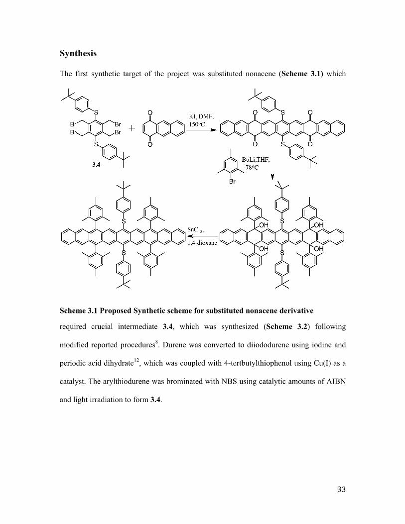
Synthesis
The first synthetic target of the project was substituted nonacene (Scheme 3.1) which
Scheme 3.1 Proposed Synthetic scheme for substituted nonacene derivative
required crucial intermediate 3.4, which was synthesized (Scheme 3.2) following
modified reported procedures8. Durene was converted to diiododurene using iodine and
periodic acid dihydrate12, which was coupled with 4-tertbutylthiophenol using Cu(I) as a
catalyst. The arylthiodurene was brominated with NBS using catalytic amounts of AIBN
and light irradiation to form 3.4.
34
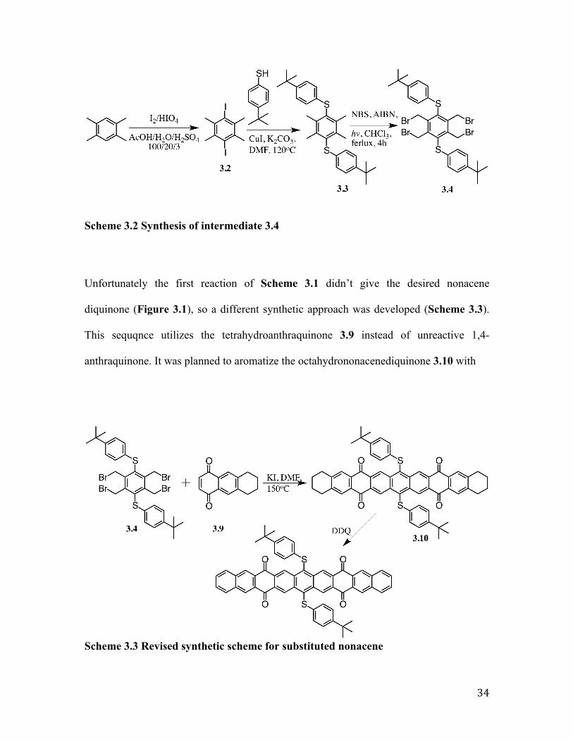
Scheme 3.2 Synthesis of intermediate 3.4
Unfortunately the first reaction of Scheme 3.1 didn’t give the desired nonacene
diquinone (Figure 3.1), so a different synthetic approach was developed (Scheme 3.3).
This sequqnce utilizes the tetrahydroanthraquinone 3.9 instead of unreactive 1,4-
anthraquinone. It was planned to aromatize the octahydrononacenediquinone 3.10 with
Scheme 3.3 Revised synthetic scheme for substituted nonacene
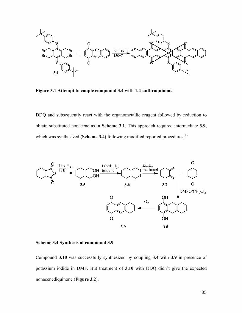
35
Figure 3.1 Attempt to couple compound 3.4 with 1,4-anthraquinone
DDQ and subsequently react with the organometallic reagent followed by reduction to
obtain substituted nonacene as in Scheme 3.1. This approach required intermediate 3.9,
which was synthesized (Scheme 3.4) following modified reported procedures.13
Scheme 3.4 Synthesis of compound 3.9
Compound 3.10 was successfully synthesized by coupling 3.4 with 3.9 in presence of
potassium iodide in DMF. But treatment of 3.10 with DDQ didn’t give the expected
nonacenediquinone (Figure 3.2).

36
Figure 3.2 Attempted aromatization of compound 3.10
At the same time Miller’s synthesis of arylthiosubstituted heptacene8 was reproduced
Scheme 3.5 Modified organometallic reaction step for Miller’s synthesis of substituted heptacene
37
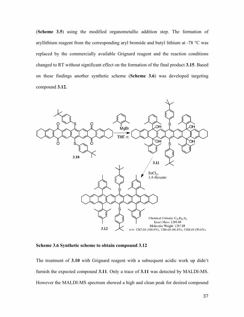
(Scheme 3.5) using the modified organometallic addition step. The formation of
aryllithium reagent from the corresponding aryl bromide and butyl lithium at -78 °C was
replaced by the commercially available Grignard reagent and the reaction conditions
changed to RT without significant effect on the formation of the final product 3.15. Based
on these findings another synthetic scheme (Scheme 3.6) was developed targeting
compound 3.12.
Scheme 3.6 Synthetic scheme to obtain compound 3.12
The treatment of 3.10 with Grignard reagent with a subsequent acidic work up didn’t
furnish the expected compound 3.11. Only a trace of 3.11 was detected by MALDI-MS.
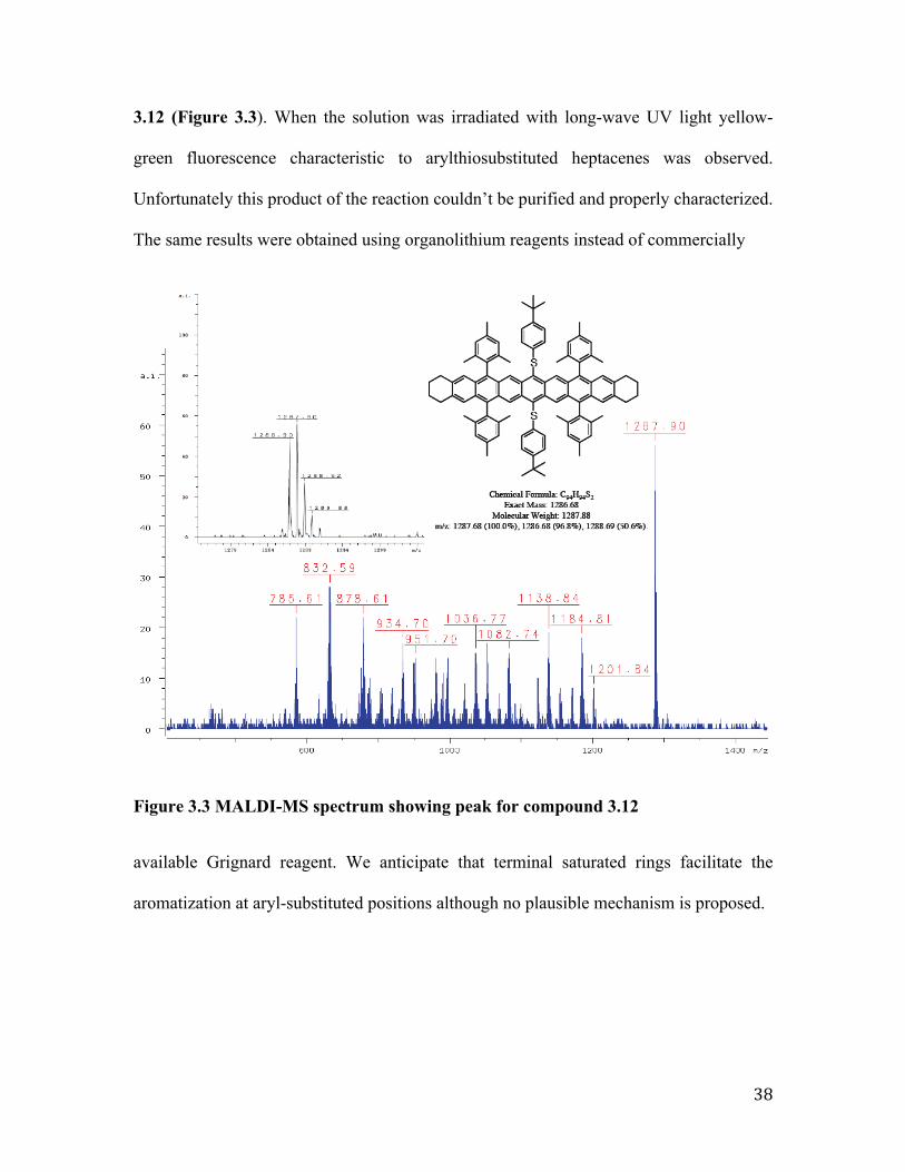
However the MALDI-MS spectrum showed a high and clean peak for desired compound
38
3.12 (Figure 3.3). When the solution was irradiated with long-wave UV light yellow-
green fluorescence characteristic to arylthiosubstituted heptacenes was observed.
Unfortunately this product of the reaction couldn’t be purified and properly characterized.
The same results were obtained using organolithium reagents instead of commercially
Figure 3.3 MALDI-MS spectrum showing peak for compound 3.12
available Grignard reagent. We anticipate that terminal saturated rings facilitate the
aromatization at aryl-substituted positions although no plausible mechanism is proposed.

39
Experimental Procedures
General Procedures. The starting materials 1,2,4,5-tetramethylbenzene and 1,2-
cyclohexanedicarboxylic anhydride were purchased from Aldrich and used as received.
Organic solvents were either spectroscopic grade or purified by distillation and dried
before use with proper drying reagents. TLC and silica gel (230-400 mesh) were
purchased from Sorbent Technologies Co. NMR spectra were recorded from BRUKER
Avance 300MHz NMR spectrometer using TMS as internal standard. Mass spectra were
recorded on SHIMADZU GCMS-QP5050A gas chromatograph mass spectrometer
(GCMS) or BRUKER DALTONICS OMNIFLEX matrix assisted laser desorption
ionization mass spectrometer (MALDI-MS). Progress of reactions was monitored either
by TLC or GCMS.
Diiododurene (3.2)12: Durene (1.34 g, 0.01 mol) was placed into round bottom flask
together with periodic acid dihydrate (0.92 g, 0.0043 mol), and iodine (2.55 g, 0.01 mol).
A solution of 3 ml of concentrated sulfuric acid and 20 ml of water in 100 ml of glacial
acetic acid was added to this mixture. The resulting purple solution was heated at 65–70°
with stirring for approximately 1 hour until the color of iodine disappeared. The reaction
mixture was diluted with approximately 250 ml of water, and the white-yellow solid that
separates was collected by filtration and washed three times with 100-ml portions of
water. The product was recrystallized from ethanol to yield 3.01 g (78%) of diiododurene
3.2 as fine colorless needles. 1H NMR (CDCl3): 2.49 (s, 12H). MS (EI): 386(82),
259(29), 117(100).
1,4-Bis(4'-t-butylphenylthio)-2,3,5,6-tetramethylbenzene (3.3): Copper iodide (0.07 g,
0.037 mmol) and cesium carbonate (2.45 g, 27.38 mmol) was added to a solution of 3.2
40
(1.0 g, 3.42 mmol) and 4-tbutylthiophenol (1.25 g, 7.52 mmol) in dimethylformamide
(20.0 mL). The resulting suspension was deoxygenated with bubbling argon for 15 min,
sealed in a seal tube, and heated at 150ºC for 1 day. The reaction mixture was then
cooled, filtered and extracted with ethyl acetate. The organic layer was separated and
washed with water followed by brine and then dried to give the crude product which was
further purified by column chromatography using hexanes : dichloromethane (10:1) as
eluent to give white solid product (1.28 g, 81% yield). 1H NMR (CDCl3): 7.23 (d, 4H),
6.87 (d, 4H), 2.50 (s, 12H), 1.28 (s, 18H). MS (EI): 462(84), 447(42), 216(36), 117(43),
91(73), 57(100).
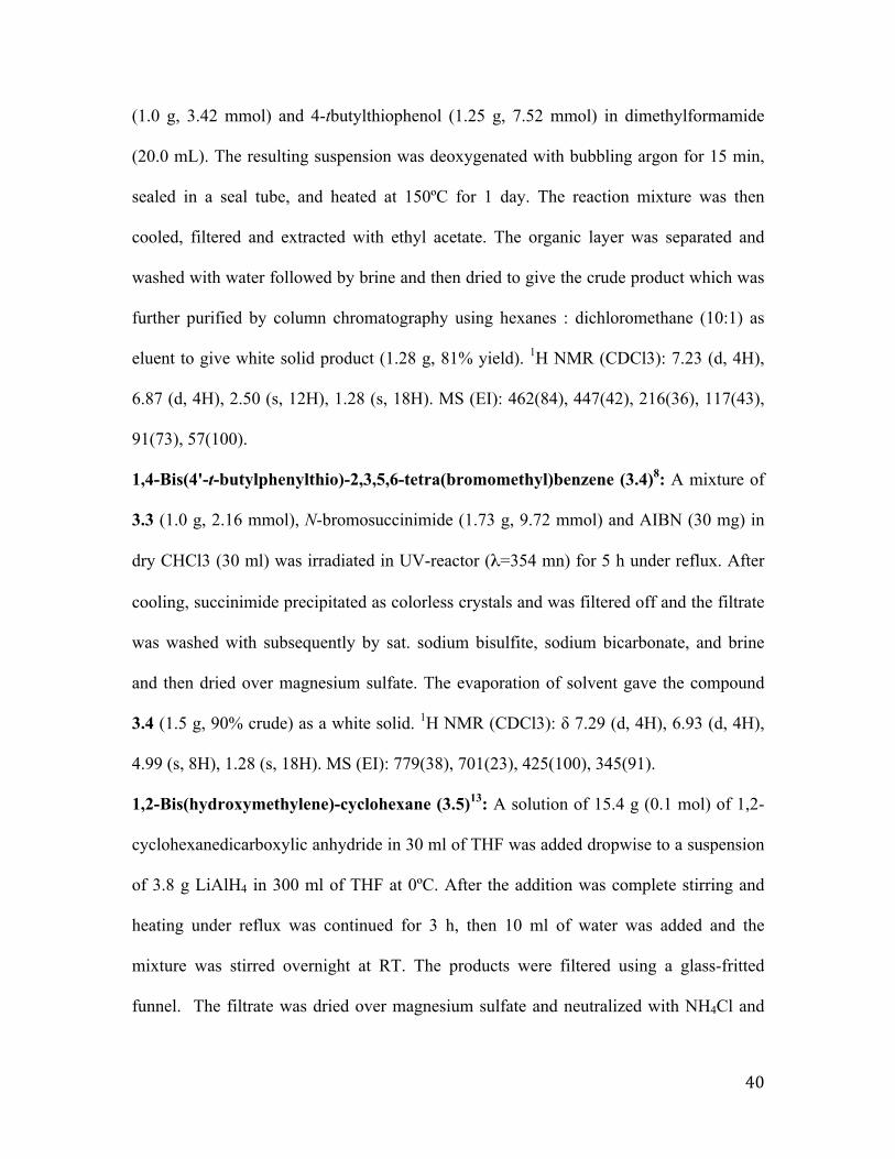
1,4-Bis(4'-t-butylphenylthio)-2,3,5,6-tetra(bromomethyl)benzene (3.4)8: A mixture of
3.3 (1.0 g, 2.16 mmol), N-bromosuccinimide (1.73 g, 9.72 mmol) and AIBN (30 mg) in
dry CHCl3 (30 ml) was irradiated in UV-reactor (λ=354 mn) for 5 h under reflux. After
cooling, succinimide precipitated as colorless crystals and was filtered off and the filtrate
was washed with subsequently by sat. sodium bisulfite, sodium bicarbonate, and brine
and then dried over magnesium sulfate. The evaporation of solvent gave the compound
3.4 (1.5 g, 90% crude) as a white solid. 1H NMR (CDCl3): δ 7.29 (d, 4H), 6.93 (d, 4H),
4.99 (s, 8H), 1.28 (s, 18H). MS (EI): 779(38), 701(23), 425(100), 345(91).
1,2-Bis(hydroxymethylene)-cyclohexane (3.5)13: A solution of 15.4 g (0.1 mol) of 1,2-
cyclohexanedicarboxylic anhydride in 30 ml of THF was added dropwise to a suspension
of 3.8 g LiAlH4 in 300 ml of THF at 0ºC. After the addition was complete stirring and
heating under reflux was continued for 3 h, then 10 ml of water was added and the
mixture was stirred overnight at RT. The products were filtered using a glass-fritted
funnel. The filtrate was dried over magnesium sulfate and neutralized with NH4Cl and
41
the solvents evaporated yielding 10 g (69%) of crude 3.5 as light yellow viscous syrup,
which was used in the next reaction without further purification. 1H NMR (CDCl3): 4.9-
4.6 (bs, 2H), 3.78-3.47 (m, 4H), 1.93-1.84 (m, 2H), 1.56-1.35 (m, 8H).
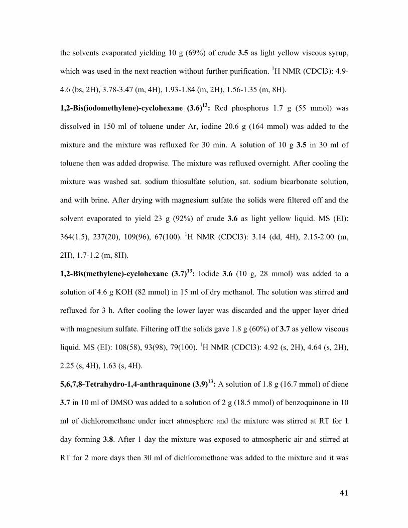
1,2-Bis(iodomethylene)-cyclohexane (3.6)13: Red phosphorus 1.7 g (55 mmol) was
dissolved in 150 ml of toluene under Ar, iodine 20.6 g (164 mmol) was added to the
mixture and the mixture was refluxed for 30 min. A solution of 10 g 3.5 in 30 ml of
toluene then was added dropwise. The mixture was refluxed overnight. After cooling the
mixture was washed sat. sodium thiosulfate solution, sat. sodium bicarbonate solution,
and with brine. After drying with magnesium sulfate the solids were filtered off and the
solvent evaporated to yield 23 g (92%) of crude 3.6 as light yellow liquid. MS (EI):
364(1.5), 237(20), 109(96), 67(100). 1H NMR (CDCl3): 3.14 (dd, 4H), 2.15-2.00 (m,
2H), 1.7-1.2 (m, 8H).
1,2-Bis(methylene)-cyclohexane (3.7)13: Iodide 3.6 (10 g, 28 mmol) was added to a
solution of 4.6 g KOH (82 mmol) in 15 ml of dry methanol. The solution was stirred and
refluxed for 3 h. After cooling the lower layer was discarded and the upper layer dried
with magnesium sulfate. Filtering off the solids gave 1.8 g (60%) of 3.7 as yellow viscous
liquid. MS (EI): 108(58), 93(98), 79(100). 1H NMR (CDCl3): 4.92 (s, 2H), 4.64 (s, 2H),
2.25 (s, 4H), 1.63 (s, 4H).
5,6,7,8-Tetrahydro-1,4-anthraquinone (3.9)13: A solution of 1.8 g (16.7 mmol) of diene
3.7 in 10 ml of DMSO was added to a solution of 2 g (18.5 mmol) of benzoquinone in 10
ml of dichloromethane under inert atmosphere and the mixture was stirred at RT for 1
day forming 3.8. After 1 day the mixture was exposed to atmospheric air and stirred at
RT for 2 more days then 30 ml of dichloromethane was added to the mixture and it was
42
washed with water 3 times (25 ml each), sodium bicarbonate, and brine. The solvent was
removed and residue was purified by column chromatography using EtOAc/hexanes 1/10
mixture as eluent to yield 2.3 g (62%) of 3.9. MS (EI): 212(100), 197(47), 130(59). 1H
NMR (CDCl3): 7.73 (s, 2H), 6.87 (s, 2H), 2.86 (m, 4H), 1.81 (m, 4H).
7,16-Bis(4’-t-butylthiophenyl)heptacene-5,9,14,18-tetraone (3.13)8: To a clear solution
of 3.4 (0.2 g, 0.260 mmol) in 8 mL of DMF was added 1,4-naphthalenedione (0.083 g,
0.52 mmol) and potassium iodide (0.425 g, 2.56 mmol). The resulting reddish brown
suspension was heated and stirred at 150°C for 4h. After cooling to RT, the orange-
yellow solids were filtered via vacuum filtration. The solids were washed with water,
acetone and dried to yield the product (0.104 g, 52%). 1H NMR (CDCl3): 10.12 (s, 4H),
8.42 (m, 4H), 7.86 (m, 4H), 7.19 (d, 4H), 7.14 (d, 4H), 1.18 (s, 18H). MALDI-MS:
766.22 [M+].
7,16-Bis(4’-t-butylthiophenyl)-5,9,14,18-tetrahydroxy-5,9,14,18-tetrahydroheptacene
(3.14)8: Compound 3.13 (0.1 g, 0.13 mmol) was added to a solution of 2,6-
dimethylphenylmagnesium bromide (1M solution in THF, 2 ml, 2 mmol) in 25 ml of dry
THF at RT and the mixture was stirred overnight. To the reaction mixture was added 10
mL of sat. NH4Cl. The mixture was extracted with CH2Cl2 (2x20 mL), the organic layer
was washed with water and dried over magnesium sulfate. The solvent was removed
under vacuum until ~5 mL remained, at which point 100 mL of pentane were added
resulting in the formation of a precipitate. The desired tetraol 3.14 was isolated by
vacuum filtration (0.09 g, 75% crude) and used in the next reaction without further
purification. MALDI-MS: 1190.05[M+].
7,16-Bis(4’-t-butylthiophenyl)-5,9,14,18-tetrakis(2’,6’-dimethylphenyl)heptacene
43
(3.15)8: To a mixture of crude 3.14 (0.02 g, 0.017 mmol) in 10 mL of 1,4-dioxane was
added anhydrous SnCl2 (1.0 g, 5.26 mmol). To the suspension was added 1 mL of 10%
HCl and the resulting mixture was stirred at room temp without light for 0.5 h under Ar.
After completion of the reaction, dark precipitates were filtered under a Ar atmosphere
with the complete exclusion of light. The solids were washed with 50 mL of water
followed by 50 ml of methanol to yield 7,16-bis(4'-t-butylthiophenyl)-5,9,14,18-
tetrakis(2',6'-dimethylphenyl)heptacene 3.15 as dark green solids. 1H NMR (CDCl3):
9.34 (s, 4H), 7.41 (m, 8H), 7.32 (m, 4H), 7.16 (m, 4H), 7.09 (m, 4H), 7.01 (d, 4H), 6.69
(d, 4H), 1.94 (s, 24H), 1.37 (s, 18H). MALDI-MS: 1122.52 [M+].
1,2,3,4,12,13,14,15-Octahydro-8,19-bis(4'-t-butylphenylthio)nonacene-6,10,17,21-
tetraone (3.10): To a clear solution of 3.4 (0.2 g, 0.256 mmol) in 8 mL of DMF was
added 3.9 (0.109 g, 0.514 mmol) and potassium iodide (0.425 g, 2.56 mmol). The
resulting brown suspension was heated and stirred at 150°C for 4h. After cooling to RT,
the orange solids were filtered via vacuum filtration. The solids were washed with water,
acetone and dried to yield the product 3.10. 1H NMR (CDCl3): 10.07 (s, 4H), 8.10 (s,
4H), 7.27 (d, 4H), 7.18 (d, 4H), 2.97 (s, 8H), 1.89 (s, 8H), 1.19 (s, 18H). MALDI-MS:
874.69 [M+].
1,2,3,4,12,13,14,15-Octahydro-8,19-bis(4'-t-butylphenylthio)nonacene (3.12):
Compound 3.10 (0.1 g, 0.114 mmol) was added to a solution of 2,6-
dimethylphenylmagnesium bromide (1M solution in THF, 2 ml, 2 mmol) in 25 ml of dry
THF at RT and the mixture was stirred overnight. To the reaction mixture was added 10
mL of sat. NH4Cl. The mixture was extracted with CH2Cl2 (2x20 mL), the organic layer
was washed with water and dried over magnesium sulfate. The solvent was removed
44
under vacuum until ~5 mL remained, at which point 100 mL of pentane were added
resulting in the formation of a brown precipitate, which appeared not to be expected
compound 3.11. When exposed to long-wave UV light the solution fluoresced with
yellow-green light characteristic for arylthiosubstituted heptacenes. Compound wasn’t
properly purified and was only characterized by MALDI-MS: 1287.90 [3.12 M+].
References
1. a) Dimitrakopoulos, C. D.; Malenfant, P. R. L. Adv. Mater. 2002, 14, 99 – 117; b)
Murphy, A. R.; Fréchet, J. M. J. Chem. Rev. 2007, 107, 1066 – 1096.
2. a) Bendikov, M.; Wudl, F.; Perepichka, D. F. Chem. Rev. 2004, 104, 4891 – 4945; b)
Anthony, J. E. Chem. Rev. 2006, 106, 5028 – 5048; c) Anthony, J. E. Angew. Chem.
2008, 120, 460 – 492; Angew. Chem. Int. Ed. 2008, 47, 452 – 483.
3. Mondal, R.; Shah, B. K.; Neckers, D. C. J. Am. Chem. Soc. 2006, 128, 9612 – 9613.
4. Tönshoff, C.; Bettinger H. F . Angew. Chem. Int. Ed. 2010, 49, 4125 –4128
5. Mondal, R.; Tönshoff, C.; Khon, D.; Neckers, D. C.; Bettinger, H. F. J. Am. Chem.
Soc. 2009, 131, 14281 – 14289.
6. Payne, M. M.; Parkin, S. R.; Anthony, J. E. J. Am. Chem. Soc. 2005, 127, 8028 – 8029.
45
7. Chun, D.; Cheng, Y.; Wudl, F. Angew. Chem. 2008, 120, 8508–8513; Angew. Chem.
Int. Ed. 2008, 47, 8380 – 8385.
8. Kaur, I.; Stein, N. N.; Kopreski, R. P.; Miller, G. P.; J. Am. Chem. Soc. 2009, 131,
3424 – 3425.
9. Qu H.; Chi C. Org. Lett., 2010, 12 (15), 3360–3363
10. Kaur, I.; Jazdzyk, M.; Stein, N. N.; Prusevich, P.; Miller, G. P. J. Am. Chem. Soc.
2010, 132, 1261 – 1263.
11. Kaur, I.; Jia, W.; Kopreski, R. P.; Selvarasah, S.; Dokmeci, M. R.; Pramanik, C.;
McGruer, N. E.; Miller, G. P. J. Am. Chem. Soc. 2008, 130, 16274 – 16286.
12. Suzuki, H.; Nakamura, K.; Goto, R. Bull. Chem. Soc. Jpn. 1966, 39, 128.
13. a) Groesbeek, M.; van Galen, A.J.J.; Ippel, J.H.; Berden, J.A.; Lugtenburg, J. Recl.
Trav. Chim. Pays-Bas 1993, 112, 237-246. b) Cao, Sh.; Murphy B.T.; Foster C.; Lazo, J.
S.; Kingston, D. G. I. Bioorg. Med. Chem. 2009, 17, 2276-2281.

Part II: Optoelectronic Properties of Metal-Semiconductor Nanocomposites
in Strongly Coupled Regime
46
Chapter 4. Exciton-Plasmon Interaction in Metal/Semiconductor Nanocomposites
The morphology of Au/CdS(Se) colloidal nanocomposites
Combining metal and semiconductor domains in a single nanocrystal offer a unique opportunity
for the development of hybrid nanoscale composites with functionalities that extend beyond
those of isolated materials1,2,3,4,5,6,7,8,9. The presence of powerful carrier confinement in these
nanoparticles joint with tunable geometry of the semiconductor-metal interface gives rise to
novel optoelectronic properties that can potentially add up to a wide range of applications10,11,12.
Recently, Au/CdS and Au/CdSe heterostructures containing gold domains grown onto cadmium
chalcogenide semiconductor nanorods (NRs) have come forward as a model system for studying
such hybrid nanomaterials13,14,15,16,17,18. Besides being a system of choice for advancing
synthetic procedures and exploring plasmon-exciton interactions, these nano-composites have
also been considered for applications in areas of solution-processed solar cells19,20 and nanoscale
wiring21. For instance, CdSe NRs with gold tips grown on both ends lead to a 105-fold increase
in carrier conductivity in contrast to pristine CdSe nanorods placed on metal contacts21, which
shows the potential of these heterostructures as nanoscale electrical interconnects. On the other
hand, CdS NRs with gold tips grown on one end only can be employed as charge-separating
components in photocatalytic and photovoltaic devices10.
To date, the deposition of gold domains onto CdS NRs has been shown using both thermal14 and
light-assisted16 methods. The former approach was initially reported by Mokari et al.5 for the
synthesis of Au/CdSe nano-composites and relied on the reduction of AuCl3 salts in a toluene

47
suspension of CdSe nanorods, dodecyldimethylammonium bromide (DDAB), and dodecylamine
(DDA). A partial reduction of Au ions in solution followed by their aggregation at lattice defects
lead to the formation of small gold islands along lateral surfaces, as well as larger gold domains
at both selenium (sulfur) and cadmium-rich facets of CdSe (S) NRs. The use of extended
reaction times in this case, enabled a selective growth of gold domains onto one (matchsticks) or
both (barbells) tips of semiconductor nanorods, with average sizes of gold domains reaching 10
nm only after 3 days of the reaction time. Such slow, tip-selective deposition was ascribed to
electrochemical Ostwald ripening22, by which minor Au domains are dissolved in favor of the
bigger tip. A significant improvement in the rate of Au growth onto one of the nanorod facets
was recently reported by Carbone et. Al16 through a light-assisted gold deposition. It was
demonstrated that ultraviolet (UV) irradiation of Au/CdS nano-composites facilitates the transfer
of excited electrons from CdS NRs to Au domains, which accelerates the process of AuCl3
reduction at one of the tips. As a result, the light-assisted method can enable the growth of Au
tips larger than 10 nm, which leads to efficient plasmon oscillations supported in absorption
spectra of Au/CdS colloids through a typical plasmon peak.
Until recently, a limited control over the size and spatial arrangement of gold domains was
reached by balancing the interchange of thermal deposition, electrochemical Ostwald ripening,
and light-induced reduction of gold. Recent experiments17 proved that a careful combination of
light- and thermal-assisted methods can, in principle, be used to control the structure of Au/CdS
nano-composites. On the other hand, a more thorough approach producing a wider range of
domain sizes and structural types of Au/CdS colloids and relying on a single synthetic variable
was needed to expand Au/CdS morphologies and facilitate better reproducibility of experimental
results. Zamkov group recently achieved this23 by developing a simple chemical route for
48
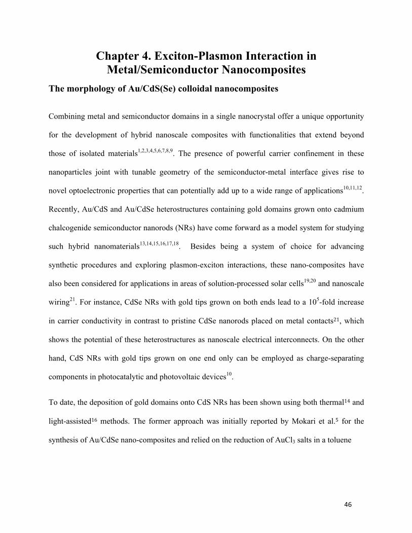
Figure 4.1 (a,b). HAADF-STEM images of Au/CdS heterostructures showing the color contrast between gold (bright) and semiconductor (dark) domains. (c, d). TEM images of the two areas shown in (a) and (b).
growing gold domains onto CdS nanorods in oleylamine. The size of Au NCs can be fine tuned
by regulating the temperature of the reaction mixture, while the shape of Au/CdS nano-
composites (matchstick or barbells) is controlled via the reaction rate (Figure 4.1)23. In contrast
49
to standard techniques for producing gold tips on semiconductor nanorods, this method does not
employ DDA/DDBA reducer/surfactant combination and can furnish large-size Au tips without
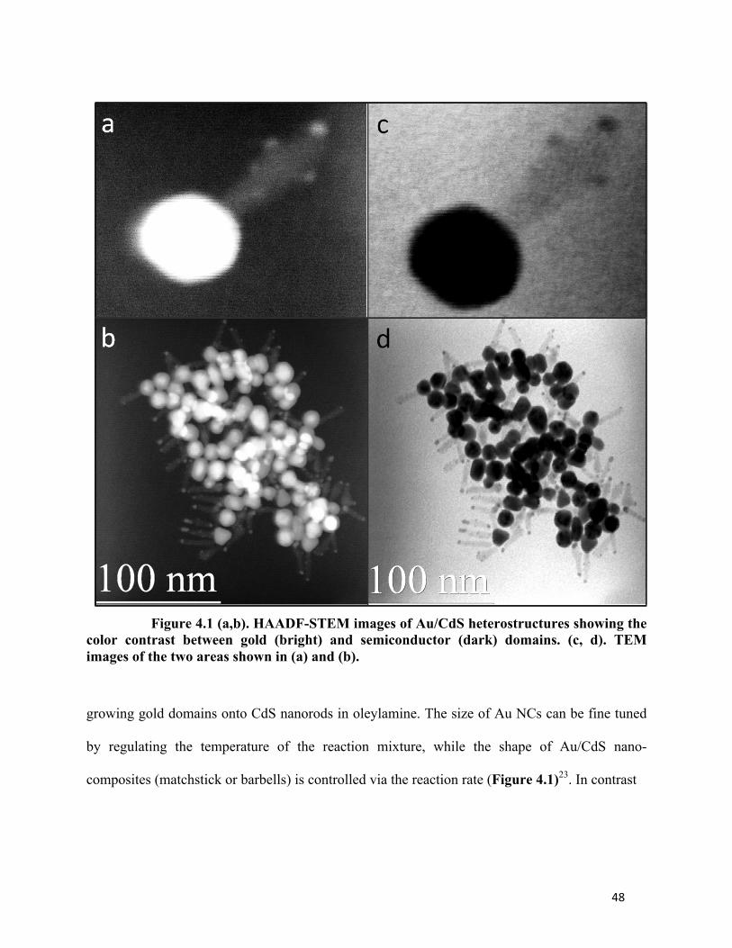
relying on UV-irradiation of the reaction mixture. Synthesized Au/CdS nano-composites
demonstrated evaporation-induced self-assembly onto TEM grids (Figure 4.2)23 either through
end-to-end or side-by-side coupling of Au domains, which should enable their incorporation into
large-area optoelectronic devices.
Figure 4.2 Evaporation-induced assembly of Au/CdS nano-composites into (a) end-to-end “chains” and (b) two-dimensional superlattices
50
Exciton-plasmon interaction in Au/CdS nanocomposites
Bulk heterojunctions of metal and semiconductor materials have long been of importance
to fundamental science and device engineering due to the unique relations of respective
domains through the formation of the space-charge region,24 which gives rise to plentiful
technological applications including Schottky barrier solar cells25, solid state lasers26,
light emitting diodes27, and field effect transistors28. Of a particular significance is a
fundamental interaction between semiconductor excitons and surface plasmons (SP) of
metal nanoparticles (Figure 4.3)29, which results from the alteration of the exciton dipole
moment because of local electromagnetic modes of SP.30,31 This interaction is facilitated
by the nanoscopic nature of both material domains and has a unique effect on
optoelectronic properties of a composite M-S system, which has been demonstrated to
significantly change the energy flow that occurs across M-S junctions. For instance, the
presence of plasmon radiative field in metals, caused by resonant oscillations of low-
energy conduction electrons, can strongly influence the dynamics of excitons in
semiconductor NCs via two distinct interaction mechanisms, including plasmon-exciton
energy transfer, and modification of the local radiation field in S domains.
Numerous studies have explored the nature of exciton-plasmon interactions in a weak
coupling regime, distinguished by the presence of a significant potential barrier at the
interface of S and M components, which was accomplished experimentally by means of
spacer molecules or non-epitaxial domain coupling. For these composites, the emission
intensity in S domains was increased32,33,34,35,36,37,38,39 due to the plasmon-induced
enhancement of S radiative rates,40,41 and was consequently studies towards improving
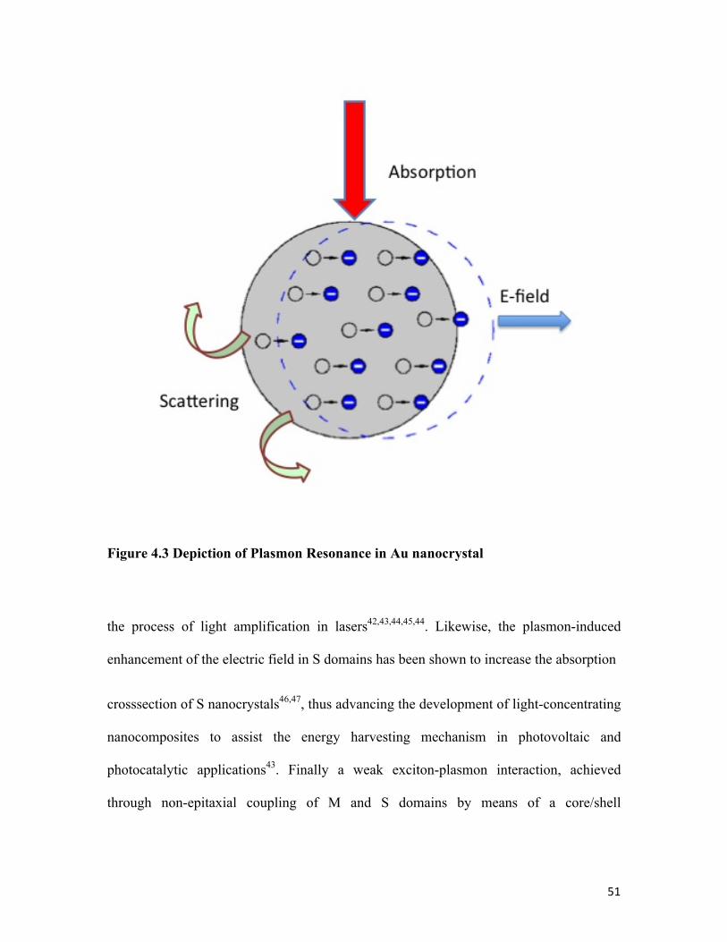
51
Figure 4.3 Depiction of Plasmon Resonance in Au nanocrystal
the process of light amplification in lasers42,43,44,45,44. Likewise, the plasmon-induced
enhancement of the electric field in S domains has been shown to increase the absorption
crosssection of S nanocrystals46,47, thus advancing the development of light-concentrating
nanocomposites to assist the energy harvesting mechanism in photovoltaic and
photocatalytic applications43. Finally a weak exciton-plasmon interaction, achieved
through non-epitaxial coupling of M and S domains by means of a core/shell

52
morphology, has been utilized for controlling the spin of Au nanoparticles41, with
potential application of this phenomenon in quantum information and spintronics48,49,50.
When metal and semiconductor components are joined directly, without using a spacer
moiety, the potential barrier for charges residing in adjacent domains may become
sufficiently diminished to allow inter-domain charge transfer, and corresponding mixing
of electronic states at the M-S interface. In addition, the enhanced electromagnetic field
of M plasmons in such strong coupling mode may create further alterations of carrier
dynamics associated with shared oscillations of the excitation energy between S and M
domains, often referred to as Rabi oscillations.51,52 In line with these expectations, several
recent experimental reports have indicated that directly joined M-S nanocomposites
demonstrate optoelectronic properties that are significantly different from those of
isolated M and S nanoparticles, and are repeatedly overlooked by existing theoretical
models, which cast doubt on the nature of exciton–plasmon interactions in epitaxial M-S
nanocomposites. For example, it has been reported that a direct growth of Au tips onto
CdSe nanorods results in quenching of the fluorescence in the S domain caused by an
ultrafast transfer of S electrons into Au. Nonetheless, a different explanation based on the
existence of sub-band gap states at Au/CdS interface cannot be excluded. Furthermore,
there is basically no theoretical report for the energy-dependent changes in the
absorbance profile of the S component emerging as a result of direct coupling to M
domain. Explaining these phenomena requires a deeper knowledge of basic electron
processes that appear in strongly coupled M-S nanocomposites. Finding answers to these
questions will help the formulation of design principles needed for the achievement of
epitaxial M-S nanocomposites in future nano-electronic device architectures.

53
Recently Zamkov group and co-workers performed29 femtosecond transient absorption
spectroscopy studies to investigate the nature of exciton-plasmon interactions in
Figure 4.4 (a) Steady-state absorption of Au/CdS heterostructures comprising 15.7-nm Au domains. A representative TEM image is shown in the insert. (b) Transient absorption spectra of 15.7-nm-Au/CdS nanocomposites resulting from the excitation at λ=400 nm with 120 fs pump pulses. The recovery of ΔA shows an expected plasmonic feature, which resembles the corresponding TA dynamics of isolated Au
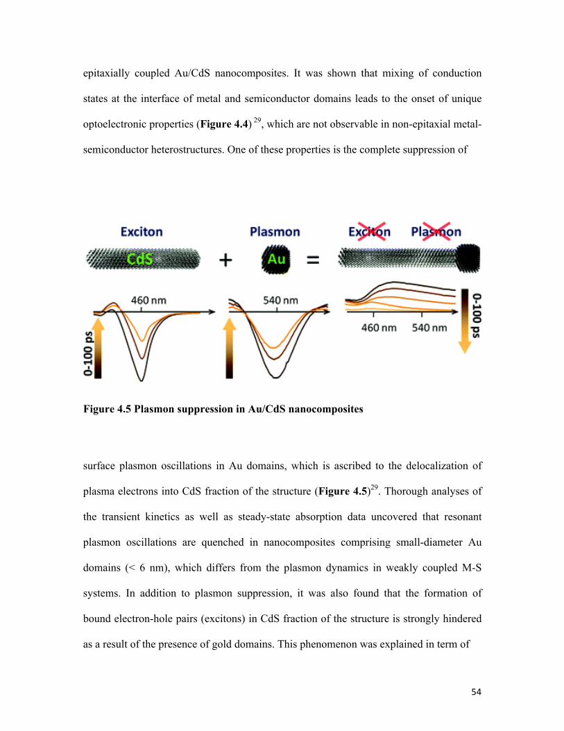
54
epitaxially coupled Au/CdS nanocomposites. It was shown that mixing of conduction
states at the interface of metal and semiconductor domains leads to the onset of unique
optoelectronic properties (Figure 4.4) 29, which are not observable in non-epitaxial metal-
semiconductor heterostructures. One of these properties is the complete suppression of
Figure 4.5 Plasmon suppression in Au/CdS nanocomposites
surface plasmon oscillations in Au domains, which is ascribed to the delocalization of
plasma electrons into CdS fraction of the structure (Figure 4.5)29. Thorough analyses of
the transient kinetics as well as steady-state absorption data uncovered that resonant
plasmon oscillations are quenched in nanocomposites comprising small-diameter Au
domains (< 6 nm), which differs from the plasmon dynamics in weakly coupled M-S
systems. In addition to plasmon suppression, it was also found that the formation of
bound electron-hole pairs (excitons) in CdS fraction of the structure is strongly hindered
as a result of the presence of gold domains. This phenomenon was explained in term of
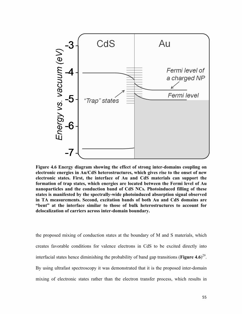
55
Figure 4.6 Energy diagram showing the effect of strong inter-domains coupling on electronic energies in Au/CdS heterostructures, which gives rise to the onset of new electronic states. First, the interface of Au and CdS materials can support the formation of trap states, which energies are located between the Fermi level of Au nanoparticles and the conduction band of CdS NCs. Photoinduced filling of these states is manifested by the spectrally-wide photoinduced absorption signal observed in TA measurements. Second, excitation bands of both Au and CdS domains are “bent” at the interface similar to those of bulk heterostructures to account for delocalization of carriers across inter-domain boundary.
the proposed mixing of conduction states at the boundary of M and S materials, which
creates favorable conditions for valence electrons in CdS to be excited directly into
interfacial states hence diminishing the probability of band gap transitions (Figure 4.6)29.
By using ultrafast spectroscopy it was demonstrated that it is the proposed inter-domain
mixing of electronic states rather than the electron transfer process, which results in
56
fluorescence quenching in CdS domains. Further evidence of the proposed interfacial
state mixing is supplied by the observation of a characteristic, long-lived photoinduced
absorption (positive TA signal), which corroborates the interfacial character of excited
states in Au/CdS heterostructures.
57
References
1. Cozzoli, P.; Pellegrino, T.; Manna, L. Chem. Soc. Rev. 2006, 35, 1195–1208.
2. Jun, Y.; Choi, J.; Cheon, J. Angew. Chem. Int. Ed. 2006, 45, 3414–3439.
3. Rajeshwar, K.; Tacconi, N.; Chenthamarakshan, C. Chem. Mater. 2001, 13, 2765-
2782.
4. Cozzoli, P.; Manna, L. Nature Mater. 2005, 4, 801-802.
5. Mokari, T.; Rothenberg, E.; Popov, I.; Costi, R.; Banin, U. Science 2004, 304, 1787–
1790.
6. Yang, J.; Elim, H. I.; Zhang, Q.; Lee, J. L.; Ji, W. J. Am. Chem. Soc. 2006, 128, 11921.
7. Dukovic, G.; Merkle, M. G.; Nelson, J. H.; Hughes, S. M.; Alivisatos, A. P. Adv.
Mater. 2008, 20, 4306–4311.
8. Deka, S.; Falqui, A.; Bertoni, G.; Sangregorio, C.; Poneti, G.; Morello, G.; Giorgi, M.;
Giannini, C.; Cingolani, R.; Manna, L.; Cozzoli, P. D. J. Am. Chem. Soc. 2009, 131,
12817–12828.
9. Zanella, M.; Falqui, A.; Kudera, S.; Manna, L.; Casula, M. F.; Parak, W. J. J. Mater.
Chem. 2008, 18, 4311–4317.
10. Maynadie`, J.; Salant, A.; Falqui, A.; Respaud, M.; Shaviv, E.; Banin, U.; Soulantica,
K.; Chaudret, B. Angew. Chem., Int. Ed. 2009, 48, 1814–1817.
11 He, S.; Zhang, H.; Delikanli, S.; Qin, Y.; Swihart, M. T.; Zeng, H. J. Phys. Chem. C
2009, 113, 87–90.
12. Lee, J. S.; Shevchenko, E. V.; Talapin, D. V. J. Am. Chem. Soc. 2008, 130, 9673-
9675.
58
13. Carbone, L.; Kudera, S.; Giannini, C.; Ciccarella, G.; Cingolani, R.; Cozzoli, P. D.;
Manna, L. J. Mater. Chem. 2006, 16, 3952.
14. Saunders, A. E.; Popov, I.; Banin, U. J. Phys. Chem. B 2006, 110, 25421.
15. Menagen, G.; Mocatta, D.; Salant, A.; Popov, I.; Dorfs, D.; Banin, U. Chem. Mater.
2008, 20, 6900–6902.
16. Carbone, L.; Jakab, A.; Khalavka, Y.; Sonnichsen, C. Nano Lett. 2009, 9, 3710-3714.
17. Menagen, G.; Macdonald, J. E.; Shemesh, Y.; Popov, I.; Banin, U. J. Am. Chem. Soc.
2009, 131, 17406–17411.
18. Mokari, T.; Costi, R.; Sztrum, C. G.; Rabani, E.; Banin, U. Phys. Stat. Sol. (b). 2006,
243, 3952–3958.
19. Costi, R.; Saunders, A. E.; Elmalem, E.; Salant, A.; Banin, U. Nano Lett. 2008, 8,
637-641.
20. Zhao, N.; Liu, K.; Greener, J.; Nie, Z.; Kumacheva, E. Nano Lett. 2009, 9, 3077-
3081.
21. Sheldon, M. T.; Trudeau, P. E.; Mokari, T.; Wang, L. W.; Alivisatos, A. P. Nano Lett.
2009, 9, 3676-3682.
22. Redmond, P. L.; Hallock, A. J.; Brus, L. E. Nano Lett. 2005, 5, 131–135.
23. Khon, E.; Hewa-Kasakarage, N. N.; Nemitz, I.; Acharya, K.; Zamkov M. Chem.
Mater. 2010, 22 (21), 5929–5936.
24. Many, A.; Goldstein, Y.; Grover, N. B. Semiconductor Surfaces; North Holland:
Amsterdam, 1965.
25. Loutfy, R. O.; Sharp, J.H. J. Am. Chem. Soc. 1979, 71, 1211–1217 .
26. Nolte, D. D. J. Appl. Phys. 1999, 85, 6259–6289.
59
27. Ozgur, U.; Alivov, Y. I.; Liu, C.; Teke, A.; Reshchikov, M. A.; Dogan, S.; Avrutin,
V.; Cho, S. J.; Morkoc, H. J. Appl. Phys. 2005, 98, 041301.
28. Storm, H. F. IEEE Trans. Electron. Dev. 1969, ED16, 957.
29. Khon, E.; Mereshchenko, A.; Tarnovsky, A. N.; Acharya, K.; Klinkova, A.; Hewa-
Kasakarage, N. N.; Nemitz, I.; Zamkov M. Nano Lett. 2011, DOI: 10.1021/nl200409x
30. Drexhage, K. H. Progress in Optics, Wolf, E., Ed.; North-Holland: Amsterdam, The
Netherlands, 1974; Vol. XII, p 163.
31. Achermann, M. J. Phys. Chem. Lett. 2010, 1, 2837–2843
32. Shimizu, K. T.;Woo,W. K.; Fisher, B. R.; Eisler, H. J.; Bawendi, M. G. Phys. Rev.
Lett. 2002, 89, 117401.
33. Farahani, J. N.; Pohl, D. W.; Eisler, H. J.; Hecht, B. Phys. Rev. Lett. 2005, 95,
017402.
34. Bergman, D. J.; Stockman, M. I. Phys. Rev. Lett. 2003, 90, 027402.
35. Mertens, H.; Biteen, J. S.; Atwater, H. A.; Polman, A. Nano Lett. 2006, 6, 2622–
2625.
36. Okamoto, K.; Niki, I.; Shvartser, A.; Narukawa, Y.; Mukai, T.; Scherer, A. Nat.
Mater. 2004, 3, 601–605.
37. Guo, P.-F.; Wu, S.; Ren, Q.-J.; Lu, J.; Chen, Z.; Xiao, S.-J.; Zhu, Y.-Y. J. Phys.
Chem. Lett. 2010, 1, 315–318.
38. Gryczynski, I.; Malicka, J.; Jiang, W.; Fischer, H.; Chan, W. C. W.; Gryczynski, Z.;
Grudzinski, W.; Lakowicz, J. R. J. Phys. Chem. B 2005, 109, 1088–1093.
39. Pillai, S.; Catchpole, K. R.; Trupke, T.; Zhang, G.; Zhao, J.; Green, M. A. Appl. Phys.
Lett. 2006, 88, 161102.
60
40. Muskens, O. L.; Giannini, V.; Sanchez-Gil, J. A.; Rivas, J. G. Nano Lett. 2007, 7,
2871–2875.
41. Wang, Y.; Yang, T.; Tuominen, M. T.; Achermann, M. Phys. Rev. Lett. 2009, 102,
163001.
42. Noginov, M. A.; Zhu, G.; Mayy, M.; Ritzo, B. A.; Noginova, N.; Podolskiy, V. A.
Phys. Rev. Lett. 2008, 101, 226806.
43. Noginov, M. A.; Zhu, G.; Belgrave, A. M.; Bakker, R.; Shalaev, V. M.; Narimanov,
E. E.; Stout, S.; Herz, E.; Suteewong, T.; Wiesner, U. Nature 2009, 460, 1110–1112.
44. Zheludev, N. I.; Prosvirnin, S. L.; Papasimakis, N.; Fedotov, V. A. Nat. Photonics
2008, 2, 351–354.
45. Englund, D.; Fattal, D.; Waks, E.; Solomon, G.; Zhang, B.; Nakaoka, T.; Arakawa,
Y.; Yamamoto, Y.; Vuckovic, J. Phys. Rev. Lett. 2005, 95, 013904.
46. Schaadt, D. M.; Feng, B.; Yu, E. T. Appl. Phys. Lett. 2005, 86, 063106
47. Rand, B. P.; Peumans, P.; Forrest, S. R. J. Appl. Phys. 2004, 96, 7519–7526.
48. Gupta, J. A.; Knobel, R.; Samarth, N.; Awschalom, D. D. Science 2001, 292, 2458–
2461.
49. Press, D., Ladd, T. D., Zhang, B.; Yamamoto, Y. Nature 2008, 456, 218–221.
50. Berezovsky, J.; Mikkelsen, M. H.; Stoltz, N. G.; Coldren, L. A.; Awschalom, D. D.
Science 2008, 320, 349–352.
51. Klimov, V. I.; McBranch, D. W.; Leatherdale, C. A.; Bawendi, M. G. Phys. Rev. B
1999, 60, 13740–13749.
52. Gόmez, D. E.; Vernon, K. C.; Mulvaney, P.; Davis T. J. Nano Lett. 2010, 10, 274.
61
Chapter 5. Synthesis and Optoelectronic Properties of Au/CdS and Au/CdSe/CdS Nanocomposites
Au/CdS Nanocomposites
Isolated gold and silver nanocrystals’ synthesis via a reduction of corresponding metal salts by
oleylamine ligands has been previously demonstrated in several reports1,2,3,4,5. In these works, the
reaction of AuCl3 or HAuCl4 with oleylamine was proceeded in a single phase solvent (e.g. toluene)
at 60-80 °C leading to a slow reduction of Au(III) ions to Au(I) and consequently to neutral Au
clusters. Careful observation of the growth kinetics during the synthesis has revealed5,6 that
oleylamine molecules created complex aggregates with gold salt immediately upon mixing of these
two agents. At a higher temperature (< 80 °C), these complexes disintegrated into very small
particles, which ultimately recombined together into bigger and thermally stable nanocrystals with
an average size varying from 5 to 10 nm. Within this method, the nanoparticle growth rate could be
altered either by adjusting the concentration of oleylamine in the toluene solution or by changing the
reaction temperature. Alternatively, in the present synthesis the control over nanoparticle growth was
simplified by using oleylamine both as a reducing agent and the reaction solvent. This results in a set
ratio of Au to oleylamine in the solution, such that the nanoparticle growth rate can be adjusted only
by varying the temperature of the reaction mixture.
In a typical synthesis, CdS nanorods were initially made by growing CdS linear extensions from
(000±1) faces of small-diameter CdS seeds7, according to a procedure modified from Ref8.
Synthesized CdS NRs were cleaned several times with toluene/ethanol combination and saved for
later use. For the deposition of Au, 3 ml of oleylamine were degassed in vacuum at 120°C for 1 hour
and consequently cooled down to 60°C. After purification, all of the oleylamine then injected into
62
the three-neck flask containing 0.0113g of Au (III) chloride, and the temperature was increased to 60
°C. When the solution became yellow and clear (approximately after 5 min of heating), 4 mg of CdS
nanorods in 0.1 ml of toluene were injected via syringe. The exact amount of CdS NRs for the
synthesis of Au/CdS nano-composites was calculated using an empirical approach, whereby the
nanorod absorption at 450 nm (excitonic feature) times the volume of the colloidal suspension (in
mL) was set to be in the range of 18 to 25. For instance, Au/CdS nano-composites shown in Figure
5.1a9 were synthesized using 20 units of CdS NRs (corresponding to 4 mg). Upon injection of CdS
NRs into AuCl3/oleylamine mixture, the heat was brought to the flask and the solution was heated at
a rate of ~ 1.5-3 °C/min. When the desired temperature was reached, the reaction was quenched by
removing the heat source and injecting 5 ml of room-temperature toluene into the mixture.
The effect of the reaction temperature on the size of gold tips is demonstrated by transmission
electron microscopy (TEM) images of Au/CdS nano-composites in Figure 5.19. Heating the
AuCl3/oleylamine mixture to approximately 105 °C facilitates the formation of 4-5 nm Au domains
on both ends of CdS nanorods (Figure 5.1c)9. Some side-wall growth of minor gold nanocrystals is
also observed at this stage and is ascribed to the reduction-induced assembly of Au clusters at
defects of the CdS lattice. The two examples of Au/CdS nano-composites in Figure 5.1 (b,c)9 prove
that the growth of Au NCs along defects of the CdS lattice can be curbed in nanorods showing a
better lattice quality. Using high-resolution TEM analysis the defect growth kinetics was captured
through monitoring a step-by-step formation of small Au nanoparticles from surface-trapped Au
ions. Deposition of large-diameter gold tips onto one of the nanorod facets (Figure 5.1a,b)9 is
accomplished by raising the temperature of the reaction
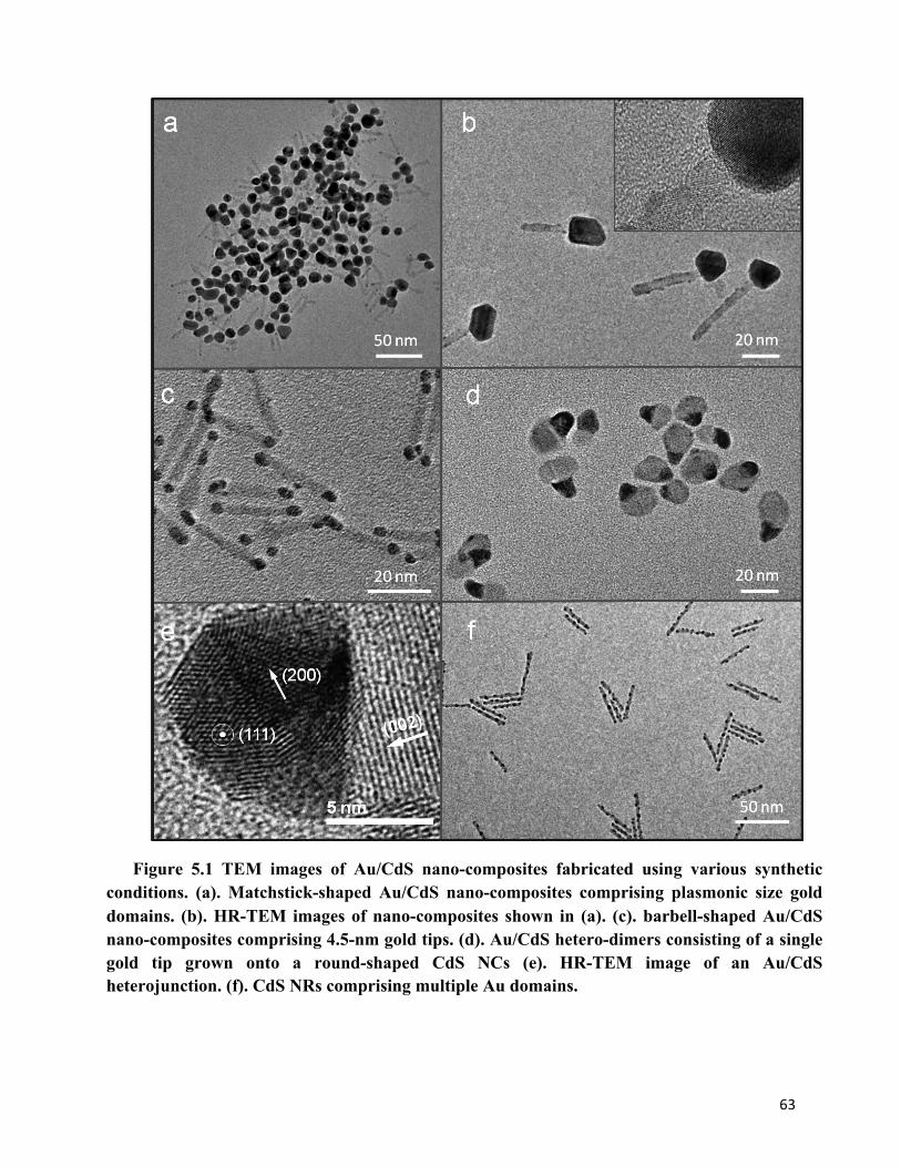
63
Figure 5.1 TEM images of Au/CdS nano-composites fabricated using various synthetic conditions. (a). Matchstick-shaped Au/CdS nano-composites comprising plasmonic size gold domains. (b). HR-TEM images of nano-composites shown in (a). (c). barbell-shaped Au/CdS nano-composites comprising 4.5-nm gold tips. (d). Au/CdS hetero-dimers consisting of a single gold tip grown onto a round-shaped CdS NCs (e). HR-TEM image of an Au/CdS heterojunction. (f). CdS NRs comprising multiple Au domains.
64
mixture to above 120 °C. This facilitates the dissolution of smaller Au domains and simultaneous
aggregation of larger Au nanoparticles via electrochemical Ostwald ripening10. It was essential to
maintain the heating rate below 3.3 °C/min to ensure the growth of large-size Au domains, while
heating of the solution at a faster rate (>4 degrees/minute) leads to the formation of isolated Au NCs
that use up a large portion of AuCl3 from the solution hence preventing the development of Au tips.
The crystalline nature of fabricated nano-composites is confirmed by high-resolution TEM (HR-
TEM) images in Figures 5.1b,e9. Both CdS and Au domains show characteristic lattice fringes
indexed to respective spacing values of hexagonal wurtzite and face-centered cubic (fcc) crystal
phases. The analysis of several samples has shown that the lattice of CdS NC’s was usually
maintained during the high-temperature synthesis with the exception of some scattered lattice
irregularities denoted by small Au domains developing along the defects and the opposite tip of CdS
NC’s. Such side-wall nucleation of gold displayes a set of small-size (1 nm < d < 2 nm) gold
nanocrystals that form on the surface of a CdS NC’s. The structure of large-diameter gold tips grown
onto one side of CdS NC’s is demonstratd in Figure 5.1e9. Judging by the spacing of (111) and
(200) atomic planes, the growth of Au tips occurs in the face-centered cubic phase with multiple
twinnings of the nanoparticle shape.
The effect of the reaction temperature and the heating rate on the shape of Au domains is further
investigated in Figure 5.29. The initial enhancement in the average size of gold tips further than
those of defect-localized domains was observed at T ≈ 95-100 °C. The heating rate of the solution
plays a critical role at these temperatures determining whether the tip grows on one or both ends of
CdS nanorods, such that a faster heating rate (≈ 3 degrees/minute) leads to the growth of barbell-
shaped nano-composites (Figure 5.2b)9, while slow heating (~ 1.5-2.3 degrees/minute) facilitates
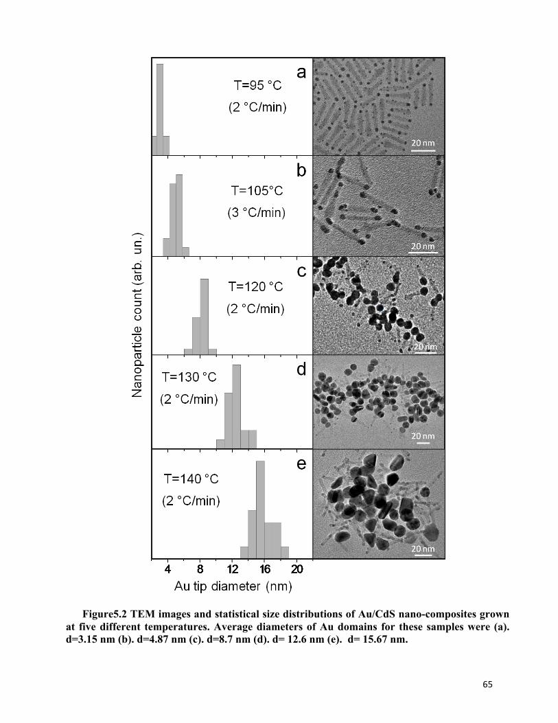
65
Figure5.2 TEM images and statistical size distributions of Au/CdS nano-composites grown at five different temperatures. Average diameters of Au domains for these samples were (a). d=3.15 nm (b). d=4.87 nm (c). d=8.7 nm (d). d= 12.6 nm (e). d= 15.67 nm.

66
the growth of Au/CdS matchsticks (Figure 5.2a)9. The average size of Au domains was measured to
be 3.2 nm (matchsticks) and 4.9 nm (barbells) with theassociated dispersion of sizes of 12% and
11%, correspondingly. For the case of nano-barbells, additional raise in the temperature of the
solution to 120 °C results in the dissolution of one of the tips and simultaneous selective deposition
on the other, leading to an nearly exclusive development of matchstick-shaped heterostructures
(Figure 5.2c)9, regardless of the heating rate. As a consequence, the largest value of the tip diameter
for nano-barbells obtained by this method was limited to 6 nm (at ~ 110 °C), due to the conversion
of these structures into matchstick-shaped composites at elevated temperatures. The average size of
the larger tip grew to 12.6 nm, upon additional increase of the reaction temperature to 130 °C,
whereas the shape of Au domains diverged from the spherical. This tendency is evidently observed
in the final sample synthesized at 140 °C (Figure 5.2e)9, where a variety of Au shapes, including
triangular, pyramidal, and cylindrical can be recognized. The raise of the reaction temperature was
supplemented by the growing dispersion of NC sizes, which altered from 7% for 8.0-nm tips to 10%
for 15-nm domains. Further research will be needed to optimize the reported synthetic protocols in
order to allow lower dispersion of shapes for Au tips with diameters larger than 15 nm. For instance,
introduction of additional stabilizing ligands other than oleylamine may be helpful in reaching the
desired size-focusing of Au nanoparticles.

67
Changes in optical properties of Au/CdS nano-composites during the development of Au domains
are investigated in Figure 5.39. At T=90 °C, the absorption profile of Au/CdS nanoparticles shows
clear changes from that of pure CdS nanorods, with the major difference occurring in the wavelength
range above λ=550 nm, where the absorption of heterostructures is enhanced. This red tail is
ascribed to the contribution from interfacial trap states as well as to optical transitions in small-size
gold clusters growing on the surface of CdS nanorods. The diminishing of the excitonic feature in
CdS NRs at this stage is ascribed to the delocalization of carriers into small gold clusters and oleate
complexes that form on the semiconductor surface. Spectral changes that are taking place during the
initial heating of the mixture are accompanied by the visible change of the solution color from
Figure 5.3 Evolution of the Au/CdS absorption spectra during the synthesis. The initial spectrum (blue curve) represents the absorbance of pure CdS nanorods. The average size of gold domains for the subsequent spectra are as follows: green ≈ 2.9 nm, olive ≈ 8.1 nm, red ≈ 15.7 nm.

68
yellow to light brown, whereas additional heating of the flask to above 100 °C leads to further
darkening of the solution and corresponding raise in the amplitude of the absorption tail (for λ > 500
nm). At this point of the reaction, the average size of the Au tip reaches 4 nm, giving rise to a small
absorption feature at λ=550 nm, correlated to the surface plasmon resonance in Au
nanoparticles11,12,13. With increasing size of Au domain this peak becomes narrower and more
prominent, which is supplemented by a gradual change the solution color from dark brown to violet.
For tips greater than 9 nm in diameter, the amplitude of the plasmon peak became comparable to that
of an excitonic absorption feature in CdS nanorods (Figure 5.3, red curve)9, whereas, for Au NCs
with sizes of 20 nm and greater this absorption feature befall inhomogenously broadened due to
large dispersions of Au shapes (prisms, rods, spheres, etc.). It is noteworthy that upon development
of Au domains, the band-gap fluorescence of CdS nanorods becomes entirely quenched. Such
suppression of emission in Au/CdS nano-composites has been observed previously14 and is ascribed
to the fast transfer of excited carriers from CdS into Au domains.
The illustrated technique for the deposition of gold tips onto CdS is free of the nanorod aspect ratio
and can be expanded to nanocrystals with other spatial geometries. For instance, heterostructures
containing spherical CdS domains can be potentially used as model systems for studying non-linear
optical behavior on nanoscale15,16, whereby contributing to the fundamental understanding of
exciton-plasmon coupling in metal-semiconductor nano-composites. Several TEM images of
Au/CdS hetero-dimers comprising low- aspect-ratio wurtzite CdS NCs used for seeding the growth
of gold domains at three different reaction temperatures are shown in Figure 5.49. Similar to
nanorods, the low-temperature (T<95 °C) deposition of gold tips onto almost spherical CdS NCs
appears primarily at surface defects that confine the assembly of small gold
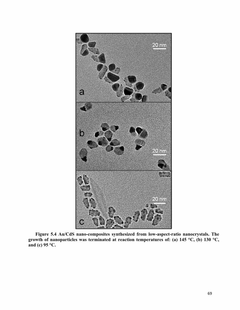
69
Figure 5.4 Au/CdS nano-composites synthesized from low-aspect-ratio nanocrystals. The growth of nanoparticles was terminated at reaction temperatures of: (a) 145 °C, (b) 130 °C, and (c) 95 °C.
70
clusters, as shown in Figure 5.4c.9 Raising the reaction temperature to above 130 °C leads to
dissolution of some smaller domains in favor of a single Au nanoparticle that can grow both on
facets and lateral walls of elongated CdS NCs (Figure 5.4a,b).9 The size of these Au tips can be
adjusted in the range of 5 to 15 nm, utilizing the same range of reaction temperatures as in the case
of nanorods-shaped semiconductor domains. The noticeable similarity between the shape of gold
domains of synthesized Au/CdS hetero-dimers and those of CdS nanorods indicates that the rate of
Au deposition onto CdS is not strongly connected with the nanorod aspect ratio.
Au/CdSe/CdS Nanocomposites
Based on procedures developed for synthesis of Au/CdS nanocomposites and the fact that Au growth
onto surface of CdS does not depend on shape of nanocrystal by this methodology we pursued study
of gold/semiconductor nanocomposites comprising CdSe/CdS core-shell NC’s as semiconductor
domain. Since suppression of emission in Au/CdS nano-composites has been observed previously17
and is ascribed to the fast transfer of excited carriers from CdS into Au domains we wanted to
investigate whether excited carriers from CdSe with a substantial shell of different band gap material
(i.e. CdS) would be sufficient enough to prevent the transfer and consequently simultaneously
observe exciton emission along with plasmon resonance by proposed nanocomposites.
Three different methods for CdS shell growth onto CdSe core were developed each varying in
number of shell material injections and amount of the material in every injection. In all three
methods shells were grown onto seeds prepared by modified procedure from Ref. 7. In method A
initial thin shell (1-2 nm) was grown onto CdSe seeds by adding seeds and sulfur precursors to Cd
precursors at very high temperature (380 °C) and subsequent shell material was added with two
injections at the same temperature each carrying as much Cd and sulfur precursors as for the initial

71
shell development yielding relatively large nearly spherical nanocrystals (Figure 5.5). These NC’s
were later used to grow Au domains.
Figure 5.5 CdSe/CdS core-shell nanocrystals synthesized by method A
In method B different approach was pursued. Core-shell NC’s with initial thin shell grown onto
CdSe seed by adding seeds and sulfur precursors to Cd precursors at very high temperature were
purified and used as seeds for subsequent similar procedure with this procedure being repeated once
more. This method furnished nanocrystals with irregular shape and one of the faces growing
nanorod-like CdS linear extension (Figure 5.6). These NC’s were not used for gold deposition due
to their irregular shape.
Method C used approach in which core-shell NC’s with initial thin shell grown onto CdSe seed

72
Figure 5.6 CdSe/CdS core-shell nanocrystals synthesized by method B
by adding seeds and sulfur precursors to Cd precursors at very high temperature and consequent
addition of shell material via multiple injections with increasing amount of Cd and sulfur precursors
for growth of several monolayers of CdS. This yielded triangular shaped NC’s which were then used
for growing Au tips.
Figure 5.7 Au/CdSe/CdS nanocomposites with CdSe/CdS core-shell nanocrystals synthesized by method C
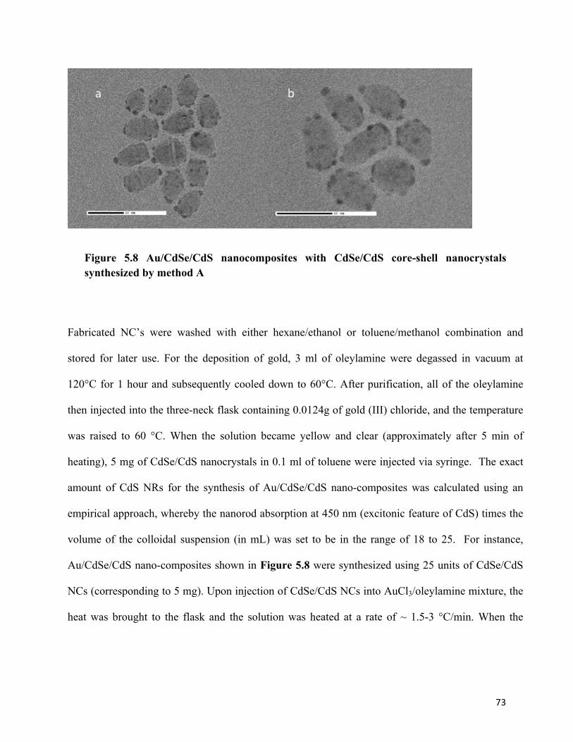
73
Figure 5.8 Au/CdSe/CdS nanocomposites with CdSe/CdS core-shell nanocrystals synthesized by method A
Fabricated NC’s were washed with either hexane/ethanol or toluene/methanol combination and
stored for later use. For the deposition of gold, 3 ml of oleylamine were degassed in vacuum at
120°C for 1 hour and subsequently cooled down to 60°C. After purification, all of the oleylamine
then injected into the three-neck flask containing 0.0124g of gold (III) chloride, and the temperature
was raised to 60 °C. When the solution became yellow and clear (approximately after 5 min of
heating), 5 mg of CdSe/CdS nanocrystals in 0.1 ml of toluene were injected via syringe. The exact
amount of CdS NRs for the synthesis of Au/CdSe/CdS nano-composites was calculated using an
empirical approach, whereby the nanorod absorption at 450 nm (excitonic feature of CdS) times the
volume of the colloidal suspension (in mL) was set to be in the range of 18 to 25. For instance,
Au/CdSe/CdS nano-composites shown in Figure 5.8 were synthesized using 25 units of CdSe/CdS
NCs (corresponding to 5 mg). Upon injection of CdSe/CdS NCs into AuCl3/oleylamine mixture, the
heat was brought to the flask and the solution was heated at a rate of ~ 1.5-3 °C/min. When the

74
desired temperature was reached, removing the heating mantle from the flask and injecting 6 ml of
room-temperature toluene quenched the reaction.
In conclusion, we have developed several chemical routes to CdSe/CdS core-shell NCs with each of
them leading to different shape of nanocrystals. Also a simple chemical method for growing Au
domains onto CdS nanorods and CdSe/CdS NCs in oleylamine was developed. The size of Au NCs
can be precisely tuned by adjusting the temperature of the reaction mixture, while the shape of
Au/CdS nano-composites (matchstick or barbells) is controllable via the reaction rate. All of the
aforementioned nanocomposites had quenched emission and further study is necessary to determine
whether a significantly wider band gap shell material can prevent fast transfer of excited carriers
from semiconductor into metal domains.
Experimental Section
Chemicals. Gold (III) chloride (99%, Aldrich), oleylamine ( tech., 70%, Aldrich), sulfur (99.999%,
Acros), 1-octadecene (ODE, tech., 90%, Aldrich), cadmium oxide (99.99%, Alrdich), oleic acid
(OA, tech., 90%, Aldrich), tri-n-octylphosphine (TOP, 97%, Strem), tri-n-octylphosphine oxide
(TOPO, 99%, Aldrich), n-octadecylphosphonic acid (ODPA, PCI Synthesis), n-hexylphosphonic
acid (HPA, PCI Synthesis), octadecylamine (ODA, 90%, tech., Acros), hexane (anhydrous, 95%,
Aldrich), methanol (99.8+%, EMD), chloroform (anhydrous, 99+%, Aldrich), ethanol ( anhydrous,
95%, Aldrich) and toluene ( anhydrous, 99.8%, Aldrich) were used as purchased. All reactions were
performed under argon atmosphere using the standard Schlenk technique.
Characterization. UV-vis absorption and photoluminescence (PL) spectra were recorded using
CARY 50 Scan spectrophotometer and Jobin Yvon Fluorolog FL3-11 fluorescence
spectrophotometer. PL quantum yield of hetero-NCs was determined relative to known QYs of
75
several organic dyes excited at 400-440 nm. High resolution transmission electron microscopy
measurements were carried out using JEOL 311UHR operated at 300 kV. Specimens were prepared
by depositing a drop of nanocrystal hexane solution onto a formvar-coated copper grid and letting it
dry in air.
Synthesis of CdS Nanocrystals: CdS seeds were fabricated according to the procedure reported
in ref 18.
In a typical synthesis, the mixture of cadmium oxide (0.0384 g, 0.3 mmol), OA (0.9 mL), and
ODE (12.0 mL) in a 50 mL 3-neck flask was heated to 300° C until the solution turned optically
clear and colorless. At this point, a sulfur precursor solution made by dissolving sulfur powder
(0.048 g, 1.5 mmol) in ODE (4.5 mL) at 200° C was quickly injected, and the temperature was
stabilized at 260° C for the nanocrystal growth. The reaction was stopped after 5-9 min, and
nanocrystals were isolated from the growth solution by precipitation with methanol, followed by
repeated hexane/methanol extractions. The average diameter of fabricated CdS nanocrystals was
in the range of 3.5-4.0 nm, depending on the growth time.
Synthesis of CdS Nanorods. The amount of CdS seeds for the synthesis of CdS nanorods was
calculated using an empirical approach, whereby the product of the particle absorption at 400 nm
(excitonic feature) and the volume of the colloidal suspension (in mL) was set to be in the range
of 5-10. For instance, CdS nanorods shown in Figure 1a were synthesized using 8 units of CdS
seeds. Overall, it was determined that using lower amounts of CdS seeds generally yields high-
aspect ratio nanorods, however, when less than 5 units of CdS is used for seeding, a small
amount of tetrapods can also form during the reaction, alongside high-aspect-ratio nanorods.
In a typical synthesis of CdS nanorods, CdS (8 units) seed powder was dispersed in 1.8 mL of
TOP and subsequently introduced into the sulfur injection solution at 60° C, previously prepared
76
by dissolving sulfur (0.120 g, 3.75 mmol) in TOP (1.81 mL) at 200° C. Separately, the mixture of
cadmium oxide (0.060 g, 0.47 mmol), TOPO (3.0 g), ODPA (0.290 g), and HPA (0.080 g) in a
50 mL 3-neck flask was exposed to vacuum at 150° C for ca. 30 min. Subsequently, the system
was switched to Ar flow and heated to above 350° C until the solution turned optically clear and
colorless. At this point, TOP (1.81 mL) was added to the flask as the Cd precursor coordinating
solvent. The rod growth was initiated by a quick injection of the seed/sulfur solution at 380° C.
After the temperature recovered to 350° C the nanorods were allowed to grow for an additional
7-9 min. Purification of CdS nanorods was similar to those of CdS seeds.
Au growth on CdS Nanorods. In a typical procedure, oleylamine (3 ml) was degased at 120°C
and pumped for about 30 min to remove any residual air from the system. At this step, the
system was switched to Ar flow and cooled down to 90°C, before it was injected via syringe into
the reaction flask which contained Gold (III) chloride (0.0113g, 0.0373 mmol) and started
heating. At 60-70°C, when Gold (III) chloride was dissolved in oleylamine, 0.5 mL of toluene-
suspended CdS nanorods (60 times diluted injection volume showed the excitonic absorption
peak of 0.75, which corresponds to approximately 12 mg of dry nanorods) was added via syringe
to the reaction flask which was slowly heated to 140°C in 0.1 mL amounts every 10 min. After
30-40 min, the reaction was stopped by cooling the flask to 50°C and adding excess toluene.
Purification of Au/CdS tipped nanocrystals. The final product was precipitated from toluene
by adding ethanol (1:1) at 50°C. The subsequent cleaning was done using toluene/ethanol
extraction.
Synthesis of CdSe/CdS NCs Method A. The amount of CdSe seeds for the synthesis of
CdSe/CdS NCs was calculated using an empirical approach, whereby the product of the particle
77
absorption at 586 nm (excitonic feature) and the volume of the colloidal suspension (in 1 mL)
was set to be in the range of 10-15. For instance, CdSe/CdS NCs shown in Figure 5.5 were
synthesized using 12 units of CdSe seeds. Overall, it was determined that using lower amounts of
CdSe seeds generally yields high-aspect ratio spherical nanocrystals, however, when less than 7
units of CdSe is used for seeding, a significant amount of nanorods is forming in the reaction.
In a typical synthesis of CdSe/CdS NCs, CdSe seed powder was dispersed in 1.8 mL of TOP and
subsequently introduced into the sulfur injection solution at 60° C, previously prepared by
dissolving sulfur (0.120 g, 3.75 mmol) in TOP (1.81 mL) at 200° C. Separately, the mixture of
cadmium oxide (0.060 g, 0.47 mmol), TOPO (3.0 g), ODPA (0.290), and HPA (0.080 g) in a 50
mL 3-neck flask was exposed to vacuum at 150° C for ca. 30 min. Subsequently, the system was
switched to Ar flow and heated to above 350° C until the solution turned optically clear and
colorless. At this point, TOP (1.81 mL) was added to the flask as the Cd precursor coordinating
solvent. The shell growth was initiated by a quick injection of the seed/sulfur solution at 380° C.
After the temperature recovered to 350° C the shell were allowed to grow for another 7-9 min.
Additional sulfur and Cd precursors injection solutions of the same amounts as for initial shell
were added after about 9 min. and this procedure repeated once more in another 10 min.
Purification of CdSe/CdS NCs was similar to those of CdS NC’s.
Synthesis of CdSe/CdS NCs Method B. The amount of CdSe seeds for the synthesis of
CdSe/CdS NCs was calculated using an empirical approach, whereby the product of the particle
absorption at 586 nm (excitonic feature) and the volume of the colloidal suspension (in mL) was
set to be in the range of 10-15. For instance, CdSe/CdS NCs shown in Figure 5.6 were
synthesized using 12 units of CdSe seeds. Overall, it was determined that using lower amounts of
78
CdSe seeds generally yields high-aspect ratio spherical nanocrystals, however, when less than 7
units of CdSe is used for seeding, a significant amount of nanorods is forming in the reaction.
In a typical synthesis of CdSe/CdS NCs, CdSe seed powder was dispersed in 1.8 mL of TOP and
subsequently introduced into the sulfur injection solution at 60° C, previously prepared by
dissolving sulfur (0.120 g, 3.75 mmol) in TOP (1.81 mL) at 200° C. Separately, the mixture of
cadmium oxide (0.060 g, 0.47 mmol), TOPO (3.0 g), ODPA (0.290), and HPA (0.080 g) in a 50
mL 3-neck flask was exposed to vacuum at 150° C for ca. 30 min. Subsequently, the system was
switched to Ar flow and heated to above 350° C until the solution turned optically clear and
colorless. At this point, TOP (1.81 mL) was added to the flask as the Cd precursor coordinating
solvent. The shell growth was initiated by a quick injection of the seed/sulfur solution at 380° C.
After the temperature recovered to 350° C the shell were allowed to grow for another 7-9 min.
These nanocrystals were purified and used as seeds in subsequent procedure with the same
amount of sulfur and Cd precursors as for initial shell growth and resulting NC’s were once more
used as seeds after purification in procedure using same amounts of Cd and sulfur as for initial
shell growth.
Synthesis of CdSe/CdS NCs Method C. The amount of CdSe seeds for the synthesis of
CdSe/CdS NCs was calculated using an empirical approach, whereby the product of the particle
absorption at 586 nm (excitonic feature) and the volume of the colloidal suspension (in mL) was
set to be in the range of 10-15. For instance, CdSe/CdS NCs shown in Figure 5.7 were
synthesized using 12 units of CdSe seeds. Overall, it was determined that using lower amounts of
CdSe seeds generally yields high-aspect ratio spherical nanocrystals, however, when less than 7
units of CdSe is used for seeding, a significant amount of nanorods is forming in the reaction.
79
In a typical synthesis of CdSe/CdS NCs, CdSe seed powder was dispersed in 1.8 mL of TOP and
subsequently introduced into the sulfur injection solution at 60° C, previously prepared by
dissolving sulfur (0.120 g, 3.75 mmol) in TOP (1.81 mL) at 200° C. Separately, the mixture of
cadmium oxide (0.060 g, 0.47 mmol), TOPO (3.0 g), ODPA (0.290), and HPA (0.080 g) in a 50
mL 3-neck flask was exposed to vacuum at 150° C for ca. 30 min. Subsequently, the system was
switched to Ar flow and heated to above 350° C until the solution turned optically clear and
colorless. At this point, TOP (1.81 mL) was added to the flask as the Cd precursor coordinating
solvent. The shell growth was initiated by a quick injection of the seed/sulfur solution at 380° C.
After the temperature recovered to 350° C the shell were allowed to grow for another 7-9 min.
For additional injections solution of sulfur (0.360 g) in TOP (5.43 mL) at 200° C was made.
Separately, the mixture of cadmium oxide (0.180 g), TOPO (9.0 g), ODPA (0.870), and HPA
(0.240 g) in a 50 mL 3-neck flask was exposed to vacuum at 150° C for ca. 30 min. After initial
shell growth 0.4 ml of sulfur solution at RT and 0.6 ml of Cd solution at 150° C were added
simultaneously to the reaction and shell allowed to grow for 10 more min. The shell material
solutions were then injected every 10 min. with each consequent injection increasing amount of
solution by 0.1 ml for sulfur and 0.15 ml for Cd respectively.
Au growth on CdSe/CdS NCs. In a typical procedure, oleylamine (3 ml) was degased at 120°C
and pumped for about 30 min to remove any residual air from the system. At this step, the
system was switched to Ar flow and cooled down to 90°C, before it was injected via syringe into
the reaction flask which contained Gold (III) chloride (0.0124g, 0.04 mmol) and started heating.
At 60-70°C, when Gold (III) chloride was dissolved in oleylamine, 0.5 mL of toluene-suspended
CdS nanorods (60 times diluted injection volume showed the excitonic absorption peak of 0.75,
which corresponds to approximately 12 mg of dry nanorods) was added via syringe to the

80
reaction flask which was slowly heated to 140°C in 0.1 mL amounts every 10 min. After 30-40
min, the reaction was stopped by cooling the flask to 50°C and adding excess toluene.
Purification of Au/CdSe/CdS nanocrystals. The final product was precipitated from
hexane by adding methanol (1:1) at 50°C. The subsequent cleaning was done using hexane
/methanol extraction.
References
1. Hiramatsu, H.; Osterloh, F. E. Chem. Mater. 2004, 16, 2509.
2. Chen, M.; Feng, M. G.; Wang, X.; Li, T. C.; Zhang, J. Y.; Qian, D. J. Langmuir 2007, 23,
5296-5304.
3. Lu, X.; Yavuz, M. S.; Tuan, H. Y.; Korgel, B. A.; Xia, Y. J. Am. Chem. Soc. 2008, 130,
8900–8901.
4. Lu, X. M.; Tnan, H. Y.; Korgel, B. A.; Xia, Y. N.; Chem. Eur. J. 2008, 14, 1584-1591.
5. Pazos-Perez, N.; Baranov, D.; Irsen, S.; Hilgendorff, M.; Liz-Marzan, L. A.; Giersig, M.
Langmuir 2008, 24, 9855.
6. Liu, X.; Atwater, M.; Wang, J.; Dai, Q.; Zou, J.; Brennan, J. P.; Huo, Q. J. Nanosci.
Nanotechnol. 2007, 7, 3126-3133.
7. Kirsanova, M.; Nemchinov, A.; Hewa-Kasakarage, N. N.; Schmall, N.; Zamkov, M.
Chem. Mater. 2009, 21, 4305-4309.
8. Lu, X. M.; Yavuz, M. S.; Tuan, H. Y.; Korgel, B. A.; Xia, Y. N. J. Am. Chem. Soc. 2008,
130, 8900-8901.
81
9. Khon, E.; Hewa-Kasakarage, N. N.; Nemitz, I.; Acharya, K.; Zamkov M. Chem. Mater.
2010, 22 (21), 5929–5936.
10. Sheldon, M. T.; Trudeau, P. E.; Mokari, T.; Wang, L. W.; Alivisatos, A. P. Nano Lett.
2009, 9, 3676-3682.
11. Kelly, K. L.; Coronado, E.; Zhao, L. L.; Schatz, G. C. J. Phys. Chem. B 2003, 107, 668-
677.
12. Link, S.; El-Sayed, M. A. J. Phys. Chem. 1999, 103, 8410-8426.
13. El-Sayed, M. A. Acc. Chem. Res. 2001, 34, 257-264.
14. Mokari, T.; Rothenberg, E.; Popov, I.; Costi, R.; Banin, U. Science 2004, 304, 1787–
1790.
15. Yang, J.; Elim, H. I.; Zhang, Q.; Lee, J. Y.; Ji, W. J. Am. Chem. Soc. 2006, 128, 11921.
16. Lee, J.; Govorov, A. O.; Dulka, J.; Kotov, N. A. Nano Lett. 2004, 4, 2323.
17. Mokari, T.; Rothenberg, E.; Popov, I.; Costi, R.; Banin, U. Science 2004, 304, 1787–
1790.
18. Yu, W. W.; Peng, X. Angew. Chem. 2002, 114, 2474.
Copyright © 2022 FDOKUMEN