
SUZUKI - iZook
801
SUZUKI ──────────── SQ 416-420-625 ──────────── M.Y 1998 - 2005 SERVICE MANUAL VOLUME 1 - CHASSIS SECTIONS - ELECTRICAL - BODY SECTIONS
-
Upload
khangminh22 -
Category
Documents
-
view
4 -
download
0
Transcript of SUZUKI - iZook

SUZUKI ──────────── SQ 416-420-625 ────────────
M.Y 1998 - 2005 SERVICE MANUAL
VOLUME 1 - CHASSIS SECTIONS - ELECTRICAL - BODY SECTIONS

YH4GRAND
vol.1
RELATED MANUAL
MANUAL NAME MANUAL NO. APPLICABILITY
SQ416/SQ420/SQ625Unit Repair Manual
99501-65D01-xxx Transmission, Transfer and Differentials(Front and Rear) of SQ series.
SQ416/SQ420/SQ625Wiring Diagram Manual
99512-65D10-015 Applicable model mentioned in FOREWORDof this manual.
SQ416/SQ420/SQ625Service Manual
99500-65D00-xxx Vehicles before the vehicle identification numbermentioned in FOREWORD of this manual.
SQ416/SQ420/SQ625Wiring Diagram Manual
99512-65D01-015
YH4GRAND
vol.1
0A
0B
1A
1B
3
3A
3B1
3C
3C1
3D
3E
3F
4A2
4B
5
6
7A5A
5B
5C
5E1
6A1
6A2
6A4
6B
6C
6E1
6E2
6F1
6F2
6G
6G1
6H
6K
7A1
7B1
7C1
7D
7E
7F
8
8B
8C
8D
8G
9
10
10A
8A
10B
6-1ENGINE
General Information andDiagnosis (G16/J20)
General Information andDiagnosis (H25)
Engine Mechanical (G16)
Engine Mechanical (H25)
Engine Mechanical (J20)
Engine Cooling
Engine Fuel
Engine and Emission ControlSystem (SFI for G16/J20)
Engine and Emission ControlSystem (SFI for H25)
Ignition System (G16)
Ignition System (J20/H25)
Cranking System(Reduction Type)
Cranking System(No-Reduction Type)
Charging System
Exhaust System
TRANSMISSION, CLUTCHAND DIFFERENTIAL
Manual Transmission (Type 1)
Manual Transmission (Type 2)
Automatic Transmission
Clutch (Hydraulic Type)
Transfer
Differential (Front)
Differential (Rear)
BODY ELECTRICAL SYSTEM
Wiring Diagram
Lighting System
Instrumentation/DriverInformation
Windows, Mirrors, Securityand Lock
Immobilizer Control System
BODY SERVICE
RESTRAINT SYSTEM
Seat Belt
Air Bag System
GENERAL INFORMATION
General Information
Maintenance and Lubrication
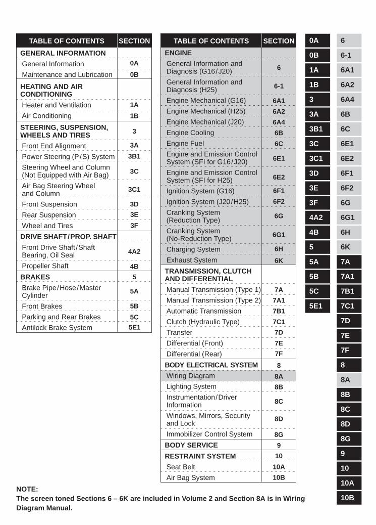
TABLE OF CONTENTS TABLE OF CONTENTS SECTIONSECTION
0B
HEATING AND AIRCONDITIONING
Heater and Ventilation
Air Conditioning
STEERING, SUSPENSION,WHEELS AND TIRES
Front End Alignment
Power Steering (P/S) System
Steering Wheel and Column(Not Equipped with Air Bag)
Air Bag Steering Wheeland Column
Front Suspension
Rear Suspension
Wheel and Tires
1A
3A
0A
1B
3B1
3C
3C1
3D
3E
3F
3
6A1
6
6A2
6A4
6B
6C
6E1
6E2
6F1
DRIVE SHAFT/PROP. SHAFT
Front Drive Shaft /ShaftBearing, Oil Seal
Propeller Shaft
BRAKES
Brake Pipe/Hose/MasterCylinder
Front Brakes
Parking and Rear Brakes
Antilock Brake System
4A2
4B
5
5A
5B
5C
5E1
6F2
6G
6G1
6H
6K
7A
7A1
7B1
7C1
7D
7E
7F
8
8A
8B
8C
8D
8G
9
10
10A
10B
6-1
NOTE:The screen toned Sections 6 – 6K are included in Volume 2 and Section 8A is in WiringDiagram Manual.
YH4GRANDVITARA
0A
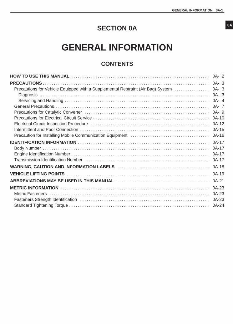
GENERAL INFORMATION 0A-1
SECTION 0A
GENERAL INFORMATION
CONTENTS
HOW TO USE THIS MANUAL 0A- 2. . . . . . . . . . . . . . . . . . . . . . . . . . . . . . . . . . . . . . . . . . . . . . . . . . . . . . . . . . . . . . .
PRECAUTIONS 0A- 3. . . . . . . . . . . . . . . . . . . . . . . . . . . . . . . . . . . . . . . . . . . . . . . . . . . . . . . . . . . . . . . . . . . . . . . . . . . . Precautions for Vehicle Equipped with a Supplemental Restraint (Air Bag) System 0A- 3. . . . . . . . . . . . . . . .
Diagnosis 0A- 3. . . . . . . . . . . . . . . . . . . . . . . . . . . . . . . . . . . . . . . . . . . . . . . . . . . . . . . . . . . . . . . . . . . . . . . . . . . . . Servicing and Handling 0A- 4. . . . . . . . . . . . . . . . . . . . . . . . . . . . . . . . . . . . . . . . . . . . . . . . . . . . . . . . . . . . . . . . . .
General Precautions 0A- 7. . . . . . . . . . . . . . . . . . . . . . . . . . . . . . . . . . . . . . . . . . . . . . . . . . . . . . . . . . . . . . . . . . . . . . Precautions for Catalytic Converter 0A- 9. . . . . . . . . . . . . . . . . . . . . . . . . . . . . . . . . . . . . . . . . . . . . . . . . . . . . . . . . Precautions for Electrical Circuit Service 0A-10. . . . . . . . . . . . . . . . . . . . . . . . . . . . . . . . . . . . . . . . . . . . . . . . . . . . . Electrical Circuit Inspection Procedure 0A-12. . . . . . . . . . . . . . . . . . . . . . . . . . . . . . . . . . . . . . . . . . . . . . . . . . . . . . Intermittent and Poor Connection 0A-15. . . . . . . . . . . . . . . . . . . . . . . . . . . . . . . . . . . . . . . . . . . . . . . . . . . . . . . . . . . Precaution for Installing Mobile Communication Equipment 0A-16. . . . . . . . . . . . . . . . . . . . . . . . . . . . . . . . . . . .
IDENTIFICATION INFORMATION 0A-17. . . . . . . . . . . . . . . . . . . . . . . . . . . . . . . . . . . . . . . . . . . . . . . . . . . . . . . . . . . . Body Number 0A-17. . . . . . . . . . . . . . . . . . . . . . . . . . . . . . . . . . . . . . . . . . . . . . . . . . . . . . . . . . . . . . . . . . . . . . . . . . . . Engine Identification Number 0A-17. . . . . . . . . . . . . . . . . . . . . . . . . . . . . . . . . . . . . . . . . . . . . . . . . . . . . . . . . . . . . . . Transmission Identification Number 0A-17. . . . . . . . . . . . . . . . . . . . . . . . . . . . . . . . . . . . . . . . . . . . . . . . . . . . . . . . .
WARNING, CAUTION AND INFORMATION LABELS 0A-18. . . . . . . . . . . . . . . . . . . . . . . . . . . . . . . . . . . . . . . . . .
VEHICLE LIFTING POINTS 0A-19. . . . . . . . . . . . . . . . . . . . . . . . . . . . . . . . . . . . . . . . . . . . . . . . . . . . . . . . . . . . . . . . .
ABBREVIATIONS MAY BE USED IN THIS MANUAL 0A-21. . . . . . . . . . . . . . . . . . . . . . . . . . . . . . . . . . . . . . . . . . .
METRIC INFORMATION 0A-23. . . . . . . . . . . . . . . . . . . . . . . . . . . . . . . . . . . . . . . . . . . . . . . . . . . . . . . . . . . . . . . . . . . . Metric Fasteners 0A-23. . . . . . . . . . . . . . . . . . . . . . . . . . . . . . . . . . . . . . . . . . . . . . . . . . . . . . . . . . . . . . . . . . . . . . . . . Fasteners Strength Identification 0A-23. . . . . . . . . . . . . . . . . . . . . . . . . . . . . . . . . . . . . . . . . . . . . . . . . . . . . . . . . . . Standard Tightening Torque 0A-24. . . . . . . . . . . . . . . . . . . . . . . . . . . . . . . . . . . . . . . . . . . . . . . . . . . . . . . . . . . . . . . .

YH4GRANDVITARA
6) Install oil pump. Refer to “Oil pump”.
7) Install flywheel (for M/T vehicle) or drive plate (for A/T vehicle).
Using special tool, lock flywheel or drive plate, and tighten
flywheel or drive plate bolts to specified torque.
Special Tool(A): 09924-17810Tightening Torque(c): 78 N.m (7.8 kg-m, 56.0 lb-ft)1. Flywheel bolts or drive plate bolts for A/T vehicle
1, (c)
0A-2 GENERAL INFORMATION
HOW TO USE THIS MANUAL
1) There is a TABLE OF CONTENTS FOR THE WHOLE MANUALon the third page of this manual, whereby you can easily find thesection that offers the information you need. Also, there is aCONTENTS on the first page of EACH SECTION, where themain items in that section are listed.
2) Each section of this manual has its own pagination. It is indicatedat the top of each page along with the Section name.
3) The SPECIAL TOOL usage and TORQUE SPECIFICATION aregiven as shown in figure below.
4) A number of abbreviations are used in the text.For their full explanations, refer to “ABBREVIATIONS MAY BEUSED IN THIS MANUAL” of this section.
5) The SI, metric and foot-pound systems are used as units in thismanual.
6) DIAGNOSIS are included in each section as necessary.7) At the end of each section, there are descriptions of SPECIAL
TOOLS, REQUIRED SERVICE MATERIALS and TIGHT-ENING TORQUE SPECIFICATIONS that should be used for theservicing work described in that section.

YH4GRANDVITARA
1. Air bag wire harness2. Passenger air bag
(inflator) module3. SDM4. DLC
5. Contact coil6. Driver air bag (inflator)
module7. Seat belt pretensioner
(if equipped)
GENERAL INFORMATION 0A-3
PRECAUTIONS
PRECAUTION FOR VEHICLES EQUIPPEDWITH A SUPPLEMENTAL RESTRAINT(AIR BAG) SYSTEM
WARNING:� The configuration of air bag system parts are as shown in
the figure. When it is necessary to service (remove, rein-stall and inspect) these parts, be sure to follow proce-dures described in SECTION 10B. Failure to follow properprocedures could result in possible air bag system activa-tion, personal injury, damage to parts or air bag systembeing unable to activate when necessary.
� If the air bag system and another vehicle system bothneed repair, SUZUKI recommends that the air bag systembe repaired first, to help avoid unintended air bag systemactivation.
� Do not modify the steering wheel, dashboard, or any otherair bag system components. Modifications can adverselyaffect air bag system performance and lead to injury.
� If the vehicle will be exposed to temperatures over 93 �C(200�F) (for example, during a paint baking process), re-move the air bag system components beforehand to avoidcomponent damage or unintended air bag system activa-tion.
DIAGNOSIS� When troubleshooting air bag system, be sure to follow
“DIAGNOSIS” in SECTION 10B. Bypassing these proce-dures may result in extended diagnostic time, incorrect diag-nosis, and incorrect parts replacement.
� Never use electrical test equipment other than that specifiedin this manual.
WARNING:Never attempt to measure the resistance of the air bag (in-flator) modules (driver and passenger) and seat belt preten-tioners (driver and passenger). It is very dangerous as theelectric current from the tester may deploy the air bag or ac-tivate the pretensioner.

YH4GRANDVITARA
ALWAYS CARRY AIR BAG (INFLATOR) MODULEWITH TRIM COVER (AIR BAG OPENING) AWAYFROM BODY.
ALWAYS PLACE AIR BAG (INFLATOR) MODULEON WORKBENCH WITH TRIM COVER (AIR BAGOPENING) UP, AWAY FROM LOOSE OBJECTS.
1. Slit on workbench2. Workbench vise3. Lower mounting bracket
0A-4 GENERAL INFORMATION
SERVICING AND HANDLING
WARNING:Many of service procedures require disconnection of “AIRBAG” fuse and all air bag (inflator) module(s) from initiatorcircuit to avoid an accidental deployment.Driver and Passenger Air Bag (Inflator) Modules� For handling and storage of a live air bag (inflator) module,
select a place where the ambient temperature below 65 �C(150�F), without high humidity and away from electricnoise.
� When carrying a live air bag (inflator) module, make surethe bag opening is pointed away from you. In case of anaccidental deployment, the bag will then deploy with mini-mal chance of injury. Never carry the air bag (inflator)module by the wires or connector on the underside of themodule. When placing a live air bag (inflator) module ona bench or other surface, always face the bag up, awayfrom the surface. As the live passenger air bag (inflator)module must be placed with its bag (trim cover) facing up,place it on the workbench with a slit or use the workbenchvise to hold it securely at its lower mounting bracket. Thisis necessary so that a free space is provided to allow theair bag to expand in the unlikely event of accidental de-ployment. Otherwise, personal injury may result.
� Never dispose of live (undeployed) air bag (inflator) mod-ules (driver and passenger). If disposal is necessary, besure to deploy them according to deployment proceduresdescribed in SECTION 10B before disposal.
� The air bag (inflator) module immediately after deploy-ment is very hot. Wait for at least half an hour to cool it offbefore proceeding the work.
� After an air bag (inflator) module has been deployed, thesurface of the air bag may contain a powdery residue. Thispowder consists primarily of cornstarch (used to lubri-cate the bag as it inflates) and by-products of the chemicalreaction. As with many service procedures, gloves andsafety glasses should be worn.
YH4GRANDVITARA
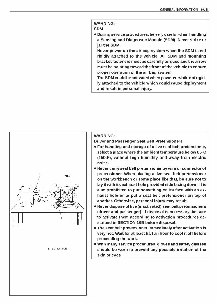
1. Exhaust hole
1
1NG
GENERAL INFORMATION 0A-5
WARNING:SDM� During service procedures, be very careful when handling
a Sensing and Diagnostic Module (SDM). Never strike orjar the SDM.Never power up the air bag system when the SDM is notrigidly attached to the vehicle. All SDM and mountingbracket fasteners must be carefully torqued and the arrowmust be pointing toward the front of the vehicle to ensureproper operation of the air bag system.The SDM could be activated when powered while not rigid-ly attached to the vehicle which could cause deploymentand result in personal injury.
WARNING:Driver and Passenger Seat Belt Pretensioners� For handling and storage of a live seat belt pretensioner,
select a place where the ambient temperature below 65 �C(150�F), without high humidity and away from electricnoise.
� Never carry seat belt pretensioner by wire or connector ofpretensioner. When placing a live seat belt pretensioneron the workbench or some place like that, be sure not tolay it with its exhaust hole provided side facing down. It isalso prohibited to put something on its face with an ex-haust hole or to put a seat belt pretensioner on top ofanother. Otherwise, personal injury may result.
� Never dispose of live (inactivated) seat belt pretensioners(driver and passenger). If disposal is necessary, be sureto activate them according to activation procedures de-scribed in SECTION 10B before disposal.
� The seat belt pretensioner immediately after activation isvery hot. Wait for at least half an hour to cool it off beforeproceeding the work.
� With many service procedures, gloves and safety glassesshould be worn to prevent any possible irritation of theskin or eyes.

YH4GRANDVITARA
0A-6 GENERAL INFORMATION
CAUTION:� Even when the accident was light enough not to cause air
bags to activate, be sure to inspect system parts and otherrelated parts according to instructions under “Repair andInspection Required after an Accident” in SECTION 10B.
� When servicing parts other than air bag system, if shocksmay be applied to air bag system component parts, re-move those parts beforehand.
� When handling the air bag (inflator) modules (driver andpassenger), seat belt pretensioners (driver and passen-ger) or SDM, be careful not to drop it or apply an impact toit. If an excessive impact was applied (e.g., dropped froma height of 91.4 cm (3 feet) or more), never attempt disas-sembly or repair but replace it with a new one.
� When grease, cleaning agent, oil, water, etc. has got ontoair bag (inflator) modules (driver and passenger) or seatbelt pretensioners (drive and passenger), wipe off im-mediately with a dry cloth.
� Air bag wire harness can be identified easily as it is cov-ered with a yellow protection tube. Be very careful whenhandling it.
� When an open in air bag wire harness, damaged wire har-ness, connector or terminal is found, replace wire har-ness, connectors and terminals as an assembly.
� Do not apply power to the air bag system unless all com-ponents are connected or a diagnostic chart requests it,as this will set a diagnostic trouble code.
� Never use air bag system component parts from anothervehicle.
� When using electric welding, be sure to temporarily dis-able air bag system referring to “Disabling Air Bag Sys-tem” described in “Service Precautions” under “On-Ve-hicle Service” in SECTION 10B.
� Never expose air bag system component parts directly tohot air (drying or baking the vehicle after painting) orflames.
� WARNING/CAUTION labels are attached on each part ofair bag system components. Be sure to follow the instruc-tions.
� After vehicle is completely repaired, perform “Air BagDiagnostic System Check” described in “Diagnosis” inSECTION 10B.

YH4GRANDVITARA
GENERAL INFORMATION 0A-7
GENERAL PRECAUTIONS
The WARNING and CAUTION below describe some general precautions that you should observe when servicinga vehicle. These general precautions apply to many of the service procedures described in this manual, and theywill not necessarily be repeated with each procedure to which they apply.
WARNING:� Whenever raising a vehicle for service, be sure to follow the instructions under “VEHICLE LIFTING
POINTS” on SECTION 0A.� When it is necessary to do service work with the engine running, make sure that the parking brake
is set fully and the transmission is in Neutral (for manual transmission vehicles) or Park (for automatictransmission vehicles). Keep hands, hair, clothing, tools, etc. away from the fan and belts when theengine is running.
� When it is necessary to run the engine indoors, make sure that the exhaust gas is forced outdoors.� Do not perform service work in areas where combustible materials can come in contact with a hot
exhaust system. When working with toxic or flammable materials (such as gasoline and refrigerant),make sure that the area you work in is well-ventilated.
� To avoid getting burned, keep away from hot metal parts such as the radiator, exhaust manifold, tail-pipe, muffler, etc.
� New and used engine oil can be hazardous. Children and pets may be harmed by swallowing new orused oil. Keep new and used oil and used engine oil filters away from children and pets.Continuous contact with used engine oil has been found to cause [skin] cancer in laboratory animals.Brief contact with used oil may irritate skin. To minimize your exposure to used engine oil, wear along-sleeve shirt and moisture-proof gloves (such as dishwashing gloves) when changing engine oil.If engine oil contacts your skin, wash thoroughly with soap and water. Launder any clothing or ragsif wet with oil, recycle or properly dispose of used oil and filters.
� Make sure the bonnet is fully closed and latched before driving. If it is not, it can fly up unexpectedlyduring driving, obstructing your view and resulting in an accident.
CAUTION:� Before starting any service work, cover fenders, seats and
any other parts that are likely to get scratched or stained dur-ing servicing. Also, be aware that what you wear (e.g, but-tons) may cause damage to the vehicle’s finish.
� When performing service to electrical parts that does not re-quire use of battery power, disconnect the negative cable ofthe battery.

YH4GRANDVITARA
“A”
0A-8 GENERAL INFORMATION
� When removing the battery, be sure to disconnect the nega-tive cable first and then the positive cable. When reconnect-ing the battery, connect the positive cable first and then thenegative cable, and replace the terminal cover.
� When removing parts that are to be reused, be sure to keepthem arranged in an orderly manner so that they may be rein-stalled in the proper order and position.
� Whenever you use oil seals, gaskets, packing, O-rings, lock-ing washers, split pins, self-locking nuts, and certain otherparts as specified, be sure to use new ones. Also, beforeinstalling new gaskets, packing, etc., be sure to remove anyresidual material from the mating surfaces.
� Make sure that all parts used in reassembly are perfectlyclean.
� When use of a certain type of lubricant, bond or sealant isspecified, be sure to use the specified type.
“A”: Sealant 99000-31150
� Be sure to use special tools when instructed.
Special Tool(A): 09917-98221(B): 09916-58210
YH4GRANDVITARA
GENERAL INFORMATION 0A-9
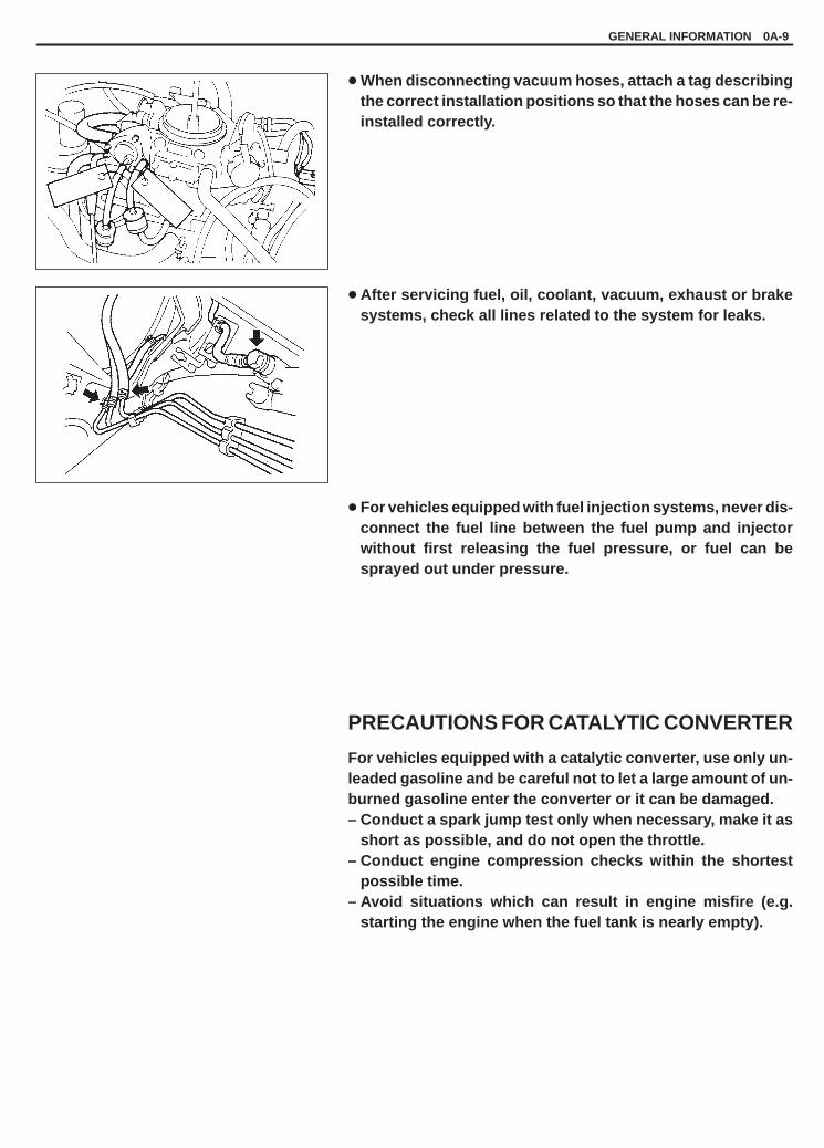
� When disconnecting vacuum hoses, attach a tag describingthe correct installation positions so that the hoses can be re-installed correctly.
� After servicing fuel, oil, coolant, vacuum, exhaust or brakesystems, check all lines related to the system for leaks.
� For vehicles equipped with fuel injection systems, never dis-connect the fuel line between the fuel pump and injectorwithout first releasing the fuel pressure, or fuel can besprayed out under pressure.
PRECAUTIONS FOR CATALYTIC CONVERTER
For vehicles equipped with a catalytic converter, use only un-leaded gasoline and be careful not to let a large amount of un-burned gasoline enter the converter or it can be damaged.– Conduct a spark jump test only when necessary, make it as
short as possible, and do not open the throttle.– Conduct engine compression checks within the shortest
possible time.– Avoid situations which can result in engine misfire (e.g.
starting the engine when the fuel tank is nearly empty).

YH4GRANDVITARA
1. Coupler2. Probe
1. Coupler2. Probe3. Where male
terminal fits
0A-10 GENERAL INFORMATION
PRECAUTIONS FOR ELECTRICAL CIRCUITSERVICE
� When disconnecting and connecting coupler, make sure toturn ignition switch OFF, or electronic parts may get dam-aged.
� Be careful not to touch the electrical terminals of parts whichuse microcomputers (e.g. electronic control unit like asECM, PCM, P/S controller, etc.). The static electricity fromyour body can damage these parts.
� Never connect any tester (voltmeter, ohmmeter, or whatever)to electronic control unit when its coupler is disconnected.Attempt to do it may cause damage to it.
� Never connect an ohmmeter to electronic control unit withits coupler connected to it. Attempt to do it may cause dam-age to electronic control unit and sensors.
� Be sure to use a specified voltmeter/ohmmeter. Otherwise,accurate measurements may not be obtained or personal in-jury may result.
� When taking measurements at electrical connectors using atester probe, be sure to insert the probe from the wire har-ness side (backside) of the connector.
� When connecting meter probe from terminal side of couplerbecause it can’t be connected from harness side, use extracare not to bend male terminal of coupler of force its femaleterminal open for connection.In case of such coupler as shown connect probe as shownto avoid opening female terminal.Never connect probe where male terminal is supposed to fit.

YH4GRANDVITARA
GENERAL INFORMATION 0A-11
� When checking connection of terminals, check its male halffor bend and female half for excessive opening and both forlocking (looseness), corrosion, dust, etc.
� Before measuring voltage at each terminal, check to makesure that battery voltage is 11V or higher. Such terminal volt-age check at low battery voltage will lead to erroneous diag-nosis.

YH4GRANDVITARA
0A-12 GENERAL INFORMATION
1. Check for loose connection
SensorECM
Check contact tension byInserting and removing just foronce
1. Looseness of crimping2. Open3. Thin wire (Single strand of wire)
ELECTRICAL CIRCUIT INSPECTIONPROCEDURE
While there are various electrical circuit inspection methods, de-scribed here is a general method to check its open and short circuitby using an ohmmeter and a voltmeter.
OPEN CIRCUIT CHECKPossible causes for the open circuit are as follows. As the cause isin the connector or terminal in many cases, they need to be checkedparticularly carefully.� Loose connection of connector� Poor contact of terminal (due to dirt, corrosion or rust on it, poor
contact tension, entry of foreign object etc.)� Wire harness being open
When checking system circuits including an electronic control unitsuch as ECM, TCM, ABS control module, etc., it is important to per-form careful check, starting with items which are easier to check.1) Disconnect negative cable from battery.2) Check each connector at both ends of the circuit being checked
for loose connection. Also check lock condition of connector ifequipped with connector lock.
3) Using a test male terminal, check both terminals of the circuit be-ing checked for contact tension of its female terminal.Check each terminal visually for poor contact (possibly causedby dirt, corrosion, rust entry of foreign object, etc.).At the same time, check to make sure that each terminal islocked in the connector fully.
4) Using continuity check or voltage check procedure described inthe following page, check the wire harness for open circuit andpoor connection with its terminals. Locate abnormality, if any.

YH4GRANDVITARA
GENERAL INFORMATION 0A-13
2V voltage drop
Continuity Check1) Measure resistance between connector terminals at both ends
of the circuit being checked (between A-1 and C-1 in the figure).If no continuity is indicated (infinity or over limit), that means thatthe circuit is open between terminals A-1 and C-1.
2) Disconnect the connector included in the circuit (connector-B inthe figure) and measure resistance between terminals A-1 andB-1.If no continuity is indicated, that means that the circuit is openbetween terminals A-1 and B-1. If continuity is indicated, thereis an open circuit between terminals B-1 and C-1 or an ab-normality in connector-B.
Voltage CheckIf voltage is supplied to the circuit being checked, voltage check canbe used as circuit check.1) With all connectors connected and voltage applied to the circuit
being checked, measure voltage between each terminal andbody ground.
If measurements were taken as shown in the figure at the leftand results were as listed below, it means that the circuit is openbetween terminals B-1 and A-1.
Voltage Between:C-1 and body ground: Approx. 5VB-1 and body ground: Approx. 5VA-1 and body ground: 0V
Also, if measured values were as listed below, it means thatthere is a resistance (abnormality) of such level that corre-sponds to the voltage drop in the circuit between terminals A-1and B-1.
Voltage Between:C-1 and body ground: Approx. 5VB-1 and body ground: Approx. 5VA-1 and body ground: Approx. 3V

YH4GRANDVITARA
0A-14 GENERAL INFORMATION
To otherparts
Other parts
To otherparts
SHORT CIRCUIT CHECK (Wire harness to ground)1) Disconnect negative cable from battery.2) Disconnect connectors at both ends of the circuit to be checked.
NOTE:If the circuit to be checked is connected to other parts, dis-connect all connectors of those parts.Otherwise, diagnosis will be misled.
3) Measure resistance between terminal at one end of circuit (A-1terminal in figure) and body ground. If continuity is indicated, itmeans that there is a short to ground between terminals A-1 andC-1 of the circuit.
4) Disconnect the connector included in circuit (connector B) andmeasure resistance between A-1 and body ground.If continuity is indicated, it means that the circuit is shorted to theground between terminals A-1 and B-1.

YH4GRANDVITARA
1. Check contact tension by inserting and removingjust once.
2. Check each terminal for bend and proper alignment.
GENERAL INFORMATION 0A-15
INTERMITTENT AND POOR CONNECTION
Most intermittent are caused by faulty electrical connections or wir-ing, although a sticking relay or solenoid can occasionally be atfault. When checking it for proper connection, perform carefulcheck of suspect circuits for:
� Poor mating of connector halves, or terminals not fully seated inthe connector body (backed out).
� Dirt or corrosion on the terminals. The terminals must be cleanand free of any foreign material which could impede proper termi-nal contact.However, cleaning the terminal with a sand paper or the like isprohibited.
� Damaged connector body, exposing the terminals to moistureand dirt, as well as not maintaining proper terminal orientationwith the component or mating connector.
� Improperly formed or damaged terminals.Check each connector terminal in problem circuits carefully to en-sure good contact tension by using the corresponding mating ter-minal.If contact tension is not enough, reform it to increase contact ten-sion or replace.

YH4GRANDVITARA
0A-16 GENERAL INFORMATION
� Poor terminal-to-wire connection.Check each wire harness in problem circuits for poor connectionby shaking it by hand lightly. If any abnormal condition is found,repair or replace.
� Wire insulation which is rubbed through, causing an intermittentshort as the bare area touches other wiring or parts of the vehicle.
� Wiring broken inside the insulation. This condition could causecontinuity check to show a good circuit, but if only 1 or 2 strandsof a multi-strand-type wire are intact, resistance could be far toohigh.If any abnormality is found, repair or replace.
PRECAUTION FOR INSTALLING MOBILECOMMUNICATION EQUIPMENT
When installing mobile communication equipment such as CB (Citi-zens-Band)-radio or cellular-telephone, be sure to observe the fol-lowing precautions.Failure to follow cautions may adversely affect electronic controlsystem.� Keep the antenna as far away as possible from the vehicle’s elec-
tronic control unit.� Keep the antenna feeder more than 20 cm (7.9 in.) away from
electronic control unit and its wire harnesses.� Do not run the antenna feeder parallel with other wire harnesses.� Confirm that the antenna and feeder are correctly adjusted.

YH4GRANDVITARA
G16 engine
J20 engine
H25 engine
M/T (Type1)
4-speed A/T
M/T (Type2)
GENERAL INFORMATION 0A-17
IDENTIFICATION INFORMATIONBODY NUMBERThe vehicle body number is on the left side of instrument panel andpunched on the chassis inside the tire housing on the right front side.It is possible to identify the country of origin (the production plant)of the vehicle by the first three digits of the body number as shownbelow.
JSAxxx Japan (Iwata) produced. . . . . . . . . . . 2S2xxx Canada (CAMI) produced. . . . . . . . . . .
ENGINE IDENTIFICATION NUMBER
The number is punched on the cylinder block.
TRANSMISSION IDENTIFICATION NUMBER
The number is located on the transmission case.
YH4GRANDVITARA
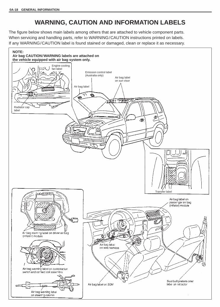
NOTE:Air bag CAUTION/WARNING labels are attached onthe vehicle equipped with air bag system only.
Engine coolingfan label
Radiator caplabel
Air bag label
Emission control label(Australia only)
Air bag labelon sun visor
Transfer label
0A-18 GENERAL INFORMATION
WARNING, CAUTION AND INFORMATION LABELSThe figure below shows main labels among others that are attached to vehicle component parts.When servicing and handling parts, refer to WARNING/CAUTION instructions printed on labels.If any WARNING/CAUTION label is found stained or damaged, clean or replace it as necessary.
YH4GRANDVITARA
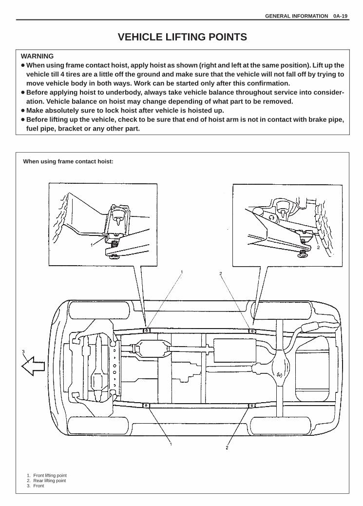
When using frame contact hoist:
1. Front lifting point2. Rear lifting point3. Front
GENERAL INFORMATION 0A-19
VEHICLE LIFTING POINTS
WARNING� When using frame contact hoist, apply hoist as shown (right and left at the same position). Lift up the
vehicle till 4 tires are a little off the ground and make sure that the vehicle will not fall off by trying tomove vehicle body in both ways. Work can be started only after this confirmation.
� Before applying hoist to underbody, always take vehicle balance throughout service into consider-ation. Vehicle balance on hoist may change depending of what part to be removed.
� Make absolutely sure to lock hoist after vehicle is hoisted up.� Before lifting up the vehicle, check to be sure that end of hoist arm is not in contact with brake pipe,
fuel pipe, bracket or any other part.

YH4GRANDVITARA
1. Front differential housing
2. Rear axlehousing
When using floor jack:
Front
Rear
1. Safety stands
0A-20 GENERAL INFORMATION
In raising front or rear vehicle end off the floor by jacking, be sureto put the jack against the center portion of the front suspensionframe or rear axle housing.
WARNING:� Never apply jack against suspension parts (i.e., stabilizer,
etc.) or vehicle floor, or it may get deformed.� If the vehicle to be jacked up only at the front or rear end,
be sure to block the wheels on ground in order to ensuresafety.After the vehicle is jacked up, be sure to support it onstands. It is extremely dangerous to do any work on thevehicle raised on jack alone.
To perform service with either front or rear vehicle end jacked up,be sure to place safety stands under chassis frame so that body issecurely supported. And then check to ensure that chassis framedoes not slide on safety stands and the vehicle is held stable forsafety’s sake.

YH4GRANDVITARA
GENERAL INFORMATION 0A-21
AABS : Anti-lock Brake SystemATDC : After Top Dead CenterAPI : American Petroleum InstituteATF : Automatic Transmission FluidALR : Automatic Locking RetractorAC : Alternating CurrentA/T : Automatic TransmissionA/C : Air ConditioningABDC : After Bottom Dead CenterA/F : Air Fuel Mixture RatioA-ELR : Automatic-Emergency
Locking Retractor
BB+ : Battery Positive VoltageBTDC : Before Top Dead CenterBBDC : Before Bottom Dead Center
CCKT : CircuitCMP Sensor : Camshaft Position Sensor
(Crank Angle Sensor, CAS)CO : Carbon MonoxideCPP Switch : Clutch Pedal Position Switch
(Clutch Switch, Clutch StartSwitch)
CPU : Central Processing UnitCRS : Child Restraint System
DDC : Direct CurrentDLC : Data Link Connector
(Assembly Line Diag. Link,ALDL, Serial Data Link, SDL)
DOHC : Double Over Head CamshaftDOJ : Double Offset JointDRL : Daytime Running LightDTC : Diagnostic Trouble Code
(Diagnostic Code)
EEBCM : Electronic Brake Control
Module, ABS ControlModule
EBD : Electric Brake force DistributionECM : Engine Control ModuleECT Sensor : Engine Coolant Temperature
Sensor (Water Temp.Sensor, WTS)
EGR : Exhaust Gas RecirculationEGRT Sensor : EGR Temperature Sensor
(Recirculated Exhaust GasTemp. Sensor, REGTS)
EFE Heater : Early Fuel EvaporationHeater (Positive TemperatureCoefficient, PTC Heater)
ELR : Emergency Locking RetractorEPS : Electronic Power SteeringEVAP : Evaporative EmissionEVAP Canister : Evaporative Emission
Canister (Charcoal Canister)
F4WD : 4 Wheel Drive
GGEN : GeneratorGND : Ground
HHC : HydrocarbonsHO2S : Heated Oxygen Sensor
IIAC Valve : Idle Air Control Valve (Idle
Speed Control SolenoidValve, ISC Solenoid Valve)
IAT Sensor : Intake Air TemperatureSensor (Air temperatureSensor, ATS)
ICM : Immobilizer Control ModuleIG : IgnitionISC Actuator : Idle Speed Control Actuator
(Motor)
ABBREVIATIONS MAY BE USED IN THIS MANUAL

YH4GRANDVITARA
LLH : Left HandLSPV : Load Sensing Proportioning
Valve
MMAF Sensor : Mass Air Flow Sensor
(Air Flow Sensor, AFS, AirFlow Meter, AFM)
MAP Sensor : Manifold Absolute PressureSensor (Pressure Sensor, PS)
Max : MaximumMFI : Multiport Fuel Injection
(Multipoint Fuel Injection)Min : MinimumMIL : Malfunction Indicator Lamp
(“CHECK ENGINE” Light)M/T : Manual Transmission
NNOx : Nitrogen Oxides
OOBD : On-Board Diagnostic System
(Self-Diagnosis Function)O/D : OverdriveOHC : Over Head Camshaft
PPNP : Park/Neutral PositionP/S : Power SteeringPSP Switch : Power Steering Pressure
Switch (P/S Pressure Switch)PCM : Powertrain Control ModulePCV : Positive Crankcase Ventilation
RRH : Right Hand
SSAE : Society of Automotive
EngineersSDM : Sensing and Diagnostic
Module (Air bag controller,Air bag control module)
SFI : Sequential Multiport FuelInjection
SOHC : Single Over Head Camshaft
TTBI : Throttle Body Fuel Injection
(Single-Point Fuel Injection,SPI)
TCC : Torque Converter ClutchTCM : Transmission Control Module
(A/T Controller, A/T ControlModule)
TP Sensor : Throttle Position SensorTVV : Thermal Vacuum Valve
(Thermal Vacuum SwitchingValve, TVSV, Bimetal VacuumSwitching Valve, BVSV)
TWC : Three Way CatalyticConverter (Three WayCatalyst)
2WD : 2 Wheel Drive
VVIN : Vehicle Identification
NumberVSS : Vehicle Speed Sensor
WWU-OC : Warm Up Oxidation
Catalytic ConverterWU-TWC : Warm Up Three Way
Catalytic Converter
0A-22 GENERAL INFORMATION

YH4GRANDVITARA
METRIC BOLTS–IDENTIFICATION CLASS NUMBERSOR MARKS CORRESPOND TO BOLTSTRENGTH–INCREASING NUMBERS REPRESENTINCREASING STRENGTH.
NUT STRENGTHIDENTIFICATION
GENERAL INFORMATION 0A-23
METRIC INFORMATION
METRIC FASTENERS
Most of the fasteners used for this vehicle are metric fasteners.When replacing any fasteners, it is most important that replacementfasteners be the correct diameter, thread pitch and strength.
FASTENER STRENGTH IDENTIFICATION
Most commonly used metric fastener strength property classes are4T, 6.8, 7T, 8.8 and radial line with the class identification embossedon the head of each bolt. Some metric nuts will be marked withpunch, 6 or 8 mark strength identification on the nut face. Figureshows the different strength markings.When replacing metric fasteners, be careful to use bolts and nutsof the same strength or greater than the original fasteners (thesame number marking or higher). It is likewise important to selectreplacement fasteners of the correct diameter and thread pitch.Correct replacement bolts and nuts are available through the partsdivision.

YH4GRANDVITARA
0A-24 GENERAL INFORMATION
Self-locknut
STANDARD TIGHTENING TORQUE
Each fastener should be tightened to the torque specified in each section of this manual. If no description or specifi-cation is provided, refer to the following tightening torque chart for the applicable torque for each fastener. Whena fastener of greater strength than the original one is used, however, use the torque specified for the original fasten-er.
NOTE:� For the flanged bolt, flanged nut and self-lock nut of 4T and 7T strength, add 10% to the tightening torque
given in the chart below.� The chart below is applicable only where the fastened parts are made of steel or light alloy.
Tightening torque chart
Thread Diameter (Nominal Diameter) (mm) 4 5 6 8 10 12 14 16 18
Strength4 5 6 8 10 12 14 16 18
A equivalent of 4T strengthfastener
N.m 1.5 3.0 5.5 13 29 45 65 105 160
kg-m 0.15 0.30 0.55 1.3 2.9 4.5 6.5 10.5 16
lb-ft 1.0 2.5 4.0 9.5 21.0 32.5 47.0 76.0 116.0
A equivalent of 6.8 strengthfastener without flange
N.m 2.4 4.7 8.4 20 42 80 125 193 280g
kg-m 0.24 0.47 0.84 2.0 4.2 8.0 12.5 19.3 28
lb-ft 2.0 3.5 6.0 14.5 30.5 58.0 90.5 139.5 202.5
A equivalent of 6.8 strengthfastener with flange
N.m 2.4 4.9 8.8 21 44 84 133 203 298g
kg-m 0.24 0.49 0.88 2.1 4.4 8.4 13.3 20.3 29.8
lb-ft 2.0 3.5 6.5 15.5 32.0 61.0 96.5 147.0 215.5
A equivalent of 7T strengthfastener
N.m 2.3 4.5 10 23 50 85 135 210 240
kg-m 0.23 0.45 1.0 2.3 5.0 8.5 13.5 21 24
lb-ft 2.0 3.5 7.5 17.0 36.5 61.5 98.0 152.0 174.0
A equivalent of 8.8 strengthfastener without flange
N.m 3.1 6.3 11 27 56 105 168 258 373g
kg-m 0.31 0.63 1.1 2.7 5.6 10.5 16.8 25.8 37.3
lb-ft 2.5 4.5 8.0 19.5 40.5 76.0 121.5 187.0 270.0
A equivalent of 8.8 strengthfastener with flange
N.m 3.2 6.5 12 29 59 113 175 270 395g
kg-m 0.32 0.65 1.2 2.9 5.9 11.3 17.5 27 39.5
lb-ft 2.5 5.0 9.0 21.0 43.0 82.0 126.5 195.5 286.0

YH4GRANDVITARA
0B
MAINTENANCE AND LUBRICATION 0B-1
SECTION 0B
MAINTENANCE AND LUBRICATIONWARNING:For vehicles equipped with Supplemental Restraint (Air Bag) System:� Service on and around the air bag system components or wiring must be performed only by an autho-
rized SUZUKI dealer. Refer to “Air Bag System Components and Wiring Location View” under “Gener-al Description” in air bag system section in order to confirm whether you are performing service onor near the air bag system components or wiring. Please observe all WARNINGS and “Service Precau-tions” under “On-Vehicle Service” in air bag system section before performing service on or aroundthe air bag system components or wiring. Failure to follow WARNINGS could result in unintentionalactivation of the system or could render the system inoperative. Either of these two conditions mayresult in severe injury.
� Technical service work must be started at least 90 seconds after the ignition switch is turned to the“LOCK” position and the negative cable is disconnected from the battery. Otherwise, the system maybe activated by reserve energy in the Sensing and Diagnostic Module (SDM).
CONTENTS
MAINTENANCE SCHEDULE 0B- 2. . . . . . . . . . . . . . . . . . . . . . . . . . . . . . . . . . . . . . . . . . . . . . . . . . . . . . . . . . . . . . . . Maintenance Schedule Under Normal Driving Conditions 0B- 2. . . . . . . . . . . . . . . . . . . . . . . . . . . . . . . . . . . . . . Maintenance Recommended Under Severe Driving Conditions 0B- 4. . . . . . . . . . . . . . . . . . . . . . . . . . . . . . . . .
MAINTENANCE SERVICE 0B- 5. . . . . . . . . . . . . . . . . . . . . . . . . . . . . . . . . . . . . . . . . . . . . . . . . . . . . . . . . . . . . . . . . . Engine 0B- 5. . . . . . . . . . . . . . . . . . . . . . . . . . . . . . . . . . . . . . . . . . . . . . . . . . . . . . . . . . . . . . . . . . . . . . . . . . . . . . . . . . Ignition System 0B-12. . . . . . . . . . . . . . . . . . . . . . . . . . . . . . . . . . . . . . . . . . . . . . . . . . . . . . . . . . . . . . . . . . . . . . . . . . . Fuel System 0B-12. . . . . . . . . . . . . . . . . . . . . . . . . . . . . . . . . . . . . . . . . . . . . . . . . . . . . . . . . . . . . . . . . . . . . . . . . . . . . Emission Control System 0B-14. . . . . . . . . . . . . . . . . . . . . . . . . . . . . . . . . . . . . . . . . . . . . . . . . . . . . . . . . . . . . . . . . . Chassis and Body 0B-15. . . . . . . . . . . . . . . . . . . . . . . . . . . . . . . . . . . . . . . . . . . . . . . . . . . . . . . . . . . . . . . . . . . . . . . . Final Inspection 0B-24. . . . . . . . . . . . . . . . . . . . . . . . . . . . . . . . . . . . . . . . . . . . . . . . . . . . . . . . . . . . . . . . . . . . . . . . . .
RECOMMENDED FLUIDS AND LUBRICANTS 0B-25. . . . . . . . . . . . . . . . . . . . . . . . . . . . . . . . . . . . . . . . . . . . . . . .

YH4GRANDVITARA
0B-2 MAINTENANCE AND LUBRICATION
MAINTENANCE SCHEDULEMAINTENANCE SCHEDULE UNDER NORMAL DRIVING CONDITIONS
Interval:This interval should be judged by
This table includes services as scheduled up to 90,000 km(54,000 miles) mileage. Beyond 90,000 km (54,000 miles), carryout the same services at the same intervals respectively.This interval should be judged by
odometer reading or months, Km (x 1,000) 15 30 45 60 75 90gwhichever comes first. Miles (x 1,000) 9 18 27 36 45 54
Months 12 24 36 48 60 72
ENGINE1-1. Drive belt V-belt I R I R I R
V-rib belt (Flat type) – – I – – R
1-2. Camshaft timing belt (G16 engine only) Replace every 100,000 km or60,000 miles
1-3. Valve lash (clearance) G16 engine only – I – I – I
1-4. Engine oil andoil filter
J20/H25 enginesG16 engine with HO2S (SG, SH, SJ)
R R R R R R
G16 engine with HO2S (SE, SF),G16 engine without HO2S
Replace every 10,000 km (6,000 miles)or 8 months
1-5. Engine coolant – – R – – R
1-6. Exhaust system – I – I – I
IGNITION SYSTEM2-1. Spark plugs
WhVehicle withoutHO2S
Nickel plug – R – R – RWhenunleaded
HO2S Iridium plug – – – R – –unleadedfuel is Vehicle with
HO2SNickel plug – – R – – Rfuel is
used HO2S Iridium plug Replace every 105,000 km or 63,000miles
When leaded fuel is used, refer to “Severe Driving Condition” schedule
FUEL SYSTEM3-1. Air cleaner filter I I R I I R
3-2. Fuel lines and connections – I – I – I
3-3. Fuel filter Replace every 105,000 km or 63,000miles
3-4. Fuel tank – – I – – I
EMISSION CONTROL SYSTEM4-1. Crankcase ventilation hoses and connections
(Vehicle without HO2S) – – I – – I
4-2. PCV valve Vehicle without HO2S – – I – – I
Vehicle with HO2S – – – – – I
4-3. Fuel evaporative emissiont l t
Vehicle without HO2S – I – I – Icontrol system Vehicle with HO2S – – – – – I
NOTES:� “R” : Replace or change� “I” : Inspect and correct, replace or lubricate if necessary� For Item 1-2. Camshaft timing belt: This belt may be replaced every 90,000 km (54,000 miles) according
to customer’s maintenance convenience.� For Sweden, item 2-1, 4-2 and 4-3 should be performed by odometer reading only.� For Item 2-1. Spark plugs, replace every 50,000 km if the local law requires.� Nickel spark plug: BKR6E-11 or K20PR-U11� Iridium spark plug: IFR6E11 or SK20PR-A11 for G16 engine, IFR5J11 or SK16PR11 for J20/H25 engines

YH4GRANDVITARA
MAINTENANCE AND LUBRICATION 0B-3
Interval:This interval should be judged by
This table includes services as scheduled up to 90,000 km(54,000 miles) mileage. Beyond 90,000 km (54,000 miles), carryout the same services at the same intervals respectively.This interval should be judged by
odometer reading or months, Km (x 1,000) 15 30 45 60 75 90gwhichever comes first. Miles (x 1,000) 9 18 27 36 45 54
Months 12 24 36 48 60 72
CHASSIS AND BODY
6-1. Clutch (pedal and fluid level) – I – I – I
6-2. Brake discs and pads (thickness, wear, damage) I I I I I I
Brake drums and shoes (wear, damage) – I – I – I
6-3. Brake hoses and pipes (leakage, damage, clamp) – I – I – I
6-4. Brake fluid – R – R – R
6-5. Brake lever and cable (damage, stroke, operation) Inspect at first 15,000 km (9,000 miles)only
6-6. Tires (wear, damage, rotation) I I I I I I
6-7. Wheel discs (damage) I I I I I I
6-8. Suspension system (tighteness, damage, rattle, breakage) – I – I – I
6-9. Propeller shafts and drive shafts – – I – – I
6-10. Manual transmission oil (leakage, level)(I: 1st 15,000 km only)
I – R – – R
6-11. Automatic transmission Fluid level – I – I – I
Fluid change Replace every 165,000 km(99,000 miles)
Fluid hose – – – R – –
6-12. Transfer oil (leakage, level) I – I – I –
6-13. Differential oil (leakage, level) (R: 1st 15,000 km only) R or I – I – I –
6-14. Steering system (tighteness, damage, breakage, rattle) – I – I – I
6-15. Power steering (if equipped) I I I I I I
6-16. All latches, hinges and locks – I – I – I
6-17. Air conditioning filter (if equipped) – I R – I R
NOTES:“R”: Replace or change“I” : Inspect and correct, replace or lubricate if necessary

YH4GRANDVITARA
0B-4 MAINTENANCE AND LUBRICATION
MAINTENANCE RECOMMENDED UNDER SEVERE DRIVING CONDITIONSIf the vehicle is usually used under the conditions corresponding to any severe condition code given below, it isrecommended that applicable maintenance operation be performed at the particular interval as given in the chartbelow.
Severe condition code
A – Repeated short trips E – Repeated short trips in extremely B – Driving on rough and/or muddy roads cold weatherC – Driving on dusty roads F – Leaded fuel useD – Driving in extremely cold weather G – – – – – – – – –
and/or salted roads H – Trailer towing (if admitted)
SevereCondition Code
MaintenanceMaintenance
OperationMaintenance Interval
B C D ITEM 1-1I Every 15,000 km
(9,000 miles) or 12 months– B C D – – – – Drive belt (V-rib belt)
R Every 45,000 km(27,000 miles) or 36 months
A – C D E F – H ITEM 1-4Engine oil and oil filter R Every 5,000 km
(3,000 miles) or 4 months
– B – – – – – – ITEM 1-6Exhaust pipe mountings I Every 15,000 km
(9,000 miles) or 12 months
C ITEM 3-1I Every 2,500 km
(1,500 miles)– – C – – – – – Air cleaner filter*1
R Every 30,000 km(18,000 miles) or 24 months
A B C E F H ITEM 2-1Nickel plug R Every 10,000 km
(6,000 miles) or 8 monthsA B C – E F – H Spark plugs
Iridium plug R Every 30,000 km(18,000 miles) or 24 months
– B – D E – – H ITEM 6-9Propeller shafts and drive shafts I Every 15,000 km
(9,000 miles) or 12 months
– B – – E – – HITEM 6-10, 6-12, 6-13Manual transmission,transfer and differential oil
R Every 30,000 km(18,000 miles) or 24 months
– B – – E – – H ITEM 6-11Automatic transmission fluid R Every 30,000 km
(18,000 miles) or 24 months
– B – – – – – – ITEM 6-8Suspension bolts and nuts T Every 15,000 km
(9,000 miles) or 12 months
– B C D – – – H ITEM 6-7Wheel bearing I Every 15,000 km
(9,000 miles) or 12 months
C DITEM 6-17Air conditioning filter *2
I Every 15,000 km(9,000 miles) or 12 months
– – C D – – – – Air conditioning filter 2(if equipped) R Every 45,000 km
(27,000 miles) or 36 months
NOTES:“I” : Inspect and correct, replace or lubricate if necessary“R” : Replace or change“T” : Tighten to the specified torque*1 : Inspect or replace more frequently if necessary.*2 : Clean or replace more frequently if the air from the air conditioning decreases.

YH4GRANDVITARA
1. Crankshaft pulley2. Water pump pulley3. 100 N, 10 kg or 22 lb
G16
H25
MAINTENANCE AND LUBRICATION 0B-5
MAINTENANCE SERVICE
ENGINEITEM 1-1
Drive Belt Inspection and Replacement
WARNING:All inspection and replacement are to be performed withENGINE NOT RUNNING.
Water pump and generator drive belt (G16 and H25 engines)
Inspection1) Disconnect negative cable at battery.2) Inspect belt for cracks, cuts, deformation, wear and cleanliness.
If any defect exists, replace.Check belt for tension.
Water pump and generator belt tension“a”: 6 – 8 mm (0.24 – 0.32 in.) deflection for G16, 9 – 11 mm
(0.35 – 0.43 in.) deflection for H25 under 100 N, 10 kg or22 lb pressure
NOTE:When replacing belt with a new one, adjust belt tension to5 – 6 mm (0.20 – 0.24 in.) for G16, 7 – 9 mm (0.28 – 0.35 in.)for H25.
3) If belt is too tight or too loose, adjust it to specification by adjust-ing alternator position.
4) Tighten alternator adjusting bolt and pivot bolts.5) Connect negative cable to battery.
ReplacementReplace belt. Refer to Section 6B for replacement procedure ofpump belt.

YH4GRANDVITARA
J20
J20
1. 100 N, 10 kg or 22 lb2. Fan pulley
3. Crankshaft pulley4. Adjusting and pivot bolt
0B-6 MAINTENANCE AND LUBRICATION
Water pump, generator, power steering and/or A/Ccompressor (if equipped) drive belt (J20 engine)
Inspection1) Disconnect negative cable at battery.2) Inspect belt for cracks, cuts, deformation, wear and cleanliness.
If any of above conditions are found, replace.Also, check belt for tension.Tension indicator “B” should be the right of indicator “A” asshown in figure. If indicator “B” is found to the left of indicator “A”,replace generator belt.
ReplacementReplace belt referring to Section 6H for replacement procedure ofgenerator drive belt.
Engine cooling fan drive belt (J20 engine)
Inspection1) Disconnect negative cable at battery.2) Inspect belt for cracks, cuts, deformation, wear and cleanliness.
If any defect exists, replace. Check belt for tension.
Cooling fan belt tension“a”: 5 – 7 mm (0.20 – 0.27 in.) deflection under 100 N, 10 kg
or 22 lb pressure.
NOTE:When replacing belt with a new one, adjust belt deflectionto 4 – 5 mm (0.16 – 0.19 in.).
3) If the belt is too tight or too loose, adjust it to specification by ad-justing cooling fan pulley position.
4) Tighten adjusting bolt and pivot bolt.5) Connect negative cable at battery.
ReplacementReplace belt referring to Section 6B for replacement procedure ofcooling fan drive belt.

YH4GRANDVITARA
G16 with P/S
G16 with P/S and A/C
H25 with P/S
H25 with P/S and A/C
1. Crankshaft pulley2. P / S pump pulley3. A / C compressor pulley
(if equipped)
4. Tension pulley5. Tension pulley bolts
MAINTENANCE AND LUBRICATION 0B-7
Power steering pump and/or A/C compressor drive belts (ifequipped) for G16 and H25 engines.
Inspection1) Disconnect negative cable at battery.2) Inspect belt for cracks, cuts, deformation, wear and cleanliness.
If any defect exists, replace.Check belt for tension.
Power steering pump and/or A/C compressor drive belttension.“a”: 6 – 9 mm (0.24 – 0.35 in.) deflection under 100 N, 10 kg
or 22 lb pressure.“b”: 4 – 7 mm (0.16 – 0.28 in.) deflection under 100 N, 10 kg
or 22 lb pressure.
If belt tension is out of above specification, adjust it referring toSection 1B or 3B1.
3) Connect negative cable to battery.
ReplacementReplace belt referring to Section 1B or 3B1 for replacement proce-dure of belt.

YH4GRANDVITARA
0B-8 MAINTENANCE AND LUBRICATION
ITEM 1-2
Camshaft Timing Belt Replacement (G16 engine only)Replace timing belt referring to Section 6A1.
ITEM 1-3
Valve Lash Inspection (G16 engine only)1) Remove cylinder head cover.2) Inspect intake and exhaust valve lash and adjust as necessary.
Refer to Section 6A1 for valve lash inspection and adjustmentprocedure.
Valvelash( “ ”)
When cold(Coolant tempera-ture is 15 – 25�C
or 59 – 77�F)
When hot(Coolant tempera-ture is 60 – 68�Cor 140 – 154�F)
(gap “a”)specifica-tion
Intake 0.13 – 0.17 mm(0.005 – 0.007 in.)
0.17 – 0.21 mm(0.007 – 0.008 in.)tion
Exhaust 0.23 – 0.27 mm(0.009 – 0.011 in.)
0.28 – 0.32 mm(0.011 – 0.013 in.)
3) Install cylinder head cover and tighten bolts to specification.
ITEM 1-4
Engine Oil and Filter Change
WARNING:New and used engine oil can be hazardous.Be sure to read “WARNING” in General Precaution in Sec-tion 0A and observe what in written there.
Before draining engine oil, check engine for oil leakage. If any evi-dence of leakage is found, make sure to correct defective part be-fore proceeding to the following work.1) Drain engine oil by removing drain plug.2) After draining oil, wipe drain plug clean. Reinstall drain plug, and
tighten it securely as specified below.
Tightening Torque(a): 35 N.m (3.5 kg-m, 25.5 lb-ft)

YH4GRANDVITARA
2
1. Oil filter2. Oil filter wrench
MAINTENANCE AND LUBRICATION 0B-9
3) Loosen oil filter by using oil filter wrench (special tool).
Special Tool(A): 09915-47310 (H25 engine)
09915-47330 (G16 and J20 engines)
NOTE:Before fitting new oil filter, be sure to oil its O-ring. Use engineoil for this purpose.
4) Screw new filter on oil filter stand by hand until the filter O-ringcontacts the mounting surface.
CAUTION:To tighten oil filter properly, it is important to accuratelyidentify the position at which at filter O-ring first contactsthe mounting surface.
5) Tighten the filter 3/4 turn from the point of contact with themounting surface using an oil filter wrench.
Tightening Torque (Reference)(b): 14 N.m (1.4 kg-m, 10.5 lb-ft)
6) Replenish oil until oil level is brought to FULL level mark on dip-stick. (oil pan and oil filter capacity). The filler inlet is at the topof the cylinder head cover.It is recommended to use engine oil of SG, SH or SJ grade.
NOTE:For temperature between –20 �C (–4�F) and 30�C (86�F), itis highly recommended to use SAE 10W – 30 oil.
G16 Engine J20 Engine H25 Engine
Oil pan capacity About 4.0 liters(10.6/8.8 US/Imp pt.)
About 5.0 liters(10.6/8.8 US/Imp pt.)
�
Oil filter capacity About 0.2 liters(0.4/0.3 US/Imp pt.)
�
About 0.5 liters(1.1/0.9 US/Imp pt.)
Others About 0.3 liters(0.6/0.5 US/Imp pt.)
About 0.4 liters(1.1/0.9 US/Imp pt.)
About 0.7 liters(1.5/1.2 US/Imp pt.)
Total About 4.5 liters(9.5/7.9 US/Imp pt.)
About 5.6 liters(11.8/9.8 US/Imp pt.)
About 6.2 liters(13.1/10.9 US/Imp pt.)

YH4GRANDVITARA
1. Full level mark (hole)2. Low level mark (hole)
0B-10 MAINTENANCE AND LUBRICATION
NOTE:Engine oil capacity is specified. However, note that theamount of oil required when actually changing oil maysomewhat differ from the data in the table depending onvarious conditions (temperature, viscosity, etc.).
7) Check oil filter and drain plug for oil leakage.
8) Start engine and run it for three minutes. Stop it and wait five min-utes before checking oil level. Add oil, as necessary, to bring oillevel to FULL level mark on dipstick.
NOTE:Step 1) – 7) outlined above must be performed with ENGINENOT RUNNING. For step 8), be sure to have adequate ven-tilation while engine is running.
ITEM 1-5
Engine Coolant Change
WARNING:To help avoid danger of being burned, do not remove radia-tor cap while engine and radiator are still hot. Scalding fluidand steam can be blown out under pressure if cap is takenoff too soon.
1) Remove radiator cap when engine is cool.2) Loosen radiator drain plug to drain coolant.3) Remove reservoir, which is on the side of radiator, and drain.4) Tighten plug securely. Also reinstall reservoir.
5) Fill radiator with specified amount of coolant, and run engine for2 or 3 minutes at idle. This drives out any air which may still betrapped within cooling system. STOP ENGINE. Add coolant asnecessary until coolant level reaches the filler throat of radiator.Reinstall radiator cap.

YH4GRANDVITARA
MAINTENANCE AND LUBRICATION 0B-11
1. Reservoir2. FULL level mark3. LOW level mark4. Arrow mark5. Reservoir cap
5 4
6) Add coolant to reservoir so that its level aligns with Full mark.Then, reinstall cap aligning arrow marks on reservoir and cap.
NOTE:When installing reservoir cap, align arrow marks on reser-voir and cap.
CAUTION:When changing engine coolant, use mixture of 50% wa-ter and 50% ANTIFREEZE/ANTICORROSION COOLANTfor the market where ambient temperature falls lowerthan –16 �C (3�F) in winter, and mixture of 70% water and30% ANTIFREEZE/ANTICORROSION COOLANT for themarket where ambient temperature doesn’t fall lowerthan –16 �C (3�F).Even in a market where no freezing temperature is antici-pated, mixture of 70% water and 30% ANTIFREEZE/AN-TICORROSION COOLANT should be used for the pur-pose of corrosion protection and lubrication.
ITEM 1-6
Exhaust System Inspection
WARING:To avoid danger of being burned, do not touch exhaust sys-tem when it is still hot. Any service on exhaust systemshould be performed when it is cool.
When carrying out periodic maintenance, or the vehicle is raised forother service, check exhaust system as follows:� Check rubber mountings for damage, deterioration, and out of
position.� Check exhaust system for leakage, loose connections, dents and
damages.If bolts or nuts are loose, tighten them to specification.
� Check nearby body areas for damaged, missing, or misposi-tioned parts, open seams, holes, loose connections or other de-fects which could permit exhaust fumes to seep into the vehicle.
� Make sure that exhaust system components have enough clear-ance from the underbody to avoid overheating and possible dam-age to the floor carpet.
� Any defects should be fixed at once.

YH4GRANDVITARA
0B-12 MAINTENANCE AND LUBRICATION
IGNITION SYSTEMITEM 2-1
Spark Plugs ReplacementReplace spark plugs with new ones referring to Section 6F1 or 6F2.
FUEL SYSTEMITEM 3-1
Air Cleaner Filter
Inspection1) Remove air cleaner case clamps.2) Take cleaner filter out of air cleaner case.3) Check air cleaner filter for dirt. Replace excessively dirty filter.
4) Blow off dust by compressed air from air outlet side of filter.5) Install air cleaner filter into case.6) Install air cleaner case cap and clamp it securely.
ReplacementReplace air cleaner filter with new one according to above steps 1),2) and 5), 6).
ITEM 3-2
Fuel Lines and Connections Inspection1) Visually inspect fuel lines and connections for evidence of fuel
leakage, hose cracking and damage. Make sure all clamps aresecure.Repair leaky joints, if any.Replace hoses that are suspected of being cracked.

YH4GRANDVITARA
MAINTENANCE AND LUBRICATION 0B-13
ITEM 3-3
Fuel Filter Replacement
WARNING:This work must be performed in a well ventilated area andaway from any open flames (such as gas hot water heaters).
Fuel filter is located at the front part of fuel tank, inside the right-hand side of chassis.Replace fuel filter with new one periodically, referring to Section 6Cfor proper procedure.
ITEM 3-4
Fuel Tank InspectionCheck fuel tank for damage, cracks, fuel leakage, corrosion andtank bolts looseness.If a problem is found, repair or replace.

YH4GRANDVITARA
[A]
[B]
[A]: Type 1[B]: Type 2
0B-14 MAINTENANCE AND LUBRICATION
EMISSION CONTROL SYSTEMITEM 4-1
Crankcase Ventilation Hoses and Connections Inspection(Vehicle not equipped with oxygen sensor)Refer to the following item 4-2, PCV valve inspection.
ITEM 4-2
PCV (Positive Crankcase Ventilation) Valve InspectionCheck crankcase ventilation hose and PCV hose for leaks, cracksor clog, and PCV valve for stick or clog. Refer to On-vehicle serviceof Section 6E1/6E2 for PCV valve checking procedure.
ITEM 4-3Evaporative Emission Control System Inspection1) Visually inspect hoses for cracks, damage, or excessive bends.
Inspect all clamps for damage and proper position.2) Check EVAP canister for operation and clog, referring to Section
6E1/6E2.If a malfunction is found, repair or replace.

YH4GRANDVITARA
1
1. Clutch pedal free travel
MAINTENANCE AND LUBRICATION 0B-15
CHASSIS AND BODYITEM 6-1
Clutch
Pedal inspectionCheck clutch pedal for height and free travel referring to Section7C1. Adjust or correct if necessary.
Fluid inspection1) Check around master cylinder and reservoir for fluid leakage.
If found leaky, correct.2) Check fluid level.
If fluid level is lower than the minimum level of reservoir, refillingis necessary. Fill reservoir with specified brake fluid indicated onclutch reservoir cap.For the details, refer to On-vehicle service in Section 7C1.
CAUTION:Since clutch system of this vehicle is factory-filled withglycol-base brake fluid, do not use or mix different typeof fluid when refilling system; otherwise serious damagewill occur. Do not use old or used brake fluid, or one takenfrom unsealed container.
ITEM 6-2
Brake Discs, Pads, Brake Drums and Shoes Inspection
[Brake discs and pads]1) Remove wheel and caliper but don’t disconnect brake hose from
caliper.2) Check front disc brake pads and discs for excessive wear, dam-
age and deflection. Replace parts as necessary. For details, re-fer to Section 5B.Be sure to torque caliper pin bolts to specification.
[Brake drums and shoes]1) Remove wheel and brake drum.2) Check rear brake drums and brake linings for excessive wear
and damage, while wheels and drums are removed. At the sametime, check wheel cylinders for leaks. Replace these parts asnecessary.For details, refer to Section 5C.

YH4GRANDVITARA
“a”: Parking brake leverstroke:5 – 7 notches(With 20 kg or 44 lbsof pull pressure)
“a”
0B-16 MAINTENANCE AND LUBRICATION
ITEM 6-3
Brake Hoses and Pipes InspectionCheck brake hoses and pipes for proper hookup, leaks, cracks,chafing and other damage.Replace any of these parts as necessary.
CAUTION:After replacing any brake pipe or hose, be sure to carry outair purge operation.
ITEM 6-4
Brake Fluid ChangeChange brake fluid as follows.Drain existing fluid from brake system completely, fill system withspecified fluid and carry out air purge operation.For air purging procedure, refer to Section 5.
ITEM 6-5
Parking Brake Lever and Cable Inspection
Parking brake lever1) Check tooth tip of each notch for damage or wear. If any damage
or wear is found, replace parking lever.2) Check parking brake lever for proper operation and stroke, and
adjust it if necessary.For checking and adjusting procedures, refer to Parking BrakeInspection and Adjustment in Section 5.
Parking brake cableInspect brake cable for damage and smooth movement.Replace cable if it is in deteriorated condition.

YH4GRANDVITARA
1. Wear indicator
MAINTENANCE AND LUBRICATION 0B-17
ITEM 6-6
Tire Inspection and Rotation1) Check tires for uneven or excessive wear, or damage.
If defective, replace.Refer to Section 3 for details.
2) Check inflating pressure of each tire and adjust pressure tospecification as necessary.Refer to Section 3F for details.
NOTE:� Tire inflation pressure should be checked when tires are
cool.� Specified tire inflation pressure should be found on tire
placard or in owner’s manual which came with the vehicle.
3) Rotate tires.For details, refer to Section 3F.
ITEM 6-7
Wheel Discs InspectionInspect each wheel disc for dents, distortion and cracks. A disc inbadly damaged condition must be replaced.
Wheel Bearing Inspection1) Check front wheel bearing for wear, damage, abnormal noise or
rattles. For details, refer to Section 3D.2) Check rear wheel bearing for wear, damage, abnormal noise or
rattles. For details, refer to Section 3E.

YH4GRANDVITARA
0B-18 MAINTENANCE AND LUBRICATION
ITEM 6-8
Suspension System InspectionCheck suspension bolts and nuts for tightness and retighten themas necessary.Repair or replace defective parts, if any.
NOTE:For details of check points, refer to tables of Tightening TorqueSpecification in Section 3D and 3E.
Front1) Check stabilizer bar for damage or deformation.2) Check bushing for damage, wear or deterioration.
3) Inspect strut for damage, deformation, oil leakage and opera-tion. If strut is found faulty, replace it as an assembly unit, be-cause it can not be disassembled.Refer to strut check Section 3D for operation check.
4) Inspect strut boot for damage or crack.5) Inspect for cracks or deformation in spring seat.6) Inspect for deterioration of bump stopper.7) Inspect strut mount for wear, cracks or deformation.
8) Check ball joint stud dust seal (boot) for leaks, detachment,tear or other damage. Check suspension arm bushing for dam-age, wear or deterioration.
Rear9) Check shock absorber for damage, deformation, oil leakage
and operation.10) Check bushings for wear and damage.

YH4GRANDVITARA
MAINTENANCE AND LUBRICATION 0B-19
11) Check coil spring, upper rod, lower rod and lateral rod for de-formation and damage.
12) Check upper rod, lower rod and lateral rod bushings and bumpstopper for wear, damage and deterioration.
13) Check other suspension parts for damage, loose or missingparts; also for parts showing signs of wear or lack of lubrication.Replace any parts found defective in steps 1) to 13).
ITEM 6-9
Propeller Shafts and Drive Shafts Inspection1) Check universal joint and spline of propeller shaft for rattle. If
rattle is found, replace defective part with a new one.2) Check propeller shaft (front & rear) flange yoke bolts for tight-
ness, and retighten them as necessary.Refer to Section 4B for tightening torque.
3) Check drive axle boots (wheel side and differential side) forleaks, detachment, tear or other damage.Replace boot as necessary.

YH4GRANDVITARA
1. Drain plug (Apply sealant)2. Reverse idle gear shaft bolt (DO NOT LOOSEN IT)3. Filler / level plug (Apply sealant)
1. Drain plug2. Filler / level plug
Type 1
Type 2
1. Level gauge2. FULL HOT mark3. LOW HOT mark4. FULL COLD mark5. LOW COLD mark
0B-20 MAINTENANCE AND LUBRICATION
ITEM 6-10
Manual Transmission Oil Inspection and Change
Inspection1) Inspect transmission case for evidence of oil leakage.
Repair leaky point if any.2) Make sure that vehicle is placed level for oil level check.3) Remove level plug of transmission.4) Check oil level.
Oil level can be checked roughly by means of level plug hole.That is, if oil flows out of level plug hole or if oil level is found upto hole when level plug is removed, oil is properly filled.If oil is found insufficient, pour specified amount of specified oil.
5) Tighten level plug to specified torque.Refer to Section 7A or 7A1 for installation and tightening torque.
ChangeChange transmission oil with new specified oil referring to Section7A or 7A1.
ITEM 6-11
Automatic Transmission Fluid Inspection and Change
Inspection1) Inspect transmission case for evidence of fluid leakage.
Repair leaky point, if any.2) Make sure that vehicle is placed level for fluid level check.3) Check fluid level.
For fluid level checking procedure, refer to On-vehicle service inSection 7B1 and be sure to perform it under specified conditions.If fluid level is low, replenish specified fluid.

YH4GRANDVITARA
1. Drain plug
Transfer
Front differential
Rear differential1
2
1
2
MAINTENANCE AND LUBRICATION 0B-21
Change1) Inspect transmission case for evidence of fluid leakage.
Repair leaky point, if any.2) Make sure that vehicle is placed level for fluid level check.3) Change fluid. For its procedure, refer to On-vehicle service in
Section 7B1.
Fluid cooler hose changeReplace inlet and outlet hoses of cooler hose and their clamps.For replacement procedure, refer to On-vehicle service in Section7B1.
ITEM 6-12 and 6-13
Transfer and Differential Oil Inspection and Change
Inspection1) Check transfer case and differential for evidence of oil leakage.
Repair leaky point if any.2) Make sure that vehicle is placed level for oil level check.3) Remove level plug of transfer or differentials (front and rear) and
check oil level.Oil level can be checked roughly by means of level plug hole.That is, if oil flows out of level plug hole or if oil level is found upto hole when level plug is removed, oil is properly filled.If oil is found insufficient, pour specified amount of specified oilreferring to Section 7D, 7B or 7F.
4) Tighten level plug to specified torque.Refer to Section 7D, 7E or 7F for tightening torque.
ChangeChange transfer oil or differentials oil with new specified oil referringto Section 7D, 7E and 7F respectively.

YH4GRANDVITARA
The figure shows right-hand steering vehicle
The figure shows right-hand steering vehicle
0B-22 MAINTENANCE AND LUBRICATION
ITEM 6-14
Steering System Inspection1) Check steering wheel for play and rattle, holding vehicle in
straight forward condition on the ground.
Steering wheel play “a”: 0 – 30 mm (0 – 1.2 in.)
2) Check universal joints of steering shaft for rattle and damage. Ifrattle or damage is found, replace defective part with a new one.
3) Check steering linkage for looseness and damage. Repair or re-place defective part, if any.
4) Check bolts and nuts for tightness and retighten them as neces-sary. Repair or replace defective parts, if any.Refer to table of Tightening Torque Specification in Section 3B(or 3B1) and 3C (or 3C1) for particular check points.
5) Check boots of steering linkage for damage (leaks, detachment,tear, dent, etc.). If damage is found, replace it with new one.If any dent is found on steering rack boots, correct it to originalshape by turning steering wheel to the right or left as far as itstops and holding it for a few seconds.
6) Check wheel alignment.
NOTE:For details of wheel alignment, refer to Wheel Alignment inSection 3A.
ITEM 6-15
Power Steering (P/S) System Inspection (if equipped)1) Visually check power steering system for fluid leakage and hose
for damage and deterioration.Repair or replace defective parts, if any.
2) With engine stopped, check fluid level indicated on fluid tank,which should be between MAX and MIN marks. If it is lower thanMIN, fill fluid up to MAX mark.
NOTE:� Be sure to use an equivalent of DEXRON �-II or DEX-
RON�-III for P/S fluid.� Fluid level should be checked when fluid is cool.

YH4GRANDVITARA
1. “UPPER” or “LOWER” mark
MAINTENANCE AND LUBRICATION 0B-23
3) Visually check pump drive belt for cracks and wear.4) Check belt for tension, referring to item 1-1.
If necessary, have belt adjusted or replaced.
ITEM 6-16
All Hinges, Latches and Locks Inspection
DoorsCheck that each door of front, rear and back doors opens andcloses smoothly and locks securely when closed.If any malfunction is found, lubricate hinge and latch or repair doorlock system.
Engine hoodCheck that secondary latch operates properly (check that second-ary latch keeps hood from opening all the way even when pullinghood release handle inside vehicle.). Also check that hood opensand closes smoothly and properly and hood locks securely whenclosed.If any malfunction is found, lubricate hinge and latch, or repair hoodlock system.
ITEM 6-17
Air Conditioning Filter (if equipped)
Inspection1) Remove air conditioning filter from cooling unit referring to Sec-
tion 1B.2) Check filter for dirt. Replace excessively dirty filter.3) Blow off dust by compressed air from air outlet side of filter.4) Install filter to cooling unit referring to Section 1B.
ReplacementReplace air conditioning filter with new one referring to Section 1B.

YH4GRANDVITARA
0B-24 MAINTENANCE AND LUBRICATION
FINAL INSPECTION
SeatsCheck that seat slides smoothly and locks securely atany position. Also check that reclining mechanism offront seat back allows it to be locked at any angle.
Seat BeltInspect belt system including webbing, buckles, latchplates, retractors and anchors for damage or wear.If “REPLACE BELT” label on front seat belt is visible,replace belt.Check that seat belt is securely locked.
Battery Electrolyte Level CheckCheck that the electrolyte level of all battery cells isbetween the upper and lower level lines on the case.If battery is equipped with built-in indicator, check bat-tery condition by the indicator.
Accelerator Pedal OperationCheck that pedal operates smoothly without gettingcaught or interfered by and other part.
Engine StartCheck engine start for readiness.
On automatic transmission vehicles, try to start theengine in each select lever position. The starting mo-tor should crank only in “P” (Park) or “N” (Neutral).On manual transmission vehicles, place the shift le-ver in “Neutral,” depress clutch pedal fully and try tostart.
Exhaust System CheckCheck for leakage, cracks or loose supports.
Clutch (For Manual transmission)Check for the following:� Clutch is completely released when depressing
clutch pedal.� No slipping clutch occurs when releasing pedal and
accelerating.� Clutch itself is free from any abnormal condition.
Gearshift or Select Lever (Transmission)Check gear shift or select lever for smooth shifting toall positions and for good performance of transmis-sion in any position.With automatic transmission equipped vehicle, alsocheck that shift indicator indicates properly accordingto which position select lever is shifted to.With automatic transmission equipped vehicle, makesure that vehicle is at complete stop when shifting se-lect lever to “P” range position and release all brakes.
Brake[Foot brake]Check the following:� that brake pedal has proper travel,� that brake works properly,� that it is free from noise,� that braking force is applied equally on all wheels,� and that brake do not drag.
[Parking brake]Check that lever has proper travel.
WARNING:With vehicle parked on a fairly steep slope,make sure nothing is in the way downhill toavoid any personal injury or property damage.Be prepared to apply regular brake quicklyeven if vehicle should start to move.
Check to ensure that parking brake is fully effectivewhen the vehicle is stopped on the safe slope andbrake lever is pulled all the way.
WARNING:When carrying out road tests, select a safeplace where no man or no running vehicle isseen so as to prevent any accident.
WARNING:Before performing the following check, besure to have enough room around the vehicle.Then, firmly apply both the parking brake andthe regular brakes. Do not use the acceleratorpedal. If the engine starts, be ready to turn offthe ignition promptly. Take these precautionsbecause the vehicle could move without warn-ing and possibly cause personal injury orproperty damage.

YH4GRANDVITARA
MAINTENANCE AND LUBRICATION 0B-25
Steering� Check to ensure that steering wheel is free from in-
stability, or abnormally heavy feeling.� Check that the vehicle does not wander or pull to
one side.
Engine� Check that engine responds readily at all speeds.� Check that engine is free from abnormal noise and
abnormal vibration.
Body, Wheels and Power Transmitting SystemCheck that body, wheels and power transmitting sys-tem are free from abnormal noise and abnormalvibration or any other abnormal condition.
Meters and GaugeCheck that speedometer, odometer, fuel meter, tem-perature gauge, etc. are operating accurately.
LightsCheck that all lights operate properly.
Windshield DefrosterPeriodically check that air comes out from defrosteroutlet when operating heater or air conditioning.Set fan switch lever to “HI” position for this check.
RECOMMENDED FLUIDS AND LUBRICANTS
Engine oil SG, SH or SJ (Refer to engine oil viscosity chart in item 1-4)
Engine coolant (Ethylene glycolbase coolant)
“Antifreeze/Anticorrosion coolant”
Brake fluid DOT 3
Manual transmission oilRefer to Section 7A or 7A1
Transfer oilRefer to Section 7A or 7A1.
Differential oil (front & rear) Refer to Section 7E or 7F.
Automatic transmission fluid andPower steering fluid
Refer to Section 3B1 or 7B1.
Door hingesEngine oil or water resistance chassis grease
Hood latch assemblyEngine oil or water resistance chassis grease
Key lock cylinder Spray lubricant

YH4GRANDVITARA
1A
HEATER AND VENTILATION 1A-1
SECTION 1A
HEATER AND VENTILATIONWARNING:For vehicles equipped with Supplement Restraint (Air Bag) System� Service on and around the air bag system components or wiring must be performed only by an autho-
rized SUZUKI dealer. Refer to “Air Bag System Components and Wiring Location View” under “Gener-al Description” in air bag system section in order to confirm whether you are performing service onor near the air bag system components or wiring. Please observe all WARNINGS and “Service Precau-tions” under “On-Vehicle Service” in air bag system section before performing service on or aroundthe air bag system components or wiring. Failure to follow WARNINGS could result in unintentionalactivation of the system or could render the system inoperative. Either or these two conditions mayresult in severe injury.
� Technical service work must be started at least 90 seconds after the ignition switch is turned to the“LOCK” position and the negative cable is disconnected from the battery. Otherwise, the system maybe activated by reserve energy in the Sensing and Diagnostic Module (SDM).
NOTE:The link mechanism of the heater varies depending on the specifications.
CONTENTS
GENERAL DESCRIPTION 1A- 2. . . . . . . . . . . . . . . . . . . . . . . . . . . . . . . . . . . . . . . . . . . . . . . . . . . . . . . . . . . . . . . . . . Body Ventilation 1A- 3. . . . . . . . . . . . . . . . . . . . . . . . . . . . . . . . . . . . . . . . . . . . . . . . . . . . . . . . . . . . . . . . . . . . . . . . . .
DIAGNOSIS 1A- 3. . . . . . . . . . . . . . . . . . . . . . . . . . . . . . . . . . . . . . . . . . . . . . . . . . . . . . . . . . . . . . . . . . . . . . . . . . . . . . . Diagnosis Table 1A- 3. . . . . . . . . . . . . . . . . . . . . . . . . . . . . . . . . . . . . . . . . . . . . . . . . . . . . . . . . . . . . . . . . . . . . . . . . . Wiring Circuit 1A- 4. . . . . . . . . . . . . . . . . . . . . . . . . . . . . . . . . . . . . . . . . . . . . . . . . . . . . . . . . . . . . . . . . . . . . . . . . . . .
ON-VEHICLE SERVICE 1A- 5. . . . . . . . . . . . . . . . . . . . . . . . . . . . . . . . . . . . . . . . . . . . . . . . . . . . . . . . . . . . . . . . . . . . Blower Unit 1A- 5. . . . . . . . . . . . . . . . . . . . . . . . . . . . . . . . . . . . . . . . . . . . . . . . . . . . . . . . . . . . . . . . . . . . . . . . . . . . . . Blower Motor 1A- 7. . . . . . . . . . . . . . . . . . . . . . . . . . . . . . . . . . . . . . . . . . . . . . . . . . . . . . . . . . . . . . . . . . . . . . . . . . . . Blower Motor Relay 1A- 8. . . . . . . . . . . . . . . . . . . . . . . . . . . . . . . . . . . . . . . . . . . . . . . . . . . . . . . . . . . . . . . . . . . . . . . Blower Motor Resistor 1A- 9. . . . . . . . . . . . . . . . . . . . . . . . . . . . . . . . . . . . . . . . . . . . . . . . . . . . . . . . . . . . . . . . . . . . . Heater Mode Control Switch 1A-10. . . . . . . . . . . . . . . . . . . . . . . . . . . . . . . . . . . . . . . . . . . . . . . . . . . . . . . . . . . . . . . Heater Mode Control Actuator 1A-12. . . . . . . . . . . . . . . . . . . . . . . . . . . . . . . . . . . . . . . . . . . . . . . . . . . . . . . . . . . . . . Heater Control Lever Assembly 1A-14. . . . . . . . . . . . . . . . . . . . . . . . . . . . . . . . . . . . . . . . . . . . . . . . . . . . . . . . . . . . Heater Control Cables 1A-15. . . . . . . . . . . . . . . . . . . . . . . . . . . . . . . . . . . . . . . . . . . . . . . . . . . . . . . . . . . . . . . . . . . . Heater Unit 1A-16. . . . . . . . . . . . . . . . . . . . . . . . . . . . . . . . . . . . . . . . . . . . . . . . . . . . . . . . . . . . . . . . . . . . . . . . . . . . . . Rear Duct 1A-19. . . . . . . . . . . . . . . . . . . . . . . . . . . . . . . . . . . . . . . . . . . . . . . . . . . . . . . . . . . . . . . . . . . . . . . . . . . . . . .

YH4GRANDVITARA
1. Side ventilator outlet2. Side defroster outlet3. Center ventilator outlet4. Heater unit5. Defroster duct
6. Ventilator duct7. Heater control lever assembly8. Heater mode control switch9. Blower unit
10. Rear duct
1A-2 HEATER AND VENTILATION
GENERAL DESCRIPTION
The heater, an in and out air selectable-type hot water heater, is so constructed that it is possible to assure anagreeable ventilation at all times by providing the ventilator air outlets at the center and both sides (right and left)of the instrument panel, the hot air outlet at a place close to the feet of front passengers, and the defroster air outletsat places, right and left, along the windshield glass.The heater and ventilation consist of following parts.
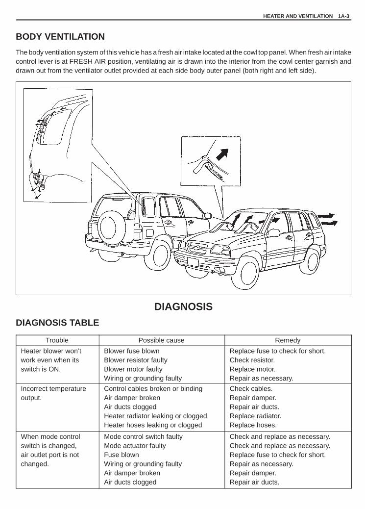
YH4GRANDVITARA
HEATER AND VENTILATION 1A-3
BODY VENTILATION
The body ventilation system of this vehicle has a fresh air intake located at the cowl top panel. When fresh air intakecontrol lever is at FRESH AIR position, ventilating air is drawn into the interior from the cowl center garnish anddrawn out from the ventilator outlet provided at each side body outer panel (both right and left side).
DIAGNOSIS
DIAGNOSIS TABLE
Trouble Possible cause Remedy
Heater blower won’t work even when itsswitch is ON.
Blower fuse blownBlower resistor faultyBlower motor faultyWiring or grounding faulty
Replace fuse to check for short.Check resistor.Replace motor.Repair as necessary.
Incorrect temperatureoutput.
Control cables broken or bindingAir damper brokenAir ducts cloggedHeater radiator leaking or cloggedHeater hoses leaking or clogged
Check cables.Repair damper.Repair air ducts.Replace radiator.Replace hoses.
When mode controlswitch is changed, air outlet port is not changed.
Mode control switch faultyMode actuator faultyFuse blownWiring or grounding faultyAir damper brokenAir ducts clogged
Check and replace as necessary.Check and replace as necessary.Replace fuse to check for short.Repair as necessary.Repair damper.Repair air ducts.

YH4GRANDVITARA
1A-4 HEATER AND VENTILATION
FOR LH VEHICLE
FOR RH VEHICLE
1. From ignition switch 12. From ignition switch 23. From blower fuse4. Head light relay5. To A / C controller
6. Blower motor relay7. Blower motor switch8. Blower resistor9. Blower motor
10. To ECM
11. To illumination controller(if equipped) or body ground
12. Mode control actuator13. Mode control switch14. From main fuse
15. TAIL fuse 15 A16. IG METER fuse 20 A17. HEATER fuse 30 A18. REAR DEFG fuse 15 A19. Drive circuit
WIRING CIRCUIT

YH4GRANDVITARA
HEATER AND VENTILATION 1A-5
1. Blower unit2. Blower motor resistor3. Blower motor relay4. Blower fan5. Blower motor
3. Cover
ON-VEHICLE SERVICEBLOWER UNIT
REMOVAL1) Disconnect negative (–) cable at battery.2) Disable air bag system, if equipped. Refer to DISABLING AIR
BAG SYSTEM in Section 10B.3) Remove passenger lower member (1).
4) Remove ECM (1) with bracket (2) from blower motor unit (4).
5) Disconnect blower motor (1), blower motor relay (2) and resistorlead wires (3) at couplers.

YH4GRANDVITARA
1A-6 HEATER AND VENTILATION
6) Remove cooling unit (If equipped).Refer to item COOLING UNIT (EVAPORATOR) REMOVAL inSection 1B.
7) Disconnect fresh air control cable from blower motor case.8) Remove blower motor unit (1) by removing its fastening nuts
(2).
9) Disconnect blower motor lead wire (2) at coupler from blowerunit (1).
10) Remove blower motor (3) by removing its mounting screws (4).
INSTALLATION1) Reverse removal procedure for installation.2) Connect fresh air control cable, refer to HEATER CONTROL
CABLES INSTALLATION.3) Enable air bag system, if equipped. Refer to ENABLING AIR
BAG SYSTEM in Section 10B.

YH4GRANDVITARA
HEATER AND VENTILATION 1A-7
1. Fastening nuts
1. Air flow
BLOWER MOTORREMOVAL1) Disconnect negative (–) cable at battery.2) Disable air bag system, if equipped. Refer to DISABLING AIR
BAG SYSTEM in Section 10B.3) Remove ECM with bracket from blower motor unit.4) Disconnect harness clamps from dash panel.5) Loosen three nuts fastening blower unit.
6) Disconnect blower motor lead wire at coupler (2).7) Remove blower motor (3) from blower unit (1).
INSPECTION� Check continuity between terminal to terminal as shown in left fig-
ure.If check results are continuity, proceed to next operation check.If not, replace.
� Connect battery to blower motor as shown, then check that theblower motor operates smoothly and specified current.
Specified current: Max. 25 A at 12 V
INSTALLATION1) Reverse removal procedure for installation.2) Enable air bag system, if equipped. Refer to ENABLING AIR
BAG SYSTEM in Section 10B.

YH4GRANDVITARA
1A-8 HEATER AND VENTILATION
BLOWER MOTOR RELAYREMOVAL1) Disconnect negative (–) cable at battery.2) Disable air bag system, if equipped. Refer to DISABLING AIR
BAG SYSTEM in Section 10B.3) Open glove box, then remove screw.4) Remove glove box.5) Disconnect relay coupler.6) Remove blower motor relay (1) by removing its fastening screw (2).
INSPECTION1) Check that there is no continuity between terminal “c” and “d”.
If there is continuity, replace relay.2) Connect battery positive (+) terminal to terminal “b” of relay.
Connect battery negative (–) terminal “a” of relay.Check continuity between terminal “c” and “d”.If there is no continuity when relay is connected to the battery,replace relay.

YH4GRANDVITARA
HEATER AND VENTILATION 1A-9
1. LO2. M13. M24. HI
BLOWER MOTOR RESISTORREMOVAL1) Disconnect negative (–) cable (2) at battery (1).2) Disable air bag system, if equipped. Refer to DISABLING AIR
BAG SYSTEM in Section 10B.
3) Open glove box (1), then remove screw (2).4) Remove glove box.
5) Disconnect blower motor resistor (1) at coupler.6) Remove heater blower resistor (1) by removing its fastening
screw (2).
INSPECTIONMeasure each terminal-to-terminal resistance on resistor.
Resistance H-LO: Approx. 2.0 �
H-M1: Approx. 1.0 �H-M2: Approx. 0.4 �
If measured resistance is incorrect, replace heater blower resistor.
INSTALLATION1) Install heater blower resistor with screws.2) Enable air bag system, if equipped. Refer to ENABLING AIR
BAG SYSTEM in Section 10B.
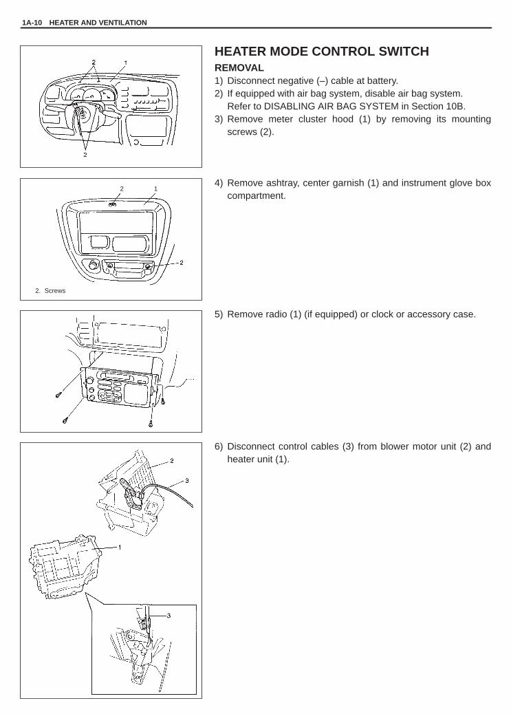
YH4GRANDVITARA
1A-10 HEATER AND VENTILATION
2. Screws
12
HEATER MODE CONTROL SWITCHREMOVAL1) Disconnect negative (–) cable at battery.2) If equipped with air bag system, disable air bag system.
Refer to DISABLING AIR BAG SYSTEM in Section 10B.3) Remove meter cluster hood (1) by removing its mounting
screws (2).
4) Remove ashtray, center garnish (1) and instrument glove boxcompartment.
5) Remove radio (1) (if equipped) or clock or accessory case.
6) Disconnect control cables (3) from blower motor unit (2) andheater unit (1).

YH4GRANDVITARA
HEATER AND VENTILATION 1A-11
1
1. Mode control switch coupler
7) Disconnect heater blower motor switch connector (1).8) Remove mode control switch with heater control lever assem-
bly from the removed hole in mentioned step (5).
9) Pull off heater control lever knob.10) Remove heater mode control switch (2) with heater control
panel (3) from heater control lever assembly (1).11) Remove heater control panel from mode control switch.
INSPECTION
Mode Control Switch� Check if continuity exists between each pair of terminals listed be-
low when mode control button is pressed.
Mode Mode control switch terminals
VENT F – M
BI-LEVEL F – N
HEAT F – E
DEF/HEAT F – B
DEF F – C
� With battery voltage (+) connected to terminal “I” and (–) to termi-nal “F”, press each mode control button and check if indicatorlamp (3) lights.
� With battery voltage (+) connected to terminal “A” and (–) to termi-nal “H”, check if illumination lamp lights.
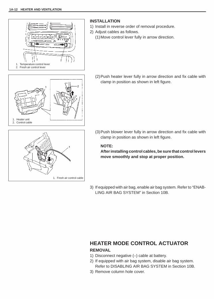
YH4GRANDVITARA
1A-12 HEATER AND VENTILATION
1. Temperature control lever2. Fresh air control lever
1. Fresh air control cable
1. Heater unit2. Control cable
1 2
INSTALLATION1) Install in reverse order of removal procedure.2) Adjust cables as follows.
(1)Move control lever fully in arrow direction.
(2)Push heater lever fully in arrow direction and fix cable withclamp in position as shown in left figure.
(3)Push blower lever fully in arrow direction and fix cable withclamp in position as shown in left figure.
NOTE:After installing control cables, be sure that control leversmove smoothly and stop at proper position.
3) If equipped with air bag, enable air bag system. Refer to “ENAB-LING AIR BAG SYSTEM” in Section 10B.
HEATER MODE CONTROL ACTUATORREMOVAL1) Disconnect negative (–) cable at battery.2) If equipped with air bag system, disable air bag system.
Refer to DISABLING AIR BAG SYSTEM in Section 10B.3) Remove column hole cover.

YH4GRANDVITARA
HEATER AND VENTILATION 1A-13
1. Lever
FOR LEFT HAND STEERING VEHICLE
FOR RIGHT HAND STEERING VEHICLE
4) Disconnect heater mode control actuator coupler (1).5) Disconnect heater mode control actuator rod (2) from heater
unit.6) Remove heater mode control actuator from heater unit by re-
moving its mounting screw (3).
INSPECTION1) Connect battery voltage (+) to terminal “b’” and (–) to terminal
“a”.2) Connect each terminal listed below to terminal “a’” (negative (–)
terminal of battery) and check if lever rotation angle is as speci-fied in figure.
MODE TERMINAL
VENT c
BI-LEVEL d
HEAT e
DEF/HEAT f
DEF g
INSTALLATION1) Install in reverse order of removal procedure.2) If equipped with air bag system, enable air bag system.
Refer to ENABLING AIR BAG SYSTEM in Section 10B.

YH4GRANDVITARA
1. Blower motor switch connector
1
1A-14 HEATER AND VENTILATION
HEATER CONTROL LEVER ASSEMBLYREMOVAL1) Disconnect negative (–) cable at battery.2) If equipped with air bag system, disable air bag system.
Refer to DISABLING AIR BAG SYSTEM in Section 10B.3) Remove mode control switch. Refer to item HEATER MODE
CONTROL SWITCH in this section.
INSPECTIONCheck heater blower motor switch for each terminal-to-terminalcontinuity. For the detail refer to WIRING CIRCUIT earlier in thissection.
E F L ML MH H
LOW
M1
M2
HIGH

YH4GRANDVITARA
HEATER AND VENTILATION 1A-15
1. Heater unit2. Blower unit3. Fresh air control cable4. Temperature control cable5. Heater control lever assembly
HEATER CONTROL CABLES
REMOVAL1) Remove heater control lever assembly.
Refer to HEATER CONTROL LEVER ASSEMBLY in this sec-tion.
2) Remove control cables (2) from control lever assembly (1).
INSTALLATION1) Install in reverse order of removal procedure.
Refer to HEATER MODE CONTROL SWITCH in this section.2) If equipped with air bag, enable air bag system.
Refer to ENABLING AIR BAG SYSTEM in Section 10B.

YH4GRANDVITARA
1A-16 HEATER AND VENTILATION
1. Heater unit2. Heater core3. Damper4. Heater mode control actuator5. Heater mode control switch6. Heater control lever assembly
HEATER UNIT
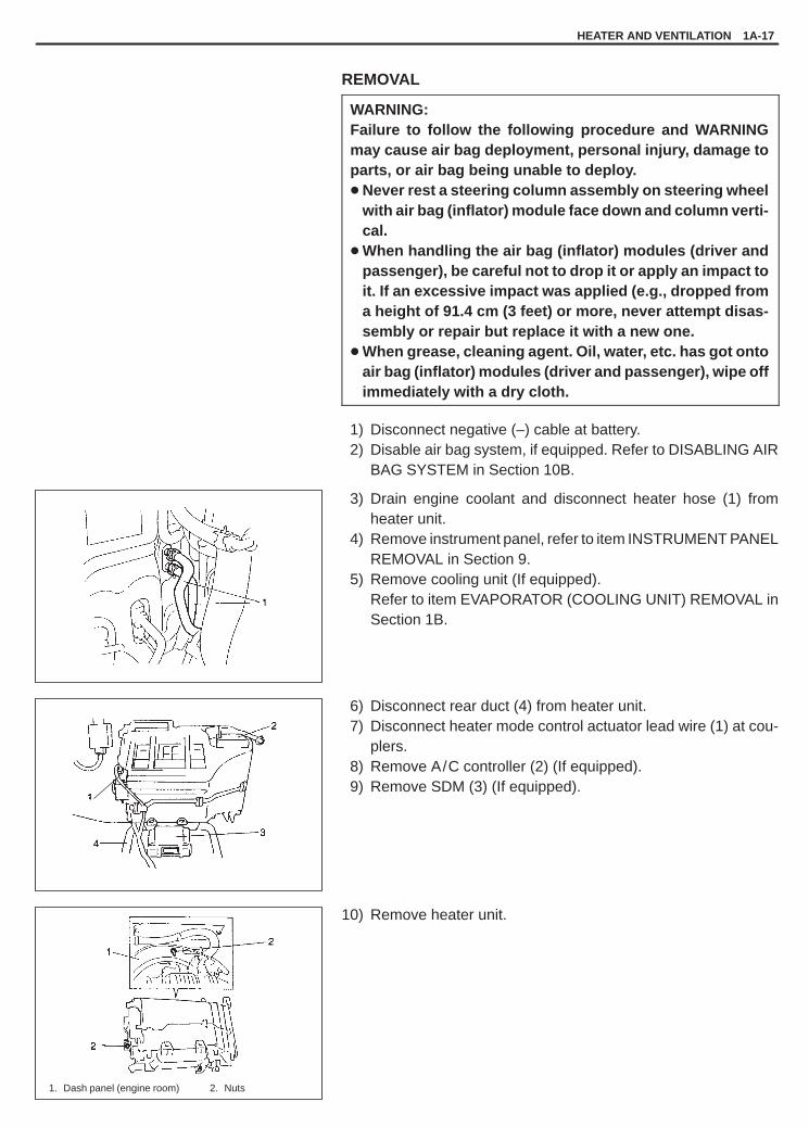
YH4GRANDVITARA
HEATER AND VENTILATION 1A-17
1. Dash panel (engine room) 2. Nuts
REMOVAL
WARNING:Failure to follow the following procedure and WARNINGmay cause air bag deployment, personal injury, damage toparts, or air bag being unable to deploy.� Never rest a steering column assembly on steering wheel
with air bag (inflator) module face down and column verti-cal.
� When handling the air bag (inflator) modules (driver andpassenger), be careful not to drop it or apply an impact toit. If an excessive impact was applied (e.g., dropped froma height of 91.4 cm (3 feet) or more, never attempt disas-sembly or repair but replace it with a new one.
� When grease, cleaning agent. Oil, water, etc. has got ontoair bag (inflator) modules (driver and passenger), wipe offimmediately with a dry cloth.
1) Disconnect negative (–) cable at battery.2) Disable air bag system, if equipped. Refer to DISABLING AIR
BAG SYSTEM in Section 10B.
3) Drain engine coolant and disconnect heater hose (1) fromheater unit.
4) Remove instrument panel, refer to item INSTRUMENT PANELREMOVAL in Section 9.
5) Remove cooling unit (If equipped).Refer to item EVAPORATOR (COOLING UNIT) REMOVAL inSection 1B.
6) Disconnect rear duct (4) from heater unit.7) Disconnect heater mode control actuator lead wire (1) at cou-
plers.8) Remove A/C controller (2) (If equipped).9) Remove SDM (3) (If equipped).
10) Remove heater unit.

YH4GRANDVITARA
1A-18 HEATER AND VENTILATION
11) Remove heater core pipe clamps (1) and grommet (2).
12) Pull out heater core (1) from unit (2).
INSTALLATION1) Install heater unit by reversing removal procedure, noting the
following items.� When installing each part, be careful not to catch any cable or
wiring harness.� When installing steering column assembly, refer to STEER-
ING COLUMN INSTALLATION in Section 3C or 3C1.2) Install control cables. (Refer to HEATER CONTROL CABLES in
this section.)3) Fill engine coolant to radiator.4) Enable air bag system, if equipped. Refer to ENABLING AIR
BAG SYSTEM in Section 10B.5) Evacuate and charge system. Refer to items EVACUATING
SYSTEM and PROCEDURE OF CHARGING in Section 1B.

YH4GRANDVITARA
HEATER AND VENTILATION 1A-19
1. Heater unit2. Rear duct3. SDM
REAR DUCT
REMOVAL1) Disconnect negative (–) cable at battery.2) Remove front seat.3) Remove console box.4) Take off carpet till rear duct is totally exposed.5) Remove rear duct.
INSTALLATIONReverse removal sequence to install rear duct.

YH4GRANDVITARA
1B
AIR CONDITIONING (OPTIONAL) 1B-1
GENERAL DESCRIPTION 1B- 3. . . . . . . . . . . . . . Identification of Refrigerating System 1B- 3. . . . Refrigerant Flow of Air Conditioning
System 1B- 4. . . . . . . . . . . . . . . . . . . . . . . . . . . . Major Components and Location 1B- 5. . . . . . .
DIAGNOSIS 1B- 6. . . . . . . . . . . . . . . . . . . . . . . . . . . General 1B- 6. . . . . . . . . . . . . . . . . . . . . . . . . . . . . Diagnosis of Abnormal Noise 1B- 8. . . . . . . . . . Quickly Checking of Refrigerant Charge
(If Equipped with Sight Glass) 1B-10. . . . . . . . . Compression System Diagnosis 1B-11. . . . . . . . Performance Diagnosis 1B-12. . . . . . . . . . . . . . . Wiring Circuit 1B-16. . . . . . . . . . . . . . . . . . . . . . . . Inspection of A/C Controller and Its
Circuits 1B-18. . . . . . . . . . . . . . . . . . . . . . . . . . . .
REFRIGERANT RECOVERY,EVACUATION AND CHARGING 1B-23. . . . . . . . Operation Procedure for Charging A/C
with Refrigerant 1B-23. . . . . . . . . . . . . . . . . . . . . Recovery 1B-24. . . . . . . . . . . . . . . . . . . . . . . . . . . . Evacuating 1B-25. . . . . . . . . . . . . . . . . . . . . . . . . . Charging 1B-26. . . . . . . . . . . . . . . . . . . . . . . . . . . . Removing Manifold Gauge Set 1B-29. . . . . . . . . Leak-Testing Refrigerant System 1B-29. . . . . . . Liquid Leak Detectors 1B-29. . . . . . . . . . . . . . . . .
ON-VEHICLE SERVICE 1B-30. . . . . . . . . . . . . . . . Precaution 1B-30. . . . . . . . . . . . . . . . . . . . . . . . . . . A/C Condenser Assembly 1B-33. . . . . . . . . . . . . Condenser Cooling Fan Assembly 1B-35. . . . . .
SECTION 1B
AIR CONDITIONING (OPTIONAL)WARNING:For vehicles equipped with Supplemental Restraint (Air Bag) System:� Service on and around the air bag system components or wiring must be performed only by an autho-
rized SUZUKI dealer. Refer to “Air Bag System Components and Wiring Location View” under “Gener-al Description” in air bag system section in order to confirm whether you are performing service onor near the air bag system components or wiring. Please observe all WARNINGS and “Service Precau-tions” under “On-Vehicle Service” in air bag system section before performing service on or aroundthe air bag system components or wiring. Failure to follow WARNINGS could result in unintentionalactivation of the system or could render the system inoperative. Either of these two conditions mayresult in severe injury.
� Technical service work must be started at least 90 seconds after the ignition switch is turned to the“LOCK” position and the negative cable is disconnected from the battery. Otherwise, the system maybe activated by reserve energy in the Sensing and Diagnostic Module (SDM).
CAUTION:The air conditioning system of this vehicle uses refrigerant HFC-134a (R-134a).None of refrigerant, compressor oil and component parts is interchangeable between two types of A/C:one using refrigerant CFC-12 (R-12) and the other using refrigerant HFC-134a (R-134a).Be sure to check which refrigerant is used before any service work including inspection and mainte-nance. For identification between these two types, refer to the description in page 1B-2.When replenishing or changing refrigerant and compressor oil and when replacing parts, make surethat the material or the part to be used is appropriate to the A/C installed in the vehicle being serviced.Use of incorrect one will result in leakage of refrigerant, damage in parts or other faulty condition.
For basic servicing method of the air conditioning system that is not described in this section, refer to AIR CONDI-TIONING BASIC MANUAL (99520-02130).
CONTENTS

YH4GRANDVITARA
1B-2 AIR CONDITIONING (OPTIONAL)
Condenser Dryer (Receiver/Dryer) 1B-36. . . . . . Air Filter Element 1B-37. . . . . . . . . . . . . . . . . . . . . Cooling Unit (Evaporator) 1B-39. . . . . . . . . . . . . . Expansion Valve 1B-42. . . . . . . . . . . . . . . . . . . . . A/C Evaporator Thermistor (Evaporator
Temperature Sensor) 1B-43. . . . . . . . . . . . . . . . Refrigerant Pipes and Hoses 1B-44. . . . . . . . . . . A/C Switch 1B-45. . . . . . . . . . . . . . . . . . . . . . . . . . A/C Controller 1B-46. . . . . . . . . . . . . . . . . . . . . . . . Dual Pressure Switch 1B-47. . . . . . . . . . . . . . . . .
A/C Compressor Relay and A/CCondenser Cooling Fan Relay 1B-48. . . . . . . .
Compressor Assembly 1B-49. . . . . . . . . . . . . . . . Magnet Clutch Assembly
(For Denso Compressor) 1B-53. . . . . . . . . . . Magnet Clutch Assembly
(For Seiko Seiki Compressor) 1B-56. . . . . . . Lip Type Seal (For Seiko Seiki) 1B-59. . . . . . .
REQUIRED SERVICE MATERIAL 1B-61. . . . . . . .
SPECIAL TOOLS 1B-61. . . . . . . . . . . . . . . . . . . . . .
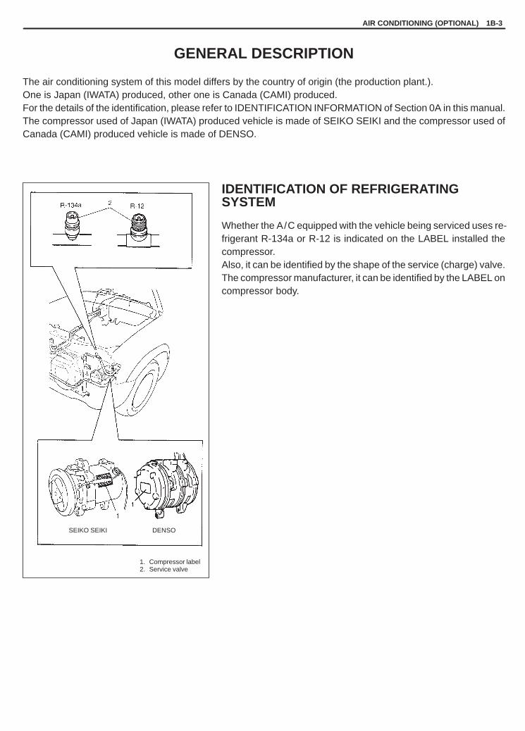
YH4GRANDVITARA
1. Compressor label2. Service valve
SEIKO SEIKI DENSO
AIR CONDITIONING (OPTIONAL) 1B-3
GENERAL DESCRIPTION
The air conditioning system of this model differs by the country of origin (the production plant.).One is Japan (IWATA) produced, other one is Canada (CAMI) produced.For the details of the identification, please refer to IDENTIFICATION INFORMATION of Section 0A in this manual.The compressor used of Japan (IWATA) produced vehicle is made of SEIKO SEIKI and the compressor used ofCanada (CAMI) produced vehicle is made of DENSO.
IDENTIFICATION OF REFRIGERATINGSYSTEM
Whether the A/C equipped with the vehicle being serviced uses re-frigerant R-134a or R-12 is indicated on the LABEL installed thecompressor.Also, it can be identified by the shape of the service (charge) valve.The compressor manufacturer, it can be identified by the LABEL oncompressor body.
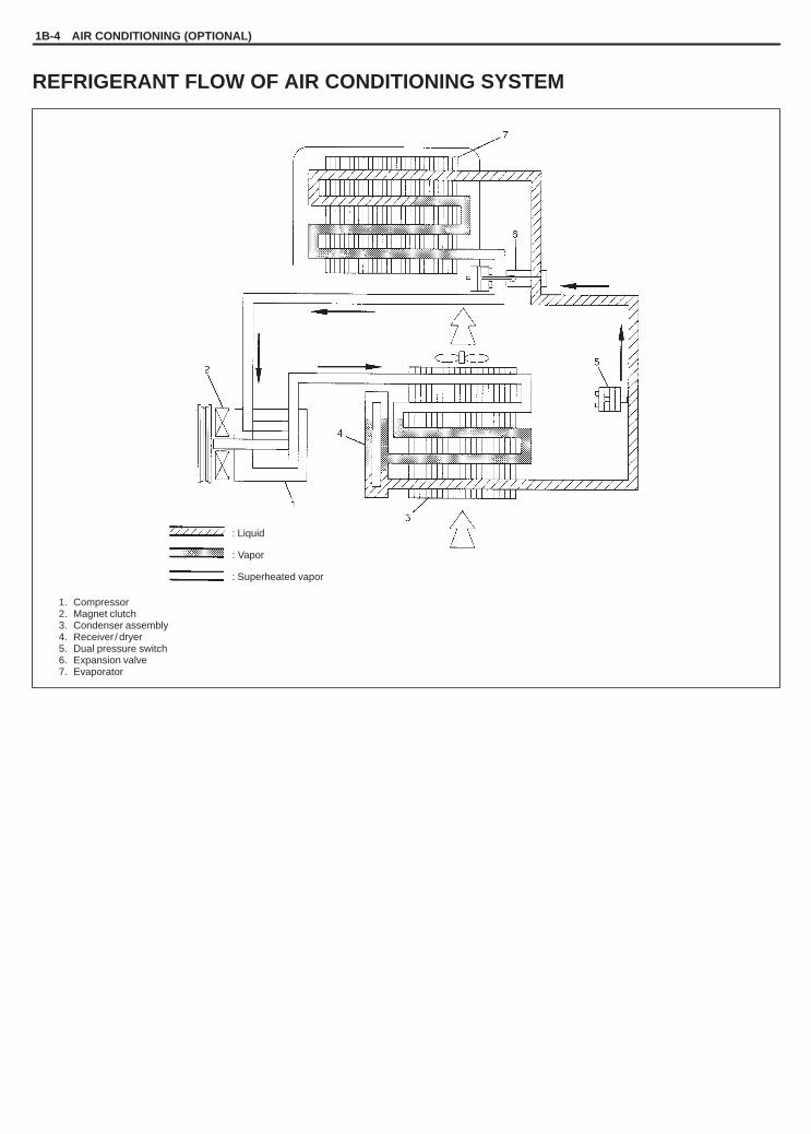
YH4GRANDVITARA
1. Compressor2. Magnet clutch3. Condenser assembly4. Receiver / dryer5. Dual pressure switch6. Expansion valve7. Evaporator
: Liquid
: Vapor
: Superheated vapor
1B-4 AIR CONDITIONING (OPTIONAL)
REFRIGERANT FLOW OF AIR CONDITIONING SYSTEM

YH4GRANDVITARA
1. Cooling unit2. Compressor3. Condenser assembly4. Receiver / dryer5. Discharge hose6. Suction hose7. Condenser outlet pipe8. Liquid pipe
9. Expansion valve10. Ventilation air11. Foot air12. Defroster air13. Demister air14. Fresh air15. Recirculation air16. Heater unit
17. Air inlet box18. Dual pressure switch19. Low pressure charge valve20. High pressure charge valve21. Suction pipe22. Sight glass
CAMI PRODUCTION VEHICLE IWATA PRODUCTION VEHICLE
AIR CONDITIONING (OPTIONAL) 1B-5
MAJOR COMPONENTS AND LOCATION

YH4GRANDVITARA
1B-6 AIR CONDITIONING (OPTIONAL)
DIAGNOSIS
GENERAL
Condition Possible Cause Correction
Cool air won’t come out(A/C system won’toperative)
� No refrigerant� Fuse blown
� A/C switch faulty� Blower motor switch faulty� A/C thermistor faulty� Dual pressure switch faulty� Wiring or grounding faulty� A/C ON permission signal in ECM
faulty� A/C controller and its circuit faulty
Recover, evacuation and charging.Check “IG METER” fuse, “REAR DEFG”fuse, and “A/C FUSE” and check forshort circuit to ground.Check A/C switch.Check blower motor switch.Check A/C evaporator thermistor.Check dual pressure switch.Repair as necessary.Check ON permission signal.
Check A/C controller and its circuit.
Cool air won’t come out(A/C compressor won’toperative)
� Magnet clutch faulty� Compressor relay faulty� Compressor thermal switch faulty
(if equipped)� Drive belt loose or broken� Compressor faulty� A/C ON permission signal in ECM
faulty� A/C controller faulty
Check magnet clutch.Check compressor thermal switch.Check compressor relay.
Adjust or replace drive belt.Check compressor.Check ON permission signal.
Check A/C controller.
Cool air won’t come out(A/C condenser coolingfan motor won’toperative)
� Condenser cooling fan relay faulty� Wiring or grounding faulty� “A/C condenser cooling fan relay”
signal in ECM faulty� Condenser cooling fan motor faulty
Check condenser cooling fan relay.Repair as necessary.Check A/C condenser cooling fan relaysignal.Check condenser cooling fan motor.
Cool air won’t come out(Blower motor won’toperative)
� Fuse blown
� Blower motor relay faulty� Blower motor resistor faulty� Blower motor switch faulty� Wiring or grounding faulty� Blower motor faulty
Check “HEATER FUSE”, “REAR DEFG”fuse and check for short circuit toground.Check blower motor relay.Check blower motor resistor.Check blower motor switch.Repair as necessary.Check blower motor.
Cool air won’t come outor insufficient cooling(A/C system normaloperative)
� Insufficient or excessive charge ofrefrigerant
� Refrigerant leak in system� Condenser clogged� A/C evaporator clogged or frosted� A/C thermistor faulty� A/C controller faulty� Expansion valve faulty� Drive belt slipping� Magnetic clutch faulty
Check charge of refrigerant.
Check system for leaks.Check condenser.Check A/C evaporator.Check A/C thermistor.Check A/C controller.Check expansion valve.Check or replace drive belt.Check magnetic clutch.

YH4GRANDVITARA
AIR CONDITIONING (OPTIONAL) 1B-7
Condition Possible Cause Correction
Cool air does not comeout or insufficientcooling (A/C systemnormal operative)
� Compressor faulty� Air in A/C system
� Air leaking from cooling unit or airduct
� Heater and ventilation system faulty
� Blower motor faulty� Excessive compressor oil existing in
A/C system
Check compressor.Replace condenser dryer, andevacuation and charging.Repair as necessary.
Check blower unit.Check heater control lever assembly.Check heater assembly.Check blower motor.Pull out compressor oil in A/C systemcircuit, and replace compressor.
Cool air does not comesout only intermittently
� Wiring connection faulty� Expansion valve faulty� Excessive moisture in A/C system
� A/C controller faulty� Magnetic clutch faulty� Excessive charge of refrigerant
Repair as necessary.Check expansion valve.Replace condenser dryer, andevacuation and charging.Check A/C controller.Check magnetic clutch.Check charge of refrigerant.
Cool air comes out onlyat high speeds
� Condenser clogged� Insufficient charge of refrigerant� Air in A/C system
� Drive belt slipping� Compressor faulty
Check condenser.Check charge of refrigerant.Replace condenser dryer, andevacuation and charging.Adjust or replace drive belt.Check compressor.
Cool air does not comesout only at high speeds
� Excessive charge of refrigerant� A/C evaporator frosted
Check charge refrigerant.Check A/C evaporator.Check A/C thermistor.
Insufficient velocity ofcooled air
� A/C evaporator clogged or frosted� Air leaking from cooling unit or air
duct� Blower motor faulty� Wiring or grounding faulty
Check A/C evaporator.Repair as necessary.
Check blower motor.Repair as necessary.

YH4GRANDVITARA
1B-8 AIR CONDITIONING (OPTIONAL)
DIAGNOSIS OF ABNORMAL NOISE
There are various types of noise, ranging from those produced in the engine compartment to those from the pas-senger compartment, also from rumbling noises to whistling noises.
ABNORMAL NOISE FROM COMPRESSOR
Condition Possible Cause Correction
� During compressor operation, arumbling noise is heardproportional to enginerevolutions.
� Inadequate clearance in pistonarea (piston or swash-plate).
� Repair or replace compressor asnecessary.
� A loud noise is heard at a certainrpm, disproportionately to enginerevolution.
� Loose or faulty V-belt.
� Loose mounting bolts.
� Adjust V-belt tension, orreplace belt.
� Retighten mounting bolts.
� A loud rattle is heard at lowengine rpm.
� Loose compressor center bolt. � Retighten center bolt.� Replace compressor if it was
operated in this condition for along time.
ABNORMAL NOISE FROM MAGNETIC CLUTCH
Condition Possible Cause Correction
� A rumbling noise is heard whencompressor is not operating.
� Worn or damaged bearings. � Replace bearings.
� A chattering noise is heard whencompressor is engaged.
� Faulty clutch gap (excessive).� Worn clutch friction surface.� Compressor oil leaked from shaft
seal, contaminating the frictionsurface.
� Adjust clutch gap.� Replace clutch.� Replace compressor shaft oil
seal.
ABNORMAL NOISE FROM TUBING
Condition Possible Cause Correction
� A droning noise is heard insidevehicle, but not particularlynoticeable in enginecompartment.
� Faulty tubing clamps.
� Resonance caused by pulsationfrom variations in refrigerantpressure.
� Reposition clamps or increasethe number of clamps.
� Attach a silencer to tubing, ormodify its position and length.
ABNORMAL NOISE FROM CONDENSER
Condition Possible Cause Correction
� Considerable vibration incondenser.
� Resonance from condensermounting stay and body.
� Firmly insert a silencer betweencondenser mounting stay andbody.
YH4GRANDVITARA
AIR CONDITIONING (OPTIONAL) 1B-9
ABNORMAL NOISE FROM CRANKSHAFT PULLEY
Condition Possible Cause Correction
� A large rattling noise is heard atidle or sudden acceleration.
� Loosen pulley mounting bolt.� Worn or broken bearings.
� Retighten bolt.� Replace bearings.
ABNORMAL NOISE FROM TENSION PULLEY
Condition Possible Cause Correction
� Clattering noise is heard frompulley.
� Pulley cranks upon contact.
� Worn or damaged bearings.
� Cracked or loose bracket.
� Replace bearings.
� Replace or retighten bracket.
ABNORMAL NOISE FROM EVAPORATOR
Condition Possible Cause Correction
� Whistling sound is heard fromevaporator.
� Depending on the combination ofthe interior/exteriortemperatures, engine rpm andrefrigerant pressure, therefrigerant flowing out of theexpansion valve may, undercertain conditions, make awhistling sound.
� At times, slightly decreasingrefrigerant volume may stop thisnoise.
� Inspect expansion valve andreplace if faulty.
ABNORMAL NOISE FROM BLOWER MOTOR
Condition Possible Cause Correction
� Blower motor emits a chirpingsound in proportion to its speed ofrotation.
� Fluttering noise or large droningnoise is heard from blower motor.
� Worn or damaged motor brushesor commutator.
� Leaves or other debrisintroduced from fresh air inlet toblower motor.
� Repair or replace blower motor.
� Remove debris and make surethat the screen at fresh air inlet isintact.

YH4GRANDVITARA
3. Bubbles
1B-10 AIR CONDITIONING (OPTIONAL)
QUICKLY CHECKING OF REFRIGERANTCHARGE (IF EQUIPPED WITH SIGHT GLASS)CHARGE OF REFRIGERANTThe following procedure can be used for quickly checking whetherthe A/C system has a proper charge of refrigerant or not.Run engine at fast idle, and operate A/C at its max. cooling capacityfor a few minutes. Then, look at the sight glass (1) on receiver/dryer(2) and compare what is observed with the symptoms listed in“CHECKING REFRIGERANT CHARGE” table given below.
CHECKING REFRIGERANT CHARGE
CONDITION POSSIBLE CAUSES CORRECTION
Bubbles observed in sight glass Insufficient charge of refrigerant insystem
Check system for leaks with a leaktester.
No bubbles observed in sight glass No charge or proper or too muchcharge of refrigerant in system
Refer to the following item.
No temperature differencebetween compressor inlet andoutlet
Empty or nearly empty system Recovery, evacuate and chargesystem and then check it for leakswith a leak tester.
Noticeable temperature differencebetween compressor inlet andoutlet
Proper or too much charge ofrefrigerant in system
Refer to the following item.
When A/C is turned OFF,refrigerant in sight glass clearsimmediately and remains clear
Too much charge of refrigerant insystem
Discharge excess charge ofrefrigerant to adjust it to a specifiedcharge.
When A/C is turned OFF,refrigerant in sight glass onceproduces bubbles and then clears
Proper charge of refrigerant insystem
No correction needed becausecharge of refrigerant is normal.

YH4GRANDVITARA
AIR CONDITIONING (OPTIONAL) 1B-11
COMPRESSION SYSTEM DIAGNOSIS
Compressor troubles are mainly following three types: gas leakage, noise and insufficient pressure.Compressor gas leakages in most cases develop from the shaft seal. When detecting gas leakage, always usea leak tester. If a small amount of oil seeps out from the shaft seal, there is no necessity of replacing the seal. Theshaft seal has been designed to allow a small amount of oil to leak out for lubricating purpose. Thus, the shaft sealshould be replaced only when a large amount of compressor oil is leaking out or when gas leakage is discoveredby using gas tester.In regard to noise and insufficient pressure, repairs should be made only after diagnosing the trouble properly.
CONDITION POSSIBLE CAUSES CORRECTION
Noise from compressor � Defective bearing� Defective cylinder and/or shaft
Replace.Replace.
Noise from magnetic clutch � Defective bearing� Defective clutch face
Replace.Replace.
Insufficient cooling � Defective gasket Replace.� Defective reed valve Replace.
Not rotating � Locked compressor� Seized magnetic clutch� Rotating parts seized by insufficient oil
amount
Replace.Replace.Replace.
Oil and/or gas leakage � Defective seal� Defective O-ring
Replace.Replace.

YH4GRANDVITARA
For CAMI production vehicle
For IWATA production vehicle
1B-12 AIR CONDITIONING (OPTIONAL)
PERFORMANCE DIAGNOSIS1) Confirm that vehicle and environmental conditions are as fol-
lows.� Vehicle is not exposed to direct sun.� Ambient temperature is within 15�C – 35�C (59�F – 95�F).
2) Make sure that high pressure valve (1) and low pressure valve(2) of manifold gauge are firmly closed.
3) Connect high pressure charging hose (3) to high pressure ser-vice valve (5) on vehicle, and connect low pressure charginghose (4) to low pressure service valve (6) on vehicle.
4) Bleed the air in charging hoses (3), (4) by loosening their respec-tive nuts on manifold gauge, utilizing the refrigerant pressure.When a hiss is heard, immediately tighten nut.
CAUTION:Do not interchange high and low pressure charginghoses by mistake.
5) Warm up engine to normal operating temperature (engine cool-ant temperature at 80 – 90�C (176 – 194�F)) and keep it at spe-cified idle speed. (Radiator cooling fan should not be workingwhen checking pressure and temperature.)
6) Turn A/C switch ON, and set blower switch at “HI” (4th position),temperature control knob at “COOL”, air outlet control knob at“FACE”, fresh/circulation control knob at “CIRCULATION”.(Confirm that A/C compressor and condenser fan are working.)
7) Keep all windows, doors and engine food open.
Ambient temperature 15 – 35�C (59�F – 95�F)
Engine rpm Keep to 1,500 rpm.
Blower motor switch Max. (4th position)
Temperature control Max. cool
Air outlet control Face
Vehicle doors All open
Air inlet door position Recirculation
8) With about 20 mm (0.8 in.) of dry bulb thermometer (1) insertedinto center duct air outlet and another one set near evaporatorair inlet, read temperature indicated on each thermometer.
YH4GRANDVITARA
AIR CONDITIONING (OPTIONAL) 1B-13
9) Check for each pressure of low side and high side if it is withinshaded range of graph.If each gauge reading is out of specified pressure, correct de-fective part referring to following Test Diagnosis table.
Example:
Gauges should read as follows when ambienttemperature is 30 �C.
Pressure on high pressuregauge (HI):
1400 – 1750 kPa14.0 – 17.5 kg/cm 2
Pressure on high pressuregauge (LO):
230 – 350 kPa2.3 – 3.5 kg/cm 2
NOTE:Pressure registered on gauge varies with ambient temper-ature. Therefore, use left graphs when determining if pres-sures are normal or not.
10) Check inlet port temperature-to-outlet port temperature rela-tionship using graph.For example, if evaporator inlet port temperature is 25�C(77�F) and center duct air outlet temperature is 8�C (46.4�F),their crossing point is within acceptable range as shown ingraph.
11) If crossing point is out of acceptable range, diagnose troublereferring to following Performance Diagnosis table.

YH4GRANDVITARA
1B-14 AIR CONDITIONING (OPTIONAL)H
IGH
PR
ES
SU
RE
CA
UG
ELO
W P
RE
SS
UR
E G
AU
GE
TH
ER
MO
ME
TE
R A
TC
EN
TE
R D
UC
T
Insufficientcooling ofcondenser
PERFORMANCE DIAGNOSIS TABLE
TESTING RESULTS POSSIBLE CAUSE REMEDY
Pressure high(“A” area of high sidegraph)
� Refrigerant overcharged� Expansion valve frozen or clogged� Clogged refrigerant passage of high side� Condenser fan malfunction
� Dirty or bent condenser fins� Compressor malfunction (Insufficient oil etc.)� Engine overheat
� Recharge� Check expansion valve� Clean or replace� Check condenser fan
� Clean or repair� Check compressor� Check engine cooling
system
Pressure low(“B” area of high sidegraph)
� Insufficient refrigerant (Insufficient charge orleakage)
� Expansion valve malfunction (Valve opens toowide)
� Compressor malfunction (Insufficientcompression)
� Check for leakage, repair ifnecessary and recharge
� Check expansion valve
� Check compressor
Pressure high(“A” area of low sidegraph)
� Expansion valve malfunction (Valve opens toowide)
� Compressor malfunction (Insufficientcompression)
� Check expansion valve
� Check compressor
Pressure low(“B” area of low sidegraph)
� Insufficient refrigerant (Insufficient charge orleakage)
� Expansion valve malfunction (Valve opens toonarrow)
� Clogged refrigerant passage (Crashed pipe)
� Check for leakage, repair ifnecessary and recharge
� Check expansion valve
� Repair or replace
Outlet air temperatureat center duct is high(Crossing point is inarea “A”)
� Insufficient or excessive charge of refrigerant
� Dirty or bent evaporator fins� Air leakage from cooling (heater) unit or air
duct� Malfunctioning, switchover function of damper
in cooling (heater) unit� Compressor malfunction
� Check refrigerantpressure
� Clean or repair� Repair or replace
� Repair or replace
� Check compressor
Outlet air temperatureat center duct is low(Crossing point is inarea “B”)
� Insufficient air volume from center duct(Heater blower malfunction)
� Compressor malfunction
� Check blower motor andfan
� Check compressor
NOTE:If ambient temperature is within 30 – 35 �C (85 – 95�F), it is possible to do using next page table for moredetail diagnosis.

YH4GRANDVITARA
AIR CONDITIONING (OPTIONAL) 1B-15
AMBIENT TEMPERATURE WITHIN 30 – 35 �C (85 – 95�F)
CONDITION
MANIFOLDGAUGE
MPa(kg/cm 2)
(psi) DETAILCAUSE CORRECTION
Lo Hi
0.23 – 0.35(2.3 – 3.5)(33 – 50)
1.4 – 1.75(14 – 17.5)(200 – 249)
Normal condition. —— ——
Negativepressure
0.5 – 0.6(5 – 6)
(71.2 – 85.3)
� The low pressure sidereads a negative pressure,and the high pressure sidereads an extremely lowpressure.
� Presence of frost aroundtubing to and from receiver /dryer and expansion valve.
� Dust particles or waterdroplets are either stuck orfrozen inside expansionvalve, preventing therefrigerant from flowing.
� Clean expansion valve.Replace it if it cannot becleaned.
� Replace receiver /dryer.� Evacuate the A/C
system and rechargewith fresh refrigerant.
Normal:0.23 – 0.35(2.3 – 3.5)(33 – 50)
� �
Abnormal:Negativepressure
Normal:1.4 – 1.75(14 – 17.5)(200 – 249)
� �
Abnormal:0.69 – 0.98
(7 – 10)(100 – 142)
� During A/C operation, thelow pressure sidesometimes indicatesnegative pressure, andsometimes normalpressure. Also highpressure side readingfluctuates between theabnormal and normalpressure.
� Expansion valve is frozendue to moisture in thesystem, and temporarilyshuts off the refrigerationcycle.
� Replace expansionvalve.
� Replace receiver /dryer.� Evacuate A/C system
and recharge with freshrefrigerant.
0.05 – 0.15(0.5 – 1.5)(4.2 – 21.3)
0.69 – 0.98(7 – 10)
(100 – 142)
� Both low and high pressuresides indicate low readings.
� Continuous air bubbles arevisible through sight glass.
� Output air is slightly cold.
� Insufficient refrigerant insystem. (Refrigerantleaking)
� Using a gas leakdetector, check for leaksand repair as necessary.
� Recharge refrigerant to aspecified amount.If the pressure reading isalmost 0 when themanifold gauges areattached, check for anyleaks, repair them, andevacuate the system.
0.4 – 0.6(4 – 6)
(56.9 – 85.3)
� Pressure on low pressureside is high.
� Pressure on high pressureside is low.
� Both pressure becomingequal right after A/C isturned OFF.
� Internal leak in compressor. � Inspect compressor andrepair or replace asnecessary.
0 35 0 45
� High pressure reading onboth low and high pressuresides.
� Air bubbles are not visibleeven when engine rpm islowered.
� Overcharged A/C system.� Faulty condenser cooling
operation.� Faulty condenser fan
operation.
� Adjust refrigerant tospecified amount.
� Clean condenser.� Inspect and repair
condenser fan.
0.35 – 0.45(3.5 – 4.5)(50 – 64)
1.96 – 2.45(20 – 25)
(285 – 355)
� High pressure reading onboth low and high pressuresides.
� Low pressure side tubing isnot cold when touched.
� Air bubbles are visiblethrough sight glass.
� Presence of air in A/Csystem. (Improperlyevacuated)
� Replace receiver /dryer.� Inspect quantity of
compressor oil andpresence ofcontaminants in oil.
� Evacuate system andrecharge with freshrefrigerant.
0.45 – 0.55(4.5 – 5.5)(64 – 78)
� High pressure reading onboth low and high pressuresides.
� Large amount of frost ordew on the low pressureside tubing.
� Faulty expansion valve.� Refrigerant flow is not
regulated properly.
� Replace expansionvalve.
YH4GRANDVITARA
1. Blower motor main relay2. Blower motor3. Blower motor resistor4. Blower motor switch5. A / C controller6. ECM7. Heater mode control switch8. Evaporator temperature sensor9. Refrigerant pressure switch
10. Compressor relay11. Compressor12. Condenser cooling fan relay13. Condenser cooling fan14. Fuse box15. A / C fuse 25 A16. Ignition switch17. Main fuse box18. Battery main fuse 80 A
19. Battery20. Generator21. Ignition main fuse 60 A22. Heater / A / C main fuse 60 A23. Ignition/ meter fuse 20 A24. Rear defogger fuse 15 A25. Heater fuse 30 A26. Compressor thermal switch
(only IWATA production vehicle)
FOR LH VEHICLE
1B-16 AIR CONDITIONING (OPTIONAL)
WIRING CIRCUIT

YH4GRANDVITARA
AIR CONDITIONING (OPTIONAL) 1B-17
1. Blower motor main relay2. Blower motor3. Blower motor resistor4. Blower motor switch5. A / C controller6. ECM7. Heater mode control switch8. Evaporator temperature sensor9. Refrigerant pressure switch
FOR RH VEHICLE
10. Compressor relay11. Compressor12. Condenser cooling fan relay13. Condenser cooling fan14. Fuse box15. A / C fuse 25 A16. Ignition switch17. Main fuse box18. Battery main fuse 80 A
19. Battery20. Generator21. Ignition main fuse 60 A22. Heater / A / C main fuse 60 A23. Ignition/ meter fuse 20 A24. Rear defogger fuse 15 A25. Heater fuse 30 A26. Compressor thermal switch
(only IWATA production vehicle)
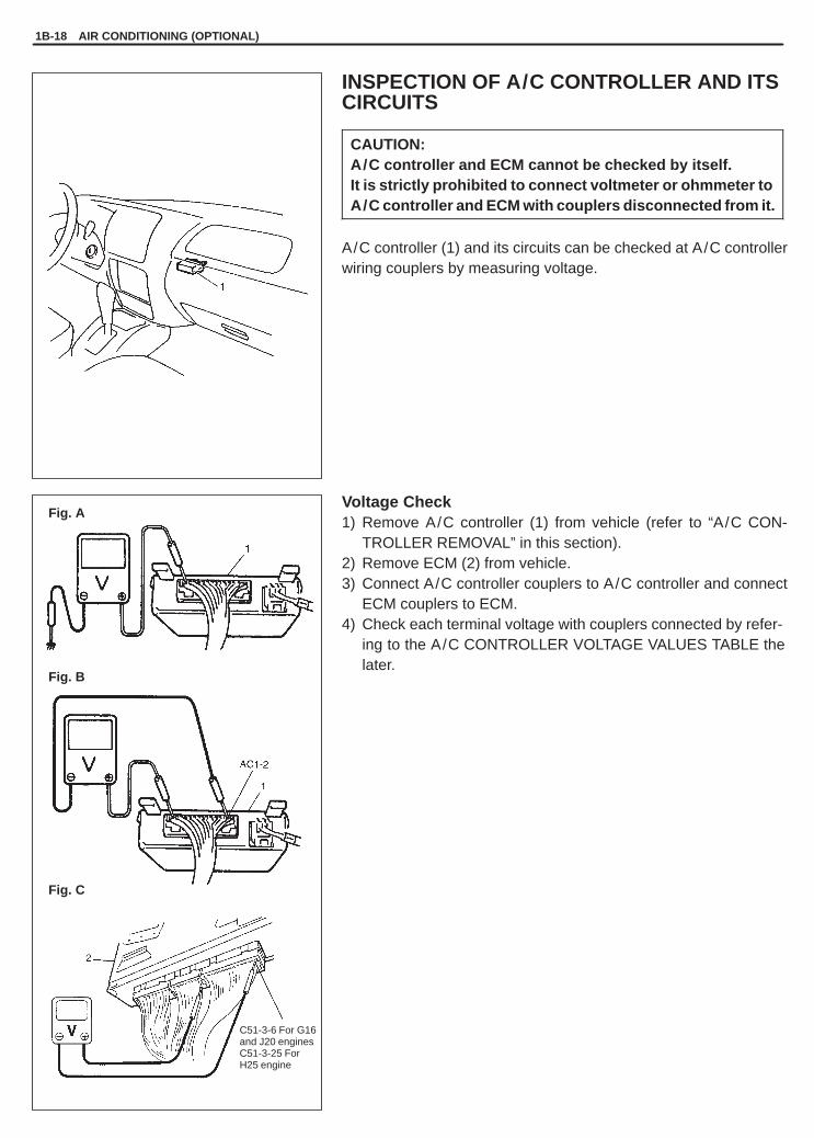
YH4GRANDVITARA
Fig. A
Fig. B
Fig. C
C51-3-6 For G16and J20 enginesC51-3-25 ForH25 engine
1B-18 AIR CONDITIONING (OPTIONAL)
INSPECTION OF A/C CONTROLLER AND ITSCIRCUITS
CAUTION:A/C controller and ECM cannot be checked by itself.It is strictly prohibited to connect voltmeter or ohmmeter toA/C controller and ECM with couplers disconnected from it.
A/C controller (1) and its circuits can be checked at A/C controllerwiring couplers by measuring voltage.
Voltage Check1) Remove A/C controller (1) from vehicle (refer to “A/C CON-
TROLLER REMOVAL” in this section).2) Remove ECM (2) from vehicle.3) Connect A/C controller couplers to A/C controller and connect
ECM couplers to ECM.4) Check each terminal voltage with couplers connected by refer-
ing to the A/C CONTROLLER VOLTAGE VALUES TABLE thelater.
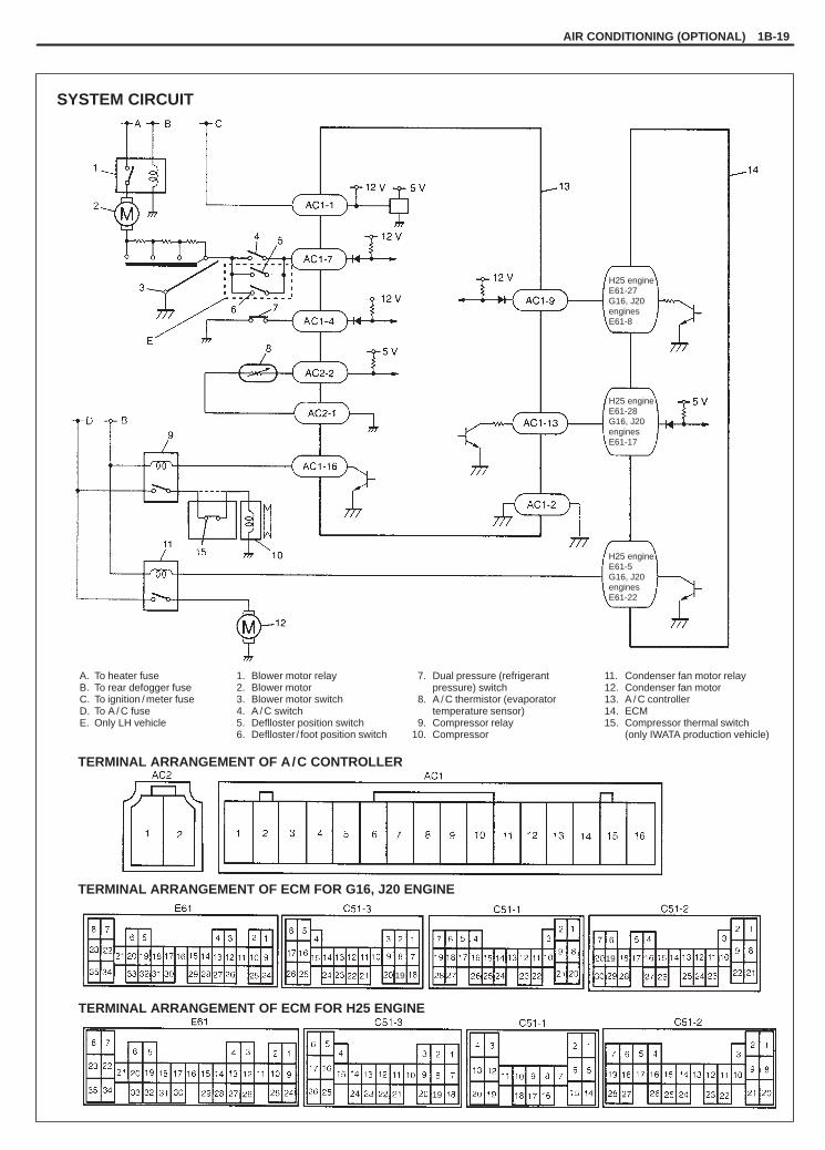
YH4GRANDVITARA
SYSTEM CIRCUIT
A. To heater fuseB. To rear defogger fuseC. To ignition / meter fuseD. To A / C fuseE. Only LH vehicle
1. Blower motor relay2. Blower motor3. Blower motor switch4. A / C switch5. Deflloster position switch6. Deflloster / foot position switch
7. Dual pressure (refrigerantpressure) switch
8. A / C thermistor (evaporatortemperature sensor)
9. Compressor relay10. Compressor
11. Condenser fan motor relay12. Condenser fan motor13. A / C controller14. ECM15. Compressor thermal switch
(only IWATA production vehicle)
TERMINAL ARRANGEMENT OF A/C CONTROLLER
TERMINAL ARRANGEMENT OF ECM FOR G16, J20 ENGINE
TERMINAL ARRANGEMENT OF ECM FOR H25 ENGINE
H25 engineE61-27G16, J20enginesE61-8
H25 engineE61-28G16, J20enginesE61-17
19
19
19
H25 engineE61-5G16, J20enginesE61-22
AIR CONDITIONING (OPTIONAL) 1B-19

YH4GRANDVITARA
1B-20 AIR CONDITIONING (OPTIONAL)
A/C CONTROLLER VOLTAGE VALUES TABLE
Terminal Wire CircuitMeasurement
groundNormal value Condition
AC1-1 B/WController mainpower supply
Ground toengine (Fig. B)
10 – 14 voltsIgnition switch ON with enginestopped
AC1-2 B/YController mainground
Ground to body(Fig. A)
–0.4 – 0 volt Engine running
AC1 4 OrRefrigerantpressure switch
Ground to
0 – 1 volt
Refrigerant pressure within 225 kPa(2.3 kg/cm2, 32.7 psi) to 2548 kPa(26 kg/cm2, 370 psi) with enginerunning
AC1-4 Or pressure switchinput
engine (Fig. B)
10 – 14 volts
Refrigerant pressure below196 kPa (2.0 kg/cm2, 28 psi) orabove 3140 kPa (32 kg/cm2, 455 psi)with engine running
AC1 7 G/B
A/C switch inputand/or defroster Ground to
8 – 14 voltsBlower fan motor switch and A/C ordefroster position switch (see NOTE)ON with engine running
AC1-7 G/Bposition switchinput (see NOTE)
engine (Fig. B)
0 – 1.5 voltsBlower fan motor switch or A/C ordefroster position switch (see NOTE)OFF with engine running
AC1 9 Gr/W
Signal input fromECM (A/C ON Ground to
10 – 14 volts Approve of A/C ONAC1-9 Gr/W
(permissionsignal)
engine (Fig. B)0 – 1 volt A/C ON forbid
AC1-13 Y/BSignal output toECM (A/C ONrequest signal)
Ground to engine(Fig. B)
0 – 1.5 volts
Blower fan motor switch and A/C ordefroster position switch (see NOTE)ON with engine running at evaporatorthermistor temperature input morethan approx. 2.5�C (less than 2.5 V(5840 �)) and refrigerant pressureswitch is ON
10 – 14 voltsExcept the above-mentioned withengine running
AC1-16 P
Compressormagnet clutchrelay output
Ground to engine(Fig. B)
0 – 1 volt
Blower fan motor switch and A/C ordefroster position switch ON withengine running at evaporatorthermistor temperature input morethan approx. 2.5�C (less than 2.5 V(5840 �)), refrigerant pressureswitch ON and signal input from ECMON
10 – 14 voltsExcept the above-mentioned withengine running

YH4GRANDVITARA
AIR CONDITIONING (OPTIONAL) 1B-21
Terminal Wire CircuitMeasurement
groundNormal value Condition
AC2-1 L/Y Sensor groundGround to body(Fig. A)
–0.4 – 0 volt Engine running
1.5 volts(3150 �)
Evaporator thermistor temperature atapprox. 15�C (59�F) with enginerunning
AC2-2 W/B
Evaporatorthermistortemperature(evaporator temp.sensor) input
Ground to engine(Fig. B)
2.62 volts(6.311 �)
Evaporator thermistor temperature atapprox. 1�C (34�F) with enginerunning* If the temperature is less than
approx. 1�C, in this casecompressor and condenser fanshould be stop (come back at morethan approx. 2.5�C (less than5840 �, 2.5 V))
H25engineE61-27/G16 J20
Gr/W
Signal output toA/C controller(A/C ON
Ground to engine(Fig C)
10 – 14 volts
Required A/C ON (terminal AC-A13)at engine running with normalcondition (refer to “INSPECTION OFECM AND ITS CIRCUIT” in Section6E)
G16, J20enginesE61-8
(permissionsignal)
(Fig. C)
0 – 1 volt
Except the above-mentioned withengine runningIn this case compressor should bestop
H25engineE61-28/
Y/B
Signal input fromA/C controller Ground to engine
0 – 1.5 volts Require A/C ON
G16, J20enginesE61-17
Y/B(A/C ON requestsignal)
g(Fig. C)
10 – 14 volts Turn off the A/C
H25engineE61-5/
G16, J20enginesE61-22
Y/LA/C condensercooling fan relayoutput
Ground to engine(Fig. C)
0 – 1 volt
� Blower fan motor switch and A/C ordefroster position switch (seeNOTE) ON with engine running atevaporator thermistor temperatureinput more than approx. 2.5�C (lessthan 2.5 V (5840 �)), refrigerantpressure switch ON and signalinput from ECM ON
� Engine coolant temperature sensormore than 113�C (236�F) withengine running
10 – 14 voltsExcept the above-mentioned withengine running
NOTE:Defroster position switch circuit is equipped with LH vehicle only.

YH4GRANDVITARA
J20 engine
H25 engine
G16 engine
1. Generator belt2. Compressor drive belt
3. Compressor pulley4. Crankshaft pulley
1B-22 AIR CONDITIONING (OPTIONAL)
DRIVE BELTINSPECTION
For G16 and H25 enginesRefer to Section 3B1 for details.
For J20 engineRefer to Section 6H for details.

YH4GRANDVITARA
Charge 440 � 50 g, 14.2 � 1.9 oz ofrefrigerant in gas form
AIR CONDITIONING (OPTIONAL) 1B-23
REFRIGERANT RECOVERY, EVACUATION AND CHARGING
WARNING:� Your eyes should not be exposed to refrigerant (liquid).
Any liquid Refrigerant-134a escaping by accident shows a temperature as low as approx. –6 �C(42.8�F) below freezing point. Should liquid HFC-134a (R-134a) get into your eyes, it may cause a seri-ous injury. To protect your eyes against such accident, it is necessary to always wear goggles. Shouldit occur that HFC-134a (R-134a) strikes your eye(s), consult a doctor immediately.– DO NOT USE YOUR HAND TO RUB THE AFFECTED EYE(S). INSTEAD, use quantities of fresh cold
water to splash it over the affected area to gradually raise temperature of such area above freezingpoint.
– Obtain proper treatment as soon as possible from a doctor or eye specialist.� Should the HFC-134a (R-134a) liquid come into contact with your skin, the affected area should be
treated in the same manner as when skin is frostbitten or frozen.� Refrigerant must not be handled near where welding or steam cleaning is performed.� Refrigerant should be kept at a cold and dark place. It should never be stored where a high tempera-
ture is anticipated, e.g. where exposed to direct sun light, close to fire or inside vehicle (includingtrunk room).
� Avoid breathing fumes produced when HFC-134a (R-134a) is burned. Such fumes may be hazardousto health.
OPERATION PROCEDURE FOR CHARGING A/C WITH REFRIGERANT

YH4GRANDVITARA
For CAMI production vehicle
For IWATA production vehicle
1B-24 AIR CONDITIONING (OPTIONAL)
RECOVERY
NOTE:� When discharging refrigerant out of A/C system, always re-
cover it by using refrigerant recovery and recycling equip-ment (1). Discharging it into atmosphere would cause ad-verse effect to environments.
� When handling recovery and recycling equipment, be sureto follow the instruction manual for the equipment.

YH4GRANDVITARA
For CAMI production vehicle
For IWATA production vehicle
AIR CONDITIONING (OPTIONAL) 1B-25
EVACUATINGEVACUATING PROCEDURE
CAUTION:Do not evacuate before recovering refrigerant in system.
NOTE:Whenever opened (exposed to atmospheric air), air condition-ing system must be evacuated by using a vacuum pump. TheA/C system should be attached with a manifold gauge set, andshould be evacuated for approx. 15 minutes.
1) Connect high charging hose (1) and low charging hose (2) ofmanifold gauge set (3) respectively as follows:High Charging Hose (1) High pressure charging valve (4)
on Discharge HoseLow Charging Hose (2)i Low pressure charging valve (5)
on Suction Pipe2) Attach center charging hose (6) of manifold gauge set (3) to vac-
uum pump (7).3) Operate vacuum pump (7), and then open discharge-side valve
(9) (Hi) of manifold gauge set (3).If there is no blockage in the system, there will be an indicationon high pressure gauge (10).When this occurs, open the other-side valve (8) (Lo) of the set.
4) Approx. 10 minutes later, low pressure gauge (11) should showa vacuum lower than –760 mmHg providing no leakage exists.
NOTE:� If the system does not show a vacuum below –760 mmHg,
close both valves, stop vacuum pump and watch move-ment of low pressure gauge.
� Increase in the gauge reading suggests existence of leak-age. In this case, repair the system before continuing itsevacuation.
� If the gauge shows a stable reading (suggesting no leak-age), continue evacuation.
5) Evacuation should be carried out for a total of at least 15 minutes.6) Continue evacuation until low pressure gauge indicates a vacu-
um less than –760 mmHg, and then close both valves (8), (9).7) Stop vacuum pump (7). Disconnect center charging hose (6) from
pump inlet. Now, the system is ready for charging refrigerant.
CHECKING SYSTEM FOR PRESSURE LEAKSAfter completing the evacuation, close manifold gauge high pres-sure valve (HI) and low-pressure valve (LO) and wait 10 minutes.Verify that low-pressure gauge reading has not changed.
CAUTION:If the gauge reading moves closer to “0”, there is a leaksomewhere. Inspect the tubing connections, make neces-sary corrections, and evacuate system once again, makingsure that there are no leaks.

YH4GRANDVITARA
For CAMI production vehicle
For IWATA production vehicle
1B-26 AIR CONDITIONING (OPTIONAL)
CHARGING
CAUTION:� ALWAYS CHARGE THROUGH LOW PRESSURE-SIDE of A/C system at after the initial charging is per-
formed from the high-pressure side with the engine stopped.� NEVER CHARGE TO HIGH PRESSURE-SIDE of A/C system with engine running.� Do not charge while compressor is hot.� When installing tap valve to refrigerant container to make a hole there through, carefully follow direc-
tions given by manufacturer.� A pressure gauge should always be used before and during charging.� The refrigerant container should be emptied of refrigerant when discarding it.� The refrigerant container should not be heated up to 40 �C (104�F) or over.� Refrigerant container should not be reversed in direction during charging. Reversing in direction
causes liquid refrigerant to enter compressor, causing troubles, such as compression of liquid refrig-erant and the like.
NOTE:The air conditioning system contains HFC-134a (R-134a).Described here is a method to charge the air conditioning system with refrigerant from the refrigerant ser-vice container.When charging refrigerant recovered by using the refrigerant and recycling equipment (when recyclingrefrigerant), follow the procedure described in the equipment manufacturer’s instruction manual.
The initial charging of the A/C system is performed from the high-pressure side with the engine stopped.And next, this method must be followed by charging from the low-pressure side with the engine running.1) Check to make sure that hoses are routed properly after eva-
cuating the system.2) Connect Low-side hose (1) and High side hose (2) of the man-
ifold gauge set (3) in position. Thus open refrigerant containervalve (4) to purge the charging line.
3) Open the high-pressure side valve (6) and charge refrigerant tosystem.
4) After a while, open the low-pressure side valve (5) and close thehigh-pressure side valve (6).
WARNING:Make sure that high pressure-side valve is closed se-curely.
5) Start engine and keep engine speed at 1500 r/min. Then, oper-ate air conditioning.
6) Charge A/C system with refrigerant in vapor state. At this time,refrigerant container should be held upright.
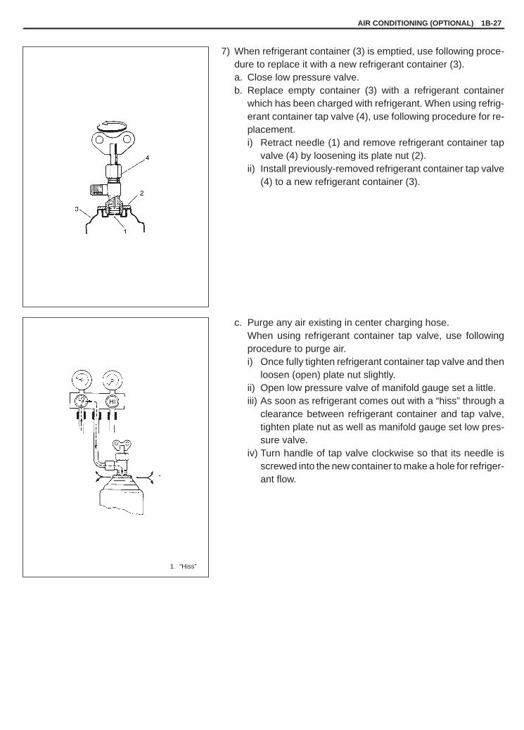
YH4GRANDVITARA
1. “Hiss”
AIR CONDITIONING (OPTIONAL) 1B-27
7) When refrigerant container (3) is emptied, use following proce-dure to replace it with a new refrigerant container (3).a. Close low pressure valve.b. Replace empty container (3) with a refrigerant container
which has been charged with refrigerant. When using refrig-erant container tap valve (4), use following procedure for re-placement.i) Retract needle (1) and remove refrigerant container tap
valve (4) by loosening its plate nut (2).ii) Install previously-removed refrigerant container tap valve
(4) to a new refrigerant container (3).
c. Purge any air existing in center charging hose.When using refrigerant container tap valve, use followingprocedure to purge air.i) Once fully tighten refrigerant container tap valve and then
loosen (open) plate nut slightly.ii) Open low pressure valve of manifold gauge set a little.iii) As soon as refrigerant comes out with a “hiss” through a
clearance between refrigerant container and tap valve,tighten plate nut as well as manifold gauge set low pres-sure valve.
iv) Turn handle of tap valve clockwise so that its needle isscrewed into the new container to make a hole for refriger-ant flow.

YH4GRANDVITARA
For CAMI production vehicle
For IWATA production vehicle
1B-28 AIR CONDITIONING (OPTIONAL)
8) After the system has been charged with specified amount of re-frigerant or when low pressure gauge (1) and high pressuregauge (2) have indicated about 2 and 15 kg/cm2 respectively,close low pressure side vale (3) of manifold gauge set (4). Ifequipped with sight glass in this time, look into the sight glass (6)of condenser outlet pipe (5) and check that there are no bubbles(7) in it, which means that the system is fully charged.
Low pressure gauge when charged with specified amount:About 200 – 300 kPa (2 – 3 kg/cm 2, 29 – 43 psi)(At A/C inlet temperature 30 – 35 �C, 86 – 95�F)
High pressure gauge when charged with specified amount:About 1370 – 1670 kPa (14 – 17 kg/cm 2, 200 – 244 psi)(At A/C inlet temperature 30 – 35 �C, 86 – 95�F)

YH4GRANDVITARA
1. Electric leak detector
AIR CONDITIONING (OPTIONAL) 1B-29
REMOVING MANIFOLD GAUGE SET
When A/C system has been charged with a specified amount of re-frigerant, remove manifold gauge set as follows:1) Close low pressure-side valve of manifold gauge set, (The high
pressure-side valve is closed continuously during the processof charging.).
2) Close refrigerant container valve.3) Stop engine.4) Using shop rag, remove charging hoses from service valves.
This operation must be performed rapidly.
WARNING:High pressure-side is naturally under high pressure.So, care must be used to protect your eyes and skin.
5) Put caps on service valves.
LEAK-TESTING REFRIGERANT SYSTEM
Whenever a refrigerant leak is suspected in the system or any ser-vice operation has been performed which may result in disturbinglines or connections, it is advisable to test for leaks.Common sense should be used in performing any refrigerant leaktest, since the need and extent of any such test will, in general, de-pend upon the nature of a complaint and the type of a service per-formed on the system.
LIQUID LEAK DETECTORS
There are a number of fittings and places throughout the air condi-tioning system where a liquid leak detector solution may be usedto pinpoint refrigerant leaks.By merely applying the solution to the area in question with a swab,bubbles will form within seconds if there is a leak.For confined areas, such as sections of the evaporator and con-denser, an electronic (gas) leak detector is more practical for deter-mining leaks.
WARNING:� To prevent explosions or fires, make sure that there are no
flammables in the vicinity.� When exposed to fire, the refrigerant turns into a poison-
ous gas (phosgene). Do not inhale this gas.

YH4GRANDVITARA
1. Suction hose2. Discharge hose3. Liquid pipe4. Condenser outlet pipe5. Expansion valve6. Dual pressure switch7. Suction pipe
: Apply compressor oil(refrigerant oil) to O-ring.
1B-30 AIR CONDITIONING (OPTIONAL)
ON-VEHICLE SERVICE
WARNING:Should refrigerant HFC-134a (R-134a) strike your eye(s), consult a doctor immediately.� DO NOT USE YOUR HAND TO RUB AFFECTED EYE(S).
Instead, use quantities of fresh cold water to splash it over affected area to thus gradually raise itstemperature above the freezing point.
� Obtain proper treatment as soon as possible from a doctor or eye specialist.Should liquid refrigerant HFC-134a (R-134a) get on your skin, such affected part should be treatedin the same manner as when skin is frostbitten or frozen.
CAUTION:None of refrigerant, compressor oil and component parts is interchangeable between two types of A/C:one using CFC-12 (R-12) and the other using HFC-134a (R-134a).(For identification between these two types, refer to page 1B-2).When replenishing or changing refrigerant and compressor oil and when replacing parts, make surethat the material or the part to be used is appropriate to the A/C installed in the vehicle being serviced.Use of incorrect one will result in leakage of refrigerant, damage in parts or other faulty condition.
PRECAUTION
When servicing air conditioning system, the following rules must be observed.
PIPING� When connecting hoses and pipes, apply a few drops of compressor oil (refrigerant oil) to seats of coupling nuts
and O-ring.
� Never use heat for bending pipes. When bending a pipe, try to make its bending radius as slight as possible.� Keep internal parts of air conditioning free from moisture and dirt. When disconnecting any line from system,
install a blind plug or cap to the fitting immediately.� When tightening or loosening a fitting, use two wrenches, one for turning and the other for support.
YH4GRANDVITARA
AIR CONDITIONING (OPTIONAL) 1B-31
� Tighten flared nuts to specified torque.
Tightening Torque (Flared Nut Used for)8 mm pipe: 13 N .m (1.3 kg-m, 9.5 lb-ft)14.5 mm pipe: 23 N .m (2.3 kg-m, 16.6 lb-ft)16 mm pipe: 33 N .m (3.3 kg-m, 23.8 lb-ft)
� Route drain hose so that drained water does not make any contact to vehicle components.
HANDLING REFRIGERANT HFC-134a (R-134a)� When handling refrigerant, always wear goggles to protect your eyes.� Avoid you direct contact to liquid refrigerant.� Do not heat refrigerant container higher than 40�C (104�F).� Do not discharge refrigerant into atmosphere.� Do not allow liquid refrigerant to touch bright metals. Refrigerant combined with moisture is corrosive and will
tarnish surfaces of bright metals including chrome.� After recovering refrigerant from system, the amount of compressor oil removed must be measured and the same
amount added to the system.
REFRIGERANT RECOVERYWhen discharging refrigerant out of A/C system, always recover it by using refrigerant recovery and recyclingequipment. Discharging refrigerant HFC-134a (R-134a) into atmosphere would cause adverse effect to environ-ments.
NOTE:When handling recovery and recycling equipment, be sure to follow the instruction manual for the equip-ment.
REFRIGERANT CHARGECharge a proper amount of refrigerant to A/C system according to charging procedure described in recovery, evac-uation and charging.
CAUTION:Do not perform an additional refrigerant charging to A/C system. This cause it to overcharge.

YH4GRANDVITARA
1. New compressor2. Removed compressor3. Excess oil (A – B)
1B-32 AIR CONDITIONING (OPTIONAL)
REPLENISHING COMPRESSOR OILWhen replacing air conditioning parts with new ones, it is necessaryto replenish oil by the amount supposedly remaining in each part.
When changing gas onlyWhen it is unavoidable to change gas without replacing any compo-nent part for engine removal and installation or for some other rea-son, replenish 20 cc oil. When replenishing gas only, oil replenish-ment it not necessary.
When replacing compressorCompressor oil is sealed in each new compressor by the amountrequired for air conditioner cycle. Therefore, when using a newcompressor for replacement, drain oil from it by the amount calcu-lated as follows.
“C” = “A” – “B”
“C”: Amount of oil to be drained“A”: Amount of oil sealed in a new compressor“B”: Amount of oil remaining in removed compressor
When replacing other part
Replaced partAmount of compressor oil
to be replenished
Evaporator 25 cc
Condenser 15 cc
Receiver /dryer 20 cc
Hoses 10 cc each
Pipes 10 cc each

YH4GRANDVITARA
2. Bolt
For CAMI production vehicle
For IWATA production vehicle
AIR CONDITIONING (OPTIONAL) 1B-33
A/C CONDENSER ASSEMBLYINSPECTIONChecka) condenser fins for blockageb) condenser fittings for leakagec) condenser fins for damageClogged condenser fins should be washed with water, and shouldbe dried with compressed air.
CAUTION:Be careful not to damage condenser fins. If condenser fin isbent, straighten it by using a screwdriver or pair of pliers. Ifany leakage is found from fitting or tube, repair or replacecondenser.
REMOVAL1) Disconnect negative (–) cable at battery.2) Recover refrigerant by using recovery and recycling equipment.
Be sure to follow the instruction manual for the equipment.The amount of compressor oil removed must be measured andthe same amount added to the system.
3) Remove front bumper assembly and remove lower stay (1) ifequipped (Refer to Section 9 “BODY SERVICE”).
4) Disconnect compressor discharge hose (1) from condenser in-let fittings.
CAUTION:As soon as above hose and pipe are disconnected, capopened fittings so that moisture and dust do not entercondenser.

YH4GRANDVITARA
3
1B-34 AIR CONDITIONING (OPTIONAL)
5) Disconnect coupler from dual pressure switch (1).6) Disconnect condenser outlet pipe (3).7) Disconnect condenser cooling fan motor coupler (2).
8) Remove condenser with fan.
NOTE:Be careful not to damage fins of condenser and radiator.
9) Remove A/C condenser cooling fan assembly from condenser.
INSTALLATIONReverse removal sequence to install condenser, noting followingpoint.1) When replacing condenser, add 20 to 30 cc of refrigerating oil
from compressor suction-side.2) Evacuate and charge system according to previously-described
procedure.

YH4GRANDVITARA
�
�
1. Air flow
AIR CONDITIONING (OPTIONAL) 1B-35
CONDENSER COOLING FAN ASSEMBLYINSPECTION� Remove condenser assembly (Refer to “A/C CONDENSER AS-
SEMBLY REMOVAL” in this section).� Check continuity between terminal to terminal as shown.
If check results are continuity, proceed to next operation check.If not, replace.
� Connect battery to condenser fan motor as shown, then checkthat the condenser fan motor operates smoothly and specifiedcurrent.
Specified current: Maximum 12 A at 12 V

YH4GRANDVITARA
1
2
2. Condenser dryer section
1B-36 AIR CONDITIONING (OPTIONAL)
CONDENSER DRYER (RECEIVER/DRYER)REMOVAL1) Remove A/C condenser assembly (1) from vehicle (Refer to
“A/C CONDENSER ASSEMBLY REMOVAL” in this section.).2) Remove the condenser dryer cap from condenser.
3) Remove the filter (1) from the condenser (2).
4) Remove the dryer (1) using a plier (2).
INSTALLATIONReverse removal sequence to install condenser dryer, according toinstruction manual with supply parts.
NOTE:� When replacing condenser dryer, add 40 cc of refrigerating
oil the same as compressor oil.� Do not remove the dryer from the plastic bag until just before
inserting it into the receiver.� Install the condenser dryer (1) with its double-layer portion
facing the bottom of the receiver.� If condenser dryer cap installing is bolt type, tighten speci-
fied torque for its bolt.
Tightening Torque:Cap: 12.5 N.m (1.25 kg-m, 9 lb-ft)

YH4GRANDVITARA
1
For CAMI production vehicle
For IWATA production vehicle
1
AIR CONDITIONING (OPTIONAL) 1B-37
AIR FILTER ELEMENTREMOVAL1) Disconnect negative (–) cable at battery.2) For vehicle with air bag system, disable air bag system. Refer
to “DISABLING AIR BAG SYSTEM” in Section 10B.
3) Pull down glove box (1) by pushing the shown part (a).
4) Remove filter cover (1).
5) Pull out filter element (1). Pull out upper filter first then the lowerone.

YH4GRANDVITARA
1
1. Ears
1. Air flow
1B-38 AIR CONDITIONING (OPTIONAL)
CLEANBlow off dust by compressed air from air outlet side of the filter ele-ment.
INSTALLATIONReverse removal procedure for installation noting the followings:� Install filter into cooling unit directing arrow mark on its end face
to heater unit.� Enable air bag system after installation. Refer to “ENABLING AIR
BAG SYSTEM” in Section 10B.

YH4GRANDVITARA
AIR CONDITIONING (OPTIONAL) 1B-39
COOLING UNIT (EVAPORATOR)REMOVAL1) Disconnect negative (–) cable at battery.2) Disable air bag system. Refer to “Disabling Air Bag System” in
Section 10B.3) Recover refrigerant by using recovery and recycling equipment.
Be sure to follow the instruction manual for the equipment.The amount of compressor oil removed must be measured andthe same amount added to the system.
4) For G16 and J20 engineDisconnect suction pipe (1), and liquid pipe (2) from evaporator(cooling unit).
CAUTION:As soon as above hose and pipe are disconnected, capopened fittings so that moisture and dust may not entercooling unit.
5) Remove blower motor unit. Refer to Section 1A “HEATER ANDVENTILATION”.
6) Disconnect thermistor wire coupler.7) Remove cooling unit (evaporator).
DISASSEMBLY (FOR CAMI PRODUCTION VEHICLE)1) Remove filter (2) from cooling unit (3) assembly by removing fil-
ter cover (1).
2) Remove screws (1) to separate evaporator upper and lowercases from each other.

YH4GRANDVITARA
1
1B-40 AIR CONDITIONING (OPTIONAL)
3) Remove upper case (1) and remove evaporator (2) from lowercase (3).
4) Remove following components from evaporator.� Expansion valve (5)� Thermistor (evaporator temperature sensor) (4)
DISASSEMBLY (FOR IWATA PRODUCTION VEHICLE)1) Remove filter (2) from cooling unit (3) assembly by removing fil-
ter cover (1).
2) Detach clamps (1) to separate evaporator upper and lowercases from each other.
3) Remove upper case (1) and remove evaporator (2) from lowercase (3).
4) Remove following components from evaporator.� Expansion valve (5)� Thermistor (evaporator temperature sensor) (4)

YH4GRANDVITARA
AIR CONDITIONING (OPTIONAL) 1B-41
INSPECTION1) Check evaporator fins for blockage. If found clogged, use com-
pressed air to clean the fins.
CAUTION:Do not use water for cleaning of evaporator.Be careful not to damage evaporator fins. If evaporatorfin is bent, straighten it by using a screwdriver or pair ofpliers. If any leakage is found from fitting or tube, repairor replace evaporator.
2) Check inlet and outlet fittings for crack or scratch. Repair themas required.
REASSEMBLY and INSTALLATION1) Reverse removal and disassembly sequence to install cooling
unit, noting the following points.� Install uniformly the evaporator packing to dash panel hole for
expansion valve.� Adjust fresh air control cable, refer to “HEATER CONTROL
LEVER ASSEMBLY” in Section 1A.2) Enable air bag system. Refer to “Enabling Air Bag System” in
Section 10B.3) Evacuate and charge system. Refer to “EVACUATING” and
“CHARGING” in this section.
NOTE:When the thermistor removed, it should be reinstalled inoriginal position.If cooling unit or evaporator is replaced, pour 25 cc of refrig-erating oil to compressor suction-side.
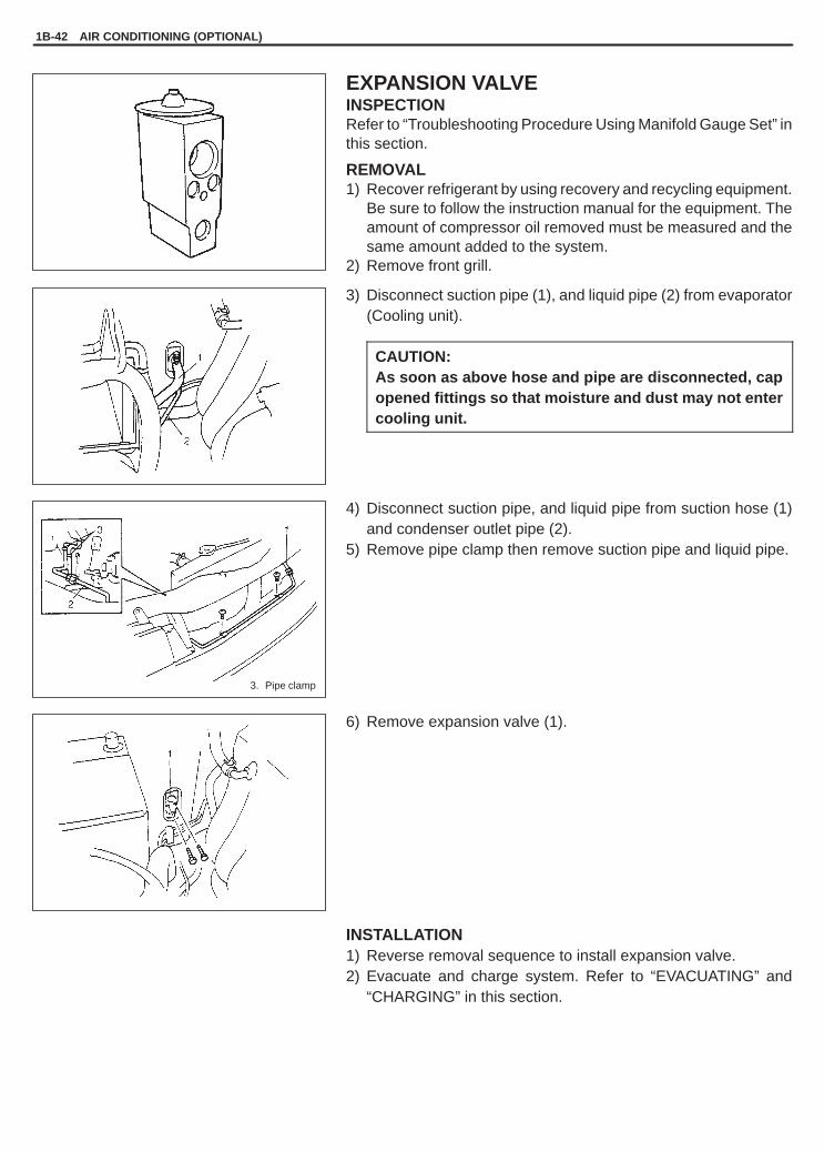
YH4GRANDVITARA
3. Pipe clamp
1B-42 AIR CONDITIONING (OPTIONAL)
EXPANSION VALVEINSPECTIONRefer to “Troubleshooting Procedure Using Manifold Gauge Set” inthis section.
REMOVAL1) Recover refrigerant by using recovery and recycling equipment.
Be sure to follow the instruction manual for the equipment. Theamount of compressor oil removed must be measured and thesame amount added to the system.
2) Remove front grill.
3) Disconnect suction pipe (1), and liquid pipe (2) from evaporator(Cooling unit).
CAUTION:As soon as above hose and pipe are disconnected, capopened fittings so that moisture and dust may not entercooling unit.
4) Disconnect suction pipe, and liquid pipe from suction hose (1)and condenser outlet pipe (2).
5) Remove pipe clamp then remove suction pipe and liquid pipe.
6) Remove expansion valve (1).
INSTALLATION1) Reverse removal sequence to install expansion valve.2) Evacuate and charge system. Refer to “EVACUATING” and
“CHARGING” in this section.
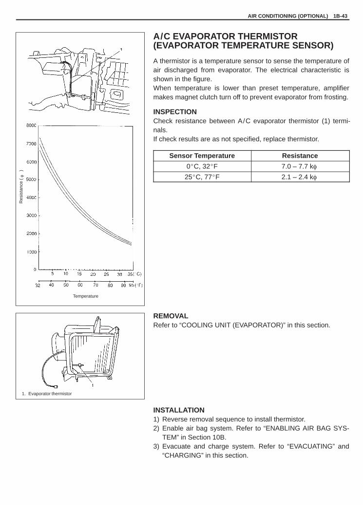
YH4GRANDVITARA
1. Evaporator thermistor
Temperature
Res
ista
nce
()
�AIR CONDITIONING (OPTIONAL) 1B-43
A/C EVAPORATOR THERMISTOR(EVAPORATOR TEMPERATURE SENSOR)
A thermistor is a temperature sensor to sense the temperature ofair discharged from evaporator. The electrical characteristic isshown in the figure.When temperature is lower than preset temperature, amplifiermakes magnet clutch turn off to prevent evaporator from frosting.
INSPECTIONCheck resistance between A/C evaporator thermistor (1) termi-nals.If check results are as not specified, replace thermistor.
Sensor Temperature Resistance
0�C, 32�F 7.0 – 7.7 k�
25�C, 77�F 2.1 – 2.4 k�
REMOVALRefer to “COOLING UNIT (EVAPORATOR)” in this section.
INSTALLATION1) Reverse removal sequence to install thermistor.2) Enable air bag system. Refer to “ENABLING AIR BAG SYS-
TEM” in Section 10B.3) Evacuate and charge system. Refer to “EVACUATING” and
“CHARGING” in this section.

YH4GRANDVITARA
1B-44 AIR CONDITIONING (OPTIONAL)
REFRIGERANT PIPES AND HOSESINSPECTION1) Use a leak tester to check hoses and pipes for any gas leakage.2) Check each hose or pipe clamp for tightness.
Retighten or replace loose clamp as required, if any.
REMOVAL1) Recover refrigerant by using recovery and recycling equipment.
Be sure to follow the instruction manual for the equipment.The amount of compressor oil removed must be measured andthe same amount must be added to the system when reinstal-ling.
2) Replace defective hose or pipe.
CAUTION:As soon as the above hose or pipe is disconnected, capits opened fitting to prevent moisture and dust from en-tering.
INSTALLATION1) Reverse removal procedure to install refrigerant line.2) Evacuate and charge system. Refer to “EVACUATING” and
“CHARGING” in this section.
INSPECTION OF IDLE SPEED WITH A/C ONFor G16 and J20 engines model, refer to Section 6E1.For H25 engine model, refer to Section 6E2.

YH4GRANDVITARA
1
1. Mode control switch coupler2. A / C switch3. Indicator lamp
AIR CONDITIONING (OPTIONAL) 1B-45
A/C SWITCHREMOVAL1) Disconnect negative (–) cable at battery.2) If equipped with air bag system, disable air bag system.
Refer to “DISABLING AIR BAG SYSTEM” in Section 10B.3) Remove mode control switch (Refer to “MODE CONTROL
SWITCH” in Section 1A).
INSPECTION
A/C Switch� Press A/C button and check if there is continuity between termi-
nals “D” and “G”.� With battery voltage (+) connected to terminal “K” and (–) to termi-
nal “D”, press A/C button and check if indicator lamp lights.
INSTALLATION1) Install in reverse order of removal procedure.2) If equipped with air bag system, enable air bag system.
Refer to “ENABLING AIR BAG SYSTEM” in Section 10B.

YH4GRANDVITARA
1B-46 AIR CONDITIONING (OPTIONAL)
A/C CONTROLLERREMOVAL1) Disconnect negative (–) cable at battery.2) Disable air bag system, if equipped.
Refer to “DISABLING AIR BAG SYSTEM” in Section 10B.3) Open glove box, then remove screw.4) Remove glove box.5) Disconnect A/C controller coupler (2), evaporator thermistor
coupler (3).6) Remove A/C controller (1) from heater unit (4).
INSPECTIONRefer to “INSPECTION OF A/C CONTROLLER AND ITS CIR-CUIT” in this section.
INSTALLATION1) Install in reverse order of removal procedure.2) If equipped with air bag system, enable air bag system. Refer to
“ENABLING AIR BAG SYSTEM” in Section 10B.

YH4GRANDVITARA
Pressure
A B
C D
SWITCHON
(Continuity)
OFF(No continuity)
AIR CONDITIONING (OPTIONAL) 1B-47
DUAL PRESSURE SWITCHINSPECTION1) Check dual pressure switch (1) on liquid pipe for continuity at
normal temperature (approx. 25�C (77�F)) when A/C systemhas a proper charge of refrigerant and when A/C system (com-pressor) is under operation. In each of these cases, switchshould show proper continuity.
2) Using a manifold gauge set, check switch for operation at speci-fied pressure as shown, refer to “PERFORMANCE DIAGNO-SIS” in this section.
Switch ON : above “C” and below “D”Switch OFF : below “A” or above “B”
“A”: Approx. 200 kPa (2.0 kg/cm 2)“B”: Approx. 3200 kPa (32 kg/cm 2)“C”: Approx. 230 kPa (2.3 kg/cm 2)“D”: Approx. 2800 kPa (28 kg/cm 2)
Tightening torque:Dual pressure switch: 10 N .m (1.0 kg-m, 7.5 lb-ft)

YH4GRANDVITARA
3. Compressor and condenser cooling fan fuse
1B-48 AIR CONDITIONING (OPTIONAL)
A/C COMPRESSOR RELAY AND A/CCONDENSER COOLING FAN RELAYINSPECTION1) Disconnect negative (–) cable at battery.2) Remove condenser cooling fan motor relay (2) and/or compres-
sor relay (1) from vehicle.3) Check that there is no continuity between terminal “c” and “d”.
If there is continuity, replace relay.4) Connect battery positive (+) terminal to terminal “b” of relay.
Connect battery negative (–) terminal “a” of relay.Check continuity between terminal “c” and “d”.If there is no continuity when relay is connected to the battery,replace relay.

YH4GRANDVITARA
For CAMI production vehicle
For IWATA production vehicle
2. High pressure side (Delivery side hose)3. Lower pressure side (Suction side pipe)
AIR CONDITIONING (OPTIONAL) 1B-49
COMPRESSOR ASSEMBLY
CAUTION:None of refrigerant, compressor oil and component parts is interchangeable between two types of A/C:one using CFC-12 (R-12) and the other using HFC-134a (R-134a).For identification between these two types, refer to page 1B-2.When replenishing or changing refrigerant and compressor oil and when replacing parts, make surethat the material or the part to be used is appropriate to the A/C installed in the vehicle being serviced.Use of incorrect refrigerant or compressor oil will result in leakage of refrigerant, damage in parts orother faulty condition.
PRECAUTIONWhen servicing the compressor, keep dirt or foreign material away from getting on or into the compressor partsand system. Clean tools and a clean work area are important for proper service.The compressor connection and the outside of the compressor should be cleaned before any “On-vehicle” repairor before removal of the compressor. The parts must be kept clean at all times and any parts to be reassembledshould be cleaned with Trichloroethane, naphtha, kerosene or equivalent solvent and dried with dry air. Use onlylint free cloths to wipe parts.The operations described are based on bench overhaul with compressor removed from the vehicle, except asnoted. They have been prepared in order of accessibility of the components.When compressor is removed from the vehicle for servicing, the oil remaining in the compressor should be dis-carded and new refrigerant oil added to the compressor.Minor repair procedures may be done on the vehicle without discharging the system. Major repair procedures re-quire that the system be discharged of refrigerant.
INSPECTION1) Install manifold gauge set (1) as shown in the figure.2) Close Hi (4) and Lo (5) hand valves.3) Run engine at fast idle.4) Check compressor assembly for following items.
If any of the above checks indicated a defect, repair compressorassembly.� High pressure gauge reading is not low and low pressure
gauge reading is not higher than normal.� Metallic sound.� Leakage from shaft seal.

YH4GRANDVITARA
1B-50 AIR CONDITIONING (OPTIONAL)
REMOVAL1) Run engine at idle with A/C ON for 10 minutes.2) Disconnect negative (–) cable at battery.3) Recover refrigerant from refrigeration system using recovery
and recycling equipment.
NOTE:The amount of compressor oil at removed must be mea-sured and the same amount must be poured when installingthe compressor.
4) Disconnect thermal protector lead wire.5) Disconnect suction and discharge hoses from compressor as-
sembly.
NOTE:Cap open fitting immediately to keep moisture out of sys-tem.
6) For G16 engine:Remove compressor drive belt by loosening compressor as-sembly mounting bolts.
For J20 engine:Remove generator belt. Refer to Section 6H.
For H25 engine:Remove compressor drive belt by loosening tension pulley bolt.
7) Remove compressor with magnet clutch assembly from itsmount.
8) If compressor assembly is replaced. Drain oil from compressorassembly, and measure its amount.

YH4GRANDVITARA
AIR CONDITIONING (OPTIONAL) 1B-51
G16 engine
J20 engine
H25 engine
3. Compressor pulley4. Crankshaft pulley
INSTALLATION
FOR IWATA PRODUCTION VEHICLE1) Pour new compressor oil. The amount must be the same with
the amount measured in REMOVAL.
NOTE:Compressor assembly supplied from factory is filled upwith following amount of oil.
Amount of oil in compressor: 120 cm 3 (120 cc, 7.5 in 3)
2) For G16 engine:Install compressor assembly temporarily to bracket, then installcompressor drive belt (2).
For J20 and H25 engines:Install compressor assembly to its bracket.Tighten bolts (a) first, then (b).
Tightening Torque(a), (b): 23 N.m (2.3 kg-m, 17.0 lb-ft)
3) Connect suction and discharge hoses to compressor assembly.
4) For G16 engine:Tension compressor drive belt (2) by tightening compressor as-sembly mounting bolts. Refer to Section 3B1 for drive belt ten-sion.Tighten bolt (a) first, then (b).
Tightening Torque(a), (b): 23 N.m (2.3 kg-m, 17.0 lb-ft)
For J20 engine:Install generator belt (1). Refer to Section 6H for details.
For H25 engine:Install compressor drive belt (2). Refer to Section 3B1 for instal-lation and belt tension.
5) Connect thermal protector lead wire.6) Evacuate and charge system according to previously described
procedure.
CAUTION:Be sure to use HFC-134a (R-134a) compressor oil.

YH4GRANDVITARA
1B-52 AIR CONDITIONING (OPTIONAL)
G16 engine
J20 engine
3. Compressor pulley4. Crankshaft pulley
FOR CAMI PRODUCTION VEHICLE1) Pour new compressor oil. The amount must be the same with
the amount measured in REMOVAL.
NOTE:Compressor assembly supplied from factory is filled upwith the following amount of oil.
Amount of oil in compressor: 120 cm 3 (120 cc, 7.5 in 3)
2) For G16 engine:Install compressor assembly temporarily to bracket, then installcompressor drive belt (2).
For J20 engine:Install compressor assembly to its bracket.Tighten bolts (a).
Tightening Torque(a): 23 N.m (2.3 kg-m, 17.0 lb-ft)
3) Connect suction and discharge hoses to compressor assembly.
4) For G16 engine:Tension compressor drive belt (2) by tightening compressor as-sembly mounting bolts. Refer to Section 3B1 for drive belt ten-sion.Tighten bolt (a) first, then (b).
Tightening Torque(a): 23 N.m (2.3 kg-m, 17.0 lb-ft)
For J20 engine:Install generator belt (1). Refer to Section 6H for details.
5) Connect thermal protector lead wire.6) Evacuate and charge system according to previously described
procedure.
CAUTION:Be sure to use HFC-134a (R-134a) compressor oil.

YH4GRANDVITARA
AIR CONDITIONING (OPTIONAL) 1B-53
1. Clutch plate bolt2. Clutch plate3. Circlip4. Clutch pulley5. Shim6. Clutch coil7. Compressor
5
6
7
MAGNET CLUTCH ASSEMBLY (FOR DENSO)
INSPECTION� Inspect clutch plate and clutch pulley for signs of oil.� Check clutch pulley for noise and grease leakage.� Using an ohmmeter, measure resistance of clutch coil between
clutch lead wire (1) and compressor body (2).If measured resistance is not within tolerance, replace magnetclutch assembly.
Standard resistance: 3.5 – 5.0 � at 20�C, 68�F
REMOVAL1) Remove compressor assembly from vehicle. Refer to “COM-
PRESSOR ASSEMBLY” in this section.2) Fix clutch plate (1) with special tool (A) and remove clutch plate
bolt.
Special Tool(A): 09991-06020
NOTE:Do not reuse clutch plate bolt.
3) Using special tool (B), remove clutch plate (1).
Special Tool(B): 09991-06030

YH4GRANDVITARA
1B-54 AIR CONDITIONING (OPTIONAL)
2
4) Remove shims from shaft.5) Using special tool (C), remove circlip.
Special Tool(C): 09900-06107
6) Remove clutch coil lead wire clamp screw, and remove clutchcoil read wire ground terminal.
7) Remove clutch pulley with puller (1) from compressor (2).
NOTE:Be careful not to damage pulley when tapping magnetclutch assembly.
8) Remove clutch coil.
Special tool(C): 09900-06107
INSTALLATION1) Install clutch coil (2).
Protrusion on under side of coil ring must match hole in com-pressor (3) to prevent movement ant correctly locate lead wire.
2) Using special tool (C), install snap ring (1) as shown.
Special Tool(C): 09990-06107
3) Install clamp portion and ground terminal of lead wire.

YH4GRANDVITARA
AIR CONDITIONING (OPTIONAL) 1B-55
1. Armature plate
4) Clutch pulley (1).(1)Set clutch pulley squarely over clutch pulley installation boss.(2)Place special tool (D) onto clutch pulley bearing.
Ensure that edge rests only on inner race of bearing.(3) Install snap ring.
Special Tool(D): 09991-06010
CAUTION:Be careful not to scratch bearing seal.
5) Adjust clearance, between clutch plate (1) and clutch pulley byputting shim on compressor shaft.
Standard clearance “a”: 0.3 – 0.5 mm (0.012 – 0.02 in.)
6) Tighten new clutch plate bolt as specified below.
Tightening Torque(a): 14 N.m (1.4 kg-m, 10.5 lb-ft)
Special Tool(A): 09991-06020

YH4GRANDVITARA
1B-56 AIR CONDITIONING (OPTIONAL)
1. Clutch plate bolt2. Clutch plate3. Circlip4. Clutch pulley5. Washer6. Shim7. Oil felt ring8. Clutch coil9. Lip type seal
10. Compressor front head11. Compressor body component12. O-ring13. Compressor thermal switch
3. Washer(if equipped)
1. Thermal switch2. Ohmmeter
MAGNET CLUTCH ASSEMBLY (FOR SEIKO SEIKI)
INSPECTION
MAGNET CLUTCH� Inspect clutch plate and clutch pulley for signs of oil.� Check clutch pulley bearings for noise and grease leakage.� Using and ohmmeter, measure resistance of clutch coil between
clutch coil lead wire (1) and compressor body.If measured resistance is not within tolerance, replace coil.
Standard resistance: 2.5 – 4.5 � at 20�C, 68�F
COMPRESSOR THERMAL SWITCHUse an ohmmeter to check thermal switch for continuity. If there isno continuity, replace it.
REMOVAL1) Remove compressor assembly from vehicle. Refer to COM-
PRESSOR ASSEMBLY in this section.2) Fix clutch plate (1) with special tool (A) and remove clutch plate
bolt (2).
Special Tool(A): 09991-06020
NOTE:Do not reuse armature plate nut.

YH4GRANDVITARA
AIR CONDITIONING (OPTIONAL) 1B-57
3) Using special tool (B), remove clutch plate (1).
Special Tool(B): 09991-06030
4) Disconnect clutch coil lead wire from compressor thermal switchled wire.
5) Remove felt ring (if equipped) and shims from shaft.6) Using special tool (C), remove circlip.
Special Tool(C): 09900-06107
7) Remove clutch coil lead wire clamp screw.
8) Remove clutch pulley with puller (1) from compressor (2).
NOTE:Be careful not to damage pulley when tapping magnetclutch.
9) Remove clutch coil.
INSTALLATION1) Install clutch coil (2).
Protrusion on under side of clutch coil must match hole in com-pressor (3) to prevent movement ant correctly locate lead wire.
2) Using special tool (C), install snap ring (1) as shown.
Special Tool(C): 09990-06107
3) Clamp covering portion of lead wire.

YH4GRANDVITARA
3. Washer(if equipped)
1B-58 AIR CONDITIONING (OPTIONAL)
4) Install clutch pulley (1).(1)Set clutch pulley squarely over clutch pulley installation boss.(2)Place special tool (D) onto clutch pulley bearing.
Ensure that edge rests only on inner race of bearing.(3) Install snap ring.
Special Tool(D): 09991-06010
CAUTION:Be careful not to scratch bearing seal.
5) Adjust clearance, between clutch plate and clutch pulley (2) byputting shim on compressor shaft.
Standard clearance “a”: 0.3 – 0.6 mm (0.012 – 0.024 in.)
6) Tighten new clutch plate (1) bolt (2) as specified below.
Tightening Torque(a): 14 N.m (1.4 kg-m, 10.5 lb-ft)
Special Tool(A): 09991-06020

YH4GRANDVITARA
AIR CONDITIONING (OPTIONAL) 1B-59
PUSH
3. Cylinder4. Case5. O-ring
2. Bearing puller
LIP TYPE SEAL (FOR SEIKO SEIKI)REMOVAL1) Remove magnet clutch assembly, referring to “MAGNET
CLUTCH ASSEMBLY” in this section.2) Remove compressor front head (1) mounting bolt (10 pcs.).
3) Remove compressor front head (1) by pushing cylinder shaft(2).
NOTE:Be careful not to remove cylinder from case.
4) Remove O-ring.
5) Remove lip seal from compressor front head (1).
INSTALLATION1) Press-fit lip seal (1) into compressor front head (2) using special
tool (E).
Special Tool(E): 09991-06050
CAUTION:Do not reuse mechanical seal once removed from com-pressor.

YH4GRANDVITARA
1B-60 AIR CONDITIONING (OPTIONAL)
1. Front head
2) Coat special tool (F) surface with oil and place it on the shaft.
Special Tool(F): 09991-06040
3) Install O-ring (2) to case.4) Apply compressor (refringent) oil to lip seal and O-ring.5) Install compressor front head (1).
6) Tighten compressor front head bolt.
Tightening Torque(a): 14 N.m (1.4 kg-m, 10.5 lb-ft)(b): 23 N.m (2.3 kg-m, 17.0 lb-ft)
NOTE:� Be sure to use new front head bolt washer.� Tighten bolt (a) first, and next (b).

YH4GRANDVITARA
AIR CONDITIONING (OPTIONAL) 1B-61
09900-06107Snap ring pliers(Opening type)
09991-06010Magnet clutch pulley installer
09991-06020Armature plate spanner
09991-06030Armature plate remover
09991-06040Lip type seal protector
09991-06050Lip type seal installer
REQUIRED SERVICE MATERIAL
MATERIALRECOMMENDED
SUZUKI PRODUCTUSE
Compressor oil for DENSOcompressor (Refrigerant oil)
COMPRESSOR OIL (ND-OIL 8, 250 cc)99000-27080
� O-ring� Each component
Compressor oil forSEIKO SEIKI compressor(Refrigerant oil)
COMPRESSOR OIL RS20 (150 cc)99000-99088-00D
� O-ring� Each component
RefrigerantREFRIGERANT DRUM (200 g)95794-50G00
� Refrigerant charge
SPECIAL TOOLS

YH4GRANDVITARA
3
STEERING, SUSPENSION, WHEELS AND TIRES 3-1
GENERAL DIAGNOSIS 3-1. . . . . . . . . . . . . . . . . Diagnosis Table 3-1. . . . . . . . . . . . . . . . . . . . . .
TIRE DIAGNOSIS 3-6. . . . . . . . . . . . . . . . . . . . . . Irregular and/or Premature Wear 3-6. . . . . . . Wear Indicator 3-6. . . . . . . . . . . . . . . . . . . . . . .
Radial Tire Waddle 3-6. . . . . . . . . . . . . . . . . . . Radial Tire Lead 3-8. . . . . . . . . . . . . . . . . . . . . .
VIBRATION DIAGNOSIS 3-8. . . . . . . . . . . . . . .
SECTION 3
STEERING, SUSPENSION, WHEELS AND TIRESDIAGNOSIS 3-1. . . . . . . . . . . . . . . . . . . . . . . . . . . . . . . . . . . . . . . . . . . . . . . . . . . . . . . . . . . . . . . . .
FRONT END ALIGNMENT 3A-1. . . . . . . . . . . . . . . . . . . . . . . . . . . . . . . . . . . . . . . . . . . . . . . . . . . .
POWER STEERING SYSTEM 3B1-1. . . . . . . . . . . . . . . . . . . . . . . . . . . . . . . . . . . . . . . . . . . . . . . . .
AIR BAG STEERING WHEEL AND COLUMN 3C1-1. . . . . . . . . . . . . . . . . . . . . . . . . . . . . . . . . . .
FRONT SUSPENSION 3D-1. . . . . . . . . . . . . . . . . . . . . . . . . . . . . . . . . . . . . . . . . . . . . . . . . . . . . . . .
REAR SUSPENSION 3E-1. . . . . . . . . . . . . . . . . . . . . . . . . . . . . . . . . . . . . . . . . . . . . . . . . . . . . . . . .
WHEELS AND TIRES 3F-1. . . . . . . . . . . . . . . . . . . . . . . . . . . . . . . . . . . . . . . . . . . . . . . . . . . . . . . .
CONTENTS
GENERAL DIAGNOSIS
Since the problems in steering, suspension, wheels and tires involve several systems, they must all be consideredwhen diagnosing a complaint. To avoid using the wrong symptom, always road test the vehicle first.Proceed with the following preliminary inspections and correct any defects which are found.1) Inspect tires for proper pressure and uneven wear.2) Raise vehicle on a hoist and inspect front and rear suspension and steering system for loose or damaged parts.3) Spin front wheel. Inspect for out-of-round tires, out-of-balance tires, bent rims, loose and/or rough wheel bear-
ings.
DIAGNOSIS TABLE
Condition Possible Cause Correction
Vehicle Pulls (Leads) � Mismatched or uneven tires.� Tires not adequately inflated.� Broken or sagging springs.� Radial tire lateral force.� Disturbed front end alignment.� Disturbed rear axle alignment.� Brake dragging in one road wheel.� Loose, bent or broken front or rear
suspension parts.
Replace tire.Adjust tire pressure.Replace spring.Replace tire.Check front end alignment.Check rear axle alignment.Repair front brake.Tighten or replace suspension part.
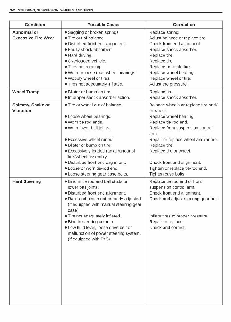
YH4GRANDVITARA
3-2 STEERING, SUSPENSION, WHEELS AND TIRES
Condition Possible Cause Correction
Abnormal orExcessive Tire Wear
� Sagging or broken springs.� Tire out of balance.� Disturbed front end alignment.� Faulty shock absorber.� Hard driving.� Overloaded vehicle.� Tires not rotating.� Worn or loose road wheel bearings.� Wobbly wheel or tires.� Tires not adequately inflated.
Replace spring.Adjust balance or replace tire.Check front end alignment.Replace shock absorber.Replace tire.Replace tire.Replace or rotate tire.Replace wheel bearing.Replace wheel or tire.Adjust the pressure.
Wheel Tramp � Blister or bump on tire.� Improper shock absorber action.
Replace tire.Replace shock absorber.
Shimmy, Shake orVibration
� Tire or wheel out of balance.
� Loose wheel bearings.� Worn tie rod ends.� Worn lower ball joints.
� Excessive wheel runout.� Blister or bump on tire.� Excessively loaded radial runout of
tire/wheel assembly.� Disturbed front end alignment.� Loose or worn tie-rod end.� Loose steering gear case bolts.
Balance wheels or replace tire and/or wheel.Replace wheel bearing.Replace tie rod end.Replace front suspension controlarm.Repair or replace wheel and/or tire.Replace tire.Replace tire or wheel.
Check front end alignment.Tighten or replace tie-rod end.Tighten case bolts.
Hard Steering � Bind in tie rod end ball studs or lower ball joints.� Disturbed front end alignment.� Rack and pinion not properly adjusted.
(if equipped with manual steering gearcase)
� Tire not adequately inflated.� Bind in steering column.� Low fluid level, loose drive belt or
malfunction of power steering system. (if equipped with P/S)
Replace tie rod end or front suspension control arm.Check front end alignment.Check and adjust steering gear box.
Inflate tires to proper pressure.Repair or replace.Check and correct.

YH4GRANDVITARA
STEERING, SUSPENSION, WHEELS AND TIRES 3-3
Condition Possible Cause Correction
Too Much Play inSteering
� Wheel bearings worn.� Loose steering gear case bolts.� Rack and pinion not properly adjusted.
(if equipped with manual steering gearcase)
� Worn steering shaft joints.� Worn tie rod ends or tie rod
inside ball joints.� Worn lower ball joints.
Replace wheel bearing.Tighten.Check and adjust rack and piniontorque.
Replace joint.Replace tie rod end or steeringgear case.Replace front suspension controlarm.
Poor Returnability � Bind in tie rod end ball studs.� Bind in ball joints.� Bind in steering column.� Poorly lubricated rack and pinion.
(if equipped with manual steering gearcase)
� Disturbed front end alignment.
� Rack and pinion not properly adjusted.(if equipped with manual steering gearcase)
� Tires not adequately inflated.
Replace tie rod end.Replace ball joint.Repair or replace.Check, repair or lubricate rack andpinion.
Check and adjust front end alignment.Check and adjust rack and piniontorque.Adjust pressure.
Steering Noise(Rattle or Chuckle)
� Loose bolts and nuts.� Broken or otherwise damaged wheel
bearings.� Worn or sticky tie rod ends.� Rack and pinion not properly adjusted.
(if equipped with manual steering gearcase)
Retighten.Replace.
Replace.Check and adjust rack and piniontorque.
Abnormal Noise,Front End
� Worn, sticky or loose tie rodends, lower ball joints, tie rodinside ball joints or drive shaftjoints.
� Damaged shock absorbers, strutsor mountings.
� Worn control arm bushings.� Loose stabilizer bar.� Loose wheel nuts.� Loose suspension bolts or nuts.� Broken or otherwise damaged
wheel bearings.� Broken suspension springs.� Poorly lubricated or worn strut
bearings.
Replace tie rod end, control arm,steering gear case or drive shaft joint.
Replace or repair.
Replace.Tighten bolts or replace bushes.Tighten wheel nuts.Tighten suspension bolts or nuts.Replace wheel bearing.
Replace spring.Lubricate or replace strut bearing.

YH4GRANDVITARA
3-4 STEERING, SUSPENSION, WHEELS AND TIRES
Condition Possible Cause Correction
Wander or PoorSteering Stability
� Mismatched or uneven tires.
� Loose ball joints and tie rodends.
� Faulty shock absorbers/struts ormounting.
� Loose stabilizer bar.
� Broken or sagging springs.� Rack and pinion not properly adjusted.
(if equipped with manual steeringgear case)
� Disturbed front end alignment.
Replace tire or inflate tires toproper pressure.Replace suspension control arm ortie rod end.Replace absorber/strut or repairmounting.Tighten or replace stabilizer bar orbushes.Replace spring.Check or adjust rack and piniontorque.
Check and adjust front end alignment.
Erratic Steering whenBraking
� Worn wheel bearings.� Broken or sagging springs.� Leaking wheel cylinder or caliper.
� Warped discs.� Badly worn brake linings.� Drum is out of round in some brakes.� Wheel tires are inflated unequally.� Defective wheel cylinders.� Disturbed front end alignment.
Replace wheel bearing.Replace spring.Repair or replace wheel cylinder orcaliper.Replace brake disc.Replace brake shoe lining.Replace brake drum.Inflate tires to proper pressure.Replace or repair wheel cylinder.Check front end alignment.
Low or Uneven TrimHeightRight-to-left trim height(H) difference should bewithin 15 mm (0.6 in.)with curb weight.
*Same with rear side.
� Broken or sagging springs.� Overloaded.� Incorrect springs.
Replace spring.Check loading.Replace spring.
Ride Too Soft � Faulty shock absorber or struts. Replace shock absorber or strut.
Suspension Bottoms � Overloaded.� Faulty shocks or struts.� Incorrect broken or sagging springs.
Check loading.Replace shock absorber or strut.Replace spring.

YH4GRANDVITARA
STEERING, SUSPENSION, WHEELS AND TIRES 3-5
Condition Possible Cause Correction
Body Leans or Swaysin Corners
� Loose stabilizer bar.
� Faulty shock absorbers, strutsor mounting.
� Broken or sagging springs.� Overloaded.
Tighten stabilizer bar bolts orreplace bushes.Replace shock absorber, strut ortighten mounting.Replace spring.Check loading.
Cupped Tires � Front struts defective.� Worn wheel bearings.� Excessive tire or wheel run-out.� Worn ball joints.
� Tire out of balance.
Replace strut.Replace wheel bearing.Replace tire or wheel disc.Replace front suspension controlarm.Adjust tire balance.

YH4GRANDVITARA
[A]
[B]
� Hard Cornering� Under-Inflation� Lack of Rotation
� Incorrect Wheel Alignment� Tire Construction Non-Uniformity� Wheel Heavy Acceleration
[A] [B]
3-6 STEERING, SUSPENSION, WHEELS AND TIRES
TIRE DIAGNOSIS
IRREGULAR AND/OR PREMATURE WEAR
Irregular and premature wear has many possible causes. Some ofthem are: incorrect inflation pressures, lack of tire rotation, drivinghabits, improper alignment.If the following conditions are noted, rotation is in order:1. Front tire wear is different from rear.2. Uneven wear exists across the tread of any tire.3. Left front and right front tire wear is unequal.4. Left rear and right rear tire wear is unequal.5. There is cupping, flat spotting, etc.A wheel alignment check is in order if the following conditions arenoted:1. Left front and right front tire wear is unequal.2. Wear is uneven across the tread of any front tire.3. Front tire treads have scuffed appearance with “feather” edges
on one side of tread ribs or blocks.
WEAR INDICATOR
The original equipment tires have built-in tread wear indicators toshow when tires need replacement. These indicators will appear as12 mm (0.47 in.) wide bands when the tire tread depth becomes 1.6mm (0.063 in.). When the indicators appear in 3 or more groovesat 6 locations, tire replacement is recommended.
RADIAL TIRE WADDLE
Waddle is side to side movement at the front and/or rear of the ve-hicle. It is caused by the steel belt not being straight within the tire.It is most noticeable at low speed, 8 to 48 km/h (5 to 30 mph). It ispossible to road test a vehicle and tell on which end of the vehiclethe faulty tire is located. If the waddle tire is on the rear, the rear endof the vehicle will shake from side to side or “waddle”. From the driv-er’s seat it feels as though someone is pushing on the side of thevehicle. If the faulty tire is on the front, the waddle is more visual.The front sheet metal appears to be moving back and forth and thedriver feels as though he is at the pivot point in the vehicle.Waddle can be quickly diagnosed by using a Tire Problem Detector(TPD) and following the equipment manufacturer’s recommenda-tions.If a TPD is not available, the more time consuming method of sub-stituting known good tire/wheel assemblies on the problem vehiclecan be used as follows:

YH4GRANDVITARA
INFLATE TIRES TORECOMMENDED PRESSURE
ROAD TEST VEHICLE ON LEVELUNCROWNED ROAD IN
BOTH DIRECTIONS
SWITCH FRONT TIRESSIDE TO SIDE ANDROAD TEST AGAIN
LEADS IN SAMEDIRECTION
LEAD CORRECTEDIF ROUGHNESS RESULTS,
REPLACE TIRES
LEAD REVERSESDIRECTION
PUT TIRES BACK INORIGINAL POSITION
AND CHECK ALIGNMENT
INSTALL A KNOWN GOOD TIRE ONONE FRONT SIDE
LEAD CORRECTEDREPLACE TIRE
LEAD REMAINSINSTALL A KNOWN GOOD TIRE IN
PLACE OF OTHER FRONT TIRE
LEAD CORRECTEDREPLACE TIRE
LEAD REMAINSKNOWN GOOD TIRES ARE NOT GOOD
STEERING, SUSPENSION, WHEELS AND TIRES 3-7
1. Ride vehicle to determine if the waddle is coming from the frontor rear.
2. Install tires and wheels that are known to be good (on similar ve-hicle) in place of those on the offending end of the vehicle. If thewaddle cannot be isolated to front or rear, substitute the rears.
3. Road test again. If improvement is noted, install originals one ata time until offender is found. If no improvement is noted, installknown good tires in place of all four. Then install originals oneat a time until offender if found.

YH4GRANDVITARA
3-8 STEERING, SUSPENSION, WHEELS AND TIRES
RADIAL TIRE LEAD
“Lead” is the deviation of the vehicle from a straight path on a levelroad with no pressure on the steering wheel.Lead is usually caused by:1) Incorrect alignment.2) Uneven brake adjustment.3) Tire construction.The way in which a tire is built can produce lead in a vehicle. An ex-ample of this is placement of the belt. Off center belts on radial tirescan cause the tire to develop a side force while rolling straight downthe road. If one side of the tire is a little larger diameter than the oth-er, the tire will tend to roll to one side. This will develop a side forcewhich can produce vehicle lead.The procedure on previous page should be used to make sure thatfront alignment is not mistaken for tire lead.1) Part of the lead diagnosis procedure is different from the tire
rotation pattern currently in the owner’s and service manuals. Ifa medium to high mileage tire is moved to the other side of thevehicle, be sure to check that ride roughness has not developed.
2) Rear tires will not cause lead.
VIBRATION DIAGNOSIS
Wheel unbalance causes most of the highway speed vibrationproblems. If a vibration remains after dynamic balancing, it can becaused by three things.1) Tire runout.2) Wheel runout.3) Tire stiffness variation.
Measuring tire and/or wheel free runout will uncover only part of theproblem. All three causes, known as loaded radial runout, must bechecked by using a Tire Problem Detector (TPD). If a TPD is notavailable, the more time consuming method of substituting knowngood tire and wheel assemblies on the problem vehicle can beused.

YH4GRANDVITARA
STEERING, SUSPENSION, WHEELS AND TIRES 3-9
Caused by
SMOOTH ROAD
SUSPENSION MOVEMENT(Loaded Runout)
TIRE OUTOF
ROUND
TIRESTIFFNESSVARIATION
RIM BENTOR
OUT OF ROUND

YH4GRANDVITARA
3A
Alignment service data (without load)Toe-in (Toe-in gauge measurement) “B” – “A”: 0 � 2 mm (0 � 0.08 in.)Camber angle “C”: 0’ � 1�Caster: 2 �40’ � 1�
*1. Forward*2. Body center
[A] : Top view[B] : Front view
1. Center line of wheel
FRONT END ALIGNMENT 3A-1
SECTION 3A
FRONT END ALIGNMENT
CONTENTS
DIAGNOSIS 3-1. . . . . . . . . . . . . . . . . . . . . . . . . . . . . . . . . . . . . . . . . . . . . . . . . . . . . . . . . . . . . . . . . . . . . . . . . . . . . . .
GENERAL INFORMATION 3A-1. . . . . . . . . . . . . . . . . . . . . . . . . . . . . . . . . . . . . . . . . . . . . . . . . . . . . . . . . . . . . . . . . . Toe-Setting 3A-1. . . . . . . . . . . . . . . . . . . . . . . . . . . . . . . . . . . . . . . . . . . . . . . . . . . . . . . . . . . . . . . . . . . . . . . . . . . . . . Camber 3A-2. . . . . . . . . . . . . . . . . . . . . . . . . . . . . . . . . . . . . . . . . . . . . . . . . . . . . . . . . . . . . . . . . . . . . . . . . . . . . . . . . Preliminary Checks Prior to Adjusting Front Alignment 3A-2. . . . . . . . . . . . . . . . . . . . . . . . . . . . . . . . . . . . . . . . . Toe Adjustment 3A-2. . . . . . . . . . . . . . . . . . . . . . . . . . . . . . . . . . . . . . . . . . . . . . . . . . . . . . . . . . . . . . . . . . . . . . . . . . Camber and Caster Adjustment 3A-2. . . . . . . . . . . . . . . . . . . . . . . . . . . . . . . . . . . . . . . . . . . . . . . . . . . . . . . . . . . . Steering Angle 3A-3. . . . . . . . . . . . . . . . . . . . . . . . . . . . . . . . . . . . . . . . . . . . . . . . . . . . . . . . . . . . . . . . . . . . . . . . . . .
GENERAL INFORMATION
Front alignment refers to the angular relationship between the front wheels, the front suspension attaching partsand the ground. Generally, the only adjustment required for front alignment is toe setting.Camber and caster can’t be adjusted. Therefore, should camber or caster be out of specification due to the damagecaused by hazardous road conditions or collision, whether the damage is in body or in suspension should be deter-mined. If the body is damaged, it should be repaired and if suspension is damaged, it should replaced.
TOE SETTING
Toe is the turning in or out of the front wheels. The purpose of a toe specification is to ensure parallel rolling of thefront wheels (Excessive toe-in or toe-out may increase tire wear).Amount of toe can be obtained by subtracting “A” front “B” as shown in above figure and therefore is given in mm(in.).

YH4GRANDVITARA
3A-2 FRONT END ALIGNMENT
CAMBER
Camber is the tilting of the front wheels from the vertical, as viewed from the front of the vehicle. When the wheelstilt outward at the top, the camber is positive. When the wheels tilt inward at the top, the camber is negative. Theamount of tilt is measured in degrees.
PRELIMINARY CHECKS PRIOR TO ADJUSTING FRONT ALIGNMENT
Steering and vibration complaints are not always the result of improper alignment. An additional item to be checkedis the possibility of tire lead due to worn or improperly manufactured tires. “Lead” is the deviation of the vehicle froma straight path on a level road without hand pressure on the steering wheel.Section 3 of this manual contains a procedure for determining the presence of a tire lead problem.Before making any adjustment affecting toe setting, the following checks and inspections should be made to en-sure correctness of alignment readings and alignment adjustments:1) Check all tires for proper inflation pressures and approximately the same tread wear.2) Check for loose ball joints. Check tie rod ends; if excessive looseness is noted, it must be corrected before ad-
justing.3) Check for run-out of wheels and tires.4) Check vehicle trim heights; if out of limits and a correction is to be made, it must be made before adjusting toe.5) Check for loose control arms.6) Check for loose or missing stabilizer bar attachments.7) Consideration must be given to excess loads, such as tool boxes. If this excess load is normally carried in ve-
hicle, it should remain in vehicle during alignment checks.8) Consider condition of equipment being used to check alignment and follow manufacturer’s instructions.9) Regardless of equipment used to check alignment, vehicle must be on a level surface both fore and aft and
transversely.
TOE ADJUSTMENT
Toe is adjusted by changing tie rod length. Loosen right and left tierod end lock nuts first and then rotate right and left tie rods by thesame amount to align toe-in to specification.In this adjustment, right and left tie rods should become equal inlength.After adjustment, tighten lock nuts to specified torque.
Tightening Torque(a): 65 N.m (6.5 kg-m, 47.0 lb-ft)
CAMBER AND CASTER ADJUSTMENT
Should camber or caster be found out of specifications upon in-spection, locate its cause first. If it is in damaged, loose, bent,dented or worn suspension parts, they should be replaced. If it isin body, repair it so as to attain specifications.To prevent possible incorrect reading of camber or caster, vehiclefront end must be moved up and down a few times before inspec-tion.

YH4GRANDVITARA
1. Turning radius gauge
1
FRONT END ALIGNMENT 3A-3
STEERING ANGLE
When tie rod end was replaced, check toe and then also steeringangle with turning radius gauges.If steering angle is not correct, check if right and left tie-rods areequal in length (“A” in left figure).
Steering angleinside: 35 � � 3�outside: 33 � � 3�
NOTE:If tie rod lengths were changed to adjust steering angle, rein-spect toe-in.
Reference Information:Side slip:For inspecting front wheel side slip with side slip tester:
Side slip limit: Less than 3 mm/m(Less than 0.118 in. /3 ft)
If side slip exceeds above limit, toe-in or front wheel alignment mayout not be correct.

YH4GRANDVITARA
3B1
POWER STEERING (P /S) SYSTEM 3B1-1
GENERAL DESCRIPTION 3B1- 2. . . . . . . . . . . . . . Power Steering System 3B1- 2. . . . . . . . . . . . . . . . . Steering Gear Box 3B1- 3. . . . . . . . . . . . . . . . . . . . . . Power Steering (P/S) Pump 3B1- 4. . . . . . . . . . . . . .
DIAGNOSIS 3B1- 5. . . . . . . . . . . . . . . . . . . . . . . . . . . General Diagnosis Table 3B1- 5. . . . . . . . . . . . . . . . Steering Wheel 3B1- 7. . . . . . . . . . . . . . . . . . . . . . . .
Steering Wheel Play Check 3B1- 7. . . . . . . . . . . . Steering Force Check 3B1- 7. . . . . . . . . . . . . . . . .
Power Steering Fluid 3B1- 7. . . . . . . . . . . . . . . . . . . . Power Steering Fluid Level Check 3B1- 7. . . . . .
Power Steering Pump Drive Belt 3B1- 8. . . . . . . . . Belt Tension Check 3B1- 8. . . . . . . . . . . . . . . . . . . Belt Tension Adjustment 3B1- 8. . . . . . . . . . . . . . .
Idle Up System 3B1- 9. . . . . . . . . . . . . . . . . . . . . . . . . Idle Up System Check 3B1- 9. . . . . . . . . . . . . . . .
Fluid 3B1- 9. . . . . . . . . . . . . . . . . . . . . . . . . . . . . . . . . . Fluid Leakage Check 3B1- 9. . . . . . . . . . . . . . . . .
Hydraulic Pressure in P/S Circuit 3B1-10. . . . . . . . . Hydraulic Pressure Check 3B1-10. . . . . . . . . . . . .
Boot 3B1-11. . . . . . . . . . . . . . . . . . . . . . . . . . . . . . . . . . Steering Rack Boot Check 3B1-11. . . . . . . . . . . . . Tie-Rod End Boot Check 3B1-12. . . . . . . . . . . . . .
Air Bleeding Procedure 3B1-12. . . . . . . . . . . . . . . . . .
ON-VEHICLE SERVICE 3B1-13. . . . . . . . . . . . . . . . Tie-Rod End 3B1-13. . . . . . . . . . . . . . . . . . . . . . . . . . . Power Steering Gear Box Assembly 3B1-14. . . . . . Rack Boot and Tie-Rod (Except Canvas
Top LH Model) 3B1-16. . . . . . . . . . . . . . . . . . . . . . . . Rack Boot and Tie-Rod (For Canvas
Top LH Model) 3B1-17. . . . . . . . . . . . . . . . . . . . . . . . Power Steering Pump 3B1-19. . . . . . . . . . . . . . . . . . .
TIGHTENING TORQUE SPECIFICATION 3B1-26. . .
REQUIRED SERVICE MATERIAL 3B1-26. . . . . . . .
SPECIAL TOOL 3B1-26. . . . . . . . . . . . . . . . . . . . . . .
SECTION 3B1
POWER STEERING (P/S) SYSTEMWARNING:For vehicles equipped with Supplemental Restraint (Air Bag) System:� Service on and around the air bag system components or wiring must be performed only by an autho-
rized SUZUKI dealer. Refer to “Air Bag System Components and Wiring Location View” under “Gener-al Description” in air bag system section in order to confirm whether you are performing service onor near the air bag system components or wiring. Please observe all WARNINGS and “Service Precau-tions” under “On-Vehicle Service” in air bag system section before performing service on or aroundthe air bag system components or wiring. Failure to follow WARNINGS could result in unintentionalactivation of the system or could render the system inoperative. Either of these two conditions mayresult in severe injury.
� Technical service work must be started at least 90 seconds after the ignition switch is turned to the“LOCK” position and the negative cable is disconnected from the battery. Otherwise, the system maybe activated by reserve energy in the Sensing and Diagnostic Module (SDM).
NOTE:� Some parts in the Power Steering Gear Box cannot be disassembled or adjusted. For detailed informa-
tion, refer to the description of “POWER STEERING GEAR BOX ASSEMBLY”.� All steering gear fasteners are important attaching parts in that they could affect the performance of vital
parts and systems, and/or could result in major repair expense. They must be replaced with one of thesame part number or with an equivalent part if replacement becomes necessary. Do not use a replace-ment part of lesser quality or substitute design. Torque values must be used as specified during reas-sembly to assure proper retention of these parts.
� Although the figures in this section show only the left-hand steering vehicle, the same work procedureand data apply to the right-hand steering vehicle.
CONTENTS

YH4GRANDVITARA
1. Power steering gear box2. Power steering pump3. P / S fluid reservoir
1. Power steering pump2. Valve section3. P / S fluid reservoir4. Rack5. Pinion6. Cylinder
3B1-2 POWER STEERING (P /S) SYSTEM
GENERAL DESCRIPTION
POWER STEERING SYSTEM
The power steering (P/S) system in this vehicle reduces the driver’s effort needed in turning the steering wheelby utilizing the hydraulic pressure generated by the power steering (P/S) pump which is driven by the engine.It is an integral type with the rack and pinion gears and the control valve unit, hydraulic pressure cylinder unit allbuilt in the steering gear box.

YH4GRANDVITARA
1. Pin2. Stub shaft (Rotor)3. Torsion bar4. Sleeve5. Bearing6. Pinion7. Gear box8. Rack9. Ferrule
10. Valve case
POWER STEERING (P /S) SYSTEM 3B1-3
STEERING GEAR BOX
The steering gear box consists of two sections: one including a cyl-inder and the other a valve. Main components of the cylinder sec-tion are a gear box, a rack and a tube and those of the valve sectionare a valve case, a sleeve and a stub shaft. The sleeve is linked withthe pinion through a pin and the valve and stub shaft are integratedinto one unit. Then the pinion and the stub shaft are linked to eachother by means of the torsion bar.Thus, when the stub shaft moves, the valve changes its position,thereby switching the hydraulic passage from the pump to the cylin-der to help steering operation.When turning the steering wheel feels heavy due to P/S fluid leak-age or for some other reason (i.e., when in the manual steeringmode), the stub shaft and pinion are in direct linkage and the forceis output directly through the pinion and rack.

YH4GRANDVITARA
1. Suction connector2. O-ring3. Pressure switch4. Flow control valve
(Relief valve)5. Spring6. Plug7. Pump cover8. Cam ring9. Vane
10. Rotor11. Snap ring12. Side plate13. Pulley (pump shaft)14. Oil seal15. Pump body16. Flow control valve Assembly
3B1-4 POWER STEERING (P /S) SYSTEM
POWER STEERING (P/S) PUMP
The power steering pump is a vane type and is driven by the V-ribbed belt from the crankshaft.
Model Vane type
Hydraulicpressurecontrol
Relievedpressure
6500 kPa (65 kg/cm2, 924 psi)G16 Type engine. . . . . . . . . . . . . . . . . . . . . .
7000 kPa (70 kg/cm2, 995 psi)J20 Type engine. . . . . . . . . . . . . . . . . . . . . . .
7350 kPa (73.5 kg/cm2, 1045 psi)H25 Type engine. . . . . . . . . . . . . . . . . . . . . .
Control Flow control valve
device Relief valve
Power steeringpressure switch
Switch turns on (closes) when thepressure is higher than 2500 – 3500 kPa(25 – 35 kg/cm2, 356 – 498 psi).ECM uses this signal for idle speed control.
Capacity0.70 – 0.75 � (1.48/1.23 – 1.58/1.32 US/ Imp. pt)
Specified fluidDEXRON�II, DEXRON�III A /T fluidor equivalent
FLOW CONTROL VALVEAs the discharge rate of the P/S pump increases in proportion to thepump revolution speed, a flow control valve is added to control it sothat the optimum amount of fluid for steering operation is suppliedaccording to the engine speed (driving condition).Described below is its operation at different engine speed.

YH4GRANDVITARA
POWER STEERING (P /S) SYSTEM 3B1-5
DIAGNOSIS
GENERAL DIAGNOSIS TABLE
Condition Possible Cause Correction
Steering wheelfeels heavy(at low speed)
� Fluid deteriorated, low viscosity, differenttype of fluid mixed
� Pipes or hoses deformed, air enteringthrough joint
� Insufficient air purging from P/S circuit� P/S belt worn, lacking in tension
� Tire inflation pressure excessively low� Front end alignment out of order
� Steering wheel installed improperly (twisted)� Bind in tie rod or tie rod end ball joint� P/S pump hydraulic pressure fails to increase
� P/S pump hydraulic pressure increasesbut slowly
� Steering gear box malfunction
Replace fluid.
Replace defective part.
Purge air.Adjust belt tension or replacebelt as necessary.Inflate tire.Check and adjust front endalignment.Install steering wheel correctly.Replace defective part.Check pressure and repair orreplace defective part.Check pressure and repair orreplace defective part.Replace gear box.
Steering wheelfeels heavymomentarily whenturning it to theleft or right
� Air drawn in due to insufficient amountof fluid
� Slipping P/S belt
� P/S pump hydraulic pressure fails toincrease
� P/S pump hydraulic pressure increasesbut slowly
� Steering gear box malfunction
Add fluid and purge air.
Adjust belt tension or replacebelt as necessary.Check pressure and repair orreplace defective part.Check pressure and repair orreplace defective part.Replace gear box.
Poor recoveryfrom turns
NOTE:To check steering wheel for recovery, with vehicle running at 22 mile/h (35 km/h),turn steering wheel 90 � and let it free. It should return more than 60 �.
� Deformed pipes or hoses� Steering column installed improperly� Front end alignment out of order
� Ball joints binding� P/S pump hydraulic pressure fails to
increase� P/S pump hydraulic pressure increases
but slowly� Steering gear box malfunction
Replace defective part.Install steering column correctly.Check and adjust front endalignment.Replace defective part.Check pressure and repair orreplace defective part.Check pressure and repair orreplace defective part.Replace gear box.
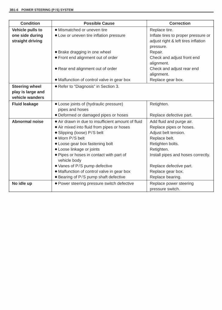
YH4GRANDVITARA
3B1-6 POWER STEERING (P /S) SYSTEM
Condition Possible Cause Correction
Vehicle pulls toone side duringstraight driving
� Mismatched or uneven tire� Low or uneven tire inflation pressure
� Brake dragging in one wheel� Front end alignment out of order
� Rear end alignment out of order
� Malfunction of control valve in gear box
Replace tire.Inflate tires to proper pressure oradjust right & left tires inflationpressure.Repair.Check and adjust front endalignment.Check and adjust rear endalignment.Replace gear box.
Steering wheelplay is large andvehicle wanders
� Refer to “Diagnosis” in Section 3.
Fluid leakage � Loose joints of (hydraulic pressure)pipes and hoses
� Deformed or damaged pipes or hoses
Retighten.
Replace defective part.
Abnormal noise � Air drawn in due to insufficient amount of fluid� Air mixed into fluid from pipes or hoses� Slipping (loose) P/S belt� Worn P/S belt� Loose gear box fastening bolt� Loose linkage or joints� Pipes or hoses in contact with part of
vehicle body� Vanes of P/S pump defective� Malfunction of control valve in gear box� Bearing of P/S pump shaft defective
Add fluid and purge air.Replace pipes or hoses.Adjust belt tension.Replace belt.Retighten bolts.Retighten.Install pipes and hoses correctly.
Replace defective part.Replace gear box.Replace bearing.
No idle up � Power steering pressure switch defective Replace power steeringpressure switch.

YH4GRANDVITARA
POWER STEERING (P /S) SYSTEM 3B1-7
STEERING WHEELSTEERING WHEEL PLAY CHECKCheck steering wheel for looseness or rattle by trying to move it inits shaft direction and lateral direction.If found defective, repair or replace.Check steering wheel for play, holding car in straight forward condi-tion on the ground and with engine stopped.
Steering wheel play “a”: 0 – 30 mm (0 – 1.2 in.)
If steering wheel play is not within specification, inspect as followsand replace if found defective.� Tie-rod end ball stud for wear� Lower ball joint for wear� Steering shaft joint for wear� Steering pinion or rack gear for wear or breakage� Each part for looseness
STEERING FORCE CHECK1) Place vehicle on level road and set steering wheel at straight-
ahead position.2) Check that tire inflation pressure is as specified. (Refer to tire
placard.)3) Start engine and keep it running till power steering fluid is
warmed to 50 to 60�C (122 to 140�F).
4) With engine idling, measure steering force by pulling spring ba-lancer hooked on steering wheel in tangential direction.
Steering force: Less than 50 N (5.0 kg, 11.0 lb)
POWER STEERING FLUIDPOWER STEERING FLUID LEVEL CHECKWith engine stopped, check fluid level indicated on P/S fluid reser-voir, which should be between “MAX” and “MIN” marks. If it is lowerthan “MIN” mark, fill fluid up to “MAX” mark.
NOTE:� Be sure to use an specified power steering fluid.� Fluid level should be checked when fluid is cool.

YH4GRANDVITARA
[D]
[C]
[A]
1. P / S pump pulley2. A / C compressor
pulley (if equipped)3. Crankshaft pulley4. Tension pulley5. Tension pulley bolts
[A]: G16 type engine with A / C[B]: G16 type engine without A / C[C]: H25 type engine with A / C[D]: H25 type engine without A / C
[B]
3B1-8 POWER STEERING (P /S) SYSTEM
POWER STEERING PUMP DRIVE BELT
NOTE:For J20 Type engine, refer to Section 6H “GENERATOR BELT”.
INSPECTIONCheck that belt is free from any damage and properly fitted in pulleygroove.
BELT TENSION CHECKCheck belt tension by measuring how much it deflects whenpushed at intermediate point between pulleys with about 10 kg(22 lb) force.
Deflection of P/S belt:6 – 9 mm (0.24 – 0.35 in.) G16 Type engine. . . . . . . . . . . . . . . . . 4 – 7 mm (0.16 – 0.28 in.) H25 Type engine. . . . . . . . . . . . . . . . .
BELT TENSION ADJUSTMENT[For G16 Type engine]a) To adjust P/S pump drive belt tension, use adjusting bolt of com-
pressor for A/C equipped vehicles and that of P/S pump for ve-hicles without A/C.
b) Adjust belt tension to above specification.c) Then tighten adjusting and mounting bolts to specified torque.
[For J20 Type engine]To adjust P/S pump drive belt tension, refer to “GENERATORBELT” in Section 6H.
[For H25 Type engine]a) To adjust P/S pump drive belt tension, loosen tension pulley
bolts and turn tension pulley using hexagon wrench.b) Adjust belt tension to above specification.
Then tighten tension pulley bolts to specified torque.
Tightening TorqueTension pulley bolts: 25 N .m (2.5 kg-m, 18.5 lb-ft)

YH4GRANDVITARA
POWER STEERING (P /S) SYSTEM 3B1-9
IDLE UP SYSTEMIDLE UP SYSTEM CHECK1) Warm up engine to normal operating temperature.2) Turn A/C switch OFF, if equipped.3) Turn steering wheel fully and check idle speed.
Engine idle speed drops a little momentarily when steeringwheel is turned fully but returns to its specified level immediately.If power steering pressure switch connector is connected, checkthe same with that connector disconnected. Momentary drop ofengine idle speed should be less when it is connected than whendisconnected.
FLUIDFLUID LEAKAGE CHECKStart engine and turn steering wheel fully to the right and left so that maximum hydraulic pressure is provided. Thenvisually check gear box, P/S pump and P/S fluid reservoir themselves and each joint of their connecting pipes forleakage.
CAUTION:Never keep steering wheel turned fully for longer than 10 seconds.

YH4GRANDVITARA
1. P / S fluid reservoir2. Attachment3. Gasket
4. Union bolt5. High pressure side6. Low pressure side
1. P / S fluid reservoir2. Gauge valve (open)3. P / S pump
4. P / S gear box5. High pressure side6. Low pressure side
3B1-10 POWER STEERING (P /S) SYSTEM
HYDRAULIC PRESSURE IN P/S CIRCUITHYDRAULIC PRESSURE CHECK1) After cleaning joint of high pressure hose and P/S pump thor-
oughly, disconnect hose from pump and install special tool (oilpressure gauge, attachment and hose).Tighten each flare nut to specified torque.
CAUTION:Take care not to cause damage to A/C condenser duringservice operation, if equipped.
Special Tool(A): 09915-77410 (Oil pressure gauge)(B): 09915-77420
2) Check each connection for fluid leakage and bleed air.Refer to “AIR BLEEDING PROCEDURE” in this section.
3) With engine idling, turn steering wheel and warm up engine tilltemperature of fluid in P/S fluid reservoir rises to 50 – 60�C (122– 140�F).
4) Check back pressure by measuring hydraulic pressure with en-gine idling and hands off steering wheel.
Back pressure: Lower than 1000 kPa (10 kg/cm 2, 142 psi)
When back pressure is higher than specified values, check con-trol valve and piping for clogging.

YH4GRANDVITARA
1. P / S fluid reservoir2. Gauge valve (shut)3. Oil pressure gauge4. P / S pump5. P / S gear box
1. P / S fluid reservoir2. Gauge valve (open)3. Oil pressure gauge4. P / S pump5. P / S gear box
POWER STEERING (P /S) SYSTEM 3B1-11
5) Check relief pressure� Increase engine speed to about 1,500 r/min (rpm). Close
gauge valve gradually while watching pressure increase indi-cated by gauge and take reading of relief pressure (maximumhydraulic pressure).
Relief pressure:6200 – 7000 kPa (62 – 70 kg/cm 2, 882 – 995 psi) G16 Type engine. . . . . . . 6700 – 7500 kPa(67 – 75 kg/cm 2, 953 – 1067 psi) J20 Type engine. . . . . . . 7050 – 7850 kPa(70.5 – 78.5 kg/cm 2, 1003 – 1116 psi) H25 Type engine. .
� When it is higher than specified values, possible cause is mal-function of relief valve.
� When it is lower than specified values, possible cause is eitherfailure of P/S pump or settling of relief valve spring.
CAUTION:Be sure not to close gauge valve for longer than 10 se-conds.
� Next, open gauge valve fully and increase engine speed toabout 1,500 r/min (rpm). Then turn steering wheel to the leftor right fully and take reading of relief pressure.
Relief pressure:6200 – 7000 kPa(62 – 70 kg/cm 2, 882 – 995 psi) G16 Type engine. . . . . . . 6700 – 7500 kPa(67 – 75 kg/cm 2, 953 – 1067 psi) J20 Type engine. . . . . . . 7050 – 7850 kPa(70.5 – 78.5 kg/cm 2, 1003 – 1116 psi) H25 Type engine. .
� When it is higher than specified values, possible cause is mal-function of relief valve.
� When it is lower than specified values, possible cause is failurein steering gear box. Replace gear box.
CAUTION:Be sure not to hold steering wheel at fully turned posi-tion for longer than 10 seconds.
BOOTSTEERING RACK BOOT CHECKCheck boot for crack and damage which, if any, means possibilityof rusty gear, entry of dust or lack of grease. Also, check if any ofsuch faulty conditions exists.Check steering rack boot for dent or breakage.If there is a dent, keep boot in most compressed state for some se-conds to correct dent.

YH4GRANDVITARA
3B1-12 POWER STEERING (P /S) SYSTEM
TIE-ROD END BOOT CHECKCheck boot for crack and damage and if any, replace it with a newone.
AIR BLEEDING PROCEDURE
1) Hoist the front end of vehicle and apply safety stands.2) Fill P/S fluid reservoir with fluid up to specified level.
NOTE:Before starting engine, place transmission gear shift leverin “Neutral” (shift selector lever to “P” range for A/T mod-el), and set parking brake.
3) After running engine at idling speed for 3 to 5 seconds, stop itand add fluid to satisfy specification.
4) With engine stopped, turn steering wheel to the right and left asfar as it stops, repeat it a few times and fill fluid to specified level.
5) With engine running at idling speed, repeat stop-to-stop turn ofsteering wheel till all foams in P/S fluid reservoir are gone.
NOTE:Make sure to bleed air completely. If air remains in fluid, P/Spump may make humming noise or steering wheel may feelheavy.
6) Finally check to make sure that fluid is filled to specified level.

YH4GRANDVITARA
1. Tie-rod end2. Knuckle3. Nut
1. Tie-rod2. Mark3. Lock nut4. Tie-rod end
1. Tie-rod end ball joint
1. Tie-rod2. Mark3. Lock nut4. Tie rod end5. Knuckle6. Nut
6, (a)
POWER STEERING (P /S) SYSTEM 3B1-13
ON-VEHICLE SERVICE
TIE-ROD ENDREMOVAL1) Hoist vehicle and remove wheel.2) Remove tie-rod end nut.
3) Disconnect tie-rod end by using puller.
4) To facilitate adjustment after installation, put a mark on tie-rodthread indicating position of tie-rod end lock nut. Then loosenlock nut and remove tie rod end from tie rod.
INSPECTION
Tie-rod End Ball JointInspect for play in tie-rod end ball joint. If found defective, replace.
INSTALLATION1) Install tie-rod end lock nut and tie rod end to tie-rod. Tighten lock
nut to mark on tie-rod thread.2) Install tie-rod end to knuckle. Tighten tie-rod end nut to specified
torque.
Tightening Torque(a): 48 N.m (4.8 kg-m, 35.0 lb-ft)

YH4GRANDVITARA
1. High pressure pipe2. Union bolt
3. Low pressure hose4. Steering lower shaft bolt
3B1-14 POWER STEERING (P /S) SYSTEM
3) After installing wheels, lower vehicle and tighten wheel nuts tospecified torque.
Tightening Torque(a): 100 N.m (10.0 kg-m, 72.5 lb-ft)
4) Check that proper amount of toe-in is obtained by referring to“FRONT WHEEL ALIGNMENT”.
5) After confirming proper amount of toe-in, tighten tie-rod end locknut to specified torque.
Tightening Torque(a): 65 N.m (6.5 kg-m, 47.0 lb-ft)
POWER STEERING GEAR BOXASSEMBLYREMOVAL1) Take out fluid in P/S fluid reservoir with syringe or such.2) Disconnect high pressure pipe from steering gear box by remov-
ing union bolt.
NOTE:As fluid flows out of disconnected joints, put a receptacleunder joints or a plug to pipe.
3) Disconnect low pressure hose from steering gear box.
NOTE:As fluid flows out of disconnected joints, put a receptacleunder joints or a plug to hose.
4) Remove steering lower shaft bolt.
5) Hoist vehicle and remove both right and left wheels.6) Disconnect both right and left tie rod ends from knuckle, refer to
steps 2) to 3) of “TIE-ROD END REMOVAL” in this section.

YH4GRANDVITARA
1. Steering gear box mounting bolts
1. Mark2. Gear case3. Pinion shaft
POWER STEERING (P /S) SYSTEM 3B1-15
7) Remove steering gear box mounting bolts and then removesteering gear box from vehicle.Steering gear box found to be in defective condition should bereplaced with a new one.
CAUTION:Never disassemble P/S gear box. If perform this prohib-ited service, it will affect original performance.
INSTALLATIONReverse removal procedure for installation of steering gear boxnoting the following points.
� After confirming that front tire is in straight position, install steeringgear box to body temporarily. Next, with tie-rod end installed toknuckle, set rack in position close to neutral. Then obtain the neu-tral state by aligning match marks on pinion shaft and steeringgear case and insert steering lower joint into pinion shaft.
CAUTION:Be sure to confirm that steering wheel and front tires(wheels) are in straight position when inserting steeringlower joint into steering pinion shaft.
� If a plug was put to disconnected pipe when removing steeringgear box, remove that plug before reconnecting pipe.
� Use specified torque as given below.
Tightening Torque(a): 25 N.m (2.5 kg-m, 18.0 lb-ft)(b): 40 N.m (4.0 kg-m, 29.0 lb-ft)(c): 25 N.m (2.5 kg-m, 18.0 lb-ft)(d): 55 N.m (5.5 kg-m, 40.0 lb-ft)
� After installation, be sure to fill specified power steering fluid andbleed air.
� Check toe setting. Adjust as required. (Refer to Front End Align-ment.)

YH4GRANDVITARA
3B1-16 POWER STEERING (P /S) SYSTEM
1. Clip2. Wire
Make marking here
RACK BOOT AND TIE-ROD (EXCEPT CANVASTOP LH MODEL)REMOVAL
CAUTION:Never disassemble tie-rod except for canvas top LH model.Performing this prohibited service will affect original per-formance.
1) Remove steering gear box by referring to “POWER STEERINGGEAR BOX ASSEMBLY REMOVAL” in this section.
2) For ease of adjustment after installation, make marking of tie-rodend lock nut position of tie-rod end thread.
3) Loosen tie-rod end lock nut and remove tie-rod end.
4) Remove boot wire and clip.5) Remove boot from tie-rod.
INSTALLATION1) Visually inspect that rack and rack end ball joint are free from dirt
or foreign matters. Clean thoroughly with cloth or such.Position boot properly in grooves of gear case and tie-rod andclamp it with wire and clip.Wire should be new and should go around twice.Pull its both ends together by screw driver or such and makesure that the wire won’t be crossed. Then twist the ends severaltimes, the twisted ends should be bent in the circumferentialdirection.After this, check to ensure that wire is tight and boot is free fromtwist and dent.
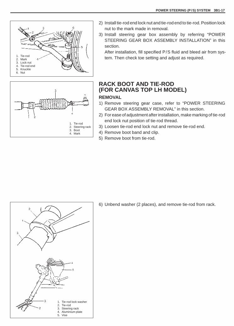
YH4GRANDVITARA
POWER STEERING (P /S) SYSTEM 3B1-17
1. Tie-rod2. Steering rack3. Boot4. Mark
1. Tie-rod lock washer2. Tie-rod3. Steering rack4. Aluminium plate5. Vise
1. Tie-rod2. Mark3. Lock nut4. Tie-rod end5. Knuckle6. Nut
2) Install tie-rod end lock nut and tie-rod end to tie-rod. Position locknut to the mark made in removal.
3) Install steering gear box assembly by referring “POWERSTEERING GEAR BOX ASSEMBLY INSTALLATION” in thissection.After installation, fill specified P/S fluid and bleed air from sys-tem. Then check toe setting and adjust as required.
RACK BOOT AND TIE-ROD(FOR CANVAS TOP LH MODEL)REMOVAL1) Remove steering gear case, refer to “POWER STEERING
GEAR BOX ASSEMBLY REMOVAL” in this section.2) For ease of adjustment after installation, make marking of tie-rod
end lock nut position of tie-rod thread.3) Loosen tie-rod end lock nut and remove tie-rod end.4) Remove boot band and clip.5) Remove boot from tie-rod.
6) Unbend washer (2 places), and remove tie-rod from rack.

YH4GRANDVITARA
3B1-18 POWER STEERING (P /S) SYSTEM
“A”
1
1
1. Mark
1. Tie-rod lock washer
(A)
INSTALLATION1) Install new tie-rod lock washer and tie-rod to rack.2) Tighten tie-rod ball nut to specified torque.
Tightening Torque(a): 85 N.m (8.5 kg-m, 61.5 lb-ft)
3) Bend lock washer 2 place at the flat part of tie-rod ball nut.
4) Apply grease to “A” indicated in figure.5) Position boot properly in grooves of gear case and tie-rod.
Check to ensure that boot is free from twist and dent.
6) Fasten boot with new clamp and clip securely.
Special Tool(A): 09943-55010
7) Install tie-rod end lock nut and tie-rod end to tie-rod.Position lock nut to marking made in removal.
NOTE:When tie-rod was replaced, measure length “A” on re-moved tie-rod and use it on new replacement tie-rod so asto position lock nut properly.
8) Install steering gear case. Refer to “POWER STEERING GEARBOX ASSEMBLY INSTALLATION” in this section.

YH4GRANDVITARA
POWER STEERING (P /S) SYSTEM 3B1-19
Tightening Torque(a): 60 N.m (6.0 kg-m, 43.5 lb-ft)(b):25 N.m (2.5 kg-m, 18.5 lb-ft)(c): 55 N.m (5.5 kg-m, 40.0 lb-ft)(d):11 N.m (1.1 kg-m, 8.0 lb-ft)(e): 35 N.m (3.5 kg-m, 25.5 lb-ft)( f ):40 N.m (4.0 kg-m, 29.0 lb-ft)(g):45 N.m (4.5 kg-m, 33.0 lb-ft)
1. Power steering pump assembly2. Bracket3. P / S fluid reservoir
4. High pressure hose & pipe5. Suction hose6. Low pressure return hose
7. Oil tank bracket8. To P / S gear box
[G16 ENGINE MODEL]
[J20 ENGINE MODEL]
[H25 ENGINE MODEL]
POWER STEERING PUMP

YH4GRANDVITARA
3B1-20 POWER STEERING (P /S) SYSTEM
1. P/S fluid reservoir
2. Suction hose
1. P / S pulley2. Mounting bolt
9. Vane10. Rotor11. Snap ring12. Side plate13. Pulley (pump shaft)14. Oil seal15. Pump body16. Flow control
valve Assembly
1. Suction connector2. O-ring3. Pressure switch4. Flow control valve
(Relief valve)5. Spring6. Plug7. Pump cover8. Cam ring
REMOVALNOTE:Be sure to clean each joint of suction and discharge sidesthoroughly before removal.
1) Remove suction hose from pump, then disconnect battery nega-tive cable.
2) Remove P/S fluid reservoir with suction hose.
3) Remove union bolt. Then disconnect high pressure pipe frompump.
NOTE:As fluid flows out of disconnected joints, put a receptacleunder joints or a plug to pipe.
4) Disconnect pressure switch lead wire at switch terminal.5) Loosen related bolts and remove power steering drive belt.
6) Remove P/S pump mounting bolt (s).7) Remove P/S pump.
NOTE:Plug each port of removed pump to prevent dust or any oth-er foreign matter from entering.
DISASSEMBLY1) Clean its exterior thoroughly.2) With aluminum plates placed on vise first, grip pump body with
it.3) Remove suction connector bolt, suction connector and O-ring
from pump body.4) Remove power steering pressure switch (terminal set) from
pump body.5) Remove plug, flow control spring and relief valve (flow control
valve) from pump body.6) Remove cover bolts, pump cover and O-ring from pump body.7) Remove snap ring from pump shaft.8) Remove vanes from rotor.9) Remove cam ring, rotor, side plate and O-rings from pump
body.10) Pull out pulley from pump body.11) Remove oil seal from pump body.

YH4GRANDVITARA
POWER STEERING (P /S) SYSTEM 3B1-21
1. Thickness gauge
INSPECTION
Pump Body, Cover, Side Plate and ShaftCheck sliding surfaces of each part for wear and damage.If any defect is found, replace pump assembly.
Cam RingCheck vane sliding surface of cam ring for wear and damage.If any defect is found, replace pump assembly.
Rotor and Vane� Check sliding surfaces of rotor and vane for wear and damage.
� Check clearance between rotor and vane.
Clearance: Standard 0.015 mm (0.0006 in.)Limit 0.027 mm (0.0011 in.)
Replace pump assembly if any defect is found in above checks.
Relief Valve (Flow Control Valve) and Its Spring� Check fluid passage of relief valve and orifice of connector for ob-
struction (clogged).� Check sliding surface of relief valve for wear and damage.

YH4GRANDVITARA
3B1-22 POWER STEERING (P /S) SYSTEM
1. Flow control spring
1. Oil seal2. Shaft (pulley)
1. O-ring
1. Side plate2. Bolt hole
1. Rotor2. Snap ring3. Dot
� Check free length of relief valve spring.
Free length: Standard 22.0 mm (0.866 in.)Limit 19.0 mm (0.748 in.)
Replace if any defective is found.
ASSEMBLYReverse disassembly procedure for assembly, noting the following.1) Apply grease to oil seal lip and apply power steering fluid to slid-
ing surface of the shaft then insert pulley’s shaft from oil seal sideof the pump body.
“A”: Grease 99000-25010
2) Apply power steering fluid to O-rings and fit them to pump body.
3) Install side plate to pump body.
NOTE:Carefully align the dowel pins on the side plate at bolt holeas shown in figure.
4) Apply power steering fluid to sliding surface of rotor.5) Install rotor to shaft, directing dot marked side of rotor facing up.6) Install new snap ring to shaft, then make sure to fit snap into shaft
groove securely.
NOTE:Never reuse the removed snap ring.

YH4GRANDVITARA
POWER STEERING (P /S) SYSTEM 3B1-23
1. Cam ring2. Side plate
1. Rotor2. Vane
1. O-ring
1. Dowel pin2. Cover plate
7) Apply power steering fluid to sliding surface of cam ring.8) Install cam ring to pump body. The tapered end of cam ring
should face the side plate.
9) Apply power steering fluid to each vane.10) Install vanes (10 pieces) to rotor.
11) Apply power steering fluid to O-ring.12) Install O-ring to pump body.
13) Apply power steering fluid to sliding surface of pump cover androtor.
14) Match the dowel pins to the holes of the cover plate as shownand install pump cover to pump body.

YH4GRANDVITARA
3B1-24 POWER STEERING (P /S) SYSTEM
1. Pump cover
1. Pressure switch
1. Suction connector2. O-ring
1. Suction connector
15) Gradually tighten new pump cover bolts to specified torque.
NOTE:After installing pump cover, check to make sure that shaftcan be turned by hand.
Tightening Torque(a): 23 N.m (2.3 kg-m, 17.0 lb-ft)
16) Apply power steering fluid to O-ring of terminal switch.17) Install pressure switch to pump body.
Tightening Torque(a): 28 N.m (2.8 kg-m, 20.0 lb-ft)
18) Apply power steering fluid to relief valve (flow control valve).19) Install relief valve (flow control valve) to pump body.20) Install flow control spring.21) Apply power steering fluid to O-rings of plug.22) Install O-rings to plug.23) Tighten plug to specified torque.
Tightening Torque(a): 60 N.m (6.0 kg-m, 43.5 lb-ft)
24) Apply power steering fluid to O-ring of suction connector.25) Install O-ring to suction connector.
26) Install suction connector to pump body as shown in figure.Tighten new suction connector bolts to specified torque.
Tightening Torque(a): 10 N.m (1.0 kg-m, 7.5 lb-ft)

YH4GRANDVITARA
POWER STEERING (P /S) SYSTEM 3B1-25
INSTALLATIONReverse removal procedure, and then noting the following instruc-tions.� For tightening torques, refer to structural diagram on previous
page.� Adjust power steering pump drive belt by referring to “BELT TEN-
SION ADJUSTMENT” under “POWER STEERING PUMPDRIVE BELT” in this section.
� Fill specified power steering fluid after installation and bleed airwithout failure. (Refer to “AIR BLEEDING PROCEDURE” in thissection.)

YH4GRANDVITARA
3B1-26 POWER STEERING (P /S) SYSTEM
09915-77420Oil pressure gaugeattachment and hose set
09915-77410Oil pressure gauge
09943-55010Boot clamp plier
TIGHTENING TORQUE SPECIFICATION
Fastening partsTightening torque
Fastening artsN.m kg-m lb-ft
Gear box mounting bolts 55 5.5 40.0
Gear box cylinder pipe flare nuts 29 2.9 21.0
Gear box low pressure pipe union bolt 40 4.0 29.0
Gear box high pressure pipe union bolt 35 3.5 25.5
Tie-rod end lock nut 65 6.5 47.0
G16 Type engine 55 5.5 40.0
Pump bracket bolt J20 Type engine 25 2.5 18.5
H25 Type engine 45 4.5 32.5
Pump union bolt 60 6.0 43.5
Oil pump mount bolts 25 2.5 18.5
Pipe clamp bolt /Reservoir bracket bolt 11 1.1 8.0
Steering shaft joint bolt 25 2.5 18.0
High pressure flare nuts 40 4.0 29.0
Pump cover bolts 23 2.3 17.0
Plug 60 6.0 43.5
Pressure switch (Terminal) 28 2.8 20
Suction connector bolt 10 1.0 7.5
Tie-rod end nut 48 4.8 35.0
Tie-rod (for canvas top LH model only) 85 8.5 61.5
REQUIRED SERVICE MATERIAL
MATERIALS RECOMMENDEDSUZUKI PRODUCT
USE
Lithium greaseSUPER GREASE (A)(99000-25010)
� Oil seal lip of P/S pump pulley shaft
Power steering fluidAn equivalent of DEXRON�-III orDEXRON�-II
� To fill P/S fluid reservoir� Parts lubrication when installing
SPECIAL TOOL

YH4GRANDVITARA
3C
STEERING WHEEL AND COLUMN 3C-1
SECTION 3C
STEERING WHEEL AND COLUMN(NOT EQUIPPED WITH AIR BAG)
NOTE:All steering wheel and column fasteners are important parts in that they could affect the performance ofvital parts and systems, and/or could result in major repair expense. They must be replaced with one ofthe same part number or with an equivalent part if replacement becomes necessary. Do not use a replace-ment part of lesser quality of substitute design. Torque values must be used as specified during reassemb-ly to assure proper retention of this part.
CONTENTS
GENERAL DESCRIPTION 3C- 1. . . . . . . . . . . . . . . . . . . . . . . . . . . . . . . . . . . . . . . . . . . . . . . . . . . . . . . . . . . . . . . . . .
DIAGNOSIS 3C- 2. . . . . . . . . . . . . . . . . . . . . . . . . . . . . . . . . . . . . . . . . . . . . . . . . . . . . . . . . . . . . . . . . . . . . . . . . . . . . . . Inspection and repair required after accident 3C- 2. . . . . . . . . . . . . . . . . . . . . . . . . . . . . . . . . . . . . . . . . . . . . . . . .
ON-VEHICLE SERVICE 3C- 3. . . . . . . . . . . . . . . . . . . . . . . . . . . . . . . . . . . . . . . . . . . . . . . . . . . . . . . . . . . . . . . . . . . . Steering wheel 3C- 3. . . . . . . . . . . . . . . . . . . . . . . . . . . . . . . . . . . . . . . . . . . . . . . . . . . . . . . . . . . . . . . . . . . . . . . . . . . Combination switch 3C- 4. . . . . . . . . . . . . . . . . . . . . . . . . . . . . . . . . . . . . . . . . . . . . . . . . . . . . . . . . . . . . . . . . . . . . . . Steering column assembly 3C- 5. . . . . . . . . . . . . . . . . . . . . . . . . . . . . . . . . . . . . . . . . . . . . . . . . . . . . . . . . . . . . . . . . Steering lock assembly (ignition switch) 3C-10. . . . . . . . . . . . . . . . . . . . . . . . . . . . . . . . . . . . . . . . . . . . . . . . . . . . . Steering lower shaft assembly 3C-11. . . . . . . . . . . . . . . . . . . . . . . . . . . . . . . . . . . . . . . . . . . . . . . . . . . . . . . . . . . . . . Checking steering column for accident damage 3C-13. . . . . . . . . . . . . . . . . . . . . . . . . . . . . . . . . . . . . . . . . . . . . . . Adjustable steering column release lever 3C-14. . . . . . . . . . . . . . . . . . . . . . . . . . . . . . . . . . . . . . . . . . . . . . . . . . . .
TIGHTENING TORQUE SPECIFICATIONS 3C-14. . . . . . . . . . . . . . . . . . . . . . . . . . . . . . . . . . . . . . . . . . . . . . . . . . . .
SPECIAL TOOL 3C-14. . . . . . . . . . . . . . . . . . . . . . . . . . . . . . . . . . . . . . . . . . . . . . . . . . . . . . . . . . . . . . . . . . . . . . . . . . .
GENERAL DESCRIPTION
This double tube type steering column has the following three important features in addition to the steering function:� The column is energy absorbing, designed to compress in a front-end collision.� The ignition switch and lock are mounted conveniently on this column.� With the column mounted lock, the ignition and steering operations can be locked to inhibit theft of the vehicle.
To insure the energy absorbing action, it is important that only the specified bolts be used as designated and thatthey are tightened to the specified torque. When the column assembly is removed from the vehicle, special caremust be taken in handling it. Use of a steering wheel puller other than the one recommended in this manual or asharp blow on the end of the steering shaft, leaning on the assembly, or dropping the assembly could shear theplastic shear pins which maintain column length and position.

YH4GRANDVITARA
1. Steering wheel pad2. Steering wheel pad screw3. Steering wheel nut4. Steering wheel5. Combination switch6. Steering column upper cover7. Steering column lower cover8. Steering column assembly9. Steering lock assembly
10. Steering column hole cover11. Steering shaft joint12. Steering lower shaft assembly13. Adjustable steering column release lever14. Steering column lower seal
: If equipped*
3C-2 STEERING WHEEL AND COLUMN
DIAGNOSIS
For diagnosis of the steering wheel, steering column and steering shaft lower assembly, refer to Section 3.
INSPECTION AND REPAIR REQUIRED AFTER ACCIDENT
After an accident, be sure to perform checks, inspections and repairs described under “CHECKING STEERINGCOLUMN FOR ACCIDENT DAMAGE” in this section.

YH4GRANDVITARA
1. Steering wheel2. Steering wheel pad3. Screw
1. Steering shaft nut
1. Steering wheel
1. Lugs2. Grooves3. Alignment marks
STEERING WHEEL AND COLUMN 3C-3
ON-VEHICLE SERVICE
STEERING WHEELREMOVAL1) Disconnect negative battery cable at battery terminal.2) Remove steering wheel pad screw.3) Remove steering wheel pad and disconnect horn harness.
4) Remove steering shaft nut.5) Make alignment marks on steering wheel and shaft for a guide
during reinstallation.
6) Remove steering wheel with special tool.
Special Tool(A): 09944-36011
CAUTION:Do not hammer the end of the shaft. Hammering it willloosen the plastic shear pins which maintain the columnlength and impair the collapsible design of the column.
INSTALLATION1) Install steering wheel to steering shaft with 2 lugs on combina-
tion switch fitted in two grooves in the back of steering wheel andalso aligning marks on steering wheel and steering shaft.
2) Tighten steering shaft nut to specified torque.
Tightening Torque(a): 33 N.m (3.3 kg-m, 23.5 lb-ft)
3) Connect horn harness and install steering wheel pad.4) Tighten steering wheel pad screw.5) Connect negative battery cable.

YH4GRANDVITARA
1. Combination switch
1. Steering column hole cover: If equipped
2. Screw
1. Combination switch 2. Screw
1. Steering column cover screw2. Steering column lower cover
*
3. Steering columnupper cover
3C-4 STEERING WHEEL AND COLUMN
COMBINATION SWITCHREMOVAL1) Disconnect negative battery cable at battery terminal.2) Remove steering wheel from steering column. Refer to
“STEERING WHEEL” in this section.3) Remove steering column hole cover.
4) Remove steering column cover screws (3 pieces).5) Separate upper cover and lower cover, then remove them.6) Disconnect all connectors for combination switch.
7) Remove combination switch from steering column.
INSPECTIONCheck combination switch wire harness for any signs of scorching,melting or other damage. If it is damaged, replace.
INSTALLATION1) Install combination switch to steering column.2) Connect all connectors that have been removed in removal.

YH4GRANDVITARA
1. Steering column hole cover2. If equipped
1. Steering column cover screw2. Steering column lower cover3. Steering column upper cover
: Tapping screw: Standard screw***
STEERING WHEEL AND COLUMN 3C-5
3) Install steering column upper and lower cover.4) Tighten steering column cover screws.
CAUTION:When installing lower cover and upper cover, be carefulso that combination switch lead wire is not caught be-tween covers.
5) Install steering column hole cover.6) Install steering wheel to steering column. Refer to “STEERING
WHEEL” in this section.7) Connect battery negative cable.
STEERING COLUMN ASSEMBLY
CAUTION:Once the steering column is removed from the vehicle, thecolumn is extremely susceptible to damage.Dropping the column assembly on its end could collapsethe steering shaft or loosen the plastic shear pins whichmaintain column length. Leaning on the column assemblycould cause it to bend or deform.Any of the above damage could impair the column’s col-lapsible design.When loosening steering column mounting bolts, makesure that steering column assembly and steering shaft low-er assembly have been separated. Loosening them withsteering column assembly and steering shaft lower assem-bly assembled could cause damage to bearing in steeringshaft lower assembly.
NOTE:When servicing steering column or any column-mountedcomponent, remove steering wheel. But when removing steer-ing column simply to gain access to instrument panel compo-nents, leave steering wheel installed on steering column.
REMOVAL1) Disconnect negative battery cable at battery terminal.

YH4GRANDVITARA
1. Steering column assembly2. Steering shaft joint3. Marks
1. Steering column assembly2. Steering shaft joint3. Steering lower shaft assembly4. Bolt (column side)5. Bolt (lower shaft assembly side)
1. Steering column hole cover: If equipped*
3C-6 STEERING WHEEL AND COLUMN
2) Remove steering wheel and combination switch, if necessary.Refer to “STEERING WHEEL” and “COMBINATION SWITCH”in this section.Perform the following procedure if not removing steering wheeland/or combination switch.i) Turn steering wheel so that vehicle’s front tires are at straight-
ahead position.ii) Turn ignition switch to “LOCK” position and remove key.
3) Remove steering column hole cover.4) Disconnect all connectors for the following parts.
� Combination switch� Ignition switch� Immobilizer control system parts (if equipped)
5) Make alignment marks on shaft joint and shaft (column side) fora guide during reinstallation.
6) After removing bolt on column side of shaft joint and looseningbolt on its lower shaft assembly side, move shaft joint to lowershaft assembly side (in arrow direction in the figure).

YH4GRANDVITARA
1. Steering column2. Steering column mounting bolt3. Steering column lower seal
1. Shift (key) interlock cable2. Screw
1. Capsule2. Steering column bracket3. Plate
1. Steering column assembly
“a”
STEERING WHEEL AND COLUMN 3C-7
7) Remove steering column mounting bolts (6 pieces).
8) If equipped with shift (key) interlock cable, remove shift (key) in-terlock cable screw and then disconnect its cable from ignitionswitch.
9) Remove steering column from vehicle.
INSPECTIONNOTE:Vehicles involved in accidents resulting in body damage,where steering column has been impacted or air bagdeployed, may have a damaged or misaligned steering col-umn.
CHECKING PROCEDURE1) Check that two capsules are attached to steering column brack-
et securely. Check clearance between capsules and steeringcolumn bracket. Clearance should be 0 mm (0 in.) on both sides.If found loose or clearance, replace steering column assembly.
2) Check two plates for any damages such as crack or breakage.If anything is found faulty, replace as steering column assembly.
3) Take measurement “a” as shown. If it is shorter than specifiedlength, replace column assembly with new one.
Length “a”: 895 � 0.8 mm (35.24 � 0.03 in.)
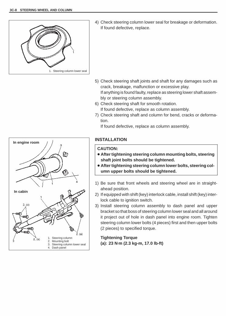
YH4GRANDVITARA
1. Steering column2. Mounting bolt3. Steering column lower seal4. Dash panel
1. Steering column lower seal
In engine room
In cabin
3C-8 STEERING WHEEL AND COLUMN
4) Check steering column lower seal for breakage or deformation.If found defective, replace.
5) Check steering shaft joints and shaft for any damages such ascrack, breakage, malfunction or excessive play.If anything is found faulty, replace as steering lower shaft assem-bly or steering column assembly.
6) Check steering shaft for smooth rotation.If found defective, replace as column assembly.
7) Check steering shaft and column for bend, cracks or deforma-tion.If found defective, replace as column assembly.
INSTALLATION
CAUTION:� After tightening steering column mounting bolts, steering
shaft joint bolts should be tightened.� After tightening steering column lower bolts, steering col-
umn upper bolts should be tightened.
1) Be sure that front wheels and steering wheel are in straight-ahead position.
2) If equipped with shift (key) interlock cable, install shift (key) inter-lock cable to ignition switch.
3) Install steering column assembly to dash panel and upperbracket so that boss of steering column lower seal and all aroundit project out of hole in dash panel into engine room. Tightensteering column lower bolts (4 pieces) first and then upper bolts(2 pieces) to specified torque.
Tightening Torque(a): 23 N.m (2.3 kg-m, 17.0 lb-ft)

YH4GRANDVITARA
1. Steering shaft joint2. Steering shaft (column side)3. Marks
1. Steering shaft joint2. Bolt (column side)3. Bolt (lower shaft assembly side)
1. Steering column hole cover: If equipped*
STEERING WHEEL AND COLUMN 3C-9
4) Install steering shaft joint to steering shaft by matching it tomarks made before removal.
5) Install shaft joint bolt (column side) to steering shaft joint. Tightenshaft joint bolt (column side) to specified torque first and thenshaft joint bolt (lower shaft assembly side) to specified torque.
Tightening Torque(b): 25 N.m (2.5 kg-m, 18.0 lb-ft)
6) If combination switch is removed, install combination switch.Refer to “COMBINATION SWITCH” in this section.
7) Connect all connectors that have been removed in removal.8) Install steering column hole cover.
9) If steering wheel is removed, install steering wheel. Refer to“STEERING WHEEL” in this section.
10) Connect negative battery cable.

YH4GRANDVITARA
1. Steering column2. Steering lock
1. Center punch (with sharp point)2. Steering lock mounting bolt
1. Steering column2. Steering shaft
3C-10 STEERING WHEEL AND COLUMN
STEERING LOCK ASSEMBLY (IGNITIONSWITCH)REMOVAL1) Remove steering column. Refer to “STEERING COLUMN” in
this section.
2) Using center punch as shown, loosen and remove steering lockmounting bolts.
NOTE:Use care not to damage aluminum part of steering lockbody with center punch.
3) Turn ignition key to “ACC” or “ON” position and remove steeringlock assembly from steering column.
INSTALLATION1) Position oblong hole of steering shaft in the center of hole in col-
umn.2) Turn ignition key to “ACC” or “ON” position and install steering
lock assembly onto column.3) Now turn ignition key to “LOCK” position and pull it out.4) Align hub on lock with oblong hole of steering shaft and rotate
shaft to assure that steering shaft is locked.
5) Tighten new bolts until head of each bolt is broken off.6) Turn ignition key to “ACC” or “ON” position and check to be sure
that steering shaft rotates smoothly. Also check for lock opera-tion.
7) Install steering column. Refer to “STEERING COLUMN” in thissection.

YH4GRANDVITARA
1. Steering column assembly2. Steering shaft joint3. Marks
1. Steering column assembly2. Steering shaft joint3. Steering lower shaft assembly4. Bolt (column side)5. Bolt (lower shaft assembly side)
1. Steering lower shaft assembly2. Steering lower shaft assembly lower joint bolt3. Steering shaft joint
STEERING WHEEL AND COLUMN 3C-11
STEERING LOWER SHAFT ASSEMBLYREMOVAL1) Turn steering wheel so that vehicle’s front tires are at straight-
ahead position.2) Turn ignition switch to “LOCK” position and remove key.3) Make alignment marks on shaft joint and shaft (column side) for
a guide during reinstallation.
4) After removing bolt on column side of shaft joint and looseningbolt on its lower shaft assembly side, move shaft joint to lowershaft assembly side (in arrow direction in figure).
5) Make alignment marks on lower shaft assembly lower joint andpinion shaft for a guide during reinstallation.
6) Remove lower shaft assembly lower joint bolt and then removelower shaft assembly.
7) Remove shaft joint bolt (lower shaft assembly side) from shaftjoint and then remove shaft joint from lower shaft assembly.

YH4GRANDVITARA
1. Steering shaft joint2. Bolt (steering column assembly side)3. Bolt (lower steering shaft assembly side)
1. Steering column assembly2. Steering shaft joint3. Marks
1. Steering lower shaft assembly2. Steering lower shaft assembly lower joint bolt3. Steering shaft joint
1. Steering shaft joint2. Steering lower shaft assembly
2
1
2, (a)
3C-12 STEERING WHEEL AND COLUMN
INSTALLATION1) Be sure that front wheels and steering wheel are in straightfor-
ward position.2) Align flat part “A” of lower shaft assembly with bolt hole “B” of
shaft joint as shown. Then insert shaft joint into lower shaft as-sembly.
3) Install shaft joint bolt (lower shaft assembly side) to shaft joint.Then tighten it by hand.
4) Insert pinion shaft into lower shaft assembly lower joint bymatching it to marks made before removal. And then install low-er shaft assembly lower joint bolt to lower shaft assembly lowerjoint. Tighten it to specified torque.
Tightening Torque(a): 25 N.m (2.5 kg-m, 18.0 lb-ft)
5) Install steering shaft joint to steering shaft by matching it tomarks made before removal.
NOTE:Be sure that front wheels and steering wheel are in straight-ahead position.
6) Install shaft joint bolt (column side) to shaft joint. Tighten shaftjoint bolt (column side) to specified torque first and then shaftjoint bolt (lower shaft assembly side) to specified torque.
Tightening Torque(b): 25 N.m (2.5 kg-m, 18.0 lb-ft)

YH4GRANDVITARA
STEERING WHEEL AND COLUMN 3C-13
1. Capsule2. Steering column bracket3. Plate
1. Steering column assembly
1. Steering column lower seal
“a”
CHECKING STEERING COLUMN FORACCIDENT DAMAGE
NOTE:Vehicles involved in accidents resulting in body damage,where steering column has been impacted, may have a dam-aged or misaligned steering column.
CHECKING PROCEDURE1) Check that two capsules are attached to steering column brack-
et securely. Check clearance between capsules and steeringcolumn bracket. Clearance should be 0 mm (0 in.) on both sides.If found loose or clearance, replace steering column assembly.
2) Check two plates for any damages such as crack or breakage.If anything is found faulty, replace as steering column assembly.
3) Take measurement “a” as shown. If it is shorter than specifiedlength, replace column assembly with new one.
Length “a”: 895 � 0.8 mm (35.24 � 0.03 in.)
4) Check steering column lower seal for breakage or deformation.If found defective, replace.
5) Check steering shaft joints and shaft for any damages such ascrack, breakage, malfunction or excessive play.If anything is found faulty, replace as steering shaft lower assem-bly or steering column assembly.
6) Check steering shaft for smooth rotation.If found defective, replace as column assembly.
7) Check steering shaft and column for bend, cracks or deforma-tion.If found defective, replace as column assembly.

YH4GRANDVITARA
1. Lower position2. Upper position
3C-14 STEERING WHEEL AND COLUMN
09944-36011Steering wheel remover
ADJUSTABLE STEERING COLUMN RELEASELEVERINSPECTIONCheck to make sure that the following:� Steering column moves smoothly when adjustable steering col-
umn release lever is at lower position (i.e., steering column is notlocked).
� Steering column is fixed securely when adjustable steering col-umn release lever is at higher position (i.e., steering column islocked).
TIGHTENING TORQUE SPECIFICATIONS
Fastening partsTightening torque
Fastening artsN.m kg-m lb-ft
Steering shaft nut 33 3.3 23.5
Steering column mounting bolt 23 2.3 17.0
Steering shaft joint bolt 25 2.5 18.0
Steering lower shaft assembly lower joint bolt 25 2.5 18.0
SPECIAL TOOL

YH4GRANDVITARA
3C1
AIR BAG STEERING WHEEL AND COLUMN 3C1-1
GENERAL DESCRIPTION 3C1- 2. . . . . . . . . . . . .
DIAGNOSIS 3C1- 3. . . . . . . . . . . . . . . . . . . . . . . . . . Inspection and Repair Required after
Accident 3C1- 3. . . . . . . . . . . . . . . . . . . . . . . . . .
ON-VEHICLE SERVICE 3C1- 3. . . . . . . . . . . . . . . Service Precautions 3C1- 3. . . . . . . . . . . . . . . . .
Diagnosis and Servicing 3C1- 3. . . . . . . . . . . . Disabling Air Bag System 3C1- 3. . . . . . . . . . . Enabling Air Bag System 3C1- 3. . . . . . . . . . . Handling and Storage 3C1- 3. . . . . . . . . . . . . . Disposal 3C1- 3. . . . . . . . . . . . . . . . . . . . . . . . . .
Driver Air Bag (Inflator) Module 3C1- 4. . . . . . . . Steering Wheel 3C1- 6. . . . . . . . . . . . . . . . . . . . . .
Centering Contact Coil 3C1- 6. . . . . . . . . . . . . Contact Coil and Combination Switch
Assembly 3C1- 7. . . . . . . . . . . . . . . . . . . . . . . . . Steering Column 3C1- 9. . . . . . . . . . . . . . . . . . . . Steering Lock Assembly (Ignition
Switch) 3C1-14. . . . . . . . . . . . . . . . . . . . . . . . . . . Steering Lower Shaft Assembly 3C1-15. . . . . . . Checking Steering Column for Accident
Damage 3C1-17. . . . . . . . . . . . . . . . . . . . . . . . . . Adjustable Steering Column Release
Lever 3C1-18. . . . . . . . . . . . . . . . . . . . . . . . . . . . .
TIGHTENING TORQUESPECIFICATIONS 3C1-18. . . . . . . . . . . . . . . . . . .
SPECIAL TOOL 3C1-18. . . . . . . . . . . . . . . . . . . . . .
SECTION 3C1
AIR BAG STEERING WHEEL AND COLUMNWARNING:� Service on and around the air bag system components or wiring must be performed only by an autho-
rized SUZUKI dealer. Please observe all WARNINGS and “Service Precautions” under “On-VehicleService” in air bag system section before performing service on or around the air bag system compo-nents or wiring. Failure to follow WARNINGS could result in unintentional activation of the systemor could render the system inoperative. Either of these two conditions may result in severe injury.
� The procedures in this section must be followed in the order listed to disable the air bag system tem-porarily and prevent false diagnostic trouble codes from setting. Failure to follow procedures couldresult in possible activation of the air bag system, personal injury or otherwise unneeded air bag sys-tem repairs.
CAUTION:When fasteners are removed, always reinstall them at the same location from which they were re-moved. If a fastener needs to be replaced, use the correct part number fastener for that application. Ifthe correct part number fastener is not available, a fastener of equal size and strength (or stronger) maybe used. Fasteners that are not reused, and those requiring thread-locking compound, will be calledout. The correct torque value must be used when installing fasteners that require it. If the above proce-dures are not followed, parts or system damage could result.
CONTENTS

YH4GRANDVITARA
14
15
1. Driver air bag (inflator) module2. Steering wheel3. Steering wheel nut4. Contact coil and combination switch assembly5. Steering column upper cover6. Steering column lower cover7. Steering column assembly8. Steering lock assembly9. Steering column hole cover
10. Steering shaft joint11. Steering lower shaft assembly12. Adjustable steering column release lever
(if equipped)13. Steering column lower seal14. With adjustable steering column release lever type15. Without adjustable steering column release lever type
3C1-2 AIR BAG STEERING WHEEL AND COLUMN
GENERAL DESCRIPTION
This double tube type steering column has the following three important features in addition to the steering function:� The column is energy absorbing, designed to compress in a front-end collision.� The ignition switch and lock are mounted conveniently on this column.� With the column mounted lock, the ignition and steering operations can be locked to inhibit theft of the vehicle.To insure the energy absorbing action, it is important that only the specified screws, bolts, and nuts be used asdesignated and that they are tightened to the specified torque. When the column assembly is removed from thevehicle, special care must be taken in handling it. Use of a steering wheel puller other than the one recommendedin this manual or a sharp blow on the end of the steering shaft, leaning on the assembly, or dropping the assemblycould shear the plastic shear pins which maintain column length and position.The driver air bag (inflator) module is one of the supplemental restraint (air bag) system components and ismounted to the center of the steering wheel. During certain frontal crashes, the air bag system supplements therestraint of the driver’s and passenger’s seat belts by deploying the air bags. The air bag (inflator) module shouldbe handled with care to prevent accidental deployment. When servicing, be sure to observe all WARNINGS in thissection. Refer to “SERVICE PRECAUTIONS” in Section 10B.

YH4GRANDVITARA
AIR BAG STEERING WHEEL AND COLUMN 3C1-3
DIAGNOSIS
For diagnosis of the steering wheel and steering column, refer toSection 3. For diagnosis of the air bag system, refer to Section 10B.
INSPECTION AND REPAIR REQUIRED AFTERACCIDENT
After an accident, whether the air bag has been deployed or not, besure to perform checks, inspections and repairs described under“CHECKING STEERING COLUMN FOR ACCIDENT DAMAGE” inthis section as well as “REPAIRS AND INSPECTIONS REQUIREDAFTER ACCIDENT” in Section 10B.
ON-VEHICLE SERVICE
SERVICE PRECAUTIONS
For service precautions, refer to “SERVICE PRECAUTIONS” un-der “ON-VEHICLE SERVICE” in Section 10B.
DIAGNOSIS AND SERVICINGFor diagnosis and servicing, refer to “DIAGNOSIS AND SERVIC-ING” under “SERVICE PRECAUTIONS” in Section 10B.
DISABLING AIR BAG SYSTEMFor disabling air bag system, refer to “DISABLING AIR BAG SYS-TEM” under “SERVICE PRECAUTIONS” in Section 10B.
ENABLING AIR BAG SYSTEMFor enabling air bag system, refer to “ENABLING AIR BAG SYS-TEM” under “SERVICE PRECAUTIONS” in Section 10B.
HANDLING AND STORAGEFor handling and storage, refer to “HANDLING AND STORAGE”under “SERVICE PRECAUTIONS” in Section 10B.
DISPOSALFor disposal, refer to “DISPOSAL” under “SERVICE PRECAU-TIONS” in Section 10B.
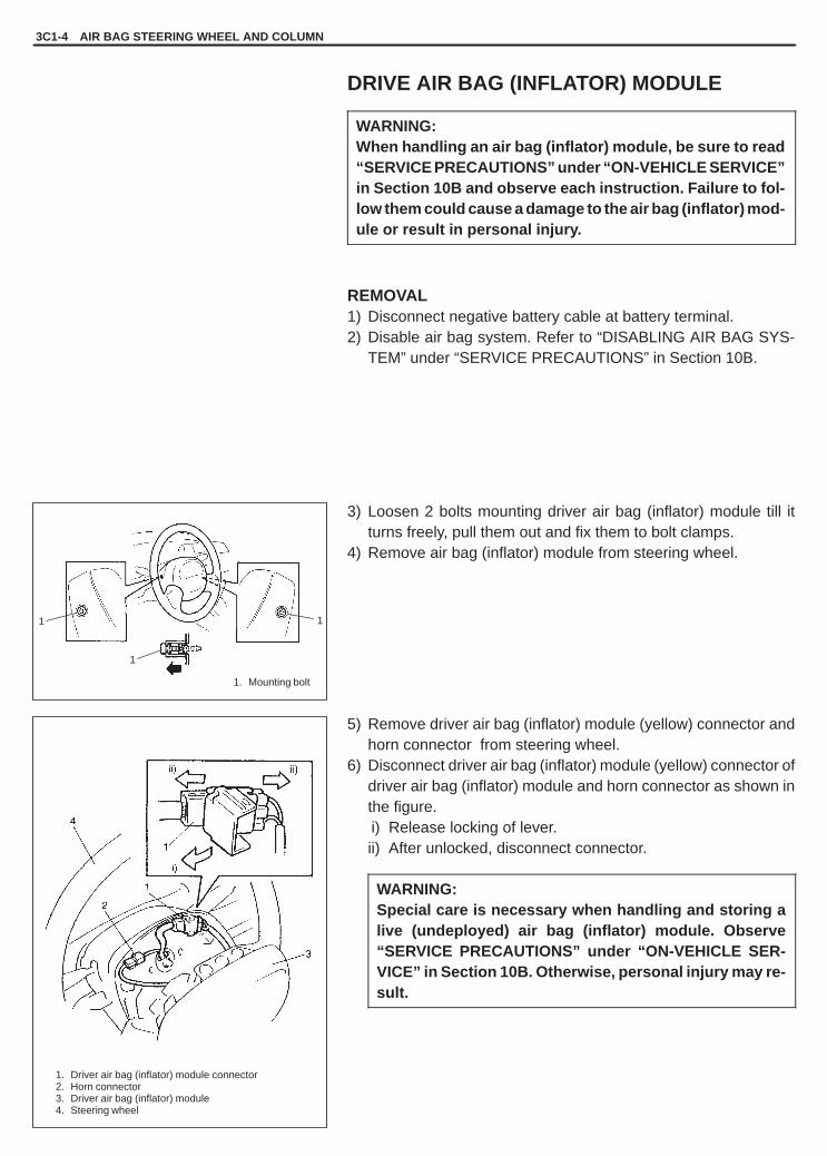
YH4GRANDVITARA
1
1 1
1. Mounting bolt
1. Driver air bag (inflator) module connector2. Horn connector3. Driver air bag (inflator) module4. Steering wheel
3C1-4 AIR BAG STEERING WHEEL AND COLUMN
DRIVE AIR BAG (INFLATOR) MODULE
WARNING:When handling an air bag (inflator) module, be sure to read“SERVICE PRECAUTIONS” under “ON-VEHICLE SERVICE”in Section 10B and observe each instruction. Failure to fol-low them could cause a damage to the air bag (inflator) mod-ule or result in personal injury.
REMOVAL1) Disconnect negative battery cable at battery terminal.2) Disable air bag system. Refer to “DISABLING AIR BAG SYS-
TEM” under “SERVICE PRECAUTIONS” in Section 10B.
3) Loosen 2 bolts mounting driver air bag (inflator) module till itturns freely, pull them out and fix them to bolt clamps.
4) Remove air bag (inflator) module from steering wheel.
5) Remove driver air bag (inflator) module (yellow) connector andhorn connector from steering wheel.
6) Disconnect driver air bag (inflator) module (yellow) connector ofdriver air bag (inflator) module and horn connector as shown inthe figure.ii) Release locking of lever.ii) After unlocked, disconnect connector.
WARNING:Special care is necessary when handling and storing alive (undeployed) air bag (inflator) module. Observe“SERVICE PRECAUTIONS” under “ON-VEHICLE SER-VICE” in Section 10B. Otherwise, personal injury may re-sult.

YH4GRANDVITARA
6, (a)
1. Trim cover (pad surface)2. Inflator case3. Wire harness
1. Driver air bag (inflator) module connector2. Horn connector3. Driver air bag (inflator) module4. Steering wheel5. Mounting bolt (left side)6. Mounting bolt (right side)
AIR BAG STEERING WHEEL AND COLUMN 3C1-5
INSPECTION
WARNING:Never disassemble air bag (inflator) module or measure itsresistance. Otherwise, personal injury may result.
CAUTION:If air bag (inflator) module was dropped from a height of90 cm (3 ft) or more, it should be replaced.
Check air bag (inflator) module visually and if any of the followingis found, replace it with a new one.� Air bag being deployed.� Trim cover (pad surface) being cracked.� Wire harness or connector being damaged.� Air bag (inflator) module being damaged or having been exposed
to strong impact (dropped).
INSTALLATION1) Connect horn connector securely.2) Connect yellow connector of driver air bag (inflator) module con-
nector as shown in the figure securely.ii) Connect connector.ii) Lock connector with lock lever.
3) Install horn connector and driver air bag (inflator) module con-nector.
4) Install driver air bag (inflator) module to steering wheel, takingcare so that no part of wire harness is caught between them.
5) Make sure that clearance between module and steering wheelis uniform all the way.
6) Tighten driver air bag (inflator) module mounting bolt (left side)to specified torque first and then driver air bag (inflator) modulemounting bolt (right side) to specified torque.
Tightening Torque(a): 9 N.m (0.9 kg-m, 6.5 lb-ft)
7) Connect negative battery cable.8) Enable air bag system. Refer to “ENABLING AIR BAG SYS-
TEM” under “SERVICE PRECAUTIONS” in Section 10B.

YH4GRANDVITARA
(A)
1
1. Make alignment marks
1. Steering wheel
Turn slowly till coil stops
Turn contact coil back about 2 anda half turns
1. Align marks
3C1-6 AIR BAG STEERING WHEEL AND COLUMN
STEERING WHEEL
CAUTION:Removal of the steering wheel allows the contact coil to turnfreely but do not turn the contact coil (on the combinationswitch) more than allowable number of turns (about two anda half turns from the center position clockwise or counter-clockwise respectively), or coil will break.
REMOVAL1) Remove driver air bag (inflator) module from steering wheel re-
ferring to “DRIVER AIR BAG (INFLATOR) MODULE” earlier inthis section.
2) Remove steering shaft nut.3) Make alignment marks on steering wheel and shaft for a guide
during reinstallation.
4) Remove steering wheel with special tool.
Special Tool(A): 09944-36011
CAUTION:Do not hammer the end of the shaft. Hammering it willloosen the plastic shear pins which maintain the columnlength and impair the collapsible design of the column.
CENTERING CONTACT COIL1) Check that vehicle’s wheels (front tires) are set at straight-ahead
position.2) Check that ignition switch is at “LOCK” position.3) Turn contact coil counterclockwise slowly with a light force till
contact coil will not turn any further.
NOTE:Contact coil can turn about 5 turns at maximum, that is, ifit is at the center position, can turn about two and a halfturns both clockwise and counterclockwise.
4) From the position where contact coil became unable to turn anyfurther (it stopped), turn it back clockwise about two and a halfrotations and align center mark with alignment mark.

YH4GRANDVITARA
1
1. Lugs2. Grooves3. Alignment marks
2. Steering column upper cover3. Steering column lower cover
1. Steering columncover screw
(a)
1. Steering column hole cover
AIR BAG STEERING WHEEL AND COLUMN 3C1-7
INSTALLATION1) Check that vehicle’s front tires are at straight-ahead position and
contact coil is centered. Refer to “CENTERING CONTACTCOIL” in this section.
CAUTION:These two conditions are prerequisite for installation ofsteering wheel. If steering wheel has been installed with-out these conditions, contact coil will break when steer-ing wheel is turned.
2) Install steering wheel to steering shaft with 2 lugs on contact coilfitted in two grooves in the back of steering wheel and also align-ing marks on steering wheel and steering shaft.
3) Tighten steering shaft nut to specified torque.
Tightening Torque(a): 33 N.m (3.3 kg-m, 23.5 lb-ft)
4) Install driver air bag (inflator) module to steering wheel. Refer to“DRIVER AIR BAG (INFLATOR) MODULE” in this section.
CONTACT COIL AND COMBINATION SWITCHASSEMBLY
CAUTION:Do not turn contact coil (on combination switch) more thanallowable number of turns (about two and a half turns fromthe center position clockwise or counterclockwise respec-tively), or coil will break.
REMOVAL1) Remove steering wheel from steering column. Refer to
“STEERING WHEEL” in this section.2) Remove steering column hole cover.
3) Remove steering column cover screws (3 pieces).4) Separate upper cover and lower cover, then remove them.5) Disconnect all connectors for contact coil and combination
switch assembly.

YH4GRANDVITARA
1
1. Contact coil and combination switch assembly2. Screw
1. Contact coil and combination switch assembly
1. Seal (if equipped, remove lock pin after installing contact coil and combination switch assembly.)
2. Lock pin (if equipped, remove lock pin after installingcontact coil and combination switch assembly.)
3C1-8 AIR BAG STEERING WHEEL AND COLUMN
6) Remove contact coil and combination switch assembly fromsteering column.
INSPECTIONCheck contact coil and combination switch wire harness for anysigns of scorching, melting or other damage. If it is damaged, re-place.
INSTALLATION1) Check to make sure that vehicle’s front tires are set at straight-
ahead position and then ignition switch is at “LOCK” position.
2) Install contact coil and combination switch assembly to steeringcolumn.
NOTE:New contact coil and combination switch assembly is sup-plied with contact coil set and held at its center positionwith a lock pin and seal. Remove this lock pin after installingcontact coil and combination switch assembly to steeringcolumn.

YH4GRANDVITARA
1
1. Steering column hole cover
1. Steering column cover screw2. Steering column upper cover3. Steering column lower cover
: Standard screw: Tapping screw***
AIR BAG STEERING WHEEL AND COLUMN 3C1-9
3) Connect all connectors that have been removed in removal.4) Install steering column upper and lower cover, and then tighten
steering column cover screws.
CAUTION:When installing lower cover and upper cover, be carefulso that contact coil and combination switch lead wire isnot caught between covers.
5) Install steering column hole cover.6) Install steering wheel to steering column. Refer to “STEERING
WHEEL” in this section.
STEERING COLUMN
CAUTION:Once the steering column is removed from the vehicle, thecolumn is extremely susceptible to damage.Dropping the column assembly on its end could collapsethe steering shaft or loosen the plastic shear pins whichmaintain column length leaning on the column assemblycould cause it to bend or deform.Any of the above damage could impair the column’s col-lapsible design.When loosening steering column mounting bolts, makesure that steering column assembly and steering shaft low-er assembly have been separated. Loosening them withsteering column assembly and steering shaft lower assem-bly assembled could cause damage to bearing in steeringshaft lower assembly.
NOTE:When servicing steering column or any column-mountedcomponent, remove steering wheel. But when removing steer-ing column simply to gain access to instrument panel compo-nents, leave steering wheel installed on steering column.

YH4GRANDVITARA
1. Steering column assembly2. Steering shaft joint3. Marks
1. Steering column assembly2. Steering shaft joint3. Steering lower shaft assembly4. Bolt (column side)5. Bolt (lower shaft assembly side)
1. Steering column hole cover
1
3C1-10 AIR BAG STEERING WHEEL AND COLUMN
REMOVAL
WARNING:Never rest a steering column assembly on the steeringwheel with air bag (inflator) module face down and columnvertical. Otherwise personal injury may result.
1) Disconnect negative battery cable at battery terminal.2) Disable air bag system. Refer to “DISABLING AIR BAG SYS-
TEM” under “SERVICE PRECAUTIONS” in Section 10B.3) Remove steering wheel and contact coil and combination switch
assembly, if necessary. Refer to “STEERING WHEEL” and“CONTACT COIL AND COMBINATION SWITCH ASSEMBLY”in this section.Perform the following procedure if not removing steering wheeland/or combination switch.ii) Turn steering wheel so that vehicle’s front tires are at straight-
ahead position.ii) Turn ignition switch to “LOCK” position and remove key.
4) Remove steering column hole cover.5) Disconnect all connectors for the following parts.
� Contact coil and combination switch� Ignition switch
6) Make alignment marks on shaft joint and shaft (column side) fora guide during reinstallation.
7) After removing bolt on column side of shaft joint and looseningbolt on its lower shaft assembly side, move shaft joint to lowershaft assembly side (in arrow direction in the figure).

YH4GRANDVITARA
AIR BAG STEERING WHEEL AND COLUMN 3C1-11
1. Steering column2. Steering column mounting bolt3. Steering column lower seal
1. Shift (key) interlock cable2. Screw
1. Capsule2. Steering column bracket3. Plate
1. Steering column assembly“a”
8) Remove steering column mounting bolts (6 pieces).
9) If equipped with shift (key) interlock cable, remove shift (key)interlock cable screw and then disconnect its cable from igni-tion switch.
10) Remove steering column from vehicle.
INSPECTIONNOTE:Vehicles involved in accidents resulting in body damage,where steering column has been impacted or air bagdeployed, may have a damaged or misaligned steering col-umn.
CHECKING PROCEDURE1) Check that two capsules are attached to steering column brack-
et securely. Check clearance between capsules and steeringcolumn bracket. Clearance should be 0 mm (0 in.) on both sides.If found loose or clearance, replace steering column assembly.
2) Check two plates for any damages such as crack or breakage.If anything is found faulty, replace as steering column assembly.
3) Take measurement “a” as shown. If it is shorter than specifiedlength, replace column assembly with new one.
Length “a”: 895 � 0.8 mm (35.24 � 0.03 in.)

YH4GRANDVITARA
1. Steering column2. Mounting bolt3. Steering column lower seal4. Dash panel
1. Steering column lower seal
In engine room
In cabin
1. Shift (key) interlock cable2. Screw
3C1-12 AIR BAG STEERING WHEEL AND COLUMN
4) Check steering column lower seal for breakage or deformation.If found defective, replace.
5) Check steering shaft joints and shaft for any damages such ascrack, breakage, malfunction or excessive play.If anything is found faulty, replace as steering lower shaft assem-bly or steering column assembly.
6) Check steering shaft for smooth rotation.If found defective, replace as column assembly.
7) Check steering shaft and column for bend, cracks or deforma-tion.If found defective, replace as column assembly.
INSTALLATION
CAUTION:After tightening steering column mounting bolts, steeringshaft joint bolts should be tightened.
1) Be sure that front wheels and steering wheel are in straight-ahead position.
2) If equipped with shift (key) interlock cable, install shift (key) inter-lock cable to ignition switch.Tightening Torque(a): 2.2 N.m (0.22 kg-m, 1.6 lb-ft)
3) Install steering column assembly to dash panel and upperbracket so that boss of steering column lower seal and all aroundit project out of hole in dash panel into engine room. Tightensteering column lower bolts (4 pieces) first and then upper bolts(2 pieces) to specified torque.
Tightening Torque(b): 23 N.m (2.3 kg-m, 17.0 lb-ft)

YH4GRANDVITARA
1. Steering shaft joint2. Steering shaft (column side)3. Marks
1. Steering shaft joint2. Bolt (column side)3. Bolt (lower shaft assembly side)
1. Steering column hole cover
1
AIR BAG STEERING WHEEL AND COLUMN 3C1-13
4) Install steering shaft joint to steering shaft by matching it tomarks made before removal.
5) Install shaft joint bolt (column side) to steering shaft joint. Tightenshaft joint bolt (column side) to specified torque first and thenshaft joint bolt (lower shaft assembly side) to specified torque.
Tightening Torque(c): 25 N.m (2.5 kg-m, 18.0 lb-ft)
6) If contact coil and combination switch assembly is removed,install it, referring to “CONTACT COIL AND COMBINATIONSWITCH ASSEMBLY” in this section.
7) Connect all connectors that have been removed in removal.8) Install steering column hole cover.
9) If steering wheel is removed, install it by referring to “STEER-ING WHEEL” in this section.
10) Connect negative battery cable.11) After installing steering column assembly, be sure to enable air
bag system by referring to “ENABLING AIR BAG SYSTEM” un-der “SERVICE PRECAUTIONS” in Section 10B.

YH4GRANDVITARA
3C1-14 AIR BAG STEERING WHEEL AND COLUMN
1. Steering column2. Steering lock
1
2
1. Center punch (with sharp point)2. Steering lock mounting bolt
1. Steering column2. Steering shaft
STEERING LOCK ASSEMBLY (IGNITIONSWITCH)REMOVAL1) Remove steering column. Refer to “STEERING COLUMN” in
this section.
2) Using center punch as shown, loosen and remove steering lockmounting bolts.
NOTE:Use care not to damage aluminum part of steering lockbody with center punch.
3) Turn ignition key to “ACC” or “ON” position and remove steeringlock assembly from steering column.
INSTALLATION1) Position oblong hole of steering shaft in the center of hole in col-
umn.2) Turn ignition key to “ACC” or “ON” position and install steering
lock assembly onto column.3) Now turn ignition key to “LOCK” position and pull it out.4) Align hub on lock with oblong hole of steering shaft and rotate
shaft to assure that steering shaft is locked.
5) Tighten new bolts until head of each bolt is broken off.6) Turn ignition key to “ACC” or “ON” position and check to be sure
that steering shaft rotates smoothly. Also check for lock opera-tion.
7) Install steering column. Refer to “STEERING COLUMN” in thissection.

YH4GRANDVITARA
AIR BAG STEERING WHEEL AND COLUMN 3C1-15
1. Steering column assembly2. Steering shaft joint
1. Steering column assembly2. Steering shaft joint3. Steering lower shaft assembly4. Bolt (column side)5. Bolt (lower shaft assembly side)
1. Steering lower shaft assembly2. Steering lower shaft assembly
lower joint bolt3. Steering shaft joint
STEERING LOWER SHAFT ASSEMBLY
CAUTION:Never turn steering wheel while steering lower shaft assem-bly is removed.Should it have been turned and contact coil (on combina-tion switch) have got out of its centered position, it needsto be centered again. Also, turning steering wheel morethan about two and a half turns will break contact coil.
REMOVAL1) Turn steering wheel so that vehicle’s front tires are at straight-
ahead position.2) Turn ignition switch to “LOCK” position and remove key.
3) After removing bolt on column side of shaft joint and looseningbolt on its lower shaft assembly side, move shaft joint to lowershaft assembly side (in arrow direction in figure).
4) Remove lower shaft assembly lower joint bolt and then removelower shaft assembly.
5) Remove shaft joint bolt (lower shaft assembly side) from shaftjoint and then remove shaft joint from lower shaft assembly.

YH4GRANDVITARA
2
1
1. Steering shaft joint2. Bolt (Steering column assembly side)3. Bolt (Steering lower shaft assembly side)
1. Steering shaft joint2. Steering lower shaft assembly
1. Steering lower shaftassembly
2. Steering lower shaftassembly lower joint
3. Steering lower shaftassembly lower joint bolt
4. Steering shaft joint5. Mark6. Slit
1. Steering column assembly2. Steering shaft joint
3C1-16 AIR BAG STEERING WHEEL AND COLUMN
INSTALLATION1) Be sure that front wheels and steering wheel are in straight
ahead position.2) Align flat part “A” of lower shaft assembly with bolt hole “B” of
shaft joint as shown. Then insert shaft joint into lower shaft as-sembly.
3) Install shaft joint bolt (lower shaft assembly side) to shaft joint.Then tighten it by hand.
4) Insert pinion shaft into lower shaft assembly lower joint with slitof lower joint, marks on pinion shaft and gear case aligned.And then install lower shaft assembly lower joint bolt to lowershaft assembly lower joint. Tighten it to specified torque.
Tightening Torque(a): 25 N.m (2.5 kg-m, 18.0 lb-ft)
5) Install steering shaft joint to steering shaft.
NOTE:Be sue that front wheels and steering wheel are in straight-ahead position.
6) Install shaft joint bolt (column side) to shaft joint. Tighten shaftjoint bolt (column side) to specified torque first and then shaftjoint bolt (shaft lower assembly side) to specified torque.
Tightening Torque(b): 25 N.m (2.5 kg-m, 18.0 lb-ft)

YH4GRANDVITARA
AIR BAG STEERING WHEEL AND COLUMN 3C1-17
1. Capsule2. Steering column bracket3. Plate
1. Steering column assembly
1. Steering column lower seal
“a”
CHECKING STEERING COLUMN FORACCIDENT DAMAGE
NOTE:Vehicles involved in accidents resulting in body damage,where steering column has been impacted or air bagdeployed, may have a damaged or misaligned steering col-umn.
CHECKING PROCEDURE1) Check that two capsules are attached to steering column brack-
et securely. Check clearance between capsules and steeringcolumn bracket. Clearance should be 0 mm (0 in.) on both sides.If found loose or clearance, replace steering column assembly.
2) Check two plates for any damages such as crack or breakage.If anything is found faulty, replace as steering column assembly.
3) Take measurement “a” as shown. If it is shorter than specifiedlength, replace column assembly with new one.
Length “a”: 895 � 0.8 mm (35.24 � 0.03 in.)
4) Check steering column lower seal for breakage or deformation.If found defective, replace.
5) Check steering shaft joints and shaft for any damages such ascrack, breakage, malfunction or excessive play.If anything is found faulty, replace as steering shaft lower assem-bly or steering column assembly.
6) Check steering shaft for smooth rotation.If found defective, replace as column assembly.
7) Check steering shaft and column for bend, cracks or deforma-tion.If found defective, replace as column assembly.

YH4GRANDVITARA
1. Lower position2. Upper position
3C1-18 AIR BAG STEERING WHEEL AND COLUMN
09944-36011Steering wheel remover
ADJUSTABLE STEERING COLUMN RELEASELEVERINSPECTIONCheck to make sure that the following:� Steering column moves smoothly when adjustable steering col-
umn release lever is at lower position (i.e., steering column is notlocked).
� Steering column is fixed securely when adjustable steering col-umn release lever is at upper position (i.e., steering column islocked).
TIGHTENING TORQUE SPECIFICATIONS
Fastening partsTightening torque
Fastening artsN.m kg-m lb-ft
Driver air bag (inflator) module bolt 9 0.9 6.5
Steering shaft nut 33 3.3 23.5
Steering column mounting bolt 23 2.3 17.0
Steering shaft joint bolt 25 2.5 18.0
Steering lower shaft assembly lower joint bolt 25 2.5 18.0
Shift (key) interlock cable screw 2.2 0.22 1.6
SPECIAL TOOL

YH4GRANDVITARA
3D
FRONT SUSPENSION 3D-1
GENERAL DESCRIPTION 3D- 2. . . . . . . . . . . . . .
DIAGNOSIS 3D- 3. . . . . . . . . . . . . . . . . . . . . . . . . . . Diagnosis Table 3D- 3. . . . . . . . . . . . . . . . . . . . . . Stabilizer Bar and Bushing Check 3D- 3. . . . . . Strut Damper and/or Coil Spring Check 3D- 3. . Suspension Arm/Knuckle Check 3D- 3. . . . . . . . Suspension Control Arm Joint Check 3D- 4. . . . Suspension Control Arm Bushing Check 3D- 4. Wheel Disc, Nut & Bearing Check 3D- 4. . . . . .
ON-VEHICLE SERVICE 3D- 5. . . . . . . . . . . . . . . .
Stabilizer Bar/Bushings 3D- 5. . . . . . . . . . . . . . . Strut Damper 3D- 6. . . . . . . . . . . . . . . . . . . . . . . . Coil Spring 3D- 8. . . . . . . . . . . . . . . . . . . . . . . . . . Bump Stopper/Spring Rubber Seat 3D-11. . . . . Wheel Hub (Included Wheel Bearing) 3D-12. . . Knuckle/Wheel Spindle 3D-17. . . . . . . . . . . . . . . . Suspension Control Arm/Bushings 3D-21. . . . . .
TIGHTENING TORQUESPECIFICATIONS 3D-23. . . . . . . . . . . . . . . . . . . .
REQUIRED SERVICE MATERIALS 3D-24. . . . . .
SPECIAL TOOLS 3D-25. . . . . . . . . . . . . . . . . . . . . .
SECTION 3D
FRONT SUSPENSIONCAUTION:� All front suspension fasteners are an important attaching part in that it could affect the performance
of vital parts and systems, and/or could result in major repair expense. They must be replaced withone of the same part number or with an equivalent part if replacement becomes necessary. Do notuse a replacement part of lesser quality or substitute design. Torque values must be used as specifiedduring reassembly to assure proper retention of this part.
� Never attempt to heat, quench or straighten any front suspension part. Replace it with a new part ordamage to the part may result.
CONTENTS

YH4GRANDVITARA
1. Body2. Strut assembly3. Steering knuckle4. Suspension control arm
(Lower arm)5. Ball stud6. Wheel bearing7. Axle shaft drive flange8. Wheel
2WD
4WD
3D-2 FRONT SUSPENSION
GENERAL DESCRIPTION
The front suspension is the strut type independent suspension. The upper end of a strut is anchored to the bodyby a strut support. The strut and strut support are isolated by a rubber mount.The lower end of the strut is connected to the upper end of a steering knuckle and lower end of knuckle is attachedto the stud of a ball joint which is incorporated in a unit with a suspension control arm. And this steering knuckleis connected to the tie rod end.Thus, movement of the steering wheel is transmitted to the tie rod end and then to the knuckle, eventually causingthe wheel-and-tire to move.

YH4GRANDVITARA
FRONT SUSPENSION 3D-3
DIAGNOSISDIAGNOSIS TABLERefer to Section 3.
STABILIZER BAR AND BUSHING CHECKBARInspect for damage or deformation. If defective, replace.
BUSHINGInspect for damage, wear or deterioration. If defective, replace.
STRUT DAMPER AND/OR COIL SPRINGCHECK
1) Inspect strut for oil leakage. If strut is found faulty, replace it asan assembly unit, because it can not be disassembled.
2) Strut function checkCheck and adjust tire pressures as specified.Bounce body three or four times continuously by pushing frontend on the side with strut to be checked. Apply the same amountof force at each push and note strut resistance both whenpushed and rebounding.Also, note how many times vehicle body rebounds before com-ing to stop after hands are off. Do the same for strut on the otherside.Compare strut resistance and number of rebound on the rightwith those on the left.And they must be equal in both. With proper strut, body shouldcome to stop the moment hands are off or after only one or twosmall rebounds. If struts are suspected, compare them withknown good vehicle or strut.
3) Inspect for damage or deformation.4) Inspect strut boot for damage or crack.5) Inspect for cracks or deformation in spring seat.6) Inspect for deterioration of bump stopper.7) Inspect strut mount for wear, cracks or deformation.Replace any parts found defective in steps 2) – 7).
SUSPENSION ARM/KNUCKLE CHECK
Inspect for cracks, deformation or damage.

YH4GRANDVITARA
3D-4 FRONT SUSPENSION
SUSPENSION CONTROL ARM JOINT CHECK
1) Check for smoothness of rotation.2) Inspect ball stud for damage.3) Inspect dust cover for damage.Replace any parts found defective in steps 1) – 3).
SUSPENSION CONTROL ARM BUSHINGCHECK
Inspect for damage, wear or deterioration.
WHEEL DISC, NUT & BEARING CHECK
1) Inspect each wheel disc for dents, distortion and cracks.Disc in badly damaged condition must be replaced.
2) Check wheel nuts for tightness and retighten them to specifica-tion as necessary.
Tightening Torque(a): 100 N.m (10.0 kg-m, 72.5 lb-ft)
3) Check wheel bearing for wear. After retightening lock nut to spe-cified torque, apply dial gauge to wheel hub center and measurethrust play.
Thrust play limit: 0.05 mm (0.002 in.)
When measurement exceeds limit, replace bearing.
4) By rotating wheel actually, check wheel bearing for noise andsmooth rotation. If defective, replace bearing.

YH4GRANDVITARA
FRONT SUSPENSION 3D-5
1. Suspension control arm2. Stabilizer bar3. Stabilizer ball joint4. Ball joint bushings5. Ball joint washers6. Ball joint nuts7. Bracket bolts
1. Painted2. Mount bush bracket3. Mount bush
ON-VEHICLE SERVICE
STABILIZER BAR/BUSHINGSREMOVAL1) Hoist vehicle.2) Remove stabilizer bar mount bush bracket bolts.3) Remove stabilizer ball joint nuts, washers and bushings.4) Remove stabilizer bar with its ball joints.5) Disconnect stabilizer ball joints from stabilizer bar.
INSTALLATIONNOTE:For correct installation of stabilizer bar, side-to-side, be surethat color paint on stabilizer bar aligns with mount bush, bothright and left, as shown.
1) Connect stabilizer ball joints and stabilizer bar.2) Install stabilizer ball joints to control arms.
NOTE:Do not tighten stabilizer ball joint nuts completely.
3) Install stabilizer bar mount bush brackets.4) When installing stabilizer, loosely assemble all components
while insuring that stabilizer is centered, side-to-side.Check that ball joint is set at neutral position seeing from bodyupper side.
5) Tighten stabilizer bracket bolts and stabilizer ball joint nuts tospecified torque.
Tightening Torque(a): 29 N.m (2.9 kg-m, 21.0 lb-ft)(b): 50 N.m (5.0 kg-m, 36.5 lb-ft)(c): 23 N.m (2.3 kg-m, 17.0 lb-ft)

YH4GRANDVITARA
3D-6 FRONT SUSPENSION
1. Strut tower bar
1. E-ring
1. Front wheel speed sensor harness clamp bolt
1. Strut bracket bolts2. Lower arm3. Jack
1. Strut support nuts
STRUT DAMPERREMOVAL1) Remove strut tower bar (if equipped).
2) Hoist vehicle, allowing front suspension to hang free.3) Remove wheel.4) Remove E-ring securing brake hose and take brake hose off
strut bracket as shown.
5) If equipped with ABS, remove front wheel speed sensor harnessclamp bolt.
6) Remove strut bracket bolts, then support lower arm with jack.
7) Remove strut support nuts.Hold strut by hand so that it will not fall off.
8) Remove strut.

YH4GRANDVITARA
FRONT SUSPENSION 3D-7
1. E-ring2. Bracket end surface
INSTALLATION1) Install strut by reversing removal steps 1) – 8). Insert bolts in
such a direction as shown.2) Torque all fasteners to specifications.
Tightening Torque(a): 55 N.m (5.5 kg-m, 40.0 lb-ft)(b): 95 N.m (9.5 kg-m, 69.0 lb-ft)(c): 50 N.m (5.0 kg-m, 36.5 lb-ft)
NOTE:Brake hose installation.Don’t twist hose when installing it. Install E-ring as far asbracket end surface as shown.

YH4GRANDVITARA
3D-8 FRONT SUSPENSION
1. Circlip2. Washer
1. Wire
1. Front wheelspeed sensor
2. Harness clamp bolt
COIL SPRINGREMOVAL1) Hoist vehicle, allowing front suspension to hang free.2) Remove wheels.3) Remove axle shaft drive flange (For 4WD vehicle).
4) Remove front drive shaft circlip and washer (For 4WD vehicle).
5) Remove caliper bolts and suspend caliper with a wire hook.
CAUTION:Hang removed caliper with a wire hook so as to preventbrake hose from bending and twisting excessively or be-ing pulled.Don’t operate brake pedal with pads removed.
6) If equipped with ABS, remove harness clamp bolt and removefront wheel speed sensor from knuckle.
CAUTION:� Do not pull wire harness when removing front wheel
speed sensor.� Do not cause damage to surface of front wheel speed
sensor and do not allow dust, etc. to enter its installa-tion hole.
7) Remove brake disc.
NOTE:If brake disc can not be removed by hand, use 8 mm boltsas shown.

YH4GRANDVITARA
FRONT SUSPENSION 3D-9
1. Coil spring
8) Remove stabilizer bar, refer to steps 2) to 5) of item STABILIZ-ER BAR/BUSHINGS REMOVAL in this section.
9) Disconnect tie rod end from knuckle by using puller.
10) Support lower arm, using jack as shown.
11) Remove strut bracket bolts.
12) Remove ball stud castle nut.13) Using puller, disconnect knuckle from ball stud.
14) Remove knuckle and wheel hub comp, while lowering jack.15) Remove coil spring.

YH4GRANDVITARA
3D-10 FRONT SUSPENSION
“a” < “b”
1. Circlip2. Large diameter
1. Axle shaft drive flange2. Bolt
1. Spring seat Bottom
INSTALLATIONReverse removal procedure to install coil spring.
NOTE:Upper and lower diameters of coil spring are different.Bring larger diameter end at bottom and set its open end inplace on spring seat.
� Be sure to use specified torque for tightening each fastener.� Refer to torque specification chart at the end of this section.� As for ball stud nut, be sure to insert split pin and bend it after tight-
ening it.� Tighten tie-rod end nut with pushing ball stud to upper side so as
not ball stud to be rotated.
� For 4WD vehicleApply lithium grease to front drive shaft washer and front wheelspindle outer.
“A”: Grease 99000-25010
� For 4WD vehicleWhen installing circlip to drive shaft, utilize screw hole in driveshaft to pull it out and bring large diameter of circlip at right asshown.
� For 4WD vehicleWhen installing axle shaft drive flange to wheel hub, apply sealantto mating surface of axle shaft drive flange and tighten flange boltto specified torque.
“A”: Sealant 99000-31090
Tightening Torque(a): 50 N.m (5.0 kg-m, 36.5 lb-ft)

YH4GRANDVITARA
FRONT SUSPENSION 3D-11
1. Front wheel speed sensor2. Bolt
1. Spring rubberseat
2. Bump stopper
2, (b)
1
� Check that no foreign material is attached to sensor and rotor.Install wheel speed sensor and its harness clamp.
Tightening Torque(a): 10 N.m (1.0 kg-m, 7.5 lb-ft)(b): 23 N.m (2.3 kg-m, 17.0 lb-ft)
CAUTION:� Do not pull wire harness or twist more than necessary
when installing front wheel speed sensor.� Fit harness grommet to inner fender securely.
� Check that there is no clearance between sensor and knuckle.
BUMP STOPPER/SPRING RUBBER SEATREMOVAL1) Remove coil spring. Refer to steps 1) to 15) of item “COIL
SPRING REMOVAL” in this section.2) Remove spring rubber seat.
3) Remove bump stopper, using special tool.
Special Tool(A): 09941-66010
INSTALLATION1) Tighten bump stopper to specified torque, using special tool.
Tightening Torque(a): 50 N.m (5.0 kg-m, 36.5 lb-ft)
2) Install spring rubber seat.3) Install coil spring. Refer to item “COIL SPRING INSTALLATION”
in this section.

YH4GRANDVITARA
3D-12 FRONT SUSPENSION
1. Lock washer2. Screws
1. Axle shaft drive flange
WHEEL HUB (INCLUDED WHEEL BEARING)REMOVAL1) Hoist vehicle and remove wheel.2) Remove axle shaft drive flange (4WD vehicle) or hub cap (2WD
vehicle).
3) If equipped with ABS, remove wheel speed sensor from knuckleand harness clamp from strut.
4) Remove caliper bolt and suspend caliper.
CAUTION:Hang removed caliper with a wire hook or the like so as toprevent brake hose from bending and twisting excessivelyor being pulled.Don’t operate brake pedal with pads removed.
5) Remove brake disc.NOTE:If brake disc can not be removed by hand, use 8 mm bolts asshown.
6) Remove front wheel bearing lock washer by loosening 4 screws.
7) Remove front wheel bearing lock nut by using special tool.
Special Tool(A): 09951-16050
8) Remove front wheel bearing washer.9) Remove wheel hub component by hand.

YH4GRANDVITARA
1. Sensor rotor2. Wheel hub3. Vise4. Flat end rod
1. Bearing lock washer2. Screw3. Bearing lock nut4. Wheel bearing washer5. Wheel hub component6. Bolt
1. Oil hydraulic press2. Hub bolt
FRONT SUSPENSION 3D-13
NOTE:If wheel hub can not be removed by hand, use special toolsas shown.
Special Tool(B): 09943-35512(C): 09942-15510
CAUTION:If wheel bearing inner race remains on wheel spindlewhen removing wheel hub, which means break of wheelbearing, replace wheel hub component (included wheelbearing).
10) Remove sensor rotor from wheel hub as shown (if equippedwith ABS).
CAUTION:� Pull out sensor rotor from wheel hub gradually and
evenly.� Do not reuse sensor rotor once removed.
Be sure to new sensor rotor when installing.
11) Remove hub bolts from hub.
INSTALLATION
1) Insert new stud in hub hole. Rotate stud slowly to assure serra-tions are aligned with those made by original bolt.
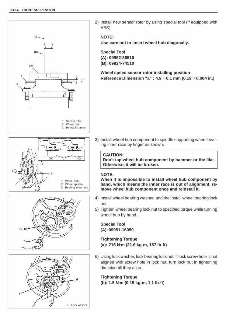
YH4GRANDVITARA
1. Wheel hub2. Wheel spindle3. Bearing inner race
1. Lock washer
1. Sensor rotor2. Wheel hub3. Hydraulic press
OK NG
3D-14 FRONT SUSPENSION
2) Install new sensor rotor by using special tool (if equipped withABS).
NOTE:Use care not to insert wheel hub diagonally.
Special Tool(A): 09952-86510(B): 09924-74510
Wheel speed sensor rotor installing positionReference Dimension “a” : 4.9 � 0.1 mm (0.19 � 0.004 in.)
3) Install wheel hub component to spindle supporting wheel bear-ing inner race by finger as shown.
CAUTION:Don’t tap wheel hub component by hammer or the like.Otherwise, it will be broken.
NOTE:When it is impossible to install wheel hub component byhand, which means the inner race is out of alignment, re-move wheel hub component once and reinstall it.
4) Install wheel bearing washer, and the install wheel bearing locknut.
5) Tighten wheel bearing lock nut to specified torque while turningwheel hub by hand.
Special Tool(A): 09951-16050
Tightening Torque(a): 216 N.m (21.6 kg-m, 157 lb-ft)
6) Using lock washer, lock bearing lock nut. If lock screw hole is notaligned with screw hole in lock nut, turn lock nut in tighteningdirection till they align.
Tightening Torque(b): 1.5 N.m (0.15 kg-m, 1.1 lb-ft)

YH4GRANDVITARA
2, (b)
1
1. Circlip2. Large diameter
1. Front wheel speed sensor2. Bolt
FRONT SUSPENSION 3D-15
7) For 4WD vehicle, apply lithium grease to front drive shaft wash-er and front wheel spindle outer.
“A”: Grease 99000-25010
8) For 4WD vehicle, when installing circlip to drive shaft, utilizescrew hole in drive shaft to pull it out and bring large diameterof circlip at right as shown.
9) For vehicle with ABS, check that no foreign material is attachedto sensor and rotor. Install wheel speed sensor and its harnessclamp.
Tightening Torque(a): 10 N.m (1.0 kg-m, 7.5 lb-ft)(b): 23 N.m (2.3 kg-m, 17.0 lb-ft)
CAUTION:� Do not pull wire harness or twist more than necessary
when installing front wheel speed sensor.� Fit harness grommet to inner fender securely.
Check that there is no clearance between sensor and knuckle.
10) Install brake disc and caliper assembly.
Tightening Torque(e): 85 N.m (8.5 kg-m, 61.5 lb-ft)

YH4GRANDVITARA
1. Axle shaft driveflange
2. Bolt3. Hub cap4. Wheel hub
For 4WD vehicle
For 2WD vehicle
3D-16 FRONT SUSPENSION
11) Apply sealant and install axle shaft drive flange or hub cap.� For 4WD vehicle
Apply sealant mating surface of axle shaft drive flange, theninstall axle shaft drive flange and tighten flange bolt to speci-fied torque.
Tightening Torque(a): 50 N.m (5.0 kg-m, 36.5 lb-ft)
“A”: Sealant 99000-31090
� For 2WD vehicleRemove grease, old sealant and dusts from mating surfacesof hub cap and hub to clean, apply water tight sealant “A” tocap mating surface evenly, and install cap to hub.
“A”: Sealant 99000-31090
12) Install wheel.
Tightening Torque(a): 100 N.m (10.0 kg-m, 72.5 lb-ft)
13) For vehicle equipped with ABS, perform driving test referringto “DRIVING TEST” of “ABS DIAGNOSTIC FLOW TABLE” inSection 5E or 5E1.
YH4GRANDVITARA
1. Drive shaftcirclip
2. Spindle thrustwasher
3. Drive shaft4. Wheel spindle
1. Tie-rod end2. Knuckle
1. Strut2. Knuckle
1. Dust cover2. Wheel spindle3. Knuckle4. Inner oil seal /
knuckle cap
FRONT SUSPENSION 3D-17
KNUCKLE/WHEEL SPINDLEREMOVAL
1) Remove wheel hub. Refer to “WHEEL HUB (INCLUDEDWHEEL BEARING)” in this section.
2) Remove front drive shaft circlip and front spindle thrust washer(for 4WD vehicle) or front hub cap (for 2WD vehicle).
3) Disconnect tie-rod end from knuckle.4) Remove stabilizer bar. Refer to “STABILIZER BAR/BUSH-
INGS” in this section.
5) Remove ball stud nut.6) Support lower arm with jack.7) Remove strut bracket bolts from strut bracket.
8) By using puller, disconnect knuckle from ball stud.
9) While lowering jack, remove knuckle/wheel spindle comp.10) Remove inner oil seal (for 4WD vehicle), knuckle cap (for 2WD
vehicle), dust cover and wheel spindle.

YH4GRANDVITARA
“A”
“B”
1. Wheel spindle2. Drive shaft bearing
1. Wheel spindle2. Drive shaft
bearing3. Front drive shaft
thrust washer4. Inner oil seal5. Knuckle cap6. Drive shaft oil seal
Type A Type B
1. Drive shaft bearing2. Wheel spindle
3D-18 FRONT SUSPENSION
11) For 4WD vehicleRemove drive shaft bearing by using special tool.
Special Tool(A): 09923-74510(B): 09930-30102
INSTALLATIONReverse removal sequence to install knuckle, wheel spindle oil sealand drive shaft bearing,noting following points.
� For 4WD vehicleInstall drive shaft bearing by using special tool.
Special Tool(A): 09913-76010 Type A drive shaft thrust washer. . . . . . . . (A): 09913-80112 Type B drive shaft thrust washer. . . . . . . .
Dimension “a”: 0 – 1 mm (0 – 0.04 in.)Dimension “a”: Type A drive shaft thrust washer. . . . . . . . . Dimension “a”: 1.75 – 2.50 mm (0.069 – 0.098 in.)Dimension “a”: Type B drive shaft thrust washer. . . . . . . . .
� When installing wheel spindle to knuckle, coat their mating sur-faces with sealant.
“A”: Sealant 99000-31110
� For 4WD vehicleAlso, fill recess in wheel spindle with about 10 g lithium grease.
“B”: Grease 99000-25010

YH4GRANDVITARA
FRONT SUSPENSION 3D-19
1. Knuckle2. Knuckle cap3. Wheel spindle
1. Oil seal2. Drive shaft3. Drive shaft
thrust washer
Type A Type B
� Tighten wheel spindle nut to specified torque.
Tightening Torque(a): 50 N.m (5.0 kg-m, 36.5 lb-ft)
� For 4WD vehiclePress-fitting inner oil seal.Drive in inner oil seal until its end contacts stepped surface ofknuckle by using special tools.
Special Tool(B): 09944-66010(C): 09924-74510
� For 4WD vehicle� Apply lithium grease to oil seal lip and into its hollow to fill more
than 60% of its vacant space.� Apply lithium grease “A” to drive shaft.
“A”: Grease 99000-25010
� Press-fit front drive shaft thrust washer to drive shaft, if it is re-moved (for Type B drive shaft thrust washer). Apply lithiumgrease “A” to drive shaft thrust washer.
“A”: Grease 99000-25010
� Apply lithium grease “A” and install front drive shaft thrust wash-er with its chamfered side facing to center side (for Type A driveshaft thrust washer).
“A”: Grease 99000-25010
� For 2WD vehicleRemove grease, old sealant and dusts from mating surfaces ofknuckle cap and knuckle to clean, apply water tight sealant to capmating surface evenly, and install cap to knuckle.
“B”: Sealant 99000-31090

YH4GRANDVITARA
(a)
1. Axle shaft drive flange2. Bolt
1. Hub cap2. Wheel hub
3D-20 FRONT SUSPENSION
� Tighten control arm ball stud nutWhen tightening ball stud nut, use new nut and tighten it to speci-fied torque.
Tightening Torque(a): 60 N.m (6.0 kg-m, 43.5 lb-ft)
� For 2WD vehicleApply water tight sealant to mating surface of wheel hub andinstall hub cap to wheel hub.
“A”: Sealant 99000-31090
� For 4WD vehicleWhen installing axle shaft drive flange to wheel hub, apply sealantto mating surface of axle shaft drive flange.
“A”: Sealant 99000-31090
Tightening Torque(a): 50 N.m (5.0 kg-m, 36.5 lb-ft)
� For installation procedures of wheel hub component, refer to“WHEEL HUB (INCLUDED WHEEL BEARING)” in this section.
� Connect tie-rod end to knuckle and tighten new tie-rod end nut.
Tightening Torque(a): 43 N.m (4.3 kg-m, 31.5 lb-ft)
� For any tightening torque other than those specified in text, referto “TIGHTENING TORQUE SPECIFICATION” in this section.

YH4GRANDVITARA
FRONT SUSPENSION 3D-21
(1)(2)
(A)
1. Hydraulic press
1. Hydraulic press
Cut off flange
Bush outer diameter
SUSPENSION CONTROL ARM/BUSHINGSREMOVAL1) Remove coil spring. Refer to COIL SPRING in this section.2) Remove control arm bolts and nuts. Then remove control arm.3) Cut flange part of control arm bush (rubber and steel) with using
care not to damage control arm end surface.
Dimension “A”: Approx. 6 mm (0.236 in.)
4) Place control arm and special tool on hydraulic press. Set con-trol arm cutting flange to welded part (1) of the special tool andcontrol arm joint side to the stepped part (2) of special tool.
CAUTION:Use special care in driving out control arm bush to pressit vertically.Or it may cause personally injury.
Special tool(A): 09951-46020
5) Remove front bushing by using hydraulic press and specialtools, pull out bushing.
Special Tool(A): 09951-46020(B): 09924-74510(C): 09951-16060
6) Remove rear bushing by using hydraulic press and specialtools, pull out bushing.
Special Tool(A): 09951-46020(D): 09913-80112(E): 09925-58210

YH4GRANDVITARA
3D-22 FRONT SUSPENSION
1. Hydraulic press2. Front bushingA: Bushing flange
contacts housing edge
1. Hydraulic press2. Rear bushingA: Bushing flange
contacts housing edge
INSTALLATION1) Front bushing
Press-fit front bushing until its flange contacts housing edge ofcontrol arm, use special tools as shown.
Special Tool(C): 09951-16060(F): 09913-85210
NOTE:When press-fitting bushing, compounding oil or soap waterapplied to inside of control arm housing will facilitate work.
2) Rear bushingPress-fit rear bushing until its flange contacts housing edge ofcontrol arm, use special tools as shown.
Special Tool(E): 09925-58210(F): 09913-85210
NOTE:When press-fitting bushing, compounding oil or soap waterapplied to inside of control arm housing will facilitate work.
3) Install control arm to chassis.Tighten suspension arm nut to specified torque after loweringhoist and vehicle in non-loaded condition.Tightening Torque(a): 85 N.m (8.5 kg-m, 61.5 lb-ft)(b): 127 N.m (12.7 kg-m, 92.0 lb-ft)
4) As installation procedure hereafter is the same as that for coilspring. Refer to “COIL SPRING” in this section.NOTE:For any tightening torque other than those specified in text,refer to “TORQUE SPECIFICATION TABLE” at the end ofthis section.

YH4GRANDVITARA
FRONT SUSPENSION 3D-23
TIGHTENING TORQUE SPECIFICATIONS

YH4GRANDVITARA
3D-24 FRONT SUSPENSION
REQUIRED SERVICE MATERIALS
MATERIALSRECOMMENDED
SUZUKI PRODUCTUSE NO.
Lithium greaseSUZUKI SUPER GREASE (A)(99000-25010)
Bearing inner oil seal /drive shaft oil sealRecess of wheel spindlesSpindle outer washerSpindle part of drive shaftSpindle bush (inside and flange part)Spindle inner washer
abcdef
SealantSUZUKI BOND NO. 1215(99000-31110)
Mating surfaces of wheel spindleand knuckle
1
Sealing compoundSUZUKI SEALING COM-POUND 366E(99000-31090)
Front axle capMating surfaces of wheel hub and driveflangeKnuckle capHub cap
AB
CD

YH4GRANDVITARA
FRONT SUSPENSION 3D-25
09923-74510Bearing remover
09930-30102Sliding shaft
09924-74510Bearing installer handle
09941-66010Bump stopper wrench
09942-15510Sliding hammer
09943-35512Brake drum remover
09944-68210Bearing & oil seal installer
09944-66010Wheel hub/knuckle oilseal installer
09951-16050Wheel bearing tightening tool
09951-46020Control arm remover support
09951-16060Control arm bush remover(front)
09913-80112Bearing installer
09925-58210Oil seal installer
09913-85210Oil seal installer
09952-86510Front sensor rotor installer
SPECIAL TOOLS

YH4GRANDVITARA
3E
REAR SUSPENSION 3E-1
GENERAL DESCRIPTION 3E- 2. . . . . . . . . . . . . .
DIAGNOSIS 3E- 3. . . . . . . . . . . . . . . . . . . . . . . . . . . Diagnosis Table 3E- 3. . . . . . . . . . . . . . . . . . . . . . Shock Absorber Check 3E- 3. . . . . . . . . . . . . . . . Lower/Upper/Lateral Rod Check 3E- 3. . . . . . . . Axle Housing and Coil Spring Check 3E- 3. . . . Bearing Retainer & Axle Shaft Inner Oil
Seal Check 3E- 4. . . . . . . . . . . . . . . . . . . . . . . . . Wheel Disc, Nut & Bearing Check 3E- 4. . . . . .
ON-VEHICLE SERVICE 3E- 5. . . . . . . . . . . . . . . . Shock Absorber 3E- 5. . . . . . . . . . . . . . . . . . . . . .
Coil Spring 3E- 6. . . . . . . . . . . . . . . . . . . . . . . . . . Lower Rod 3E- 8. . . . . . . . . . . . . . . . . . . . . . . . . . Upper Rod 3E- 9. . . . . . . . . . . . . . . . . . . . . . . . . . Lateral Rod 3E-10. . . . . . . . . . . . . . . . . . . . . . . . . . Rear Axle Shaft and Wheel Bearing 3E-10. . . . . Rear Axle Shaft Inner Oil Seal 3E-15. . . . . . . . . . Rear Axle Housing 3E-16. . . . . . . . . . . . . . . . . . . .
TIGHTENING TORQUESPECIFICATIONS 3E-23. . . . . . . . . . . . . . . . . . . .
REQUIRED SERVICE MATERIALS 3E-23. . . . . .
SPECIAL TOOLS 3E-24. . . . . . . . . . . . . . . . . . . . . .
SECTION 3E
REAR SUSPENSIONNOTE:� All suspension fasteners are an important attaching part in that it could affect the performance of vital
parts and systems, and/or could result in major repair expense. They must be replaced with one of thesame part number or with an equivalent part if replacement becomes necessary. Do not use a replace-ment part of lesser quality or substitute design. Torque values must be used as specified during reas-sembly to assure proper retention of this part.
� Never attempt to heat, quench or straighten any suspension part. Replace it with a new part, or damageto the part may result.
CONTENTS
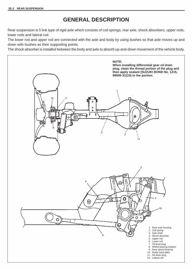
YH4GRANDVITARA
1. Rear axle housing2. Coil spring3. Axle shaft4. Shock absorber5. Upper rod6. Lower rod7. Oil level plug8. Wheel bearing retainer9. Rear wheel bearing
10. Brake back plate11. Oil drain plug12. Lateral rod
NOTE:When installing differential gear oil drainplug, clean the thread portion of the plug andthen apply sealant (SUZUKI BOND No. 1215,99000-31110) to the portion.
8
3E-2 REAR SUSPENSION
GENERAL DESCRIPTION
Rear suspension is 5 link type of rigid axle which consists of coil springs, rear axle, shock absorbers, upper rods,lower rods and lateral rod.The lower rod and upper rod are connected with the axle and body by using bushes so that axle moves up anddown with bushes as their supporting points.The shock absorber is installed between the body and axle to absorb up-and-down movement of the vehicle body.

YH4GRANDVITARA
“A”: Drill hole with approximately3 mm (0.12 in.) diameter.
REAR SUSPENSION 3E-3
DIAGNOSISDIAGNOSIS TABLERefer to SECTION 3.
SHOCK ABSORBER CHECK� Inspect for deformation or damage.� Inspect bushings for wear or damage.� Inspect for evidence of oil leakage.
Replace any defective part.
WARNING:When handling rear shock absorber in which high-pressuregas is sealed, make sure to observe the following precau-tions.1) Don’t disassemble it.2) Don’t put it into the fire.3) Don’t store it where it gets hot.4) Before disposing it, be sure to drill a hole in it where
shown by an arrow in the figure and let gas and oil out.Lay it down sideways for this work.
5) The gas itself is harmless but it may issue out of the holetogether with chips generated by the drill. Therefore, besure to wear goggle.
LOWER ROD, UPPER ROD, LATERAL RODCHECK
Inspect for cracks, deformation or damage.Replace any defective part.Inspect each bush for wear and breakage. If found defective, re-place.
AXLE HOUSING AND COIL SPRING CHECK
Inspect for cracks, deformation or damage.Inspect for evidence of oil leakage at axle housing.If any, replace defective part.

YH4GRANDVITARA
3E-4 REAR SUSPENSION
REAR SUSPENSION FASTENERSCheck each bolt and nut fastening suspension parts for tightness.Tighten loose one, if any, to specified torque, referring to “TIGHT-ENING TORQUE SPECIFICATIONS” of this section.
BEARING RETAINER AND AXLE SHAFTINNER OIL SEAL CHECK
� When brake drum has been removed, check inside of brake drumfor gear oil leakage.
� Also, check backside of brake back plate for oil leakage.If oil leakage is found, replace defective oil seal.
� Whenever it is possible to check oil seal during disassembly,check its lip for wear.If oil leakage or worn lip is found, replace defective oil seal.
WHEEL DISC, NUT & BEARING CHECK
� Inspect each wheel disc for dents, distortion and cracks. A discin badly damaged condition must be replaced.
� Check wheel hub nuts for tightness and retighten to specificationas necessary.
Tightening Torque(a): 100 N.m (10.0 kg-m, 72.5 lb-ft)
� Check wheel bearings for wear. When measuring thrust play, ap-ply a dial gauge to axle shaft center after removing wheel centercap from wheel.
Thrust play limit Rear 0.8 mm (0.03 in.)
When measurement exceeds limit, replace bearing.
� By rotating wheel actually, check wheel bearing for noise andsmooth rotation. If it is defective, replace bearing.

YH4GRANDVITARA
1. Rear axle housing2. Floor jack
1. Lock nut (if equipped)2. Absorber nut3. Upper support4. Rubber bush5. Lower support6. Shock absorber7. Bolt
Upper side
Lower side
1. Lock nut (if equipped)2. Absorber nut3. Body outside
REAR SUSPENSION 3E-5
ON-VEHICLE SERVICE
SHOCK ABSORBER
The shock absorber is non-adjustable, non-refillable, and cannotbe disassembled. The only service the shock absorber requires isreplacement when it has lost its resistance, is damaged, or leakingfluid.
REMOVAL1) Hoist vehicle and remove rear wheel.2) Support rear axle housing by using floor jack to prevent it from
lowering.
3) Remove lock nut (if equipped) and absorber nut.4) Remove lower mounting bolt.5) Remove shock absorber.
INSTALLATION1) Install shock absorber. Refer to figure for proper installing direc-
tion of lower mounting bolt.2) Remove floor jack.3) Lower hoist.4) Tighten nuts to specified torque.
NOTE:� Tighten lower nut with vehicle off hoist and in non-loaded
condition.
Tightening Torque(a): 29 N.m (2.9 kg-m, 21.0 lb-ft)(b): 85 N.m (8.5 kg-m. 61.5 lb-ft)

YH4GRANDVITARA
1. Parking brakecable hanger
2. Cross member3. Clamp4. Chassis frame
1. Rear axle housing2. Floor jack
1. Shock absorber2. Lower bolt
1. Clamp2. Upper rod
3E-6 REAR SUSPENSION
COIL SPRINGREMOVAL1) Hoist vehicle and remove rear wheel.2) Support rear axle housing by using floor jack.
3) Disconnect parking brake cable hanger from chassis frame andclamp from cross member.
4) Remove shock absorber lower mounting bolt.
5) Remove wheel speed sensor clamps from upper rod and axlehousing, if equipped with ABS.For right side, remove E-ring for fixing brake pipe from crossmember and disconnect breather hose from axle housing.
6) Lower rear axle housing gradually as far down as where coilspring can be removed.
7) Remove coil spring.

YH4GRANDVITARA
1. Rear axle housing2. Spring seat3. Coil spring4. Stepped part
1. Body center2. Body outside
1. Body center2. Body outside
1. Parking brakecable hanger
2. Cross member3. Clamp4. Chassis frame
REAR SUSPENSION 3E-7
INSTALLATION1) Install coil spring on spring seat of axle housing and then raise
axle housing.
NOTE:When seating coil spring, mate spring end with steppedpart of rear axle spring seat as shown.
2) Install shock absorber lower bolt. For its proper installing direc-tion, refer to figure.Nut should not be tightened.
3) Install wheel speed sensor clamp (if equipped) and E-ring, andconnect breather hose to axle housing.
4) Connect cable hanger to chassis frame and clamp to crossmember. Remove floor jack from axle housing.
5) Install wheel and tighten wheel nuts to specified torque.
Tightening Torque(a): 100 N.m (10.0 kg-m, 72.5 lb-ft)
6) Lower hoist and tighten absorber lower nut to specified torque.
Tightening Torque(b): 85 N.m (8.5 kg-m, 61.5 lb-ft)
NOTE:For tightening of lower nut, refer to NOTE given underSHOCK ABSORBER INSTALLATION in this section.

YH4GRANDVITARA
1. Axle housing2. Floor jack
1. Lower rod2. Rear mount nut
1. Lower rod2. Front mount bolt
1. Lower rod2. Front bolt3. Rear bolt4. Vehicle body5. Axle housing6. Body center7. Body out side
[A]: Body side[B]: Axle side
3E-8 REAR SUSPENSION
LOWER RODREMOVAL1) Hoist vehicle and remove rear wheel.2) Support rear axle housing by using floor jack.
3) Remove lower rod front mount bolt.
4) Remove lower rod rear mount bolt.
INSTALLATION1) Install lower rod to chassis frame and axle housing, referring to
figure for proper installing direction of bolts.
Nuts should not be tightened.
2) Remove floor jack from rear axle housing.3) Install wheel and tighten wheel nuts to specified torque.
Tightening Torque for wheel nuts100 N.m (10.0 kg-m, 72.5 lb-ft)
4) Lower hoist and with vehicle in non loaded condition, tightenfront bolt and rear nut of lower rod to specified torque.
Tightening Torque(a): 90 N.m (9.0 kg-m, 65.0 lb-ft)

YH4GRANDVITARA
1. Clamp2. Upper rod
1. Upper rod front bolt2. Nut3. Upper rod4. Wheel speed sensor
harness bracket(Toward outside of body)
1. Upper rod2. Bolt
5. Upper rod rear bolt6. Washer7. Body center8. Front side
REAR SUSPENSION 3E-9
UPPER RODREMOVAL1) Hoist vehicle and remove rear wheel.2) If equipped with ABS, disconnect wheel speed sensor harness
clamp from left upper rod.
3) Remove upper rod.
INSTALLATION1) Install upper rod to chassis frame and axle housing, referring to
figure for installing direction of bolts.Nuts should not be tightened.
2) See figure for distinction of installing direction of left side upperrod for vehicle equipped with ABS.
3) Connect wheel speed sensor harness clamp to upper rod (ifequipped with ABS).
4) Lower hoist and with vehicle in non-loaded condition, tightenfront bolt and rear nut of upper rod to specified torque.
Tightening Torque(a): 90 N.m (9.0 kg-m, 65 lb-ft)

YH4GRANDVITARA
(a)
(a)
1. Bolt2. Washer3. Lateral rod
1. Nut1
3E-10 REAR SUSPENSION
LATERAL RODREMOVAL1) Hoist vehicle.2) Remove lateral rod mounting bolts.3) Remove lateral rod.
INSTALLATION1) Install lateral rod to rear axle, and vehicle body.2) Lower hoist.3) Tighten lateral rod mounting bolts to specified torque.
Tightening Torque(a): 90 N.m (9.0 kg-m, 65.0 lb-ft)
REAR AXLE SHAFT AND WHEEL BEARINGREMOVAL1) Remove rear brake drum. For details, refer to REAR BRAKE
DRUM REMOVAL in SECTION 5C.
2) Drain gear oil from rear axle housing by loosening drain plug.
3) Remove rear wheel bearing retainer nuts from axle housing.

YH4GRANDVITARA
1. Bearing retainer2. Parking brake shoe
lever3. Clearance
1. Wheel speed sensor
1
L
REAR SUSPENSION 3E-11
4) Remove wheel speed sensor from rear axle housing (ifequipped with ABS).
CAUTION:� Do not pull wire harness or twist more than necessary
when removing rear wheel speed sensor.� Do not cause damage to surface of rear wheel speed
sensor or pole piece and do not allow dust, etc. to enterits installation hole.
5) Check to ensure that there is clearance between rear wheelbearing retainer and parking brake shoe lever. If no clearanceis found, loosen cable locking nut further to obtain clearance.
6) Using special tools (B) & (C) indicated below, draw out axleshaft.
NOTE:Use care not to pull brake back plate along with shaft.
CAUTION:Pull out axle shaft using care so that upper and lowerbrake struts and parking cable are not caught.
Special Tool(C): 09943-35512(B): 09942-15510
7) Rear axle shaft that was drawn out.
Shaft length “L”:Left side: 711.5 mm (28.0 in.)Right side: 757.5 mm (29.8 in.)
8) If equipped with ABS, in order to remove sensor rotor from re-tainer ring, grind with a grinder one part of the sensor rotor asillustrated till it becomes thin.

YH4GRANDVITARA
1. Axle shaft2. Wheel bearing3. Press
1. Stud bolt2. Hydraulic press
1. Rear wheel bearingretainer ring
2. Grind with a grinder3. Rear axle
3E-12 REAR SUSPENSION
9) Break with a chisel the thin ground sensor rotor, and it can beremoved (if equipped with ABS).
10) In order to remove the retainer ring from the shaft, grind witha grinder two parts of the bearing retainer ring as illustrated tillit becomes thin.
CAUTION:Be careful not to grind too far not to damage the shaft.
11) Break with a chisel the thin ground retainer ring, and it can beremoved.
12) Remove bearing from shaft by using hydraulic press.13) Remove bearing retainer.
14) Remove stud bolt(s) by using hydraulic press.

YH4GRANDVITARA
[B]
1
2
[A]
1. Bearing retainer2. Oil seal3. Wheel side4. Differential side
1. Stud bolt2. Nut3. Washer4. Flange of axle shaft
1. Axle shaft2. Bearing retainer
[A]: Vehicle without ABS[B]: Vehicle with ABS1. Bearing2. Retainer ring
REAR SUSPENSION 3E-13
INSTALLATIONInstall removed parts in reverse order of removal procedure, notingthe following.1) Apply grease to oil seal lip as shown and install it to axle shaft.
NOTE:Amount of grease applied to hollow in oil seal should bemore than 60% of its vacant space.
“A”: Grease 99000-25010
2) Aligning serrations between new stud bolt(s) and flange, installnew stud bolt(s) by tightening nut as shown.
3) Install bearing retainer to shaft.
4) Press-fit wheel bearing and retainer ring as shown.
NOTE:� Use care not to cause any damage to outside of retainer
ring.� Refer to figure so that wheel bearing is installed in proper
direction.

YH4GRANDVITARA
1. Sensor rotor
1. Axle housing
1. Bearing retainer
(b)
3E-14 REAR SUSPENSION
5) For vehicle with ABS, press-fit new sensor rotor as shown.
NOTE:Use care not to cause any damage to outside of retainerring.
6) Apply grease to axle shaft inner oil seal lip as shown.
“A”: Grease 99000-25010
7) Apply sealant to mating surface of bearing retainer with brakeback plate.
NOTE:Make sure to remove old sealant before applying it anew.
“B”: Sealant 99000-31110
8) Install rear axle shaft to rear axle housing and tighten bearingretainer nuts to specified torque.
NOTE:When installing rear axle shaft, be careful not to causedamage to oil seal lip in axle housing.
Tightening Torque(a): 23 N.m (2.3 kg-m, 17.0 lb-ft)
9) Tighten wheel speed sensor bolt to specified torque (ifequipped with ABS).
Tightening Torque(b): 21 N.m (2.1 kg-m, 15.5 lb-ft)
10) Refill rear axle (differential) housing with new specified gear oil.Refer to SECTION 7F for refill.
11) Install brake drum. (For details, refer to BRAKE DRUMINSTALLATION in SECTION 5.)
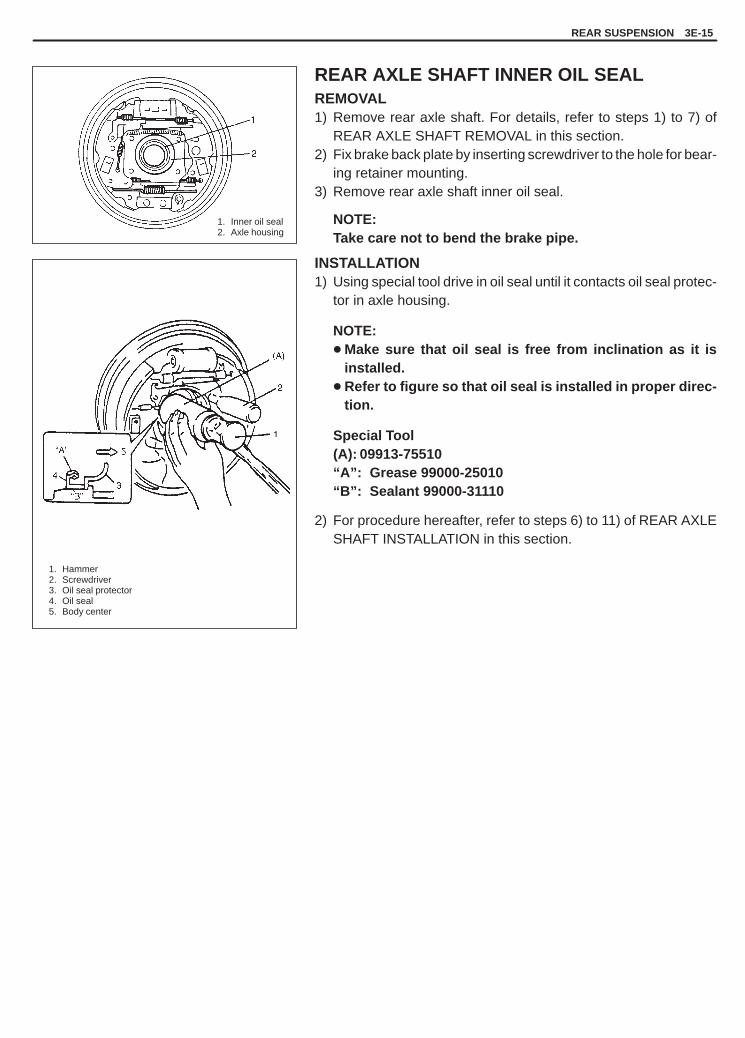
YH4GRANDVITARA
REAR SUSPENSION 3E-15
1. Inner oil seal2. Axle housing
1. Hammer2. Screwdriver3. Oil seal protector4. Oil seal5. Body center
REAR AXLE SHAFT INNER OIL SEALREMOVAL1) Remove rear axle shaft. For details, refer to steps 1) to 7) of
REAR AXLE SHAFT REMOVAL in this section.2) Fix brake back plate by inserting screwdriver to the hole for bear-
ing retainer mounting.3) Remove rear axle shaft inner oil seal.
NOTE:Take care not to bend the brake pipe.
INSTALLATION1) Using special tool drive in oil seal until it contacts oil seal protec-
tor in axle housing.
NOTE:� Make sure that oil seal is free from inclination as it is
installed.� Refer to figure so that oil seal is installed in proper direc-
tion.
Special Tool(A): 09913-75510“A”: Grease 99000-25010“B”: Sealant 99000-31110
2) For procedure hereafter, refer to steps 6) to 11) of REAR AXLESHAFT INSTALLATION in this section.
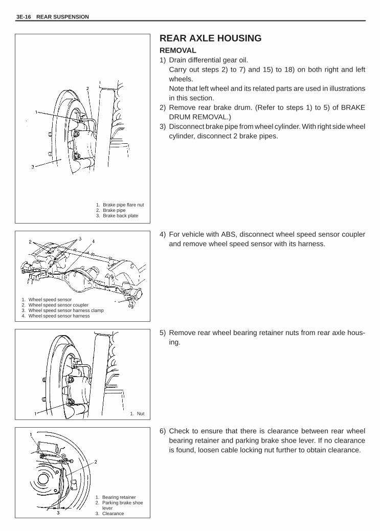
YH4GRANDVITARA
1. Brake pipe flare nut2. Brake pipe3. Brake back plate
1. Bearing retainer2. Parking brake shoe
lever3. Clearance
1. Nut
1. Wheel speed sensor2. Wheel speed sensor coupler3. Wheel speed sensor harness clamp4. Wheel speed sensor harness
3E-16 REAR SUSPENSION
REAR AXLE HOUSINGREMOVAL1) Drain differential gear oil.
Carry out steps 2) to 7) and 15) to 18) on both right and leftwheels.Note that left wheel and its related parts are used in illustrationsin this section.
2) Remove rear brake drum. (Refer to steps 1) to 5) of BRAKEDRUM REMOVAL.)
3) Disconnect brake pipe from wheel cylinder. With right side wheelcylinder, disconnect 2 brake pipes.
4) For vehicle with ABS, disconnect wheel speed sensor couplerand remove wheel speed sensor with its harness.
5) Remove rear wheel bearing retainer nuts from rear axle hous-ing.
6) Check to ensure that there is clearance between rear wheelbearing retainer and parking brake shoe lever. If no clearanceis found, loosen cable locking nut further to obtain clearance.

YH4GRANDVITARA
1. Flexible hose2. E-ring3. Brake pipe4. Cross member
1. LSPV stay
1. Hose2. Axle housing
1. Propeller shaft2. Differential carrier
REAR SUSPENSION 3E-17
7) Using special tools (B) & (C) indicated below, draw out axleshafts. For vehicle equipped with ABS, remove wheel speedsensor from axle housing before drawing out axle shaft.
NOTE:Use care not to pull brake back plate along with shaft.
Special Tool(C): 09943-35512(B): 09942-15510
8) For vehicle without ABS, remove LSPV stay from axle housing.
9) Remove brake back plate from rear axle housing.10) Disconnect brake pipe from flexible hose and remove E-ring
(front side).
11) Remove brake pipe clamps and pipes from axle housing anddisconnect breather hose from axle housing.
12) Disconnect propeller shaft and remove propeller shaft fromtransmission.

YH4GRANDVITARA
3E-18 REAR SUSPENSION
1. Axle housing2. Jack
1. Differential carrierassembly
2. Differential carrier nut
1. Lower rod2. Lower rod rear
mount nut3. Shock absorber
1. Lower mountbolt
13) For jobs hereafter, support rear axle housing by using floor jackunder axle housing.
14) Remove differential carrier assembly.
15) Loosen rear mount nut of upper rod but don’t remove bolt.16) Loosen rear mount nut of lower rod but don’t remove bolt.
17) Remove rear axle side lateral rod mount bolt.18) Remove shock absorber lower mount bolt.
19) Lower floor jack until tension of suspension coil spring be-comes a little loose and remove rear mount bolt of upper , lowerand lateral rod.
20) Lower rear axle housing gradually.21) Remove axle housing.

YH4GRANDVITARA
1. Lower rod2. Body center
1. Rear axle housing2. Spring seat3. Coil spring4. Stepped part
1. Axle housing“A”
1. Body center
1
2
1
REAR SUSPENSION 3E-19
INSTALLATIONInstall removed parts in reverse order of removal, noting the follow-ing.1) Place rear axle housing on floor jack. Then install upper/ lower
rod rear mounting bolts (right & left) in proper direction as shown(refer to UPPER ROD INSTALLATION for upper rod bolts). Atthis time, mount nuts but don’t tighten them.
2) Install coil spring (right & left) on spring seat of axle housing andraise axle housing.
NOTE:When seating coil spring, mate spring end with steppedpart of rear axle spring seat as shown.
3) Install lateral rod to rear axle housing.4) Install lower part of shock absorber to right and left sides of axle
housing and install bolts in proper direction as shown in figure.At this time, mount nuts but don’t tighten them.
5) Clean mating surfaces of axle housing and differential carrierand apply sealant to housing side.
“A”: Sealant 99000-31110
6) Install differential carrier assembly to axle housing and tightencarrier nuts to specified torque.
Tightening Torque(a): 55 N.m (5.5 kg-m, 40.0 lb-ft)

YH4GRANDVITARA
1. Axle housing
“A”
(c)
1. Axle housing
3E-20 REAR SUSPENSION
7) For vehicle with ABS, connect wheel speed sensor coupler andinstall harness.
8) Install propeller shaft and torque nuts to specification.
Tightening Torque(b): 50 N.m (5.0 kg-m, 36.5 lb-ft)
9) Remove floor jack from axle housing and connect breatherhose onto axle housing and clamp it securely.
10) Connect brake pipes onto axle housing and clamp them se-curely.For clamping positions, refer to SECTION 5A of this manual.
11) Connect brake flexible hose to bracket on axle housing and se-cure it with E-ring.
12) Install LSPV stay to axle housing, tighten LSPV stay bolt tospecified torque.And adjust LSPV referring to “LSPV ASSEMBLY INSPEC-TION AND ADJUSTMENT” in SECTION 5A.
Tightening Torque(c): 23 N.m (2.3 kg-m, 17.0 lb-ft)
13) Connect brake pipe to brake flexible hose and tighten brakepipe flare nut to specified torque.
Tightening Torque(d): 16 N.m (1.6 kg-m, 11.5 lb-ft)
14) Clean mating surface of axle housing (right & left) and brakeback plate, then apply sealant as shown.
“A”: Sealant 99000-31110
15) Apply grease to axle shaft inner oil seal lip as shown.
“A”: Grease 99000-25010

YH4GRANDVITARA
3. Container1. Plug cap2. Vinyl tube
1. Bearing retainer
(e)
(f)
(g)
REAR SUSPENSION 3E-21
16) Apply sealant to mating surface of bearing retainer with brakeback plate.
NOTE:Make sure to remove old sealant before applying it anew.
“B”: Sealant 99000-31110
17) Install rear axle shaft to rear axle housing and tighten bearingretainer nuts to specified torque.
NOTE:When installing rear axle shaft, be careful not to causedamage to oil seal lip in axle housing.
Tightening Torque(e): 23 N.m (2.3 kg-m, 17.0 lb-ft)
18) For vehicle with ABS, tighten wheel speed sensor bolt to speci-fied torque.
Tightening Torque(f): 21 N.m (2.1 kg-m, 15.5 lb-ft)
19) Connect brake pipes to wheel cylinders (right & left) and tightenbrake pipe flare nuts to specified torque.
Tightening Torque(g): 16 N.m (1.6 kg-m, 11.5 lb-ft)
20) Install brake drum (right & left). For details, refer to SECTION5C “BRAKE DRUM INSTALLATION”.
21) Refill differential gear housing with new specified gear oil. Re-fer to “ON-VEHICLE SERVICE” in SECTION 7F for refill.
22) Fill reservoir with brake fluid and bleed brake system.(Forbleeding operation, see SECTION 5.)

YH4GRANDVITARA
3E-22 REAR SUSPENSION
23) Install wheel and tighten wheel nuts to specified torque.
Tightening Torque(h): 100 N.m (10.0 kg-m, 72.5 lb-ft)
24) Upon completion of all jobs, depress brake pedal with about 30kg (66 lbs) load three to ten times so as to obtain proper drum-to-shoe clearance.Adjust parking brake cable (for adjustment, see SECTION 5Cof this manual.)
25) Tighten parking brake lever cover screws.26) Lower hoist.
27) Tighten right and left lower/upper rod nuts lateral rod mountbolt and shock absorber nuts to specified torque.
NOTE:When tightening these nuts, be sure that vehicle is offhoist and in non loaded condition.
Tightening Torque(i): 90 N.m (9.0 kg-m, 65.0 lb-ft)(j): 85 N.m (8.5 kg-m, 61.5 lb-ft)
28) Check to ensure that brake drum is free from dragging andproper braking is obtained.
29) Perform brake test (foot brake and parking brake).30) Check each installed part for oil leakage.

YH4GRANDVITARA
REAR SUSPENSION 3E-23
TIGHTENING TORQUE SPECIFICATIONS
Fastening partsTightening torque
Fastening artsN.m Kg-m lb-ft
Shock absorber lock nut 29 2.9 21.0
Shock absorber nut 29 2.9 21.0
Shock absorber lower nut 85 8.5 61.5
Lower rod bolt and nut
Upper rod bolt and nut 90 9.0 65.0
Lateral rod bolt
Differential carrier nut 55 5.5 40.0
Propeller shaft nut 50 5.0 36.5
Brake pipe flare nut 16 1.6 11.5
Bearing retainer nut 23 2.3 17.0
Differentiation gear oil Filler plug 50 5.0 36.5gfiller & drain plug Drain plug 27 2.7 16.0
Wheel nut 100 10.0 72.5
REQUIRED SERVICE MATERIALS
MATERIALSRECOMMENDED
SUZUKI PRODUCTUSE
Lithium greaseSUZUKI SUPER GREASE A(99000-25010)
Oil seal lip
Brake fluid DOT 3 Brake reservoir tank
Sealant
SUZUKI BOND NO. 1215(99000-31110)
� Joint seam of axle and brake backplate
� Joint seam of bearing retainer andbrake back plate
� Joint seam of differential carrier andaxle housing
� Drain plug� Mating surface of oil seal and axle
housing
Gear oilFor gear oil information, refer toSECTION 7F of this manual
Differential gear(Refer axle housing.)

YH4GRANDVITARA
3E-24 REAR SUSPENSION
09924-74510Bush remover handle
09926-88310Oil seal installer
09942-15510Sliding hammer
09943-35512Brake drum remover
09913-75510Oil seal installer
SPECIAL TOOLS

YH4GRANDVITARA
3F
WHEELS AND TIRES 3F-1
GENERAL DESCRIPTION 3F- 1. . . . . . . . . . . . . . Tires 3F- 1. . . . . . . . . . . . . . . . . . . . . . . . . . . . . . . . Wheels 3F- 1. . . . . . . . . . . . . . . . . . . . . . . . . . . . . Replacement Tires 3F- 1. . . . . . . . . . . . . . . . . . . Wheels Replacement 3F- 2. . . . . . . . . . . . . . . . . Metric Lug Nuts and Wheel Studs 3F- 2. . . . . .
DIAGNOSIS 3F- 3. . . . . . . . . . . . . . . . . . . . . . . . . . . Diagnosis Table 3F- 3. . . . . . . . . . . . . . . . . . . . . . Balancing Wheels 3F- 3. . . . . . . . . . . . . . . . . . . .
MAINTENANCE AND MINORADJUSTMENTS 3F- 4. . . . . . . . . . . . . . . . . . . . . . Wheel and Tire 3F- 4. . . . . . . . . . . . . . . . . . . . . . .
ON-VEHICLE SERVICE 3F- 6. . . . . . . . . . . . . . . . Wheel 3F- 6. . . . . . . . . . . . . . . . . . . . . . . . . . . . . . Tire 3F- 7. . . . . . . . . . . . . . . . . . . . . . . . . . . . . . . . .
TIGHTENING TORQUESPECIFICATIONS 3F- 8. . . . . . . . . . . . . . . . . . . .
SECTION 3F
WHEELS AND TIRESNOTE:All wheel fasteners are important attaching parts in that they could affect the performance of vital partsand systems, and/or could result in major repair expense. They must be replaced with one of the samepart number or with an equivalent part if replacement becomes necessary. Do not use a replacement partof lesser quality or substitute design. Torque values must be used as specified during reassembly to as-sure proper retention of all parts.There is to be no welding as it may result in extensive damage and weakening of the metal.
CONTENTS
GENERAL DESCRIPTIONTIRES
This vehicle is equipped with following tire. P215/65 R16, 215/65 R16 or 235/60 R16The tires are of tubeless type. The tires are designed to operate satisfactorily with loads up to the full rated loadcapacity when inflated to the recommended inflation pressure.Correct tire pressures and driving habits have an important influence on tire life. Heavy cornering, excessively rapidacceleration, and unnecessary sharp braking increase tire wear.
WHEELS
Standard equipment wheels are following steel wheel. 16 � 6 1/2 J or 16 � 7JJ
REPLACEMENT TIRES
When replacement is necessary, the original equipment type tire should be used. Refer to the Tire Placard. Re-placement tires should be of the same size, load range and construction as those originally on the vehicle. Useof any other size or type tire may affect ride, handling, speedometer/odometer calibration, vehicle ground clear-ance and tire or snow chain clearance to the body and chassis.
NOTE:Do not mix different types of tires on the same vehicle such as radial, bias and bias-belted tires except inemergencies, because vehicle handling may be seriously affected and may result in loss of control.
It is recommended that new tires be installed in pairs on the same axle. If necessary to replace only one tire, itshould be paired with the tire having the most tread, to equalize braking traction.
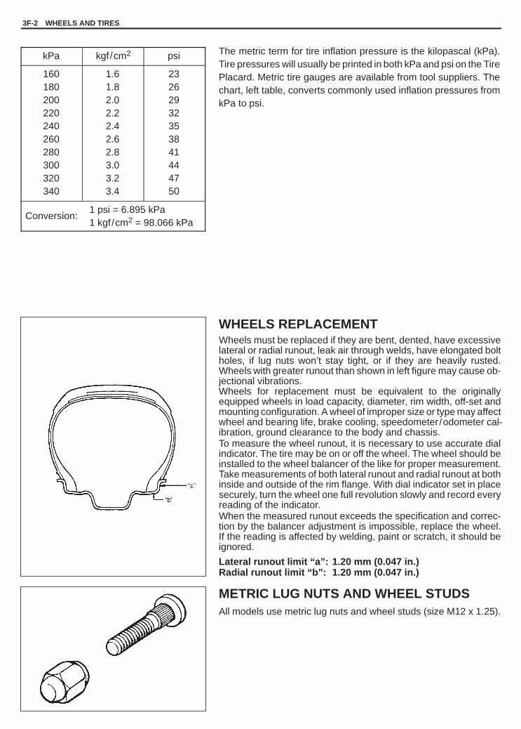
YH4GRANDVITARA
3F-2 WHEELS AND TIRES
The metric term for tire inflation pressure is the kilopascal (kPa).Tire pressures will usually be printed in both kPa and psi on the TirePlacard. Metric tire gauges are available from tool suppliers. Thechart, left table, converts commonly used inflation pressures fromkPa to psi.
kPa kgf/cm2 psi
160180200220240260280300320340
1.61.82.02.22.42.62.83.03.23.4
23262932353841444750
Conversion:1 psi = 6.895 kPa1 kgf/cm2 = 98.066 kPa
WHEELS REPLACEMENTWheels must be replaced if they are bent, dented, have excessivelateral or radial runout, leak air through welds, have elongated boltholes, if lug nuts won’t stay tight, or if they are heavily rusted.Wheels with greater runout than shown in left figure may cause ob-jectional vibrations.Wheels for replacement must be equivalent to the originallyequipped wheels in load capacity, diameter, rim width, off-set andmounting configuration. A wheel of improper size or type may affectwheel and bearing life, brake cooling, speedometer/odometer cal-ibration, ground clearance to the body and chassis.To measure the wheel runout, it is necessary to use accurate dialindicator. The tire may be on or off the wheel. The wheel should beinstalled to the wheel balancer of the like for proper measurement.Take measurements of both lateral runout and radial runout at bothinside and outside of the rim flange. With dial indicator set in placesecurely, turn the wheel one full revolution slowly and record everyreading of the indicator.When the measured runout exceeds the specification and correc-tion by the balancer adjustment is impossible, replace the wheel.If the reading is affected by welding, paint or scratch, it should beignored.
Lateral runout limit “a”: 1.20 mm (0.047 in.)Radial runout limit “b”: 1.20 mm (0.047 in.)
METRIC LUG NUTS AND WHEEL STUDSAll models use metric lug nuts and wheel studs (size M12 x 1.25).

YH4GRANDVITARA
[A]: Before correction[B]: Corrective weights1. Heavy spot wheel tramp2. Balance weights addition point3. C / L of spindle
[C]: Before correction[D]: Corrective weights1. Heavy spot wheel shimmy2. Balance weights addition point3. C / L of spindle
WHEELS AND TIRES 3F-3
DIAGNOSISDIAGNOSIS TABLERefer to SECTION 3.
BALANCING WHEELSThere are two types of wheel and tire balance: static and dynamic.Static balance, as shown in left figure, is equal distribution of weightaround wheel. Wheels that are statically unbalanced cause bounc-ing action called tramp. This condition will eventually cause uneventire wear.
Dynamic balance, as shown in left figure, is equal distribution ofweight on each side of wheel centerline so that when the tire spinsthere is no tendency for the assembly to move from side to side.Wheels that are dynamically unbalanced may cause shimmy.
GENERAL BALANCE PROCEDUREDeposits of mud, etc. must be cleaned from inside of rim.
WARNING:Stones should be removed from tread in order to avoid operator injury during spin balancing and toobtain good balance.
Tire should be inspected for any damage, then balanced according to equipment manufacturer’s recommendation.
OFF-VEHICLE BALANCINGMost electronic off-vehicle balancers are more accurate than on-vehicle spin balancers. They are easy to use andgive a dynamic (two plane) balance. Although they do not correct for drum or disc unbalance as does on-vehiclespin balancing, this is overcome by their accuracy, usually to within 1/8 ounce.
ON-VEHICLE BALANCINGON-vehicle balancing methods vary with equipment and tool manufacturers. Be sure to follow each manufacturer’sinstructions during balancing operation.

YH4GRANDVITARA
1. Paint
3F-4 WHEELS AND TIRES
Higher than Recommended Pressure Can Cause:1. Hard ride2. Tire bruising or carcass damage3. Rapid tread wear at center of tire
Unequal Pressure on Same Axle Can Cause:1. Uneven braking2. Steering lead3. Reduced handling4. Swerve on accelerationValve caps should be kept on valves to keep dust andwater out.
Lower than Recommended Pressure Can Cause:1. Tire squeal on turns2. Hard steering3. Rapid and uneven wear on the edges of the tread4. Tire rim bruises and rupture5. Tire cord breakage6. High tire temperatures7. Reduced handling8. High fuel consumption
MAINTENANCE AND MINOR ADJUSTMENTS
WHEEL AND TIRE
Wheel repairs that use welding, heating, or peening are not approved. All damaged wheels should be replaced.
STUDSIf a broken stud is found, see Section 3E (rear) or Section 3D (front) for Note and Replacement procedure.
MATCHED TIRES AND WHEELS
(For vehicle equipped with steel wheels)Tires and wheels are matchmounted at the assembly plant.This means that the radially stiffest part of the tire, or “high spot”, ismatched to the smallest radius or “low spot” of the wheel.This is done to provide the smoothest possible ride.The “high spot” of the tire is originally marked by paint dot on theoutboard sidewall. This paint dot will eventually wash off the tire.The “low spot” of the wheel is originally marked by paint dot on thewheel rim-flange. Properly assembled, the wheel rims’ paint dotshould be aligned with the tires’ paint dot as shown in left figure.Whenever a tire is dismounted from its wheel, it should be re-mounted so that the tire and wheel are matched. If the tire’s paintdot cannot be located, a line should be scribed on the tire and wheelbefore dismounting to assure that it is remounted in the same posi-tion.
INFLATION OF TIRESThe pressure recommended for any model is carefully calculated to give a satisfactory ride, stability, steering, treadwear, tire life and resistance to bruises.Tire pressure, with tires cold, (after vehicle has set for three hours or more, or driven less than one mile) shouldbe checked monthly or before any extended trip. Set to the specifications on the tire placard located on the sideof instrument panel.It is normal for tire pressure increase when the tires become hot during driving. Do not bleed or reduce tire pressureafter driving. Bleeding reduces the “Cold Inflation Pressure”.

YH4GRANDVITARA
1. Front
WHEELS AND TIRES 3F-5
TIRE PLACARDThe tire placard is located on the driver’s side door lock pillar andshould be referred to for tire information. The placard lists the maxi-mum load, tire size and cold tire pressure where applicable.
TIRE ROTATIONTo equalize wear, rotate tires periodically as shown in figure.

YH4GRANDVITARA
3F-6 WHEELS AND TIRES
ON-VEHICLE SERVICEWHEELREMOVAL1) Loosen wheel nuts by approximately 180� (half a rotation).2) Hoist vehicle.3) Remove wheel.
NOTE:Never use heat to loosen tight wheel because application ofheat to wheel can shorten life of wheel and damage wheelbearings.
INSTALLATIONWheel nuts must be tightened in sequence and to proper torque toavoid bending wheel or brake drum or disc as in figure.
NOTE:Before installing wheels, remove any build-up of corrosion onwheel mounting surface and brake drum or disc mounting sur-face by scraping and wire brushing. Installing wheels withoutgood metal-to-metal contact at mounting surfaces can causewheel nuts to loosen, which can later allow wheel to come offwhile vehicle is moving.
Tightening Torque(a): 100 N.m (10.0 kg-m, 72.5 lb-ft)

YH4GRANDVITARA
WHEELS AND TIRES 3F-7
TIREMOUNTING AND DEMOUNTINGUse tire changing machine to mount or demount tires. Follow equip-ment manufacturer’s instructions. Do not use hand tools or tireirons alone to change tires as they may damage tire beads or wheelrim.Rim bead seats should be cleaned with wire brush or coarse steelwool to remove lubricants, old rubber and light rust. Before mount-ing or demounting tire, bead area should be well lubricated with ap-proved tire lubricant.After mounting, inflate to 240 kPa (35psi) so that beads are com-pletely seated. Then adjust pressure to specified shown an tireplacard.
WARNING:Do not stand over tire when inflating. Bead may break whenbead snaps over rim’s safety hump and cause serious per-sonal injury.Do not exceed 240 kPa (35 psi) pressure when inflating. If240 kPa (35 psi) pressure will not seat beads, deflate, re-lu-bricate and reinflate. Over inflation may cause bead to breakand cause serious personal injury.
Install valve core and inflate to proper pressure.
TIRE REPAIRThere are many different materials and techniques on the marketto repair tires. As not all of these work on all types of tires, tiremanufacturers have published detailed instructions on how andwhen to repair tires. These instructions can be obtained from thetire manufacturer.

YH4GRANDVITARA
3F-8 WHEELS AND TIRES
TIGHTENING TORQUE SPECIFICATIONSTightening Torque for wheel nut(a): 100 N.m (10.0 kg-m, 72.5 lb-ft)

YH4GRANDVITARA
4A2
1. Drive shaft oil seal2. Double off set joint (DOJ)3. Joint circlip4. DOJ boot5. Ball joint boot6. Ball joint assembly (RH side)7. Drive shaft assembly (LH side)8. Left drive shaft9. Drive shaft bearing circlip
10. Drive shaft bearing
FRONT DRIVE SHAFT/SHAFT BEARING, OIL SEAL 4A2-1
SECTION 4A2
FRONT DRIVE SHAFT/SHAFT BEARING,OIL SEAL
CONTENTS
GENERAL DESCRIPTION 4A2- 1. . . . . . . . . . . . . . . . . . . . . . . . . . . . . . . . . . . . . . . . . . . . . . . . . . . . . . . . . . . . . . . . . .
DIAGNOSIS 4A2- 2. . . . . . . . . . . . . . . . . . . . . . . . . . . . . . . . . . . . . . . . . . . . . . . . . . . . . . . . . . . . . . . . . . . . . . . . . . . . . . . Diagnosis Table 4A2- 2. . . . . . . . . . . . . . . . . . . . . . . . . . . . . . . . . . . . . . . . . . . . . . . . . . . . . . . . . . . . . . . . . . . . . . . . . . Drive Shaft Boot And Joint Check 4A2- 2. . . . . . . . . . . . . . . . . . . . . . . . . . . . . . . . . . . . . . . . . . . . . . . . . . . . . . . . . . .
ON-VEHICLE SERVICE 4A2- 3. . . . . . . . . . . . . . . . . . . . . . . . . . . . . . . . . . . . . . . . . . . . . . . . . . . . . . . . . . . . . . . . . . . . Drive Shaft 4A2- 3. . . . . . . . . . . . . . . . . . . . . . . . . . . . . . . . . . . . . . . . . . . . . . . . . . . . . . . . . . . . . . . . . . . . . . . . . . . . . . Shaft Bearing/Oil Seal 4A2- 9. . . . . . . . . . . . . . . . . . . . . . . . . . . . . . . . . . . . . . . . . . . . . . . . . . . . . . . . . . . . . . . . . . . .
TIGHTENING TORQUE SPECIFICATIONS 4A2-11. . . . . . . . . . . . . . . . . . . . . . . . . . . . . . . . . . . . . . . . . . . . . . . . . . . .
REQUIRED SERVICE MATERIALS 4A2-11. . . . . . . . . . . . . . . . . . . . . . . . . . . . . . . . . . . . . . . . . . . . . . . . . . . . . . . . . .
SPECIAL TOOLS 4A2-11. . . . . . . . . . . . . . . . . . . . . . . . . . . . . . . . . . . . . . . . . . . . . . . . . . . . . . . . . . . . . . . . . . . . . . . . . .
GENERAL DESCRIPTION
The drive shaft joint is a constant velocity joint (C.V. joint) which slides in the axial direction. The joint is composedof an outer race, cage, inner race and balls. In the turning direction, the joint rotates in the same way as a ball bear-ing. The balls lock rotation completely and transmit drive. In addition this vehicle is also characterized by a functionthat the shaft can slide through the balls in the grooves of the outer race in the extension/contraction direction ofthe drive shaft.

YH4GRANDVITARA
4A2-2 FRONT DRIVE SHAFT/SHAFT BEARING, OIL SEAL
DIAGNOSIS
DIAGNOSIS TABLE
Condition Possible Cause Correction
When starting:Abnormal Noise
� Loose wheel nuts.� Loose drive shaft flange bolts.� Broken or otherwise damaged wheel
bearing.
Tighten wheel nuts.Tighten drive shaft flange bolts.Replace or change.
When making turns:Abnormal Noise
� Grease leakage from drive shaft jointboot.
� Worn or broken drive shaft joint.
Replace joint boot and apply grease.
Replace drive shaft joint.
When running:Abnormal Noise
� Broken drive shaft joint.� Poorly lubricated or worn drive
shaft joint.� Loose drive shaft flange bolts.� Deformed drive shaft oil seal.
Replace drive shaft joint.Lubricate or replace joint.
Tighten drive shaft flange bolts.Replace.
Vibration � Worn drive shaft joint.� Deformed drive shaft oil seal.� Deformed drive shaft.
Replace drive shaft joint.Replace.Replace.
DRIVE SHAFT BOOT AND JOINT CHECK
Check drive shaft boot for tear. If even a small tear is noted, replacewith new one.Check drive shaft joint for wear, breakage and other damage andreplace if any defect exists.

YH4GRANDVITARA
1. Oil filler / level plug2. Front drain plug
1. Circlip2. Washer
1. Drive shaft flange bolts and nuts
1. Oil seal
FRONT DRIVE SHAFT/SHAFT BEARING, OIL SEAL 4A2-3
ON-VEHICLE SERVICE
DRIVE SHAFTREMOVAL (LEFT SIDE)1) Hoist vehicle and remove wheel.
2) Remove axle shaft drive flange.3) Remove drive shaft circlip and front spindle thrust washer.
4) Remove drive shaft flange bolts and nuts.
5) Remove drive shaft assembly to differential side as shown in leftfigure.
CAUTION:To prevent breakage of boots (wheel side and differentialside), be careful not to bring them into contact with otherparts when removing drive shaft assembly.
6) Remove drive shaft thrust washer (vehicle with G16 or J20 en-gine) from drive shaft and remove drive shaft oil seal as shownin figure.
CAUTION:Be careful not to cause damage to drive shaft joint.

YH4GRANDVITARA
1. Oil filler / level plug2. Front drain plug
1. Circlip2. Washer
1. Differential side joint2. Tire lever3. Front differential assembly
1. Oil seal
2
1
4A2-4 FRONT DRIVE SHAFT/SHAFT BEARING, OIL SEAL
REMOVAL (RIGHT SIDE)1) Hoist vehicle and remove wheel.2) Drain differential gear oil.
3) Remove axle shaft drive flange.4) Remove circlip and front spindle thrust washer.5) Remove knuckle and wheel hub comp, refer to steps 5) to 7) and
9) to 14) of item COIL SPRING REMOVAL in Section 3D.
6) Remove drive shaft assembly.To detach snap ring fitted on the spline of differential side joint(inboard joint) from differential side gear, pull inboard joint by us-ing a tire lever.
CAUTION:To prevent breakage of boots (wheel side and differentialside), be careful not to bring them into contact with otherparts when removing drive shaft assembly.
7) Remove drive shaft thrust washer (to vehicle with G16 or J20 en-gine) from drive shaft and remove drive shaft oil seal as shownin figure.
CAUTION:Be careful not to cause damage to drive shaft joint.

YH4GRANDVITARA
1. Boot2. Snap ring
1. Circlip2 Snap ring plier3. Cage
FRONT DRIVE SHAFT/SHAFT BEARING, OIL SEAL 4A2-5
DISASSEMBLY1) Remove boot band of differential side joint.
2) Slide boot toward the center of shaft and remove snap ring fromouter race, then take shaft out of outer race.
3) Remove circlip and then cage.4) Remove inside and outside boots from shaft.
CAUTION:� Do not disassemble wheel side joint (outboard joint). If
any malcondition is found in joint, replace it as assem-bly.
� Do not disassemble ball joint of differential side joint.If any malcondition is found in ball joint, replace differ-ential side joint assembly.
INSPECTION� Check boots for breakage or deterioration. Replace them as nec-
essary.� Check circlip, snap ring and boot bands for breakage or deforma-
tion. Replace as necessary.
CLEANING� Wash disassembled parts (except boots) in degreaser. After
washing, dry parts completely by blowing air.� Clean boots with cloth. DO NOT wash boots in degreaser, such
as gasoline or kerosene, etc.Washing in degreaser causes deterioration of boot.

YH4GRANDVITARA
1. Boot2. Boot band
1. Circlip
1. Cage
Wheel side
“A” Fill grease 85g (3.0 oz)
4A2-6 FRONT DRIVE SHAFT/SHAFT BEARING, OIL SEAL
ASSEMBLY
CAUTION:� To prevent any problem caused by washing solution, do
not wash joint boots. Degreasing of those parts with clothis allowed.
� For M/T vehicle with H25 engineTo ensure full performance of joint as designed, be sureto distinguish between two types of grease in repair setand apply specified volume to respective joint. i.e. yellowgrease to wheel side joint and black one to differentialside.
� Bend each boot band against forward rotation.� Do not squeeze or distort boot when fastening it with
bands.Distorted boot caused by squeezing air may reduce its du-rability.
1) Fully apply joint grease to wheel side joint.Use joint grease in the tube included in spare part.
2) Fit wheel side boot on shaft.Fill up inside of boot with joint grease of about 90 gram.Before fixing boot band, insert screwdriver into boot on joint sideand allow air to enter boot so that air pressure in boot becomesthe same as atmospheric pressure.
3) Fixing boot band.
4) Install boot onto drive shaft till its small diameter side fits to shaftgroove and fix there with boot band.
5) Install cage to shaft.
CAUTION:Install cage directing smaller outside diameter side toshaft end.
6) Install circlip by using snap ring plier.

YH4GRANDVITARA
“ A”: Fill grease 90 – 95 g (3.2 – 3.4 oz)
1. Circlip
[LH]
[RH]
Differential side
FRONT DRIVE SHAFT/SHAFT BEARING, OIL SEAL 4A2-7
7) Apply grease to entire surface of cage.Use joint grease in tube included in spare part or joint grease(99000-25120).
8) Insert cage into outer race and fit circlip into groove of outerrace.
CAUTION:Position opening of circlip “a” so that it will not be linedup with a ball.
9) Apply grease to inside of outer race, and fit boot to outer race.Fill up inside of boot with joint grease.
“A”: Joint Grease 99000-25120(about 90 – 95g /3.2 – 3.4 oz)
10) Fitting boot to outer race, adjust so that measurements “b” and“c” become as indicated in figure.
Length“b”: 203.2 – 213.2 mm(8.00 – 8.40 in.)196.8 – 206.8 mm(7.75 – 8.14 in.) M �/�T vehicle with. . . . . . . . .
H25 engine“c”: 125.5 – 135.5 mm
(4.94 – 5.33 in.)127.5 – 137.5 mm(5.02 – 5.41 in.) M �/�T vehicle with. . . . . . . . .
H25 engine
Before fixing boot band, insert screwdriver into boot on jointside and allow air to enter boot so that air pressure in boot be-comes the same as atmospheric pressure.
11) Clamp boot band. Check boots for distortion or dent.

YH4GRANDVITARA
1. Drive shaft oil seal
1. Drive shaft flange bolt and nut2. Front spindle thrust washer3. Axle shaft drive flange
“A”
1. Drive shaft joint2. Oil seal3. Pipe4. Thrust washer
4
4A2-8 FRONT DRIVE SHAFT/SHAFT BEARING, OIL SEAL
INSTALLATIONInstall drive shaft assembly by reversing removal procedure andnoting following points.� Clean front drive shaft oil seal and then apply lithium grease to oil
seal and DOJ shaft.
“A”: Grease 99000-25010
� Check oil seal for breakage or deterioration.Replace it as necessary.
� Drive in oil seal until its end contacts stepped surface of driveshaft joint by using a pipe whose inner diameter is 76 mm (2.992in.) or more and outer diameter is 80 mm (3.150 in.) or less.
Diameter “a”: 76 mm (2.992 in.) or moreDiameter “b”: 80 mm (3.150 in.) or less
� Drive in drive shaft thrust washer (Vehicle with G16 or J20 en-gine).
� RH SidePush differential side joint by hand until it is positioned by snapring fitted to its spline.
LH SideConnect drive shaft flange bolts and nuts.
Tightening Torque(a): 50 N.m (5.0 kg-m, 36.5 lb-ft)
� Apply grease to front spindle thrust washer and front spindle partof drive shaft.
“A”: Grease 99000-25010
� When installing axle shaft drive flange to wheel hub, apply sealantto mating surface of axle shaft drive flange.
“B”: Sealant 99000-31090
Tightening Torque (b): 50 N.m (5.0 kg-m, 36.5 lb-ft)
CAUTION:� To prevent breakage of boots (wheel side and differen-
tial side), be careful not to bring them into contact withother parts when installing drive shaft assembly.
� Do not pull housing of differential side joint.If housing is pulled, it may be detached from drive shaft.
� Fill specified differential gear oil into differential case to specifiedlevel.

YH4GRANDVITARA
1. Left drive shaft2. Tire lever
1. Shaft bearing
1. Axle oil seal2. Circlip3. Axle bearing
FRONT DRIVE SHAFT/SHAFT BEARING, OIL SEAL 4A2-9
SHAFT BEARING/OIL SEALREMOVAL1) Remove drive shaft assembly.
Refer to item DRIVE SHAFT REMOVAL (LEFT and RIGHT) inthis section.For right side shaft bearing/oil seal removal, drain differentialgear oil.
2) Remove left drive shaft by using tire lever.3) Remove left side strut. Refer to steps 1) and 4) to 8) of item
STRUT DAMPER REMOVAL in Section 3D.
4) Remove oil seal, using plain screw driver.5) Remove circlip.
6) Remove bearing, using special tools (A) and (B).
Special Tool(A): 09941-64510(B): 09930-30102

YH4GRANDVITARA
“A”
1. Shaft bearing
1. Shaft oil seal2. Right side3. Left side
4A2-10 FRONT DRIVE SHAFT/SHAFT BEARING, OIL SEAL
INSTALLATION1) Clean drive shaft oil seal and then apply lithium grease.
“A”: Grease 99000-25010
Check oil seal for breakage or deterioration.Replace it as necessary.
2) Drive in drive shaft bearing with special tool (A) (on left handside).
Special Tool(A): 09913-75520
3) Install circlip.
4) Drive in oil seal with special tools (B) and (C).
Special Tool(B): 09951-16090(C): 09924-74510
NOTE:As depth to which oil seal should be driven into axle hous-ing is different between the left and right, be sure to checkstamped marks on special tool (B) and drive each oil seal tocorresponding mark.
5) Install left drive shaft.6) Install left side strut. Refer to steps 1) to 2) of item STRUT
DUMPER INSTALLATION in Section 3D.7) Install drive shaft assembly.
Refer to DRIVE SHAFT INSTALLATION in this section.8) Fill specified differential gear oil into differential case to specified
level.

YH4GRANDVITARA
FRONT DRIVE SHAFT/SHAFT BEARING, OIL SEAL 4A2-11
09913-75520Bearing installer
09924-74510Installer attachment
09930-30102Sliding shaft
09941-64510Bearing remover
09951-16090Oil seal installer
TIGHTENING TORQUE SPECIFICATIONS
Fastening partsTightening torque
Fastening artsN.m kg-m lb-ft
Drive shaft flange nut (Dif. side) 50 5.0 36.5
Oil level plug 23 2.3 17.0
Drain plug 23 2.3 17.0
Axle shaft drive flange bolt 48 4.8 35.0
NOTE:Refer to standard tightening torque specifications, if no description or specification is provided.
REQUIRED SERVICE MATERIALS
MATERIAL RECOMMENDEDSUZUKI PRODUCT
USE
Joint grease(Molybdenum grease)
SUZUKI SUPER GREASE H(99000-25120)
Drive axle joint
Lithium grease SUZUKI SUPER GREASE A(99000-25010)
Drive shaft oil sealWheel spindle part of differential sidedrive shaft (RH)
Sealant SEALING COMPOUND 366E(99000-31090)
Axle shaft drive flange
SPECIAL TOOLS

YH4GRANDVITARA
4B
1. Front propeller shaft(if equipped)
2. Rear propeller shaft
PROPELLER SHAFTS 4B-1
SECTION 4B
PROPELLER SHAFTSNOTE:� All propeller shaft fasteners are an important attaching part in that it could affect the performance of vital
parts and systems, and/or could result in major repair expense. They must be replaced with one of thesame part number or with an equivalent part if replacement becomes necessary. Do not use a replace-ment part of lesser quality or substitute design. Torque values must be used as specified during reas-sembly to assure proper retention of this part.
� Never attempt to heat, quench or straighten any propeller shaft part. Replace it with a new part, or dam-age to the part may result.
CONTENTS
GENERAL DESCRIPTION 4B- 1. . . . . . . . . . . . . . . . . . . . . . . . . . . . . . . . . . . . . . . . . . . . . . . . . . . . . . . . . . . . . . . . . .
DIAGNOSIS 4B- 2. . . . . . . . . . . . . . . . . . . . . . . . . . . . . . . . . . . . . . . . . . . . . . . . . . . . . . . . . . . . . . . . . . . . . . . . . . . . . . . Diagnosis Table 4B- 2. . . . . . . . . . . . . . . . . . . . . . . . . . . . . . . . . . . . . . . . . . . . . . . . . . . . . . . . . . . . . . . . . . . . . . . . . . Propeller Shaft Joint Check 4B- 2. . . . . . . . . . . . . . . . . . . . . . . . . . . . . . . . . . . . . . . . . . . . . . . . . . . . . . . . . . . . . . . .
ON-VEHICLE SERVICE 4B- 3. . . . . . . . . . . . . . . . . . . . . . . . . . . . . . . . . . . . . . . . . . . . . . . . . . . . . . . . . . . . . . . . . . . . Propeller Shaft 4B- 3. . . . . . . . . . . . . . . . . . . . . . . . . . . . . . . . . . . . . . . . . . . . . . . . . . . . . . . . . . . . . . . . . . . . . . . . . . .
TIGHTENING TORQUE SPECIFICATION 4B- 6. . . . . . . . . . . . . . . . . . . . . . . . . . . . . . . . . . . . . . . . . . . . . . . . . . . . .
REQUIRED SERVICE MATERIAL 4B- 6. . . . . . . . . . . . . . . . . . . . . . . . . . . . . . . . . . . . . . . . . . . . . . . . . . . . . . . . . . . .
SPECIAL TOOLS 4B- 6. . . . . . . . . . . . . . . . . . . . . . . . . . . . . . . . . . . . . . . . . . . . . . . . . . . . . . . . . . . . . . . . . . . . . . . . . .
GENERAL DESCRIPTION
Most universal joints require no maintenance. They are lubricated for life and can not be lubricated on the vehicle.If a universal joint becomes noisy or worn, it must be replaced.The propeller shaft is a balanced unit. Handle it carefully so that balance can be maintained.

YH4GRANDVITARA
4B-2 PROPELLER SHAFTS
DIAGNOSIS
DIAGNOSIS TABLE
Condition Possible Cause Correction
Abnormal noise � Loose universal joint bolt.� Spider bearing worn out or stuck.� Wear spider.
Tighten universal joint bolt.Replace.Replace propeller shaft.
Vibration � Deformed propeller shaft. Replace.
PROPELLER SHAFT JOINT CHECKIf universal joints are suspected of producing chattering or rattlingnoise, inspect them for wear. Check to see if cross spider rattles inyokes or if splines are worn down and replace defective propellershaft with new one.Noise coming from universal joint can be easily distinguished fromother noises because rhythm of chattering or rattling is in step withcruising speed. Noise is pronounced particularly on standing startor in coasting condition (when braking effect of engine is showingin the drive line).

YH4GRANDVITARA
1. Match mark
PROPELLER SHAFTS 4B-3
ON-VEHICLE SERVICE
PROPELLER SHAFTREMOVAL
1) Hoist vehicle.2) Drain transfer oil only when servicing front propeller shaft.3) Before removing propeller shaft, give match marks on joint
flange and propeller shaft as shown.4) Remove propeller shaft.
DISASSEMBLY1) Using special tool(A), remove 2 circlips.
Special Tool(A): 09900-06108
2) Using special tool(B), push spider bearing race out 3 – 4 mm(0.12 – 0.16 in.) from shaft yoke race.
NOTE:Before pushing it out, apply penetrate lubricant betweenbearing race and yoke race.
Special Tool(B): 09926-48010
Length “a”: 3 – 4 mm (0.12 – 0.16 in.)
3) Tapping yoke with a hammer, completely remove bearing race.4) Take out bearing race on the other side in the same way as in
2) and 3).

YH4GRANDVITARA
1. Vise
1. Spider2. Bearing
“A”
4B-4 PROPELLER SHAFTS
5) Push out bearing race on flange yoke side as described in 1) and2), and then, holding bearing race in a vise, tap flange yoke andtake out race. (Refer to the figure.)Remove bearing race on the opposite side in the same way.
NOTE:� Take care not to lose rollers in spider bearing race when
removing it.� Fit removed bearings temporarily in spider so that they
can be reinstalled in their original positions.
INSPECTIONInspect propeller shaft and flange yoke for damage, and propellershaft for runout.If damage is found or shaft runout exceeds its limit, replace.
Runout limit: 0.8 mm (0.031 in.)
ASSEMBLY
NOTE:� Make sure that rollers inside spider bearing race are all in
place.� Make sure to apply grease to spider bearing race.
“A”: Grease 99000-25030
CAUTION:In assembly, be sure to use new circlips, spider and bear-ings. Reuse of circlips, spider and bearings once as-sembled is prohibited.

YH4GRANDVITARA
1. Copper hammer2. Bearing race3. Yoke4. Spider
Center support equipped vehicle
PROPELLER SHAFTS 4B-5
1) Insert bearing race into yoke, tapping it with a hammer, until it isflush with yoke face. When doing this, insert spider into bearingrace to prevent rollers in bearing race from coming out.
2) Insert the other bearing race on the opposite side into yoke, tap-ping with a hammer until it is flush with yoke face.
3) Insert bearing races on the flange yoke side in the same way asdescribed in 1) and 2) above.
4) Place a metal plate on bearing races when tapping them in toavoid damaging yoke.
5) Securely fit 4 circlips to shaft and flange yoke.
NOTE:� After assembly, check to ensure that both shaft yoke and
flange yoke move smoothly.� Make sure that each circlip is fitted in groove securely.
INSTALLATIONReverse removal procedure to install propeller shaft.� Use following specification to torque universal joint flange bolts
(and center support bolts).
Tightening Torque(a): 50 N.m (5.0 kg-m, 36.5 lb-ft)
� When installing propeller shaft, align the match marks.Otherwise, vibration may occur during driving.
NOTE:If transfer oil was drained for front propeller shaft removal,pour specified gear oil into transfer case to specified level.

YH4GRANDVITARA
4B-6 PROPELLER SHAFTS
09900-06108Snap ring pliers(Closing type)
09926-48010Universal joint disassembling tool set
TIGHTENING TORQUE SPECIFICATION
FastenerTightening torque
FastenerN.m kg-m lb-ft
Propeller shaft nut/Center support bolt 50 5.0 36.5
REQUIRED SERVICE MATERIAL
MATERIALRECOMMENDED
SUZUKI PRODUCTUSE
Lithium greaseSUPER GREASE C(99000-25030)
To apply to spider bearing race.
SPECIAL TOOLS

YH4GRANDVITARA
5
BRAKES 5-1
GENERAL DESCRIPTION 5- 2. . . . . . . . . . . . . .
DIAGNOSIS 5- 3. . . . . . . . . . . . . . . . . . . . . . . . . . . Road Testing Brakes 5- 3. . . . . . . . . . . . . . . . . . Brake Fluid Leaks 5- 3. . . . . . . . . . . . . . . . . . . . Substandard or Contaminated
Brake Fluid 5- 3. . . . . . . . . . . . . . . . . . . . . . . . . Diagnosis Table 5- 4. . . . . . . . . . . . . . . . . . . . . .
CHECK AND ADJUSTMENT 5- 7. . . . . . . . . . . . Bleeding Brakes 5- 7. . . . . . . . . . . . . . . . . . . . . . Brake Pedal Free Height Check 5- 9. . . . . . . . Brake Light Switch Adjustment 5- 9. . . . . . . . . Excessive Pedal Travel Check 5- 9. . . . . . . . . Brake Pedal Play Check 5-10. . . . . . . . . . . . . . . Brake Fluid Level Check 5-10. . . . . . . . . . . . . . .
Brake Hose and Pipe Check 5-10. . . . . . . . . . . Master Cylinder Check 5-10. . . . . . . . . . . . . . . . Brake Disc Check 5-11. . . . . . . . . . . . . . . . . . . . Brake Pad Check 5-11. . . . . . . . . . . . . . . . . . . . . Brake Shoe Check 5-11. . . . . . . . . . . . . . . . . . . . Parking Brake Check and
Adjustment 5-12. . . . . . . . . . . . . . . . . . . . . . . . . Flushing Brake Hydraulic System 5-13. . . . . . . Fluid Pressure Test 5-13. . . . . . . . . . . . . . . . . . . Booster Operation Check 5-15. . . . . . . . . . . . . .
TIGHTENING TORQUE SPECIFICATIONS 5-17. . . . . . . . . . . . . . . . . . . .
REQUIRED SERVICE MATERIAL 5-17. . . . . . . .
SPECIAL TOOLS 5-18. . . . . . . . . . . . . . . . . . . . . .
SECTION 5
BRAKESWARNING:For vehicles equipped with Supplemental Restraint (Air Bag) System:� Service on and around the air bag system components or wiring must be performed only by an autho-
rized SUZUKI dealer. Refer to “Air Bag System Components and Wiring Location View” under “Gener-al Description” in air bag system section in order to confirm whether you are performing service onor near the air bag system components or wiring. Please observe all WARNINGS and “Service Precau-tions” under “On-Vehicle Service” in air bag system section before performing service on or aroundthe air bag system components or wiring. Failure to follow WARNINGS could result in unintentionalactivation of the system or could render the system inoperative. Either of these two conditions mayresult in severe injury.
� Technical service work must be started at least 90 seconds after the ignition switch is turned to the“LOCK” position and the negative cable is disconnected from the battery. Otherwise, the system maybe activated by reserve energy in the Sensing and Diagnostic Module (SDM).
NOTE:� When inspecting and servicing vehicle equipped with ABS, be sure to refer to section 5E or 5E1 first.� All brake fasteners are important attaching parts in that they could affect the performance of vital parts
and systems, and/or could result in major repair expense. They must be replaced with one of same partnumber or with an equivalent part if replacement becomes necessary. Do not use a replacement part oflesser quality or substitute design. Torque values must be used as specified during reassembly to as-sure proper retention of all parts. There is to be no welding as it may result in extensive damage andweakening of the metal.
DIAGNOSIS 5-3. . . . . . . . . . . . . . . . . . . . . . . . . . . . . . . . . . . . . . . . . . . . . . . . . . . . . . . . . . . . . . . . . . . . . . . . . . . . . . .
BRAKE PIPE/HOSE/MASTER CYLINDER 5A-1. . . . . . . . . . . . . . . . . . . . . . . . . . . . . . . . . . . . . . . . . . . . . . . . . . . .
FRONT BRAKE 5B-1. . . . . . . . . . . . . . . . . . . . . . . . . . . . . . . . . . . . . . . . . . . . . . . . . . . . . . . . . . . . . . . . . . . . . . . . . . . .
PARKING AND REAR BRAKE 5C-1. . . . . . . . . . . . . . . . . . . . . . . . . . . . . . . . . . . . . . . . . . . . . . . . . . . . . . . . . . . . . .
CONTENTS
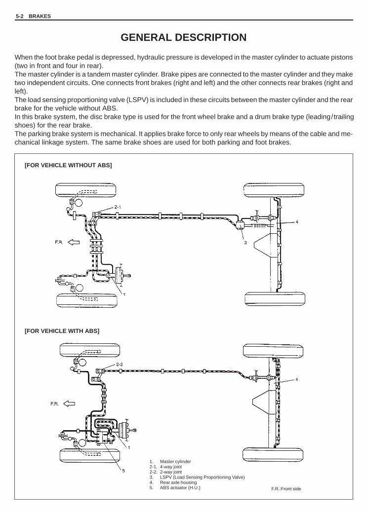
YH4GRANDVITARA
[FOR VEHICLE WITHOUT ABS]
[FOR VEHICLE WITH ABS]
1. Master cylinder2-1. 4-way joint2-2. 2-way joint3. LSPV (Load Sensing Proportioning Valve)4. Rear axle housing5. ABS actuator (H.U.) F.R.:Front side
5-2 BRAKES
GENERAL DESCRIPTION
When the foot brake pedal is depressed, hydraulic pressure is developed in the master cylinder to actuate pistons(two in front and four in rear).The master cylinder is a tandem master cylinder. Brake pipes are connected to the master cylinder and they maketwo independent circuits. One connects front brakes (right and left) and the other connects rear brakes (right andleft).The load sensing proportioning valve (LSPV) is included in these circuits between the master cylinder and the rearbrake for the vehicle without ABS. In this brake system, the disc brake type is used for the front wheel brake and a drum brake type (leading/trailingshoes) for the rear brake.The parking brake system is mechanical. It applies brake force to only rear wheels by means of the cable and me-chanical linkage system. The same brake shoes are used for both parking and foot brakes.

YH4GRANDVITARA
BRAKES 5-3
SUBSTANDARD ORCONTAMINATED BRAKE FLUID
Improper brake fluid, mineral oil or water in the fluidmay cause the brake fluid to boil or the rubber compo-nents in the hydraulic system to deteriorate.
If primary piston cups are swollen, then rubber partshave deteriorated. This deterioration may also be evi-denced by swollen wheel cylinder piston cups on thedrum brake wheels.
If deterioration of rubber is evident, disassemble allhydraulic parts and wash with alcohol. Dry these partswith compressed air before assembly to keep alcoholout of the system. Replace all rubber parts in the sys-tem, including hoses. Also, when working on thebrake mechanisms, check for fluid on the linings. If ex-cessive fluid is found, replace the linings.
If master cylinder piston seals are satisfactory, checkfor leakage or excessive heat conditions. If conditionis not found, drain fluid, flush with brake fluid, refill andbleed system.
The system must be flushed if there is any doubt asto the grade of fluid in the system or if fluid has beenused which contained parts that have been subjectedto contaminated fluid.
DIAGNOSIS
ROAD TESTING BRAKES
Brakes should be tested on dry, clean, smooth andreasonably level roadway which is not crowned. Roadtest brakes by making brake applications with bothlight and heavy pedal forces at various speeds to de-termine if the vehicle stops evenly and effectively.Also drive vehicle to see if it leads to one side or theother without brake application. If it does, check thetire pressure, front end alignment and front suspen-sion attachments for looseness. See diagnosis chartfor other causes.
BRAKE FLUID LEAKS
Check the master cylinder fluid levels. While a slightdrop in reservoir level does result from normal liningwear, an abnormally low level indicates a leak in thesystem. In such a case, check the entire brake systemfor leakage. If even a slight evidence of leakage isnoted, the cause should be corrected or defectiveparts should be replaced.If fluid level is lower than the minimum level of reser-voir, refilling is necessary. Fill reservoir with specifiedbrake fluid.
Brake fluid: Refer to reservoir tank cap.
CAUTION:Since brake system of this vehicle is factory-filled with brake fluid indicated on reservoirtank cap, do not use or mix different type offluid when refilling; otherwise serious damagewill occur.Do not use old or used brake fluid, or any fluidfrom a unsealed container.

YH4GRANDVITARA
5-4 BRAKES
DIAGNOSIS TABLE
Condition Possible Cause Correction
Not enough brak-ing force
� Brake oil leakage from brake lines.� Brake disc or pads stained with oil.� Overheated brakes.� Poor contact of shoes on brake drum.� Brake shoes linings stained with oil or wet
with water.� Badly worn brake shoe linings.� Defective wheel cylinders.� Malfunctioning caliper assembly.� Air in system.� Maladjusted sensor spring length of LSPV.� Broken sensor spring of LSPV.� Defective collar of LSPV.� Malfunctioning ABS (Antilock brake system),
if equipped.
Locate leaking point and repair.Clean or replace.Determine cause and repair.Repair for proper contact.Replace.
Replace.Repair or replace.Repair or replace.Bleed system.Check or adjust.Replace.Replace.Check system and replace as necessary.
Brake pull(Brakes not work-ing in unison)
� Pad or shoe linings are wet with water orstained with oil in some brakes.
� Drum-to-shoe clearance out of adjustment insome brakes. (Malfunctioning auto adjusting mechanism)
� Drum is out of round in some brakes.� Wheel tires are inflated unequally.� Malfunctioning wheel cylinders.� Disturbed front end alignment.� Unmatched tires on same axle.
� Restricted brake pipes or hoses.
� Malfunctioning caliper assembly.
� Loose suspension parts.
� Loose calipers.
Replace.
Check for inoperative auto adjustingmechanism.
Replace.Inflate equally.Repair or replace.Adjust as prescribed.Tires with approximately the sameamount of tread should be used on thesame axle.Check for soft hoses and damagedlines.Replace with new hoses and newbrake pipes.Check for stuck or sluggish pistonsand proper lubrication of caliper slidebush.Caliper should slide.Check all suspension mountings.Check and torque bolts to specifica-tions.
Noise (High pitchedsqueak withoutbrake applied)
� Front lining worn out. Replace linings.
Rear brake lockedprematurely
� Maladjusted sensor spring length of LSPV.� Malfunction LSPV assembly.
Check or adjust.Replace assembly.
Brake locked(For vehiclesequipped withABS)
� Malfunctioning ABS, if equipped. Check system and replace as necessary.

YH4GRANDVITARA
BRAKES 5-5
Condition Possible Cause Correction
Excessive pedaltravel (Pedalstroke too large)
� Partial brake system failure.
� Insufficient fluid in master cylinder reservoirs.
� Air in system. (pedal soft /spongy)� Rear brake system not adjusted.
(malfunctioning auto adjusting mechanism)� Bent brake shoes.� Worn rear brake shoes.
Check brake systems and repair asnecessary.Fill reservoirs with approved brakefluid.Check for leaks and air in brake systems.Check warning light. Bleed system ifrequired.Bleed system.Repair auto adjusting mechanism.Adjust rear brakes.Replace brake shoes.Replace brake shoes.
Dragging brakes(A very light dragis present in alldisc brakes immediatelyafter pedal isreleased)
� Master cylinder pistons not returning correctly.
� Restricted brake pipes or hoses.
� Incorrect parking brake adjustment on rearbrakes.
� Weakened or broken return springs in thebrake.
� Sluggish parking-brake cables or linkage.� Wheel cylinder or caliper piston sticking.� Malfunctioning ABS, if equipped with ABS.
Replace master cylinder.
Check for soft hoses or damagedpipes and replace with new hosesand/or new brake pipes.Check and adjust to correct specifi-cations.Replace.
Repair or replace.Repair as necessary.Check system and replace asnecessary.
Pedal pulsation(Pedal pulsateswhen depressedfor braking)
� Damaged or loose wheel bearings.� Distorted steering knuckle or rear axle
shafts.� Excessive disc lateral runout.
� Parallelism not within specifications.
� Rear drums out of round.
Replace wheel hub component.Replace knuckle or rear axle shaft.
Check per instructions. If not withinspecifications, replace or machinethe disc.Check per instructions. If not withinspecifications, replace or machinethe disc.Check runout.Repair or replace drum as necessary.
Braking noise � Glazed shoe linings, or foreign mattersstuck to linings.
� Worn or distorted shoe linings.� Loose front wheel bearings.� Distorted backing plates or loose mounting
bolts.
Repair or replace shoe lining.
Replace shoe lining (or pad).Replace wheel hub component.Replace or retighten securing bolts.
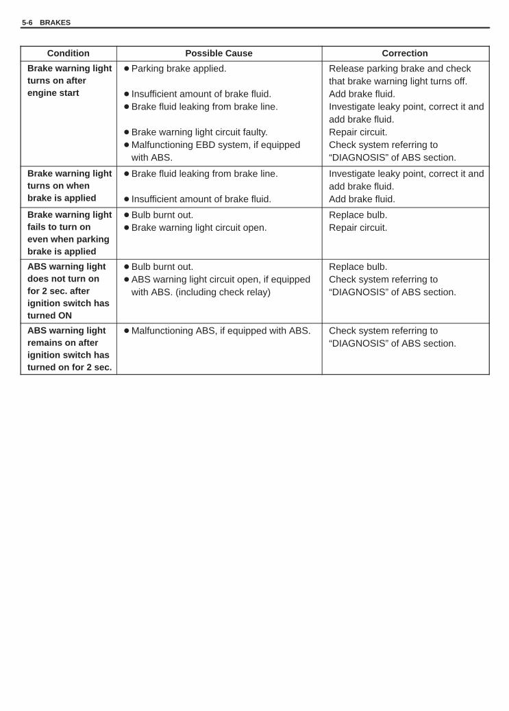
YH4GRANDVITARA
5-6 BRAKES
Condition Possible Cause Correction
Brake warning lightturns on after engine start
� Parking brake applied.
� Insufficient amount of brake fluid.� Brake fluid leaking from brake line.
� Brake warning light circuit faulty.� Malfunctioning EBD system, if equipped
with ABS.
Release parking brake and checkthat brake warning light turns off.Add brake fluid.Investigate leaky point, correct it andadd brake fluid.Repair circuit.Check system referring to“DIAGNOSIS” of ABS section.
Brake warning lightturns on whenbrake is applied
� Brake fluid leaking from brake line.
� Insufficient amount of brake fluid.
Investigate leaky point, correct it andadd brake fluid.Add brake fluid.
Brake warning lightfails to turn oneven when parkingbrake is applied
� Bulb burnt out.� Brake warning light circuit open.
Replace bulb.Repair circuit.
ABS warning lightdoes not turn onfor 2 sec. after ignition switch hasturned ON
� Bulb burnt out.� ABS warning light circuit open, if equipped
with ABS. (including check relay)
Replace bulb.Check system referring to“DIAGNOSIS” of ABS section.
ABS warning lightremains on afterignition switch hasturned on for 2 sec.
� Malfunctioning ABS, if equipped with ABS. Check system referring to“DIAGNOSIS” of ABS section.

YH4GRANDVITARA
1. 4-way joint / 2-way joint2. Master cylinder3. LSPV4. Right brake caliper5. Left brake caliper6. Right wheel cylinder7. Left wheel cylinder8. ABS actuator�: Air bleeding point
[A]: Without ABS[B]: With ABS
1. Plug cap 2. Vinyl tube (See-through tube)3. Container
[A]
[B]
BRAKES 5-7
CHECK AND ADJUSTMENT
BLEEDING BRAKES
CAUTION:Brake fluid is extremely damaging to paint. If fluid shouldaccidentally touch painted surface, immediately wipefluid from paint and clean painted surface.
NOTE:For vehicle equipped with ABS, make sure that ignition switchturns off.
Be sure to bleed air of brake system according to following proce-dure when its oil hydraulic circuit has been disconnected.
Hydraulic lines of brake system consists of two separate lines, onefor front wheel brakes and the other for rear wheel brakes.Air bleeding is necessary at right and left front wheel brakes, leftrear wheel brake and LSPV (if equipped without ABS), i.e. 4 places(3 places for vehicle with ABS) in all.
1) Fill master cylinder reservoir with brake fluid and keep at leastone-half full of fluid during bleeding operation.
2) Remove bleeder plug cap.Attach a vinyl tube to bleeder plug of wheel cylinder, and insertthe other end into container.
3) Depress brake pedal several times, and then while holding it de-pressed, loosen bleeder plug about one-third to one half turn.
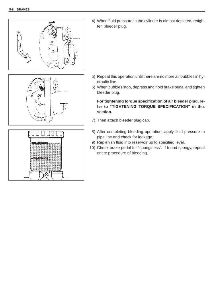
YH4GRANDVITARA
5-8 BRAKES
4) When fluid pressure in the cylinder is almost depleted, retigh-ten bleeder plug.
5) Repeat this operation until there are no more air bubbles in hy-draulic line.
6) When bubbles stop, depress and hold brake pedal and tightenbleeder plug.
For tightening torque specification of air bleeder plug, re-fer to “TIGHTENING TORQUE SPECIFICATION” in thissection.
7) Then attach bleeder plug cap.
8) After completing bleeding operation, apply fluid pressure topipe line and check for leakage.
9) Replenish fluid into reservoir up to specified level.10) Check brake pedal for “sponginess”. If found spongy, repeat
entire procedure of bleeding.

YH4GRANDVITARA
1. Stop light switch
BRAKES 5-9
BRAKE PEDAL FREE HEIGHT CHECK
Remove foot rest and displace carpet and dash silencer(s) so as tomeasure brake pedal free height between pedal face and asphaltsheet installed on dash panel.
Brake pedal free height “a” from asphalt sheet:208 – 218 mm (8.19 – 8.58 in.)
If the measurement is not within the specification, check the posi-tion of booster push rod clevis and/or stop light switch accordingto the instruction shown in this section.
The free height varies depending on installation position of boosterpush rod clevis and stop light switch.
BRAKE LIGHT SWITCH ADJUSTMENTAdjustment should be made as follows when installing switch. Pullup brake pedal toward you and while holding it there, adjust switchposition so that clearance between end of thread and brake pedalreturn cushion (shown as “b” in figure).Then tighten lock nut to specified torque.
Clearance “b”: 1.5 – 2.0 mm (0.06 – 0.08 in.)
Tightening Torque(b): 7.5 N.m (0.75 kg-m, 5.5 lb-ft)
EXCESSIVE PEDAL TRAVEL CHECK
1) Remove foot rest and displace carpet and dash silencer(s).2) Start engine.3) Depress brake pedal a few times.4) With brake pedal depressed with approximately 30 kg (66 lbs)
load, measure pedal to asphalt sheet clearance “c”.
Clearance “c”: over 115 mm (4.53 in.)
5) If clearance “c” is less than specification, the most possiblecause is either rear brake shoes are worn out beyond limit or airis in lines.Should clearance “c” remain less than specification even afterreplacement of brake shoes and bleeding of system, other pos-sible but infrequent cause is malfunction of rear brake shoe ad-justers or booster push rod length out of adjustment.

YH4GRANDVITARA
5-10 BRAKES
BRAKE PEDAL PLAY CHECK
Pedal play should be within specification. If out of specification,check brake light switch for proper installation position and adjustif necessary.Also check pedal shaft bolt and master cylinder pin installation forlooseness and replace if defective.
Pedal play “d”: 1 – 8 mm (0.04 – 0.32 in.)
BRAKE FLUID LEVEL CHECK
Be sure to use particular brake fluid either as indicated on reservoircap of that vehicle or recommended in owner’s manual whichcomes along with that vehicle. Use of any other fluid is strictly prohibited.Fluid level should be between MIN and MAX lines marked on reser-voir.When warning light lights sometimes during driving, replenish fluidto MAX line.When fluid decreases quickly, inspect brake system for leakage.Correct leaky points and then refill to specified level.
CAUTION:Do not use shock absorber fluid or any other fluid whichcontains mineral oil. Do not use a container which has beenused for mineral oil or a container which is wet from water.Mineral oil will cause swelling and distortion of rubber partsin hydraulic brake system and water mixed into brake fluidwill lower fluid boiling point. Keep all fluid containerscapped to prevent contamination.
BRAKE HOSE AND PIPE CHECK
The brake hose assembly should be checked for road hazard dam-age, for cracks and chafing of the outer cover, for leaks and blisters.A light and mirror may be needed for an adequate inspection. If anyof the above conditions are observed on the brake hose, it is neces-sary to replace it.
Inspect the pipe for damage, cracks, dents and corrosion. If any de-fect is found, replace it.
MASTER CYLINDER CHECK
Check for a cracked master cylinder casting or brake fluid aroundthe master cylinder. Leaks are indicated only if there is at least adrop of fluid. A damp condition is not abnormal.

YH4GRANDVITARA
1. Pad rim2. Lining3. Disc
1. Rubber plug2. Brake shoe3. Brake shoe rim
BRAKES 5-11
BRAKE DISC CHECK
Refer to FRONT DISC BRAKE PAD of Section 5B for inspectionpoint and procedure.
BRAKE PAD CHECK
Inspect pad linings periodically according to maintenance schedulewhenever wheels are removed (for tire rotation or other reason).Take a look through hole of caliper and check lining thickness of in-side pad.
Thickness “e”Standard: 10.0 mm (0.39 in.)Service Limit: 2.0 mm (0.08 in.)
If one of brake pad is worn to service limit, all linings must be re-placed at the same time.
BRAKE SHOE CHECK
Inspection should be carried out on following points after brake ped-al travel “c” (pedal to asphalt sheet clearance) check as describedon previous page of this section, even when it is more than 115 mm(4.53 in.).Amount of brake shoe wear can be checked as follows.1) Hoist vehicle.2) Remove rubber plug from brake back plate.3) Through hole of back plate, visually check for thickness of brake
shoe lining. If lining thickness “f” is found less than below speci-fied wear limit, replace with new brake shoes.
Thickness “f”Service Limit: 1.0 mm (0.04 in.)

YH4GRANDVITARA
1. Parking brake lever2. Brake cable3. Self locking nut
5-12 BRAKES
PARKING BRAKE CHECK ANDADJUSTMENTCHECKHold center of parking brake lever grip and pull it up with 20 kg(40 lbs) force.With parking brake lever pulled up as shown, count ratchetnotches.There should be 5 to 7 notches.Also, check if both right and left rear wheels are locked firmly.To count number of notches easily, listen to click sounds that ratchetmakes while pulling parking brake lever without pressing its button.One click sound corresponds to one notch.If number of notches is out of specification, adjust cable by referringto adjustment procedure described on the following as to obtainspecified parking brake stroke.
NOTE:Check tooth tip of each notch for damage or wear. If any dam-age or wear is found, replace parking brake lever.
ADJUSTMENTNOTE:Make sure for following conditions before cable adjustment.� No air is trapped in brake system.� Brake pedal travel is proper.� Brake pedal has been depressed a few times with about
30 kg (66 lbs) load.� Parking brake lever has been pulled up a few times with
about 20 kg (44 lbs) force.� Rear brake shoes are not worn beyond limit, and self adjust-
ing mechanism operates properly.� To slacken parking brake cable, loosen self locking nut as far
as end of bolt. Then depress brake pedal a few times withabout 30 kg (66 lbs) load.
After confirming that above 6 conditions are all satisfied, adjustparking brake lever stroke by loosening or tightening locking nut.
NOTE:Check brake drum for dragging after adjustment.
Parking brake stroke: 5 to 7 notches(When lever is pulled up at 20 kg (44 lbs).)

YH4GRANDVITARA
1. Air bleeder plug2. Weight3. Attachment
2
“L”
BRAKES 5-13
FLUSHING BRAKE HYDRAULIC SYSTEM
It is recommended that entire hydraulic system be thoroughlyflushed with clean brake fluid whenever new parts are installed inhydraulic system.Periodical change of brake fluid is also recommended.
FLUID PRESSURE TEST(if equipped withLSPV)
Test procedure for LSPV assembly is as follows.
Before testing, confirm the following.� Fuel tank is filled with fuel fully.� Vehicle is equipped with spare tire, tools, jack and jack handle.1) Stop vehicle on level floor and place approximately about
200 kg (441 lbs) weight on rear housing so that rear axle weight800 kg (1764 lb).
Rear axle weight “L”: 800 kg (1764 lb)
2) Install special tool to front and rear brake.
NOTE:Special tool should be connected to breather of front (driv-er’s side brake) and rear brakes.
Special ToolFront brake(A): 09956-02310(B): 09952-46510 (Attachment for vehicle with SUMITOMO
ELECTRIC brake caliper)(C): 55473-82030 (Air bleeder plug supplied as a spare part)
Rear brake(A): 09956-02310(B): 09952-36310 (Attachment for thread diameter 7 mm of
bleeder plug) or09952-46510 (Attachment for thread diameter 8 mm ofbleeder plug)
(C): 55473-82030 (Air bleeder plug supplied as a spare part)
NOTE:� Special tool (B) is used instead of thread diameter 10 mm
attachment of special tool (A).So remove the attachment from (A) and install (B) asshown in figure.
� For vehicle with TOKICO brake caliper, use the attach-ment included in special tool (A).
� For identification of brake caliper type, refer to GENERALDESCRIPTION in SECTION 5B.

YH4GRANDVITARA
3. LSPV stay
1. Master cylinder2. Disconnect brake pipe
1. LSPV lever2. LSPV spring
3, “A”
21
2
(a)
“a”
“b”
5-14 BRAKES
3) Depress brake pedal gradually till fluid pressure of front brakebecomes as specified below and check corresponding pressureof rear brake then. It should be within specification given below.
Front brake Rear brake
8,000 kPa80 kg/cm2
3 Door6,000 – 7,300 kPa
60 – 73 kg/cm2
853 – 1,038 psi80 kg/cm2
1,138 psi5 Door
4,500 – 7,300 kPa45 – 73 kg/cm2
640 – 1,038 psi
As done above, apply 100 kg/cm2 pressure to front brake andcheck that rear brake pressure then is within specification as giv-en below.
Front brake Rear brake
10,000 kPa100 kg/cm2
3 Door6,500 – 8,000 kPa
65 – 80 kg/cm2
924 – 1,138 psi100 kg/cm2
1,422 psi5 Door
5,000 – 8,000 kPa50 – 80 kg/cm2
711 – 1,138 psi
4) If rear brake pressure is not within specification, adjust it bychanging stay “A” position as follows.
Tightening Torque(a): 23 N.m (2.3 kg-m, 17.0 lb-ft)
� If rear brake pressure is higher than specification, move stay“A” to direction “a” and if it is lower, to direction “b”.
� Repeat steps 3) and 4) until rear brake pressure is within spec-ification.
� After adjustment, be sure to torque bolt to specification.
5) Disconnect brake pipe (connecting between master cylindersecondary side and 4-way joint) from master cylinder.Tighten plug (special tool) to master cylinder.Depress brake pedal. If rear brake pressure is 95 – 100 kg/cm2
when front brake pressure is 100 kg/cm2, it means that front fail-safe system functions properly.
Front brake Rear brake
10000 kPa100 kg/cm2
1422 psi
9500 – 10000 kPa95 – 100 kg/cm2
1350 – 1422 psi
Special Tool(A): 09956-02210

YH4GRANDVITARA
GOOD
NO GOOD
BRAKES 5-15
6) Upon completion of fluid pressure test, bleed brake system andperform brake test.
BOOSTER OPERATION CHECK
There are two ways to perform this inspection, with and without atester. Ordinarily, it is possible to roughly determine its conditionwithout using a tester.
NOTE:For this check, make sure that no air is in hydraulic line.
INSPECTION WITHOUT TESTER
Check Air Tightness1) Start engine.2) Stop engine after running for 1 to 2 minutes.
3) Depress brake pedal several times with the same load as in ordi-nary braking and observe pedal travel. If pedal goes down deepthe first time but its travel decreases as it is depressed the se-cond and more times, air tightness is obtained.
4) If pedal travel doesn’t change, air tightness isn’t obtained.
NOTE:If defective, inspect vacuum lines and sealing parts, and re-place any faulty part.When this has been done, repeat the entire test.

YH4GRANDVITARA
5-16 BRAKES
Check Operation1) With engine stopped, depress brake pedal several times with
the same load and make sure that pedal travel doesn’t change.
2) Start engine while depressing brake pedal. If pedal travel in-creases a little, operation is satisfactory. But no change in pedaltravel indicates malfunction.
Check Air Tightness Under Load1) With engine running, depress brake pedal. Then stop engine
while holding brake pedal depressed.
2) Hold brake pedal depressed for 30 seconds. If pedal height doesnot change, condition is good. But it isn’t if pedal rises.

YH4GRANDVITARA
BRAKES 5-17
TIGHTENING TORQUE SPECIFICATIONS
Fastening partsTightening torque
Fastening artsN.m kg-m lb-ft
Brake pipe 2-way (or 4-way) joint bolt 23 2.3 17.0
Brake pipe flare nut 16 1.6 11.5
Front caliperM8 8.0 0.8 6.0
Brake bleeder plug
Front cali erM10 8.5 0.85 6.5
Brake bleeder lugWheel cylinder 7.5 0.75 5.5
LSPV 7.5 0.75 5.5
LSPV mounting bolt
LSPV stay bolt 23 2.3 17.0
LSPV spring nut
Wheel nut 100 10.0 72.5
Stop light switch lock nut 7.5 0.75 5.5
REQUIRED SERVICE MATERIAL
MATERIALSRECOMMENDED
SUZUKI PRODUCTUSE
Brake fluidIndicated on reservoircap or described in owner’smanual of vehicle
� To fill master cylinder reservoir.� To clean and apply to inner parts of master
cylinder caliper and wheel cylinder whenthey are disassembled.

YH4GRANDVITARA
5-18 BRAKES
09950-78220Flare nut wrench (10 mm)
09900-20205Micrometer (0 – 25 mm)
09956-02310Fluid pressure gauge
09956-02210Brake circuit plug
09952-36310/09952-46510Pressure gauge attachment
SPECIAL TOOLS

YH4GRANDVITARA
5A
BRAKES PIPE/HOSE/MASTER CYLINDER 5A-1
SECTION 5A
BRAKES PIPE/HOSE/MASTER CYLINDERWARNING:For vehicles equipped with Supplemental Restraint (Air Bag) System� Service on and around the air bag system components or wiring must be performed only by an autho-
rized SUZUKI dealer. Refer to “Air Bag System Components and Wiring Location View” under “Gener-al Description” in air bag system section in order to confirm whether you are performing service onor near the air bag system components or wiring. Please observe all WARNINGS and “Service Precau-tions” under “On-Vehicle Service” in air bag system section before performing service on or aroundthe air bag system components or wiring. Failure to follow WARNINGS could result in unintentionalactivation of the system or could render the system inoperative. Either of these two conditions mayresult in severe injury.
� Technical service work must be started at least 90 seconds after the ignition switch is turned to the“LOCK” position and the negative cable is disconnected from the battery. Otherwise, the system maybe activated by reserve energy in the Sensing and Diagnostic Module (SDM).
NOTE:All brake fasteners are important attaching parts in that they could affect the performance of vital partsand systems, and/or could result in major repair expense. They must be replaced with one of same partnumber or with an equivalent part if replacement becomes necessary. Do not use a replacement part oflesser quality or substitute design. Torque values must be used as specified during reassembly to assureproper retention of all parts. There is to be no welding as it may result in extensive damage and weakeningof the metal.
CONTENTS
GENERAL DESCRIPTION 5A- 2. . . . . . . . . . . . . . . . . . . . . . . . . . . . . . . . . . . . . . . . . . . . . . . . . . . . . . . . . . . . . . . . . . Master Cylinder Assembly 5A- 2. . . . . . . . . . . . . . . . . . . . . . . . . . . . . . . . . . . . . . . . . . . . . . . . . . . . . . . . . . . . . . . . . Booster Assembly 5A- 2. . . . . . . . . . . . . . . . . . . . . . . . . . . . . . . . . . . . . . . . . . . . . . . . . . . . . . . . . . . . . . . . . . . . . . . . LSPV (Load Sensing Proportioning Valve) Assembly 5A- 3. . . . . . . . . . . . . . . . . . . . . . . . . . . . . . . . . . . . . . . . . .
DIAGNOSIS 5A- 4. . . . . . . . . . . . . . . . . . . . . . . . . . . . . . . . . . . . . . . . . . . . . . . . . . . . . . . . . . . . . . . . . . . . . . . . . . . . . . .
CHECK AND ADJUSTMENT 5A- 4. . . . . . . . . . . . . . . . . . . . . . . . . . . . . . . . . . . . . . . . . . . . . . . . . . . . . . . . . . . . . . . .
ON-VEHICLE SERVICE 5A- 4. . . . . . . . . . . . . . . . . . . . . . . . . . . . . . . . . . . . . . . . . . . . . . . . . . . . . . . . . . . . . . . . . . . . Front Brake Hose/Pipe 5A- 4. . . . . . . . . . . . . . . . . . . . . . . . . . . . . . . . . . . . . . . . . . . . . . . . . . . . . . . . . . . . . . . . . . . . Rear Brake Hose/Pipe 5A- 7. . . . . . . . . . . . . . . . . . . . . . . . . . . . . . . . . . . . . . . . . . . . . . . . . . . . . . . . . . . . . . . . . . . . Master Cylinder Reservoir 5A- 8. . . . . . . . . . . . . . . . . . . . . . . . . . . . . . . . . . . . . . . . . . . . . . . . . . . . . . . . . . . . . . . . . Master Cylinder Assembly 5A-10. . . . . . . . . . . . . . . . . . . . . . . . . . . . . . . . . . . . . . . . . . . . . . . . . . . . . . . . . . . . . . . . . Brake Booster 5A-14. . . . . . . . . . . . . . . . . . . . . . . . . . . . . . . . . . . . . . . . . . . . . . . . . . . . . . . . . . . . . . . . . . . . . . . . . . . LSPV (Load Sensing Proportioning Valve) Assembly 5A-17. . . . . . . . . . . . . . . . . . . . . . . . . . . . . . . . . . . . . . . . . .
TIGHTENING TORQUE SPECIFICATIONS 5A-19. . . . . . . . . . . . . . . . . . . . . . . . . . . . . . . . . . . . . . . . . . . . . . . . . . . .
REQUIRED SERVICE MATERIAL 5A-19. . . . . . . . . . . . . . . . . . . . . . . . . . . . . . . . . . . . . . . . . . . . . . . . . . . . . . . . . . . .
SPECIAL TOOLS 5A-19. . . . . . . . . . . . . . . . . . . . . . . . . . . . . . . . . . . . . . . . . . . . . . . . . . . . . . . . . . . . . . . . . . . . . . . . . .

YH4GRANDVITARA
[A]: With ABS[B]: Without ABS
1. Piston stopper circlip2. Piston stopper3. Cylinder cup4. Plate5. Primary piston6. Piston cup7. Primary piston return spring8. Primary spring retainer9. Secondary piston pressure cup
10. Secondary piston11. Return spring secondary seat12. Secondary piston return spring13. Secondary piston stopper bolt14. Master cylinder body“A”: Primary piston“B”: Secondary piston
[B]
[A]
5A-2 BRAKES PIPE/HOSE/MASTER CYLINDER
GENERAL DESCRIPTION
MASTER CYLINDER ASSEMBLYThe master cylinder has two pistons and three piston cups. Its hydraulic pressure is produced in the primary (“a”in the figure below) and secondary (“b”) chambers. The hydraulic pressure produced in the primary chamber (“a”)acts on the front (for vehicle without ABS, rear) wheel brakes.Also, the hydraulic pressure produced in the secondary chamber (“b”) acts on the rear (for vehicle without ABS,front) wheel brakes.
NOTE:Replace all components included in repair kits to service this master cylinder. Lubricate rubber parts withclean, fresh brake fluid to ease assembly. Do not use lubricated shop air on brake parts as damage to rub-ber components may result. If any hydraulic component is removed or brake line disconnected, bleed thebrake system.The torque values specified are for dry, unlubricated fasteners.
BOOSTER ASSEMBLYThe booster is located between the master cylinder and the brake pedal. It is so designed that the force createdwhen the brake pedal is depressed is mechanically increased combined with the engine vacuum.The booster has two diaphragms of ø7.5 in. (191 mm) effective diameter.
CAUTION:� Never disassemble brake booster assembly. If it is found faulty, replace it with new assembly.� The torque values specified are for dry, unlubricated fasteners. If any hydraulic component is re-
moved or brake line disconnected, bleed the brake system.

YH4GRANDVITARA
1. LSPV2. LSPV lever3. Spring4. LSPV stay5. Brake flare nut
[A]: Type A[B]: Type B
1. Plunger2. Lip seal3. LSPV lever4. Sensor spring5. From master cylinder
primary chamber(Rear wheel brake)
6. From master cylindersecondary chamber(Front wheel brake)
7. To rear wheel brake8. Pin9. Bolt hole
[A] [B]
4 4
BRAKES PIPE/HOSE/MASTER CYLINDER 5A-3
LSPV (Load Sensing Proportioning Valve) ASSEMBLY (if equipped)As shown in figure below, LSPV is included within the brake circuit which connects the master cylinder and the rearwheel brake. It controls the hydraulic pressure applied to the rear wheel brake according to the loaded state of thevehicle (or weight of the load), whereby preventing the rear wheels from getting locked prematurely.Also, it releases the above described control over the hydraulic pressure applied to the rear wheel brake, shouldany failure occur in the hydraulic circuit of the front wheel brake so that the hydraulic pressure produced in the mas-ter cylinder is applied to the rear wheel brake directly to operate it.
CONSTITUTION
The LSPV components are grouped into three sections as follows.“A”: Sensor section
The main parts in this section are a lever and a spring which senses variation in the vehicle height as affectedby the loaded condition and converts it into the load.
“B”: Hydraulic pressure control sectionIncluded in this section are a stepped plunger and valve mechanism to execute proportional control.
“C”:Fail-safe sectionThe main parts in this section are a chamber which draws in the hydraulic pressure from the front wheel brakesystem and a fail-safe piston which releases the valve mechanism in the control section connected to the rearwheel brake, should any failure occur in the front wheel brake system.
YH4GRANDVITARA
5A-4 BRAKES PIPE/HOSE/MASTER CYLINDER
DIAGNOSIS
Refer to Section 5 (BRAKES)
CHECK AND ADJUSTMENT
Refer to Section 5 (BRAKES)
ON-VEHICLE SERVICE
FRONT BRAKE HOSE/PIPEREMOVAL1) Raise and suitably support vehicle. Remove tire and wheel.
This operation is not necessary when removing pipes connecting master cylinder and flexible hose.2) Clean dirt and foreign material from both hose end or pipe end fittings. Remove brake hose or pipe.
INSTALLATION1) Reverse removal procedure for brake hose and pipe installation procedure.
For installation, make sure that steering wheel is in straightforward position and hose has no twist or kink. Checkto make sure that hose doesn’t contact any part of suspension, both in extreme right and extreme left turn condi-tions. If it does at any point, remove and correct. Fill and maintain brake fluid level in reservoir. Bleed brake sys-tem.
2) Perform brake test and check installed part for fluid leakage.
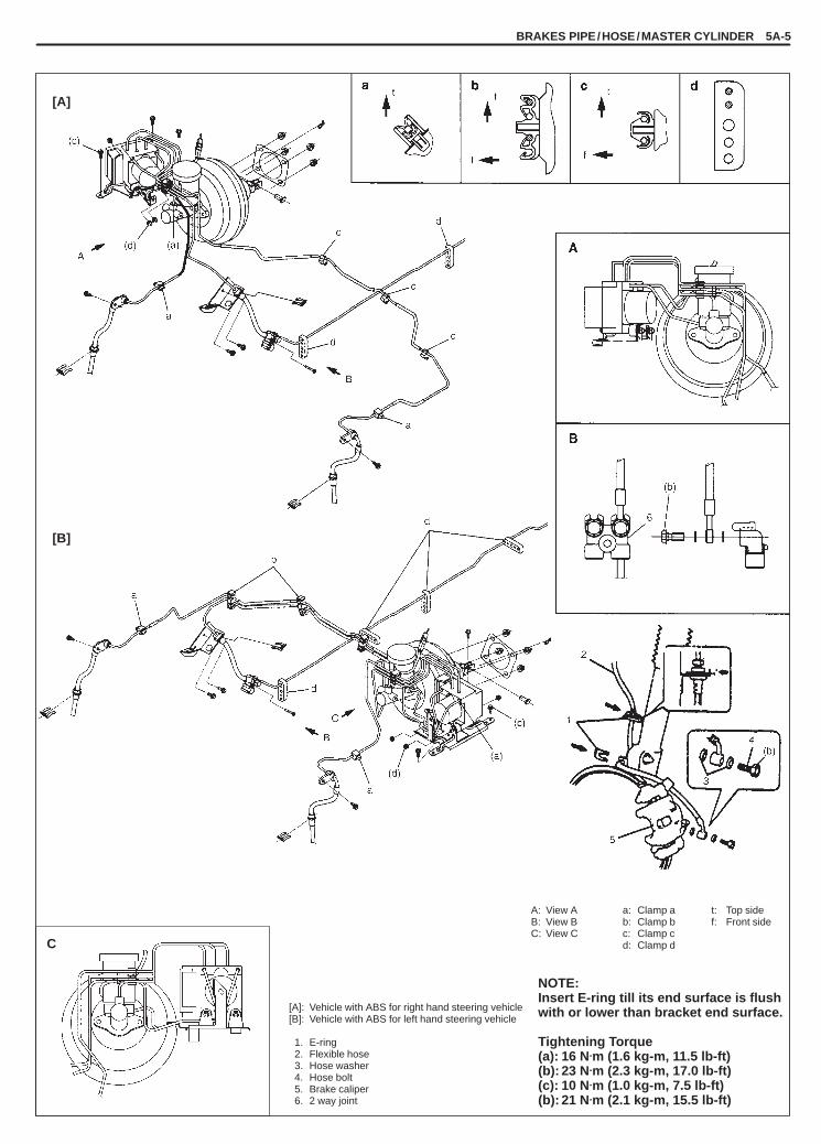
YH4GRANDVITARA
BRAKES PIPE/HOSE/MASTER CYLINDER 5A-5
[A]: Vehicle with ABS for right hand steering vehicle[B]: Vehicle with ABS for left hand steering vehicle
1. E-ring2. Flexible hose3. Hose washer4. Hose bolt5. Brake caliper6. 2 way joint
NOTE:Insert E-ring till its end surface is flushwith or lower than bracket end surface.
Tightening Torque(a): 16 N.m (1.6 kg-m, 11.5 lb-ft)(b): 23 N.m (2.3 kg-m, 17.0 lb-ft)(c): 10 N.m (1.0 kg-m, 7.5 lb-ft)(b): 21 N.m (2.1 kg-m, 15.5 lb-ft)
A: View AB: View BC: View C
a: Clamp ab: Clamp bc: Clamp cd: Clamp dC
t: Top sidef: Front side
[A]
[B]

YH4GRANDVITARA
5A-6 BRAKES PIPE/HOSE/MASTER CYLINDER
NOTE:Insert E-ring till its end surface is flushwith or lower than bracket end surface.
Tightening Torque(a): 10 N.m (1.0 kg-m, 7.5 lb-ft)(b): 23 N.m (2.3 kg-m, 17.0 lb-ft)
[C]: Vehicle without ABS for right hand steering vehicle[D]: Vehicle without ABS for left hand steering vehicle
1. E-ring2. Flexible hose3. Hose washer4. Hose bolt5. Brake caliper6. 4way joint
[C]
[D]
D: View D a: Clamp ab: Clamp bc: Clamp cd: Clamp d
t: Top sidef: Front side

YH4GRANDVITARA
BRAKES PIPE/HOSE/MASTER CYLINDER 5A-7
1. Rear axle2. Shock absorber3. Clamp
1. Brake pipe (to rear)2. Brake pipe
(to LSPV, for vehicle without ABS)3. 4-way (2-way) joint4. Chassis frame
REAR BRAKE HOSE/PIPEREMOVAL1) Raise and suitably support vehicle. Remove tire and wheel.2) Clean dirt and foreign material from both hose end or pipe end fittings. Remove brake hose or pipe.
INSTALLATION1) Reverse removal procedure for brake hose or pipe installation procedure.
� Be sure to obtain more than 3 mm (0.118 in.) clearance between axle housing and brake pipe.� Install clamps properly referring to figure below and tighten bolts.� When installing hose, make sure that it has no twist or kink.
2) Fill and maintain brake fluid level in reservoir. Bleed brake system.3) Perform brake test and check each installed part for fluid leakage.
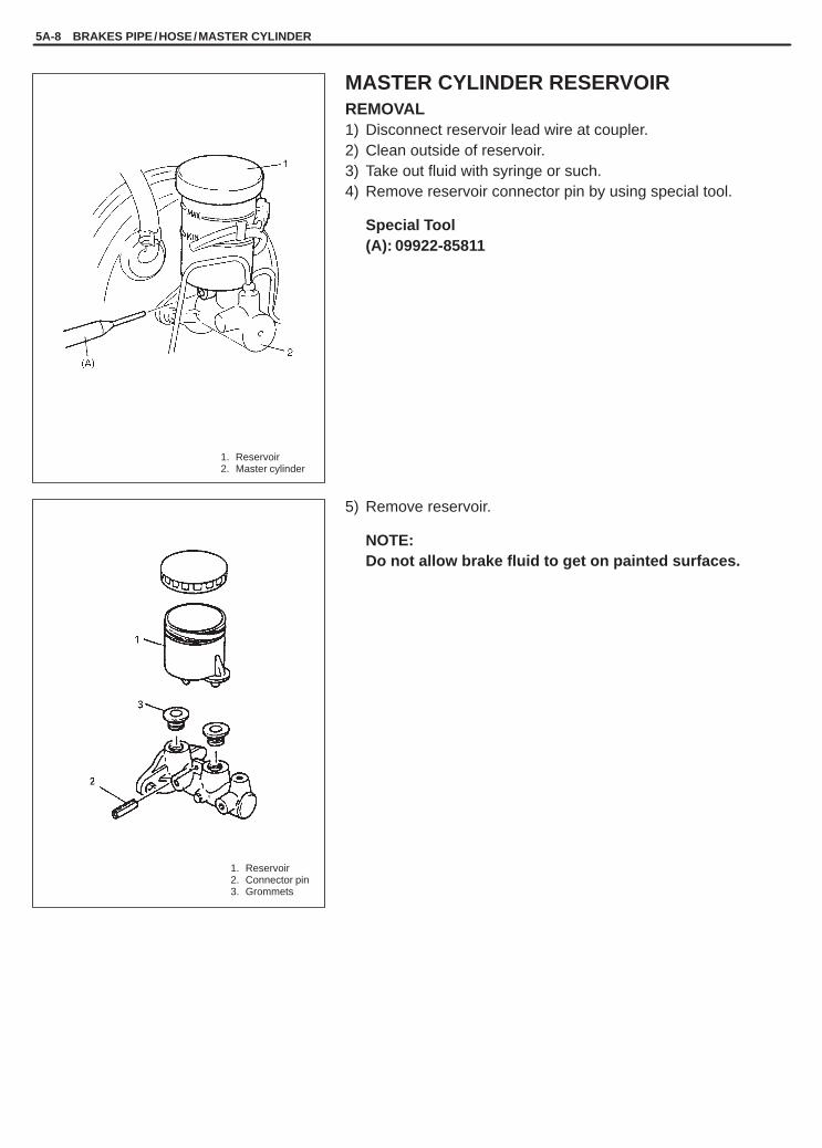
YH4GRANDVITARA
5A-8 BRAKES PIPE/HOSE/MASTER CYLINDER
1. Reservoir2. Master cylinder
1. Reservoir2. Connector pin3. Grommets
MASTER CYLINDER RESERVOIRREMOVAL1) Disconnect reservoir lead wire at coupler.2) Clean outside of reservoir.3) Take out fluid with syringe or such.4) Remove reservoir connector pin by using special tool.
Special Tool(A): 09922-85811
5) Remove reservoir.
NOTE:Do not allow brake fluid to get on painted surfaces.

YH4GRANDVITARA
1. Reservoir2. Pin
1. Reservoir2. Cap
BRAKES PIPE/HOSE/MASTER CYLINDER 5A-9
INSTALLATIONNOTE:See NOTE at the beginning of this section.
1) When using new grommets, lubricate them with the same fluidas the one to fill reservoir with. Then press-fit grommets to mas-ter cylinder. Grommets must be seated in place.
2) Install reservoir and drive in reservoir pin.
NOTE:Drive in reservoir pin till both of its ends at the right and leftor reservoir becomes the same length.
3) Connect reservoir lead wire.4) Fill reservoir with specified fluid.5) Upon completion of installation, check for fluid leakage.

YH4GRANDVITARA
4
3
1. Piston stopper circlip2. Piston stopper3. Cylinder cup and plate4. Primary piston5. Piston cup6. Secondary piston pressure cup7. Primary piston Assy8. Secondary piston9. Secondary piston Assy
10. Secondary piston stopper bolt11. Master cylinder body12. O-ring
[A] [B]
[A]: With ABS[B]: Without ABS
5. Attaching nut6. ABS control module
connector7. Bracket bolt
1. Reservoir cap2. Reservoir3. Master cylinder4. Flare nuts
5A-10 BRAKES PIPE/HOSE/MASTER CYLINDER
MASTER CYLINDER ASSEMBLY
REMOVALNOTE:Do not allow brake fluid to get on painted surfaces.
1) Disconnect reservoir lead wire at coupler.2) Clean around reservoir cap and take out fluid with syringe or
such.3) Remove master cylinder with reservoir from brake booster.
� For vehicle with ABSa) Loosen flare nuts for master cylinder and ABS hydraulic
unit as shown.b) For LH steering vehicle, disconnect ABS control module
connector.c) For RH steering vehicle, remove ABS hydraulic unit brack-
et bolts.d) Disconnect brake pipes between master cylinder and ABS
hydraulic unit.� For vehicle without ABS
a) Loosen flare nuts for master cylinder.b) Disconnect brake pipes for master cylinder.
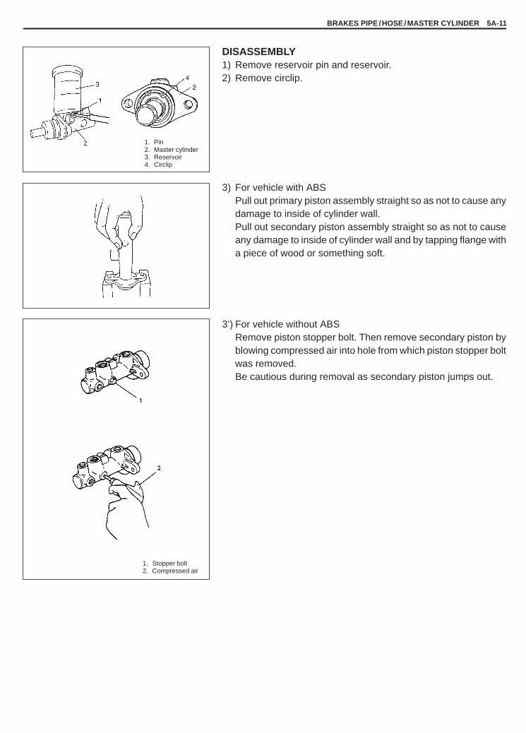
YH4GRANDVITARA
BRAKES PIPE/HOSE/MASTER CYLINDER 5A-11
1. Pin2. Master cylinder3. Reservoir4. Circlip
1. Stopper bolt2. Compressed air
DISASSEMBLY1) Remove reservoir pin and reservoir.2) Remove circlip.
3) For vehicle with ABSPull out primary piston assembly straight so as not to cause anydamage to inside of cylinder wall.Pull out secondary piston assembly straight so as not to causeany damage to inside of cylinder wall and by tapping flange witha piece of wood or something soft.
3’) For vehicle without ABSRemove piston stopper bolt. Then remove secondary piston byblowing compressed air into hole from which piston stopper boltwas removed.Be cautious during removal as secondary piston jumps out.

YH4GRANDVITARA
5A-12 BRAKES PIPE/HOSE/MASTER CYLINDER
Vehicle not equipped with ABS
Vehicle equipped with ABS
1. Rod2. Circlip
INSPECTIONInspect all disassembled parts for wear or damage, and replaceparts if necessary.
NOTE:� Wash disassembled parts with brake fluid.� Do not reuse piston cups.
Inspect master cylinder bore for scoring or corrosion. It is best to re-place corroded cylinder.Corrosion can be identified as pits or excessive roughness.
NOTE:Polishing bore or master cylinder with cast aluminum bodywith anything abrasive is prohibited, as damage to cylinderbore may occur.
Rinse cylinder in clean brake fluid. Shake excess rinsing fluid fromcylinder. Do not use a cloth to dry cylinder, as lint from cloth cannotbe kept from cylinder bore surfaces.
ASSEMBLYNOTE:� See NOTE at the beginning of this section.� Before assembling, wash each part in fluid recommended to
use for that vehicle.
1) Install secondary piston assembly into cylinder.2) Install primary piston assembly in cylinder.
3) Depress, and install circlip.
4) Install piston stopper bolt with pistons pushed in all the way andtighten it to specified torque (For vehicle without ABS).
Tightening Torque(a): 10 N.m (1.0 kg-m, 7.5 lb-ft)

YH4GRANDVITARA
1. Pin2. Reservoir3. Master cylinder
BRAKES PIPE/HOSE/MASTER CYLINDER 5A-13
5) Apply thin coat of brake fluid to all around new grommets (2pcs.)and install them to cylinder body, then install reservoir.
6) Set a new pin in reservoir hole and drive it in. At this time, makeend of pin and end face margin of reservoir equal.
INSTALLATIONNOTE:� See NOTE at the beginning of this section.� Adjust clearance between booster piston rod and primary
piston with special tool, referring to CLEARANCE BETWEENBOOSTER PISTON AND MASTER CYLINDER PISTON AD-JUSTMENT in this section.
1) Install master cylinder to brake booster.2) Tighten master cylinder attaching nuts to specification.
Tightening Torque(a): 13 N.m (1.3 kg-m, 9.5 lb-ft)
3) Connect brake pipes to master cylinder.� For vehicle with ABS
a) Connect brake pipes between master cylinder and ABS hy-draulic unit.
b) For LH steering vehicle, connect ABS control module con-nector.
c) For RH steering vehicle, install ABS hydraulic unit bracketbolts and tighten it to specified torque.
Tightening Torque(b): 10 N.m (1.0 kg-m, 7.5 lb-ft)
4) Tighten flare nuts to specification.
Tightening Torque(c): 16 N.m (1.6 kg-m, 12.0 lb-ft)
5) Connect reservoir lead wire.6) Fill reservoir with specified brake fluid.7) Check brake pedal play and bleed air from system.8) Perform brake test and check each installed part for fluid leak-
age.

YH4GRANDVITARA
5
1
6
4
2
6
3
6
1. Brake master cylinder ass’y2. Brake booster ass’y3. Gasket4. Push rod clevis5. Nut6. Clevis pin7. Clip8. Nut9. Brake vacuum hose
1. Steering column2. Push rod clevis3. Brake pedal arm4. Clevis pin5. Clip6. Nut
1. ABS hydraulicunit
2. Brake pipes
5A-14 BRAKES PIPE/HOSE/MASTER CYLINDER
BRAKE BOOSTER
REMOVALNOTE:Do not allow brake fluid to get on painted surfaces.
1) For vehicle equipped with ABS, disconnect brake pipes fromABS hydraulic unit.
2) Remove master cylinder assembly, referring to MASTER CYL-INDER ASSEMBLY REMOVAL in this section.
3) Disconnect brake vacuum hose from brake booster.
4) Disconnect push rod clevis from brake pedal arm.5) Remove attaching nuts and then booster as shown.
CAUTION:Never disassemble brake booster. Disassembly will spoilits original function. If it is found faulty, replace it withnew one.

YH4GRANDVITARA
BRAKES PIPE/HOSE/MASTER CYLINDER 5A-15
1. Booster piston rod2. Master cylinder piston
1. Master cylinder2. Piston3. Pin head
1. Booster body2. Piston rod
1. Booster piston rod2. Master cylinder piston
CLEARANCE BETWEEN BOOSTER PISTON ROD AND MASTER CYLINDER PISTON ADJUSTMENTThe length of booster piston rod is adjusted to provide specifiedclearance “a” between piston rod end and master cylinder piston.
� Before measuring clearance, push piston rod several times so asto make sure reaction disc is in place.
� Keep inside of booster at atmospheric pressure for measure-ment.
1) Set special tool (A) on master cylinder and push pin until con-tacts piston.
Special Tool(A): 09950-96010
2) Turn special tool upside down and place it on booster. Adjustbooster piston rod length until rod end contacts pin head.
Special Tool(A): 09950-96010
Clearance “b”: 0 mm (0 in.)
NOTE:Take measurement with booster set vertically and rod at thecenter.
3) Adjust clearance by turning adjusting screw of piston rod.
Special Tool(F): 09952-16010
ReferenceWhen adjusted as above, its negative pressure is applied to boost-er with engine at idle, piston to piston rod clearance “a” should be-come below.
Clearance “a”: 0.25 – 0.5 mm (0.010 – 0.020 in.)

YH4GRANDVITARA
5A-16 BRAKES PIPE/HOSE/MASTER CYLINDER
1. Clevis2. Nut
1. Steering column 4. Clevis pin2. Push rod clevis 5. Clip3. Brake pedal arm 6. Nut
BOOSTER PUSH ROD CLEVIS ADJUSTMENTInstall push rod clevis so that measurement “a” is obtained andtorque nut to specification.
Tightening Torque(a): 25 N.m (2.5 kg-m, 18.0 lb-ft)
Length“a”: 109.5 – 110.5 mm (4.31 – 4.35 in.)
INSTALLATIONNOTE:� See NOTE at the beginning of this section.� Check length of push rod clevis. (Refer to BOOSTER PUSH
ROD CLEVIS ADJUSTMENT.)� Before installing master cylinder, adjust booster piston rod.
(Refer to CLEARANCE BETWEEN BOOSTER PISTON RODAND MASTER CYLINDER PISTON ADJUSTMENT of this sec-tion.)
� Apply silicone grease to master cylinder piston.
1) Install booster to dash panel as shown. Then connect boosterpush rod clevis to pedal arm with clevis pin and clip.
2) Tighten booster attaching nuts to the specified torque.
Tightening Torque(a): 13 N.m (1.3 kg-m, 9.5 lb-ft)
3) Connect brake vacuum hose to brake booster.
4) For vehicle equipped with ABS, connect brake pipes to ABS hy-draulic unit. If ABS hydraulic unit bracket bolts removed, tightenflare nuts to specification after installing master cylinder.
Tightening Torque(a): 16 N.m (1.6 kg-m, 12.0 lb-ft)
5) Install master cylinder, referring to MASTER CYLINDER AS-SEMBLY INSTALLATION in this section.

YH4GRANDVITARA
1. LSPV2. Brake pipe
1. LSPV assembly2. LSPV spring3. LSPV stay4. Bolt5. Stepper bole
BRAKES PIPE/HOSE/MASTER CYLINDER 5A-17
LSPV (Load Sensing Proportioning Valve) ASSEMBLY (if equipped)REMOVAL1) Clean around reservoir cap and take out fluid with syringe or
such.2) Hoist vehicle.3) Disconnect brake pipes from LSPV.
4) Remove LSPV assembly with spring from vehicle body.5) Remove spring from lever.
CAUTION:� LSPV assembly must not be disassembled.
Replace with new one if defective.� Stopper bolt should not be loosened or tightened. (if
equipped)
INSTALLATION
CAUTION:Refer to above CAUTION.
Install by reversing removal procedure, noting the following.1) Apply multi-purpose grease “A” to upper and lower joint of coil
spring.

YH4GRANDVITARA
5A-18 BRAKES PIPE/HOSE/MASTER CYLINDER
1. LSPV spring bolt2. LSPV bolt3. Brake pipe flare nut4. Air bleeding plug
1. LSPV lever2. Stopper bolt (if equipped)3. Coil spring “A”: Don’t turn
(a)
2) Torque each bolt and nut to specification as indicated respec-tively in figure.
Tightening Torque(a): 23 N.m (2.3 kg-m, 17.0 lb-ft)(b): 16 N.m (1.6 kg-m, 11.5 lb-ft) (brake flare nut)(c): 7.5 N.m (0.75 kg-m, 9.0 lb-ft) (bleeder plug)
3) Upon completion of installation, fill reservoir tank with specifiedfluid and bleed air from brake system.
NOTE:Make sure to bleed air from LSPV bleeder without failure.
4) After bleeding air, check that LSPV is installed properly, referringto following INSPECTION & ADJUSTMENT.
INSPECTION & ADJUSTMENTConfirm the following before inspection and adjustment.� Fuel tank is filled with fuel fully.� Vehicle is equipped with spare tire, tools, jack and jack handle.� Vehicle is free from any other load.
With vehicle in above conditions;1) Place it on level floor.2) Push up (for 5 door model) or push down (for 3 door model)
LSPV lever with finger till it stops and measure length “L” of coilspring as it is pulled.
3) Spring length “L” should be the value specified below.
Spring length (between spring end and spring bolt)“L”: 103 mm (4.06 in.) (5 door model). . . . . “L”: 157 mm (6.18 in.) (3 door model). . . . .
4) If it isn’t, adjust it to specification by changing stay positions asshown in figure. After adjustment, tighten bolt to specifiedtorque.For details, refer to left figure.
Tightening Torque(a): 23 N.m (2.3 kg-m, 17.0 lb-ft)
NOTE:Check to make sure that LSPV body and brake pipe jointsare free from fluid leakage. Replace defective parts, if any.

YH4GRANDVITARA
BRAKES PIPE/HOSE/MASTER CYLINDER 5A-19
09922-85811Connector pin remover
09950-96010Booster piston rod gauge
09952-16010Booster piston rod adjuster
TIGHTENING TORQUE SPECIFICATIONS
Fastening partsTightening torque
Fastening artsN.m kg-m lb-ft
Brake flexible hose bolt (Brake caliper /2 (4) way joint) 23 2.3 17.0
Master cylinder attaching nut 13 1.3 9.5
Booster nut 13 1.3 9.5
Clevis nut 25 2.5 18
2-way (or 4-way) joint mounting bolt 10 1.0 7.5
Brake pipe flare nut 16 1.6 11.5
Front caliperM8 8.0 0.8 6.0
Brake bleeder plug
Front cali erM10 8.5 0.85 6.5
Brake bleeder lugWheel cylinder 7.5 0.75 5.5
LSPV 8.0 0.8 6.0
LSPV mounting bolt
LSPV stay bolt 23 2.3 17.0
LSPV spring nut
Wheel nut 100 10.0 72.5
REQUIRED SERVICE MATERIAL
MATERIALSRECOMMENDED
SUZUKI PRODUCTUSE
Brake fluidIndicated on reservoircap or described in owner’smanual of vehicle
� To fill master cylinder reservoir.� To clean and apply to inner parts of master
cylinder caliper and wheel cylinder whenthey are disassembled.
SPECIAL TOOLS

YH4GRANDVITARA
5B
FRONT BRAKE 5B-1
SECTION 5B
FRONT BRAKENOTE:All brake fasteners are important attaching parts in that they could affect the performance of vital partsand systems, and/or could result in major repair expense. They must be replaced with one of same partnumber or with an equivalent part if replacement becomes necessary. Do not use a replacement part oflesser quality or substitute design. Torque values must be used as specified during reassembly to assureproper retention of all parts. There is to be no welding as it may result in extensive damage and weakeningof the metal.
CONTENTS
GENERAL DESCRIPTION 5B- 2. . . . . . . . . . . . . . . . . . . . . . . . . . . . . . . . . . . . . . . . . . . . . . . . . . . . . . . . . . . . . . . . . .
DIAGNOSIS 5B- 3. . . . . . . . . . . . . . . . . . . . . . . . . . . . . . . . . . . . . . . . . . . . . . . . . . . . . . . . . . . . . . . . . . . . . . . . . . . . . . .
CHECK AND ADJUSTMENT 5B- 3. . . . . . . . . . . . . . . . . . . . . . . . . . . . . . . . . . . . . . . . . . . . . . . . . . . . . . . . . . . . . . . .
ON-VEHICLE SERVICE 5B- 3. . . . . . . . . . . . . . . . . . . . . . . . . . . . . . . . . . . . . . . . . . . . . . . . . . . . . . . . . . . . . . . . . . . . Front Disc Brake Pad 5B- 3. . . . . . . . . . . . . . . . . . . . . . . . . . . . . . . . . . . . . . . . . . . . . . . . . . . . . . . . . . . . . . . . . . . . . Front Disc Brake Caliper 5B- 6. . . . . . . . . . . . . . . . . . . . . . . . . . . . . . . . . . . . . . . . . . . . . . . . . . . . . . . . . . . . . . . . . . Front Brake Disc 5B-10. . . . . . . . . . . . . . . . . . . . . . . . . . . . . . . . . . . . . . . . . . . . . . . . . . . . . . . . . . . . . . . . . . . . . . . . .
TIGHTENING TORQUE SPECIFICATIONS 5B-11. . . . . . . . . . . . . . . . . . . . . . . . . . . . . . . . . . . . . . . . . . . . . . . . . . . .
REQUIRED SERVICE MATERIAL 5B-11. . . . . . . . . . . . . . . . . . . . . . . . . . . . . . . . . . . . . . . . . . . . . . . . . . . . . . . . . . . .

YH4GRANDVITARA
[A]: TOKICO produced[B]: SUMITOMO ELECTRIC produced
1. Caliper pin bolt2. Boot3. Disc brake caliper
(Disc brake cylinder)4. Piston seal5. Disc brake piston6. Cylinder boot7. Disc brake inner pad8. Disc brake outer pad9. Brake caliper carrier
10. Pad spring11. Bleeder plug12. Bleeder plug cap13. Caliper pin14. Anti noise shim15. Inner shim
Tightening torque(a): 8.5 N.m (0.85 kg-m, 6.5 lb-ft)(b): 8.0 N.m (0.80 kg-m, 6.0 lb-ft)
[A]
[B]
5B-2 FRONT BRAKE
GENERAL DESCRIPTION
DISC BRAKE CALIPER ASSEMBLY
This caliper is mounted to the brake caliper carrier with two caliper pin bolts. Hydraulic force, created by applyingforce to the brake pedal, is converted by the caliper to friction. The hydraulic force acts equally against the pistonand the bottom of the caliper bore to move the piston outward and to move (slide) the caliper inward, resulting ina clamping action on the disc. This clamping action forces the pads (linings against the disc, creating friction tostop the vehicle.
NOTE:� Lubricate parts as specified. Do not use lubricated shop air on brake parts as damage to rubber compo-
nents may result. If any component is removed or line disconnected, bleed the brake system.Replace pads in axle sets only. The torque values specified are for dry, unlubricated fasteners.
� For identification of the brake caliper type, see maker name or mark on brake caliper as shown.

YH4GRANDVITARA
1. Caliper2. Caliper pin bolts3. Disc
1. Caliper2. Wire hook3. Pad
FRONT BRAKE 5B-3
DIAGNOSIS
Refer to Section 5 (BRAKES).
CHECK AND ADJUSTMENT
Refer to Section 5 (BRAKES).
ON-VEHICLE SERVICE
FRONT DISC BRAKE PADREMOVAL1) Hoist vehicle and remove wheel.2) Remove caliper pin bolts.
3) Remove E-ring from strut and then remove caliper from calipercarrier.
NOTE:Hang removed caliper with a wire hook or the like so as toprevent brake hose from bending and twisting excessivelyor being pulled. Don’t operate brake pedal with pads re-moved.
4) Remove pads.
INSPECTIONBrake PadCheck pad lining for wear. When wear exceeds limit, replace withnew one.
CAUTION:Never polish pad lining with sandpaper. If lining is polishedwith sandpaper, hard particles of sandpaper will be depos-ited in lining and may damage disc. When pad lining re-quires correction, replace it with a new one.
Pad thickness (lining + rim) “a”Standard: 15.0 mm (0.590 in.) For SUMITOMO ELECTRIC. . .
brake calliper15.5 mm (0.610 in.) For TOKICO brake caliper. . .
Service limit: 7.0 mm (0.275 in.) For SUMITOMO ELECTRIC. . brake caliper
7.5 mm (0.295 in.) For TOKICO brake caliper. .
NOTE:When pads are removed, visually inspect caliper for brakefluid leak. Correct leaky point, if any.

YH4GRANDVITARA
5B-4 FRONT BRAKE
1. Wheel nut2. Washer
(or spacer)
“A”: Apply grease
Brake DiscBefore this inspection, brake pads must be removed.Check disc surface for scratches in wearing parts. Scratches ondisc surface noticed at the time of specified inspection or replace-ment are normal and disc is not defective unless they are serious.But when there are deep scratches or scratches all over disc sur-face, replace it. When only one side is scratched, polish and correctthat side.
Disc thickness “a”Standard: 22 mm (0.866 in.) For SUMITOMO ELECTRIC. . . . .
brake caliper17 mm (0.670 in.) For TOKICO brake caliper. . . . .
Service limit: 20 mm (0.787 in.) For SUMITOMO ELECTRIC. . brake caliper
15 mm (0.590 in.) For TOKICO brake caliper. .
Use wheel nuts and suitable plain washers to hold the disc securelyagainst the hub, then mount a dial indicator as shown and measurethe runout at 25 mm (0.98 in.) from the outer edge of the disc.
Limit on disc deflection: 0.15 mm (0.006 in.)
NOTE:Check front wheel bearing for looseness before measure-ment.
Cylinder Slide Guide Pin/Pin BoltCheck guide pin for smooth movement as shown.If it is found faulty, correct or replace. Apply rubber grease to guidepin outer surface. Rubber grease should be the on whose viscosityis less affected by such low temperature a –40�C (–40�F).
Dust BootCheck boot for breakage, crack and damage. If defective, replace.

YH4GRANDVITARA
1. Clips2. Pads3. Disc4. Caliper carrier5. Sensor6. Shim
1. Caliper pin bolts
ELECTRIC brakecaliper
FRONT BRAKE 5B-5
INSTALLATIONNOTE:See NOTE at the beginning of this section.
1) Install pad clips and pads.
NOTE:Install pad with sensor to body center side of caliper.
2) Install caliper and torque caliper pin bolts to specification.
Tightening Torque(a), (b): 27 N.m (2.7 kg-m, 20.0 lb-ft) For TOKICO brake. .
caliper(a): 50 N.m (5.0 kg-m, 36.5 lb-ft) For SUMITOMO. . . . . . (b): 85 N.m (8.5 kg-m, 61.5 lb-ft)
NOTE:Make sure that boots are fit into groove securely.
3) Torque front wheel nuts to specification.
Tightening Torque(b): 100 N.m (10.0 kg-m, 72.5 lb-ft)
4) Upon completion of installation, perform brake test.
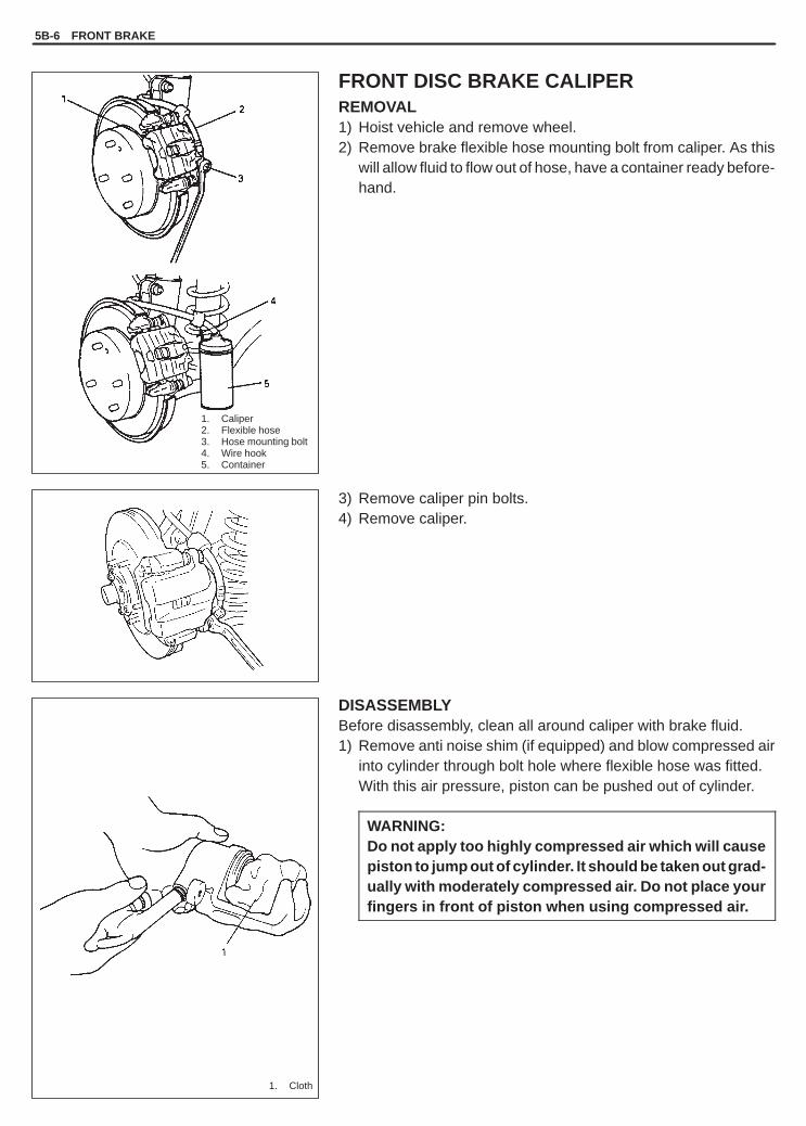
YH4GRANDVITARA
1. Caliper2. Flexible hose3. Hose mounting bolt4. Wire hook5. Container
1. Cloth
5B-6 FRONT BRAKE
FRONT DISC BRAKE CALIPERREMOVAL1) Hoist vehicle and remove wheel.2) Remove brake flexible hose mounting bolt from caliper. As this
will allow fluid to flow out of hose, have a container ready before-hand.
3) Remove caliper pin bolts.4) Remove caliper.
DISASSEMBLYBefore disassembly, clean all around caliper with brake fluid.1) Remove anti noise shim (if equipped) and blow compressed air
into cylinder through bolt hole where flexible hose was fitted.With this air pressure, piston can be pushed out of cylinder.
WARNING:Do not apply too highly compressed air which will causepiston to jump out of cylinder. It should be taken out grad-ually with moderately compressed air. Do not place yourfingers in front of piston when using compressed air.

YH4GRANDVITARA
FRONT BRAKE 5B-7
2) Remove piston seal using a thin blade like a thickness gauge,etc.
CAUTION:Be careful not to damage inside (bore side) of cylinder.
INSPECTION
Cylinder BootCheck boots for breakage, crack and damage. If defective, replace.
Piston SealExcessive or uneven wear of pad lining may indicate unsmooth re-turn of the piston. In such a case, replace rubber seal.
ASSEMBLYReassemble front brake in reverse order of disassembly, noting thefollowing points.
CAUTION:� Wash each part cleanly before installation in the same
fluid as the one used in master cylinder reservoir.� Never use other fluid or thinner.� Before installing piston and piston seal to cylinder, apply
fluid to them.� After reassembling brake lines, bleed air from them.
Piston SealPiston seal is used to seal piston and cylinder and to adjust clear-ance between pad and disc. Replace with a new one at every over-haul. Fit piston seal into groove in cylinder taking care not to twistit.
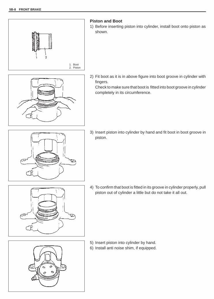
YH4GRANDVITARA
1. Boot2. Piston
5B-8 FRONT BRAKE
Piston and Boot1) Before inserting piston into cylinder, install boot onto piston as
shown.
2) Fit boot as it is in above figure into boot groove in cylinder withfingers.Check to make sure that boot is fitted into boot groove in cylindercompletely in its circumference.
3) Insert piston into cylinder by hand and fit boot in boot groove inpiston.
4) To confirm that boot is fitted in its groove in cylinder properly, pullpiston out of cylinder a little but do not take it all out.
5) Insert piston into cylinder by hand.6) Install anti noise shim, if equipped.

YH4GRANDVITARA
1. Caliper pin bolts
1. Flexible hose bolt
FRONT BRAKE 5B-9
CaliperBefore installing caliper (cylinder body) to carrier, check to ensurethat guide pin (pin bolt) inserted in each caliper carrier hole can bemoved smoothly in thrust direction.
NOTE:Where temperature gets as low as –30 �C in cold weather, userubber grease whose viscosity varies very little even at –40 �C(–40�F).
INSTALLATION1) Install caliper to caliper carrier.2) Torque caliper pin bolts to specifications.
Tightening Torque(a), (b): 27 N.m (2.7 kg-m, 20.0 lb-ft) For TOKICO brake. .
caliper(a): 50 N.m (5.0 kg-m, 36.5 lb-ft) For SUMITOMO. . . . . (b): 85 N.m (8.5 kg-m, 61.5 lb-ft) ELECTRIC brake
85 N.m (8.5 kg-m, 61.5 lb-ft) caliperNOTE:Make sure that boots are fit into groove securely.
3) Install brake flexible hose as shown and torque hose mountingbolt to specification.
Tightening Torque(b): 23 N.m (2.3 kg-m, 17.0 lb-ft)
4) Torque wheel nuts to specification.
Tightening Torque(c): 100 N.m (10.0 kg-m, 72.5 lb-ft)
5) After completing installation, fill reservoir with brake fluid andbleed brake system. Perform brake test and check eachinstalled part for oil leakage.

YH4GRANDVITARA
1. 8 mm bolt
5B-10 FRONT BRAKE
FRONT BRAKE DISCREMOVAL1) Hoist vehicle and remove wheel.2) Remove caliper assembly by loosening carrier bolts (2 pcs.).
CAUTION:During removal, be careful not to damage brake flexiblehose and not to depress brake pedal.
3) Remove disc by using 8 mm bolts (2 pcs.).
INSPECTIONRefer to FRONT DISC BRAKE PAD INSPECTION.
INSTALLATIONNOTE:See NOTE at the beginning of this section.
1) Install disc to wheel hub.2) Install caliper assembly to steering knuckle.3) Torque caliper carrier bolts to specification.
Tightening Torque(a): 85 N.m (8.5 kg-m, 61.5 lb-ft)
4) Torque front wheel nuts to specifications.
Tightening Torque(b): 100 N.m (10.0 kg-m, 72.5 lb-ft)
5) Upon completion of installation, perform brake test.

YH4GRANDVITARA
FRONT BRAKE 5B-11
TIGHTENING TORQUE SPECIFICATIONS
Fastening partsTightening torque
Fastening artsN.m kg-m lb-ft
Brake caliper bleeder plug(For SUMITOMO ELECTRIC brake caliper)
8.0 0.80 6.0
Brake caliper bleeder plug(For TOKICO brake caliper)
8.5 0.85 6.5
Caliper pin bolt (For TOKICO brake caliper) 27 2.7 20.0
Caliper pin bolt (M10)(For SUMITOMO ELECTRIC brake caliper)
50 5.0 36.5
Caliper pin bolt (M12)(For SUMITOMO ELECTRIC brake caliper)
85 8.5 61.5
Flexible hose bolt 23 2.3 17.0
Brake carrier bolt 85 8.5 61.5
Wheel nut 100 10.0 72.5
REQUIRED SERVICE MATERIAL
MATERIALSRECOMMENDED
SUZUKI PRODUCTUSE
Brake fluidIndicated on reservoircap or described in owner’smanual of vehicle
� To fill master cylinder reservoir.� To clean and apply to inner parts of master
cylinder caliper and wheel cylinder whenthey are disassembled.

YH4GRANDVITARA
5C
PARKING AND REAR BRAKE 5C-1
SECTION 5C
PARKING AND REAR BRAKEWARNING:For vehicles equipped with Supplemental Restraint (Air Bag) System� Service on and around the air bag system components or wiring must be performed only by an autho-
rized SUZUKI dealer. Refer to “Air Bag System Components and Wiring Location View” under “Gener-al Description” in air bag system section in order to confirm whether you are performing service onor near the air bag system components or wiring. Please observe all WARNINGS and “Service Precau-tions” under “On-Vehicle Service” in air bag system section before performing service on or aroundthe air bag system components or wiring. Failure to follow WARNINGS could result in unintentionalactivation of the system or could render the system inoperative. Either of these two conditions mayresult in severe injury.
� Technical service work must be started at least 90 seconds after the ignition switch is turned to the“LOCK” position and the negative cable is disconnected from the battery. Otherwise, the system maybe activated by reserve energy in the Sensing and Diagnostic Module (SDM).
NOTE:All brake fasteners are important attaching parts in that they could affect the performance of vital partsand systems, and/or could result in major repair expense. They must be replaced with one of same partnumber or with an equivalent part if replacement becomes necessary. Do not use a replacement part oflesser quality or substitute design. Torque values must be used as specified during reassembly to assureproper retention of all parts. There is to be no welding as it may result in extensive damage and weakeningof the metal.
CONTENTS
GENERAL DESCRIPTION 5C- 2. . . . . . . . . . . . . . . . . . . . . . . . . . . . . . . . . . . . . . . . . . . . . . . . . . . . . . . . . . . . . . . . . . Drum Brake Assembly 5C- 2. . . . . . . . . . . . . . . . . . . . . . . . . . . . . . . . . . . . . . . . . . . . . . . . . . . . . . . . . . . . . . . . . . . .
DIAGNOSIS 5C- 3. . . . . . . . . . . . . . . . . . . . . . . . . . . . . . . . . . . . . . . . . . . . . . . . . . . . . . . . . . . . . . . . . . . . . . . . . . . . . . .
CHECK AND ADJUSTMENT 5C- 3. . . . . . . . . . . . . . . . . . . . . . . . . . . . . . . . . . . . . . . . . . . . . . . . . . . . . . . . . . . . . . . .
ON-VEHICLE SERVICE 5C- 3. . . . . . . . . . . . . . . . . . . . . . . . . . . . . . . . . . . . . . . . . . . . . . . . . . . . . . . . . . . . . . . . . . . . Parking Brake Lever 5C- 3. . . . . . . . . . . . . . . . . . . . . . . . . . . . . . . . . . . . . . . . . . . . . . . . . . . . . . . . . . . . . . . . . . . . . . Parking Brake Cable 5C- 5. . . . . . . . . . . . . . . . . . . . . . . . . . . . . . . . . . . . . . . . . . . . . . . . . . . . . . . . . . . . . . . . . . . . . . Brake Drum 5C- 7. . . . . . . . . . . . . . . . . . . . . . . . . . . . . . . . . . . . . . . . . . . . . . . . . . . . . . . . . . . . . . . . . . . . . . . . . . . . . Brake Shoe 5C- 9. . . . . . . . . . . . . . . . . . . . . . . . . . . . . . . . . . . . . . . . . . . . . . . . . . . . . . . . . . . . . . . . . . . . . . . . . . . . . . Wheel Cylinder 5C-12. . . . . . . . . . . . . . . . . . . . . . . . . . . . . . . . . . . . . . . . . . . . . . . . . . . . . . . . . . . . . . . . . . . . . . . . . . . Brake Back Plate 5C-14. . . . . . . . . . . . . . . . . . . . . . . . . . . . . . . . . . . . . . . . . . . . . . . . . . . . . . . . . . . . . . . . . . . . . . . . .
TIGHTENING TORQUE SPECIFICATIONS 5C-17. . . . . . . . . . . . . . . . . . . . . . . . . . . . . . . . . . . . . . . . . . . . . . . . . . . .
REQUIRED SERVICE MATERIALS 5C-17. . . . . . . . . . . . . . . . . . . . . . . . . . . . . . . . . . . . . . . . . . . . . . . . . . . . . . . . . .
SPECIAL TOOLS 5C-17. . . . . . . . . . . . . . . . . . . . . . . . . . . . . . . . . . . . . . . . . . . . . . . . . . . . . . . . . . . . . . . . . . . . . . . . . .

YH4GRANDVITARA
1. Brake back plate2. Brake shoe3. Shoe return upper spring4. Adjuster5. Shoe return lower spring6. Adjuster lever7. Adjuster spring8. Shoe hold down spring9. Shoe hold down pin
10. Wheel cylinder11. Link12. Brake strut
(a)
Tightening torque(a): 7.5 N.m (0.75 kg-m, 5.5 lb-ft)
5C-2 PARKING AND REAR BRAKE
GENERAL DESCRIPTION
DRUM BRAKE ASSEMBLY
The drum brake assembly has a self shoe clearance adjusting system so that drum-to-shoe clearance is main-tained appropriate at all times. Rear brake is a drum type. It uses leading trailing operation when brake pedal isdepressed and when parking brake is applied on level road.It also uses duo servo operation when parking brake is applied on gradient road and load is applied in longitudinaldirection of vehicle.
NOTE:Replace all components included in repair kits to service this drum brake. Lubricate parts as specified.
WARNING:If any hydraulic component is removed or brake line disconnected, bleed the brake system. The torquevalues specified are for dry, unlubricated fasteners.
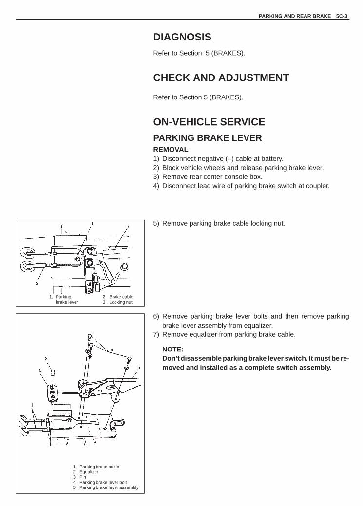
YH4GRANDVITARA
2. Brake cable3. Locking nut
1. Parking brake cable2. Equalizer3. Pin4. Parking brake lever bolt5. Parking brake lever assembly
1. Parking brake lever
PARKING AND REAR BRAKE 5C-3
DIAGNOSISRefer to Section 5 (BRAKES).
CHECK AND ADJUSTMENT
Refer to Section 5 (BRAKES).
ON-VEHICLE SERVICE
PARKING BRAKE LEVERREMOVAL1) Disconnect negative (–) cable at battery.2) Block vehicle wheels and release parking brake lever.3) Remove rear center console box.4) Disconnect lead wire of parking brake switch at coupler.
5) Remove parking brake cable locking nut.
6) Remove parking brake lever bolts and then remove parkingbrake lever assembly from equalizer.
7) Remove equalizer from parking brake cable.
NOTE:Don’t disassemble parking brake lever switch. It must be re-moved and installed as a complete switch assembly.

YH4GRANDVITARA
1. Parking brake cable2. Equalizer3. Pin4. Parking brake lever bolt5. Parking brake lever assembly
5C-4 PARKING AND REAR BRAKE
INSTALLATION1) Install in reverse order of REMOVAL procedure.
Check equalizer inclined angle.
Angle “a”: within 15 degrees
Tightening Torque(a): 23 N.m (2.3 kg-m, 17.0 lb-ft)
2) After all parts are installed, parking brake lever needs to be ad-justed. Refer to PARKING BRAKE INSPECTION AND AD-JUSTMENT in Section 5.
3) Check brake drum for dragging and brake system for proper per-formance.
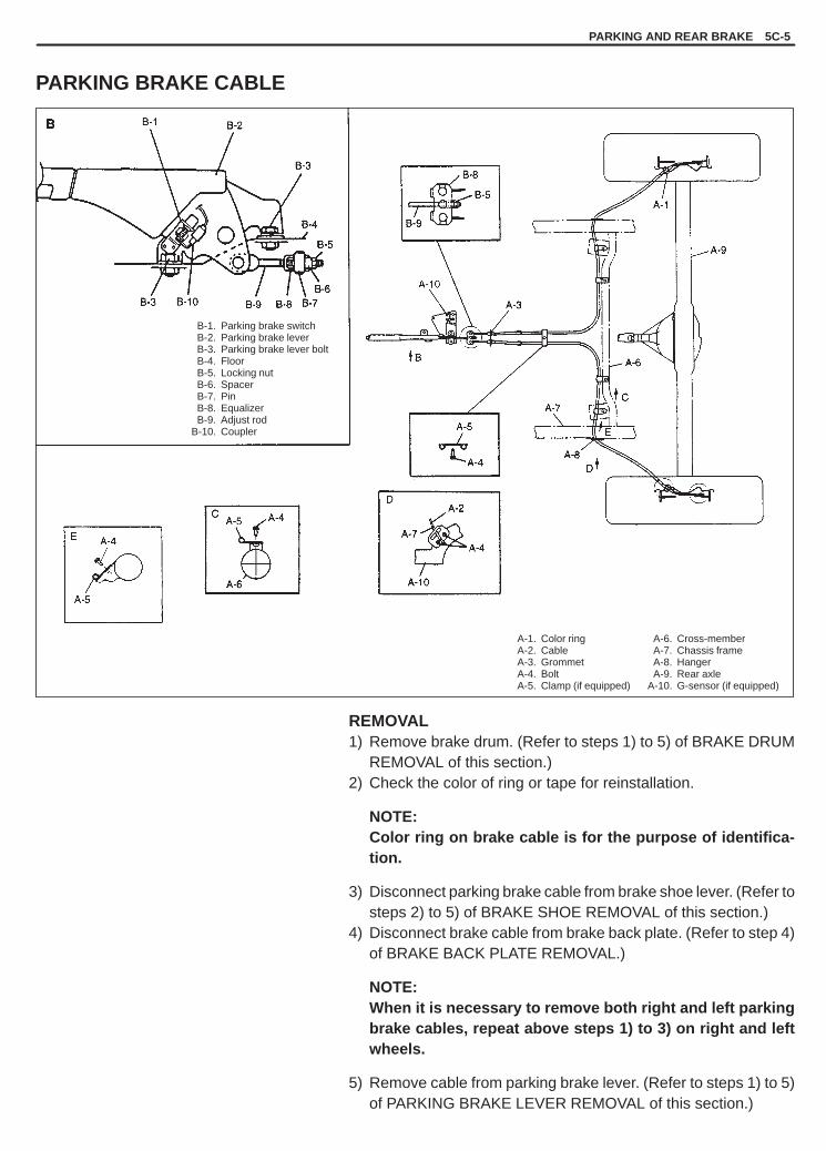
YH4GRANDVITARA
A-1. Color ringA-2. CableA-3. GrommetA-4. BoltA-5. Clamp (if equipped)
A-6. Cross-memberA-7. Chassis frameA-8. HangerA-9. Rear axle
A-10. G-sensor (if equipped)
B-1. Parking brake switchB-2. Parking brake leverB-3. Parking brake lever boltB-4. FloorB-5. Locking nutB-6. SpacerB-7. PinB-8. EqualizerB-9. Adjust rod
B-10. Coupler
PARKING AND REAR BRAKE 5C-5
PARKING BRAKE CABLE
REMOVAL1) Remove brake drum. (Refer to steps 1) to 5) of BRAKE DRUM
REMOVAL of this section.)2) Check the color of ring or tape for reinstallation.
NOTE:Color ring on brake cable is for the purpose of identifica-tion.
3) Disconnect parking brake cable from brake shoe lever. (Refer tosteps 2) to 5) of BRAKE SHOE REMOVAL of this section.)
4) Disconnect brake cable from brake back plate. (Refer to step 4)of BRAKE BACK PLATE REMOVAL.)
NOTE:When it is necessary to remove both right and left parkingbrake cables, repeat above steps 1) to 3) on right and leftwheels.
5) Remove cable from parking brake lever. (Refer to steps 1) to 5)of PARKING BRAKE LEVER REMOVAL of this section.)

YH4GRANDVITARA
1. Brake back plate2. Cable cap3. Brake cable
1. Parking brake shoe lever2. Spring3. Nipple end
5C-6 PARKING AND REAR BRAKE
INSTALLATIONInstall parts in reverse order of removal procedure, noting the fol-lowing.1) Install brake cable cap to brake back plate securely as shown in
figure.
NOTE:Color ring or tape on brake cable is for the purpose of identi-fication. Use cable with the same colored ring as before re-moval.
2) Install brake cable spring and nipple end to parking brake shoelever securely as shown in figure.
3) For brake shoe installation, refer to steps 1) and 4) of BRAKESHOE INSTALLATION of this section.
4) For brake drum installation, refer to steps 1) and 3) of BRAKEDRUM INSTALLATION of this section.
5) For proper routing and secure clamping of parking brake cable.6) For installation of cable to parking brake lever, refer to PARKING
BRAKE LEVER INSTALLATION of this section.
7) Upon completion of installation, adjust cable. (Refer to PARK-ING BRAKE CHECK AND ADJUSTMENT in Section 5.) Thencheck brake drum for dragging and brake system for proper per-formance. After removing vehicle from hoist, brake test shouldbe performed.

YH4GRANDVITARA
1. Parking brake lever cover2. Brake cable locking nut
1. Brake drum2. 8 mm bolts
PARKING AND REAR BRAKE 5C-7
BRAKE DRUMREMOVAL1) Hoist vehicle and pull up parking brake lever.2) Remove wheel.
3) Release parking brake lever.4) Remove rear center console box screws and with rear part of
rear center console box lifted a little, loosen parking brake cablelocking nut.
5) Remove brake drum by using 8 mm bolts (2 pcs.).
INSPECTION
Brake DrumInspect drum for cleanliness. Check wear of its braking surface bymeasuring its inside diameter.
Inside diameter “a”Standard: 220 mm (8.66 in.)Service Limit: 222 mm (8.74 in.)
Whenever brake drums are removed, they should be thoroughlycleaned and inspected for cracks, scores, deep grooves.

YH4GRANDVITARA
1. Pawl lever2. Adjuster3. Brake shoes
5C-8 PARKING AND REAR BRAKE
Cracked, Scored, or Grooved DrumA cracked, drum is unsafe for further service and must be replaced.Do not attempt to weld a cracked drum.Smooth up any slight scores. Heavy or extensive scoring will causeexcessive brake lining wear and it will probably be necessary to re-surface drum braking surface.If brake linings are slightly worn and drum is grooved, drum shouldbe polished with fine emery cloth but should no be turned.
NOTE:When drum is removed, visually inspect wheel cylinder forbrake fluid leakage. Correct leaky point, if any.
Brake ShoeWhere lining is worn out beyond service limit, replace shoe.
Thickness “a”Standard: 6.5 mm (0.24 in.)Service limit: 3.0 mm (0.12 in.)
If one of brake linings is to service limit, all linings must be replacedat the same time.
CAUTION:Never polish lining with sandpaper. If lining is polished withsandpaper, hard particles of sandpaper will be deposited inlining and may damage drum. When it is required to correctlining, replace it with a new one.
INSTALLATIONNOTE:See NOTE at the beginning of the section.
1) Before installing brake drum, check outer diameter of brakeshoes. If it is not within value as specified below, adjust it to spec-ification by turning adjuster.
Outer diameter of brake shoes“a”: 219.4 – 219.7 mm (8.638 – 8.650 in.)

YH4GRANDVITARA
6. Shoe hold downsprings
7. Strut spring8. Lower shoe return
spring
1. Upper shoe return spring2. Adjuster3. Pawl lever4. Adjuster spring5. Shoe hold down pins
1. Brake back plate2. Cable cap3. Brake cable
PARKING AND REAR BRAKE 5C-9
2) Install brake drum after making sure that inside of brake drumand brake shoes are free from dirt and oil.
3) Upon completion of all jobs, depress brake pedal with about 30kg (66 lbs) load three to ten times so as to obtain proper drum-to-shoe clearance.Adjust parking brake cable. (For adjustment, refer to PARKINGBRAKE CHECK AND ADJUSTMENT in Section 5.)
4) Tighten rear center console box screws.
5) Install wheel and tighten wheel nuts to specified torque.
Tightening Torque(b): 100 N.m (10.0 kg-m, 72.5 lb-ft)
6) Check to ensure that brake drum is free from dragging and prop-er braking is obtained. Then remove vehicle from hoist and per-form brake test (foot brake and parking brake).
BRAKE SHOEREMOVAL1) Perform steps 1) to 5) of BRAKE DRUM REMOVAL.
WARNING:Use special care when installing brake shoe returnspring. Failure in its proper installation may allow it tospringback and cause personal injury.
2) Remove shoe hold down springs by turning shoe hold downpins.
3) Remove upper return spring, struts, adjuster, adjuster lever andsprings.
4) Remove brake shoes and lower shoe return spring.
5) Remove brake shoes and disconnect parking brake cable fromparking brake shoe lever.

YH4GRANDVITARA
5C-10 PARKING AND REAR BRAKE
1. Retainer2. Parking brake shoe lever3. Brake shoe
6) Remove parking brake shoe lever from brake shoe.
INSPECTION
Parking Shoe LeverInspect brake shoe lever for free movement against brake shoeweb. If defective, correct or replace.
Strut, AdjusterCheck thread or ratchet of strut and adjuster for wear, sticking andcorrosion.
SpringsInspect for damage or weakening.Inspect each part with arrow for rust. If found defective, replace.
Brake ShoeRefer to BRAKE DRUM INSPECTION.

YH4GRANDVITARA
6. Shoe hold downsprings
7. Strut spring8. Lower shoe return
spring
1. Upper shoe return spring2. Adjuster3. Pawl lever4. Adjuster spring5. Shoe hold down pins
1. Lower return spring2. Lower strut
PARKING AND REAR BRAKE 5C-11
INSTALLATION1) Assemble parts as shown in reverse order of removal.
2) Install shoe hold down springs by pushing them down in placeand turning hold down pins.
3) Install adjuster and upper shoe return spring.4) Install adjuster lever, adjuster spring and strut spring.5) For procedure hereafter, refer to steps 1) to 6) of BRAKE DRUM
INSTALLATION.

YH4GRANDVITARA
1. Wheel cylinder
1. Brake back plate2. Brake pipe flare nut3. Brake pipe4. Wheel cylinder bolts
1. Bleeder plug cap
5C-12 PARKING AND REAR BRAKE
WHEEL CYLINDERREMOVAL1) Perform steps 1) to 5) of BRAKE DRUM REMOVAL.2) Perform steps 2) to 4) of BRAKE SHOE REMOVAL.3) Loosen brake pipe flare nut (or nuts) but only within the extent
that fluid does not leak.4) Remove wheel cylinder mounting bolts. Disconnect brake pipe
(or pipes) from wheel cylinder and put wheel cylinder bleederplug cap onto pipe to prevent fluid from spilling.
INSPECTIONInspect wheel cylinder disassembled parts for wear, cracks, corro-sion or damage.
NOTE:Clean wheel cylinder components with brake fluid.
INSTALLATION (For non sealed type)1) Take off bleeder plug cap from brake pipe and connect pipe (or
pipes) to wheel cylinder just enough to prevent fluid from leak-ing.
2) Tighten wheel cylinder to brake back plate to specified torque.
Tightening Torque(a): 8.5 N.m (0.85 kg-m, 6.5 lb-ft)
3) Torque flare nut (or nuts) of brake pipe which was connected instep 1) to specification.
Tightening Torque(b): 16 N.m (1.6 kg-m, 12.0 lb-ft)
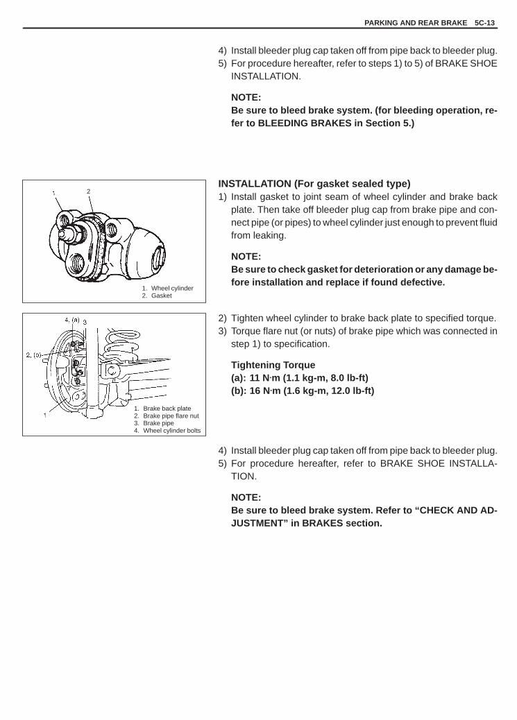
YH4GRANDVITARA
2
1. Wheel cylinder2. Gasket
1. Brake back plate2. Brake pipe flare nut3. Brake pipe4. Wheel cylinder bolts
PARKING AND REAR BRAKE 5C-13
4) Install bleeder plug cap taken off from pipe back to bleeder plug.5) For procedure hereafter, refer to steps 1) to 5) of BRAKE SHOE
INSTALLATION.
NOTE:Be sure to bleed brake system. (for bleeding operation, re-fer to BLEEDING BRAKES in Section 5.)
INSTALLATION (For gasket sealed type)1) Install gasket to joint seam of wheel cylinder and brake back
plate. Then take off bleeder plug cap from brake pipe and con-nect pipe (or pipes) to wheel cylinder just enough to prevent fluidfrom leaking.
NOTE:Be sure to check gasket for deterioration or any damage be-fore installation and replace if found defective.
2) Tighten wheel cylinder to brake back plate to specified torque.3) Torque flare nut (or nuts) of brake pipe which was connected in
step 1) to specification.
Tightening Torque(a): 11 N.m (1.1 kg-m, 8.0 lb-ft)(b): 16 N.m (1.6 kg-m, 12.0 lb-ft)
4) Install bleeder plug cap taken off from pipe back to bleeder plug.5) For procedure hereafter, refer to BRAKE SHOE INSTALLA-
TION.
NOTE:Be sure to bleed brake system. Refer to “CHECK AND AD-JUSTMENT” in BRAKES section.
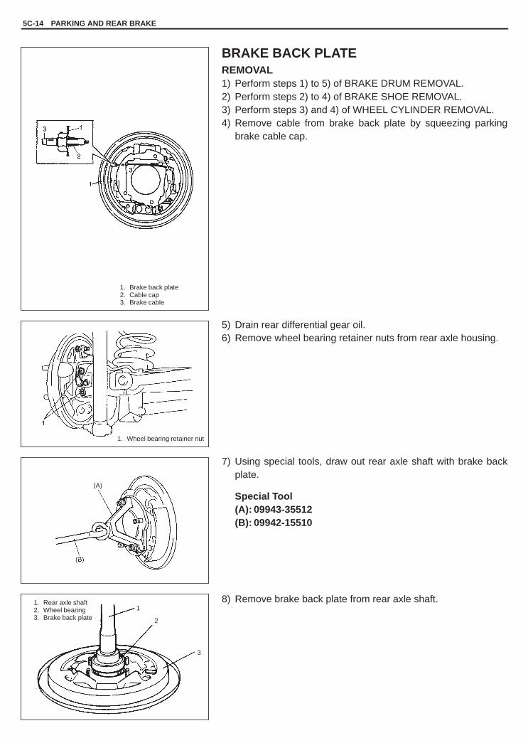
YH4GRANDVITARA
5C-14 PARKING AND REAR BRAKE
1
2
3
1. Brake back plate2. Cable cap3. Brake cable
1. Wheel bearing retainer nut
1. Rear axle shaft2. Wheel bearing3. Brake back plate
(A)
BRAKE BACK PLATEREMOVAL1) Perform steps 1) to 5) of BRAKE DRUM REMOVAL.2) Perform steps 2) to 4) of BRAKE SHOE REMOVAL.3) Perform steps 3) and 4) of WHEEL CYLINDER REMOVAL.4) Remove cable from brake back plate by squeezing parking
brake cable cap.
5) Drain rear differential gear oil.6) Remove wheel bearing retainer nuts from rear axle housing.
7) Using special tools, draw out rear axle shaft with brake backplate.
Special Tool(A): 09943-35512(B): 09942-15510
8) Remove brake back plate from rear axle shaft.

YH4GRANDVITARA
PARKING AND REAR BRAKE 5C-15
1. Rear axle shaft2. Wheel bearing3. Brake back plate
1. Rear axle shaft
1. Rear axlehousing
“A”
INSTALLATION1) Apply sealant to mating surface of bearing retainer with brake
back plate.
“A”: Sealant 99000-31110
NOTE:Make sure to remove old sealant before applying it anew.
2) Install brake back plate to rear axle shaft.
3) Apply sealant to joint seam of rear axle housing and brake backplate.
“A”: Sealant 99000-31110
NOTE:Make sure to remove old sealant before applying it anew.
4) Install rear axle shaft to rear axle housing.5) Tighten brake back plate nuts to specified torque.
Tightening Torque(a): 23 N.m (2.3 kg-m, 17.0 lb-ft)

YH4GRANDVITARA
5C-16 PARKING AND REAR BRAKE
1. Brake back plate2. Cable cap3. Parking brake cable
6) Install wheel cylinder, and tighten wheel cylinder bolts andbrake pipe flare nut (or nuts) to specified torque. (Refer to steps1) to 4) of WHEEL CYLINDER INSTALLATION of this section.)
7) Install parking brake cable to brake back plate.
8) Install brake shoes, referring to steps 1) to 4) of BRAKE SHOEINSTALLATION.
9) Install brake drum. Refer to steps 1) to 2) of BRAKE DRUMINSTALLATION in this section.
10) Refill differential housing with new specified gear oil. Refer to“MAINTENANCE SERVICE” in Section 7E for refill.
11) Fill reservoir with brake fluid and bleed brake system. (Forbleeding operation, refer to BLEEDING BRAKES in Section 5.)
12) Install wheel and tighten wheel nuts to specified torque.
Tightening Torque(b): 100 N.m (10.0 kg-m, 72.5 lb-ft)
13) Upon completion of all jobs, depress brake pedal with about 30kg (66 lbs) load three to ten times so as to obtain proper drum-to-shoe clearance.Adjust parking brake cable. (For adjustment, refer to PARKINGBRAKE CHECK AND ADJUSTMENT in Section 5.)
14) Tighten rear center console box screws.15) Check to ensure that brake drum is free from dragging and
proper braking is obtained. Then remove vehicle from hoistand perform brake test (foot brake and parking brake).
16) Check each installed part for oil leakage.

YH4GRANDVITARA
PARKING AND REAR BRAKE 5C-17
09943-35512Brake drum remover(Front wheel hub remover)
09942-15510Sliding hammer
TIGHTENING TORQUE SPECIFICATIONS
Fastening partsTightening torque
Fastening artsN.m kg-m lb-ft
Wheel cylinder bleeder plug 7.5 0.75 5.5
Parking brake lever bolt 23 2.3 17.0
Wheel cylinder bolt (For non sealed type) 8.5 0.85 6.5
Wheel cylinder bolt (For gasket sealed type) 11 1.1 12.0
Brake pipe flare nut 16 1.6 12.0
Brake back plate nut 23 2.3 17.0
Wheel nut 100 10.0 72.5
REQUIRED SERVICE MATERIALS
MATERIALSRECOMMENDED
SUZUKI PRODUCTUSE
Brake fluidIndicated on reservoircap or described in owner’smanual of vehicle
� To fill master cylinder reservoir.� To clean and apply to inner parts of master
cylinder caliper and wheel cylinder whenthey are disassembled.
Water tightsealant
SEALING COMPOUND 366E99000-31090
� To apply to mating surfaces of brake backplate and rear wheel cylinder.
SealantSUZUKI BOND NO. 121599000-31110
� To apply to mating surfaces of brake backplate and rear axle housing.
� To apply mating surfaces of brake backplate and rear wheel bearing retainer.
SPECIAL TOOLS

YH4GRANDVITARA
5E1
ANTILOCK BRAKE SYSTEM (ABS) (OPTIONAL) 5E1-1
GENERAL DESCRIPTION 5E1- 2. . . . . . . . . . . . . . Brake Hose/Pipe Routing 5E1- 3. . . . . . . . . . . . . . System Schematic 5E1- 4. . . . . . . . . . . . . . . . . . . . ABS Component Parts Location 5E1- 5. . . . . . . . ABS Hydraulic Unit/Control Module
Assembly 5E1- 6. . . . . . . . . . . . . . . . . . . . . . . . . .
DIAGNOSIS 5E1- 7. . . . . . . . . . . . . . . . . . . . . . . . . . . Precaution in Diagnosing Troubles 5E1- 7. . . . . . ABS Diagnostic Flow Table 5E1- 8. . . . . . . . . . . .
EBD Warning Lamp (Brake WarningLamp) Check 5E1-11. . . . . . . . . . . . . . . . . . . . . . .
“ABS” Warning Lamp Check 5E1-11. . . . . . . . . . . Diagnostic Trouble Code (DTC) Check
(Using “ABS” Warning Lamp) 5E1-11. . . . . . . . . DTC Check (Using SUZUKI Scan
Tool) 5E1-13. . . . . . . . . . . . . . . . . . . . . . . . . . . . . . . Diagnostic Trouble Code (DTC)
Clearance 5E1-13. . . . . . . . . . . . . . . . . . . . . . . . . .
SECTION 5E1
ANTILOCK BRAKE SYSTEM (ABS)(OPTIONAL)
WARNING:For vehicles equipped with Supplemental Restraint (Air Bag) System:� Service on and around the air bag system components or wiring must be performed only by an autho-
rized SUZUKI dealer. Refer to “Air Bag System Components and Wiring Location View” under “Gener-al Description” in air bag system section in order to confirm whether you are performing service onor near the air bag system components or wiring. Please observe all WARNINGS and “Service Precau-tions” under “On-Vehicle Service” in air bag system section before performing service on or aroundthe air bag system components or wiring. Failure to follow WARNINGS could result in unintentionalactivation of the system or could render the system inoperative. Either of these two conditions mayresult in severe injury.
� Technical service work must be started at least 90 seconds after the ignition switch is turned to the“LOCK” position and the negative cable is disconnected from the battery. Otherwise, the system maybe activated by reserve energy in the Sensing and Diagnostic Module (SDM).
NOTE:All brake fasteners are important attaching parts in that they could affect the performance of vital partsand systems, and/or could result in major repair expense. They must be replaced with one of same partnumber or with an equivalent part if replacement becomes necessary. Do not use a replacement part oflesser quality or substitute design. Torque values must be used as specified during reassembly to assureproper retention of all parts. There is to be no welding as it may result in extensive damage and weakeningof the metal.
CONTENTS

YH4GRANDVITARA
Diagnostic Trouble Code (DTC) Table 5E1-14. . . System Circuit 5E1-15. . . . . . . . . . . . . . . . . . . . . . . Table – A “ABS” Warning Lamp Circuit
Check – Lamp does not come “ON”at ignition switch on 5E1-16. . . . . . . . . . . . . . . . . .
Table – B “ABS” Warning Lamp CircuitCheck – Lamp comes “ON” steady 5E1-17. . . .
Table – C “ABS” Warning Lamp CircuitCheck – The lamp flashes continuouslywhile ignition switch is on 5E1-18. . . . . . . . . . . . . .
Table – D Code (DTC) is not Outputtedeven with Diag. Switch TerminalConnected to Ground 5E1-19. . . . . . . . . . . . . . . .
Table – E EBD Warning Lamp (BrakeWarning Lamp) Check-lamp Comes“ON” Steady 5E1-20. . . . . . . . . . . . . . . . . . . . . . . .
DTC 15 – G Sensor Circuit 5E1-21. . . . . . . . . . . . DTC 21, 22, 25, 26, 31, 32, 35 or 36
– Wheel Speed Sensor Circuit 5E1-23. . . . . . . . DTC 41, 45 or 56 – Solenoid Circuit 5E1-26. . . . . DTC 57 – Solenoid and Pump Motor
Power Source Circuit 5E1-27. . . . . . . . . . . . . . . . DTC 61 – ABS Pump Motor Circuit 5E1-28. . . . . . DTC 63 – ABS Fail-Safe Relay Circuit 5E1-29. . . DTC 71 – ABS Control Module 5E1-30. . . . . . . . .
ON-VEHICLE SERVICE 5E1-31. . . . . . . . . . . . . . . . Precaution 5E1-31. . . . . . . . . . . . . . . . . . . . . . . . . . . ABS Hydraulic Unit Operation Check 5E1-31. . . . ABS Hydraulic Unit /Control Module
Assembly 5E1-32. . . . . . . . . . . . . . . . . . . . . . . . . . Hydraulic unit inspection 5E1-32. . . . . . . . . . . . .
Removal 5E1-32. . . . . . . . . . . . . . . . . . . . . . . . . . Installation 5E1-33. . . . . . . . . . . . . . . . . . . . . . . . .
Front Wheel Speed Sensor 5E1-34. . . . . . . . . . . . Output voltage inspection 5E1-34. . . . . . . . . . . . Removal 5E1-35. . . . . . . . . . . . . . . . . . . . . . . . . . Sensor inspection 5E1-35. . . . . . . . . . . . . . . . . . Sensor rotor inspection 5E1-35. . . . . . . . . . . . . . Installation 5E1-36. . . . . . . . . . . . . . . . . . . . . . . . .
Front Sensor Rotor 5E1-36. . . . . . . . . . . . . . . . . . . Removal 5E1-36. . . . . . . . . . . . . . . . . . . . . . . . . . Installation 5E1-36. . . . . . . . . . . . . . . . . . . . . . . . .
Rear Wheel Speed Sensor 5E1-37. . . . . . . . . . . . Output voltage inspection 5E1-37. . . . . . . . . . . . Removal 5E1-37. . . . . . . . . . . . . . . . . . . . . . . . . . Sensor inspection 5E1-38. . . . . . . . . . . . . . . . . . Sensor rotor inspection 5E1-38. . . . . . . . . . . . . . Installation 5E1-38. . . . . . . . . . . . . . . . . . . . . . . . .
Rear Sensor Rotor 5E1-39. . . . . . . . . . . . . . . . . . . . Removal 5E1-39. . . . . . . . . . . . . . . . . . . . . . . . . . Installation 5E1-39. . . . . . . . . . . . . . . . . . . . . . . . .
G Sensor 5E1-40. . . . . . . . . . . . . . . . . . . . . . . . . . . . Removal 5E1-40. . . . . . . . . . . . . . . . . . . . . . . . . . Inspection 5E1-40. . . . . . . . . . . . . . . . . . . . . . . . . Installation 5E1-40. . . . . . . . . . . . . . . . . . . . . . . . .
Transfer 4WD Switch 5E1-41. . . . . . . . . . . . . . . . .
TIGHTENING TORQUESPECIFICATIONS 5E1-41. . . . . . . . . . . . . . . . . . . .
SPECIAL TOOLS 5E1-42. . . . . . . . . . . . . . . . . . . . . .
5E1-2 ANTILOCK BRAKE SYSTEM (ABS) (OPTIONAL)
GENERAL DESCRIPTION
The ABS (Antilock Brake System) controls the fluid pressure applied to the wheel cylinder of each brake from themaster cylinder so that each wheel is not locked even when hard braking is applied. This ABS is a 4-wheel typewhich controls the fluid pressure applied to the wheel cylinder of each of the four brakes to prevent each wheelfrom getting locked.The component parts of this ABS includes following parts in addition to those of the conventional brake system.� Wheel speed sensor which senses revolution speed of each wheel and outputs its signal.� In this ABS, ABS hydraulic unit (actuator assembly), ABS control module, pump motor relay and fail-safe relay
are combined as one component.� ABS control module which sends operation signal to ABS hydraulic unit to control fluid pressure applied to each
wheel cylinder based on signal from each wheel speed sensor so as to prevent wheel from locking.� ABS hydraulic unit which operates according to signal from ABS control module to control fluid pressure applied
to wheel cylinder of each of 4 wheels.� Fail-safe (solenoid valve) relay which supplies power to solenoid valve in ABS hydraulic unit and pump motor
relay.� Pump motor relay which supplies power to pump motor in ABS hydraulic unit.� “ABS” warning lamp which lights to inform abnormality when system fails to operate properly.� G sensor which detects body deceleration speed. (For 4WD model only)This ABS is equipped with Electronic Brake force Distribution (EBD) system that controls a fluid pressure of rearwheels to best condition, which is the same function as that of proportioning valve, by the signal from wheel sensorindependently of change of load due to load capacity and so on. And if the EBD system fails to operate properly,the brake warning lamp lights to inform abnormality.

YH4GRANDVITARA
1. Front disk brake2. Rear drum brake3. ABS hydraulic unit / control module assembly
with ABS pump motorrelay and fail-safe relay
4. Brake master cylinder / Reservoir
LH steering vehicle
RH steering vehicle
ANTILOCK BRAKE SYSTEM (ABS) (OPTIONAL) 5E1-3
BRAKE HOSE/PIPE ROUTING

YH4GRANDVITARA
1. Wheel speed sensor (Right-front)2. Stop lamp switch3. ABS control module4. Wheel speed sensor (Right-rear)5. Diagnosis connector6. Data link connector
7. Wheel speed sensor (Left-rear)8. “ABS” warning lamp9. ABS pump motor relay
10. ABS fail-safe relay (Solenoid valve relay)11. Lamp drive module12. Wheel speed sensor (Left-front)
13. ABS hydraulic unit14. G sensor (For 4WD model only)15. 4WD switch (For 4WD model only)16. ABS hydraulic unit / control module assembly
(with ABS pump motor & fail-safe relays)17. “EBD” warning lamp (Brake warning lamp)
Wheel speed sensor (LR)Wheel speed sensor (LF)Wheel speed sensor (RF)Wheel speed sensor (RR)Stop lamp switchG sensor (For 4WD model only)Diag. switch terminalBattery Voltage4WD switch (For 4WD model only)
Pump motor relay Pump motor
LF inlet solenoid
LF outlet solenoid
LR inlet solenoid
LR outlet solenoid
Rear inlet solenoid
Rear outlet solenoid
“ABS” warning lamp
Brake warning lamp
Data link connector
Fail-safe relay
Hydraulic unit
OUTPUTINPUT
ABS controlmodule
ABS hydraulic unit / controlmodule assembly
PCM or ECMIdle up
5E1-4 ANTILOCK BRAKE SYSTEM (ABS) (OPTIONAL)
SYSTEM SCHEMATIC

YH4GRANDVITARA
1. Wheel speed sensor(Right-front)
2. Stop lamp switch3. Data link connector4. “ABS” warning lamp5. Wheel speed sensor
(Right-rear)
6. Wheel speed sensor(Left-rear)
7. Ground8. Diagnosis connector (Black connector)9. Wheel speed sensor
(Left-front)
10. ABS hydraulic unit/control module assemblywith ABS pump motor relay and fail-safe relay
11. G sensor (For 4WD model only)12. Wheel speed sensor rotor (ring)13. 4WD switch (For 4WD model only)14. EBD warning lamp (Brake warning lamp)
LH steering vehicle
RH steering vehicle
ANTILOCK BRAKE SYSTEM (ABS) (OPTIONAL) 5E1-5
ABS COMPONENT PARTS LOCATION

YH4GRANDVITARA
1. Diagnosis connector(6 pins connector)
2. Ground terminal
3. Diag. switch terminal4. Service wire
5E1-6 ANTILOCK BRAKE SYSTEM (ABS) (OPTIONAL)
ABS HYDRAULIC UNIT/CONTROL MODULEASSEMBLYABS control module is a component of ABS hydrauli unit /controlmodule assembly and has the following functions.
Self-Diagnosis FunctionABS control module diagnoses conditions of the system compo-nent parts (whether or not there is any abnormality) all the time andindicates the results (warning of abnormality occurrence and DTC)through the “ABS” warning lamp as described below.
1) When ignition switch is turned ON, “ABS” warning lamp lights for2 seconds to check its bulb and circuit.
2) When no abnormality has been detected (the system is in goodcondition), “ABS” warning lamp turns OFF after 2 seconds.
3) When the vehicle starts to move after the ignition switch is turnedON (more than one wheel speed sensor signals are inputted),solenoid valves and motor of ABS hydraulic unit operate onceone after another for electrical check.During this check, motor operation sound may be heard but thatmeans nothing abnormal.
4) When an abnormality in the system is detected, “ABS” warninglamp lights and the area where that abnormality lies is stored inthe memory of EEPROM in ABS control module.
5) When Diag. switch terminal of diagnosis connector (monitorconnector) is grounded, the abnormal area is output as DTC. Itis indicated by flashing of “ABS” warning lamp. (Refer to thetable below. )
ABS WARNING LAMP
SYSTEM CONDITION Diag. switchterminal is not
grounded
Diag. switchterminal isgrounded
In good condi-
No trouble inthe past
OFF DTC 12g
tion at present Trouble occur-red in the past
OFF History DTC
Abnormalityexists at
No trouble inthe past
ON Current DTCexists at present Trouble occur-
red in the pastON
Current andhistory DTCs
For procedure to clear all DTC’s, refer to the item “DiagnosticTrouble Code Clearance” in this section.
Also ABS control module turns ON EBD warning lamp (brake warn-ing lamp) depending on the trouble that detected by the module andEBD warning lamp does not indicate DTC as well as “ABS” warninglamp.
Fail-Safe FunctionWhen an abnormality occurs (an abnormal DTC is detected), ABScontrol module turns OFF the fail-safe relay which supplies powerto ABS hydraulic unit. Thus, with ABS not operating, brakes func-tion just like the brake system of the vehicle not equipped with ABS.

YH4GRANDVITARA
ANTILOCK BRAKE SYSTEM (ABS) (OPTIONAL) 5E1-7
DIAGNOSIS
To ensure that the trouble diagnosis is done accurately and smooth-ly, observe “Precautions in Diagnosing Troubles” and follow “ABSDiagnostic Flow Table”.
PRECAUTION IN DIAGNOSING TROUBLES
� If the vehicle was operated in any of the following ways, “ABS”warning light may light momentarily but this does not indicate any-thing abnormal in ABS.– The vehicle was driven with parking brake pulled.– The vehicle was driven with brake dragging.– The vehicle was stuck in mud, sand, etc.– Wheel spin occurred while driving.– Wheel(s) was rotated while the vehicle was jacked up.
� Be sure to read “Precautions for Electronic Circuit Service” in“GENERAL INFORMATION” section before inspection and ob-serve what is written there.
� Be sure to use the trouble diagnosis procedure as described inthe flow table. Failure to follow the flow table may result in incor-rect diagnosis. (Some other diag. trouble code may be stored bymistake in the memory of ABS control module during inspection.)

YH4GRANDVITARA
5E1-8 ANTILOCK BRAKE SYSTEM (ABS) (OPTIONAL)
ABS DIAGNOSTIC FLOW TABLE
Refer to the following pages for the details of each step.
STEP ACTION YES NO
1 Perform customer complaint analysis, problemsymptom confirmation and diagnostic trouble codecheck record and clearance. Is there any trouble code?
Go to step 2. Go to step 5.
2 Perform driving test. Is trouble symptom identified? Go to step 3. Go to step 6.
3 Check diagnostic trouble code. Is it malfunctioncode?
Go to step 4. Go to step 5.
4 Inspect and repair referring to applicable diagnostic troublecode table in this section. Then perform final confirmationtest after clearing diagnostic trouble code. Is trouble recur?
Go to step 7. END.
5 Inspect and repair referring to DIAGNOSIS in“BRAKES” section. Then perform final confirmation testafter clearing diagnostic trouble code. Is trouble recur?
Go to step 7. END.
6 Check for intermittent problems referring toINTERMITTENT AND POOR CONNECTION in“GENERAL INFORMATION” section and related circuitof trouble code recorded in step 1. Then perform finalconfirmation test after clearing diagnostic trouble code.Is trouble recur?
Go to step 7. END.
7 Perform diagnostic trouble code check recordand clearance. Is there any trouble code?
Go to step 2. Go to step 5.

YH4GRANDVITARA
ANTILOCK BRAKE SYSTEM (ABS) (OPTIONAL) 5E1-9
1-1. CUSTOMER COMPLAINT ANALYSISRecord details of the problem (failure, complaint) and how it occurred as described by the customer.For this purpose, use of such a questionnaire form as shown below will facilitate collecting information to thepoint required for proper analysis and diagnosis.
CUSTOMER QUESTIONNAIRE (EXAMPLE)
Customer’s name: Model: VIN:
Date of issue: Date Reg. Date of problem: Mileage:
Problem Symptoms
� “ABS” warning light abnormal: fails to turn on/fails to go off /flashes
� Abnormal noise while vehicle is running: from motor, from valve,other__________________
� Wheel is locked at braking:� Pump motor does not stop (running):� Braking does not work:� Other:
Frequency of occurrence� Continuous/Intermittent ( times a day, a month)/
other______________
Conditions for Occurrenceof Problem
� Vehicle at stop & ignition switch ON:� When starting: at initial start only/at every start /Other______________� Vehicle speed: while accelerating/while decelerating/at stop/
while turning/while running at constant speed/other________________
� Road surface condition: Paved road/rough road/snow-coveredroad/other_________________
� Chain equipment:
Environmental Condition� Weather: fair /cloudy/rain/snow/other___________________� Temperature: �F ( �C)
Diagnostic Trouble Code� First check: Normal code/malfunction code ( )� Second check after test drive: Normal code/malfunction code ( )

YH4GRANDVITARA
5E1-10 ANTILOCK BRAKE SYSTEM (ABS) (OPTIONAL)
1-2. PROBLEM SYMPTOM CONFIRMATIONCheck if what the customer claimed in CUSTOMER QUESTIONNAIRE is actually found in the vehicle andif that symptom is found, whether it is identified as a failure. (This step should be shared with the customerif possible.) When “ABS” warning lamp is not operated correctly, proceed to “Diagnostic Flow Table-A, B orC”.
1-3. DIAGNOSTIC TROUBLE CODE (DTC) CHECK, RECORD AND CLEARANCEPerform “Diagnostic Trouble Code Check” as shown below, record it and then clear it referring to “DiagnosticTrouble Code Clearance” in this section.If the malfunction DTC which was once displayed and then cleared cannot be detected (indicated) again whenthe ignition switch is turned ON, attempt to diagnose the trouble based on the DTC recorded in this step maymislead the diagnosis or make diagnosing difficult. Proceed to Step 2 to check ABS control module for properself-diagnosis function.If the malfunction DTC which was once displayed and then cleared can be detected (indicated) again whenignition switch is turned ON, proceed to Step 3.
2. DRIVING TESTTest drive the vehicle at 40 km/h for more than a minute and check if any trouble symptom (such as abnormallighting of “ABS” warning lamp) exists.If the malfunction DTC is confirmed again at ignition switch ON, driving test as described in above is not neces-sary. Proceed to Step 3.
3. DIAGNOSTIC TROUBLE CODE CHECKRecheck diagnostic trouble code referring to item “DTC CHECK” as shown below.
4. DIAGNOSTIC TROUBLE CODE FLOW CHARTAccording to Diagnostic flow table for the diagnostic trouble code confirmed in Step 3, locate the cause of thetrouble, namely in a sensor, switch, wire harness, connector, actuator, ABS control module or other part andrepair or replace faulty parts.
5. “DIAGNOSIS” IN “BRAKE” SECTIONCheck the parts or system suspected as a possible cause referring to “Diagnosis” in “BRAKES” section andbased on symptoms appearing on the vehicle (symptoms obtained through Steps 1-1, 1-2 and 2 and repair orreplace faulty parts, if any.
6. CHECK FOR INTERMITTENT PROBLEMCheck parts where an intermittent trouble is easy to occur (e.g., wire harness, connector, etc.), referring to IN-TERMITTENT TROUBLE in “GENERAL INFORMATION” section and related circuit of trouble code recordedin Step 1-3.
7. FINAL CONFIRMATION TESTConfirm that the problem symptom has gone and the ABS is free from any abnormal conditions. If what has beenrepaired is related to the malfunction DTC, clear the DTC once and perform test driving and confirm that a nor-mal code is indicated.

YH4GRANDVITARA
Example: When right-front wheel speed sensor circuit opens (DTC 21)
1. Diagnosis connector(6 pins connector)
2. Ground terminal
3. Diag. switch terminal4. Service wire
Voltmeter indicator(or “ABS” warninglamp) HIGH
(ON)
LOW(OFF)
Time (sec.)
1. EBD warning lamp(brake warning lamp)
ANTILOCK BRAKE SYSTEM (ABS) (OPTIONAL) 5E1-11
EBD WARNING LAMP (BRAKE WARNINGLAMP) CHECKNOTE:Perform this check on a level place.
1) Turn ignition switch ON with parking brake applied.2) Check that brake warning lamp is turned ON.3) Release parking brake with ignition switch ON and check that
EBD warning lamp (brake warning lamp) goes off.If it doesn’t go off, go to “TABLE-E” in this section.
“ABS” WARNING LAMP CHECK
1) Turn ON the ignition switch.2) Check that “ABS” warning lamp lights for about 2 seconds and
then goes OFF.If anything faulty is found, advance to Diagnostic table – A, B orC.
DIAGNOSTIC TROUBLE CODE (DTC) CHECK(USING “ABS” WARNING LAMP)
1) Using service wire, connect diag. switch terminal of diagnosisconnector to ground.
2) Turn ignition switch ON.3) Read flashing of “ABS” warning lamp which represents DTC as
shown in example below and write it down. When more than 2DTC’s are stored in memory, deflection and flashing for eachDTC is repeated three times starting with the smallest DTC num-ber in increasing order.For details of DTC, refer to “DTC Table”.

YH4GRANDVITARA
5E1-12 ANTILOCK BRAKE SYSTEM (ABS) (OPTIONAL)
NOTE:“ABS” warning lamp indicates only following DTC’s, DTC12 which means that no malfunction DTC is stored and his-tory DTC which indicates history trouble area. When thereis a current trouble, “ABS” warning lamp remains ON andtherefore DTC is not indicated.
4) After completing the check, turn ignition switch off and discon-nect service wire from DIAG. connector.

YH4GRANDVITARA
ANTILOCK BRAKE SYSTEM (ABS) (OPTIONAL) 5E1-13
1. Data link connector (DLC)
1. Diagnosis connector (6 pins connector)2. Ground terminal3. Diag. switch terminal4. Service wire
DTC CHECK (USING SUZUKI SCAN TOOL)
1) After setting cartridge for ABS to SUZUKI scan tool, connect SU-ZUKI scan tool to data link connector.
Special Tool(A): 09931-76011 (SUZUKI scan tool)(B): Mass storage cartridge(C): 16/14 pin DLC cable
2) Turn ignition switch ON.3) Read DTC according to instructions displayed on SUZUKI scan
tool and print it or write it down. Refer to SUZUKI scan tool opera-tor’s manual for further details.
4) After completing the check, turn ignition switch off and discon-nect SUZUKI scan tool from DLC.
DIAGNOSTIC TROUBLE CODE (DTC)CLEARANCE
WARNING:When performing a driving test, select a safe place wherethere is neither any traffic nor any traffic accident possibil-ity and be very careful during testing to avoid occurrence ofan accident.
After repair or replace malfunction part(s), clear all DTC’s by per-forming the following procedure.1) Turn ignition switch OFF.2) Using service wire, connect diag. switch terminal of diag. con-
nector to diag. ground terminal.3) With connection described in above step 2) maintained, turn
ignition switch ON.4) Repeat on/off operation of service wire at diag. ground terminal
at least 5 times within 10 seconds.
NOTE:Service wire ON time must be for 0.1 second and more.
5) Turn ignition switch OFF and disconnect service wire from diag.connector.
6) Perform DRIVING TEST and DTC CHECK and confirm that nor-mal DTC (DTC 12) is displayed; not malfunction DTC.
NOTE:It is also possible to clear DTC by using SUZUKI scan tool.Refer to Cartridge Manual for procedure to clear DTC.

YH4GRANDVITARA
5E1-14 ANTILOCK BRAKE SYSTEM (ABS) (OPTIONAL)
DIAGNOSTIC TROUBLE CODE (DTC) TABLE
DTC(indicated
DTC(displayed VOLTMETER INDICATION(indicated
by ABSi
(dis layedon
SUZUKI
VOLTMETER INDICATION(or “ABS” warning
l fl hi tt )DIAGNOSTIC AREA
warninglamp)
SUZUKIscan tool)
lamp flashing pattern)
15 C1015 G sensor (for 4WD model only)
21 C1021Right-
21 C1021g
front
25 C1025Left-
25 C1025front
31 C1031Right-
31 C1031g
rear
35 C1035Left-
35 C1035rear
Wheel speed sensor circuit and rotor
22 C1022Right-
Wheel speed sensor circuit and rotor
22 C1022g
front
26 C1026Left-
26 C1026front
32 C1032Right-
32 C1032g
rear
36 C1036Left-
36 C1036rear
41C1041 Right- Inlet solenoid circuit
41C1042
gfront Outlet solenoid circuit
45C1045 Left- Inlet solenoid circuit
45C1046 front Outlet solenoid circuit
56C1055
RearInlet solenoid circuit
56C1056
RearOutlet solenoid circuit
57 C1057 Solenoid and pump motor power source circuit
61 C1061 ABS pump motor (in hydraulic unit) circuit
63 C1063 ABS fail-safe relay circuit
71 C1071 ABS control module Internal malfunction
12 – Normal

YH4GRANDVITARA
ANTILOCK BRAKE SYSTEM (ABS) (OPTIONAL) 5E1-15
1. Battery2. Main fuses3. Ignition switch4. Circuit fuses5. ABS hydraulic unit / control module5-1. Terminal arrangement for ABS hydraulic unit /
control module assembly5-2. ABS fail-safe relay (Solenoid valve relay)5-3. ABS pump motor relay5-4. Pump motor5-5. Solenoid valves6. “ABS” warning lamp7. Right-rear wheel speed sensor8. Left-rear wheel speed sensor9. Right-front wheel speed sensor
10. Left-front wheel speed sensor11. Data link connector12. Diagnosis connector13. Stop lamp14. Stop lamp switch15. PCM (ECM+TCM) or ECM16. G sensor (For 4WD model only)17. 4WD switch (For 4WD model only)18. 4WD indicator lamp (For 4WD model only)19. 4WD controller (If equipped)20. EBD warning lamp (Brake warning lamp)21. Combination meter22. Parking brake switch23. Brake fluid lever switch24. Warning lamp driver module
Wire colorB : BlackB / Bl : Black / BlueB / O : Black / OrangeB / W : Black / WhiteBl : BlueBl /B : Blue / BlackBl / O : Blue / OrangeBr : BrownG : GreenG / B : Green / BlackG / W : Green / WhiteLg : LightgreenLg / B : Lightgreen / BlackO / B : Orange / BlackO / G : Orange / GreenO / W : Orange / WhiteP : PinkP / B : Pink / BlackV / G : Violet / GreenW / BI : White / BlueW / G : White / GreenW / Y : White / YellowY : YellowY / B : Yellow/ Black
SYSTEM CIRCUIT
TERMINAL CIRCUIT
A1 Right-rear wheel speed sensor (+)
A2 Right-front wheel speed sensor (–)
A3 Right-front wheel speed sensor (+)
A4 G sensor ground (For 4WD model only)
A5 ———
A6 ———
A7 Idle up signal
A8 Diagnosis switch terminal
A9 Stop lamp switch
A10 Ground (For ABS control module)
A11 ABS fail-safe relay
A12 Right-rear wheel speed sensor (–)
A13 Left-front wheel speed sensor (–)
A14 G sensor signal (For 4WD model only)
A15 ———
A16 ———
A17 “ABS” warning lamp
A18 Left-rear wheel speed sensor (+)
A19 Left-rear wheel speed sensor (–)
A20 Left-front wheel speed sensor (+)
A21 ———
A22 Data link connector
A23 ———
A24 4WD switch (For 4WD model only)
A25 Ignition switch
A26 “EBD” warning lamp
A27 ABS pump motor relay
A28 Ground (For ABS pump motor)

YH4GRANDVITARA
5E1-16 ANTILOCK BRAKE SYSTEM (ABS) (OPTIONAL)
-1. Main fuse-2. Ignition switch-3. Circuit fuse for IG-4. “ABS” warning lamp-5. ABS hydraulic unit / control
module assembly5-1. Fail-safe relay5-2. To solenoid valves and
pump motor relay(ABS hydraulic unit)
-6. Diagnosis connector(Black connector)
6-1. Diag. switch terminal6-2. Diag. ground terminal-7. Combination meter
7-1. ABS lamp driver module-8. ABS hydraulic unit/
control module connectorof harness
-9. EBD warning lamp (Brake warning lamp)
-10. Parking brake switch-11. Brake fluid level switch
TABLE – A “ABS” WARNING LAMP CIRCUIT CHECK – LAMP DOES NOTCOME “ON” AT IGNITION SWITCH ON
CIRCUIT DESCRIPTIONOperation (ON/OFF) of the “ABS” warning lamp is controlled by the ABS control module and ABS lamp driver mod-ule.
If the Antilock brake system is in good condition, the ABS control module turns the “ABS” warning lamp ON at theignition switch ON, keeps it ON for 2 seconds only and then turns it OFF. If an abnormality in the system is detected,the lamp is turned ON by ABS control module. Also, it is turned ON by ABS lamp driver module when the connectorof the ABS control module was disconnected.
INSPECTION
STEP ACTION YES NO
1 1) Turn ignition switch ON.Do other warning lamp come ON?
Go to step 2. Go to step 4.
2 1) Disconnect ABS hydraulic unit /control moduleconnector.
Does ABS warning lamp light with ignition switch ON?
Replace ABShydraulic unit /controlmodule assembly.
Go to step 3.
3 1) Remove combination meter.Is bulb of ABS warning lamp in good condition?
“Bl/O” circuit shortedto ground. If OK,replace ABSwarning circuit (lampdriver module).
Replace bulb.
4 Is IG fuse in good condition? Open in “B/W” wire tocombination meter orpoor connection.
Repair andreplace.

YH4GRANDVITARA
ANTILOCK BRAKE SYSTEM (ABS) (OPTIONAL) 5E1-17
1. ABS hydraulicunit / controlmodule connector
TABLE – B “ABS” WARNING LAMP CIRCUIT CHECK – LAMP COMES “ON”STEADY
Refer to TABLE – A for System Circuit Diagram and Circuit Description.
INSPECTION
STEP ACTION YES NO
1 Perform diagnostic trouble code check. Is there any DTC(including code No.12, NO CODES on SUZUKI scantool) exists?
Go to step 2. Go to step 3.
2 Is malfunction DTC (other than code No.12) exists at step1?
Go to step 7 of ABSdiagnostic flow tablein this section.
Go to step 3.
3 1) Disconnect ABS hydraulic unit /control moduleconnector. (See Fig. 1)
2) Check for proper connection to ABS hydraulicunit /control module connector at terminals “A17”,“A25” and “A10”.
3) If OK, turn ignition switch “ON” and measurevoltage at terminal “A25” of connector.
Is it 10 – 14 V?
Go to step 4. “B/W” circuit open.
4 1) With ABS control module connector disconnected,turn ignition switch ON and light ABS warning lamp.
2) Connect terminal “A17” of disconnected connector toground using service wire.
Does “ABS warning lamp” turn off?
Go to step 5. “Bl/O” circuit open.If wire andconnection are OK,replace ABS lampdriver module.
5 1) Measure resistance from connector terminal “A10”to body ground.
Is continuity indicated?
Substitute aknown-good ABShydraulic unit /control moduleassembly andrecheck.
“B” circuit open.
Fig. 1
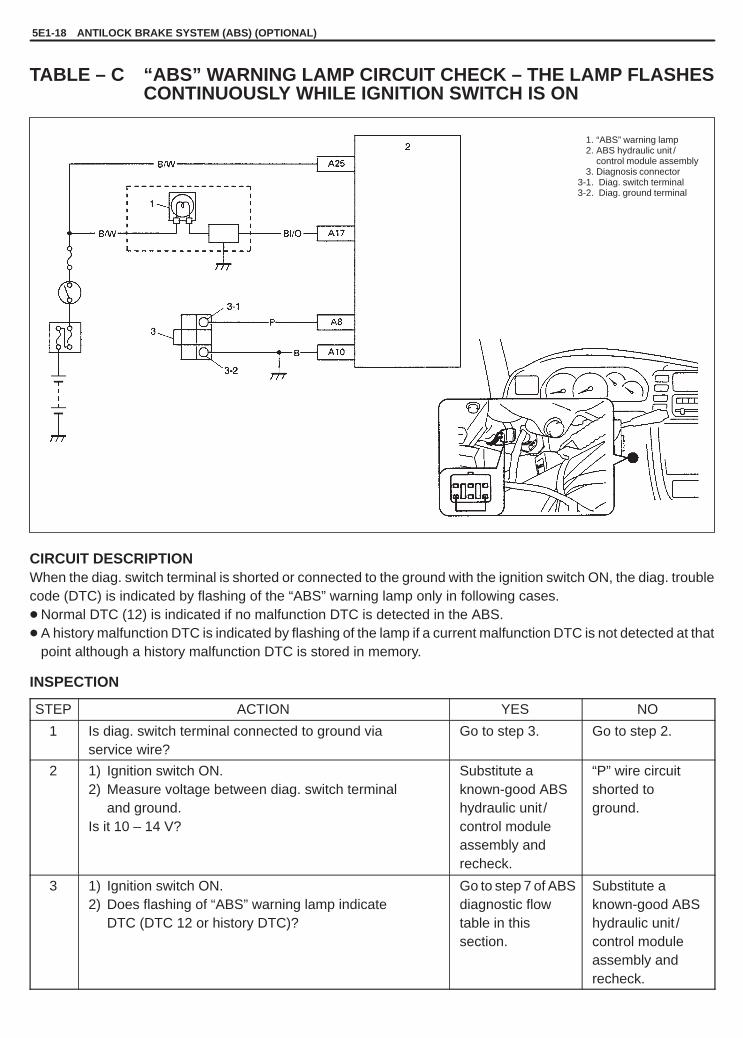
YH4GRANDVITARA
5E1-18 ANTILOCK BRAKE SYSTEM (ABS) (OPTIONAL)
-1. “ABS” warning lamp-2. ABS hydraulic unit /
control module assembly-3. Diagnosis connector
3-1. Diag. switch terminal3-2. Diag. ground terminal
TABLE – C “ABS” WARNING LAMP CIRCUIT CHECK – THE LAMP FLASHESCONTINUOUSLY WHILE IGNITION SWITCH IS ON
CIRCUIT DESCRIPTIONWhen the diag. switch terminal is shorted or connected to the ground with the ignition switch ON, the diag. troublecode (DTC) is indicated by flashing of the “ABS” warning lamp only in following cases.� Normal DTC (12) is indicated if no malfunction DTC is detected in the ABS.� A history malfunction DTC is indicated by flashing of the lamp if a current malfunction DTC is not detected at that
point although a history malfunction DTC is stored in memory.
INSPECTION
STEP ACTION YES NO
1 Is diag. switch terminal connected to ground viaservice wire?
Go to step 3. Go to step 2.
2 1) Ignition switch ON.2) Measure voltage between diag. switch terminal
and ground.Is it 10 – 14 V?
Substitute aknown-good ABShydraulic unit /control moduleassembly andrecheck.
“P” wire circuitshorted toground.
3 1) Ignition switch ON.2) Does flashing of “ABS” warning lamp indicate
DTC (DTC 12 or history DTC)?
Go to step 7 of ABSdiagnostic flowtable in thissection.
Substitute aknown-good ABShydraulic unit /control moduleassembly andrecheck.

YH4GRANDVITARA
ANTILOCK BRAKE SYSTEM (ABS) (OPTIONAL) 5E1-19
-1. “ABS” warning lamp-2. ABS hydraulic unit / control
module assembly-3. Diagnosis connector
3-1. Diag. switch terminal3-2. Diag. ground terminal-4. ABS hydraulic unit/
control module connectorof harness
1. ABS hydraulicunit / controlmodule connector
TABLE – D CODE (DTC) IS NOT OUTPUTTED EVEN WITH DIAG. SWITCHTERMINAL CONNECTED TO GROUND
CIRCUIT DESCRIPTIONWhen the diag. switch terminal is connected to the ground with the ignition switch turned ON, the ABS control mod-ule outputs a diagnostic trouble code by flashing “ABS” warning lamp.
INSPECTION
STEP ACTION YES NO
1 Is it shorted diag. switch terminal and ground terminal byservice wire properly?
Go to step 2. Connect servicewire securely.
2 1) Disconnect service wire.2) Disconnect ABS hydraulic unit /control module
connector. (See Fig. 1)3) Measure resistance between diag. switch terminal
and connector terminal “A8”.Is it infinite (�)?
“P” circuit open. Go to step 3.
3 1) Measure resistance between ground terminal ofmonitor connector and body ground.
Is continuity indicated?
Go to step 4. “B” circuit open orpoor connection.
4 1) Check for proper connection to ABS hydraulicunit /control module at terminal “A8” and “A10”.
2) If OK, then check “ABS” warning lamp circuitreferring to “TABLE A, B and C”.
Is it in good condition?
Substitute aknown-good ABShydraulic unit/control moduleassembly andrecheck.
Repair “ABS”warning lampcircuit.
Fig. 1

YH4GRANDVITARA
5E1-20 ANTILOCK BRAKE SYSTEM (ABS) (OPTIONAL)
TABLE – E EBD WARNING LAMP (BRAKE WARNING LAMP) CHECK-LAMPCOMES “ON” STEADY
CIRCUIT DESCRIPTIONEBD warning lamp (brake warning lamp) is controlled by parking brake switch, brake fluid level switch and ABScontrol module/hydraulic unit assembly through lamp driver module in combination meter. Refer to “TABLE-A” forcircuit diagram.
STEP ACTION YES NO
1 1) Make sure that:� Parking brake is completely released.
Go to step 2. Release parkingbrake completely
� Brake fluid level is upper than the minimum level.Are the check results OK?
and/or replenishbrake fluid.
2 Does “ABS” warning lamp come on? Perform “TABLE B”previouslyoutlined.
Go to step 3.
3 1) Disconnect ABS hydraulic unit /control moduleconnector.
2) Check for proper connection to ABS hydraulic unit /control module connector at terminals “A26”.
3) If OK, apply chocks to wheels and select gear in neutralposition (P range for A/T).
4) Keep brake pedal depressed and start engine.Release parking brake.
5) Connect terminal “A26” of disconnected connector toground using service wire.
Does EBD warning lamp (brake warning lamp) turn off?
Substitute aknown-good ABShydraulic unit /control moduleassembly andrecheck.
“Br” circuit open.If wire andconnection areOK, replacecombinationmeter.

YH4GRANDVITARA
ANTILOCK BRAKE SYSTEM (ABS) (OPTIONAL) 5E1-21
1. Ignition switch2. G sensor3. ABS hydraulic unit control
module assembly4. ABS hydraulic unit/
control moduleconnector of harness
O / G
DTC 15 (DTC C1015) – G SENSOR CIRCUIT (FOR 4WD MODEL ONLY)
DESCRIPTIONWhile a vehicle is at stop or running, if the potential difference between the sensor signal terminal “A14” and thesensor ground terminal “A4” is not within the specified voltage value, or if the signal voltage while at a stop doesnot vary from that while running, this DTC is set.Therefore, this DTC may be set when a vehicle is lifted up and its wheel(s) is turned. In such case, clear the DTCand check again.

YH4GRANDVITARA
5E1-22 ANTILOCK BRAKE SYSTEM (ABS) (OPTIONAL)
1. ABS hydraulicunit / controlmodule connector
INSPECTION
STEP ACTION YES NO
1 Is G sensor installed floor securely? Go to step 2. Tighten sensor orbracket screwsecurely. If not,using new screw.
2 1) Ignition switch OFF.2) Remove G sensor with bracket.3) Check for proper connection to G sensor.4) If OK then check G sensor referring to item
INSPECTION of G sensor.Is it in good condition?
Go to step 3. Replace G sensor.
3 1) Disconnect connectors from ABS hydraulic unit /control module assembly (See Fig. 1) and G sensor.
2) Check for proper connection to ABS control moduleat terminals “A14” and “A4”.
3) If OK, then turn ignition switch ON and measurevoltage between “B/W” terminal of sensorconnector and body ground.
Is it 10 – 14 V?
Go to step 4. “B/W” circuit open.
4 Measure voltage between “O/W” terminal of sensorconnector and body ground.Is it 0 V?
Go to step 5. “O/W” circuitshorted to powercircuit.
5 1) Ignition switch OFF.2) Check that “O/W” circuit is free from open
or short to ground and “O/G” circuit.Is it in good condition? (See Fig. 2)
“O/G” circuit open.If circuit is OK, substi-tute a known-goodABS hydraulicunit /control moduleassembly.
“O/W” circuit openor shorted toground or “O/G”circuit.
Fig. 1 Fig. 2

YH4GRANDVITARA
ANTILOCK BRAKE SYSTEM (ABS) (OPTIONAL) 5E1-23
1. Ignition switch2. ABS hydraulic unit /
control module assembly3. Left-front wheel speed
sensor4. Right-front wheel speed
sensor5. Left-rear wheel speed
sensor6. Right-rear wheel speed
sensor7. ABS hydraulic unit /
control connector of harness
DTC 21 (DTC C1021), 22 (DTC C1022) – RIGHT-FRONT WHEEL SPEED SENSORCIRCUIT
DTC 25 (DTC C1025), 26 (DTC C1026) – LEFT-FRONT WHEEL SPEED SENSORCIRCUIT
DTC 31 (DTC C1031), 32 (DTC C1032) – RIGHT-REAR WHEEL SPEED SENSORCIRCUIT
DTC 35 (DTC C1035), 36 (DTC C1036) – LEFT-REAR WHEEL SPEED SENSORCIRCUIT
DESCRIPTIONThe ABS control module monitors the voltage at the positive (+) terminal of each sensor while the ignition switchis ON. When the voltage is not within the specified range, an applicable DTC will be set. Also, when no sensor signalis inputted at starting or while running, an applicable DTC will be set.
NOTE:When the vehicle was operated in any of the following ways, one of these DTC’s may be set even whenthe sensor is in good condition. If such possibility is suspected, repair the trouble (dragging of brake, etc.)of the vehicle, clear DTC once and then after performing the driving test as described in Step 2 of “ABSDIAG. FLOW TABLE”, check whether or not any abnormality exists.– The vehicle was driven with parking brake pulled.– The vehicle was driven with brake dragging.– Wheel spin occurred while driving.– Wheel(s) was turned while the vehicle was jacked up.– The vehicle was stuck.

YH4GRANDVITARA
5E1-24 ANTILOCK BRAKE SYSTEM (ABS) (OPTIONAL)
INSPECTION
STEP ACTION YES NO
1 1) Disconnect the applicable sensor connector withignition switch OFF.
2) Measure resistance between sensor terminals.Resistance of wheel speed sensor: 1.2 – 1.6 k� (at 20�C, 68�F)
3) Measure resistance between each terminal andbody ground.Insulation resistance: 1M� or higher
Were measured resistance values in step 2) and 3)as specified? (See Fig. 1)
Go to step 2. Replace sensor.
2 1) Ignition switch OFF.2) Disconnect connector from ABS hydraulic
unit /control module assembly. (See Fig. 2)3) Check for proper connection to ABS hydraulic unit /
control module assembly at each sensor terminal.4) If OK then, turn ignition switch ON and measure
voltage between sensor positive terminal of moduleconnector and body ground.
Is it 0 V?
Go to step 3. Sensor positivecircuit shorted topower.
3 1) Ignition switch OFF.2) Connect connector to sensor.3) Measure resistance between sensor terminals at
module connector.4) Measure resistance between sensor positive
terminal and negative terminal of module connector,between positive terminal and body ground.
Are measured resistance values within each specifiedrange described in above step 1?
Go to step 4. Circuit open orshorted toground.
4 1) Remove wheel speed sensor.2) Check sensor for damage or foreign material being
attached.Is it in good condition? (See Fig. 3)
Go to step 5. Clean or replacesensor.
5 Check visually through wheel speed sensorinstallation hole for following.� Rotor neither missing or damaged.� No foreign material being attached.� Rotor not being eccentric.� Wheel bearing free from excessive play.Are they in good condition? (See Fig. 4)
Go to step 6. Clean, repair orreplace.
6 1) Install sensor to knuckle or axle housing.2) Tighten sensor bolt to specified torque and check
that there is not any clearance between sensor andknuckle or axle housing. (See Fig. 5)Replace sensor if any.
Referring to item OUTPUT VOLTAGE INSPECTION ofFRONT WHEEL SPEED SENSOR, check output voltageor waveform of sensor. Is proper output voltage orwaveform obtained?
Substitute aknown-good ABShydraulic unit /control moduleassembly andrecheck.
Replace sensorand recheck.

YH4GRANDVITARA
ANTILOCK BRAKE SYSTEM (ABS) (OPTIONAL) 5E1-25
1. ABS hydraulicunit / controlmodule connector
Fig. 1 Fig. 2 Fig. 3
Fig. 4 Fig. 5
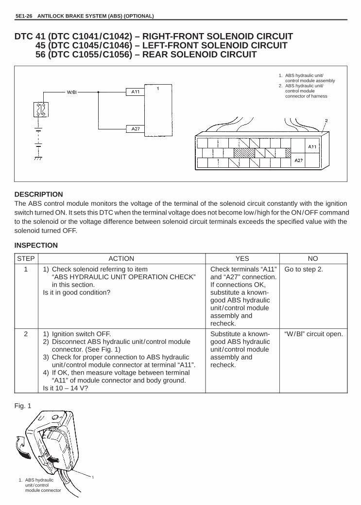
YH4GRANDVITARA
5E1-26 ANTILOCK BRAKE SYSTEM (ABS) (OPTIONAL)
1. ABS hydraulic unit/control module assembly
2. ABS hydraulic unit/control moduleconnector of harness
1. ABS hydraulicunit / controlmodule connector
DTC 41 (DTC C1041/C1042) – RIGHT-FRONT SOLENOID CIRCUITDTC 45 (DTC C1045/C1046) – LEFT-FRONT SOLENOID CIRCUITDTC 56 (DTC C1055/C1056) – REAR SOLENOID CIRCUIT
DESCRIPTIONThe ABS control module monitors the voltage of the terminal of the solenoid circuit constantly with the ignitionswitch turned ON. It sets this DTC when the terminal voltage does not become low/high for the ON/OFF commandto the solenoid or the voltage difference between solenoid circuit terminals exceeds the specified value with thesolenoid turned OFF.
INSPECTION
STEP ACTION YES NO
1 1) Check solenoid referring to item“ABS HYDRAULIC UNIT OPERATION CHECK”in this section.
Is it in good condition?
Check terminals “A11”and “A27” connection.If connections OK,substitute a known-good ABS hydraulicunit /control moduleassembly andrecheck.
Go to step 2.
2 1) Ignition switch OFF.2) Disconnect ABS hydraulic unit /control module
connector. (See Fig. 1)3) Check for proper connection to ABS hydraulic
unit /control module connector at terminal “A11”.4) If OK, then measure voltage between terminal
“A11” of module connector and body ground.Is it 10 – 14 V?
Substitute a known-good ABS hydraulicunit /control moduleassembly andrecheck.
“W/Bl” circuit open.
Fig. 1

YH4GRANDVITARA
ANTILOCK BRAKE SYSTEM (ABS) (OPTIONAL) 5E1-27
1. ABS hydraulic unit/control module assembly
2. ABS hydraulic unit/control moduleconnector
1. ABS hydraulicunit / controlmodule connector
DTC 57 (DTC C1057) – SOLENOID AND PUMP MOTOR POWER SOURCECIRCUIT
DESCRIPTIONThe ABS control module monitors the voltage at terminal ( “A11” and “A27”) of the fail-safe and pump motor relayscircuit constantly with the ignition switch turned ON. When all solenoid circuit voltages are below the specified valueor the voltage at the terminal “A27” became below the specified value while the pump motor is operating, this DTCwill be set. As soon as the voltage rises to the specified level, the set DTC will be cleared.
INSPECTION
STEP ACTION YES NO
1 Check battery voltage. Is it about 11 V or higher? Go to step 2. Check chargingsystem referringto “CHARGINGSYSTEM” section.
2 Check ABS main fuse and connection. Is it in goodcondition?
Go to step 3. Repair and/orreplace fuse.
3 1) Ignition switch OFF.2) Disconnect ABS hydraulic unit /control module
connector. (See Fig. 1)3) Check proper connection to ABS hydraulic unit /
control module connector at terminal “A27”.4) If OK, then measure voltage between connector
terminal “A27” and body ground.Is it 10 – 14 V?
Substitute aknown-goodABS hydraulicunit /controlmodule assemblyand recheck.
“W/Bl” circuit open.
Fig. 1

YH4GRANDVITARA
5E1-28 ANTILOCK BRAKE SYSTEM (ABS) (OPTIONAL)
-1. ABS hydraulic unit /control module assembly
1-1. ABS pump motor relay1-2. ABS pump motor1-3. ABS fail safe relay-2. ABS hydraulic unit/
control module connectorof harness
1. ABS hydraulicunit / controlmodule connector
DTC 61 (DTC C1061) – ABS PUMP MOTOR CIRCUIT
DESCRIPTIONThe ABS control module monitors the voltage at the monitor terminal of the pump motor circuit constantly with theignition switch turned ON. It sets this DTC when the voltage at the monitor terminal does not become high/ lowaccording to ON/OFF commands to the motor relay of the module (does not follow these commands).
INSPECTION
STEP ACTION YES NO
1 1) Check pump motor referring to item“ABS HYDRAULIC UNIT OPERATIONCHECK” in this section.
Is it in good condition?
Check terminals “A11”and “A27” connection.If connections OK,substitute a known-good ABS hydraulicunit /control moduleassembly and recheck.
Go to step 2.
2 1) Ignition switch OFF.2) Disconnect ABS hydraulic unit /control
module connector. (See Fig. 1)3) Check for proper connection to ABS
hydraulic unit /control module connectorat terminal “A27”.
4) If OK, then measure voltage betweenterminal “A27” of module connectorand body ground.
Is it 10 – 14 V?
Go to step 3. “W/Bl” circuit open.
3 Measure resistance between connectorterminal “A28” of ABS hydraulic unit /controlmodule assembly.Is it infinite (�)?
“B” circuit open. Substitute a known-good ABS hydraulicunit /control moduleassembly and recheck.
Fig. 1

YH4GRANDVITARA
ANTILOCK BRAKE SYSTEM (ABS) (OPTIONAL) 5E1-29
1. Ignition switch2. ABS hydraulic unit/
control module assembly3. ABS hydraulic unit/
control module connectorof harness
2
1. ABS hydraulicunit / controlmodule connector
DTC 63 (DTC C1063) – ABS FAIL-SAFE RELAY CIRCUIT
DESCRIPTIONThe ABS control module monitors the voltage at the terminal of the solenoid circuit constantly with the ignitionswitch turned ON. Also, immediately after the ignition switch is turned “ON”, perform an initial check as follows.Switch the fail-safe relay in the order of ON � OFF � ON and check if the voltage at 6 solenoid circuit terminalschanges to High � Low � High. If anything faulty is found in the initial check and when the voltage at all solenoidcircuit terminals is low with the ignition switch turned ON and ABS not operated, this DTC will be set.
INSPECTION
STEP ACTION YES NO
1 Check battery voltage. Is it about 11 V or higher? Go to step 2. Check chargingsystem referringto “CHARGINGSYSTEM” section.
2 Check ABS main fuse and connection. Is it in goodcondition?
Go to step 3. Repair and/orreplace fuse.
3 1) Ignition switch OFF.2) Disconnect ABS hydraulic unit /control module
connector. (See Fig. 1)3) Check proper connection to ABS hydraulic unit /
control module at terminal “A11”.4) If OK, then measure voltage between connector
terminal “A11”, and body ground.Is it 10 – 14 V?
Substitute aknown-good ABShydraulic unit /control moduleassembly andrecheck.
“W/Bl” circuit openor short to ground.
Fig. 1

YH4GRANDVITARA
5E1-30 ANTILOCK BRAKE SYSTEM (ABS) (OPTIONAL)
DTC 71 (DTC C1071) – ABS CONTROL MODULEDESCRIPTIONThis DTC will be set when an internal fault is detected in the ABS control module.
INSPECTION
STEP ACTION YES NO
1 1) Ignition switch OFF.2) Disconnect connectors from ABS control module.3) Check for proper connection to ABS control
module at all terminals.Are they in good condition?
Substitute aknown-good ABScontrol module andrecheck.
Repair or replace.

YH4GRANDVITARA
ANTILOCK BRAKE SYSTEM (ABS) (OPTIONAL) 5E1-31
1. Diagnosisconnector(6 pins connector)
2. Diag. switchterminal
3. Ground4. Service wire
Brakepedal
Ignitionsw.
Motor
Solenoid
Rear
3.0 sec.
3.0
ON-VEHICLE SERVICEPRECAUTIONWhen connector are connected to ABS hydraulic unit /control mod-ule assembly, do not disconnect connectors of sensors and turnignition switch ON. Then DTC will be set in ABS control module.
ABS HYDRAULIC UNIT OPERATION CHECK1) Check that basic brake system other than ABS is in good condi-
tion.
2) Check that battery voltage is 11V or higher.3) With “ABS” warning lamp, check that no abnormality is de-
tected in ABS. Refer to “DIAGNOSTIC TROUBLE CODE(DTC) CHECK” in this section.
4) Lift up vehicle.5) Set transmission to neutral and release parking brake.6) Turn each wheel gradually by hand to check if brake dragging
occurs. If it does, correct.
7) With diag. switch terminal of diagnosis connector connected toground by using service wire, turn ignition switch ON and checkif “ABS” warning lamp indicates DTC 12.
8) Turn ignition switch OFF.
9) Perform following checks with help of another person.Brake pedal should be depressed and then ignition switchturned ON by one person and wheel should be turned byanother person’s hand. At this time, check that:� Operation sound of solenoid is heard and wheel turns only
about 0.5 sec. (Brake force is depressurized).� Operation sound of pump motor is heard and pulsation is felt
at brake pedal.10) If all 4-wheels cannot be checked during one ignition cycle
(OFF � ON), repeat Steps 8) and 9) till all 4 wheels arechecked.If a faulty condition is found in Steps 9) and 10), replace hydrau-lic unit /control module assembly.
11) Turn ignition switch OFF and remove service wire from diagno-sis connector.

YH4GRANDVITARA
5E1-32 ANTILOCK BRAKE SYSTEM (ABS) (OPTIONAL)
1. ABS hydraulicunit /controlmoduleassembly
2. Brake pipe
1. ABS hydraulicunit / controlmodule connector
1. Brake pipe2. ABS hydraulic unit /
control module assembly3. Bracket
ABS HYDRAULIC UNIT/CONTROL MODULEASSEMBLY
CAUTION:Never disassemble ABS hydraulic unit /control module as-sembly, loosen blind plug or remove motor. Performing anyof these prohibited services will affect original performanceof ABS hydraulic unit /control module assembly.
HYDRAULIC UNIT INSPECTION� Check hydraulic unit for fluid leakage.
If any, repair or replace.
REMOVAL1) Disconnect negative cable at battery.2) Using special tool, disconnect brake pipes from ABS hydraulic
unit /control module assembly and loosen flare nuts as shownfigure.
Special Tool(A): 09950-78220
NOTE:Put bleeder plug cap onto pipe to prevent fluid from spilling.Do not allow brake fluid to get on painted surfaces.
3) Disconnect ABS hydraulic unit /control module assembly con-nector.

YH4GRANDVITARA
ANTILOCK BRAKE SYSTEM (ABS) (OPTIONAL) 5E1-33
1. ABS hydraulic unit /control moduleassembly
2. Nut
1. To left-front2. To right-front3. To rear4. From master cylinder
4) Remove three nuts and take out ABS hydraulic unit /controlmodule assembly from bracket.
CAUTION:� Do not give an impact to hydraulic unit.� Use care not to allow dust to enter hydraulic unit.� Do not place hydraulic unit on its side or upside down.
Handling it in inappropriate way will affect its originalperformance.
INSTALLATION1) Install hydraulic unit by reversing removal procedure.
Tightening Torque(a): 16 N.m (1.6 kg-m, 12.0 lb-ft)(b): 21 N.m (2.1 kg-m, 15.5 lb-ft)(c): 10 N.m (1.0 kg-m, 7.5 lb-ft)
2) Bleed air from brake system. Refer to “BLEEDING BRAKES” inSection 5.
3) Check each installed part for fluid leakage and perform hydraulicunit operation check.

YH4GRANDVITARA
5E1-34 ANTILOCK BRAKE SYSTEM (ABS) (OPTIONAL)
1. Left front wheel speed sensor2. Left front strut3. Sensor rotor
1. Wheel speed sensor connector
1. Peak-to-peak voltage
FRONT WHEEL SPEED SENSOR
OUTPUT VOLTAGE INSPECTION1) Turn ignition switch OFF.2) Hoist vehicle a little.3) Disconnect connector of wheel speed sensor.4) Connect voltmeter between connector terminals.5) While turning wheel at a speed of approximately 2/3 to 1 full
rotation per second, check AC voltage of sensor.
Output AC voltage at 2/3 toone rotation per second (35 – 53 Hz): 106 mV or more
If measured voltage is not as specified, check sensor, rotor andtheir installation conditions.
ReferenceWhen using oscilloscope for this check, check if peak-to-peak volt-age meets specification and waveform is complete.
Peak-to-peak voltageat 2/3 to one rotation per second (35 – 53 Hz): 150 mV or more

YH4GRANDVITARA
ANTILOCK BRAKE SYSTEM (ABS) (OPTIONAL) 5E1-35
FORWARD
1. Front wheel speedsensor connector
2. Headlight assembly
1. Front wheel speed sensor2. Bolt
REMOVAL1) Disconnect negative cable at battery.2) Hoist vehicle and remove wheel.3) Disconnect front wheel speed sensor connector.
4) Remove harness clamp bolts and remove front wheel speedsensor from knuckle.
CAUTION:� Do not pull wire harness when removing front wheel
speed sensor.� Do not cause damage to surface of front wheel speed
sensor and do not allow dust, etc. to enter its installa-tion hole.
SENSOR INSPECTION� Check sensor for damage.� Check sensor for resistance.
Resistance between terminals: 1.2 – 1.6 k � at 20�C (68�F)Resistance between terminal and sensor body: 1 M � or more
If any faulty is found, replace.
SENSOR ROTOR INSPECTION� Check rotor for being missing, damaged or deformed.� Turn drive shaft and check if rotor rotation is free from eccentricity
and looseness.� Check that no foreign material is attached.
If any faulty is found, repair or replace. Refer to WHEEL HUB RE-MOVAL and INSTALLATION in Section 3D.
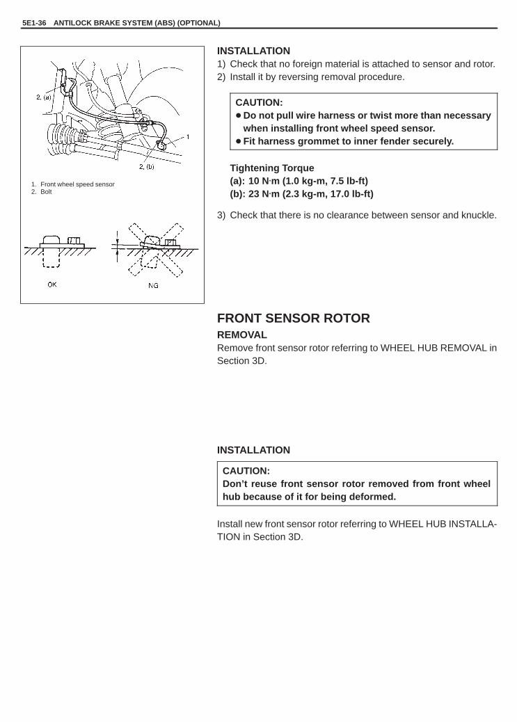
YH4GRANDVITARA
5E1-36 ANTILOCK BRAKE SYSTEM (ABS) (OPTIONAL)
1. Front wheel speed sensor2. Bolt
INSTALLATION1) Check that no foreign material is attached to sensor and rotor.2) Install it by reversing removal procedure.
CAUTION:� Do not pull wire harness or twist more than necessary
when installing front wheel speed sensor.� Fit harness grommet to inner fender securely.
Tightening Torque(a): 10 N.m (1.0 kg-m, 7.5 lb-ft)(b): 23 N.m (2.3 kg-m, 17.0 lb-ft)
3) Check that there is no clearance between sensor and knuckle.
FRONT SENSOR ROTORREMOVALRemove front sensor rotor referring to WHEEL HUB REMOVAL inSection 3D.
INSTALLATION
CAUTION:Don’t reuse front sensor rotor removed from front wheelhub because of it for being deformed.
Install new front sensor rotor referring to WHEEL HUB INSTALLA-TION in Section 3D.

YH4GRANDVITARA
ANTILOCK BRAKE SYSTEM (ABS) (OPTIONAL) 5E1-37
1. Rear wheel speed sensor2. Sensor rotor3. Rear axle housing
1. Rear wheel speedsensor harness
2. Connector
1. Sensor bolt2. Clamps
REAR WHEEL SPEED SENSOR
OUTPUT VOLTAGE INSPECTIONCheck in the same procedure as that used of front wheel speedsensor check.
Output AC voltage at 2/3 to one rotation per second (25 – 38 Hz): 106 mV or moreReferenceWhen using oscilloscope, peak-to-peak voltage at 2/3 to one rotation per second (25 – 38 Hz): 150 mV or more
REMOVAL1) Disconnect negative cable at battery.2) Hoist vehicle.3) Disconnect rear wheel speed sensor connector and detach wire
harness from vehicle body and rear axle.
4) Remove harness clamps and remove rear wheel speed sensorfrom rear axle.
CAUTION:� Do not pull wire harness when removing rear wheel
speed sensor.� Do not cause damage to surface of rear wheel speed
sensor and do not allow dust, etc. to enter its installa-tion hole.

YH4GRANDVITARA
5E1-38 ANTILOCK BRAKE SYSTEM (ABS) (OPTIONAL)
1. Clamps2. Sensor bolt
SENSOR INSPECTION� Check sensor (pole piece) for damage or bent.� Check sensor for resistance.
Resistance betweenterminals : 1.2 – 1.6 k � at 20�C, 68�F
Resistance betweenterminal and sensor body: 1 M � or more
If any faulty is found, replace.
SENSOR ROTOR INSPECTION� Check rotor serration (teeth) for being missing, damaged or de-
formed.� Turn wheel and check if rotor rotation is free from eccentricity and
looseness.� Check that no foreign material is attached.
If any faulty is found, repair or replace.
INSTALLATION1) Check that no foreign material is attached to sensor and rotor.2) Install it by reversing removal procedure.
Tightening Torque(a): 21 N.m (2.1 kg-m, 15.0 lb-ft)
CAUTION:Do not pull wire harness or twist more than necessarywhen installing rear wheel speed sensor.
3) Check that there is no clearance between sensor and knuckle.

YH4GRANDVITARA
ANTILOCK BRAKE SYSTEM (ABS) (OPTIONAL) 5E1-39
1. Rear axle2. Retainer ring3. Sensor rotor4. Vinyl envelope
“A” Grind with grinder
“A”
1. Sensor rotor
4
3
1
2
2
1
3
REAR SENSOR ROTORREMOVAL1) Remove rear axle shaft. Refer to REAR AXLE SHAFT RE-
MOVAL in Section 3E.
2) In order to remove sensor rotor from retainer ring, grind with agrinder one part of the sensor rotor as illustrated till it becomesthin.
CAUTION:� Cover vinyl sheet or the like over wheel bearing so that
fine grains from grinding will not enter there.� Be careful not to go so far as to grind the retainer ring.
3) Break with a chisel the thin ground sensor rotor, and it can be re-moved.
INSTALLATION1) Press-fit sensor rotor as shown.
NOTE:Use care not to cause any damage to outside of retainerring.
2) Install rear axle shaft. Refer to REAR AXLE SHAFT INSTALLA-TION in Section 3E.

YH4GRANDVITARA
5E1-40 ANTILOCK BRAKE SYSTEM (ABS) (OPTIONAL)
1. Parking brakelever ass’y
2. G sensor3. Bolt “1”4. Bolt “2”
[A] Horizontal[B] Upright with
arrow upward[C] Upright with
arrow downward
A: Forward
G SENSOR (FOR 4WD MODEL ONLY)REMOVAL1) Turn ignition switch OFF and disconnect battery negative cable.2) Remove rear center console box.3) Remove parking brake lever bolts “1” and G sensor with bracket
from floor.
NOTE:Loosen only bolt “2”.
4) Remove sensor with bracket from floor.5) Disconnect connector from sensor.
CAUTION:� Do not separate sensor and bracket. It will lead to erro-
neous assembly.� Sensor must not be dropped or shocked. It will affect its
original performance.
INSPECTION1) Check sensor bracket for bend.2) Connect positive cable of 12 volt battery to “A” terminal of sensor
and ground cable to “C” terminal. Then using voltmeter, checkvoltage between “B” terminal and “C” terminal.
When placed horizontally: 2 – 3 VWhen placed upright with arrow upward: 3 – 4 VWhen placed upright with arrow downward: 1 – 2 V
If measured voltage is not as specified, replace sensor withbracket.
INSTALLATION1) Connect connector to sensor securely.2) Install sensor with bracket and parking lever assy onto floor so
that arrow mark directs vehicle forward.
Tightening Torque(a): 23 N.m (2.3 kg-m, 17.0 lb-ft)
3) Install rear console box.

YH4GRANDVITARA
ANTILOCK BRAKE SYSTEM (ABS) (OPTIONAL) 5E1-41
(d)
TRANSFER 4WD SWITCH
For removal, inspection and installation of this switch, refer toSWITCHES in Section 7A.
TIGHTENING TORQUE SPECIFICATIONS
Fastening partsTightening torque
Fastening artsN.m kg-m lb-ft
Brake pipe flare nut: (a) 16 1.6 11.5
ABS hydraulic unit nut: (b) 21 2.1 15.5
ABS hydraulic unit bracket bolt: (c) 10 1.0 7.5
Wheel speed sensor bolt(Front): (d) 23 2.3 17.0
Wheel s eed sensor bolt(Rear): (e) 21 2.1 15.5
Parking lever assy mounting bolt: (f) 23 2.3 17.0

YH4GRANDVITARA
5E1-42 ANTILOCK BRAKE SYSTEM (ABS) (OPTIONAL)
09950-78220Flare nut wrench(10 mm)
09931-76011SUZUKI scan tool (Tech 1A) kit
1. Storage case2. Operator’s manual3. Tech 1A4. DLC cable5. Test lead/probe6. Power source cable7. DLC cable adapter8. Self-test adapter
Mass storage cartridge
09931-7603016/14 pin DLC cable
SPECIAL TOOLS

YH4GRANDVITARA
7A
MANUAL TRANSMISSION (TYPE 1) 7A-1
TYPE 1
GENERAL DESCRIPTION 7A- 1. . . . . . . . . . . . . .
DIAGNOSIS 7A- 2. . . . . . . . . . . . . . . . . . . . . . . . . . .
ON-VEHICLE SERVICE 7A- 3. . . . . . . . . . . . . . . . Gear Oil 7A- 3. . . . . . . . . . . . . . . . . . . . . . . . . . . . . Shift Control Levers 7A- 4. . . . . . . . . . . . . . . . . . . Switches 7A- 6. . . . . . . . . . . . . . . . . . . . . . . . . . . . Engine Rear Mounting 7A- 8. . . . . . . . . . . . . . . . Dismounting of Trans. Unit 7A- 9. . . . . . . . . . . . . Remounting of Trans. Unit 7A-12. . . . . . . . . . . . .
Extension Case (2WD MODEL) 7A-13. . . . . . . . Extension Case Oil Seal
(2WD MODEL) 7A-13. . . . . . . . . . . . . . . . . . . . . .
UNIT REPAIR 7A-14. . . . . . . . . . . . . . . . . . . . . . . . .
TIGHTENING TORQUESPECIFICATIONS 7A-14. . . . . . . . . . . . . . . . . . . .
REQUIRED SERVICE MATERIALS 7A-14. . . . . .
SPECIAL TOOL 7A-14. . . . . . . . . . . . . . . . . . . . . . .
As the aluminum case is sealed with liquid type gas-ket, it is necessary to use genuine sealant or its equiv-alent on its mating surfaces when reassembling it.Also, the case fastening bolts must be tightened tospecified torque by means of the torque wrench andtightening over or below the specified torque shouldbe avoided.
The description under ON-VEHICLE SERVICE in thissection covers a part of the TYPE 2 manual transmis-sion and the transfer. The transfer is next to the trans-mission as well, but their gear boxes are independentand each of them has its own drain and level / fillerplugs for the oil change or the level check.For the repair procedure of the transfer unit, refer toSection 7D.
SECTION 7A
MANUAL TRANSMISSION(TYPE 1)
CONTENTS
GENERAL DESCRIPTION
The manual transmission consists of the input shaft,main shaft, countershaft and reverse gear which areinstalled in the aluminum case. Its gears are of for-ward five speeds in synchro mesh and reverse onespeed in constant mesh system.
The main shaft gears are held by the needle bearingsand on them the synchronizer rings and synchronizersleeve & hubs are assembled.
The gear shift lever case is located at the upper be-hind the transmission case and has a cam which pre-vents direct gear shift from the 5th speed gear to thereverse gear.

YH4GRANDVITARA
7A-2 MANUAL TRANSMISSION (TYPE 1)
DIAGNOSIS
Condition Possible Cause Correction
Gear slipping out of mesh � Worn shift fork shaft� Worn shift fork or synchronizer sleeve� Weak or damaged locating spring� Worn bearings on input shaft or main shaft� Worn chamfered tooth on sleeve or gear� Missing or disengagement of circlip(s)
ReplaceReplaceReplaceReplaceReplace sleeve and gearInstall
Gears refusing to disengage � Weakened or broken synchronizer spring� Distorted shift shaft or shift fork
ReplaceReplace
Hard shifting � Improper clutch pedal free travel� Distorted or broken clutch disc� Damaged clutch pressure plate� Worn synchronizer ring� Worn chamfered tooth on sleeve or gear� Distorted shift shaft
AdjustReplaceReplace clutch coverReplaceReplace sleeve and gearReplace
Noise � Inadequate or insufficient lubricant� Damaged or worn bearing(s)� Damaged or worn gear(s)� Damaged or worn synchronizer ring� Damaged or worn chamfered tooth on
sleeve or gear
ReplenishReplaceReplaceReplaceReplace
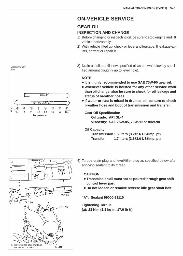
YH4GRANDVITARA
Viscosity chartSAE
1. Reverse idle gear shaft bolt(DO NOT LOOSEN IT)
MANUAL TRANSMISSION (TYPE 1) 7A-3
ON-VEHICLE SERVICE
GEAR OILINSPECTION AND CHANGE1) Before changing or inspecting oil, be sure to stop engine and lift
vehicle horizontally.2) With vehicle lifted up, check oil level and leakage. If leakage ex-
ists, correct or repair it.
3) Drain old oil and fill new specified oil as shown below by speci-fied amount (roughly up to level hole).
NOTE:� It is highly recommended to use SAE 75W-90 gear oil.� Whenever vehicle is hoisted for any other service work
than oil change, also be sure to check for oil leakage andstatus of breather hoses.
� If water or rust is mixed in drained oil, be sure to checkbreather hose and boot of transmission and transfer.
Gear Oil SpecificationOil grade: API GL-4Viscosity: SAE 75W-85, 75W-90 or 80W-90
Oil Capacity:Transmission 1.5 liters (3.2/2.6 US/Imp. pt)Transfer 1.7 liters (3.6/3.0 US/Imp. pt)
4) Torque drain plug and level / filler plug as specified below afterapplying sealant to its thread.
CAUTION:� Transmission oil must not be poured through gear shift
control lever part.� Do not loosen or remove reverse idle gear shaft bolt.
“A”: Sealant 99000-31110
Tightening Torque(a): 23 N.m (2.3 kg-m, 17.0 lb-ft)

YH4GRANDVITARA
1. Bolt2. Console box
bracket3. Boot cover
1. Boot No. 32. Boot cover3. Boot No. 24. Control lever5. Lever case6. Control case cover7. Boot No. 1
1. Transmission controllever locating bolt
2. Transfer control leverlocating bolt
7A-4 MANUAL TRANSMISSION (TYPE 1)
SHIFT CONTROL LEVERSREMOVAL1) Remove 4 screws at the front and rear and 2 clips at the center
then take off front and rear center console boxes.
NOTE:To remove clip, push in its center pin first.
2) Remove console box bracket by removing bolts and lift up bootcover and boot No. 2.
3) Remove boot clamp and then remove boot No. 1 from transmis-sion shift lever case.
4) With gear shift control case cover pushed down with fingers, turnit to counter clockwise and take out shift control lever.
5) Take out transfer shift control lever in similar manner as de-scribed above.
INSPECTION AND INSTALLATION1) Check shift control lever lower portion and control lever locating
sheet for excessive wear, and boot for damage. Correct or re-place if necessary.
2) Apply grease to pivot portions and seat, then install shift controllever.
“A”: Grease 99000-25010
3) Perform above steps also for transfer shift control lever.4) If control lever locating bolts (a) are replaced or retightened,
torque them as specified below.Replacing of control lever locating bolts requires thread lock ce-ment.
“B”: Cement 99000-32020
Tightening Torque(a): 17 N.m (1.7 kg-m, 12.5 lb-ft)

YH4GRANDVITARA
1. Boot No. 12. Boot clamp3. Boot cover4. Boot No. 2
1. Transfer boot No. 12. Boot clamp
1. Console boxbracket
2. Boot cover3. Boot No. 3
MANUAL TRANSMISSION (TYPE 1) 7A-5
5) Install transmission boot No. 1 from inside of cabin and clampit with a new clamp securely.
6) Install transfer boot No. 1 securely on lift and clamp it by usinga new clamp.
7) Tighten transmission boot No. 2 with boot cover and console boxbracket.
Tightening Torque(a): 6 N.m (0.6 kg-m, 4.0 lb-ft)
8) Install console box.
NOTE:Be sure that flare end of transmission boot No. 3 is engagedwith console box.

YH4GRANDVITARA
7A-6 MANUAL TRANSMISSION (TYPE 1)
3, (a)
1. Coupler2. Clamp
3. 4WD switch4. Boot No. 2
1. Back up light switch2. 4WD switch
1. Back up light switch coupler2. Front propeller shaft
SWITCHESTRANSFER 4WD SWITCH1) Remove console box and lift transmission control lever boots
No. 2 and No. 3. (Refer to page 7A-4.)2) Remove transfer control lever boot No. 2, unclamp wiring on
transfer case to free it and pull off coupler.
3) Replace switch and connect as it was.
Tightening Torque(a): 20 N.m (2.0 kg-m, 14.5 lb-ft)
4) Turn ON ignition switch, shift transfer shift control lever to 4WDposition and check that indicator lights. Turn OFF switch afterchecking.
NOTE:� When removing and reinstalling switch, use care not to let
dust enter transfer box inside.� Make sure to reset clamp for wiring which is located
where invisible directly.� It is recommended to work on transfer shift control lever
boot No. 1 from underside of vehicle on lift.� Identify this switch by its leg part which is different for that
of back up light switch.
BACK UP LIGHT SWITCH
WARNING:Refrain from work while exhaust center pipe is hot.
REMOVAL AND INSTALLATION
NOTE:When replacing switch, use care not to let dust enter transmis-sion through switch hole.
1) Lift up vehicle.2) Remove coupler(s) for switch wiring.

YH4GRANDVITARA
1. Back up light switch2. Exhaust center pipe
1. Ohmmeter2. Back up light switch or 4WD switch
1, (a)[Type 1]
[Type 2]
MANUAL TRANSMISSION (TYPE 1) 7A-7
3) Replace switch, connect and clamp as they were.
Tightening Torque(a): 20 N.m (2.0 kg-m, 14.5 lb-ft) (Type 1)(a): 45 N.m (4.5 kg-m, 32.5 lb-ft) (Type 2)
4) When back up light switch has been replaced, check switch forproper function with ignition switch turned ON and gear shiftedto reverse position. Turn OFF switch after checking its function.
INSPECTION OF 4WD SWITCH AND BACK UP LIGHTSWITCH1) Undo clamp and disconnect coupler of back up light switch
and/or 4WD switch.
2) Function of back up light switch can be checked as shown in fig-ure.There should be conduction at these terminals only when shiftlever is shifted to reverse position.
3) Function of transfer 4WD switch can be checked in the samemanner as back up light switch.There should be conduction at these terminals when shift leveris shifted to 4H, and 4L positions.
Upon completion of check, connect coupler and clamp wiring har-ness as they were.
NOTE:When replacing switch(es), use care not to let dust enter trans-mission through switch hole(s).

YH4GRANDVITARA
1. Engine rear mounting member2. Mounting bracket3. Engine rear mounting
FRONT SIDE
REAR SIDE
7A-8 MANUAL TRANSMISSION (TYPE 1)
ENGINE REAR MOUNTING
When replacement of mounting parts are necessary, torque boltsand nut as specified below.
Tightening Torque(a): 50 N.m (5.0 kg-m, 36.5 lb-ft)
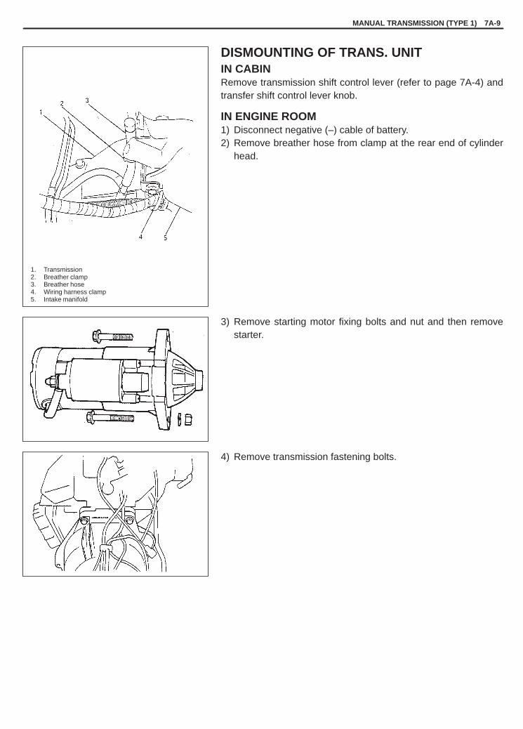
YH4GRANDVITARA
1. Transmission2. Breather clamp3. Breather hose4. Wiring harness clamp5. Intake manifold
MANUAL TRANSMISSION (TYPE 1) 7A-9
DISMOUNTING OF TRANS. UNITIN CABINRemove transmission shift control lever (refer to page 7A-4) andtransfer shift control lever knob.
IN ENGINE ROOM1) Disconnect negative (–) cable of battery.2) Remove breather hose from clamp at the rear end of cylinder
head.
3) Remove starting motor fixing bolts and nut and then removestarter.
4) Remove transmission fastening bolts.

YH4GRANDVITARA
1. Match mark
1. Flange bolt2. Front propeller shaft
1. Transmission jack2. Engine rear mounting member
7A-10 MANUAL TRANSMISSION (TYPE 1)
ON LIFT1) Drain oil from transmission and transfer.2) Give match marks on joint flange and propeller shaft as shown
in figure. (front and rear)3) Remove flange bolts of rear propeller shaft universal joint and
pull out propeller shaft.4) Remove flange bolts of front propeller shaft universal joint and
pull out propeller shaft.5) Remove clutch operating cylinder from transmission. It is not
necessary to disconnect clutch hose from operating cylinder.
NOTE:� It is not necessary to drain transmission oil when dis-
mounting transmission and transfer for clutch mainte-nance only.
� Work without draining transfer oil is possible if front pro-peller shaft is dismounted together with transmission andtransfer.
6) Remove clutch housing lower plate.
7) Disconnect couplers from 4WD switch, back up light switch andspeed sensor assembly and release their harness from clamps.Remove nuts from joint with engine.
8) Apply transmission jack and remove engine rear mountingmember taking off its bolts.
9) After removing mounting member, move rearward transmissionand transfer assemblies placed on jack and then lower them.

YH4GRANDVITARA
1. Transmission assembly2. Transfer assembly3. Wiring harness
4. Breather hose5. Gear shift lever case6. Bolt7. Bolt
MANUAL TRANSMISSION (TYPE 1) 7A-11
10) Remove wiring harness and breather hose.11) Separate gear shift lever case and transfer assembly (or exten-
sion case: 2WD model) from transmission.

YH4GRANDVITARA
1. Match mark
7A-12 MANUAL TRANSMISSION (TYPE 1)
REMOUNTING OF TRANS. UNITFor remounting, reverse dismounting procedure.Use specified torques as given below.
Tightening Torque(a): 85 N.m (8.5 kg-m, 61.5 lb-ft)(b): 50 N.m (5.0 kg-m, 36.5 lb-ft)
� For tightening torque of transmission stiffener bolt, refer to“ENGINE MECHANICAL” section.
� Set each clamp for wiring, hose and cable securely.� Set clamp for shift control lever boots securely.� After installing clutch operating cylinder, check clutch pedal free
travel. Refer to SECTION 7C1 “CLUTCH”.� Fill gear oil to transmission and transfer as specified.� Connect battery and check function of engine, clutch and trans.� When installing propeller shaft, align the match marks.

YH4GRANDVITARA
MANUAL TRANSMISSION (TYPE 1) 7A-13
1
1. Extension case2. Select return spring bolt3. Select return spring (short)4. Select return spring (long)5. Guide pin6. Speed sensor assembly
6
2,“A”,(a)
3,“A”
5,“A”
5,“A”
4,“A”
2,“A”,(a)
1. Oil seal2. Extension case
“B”
“A”
11
2
2
EXTENSION CASE (2WD MODEL)DISASSEMBLY1) Remove oil seal.2) Remove select return spring bolts and then springs and guide
pins.3) Remove speed sensor assembly.
REASSEMBLY1) Install oil seal.2) After applying grease, install select guide pins, select return
springs and spring bolts and torque them to specification.
“A”: Grease 99000-25010
Tightening Torque(a): 23 N.m (2.3 kg-m, 17.0 lb-ft)
After installing, check to make sure that each pin moves smooth-ly.
3) Install speedometer driven gear case assembly to extensioncase.
EXTENSION CASE OIL SEAL (2WD MODEL)REMOVAL AND INSTALLATION1) Remove propeller shaft referring to SECTION 4B.2) Using screwdriver, remove oil seal.
3) Using special tool (A) and plastic hammer, press fit new oil sealinto extension case till oil seal contacts stepped part of extensioncase as shown. Be sure to apply grease to oil seal lip.
“A”: Grease 99000-25010
Special Tool(A): 09951-16060
4) Clean and inspect sliding portion of propeller shaft front end(where oil seal contacts) before installation and if even smalldent or scratch exists, correct and clean it again.Then apply grease inside splines of propeller shaft.
“B”: Grease 99000-25010
5) Install propeller shaft referring to SECTION 4B.

YH4GRANDVITARA
7A-14 MANUAL TRANSMISSION (TYPE 1)
09951-16060Oil seal installer
UNIT REPAIRRefer to the same section of UNIT REPAIR MANUAL mentioned in FOREWORD of this manual.
TIGHTENING TORQUE SPECIFICATIONS
Fastening portionTightening torque
Fastening ortionN.m kg-m lb-ft
Oil filler / level and drain plugs 23 2.3 17.0
Control lever boot cover bolts 6 0.6 4.0
4WD switch 20 2.0 14.5
Back up light switch (Type 1) 20 2.0 14.5
Back up light switch (Type 2) 45 4.5 32.5
Control lever locating bolts 17 1.7 12.5
Transmission to engine bolts and nuts 85 8.5 61.5
Engine rear mounting bolts and nut 50 5.0 36.5
Exhaust center pipe to manifold nuts 50 5.0 36.5
Muffler to exhaust center pipe bolts 50 5.0 36.5
Universal joint flange bolts 50 5.0 36.5
Select return spring bolts 23 2.3 17.0
REQUIRED SERVICE MATERIALS
MATERIAL RECOMMENDEDSUZUKI PRODUCT
USE
Lithium grease SUZUKI SUPER GREASE A(99000-25010)
� Shift control lever.� Select return springs, bolts and guides.
Thread lock cement THREAD LOCK CEMENTSUPER 1333B (99000-32020)
� Shift control lever locating bolts.
Sealant SUZUKI BOND No. 1215(99000-31110)
� Oil Drain and filler / level plugs.
SPECIAL TOOL

YH4GRANDVITARA
7A1
MANUAL TRANSMISSION (TYPE 2) 7A1-1
TYPE 2
GENERAL DESCRIPTION 7A1-1. . . . . . . . . . . . . .
DIAGNOSIS 7A1-2. . . . . . . . . . . . . . . . . . . . . . . . . . .
ON-VEHICLE SERVICE 7A1-3. . . . . . . . . . . . . . . . Gear Oil 7A1-3. . . . . . . . . . . . . . . . . . . . . . . . . . . . . Shift Control Levers 7A1-4. . . . . . . . . . . . . . . . . . . Switches 7A1-4. . . . . . . . . . . . . . . . . . . . . . . . . . . . Engine Rear Mounting 7A1-4. . . . . . . . . . . . . . . .
Dismounting/Remounting of Trans. Unit 7A1-4. . . . . . . . . . . . . . . . . . . . . . . . .
UNIT REPAIR 7A1-4. . . . . . . . . . . . . . . . . . . . . . . . .
TIGHTENING TORQUESPECIFICATIONS 7A1-5. . . . . . . . . . . . . . . . . . . .
REQUIRED SERVICE MATERIALS 7A1-5. . . . . .
The manual transmission consists of the input shaft,main shaft, counter shaft and reverse gear which areinstalled in the aluminum and castings cases. Itsgears are of forward five speeds in synchro mesh andreverse one speed in sliding idler gear arrangementsystem.
The main shaft gears are held by the needle bear-ings and on them the synchronizer rings and syn-chronizer sleeve & hubs are assembled.
The gear shift lever case is located at the upper be-hind the transmission case and has a cam which pre-vents direct gear shift from the 5th speed gear to thereverse gear.
As the aluminum and castings cases are sealed withliquid type gasket, it is necessary to use genuine seal-ant or its equivalent on its mating surfaces when reas-sembling them. Also, the case fastening bolts must betightened to specified torque by means of the torquewrench and tightening over or below the specifiedtorque should be avoided.
The description under ON-VEHICLE SERVICE in thissection covers the transfer partially which is next tothe transmission as well, but their gear boxes are in-dependent and each of them has its own drain andlevel / filler plugs for the oil change or the level check.For the repair procedure of the transfer unit, refer toSection 7D.
SECTION 7A1
MANUAL TRANSMISSION(TYPE 2)
CONTENTS
GENERAL DESCRIPTION

YH4GRANDVITARA
7A1-2 MANUAL TRANSMISSION (TYPE 2)
DIAGNOSIS
Condition Possible Cause Correction
Gear slipping out of mesh � Worn shift fork shaft� Worn shift fork or synchronizer sleeve� Weak or damaged locating spring� Worn bearings on input shaft or main shaft� Worn chamfered tooth on sleeve or gear� Missing or disengagement of circlip(s)
ReplaceReplaceReplaceReplaceReplace sleeve and gearInstall
Gears refusing to disengage � Weakened or broken synchronizer spring� Distorted shift shaft or shift fork
ReplaceReplace
Hard shifting � Improper clutch pedal free travel� Distorted or broken clutch disc� Damaged clutch pressure plate� Worn synchronizer ring� Worn chamfered tooth on sleeve or gear� Distorted shift shaft
AdjustReplaceReplace clutch coverReplaceReplace sleeve and gearReplace
Noise � Inadequate or insufficient lubricant� Damaged or worn bearing(s)� Damaged or worn gear(s)� Damaged or worn synchronizer ring� Damaged or worn chamfered tooth on
sleeve or gear
ReplenishReplaceReplaceReplaceReplace

YH4GRANDVITARA
Viscosity chartSAE
Temperature
1. Drain plug2. Oil level / filler plug
MANUAL TRANSMISSION (TYPE 2) 7A1-3
ON-VEHICLE SERVICE
GEAR OILINSPECTION AND CHANGE1) Before changing or inspecting oil, be sure to stop engine and lift
vehicle horizontally.2) With vehicle lifted up, check oil level and leakage. If leakage ex-
ists, correct or repair it.
3) Drain old oil and fill new specified oil as shown below by speci-fied amount (roughly up to level hole).
NOTE:� It is highly recommended to use SAE 75W-90 gear oil.� Whenever vehicle is hoisted for any other service work
than oil change, also be sure to check for oil leakage andstatus of breather hoses.
� If water or rust is mixed in drained oil, be sure to checkbreather hose and boot of transmission and transfer.
Gear Oil SpecificationOil grade: API GL-4Viscosity: SAE 75W-85, 75W-90 or 80W-90
Oil Capacity:Transmission 2.6 liters (5.5/4.6 US/Imp. pt)Transfer 1.7 liters (3.6/3.0 US/Imp. pt)
4) Torque drain plug and level / filler plug as specified below afterapplying sealant to thread of plug (c).
CAUTION:Transmission oil must not be poured through gear shiftcontrol lever part.
“A”: Sealant 99000-31110
Tightening Torque(a): 38 N·m (3.8 kg-m, 27.5 lb-ft)(b): 23 N·m (2.3 kg-m, 17.0 lb-ft)

YH4GRANDVITARA
7A1-4 MANUAL TRANSMISSION (TYPE 2)
SHIFT CONTROL LEVERS
Refer to SECTION 7A in this manual.
SWITCHES
Refer to SECTION 7A in this manual.
ENGINE REAR MOUNTING
Refer to SECTION 7A in this manual.
DISMOUNTING/REMOUNTING OF TRANS. UNIT
Refer to the same item in SECTION 7A “MANUAL TRANSMIS-SION”.For tightening torque of filler and level /drain plug, refer to “Gear OilInspection and Change” of “ON-VEHICLE SERVICE” in this sec-tion.
UNIT REPAIR
Refer to the same section of UNIT REPAIR MANUAL mentioned in FOREWORD of this manual.

YH4GRANDVITARA
MANUAL TRANSMISSION (TYPE 2) 7A1-5
TIGHTENING TORQUE SPECIFICATIONS
Fastening portionTightening torque
Fastening ortionN·m kg-m lb-ft
Transfer oil filler / level and drain plugs 23 2.3 17.0
Transmission oil filler / level and drain plugs 38 3.8 27.5
Control lever boot cover bolts 6 0.6 4.0
4WD switch 20 2.0 14.5
Back-up light switch 45 4.5 32.5
Control lever locating bolts 17 1.7 12.5
Transmission to engine bolts and nuts 85 8.5 61.5
Engine rear mounting bolts 50 5.0 36.5
Muffler to exhaust No. 2 pipe nuts 50 5.0 36.5
Universal joint flange bolts 50 5.0 36.5
REQUIRED SERVICE MATERIALS
MATERIAL RECOMMENDEDSUZUKI PRODUCT
USE
Lithium grease SUZUKI SUPER GREASE A(99000-25010)
� Shift control lever
Thread lock cementTHREAD LOCK CEMENTSUPER 1333B(99000-32020)
� Shift control lever locating bolts
Sealant SUZUKI BOND No. 1215(99000-31110)
� Oil drain and filler / level plugs

YH4GRANDVITARA
7B1
AUTOMATIC TRANSMISSION (4 A /T) 7B1-1
GENERAL DESCRIPTION 7B1- 3. . . . . . . . . . . . . . CLUTCH/BRAKE FUNCTIONS 7B1- 5. . . . . . . . . TABLE OF COMPONENT OPERATION 7B1- 6. . . ELECTRONIC SHIFT CONTROL
SYSTEM 7B1- 7. . . . . . . . . . . . . . . . . . . . . . . . . . .
AUTOMATIC TRANSMISSIONDIAGNOSIS 7B1-17. . . . . . . . . . . . . . . . . . . . . . . . . . PRECAUTION IN DIAGNOSING
TROUBLE 7B1-20. . . . . . . . . . . . . . . . . . . . . . . . . . AUTOMATIC TRANSMISSION
DIAGNOSTIC FLOW TABLE 7B1-21. . . . . . . . . . Customer Problem Inspection Form 7B1-23. . . Malfunction Indicator lamp (MIL)
Check 7B1-24. . . . . . . . . . . . . . . . . . . . . . . . . . . “O/D OFF” Lamp Check 7B1-24. . . . . . . . . . . . . “POWER” Lamp Check 7B1-24. . . . . . . . . . . . . . Diagnostic Trouble Code (DTC)
Check 7B1-24. . . . . . . . . . . . . . . . . . . . . . . . . . . Diagnostic Trouble Code (DTC)
Clearance 7B1-24. . . . . . . . . . . . . . . . . . . . . . . . Diagnostic Trouble Code (DTC) Table 7B1-24. . . Fail-Safe Table 7B1-25. . . . . . . . . . . . . . . . . . . . . Visual Inspection 7B1-26. . . . . . . . . . . . . . . . . . . A/T Basic Check 7B1-27. . . . . . . . . . . . . . . . . . . Trouble Diagnosis Table 1 7B1-28. . . . . . . . . . . Trouble Diagnosis Table 2 7B1-28. . . . . . . . . . .
Trouble Diagnosis Table 3 7B1-29. . . . . . . . . . . Scan Tool Data 7B1-30. . . . . . . . . . . . . . . . . . . . . Inspection of PCM and Its Circuit 7B1-30. . . . . Wire Harness and Connectors 7B1-30. . . . . . . . Diagnostic Flow Table A-1 7B1-31. . . . . . . . . . . Diagnostic Flow Table A-2 7B1-33. . . . . . . . . . . Table B-1 “O/D OFF” Light Circuit
Check 7B1-35. . . . . . . . . . . . . . . . . . . . . . . . . . . Table B-2 “O/D OFF” Light Circuit
Check 7B1-36. . . . . . . . . . . . . . . . . . . . . . . . . . . Table B-3 “POWER” Light Circuit
Check 7B1-37. . . . . . . . . . . . . . . . . . . . . . . . . . . Table B-4 “POWER” Light Circuit
Check 7B1-38. . . . . . . . . . . . . . . . . . . . . . . . . . . DTC P0705 Transmission Range
Sensor (Switch) Circuit Malfunction 7B1-39. . DTC P0715 Input/Turbine Speed
Sensor Circuit Malfunction 7B1-42. . . . . . . . . . DTC P0720 Output Speed Sensor
Circuit Malfunction 7B1-44. . . . . . . . . . . . . . . . . DTC P0741 TCC Solenoid Valve
Performance or Stuck Off 7B1-46. . . . . . . . . . . DTC P0743 TCC Solenoid Electrical 7B1-47. . DTC P0751 Shift Solenoid Valve-A (#1)
Performance or Stuck Off 7B1-49. . . . . . . . . . . DTC P0756 Shift Solenoid Valve-B (#2)
Performance or Stuck Off 7B1-49. . . . . . . . . . .
SECTION 7B1
AUTOMATIC TRANSMISSION(4 A �/�T)
WARNING:For vehicles equipped with Supplemental Restraint (Air Bag) System:� Service on and around the air bag system components or wiring must be performed only by an autho-
rized SUZUKI dealer. Refer to “Air Bag System Components and Wiring Location View” under “Gener-al Description” in air bag system section in order to confirm whether you are performing service onor near the air bag system components or wiring. Please observe all WARNINGS and “Service Precau-tions” under “On-Vehicle Service” in air bag system section before performing service on or aroundthe air bag system components or wiring. Failure to follow WARNINGS could result in unintentionalactivation of the system or could render the system inoperative. Either of these two conditions mayresult in severe injury.
� Technical service work must be started at least 90 seconds after the ignition switch is turned to the“LOCK” position and the negative cable is disconnected from the battery. Otherwise, the system maybe activated by reserve energy in the Sensing and Diagnostic Module (SDM).
CONTENTS

YH4GRANDVITARA
7B1-2 AUTOMATIC TRANSMISSION (4 A /T)
DTC P0753 Shift Solenoid-A (#1) Electrical 7B1-50. . . . . . . . . . . . . . . . . . . . . . . . .
DTC P0758 Shift Solenoid-B (#2) Electrical 7B1-50. . . . . . . . . . . . . . . . . . . . . . . . .
DTC P1875 4WD Low Switch Circuit Malfunction 7B1-52. . . . . . . . . . . . . . . . . . . . . . .
Line Pressure Test 7B1-54. . . . . . . . . . . . . . . . . . Stall Test 7B1-55. . . . . . . . . . . . . . . . . . . . . . . . . . Road Test 7B1-56. . . . . . . . . . . . . . . . . . . . . . . . . Manual Road Test 7B1-57. . . . . . . . . . . . . . . . . . Time Lag Test 7B1-57. . . . . . . . . . . . . . . . . . . . . . Engine Brake Test 7B1-58. . . . . . . . . . . . . . . . . . “P” Range Test 7B1-58. . . . . . . . . . . . . . . . . . . . .
ON-VEHICLE SERVICE 7B1-59. . . . . . . . . . . . . . . . MAINTENANCE SERVICE 7B1-59. . . . . . . . . . . .
Fluid Level 7B1-59. . . . . . . . . . . . . . . . . . . . . . . . . Fluid Change 7B1-60. . . . . . . . . . . . . . . . . . . . . . Oil Cooler Hoses 7B1-61. . . . . . . . . . . . . . . . . . .
A/T THROTTLE CABLE 7B1-61. . . . . . . . . . . . . . . MANUAL SELECTOR ASSEMBLY 7B1-62. . . . . SELECT CABLE 7B1-63. . . . . . . . . . . . . . . . . . . . .
TRANSMISSION RANGE SWITCH 7B1-64. . . . . A�/�T OUTPUT SPEED SENSOR 7B1-64. . . . . . . . O/D CUT SWITCH 7B1-64. . . . . . . . . . . . . . . . . . . SOLENOID VALVES 7B1-64. . . . . . . . . . . . . . . . . . THROTTLE POSITION SENSOR 7B1-66. . . . . . . POWER/NORMAL CHANGE SWITCH 7B1-66. . OIL COOLER PIPES 7B1-67. . . . . . . . . . . . . . . . . . BRAKE INTERLOCK SYSTEM 7B1-68. . . . . . . . .
Shift Lock Solenoid Control 7B1-68. . . . . . . . . . Shift Lock Solenoid Control Operations 7B1-68Shift Lock (Solenoid) Manual Release 7B1-69. System Inspection 7B1-69. . . . . . . . . . . . . . . . . .
KEY INTERLOCK CABLE 7B1-71. . . . . . . . . . . . . DISMOUNTING OF TRANSMISSION
(WITH TRANSFER IF EQUIPPED) 7B1-74. . . . REMOUNTING 7B1-77. . . . . . . . . . . . . . . . . . . . . . .
UNIT REPAIR 7B1-78. . . . . . . . . . . . . . . . . . . . . . . . .
TIGHTENING TORQUESPECIFICATIONS 7B1-78. . . . . . . . . . . . . . . . . . . .
REQUIRED SERVICE MATERIALS 7B1-79. . . . . .
SPECIAL TOOLS 7B1-79. . . . . . . . . . . . . . . . . . . . . .

YH4GRANDVITARA
AUTOMATIC TRANSMISSION (4 A /T) 7B1-3
1. Torque converter2. Overdrive input shaft3. Oil pump4. Overdrive brake5. Overdrive clutch6. Forward clutch input shaft7. Forward clutch8. Direct clutch9. One-way clutch
10. Second coast brake11. Second brake12. Reverse brake13. Front planetary gear14. Rear planetary gear15. Overdrive planetary gear
GENERAL DESCRIPTION
This automatic transmission is a full automatic type with 3-speed plus overdrive (O/D).The torque converter is a 3-element, 1-step and 2-phase type and is equipped with an electronically controlledlock-up mechanism. The gear shift device consists of 3 sets of planetary gear units, 3 disc type clutches, 4 disctype brakes and 3 one-way clutches. The gear shift is done by selecting one of 6 positions (“P”, “R”, “N”, “D”, “2”and “L”) by means of the select lever installed on the floor. On the shift knob, there is an overdrive (O/D) cut switchwhich allows shift-up to the overdrive mode (except at 4L) and shift-down from the overdrive mode. Also, by usingthe P/N change switch located on the console box, it is possible to select the gear change timing of 2 modes, nor-mal and power.

YH4GRANDVITARA
7B1-4 AUTOMATIC TRANSMISSION (4 A /T)
Item Specifications
Torqueconver-ter
Type
Stall torque ratio
3-element, 1-step, 2-phase type (with TCC (lock-up)mechanism)2.4 (G16 engine) 2.0 (J20 engine) 1.9 (H25 engine)
Oilpump
TypeDrive system
Trochoid type oil pumpEngine driven
Type Forward 4-step, reverse 1-step planetary gear type
Shift position
“P” range Gear in neutral, output shaft fixed,engine start“R” range Reverse“N” range Gear in neutral, engine start“D” range Forward 1st � 2nd � 3rd � 4th (O/D)(O/D ON) automatic gear change“D” range Forward 1st � 2nd � 3rd(O/D OFF) automatic gear change“2” range (Normal mode) Forward 1st � 2nd � 3rd automatic gear
change(Power mode) Forward 2nd � 3rd automatic gearchange and fixed at 2nd gear
“L” range Forward 1st � 2nd � 3rd reduction, and fixed at 1st gear
Gear Engine type G16 engine J20/H25 engineschangedevice
1st (low gear) 2.826 2.826device
2nd (second gear) 1.493 1.493
Gear 3rd (top gear) 1.000 1.000Gearratio 4th (overdrive
4th gear)0.730 0.689
Reverse (reverseReverse gear)
2.703 2.703
Control elementsWet type multi-disc clutch 3 sets. . . . . . . . . . Wet type multi-disc brake 4 sets. . . . . . . . . . One-way clutch 3 sets. . . . . . . . . . . . . . . . . . .
Transfer Hi: 1.000 Lo: 1.816 (4WD model only)
Final gear reductionratio (Differential)
5.125 (G16 engine) 4.875 (J20/H25 engines)
Lubrica-tion
Lubrication system Force feed system by oil pump
Cooling Cooling system Radiator assisted cooling (water-cooled)
Fluid used An equivalent of DEXRON�III

YH4GRANDVITARA
AUTOMATIC TRANSMISSION (4 A /T) 7B1-5
1. Overdrive clutch2. Overdrive brake3. Forward clutch4. Direct clutch5. Second coast brake6. Second brake7. Reverse brake8. One-way clutch No.29. One-way clutch No.1
10. Overdrive one-way clutch11. Overdrive input shaft12. Forward clutch input shaft13. Intermediate shaft
CLUTCH/BRAKE FUNCTIONS
Part Name Function
Overdrive clutch Meshes overdrive carrier and overdrive sun gear.
Overdrive brake Fixes overdrive sun gear.
Overdrive one-way clutch Meshes overdrive carrier and overdrive sun gear only when drivenby engine.
Forward clutch Meshes input shaft and intermediate shaft.
Direct clutch Meshes input shaft with front sun gear and rear sun gear.
Second coast brake Fixes front sun gear and rear sun gear.
Second brake Fixes outer race of one-way clutch No.1, to prevent front sun gearand rear sun gear from turning counterclockwise (reverse directionof engine input rotation direction).
Reverse brake Fixes front planetary carrier.
One-way clutch No.1 Prevents front sun gear and rear sun gear from turning counterclockwiseonly when second brake is at work.
One-way clutch No.2 Prevents front planetary carrier from turning counterclockwise.

YH4GRANDVITARA
7B1-6 AUTOMATIC TRANSMISSION (4 A /T)
ElementShiftposition
TABLE OF COMPONENT OPERATION
Solenoid Solenoid O / D ForwardDirect clutch
O / D Second SecondReverse brake O/D One-way One-way
valveNo. 1–A
valveNo. 1–B
O / Dclutch
Forwardclutch Inner
pistonOuterpiston
O / Dbrake coast
brake
Secondbrake Inner
pistonOuterpiston
one-wayclutch
yclutchNo. 1
yclutchNo. 2
P � X � – – – – – – – – � – –
R � X � – � � – – – � � � – –
N � X � – – – – – – – – � – –
1st gear � X � � – – – – – – – � – �
D2nd gear � � � � – – – – � – – � � –
D3rd gear X � � � – � – – � – – � – –
O/D X X – � – � � – � – – – – –
1st gear � X � � – – – – – – – � – �
2 2nd gear � � � � – – – � � – – � – –23rd gear
(Fail safe)X � � � – � – – � – – � – –
1st gear � X � � – – – – – � � � – –L 2nd gear
(Fail safe)� � � � – – – � � – – � – –
�: ON, X: OFF

YH4GRANDVITARA
Engine
Vehicle speedsensor
Throttle position sensor
ECT sensor
Cruise controlmodule(if equipped)
Torque converter Planetary gear Final gearreduction unit
Oil pump
Shift and TCCsolenoid valves
Clutch and brake
Control valve
“O/D OFF” lamp“POWER” lampMIL
Transmission range switch
O/D cut switch
P/N change switch
Transfer 4L switch(if equipped)
CMP sensor
Powertrain (engine) control module
Power transmissionFluid pressure circuitElectric signal Input speed sensor
Brake pedal switch
Output speed sensor
AUTOMATIC TRANSMISSION (4 A /T) 7B1-7
ELECTRONIC SHIFT CONTROL SYSTEM
The gear ratio change in “D” or “2” range and torque converter clutch operation are controlled by Powertrain (En-gine) Control Module.

YH4GRANDVITARA
7B1-8 AUTOMATIC TRANSMISSION (4 A /T)
G16/J20 Engines
1. PCM (ECM)2. VSS3. CMP sensor4. TP sensor5. ECT sensor6. A / T input speed sensor7. A / T output speed sensor8. Transmission range switch
9. Shift solenoid-A10. Shift solenoid-B11. TCC solenoid12. Data link connector13. Cruise control module14. “POWER” lamp15. “O / D OFF” lamp16. MIL
17. O / D cut switch18. P / N change switch19. 4WD low switch20. Main relay21. Ignition switch22. Battery23. PCM (ECM) connector terminal
(viewed from harness side)
Bl / YBl / G
WOr
C51-1-11C51-1-10
C51-1-23C51-1-22
12V

YH4GRANDVITARA
AUTOMATIC TRANSMISSION (4 A /T) 7B1-9
H25 Engine
1. PCM (ECM)2. VSS3. CMP sensor4. TP sensor5. ECT sensor6. Brake pedal switch7. A / T input speed sensor8. A / T output speed sensor
9. Transmission range switch10. Shift solenoid-A11. Shift solenoid-B12. TCC solenoid13. Data link connector14. Cruise control module15. “POWER” lamp16. “O / D OFF” lamp
17. MIL18. O / D cut switch19. P / N change switch20. 4WD low switch21. Main relay22. Ignition switch23. Battery24. PCM (ECM) connector terminal
(viewed from harness side)
Bl / YBl / G
WOr
C51-1-16C51-1-8
C51-1-10C51-1-9
12V

YH4GRANDVITARA
7B1-10 AUTOMATIC TRANSMISSION (4 A /T)
Shift the selectlever with itsbutton pushedin.
Shift the selectlever withoutpushing itsbutton.
RANGE
GEARSOLENOIDS
Fail Safe FunctionThis function is provided by the safe mechanism that assures safe driveability even when the shift solenoid valveor speed sensor fails.The table below shows the gear position in each shift under a normal/abnormal condition.
Condition
Shift positionNormal
Shift solenoidvalve-A(#1)abnormal
Shift solenoidvalve-B(#2)abnormal
Shift solenoidvalves-A&B
(#1 and #2) abnormal
1st 1st
D2nd 3rd
O/DD3rd O/D
O/D
O/D O/D
1st 1st
2 2nd 3rd3rd
3rd
(3rd)3rd
L1st 1st
1st 1stL(2nd) (2nd)
1st 1st
Change MechanismThe same select pattern shift lever is used as the floor type and fre-quently used “N” and “D” ranges are made selectable freely.
Operation of Shift Solenoids and TCC Solenoid
D 2 L P, N & R
1st 2nd 3rd 4th(O/D) 1st 2nd 1st —
Shift solenoid-A (#1, NO.1) � � � � � � � �
Shift solenoid-B (#2, NO.2) � � � � � � � �
TCC solenoid � � � � � � � �
�: ON (valve is open) �: OFF (valve is closed)

YH4GRANDVITARA
Gear Shift Diagram
TCC Lock-up Diagram
Vehicle speed
UpshiftDownshift
Thr
ottle
val
ve o
peni
ng
Vehicle speed
Thr
ottle
val
ve o
peni
ng
TCC ONTCC OFF
4th gear
3rdgear
(km / h)
(km / h)
AUTOMATIC TRANSMISSION (4 A /T) 7B1-11
AUTOMATIC GEAR SHIFT DIAGRAMAutomatic shift schedule as a result of shift control is shown below. In case that select lever is shifted to L at a higherthan 52 km/h or 33 mile/h speed for G16 engine (45 km/h or 28 mile/h for J20 engine, 55 km/h or 34 mile/h forH25 engine), 2nd or 3rd gear is operated and then down shifts to 1st at a speed lower than that. No up shift isavailable in L.The same as, the select lever is shifted to 2 at a higher than 102 km/h (64 mile/h) speed for G16/J20 engines (105km/h or 65 mile/h for H25 engine), 3rd gear is operated and then down shifts to 2nd at a speed lower than that.
Power Mode For G16 Engine Unit: km/h(mile/h)
Shift
Throttle opening1�2 2�3 3�4 4�3 3�2 2�1
Full throttle 49(30)
94(58)
153(95)
124(77)
85(53)
43(27)
Closed throttle 18(11)
36(23)
48(30)
40(25)
29(18)
7(4)

YH4GRANDVITARA
Gear Shift Diagram
TCC Lock-up DiagramVehicle speed
UpshiftDownshift
Thr
ottle
val
ve o
peni
ng
Vehicle speed
Thr
ottle
val
ve o
peni
ng
TCC ONTCC OFF
4thgear
3rdgear
(km / h)
(km / h)
7B1-12 AUTOMATIC TRANSMISSION (4 A /T)
Normal Mode For G16 Engine Unit: km/h(mile/h)
Shift
Throttle opening1�2 2�3 3�4 4�3 3�2 2�1
Full throttle 45(28)
94(58)
136(85)
124(77)
74(46)
39(24)
Closed throttle 14(9)
32(20)
45(28)
35(22)
29(18)
7(4)

YH4GRANDVITARA
Gear Shift Diagram
TCC Lock-up Diagram
Thr
ottle
val
ve o
peni
ng
Vehicle speed
UpshiftDownshift
Thr
ottle
val
ve o
peni
ng
Vehicle speed
3rdgear
4thgear
TCC ONTCC OFF
(km / h)
(km / h)
AUTOMATIC TRANSMISSION (4 A /T) 7B1-13
Power Mode For J20 Engine Unit: km/h(mile/h)
Shift
Throttle opening1�2 2�3 3�4 4�3 3�2 2�1
Full throttle 50(31)
98(61)
— 135(84)
84(52)
46(29)
Closed throttle 18(11)
33(21)
50(31)
44(27)
26(16)
8(5)

YH4GRANDVITARA
Gear Shift Diagram
TCC Lock-up Diagram
UpshiftDownshift
Thr
ottle
val
ve o
peni
ng
Vehicle speed
Thr
ottle
val
ve o
peni
ng
3rdgear
4thgear
TCC ONTCC OFF
Vehicle speed
(km / h)
(km / h)
7B1-14 AUTOMATIC TRANSMISSION (4 A /T)
Normal Mode For J20 Engine Unit: km/h(mile/h)
Shift
Throttle opening1�2 2�3 3�4 4�3 3�2 2�1
Full throttle 50(31)
98(61)
147(91)
135(84)
84(52)
42(26)
Closed throttle 11(7)
27(17)
40(25)
37(23)
24(15)
8(5)

YH4GRANDVITARA
Gear Shift Diagram
TCC Lock-up Diagram
Thr
ottle
val
ve o
peni
ng
Vehicle speed
UpshiftDownshift
Thr
ottle
val
ve o
peni
ng
Vehicle speed
TCC ONTCC OFF
3rdgear
4thgear
(km / h)
(km / h)
AUTOMATIC TRANSMISSION (4 A /T) 7B1-15
Power Mode For H25 Engine Unit: km/h(mile/h)
Shift
Throttle opening1�2 2�3 3�4 4�3 3�2 2�1
Full throttle 48(30)
99(62)
160(99)
150(93)
90(56)
41(25)
Closed throttle 16(10)
30(19)
45(28)
38(24)
24(15)
7(4)

YH4GRANDVITARA
7B1-16 AUTOMATIC TRANSMISSION (4 A /T)
Gear Shift Diagram
TCC Lock-up Diagram
Thr
ottle
val
ve o
peni
ng
Vehicle speed
Thr
ottle
val
ve o
peni
ng
Vehicle speed
UpshiftDownshift
TCC ONTCC OFF
3rdgear
4thgear
(km / h)
(km / h)
Normal Mode For H25 Engine Unit: km/h(mile/h)
Shift
Throttle opening1�2 2�3 3�4 4�3 3�2 2�1
Full throttle 48(30)
99(62)
160(99)
150(93)
90(56)
41(25)
Closed throttle 11(7)
27(17)
40(25)
35(22)
21(13)
7(4)

YH4GRANDVITARA
1. Monitor connector
AUTOMATIC TRANSMISSION (4 A /T) 7B1-17
AUTOMATIC TRANSMISSION DIAGNOSIS
This vehicle is equipped with an electronic transmission control system, which control the automatic shift up andshift down timing, TCC operation, etc. suitably to vehicle driving conditions.PCM (ECM) has an On-Board Diagnosis system which detects a malfunction in this system and abnormality ofthose parts that influence the engine exhaust emission.When diagnosing a trouble in transmission including this system, be sure to have full understanding of the outlineof “On-board Diagnostic System” and each item in “Precaution in Diagnosing Trouble” and execute diagnosis ac-cording to “AUTOMATIC TRANSMISSION DIAGNOSTIC FLOW TABLE” given below to obtain correct resultsmoothly.
NOTE:There are two types of ON-BOARD DIAGNOSTIC SYSTEM de-pending on vehicle specifications. The type of system for ve-hicle being serviced can be identified by whether equippedwith monitor connector or not.

YH4GRANDVITARA
1. Malfunction indicator lamp (MIL)2. Scan tool3. DLC
7B1-18 AUTOMATIC TRANSMISSION (4 A /T)
[For Vehicle without Monitor Connector]
ON-BOARD DIAGNOSTIC SYSTEMFor automatic transmission control system, PCM (ECM) has follow-ing functions. Refer to Section 6/6-1 for details.
� When the ignition switch is turned ON with the engine at a stop,malfunction indicator lamp (MIL) turns ON to check the bulb of theMIL.
� When PCM detects a malfunction in A/T control system (and/ora malfunction which gives an adverse effect to vehicle emission)while the engine is running, it makes the malfunction indicatorlamp in the meter cluster of the instrument panel turn ON andstores the malfunction area in its memory. (If it detects that contin-uously 3 driving cycles are normal after detecting a malfunction,however, it makes MIL turn OFF although DTC stored in itsmemory will remain.)
� It is possible to communicate through DLC by using not only SU-ZUKI scan tool (Tech-1) but also generic scan tool. (Diagnostic in-formation can be accessed by using a scan tool.)
2 Driving Cycle Detection LogicRefer to section 6/6-1 for details.
Pending DTCRefer to section 6/6-1 for details.
Freeze Frame DataRefer to section 6/6-1 for details.

YH4GRANDVITARA
1. Malfunction indicator lamp (MIL)2. Scan tool3. DLC4. Monitor connector5. Diagnosis switch terminal6. Ground terminal
MIL
OFF
Time (sec.)
AUTOMATIC TRANSMISSION (4 A /T) 7B1-19
[For Vehicle with Monitor Connector]
ON-BOARD DIAGNOSTIC SYSTEMFor automatic transmission control system, PCM (ECM) has follow-ing functions. Refer to Section 6/6-1 for details.
� When the ignition switch is turned ON with the engine at a stop,malfunction indicator lamp (MIL) turns ON to check the bulb of theMIL.
� When PCM detects a trouble in electronic shift control system, itstores its trouble code in back-up memory in itself. (The memoryis kept as it is even if the trouble was only temporary and disap-peared immediately. And it is not erased unless the power to PCMis shut off for 30 seconds or longer.)
� It is possible to communicate through DLC by using not only SU-ZUKI scan tool (Tech-1) but also generic scan tool. (Diagnostic in-formation can be accessed by using a scan tool.)
� It is also possible to communicate by not using scan tool. PCMindicates trouble area in memory by means of flashing of malfunc-tion indicator lamp at the time of inspection (i.e. when diagnosisswitch terminal is grounded and ignition switch is turned ON).

YH4GRANDVITARA
7B1-20 AUTOMATIC TRANSMISSION (4 A /T)
PRECAUTION IN DIAGNOSING TROUBLE
� Don’t disconnect couplers from PCM (ECM), battery cable from battery, PCM ground wire harness from engineor main fuse before checking the diagnosis information (DTC, freeze frame data, etc.) stored in PCM memory.Such disconnection will clear memorized information in PCM memory.
� Using SUZUKI scan tool (Tech-1), or also generic scan tool for vehicle without monitor connector, the diagnosticinformation stored in PCM memory can be checked and cleared as well. Before its use, be sure to read Operator’s(instruction) Manual supplied with it carefully to have good understanding of its functions and usage.
� Priorities for diagnosing troubles (Only for vehicle without monitor connector)If two or more diagnostic trouble codes (DTCs) are stored, proceed to the flow table of the DTC which was de-tected earliest in the order and follow the instruction in that table.If no instructions are given, troubleshoot diagnostic trouble codes according to the following priorities.1. Diagnostic trouble codes (DTCs) other than DTC P0171/P0172 (Fuel system too lean/too rich) and DTC
P0400 (EGR flow malfunction)2. DTC P0171/P0172 (Fuel system too lean/too rich) and DTC P0400 (EGR flow malfunction)
� Be sure to read “Precautions for Electrical Circuit Service” in Section 0A before inspection and observe what iswritten there.
� PCM replacementWhen substituting a known-good PCM, check for following conditions.Neglecting this check may result in damage to good PCM.– All relays and actuators have resistance of specified value.– MAF sensor, MDP sensor, TP sensor and fuel tank pressure sensor are in good condition. Also, the power
circuit of these sensors is not shorted to the ground.

YH4GRANDVITARA
AUTOMATIC TRANSMISSION (4 A /T) 7B1-21
AUTOMATIC TRANSMISSION DIAGNOSTIC FLOW TABLE
Refer to the following pages for the details of each step.
STEP ACTION YES NO
1 Customer Complaint Analysis1) Perform customer complaint analysis referring to
the next page.Was customer complaint analysis performedaccording to instruction on the next page?
Go to Step 2. Perform customercomplaint analysis.
2 Diagnostic Trouble Code (DTC) and Freeze FrameData Check, Record and Clearance1) Check for DTC (including pending DTC) referring
to the next page.Is there any DTC(s)?
1) Print DTC andfreeze frame dataor write themdown and clearthem by referringto “DTCClearance” in thissection.
2) Go to Step 3.
Go to Step 4.
3 Visual Inspection1) Perform visual inspection referring to the next page.Is there any faulty condition?
1) Repair or replacemalfunction part.
2) Go to Step 11.
Go to Step 5.
4 Visual Inspection1) Perform visual inspection referring to the next page.Is there any faulty condition?
Go to Step 8.
5 Trouble Symptom Confirmation1) Confirm trouble symptom referring to the next page.Is trouble symptom identified?
Go to Step 6. Go to Step 7.
6 Rechecking and Record of DTC/Freeze Frame Data1) Recheck for DTC and freeze frame data referring
to “DTC Check” in this section.Is there any DTC(s)?
Go to Step 9. Go to Step 8.
7 Rechecking and Record of DTC/Freeze Frame Data1) Recheck for DTC and freeze frame data referring
to “DTC Check” in this section.Is there any DTC(s)?
Go to Step 9. Go to Step 10.
8 Automatic Transmission Basic Inspection andTrouble Diagnosis Table1) Check and repair according to “A/T Basic Check”
and “Trouble Diagnosis Table” in this section.Are check and repair complete?
Go to Step 11. 1) Check and repairmalfunction part(s).
2) Go to Step 11.
9 Troubleshooting for DTC1) Check and repair according to applicable DTC diag.
flow Table.Are check and repair complete?
10 Check for Intermittent Problems1) Check for intermittent problems referring to the next
page.Is there any faulty condition?
1) Repair or replacemalfunctionpart(s).
2) Go to Step 11.
Go to Step 11.
11 Final Confirmation Test1) Clear DTC if any.2) Perform final confirmation test referring to the next
page.Is there any problem symptom, DTC or abnormalcondition?
Go to Step 6. End.
YH4GRANDVITARA
7B1-22 AUTOMATIC TRANSMISSION (4 A /T)
1. CUSTOMER COMPLAINT ANALYSISRecord details of the problem (failure, complaint) and how it occurred as described by the customer.For this purpose, use of such a inspection form will facilitate collecting information to the point required for properanalysis and diagnosis.
2. DIAGNOSTIC TROUBLE CODE (DTC)/FREEZE FRAME DATA CHECK, RECORD AND CLEARANCEFirst, referring to DTC check section, check DTC (including pending DTC). If DTC exists, print or write downDTC and freeze frame data and then clear them by referring to DTC clearance section. DTC indicates malfunc-tion in the system but it is not possible to know from it whether the malfunction is occurring now or it occurredin the past and normal condition has been restored. In order to know that, check symptom in question accordingto Step 5 and then recheck DTC according to Step 6.Diagnosing a trouble based on the DTC in this step only or failure to clear the DTC in this step may result inan faulty diagnosis, trouble diagnosis of a normal circuit or difficulty in troubleshooting which is otherwise unnec-essary.
3 and 4. VISUAL INSPECTIONAs a preliminary step, be sure to perform visual check of the items that support proper function of the A/T andengine referring to Visual Inspection section.
5. TROUBLE SYMPTOM CONFIRMATIONCheck trouble symptoms based on information obtained in Step 1 “CUSTOMER COMPLAINT ANALYSIS” andStep 2 “DTC/FREEZE FRAME DATA CHECK”.Also, recheck DTC according to “DTC Confirmation Procedure” described in each “DTC FLOW TABLE”.
6 and 7. RECHECKING AND RECORD OF DTC/FREEZE FRAME DATARefer to “DTC Check” section for checking procedure.
8. A/T BASIC CHECK AND TROUBLE DIAGNOSIS TABLEPerform A/T basic check according to the “A/T Basic Check Flow Table” first. When the end of the flow tablehas been reached, check the parts of the system suspected as a possible cause referring to TROUBLE DIAG-NOSIS TABLE and based on symptoms appearing on the vehicle (symptoms obtained through steps of custom-er complaint analysis, trouble symptom confirmation and/or A/T basic check) and repair or replace faulty parts,if any.
9. DIAGNOSTIC TROUBLE CODE FLOW TABLEBased on the DTC indicated in Step 6 and 7 and referring to “DIAGNOSTIC TROUBLE CODE FLOW TABLE”in this section, locate the cause of the trouble, namely in a sensor, switch, wire harness, connector, actuator,PCM or other part and repair or replace faulty parts.
10. CHECK FOR INTERMITTENT PROBLEMCheck parts where an intermittent trouble is easy to occur (e.g., wire harness, connector, etc.), referring to“INTERMITTENT AND POOR CONNECTION” in Section 0A and related circuit of DTC recorded in Step 2.
11. FINAL CONFIRMATION TESTConfirm that the problem symptom has gone and the A/T is free from any abnormal conditions.If what has been repaired is related to the malfunction DTC, clear the DTC once, set conditions under whichDTC was detected and A/T and/or vehicle was repaired and confirm that no DTC is indicated.

YH4GRANDVITARA
AUTOMATIC TRANSMISSION (4 A /T) 7B1-23
User name: Model: VIN:
Date of issue: Date of Reg: Date of problem: Mileage:
PROBLEM SYMPTOMS
�Engine does not start
�Vehicle does not move (forward, rearward)
�No lock-up (TCC clutch operation)
�Shift point too high or too low
�Excessive gear change shock
�Engine stops
�Transmission does not shift (1st, 2nd, 3rd, 4th, Rev) gear
�Automatic shift does not occur
�Transmission slipping in (1st, 2nd, 3rd, 4th, Rev) gear
�Other:
VEHICLE/ ENVIRONMENTAL CONDITION WHEN PROBLEM OCCURS
Environmental Condition
WeatherTemperatureFrequencyRoad
�Fair/�Cloudy/�Rain/�Snow/�Always/�Other ( )�Hot/�Warm/�Cool/�Cold/�( �C �F)/�Always�Always/�Sometimes/�( times/ day, month)/�Only Once�Urban/�Suburb/�Highway/�Mountainous (uphill/downhill)/�Paved road/�Gravel/�Other( )
Vehicle Condition
EngineBrakeO/D cut switchP/N change switch
�(P,R,N,D,2,L) range/�( � ) range�Cold/�Warming up phase/�Warmed up�At stop/�During driving (constant speed/accelerating/decelerating/
right hand corner/left hand corner)/�Other ( )/�Speed ( km/h mile/h)�Speed( r/min)/�Throttle opening(idle/about %/full)�Apply/�Not apply�ON/�OFF�Power/�Normal
Malfunction indicator lamp condition�Always ON �Sometimes ON �Always OFF �Good condition
Diagnostic trouble code
First check : �No code �Malfunction code( )
Second check : �No code �Malfunction code( )
Transmission rangeTransmission temp.Vehicle
CUSTOMER PROBLEM INSPECTION FORM (EXAMPLE)
NOTE:The above form is a standard sample. It should be modified according to conditions characteristic of eachmarket.

YH4GRANDVITARA
7B1-24 AUTOMATIC TRANSMISSION (4 A /T)
MALFUNCTION INDICATOR LAMP (MIL) CHECKRefer to the same item in Section 6/6-1 for checking procedure.
“O/D OFF” LAMP CHECK1) Check that O/D cut switch button is at OFF position (pushed).2) Turn ignition switch ON.3) Check that “O/D OFF” lamp lights for about 2 – 4 sec. and then goes OFF.
If anything faulty is found, advance “Diagnostic flow table B-1 or B-2” O/D OFF “LAMP CIRCUIT CHECK”.
“POWER” LAMP CHECK1) Check that Power/Normal change switch button is at Normal position.2) Turn ignition switch ON.3) Check that “Power” Lamp light for 2 – 4 sec. and then goes OFF.
If anything faulty is found, advance “Diagnostic flow table B-3 or B-4 “POWER” LAMP CIRCUIT CHECK 2.
DIAGNOSTIC TROUBLE CODE (DTC) CHECKRefer to the same item in Section 6/6-1 for checking procedure.
DIAGNOSTIC TROUBLE CODE (DTC) CLEARANCERefer to the same item in Section 6/6-1 for clearance procedure.
DIAGNOSTIC TROUBLE CODE (DTC) TABLE (A/T RELATED CODE)
DTC NO. MIL
Usingscan tool
Not usingscan tool
DETECTED ITEM DETECTING CONDITIONVehiclewithoutmonitor
connector
Vehiclewith
monitorconnector
– 12 – No trouble. – –
P0705 72 Transmission rangesensor circuit
Multiple signals inputted simulta-neously or no signal inputted while
2 drivingcycles
Notapplicablesensor circuit
malfunctionneously or no signal in utted whilerunning at 60 km/h or more.
cycles a licable
P0715 76 Input/Turbine speedsensor circuitmalfunction
Input shaft revolution speed is lowerthan specified value whilevehicle is running with “D” range andspecified engine speed or higher.
2 drivingcycles
Notapplicable
P0720 75 Output speed sensorcircuit malfunction
Output speed sensor signal notinputted while VSS signal beinginputted.
2 drivingcycles
Notapplicable
*1
P0741Notapplicable
TCC (lock-up) solenoidperformance or stackoff
Actual TCC operation does notagree with ON/OFF control fromPCM to TCC.
2 drivingcycles
Notapplicable
P0743 6566
TCC (lock-up)solenoid electrical
Monitor signal OFF is detectedWhen TCC control solenoid is ON ormonitor signal ON is detected whenit is OFF.
1 drivingcycle
Notapplicable
*1
P0751Notapplicable
Shift solenoid A (#1)performance or stuckoff
Gear change control from PCM toA/T does not agree with actual gearposition of A/T.
2 drivingcycles
Notapplicable
P0753 6162
Shift solenoid A (#1)electrical
Monitor signal OFF is detectedwhen shift solenoid A (#1) is ON ormonitor signal ON is detected whenit is OFF.
1 drivingcycle
Notapplicable

YH4GRANDVITARA
AUTOMATIC TRANSMISSION (4 A /T) 7B1-25
DIAGNOSTIC TROUBLE CODE (DTC) TABLE (A/T RELATED CODE) (cont’d)DTC NO. MIL
Usingscan tool
Not usingscan tool
DETECTED ITEM DETECTING CONDITIONVehiclewithoutmonitor
connector
Vehiclewith
monitorconnector
*1
P0756Notapplicable
Shift solenoid B (#2)performance or stuckoff
Gear change control from PCM toA/T does not agree with actual gearposition of A/T.
2 drivingcycles
Notapplicable
P0758 6364
Shift solenoid B (#2)electrical
Monitor signal OFF is detectedwhen shift solenoid B (#2) is ON ormonitor signal ON is detected whenit is OFF.
1 drivingcycle
Notapplicable
*1
P1875Notapplicable
4WD low switch circuitmalfunction
Difference between vehicle speeddetected by VSS and vehicle speeddetected by output speed sensorand compensated by 4WD lowswitch is larger than specification.
2 drivingcycles
Notapplicable
NOTE:*1: Applicable to vehicle without monitor connector only.
FAIL-SAFE TABLEWhen any of the following DTC is detected, ECM (PCM) enters fail-safe mode as long as malfunction continuesto exist but that mode is canceled when ECM detects normal condition after that.
DTC NO.
Usingscan tool
Not usingscan tool
TROUBLE AREA FAIL SAFE OPERATION
P0177P0118
1415
ECT SENSOR � Each control except 4-A/T is permitted on the basis of30.1�C engine coolant temp.
� 4-A/T control is performed assuming 31�C (engine warmedup) or higher after 15 min. from engine start.
P0122P0123
2122
TP SENSOR � Each control except 4-A/T is performed on the basis of 124�throttle valve opening.
� 4-A/T control is performed on the basis of 0� throttle valveopening.
P0705 72 TR SWITCH A/T control is performed in priority order of L, 2, N, D, Rand P.
P0720 75 OUTPUT SPEEDSENSOR CIRCUITMALFUNCTION
A/T control is performed by using signal from VSS.
P0753 6162
SHIFT SOLENOIDA (#1)
� A/T control using 3rd gear is performed when D range, 1stor 2nd gear is used.
� TCC solenoid OFF.
P0758 6364
SHIFT SOLENOIDB (#2)
� A/T control using 4th gear is performed when D range 2ndor 3rd gear is used.
� When both shift solenoid A (#1) and B (#2) failedsimultaneously, A/T control using 4th gear is alwaysperformed in D range.
� TCC solenoid OFF.
P0743 6566
TCC (Lock-up)SOLENOID
TCC (lock-up) solenoid OFF.

YH4GRANDVITARA
7B1-26 AUTOMATIC TRANSMISSION (4 A /T)
Operation
VISUAL INSPECTIONVisually check following parts and systems.
INSPECTION ITEM REFERRING SECTION
� A/T fluid – – – – – level, leakage, color� A/T fluid hoses – – – – – disconnection, looseness, deterioration� Throttle (accelerator) cable – – – – – play, installation� A/T throttle cable – – – – – play, installation� A/T select cable – – – – – installation, operation� Engine oil – – – – – level, leakage� Engine coolant – – – – – level, leakage� Battery – – – – – fluid level, corrosion of terminal� Connectors of electric wire harness – – – – – disconnection, friction� Fuses – – – – – burning� Parts – – – – – installation, damage� Bolt – – – – – looseness� Other parts that can be checked visuallyAlso check following items at engine start, if possible.� “O/D OFF” lamp� “POWER” lamp� Malfunction indicator lamp
� Charge warning lamp� Engine oil pressure warning lamp� Engine coolant temp. meter� Other parts that can be checked visually
Section 0BSection 7B1Section 6E1/6E2Section 7B1Section 7B1Section 0BSection 0B
Section 6/6-1/7B1Section 8
Section 7B1Section 7B1Section 6/6-1Section 6HSection 8 (Section 6A1/6A2/6A4 for pressure check)

YH4GRANDVITARA
AUTOMATIC TRANSMISSION (4 A /T) 7B1-27
A/T BASIC CHECKThis inspection is important for troubleshooting when PCM (ECM) has detected no DTC and no abnormality hasbeen noted in visual inspection.Follow flow table carefully.
STEP ACTION YES NO
1 Was “A/T DIAG. FLOW TABLE” performed? Go to Step 2. Go to “A/T DIAG.FLOW TABLE”.
2 Perform MANUAL ROAD TEST in this section.Is it OK?
Go to Step 3. Go to Step 4.
3 Proceed to TROUBLE DIAGNOSIS TABLE 1 in thissection.Is trouble identified?
Repair or replacedefective parts.
Go to Step 5.
4 Perform stall test, time rag test, line pressure test,engine brake test and “P” range test referring to STALLTEST, LINE PRESSURE TEST, ENGINE BRAKETEST and “P” RANGE TEST in this section.Are the test results satisfactory?
Go to Step 5. Proceed toTROUBLE DIAGNO-SIS TABLE 3 in thissection.
5 Proceed to TROUBLE DIAGNOSIS TABLE 2 in thissection.Is trouble identified?
Repair or replacedefective parts.
Proceed toTROUBLE DIAGNO-SIS TABLE 3 in thissection.

YH4GRANDVITARA
7B1-28 AUTOMATIC TRANSMISSION (4 A /T)Tr
ansm
issi
on fl
uid
Run
ning
con
ditio
nR
unni
ng c
ondi
tion
Gea
r sh
ift
TROUBLE DIAGNOSIS TABLE 1
Condition Possible Cause Correction
TCC does not operate � Brake pedal (stop lamp) switch or itscircuit faulty (H25 engine only)
� 4WD low switch or its circuit faulty� Engine coolant temp. sensor or its
circuit faulty� Cruise control signal circuit faulty
(if equipped)
DIAGNOSTIC FLOW TABLE A-1
Gear does not change to 4th
� O/D cut switch or its circuit faulty� 4WD low switch or its circuit faulty� Engine coolant temp. sensor or its
circuit faulty� Cruise control signal circuit faulty
(if equipped)
DIAGNOSTIC FLOW TABLE A-2
TROUBLE DIAGNOSIS TABLE 2
Condition Possible Cause Correction
Low fluid pressure � Clogged oil pump strainer
� Malfunction of pressure regulator valve
Wash strainer.
Overhaul valve body.
High fluid pressure � Pressure regulator valve Overhaul valve body.
Unable to run in allrange
� Regulator valve stick Replace.
� Clogged oil strainer Wash strainer.
� Seized or broken planetary gear Repair or replace.
� Faulty manual valve Replace.
Poor 1st speed run-ning or excessiveslippage in “D” or“2”
� Faulty 1–2 shift valve Replace.
Poor 1–2 shift, ex-i li
� Regulator valve sticking Replace.cessive slippage
� 1–2 shift valve sticking Replace.
� Shift solenoid valve-B sticking Replace.
� Intermediate coast modulator valve stick-ing
Replace.
Poor 2–3 shift, ex-i li
� 2–3 shift valve sticking Replace.cessive slippage
� Shift solenoid valve-A sticking Replace.
Poor start or surg-ing in “D” range
� Regulator valve sticking Replace.

YH4GRANDVITARA
AUTOMATIC TRANSMISSION (4 A /T) 7B1-29G
ear
shift
Tran
smis
sion
flui
dR
unni
ng c
ondi
tion
Condition Possible Cause Correction
Poor 3–4 shift, ex- � 3–4 shift valve sticking Replace.cessive slippage
� Shift solenoid valve-B sticking Replace.
Excessive shock on � Regulator valve sticking Replace.1–2 shift
� Faulty accumulator, second brake piston Replace.
Excessive shock on � Regulator valve sticking Replace.2–3 shift
� Faulty accumulator, direct clutch piston Replace.
Excessive shock on3–4 shift
� Regulator valve sticking Replace.
Non operate lock- � TCC (Lock-up) control valve sticking Replace.up system
� Solenoid valve No.2 (TCC solenoid valve)sticking
Replace.
TROUBLE DIAGNOSIS TABLE 3
Condition Possible Cause Correction
Low fluid pressure � Leakage from oil pressure circuit Overhaul.
Unable to run in allrange
� Wear in oil pump Replace.
� Seizure in oil pump Replace.
� Fluid pressure leakage to over drive clutchdue to wear of oil pump bushing
Replace.
� Faulty in torque converter Replace.

YH4GRANDVITARA
7B1-30 AUTOMATIC TRANSMISSION (4 A /T)R
unni
ng c
ondi
tion
Gea
r sh
iftA
bnor
mal
nois
e
Condition Possible Cause Correction
Poor 1st speed run-ning or excessiveslippage in “D” or “2”
� Fluid pressure leakage from forward clutchdue to wear or breakage of O/D case sealring
Replace.
� Overdrive clutch slipping Replace.
Unable to run or ex-cessive slippage in“L” range
� Fluid pressure leakage of forward clutchdue to wear or breakage of O/D case sealring
Replace.
� Reverse brake disc slipping Replace.
� Broken brake piston O-ring Replace.
Unable to run or ex-cessive slippage in“R” range
� Fluid pressure leakage to direct clutch dueto wear or breakage of center support sealring
Replace.
� Worn direct clutch Replace.
Poor 1–2 shift, ex-cessive slippage
� Fluid pressure leakage to overdrive clutchdue to wear or breakage of O/D case sealring
Replace.
� Faulty second brake Replace.
� Broken O-ring of second brake piston Replace.
� Faulty second coast brake (in “2” range) Replace.
Poor 2–3 shift, ex-cessive slippage
� Fluid pressure leakage to overdrive clutchdue to wear or breakage of O/D case sealring
Replace.
� Worn direct clutch bushing Replace.
� Direct clutch slipping Replace.
� Foreign material caught in direct clutch pis-ton check ball
Replace.
Poor start or surgingin “D” range
� Fluid pressure leakage of forward clutchdue to wear or breakage of O/D case sealring
Replace.
� Malfunction of forward clutch Replace.
Poor 3–4 shift, ex-i li
� Faulty overdrive brake Replace.cessive slippage
� Faulty overdrive clutch Replace.
Poor start or judder-ing in “R” range
� Fluid pressure leakage of direct clutch dueto wear or breakage of oil center supportseal ring
Replace.
� Worn direct clutch Replace.
Excessive shock on1– 2 shift
� Faulty one-way clutch Replace.
Non operate lock-upsystem
� Faulty torque converter Replace.
Abnormal noise in“P” or “N” range
� Worn oil pump Replace.
SCAN TOOL DATA -Refer to SECTION 6/6-1.
INSPECTION OF PCM AND ITS CIRCUIT-Refer to SECTION 6/6-1.
WIRE HARNESS AND CONNECTORS -Refer to SECTION 6/6-1.

YH4GRANDVITARA
AUTOMATIC TRANSMISSION (4 A /T) 7B1-31
Brake pedal Released Depressed
Voltage 0 VBatteryvoltage
DIAGNOSTIC FLOW TABLE A-1 (NO TCC LOCK-UP OCCURS)SYSTEM DESCRIPTIONPCM turns TCC solenoid OFF under any of the following conditions.� Brake pedal switch: ON� 4WD LOW switch: ON� Cruise control module: TCC OFF command signal is output (if equipped).� ECT: ECT < 30�C (86�F)
TROUBLESHOOTING
WARNING:� When performing a road test, select a place where there is no traffic or possibility of a traffic accident
and very careful during testing to avoid occurrence of an accident.� Road test should be carried out with 2 person, a driver and tester, on a level road.
STEP ACTION YES NO
1 Was “AUTOMATIC TRANSMISSIONDIAGNOSTIC FLOW TABLE” performed?
Go to Step 2. Go to “AUTOMATICTRANSMISSIONDIAGNOSTIC FLOWTABLE”.
2 ECT check:(1)Warm up engine to normal operating
temperature.(2)Check ECT using scan tool.Is ECT more than 30�C (86�F)?
Go to Step 3. Faulty ECT sensor, itscircuit or engine coolingsystem.If OK, substitute a known-good PCM and recheck.
3 Perform running test under the followingconditions and check voltage betweenC51-1-8 (G16/J20 engines) or C51-1-2 (H25engine) terminal of PCM coupler and ground.� Normal mode in “D” range.� Transfer “2H” position.� Cruise control is not operated (if equipped).� Brake pedal released.� Drive vehicle with TCC ON condition
referring to “TCC lock-up diagram” inthis section.
Is it battery voltage?
Faulty TCC solenoidvalve, its circuit ortransmission.
Go to Step 4.
4 Is vehicle equipped with H25 engine? Go to Step 5. Go to Step 6.
5 Brake switch signal inspection:(1)With ignition switch ON, check voltage
between E61-31 terminal of PCM couplerterminal and ground.
Is the result as specified?
Go to Step 6. Faulty brake pedal switchor its circuit.If OK, substitute a known-good PCM and recheck.

YH4GRANDVITARA
7B1-32 AUTOMATIC TRANSMISSION (4 A /T)
Transfer gearposition “4L” or “N” “4H” or “2H”
Voltage 0 VBatteryvoltage
STEP ACTION YES NO
6 “4WD LOW” switch signal inspection:(1)With ignition switch ON, check voltage
between C51-1-26 (G16/J20 engines) orC51-1-5 (H25 engine) terminal of PCMcoupler and ground.
Is the result as specified?
Go to Step 7. Faulty “4WD LOW”switch or its circuit.If OK, substitute a known-good PCM and recheck.
7 Is vehicle equipped with cruise controlsystem?
Go to Step 8. Substitute a known-goodPCM and recheck.
8 Cruise control signal inspection:(1)With ignition switch ON, check voltage
between E61-35 (G16/J20 engines) orE61-3 (H25 engine) terminal of PCMcoupler and ground.
Is it battery voltage?
Substitute a known-goodPCM and recheck.
Faulty cruise controlmodule or its circuit.If OK, substitute a known-good PCM and recheck.

YH4GRANDVITARA
AUTOMATIC TRANSMISSION (4 A /T) 7B1-33
O/D cutswitch OFF ON
Voltage Batteryvoltage
0 V
DIAGNOSTIC FLOW TABLE A-2 (NO GEAR SHIFT TO O/D)SYSTEM DESCRIPTIONPCM does not shift to O/D gear under any of the following conditions.� O/D cut switch: ON� 4WD LOW switch: ON� Cruise control module: O/D OFF command signal is output (if equipped).� ECT: ECT < 30�C (86�F)
TROUBLESHOOTING
WARNING:� When performing a road test, select a place where there is no traffic or possibility of a traffic accident
and very careful during testing to avoid occurrence of an accident.� Road test should be carried out with 2 person, a driver and tester, on a level road.
STEP ACTION YES NO
1 Was “AUTOMATIC TRANSMISSIONDIAGNOSTIC FLOW TABLE” performed?
Go to Step 2. Go to “AUTOMATICTRANSMISSIONDIAGNOSTIC FLOWTABLE”.
2 ECT check:(1)Warm up engine to normal operating
temperature.(2)Check ECT using scan tool.Is ECT more than 30�C (86�F)?
Go to Step 3. Faulty ECT sensor,its circuit or enginecooling system.If OK, substitute a known-good PCM and recheck.
3 Perform running test under the followingconditions and check voltage betweenC51-1-2 (G16/J20 engines) or C51-1-6 (H25engine) terminal of PCM coupler and ground,C51-1-1 terminal of PCM coupler and ground.� O/D cut switch OFF (“O/D OFF” lamp OFF).� Normal mode in “D” range.� Transfer “2H” position.� Cruise control is not operated (if equipped).� Drive vehicle with 4th gear condition
referring to “Gear shift diagram” in thissection.
Is each voltage about 0 V?
Faulty shift solenoidvalve, its circuit ortransmission.
“G” wire or “G/R” wireshorted to power circuit.If OK, go to Step 4.
4 O/D cut switch signal inspection:(1)With ignition switch ON, check voltage
between E61-33 (G16/J20 engines) orE61-14 (H25 engine) terminal of PCMcoupler and ground.
Is the result as specified?
Go to Step 5. Faulty O/D cut switch orits circuit.If OK, substitute a known-good PCM and recheck.
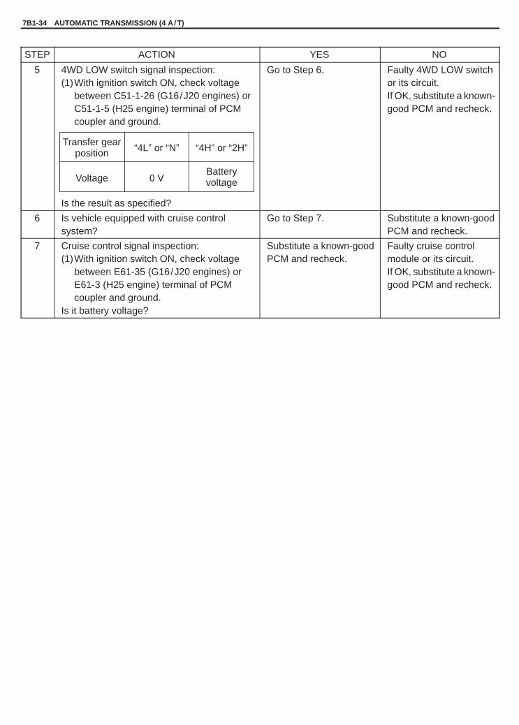
YH4GRANDVITARA
7B1-34 AUTOMATIC TRANSMISSION (4 A /T)
Transfer gearposition “4L” or “N” “4H” or “2H”
Voltage 0 VBatteryvoltage
STEP ACTION YES NO
5 4WD LOW switch signal inspection:(1)With ignition switch ON, check voltage
between C51-1-26 (G16/J20 engines) orC51-1-5 (H25 engine) terminal of PCMcoupler and ground.
Is the result as specified?
Go to Step 6. Faulty 4WD LOW switchor its circuit.If OK, substitute a known-good PCM and recheck.
6 Is vehicle equipped with cruise controlsystem?
Go to Step 7. Substitute a known-goodPCM and recheck.
7 Cruise control signal inspection:(1)With ignition switch ON, check voltage
between E61-35 (G16/J20 engines) orE61-3 (H25 engine) terminal of PCMcoupler and ground.
Is it battery voltage?
Substitute a known-goodPCM and recheck.
Faulty cruise controlmodule or its circuit.If OK, substitute a known-good PCM and recheck.

YH4GRANDVITARA
G16/J20 Engines
H25 Engine
1. PCM2. J / B3. O / D cut switch4. P / N change switch5. J / C
1. PCM2. Fuse3. O / D cut switch4. P / N change switch5. J / C6. J / C
AUTOMATIC TRANSMISSION (4 A /T) 7B1-35
DIAGNOSTIC FLOW TABLE B-1 “O/D OFF” LIGHT CIRCUIT CHECK(“O/D OFF” LIGHT DOESN’T LIGHT AT IGNITION SWITCH ON BUTENGINE STARTS UP)
WIRING DIAGRAM
TROUBLESHOOTING
STEP ACTION YES NO
1 “O/D OFF” light circuit check:(1)With ignition switch OFF, disconnect
couplers from PCM.(2)Using service wire, connect E61-20
(G16/J20 engines) or E61-7 (H25 engine)terminal of disconnected PCM coupler andground.
Does “O/D OFF” light turn ON at ignitionswitch ON?
Poor E61-20 (G16/J20engines) or E61-7 (H25engine) terminalconnection.If OK, substitute a known-good PCM and recheck.
Bulb burned out or faulty“W/B”, “B/W” wire.

YH4GRANDVITARA
7B1-36 AUTOMATIC TRANSMISSION (4 A /T)
Switch ONposition
Switch OFFposition
Switch ONposition
Switch OFFposition
DIAGNOSTIC FLOW TABLE B-2 “O/D OFF” LIGHT CIRCUIT CHECK(“O/D OFF” LIGHT COMES ON STEADILY)
WIRING DIAGRAM – Refer to Table B-1 in this section.
TROUBLESHOOTING
STEP ACTION YES NO
1 Check O/D cut Switch Position.Is O/D cut switch turned OFF (Is switch button at OFFposition)?
Go to Step 2. Turn O/D cut switchOFF.
2 Check Lamp Circuit for Short.1) Turn ignition switch OFF and disconnect PCM
connectors.2) Turn ignition switch ON.Does “O/D OFF” lamp come ON steadily?
“W/B” circuit shortedto ground.
Go to Step 3.
3 Check O/D cut Switch Circuit.1) Check resistance between terminal E61-33
(G16/J20 engines) or E61-14 (H25 engine) ofdisconnected PCM connector and body ground withO/D cut switch OFF.
Is continuity indicated?
Go to Step 4. Check PCM groundcircuit for open.If ground circuit isOK, substitute aknown-good PCMand recheck.
4 Check O/D cut Switch for Operation.1) Remove console box.2) Disconnect O/D cut switch connector.3) Check continuity between switch terminals under
each condition below.Switch OFF position: No continuitySwitch ON position: Continuity
Is check result satisfactory?
“Y/R” circuit shortedto ground.
Replace O/D cutswitch.
Fig. for Step 1. Fig. for Step 4.

YH4GRANDVITARA
G16/J20 Engines
H25 Engine
1. PCM2. J / B3. O / D cut switch4. P / N change switch5. J / C
1. PCM2. Fuse3. O / D cut switch4. P / N change switch5. J / C6. J / C
AUTOMATIC TRANSMISSION (4 A /T) 7B1-37
DIAGNOSTIC FLOW TABLE B-3 “POWER” LIGHT CIRCUIT CHECK(“POWER” LIGHT DOESN’T LIGHT AT IGNITION SWITCH ON BUTENGINE STARTS UP)
WIRING DIAGRAM
TROUBLESHOOTING
STEP ACTION YES NO
1 “POWER” light circuit check:(1)With ignition switch OFF, disconnect
couplers from PCM.(2)Using service wire, connect E61-21 (G16/
J20 engines) or E61-10 (H25 engine)terminal of disconnected PCM coupler andground.
Does “POWER” light turn ON at ignition switchON?
Poor E61-21 (G16/J20engines) or E61-10 (H25engine) terminalconnection.If OK, substitute a known-good PCM and recheck.
Bulb burned out or faulty“Gr/Bl”, “B/W” wire.

YH4GRANDVITARA
7B1-38 AUTOMATIC TRANSMISSION (4 A /T)
“5” “4”
DIAGNOSTIC FLOW TABLE B-4 “POWER” LIGHT CIRCUIT CHECK(“POWER” LIGHT COMES ON STEADILY)
WIRING DIAGRAM – Refer to Table B-3 in this section.
TROUBLESHOOTING
STEP ACTION YES NO
1 Check Power/Normal Change Switch Position.Is switch button at Normal position?
Go to Step 2. Set Power/Normalchange switch atNormal position.
2 Check Lamp Circuit for Short.1) Turn ignition switch OFF and disconnect PCM
connectors.2) Turn ignition switch ON.Does “POWER” lamp come ON steadily?
“Gr/Bl” circuitshorted to ground.
Go to Step 3.
3 Check Power/Normal Change Switch Circuit.1) Check resistance between terminal E61-31
(G16/J20 engines) or E61-9 (H25 engine) ofdisconnected PCM connector and body ground withP/N change switch OFF.
Is continuity indicated?
Go to Step 4. Check PCM groundcircuit for open.If ground circuit isOK, substitute aknown-good PCMand recheck.
4 Check Power/Normal Change Switch for Operation.1) Remove Power/Normal change switch.2) Check continuity between switch terminals “4” and
“5” under each condition below.Normal position: No continuityPower position: Continuity.
Is check result satisfactory?
“Or/Bl” circuitshorted to ground.
Replace Power/Normal changeswitch.
Fig. for Step 1. Fig. for Step 4.

YH4GRANDVITARA
AUTOMATIC TRANSMISSION (4 A /T) 7B1-39
G16/J20 Engines
H25 Engine
1. PCM2. J / B3. Transmission range
sensor (switch)
1. PCM2. Fuse3. J / C4. Transmission range
sensor (switch)
DTC P0705 (DTC NO.72) TRANSMISSION RANGE SENSOR (SWITCH) CIRCUITMALFUNCTION
WIRING DIAGRAM

YH4GRANDVITARA
7B1-40 AUTOMATIC TRANSMISSION (4 A /T)
DTC DETECTING CONDITION AND TROUBLE AREA
DTC DETECTING CONDITION TROUBLE AREA
� Transmission range switch signal (P, R, N, D, 2 or L)is not inputted for 25 sec. at 60 km/h (38 mph) orhigher vehicle speed.or
� Multiple signals are inputted simultaneously for 25sec.(2 driving cycles detection logic)
� Transmission range sensor (switch) maladjusted.� Transmission range sensor (switch) or its circuit mal-
function.� PCM
DTC CONFIRMATION PROCEDURE
WARNING:� When performing a road test, select a place where there is no traffic or possibility of a traffic accident
and be very careful during testing to avoid occurrence of an accident.� Road test should be carried out with 2 persons, a driver and a tester, on a level road.
1) Connect scan tool to DLC with ignition switch OFF, if available.2) Clear DTC and start engine.3) Shift A/T selector lever to each of L, 2, D, N, R and P ranges for 30 seconds each.4) Increase vehicle speed to about 70 km/h (45 mph) in D range.5) Keep driving above vehicle speed for 30 seconds.6) Release accelerator pedal, decrease vehicle speed and stop vehicle.7) Check DTC and/or pending DTC.

YH4GRANDVITARA
AUTOMATIC TRANSMISSION (4 A /T) 7B1-41
C51-1-18
C51-1-17
C51-1-16
C51-1-15
C51-1-28
C51-1-27
G16/J20
H25 C51-1-4 C51-1-3 C51-1-13 C51-1-12 C51-1-20 C51-1-19
Terminal
Selectleverposition
TROUBLESHOOTING (DTC P0705)
STEP ACTION YES NO
1 Was “A/T DIAG. FLOW TABLE” performed? Go to Step 2. Go to “A/T DIAG.FLOW TABLE”.
2 Check Transmission Range Switch (Sensor) Circuit forOperation.When using SUZUKI scan tool:1) Connect SUZUKI scan tool to DLC with ignition
switch OFF.2) Turn ignition switch ON and check transmission
range signal (P, R, N, D, 2 or L) on displaywhen shifting select lever to each range.
Is applicable range indicated?When not using SUZUKI scan tool:1) Turn ignition switch ON.2) Check voltage at terminals C51-1-15, C51-1-16,
C51-1-17, C51-1-18, C51-1-27 and C51-1-28 forG16/J20 (C51-1-4, C51-1-3, C51-1-13, C51-1-12,C51-1-20 and C51-1-19 for H25) respectively withselect lever shifted to each range.Taking terminal C51-1-28 for G16/J20 (C51-1-20 forH25) as an example, is battery voltage indicatedonly when select lever is shifted to “2” range and0 V for other ranges as shown in figure?Check voltage at other terminals likewise, referringto figure.
Are check results satisfactory?
Intermittent trouble.Check for intermittentreferring to “Intermit-tent and PoorConnection” insection 0A.
Go to Step 3.
3 Check Select Cable for Adjustment referring to “SelectCable Adjustment” in this section.Is it adjusted correctly?
Go to Step 4. Adjust.
4 Check Transmission Range Switch for InstallationPosition.1) Shift select lever to “N” range.2) Check that “N” reference line on switch and center
line on shaft are aligned.Are they aligned?
Go to Step 5. Adjust.
5 Check Transmission Range Switch (Sensor) referringto “Transmission Range Switch” in this section.Are check results satisfactory?
“Y”, “Or/G”, “R”,“Or/Bl”, “Y/G”,“G/Or” or “G/Bl”circuit open or short.If wires andconnections are OK,substitute a known-good PCM andrecheck.
Replace TR switch.
Fig. for Step 2.

YH4GRANDVITARA
G16/J20 Engines H25 Engine
G16/J20 Engines
H25 Engine1. PCM2. A / T input speed sensor
11 10
Bl / Y Bl / G
16 8
Bl / Y Bl / G
7B1-42 AUTOMATIC TRANSMISSION (4 A /T)
DTC P0715 (DTC NO.76) INPUT/TURBINE SPEED SENSOR CIRCUIT MALFUNCTIONWIRING DIAGRAM
DTC DETECTING CONDITION AND TROUBLE AREA
DTC DETECTING CONDITION TROUBLE AREA
Input speed sensor detected speed is lower than spec-ification while vehicle running under all of the followingconditions:� at higher than 10 km/h (7 mph) with 1st gear in D
range for 1 sec. or more.� at higher than 20 km/h (13 mph) with 2nd gear in D
range for 2 sec. or more.� at higher than 30 km/h (20 mph) with 3rd gear in D
range for 2 sec. or more.(2 driving cycles detection logic)
� Input speed sensor and its circuit� PCM
DTC CONFIRMATION PROCEDURE
WARNING:� When performing a road test, select a place where there is no traffic or possibility of a traffic accident
and be very careful during testing to avoid occurrence of an accident.� Road test should be carried out with 2 persons, a driver and a tester, on a level road.
1) Connect scan tool to DLC with ignition switch OFF, if available.2) Clear DTC.3) Start engine and turn O/D cut switch ON.4) Shift select lever to D range and start vehicle.5) Keep vehicle speed at higher than 10 km/h (7 mph) with 1st gear in D range for 2 sec. or more.6) Increase vehicle speed and keep it at higher than 20 km/h (13 mph) with 2nd gear in D range for 2 sec. or more.7) Increase vehicle speed and keep it at higher than 30 km/h (20 mph) with 3rd gear in D range for 2 sec. or more.8) Stop vehicle.9) Check DTC and/or pending DTC.

YH4GRANDVITARA
Oscilloscope waveforms
2V/Div.
Waveforms at specified idlespeed in “P” range
5ms / Div.
AUTOMATIC TRANSMISSION (4 A /T) 7B1-43
TROUBLESHOOTING (DTC P0715)
STEP ACTION YES NO
1 Was “A/T DIAG. FLOW TABLE” performed? Go to Step 2. Go to “A/T DIAG.FLOW TABLE”.
2 Input speed sensor circuit check:1) Remove PCM cover.2) With ignition switch OFF, disconnect PCM
connectors.3) Check for proper connection to input speed sensor
at C51-1-10 and C51-1-11 terminals for G16/J20(at C51-1-8 and C51-1-16 terminals for H25)
4) If OK, check resistance of sensor circuit.Resistance between C51-1-10and C51-1-11 for G16/J20(C51-1-8 and C51-1-16 for H25): 530 – 650 � at
20�C, 68�F
Resistance between C51-1-10/C51-1-11 for G16/J20 (C51-1-8/C51-1-16 for H25) and ground: 1 M� or more
Are check results satisfactory?
Go to Step 4. Go to Step 3.
3 Input speed sensor check:1) With ignition switch OFF, disconnect input speed
sensor connector.2) Check for proper connection to input speed sensor
at each terminals.3) If OK, then check resistance of input speed sensor.Are measured values as specified in Step 2?
“Bl/G” or “Bl /Y” wireopen or shorted toground.
Replace input speedsensor.
4 Check visually input speed sensor and overdrive clutchdrum for the followings.� No damage� No foreign material attached� Correct installationAre they in good condition?
Intermittent troubleor faulty PCM.Check for intermittentreferring to“Intermittent andPoor Connection” inSection 0A.
Clean, repair orreplace.
ReferenceConnect oscilloscope between C51-1-11 (+) and C51-1-10 (–) forG16/J20 (C51-1-16 (+) and C51-1-8 (–) for H25) of PCM connectorconnected to PCM and check input speed sensor signal.

YH4GRANDVITARA
G16/J20 Engines H25 Engine
G16/J20 Engines
H25 Engine1. PCM2. A / T output speed sensor
23 22
W Or
10 9
W Or
7B1-44 AUTOMATIC TRANSMISSION (4 A /T)
DTC P0720 (DTC NO.75) OUTPUT SPEED SENSOR CIRCUIT MALFUNCTIONWIRING DIAGRAM
DTC DETECTING CONDITION AND TROUBLE AREA
DTC DETECTING CONDITION TROUBLE AREA
� With 4WD LOW switch OFF, no output speed sensorsignal is inputted while vehicle speed sensor signalare inputted.or
� With 4WD LOW switch OFF, no output speed sensorsignal is inputted while engine running at higher thanspecified engine speed with “D” range.(2 driving cycles detection logic)
� A/T output speed sensor or its circuit� PCM
DTC CONFIRMATION PROCEDURE
WARNING:� When performing a road test, select a place where there is no traffic or possibility of a traffic accident
and be very careful during testing to avoid occurrence of an accident.� Road test should be carried out with 2 persons, a driver and a tester, on a level road.
1) Connect scan tool to DLC with ignition switch OFF, if available.2) Clear DTC.3) Start engine and shift transfer lever to “2H” or “4H” range.4) Drive vehicle at 40 km/h (25 mph) or more for longer than 10 sec. (or higher than 3500 rpm engine speed with
D range for longer than 10 sec.)5) Stop vehicle and check DTC and/or pending DTC.

YH4GRANDVITARA
Oscilloscope waveforms
2 V/Div.
5 ms / Div.Waveforms at about 25 mph, 40 km / h
AUTOMATIC TRANSMISSION (4 A /T) 7B1-45
TROUBLESHOOTING (DTC P0720)
STEP ACTION YES NO
1 Was “A/T DIAG. FLOW TABLE” performed? Go to Step 2. Go to “A/T DIAG.FLOW TABLE”.
2 Output speed sensor circuit check:1) Remove PCM cover.2) With ignition switch OFF, disconnect PCM
connectors.3) Check for proper connection to output speed sensor
at C51-1-22 and C51-1-23 terminals for G16/J20(at C51-1-9 and C51-1-10 terminals for H25).
4) If OK, check resistance of sensor circuit.Resistance between C51-1-22and C51-1-23 for G16/J20(C51-1-9 and C51-1-10 for H25): 387 – 473 � at
20 �C, 68 �F
Resistance between C51-1-22/C51-1-23 for G16/J20 (C51-1-9/C51-1-10 for H25) and ground: 1 M� or more
Are check results satisfactory?
Go to Step 4. Go to Step 3.
3 Output speed sensor check:1) With ignition switch OFF, disconnect output speed
sensor connector.2) Check for proper connection to output speed sensor
at each terminals.3) If OK, then check resistance of output speed sensor.Are measured values as specified in Step 2?
“Or” or “W” wireopen or shorted toground.
Replace outputspeed sensor.
4 Check visually output speed sensor and sensor rotorfor the followings.� No damage� No foreign material attached� Correct installationAre they in good condition?
Intermittent troubleor faulty PCM.Check for intermittentreferring to“Intermittent andPoor Connection” inSection 0A.
Clean, repair orreplace.
ReferenceConnect oscilloscope between C51-1-23 (+) and C51-1-22 (–) forG16/J20 (C51-1-10 (+) and C51-1-9 (–) for H25) of PCM connectorconnected to PCM and check output speed sensor signal.

YH4GRANDVITARA
7B1-46 AUTOMATIC TRANSMISSION (4 A /T)
DTC P0741 TCC (LOCK-UP) SOLENOID VALVE PERFORMANCE OR STUCK OFFDTC DETECTING CONDITION AND TROUBLE AREA
DTC DETECTING CONDITION TROUBLE AREA
While running in 2nd or 4th gear, D range, TCC controlof PCM does not agree with actual operation of trans-mission TCC even though solenoid valve is electricallyin good condition.(2 driving cycles detection logic)
� TCC (lock-up) solenoid valve stuck� TCC control valve stuck� Valve body fluid passage clogged� TCC faulty
DTC CONFIRMATION PROCEDURE
WARNING:� When performing a road test, select a place where there is no traffic or possibility of a traffic accident
and be very careful during testing to avoid occurrence of an accident.� Road test should be carried out with 2 persons, a driver and a tester, on a level road.
1) Connect scan tool to DLC with ignition switch OFF.2) Clear DTC, pending DTC and freeze frame data in PCM memory by using scan tool and check fuel level meter
indication is 1/4 or more.3) Start engine, warm it up to normal operating temperature and shift transfer lever to “2H” or “4H” range.4) Increase vehicle speed with D range, and check that gear position changes from 1st to 2nd and keep driving
about 20 mph, 30 km/h in 2nd of “D” range for 10 seconds. (Throttle valve should be not at idle position andthe opening should be kept constant in this step.)
5) Keep driving about 50 mph, 80 km/h in 4th of “D” range for 10 seconds.6) Release accelerator pedal, decrease vehicle speed and stop vehicle.7) Check pending DTC and DTC by using scan tool.
TROUBLESHOOTING
STEP ACTION YES NO
1 Was “A/T DIAG. FLOW TABLE” performed? Go to Step 2. Go to “A/T DIAG.FLOW TABLE”.
2 TCC solenoid valve operation check:1) Check TCC solenoid valve operation referring to
“Solenoid Valves Operation Check” in this section.Is it in good condition?
Go to Step 3. Faulty TCC solenoidvalve.
3 Valve body check:1) Check valve body referring to “Unit Repair” in this
section.Is it in good condition?
Faulty torqueconverter.
Faulty valve body.

YH4GRANDVITARA
G16/J20 Engines H25 Engine
G16/J20 Engines
H25 Engine
1. PCM2. Shift solenoid-A3. Shift solenoid-B4. TCC solenoid
AUTOMATIC TRANSMISSION (4 A /T) 7B1-47
DTC P0743 (DTC NO.65/66) TCC (LOCK-UP) SOLENOID ELECTRICALWIRING DIAGRAM
DTC DETECTING CONDITION AND TROUBLE AREA
DTC DETECTING CONDITION TROUBLE AREA
Voltage at terminal C51-1-8 for G16/J20 (C51-1-2 forH25) of PCM is high while TCC solenoid OFF is com-manded or low while TCC solenoid ON is comman-ded.
� TCC (lock-up) solenoid valve� TCC (lock-up) solenoid valve circuit� PCM
DTC CONFIRMATION PROCEDURE
WARNING:� When performing a road test, select a place where there is no traffic or possibility of a traffic accident
and be very careful during testing to avoid occurrence of an accident.� Road test should be carried out with 2 persons, a driver and a tester, on a level road.
1) Connect scan tool to DLC with ignition switch OFF, if available.2) Clear DTC.3) Start engine, warm it up to normal operating temperature and shift transfer lever to “2H” or “4H” range.4) Shift selector lever in D range and keep it there for 10 seconds.5) Increase vehicle speed to about 80 km/h (50 mph) in 4th gear and in D range.6) Keep driving at above speed for 20 seconds.7) Release accelerator pedal, decrease vehicle speed and stop vehicle.8) Check DTC and/or pending DTC.

YH4GRANDVITARA
7B1-48 AUTOMATIC TRANSMISSION (4 A /T)
TROUBLESHOOTING
STEP ACTION YES NO
1 Was “A/T DIAG. FLOW TABLE” performed? Go to Step 2. Go to “A/T DIAG.FLOW TABLE”.
2 Is the vehicle equipped with monitor connector? Go to Step 3. Go to Step 4.
3 Is DTC NO.65? G to Step 4. Go to Step 6.
4 Check TCC Solenoid Circuit for Open or Short.1) Turn ignition switch OFF and disconnect PCM
connectors.2) Check for proper connection to PCM at terminals
C51-1-8 for G16/J20 (C51-1-2 for H25).3) If OK, then measure resistance between terminal
C51-1-8 for G16/J20 (C51-1-2 for H25) ofdisconnected PCM connector and ground.
Is it 11 – 15 � at 20�C, 68�F?
Go to Step 5. “G/Y” circuit open orshorted to ground.If wire andconnections are OK,replace malfunctionshift solenoid.
5 Check TCC Solenoid Circuit for Short.1) Turn ignition switch ON.2) Measure voltage between terminal C51-1-8 for
G16/J20 (C51-1-2 for H25) of disconnected PCMconnector and ground.
Is it about 0 V?
Intermittent trouble orfaulty PCM.Check for“Intermittent andPoor Connection” inSection 0A.
“G/Y” circuit shortedto power circuit.
6 Check TCC Solenoid Circuit for Short.1) Turn ignition switch OFF and disconnect PCM
connectors.2) Check for proper connection to PCM at terminals
C51-1-8 for G16/J20 (C51-1-2 for H25) or C51-1-1.3) If OK, then measure resistance between terminal
C51-1-8 for G16/J20 (C51-1-2 for H25) ofdisconnected PCM connector and ground.
Is it 11 – 15 � at 20�C, 68�F?
Intermittent trouble orfaulty PCM.Check for“Intermittent andPoor Connection” inSection 0A.
“G/Y” circuit shortedto ground.If wire andconnections are OK,replace malfunctionshift solenoid.

YH4GRANDVITARA
AUTOMATIC TRANSMISSION (4 A /T) 7B1-49
DTC P0751 SHIFT SOLENOID VALVE-A (#1) PERFORMANCE OR STUCK OFFDTC P0756 SHIFT SOLENOID VALVE-B (#2) PERFORMANCE OR STUCK OFFDTC DETECTING CONDITION AND TROUBLE AREA
DTC DETECTING CONDITION TROUBLE AREA
While running in D range, gear change control fromPCM to A/T does not agree with actual A/T gear posi-tion even though solenoid valve is electrically in goodcondition.(A/T gear position is calculated based on enginespeed signal and vehicle speed sensor signal.)(2 driving cycles detection logic)
DTC P0751:� Shift solenoid valve-A stuck or leakage.� 2-3 shift valve stuck.� Valve body fluid passage clogged.� Mechanical malfunction in transmission.
(Direct clutch malfunction)DTC P0756:� Shift solenoid valve-B stuck or leakage.� 1-2 shift valve stuck.� 3-4 shift valve stuck.� Valve body fluid passage clogged.� Mechanical malfunction in transmission.
(2nd brake malfunction)
DTC CONFIRMATION PROCEDURE
WARNING:� When performing a road test, select a place where there is no traffic or possibility of a traffic accident
and be very careful during testing to avoid occurrence of an accident.� Road test should be carried out with 2 persons, a driver and a tester, on a level road.
1) Connect scan tool to DLC with ignition switch OFF.2) Clear DTC, pending DTC and freeze frame data in PCM memory by using scan tool and check fuel level meter
indication is 1/4 or more.3) Start engine, warm it up to normal operating temperature and shift transfer lever to “2H” or “4H” range.4) Increase vehicle speed with D range, and check that gear position changes from 1st to 2nd, 3rd and 4th in that
order as vehicle speed increases, referring to “Gear Shift Diagram” in this section.5) Stop vehicle and check pending DTC and DTC by using scan tool.
TROUBLESHOOTING
STEP ACTION YES NO
1 Was “A/T DIAG. FLOW TABLE” performed? Go to Step 2. Go to “A/T DIAG.FLOW TABLE”.
2 Shift solenoid valve-A or -B operation check:1) Check shift solenoid valve-A or -B for operation
referring to “Solenoid Valves Operation Check”section.
Is it in good condition?
Go to Step 3. Faulty shift solenoidvalve-A or -B.
3 Valve body check:1) Check valve body and its passage referring to
“Unit Repair” section.Are they in good condition?
Overhaul and repairautomatic transmis-sion.
Faulty valve body.

YH4GRANDVITARA
G16/J20 Engines H25 Engine
H25 Engine
G16/J20 Engines
1. PCM2. Shift solenoid-A3. Shift solenoid-B4. TCC solenoid
7B1-50 AUTOMATIC TRANSMISSION (4 A /T)
DTC P0753 (DTC NO.61/62) SHIFT SOLENOID-A (#1) ELECTRICALDTC P0758 (DTC NO.63/64) SHIFT SOLENOID-B (#2) ELECTRICALWIRING DIAGRAM
DTC DETECTING CONDITION AND TROUBLE AREA
DTC DETECTING CONDITION TROUBLE AREA
DTC P0753:Voltage detected at C51-1-2 for G16/J20 (C51-1-6 forH25) terminal is specified voltage or lower when shiftsolenoid valve-A is ON or specified voltage or higherwhen it is OFF.
� Shift solenoid valve-A� Shift solenoid valve-A circuit� PCM
DTC P0758:Voltage detected at C51-1-1 terminal is specified volt-age or lower when shift solenoid valve-B is ON or spe-cified voltage or higher when it is OFF.
� Shift solenoid valve-B� Shift solenoid valve-B circuit� PCM

YH4GRANDVITARA
AUTOMATIC TRANSMISSION (4 A /T) 7B1-51
DTC CONFIRMATION PROCEDURE
WARNING:� When performing a road test, select a place where there is no traffic or possibility of a traffic accident
and be very careful during testing to avoid occurrence of an accident.� Road test should be carried out with 2 persons, a driver and a tester, on a level road.
1) Connect scan tool to DLC with ignition switch OFF, if available.2) Clear DTC.3) Start engine and shift transfer lever to “2H” or “4H” range.4) Shift selector lever in D range and keep it for 10 seconds.5) Drive vehicle about 30 km/h (20 mph) with 2nd gear in D range for 10 seconds.6) Increase vehicle speed to about 80 km/h (50 mph) with 4th gear in D range and keep it for 10 seconds.7) Release accelerator pedal, decrease vehicle speed and stop vehicle.8) Check DTC and/or pending DTC.
TROUBLESHOOTING (DTC P0753/P0758)
STEP ACTION YES NO
1 Was “A/T DIAG. FLOW TABLE” performed? Go to Step 2. Go to “A/T DIAG.FLOW TABLE”.
2 Is the vehicle equipped with monitor connector? Go to Step 3. Go to Step 4.
3 Is DTC NO.61 or 63? Go to Step 4. Go to Step 6.
4 Check Shift Solenoid Circuit for Open or Short.1) Turn ignition switch OFF and disconnect PCM
connectors.2) Check for proper connection to PCM at terminals
C51-1-2 for G16/J20 (C51-1-6 for H25) or C51-1-1.3) If OK, then measure resistance between terminal
C51-1-2 for G16/J20 (C51-1-6 for H25) or C51-1-1of disconnected PCM connector and ground.
Is it 11 – 15 � at 20�C, 68�F?
Go to Step 5. “G” or “G/R” circuitopen or shorted toground.If wire andconnections are OK,replace malfunctionshift solenoid.
5 Check Shift Solenoid Circuit for Short.1) Turn ignition switch ON.2) Measure voltage between terminal C51-1-2 for
G16/J20 (C51-1-6 for H25) or C51-1-1 ofdisconnected PCM connector and ground.
Is it about 0 V?
Intermittent trouble orfaulty PCM.Check for“Intermittent andPoor Connection” inSection 0A.
“G” or “G/R” circuitshorted to powercircuit.
6 Check Shift Solenoid Circuit for Short.1) Turn ignition switch OFF and disconnect PCM
connectors.2) Check for proper connection to PCM at terminals
C51-1-2 for G16/J20 (C51-1-6 for H25) or C51-1-1.3) If OK, then measure resistance between terminal
C51-1-2 for G16/J20 (C51-1-6 for H25) or C51-1-1of disconnected PCM connector and ground.
Is it 11 – 15 � at 20�C, 68�F?
Intermittent trouble orfaulty PCM.Check for“Intermittent andPoor Connection” inSection 0A.
“G” or “G/R” circuitshorted to ground.

YH4GRANDVITARA
G16/J20 Engines
H25 Engine1. PCM2. 4WD low switch3. J / C
7B1-52 AUTOMATIC TRANSMISSION (4 A /T)
DTC P1875 4WD LOW SWITCH CIRCUIT MALFUNCTION (if equipped)WIRING DIAGRAM
DTC DETECTING CONDITION AND TROUBLE AREA
DTC DETECTING CONDITION TROUBLE AREA
While driving at higher than specified vehicle speedand with more than specified throttle valve opening,the following conditions are satisfied for specified time.� Vehicle speed sensed by vehicle speed sensor is
more than 10 km/h higher than that sensed by A/Toutput speed sensor.(2 driving cycles detection logic)
� 4WD LOW switch or its circuit� PCM
DTC CONFIRMATION PROCEDURE
WARNING:� When performing a road test, select a place where there is no traffic or possibility of a traffic accident
and be very careful during testing to avoid occurrence of an accident.� Road test should be carried out with 2 persons, a driver and a tester, on a level road.
1) Connect scan tool to DLC with ignition switch OFF.2) Clear DTC, pending DTC and freeze frame data in PCM memory by using scan tool.3) Start engine.4) Increase vehicle speed to about 30 km/h (19 mph) or more in D range and is in 2H position.5) Keep driving at above vehicle speed for 30 seconds.6) Stop vehicle and shift transfer lever to 4L position with A/T selector lever is in P range7) Increase vehicle speed to about 25 km/h (15 mph) or more in D range and is in 4L position.8) Keep driving at above vehicle speed for 30 seconds.9) Stop vehicle and check pending DTC and DTC by using scan tool.

YH4GRANDVITARA
1
1. 4WD low switch
AUTOMATIC TRANSMISSION (4 A /T) 7B1-53
TROUBLESHOOTING (DTC P1875)
STEP ACTION YES NO
1 Was “A/T DIAG. FLOW TABLE” performed? Go to Step 2. Go to “A/T DIAG.FLOW TABLE”.
2 4WD low switch and its circuit check:When using SUZUKI scan tool:1) Connect SUZUKI scan tool to DLC with ignition
switch OFF.2) Turn ignition switch ON.3) Select “Data list” mode on scan tool.4) Check 4WD low switch signal (ON or OFF) on
display when shifting transfer lever to eachposition.4H or 2H position: OFF4L position : ON
Is OFF/ON displayed as described above?When not using SUZUKI scan tool:1) Remove PCM cover.2) Turn ignition switch ON.3) Check voltage at terminal C51-1-26 for G16/J20
(C51-1-5 for H25) of PCM connector connectedwhen shifting transfer lever to each position.4H or 2H position: 10 – 14 V4L position : 0 – 1 V
Is voltage as specified?
Check for poor con-nection at the termi-nal of PCM if voltme-ter is used in Step 2.If connection is OK,intermittent troubleor faulty PCM.Check for intermittentreferring to “Intermit-tent and PoorConnection” inSection 0A.
Go to Step 3.
3 4WD low switch check:1) Check 4WD low switch for operation referring to
“4WD Low Switch Inspection” below.Is check result satisfactory?
“Or/W” or “B” circuitopen or short. If wiresand connections areOK, substitute aknown-good PCMand recheck.
Replace 4WD lowswitch.
4WD Low Switch Inspection1) Disconnect negative cable at battery.2) Disconnect 4WD low switch coupler.3) Check continuity between 4WD low switch terminals.
There should be continuity when transfer lever shifted to 4L posi-tion and should be infinity when transfer lever shifted to 4H or 2Hpositions.If not, replace 4WD low switch.
4) Connect 4WD low switch coupler and battery negative cable.

YH4GRANDVITARA
1. Fluid pressure check hole2. Oil pan
1. Oil pan2. Exhaust pipe
7B1-54 AUTOMATIC TRANSMISSION (4 A /T)
LINE PRESSURE TESTPurpose of this test is to check operating conditions of each part bymeasuring fluid pressure in fluid pressure line. Line pressure testrequires following conditions.� Automatic fluid is at normal operating temperature (70 to 80�C /
158 – 176�F).� Fluid is filled to proper level (between FULL HOT and LOW HOT
on dipstick).
1) Apply parking brake securely and place checks against wheels.2) Attach oil pressure gauge to fluid pressure check hole in trans-
mission case.
Special Tool(A): 09925-37810
CAUTION:After attaching oil pressure gauge, check that not fluidleakage exists.
3) Depress foot brake fully, run engine at idle and stall and thencheck fluid pressure in “D” or “R” range.
CAUTION:Do not continue running engine at stall speed longer than5 seconds.
G16 Engine
Engine running Line pressureg gmode “D” range “R” range
At idle speed 3.9 – 4.4 kg/cm2
55 – 63 psi5.1 – 5.7 kg/cm2
73 – 81 psi
At stall speed 11.7 – 13.2 kg/cm2
166 – 188 psi14.2 – 16.7 kg/cm2
202 – 237 psi
J20 Engine
Engine running Line pressureg gmode “D” range “R” range
At idle speed 3.8 – 4.3 kg/cm2
54 – 61 psi5.3 – 5.9 kg/cm2
75 – 84 psi
At stall speed 9.7 – 11.2 kg/cm2
138 – 159 psi12.9 – 15.5 kg/cm2
183 – 220 psi
H25 Engine
Engine running Line pressureg gmode “D” range “R” range
At idle speed 3.9 – 4.4 kg/cm2
55 – 63 psi6.6 – 7.2 kg/cm2
94 – 102 psi
At stall speed 11.3 – 12.7 kg/cm2
161 – 181 psi14.7 – 22.7 kg/cm2
209 – 323 psi

YH4GRANDVITARA
AUTOMATIC TRANSMISSION (4 A /T) 7B1-55
Check result Possible cause
Line pressure higherthan standard level ineach range
� Malfunctioning regulator valve� Malfunctioning throttle valve� Maladjusted A/T throttle cable
Line pressure lower thanstandard level in eachrange
� Defective O/D clutch� Defective oil pump� Malfunctioning throttle valve� Malfunctioning regulator value� Maladjusted A/T throttle cable
Line pressure lower thanstandard level only in “D”range
� Fluid leakage from forward clutch� Defective O/D clutch� Leakage from “D” range fluid pressure cir-
cuit
Line pressure lower thanstandard level only in “R”range
� Fluid leakage from direct clutch� Defective O/D clutch� Fluid leakage from reverse brake� Fluid leakage from “R” range fluid circuit
Tightening torque of transmission case plug:17 N.m (1.7 kg-m, 12.0 lb-ft)
STALL TESTThis test is to check overall performance of automatic transmissionand engine by measuring stall speed at “D” and “R” ranges. Be sureto perform this test only when transmission fluid is at normal operat-ing temperature and its level is between FULL and LOW marks.
CAUTION:� Do not run engine at stall more than 5 seconds continu-
ously, for fluid temperature may rise excessively high.� After performing stall test, be sure to leave engine running
at idle for longer than 30 seconds before another stall test.
1) Apply parking brake and block wheels.2) Install tachometer.3) Start engine with select lever shifted to “P”.4) Depress brake pedal fully.5) Shift select lever to “D” and depress accelerator pedal fully while
watching tachometer. Read engine rpm quickly when it has be-come constant (stall speed).
6) Release accelerator pedal immediately after stall speed ischecked.
7) In the same way, check stall speed in “R” range.

YH4GRANDVITARA
7B1-56 AUTOMATIC TRANSMISSION (4 A /T)
8) Stall speed should be within the following specification.
Stall speed: 2,100 – 2,400 r/min. for G16 engine2,300 – 2,600 r/min. for J20 engine2,300 – 2,600 r/min. for H25 engine
Check result Possible cause
Lower than standardlevel
� Faulty engine output� Defective torque converter
Higher than standardlevel in “D” range
� Slippery O/D clutch� Slippery forward clutch� Malfunctioning O/D one-way clutch� Malfunctioning one-way clutch No. 2� Low line pressure
Higher than standardlevel in “R” range
� Slippery direct clutch� Slippery reverse brake� Low fluid pressure� Slippery O/D clutch� Defective O/D one-way clutch
ROAD TESTThis test is to check if upshift and downshift take place at specifiedspeed while actually driving vehicle on a level road.
WARNING:� Carry out test in very little traffic area to prevent an acci-
dent.� Test requires 2 persons, a driver and a tester.
1) Warm up engine.2) With engine running at idle, shift select lever “D”.3) Accelerate vehicle speed by depressing accelerator pedal grad-
ually.4) While driving in “D” range, check if gear shift occurs properly as
shown in Gear Shift Diagram in this section.
Test result Possible cause
When 1 � 2 upshift fails tooccur
1–2 shift valve stuck
When 2 � 3 upshift fails tooccur
2–3 shift valve stuck
When 3 � O/D upshiftfails to occur
3–4 shift valve stuck
When gear shift point is in-correct
� Maladjusted throttle cable� Defective shift solenoid valve
-A or -B� 1–2, 2–3 or 3–4 shift valve not
operating properly

YH4GRANDVITARA
1
1. Shift solenoids connector
AUTOMATIC TRANSMISSION (4 A /T) 7B1-57
MANUAL ROAD TESTThis test check the gear being used in “L”, “2” or “D” range whendriven with unoperated gear shift control system. Test drive vehicleon a level road.
NOTE:Before this test, check diagnostic trouble code (DTC).
1) Disconnect coupler of shift solenoid valves on transmission.
WARNING:To avoid the danger of being burned, do not touch the hotexhaust system when disconnecting shift solenoidvalves coupler.
2) With select lever in “P”, start engine and warm it up.3) With select lever in “L” range, start vehicle and accelerate to 20
km/h (12.5 mile/h). Check in this state that 1st gear is beingused.
4) At 20 km/h (12.5 mile/h), shift select lever to 2 range and acceler-ate to 40 km/h (25 mile/h). Check in this state that 3rd gear isbeing used.
5) At 40 km/h (25 mile/h), shift select lever to D range and checkthat O/D gear is used when speed is higher than 40 km/h (25mile/h).
6) After above checks, stop vehicle then engine, and connect shiftsolenoids coupler with ignition switch OFF.
WARNING:To avoid the danger of being burned, do not touch the hotexhaust system when connecting shift solenoid valvescoupler.
7) Clear DTC with scan tool.
TIME LAG TESTThis test is to check conditions of clutch, reverse brake and fluidpressure. “Time lag” means time elapsed since select lever isshifted with engine idling till shock is felt.1) With chocks placed before and behind front and rear wheels re-
spectively, depress brake pedal.2) Start engine.3) With stop watch ready, shift select lever from “N” to “D” range
and measure time from that moment till shock is felt.4) Similarly measure time lag by shifting select lever from “N” to “R”
range.
Specification for “N”�“D” Less than 1.2 sec.time lag “N”�“R” Less than 1.5 sec.
NOTE:� When repeating this test, be sure to wait at least minute
after select lever is shifted back to “N” range.� Engine should be warmed up fully for this test.
Test result Possible causes
When “N”�“D” time lag exceeds specification
� Low line pressure� Worn forward clutch
When “N”�“R” time lag exceeds specification
� Low line pressure� Worn direct clutch� Worn reverse brake

YH4GRANDVITARA
7B1-58 AUTOMATIC TRANSMISSION (4 A /T)
ENGINE BRAKE TEST
WARNING:Before test, make sure that there is no vehicle behind so asto prevent rear-end collision.
1) While driving vehicle in 3rd gear of “D” range, shift select leverdown to “2” range and check if engine brake operates.
2) In the same way as in step 1, check engine brake for operationwhen select lever is shifted down to “L” range.
3) If engine brake fails to operate in above tests, possible causesfor such failure are as follows. Check each part which is sus-pected to be the cause.
Condition Possible cause
Fails to operate when shifteddown to “2” range
Second coast brake defec-tive
Fails to operate when shifteddown to “L” range
Reverse brake defective
“P” RANGE TEST1) Stop vehicle on a slope, shift select lever to “P” range and at the
same time apply parking brake.2) After stopping engine, depress brake pedal and release parking
brake.3) Then, release brake pedal gradually and check that vehicle re-
mains stationary.4) Depress brake pedal and shift select lever to “N” range.5) Then, release brake pedal gradually and check that vehicle
moves.
WARNING:Before test, check to make sure no one is around vehicleor down on a slope and keep watchful for safety duringtest.
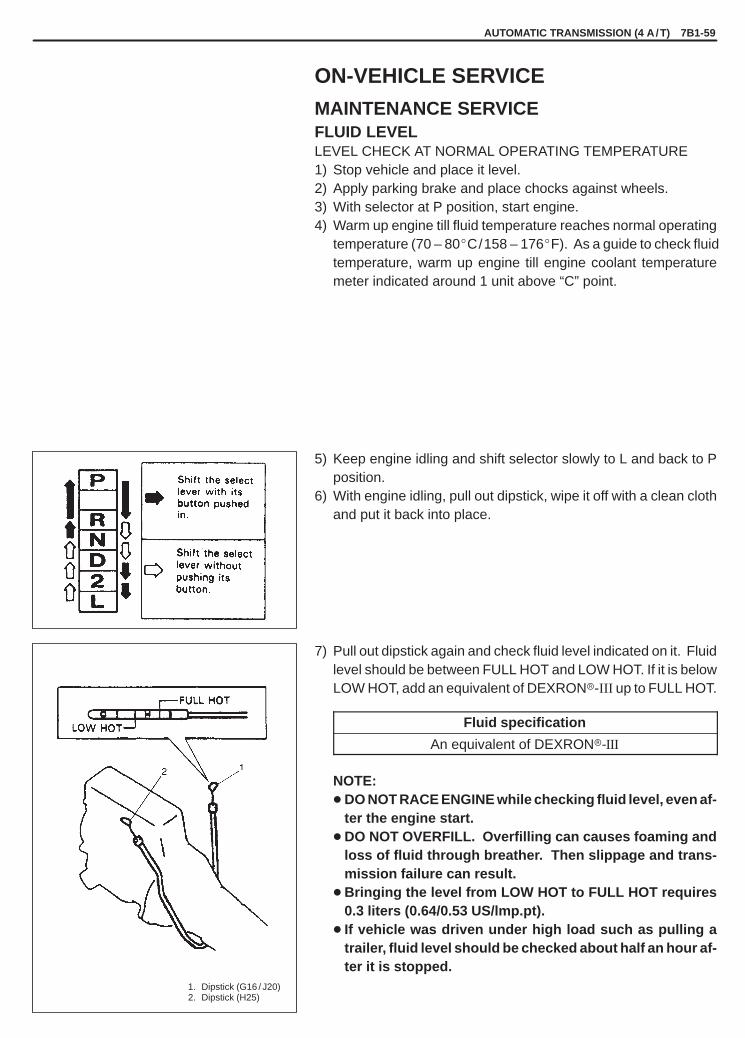
YH4GRANDVITARA
1. Dipstick (G16 / J20)2. Dipstick (H25)
AUTOMATIC TRANSMISSION (4 A /T) 7B1-59
ON-VEHICLE SERVICE
MAINTENANCE SERVICEFLUID LEVELLEVEL CHECK AT NORMAL OPERATING TEMPERATURE1) Stop vehicle and place it level.2) Apply parking brake and place chocks against wheels.3) With selector at P position, start engine.4) Warm up engine till fluid temperature reaches normal operating
temperature (70 – 80�C/158 – 176�F). As a guide to check fluidtemperature, warm up engine till engine coolant temperaturemeter indicated around 1 unit above “C” point.
5) Keep engine idling and shift selector slowly to L and back to Pposition.
6) With engine idling, pull out dipstick, wipe it off with a clean clothand put it back into place.
7) Pull out dipstick again and check fluid level indicated on it. Fluidlevel should be between FULL HOT and LOW HOT. If it is belowLOW HOT, add an equivalent of DEXRON�-III up to FULL HOT.
Fluid specification
An equivalent of DEXRON�-III
NOTE:� DO NOT RACE ENGINE while checking fluid level, even af-
ter the engine start.� DO NOT OVERFILL. Overfilling can causes foaming and
loss of fluid through breather. Then slippage and trans-mission failure can result.
� Bringing the level from LOW HOT to FULL HOT requires0.3 liters (0.64/0.53 US/lmp.pt).
� If vehicle was driven under high load such as pulling atrailer, fluid level should be checked about half an hour af-ter it is stopped.

YH4GRANDVITARA
1. Dipstick (G16 / J20)2. Dipstick (H25)
1. Drain plug2. Propeller shaft
1. Dipstick (G16 / J20)2. Dipstick (H25)
7B1-60 AUTOMATIC TRANSMISSION (4 A /T)
LEVEL CHECK AT ROOM TEMPERATUREThe fluid level check at room temperature performed after repair orfluid change before test driving is just preparation for level check ofnormal operating temperature. The checking procedure itself is thesame as that described previously. If the fluid level is between FULLCOLD and LOW COLD, proceed to test drive. And when the fluidtemperature has reached the normal operating temperature, checkfluid level again and adjust it as necessary.
FLUID CHANGE1) Lift up vehicle.2) With engine is cool, remove drain plug from oil pan and drain A/T
fluid.3) Install drain plug.
Tightening Torque(a): 23 N.m (2.3 kg-m, 17.0 lb-ft)
4) Lower vehicle and fill proper amount of an equivalent of DEX-RON�-III .
5) Check fluid level according to procedure described under LEV-EL CHECK NORMAL OPERATING TEMPERATURE.
Fluid specificationAn equivalent of DEXRON�-III
Fluid capacityWhen drainingfrom drain plughole
2.5 liters (5.28/4.40 US/lmp.pt.)
Whenoverhauling
6.9 liters (14.58/12.14 US/lmp.pt.)for G167.1 liters (15.00/12.50 US/lmp.pt.)for J20/H25

YH4GRANDVITARA
1. Radiator2. Inlet hose (Outlet from oil cooler)3. Outlet hose (Inlet to coil cooler)4. Converter housing5. Outlet hose6. Inlet hose
1. A / T throttle cable2. Adjusting nut3. Lock nut
1. A / T throttle cable2. Adjusting nut3. Lock nut
G16/J20
H25
1. A / T throttle cable2. Stopper3. Inner cable4. A / T assembly
R100 mm(3.94 in.)
AUTOMATIC TRANSMISSION (4 A /T) 7B1-61
OIL COOLER HOSESWhen replacing them, be sure to note the followings.� to replace clamps at the same time.� to insert hose as far as its limit mark.� to clamp hose securely.
A / T THROTTLE CABLEADJUSTMENT1) Pull inner cable by force of 2 N (0.2 kg, 0.45 lb) or less to be no
slack of inner cable with A/T throttle cable curved as shown inthe figure.
2) Fix stopper to inner cable with clearance “c”.
Clearance “c” : 0.8 – 1.5 mm (0.03 – 0.06 in.)
3) For G16/J20 enginesa) Check clearance “c”. If it is out of specifications, adjust it by
turning cable adjusting nut.
Clearance “c” : 0.8 – 1.5 mm (0.03 – 0.06 in.)
b) Tighten lock nut securely.
For H25 enginea) Warm up engine and transmission to normal operating tem-
perature.b) Make sure that accelerator cable is adjusted as specified.c) With throttle valve closed, check clearance “c” which should
be within the following specification.
Clearance “c” : 0.8 – 1.5 mm (0.03 – 0.06 in.)
If it is out of specification, adjust it by turning cable adjusting nut.

YH4GRANDVITARA
1. Manual selector assembly (Select lever assembly)
2. Manual lever assembly3. Select cable bracket4. Select indicator5. Slide cover6. Select lever knob
7. Spring8. Knob button9. Shift lock solenoid rod
10. Shift lock solenoid11. Cover12. Illumination lamp13. Interlock cam
1. Interlock cam pin (only for new selector assembly)
Tightening Torque(a): 18 N.m (1.8 kg-m, 13.5 lb-ft)
1. Manual leverassembly
2. Select indicator assembly
3. Illumination lampassembly
4. Bulb filter5. Bulb6. Knob assembly7. Shift lock solenoid
Type-1 Type-2
Type-1
7B1-62 AUTOMATIC TRANSMISSION (4 A /T)
MANUAL SELECTOR ASSEMBLY
REMOVAL1) Disconnect negative cable at battery.2) Remove console box.3) Disconnect connector for illumination lamp, shift lock solenoid
and overdrive OFF switch.4) Disconnect interlock cable from interlock cam of selector as-
sembly.5) Remove selector assembly mounting bolts.6) Disconnect select cable from lever of selector assembly.
INSTALLATION
NOTE:New selector assembly of Type-1 is supplied with held inter-lock cam at interlock cable connecting position with pin. Re-move this pin after connecting interlock cable to interlock camand tightening cable nut.
Reverse removal procedure to install noting the followings.� Connect interlock cable end to cam referring to steps 2) to 8) of
“Interlock Cable Installation” section.� Upon completion of installation, confirm that brake (key) interlock
system operates properly.

YH4GRANDVITARA
AUTOMATIC TRANSMISSION (4 A /T) 7B1-63
1. Select lever assembly2. Bolt3. Select cable4. Cable bracket5. Bolt6. Blank7. Washer8. Clip9. Nut
10. Manual select lever11. Lock washer12. Nut13. Select cable joint14. Bush15. Washer16. E-ring17. Transmission range switch assembly18. Bolt
1. Transmission range sensor (switch)
2. Select cable3. Manual shift lever4. Select cable joint
1. Select cable jointA. Align with cable jointB. Tighten with wrench
Tightening Torque(a): 13 N.m (1.3 kg-m, 9.5 lb-ft)(b): 7 N.m (0.7 kg-m, 5.5 lb-ft)
INSPECTIONCheck select lever for smooth and clear-cut movement and positionindicator for correct indication.For operation of select lever, refer to left figure.
SELECT CABLE
ADJUSTMENT1) Before tightening cable end nut, shift select lever to “N”.2) Also shift manual shift lever to “N”.
NOTE:� Make sure that nut and cable joint have clearance under
above conditions.� If select cable has been moved, push it in arrow C direc-
tion as shown in figure at the left till it stops and then con-firm that select lever is in “N” position.
3) Turn nut A by hand till it contacts manual select cable joint.Then tighten nut B with wrench.
4) After select cable was installed, check for the following.� Push vehicle with select lever shifted to “P”.
Vehicle should not move.� Vehicle can not be driven in “N”.� Vehicle can be driven in “D”, “2”, and “L”.� Vehicle can be backed in “R”.

YH4GRANDVITARA
7B1-64 AUTOMATIC TRANSMISSION (4 A /T)
1. A / T vehicle (output) speed sensor
“N” referenceline
Center line onmanual valve shaft
G16/J20
1. Service wire2. PCM connectors disconnected
Switchposition
TRANSMISSION RANGE SWITCH (SENSOR)INSPECTION & ADJUSTMENT1) Shift select lever to “N” range.2) Check that center line on manual valve shaft and “N” reference
line on switch are aligned. If not, loosen switch bolt and alignthem.
3) Check that engine starts in “N” and “P” ranges but it doesn’t startin “D”, “2”, “L” or “R” range. Also, check that back-up lamp lightsin “R” range.
4) If faulty condition cannot be corrected by adjustment, discon-nect transmission range switch coupler and check that continu-ity exists as shown by moving select lever.
Terminal No.5 4 9 8 2 3 10 7 65 4 9 8 2 3 10 7 6
P
R
N
D
2
L
A/T OUTPUT SPEED SENSORINSPECTIONCheck A/T output speed sensor for resistance between terminalsof sensor or PCM coupler.
A/T output speed sensorresistance value : 387 – 473 � at 20�C, 68�F
O/D CUT SWITCHINSPECTIONCheck O/D cut switch for operation referring to step 4 of Diag. FlowTable B-2 in this section.If malfunction is found, replace.
SOLENOID VALVES(Shift solenoid valves & TCC solenoid valve)INSPECTIONWith couplers of PCM disconnected and using service wire asshown at the left, check each solenoid valve for clicking sound.
G16/J20 Engines
Shift solenoid valve - A (#1) C51-1-2
Shift solenoid valve - B (#2) C51-1-1
TCC (Lock-up) solenoid valve C51-1-8

YH4GRANDVITARA
AUTOMATIC TRANSMISSION (4 A /T) 7B1-65
1. Drain plug2. Propeller shaft
1. Oiler (with transmission fluid)2. Solenoid valve3. Battery
A: Hole (Should be dry)B: Exhausting fluid
Terminal Arrangement of PCM Coupler(Viewed from harness side)
WITH BATTERY VOLTAGE
WITHOUT BATTERY VOLTAGE
H25 Engine
Shift solenoid valve – A (#1) C51-1-6
Shift solenoid valve – B (#2) C51-1-1
TCC (Lock-up) solenoid valve C51-1-2
REMOVAL1) Pull out dipstick and lift up vehicle.2) With engine cooled, remove drain plug from oil pan and drain
A/T fluid.3) Install drain plug with gasket.
Tightening Torque(a): 23 N.m (2.3 kg-m, 17.0 lb-ft)
4) Remove exhaust pipe bracket and disconnect front propellershaft from front differential (if equipped).
5) Remove oil pan bolts.6) Remove oil pan.7) Remove oil tubes.8) Remove solenoid valve No.1 (shift solenoid valve A and B) or so-
lenoid valve No.2 (TCC solenoid valve).
OPERATION CHECKWhenever shift solenoid valves and TCC (lock-up) solenoid valveare removed from transmission, verify their valve function physical-ly before they are reinstalled.1) Apply oiler to solenoid valve and give compression by hands
and then check to be sure that transmission fluid from oiler doesnot come out of holes in solenoid valve when battery voltage isnot conducted.
2) Under the same conditions as above, conduct battery voltageand then make sure that fluid comes out with vigor.
NOTE:� If fluid does not come out with vigor in above step 2 in-
spection, do not re-use that solenoid valve.� Figure at the left shows shift solenoid valve check.
Check TCC solenoid valve also in the same way.

YH4GRANDVITARA
7B1-66 AUTOMATIC TRANSMISSION (4 A /T)
1 4
2
3
INSTALLATIONReverse removal procedure to install solenoid valves and notingthe following points.� For details of solenoid valve installation, refer to “Unit Repair”
section. Use new gasket and O-ring.� Install oil tubes in such order as shown in figure.� For details of oil pan installation, refer to “Unit Repair” section.
Use new oil pan gasket.� Tighten universal joint flange bolts & nuts and exhaust pipe brack-
et bolts to specified torque.� Fill A/T fluid and check fluid level according to procedure de-
scribed in “CHANGING FLUID” previously.� Check for fluid leakage after warming up A/T.
THROTTLE POSITION SENSORINSPECTIONRefer to SECTION 6E1/6E2 for inspection.
POWER/NORMAL CHANGE SWITCHINSPECTIONCheck Power/Normal change switch for operation referring to Step4 of Diag. Flow Table B-4 in this section.If malfunction is found, replace.

YH4GRANDVITARA
AUTOMATIC TRANSMISSION (4 A /T) 7B1-67
1. Oil cooler pipes2. Union gaskets3. Pipe bolt
OIL COOLER PIPESREMOVAL1) Lift up vehicle.2) Make sure to wash dirt off from around pipe joints.3) With engine is cool, loosen oil cooler pipe union bolts with oil out-
let union locked and remove oil cooler pipes from oil outletunions and hoses.
NOTE:To avoid fluid leakage, plug open ends of oil outlet unionsand hoses right after they are disconnected.
INSTALLATION1) Use new union gaskets and connect oil cooler pipes to oil outlet
unions.2) Connect hoses to pipes and clamp them securely.3) Tighten union bolts to specified torque with oil outlet union
locked.
Tightening Torque(a): 35 N.m (3.5 kg-m, 25.5 lb-ft)
4) Tighten pipe bolt securely.5) Check A/T fluid level according to procedure described in “Fluid
Level” section.Add if necessary.
6) Check for fluid leakage after warming up A/T.

YH4GRANDVITARA
7B1-68 AUTOMATIC TRANSMISSION (4 A /T)
1. Select lever2. Shift lock solenoid3. Brake light switch4. Brake pedal5. Cable6. Ignition switch
1. Select lever2. Interlock cam
3. Shift lock solenoid rod4. Shift lock solenoid
Type-1
BRAKE INTERLOCK SYSTEMSHIFT LOCK SOLENOID CONTROLThis system consists of shift lock solenoid control system and inter-lock cable control system.The shift lock solenoid control system is so designed that the selec-tor lever can not be shifted from “P” range position unless the igni-tion switch is turned ON and the brake pedal is depressed. And theinterlock cable control system is so designed that the selector levercannot be shifted from “P” range position unless the ignition switchis turned to “ACC” or “ON” position. Also, the ignition key cannot bepulled out of the key slot unless the selector lever is in “P” range.
SHIFT LOCK SOLENOID CONTROL OPERATIONSWhen the select lever is in “P” range, the ignition key position is“ON” and depressing the brake pedal cause the electric current toflow to the solenoid. As the shift lock solenoid rod (or the lock plate)is drawn toward the solenoid in this state, it frees the interlock cam(or the detent pin), which then allows the select lever to be shiftedfrom “P” range to any other position.Even when the select lever is in “P” range, if the ignition key positionis “LOCK” or “ACC” or the brake pedal is not depressed, the electriccurrent does not flow to the solenoid.In this state, the shift lock solenoid rod (or the lock plate) is pushedaway from the solenoid by spring force and it obstructs the interlockcam (or the detent pin) movement. Thus the select lever buttondoes not work even when pressed and the select lever shift is pre-vented.

YH4GRANDVITARA
Type-2
1. Select lever2. Detent pin3. Detent plate
4. Lock plate5. Shift lock solenoid
1. Cover2. Screw
3. Select lever4. Button
AUTOMATIC TRANSMISSION (4 A /T) 7B1-69
SHIFT LOCK (SOLENOID) MANUAL RELEASEShift lock can be manually released by following procedure.1) Remove access hole cover by unfastening screw.2) Turn ignition key to “ACC” position and move shift lock solenoid
rod (or manual release plate) toward rear side of vehicle by usingscrew driver or the like.
3) In this state, select lever can be moved to any range or position.
SYSTEM INSPECTION1) Check to make sure that select lever cannot be moved to any
other range from “P” range position when ignition switch key isat “ACC” position, at “LOCK” position (or it is removed from key-hole of ignition switch) or brake pedal is not depressed.
2) Shift select lever to “P” range position, release knob button andcheck for the following.� Ignition key can be turned between “LOCK” and “ACC” posi-
tions back and forth and also it can be removed from ignitionswitch.

YH4GRANDVITARA
7B1-70 AUTOMATIC TRANSMISSION (4 A /T)
1. Cover2. Screw3. Shift lock solenoid rod
(or manual release plate)
4. Select lever5. Button
Not turn between “ACC” and “LOCK” positions.
Type-1
Type-2
� With shift lock solenoid rod (or manual release plate) movedin arrow direction and ignition key turned to “ACC” position, se-lect lever can be shifted from “P” range position to any otherrange.
� With shift lock solenoid rod (or manual release plate) movedin arrow direction and ignition key turned to “LOCK” position,select lever can not be shifted from “P” range position to anyother range.
� When ignition switch is turned “ON” and brake pedal is de-pressed, select lever can be shifted from “P” range position toany other range.
3) With select lever shifted to any position other than “P” range,check that ignition key cannot be turned “LOCK” position and itcannot be removed from ignition switch unless it is at “LOCK”position.

YH4GRANDVITARA
AUTOMATIC TRANSMISSION (4 A /T) 7B1-71
Ignition switch side
1. Ignition switch assembly2. Clamp screw3. Interlock cable
Select lever sideType-1
1. Inner end of interlock cable2. Interlock cam (or key release cam)3. Stud bolt
4. Cam boss5. Claw
Select lever sideType-2
KEY INTERLOCK CABLE
NOTE:Don’t bend interlock cable excessively when removing andinstalling it, or system will not operate correctly.
Removal1) Disconnect negative (–) cable from battery.2) If equipped with air bag system, disable air bag system.
Refer to “Disabling Air bag System” in Section 10B.3) Remove steering column hole cover.4) Tilt steering column if steering column is adjustable.
If no adjustable, loosen steering column bolts.5) Remove steering column cover.
6) Remove interlock cable clamp screw located at ignition switchassembly.
7) Disconnect interlock cable inner end.(Ignition switch side.)
8) With console box removed, take out interlock cable by looseninglock nuts.
9) Detach cable end from interlock cam (or key release cam) whilepressing claws of interlock cam boss. At this time, be careful notto cause damage to its claws.

YH4GRANDVITARA
1. Ignition switch assembly2. Clamp screw3. Outer end
1. Interlock cable2. Steering column3. Steering column
holder
Type-1
1. Interlock cam2. Lever plate3. Interlock cable4. Pin with 4 mm (0.15 in.) dia.
7B1-72 AUTOMATIC TRANSMISSION (4 A /T)
Installation1) Shift select lever to “N” range and turn ignition key to “ACC”
position.2) Connect inner end of interlock cable to key interlock lever (Igni-
tion switch side).3) Install outer end bracket of interlock cable to ignition switch as-
sembly, and tighten screw to specified torque.
Tightening Torque(a): 2.2 N.m (0.22 kg-m, 1.5 lb-ft)
4) Pass and connect interlock cable as shown at the left figure.
TYPE-15) Fix interlock cam by inserting pin with about 4 mm (0.15 in.) dia.
into holes of cam and lever plate.6) Install cable end to interlock cam and stud bolt and after making
sure that cable outer is pushed in arrow direction B by leafspring, tighten mounting nut to specified torque. Remove pin.
Tightening Torque(a): 13 N.m (1.3 kg-m, 9.5 lb-ft)
7) Turn ignition key to “ACC” position and shift select lever to “N”range, and check for the followings.a. When select lever is shifted at “P” range with knob button
depressed, ignition key can not be turned from “ACC” to“LOCK” position.
b. When knob button is released, ignition key can be turned to“LOCK” position.
c. When ignition key is at “LOCK” position, select lever can notbe shifted from “P” to any other range.
8) Install console box.9) Install steering column cover.
10) Adjust steering column or tighten steering column bolts.11) Install steering column hole cover.12) If equipped with air bag system, enable air bag system.
Refer to “Enabling Air bag System” in Section 10B.

YH4GRANDVITARA
1. Inner end of interlock cable2. Key release cam
1. Key release cam2. Cable outer
(a)
Type-2
Type-2
AUTOMATIC TRANSMISSION (4 A /T) 7B1-73
TYPE-25) With key release cam set as shown at the left figure, connect
inner end of interlock cable to key release cam. (Select leverside.)
6) Move key release cam so that it is set at such angle as shownat the left figure and with special tool inserted in hole A , fix keyrelease cam.
Special Tool(A): 09925-78210 (6 mm)
7) With key release cam fixed with special tool, install cable outerto bracket and after making sure that cable outer is pushed inarrow direction B by leaf spring, tighten mounting nut to speci-fied torque. Remove special tool.
Tightening Torque(a): 13 N.m (1.3 kg-m, 9.5 lb-ft)
8) Turn ignition key to “ACC” position and shift select lever to “N”range, and check for the followings.a. When select lever is shifted at “P” range with knob button
depressed, ignition key can not be turned from “ACC” to“LOCK” position.
b. When knob button is released, ignition key can be turned to“LOCK” position.
c. When ignition key is at “LOCK” position, select lever can notbe shifted from “P” to any other range.
9) Install console box.10) Install steering column cover.11) Adjust steering column or tighten steering column bolts.12) Install steering column hole cover.13) If equipped with air bag system, enable air bag system.
Refer to “Enabling Air bag System” in Section 10B.

YH4GRANDVITARA
7B1-74 AUTOMATIC TRANSMISSION (4 A /T)
1. Boot No.22. Boot cover
1. Boot clamp2. Boot No.13. Gear shift control lever
1. Boot No.22. Transfer shift control
lever3. Transfer shift lever case
4. Transfer shift control case cover
5. Boot No.1
1. A / T throttle cable2. Adjusting nut3. Lock nut
G16/J20 H25
DISMOUNTING OF TRANSMISSION (WITH TRANSFER IF EQUIPPED)IN CABIN1) Remove console box.
NOTE:To remove clip, push in its center pin first.
2) Remove boot cover and boot No.2. (if equipped)
3) Remove boot clamp and then remove boot No.1 from transfergear shift lever case. (if equipped)
4) With transfer shift control case cover pushed down with fingers,turn it to counterclockwise and take out shift control lever. (ifequipped)
IN ENGINE ROOM1) Remove battery, dipstick and oil filler tube.2) Disconnect A�/�T throttle cable from throttle cam and bracket.3) Remove starter motor. But don’t disconnect its wiring harness.4) Remove transmission to engine bolt and nut.

YH4GRANDVITARA
AUTOMATIC TRANSMISSION (4 A /T) 7B1-75
1. Drain plug2. Filler and level plug
1. Drain plug2. Front propeller shaft
1. Match marks
1. Right side transmission stiffener (if equipped)
G16/J20
ON LIFT1) Drain transfer oil for 4WD vehicle or A/T fluid for 2WD vehicle.
NOTE:If 4WD automatic transmission is overhauled later on,draining A/T fluid at this point will facilitate work.
Tightening Torque(a): 23 N.m (2.3 kg-m, 17.0 lb-ft)
2) Before removing propeller shaft, give match marks on jointflange and propeller shaft as shown in left figure.
3) Remove universal joint flange bolts and take out rear propellershaft.
4) Likewise, take out front propeller shaft. (if equipped)5) Remove nut from the end of select cable and bracket to set
cable free.6) Remove select cable bracket by removing its 2 bolts.7) Remove exhaust No.1 and No.2 pipe.
8) Remove transmission stiffener (right side) if equipped.9) Unclamp and disconnect oil cooler hoses from pipes.
NOTE:To avoid leakage of transmission fluid, plug open ends ofoil cooler pipes and hoses right after they are discon-nected.
10) Remove torque converter housing lower plate.
11) Holding drive plate stationary with special tool or the like, re-move torque converter mounting bolts with wrench.
Special Tool (only for G16/J20)(A): 09927-56010

YH4GRANDVITARA
7B1-76 AUTOMATIC TRANSMISSION (4 A /T)
12) Remove engine to transmission nuts.13) Disconnect connectors from VSS, output speed sensor, input
speed sensor, TR switch, shift & TCC solenoid valves and oth-er electrical parts, and release their wire harness from clamps.
14) Apply transmission jack and take off rear mounting member byremoving its bolts.
15) With transmission (and transfer if equipped) assembly held upon jack, move them to the rear and lower them including torqueconverter.
WARNING:Transmission (and transfer if equipped) assembly maytilt rearward on jack. It is recommended to use an auxil-iary arm of jack for the purpose of safety.
AFTER DISMOUNTING
WARNING:Be sure to keep transmission (and transfer if equipped) as-sembly horizontal throughout the work. Should they betilted, torque converter may fall off and cause personal inju-ry and A/T fluid may flow out.
1) Remove breather hoses.2) Remove transfer by removing its bolts, if equipped.

YH4GRANDVITARA
AUTOMATIC TRANSMISSION (4 A /T) 7B1-77
“A”, (d)
1. Drive plate2. Torque converter3. Case right stiffener (if equipped)4. Automatic transmission
Tightening torque(a): 50 N·m
5.0 kg-m36.5 lb-ft
(b): 65 N·m6.5 kg-m47.0 lb-ft
(c): 85 N·m8.5 kg-m61.5 lb-ft
(d): 78 N·m7.8 kg-m56.5 lb-ft
1. Automatic transmission2. Transfer (4WD)3. Engine rear mounting4. Engine rear mounting member
Tightening torque(a): 50 N·m (5.0 kg-m, 36.5 lb-ft)
“A”: Sealant 99000-31110
REMOUNTING
WARNING:When moving transmission assembly with torque convert-er equipped in it, be sure to keep it horizontal. Tilting it withits front facing down may allow converter to fall off. Where-by an injury may result.
For remounting, reverse dismounting procedure. Use specifiedtorque as given below and left.
Tightening torque N.m kg-m lb-ft
Exhaust No.1 pipe to manifoldbolts or nuts
50 5.0 36.5
Muffler to exhaust No.2 pipenuts
60 6.0 43.5
Universal joint flange bolts andnuts
50 5.0 36.5
� Oil filler tube bolts� Select cable bracket bolts
23 2.3 17.0
� Clamp wiring harness and hoses securely.� Refer to “Select Cable” section for adjusting procedure of select
cable.� Refer to “A/T Throttle Cable” section for tuning of A/T throttle
cable.� Follow fluid level check procedure for refilling automatic transmis-
sion fluid and its level adjusting.� Connect battery, and confirm that engine and transmission func-
tion acceptably.� When remounting drive plate, use specified bolts.

YH4GRANDVITARA
7B1-78 AUTOMATIC TRANSMISSION (4 A /T)O
N-V
EH
ICLE
SE
RV
ICE
MO
UN
TIN
GE
XT
ER
NA
L
UNIT REPAIR
Refer to the same section of UNIT REPAIR MANUAL mentioned in FOREWORD of this manual.
TIGHTENING TORQUE SPECIFICATIONS
Fastening portionTightening torque
Fastening portionN·m kg-m lb-ft
Automatic transmission fluid drain plug 23 2.3 17.0
Transfer oil filler / level and drain plugs 23 2.3 17.0
Transmission case plug 17 1.7 12.5
Manual select lever nut 13 1.3 9.5
Manual select cable nut 7 0.7 5.5
Manual selector assembly bolts 18 1.8 13.5
Transmission to engine bolts and nuts 85 8.5 61.5
Engine rear mounting boltsEngine rear mounting member boltsTransmission case right stiffener bolts
50 5.0 36.5
Universal joint flange bolts and nuts 50 5.0 36.5
Torque converter mounting bolts 65 6.5 47.0
Adapter case or extension case bolts(G16 engine)
35 3.5 25.5
Adapter case or extension case bolts(J20/H25 engines)
42 4.2 30.0
Transmission range switch lock bolt 5.5 0.55 4.0
Oil pipe union bolts 35 3.5 22.5
Drive plate bolts 78 7.8 56.5
Interlock cable clamp screw 2.2 0.22 1.5
Interlock cable outer mounting nut 13 1.3 9.5

YH4GRANDVITARA
AUTOMATIC TRANSMISSION (4 A /T) 7B1-79
09925-37810Oil pressure gauge
09927-56010Gear stopper(only for G16/J20)
09931-7603016/14 pin DLC(OBD-II adapter) cable
09931-76011SUZUKI scan tool (Tech 1A) kit
1. Storage case2. Operator’s manual3. Tech 1A4. DLC cable5. Test lead/probe6. Power source cable7. DLC cable adapter8. Self–test adapter
Mass storage cartridge
REQUIRED SERVICE MATERIALS
MATERIALRECOMMENDED
SUZUKI PRODUCTUSE
A/T fluid An equivalent of DEXRON�-III� Automatic transmission� Parts lubrication when installing
Lithium greaseSUZUKI SUPER GREASE A(99000–25010)
� Cable ends
SealantSUZUKI BOND NO.1215(99000-31110)
� Flywheel bolts
SPECIAL TOOLS

YH4GRANDVITARA
7C1
CLUTCH 7C1-1
GENERAL DESCRIPTION 7C1- 2. . . . . . . . . . . . .
DIAGNOSIS 7C1- 3. . . . . . . . . . . . . . . . . . . . . . . . . .
ON-VEHICLE SERVICE 7C1- 4. . . . . . . . . . . . . . . Clutch Pedal Height 7C1- 4. . . . . . . . . . . . . . . . . . Clutch Pedal Free Travel 7C1- 4. . . . . . . . . . . . . Clutch Fluid Pipe and Hose 7C1- 4. . . . . . . . . . . Clutch Master Cylinder 7C1- 5. . . . . . . . . . . . . . . Fluid Inspection 7C1- 6. . . . . . . . . . . . . . . . . . . . . Disassembly and Assembly
Clutch Master Cylinder 7C1- 7. . . . . . . . . . . . . .
Clutch Operating Cylinder 7C1- 8. . . . . . . . . . . .
UNIT REPAIR 7C1-10. . . . . . . . . . . . . . . . . . . . . . . . Clutch Cover, Clutch Disc and
Flywheel 7C1-10. . . . . . . . . . . . . . . . . . . . . . . . . .
TIGHTENING TORQUESPECIFICATIONS 7C1-14. . . . . . . . . . . . . . . . . . .
REQUIRED SERVICE MATERIALS 7C1-14. . . . .
SPECIAL TOOLS 7C1-14. . . . . . . . . . . . . . . . . . . . .
SECTION 7C1
CLUTCH
CONTENTS

YH4GRANDVITARA
1. Crankshaft2. Flywheel3. Clutch disc4. Pressure plate5. Clutch cover6. Diaphragm spring7. Release bearing8. Input shaft bearing9. Input shaft
10. Operating cylinder11. Clutch housing12. Release fork
7C1-2 CLUTCH
The clutch is a diaphragm-spring clutch of a dry singledisc type. The diaphragm spring is of a tapering-fingertype, which is a solid ring in the outer diameter part,with a series of tapered fingers pointing inward.The disc, carrying torsional coil springs, is positionedon the transmission input shaft with an involute splinefit.The clutch cover is secured to the flywheel, and car-ries the diaphragm spring in such a way that the pe-ripheral edge part of the spring pushes on the pres-sure plate against the flywheel (with the disc in be-tween), when the clutch release bearing is held back.This is the engaged condition of the clutch.
Depressing the clutch pedal causes the release bear-ing to advance and pushes on the tips of the taperedfingers of the diaphragm spring. When this happens,the diaphragm spring pulls the pressure plate awayfrom the flywheel, thereby interrupting the flow ofdrive from flywheel through clutch disc to transmis-sion input shaft.
GENERAL DESCRIPTION

YH4GRANDVITARA
CLUTCH 7C1-3
DIAGNOSIS
Condition Possible Cause Correction
Slipping � Improper clutch pedal free travel.
� Worn or oily clutch disc facing.� Warped disc, pressure plate or flywheel
surface.� Weakened diaphragm spring.� Master cylinder piston or seal cup not returning.
Bleed air or replace mastercylinder.Replace disc.Replace disc, clutch cover orflywheel.Replace clutch cover.Repair master cylinder.
Dragging clutch � Improper clutch pedal free travel.
� Weakened diaphragm spring, or worn spring tip.� Rusted input shaft splines.� Damaged or worn splines of transmission
input shaft.� Excessively wobbly clutch disc.� Clutch facings broken or dirty with oil.� Fluid leakage.
Bleed air or replace mastercylinder.Replace clutch cover.Lubricate.Replace input shaft.
Replace disc.Replace disc.Repair or replace.
Clutch vibration � Glazed (glass-like) clutch facings.� Clutch facings dirty with oil.� Release bearing slides unsmoothly on input
shaft bearing retainer.� Wobbly clutch disc, or poor facing contact.� Weakened torsion springs in clutch disc.� Clutch disc rivets loose.� Distorted pressure plate or flywheel surface.� Weakened or loosened engine mounting
bolt or nut.
Repair or replace disc.Replace disc.Lubricate or replace inputshaft bearing retainer.Replace disc.Replace disc.Replace disc.Replace clutch cover or flywheel.Retighten or replace mounting.
Noisy clutch � Worn or broken release bearing.� Input shaft front bearing worn down.� Excessive rattle of clutch disc hub.� Cracked clutch disc.� Pressure plate and diaphragm spring rattling.
Replace release bearing.Replace input shaft bearing.Replace disc.Replace disc.Replace clutch cover.
Grabbing clutch � Clutch disc facings soaked with oil.� Clutch disc facings excessively worn.� Rivet heads showing out of facing.� Weakened torsion springs.
Replace disc.Replace disc.Replace disc.Replace disc.

YH4GRANDVITARA
1. Clutch pedal2. Clevis lock nut3. Push rod
1. Clutch master cylinder2. Clutch pipe3. Clutch hose4. Clutch operating cylinder
1. Pipe2. Hose3. Spanner4. Flare nut wrench
2, (a)
7C1-4 CLUTCH
ON-VEHICLE SERVICE
CLUTCH PEDAL HEIGHT
Adjust clutch pedal height by loosening clevis lock nut and turningpush rod as shown.
Clutch pedal height is normal if clutch pedal is about20 mm (0.79 in.) higher than brake pedal.
After adjusting, tighten lock nut to specified torque.
Tightening Torque(a): 10 N.m (1.0 kg-m, 7.5 lb-ft)
CLUTCH PEDAL FREE TRAVELDepress clutch pedal, stop the moment clutch resistance is felt andmeasure distance (clutch pedal free travel). Free travel should bewithin following specification.
Pedal free travel “a”: 15 – 25 mm (0.6 – 1.1 in.)
CLUTCH FLUID PIPE AND HOSE
REMOVAL
NOTE:Do not allow fluid to get on painted surface.
1) Remove dust and dirt from each joint of hose and pipe to be dis-connected and clean around reservoir cap.
2) Take out fluid with syringe or such.3) Disconnect fluid pipe from hose.
NOTE:To disconnect pipe from hose, separate them by using flarenut wrench and spanner so as not to kink them.

YH4GRANDVITARA
1. Pipe2. Hose3. Flare nut
1. Pipe2. Hose3. Flare nut4. E-ring
1. Master cylinder assembly
2. Clutch pipe3. Attaching nut4. Attaching bolt5. Clevis pin6. Clip7. Flare nut
CLUTCH 7C1-5
INSPECTIONCheck pipe and hose for dent, kink, crack, dirt and dust. Replaceif check result is not satisfactory.
INSTALLATIONReverse removal sequence noting following points.Tighten flare nuts to specified torque.
Tightening Torque(a): 16 N.m (1.6 kg-m, 11.5 lb-ft)
NOTE:� For air bleeding of master cylinder alone, it must be removed
from vehicle.(For procedures of removal and installation of master cylin-der assembly and air bleeding, refer to CLUTCH MASTERCYLINDER section.)
� Do not allow fluid to get on painted surface.� Do not allow pipe and hose to contact hard against vehicle
or other parts.� Install each clamp securely.� Install E-ring securely as shown.� After installation, check clutch pedal free travel and bleed air
from system.� Check fluid leakage.� Add fluid close to MAX level of reservoir.
CLUTCH MASTER CYLINDERREMOVAL1) Clean around reservoir cap and take out fluid with syringe or
such.2) Remove push rod clevis pin.3) Disconnect fluid pipe from master cylinder.
NOTE:Do not allow fluid to get on painted surfaces.
4) Remove master cylinder attaching nut and bolt.5) Remove master cylinder assembly and gasket.
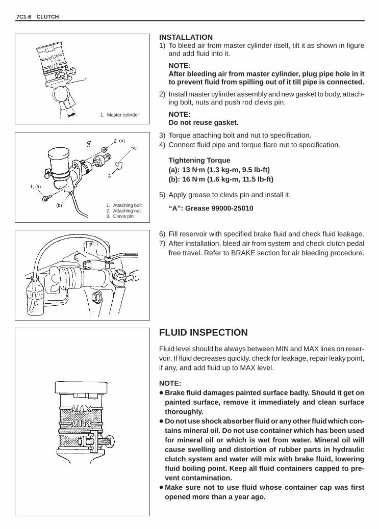
YH4GRANDVITARA
1. Master cylinder
1. Attaching bolt2. Attaching nut3. Clevis pin
“A”
7C1-6 CLUTCH
INSTALLATION1) To bleed air from master cylinder itself, tilt it as shown in figure
and add fluid into it.
NOTE:After bleeding air from master cylinder, plug pipe hole in itto prevent fluid from spilling out of it till pipe is connected.
2) Install master cylinder assembly and new gasket to body, attach-ing bolt, nuts and push rod clevis pin.
NOTE:Do not reuse gasket.
3) Torque attaching bolt and nut to specification.4) Connect fluid pipe and torque flare nut to specification.
Tightening Torque(a): 13 N.m (1.3 kg-m, 9.5 lb-ft)(b): 16 N.m (1.6 kg-m, 11.5 lb-ft)
5) Apply grease to clevis pin and install it.
“A”: Grease 99000-25010
6) Fill reservoir with specified brake fluid and check fluid leakage.7) After installation, bleed air from system and check clutch pedal
free travel. Refer to BRAKE section for air bleeding procedure.
FLUID INSPECTION
Fluid level should be always between MIN and MAX lines on reser-voir. If fluid decreases quickly, check for leakage, repair leaky point,if any, and add fluid up to MAX level.
NOTE:� Brake fluid damages painted surface badly. Should it get on
painted surface, remove it immediately and clean surfacethoroughly.
� Do not use shock absorber fluid or any other fluid which con-tains mineral oil. Do not use container which has been usedfor mineral oil or which is wet from water. Mineral oil willcause swelling and distortion of rubber parts in hydraulicclutch system and water will mix with brake fluid, loweringfluid boiling point. Keep all fluid containers capped to pre-vent contamination.
� Make sure not to use fluid whose container cap was firstopened more than a year ago.

YH4GRANDVITARA
3
4
1. Reservoir cap2. Cylinder3. Piston assembly4. Push rod5. Piston stopper
6. Circlip7. Boot8. Lock nut9. Clevis
1. Circlip2. Push rod3. Piston4. Cylinder
1. Circlip2. Push rod3. Piston stopper
CLUTCH 7C1-7
DISASSEMBLY AND ASSEMBLY CLUTCHMASTER CYLINDER
DISASSEMBLY1) Remove boot and then circlip with piston pushed in.2) Remove push rod and blow compressed air gradually into hole
for pipe connection to remove piston assembly, using care toprevent it from jumping out.
INSPECTIONInspect all disassembled parts for wear or damage and replaceparts if necessary.
NOTE:� Wash disassembled parts with brake fluid.� Do not reuse piston assembly and circlip.
Inspect cylinder bore for scoring or corrosion. It is best to replacecorroded cylinder. Corrosion can be identified as pits or excessiveroughness.
NOTE:Polishing bore of cylinder with anything abrasive is prohib-ited, as damage to cylinder bore may occur.
Rinse cylinder in clean brake fluid. Shake excess rinsing fluid fromcylinder. Do not use a cloth to dry cylinder, as lint from cloth cannotbe kept away from cylinder bore surfaces.
ASSEMBLY
NOTE:Before installation, wash each part in specified brake fluid.
1) Apply brake fluid to inside of piston assembly and cylinder body.2) Install piston assembly into cylinder.3) With piston pushed down, install circlip as shown.
And install boot.

YH4GRANDVITARA
“A”
1. Reservoir cap2. Cylinder3. Piston assembly4. Push rod5. Piston stopper
6. Circlip7. Boot8. Lock nut9. Clevis
1. Clutch operating cylinder2. Hose3. E-ring
7C1-8 CLUTCH
4) Tighten lock nut to specified torque.
Tightening Torque(a): 10 N.m (1.0 kg-m, 7.5 lb-ft)
5) For installation of master cylinder to vehicle, refer to INSTALLA-TION described previously.
CLUTCH OPERATING CYLINDERREMOVAL
NOTE:Do not allow fluid to get on painted surfaces.
1) Clean around reservoir cap and take out fluid with syringe orsuch.
2) Disconnect fluid hose from operating cylinder.3) Remove operating cylinder attaching bolts and operating cylin-
der.
INSTALLATION1) For air bleeding of master cylinder alone, it must be removed
from vehicle.For procedures of removal and installation of master cylinder as-sembly and air bleeding, refer to CLUTCH MASTER CYLINDERsection.
2) Apply small amount of grease to rod tip.
“A”: Grease 99000-25010
NOTE:Don’t allow any grease to be on boot.
3) Install clutch operating cylinder and torque attaching bolts tospecification.
4) Connect clutch fluid hose and torque union bolt to specification.
Tightening Torque(a): 50 N.m (5.0 kg-m, 36.5 lb-ft)(b): 23 N.m (2.3 kg-m, 16.5 lb-ft)

YH4GRANDVITARA
CLUTCH 7C1-9
5) Fill reservoir with specified brake fluid and check for fluid leak-age.
6) Bleed air from system and check clutch pedal free travel. Referto BRAKE section for air bleeding procedure.

YH4GRANDVITARA
7C1-10 CLUTCH
(B)1
1
2
(A)
1. Input shaft bearing2. Flywheel3. Clutch disc4. Clutch cover5. Bolt6. Release bearing7. Clutch release fork8. Boot9. Clip
10. Clutch release fork support
1. Bolt2. Clutch cover
1. Input shaft bearing
UNIT REPAIR
CLUTCH COVER, CLUTCH DISC AND FLYWHEEL
DISMOUNTING/REMOUNTINGRefer to SECTION 7A “Dismounting/Remounting of Trans Unit”.
REMOVAL1) Hold flywheel stationary with special tool (A) and remove clutch
cover bolts, clutch cover and clutch disc.
Special Tool(A): 09924-17810
2) Pull out input shaft bearing by using special tool (B) and wrench.
Special Tool(B): 09917-58010 (G16 engine)(B): 09923-73210 (J20 and H25 engines)
3) Remove release bearing and release fork.
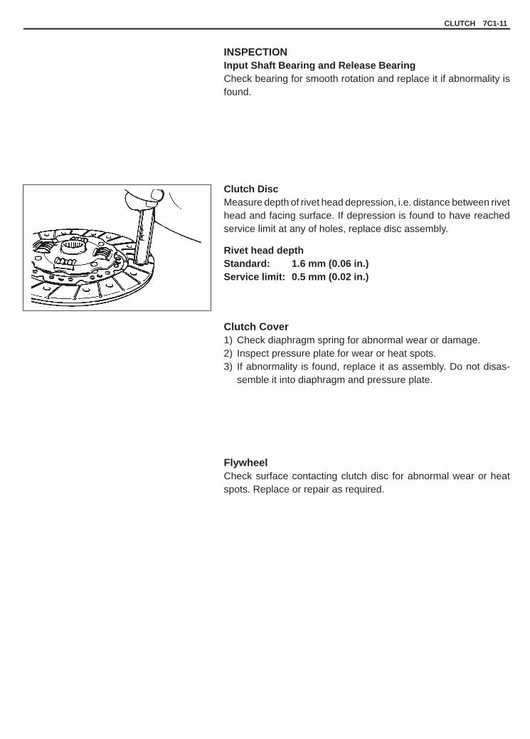
YH4GRANDVITARA
CLUTCH 7C1-11
INSPECTIONInput Shaft Bearing and Release BearingCheck bearing for smooth rotation and replace it if abnormality isfound.
Clutch DiscMeasure depth of rivet head depression, i.e. distance between rivethead and facing surface. If depression is found to have reachedservice limit at any of holes, replace disc assembly.
Rivet head depthStandard: 1.6 mm (0.06 in.)Service limit: 0.5 mm (0.02 in.)
Clutch Cover1) Check diaphragm spring for abnormal wear or damage.2) Inspect pressure plate for wear or heat spots.3) If abnormality is found, replace it as assembly. Do not disas-
semble it into diaphragm and pressure plate.
FlywheelCheck surface contacting clutch disc for abnormal wear or heatspots. Replace or repair as required.

YH4GRANDVITARA
7C1-12 CLUTCH
(C)
1
“A”, (a)
1
2
1. Flywheel2. Bolt
1. Clutch cover
INSTALLATIONNOTE:Before assembling, make sure that flywheel surface and pres-sure plate surface have been cleaned and dried thoroughly.
1) Install flywheel to crankshaft and tighten bolts to which sealantis applied to specification.
Special Tool(A): 09924-17810
“A”: Sealant 99000-31110
Tightening Torque(a): 78 N.m (7.8 kg-m, 56.5 lb-ft) (G16 engine)(a): 70 N.m (7.0 kg-m, 50.5 lb-ft) (J20 and H25 engines)
2) Using special tool (B), install input shaft bearing to flywheel.
Special Tool(B): 09925-98210
3) Aligning clutch disc to flywheel center by using special tool (C),install clutch cover and bolts. Then tighten bolts to specification.
NOTE:� While tightening clutch cover bolts, compress clutch disc
with special tool (C) by hand so that disc centered.� Tighten cover bolts little by little evenly in diagonal order.
Special Tools(A): 09924-17810(C): 09923-36330 (G16 engine)(C): 09923-36320 (J20 and H25 engines)
Tightening Torque(b): 23 N.m (2.3 kg-m, 16.5 lb-ft)

YH4GRANDVITARA
CLUTCH 7C1-13
1. Release fork2. Clip3. Input shaft
“B”
“B”
“A”
3
2
1
1
2
4) Install clip to release fork and apply grease.
“A”: Grease 99000-25010
Then install release fork and release bearing as shown in figure.5) Slightly apply grease to input shaft and install clutch disc. Then
join transmission transfer assembly with engine. Refer to SEC-TION 7A.
“B”: Grease 99000-25210
NOTE:Turn crankshaft with wrench from front while insertingtransmission input shaft to clutch disc until splines mesh.
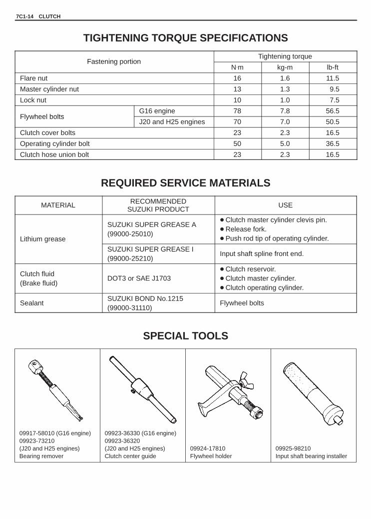
YH4GRANDVITARA
7C1-14 CLUTCH
09917-58010 (G16 engine)09923-73210(J20 and H25 engines)Bearing remover
09923-36330 (G16 engine)09923-36320(J20 and H25 engines)Clutch center guide
09924-17810Flywheel holder
09925-98210Input shaft bearing installer
TIGHTENING TORQUE SPECIFICATIONS
Fastening portionTightening torque
Fastening ortionN.m kg-m lb-ft
Flare nut 16 1.6 11.5
Master cylinder nut 13 1.3 9.5
Lock nut 10 1.0 7.5
Flywheel boltsG16 engine 78 7.8 56.5
Flywheel boltsJ20 and H25 engines 70 7.0 50.5
Clutch cover bolts 23 2.3 16.5
Operating cylinder bolt 50 5.0 36.5
Clutch hose union bolt 23 2.3 16.5
REQUIRED SERVICE MATERIALS
MATERIAL RECOMMENDEDSUZUKI PRODUCT
USE
Lithium grease
SUZUKI SUPER GREASE A(99000-25010)
� Clutch master cylinder clevis pin.� Release fork.� Push rod tip of operating cylinder.
SUZUKI SUPER GREASE I(99000-25210)
Input shaft spline front end.
Clutch fluid(Brake fluid)
DOT3 or SAE J1703� Clutch reservoir.� Clutch master cylinder.� Clutch operating cylinder.
SealantSUZUKI BOND No.1215(99000-31110)
Flywheel bolts
SPECIAL TOOLS

YH4GRANDVITARA
7D
TRANSFER 7D-1
The aluminum transfer case directly connected to theback of the transmission contains the input gear,countershaft & gear, output rear shaft, output low gearand output front shaft (for front drive) connected byway of the hyvo-chain.The transfer has such a selective mechanism as toenable the shift control lever to make selection of highspeed (direct connection with transmission output:main shaft), low speed (speed reduction by inputgear, counter gear and output low gear) or neutral byway of the reduction sleeve located between inputgear and output low gear, and selection of two-wheel-drive (high speed only) or four-wheel-drive (high orlow speed) by way of the front drive clutch sleeve lo-
cated at the center of the output rear shaft. Also, witha synchronizer installed to the front drive clutch, it ispossible to change the drive mode between 2WD(high speed only) and 4WD (high speed only) evenwhile running.The front drive shift fork has an auxiliary spring tomake a smooth shift from 4H to 2H possible.The case has an oil gutter and a plate at synchronizerto provide proper lubrication even under the strictconditions of use.
WARNING:For towing the vehicle for the purpose of repair orthe like, follow the towing instructions in OWN-ER’S MANUAL.
SECTION 7D
TRANSFER
CONTENTS
GENERAL DESCRIPTION 7D-1. . . . . . . . . . . . . . . . . . . . . . . . . . . . . . . . . . . . . . . . . . . . . . . . . . . . . . . . . . . . . . . . . .
DIAGNOSIS 7D-2. . . . . . . . . . . . . . . . . . . . . . . . . . . . . . . . . . . . . . . . . . . . . . . . . . . . . . . . . . . . . . . . . . . . . . . . . . . . . . . Diagnosis Table 7D-2. . . . . . . . . . . . . . . . . . . . . . . . . . . . . . . . . . . . . . . . . . . . . . . . . . . . . . . . . . . . . . . . . . . . . . . . . .
ON-VEHICLE SERVICE 7D-3. . . . . . . . . . . . . . . . . . . . . . . . . . . . . . . . . . . . . . . . . . . . . . . . . . . . . . . . . . . . . . . . . . . . Gear Oil 7D-3. . . . . . . . . . . . . . . . . . . . . . . . . . . . . . . . . . . . . . . . . . . . . . . . . . . . . . . . . . . . . . . . . . . . . . . . . . . . . . . . . Transfer Oil Seals 7D-3. . . . . . . . . . . . . . . . . . . . . . . . . . . . . . . . . . . . . . . . . . . . . . . . . . . . . . . . . . . . . . . . . . . . . . . . Speedometer Driven Gear 7D-4. . . . . . . . . . . . . . . . . . . . . . . . . . . . . . . . . . . . . . . . . . . . . . . . . . . . . . . . . . . . . . . . . Engine Rear Mounting 7D-4. . . . . . . . . . . . . . . . . . . . . . . . . . . . . . . . . . . . . . . . . . . . . . . . . . . . . . . . . . . . . . . . . . . . Transfer Assembly 7D-5. . . . . . . . . . . . . . . . . . . . . . . . . . . . . . . . . . . . . . . . . . . . . . . . . . . . . . . . . . . . . . . . . . . . . . . . Dismounting 7D-5. . . . . . . . . . . . . . . . . . . . . . . . . . . . . . . . . . . . . . . . . . . . . . . . . . . . . . . . . . . . . . . . . . . . . . . . . . . . . Remounting 7D-6. . . . . . . . . . . . . . . . . . . . . . . . . . . . . . . . . . . . . . . . . . . . . . . . . . . . . . . . . . . . . . . . . . . . . . . . . . . . .
UNIT REPAIR 7D-7. . . . . . . . . . . . . . . . . . . . . . . . . . . . . . . . . . . . . . . . . . . . . . . . . . . . . . . . . . . . . . . . . . . . . . . . . . . . .
TIGHTENING TORQUE SPECIFICATIONS 7D-7. . . . . . . . . . . . . . . . . . . . . . . . . . . . . . . . . . . . . . . . . . . . . . . . . . . .
REQUIRED SERVICE MATERIALS 7D-7. . . . . . . . . . . . . . . . . . . . . . . . . . . . . . . . . . . . . . . . . . . . . . . . . . . . . . . . . .
SPECIAL TOOL 7D-7. . . . . . . . . . . . . . . . . . . . . . . . . . . . . . . . . . . . . . . . . . . . . . . . . . . . . . . . . . . . . . . . . . . . . . . . . . .
GENERAL DESCRIPTION

YH4GRANDVITARA
7D-2 TRANSFER
DIAGNOSIS
DIAGNOSIS TABLE
Before attempting to repair the transfer or related components for any reason other than mechanical failure, thecondition and probable causes should be identified.Transfer failures are revealed by shifting difficulties such as excessive shifting effort, gear clash, or gear grinding.When any of these conditions occur, the following inspections should be made before disassembling the transfer.1) Check transfer oil level for insufficient or incorrect oil. Refer to “Transfer and Differential Oil Inspection and
Change” in SECTION 0B “MAINTENANCE AND LUBRICATION”.2) Check transfer mountings for wear or looseness.3) Check gearshift control lever for distortion or excessive wear.
After performing the above inspections, refer to following diagnosis table.
Condition Possible Cause Correction
Gear slipping out of mesh � Worn shift fork shaft� Worn shift fork or synchronizer sleeve� Weak or damaged locating spring� Worn bearings on output rear shaft� Worn chamfered tooth on sleeve or gear� Missing or disengagement of circlip(s)
ReplaceReplaceReplaceReplaceReplace sleeve and gearInstall
Gears refusing to disengage � Weakened or broken synchronizer spring� Distorted shift shaft or shift fork
ReplaceReplace
Hard shifting � Weakened front drive shift shaft spring� Distorted or mispositioned front drive shift
shaft circlip and washer� Inadequate or insufficient lubricant� Worn synchronizer ring� Worn chamfered tooth on sleeve or gear� Distorted shift shaft
ReplaceReplace
ReplenishReplaceReplace sleeve and gearReplace
Noise � Inadequate or insufficient lubricant� Damaged or worn bearing(s)� Damaged or worn gear(s)� Damaged or worn synchronizer ring� Damaged or worn chamfered tooth on
sleeve or gear
ReplenishReplaceReplaceReplaceReplace
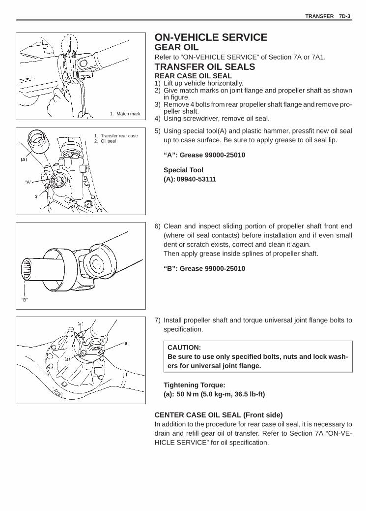
YH4GRANDVITARA
1. Match mark
1. Transfer rear case2. Oil seal
“A”
“B”
TRANSFER 7D-3
ON-VEHICLE SERVICEGEAR OILRefer to “ON-VEHICLE SERVICE” of Section 7A or 7A1.
TRANSFER OIL SEALSREAR CASE OIL SEAL1) Lift up vehicle horizontally.2) Give match marks on joint flange and propeller shaft as shown
in figure.3) Remove 4 bolts from rear propeller shaft flange and remove pro-
peller shaft.4) Using screwdriver, remove oil seal.
5) Using special tool(A) and plastic hammer, pressfit new oil sealup to case surface. Be sure to apply grease to oil seal lip.
“A”: Grease 99000-25010
Special Tool(A): 09940-53111
6) Clean and inspect sliding portion of propeller shaft front end(where oil seal contacts) before installation and if even smalldent or scratch exists, correct and clean it again.Then apply grease inside splines of propeller shaft.
“B”: Grease 99000-25010
7) Install propeller shaft and torque universal joint flange bolts tospecification.
CAUTION:Be sure to use only specified bolts, nuts and lock wash-ers for universal joint flange.
Tightening Torque:(a): 50 N.m (5.0 kg-m, 36.5 lb-ft)
CENTER CASE OIL SEAL (Front side)In addition to the procedure for rear case oil seal, it is necessary todrain and refill gear oil of transfer. Refer to Section 7A “ON-VE-HICLE SERVICE” for oil specification.

YH4GRANDVITARA
1. Speed sensor assembly2. Transfer
7D-4 TRANSFER
SPEEDOMETER DRIVEN GEARREMOVAL1) Lift up vehicle horizontally or rear up.2) Disconnect speed sensor coupler at transfer case.3) Remove bolt and take off speed sensor from transfer.
INSTALLATION1) Make sure that O-ring and speed sensor have not been dam-
aged.2) Inspect speedometer driven gear for abnormal wear of gear
teeth or bend of shaft portion and replace it if necessary.3) Make sure its smooth rotation.4) Install speed sensor assembly to transfer and connect coupler
as it was.
Tightening Torque(a): 6 N.m (0.6 kg-m, 4.5 lb-ft)
ENGINE REAR MOUNTING
Refer to “ON-VEHICLE SERVICE” of Section 7A.

YH4GRANDVITARA
1. Wood block2. Dash panelt: 45 mm / 1.8 in.H: 200 mm / 8 in.W: 100 – 150 mm / 4 – 6 in.
1. Transmission jack2. Engine rear mounting member3. Gear shift lever case4. Bolt
TRANSFER 7D-5
TRANSFER ASSEMBLYDismounting and remounting of transfer and transmission togetheras a unit is described in Section 7A for Manual Transmission or 7B1for Automatic Transmission, but it is also possible to dismount andremount transfer assembly by itself as described below.
DISMOUNTINGIN ENGINE ROOM1) Disconnect negative (–) cable from battery.2) Remove distributor assembly (if equipped).3) Place wood block between engine and dash panel so that it
serves as stopper when engine, transmission and transfer unithangs down as rear mounting member is removed.
CAUTION:Make sure to use wood block to prevent contact whichmay occur between dash panel and CMP sensor case(G16), CMP sensor (J20) or intake manifold (H25), and fanand shroud.
IN CABIN1) Remove console box.2) Remove shift lever of transmission and transfer.
ON LIFT1) Drain transfer oil.2) Remove rear propeller shaft.3) Remove front propeller shaft.4) Disconnect exhaust center pipe.5) Disconnect speed sensor coupler.6) Place transmission jack and remove mounting member.7) Lower transmission jack gradually and check to ensure that
wood block serves as stopper between engine and dash panel.8) Remove bolts for gear shift lever case.9) Pull off breather hose.

YH4GRANDVITARA
1. Bolt2. Transfer assembly
1. Bolt2. Engine rear mounting
3. Transfer assembly
1. Bolt2. Transfer assembly3. Transmission jack
7D-6 TRANSFER
IN CABINRemove gear shift lever case and then remove transfer center casebolt.
ON LIFT1) Remove transfer mounting (engine rear mounting) by removing
bolts.
2) Apply transmission jack to transfer to support it.3) Remove couplers for 4WD/4WD-LOW switches lead.4) Remove transfer front case bolts.5) With transfer assembly supported with transmission jack, slide
it rearward and when it is apart from transmission, lower it.
REMOUNTING
For remounting, reverse dismounting procedure described above,noting following.� Be sure to use specified torque for tightening.� Clamp wiring and breather hose securely.� Clamp shift lever boot securely.� Fill specified gear oil by specified amount.� Connect battery and check for function.
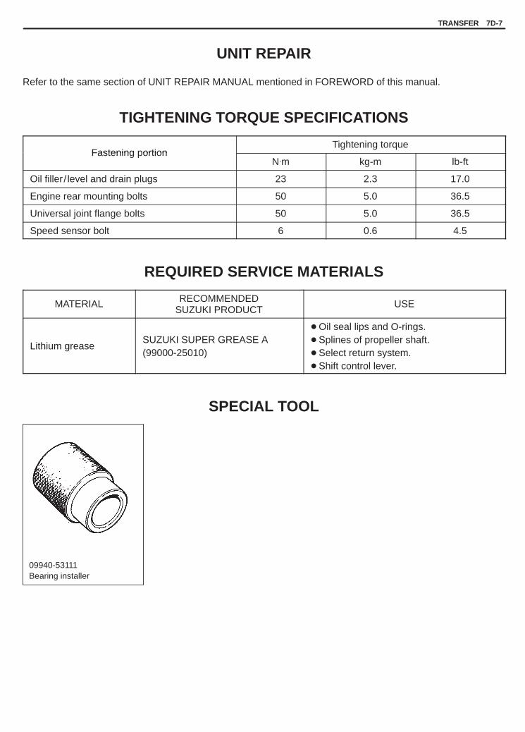
YH4GRANDVITARA
TRANSFER 7D-7
09940-53111Bearing installer
UNIT REPAIR
Refer to the same section of UNIT REPAIR MANUAL mentioned in FOREWORD of this manual.
TIGHTENING TORQUE SPECIFICATIONS
Fastening portionTightening torque
Fastening ortionN.m kg-m lb-ft
Oil filler / level and drain plugs 23 2.3 17.0
Engine rear mounting bolts 50 5.0 36.5
Universal joint flange bolts 50 5.0 36.5
Speed sensor bolt 6 0.6 4.5
REQUIRED SERVICE MATERIALS
MATERIAL RECOMMENDEDSUZUKI PRODUCT
USE
Lithium greaseSUZUKI SUPER GREASE A(99000-25010)
� Oil seal lips and O-rings.� Splines of propeller shaft.� Select return system.� Shift control lever.
SPECIAL TOOL

YH4GRANDVITARA
7E
DIFFERENTIAL (FRONT) 7E-1
The differential assembly using a hypoid bevel pinionand gear is installed to the front axle.4WD control system controls drive force to be trans-mitted to front axles or not. The reduction ratio variesdepending on transmission or engine type.
The differential assembly is decisive in that the drivepower is concentrated there. Therefore, use of genu-ine parts and specified torque is compulsory. Further,because of sliding tooth meshing with high pressurebetween bevel pinion and gear, it is mandatory to lu-bricate them by hypoid gear oil.
SECTION 7E
DIFFERENTIAL (FRONT)
CONTENTS
GENERAL DESCRIPTION 7E- 1. . . . . . . . . . . . . . . . . . . . . . . . . . . . . . . . . . . . . . . . . . . . . . . . . . . . . . . . . . . . . . . . . . 4WD CONTROL SYSTEM 7E- 2. . . . . . . . . . . . . . . . . . . . . . . . . . . . . . . . . . . . . . . . . . . . . . . . . . . . . . . . . . . . . . . . .
DIAGNOSIS 7E- 5. . . . . . . . . . . . . . . . . . . . . . . . . . . . . . . . . . . . . . . . . . . . . . . . . . . . . . . . . . . . . . . . . . . . . . . . . . . . . . . DIAGNOSIS TABLE 7E- 5. . . . . . . . . . . . . . . . . . . . . . . . . . . . . . . . . . . . . . . . . . . . . . . . . . . . . . . . . . . . . . . . . . . . . .
Differential Assembly 7E- 5. . . . . . . . . . . . . . . . . . . . . . . . . . . . . . . . . . . . . . . . . . . . . . . . . . . . . . . . . . . . . . . . . . . . 4WD Control System Diagnostic Flow Table 7E- 5. . . . . . . . . . . . . . . . . . . . . . . . . . . . . . . . . . . . . . . . . . . . . . . .
4WD CONTROL CIRCUIT INSPECTION 7E- 7. . . . . . . . . . . . . . . . . . . . . . . . . . . . . . . . . . . . . . . . . . . . . . . . . . . .
ON-VEHICLE SERVICE 7E- 9. . . . . . . . . . . . . . . . . . . . . . . . . . . . . . . . . . . . . . . . . . . . . . . . . . . . . . . . . . . . . . . . . . . . MAINTENANCE SERVICE 7E- 9. . . . . . . . . . . . . . . . . . . . . . . . . . . . . . . . . . . . . . . . . . . . . . . . . . . . . . . . . . . . . . . .
Gear Oil Change 7E- 9. . . . . . . . . . . . . . . . . . . . . . . . . . . . . . . . . . . . . . . . . . . . . . . . . . . . . . . . . . . . . . . . . . . . . . . INSPECTION 7E-10. . . . . . . . . . . . . . . . . . . . . . . . . . . . . . . . . . . . . . . . . . . . . . . . . . . . . . . . . . . . . . . . . . . . . . . . . . . .
4WD Control System 7E-10. . . . . . . . . . . . . . . . . . . . . . . . . . . . . . . . . . . . . . . . . . . . . . . . . . . . . . . . . . . . . . . . . . . . Actuator 7E-11. . . . . . . . . . . . . . . . . . . . . . . . . . . . . . . . . . . . . . . . . . . . . . . . . . . . . . . . . . . . . . . . . . . . . . . . . . . . . . . Air Pump Assembly 7E-12. . . . . . . . . . . . . . . . . . . . . . . . . . . . . . . . . . . . . . . . . . . . . . . . . . . . . . . . . . . . . . . . . . . . .
REMOVAL AND INSTALLATION 7E-13. . . . . . . . . . . . . . . . . . . . . . . . . . . . . . . . . . . . . . . . . . . . . . . . . . . . . . . . . . . Differential Mountings 7E-13. . . . . . . . . . . . . . . . . . . . . . . . . . . . . . . . . . . . . . . . . . . . . . . . . . . . . . . . . . . . . . . . . . .
DISMOUNTING 7E-15. . . . . . . . . . . . . . . . . . . . . . . . . . . . . . . . . . . . . . . . . . . . . . . . . . . . . . . . . . . . . . . . . . . . . . . . . . REMOUNTING 7E-16. . . . . . . . . . . . . . . . . . . . . . . . . . . . . . . . . . . . . . . . . . . . . . . . . . . . . . . . . . . . . . . . . . . . . . . . . . .
UNIT REPAIR 7E-17. . . . . . . . . . . . . . . . . . . . . . . . . . . . . . . . . . . . . . . . . . . . . . . . . . . . . . . . . . . . . . . . . . . . . . . . . . . . .
TIGHTENING TORQUE SPECIFICATIONS 7E-17. . . . . . . . . . . . . . . . . . . . . . . . . . . . . . . . . . . . . . . . . . . . . . . . . . . .
REQUIRED SERVICE MATERIAL 7E-17. . . . . . . . . . . . . . . . . . . . . . . . . . . . . . . . . . . . . . . . . . . . . . . . . . . . . . . . . . . .
SPECIAL TOOLS 7E-17. . . . . . . . . . . . . . . . . . . . . . . . . . . . . . . . . . . . . . . . . . . . . . . . . . . . . . . . . . . . . . . . . . . . . . . . . .
GENERAL DESCRIPTION

YH4GRANDVITARA
1. 4WD switch2. Transfer3. Blank4. Blank5. ECM or PCM6. Glove box
7. Air pump assembly8. Actuator9. Axle lock clutch
10. Free axle hub11. 4WD indicator lamp
7E-2 DIFFERENTIAL (FRONT)
4WD CONTROL SYSTEM
When the 4WD switch is turned ON by shifting the transfer shift lever, ECM (PCM) (G16 and J20 engine models)or 4WD controller (H25 engine model) actuates (energizes) the air pump assembly. Then positive pressure is sentfrom the air pump assembly to the actuator installed to the differential case and causes the axle lock clutch andthe free axle hub in the differential case to be engaged, resulting in the 4WD mode. Only when running in the 4WDmode, front axles are joined to differential case, and they become free when 2WD mode is used (or when transfershift lever is shifted to N position), thereby reducing the power loss.

YH4GRANDVITARA
1. 4WD switch2. Air pump assembly3. Pump motor4. Release valve5. Pressure switch
6. Transfer7. Front differential8. Air hose and pipe9. 4WD indicator lamp
10. To ignition switch11. ECM or PCM
Operation(refer to “Components and Functions”)
Power supply(from ECM or PCM)
DIFFERENTIAL (FRONT) 7E-3
System Circuit and Operation

YH4GRANDVITARA
7E-4 DIFFERENTIAL (FRONT)
Components and Functions
Component Function
4WD switchWhen the transfer shift lever is shifted to 4L or 4H position, this switch turns ONand causes the 4WD control system to turn ON, unless it is shifted to N or 2Hwithin 1 second.
ECM or PCM
When the 4WD switch turns ON [unless it turns OFF within 1 second], this com-ponent actuates the pump assembly. If the pressure in the air pump assemblyfails to increase higher than the set level even after the pump motor has run morethan 10 seconds, this component stops the motor to protect it.
Air pump assembly� Pump motor� Release valve� Pressure switch
The air pump assembly consists of a pump motor, release valve and a pressureswitch.Pump motor:Produces positive pressure which actuates the actuator.Release valve:Closes when transfer shift lever is shifted to 4H or 4L so that the positive pressureis applied to the actuator, and opens when N or 2H to release the pressure to theatmosphere.Pressure switch:Turns ON and OFF depending on the pressure level in the pump assembly(whether higher or lower than the set pressure level). ECM or PCM detects thepressure level through this switch.
Differential case assembly� Free axle hub� Axle lock clutch� Actuator
The free axle hub, axle lock clutch and actuator are installed in the differentialleft case. The positive pressure produced in the air pump assembly is appliedto the actuator which then pushes the axle lock clutch to be engaged with the freeaxle hub. In this state, the drive force is transmitted to the front axle, resulting inthe 4WD mode.When the actuator is free from the positive pressure [when it is under the atmo-spheric pressure], the axle lock clutch is pushed back by the return spring forceand cannot be engaged with the free axle hub, resulting in the 2WD mode.
“4WD” indicator lamp It lights up when 4WD control system is in the 4WD mode.

YH4GRANDVITARA
DIFFERENTIAL (FRONT) 7E-5
DIAGNOSIS
DIAGNOSIS TABLEDifferential Assembly
Condition Possible Cause Correction
Gear noise � Deteriorated or water mixed lubricant� Inadequate or insufficient lubricant� Maladjusted backlash between bevel
pinion and gear� Improper tooth contact in the mesh between
bevel pinion and gear� Loose bevel gear securing bolts� Damaged side gear(s) or side pinion(s)
Repair and replenishRepair and replenishAdjust
Adjust or replace
Replace or retightenReplace
Bearing noise � (Constant noise) Deteriorated or watermixed lubricant
� (Constant noise) Inadequate or insufficientlubricant
� (Noise while coasting) Damaged bearing(s) of bevel pinion� (Noise while turning) Damaged diff. side
bearing(s) or axle bearing(s)
Repair and replenish
Repair and replenish
Replace
Replace
Oil leakage � Worn or damaged oil seal� Excessive oil� Loose differential carrier bolts
ReplaceAdjust oil levelReplace or retighten
2WD/4WDswitching error
� Defective actuator� Abnormality in 4WD control system
ReplaceInspect referring to “4WDCONTROL SYSTEM DIAG-NOSTIC FLOW TABLE”.
4WD Control System Diagnostic Flow TableBefore performing the trouble diagnosis, check that the transfer and front differential are in good condition andthere is no air leakage from air hoses and the actuator. Refer to “ON-VEHICLE SERVICE” in this section for airleakage.
[NOTES ON SYSTEM CIRCUIT INSPECTION]� Be sure to read “Precautions for Electrical Circuit Service” in Section 0A before circuit inspection and observe
what is written there.� For system circuit, refer to the figure of “GENERAL DESCRIPTION” in this section.� For terminal arrangement, refer to “4WD Control Circuit Inspection” in this section.

YH4GRANDVITARA
7E-6 DIFFERENTIAL (FRONT)
STEP ACTION YES NO
1 Turn ON ignition switch (but engine at stop) andcheck malfunction indicator lamp.Does lamp light up?
Go to step 2. A trouble hasoccurred at someplace. Repair itreferring toMALFUNCTIONINDICATOR LAMP(“CHECK ENGINE”LAMP) CHECK inDIAGNOSIS ofSECTION 6.
2 Check 4WD switch circuit.Turn ignition switch ON and check that voltagebetween terminal C51-2-18 and terminal C51-3-17(ground) for G16/J20 (terminal C51-1-11 and terminalC51-3-26 (ground) for H25) is as follows.� When transfer shift lever is in N or 2H: 10 – 14 V� When transfer shift lever is in 4L or 4H: 0 – 1 VIs the check result satisfactory?
Go to step 3. Check 4WD switch(refer to SECTION7A), “B/Or” and “B”circuits of 4WDswitch.If OK, substitute aknown-good ECM(PCM) and recheck.
3 Check power supply.1) Turn ignition switch ON.2) Check voltage between C51-2-7 and C51-3-17
(ground) for G16/J20 (C51-1-15 and C51-3-26(ground) for H25). The check results should be asfollows.
� When transfer shift lever is in N or 2H: 0 – 1 V� When transfer shift lever is in 4L or 4H: 10 – 14 VIs the check result satisfactory?
Go to step 4. Check “R” circuit. Ifit is OK, substitute aknown-good ECM(PCM) and recheck.
4 Check air pump assembly circuit.1) Check for proper connection to air pump
assembly at all terminals.2) Turn ignition switch ON.3) Check voltage between C51-2-27 and C51-3-17
(ground) for G16/J20 (C51-1-18 and C51-3-26(ground) for H25). The check result should be asfollows.
� When transfer shift lever is in 2H or N: 0 – 1 V� When transfer shift lever is in 4L or 4H
(more than 4 seconds after shifted to 4L or 4H):10 – 14 V
Is the check result satisfactory?
Go to step 5. Check air pumpassembly referringto “ON-VEHICLESERVICE”, and then“P” circuit.If OK, substitute aknown-good ECM(PCM) and recheck.
5 Check 4WD indicator lamp circuit.1) Turn ignition switch ON.2) Check voltage between E61-19 and C51-3-17
(ground) for G16/J20 (C51-1-7 and C51-3-26(ground) for H25). The check result should be asfollows.
� When transfer shift lever is in 2H or N: 10 – 14 V� When transfer shift lever is in 4L or 4H: 0 – 1 VIs the check result satisfactory?
4WD control systemis in good condition.
Check “Or/B” circuit(including indicatorlamp andcombination meter).If OK, substitute aknown-good ECM(PCM) and recheck.

YH4GRANDVITARA
DIFFERENTIAL (FRONT) 7E-7
1
1. ECM (PCM); viewed from harness side
4WD CONTROL CIRCUIT INSPECTIONVoltage Check [G16 and J20 engine models]Check for input or output voltage (voltage between each circuit andbody ground) of ECM (PCM) with ECM (PCM) connector con-nected and ignition switch turned ON.
TER-MINAL CIRCUIT WIRE
COLORNORMALVOLTAGE CONDITION
E6110 – 14 V Transfer shift lever: 2H or N
E61-19
4WD Indicator lamp Or/B0 – 1 V 4 seconds after transfer shift lever shifted
to 4H or 4L
C51 2Air pump assembly 0 – 1 V Transfer shift lever: 2H or N
C51-2-7
(Pump motor and releasevalve)
R10 – 14 V 1 seconds after transfer shift lever shifted
to 4H or 4L
C51-2 4WD switch B/Or10 – 14 V Transfer shift lever: 2H or N
-184WD switch B/Or
0 – 1 V Transfer shift lever: 4H or 4L
C51-3-17
Ground B/Bl 0 – 1 V –
C51 2 Air pump assembly0 – 1 V Transfer shift lever: 2H or N
C51-2-27
Air um assembly(pressure switch)
P10 – 14 V 4 seconds after transfer shift lever shifted
to 4H or 4L

YH4GRANDVITARA
7E-8 DIFFERENTIAL (FRONT)
1. ECM (PCM); viewed from harness side
Voltage Check [H25 engine model]
TER-MINAL CIRCUIT WIRE
COLORNORMALVOLTAGE CONDITION
C51 110 – 14 V Transfer shift lever: 2H or N
C51-1-7
4WD Indicator lamp Or/B0 – 1 V 4 seconds after transfer shift lever shifted
to 4H or 4L
C51 1Air pump assembly 0 – 1 V Transfer shift lever: 2H or N
C51-1-15
(Pump motor and releasevalve)
R10 – 14 V 1 seconds after transfer shift lever shifted
to 4H or 4L
C51-1 4WD switch B/Or10 – 14 V Transfer shift lever: 2H or N
-114WD switch B/Or
0 – 1 V Transfer shift lever: 4H or 4L
C51-3-26
Ground B/Bl 0 – 1 V –
C51-1 Air pump assembly0 – 1 V Transfer shift lever: 2H or N
C51-1-18
Air um assembly(pressure switch)
P10 – 14 V 4 seconds after transfer shift lever shifted
to 4H or 4L

YH4GRANDVITARA
DIFFERENTIAL (FRONT) 7E-9
Viscosity chart SAE
Temperature
ON-VEHICLE SERVICEMAINTENANCE SERVICENOTE:� When having driven through water, check immediately if wa-
ter has entered (if so, oil is cloudy). Water mixed oil must bechanged at once.
� Whenever vehicle is hoisted for any other service work thanoil change, also be sure to check for oil leakage and statusof breather hoses.
Gear Oil Change
NOTE:� Hypoid gear oil must be used for differential.� It is highly recommended to use SAE 80W – 90 viscosity.
1) Before oil change or inspection, be sure to stop engine and liftup vehicle horizontally.
2) Check oil level and existence of leakage. If leakage is found, cor-rect its cause.
3) Drain old oil and pour proper amount of gear oil as specified be-low (roughly up to level hole).
4) Apply sealant to thread of drain plug (b) and torque plugs tospecification.
Sealant 99000-31110
Tightening Torque(a): 23 N.m (2.3 kg-m, 17.0 lb-ft)(b): 23 N.m (2.3 kg-m, 17.0 lb-ft)
Specified gear oil: Hypoid gear oil API GL-5SAE 75W – 85, 90 or 80W – 90For oil viscosity, refer to left chart.
Oil capacity: 1.0 liters (2.1/1.8 US/lmp. pt)

YH4GRANDVITARA
7E-10 DIFFERENTIAL (FRONT)
1. Plugged hose2. Adjusting screw3. Pipe (to air pump assembly)4. Hose (to differential carrier)5. Differential housing
45
INSPECTION4WD Control System1) Install special tool to air hose connecting between air pump as-
sembly and differential (actuator) as shown in figure. Tighten ad-justing screw of special tool as far as it stops. Close air checkside opening by using fuel hose as blind plug.
Special Tool(A): 09918-18110(B): 09367-04002
NOTE:Use care not to bend any part of hose.
2) Turn ON ignition switch and shift transfer lever from 2H to 4Hrange.
3) Check that motor starts running (a sound can be heard) within1 second and it stops when gauge of special tool indicates speci-fied pressure value.Check also for air leakage.
Pressure specification:30.0 – 45.0 kPa (0.30 – 0.45 kg/cm 2, 4.25 – 6.40 psi)
4) Check that pressure value indicated on gauge of special tooldrops as soon as transfer lever is shifted to 2H position.
5) Start motor by shifting transfer lever to 4H position again. Loos-en adjusting screw to lower pressure value on gauge. Motorshould start to run again and stop in about 4 seconds.
6) With the adjusting screw of special tool loosened, shift transfershift lever to N or 2H position and then 4L or 4H position.Pump motor should stop about 10 seconds after motor starts torun.

YH4GRANDVITARA
DIFFERENTIAL (FRONT) 7E-11
1. Differential housing2. Adjusting screw3. To air compressor
Actuator1) Disconnect air hose from pump assembly and install special tool
to air hose as shown in figure. Loosen adjusting screw of specialtool.
Special Tool(A): 09918-18110
2) Connect compressor air hose to special tool.Blow air and turn adjusting screw to obtain specified pressure.
Specified pressure: 30.0 kPa (0.3 kg/cm 2, 4.25 psi)
CAUTION:Do not apply a pressure exceeding 200 kPa (2.0 kg/cm 2,28.4 psi) which may cause damage to diaphragm.
3) With the vehicle lifted so that both of the front wheels are off theground, turn one of the front wheels by hand and check the otherwheel, which should act as described below.� When the pressure from compressor is applied to actuator:
The other front wheel should turn in the direction opposite tothe wheel being turned by hand.
� When the pressure from compressor is not applied to actuator:The other front wheel should remain stationary while the wheelpushed by hand is turning.
If the result is not satisfactory, inspect differential assembly. Re-fer to “INSPECTION” of SECTION 7E in UNIT REPAIR MANU-AL.

YH4GRANDVITARA
7E-12 DIFFERENTIAL (FRONT)
1. Pump assembly
Air Pump AssemblyRemoval/ Installation1) Disconnect air hoses and coupler from air pump assembly.2) Remove pump assembly by removing bolts.3) Reverse removal procedure for installation.
Tightening Torque(a): 13 N.m (1.3 kg-m, 9.5 lb-ft)
Inspection1) Install special tool, voltmeter and battery to pump assembly as
shown in figure.2) Tighten adjusting screw of special tool as far as it stops and
close its air check side opening by using fuel hose as blind plug.
Special Tool(A): 09918-18110
3) Check that motor starts to run (a sound can be heard) when bat-tery is connected and it stops when specified pressure is ob-tained.Check also for air leakage.
Specified pressure: 30.0 – 45.0 kPa(0.30 – 0.45 kg/cm 2, 4.25 – 6.40 psi)
4) Check that value indicated on voltmeter is within specificationshown below.
When motor is running: 0 – 1 VWhen motor has stopped running: 10 – 14 V
CAUTION:Do not run motor more than 10 seconds continuously toprevent motor breakage.

YH4GRANDVITARA
DIFFERENTIAL (FRONT) 7E-13
1. Mounting bracket bolt2. Mounting bracket R3. Differential housing4. Mounting front bolt
1. Differential housing2. Mounting front bolt
3. Mounting bracket L4. Mounting bracket bolt
1. Mounting bracket
1. Mounting bracket L2. Bush
3. Mounting bracket RA: Slit alignment 45�
4
2
3
1
2
REMOVAL AND INSTALLATIONDifferential Mountings1) Lift up vehicle and turn steering wheel all way to the right.2) Separate mounting bracket R from differential housing by re-
moving bolts from its lower part.3) Remove mounting bracket R by removing mounting front bolt
from its upper part.
4) Remove mounting bracket L by removing upper and lower fas-tening bolts.
5) Check conditions of each bush. If it is damaged or deteriorated,drive it out with special tools and press for replacement.
Special Tool(A): 09951-26010(B): 09951-16080
6) Position slit in each bush as shown when press-fitting it.

YH4GRANDVITARA
7E-14 DIFFERENTIAL (FRONT)
1. Mounting bracket R2. Mounting bracket L
1. Bolt and nut2. Differential carrier3. Cross member4. Bolt5. Differential rear mounting assembly
7) Position each bush to bracket as shown.
Length “a”: 3.0 mm (0.12 in.)
8) Use following torque for reinstallation.
Tightening Torque(a): 85 N.m (8.5 kg-m, 61.5 lb-ft)(b): 50 N.m (5.0 kg-m, 36.5 lb-ft)
REAR MOUNTING
(For front differential carrier)1) Lift up vehicle and remove mounting assembly by removing 2
bolts and nuts from differential carrier side and 2 bolts from crossmember side.
2) Check mounting rubber for damage or deterioration and replaceas necessary.
3) Use following torque for reinstallation.
Tightening Torque(a): 50 N.m (5.0 kg-m, 36.5 lb-ft)

YH4GRANDVITARA
DIFFERENTIAL (FRONT) 7E-15
A: Match marks
1. Mounting bracket bolt2. Flange bolt and nut
1. Bolts
1. Mounting bracket bolt2. Mounting bracket R3. Differential housing
DISMOUNTING
1) Lift up vehicle and drain oil.2) Disconnect air hose and breather hose from differential housing.
3) Before removing propeller shaft, give match marks on jointflange and propeller shaft as shown.
4) Remove propeller shaft flange by removing its 4 bolts and sus-pend it with cord or the like.
NOTE:If pull out propeller shaft, transfer oil must be drained be-fore pulling out.
5) Remove 3 bolts for left mounting bracket and 3 bolts for driveshaft flange to set left side of differential free.
6) Remove 2 bolts from cross member to set differential rearmounting free.
7) With differential housing assembly held with transmission jack,remove mounting bolts on right end of housing.
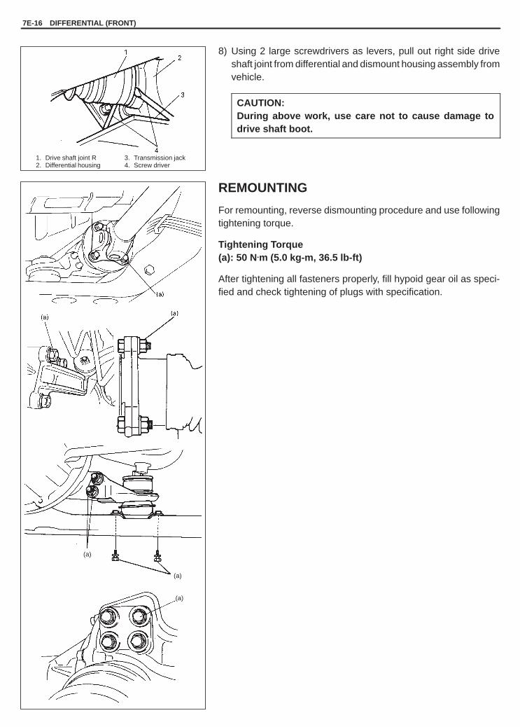
YH4GRANDVITARA
7E-16 DIFFERENTIAL (FRONT)
(a)
(a)
(a)
1. Drive shaft joint R2. Differential housing
3. Transmission jack4. Screw driver
8) Using 2 large screwdrivers as levers, pull out right side driveshaft joint from differential and dismount housing assembly fromvehicle.
CAUTION:During above work, use care not to cause damage todrive shaft boot.
REMOUNTING
For remounting, reverse dismounting procedure and use followingtightening torque.
Tightening Torque(a): 50 N.m (5.0 kg-m, 36.5 lb-ft)
After tightening all fasteners properly, fill hypoid gear oil as speci-fied and check tightening of plugs with specification.

YH4GRANDVITARA
DIFFERENTIAL (FRONT) 7E-17
09951-16080Bearing installer
09951-26010Bush remover plate
09918-18110Air pressure regulator09367-040023-way joint
UNIT REPAIR
Refer to the same section of UNIT REPAIR MANUAL mentioned in FOREWORD of this manual.
TIGHTENING TORQUE SPECIFICATIONS
Fastening portionTightening torque
Fastening ortionN.m Kg-m lb-ft
Differential oil filler / level plug 23 2.3 17.0
Differential oil drain plug 23 2.3 17.0
Differential mounting front bolts 85 8.5 61.5
Differential mounting bracket bolts 50 5.0 36.5
Front drive shaft flange bolts 50 5.0 36.5
Propeller shaft flange bolts 50 5.0 36.5
Pump assembly bolts 13 1.3 9.5
REQUIRED SERVICE MATERIAL
MATERIAL RECOMMENDEDSUZUKI PRODUCT
USE
Sealant SUZUKI BOND NO. 1215(99000-31110)
Front differential drain plug
SPECIAL TOOLS

YH4GRANDVITARA
7F
DIFFERENTIAL (REAR) 7F-1
The differential assembly is decisive in that the drivepower is concentrated there. Therefore, use of genu-ine parts and specified torque is compulsory. Further,because of sliding tooth meshing with high pressurebetween bevel pinion and gear, it is mandatory to lu-bricate them by hypoid gear oil.
SECTION 7F
DIFFERENTIAL (REAR)
CONTENTS
GENERAL DESCRIPTION 7F-1. . . . . . . . . . . . . . . . . . . . . . . . . . . . . . . . . . . . . . . . . . . . . . . . . . . . . . . . . . . . . . . . . . .
DIAGNOSIS 7F-2. . . . . . . . . . . . . . . . . . . . . . . . . . . . . . . . . . . . . . . . . . . . . . . . . . . . . . . . . . . . . . . . . . . . . . . . . . . . . . . .
ON-VEHICLE SERVICE 7F-3. . . . . . . . . . . . . . . . . . . . . . . . . . . . . . . . . . . . . . . . . . . . . . . . . . . . . . . . . . . . . . . . . . . . . Maintenance Service 7F-3. . . . . . . . . . . . . . . . . . . . . . . . . . . . . . . . . . . . . . . . . . . . . . . . . . . . . . . . . . . . . . . . . . . . . . . Dismounting 7F-4. . . . . . . . . . . . . . . . . . . . . . . . . . . . . . . . . . . . . . . . . . . . . . . . . . . . . . . . . . . . . . . . . . . . . . . . . . . . . . Remounting 7F-5. . . . . . . . . . . . . . . . . . . . . . . . . . . . . . . . . . . . . . . . . . . . . . . . . . . . . . . . . . . . . . . . . . . . . . . . . . . . . .
UNIT REPAIR 7F-5. . . . . . . . . . . . . . . . . . . . . . . . . . . . . . . . . . . . . . . . . . . . . . . . . . . . . . . . . . . . . . . . . . . . . . . . . . . . . .
TIGHTENING TORQUE SPECIFICATIONS 7F-6. . . . . . . . . . . . . . . . . . . . . . . . . . . . . . . . . . . . . . . . . . . . . . . . . . . . .
REQUIRED SERVICE MATERIALS 7F-6. . . . . . . . . . . . . . . . . . . . . . . . . . . . . . . . . . . . . . . . . . . . . . . . . . . . . . . . . . .
GENERAL DESCRIPTION
The differential assembly using a hypoid bevel pinionand gear is installed to the rear axle. It is set in the con-ventional type axle housing.
The reduction ratio and differential case vary depend-ing on transmission or engine type.

YH4GRANDVITARA
7F-2 DIFFERENTIAL (REAR)
DIAGNOSISCondition Possible Cause Correction
Gear noise � Deteriorated or water mixed lubricant� Inadequate or insufficient lubricant� Maladjusted backlash between bevel pinion and gear� Improper tooth contact in the mesh between bevel pinion and gear� Loose bevel gear securing bolts� Damaged side gear(s) or side pinion(s)
Repair and replenishRepair and replenishAdjust as prescribed
Adjust or replace
Replace or retightenReplace
Bearing noise � (Constant noise) Deteriorated or water mixed lubricant� (Constant noise) Inadequate or insufficient lubricant� (Noise while coasting) Damaged bearing(s) of bevel pinion� (Noise while turning) Damaged diff. side bearing(s) or axle bearing(s)
Repair and replenish
Repair and replenish
Replace
Replace
Oil leakage � Clogged breather plug� Worn or damaged oil seal� Excessive oil
CleanReplaceAdjust oil level

YH4GRANDVITARA
1. Breather hose2. Oil filler / level plug3. Rear drain plug
(Apply sealant)
Viscosity chart SAE
DIFFERENTIAL (REAR) 7F-3
ON-VEHICLE SERVICE
MAINTENANCE SERVICE
NOTE:� When having driven through water, check immediately if wa-
ter has entered (if so, oil is cloudy). Water mixed oil must bechanged at once.
� Whenever vehicle is hoisted for any other service work thanoil change, also be sure to check for oil leakage and statusof breather hoses.
CHANGING OIL
NOTE:� Hypoid gear oil must be used for differential.� It is highly recommended to use SAE 80W-90 viscosity.
1) Before oil change or inspection, be sure to stop engine and liftup vehicle horizontally.
2) Check oil level and existence of leakage. If leakage is found, cor-rect its cause.
3) Drain old oil and pour proper amount of gear oil as specified(roughly up to level hole).
4) Torque drain and level / filler plugs to specification.
“A”: Sealant 99000-31110
Tightening Torque(a): 50 N.m (5.0 kg-m, 36.5 lb-ft)(b): 28 N.m (2.8 kg-m, 20.5 lb-ft)
Specified gear oil: Hypoid gear oil API GL-5SAE 75W-85, 80W-90 or 90For oil viscosity, refer to the chart at the left.
Oil capacity : 2.2 liters (4.6/3.9 US/Imp. pt.)

YH4GRANDVITARA
1. Match mark
1. Differential to rear axle nut
7F-4 DIFFERENTIAL (REAR)
DISMOUNTING
1) Lift up vehicle and drain oil from rear differential housing.2) Remove rear brake drums and pull out right and left rear axle
shafts. (Refer to rear axle shaft removal of SECTION 3E.)
3) Before removing propeller shaft, give match marks on jointflange and propeller shaft as shown.
4) Remove propeller shaft by removing its 4 flange bolts and nuts.
5) Remove differential assembly by removing its 8 fastening nuts.

YH4GRANDVITARA
1. Differential to rear axle nut
(a)
(a)
DIFFERENTIAL (REAR) 7F-5
REMOUNTING
1) Clean mating surfaces of rear axle and differential assembly andapply sealant (Suzuki bond 1215) to axle side evenly.
“A”: Sealant 99000-31110
2) Install differential assembly to axle and fix it with nuts tightenedto specified torque.
Tightening Torque(a): 55 N.m (5.5 kg-m, 40.0 lb-ft)
3) Install propeller shaft to joint flange aligning match marks andtorque flange bolts to specification.
Tightening Torque(a): 50 N.m (5.0 kg-m, 36.5 lb-ft)
4) Install right and left rear axle shafts and drums.(Refer to rear axle installation of SECTION 3E and rear brakedrum installation of SECTION 5.)
5) Install wheels.6) Fill hypoid gear oil as specified and tighten plug to specification.
Lower lift.
UNIT REPAIR
Refer to the same section of UNIT REPAIR MANUAL mentioned in Foreword of this manual.

YH4GRANDVITARA
7F-6 DIFFERENTIAL (REAR)
TIGHTENING TORQUE SPECIFICATIONS
Fastening portionTightening torque
Fastening ortionN.m kg-m lb-ft
Differential oil filler / level plug 50 5.0 36.5
Differential oil drain plug 28 2.8 20.5
Propeller shaft flange bolts 50 5.0 36.5
Differential carrier nuts 55 5.5 40.0
REQUIRED SERVICE MATERIALS
MATERIAL RECOMMENDEDSUZUKI PRODUCT
USE
Sealant SUZUKI BOND NO. 1215(99000-31110)
� Rear differential oil drain plug� Mating surface of differential
housing� Mating surface of rear axle housing

YH4GRANDVITARA
8
BODY ELECTRICAL SYSTEM 8-1
SECTION 8
BODY ELECTRICAL SYSTEMWARNING:For vehicles equipped with Supplemental Restraint (Air Bag) System� Service on and around the air bag system components or wiring must be performed only by an autho-
rized SUZUKI dealer. Refer to “Air Bag System Components and Wiring Location View” under “Gener-al Description” in air bag system section in order to confirm whether you are performing service onor near the air bag system components or wiring. Please observe all WARNINGS and “Service Precau-tions” under “On-vehicle Service” in air bag system section before performing service on or aroundthe air bag system components or wiring. Failure to follow WARNINGS could result in unintentionalactivation of the system or could render the system inoperative. Either of these two conditions mayresult in severe injury.
� Technical service work must be started at least 90 seconds after the ignition switch is turned to the“LOCK” position and the negative cable is disconnected from the battery. Otherwise, the system maybe activated by reserve energy in the Sensing and Diagnostic Module (SDM).
WIRING SYSTEM(Harnesses, Connectors, Fuses, Relay, Switches, Grounds, System Circuit Diagram) Section 8A. . . . . . .
LIGHTING SYSTEM Section 8B. . . . . . . . . . . . . . . . . . . . . . . . . . . . . . . . . . . . . . . . . . . . . . . . . . . . . . . . . . . . . . . . . . . . .
INSTRUMENTATION AND DRIVER INFORMATION Section 8C. . . . . . . . . . . . . . . . . . . . . . . . . . . . . . . . . . . . . . . . .
WINDOWS, MIRRORS, SECURITY AND LOCKS Section 8D. . . . . . . . . . . . . . . . . . . . . . . . . . . . . . . . . . . . . . . . . . .
IMMOBILIZER CONTROL SYSTEM Section 8F. . . . . . . . . . . . . . . . . . . . . . . . . . . . . . . . . . . . . . . . . . . . . . . . . . . . . . .
CONTENTS
GENERAL DESCRIPTION 8-2. . . . . . . . . . . . . . . . . . . . . . . . . . . . . . . . . . . . . . . . . . . . . . . . . . . . . . . . . . . . . . . . . . . . Cautions in Servicing 8-2. . . . . . . . . . . . . . . . . . . . . . . . . . . . . . . . . . . . . . . . . . . . . . . . . . . . . . . . . . . . . . . . . . . . . . . Symbols and Marks 8-4. . . . . . . . . . . . . . . . . . . . . . . . . . . . . . . . . . . . . . . . . . . . . . . . . . . . . . . . . . . . . . . . . . . . . . . . . Abbreviations 8-4. . . . . . . . . . . . . . . . . . . . . . . . . . . . . . . . . . . . . . . . . . . . . . . . . . . . . . . . . . . . . . . . . . . . . . . . . . . . . . Wiring Color Symbols 8-5. . . . . . . . . . . . . . . . . . . . . . . . . . . . . . . . . . . . . . . . . . . . . . . . . . . . . . . . . . . . . . . . . . . . . . . Joint Connector 8-5. . . . . . . . . . . . . . . . . . . . . . . . . . . . . . . . . . . . . . . . . . . . . . . . . . . . . . . . . . . . . . . . . . . . . . . . . . . . Fuse Box and Relay 8-5. . . . . . . . . . . . . . . . . . . . . . . . . . . . . . . . . . . . . . . . . . . . . . . . . . . . . . . . . . . . . . . . . . . . . . . . Power Supply Diagram 8-6. . . . . . . . . . . . . . . . . . . . . . . . . . . . . . . . . . . . . . . . . . . . . . . . . . . . . . . . . . . . . . . . . . . . . .

YH4GRANDVITARA
8-2 BODY ELECTRICAL SYSTEM
GENERAL DESCRIPTION
The body electrical components of this vehicle are designed to operate on 12 Volts power supplied by the battery.The electrical system utilizes negative ground polarity.
CAUTIONS IN SERVICING
When performing works related to electric systems, observe follow-ing cautions for the purpose of protection of electrical parts and pre-vention of a fire from occurrence.
� When removing the battery from the vehicle or disconnecting thecable from the battery terminals for inspection or service workson the electric systems, always confirm first that the ignitionswitch and all the other switches have been turned OFF. Other-wise, the semi-conductor part may be damaged.
� When disconnecting cables from the battery, be sure to discon-nect the one from the negative (–) terminal first and then the otherfrom the positive (+) terminal.
� Reverse the above order when connecting the cables to the bat-tery terminals.
� When disconnecting connectors, never pull the wiring harnesses.Unlock the connector lock first and then pull them apart by holdingconnectors themselves.
� When connecting connectors, also hold connectors and put themtogether until they lock securely (a click is heard).

YH4GRANDVITARA
BODY ELECTRICAL SYSTEM 8-3
� When installing the wiring harness, fix it with clamps so that noslack is left.
� When installing vehicle parts, be careful so that the wiring har-ness is not interfered with or caught by any other part.
� To avoid damage to the harness, protect its part which may con-tact against a part forming a sharp angle by winding tape or thelike around it.
� When replacing a fuse, make sure to use a fuse of the specifiedcapacity. Use of a fuse with a larger capacity will cause a damageto the electrical parts and a fire.
� Always be careful not to handle electrical parts (computer, relay,etc.) in a rough manner or drop them.

YH4GRANDVITARA
8-4 BODY ELECTRICAL SYSTEM
� When performing a work that produces a heat exceeding 80�Cin the vicinity of the electrical parts, remove the heat sensitiveelectrical part(s) beforehand.
� Use care not to expose connectors and electrical parts to waterwhich will be a cause of a trouble.
� When using a tester for checking continuity or measuring voltage,be sure to insert the tester probe from the wire harness side.
SYMBOLS AND MARKS
Refer to Section 8A.
ABBREVIATIONS
Refer to Section 8A.
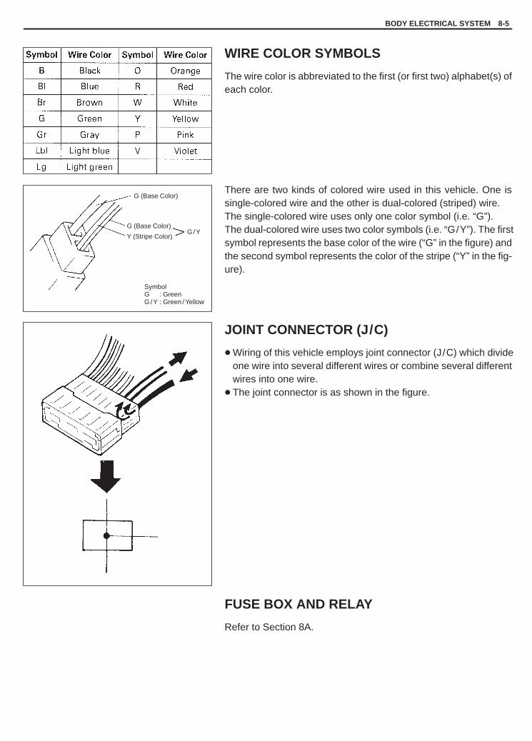
YH4GRANDVITARA
SymbolG : GreenG / Y : Green / Yellow
G (Base Color)
G (Base Color)
Y (Stripe Color)G / Y
BODY ELECTRICAL SYSTEM 8-5
WIRE COLOR SYMBOLS
The wire color is abbreviated to the first (or first two) alphabet(s) ofeach color.
There are two kinds of colored wire used in this vehicle. One issingle-colored wire and the other is dual-colored (striped) wire.The single-colored wire uses only one color symbol (i.e. “G”).The dual-colored wire uses two color symbols (i.e. “G/Y”). The firstsymbol represents the base color of the wire (“G” in the figure) andthe second symbol represents the color of the stripe (“Y” in the fig-ure).
JOINT CONNECTOR (J/C)
� Wiring of this vehicle employs joint connector (J/C) which divideone wire into several different wires or combine several differentwires into one wire.
� The joint connector is as shown in the figure.
FUSE BOX AND RELAY
Refer to Section 8A.

YH4GRANDVITARA
8-6 BODY ELECTRICAL SYSTEM
POWER SUPPLY DIAGRAM
Refer to Section 8A.

YH4GRANDVITARA
8B
LIGHTING SYSTEM 8B-1
SECTION 8B
LIGHTING SYSTEMWARNING:For vehicles equipped with Supplemental Restraint (Air Bag) System:� Service on and around the air bag system components or wiring must be performed only by an autho-
rized SUZUKI dealer. Refer to “Air Bag System Components and Wiring Location View” under “Gener-al Description” in air bag system section in order to confirm whether you are performing service onor near the air bag system components or wiring. Please observe all WARNINGS and “Service Precau-tions” under “On-Vehicle Service” in air bag system section before performing service on or aroundthe air bag system components or wiring. Failure to follow WARNINGS could result in unintentionalactivation of the system or could render the system inoperative. Either of these two conditions mayresult in severe injury.
� Technical service work must be started at least 90 seconds after the ignition switch is turned to the“LOCK” position and the negative cable is disconnected from the battery. Otherwise, the system maybe activated by reserve energy in the Sensing and Diagnostic Module (SDM).
CONTENTS
GENERAL DESCRIPTION 8B- 2. . . . . . . . . . . . . . . . . . . . . . . . . . . . . . . . . . . . . . . . . . . . . . . . . . . . . . . . . . . . . . . . . . Cautions in Servicing 8B- 2. . . . . . . . . . . . . . . . . . . . . . . . . . . . . . . . . . . . . . . . . . . . . . . . . . . . . . . . . . . . . . . . . . . . . Symbols and Marks 8B- 2. . . . . . . . . . . . . . . . . . . . . . . . . . . . . . . . . . . . . . . . . . . . . . . . . . . . . . . . . . . . . . . . . . . . . . . Wiring Color Symbols 8B- 2. . . . . . . . . . . . . . . . . . . . . . . . . . . . . . . . . . . . . . . . . . . . . . . . . . . . . . . . . . . . . . . . . . . . . Abbreviations 8B- 2. . . . . . . . . . . . . . . . . . . . . . . . . . . . . . . . . . . . . . . . . . . . . . . . . . . . . . . . . . . . . . . . . . . . . . . . . . . . Joint Connector 8B- 2. . . . . . . . . . . . . . . . . . . . . . . . . . . . . . . . . . . . . . . . . . . . . . . . . . . . . . . . . . . . . . . . . . . . . . . . . . Fuse Box and Relay 8B- 2. . . . . . . . . . . . . . . . . . . . . . . . . . . . . . . . . . . . . . . . . . . . . . . . . . . . . . . . . . . . . . . . . . . . . . Power Supply Diagram 8B- 2. . . . . . . . . . . . . . . . . . . . . . . . . . . . . . . . . . . . . . . . . . . . . . . . . . . . . . . . . . . . . . . . . . . . Headlights 8B- 2. . . . . . . . . . . . . . . . . . . . . . . . . . . . . . . . . . . . . . . . . . . . . . . . . . . . . . . . . . . . . . . . . . . . . . . . . . . . . . . Headlight with Leveling System (If Equipped) 8B- 3. . . . . . . . . . . . . . . . . . . . . . . . . . . . . . . . . . . . . . . . . . . . . . . . .
DIAGNOSIS 8B- 4. . . . . . . . . . . . . . . . . . . . . . . . . . . . . . . . . . . . . . . . . . . . . . . . . . . . . . . . . . . . . . . . . . . . . . . . . . . . . . . Headlights 8B- 4. . . . . . . . . . . . . . . . . . . . . . . . . . . . . . . . . . . . . . . . . . . . . . . . . . . . . . . . . . . . . . . . . . . . . . . . . . . . . . . Headlights with Leveling System (If Equipped) 8B- 4. . . . . . . . . . . . . . . . . . . . . . . . . . . . . . . . . . . . . . . . . . . . . . . . Turn Signal and Hazard Warning Lights 8B- 4. . . . . . . . . . . . . . . . . . . . . . . . . . . . . . . . . . . . . . . . . . . . . . . . . . . . . Clearance, Tail and License Plate Lights 8B- 5. . . . . . . . . . . . . . . . . . . . . . . . . . . . . . . . . . . . . . . . . . . . . . . . . . . . . Back-up Lights 8B- 5. . . . . . . . . . . . . . . . . . . . . . . . . . . . . . . . . . . . . . . . . . . . . . . . . . . . . . . . . . . . . . . . . . . . . . . . . . . Brake Lights 8B- 5. . . . . . . . . . . . . . . . . . . . . . . . . . . . . . . . . . . . . . . . . . . . . . . . . . . . . . . . . . . . . . . . . . . . . . . . . . . . . Rear Fog Light (If Equipped) 8B- 5. . . . . . . . . . . . . . . . . . . . . . . . . . . . . . . . . . . . . . . . . . . . . . . . . . . . . . . . . . . . . . . Interior Lights 8B- 5. . . . . . . . . . . . . . . . . . . . . . . . . . . . . . . . . . . . . . . . . . . . . . . . . . . . . . . . . . . . . . . . . . . . . . . . . . . .
ON-VEHICLE SERVICE 8B- 6. . . . . . . . . . . . . . . . . . . . . . . . . . . . . . . . . . . . . . . . . . . . . . . . . . . . . . . . . . . . . . . . . . . . Headlights 8B- 6. . . . . . . . . . . . . . . . . . . . . . . . . . . . . . . . . . . . . . . . . . . . . . . . . . . . . . . . . . . . . . . . . . . . . . . . . . . . . . . Headlights with Leveling System (If Equipped) 8B- 8. . . . . . . . . . . . . . . . . . . . . . . . . . . . . . . . . . . . . . . . . . . . . . . . Turn Signal and Hazard Warning Lights 8B- 9. . . . . . . . . . . . . . . . . . . . . . . . . . . . . . . . . . . . . . . . . . . . . . . . . . . . . Rear Fog Light (If Equipped) 8B-11. . . . . . . . . . . . . . . . . . . . . . . . . . . . . . . . . . . . . . . . . . . . . . . . . . . . . . . . . . . . . . .

YH4GRANDVITARA
65
1. Headlight assembly2. Halogen bulb3. Socket cover4. Turn signal light bulb5. Position light bulb6. Turn signal light bulb socket7. Position light bulb socket
8B-2 LIGHTING SYSTEM
GENERAL DESCRIPTIONCAUTIONS IN SERVICINGRefer to Section 8.
SYMBOLS AND MARKSRefer to Section 8.
WIRING COLOR SYMBOLSRefer to Section 8.
ABBREVIATIONSRefer to Section 8.
JOINT CONNECTORRefer to Section 8.
FUSE BOX AND RELAYRefer to Section 8.
POWER SUPPLY DIAGRAMRefer to Section 8.
HEADLIGHTS

YH4GRANDVITARA
1. Headlight leveling switch2. Headlight leveling unit (actuator)3. Headlight4. Headlight leveling unit shaft
SwitchPosition
Headlight beamdown angle
0 ———1 0.624�2 1.243�3 1.867�4 2.479�
LIGHTING SYSTEM 8B-3
HEADLIGHT WITH LEVELING SYSTEM (IF EQUIPPED)

YH4GRANDVITARA
8B-4 LIGHTING SYSTEM
DIAGNOSIS
NOTE:Fuse name (“ ”) in the table below is shown on the fuse box cover (Hard Top Model) or the junction box(Canvas Top Model).
HEADLIGHTSTrouble Possible cause Correction
Only one light does notlight
� Bulb blown� Headlight L or R fuse blown� Socket, wiring or grounding faulty
Replace bulbReplace fuse to check for shortRepair
Headlights do not light � Headlight L and R fuses blown� Lighting and dimmer switch faulty� Defective light relay� Wiring or grounding faulty
Replace fuses to check for shortReplace switchesReplace light relayRepair
Only one beam (“Hi” or“Lo”) does not light
� Bulb blown� Lighting or dimmer switch faulty
Replace bulbReplace switch
HEADLIGHTS WITH LEVELING SYSTEM (IF EQUIPPED)Trouble Possible cause Correction
Both headlights do notmove
� “TURN/BACK” fuse blown (Hard Top Model)“TRN” fuse blown (Canvas Top Model)
� Leveling switch faulty� Supply voltage too low
Replace fuse to check for short
Replace switchRecharge or replace battery
One of headlights (eitherRight or Left) does notmove
� Socket, wiring or grounding faulty� Actuator faulty� Vehicle body around headlight deformed� Headlight ass’y itself deformed
RepairReplace actuatorRepair bodyReplace headlight ass’y
TURN SIGNAL AND HAZARD WARNING LIGHTSTrouble Possible cause Correction
Flash rate high or one sideonly flashes
� Incorrect bulb� One of light bulbs burnt out� Turn signal/hazard warning relay faulty� Open circuit or high resistance existing
Replace bulbReplaceReplace relayRepair� O en circuit or high resistance existing
between turn signal/hazard warningswitch and lights on one side
� Wiring or grounding faulty
Re air
Repair
No flashing � “TURN/BACK” and/or “HAZARD” fuse(s)blown (Hard Top Model)“TRN” and/or “HAZ” fuse(s) blown(Canvas Top Model)
� Open circuit or high resistance existingbetween battery and switch
� Turn signal/hazard relay faulty� Combination switch or hazard switch faulty� Wiring or grounding faulty
Replace fuse(s) to check forshort
Check bulb and check circuit
Replace relayReplace switchRepair
Flash rate low � Supply voltage too low� Turn signal/hazard relay faulty
Check charging systemReplace relay

YH4GRANDVITARA
LIGHTING SYSTEM 8B-5
CLEARANCE, TAIL AND LICENCE PLATE LIGHTSTrouble Possible cause Correction
All lights do not light � “TAIL” fuse blown� Lighting switch faulty� Wiring or grounding faulty
Replace fuse to check for shortReplace switchRepair
Some lights do not lightup
� Bulb(s) blown� Wiring or grounding faulty
Replace bulb(s)Repair
BACK-UP LIGHTSTrouble Possible cause Correction
Back-up lights do notlight
� “TURN/BACK” fuse blown (Hard Top Model)“TRN” fuse blown (Canvas Top Model)
� Bulb blown� ������ ���� ������ � ����� switch faulty� Wiring or grounding faulty
Replace fuse to check for short
Replace bulbReplace switchRepair
Back-up lights remainsON
� Back-up light switch or shift switch faulty� Wiring or grounding faulty
Replace switchRepair
BRAKE LIGHTSTrouble Possible cause Correction
Brake lights do not lightup
� “STOP/HORN” fuse blown (Hard TopModel)“STP” fuse blown (Canvas Top Model)
� Bulb(s) blown� Brake light switch faulty� Wiring or grounding faulty
Replace fuse to check for short
Replace bulb(s)Adjust or replace switchRepair
Brake lights stay on � Brake light switch faulty Adjust or replace switch
Only one light does notlight
� Bulb blown� Wiring or grounding faulty
Replace bulbRepair
REAR FOG LIGHT (IF EQUIPPED)Trouble Possible cause Correction
Rear fog light does notcome on
� “FOG” fuse blown� Rear fog light switch faulty� Lighting switch faulty� Wiring or grounding faulty� Bulb blown
Replace fuse to check for shortReplace fog light switchReplace switchRepairReplace bulb
INTERIOR LIGHTSTrouble Possible cause Correction
Interior light (s) does (do)not light up
� Bulb(s) blown� “DOME” fuse blown (Hard Top Model)
“DOM” fuse blown (Canvas Top Model)� Wiring or grounding faulty� Door switch faulty� Interior light switch faulty
Replace bulb(s)Replace fuse to check for short
RepairReplace switchReplace light assy
Front spot lights do notlight up
� Bulb(s) blown� Wiring or grounding faulty� Spot light switch faulty
Replace bulb(s)RepairReplace light assy

YH4GRANDVITARA
Terminal
Wire ColorSwitch Position
Terminal
Switch Position Wire Color
HEAD
OFF
HI
PASS
SMALL
8B-6 LIGHTING SYSTEM
ON-VEHICLE SERVICE
HEADLIGHTSHEADLIGHT SWITCH (IN COMBINATION SWITCH)INSPECTION1) Disconnect negative cable at battery.2) Disconnect combination switch lead wire coupler.3) Check for continuity between terminals at each switch position
shown below. If check result is not as specified, replace switch.
Lighting Switch
EL T H
W G R
OFF
SMALL
HEAD
Dimmer & Passing Switch
ED HL HU HF
W/B R/W R R/B
Passing (PASS)
Low Beam
High Beam (HI)
REMOVAL AND INSTALLATIONFor vehicle without air bag system, refer to Section 3C COMBINA-TION SWITCH, and for vehicle with air bag system, refer to Section3C1 CONTACT COIL AND COMBINATION SWITCH ASSEMBLY.
REMOVAL1) Disconnect negative cable at battery.2) Remove front grille.3) Disconnect harness and couplers from headlight assembly.4) Remove three bolts and pull headlight assembly off vehicle.
INSTALLATIONReverse removal procedure for installation.Make sure to follow HEADLIGHT AIMING WITH SCREEN and aimheadlight after installation.
YH4GRANDVITARA
LH steering vehicle shownX-X:Horizontal center line of headlight bulbsA-A:Vertical center line of left headlight bulbB-B:Vertical center line of right headlight bulb
1. Screen
2. For right / left adjustment3. For up / down adjustment
(for vehicle without leveling system)4. For up / down adjustment
(for vehicle with leveling system)5. Headlight leveling actuator
HOTSPOTLH. HEADLIGHT RH. HEADLIGHT
LIGHTING SYSTEM 8B-7
BULB REPLACEMENT
WARNING:Don’t touch when the bulb is hot.
1) Disconnect negative cable at battery.2) Disconnect harness from bulb.3) Remove socket cover and bulb.4) Replace bulb and install in reverse removal procedure.
HEADLIGHT AIMING WITH SCREEN
NOTE:� Unless otherwise obligated by local regulations, adjust
headlight aiming according to following procedure.� After replacing headlight, be sure to perform its aiming.� When inspecting and adjusting headlight with leveling sys-
tem, make sure to set the leveling switch to “0” position withIG switch ON.
Before adjustment, make sure the following.a) Place vehicle on a flat surface in front of blank wall as below
ahead of headlight surface.
Clearance “a”: 10 m (32.8 ft)
b) Adjust air pressure of all tires to a specified value respectively.c) Bounce vehicle body up and down by hand to stabilize suspen-
sion.d) Carry out one driver aboard.
Driver’s weight: 75 kg (165 lb)
Adjustment1) Check to see if hot spot (high intensity zone) of each main (low)
beam axis falls as illustrated.
Clearance “H”: Approx. 130 mm (5.15 in.)
2) If headlight aiming is not set properly, align it to specification byadjusting aiming screw and aiming gear.

YH4GRANDVITARA
8B-8 LIGHTING SYSTEM
HEADLIGHTS WITH LEVELING SYSTEM(IF EQUIPPED)LEVELING SWITCHINSPECTIONTo check the switch operation, substitute it with a new one. If properoperation is obtained, it means the switch is defective.Replace it with a new one.
LEVELING ACTUATORINSPECTIONAll headlight system couples connected including leveling actuatorand switch, and at Ignition switch ON, listen to the leveling actuatorsound on both actuators according to the movement of the levelingswitch. If no sound is heard with the movement of the levelingswitch, replace headlight assembly.
YH4GRANDVITARA
1. Meter cluster2. Hazard switch
Terminal
Wire ColorSwitch Position
LH steering vehicle shown
LIGHTING SYSTEM 8B-9
TURN SIGNAL AND HAZARD WARNINGLIGHTSTURN SIGNAL SWITCH (IN COMBINATION SWITCH)INSPECTION1) Disconnect negative cable at battery.2) Disconnect combination switch lead wire coupler.3) Check for continuity between terminals at each switch position
shown below. If check result is not as specified, replace switch.
TL TB TR
G/R G G/Y
L
N
R
REMOVAL AND INSTALLATIONRefer to Section 3C COMBINATION SWITCH for vehicle without airbag system and Section 3C1 CONTACT COIL AND COMBINA-TION SWITCH ASSEMBLY for vehicle with air bag system.
HAZARD SWITCHREMOVAL1) Remove meter cluster.2) Pull hazard switch out of instrument panel.3) Disconnect coupler from hazard switch.4) Remove hazard switch.
INSTALLATIONReverse removal procedure.
INSPECTIONCheck for continuity between terminals at each switch positionshown below. If check result is not as specified, replace siwtch.

YH4GRANDVITARA
8B-10 LIGHTING SYSTEM
1. Hazard relay2. Junction box3. Fuse box
Type A
Type B3
3
2
HAZARD RELAYINSPECTIONConnect battery and tester as shown.Unless a continued click sound is heard, replace relay.

YH4GRANDVITARA
LIGHTING SYSTEM 8B-11
REAR FOG LIGHT (IF EQUIPPED)REAR FOG LIGHT SWITCHINSPECTIONCheck for continuity between terminals at each switch positionshown below. Hold the switch button (ON or OFF) pushed in duringchecking switch.
NOTE:Rear fog light lights up only when headlights (low or highbeams) or front fog lights (if equipped) are ON.Rear fog lights turns OFF automatically when headlights orfront lights are turned OFF.

YH4GRANDVITARA
8C
INSTRUMENTATION/DRIVER INFORMATION 8C-1
GENERAL DESCRIPTION 8C- 2. . . . . . . . . . . . . . Cautions in Servicing 8C- 2. . . . . . . . . . . . . . . . . Symbols and Marks 8C- 2. . . . . . . . . . . . . . . . . . . Wiring Color Symbols 8C- 2. . . . . . . . . . . . . . . . . Abbreviations 8C- 2. . . . . . . . . . . . . . . . . . . . . . . . Joint Connector 8C- 2. . . . . . . . . . . . . . . . . . . . . . Fuse Box and Relay 8C- 2. . . . . . . . . . . . . . . . . . Power Supply Diagram 8C- 2. . . . . . . . . . . . . . . . Combination Meter 8C- 2. . . . . . . . . . . . . . . . . . .
DIAGNOSIS 8C- 4. . . . . . . . . . . . . . . . . . . . . . . . . . . Speedometer and VSS 8C- 4. . . . . . . . . . . . . . . . Fuel Meter/Fuel Gauge Unit 8C- 4. . . . . . . . . . . . Engine Coolant Temp. (ECT) Meter and
Sensor 8C- 4. . . . . . . . . . . . . . . . . . . . . . . . . . . . . Oil Pressure Light 8C- 4. . . . . . . . . . . . . . . . . . . . Brake and Parking Brake Warning
Light 8C- 5. . . . . . . . . . . . . . . . . . . . . . . . . . . . . . . Light Remainder Warning Buzzer 8C- 5. . . . . . .
Seat Belt Warning Light (If Equipped) 8C- 5. . . Ignition Key Remainder Warning
Buzzer (If Equipped) 8C- 5. . . . . . . . . . . . . . . . . Cigarette Lighter and Accessory Socket 8C- 5.
ON-VEHICLE SERVICE 8C- 6. . . . . . . . . . . . . . . . Ignition (Main) Switch 8C- 6. . . . . . . . . . . . . . . . . Combination Meter 8C- 7. . . . . . . . . . . . . . . . . . . Speedometer and VSS 8C- 8. . . . . . . . . . . . . . . . Fuel Meter/Fuel Gauge Unit 8C- 9. . . . . . . . . . . . Engine Coolant Temp. (ECT) Meter andSensor 8C-10. . . . . . . . . . . . . . . . . . . . . . . . . . . . .
Oil Pressure Light 8C-11. . . . . . . . . . . . . . . . . . . . Brake and Parking Brake Warning
Light 8C-12. . . . . . . . . . . . . . . . . . . . . . . . . . . . . . . Ignition Key Remainder (If Equipped)/
Light Remainder Warning Buzzer 8C-12. . . . . . Door Switch 8C-13. . . . . . . . . . . . . . . . . . . . . . . . . Seat Belt Warning Light (If Equipped) 8C-13. . .
SECTION 8C
INSTRUMENTATION/DRIVER INFORMATIONWARNING:For vehicles equipped with Supplemental Restraint (Air Bag) System� Service on and around the air bag system components or wiring must be performed only by an autho-
rized SUZUKI dealer. Refer to “Air Bag System Components and Wiring Location View” under “Gener-al Description” in air bag system section in order to confirm whether you are performing service onor near the air bag system components or wiring. Please observe all WARNINGS and “Service Precau-tions” under “On-Vehicle Service” in air bag system section before performing service on or aroundthe air bag system components or wiring. Failure to follow WARNINGS could result in unintentionalactivation of the system or could render the system inoperative. Either of these two conditions mayresult in severe injury.
� Technical service work must be started at least 90 seconds after the ignition switch is turned to the“LOCK” position and the negative cable is disconnected from the battery. Otherwise, the system maybe activated by reserve energy in the Sensing and Diagnostic Module (SDM).
CONTENTS

YH4GRANDVITARA
1. Tachometer2. Speedometer3. Fuel level meter4. Water temperature meter5. Turn signal pilot light (LH)6. 4WD indicator (if equipped)7. ABS warning light (if equipped)8. Immobilizer warning light (if equipped)9. CHECK ENGINE light
10. Turn signal pilot light (RH)
11. AIR BAG warning light (if equipped)12. O / D OFF light (A / T vehicle only)13. Fasten seat belt light (if equipped)14. High beam light15. Oil pressure warning light16. Charge warning light17. Brake and parking brake warning light18. POWER indicator light (A / T vehicle only)19. Shift position indicator (A / T vehicle, if equipped)
orCHECKENGINE
orABS
8C-2 INSTRUMENTATION/DRIVER INFORMATION
GENERAL DESCRIPTIONCAUTIONS IN SERVICINGRefer to Section 8.
SYMBOLS AND MARKSRefer to Section 8.
WIRING COLOR SYMBOLSRefer to Section 8.
ABBREVIATIONSRefer to Section 8.
JOINT CONNECTORRefer to Section 8.
FUSE BOX AND RELAYRefer to Section 8.
POWER SUPPLY DIAGRAMRefer to Section 8.
COMBINATION METER

YH4GRANDVITARA
1. To door switch (driver side) B / Bl2. To transmission range switch G / Bl
(A / T vehicle only, if equipped) L3. To transmission range switch G / O
(A / T vehicle only, if equipped) 24. To transmission range switch Y / G
(A / T vehicle only, if equipped) D5. To transmission range switch O / Bl
(A / T vehicle only, if equipped) N6. To transmission range switch O / G
(A / T vehicle only, if equipped) P7. To transmission range switch R
(A / T vehicle only, if equipped) R8. To ground B9. To PCM (A / T vehicle only) W / B
10. To ECT sensor Y / W11. To fuel level gauge Bl / W12. To ground B / Y13. To combination switch G / Y
NOTE:Terminal arrangement of coupler viewed from harness side.
Coupler A Coupler B Coupler C
Coupler A Coupler B Coupler C
1. Blank ——2. Blank ——3. To ignition switch B / W4. Blank ——5. To ABS control module Bl / O
(if equipped)6. To PCM (A / T vehicle only) Gr / Bl7. To ABS control module Br
(if equipped)8. To VSS Bl / Y9. To combination switch G / R
10. To SDM (if equipped) Y / G or Bl11. To main fuse W / Bl12. To fuse box W13. To combination switch R14. To ECM (PCM for A / T vehicle) V
(if equipped)15. To ECM (PCM for A / T vehicle) V / Y16. To ECM (PCM for A / T vehicle) O / B
(if equipped)
1. To ground B2. To ECM (PCM for A / T vehicle) Br3. To ignition switch (if equipped) V / R4. To brake fluid level switch R / B5. To parking brake switch V6. To seat belt switch (if equipped) Gr / R7. To generator W / R8. To oil pressure switch Y / B9. To combination switch R / Y
10. To ignition switch (if equipped) Bl / R
or CHECKor ENGINE or ABS
if equipped
if equipped if equipped
INSTRUMENTATION/DRIVER INFORMATION 8C-3
YH4GRANDVITARA
8C-4 INSTRUMENTATION/DRIVER INFORMATION
DIAGNOSIS
NOTE:Fuse name (“ ”) in the table below is shown on the fuse box cover (Hard Top Model) or the junction box(Canvas Top Model).
SPEEDOMETER AND VSSTrouble Possible Cause Correction
Speedometer shows nooperation
� “IG/METER” fuse blown (Hard TopModel)“IG” fuse blown (Canvas Top Model)
� VSS faulty� Printed plate in combination meter
faulty� Speedometer faulty� Wiring or grounding faulty
Replace fuse to check for short
Replace VSSReplace printed plate
Replace speedometerRepair
FUEL METER/FUEL GAUGE UNITTrouble Possible Cause Correction
Fuel meter shows nooperation
� “IG/METER” fuse blown (Hard TopModel)“IG” fuse blown (Canvas Top Model)
� Fuel gauge unit faulty� Printed plate in combination meter
faulty� Fuel meter faulty� Wiring or grounding faulty
Replace fuse to check for short
Replace fuel gauge unitReplace printed plate
Replace fuel meterRepair
ENGINE COOLANT TEMP. (ECT) METER AND SENSORTrouble Possible Cause Correction
Engine coolant temp.meter shows no operation
� “IG/METER” fuse blown (Hard TopModel)“IG” fuse blown (Canvas Top Model)
� ECT meter faulty� Printed plate in combination meter
faulty� ECT sensor faulty� Wiring or grounding faulty
Replace fuse to check for short
Replace ECT meterReplace printed plate
Replace ECT sensorRepair
OIL PRESSURE LIGHTTrouble Possible Cause Correction
Oil pressure warning lightdoes not light up
� Bulb in combination meter blown� “IG/METER” fuse blown (Hard Top
Model)“IG” fuse blown (Canvas Top Model)
� Printed plate in combination meterfaulty
� Oil pressure switch faulty� Wiring or grounding faulty
Replace bulbReplace fuse to check for short
Replace printed plate
Replace oil pressure switchRepair
YH4GRANDVITARA
INSTRUMENTATION/DRIVER INFORMATION 8C-5
BRAKE AND PARKING BRAKE WARNING LIGHTTrouble Possible Cause Correction
Brake warning light doesnot light up
� Bulb in combination meter blown� “IG/METER” fuse blown (Hard Top
Model)“IG” fuse blown (Canvas Top Model)
� Printed plate in combination meterfaulty
� Parking brake switch faulty� Brake fluid level switch faulty� Wiring or grounding faulty
Replace bulbReplace fuse to check for short
Replace printed plate
Replace parking brake switchReplace brake fluid level switchRepair
LIGHT REMAINDER WARNING BUZZERTrouble Possible Cause Correction
Light remainder warningbuzzer shows nosounding
� “TAIL” fuse blown� Buzzer faulty� Wiring or grounding faulty� Driver side door switch faulty
Replace fuse to check for shortReplace buzzerRepairReplace door switch
SEAT BELT WARNING LIGHT (IF EQUIPPED)Trouble Possible Cause Correction
Seat belt warning lightdoes not light up
� Bulb in combination meter blown� “IG/METER” fuse blown (Hard Top
Model)“IG” fuse blown (Canvas Top Model)
� Seat belt switch faulty� Wiring or grounding faulty
Replace bulbReplace fuse to check for short
Replace seat belt switchRepair
IGNITION KEY REMAINDER WARNING BUZZER (IF EQUIPPED)Trouble Possible Cause Correction
Ignition key remainderwarning buzzer shows nosounding
� “DOME” fuse blown (Hard Top Model)“DOM” fuse blown (Canvas TopModel)
� Buzzer faulty� Wiring or grounding faulty� Driver side door switch faulty� Ignition key switch faulty
Replace fuse to check for short
Replace buzzerRepairReplace door switchReplace ignition key switch
CIGARETTE LIGHTER AND ACCESSORY SOCKETTrouble Possible Cause Correction
Cigarette lighter/accessory socket showsno operation
� “CIGAR” fuse blown (Hard Top Model)“CIG” fuse blown (Canvas Top Model)
� Ignition switch faulty� Cigarette lighter/accessory socket
faulty� Wiring or grounding faulty
Replace fuse to check for short
Replace ignition switchReplace cigarette lighter/accessorysocketRepair

YH4GRANDVITARA
8C-6 INSTRUMENTATION/DRIVER INFORMATION
Key Position
TerminalWire
color
Hard Top Model
Canvas Top Model
ON-VEHICLE SERVICE
IGNITION (MAIN) SWITCHINSPECTION1) Disconnect negative cable at battery.2) Disable air bag system. Refer to DISABLING AIR BAG SYSTEM
in Section 10B of this manual.3) Disconnect main switch lead wire coupler.4) Check for continuity between terminals at each switch position
shown below. If check result is not as specified, replace ignition(main) switch.
+B +ACC IG1-1 IG1-2 IG2 ST L1 L2 K1 K2
W / Y Bl B / W B / W Y / B B / Y B B G G
OUTLOCKLOCK
ACC
IN
ON
START
REMOVAL1) Disconnect negative cable at battery.2) Disable air bag system. Refer to DISABLING AIR BAG SYSTEM
in Section 10B of this manual.3) Remove steering column referring to Section 3C1 of this manu-
al. Then remove steering lock/ ignition (main) switch from steer-ing column.
INSTALLATION1) Install steering lock/ ignition (main) switch to steering column.
Install steering column assembly referring to Section 3C1 of thismanual.
2) Enable air bag system. Refer to ENABLING AIR BAG SYSTEMin Section 10B of this manual.
NOTE:When installing steering column, special care must be tak-en for tightening sequence and its torque.

YH4GRANDVITARA
INSTRUMENTATION/DRIVER INFORMATION 8C-7
1. Steering column hole cover
COMBINATION METERREMOVAL1) Disconnect negative cable at battery.2) If the vehicle is equipped with air bag system, disable air bag
system. Refer to DISABLING AIR BAG SYSTEM in Section10B of this manual.
3) Remove column hole cover.
4) Remove instrument cluster panel.5) Remove screws fastening combination meter.6) Disconnect couplers from combination meter.7) Remove combination meter from instrument panel.
INSTALLATIONReverse removal procedure for installation, noting the following.� If the vehicle is equipped with air bag system, be sure to enable
air bag system after installation. Refer to ENABLING AIR BAGSYSTEM in Section 10B of this manual for details.

YH4GRANDVITARA
8C-8 INSTRUMENTATION/DRIVER INFORMATION
SPEEDOMETER AND VSSVEHICLE SPEED SENSOR (VSS)REMOVAL1) Hoist vehicle.2) Disconnect coupler from VSS (1).3) Remove VSS.
INSTALLATIONReverse removal procedure for installation.
Tightening Torque(a): 5.5 N.m (0.55 kg-m, 4.0 lb-ft)

YH4GRANDVITARA
INSTRUMENTATION/DRIVER INFORMATION 8C-9
1. Exhaust pipe
FUEL METER/FUEL GAUGE UNITFUEL METERINSPECTION1) Remove rear bumper facing.2) Detach grommet (3) from vehicle.3) Disconnect coupler (2) of fuel pump and gauge.4) Turning switch ON, and check that fuel meter indicates E.5) Turn ignition switch OFF.6) Ground Bl/W lead through a 3.4 W test bulb (4) as illustrated.7) Turn ignition switch ON and check that bulb light up and pointer
(5) moves to F side.8) If fuel meter shows no operation, repair or replace defective
parts.
FUEL SENDER GAUGEINSPECTION1) Remove fuel pump assembly (1) referring to FUEL PUMP RE-
MOVAL in Section 6C.2) Check resistance between terminals (A) and (B) under each
float position.
Float Position Fuel Resistance (�)56 � model 66 � model Meter
Resistance (�)
“a” 88.3 mm(3.48 in.)
51.7 mm(2.04 in.)
F 6 – 8
“b” 157.2 mm(6.20 in.)
139.6 mm(5.50 in.)
1/2 29.5 – 35.5
“c” 254.9 mm(10.0 in.)
254.9 mm(10.0 in.)
E 94 – 96
If measured valve is out of specification, replace fuel sender gauge.

YH4GRANDVITARA
8C-10 INSTRUMENTATION/DRIVER INFORMATION
G16
J20
H25
1. ECT sensor
1
ENGINE COOLANT TEMP. (ECT) METER ANDSENSORENGINE COOLANT TEMPERATURE (ECT) METERINSPECTION1) Disconnect Y/W lead wire going to ECT sensor.2) Turn ignition switch ON, and check that ECT meter indicates
COOL.3) Turn ignition switch OFF.4) Ground Y/W lead wire through a 3.4 W test bulb (1) as illustrated.5) Turn ignition switch ON, and check that bulb light up and pointer
(2) moves to hot side.6) If ECT meter shows no operation, repair or replace defective
parts.
ENGINE COOLANT TEMPERATURE (ECT) SENSORREMOVAL AND INSTALLATIONRefer to ECT SENSOR in ON-VEHICLE SERVICE in Section 6E1(for G16 and J20) or Section 6E2 (for H25) of this manual for details.
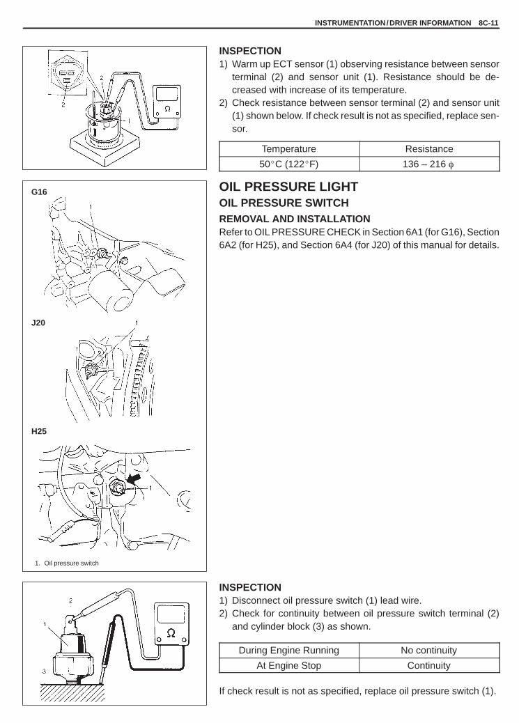
YH4GRANDVITARA
G16
J20
H25
1. Oil pressure switch
INSTRUMENTATION/DRIVER INFORMATION 8C-11
INSPECTION1) Warm up ECT sensor (1) observing resistance between sensor
terminal (2) and sensor unit (1). Resistance should be de-creased with increase of its temperature.
2) Check resistance between sensor terminal (2) and sensor unit(1) shown below. If check result is not as specified, replace sen-sor.
Temperature Resistance
50�C (122�F) 136 – 216 �
OIL PRESSURE LIGHTOIL PRESSURE SWITCHREMOVAL AND INSTALLATIONRefer to OIL PRESSURE CHECK in Section 6A1 (for G16), Section6A2 (for H25), and Section 6A4 (for J20) of this manual for details.
INSPECTION1) Disconnect oil pressure switch (1) lead wire.2) Check for continuity between oil pressure switch terminal (2)
and cylinder block (3) as shown.
During Engine Running No continuity
At Engine Stop Continuity
If check result is not as specified, replace oil pressure switch (1).

YH4GRANDVITARA
8C-12 INSTRUMENTATION/DRIVER INFORMATION
BRAKE AND PARKING BRAKE WARNINGLIGHTBRAKE FLUID LEVEL SWITCHINSPECTIONCheck switch (1) for continuity.If check result is not as specified, replace switch (reservoir).
OFF position (float up) No continuity
ON position (float down) Continuity
PARKING BRAKE SWITCHINSPECTIONCheck switch (1) for continuity.If check result is not as specified, replace switch.
OFF position(parking brake lever released)
No continuity
ON position(parking brake lever pulled up)
Continuity
IGNITION KEY REMAINDER (IF EQUIPPED)/LIGHT REMAINDER WARNING BUZZERREMOVAL1) Remove combination meter (1). Refer to COMBINATION ME-
TER in this section.2) Remove buzzer unit (2) from combination meter.
INSTALLATIONReverse removal procedure for installation.

YH4GRANDVITARA
INSTRUMENTATION/DRIVER INFORMATION 8C-13
ON OFF
buckle out
buckle in
A
DOOR SWITCHINSPECTIONRemove door switch (1) from body and check switch for continuity.If found defective, replace switch.
OFF position(Door closed)
No continuity
ON position(Door open)
Continuity
SEAT BELT WARNING LIGHT (IF EQUIPPED)SEAT BELT BUCKLE SWITCHINSPECTIONCheck for continuity between seat belt buckle switch terminal A andB at following condition.
Buckle out (seat belt not fastened): ContinuityBuckle in (seat belt fastened): No Continuity
If seat belt buckle switch does not follow the above condition, re-place seat belt buckle switch.

YH4GRANDVITARA
8D
WINDOWS, MIRRORS, SECURITY AND LOCKS 8D-1
GENERAL DESCRIPTION 8D- 2. . . . . . . . . . . . . . Cautions in Servicing 8D- 2. . . . . . . . . . . . . . . . . Symbols and Marks 8D- 2. . . . . . . . . . . . . . . . . . . Wiring Color Symbols 8D- 2. . . . . . . . . . . . . . . . . Abbreviations 8D- 2. . . . . . . . . . . . . . . . . . . . . . . . Joint Connector 8D- 2. . . . . . . . . . . . . . . . . . . . . . Fuse Box and Relay 8D- 2. . . . . . . . . . . . . . . . . . Power Supply Diagram 8D- 2. . . . . . . . . . . . . . . . Windshield Wiper and Washer 8D- 2. . . . . . . . .
Front Wiper and Washer 8D- 2. . . . . . . . . . . . . Rear Wiper and Washer (If Equipped) 8D- 3.
Power Door Lock and Keyless Entry(If Equipped) System 8D- 4. . . . . . . . . . . . . . . .
DIAGNOSIS 8D- 5. . . . . . . . . . . . . . . . . . . . . . . . . . . Windshield Wiper and Washer 8D- 5. . . . . . . . .
Front Wiper and Washer 8D- 5. . . . . . . . . . . . . Rear Wiper and Washer (If Equipped) 8D- 5.
Rear Window Defogger (If Equipped) 8D- 5. . . Power Window Control System 8D- 5. . . . . . . . . Power Door Lock System (If Keyless
Entry is not Equipped) 8D- 6. . . . . . . . . . . . . . .
Power Door Lock and Keyless EntrySystem (If Keyless Entry is Equipped) 8D- 7. .
Power Door Mirror Control System 8D- 8. . . . . . Door Mirror Heater (If Equipped) 8D- 8. . . . . . . . Power Sliding Roof (If Equipped) 8D- 8. . . . . . . Front Seat Heater (If Equipped) 8D- 8. . . . . . . .
ON-VEHICLE SERVICE 8D- 9. . . . . . . . . . . . . . . . Windshield Wiper and Washer 8D- 9. . . . . . . . .
Front Wiper and Washer 8D- 9. . . . . . . . . . . . . Rear Wiper and Washer (If Equipped) 8D-13.
Rear Window Defogger (If Equipped) 8D-16. . . Power Window Control System 8D-18. . . . . . . . . Power Door Lock System (If Keyless
Entry is not Equipped) 8D-20. . . . . . . . . . . . . . . Power Door Lock and Keyless Entry
System (If Keyless Entry is Equipped) 8D-23. . Power Door Mirror Control System 8D-30. . . . . . Door Mirror Heater (If Equipped) 8D-31. . . . . . . . Power Sliding Roof (If Equipped) 8D-32. . . . . . . Front Seat Heater (If Equipped) 8D-33. . . . . . . .
SECTION 8D
WINDOWS, MIRRORS, SECURITY AND LOCKSWARNING:For vehicles equipped with Supplemental Restraint (Air Bag) System:� Service on and around the air bag system components or wiring must be performed only by an autho-
rized SUZUKI dealer. Refer to “Air Bag System Components and Wiring Location View” under “Gener-al Description” in air bag system section in order to confirm whether you are performing service onor near the air bag system components or wiring. Please observe all WARNINGS and “Service Precau-tions” under “On-Vehicle Service” in air bag system section before performing service on or aroundthe air bag system components or wiring. Failure to follow WARNINGS could result in unintentionalactivation of the system or could render the system inoperative. Either of these two conditions mayresult in severe injury.
� Technical service work must be started at least 90 seconds after the ignition switch is turned to the“LOCK” position and the negative cable is disconnected from the battery. Otherwise, the system maybe activated by reserve energy in the Sensing and Diagnostic Module (SDM).
CONTENTS

YH4GRANDVITARA
Front Wiper Assembly
Washer Assembly
Front Wiper Switch
8D-2 WINDOWS, MIRRORS, SECURITY AND LOCKS
GENERAL DESCRIPTIONCAUTIONS IN SERVICINGRefer to Section 8.
SYMBOLS AND MARKSRefer to Section 8.
WIRING COLOR SYMBOLSRefer to Section 8.
ABBREVIATIONSRefer to Section 8.
JOINT CONNECTORRefer to Section 8.
FUSE BOX AND RELAYRefer to Section 8.
POWER SUPPLY DIAGRAMRefer to Section 8.
WINDSHIELD WIPER AND WASHERFRONT WIPER AND WASHER

YH4GRANDVITARA
Rear Wiper Switch
Rear Wiper Intermittent Relay
Rear Wiper Assembly
WINDOWS, MIRRORS, SECURITY AND LOCKS 8D-3
REAR WIPER AND WASHER (IF EQUIPPED)

YH4GRANDVITARA
8D-4 WINDOWS, MIRRORS, SECURITY AND LOCKS
LH steering vehicle RH steering vehicle
Type 1
Type 2
Power Door Lock Controller (Canvas Top Model)
Power Door Lock Switch
Back Door Actuator(except Canvas TopModel)
Rear Door Actuator
Front Door Actuator
Fuse box
Power Door Lock and Keyless Entry (if equipped)Controller (Hard Top Model)
Keyless Entry Transmitter(If keyless entry is equipped)
The illustration shows LH steering vehicle.And RH steering vehicle is symmetrical.
POWER DOOR LOCK AND KEYLESS ENTRY (IF EQUIPPED) SYSTEM

YH4GRANDVITARA
WINDOWS, MIRRORS, SECURITY AND LOCKS 8D-5
DIAGNOSISNOTE:Fuse name (“ ”) in the table below is shown on the fuse box cover (Hard Top Model) or the junction box(Canvas Top Model).
WINDSHIELD WIPER AND WASHERFRONT WIPER AND WASHERREAR WIPER AND WASHER (IF EQUIPPED)
Trouble Possible cause Correction
Wiper malfunctions � “WIPER/WASHER” fuse blown (Hard TopModel)“WIP” fuse blown (Canvas Top Model)
� Wiper motor faulty� Wiper switch faulty� Wiring or grounding faulty
Replace fuse to check for short
Replace motorReplace switchRepair
Washer malfunctions � Washer hose or nozzle clogged
� “WIPER/WASHER” fuse blown (Hard TopModel)“WIP” fuse blown (Canvas Top Model)
� Washer motor faulty� Washer switch faulty� Wiring faulty
Clean or repair clogged hose ornozzleReplace fuse to check for short
Replace motorReplace switchRepair
REAR WINDOW DEFOGGER (IF EQUIPPED)
Trouble Possible cause Correction
Defogger does not work � “REAR DEFG” fuse blown� Defogger switch faulty� Defogger heat wire faulty� Wiring or grounding faulty
Replace fuse to check for shortReplace switchRepair heat wireRepair
POWER WINDOW CONTROL SYSTEM
Trouble Possible cause Correction
All power windows do notoperate
� “POWER WINDOW” fuse blown (Hard TopModel)“P/W” fuse blown (Canvas Top Model)
� Ignition switch faulty� Wiring or grounding faulty
Replace fuse to check for short
Replace switchRepair
Only one power windowdoes not operate
� Power window switch (main or sub) faulty� Power window motor faulty� Window lock switch faulty� Wiring or grounding faulty
Replace switchReplace motorReplace switchRepair

YH4GRANDVITARA
8D-6 WINDOWS, MIRRORS, SECURITY AND LOCKS
POWER DOOR LOCK SYSTEM (IF KEYLESS ENTRY IS NOT EQUIPPED)
Trouble Possible cause Correction
All power doors are notlocked/unlocked by bothdriver side door keyswitch and power doorlock switch
� “DOOR LOCK” fuse blown (Hard TopModel)“D/L” fuse blown (Canvas Top Model)
� Power door controller faulty� Wiring or grounding faulty
Replace fuse to check for short
Replace controllerRepair
All power doors are notlocked/unlocked by onlypower door lock switch
� Power door lock switch faulty� Wiring or grounding faulty
Replace switchRepair
All power doors are notlocked/unlocked by onlydriver side door keyswitch
� Driver side door key switch faulty� Wiring or grounding faulty
Replace switchRepair
Only one power door is notlocked/unlocked
� Wiring or coupler faulty� Actuator (door lock motor) faulty
RepairReplace actuator

YH4GRANDVITARA
WINDOWS, MIRRORS, SECURITY AND LOCKS 8D-7
POWER DOOR LOCK AND KEYLESS ENTRY SYSTEM (IF KEYLESS ENTRY ISEQUIPPED)
Trouble Possible cause Correction
� All power doors are notlocked/unlocked byboth driver side door keyswitch and power doorlock switch. But allpower doors are locked/unlocked by keylessentry transmitter
� All power doors are notlocked/unlocked bydriver side door keyswitch, power door lockswitch and keyless entrytransmitter
� When power doors arelocked/unlocked bykeyless entrytransmitter, hazardwarning lights do notflash
� “DOOR LOCK” fuse blown� Power door lock and keyless entry system
faulty
Replace fuse to check for shortRefer to SYSTEM INSPECTIONof POWER DOOR LOCK ANDKEYLESS ENTRY SYSTEM(IF KEYLESS ENTRY ISEQUIPPED) in this section
All power doors are notlocked/unlocked by onlypower door lock switch
� Power door lock switch faulty� Wiring or grounding faulty
Replace switchRepair
All power doors are notlocked/unlocked by onlydriver side door keyswitch
� Driver side door key switch faulty� Wiring or grounding faulty
Replace switchRepair
All power doors are notlocked/unlocked by onlykeyless entry transmitter
� Code registration error� Transmitter battery dead� Transmitter faulty� Power door lock and keyless entry system
faulty
Register codeReplace batteryReplace transmitterRefer to SYSTEM INSPECTIONof POWER DOOR LOCK ANDKEYLESS ENTRY SYSTEM(IF KEYLESS ENTRY ISEQUIPPED) in this section
Although any door isopened within 30 secondsafter power door(s)unlocked by keyless entrytransmitter, all powerdoors are locked againautomatically
� Door switch faulty� Wiring harness connected to door switch
brakes
Replace switchRepair
Only one power door is notlocked/unlocked
� Wiring or coupler faulty� Actuator (door lock motor) faulty
RepairReplace actuator
Operation distance ofkeyless entry is unstable
� Transmitter battery dead� Transmitter faulty
Replace batteryReplace transmitter

YH4GRANDVITARA
8D-8 WINDOWS, MIRRORS, SECURITY AND LOCKS
POWER DOOR MIRROR CONTROL SYSTEM
Trouble Possible cause Correction
All power mirrors do notoperate
� “CIGAR” fuse blown (Hard Top Model)“CIG” fuse blown (Canvas Top Model)
� Power door mirror switch faulty� Wiring or grounding faulty
Replace fuse to check for short
Replace switchRepair
One power mirror doesnot operate
� Power door mirror switch faulty� Actuator (power door mirror motor) faulty� Wiring or grounding faulty
Replace switchReplace actuatorRepair
DOOR MIRROR HEATER (IF EQUIPPED)
Trouble Possible cause Correction
The surface of mirror isnot defrosted althoughdoor mirror heaterswitch is ON
� “REAR DEFG” fuse blown (Hard Top Model)“DEF” fuse blown (Canvas Top Model)
� Door mirror heater switch faulty� Door mirror heater faulty� Wiring or grounding faulty
Replace fuse to check for short
Replace switchReplace outside mirrorRepair
POWER SLIDING ROOF (IF EQUIPPED)
Trouble Possible cause Correction
Sliding roof does notoperate (sliding roofmotor runs OK)
� Foreign object stuck in sliding roof rail� Misinstallation of sliding roof rail� Conflicts of sliding roof parts� Misinstallation of sliding roof drive cable
Remove or clean stuck objectInstall correctlyFix conflictsInstall correctly
Sliding roof does notoperate (sliding roofmotor does not run)
� “SUN ROOF” fuse blown� Sliding roof switch faulty� Sliding roof motor ass’y faulty� Wiring or grounding faulty
Replace fuse to check for shortReplace switchReplace motorRepair
FRONT SEAT HEATER (IF EQUIPPED)
Trouble Possible cause Correction
Both seat back andcushion do not becomehot although seat heaterswitch is LO/HI position
� “SEAT HTR” fuse blown (Hard Top Model)“S/H” fuse blown (Canvas Top Model)
� Seat heater switch faulty� Seat heater circuit in seat back and/or seat
cushion faulty� Wiring or grounding faulty
Replace fuse to check for short
Replace switchReplace heater front back and/or heater front cushionRepair
Only seat back does notbecome hot although seatheater switch is HIposition
� Seat heater circuit in seat back faulty(Hard Top Model)
� Seat heater circuit in seat back and/or seatcushion faulty (Canvas Top Model)
� Seat heater switch faulty� Wiring faulty
Replace heater front back
Replace heater front backand/or heater front cushionReplace switchRepair
Only seat cushion doesnot become hot althoughseat heater switch is HIposition
� Seat heater circuit in seat back and/or seatcushion faulty (Hard Top Model)
� Seat heater circuit in seat cushion(Canvas Top Model)
� Seat heater switch faulty� Wiring faulty
Replace heater front backand/or heater front cushionReplace heater front cushion
Replace switchRepair

YH4GRANDVITARA
WASHERON
INT
LO
HI
Type A
Type B
Type C
WINDOWS, MIRRORS, SECURITY AND LOCKS 8D-9
WiperSW
Terminal
Wiper SW
Terminal
ON-VEHICLE SERVICE
WINDSHIELD WIPER AND WASHERFRONT WIPER AND WASHERINSPECTION
Front Wiper and Washer Switch (in Combination Switch)1) Disconnect negative cable at battery.2) Disconnect combination switch lead wire coupler.3) Check for continuity between terminals at each switch position
as shown below. If check result is not as specified, replaceswitch.
B3 +2 +1 AsB3 +2 +1 As
OFFB3 W
INTB3 W
LO OFF
HI ON
REMOVAL AND INSTALLATIONFor vehicle without air bag system, refer to Section 3C COMBINA-TION SWITCH, and for vehicle with air bag system, refer to Section3C1 CONTACT COIL AND COMBINATION SWITCH ASSEMBLY.
Wiper Motor1) As illustrated, use a 12 V battery to connect its (+) terminal to ter-
minal “A”, and its (–) terminal to Black lead wire (2) (Type A, B)or terminal “E” (Type C).If motor (1) rotates at a low revolution speed of 45 to 55 rpm, itis proper. For high speed check, connect battery (+) terminal toterminal “B”, and its (–) terminal to Black lead wire (2) (Type A,B) or terminal “E” (Type C). If motor rotates at a high revolutionspeed of 67 to 83 rpm, it is proper.

YH4GRANDVITARA
Type B
Type A
Type C
1. Washer tank
8D-10 WINDOWS, MIRRORS, SECURITY AND LOCKS
2) Testing automatic stop action.a) Connect 12 V battery (+) terminal to terminal “A” of wiper mo-
tor (1) and (–) terminal to Black lead wire (2) (Type A, B) orterminal “E” (Type C), and let the motor turn.
b) Disconnect terminal “A” from battery, and let the motor stop.c) Connect terminal “A” and “D” with a jumper wire (3), and con-
nect terminal “C” to battery (+) terminal. Observe the motorturns once again then stops at a given position.
d) Repeat a) thru c) several times and inspect if the motor stopsat the given position every time.
Washer PumpConnect battery (+) and (–) terminals to pump (+) and (–) terminalsrespectively to check pumping rate.Check for both front (3) and rear (2) (if equipped) washer pump.
Pumping Rate:Front and Rear (if equipped) more than 1.0 l /min.
(2.1 US pt. /min.,1.76 lmp pt. /min.).

YH4GRANDVITARA
WINDOWS, MIRRORS, SECURITY AND LOCKS 8D-11
SLOW
FAST
10 – 14 V
0 V1.6 � 1 sec.
10 – 14 V
0 V10.7 � 5 sec.
Intermittent Wiper Relay Circuit1) Disconnect negative cable at battery.2) Disconnect combination switch lead wire coupler.3) Turn the front wiper switch to INT position.4) Turn the intermittent time control switch to FAST position.5) Connect battery positive terminal to terminal “B3” and battery
negative terminal to terminal “E”.6) Connect voltmeter positive lead to terminal “+1” and negative
lead to terminal “E”.Check that the voltmeter indicates the battery voltage (10 –14 V).
7) Connect terminal “As” and terminal “B3” by a jumper wire. Thenmove jumper wire end connected to terminal “B3” to terminal “E”.Observe the voltmeter voltage drops to 0 V right after connectingthe jumper wire from terminal “B3” to “E”. Then the voltage risesto battery voltage (10 – 14 V) within the time shown in the tablebelow.
INT time controlswitch position
Voltage
FAST
SLOW

YH4GRANDVITARA
WASHERON
ON
OFF
10 – 14V
0V
Approx. 2.5 sec.Approx. 0.5 sec.
8D-12 WINDOWS, MIRRORS, SECURITY AND LOCKS
Washer Linked Operation1) Disconnect negative cable at battery.2) Disconnect combination switch lead wire coupler.3) Make sure that front wiper switch is at OFF position.4) Connect battery positive terminal to terminal “B3” and battery
negative terminal to terminal “E”.5) Connect voltmeter positive lead to terminal “+1” and negative
lead to terminal “E”.6) Pull washer switch and check that voltage changes as shown in
the table.
Washer switch
Voltmeter

YH4GRANDVITARA
TerminalSwitch
TerminalSwitch
ON
INT
WASHERON
BRINT
WINDOWS, MIRRORS, SECURITY AND LOCKS 8D-13
REAR WIPER AND WASHER (IF EQUIPPED)INSPECTION
Rear Wiper and Washer Switch (in Combination Switch)1) Disconnect negative cable at battery.2) Disconnect combination switch lead wire coupler.3) Check for continuity between terminals at each switch position
as shown below. If check result is not as specified, replaceswitch.
Rear Wiper Switch
BR INT +IRBR INT +IR
OFF
INT
ON
Rear Washer Switch
BR WRBR WR
OFF
ON
Washer PumpRefer to FRONT WIPER AND WASHER INSPECTION in this sec-tion.
Wiper Motor1) TESTING WIPER MOTOR
As shown left, use a 12 V battery to connect its (+) and (–) termi-nals to terminal “D” and Black lead wire (2) respectively. Thenmotor (1) should rotate at 35 to 45 rpm.
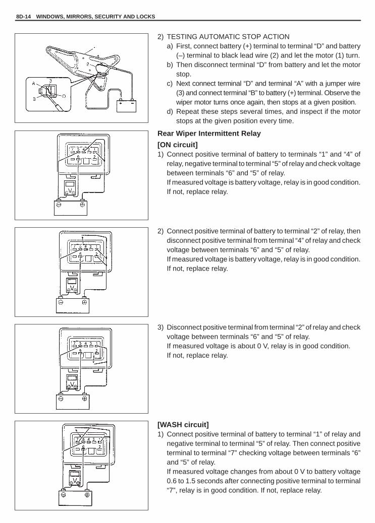
YH4GRANDVITARA
8D-14 WINDOWS, MIRRORS, SECURITY AND LOCKS
2) TESTING AUTOMATIC STOP ACTIONa) First, connect battery (+) terminal to terminal “D” and battery
(–) terminal to black lead wire (2) and let the motor (1) turn.b) Then disconnect terminal “D” from battery and let the motor
stop.c) Next connect terminal “D” and terminal “A” with a jumper wire
(3) and connect terminal “B” to battery (+) terminal. Observe thewiper motor turns once again, then stops at a given position.
d) Repeat these steps several times, and inspect if the motorstops at the given position every time.
Rear Wiper Intermittent Relay
[ON circuit]1) Connect positive terminal of battery to terminals “1” and “4” of
relay, negative terminal to terminal “5” of relay and check voltagebetween terminals “6” and “5” of relay.If measured voltage is battery voltage, relay is in good condition.If not, replace relay.
2) Connect positive terminal of battery to terminal “2” of relay, thendisconnect positive terminal from terminal “4” of relay and checkvoltage between terminals “6” and “5” of relay.If measured voltage is battery voltage, relay is in good condition.If not, replace relay.
3) Disconnect positive terminal from terminal “2” of relay and checkvoltage between terminals “6” and “5” of relay.If measured voltage is about 0 V, relay is in good condition.If not, replace relay.
[WASH circuit]1) Connect positive terminal of battery to terminal “1” of relay and
negative terminal to terminal “5” of relay. Then connect positiveterminal to terminal “7” checking voltage between terminals “6”and “5” of relay.If measured voltage changes from about 0 V to battery voltage0.6 to 1.5 seconds after connecting positive terminal to terminal“7”, relay is in good condition. If not, replace relay.

YH4GRANDVITARA
WINDOWS, MIRRORS, SECURITY AND LOCKS 8D-15
2) Disconnect positive terminal from terminal “7” checking voltagebetween terminal “6” and “5” of relay.If measured voltage changes from battery voltage to about 0 V2.7 to 4.6 seconds after disconnecting positive terminal from ter-minal “7”, relay is in good condition.If not, replace relay.
[INT circuit]1) Connect positive terminal of battery to terminals “1” of relay and
negative terminal to terminal “5” of relay. Then positive terminalto terminal “3” of relay checking voltage between terminals “6”and “5” of relay.If measured voltage changes from about 0 V to battery voltagewhen connecting positive terminal to terminal “3”, relay is ingood condition.If not, replace relay.
2) Connect positive terminal of battery to terminal “2” of relay, thendisconnect positive terminal from terminal “2” of relay checkingvoltage between terminals “6” and “5” of relay.If measured voltage changes from battery voltage to about 0 Vwhen disconnecting positive terminal from terminal “2” andabout 0 V to battery voltage 8 � 2 seconds after disconnectingpositive terminal from terminal “2”, relay is in good condition.If not, replace relay.

YH4GRANDVITARA
1. Heat wire2. Tin foil3. Tester probe
1. Voltmeter
At center
Good
Brokenwire
brokenwire
8D-16 WINDOWS, MIRRORS, SECURITY AND LOCKS
REAR WINDOW DEFOGGER (IF EQUIPPED)INSPECTIONDEFOGGER SWITCHCheck for continuity between terminals at each switch position asshown below.If check result is not as specified, replace switch.
DEFOGGER WIRENOTE:� When cleaning rear window glass, use a dry cloth to wipe it
along wire direction.� When cleaning glass, do not use detergent or abrasive-con-
taining glass cleaner.� When measuring wire voltage, use a tester with negative
probe wrapped with a tin foil which should be held down onwire by finger pressure.
1) Checking wire damagea. Turn main switch ON.b. Turn defogger switch ON.c. Use a voltmeter to check voltage at the center of each heat
wire, as shown.
Voltage Criteria
Approx. 5 V Good (No break in wire)
Approx. 10 V or 0 V Broken wire
If measured voltage is 10 V, wire must be damaged betweenits center and positive end. If voltage is zero, wire must bedamaged between its center and ground.

YH4GRANDVITARA
1. Masking tape2. Wood spatula3. Broken wire4. Repair agent
Several volts
0 volt
WINDOWS, MIRRORS, SECURITY AND LOCKS 8D-17
2) Locating damage in wirea. Touch voltmeter positive (+) lead to heat wire positive termi-
nal end.b. Touch voltmeter negative (–) lead with a foil strip to heat wire
positive terminal end, then move it along wire to the negativeterminal end.
c. The place where voltmeter fluctuates from zero to severalvolts is where there is damage.
NOTE:If heat wire is free from damage, voltmeter should indicate12 V at heat wire positive terminal end and its indicationshould decrease gradually toward zero at the other terminal(ground).
REPAIRDEFOGGER CIRCUIT1) Use white gasoline for cleaning.2) Apply masking tape at both upper and lower sides of heat wire
to be repaired.3) Apply commercially-available repair agent with a fine-tip brush.4) Two to three minutes later, remove masking tapes previously
applied.5) Leave repaired heat wire as it is for at least 24 hours before oper-
ating defogger again.

YH4GRANDVITARA
Type 1
Type 2LH steering vehicle
Terminal
Switch
Terminal
Switch
8D-18 WINDOWS, MIRRORS, SECURITY AND LOCKS
POWER WINDOW CONTROL SYSTEMINSPECTIONPOWER WINDOW MAIN SWITCHCheck switch for continuity between terminals as shown below.Type 1
WindowDriver Side Passenger Side
WindowLock
Window Switch (2)g
Window Switch (3)Lock
Switch (1) C H G A C E B A A F
UPUP
OFF OFFOFF OFF
DOWNDOWN
UPUP
ON OFFON OFF
DOWNDOWN
Type 2 LH steering vehicle
WindowLock
Switch (1)
DriverSide
WindowSwitch (2)
PassengerSide
WindowSwitch (3)
Rear RHWindow
Switch (4)
Rear LHWindow
Switch (5)Switch (1)
K C A B K C E F K C I J K C G HK C A B K C E F K C I J K C G H
UPUP
OFF OFFOFF OFF
DOWNDOWN
UPUP
ON OFFON OFF
DOWNDOWN

YH4GRANDVITARA
Terminal
Switch
TerminalSwitchPosition
Type 2RH steering vehicle
WINDOWS, MIRRORS, SECURITY AND LOCKS 8D-19
Type 2 RH steering vehicle
WindowLock
Switch (1)
DriverSide
WindowSwitch (2)
PassengerSide
WindowSwitch (3)
Rear RHWindow
Switch (4)
Rear LHWindow
Switch (5)Switch (1)
K C E F K C A B K C I J K C G HK C E F K C A B K C I J K C G H
UPUP
OFF OFFOFF OFF
DOWNDOWN
UPUP
ON OFFON OFF
DOWNDOWN
POWER WINDOW SUB SWITCHCheck switch for continuity between terminals as shown below.
C B E A DC B E A D
UPUP
OFFOFF
DOWNDOWN

YH4GRANDVITARA
TerminalSwitch
Type 1
Type 2
1. Door lock switch2. Door lock switch coupler
TerminalSwitch
8D-20 WINDOWS, MIRRORS, SECURITY AND LOCKS
POWER DOOR LOCK SYSTEM (IF KEYLESSENTRY IS NOT EQUIPPED)INSPECTIONPOWER DOOR LOCK SWITCHCheck for continuity between terminals at each switch position asshown below.Type 1
A L K
LOCK
NEUTRAL
UNLOCK
Type 2
A B F
LOCK
OFF
UNLOCK
POWER DOOR LOCK CONTROLLER (CANVAS TOPMODEL)1) Disconnect power door lock controller coupler.2) Connect (+) wire and (–) wire of 12 V battery to terminal “A”, “E”
and “F” as shown in figure.3) Disconnect cord from terminal “E” and connect it to terminal “G”.4) Repeat Steps 2) and 3) several times and if relay operation is
heard every time, it means that controller is operating.
POWER DOOR LOCK CONTROLLER (HARD TOP MODEL)1) With the driver side door key turned LOCK, check all power
doors are locked.2) With the driver side door key turned UNLOCK, check only the
driver side power door is unlocked.Turn the driver side door key to UNLOCK again within 5 se-conds, check all power doors are unlocked.
If check result of Step 1) and Step 2) is satisfactory, power door lockcontroller is OK. If check result is not satisfactory, go to next Step 3).
3) Disconnect negative cable at battery.4) Disconnect coupler of power door lock controller.5) Use a 12 V battery to connect its (+) terminal to terminal E02-1,
and its (–) terminal to terminal E02-2 and E02-3. Check all powerdoors are locked.
If check result is not satisfactory, repair circuit and recheck.If check result is satisfactory, go to next Step 6).

YH4GRANDVITARA
TerminalKey
WINDOWS, MIRRORS, SECURITY AND LOCKS 8D-21
6) Connect negative cable at battery.7) Check that the voltage and resistance between following termi-
nals are specifications.
Terminals Condition Specification
E02-7 andground
Anytime 10 – 14 V
E02-14 andground
Anytime continuity
E02-8 andWhen driver side door keyswitch is OFF position
No continuity
ground When driver side door keyswitch is LOCK position
Continuity
E02-9 andWhen driver side door keyswitch is OFF position
No continuity
ground When driver side door keyswitch is UNLOCK position
Continuity
If check result is not satisfactory, repair circuit and recheck.If check result is satisfactory, replace controller.
KEY CYLINDER SWITCH (DRIVER SIDE)Check for continuity between terminals according to the key actionshown below.
3 2 1
LOCK
OFF
UNLOCK

YH4GRANDVITARA
Operation
Terminal
Front Door
Rear Door
Back Door (except Canvas Top Model)
LOCK
UNLOCK
LOCK
UNLOCK
LOCK
UNLOCK
8D-22 WINDOWS, MIRRORS, SECURITY AND LOCKS
POWER DOOR LOCK ACTUATOR1) Disconnect power door lock actuator coupler.2) Connect 12 V battery positive and negative terminals to the door
lock actuator terminals shown below and check operation.If it does not operate as specified in table below, replace doorlock actuator.
UNLOCK LOCK
2 � �
3 � �

YH4GRANDVITARA
WINDOWS, MIRRORS, SECURITY AND LOCKS 8D-23
POWER DOOR LOCK AND KEYLESS ENTRY SYSTEM (IF KEYLESS ENTRY ISEQUIPPED)SYSTEM INSPECTION
STEP ACTION YES NO
1 Check power door lock operation referring to itsINSPECTION in this section.Is this operation OK?
Go to Step 2. Go to Step 3.
2 Check keyless entry operation referring to itsINSPECTION in this section.Is this operation OK?
Go to Step 4. Go to Step 6.
3 Check keyless entry operation referring to itsINSPECTION in this section.Is this operation OK?
Go to Step 5. Go to Step 7.
4 Check hazard warning lights operation referring toits INSPECTION in this section.Is this operation OK?
This system is OK. Go to Step 10.
5 Check door lock key and power door lock switchcircuit referring to its INSPECTION in this section.Is this circuit OK?
Replace controller andrecheck.And go to Step 4.
Repair circuit referringto WIRING DIAGRAMMANUAL and recheck.And go to Step 4.
6 Check ignition switch and door switch circuitreferring to its INSPECTION in this section.Is this circuit OK?
Replace controller andrecheck.And go to Step 4.
Repair circuit referringto WIRING DIAGRAMMANUAL and recheck.And go to Step 4.
7 Check power door lock actuator circuit referring toits INSPECTION in this section.Is this circuit OK?
Go to Step 8. Repair circuit referringto WIRING DIAGRAMMANUAL and recheck.If OK, go to Step 4.If not OK, go to nextStep 8.
8 Check power supply and grounding circuitreferring to its INSPECTION in this section.Is this circuit OK?
Go to Step 9. Repair circuit referringto WIRING DIAGRAMMANUAL and recheck.If OK, go to Step 4.If not OK, go to nextStep 9.
9 1) Check door lock key and power door lockswitch circuit referring to its INSPECTION inthis section.
2) Check ignition switch and door switch circuitreferring to its INSPECTION in this section.
Are these circuits OK?
Replace controller andrecheck.And go to Step 4.
Repair circuit referringto WIRING DIAGRAMMANUAL and recheck.And go to Step 4.
YH4GRANDVITARA
8D-24 WINDOWS, MIRRORS, SECURITY AND LOCKS
STEP ACTION YES NO
10 Check that hazard warning lights flash with hazardswitch ON.Is check result OK?
Go to Step 11. Refer to “Turn Signaland Hazard WarningLights” in DIAGNOSISand repair.And go to Step 4.
11 Check door knob switch and turn signal relaycircuit referring to its INSPECTION in this section.Is this circuit OK?
Replace controller andrecheck.
Repair circuit referringto WIRING DIAGRAMMANUAL and recheck.
POWER DOOR LOCK OPERATION
INSPECTION1) With the driver side door key turned LOCK, check all power
doors are locked.2) With the driver side door key turned UNLOCK, check only the
driver side power door is unlocked.Turn the driver side door key to UNLOCK again within 5 se-conds, check all power doors are unlocked.
If check result of Step 1) and Step 2) is satisfactory, this operationis OK.
KEYLESS ENTRY OPERATION
INSPECTION1) With the IG switch OFF and all doors closed, push LOCK button
on transmitter. Check all power doors are locked.2) Push UNLOCK button on transmitter. Check only driver side
power door is unlocked.3) Push UNLOCK button on transmitter again within 5 seconds.
Check all power doors are unlocked.But if any door is not opened within 30 seconds after powerdoor(s) unlocked, all power doors are locked again automatical-ly.
If check result of Step 1) to Step 3) is satisfactory, this operation isOK.
HAZARD WARNING LIGHTS OPERATION
INSPECTION1) Check that hazard warning lights flash one time when power
doors are locked by pushing LOCK button on transmitter.2) Check that hazard warning lights flash two times when power
door(s) is (are) unlocked by pushing UNLOCK button on trans-mitter.
If check result of Step 1) and Step 2) is satisfactory, this operationis OK.

YH4GRANDVITARA
WINDOWS, MIRRORS, SECURITY AND LOCKS 8D-25
POWER DOOR LOCK ACTUATOR CIRCUIT
INSPECTION1) Disconnect negative cable at battery.2) Disconnect coupler of power door lock and keyless entry con-
troller.3) Use a 12 V battery to connect its (+) terminal to terminal E02-1,
and its (–) terminal to terminal E02-2 and E02-3. Check all powerdoors are locked.
If check result is satisfactory, this circuit is OK.
POWER SUPPLY AND GROUNDING CIRCUIT
INSPECTION1) Disconnect negative cable at battery.2) Disconnect coupler of power door lock and keyless entry con-
troller, and connect negative cable at battery.3) Check that the voltage and resistance between following termi-
nals are specifications.
Terminals Condition Specification
E02-7 andground
Anytime 10 – 14 V
E02-14 andground
Anytime Continuity
If check result is satisfactory, this circuit is OK.
DOOR LOCK KEY AND POWER DOOR LOCK SWITCHCIRCUIT
INSPECTION1) Disconnect negative cable at battery.2) Disconnect coupler of power door lock and keyless entry con-
troller.3) Check for continuity between following terminals at each condi-
tion.
Terminals Condition Specification
E02-8 and
When driver side door keyswitch is OFF position
No continuity
ground When driver side door keyswitch is LOCK position
Continuity
E02-9 andWhen driver side door keyswitch is OFF position
No continuity
ground When driver side door keyswitch is UNLOCK position
Continuity
If check result is satisfactory, this circuit is OK.
YH4GRANDVITARA
8D-26 WINDOWS, MIRRORS, SECURITY AND LOCKS
IGNITION SWITCH AND DOOR SWITCH CIRCUIT
INSPECTION1) Disconnect negative cable at battery.2) Disconnect coupler of power door lock and keyless entry con-
troller, and connect negative cable at battery.3) Check that the voltage and resistance between following termi-
nals are specifications.
Terminals Condition Specification
E02-4 and
When ignition switch is OFFposition
0 V
ground When ignition switch is ONposition
10 – 14 V
E02 10 andWhen all doors are closed No continuity
E02-10 andground
When any one door isopened
Continuity
If check result is satisfactory, this circuit is OK.
DOOR KNOB SWITCH AND TURN SIGNAL RELAY CIRCUIT
INSPECTION1) Disconnect negative cable at battery.2) Disconnect coupler of power door lock and keyless entry con-
troller, and connect negative cable at battery.3) Check that the voltage and resistance between following termi-
nals are specifications.
Terminals Condition Specification
E02-6 andground
Anytime 10 – 14 V
E02-11 and
When driver side door lockknob is pulled up
Continuity
ground When driver side door lockknob is pushed down
No continuity
If check result is satisfactory, this circuit is OK.
YH4GRANDVITARA
WINDOWS, MIRRORS, SECURITY AND LOCKS 8D-27
POWER DOOR LOCK SWITCH
INSPECTIONRefer to POWER DOOR LOCK SWITCH INSPECTION of POWERDOOR LOCK SYSTEM (IF KEYLESS ENTRY IS NOT EQUIPPED)in this section.
KEY CYLINDER SWITCH (DRIVER SIDE)
INSPECTIONRefer to KEY CYLINDER SWITCH (DRIVER SIDE) INSPECTIONof POWER DOOR LOCK SYSTEM (IF KEYLESS ENTRY IS NOTEQUIPPED) in this section.
POWER DOOR LOCK ACTUATOR
INSPECTIONRefer to POWER DOOR LOCK ACTUATOR INSPECTION ofPOWER DOOR LOCK SYSTEM (IF KEYLESS ENTRY IS NOTEQUIPPED) in this section.

YH4GRANDVITARA
8D-28 WINDOWS, MIRRORS, SECURITY AND LOCKS
TRANSMITTER
REPLACEMENT OF THE BATTERYIf the transmitter becomes unreliable, replace the battery.As the battery power is consumed, the operation distance will beshorter.1) Put the edge of a coin or a flat blade screw driver in the slot (1)
of the transmitter and pry it open.2) Replace the battery (lithium disc-type CR2032 or equivalent) so
its � terminal faces the “+” mark of the transmitter.
CAUTION:Use care not to allow grease or dirt to be attached on theprinted circuit board and the battery.
3) Close the transmitter firmly.4) Make sure the door locks can be operated with the transmitter.
NOTE:� To prevent theft, be sure to break the transmitter before
discarding it.� Dispose of the used battery properly according to appli-
cable rules or regulations. Do not dispose of lithium bat-teries with ordinary household trash.

YH4GRANDVITARA
WINDOWS, MIRRORS, SECURITY AND LOCKS 8D-29
CODE REGISTRATION PROCEDURE1) Confirm that IG switch is OFF position and all doors are closed.2) Open driver side door and then turn the IG switch to ON position
within 10 seconds.3) Turn the IG switch to OFF position within 10 seconds after it is
turned to ON position.4) Push and release the door switch to turn OFF and ON at three
times by hand within 20 seconds after the IG switch is turned toOFF position.
5) Within 10 seconds after the door switch is turned to ON, turn theIG switch to ON position and then OFF position.
6) Push and hold the LOCK and UNLOCK buttons on transmitterat the same time within 20 seconds after IG switch is turned toOFF position. Hold the buttons for at least 5 seconds. During thistime, the driver side door should lock and unlock once.
7) Push LOCK or UNLOCK buttons on transmitter within 5 secondsafter Step 6), and then confirm that driver side door is locked andunlocked once.
NOTE:� Two transmitter codes can be registered.� When a new transmitter is registered, the oldest one will
be cleared.

YH4GRANDVITARA
Terminal
Operation
If mirror heater is not equipped
If mirror heater is equipped
8D-30 WINDOWS, MIRRORS, SECURITY AND LOCKS
POWER DOOR MIRROR CONTROL SYSTEMINSPECTIONMIRROR SWITCH1) Remove mirror switch from instrument panel.2) Check for continuity between terminals at each switch position
as shown below.If check result is not as specified, replace mirror switch.
DOOR MIRROR ACTUATOR1) Remove garnish from door.2) Disconnect door mirror coupler.3) Check that door mirror operates properly when battery voltage
is applied to connector terminals.Connect battery positive and negative terminal to the door mirrorterminal shown below and check operation.If it does not operate as specified in table below, replace doormirror assembly.
V Bl YV Bl Y
Up � �
Down � �
Left � �
Right � �
NOTE:When installing door mirror to door, be careful not to pinchharness between door and door mirror.
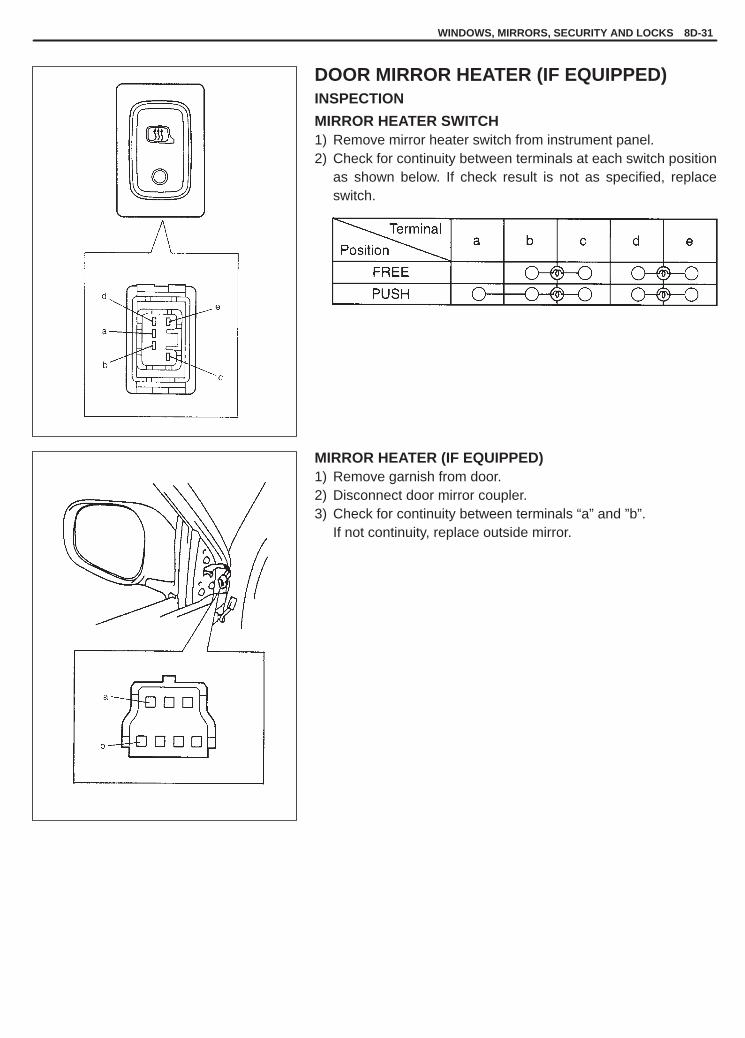
YH4GRANDVITARA
WINDOWS, MIRRORS, SECURITY AND LOCKS 8D-31
DOOR MIRROR HEATER (IF EQUIPPED)INSPECTION
MIRROR HEATER SWITCH1) Remove mirror heater switch from instrument panel.2) Check for continuity between terminals at each switch position
as shown below. If check result is not as specified, replaceswitch.
MIRROR HEATER (IF EQUIPPED)1) Remove garnish from door.2) Disconnect door mirror coupler.3) Check for continuity between terminals “a” and ”b”.
If not continuity, replace outside mirror.

YH4GRANDVITARA
8D-32 WINDOWS, MIRRORS, SECURITY AND LOCKS
3. To open4. To close
3. Left turn4. Right turn
Terminal
Switch
Terminal
Switch
POWER SLIDING ROOF (IF EQUIPPED)INSPECTIONSLIDING ROOF SWITCHCheck switch for continuity between terminals as shown below.
Slide Switch (1)
C D FC D F
OPEN
OFF
CLOSE
Tilt Switch (2)
E D BE D B
UP
OFF
DOWN
SLIDING ROOF MOTOR ASSEMBLY1) Remove head lining. Refer to Section 9 for detail.2) Remove sliding roof motor assembly (1).3) Connect known-good sliding roof switch (2) to sliding roof motor
assembly.4) Connect 12 V battery positive terminal to terminal “A” of motor
assembly (1) and battery negative terminal to terminal “B” of mo-tor assembly (1).
5) Check that the sliding roof motor (1) runs according to the move-ment of the sliding roof switch (2).
Sliding Roof Switch Motor
Tilt up turns left
Tilt down turns right
Slide open turns right
Slide close turns left
If motor does not operate as above, replace sliding roof motorassembly (1).

YH4GRANDVITARA
Hard Top Model
Canvas Top Model
LOAD2 LOAD1
1. Heater wire2. Thermostat
WINDOWS, MIRRORS, SECURITY AND LOCKS 8D-33
FRONT SEAT HEATER (IF EQUIPPED)SEAT HEATER SWITCH (DRIVER AND PASSENGER SIDE)
INSPECTION1) Confirm that ignition switch is OFF position.2) Pull out seat heater switch from front center console box.3) Disconnect seat heater switch coupler.4) Check for continuity between terminals at each switch position
as shown below. If check result is not as specified, replace.
SEAT HEATER WIRE
INSPECTION1) Confirm that seat heater switch is OFF position.2) Disconnect two couplers of seat heater under the seat cushion.
(If seat under tray is equipped, pull out coupler between tray andseat cushion.)
3) Check for continuity between terminals as shown below.If not continuity, replace faulty seat heater.
Hard Top ModelSeat heater circuit in seat backBetween a and bBetween b and dBetween c and eSeat heater circuit in seat cushionBetween f and g
Canvas Top ModelSeat heater circuit in seat backBetween A And BSeat heater circuit in seat cushionBetween C and DBetween D and FBetween E and G
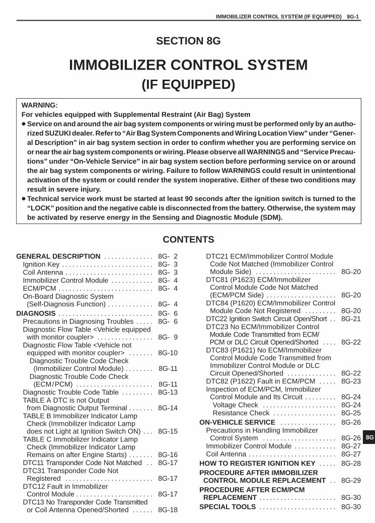
YH4GRANDVITARA
8G
IMMOBILIZER CONTROL SYSTEM (IF EQUIPPED) 8G-1
GENERAL DESCRIPTION 8G- 2. . . . . . . . . . . . . . Ignition Key 8G- 3. . . . . . . . . . . . . . . . . . . . . . . . . . Coil Antenna 8G- 3. . . . . . . . . . . . . . . . . . . . . . . . . Immobilizer Control Module 8G- 4. . . . . . . . . . . . ECM/PCM 8G- 4. . . . . . . . . . . . . . . . . . . . . . . . . . . On-Board Diagnostic System
(Self-Diagnosis Function) 8G- 4. . . . . . . . . . . . . DIAGNOSIS 8G- 6. . . . . . . . . . . . . . . . . . . . . . . . . . .
Precautions in Diagnosing Troubles 8G- 6. . . . . Diagnostic Flow Table <Vehicle equipped
with monitor coupler> 8G- 9. . . . . . . . . . . . . . . . Diagnostic Flow Table <Vehicle not
equipped with monitor coupler> 8G-10. . . . . . . Diagnostic Trouble Code Check
(Immobilizer Control Module) 8G-11. . . . . . . . Diagnostic Trouble Code Check
(ECM/PCM) 8G-11. . . . . . . . . . . . . . . . . . . . . . Diagnostic Trouble Code Table 8G-13. . . . . . . . . TABLE A DTC is not Output
from Diagnostic Output Terminal 8G-14. . . . . . . TABLE B Immobilizer Indicator Lamp
Check (Immobilizer Indicator Lampdoes not Light at Ignition Switch ON) 8G-15. . .
TABLE C Immobilizer Indicator LampCheck (Immobilizer Indicator LampRemains on after Engine Starts) 8G-16. . . . . . .
DTC11 Transponder Code Not Matched 8G-17. . DTC31 Transponder Code Not
Registered 8G-17. . . . . . . . . . . . . . . . . . . . . . . . . DTC12 Fault in Immobilizer
Control Module 8G-17. . . . . . . . . . . . . . . . . . . . . . DTC13 No Transponder Code Transmitted
or Coil Antenna Opened/Shorted 8G-18. . . . . .
DTC21 ECM/Immobilizer Control ModuleCode Not Matched (Immobilizer ControlModule Side) 8G-20. . . . . . . . . . . . . . . . . . . . . . .
DTC81 (P1623) ECM/ImmobilizerControl Module Code Not Matched(ECM/PCM Side) 8G-20. . . . . . . . . . . . . . . . . . . .
DTC84 (P1620) ECM/Immobilizer Control Module Code Not Registered 8G-20. . . . . . . . .
DTC22 Ignition Switch Circuit Open/Short 8G-21. . DTC23 No ECM/Immobilizer ControlModule Code Transmitted from ECM/PCM or DLC Circuit Opened/Shorted 8G-22. . . .
DTC83 (P1621) No ECM/Immobilizer Control Module Code Transmitted fromImmobilizer Control Module or DLCCircuit Opened/Shorted 8G-22. . . . . . . . . . . . . .
DTC82 (P1622) Fault in ECM/PCM 8G-23. . . . . Inspection of ECM/PCM, Immobilizer
Control Module and Its Circuit 8G-24. . . . . . . . . Voltage Check 8G-24. . . . . . . . . . . . . . . . . . . . . Resistance Check 8G-25. . . . . . . . . . . . . . . . . .
ON-VEHICLE SERVICE 8G-26. . . . . . . . . . . . . . . . Precautions in Handling Immobilizer
Control System 8G-26. . . . . . . . . . . . . . . . . . . . . Immobilizer Control Module 8G-27. . . . . . . . . . . . Coil Antenna 8G-27. . . . . . . . . . . . . . . . . . . . . . . . .
HOW TO REGISTER IGNITION KEY 8G-28. . . . . PROCEDURE AFTER IMMOBILIZER
CONTROL MODULE REPLACEMENT 8G-29. . PROCEDURE AFTER ECM/PCM
REPLACEMENT 8G-30. . . . . . . . . . . . . . . . . . . . . . SPECIAL TOOLS 8G-30. . . . . . . . . . . . . . . . . . . . . .
SECTION 8G
IMMOBILIZER CONTROL SYSTEM(IF EQUIPPED)
WARNING:For vehicles equipped with Supplemental Restraint (Air Bag) System� Service on and around the air bag system components or wiring must be performed only by an autho-
rized SUZUKI dealer. Refer to “Air Bag System Components and Wiring Location View” under “Gener-al Description” in air bag system section in order to confirm whether you are performing service onor near the air bag system components or wiring. Please observe all WARNINGS and “Service Precau-tions” under “On-Vehicle Service” in air bag system section before performing service on or aroundthe air bag system components or wiring. Failure to follow WARNINGS could result in unintentionalactivation of the system or could render the system inoperative. Either of these two conditions mayresult in severe injury.
� Technical service work must be started at least 90 seconds after the ignition switch is turned to the“LOCK” position and the negative cable is disconnected from the battery. Otherwise, the system maybe activated by reserve energy in the Sensing and Diagnostic Module (SDM).
CONTENTS

YH4GRANDVITARA
1. Coil antenna2. Ignition key3. Immobilizer control module4. Data link connector (DLC)5. Immobilizer diagnostic coupler
Ignition key
Transpondercode
ImmobilizerControlModule
ECM/PCM
8G-2 IMMOBILIZER CONTROL SYSTEM (IF EQUIPPED)
GENERAL DESCRIPTION
The immobilizer control system designed to prevent vehicle burglar consists of following components.� Engine control module (ECM)/Powertrain control module (PCM)� Immobilizer control module� Ignition key (with built-in transponder)� Coil antenna
Operation of this system is as follows.(1)Each ignition key has its own code (Transponder code) stored in memory. When the ignition switch is turned
ON, Immobilizer Control Module tries to read the Transponder code through the coil antenna installed to thesteering lock assembly.
(2) Immobilizer Control Module compares the Transponder code read in (1) and that registered in Immobilizer Con-trol Module and checks if they match.
(3)When it is confirmed that two Transponder codes match each other as described above, Immobilizer ControlModule and ECM/PCM check if ECM/Immobilizer Control Module codes registered in them respectively match.
(4)Only when it is confirmed that ECM/Immobilizer Control Module codes match, the engine starts running. IfTransponder codes in Step (2) or ECM/Immobilizer Control Module codes in Step (3) do not match, ECM/PCMwill stop operation of the injector and ignition of spark plug.
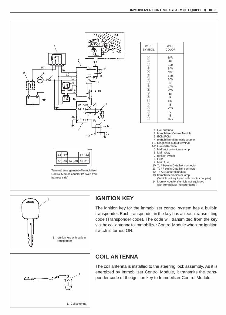
YH4GRANDVITARA
IMMOBILIZER CONTROL SYSTEM (IF EQUIPPED) 8G-3
1
A1 A2 A3 A4
A5 A6 A9 A10A7 A8
1. Coil antenna2. Immobilizer Control Module3. ECM/PCM4. Immobilizer diagnostic coupler
4-1. Diagnostic output terminal4-2. Ground terminal
5. Malfunction indicator lamp6. Main relay7. Ignition switch8. Fuse9. Main fuse
-10. To #9-pin in Data link connector-11. To #7-pin in Data link connector-12. To ABS control module-13. Immobilizer indicator lamp
(Vehicle not equipped with monitor coupler)-14. Monitor coupler (Vehicle not equipped
with immobilizer indicator lamp))
Terminal arrangement of ImmobilizerControl Module coupler (Viewed fromharness side)
B/RBI
BI/BB/WV/YBI/BB/W
BV/WV/WBIR
SbIB
V/GVB
R / Y
WIRESYMBOL
WIRECOLOR
ab
c
d
e
f
g
h
i
j
k
l
m
n
1. Ignition key with built-in transponder
1
1. Coil antenna
o
p
q
r
IGNITION KEY
The ignition key for the immobilizer control system has a built-intransponder. Each transponder in the key has an each transmittingcode (Transponder code). The code will transmitted from the keyvia the coil antenna to Immobilizer Control Module when the ignitionswitch is turned ON.
COIL ANTENNA
The coil antenna is installed to the steering lock assembly. As it isenergized by Immobilizer Control Module, it transmits the trans-ponder code of the ignition key to Immobilizer Control Module.

YH4GRANDVITARA
1. Immobilizer Control Module
8G-4 IMMOBILIZER CONTROL SYSTEM (IF EQUIPPED)
IMMOBILIZER CONTROL MODULE
Immobilizer Control Module is installed to the underside of theinstrument panel at the driver’s seat side.As main functions, Immobilizer Control Module checks matchingnot only between the Transponder Code transmitted from the igni-tion key and that registered in Immobilizer Control Module (Up to4 different Transponder codes can be registered.) but also betweenthe ECM/Immobilizer Control Module code transmitted fromECM/PCM and that registered in Immobilizer Control Module. Inaddition, it has an on-board diagnostic system (self-diagnosis func-tion) which is described in “On-Board Diagnostic System (Self-Diagnosis Function)” in this section.
ECM/PCM
As main functions, ECM/PCM not only checks matching of ECM/Immobilizer Control Module code but also has an on-board diag-nostic system (self-diagnosis function) as described in “On-BoardDiagnostic System (Self-Diagnosis Function)” in this section.For installation position of ECM/PCM, refer to Section 6E1 or 6E2.
ON-BOARD DIAGNOSTIC SYSTEM(SELF-DIAGNOSIS FUNCTION)
Immobilizer Control Module and ECM/PCM diagnose troubleswhich may occur in the area including the following parts when theignition switch is ON.
ECM/ �ECM/Immobilizer Immobilizer �Transponder codePCM: Control Module Control �Coil antenna
code Module: �ECM/Immobilizer �Serial data link �Control Module code
circuit �Serial data link circuit�ECM/PCM �Immobilizer Control
�Module�Ignition signal

YH4GRANDVITARA
0.5
TIME (sec.)
Ignition switch ON
High
Immobilizercontrol systemis normal
Immobilizercontrol systemis abnormal
Low
0.5 0.5 0.5 0.5
HighLow
0.5
TIME (sec.)
Ignition switch ON
High
Immobilizercontrol systemis normal
Immobilizercontrol systemis abnormal
Low
0.5 0.5 0.5 0.5
HighLow
IMMOBILIZER CONTROL SYSTEM (IF EQUIPPED) 8G-5
<Vehicle equipped with monitor coupler>With the diagnosis switch terminal of monitor coupler forECM/PCM not grounded, the ignition switch turned ON (but the en-gine at stop) and regardless of the condition of the electronic fuelinjection system, ECM/PCM indicates whether a trouble has oc-curred in the immobilizer control system or not by causing the mal-function indicator lamp to flash or turn ON.
Malfunction indicator lamp is ON:No trouble exists in the immobilizer control system.Malfunction indicator lamp is flashing:ECM/PCM or Immobilizer Control Module has detected sometrouble in the immobilizer control system.
NOTE:As soon as the ignition switch is turned ON, ECM/PCM and Im-mobilizer Control Module diagnose if a trouble has occurredin the immobilizer control system. While the diagnosis is beingmade, the malfunction indicator lamp stays ON and if the diag-nosis result is “abnormal”, it immediately changes to flashingbut if the result is “normal”, it remains ON. Diagnosis takesabout 3 seconds at maximum.
<Vehicle not equipped with monitor coupler>With the ignition switch turned ON (but the engine at stop) regard-less of the condition of the electronic fuel injection system,ECM/PCM indicates whether a trouble has occurred in the immobi-lizer control system or not by causing the immobilizer indicator lampto flash or turn ON.
Immobilizer indicator lamp is ON:No trouble exists in the immobilizer control system.Immobilizer indicator lamp is flashing:ECM/PCM or Immobilizer Control Module has detected sometrouble in the immobilizer control system.
NOTE:As soon as the ignition switch is turned ON, ECM/PCM and Im-mobilizer Control Module diagnose if a trouble has occurredin the immobilizer control system. While the diagnosis is beingmade, the Immobilizer indicator lamp stays ON and if the diag-nosis result is “abnormal”, it immediately changes to flashingbut if the result is “normal”, it remains ON. Diagnosis takesabout 3 seconds at maximum.
When ECM/PCM and Immobilizer Control Module detects atrouble which has occurred in the above areas, it stores DTC corre-sponding to the exact trouble area in ECM/PCM and ImmobilizerControl Module memory.
DTCs stored in memory of each controller (Immobilizer ControlModule and ECM/PCM) can be read by using the procedure de-scribed in “DIAGNOSTIC TROUBLE CODE CHECK (IMMOBILIZ-ER CONTROL MODULE)” and “DIAGNOSTIC TROUBLE CODECHECK (ECM/PCM)” in this section.

YH4GRANDVITARA
8G-6 IMMOBILIZER CONTROL SYSTEM (IF EQUIPPED)
1. Immobilizer diagnostic coupler
DIAGNOSISECM/PCM and Immobilizer Control Module have on-board diag-nostic system (a system self-diagnosis function) as described pre-viously.Investigate where the trouble is by referring to “Diagnostic FlowTable” and “Diagnostic Trouble Code Table” on later pages.
PRECAUTIONS IN DIAGNOSING TROUBLES
[PRECAUTIONS IN IDENTIFYING DIAGNOSTIC TROUBLE CODE]
ECM/PCM<Vehicle equipped with monitor coupler>� Before identifying diagnostic trouble code indicated by malfunc-
tion indicator lamp, don’t disconnect couplers from ECM/PCM,battery cable from battery, ECM/PCM ground wire harness fromengine.Such disconnection will clear trouble codes for electronic fuel in-jection system stored in memory of ECM/PCM.
� If abnormality or malfunction lies in two or more areas, malfunc-tion indicator lamp indicates applicable codes three times each.And flashing of these codes is repeated as long as diagnosis ter-minal is grounded and ignition switch is held at ON position.
� When ECM/PCM detects a trouble in both electronic fuel injec-tion system and immobilizer control system, malfunction indicatorlamp indicates trouble codes of both systems alternately while theignition switch is turned ON and the diagnosis terminal isgrounded.
� Take a note of diagnostic trouble code indicated first.
<Vehicle not equipped with monitor coupler>� Before identifying diagnostic trouble code indicated through Su-
zuki scan tool, don’t disconnect couplers from ECM/PCM, bat-tery cable from battery, ECM/PCM ground wire harness from en-gine.Such disconnection will clear trouble codes for electronic fuel in-jection system stored in memory of ECM/PCM.
� Take a note of diagnostic trouble code indicated first.
Immobilizer Control Module� Take a note of diagnostic trouble code indicated first.

YH4GRANDVITARA
IMMOBILIZER CONTROL SYSTEM (IF EQUIPPED) 8G-7
[INTERMITTENT TROUBLES]
<Vehicle equipped with monitor coupler>� There are cases where output of diagnostic output terminal
and/or malfunction indicator lamp indicate a diagnostic troublecode representing a trouble which occurred only temporarily andhas gone. In such case, it may occur that good parts are replacedunnecessarily. To prevent such accident, be sure to follow instruc-tions given below when checking by using “Diagnostic FlowTable”.* When trouble can be identified, it is not an intermittent one:
Check coil antenna, ignition key, wires and each connectionand if they are all in good condition, substitute a known-goodECM/PCM and recheck.
* When trouble can not be identified but output of diagnostic out-put terminal and/or malfunction indicator lamp indicate atrouble code:Diagnose trouble by using that code No. and if ignition key, coilantenna, wires and each connection are all in good condition,turn OFF ignition switch and then ON.
Then check what malfunction indicator lamp and/or output of diag-nostic output terminal indicate.Only when they indicate trouble code again, substitute a known-good ECM/PCM or Immobilizer Control Module and check again.If they indicate not trouble code but normal code, it means that anintermittent trouble did occur and has gone. In this case, checkwires and connections carefully again.
<Vehicle not equipped with monitor coupler>� There are cases where output of diagnostic output terminal and/
or Suzuki scan tool indicates a diagnostic trouble code represent-ing a trouble which occurred only temporarily and has gone. Insuch case, it may occur that good parts are replaced unnecessar-ily. To prevent such accident, be sure to follow instructions givenbelow when checking by using “Diagnostic Flow Table”.* When trouble can be identified, it is not an intermittent one:
Check coil antenna, ignition key, wires and each connectionand if they are all in good condition, substitute a known-goodECM/PCM and recheck.
* When trouble can not be identified but output of diagnostic out-put terminal and/or Suzuki scan tool indicates a trouble code:Diagnose trouble by using that code No. and if ignition key, coilantenna, wires and each connection are all in good condition,turn OFF ignition switch and then ON.
Then check what Suzuki scan tool and/or output of diagnostic out-put terminal indicates.Only when they indicate trouble code again, substitute a known-good ECM/PCM or Immobilizer Control Module and check again.If they indicate not trouble code but normal code, it means that anintermittent trouble did occur and has gone. In this case, checkwires and connections carefully again.

YH4GRANDVITARA
8G-8 IMMOBILIZER CONTROL SYSTEM (IF EQUIPPED)
[NOTES ON SYSTEM CIRCUIT INSPECTION]Refer to “Precautions for Electrical Circuit Service” and “Intermit-tents and Poor Connection” in Section 0A.
[Precaution after replacing ECM/PCM or Immobilizer Control Mod-ule]� When ECM/PCM was replaced, including when replaced be-
cause rechecking by using a known-good ECM/PCM was neces-sary during trouble diagnosis, the ECM/Immobilizer Control Mod-ule code must be registered in ECM/PCM and ImmobilizerControl Module by performing procedure described in “Proce-dure after ECM/PCM Replacement” on p. 8G-27. If it is not regis-tered, the engine would not start and accurate trouble diagnosiswould not be assured.
� When Immobilizer Control Module was replaced, including whenreplaced because rechecking by using a known-good Immobiliz-er Control Module was necessary during trouble diagnosis, theTransponder code and ECM/Immobilizer Control Module codemust be registered in Immobilizer Control Module and ECM/Im-mobilizer Control Module code in ECM/PCM by performing pro-cedure described in “Procedure after Immobilizer Control ModuleReplacement” on p. 8G-26. If they are not registered, the enginewould not start and accurate trouble diagnosis would not be as-sured.

YH4GRANDVITARA
IMMOBILIZER CONTROL SYSTEM (IF EQUIPPED) 8G-9
Fig. 1 for Step 1 Fig. 2 for Step 1 Fig. 3 for Step 2
1. Monitor coupler2. Service wireA: Diagnosis switch terminalB: Ground terminalFig. 4 for Step 3
“CHECK ENGINE” light 0.5
ON
OFFTIME (sec.)
DIAGNOSTIC FLOW TABLE<Vehicle equipped with monitor coupler>
STEP ACTION YES NO
1 1) Make sure that diagnosis switchterminal in monitor coupler is notgrounded by service wire. See Fig. 1.
2) Check malfunction indicator lampwhile ignition switch is ON (but withoutstarting engine). See Fig. 2.
Dose malfunction indicator lamp flash?
Go to Step 3. � If malfunction indicator lampremains ON, go to Step 2.
� If malfunction indicator lampremains OFF, go to“MALFUNCTION INDICATORLAMP CHECK” in Section 6.
2 1) Using service wire, ground diagnosisswitch terminal in monitor coupler.See Fig. 3.
Dose malfunction indicator lamp flash?
Immobilizer controlsystem is in goodcondition.
Go to “MALFUNCTIONINDICATOR LAMP CHECK” inSection 6.
3 Dose malfunction indicator lamp flash asFig. 4?
Go to Step 4. Go to “MALFUNCTIONINDICATOR LAMP CHECK” inSection 6.
4 1) Check DTC stored in immobilizercontrol module referring to“DIAGNOSTIC TROUBLE CODECHECK (IMMOBILIZER CONTROLMODULE)” in this section.
Is there any DTC(s)?
Go to flow table forDTC No.
Go to Step 5.
5 1) Check DTC stored in ECM/PCMreferring to “DIAGNOSTIC TROUBLECODE CHECK (ECM/PCM)” in thissection.
Is there any DTC(s)?
Go to flow table forDTC No.
Substitute a known-good ECM/PCM and recheck.NOTE:After replacing with a known-good ECM/PCM, registerECM/Immobilizer ControlModule code in ECM/PCM byperforming procedure describedin “Procedure after ECM/PCMReplacement” section.

YH4GRANDVITARA
8G-10 IMMOBILIZER CONTROL SYSTEM (IF EQUIPPED)
DIAGNOSTIC FLOW TABLE<Vehicle not equipped with monitor coupler>
STEP ACTION YES NO
1 1) Check immobilizer indicator lampwhile ignition switch is ON (but withoutstarting engine). See Fig. 1.
Dose immobilizer indicator lamp flash?
Go to Step 3. � If immobilizer indicator lampremains ON, go to Step 2.
� If immobilizer indicator lampremains OFF, go to“IMMOBILIZER INDICATORLAMP CHECK” in this section.
2 1) Check DTC stored in ECM/PCMreferring to “DIAGNOSTIC TROUBLECODE CHECK (ECM/PCM)” in thissection.
Is there any DTC(s)?
Go to “IMMOBILIZERINDICATOR LAMPCHECK” in this section.
Immobilizer control system is ingood condition.
3 1) Check DTC stored in immobilizercontrol module referring to“DIAGNOSTIC TROUBLE CODECHECK (IMMOBILIZER CONTROLMODULE)” in this section.
Is there any DTC(s)?
Go to flow table forDTC No.
Go to Step 4.
4 1) Check DTC stored in ECM/PCMreferring to “DIAGNOSTIC TROUBLECODE CHECK (ECM/PCM)” in thissection.
Is there any DTC(s) for immobilizercontrol system?
Go to flow table forDTC No.
Substitute a known-good ECM/PCM and recheck.NOTE:After replacing with a known-good ECM/PCM, registerECM/Immobilizer ControlModule code in ECM/PCM byperforming procedure describedin “Procedure after ECM/PCMReplacement” section.
FIg. 1 for Step 1

YH4GRANDVITARA
IMMOBILIZER CONTROL SYSTEM (IF EQUIPPED) 8G-11
1. Immobilizer diagnostic coupler
EXAMPLE :� COIL ANTENNA FAILURE (CODE NO.13)
Voltmeter indicator
� NORMAL (No code)Voltmeter indicator
TIME (sec.)
TIME (sec.)
CODE No. 13 CODE No. 13 CODE No. 13
High
Low
High
Low
1. Monitor coupler2. Service wireA: Diagnosis switch
terminalB: Ground terminal
DIAGNOSTIC TROUBLE CODE (DTC) CHECK(IMMOBILIZER CONTROL MODULE)1) Using analog type voltmeter, connect positive probe to diagnos-
tic output terminal and negative probe to ground of immobilizerdiagnostic coupler with ignition switch turned ON.
2) Read deflection of voltmeter indicator which represents DTC asshown in example below and write it down. For details of DTC,refer to Immobilizer Control Module side in “Diagnostic TroubleCode Table”.If voltmeter indicator dose not deflect, go to “Diagnostic FlowTable A”.
NOTE:If abnormality or malfunction lies in two or more areas, volt-meter indicates applicable codes three times each.
DIAGNOSTIC TROUBLE CODE (DTC) CHECK (ECM/PCM)
[Not using SUZUKI scan tool] (Vehicle equipped withmonitor coupler)1) Using service wire, ground diagnostic switch terminal in monitor
coupler.2) Read DTC from flashing pattern of malfunction indicator lamp as
shown in example below and write it down. For details of DTC,refer to ECM/PCM side in “Diagnostic Trouble Code Table”.If lamp remains ON, go to “Malfunction Indicator Lamp Check”in Section 6.
NOTE:If abnormality or malfunction lies in two or more areas, mal-function indicator lamp indicates applicable codes threetimes each.And flashing of these codes is repeated as long as diagno-sis terminal is grounded and ignition switch is held at ONposition.
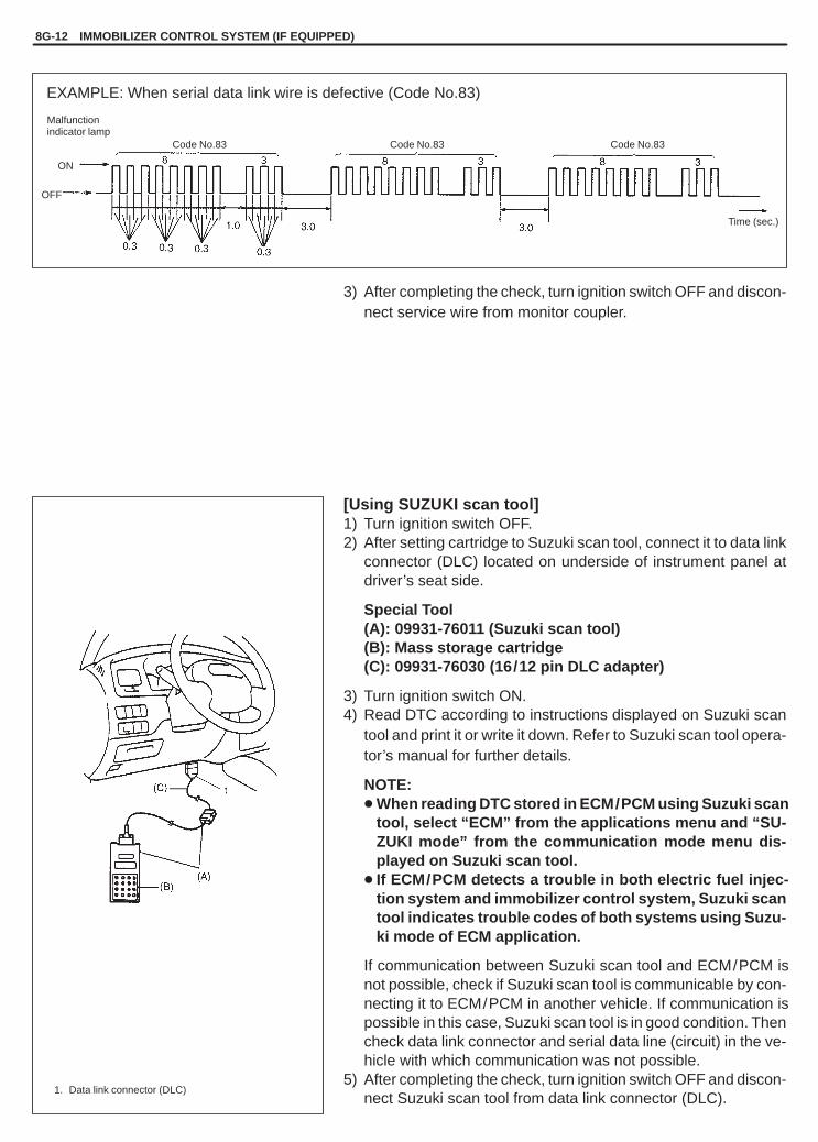
YH4GRANDVITARA
8G-12 IMMOBILIZER CONTROL SYSTEM (IF EQUIPPED)
EXAMPLE: When serial data link wire is defective (Code No.83)
ON
OFF
Malfunctionindicator lamp
Code No.83 Code No.83 Code No.83
Time (sec.)
1. Data link connector (DLC)
3) After completing the check, turn ignition switch OFF and discon-nect service wire from monitor coupler.
[Using SUZUKI scan tool]1) Turn ignition switch OFF.2) After setting cartridge to Suzuki scan tool, connect it to data link
connector (DLC) located on underside of instrument panel atdriver’s seat side.
Special Tool(A): 09931-76011 (Suzuki scan tool)(B): Mass storage cartridge(C): 09931-76030 (16/12 pin DLC adapter)
3) Turn ignition switch ON.4) Read DTC according to instructions displayed on Suzuki scan
tool and print it or write it down. Refer to Suzuki scan tool opera-tor’s manual for further details.
NOTE:� When reading DTC stored in ECM/PCM using Suzuki scan
tool, select “ECM” from the applications menu and “SU-ZUKI mode” from the communication mode menu dis-played on Suzuki scan tool.
� If ECM/PCM detects a trouble in both electric fuel injec-tion system and immobilizer control system, Suzuki scantool indicates trouble codes of both systems using Suzu-ki mode of ECM application.
If communication between Suzuki scan tool and ECM/PCM isnot possible, check if Suzuki scan tool is communicable by con-necting it to ECM/PCM in another vehicle. If communication ispossible in this case, Suzuki scan tool is in good condition. Thencheck data link connector and serial data line (circuit) in the ve-hicle with which communication was not possible.
5) After completing the check, turn ignition switch OFF and discon-nect Suzuki scan tool from data link connector (DLC).

YH4GRANDVITARA
IMMOBILIZER CONTROL SYSTEM (IF EQUIPPED) 8G-13
DIAGNOSTIC TROUBLE CODE TABLEImmobilizer Control Module side
DIAGNOSTIC TROUBLE CODEDIAGNOSTIC AREA DIAGNOSIS
NO. VOLTMETER INDICATIONDIAGNOSTIC AREA DIAGNOSIS
– Normal (No code)This code appears when none of theother codes are identified.
11
Transponder code
31
Trans onder code
12 Immobilizer Control Module
Diagnose trouble according to13
Coil antenna or ignition key withbuilt-in transponder
Diagnose trouble according to“DIAGNOSTIC FLOW TABLE”corresponding to each code No.
21 ECM/Immobilizer Control Module code
corres onding to each code No.
22 Ignition switch circuit
23 Serial data link wire
ECM/PCM side
DTC(indicated on
Suzukiscan tool)
DTC(indicatedby MIL)
Malfunction Indicator lamp(MIL) flashing pattern
DIAGNOSTIC AREA DIAGNOSIS
NO DTC 12 Normal
This code appears when it isconfirmed that none of othertrouble codes is set for immo-bilizer control system or elec-tronic fuel injection system.
P1623 81ECM/Immobilizer
P1620 84Control Module code Diagnose trouble according to
“DIAGNOSTIC FLOW
P1622 82 ECM/PCMTABLE” corresponding toeach code No.
P1621 83 Serial data link wire

YH4GRANDVITARA
8G-14 IMMOBILIZER CONTROL SYSTEM (IF EQUIPPED)
In cabin
- 1. Main fuse- 2. Main relay- 3. Immobilizer Control Module- 4. Immobilizer diagnostic coupler4-1. Ground terminal4-2. Diagnostic output terminal- 5. To ECM / PCM
TABLE A DTC IS NOT OUTPUT FROM DIAGNOSTIC OUTPUT TERMINAL
STEP ACTION YES NO
1 Check voltage between A3 terminaland body ground with ignition switchturned ON.Is it 10 – 14V?
Go to Step 2. “(f)” wire open.
2 1) Connect voltmeter between A5terminal and body ground.
2) Does voltmeter indicator deflect?
Go to Step 3. � Poor A3, A5 or A7 connection.� “(h)” wire of A7 terminal open.� “(m)” wire between A5 terminal and
diagnostic output terminal of immobi-lizer diagnostic coupler short.
If wire and connections are OK, substi-tute a known-good Immobilizer ControlModule and recheck.NOTE:After replacing with a known-goodImmobilizer Control Module, registerECM/Immobilizer Control Modulecode in ECM/PCM and Transpondercode and ECM/Immobilizer ControlModule code in Immobilizer ControlModule by performing procedure described in “Procedure after Immo-bilizer Control Module Replace-ment” section.
3 1) Connect voltmeter between diag-nostic output terminal of immobiliz-er diagnostic coupler and bodyground.
2) Is it possible to read DTC by check-ing deflection of voltmeter indicator?
“(n)” wire of groundterminal for immo-bilizer diagnosticcoupler open.
“(m)” wire between A5 terminal and diag-nostic output terminal of immobilizerdiagnostic coupler open.

YH4GRANDVITARA
IMMOBILIZER CONTROL SYSTEM (IF EQUIPPED) 8G-15
1. Main fuse2. Main relay3. ECM/PCM4. Immobilizer indicator lamp
(Vehicle not equipped withmonitor coupler)
For G16 / J20 engine For H25 engine
G16/J20 Engine
H25 Engine
TABLE B IMMOBILIZER INDICATOR LAMP CHECK(IMMOBILIZER INDICATOR LAMP DOSE NOT LIGHT AT IGNITIONSWITCH ON)
STEP ACTION YES NO
1 1) Turn ignition switch ON.Do other indicator/warning lights incombination meter come ON?
Go to Step 2. “IG” fuse blown, main fuse blown,ignition switch malfunction,“B/W” circuit between “IG” fuseand combination meter or poorcoupler connection atcombination meter.
2 1) Turn ignition switch OFF anddisconnect connectors from ECM/PCM.
2) Check for proper connection to ECM/PCM at terminal E61-5 for G16/J20engine or E61-23 for H25 engine.
3) If OK, then using service wire, groundterminal E61-5 for G16/J20 engine orE61-23 for H25 engine in connectordisconnected.
Does immobilizer indicator lamp turn onat ignition switch ON?
Substitute a known-good ECM/PCM andrecheck.
Bulb burned out or “(b)” wirecircuit open.

YH4GRANDVITARA
8G-16 IMMOBILIZER CONTROL SYSTEM (IF EQUIPPED)
1. Main fuse2. Main relay3. ECM/ PCM4. Immobilizer indicator lamp
(Vehicle not equipped withmonitor coupler)
For G16 / J20 engine For H25 engine
G16/J20 Engine
H25 Engine
TABLE C IMMOBILIZER INDICATOR LAMP CHECK(IMMOBILIZER INDICATOR LAMP REMAINS ON AFTER ENGINESTARTS)
STEP ACTION YES NO
1 1) With ignition switch OFF, disconnectcouplers from ECM/PCM.
Does immobilizer indicator lamp turn ONat ignition switch ON?
“(p)” wire shorted toground circuit.
Substitute a known-good ECM/PCM and recheck.

YH4GRANDVITARA
IMMOBILIZER CONTROL SYSTEM (IF EQUIPPED) 8G-17
DTC11 TRANSPONDER CODE NOT MATCHEDDESCRIPTION:Immobilizer Control Module checks if Transponder code transmitted from ignition key and that registered in Immo-bilizer Control Module match when ignition switch is ON. If they do not, this DTC is set.
INSPECTION:Register ignition key with built-in transponder by using Suzuki scan tool (TECH1 cartridge for immobilizer controlsystem and TECH 1A kit) and performing following steps.1) Register Transponder code in Immobilizer Control Module by performing procedure described in “How to regis-
ter ignition key” section.2) Turn ignition switch OFF, then turn it ON and check that DTC11 is not set.
DTC31 TRANSPONDER CODE NOT REGISTEREDDESCRIPTION:Immobilizer Control Module checks if Transponder code transmitted from ignition key and that registered in Immo-bilizer Control Module match when ignition switch is ON. If there is no Transponder code registered in ImmobilizerControl Module, this DTC is set.
INSPECTION:Register ignition key with built-in transponder by using Suzuki scan tool (TECH1 cartridge for immobilizer controlsystem and TECH 1A kit) and performing following steps.1) Register Transponder code in Immobilizer Control Module by performing procedure described in “How to regis-
ter ignition key” section.2) Turn ignition switch OFF, then turn it ON and check that DTC31 is not set.
DTC12 FAULT IN IMMOBILIZER CONTROL MODULEDESCRIPTION:This DTC is set when an internal fault is detected in Immobilizer Control Module.
INSPECTION:
STEP ACTION YES NO
1 1) Ignition switch OFF.2) Disconnect connectors from Immobi-
lizer Control Module.3) Check for proper connection to Im-
mobilizer Control Module at all termi-nals.
Are they in good condition?
Substitute a known-good ImmobilizerControl Module and recheck.NOTE:After replacing with a known-goodImmobilizer Control Module, registerECM/Immobilizer Control Modulecode in ECM/PCM and Transpondercode and ECM/ImmobilizerControl Module code in ImmobilizerControl Module by performingprocedure described in “Procedureafter Immobilizer Control ModuleReplacement” section.
Repair or replace.

YH4GRANDVITARA
8G-18 IMMOBILIZER CONTROL SYSTEM (IF EQUIPPED)
1
2
3 4
1. Main fuse2. Main relay3. Immobilizer
Control Module4. Coil antenna5. To ECM / PCM
5(a)
(f) (k)
(I)
DTC13 NO TRANSPONDER CODE TRANSMITTED OR COIL ANTENNAOPENED/SHORTED
DESCRIPTION:Immobilizer Control Module energizes the coil antenna when the ignition switch is ON and reads Transponder codefrom the ignition key. When Immobilizer Control Module cannot read Transponder code from the ignition key evenwhen the coil antenna is energized, this DTC is set.
INSPECTION:
STEP ACTION YES NO
1 Does ignition key being used have built-in trans-ponder? (See Fig. 1)
Go to Step 2. Replace ignition key with built-in trans-ponder and follow “DIAGNOSTICFLOW TABLE” again.
2 1) Disconnect coil antenna coupler with ignitionswitch turned OFF.
2) Is there continuity between coil antenna cou-pler terminals A and B? (See Fig. 2)
Go to Step 3. Coil antenna open.
3 Measure resistance between terminals of coil an-tenna coupler and body ground. (See Fig. 3)Is it � (infinity) � ?
Go to Step 4. Coil antenna shorted to ground.
4 1) With coil antenna coupler disconnected, dis-connect Immobilizer Control Module coupler.
2) Measure resistance between coil antenna ter-minals of Immobilizer Control Module coupler.(See Fig. 4)
Is it � (infinity) � ?
Go to Step 5. “(k)” wire shorted to “(l)”wire.
5 Measure resistance between terminal A1 of Im-mobilizer Control Module coupler and bodyground. (See Fig. 5)Is it � (infinity) � ?
Go to Step 6. “(k)” wire shorted to ground.
6 Measure resistance between terminal A2 of Im-mobilizer Control Module coupler and bodyground. (See Fig. 6)Is it � (infinity) � ?
Go to Step 7. “(I)” wire shorted to ground.
7 1) Connect coil antenna coupler.2) Is there continuity between Immobilizer Con-
trol Module coupler terminals A1 and A2? (See Fig. 7)
Go to Step 8. � “(k)” or “(I)” wire open.� Poor coil antenna-to-coupler.

YH4GRANDVITARA
IMMOBILIZER CONTROL SYSTEM (IF EQUIPPED) 8G-19
DTC13 NO TRANSPONDER CODE TRANSMITTED ORCOIL ANTENNA OPENED/SHORTED (CONTINUED)
STEP ACTION YES NO
8 Poor A1 or A2 connection.1) If connections are OK, connect
Immobilizer Control Modulecoupler and substitute a known-good coil antenna.
2) Is DTC 13 also indicated withignition switch turned ON?
Go to Step 9. Faulty coil antenna.
9 Is DTC 13 still indicated even whenanother ignition key (with built-intransponder) for that vehicle used?
Substitute a known-good ImmobilizerControl Module and recheck.NOTE:After replacing with a known-goodImmobilizer Control Module, registerECM/Immobilizer Control Module codein ECM/PCM and Transponder codeand ECM/Immobilizer Control Modulecode in Immobilizer Control Module byperforming procedure described in“Procedure after Immobilizer ControlModule Replacement” section.
Faulty ignition key.
1. Coil antenna coupler
1
1. Coil antenna coupler
1
A
B
Fig. 1 for Step 1
Ignition key with built-in transponder
Fig. 2 for Step 2 Fig. 3 for Step 3
Fig. 4 for Step 4 Fig. 5 for Step 5 Fig. 6 for Step 6
1. Immobilizer ControlModule coupler
1A1
A2
A1 1
1. Immobilizer Control Module coupler
1. Immobilizer ControlModule coupler
A2 1
Fig. 7 for Step 7
1. Immobilizer Control Module coupler
A1 1A2

YH4GRANDVITARA
8G-20 IMMOBILIZER CONTROL SYSTEM (IF EQUIPPED)
DTC21 ECM/IMMOBILIZER CONTROL MODULE CODE NOT MATCHED(IMMOBILIZER CONTROL MODULE SIDE)
DTC81 ECM/IMMOBILIZER CONTROL MODULE CODE NOT MATCHED(P1623) (ECM/PCM SIDE)DTC84 ECM/IMMOBILIZER CONTROL MODULE CODE NOT REGISTERED(P1620)DESCRIPTION:� DTC21
Immobilizer Control Module checks if ECM/Immobilizer Control Module code transmitted from ECM/PCM andthat registered in Immobilizer Control Module match when ignition switch is ON. If they do not, this DTC is set.
� DTC81 (P1623)ECM/PCM checks if ECM/Immobilizer Control Module code transmitted from Immobilizer Control Module andthat registered in ECM/PCM match when ignition switch is ON. If they do not, this DTC is set.
� DTC84 (P1620)ECM/PCM checks if code transmitted from Immobilizer Control Module and that registered in ECM/PCM matchwhen ignition switch is ON. If there is no ECM/Immobilizer Control Module code registered in ECM/PCM, thisDTC is set.
INSPECTION:Perform procedure described in “Procedure after ECM/PCM Replacement” section.

YH4GRANDVITARA
IMMOBILIZER CONTROL SYSTEM (IF EQUIPPED) 8G-21
1
2
3
1. Main fuse2. Ignition switch3. Immobilizer
Control Module
(g)A4
DTC22 IGNITION SWITCH CIRCUIT OPEN/SHORT
DESCRIPTION:Immobilizer Control Module monitors ignition signal when the ignition switch is ON. This DTC is set when no ignitionsignal input is detected by Immobilizer Control Module.
INSPECTION:
STEP ACTION YES NO
1 Check voltage between ImmobilizerControl Module coupler terminal A4and body ground with ignitionswitch turned ON. (See Fig.1)Is it 10 – 14V?
Poor A4 terminal connection.If connection is OK, substitute aknown-good Immobilizer ControlModule and recheck.NOTE:After replacing with a know-goodImmobilizer Control Module, register ECM/Immobilizer ControlModule code in ECM/PCM andTransponder code and ECM/Immobilizer Control Module codein Immobilizer Control Module byperforming procedure describedin “Procedure after ImmobilizerControl Module Replacement”section.
“(g)” wire open or short.
Fig. 1 for Step 1
1
A41. Immobilizer Control Module

YH4GRANDVITARA
8G-22 IMMOBILIZER CONTROL SYSTEM (IF EQUIPPED)
A8
1 2
To SDM (if equipped with AIRBAG)
To data link connector (DLC)
1. Immobilizer Control Module2. ECM/ PCM
(j) (i)
(i)
(i)
DTC23 NO ECM/IMMOBILIZER CONTROL MODULE CODE TRANSMITTEDFROM ECM/PCM OR DLC CIRCUIT OPENED/SHORTED
DTC83 NO ECM/IMMOBILIZER CONTROL MODULE CODE TRANSMITTED(P1621) FROM IMMOBILIZER CONTROL MODULE OR DLC CIRCUIT
OPENED/SHORTED
DESCRIPTIONWhen the ignition switch is ON, Immobilizer Control Module requests ECM/PCM and ECM/PCM requests Immobi-lizer Control Module to transmit ECM/Immobilizer Control Module code. If ECM/Immobilizer Control Module codeis not transmitted from ECM/PCM or Immobilizer Control Module, Immobilizer Control Module sets DTC23 andECM/PCM sets DTC83 (P1621).
INSPECTION:STEP ACTION YES NO
1 Check voltage betweenImmobilizer Control Mod-ule coupler terminal A8and body ground with igni-tion switch turned ON.Is it 4 – 5V?
Go to Step 2. “(i)” or “(j)” wireshort.
2 1) Disconnect ECM/PCM coupler with igni-tion switch turnedOFF.
2) Is there continuity be-tween ImmobilizerControl Module cou-pler terminal A8 andData link connectorterminal of ECM/PCMcoupler? (For posi-tions of Data link con-nector terminal ofECM/PCM coupler,refer to Section 6E1 or6E2.)
Poor A8 connection (Immobilizer Control Module) orPoor Data link connector terminal connection (ECM/PCM). If connections are OK, substitute a known-goodECM/PCM or Immobilizer Control Module and re-check.NOTE :� After replacing with a known-good ECM/PCM,
register ECM/Immobilizer Control Module codein ECM/PCM by performing procedure de-scribed in “Procedure after ECM/PCM Replace-ment” section.
� After replacing with a known-good ImmobilizerControl Module, register ECM/Immobilizer ControlModule code in ECM/PCM and Transponder codeand ECM/Immobilizer Control Module code in Im-mobilizer Control Module by performing proce-dure described in “Procedure after ImmobilizerControl Module Replacement” section.
“(i)” or “(j)” wire be-tween ImmobilizerControl Module andECM/PCM open.
Fig. 1 for step 1
1
A8
1. Immobilizer Control Module 1. Immobilizer Control Module coupler disconnected
1
A8Connect to Data link connector terminal of ECM / PCM coupler disconnected
Fig. 2 for step 2

YH4GRANDVITARA
IMMOBILIZER CONTROL SYSTEM (IF EQUIPPED) 8G-23
DTC82 (P1622) FAULT IN ECM/PCMDESCRIPTION:This DTC is set when an internal fault is detected in ECM/PCM.
INSPECTION:
STEP ACTION YES NO
1 1) Ignition switch OFF.2) Disconnect connectors from
ECM/PCM.3) Check for proper connection
to ECM/PCM at all terminals.Are they in good condition?
Substitute a known-good ECM/PCM andrecheck.NOTE:After replacing with a known-good ECM/PCM, register ECM/Immobilizer ControlModule code in ECM/PCM by performingprocedure described in “Procedure afterECM/PCM Replacement” section.
Repair or replace.

YH4GRANDVITARA
8G-24 IMMOBILIZER CONTROL SYSTEM (IF EQUIPPED)
1
2
3
1
2
1. Immobilizer Control Module2. Immobilizer Control Module Coupler3. Body ground
INSPECTION OF ECM/PCM, IMMOBILIZERCONTROL MODULE AND ITS CIRCUITECM/PCM, Immobilizer Control Module and its circuit can bechecked at ECM/PCM wiring couplers and Immobilizer ControlModule wiring coupler by measuring voltage and resistance. De-scribed here is only inspection of Immobilizer Control Module. Forinspection of ECM/PCM, refer to “SECTION 6E1 or 6E2”.
CAUTION:Immobilizer Control Module cannot be checked by itself. Itis strictly prohibited to connect voltmeter or ohmmeter toImmobilizer Control Module with coupler disconnectedfrom it.
Voltage Check1) Remove Immobilizer Control Module from body with ignition
switch OFF, referring to p. 8G-24.2) Connect Immobilizer Control Module coupler to Immobilizer
Control Module.3) Check voltage at each terminal of coupler connected.
NOTE:As each terminal voltage is affected by the battery voltage,confirm that it is 11 V or more when ignition switch is ON.
TERMINAL CIRCUITNORMALVOLTAGE
CONDITION
A1 Coil antenna 1 0 V
A2 Coil antenna 2 0 V Ignition switch ON
A3 Power source 10 – 14 V
A4 Ignition signal10 – 14 V Ignition switch ON
A4 Ignition signal0 – 0.8 V Ignition switch OFF
A5 Diagnosis output0 – 14 V Ignition switch ON
A5 Diagnosis output0 V Ignition switch OFF
A6 Blank – –
A7 Ground – –
A8Data link connector(Serial data terminal)
4 – 5 V Ignition switch ON
A9A10
Blank – –
NOTE:When measuring voltage at A1 and A2 terminals with ignition switch turned ON, be sure to turn ignitionswitch ON before connecting positive probe of voltmeter to A1 or A2 terminal. If it is not turned ON first,DTC13 (Diagnostic Trouble Code 13) may be indicated.

YH4GRANDVITARA
IMMOBILIZER CONTROL SYSTEM (IF EQUIPPED) 8G-25
1
2
1. Immobilizer Control Modulecoupler disconnected
2. Ohmmeter
Resistance Check1) Disconnect Immobilizer Control Module couplers from Immobi-
lizer Control Module with ignition switch OFF.
CAUTION:Never touch terminals of Immobilizer Control Module it-self or connect voltmeter or ohmmeter.
2) Check resistance between each terminal of coupler discon-nected.
CAUTION:� Be sure to connect ohmmeter probe from wire harness
side of coupler.� Be sure to turn OFF ignition switch for this check.� Resistance in table below represents that when parts
temperature is 20 �C (68�F).
TERMINAL CIRCUITNORMAL
RESISTANCECONDITION
A1 – A2 Coil antenna Continuity –

YH4GRANDVITARA
8G-26 IMMOBILIZER CONTROL SYSTEM (IF EQUIPPED)
ON-VEHICLE SERVICE
PRECAUTIONS IN HANDLING IMMOBILIZERCONTROL SYSTEM
� Do not turn ON ignition switch with ignition key for immobilizercontrol system put together with another one or placed quite closeto another one. Or the system may detect abnormal condition andprevent engine from starting.
� Do not turn ON ignition switch by using ignition key with any typeof metal wound around its grip or in contact with it. Or the systemmay detect abnormal condition and prevent engine from starting.
� Do not leave ignition key where high temperature is anticipated.High temperature will cause transponder in ignition key to be ab-normal or damaged.
� Do not turn ON ignition switch with a radio antenna placed nearcoil antenna or its harness to Immobilizer Control Module. Or thesystem may detect abnormal condition and prevent engine fromstarting.
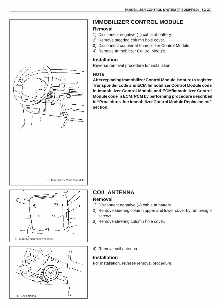
YH4GRANDVITARA
IMMOBILIZER CONTROL SYSTEM (IF EQUIPPED) 8G-27
1
1. Immobilizer Control Module
1. Steering column lower cover
1. Coil antenna
IMMOBILIZER CONTROL MODULERemoval1) Disconnect negative (–) cable at battery.2) Remove steering column hole cover.3) Disconnect coupler at Immobilizer Control Module.4) Remove Immobilizer Control Module.
InstallationReverse removal procedure for installation.
NOTE:After replacing Immobilizer Control Module, be sure to registerTransponder code and ECM/Immobilizer Control Module codein Immobilizer Control Module and ECM/Immobilizer ControlModule code in ECM/PCM by performing procedure describedin “Procedure after Immobilizer Control Module Replacement”section.
COIL ANTENNARemoval1) Disconnect negative (–) cable at battery.2) Remove steering column upper and lower cover by removing 3
screws.3) Remove steering column hole cover.
4) Remove coil antenna.
InstallationFor installation, reverse removal procedure.

YH4GRANDVITARA
8G-28 IMMOBILIZER CONTROL SYSTEM (IF EQUIPPED)
1
1. Ignition key with built-in transponder
1. Data link connector (DLC)
HOW TO REGISTER IGNITION KEY
Register the ignition key with a built-in transponder in ImmobilizerControl Module by using the following procedure.1) Prepare Suzuki scan tool (TECH 1A kit and cartridge for immobi-
lizer control system).2) With ignition switch OFF, connect Suzuki scan tool to data link
connector (DLC) located on underside of instrument panel atdriver’s seat side.
Special Tool(A): 09931-76011 (Tech 1A)(B): Immobilizer cartridge(C): 09931-76030 (16/14-pin DLC cable)
NOTE:For operation procedure of Suzuki scan tool, refer to Suzukiscan tool operator’s manual.
3) Prepare ignition key with a built-in transponder. And then turnignition switch ON by using it.
4) Number of Transponder codes for ignition key with a built-intransponder that can be registered in Immobilizer Control Mod-ule is limited to 4. If needed, clear all Transponder codes for igni-tion key with a built-in transponder that have been registered inImmobilizer Control Module by executing the “CLR. TRANSCOD (CLEAR TP CODE)” command in the SELECT MODEmenu by using Suzuki scan tool.
NOTE:When “CLR. TRANS COD (CLEAR TP CODE)” command isexecuted with the malfunction indicator lamp (the lamp forvehicles equipped with the monitor coupler) ON or the im-mobilizer indicator lamp (the lamp for vehicle not equippedwith the monitor coupler) ON, it remains ON even afterexecution of that command is over. It will start flashingwhen the ignition switch is turned OFF once and thenturned ON after some seconds.
5) Using Suzuki scan tool, register Transponder code in Immobiliz-er Control Module by executing “ENT. TRANS COD (ENT. TPCODE)” command in SELECT MODE menu.
6) [Vehicle equipped with monitor coupler]Make sure that malfunction indicator lamp lights when ignitionswitch is turned OFF once and then ON.[Vehicle not equipped with monitor coupler]Make sure that immobilizer indicator lamp lights when ignitionswitch is turned OFF once and then ON.

YH4GRANDVITARA
IMMOBILIZER CONTROL SYSTEM (IF EQUIPPED) 8G-29
7) If any other Transponder code for ignition key with a built-intransponder needs to be registered, repeat above Steps 3), 5)and 6).
NOTE:� Up to 4 Transponder codes for ignition key with a built-in
transponder can be registered.� It is not possible to register the same Transponder code
for ignition key with a built-in transponder as the one al-ready registered in Immobilizer Control Module.
PROCEDURE AFTER IMMOBILIZERCONTROL MODULE REPLACEMENTWhen Immobilizer Control Module was replaced, including whenreplaced because rechecking by using a known-good ImmobilizerControl Module was necessary during trouble diagnosis, registerTransponder code and ECM/Immobilizer Control Module code inImmobilizer Control Module and ECM/Immobilizer Control Modulecode in ECM/PCM by performing following procedure.1) Perform Steps 1) and 2) described in “How to register ignition
key” section.2) Prepare ignition key with a built-in transponder. And then turn
ignition switch ON by using it.3) Using Suzuki scan tool, clear all transponder codes registered
in Immobilizer Control Module by executing “CLR. TRANS COD(CLEAR TP CODE)” command in SELECT MODE menu.
NOTE:When “CLR. TRANS COD (CLEAR TP CODE)” command isexecuted with the malfunction indicator lamp (the lamp forvehicles equipped with the monitor coupler) ON or the im-mobilizer indicator lamp (the lamp for vehicles notequipped with the monitor coupler) ON, it remains ON evenafter execution of that command is over. It will start flashingwhen the ignition switch is turned OFF once and thenturned ON after some seconds.
4) Using Suzuki scan tool, register Transponder code in Immobiliz-er Control Module by executing “ENT. TRANS COD (ENT. TPCODE)” command in SELECT MODE menu.
5) Using Suzuki scan tool, register ECM/Immobilizer Control Mod-ule code in both Immobilizer Control Module and ECM/PCM byexecuting “RECORD ECU (RECORD ECM/PCM/ICM)” com-mand in SELECT MODE menu.
6) [Vehicle equipped with monitor coupler]Make sure that malfunction indicator lamp lights when ignitionswitch is turned OFF once and then ON.[Vehicle not equipped with monitor coupler]Make sure that immobilizer indicator lamp lights when ignitionswitch is turned OFF once and then ON.
7) If any other Transponder code for ignition key with a built-in trans-ponder needs to be registered, repeat above Steps 2), 4) and 6).
NOTE:� Up to 4 Transponder codes for ignition key with a built-in
transponder can be registered.� It is not possible to register the same Transponder code
for ignition key with a built-in transponder as the one al-ready registered in Immobilizer Control Module.

YH4GRANDVITARA
8G-30 IMMOBILIZER CONTROL SYSTEM (IF EQUIPPED)
09931-7603016/14 pin DLC cable
09931-76011Suzuki scan tool (Tech 1A kit)
1. Storage case2. Operator’s manual3. Tech 1A4. DLC cable
(14/26 pin, 09931-76040)5. Test lead/probe6. Power source cable7. DLC cable adapter8. Self-test adapter
Immobilizer cartridge ofversion 1.1 or more
NOTE:Use this cable only with im-mobilizer cartridge of ver-sion 1.1 or more.Use of this cable with 96immobilizer cartridge willdisable 96 immobilizer car-tridge from operating prop-erly.
Mass storage cartridge ofversion1.5 or more
PROCEDURE AFTER ECM/PCMREPLACEMENTWhen ECM/PCM was replaced, including when replaced becauserechecking by using a known-good ECM/PCM was necessary dur-ing trouble diagnosis, register ECM/Immobilizer Control Modulecode in ECM/PCM by performing following procedure.1) Perform Steps 1) and 2) described in “How to register ignition
key” section. And then turn ignition switch ON.2) Using TECH1, register ECM/Immobilizer Control Module code in
ECM/PCM by executing “RECORD ECU (RECORD ECM/PCM/ICM)” command in SELECT MODE menu.
NOTE:For operation procedure of Suzuki scan tool, refer to TECH1operator’s manual.
3) [Vehicle equipped with monitor coupler]Make sure that malfunction indicator lamp lights when ignitionswitch is turned OFF once and then ON.[Vehicle not equipped with monitor coupler]Make sure that immobilizer indicator lamp lights when ignitionswitch is turned OFF once and then ON.
SPECIAL TOOLS

YH4GRANDVITARA
9
BODY SERVICE 9-1
GLASS, WINDOWS AND MIRRORS 9- 2. . . . . Front Door Glass 9- 2. . . . . . . . . . . . . . . . . . . . . Front Door Window Regulator 9- 5. . . . . . . . . . Windshield 9- 6. . . . . . . . . . . . . . . . . . . . . . . . . . Rear Door Glass 9-12. . . . . . . . . . . . . . . . . . . . . Rear Door Window Regulator 9-14. . . . . . . . . . Quarter Window 9-15. . . . . . . . . . . . . . . . . . . . . . Back Door Glass 9-16. . . . . . . . . . . . . . . . . . . . .
BODY STRUCTURE 9-17. . . . . . . . . . . . . . . . . . . Front Door Assembly 9-17. . . . . . . . . . . . . . . . . Rear Door Assembly 9-18. . . . . . . . . . . . . . . . . . Back Door/Rear Gate Assembly 9-19. . . . . . . . Hood 9-21. . . . . . . . . . . . . . . . . . . . . . . . . . . . . . . Front Fender 9-22. . . . . . . . . . . . . . . . . . . . . . . . . Front Bumper 9-23. . . . . . . . . . . . . . . . . . . . . . . . Rear Bumper 9-24. . . . . . . . . . . . . . . . . . . . . . . . Under Body Dimensions 9-25. . . . . . . . . . . . . . . Body Dimensions 9-26. . . . . . . . . . . . . . . . . . . . .
INSTRUMENTATION AND DRIVERINFORMATION 9-33. . . . . . . . . . . . . . . . . . . . . . . Instrument Panel 9-33. . . . . . . . . . . . . . . . . . . . .
SEAT 9-34. . . . . . . . . . . . . . . . . . . . . . . . . . . . . . . . . Front Seat 9-34. . . . . . . . . . . . . . . . . . . . . . . . . . .
Rear Seat 9-35. . . . . . . . . . . . . . . . . . . . . . . . . . .
PAINT AND COATINGS 9-36. . . . . . . . . . . . . . . . Anti-Corrosion Treatment 9-36. . . . . . . . . . . . . . Metal Replacement Parts Finishing 9-37. . . . . Plastic Parts Finishing 9-58. . . . . . . . . . . . . . . . .
SECURITY AND LOCKS 9-59. . . . . . . . . . . . . . . . Front Door Lock Assembly 9-59. . . . . . . . . . . . . Rear Door Lock Assembly 9-61. . . . . . . . . . . . . Back Door/Rear Gate Lock Assembly 9-62. . . Key Coding 9-63. . . . . . . . . . . . . . . . . . . . . . . . . .
SUNROOF/CONVERTIBLE TOP 9-64. . . . . . . . . Sliding Roof (if equipped) 9-64. . . . . . . . . . . . . . Canvas Top And Topbow Frames 9-71. . . . . . .
EXTERIOR AND INTERIOR TRIM 9-72. . . . . . . Floor Carpet 9-72. . . . . . . . . . . . . . . . . . . . . . . . . Head lining 9-73. . . . . . . . . . . . . . . . . . . . . . . . . . Roof Trim (2 Door Model) 9-75. . . . . . . . . . . . . . Side Moldings (if equipped) 9-77. . . . . . . . . . . . Splash Guard (if equipped) 9-78. . . . . . . . . . . . Roof Rail (if equipped) 9-79. . . . . . . . . . . . . . . . Roof Molding 9-79. . . . . . . . . . . . . . . . . . . . . . . . Luggage Under Box 9-80. . . . . . . . . . . . . . . . . .
SECTION 9
BODY SERVICEWARNING:For vehicles equipped with Supplemental Restraint (Air Bag) System� Service on and around the air bag system components or wiring must be performed only by an autho-
rized SUZUKI dealer. Refer to “Air Bag System Components and Wiring Location View” under “Gener-al Description” in air bag system section in order to confirm whether you are performing service onor near the air bag system components or wiring. Please observe all WARNINGS and “Service Precau-tions” under “On-Vehicle Service” in air bag system section before performing service on or aroundthe air bag system components or wiring. Failure to follow WARNINGS could result in unintentionalactivation of the system or could render the system inoperative. Either of these two conditions mayresult in severe injury.
� Technical service work must be started at least 90 seconds after the ignition switch is turned to the“LOCK” position and the negative cable is disconnected from the battery. Otherwise, the system maybe activated by reserve energy in the Sensing and Diagnostic Module (SDM).
� When body servicing, if shock may be applied to air bag system component parts, remove those partsbeforehand. (Refer to Section 10B.)
NOTE:Fasteners are important attaching parts in that they could affect the performance of vital components andsystems, and/or could result in major repair expense. They must be replaced with one of the same partnumber of with an equivalent part if replacement becomes necessary.Do not use a replacement part of lesser quality or substitute a design. Torque values must be used as spe-cified during reassembly to assure proper retention of these parts.
CONTENTS

YH4GRANDVITARA
6. Door trim7. Door hinge8. Door open stop9. Door sealing cover
10. Window regulator handle (if equipped)
1. Door glass2. Weatherstrip3. Opening weatherstrip4. Window regulator5. Glass run
9-2 BODY SERVICE
GLASS, WINDOWS AND MIRROR
FRONT DOOR GLASS
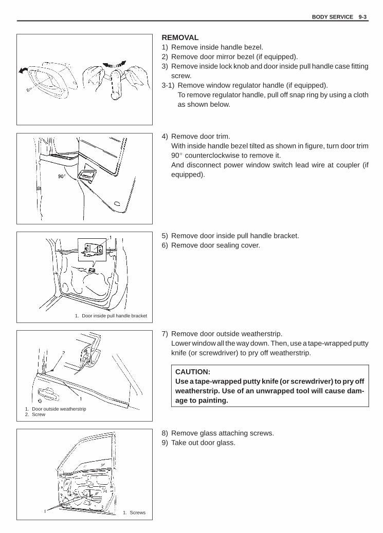
YH4GRANDVITARA
1. Screws
1. Door outside weatherstrip2. Screw
1. Door inside pull handle bracket
BODY SERVICE 9-3
REMOVAL1) Remove inside handle bezel.2) Remove door mirror bezel (if equipped).3) Remove inside lock knob and door inside pull handle case fitting
screw.3-1) Remove window regulator handle (if equipped).
To remove regulator handle, pull off snap ring by using a clothas shown below.
4) Remove door trim.With inside handle bezel tilted as shown in figure, turn door trim90� counterclockwise to remove it.And disconnect power window switch lead wire at coupler (ifequipped).
5) Remove door inside pull handle bracket.6) Remove door sealing cover.
7) Remove door outside weatherstrip.Lower window all the way down. Then, use a tape-wrapped puttyknife (or screwdriver) to pry off weatherstrip.
CAUTION:Use a tape-wrapped putty knife (or screwdriver) to pry offweatherstrip. Use of an unwrapped tool will cause dam-age to painting.
8) Remove glass attaching screws.9) Take out door glass.

YH4GRANDVITARA
1. Screws
1. Bolts
1. Door sealing cover2. Adhesive
1, (a)
9-4 BODY SERVICE
INSTALLATIONReverse removal procedure to install door glass noting followingpoints:� Tighten glass attaching screws to specified torque. Tighten front
screw first, then rear screw.
Tightening Torque(a): 2.5 N.m (0.25 kg-m, 1.8 lb-ft)
� When window becomes hard to raise and lower, adjust screws tocorrect tilted glass as shown in figure.
� Adjust equalizer of window regulator so that measurement A andB are equal.
� Secure door sealing cover with adhesive.

YH4GRANDVITARA
1. Window regulator lubrication point
1. Regulator mounting bolts2. Regulator motor mounting nuts3. Hole
BODY SERVICE 9-5
FRONT DOOR WINDOW REGULATORREMOVAL1) Remove door glass, referring to steps 1) to 9) of FRONT DOOR
GLASS REMOVAL in this section.2) Disconnect power window motor lead wire at coupler and loosen
clamp.3) Loosen regulator mounting bolts, nuts and take out regulator
through hole as shown in left figure.
INSPECTION1) Check regulator sliding and rotating parts for greasing.2) Check rollers for wear and damage.3) Check wire for damage.
INSTALLATIONReverse removal procedure to install window regulator noting thefollowing point.� Tighten bolts and nuts according to the order (a, b, c/1, 2, 3, 4)
shown in left figure.� When installing glass, check that the top part of the glass contacts
the glass run evenly and that the glass moves up and downsmoothly.If the glass is tilted with respect to the glass run, make a fine ad-justment with the screws.
� Install door window regulator handle (if equipped) so that it hasan angle as shown in figure when glass is fully closed.
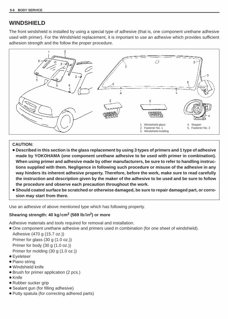
YH4GRANDVITARA
1. Windshield glass2. Fastener No. 13. Windshield molding
4. Stopper5. Fastener No. 2
9-6 BODY SERVICE
WINDSHIELDThe front windshield is installed by using a special type of adhesive (that is, one component urethane adhesiveused with primer). For the Windshield replacement, it is important to use an adhesive which provides sufficientadhesion strength and the follow the proper procedure.
CAUTION:� Described in this section is the glass replacement by using 3 types of primers and 1 type of adhesive
made by YOKOHAMA (one component urethane adhesive to be used with primer in combination).When using primer and adhesive made by other manufacturers, be sure to refer to handling instruc-tions supplied with them. Negligence in following such procedure or misuse of the adhesive in anyway hinders its inherent adhesive property. Therefore, before the work, make sure to read carefullythe instruction and description given by the maker of the adhesive to be used and be sure to followthe procedure and observe each precaution throughout the work.
� Should coated surface be scratched or otherwise damaged, be sure to repair damaged part, or corro-sion may start from there.
Use an adhesive of above mentioned type which has following property.
Shearing strength: 40 kg/cm 2 (569 lb/ in 2) or more
Adhesive materials and tools required for removal and installation.� One component urethane adhesive and primers used in combination (for one sheet of windshield).
Adhesive (470 g (15.7 oz.))Primer for glass (30 g (1.0 oz.))Primer for body (30 g (1.0 oz.))Primer for molding (30 g (1.0 oz.))
� Eyeleteer� Piano string� Windshield knife� Brush for primer application (2 pcs.)� Knife� Rubber sucker grip� Sealant gun (for filling adhesive)� Putty spatula (for correcting adhered parts)

YH4GRANDVITARA
1. Eyeleteer
1. Piano string2. Windshield3. Windshield knife
BODY SERVICE 9-7
REMOVAL1) Clean both inside and outside of glass and around it.2) Remove wiper arms and garnish.3) Using tape, cover body surface around glass to prevent any
damage.4) Remove rear view mirror, sunvisor, and front pillar trims (right
& left).5) If necessary, remove instrument panel. Refer to “INSTRU-
MENT PANEL” in this section.6) If necessary, remove head lining. Refer to “HEAD LINING” in
this section.7) If necessary, remove roof trim. Refer to “ROOF TRIM” in this
section.8) Remove (or cut) windshield molding all around until windshield
edge comes out.
9) Drill hole with eyeletter through adhesive and let piano stringthrough it.
10) Cut adhesive all around windshield with piano string.When using tool to cut adhesive, be careful not to cause dam-age to windshield. Use wire to cut adhesive along lower part ofwindshield.
NOTE:Use piano string as close to glass as possible so as to pre-vent damage to body and instrument panel.
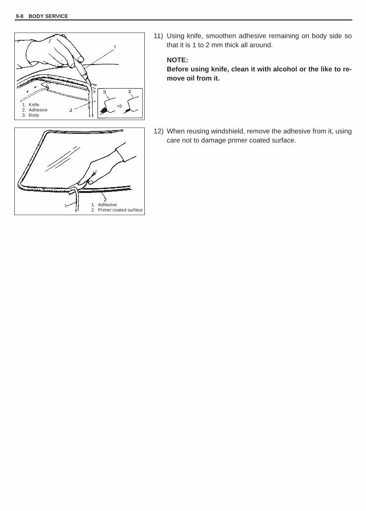
YH4GRANDVITARA
1. Knife2. Adhesive3. Body
1. Adhesive2. Primer coated surface
9-8 BODY SERVICE
11) Using knife, smoothen adhesive remaining on body side sothat it is 1 to 2 mm thick all around.
NOTE:Before using knife, clean it with alcohol or the like to re-move oil from it.
12) When reusing windshield, remove the adhesive from it, usingcare not to damage primer coated surface.

YH4GRANDVITARA
1. Fastener
“a”: Approx. 5mm (0.197 in.)1. Mark mating marks2. Glass3. Body4. Molding
1. Do not apply primer2. Primer3. Apply primer4. Old adhesive
1. Molding2. Glass
BODY SERVICE 9-9
INSTALLATION1) Using cleaning solvent, clean windshield edge where wind-
shield glass is to be adhered. (Let it dry for more than 10 min-utes.)
2) Install new glass stoppers (2pcs.) to lower side of windshield andnew fastener to body.When reusing wind shield, install new fastener to wind shield.
3) To determine installing position of glass to body, position glassagainst body so that clearance between upper end of glass andbody is about 5 mm (0.197 in.) and clearances between eachside end (right & left) of glass and body are even. Place glass sothat lug of fastener is matched with cut in body and fit fastener.Then mark mating marks on glass and body as shown.Upper clearance can be adjusted by moving stoppers position.
4) Clean contact surfaces of old adhesive, paint or bare metal thor-oughly.If surfaces of paint or bare metal come out, apply primer for bodywith caution not to apply primer to surface of adhesive remainingon body.
NOTE:� Be sure to refer to primer maker’s instruction for proper
handling and drying time.� Do not touch body and old adhesive surfaces where glass
is to be adhered.
5) Install new molding to glass.6) Clean glass surface to be adhered to body with clean cloth. If
cleaning solvent is used, let it dry for more than 10 minutes.
Cleaning Area
Distance from the edge of glass or molding“a”: 30 – 50 mm (1.18 – 1.97 in.)

YH4GRANDVITARA
1. Molding2. Fastener
1. Molding2. Adhesive3. Glass
“A”: Primer for molding
1. Rubber sucker grip
9-10 BODY SERVICE
7) Using new brush, apply sufficient amount of primer for glassalong glass surface to be adhered to body.NOTE:� Be sure to refer to maker’s instruction for proper han-
dling and drying time.� Do not apply primer on outside of ceramic coated sur-
face.� Do not touch primer coated surface.
Width “b”: 18 – 19 mm (0.71 – 0.75 in.)“c”: 16 – 17 mm (0.63 – 0.67 in.)“d”: 24 mm (0.94 in.)“e”: 27 mm (1.06 in.)
8) Apply primer for molding along molding surface all around asshown in figure.
9) Apply adhesive referring to figure at the left.
NOTE:� Start from bottom side of glass.� Be careful not to damage primer.� Height of adhesive applied to lower side should be high-
er than that of other three sides.
Upper, right and left sidesWidth “e” : Approx. 11 mm (0.43 in.)Height “f” : Approx. 17 mm (0.67 in.)
“g” : Approx. 25 mm (0.98 in.)Distance “h” : Approx. 16 mm (0.63 in.)
� Press glass against body quickly after adhesive is ap-plied.
� Use of rubber sucker grip is helpful to hold and carryglass after adhesive is applied.
� Perform steps 9) to 10) within 10 min. to ensure sufficientadhesion.
� Be sure to refer to adhesive maker’s instruction for prop-er handling and drying time.
10) Holding rubber sucker grips, place glass onto body by aligningmating marks marked in step 3) and press it.

YH4GRANDVITARA
BODY SERVICE 9-11
11) Check for water leakage by pouring water over windshieldthrough hose. If leakage is found, dry windshield and fill leakypoint with adhesive. If water still leaks even after that, removeglass and start installation procedure all over again.
CAUTION:Upon completion of installation, note the following.� Do not use high pressure water.� Do not blow compressed air directly at adhesive ap-
plied part when drying.� Do not use infrared lamp or like for drying.� Sudden closing of door before adhesive is completely
set may cause glass to become loose or to come off.Therefore, if door is opened or closed before adhesiveis completely set, make sure to open all door glassesand use proper care.
� If molding is not securely in place, hold it down witha tape until adhesive is completely set.
� Each adhesive has its own setting time.Be sure to refer to its maker’s instruction, check set-ting time of adhesive to be used and observe precau-tions to be taken before adhesive is set.
� Refrain from driving till adhesive is completely set soas to ensure proper and sufficient adhesion.

YH4GRANDVITARA
1. Door trim2. Inside handle
bezel
7. Door hinge8. Door open stop9. Door sealing cover
10. Door center sash11. Partition glass12. Window regulator handle (if equipped)
1. Door glass2. Weatherstrip (outside)3. Glass run4. Window regulator5. Partition weather strip6. Door trim
9-12 BODY SERVICE
REAR DOOR GLASS
REMOVAL-1) Remove inside handle bezel.-2) Remove inside lock knob and door inside pull handle case fit-
ting screw.2-1) Window regulator handle (if equipped).
To remove regulator handle, pull off snap ring by using a clothas shown below.
3) Remove door trim with inside weatherstrip.With inside handle bezel tilted as shown in figure, turn door trim90� counterclockwise to remove it. And disconnect power win-dow switch lead wire.
4) Remove door sealing cover.

YH4GRANDVITARA
1. Glass2. Screw
1. Glass run2. Center sash3. Partition glass
1. Screw2. Partition glass3. Center sash
1. Door outerweatherstrip
2. Screw
1. Door sealingcover
2. Adhesive
1
BODY SERVICE 9-13
5) Remove outer weatherstrip.
CAUTION:Using a tape-wrapped putty knife (or tape-wrappedscrewdriver), pry off weatherstrip. Use of an unwrappedtool will cause damage to painting.
6) Remove glass fitting screws. Then down door glass.
7) Detach rear part of glass run from center sash.
8) Remove door center sash (by removing two screws with doorglass lowered all the way down).
9) When remove partition glass, slide to front to remove it.10) Take out glass.
INSTALLATIONReverse removal sequence to install door glass.However, be careful of following points.� Securely seal door sealing cover with adhesive.� When weatherstrip is hardened, water leak may develop. In such
case, replace it with new one.

YH4GRANDVITARA
9-14 BODY SERVICE
1. Door windowregulator attachingnuts
2. Hole
1. Window regulator lubrication points
1. Door sealingcover
2. Adhesive
REAR DOOR WINDOW REGULATORREMOVAL1) Remove door glass, refer to steps 1) to 10) of REAR DOOR
GLASS REMOVAL in this section.2) Disconnect power window motor lead wire at coupler and clamp.3) Remove door window regulator attaching nuts (6 pcs.), and take
out regulator through hole as shown in left figure.
INSPECTION1) Check regulator sliding and rotating parts for greasing.2) Check rollers for wear and damage.3) Check wire for damage.
INSTALLATIONReverse removal sequence to install door window regulator notingfollowing points.� Tighten regulator base nuts according to the order (a, b, c) shown
in figure.� Adjust door window regulator according to following procedure.
a. Loosen three nuts, two screws and two bolts.b. Raise window fully.c. Tighten three regulator rail nuts according to the order (d, e,
f) shown in figure and two center sash bolts A.d. Lower window.e. Tighten two screws B to specified torque. Tighten front screw
first, then rear.
Tightening Torque for glass attaching screws2.5 N.m (0.25 kg-m, 1.8 lb-ft)
f. Check that the glass moves up and down smoothly and thatthe top part of the glass contacts the glass run evenly.
� Securely seal door sealing cover with adhesive.� Install door window regulator handle (if equipped) so that it has
an angle as shown when glass is fully closed.

YH4GRANDVITARA
BODY SERVICE 9-15
1. Fastener2. Glass3. Molding4. Adhesive5. Primer
QUARTER WINDOWREMOVAL AND INSTALLATIONRefer to “WINDSHIELD” section as removal and installation proce-dures and cautions are basically the same. However, note the fol-lowing.
NOTE:� Before applying primer to glass edge, install molding ac-
cording to installing position shown in figure.� Observe following precautions when applying adhesive
along glass edge.– Adhesive should be applied evenly especially in height.– Be careful not to damage primer.– Press glass against body quickly after adhesive is applied.
Height “b”: 12 mm (0.47 in.)Width “d”: 16 mm (0.63 in.)
“c” : 8 mm (0.31 in.)Clearance “e” : 1 mm (0.04 in.)

YH4GRANDVITARA
9-16 BODY SERVICE
1. Molding2. Glass3. Fastener
1. Molding2. Glass3. Primer4. Adhesive5. Fastener
1. Door sealing cover
BACK DOOR GLASSREMOVAL AND INSTALLATIONRefer to “WINDSHIELD” section as removal and installation proce-dures and cautions are basically the same. However, note the fol-lowing.
NOTE:� Before applying primer to glass edge, install molding ac-
cording to installing position shown in figure.
� Observe following precautions when applying adhesivealong glass edge.– Adhesive should be applied evenly especially in height.– Be careful not to damage primer.– Press glass against body quickly after adhesive is applied.
Height “b”: 15 mm (0.59 in.)Width “c” : 8 mm (0.31 in.)Width “d”: 16 mm (0.63 in.)Clearance “e” : 1 mm (0.04 in.)
� When replacing back door, coat replacement door insidewith wax for proper anticorrosive treatment. Refer to “UN-DER COATING/ANTI-CORROSION COMPOUND APPLICA-TION AREA” in this section.
� Apply sealing compound to peripheral of door hem area andreinstall door sealing cover.
� When weatherstrip is hardened and water leaks have devel-oped, replace it.

YH4GRANDVITARA
BODY SERVICE 9-17
1. Stopper pin
1. Rags2. Wooden piece
1. Upper hingemounting bolts
2. Lower hingemounting bolt
3. Door4. Body
1. Front door hinge2. Upper hinge nut (rear door)3. Rear door hinge
BODY STRUCTURE
FRONT DOOR ASSEMBLYREMOVAL1) Remove front fender. Refer to “FRONT FENDER” in this section.2) Disconnect door harness lead wires at each coupler.3) Remove stopper pin.
4) Support door panel using a jack with a piece of wood placed be-tween jack and panel, as shown.
5) Remove door assembly by loosening hinge mounting bolts.
INSTALLATIONReverse removal procedure to install door assembly, noting follow-ing point.
NOTE:When replacing door, coat replacement door inside with waxfor proper anticorrosion treatment.Refer to “UNDERCOATING/ANTI-CORROSION COMPOUNDAPPLICATION AREA” in this section.
� Tighten door hinge bolts (and nut) to specified torque.
Tightening torque(a): 27 N.m (2.7 kg-m, 19.5 lb-ft)(b): 23 N.m (2.3 kg-m, 17.0 lb-ft)
� Adjust door latch striker position by referring to “FRONT DOORLOCK INSTALLATION” section so that door is positioned correctly.
� Adjust front door cushion so that door contacts body when closed.� After installation, open and close the door to check looseness.
Replace door open stopper pin when there is looseness.� When weatherstrip is hardened, water leak may develop.
In such case, replace it with new one.

YH4GRANDVITARA
9-18 BODY SERVICE
REAR DOOR ASSEMBLYREMOVAL/INSTALLATIONFollow procedures for Front Door removal/ installation in this sec-tion.
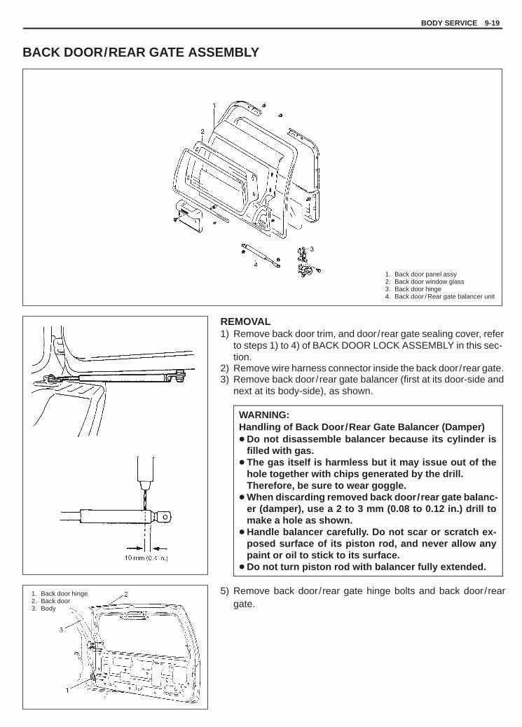
YH4GRANDVITARA
BODY SERVICE 9-19
1. Back door panel assy2. Back door window glass3. Back door hinge4. Back door / Rear gate balancer unit
1. Back door hinge2. Back door3. Body
BACK DOOR/REAR GATE ASSEMBLY
REMOVAL1) Remove back door trim, and door/rear gate sealing cover, refer
to steps 1) to 4) of BACK DOOR LOCK ASSEMBLY in this sec-tion.
2) Remove wire harness connector inside the back door/rear gate.3) Remove back door/rear gate balancer (first at its door-side and
next at its body-side), as shown.
WARNING:Handling of Back Door/Rear Gate Balancer (Damper)� Do not disassemble balancer because its cylinder is
filled with gas.� The gas itself is harmless but it may issue out of the
hole together with chips generated by the drill.Therefore, be sure to wear goggle.
� When discarding removed back door/rear gate balanc-er (damper), use a 2 to 3 mm (0.08 to 0.12 in.) drill tomake a hole as shown.
� Handle balancer carefully. Do not scar or scratch ex-posed surface of its piston rod, and never allow anypaint or oil to stick to its surface.
� Do not turn piston rod with balancer fully extended.
5) Remove back door/rear gate hinge bolts and back door/reargate.

YH4GRANDVITARA
9-20 BODY SERVICE
1. Sealing cover2. Adhesive
INSTALLATIONReverse removal procedure to install back door/rear gate notingfollowing points.� Secure wiring harness.
� Secure back door/rear gate sealing cover.
NOTE:Use adhesive to seal sealing cover to back door/rear gate.
� Adjust back door/rear gate latch striker position by referring“BACK DOOR LOCK ASSEMBLY INSTALLATION” so that backdoor/rear gate is positioned correctly.
� Adjust back door/rear gate cushion so that back door/rear gatecontacts body when closed.

YH4GRANDVITARA
BODY SERVICE 9-21
1. Hood lock2. Hood lock bolts3. Match marks
1. Hood cushion
HOODREMOVAL1) Remove window washer hose from hood.2) Remove four mounting bolts to detach hood.
ADJUSTMENT� Fore-and-aft and right-and-left adjustment.
Loosen four mounting bolts for adjustment.
� Hood lock adjustmentWhen installing hood lock, bring bolt at intersection point of matchmarks and move it in vertical direction for adjustment, if neces-sary.
Tightening Torque(a): 10 N.m (1.0 kg-m, 7.5 lb-ft)
� Vertical adjustmentIf only one side (right or left) of hood is not level with front fender,make it level by tightening or loosening hood cushion.
INSTALLATIONReverse removal procedure to install hood.
INSPECTIONCheck that secondary latch operates properly (check that second-ary latch keeps hood from opening all the way even when pullinghood release handle inside vehicle.) Also check that hood opensand closes smoothly and properly and hood locks securely whenclosed.If any malfunction is found, lubricate hinge and latch, or repair hoodlock system.

YH4GRANDVITARA
1. Side body2. Fender3. Pad
1. Side body2. Pad3. Knife
9-22 BODY SERVICE
1. Front fender2. Front fender lining3. Fender attaching bolts4. Fender lining attaching screws
FRONT FENDER
REMOVAL1) Remove front bumper.2) Remove fender splush guard (H25 engine).3) Remove front fender lining.4) Remove front fender.
INSTALLATION1) Remove pad from side body and (or) fender, using care not to
damage painted surface.
2) Attach new pad cutting appropriately size temporarily and adjustheight with a knife so that fender becomes flush with side body.
3) Reverse removal procedure for installation.
NOTE:If paint on fender bolt is peeled off, be sure to apply paintagain.

YH4GRANDVITARA
BODY SERVICE 9-23
1. Front bumper2. Screws3. Front bumper member4. Side marker
FRONT BUMPER
NOTE:� Fasteners are important attaching parts in that they could affect the performance of vital components
and systems, and/or could result in major repair expense. They must be replaced with one of the samepart number or with an equivalent part if replacement becomes necessary.Do not use a replacement part of lesser quality or substitute design. Torque values must be used as spe-cified during reassembly to assure proper retention of these parts.
� Before removing front bumper, remove fender lining and disconnect connector of side marker.

YH4GRANDVITARA
9-24 BODY SERVICE
1. Rear bumper2. Rear bumper screws3. Rear bumper member
REAR BUMPER

YH4GRANDVITARA
BODY SERVICE 9-25
a. Front bumperb. 1st mountingc. Suspension framed. Front strute. Suspension armf. 2nd mountingg. ø20 zig holeh. Zig holei. 3rd mountingj. Lower rodk. Upper rodl. Lateral rodm. Rear shock absorbern. 4th mountingo. Fuel tankp. Fuel tankq. Lower rod
a – g : 1315 mm (51.77 in.)a – g’ : 1534 mm (60.39 in.)b – g : 1243 mm (48.94 in.)b – g’ : 1518 mm (59.76 in.)c – g : 1377 mm (54.21 in.)c – g’ : 1105 mm (43.50 in.)d – g’ : 1319 mm (51.93 in.)d – f : 874 mm (34.41 in.)e – g : 525 mm (20.67 in.)e – g’ : 857 mm (33.74 in.)f – g’ : 927 mm (36.50 in.)h – i : 178 mm (7.01 in.)h – j : 133 mm (5.24 in.)h – k : 325 mm (12.80 in.)h – l : 674 mm (26.54 in.)
h – m : 803 mm (31.61 in.)h – n : 1161 mm (45.71 in.)h – o : 1184 mm (46.61 in.)h – p : 1190 mm (46.85 in.)i – q : 999 mm (39.33 in.)j – q : 997 mm (39.25 in.)k – q : 824 mm (32.44 in.)l – q : 1130 mm (44.49 in.)m – q : 1258 mm (49.53 in.)n – q : 1483 mm (58.39 in.)o – q : 1349 mm (53.11 in.)p – q : 1334 mm (52.52 in.)
For 4 door modelg’ – q : 1275 mm (50.20 in.)g – q : 1534 mm (60.39 in.)
For 2 door modelg’ – q : 995 mm (39.17 in.)g – q : 1310 mm (51.57 in.)
UNDER BODY DIMENSIONS

YH4GRANDVITARA
Hole to hole distance“a – g” : 276 mm (10.87 in.)“a – k” : 1000 mm (39.37 in.)“b – b’” : 1302 mm (51.26 in.)“b – g” : 730 mm (28.74 in.)“c – c’” : 668 mm (26.30 in.)“c – e” : 414 mm (16.30 in.)“c – g” : 406 mm (15.98 in.)“c – j” : 1029 mm (40.51 in.)“c – k” : 1000 mm (39.37 in.)“d – d’” : 1302 mm (51.26 in.)“d – e” : 189 mm (7.44 in.)“d – c’” : 1016 mm (40.00 in.)“d – g” : 672 mm (26.46 in.)“d – k” : 968 mm (38.11 in.)“e – e’” : 1456 mm (57.32 in.)
“f – f’” : 1550 mm (61.02 in.)“f – h” : 299 mm (11.77 in.)“f – j” : 811 mm (31.93 in.)“g – k” : 854 mm (33.62 in.)“h – h’” : 1339 mm (52.72 in.)“h – j’” : 1504 mm (59.21 in.)“h – j” : 677 mm (26.65 in.)“h – k” : 927 mm (36.50 in.)“i – i’” : 1344 mm (52.91 in.)“i – j” : 391 mm (15.39 in.)“i – k” : 760 mm (29.92 in.)“j – j’” : 1348 mm (53.07 in.)“j – k” : 676 mm (26.61 in.)“l – j” : 961 mm (37.83 in.)“l – k” : 1018 mm (40.08 in.)
a. Front bumper installation clip holeb (b’). Front bumper installation holec (c’). Headlight installation holed (d’). Headlight installation resin nut holee (e’). Headlight installation holef (f’). Front fender installation holeg. Center member installation holeh (h’). Fender installation reference holei (i’). Fender installation holej (j’). Fender installation reference holek. Garnish installation clip holel. Mounting installation hole
9-26 BODY SERVICE
BODY DIMENSIONS4 door model, 2 door model

YH4GRANDVITARA
“h – h’” : 1521 mm (59.88 in.)“h – o” : 901 mm (35.47 in.)“i – i’” : 1547 mm (60.91 in.)“j – n” : 806 mm (31.73 in.)“j – j’” : 1511 mm (59.49 in.)“j – o” : 649 mm (25.55 in.)“k – k’” : 1126 mm (44.33 in.)“k – o” : 1350 mm (53.15 in.)“l – l’” : 1491 mm (58.70 in.)“l – o” : 1130 mm (44.49 in.)“m – m’”: 939 mm (36.97 in.)“m – o” : 1725 mm (67.91 in.)
Hole to hole distance“a – c” : 982 mm (38.66 in.)“b – b’” : 1390 mm (54.72 in.)“b – c’” : 1406 mm (55.35 in.)“b – c” : 755 mm (29.72 in.)“c – c’” : 1012 mm (39.84 in.)“d – d’” : 1545 mm (60.83 in.)“d – n” : 800 mm (31.50 in.)“e – e’” : 1110 mm (43.70 in.)“e – n” : 1036 mm (40.79 in.)“f – f’” : 1511 mm (59.49 in.)“f – n” : 620 mm (34.41 in.)“g – g’” : 1085 mm (42.72 in.)“g – o” : 1099 mm (43.27 in.)
a. Garnish installation clip holeb (b’). Front end of front windshield lower installation sectionc (c’). Front end of front windshield upper installation sectiond. Hole in F door lower hinge at reare. Trim installation clip holef (f’). Scuff installation hole (at rearmost end)g (g’). Trim installation holeh (h’). Hole in R door upper hinge in upper parti (i’). Hole in R door lower hinge in lower partj (j’). Rear scuff installation hole (at front end)k (k’). Trim installation holel (l’). R door striker lower section installation holem (m’). Trim installation holen. Installation hole for F seat front insideo. Installation hole for F seat rear inside
Opposite side of the point shown in figure
BODY SERVICE 9-27
4 door model

YH4GRANDVITARA
a. Hole in F door upper hinge at rearb. Hole in F door lower hinge at rearc. Trim installation clip holed. ø7 jig holee. Scuff installation hole (rearmost end)f. Hole n R door upper hinge in upper partg. Hole in R door lower hinge in lower parth. Assistant grip installation holei. Trim installation holej. Door striker lower section installation holek. F seat belt installation hole
Hole to hole distance“a – d” : 1155 mm (45.47 in.)“a – g” : 1090 mm (42.91 in.)“a – f” : 1046 mm (41.18 in.)“b – f” : 1120 mm (44.09 in.)“b – g” : 1140 mm (44.88 in.)“c – k” : 1245 mm (49.02 in.)“d – e” : 1174 mm (46.22 in.)“f – j” : 839 mm (33.03 in.)“g – j” : 918 mm (36.14 in.)“h – j” : 941 mm (37.04 in.)“h – k” : 1189 mm (46.81 in.)“i – k” : 1309 mm (51.53 in.)
9-28 BODY SERVICE
4 door model

YH4GRANDVITARA
“a – b’” : 448 mm (17.64 in.)“a – f’” : 1054 mm (41.50 in.)“a – h” : 926 mm (36.43 in.)“a – g” : 1050 mm (41.34 in.)“b – b’” : 888 mm (34.96 in.)“b – d” : 400 mm (15.75 in.)“b’ – f” : 1314 mm (51.73 in.)“b – e” : 837 mm (32.95 in.)“b – f” : 892 mm (35.12 in.)
“b’ – c” : 650 mm (25.59 in.)“b’ – g” : 996 mm (39.21 in.)“b’ – f” : 1314 mm (51.73 in.)“c – d” : 1245 mm (49.02 in.)“c – e” : 1293 mm (50.90 in.)“f – f’” : 1030 mm (40.55 in.)“f’ – g” : 512 mm (20.16 in.)“g – h” : 808 mm (31.79 in.)“g – g’” : 1544 mm (60.79 in.)
a. Clip hole in the center of head lining rear installation sectionb (b’). Innermost end of roof panel installation sectionc. Installation hole in upper part of back door strikerd. Installation hole in uppermost part of upper hingee. Installation hole in uppermost part of lower hingef (f’). Innermost end of rear floor tail member installation sectiong (g’). Installation hole in outer upper section of R-COMB R lamph. Nut hole
BODY SERVICE 9-29
4 door model

YH4GRANDVITARA
Hole to hole distancea – c : 981 mm (38.62 in.)b – b’ : 1390 mm (54.72 in.)b – c’ : 1404 mm (55.28 in.)c – c’ : 1008 mm (39.69 in.)e – e’ : 1110 mm (43.70 in.)e – i : 1036 mm (40.79 in.)f – i : 688 mm (27.09 in.)
g – g’ : 1145 mm (45.08 in.)g – h : 1017 mm (40.04 in.)g – j : 1078 mm (42.44 in.)h – h’ : 1338 mm (52.68 in.)h – j : 1459 mm (57.44 in.)j – k : 548 mm (21.57 in.)l – l’ : 956 mm (37.64 in.)
a. Garnish installation clip holeb (b’). Front end of front windshield lower installation sectionc (c’). Front end of front windshield upper installation sectiond. Hole in F door lower hinge at reare. Trim installation clip holef (f’). Scuff installation hole (at rearmost end)g (g’). Trim installation holeh (h’). �11 jig holei. Installation hole for F seat front insidej. Installation hole for F seat rear insidek (k’). F seat belt installation holel (l’). Innermost end of side body installation section
9-30 BODY SERVICE
2 door model
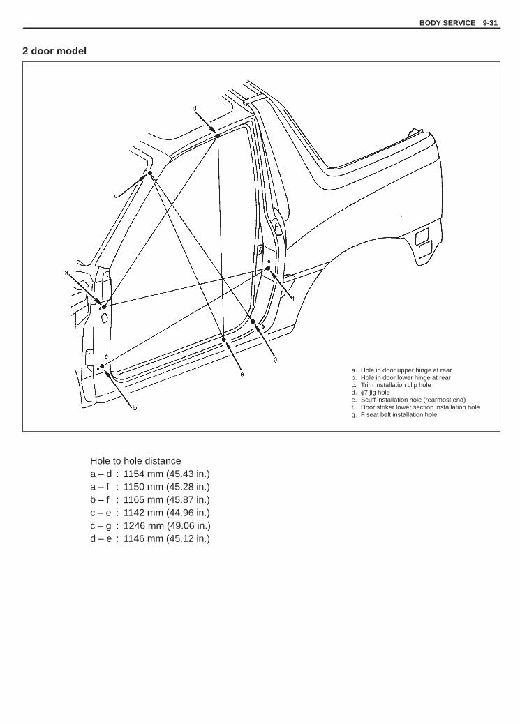
YH4GRANDVITARA
Hole to hole distancea – d : 1154 mm (45.43 in.)a – f : 1150 mm (45.28 in.)b – f : 1165 mm (45.87 in.)c – e : 1142 mm (44.96 in.)c – g : 1246 mm (49.06 in.)d – e : 1146 mm (45.12 in.)
a. Hole in door upper hinge at rearb. Hole in door lower hinge at rearc. Trim installation clip holed. �7 jig holee. Scuff installation hole (rearmost end)f. Door striker lower section installation holeg. F seat belt installation hole
BODY SERVICE 9-31
2 door model

YH4GRANDVITARA
Hole to hole distancea – a’ : 1112 mm (43.78 in.)a – f’ : 1134 mm (44.65 in.)a – g’ : 796 mm (31.34 in.)a’ – f : 1156 mm (45.51 in.)a’ – g : 824 mm (32.44 in.)b – d : 1229 mm (48.39 in.)c – d : 1324 mm (52.13 in.)e – e’ : 1544 mm (60.79 in.)f – f’ : 1029 mm (40.51 in.)
a (a’). Trim installation clip holeb. Installation hole in uppermost part of upper hingec. Installation hole in outside part of lower hinged. Installation hole in uppermost part of rear gate strikere (e’). Installation hole in outer upper section of R-COMB R (L) lampf (f’). Innermost end of rear floor tail member installation sectiong (g’). Garnish installation clip hole
9-32 BODY SERVICE
2 door model

YH4GRANDVITARA
1. (a)
1. (a)
1
1
1
Tightening Torque(a): 23 N.m (2.3 kg-m, 17.0 lb-ft)
1. Bolt
BODY SERVICE 9-33
INSTRUMENTATION AND DRIVER INFORMATION
INSTRUMENT PANEL
WARNING:See WARNING at the beginning of this section.
REMOVAL1) Disconnect negative cable at battery.2) Disable air bag system. Refer to “Disabling Air Bag System” in
Section 10B.3) Remove console box.4) Remove glove box and column hole cover.5) Disconnect wires and cables from heater unit and blower motor
assembly.6) Remove steering column assembly. Refer to Section 3C1.7) Disconnect speedometer connector and remove speedometer
assembly. If equipped with air bag, disconnect wire coupler atSDM and air bag ground terminal for air bag.
8) Remove engine hood opener.9) Disconnect couplers which need to be disconnected for removal
for instrument panel.10) Remove instrument panel mounting screws.11) Remove instrument panel mounting bolt.12) Remove instrument panel.
CAUTION:For vehicle with Air Bag, instrument panel could not be re-moved with SDM coupler connected and ground terminalinstalled.Use care not to damage Air Bag harness.
INSTALLATION1) Install instrument panel by reversing removal procedure, noting
the following items.� When installing each part, be careful not to catch any cable or
wiring harness.� When installing steering column assembly, refer to “AIR BAG
STEERING COLUMN INSTALLATION” in Section 3C1.2) Adjust control cables. (Refer to Section 1A “HEATER CON-
TROL CABLES”.)3) Enable air bag system. Refer to “Enabling Air Bag System” in
Section 10B.

YH4GRANDVITARA
1. Seat cushion2. Seat back3. Reclining assy (RH side)4. Reclining assy (LH side)5. Seat adjuster (RH outside)6. Seat adjuster (RH inside)7. Seat adjuster (LH outside)8. Seat adjuster (LH inside)
Tightening Torque(a): 35 N.m (3.5 kg-m, 25.5 lb-ft)(b): 23 N.m (2.3 kg-m, 17.0 lb-ft)
1. Cover2. Coupler
(b)
9-34 BODY SERVICE
SEAT
FRONT SEAT
REMOVAL1) Disconnect lead wire(s) at coupler (if equipped). Remove four
mounting bolts fixing front seat to seat rail to remove front seat.2) Disassemble and repair seat as necessary.
INSTALLATIONReverse removal procedure to install front seat.Torque to specifications, as shown.
Tightening Torque(a): 35 N.m (3.5 kg-m, 25.5 lb-ft)

YH4GRANDVITARA
1. Seat cushion2. Seat back3. Seat auto lock release handle4. Seat hinge male5. Hinge male cover
BODY SERVICE 9-35
REAR SEAT
REMOVAL1) Remove four mounting bolt to remove seat cushion.2) Remove four mounting bolts to remove seat back.3) Disassemble and repair seat as necessary.
INSTALLATIONReverse removal procedure to install rear seat.Torque to specifications, as shown.
Tightening Torque(a): 35 N.m (3.5 kg-m, 25.5 lb-ft)

YH4GRANDVITARA
9-36 BODY SERVICE
Sealer is applied to the specific joints of a vehicle dur-ing production. The sealer is intended to prevent dustfrom entering the vehicle and serves also as an anti-corrosion barrier. The sealer is applied to the door andhood hem areas and between panels. Correct and re-seal the originally sealed joints if damaged. Resealthe attaching joints of a new replacement panel andreseal the hem area of a replacement door or hood.Use a quality sealer to seal the flanged joints, overlapjoints and seams. The sealer must have flexible char-acteristics and paintability after it’s applied to repairareas.For the sealer to fill open joints, use caulking material.Select a sealer in conformance with the place andpurpose of a specific use. Observe the manufactur-er’s label-stand instructions when using the sealer.In many cases, repaired places require color painting.When this is required, follow the ordinary techniquesspecified for the finish preparation, color painting andundercoating build-up.Rust proof wax, a penetrative compound, is appliedto the metal-to-metal surfaces (door and side sill in-sides) where it is difficult to use ordinary undercoatingmaterial for coating. Therefore, when selecting therust proof wax, it may be the penetrative type.During the undercoating (vinyl coating) application,care should be taken that sealer is not applied to theengine-related parts and shock absorber mounting orrotating parts. Following the under coating, makesure that body drain holes are kept open.he sequence of the application steps of the anti-corro-sion materials are as follows:1) Clean and prepare the metal surface.2) Apply primer.3) Apply sealer (all joints sealed originally).4) Apply color in areas where color is required such
as hem flanges, exposed joints and under bodycomponents.
5) Apply anticorrosion compound (penetrative wax).6) Apply undercoating (rust proof material).
PAINT AND COATINGS
ANTI-CORROSION TREATMENT
WARNING:Standard shop practices, particularly eyeprotection, should be followed during the per-formance of the below-itemized operations toavoid personal injury.
As rust proof treatment, steel sheets are given corro-sion resistance on the interior and/or exterior.These corrosion resistance steel sheet materials arecalled one of two-side galvanized steel sheets.It is for the sake of rust protection that these materialsare selected and given a variety of treatments as de-scribed blow.1) Steel sheets are treated with cathodic electroprim-
er which is excellent in corrosion resistance.2) Rust proof wax coatings are applied to door and
side sill insides where moisture is liable to stay.3) Vinyl coating is applied to body underside and
wheel housing inside.4) Sealer is applied to door hem, engine compart-
ment steel sheet-to-steel sheet joint, and the likeportions to prevent water penetration and resultingin rust occurrence.
In panel replacement or collision damage repair, leav-ing the relevant area untreated as it is in any operationwhich does disturb the above-mentioned rust prooftreatment will cause corrosion to that area. Therefore,it is the essential function of any repair operation tocorrectly recoat the related surfaces of the relevantarea.All the metal panels are coated with metal condition-ers and primer coating during vehicle production. Fol-lowing the repair and/or replacement parts installa-tion, every accessible bare metal surface should becleaned and coated with rust proof primer. Performthis operation prior to the application of sealer andrust proof wax coating.

YH4GRANDVITARA
When the welding or heating operation causes theoriginal galvanization or other anticorrosive materialsto be burnt, the interior and under-body panel sur-faces must be cleaned.Removal of residues of the burning should be carriedout carefully when the relevant place has boxtypeconstruction or has shape which limits the access tothe interior surfaces. In general, the following methodcan be used satisfactorily for the removal of those res-idues.
Scrape the accessible places. If a standard putty knifeor scraper does not fit to the elevant place, considerto use a more flexible scraper to a place narrowly en-closed by sheet metals.A jet of compressed air can remove most residues,and is effective to limited areas.However, this type of operation absolutely requireseye protection.
BODY SERVICE 9-37
The metal service replacement parts (or assemblies)are coated with electro-deposition primer.For the proper adhesion of a paint, the following finishprocess (refinish steps) becomes necessary.1) Use wax or grease-removing solvent to clean the
part.2) Use a wet or dry sand-paper (No. 400) to polish the
panel lightly. Do not polish it forcibly to produce anyscratch. Clean the part again.
3) If factory-applied primer coating is cut through tothe bare metal, apply metal conditioner to the baremetal exposed to open air. As for method of use ofthe metal conditioner, follow directions on the con-tainer.
4) Apply primer-surfacer to the part completely drybefore starting sand-paper polishing. As for dryingtime, follow directions advised on the primer-sur-facer container.
5) Use a wet or dry sand-paper (No. 400) and waterto polish the panel lightly.
6) Wash the part again.7) Apply color, coating to the part.8) Different paints demand different drying methods.
Hence, follow directions advised on the pertinentpaint container.
9) When lacquer coating (quick-drying paint coat-ing) is applied, dry coated surface and polish itwith compound.In the case of the melamine or acrylic coating,compound polishing can be omitted after drying.
10) If the case of lacquer coating, wax should not beapplied to coated surface until the surface hasdried completely (for approx. two months).
Before replacing exterior parts or assemblies, checkpaint conditions of all the covered or hidden interiorsurfaces. If any rust scale is found at these places,proceed as follows:1) Use a proper wire brush, adhesive or liquid rust re-
moving agent to remove rust. As for the method ofuse, follow directions advised for respecitve mate-rials.
2) If necessary, wash parts with detergent, rinse, anddry them.
3) Before installing exterior body parts, apply anticor-rosive compound to all cleaner surfaces of exteriorbody parts. Also, apply anticorrosive compound toinner surfaces of exterior body parts to beinstalled.
METAL REPLACEMENT PARTS FINISHING

YH4GRANDVITARA
1. Side body inner panel2. Rear wheel housing outer rear panel3. Rear wheel housing panel4. Rear floor panel5. Tail lower member6. Center floor panel7. Front floor panel8. Center floor member9. Side sill inner panel
10. Side outer panel
“A”: Apply sealant“B”: Brush treatment
9-38 BODY SERVICE
SEALANT APPLICATION AREA4 door model

YH4GRANDVITARA
1. Cowl top panel2. Dash panel3. Cowl front panel4. Front floor panel5. Front pillar inner lower panel
“A”: Apply sealant“B”: Brush treatment
BODY SERVICE 9-39

YH4GRANDVITARA
9-40 BODY SERVICE
1. Side body inner panel2. Side body outer panel3. Back pillar outer panel4. Front pillar inner panel5. Roof panel6. Front pillar upper reinforcement7. Rear wheel housing panel8. Fuel inlet box
“A”: Apply sealant“B”: Brush treatment

YH4GRANDVITARA
BODY SERVICE 9-41
1. Side body outer panel“A”: Apply sealant“B”: Brush treatment
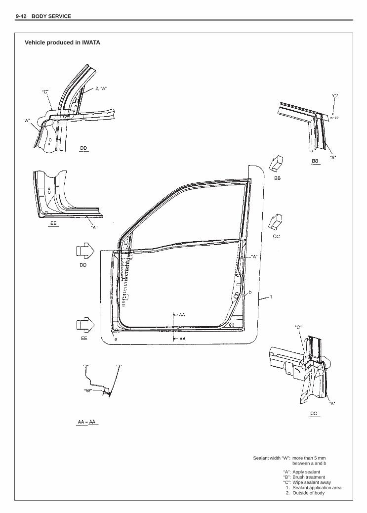
YH4GRANDVITARA
9-42 BODY SERVICE
Sealant width “W”: more than 5 mmbetween a and b
“A”: Apply sealant“B”: Brush treatment“C”: Wipe sealant away1. Sealant application area2. Outside of body
2, “A”
Vehicle produced in IWATA

YH4GRANDVITARA
“A”: Apply sealant“B”: Brush treatment“C”: Wipe sealant away“D”: Role sealant between d and e
Sealant width “W”: more than 5 mm between c and d1. Sealant application area
Vehicle produced in IWATA
BODY SERVICE 9-43

YH4GRANDVITARA
“A”: Apply sealant Sealant width “W”: more than 5 mm between c and d
Vehicle produced in IWATA
9-44 BODY SERVICE
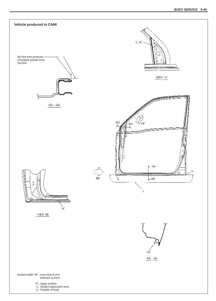
YH4GRANDVITARA
Sealant width “W”: more than 5 mmbetween a and b
“A”: Apply sealant1. Sealant application area2. Outside of body
Be free from protrudeof sealant outside fromthis line
Vehicle produced in CAMI
BODY SERVICE 9-45

YH4GRANDVITARA
9-46 BODY SERVICE
Sealant width “W”: more than 5 mmbetween a and b,between c and d
“A”: Apply sealant1. Sealant application area
Vehicle produced in CAMI
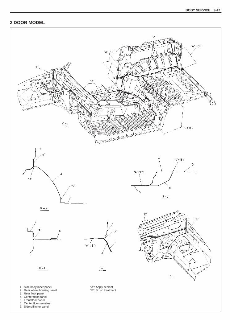
YH4GRANDVITARA
1. Side body inner panel2. Rear wheel housing panel3. Rear floor panel4. Center floor panel5. Front floor panel6. Center floor member7. Side sill inner panel
“A”: Apply sealant“B”: Brush treatment
BODY SERVICE 9-47
2 DOOR MODEL

YH4GRANDVITARA
9-48 BODY SERVICE
1. Cowl top panel2. Dash panel3. Cowl front panel4. Front floor panel5. Front pillar inner lower panel
“A”: Apply sealant“B”: Brush treatment

YH4GRANDVITARA
BODY SERVICE 9-49
1. Side body inner panel2. Side body outer panel3. Front pillar inner panel4. Front pillar upper reinforcement5. Rear wheel housing panel6. Fuel inlet box7. Center pillar reinforcement8. Center pillar joint outer panel9. Center pillar joint inner panel
10. Tail upper member11. Back pillar outer panel
“A”: Apply sealant“B”: Brush treatment“C”: Wipe

YH4GRANDVITARA
9-50 BODY SERVICE
Sealant width “W”: more than 5 mm
Be free from protrudeof sealant outside fromthis line.
“A”: Apply sealant

YH4GRANDVITARA
“a”: 200 mm (7.87 in.)“b”: 100 mm (3.94 in.)
“A”: Apply rust proof wax (hot wax 50 �m or more)“B”: Apply rust proof wax (high viscosity wax 50 �m or more)
1. Side body outer2. Side sill inner3. Frame4. Main floor5. Rear fender6. Rear wheel housing7. Center floor
BODY SERVICE 9-51
UNDERCOATING/ANTI-CORROSION COMPOUND APPLICATION AREA4 door model

YH4GRANDVITARA
“a”: 30 mm (1.18 in.)“b”: 100 mm (3.94 in.)
“A”: Apply undercoating (PVC, 400 �m or more)“B”: Additional applying of under coating “B”: (for 5 door vehicle without splush guard)“C”: Apply PVC chip resistant material (200 �m or more)
1. Side body outer2. Side sill inner3. Main floor4. Front fender5. Front wheel housing6. Frame7. Dash panel8. Center floor9. Rear floor
Vehicle produced in IWATA
VIEW: Z
9-52 BODY SERVICE

YH4GRANDVITARA
“a”: 30 mm (1.18 in.)“b”: 100 mm (3.94 in.)
“A”: Apply undercoating (PVC, 400 �m or more)“B”: Additional applying of under coating “B”: (for 5 door vehicle without splush guard)“C”: Apply PVC chip resistant material (200 �m or more)
1. Side body outer2. Side sill inner3. Main floor4. Front fender5. Front wheel housing6. Frame7. Dash panel8. Center floor9. Rear floor
Vehicle produced in CAMI
VIEW : Z
BODY SERVICE 9-53

YH4GRANDVITARA
9-54 BODY SERVICE
“a”: 240 mm (9.45 in.)“b”: 20 mm (0.79 in.)“c”: 40 mm (1.57 in.)“d”: 134 mm (5.28 in.)“e”: 177 mm (6.97 in.)
“A”: Black paint
“A” “e”
Vehicle produced in CAMI

YH4GRANDVITARA
BODY SERVICE 9-55
B – B C – C
2 DOOR MODEL

YH4GRANDVITARA
9-56 BODY SERVICE
B
A
D
C
“a”: 30 mm (1.18 in.)“b”: 100 mm (3.93 in.)
“A”: Apply undercoating (PVC, 400 �m or more)“B”: Additional applying of under coating “B”: (for 5 door vehicle without splush guard)“C”: Apply PVC chip resistant material (200 �m or more)
1. Side body outer2. Side sill inner3. Main floor4. Front fender5. Front wheel housing6. Frame7. Dash panel8. Center floor9. Rear floor
B – B
A – A
C – C
VIEW : Z

YH4GRANDVITARA
BODY SERVICE 9-57
“a”: 240 mm (9.45 in.)“b”: 20 mm (0.79 in.)“c”: 40 mm (1.57 in.)“d”: 134 mm (5.28 in.)“e”: 177 mm (6.97 in.)
“A”: Black paint
VIEW : A
VIEW : B
VIEW : C
VIEW : D

YH4GRANDVITARA
9-58 BODY SERVICE
PLASTIC PARTS FINISHING
Paintable plastic parts are ABS plastic parts.
PaintingRigid or hard ABS plastic needs no primer coating.General acrylic lacquers can be painted properly over hard ABSplastic in terms of adherence.1) Use cleaning solvent for paint finish to wash each part.2) Apply conventional acrylic color lacquer to part surface.3) Follow lacquer directions for required drying time. (Proper dry-
ing temperature range is 60 to 70�C).
ReferencePlastic parts employ not only ABS (Acrylonitrile Butadiene Styrene)plastic but also polypropylene, vinyl, or the like plastic. Burning testmethod to identify ABS plastic is described below.1) Use a sharp blade to cut off a plastic sliver from the part at its
hidden backside.2) Hold sliver with pincers and set it on fire.3) Carefully observe condition of the burning plastic.4) ABS plastic must raise readily distinguishable back smoke while
burning with its residue suspended in air temporarily.5) Polypropylene must raise no readily distinguishable smoke
while burning.

YH4GRANDVITARA
BODY SERVICE 9-59
1. Door latch2. Outside handle3. Inside handle bezel4. Latch striker
1. Door opening control rod pin retainer2. Door opening control rod3. Door lock control rod
3
SECURITY AND LOCKS
FRONT DOOR LOCK ASSEMBLY
REMOVAL1) Raise window all the way up.2) Remove door trim and door sealing cover, refer to steps 1) to 6)
of FRONT DOOR GLASS REMOVAL in this section.
3) Remove door opening control rods.Unlock door lock rod pin retainer and disconnect control rod.
4) Remove door lock control rod.5) Disconnect door lock motor lead wire (if equipped).6) Remove lock assembly.

YH4GRANDVITARA
9-60 BODY SERVICE
1. Door latch2. Door latch striker3. Shaft
1. Door latch striker2. Body3. Door
4. Front side5. Shim
INSTALLATIONTo install front door lock, reverse removal procedure, noting follow-ing.
� Door latch striker.Move door latch striker up or down so its center aligns with thecenter of groove “A” on the door, as shown.
NOTE:Striker should be moved vertically and placed level. Do notadjust door lock.
Tightening Torque(a): 13 N.m (1.3 kg-m, 9.5 lb-ft)
� Move door latch striker sideways to adjust door surface flush withbody surface, as shown.In order to correctly obtain door latch striker position in the fore-and-aft direction, increase or decrease number of shims insertedbetween body and striker to adjust it.
Dimension“a”: 10.9 – 12.9 mm (0.43 – 0.5 in.)“b”: 3.4 – 5.4 mm (0.13 – 0.21 in.)
NOTE:Apply oil or grease to striker joints periodically.
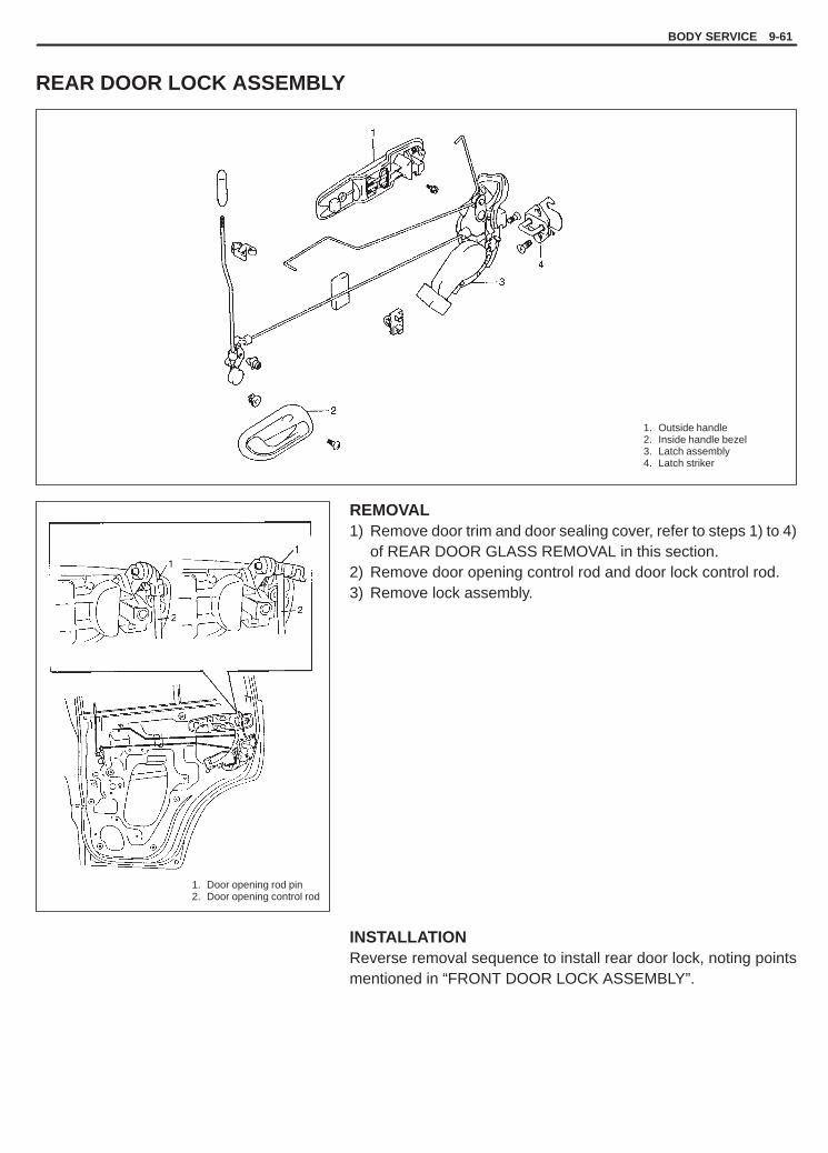
YH4GRANDVITARA
BODY SERVICE 9-61
1. Outside handle2. Inside handle bezel3. Latch assembly4. Latch striker
1. Door opening rod pin2. Door opening control rod
REAR DOOR LOCK ASSEMBLY
REMOVAL1) Remove door trim and door sealing cover, refer to steps 1) to 4)
of REAR DOOR GLASS REMOVAL in this section.2) Remove door opening control rod and door lock control rod.3) Remove lock assembly.
INSTALLATIONReverse removal sequence to install rear door lock, noting pointsmentioned in “FRONT DOOR LOCK ASSEMBLY”.

YH4GRANDVITARA
1. Shim
1. Rubber cushion1
9-62 BODY SERVICE
BACK DOOR/REAR GATE LOCK ASSEMBLYREMOVAL1) Remove inside handle bezel (if equipped).2) Remove inside lock knob.
3) Remove door trim.With inside handle bezel tilted as shown in figure, turn door trim90� counterclockwise to remove it (if equipped with inside han-dle).
4) Remove back door/rear gate sealing cover.
5) Remove back door/rear gate lock control rod.Unlock back door/rear gate lock rod pin retainer and disconnectcontrol rod.
6) Disconnect back door lock motor lead wire (if equipped).7) Remove lock assembly.
INSTALLATIONReverse removal procedure to install back door/rear gate lock as-sembly noting following points.� Back door/Rear gate latch striker.
Adjust back door/rear gate latch striker so that its center alignswith the center of groove in back door/rear gate latch base.To adjust back door/rear gate latch and striker with each other,insert proper number of shims below the bottom of striker, asshown.
� Back door/Rear gate rubber cushion.Move rubber cushion installed at the left side of back door/reargate to align it with its guide.

YH4GRANDVITARA
BODY SERVICE 9-63
KEY CODINGKEY USAGE AND IDENTIFICATIONKey is used for ignition and door lock cylinder. Keys are cut on bothedges to make them reversible.
Key identification is obtained from five character key code stampedon key code tag. Using this key code, key code cutting combinationcan be determined from a code list (available to owners of key cut-ting equipment from suppliers).If key codes are not available from records or tags, key code canbe obtained from the right hand door lock cylinder (if lock has notbeen replaced). Lock cylinders supplied by the factory as serviceparts are unmarked.If original key is available, key code cutting combination can be de-termined by laying key.
IGNITION SWITCH LOCK CYLINDER
Removal/ InstallationSee Section 3C1, “AIR BAG STEERING WHEEL AND COLUMN”.
ELECTRICAL DIAGNOSISFor ignition switch electrical troubleshooting, see Section 8, “BODYELECTRICAL SYSTEM”.
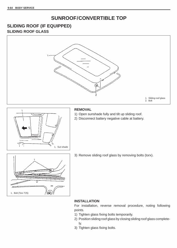
YH4GRANDVITARA
1. Sliding roof glass2. Bolt
1. Sun shade
1. Bolt (Torx T25)
9-64 BODY SERVICE
SUNROOF/CONVERTIBLE TOP
SLIDING ROOF (IF EQUIPPED)SLIDING ROOF GLASS
REMOVAL1) Open sunshade fully and tilt up sliding roof.2) Disconnect battery negative cable at battery.
3) Remove sliding roof glass by removing bolts (torx).
INSTALLATIONFor installation, reverse removal procedure, noting followingpoints.1) Tighten glass fixing bolts temporarily.2) Position sliding roof glass by closing sliding roof glass complete-
ly.3) Tighten glass fixing bolts.

YH4GRANDVITARA
BODY SERVICE 9-65
Section A – A
ADJUSTMENT1) Loosen sunroof glass fixing screws (at 4 locations) and move
sunroof glass up and down 2 to 3 times. In this way, sunroofglass can be positioned in both vertical and horizontal directionsby elasticity of sliding roof weather strip.
2) Position sunroof glass by such dimensions with respect to roofpanel surface as specified below.
Dimension: “a”: 0 mm (0.0 in.)
3) After installing all parts and adjusting properly, check sunroof forproper operation (open, close and up).
SLIDING ROOF DEFLECTOR
REMOVAL1) Open sliding roof.2) Disconnect negative cable at battery.3) Remove screws and disconnect deflector from deflector link.
INSTALLATIONReverse removal procedure to install deflector.
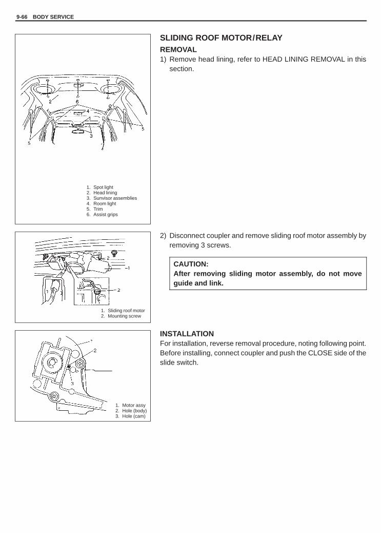
YH4GRANDVITARA
1. Spot light2. Head lining3. Sunvisor assemblies4. Room light5. Trim6. Assist grips
1. Sliding roof motor2. Mounting screw
1. Motor assy2. Hole (body)3. Hole (cam)
9-66 BODY SERVICE
SLIDING ROOF MOTOR/RELAYREMOVAL1) Remove head lining, refer to HEAD LINING REMOVAL in this
section.
2) Disconnect coupler and remove sliding roof motor assembly byremoving 3 screws.
CAUTION:After removing sliding motor assembly, do not moveguide and link.
INSTALLATIONFor installation, reverse removal procedure, noting following point.Before installing, connect coupler and push the CLOSE side of theslide switch.

YH4GRANDVITARA
BODY SERVICE 9-67
1. Drain hoses
1. Sliding roof motor2. Coupler
1. Sliding roof assembly fixing nuts2. Sliding roof assembly
SLIDING ROOF ASSEMBLYREMOVAL1) Remove roof lining. Refer to HEAD LINING REMOVAL in this
section.2) Remove sliding roof glass. Refer to SLIDING ROOF GLASS
REMOVAL.
3) Disconnect drain hoses connected to sliding roof assembly at 4locations.
4) Disconnect sliding roof motor at coupler.
5) Remove 6 nuts and then remove sliding roof assembly.
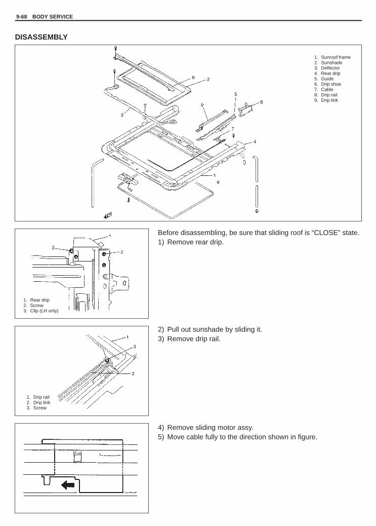
YH4GRANDVITARA
9-68 BODY SERVICE
1. Sunroof frame2. Sunshade3. Deflector4. Rear drip5. Guide6. Drip shoe7. Cable8. Drip rail9. Drip link
1. Rear drip2. Screw3. Clip (LH only)
1. Drip rail2. Drip link3. Screw
DISASSEMBLY
Before disassembling, be sure that sliding roof is “CLOSE” state.1) Remove rear drip.
2) Pull out sunshade by sliding it.3) Remove drip rail.
4) Remove sliding motor assy.5) Move cable fully to the direction shown in figure.

YH4GRANDVITARA
BODY SERVICE 9-69
1. Drip shoe2. Frame3. Guide
1. Dent2. Protrusion of lifter3. Resin part4. Motor assembly
5. Hole6. Hole (cam)7. Rear drip
“A”: Apply sealant
6) Remove sliding roof deflector.7) Pull out drip shoe, guide and cable assy as a set.
ASSEMBLYReverse disassembly procedure for assembly, observing followinginstructions.
CAUTION:Match protrusion of guide and dent in cable for completelyclosed position of sliding roof drive cable and match marks(holes) for completely closed position of sliding roof motorassembly and then install sliding roof motor assembly.
� Press the CLOSE side switch to match marks of sliding roof motorassembly.
� Apply butyl rubber sealant to contact surface of the rear drip.
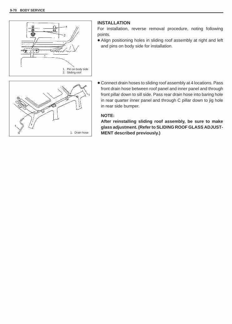
YH4GRANDVITARA
9-70 BODY SERVICE
1. Pin on body side2. Sliding roof
1. Drain hose
INSTALLATIONFor installation, reverse removal procedure, noting followingpoints.� Align positioning holes in sliding roof assembly at right and left
and pins on body side for installation.
� Connect drain hoses to sliding roof assembly at 4 locations. Passfront drain hose between roof panel and inner panel and throughfront pillar down to sill side. Pass rear drain hose into baring holein rear quarter inner panel and through C pillar down to jig holein rear side bumper.
NOTE:After reinstalling sliding roof assembly, be sure to makeglass adjustment. (Refer to SLIDING ROOF GLASS ADJUST-MENT described previously.)

YH4GRANDVITARA
BODY SERVICE 9-71
1. Topbow center frame2. Bracket cover
1. Topbow front frame
CANVAS TOP AND TOPBOW FRAMESRemoval1) Open canvas to referring to Owner’s Manual.2) Remove fording top and rear canvas top.3) Remove topbow bracket cover.
4) Remove topbow center frame.5) Remove topbow front frame.
InstallationInstall in reverse order of removal procedure.

YH4GRANDVITARA
9-72 BODY SERVICE
1. Front floor carpet2. Luggage floor carpet3. Dash panel insulation
1. Dash side trim2. Front side sill scuffs3. Center pillar inner lower trim4. Rear side sill scuff
5. Fastener6. Side sill scuff7. Rear quarter lower trim
EXTERIOR AND INTERIOR TRIM
FLOOR CARPET
FRONT FLOOR CARPET
REMOVAL1) Remove front seats and rear seat cushions.2) Remove seat belt lower anchor bolt.3) Remove dash side trims, front side sill scuffs (4 door model),
center pillar inner lower rims (4 door model), rear side sill scuffs(4 door model), side sill scuffs (2 door model) and rear quarterlower trim.
4) Remove parking brake lever cover, console box and consolebox front extension.
5) Remove front floor carpet.
INSTALLATIONReverse removal sequence to install front floor carpet, noting fol-lowing point.� When tightening seat belt anchor bolt, refer to Section 10A
“FRONT SEAT BELT” for tightening torque.
LUGGAGE FLOOR CARPETLuggage floor carpet is fixed to floor with clips.
REMOVALDetach clips, using care not to pull up carpet with force and breakclips. And remove inner trim.
INSTALLATIONReverse removal sequence to install luggage floor carpet.
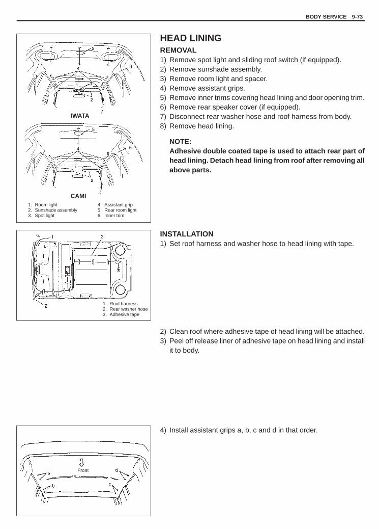
YH4GRANDVITARA
BODY SERVICE 9-73
5
4 6
4. Assistant grip5. Rear room light6. Inner trim
1. Roof harness2. Rear washer hose3. Adhesive tape
Front
1. Room light2. Sunshade assembly3. Spot light
IWATA
CAMI
HEAD LININGREMOVAL1) Remove spot light and sliding roof switch (if equipped).2) Remove sunshade assembly.3) Remove room light and spacer.4) Remove assistant grips.5) Remove inner trims covering head lining and door opening trim.6) Remove rear speaker cover (if equipped).7) Disconnect rear washer hose and roof harness from body.8) Remove head lining.
NOTE:Adhesive double coated tape is used to attach rear part ofhead lining. Detach head lining from roof after removing allabove parts.
INSTALLATION1) Set roof harness and washer hose to head lining with tape.
2) Clean roof where adhesive tape of head lining will be attached.3) Peel off release liner of adhesive tape on head lining and install
it to body.
4) Install assistant grips a, b, c and d in that order.

YH4GRANDVITARA
9-74 BODY SERVICE
1. Door opening trim2. Head lining
Set Set
4. Assistant grip5. Rear room light6. Inner trim
1. Room light2. Sunshade assembly3. Spot light
IWATA
CAMI
5) Install door opening trim.
6) Install spot light, sunshade assembly, speaker cover, room lightand inner trims covering head lining.

YH4GRANDVITARA
BODY SERVICE 9-75
1. Canvas top2. Rear topbow3. Side body garnish4. Luggage mat end garnish5. Assistant grip6. Sunshade assembly7. Sunshade hook8. Front topbow lock9. Canvas top snap
10. Front seat belt11. Front pillar trim12. Rear side inner lower trim13. Rear side inner upper trim14. Room light connector15. Room light harness clamp16. Roof trim17. Left-front seat belt
ROOF TRIM (2 DOOR MODEL)REMOVAL
1) Remove canvas top.2) Remove rear topbow.3) Remove side body garnishes.4) Remove luggage mat end garnish.5) Remove assistant grips.6) Remove sunshade assemblies.7) Remove sunshade hooks.8) Remove front topbow locks.9) Remove canvas top snaps.
10) Remove front seat belts.11) Remove front pillar trims.12) Remove rear side inner lower trims.13) Remove rear side inner upper trims.14) Disconnect room light connector and remove room light har-
ness clamp.15) Remove roof trim.
CAUTION:Be very careful not to separate roof trim consists of 4components when removing. If disassemble it, it couldnot be assembled to original unit.

YH4GRANDVITARA
9-76 BODY SERVICE
1. Roof trim2. Room light3. Room light lens
4. Clip5. Screw6. Room light harness7. Marking tape
1. Seat belt
INSTALLATION1) Set room light and clip to roof trim.2) Set room light harness to roof trim with marking tape.
3) Reverse removal sequence to install roof trim.
Tightening Torque(a): 35 N.m (3.5 kg-m, 25.3 lb-ft)

YH4GRANDVITARA
BODY SERVICE 9-77
1. Front door molding2. Rear door molding3. Front fender molding
SIDE MOLDINGS (IF EQUIPPED)
INSTALLATION1) Bonding surfaces should be cleaned thoroughly.2) Install molding by aligning it to clip holes and pulling it to the rear
so that fender or door will not interfere with it when door isopened.
3) If adequate adhesive force is not available, use urethane adhe-sive.

YH4GRANDVITARA
9-78 BODY SERVICE
1. Fender splash guard2. Front door splash guard3. Rear door splash guard4. Rear splash guard5. Side sill splash guard6. Rear door guard holder
SPLASH GUARD (IF EQUIPPED)

YH4GRANDVITARA
BODY SERVICE 9-79
1. Roof rail assembly2. Front cap3. Rear cap4. Base seal5. Nut
1. Roof molding2. Roof panel3. Clip4. Molding stud
ROOF RAIL (IF EQUIPPED)
Removal1) Remove roof rail front and rear caps as shown in figure.2) Remove nuts.3) Remove roof rail assembly.
InstallationReverse removal procedure for installation.Confirm that each roof rail fixing nut is tightened securely.
ROOF MOLDINGREMOVAL AND INSTALLATION� If roof rail is equipped, remove it in advance (refer to “ROOF RAIL” section).� When reusing roof molding, be careful not to make roof molding warped.

YH4GRANDVITARA
9-80 BODY SERVICE
1. Bolt2. Member
LUGGAGE UNDER BOX
WARNING:Do not remove member in the center of luggage under box.
If member had to be removed temporarily for repair or for some oth-er reason, be sure to reinstall it by using specified new bolts untilhead of bolt is broken off.

YH4GRANDVITARA
10
RESTRAINT SYSTEM 10-1
SECTION 10
RESTRAINT SYSTEMWARNING:For vehicles equipped with Supplemental Restraint (Air Bag) System� Service on and around the air bag system components or wiring must be performed only by an autho-
rized SUZUKI dealer. Refer to “Air Bag System Components and Wiring Location View” under “Gener-al Description” in air bag system section in order to confirm whether you are performing service onor near the air bag system components or wiring. Please observe all WARNINGS and “Service Precau-tions” under “On-Vehicle Service” in air bag system section before performing service on or aroundthe air bag system components or wiring. Failure to follow WARNINGS could result in unintentionalactivation of the system or could render the system inoperative. Either of these two conditions mayresult in severe injury.
� Technical service work must be started at least 90 seconds after the ignition switch is turned to the“LOCK” position and the negative cable is disconnected from the battery. Otherwise, the system maybe activated by reserve energy in the Sensing and Diagnostic Module (SDM).
SEAT BELT SECTION 10A. . . . . . . . . . . . . . . . . . . . . . . . . . . . . . . . . . . . . . . . . . . . . . . . . . . . . . . . . . . . . . . . . . . . . . . .
AIR BAG SYSTEM SECTION 10B. . . . . . . . . . . . . . . . . . . . . . . . . . . . . . . . . . . . . . . . . . . . . . . . . . . . . . . . . . . . . . . . . .
CONTENTS
GENERAL DESCRIPTION 10-2. . . . . . . . . . . . . . . . . . . . . . . . . . . . . . . . . . . . . . . . . . . . . . . . . . . . . . . . . . . . . . . . . . .
DIAGNOSIS Refer to “Diagnosis” in SECTION 10A and 10B.. . . . . . . . . . . . . . . . . . . . . . . . . . . . . . . . . . . . . . . . . . .

YH4GRANDVITARA
10-2 RESTRAINT SYSTEM
Driver Side Seat Belt: Seat belt with ELRFront Passenger Side Seat AndRear Left And Right Seat Belts: Seat belt with A-ELRRear Center Seat Belt (If Equipped): Seat belt without ELR and A-ELRSupplemental Restraint System: Driver and front passenger side air bags
1. Driver side seat belt2. Front passenger side seat belt3. Rear left seat belt4. Rear right seat belt5. Rear center seat belt (If equipped)6. Driver side air bag7. Passenger side air bag
GENERAL DESCRIPTION
Seat belt with ELRThe seat belt with Emergency Locking Retractor (ELR) is designed so that it locks immediately (to prevent the web-bing from being pulled out of the retractor any further) when any of the following items is detected as exceedingeach set value; speed at which the webbing is pulled out of the retractor, acceleration or deceleration of the vehiclespeed, and inclination.
Seat belt with A-ELRThe automatic and emergency locking retractor (A-ELR) works as an Emergency Locking Retractor (ELR) till itswebbing is pulled all the way out and then on as an Automatic Locking Retractor (ALR) till it is retracted fully.ALR: Automatically locks when the webbing is pulled out from the retractor and allowed to retract even a little.
Then the webbing can not be pulled out any further, unless it is wound all the way back into the retractor, whichreleases the lock and allows the webbing to be pulled out.
Driver and front passenger side air bagsThe driver and front passenger side air bags are components of the air bag system. In occurrence of a front collisionwith an impact larger than a certain set value, they are activated by the ignition signal from SDM to supplementprotection offered by the driver and front passenger seat belts.� the driver air bag (inflator) module is deployed from the center of the steering column� the passenger air bag (inflator) module from the top of the instrument panel in front of the front passenger seatFor more information, refer to SECTION 10B “Air Bag System”.

YH4GRANDVITARA
10A
SEAT BELT 10A-1
SECTION 10A
SEAT BELTWARNING:For vehicles equipped with Supplemental Restraint (Air Bag) System� Service on and around the air bag system components or wiring must be performed only by an autho-
rized SUZUKI dealer. Refer to “Air Bag System Components and Wiring Location View” under “Gener-al Description” in air bag system section in order to confirm whether you are performing service onor near the air bag system components or wiring. Please observe all WARNINGS and “Service Precau-tions” under “On-Vehicle Service” in air bag system section before performing service on or aroundthe air bag system components or wiring. Failure to follow WARNINGS could result in unintentionalactivation of the system or could render the system inoperative. Either of these two conditions mayresult in severe injury.
� Technical service work must be started at least 90 seconds after the ignition switch is turned to the“LOCK” position and the negative cable is disconnected from the battery. Otherwise, the system maybe activated by reserve energy in the Sensing and Diagnostic Module (SDM).
CAUTION:When fasteners are removed, always reinstall them at the same location from which they were re-moved. If a fastener needs to be replaced, use the correct part number fastener for that application. Ifthe correct part number fastener is not available, a fastener of equal size and strength (or stronger) maybe used. Fasteners that are not reused, and those requiring thread-locking compound, will be calledout. The correct torque value must be used when installing fasteners that require it. If the above proce-dures are not followed, parts or system damage could result.
CONTENTS
GENERAL DESCRIPTION Refer to SECTION 10. . . . . . . . . . . . . . . . . . . . . . . . . . . . . . . . . . . . . . . . . . . . . . . . . . . . . .
ON-VEHICLE SERVICE 10A-2. . . . . . . . . . . . . . . . . . . . . . . . . . . . . . . . . . . . . . . . . . . . . . . . . . . . . . . . . . . . . . . . . . . . Service precautions 10A-2. . . . . . . . . . . . . . . . . . . . . . . . . . . . . . . . . . . . . . . . . . . . . . . . . . . . . . . . . . . . . . . . . . . . . . . Front seat belt 10A-3. . . . . . . . . . . . . . . . . . . . . . . . . . . . . . . . . . . . . . . . . . . . . . . . . . . . . . . . . . . . . . . . . . . . . . . . . . . Rear seat belt 10A-6. . . . . . . . . . . . . . . . . . . . . . . . . . . . . . . . . . . . . . . . . . . . . . . . . . . . . . . . . . . . . . . . . . . . . . . . . . . .
TIGHTENING TORQUE SPECIFICATIONS 10A-6. . . . . . . . . . . . . . . . . . . . . . . . . . . . . . . . . . . . . . . . . . . . . . . . . . . .

YH4GRANDVITARA
10A-2 SEAT BELT
ON-VEHICLE SERVICE
SERVICE PRECAUTIONS
WARNING:If replacing seat belt is necessary, replace buckle and ELR (or webbing) together as a set. This is forthe reason of ensuring locking of tongue plate with buckle. If these parts are replaced individually, sucha locking condition may become unreliable. For this reason, SUZUKI will supply only the spare buckleand ELR (or webbing) in a set part.
Before servicing or replacing seat belts, refer to following precautionary items.� Seat belts should be normal relative to strap retractor and buckle portions.� Keep sharp edges and damaging objects away from belts. Avoid bending or damaging any portion of belt buckle,
latch plate and ELR.� Do not bleach or dye belt webbing. (Use only mild soap and lukewarm water to clean it.)� When installing a seat belt anchor bolt, start bolt by hand to prevent cross-threading.� Use only the correct seat belt anchor bolts and screws and tighten to the correct torque value.� Do not attempt any repairs on retractor mechanisms or retractor covers. Replace defective assemblies with new
replacement parts.� Keep belts dry and clean at all times.� If there exist any parts in question, replace such parts.� Replace belts whose webbing is cut or otherwise damaged.� Do not put anything into trim panel opening which seat belt webbing passes through.

YH4GRANDVITARA
1. Upper anchor2. Lower anchor3. Retractor assembly4. Buckle
SEAT BELT 10A-3
FRONT SEAT BELT
WARNING:Be sure to read “Service Precautions” before starting to work and observe every precaution duringwork.
REMOVALRefer to the figure below to remove front seat belts.

YH4GRANDVITARA
1. Buckle tongue2. Buckle catch
10A-4 SEAT BELT
INSPECTIONSeat belts and attaching parts can affect the vital components andsystems of a vehicle. Therefore, they should be inspected carefullyand replaced with genuine parts only.Seat belt� The seat belt webbing or strap should be free from damage.� Fully extend the seat belt to make sure there are no twists or tears
in it.Retractor assemblyLet the seat belt retract fully to confirm its easy retraction.� The retractor assembly should lock webbing when pulled quickly.� The retractor assembly should lock webbing even when tilted
(approx. 15�) toward the fore and aft or right and left directions.Anchor bolt� Inspect all seat belt anchor bolts to verify that they are secure.� All anchor bolts should be secure and torqued to specification.Belt latch� Belt latch should be secure when latched.� Inspect the seat belt buckle, ensuring that it locks and unlocks
easily.� After buckling the seat belt, tug sharply on the belt, checking that
the buckle remains locked.
Warning systemCheck driver side seat belt strap switch for continuity by using ohm-meter.
Without inserted buckle tongue to buckle catch:Terminal “A” and “B”: ContinuityWith inserted buckle tongue to buckle catch:Terminal “A” and “B”: No continuity ( ��)
As to seat belts with ALR (other than driver side seat belt), checkthem as follows in addition to above check.� With vehicle at stop, pull seat belt all the way out, let it retract a
little and try to pull it. It should not be pulled out, that is, it shouldbe locked where retracted.
� Let seat belt retract to its original state. Next, pull it half way out,let it retract a little and try to pull it again. It should be pulled outsmoothly, that is it should not be locked at this time.

YH4GRANDVITARA
SEAT BELT 10A-5
(a)
(a)
(a)
(a)
(b)
1. Upper anchor2. Lower anchor3. Retractor assembly4. Buckle
INSTALLATIONInstall in reverse order of removal, noting the following.� Seat belt anchor bolts should have an unified fine thread (7/16-20 UNF). Under no circumstances should any
different sized or metric screw threads be used.� Be sure to tighten seat belt anchor bolts to specified torque.
Tightening torque(a): 35 N.m (3.5 kg-m, 25.5 lb-ft)(b): 5.5 N.m (0.55 kg-m, 4.0 lb-ft)

YH4GRANDVITARA
10A-6 SEAT BELT
1. Upper anchor2. Lower anchor3. Retractor assembly4. Buckle
: If equipped*
*
REAR SEAT BELT
WARNING:Be sure to read “Service Precautions” before starting to work and observe every precaution duringwork.
REMOVALRefer to the figure below to remove rear seat belts.
INSPECTIONCheck the rear seat belt in the same way as when inspecting front seat belt. (Refer to page 10A-4.)
INSTALLATIONInstall the rear seat belt observing the same precautions as when installing front seat belt. (Refer to page 10A-5.)
Tightening Torque(a): 35 N.m (3.5 kg-m, 25.5 lb-ft)
TIGHTENING TORQUE SPECIFICATIONS
Fastening partsTightening torque
Fastening artsN.m kg-m lb-ft
Upper and lower anchor bolt 35 3.5 25.5
Retractor assembly bolt 35 3.5 25.5
Retractor assembly screw 5.5 0.55 4.0
Buckle bolt 35 3.5 25.5

YH4GRANDVITARA
10B
AIR BAG SYSTEM 10B-1
GENERAL DESCRIPTION 10B- 3. . . . . . . . . . . . . System Components and Wiring
Location View and Connectors 10B- 4. . . . . . . System Wiring Diagram 10B- 5. . . . . . . . . . . . . .
DIAGNOSIS 10B- 6. . . . . . . . . . . . . . . . . . . . . . . . . . Diagnostic Trouble Codes 10B- 6. . . . . . . . . . . . Use of Special Tools 10B- 6. . . . . . . . . . . . . . . . . Intermittent and Poor Connections 10B- 8. . . . . Air Bag Diagnostic System Check 10B-10. . . . .
Air bag diagnostic system checkflow table 10B-11. . . . . . . . . . . . . . . . . . . . . . . .
Diagnostic trouble code (DTC) check 10B-12. Diagnostic trouble code (DTC)
clearance 10B-13. . . . . . . . . . . . . . . . . . . . . . . Diagnostic trouble code table 10B-14. . . . . . . . Table A - “AIR BAG” warning lamp
comes “ON” steady 10B-16. . . . . . . . . . . . . . . Table B - “AIR BAG” warning lamp
does not come “ON” 10B-18. . . . . . . . . . . . . . Table C - “AIR BAG” warning lamp
flashes 10B-20. . . . . . . . . . . . . . . . . . . . . . . . . . Table D - SDM cannot communicate
through the serial data circuit 10B-22. . . . . . .
Code 15 - Passenger air bag initiatorcircuit resistance high 10B-24. . . . . . . . . . . . .
Code 16 - Passenger air bag initiatorcircuit resistance low 10B-26. . . . . . . . . . . . . .
Code 18 - Passenger air bag initiatorcircuit short to ground 10B-28. . . . . . . . . . . . .
Code 19 - Passenger air bag initiatorcircuit short to power circuit 10B-30. . . . . . . .
Code 21 - Driver air bag initiatorcircuit resistance high 10B-32. . . . . . . . . . . . .
Code 22 - Driver air bag initiatorcircuit resistance low 10B-34. . . . . . . . . . . . . .
Code 24 - Driver air bag initiatorcircuit short to ground 10B-36. . . . . . . . . . . . .
Code 25 - Driver air bag initiatorcircuit short to power circuit 10B-38. . . . . . . .
Code 31 - Power source voltage high 10B-40Code 32 - Power source voltage low 10B-42. Code 41 - Driver pretensioner initiator
circuit resistance high 10B-44. . . . . . . . . . . . . Code 45 - Passenger pretensioner
initiator circuit resistance high 10B-44. . . . . . Code 42 - Driver pretensioner initiator
circuit resistance low 10B-46. . . . . . . . . . . . . .
SECTION 10B
AIR BAG SYSTEMWARNING:� Service on or around the air bag system components or wiring must be performed only by an autho-
rized SUZUKI dealer. Please observe all WARNINGS and “Service Precautions” under “On-VehicleService” in this section before performing service on or around the air bag system components orwiring. Failure to follow WARNINGS could result in unintended activation of the system or could ren-der the system inoperative. Either of these two conditions may result in severe injury.
� The procedures in this section must be followed in the order listed to disable the air bag system tem-porarily and prevent false diagnostic trouble codes from setting. Failure to follow procedures couldresult in possible activation of the air bag system, personal injury or otherwise unneeded air bag sys-tem repairs.
CAUTION:When fasteners are removed, always reinstall them at the same location from which they were re-moved. If a fastener needs to be replaced, use the correct part number fastener for that application. Ifthe correct part number fastener is not available, a fastener of equal size and strength (or stronger) maybe used. Fasteners that are not reused, and those requiring thread-locking compound, will be calledout. The correct torque value must be used when installing fasteners that require it. If the above condi-tions are not followed, parts or system damage could result.
CONTENTS

YH4GRANDVITARA
10B-2 AIR BAG SYSTEM
Code 46 - Passenger pretensionerinitiator circuit resistance low 10B-46. . . . . . .
Code 43 - Driver pretensioner initiator circuit short to ground 10B-48. . . . . . . . . . . . .
Code 47 - Passenger pretensionerinitiator circuit short to ground 10B-48. . . . . .
Code 44 - Driver pretensioner initiatorcircuit short to power circuit 10B-50. . . . . . . .
Code 48 - Passenger pretensioner initiator circuit short to power circuit 10B-50.
Code 51 - Frontal crash detected (System activation command isoutputted) 10B-52. . . . . . . . . . . . . . . . . . . . . . .
Code 61 -“AIR BAG” warning lampcircuit failure 10B-53. . . . . . . . . . . . . . . . . . . . .
Code 71 - Internal SDM fault 10B-54. . . . . . . .
ON-VEHICLE SERVICE 10B-55. . . . . . . . . . . . . . . Service Precautions 10B-55. . . . . . . . . . . . . . . . .
Service and diagnosis 10B-55. . . . . . . . . . . . . . Disabling air bag system 10B-56. . . . . . . . . . . . Enabling air bag system 10B-56. . . . . . . . . . . . Handling and storage 10B-57. . . . . . . . . . . . . . Disposal 10B-62. . . . . . . . . . . . . . . . . . . . . . . . . .
Repairs and Inspections Requiredafter an Accident 10B-63. . . . . . . . . . . . . . . . . . . Accident with deployment
- component replacement 10B-63. . . . . . . . . .
Accident with or without deployment- component inspections 10B-64. . . . . . . . . . .
Driver Air Bag (Inflator) Module 10B-66. . . . . . . . Contact Coil and Combination Switch
Assembly 10B-66. . . . . . . . . . . . . . . . . . . . . . . . . Seat Belt Pretensioner 10B-66. . . . . . . . . . . . . . . “AIR BAG” Warning Lamp 10B-66. . . . . . . . . . . . SDM 10B-67. . . . . . . . . . . . . . . . . . . . . . . . . . . . . . . Passenger Air Bag (Inflator) Module 10B-69. . .
AIR BAG (INFLATOR) MODULESDISPOSAL 10B-71. . . . . . . . . . . . . . . . . . . . . . . . . . Deployment Outside Vehicle 10B-71. . . . . . . . . . Deployment Inside Vehicle 10B-78. . . . . . . . . . . .
SEAT BELT PRETENSIONERSDISPOSAL 10B-83. . . . . . . . . . . . . . . . . . . . . . . . . . Activation Outside Vehicle 10B-83. . . . . . . . . . . . Activation Inside Vehicle 10B-89. . . . . . . . . . . . . .
DEPLOYED AIR BAG (INFLATOR)MODULES DISPOSAL 10B-93. . . . . . . . . . . . .
ACTIVATED SEAT BELT PRETENSIONERSDISPOSAL 10B-94. . . . . . . . . . . . . . . . . . . . . . . .
TIGHTENING TORQUESPECIFICATIONS 10B-95. . . . . . . . . . . . . . . . . .
SPECIAL TOOLS 10B-95. . . . . . . . . . . . . . . . . . . .

YH4GRANDVITARA
1 2
3
3
1. Driver side air bag2. Passenger side air bag3. Seat belt pretensioner
(if equipped)
1-1. SDM1-1. Sensor1-2. Voltage converter
1-3. Safing sensor1-4. Micro-controller1-5. Energy reserve circuit
1-6. Ignition driver circuit1-2. Power source 3. Driver air bag
4. Passenger air bag 5. Seat belt pretensioner (if equipped) 6. Squib circuit
AIR BAG SYSTEM 10B-3
GENERAL DESCRIPTION
With the air bag system which includes air bags for both the driver’sand passenger’s sides as well as the seat belt pretensioners (ifequipped), the sag of the seat belt is taken up, the driver air bag (in-flator) module is deployed from the center of the steering columnand the passenger air bag (inflator) module from the top of theinstrument panel in front of the front passenger seat in occurrenceof a front collision with an impact larger than a certain set value tosupplement protection offered by the driver and front passengerseat belts.
The air bag system is designed to activate only in severe frontal col-lisions. It is not designed to activate in rear impacts, side impacts,rollovers, or minor frontal collisions, since it would offer no protec-tion in those types of accidents.

YH4GRANDVITARA
10B-4 AIR BAG SYSTEM
1. Air bag harness2. “AIR BAG” fuse box3. “AIR BAG” monitor coupler4. DLC5. Contact coil assembly6. Driver air bag (inflator) module7. Passenger air bag (inflator) module8. SDM9. Seat belt pretensioner
(retractor assembly) (if equipped)10. Pretensioner harness (if equipped)11. Ground for air bag system
CONNECTOR “A”
CONNECTOR “C”, “D”
CONNECTOR “B”
CONNECTOR “E”
CONNECTOR “H”
CONNECTOR “F”
CONNECTOR “G”
SYSTEM COMPONENTS AND WIRING LOCATION VIEW AND CONNECTORS

YH4GRANDVITARA
WIRE HARNESS COLOR
B : BlackB/W : Black/WhiteBl : BlueBl/B : Blue/BlackBl/R : Blue/RedBr : Brown
G : GreenGr : GrayG/R : Green/RedLg : LightgreenP : PinkV : Violet
Y : YellowY / G : Yellow/GreenY/R : Yellow/RedW : WhiteW/B : White/Black
1. From main fuse2. Ignition switch3. “IG.COIL METER” fuse in J/B4. “AIR BAG” warning lamp in combination meter5. “AIR BAG” fuse in “AIR BAG” fuse box6. Connection detection pin7. To ECM (or PCM), ICM (if equipped) and ABS
controller (if equipped)8. To data link connector (DLC)9. “AIR BAG” monitor coupler
10. SDM11. Contact coil assembly12. Driver air bag (inflator) module13. Driver seat belt pretensioner (if equipped)14. Passenger air bag (inflator) module15. Passenger seat belt pretensioner (if equipped)16. Pretensioner harness (if equipped)17. Ground for air bag system
TERMINALA1A2A3A4A5A6A7A8A9
A10
A13
A11A12
A14A15A16
Passenger air bag (inflator) module LowHigh
CIRCUIT
Data link connector (DLC)
LowHigh
LowHigh
LowHigh
“AIR BAG” warning lamp
Driver air bag (inflator) module
Diagnosis switch–––––––––
Ground
Passenger pretensioner
Driver pretensioner
Ignition switch (power source)
–––––––––
–––––––––
CONNECTOR “A” (SDM connector)TERMINAL ARRANGEMENT OF SDM(VIEWED FROM HARNESS SIDE)
L1L2
Connection detection pin
: Shorting bar: Air bag harness
“A” � “H” : Connector
AIR BAG SYSTEM 10B-5
SYSTEM WIRING DIAGRAM
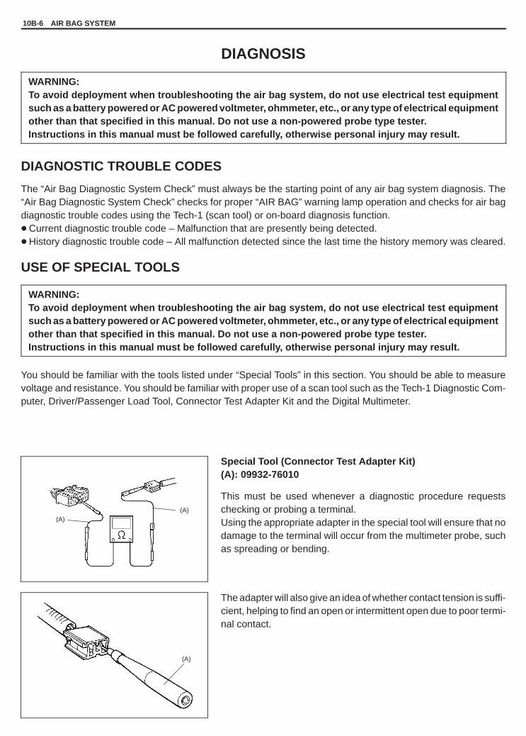
YH4GRANDVITARA
(A)(A)
(A)
10B-6 AIR BAG SYSTEM
DIAGNOSIS
WARNING:To avoid deployment when troubleshooting the air bag system, do not use electrical test equipmentsuch as a battery powered or AC powered voltmeter, ohmmeter, etc., or any type of electrical equipmentother than that specified in this manual. Do not use a non-powered probe type tester.Instructions in this manual must be followed carefully, otherwise personal injury may result.
DIAGNOSTIC TROUBLE CODES
The “Air Bag Diagnostic System Check” must always be the starting point of any air bag system diagnosis. The“Air Bag Diagnostic System Check” checks for proper “AIR BAG” warning lamp operation and checks for air bagdiagnostic trouble codes using the Tech-1 (scan tool) or on-board diagnosis function.� Current diagnostic trouble code – Malfunction that are presently being detected.� History diagnostic trouble code – All malfunction detected since the last time the history memory was cleared.
USE OF SPECIAL TOOLS
WARNING:To avoid deployment when troubleshooting the air bag system, do not use electrical test equipmentsuch as a battery powered or AC powered voltmeter, ohmmeter, etc., or any type of electrical equipmentother than that specified in this manual. Do not use a non-powered probe type tester.Instructions in this manual must be followed carefully, otherwise personal injury may result.
You should be familiar with the tools listed under “Special Tools” in this section. You should be able to measurevoltage and resistance. You should be familiar with proper use of a scan tool such as the Tech-1 Diagnostic Com-puter, Driver/Passenger Load Tool, Connector Test Adapter Kit and the Digital Multimeter.
Special Tool (Connector Test Adapter Kit)(A): 09932-76010
This must be used whenever a diagnostic procedure requestschecking or probing a terminal.Using the appropriate adapter in the special tool will ensure that nodamage to the terminal will occur from the multimeter probe, suchas spreading or bending.
The adapter will also give an idea of whether contact tension is suffi-cient, helping to find an open or intermittent open due to poor termi-nal contact.

YH4GRANDVITARA
AIR BAG SYSTEM 10B-7
Special Tool (Air Bag Driver/Passenger Load Tool)(B): 09932-75010
This tool is used only when called for in this section. It is used asa diagnostic aid and safety device to prevent inadvertent air bag (in-flator) module deployment and seat belt pretensioner activation.The load tool has three connectors attached to its case are electri-cally functional and serve as resistive load substitutions.No more than two connectors are used at any time.
One of connectors (“A”: BASE OF COLUMN) is used to substitutethe load of the driver air bag (inflator) module and the contact coilassembly when it is connected at the base of the column to the airbag wire harness.Another connector (“B”: STEERING WHEEL) is used to substitutethe load of followings.� Driver air bag (inflator) module when it is connected at the top of
the column to the contact coil assembly.� Passenger air bag (inflator) module when it is connected to the
air bag harness connector for passenger air bag (inflator) module.� Driver and passenger seat belt pretensioner when it is connected
to air bag harness connector for driver and passenger seat beltpretensioner.
The third connector (“C”: PASSENGER INFLATOR) is not used.By substituting the resistance of the load tool when called for, a de-termination can be made as to whether an inflator circuit compo-nent is causing system malfunction and which component is caus-ing the malfunction.The load tool should be used only when specifically called for in thediagnostic procedures.

YH4GRANDVITARA
(A)
10B-8 AIR BAG SYSTEM
INTERMITTENT AND POOR CONNECTIONS
Most intermittent are caused by faulty electrical connections or wir-ing. When a check for proper connection is requested in a diagnos-tic flow table, perform careful check of suspect circuits for:
� Poor mating of connector halves, or terminals not fully seated inthe connector body (backed out).
� Dirt or corrosion on the terminals. The terminals must be cleanand free of any foreign material which could impede proper termi-nal contact.However, cleaning the terminal with a sand paper or the like isprohibited.
� Damaged connector body, exposing the terminals to moistureand dirt, as well as not maintaining proper terminal orientationwith the component or mating connector.
� Improperly formed or damaged terminals.
If any abnormality is found, repair or replace as a wire harness as-sembly.
Check each connector terminal in problem circuits carefully to en-sure good contact tension by using the corresponding mating termi-nal included in the connector test adapter kit (special tool).If contact tension is not enough, reform it to increase contact ten-sion or replace.
Special Tool (Connector Test Adapter Kit)(A): 09932-76010
� Poor terminal-to-wire connection.Check each wire harness in problem circuits for poor connectionby shaking it by hand lightly.If any abnormal condition is found, change the wire harness as-sembly or component parts with new ones.

YH4GRANDVITARA
AIR BAG SYSTEM 10B-9
� Wire insulation which is rubbed through, causing an intermittentshort as the bare area touches other wiring or parts of the vehicle.
� Wiring broken inside the insulation. This condition could cause acontinuity check to show a good circuit, but if only 1 or 2 strandsof a multi-strand-type wire are intact, resistance could be far toohigh.
If any abnormality is found, repair or replace as a wire harness as-sembly.

YH4GRANDVITARA
10B-10 AIR BAG SYSTEM
AIR BAG DIAGNOSTIC SYSTEM CHECK
WARNING:To avoid deployment when troubleshooting the air bag system, do not use electrical test equipmentsuch as a battery powered or AC powered voltmeter, ohmmeter, etc., or any type of electrical equipmentother than that specified in this manual. Do not use a non-powered probe type tester.Instructions in this manual must be followed carefully, otherwise personal injury may result.
CAUTION:The order in which diagnostic trouble codes are diagnosed is very important. Failure to diagnose thediagnostic trouble codes in the order specified may result in extended diagnostic time, incorrect diag-nosis and incorrect parts replacement.
The diagnostic procedures used in this section are designed to find and repair air bag system malfunctions.To get the best results, it is important to use the diagnostic flow tables and follow the sequence listed below.
A. PERFORM THE “AIR BAG DIAGNOSTIC SYSTEM CHECK FLOW TABLE”The “Air Bag Diagnostic System Check Flow Table” must be the starting point of any air bag system diagnostics.The “Air Bag Diagnostic System Check Flow Table” checks for proper “AIR BAG” warning lamp operation, theability of the SDM to communicate through “AIR BAG” warning lamp and whether air bag diagnostic troublecodes exist.
B. REFER TO THE PROPER DIAGNOSTIC TABLE AS DIRECTED BY THE “AIR BAG DIAGNOSTIC SYSTEMCHECK FLOW TABLE”.The “Air Bag Diagnostic System Check Flow Table” will lead you to the correct chart to diagnose any air bagsystem malfunctions. Bypassing these procedures may result in extended diagnostic time, incorrect diagnosisand incorrect parts replacement.
C. REPEAT THE “AIR BAG DIAGNOSTIC SYSTEM CHECK FLOW TABLE” AFTER ANY REPAIR OR DIAGNOS-TIC PROCEDURES HAVE BEEN PERFORMED.Performing the “Air Bag Diagnostic System Check Flow Table” after all repair or diagnostic procedures will en-sure that the repair has been made correctly and that no other malfunctions exist.

YH4GRANDVITARA
AIR BAG SYSTEM 10B-11
AIR BAG DIAGNOSTIC SYSTEM CHECK FLOW TABLE
STEP ACTION YES NO
1 1) Make sure that battery voltage is about11V or higher.
2) Note “AIR BAG” warning lamp as ignitionswitch is tuned ON.
3) Does “AIR BAG” warning lamp flash6 times when ignition switch is tuned ON?
Go to step 2. “AIR BAG” warning lampdoes not come “ON”Proceed to “Table B”on p.10B-18.
2 Does “AIR BAG” warning lamp keep flashing(indicating DTC) when ignition switch isturned ON ?
“AIR BAG” warninglamp flashesProceed to “Table C”on p.10B-20.
Go to step 3.
3 After flashing 6 times then does“AIR BAG” warning lamp turn OFF?
Go to step 4. Go to step 5.
4 1) Check DTC, referring to “DiagnosticTrouble Code (DTC) Check” onp.10B-12.
2) [Using SUZUKI scan tool]Is “NO CODES” displayed ?
NOTE:If SDM cannot communicate throughserial data circuit, proceed to “TableD” on p.10B-22.
[Not using SUZUKI scan tool]Is DTC 12 indicated ?
Air bag system is ingood condition.
NOTE:As execution of the “Diag-nostic Trouble Code (DTC)Clearance” will clear allDTCs, be sure to record allDTCs before servicing.
An intermittent trouble hasoccurred at some place.Check the connectorharness, etc. related to thesensed DTC (Refer to“Intermittent and PoorConnections” in this section.).Then clear DTC (Refer top.10B-13.) and repeat thistable.
5 1) Check DTC, referring to “DiagnosticTrouble Code (DTC) Check” onp.10B-12.
2) [Using SUZUKI scan tool]Is “NO CODES” displayed ?
NOTE:If SDM cannot communicate throughserial data circuit, proceed to “TableD” on p.10B-22.
[Not using SUZUKI scan tool]Is DTC 12 indicated ?
“AIR BAG” warninglamp come “ON”steadyProceed to “Table A” onp.10B-16.
NOTE:As execution of the “Diag-nostic Trouble Code (DTC)Clearance” will clear allDTCs, be sure to record allDTCs before servicing.
Check and repair accordingto Flow Table correspondingto that DTC.

YH4GRANDVITARA
10B-12 AIR BAG SYSTEM
1. Data link connector (DLC)2. DLC cable adapter3. DLC cable
- 1. “AIR BAG”warning lamp
- 2. “AIR BAG” fuse box- 3. “AIR BAG”
monitor coupler3-1. Diagnostic switch
terminal- 4. Air bag harness
(covered yellow tube)
EXAMPLE: When driver air bag initiator circuit resistance high (Code No.21) is set
Malfunction indicator lamp(“AIR BAG” warning lamp)
Turn ON
Turn OFF
Time (sec.)
Code No. 21 Code No. 21 Code No. 21
1
DIAGNOSTIC TROUBLE CODE (DTC) CHECK[Using SUZUKI scan tool]1) Turn ignition switch OFF.2) After setting cartridge to Tech 1, connect it to data link connector
(DLC) located on underside of instrument panel at driver’s seatside.
Special Tool(A): 09931-76011 (Tech 1)(B): Mass storage cartridge(C): 09931-76030
3) Turn ignition switch ON.4) Read DTC according to instructions displayed on Tech 1 and
print it or write it down. Refer to Tech 1 operator’s manual for fur-ther details.
5) After completing the check, turn ignition switch OFF and discon-nect Tech 1 from data link connector (DLC).
[Not using SUZUKI scan tool]1) Check that malfunction indicator lamp (“AIR BAG” warning
lamp) comes ON when ignition switch is turned ON.If it does not come “ON”, proceed to “Table B” on p.10B-18.
2) Using service wire, ground diagnosis switch terminal in monitorcoupler.
3) Read DTC from flashing pattern of malfunction indicator lamp(“AIR BAG” warning lamp). (Refer to “Diagnostic Trouble CodeTable” on p.10B-14 and 10B-15.)
4) After completing the check, turn ignition switch OFF and discon-nect service wire from “AIR BAG” monitor coupler.

YH4GRANDVITARA
1. Data link connector2. DLC cable adapter3. DLC cable
1sec. 1sec.
About 10 seconds
Open
Short
- 1. “AIR BAG” warning lamp- 2. “AIR BAG” fuse box- 3. “AIR BAG” monitor coupler3-1. Diagnostic switch terminal- 4. Air bag harness (covered yellow tube)
1
AIR BAG SYSTEM 10B-13
DIAGNOSTIC TROUBLE CODE (DTC) CLEARANCE[Using SUZUKI scan tool]1) Turn ignition switch OFF.2) Connect Tech 1 to data link connector (DLC) in the same manner
as when making this connection for DTC check.
Special Tool(A): 09931-76011 (Tech 1)(B): Mass storage cartridge(C): 09931-76030
3) Turn ignition switch ON.4) Erase DTC according to instructions displayed on Tech 1.
Refer to Tech 1 operator’s manual for further details.5) After completing the check, turn ignition switch OFF and discon-
nect Tech 1 from data link connector (DLC).6) Perform “Diagnosis Trouble Code (DTC) Check” and confirm
that normal DTC (NO CODES) is displayed and not malfunctionDTC.
NOTE:If DTC 51 or DTC 71 is stored in SDM, it is not possible toclear DTC.
[Not using SUZUKI scan tool]1) Turn ignition switch ON and wait about 6 seconds or more.2) Using service wire, repeat shorting and opening between diag-
nosis switch terminal and ground terminal on “AIR BAG” monitorcoupler 5 times at about 1 second intervals.
3) Perform “Diagnosis Trouble Code (DTC) Check” and confirmthat normal DTC (DTC 12) is displayed and not malfunctionDTC.
NOTE:If DTC 51 or DTC 71 is stored in SDM, it is not possible toclear DTC.

YH4GRANDVITARA
10B-14 AIR BAG SYSTEM
DIAGNOSTIC TROUBLE CODE TABLE (Page 1 of 2)
EXAMPLE: WHEN DRIVER AIR BAG INITIATOR CIRCUIT RESISTANCE HIGH (CODE NO.21) IS SET
Turn ON
Turn OFF
0.3 0.31.0 3.0 3.0
Malfunction indicator lamp(“AIR BAG” warning lamp)
Code No. 21 Code No. 21 Code No. 21
Time (sec.)
DIAGNOSTIC TROUBLE CODEDIAGNOSIS
NO. MODEDIAGNOSIS
12 Normal –––––
15 Resistance high
16 Passengerair bag
Resistance low
18
air bagcircuit Short to ground
19 Short to power circuit
21 Resistance highDiagnose troubleaccording to “Diagnos-tic Flow Table” corre-
22Driver air bag
Resistance low
tic Flow Table corre-sponding to each codeNo.
24
gcircuit
Short to ground
25 Short to power circuit
31 Powersource
Too high
32
sourcevoltage Too low

YH4GRANDVITARA
AIR BAG SYSTEM 10B-15
DIAGNOSTIC TROUBLE CODE TABLE (Page 2 of 2)
DIAGNOSTIC TROUBLE CODEDIAGNOSIS
NO. MODEDIAGNOSIS
41 Resistance high
42 Driverpretensioner
Resistance low
43circuit(if equipped) Short to ground
44 Short to power circuit
45 Resistance high Diagnose troubledi t “Di
46 Passengerpretensioner
Resistance lowaccording to “Diagnos-tic Flow Table” corre-sponding to each code
47circuit(if equipped) Short to ground
s onding to each codeNo.
48 Short to power circuit
51 SDM Frontal crash detected
61 “AIR BAG” warning lamp circuit
71 SDM Internal fault
NOTE:� When 2 or more codes are indicated, the lowest numbered code will appear first.� If a code not listed on the table is displayed, then the SDM is faulty.� Current DTC and history DTC can be identified by lighting and flashing of “AIR BAG” warning lamp as
follows.
Current DTC is set.(Abnormality exists at present.)
History DTC is set only. (Faulty condi-tion occurred once in the past but nor-mal condition is restored at present.)
“AIR BAG” warning lampafter ignition switch ON
Remains ON. Flashing 6 times and turns OFF.
“AIR BAG” warning lampwhen grounding diagnosisswitch
Current DTC is displayed. History DTC is displayed.
However, if a multiple number of DTC’s are set an even one of them is a current DTC, “AIR BAG” warninglamp remains on after ignition switch is turned ON. Therefore, it is not possible to identify any of themas to whether it is a current one or a history one. (But use of scan tool (Tech 1) will make identificationpossible.)

YH4GRANDVITARA
7. SDM7-1. “AIR BAG” warning lamp driver circuit
4. “AIR BAG” warning lamp in combination meter5. “AIR BAG” fuse in “AIR BAG” fuse box6. Connection detection pin
1. From main fuse2. Ignition switch3. “IG.COIL METER” fuse in J/B
: Air bag harness
10B-16 AIR BAG SYSTEM
TABLE A – “AIR BAG” WARNING LAMP COMES “ON” STEADY (Page 1 of 2)
CAUTION:� When measurements are requested in this chart use specified digital multimeter with correct terminal
adapter from special tool (Connector test adapter kit).� When a check for proper connection is requested refer to “Intermittent and Poor Connections” in this
section.� When an open in air bag wire harness, damaged wire harness, connector or terminal is found, replace
wire harness, connectors and terminals as an assembly.
STEP ACTION YES NO
1 1) Ignition switch OFF.2) Remove and inspect “AIR BAG” fuse.3) Is fuse good?
Go to step 2. “BI/R” wire short to ground.After repair, replace“AIR BAG” fuse.
2 1) Disconnect SDM.2) Check proper connection to SDM at
terminal “A16”.3) If OK then check voltage between “A16”
terminal of SDM connector and bodyground with ignition switch ON.
4) Is it 8 V or more?
Go to step 3. “BI/R” wire (between“AIR BAG” fuse and SDMconnector) open “BI/B” wire(between ignition switch and“AIR BAG” fuse) open or shortto ground.
3 1) Disconnect 16p connector fromcombination meter, referring to Section8C.
2) Check resistance between “A5” terminalof SDM connector and body ground.
3) Is resistance 1 k� or more?
Substitute a known-good SDM andrecheck.
“BI” wire (between combina-tion meter and SDM connec-tor) short to ground.
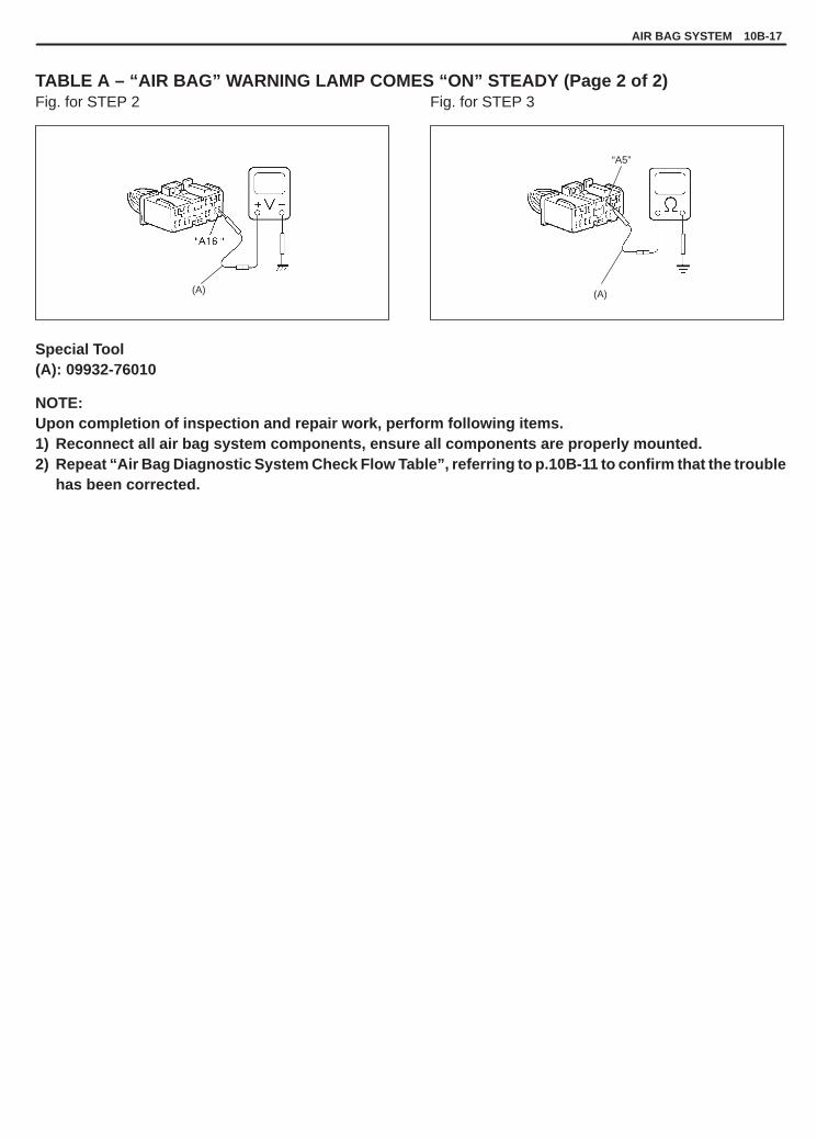
YH4GRANDVITARA
(A)
“A5”
(A)
AIR BAG SYSTEM 10B-17
TABLE A – “AIR BAG” WARNING LAMP COMES “ON” STEADY (Page 2 of 2)Fig. for STEP 2 Fig. for STEP 3
Special Tool(A): 09932-76010
NOTE:Upon completion of inspection and repair work, perform following items.1) Reconnect all air bag system components, ensure all components are properly mounted.2) Repeat “Air Bag Diagnostic System Check Flow Table”, referring to p.10B-11 to confirm that the trouble
has been corrected.

YH4GRANDVITARA
7. SDM7-1. “AIR BAG” warning lamp driver circuit
4. “AIR BAG” warning lamp in combination meter5. “AIR BAG” fuse in “AIR BAG” fuse box6. Connection detection pin
1. From main fuse2. Ignition switch3. “IG.COIL METER” fuse in J/B
: Air bag harness
10B-18 AIR BAG SYSTEM
TABLE B – “AIR BAG” WARNING LAMP DOES NOT COME “ON” (Page 1 of 2)
CAUTION:� When measurements are requested in this chart use specified digital multimeter with correct terminal
adapter from special tool (Connector test adapter kit).� When a check for proper connection is requested refer to “Intermittent and Poor Connections” in this
section.� When an open in air bag wire harness, damaged wire harness, connector or terminal is found, replace
wire harness, connectors and terminals as an assembly.
STEP ACTION YES NO
1 1) Set parking brake.2) Note combination meter as ignition switch
is turned ON.3) Does the “BRAKE” indicator (warning lamp)
come ON?
Go to step 2. “B/W” wire, “IG.COILMETER” fuse or J/B(between ignitionswitch and combinationmeter) open or short toground.
2 1) With ignition switch OFF, disconnect SDM.2) Check electrical connection check
mechanism (connection detection pin).3) Is it in good condition?
Go to step 3. Repair electricalconnection checkmechanism.
3 1) Disconnect SDM.2) Check proper connection to SDM at
terminal “A5”.3) If OK then check voltage from “A5” terminal of
SDM connector to body ground with ignitionswitch ON.
4) Is it 9 V or more?
Substitute a known-goodSDM and recheck.
Go to step 4 on thenext page.

YH4GRANDVITARA
(A)
“A5”
1. Combination meter connector (16p)2. “Y / G” wire terminal
1. Connection detection pin
AIR BAG SYSTEM 10B-19
TABLE B – “AIR BAG” WARNING LAMP DOES NOT COME “ON” (Page 2 of 2)
STEP ACTION YES NO
4 1) Remove combination meter, referring toSECTION 8C.
2) Check proper connection to combinationmeter at terminal for “AIR BAG” warning lampand to SDM at terminal “A5”.
3) If OK then check resistance between “Y/G”wire terminal of combination meter connector(16p) and “A5” terminal of SDM connector.
4) Is resistance 1 � or less?
Go to step 5. Repair high resistanceor open in “BI” or “Y/G”wire circuit (betweencombination meter andSDM).
5 1) Measure voltage from “A5” terminal of SDMconnector to body ground with ignition switchON.
2) Is it 9 V or more?
Repair short from “BI” or“Y/G” wire circuit(between combinationmeter and SDM) topower circuit.
Go to step 6.
6 1) Remove and inspect “AIR BAG” bulb.2) Is bulb good?
Substitute a known-goodcombination meter andrecheck.
Replace bulb.
Fig. for STEP 2 Fig. for STEP 3 and 5
Fig. for STEP 4
Special Tool(A): 09932-76010
NOTE:Upon completion of inspection and repair work, perform following items.1) Reconnect all air bag system components, ensure all components are properly mounted.2) Repeat “Air Bag Diagnostic System Check Flow Table”, referring to p.10B-11 to confirm that the trouble
has been corrected.

YH4GRANDVITARA
1. From main fuse2. Ignition switch3. “IG.COIL METER” fuse in J/B4. “AIR BAG” warning lamp in combination meter
7. Connection detection pin8. SDM
8-1. “AIR BAG” warning lamp driver circuit
-5. “AIR BAG” fuse in “AIR BAG” fuse box-6. “AIR BAG” monitor coupler
6-1. Diagnosis switch terminal
: Air bag harness
6–1
6
10B-20 AIR BAG SYSTEM
TABLE C – “AIR BAG” WARNING LAMP FLASHES (Page 1 of 2)
CAUTION:� When measurements are requested in this chart use specified digital multimeter with correct terminal
adapter from special tool (Connector test adapter kit).� When a check for proper connection is requested refer to “Intermittent and Poor Connections” in this
section.� When an open in air bag wire harness, damaged wire harness, connector or terminal is found, replace
wire harness, connectors and terminals as an assembly.
STEP ACTION YES NO
1 1) Check “AIR BAG” monitor coupler.2) Is it connected diagnosis switch terminal and
ground terminal in “AIR BAG” monitor couplerby service wire?
Remove service wire. Go to step 2.
2 1) With ignition switch OFF, disconnect SDM.2) Measure resistance between “A8” terminal of
SDM connector and body ground.3) Is resistance 1 k� or more?
Substitute a known-goodSDM and recheck.
Repair short from “V”wire circuit to ground.

YH4GRANDVITARA
(A)
AIR BAG SYSTEM 10B-21
TABLE C – “AIR BAG” WARNING LAMP FLASHES (Page 2 of 2)Fig. for STEP 2
Special Tool(A): 09932-76010
NOTE:Upon completion of inspection and repair work, perform following items.1) Reconnect all air bag system components, ensure all components are properly mounted.2) Repeat “Air Bag Diagnostic System Check Flow Table”, referring to p.10B-11 to confirm that the trouble
has been corrected.

YH4GRANDVITARA
1. From main fuse2. Ignition switch3. “IG.COIL METER” fuse in J/B4. “AIR BAG” warning lamp in combination lamp5. “AIR BAG” fuse in “AIR BAG” fuse box
6. DLC7. To, ICM (if equipped)8. Connection detection pin9. SDM
9-1. “AIR BAG” warning lamp driver circuit
: Air bag harness
10B-22 AIR BAG SYSTEM
TABLE D – SDM CANNOT COMMUNICATE THROUGH THE SERIAL DATA CIRCUIT(Page 1 of 2)
CAUTION:� When measurements are requested in this chart use specified digital multimeter with correct terminal
adapter from special tool (Connector test adapter kit).� When a check for proper connection is requested refer to “Intermittent and Poor Connections” in this
section.� When an open in air bag wire harness, damaged wire harness, connector or terminal is found, replace
wire harness, connectors and terminals as an assembly.
STEP ACTION YES NO
1 1) Make sure that scan tool (Tech 1) is freefrom malfunction and correct cartridge forair bag system is used.
2) Ignition switch OFF.3) Check proper connection of scan tool
(Tech 1) to DLC.4) Is connection in good condition?
Go to step 2 onnext page.
Properly connect scantool to DLC.

YH4GRANDVITARA
1. DLC2. Scan tool 1. “W/B” wire terminal
AIR BAG SYSTEM 10B-23
TABLE D – SDM CANNOT COMMUNICATE THROUGH THE SERIAL DATA CIRCUIT(Page 2 of 2)
STEP ACTION YES NO
2 1) Check if communication is possible bytrying communication with othercontroller (ECM (or PCM), ICM or ABScontroller).
2) Is it possible to communicate with othercontroller?
Go to step 3. Repair open in commonsection of serial data circuit(“W/B” wire circuit) used byall controllers or short toground or power circuitwhich has occurred some-where in serial data circuit(“W/B” wire circuit).
3 1) With ignition switch OFF, disconnectSDM and “Lamp, DLC and MonitorCoupler Ground” (“E”) connector.
2) Check proper connection at “W/B” wireterminal for DLC in “E” connector.
3) If OK, then check resistance between“W/B” wire terminal in “E” connector and“A4” terminal of SDM connector.
4) Is resistance 1 � or less?
Substitute a known-goodSDM and recheck.
Repair high resistance oropen in “W/B” wire circuit(in air bag harness).
Fig. for STEP 1 Fig. for STEP 3
Special Tool(A): 09932-76010
NOTE:Upon completion of inspection and repair work, perform following items.1) Reconnect all air bag system components, ensure all components are properly mounted.2) Repeat “Air Bag Diagnostic System Check Flow Table”, referring to p.10B-11 to confirm that the trouble
has been corrected.

YH4GRANDVITARA
1. SDM2. Passenger air bag (inflator) module
: Shorting bar
: Air bag harness
10B-24 AIR BAG SYSTEM
CODE 15 – PASSENGER AIR BAG INITIATOR CIRCUIT RESISTANCE HIGH (Page 1 of 2)
CAUTION:� When measurements are requested in this chart use specified digital multimeter with correct terminal
adapter from special tool (Connector test adapter kit).� When a check for proper connection is requested refer to “Intermittent and Poor Connections” in this
section.� When an open in air bag wire harness, damaged wire harness, connector or terminal is found, replace
wire harness, connectors and terminals as an assembly.
DTC WILL SET WHEN:The combined resistance of the passenger air bag (inflator) module, harness wiring and connector terminal contactis above a specified value for specified time.
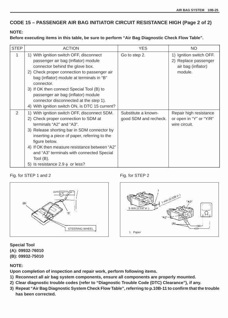
YH4GRANDVITARA
STEERING WHEEL1. Paper
AIR BAG SYSTEM 10B-25
CODE 15 – PASSENGER AIR BAG INITIATOR CIRCUIT RESISTANCE HIGH (Page 2 of 2)
NOTE:Before executing items in this table, be sure to perform “Air Bag Diagnostic Check Flow Table”.
STEP ACTION YES NO
1 1) With ignition switch OFF, disconnectpassenger air bag (inflator) moduleconnector behind the glove box.
2) Check proper connection to passenger airbag (inflator) module at terminals in “B”connector.
3) If OK then connect Special Tool (B) topassenger air bag (inflator) moduleconnector disconnected at the step 1).
4) With ignition switch ON, is DTC 15 current?
Go to step 2. 1) Ignition switch OFF.2) Replace passenger
air bag (inflator)module.
2 1) With ignition switch OFF, disconnect SDM.2) Check proper connection to SDM at
terminals “A2” and “A3”.3) Release shorting bar in SDM connector by
inserting a piece of paper, referring to thefigure below.
4) If OK then measure resistance between “A2”and “A3” terminals with connected SpecialTool (B).
5) Is resistance 2.9 � or less?
Substitute a known-good SDM and recheck.
Repair high resistanceor open in “Y” or “Y/R”wire circuit.
Fig. for STEP 1 and 2 Fig. for STEP 2
Special Tool(A): 09932-76010(B): 09932-75010
NOTE:Upon completion of inspection and repair work, perform following items.1) Reconnect all air bag system components, ensure all components are properly mounted.2) Clear diagnostic trouble codes (refer to “Diagnostic Trouble Code (DTC) Clearance”), if any.3) Repeat “Air Bag Diagnostic System Check Flow Table”, referring to p.10B-11 to confirm that the trouble
has been corrected.

YH4GRANDVITARA
1. SDM2. Passenger air bag (inflator) module
: Shorting bar
: Air bag harness
10B-26 AIR BAG SYSTEM
CODE 16 – PASSENGER AIR BAG INITIATOR CIRCUIT RESISTANCE LOW (Page 1 of 2)
CAUTION:� When measurements are requested in this chart use specified digital multimeter with correct terminal
adapter from special tool (Connector test adapter kit).� When a check for proper connection is requested refer to “Intermittent and Poor Connections” in this
section.� When an open in air bag wire harness, damaged wire harness, connector or terminal is found, replace
wire harness, connectors and terminals as an assembly.
DTC WILL SET WHEN:The combined resistance of the passenger air bag (inflator) module, harness wiring and connector terminal contactis below a specified value for specified time.

YH4GRANDVITARA
STEERING WHEEL 1. Paper
AIR BAG SYSTEM 10B-27
CODE 16 – PASSENGER AIR BAG INITIATOR CIRCUIT RESISTANCE LOW (Page 2 of 2)
NOTE:Before executing items in this table, be sure to perform “Air Bag Diagnostic Check Flow Table”.
STEP ACTION YES NO
1 1) With ignition switch OFF, disconnectpassenger air bag (inflator) moduleconnector behind the glove box.
2) Check proper connection to passengerair bag (inflator) module at terminals in “B”connector.
3) If OK then connect Special Tool (B) topassenger air bag (inflator) moduleconnector disconnected at the step 1).
4) With ignition switch ON, is DTC 16current?
Go to step 2. 1) Ignition switch OFF.2) Replace passenger air
bag (inflator) module.
2 1) With ignition switch OFF, disconnectSDM.
2) Check proper connection to SDM atterminals “A2” and “A3”.
3) Release shorting bar in SDM connectorby inserting a piece of paper, referring tothe figure below.
4) If OK then measure resistance between“A2” and “A3” terminals with connectedSpecial Tool (B).
5) Is resistance 1.7 � or more?
Substitute a known-good SDM and recheck.
Repair short from “Y” wirecircuit to “Y/R” wire circuit orfrom “Y” or “Y/R” wire circuitto other wire circuit.
Fig. for STEP 1 and 2 Fig. for STEP 2
Special Tool(A): 09932-76010(B): 09932-75010
NOTE:Upon completion of inspection and repair work, perform following items.1) Reconnect all air bag system components, ensure all components are properly mounted.2) Clear diagnostic trouble codes (refer to “Diagnostic Trouble Code (DTC) Clearance”), if any.3) Repeat “Air Bag Diagnostic System Check Flow Table”, referring to p.10B-11 to confirm that the trouble
has been corrected.
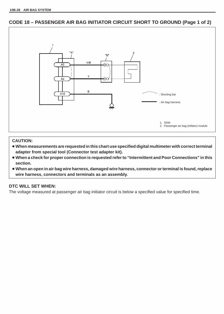
YH4GRANDVITARA
1. SDM2. Passenger air bag (inflator) module
: Shorting bar
: Air bag harness
10B-28 AIR BAG SYSTEM
CODE 18 – PASSENGER AIR BAG INITIATOR CIRCUIT SHORT TO GROUND (Page 1 of 2)
CAUTION:� When measurements are requested in this chart use specified digital multimeter with correct terminal
adapter from special tool (Connector test adapter kit).� When a check for proper connection is requested refer to “Intermittent and Poor Connections” in this
section.� When an open in air bag wire harness, damaged wire harness, connector or terminal is found, replace
wire harness, connectors and terminals as an assembly.
DTC WILL SET WHEN:The voltage measured at passenger air bag initiator circuit is below a specified value for specified time.

YH4GRANDVITARA
(A)STEERING WHEEL
AIR BAG SYSTEM 10B-29
CODE 18 – PASSENGER AIR BAG INITIATOR CIRCUIT SHORT TO GROUND (Page 2 of 2)
NOTE:Before executing items in this table, be sure to perform “Air Bag Diagnostic Check Flow Table”.
STEP ACTION YES NO
1 1) With ignition switch OFF, disconnectpassenger air bag (inflator) moduleconnector behind the glove box.
2) Check proper connection to passengerair bag (inflator) module at terminals in “B”connector.
3) If OK then connect Special Tool (B) topassenger air bag (inflator) moduleconnector disconnected at the step 1).
4) With ignition switch ON, is DTC 18current?
Go to step 2. 1) Ignition switch OFF.2) Replace passenger air
bag (inflator) module.
2 1) With ignition switch OFF, disconnectSpecial Tool (B) and SDM.
2) Measure resistance between “A2” and“A10” terminals.
3) Is resistance 1 k� or more?
Substitute a known-goodSDM and recheck.
Repair short from “Y” or“Y/R” wire circuit to ground.
Fig. for STEP 1 and 2 Fig. for STEP 2
Special Tool(A): 09932-76010(B): 09932-75010
NOTE:Upon completion of inspection and repair work, perform following items.1) Reconnect all air bag system components, ensure all components are properly mounted.2) Clear diagnostic trouble codes (refer to “Diagnostic Trouble Code (DTC) Clearance”), if any.3) Repeat “Air Bag Diagnostic System Check Flow Table”, referring to p.10B-11 to confirm that the trouble
has been corrected.

YH4GRANDVITARA
1. From ignition switch2. “AIR BAG” fuse in “AIR BAG” fuse box3. SDM4. Passenger air bag (inflator) module
: Shorting bar
: Air bag harness
10B-30 AIR BAG SYSTEM
CODE 19 – PASSENGER AIR BAG INITIATOR CIRCUIT SHORT TO POWER CIRCUIT(Page 1 of 2)
CAUTION:� When measurements are requested in this chart use specified digital multimeter with correct terminal
adapter from special tool (Connector test adapter kit).� When a check for proper connection is requested refer to “Intermittent and Poor Connections” in this
section.� When an open in air bag wire harness, damaged wire harness, connector or terminal is found, replace
wire harness, connectors and terminals as an assembly.
DTC WILL SET WHEN:The voltage measured at passenger air bag initiator circuit is above a specified value for specified time.
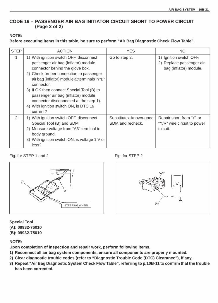
YH4GRANDVITARA
(A)STEERING WHEEL
AIR BAG SYSTEM 10B-31
CODE 19 – PASSENGER AIR BAG INITIATOR CIRCUIT SHORT TO POWER CIRCUIT(Page 2 of 2)
NOTE:Before executing items in this table, be sure to perform “Air Bag Diagnostic Check Flow Table”.
STEP ACTION YES NO
1 1) With ignition switch OFF, disconnectpassenger air bag (inflator) moduleconnector behind the glove box.
2) Check proper connection to passengerair bag (inflator) module at terminals in “B”connector.
3) If OK then connect Special Tool (B) topassenger air bag (inflator) moduleconnector disconnected at the step 1).
4) With ignition switch ON, is DTC 19current?
Go to step 2. 1) Ignition switch OFF.2) Replace passenger air
bag (inflator) module.
2 1) With ignition switch OFF, disconnectSpecial Tool (B) and SDM.
2) Measure voltage from “A3” terminal tobody ground.
3) With ignition switch ON, is voltage 1 V orless?
Substitute a known-goodSDM and recheck.
Repair short from “Y” or“Y/R” wire circuit to powercircuit.
Fig. for STEP 1 and 2 Fig. for STEP 2
Special Tool(A): 09932-76010(B): 09932-75010
NOTE:Upon completion of inspection and repair work, perform following items.1) Reconnect all air bag system components, ensure all components are properly mounted.2) Clear diagnostic trouble codes (refer to “Diagnostic Trouble Code (DTC) Clearance”), if any.3) Repeat “Air Bag Diagnostic System Check Flow Table”, referring to p.10B-11 to confirm that the trouble
has been corrected.

YH4GRANDVITARA
: Shorting bar
: Air bag harness
1. SDM2. Contact coil assembly3. Driver air bag (inflator) module
10B-32 AIR BAG SYSTEM
CODE 21 – DRIVER AIR BAG INITIATOR CIRCUIT RESISTANCE HIGH (Page 1 of 2)
CAUTION:� When measurements are requested in this chart use specified digital multimeter with correct terminal
adapter from special tool (Connector test adapter kit).� When a check for proper connection is requested refer to “Intermittents and Poor Connections” in
this section.� When an open in air bag wire harness, damaged wire harness, connector or terminal is found, replace
wire harness, connectors and terminals as an assembly.
DTC WILL SET WHEN:The combined resistance of the driver air bag (inflator) module, contact coil assembly, harness wiring and connec-tor terminal contact is above a specified value for specified time.
NOTE:Before executing items in this table, be sure to perform “Air Bag Diagnostic Check Flow Table”.
STEP ACTION YES NO
1 1) With ignition switch OFF, disconnect contactcoil connector located near the base of thesteering column.
2) Check proper connection to contact coil atterminals in “C” connector.
3) If OK then connect Special Tool (B) to contactcoil connector disconnected at step 1).
4) With ignition switch ON, is DTC 21 current?
Go to step 2. Go to step 3 on thenext page.
2 1) With ignition switch OFF, disconnect SDM.2) Check proper connection to SDM at terminals
“A6” and “A7”.3) Release shorting bar in SDM connector,
referring to the figure below.4) If OK then measure resistance between “A6”
and “A7” terminals with connected Special Tool(B).
5) Is resistance 3.5 � or less?
Substitute a known-good SDM andrecheck.
Repair high resistanceor open in “G” or “G/R”wire circuit.

YH4GRANDVITARA
AIR BAG SYSTEM 10B-33
BASE OF COLUMN 1. Paper
STEERINGWHEEL
CODE 21 – DRIVER AIR BAG INITIATOR CIRCUIT RESISTANCE HIGH (Page 2 of 2)
STEP ACTION YES NO
3 1) With ignition switch OFF, disconnect SpecialTool (B) then reconnect contact coil connectorlocated near the base of the steering column.
2) Remove driver air bag (inflator) module fromsteering wheel (Refer to SECTION 3C1).
3) Check proper connection to driver air bag(inflator) module at terminals in “D” connector.
4) If OK then connect Special Tool (B) to driverair bag (inflator) module disconnected at step 2).
5) With ignition switch ON, is DTC 21 current?
1) Ignition switch OFF.2) Replace contact coil
assembly (Refer toSECTION 3C1).
1) Ignition switch OFF.2) Replace driver air
bag (inflator)module (Refer toSECTION 3C1).
Fig. for STEP 1 and 2 Fig. for STEP 2
Fig. for STEP 3
Special Tool(A): 09932-76010(B): 09932-75010
NOTE:Upon completion of inspection and repair work, perform following items.1) Reconnect all air bag system components, ensure all components are properly mounted.2) Clear diagnostic trouble codes (refer to “Diagnostic Trouble Code (DTC) Clearance”), if any.3) Repeat “Air Bag Diagnostic System Check Flow Table”, referring to p.10B-11 to confirm that the trouble
has been corrected.

YH4GRANDVITARA
: Shorting bar
: Air bag harness
1. SDM2. Contact coil assembly3. Driver air bag (inflator) module
10B-34 AIR BAG SYSTEM
CODE 22 – DRIVER AIR BAG INITIATOR CIRCUIT RESISTANCE LOW (Page 1 of 2)
CAUTION:� When measurements are requested in this chart use specified digital multimeter with correct terminal
adapter from special tool (Connector test adapter kit).� When a check for proper connection is requested refer to “Intermittent and Poor Connections” in this
section.� When an open in air bag wire harness, damaged wire harness, connector or terminal is found, replace
wire harness, connectors and terminals as an assembly.
DTC WILL SET WHEN:The combined resistance of the driver air bag (inflator) module, contact coil assembly, harness wiring and connec-tor terminal contact is below a specified value for specified time.
NOTE:Before executing items in this table, be sure to perform “Air Bag Diagnostic Check Flow Table”.
STEP ACTION YES NO
1 1) With ignition switch OFF, disconnect contactcoil connector located near the base of thesteering column.
2) Check proper connection to contact coil atterminals in “C” connector.
3) If OK then connect Special Tool (B) to contactcoil connector disconnected at step 1).
4) With ignition switch ON, is DTC 22 current?
Go to step 2. Go to step 3 on thenext page.
2 1) With ignition switch OFF, disconnect SDM.2) Check proper connection to SDM at terminals
“A6” and “A7”.3) Release shorting bar in SDM connector,
referring to the figure below.4) If OK then measure resistance between “A6”
and “A7” terminals with connected Special Tool(B).
5) Is resistance 1.7 � or more?
Substitute a known-good SDM andrecheck.
Repair short from “G”wire circuit to “G/R” wirecircuit or from “G” or“G/R” wire circuit toother wire circuit.
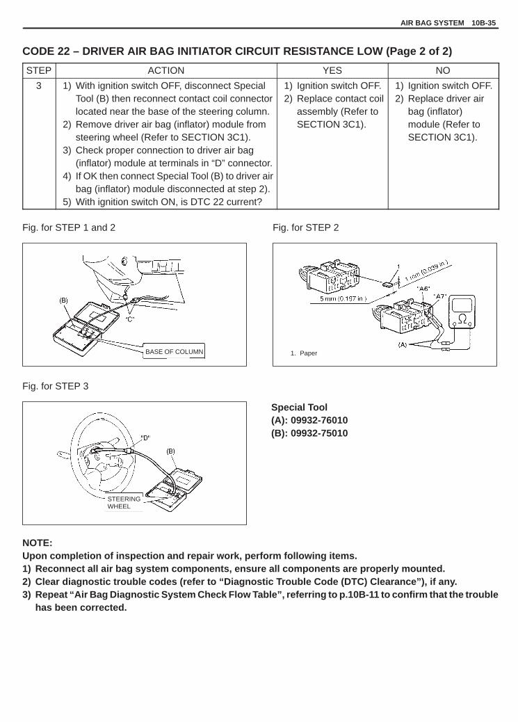
YH4GRANDVITARA
AIR BAG SYSTEM 10B-35
BASE OF COLUMN 1. Paper
STEERINGWHEEL
CODE 22 – DRIVER AIR BAG INITIATOR CIRCUIT RESISTANCE LOW (Page 2 of 2)
STEP ACTION YES NO
3 1) With ignition switch OFF, disconnect SpecialTool (B) then reconnect contact coil connectorlocated near the base of the steering column.
2) Remove driver air bag (inflator) module fromsteering wheel (Refer to SECTION 3C1).
3) Check proper connection to driver air bag(inflator) module at terminals in “D” connector.
4) If OK then connect Special Tool (B) to driver airbag (inflator) module disconnected at step 2).
5) With ignition switch ON, is DTC 22 current?
1) Ignition switch OFF.2) Replace contact coil
assembly (Refer toSECTION 3C1).
1) Ignition switch OFF.2) Replace driver air
bag (inflator)module (Refer toSECTION 3C1).
Fig. for STEP 1 and 2 Fig. for STEP 2
Fig. for STEP 3
Special Tool(A): 09932-76010(B): 09932-75010
NOTE:Upon completion of inspection and repair work, perform following items.1) Reconnect all air bag system components, ensure all components are properly mounted.2) Clear diagnostic trouble codes (refer to “Diagnostic Trouble Code (DTC) Clearance”), if any.3) Repeat “Air Bag Diagnostic System Check Flow Table”, referring to p.10B-11 to confirm that the trouble
has been corrected.

YH4GRANDVITARA
: Shorting bar
: Air bag harness
1. SDM2. Contact coil assembly3. Driver air bag (inflator) module
10B-36 AIR BAG SYSTEM
CODE 24 –DRIVER AIR BAG INITIATOR CIRCUIT SHORT TO GROUND (Page 1 of 2)
CAUTION:� When measurements are requested in this chart use specified digital multimeter with correct terminal
adapter from special tool (Connector test adapter kit).� When a check for proper connection is requested refer to “Intermittent and Poor Connections” in this
section.� When an open in air bag wire harness, damaged wire harness, connector or terminal is found, replace
wire harness, connectors and terminals as an assembly.
DTC WILL SET WHEN:The voltage measured at driver air bag initiator circuit is below a specified value for specified time.
NOTE:Before executing items in this table, be sure to perform “Air Bag Diagnostic Check Flow Table”.
STEP ACTION YES NO
1 1) With ignition switch OFF, disconnect contactcoil connector located near the base of thesteering column.
2) Check proper connection to contact coil atterminals in “C” connector.
3) If OK then connect Special Tool (B) to contactcoil connector disconnected at step 1).
4) With ignition switch ON, is DTC 24 current?
Go to step 2. Go to step 3 on thenext page.
2 1) With ignition switch OFF, disconnect SpecialTool (B) and SDM.
2) Measure resistance between “A6” and “A10”terminals.
3) Is resistance 1 k� or more?
Substitute a known-good SDM and recheck.
Repair short from “G” or“G/R” wire circuit toground.

YH4GRANDVITARA
AIR BAG SYSTEM 10B-37
(A)BASE OF COLUMN
STEERINGWHEEL
CODE 24 –DRIVER AIR BAG INITIATOR CIRCUIT SHORT TO GROUND (Page 2 of 2)
STEP ACTION YES NO
3 1) With ignition switch OFF, disconnect SpecialTool (B) then reconnect contact coil connec-tor located near the base of the steeringcolumn.
2) Remove driver air bag (inflator) module fromsteering wheel (Refer to SECTION 3C1).
3) Check proper connection to driver air bag(inflator) module at terminals in “D”connector.
4) If OK then connect Special Tool (B) to driverair bag (inflator) module disconnected atstep 2).
5) With ignition switch ON, is DTC 24 current?
1) Ignition switch OFF.2) Replace contact coil
assembly (Refer toSECTION 3C1).
1) Ignition switch OFF.2) Replace driver air bag
(inflator) module(Refer to SECTION3C1).
Fig. for STEP 1 and 2 Fig. for STEP 2
Fig. for STEP 3
Special Tool(A): 09932-76010(B): 09932-75010
NOTE:Upon completion of inspection and repair work, perform following items.1) Reconnect all air bag system components, ensure all components are properly mounted.2) Clear diagnostic trouble codes (refer to “Diagnostic Trouble Code (DTC) Clearance”), if any.3) Repeat “Air Bag Diagnostic System Check Flow Table”, referring to p.10B-11 to confirm that the trouble
has been corrected.
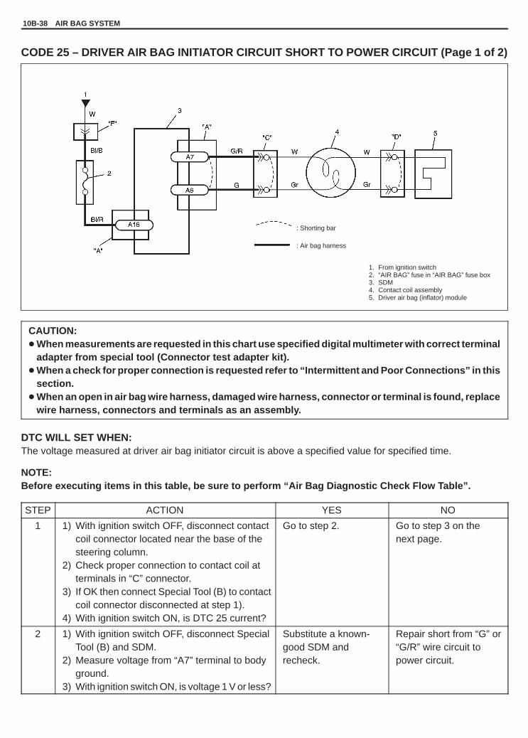
YH4GRANDVITARA
: Shorting bar
: Air bag harness
1. From ignition switch2. “AIR BAG” fuse in “AIR BAG” fuse box3. SDM4. Contact coil assembly5. Driver air bag (inflator) module
10B-38 AIR BAG SYSTEM
CODE 25 – DRIVER AIR BAG INITIATOR CIRCUIT SHORT TO POWER CIRCUIT (Page 1 of 2)
CAUTION:� When measurements are requested in this chart use specified digital multimeter with correct terminal
adapter from special tool (Connector test adapter kit).� When a check for proper connection is requested refer to “Intermittent and Poor Connections” in this
section.� When an open in air bag wire harness, damaged wire harness, connector or terminal is found, replace
wire harness, connectors and terminals as an assembly.
DTC WILL SET WHEN:The voltage measured at driver air bag initiator circuit is above a specified value for specified time.
NOTE:Before executing items in this table, be sure to perform “Air Bag Diagnostic Check Flow Table”.
STEP ACTION YES NO
1 1) With ignition switch OFF, disconnect contactcoil connector located near the base of thesteering column.
2) Check proper connection to contact coil atterminals in “C” connector.
3) If OK then connect Special Tool (B) to contactcoil connector disconnected at step 1).
4) With ignition switch ON, is DTC 25 current?
Go to step 2. Go to step 3 on thenext page.
2 1) With ignition switch OFF, disconnect SpecialTool (B) and SDM.
2) Measure voltage from “A7” terminal to bodyground.
3) With ignition switch ON, is voltage 1 V or less?
Substitute a known-good SDM andrecheck.
Repair short from “G” or“G/R” wire circuit topower circuit.

YH4GRANDVITARA
AIR BAG SYSTEM 10B-39
(A)
STEERINGWHEEL
BASE OF COLUMN
CODE 25 – DRIVER AIR BAG INITIATOR CIRCUIT SHORT TO POWER CIRCUIT (Page 2 of 2)
STEP ACTION YES NO
3 1) With ignition switch OFF, disconnect SpecialTool (B) then reconnect contact coil connectorlocated near the base of the steering column.
2) Remove driver air bag (inflator) module fromsteering wheel (Refer to SECTION 3C1).
3) Check proper connection to driver air bag(inflator) module at terminals in “D” connector.
4) If OK then connect Special Tool (B) to driverair bag (inflator) module disconnected atstep 2).
5) With ignition switch ON, is DTC 25 current?
1) Ignition switch OFF.2) Replace contact coil
assembly (Refer toSECTION 3C1).
1) Ignition switch OFF.2) Replace driver air bag
(inflator) module(Refer to SECTION3C1).
Fig. for STEP 1 and 2 Fig. for STEP 2
Fig. for STEP 3
Special Tool(A): 09932-76010(B): 09932-75010
NOTE:Upon completion of inspection and repair work, perform following items.1) Reconnect all air bag system components, ensure all components are properly mounted.2) Clear diagnostic trouble codes (refer to “Diagnostic Trouble Code (DTC) Clearance”), if any.3) Repeat “Air Bag Diagnostic System Check Flow Table”, referring to p.10B-11 to confirm that the trouble
has been corrected.

YH4GRANDVITARA
: Air bag harness
1. From main fuse2. Ignition switch3. “AIR BAG” fuse in “AIR BAG” fuse box4. SDM
10B-40 AIR BAG SYSTEM
CODE 31 – POWER SOURCE VOLTAGE HIGH (Page 1 of 2)
CAUTION:� When measurements are requested in this chart use specified digital multimeter with correct terminal
adapter from special tool (Connector test adapter kit).� When a check for proper connection is requested refer to “Intermittent and Poor Connections” in this
section.� When an open in air bag wire harness, damaged wire harness, connector or terminal is found, replace
wire harness, connectors and terminals as an assembly.
DTC WILL SET WHEN:The power source voltage to SDM is above specified value for specified time.

YH4GRANDVITARA
(A)
AIR BAG SYSTEM 10B-41
CODE 31 – POWER SOURCE VOLTAGE HIGH (Page 2 of 2)
NOTE:Before executing items in this table, be sure to perform “Air Bag Diagnostic Check Flow Table”.
STEP ACTION YES NO
1 1) With ignition switch OFF, disconnect SDM.2) Check proper connection to SDM at
“A16” terminal.3) If OK then ignition switch ON, and then check
voltage from “A16” terminal on SDM harnessconnector to body ground.
4) Is voltage 14 V or less?
Go to step 2. Check Charging Systemand repair as necessary.(Refer to SECTION 6H“Changing System”)
2 1) With ignition switch OFF, reconnect SDM2) With ignition switch ON, is DTC 31 current?
Substitute a known-good SDM and recheck.
Check Charging Systemand repair as necessary.(Refer to SECTION 6H“Changing System”)
Fig. for STEP 1
Special Tool(A): 09932-76010
NOTE:Upon completion of inspection and repair work, perform following items.1) Reconnect all air bag system components, ensure all components are properly mounted.2) Clear diagnostic trouble codes (refer to “Diagnostic Trouble Code (DTC) Clearance”), if any.3) Repeat “Air Bag Diagnostic System Check Flow Table”, referring to p.10B-11 to confirm that the trouble
has been corrected.

YH4GRANDVITARA
1. From main fuse2. Ignition switch3. “AIR BAG” fuse in “AIR BAG” fuse box4. SDM
: Air bag harness
10B-42 AIR BAG SYSTEM
CODE 32 – POWER SOURCE VOLTAGE LOW (Page 1 of 2)
CAUTION:� When measurements are requested in this chart use specified digital multimeter with correct terminal
adapter from special tool (Connector test adapter kit).� When a check for proper connection is requested refer to “Intermittent and Poor Connections” in this
section.� When an open in air bag wire harness, damaged wire harness, connector or terminal is found, replace
wire harness, connectors and terminals as an assembly.
DTC WILL SET WHEN:The power source voltage is below an approx. 8 V for specified time.

YH4GRANDVITARA
(A)
AIR BAG SYSTEM 10B-43
CODE 32 – POWER SOURCE VOLTAGE LOW (Page 2 of 2)NOTE:Before executing items in this table, be sure to perform “Air Bag Diagnostic Check Flow Table”.
STEP ACTION YES NO
1 1) Measure voltage on battery.2) Is voltage 11 V or more?
Go to step 2. Check Charging Systemand repair as necessary.(Refer to SECTION 6H“Changing System”)
2 1) With ignition switch OFF, disconnect SDM.2) Check proper connection to SDM at “A16”
terminal.3) If OK then ignition switch ON, and then check
voltage from “A16” terminal on SDM harnessconnector to body ground.
4) Is voltage 8 V or more?
Go to step 4. Go to step 3.
3 1) With ignition switch OFF, disconnect ignitionconnector (“F” connector) in air bag harness.
2) Check proper connection at terminal in “F”connector.
3) If OK then ignition switch ON, and then checkvoltage from terminal in “F” connector on mainharness to body ground.
4) Is voltage 8 V or more?
Repair poor connec-tion, high resistancein “BI/R” or “BI/B”circuit of air bagharness or“AIR BAG” fuse.
Possibly faulty points areas follows. Check each ofthem and repair asnecessary.� Circuit from battery to
“F” connector� Charging System
(Refer to SECTION6H “Changing System”)
4 1) With ignition switch OFF, reconnect SDM2) With ignition switch ON, is DTC 32 current?
Substitute a known-good SDM andrecheck.
Check Charging Systemand repair as necessary.(Refer to SECTION 6H“Changing System”)
Fig. for STEP 2
Special Tool(A): 09932-76010
NOTE:Upon completion of inspection and repair work, perform following items.1) Reconnect all air bag system components, ensure all components are properly mounted.2) Clear diagnostic trouble codes (refer to “Diagnostic Trouble Code (DTC) Clearance”), if any.3) Repeat “Air Bag Diagnostic System Check Flow Table”, referring to p.10B-11 to confirm that the trouble
has been corrected.
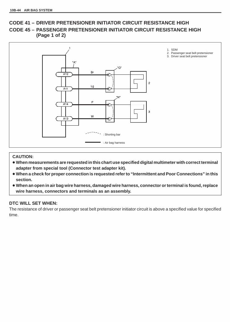
YH4GRANDVITARA
1. SDM2. Passenger seat belt pretensioner3. Driver seat belt pretensioner
: Shorting bar
: Air bag harness
10B-44 AIR BAG SYSTEM
CODE 41 – DRIVER PRETENSIONER INITIATOR CIRCUIT RESISTANCE HIGHCODE 45 – PASSENGER PRETENSIONER INITIATOR CIRCUIT RESISTANCE HIGH
(Page 1 of 2)
CAUTION:� When measurements are requested in this chart use specified digital multimeter with correct terminal
adapter from special tool (Connector test adapter kit).� When a check for proper connection is requested refer to “Intermittent and Poor Connections” in this
section.� When an open in air bag wire harness, damaged wire harness, connector or terminal is found, replace
wire harness, connectors and terminals as an assembly.
DTC WILL SET WHEN:The resistance of driver or passenger seat belt pretensioner initiator circuit is above a specified value for specifiedtime.
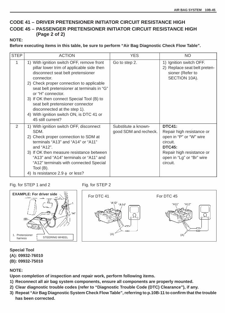
YH4GRANDVITARA
(A)
For DTC 45
“A11” “A12”
(A)
For DTC 41
STEERING WHEEL1. Pretensioner
harness
EXAMPLE: For driver side
AIR BAG SYSTEM 10B-45
CODE 41 – DRIVER PRETENSIONER INITIATOR CIRCUIT RESISTANCE HIGHCODE 45 – PASSENGER PRETENSIONER INITIATOR CIRCUIT RESISTANCE HIGH
(Page 2 of 2)NOTE:Before executing items in this table, be sure to perform “Air Bag Diagnostic Check Flow Table”.
STEP ACTION YES NO
1 1) With ignition switch OFF, remove frontpillar lower trim of applicable side thendisconnect seat belt pretensionerconnector.
2) Check proper connection to applicableseat belt pretensioner at terminals in “G”or “H” connector.
3) If OK then connect Special Tool (B) toseat belt pretensioner connectordisconnected at the step 1).
4) With ignition switch ON, is DTC 41 or45 still current?
Go to step 2. 1) Ignition switch OFF.2) Replace seat belt preten-
sioner (Refer toSECTION 10A).
2 1) With ignition switch OFF, disconnectSDM.
2) Check proper connection to SDM atterminals “A13” and “A14” or “A11”and “A12”.
3) If OK then measure resistance between“A13” and “A14” terminals or “A11” and“A12” terminals with connected SpecialTool (B).
4) Is resistance 2.9 � or less?
Substitute a known-good SDM and recheck.
DTC41:Repair high resistance oropen in “P” or “W” wirecircuit.DTC45:Repair high resistance oropen in “Lg” or “Br” wirecircuit.
Fig. for STEP 1 and 2 Fig. for STEP 2
Special Tool(A): 09932-76010(B): 09932-75010
NOTE:Upon completion of inspection and repair work, perform following items.1) Reconnect all air bag system components, ensure all components are properly mounted.2) Clear diagnostic trouble codes (refer to “Diagnostic Trouble Code (DTC) Clearance”), if any.3) Repeat “Air Bag Diagnostic System Check Flow Table”, referring to p.10B-11 to confirm that the trouble
has been corrected.

YH4GRANDVITARA
1. SDM2. Passenger seat belt pretensioner3. Driver seat belt pretensioner
: Shorting bar
: Air bag harness
10B-46 AIR BAG SYSTEM
CODE 42 – DRIVER PRETENSIONER INITIATOR CIRCUIT RESISTANCE LOWCODE 46 – PASSENGER PRETENSIONER INITIATOR CIRCUIT RESISTANCE LOW
(Page 1 of 2)
CAUTION:� When measurements are requested in this chart use specified digital multimeter with correct terminal
adapter from special tool (Connector test adapter kit).� When a check for proper connection is requested refer to “Intermittent and Poor Connections” in this
section.� When an open in air bag wire harness, damaged wire harness, connector or terminal is found, replace
wire harness, connectors and terminals as an assembly.
DTC WILL SET WHEN:The resistance of driver or passenger seat belt pretensioner initiator circuit is below a specified value for specifiedtime.
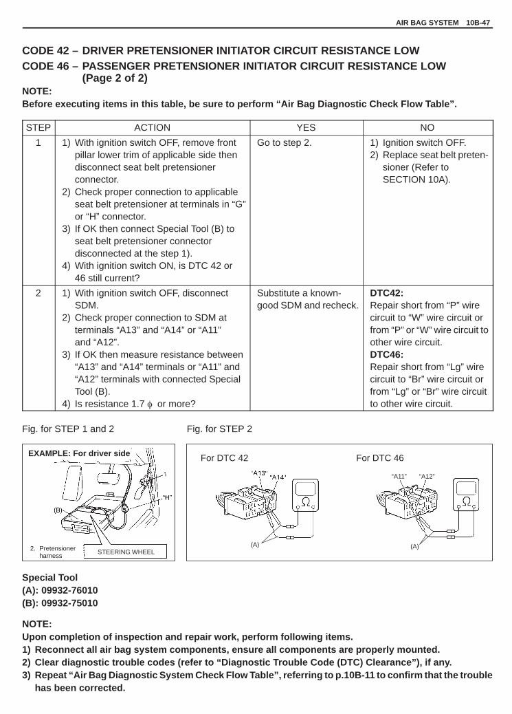
YH4GRANDVITARA
(A)
For DTC 46
“A11” “A12”
(A)
For DTC 42
2. Pretensionerharness
STEERING WHEEL
EXAMPLE: For driver side
AIR BAG SYSTEM 10B-47
CODE 42 – DRIVER PRETENSIONER INITIATOR CIRCUIT RESISTANCE LOWCODE 46 – PASSENGER PRETENSIONER INITIATOR CIRCUIT RESISTANCE LOW
(Page 2 of 2)NOTE:Before executing items in this table, be sure to perform “Air Bag Diagnostic Check Flow Table”.
STEP ACTION YES NO
1 1) With ignition switch OFF, remove frontpillar lower trim of applicable side thendisconnect seat belt pretensionerconnector.
2) Check proper connection to applicableseat belt pretensioner at terminals in “G”or “H” connector.
3) If OK then connect Special Tool (B) toseat belt pretensioner connectordisconnected at the step 1).
4) With ignition switch ON, is DTC 42 or46 still current?
Go to step 2. 1) Ignition switch OFF.2) Replace seat belt preten-
sioner (Refer toSECTION 10A).
2 1) With ignition switch OFF, disconnectSDM.
2) Check proper connection to SDM atterminals “A13” and “A14” or “A11”and “A12”.
3) If OK then measure resistance between“A13” and “A14” terminals or “A11” and“A12” terminals with connected SpecialTool (B).
4) Is resistance 1.7 � or more?
Substitute a known-good SDM and recheck.
DTC42:Repair short from “P” wirecircuit to “W” wire circuit orfrom “P” or “W” wire circuit toother wire circuit.DTC46:Repair short from “Lg” wirecircuit to “Br” wire circuit orfrom “Lg” or “Br” wire circuitto other wire circuit.
Fig. for STEP 1 and 2 Fig. for STEP 2
Special Tool(A): 09932-76010(B): 09932-75010
NOTE:Upon completion of inspection and repair work, perform following items.1) Reconnect all air bag system components, ensure all components are properly mounted.2) Clear diagnostic trouble codes (refer to “Diagnostic Trouble Code (DTC) Clearance”), if any.3) Repeat “Air Bag Diagnostic System Check Flow Table”, referring to p.10B-11 to confirm that the trouble
has been corrected.

YH4GRANDVITARA
1. SDM2. Passenger seat belt pretensioner3. Driver seat belt pretensioner
: Shorting bar
: Air bag harness
10B-48 AIR BAG SYSTEM
CODE 43 – DRIVER PRETENSIONER INITIATOR CIRCUIT SHORT TO GROUNDCODE 47 – PASSENGER PRETENSIONER INITIATOR CIRCUIT SHORT TO GROUND
(Page 1 of 2)
CAUTION:� When measurements are requested in this chart use specified digital multimeter with correct terminal
adapter from special tool (Connector test adapter kit).� When a check for proper connection is requested refer to “Intermittent and Poor Connections” in this
section.� When an open in air bag wire harness, damaged wire harness, connector or terminal is found, replace
wire harness, connectors and terminals as an assembly.
DTC WILL SET WHEN:The voltage measured at driver or passenger seat belt pretensioner initiator circuit is below a specified value forspecified time.

YH4GRANDVITARA
(A)
“A11”
(A)1. Pretensionerharness
For DTC 43 For DTC 47
STEERING WHEEL
EXAMPLE: For driver side
AIR BAG SYSTEM 10B-49
CODE 43 – DRIVER PRETENSIONER INITIATOR CIRCUIT SHORT TO GROUNDCODE 47 – PASSENGER PRETENSIONER INITIATOR CIRCUIT SHORT TO GROUND
(Page 2 of 2)NOTE:Before executing items in this table, be sure to perform “Air Bag Diagnostic Check Flow Table”.
STEP ACTION YES NO
1 1) With ignition switch OFF, remove frontpillar lower trim of applicable side thendisconnect seat belt pretensionerconnector.
2) Check proper connection to applicableseat belt pretensioner at terminals in “G”or “H” connector.
3) If OK then connect Special Tool (B) toseat belt pretensioner connectordisconnected at the step 1).
4) With ignition switch ON, is DTC 43 or 47still current?
Go to step 2. 1) Ignition switch OFF.2) Replace seat belt preten-
sioner (Refer toSECTION 10A).
2 1) With ignition switch OFF, disconnectSpecial Tool (B) and SDM.
2) Measure resistance between “A13” or“A11” and “A10” terminals.
3) Is resistance 1 k� or more?
Substitute a known-good SDM and recheck.
DTC43:Repair short “P” or “W” wirecircuit to ground.DTC47:Repair short from “Lg” or “Br”wire circuit to ground.
Fig. for STEP 1 and 2 Fig. for STEP 2
Special Tool(A): 09932-76010(B): 09932-75010
NOTE:Upon completion of inspection and repair work, perform following items.1) Reconnect all air bag system components, ensure all components are properly mounted.2) Clear diagnostic trouble codes (refer to “Diagnostic Trouble Code (DTC) Clearance”), if any.3) Repeat “Air Bag Diagnostic System Check Flow Table”, referring to p.10B-11 to confirm that the trouble
has been corrected.

YH4GRANDVITARA
1. From ignition switch2. “AIR BAG” fuse in “AIR BAG” fuse box3. SDM4. Passenger seat belt pretensioner5. Driver seat belt pretensioner
: Shorting bar
: Air bag harness
10B-50 AIR BAG SYSTEM
CODE 44 – DRIVER PRETENSIONER INITIATOR CIRCUIT SHORT TO POWER CIRCUITCODE 48 – PASSENGER PRETENSIONER INITIATOR CIRCUIT SHORT TO POWER CIRCUIT
(Page 1 of 2)
CAUTION:� When measurements are requested in this chart use specified digital multimeter with correct terminal
adapter from special tool (Connector test adapter kit).� When a check for proper connection is requested refer to “Intermittent and Poor Connections” in this
section.� When an open in air bag wire harness, damaged wire harness, connector or terminal is found, replace
wire harness, connectors and terminals as an assembly.
DTC WILL SET WHEN:The voltage measured at driver or passenger seat belt pretensioner initiator circuit is above a specified value forspecified time.

YH4GRANDVITARA
(A)(A)1. Pretensionerharness
For DTC 44 For DTC 48
STEERING WHEEL
EXAMPLE: For driver side
AIR BAG SYSTEM 10B-51
CODE 44 – DRIVER PRETENSIONER INITIATOR CIRCUIT SHORT TO POWER CIRCUITCODE 48 – PASSENGER PRETENSIONER INITIATOR CIRCUIT SHORT TO POWER CIRCUIT
(Page 2 of 2)NOTE:Before executing items in this table, be sure to perform “Air Bag Diagnostic Check Flow Table”.
STEP ACTION YES NO
1 1) With ignition switch OFF, remove front pillarlower trim of applicable side thendisconnect seat belt pretensioner connector.
2) Check proper connection to applicableseat belt pretensioner at terminals in “G” or“H” connector.
3) If OK then connect Special Tool (B) toseat belt pretensioner connectordisconnected at the step 1).
4) With ignition switch ON, is DTC 44 or 48still current?
Go to step 2. 1) Ignition switch OFF.2) Replace seat belt
pretensioner (Referto SECTION 10A).
2 1) With ignition switch OFF, disconnect SpecialTool (B) and SDM.
2) Measure voltage from “A14” or “A12”terminal to body ground.
3) With ignition switch ON, is voltage 1 V orless?
Substitute a known-good SDM and recheck.
DTC44:Repair short “P” or “W”wire circuit to powercircuit.DTC48:Repair short from “Lg” or“Br” wire circuit to powercircuit.
Fig. for STEP 1 and 2 Fig. for STEP 2
Special Tool(A): 09932-76010(B): 09932-75010
NOTE:Upon completion of inspection and repair work, perform following items.1) Reconnect all air bag system components, ensure all components are properly mounted.2) Clear diagnostic trouble codes (refer to “Diagnostic Trouble Code (DTC) Clearance”), if any.3) Repeat “Air Bag Diagnostic System Check Flow Table”, referring to p.10B-11 to confirm that the trouble
has been corrected.

YH4GRANDVITARA
10B-52 AIR BAG SYSTEM
CODE 51 – FRONTAL CRASH DETECTED (SYSTEM ACTIVATION COMMAND IS OUT-PUTTED)
DTC WILL SET WHEN:The SDM detects a frontal crash of sufficient force to warrant activation of the air bag system. (SDM outputs a de-ployment/activation command.)
NOTE:Before executing items in this table, be sure to perform “Air Bag Diagnostic Check Flow Table”.
STEP ACTION YES NO
1 1) Ignition switch OFF.2) Has air bag system deployed?
Replace components andperform inspections asdirected in “Repairs and Inspections Required afteran Accident” in this section.
Go to step 2.
2 1) Inspect front of vehicle andundercarriage for signs of impact.
2) Are there signs of impact?
Replace components andperform inspections asdirected in “Repairs andInspections Required afteran Accident” in this section.
Substitute a known-goodSDM and recheck.
NOTE:� CODE 51 can never be cleared once it has been set.� Upon completion of inspection and repair work, perform following items.
1) Replace SDM.2) Reconnect all air bag system components, ensure all components are properly mounted.3) Repeat “Air Bag Diagnostic System Check Flow Table”, referring to p.10B-11 to confirm that the
trouble has been corrected.

YH4GRANDVITARA
1. From main fuse2. Ignition switch3. “IG.COIL METER” fuse in J/B
7. Connection detection pin8. SDM
8-1. “AIR BAG” warning lamp driver circuit
4. “AIR BAG” warning lamp in combination meter5. “AIR BAG” fuse in “AIR BAG” fuse box6. “AIR BAG” monitor coupler
: Air bag harness
AIR BAG SYSTEM 10B-53
CODE 61 – “AIR BAG” WARNING LAMP CIRCUIT FAILURE (Page 1 of 2)
CAUTION:� When measurements are requested in this chart use specified digital multimeter with correct terminal
adapter from special tool (Connector test adapter kit).� When a check for proper connection is requested refer to “Intermittent and Poor Connections” in this
section.� When an open in air bag wire harness, damaged wire harness, connector or terminal is found, replace
wire harness, connectors and terminals as an assembly.
DTC WILL SET WHEN:The voltage at the “AIR BAG” warning lamp circuit terminal “A5” does not match the commanded state of the warn-ing lamp driver for specified time.

YH4GRANDVITARA
10B-54 AIR BAG SYSTEM
CODE 61 – “AIR BAG” WARNING LAMP CIRCUIT FAILURE (Page 2 of 2)NOTE:Before executing items in this table, be sure to perform “Air Bag Diagnostic System Check Flow Table”.
STEP ACTION YES NO
1 1) This DTC is set when there is a trouble in“AIR BAG” warning lamp circuit. Failure toproperly perform “Air Bag Diagnostic SystemCheck Flow Table” may also result inmisdiagnosis. Therefore, check “AIR BAG”warning lamp circuit again according to “AirBag Diagnostic System Check Flow Table”.
2) Is “AIR BAG” warning lamp circuit in goodcondition?
Go to step 2. Repair “AIR BAG”warning lamp circuit.
2 1) Clear diagnostic trouble codes.2) Is DTC 61 set ?
Substitute a known-good SDM and recheck.
Recheck air bag system,referring to “Air BagDiagnostic SystemCheck Flow Table”.
NOTE:Upon completion of inspection and repair work, perform following items.1) Reconnect all air bag system components, ensure all components are properly mounted.2) Repeat “Air Bag Diagnostic System Check Flow Table”, referring to p. 10B-11 to confirm that the trouble
has been corrected.
CODE 71 – INTERNAL SDM FAULTDTC WILL SET WHEN:An internal SDM fault is detected by SDM.
NOTE:CODE 71 can never be cleared once it has been set.
1) Ignition switch OFF.2) Replace SDM.3) Repeat “Air Bag Diagnostic System Check Flow Table”, referring to p.10B-11.

YH4GRANDVITARA
AIR BAG SYSTEM 10B-55
ON-VEHICLE SERVICE
SERVICE PRECAUTIONSSERVICE AND DIAGNOSISWARNING/CAUTION labels are attached on each part of air bag system components (SDM, air bag (inflator) mod-ules and seat belt pretensioners). Be sure to follow the instructions.
WARNING:� If the air bag system and another vehicle system both need repair, Suzuki recommends that the air
bag system be repaired first, to help avoid unintended air bag system activation.� Do not modify the steering wheel, dashboard or any other air bag system components. Modifications
can adversely affect air bag system performance and lead to injury.� Failure to follow procedures could result in possible air bag system activation, personal injury or un-
needed air bag system repairs.
� Many of service procedures require disconnection of “AIR BAG” fuse and air bag (inflator) modules (driver andpassenger) from initiator circuit to avoid an accidental deployment.
� Do not apply power to the air bag system unless all components are connected or a diagnostic chart requestsit, as this will set a diagnostic trouble code.
� The “Air Bag Diagnostic System Check” must be the starting point of any air bag diagnostics. The “Air Bag Diag-nostic System Check” will verify proper “AIR BAG” warning lamp operation and will lead you to the correct chartto diagnose any air bag malfunctions. Bypassing these procedures may result in extended diagnostic time, incor-rect diagnosis, and incorrect parts replacements.
� Never use air bag component parts from another vehicle.� If the vehicle will be exposed to temperatures over 93�C (200�F) (for example, during a paint baking process),
remove the air bag system components beforehand to avoid component damage or unintended system activa-tion.
� When servicing, if shocks may be applied (eg., dropped from a height of 90 cm (3 ft) or more) to air bag systemcomponent parts, remove those parts beforehand.
� When using electric welding, be sure to disconnect air bag (inflator) module and seat belt pretensioner connec-tors (driver and passenger) respectively.
� When applying paint around the air bag system related parts, use care so that the harness or connector will notbe exposed to the paint mist.
� Never expose air bag system component parts directly to hot air (drying or baking the vehicle after painting) orflames.
WARNING:When performing service on or around air bag system components or air bag wiring, follow the proce-dures listed in the following pages to temporarily disable the air bag system. Refer to appropriate ser-vice manual procedures. Failure to follow procedures could result in possible air bag system activa-tion, personal injury or unneeded air bag system repairs.

YH4GRANDVITARA
1. Air bag harness2. “AIR BAG” monitor coupler3. Yellow connector of contact coil and combination
switch assembly4. Yellow connector of passenger air bag (inflator) module5. Steering support member
1. Air bag harness2. “AIR BAG” monitor coupler3. Yellow connector of contact coil and combination
switch assembly
10B-56 AIR BAG SYSTEM
DISABLING AIR BAG SYSTEM1) Turn steering wheel so that vehicle’s wheels (front tires) and
pointing straight ahead.2) Turn ignition switch to “LOCK” position and remove key.3) Remove “AIR BAG” fuse from “AIR BAG” fuse box.4) Disconnect Yellow connector of contact coil and combination
switch assembly.ii) Release locking of lock lever.ii) After unlocked, disconnect to connector.
5) Pull out glove box while pushing its stopper from both right andleft sides and disconnect Yellow connector of passenger air bag(inflator) module.ii) Release locking of lock lever.ii) After unlocked, disconnect to connector.
NOTE:With “AIR BAG” fuse removed and ignition switch ON, “AIRBAG” warning lamp will be ON.This is normal operation and does not indicate an air bagsystem malfunction.
ENABLING AIR BAG SYSTEM1) Turn ignition switch to “LOCK” and remove key.2) Connect Yellow connector of contact coil and combination
switch assembly, and be sure to lock connector with lock lever.ii) Connect connector.ii) Lock connector with lock lever.

YH4GRANDVITARA
1. Yellow connector of passenger air bag (inflator) module2. Steering support member3. Air bag harness
AIR BAG SYSTEM 10B-57
3) Connect Yellow connector of passenger air bag (inflator) mod-ule, and be sure to lock connector with lock lever.ii) Connect connector.ii) Lock connector with lock lever.
4) Install glove box.5) Install “AIR BAG” fuse to “AIR BAG” fuse box.6) Turn ignition switch to ON and verify that “AIR BAG” warning
lamp flashes 6 times and then turns off.If it does not operate as described, perform “Air Bag DiagnosticSystem Check” in this section.
HANDLING AND STORAGESDM
WARNING:Never power up air bag system when SDM is not rigidly at-tached to the vehicle. Otherwise, personal injury may result.
CAUTION:After detecting one time of such collision as to meet deploy-ment conditions, the SDM must not be used.Refer to “Diagnosis” when checking the SDM.
� Never attempt disassembly of SDM.� When storing SDM, select a place where neither high tempera-
ture nor high humidity is anticipated and oil, water and dust arekept off.
� If SDM was dropped from a height of 90 cm (3 ft) or more or if itis found to be damaged or deformed, replace it with a new one.
� If installation part of SDM was damaged, repair that part com-pletely before reinstallation.
� All SDM and mounting bracket fasteners must be carefullytorqued and the arrow must be pointed toward the front of the ve-hicle to ensure proper operation of the air bag system.

YH4GRANDVITARA
ALWAYS CARRY AIR BAG (INFLATOR) MODULEWITH TRIM COVER (AIR BAG OPENING) AWAYFROM BODY.
10B-58 AIR BAG SYSTEM
LIVE (UNDEPLOYED) AIR BAG (INFLATOR) MODULESSpecial care is necessary when handling and storing a live (unde-ployed) air bag (inflator) modules.The rapid gas generation produced during deployment of the airbag could cause the air bag (inflator) module, or an object in frontof the air bag (inflator) module, to be thrown through the air in theunlikely event of an accidental deployment.
WARNING:Never attempt to measure the resistance of the air bag (in-flator) modules (driver and passenger). It is very dangerousas the electric current from the tester may deploy the airbag.
� Never attempt disassembly of the air bag (inflator) modules.� If any abnormality is found, be sure to replace it with new one as
an assembly.� When an abnormality is noted as existing in the live (undeployed)
air bag (inflator) module, be sure to deploy it before discarding it.� When grease, cleaning agent, oil, water, etc., got on the air bag
(inflator) modules (driver and passenger), wipe it off immediatelywith a dry cloth.
� If air bag (inflator) module was dropped from a height of 90 cm (3ft) or more, it should be replaced with a new one as an assembly.
WARNING:� For handling and storage of a live air bag (inflator) module,
select a place where the ambient temperature below 65 �C(150�F), without high humidity and away from electricnoise.
� When carrying a live air bag (inflator) module, make surethe bag opening is pointed away from you. In case of anaccidental deployment, the bag will then deploy with mini-mal chance of injury. Never carry the air bag (inflator)module by the wires or connector on the underside of themodule.
Otherwise, personal injury may result.

YH4GRANDVITARA
ALWAYS PLACE AIR BAG (INFLATOR) MODULEON WORKBENCH WITH TRIM COVER (AIR BAGOPENING) UP, AWAY FROM LOOSE OBJECTS.
1. Slit on workbench2. Workbench vise3. Lower mounting bracket
2-1. Webbing2-2. Retractor assembly2-1. Seat belt pretensioner2-2. Seat belt pretensioner harness
2-2
AIR BAG SYSTEM 10B-59
WARNING:When placing a live air bag (inflator) module on bench orother surface, always face the bag up, away from the sur-face. As the live passenger air bag (inflator) module must beplaced with its bag (trim cover) facing up, place it on theworkbench with a slit or use the workbench vise to hold itsecurely at its lower mounting bracket.It is also prohibited to place anything on top of the trim cov-er and stack air bag (inflator) modules.This is necessary so that a free space is provided to allowthe air bag to expand in the unlikely event of accidental de-ployment.Otherwise, personal injury may result.
LIVE (INACTIVATED) SEAT BELT PRETENSIONERSSpecial care is necessary when handling and storing a live (inacti-vated) seat belt pretensioners.Also, when the seat belt pretensioners activate, gas is generatedand the seat belt is retracted into the retractor quickly.Note, therefore, that if they activate accidentally, the seat belt pre-tensioners and other object(s) around them may be thrown throughthe air.
WARNING:Never attempt to measure the resistance of the seat belt pre-tensioners. It is very dangerous as the electric current fromthe tester may activate pretensioner.

YH4GRANDVITARA
1. Exhaust hole
1
1NG
10B-60 AIR BAG SYSTEM
� Never attempt to disassemble the seat belt pretensioners (retrac-tor assembly).
� If any abnormality is found, be sure to replace it with new one asan assembly.
� When an abnormality is noted as existing in the live (inactivated)seat belt pretensioner, be sure to activate it before discarding it.
� When grease, cleaning agent oil, water, etc., got on the seat beltpretensioners (retractor assembly), wipe it off immediately with adry cloth.
� If seat belt pretensioner was dropped from a height of 30 cm (1ft) or more, it should be replaced with a new one as an assembly.
WARNING:� For handling and storage of a live seat belt pretensioner,
select a place where the ambient temperature below 65 �C(150�F), without high humidity and away from electricnoise.
� Never carry the seat belt pretensioner by the wires or con-nector on the underside of the pretensioner.
� When placing a live seat belt pretensioner on the work-bench or some place like that, be sure not to lay it with itsexhaust hole provided side facing down. It is also prohib-ited to put something on its face with an exhaust hole orto put a seat belt pretensioner on top of another.
Otherwise, personal injury may result.

YH4GRANDVITARA
AIR BAG SYSTEM 10B-61
DEPLOYED AIR BAG (INFLATOR) MODULES
WARNING:� The air bag (inflator) module immediately after deploy-
ment is very hot. Wait for at least 30 minutes to cool it offbefore proceeding the work.
� Do not apply water, oil, etc. to deployed air bag (inflator)module.
� After an air bag (inflator) module has been deployed, thesurface of the air bag may contain a powdery residue. Thispowder consists primarily of cornstarch (used to lubri-cate the bag as it inflates) and byproducts of the chemicalreaction. As with many service procedures, gloves andsafety glasses should be worn.
� Wash your hands with mild soap and water after complet-ing the work.
Refer to the procedure described under “Deployed Air Bag (Inflator)Modules Disposal” in this section.
ACTIVATED SEAT BELT PRETENSIONERS
WARNING:� The seat belt pretensioner immediately after activation is
very hot. Wait for at least 30 minutes to cool it off beforeproceeding the work.
� Do not apply water, oil, etc. to activated seat belt preten-sioner.
� With many service procedures, gloves and safety glassesshould be worn to prevent any possible irritation of theskin or eyes.
� Wash your hands with mild soap and water after complet-ing the work.
Refer to the procedure described under “Activated Seat Belt Pre-tensioners Disposal” in this section.

YH4GRANDVITARA
10B-62 AIR BAG SYSTEM
1. Air bag wire harness2. Ground3. SDM case ground
AIR BAG WIRE HARNESS AND CONNECTORSAir bag wire harness can be identified easily as it is covered with ayellow protection tube. Be very careful when handling it.� When an open in air bag wire harness, damaged wire harness,
connector or terminal is found, replace wire harness, connectorsand terminals as an assembly.
� When installing it, be careful so that the air bag wire harness is notcaught or does not interfere with other parts.
� Make sure all air bag system grounding points are clean andgrounds are securely fastened for optimum metal-to-metal con-tact. Poor grounding can cause intermittent problems that are dif-ficult to diagnose.
DISPOSALDo not dispose of the live (undeployed) air bag (inflator) modulesand the live (inactivated) seat belt pretensioners. When disposal isnecessary, be sure to deploy the air bag according to deploymentprocedure described under “Air Bag (Inflator) Modules Disposal”and to activate the pretensioner according to activation proceduredescribed under “Seat Belt Pretensioners Disposal”.
WARNING:Failure to follow proper air bag (inflator) module and seatbelt pretensioner disposal procedures can result in air bagdeployment and pretensioner activation which could causepersonal injury. Undeployed air bag (inflator) module andinactivated seat belt pretensioner must not be disposed ofthrough normal refuse channels.The undeployed air bag (inflator) module and inactivatedseat belt pretensioner contain substances that can causesevere illness or personal injury if the sealed container isdamaged during disposal.

YH4GRANDVITARA
AIR BAG SYSTEM 10B-63
REPAIRS AND INSPECTIONS REQUIRED AFTER AN ACCIDENT
CAUTION:� All air bag system components, including the electrical harness (component mounting points), must
be inspected after an accident. If any components are damaged or bent, they must be replaced evenif air bag system activation did not occur.
� Never use air bag system parts from another vehicle.� Do not attempt to service the parts below. Service of these parts is by replacement only.
– Driver/Passenger air bag (inflator) module– Driver/Passenger seat belt pretensioner– SDM– Contact coil and combination switch assembly– Air bag wire harness
� Proper operation of the sensors and air bag system requires that any repairs to the vehicle structurereturn it to its original production configuration.
CAUTION:After detecting one time of such collision as to meet deployment conditions, the SDM must not be used.Refer to “Diagnosis” when checking the SDM.
ACCIDENT WITH DEPLOYMENT – COMPONENTREPLACEMENTCertain air bag system components must be replaced. Those com-ponents are:� Driver and passenger air bag (inflator) modules
– Replace with new one.� Driver and passenger seat belt pretensioners
– Replace with new one as an assembly.� SDM after detecting such collision as to meet deployment condi-
tions– Replace with new one.

YH4GRANDVITARA
10B-64 AIR BAG SYSTEM
ACCIDENT WITH OR WITHOUT DEPLOYMENT – COM-PONENT INSPECTIONSCertain air bag and restraint system components must be in-spected after any crash, whether the air bag deployed or not.Those components are:� Steering column and shaft joints
– Check for length, damage and bend according to “CheckingSteering Column for Accident Damage” in SECTION 3C1.
� Steering column bracket and capsules– Check for damage and bent.If any faulty condition is found in above checks, replace faultypart.
� Steering wheel and driver air bag (inflator) module– Check for damage or air bag (inflator) module fitness.– Check trim cover (pad surface) for cracks.– Check wire harness and connector for damage or tightness.If any faulty condition is found in above checks, replace faultypart.
� Contact coil and combination switch assembly– Check wire harness and connectors for damage or tightness.– Check contact coil case for damage.If any faulty condition is found in above checks, replace.
� Instrument panel member and reinforcement– Check for any distortion, bending, cracking or other damage.If any faulty condition is found in above checks, replace.

YH4GRANDVITARA
1. SDM2. SDM connector3. SDM plate4. SDM cover
1. Air bag wire harness2. Ground3. SDM case ground
AIR BAG SYSTEM 10B-65
� Passenger air bag (inflator) module– Check for dents, cracks, damage or fitness.– Check trim cover for cracks or deformities.– Check harness and connector for damage or tightness.If any faulty condition is found in above checks, replace.
� SDM and SDM plate– Check for external damage such as deformation, scratch,
crack, peeled paint, etc.– Check whether SDM can installed properly due to a cause in it-
self. (There is a gap between SDM and SDM plate, or it cannotbe fixed securely.)
– Check whether connector or lead wire of SDM has a scorching,melting or damage.
– Check whether connector can be connected securely or locked.– Check SDM connector and terminals for tightness.– Check SDM sets a diagnostic trouble code and the diagnostic
table leads to a malfunctioning SDM.If any faulty condition is found in above checks, replace.
� Air bag wire harness and connections– Check for damages, deformities or poor connections.
(Refer to “Intermittent And Poor Connections” in this section.)– Check wire harness clamps for tightness.If any faulty condition is found, correct or replace.

YH4GRANDVITARA
2-2
2-1. Webbing2-2. Retractor assembly2-1. Seat belt pretensioner2-2. Seat belt pretensioner harness
10B-66 AIR BAG SYSTEM
� Seat belt pretensioner– Check for dents, cracks, damage or fitness.– Check harness and connector for damage or tightness.If any faulty condition is found in above checks, replace.
� Seat belts and mounting points– Refer to SECTION 10A.
� “AIR BAG” warning lamp (air bag system)– After vehicle is completely repaired, perform “Air Bag Diagnos-
tic System Check” under “Diagnosis” in this section.
DRIVER AIR BAG (INFLATOR) MODULE
Refer to SECTION 3C1 for removal, inspection and installation.
CONTACT COIL AND COMBINATION SWITCHASSEMBLY
Refer to SECTION 3C1 for removal, inspection and installation.
SEAT BELT PRETENSIONER
Refer to SECTION 10A for removal, inspection and installation.
“AIR BAG” WARNING LAMP
Refer to SECTION 8C for removal and installation of combinationmeter.

YH4GRANDVITARA
1. SDM2. SDM bolt3. SDM cover4. SDM connector
1. Front center console box2. Center garnish panel3. Ashtray4. Radio hole cover5. Clock assembly
AIR BAG SYSTEM 10B-67
SDM
WARNING:During service procedures, be very careful when handlinga Sensing and Diagnostic Module (SDM).Be sure to read “Service Precautions” in this section beforestarting to work and observe every precaution during work.Neglecting them may result in personal injury or inactiva-tion of the air bag system when necessary.
REMOVAL1) Disconnect negative cable at battery.2) Disable air bag system. Refer to “Disabling Air Bag System” ear-
lier in this section.3) Remove rear and front center console box by removing screw
and clips.4) Remove center garnish panel.5) Remove ashtray and tuner assembly, clock assembly, tuner
pocket, radio hole cover, etc.
6) Disconnect SDM connector from SDM.7) Remove SDM (with SDM plate) as an assembly from vehicle.
NOTE:Do not separate SDM and SDM plate.
INSPECTION
CAUTION:� Do not connect a tester whatever type it may be.� Never repair or disassemble SDM.� If SDM was dropped from a height of 90 cm (3 ft) or more,
it should be replaced.
� Check SDM and SDM plate for dents, cracks or deformation.� Check SDM connector for damage, cracks or lock mechanism.� Check SDM terminal for bent, corrosion or rust.If any faulty condition is found in above checks, replace.

YH4GRANDVITARA
1. SDM2. SDM bolt3. SDM cover4. SDM connector5. Arrow
1. Front center console box2. Center garnish panel3. Ashtray4. Radio hole cover5. Clock assembly
10B-68 AIR BAG SYSTEM
INSTALLATION1) Check that none of following faulty conditions exists.
� Bend, scratch, deformity in vehicle body mounted on SDM� Foreign matter or rust on mating surface of vehicle body
mounted on SDM2) Install SDM (with SDM plate) to vehicle.
CAUTION:Ensure that arrow on the SDM is pointing toward the frontof the vehicle.
3) Tighten SDM bolts to specified torque.
Tightening Torque(a): 6.0 N·m (0.6 kg-m, 4.5 lb-ft)
4) Connect SDM connector to SDM securely.
5) Install tuner assembly, clock assembly, tuner pocket, radio holecover, etc. and ashtray.
6) Install center garnish panel.7) Install front and rear center console box.8) Connect negative cable to battery.9) Enable air bag system. Refer to “Enabling Air Bag System” earli-
er in this section.

YH4GRANDVITARA
1. Passenger air bag (inflator) module2. Instrument panel3. Glove box
1. Glove box2. Push3. Pull
AIR BAG SYSTEM 10B-69
PASSENGER AIR BAG (INFLATOR) MODULE
WARNING:� Never attempt to disassemble or repair the passenger air bag (inflator) module. If any abnormality is
found, be sure to replace it with new one as an assembly.� Be sure to read “Service Precautions” in this section before starting to work and observe every pre-
caution during work. Neglecting them may result in personal injury or undeployment of the air bagwhen necessary.
REMOVAL1) Disconnect negative battery cable at battery.2) Disable air bag system. Refer to “Disabling Air Bag System” ear-
lier in this section.3) Open glove box, then while pressing glove box stopper, pull out
glove box from instrument panel.
4) Remove glove box from instrument panel.5) Remove passenger air bag (inflator) module attaching bolts and
screws, and passenger air bag (inflator) module from vehicle.
WARNING:� When carrying a live air bag (inflator) module, make
sure the bag opening is pointed away from you.Never carry air bag (inflator) module by wires or con-nector on the side of the module. In case of an acciden-tal deployment, the bag will then deploy with minimalchance of injury.
� As the live passenger air bag (inflator) module must bekept with its bag (trim cover) facing up while beingstored or left standing, place it on the workbench witha slit or use the workbench vise to hold it securely at itslower mounting bracket. This is necessary so that afree space is provided to allow the air bag to expand inthe unlikely event of accidental deployment.
� Observe “Service Precautions” earlier in this sectionfor handling and storing it.
Otherwise personal injury may result.

YH4GRANDVITARA
1. Passenger air bag (inflator) module2. Instrument panel3. Glove box
10B-70 AIR BAG SYSTEM
INSPECTION
WARNING:Never measure resistance of passenger air bag (inflator)module or disassemble it. Otherwise personal injury mayresult.
CAUTION:If air bag (Inflator) module was dropped from a height or 90cm (3 ft) or more, it should be replaced.
Check air bag (inflator) module appearance visually for followingsymptoms and if any one of them is applicable, replace with a newone.� Air bag has deployed.� There is a crack in trim cover (pad surface).� Wire harness or connector is damaged.� Air bag (inflator) module is damaged or a strong impact
(e.g., dropping) was applied to it.
INSTALLATION1) Install passenger air bag (inflator) module to vehicle.2) Tighten passenger air bag (inflator) module attaching bolts and
screws to specified torque.
Tightening Torque(a): 23 N·m (2.3 kg-m, 16.5 lb-ft)(b): 5.5 N·m (0.55 kg-m, 4.0 lb-ft)
3) Connect negative battery cable to battery.4) Enable air bag system. Refer to “Enabling Air Bag System” earli-
er in this section.

YH4GRANDVITARA
AIR BAG SYSTEM 10B-71
AIR BAG (INFLATOR) MODULES DISPOSAL
WARNING:Failure to follow proper air bag (inflator) module disposal procedures can result in air bag deploymentwhich may cause personal injury. Undeployed air bag (inflator) module must not be disposed ofthrough normal refuse channels.The undeployed air bag (inflator) module contain substances that can cause severe illness or personalinjury if the sealed container is damaged during disposal.
Do not dispose of the live (undeployed) air bag (inflator) modules.The method employed depends upon the final disposition of the particular vehicle, as noted in “Deployment Out-side Vehicle” and “Deployment Inside Vehicle” in this section.Deployment Outside Vehicle disposing of the air bag (inflator) module(s) only (i.e., the vehicle itself will be. . . . . .
used again).Deployment Inside Vehicle scrapping the entire vehicle including the air bag (inflator) module(s).. . . . . . . .
DEPLOYMENT OUTSIDE VEHICLE
Use this procedure when the vehicle itself is used again (only the air bag (inflator) module(s) are disposed of).
WARNING:Following precautions must be observed for this work. Failure to observe any of them may result inpersonal injury.� To avoid an accidental deployment, this work should be performed by no more than one person.� The procedure should be followed strictly as described here.� Be sure to read “Service Precautions” in this section for the air bag (inflater) module beforehand.� Never connect deployment harness to any power source before connecting deployment harness to
the air bag (inflator) module. Deployment harness shall remain shorted and not be connected to apower source until the air bag is to be deployed.
� Since a large amount of smoke is produced when air bag is deployed, select a well-ventilated area.� The air bag (inflator) module will immediately deploy the air bag when a power source is connected
to it. Wear safety glasses throughout this entire deployment and disposal procedure.� Wear suitable ear protection when deploying air bag. Also, advise those who are in the area close to
deployment site to wear suitable ear protection.� Do not deploy driver and passenger air bag (inflator) modules at the same time.
The following procedure requires use of special tool(s) (deployment harness and passenger air bag (inflator) mod-ule deployment fixture). Do not attempt procedure without it (them).

YH4GRANDVITARA
1. Shorted
1. Slit on workbench2. Workbench vise3. Lower mounting bracket
ALWAYS CARRY AIR BAG (INFLATOR) MODULEWITH TRIM COVER (AIR BAG OPENING) AWAYFROM BODY.
ALWAYS PLACE AIR BAG (INFLATOR) MODULEON WORKBENCH WITH TRIM COVER (AIR BAGOPENING) UP, AWAY FROM LOOSE OBJECTS.
10B-72 AIR BAG SYSTEM
1) Turn ignition switch to “LOCK”, remove key and put on safetyglasses.
2) Check that there is no open, short or damage in special tool (de-ployment harness). If any faulty is found, do not use it and besure to use new deployment harness.
Special Tool(A): 09932-75030
3) Short the two deployment harness leads together by fully seat-ing one banana plug into the other.
WARNING:Deployment harness shall remain shorted and not beconnected to a power source until the air bag is to bedeployed.
Special Tool(A): 09932-75030
4) Remove driver or passenger air bag (inflator) module from ve-hicle, referring to SECTION 3C1 or 10B.
WARNING:� Always carry live air bag (inflator) module with trim cov-
er away from you.� When storing a live air bag (inflator) module or when
leaving a live air bag (inflator) module unattended on abench or other surface, always face the bag and trimcover up and away from the surface. As the live passen-ger air bag (inflator) module must be placed with its bag(trim cover) facing up, place it on the workbench witha slit or use the workbench vise to hold it securely at itslower mounting bracket.This is necessary so that a free space is provided to al-low the air bag to expand in the unlikely event of acci-dental deployment.
Failure to follow procedures may result in personal inju-ry.
5) Temporarily place driver or passenger air bag (inflator) moduleon the workbench or the vise according to above WARNING.

YH4GRANDVITARA
AIR BAG SYSTEM 10B-73
1. Driver air bag (inflator) module2. Trim cover must face up3. 185 cm (6 ft) of clearance
1. Trim cover must face up2. 185 cm (6 ft) of clearance3. Mounting attachment4. Bag opening side5. M8 bolt and nut6. Hold-down bolt and nut
(B)
6) [In case of Driver Air Bag (Inflator) Module]ii) Clear a space on the ground about 185 cm (6 ft) in diameter
where the driver air bag (inflator) module is to be deployed.A paved, outdoor location where there is no activity is pre-ferred. If an outdoor location is not available, a space on theshop floor where there is no activity and sufficient ventilationis recommended.Ensure no loose or flammable objects are within the deploy-ment area.
ii) Place the driver air bag (inflator) module, with its vinyl trimcover facing up, on the ground in the space just cleared.
[In case of Passenger Air Bag (Inflator) Module]iii) Clear a space on the ground about 185 cm (6 ft) in diameter
where the fixture (special tool) with attached air bag (inflator)module is to be placed for deployment. A paved outdoor loca-tion where there is no activity is preferred. If an outdoor loca-tion is not available, a space on the shop floor where there isno activity and sufficient ventilation is recommended. Ensurethat no loose or flammable objects are within the deploymentarea.
iii) Place special tool (passenger air bag (inflator) module de-ployment fixture) on the ground in the space cleared in stepi), if it has not already been placed there.Special Tool (B): 09932-75040
iii) Fill plastic reservoir in fixture (special tool) with water or sand.This is necessary to provide sufficient stabilization of the fix-ture during deployment.
iv) Securely attach the passenger air bag (inflator) module in thefixture (special tool) using mounting attachment, hold-downbolts and nuts and M8 bolts and nuts.
CAUTION:Be sure to use the following bolt and nut for fixing pas-senger air bag (inflator) module to mounting attach-ment. Size: M8, Strength: 7T
Passenger air bag (inflator) module must be mounted so thatthe bag will deploy upward. Securely tighten all fastener priorto deployment.

YH4GRANDVITARA
4
3
1
2
2
4
3
1
For driver air bag (inflator) module
For passenger air bag (inflator) module
1. Stretch deployment harness to full length 10 m (33 ft).2. Connect connectors.3. Power source (12V vehicle battery).4. Short the two deployment harness leads.
10B-74 AIR BAG SYSTEM
7) Stretch the deployment harness from the driver or passengerair bag (inflator) module to its full length 10 m (33 ft).
8) Place a power source near the shorted end of the deploymentharness. Recommended application: 12 Volts minimum, 2amps minimum. A vehicle battery is suggested.
9) Verify that the area around the driver or passenger air bag (in-flator) module is clear of all people and loose or flammable ob-jects.
10) [In case of Driver Air Bag (Inflater) Module]Verify that the driver air bag (inflator) module is resting with itsvinyl trim cover facing up.[In case of Passenger Air Bag (Inflator) Module]Verify that the passenger air bag (inflator) module is firmly andproperly secured in passenger air bag (inflator) module deploy-ment fixture (special tool).
11) Connect the driver or passenger air bag (inflator) module to thedeployment harness connector and lock connector with lock le-ver.
12) Notify all people in the immediate area that you intend to deploythe air bag (inflator) module.
NOTE:� When the air bag deploys, the rapid gas expansion will
create a substantial report. Wear suitable ear protection.Notify all people in the immediate area that you intend todeploy the air bag (inflator) module and suitable earprotection should be worn.
� When the air bag deploys, the driver air bag (inflator)module may jump about 30 cm (1 ft) vertically. This is anormal reaction of the driver air bag (inflator) module tothe force of the rapid gas expansion inside the air bag.
� After the air bag (inflator) module has been deployed, thesurface of the air bag may contain a powdery residue.This powder consists primarily of cornstarch (used to lu-bricate the bag as it inflates) and byproducts of thechemical reaction.
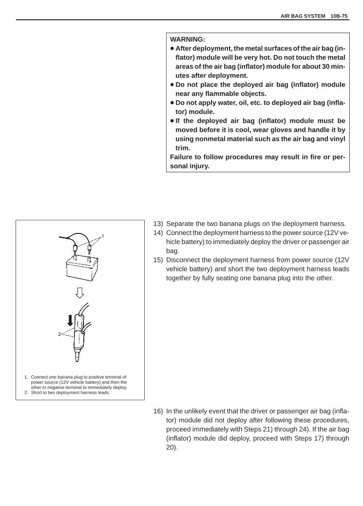
YH4GRANDVITARA
AIR BAG SYSTEM 10B-75
1. Connect one banana plug to positive terminal of power source (12V vehicle battery) and then the other to negative terminal to immediately deploy.
2. Short to two deployment harness leads.
WARNING:� After deployment, the metal surfaces of the air bag (in-
flator) module will be very hot. Do not touch the metalareas of the air bag (inflator) module for about 30 min-utes after deployment.
� Do not place the deployed air bag (inflator) modulenear any flammable objects.
� Do not apply water, oil, etc. to deployed air bag (infla-tor) module.
� If the deployed air bag (inflator) module must bemoved before it is cool, wear gloves and handle it byusing nonmetal material such as the air bag and vinyltrim.
Failure to follow procedures may result in fire or per-sonal injury.
13) Separate the two banana plugs on the deployment harness.14) Connect the deployment harness to the power source (12V ve-
hicle battery) to immediately deploy the driver or passenger airbag.
15) Disconnect the deployment harness from power source (12Vvehicle battery) and short the two deployment harness leadstogether by fully seating one banana plug into the other.
16) In the unlikely event that the driver or passenger air bag (infla-tor) module did not deploy after following these procedures,proceed immediately with Steps 21) through 24). If the air bag(inflator) module did deploy, proceed with Steps 17) through20).

YH4GRANDVITARA
1
2
1. Deployed driver air bag (inflator) module2. Gloves
For driver air bag (inflator) module
10B-76 AIR BAG SYSTEM
17) Put on a pair of shop gloves to protect your hands from possibleirritation and heat when handling the deployed air bag (inflator)module.
NOTE:As a precaution, gloves and safety glasses are recom-mended to prevent any possible irritation of the skin oreyes.
18) Disconnect the deployment harness from the air bag (inflator)module as soon after deployment as possible. This will preventdamage to the deployment harness due to possible contactwith the hot air bag (inflator) module canister. The deploymentharness are designed to be reused. They should, however, beinspected for damage after each deployment and replaced ifnecessary.
19) Dispose of the deployed air bag (inflator) module through nor-mal refuse channels after it has cooled for at least 30 minutesand tightly seal the air bag (inflator) module in a strong vinylbag. (Refer to “Deployed Air Bag (Inflator) Modules Disposal”in detail.)
20) Wash your hands with mild soap and water afterward.
NOTE:The remaining steps are to be followed in the unlikely eventthat the air bag (inflator) module did not deploy after followingthese procedures.
21) Ensure that the deployment harness has been disconnectedfrom the power source and that its two banana plugs have beenshorted together by fully seating one banana plug into the oth-er.
22) Disconnect the deployment harness from the air bag (inflator)module.

YH4GRANDVITARA
AIR BAG SYSTEM 10B-77
1. Slit on workbench2. Workbench vise3. Lower mounting bracket
ALWAYS CARRY AIR BAG (INFLATOR) MODULEWITH TRIM COVER (AIR BAG OPENING) AWAYFROM BODY.
ALWAYS PLACE AIR BAG (INFLATOR) MODULEON WORKBENCH WITH TRIM COVER (AIR BAGOPENING) UP, AWAY FROM LOOSE OBJECTS.
WARNING:� Always carry a live air bag (inflator) module with trim
cover away from you.� When storing a live air bag (inflator) module or when
leaving a live air bag (inflator) module unattended ona bench or other surface, always face the bag and trimcover up and away from the surface. As the live pas-senger air bag (inflator) module must be placed withits bag (trim cover) facing up, place it or the work-bench with a slit or use the workbench vise to hold itsecurely at its lower mounting bracket.
� This is necessary so that a free space is provided toallow the air bag to expand in the unlikely event of ac-cidental deployment.
Failure to follow procedures may result in personal inju-ry.
23) Temporarily store the air bag (inflator) module with its vinyl trimcover facing up, away from the surface upon which it rests. Re-fer to “Service Precautions” in this section for details.
24) Contact your local distributor for further assistance.

YH4GRANDVITARA
10B-78 AIR BAG SYSTEM
DEPLOYMENT INSIDE VEHICLE
Use this procedure when scrapping the entire vehicle including the driver and passenger air bag (inflator) modules.
CAUTION:When vehicle itself will be used again, deploy the air bag outside vehicle according to “DeploymentOutside Vehicle”, for deploying it inside will cause the instrument panel, glove box and their vicinityto be deformed.Failure to observe this CAUTION may require unneeded vehicle inspection and repair.
WARNING:Following precautions must be observed for this work. Failure to observe any of them may result inpersonal injury.� To avoid an accidental deployment, this work should be performed by no more than one person.� The procedure should be followed strictly as described here.� Be sure to read “Service Precautions” for the air bag (inflator) module beforehand.� Never connect deployment harness to any power source before connecting deployment harness to
the air bag (inflator) module. Deployment harness shall remain shorted and not be connected to apower source until the air bag is to be deployed.
� The air bag (inflator) module will immediately deploy the air bag when a power source is connectedto it. Wear safety glasses throughout this entire deployment and disposal procedure.
� Wear suitable ear protection when deploying air bag. Also, advise those who are in the area close todeployment site to wear suitable ear protection.
� Do not deploy driver and passenger air bag (inflator) modules at the same time.
1) Turn ignition switch to “LOCK”, remove key and put on safetyglasses.
2) Remove all loose objects from front seats and instrument panel.
3) [For driver air bag (inflator) module]Disconnect contact coil connector (yellow connector) locatednear the base of the steering column.ii) Release locking of lock lever.ii) After unlocked, disconnect to connector.
[For passenger air bag (inflator) module]Remove glove box from instrument panel and disconnect pas-senger air bag (inflator) module connector (yellow connector).ii) Release locking of lock lever.ii) After unlocked, disconnect to connector.

YH4GRANDVITARA
1. Shorted
For driver air bag (inflator) module
1. Short deployment harness leads
AIR BAG SYSTEM 10B-79
4) Confirm that each air bag (inflator) module is securely mounted.
5) Check that there is no open/short or damage in special tool (de-ployment harness). If any faulty condition is found, do not use itand be sure to use new deployment harness.
Special Tool(A): 09932-75030
6) Short the two deployment harness leads together by fully seat-ing one banana plug into the other.
WARNING:Deployment wires shall remain shorted and not be con-nected to a power source until the air bag is to bedeployed.
Special Tool(A): 09932-75030
7) Connect deployment harness connector to air bag (inflator)module (driver or passenger) and lock connector with lock lever.
Special Tool(A): 09932-75030

YH4GRANDVITARA
Driver side for left hand steering vehicle
Driver side for right hand steering vehicle
1. Stretch deployment harness to its full length 10 m (33 ft).
2. Drop cloth, blanket or similar item
2
10B-80 AIR BAG SYSTEM
8) Route deployment harness out the vehicle.9) Verify that the inside of the vehicle and the area surrounding
the vehicle are clear of all people and loose or flammable ob-jects.
10) Stretch the deployment harness to its full length 10 m (33 ft).11) Place a power source near the shorted end of the deployment
harness. Recommended application: 12 Volts minimum, 2amps minimum. A vehicle battery is suggested.
12) Completely cover windshield area and front door windowopenings with a drop cloth, blanket to similar item. This reducesthe possibility of injury due to possible fragmentation of the ve-hicle’s glass or interior.
13) Notify all people in the immediate area that you intend to deploythe air bag (inflator) module.
NOTE:� When the air bag deploys, the rapid gas expansion will
create a substantial report. Wear suitable ear protection.Notify all people in the immediate area that you intend todeploy the air bag (inflator) module and suitable earprotection should be worn.
� After the air bag (inflator) module has been deployed, thesurface of the air bag may contain a powdery residue.This powder consists primarily of cornstarch (used to lu-bricate the bag as it inflates) and byproducts of thechemical reaction.
WARNING:Safety precautions must be observed when handling adeployed air bag (inflator) module.� After deployment, the metal surfaces of the air bag (infla-
tor) module will be very hot. Do not touch the metal areasof the air bag (inflator) module for about 30 minutes afterdeployment.
� Do not apply water, oil, etc. to deployed air bag (inflator)module.
� If the deployed air bag (inflator) module must be movedbefore it is cool, wear gloves and handle by the air bag orvinyl trim.
Failure to follow procedures may result in fire or personalinjury.

YH4GRANDVITARA
1. Stretch it to full length 10m (33 ft).2. Power source (12V vehicle battery)3. Connect one banana plug to positive terminal of power
source (12V vehicle battery) and then the other tonegative terminal to immediately deploy.
4. Short harness leads after deployment.5. Drop cloth, blanket or similar them
5
AIR BAG SYSTEM 10B-81
14) Separate the two banana plugs on the deployment harness.15) Connect the deployment harness to the power source (12 V ve-
hicle battery) to immediately deploy the driver or passenger airbag.
16) Disconnect the deployment harness from the power source (12V vehicle battery) and short the two deployment harness leadstogether by fully seating one banana plug into the other.
17) Put on a pair of shop gloves to protect your hands from possibleirritation and heat when handling the deployed air bag (inflator)module.
NOTE:As a precaution, gloves and safety glasses are recom-mended to prevent any possible irritation of the skin oreyes.
18) Disconnect the deployment harness from the air bag (inflator)module as soon after deployment as possible. This will preventdamage to the deployment harness due to possible contactwith the hot air bag (inflator) module canister. The deploymentharness are designed to be reused. They should, however, beinspected for damage after each deployment and replaced ifnecessary.
19) Carefully remove drop cloth from vehicle and clean off any frag-ments or discard drop cloth entirely.
20) Repeat Steps 2) through 19) to deploy driver or passenger airbag (inflator) module which has not been deployed, if any.

YH4GRANDVITARA
ALWAYS CARRY AIR BAG (INFLATOR) MODULEWITH TRIM COVER (AIR BAG OPENING) AWAYFROM BODY.
ALWAYS PLACE AIR BAG (INFLATOR) MODULEON WORKBENCH WITH TRIM COVER (AIR BAGOPENING) UP, AWAY FROM LOOSE OBJECTS.
1. Slit on workbench2. Workbench vise3. Lower mounting bracket
10B-82 AIR BAG SYSTEM
21) In the unlikely event that either or both of the air bag (inflator)modules proceed immediately with Steps 23) through 25). Ifthe air bag (inflator) module did deploy, proceed with Steps 22).
22) With air bags deployed the vehicle may be scrapped in thesame manner as a non-air bag system equipped vehicle.
23) Remove the undeployed air bag (inflator) module(s) from thevehicle. For driver air bag (inflator) module refer to SECTION3C1, for passenger air bag (inflator) module refer to “On-Ve-hicle Service” in this section.
WARNING:� Always carry a live air bag (inflator) module with trim
cover away from you.� When storing a live air bag (inflator) module or when
leaving a live air bag (inflator) module unattended ona bench or other surface, always face the bag up, awayfrom the surface.This is necessary so that a free space is provided toallow the air bag to expand in the unlikely event of ac-cidental deployment.
Failure to follow procedures could result in personal in-jury.
24) Temporarily store the air bag (inflator) module with its vinyl trimcover facing up, away from the surface upon which it rests. Re-fer to “Service Precautions” in this section for details.
25) Contact your local distributor for further assistance.

YH4GRANDVITARA
AIR BAG SYSTEM 10B-83
SEAT BELT PRETENSIONERS DISPOSAL
WARNING:Failure to follow proper seat belt pretensioner (retractor assembly) disposal procedures can result inpretensioner activation which may cause personal injury. Inactivated seat belt pretensioner must notbe disposed of through normal refuse channels.The inactivated seat belt pretensioner contain substances that can cause severe illness or personalinjury if the sealed container is damaged during disposal.
Do not dispose of the live (inactivated) seat belt pretensioners.The method employed depends upon the final disposition of the particular vehicle, as noted in “Activation OutsideVehicle” and “Activation Inside Vehicle” in this section.Activation Outside Vehicle disposing of the seat belt pretension(s) only (i.e., the vehicle itself will be used. . . . . . . .
again).Activation Inside Vehicle scrapping the entire vehicle including the seat belt pretensioners.. . . . . . . . . .
ACTIVATION OUTSIDE VEHICLE
Use this procedure when the vehicle itself is used again (only the seat belt pretensioner(s) are disposed of).
WARNING:Following precautions must be observed for this work. Failure to observe any of them may result inpersonal injury.� To avoid an accidental activation, this work should be performed by no more than one person.� The procedure should be followed strictly as described here.� Be sure to read “Service Precautions” in this section for the seat belt pretensioner beforehand.� Never connect deployment harness to any power source before connecting deployment harness to
the seat belt pretensioner. Deployment harness shall remain shorted and not be connected to a powersource until the pretensioner is to be activated.
� The seat belt pretensioner will immediately activate the pretensioner when a power source is con-nected to it. Wear safety glasses throughout this entire activation and disposal procedure.
� Wear suitable ear protection when activating pretensioner. Also, advise those who are in the areaclose to activation site to wear suitable ear protection.
� Do not activate driver and passenger seat belt pretensioners at the same time.
The following procedure requires use of special tools (deployment harness). Do not attempt procedure without it.

YH4GRANDVITARA
1. Shorted
1. Exhaust hole
1
1NG
10B-84 AIR BAG SYSTEM
1) Turn ignition switch to “LOCK”, remove key and put on safetyglasses.
2) Check that there is no open, short or damage in special tool (de-ployment harness). If any faulty is found, do not use it and besure to use new deployment harness.
Special Tool(A): 09932-75030
3) Short the two deployment harness leads together by fully seat-ing one banana plug into the other.
WARNING:Deployment harness shall remain shorted and not beconnected to a power source until the pretensioner is tobe activated.
Special Tool(A): 09932-75030
4) Remove driver or passenger seat belt pretensioner(s) and seatbelt pretensioner harness(s) from vehicle, referring to SECTION10A.
WARNING:� For handling and storage of a live seat belt pretension-
er, select a place where the ambient temperature below65�C (150�F), without high humidity and away fromelectric noise.
� Never carry the seat belt pretensioner by the wires orconnector on the underside of the pretensioner.
� When placing a live seat belt pretensioner on the work-bench or some place like that, be sure not to lay with itsexhaust hole provided side facing down. it is also pro-hibited to put something on its face with an exhausthole or to put a seat belt pretensioner on top of another.
Otherwise, personal injury may result.
5) Temporarily place seat belt pretensioner on the workbench ac-cording to above WARNING.

YH4GRANDVITARA
1. Seat belt pretensioner (retractor assembly)2. Webbing3. 185 cm (6 ft) of clearance4. Exhaust hole
1. Stretch deployment harness to full length 10 m (33 ft).2. Connect connectors.3. Power source (12V vehicle battery)4. Short the two deployment harness leads.5. Seat belt pretensioner harness
4
AIR BAG SYSTEM 10B-85
6) Pull out the webbing fully as shown at the left and cut it at theroot of the pretensioner (retractor assembly) as shown in thefigure.
WARNING:As the drum of the retractor assembly turns very quick-ly as soon as the webbing is cut, fix the retractor assem-bly with a vise on the workbench and keep your handsand fingers away from it when cutting the webbing.
7) Clear a space on the ground about 185 cm (6 ft) in diameterwhere the seat belt pretensioner is to be activated. A paved,outdoor location where there is no activity is preferred. If an out-door location is not available, a space on the shop floor wherethere is no activity and sufficient ventilation is recommended.Ensure no loose or flammable objects are within the activationarea.
8) Place the seat belt pretensioner as shown in the figure on theground in the space just cleared.
9) Stretch the deployment harness from the seat belt pretension-er to its full length 10 m (33 ft).
10) Place a power source near the shorted end of the deploymentharness. Recommended application: 12 Volts minimum, 2amps minimum. A vehicle battery is suggested.
11) Verify that the area around the seat belt pretensioner is clearof all people and loose or flammable objects.
12) Verify that the seat belt pretensioner is placed as shown in thefigure on the ground in the space just cleared.
13) Connect the seat belt pretensioner harness to the deploymentharness connector and lock the connector with lock lever.
Special Tool(A): 09932-75030

YH4GRANDVITARA
1. Connect one banana plug to positive terminal of powersource (12V vehicle battery) and then the other to negative terminal to immediately activate.
2. Short to two deployment harness leads.
10B-86 AIR BAG SYSTEM
14) Notify all people in the immediate area that you intend to acti-vate the seat belt pretensioner.
NOTE:� When the pretensioner activates, the rapid gas expan-
sion will create a substantial report. Wear suitable earprotection. Notify all people in the immediate area thatyou intend to activate the seat belt pretensioner and suit-able ear protection should be worn.
� When the pretensioner activates, the seat belt preten-sioner may jump about 30 cm (1 ft) vertically. This is anormal reaction of the seat belt pretensioner to the forceof the rapid gas expansion inside the pretensioner.
WARNING:Safety precautions must be observed when handlingan activated seat belt pretensioner.� After activation, the metal surfaces of the seat belt
pretensioner will be very hot. Do not touch the metalareas of the seat belt pretensioner for about 30 min-utes after activation.
� Do not place the activated seat belt pretensionernear any flammable objects.
� Do not apply water, oil, etc. to the activated seat beltpretensioner.
� If the activated seat belt pretensioner must bemoved before it is cool, wear gloves and handle it byusing nonmetal material.
Failure to follow procedures may result in fire or per-sonal injury.
15) Separate the two banana plugs on the deployment harness.16) Connect the deployment harness to the power source (12V ve-
hicle battery) to immediately activate the pretensioner.17) Disconnect the deployment harness from power source (12V
vehicle battery) and short the two deployment harness leadstogether by fully seating one banana plug into the other.

YH4GRANDVITARA
AIR BAG SYSTEM 10B-87
1. Activated seat belt pretensioner2. Gloves3. Pretensioner harness
18) In the unlikely event that the seat belt pretensioner did not acti-vate after following these procedures, proceed immediatelywith Steps 23) through 26). If the the seat belt pretensioner didactivate, proceed with Steps 19) through 22).
19) Put on a pair of shop gloves to protect your hands from possibleirritation and heat when handling the activated seat belt preten-sioner.
NOTE:As a precaution, gloves and safety glasses are recom-mended to prevent any possible irritation of the skin oreyes.
20) Disconnect the deployment harness from the seat belt preten-sioner as soon after activation as possible. This will preventdamage to the deployment harness due to possible contactwith the hot seat belt pretensioner canister. The deploymentharness are designed to be reused. They should, however, beinspected for damage after each activation and replaced if nec-essary.
21) Dispose of the activated seat belt pretensioner through normalrefuse channels after it has cooled for at least 30 minutes andtightly seal the seat belt pretensioner in a strong vinyl bag. (Re-fer to “Activated Seat Belt Pretensioners Disposal” in detail.)
22) Wash your hands with mild soap and water afterward.

YH4GRANDVITARA
1. Exhaust hole
1
1NG
10B-88 AIR BAG SYSTEM
NOTE:The remaining steps are to be followed in the unlikely eventthat the seat belt pretensioner did not activate after followingthese procedures.
23) Ensure that the deployment harness has been disconnectedfrom the power source and that its two banana plugs have beenshorted together by fully seating one banana plug into the oth-er.
24) Disconnect the deployment harness from the seat belt preten-sioner.
WARNING:� For handling and storage of a live seat belt pretensioner,
select a place where the ambient temperature below 65 �C(150�F), without high humidity and away from electricnoise.
� Never carry the seat belt pretensioner by the wires or con-nector on the underside of the pretensioner.
� When placing a live seat belt pretensioner on the work-bench or some place like that, be sure not to lay it with itsexhaust hole provided side facing down. It is also prohib-ited to put something on its face with an exhaust hole orto put a seat belt pretensioner on top of another.
Otherwise, personal injury may result.
25) Temporarily store the seat belt pretensioner. At that time, besure NOT to face its exhaust hole provided side down. It mustface up. Refer to “Service Precautions” in this section for detail.
26) Contact your local distributor for further assistance.

YH4GRANDVITARA
1. Air bag harness2. Seat belt pretensioner harness
For driver side
AIR BAG SYSTEM 10B-89
ACTIVATION INSIDE VEHICLE
Use this procedure when scrapping the entire vehicle including the seat belt pretensioners.
CAUTION:When vehicle itself will be used again, activate pretensioner outside vehicle according to “ActivationOutside Vehicle”, for activating it inside will cause the center pillar inner garnish and their vicinity tobe deformed.Failure to observe this CAUTION may require unneeded vehicle inspection and repair.
WARNING:Following precautions must be observed for this work. Failure to observe any of them may result inpersonal injury.� To avoid an accidental activation, this work should be performed by no more than one person.� The procedure should be followed strictly as described here.� Be sure to read “Service Precautions” for the seat belt pretensioner beforehand.� Never connect deployment harness to any power source before connecting deployment harness to
the seat belt pretensioner. Deployment harness shall remain shorted and not be connected to a powersource until the pretensioner is to be activated.
� The seat belt pretensioner will immediately activate the pretensioner when a power source is con-nected to it. Wear safety glasses throughout this entire activation and disposal procedure.
� Wear suitable ear protection when activating pretensioner. Also, advise those who are in the areaclose to activation site to wear suitable ear protection.
� Do not activate driver and passenger seat belt pretensioners at the same time.
1) Turn ignition switch to “LOCK”, remove key and put on safetyglasses.
2) Remove all loose objects from front seats and instrument panel.
3) Remove both side (driver and passenger side) front pillar lowertrims and disconnect seat belt pretensioner harnesses from airbag harness.
4) Confirm that each seat belt pretensioner is securely mounted.

YH4GRANDVITARA
1. Shorted
Driver side for left hand steering vehicle
Driver side for right hand steering vehicle
1. Stretch deployment harnessto its full length 10 m (33 ft).
2. Drop cloth, blanket or similar item.
10B-90 AIR BAG SYSTEM
5) Check that there is no open/short or damage in special tool (de-ployment harness). If any faulty condition is found, do not useit and be sure to use new deployment harness.
Special Tool(A): 09932-75030
6) Short the two deployment harness leads together by fully seat-ing one banana plug into the other.
WARNING:Deployment wires shall remain shorted and not be con-nected to a power source until the pretensioner is to beactivated.
Special Tool(A): 09932-75030
7) Connect the deployment harness connector to the seat beltpretensioner harness and lock the connector with lock lever.
Special Tool(A): 09932-75030
8) Route deployment harness out the vehicle.9) Verify that the inside of the vehicle and the area surrounding
the vehicle are clear of all people and loose or flammable ob-jects.
10) Stretch the deployment harness to its full length 10 m (33 ft).11) Place a power source near the shorted end of the deployment
harness. Recommended application: 12 Volts minimum, 2amps minimum. A vehicle battery is suggested.
12) Completely cover windshield area and front door windowopenings with a drop cloth, blanket to similar item. This reducesthe possibility of injury due to possible fragmentation of the ve-hicle’s glass or interior.
13) Notify all people in the immediate area that you intend to acti-vate the seat belt pretensioner.

YH4GRANDVITARA
1. Stretch it to full length 10m (33 ft).2. Power source (12V vehicle battery)3. Connect one banana plug to positive terminal of power
source (12V vehicle battery) and then the other tonegative terminal to immediately activate.
4. Short harness leads after activation.5. Drop cloth, blanket or similar them.
AIR BAG SYSTEM 10B-91
NOTE:When the pretensioner activates, the rapid gas expansionwill create a substantial report. Wear suitable ear protec-tion. Notify all people in the immediate area that you intendto activate the seat belt pretensioner and suitable earprotection should be worn.
WARNING:Safety precautions must be observed when handling anactivated seat belt pretensioner.� After activation, the metal surfaces of the seat belt
pretensioner will be very hot. Do not touch the metalareas of the seat belt pretensioner for about 30 min-utes after activation.
� Do not apply water, oil, etc. to activated seat belt pre-tensioner.
� If the activated seat belt pretensioner must be movedbefore it is cool, wear gloves and handle by using non-metal material.
Failure to follow procedures may result in fire or per-sonal injury.
14) Separate the two banana plugs on the deployment harness.15) Connect the deployment harness to the power source (12 V ve-
hicle battery) to immediately activate the pretensioner.16) Disconnect the deployment harness from the power source (12
V vehicle battery) and short the two deployment harness leadstogether by fully seating one banana plug into the other.

YH4GRANDVITARA
1. Exhaust hole
1
1NG
10B-92 AIR BAG SYSTEM
17) Put on a pair of shop gloves to protect your hands from possibleirritation and heat when handling the activated seat belt preten-sioner.
NOTE:As a precaution, gloves and safety glasses are recom-mended to prevent any possible irritation of the skin oreyes.
18) Disconnect the deployment harness from the seat belt preten-sioner as soon after activation as possible. This will preventdamage to the deployment harness due to possible contactwith the hot seat belt pretensioner canister. The deploymentharness are designed to be reused. They should, however, beinspected for damage after each activation and replaced if nec-essary.
19) Carefully remove drop cloth from vehicle and clean off any frag-ments or discard drop cloth entirely.
20) Repeat steps 2) through 19) to activate seat belt pretensionerwhich has not been activated, if any.
21) In the unlikely event that either or both of the seat belt preten-sioners proceed immediately with steps 23) through 25). If theseat belt pretensioner did activate, proceed with step 22).
22) With pretensioners activated the vehicle may be scrapped inthe same manner as a non-air bag system equipped vehicle.
23) Remove the inactivated seat belt pretensioner(s) from the ve-hicle. Refer to SECTION 10A.
WARNING:� For handling and storage of a live seat belt pretension-
er, select a place where the ambient temperature be-low 65 �C (150�F), without high humidity and awayfrom electric noise.
� Never carry the seat belt pretensioner by the wires orconnector on the underside of the pretensioner.
� When placing a live seat belt pretensioner on theworkbench or some place like that, be sure not to layit with its exhaust hole provided side facing down. Itis also prohibited to put something on its face with anexhaust hole or to put a seat belt pretensioner on topof another.
Otherwise, personal injury may result.

YH4GRANDVITARA
AIR BAG SYSTEM 10B-93
24) Temporarily store the seat belt pretensioner. At that time, besure NOT to face its exhaust hole provided side down. It mustface up. Refer to “Service Precautions” in this section for de-tails.
25) Contact your local distributor for further assistance.
DEPLOYED AIR BAG (INFLATOR)MODULES DISPOSAL
WARNING:Failure to follow proper air bag (inflator) module disposalprocedures can result in air bag deployment which maycause personal injury. Undeployed air bag (inflator) modulemust not be disposed of through normal refuse channels.The undeployed air bag (inflator) module contains sub-stances that can cause severe illness or personal injury ifthe sealed container is damaged during disposal.
Deployed air bag (inflator) modules (driver/passenger) can be dis-posed of through normal refuse channels just like any other parts.For their disposal, however, following points should be noted.� The air bag (inflator) module immediately after deployment is very
hot. Wait for 30 minutes to cool it off before handling it.
� Never apply water, oil, etc. to deployed air bag (inflator) moduleto cool it off and be careful so that water, oil etc. does not get onthe deployed air bag (inflator) module.
� After the air bag (inflator) module has been deployed, the surfaceof the air bag may contain a powdery residue. This powder con-sists primarily of cornstarch (used to lubricate the bag as it in-flates) and byproducts of the chemical reaction. As with many ser-vice procedures, you should wear gloves and safety glasses.
� When disposing of the deployed air bag (inflator) module, be sureto seal it in a vinyl bag.
� When air bag (inflator) module(s) have been deployed inside thevehicle which is going to be scrapped, leave them as installed tothe vehicle.
� Be sure to wash your hands with mild soap and water after han-dling it.

YH4GRANDVITARA
10B-94 AIR BAG SYSTEM
ACTIVATED SEAT BELTPRETENSIONERS DISPOSAL
WARNING:Failure to follow proper seat belt pretensioner (retractor as-sembly) disposal procedures can result in pretensioner ac-tivation which may cause personal injury. Inactivated seatbelt pretensioner must not be disposed of through normalrefuse channels.The inactivated seat belt pretensioner contains substancesthat can cause severe illness or personal injury if the sealedcontainer is damaged during disposal.
Activated seat belt pretensioners (driver/passenger) can be dis-posed of through normal refuse channels just like any other parts.For their disposal, however, following points should be noted.� The seat belt pretensioner immediately after activation is very
hot. Wait for 30 minutes to cool it off before handling it.
� Never apply water, oil, etc. to activated seat belt pretensioner tocool it off and be careful so that water, oil etc. does not get on theactivated seat belt pretensioner.
� With many service procedures, gloves and safety glasses shouldbe worn to prevent any possible irritation of the skin or eyes.
� When disposing of the activated seat belt pretensioner alone, besure to seal it in a vinyl bag.
� When seat belt pretensioners have been activated inside the ve-hicle which is going to be scrapped, leave them as installed to thevehicle.
� Be sure to wash your hands with mild soap and water after han-dling it.
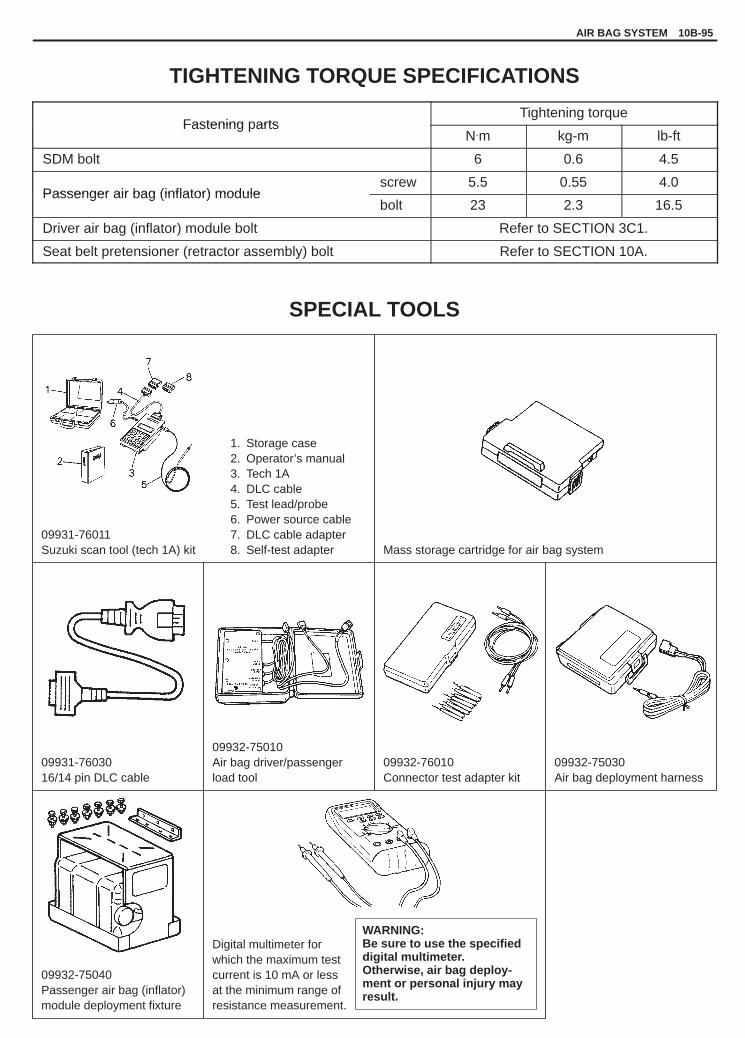
YH4GRANDVITARA
AIR BAG SYSTEM 10B-95
09931-76011Suzuki scan tool (tech 1A) kit
1. Storage case2. Operator’s manual3. Tech 1A4. DLC cable5. Test lead/probe6. Power source cable7. DLC cable adapter8. Self-test adapter Mass storage cartridge for air bag system
09931-7603016/14 pin DLC cable
09932-75010Air bag driver/passengerload tool
09932-76010Connector test adapter kit
09932-75030Air bag deployment harness
09932-75040Passenger air bag (inflator)module deployment fixture
Digital multimeter forwhich the maximum testcurrent is 10 mA or lessat the minimum range ofresistance measurement.
WARNING:Be sure to use the specified digital multimeter.Otherwise, air bag deploy-ment or personal injury mayresult.
TIGHTENING TORQUE SPECIFICATIONS
Fastening partsTightening torque
Fastening artsN.m kg-m lb-ft
SDM bolt 6 0.6 4.5
Passenger air bag (inflator) modulescrew 5.5 0.55 4.0
Passenger air bag (inflator) modulebolt 23 2.3 16.5
Driver air bag (inflator) module bolt Refer to SECTION 3C1.
Seat belt pretensioner (retractor assembly) bolt Refer to SECTION 10A.
SPECIAL TOOLS