STURDEVANTS ART AND SCIENCE of OPERATIVE ...
50
386 Chapter 1Ciass I, II, and VI Amalgam Restorations c Fig 14-56 The mandibular first premolar with a sound transverse ridge. A, A two-surface tooth preparation that does not include the opposite pit. B, Occlusal outline form. C, Proximal view of the completed preparation. cusp and prevents encroachment on the facial pulp horn). The primary difference in tooth preparation on this tooth, compared with the preparation on other posterior teeth, is the facial inclination of the pulpal wall. The isthmus is broad ened as necessary, but maintains the dovetail retention form, if required. Figure 14-56, B, illustrates the correct occlusal outline form. Removing any remaining caries (if present) and inserting necessary liners, bases, or both precede the place ment of proximal grooves and the finishing of the enamel margins to complete the preparation (see Fig. 14-56, C). Maxillary First Molar When mesial and distal proximal surface amalgam restora tions are indicated on the maxillary first molar that has an unaffected oblique ridge, separate two-surface tooth prepara tions are indicated (rather than a mesiooccluso-distal prepara tion) because the strength of the tooth crown is significantly greater when the oblique ridge is intact.19 The mesio-occlusal tooth preparation is generally uncomplicated (Fig. 14-57, A). Occasionally, extension through the ridge and into the distal pit is necessary because of the extent of caries. The outline of this occlusolingual pit-and-fissure portion is similar to that of the Class I occlusolingual preparation. Figure 14-57, B and C, illustrates a mesio-occlusal preparation extended to include the distal pit and the outline form that includes the distal oblique and lingual fissures. When the occlusal fissure extends into the facial cusp ridge and cannot be removed by enameloplasty, the defect should be eliminated by extension of the tooth preparation. Occa sionally, this can be accomplished by tilting the bur to create an occlusal divergence of the facial wall while maintaining the dentin support of the ridge. Tf this fault cannot be eliminated without extending the margin to the height of the cusp ridge or undermining the enamel margin, the preparation should be extended facially through the ridge (see Fig. 14-57, D). The pulpal wall of this facial extension may have remaining enamel, but a depth of 1.5 to 2 mm is necessary to provide sufficient bulk of material for adequate strength. For the best esthetic results, minimal extension of the proximal mesiofacial margin is indicated. Fig. 14-57 Maxillary first molar. A, Conventional mesioocclusal prepara tion. B, Mesioocclusal preparation extended to include the distal pit. C, Mesiooccluso-lingual preparation, including the distal pit and the distal oblique and lingual fissures. D, Mesioocclusal preparation with facial fissure extension. The disto-occlusal tooth preparation may take one of several outlines, depending on the occlusal anatomy. The occlusal outline is determined by the pit-and-fissure patte and by the amount and extension of caries. An extension onto the lingual surface to include a lingual fissure should be pre pared only after the distolingual proximal margin is estab lished. This approach may allow conservation of more tooth structure between the distolingual wall and the lingual fissure extension, resulting in more strength of the distolingual cusp. www.ShayanNemoodar.com
-
Upload
khangminh22 -
Category
Documents
-
view
0 -
download
0
Transcript of STURDEVANTS ART AND SCIENCE of OPERATIVE ...
386 Chapter 14-Ciass I, II, and VI Amalgam Restorations
c
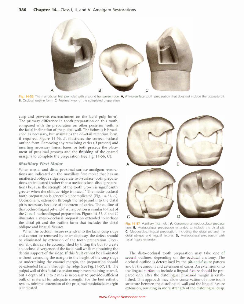
Fig 14-56 The mandibular first premolar with a sound transverse ridge. A, A two-surface tooth preparation that does not include the opposite pit.
B, Occlusal outline form. C, Proximal view of the completed preparation.
cusp and prevents encroachment on the facial pulp horn). The primary difference in tooth preparation on this tooth, compared with the preparation on other posterior teeth, is the facial inclination of the pulpal wall. The isthmus is broadened as necessary, but maintains the dovetail retention form, if required. Figure 14-56, B, illustrates the correct occlusal outline form. Removing any remaining caries (if present) and inserting necessary liners, bases, or both precede the placement of proximal grooves and the finishing of the enamel margins to complete the preparation (see Fig. 14-56, C).
Maxillary First Molar
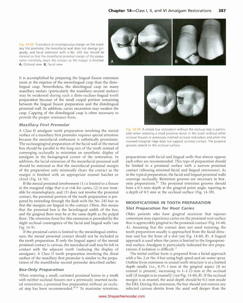
When mesial and distal proximal surface amalgam restorations are indicated on the maxillary first molar that has an unaffected oblique ridge, separate two-surface tooth preparations are indicated (rather than a mesiooccluso-distal preparation) because the strength of the tooth crown is significantly greater when the oblique ridge is intact.19 The mesio-occlusal tooth preparation is generally uncomplicated (Fig. 14-57, A). Occasionally, extension through the ridge and into the distal pit is necessary because of the extent of caries. The outline of this occlusolingual pit-and-fissure portion is similar to that of the Class I occlusolingual preparation. Figure 14-57, B and C, illustrates a mesio-occlusal preparation extended to include the distal pit and the outline form that includes the distal oblique and lingual fissures.
When the occlusal fissure extends into the facial cusp ridge and cannot be removed by enameloplasty, the defect should be eliminated by extension of the tooth preparation. Occasionally, this can be accomplished by tilting the bur to create an occlusal divergence of the facial wall while maintaining the dentin support of the ridge. Tf this fault cannot be eliminated without extending the margin to the height of the cusp ridge or undermining the enamel margin, the preparation should be extended facially through the ridge (see Fig. 14-57, D). The pulpal wall of this facial extension may have remaining enamel, but a depth of 1.5 to 2 mm is necessary to provide sufficient bulk of material for adequate strength. For the best esthetic results, minimal extension of the proximal mesiofacial margin is indicated.
Fig. 14-57 Maxillary first molar. A, Conventional mesioocclusal prepara
tion. B, Mesioocclusal preparation extended to include the distal pit.
C, Mesiooccluso-lingual preparation, including the distal pit and the
distal oblique and lingual fissures. D, Mesioocclusal preparation with
facial fissure extension.
The disto-occlusal tooth preparation may take one of several outlines, depending on the occlusal anatomy. The occlusal outline is determined by the pit-and-fissure pattern and by the amount and extension of caries. An extension onto the lingual surface to include a lingual fissure should be prepared only after the distolingual proximal margin is established. This approach may allow conservation of more tooth structure between the distolingual wall and the lingual fissure extension, resulting in more strength of the distolingual cusp.
www.ShayanNemoodar.com
Chapter 14-Ciass I, II, and VI Amalgam Restorations 387
Fig. 14-58 To produce an inconspicuous margin on the maxil
lary first premolar, the mesiofacial wall does not diverge gin
givally, and facial extension with a No. 245 bur should be
minimal so that the mesiofacial proximal margin of the prepa
ration minimally clears the contact as the margin is finished.
A, Occlusal view. B, Facial view.
It is accomplished by preparing the lingual fissure extension more at the expense of the mesiolingual cusp than the distolingual cusp. Nevertheless, the distolingual cusp on many maxillary molars (particularly the maxillary second molars) may be weakened during such a disto-occluso-lingual tooth preparation because of the small cuspal portion remaining between the lingual fissure preparation and the distolingual proximal wall. In addition, caries excavation may weaken the cusp. Capping of the distolingual cusp is often necessary to provide the proper resistance form.
Maxillary First Premolar
A Class IT amalgam tooth preparation involving the mesial surface of a maxillary first premolar requires special attention because the mesiofacial embrasure is esthetically prominent. The occl usogingival preparation of the facial wall of the mesial box should be parallel to the long axis of the tooth instead of converging occlusally to minimize an unesthetic display of amalgam in the faciogingival corner of the restoration. In addition, the facial extension of the mesiofacial proximal wall should be minimal so that the mesiofacial proximal margin of the preparation only minimally clears the contact as the margin is finished with an appropriate enamel hatchet or chisel (Fig. 14-58).
If the mesial proximal involvement ( l) is limited to a fissure in the marginal ridge that is at risk for caries, (2) is not treatable by enameloplasty, and (3) does not involve the proximal contact, the proximal portion of the tooth preparation is prepared by extending through the fault with the No. 245 bur so that the margins are lingual to the contact. Often, this means that the proximal box is the faciolingual width of the bur, and the gingival floor may be at the same depth as the pulpal floor. The retention form for this extension is provided by the slight occlusal convergence of the facial and lingual walls (see Fig. 14-9).
If the proximal caries is limited to the mesiolingual embrasure, the mesial proximal contact should not be included in the tooth preparation. If only the lingual aspect of the mesial proximal contact is carious, the mesiofacial wall may be left in contact with the adjacent tooth (reducing the display of amalgam). A Class II tooth preparation involving the distal surface of the maxillary first premolar is similar to the preparation of the mandibular second premolar described earlier.
Box-Only Preparation
When restoring a small, cavitated proximal lesion in a tooth with neither occlusal fissures nor a previously inserted occlusal restoration, a proximal box preparation without an occlusal step has been recommended.18'19 To maximize retention,
Fig. 14 .. 59 A simple box restoration without the occlusal step is permis
sible when restoring a small proximal lesion in the tooth without either
occlusal fissures or previously inserted occlusal restoration and when the
involved marginal ridge does not support occlusal contact. T he proximal
grooves extend to the occlusal surface.
preparations with facial and lingual walls that almost oppose each other are recommended. This type of preparation should be limited to a proximal surface with a narrow proximal contact (allowing minimal facial and lingual extensions). As in the ty pical preparation, the facial and lingual proximal walls converge occlusally. Retention grooves are necessary in boxonly preparations.82 The proximal retention grooves should have a 0.5-mm depth at the gingival point angle, tapering to a depth of 0.3 mm at the occlusal surface (Fig. 14-59).
MODIFICATIONS IN TOOTH PREPARATION
Slot Preparation for Root Caries
Older patients who have gingival recession that exposes cementum may experience caries on the proximal root surface that is appreciably gingival to the proximal contact (Fig. 14-60, A). Assuming that the contact does not need restoring, the tooth preparation usually is approached from the facial direction and has the form of a slot (see Fig. 14-60, B). A lingual approach is used when the caries is limited to the linguoproximal surface. Amalgam is particularly indicated for slot preparations if isolation is difficult. 13
The initial outline form is prepared from a facial approach with a No. 2 or No.4 bur using high speed and air-water spray. Outline form extension to sound tooth structure is at a limited depth axially (i.e., 0.75-1 mm at the gingival aspect [if no enamel is present], increasing to 1-1.25 mm at the occlusal wall [if margin is in enamel]) (see Fig. 14-60, B). If the occlusal margin is in enamel, the axial depth should be 0.5 mm inside the DEJ. During this extension, the bur should not remove any infected carious dentin from the axial wall deeper than the
www.ShayanNemoodar.com
388 Chapter 14-Ciass I, II, and VI Amalgam Restorations
A
I )
a
c
Rubber dam
r--
1 / I , --------1----------d
D
Lingual
I
I
I
I
I
I
) I
\ \ 1 \ 1
1
-------- - - -U Optional
wrap-around matrix
Facial
I I
Insert wedge from facial to lingual if facial embrasure is larger; and vice versa •
I
I
I
I
I
I
c
E F
I /
Rigid supporting material
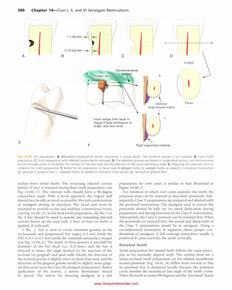
Fig 14-60 Slot preparation. A, Mesiodistal longitudinal section illustrating a carious lesion. T he proximal contact is not involved. B, Initial tooth
preparation. C, Tooth preparation with infected carious dentin removed. D, The retention grooves are shown in longitudinal section, and the transverse
section through plane cd illustrates the contour of the axial wall and the direction of the facial and lingual walls. E, Preparing the retention form to
complete the tooth preparation. F, Matrix for slot preparation: a, facial view of wedged matrix; b, wedged matrix as viewed in transverse cross-section
(x), gingival to gingival floor; c, wedged matrix as viewed in transverse cross-section (y), occlusal to gingival floor.
outline form initial depth. The remammg infected carious dentin (if any) is removed during final tooth preparation (see Fig. 14-60, C). The external walls should form a 90-degree cavosurface angle. With a facial approach, the lingual wall should face facially as much as possible; this aids condensation of amalgam during its insertion. The facial wall must be extended to provide access and visibility (convenience form) (see Fig. 14-60, D). In the final tooth preparation, the No.2 or No. 4 bur should be used to remove any remaining infected carious dentin on the axial wall. A liner or base (or both) is applied, if indicated.
A No. ;:; bur is used to create retention grooves in the occlusoaxial and gingivoaxial line angles, 0.2 mm inside the DE) or 0.3 to 0.5 mm inside the cementa! cavosurface margin (see Fig. 14-60, £).The depth of these grooves is one-half the diameter of the bur head (i.e., 0.25 mm), and the bur is directed to bisect the angle formed by the junction of the occlusal (or gingival) and axial walls. Ideally, the direction of the occlusal groove is slightly more occlusal than axial, and the direction of the gingival groove would be slightly more gingival than axial (as in the Class lll amalgam preparation). Before application of the matrix, a dentin desensitizer should be placed. The matrix for inserting amalgam in a slot
preparation for root canes is similar to that illustrated in Figure 14-60, F.
For instances in which root caries encircles the tooth, the proximal areas can be restored as described previously. Subsequently, Class V preparations are prepared and abutted with the proximal restorations. The amalgam used to restore the proximals should be fully set (to avoid dislocation during preparation and during insertion of the Class V restorations). Alternatively, the Class V portions can be restored first. When the proximals are restored first, the mesial and distal walls of the Class V preparations would be in amalgam. Doing a circumferential restoration in segments allows proper condensation of amalgam. A full-coverage restoration usually is preferred if caries encircles the tooth cervically.
Rotated Teeth
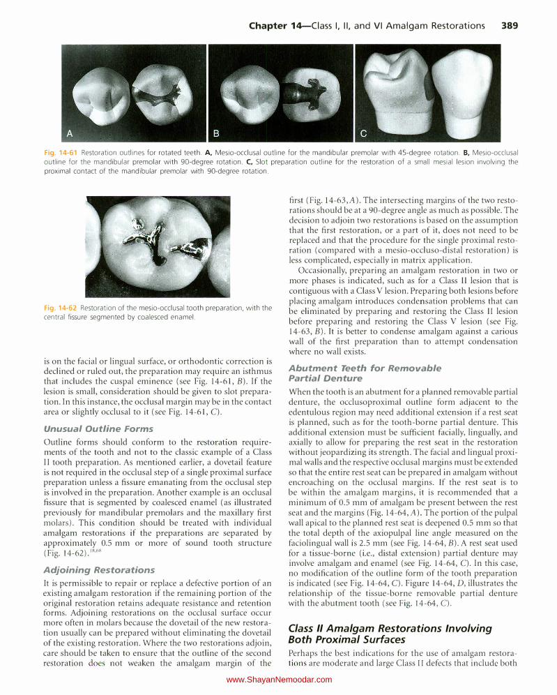
Tooth preparation for rotated teeth follows the same principles as for normally aligned teeth. The outline form for a mesio-occlusal tooth preparation on the rotated mandibular second premolar (Fig. 14-61, A) differs from normal in that its proximal box is displaced facially because the proximal caries involves the mesiofacial line angle of the tooth crown. When the tooth is rotated 90 degrees and the "proximal" lesion
www.ShayanNemoodar.com
Chapter 14-Ciass I, II, and VI Amalgam Restorations 389
Fig. 14-61 Restoration outlines for rotated teeth. A, Mesio-occlusal outline for the mandibular premolar with 45-degree rotation. B, Mesio-occlusal outline for the mandibular premolar with 90-degree rotation. C, Slot preparation outline for the restoration of a small mesial lesion involving the proximal contact of the mandibular premolar with 90-degree rotation.
Fig. 14-62 Restoration of the mesio-occlusal tooth preparation, with the central fissure segmented by coalesced enamel.
is on the facial or lingual surface, or orthodontic correction is declined or ruled out, the preparation may require an isthmus that includes the cuspal eminence (see Fig. 14-61, B). If the lesion is small, consideration should be given to slot preparation. In this instance, the occlusal margin may be in the contact area or slightly occlusal to it (see Fig. 14-61, C).
Unusual Outline Forms
Outline forms should conform to the restoration requirements of the tooth and not to the classic example of a Class II tooth preparation. As mentioned earlier, a dovetail feature is not required in the occlusal step of a single proximal surface preparation unless a fissure emanating from the occlusal step is involved in the preparation. Another example is an occlusal fissure that is segmented by coalesced enamel (as illustrated previously for mandibular premolars and the maxillary first molars). This condition should be treated with individual amalgam restorations if the preparations are separated by approximately 0.5 mm or more of sound tooth structure (Fig. 14-62).18'68
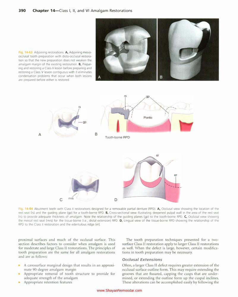
Adjoining Restorations
It is permissible to repair or replace a defective portion of an existing amalgam restoration if the remaining portion of the original restoration retains adequate resistance and retention forms. Adjoining restorations on the occlusal surface occur more often in molars because the dovetail of the new restoration usually can be prepared without eliminating the dovetail of the existing restoration. Where the two restorations adjoin, care should be taken to ensure that the outline of the second restoration does not weaken the amalgam margin of the
first (Fig. 14-63,A). The intersecting margins of the two restorations should be at a 90-degree angle as much as possible. The decision to adjoin two restorations is based on the assumption that the first restoration, or a part of it, does not need to be replaced and that the procedure for the single proximal restoration (compared with a mesio-occluso-distal restoration) is less complicated, especially in matrix application.
Occasionally, preparing an amalgam restoration in two or more phases is indicated, such as for a Class II lesion that is contiguous with a Class V lesion. Preparing both lesions before placing amalgam introduces condensation problems that can be eliminated by preparing and restoring the Class II lesion before preparing and restoring the Class V lesion (see Fig. 14-63, B). It is better to condense amalgam against a carious wall of the first preparation than to attempt condensation where no wall exists.
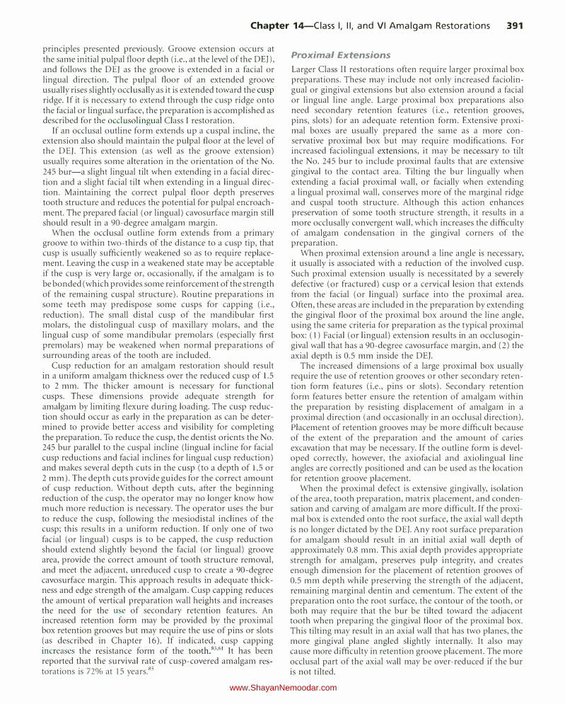
Abutment Teeth for Removable Partial Denture
When the tooth is an abutment for a planned removable partial denture, the occlusoproxima1 outline form adjacent to the edentulous region may need additional extension if a rest seat is planned, such as for the tooth-borne partial denture. This additional extension must be sufficient facially, lingually, and axially to allow for preparing the rest seat in the restoration without jeopardizing its strength. The facial and lingual proximal walls and the respective occlusal margins must be extended so that the entire rest seat can be prepared in amalgam without encroaching on the occlusal margins. If the rest seat is to be within the amalgam margins, it is recommended that a minimum of 0.5 mm of amalgam be present between the rest seat and the margins (Fig. 14-64, A). The portion of the pulpal wall apical to the planned rest seat is deepened 0.5 mm so that the total depth of the axiopulpal line angle measured on the faciolingual wall is 2.5 mm (see Fig. 14-64, B). A rest seat used for a tissue-borne (i.e., distal extension) partial denture may involve amalgam and enamel (see Fig. 14-64, C). In this case, no modification of the outline form of the tooth preparation is indicated (see Fig. 14-64, C). Figure 14-64, D, illustrates the relationship of the tissue-borne removable partial denture with the abutment tooth (see Fig. I 4-64, C).
Class II Amalgam Restorations Involving Both Proximal Surfaces Perhaps the best indications for the use of amalgam restorations are moderate and large Class II defects that include both
www.ShayanNemoodar.com
390 Chapter 14-Ciass I, II, and VI Amalgam Restorations
g 4-63 Adjoining restorations. A, Adjoining mesio
occlusal tooth preparation with disto-occlusal restoration so that the new preparation does not weaken the
amalgam margin of the existing restoration. B, Preparing and restoring a Class II lesion before preparing and restoring a Class V lesion contiguous with it eliminates condensation problems that occur when both lesions are prepared before either is restored.
rs
A
rs
B Tooth-borne RPD
c mrs D
Fa 14- Abutment teeth with Class II restorations designed for a removable partial denture (RPD). A, Occlusal view showing the location of the rest seat (rs) and the guiding plane (gp) for a tooth-borne RPD. B, Cross-sectional view illustrating deepened pulpal wall in the area of the rest seat
(rs) to provide adequate thickness of amalgam. Note the relationship of the guiding planes (gp) to the tooth-borne RPD. C, Occlusal view showing the mesial rest seat (mrs) for the tissue-borne (i.e., distal extension) RPD. D, Lingual view of the tissue-borne RPD showing the relationship of the RPD to the Class II restoration and the edentulous ridge (er).
proximal surfaces and much of the occlusal surface. This section describes factors to consider when amalgam is u ed for moderate and large Class II restorations. The principles of tooth preparation are the same for all amalgam restorations and are as follows:
A cavosurface marginal design that results in an approximate 90-degree amalgam margin Appropriate removal of tooth structure to provide for adequate strength of the amalgam
• Appropriate retention features
The tooth preparation techniques presented for a twosurface Class II restoration apply to larger Class II restorations as well. When the defect is large, however, certain modifications in tooth preparation may be necessary.
Occlusal Extensions
Often, a larger Class II defect requires greater extension of the occlusal surface outline form. This may require extending the grooves that are fissured, capping the cusps that are undermined, or extending the outline form up the cuspal inclines. These alterations can be accomplished easily by following the
www.ShayanNemoodar.com
Chapter 14-Ciass I, II, and VI Amalgam Restorations 391
principles presented previously. Groove extension occurs at the same initial pulpal floor depth (i.e., at the level of the DEJ), and follows the DEJ as the groove is extended in a facial or lingual direction. The pulpal floor of an extended groove usually rises slightly occlusally as it is extended toward the cusp ridge. If it is necessary to extend through the cusp ridge onto the facial or lingual surface, the preparation is accomplished as described for the occlusolingual Class I restoration.
If an occlusal outline form extends up a cuspal incline, the extension also should maintain the pulpal floor at the level of the DEJ. This extension (as well as the groove extension) usually requires some alteration in the orientation of the No. 245 bur-a slight lingual tilt when extending in a facial direction and a slight facial tilt when extending in a lingual direction. Maintaining the correct pulpal floor depth preserves tooth structure and reduces the potential for pulpal encroachment. The prepared facial (or lingual) cavosurface margin still should result in a 90-degree amalgam margin.
When the occlusal outline form extends from a primary groove to within two-thirds of the distance to a cusp tip, that cusp is usually sufficiently weakened so as to require replacement. Leaving the cusp in a weakened state may be acceptable if the cusp is very large or, occasionally, if the amalgam is to be bonded (which provides some reinforcement of the strength of the remaining cuspal structure). Routine preparations in some teeth may predispose some cusps for capping (i.e., reduction). The small distal cusp of the mandibular first molars, the distolingual cusp of maxillary molars, and the lingual cusp of some mandibular premolars (especially first premolars) may be weakened when normal preparations of surrounding areas of the tooth are included.
Cusp reduction for an amalgam restoration should result in a uniform amalgam thickness over the reduced cusp of 1.5 to 2 mm. The thicker amount is necessary for functional cusps. These dimensions provide adequate strength for amalgam by limiting flexure during loading. The cusp reduction should occur as early in the preparation as can be determined to provide better access and visibility for completing the preparation. To reduce the cusp, the dentist orients the No. 245 bur parallel to the cuspal incline (lingual incline for facial cusp reductions and facial inclines for lingual cusp reduction) and makes several depth cuts in the cusp (to a depth of 1.5 or 2 mm). The depth cuts provide guides for the correct amount of cusp reduction. Without depth cuts, after the beginning reduction of the cusp, the operator may no longer know how much more reduction is necessary. The operator uses the bur to reduce the cusp, following the mesiodistal inclines of the cusp; this results in a uniform reduction. If only one of two facial (or lingual) cusps is to be capped, the cusp reduction should extend slightly beyond the facial (or lingual) groove area, provide the correct amount of tooth structure removal, and meet the adjacent, unreduced cusp to create a 90-degree cavosurface margin. This approach results in adequate thickness and edge strength of the amalgam. Cusp capping reduces the amount of vertical preparation wall heights and increases the need for the use of secondary retention features. An increased retention form may be provided by the proximal box retention grooves but may require the use of pins or slots (as described in Chapter 16). If indicated, cusp capping increases the resistance form of the tooth.83 '84 It has been reported that the survival rate of cusp-covered amalgam restorations is 72o/o at 15 years.85
Proximal Extensions
Larger Class II restorations often require larger proximal box preparations. These may include not only increased faciolingual or gingival extensions but also extension around a facial or lingual line angle. Large proximal box preparations also need secondary retention features (i.e., retention grooves, pins, slots) for an adequate retention form. Extensive proximal boxes are usually prepared the same as a more conservative proximal box but may require modifications. For increased faciolingual extensions, it may be necessary to tilt the No. 245 bur to include proximal faults that are extensive gingival to the contact area. Tilting the bur lingually when extending a facial proximal wall, or facially when extending a lingual proximal wall, conserves more of the marginal ridge and cuspal tooth structure. Although this action enhances preservation of some tooth structure strength, it results in a more occlusally convergent wall, which increases the difficulty of amalgam condensation in the gingival corners of the preparation.
When proxjmal extension around a line angle is necessary, it usually is associated with a reduction of the involved cusp. Such proximal extension usually is necessitated by a severely defective (or fractured) cusp or a cervical lesion that extends from the facial (or lingual) surface into the proximal area. Often, these areas are included in the preparation by extending the gingival floor of the proximal box around the line angle, using the same criteria for preparation as the typical proximal box: (1) Facial (or lingual) extension results in an occlusogingival wall that has a 90-degree cavosurface margin, and (2) the axial depth is 0.5 mm inside the DEJ.
The increased dimensions of a large proximal box usually require the use of retention grooves or other secondary retention form features (i.e., pins or slots). Secondary retention form features better ensure the retention of amalgam within the preparation by resisting displacement of amalgam in a proximal direction (and occasionally in an occlusal direction). Placement of retention grooves may be more difficult because of the extent of the preparation and the amount of caries excavation that may be necessary. If the outline form is developed correctly, however, the axiofacial and axiolingual line angles are correctly positioned and can be used as the location for retention groove placement.
When the proximal defect is extensive gingivally, isolation of the area, tooth preparation, matrix placement, and condensation and carving of amalgam are more difficult. If the proximal box is extended onto the root surface, the axial wall depth is no longer dictated by the DEJ. Any root surface preparation for amalgam should result in an initial axial wall depth of approximately 0.8 mm. This axial depth provides appropriate strength for amalgam, preserves pulp integrity, and creates enough dimension for the placement of retention grooves of 0.5 mm depth while preserving the strength of the adjacent, remaining marginal dentin and cementum. The extent of the preparation onto the root surface, the contour of the tooth, or both may require that the bur be tilted toward the adjacent tooth when preparing the gingival floor of the proximal box. This tilting may result in an axial wall that has two planes, the more gingival plane angled slightly internally. It also may cause more difficulty in retention groove placement. The more occlusal part of the axial wall may be over-reduced if the bur is not tilted.
www.ShayanNemoodar.com
392 Chapter 14-Ciass I, II, and VI Amalgam Restorations
4 6. Mesio-occluso-distal preparation on the mandibular second
premolar.
Caries Excavation and Pulp Protection
Larger Class II restorations often require more extensive caries excavation and pulp protection procedures during tooth preparation. Deep excavations indicate the increased need for pulp protection with a liner, a base, or both.
Matrix Placement
When a tooth preparation is extensive, matrix placement is more difficult. This is especially true for preparations that extend onto the root surface. Use of modified matrix bands and wedging techniques may be required. Different types of matrix systems are presented in Chapter 16.
Condensation and Carving of the Amalgam
Larger Class II preparations that extend around line angles or cap cusps or onto the root surface require careful amalgam condensation and carving techniques. Condensation of amalgam is more difficult in areas where cusps have been capped, where slots or pins have been placed, where vertical walls are more convergent occlusally, and where the root surface is involved. For larger restorations, lateral condensation is important to produce a properly condensed restoration in the gingival corners; also, carving cusps and gingival areas is more difficult.
EXAMPLES OF MODERATE CLASS II AMALGAM TOOTH PREPARATIONS THAT IN VOLVE BOTH PROXIMAL SURFACES
Mandibular Second Premolar
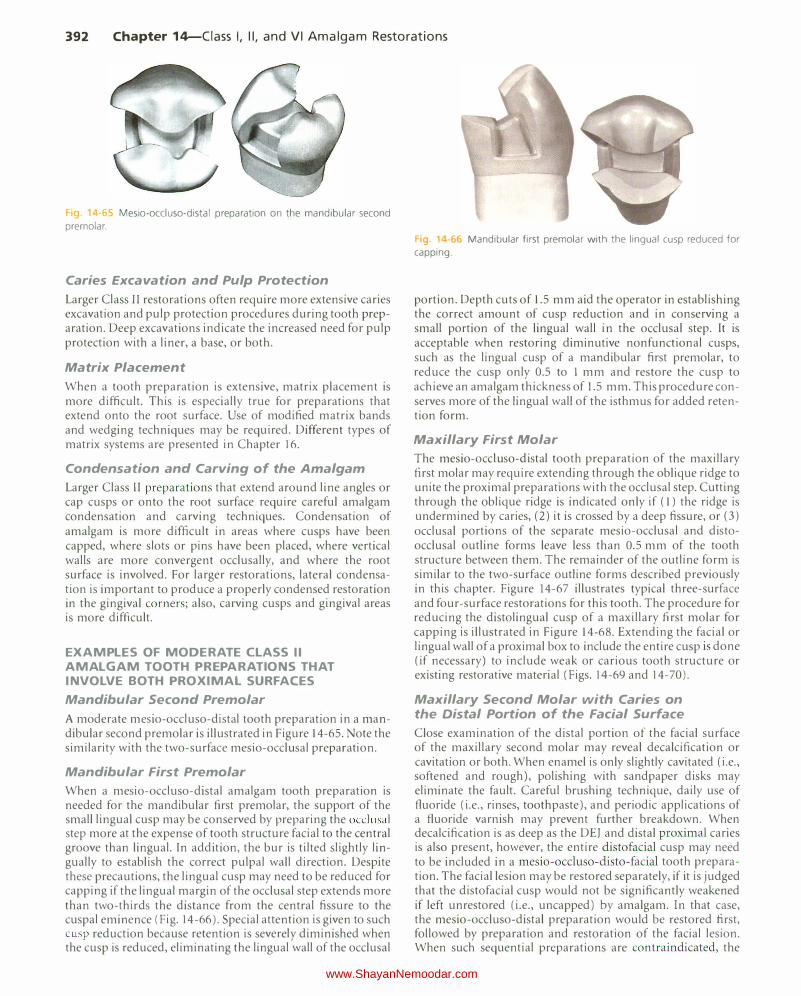
A moderate mesio-occluso-distal tooth preparation in a mandibular second premolar is illustrated in Figure 14-65. Note the similarity with the two-surface mesio-occlusal preparation.
Mandibular First Premolar
When a mesio-occluso-distal amalgam tooth preparation is needed for the mandibular first premolar, the support of the small lingual cusp may be conserved by preparing the occlusal step more at the expense of tooth structure facial to the central groove than lingual. In addition, the bur is tilted slightly lingually to establish the correct pulpal wall direction. Despite these precautions, the lingual cusp may need to be reduced for capping if the lingual margin of the occlusal step extends more than two-thirds the distance from the central fissure to the cuspal eminence (Fig. 14-66). Special attention is given to such cusp reduction because retention is severely diminished when the cusp is reduced, eliminating the lingual wall of the occlusal
g 1 ·66 Mandibular first premolar with the lingual cusp reduced for
capping.
portion. Depth cuts of 1.5 mm aid the operator in establishing the correct amount of cusp reduction and in conserving a small portion of the lingual wall in the occlusal step. It is acceptable when restoring diminutive nonfunctional cusps, such as the lingual cusp of a mandibular first premolar, to reduce the cusp only 0.5 to 1 mm and restore the cusp to achieve an amalgam thickness of 1.5 mm. This procedure conserves more of the lingual wall of the isthmus for added retention form.
Maxillary First Molar
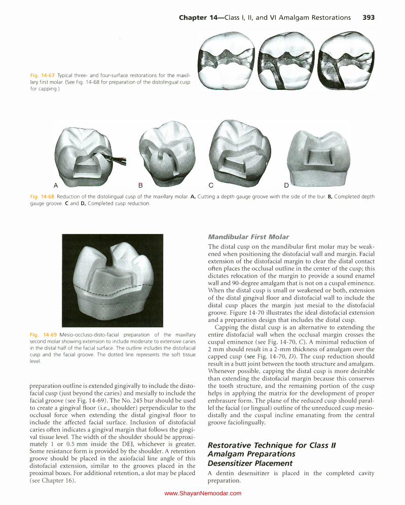
The mesio-occluso-distal tooth preparation of the maxillary first molar may require extending through the oblique ridge to unite the proximal preparations with the occlusal step. Cutting through the oblique ridge is indicated only if ( 1) the ridge is undermined by caries, (2) it is crossed by a deep fissure, or (3) occlusal portions of the separate mesio-occlusal and distoocclusal outline forms leave less than 0.5 mm of the tooth structure between them. The remainder of the outline form is similar to the two-surface outline forms described previously in this chapter. Figure 14-67 illustrates typical three-surface and four-surface restorations for this tooth. The procedure for reducing the distolingual cusp of a maxillary first molar for capping is illustrated in Figure 14-68. Extending the facial or lingual wall of a proximal box to include the entire cusp is done (if necessary) to include weak or carious tooth structure or existing restorative material (Figs. 14-69 and 14-70).
Maxillary Second Molar with Caries on the Distal Portion of the Facial Surface
Close examination of the distal portion of the facial surface of the maxillary second molar may reveal decalcification or cavitation or both. When enamel is only slightly cavitated (i.e., softened and rough), polishing with sandpaper disks may eliminate the fault. Careful brushing technique, daily use of fluoride (i.e., rinses, toothpaste), and periodic applications of a fluoride varnish may prevent further breakdown. When decalcification is as deep as the DEJ and distal proximal caries is also present, however, the entire distofacial cusp may need to be included in a mesio-occluso-disto-facial tooth preparation. The facial lesion may be restored separately, if it is judged that the distofacial cusp would not be significantly weakened if left unrestored (i.e., uncapped) by amalgam. In that case, the mesio-occluso-distal preparation would be restored first, foLlowed by preparation and restoration of the facial lesion. When such sequential preparations are contraindicated, the
www.ShayanNemoodar.com
Chapter 14-Ciass I, II, and VI Amalgam Restorations 393
ig 14-67 Typical three- and four-surface restorations for the maxillary first molar. (See Fig. 14-68 for preparation of the distolingual cusp for capping.)
Fig 14-68 Reduction of the distolingual cusp of the maxillary molar. A, Cutting a depth gauge groove with the side of the bur. B, Completed depth
gauge groove. C and D, Completed cusp reduction.
Fig. 14-69 Mesio-occluso-disto-facial preparation of the maxillary second molar showing extension to include moderate to extensive caries in the distal half of the facial surface. The outline includes the distofacial cusp and the facial groove. T he dotted line represents the soft tissue level.
preparation outline is extended gingivally to include the distofacial cusp (just beyond the caries) and mesially to include the facial groove (see Fig. 14-69). The No. 245 bur should be used to create a gingival floor (i.e., shoulder) perpendicular to the occlusal force when extending the distal gingival floor to include the affected facial surface. Inclusion of distofacial caries often indicates a gingival margin that follows the gingival tissue level. The width of the shoulder should be approximately 1 or 0.5 mm inside the DEJ, whichever is greater. Some resistance form is provided by the shoulder. A retention groove should be placed in the axiofaciaJ line angle of this distofacial extension, similar to the grooves placed in the proximal boxes. For additional retention, a slot may be placed (see Chapter 16).
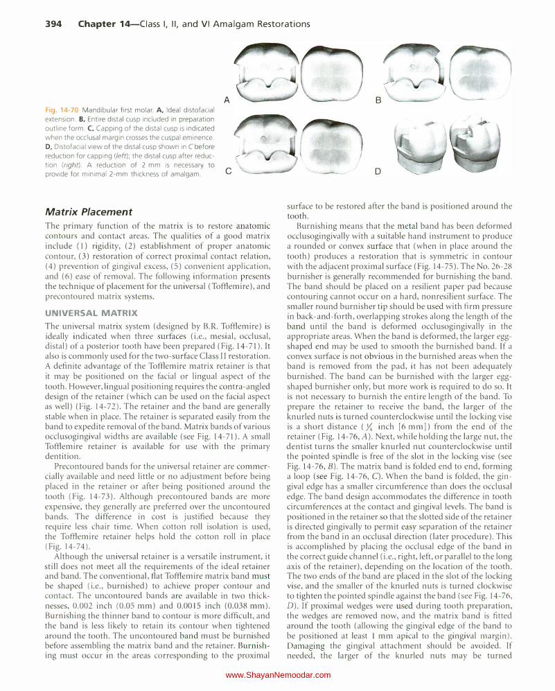
Mandibular First Molar The distal cusp on the mandibular first molar may be weakened when positioning the distofacial wall and margin. Facial extension of the distofacial margin to clear the distal contact often places the occlusal outline in the center of the cusp; this dictates relocation of the margin to provide a sound enamel wall and 90-degree amalgam that is not on a cuspaJ eminence. When the distal cusp is small or weakened or both, extension of the distal gingival floor and distofacial wall to include the distal cusp places the margin just mesial to the distofacial groove. Figure 14-70 illustrates the ideal distofacial extension and a preparation design that includes the distal cusp.
Capping the distal cusp is an alternative to extending the entire distofacial wall when the occlusal margin crosses the cuspal eminence (see Fig. 14-70, C). A minimal reduction of 2 mm should result in a 2-mm thickness of amalgam over the capped cusp (see Fig. 14-70, D). The cusp reduction should result in a butt joint between the tooth structure and amalgam. Whenever possible, capping the distal cusp is more desirable than extending the distofacial margin because this conserves the tooth structure, and the remaining portion of the cusp helps in applying the matrix for the development of proper embrasure form. The plane of the reduced cusp should parallel the facial (or lingual) outline of the unreduced cusp mesiodistally and the cuspal incline emanating from the central groove faciolingually.
Restorative Technique for Class II Amalgam Preparations Desensitizer Placement A dentin desensitizer is placed in the completed cavity preparation.
www.ShayanNemoodar.com
394 Chapter 14-Ciass I, II, and VI Amalgam Restorations
Fig. 14 70 Mandibular first molar. A, Ideal distofacial
extension. B. Entire distal cusp included in preparation
outline form. C, Capping of the distal cusp is indicated
when the occlusal margin crosses the cuspal eminence.
D, Distofacial view of the distal cusp shown in C before
reduction for capping (left); the distal cusp after reduc
tion (right). A reduction of 2 mm is necessary to
provide for minimal 2-mm thickness of amalgam.
Matrix Placement
A
c
The primary function of the matrix is to restore anatomic contours and contact areas. The qualities of a good matrix include (I) rigidity, (2) establishment of proper anatomic contour, (3) restoration of correct proximal contact relation, (4) prevention of gingival excess, (5) convenient application, and (6) ease of removal. The following information presents the technique of placement for the universal (Tofflemire), and precontoured matrix systems.
UNIVERSAL MATRIX
The universal matrix system (designed by B.R. Tofflemire) is ideally indicated when three surfaces (i.e., mesial, occlusal, distal) of a posterior tooth have been prepared (Fig. 14-71). It also is commonly used for the two-surface Class II restoration. A definite advantage of the Tofflemire matrix retainer is that it may be positioned on the facial or lingual aspect of the tooth. However, lingual positioning requires the contra-angled design of the retainer (which can be used on the facial aspect as well) (Fig. 14-72). The retainer and the band are generally stable when in place. The retainer is separated easily from the band to expedite removal of the band. Matrix bands of various occlusogingival widths are available (see Fig. 14-71). A small Tofflemire retainer is available for use with the primary dentition.
Precontoured bands for the universal retainer are commercially available and need little or no adjustment before being placed in the retainer or after being positioned around the tooth (Fig. 14-73 ). Although precontoured bands are more expensive, they generally are preferred over the uncontoured bands. The difference in cost is justified because they require less chair time. When cotton roll isolation is used, the Tofflemire retainer helps hold the cotton roll in place (Fig. 14-74).
Although the universal retainer is a versatile instrument, it still does not meet all the requirements of the ideal retainer and band. The conventional, flat Tofflemire matrix band must be shaped (i.e., burnished) to achieve proper contour and contact. The uncontoured bands are available in two thicknesses, 0.002 inch (0.05 mm) and 0.0015 inch (0.038 mm). Burnishing the thinner band to contour is more difficult, and the band is less likely to retain its contour when tightened around the tooth. The uncontoured band must be burnished before assembling the matrix band and the retainer. Burnishing must occur in the areas corresponding to the proximal
B
D
surface to be restored after the band is positioned around the tooth.
Burnishing means that the metal band has been deformed occlusogingivally with a suitable hand instrument to produce a rounded or convex surface that (when in place around the tooth) produces a restoration that is symmetric in contour with the adjacent proximal surface (Fig. 14-75). The No. 26-28 burnisher is generally recommended for burnishing the band. The band should be placed on a resilient paper pad because contouring cannot occur on a hard, nonresilient surface. The smaller round burnisher tip should be used with firm pressure in back-and-forth, overlapping strokes along the length of the band until the band is deformed occlusogingivally in the appropriate areas. When the band is deformed, the larger eggshaped end may be used to smooth the burnished band. If a convex surface is not obvious in the burnished areas when the band is removed from the pad, it has not been adequately burnished. The band can be burnished with the larger eggshaped burnisher only, but more work is required to do so. It is not necessary to burnish the entire length of the band. To prepare the retainer to receive the band, the larger of the knurled nuts is turned counterclockwise until the locking vise is a short distance ( y,; inch [6 mm]) from the end of the retainer (Fig. 14-76, A). Next, while holding the large nut, the dentist turns the smaller knurled nut counterclockwise until the pointed spindle is free of the slot in the locking vise (see Fig. 14-76, B). The matrix band is folded end to end, forming a loop (see Fig. 14-76, C). When the band is folded, the gingival edge has a smaller circumference than does the occlusal edge. The band design accommodates the difference in tooth circumferences at the contact and gingival levels. The band is positioned in the retainer so that the slotted side of the retainer is directed gingivally to permit easy separation of the retainer from the band in an occlusal direction (later procedure). This is accomplished by placing the occlusal edge of the band in the correct guide channel (i.e., right, left, or parallel to the long axis of the retainer), depending on the location of the tooth. The two ends of the band are placed in the slot of the locking vise, and the smaller of the knurled nuts is turned clockwise to tighten the pointed spindle against the band (see Fig. 14-76, D). If proximal wedges were used during tooth preparation, the wedges are removed now, and the matrix band is fitted around the tooth (allowing the gingival edge of the band to be positioned at least l mm apical to the gingival margin). Damaging the gingival attachment should be avoided. If needed, the larger of the knurled nuts may be turned
www.ShayanNemoodar.com

Chapter 14-Ciass I, II, and VI Amalgam Restorations 395
Fig. 14-71 Straight and contra-angled Universal (Tofflemire) retainers. Bands with varying occlusogingival measurements are available.
Fg. 14-72 Lingual positioning requires a contra-angled Universal
retainer. Fig 14-73 Precontoured bands for a Universal retainer. Pictured: Water
pik Getz Contour Matrix Bands (Courtesy of Water Pik Inc.. Fort Collins, CO)
www.ShayanNemoodar.com
396 Chapter 14-Ciass I, II, and VI Amalgam Restorations
counterclockwise to obtain a larger loop to fit around the tooth. Care should be taken not to trap the rubber dam between the band and the gingival margin. If the dam material is trapped between the band and the tooth, the septum of the dam should be stretched and depressed gingivally to reposition the dam material. Nexl, the larger knurled nut is rotated clockwise to tighten the band slightly. Exploration along the
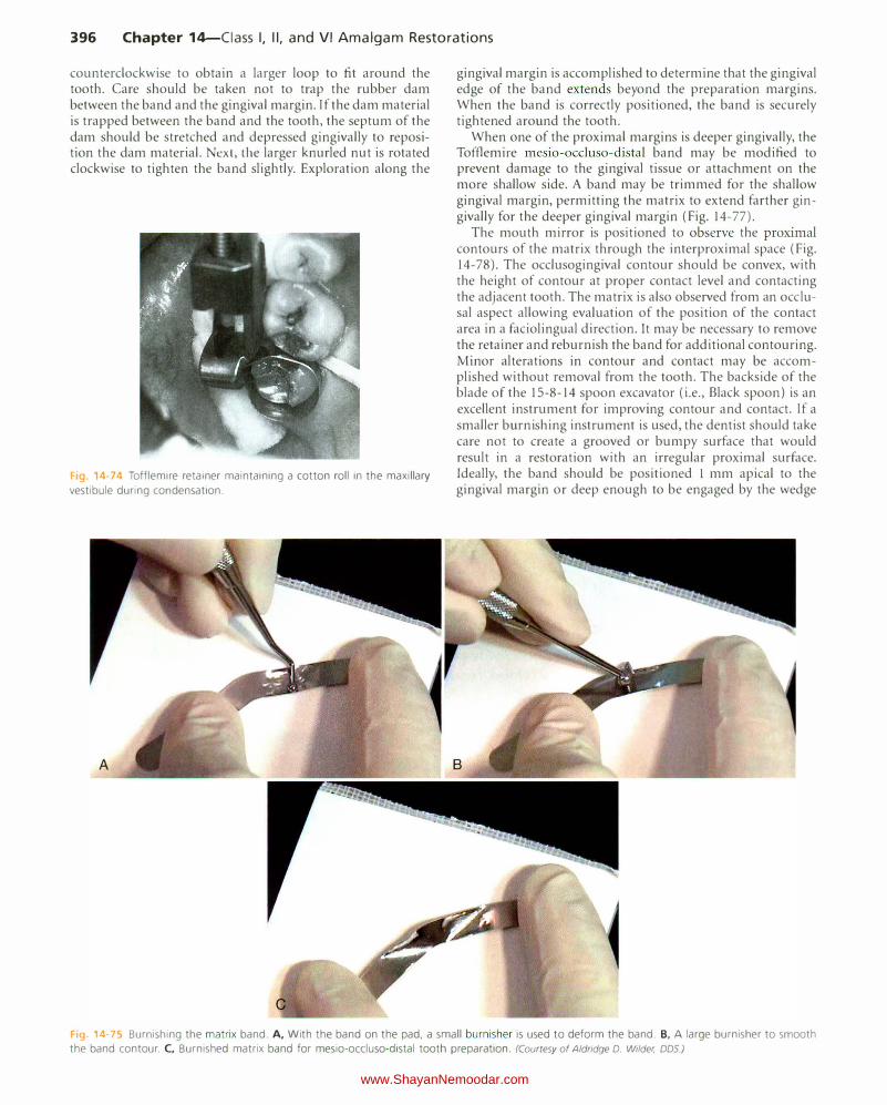
Fig. 14-74 Tofflemire retainer maintaining a cotton roll in the maxillary
vestibule during condensation.
gingival margin is accomplished to determine that the gingival edge of the band extends beyond the preparation margins. When the band is correctly positioned, the band is securely tightened around the tooth.
When one of the proximal margins is deeper gingivally, the Tofflemire mesio-occluso-distal band may be modified to prevent damage to the gingival tissue or attachment on the more shallow side. A band may be trimmed for the shallow gingival margin, permitting the matrix to extend farther gingivally for the deeper gingival margin (Fig. 14-77).
The mouth mirror is positioned to observe the proximal contours of the matrix through the interproximal space (Fig. 14-78). The occlusogingival contour should be convex, with the height of contour at proper contact level and contacting the adjacent tooth. The matrix is also observed from an occlusal aspect allowing evaluation of the position of the contact area in a faciolingual direction. It may be necessary to remove the retainer and reburnish the band for additional contouring. Minor alterations in contour and contact may be accomplished without removal from the tooth. The backside of the blade of the 15-8-14 spoon excavator (i.e., Black spoon) is an excellent instrument for improving contour and contact. If a smaller burnishing instrument is used, the dentist should take care not to create a grooved or bumpy surface that would result in a restoration with an irregular proximal surface. Ideally, the band should be positioned l mm apical to the gingival margin or deep enough to be engaged by the wedge
Fig 14 75 Burnishing the matrix band. A, With the band on the pad, a small burnisher is used to deform the band. B, A large burnisher to smooth
the band contour. C, Burnished matrix band for mesio-occluso-distal tooth preparation. (Courtesy of Aldridge D. Wilder, DDS.)
www.ShayanNemoodar.com
Chapter 14-Ciass I, II, and VI Amalgam Restorations 397
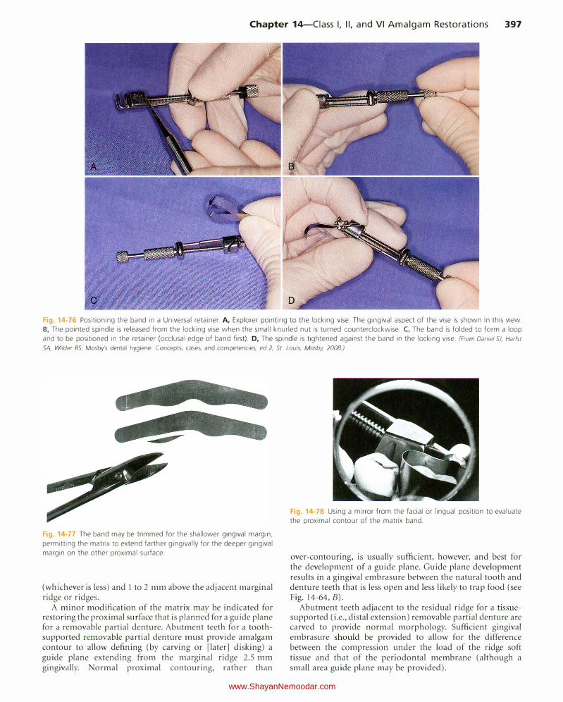
Fig. 14-76 Positioning the band in a Universal retainer. A, Explorer pointing to the locking vise. The gingival aspect of the vise is shown in this view.
B, The pointed spindle is released from the locking vise when the small knurled nut is turned counterclockwise. C, The band is folded to form a loop
and to be positioned in the retainer (occlusal edge of band first). D, The spindle is tightened against the band in the locking vise. (From Daniel SJ, Harfst SA, Wilder RS: Mosby's dental hygiene: Concepts, cases, and competencies, ed 2, St. Louis, Mosby, 2008.)
Fig. 14-77 The band may be trimmed for the shallower gingival margin,
permitting the matrix to extend farther gingivally for the deeper gingival
margin on the other proximal surface.
(whichever is less) and l to 2 mm above the adjacent marginal ridge or ridges.
A minor modification of the matrix may be indicated for restoring the proximal surface that is planned for a guide plane for a removable partial denture. Abutment teeth for a toothsupported removable partial denture must provide amalgam contour to allow defining (by carving or [later] disking) a guide plane extending from the marginal ridge 2.5 mm gingivally. Normal proximal contouring, rather than
Fig. 14-78 Using a mirror from the facial or lingual position to evaluate
the proximal contour of the matrix band.
over-contouring, is usually sufficient, however, and best for the development of a guide plane. Guide plane development results in a gingival embrasure between the natural tooth and denture teeth that is less open and less likely to trap food (see Fig. 14-64, B).
Abutment teeth adjacent to the residual ridge for a tissuesupported (i.e., distal extension) removable partial denture are carved to provide normal morphology. Sufficient gingival embrasure should be provided to allow for the difference between the compression under the load of the ridge soft tissue and that of the periodontal membrane (although a small area guide plane may be provided).
www.ShayanNemoodar.com
398 Chapter 14-Ciass I, II, and VI Amalgam Restorations
l
A B
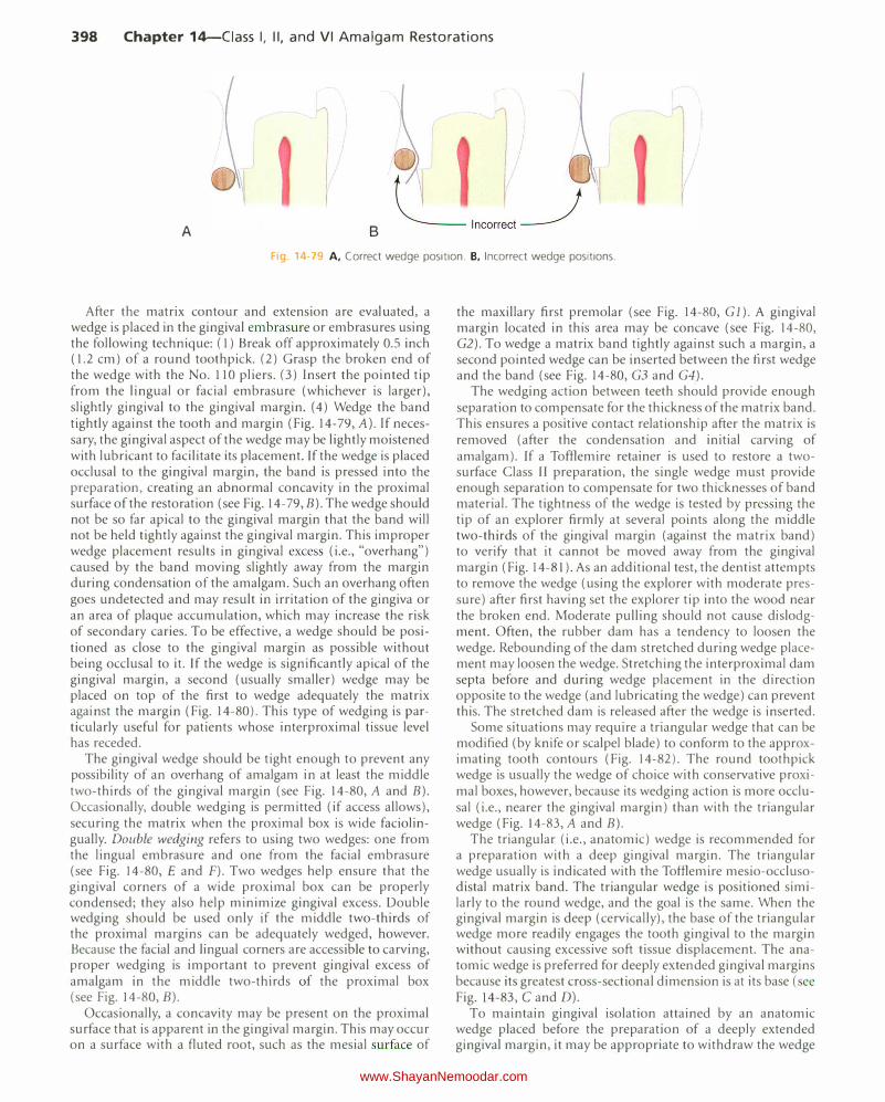
Fig. 14· 9 A, Correct wedge position. B, Incorrect wedge positions.
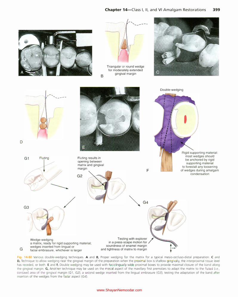
After the matrix contour and extension are evaluated, a wedge is placed in the gingival embrasure or embrasures using the following technique: (1) Break off approximately 0.5 inch ( 1.2 em) of a round toothpick. (2) Grasp the broken end of the wedge with the No. 110 pliers. (3) Insert the pointed tip from the lingual or facial embrasure (whichever is larger), slightly gingival to the gingival margin. (4) Wedge the band tightly against the tooth and margin (Fig. 14-79, A). If necessary, the gingival aspect of the wedge may be lightly moistened with lubricant to facilitate its placement. If the wedge is placed occlusal to the gingival margin, the band is pressed into the preparation, creating an abnormal concavity in the proximal surface of the restoration (see Fig. 14-79, B). The wedge should not be so far apical to the gingival margin that the band will not be held tightly against the gingival margin. This improper wedge placement results in gingival excess (i.e., "overhang") caused by the band moving slightly away from the margin during condensation of the amalgam. Such an overhang often goes undetected and may result in irritation of the gingiva or an area of plaque accumulation, which may increase the risk of secondary caries. To be effective, a wedge should be positioned as close to the gingival margin as possible without being occlusal to it. If the wedge is significantly apical of the gingival margin, a second (usually smaller) wedge may be placed on top of the first to wedge adequately the matrix against the margin (Fig. 14-80). This type of wedging is particularly useful for patients whose interproximal tissue level has receded.
The gingival wedge should be tight enough to prevent any possibility of an overhang of amalgam in at least the middle two-thirds of the gingival margin (see Fig. 14-80, A and B). Occasionally, double wedging is permitted (if access allows), securing the matrix when the proximal box is wide faciolingually. Double wedging refers to using two wedges: one from the lingual embrasure and one from the facial embrasure (see Fig. 14-80, E and F). Two wedges help ensure that the gingival corners of a wide proximal box can be properly condensed; they also help minimize gingival excess. Double wedging should be used only if the middle two-thirds of the proximal margins can be adequately wedged, however. Because the facial and lingual corners are accessible to carving, proper wedging is important to prevent gingival excess of amalgam in the middle two-thirds of the proximal box (see Fig. 14-80, B).
Occasionally, a concavity may be present on the proximal surface that is apparent in the gingival margin. This may occur on a surface with a fluted root, such as the mesial surface of
the maxillary first premolar (see Fig. 14-80, Gl). A gingival margin located in this area may be concave (see Fig. 14-80, G2). To wedge a matrix band tightly against such a margin, a second pointed wedge can be inserted between the first wedge and the band (see Fig. 14-80, G3 and G4).
The wedging action between teeth should provide enough separation to compensate for the thickness of the matrix band. This ensures a positive contact relationship after the matrix is removed (after the condensation and initial carving of amalgam). If a Tofflemire retainer is used to restore a twosurface Class II preparation, the single wedge must provide enough separation to compensate for two thicknesses of band material. The tightness of the wedge is tested by pressing the tip of an explorer firmly at several points along the middle two-thirds of the gingival margin (against the matrix band) to verify that it cannot be moved away from the gingival margin (Fig. 14-81). As an additional test, the dentist attempts to remove the wedge (using the explorer with moderate pressure) after first having set the explorer tip into the wood near the broken end. Moderate pulling should not cause dislodgment. Often, the rubber dam has a tendency to loosen the wedge. Rebounding of the dam stretched during wedge placement may loosen the wedge. Stretching the interproximal dam septa before and during wedge placement in the direction opposite to the wedge (and lubricating the wedge) can prevent this. The stretched dam is released after the wedge is inserted.
Some situations may require a triangular wedge that can be modified (by knife or scalpel blade) to conform to the approximating tooth contours (Fig. 14-82). The round toothpick wedge is usually the wedge of choice with conservative proximal boxes, however, because its wedging action is more occlusal (i.e., nearer the gingival margin) than with the triangular wedge (Fig. 14-83, A and B).
The triangular (i.e., anatomic) wedge is recommended for a preparation with a deep gingival margin. The triangular wedge usually is indicated with the Tofflemire mesio-occlusodistal matrix band. The triangular wedge is positioned similarly to the round wedge, and the goal is the same. When the gingival margin is deep (cervically), the base of the triangular wedge more readily engages the tooth gingival to the margin without causing excessive soft tissue displacement. The anatomic wedge is preferred for deeply extended gingival margins because its greatest cross-sectional dimension is at its base (see Fig. 14-83, C and D).
To maintain gingival isolation attained by an anatomic wedge placed before the preparation of a deeply extended gingival margin, it may be appropriate to withdraw the wedge
www.ShayanNemoodar.com
D
G3
G
,/- ..... , ..... ___ _
/
Wedge-wedging
B
Fluting results in opening between matrix and gingival margin
G2
Chapter 14-Ciass I, II, and VI Amalgam Restorations 399
Triangular or round wedge for moderately extended
gingival margin
F
�G4
Testing with explorer / in a press-scape motion for
soundness of enamel margin
Double-wedging
Rigid supporting material: most wedges should be anchored by rigid supporting material
to forestall any loosening of wedges during amalgam
condensation
a matrix, ready for rigid supporting material; wedges inserted from lingual or facial embrasure, whichever is larger and tightness of matrix to margin
Fig. 14-80 Various double-wedging techniques. A and B, Proper wedging for the matrix for a typical mesio-occluso-distal preparation. C and D, Technique to allow wedging near the gingival margin of the preparation when the proximal box is shallow gingivally, the interproximal tissue level has receded, or both. E and F, Double wedging may be used with faciolingually wide proximal boxes to provide maximal closure of the band along the gingival margin. G, Another technique may be used on the mesial aspect of the maxillary first premolars to adapt the matrix to the fluted (i.e., concave) area of the gingival margin (G 7, G2); a second wedge inserted from the lingual embrasure (GJ); testing the adaptation of the band after insertion of the wedges from the facial aspect (G4).
www.ShayanNemoodar.com
400 Chapter 14-Ciass I, II, and VI Amalgam Restorations
a small distance to allow passage of the band between the loosened wedge and the gingival margin. Tilting (i.e., canting) the matrix into place helps the gingival edge of the band slide between the loosened wedge and the gingival margin. The band is tightened, and the same wedge is firmly re-inserted.
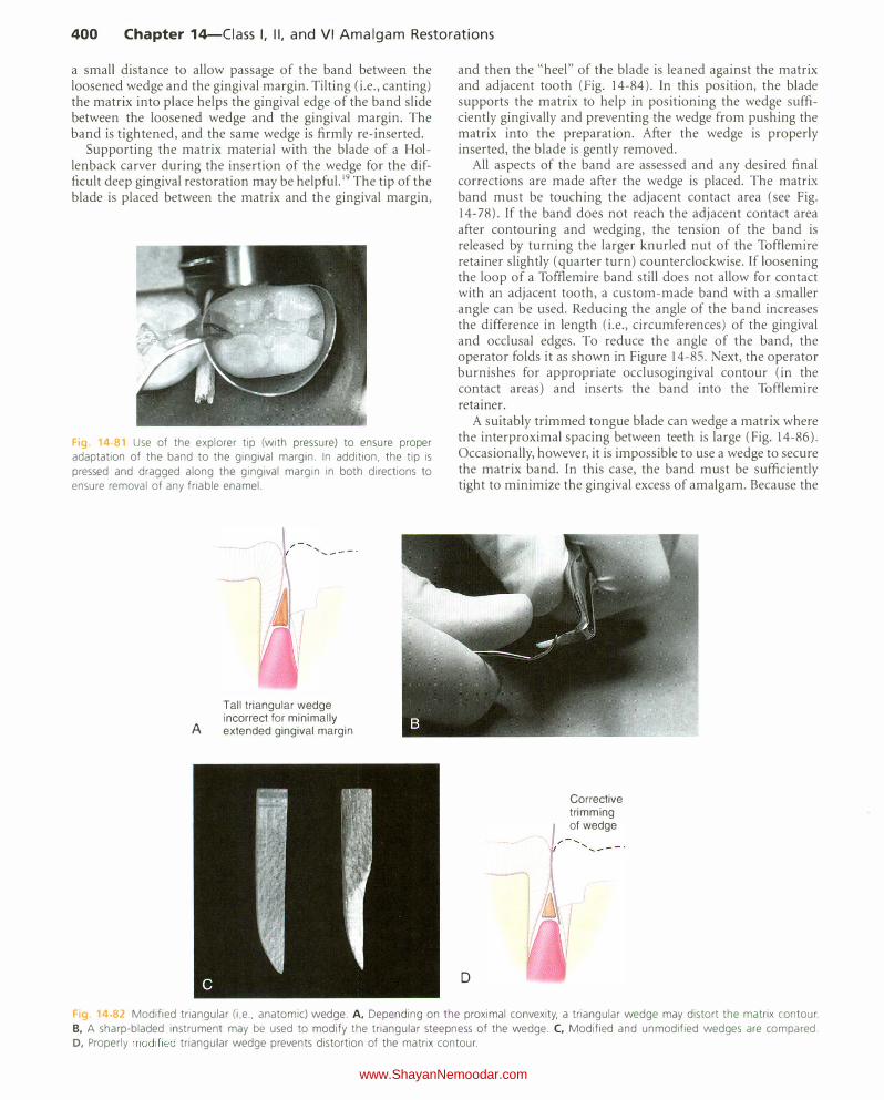
Supporting the matrix material with the blade of a Hollenback carver during the insertion of the wedge for the difficult deep gingival restoration may be helpful. 19 The tip of the blade is placed between the matrix and the gingival margin,
F1g 14-81 Use of the explorer tip (with pressure) to ensure proper adaptation of the band to the gingival margin. In addition, the tip is
pressed and dragged along the gingival margin in both directions to ensure removal of any friable enamel.
A
' ..... ---·
Tall triangular wedge incorrect for minimally extended gingival margin
and then the "heel" of the blade is leaned against the matrix and adjacent tooth (Fig. 14-84). ln this position, the blade supports the matrix to help in positioning the wedge sufficiently gingivally and preventing the wedge from pushing the matrix into the preparation. After the wedge is properly inserted, the blade is gently removed.
All aspects of the band are assessed and any desired final corrections are made after the wedge is placed. The matrix band must be touching the adjacent contact area (see Fig. 14-78). If the band does not reach the adjacent contact area after contouring and wedging, the tension of the band is released by turning the larger knurled nut of the Toftlemire retainer slightly (quarter turn) counterclockwise. If loosening the loop of a Toffiemire band still does not allow for contact with an adjacent tooth, a custom-made band with a smaller angle can be used. Reducing the angle of the band increases the difference in length (i.e., circumferences) of the gingival and occlusal edges. To reduce the angle of the band, the operator folds it as shown in Figure 14-85. Next, the operator burnishes for appropriate occlusogingival contour (in the contact areas) and inserts the band into the Toftlemire retainer.
A suitably trimmed tongue blade can wedge a matrix where the interproximal spacing between teeth is large (Fig. 14-86). Occasionally, however, it is impossible to use a wedge to secure the matrix band. In this case, the band must be sufficiently tight to minimize the gingival excess of amalgam. Because the
I
D
,.
Corrective trimming of wedge
Fig. 14 82 Modified triangular (i e .. anatomic) wedge. A, Depending on the proximal convexity, a triangular wedge may distort the matrix contour. B, A sharp-bladed instrument may be used to modify the triangular steepness of the wedge. C, Modified and unmodified wedges are compared. 0, Properly modified triangular wedge prevents distortion of the matrix contour.
www.ShayanNemoodar.com

Chapter 14-Ciass I, II, and VI Amalgam Restorations 401
A
Fig. 14-83 Indications for the use of a round toothpick wedge versus a triangular (i.e., anatomic) wedge. A, As a rule, the triangular wedge does not firmly support the matrix band
against the gingival margin in conservative Class II preparations
(arrowhead). B, The round toothpick wedge is preferred for these preparations because its wedging action is nearer the gingival margin. C, In Class II preparations with deep gingival
margins, the round toothpick wedge crimps the matrix band
contour if it is placed occlusal to the gingival margin. D, The
triangular wedge is preferred with these preparations because
its greatest width is at its base. C
Hollenback carver blade
Fig 14-84 Supporting the matrix with the blade of a Hollenback carver during wedge insertion.
Occlusal edge
I
Gingival edge
-;-----:
Fig. 14-85 The custom-made matrix strip is folded, as indicated by arrows. The smaller angle (a) compared with the angle of the commercial strip increases the difference between the lengths of the gingival and
occlusal edges.
Incorrect B Correct
Incorrect D Correct
Fig. 14-86 A custom-made tongue blade wedge may be used when excessive space exists between adjacent teeth.
band is not wedged, special care must be exercised by placing small amounts of amalgam in the gingival floor and condensing the first I mm of amalgam lightly, but thoroughly, in a gingival direction. The condensation is then carefully continued in a gingival direction using a larger condenser with firm pressure. Condensation against an unwedged matrix may cause the amalgam to extrude grossly beyond the gingival margin. Without a wedge, some excess amalgam that is overcontoured remains at the proximal margins, requiring correction by a suitable carver immediately after matrix removal.
The matrix is removed after insertion of the amalgam, carving of the occlusal portion (including the occlusal embrasure or embrasures), and hardening of the amalgam to avoid fracture of the marginal ridge during band removal. The retainer is removed from the band after turning the small knurled nut counterclockwise to retract the pointed spindle.
www.ShayanNemoodar.com

402 Chapter 14-Ciass I, II, and VI Amalgam Restorations
The end of the index finger may be placed on the occlusal surface of the tooth to stabilize the band as the retainer is removed. Any rigid supporting material applied to support the matrix is then removed. The No. II 0 pliers are used to tease the band free from one contact area at a time by pushing or pulling the band in a linguo-occlusal (or facio-occlusal) direction and, if possible, in the direction of wedge insertion (Fig. 14-87). The wedge may be left in place to provide separation of teeth while the matrix band is removed, and then it (the wedge) is removed. By maintaining slight interdental separation, the wedge reduces the risk of fracturing of amalgam. A straight occlusal direction should be avoided during matrix removal to prevent breaking of the marginal ridges.
RIGID-MATERIAL SUPPORTED SECTIONAL MATRIX
An alternative to the universal matrix is the use of a properly contoured sectional matrix that is wedged and supported by a material that is rigid enough to resist condensation pressure. The supporting material selected must be easy to place and to remove. Examples include light-cured, thermoplastic and quick-setting rigid polyvinyl siloxane (PVS) materials (Fig. 14-88). The gingival wedge is positioned interproximally to secure the band tightly at the gingival margin to prevent any excess of amalgam (i.e., overhang). The wedge also separates teeth slightly to compensate for the thickness of the band material.
A
D
I I
/
B
E
The proximal surface contour of the matrix should allow the normal slight convexity between the occlusal and middle thirds of the proximal surface when viewed from the lingual (or facial) aspect. Proximal surface restorations often display an occlusogingival proximal contour that is too straight, thereby causing the contact relationship to be located too far
Fig. 14-87 Using No. 110 pliers, the matrix band should be removed in
a lingua-occlusal (arrow) or facio-occlusal direction (not just in an occlu
sal direction).
c
F
Fig. 14-88 Rigid material-supported sectional matrix. A, The shape of the stainless steel strip after trimming. B, The strip contoured to the circum
ferential contour of the tooth (fingers can be used). C, Burnishing the strip to produce occlusogingival contact contour (left and right arrows indicate
the short, back-and-forth motion of the burnisher). D, Contoured strip in position. E, Matrix strip properly wedged. F, Completed rigid material
supported sectional matrix.
www.ShayanNemoodar.com
Chapter 14-Ciass I, II, and VI Amalgam Restorations 403
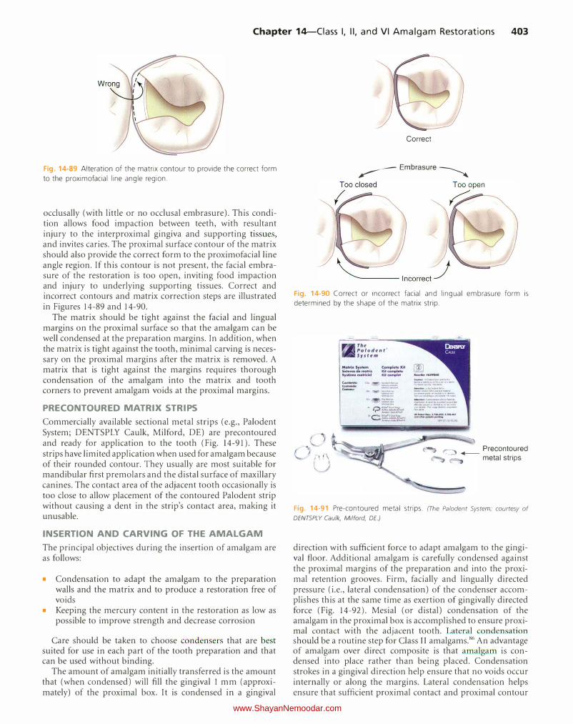
Fig. 14-89 Alteration of the matrix contour to provide the correct form
to the proximofacial line angle region.
occlusally (with little or no occlusal embrasure). This condition allows food impaction between teeth, with resultant injury to the interproximal gingiva and supporting tissues, and invites caries. The proximal surface contour of the matrix. should also provide the correct form to the proximofacial line angle region. If this contour is not present, the facial embrasure of the restoration is too open, inviting food impaction and injury to underlying supporting tissues. Correct and incorrect contours and matrix. correction steps are illustrated in Figures 14-89 and 14-90.
The matrix. should be tight against the facial and lingual margins on the proximal surface so that the amalgam can be well condensed at the preparation margins. In addition, when the matrix. is tight against the tooth, minimal carving is necessary on the proximal margins after the matrix. is removed. A matrix that is tight against the margins requires thorough condensation of the amalgam into the matrix. and tooth corners to prevent amalgam voids at the proximal margins.
PRECONTOURED MATRIX STRIPS
Commercially available sectional metal strips (e.g., Paloden t System; DENTSPLY Caulk, Milford, DE) are precontoured and ready for application to the tooth (Fig. 14-91). These strips have limited application when used for amalgam because of their rounded contour. They usually are most suitable for mandibular first premolars and the distal surface of maxillary canines. The contact area of the adjacent tooth occasionally is too close to allow placement of the contoured Palodent strip without causing a dent in the strip's contact area, making it unusable.
INSERTION AND CARVING OF THE AMALGAM
The principal objectives during the insertion of amalgam are as follows:
• Condensation to adapt the amalgam to the preparation walls and the matrix and to produce a restoration free of voids
• Keeping the mercury content in the restoration as low as possible to improve strength and decrease corrosion
Care should be taken to choose condensers that are best suited for use in each part of the tooth preparation and that can be used without binding.
The amount of amalgam initially transferred is the amount that (when condensed) will fill the gingival 1 mm (approximately) of the proximal box. It is condensed in a gingival
Correct
� Embrasure �
Fig. 14-90 Correct or incorrect facial and lingual embrasure form is determined by the shape of the matrix strip.
(Oft-h: -··-· ....
-
,_
Precontoured ..- metal strips
Fig. 14-91 Pre-contoured metal strips. (The Palodent System; courtesy of
DENTSPLY Caulk, Milford, DE.)
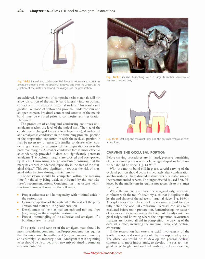
direction with sufficient force to adapt amalgam to the gingival floor. Additional amalgam is carefully condensed against the proximal margins of the preparation and into the proximal retention grooves. Firm, facially and lingually directed pressure (i.e., lateral condensation) of the condenser accomplishes this at the same time as exertion of gingivally directed force (Fig. 14-92). Mesial (or distal) condensation of the amalgam in the proximal box is accomplished to ensure proximal contact with the adjacent tooth. Lateral condensation should be a routine step for Class II amalgams.86 An advantage of amalgam over direct composite is that amalgam is condensed into place rather than being placed. Condensation strokes in a gingival direction help ensure that no voids occur internally or along the margins. Lateral condensation helps ensure that sufficient proximal contact and proximal contour
www.ShayanNemoodar.com
404 Chapter 14-Ciass I, II, and VI Amalgam Restorations
Fig. 14-92 Lateral and occlusogingival force is necessary to condense amalgam properly into the proximal grooves and into the angles at the junction of the matrix band and the margins of the preparation.
are achieved. Placement of composite resin materials will not allow distortion of the matrix band laterally into an optimal contact with the adjacent proximal surface. This results in a greater likelihood of restoration proximal undercontour and an open contact. Proximal contact and contour of the matrix band must be ensured prior to composite resin restoration placement.
The procedure of adding and condensing continues until amalgam reaches the level of the pulpal wall. The size of the condenser is changed (usually to a larger one), if indicated, and amalgam is condensed in the remaining proximal portion of the preparation concurrently with the occlusal portion. It may be necessary to return to a smaller condenser when condensing in a narrow extension of the preparation or near the proximal margins. A smaller condenser face is more effective at condensing, provided it does not significantly penetrate amalgam. The occlusal margins are covered and over-packed by at least 1 mm using a large condenser, ensuring that the margins are well condensed, especially in the area of the marginal ridge.87 This step significantly reduces the risk of marginal ridge fracture during matrix removal.
Condensation should be completed within the working time for the alloy being used, as indicated by the manufacturer's recommendations. Condensation that occurs within this time frame will result in the following:
• Proper coherence and homogeneity, with minimal voids in the restoration
• Desired adaptation of the material to the walls of the preparation and matrix during condensation
• Development of the maximal strength and minimal flow (i.e., creep) in the completed restoration
• Proper intermingling of the adhesive and amalgam, if a bonding system is used
The plasticity and wetness of the amalgam mass should be monitored during condensation. Proper condensation requires that the mix should be neither wet (i.e., mercury-rich) nor dry and crumbly (i.e., mercury-poor). Amalgam that is beginning to set should be discarded and a new mix obtained to complete any condensation.
F1g. 14-93 Precarve burnishing with a large burnisher. (Courtesy of Aldridge D. Wilder, DDS.)
F1g. 14-94 Defining the marginal ridge and the occlusal embrasure with
an explorer.
CARVING THE OCCLUSAL PORTION
Before carving procedures are initiated, precarve burnishing of the occlusal portion with a large egg-shaped or ball burnisher should be done (Fig. 14-93).52
With the matrix band still in place, careful carving of the occlusal portion should begin immediately after condensation and burnishing. Sharp discoid instruments of suitable size are the recommended carvers. The larger discoid is used first, followed by the smaller one in regions not accessible to the larger instrument.
While the matrix is in place, the marginal ridge is carved confluent with the tooth's anatomy such that it duplicates the height and shape of the adjacent marginal ridge (Fig. 14-94). An explorer or small Hollenback carver may be used to carefully define the occlusal embrasure. Occlusal contacts were evaluated before tooth preparation. Remembering the pattern of occlusal contacts, observing the height of the adjacent marginal ridge, and knowing where the preparation cavosurface margins are located all aid in completing the carving of the occlusal surface, including the marginal ridge and occlusal embrasure.
If the restoration has extensive axial involvement of the tooth, the occlusal carving should be accomplished quickly. The objectives would be to develop the general occlusal contour and, most importantly, to develop the correct marginal ridge height and occlusal embrasure form (see Fig.
www.ShayanNemoodar.com
Chapter 14-Ciass I, II, and VI Amalgam Restorations 405
14-94). Then, the matrix is removed, and access is gained to carve the axial portions of the restoration. This permits these areas (usually more inaccessible) to be carved while amalgam is carvable. When the axial carving is completed, the occlusal surface contouring is completed. Occasionally, this occlusal contouring may require the use of an abrasive stone or finishing bur if the setting of the amalgam is nearing completion.
REMOVAL OF THE MATRIX BAND AND COMPLETION OF CARVING
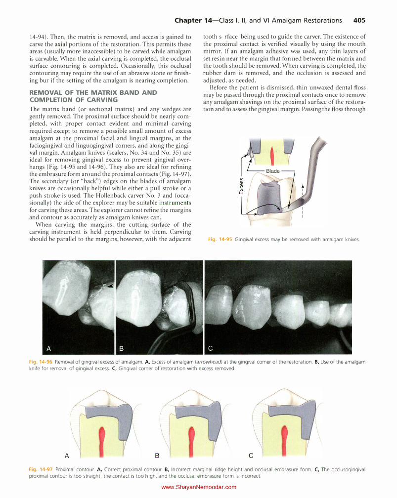
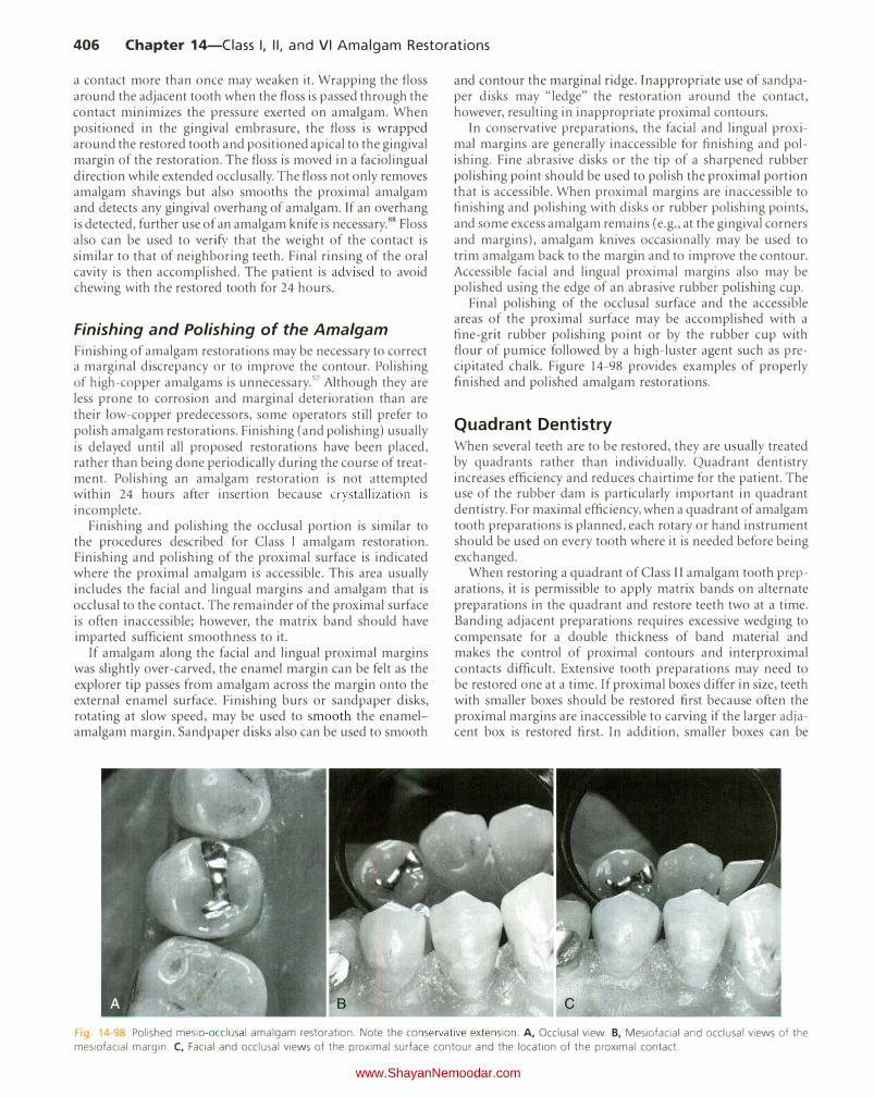
The matrix band (or sectional matrix) and any wedges are gently removed. The proximal surface should be nearly completed, with proper contact evident and minimal carving required except to remove a possible small amount of excess amalgam at the proximal facial and lingual margins, at the faciogingival and linguogingival corners, and along the gingival margin. Amalgam knives (scalers, No. 34 and No. 35) are ideal for removing gingival excess to prevent gingival overhangs (Fig. 14-95 and 14-96). They also are ideal for refining the embrasure form around the proximal contacts (Fig. 14-97). The secondary (or "back") edges on the blades of amalgam knives are occasionally helpful while either a pull stroke or a push stroke is used. The Hollenback carver No.3 and (occasionally) the side of the explorer may be suitable instruments for carving these areas. The explorer cannot refine the margins and contour as accurately as amalgam knives can.
When carving the margins, the cutting surface of the carving instrument is held perpendicular to them. Carving should be parallel to the margins, however, with the adjacent
tooth surface being used to guide the carver. The existence of the proximal contact is verified visually by using the mouth mirror. If an amalgam adhesive was used, any thin layers of set resin near the margin that formed between the matrix and the tooth should be removed. When carving is completed, the rubber dam is removed, and the occlusion is assessed and adjusted, as needed.
Before the patient is dismissed, thin unwaxed dental floss may be passed through the proximal contacts once to remove any amalgam shavings on the proximal surface of the restoration and to assess the gingival margin. Passing the floss through
Fig. 14-95 Gingival excess may be removed with amalgam knives.
Fig. 14-96 Removal of gingival excess of amalgam. A, Excess of amalgam (arrowhead) at the gingival corner of the restoration. B, Use of the amalgam
knife for removal of gingival excess. C, Gingival corner of restoration with excess removed.
\ A c
Fig. 14-97 Proximal contour. A, Correct proximal contour. B, Incorrect marginal ridge height and occlusal embrasure form. C, The occlusogingival
proximal contour is too straight, the contact is too high, and the occlusal embrasure form is incorrect.
www.ShayanNemoodar.com
406 Chapter 14-Ciass I, II, and VI Amalgam Restorations
a contact more than once may weaken it. Wrapping the floss around the adjacent tooth when the floss is passed through the contact minimizes the pressure exerted on amalgam. When positioned in the gingival embrasure, the floss is wrapped around the restored tooth and positioned apical to the gingival margin of the restoration. The floss is moved in a faciolingual direction while extended occlusally. The floss not only removes amalgam shavings but also smooths the proximal amalgam and detects any gingival overhang of amalgam. If an overhang is detected, further use of an amalgam knife is necessary.88 Floss also can be used to verify that the weight of the contact is similar to that of neighboring teeth. Final rinsing of the oral cavity is then accomplished. The patient is advised to avoid chewing with the restored tooth for 24 hours.
Finishing and Polishing of the Amalgam
Finishing of amalgam restorations may be necessary to correct a marginal discrepancy or to improve the contour. Polishing of high-copper amalgams is unnecessary. 57 Although they are less prone to corrosion and marginal deterioration than are their low-copper predecessors, some operators still prefer to polish amalgam restorations. Finishing (and polishing) usually is delayed until all proposed restorations have been placed, rather than being done periodically during the course of treatment. Polishing an amalgam restoration is not attempted within 24 hours after insertion because crystallization is incomplete.
Finishing and polishing the occlusal portion is similar to the procedures described for Class 1 amalgam restoration. Finishing and polishing of the proximal surface is indicated where the proximal amalgam is accessible. This area usually includes the facial and lingual margins and amalgam that is occlusal to the contact. The remainder of the proximal surface is often inaccessible; however, the matrix band should have imparted sufficient smoothness to it.
If amalgam along the facial and lingual proximal margins was slightly over-carved, the enamel margin can be felt as the explorer tip passes from amalgam across the margin onto the external enamel surface. Finishing burs or sandpaper disks, rotating at slow speed, may be used to smooth the enamelamalgam margin. Sandpaper disks also can be used to smooth
and contour the marginal ridge. Inappropriate use of sandpaper disks may "ledge" the restoration around the contact, however, resulting in inappropriate proximal contours.
In conservative preparations, the facial and lingual proximal margins are generally inaccessible for finishing and polishing. Fine abrasive disks or the tip of a sharpened rubber polishing point should be used to polish the proximal portion that is accessible. When proximal margins are inaccessible to finishing and polishing with disks or rubber polishing points, and some excess amalgam remains (e.g., at the gingival corners and margins), amalgam knives occasionally may be used to trim amalgam back to the margin and to improve the contour. Accessible facial and lingual proximal margins also may be polished using the edge of an abrasive rubber polishing cup.
Final polishing of the occlusal surface and the accessible areas of the proximal surface may be accomplished with a fine-grit rubber polishing point or by the rubber cup with flour of pumice followed by a high-luster agent such as precipitated chalk. Figure 14-98 provides examples of properly finished and polished amalgam restorations.
Quadrant Dentistry When several teeth are to be restored, they are usually treated by quadrants rather than individually. Quadrant dentistry increases efficiency and reduces chairtime for the patient. The use of the rubber dam is particularly important in quadrant dentistry. For maximal efficiency, when a quadrant of amalgam tooth preparations is planned, each rotary or hand instrument should be used on every tooth where it is needed before being exchanged.
When restoring a quadrant of Class II amalgam tooth preparations, it is permissible to apply matrix bands on alternate preparations in the quadrant and restore teeth two at a time. Banding adjacent preparations requires excessive wedging to compensate for a double thickness of band material and makes the control of proximal contours and interproximal contacts difficult. Extensive tooth preparations may need to be restored one at a time. If proximal boxes differ in size, teeth with smaller boxes should be restored first because often the proximal margins are inaccessible to carving if the larger adjacent box is restored first. In addition, smaller boxes can be
Fig 14-98 Polished mesio-occlusal amalgam restoration. Note the conservative extension. A, Occlusal view. B, Mesiofacial and occlusal views of the
mesiofacial margin. C, Facial and occlusal views of the proximal surface contour and the location of the proximal contact.
www.ShayanNemoodar.com
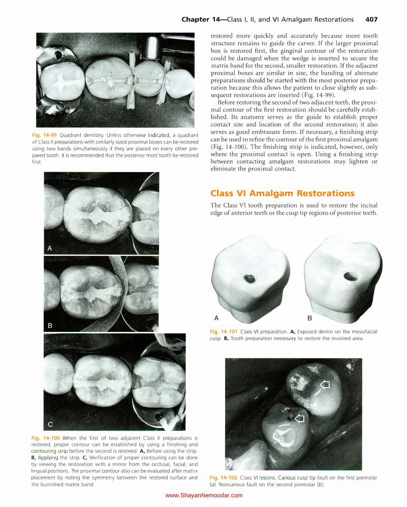
Chapter 14-Ciass I, II, and VI Amalgam Restorations 407
Fig. 14-99 Quadrant dentistry. Unless otherwise indicated, a quadrant
of Class II preparations with similarly sized proximal boxes can be restored
using two bands simultaneously if they are placed on every other pre
pared tooth. It is recommended that the posterior most tooth be restored first.
Fig. 14-100 When the first of two adjacent Class II preparations is restored, proper contour can be established by using a finishing and contouring strip before the second is restored. A, Before using the strip. B, Applying the strip. C, Verification of proper contouring can be done by viewing the restoration with a mirror from the occlusal, facial, and lingual positions. The proximal contour also can be evaluated after matrix placement by noting the symmetry between the restored surface and
the burnished matrix band.
restored more quickly and accurately because more tooth structure remains to guide the carver. If the larger proximal box is restored first, the gingival contour of the restoration could be damaged when the wedge is inserted to secure the matrix band for the second, smaller restoration. If the adjacent proximal boxes are similar in size, the banding of alternate preparations should be started with the most posterior preparation because this aiJows the patient to close slightly as subsequent restorations are inserted (Fig. 14-99).
Before restoring the second of two adjacent teeth, the proximal contour of the first restoration should be carefully established. Its anatomy serves as the guide to establish proper contact size and location of the second restoration; it also serves as good embrasure form. If necessary, a finishing strip can be used to refine the contour of the first proximal amalgam (Fig. 14-100). The finishing strip is indicated, however, only where the proximal contact is open. Using a finishing strip between contacting amalgam restorations may lighten or eliminate the proximal contact.
Class VI Amalgam Restorations
The Class VI tooth preparation is used to restore the incisal edge of anterior teeth or the cusp tip regions of posterior teeth.
Fig. 14-101 Class VI preparation. A, Exposed dentin on the mesiofacial
cusp. 8, Tooth preparation necessary to restore the involved area.
Fig. 14-102 Class VI lesions. Carious cusp tip fault on the first premolar
(a). Noncarious fault on the second premolar (b).
www.ShayanNemoodar.com

408 Chapter 14-Ciass I, II, and VI Amalgam Restorations
19. 4·103 Clinical examples of long-term amalgam restorations. A, 44-year-old amalgams. B, 58-year-old amalgams in the first molar. C, 55-year
old amalgams in molars. (A and 8, courtesy of Drs. John Osborne and James Summitt.)
Such tooth preparations are frequently indicated where attrition (loss of tooth substance from the occluding of food, abrasives, and opposing teeth) has removed enamel to expose the underlying dentin on those areas (Fig. 14-10 I). This occurs more frequently in older patients. When the softer dentin is exposed, it wears faster than the surrounding enamel, resulting in "cupped-out" areas. As the dentin support is lost, enamel begins to fracture away, exposing more dentin and often causing sensitivity. Sensitivity to hot and cold is a frequent complaint with Class VI lesions, and some patients are bothered by food impaction in the deeper depressions. Enamel edges may become jagged and sharp to the tongue, lips, or cheek. Lip, tongue, or cheek biting is occasionally a complaint. Rounding and smoothing such incisoax.ial (or occlusoaxial) edges is an excellent service to the patient. Early recognition and restoration of these lesions is recommended to limit the loss of dentin and the subsequent loss of enamel supported by this dentin.
The Class VI tooth preparation also is indicated to restore the hypoplastic pit occasionally found on cusp tips (Fig. 14-102). Such developmental faults are vulnerable to caries, especially in high-risk patients, and should be restored as soon as they are detected. Caries are rarely found in dentin where attritional wear has removed the overlying enamel.
Composite is generally used to restore Class VI preparations. Amalgam may be selected for posterior class VI preparations because of its wear resistance and longevity. Moisture control for Class VI restorations is usually achieved with cotton roll isolation. Class VI amalgam preparations may be accomplished with a small tapered fissure bur (e.g., No. 169 L
or 271) and involves extension to place the cavosurface margin on enamel that has sound dentin support (see Fig. 14-10 I). The preparation walls may need to diverge occlusally to ensure a 90-degree cavosurface margin. A depth of 1.5 mm is sufficient to provide bulk of material for strength. Retention of the restoration is ensured by the creation of small undercuts along the internal line angles. Do not remove dentin that is immediately supporting enamel. Conservative tooth preparation is particularly important with Class V1 preparations because it is easy to undermine the enamel on incisal edges and cusp tips. Inserting, carving, and polishing are similar to procedures described for Class I tooth preparations for amalgam.
Some older patients have excessive occlusal wear of most of their teeth in the form of large concave areas with much exposed dentin. Teeth with excessive wear may require indirect restorations.
Summary
Class I and II amalgam restorations are still common procedures performed by general dentists. Class VI amalgam restorations are done infrequently. It is important for practitioners to understand the indications, advantages, techniques, and limitations of these restorations. When used correctly and in properly selected cases, these restorations have the potential to serve for many years (Fig. 14-103).
eferences
I. Bjcrtness E, Sonju T: Survival analysis of amalgam restorations in long-term
recall patients, Acta Odontol Scand 48:93, 1990.
2. D owner MC, Azli NA, Bedi R, et al: How long do routine restorations last? A
systematic review, Br Dent I 187:432, 1999. 3. Letzel H, van 't Hof MA, Marshall GW, et al: The influence of the amalgam
alloy on the survival of amalgam restorations: A secondary analysis of
multiple controlled clinical trials, I Dent Res 76:1787, 1997.
4. Mjor lA, jokstad A, Qvist V: Longevity of posterior restorations, In/ Dwt I
40:11, 1990.
5. Osborne JW, Norman RD: 13-year clinical assessment of 10 amalgam alloys,
Dent Mater 6: 189, 1990.
6. Osborne )W, Norman RD, Gale EN: A 14-year clinical assessment of 12 amalgam alloys, Quintessence Int 22:857, 1991.
7. Maryniuk GA: In search of treatment longevity-a 30-year perspective, I Alii Dent Assoc 109:739, 1984.
8. Maryniuk GA, Kaplan Sl-1: Longevity of restorations: survey results of
dentists' estimates and attitudes, I Am Dent Assoc 112:39, 1986. 9. jokstad A, Mjor lA: The quality of routine class II cavity preparations for
amalgam, Acta Odontol Scand 47:53, 1989. 10. Kreulen CM, Tobi H, Gruythuysen RJ, et al: Replacement risk of amalgam
treatment modalities: IS-year results, I Dent 26:627, 1998.
II. Smales Rj: Longevity of low- and high-copper amalgams analyzed by preparation class, tooth site, patient age, and operator, Oper Delli 16:162,
1991.
12. Bader JD, Shugars DA: Variations in dentists' clinical decisions, I Public
Health Dent 55:181, 1995.
13. Burgess JO: Dental materials for the restorations of root surface caries, A111 I Dent 8:342, 1995.
14. Gottlieb EW, Retief DH, Bradley EL: Microleakage of conventional and
high-copper amalgam restorations, 1 Prosthet Dent 53:355, 1985.
IS. Hilton T): Can modern restorative procedures and mater ials reliably seal cavities? In vitro investigations: Part 2, A111 1 Dent 15:279, 2002.
16. Dilley DC, Vann WF )r, Oldenburg TR, et al: Time required for placement of composite versus amalgam restorations, I Dent Child 57: 1 77, 1990.
17. Gilmore HW: Pulpal considerations for operative dentistry, j Prosthet Dent
14:752, 1964.
18. Almquist TC, Cowan RD, Lambert RL: onservative amalgam restorat ions,
1 Prosthet Dent 29:524, 1973. 19. Markley MR: Restorations of silver amalgam, 1 A111 Dent Assoc 43:133,
1951. 20. Berry TG, Laswell HR, Osborne JW, et al: Width of isthmus and marginal
failure of restorations of amalgam, Oper Dellt 6:55, 1981.
www.ShayanNemoodar.com

Chapter 14-Ciass I, II, and VI Amalgam Restorations 409
21. Osborne )W, Gale EN: Relationship of restoration width, tooth position and alloy to fracture at the margins of 13- to 14-year-old amalgams,] De11t Ues 69:1599, 1990.
22. Goel VK, Khera SC, Gurusami S, et al: Effect of cavity depth on stresses in a restored tooth,] Prosthet Dent 67:174, 1992.
23. Lagouvardos P, Sourai P, Douvitsas G: Coronal fractures in posterior teeth, Oper Dent 14:28, 1989.
24. Osborne )W, Gale EN: Failure at the margin of amalgams as affected by cavity width, tooth position, and alloy selection, f Dent Res 60:681, 1981.
25. Anusavice K). editor: Phillips' scie11ce of dental materials, ed II, St. Louis, 2003, Mosby.
26. Council on Dental Materials, Instruments, and Equipment: Dental mercury hygiene: summary of recommendations in 1990,] Am Dent Assoc 122:112, 1991.
27. Sockwell CL: Dental handpieces and rotary cutting instruments, De11t Cli11 North Am 15:219, 1971.
28. Goho C, Aaron GR: Enhancement of anti-microbial properties of cavity varnish: A preliminary report, f Prosthet Dwt 68:623, 1992.
29. Blaser PK, Lund MR, Cochran MA, et al: Effect of designs of Class 2 preparations on resistance of teeth to fracture, Oper De11t 8:6, 1983.
30. Vale WA: Tooth preparation and further thoughts on high speed, Br De11t ] I 07:333, 1959.
31. Gilmore HW: Restorative materials and tooth preparation design, Derlf Clin North Am 15:99, 1971.
32. Fusayama T: Two layers of carious dentin: Diagnosis and treatment, Oper Dent 4:63, 1979.
33. Hebling ), Giro EM, Costa CA: Human pulp response after an adhesive system application in deep cavities,] Dent 27:557, 1999.
34. Hilton TJ: Cavity sealers, liners, and bases: Current philosophies and indications for use, Oper Dwt 21:134, 1996.
35. Eliades G, Palaghias G: In-vitro characterization of visible-light-cured glass-ionomer liners, Dwt Mater 9: 198, 1993.
36. Wieczkowski G )r, Yu XY, Joynt RB, et al: Microleakage evaluation in amalgam restorations used with bases,] Esther Dmt 4:37, 1992.
37. Robbins )W: The placement of bases beneath amalgam restorations: Review of literature and recommendations for use, f Am Dent Assoc 113:910, 1986.
38. Mahler DB, Terkla LG: Analysis of stress in dental structures, Dent Clin
North Am 2:789, 1958. 39. V lietstra )R, Sidaway DA, Plant CG: Cavity cleansers, Br Derlf f 149:293,
1980. 40. Berry FA, Parker SD, Rice D, et al: Microleakage of amalgam restorations
using dentin bonding system primers, Am ] Der'lf 9:174, 1996. 41. Schupbach P, Lutz F, Finger W): Closing of dentinal tubules by Gluma
desensitizer, Eur f Oral Sci I 05:414, 1997. 42. Mahler DB, Nelson LW: Sensitivity answers sought in amalgam alloy
microleakage study, ] Am Derrt Assoc 125:282, 1994. 43. Ziskind D, Venezia E, Kreisman I, et al: Amalgam type, adhesive system, and
storage period as influencing factors on microleakage of amalgam restorations,] Prosthet Dent 90:255, 2003.
44. Lindemuth )S, Hagge MS, Broome )S: Effect of restoration size on fracture resistance of bonded amalgam restorations, Oper De11t 25:177, 2000.
45. Mahler DB: The amalgam-tooth interface, Oper Dent 21:230, 1996. 46. Symons AL, Wing G, Hewitt GH: Adaptation of eight modern dental
amalgams to walls of Class I cavity preparations,] Oral Rehabi/14:55, 1987. 47. Hilton T): Sealers, liners, and bases,] Esther Restor Dent 15:141,2003. 48. Bauer )G: A study of procedures for burnishing amalgam restorations,
f Prosthet Dent 57:669, 1987. 49. Lovadino )R, Ruhnke LA, Consani S: Influence of burnishing on amalgam
adaptation to cavity walls,] Prosthet De11t 58:284, 1987. 50. Restoration of tooth preparations with amalgam and tooth-colored
materials: Project ACCORDE student syllabus, Washington, D.C., 1974, US Department of Health, Education, and Welfare.
51. Kanai S: Structure studies of amalgam II: Effect of burnishing on the margins of occlusal amalgam fillings, Acta Odonto/ Scand 24:47, 1966.
52. May KN , Wilder AD, Leinfelder KF: Clinical evaluation of various burnishing techniques on high-copper amalgam !abstract J, f Prosthet Dent 61:213, 1982.
53. May KN )r, Wilder AD )r, Leinfelder KF: Burnished amalgam restorations: a two-year evaluation, f Prosthet Derzt 49:193, 1983.
54. Straffon LH, Corpron RE, Dennison )B, et al: A clinical evaluation of polished and unpolished amalgams: 36-month results, Pediatr De11t 6:220, 1984.
55. Collins C), Bryant RW: Finishing of amalgam restorations: a three-year clinical study,] Dent 20:202, 1992.
56. Drummond JL, )ung H, Savers EE, et al: Surface roughness of polished amalgams, Oper Dent 17:129, 1992.
57. Moffa )P: The longevity and reasons for replacement of amalgam alloys I abstract],] Derrt Res 68: 188, 1989.
58. Summitt )B, Burgess )0, Berry TG, et al: Six-year clinical evaluation of bonded and pin-retained complex amalgam restorations, Oper Dent 29:261, 2004.
59. Mayhew RB, Schmeltzer LD, Pierson WP: Effect of polishing on the marginal integrity of high-copper amalgams, Oper Dent I I :8, 1986.
60. Osborne )W, Leinfelder KF, Gale EN, et al: Two independent evaluations of
ten amalgam alloys, f Prosthet Dent 43:622, 1980.
61. Dias de Souza GM, Pereira GD, Dias CT, et al: Fracture resistance of teeth restored with the bonded amalgam technique, Oper Dent 26:511, 200 I.
62. Mahler DB, Engle )H: Clinical evaluation of amalgam bonding in class I and II restorations,] Am Dent Assoc 131 :43, 2000.
63. Smales R), Wetherell )D: Review of bonded amalgam restorations and assessment in a general practice over five years, Oper Delli 25:374, 2000.
64. Larson TD, Douglas WH, Geistfeld RE: Effect of prepared cavities on the strength of teeth, Oper Dent 6:2, 1981.
65. Rodda )C: Modern class II amalgam tooth preparations, N Z Dent] 68:132, 1972.
66. Joynt RB, Davis EL, Wieczkowski G )r, et al: Fracture resistance of posterior teeth with glass ionomer-composite resin systems, f Prosthet Dent 62:28, 1989.
67. Osborne )W, Summitt )B: Extension for prevention: is it relevant today? Am J Dent 11:189, 1998.
68. Summitt )B, Osborne )W: Initial preparations for amalgam restorations: Extending the longevity of the tooth-restoration unit, f Am Dent Assoc 123:67, 1992.
69. Leon AR: The periodontium and restorative procedures: A critical review, ] Om/ J?ehabi/4:105, 1977.
70. Loe H: Reactions of marginal periodontal tissues to restorative procedures, lnt Dwt] 18:759, 1968.
71. Waerhaug ): Histologic considerations which govern where the margins of restorations should be located in relation to the gingivae, Derzt Clin North Am 4:161, 1960.
72. Della Bona A, Summitt )B: The effect of amalgam bonding on resistance form of class II amalgam restorations, Quirrtessence Int 29:95, 1998.
73. Goriic(i ), et al: Effects of preparation designs and adhesive systems on
retention of class II amalgam restorations, ] Prosthet Dent 78:250, 1997. 74. Mondelli ), lshikiriama A, de Lima Navarro M F, et al: Fracture strength of
amalgam restorations in modern Class II preparations with proximal retentive grooves, f Prosthet Dent 32:564, 1974.
75. Mondelli ), Francischone CE, Steagall L, et al: Influence of proximal retention on the fracture strength of Class II amalgam restorations,] Prosthet
Dent 46:420, 1981. 76. Summitt )B, Howell ML, Burgess )0, et al: Effect of grooves on resistance
form of conservative class 2 amalgams, Oper Dent 17:50, 1992. 77. Moore DL: Retentive grooves for the Class 2 amalgam restoration: Necessity
or hazard? Oper Dent 17:29, 1992. 78. Sturdevant )R, Taylor DF, Leonard RH, et al: Conservative preparation
designs for Class II amalgam restorations, Dent Mater 3:144, 1987. 79. Crockett WD, Shepard FE, Moon PC, et al: The influence of proximal
retention grooves on the retention and resistance of class II preparations for
amalgam, f Am Dent Assoc 91: I 053, 1975. 80. Summitt )B, Osborne )W, Burgess )0, et al: Effect of grooves on resistance
form of Class 2 amalgams with wide occlusal preparations, Oper Dent 18:42, 1993.
81. Khera SC, Chan KC: Microleakage and enamel finish,] Prosthet Dertt 39:414, 1978.
82. Summitt JB, Osborne )W, Burgess )0: Effect of grooves on resistance/ retention form of Class 2 approximal slot amalgam restorations, Oper Dent 18:209, 1993.
83. Gwinnett A), Baratieri LN, Monteiro S )r, et al: Adhesive restorations with amalgam: guidelines for the clinician, Quintessence lnt 25:687, 1994.
84. Mondelli RF, Barbosa WF, Mondelli ), et al: Fracture strength of weakened human premolars restored with amalgam with and without cusp coverage, Am] Dent 11:181,1998.
85. Smales RJ: Longevity of cusp-covered amalgams: Survival after 15 years, OperDent 16:17,1991.
86. Duncalf WV, Wilson NI-l F: Adaptation and condensation of amalgam restorations in Class II preparations of conventional and conservative design, Quintessence lnt 23:499, 1992.
87. )okstad A, Mjor lA: Cavity design and marginal degradation of the occlusal part of Class II amalgam restorations, Acta Odontol Scand 48:389, 1990.
88. Pack AR: The amalgam overhang dilemma: A review of causes and effects, prevention, and removal, N Z Dent f 85:55, 1989.
www.ShayanNemoodar.com
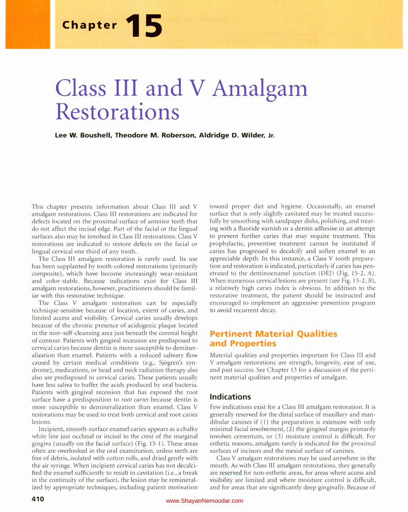
Chapter 15
Class III and V Amalgam Restorations Lee W. Boushell, Theodore M. Roberson, Aldridge D. Wilder, Jr.
This chapter presents information about Class III and V
amalgam restorations. Class III restorations are indicated for defects located on the proximal surface of anterior teeth that do not affect the incisal edge. Part of the facial or the lingual surfaces also may be involved in Class III restorations. Class V
restorations are indicated to restore defects on the facial or lingual cervical one third of any tooth.
The Class III amalgam restoration is rarely used. Its use has been supplanted by tooth-colored restorations (primarily composite), which have become increasingly wear-resistant and color-stable. Because indications exist for Class III amalgam restorations, however, practitioners should be familiar with this restorative technique.
The Class V amalgam restoration can be especially technique-sensitive because of location, extent of caries, and limited access and visibility. Cervical caries usually develops because of the chronic presence of acidogenic plaque located in the non-self-cleansing area just beneath the coronal height of contour. Patients with gingival recession are predisposed to cervical caries because dentin is more susceptible to demineralization than enamel. Patients with a reduced salivary flow caused by certain medical conditions (e.g., Sjogren's syndrome), medications, or head and neck radiation therapy also also are predisposed to cervical caries. These patients usually have less saliva to buffer the acids produced by oral bacteria. Patients with gingival recession that has exposed the root surface have a predisposition to root caries because dentin is more susceptible to demineralization than enamel. Class V
restorations may be used to treat both cervical and root caries lesions.
Incipient, smooth-surface enamel caries appears as a chalky white line just occlusal or incisal to the crest of the marginal gingiva (usually on the facial surface) (Fig. 15-1). These areas often are overlooked in the oral examination, unless teeth are free of debris, isolated with cotton rolls, and dried gently with the air syringe. When incipient cervical caries has not decalcified the enamel sufficiently to result in cavitation (i.e., a break in the continuity of the surface), the lesion may be remineralized by appropriate techniques, including patient motivation
410
toward proper diet and hygiene. Occasionally, an enamel surface that is only slightly cavitated may be treated successfully by smoothing with sandpaper disks, polishing, and treating with a fluoride varnish or a dentin adhesive in an attempt to prevent further caries that may require treatment. This prophylactic, preventive treatment cannot be instituted if caries has progressed to decalcify and soften enamel to an appreciable depth. In this instance, a Class V tooth preparation and restoration is indicated, particularly if caries has penetrated to the dentinoenamel junction (DEJ) (Fig. 15-2, A). When numerous cervical lesions are present (see Fig. 15-2, B), a relatively high caries index is obvious. In addition to the restorative treatment, the patient should be instructed and encouraged to implement an aggressive prevention program to avoid recurrent decay.
Pertinent Material Qualities and Properties Material qualities and properties important for Class lii and V amalgam restorations are strength, longevity, ease of use, and past success. See Chapter 13 for a discussion of the pertinent material qualities and properties of amalgam.
Indications Few indications exist for a Class III amalgam restoration. It is generally reserved for the distal surface of maxillary and mandibular canines if (I) the preparation is extensive with only minimal facial involvement, (2) the gingival margin primarily involves cementum, or (3) moisture control is difficult. For esthetic reasons, amalgam rarely is indicated for the proximal surfaces of incisors and the mesial surface of canines.
Class V amalgam restorations may be used anywhere in the mouth. As with Class Ill amalgam restorations, they generally are reserved for non-esthetic areas, for areas where access and visibility are limited and where moisture control is difficult, and for areas that are significantly deep gingivally. Because of
www.ShayanNemoodar.com
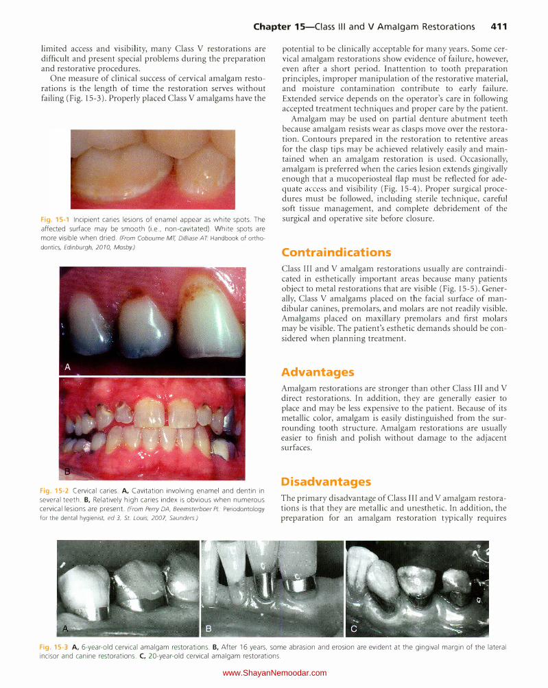
Chapter 15-Ciass Ill and V Amalgam Restorations 411
limited access and visibility, many Class V restorations are difficult and present special problems during the preparation and restorative procedures.
One measure of clinical success of cervical amalgam restorations is the length of time the restoration serves without failing (Fig. 15-3). Properly placed Class V amalgams have the
Fig 15-1 Incipient caries lesions of enamel appear as white spots. The
affected surface may be smooth (i.e., non-cavitated). White spots are
more visible when dried. (From Cobourne MT, DiBiase AT Handbook of orthodontics, Edinburgh, 20 10, Mosby.)
Fig 15-2 Cervical caries. A, Cavitation involving enamel and dentin in
several teeth. B, Relatively high caries index is obvious when numerous
cervical lesions are present. (From Perry DA, Beemsterboer PL. Periodontology for the dental hygienist, ed 3, St. Lows, 2007, Saunders)
potential to be clinically acceptable for many years. Some cervical amalgam restorations show evidence of failure, however, even after a short period. Inattention to tooth preparation principles, improper manipulation of the restorative material, and moisture contamination contribute to early failure. Extended service depends on the operator's care in following accepted treatment techniques and proper care by the patient.
Amalgam may be used on partial denture abutment teeth because amalgam resists wear as clasps move over the restoration. Contours prepared in the restoration to retentive areas for the clasp tips may be achieved relatively easily and maintained when an amalgam restoration is used. Occasionally, amalgam is preferred when the caries lesion extends gingivally enough that a mucoperiosteal flap must be reflected for adequate access and visibility (Fig. 15-4). Proper surgical procedures must be followed, including sterile technique, careful soft tissue management, and complete debridement of the surgical and operative site before closure.
Contra indications
Class III and V amalgam restorations usually are contraindicated in esthetically important areas because many patients object to metal restorations that are visible (Fig. 15-5). Generally, Class V amalgams placed on the facial surface of mandibular canines, premolars, and molars are not readily visible. Amalgams placed on maxillary premolars and first molars may be visible. The patient's esthetic demands should be considered when planning treatment.
Advantages
Amalgam restorations are stronger than other Class Ill and V
direct restorations. In addition, they are generally easier to place and may be less expensive to the patient. Because of its metallic color, amalgam is easily distinguished from the surrounding tooth structure. Amalgam restorations are usually easier to finish and polish without damage to the adjacent surfaces.
Disadvantages
The primary disadvantage of Class III and V amalgam restorations is that they are metallic and unesthetic. In addition, the preparation for an amalgam restoration typically requires
Fig 15-3 A, 6-year-old cervical amalgam restorations. B, After 16 years, some abrasion and erosion are evident at the gingival margin of the lateral incisor and canine restorations. C, 20-year-old cervical amalgam restorations.
www.ShayanNemoodar.com
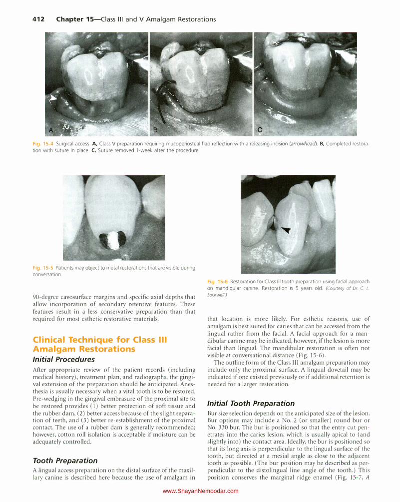
412 Chapter 15-Ciass Ill and V Amalgam Restorations
Fig. 15-4 Surgical access. A, Class V preparation requiring mucoperiosteal flap reflection with a releasing incision (arrowhead). B. Completed restora
tion with suture in place. C, Suture removed 1-week after the procedure.
Fig 15-5 Patients may object to metal restorations that are visible during conversation.
90-degree cavosurface margins and specific axial depths that allow incorporation of secondary retentive features. These features result in a less conservative preparation than that required for most esthetic restorative materials.
Clinical Technique for Class Ill Amalgam Restorations Initial Procedures
After appropriate review of the patient records (including medical history), treatment plan, and radiographs, the gingival extension of the preparation should be anticipated. Anesthesia is usually necessary when a vital tooth is to be restored. Pre-wedging in the gingival embrasure of the proximal site to be restored provides (1) better protection of soft tissue and the rubber dam, (2) better access because of the slight separation of teeth, and (3) better re-establishment of the proximal contact. The use of a rubber dam is generally recommended; however, cotton roll isolation is acceptable if moisture can be adequately controlled.
Tooth Preparation A lingual access preparation on the distal surface of the maxillary canine is described here because the use of amalgam in
Fig 15-6 Restoration for Class Ill tooth preparation using facial approach on mandibular canine. Restoration is 5 years old. (Courtesy of Dr C L. Sockwell)
that location is more likely. For esthetic reasons, use of amalgam is best suited for caries that can be accessed from the lingual rather from the facial. A facial approach for a mandibular canine may be indicated, however, if the lesion is more facial than lingual. The mandibular restoration is often not visible at conversational distance (Fig. 15-6).
The outline form of the Class III amalgam preparation may include only the proximal surface. A lingual dovetail may be indicated if one existed previously or if additional retention is needed for a larger restoration.
Initial Tooth Preparation
Bur size selection depends on the anticipated size of the lesion. Bur options may include a No. 2 (or smaller) round bur or No. 330 bur. The bur is positioned so that the entry cut penetrates into the caries lesion, which is usually apical to (and slightly into) the contact area. Ideally, the bur is po itioned so that its long axis is perpendicular to the lingual surface of the tooth, but directed at a mesial angle as close to the adjacent tooth as possible. (The bur position may be described as perpendicular to the distolingual line angle of the tooth.) This position conserves the marginal ridge enamel (Fig. 1 5- 7 , A
www.ShayanNemoodar.com
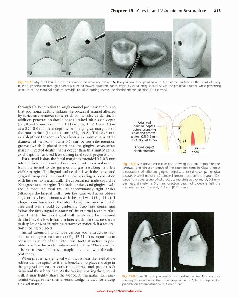
Chapter 15-Ciass Ill and V Amalgam Restorations 413
Fig. 15-7 Entry for Class Ill tooth preparation on maxillary canine. A, Bur position is perpendicular to the enamel surface at the point of entry. B, Initial penetration through enamel is directed toward cavitated, caries lesion. C, Initial entry should isolate the proximal enamel, while preserving
as much of the marginal ridge as possible. D, Initial cutting reveals the dentinoenamel junction (DEJ) (arrow)
through C). Penetration through enamel positions the bur so that additional cutting isolates the proximal enamel affected by caries and removes some or all of the infected dentin. In addition, penetration should be at a limited initial axial depth (i.e., 0.5-0.6 mm) inside the DEJ (see Fig. 15-7, C and D) or at a 0.75-0.8-mm axial depth when the gingival margin is on the root surface (in cementum) (Fig. 15-8). This 0.75-mm axial depth on the root surface allows a 0.25-mm distance (the diameter of the No . .X bur is 0.5 mm) between the retention groove (which is placed later) and the gingival cavosurface margin. Infected dentin that is deeper than this limited initial axial depth is removed later during final tooth preparation.
For a small lesion, the facial margin is extended 0.2-0.3 mm into the facial embrasure (if necessary), with a curved outline from the incisal to the gingival margin (resulting in a less visible margin). The lingual outline blends with the incisal and gingival margins in a smooth curve, creating a preparation with little or no lingual wall. The cavosurface angle should be 90 degrees at all margins. The facial, incisal, and gingival walls should meet the axial wall at approximately right angles (although the lingual wall meets the axial wall at an obtuse angle or may be continuous with the axial wall) (Fig. 15-9). If a large round bur is used, the internal angles are more rounded. The axial wall should be uniformly deep into dentin and follow the faciolingual contour of the external tooth surface (Fig. 15-10). The initial axial wall depth may be in sound dentin (i.e., shallow lesion), in infected dentin (i.e., moderate to deep lesion), or in existing restorative material, if a restoration is being replaced.
Incisal extension to remove carious tooth structure may eliminate the proximal contact (Fig. 15-11 ). It is important to conserve as much of the distoincisal tooth structure as possible to reduce the risk for subsequent fracture. When possible, it is best to leave the incisal margin in contact with the adjacent tooth.
When preparing a gingival wall that is near the level of the rubber dam or apical to it, it is beneficial to place a wedge in the gingival embrasure earlier to depress and protect soft tissue and the rubber dam. As the bur is preparing the gingival wall, it may lightly shave the wedge. A triangular (i.e., anatomic) wedge, rather than a round wedge, is used for a deep gingival margin.
Axial wall dentinal depths
before preparing cove and groove:
crown, 0.5-0.6 mm
root, 0.75-0.8 mm
Arrows depict depth direction
Fig. 15-8 Mesiodistal vertical section showing location, depth direction
(arrows), and direction depth of the retention form in Class Ill tooth
preparations of different gingival depths. i, incisal cove; g 1, gingival
groove, enamel margin; g2, gingival groove, root surface margin. Dis
tance from outer aspect of g2 groove to margin is approximately 0.3 mm;
bur head diameter is 0.5 mm; direction depth of groove is half this
diameter (or approximately 0.3 mm [0.25 mm]).
Fig. 15-9 Class Ill tooth preparation on maxillary canine. A, Round bur
shaping the incisal area. The incisal angle remains. B, Initial shape of the
preparation accomplished with a round bur.
www.ShayanNemoodar.com
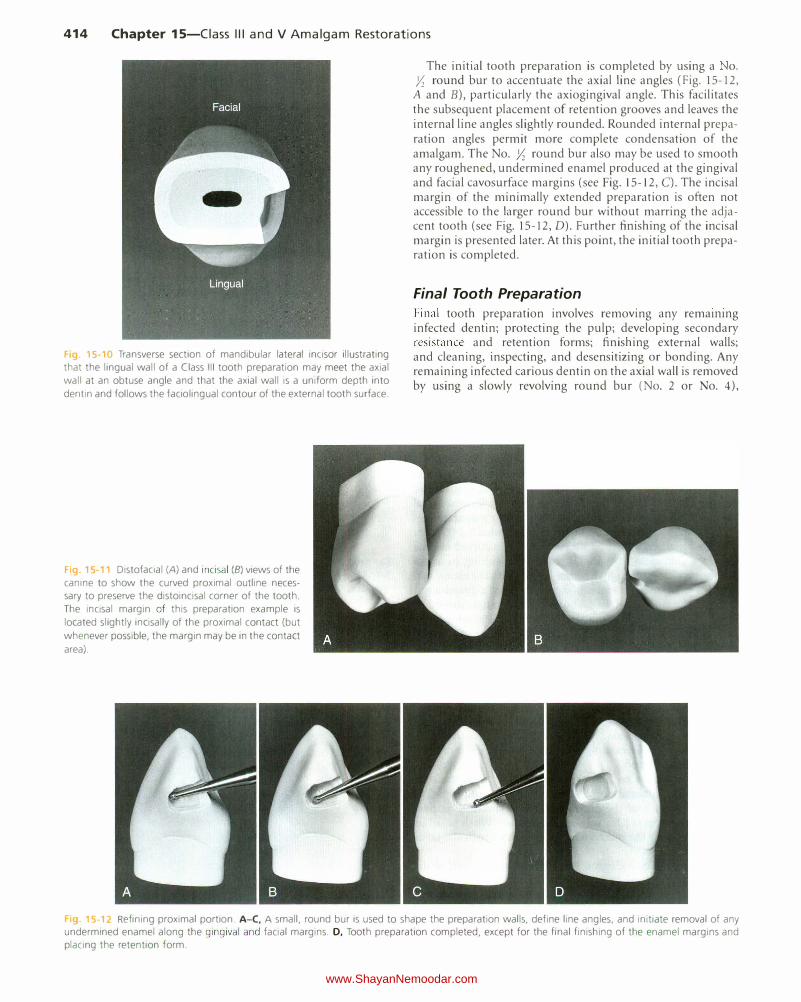
414 Chapter 15-Ciass Ill and V Amalgam Restorations
F g 15·10 Transverse section of mandibular lateral incisor illustrating that the lingual wall of a Class Ill tooth preparation may meet the axial
wall at an obtuse angle and that the axial wall is a uniform depth into
dentin and follows the faciolingual contour of the external tooth surface.
F g. 15 11 Distofacial (A) and incisal (B) views of the canine to show the curved proximal outline necessary to preserve the distoincisal corner of the tooth.
The incisal margin of this preparation example is
located slightly incisally of the proximal contact (but
whenever possible, the margin may be in the contact
area).
The initial tooth preparation is completed by using a o. Yz round bur to accentuate the axial line angles (Fig. 15-12,
A and B), particularly the axiogingival angle. This facilitates the subsequent placement of retention grooves and leaves the internal line angles slightly rounded. Rounded internal preparation angles permit more complete condensation of the amalgam. The No. Yz round bur also may be used to smooth any roughened, undermined enamel produced at the gingival and facial cavosurface margins (see Fig. 15-12, C). The incisal margin of the minimally extended preparation is often not accessible to the larger round bur without marring the adjacent tooth (see Fig. 15-12, D). Further finishing of the incisal margin is presented later. At this point, the initial tooth preparation is completed.
Final Tooth Preparation
Final tooth preparation involves removing any remammg infected dentin; protecting the pulp; developing secondary resistance and retention forms; finishing external walls; and cleaning, inspecting, and desensitizing or bonding. Any remaining infected carious dentin on the axial wall is removed by using a slowly revolving round bur (No. 2 or No. 4),
15-12 Refining proximal portion. A-C, A small, round bur is used to shape the preparation walls, define line angles, and initiate removal of any undermined enamel along the gingival and facial margins. D, Tooth preparation completed, except for the final finishing of the enamel margins and placing the retention form.
www.ShayanNemoodar.com
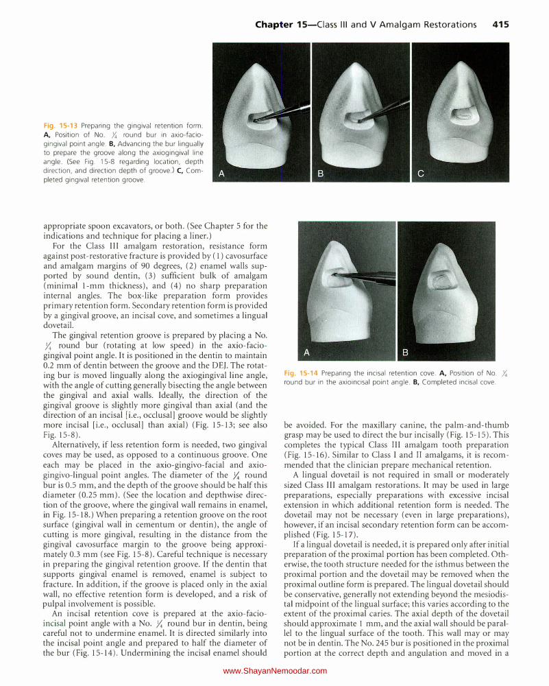
Chapter 15-Ciass Ill and V Amalgam Restorations 415
Fig. 15-13 Preparing the gingival retention form.
A, Position of No. Y. round bur in axio-facio
gingival point angle. B, Advancing the bur lingually
to prepare the groove along the axiogingival line
angle. (See Fig. 15-8 regarding location, depth
direction, and direction depth of groove.) C, Com
pleted gingival retention groove.
appropriate spoon excavators, or both. (See Chapter 5 for the indications and technique for placing a liner.)
For the Class III amalgam restoration, resistance form against post-restorative fracture is provided by (1) cavosurface and amalgam margins of 90 degrees, (2) enamel walls supported by sound dentin, (3) sufficient bulk of amalgam (minimal 1-mm thickness), and (4) no sharp preparation internal angles. The box-like preparation form provides primary retention form. Secondary retention form is provided by a gingival groove, an incisal cove, and sometimes a lingual dovetail.
The gingival retention groove is prepared by placing a No. y,; round bur (rotating at low speed) in the axio-faciogingival point angle. It is positioned in the dentin to maintain 0.2 mm of dentin between the groove and the DEJ. The rotating bur is moved lingually along the axiogingival line angle, with the angle of cutting generally bisecting the angle between the gingival and axial walls. Ideally, the direction of the gingival groove is slightly more gingival than axial (and the direction of an incisal [i.e., occlusal] groove would be slightly more incisal [i.e., occlusal] than axial) (Fig. 15-13; see also Fig. 15-8).
Alternatively, if less retention form is needed, two gingival coves may be used, as opposed to a continuous groove. One each may be placed in the axio-gingivo-facial and axiogingivo-lingual point angles. The diameter of the y,; round bur is 0.5 mm, and the depth of the groove should be half this diameter (0.25 mm). (See the location and depthwise direction of the groove, where the gingival wall remains in enamel, in Fig. 15-18.) When preparing a retention groove on the root surface (gingival wall in cementum or dentin), the angle of cutting is more gingival, resulting in the distance from the gingival cavosurface margin to the groove being approximately 0.3 mm (see Fig. 15-8). Careful technique is necessary in preparing the gingival retention groove. If the dentin that supports gingival enamel is removed, enamel is subject to fracture. In addition, if the groove is placed only in the axial wall, no effective retention form is developed, and a risk of pulpal involvement is possible.
An incisal retention cove is prepared at the axio-facioincisal point angle with a No. y,; round bur in dentin, being careful not to undermine enamel. It is directed similarly into the incisal point angle and prepared to half the diameter of the bur (Fig. 15-14). Undermining the incisal enamel should
Fig. 15-14 Preparing the incisal retention cove. A, Position of No. Y.
round bur in the axioincisal point angle. B, Completed incisal cove.
be avoided. For the maxillary canine, the palm-and-thumb grasp may be used to direct the bur incisally (Fig. 15-15). This completes the typical Class III amalgam tooth preparation (Fig. 15-16). Similar to Class I and II amalgams, it is recommended that the clinician prepare mechanical retention.
A lingual dovetail is not required in small or moderately sized Class III amalgam restorations. It may be used in large preparations, especially preparations with excessive incisal extension in which additional retention form is needed. The dovetail may not be necessary (even in large preparations), however, if an incisal secondary retention form can be accomplished (Fig. 15-17).
If a lingual dovetail is needed, it is prepared only after initial preparation of the proximal portion has been completed. Otherwise, the tooth structure needed for the isthmus between the proximal portion and the dovetail may be removed when the proximal outline form is prepared. The lingual dovetail should be conservative, generally not extending beyond the mesiodistal midpoint of the lingual surface; this varies according to the extent of the proximal caries. The axial depth of the dovetail should approximate I mm, and the axial wall should be parallel to the lingual surface of the tooth. This wall may or may not be in dentin. The No. 245 bur is positioned in the proximal portion at the correct depth and angulation and moved in a
www.ShayanNemoodar.com
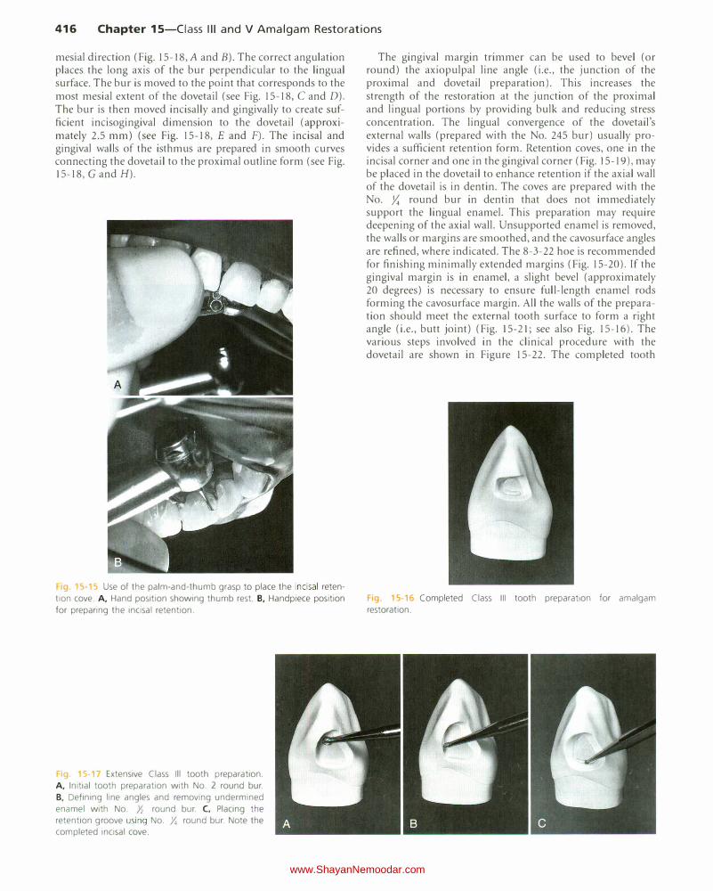
416 Chapter 15-Ciass Ill and V Amalgam Restorations
mesial direction (Fig. 15-18, A and B). The correct angulation places the long axis of the bur perpendicular to the lingual surface. The bur is moved to the point that corresponds to the most mesial extent of the dovetail (see Fig. 15-18, C and D). The bur is then moved incisally and gingivally to create sufficient incisogingival dimension to the dovetail (approximately 2.5 mm) (see Fig. 15-18, E and F). The incisal and gingival walls of the isthmus are prepared in smooth curves connecting the dovetail to the proximal outline form (see Fig. 15-18, G and H).
19. 15·15 Use of the palm-and-thumb grasp to place the incisal reten
tion cove. A, Hand position showing thumb rest. B, Handpiece position for preparing the incisal retention.
1g. 5 Extensive Class Ill tooth preparation. A, Initial tooth preparation with No. 2 round bur. B, Defining line angles and removing undermined enamel with No. Yz round bur. C, Placing the retention groove using No . .Y. round bur. Note the completed incisal cove.
The gingival margin trimmer can be used to bevel (or round) the axiopulpal line angle (i.e., the junction of the proximal and dovetail preparation). This increases the strength of the restoration at the junction of the proximal and lingual portions by providing bulk and reducing stress concentration. The lingual convergence of the dovetail's external walls (prepared with the No. 245 bur) usually provides a sufficient retention form. Retention coves, one in the incisal corner and one in the gingival corner (Fig. 15-19), may be placed in the dovetail to enhance retention if the axial wall of the dovetail is in dentin. The coves are prepared with the No. y,; round bur in dentin that does not immediately support the lingual enamel. This preparation may require deepening of the axial wall. Unsupported enamel is removed, the walls or margins are smoothed, and the cavosurface angles are refined, where indicated. The 8-3-22 hoe is recommended for finishing minimally extended margins (Fig. 15-20). If the gingival margin is in enamel, a slight bevel (approximately 20 degrees) is necessary to ensure full-length enamel rods forming the cavosurface margin. All the walls of the preparation should meet the external tooth surface to form a right angle (i.e., butt joint) (Fig. 15-21; see also Fig. 15-16). The various steps involved in the clinical procedure with the dovetail are shown in Figure 15-22. The completed tooth
Fig. 15-16 Completed Class Ill tooth preparation for amalgam restoration.
www.ShayanNemoodar.com

Chapter 15-Ciass Ill and V Amalgam Restorations 417
Fig 15-18 Lingual dovetail providing additional retention for extensive amalgam restoration. A, Bur position at correct depth and angulation to begin
cutting. B, Initial cut in beginning dovetail. C, Bur moved to most mesial extent of dovetail. D, If possible, cutting should not extend beyond the
midlingual position. E, Bur cutting gingival extension of the dovetail. F, Incisal and gingival extensions of the dovetail. G, Completing the isthmus.
The proximal and lingual portions are connected by the incisal and gingival walls in smooth curves. H, Completed lingual dovetail.
Fig. 15-19 Ensuring retention in lingual dovetail (often optional).
A, Position of No. 33Yz bur for cutting the retention cove. B, Preparation
of the cove should not remove the dentinal support of the lingual enamel
(arrow).
preparation should be cleaned of any residual debris and inspected. Careful assessment should be made to see that all of the caries has been removed, that the depth and retention are appropriate, and that cavosurface margins provide for the amalgam bulk.
Restorative Technique
Desensitizer Placement
The use of a dentin desensitizer over the prepared tooth structure before placing amalgam is generally recommended. The dentin desensitizer is rubbed onto the prepared tooth surface for 30 seconds and excess moisture is removed without desiccating the dentin.
Matrix Placement The wedged, rigid material-supported sectional matrix may be used for the Class III amalgam restoration. Insertion of amalgam into the Class Ill tooth preparation is usually from the lingual aspect. It is essential to trim the lingual portion of the sectional matrix material correctly to avoid covering the preparation and blocking access for insertion of the amalgam. A length of ){6 inch (8 mm) wide, 0.002 inch (0.05 mm) thick stainless steel matrix material that covers one-third of the facial surface and extends through the proximal to the lingual surface is obtained. The lingual portion is trimmed at an angle that corresponds approximately to the slope of the lingual surface of the tooth (Fig. 15-23). The section of matrix is burnished on a resilient paper pad to create the desired contact and contour form. The sectional matrix is placed in position and wedged from the facial or lingual embrasure, whichever
www.ShayanNemoodar.com
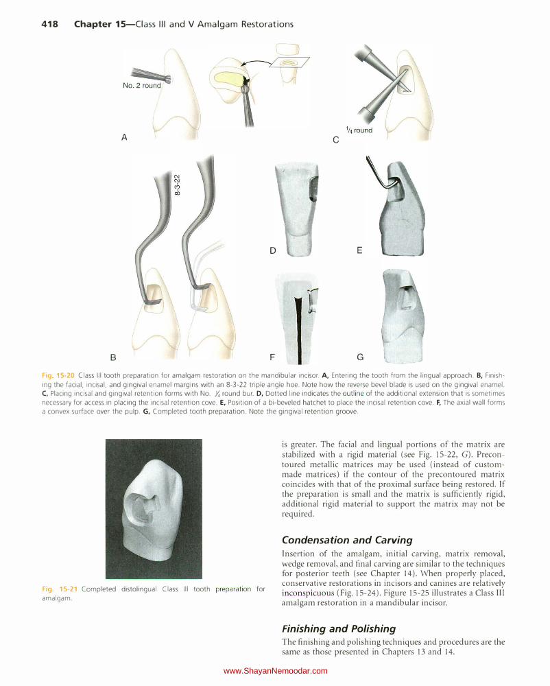
418 Chapter 15-Ciass Ill and V Amalgam Restorations
A c
E
B F G
Fig 5-20 Class Ill tooth preparation for amalgam restoration on the mandibular incisor. A, Entering the tooth from the lingual approach. B, Finish
ing the facial, incisal, and gingival enamel margins with an 8-3-22 triple angle hoe. Note how the reverse bevel blade is used on the gingival enamel. C, Placing incisal and gingival retention forms with No. Y. round bur. D, Dotted line indicates the outline of the additional extension that is sometimes
necessary for access in placing the incisal retention cove. E, Position of a bi-beveled hatchet to place the incisal retention cove. F, The axial wall forms
a convex surface over the pulp. G, Completed tooth preparation. Note the gingival retention groove.
F1g 15 21 Completed distolingual Class Ill tooth preparation for
amalgam.
is greater. The facial and lingual portions of the matrix are stabilized with a rigid material (see Fig. 15-22, G). Precontoured metallic matrices may be used (instead of custommade matrices) if the contour of the precontoured matrix coincides with that of the proximal surface being restored. If the preparation is small and the matrix is sufficiently rigid, additional rigid material to support the matrix may not be required.
Condensation and Carving
Insertion of the amalgam, initial carving, matrix removal, wedge removal, and final carving are similar to the techniques for posterior teeth (see Chapter 14). When properly placed, conservative restorations in incisors and canines are relatively inconspicuous (Fig. 15-24). Figure 15-25 illustrates a Class Ill amalgam restoration in a mandibular incisor.
Finishing and Polishing The finishing and polishing techniques and procedures are the same as those presented in Chapters 13 and 14.
www.ShayanNemoodar.com
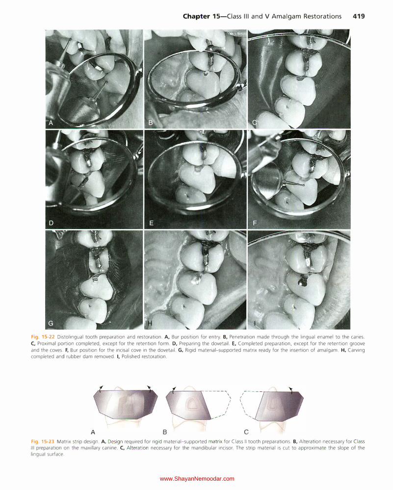
Chapter 15-Ciass Ill and V Amalgam Restorations 419
Fig. 15-22 Distolingual tooth preparation and restoration. A, Bur position for entry. B, Penetration made through the lingual enamel to the caries.
C, Proximal portion completed, except for the retention form. D, Preparing the dovetail. E, Completed preparation, except for the retention groove
and the coves. F, Bur position for the incisal cove in the dovetail. G, Rigid material-supported matrix ready for the insertion of amalgam. H, Carving completed and rubber dam removed. I, Polished restoration.
A B
rf-----..- -----""' \ I
\ I
I I
I I
I I
I I '
'
c
Fig. 15-23 Matrix strip design. A, Design required for rigid material-supported matrix for Class II tooth preparations. B, Alteration necessary for Class Ill preparation on the maxillary canine. C, Alteration necessary for the mandibular incisor. The strip material is cut to approximate the slope of the lingual surface.
www.ShayanNemoodar.com

420 Chapter 15-Ciass Ill and V Amalgam Restorations
Fi 15· 24 Inconspicuous facial margin (arrow) of Class Ill amalgam
restoration on the maxillary canine.
F1g. 15-25 Class Ill amalgam restoration on the mandibular incisor
(arrowhead).
Clinical Technique for Class V Amalgam Restorations
Initial Procedures Proper isolation prevents moisture contamination of the operating site, enhances asepsis, and facilitates access and visibility. Moisture in the form of saliva, gingival sulcular fluid, or gingival hemorrhage must be excluded during caries removal, liner application, and insertion and carving of amalgam. Moisture impairs visual assessment, may contaminate the pulp during caries removal (especially with a pulpal exposure), and negatively affects the physical properties of restorative materials. The gingival margin of Class V tooth preparations is often apical to the gingival crest. Such a gingival margin necessitates retraction of the free gingiva with a retraction cord or appropriate rubber dam and retainer to protect it and to provide access, while eliminating seepage of sulcular fluid into the tooth preparation or restorative materials.
These isolation objectives are met by local anesthesia and isolation by (1) a cotton roll and a retraction cord or (2) a rubber dam and a suitable cervical retainer (Fig. 15-26). Isolation with a cotton roll and a retraction cord is satisfactory when properly performed. This type of isolation is practical and probably the approach most often used. The retraction cord should be placed in the sulcus before initial tooth preparation to reduce the possibility of cutting instruments damaging the free gingiva. The cord should produce a temporary,
Fig. 15-26 A rubber dam and a No. 212 retainer may be required to isolate the carious area properly.
adequate, a traumatic apical retraction and lateral deflection of the free gingiva. The cord may be treated with hemostatic preparations containing aluminum chloride or ferrous sulfate. Alternatively, the cord may be treated with epinephrine. However, caution must be used as epinephrine on abraded gingiva can be absorbed rapidly into the circulatory system, causing an increase in blood pressure, elevated heart rate, and possible dysrhythmia. The retraction cord may be braided, twisted, or woven. The diameter of the cord should be easily accommodated in the gingival sulcus. An appropriate amount is cut to a length y; inch (6 mm) longer than the gingival margin. Some operators prefer to place the cord in a Dappen dish, wet it with a drop of hemostatic solution and blot it with a 2 x 2 inch (5 x 5 em) gauze to remove excess liquid. A braided or woven cord is usually easier to use because it does not unravel during placement. A larger cord can be inserted over the first cord if the sulcus is large enough to accommodate two cords. A thin, blunt-edged instrument blade or the side of an explorer tine may be used to gently insert the cord progressively into place. A slight backward direction of the instrument as it steps along the cord helps prevent dislodgment of previously inserted cord (Fig. 15-27). In addition, using a second instrument stepping along behind the first instrument can help prevent dislodgment of cord. Additionally, using the air syringe or cotton pellets to reduce or absorb the sulcular fluid in the cord already placed is helpful during cord placement. The cord results in adequate retraction in a short time. If significant blanching of the free gingiva is observed (or if too much pressure has to be applied to place the cord), it means that an oversized cord has been selected, and it should therefore be exchanged with a cord of smaller diameter. The cord can be moistened before or after placement with the hemostatic solution if slight hemorrhage is anticipated or observed. Alternatively, the cord can be used dry.
The cord usually remains in place throughout tooth preparation as well as insertion and initial carving of amalgam. While carving amalgam at the gingival margin, the presence of the cord may cause difficulty in feeling the unprepared tooth surface apical to the margin to prevent under-carving of the margin; this results in over-contouring and marginal excess. In this instance, after carving gross excess, the cord can be teased from its place before the carving is completed.
Tooth Preparation Proper outline form for Class V amalgam tooth preparations results in extending the cavosurface margins to sound tooth structure while maintaining a limited axial depth of 0.5 mm
www.ShayanNemoodar.com
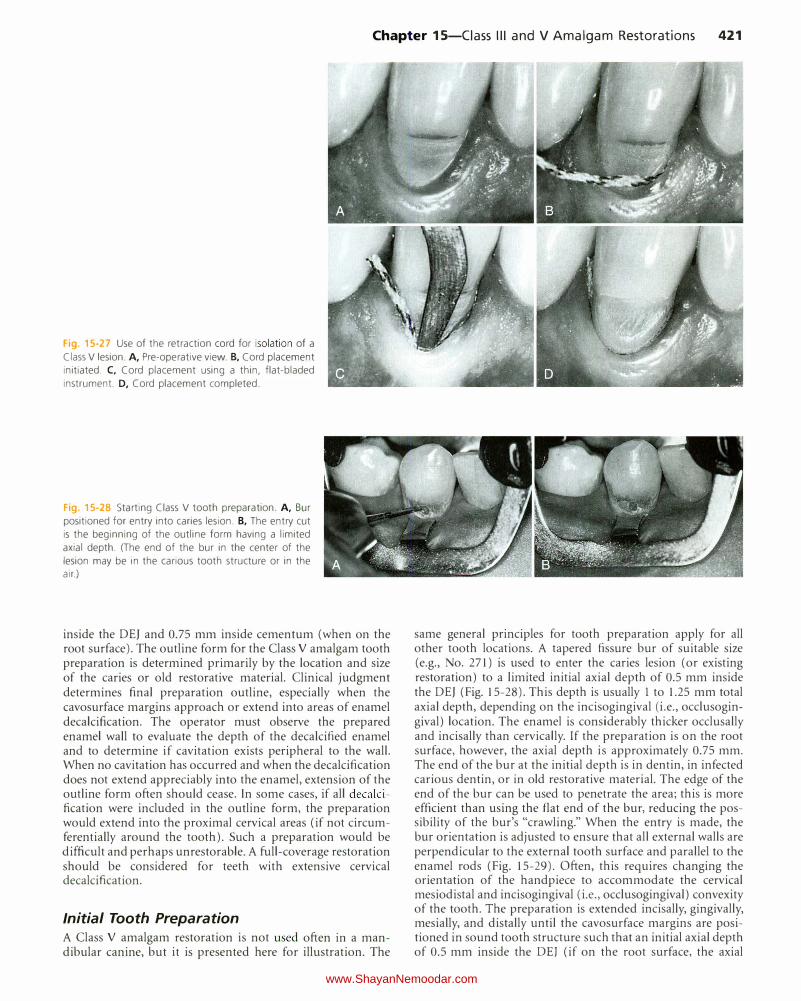
Chapter 15-Ciass Ill and V Amalgam Restorations 421
Fig. 15-27 Use of the retraction cord for isolation of a
Class V lesion. A, Pre-operative view. B, Cord placement initiated. C, Cord placement using a thin, flat-bladed
instrument. D, Cord placement completed.
Fig. 15-28 Starting Class V tooth preparation. A, Bur
positioned for entry into caries lesion. B, The entry cut is the beginning of the outline form having a limited
axial depth. (The end of the bur in the center of the
lesion may be in the carious tooth structure or in the air.)
inside the DEJ and 0.75 mm inside cementum (when on the root surface). The outline form for the Class V amalgam tooth preparation is determined primarily by the location and size of the caries or old restorative material. Clinical judgment determines final preparation outline, especially when the cavosurface margins approach or extend into areas of enamel decalcification. The operator must observe the prepared enamel wall to evaluate the depth of the decalcified enamel and to determine if cavitation exists peripheral to the wall. When no cavitation has occurred and when the decalcification does not extend appreciably into the enamel, extension of the outline form often should cease. In some cases, if all decalcification were included in the outline form, the preparation would extend into the proximal cervical areas (if not circumferentially around the tooth). Such a preparation would be difficult and perhaps unrestorable. A full-coverage restoration should be considered for teeth with extensive cervical decalcification.
Initial Tooth Preparation
A Class V amalgam restoration is not used often in a mandibular canine, but it is presented here for illustration. The
same general principles for tooth preparation apply for all other tooth locations. A tapered fissure bur of suitable size (e.g., No. 271) is used to enter the caries lesion (or existing restoration) to a limited initial axial depth of 0.5 mm inside the DEJ (Fig. 15-28). This depth is usually 1 to 1.25 mm total axial depth, depending on the incisogingival (i.e., occlusogingival) location. The enamel is considerably thicker occlusally and incisally than cervically. If the preparation is on the root surface, however, the axial depth is approximately 0.75 mm. The end of the bur at the initial depth is in dentin, in infected carious dentin, or in old restorative material. The edge of the end of the bur can be used to penetrate the area; this is more efficient than using the flat end of the bur, reducing the possibility of the bur's "crawling." When the entry is made, the bur orientation is adjusted to ensure that all external walls are perpendicular to the external tooth surface and parallel to the enamel rods (Fig. 15-29). Often, this requires changing the orientation of the handpiece to accommodate the cervical mesiodistal and incisogingival (i.e., occlusogingival) convexity of the tooth. The preparation is extended incisally, gingivally, mesially, and distally until the cavosurface margins are positioned in sound tooth structure such that an initial axial depth of 0.5 mm inside the DEJ (if on the root surface, the axial
www.ShayanNemoodar.com
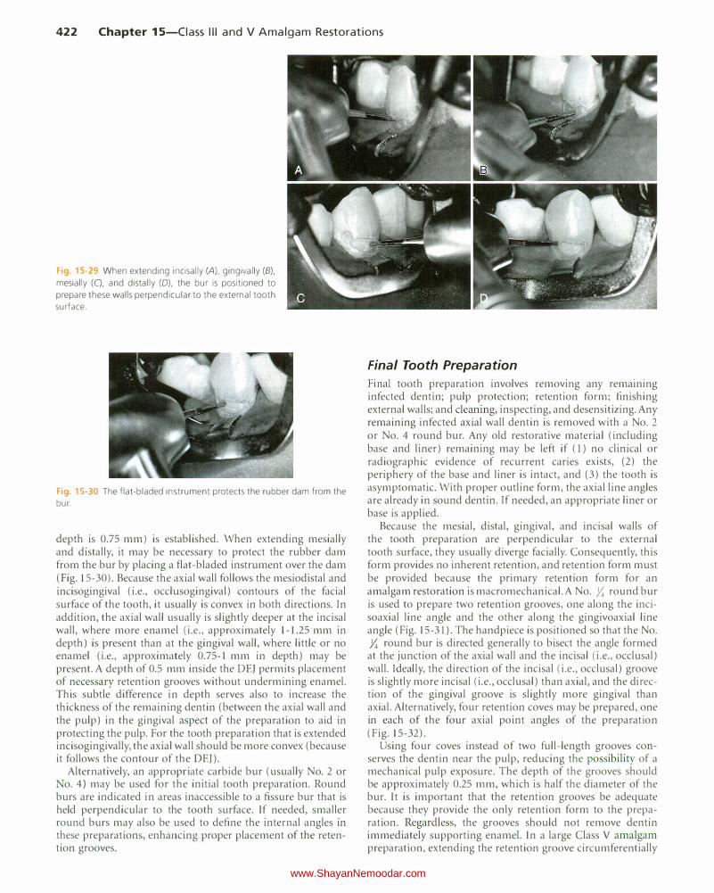
422 Chapter 15-Ciass Ill and V Amalgam Restorations
Fig. 15-29 When extending incisally (A), gingivally (B), mesially (C), and distally (0), the bur is positioned to
prepare these walls perpendicular to the external tooth
surface.
Fig 15-30 The flat-bladed instrument proteds the rubber dam from the
bur.
depth is 0.75 mm) is established. When extending mesially and distally, it may be necessary to protect the rubber dam from the bur by placing a flat-bladed instrument over the dam (Fig. 15-30). Because the axial wall follows the mesiodistal and incisogingival (i.e., occlusogingival) contours of the facial surface of the tooth, it usually is convex in both directions. In addition, the axial wall usually is slightly deeper at the incisal wall, where more enamel (i.e., approximately 1-1.25 mm in depth) is present than at the gingival wall, where little or no enamel (i.e., approximately 0.75-1 mm in depth) may be present. A depth of 0.5 mm inside the DEJ permits placement of necessary retention grooves without undermining enamel. This subtle difference in depth serves also to increase the thickness of the remaining dentin (between the axial wall and the pulp) in the gingival aspect of the preparation to aid in protecting the pulp. For the tooth preparation that is extended incisogingivally, the axial wall should be more convex (because it follows the contour of the DEJ).
Alternatively, an appropriate carbide bur (usually No. 2 or o. 4) may be used for the initial tooth preparation. Round
burs are indicated in areas inaccessible to a fissure bur that is held perpendicular to the tooth surface. If needed, smaller round burs may also be used to define the internal angles in these preparations, enhancing proper placement of the retention grooves.
Final Tooth Preparation
Final tooth preparation involves removmg any remammg infected dentin; pulp protection; retention form; finishing external walls; and cleaning, inspecting, and desensitizing. Any remaining infected axial wall dentin is removed with a No. 2
or No. 4 round bur. Any old restorative material (including base and liner) remaining may be left if (1) no clinical or radiographic evidence of recurrent caries exists, (2) the periphery of the base and liner is intact, and (3) the tooth is asymptomatic. With proper outline form, the axial line angles are already in sound dentin. If needed, an appropriate liner or base is applied.
Because the mesial, distal, gingival, and incisal walls of the tooth preparation are perpendicular to the external tooth surface, they usually diverge facially. Consequently, this form provides no inherent retention, and retention form must be provided because the primary retention form for an amalgam restoration is macromechanical. A No. )I; round bur is used to prepare two retention grooves, one along the incisoaxial line angle and the other along the gingivoaxial line angle (Fig. 15-31 ). The handpiece is positioned so that the No. y,; round bur is directed generally to bisect the angle formed
at the junction of the axial wall and the incisal (i.e., occlusal) wall. Ideally, the direction of the incisal (i.e., occlusal) groove is slightly more incisal (i.e., occlusal) than axial, and the direction of the gingival groove is slightly more gingival than axial. Alternatively, four retention coves may be prepared, one in each of the four axial point angles of the preparation (Fig. 15-32).
Using four coves instead of two full-length grooves conserves the dentin near the pulp, reducing the possibility of a mechanical pulp exposure. The depth of the grooves should be approximately 0.25 mm, which is half the diameter of the bur. It is important that the retention grooves be adequate because they provide the only retention form to the preparation. Regardless, the grooves should not remove dentin immediately supporting enamel. In a large Class V amalgam preparation, extending the retention groove circumferentially
www.ShayanNemoodar.com
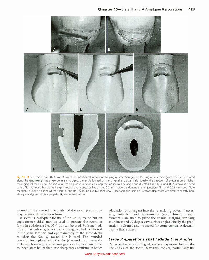
Chapter 15-Ciass Ill and V Amalgam Restorations 423
Fig. 15-31 Retention form. A, A No. Y. round bur positioned to prepare the gingival retention groove. B, Gingival retention groove (arrow) prepared along the gingivoaxial line angle generally to bisect the angle formed by the gingival and axial walls. Ideally, the direction of preparation is slightly
more gingival than pulpal. An incisal retention groove is prepared along the incisoaxial line angle and directed similarly. C and D, A groove is placed with a No. Y. round bur along the gingivoaxial and incisoaxial line angles 0.2 mm inside the dentinoenamel junction (DEJ) and 0.25 mm deep. Note
the slight pulpal inclination of the shank of the No. Y. round bur. E, Facial view. F, lncisogingival section. Grooves depthwise are directed mostly incisally (gingivally) and slightly pulpally. G, Mesiodistal section.
around all the internal line angles of the tooth preparation may enhance the retention form.
If access is inadequate for use of the No. )':; round bur, an angle-former chisel may be used to prepare the retention form. In addition, a No. 33Yz bur can be used. Both methods result in retention grooves that are angular, but positioned in the same location and approximately to the same depth as when the No. )':; round bur is used. The rounded retention form placed with the No. )':; round bur is generally preferred, however, because amalgam can be condensed into rounded areas better than into sharp areas, resulting in better
adaptation of amalgam into the retention grooves. If necessary, suitable hand instruments (e.g., chisels, margin trimmers) are used to plane the enamel margins, verifying soundness and 90-degree cavosurface angles. Finally, the preparation is cleaned and inspected for completeness. A desensitizer is then applied.
Large Preparations That Include Line Angles
Caries on the facial (or lingual) surface may extend beyond the line angles of the tooth. Maxillary molars, particularly the
www.ShayanNemoodar.com

424 Chapter 15-Ciass Ill and V Amalgam Restorations
I _______ l. __ _
I I I
B ,!f,i
I IJ IJ IJ II 0.25 mm
II \ II
\ ( 'I \I I _, .
"'·-{-_ .... · I I
t
0.75mm�� �
0.25 - 0.3 mm- :-+---
\ \
Recommended
D four-cove retention A c
Fig 15-32 A-C, Extended Class V tooth preparation (A) with the axial wall contoured parallel to the dentinoenamel junction (DEJ) mesiodistally (B) and incisogingivally (C). T he axial wall pulpal depth is 1 mm in the crown and 0.75 mm in the root. In addition, note location and direction depth (0.25 mm) of the retention grooves and the dimension of the gingival wall (0.25 mm) from the root surface to the retention groove. D, Large Class
V preparation with retention coves prepared in the four axial point angles.
Fig 15-33 Tooth preparation on maxillary molar. A, Caries extending around distofacial corner of the tooth. B and C, Distal extension is accomplished with round bur. D-F, A
gingival margin trimmer may be useful in completing
the distal half of the preparation when handpiece access
is limited. G, A gingival margin trimmer may be used to provide the retention grooves. H, An angle-former chisel may be used to prepare the retention grooves in the distal portion of the preparation. I, Completed tooth preparation.
A
D
G
second molars, are most commonly affected by these extensive defects (Fig. 15-33, A). In this example, if the remainder of the distal surface is sound and the distal caries is accessible facially, the facial restoration should extend around the line angle. This prevents the need for a Class II proximal restoration to restore the distal surface. As much of the preparation as possible should be completed with a fissure bur. A round bur, approximately the same diameter as the fissure bur, is then used to initiate the distal portion of the preparation (see Fig. 15-33, B
and C). Smaller round burs should be used to accentuate the internal line angles of the distal portion. Preparing the facial portion first provides better access and visibility to the distal
c
E F
H
portion. Occasionally, hand instruments may be useful for completing the distal half of the preparation when space for the handpiece is limited (see Fig. 15-33, D through F).
Grooves placed along the entire length of the occlusoaxial and gingivoaxial line angles help ensure retention of the restoration. The No. ,Y.; round bur is used as previously described to prepare the retention grooves. A gingival margin trimmer or a 7-85- 2/i -6 angle-former chisel can be used in the distal half of the preparation to provide retention form when access for the handpiece is limited (see Fig. 15-33, G and H).
Because of the proximity of the coronoid process, access to the facial surfaces of maxillary molars, particularly the second
www.ShayanNemoodar.com
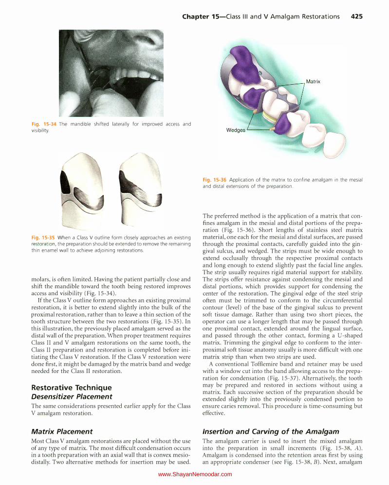
Chapter 15-Ciass Ill and V Amalgam Restorations 425
Fig. 15-34 The mandible shifted laterally for improved access and visibility.
(
Fig. 15-35 When a Class V outline form closely approaches an existing restoration, the preparation should be extended to remove the remaining thin enamel wall to achieve adjoining restorations.
molars, is often limited. Having the patient partially close and shift the mandible toward the tooth being restored improves access and visibility (Fig. 15-34).
If the Class V outline form approaches an existing proximal restoration, it is better to extend slightly into the bulk of the proximal restoration, rather than to leave a thin section of the tooth structure between the two restorations (Fig. 15-35). In this illustra6on, the previously placed amalgam served as the distal wall of the preparation. When proper treatment requires Class II and V amalgam restorations on the same tooth, the Class II preparation and restoration is completed before initiating the Class V restoration. If the Class V restoration were done first, it might be damaged by the matrix band and wedge needed for the Class II restoration.
Restorative Technique Desensitizer Placement The same considerations presented earlier apply for the Class V amalgam restoration.
Matrix Placement Most Class V amalgam restorations are placed without the use of any type of matrix. The most difficult condensation occurs in a tooth preparation with an axial wall that is convex mesiodistally. Two alternative methods for insertion may be used.
Fig. 15-36 Application of the matrix to confine amalgam in the mesial and distal extensions of the preparation.
The preferred method is the application of a matrix that confines amalgam in the mesial and distal portions of the preparation (Fig. 15-36). Short lengths of stainless steel matrix material, one each for the mesial and distal surfaces, are passed through the proximal contacts, carefully guided into the gingival sulcus, and wedged. The strips must be wide enough to extend occlusally through the respective proximal contacts and long enough to extend slightly past the facial line angles. The strip usually requires rigid material support for stability. The strips offer resistance against condensing the mesial and distal portions, which provides support for condensing the center of the restoration. The gingival edge of the steel strip often must be trimmed to conform to the circumferential contour (level) of the base of the gingival sulcus to prevent soft tissue damage. Rather than using two short pieces, the operator can use a longer length that may be passed through one proximal contact, extended around the lingual surface, and passed through the other contact, forming a U-shaped matrix. Trimming the gingival edge to conform to the interproximal soft tissue anatomy usually is more difficult with one matrix strip than when two strips are used.
A conventional Toffiemire band and retainer may be used with a window cut into the band allowing access to the preparation for condensation (Fig. 15-37). Alternatively, the tooth may be prepared and restored in sections without using a matrix. Each successive section of the preparation should be extended slightly into the previously condensed portion to ensure caries removal. This procedure is time-consuming but effective.
Insertion and Carving of the Amalgam The amalgam carrier is used to insert the mixed amalgam into the preparation in small increments (Fig. 15-38, A). Amalgam is condensed into the retention areas first by using an appropriate condenser (see Fig. 15-38, B). Next, amalgam
www.ShayanNemoodar.com
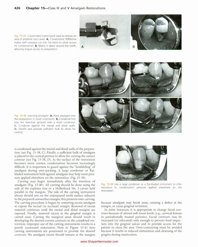
426 Chapter 15-Ciass Ill and V Amalgam Restorations
Fig. 15-37 Customized matrix band used to restore an
area of proximal root caries. A, Conventional Tofflemire
matrix with window cut into the band to allow access
for condensation. B, Matrix in place around the tooth,
allowing lingual access to preparation.
Fig. 15-38 Inserting amalgam. A, Place amalgam into
the preparation in small increments. B, Condense first
into the retention grooves with a small condenser.
C, Condense against the mesial and distal walls.
D, Overfill and provide sufficient bulk to allow for
carving.
is condensed against the mesial and distal walls of the preparation (see Fig. 15-38, C). Finally, a sufficient bulk of amalgam is placed in the central portion to allow for carving the correct contour (see Fig. 15-38, D). As the surface of the restoration becomes more convex, condensation becomes increasingly difficult. It is important to guard against the "landsliding" of amalgam during over-packing. A large condenser or flatbladed instrument held against amalgam may help resist pressure applied elsewhere on the restoration (Fig. 15-39).
Carving may begin immediately after the insertion of amalgam (Fig. 15-40). All carving should be done using the side of the explorer tine or a Hollenback No. 3 carver held parallel to the margins. The side of the carving instrument always should rest on the unprepared tooth surface adjacent to the prepared cavosurface margin; this prevents over-carving. The carving procedure is begun by removing excess amalgam to expose the incisal (or occlusal) margin. Removal of excess material continues until the mesial and distal margins are exposed. Finally, material excess at the gingival margin is carved away. Carving the marginal areas should result in developing the desired convex contours in the completed restoration. Improper use of the carving instruments results in a poorly contoured restoration. Note in Figure 15-41 how carving instruments are positioned to provide the desired contours. No amalgam excess should remain at the margins
Fig. 15-39 Use a large condenser or a flat-bladed instrument to offer resistance to condensation pressure applied elsewhere on the restoration.
because amalgam may break away, creating a defect at the margin, or cause gingival irritation.
In some instances, it is appropriate to change facial contours because of altered soft tissue levels (e.g., cervical lesions in periodontally treated patients). Facial contours may be increased (or relocated) only enough to prevent food impaction into the gingival sulcus and to provide access for the patient to clean the area. Over-contouring must be avoided because it results in reduced stimulation and cleansing of the gingiva during mastication.
www.ShayanNemoodar.com

Fig. 15-40 Carving and contouring the restoration. A, Begin the carving procedure by removing any excess and locating the incisal margin. B and C, An explorer
may be used to remove the excess and locate the
mesial and distal margins. D, Remove the excess and locate the gingival margin.
Chapter 15-Ciass Ill and V Amalgam Restorations 427
I / I
Fig. 15-41 Positioning of the carving instrument to prevent over-carving amalgam and to develop the desired gingival contours.
Fig. 15-42 Incorrect use of a pointed stone at the gingival margin results in the removal of cementum, notching of the tooth structure gingival to
the margin, or both.
A c
Fig. 15-43 Reshaping a rubber abrasive point against a mounted carborundum disk.
www.ShayanNemoodar.com
428 Chapter 15-Ciass Ill and V Amalgam Restorations
When a rubber dam and the No. 212 cervical retainer have been used for isolation, the retainer is removed using care to open the jaws of the retainer wide enough to prevent marring the surface of the restoration. The rubber dam is removed, and the area is examined carefully to ensure that no amalgam particles remain in the sulcus.
When a retraction cord is used for isolation, it may interfere with carving any excess amalgam at the gingival margin. If so, removal of the gross excess of amalgam is followed by careful removal of the cord, followed by completion of the carving along the margin.
Finishing and Polishing of the Amalgam If carving procedures were performed correctly, no finishing of the restoration should be required. A slightly moistened
cotton pellet held in cotton pliers may be used to further smooth the carved restoration. Additional finishing and polishing of amalgam restorations may be necessary, however, to correct a marginal discrepancy or to improve contour. Care is required when using stones or any rotating cutting instruments on margins positioned below the cementoenamel junction (CEJ) because of the possibility of removing cementum, notching the tooth structure gingival to the margin, or both (Fig. 15-42). Figure 15-43 illustrates re-shaping a rubber abrasive point to allow optimal access to the gingival portion of a Class V amalgam restoration.
www.ShayanNemoodar.com

Chapter 16
Complex Amalgam Restorations Lee W. Boushell, Aldridge D. Wilder, Jr.
Complex posterior restorations are used to replace any missing structure of teeth that have fractured, have severe caries involvement, or have existing restorative material. These restorations usually involve the replacement of one or more missing cusps and require additional means of retention. This chapter describes the use of dental amalgam for complex direct posterior restorations.
Review of Pertinent Material Qualities and Properties The properties, advantages, and limitations of amalgam are discussed in Chapter 13 and Online Chapter 18. Amalgam is easy to use and has a high compressive strength, excellent wear resistance, and proven long-term clinical performance. It has a metallic color, does not strengthen the tooth, and does not bond to tooth structure and therefore requires a retentive tooth preparation.
Indications Complex posterior amalgam restorations should be considered when large amounts of tooth structure are missing and when one or more cusps need capping (Fig. 16-1).1 Complex amalgams can be used as (1) definitive final restorations, (2) foundations, (3) control restorations in teeth that have a questionable pulpal or periodontal prognosis, or ( 4) control restorations in teeth with acute or severe caries. When determining the appropriateness of a complex amalgam restoration, the factors discussed in the following sections must be considered.
Resistance and Retention Forms ln a tooth with severe caries or existing restorative material, any undermined enamel or weak tooth structure subject to fracture must be removed and restored. Usually, a
weakened tooth is best restored with a properly designed indirect (usually cast) restoration that prevents tooth fracture caused by mastication forces (see Chapter 17). In selected cases, amalgam preparations that improve the resistance form of a tooth can be designed (Fig. 16-2).
When conventional retention features are not adequate because of insufficient remaining tooth structure, the retention form can be enhanced by using pins, slots, and elective groove extensions. The retention features needed depend on the amount of tooth structure remaining and the tooth being restored. As more tooth structure is lost, more auxiliary retention is required. Pins, slots, and box-like forms also provide additional resistance form to the restoration.
Status and Prognosis of the Tooth A tooth with severe caries that might require endodontic therapy or crown lengthening or that has an uncertain periodontal prognosis often is treated initially with a control restoration. A control restoration helps (1) protect the pulp from the oral cavity (i.e., fluids, thermal stresses, pH changes, bacteria), (2) provide an anatomic contour against which gingival tissue may be healthier, (3) facilitate control of caries and plaque, and ( 4) provide some resistance against tooth fracture (or propagation of an existing fracture). (See Chapter 2 for caries-control rationale and techniques.)
The status and prognosis of the tooth determine the size, number, and placement of retention features. Larger restorations generally require more retention. The size, number, and location of retention features demand greater care in smaller teeth, in teeth with deep excavations, and in symptomatic teeth. Carelessness can risk pulpal irritation or exposure.
Role of the Tooth in Overall Treatment Plan The restorative treatment choice for a tooth is influenced by its role in the overall treatment plan. Although complex amalgam restorations are used occasionally as an alternative
429 www.ShayanNemoodar.com

430 Chapter 16-Complex Amalgam Restorations
to indirect restorations, they often are used as foundations for full coverage restorations. Abutment teeth for fixed prostheses may use a complex restoration as a foundation (Fig. 16-3). Extensive caries or previous restorations on abutment teeth for removable prostheses generally indicate an indirect restoration for the resistance and retention forms and for development of external surface contours for retention of the prosthesis. A tooth may be treated with a complex direct restoration if adequate resistance and retention forms can be provided. For patients with periodontal and orthodontic problems, the complex restoration may be the restoration of choice until the final phase of treatment, when indirect restorations may be preferred.
Occlusion, Esthetics, and Economics Complex amalgam restorations are sometimes indicated as interim restorations for teeth that require elaborate occlusal alterations, ranging from vertical dimension changes to correcting occlusal plane discrepancies. When esthetics is a primary consideration, a complex amalgam restoration may not be the treatment of choice because of the display of metal. When cost of indirect restorations is a major factor for the patient, the complex direct amalgam restoration may be an appropriate treatment option, provided that adequate resistance and retention forms are included (Fig. 16-4).
Fig 16·1 Mesio-occluso-disto-lingual (MODL) complex amalgam tooth No.3.
Fig 6-2 Maxillary second premolar weakened by extensive caries and by the small fracture line extend
ing mesiodistally on the center of the excavated dentinal wall. A, Minikin pins placed in the gingival floor improve resistance form after amalgam has been placed. B, Restorations polished.
Age and Health of Patient For some older patients and those who are debilitated, complex amalgam restoration may be the treatment preferred over the more expensive and time-consuming cast restoration.
Contra indications
The complex amalgam restoration might be contraindicated if the patient has significant occlusal problems, or if the tooth cannot be restored properly with direct restoration because of anatomic or functional considerations (or both). The complex amalgam restoration also might be contraindicated if the area to be restored has esthetic importance for the patient.
Fig. 16-3 Mesio-occluso-disto-facial (MODF) amalgam foundation tooth
No. 15.
Fig. 16-4 Mesio-occluso-disto-facial-lingual (MODFL) complex amalgam
tooth #19
www.ShayanNemoodar.com
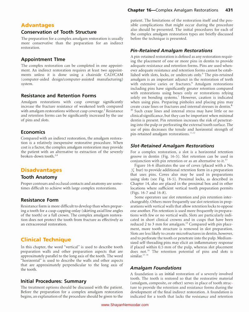
Advantages
Conservation of Tooth Structure
The preparation for a complex amalgam restoration is usually more conservative than the preparation for an indirect restoration.
Appointment Time The complex restoration can be completed in one appointment. An indirect restoration requires at least two appointments unless it is done using a chairside CAD/CAM (computer-aided design/computer-assisted manufacturing) system.
Resistance and Retention Forms Amalgam restorations with cusp coverage significantly increase the fracture resistance of weakened teeth compared with amalgam restorations without cusp coverage.2 Resistance and retention forms can be significantly increased by the use of pins and slots.
Economics Compared with an indirect restoration, the amalgam restoration is a relatively inexpensive restorative procedure. When cost is a factor, the complex amalgam restoration may provide the patient with an alternative to extraction of the severely broken-down toothY
Disadvantages
Tooth Anatomy
Proper contours and occlusal contacts and anatomy are sometimes difficult to achieve with large complex restorations.
Resistance Form Resistance form is more difficult to develop than when preparing a tooth for a cusp-capping onlay (skirting axial line angles of the tooth) or a full crown. The complex amalgam restoration does not protect the tooth from fracture as effectively as an extracoronal restoration.
Clinical Technique
In this chapter, the word "vertical" is used to describe tooth preparation walls and other preparation aspects that are approximately parallel to the long axis of the tooth. The word "horizontal" is used to describe the walls and other aspects that are approximately perpendicular to the long axis of the tooth.
Initial Procedures: Summary The treatment options should be discussed with the patient. Before the preparation for a complex amalgam restoration begins, an explanation of the procedure should be given to the
Chapter 16-Complex Amalgam Restorations 431
patient. The limitations of the restoration itself and the possible complications that might occur during the procedure also should be presented. The initial procedures for each of the complex amalgam restoration types are briefly discussed before the technique is presented.
Pin-Retained Amalgam Restorations A pin-retained restoration is defined as any restoration requiring the placement of one or more pins in dentin to provide adequate resistance and retention forms. Pins are used whenever adequate resistance and retention forms cannot be established with slots, locks, or undercuts only.5 The pin-retained amalgam is an important adjunct in the restoration of teeth with extensive caries or fractures.6 Amalgam restorations including pins have significantly greater retention compared with restorations using boxes only or restorations relying solely on bonding systems.7 However, caution is indicated when using pins. Preparing pinholes and placing pins may create craze lines or fractures and internal stresses in dentin.8-10 Such craze lines and internal stress may have little or no clinical significance, but they can be important when minimal dentin is present. Pin retention increases the risk of penetrating into the pulp or perforating the external tooth surface. The use of pins decreases the tensile and horizontal strength of pin-retained amalgam restorations.11•12
Slot-Retained Amalgam Restorations For a complex restoration, a slot is a horizontal retention groove in dentin (Fig. 16-5). Slot retention can be used in conjunction with pin retention or as an alternative to it.13
Figure 16-6 illustrates the use of coves (placed with a No. Y,: bur) to provide additional retention form in a preparation
that uses pins. Coves also may be used in preparations using slots (see Fig. 16-5). Proximal locks, as described in Chapter 14, also are placed in the proximal box and in other locations where sufficient vertical tooth preparation permits (Figs. 16-7 and 16-8).
Some operators use slot retention and pin retention interchangeably. Others more frequently use slot retention in preparations with vertical walls that allow retention locks to oppose one another. Pin retention is used more frequently in preparations with few or no vertical walls. Slots are particularly indicated in short clinical crowns and in cusps that have been reduced 2 to 3 mm for amalgam.13 Compared with pin placement, more tooth structure is removed in slot preparation. Slots are less likely to create micro fractures in dentin, however, and to perforate the tooth or penetrate into the pulp. Mediumsized self-threading pins may elicit an inflammatory response if placed within 0.5 mm of the pulp, whereas slot placement does not.14 The retention potential of pins and slots is similar.15-18
Amalgam Foundations A foundation is an initial restoration of a severely involved tooth. The tooth is restored so that the restorative material (amalgam, composite, or other) serves in place of tooth structure to provide the retention and resistance forms during the development of the final indirect restoration. A foundation is indicated for a tooth that lacks the resistance and retention
www.ShayanNemoodar.com
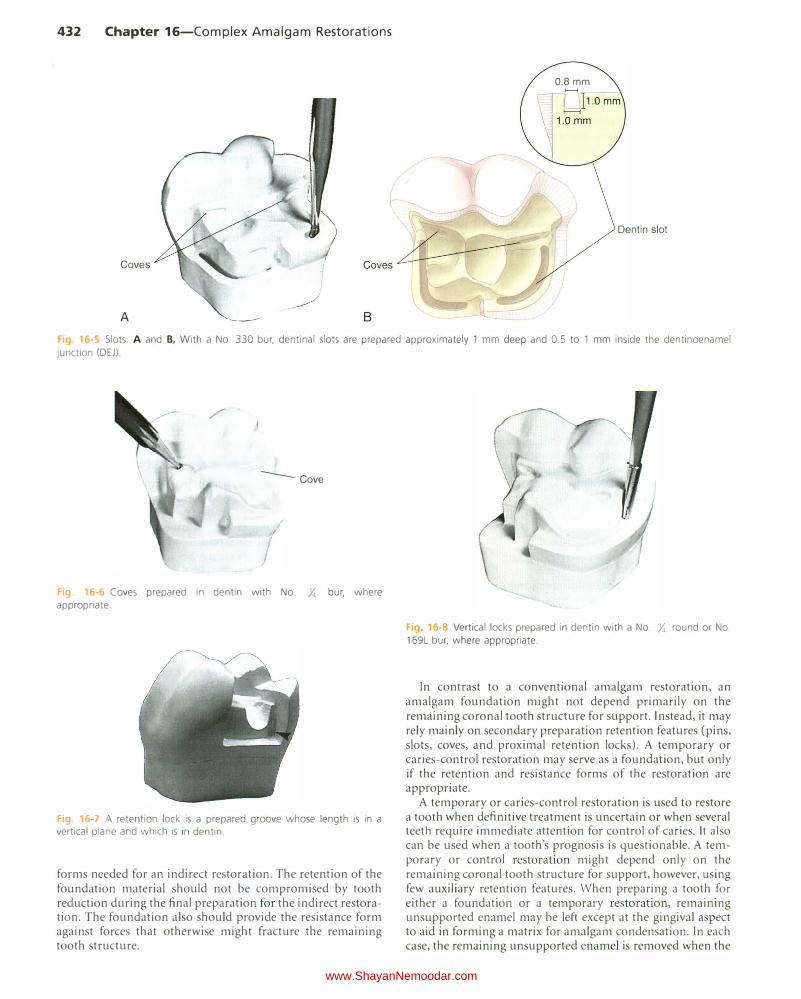
432 Chapter 16-Complex Amalgam Restorations
Coves
A
0.8mm
Dentin slot
Fig. 16-5 Slots. A and B. With a No. 330 bur, dentinal slots are prepared approximately 1 mm deep and 0.5 to 1 mm inside the dentinoenamel
junction (DEJ).
/ -
--Cove
"
I Fig. 16-6 Coves prepared in dentin with No. Y. bur, where appropriate.
Fig 16-7 A retention lock is a prepared groove whose length is in a vertical plane and which is i n dentin.
forms needed for an indirect restoration. The retention of the foundation material should not be compromised by tooth reduction during the final preparation for the indirect restoration. The foundation also should provide the resistance form against forces that otherwise might fracture the remaining tooth structure.
/
Fig 16-8 Vertical locks prepared in dentin with a No. Y. round or No. 169L bur, where appropriate.
In contrast to a conventional amalgam restoration, an amalgam foundation might not depend primarily on the remaining coronal tooth structure for support. Instead, it may rely mainly on secondary preparation retention features (pins, slots, coves, and proximal retention locks). A temporary or caries-control restoration may serve as a foundation, but only if the retention and resistance forms of the restoration are appropriate.
A temporary or caries-control restoration is used to restore a tooth when definitive treatment is uncertain or when several teeth require immediate attention for control of caries. It also can be used when a tooth's prognosis is questionable. A temporary or control restoration might depend only on the remaining coronal tooth structure for support, however, using few auxiliary retention features. When preparing a tooth for either a foundation or a temporary restoration, remaining unsupported enamel may be left except at the gingival aspect to aid in forming a matrix for amalgam condensation. In each case, the remaining unsupported enamel is removed when the
www.ShayanNemoodar.com

indirect restoration is placed. Occasionally, when providing a temporary or control restoration, sufficient retention and resistance forms are included in the preparation to meet the requirements of a foundation.
As a rule, foundations are placed in anticipation of a fullcoverage indirect restoration. Not all teeth with foundations, however, need to be immediately restored with full-coverage crowns. For example, amalgam can be used as a definitive partial-coverage restoration if only minimal coronal damage has occurred in endodontically treated teeth.19 The greatest influence on fracture resistance is the amount of remaining tooth structure. 20
The restorative materials used for foundations include amalgam, composite, and occasionally resin-modified glass ionomers (RMGis). Of the direct filling materials, amalgam may be preferred by some clinicians because it is easy to use and is strong. Threaded pins and slots can be used for retention in vital teeth. Prefabricated posts and cast post and cores also may be used to provide additional retention for the foundation material in endodontically treated teeth receiving foundations. The use of prefabricated posts and cast post and cores is limited to endodontically treated teeth and is used generally on anterior teeth or single-canal premolars with little or no remaining coronal tooth structure. On endodontically treated molars, the pulp chamber or canals typically provide retention for the foundation, and it is not necessary to use any form of intra-radicular retention.
Tooth Preparation Tooth Preparation for Pin-Retained Amalgam Restorations INITIAL TOOTH PREPARATION The general concept of the initial tooth preparation is presented in Chapter 14, and it applies to the pin-retained complex amalgam restorations described here. When caries is extensive, reduction of one or more of the cusps for capping may be indicated. For cusps prone to fracture, capping of cusps reduces the risk of cusp fracture and extends the life of the restoration.21.22 Complex amalgam restorations with one or more capped cusps have documented longevity of 72% after 15 years and show no differences in the survival rate of cusp-covered and non-cusp-covered amalgam restorations, whether or not pins were used.4•23
When the facial or lingual extension exceeds two-thirds the distance from a primary groove toward the cusp tip (or when the faciolingual extension of the occlusal preparation exceeds two-thirds the distance between the facial and lingual cusp tips), reduction of the cusp for amalgam usually is required for the development of adequate resistance form (Fig. 16-9, A). Reduction should be accomplished during the initial tooth preparation because it improves access and visibility for subsequent steps. If the cusp to be capped is located at the correct occlusal height before preparation, depth cuts should be made on the remaining occlusal surface of each cusp to be capped, using the side of a carbide fissure bur or a suitable diamond instrument (see Fig. 16-9, B). The depth cuts should be a minimum of 2 mm for functional cusps and 1.5 mm for nonfunctional cusps.24 To correct an occlusal relationship, if the unreduced cusp height is located at less than the correct occlusal height, the depth cuts may be less. Likewise, if the
Chapter 16-Complex Amalgam Restorations 433
unreduced cusp height is located at more than the correct occlusal height, the depth cuts may be deeper. The goal is to ensure that the final restoration has restored cusps with a minimal thickness of 2 mm of amalgam for functional cusps and 1.5 mm of amalgam for nonfunctional cusps (see Fig. 16-9, C), while developing an appropriate occlusal relationship.
Using the depth cuts as a guide, the reduction is completed to provide for a uniform reduction of tooth structure (see Fig. 16-9, D). The occlusal contour of the reduced cusp should be similar to the normal contour of the unreduced cusp. Any sharp internal corners of the tooth preparation formed at the junction of prepared surfaces should be rounded to reduce stress concentration in the amalgam and improve its resistance to fracture from occlusal forces (see Fig. 16-9, E). When reducing only one of two facial or lingual cusps, the cusp reduction should be extended just past the facial or lingual groove, creating a vertical wall against the adjacent unreduced cusp. Figure 16-9, F and G, illustrates a final restoration. The procedure for capping the distolingual cusp of a maxillary first molar is illustrated in Figure 14-68. Extending the facial or lingual wall of a proximal box to include the entire cusp is indicated only when necessary to include carious or unsupported tooth structure or existing restorative material. The typical extension of the proximal box for restoring an entire cusp is illustrated in Figures 14-69 and 14-70, B.
When possible, opposing vertical walls should be formed to converge occlusally, to enhance the primary retention form. Also, a facial or lingual groove can be extended arbitrarily to increase the retention form. The pulpal and gingival walls should be relatively flat and perpendicular to the long axis of the tooth.
FINAL TOOTH PREPARATION After the initial tooth preparation of a severely involved tooth, removal of any remaining infected carious dentin or remaining old restorative material is usually necessary and is accomplished as described previously. An RMGI base can be applied, if needed; if used, a liner or base should not extend closer than 1 mm to a slot or a pin.
Pins placed into prepared pinholes (also referred to as pin chan nels) provide auxiliary resistance and retention forms. Coves and retention locks should be prepared when possible (Figs. 16-10, and 16-11). Coves are prepared in a horizontal plane, and locks are prepared in a vertical plane. These locks and coves should be prepared before preparing the pinholes and inserting the pins. Cusp reduction significantly diminishes the retention form by decreasing the height of the vertical walls. When additional retention is indicated, pins may be inserted in carefully positioned pinholes, thus increasing retention. Slots may be prepared along the gingival floor, axial to the dentinoenamel junction (DEJ) instead of, or in addition to, pinholes (see Fig. 16-10, B). Slot preparation is discussed later in this chapter.
TYPES OF PINS The most frequently used pin type is the self-threading pin. Friction-locked and cemented pins, although still available, are rarely used (Fig. 16-12). The pin-retained amalgam restoration using self-threading pins originally was described by Going in 1966.25 The diameter of the prepared pinhole is
www.ShayanNemoodar.com

434 Chapter 16-Complex Amalgam Restorations
F1g. 16-9 Capping the cusp with amalgam. A, Comparison of the mesial aspects of normally extended (left) and extensive (right) mesio-occluso-distal
tooth preparation. The resistance form of the mesiolingual cusp of extensive preparation is compromised and indicated for capping with amalgam.
B, Preparing depth cuts. C. Depth cuts prepared. D, Reducing the cusp. E, Cusp reduced. F and G, Final restoration.
Fig. 16-10 Lock (A), slots (B), and coves (C)
0.0015 to 0.004 inch smaller than the diameter of the pin (Table 16-1). The threads engage dentin as the pin is inserted, thus retaining it. The elasticity (resiliency) of dentin permits insertion of a threaded pin into a hole of smaller diameter.26 Although the threads of self-threading pins do not engage
dentin for their entire width, self-threading pins are the most retentive of the three types of pins (Fig. 16-13), being three to six times more retentive than cemented pins.27.29
Vertical and horizontal stresses can be generated in dentin when a self-threading pin is inserted. Craze lines in dentin may be related to the size of the pin. The insertion of 0.031-inch self-threading pins produces more dentinal craze lines than does the insertion of 0.021-inch self-threading pins.30 Some evidence suggests, however, that self-threading pins may not cause dentinal crazing.26 Pulpal stress is maximal when the self-threading pin is inserted perpendicular to the pulp.31 The depth of the pinhole varies from 1.3 to 2 mm, depending on the diameter of the pin used.32 A general guideline for pinhole depth is 2 mm.
Several styles of self-threading pins are available. The Thread Mate System (TMS) (Coltene/Whaledent Inc., Mahwah, NJ) is the most widely used self-threading pin because of its (l) versatility, (2) wide range of pin sizes, (3) color-coding system, and ( 4) greater retentiveness.33'34 TMS pins are available in gold-plated stainless steel or in titanium. Other titanium alloy pins (Max system, Coltene/Whaledent Inc.) are avai.lable.
www.ShayanNemoodar.com
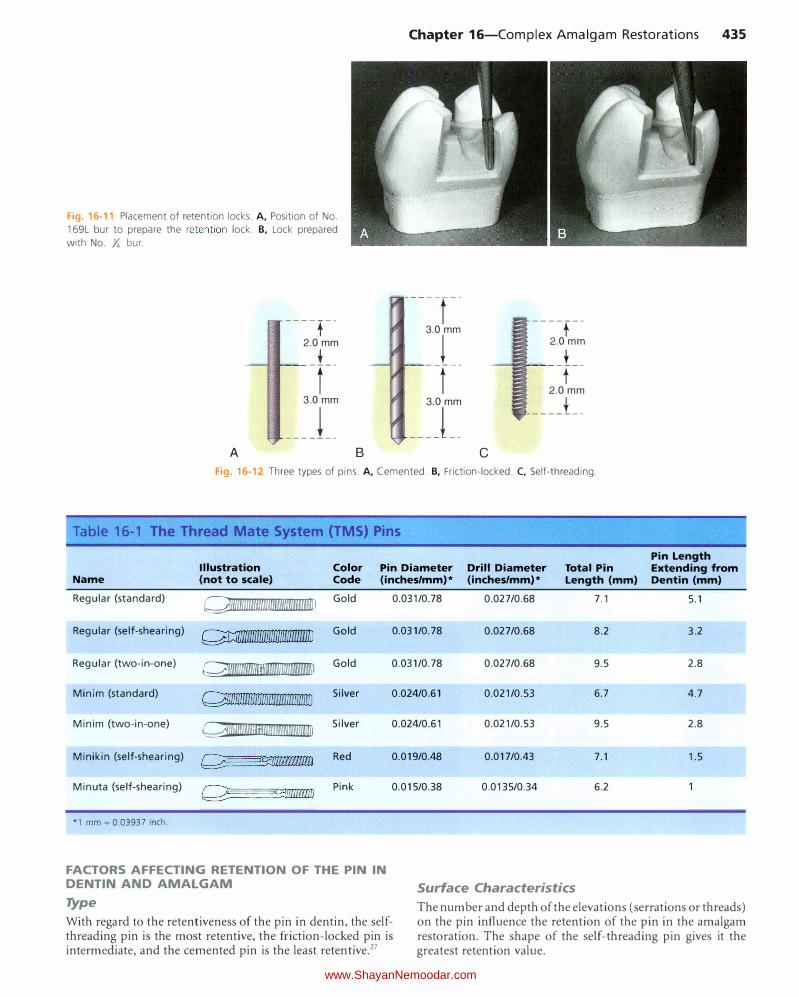
Chapter 16-Complex Amalgam Restorations 435
Fig. 16-11 Placement of retention locks. A, Position of No.
169L bur to prepare the retention lock. B, Lock prepared
with No. Y. bur.
----t--2.0 mm
_L_
t
3.0 mm
___ j __
A B
-----r--
3.0 mm
� --f--
3.0 mm
___ j __
c
----f--
2.0 mm
t -r-
2.0mm
____ j __
Fig. 16-12 Three types of pins. A, Cemented. B, Friction-locked. C, Self-threading.
Table 16-1 The Thread Mate System (TMS) Pins
Illustration Color Pin Diameter Drill Diameter Total Pin Name (not to scale) Code (inches/mm)* (inches/mm)* Length (mm)
Regular (standard) Q\llmmlllllmlmlm�mnm��umlllll Gold 0.031/0.78 0.027/0.68 7.1
Regular (self-shearing) � Gold 0.031/0.78 0.027/0.68 8.2
Regular (two-in-one) �����l1llllilffil Gold 0.031/0.78 0.027/0.68 9.5
Minim (standard) Q�nmmrnm������lllllmmn�nrnlliD Silver 0.024/0.61 0.021/0.53 6.7
Minim (two-in-one) Qlllllllll\Ulfllii!lllliiiUUUIIUUIIU�liD Silver 0.024/0.61 0.021/0.53 9.5
Minikin (self-shearing) �c;_:D\\\\\\\Iii9 Red 0.019/0.48 0.017/0.43 7.1
Minuta (self-shearing) Pink 0.015/0.38 0.0135/0.34 6.2
*1 mm � 0.03937 inch.
FACTORS AFFECTING RETENTION OF THE PIN IN DENTIN AND AMALGAM Surface Characteristics
Pin Length Extending from Dentin (mm)
5.1
3.2
2.8
4.7
2.8
1.5
Type
With regard to the retentiveness of the pin in dentin, the selfthreading pin is the most retentive, the friction-locked pin is intermediate, and the cemented pin is the least retentive.27
The number and depth of the elevations (serrations or threads) on the pin influence the retention of the pin in the amalgam restoration. The shape of the self-threading pin gives it the greatest retention value.
www.ShayanNemoodar.com