St.Joseph's College of Engg MCA MC5302 Computer ...
99
St.Joseph’s College of Engg MCA MC5302 Computer Networks 2018- 2019 1 II M.C.A SEM III MC 5302 - COMPUTER NETWORKS UNIT I NETWORK FUNDAMENTALS: Uses of Networks – Categories of Networks -Communication model – Data transmission concepts and terminology – Protocol architecture – Protocols – OSI – TCP/IP – LAN Topology – Transmission media UNIT II DATA LINK LAYER Data link control - Flow Control – Error Detection and Error Correction - MAC – Ethernet, Token ring, Wireless LAN MAC – Blue Tooth - Bridges. UNIT III NETWORK LAYER Network layer – Switching concepts – Circuit switching – Packet switching –IP –– Datagram – IP addresses- IPV6– ICMP – Routing Protocols – Distance Vector – Link State- BGP. UNIT IV TRANSPORT LAYER Transport layer –service –Connection establishment – Flow control – Transmission control protocol – Congestion control and avoidance – User datagram protocol. -Transport for Real Time Applications (RTP). UNIT V APPLICATIONS - DNS- SMTP – WWW –SNMP- Security threats and services - DES- RSA- REFERENCES: 1. Achyut S Godbole,AtulHahate, “ Data Communications and Networks”, Second edition 2011 2. Andrew S.Tannenbaum David J. Wetherall, “Computer Networks” Fifth Edition , Pearson Education 2011 3. Douglas E. Comer, ―Internetworking with TCP/IP (Volume I) Principles, Protocols and Architecture‖, Sixth Edition, Pearson Education, 2013. 4. Forouzan, “ Data Communication and Networking”, Fifth Edition , TMH 2012. 5. James F. Kurose, Keith W. Ross, “Computer Networking: A Top-down Approach, Pearson Education, Limited, 6. John Cowley, “Communications and Networking : An Introduction”, Springer Indian Reprint, 2010. 7. Larry L. Peterson & Bruce S. Davie, “Computer Networks – A systems Approach”, Fifth Edition, Morgan Kaufmann, 2012 8. William Stallings, ―Data and Computer Communications‖, Tenth Edition, Pearson Education, 2013 9. Wayne Tomasi, “ Introduction to Data communications and Networking” , Pearson 2011 COURSE OUTCOMES (COs) CO201.1: Able to trace the flow of information from one node to another node in the network CO201.2 CO201.3 CO201.4 unctionality at each layer for given application CO201.5 CO201.6 MAPPING BETWEEN COs, POs AND PSOs COs PROGRAMME OUTCOMES (POs) PSOs PO1 PO2 PO3 PO4 PO5 PO6 PO7 PO8 PO9 PO10 PO11 PO12 PSO1 PSO2 CO213.1 2 3 CO213.2 2 2 2 CO213.3 1 3 2 CO213.4 3 2 2 1 CO213.5 3 1 1 CO213.6 1 2 1 1 2 1 RELATION BETWEEN COURSE CONTENTS WITH COs S. No Contents COs Knowledge Level UNIT I - NETWORK FUNDAMENTALS 1 Uses of Networks – Categories of Networks CO201.1 & CO201.2 & CO201.3 U,R 2 Communication model U,R 3 Data transmission concepts and terminology U,R,Ap 4 Protocol architecture U,R,Ap 5 Protocols – OSI U,R,Ap 6 TCP/IP U,R,Ap 7 LAN Topology U,R,Ap 8 Transmission media U,R,Ap, An UNIT II - DATA LINK LAYER 1 Data link control U,R
-
Upload
khangminh22 -
Category
Documents
-
view
0 -
download
0
Transcript of St.Joseph's College of Engg MCA MC5302 Computer ...
St.Joseph’s College of Engg MCA MC5302 Computer Networks 2018- 2019 1
II M.C.A SEM III MC 5302 - COMPUTER NETWORKS
UNIT I NETWORK FUNDAMENTALS: Uses of Networks – Categories of Networks -Communication model –Data transmission concepts and terminology – Protocol architecture – Protocols – OSI – TCP/IP – LAN Topology – Transmission media
UNIT II DATA LINK LAYER Data link control - Flow Control – Error Detection and Error Correction - MAC – Ethernet, Token ring, Wireless LAN MAC – Blue Tooth - Bridges.
UNIT III NETWORK LAYER Network layer – Switching concepts – Circuit switching – Packet switching –IP –– Datagram – IP addresses- IPV6– ICMP – Routing Protocols – Distance Vector – Link State- BGP.
UNIT IV TRANSPORT LAYER Transport layer –service –Connection establishment – Flow control – Transmission control protocol – Congestion control and avoidance – User datagram protocol. -Transport for Real Time Applications (RTP). UNIT V APPLICATIONS - DNS- SMTP – WWW –SNMP- Security threats and services - DES- RSA- REFERENCES: 1. Achyut S Godbole,AtulHahate, “ Data Communications and Networks”, Second edition 2011 2. Andrew S.Tannenbaum David J. Wetherall, “Computer Networks” Fifth Edition , Pearson Education 2011
3. Douglas E. Comer, ―Internetworking with TCP/IP (Volume I) Principles, Protocols and Architecture‖, Sixth Edition, Pearson Education, 2013.
4. Forouzan, “ Data Communication and Networking”, Fifth Edition , TMH 2012. 5. James F. Kurose, Keith W. Ross, “Computer Networking: A Top-down Approach, Pearson Education, Limited, 6. John Cowley, “Communications and Networking : An Introduction”, Springer Indian Reprint, 2010.
7. Larry L. Peterson & Bruce S. Davie, “Computer Networks – A systems Approach”, Fifth Edition, Morgan Kaufmann, 2012
8. William Stallings, ―Data and Computer Communications‖, Tenth Edition, Pearson Education, 2013
9.
Wayne Tomasi, “ Introduction to Data communications and Networking” , Pearson 2011
COURSE OUTCOMES (COs) CO201.1: Able to trace the flow of information from one node to another node in the network CO201.2 CO201.3 CO201.4 unctionality at each layer for given application CO201.5 CO201.6
MAPPING BETWEEN COs, POs AND PSOs
COs PROGRAMME OUTCOMES (POs) PSOs
PO1 PO2 PO3 PO4 PO5 PO6 PO7 PO8 PO9 PO10 PO11 PO12 PSO1 PSO2 CO213.1 2 3 CO213.2 2 2 2 CO213.3 1 3 2 CO213.4 3 2 2 1 CO213.5 3 1 1 CO213.6 1 2 1 1 2 1
RELATION BETWEEN COURSE CONTENTS WITH COs
S. No
Contents COs Knowledge Level
UNIT I - NETWORK FUNDAMENTALS
1 Uses of Networks – Categories of Networks CO201.1
& CO201.2
& CO201.3
U,R
2 Communication model U,R
3 Data transmission concepts and terminology U,R,Ap 4 Protocol architecture U,R,Ap 5 Protocols – OSI U,R,Ap 6 TCP/IP U,R,Ap
7 LAN Topology U,R,Ap
8 Transmission media U,R,Ap, An UNIT II - DATA LINK LAYER
1 Data link control U,R

St.Joseph’s College of Engg MCA MC5302 Computer Networks 2018- 2019 2
2 Flow Control CO201.3
& CO201.4
U,R,Ap, An
3 Error Detection U,R,Ap, An,E
4 Error Correction U,R,Ap, An 5 MAC – Ethernet U,R,Ap, An 6 Token ring U,R,Ap, An
7 Wireless LAN MAC U,R,Ap, An
8 Blue Tooth U,R,Ap, An 9 Bridges U,R,Ap, An,E
UNIT III - NETWORK LAYER
1 Switching concepts
CO201.3 &
CO201.4
U,R
2 Circuit switching U,R,Ap, An 3 Packet switching U,R,Ap, An 4 IP –– Datagram U,R,Ap, An
5 IP addresses U,R,Ap, An,E
6 IPV6 U,R
7 ICMP U,R,Ap, An 8 Routing Protocols- Distance Vector U,R,Ap, An,E 9 Routing Protocols –– Link State U,R,Ap, An,E
9 Routing Protocols ––- BGP U,R
UNIT IV - TRANSPORT LAYER
1 Transport layer service
CO201.3 &
CO201.4
U,R
2 Connection establishment U,R,Ap, An
3 Flow control U,R,Ap, An
4 Congestion control and avoidance U,R,Ap, An 5 User datagram protocol U,R
6 Transport for Real Time Applications (RTP) U,R
UNIT V - APPLICATION LAYER
1 DNS
CO201.5 &
CO201.6
U,R,Ap, An
2 SMTP U,R,Ap, An
3 WWW U,R,Ap, An
4 SNMP U,R,Ap, An
5 Security threats and services U,R,Ap, An
6 DES U,R,Ap, An
7 RSA U,R,Ap, An
CONTENT BEYOND SYLLABUS
1 IOT CO201.6 U,R,Ap, An
UNIT I - PART A
1. What is the purpose of communication model? Name the various components of data communication system (MAY 13)
The fundamental purpose of a communication system is exchange of data between two parties. The key elements of the model are source, transmitter, transmission system, receiver and destination.
2. What are types of transmission media ?/Differentiate guided and unguided transmission media
(NOV-12, May 13)
In Guided media the waves are guided along a physical path. Ex : coaxial cable, twisted pair. Unguided media provides a mean for transmitting Electromagnetic waves but not guide them.
3. What are the two types of transmission technology (NOV 17)
Differentiate Point to Point and multipoint connection (NOV 13)
Line Configuration refers to the way in which two or more communication devices are attached to a link. It is categorized into two types,
St.Joseph’s College of Engg MCA MC5302 Computer Networks 2018- 2019 3
Point-to-Point
It provides a dedicated link between two devices.
Entire capacity of the channel is reserved between two devices.
Multi-Point :It is one in which more than two specific devices share a single channel.
4. What is a protocol? What are the key elements of a protocol? ( NOV 13)
Protocol is the set of rules governing the exchange of data between 2 entities. It defines what is communicated, how it is communicated, when it is communicated
Key elements of Protocol
Syntax – It refers to the structure /format of data meaning the order in which they are presented.
Semantics – It refers to the meaning of each section of bit. How to do interpretation?.
Timing – When data should be sent and how fast they can be sent.
5. Define Simplex, Half Duplex, Full Duplex transmission system.(Different transmission mode)
Full duplex transmission: Two stations can simultaneously send and receive data from each other.
Half duplex transmission: Stations can send and receive data from each other. The signals are transmitted in one direction at a time.
Simplex Transmission: Only one way of communication is possible Always, One is the sender and another one is the receiver.
6. What is continuous (analog) signal and discrete signal(digital)?
A continuous signal is a one in which the signal intensity varies in a smooth fashion over time.
A discrete signal is one in which the signal intensity maintains a constant level for some Period of time and then changes to another constant level.
Periodic signal :A periodic signal is in which the same signal pattern repeats over time
7. What is attenuation ?
Strength of signal falls off with distance over any Transmission medium is called attenuation.
8. What is channel capacity /data rate?
Data rate is the maximum rate at which data can be transmitted over a communication path. It is measured in bps (bits per second)
9. What are the factors that determine channel capacity? (DEC 16)
Data rate - in bps
Bandwidth - constrained by transmitter and nature of transmission medium,
expressed in cycles per second, or Hz
Noise -Average noise level over channel
Error rate - Percentage of time when bits are flipped
10. State Nyquist formulation for multilevel signaling. (NOV – 11)
With multilevel signaling, Nyquist formulation is
C- Capacity of channel in bits per second.
M- Number of discrete /voltage level.
B- Bandwidth in Hz.
St.Joseph’s College of Engg MCA MC5302 Computer Networks 2018- 2019 4
11. What is Layered Network Architecture?
A layer is created when a different level of abstraction occurs at protocol. Each layer should perform a well defined function.
Function of each layer should be chosen using internationality standardized protocols. Boundaries between should be chosen to minimize information flow across the interfaces.
A set of layers and protocol is called network architecture. A list of protocols used by a system is called protocol stack.
12. What is the need for layering?
It reduces the design complexity.
It decomposes the problem of building a network into more manageable components.
t provides a modular design, if we want to add some new service, you may only need to modify the functionality at one layer, reusing the functions provided at all other layers
13. Compare OSI and Internet Protocol. How do layers of the internet model correlate to the layers of the OSI model./List the layers of TCP/IP (Nov- 12, Dec 14))
OSI TCP
It distinguishes between It does not distinguish between
service, Interface, protocol service, interface, protocol
Protocols are well hidden Protocols are not just hidden
Dejure. Standard Fit Model Defacto standard Fit protocol then
then protocol model
In transport layer only connection In Transport layer choice is for
Oriented services are available Connection oriented/connection less.
It contains 7 layers It contains 5 layers
14. Each layer has distinct functions. Why flow control & error control is duplicated in different layers.
Like the data link layer the transport layer is responsible for flow and error control . Flow control and error control at data link layer is node-to-node level. But at transport layer, flow control and error control is performed end-end rather than across a single link.
15 What are the functions of physical layer of IEEE 802 reference model? Physical layer: The physical layers coordinate requiring transmitting a bit streams over a physical medium. It deals with a mechanical and electrical specifications of the interface and medium.
Physical characteristics of interface and media. The physical layer defines the characteristics of the interface between the device and the transmission medium. Representation of the bits. bits must be encoded into signals-electrical or optical the physical layer defines the type of encoding. Data rate: The transmission rate – the number of bits sent each second –is also defined Synchronization of bits: The sender and the receiver must be synchronizing at the bit level. Line configuration, Physical topology,Transmission mode.
OSI TCP/IP
Physical Layer Physical Layer
Data Link Layer Network Access Layer
Network Layer IP Layer
Transport Layer TCP Layer
Session Layer
Application Layer Presentation Layer
Application Layer
St.Joseph’s College of Engg MCA MC5302 Computer Networks 2018- 2019 5
16.List the common topologies available for LAN.
Star Topology Ring Topology Bus Topology, Tree Topology
17. What are the uses of Network?
Computer network is an interconnection of computers, printers, scanners and other hardware devices and software applications.
Communication and Access to Information: It helps users at different places to send and receive data. It allows remote users to connect via videoconferencing, virtual meetings and digital emails. Computer networks provide access to online libraries, journals, electronic newspapers, chat rooms, social networking websites, email, www etc. Computer networks allow users to access interactive entertainment channels
Resource Sharing : It allows users to share files and resources
Centralized Support and Administration
18. What are the types or categories of network?
- Local Area Network - Wireless Local Area Network
- Wide Area Network - Metropolitan Area Network
- Storage Area Network PAN - Personal Area Network
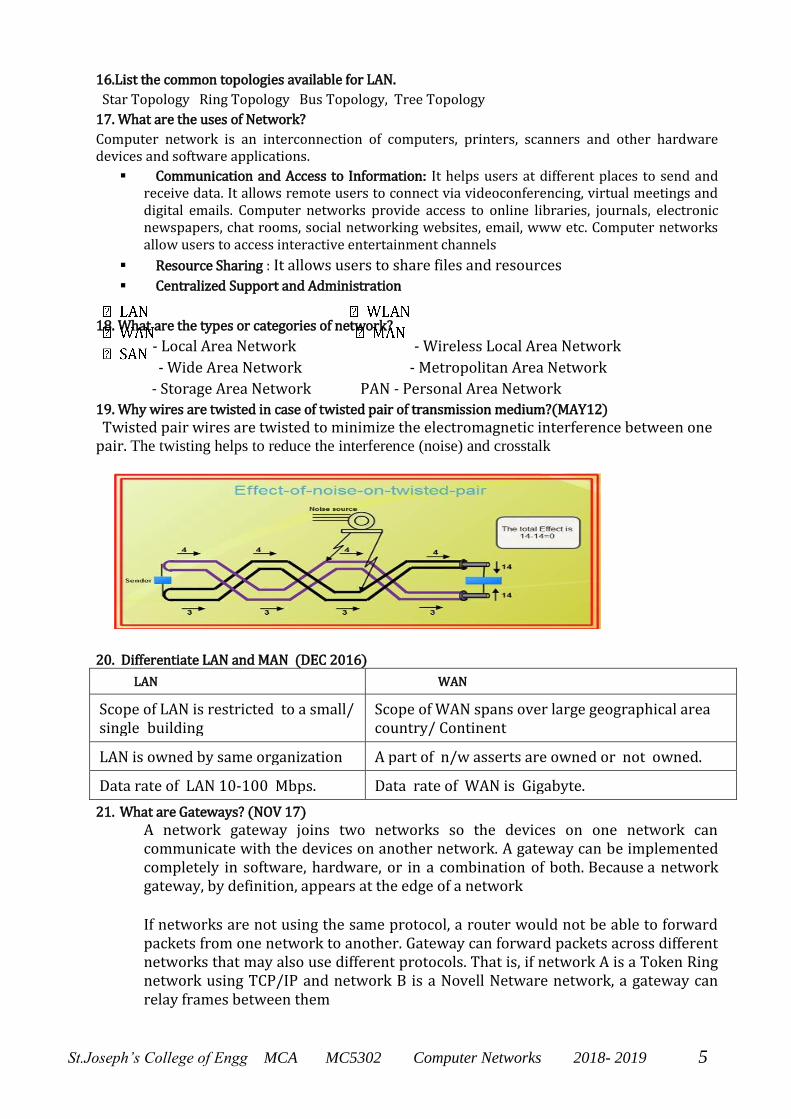
19. Why wires are twisted in case of twisted pair of transmission medium?(MAY12)
Twisted pair wires are twisted to minimize the electromagnetic interference between one pair. The twisting helps to reduce the interference (noise) and crosstalk
20. Differentiate LAN and MAN (DEC 2016)
LAN WAN
Scope of LAN is restricted to a small/ single building
Scope of WAN spans over large geographical area country/ Continent
LAN is owned by same organization A part of n/w asserts are owned or not owned.
Data rate of LAN 10-100 Mbps. Data rate of WAN is Gigabyte.
21. What are Gateways? (NOV 17)
A network gateway joins two networks so the devices on one network can communicate with the devices on another network. A gateway can be implemented completely in software, hardware, or in a combination of both. Because a network gateway, by definition, appears at the edge of a network
If networks are not using the same protocol, a router would not be able to forward packets from one network to another. Gateway can forward packets across different networks that may also use different protocols. That is, if network A is a Token Ring network using TCP/IP and network B is a Novell Netware network, a gateway can relay frames between them

St.Joseph’s College of Engg MCA MC5302 Computer Networks 2018- 2019 6
22. Define Shanon Capacity formula
.
SNR-signal to noise ratio
Shannon addressed the question of what signaling rate can be achieved over a channel with a given bandwidth, a given signal power, and in the presence of noise
23. What is the channel capacity for a teleprinter channel with a 300-Hz bandwidth and a signal-to-noise ratio of 3 dB?
24. A digital signaling system is required to operate at 9600 bps.
a. If a signal element encodes a 4-bit word, what is the minimum required bandwidth of the channel?
b. Repeat part (a) for the case of 8 bit words.
25. We can calculate the theoretical highest bit rate of a regular telephone line. A telephone line normally has a bandwidth of 3000 Hz (300 Hz to 3300 Hz). The signal-to-noise ratio is usually 3162. For this channel the capacity is calculated as
C = B log2 (1 + SNR) = 3000 log2 (1 + 3162) = 3000 log2 (3163)
C = 3000 11.62 = 34,860 bps
26. How many lines are required to connect n – systems in Direct Mesh topology? n(n-1)/2
27. Define the terms: OSI and TCP/IP
The Open Systems Interconnection model (OSI Model) is a conceptual model that characterizes and standardizes the internal functions of a communication system by partitioning it into abstraction layers.
28.What is 10base5? (Nov 13,Dec 14)
10 represents data rate 10 Mbps.
5 refers to segment length 5* 100 m that can run without repeaters
Base represents Base band communication
UNIT II - PART A
1. Differentiate Ethernet and Fast Ethernet (MAY 13)
Fast Ethernet is a collective term for a number of Ethernet standards that carry traffic at the nominal rate of 100 Mbit/s, against the original Ethernet speed of 10 Mbit/s. Of the Fast Ethernet standards 100BASE-TX is by far the most common. Fast Ethernet is an extension of the existing Ethernet standard. It runs on UTP data or optical fiber cable in a star wired bus topology.
St.Joseph’s College of Engg MCA MC5302 Computer Networks 2018- 2019 7
2. List some factors that determine whether the communication system is a LAN or WAN. (May ’13)
LAN
1.Scope of LAN is restricted to a small/ single building
2. LAN is owned by same organization
3. Data rate of LAN 10-100mbps
WAN
scope of WAN spans over large geographical area country/ Continent
a part of n/w asserts are owned or not owned
1. Data rate of WAN is Gigabyte.
3. What is CSMA/CD? (NOV 13)
It is a MAC protocol used to sense whether a medium is busy before transmission but it has the ability to check whether a transmission has collided with another.
4. What does IEEE 10 Base 5 standard signify? (NOV 13)
10 represents data rate 10 Mbps.
5 refers to segment length 5* 100 m that can run without repeaters
Base represents Base band communication
5. What is the use of data link layer in OSI? (MAY 17)
Data link layer provides for reliable transfer of information across the physical link; sends block of data (frames) with necessary synchronization, error control, and flow control.
Frame synchronization: Data is divided by data link layer as frames ,a manageable unit.
Flow Control: Sending station does not overwhelm receiving station.
Error Control: Any error in bits must be detected and corrected using some mechanism.
Addressing: Two stations in a multi point that involved in transmission must be specified using physical address
Access Control: When two or more devices are connected to the same link, Access control mechanism is needed to determine which device has control over the link at any given time.
6. Define Flow Control and error control.(DEC 16)
Flow control is a technique for assuring that a transmitting entity does not overwhelm a receiving entity with data.
Error control refers to mechanism to detect and correct errors that occur in the transmission of frames.
7.Why sliding window flow control is considered to be more efficient than stop and wait
In sliding window flow control, the transmission link is treated as a pipeline that may be filled with frames in transit. But with stop-and-wait flow control only one frame may be in the pipe at a time.
8. Name any error checking / correction mechanism in data link control.
Error checking: parity check, check sum, cyclic redundancy check Correction: Automatic repeat request (ARQ), Forward Error correction (FEC), Hamming code
9. Define piggybacking.
The technique of temporarily delaying outgoing acknowledgment so that they can be hooked onto the next outgoing data frame is widely known as piggybacking.
10. Differentiate between lost frame and damaged frame?
Lost frame is the frame that fails to arrive at the other side. The damaged frame is a recognizable frame does arrive, but some of the bits are in error.
11.What are the two sub layers of Data Link Layer and their functions
1. MAC :This Layer contains control information needed for the functioning of medium access
2. LLC: This Layer provides services for Framing, Error control , Flow control
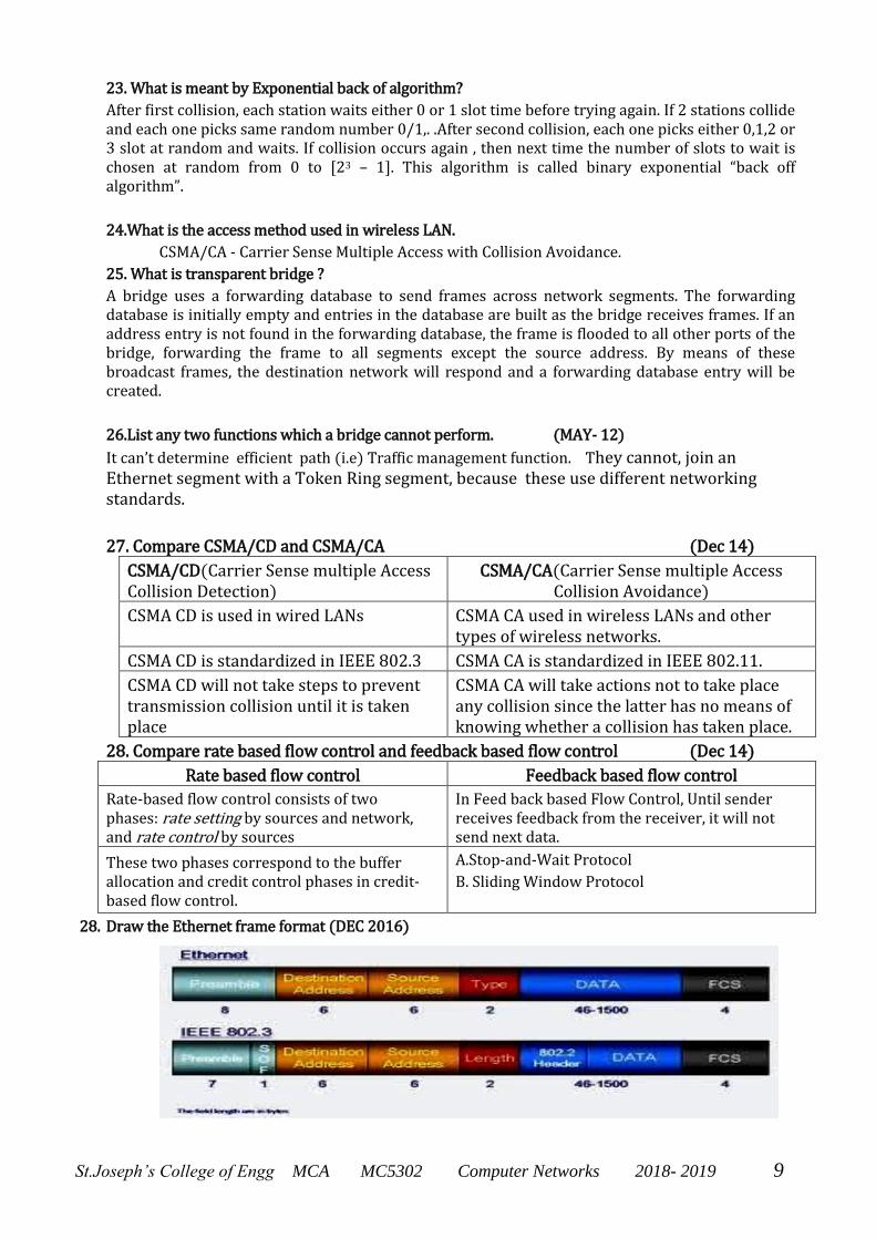
12. What is preamble?
A 7-octet pattern of alternating 0s and 1s is used by the receiver to establish bit synchronization
13. When a transmitting station will insert a new token on the ring?
It will insert a new token when the station has completed transmission of its frame.

St.Joseph’s College of Engg MCA MC5302 Computer Networks 2018- 2019 8
The leading edge of the transmitted frame has returned to the station.
14. What is a bridge? List the functions of a bridge? (NOV -12)
Bridge is a hardware networking device used to connect two LANs. A bridge operates at data link layer. It reads all frames transmitted on port A and accepts those addressed to stations on B. It uses medium access control protocol for B, retransmits the frames onto B. It doess the same for B-to-A traffic.
15. List the reason for using bridges in LAN.
Improvement in Reliability, performance, security, and geography are the reason for using bridges in LAN
16. What are the limitations of bridges?
1.Scalability 2. Heterogeneity
17. What is spanning tree routing?
The spanning tree approach is a mechanism where Bridge connects n/w and removes loop in the path. It constructs a spanning tree of edges between hosts that maintain connectivity of the graph with no loops. It is a dynamic algorithm in which bridges automatically develop a routing table and update that table in response to changing topology. The algorithm works as follows
FRAME FORWARDING , ADDERESS LEARNING , LOOP RESOLUTION
18.What are different types of bridge?
Simple Bridge connects 2 LAN,
Multi port Bridge connect more than 2 LANs
Transparent Bridge it learns on its own about connected LANs.
19.Compare FDDI with token ring 802.5.
FDDI 802.5
No priority and reservation bits It has priority scheme by using reservation bits.
No need of converting a token to start of data frame by inverting token bits because of high data rate
It converts a token to data frame changing token frame.
ETR : Early Token Release :A station that transmits data frames releases a new token as soon as it completes data whether or not the frame header has returned to the station
DTR : Delayed Token Release A station that transmits data releases the token only after its own transmission comes back to it .
20. Ethernet stipulates a minimum size of a frame. Why is it necessary?
To detect collision. To identify valid frame from garbage, valid full format should contain 64 bytes from destination address to checksum. So if the data portion is less than 46 bytes, pad field is used to fill out the frame to minimize size.
21. What is meant by the contention period of Ethernet?
When several stations on an Ethernet have data to send, there are contention periods during which collisions happen and no data is successfully transmitted.
22. Define Repeater, Hub.
Repeaters and hubs are interconnecting devices.
Repeater: Repeaters extends the Ethernet segment and it repeats the signal. It does not amplify it
Hub: It is a multi way repeater. It broadcasts any signal through all outgoing lines. It broadcast information (it receives on any port) to all ports hence is called non-intelligent or dumb. It works on Physical layer
SWITCH works on data link layer, Switch divides networks into multiple collision domains.
It is an intelligent HUB. It does not broadcasts any signal through all outgoing lines but only to the receiver line.
St.Joseph’s College of Engg MCA MC5302 Computer Networks 2018- 2019 9
23. What is meant by Exponential back of algorithm?
After first collision, each station waits either 0 or 1 slot time before trying again. If 2 stations collide and each one picks same random number 0/1,. .After second collision, each one picks either 0,1,2 or 3 slot at random and waits. If collision occurs again , then next time the number of slots to wait is chosen at random from 0 to [23 – 1]. This algorithm is called binary exponential “back off algorithm”.
24.What is the access method used in wireless LAN.
CSMA/CA - Carrier Sense Multiple Access with Collision Avoidance.
25. What is transparent bridge ?
A bridge uses a forwarding database to send frames across network segments. The forwarding database is initially empty and entries in the database are built as the bridge receives frames. If an address entry is not found in the forwarding database, the frame is flooded to all other ports of the bridge, forwarding the frame to all segments except the source address. By means of these broadcast frames, the destination network will respond and a forwarding database entry will be created.
26.List any two functions which a bridge cannot perform. (MAY- 12)
It can’t determine efficient path (i.e) Traffic management function. They cannot, join an Ethernet segment with a Token Ring segment, because these use different networking standards.
27. Compare CSMA/CD and CSMA/CA (Dec 14)
CSMA/CD(Carrier Sense multiple Access Collision Detection)
CSMA/CA(Carrier Sense multiple Access Collision Avoidance)
CSMA CD is used in wired LANs CSMA CA used in wireless LANs and other types of wireless networks.
CSMA CD is standardized in IEEE 802.3 CSMA CA is standardized in IEEE 802.11.
CSMA CD will not take steps to prevent transmission collision until it is taken place
CSMA CA will take actions not to take place any collision since the latter has no means of knowing whether a collision has taken place.
28. Compare rate based flow control and feedback based flow control (Dec 14)
Rate based flow control Feedback based flow control
Rate-based flow control consists of two phases: rate setting by sources and network, and rate control by sources
In Feed back based Flow Control, Until sender receives feedback from the receiver, it will not send next data.
These two phases correspond to the buffer allocation and credit control phases in credit-based flow control.
A.Stop-and-Wait Protocol
B. Sliding Window Protocol
28. Draw the Ethernet frame format (DEC 2016)
St.Joseph’s College of Engg MCA MC5302 Computer Networks 2018- 2019 10
26. Mention the layers where gateway, router, switch, hub functions?(NOV 17)
Network connecting devices
Layer
HUB Physical
Switch Physical
Bridge Datalink
Router Network
Gateway Application
UNIT III - PART A
1. Differentiate Physical Address and Logical Address.
Physical Address (MAY 13) Logical Address
1. It is implemented by data link layer. It is implemented by n/w layer.
2. It contains 48 bits. It contains 32 bits
3. It is a local addressing system. It is an universal address system.
4. Another name MAC address. Another name IP address.
5. It is flat in nature Hierarchical in nature
6. Does not give any clue for routing Its structure gives clue for routing
2. What are the various classes of IP addresses? / Define various levels of addressing in Internet. (MAY 13)
Class A : They use only 1 byte to identify class type and Net Id and 3 bytes to identify host Id
0.0.0.1.1 to 127.255.255.255
Class B : They use only 2 bytes to identify class type and Net Id and 2 bytes to identify host Id
Range :128.0.0.0 to 191.255.255.255
Class C : They use only 3 bytes to identify class type and Net Id and 1 byte to identify host Id
Range :192.0.0.0 to 223.255.255.255
Class D : It is reserved for multicast address, Range : 224.0.0.0 to 239.255.255.255
Class E : Addresses are reserved for further use the structure of each IP address class.
Range : 240.0.0.0 to 255.255.255.255
3. Give the characteristics of connectionless (datagram) network. (Nov ’13)
In connectionless (datagram) network, no dedicated path is required between two nodes. Each packet contains the full source and destination address. Each packet is routed independently. It is suitable for dynamic bandwidth environment.
4.What do you mean by ICMP? To whom ICMP reports error message.(Nov 13)
ICMP is an error reporting mechanism. It does not specify the action to be taken for each possible error. The source must relate the error to an individual application program and take other actions to correct the problem.
ICMP allows routers to send error messages to other router or hosts. ICMP is an error reporting mechanism. It does not specify the action to be taken for each possible error. It is informing the source that the error has occurred and the source has to take actions to rectify the errors.
5.What is VCS?
In the virtual circuit approach the relationship between all packets belonging to a message or session is preserved single route is chosen between sender and receiver at the beginning of the session. When the data are sent all packets of the transmission travel one after another along that route Virtual circuit transmission is implemented in two formats - PVC, SVC.
St.Joseph’s College of Engg MCA MC5302 Computer Networks 2018- 2019 11
6.Differentiate Packet Switching and circuit Switching.
7.Differentiate SVC from PVC.
Switched virtual circuit :In this method virtual circuit is created wherever is needed and exist only for duration of the specific exchange. It can be used with connection establishment and connection termination.
PVC Permanent virtual circuit :In this technique the same virtual circuit provided between two users on a continuous basis. The circuit is dedicated to a specific user. No one else can use it. Because it always in place, it can be used without connection establishment and connection termination
8.Define a switch and a bridge.
Switch: switches are hardware or software device capable of creating temporary connections between more devices which are not directly connected. It is a multi input/output port device. It transfers data coming from one input port to one or more output ports. This function is called as forwarding.
Bridge: Bridges are used to interconnect LANs. A bridge observes and forwards all frames that it receives.
9.Name any two network connecting devices? Can a bridge replace repeater for interconnecting 2 segments of a n/w? Repeater, Bridges.
Repeater repeats the signal to the actual strength so that they can travel and works at physical layer. Repeater operates on the physical layer level. Here collision probability is more.
Bridge is an network connecting device. It does forwarding & filtering frames using LAN destination address. Bridges are used to connect LAN or WAN and works at data link layer level. Collision Probability is more.A bridge cannot replace repeater for interconnecting 2 segments of a network because functions of them are entirely different.
10.Which class IP addresses are used for multicast and unicast?
Unicast : Class A, Class B , Class C Multicast: Class D
11.Classify the following addresses
23.8.8.9 ---------- Class A
127.24.34.56 ------------- Class A
159.78.9.10 ------------ Class B
Datagram subnet Circuit Switching Transmission path No dedicated path is required between
two nodes. a dedicated communication path is established between two nodes
Circuit setup Not Required Required Transmission Data are sent in sequence
continuously Data are sent out in a sequence called packets
Delay Packet transmission delay Call setup delay Addressing Each packet contains the full source
and destination address Only data is sent
Bandwidth Dynamic Bandwidth Fixed Bandwidth Routing Each packet is routed independently Entire data is sent through the same
path Congestion control Difficult Easy if enough buffers can be allocated
in advance for each VC set up Complexity In the transport layer In the network layer Suited for Connection-oriented and
connectionless service Connection-oriented service
St.Joseph’s College of Engg MCA MC5302 Computer Networks 2018- 2019 12
192.20.10.11. ------------ Class C
12. What is IP address?
An Internet Address is made of four bytes (32 bits) that define a host’s connection to a network.
Class Netid Hosted
There are currently 5 different field lengths patterns, each define a class of addresses. These are designed to cover the needs of different types of organizations, class A, B, C, D, E.
13. How many network addresses and host addresses are supported by class A, class B networks?
Class A: Number of networks = 127 Number of hosts = 224 -1
Class B : Number of networks = 214 -1 Number of hosts = 216 – 1 = 65,535
13. Define Router.
A router operates as the physical, data link and network layer of the OSI model ,
A router is termed as an intelligent device. Therefore, its capabilities are much more than those of a repeater or a bridge.
A router is useful for interconnecting two or more heterogeneous networks that differ in their physical characteristics such as frame size, transmission rates, topologies, addressing etc. A router has to determine the best possible transmission path among several available paths.
14. What does a router do when it receives a packet with a destination address that it does not have an entry for, in its routing table?
Default Router : If IP Software is not able to find the destination, from routing table then it sends the datagram to default router. It is useful when a site has small set of local address connected to it and connected to the rest of the Internet.
15. List out functions of IP.
IP services are unreliable, best-effort, connectionless packet system.
Unreliable – delivery is not guaranteed
Connectionless – each pocket is treated independent from others
Best-effort delivery – it makes an earnest attempt to deliver packets.
It defines basic unit of data transfer through TCP/IP.
IP s/w performs routing function – finds a path from source to destination.
IP includes a set of rules that embody the idea of unreliable packet delivery
16. What is the use of TTL in IP header? / What is the router’s role in controlling the packet lifetime ? (MAY- 12)
It lets how long that datagram is allowed to live in the network. The source sets that time. Routers and hosts in the path of that datagram should decrement TTL and removes it when TTL = 0 and send an error message to the source. TTL is written hops or time in seconds.
17. What are the important fields in a routing table?
1. Destination 2. Cost 3. Next Hop
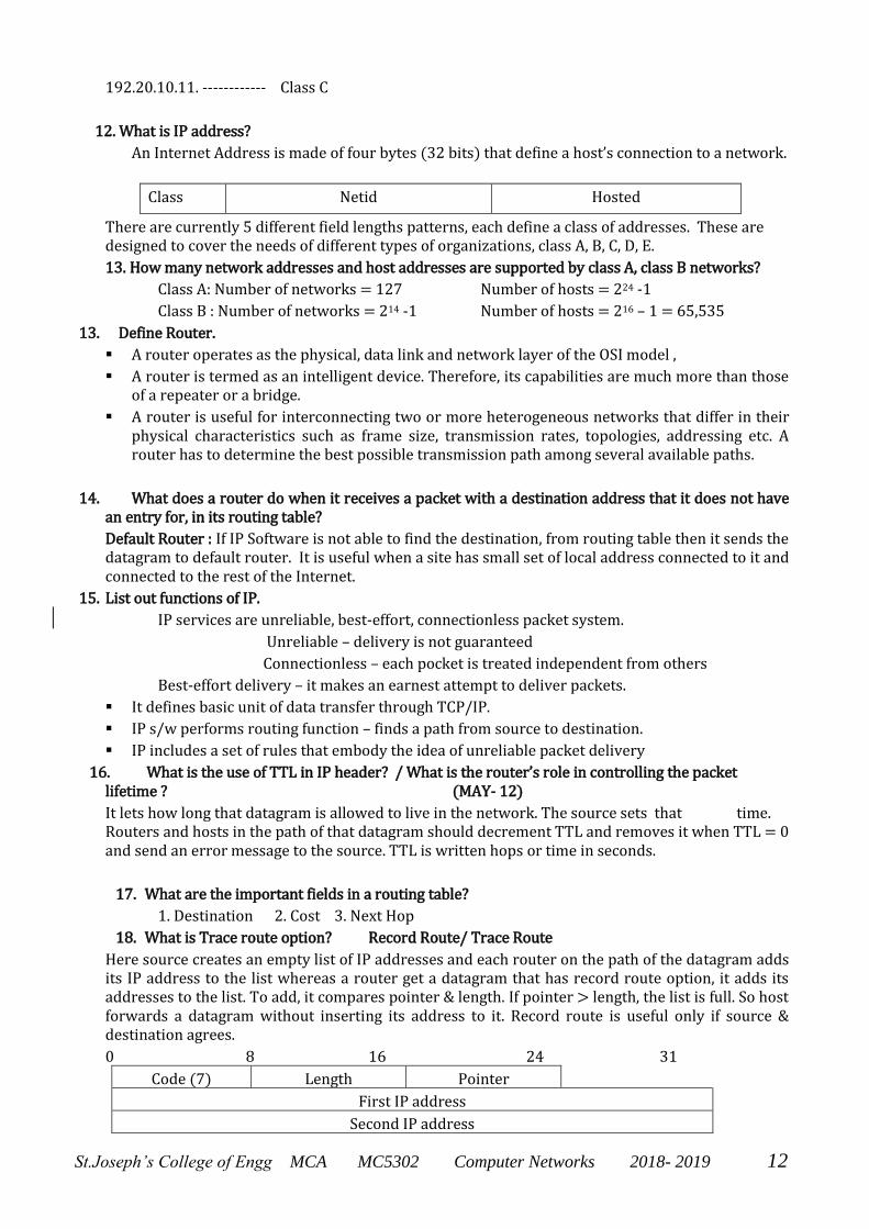
18. What is Trace route option? Record Route/ Trace Route
Here source creates an empty list of IP addresses and each router on the path of the datagram adds its IP address to the list whereas a router get a datagram that has record route option, it adds its addresses to the list. To add, it compares pointer & length. If pointer > length, the list is full. So host forwards a datagram without inserting its address to it. Record route is useful only if source & destination agrees.
0 8 16 24 31
Code (7) Length Pointer
First IP address
Second IP address

St.Joseph’s College of Engg MCA MC5302 Computer Networks 2018- 2019 13
19. Write the difference between Distance vector routing and Link state routing.
Distance Vector Routing Link state routing
1. Basic idea is each node sends its knowledge about the entire network to its neighbours.
1. Basic idea is every node sends its knowledge about its neighbours to the entire network
2. It is dynamic routing 2. It is dynamic routing
3. RIP uses Distance vector routing 3. OSPF uses link state routing
20. List some of the unicast routing protocols.
Routing Information Protocol (RIP) for IP ,Open Shortest Path First (OSPF)
21. State the goals of Network layer. Goals of network layer: The main goal of the network layer is the delivery of a packet from the source to destination possibly across multiple networks. To achieve this goal it uses the functions: Logical addressing, Routing.
22. How broadcast and multicast address is represented in IP addressing scheme?
Broadcast is formed by setting all the host bits to 1 for a class address prefix.
For example, 131.107.255.255 is a network broadcast address
Limited broadcast - Formed by setting all 32 bits of the IPv4 address to 1 (255.255.255.255). The limited broadcast address is used for one-to-everyone delivery on the local subnet when the local subnet prefix is unknown.
23. What does the term ‘cost’ refer to in routing?
A hop-count metric simply counts router hops. A bandwidth metric would choose a higher-bandwidth path over a lower-bandwidth link. Load metric reflects the amount of traffic utilizing the links along the path. The best path is the one with the lowest load. Delay is a measure of the time a packet takes to traverse a route. Reliability measures the likelihood that the link will fail in some way and can be either variable or fixed.
24. What is meant by fixed routing or static routing? (NOV – 11) (NOV – 17) A route is selected for each source-destination pair of nodes in the network initially. The routes are fixed. Link costs used in designing of routes cannot be based on any dynamic variable such as traffic. A central routing matrix is created, to be stored perhaps at a network control center. The matrix shows, for each source-destination pair of nodes, the identity of the next node on the route.
25. List out the three basic steps involved in data communication through circuit switching. 1. Connection establishment 2. Data transfer 3. Connection termination. (MAY- 12) 26. Define datagram. (NOV – 11 & 12)
A datagram is a type of packet that has been sent in a connectionless manner over a network. Every datagram carries enough information to let the network forward the packet to its correct destination.
27. What are the routing strategies? (NOV -12)
1. fixed routing 2. Flooding 3.Adaptive routing 4. Isolated Routing 5. Random Multipath
29. What is the similarity/difference between a Bridge and a router? Bridges and Routers both are network connecting devices.
St.Joseph’s College of Engg MCA MC5302 Computer Networks 2018- 2019 14
Bridges Router
It operates at physical & data link layer of OSI.
It receives frames from LANs and filters and forwards that frames to correct destination across the LANs.
A router operates as the physical, data link and network layer of the OSI model.
Every router can receive packets, and then route the data packets to the destination based on the routing table across the n/ws.
30. What is the difference between IPV4 and IPV6? Write down the advantages of IPV6 over IPV4 ( DEC 2016)
IPV4 IPV6
IP address is a 32 bit address 128 bit (16 bytes) IP address
IP V4 can potentially address four billion nodes if address assignment efficiency reaches 100%.
IPv6 can address 3.4×1038 nodes, again assuming 100% efficiency.
IP V4 has 5 address classes (Class A, B, C, D and E) and also it provides classless addressing
IPv6 addresses do not have classes, but the address space is subdivided in various
ways based on the leading bits.
Eg: 001 - Aggregatable Global Unicast Addresses
1111 1110 10 - Link local use addresses
31. What is BGP? (Dec 14)
Border Gateway Protocol (BGP) is a standardized exterior gateway protocol designed to exchange routing and reachability information between autonomous systems (AS) on the Internet. The protocol is often classified as a path vector protocol but is sometimes also classed as a distance-vector routing protocol. The Border Gateway Protocol makes routing decisions based on paths, network policies, or rule-sets configured by a network administrator and is involved in making core routing decisions.
32 What is dynamic routing? Or Adaptive routing (Nov 17) Adaptive Algorithm : The routing decisions changes w.r.t to topology changes. The principle conditions that influence routing decisions are
A Failure. When a node or Link fails, it can’t be used no longer used in route. Congestion. When a particular portion of the network is heavily congested, it is
desirable to route packets around, rather than through, the area of congestion.
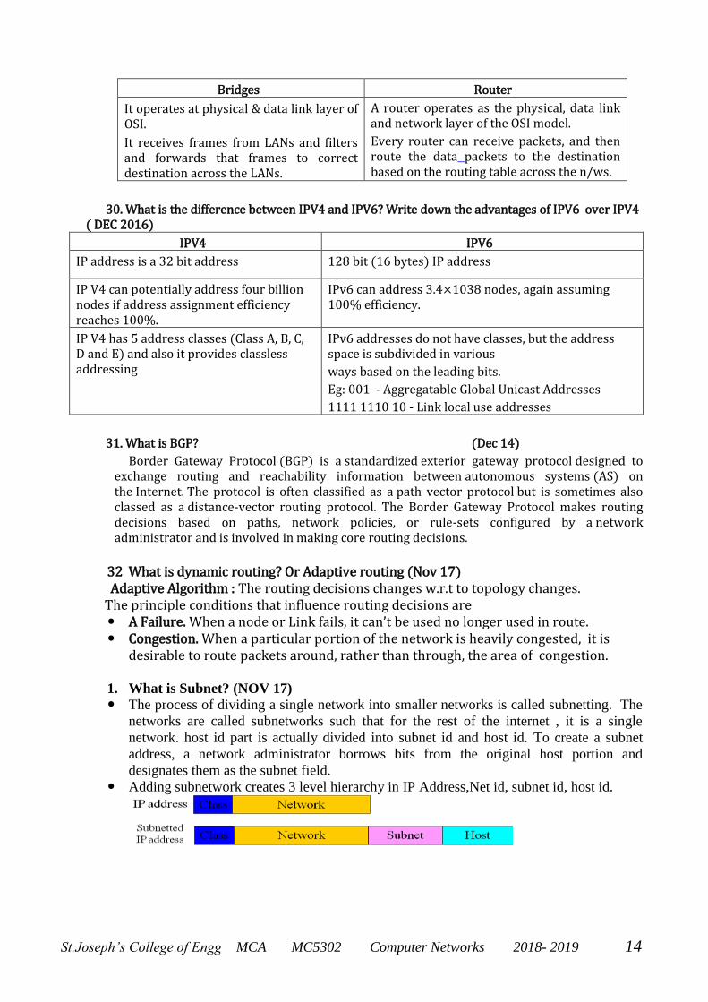
1. What is Subnet? (NOV 17)
The process of dividing a single network into smaller networks is called subnetting. The
networks are called subnetworks such that for the rest of the internet , it is a single
network. host id part is actually divided into subnet id and host id. To create a subnet
address, a network administrator borrows bits from the original host portion and
designates them as the subnet field.
Adding subnetwork creates 3 level hierarchy in IP Address,Net id, subnet id, host id.
St.Joseph’s College of Engg MCA MC5302 Computer Networks 2018- 2019 15
UNIT IV - PART A
1. What is the main difference between TCP & UDP? (May ’13, Nov ’13, Dec 14)
TCP UDP
It provides Connection oriented service
Provides connectionless service.
Connection Establishment delay will be there
No connection establishment delay
Provides reliable service Provides unreliable, but fast service
It is used by FTP, SMTP It is used by audio, video and multimedia applications.
2. Define Channelization. (May ’13) Channelization is a multiple-access method in which the available bandwidth of a link is shared in time, frequency, or through code, between different stations. There are three channelization protocols available: FDMA, TDMA, and CDMA. 3. What is sequence number in TCP segment? (May ’13) TCP is a byte-oriented protocol. Each byte of data has a sequence number. The SequenceNum field in the TCP segment contains the sequence number for the first byte of data carried in that segment.
4. Differentiate between Congestion and collision. (Nov ’13)
Congestion occurs when the total traffic generated by the host/input link is greater than output link capacity. Collision occurs when multiple hosts compete for common channel access.
5. Give any two Transport layer service ( NOV -12)
1. Multiplexing:- Transport layer performs multiplexing/ demultiplexing function. Multiple applications employ same transport protocol, but use different port number. According to lower layer n/w protocol, it does upward multiplexing or downward multiplexing. (eg) X.25 can have 4095 VC. Multiple services can use that single VC using upward multiplexing.
(eg) X.25 can use only 3bit/7bit/15bit sequence number. So a high speed network may need a larger sequence space. For that downward multiplexing / splitting used to improve throughput.
2. Reliability : [ Error Control and Flow Control ] 3. Segmentation and reassembly
6. How an application process running in one host is addressed by another process through TCP.
It uses socket address (host, port). Port represents a particular transport service in a host.
7. What is silly window syndrome? What is TINYGRAM?
Suppose receiver buffer is full. It advertises window is zero. Sender will not transmit any data to receiver, finally sender buffer will fill.
As soon as receiver process starts to read again, its advertiser window will become > 0 that allows sender to transmit data out of its buffer. The sender obliges and sends 1 byte. The buffer is now full, so the receiver acknowledges the 1 –byte segments but sets the window to 0. This behavior can go on forever. Each byte is sent as TCP segment:
1byte data + 20 byte IP header + 20 byte TCP header=41 byte =>
known as TINYGRAM’s overhead is more . ( - for one byte data over head is 40 byte)
8. What is the various adaptive retransmission policy of TCP.
Simple average, Exponential / weighted average , Exponential RTT back off , Jacobson’s Algorithm
9. What is the wrap around time for TCP Sequence Number? What is the Wrap around time for T3 link with 45 Mbps data rate?
Once a segment with sequence x survives in Internet, TCP cannot use the same sequence no. How fast 32-bit sequence no space can be consumed? 32-bit sequence no is adequate for today’s network.
Wrap Around Time for T3-45Mbps (232 x 8) / 45 Mbps = 763.55 sec = 12.73 min

St.Joseph’s College of Engg MCA MC5302 Computer Networks 2018- 2019 16
10. What is Additive increase and multiplicative decrease congestion control?
If packets are not delivered, a timeout results, congestion is present in them. Whenever timeout occurs, the source sets congestion window to half of its previous value each time – multiplicative decrease. Suppose now congestion window is 16 packets . If a loss is detected, congestion window is set to 8. Additional losses cause congestion window to be 4 then to 2 finally to 1.
Every time when the source successfully sends a congestion window, it adds 1 packet to the congestion window.-additive increase
This pattern of continually increasing and decreasing congestion window continues throughout life time of the connection. If we draw congestion window as a function of time, the curve is saw tooth form.
11. What do you mean by congestion?
Any given node has a number of I/O ports attached to it. There are two buffers at each port—one to accept arriving packets & another one to hold packets that are waiting to depart. If packets arrive too fast node than to process them or faster than packets can be cleared from the outgoing buffers, then there will be no empty buffer. The first such strategy is to discard any incoming packet for which there is no available buffer space. The alternative is for the node that is experiencing these problems to exercise some sort of flow control over its neighbors so that the traffic flow remains manageable.
12. Name the policies that can prevent congestion. Additive Increase Multiplicative decrease , Slow start mechanism, Fast retransmit and fast recovery
13. Give Datagram Format of UDP
Source port Address 16 bits Destination port Address 16 bits
Total Length 16 bits Checksum 16 bits
Source port address:- It is the address of the application program that has created the message.
Destination port address:- It is the address of the application program that will receive the message.
Total Length :- It defines the total length of the user datagram in bytes.
Checksum :- It is a 16 – bit field used in error correction.
14. What is the significance of Pseudo Header in UDP?
PSEUDO HEADER TCP/UDP
To compute checksum, UDP/TCP prepends a pseudo header to datagram.
Source IP address
Destination IP address
Zero Protocol UDP Length
Pseudo header is not transmitted nor they included in length. To compare checksum,
Store zeroes in CHECKSUM field
Entire object (pseudo header, header , data) is divided into 16 bits.
Added & taken ones complemented.
All destination side, s/w finds out pseudo header from IP datagram and does verification. It is useful to find whether datagram has reached correct destination with correct protocol port. It is misdelivered, it would be detected in checksum calculation
15. Give some examples for situations using UDP
It is very useful for audio or video delivery which does not need acknowledgement. It is useful in the transmission of multimedia data.
St.Joseph’s College of Engg MCA MC5302 Computer Networks 2018- 2019 17
16. What are the different phases in TCP state machine?
1) Connection Establishment 2) Data transfer 3) Connection Release
17. How check sum is calculated in TCP?
To compute checksum, UDP/TCP prepends a pseudo header to datagram.
Source IP address
Destination IP address
Zero Protocol TCP Length
Pseudo header is not transmitted nor they included in length. To compare checksum,
Store zeroes in CHECKSUM field
Entire object (pseudo header, header , data) is divided into 16 bits.
Added & taken ones complemented.
18. What is SYN segment? It is used to start a TCP connection and provides agreement between sender and receiver on sequence number
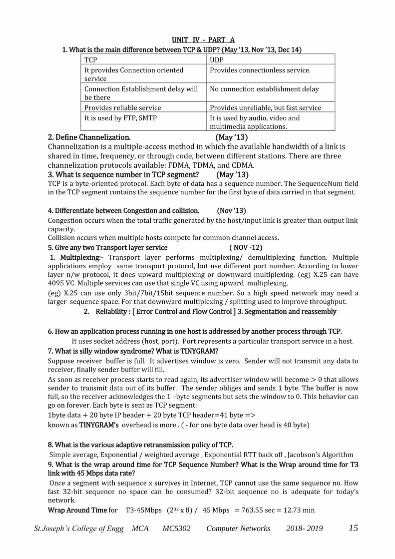
19. Explain connection establishment in TCP.
Establishing TCP Connection :TCP uses 3 way handshake.
Send SYN seq=x
Receive SYN
Receive SYN +ACK
ACK=x+1
To initiate a connection, an entity sends a SYN, Seg=x, where x is the initial sequence no. The receiver responds with SYN , Seg=y, Ack x+1. It indicates that Y is its sequence number. And is now expecting to receive a segment beginning with data octet x+1. Finally initiator responds with Ack y+1, indicating that it is ready to receive segment beginning with data octet y+1. Each machine must choose an initial sequence number at random. It cannot choose 1 every time it creates connection. It is important that both sides agree on an initial number.
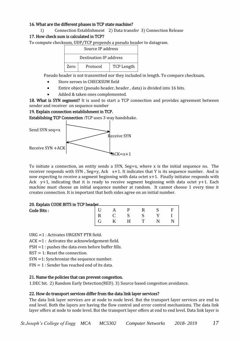
20. Explain CODE BITS in TCP header
Code Bits :
URG =1 : Activates URGENT PTR field.
ACK =1 : Activates the acknowledgement field.
PSH =1 : pushes the data even before buffer fills.
RST = 1: Reset the connection.
SYN =1: Synchronize the sequence number.
FIN = 1 : Sender has reached end of its data.
21. Name the policies that can prevent congestion.
1.DEC bit. 2) Random Early Detection(RED). 3) Source based congestion avoidance. 22. How do transport services differ from the data link layer services?
The data link layer services are at node to node level. But the transport layer services are end to end level. Both the layers are having the flow control and error control mechanisms. The data link layer offers at node to node level. But the transport layer offers at end to end level. Data link layer is
U A P R S F
R C S S Y I
G K H T N N
St.Joseph’s College of Engg MCA MC5302 Computer Networks 2018- 2019 18
responsible for node to node delivery of the frames while transport layer is responsible for end to end delivery of the entire message.
23. Define Slow start mechanism. / What is meant by slow start in TCP ?(MAY-12) The source starts out by setting congestion window to one packet. When ACK for this packet arrives, TCP adds 1 to congestion window and then sends 2 packets. Upon receiving 2 ACK, TCP increments congestion window to be 4.
Consider the case when timeout occurs. By that time source will not transmit any more packets. After sometime, source will receive a single cumulative ACK that re opens a entire advertised window. Now source uses slow start rather (i.e.)window size is 1.
24. Give the significance of Clark’s solution and Nagle’s algorithm
Clark’s solution is to prevent the receiver from sending a window update for 1 byte. Instead it is forced to wait until it has a decent amount of space available and advertise that instead. Specially, the receiver should not send a window update until it can handle the maximum segment size it advertised when the connection was established, or its buffer is half empty, whichever is smaller.
Furthermore, the sender can also help by not sending tiny segments. Instead, it should try to wait until it has accumulated enough space in the window to send a full segment or at least one containing half of the receiver’s buffer size (which it must estimate from the pattern of window updates it has received in the past).
To overcome this, Nagle proposed that at any point of time there can be only one outstanding packet. Till the ack. Is received, data is accumulated and on receipt of ack. Accumulated data is transmitted. N/W utilization increases
25. What are the TCP services to provide reliable communication?
Error control Flow control Connection control and Congestion control
26. List out various congestion control techniques AIMD, slow start, Fast retransmit and Recovery
27. List out various congestion avoidance techniques. DEC bit , RED
28. Distinguish between Contention and Congestion. Congestion occurs when the total traffic generated by the host/input link is greater than output
link capacity. Contention occurs when multiple hosts compete for common channel access.
29. State the use of SYN and FIN bits in TCP ? SYN – To establish the connection FIN – To terminate the connection. 30. List the services of TCP from the application programs point of view.
Segmentation and reassembly, Connection control, Multiplexing, Error Control, Flow Control 31. Name the two protocols available at transport layer. (NOV – 11) TCP- (Transmission control protocol) UDP (User Datagram Protocol) 32. Give the format of TPDU. (NOV – 11) A TPDU is the name for the messages that the protocols in the transport layer of the OSI-model use for communication. It adds a transport header to the APDU to make a TPDU which is then sent to Network layer. 33. What are the four major aspects of reliable delivery at the transport layer? (MAY- 12) The four aspects are, Error control Sequence control Loss control Duplication control 34. Define Flow control. (MAY- 12 & NOV- 12 )
Flow control: It is to assure that source does not overwhelm the destination by sending data faster than they can be processed by destination
35. What is RTP? Basic requirements of PTP? (Dec -14)
The Real-Time Transport Protocol (RTP) is an Internet protocol standard that specifies a way for programs to manage the real-time transmission of multimedia data over either unicast or multicast network services. It provides facilities for jitter compensation and detection of out of sequence arrival in data, which are common during transmissions on an IP network. RTP allows data transfer to multiple destinations through IP multicast.
St.Joseph’s College of Engg MCA MC5302 Computer Networks 2018- 2019 19
UNIT V - PART A
1. List the SNMP functions. Need of SNMP (May ’13) (DEC 16)
Get – enables the management station to retrieve the value of objects at the agent
Set – enables the management station to set value of objects at the agent
Notify – enables an agent to notify management station events
2. Give the two types of connections provided by FTP. (Nov ’13)
FTP uses two parallel TCP connections to transfer a file. They are, Control Connection and Data connection.
Control Connection: It is used for sending control information like user identification, password, commands.
Data Connection: It is used to transfer a file.
3. What is Steganography? (Nov ’13)
Steganography is the art or practice of concealing a message, image, or file within another message, image, or file. Steganography is concerned with concealing the fact that a secret message is being sent, as well as concealing the contents of the message.
4. Write any two applications of network.
SNMP,HTTP
5. What are the two methods of HTTP
GetMethod( ) PostMethod( )
6. What are the advantages of stateless server of HTTP?
Because of the statelessness of HTTP, it need not remember any transaction, request or response. This results in a very simple implementation without the need for complex state machines.
7. What is the use of MIME Extension?
MIME converts binary files, executed files into text files. Then only it can be transmitted using SMTP.
SMTP cannot transmit text data including national language characters. MIME translates all these non ASCII codes to SMTP 7 bit ASCII code
Messages – more than certain size can be translated by MIME into SMTP acceptable size
MIME is needed to transfer audio and video through SMTP (i.e.) non text data
8. Give the advantages of Email.
Composition – The email system can provide features like automatic insertion of receiver’s address while replying as well as basic editor features.
Transfer – It takes responsibility of moving message from sender to receiver
Reporting – It reports to the sender that email messages are sent successfully
Displaying – It displays messages in special pop-up window
Disposition – It does forwarding / deleting etc.
9. What are the features of email.
Features of e-mail:
Composing and sending / receiving mails
Storing / Forwarding / Deleting messages and replying to a message with facilities like CC, BCC
Sending mails to more than one person
Sending text, voice, graphics and video
10. Which protocol support email and give details about that protocol.
SMTP is a standard protocol for transferring mails using TCP/IP
SMTP standardization for message character is 7 bit ASCII
SMTP adds log info to the start (i.e.) path of the message
St.Joseph’s College of Engg MCA MC5302 Computer Networks 2018- 2019 20
11. What is cipher text and Plain text?
Plaintext – original message that is the input to algorithm
Encryption algorithm – It does various substitutions and transformations on plaintext
Secret key – It is the key used for encryption by sender and for decryption by receiver.
Ciphertext – It is the scrambled message produced as o/p
Decryption algorithm – It converts ciphertext to original messages
12. What is authentication?
Message Authentication
It is a procedure that allows communicating parties to verify the received messages are authentic. Message authentication may be preferable in some situations where confidentiality is not needed.
13. What are the classifications of Encryption methods?
Conventional encryption
Asymmetric encryption
14. How many symmetric keys are needed for n persons to communicate in symmetric key cipher?
Number of symmetric keys = nc2
15. Define NIC and NAT.
A domain name registry, also called Network Information Centre (NIC), is part of the Domain Name System (DNS) of the Internet which converts domain names to IP addresses.
NAT: In computer networking, network address translation (NAT, also known as network masquerading, native address translation or IP masquerading) is a technique of transceiving network traffic through a router that involves re-writing the source and/or destination IP addresses and usually also the TCP/UDP port numbers of IP packets as they pass through. Most systems using NAT do so in order to enable multiple hosts on a private network to access the Internet using a single public IP address .
16. What is MIB?
MIB: Object is a data variable that represents one aspect of the management agent. It represents resources.
Collection of objects is known as MIB.A management station performs
monitoring MIB objects
retriving MIB objects value
change MIB object value
17. Different classification of DNS servers.
Internet is divided into many top level domains. Each domain is divided into sub domain and so on.
Topmost domains are categorized into generic and countries.
Generic domain categories are:
com- commercial
gov- US government
edu- educational
org- profile organization
mil- US military
net- network providers.
country category
uk - United kingdom
jp - Japan
in - India
18. What an application program of DNS does?
The application program interested in obtaining IP address of a domain name calls a library program "Resolver"
St.Joseph’s College of Engg MCA MC5302 Computer Networks 2018- 2019 21
Resolver sends UDP packet to nearest DNS server (local DNS server)
Local DNS server looks up domain name and returns IP address to resolver as in previous part.
Resolver returns IP address to application program.
19. Mention the components of SNMP model. (NOV -12)
Key elements of Network Management System:
Management station / Manager , Agent, Management Information base
Network Management Protocol
20. What are the functions of presentation layer?
Translation , Encryption / Decryption, Authentication, Compression
21. Name the functions of Telnet. Telnet offers users the capability of running programs remotely and facilitates remote
administration. Telnet client program run a logon session on a remote computer where the user's communications needs are handled by a Telnet server program.
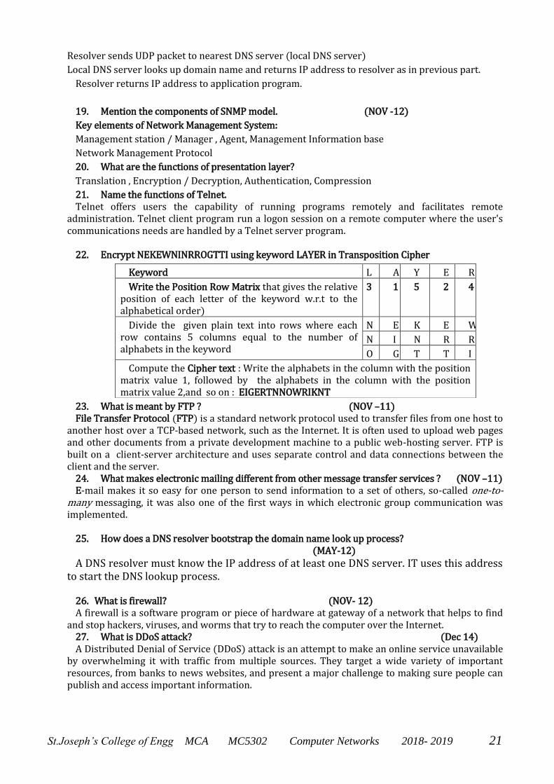
22. Encrypt NEKEWNINRROGTTI using keyword LAYER in Transposition Cipher
23. What is meant by FTP ? (NOV –11) File Transfer Protocol (FTP) is a standard network protocol used to transfer files from one host to
another host over a TCP-based network, such as the Internet. It is often used to upload web pages and other documents from a private development machine to a public web-hosting server. FTP is built on a client-server architecture and uses separate control and data connections between the client and the server.
24. What makes electronic mailing different from other message transfer services ? (NOV –11) E-mail makes it so easy for one person to send information to a set of others, so-called one-to-
many messaging, it was also one of the first ways in which electronic group communication was implemented.
25. How does a DNS resolver bootstrap the domain name look up process? (MAY-12) A DNS resolver must know the IP address of at least one DNS server. IT uses this address
to start the DNS lookup process. 26. What is firewall? (NOV- 12) A firewall is a software program or piece of hardware at gateway of a network that helps to find
and stop hackers, viruses, and worms that try to reach the computer over the Internet. 27. What is DDoS attack? (Dec 14) A Distributed Denial of Service (DDoS) attack is an attempt to make an online service unavailable
by overwhelming it with traffic from multiple sources. They target a wide variety of important resources, from banks to news websites, and present a major challenge to making sure people can publish and access important information.
Keyword L A Y E R
Write the Position Row Matrix that gives the relative position of each letter of the keyword w.r.t to the alphabetical order)
3 1 5 2 4
Divide the given plain text into rows where each row contains 5 columns equal to the number of alphabets in the keyword
N E K E W
N I N R R
O G T T I
Compute the Cipher text : Write the alphabets in the column with the position matrix value 1, followed by the alphabets in the column with the position matrix value 2,and so on : EIGERTNNOWRIKNT

St.Joseph’s College of Engg MCA MC5302 Computer Networks 2018- 2019 22
28. Give the features of SSL. (Dec 14)
Encrypts Information
Necessary for Accepting Payments
Guards Against Phishing
Offers Added Brand Power
Improves Customer Trust 29. What is the difference between symmetric and asymmetric encryption algorithm?
(NOV 17) SYMMETRIC ALGORITHMS ASYMMETRIC ALGORITHMS
use single key called “secret key” use pair of keys public key and Private Key
use the same key for
both encryption and decryption
Use different keys for encryption and
decryption
Used for data confidentiality:
encryption and decryption
Mostly used for key exchange
PART-B UNIT I
1. Explain with an example the basic communication model? (NOV- 12) (DEC 16) Communication model: Communication is the exchange of data between 2 parties
Elements/components of communication:
Source: It is a device that generates data that is to be generated (Phone , PC)
Transmitter: It transforms and encodes the data into electromagnetic signals that can be
transmitted across some transmission system
Transmission System: It can be a single transmission line or complex network connecting
source and destination
Receiver: It accepts signal from transmission line and converts it into a form that can be
accepted by the destination device
Destination: It accepts incoming data from the receiver
Communication Tasks:
Transmission system utilization: Interfacing Signal generation: Synchronization:
Exchange Management Error detection & correction Flow control: Addressing and Routing:
Recovery: Message formatting: Security: Network management:
2. Classification of Communication Networks / Categories of Network (Nov – ’13) Classification of Communication Networks / Categories of Network
LAN:- LOCAL AREA NETWORK LAN is a Privately owned network with in a single
building of few Kilometers in size. E.g.: office, factory uses LANS to share recourses and
exchange info. LAN uses broadcast n/w approach. Speed of LAN 10 to 100 mbps.
If LAN uses bus topology (i.e.) single cable it uses IEEE 802.3 mechanism.
If LAN uses ring topology then it uses 802.5 mechanism for broadcasting in LAN , channel
St.Joseph’s College of Engg MCA MC5302 Computer Networks 2018- 2019 23
allocation can be static and dynamic. The channel is common and only one station can
transmit.
MAN: It contains a collection of machines that spans over a city.
WAN: It contains a collection of machines that spans over large geographical area.
This n/w consist of 2 distinct components transaction lines and switching elements that are
inter connected. Data from source to destination is routed across intermediate nodes. The
purpose of intermediate nodes is to provide switching facility that move data from node to
node until they reach their destination.
S. NO LAN WAN
1. Scope of LAN is restricted to a small/
single building
Scope of WAN spans over large
geographical area country/ Continent
2. LAN is owned by same organization A part of n/w asserts are owned or not
owned.
3. Data rate of LAN 10-100 Mbps. Data rate of WAN is Gigabyte.
3. State the functionality of Network adaptors. Explain how the bytes of a frame are transferred between the adaptor and the host memory. Explain the concept of memory Bottleneck in network adaptors. Network Adaptor and frame transmission
Network Adaptor and frame transmission Each node connects to the network via a network adaptor. This adaptor generally sits on the
system’s I/O bus and delivers data between the workstation’s memory and the network link. A
software module running on the workstation – the device driver – manages this adaptor.
Memory Bottleneck: While I/O bus is fast enough to transfer frames between the network
adaptor and host memory, there are two potential problems. The first is that the advertised I/O
speed corresponds to its peak bandwidth. Limitation is that the size of the data block that is being
transferred across the I/O bus, since there is a certain amount of overhead involved in each bus
transfer. The second is that the memory/CPU bandwidth, which is slightly more than the
bandwidth of the I/O bus.
4. Explain in detail the different transmission media and compare and contrast them of cost, speed, security, attenuation and other in terms of relevant characteristics. Write short notes on coaxial cable.(6) (MAY- 12) (DEC 16)
Discuss in detail about i) optical fiber (6) ii) Coaxial Cable (5) (NOV - 12) Explain the various Guided Transmission media. (Nov – 13)
The transmission media that are used to convey information can be classified as guided or
unguided. Guided media provide a physical path along which the signals are propagated; these
include twisted pair, coaxial cable, and optical fiber. Unguided media employ an antenna for
transmitting through air, vacuum, or water.
GUIDED TRANSMISSION MEDIA
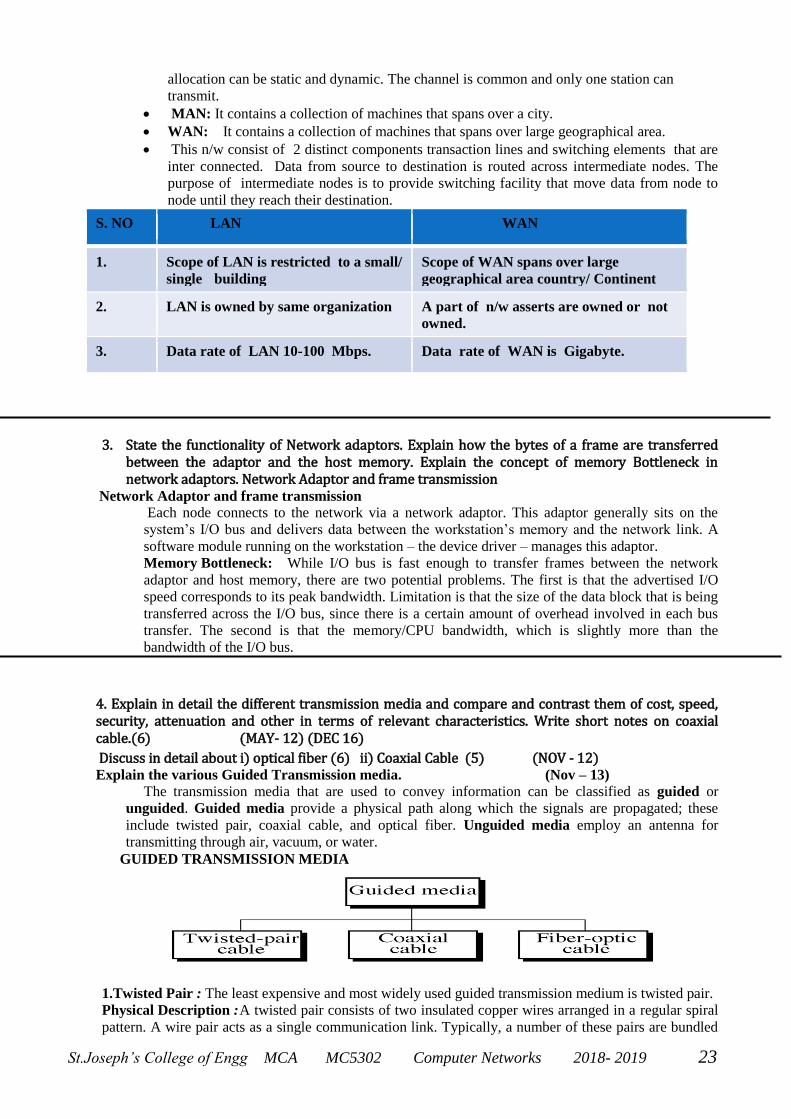
1.Twisted Pair : The least expensive and most widely used guided transmission medium is twisted pair.
Physical Description : A twisted pair consists of two insulated copper wires arranged in a regular spiral
pattern. A wire pair acts as a single communication link. Typically, a number of these pairs are bundled
St.Joseph’s College of Engg MCA MC5302 Computer Networks 2018- 2019 24
together into a cable by wrapping them in a tough protective sheath. Over longer distances, cables may
contain hundred of pairs. The twisting tends to decrease the crosstalk interference between adjacent pairs
in a cable. Neighboring pairs in a bundle typically have somewhat different twist lengths to reduce
crosstalk interference. On long-distance links, the twist length typically varies from 5 to 15 cm. The
wires in a pair have thicknesses of form 0.4 to 0.9 mm.
Transmission characteristics :
For analog signals, amplifiers are required about every 5 to 6 km. For digital
transmission, repeaters are required every 2 to 3 km.
Twisted pair is limited in distance, bandwidth, and data rate. The medium is quite susceptible to interference and noise because of its easy coupling
with electromagnetic fields.
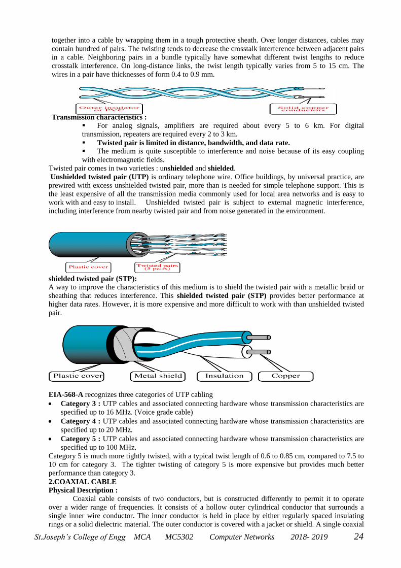
Twisted pair comes in two varieties : unshielded and shielded.
Unshielded twisted pair (UTP) is ordinary telephone wire. Office buildings, by universal practice, are
prewired with excess unshielded twisted pair, more than is needed for simple telephone support. This is
the least expensive of all the transmission media commonly used for local area networks and is easy to
work with and easy to install. Unshielded twisted pair is subject to external magnetic interference,
including interference from nearby twisted pair and from noise generated in the environment.
shielded twisted pair (STP): A way to improve the characteristics of this medium is to shield the twisted pair with a metallic braid or
sheathing that reduces interference. This shielded twisted pair (STP) provides better performance at
higher data rates. However, it is more expensive and more difficult to work with than unshielded twisted
pair.
EIA-568-A recognizes three categories of UTP cabling
Category 3 : UTP cables and associated connecting hardware whose transmission characteristics are
specified up to 16 MHz. (Voice grade cable)
Category 4 : UTP cables and associated connecting hardware whose transmission characteristics are
specified up to 20 MHz.
Category 5 : UTP cables and associated connecting hardware whose transmission characteristics are
specified up to 100 MHz.
Category 5 is much more tightly twisted, with a typical twist length of 0.6 to 0.85 cm, compared to 7.5 to
10 cm for category 3. The tighter twisting of category 5 is more expensive but provides much better
performance than category 3.
2.COAXIAL CABLE
Physical Description :
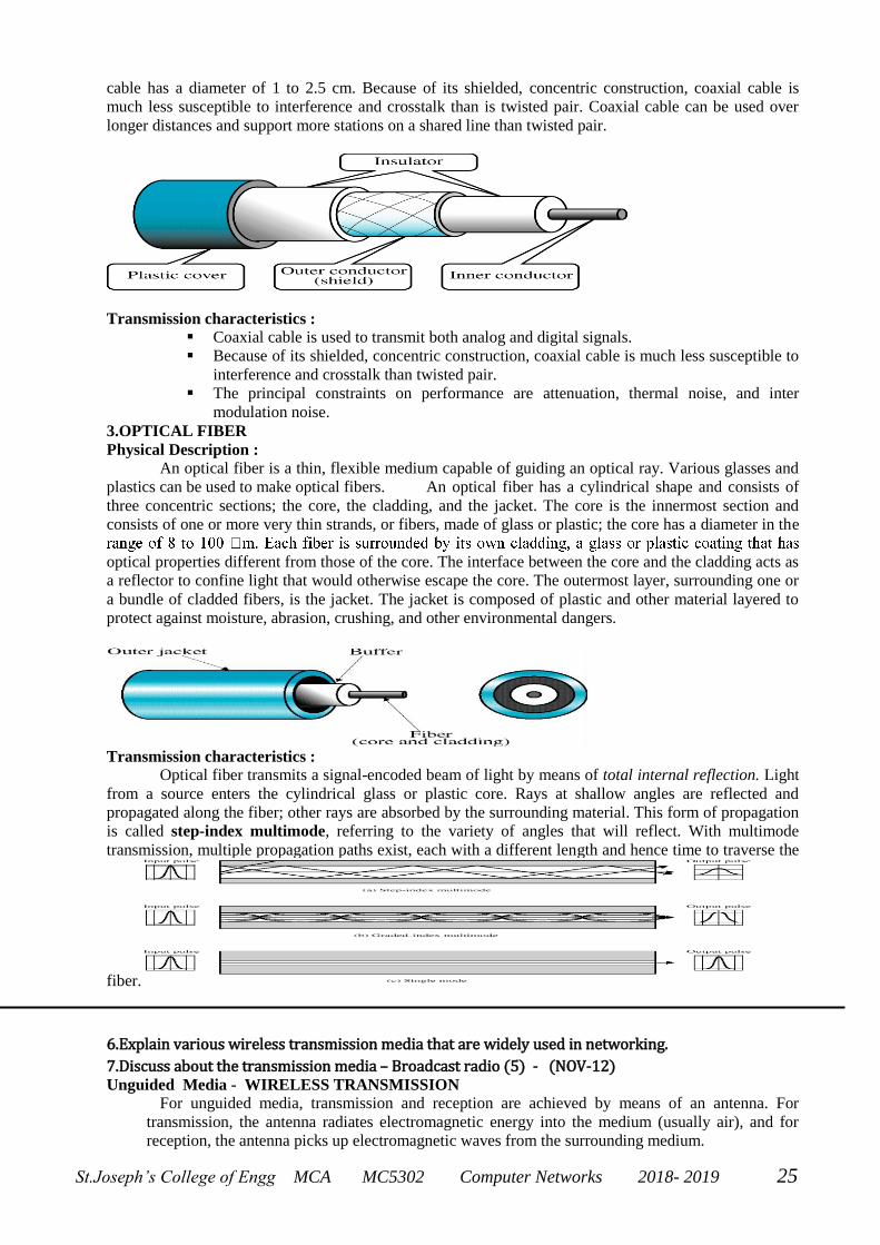
Coaxial cable consists of two conductors, but is constructed differently to permit it to operate
over a wider range of frequencies. It consists of a hollow outer cylindrical conductor that surrounds a
single inner wire conductor. The inner conductor is held in place by either regularly spaced insulating
rings or a solid dielectric material. The outer conductor is covered with a jacket or shield. A single coaxial
St.Joseph’s College of Engg MCA MC5302 Computer Networks 2018- 2019 25
cable has a diameter of 1 to 2.5 cm. Because of its shielded, concentric construction, coaxial cable is
much less susceptible to interference and crosstalk than is twisted pair. Coaxial cable can be used over
longer distances and support more stations on a shared line than twisted pair.
Transmission characteristics :
Coaxial cable is used to transmit both analog and digital signals.
Because of its shielded, concentric construction, coaxial cable is much less susceptible to
interference and crosstalk than twisted pair.
The principal constraints on performance are attenuation, thermal noise, and inter
modulation noise.
3.OPTICAL FIBER
Physical Description :
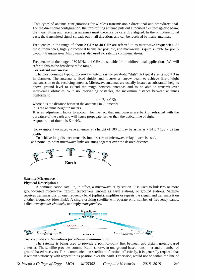
An optical fiber is a thin, flexible medium capable of guiding an optical ray. Various glasses and
plastics can be used to make optical fibers. An optical fiber has a cylindrical shape and consists of
three concentric sections; the core, the cladding, and the jacket. The core is the innermost section and
consists of one or more very thin strands, or fibers, made of glass or plastic; the core has a diameter in the
optical properties different from those of the core. The interface between the core and the cladding acts as
a reflector to confine light that would otherwise escape the core. The outermost layer, surrounding one or
a bundle of cladded fibers, is the jacket. The jacket is composed of plastic and other material layered to
protect against moisture, abrasion, crushing, and other environmental dangers.
Transmission characteristics :
Optical fiber transmits a signal-encoded beam of light by means of total internal reflection. Light
from a source enters the cylindrical glass or plastic core. Rays at shallow angles are reflected and
propagated along the fiber; other rays are absorbed by the surrounding material. This form of propagation
is called step-index multimode, referring to the variety of angles that will reflect. With multimode
transmission, multiple propagation paths exist, each with a different length and hence time to traverse the
fiber.
6.Explain various wireless transmission media that are widely used in networking.
7.Discuss about the transmission media – Broadcast radio (5) - (NOV-12) Unguided Media - WIRELESS TRANSMISSION
For unguided media, transmission and reception are achieved by means of an antenna. For
transmission, the antenna radiates electromagnetic energy into the medium (usually air), and for
reception, the antenna picks up electromagnetic waves from the surrounding medium.
St.Joseph’s College of Engg MCA MC5302 Computer Networks 2018- 2019 26
Two types of antenna configurations for wireless transmission : directional and omnidirectional.
For the directional configuration, the transmitting antenna puts out a focused electromagnetic beam;
the transmitting and receiving antennas must therefore be carefully aligned. In the omnidirectional
case, the transmitted signal spreads out in all directions and can be received by many antennas.
Frequencies in the range of about 2 GHz to 40 GHz are referred to as microwave frequencies. At
these frequencies, highly directional beams are possible, and microwave is quite suitable for point-
to-point transmission. Microwave is also used for satellite communications.
Frequencies in the range of 30 MHz to 1 GHz are suitable for omnidirectional applications. We will
refer to this as the broadcast radio range.
Terrestrial microwave
The most common type of microwave antenna is the parabolic “dish”. A typical size is about 3 m
in diameter. The antenna is fixed rigidly and focuses a narrow beam to achieve line-of-sight
transmission to the receiving antenna. Microwave antennas are usually located at substantial heights
above ground level to extend the range between antennas and to be able to transmit over
intervening obstacles. With no intervening obstacles, the maximum distance between antennas
conforms to
d = 7.14 Kh
where d is the distance between the antennas in kilometers
h is the antenna height in meters
K is an adjustment factor to account for the fact that microwaves are bent or refracted with the
curvature of the earth and will hence propagate farther than the optical line of sight.
A good rule of thumb is K = 4/3.
for example, two microwave antennas at a height of 100 m may be as far as 7.14 x 133 = 82 km
apart.
To achieve long-distance transmission, a series of microwave relay towers is used,
and point- to-point microwave links are stung together over the desired distance.
Satellite Microwave
Physical Description :
A communication satellite, in effect, a microwave relay station. It is used to link two or more
ground-based microwave transmitter/receivers, known as earth stations, or ground stations. Satellite
receives transmissions on one frequency band (uplink), amplifies or repeats the signal, and transmits it on
another frequency (downlink). A single orbiting satellite will operate on a number of frequency bands,
called transponder channels, or simply transponders.
Two common configurations for satellite communication :
The satellite is being used to provide a point-to-point link between two distant ground-based
antennas. The satellite provides communications between one ground-based transmitter and a number of
ground-based receivers. For a communication satellite to function effectively, it is generally required that
it remain stationary with respect to its position over the earth. Otherwise, would not be within the line of
St.Joseph’s College of Engg MCA MC5302 Computer Networks 2018- 2019 27
sight of its earth stations at all times. To remain stationary, the satellite must have a period of rotation
equal to the earth’s period of rotation. This match occurs at a height of 35,784 km.
Broadcast Radio
Physical Description :
The principal difference between broadcast radio and microwave is that the former is
omnidirectional and the latter is directional. Thus broadcast radio does not require dish-shaped
antennas need not be rigidly mounted to a precise alignment.
Transmission Characteristics :
The range 30 MHz to 1 GHz is an effective one for broadcast communications. Unlike the case
for lower-frequency electromagnetic waves, the ionosphere is transparent to radio waves above 30
MHz.
Infrared: Infrared communications is achieved using transmitters/receivers (transceivers) that
modulate non coherent infrared light. Transceivers must be within the line of sight of each other either
directly or via reflection from a light-colored surface such as the ceiling of a room. One important
difference between infrared and microwave transmission is that the former does not penetrate walls.
Thus the security and interference problems encountered in microwave systems are not present.
8. Describe in detail about the concept of data transmission and its terminology with necessary example. (MAY – 12)
DATA TRANSMISSION CONCEPTS AND TERMINOLOGY
Transmission media In Guided media the waves are guided along a physical path. Unguided
media provides a mean for transmitting Electro magnetic waves but not guide them.
Transmission line Point-point link-provides direct link between two devices. Only that two
devices share the medium. In Multipoint link, more than two devices share the same medium.
Transmission mode Simplex ----signals are transmitted in only one direction. One is sender
& another is receiver. Half duplex-both stations can transmit and send but only in one
direction. Full duplex-both can send and receive at same time.
Note:Data is transmitted in a means of electromagnetic signals which is a function of time and
frequency.
Spectrum-is the range of frequencies that a signal contains.
Absolute bandwidth-the width of a spectrum of a signal
Effective bandwidth- is the bandwidth within which most of the signal energy is concentrated.
ANALOG vs DIGITAL
A Signal DS
A
Data
Data can occupy same spectrum
are different portion of spectrum
Data are encoded using codec to produce
digital bit stream.
DD Data are encoded using to
produce analog signal.
Signal uses 2 levels to represent 2 binary
values.
A Transmission DT
AS It is propagated through
amplifiers
Signal is propagated. through repeaters.
Assuming that it represents digital data
DS Not used It represents digital data/and coding of
analog data. It is propagated through
repeater
Transmission impairments
Attenuation –strength of signal falls off with distance over any Transmission medium.
Delay distortion The received signal is distorted due to varying delays experienced at its
constituent’s frequencies. It is caused by variation in velocity of propagation through guided
medium some of signal components of one bit position will split over into other bit position
cavity ISI(inter symbol interference).

St.Joseph’s College of Engg MCA MC5302 Computer Networks 2018- 2019 28
NOISE The Transmitted signal can be modified by some unwanted signal known as noise -
thermal noise--inter modulation noise-cross talk- Impulse noise
Channel capacity The maximum rate at which data can be transmitted over a communication
path
Data rateIt is the rate in bps at which data can be communicated
Channel bandwidthit is the bandwidth of transmitted signal constrained by sender ,nature of
Transmission medium in cycles per seconds/hertz
Noise It is the average level of noise over communication path.
Error rate The rate at which errors occur
Nyguist bandwidth Doubling bandwidth doubles data rate
C- Capacity of channel in bits per second.
M- Number of discrete /voltage level.
B- Bandwidth in Hz.
Shannon capacity Formula
.
SNR-signal to noise ratio
Nyquist analyzed the theoretical capacity of a noiseless channel; therefore, in that case,
the signaling rate is limited solely by channel bandwidth.
Shannon addressed the question of what signaling rate can be achieved over a
channel with a given bandwidth, a given signal power, and in the presence of noise.
8. What is a protocol? Explain in detail about the protocol data units? Protocol is the set of rules governing the exchange of data between 2 entities. It defines what
is communicated, how it is communicated, when it is communicated
Key elements of Protocol
Syntax – It refers to the structure or format of data meaning the order in which they are
presented.
Semantics – It refers to the meaning of each section of bit. How to do interpretation.
Timing – When data should be sent and how fast they can be sent.
Characteristics of protocol:
Direct/Indirect:If 2 systems share a point to point link, data and control pass directly
between them with no intervening active agent. If systems are connected through a switched
communication network the systems should depend on others to exchange data.
Monolithic/Structured:Monolithic: There is a single protocol for all functioning. It is too
complex to handle as one unit.Structured: It is a set of protocols that exhibits a hierarchical
or layered structure. Primitive functions are implemented in lower level entities which
provides services to higher level entities.
Symmetric or asymmetric:Symmetry : Involve communication between peer
entities.Asymmetry: It is dictated by the logic of an exchange.[Client and Server]
Strandard or Unstandered: If K different sources have to communicate with L destinations
,then K different protocols needed with 2*K*L implementations. If all systems share a
common protocol, K+L implementations are needed.
Functions:
Encapsulation: The addition of control information(Address Error detaching code protocol
control) is known as Encapsulation.
Segmentation and Reassembly:Sending data in smaller PDU size is best one for easy error
control, retransmission, shorter delay, need of smaller buffer. So data is transmitted as a
sequence of blocks of data .Eventually the segmented data is to be reassembled into message
at receiver side.
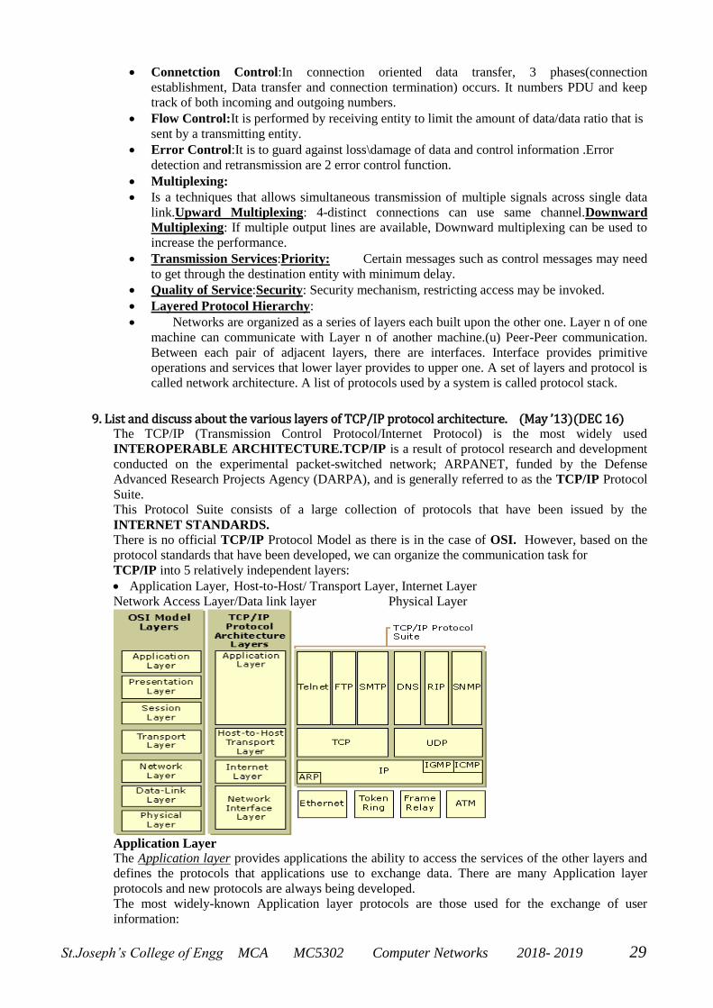
St.Joseph’s College of Engg MCA MC5302 Computer Networks 2018- 2019 29
Connetction Control:In connection oriented data transfer, 3 phases(connection
establishment, Data transfer and connection termination) occurs. It numbers PDU and keep
track of both incoming and outgoing numbers.
Flow Control:It is performed by receiving entity to limit the amount of data/data ratio that is
sent by a transmitting entity.
Error Control:It is to guard against loss\damage of data and control information .Error
detection and retransmission are 2 error control function.
Multiplexing:
Is a techniques that allows simultaneous transmission of multiple signals across single data
link.Upward Multiplexing: 4-distinct connections can use same channel.Downward
Multiplexing: If multiple output lines are available, Downward multiplexing can be used to
increase the performance.
Transmission Services:Priority: Certain messages such as control messages may need
to get through the destination entity with minimum delay.
Quality of Service:Security: Security mechanism, restricting access may be invoked.
Layered Protocol Hierarchy:
Networks are organized as a series of layers each built upon the other one. Layer n of one
machine can communicate with Layer n of another machine.(u) Peer-Peer communication.
Between each pair of adjacent layers, there are interfaces. Interface provides primitive
operations and services that lower layer provides to upper one. A set of layers and protocol is
called network architecture. A list of protocols used by a system is called protocol stack.
9. List and discuss about the various layers of TCP/IP protocol architecture. (May ’13)(DEC 16) The TCP/IP (Transmission Control Protocol/Internet Protocol) is the most widely used
INTEROPERABLE ARCHITECTURE.TCP/IP is a result of protocol research and development
conducted on the experimental packet-switched network; ARPANET, funded by the Defense
Advanced Research Projects Agency (DARPA), and is generally referred to as the TCP/IP Protocol
Suite.
This Protocol Suite consists of a large collection of protocols that have been issued by the
INTERNET STANDARDS.
There is no official TCP/IP Protocol Model as there is in the case of OSI. However, based on the
protocol standards that have been developed, we can organize the communication task for
TCP/IP into 5 relatively independent layers:
Application Layer, Host-to-Host/ Transport Layer, Internet Layer
Network Access Layer/Data link layer Physical Layer
Application Layer
The Application layer provides applications the ability to access the services of the other layers and
defines the protocols that applications use to exchange data. There are many Application layer
protocols and new protocols are always being developed.
The most widely-known Application layer protocols are those used for the exchange of user
information:
St.Joseph’s College of Engg MCA MC5302 Computer Networks 2018- 2019 30
The Hypertext Transfer Protocol (HTTP) is used to transfer files that make up the Web pages of
the World Wide Web.
The File Transfer Protocol (FTP) is used for interactive file transfer.
The Simple Mail Transfer Protocol (SMTP) is used for the transfer of mail messages and
attachments.
Telnet, a terminal emulation protocol, is used for logging on remotely to network hosts.
Additionally, the following Application layer protocols help facilitate the use and management of
TCP/IP networks:
The Domain Name System (DNS) is used to resolve a host name to an IP address.
The Routing Information Protocol (RIP) is a routing protocol that routers use to exchange routing
information.
The Simple Network Management Protocol (SNMP) is used between a network management
console and network devices (routers, bridges, intelligent hubs) to collect and exchange network
management information.
Examples of Application layer interfaces for TCP/IP applications are Sockets and NetBIOS. Sockets
provide a standard application programming interface (API) for interprocess communication via
TCP/IP. NetBIOS is an industry standard interface for accessing protocol services such as sessions,
datagrams, and name resolution.
Transport Layer
The Transport layer (also known as the Host-to-Host Transport layer) is responsible for providing
the Application layer with session and datagram communication services. The core protocols of the
Transport layer are Transmission Control Protocol (TCP) and the User Datagram Protocol (UDP).
Either of these two protocols are used by the application layer process, the choice depends on the
application's transmission reliability requirements.
The mechanisms used by the Transport layer to determine whether data has been correctly delivered
are: Acknowledgement responses, Sequencing and Flow control
The Transport layer facilitates end-to-end data transfer. It supports multiple operations
simultaneously. The layer is implemented by two protocols: the Transmission Control Protocol
(TCP) and the User Datagram Protocol (UDP). TCP uses packets called segments, while UDP uses
packets called datagrams. Both TCP and UDP are encapsulated inside Internet layer datagrams for
transmission to the next node.
The Transport layer facilitates two types of communication:
Connection-oriented (TCP) – A connection must be established at the Transport layer of both
systems before the application can transmit any data.
Connectionless (UDP) – All systems do not need to establish a connection with the recipient prior to
data exchange. TCP is a more reliable form of data exchange than UDP.
TCP and UDP: TCP is a reliable, connection-oriented protocol that provides error checking and flow control
through a virtual link that it establishes and finally terminates. TCP is responsible for the
establishment of a TCP connection (TCP handshake), the sequencing and acknowledgment of packets
sent, and the recovery of packets lost during transmission.
UDP is an unreliable, connectionless protocol that provides data transport with lower network traffic
overheads than TCP. UDP is used when the amount of data to be transferred is small (such as the data
that would fit into a single packet), or when the overhead of establishing a TCP connection is not
desired or when the applications or upper layer protocols provide reliable delivery. UDP does not
error check or offer any flow control, this is left to the application process. Still it can be used by
protocols that provide reliable packet transmission like NFS.
The Transport layer encompasses the responsibilities of the OSI Transport layer and some of the
responsibilities of the OSI Session layer.
Internet Layer : This layer is responsible for addressing, packaging, and routing functions. It
allows communication across networks of the same and different types and carries out translations to
deal with dissimilar data addressing schemes. The core protocols of the Internet layer are IP, ARP,
ICMP, and IGMP.
The Internet Protocol (IP) is a routable protocol responsible for IP addressing, routing, and the
fragmentation and reassembly of packets.
The Address Resolution Protocol (ARP) is responsible for the resolution of the Internet layer address
to the Network Interface layer address such as a hardware address.
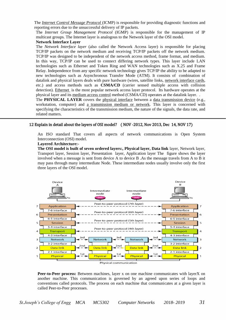
St.Joseph’s College of Engg MCA MC5302 Computer Networks 2018- 2019 31
The Internet Control Message Protocol (ICMP) is responsible for providing diagnostic functions and
reporting errors due to the unsuccessful delivery of IP packets.
The Internet Group Management Protocol (IGMP) is responsible for the management of IP
multicast groups. The Internet layer is analogous to the Network layer of the OSI model.
Network Interface Layer
The Network Interface layer (also called the Network Access layer) is responsible for placing
TCP/IP packets on the network medium and receiving TCP/IP packets off the network medium.
TCP/IP was designed to be independent of the network access method, frame format, and medium.
In this way, TCP/IP can be used to connect differing network types. This layer include LAN
technologies such as Ethernet and Token Ring and WAN technologies such as X.25 and Frame
Relay. Independence from any specific network technology gives TCP/IP the ability to be adapted to
new technologies such as Asynchronous Transfer Mode (ATM). It consists of combination of
datalink and physical layers deals with pure hardware (wires, satellite links, network interface cards,
etc.) and access methods such as CSMA/CD (carrier sensed multiple access with collision
detection). Ethernet is the most popular network access layer protocol. Its hardware operates at the
physical layer and its medium access control method (CSMA/CD) operates at the datalink layer. .
The PHYSICAL LAYER covers the physical interface between a data transmission device (e.g.,
workstation, computer) and a transmission medium or network. This layer is concerned with
specifying the characteristics of the transmission medium, the nature of the signals, the data rate, and
related matters.
12 Explain in detail about the layers of OSI model? ( NOV -2012, Nov 2013, Dec 14, NOV 17)
An ISO standard That covers all aspects of network communications is Open System
Interconnection (OSI) model.
Layered Architecture:- The OSI model is built of seven ordered layers:, Physical layer, Data link layer, Network layer,
Transport layer, Session layer, Presentation layer, Application layer The figure shows the layer
involved when a message is sent from device A to device B .As the message travels from A to B it
may pass through many intermediate Node. These intermediate nodes usually involve only the first
three layers of the OSI model.
Peer-to-Peer process: Between machines, layer x on one machine communicates with layerX on
another machine. This communication is governed by an agreed upon series of loops and
conventions called protocols. The process on each machine that communicates at a given layer is
called Peer-to-Peer processes.
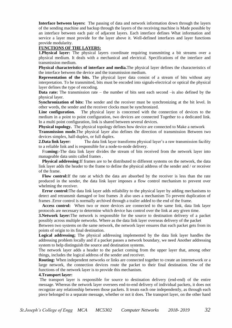
St.Joseph’s College of Engg MCA MC5302 Computer Networks 2018- 2019 32
Interface between layers: The passing of data and network information down through the layers
of the sending machine and backup through the layers of the receiving machine is Made possible by
an interface between each pair of adjacent layers. Each interface defines What information and
service a layer must provide for the layer above it. Well-defined interfaces and layer functions
provide modularity.
FUNCTIONS OF THE LAYERS:
1.Physical layer: The physical layers coordinate requiring transmitting a bit streams over a
physical medium. It deals with a mechanical and electrical. Specifications of the interface and
transmission medium.
Physical characteristics of interface and media.The physical layer defines the characteristics of
the interface between the device and the transmission medium.
Representation of the bits. The physical layer data consist of a stream of bits without any
interpretation. To be transmitted, bits must be encoded into signals-electrical or optical the physical
layer defines the type of encoding.
Data rate: The transmission rate – the number of bits sent each second –is also defined by the
physical layer.
Synchronization of bits: The sender and the receiver must be synchronizing at the bit level. In
other words, the sender and the receiver clocks must be synchronized.
Line configuration. The physical layer is concerned with the connection of devices to the
medium in a point to point configuration, two devices are connected Together to a dedicated link.
In a multi point configuration, link is shared between several devices.
Physical topology. The physical topology defines how device are connected to Make a network
Transmission mode.The physical layer also defines the direction of transmission Between two
devices simplex, half-duplex, or full duplex.
2.Data link layer: The data link layer transforms physical layer’s a raw transmission facility
to a reliable link and is responsible for a node-to-node delivery.
Framing:-The data link layer divides the stream of bits received from the network layer into
manageable data units called frames .
Physical addressing:If frames are to be distributed to different systems on the network, the data
link layer adds the header to the frame to define the physical address of the sender and / or receiver
of the frame.
Flow control:If the rate at which the data are absorbed by the receiver is less than the rate
produced in the sender, the data link layer imposes a flow control mechanism to prevent over
whelming the receiver.
Error control:The data link layer adds reliability to the physical layer by adding mechanisms to
detect and retransmit damaged or lost frames .It also uses a mechanism To prevent duplication of
frames .Error control is normally archived through a trailer added to the end of the frame.
Access control: When two or more devices are connected to the same link, data link layer
protocols are necessary to determine which device has control over the link at any given time.
3.Network layer:The network is responsible for the source to destination delivery of a packet
possibly across multiple networks. Where as the data link layer overseas delivery of the packet
Between two systems on the same network, the network layer ensures that each packet gets from its
points of origin to its final destination.
Logical addressing; The physical addressing implemented by the data link layer handles the
addressing problem locally and if a packet passes a network boundary, we need Another addressing
system to help distinguish the source and destination systems.
The network layer adds a header to the packet coming from the upper layer that, among other
things, includes the logical address of the sender and receiver.
Routing: When independent networks or links are connected together to create an internetwork or a
large network, the connection devices route the packet to their final destination. One of the
functions of the network layer is to provide this mechanism.
4.Transport layer:
The transport layer is responsible for source to destination delivery (end-end) of the entire
message. Whereas the network layer oversees end-to-end delivery of individual packets, it does not
recognize any relationship between those packets. It treats each one independently, as through each
piece belonged to a separate message, whether or not it does. The transport layer, on the other hand
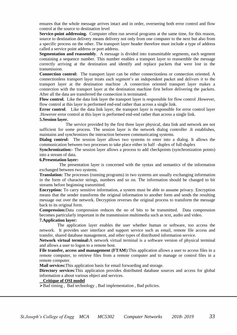
St.Joseph’s College of Engg MCA MC5302 Computer Networks 2018- 2019 33
ensures that the whole message arrives intact and in order, overseeing both error control and flow
control at the source to destination level
Service-point addressing. Computer often run several programs at the same time, for this reason,
source to destination delivery means delivery not only from one computer to the next but also from
a specific process on the other. The transport layer header therefore must include a type of address
called a service point address or port address.
Segmentation and reassembly. A message is divided into transmittable segments, each segment
containing a sequence number. This number enables a transport layer to reassemble the message
correctly arriving at the destination and identify and replace packets that were lost in the
transmission.
Connection control: The transport layer can be either connectionless or connection oriented. A
connectionless transport layer treats each segment’s an independent packet and delivers it to the
transport layer at the destination machine .A connection oriented transport layer makes a
connection with the transport layer at the destination machine first before delivering the packets.
After all the data are transferred the connection is terminated.
Flow control. Like the data link layer the transport layer is responsible for flow control .However,
flow control at this layer is performed end-end rather than across a single link.
Error control. Like the data link layer, the transport layer is responsible for error control layer
.However error control at this layer is performed end-end rather than across a single link.
5.Session layer.
The service provided by the first three layer physical, data link and network are not
sufficient for some process. The session layer is the network dialog controller .It establishes,
maintains and synchronizes the interaction between communicating systems.
Dialog control: The session layer allows two systems to enter into a dialog. It allows the
communication between two processes to take place either in half –duplex of full-duplex
Synchronization:- The session layer allows a process to add checkpoints (synchronization points)
into a stream of data.
6.Presentation layer:
The presentation layer is concerned with the syntax and semantics of the information
exchanged between two systems.
Translation: The processes (running programs) in two systems are usually exchanging information
in the form of character strings, numbers and so on. The information should be changed to bit
streams before beginning transmitted.
Encryption: To carry sensitive information, a system must be able to assume privacy. Encryption
means that the sender transforms the original information to another form and sends the resulting
message out over the network. Decryption reverses the original process to transform the message
back to its original form.
Compression:Data compression reduces the no of bits to be transmitted. Data compression
becomes particularly important in the transmission multimedia such as text, audio and video.
7.Application layer:
The application layer enables the user whether human or software, too access the
network. It provides user interface and support service such as email, remote file access and
transfer, shared database management, and other types of distributed information service.
Network virtual terminal:A network virtual terminal is a software version of physical terminal
and allows a user to logon to a remote host.
File transfer, access and management (FTAM):This application allows a user to access files in a
remote computer, to retrieve files from a remote computer and to manage or control files in a
remote computer.
Mail services:This application basis for email forwarding and storage.
Directory services:This application provides distributed database sources and access for global
information a about various object and services.
Critique of OSI model
Bad timing , Bad technology , Bad implementation , Bad policies.
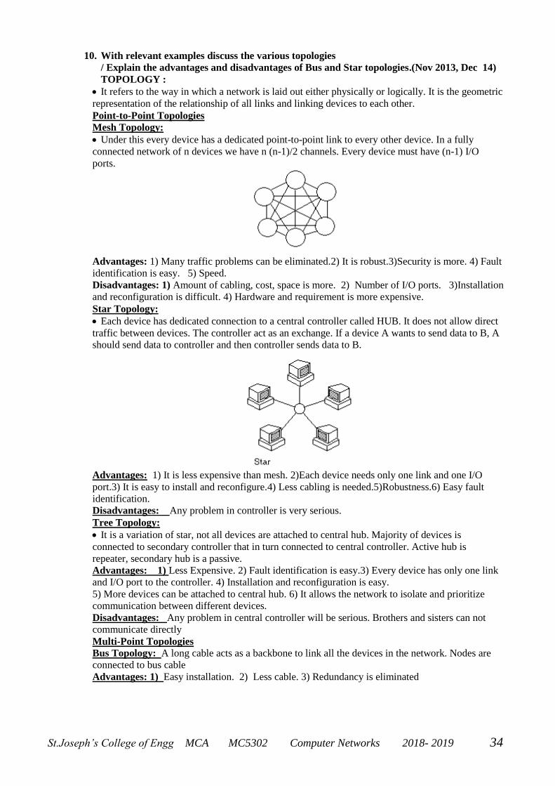
St.Joseph’s College of Engg MCA MC5302 Computer Networks 2018- 2019 34
10. With relevant examples discuss the various topologies
/ Explain the advantages and disadvantages of Bus and Star topologies.(Nov 2013, Dec 14)
TOPOLOGY :
It refers to the way in which a network is laid out either physically or logically. It is the geometric
representation of the relationship of all links and linking devices to each other.
Point-to-Point Topologies
Mesh Topology:
Under this every device has a dedicated point-to-point link to every other device. In a fully
connected network of n devices we have n (n-1)/2 channels. Every device must have (n-1) I/O
ports.
Advantages: 1) Many traffic problems can be eliminated.2) It is robust.3)Security is more. 4) Fault
identification is easy. 5) Speed.
Disadvantages: 1) Amount of cabling, cost, space is more. 2) Number of I/O ports. 3)Installation
and reconfiguration is difficult. 4) Hardware and requirement is more expensive.
Star Topology:
Each device has dedicated connection to a central controller called HUB. It does not allow direct
traffic between devices. The controller act as an exchange. If a device A wants to send data to B, A
should send data to controller and then controller sends data to B.
Advantages: 1) It is less expensive than mesh. 2)Each device needs only one link and one I/O
port.3) It is easy to install and reconfigure.4) Less cabling is needed.5)Robustness.6) Easy fault
identification.
Disadvantages: Any problem in controller is very serious.
Tree Topology:
It is a variation of star, not all devices are attached to central hub. Majority of devices is
connected to secondary controller that in turn connected to central controller. Active hub is
repeater, secondary hub is a passive.
Advantages: 1) Less Expensive. 2) Fault identification is easy.3) Every device has only one link
and I/O port to the controller. 4) Installation and reconfiguration is easy.
5) More devices can be attached to central hub. 6) It allows the network to isolate and prioritize
communication between different devices.
Disadvantages: Any problem in central controller will be serious. Brothers and sisters can not
communicate directly
Multi-Point Topologies
Bus Topology: A long cable acts as a backbone to link all the devices in the network. Nodes are
connected to bus cable
Advantages: 1) Easy installation. 2) Less cable. 3) Redundancy is eliminated
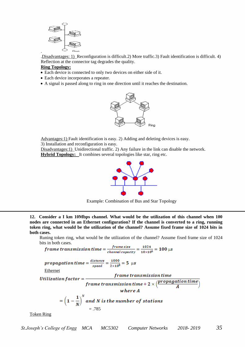
St.Joseph’s College of Engg MCA MC5302 Computer Networks 2018- 2019 35
.
.Disadvantages: 1) Reconfiguration is difficult.2) More traffic.3) Fault identification is difficult. 4)
Reflection at the connector tag degrades the quality.
Ring Topology:
Each device is connected to only two devices on either side of it.
Each device incorporates a repeater.
A signal is passed along to ring in one direction until it reaches the destination.
Advantages:1) Fault identification is easy. 2) Adding and deleting devices is easy.
3) Installation and reconfiguration is easy.
Disadvantages:1) Unidirectional traffic. 2) Any failure in the link can disable the network.
Hybrid Topology: It combines several topologies like star, ring etc.
Example: Combination of Bus and Star Topology
12. Consider a I km 10Mbps channel. What would be the utilization of this channel when 100
nodes are connected in an Ethernet configuration? If the channel is converted to a ring, running
token ring, what would be the utilization of the channel? Assume fixed frame size of 1024 bits in
both cases.
Runing token ring, what would be the utilization of the channel? Assume fixed frame size of 1024
bits in both cases.
Ethernet
= .785
Token Ring
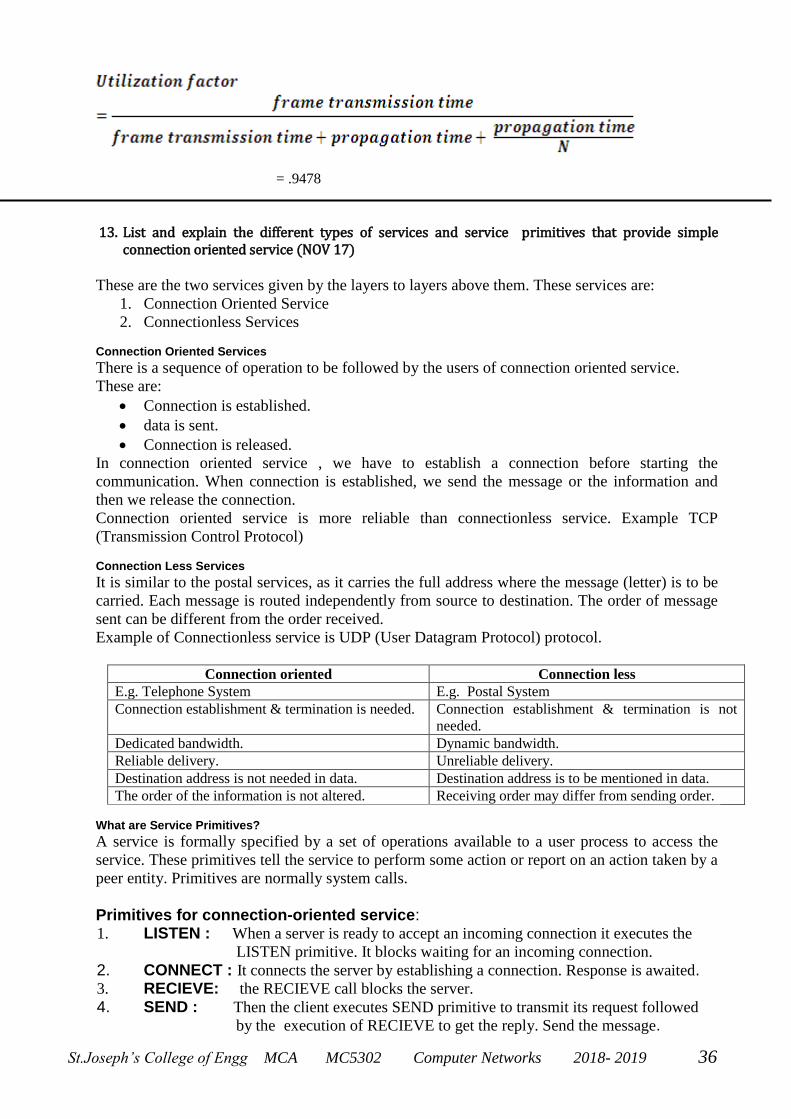
St.Joseph’s College of Engg MCA MC5302 Computer Networks 2018- 2019 36
= .9478
13. List and explain the different types of services and service primitives that provide simple connection oriented service (NOV 17)
These are the two services given by the layers to layers above them. These services are:
1. Connection Oriented Service
2. Connectionless Services Connection Oriented Services
There is a sequence of operation to be followed by the users of connection oriented service.
These are:
Connection is established.
data is sent.
Connection is released.
In connection oriented service , we have to establish a connection before starting the
communication. When connection is established, we send the message or the information and
then we release the connection.
Connection oriented service is more reliable than connectionless service. Example TCP
(Transmission Control Protocol)
Connection Less Services
It is similar to the postal services, as it carries the full address where the message (letter) is to be
carried. Each message is routed independently from source to destination. The order of message
sent can be different from the order received.
Example of Connectionless service is UDP (User Datagram Protocol) protocol.
Connection oriented Connection less
E.g. Telephone System E.g. Postal System
Connection establishment & termination is needed. Connection establishment & termination is not
needed.
Dedicated bandwidth. Dynamic bandwidth.
Reliable delivery. Unreliable delivery.
Destination address is not needed in data. Destination address is to be mentioned in data.
The order of the information is not altered. Receiving order may differ from sending order. What are Service Primitives?
A service is formally specified by a set of operations available to a user process to access the
service. These primitives tell the service to perform some action or report on an action taken by a
peer entity. Primitives are normally system calls.
Primitives for connection-oriented service: 1. LISTEN : When a server is ready to accept an incoming connection it executes the
LISTEN primitive. It blocks waiting for an incoming connection.
2. CONNECT : It connects the server by establishing a connection. Response is awaited. 3. RECIEVE: the RECIEVE call blocks the server.
4. SEND : Then the client executes SEND primitive to transmit its request followed by the execution of RECIEVE to get the reply. Send the message.

St.Joseph’s College of Engg MCA MC5302 Computer Networks 2018- 2019 37
5. DISCONNECT : This primitive is used for terminating the connection. After this
primitive one can't send any message. When the client sends DISCONNECT packet then the
server also sends the DISCONNECT packet to acknowledge the client. When the server
package is received by client then the process is terminated.
Primitives for connectionless service
UNIDATA This primitive sends a packet of data
FACILITY, REPORT
Primitive for enquiring about the performance of the network, like delivery
statistics.
UNIT –II
1. (i) Explain the error detection techniques of cyclic redundancy by check. (Dec 14) (Dec 16)
(NOV 17)
2. i) Distinguish between forward error correction versus error correction by transmission.
ii) For P = 110011 and M = 1100011, find CRC.
2. List and discuss the various techniques available in error detection. CRC
SENDER SIDE :
0 1 0 1 0 0 0 1 0 1 0 1 0 1 1 0
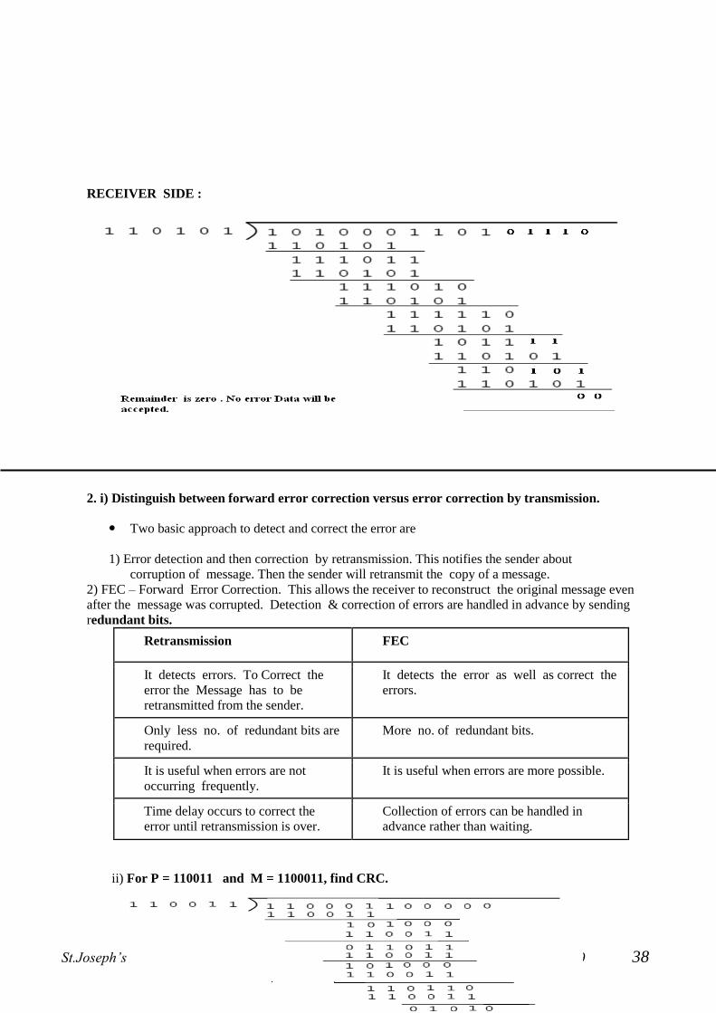
St.Joseph’s College of Engg MCA MC5302 Computer Networks 2018- 2019 38
RECEIVER SIDE :
2. i) Distinguish between forward error correction versus error correction by transmission.
Two basic approach to detect and correct the error are
1) Error detection and then correction by retransmission. This notifies the sender about
corruption of message. Then the sender will retransmit the copy of a message.
2) FEC – Forward Error Correction. This allows the receiver to reconstruct the original message even
after the message was corrupted. Detection & correction of errors are handled in advance by sending
redundant bits.
Retransmission FEC
It detects errors. To Correct the
error the Message has to be
retransmitted from the sender.
It detects the error as well as correct the
errors.
Only less no. of redundant bits are
required.
More no. of redundant bits.
It is useful when errors are not
occurring frequently.
It is useful when errors are more possible.
Time delay occurs to correct the
error until retransmission is over.
Collection of errors can be handled in
advance rather than waiting.
ii) For P = 110011 and M = 1100011, find CRC.
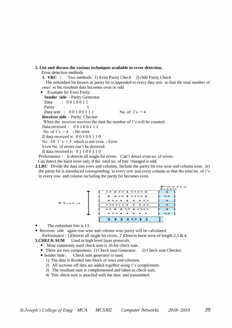
St.Joseph’s College of Engg MCA MC5302 Computer Networks 2018- 2019 39
2. List and discuss the various techniques available in error detection.
Error detection methods
1. VRC : Two methods. 1) Even Parity Check 2) Odd Parity Check
The redundant bit known as parity bit is appended to every data unit so that the total number of
ones’ in the resultant data becomes even or odd.
Example for Even Parity
Sender side - Parity Generator
Data : 0 0 1 0 0 1 1
Parity : 1
Data sent : 0 0 1 0 0 1 1 1 No. of 1’s = 4
Receiver side - Parity Checker
When the receiver receives the data the number of 1’s will be counted.
Data received : 0 0 1 0 0 1 1 1
No. of 1’s = 4 - No error
If data received is 0 0 1 0 0 1 1 0
No . Of 1’ s = 3 which is not even. - Error
Even No. of errors can’t be detected.
If data received is 0 1 1 0 0 1 1 0
Performance : It detects all single bit errors. Can’t detect even no. of errors.
Can detect the burst error only if the total no. of bits changed is odd.
2. LRC Divide the data into rows and columns. Include the parity bit row wise and column wise. ie)
the parity bit is introduced corresponding to every row and every column so that the total no. of 1’s
in every row and column including the parity bit becomes even.
Either odd or even parity can be used.
The redundant bits is 13.
Receiver side again row wise and column wise parity will be calculated.
Performance : 1)Detects all single bit errors. 2 )Detects burst error of length 2,3 & 4.
3.CHECK SUM Used in high level layer protocols.
Most commonly used check sum is 16-bit check sum .
There are two components. 1) Check sum Generator. 2) Check sum Checker.
Sender Side : Check sum generator is used.
1) The data is divided into block of rows and columns.
2) All sections off data are added together using 1’s complement.
3) The resultant sum is complemented and taken as check sum.
4) This check sum is attached with the data and transmitted.
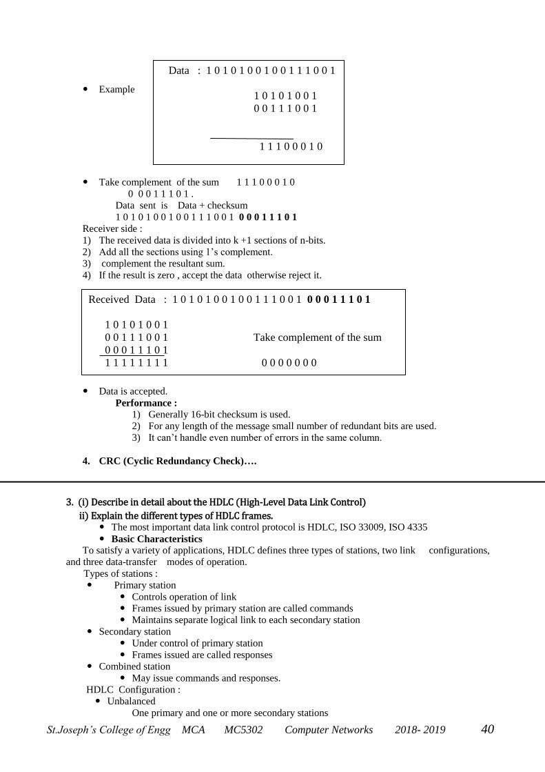
St.Joseph’s College of Engg MCA MC5302 Computer Networks 2018- 2019 40
Example
Take complement of the sum 1 1 1 0 0 0 1 0
0 0 0 1 1 1 0 1 .
Data sent is Data + checksum
1 0 1 0 1 0 0 1 0 0 1 1 1 0 0 1 0 0 0 1 1 1 0 1
Receiver side :
1) The received data is divided into k +1 sections of n-bits.
2) Add all the sections using 1’s complement.
3) complement the resultant sum.
4) If the result is zero , accept the data otherwise reject it.
Data is accepted.
Performance :
1) Generally 16-bit checksum is used.
2) For any length of the message small number of redundant bits are used.
3) It can’t handle even number of errors in the same column.
4. CRC (Cyclic Redundancy Check)….
3. (i) Describe in detail about the HDLC (High-Level Data Link Control)
ii) Explain the different types of HDLC frames. The most important data link control protocol is HDLC, ISO 33009, ISO 4335
Basic Characteristics To satisfy a variety of applications, HDLC defines three types of stations, two link configurations,
and three data-transfer modes of operation.
Types of stations :
Primary station
Controls operation of link
Frames issued by primary station are called commands
Maintains separate logical link to each secondary station
Secondary station
Under control of primary station
Frames issued are called responses
Combined station
May issue commands and responses.
HDLC Configuration :
Unbalanced
One primary and one or more secondary stations
Data : 1 0 1 0 1 0 0 1 0 0 1 1 1 0 0 1
1 0 1 0 1 0 0 1
0 0 1 1 1 0 0 1
1 1 1 0 0 0 1 0
Received Data : 1 0 1 0 1 0 0 1 0 0 1 1 1 0 0 1 0 0 0 1 1 1 0 1
1 0 1 0 1 0 0 1
0 0 1 1 1 0 0 1 Take complement of the sum
0 0 0 1 1 1 0 1
1 1 1 1 1 1 1 1 0 0 0 0 0 0 0

St.Joseph’s College of Engg MCA MC5302 Computer Networks 2018- 2019 41
Supports full duplex and half duplex
Balanced
Two combined stations
Supports full duplex and half duplex
HDLC transfer mode
Normal Response Mode (NRM)
Unbalanced configuration
Primary initiates transfer to secondary
Secondary may only transmit data in response to command from primary
Used on multi-drop lines
Host computer as primary
Terminals as secondary
Asynchronous Balanced Mode (ABM)
Balanced configuration
Either station may initiate transmission without receiving permission
Most widely used
No polling overhead
Asynchronous Response Mode (ARM)
Unbalanced configuration
Secondary may initiate transmission without permission form primary
Primary responsible for line
rarely used
Frame Structure
Synchronous transmission.
All transmissions are in the form of frames.
Single frame format is used for all data and control exchanges.
HDLC Operation
Exchange of information, supervisory and unnumbered frames
Three phases
Initialization Data transfer Disconnect

St.Joseph’s College of Engg MCA MC5302 Computer Networks 2018- 2019 42
(ii) Explain the different types of HDLC frames.
HDLC defines three types of frames, each with a different control field format. Information frames
(I-frames) carry the data to be transmitted for the user (the logic above HDLC that is using
HDLC). Additionally, flow- and error-control data, using the ARQ mechanism, are piggybacked
on an information frame. Supervisory frames (S-frames) provide the ARQ mechanism when
piggybacking is not used. Unnumbered frames (U-frames) provide supplemental link control
functions. The first one or two bits of the control field serves to identify the frame type. The
remaining bit positions are organized into subfields as indicated in Figure .
4. Discuss in detail about the flow control mechanism and error control mechanism.
Flow Control:
5. (i) Distinguish between flow control and error control in DLL. (May – ’13)
(ii) Explain in detail the stop-and-wait, Go-back N and selective repeat ARQ protocols in DLL. Flow Control:
Ensuring the sending entity does not overwhelm the receiving entity .
There are two flow control mechanisms
b. Stop –wait protocol 2) Sliding window protocol.
1. Stop – wait protocol :
Source transmits frame.
Destination receives frame and replies with acknowledgement.
Source waits for ACK before sending next frame.
Destination can stop flow by not send ACK.
Works well for a few large frames.
2. Sliding Windows Flow Control
Allow multiple frames to be in transit.
Receiver has buffer W long
Transmitter can send up to W frames without ACK
Each frame is numbered.
ACK includes number of next frame expected
Sequence number bounded by size of field (k)
Frames are numbered modulo 2 k
Error Control
Lost frames – A frame fails to arrive at the other side.
Damaged frames – Frame is arrived but with some of the bits are in error.
Automatic repeat request(ARQ)
Error detection
Positive acknowledgment – Destination returns positive ACK for successfully received
frames.
Retransmission after timeout- Source retransmits a frame when it times out before
getting ACK.
Negative acknowledgement and retransmission – Destination returns NACK for error
frames.
5. (i) Distinguish between flow control and error control in DLL. (May – ’13)
Flow Control: Sending station does not overwhelm receiving station. Stop and wait
protocol and sliding window protocol are the flow control mechanisms.
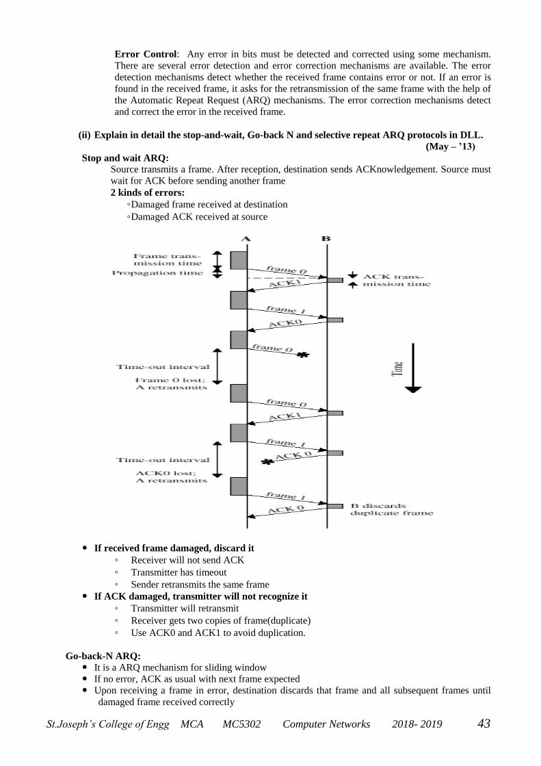
St.Joseph’s College of Engg MCA MC5302 Computer Networks 2018- 2019 43
Error Control: Any error in bits must be detected and corrected using some mechanism.
There are several error detection and error correction mechanisms are available. The error
detection mechanisms detect whether the received frame contains error or not. If an error is
found in the received frame, it asks for the retransmission of the same frame with the help of
the Automatic Repeat Request (ARQ) mechanisms. The error correction mechanisms detect
and correct the error in the received frame.
(ii) Explain in detail the stop-and-wait, Go-back N and selective repeat ARQ protocols in DLL.
(May – ’13)
Stop and wait ARQ:
Source transmits a frame. After reception, destination sends ACKnowledgement. Source must
wait for ACK before sending another frame
2 kinds of errors:
◦ Damaged frame received at destination
◦ Damaged ACK received at source
If received frame damaged, discard it
◦ Receiver will not send ACK
◦ Transmitter has timeout
◦ Sender retransmits the same frame
If ACK damaged, transmitter will not recognize it
◦ Transmitter will retransmit
◦ Receiver gets two copies of frame(duplicate)
◦ Use ACK0 and ACK1 to avoid duplication.
Go-back-N ARQ:
It is a ARQ mechanism for sliding window
If no error, ACK as usual with next frame expected
Upon receiving a frame in error, destination discards that frame and all subsequent frames until
damaged frame received correctly
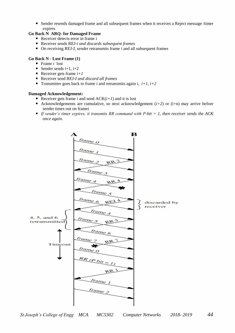
St.Joseph’s College of Engg MCA MC5302 Computer Networks 2018- 2019 44
Sender resends damaged frame and all subsequent frames when it receives a Reject message /timer
expires
Go Back N ARQ- for Damaged Frame
Receiver detects error in frame i
Receiver sends REJ-i and discards subsequent frames
On receiving REJ-I, sender retransmits frame i and all subsequent frames
Go Back N - Lost Frame (1)
Frame i lost
Sender sends i+1, i+2
Receiver gets frame i+1
Receiver send REJ-I and discard all frames
Transmitter goes back to frame i and retransmits again i, i+1, i+2
Damaged Acknowledgement:
Receiver gets frame i and send ACK(i+1) and it is lost
Acknowledgements are cumulative, so next acknowledgement (i+2) or (i+n) may arrive before
sender times out on framei
If sender’s timer expires, it transmits RR command with P-bit = 1, then receiver sends the ACK
once again.
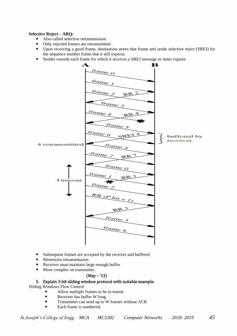
St.Joseph’s College of Engg MCA MC5302 Computer Networks 2018- 2019 45
Selective Reject – ARQ:
Also called selective retransmission
Only rejected frames are retransmitted
Upon receiving a good frame, destination stores that frame and sends selective reject (SREJ) for
the sequence number frame that it still expects.
Sender resends each frame for which it receives a SREJ message or timer expires
Subsequent frames are accepted by the receiver and buffered
Minimizes retransmission
Receiver must maintain large enough buffer
More complex on transmitter.
(May – ’13)
5. Explain 3-bit sliding window protocol with suitable example. Sliding Windows Flow Control
Allow multiple frames to be in transit.
Receiver has buffer W long
Transmitter can send up to W frames without ACK
Each frame is numbered.
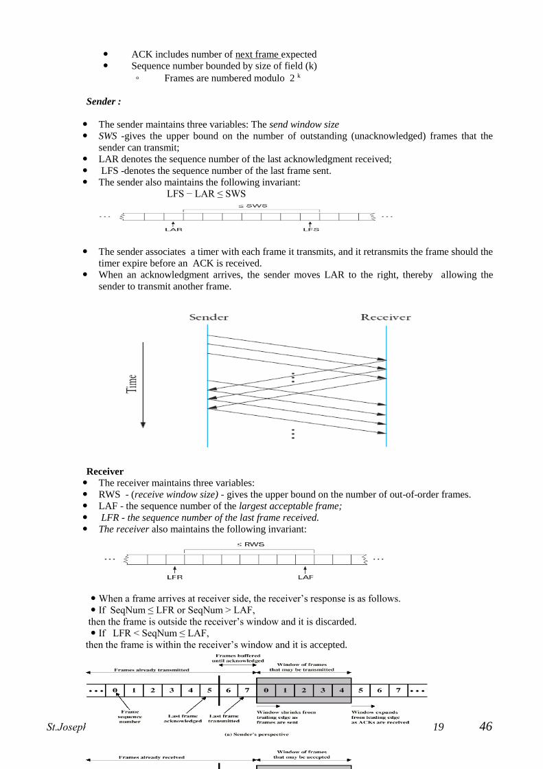
St.Joseph’s College of Engg MCA MC5302 Computer Networks 2018- 2019 46
ACK includes number of next frame expected
Sequence number bounded by size of field (k)
◦ Frames are numbered modulo 2 k
Sender :
The sender maintains three variables: The send window size
SWS -gives the upper bound on the number of outstanding (unacknowledged) frames that the
sender can transmit;
LAR denotes the sequence number of the last acknowledgment received;
LFS -denotes the sequence number of the last frame sent.
The sender also maintains the following invariant:
LFS − LAR ≤ SWS
The sender associates a timer with each frame it transmits, and it retransmits the frame should the
timer expire before an ACK is received.
When an acknowledgment arrives, the sender moves LAR to the right, thereby allowing the
sender to transmit another frame.
Receiver
The receiver maintains three variables:
RWS - (receive window size) - gives the upper bound on the number of out-of-order frames.
LAF - the sequence number of the largest acceptable frame;
LFR - the sequence number of the last frame received.
The receiver also maintains the following invariant:
When a frame arrives at receiver side, the receiver’s response is as follows.
If SeqNum ≤ LFR or SeqNum > LAF,
then the frame is outside the receiver’s window and it is discarded.
If LFR < SeqNum ≤ LAF,
then the frame is within the receiver’s window and it is accepted.

St.Joseph’s College of Engg MCA MC5302 Computer Networks 2018- 2019 47
Acknowledgements
- Cumulative Ack is used.
- Ack contains the sequence number of the next frame
expected to arrive.
- Frames are received out of order say before getting 5th
frame 6 and 7 are received, receiver will send the Ack
with seq. no 5 .
selective acknowledgments.
That is, the receiver could acknowledge exactly those frames it has received.
ie) in previous example Ack will send for frames 6 and 7 thus inform the non- arrival of frame 5
to the sender.
Sequence numbers :
SWS < (MaxSeqNum + 1)/2
The sliding window protocol alternates between the two halves of the sequence number space.
ie) for first set of frames 0,1,2,3 & next set of frames 4,5,6,7.
6. Discuss in detail about the Ethernet and 802.3 frame format(Nov– ’13) (DEC 16)(NOV 17) IEEE 802.1 is concerned with internetworking issues in LAN and MAN. It is not yet complete.
It tries to resolve the incompatibility mechanism.
This project divides DLC into 2 sets of functions.
IEEE 802.2 deals with end user portions of the frame i.e logical address, control information, data
IEEE 802.3, 802.3, 802.4, 802.5 -the second set of the functions, MAC resolves the contention
of the shared media.
It is the most widely used MAC protocol , It uses Manchester encoding scheme
It gives a data rate 100 Mbps generally, It uses star or bus topology.
Whenever multiple user access a single line, there is a danger of overlapping and destroying
called collision. As traffic increases collisions increases. The access mechanism used in Ethernet
is called Carrier Sense Multiple Access with Collision Detection (CSMA/CD).
CSMA/CD
Here any workstation that wishes to transmit, listen for existing traffic on the line. If it is not
idle, it listens to the traffic until there is no traffic. If the line is idle, it will transmit.
It reduces the number of collisions but not eliminate them.
To detect collision after transmission ,it checks the line for the extremely high voltage that
indicates a collision.
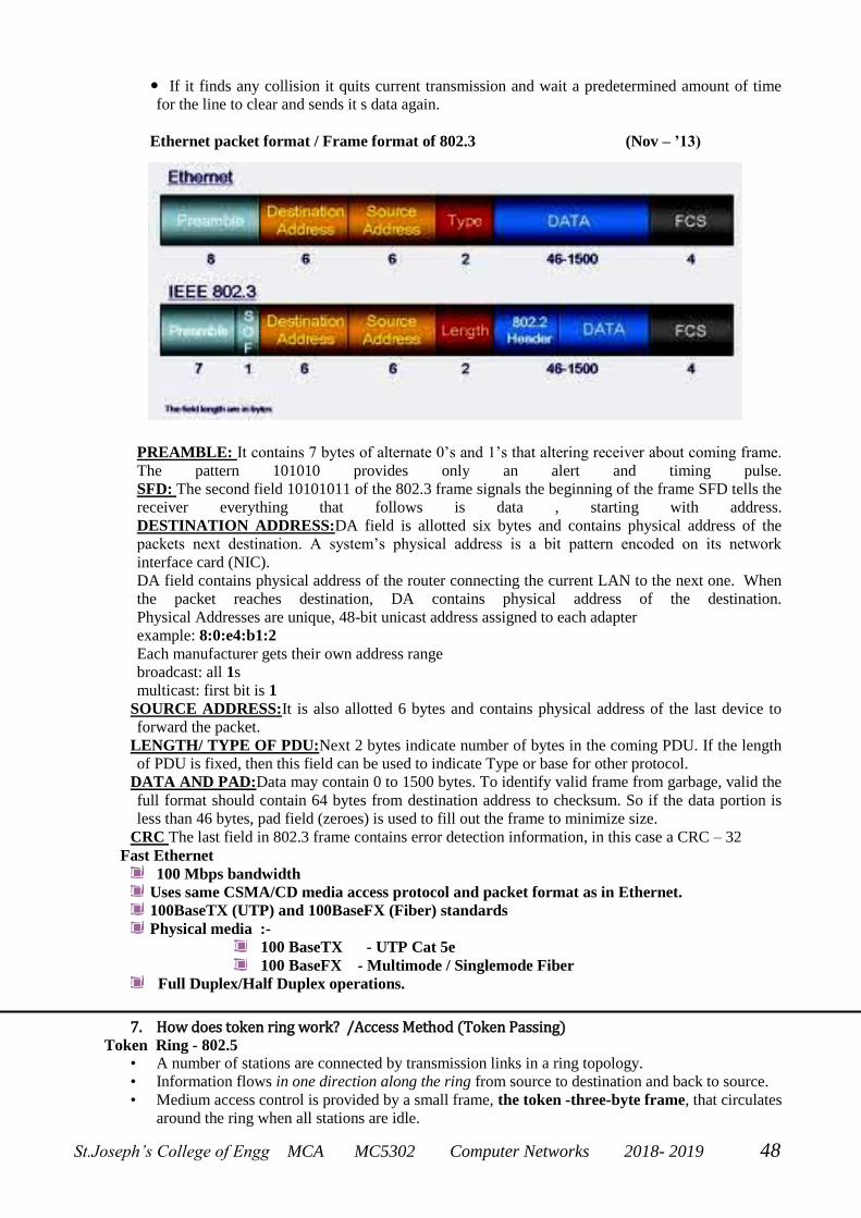
St.Joseph’s College of Engg MCA MC5302 Computer Networks 2018- 2019 48
If it finds any collision it quits current transmission and wait a predetermined amount of time
for the line to clear and sends it s data again.
Ethernet packet format / Frame format of 802.3 (Nov – ’13)
PREAMBLE: It contains 7 bytes of alternate 0’s and 1’s that altering receiver about coming frame.
The pattern 101010 provides only an alert and timing pulse.
SFD: The second field 10101011 of the 802.3 frame signals the beginning of the frame SFD tells the
receiver everything that follows is data , starting with address.
DESTINATION ADDRESS:DA field is allotted six bytes and contains physical address of the
packets next destination. A system’s physical address is a bit pattern encoded on its network
interface card (NIC).
DA field contains physical address of the router connecting the current LAN to the next one. When
the packet reaches destination, DA contains physical address of the destination.
Physical Addresses are unique, 48-bit unicast address assigned to each adapter
example: 8:0:e4:b1:2
Each manufacturer gets their own address range
broadcast: all 1s
multicast: first bit is 1
SOURCE ADDRESS:It is also allotted 6 bytes and contains physical address of the last device to
forward the packet.
LENGTH/ TYPE OF PDU:Next 2 bytes indicate number of bytes in the coming PDU. If the length
of PDU is fixed, then this field can be used to indicate Type or base for other protocol.
DATA AND PAD:Data may contain 0 to 1500 bytes. To identify valid frame from garbage, valid the
full format should contain 64 bytes from destination address to checksum. So if the data portion is
less than 46 bytes, pad field (zeroes) is used to fill out the frame to minimize size.
CRC The last field in 802.3 frame contains error detection information, in this case a CRC – 32
Fast Ethernet
100 Mbps bandwidth
Uses same CSMA/CD media access protocol and packet format as in Ethernet.
100BaseTX (UTP) and 100BaseFX (Fiber) standards
Physical media :-
100 BaseTX - UTP Cat 5e
100 BaseFX - Multimode / Singlemode Fiber
Full Duplex/Half Duplex operations.
7. How does token ring work? /Access Method (Token Passing) Token Ring - 802.5
• A number of stations are connected by transmission links in a ring topology.
• Information flows in one direction along the ring from source to destination and back to source.
• Medium access control is provided by a small frame, the token -three-byte frame, that circulates
around the ring when all stations are idle.

St.Joseph’s College of Engg MCA MC5302 Computer Networks 2018- 2019 49
• When a station wishes to transmit, it must wait for token to pass by and seize the token
• Only the station possessing the token is allowed to transmit at any given time.
• When nodes gets the token it can transmit for a limited time. Every node gets an equal
opportunity to send
• Designed for predictability, fairness and reliability
• Data rate is 4 and 16 Mbps using twisted-pair cabling
• It uses differential Manchester line encoding.
• Maximum number of stations is 250.
How does token ring work? /Access Method (Token Passing)
A station that wants to transmit a frame will capture a token frame.
Token frame will be converted into data frame - by setting token bit
The frame starts its circulation in the ring
Each station receives the frame and regenerates and repeats the frame onto the ring. {Normally,
there is a one bit delay as the frame passes through a station.}
• Each station interrogates passing frame, if destined for that station, it copies frame into local
buffer. The destination will set two bits
A- Address Recognized Indicator C-Frame Copied Indicator
Frame continues to circle the ring and reaches the sender
The sender removes the frame and release the token known as Delay token Release.
Token FRAME FORMAT
It is a simple frame of size 3 – bytes or 24 – bits.
It circulates around the ring from host to host
A host can transmit the data only when it possess the token.
◦ STARTING DELIMITER:It is 1 Byte. It is used to alert the receiver and to mark starting
of frame.
ACCESS CONTROL:It is one Byte long and it includes 4 sub fields.
First 3 bits are the priority fields
Fourth bit is called the Token Bit – to indicate data frame or token frame.
It is followed by monitor bit.
Last 3 bits are Reservation Field that can be set by stations wishing to reserve access to
the ring.
FRAME CONTROL:It is 1 byte long contains 2 fields.The first one bit field is used to indicate
the type of information (control information or data)
DESTINATION ADDRESS:The 2 to 6 bytes DA field contains the physical address of the
frames next destination. If its ultimate destination is another network, the DA is the address of the
P P P T M R R R
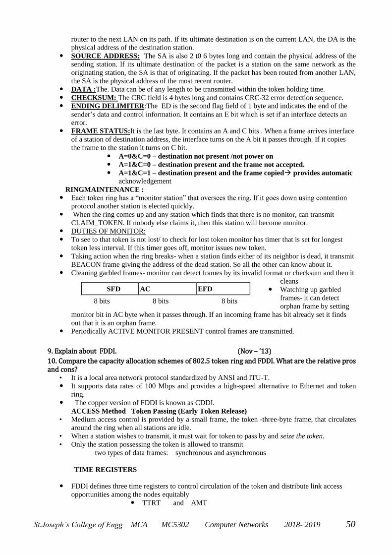
St.Joseph’s College of Engg MCA MC5302 Computer Networks 2018- 2019 50
router to the next LAN on its path. If its ultimate destination is on the current LAN, the DA is the
physical address of the destination station.
SOURCE ADDRESS: The SA is also 2 t0 6 bytes long and contain the physical address of the
sending station. If its ultimate destination of the packet is a station on the same network as the
originating station, the SA is that of originating. If the packet has been routed from another LAN,
the SA is the physical address of the most recent router.
DATA :The. Data can be of any length to be transmitted within the token holding time.
CHECKSUM: The CRC field is 4 bytes long and contains CRC-32 error detection sequence.
ENDING DELIMITER:The ED is the second flag field of 1 byte and indicates the end of the
sender’s data and control information. It contains an E bit which is set if an interface detects an
error.
FRAME STATUS:It is the last byte. It contains an A and C bits . When a frame arrives interface
of a station of destination address, the interface turns on the A bit it passes through. If it copies
the frame to the station it turns on C bit.
A=0&C=0 – destination not present /not power on
A=1&C=0 – destination present and the frame not accepted.
A=1&C=1 – destination present and the frame copied provides automatic acknowledgement
RINGMAINTENANCE :
Each token ring has a “monitor station” that oversees the ring. If it goes down using contention
protocol another station is elected quickly.
When the ring comes up and any station which finds that there is no monitor, can transmit
CLAIM_TOKEN. If nobody else claims it, then this station will become monitor.
DUTIES OF MONITOR:
To see to that token is not lost/ to check for lost token monitor has timer that is set for longest
token less interval. If this timer goes off, monitor issues new token.
Taking action when the ring breaks- when a station finds either of its neighbor is dead, it transmit
BEACON frame giving the address of the dead station. So all the other can know about it.
Cleaning garbled frames- monitor can detect frames by its invalid format or checksum and then it
cleans
Watching up garbled
frames- it can detect
orphan frame by setting
monitor bit in AC byte when it passes through. If an incoming frame has bit already set it finds
out that it is an orphan frame.
Periodically ACTIVE MONITOR PRESENT control frames are transmitted.
9. Explain about FDDI. (Nov – ’13)
10. Compare the capacity allocation schemes of 802.5 token ring and FDDI. What are the relative pros and cons?
• It is a local area network protocol standardized by ANSI and ITU-T.
It supports data rates of 100 Mbps and provides a high-speed alternative to Ethernet and token
ring.
The copper version of FDDI is known as CDDI.
ACCESS Method Token Passing (Early Token Release)
• Medium access control is provided by a small frame, the token -three-byte frame, that circulates
around the ring when all stations are idle.
• When a station wishes to transmit, it must wait for token to pass by and seize the token.
• Only the station possessing the token is allowed to transmit
two types of data frames: synchronous and asynchronous
TIME REGISTERS
FDDI defines three time registers to control circulation of the token and distribute link access
opportunities among the nodes equitably
TTRT and AMT
SFD AC EFD
8 bits 8 bits 8 bits
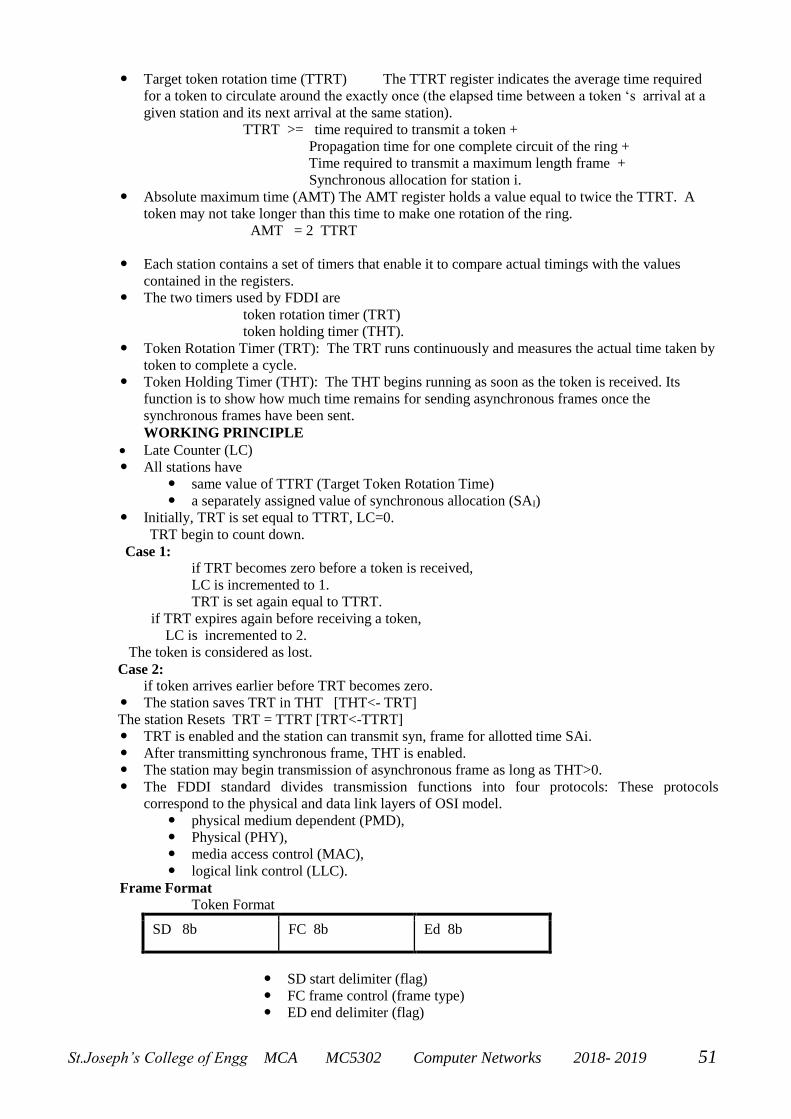
St.Joseph’s College of Engg MCA MC5302 Computer Networks 2018- 2019 51
Target token rotation time (TTRT) The TTRT register indicates the average time required
for a token to circulate around the exactly once (the elapsed time between a token ‘s arrival at a
given station and its next arrival at the same station).
TTRT >= time required to transmit a token +
Propagation time for one complete circuit of the ring +
Time required to transmit a maximum length frame +
Synchronous allocation for station i.
Absolute maximum time (AMT) The AMT register holds a value equal to twice the TTRT. A
token may not take longer than this time to make one rotation of the ring.
AMT = 2 TTRT
Each station contains a set of timers that enable it to compare actual timings with the values
contained in the registers.
The two timers used by FDDI are
token rotation timer (TRT)
token holding timer (THT).
Token Rotation Timer (TRT): The TRT runs continuously and measures the actual time taken by
token to complete a cycle.
Token Holding Timer (THT): The THT begins running as soon as the token is received. Its
function is to show how much time remains for sending asynchronous frames once the
synchronous frames have been sent.
WORKING PRINCIPLE
Late Counter (LC)
All stations have
same value of TTRT (Target Token Rotation Time)
a separately assigned value of synchronous allocation (SAI)
Initially, TRT is set equal to TTRT, LC=0.
TRT begin to count down.
Case 1:
if TRT becomes zero before a token is received,
LC is incremented to 1.
TRT is set again equal to TTRT.
if TRT expires again before receiving a token,
LC is incremented to 2.
The token is considered as lost.
Case 2:
if token arrives earlier before TRT becomes zero.
The station saves TRT in THT [THT<- TRT]
The station Resets TRT = TTRT [TRT<-TTRT]
TRT is enabled and the station can transmit syn, frame for allotted time SAi.
After transmitting synchronous frame, THT is enabled.
The station may begin transmission of asynchronous frame as long as THT>0.
The FDDI standard divides transmission functions into four protocols: These protocols
correspond to the physical and data link layers of OSI model.
physical medium dependent (PMD),
Physical (PHY),
media access control (MAC),
logical link control (LLC).
Frame Format
Token Format
SD 8b FC 8b Ed 8b
SD start delimiter (flag)
FC frame control (frame type)
ED end delimiter (flag)

St.Joseph’s College of Engg MCA MC5302 Computer Networks 2018- 2019 52
DATA FRAME
DESTINATION ADDRESS: specifies where the frame should go
SOURCE ADDRESS: specifies the station that sent the frame.
INFORMATION: contains data unit or control information.
FRAME CHECK SEQUENCE: 32bit CRC
ENDING DELIMITERS: marks end of the frame.
FRAME STATUS:It contains 3 special bits A , E C E -----Error detected
A -------- address recognized
C --------- frame copied
10. Compare the capacity allocation schemes of 802.5 token ring and FDDI. What are the relative
pros and cons?
11. i)How does the 802.11 media access control protocol ensure that the receiver has a greater chance to transmit the acknowledgement frame before any other wireless station grab the media ?Does it always guarantee that the acknowledgement frame sent by the receiver will not collide with another frame transmitted by another wireless station ? (MAY- 12)
The higher priority of ACK frame transmission at receiver side is achieved through the Short Inter
Frame Spacing concept of 802.11 standards. At some possible situation, this ACK frame can be
collided with another frame transmitted by another wireless station for various reasons, such as
the hidden terminal problem.
Collision Avoidance:
Consider a situation, where 3 nodes are able to send and receive the signals, and they send
immediate left or right nodes.
FDDI 802.5
Any station wants to transmit should wait for
token to enter its board. After seizing the
token it can transmit synchronous and
asynchronous data. It may transmit
synchronous frames for a time SAi. After
transmitting synchronous frames, or if there
were no synchronous frames to transmit, THT
is enabled. The station may begin
transmission of asynchronous frames as long
as THT > 0.If a station receives a token late,
then it transmits synchronous frames for a
time SAi. The station may not transmit any
asynchronous frames.
Any station wants to transmit should
wait for token to enter its board. Each
intermediate station examines the
destination address, if the data is not
for it, it sends to its neighbor. The
receiver recognizes its own address
copies the message. Each station is
responsible for absorbing its own
frame and releases the token.
Priority and reservation are not used It provides priority scheme by
reservation
A station that transmits data frames releases a
new token as soon as it completes data.
Early token release
A station that data transmissions after
releasing back its own transmission,
release the token. Delay token release
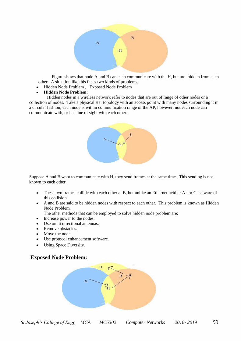
St.Joseph’s College of Engg MCA MC5302 Computer Networks 2018- 2019 53
Figure shows that node A and B can each communicate with the H, but are hidden from each
other. A situation like this faces two kinds of problems,
Hidden Node Problem , Exposed Node Problem
Hidden Node Problem:
Hidden nodes in a wireless network refer to nodes that are out of range of other nodes or a
collection of nodes. Take a physical star topology with an access point with many nodes surrounding it in
a circular fashion; each node is within communication range of the AP, however, not each node can
communicate with, or has line of sight with each other.
Suppose A and B want to communicate with H, they send frames at the same time. This sending is not
known to each other.
These two frames collide with each other at B, but unlike an Ethernet neither A nor C is aware of
this collision.
A and B are said to be hidden nodes with respect to each other. This problem is known as Hidden
Node Problem.
The other methods that can be employed to solve hidden node problem are:
Increase power to the nodes.
Use omni directional antennas.
Remove obstacles.
Move the node.
Use protocol enhancement software.
Using Space Diversity.
Exposed Node Problem:
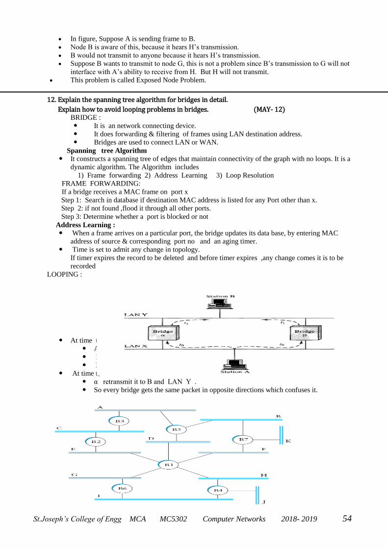
St.Joseph’s College of Engg MCA MC5302 Computer Networks 2018- 2019 54
In figure, Suppose A is sending frame to B.
Node B is aware of this, because it hears H’s transmission.
B would not transmit to anyone because it hears H’s transmission.
Suppose B wants to transmit to node G, this is not a problem since B’s transmission to G will not
interface with A’s ability to receive from H. But H will not transmit.
This problem is called Exposed Node Problem.
12. Explain the spanning tree algorithm for bridges in detail.
Explain how to avoid looping problems in bridges. (MAY- 12) BRIDGE :
It is an network connecting device.
It does forwarding & filtering of frames using LAN destination address.
Bridges are used to connect LAN or WAN.
Spanning tree Algorithm
It constructs a spanning tree of edges that maintain connectivity of the graph with no loops. It is a
dynamic algorithm. The Algorithm includes
1) Frame forwarding 2) Address Learning 3) Loop Resolution
FRAME FORWARDING:
If a bridge receives a MAC frame on port x
Step 1: Search in database if destination MAC address is listed for any Port other than x.
Step 2: if not found ,flood it through all other ports.
Step 3: Determine whether a port is blocked or not
Address Learning :
When a frame arrives on a particular port, the bridge updates its data base, by entering MAC
address of source & corresponding port no and an aging timer.
Time is set to admit any change in topology.
If timer expires the record to be deleted and before timer expires ,any change comes it is to be
recorded
LOOPING :
At time t0
A transmit a frame to B.
It is captured by both bridges α and β.
Each bridge updates its data base for source address.
At time t1
α retransmit it to B and LAN Y .
So every bridge gets the same packet in opposite directions which confuses it.
Each bridge is assigned with unique identifier.
Each port of a bridge is assigned with unique port identifier.

St.Joseph’s College of Engg MCA MC5302 Computer Networks 2018- 2019 55
Root port: through which the first HOP to root bridge is made with minimum cost.
Root path cost: for each bridge the minimum cost of path to root bridge
STEP 1: Determine root bridge
Each bridge broadcast its identifier on each LAN it is
attached. Root bridge with lowest value identifier is found.
STEP 2: Determine the root port on all other bridge.
STEP 3: Determine designated bridge .Each of the bridges one HOP away from root bridge will
broadcast their positions away from root bridge. It spreads over internet. So every bridge in network
finds the root path cost, destination bridge , destination port.
Initial Configuration Message
It consists of three pieces of information.
1) The id for what the sending bridge believes to be the root bridge.
2) Distance in hops between sending bridge and the root.
3) Id of the sending bridge.
B3 receives ( B2 , 0 , B2)
Since 2 is less than 3, B3 accepts that B2 as root.
B3 sends to B5 as (B2, 1, B3) by incrementing the distance.
Mean while B2 and B5 accepts that B1 as the root.
B2 sends (B1 , 1 , B2) to B3.
B5 sends (B1, 1 , B5) to B3.
Thus now B3 accepts B1 as root and finds B2 & B5 are closer to the root and it stops forwarding
any messages to the root.
SPANNING TREEE WITH SELECTECD PORTS
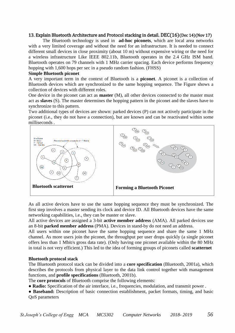
St.Joseph’s College of Engg MCA MC5302 Computer Networks 2018- 2019 56
13. Explain Bluetooth Architecture and Protocol stacking in detail. DEC(16)(Dec 14)(Nov 17) The Bluetooth technology is used in ad-hoc piconets, which are local area networks
with a very limited coverage and without the need for an infrastructure. It is needed to connect
different small devices in close proximity (about 10 m) without expensive wiring or the need for
a wireless infrastructure Like IEEE 802.11b, Bluetooth operates in the 2.4 GHz ISM band.
Bluetooth operates on 79 channels with 1 MHz carrier spacing. Each device performs frequency
hopping with 1,600 hops per sec in a pseudo random fashion. (FHSS)
Simple Bluetooth piconet
A very important term in the context of Bluetooth is a piconet. A piconet is a collection of
Bluetooth devices which are synchronized to the same hopping sequence. The Figure shows a
collection of devices with different roles.
One device in the piconet can act as master (M), all other devices connected to the master must
act as slaves (S). The master determines the hopping pattern in the piconet and the slaves have to
synchronize to this pattern.
Two additional types of devices are shown: parked devices (P) can not actively participate in the
piconet (i.e., they do not have a connection), but are known and can be reactivated within some
milliseconds .
Bluetooth scatternet
Forming a Bluetooth Piconet
As all active devices have to use the same hopping sequence they must be synchronized. The
first step involves a master sending its clock and device ID. All Bluetooth devices have the same
networking capabilities, i.e., they can be master or slave.
All active devices are assigned a 3-bit active member address (AMA). All parked devices use
an 8-bit parked member address (PMA). Devices in stand-by do not need an address.
All users within one piconet have the same hopping sequence and share the same 1 MHz
channel. As more users join the piconet, the throughput per user drops quickly (a single piconet
offers less than 1 Mbit/s gross data rate). (Only having one piconet available within the 80 MHz
in total is not very efficient.) This led to the idea of forming groups of piconets called scatternet
Bluetooth protocol stack The Bluetooth protocol stack can be divided into a core specification (Bluetooth, 2001a), which
describes the protocols from physical layer to the data link control together with management
functions, and profile specifications (Bluetooth, 2001b).
The core protocols of Bluetooth comprise the following elements:
● Radio: Specification of the air interface, i.e., frequencies, modulation, and transmit power .
● Baseband: Description of basic connection establishment, packet formats, timing, and basic
QoS parameters
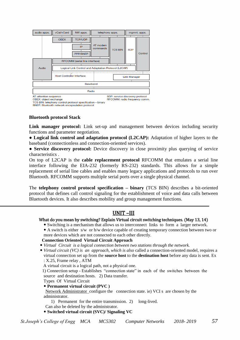
St.Joseph’s College of Engg MCA MC5302 Computer Networks 2018- 2019 57
Bluetooth protocol Stack
Link manager protocol: Link set-up and management between devices including security
functions and parameter negotiation.
● Logical link control and adaptation protocol (L2CAP): Adaptation of higher layers to the
baseband (connectionless and connection-oriented services).
● Service discovery protocol: Device discovery in close proximity plus querying of service
characteristics .
On top of L2CAP is the cable replacement protocol RFCOMM that emulates a serial line
interface following the EIA-232 (formerly RS-232) standards. This allows for a simple
replacement of serial line cables and enables many legacy applications and protocols to run over
Bluetooth. RFCOMM supports multiple serial ports over a single physical channel.
The telephony control protocol specification – binary (TCS BIN) describes a bit-oriented
protocol that defines call control signaling for the establishment of voice and data calls between
Bluetooth devices. It also describes mobility and group management functions.
UNIT –III What do you mean by switching? Explain Virtual circuit switching techniques. (May 13, 14) Switching is a mechanism that allows us to interconnect links to form a larger network.
A switch is either s/w or h/w device capable of creating temporary connection between two or
more devices which are not connected to each other directly.
Connection Oriented Virtual Circuit Approach
Virtual Circuit is a logical connection between two stations through the network.
Virtual circuit (VC) is an approach, which is also called a connection-oriented model, requires a
virtual connection set up from the source host to the destination host before any data is sent. Ex
: X.25, Frame relay , ATM
A virtual circuit is a logical path, not a physical one.
1) Connection setup - Establishes “connection state” in each of the switches between the
source and destination hosts. 2) Data transfer.
Types Of Virtual Circuit
Permanent virtual circuit (PVC ) Network Administrator configure the connection state. ie) VCI s are chosen by the
administrator.
1) Permanent for the entire transmission. 2) long-lived.
Can also be deleted by the administrator.
Switched virtual circuit (SVC)/ Signaling VC
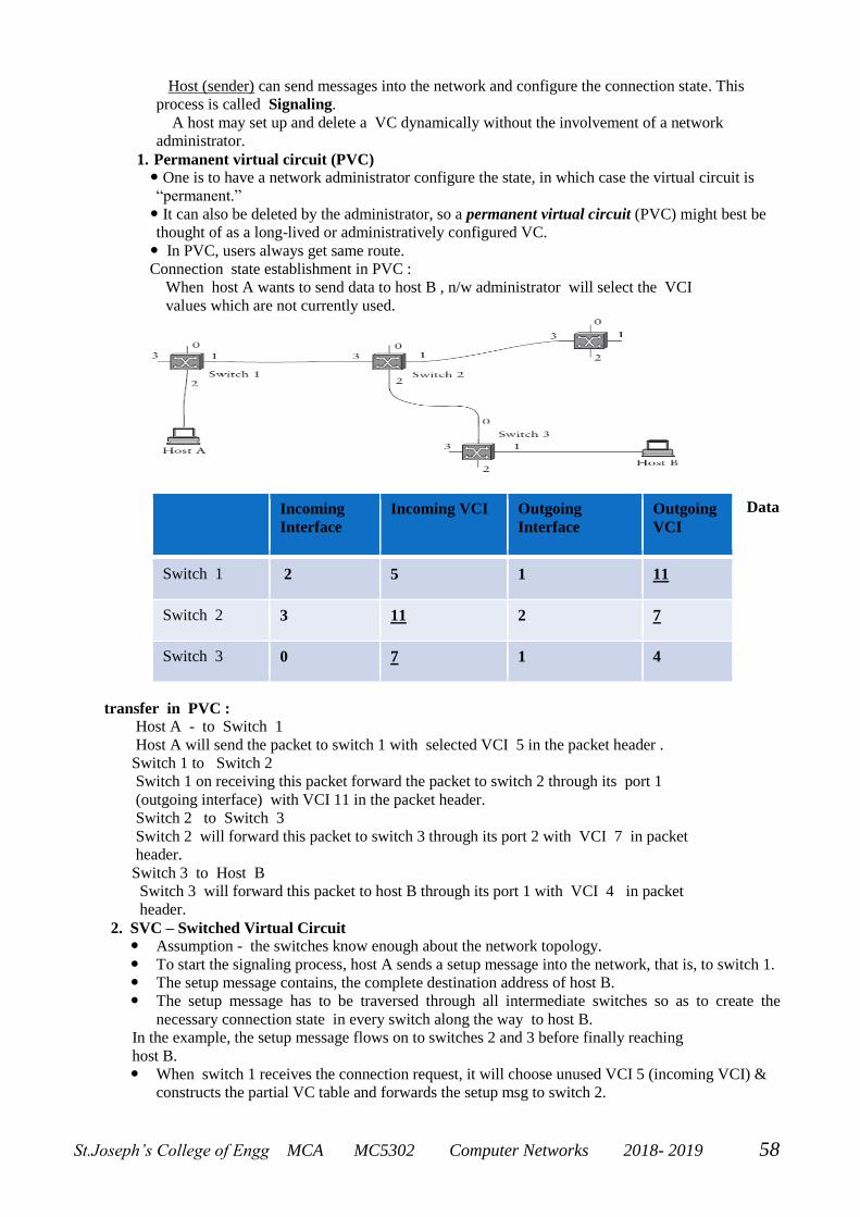
St.Joseph’s College of Engg MCA MC5302 Computer Networks 2018- 2019 58
Host (sender) can send messages into the network and configure the connection state. This
process is called Signaling.
A host may set up and delete a VC dynamically without the involvement of a network
administrator.
1. Permanent virtual circuit (PVC)
One is to have a network administrator configure the state, in which case the virtual circuit is
“permanent.”
It can also be deleted by the administrator, so a permanent virtual circuit (PVC) might best be
thought of as a long-lived or administratively configured VC.
In PVC, users always get same route.
Connection state establishment in PVC :
When host A wants to send data to host B , n/w administrator will select the VCI
values which are not currently used.
Data
transfer in PVC :
Host A - to Switch 1
Host A will send the packet to switch 1 with selected VCI 5 in the packet header .
Switch 1 to Switch 2
Switch 1 on receiving this packet forward the packet to switch 2 through its port 1
(outgoing interface) with VCI 11 in the packet header.
Switch 2 to Switch 3
Switch 2 will forward this packet to switch 3 through its port 2 with VCI 7 in packet
header.
Switch 3 to Host B
Switch 3 will forward this packet to host B through its port 1 with VCI 4 in packet
header.
2. SVC – Switched Virtual Circuit
Assumption - the switches know enough about the network topology.
To start the signaling process, host A sends a setup message into the network, that is, to switch 1.
The setup message contains, the complete destination address of host B.
The setup message has to be traversed through all intermediate switches so as to create the
necessary connection state in every switch along the way to host B.
In the example, the setup message flows on to switches 2 and 3 before finally reaching
host B.
When switch 1 receives the connection request, it will choose unused VCI 5 (incoming VCI) &
constructs the partial VC table and forwards the setup msg to switch 2.
Incoming
Interface
Incoming VCI Outgoing
Interface
Outgoing
VCI
Switch 1 2 5 1 11
Switch 2 3 11 2 7
Switch 3 0 7 1 4
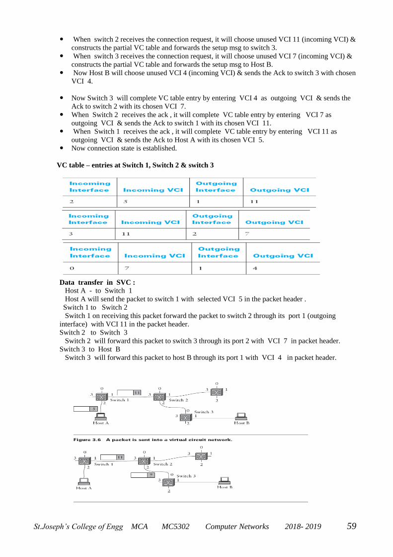
St.Joseph’s College of Engg MCA MC5302 Computer Networks 2018- 2019 59
When switch 2 receives the connection request, it will choose unused VCI 11 (incoming VCI) &
constructs the partial VC table and forwards the setup msg to switch 3.
When switch 3 receives the connection request, it will choose unused VCI 7 (incoming VCI) &
constructs the partial VC table and forwards the setup msg to Host B.
Now Host B will choose unused VCI 4 (incoming VCI) & sends the Ack to switch 3 with chosen
VCI 4.
Now Switch 3 will complete VC table entry by entering VCI 4 as outgoing VCI & sends the
Ack to switch 2 with its chosen VCI 7.
When Switch 2 receives the ack , it will complete VC table entry by entering VCI 7 as
outgoing VCI & sends the Ack to switch 1 with its chosen VCI 11.
When Switch 1 receives the ack , it will complete VC table entry by entering VCI 11 as
outgoing VCI & sends the Ack to Host A with its chosen VCI 5.
Now connection state is established.
VC table – entries at Switch 1, Switch 2 & switch 3
Data transfer in SVC :
Host A - to Switch 1
Host A will send the packet to switch 1 with selected VCI 5 in the packet header .
Switch 1 to Switch 2
Switch 1 on receiving this packet forward the packet to switch 2 through its port 1 (outgoing
interface) with VCI 11 in the packet header.
Switch 2 to Switch 3
Switch 2 will forward this packet to switch 3 through its port 2 with VCI 7 in packet header.
Switch 3 to Host B
Switch 3 will forward this packet to host B through its port 1 with VCI 4 in packet header.
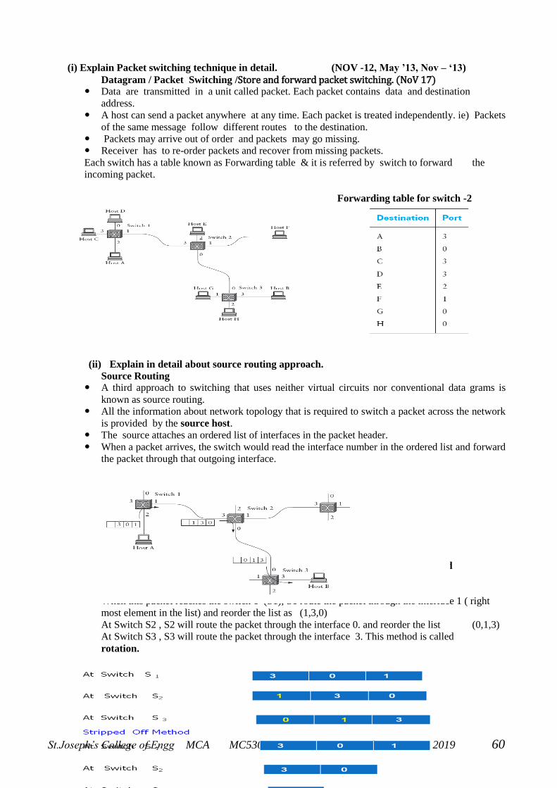
St.Joseph’s College of Engg MCA MC5302 Computer Networks 2018- 2019 60
(i) Explain Packet switching technique in detail. (NOV -12, May ’13, Nov – ‘13)
Datagram / Packet Switching /Store and forward packet switching. (NoV 17)
Data are transmitted in a unit called packet. Each packet contains data and destination
address.
A host can send a packet anywhere at any time. Each packet is treated independently. ie) Packets
of the same message follow different routes to the destination.
Packets may arrive out of order and packets may go missing.
Receiver has to re-order packets and recover from missing packets.
Each switch has a table known as Forwarding table & it is referred by switch to forward the
incoming packet.
Forwarding table for switch -2
(ii) Explain in detail about source routing approach.
Source Routing
A third approach to switching that uses neither virtual circuits nor conventional data grams is
known as source routing.
All the information about network topology that is required to switch a packet across the network
is provided by the source host.
The source attaches an ordered list of interfaces in the packet header.
When a packet arrives, the switch would read the interface number in the ordered list and forward
the packet through that outgoing interface.
Handling of headers for Source Routing - Rotation, stripped off , Pointer Method
In the example, a packet has to be transmitted from Host A to host B .
Host A attaches the ordered list (3, 0 1)in the packet header.
When this packet reaches the switch 1 (S1), S1 route the packet through the interface 1 ( right
most element in the list) and reorder the list as (1,3,0)
At Switch S2 , S2 will route the packet through the interface 0. and reorder the list (0,1,3)
At Switch S3 , S3 will route the packet through the interface 3. This method is called
rotation.
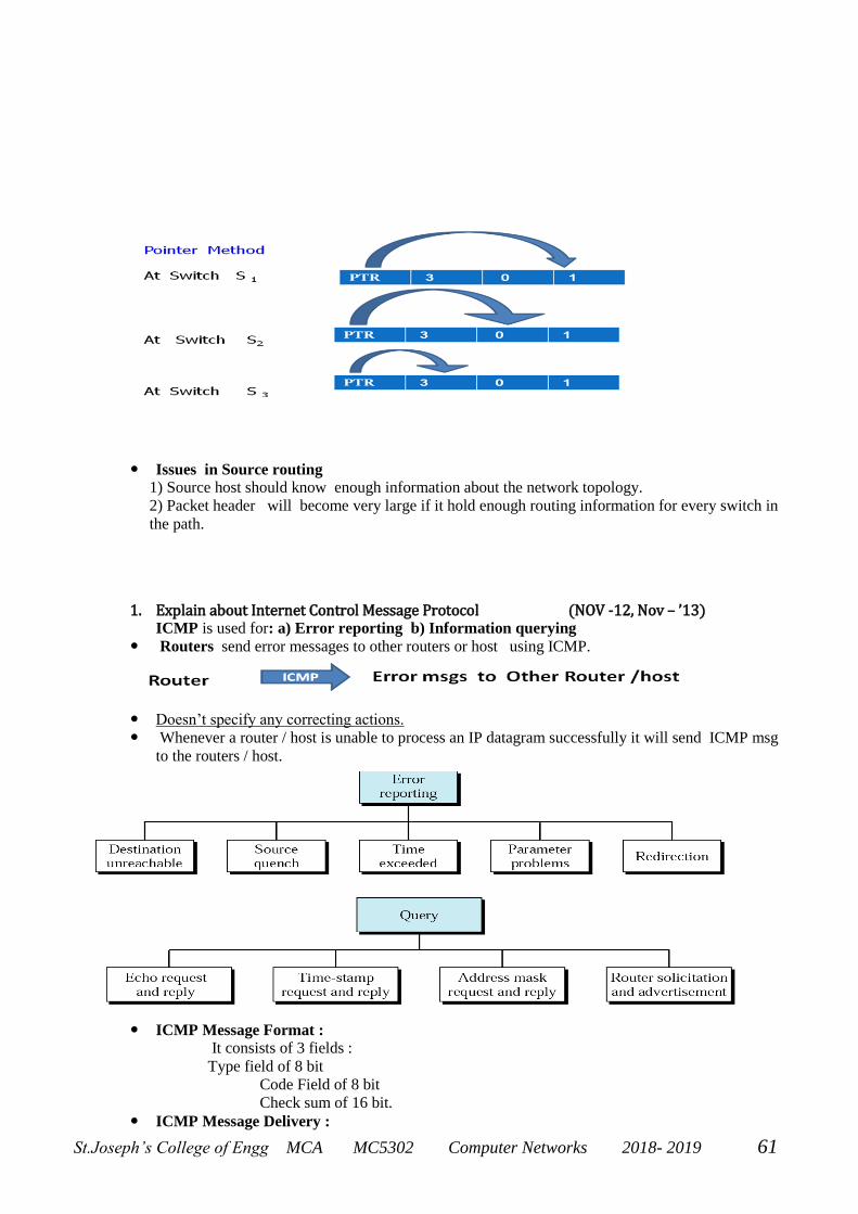
St.Joseph’s College of Engg MCA MC5302 Computer Networks 2018- 2019 61
Issues in Source routing 1) Source host should know enough information about the network topology.
2) Packet header will become very large if it hold enough routing information for every switch in
the path.
1. Explain about Internet Control Message Protocol (NOV -12, Nov – ’13) ICMP is used for: a) Error reporting b) Information querying
Routers send error messages to other routers or host using ICMP.
Doesn’t specify any correcting actions.
Whenever a router / host is unable to process an IP datagram successfully it will send ICMP msg
to the routers / host.
ICMP Message Format : It consists of 3 fields :
Type field of 8 bit
Code Field of 8 bit
Check sum of 16 bit.
ICMP Message Delivery :
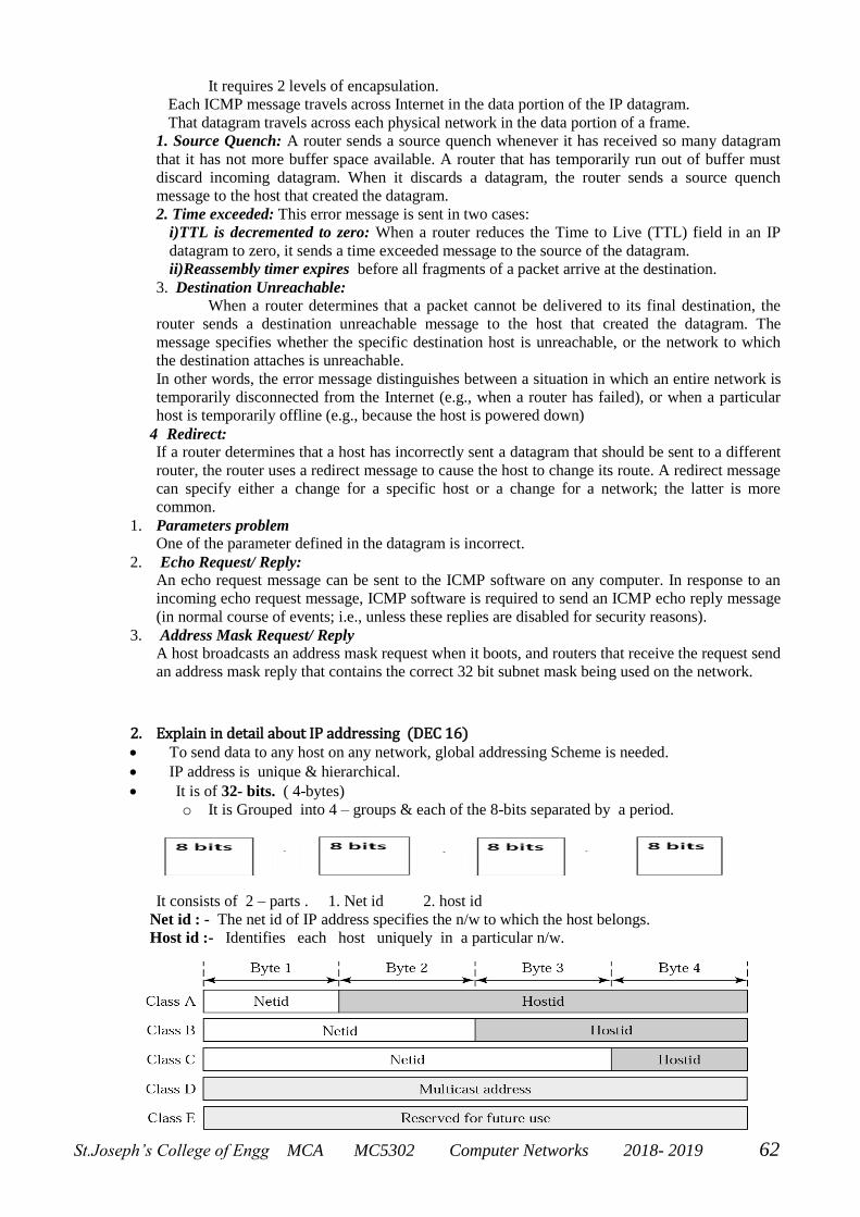
St.Joseph’s College of Engg MCA MC5302 Computer Networks 2018- 2019 62
It requires 2 levels of encapsulation.
Each ICMP message travels across Internet in the data portion of the IP datagram.
That datagram travels across each physical network in the data portion of a frame.
1. Source Quench: A router sends a source quench whenever it has received so many datagram
that it has not more buffer space available. A router that has temporarily run out of buffer must
discard incoming datagram. When it discards a datagram, the router sends a source quench
message to the host that created the datagram.
2. Time exceeded: This error message is sent in two cases:
i)TTL is decremented to zero: When a router reduces the Time to Live (TTL) field in an IP
datagram to zero, it sends a time exceeded message to the source of the datagram.
ii)Reassembly timer expires before all fragments of a packet arrive at the destination.
3. Destination Unreachable: When a router determines that a packet cannot be delivered to its final destination, the
router sends a destination unreachable message to the host that created the datagram. The
message specifies whether the specific destination host is unreachable, or the network to which
the destination attaches is unreachable.
In other words, the error message distinguishes between a situation in which an entire network is
temporarily disconnected from the Internet (e.g., when a router has failed), or when a particular
host is temporarily offline (e.g., because the host is powered down)
4 Redirect: If a router determines that a host has incorrectly sent a datagram that should be sent to a different
router, the router uses a redirect message to cause the host to change its route. A redirect message
can specify either a change for a specific host or a change for a network; the latter is more
common.
1. Parameters problem One of the parameter defined in the datagram is incorrect.
2. Echo Request/ Reply: An echo request message can be sent to the ICMP software on any computer. In response to an
incoming echo request message, ICMP software is required to send an ICMP echo reply message
(in normal course of events; i.e., unless these replies are disabled for security reasons).
3. Address Mask Request/ Reply A host broadcasts an address mask request when it boots, and routers that receive the request send
an address mask reply that contains the correct 32 bit subnet mask being used on the network.
2. Explain in detail about IP addressing (DEC 16) To send data to any host on any network, global addressing Scheme is needed.
IP address is unique & hierarchical.
It is of 32- bits. ( 4-bytes)
o It is Grouped into 4 – groups & each of the 8-bits separated by a period.
It consists of 2 – parts . 1. Net id 2. host id
Net id : - The net id of IP address specifies the n/w to which the host belongs.
Host id :- Identifies each host uniquely in a particular n/w.
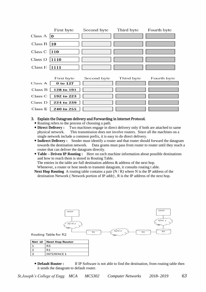
St.Joseph’s College of Engg MCA MC5302 Computer Networks 2018- 2019 63
3. Explain the Datagram delivery and Forwarding in Internet Protocol. Routing refers to the process of choosing a path.
Direct Delivery : Two machines engage in direct delivery only if both are attached to same
physical network. This transmission does not involve routers. Since all the machines on a
single network include a common prefix, it is easy to do direct delivery.
Indirect Delivery : Sender must identify a router and that router should forward the datagram
towards the destination network. Data grams must pass from router to router until they reach a
router that can deliver the datagram directly.
Table – Driven IP Routing : Here on each machine information about possible destinations
and how to reach them is stored in Routing Table.
The entries in the table are full destination address & address of the next hop.
Whenever, a router or host needs to transmit datagram, it consults routing t able.
Next Hop Routing A routing table contains a pair (N / R) where N is the IP address of the
destination Network ( Network portion of IP addr) , R is the IP address of the next hop.
Default Router : If IP Software is not able to find the destination, from routing table then
it sends the datagram to default router.

St.Joseph’s College of Engg MCA MC5302 Computer Networks 2018- 2019 64
It is useful when a site has small set of local address connected to it and connected to the rest of
the Internet.
Routing Algorithm :
Route Datagram (Datagram, Routing Table)
Extract destination IP Address from datagram.
Compute network prefix N
If N matches any directly connected network address Deliver the datagram to that network.
Else If table contains a host specific route for B, Send the datagram to next hop specified in table
else if the table contains a route for Network N, Send datagram to next hop specified in table
Else if the table contains a default router Send datagram to default router
Else Declare routing error.
4. Explain the IP datagram format. (NOV -12, Dec 14)
5. Explain the packet format of IPV4 (NOV – ’13) Explain the packet format of IPV4 (NOV – ’13)
IP services unreliable, best-effort, connectionless packet system.
Unreliable – delivery is not guaranteed
Connectionless – Each packet is treated independent from others .
Best-effort delivery – It makes an earnest attempt to deliver packets.
IP Data gram : The IP datagram is fundamental to the Internet Protocol.
A datagram is a type of packet that has been sent in a connectionless manner over a network.
Every datagram carries enough information to let the network forward the packet to its correct
destination.
Version field specifies the version of IP. Current version is IPv4.
Hlen - length of the header in 32-bit words. The header is 5 words (20 bytes) long when there are
no options.
TOS - type of service field allow packets to be treated differently based on application needs.
Precedence D T R Unused
Precedence – varies from 000(normal) to 111 (high)
D- bit = 1 request for low delay in datagram delivery
T – bit = 1 –Request for high through put.
R- bit = 1 – Request for high reliability.
Length field - Length of the datagram, including the header. It counts bytes rather than words. Max
– size of data gram is 65535 bytes.
Identification (Ident) – Unique identifier that identifies the datagram , when the
datagram is divided into fragments.
During fragmentation, this number is copied into all fragments of the original datagram.
Flag (3-bits)- the lower order bit M specifies whether some more fragments are following or not.
M = 0 - No more fragments.
M = 1 - still more fragments are arriving.
F - (F = 1) bit specifies whether datagram is fragmented or not.
C – (C= 1)bit specifies to copy the option in each fragment.
TTL (time to live) field. TTL was set to a specific number of seconds (hops) that the packet would
be allowed to live.
Routers along the path would decrement this field until it reached 0.
Purpose is to discard the packets that forms loops or consume the resources indefinitely. Set by
the sender.

St.Joseph’s College of Engg MCA MC5302 Computer Networks 2018- 2019 65
The Protocol field - identifies the higher-level protocol to which this IP packet should be passed.
TCP – 6 UDP – 17
Checksum – for Error detection
SourceAddr and the DestinationAddr for the packet.
Every packet contains a full address.
Option - it is optional one. Not required for all the data grams.
Some of the options
1) Trace Route 2) Source Route
Trace route – Source creates an empty list in which each intermediate routers on the path of the
datagram has to write their IP address.
When the data gram with this option arrives, router will check the pointer length ,
if it is > length – list is full hence the router won’t insert its IP address.
otherwise – insert the address & increment the pointer.
Source route : Here the source specifies the path through which the data gram has to be sent.
6. Explain fragmentation and reassembly
7. Explain the Routing Information protocol/Distance vector routing in detail. (DEC 16)
(NOV 17) Distance Vector Routing :Each node constructs a one-dimensional array (a vector) containing the
“distances” (costs) to all other nodes.
distributes that vector to its immediate neighbors.
Each node knows the cost of the link to each of its directly connected neighbors.
A link that is down/unknown is assigned an infinite cost.
PRINCIPLE: Constructing RIP message
Step 1: Each node sets a cost of 1 (one) to all directly connected neighbors and cost of ∞ to
others in the neighbors.
Step 2: Each node sends a message to its directly connected neighbor s containing its knowledge
of distances of all nodes in the network.
Repeat the following steps for each advertised destination:
1. If (destination not in the routing table)
Add the advertised information to the table by adding
the two costs
2. Else (destination in the routing table)
If (next-hop field is the same) Replace entry in the
table with the advertised one. (Because this may be new)
Else (next-hop field is not the same)
If (advertised hop count smaller than one in
the table) Replace entry in the routing table. (better one
3. Return.
Initially, each node sets a cost of 1 to its directly connected neighbors and ∞ to all other nodes.
Thus, A initially believes that it can reach B ,C, E, F in one hop and that D is unreachable.
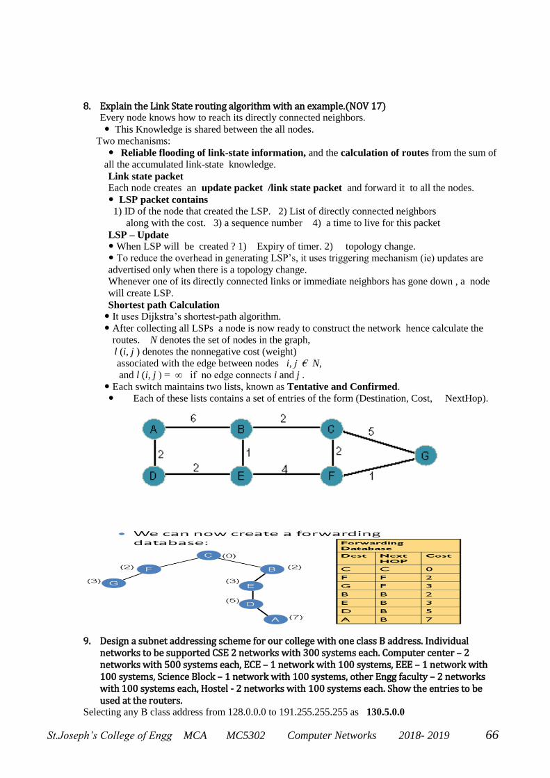
St.Joseph’s College of Engg MCA MC5302 Computer Networks 2018- 2019 66
8. Explain the Link State routing algorithm with an example.(NOV 17) Every node knows how to reach its directly connected neighbors.
This Knowledge is shared between the all nodes.
Two mechanisms:
Reliable flooding of link-state information, and the calculation of routes from the sum of
all the accumulated link-state knowledge.
Link state packet
Each node creates an update packet /link state packet and forward it to all the nodes.
LSP packet contains 1) ID of the node that created the LSP. 2) List of directly connected neighbors
along with the cost. 3) a sequence number 4) a time to live for this packet
LSP – Update
When LSP will be created ? 1) Expiry of timer. 2) topology change.
To reduce the overhead in generating LSP’s, it uses triggering mechanism (ie) updates are
advertised only when there is a topology change.
Whenever one of its directly connected links or immediate neighbors has gone down , a node
will create LSP.
Shortest path Calculation
It uses Dijkstra’s shortest-path algorithm.
After collecting all LSPs a node is now ready to construct the network hence calculate the
routes. N denotes the set of nodes in the graph,
l (i, j ) denotes the nonnegative cost (weight)
associated with the edge between nodes i, j € N,
and l (i, j ) = ∞ if no edge connects i and j .
Each switch maintains two lists, known as Tentative and Confirmed.
Each of these lists contains a set of entries of the form (Destination, Cost, NextHop).
9. Design a subnet addressing scheme for our college with one class B address. Individual networks to be supported CSE 2 networks with 300 systems each. Computer center – 2 networks with 500 systems each, ECE – 1 network with 100 systems, EEE – 1 network with 100 systems, Science Block – 1 network with 100 systems, other Engg faculty – 2 networks with 100 systems each, Hostel - 2 networks with 100 systems each. Show the entries to be used at the routers.
Selecting any B class address from 128.0.0.0 to 191.255.255.255 as 130.5.0.0
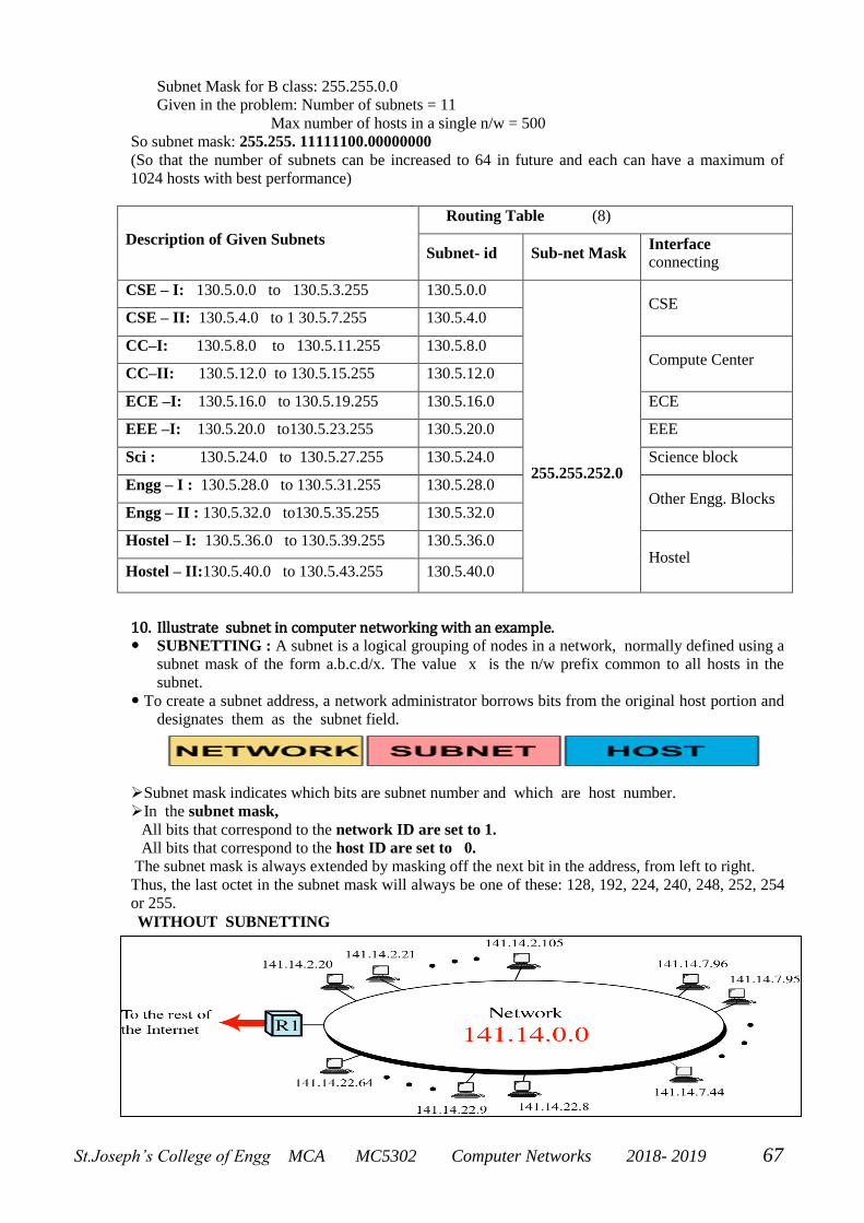
St.Joseph’s College of Engg MCA MC5302 Computer Networks 2018- 2019 67
Subnet Mask for B class: 255.255.0.0
Given in the problem: Number of subnets = 11
Max number of hosts in a single n/w = 500
So subnet mask: 255.255. 11111100.00000000
(So that the number of subnets can be increased to 64 in future and each can have a maximum of
1024 hosts with best performance)
Description of Given Subnets
Routing Table (8)
Subnet- id Sub-net Mask Interface
connecting
CSE – I: 130.5.0.0 to 130.5.3.255 130.5.0.0
255.255.252.0
CSE CSE – II: 130.5.4.0 to 1 30.5.7.255 130.5.4.0
CC–I: 130.5.8.0 to 130.5.11.255 130.5.8.0 Compute Center
CC–II: 130.5.12.0 to 130.5.15.255 130.5.12.0
ECE –I: 130.5.16.0 to 130.5.19.255 130.5.16.0 ECE
EEE –I: 130.5.20.0 to130.5.23.255 130.5.20.0 EEE
Sci : 130.5.24.0 to 130.5.27.255 130.5.24.0 Science block
Engg – I : 130.5.28.0 to 130.5.31.255 130.5.28.0 Other Engg. Blocks
Engg – II : 130.5.32.0 to130.5.35.255 130.5.32.0
Hostel – I: 130.5.36.0 to 130.5.39.255 130.5.36.0 Hostel
Hostel – II:130.5.40.0 to 130.5.43.255 130.5.40.0
10. Illustrate subnet in computer networking with an example. SUBNETTING : A subnet is a logical grouping of nodes in a network, normally defined using a
subnet mask of the form a.b.c.d/x. The value x is the n/w prefix common to all hosts in the
subnet.
To create a subnet address, a network administrator borrows bits from the original host portion and
designates them as the subnet field.
Subnet mask indicates which bits are subnet number and which are host number.
In the subnet mask,
All bits that correspond to the network ID are set to 1.
All bits that correspond to the host ID are set to 0.
The subnet mask is always extended by masking off the next bit in the address, from left to right.
Thus, the last octet in the subnet mask will always be one of these: 128, 192, 224, 240, 248, 252, 254
or 255.
WITHOUT SUBNETTING
WITH SUBNETTING

St.Joseph’s College of Engg MCA MC5302 Computer Networks 2018- 2019 68
11. Compare Circuit switching and Packet switching techniques/Store and forward packet switching. (DEC 16) (May ’13) (May 17)
12. Explain about Border Gateway Protocol. Routing between autonomous systems is called as Inter domain routing.
Routing within an AS is called as Intra domain routing
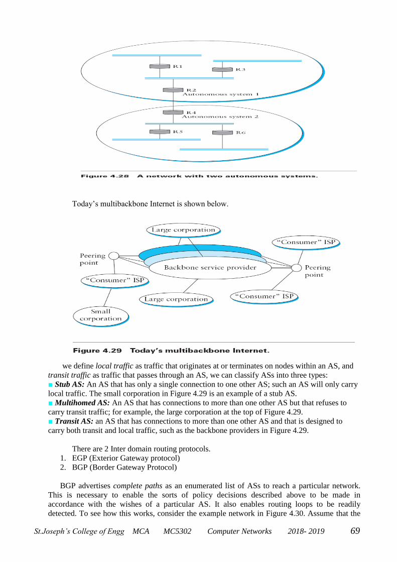
St.Joseph’s College of Engg MCA MC5302 Computer Networks 2018- 2019 69
Today’s multibackbone Internet is shown below.
we define local traffic as traffic that originates at or terminates on nodes within an AS, and
transit traffic as traffic that passes through an AS, we can classify ASs into three types:
■ Stub AS: An AS that has only a single connection to one other AS; such an AS will only carry
local traffic. The small corporation in Figure 4.29 is an example of a stub AS.
■ Multihomed AS: An AS that has connections to more than one other AS but that refuses to
carry transit traffic; for example, the large corporation at the top of Figure 4.29.
■ Transit AS: an AS that has connections to more than one other AS and that is designed to
carry both transit and local traffic, such as the backbone providers in Figure 4.29.
There are 2 Inter domain routing protocols.
1. EGP (Exterior Gateway protocol)
2. BGP (Border Gateway Protocol)
BGP advertises complete paths as an enumerated list of ASs to reach a particular network.
This is necessary to enable the sorts of policy decisions described above to be made in
accordance with the wishes of a particular AS. It also enables routing loops to be readily
detected. To see how this works, consider the example network in Figure 4.30. Assume that the
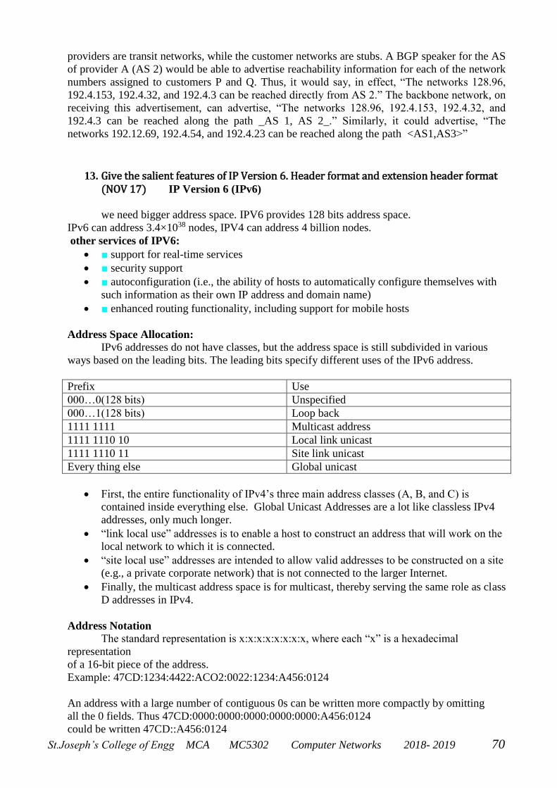
St.Joseph’s College of Engg MCA MC5302 Computer Networks 2018- 2019 70
providers are transit networks, while the customer networks are stubs. A BGP speaker for the AS
of provider A (AS 2) would be able to advertise reachability information for each of the network
numbers assigned to customers P and Q. Thus, it would say, in effect, “The networks 128.96,
192.4.153, 192.4.32, and 192.4.3 can be reached directly from AS 2.” The backbone network, on
receiving this advertisement, can advertise, “The networks 128.96, 192.4.153, 192.4.32, and
192.4.3 can be reached along the path _AS 1, AS 2_.” Similarly, it could advertise, “The
networks 192.12.69, 192.4.54, and 192.4.23 can be reached along the path <AS1,AS3>”
13. Give the salient features of IP Version 6. Header format and extension header format (NOV 17) IP Version 6 (IPv6)
we need bigger address space. IPV6 provides 128 bits address space.
IPv6 can address 3.4×1038 nodes, IPV4 can address 4 billion nodes.
other services of IPV6:
■ support for real-time services
■ security support
■ autoconfiguration (i.e., the ability of hosts to automatically configure themselves with
such information as their own IP address and domain name)
■ enhanced routing functionality, including support for mobile hosts
Address Space Allocation:
IPv6 addresses do not have classes, but the address space is still subdivided in various
ways based on the leading bits. The leading bits specify different uses of the IPv6 address.
Prefix Use
000…0(128 bits) Unspecified
000…1(128 bits) Loop back
1111 1111 Multicast address
1111 1110 10 Local link unicast
1111 1110 11 Site link unicast
Every thing else Global unicast
First, the entire functionality of IPv4’s three main address classes (A, B, and C) is
contained inside everything else. Global Unicast Addresses are a lot like classless IPv4
addresses, only much longer.
“link local use” addresses is to enable a host to construct an address that will work on the
local network to which it is connected.
“site local use” addresses are intended to allow valid addresses to be constructed on a site
(e.g., a private corporate network) that is not connected to the larger Internet.
Finally, the multicast address space is for multicast, thereby serving the same role as class
D addresses in IPv4.
Address Notation
The standard representation is x:x:x:x:x:x:x:x, where each “x” is a hexadecimal
representation
of a 16-bit piece of the address.
Example: 47CD:1234:4422:ACO2:0022:1234:A456:0124
An address with a large number of contiguous 0s can be written more compactly by omitting
all the 0 fields. Thus 47CD:0000:0000:0000:0000:0000:A456:0124
could be written 47CD::A456:0124

St.Joseph’s College of Engg MCA MC5302 Computer Networks 2018- 2019 71
the “IPv4-mapped IPv6 address” of a host whose IPv4 address was 128.96.33.81 could be
written as ::FFFF:128.96.33.81
That is, the last 32 bits are written in IPv4 notation.
Global Unicast Addresses:
The RegistryID might be an identifier assigned to a European address registry, with different IDs
assigned to other continents or countries.
Packet Format:
Version field, which is set to 6 for IPv6.
The TrafficClass and FlowLabel fields both relate to quality of service issues.
The PayloadLen field gives the length of the packet, excluding the IPv6 header.
The NextHeader field cleverly replaces both the IP options and the Protocol field of IPv4.
If options are required, then they are carried in one or more special headers following the IP
header, and this is indicated by the value of the NextHeader field. If there are no special headers,
the NextHeader field is the demux key identifying the higher-level protocol running over IP
(e.g., TCP or UDP).
The HopLimit field is simply the TTL of IPv4.
the bulk of the header is taken up with the source and destination addresses, each of which is 16
bytes (128 bits) long. Thus, the IPv6 header is always 40 bytes long.
UNIT – IV PART- B
1. Explain the real transport protocol of UDP and how will you calculate checksum in UDP
Its header format and operations (NOV- 12) (NOV -17) USER DATAGRAM PROTOCOL ( UDP ):-
It is simpler of two standard TCP/IP protocols. It is an end –to-end transport level protocol. It
adds only port address. It adds checksum error control. It adds length information to the data from
the upper layer. A protocol produced by UDP is called user datagram. UDP does not provide any
sequencing or reordering. UDP can discover that an error has occurred. ICMP can then inform the
sender that an user Datagram has been damaged and discarded. It can not find out or locate lost
packet.

St.Joseph’s College of Engg MCA MC5302 Computer Networks 2018- 2019 72
UDP datagram format:-
Source port address:- It is the address of the application program that has created the message.
Destination port address:- It is the address of the application program that will receive the
message.
Total Length :- It defines the total length of the user datagram in bytes.
Checksum :- It is a 16 – bit field used in error correction.
It Provides a Connection less service / un reliable service. Delivery of duplication protection are
not guaranteed. It is useful for transmitting Audio/ video files.
To compute checksum, UDP/TCP prepends a pseudo header to datagram.
Pseudo header is not transmitted nor they included in length. To compare checksum,
Store zeroes in CHECKSUM field
Entire object (pseudo header, header , data) is divided into 16 bits.
Added & taken ones complemented.
All destination side, s/w finds out pseudo header from IP datagram and does verification. It is
useful to find whether datagram has reached correct destination with correct protocol port. It is
misdelivered, it would be detected in checksum calculation.
When a message arrives, the protocol (e.g., UDP) appends the message to the end of the queue. Should
the queue be full, the message is discarded. There is no flow-control mechanism that tells the sender to
slow down. When an application process wants to receive a message, one is removed from the front of the
queue. If the queue is empty, the process blocks until a message becomes available. Finally, although
UDP does not implement flow control or reliable/ordered delivery, it does a little more work than to
simply demultiplex messages to some application process
2. (i) Explain the TCP segment format. (Nov – ’13, Dec 14)
Source IP address
Destination IP address
Zero Protocol UDP Length
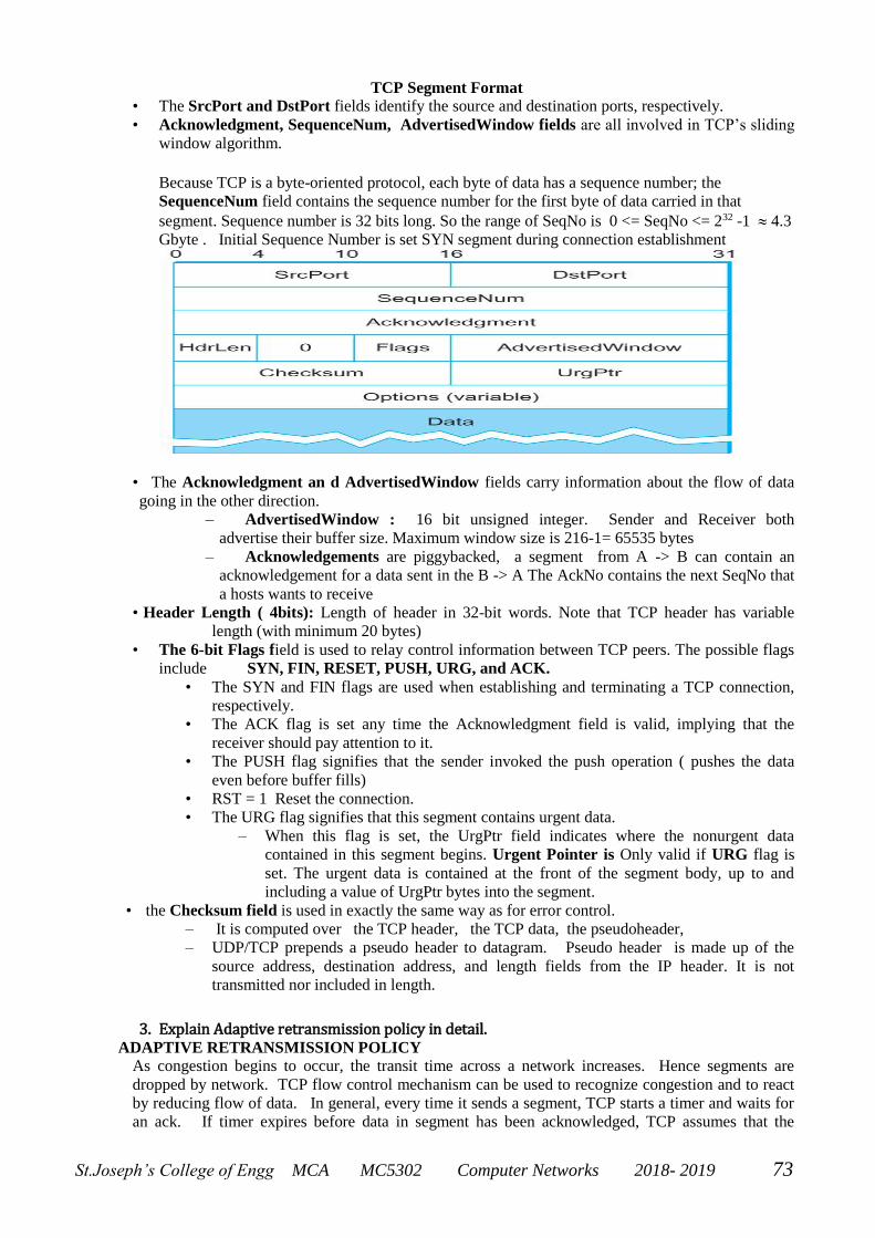
St.Joseph’s College of Engg MCA MC5302 Computer Networks 2018- 2019 73
TCP Segment Format
• The SrcPort and DstPort fields identify the source and destination ports, respectively.
• Acknowledgment, SequenceNum, AdvertisedWindow fields are all involved in TCP’s sliding
window algorithm.
Because TCP is a byte-oriented protocol, each byte of data has a sequence number; the
SequenceNum field contains the sequence number for the first byte of data carried in that
segment. Sequence number is 32 bits long. So the range of SeqNo is 0 <= SeqNo <= 232 -1 4.3
Gbyte . Initial Sequence Number is set SYN segment during connection establishment
• The Acknowledgment an d AdvertisedWindow fields carry information about the flow of data
going in the other direction.
– AdvertisedWindow : 16 bit unsigned integer. Sender and Receiver both
advertise their buffer size. Maximum window size is 216-1= 65535 bytes
– Acknowledgements are piggybacked, a segment from A -> B can contain an
acknowledgement for a data sent in the B -> A The AckNo contains the next SeqNo that
a hosts wants to receive
• Header Length ( 4bits): Length of header in 32-bit words. Note that TCP header has variable
length (with minimum 20 bytes)
• The 6-bit Flags field is used to relay control information between TCP peers. The possible flags
include SYN, FIN, RESET, PUSH, URG, and ACK.
• The SYN and FIN flags are used when establishing and terminating a TCP connection,
respectively.
• The ACK flag is set any time the Acknowledgment field is valid, implying that the
receiver should pay attention to it.
• The PUSH flag signifies that the sender invoked the push operation ( pushes the data
even before buffer fills)
• RST = 1 Reset the connection.
• The URG flag signifies that this segment contains urgent data.
– When this flag is set, the UrgPtr field indicates where the nonurgent data
contained in this segment begins. Urgent Pointer is Only valid if URG flag is
set. The urgent data is contained at the front of the segment body, up to and
including a value of UrgPtr bytes into the segment.
• the Checksum field is used in exactly the same way as for error control.
– It is computed over the TCP header, the TCP data, the pseudoheader,
– UDP/TCP prepends a pseudo header to datagram. Pseudo header is made up of the
source address, destination address, and length fields from the IP header. It is not
transmitted nor included in length.
3. Explain Adaptive retransmission policy in detail. ADAPTIVE RETRANSMISSION POLICY
As congestion begins to occur, the transit time across a network increases. Hence segments are
dropped by network. TCP flow control mechanism can be used to recognize congestion and to react
by reducing flow of data. In general, every time it sends a segment, TCP starts a timer and waits for
an ack. If timer expires before data in segment has been acknowledged, TCP assumes that the
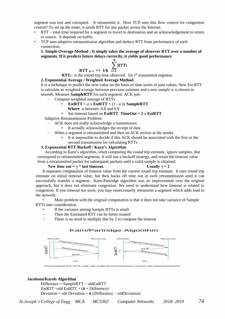
St.Joseph’s College of Engg MCA MC5302 Computer Networks 2018- 2019 74
segment was lost and corrupted. It retransmits it. How TCP uses this flow control for congestion
control? To set up the timer, it needs RTT for any packet across the Internet.
• RTT – total time required for a segment to travel to destination and an acknowledgement to return
to source. It depends on traffic.
• TCP uses adaptive retransmission algorithm and deduce RTT from performance of each
connection.
1. Simple Overage Method : It simply takes the average of observer RTT over a number of
segments. If it predicts future delays correctly, it yields good performance
RTT K+1 == 1/k
RTTi– is the round trip time observed for ith transmitted segment.
2. Exponential Average / Weighted Average Method It is a technique to predict the next value on the basis of time series of past values. New Est RTT
is calculate as weighted average between previous estimate and a new sample α is chosen to
smooth. Measure SampleRTT for each segment/ ACK pair
– Compute weighted average of RTTs
• EstRTT = a x EstRTT + (1 - a )x SampleRTT
Where a between 0.8 and 0.9
• Set timeout based on EstRTT TimeOut = 2 x EstRTT
Adaptive Retransmission Problem
– ACK does not really acknowledge a transmission
• It actually acknowledges the receipt of data
– When a segment is retransmitted and then an ACK arrives at the sender
• It is impossible to decide if this ACK should be associated with the first or the
second transmission for calculating RTTs
3. Exponential RTT Backoff / Karn’s Algorithm According to Karn’s algorithm, when computing the round trip estimate, ignore samples, that
correspond to retransmitted segments, It will use a backoff strategy, and retain the timeout value
from a retransmitted packet for subsequent packets until a valid sample is obtained.
New time out = γ * last timeout. Usually γ = 2 It separates computation of timeout value from the current round trip estimate. It uses round trip
estimate on initial timeout value, but then backs off time out in each retransmission until it can
successfully transfer a segment. Karn-Partridge algorithm was an improvement over the original
approach, but it does not eliminate congestion. We need to understand how timeout is related to
congestion. If you timeout too soon, you may unnecessarily retransmit a segment which adds load to
the network.
• Main problem with the original computation is that it does not take variance of Sample
RTTs into consideration.
• If the variance among Sample RTTs is small
– Then the Estimated RTT can be better trusted
– There is no need to multiply this by 2 to compute the timeout
Karn/Partridge Algorithm
Associating the ACK with (a) original transmission versus (b) retransmission
Jacobson/Karels Algorithm
Difference = SampleRTT − oldEstRTT
EstRTT =old EstRTT + (δ × Difference)
Deviation = old Deviation + δ (|Difference| − oldDeviation)
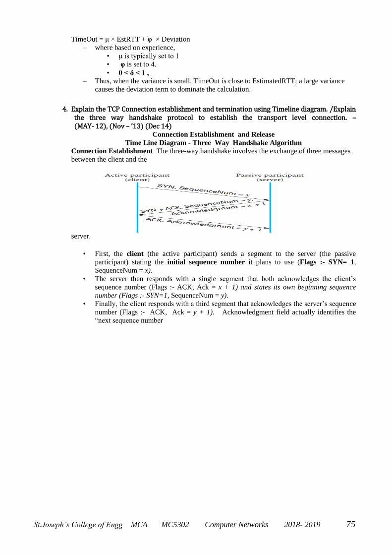
St.Joseph’s College of Engg MCA MC5302 Computer Networks 2018- 2019 75
TimeOut = μ × EstRTT + φ × Deviation
– where based on experience,
• μ is typically set to 1
• φ is set to 4.
• 0 < δ < 1 , – Thus, when the variance is small, TimeOut is close to EstimatedRTT; a large variance
causes the deviation term to dominate the calculation.
4. Explain the TCP Connection establishment and termination using Timeline diagram. /Explain the three way handshake protocol to establish the transport level connection. – (MAY- 12), (Nov – ’13) (Dec 14)
Connection Establishment and Release
Time Line Diagram - Three Way Handshake Algorithm Connection Establishment The three-way handshake involves the exchange of three messages
between the client and the
server.
• First, the client (the active participant) sends a segment to the server (the passive
participant) stating the initial sequence number it plans to use (Flags :- SYN= 1,
SequenceNum = x).
• The server then responds with a single segment that both acknowledges the client’s
sequence number (Flags :- ACK, Ack = x + 1) and states its own beginning sequence
number (Flags :- SYN=1, SequenceNum = y).
• Finally, the client responds with a third segment that acknowledges the server’s sequence
number (Flags :- ACK, Ack = y + 1). Acknowledgment field actually identifies the
“next sequence number
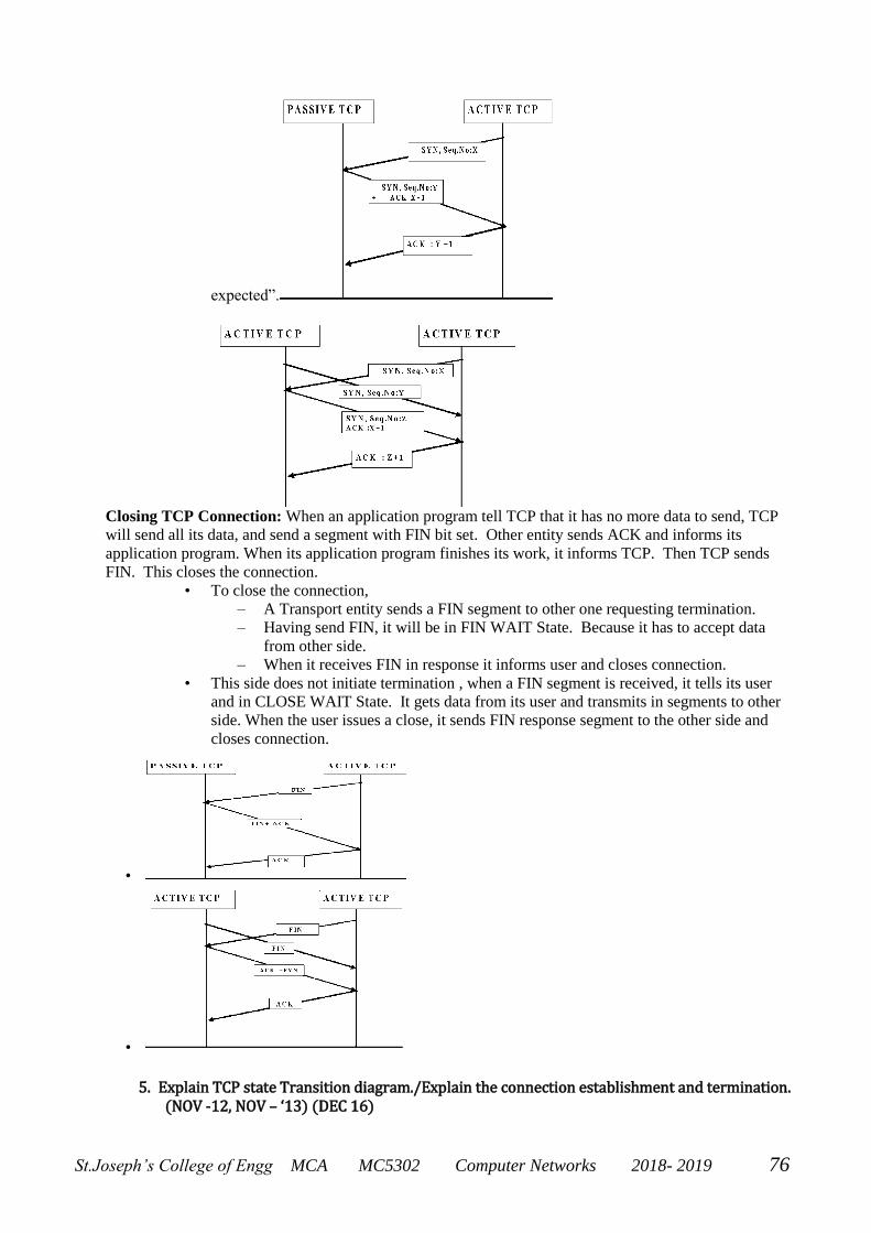
St.Joseph’s College of Engg MCA MC5302 Computer Networks 2018- 2019 76
expected”.
Closing TCP Connection: When an application program tell TCP that it has no more data to send, TCP
will send all its data, and send a segment with FIN bit set. Other entity sends ACK and informs its
application program. When its application program finishes its work, it informs TCP. Then TCP sends
FIN. This closes the connection.
• To close the connection,
– A Transport entity sends a FIN segment to other one requesting termination.
– Having send FIN, it will be in FIN WAIT State. Because it has to accept data
from other side.
– When it receives FIN in response it informs user and closes connection.
• This side does not initiate termination , when a FIN segment is received, it tells its user
and in CLOSE WAIT State. It gets data from its user and transmits in segments to other
side. When the user issues a close, it sends FIN response segment to the other side and
closes connection.
•
•
5. Explain TCP state Transition diagram./Explain the connection establishment and termination. (NOV -12, NOV – ‘13) (DEC 16)
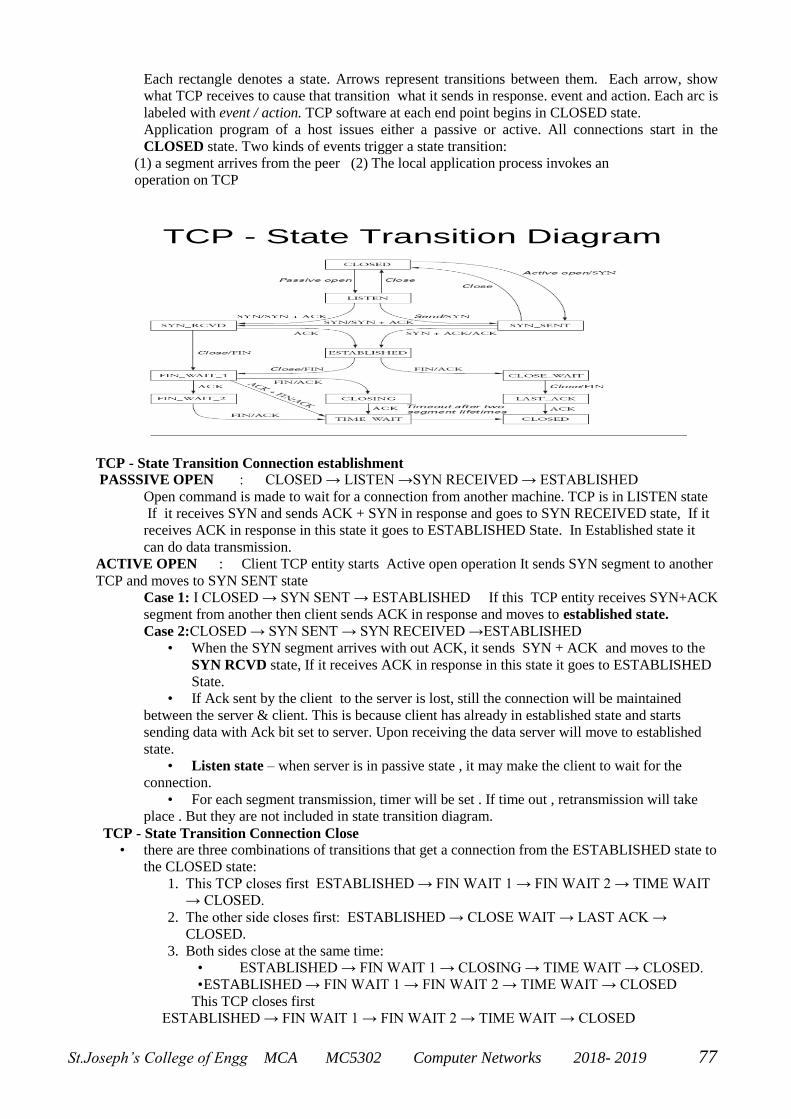
St.Joseph’s College of Engg MCA MC5302 Computer Networks 2018- 2019 77
Each rectangle denotes a state. Arrows represent transitions between them. Each arrow, show
what TCP receives to cause that transition what it sends in response. event and action. Each arc is
labeled with event / action. TCP software at each end point begins in CLOSED state.
Application program of a host issues either a passive or active. All connections start in the
CLOSED state. Two kinds of events trigger a state transition:
(1) a segment arrives from the peer (2) The local application process invokes an
operation on TCP
TCP - State Transition Diagram
TCP - State Transition Connection establishment PASSSIVE OPEN : CLOSED → LISTEN →SYN RECEIVED → ESTABLISHED
Open command is made to wait for a connection from another machine. TCP is in LISTEN state
If it receives SYN and sends ACK + SYN in response and goes to SYN RECEIVED state, If it
receives ACK in response in this state it goes to ESTABLISHED State. In Established state it
can do data transmission.
ACTIVE OPEN : Client TCP entity starts Active open operation It sends SYN segment to another
TCP and moves to SYN SENT state
Case 1: I CLOSED → SYN SENT → ESTABLISHED If this TCP entity receives SYN+ACK
segment from another then client sends ACK in response and moves to established state.
Case 2:CLOSED → SYN SENT → SYN RECEIVED →ESTABLISHED
• When the SYN segment arrives with out ACK, it sends SYN + ACK and moves to the
SYN RCVD state, If it receives ACK in response in this state it goes to ESTABLISHED
State.
• If Ack sent by the client to the server is lost, still the connection will be maintained
between the server & client. This is because client has already in established state and starts
sending data with Ack bit set to server. Upon receiving the data server will move to established
state.
• Listen state – when server is in passive state , it may make the client to wait for the
connection.
• For each segment transmission, timer will be set . If time out , retransmission will take
place . But they are not included in state transition diagram.
TCP - State Transition Connection Close
• there are three combinations of transitions that get a connection from the ESTABLISHED state to
the CLOSED state:
1. This TCP closes first ESTABLISHED → FIN WAIT 1 → FIN WAIT 2 → TIME WAIT
→ CLOSED.
2. The other side closes first: ESTABLISHED → CLOSE WAIT → LAST ACK →
CLOSED.
3. Both sides close at the same time:
• ESTABLISHED → FIN WAIT 1 → CLOSING → TIME WAIT → CLOSED.
• ESTABLISHED → FIN WAIT 1 → FIN WAIT 2 → TIME WAIT → CLOSED
This TCP closes first
ESTABLISHED → FIN WAIT 1 → FIN WAIT 2 → TIME WAIT → CLOSED
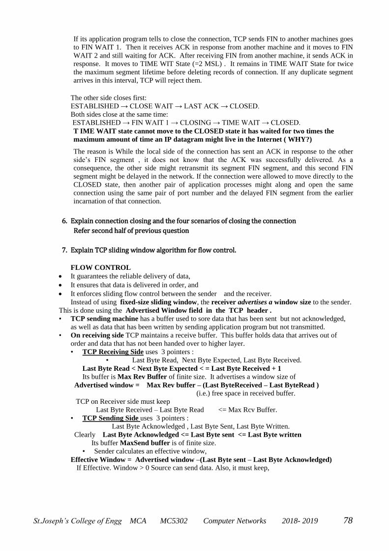
St.Joseph’s College of Engg MCA MC5302 Computer Networks 2018- 2019 78
If its application program tells to close the connection, TCP sends FIN to another machines goes
to FIN WAIT 1. Then it receives ACK in response from another machine and it moves to FIN
WAIT 2 and still waiting for ACK. After receiving FIN from another machine, it sends ACK in
response. It moves to TIME WIT State (=2 MSL) . It remains in TIME WAIT State for twice
the maximum segment lifetime before deleting records of connection. If any duplicate segment
arrives in this interval, TCP will reject them.
The other side closes first:
ESTABLISHED → CLOSE WAIT → LAST ACK → CLOSED.
Both sides close at the same time:
ESTABLISHED → FIN WAIT 1 → CLOSING → TIME WAIT → CLOSED.
T IME WAIT state cannot move to the CLOSED state it has waited for two times the
maximum amount of time an IP datagram might live in the Internet ( WHY?)
The reason is While the local side of the connection has sent an ACK in response to the other
side’s FIN segment , it does not know that the ACK was successfully delivered. As a
consequence, the other side might retransmit its segment FIN segment, and this second FIN
segment might be delayed in the network. If the connection were allowed to move directly to the
CLOSED state, then another pair of application processes might along and open the same
connection using the same pair of port number and the delayed FIN segment from the earlier
incarnation of that connection.
6. Explain connection closing and the four scenarios of closing the connection
Refer second half of previous question
7. Explain TCP sliding window algorithm for flow control.
FLOW CONTROL
It guarantees the reliable delivery of data,
It ensures that data is delivered in order, and
It enforces sliding flow control between the sender and the receiver.
Instead of using fixed-size sliding window, the receiver advertises a window size to the sender.
This is done using the Advertised Window field in the TCP header .
• TCP sending machine has a buffer used to sore data that has been sent but not acknowledged,
as well as data that has been written by sending application program but not transmitted.
• On receiving side TCP maintains a receive buffer. This buffer holds data that arrives out of
order and data that has not been handed over to higher layer.
• TCP Receiving Side uses 3 pointers :
• Last Byte Read, Next Byte Expected, Last Byte Received.
Last Byte Read < Next Byte Expected < = Last Byte Received + 1 Its buffer is Max Rev Buffer of finite size. It advertises a window size of
Advertised window = Max Rev buffer – (Last ByteReceived – Last ByteRead )
(i.e.) free space in received buffer.
TCP on Receiver side must keep
Last Byte Received – Last Byte Read <= Max Rcv Buffer.
• TCP Sending Side uses 3 pointers :
Last Byte Acknowledged , Last Byte Sent, Last Byte Written.
Clearly Last Byte Acknowledged <= Last Byte sent <= Last Byte written
Its buffer MaxSend buffer is of finite size.
• Sender calculates an effective window,
Effective Window = Advertised window –(Last Byte sent – Last Byte Acknowledged)
If Effective. Window > 0 Source can send data. Also, it must keep,
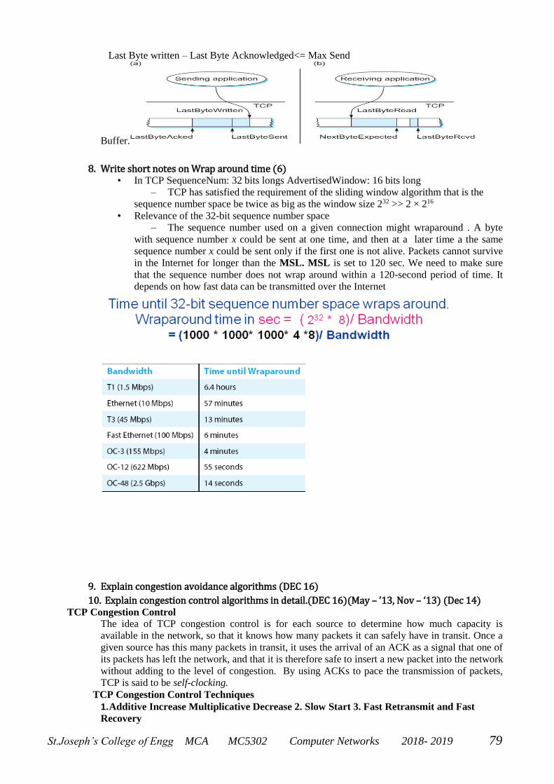
St.Joseph’s College of Engg MCA MC5302 Computer Networks 2018- 2019 79
Last Byte written – Last Byte Acknowledged<= Max Send
Buffer.
8. Write short notes on Wrap around time (6) • In TCP SequenceNum: 32 bits longs AdvertisedWindow: 16 bits long
– TCP has satisfied the requirement of the sliding window algorithm that is the
sequence number space be twice as big as the window size 232 >> 2 × 216
• Relevance of the 32-bit sequence number space
– The sequence number used on a given connection might wraparound . A byte
with sequence number x could be sent at one time, and then at a later time a the same
sequence number x could be sent only if the first one is not alive. Packets cannot survive
in the Internet for longer than the MSL. MSL is set to 120 sec. We need to make sure
that the sequence number does not wrap around within a 120-second period of time. It
depends on how fast data can be transmitted over the Internet
9. Explain congestion avoidance algorithms (DEC 16)
10. Explain congestion control algorithms in detail.(DEC 16)(May – ’13, Nov – ‘13) (Dec 14) TCP Congestion Control
The idea of TCP congestion control is for each source to determine how much capacity is
available in the network, so that it knows how many packets it can safely have in transit. Once a
given source has this many packets in transit, it uses the arrival of an ACK as a signal that one of
its packets has left the network, and that it is therefore safe to insert a new packet into the network
without adding to the level of congestion. By using ACKs to pace the transmission of packets,
TCP is said to be self-clocking.
TCP Congestion Control Techniques
1. Additive Increase Multiplicative Decrease 2. Slow Start 3. Fast Retransmit and Fast
Recovery

St.Joseph’s College of Engg MCA MC5302 Computer Networks 2018- 2019 80
Additive Increase Multiplicative Decrease
TCP maintains a new state variable for each connection, called CongestionWindow, which is used
by the source to limit how much data it is allowed to have in transit at a given time. TCP’s
effective window is revised as follows:
Thus, a TCP source is allowed to send no faster than the slowest component that the network or the
destination host can accommodate. The problem, of course, is how TCP comes to learn an
appropriate value for CongestionWindow. Unlike the AdvertisedWindow, which is sent by the
receiving side of the connection, there is no one to send a suitable CongestionWindow to the
sending side of TCP. The answer is that the TCP source sets the CongestionWindow based on
the level of congestion it perceives to exist in the network.
• This involves decreasing the congestion window when the level of congestion goes up and
increasing the congestion window when the level of congestion goes down. Taken together,
the mechanism is commonly called additive increase/multiplicative decrease
multiplicative decrease
A timeout results, is that a packet was dropped due to congestion. TCP interprets timeouts as a
sign of congestion and reduces the rate at which it is transmitting. Specifically, each time a
timeout occurs, the source sets CongestionWindow to half of its previous value. For example,
suppose the CongestionWindow is currently set to 16 packets. If a loss is detected,
CongestionWindow is set to 8. Additional losses cause CongestionWindow to be reduced to 4,
then 2, and finally to 1 packet. CongestionWindow is not allowed to fall below the size of a single
packet, or in TCP terminology, the maximum segment size (MSS).
additive increase
A congestion-control strategy should be able to increase the congestion window to take
advantage of newly available capacity in the network. This is the “additive increase” part of
AIMD, and it works as follows. Every time the source successfully sends a CongestionWindow’s
worth of packets it increases window by 1. that is, if each packet sent out has been ACKed then it
adds the equivalent of 1 packet to CongestionWindow.
81
Additive Increase
Source Destination
Add one packet each RTT
60
20
1.0 2.0 3.0 4.0 5.0 6.0 7.0 8.0 9.0
Time (seconds)
70
30
40
50
10
10.0
This pattern of continually increasing and decreasing congestion window continues throughout
life time of the connection. If we draw congestion window as a function of time, the curve is saw
tooth form

St.Joseph’s College of Engg MCA MC5302 Computer Networks 2018- 2019 81
Slow Start The additive increase mechanism is the right approach to use when the source is
operating close to the available capacity of the network, but it takes too long to ramp up a connection
when it is starting from scratch.
– TCP therefore provides a second mechanism, ironically called slow start, that is used to increase
the congestion window rapidly from a cold start. Slow start effectively increases the congestion
window exponentially, rather than linearly only.
The source starts with congestion window = 1.
Every time an ACK arrives, congestion window is incremented.
congestion window is effectively doubled per RTT
There are actually two different situations in which slow start runs.
1. The first is at the very beginning of a connection, at which time the source has no idea how many
packets it is going to be able to have in transit at a given time. In this situation, slow start continues
to double CongestionWindow each RTT until there is a loss
2. The second situation in which slow start is used is a bit more subtle; it occurs when the
connection goes dead while waiting for a timeout to occur.
When a packet is lost, the source eventually reaches a point where it has sent as much data as the
advertised window allows, and no ACK arrives. The source then uses slow start to restart the
flow of data rather than dumping a whole window’s worth of data on the network all at once. Now
source uses slow start window size 1. It uses slow start .
Then multiplicative increase until window size is half value of congestion window size because of
what loss occurs just now. This target congestion window size is also known as threshold
value. Slow start is used to rapidly increase the sending rate up to the value.Then additional
increase is used beyond the threshold
value.
• Slow Start
Packets in transit during slow start.
• S
l
o
w
S
t
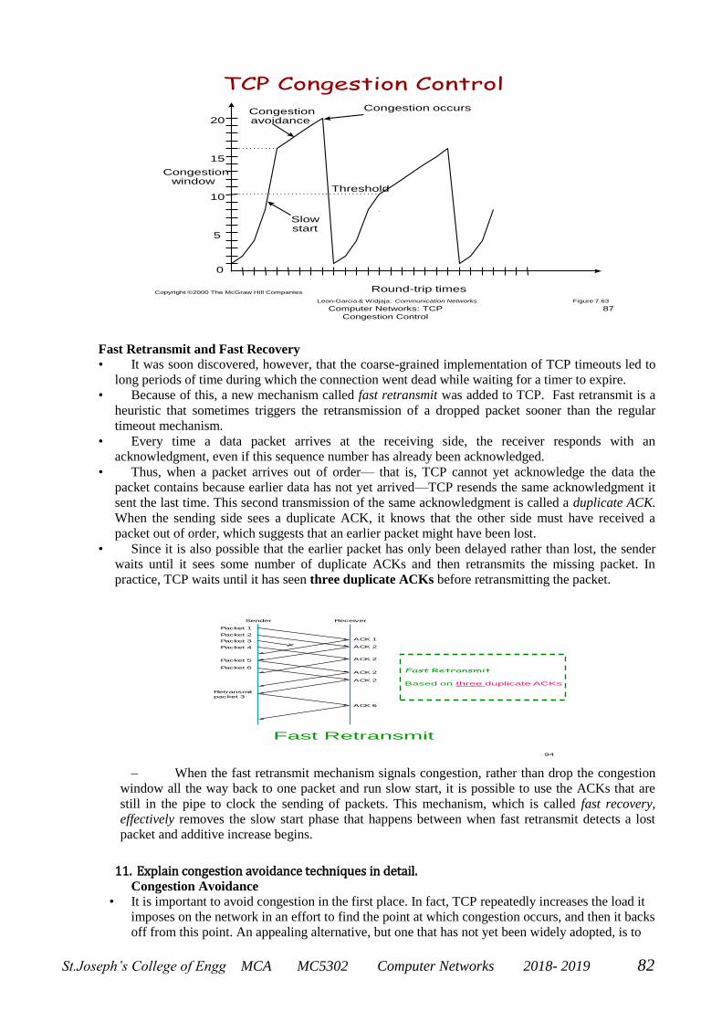
St.Joseph’s College of Engg MCA MC5302 Computer Networks 2018- 2019 82
Computer Networks: TCP
Congestion Control
87
Congestionwindow
10
5
15
20
0
Round-trip times
Slowstart
Congestionavoidance
Congestion occurs
Threshold
Figure 7.63Leon-Garcia & Widjaja: Communication Networks
Copyright ©2000 The McGraw Hill Companies
TCP Congestion Control
Fast Retransmit and Fast Recovery
• It was soon discovered, however, that the coarse-grained implementation of TCP timeouts led to
long periods of time during which the connection went dead while waiting for a timer to expire.
• Because of this, a new mechanism called fast retransmit was added to TCP. Fast retransmit is a
heuristic that sometimes triggers the retransmission of a dropped packet sooner than the regular
timeout mechanism.
• Every time a data packet arrives at the receiving side, the receiver responds with an
acknowledgment, even if this sequence number has already been acknowledged.
• Thus, when a packet arrives out of order— that is, TCP cannot yet acknowledge the data the
packet contains because earlier data has not yet arrived—TCP resends the same acknowledgment it
sent the last time. This second transmission of the same acknowledgment is called a duplicate ACK.
When the sending side sees a duplicate ACK, it knows that the other side must have received a
packet out of order, which suggests that an earlier packet might have been lost.
• Since it is also possible that the earlier packet has only been delayed rather than lost, the sender
waits until it sees some number of duplicate ACKs and then retransmits the missing packet. In
practice, TCP waits until it has seen three duplicate ACKs before retransmitting the packet.
94
Fast Retransmit
Packet 1
Packet 2
Packet 3
Packet 4
Packet 5
Packet 6
Retransmit
packet 3
ACK 1
ACK 2
ACK 2
ACK 2
ACK 6
ACK 2
Sender Receiver
Fast Retransmit
Based on three duplicate ACKs
– When the fast retransmit mechanism signals congestion, rather than drop the congestion
window all the way back to one packet and run slow start, it is possible to use the ACKs that are
still in the pipe to clock the sending of packets. This mechanism, which is called fast recovery,
effectively removes the slow start phase that happens between when fast retransmit detects a lost
packet and additive increase begins.
11. Explain congestion avoidance techniques in detail. Congestion Avoidance
• It is important to avoid congestion in the first place. In fact, TCP repeatedly increases the load it
imposes on the network in an effort to find the point at which congestion occurs, and then it backs
off from this point. An appealing alternative, but one that has not yet been widely adopted, is to
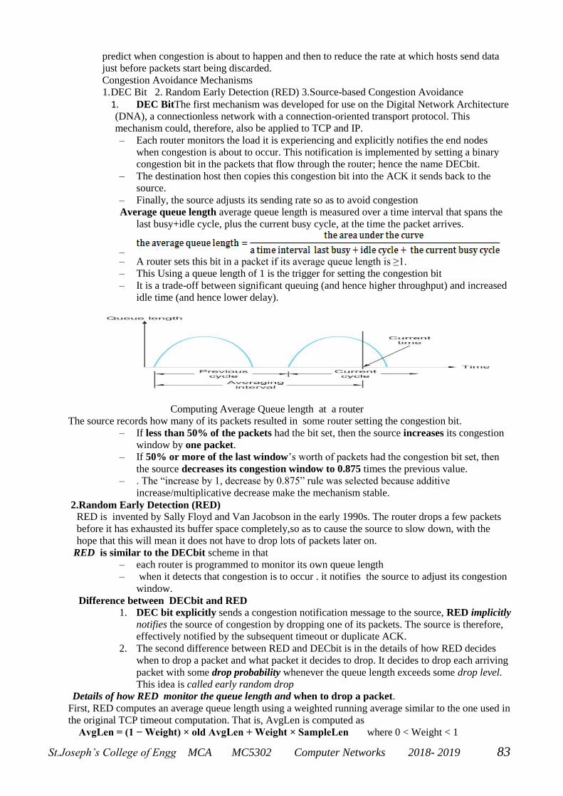
St.Joseph’s College of Engg MCA MC5302 Computer Networks 2018- 2019 83
predict when congestion is about to happen and then to reduce the rate at which hosts send data
just before packets start being discarded.
Congestion Avoidance Mechanisms
1. DEC Bit 2. Random Early Detection (RED) 3.Source-based Congestion Avoidance
1. DEC BitThe first mechanism was developed for use on the Digital Network Architecture
(DNA), a connectionless network with a connection-oriented transport protocol. This
mechanism could, therefore, also be applied to TCP and IP.
– Each router monitors the load it is experiencing and explicitly notifies the end nodes
when congestion is about to occur. This notification is implemented by setting a binary
congestion bit in the packets that flow through the router; hence the name DECbit.
– The destination host then copies this congestion bit into the ACK it sends back to the
source.
– Finally, the source adjusts its sending rate so as to avoid congestion
Average queue length average queue length is measured over a time interval that spans the
last busy+idle cycle, plus the current busy cycle, at the time the packet arrives.
– – A router sets this bit in a packet if its average queue length is ≥1.
– This Using a queue length of 1 is the trigger for setting the congestion bit
– It is a trade-off between significant queuing (and hence higher throughput) and increased
idle time (and hence lower delay).
Computing Average Queue length at a router
The source records how many of its packets resulted in some router setting the congestion bit.
– If less than 50% of the packets had the bit set, then the source increases its congestion
window by one packet.
– If 50% or more of the last window’s worth of packets had the congestion bit set, then
the source decreases its congestion window to 0.875 times the previous value.
– . The “increase by 1, decrease by 0.875” rule was selected because additive
increase/multiplicative decrease make the mechanism stable.
2.Random Early Detection (RED)
RED is invented by Sally Floyd and Van Jacobson in the early 1990s. The router drops a few packets
before it has exhausted its buffer space completely,so as to cause the source to slow down, with the
hope that this will mean it does not have to drop lots of packets later on.
RED is similar to the DECbit scheme in that
– each router is programmed to monitor its own queue length
– when it detects that congestion is to occur . it notifies the source to adjust its congestion
window.
Difference between DECbit and RED
1. DEC bit explicitly sends a congestion notification message to the source, RED implicitly
notifies the source of congestion by dropping one of its packets. The source is therefore,
effectively notified by the subsequent timeout or duplicate ACK.
2. The second difference between RED and DECbit is in the details of how RED decides
when to drop a packet and what packet it decides to drop. It decides to drop each arriving
packet with some drop probability whenever the queue length exceeds some drop level.
This idea is called early random drop
Details of how RED monitor the queue length and when to drop a packet.
First, RED computes an average queue length using a weighted running average similar to the one used in
the original TCP timeout computation. That is, AvgLen is computed as
AvgLen = (1 − Weight) × old AvgLen + Weight × SampleLen where 0 < Weight < 1

St.Joseph’s College of Engg MCA MC5302 Computer Networks 2018- 2019 84
• SampleLen is the length of the queue when a sample measurement is made.
• queue length is measured every time a new packet arrives at the gateway. In
hardware, it might be calculated at some fixed sampling interval.
RED has two queue length thresholds that trigger certain activity: MinThreshold and MaxThreshold.,
RED compares the current AvgLen with these two thresholds, according to the following rules:
• if AvgLen MinThreshold queue the packet
• if MinThreshold < AvgLen < MaxThreshold
– calculate probability P
– drop the arriving packet with probability P
• if MaxThreshold AvgLen drop the arriving packet
The drop probability P is a function of both AvgLen and how long it has been since the last packet was
dropped.
P = TempP / (1 − count × TempP)
TempP = MaxP × (AvgLen − MinThreshold) / (MaxThreshold − MinThreshold)
Count keeps track of how many newly arriving packets have been queued (not dropped) while AvgLen
has been between the two thresholds.
3. Source-based Congestion Avoidance
The source might notice that as packet queues build up in the network’s routers, there is a measurable
increase in the RTT for each successive packet it sends.
Algorithm 1
• The congestion window normally increases as in TCP, but every two round-trip delays the
algorithm checks to see if the current RTT is greater than the average of the minimum and
maximum RTTs seen so far. If it is, then the algorithm decreases the congestion window
by one-eighth.
Algorithm 2
– The decision as to whether or not to change the current window size is based on changes
to both the RTT and the window size. The window is adjusted once every two round-trip
delays based on the product
(CurrentWindow − OldWindow)×(CurrentRTT − OldRTT)
• If the result is +ve, the source decreases the window size by one-eighth;
• if the result is -ve or 0, the source increases the window by one maximum
packet size.
Note that the window changes during every adjustment; that is, it oscillates around its optimal point.
Algorithm 3
Every RTT, it increases the window size by one packet and compares the throughput achieved to the
throughput when the window was one packet smaller. If the difference is less than one-half the
throughput achieved when only one packet was in transit—as was the case at the beginning of the
connection—the algorithm decreases the window by one packet. This scheme calculates the throughput
by dividing the number of bytes outstanding in the network by the RTT
Algorithm 4 -TCP Vegas: According to this algorithm when actual bandwidth is 10 pkts /sec the sender
can send 10 packets /sec because the extra data will be handled by the router in the network.It is known as
TCP Vegas
St.Joseph’s College of Engg MCA MC5302 Computer Networks 2018- 2019 85
12. Consider transferring an enormous file of L bytes from host A to host B. Assume an MSS of 1640 bytes. What is the maximum value of L such that the TCP sequence numbers are not exhausted? For this L, how long does it take to transmit a file over a 10 Mpbs link? Assume that a total of 66 bytes of transport network and data link header are added to each segment, and ignore flow and congestion control. The value of L is irrelevant to the concept of TCP sequence numbers – exhausted. The value of L is irrelevant to the concept of TCP sequence numbers – exhausted.
There are possible sequence numbers. The sequence number is incremented by number of
bytes of data sent and not by one.
How long does it take to transmit a file over a 10 Mpbs link? ( use )
Bytes
Bytes
=3409 bits
13. Explain about Silly window syndrome and Nagle’s Solution. (Nov – ’13) Silly Window Syndrome: Suppose receiver buffer is full. It advertises window is zero. Sender will not transmit any data to
receiver, finally sender buffer will fill.
As soon as receiver process starts to read again, its advertiser window will become > 0 that allows
sender to transmit data out of its buffer. The sender obliges and sends 1 byte. The buffer is now full,
so the receiver acknowledges the 1 –byte segments but sets the window to 0. This behavior can go
on forever. Each byte is sent as TCP segment:
1byte data + 20 byte IP header + 20 byte TCP header=41 byte =>
known as TINYGRAM’s overhead is more . ( - for one byte data over head is 40 byte)
Nagle’s Solution: The sender can help by not sending tiny segments. Instead, it should try to wait until it has
accumulated enough space in the window to send a full segment or at least one containing half of the
receiver’s buffer size (which it must estimate from the pattern of window updates it has received in
the past).
To overcome this, Nagle proposed that at any point of time there can be only one
outstanding packet. Till the ack. Is received, data is accumulated and on receipt of ack. Accumulated
data is transmitted. N/W utilization increases
14. Explain in detail about RTP. The protocol used to transmit digitized audio or video signals over an IP internet is
known as the Real-Time Transport Protocol (RTP). Interestingly, RTP does not contain
mechanisms that ensure timely delivery; such guarantees must be made by the underlying
system. Instead, RTP provides two key facilities: a sequence number in each packet that
allows a receiver to detect out-of-order delivery or loss, and a timestamp that allows a
receiver to control playback. Because RTP is designed to carry a wide variety of real-time
data, including both audio and video, RTP does not enforce a uniform interpretation of
semantics. Instead, each packet begins with a fixed header; fields in the header specify how
to interpret remaining header fields and how to interpret the payload. Figure illustrates the
format of RTP's fixed header.

St.Joseph’s College of Engg MCA MC5302 Computer Networks 2018- 2019 86
A key part of RTP is its support for translation (i.e., changing the encoding of a
stream at an intermediate station) or mixing (i.e., receiving streams of data from multiple
sources, combining them into a single stream, and sending the result). To understand
the need for mixing, imagine that individuals at multiple sites participate in a conference
call using IP. To minimize the number of RTP streams, the group can designate a mixer,
and arrange for each site to establish an RTP session to the mixer. The mixer combines the
audio streams (possibly by converting them back to analog and resampling the resulting
signal), and sends the result as a single digital stream. Fields in the RTP header identify the
sender and indicate whether mixing occurred. The field labeled SYNCHRONIZ4TION
SOURCE IDENTIFIER specifies the source of a stream. Each source must choose a
unique 32-bit identifier; the protocol includes a mechanism for resolving conflicts if they
arise. When a mixer combines multiple streams, the mixer becomes the synchronization
source for the new stream. Information about the original sources is not lost, however,
because the mixer uses the variable-size CONTRIBUTING SOURCE ID field to provide
the synchronization IDS of streams that were mixed together. The four-bit CC field gives a
count of contributing sources; a maximum of 15 sources can be listed. RTP is designed to
work with IP multicasting, and mixing is especially attractive in a multicast environment.
UNIT V PART B
1. What is the role of the local name server and the authoritative name server in DNS? What is the resource records maintained in each of them? (DEC 16)
DNS Overview and name servers
Local name servers: Each ISP has a local name server. When a host issues a DNS query message, the
message is first sent to the host’s local name server. The IP address of the local name server is configured
by hand in a host.
Authoritative servers: Every host is registered with an authoritative name server. Authoritative name
server for a host is a name server in the host’s local ISP. A name server is authoritative for a host if it
always has a DNS record that translates the host’s hostname to that host’s IP address
RR: Each name server maintains resource records (Name, Value, Type, Class, TTL)
• Type (some examples)
– A: Name = full domain name, Value = IP address
– NS: Value gives domain name for host running name server
– CNAME: Value gives canonical name for particle host.
– MX: Value gives domain name for host running mail server
If a name server is authoritative for a particular host name, then the name server will contain a Type A
record for the hostname. If a server is not authoritative for a host name, then the server will contain a
Type NS record for the domain that includes the hostname; it will also contain a Type A record that
provides the IP address of the name server in the Value field of the NS record.
2. Explain in detail the RSA Algorithm /one asymmetric algorithm and type of attacks possible
in RSA (DEC 16)(Dec 14) (NOV 17)
St.Joseph’s College of Engg MCA MC5302 Computer Networks 2018- 2019 87
RSA involves a public key and a private key. The public key can be known to everyone and is used
for encrypting messages. Messages encrypted with the public key can only be decrypted using the
private key. The keys for the RSA algorithm are generated the following way:
Choose two distinct prime numbers p and q. For security purposes, the integers p and q should be
chosen at random, and should be of similar bit-length.
Compute n = pq. n is used as the modulus for both the public and private keys
Compute φ(n) = (p – 1)(q – 1), where φ is Euler's totient function.
Choose an integer e such that 1 < e < φ(n) and greatest common divisor of (e, φ(n)) = 1; i.e., e and
φ(n) are coprime..e is released as the public key exponent.
Determine d as:i.e., d is the multiplicative inverse of e mod φ(n). d is kept as the private key
exponent.
The private key consists of {d, n} and the public key consists of {e, n}. Suppose that user A has
published its public key and that user B wishes to send the message M to A. Then B calculates cipher
text and transmits C. On receipt of this cipher text, user A decrypts by calculating
M = C (d mod n).
Example
Select primes: p=17 & q=11
Compute n = pq =17×11=187
Compute ø(n)=(p–1)(q-1)=16×10=160
Select e : gcd(e,160)=1; choose e=7
Determine d: de=1 mod 160 and d < 160 Value is d=23 since 23×7=161= 10×160+1
Publish public key KU={7,187}
Keep secret private key KR={23,17,11}
RSA encryption/decryption is:
given message M = 88 (nb. 88<187)
encryption: C = 887 mod 187 = 11
decryption: M = 1123 mod 187 = 88
Security of RSA
Brute force: This involves trying all possible private keys.
Mathematical attacks: There are several approaches, all equivalent in effort to factoring the product of
two primes.
● Timing attacks: These depend on the running time of the decryption algorithm.
● Chosen cipher text attacks: This type of attack exploits properties of the RSA
algorithm.
3. Explain DES algorithm in detail / Symmetric key Algorithm / symmetric cryptography –
(MAY- 12) (NOV 17) DES : Data Encryption std.. DES is the block cipher algorithm that takes a fixed-length string of
plaintext bits and transforms it through a series of complicated operations into another cipher text string
of the same length. In the case of DES, the block size is 64 bits. DES also uses a key to customize the
transformation, so that decryption can supposedly only be performed by those who know the particular
key used to encrypt. The key consists of 64 bits; however, only 56 of these are actually used by the
algorithm.
Algorithm : 64 bit plain text passes through initial permutation. It is followed by 16 rounds. Then a
swap is done. Preoutput is passed through IP.
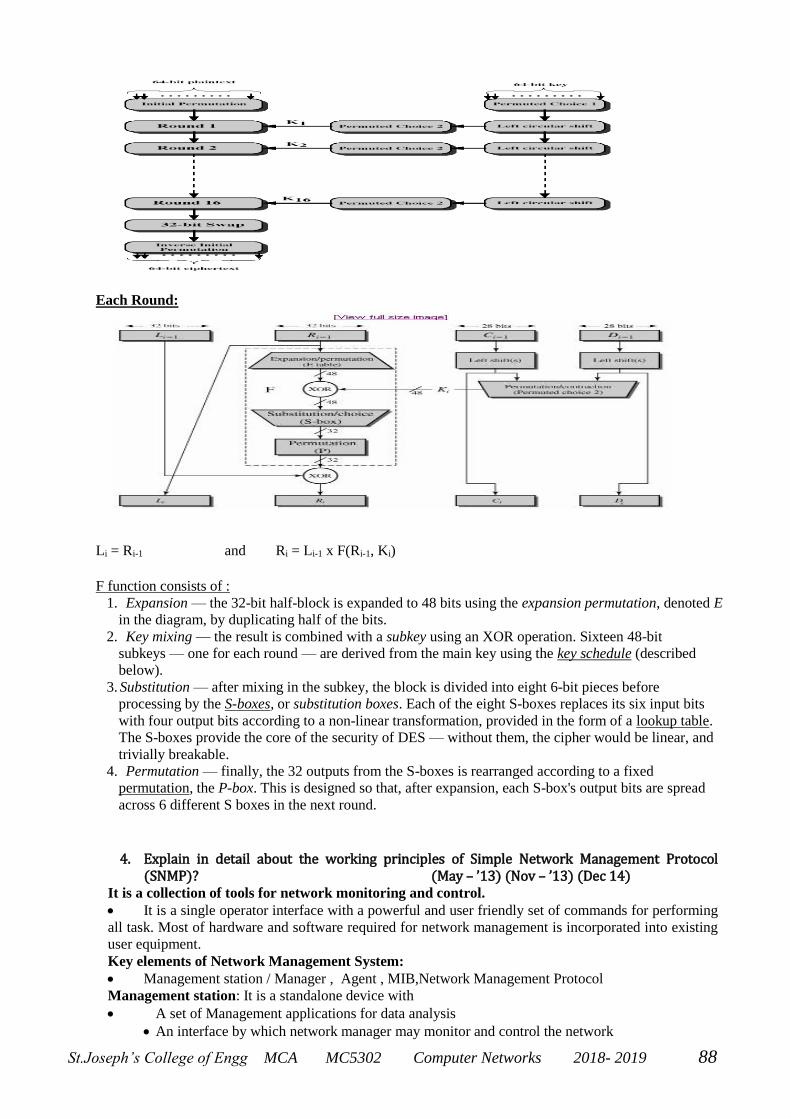
St.Joseph’s College of Engg MCA MC5302 Computer Networks 2018- 2019 88
Each Round:
Li = Ri-1 and Ri = Li-1 x F(Ri-1, Ki)
F function consists of :
1. Expansion — the 32-bit half-block is expanded to 48 bits using the expansion permutation, denoted E
in the diagram, by duplicating half of the bits.
2. Key mixing — the result is combined with a subkey using an XOR operation. Sixteen 48-bit
subkeys — one for each round — are derived from the main key using the key schedule (described
below).
3. Substitution — after mixing in the subkey, the block is divided into eight 6-bit pieces before
processing by the S-boxes, or substitution boxes. Each of the eight S-boxes replaces its six input bits
with four output bits according to a non-linear transformation, provided in the form of a lookup table.
The S-boxes provide the core of the security of DES — without them, the cipher would be linear, and
trivially breakable.
4. Permutation — finally, the 32 outputs from the S-boxes is rearranged according to a fixed
permutation, the P-box. This is designed so that, after expansion, each S-box's output bits are spread
across 6 different S boxes in the next round.
4. Explain in detail about the working principles of Simple Network Management Protocol
(SNMP)? (May – ’13) (Nov – ’13) (Dec 14) It is a collection of tools for network monitoring and control.
It is a single operator interface with a powerful and user friendly set of commands for performing
all task. Most of hardware and software required for network management is incorporated into existing
user equipment.
Key elements of Network Management System:
Management station / Manager , Agent , MIB,Network Management Protocol
Management station: It is a standalone device with
A set of Management applications for data analysis
An interface by which network manager may monitor and control the network
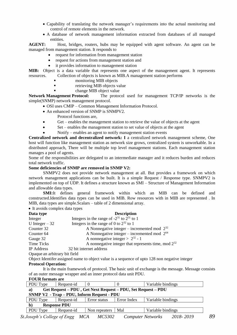
St.Joseph’s College of Engg MCA MC5302 Computer Networks 2018- 2019 89
Capability of translating the network manager’s requirements into the actual monitoring and
control of remote elements in the network.
A database of network management information extracted from databases of all managed
entities.
AGENT: Host, bridges, routers, hubs may be equipped with agent software. An agent can be
managed from management station. It responds to
request for information from management station
request for actions from management station and
it provides information to management station
MIB: Object is a data variable that represents one aspect of the management agent. It represents
resources. Collection of objects is known as MIB.A management station performs
monitoring MIB objects
retrieving MIB objects value
change MIB object value
Network Management Protocol: The protocol used for management TCP/IP networks is the
simple(SNMP) network management protocol.
OSI uses CMIP – Common Management Information Protocol.
An enhanced version of SNMP is SNMPV2.
Protocol functions are,
Get – enables the management station to retrieve the value of objects at the agent
Set – enables the management station to set value of objects at the agent
Notify – enables an agent to notify management station events
Centralized network and decentralized network: I a centralized network management scheme, One
host will function like management station as network size grows, centralized system is unworkable. In a
distributed approach, There will be multiple top level management stations. Each management station
manages a pool of agents.
Some of the responsibilities are delegated to an intermediate manager and it reduces burden and reduces
total network traffic.
Some deficiencies of SNMP are removed in SNMP V2:
SNMPV2 does not provide network management at all. But provides a framework on which
network management applications can be built. It is a simple Request / Response type. SNMPV2 is
implemented on top of UDP. It defines a structure known as SMI – Structure of Management Information
and allowable data types.
SMI:It defines general framework within which an MIB can be defined and
constructed.Identifies data types can be used in MIB. Row resources with in MIB are represented . In
MIB, data types are simple.Scalars – table of 2 dimensional array.
It avoids complex data types
Data type Description
Integer Integers in the range of -231 to 231 to 1
U Integer – 32 Integers in the range of 0 to 232 to 1
Counter 32 A Nonnegative integer – incremented mod 232
Counter 64 A Nonnegative integer – incremented mod 264
Gauge 32 A nonnegative integer > 232 - 1
Time Ticks A nonnegative integer that represents time, mod 232
IP Address 32 bit internet address
Opaque an arbitrary bit field
Object Identifer assigned name to object value is a sequence of upto 128 non negative integer
Protocol Operation:
It is the main framework of protocol. The basic unit of exchange is the message. Message consists
of an outer message wrapper and an inner protocol data unit PDU.
FOUR formats are
PDU Type Request-id 0 0 Variable bindings
a) Get Request – PDU , Get Next Request – PDU, Set Request – PDU
SNMP V2 - Trap – PDU, Inform Request - PDU
PDU Type Request-id Error status Error Index Variable bindings
b) Response PDU
PDU Type Request-id Non repeaters Mal Variable bindings
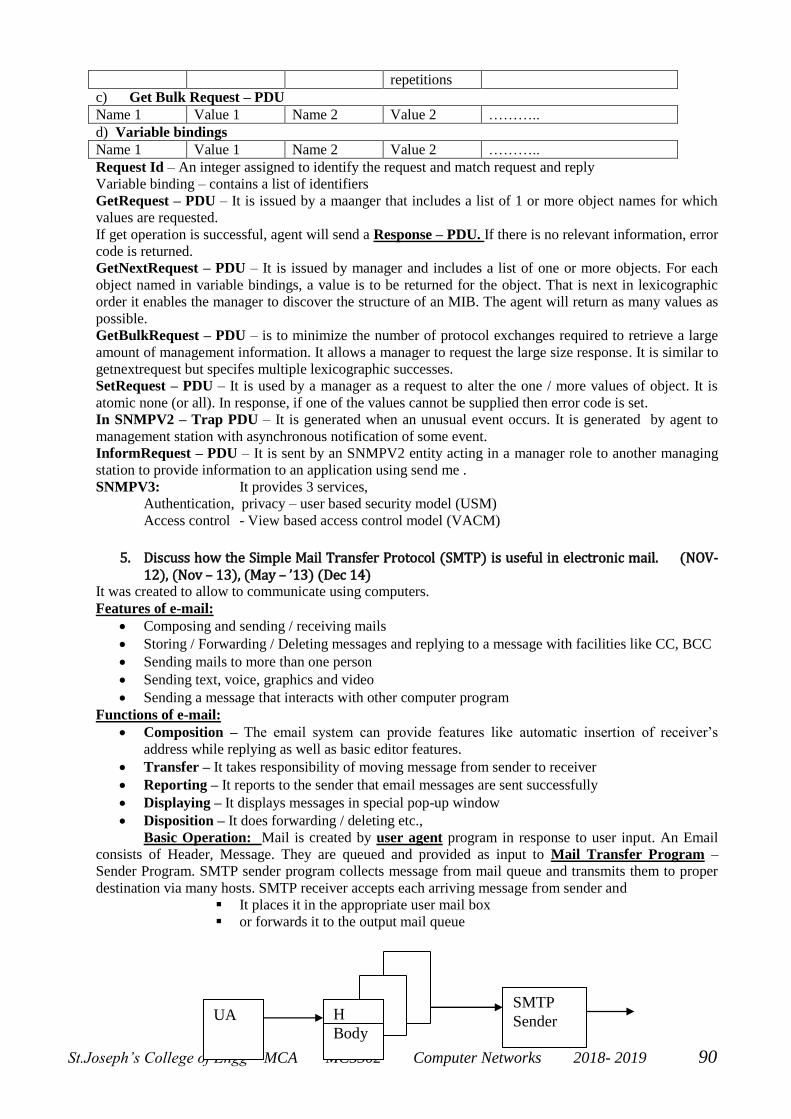
St.Joseph’s College of Engg MCA MC5302 Computer Networks 2018- 2019 90
repetitions
c) Get Bulk Request – PDU
Name 1 Value 1 Name 2 Value 2 ………..
d) Variable bindings
Name 1 Value 1 Name 2 Value 2 ………..
Request Id – An integer assigned to identify the request and match request and reply
Variable binding – contains a list of identifiers
GetRequest – PDU – It is issued by a maanger that includes a list of 1 or more object names for which
values are requested.
If get operation is successful, agent will send a Response – PDU. If there is no relevant information, error
code is returned.
GetNextRequest – PDU – It is issued by manager and includes a list of one or more objects. For each
object named in variable bindings, a value is to be returned for the object. That is next in lexicographic
order it enables the manager to discover the structure of an MIB. The agent will return as many values as
possible.
GetBulkRequest – PDU – is to minimize the number of protocol exchanges required to retrieve a large
amount of management information. It allows a manager to request the large size response. It is similar to
getnextrequest but specifes multiple lexicographic successes.
SetRequest – PDU – It is used by a manager as a request to alter the one / more values of object. It is
atomic none (or all). In response, if one of the values cannot be supplied then error code is set.
In SNMPV2 – Trap PDU – It is generated when an unusual event occurs. It is generated by agent to
management station with asynchronous notification of some event.
InformRequest – PDU – It is sent by an SNMPV2 entity acting in a manager role to another managing
station to provide information to an application using send me .
SNMPV3: It provides 3 services,
Authentication, privacy – user based security model (USM)
Access control - View based access control model (VACM)
5. Discuss how the Simple Mail Transfer Protocol (SMTP) is useful in electronic mail. (NOV-
12), (Nov – 13), (May – ’13) (Dec 14) It was created to allow to communicate using computers.
Features of e-mail:
Composing and sending / receiving mails
Storing / Forwarding / Deleting messages and replying to a message with facilities like CC, BCC
Sending mails to more than one person
Sending text, voice, graphics and video
Sending a message that interacts with other computer program
Functions of e-mail:
Composition – The email system can provide features like automatic insertion of receiver’s
address while replying as well as basic editor features.
Transfer – It takes responsibility of moving message from sender to receiver
Reporting – It reports to the sender that email messages are sent successfully
Displaying – It displays messages in special pop-up window
Disposition – It does forwarding / deleting etc.,
Basic Operation: Mail is created by user agent program in response to user input. An Email
consists of Header, Message. They are queued and provided as input to Mail Transfer Program –
Sender Program. SMTP sender program collects message from mail queue and transmits them to proper
destination via many hosts. SMTP receiver accepts each arriving message from sender and
It places it in the appropriate user mail box
or forwards it to the output mail queue
UA H
Body
SMTP
Sender
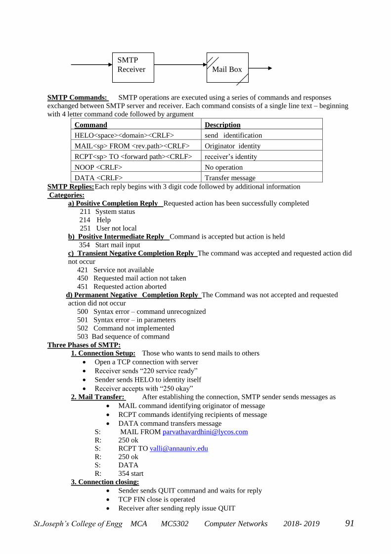
St.Joseph’s College of Engg MCA MC5302 Computer Networks 2018- 2019 91
SMTP Commands: SMTP operations are executed using a series of commands and responses
exchanged between SMTP server and receiver. Each command consists of a single line text – beginning
with 4 letter command code followed by argument
Command Description
HELO<space><domain><CRLF> send identification
MAIL<sp> FROM <rev.path><CRLF> Originator identity
RCPT<sp> TO <forward path><CRLF> receiver’s identity
NOOP <CRLF> No operation
DATA <CRLF> Transfer message
SMTP Replies: Each reply begins with 3 digit code followed by additional information
Categories: a) Positive Completion Reply Requested action has been successfully completed
211 System status
214 Help
251 User not local
b) Positive Intermediate Reply Command is accepted but action is held
354 Start mail input
c) Transient Negative Completion Reply The command was accepted and requested action did
not occur
421 Service not available
450 Requested mail action not taken
451 Requested action aborted
d) Permanent Negative Completion Reply The Command was not accepted and requested
action did not occur
500 Syntax error – command unrecognized
501 Syntax error – in parameters
502 Command not implemented
503 Bad sequence of command
Three Phases of SMTP:
1. Connection Setup: Those who wants to send mails to others
Open a TCP connection with server
Receiver sends “220 service ready”
Sender sends HELO to identity itself
Receiver accepts with “250 okay”
2. Mail Transfer: After establishing the connection, SMTP sender sends messages as
MAIL command identifying originator of message
RCPT commands identifying recipients of message
DATA command transfers message
S: MAIL FROM [email protected]
R: 250 ok
S: RCPT TO [email protected]
R: 250 ok
S: DATA
R: 354 start
3. Connection closing:
Sender sends QUIT command and waits for reply
TCP FIN close is operated
Receiver after sending reply issue QUIT
SMTP
Receiver
Mail Box
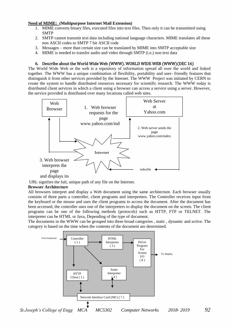
St.Joseph’s College of Engg MCA MC5302 Computer Networks 2018- 2019 92
Need of MIME: (Multipurpose Internet Mail Extension)
1. MIME converts binary files, executed files into text files. Then only it can be transmitted using
SMTP
2. SMTP cannot transmit text data including national language characters. MIME translates all these
non ASCII codes to SMTP 7 bit ASCII code
3. Messages – more than certain size can be translated by MIME into SMTP acceptable size
4. MIME is needed to transfer audio and video through SMTP (i.e.) non text data
6. Describe about the World Wide Web (WWW). WORLD WIDE WEB (WWW)(DEC 16)
The World Wide Web or the web is a repository of information spread all over the world and linked
together. The WWW has a unique combination of flexibility, portability and user- friendly features that
distinguish it from other services provided by the Internet. The WWW Project was initiated by CERN to
create the system to handle distributed resources necessary for scientific research. The WWW today is
distributed client services in which a client using a browser can access a service using a server. However,
the service provided is distributed over many locations called web sites.
URL signifies the full, unique path of any file on the Internet.
Browser Architecture
All browsers interpret and display a Web document using the same architecture. Each browser usually
consists of three parts a controller, client programs and interpreters. The Controller receives input from
the keyboard or the mouse and uses the client programs to access the document. After the document has
been accessed, the controller uses one of the interpreters to display the document on the screen. The client
programs can be one of the following methods (protocols) such as HTTP, FTP or TELNET. The
interpreter can be HTML or Java, Depending of the type of document.
The documents in the WWW can be grouped into three broad categories , static , dynamic and active. The
category is based on the time when the contents of the document are determined.
Web
Browser
Web Server
at
Yahoo.com 1. Web browser
requests for the
page
www.yahoo.com/ind
ex
Internet
indexfile
fifilwe
3. Web browser
interprets the
page
and displays its
contents on
screen
2. Web server sends the
page
www.yahoo.com/index
Controller
( 1 )
HTML
Interpreter
( 3 )
Driver
Program For
Screen
I/O
( 8 )
HTTP
Client ( 2 )
Network Interface Card (NIC) ( 7 )
Some
Interpreter
( 4 )
From Keyboard
To display

St.Joseph’s College of Engg MCA MC5302 Computer Networks 2018- 2019 93
Communication with remote server
STATIC DOCUMENTS
Static documents are fixed content documents that are created and stored in a server. The client can get
only a copy of the document. Although the contents in the server can be changed the user cannot change
it. When a client accesses the document, a copy of the document is sent, the user can then use a browsing
program to display the document.
HTML HyperText Markup Language is language for creating a web page.
Structure of a Web page: A Web page is made up of two parts, the head and the body.
Head : It is the first part of the web page. It contains the title of the page and other parameters
that the browser will use.
Body: The actual contents of a page are in the body, which includes the text and the tags.
Whereas the text is the actual information contained in the page, the tags determine the
appearance of the documents. Every HTML tags is a name followed by an option list of attributes
all enclosed between less than and greater than brackets ( < and > ).
Tags The browser makes a decision about the structure of the text based on the tags, which are
marks that are embedded into the text. A tag is enclosed in two brackets and usually come in
pairs.
DYNAMIC DOCUMENTS
Dynamic documents do not exist in a predefined format. Instead a dynamic document is created by a web
server whenever a browser requests a document. When a request arrives the web server runs an
application program that creates the dynamic documents. The server returns the output of the program as
a response to browser that requested the document. Because of fresh document is created for each request
the contents of a dynamic document can vary from one request to another. Avery simple example of a
dynamic document is getting the time and date from the server.
A server that handles dynamic documents follows these steps.
1. The server examines the URL to find if it defines a dynamic document.
2. If the URL defines a dynamic document, the server executes the program
3. the server sends the output of the program to the client.
COMMON GATEWAY INTERFACE (CGI)
Common gateway Interface (CGI) is a technology that creates and handles dynamic documents.
CGI is a set of standards that defines how a dynamic document should be written how input data
should be supplied to the program, and how the output result should be used.
CGI is not a new language ; instead, it allows programmers to use any of several languages such
as C, C++, Bourne Shell, Korn Shell, Tcl, or Perl. The only thing that CGI defines is a set of rules
and terms that the programmer should follow.
ACTIVE DOCUMENTS
Client Request Serve
r
Client Documen
t
Serve
r
Client Request
/
Progra
m
Server
Client Server
Client Documen
t Server
Client Request for a
Program
Server
Running the program and
producing the document
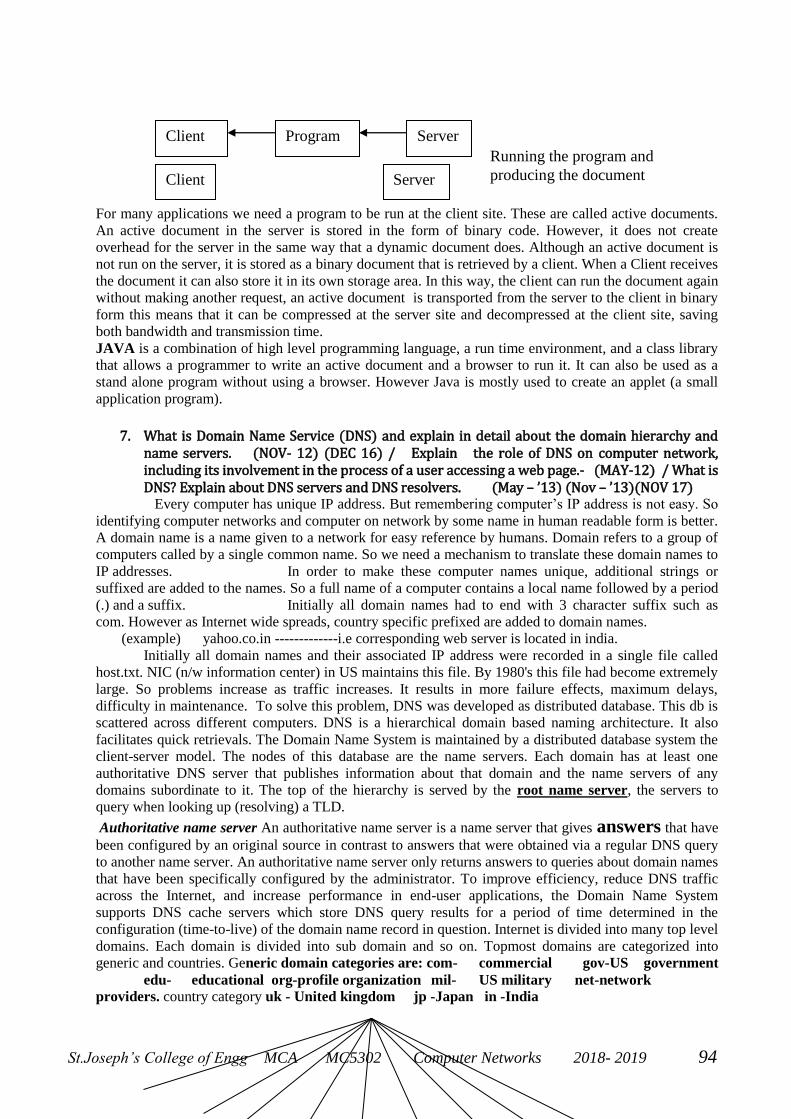
St.Joseph’s College of Engg MCA MC5302 Computer Networks 2018- 2019 94
For many applications we need a program to be run at the client site. These are called active documents.
An active document in the server is stored in the form of binary code. However, it does not create
overhead for the server in the same way that a dynamic document does. Although an active document is
not run on the server, it is stored as a binary document that is retrieved by a client. When a Client receives
the document it can also store it in its own storage area. In this way, the client can run the document again
without making another request, an active document is transported from the server to the client in binary
form this means that it can be compressed at the server site and decompressed at the client site, saving
both bandwidth and transmission time.
JAVA is a combination of high level programming language, a run time environment, and a class library
that allows a programmer to write an active document and a browser to run it. It can also be used as a
stand alone program without using a browser. However Java is mostly used to create an applet (a small
application program).
7. What is Domain Name Service (DNS) and explain in detail about the domain hierarchy and
name servers. (NOV- 12) (DEC 16) / Explain the role of DNS on computer network, including its involvement in the process of a user accessing a web page.- (MAY-12) / What is DNS? Explain about DNS servers and DNS resolvers. (May – ’13) (Nov – ’13)(NOV 17)
Every computer has unique IP address. But remembering computer’s IP address is not easy. So
identifying computer networks and computer on network by some name in human readable form is better.
A domain name is a name given to a network for easy reference by humans. Domain refers to a group of
computers called by a single common name. So we need a mechanism to translate these domain names to
IP addresses. In order to make these computer names unique, additional strings or
suffixed are added to the names. So a full name of a computer contains a local name followed by a period
(.) and a suffix. Initially all domain names had to end with 3 character suffix such as
com. However as Internet wide spreads, country specific prefixed are added to domain names.
(example) yahoo.co.in -------------i.e corresponding web server is located in india.
Initially all domain names and their associated IP address were recorded in a single file called
host.txt. NIC (n/w information center) in US maintains this file. By 1980's this file had become extremely
large. So problems increase as traffic increases. It results in more failure effects, maximum delays,
difficulty in maintenance. To solve this problem, DNS was developed as distributed database. This db is
scattered across different computers. DNS is a hierarchical domain based naming architecture. It also
facilitates quick retrievals. The Domain Name System is maintained by a distributed database system the
client-server model. The nodes of this database are the name servers. Each domain has at least one
authoritative DNS server that publishes information about that domain and the name servers of any
domains subordinate to it. The top of the hierarchy is served by the root name server, the servers to
query when looking up (resolving) a TLD.
Authoritative name server An authoritative name server is a name server that gives answers that have
been configured by an original source in contrast to answers that were obtained via a regular DNS query
to another name server. An authoritative name server only returns answers to queries about domain names
that have been specifically configured by the administrator. To improve efficiency, reduce DNS traffic
across the Internet, and increase performance in end-user applications, the Domain Name System
supports DNS cache servers which store DNS query results for a period of time determined in the
configuration (time-to-live) of the domain name record in question. Internet is divided into many top level
domains. Each domain is divided into sub domain and so on. Topmost domains are categorized into
generic and countries. Generic domain categories are: com- commercial gov-US government
edu- educational org-profile organization mil- US military net-network
providers. country category uk - United kingdom jp -Japan in -India
Client Program Server
Client Server
Running the program and
producing the document
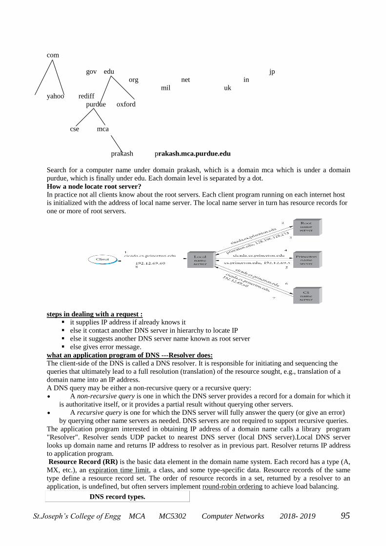
St.Joseph’s College of Engg MCA MC5302 Computer Networks 2018- 2019 95
com
gov edu jp
org net in
mil uk
yahoo rediff
purdue oxford
cse mca
prakash prakash.mca.purdue.edu
Search for a computer name under domain prakash, which is a domain mca which is under a domain
purdue, which is finally under edu. Each domain level is separated by a dot.
How a node locate root server?
In practice not all clients know about the root servers. Each client program running on each internet host
is initialized with the address of local name server. The local name server in turn has resource records for
one or more of root servers.
steps in dealing with a request :
it supplies IP address if already knows it
else it contact another DNS server in hierarchy to locate IP
else it suggests another DNS server name known as root server
else gives error message.
what an application program of DNS ---Resolver does:
The client-side of the DNS is called a DNS resolver. It is responsible for initiating and sequencing the
queries that ultimately lead to a full resolution (translation) of the resource sought, e.g., translation of a
domain name into an IP address.
A DNS query may be either a non-recursive query or a recursive query:
A non-recursive query is one in which the DNS server provides a record for a domain for which it
is authoritative itself, or it provides a partial result without querying other servers.
A recursive query is one for which the DNS server will fully answer the query (or give an error)
by querying other name servers as needed. DNS servers are not required to support recursive queries.
The application program interested in obtaining IP address of a domain name calls a library program
"Resolver". Resolver sends UDP packet to nearest DNS server (local DNS server).Local DNS server
looks up domain name and returns IP address to resolver as in previous part. Resolver returns IP address
to application program.
Resource Record (RR) is the basic data element in the domain name system. Each record has a type (A,
MX, etc.), an expiration time limit, a class, and some type-specific data. Resource records of the same
type define a resource record set. The order of resource records in a set, returned by a resolver to an
application, is undefined, but often servers implement round-robin ordering to achieve load balancing.
DNS record types.
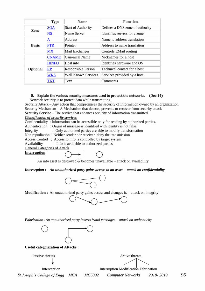
St.Joseph’s College of Engg MCA MC5302 Computer Networks 2018- 2019 96
Type Name Function
Zone SOA Start of Authority Defines a DNS zone of authority
NS Name Server Identifies servers for a zone
Basic
A Address Name to address translation
PTR Pointer Address to name translation
MX Mail Exchanger Controls EMail routing
Optional
CNAME Canonical Name Nicknames for a host
HINFO Host info Identifies hardware and OS
RP Responsible Person Technical contact for a host
WKS Well Known Services Services provided by a host
TXT Text Comments
8. Explain the various security measures used to protect the networks. (Dec 14)
Network security is to protect data while transmitting.
Security Attack – Any action that compromises the security of information owned by an organization.
Security Mechanism – A Mechanism that detects, prevents or recover from security attack
Security Service – The service that enhances security of information transmitted.
Classification of security services Confidentiality : Information can be accessible only for reading by authorized parties.
Authentication : Origin of message is identified with identity is not false
Integrity : Only authorized parties are able to modify transformation
Non repudiation : Neither sender nor receiver deny the transmission
Access Control : Access to info is controlled by target system
Availability : Info is available to authorized parties
General Categories of Attack
Interruption
An info asset is destroyed & becomes unavailable – attack on availability.
Interception : An unauthorized party gains access to an asset - attack on confidentiality
Modification : An unauthorized party gains access and changes it. – attack on integrity
Fabrication :An unauthorized party inserts fraud messages – attack on authenticity
Useful categorization of Attacks :
Passive threats Active threats
Interception interruption Modification Fabrication
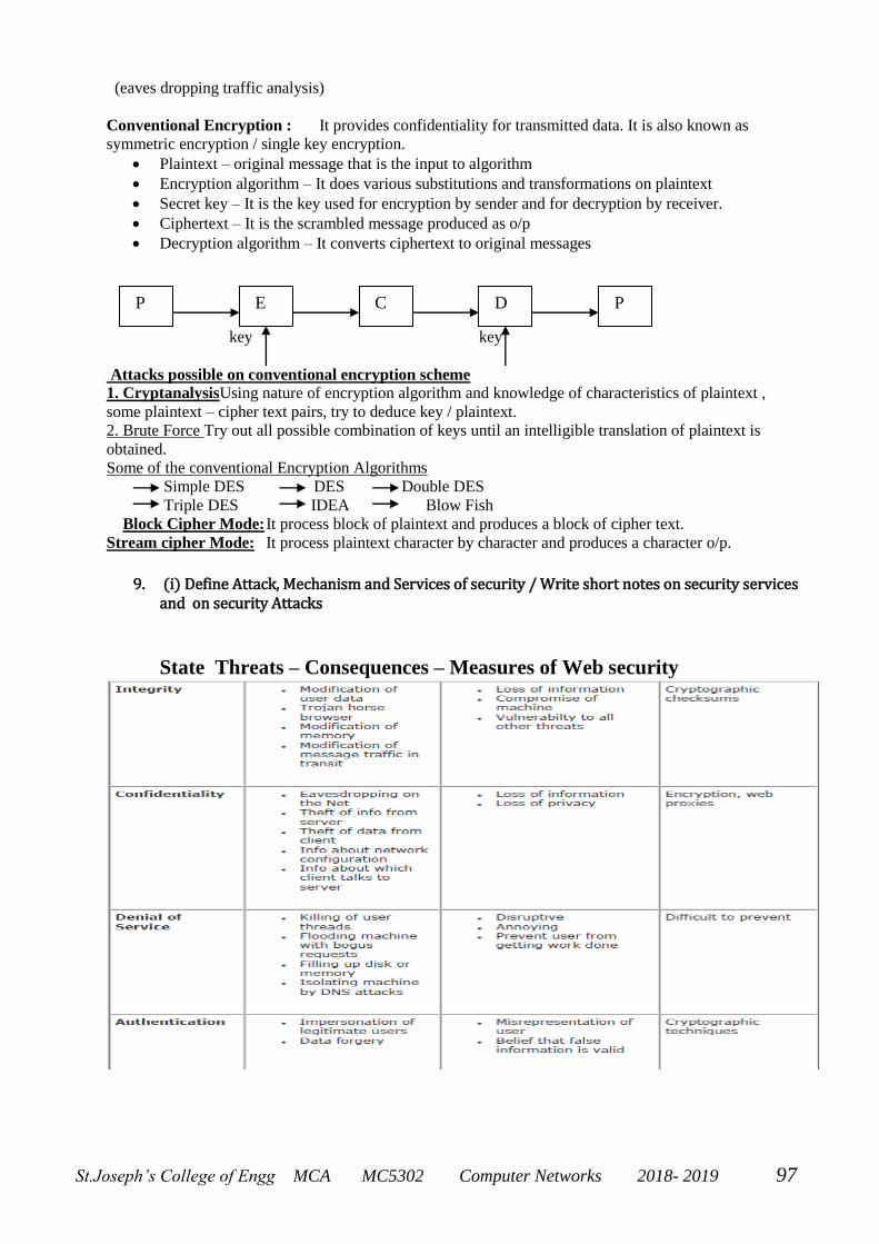
St.Joseph’s College of Engg MCA MC5302 Computer Networks 2018- 2019 97
(eaves dropping traffic analysis)
Conventional Encryption : It provides confidentiality for transmitted data. It is also known as
symmetric encryption / single key encryption.
Plaintext – original message that is the input to algorithm
Encryption algorithm – It does various substitutions and transformations on plaintext
Secret key – It is the key used for encryption by sender and for decryption by receiver.
Ciphertext – It is the scrambled message produced as o/p
Decryption algorithm – It converts ciphertext to original messages
key key
Attacks possible on conventional encryption scheme
1. CryptanalysisUsing nature of encryption algorithm and knowledge of characteristics of plaintext ,
some plaintext – cipher text pairs, try to deduce key / plaintext.
2. Brute Force Try out all possible combination of keys until an intelligible translation of plaintext is
obtained.
Some of the conventional Encryption Algorithms
Simple DES DES Double DES
Triple DES IDEA Blow Fish
Block Cipher Mode: It process block of plaintext and produces a block of cipher text.
Stream cipher Mode: It process plaintext character by character and produces a character o/p.
9. (i) Define Attack, Mechanism and Services of security / Write short notes on security services
and on security Attacks
State Threats – Consequences – Measures of Web security
P E C D P
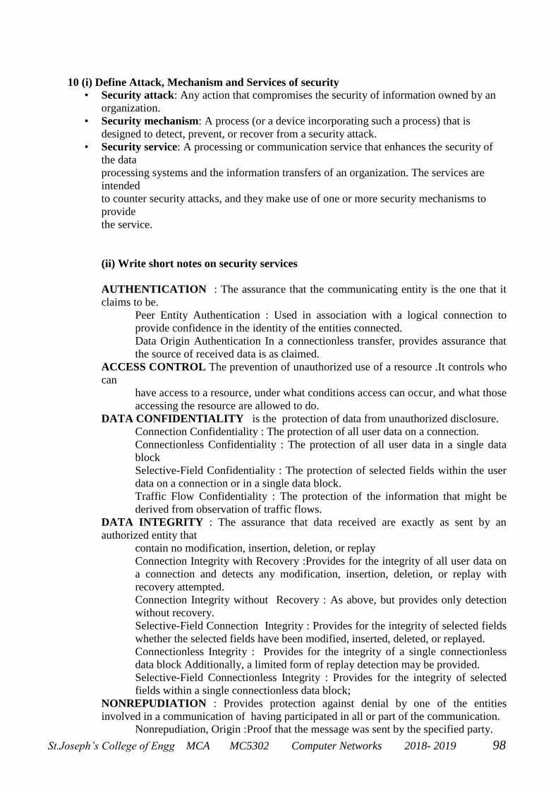
St.Joseph’s College of Engg MCA MC5302 Computer Networks 2018- 2019 98
10 (i) Define Attack, Mechanism and Services of security
• Security attack: Any action that compromises the security of information owned by an
organization.
• Security mechanism: A process (or a device incorporating such a process) that is
designed to detect, prevent, or recover from a security attack.
• Security service: A processing or communication service that enhances the security of
the data
processing systems and the information transfers of an organization. The services are
intended
to counter security attacks, and they make use of one or more security mechanisms to
provide
the service.
(ii) Write short notes on security services
AUTHENTICATION : The assurance that the communicating entity is the one that it
claims to be.
Peer Entity Authentication : Used in association with a logical connection to
provide confidence in the identity of the entities connected.
Data Origin Authentication In a connectionless transfer, provides assurance that
the source of received data is as claimed.
ACCESS CONTROL The prevention of unauthorized use of a resource .It controls who
can
have access to a resource, under what conditions access can occur, and what those
accessing the resource are allowed to do.
DATA CONFIDENTIALITY is the protection of data from unauthorized disclosure.
Connection Confidentiality : The protection of all user data on a connection.
Connectionless Confidentiality : The protection of all user data in a single data
block
Selective-Field Confidentiality : The protection of selected fields within the user
data on a connection or in a single data block.
Traffic Flow Confidentiality : The protection of the information that might be
derived from observation of traffic flows.
DATA INTEGRITY : The assurance that data received are exactly as sent by an
authorized entity that
contain no modification, insertion, deletion, or replay
Connection Integrity with Recovery :Provides for the integrity of all user data on
a connection and detects any modification, insertion, deletion, or replay with
recovery attempted.
Connection Integrity without Recovery : As above, but provides only detection
without recovery.
Selective-Field Connection Integrity : Provides for the integrity of selected fields
whether the selected fields have been modified, inserted, deleted, or replayed.
Connectionless Integrity : Provides for the integrity of a single connectionless
data block Additionally, a limited form of replay detection may be provided.
Selective-Field Connectionless Integrity : Provides for the integrity of selected
fields within a single connectionless data block;
NONREPUDIATION : Provides protection against denial by one of the entities
involved in a communication of having participated in all or part of the communication.
Nonrepudiation, Origin :Proof that the message was sent by the specified party.
St.Joseph’s College of Engg MCA MC5302 Computer Networks 2018- 2019 99
Nonrepudiation, Destination : Proof that the message was received by the
specified party.
AVAILABILITY: An availability service is one that protects a system to ensure its
availability. This service addresses the security concerns raised by denial-of-service
attacks. It depends on proper management and control of system resources and thus
depends on access control service and other security services