
SqovumQha5-1-1-6-road-and-environmentpdf.pdf - JP Ceste ...
145
Bosnia & Herzegovina ROAD DIRECTORATE Public Company FEDERATION OF B&H “REPUBLIC OF SRPSKA ROADS ” Sarajevo Banja Luka University of Ljubljana Faculty of Civil Engineering and Geodesy GUIDELINES FOR ROAD DESIGN, CONSTRUCTION, MAINTENANCE AND SUPERVISION VOLUME I: DESIGNING SECTION 1: ROAD DESIGNING Part 6: ROAD AND ENVIRONMENT Sarajevo/Banja Luka 2005
-
Upload
khangminh22 -
Category
Documents
-
view
0 -
download
0
Transcript of SqovumQha5-1-1-6-road-and-environmentpdf.pdf - JP Ceste ...

Bosnia & Herzegovina ROAD DIRECTORATE Public Company FEDERATION OF B&H “REPUBLIC OF SRPSKA ROADS ” Sarajevo Banja Luka
University of Ljubljana Faculty of Civil Engineering and Geodesy
GUIDELINES FOR ROAD DESIGN, CONSTRUCTION, MAINTENANCE AND
SUPERVISION
VOLUME I: DESIGNING
SECTION 1: ROAD DESIGNING
Part 6: ROAD AND ENVIRONMENT
Sarajevo/Banja Luka 2005


Guidelines for Road Design Road and Environment
RS-FB&H/3CS – DDC 433/04 Volume I – Section 1 – Part 6 Page 1 of 143
CONTENTS 1. NOISE PROTECTION.............................................................................................. 5 1.1 SUBJECT OF GUDELINE ................................................................................................ 5 1.2 DEFINITION OF TERMS ................................................................................................ 5 1.3 NOISE IN GENERAL...................................................................................................... 6
1.3.1 Noise source.......................................................................................................6 1.3.2 Calculation of noise caused by road traffic.............................................................6 1.3.3 Estimate and measurements of noise....................................................................9 1.3.4 Noise reduction measures.................................................................................. 11
1.4 PLANNING NOISE PROTECTION ...................................................................................13 1.4.1 Project documentation....................................................................................... 13 1.4.2 Noise protection measure types.......................................................................... 18 1.4.3 Loading and safety of noise protection structures ................................................ 19 1.4.4 IMPLEMENTING NOISE PROTECTION ................................................................. 23 1.4.5 Providing quality ............................................................................................... 37
1.5 MAINTENANCE OF NOISE PROTECTION STRUCTURES....................................................43 1.5.1 General ............................................................................................................ 43 1.5.2 Maintenance instructions ................................................................................... 43
2. WATER AND SOIL PROTECTION.......................................................................... 49 2.1 SUBJECT OF GUIDELINE..............................................................................................49 2.2 DEFINITION OF TERMS ...............................................................................................49 2.3 FORMS OF POLLUTION................................................................................................50 2.4 HYDROGEOLOGICAL BASES.........................................................................................50
2.4.1 Hydrogeological research................................................................................... 50 2.4.2 Hydrogeological characteristics........................................................................... 50
2.5 ESTIMATE OF AREA SENSITIVITY.................................................................................52 2.5.1 Vulnerability of an aquifer .................................................................................. 52 2.5.2 Exposure of a water source................................................................................ 52 2.5.3 Sensitivity of an aquifer ..................................................................................... 53 2.5.4 Bases for aquifer protection ............................................................................... 53
2.6 ROAD DRAINAGE METHODS ........................................................................................54 2.6.1 Surface drainage............................................................................................... 55 2.6.2 Deep drainage .................................................................................................. 55 2.6.3 Trap and containment reservoirs ........................................................................ 55
2.7 SEALING METHODS.....................................................................................................56 2.7.1 Description ....................................................................................................... 56 2.7.2 Materials .......................................................................................................... 56
2.8 UNDERGROUND WATER PROTECTION METHODS ..........................................................60 2.8.1 Very sensitive area............................................................................................ 60 2.8.2 Low sensitivity area........................................................................................... 64 2.8.3 Insensitive area ................................................................................................ 64
3. PROTECTION FROM EROSION AND SNOW AVALANCHES................................... 67 3.1 SUBJECT OF GUIDELINE..............................................................................................67 3.2 GENERAL ABOUT PROTECTION....................................................................................67
3.2.1 Stability of road and road structures ................................................................... 67 3.2.2 Stability of soil on demolished land ..................................................................... 67 3.2.3 Arrangement of water courses in roadside area ................................................... 67 3.2.4 Greening-grass and/or tree planting ................................................................... 67 3.2.5 Stabilisation of plant forms in roadside area ........................................................ 67 3.2.6 Restrictions of bioengineering measures ............................................................. 68 3.2.7 Other aspects of bioengineering measures .......................................................... 68
3.3 BASIC PRINCIPLES OF PROTECTION.............................................................................68 3.3.1 Proper sequence of bioengineering measure implementation ................................ 68 3.3.2 Breakdown of bioengineering measures .............................................................. 69 3.3.3 Technical works ................................................................................................ 70 3.3.4 Measures for water dispersion............................................................................ 73 3.3.5 Biotechnical works ............................................................................................ 81

Road and Environment Guidelines for Road Design
Page 2 of 143 Volume I – Section 1 – Part 6 RS-FB&H/3CS – DDC 433/04
3.4 PROTECTION OF SLOPES - EXAMPLES ..........................................................................87 4. ANIMAL PASSAGES ..............................................................................................91 4.1 BASES FOR PROTECTION PROVISIONS.........................................................................91
4.1.1 Provisions of regulations.....................................................................................91 4.1.2 Purpose of measures .........................................................................................93 4.1.3 Description of the state before the intervention....................................................93
4.2 IMPACT EVALUATION .................................................................................................94 4.3 ENDANGERED ANIMAL GROUPS...................................................................................95
4.3.1 LAND INVERTEBRATES ......................................................................................95 4.3.2 Animals bound to water environment (water invertebrates, fish, amphibians, water
birds) ...............................................................................................................95 4.3.3 AMPHIBIANS (AMPHIBIA)...................................................................................96 4.3.4 Reptiles (Reptilia) ..............................................................................................96 4.3.5 BIRDS (AVES) ...................................................................................................97 4.3.6 Mammals (Mammalia) ........................................................................................97
4.4 MEASURE TYPES......................................................................................................... 100 4.4.1 Measures preventing/reducing endangerment and mortality of animals resulting from
transport infrastructure ....................................................................................101 4.4.2 Measures enabling preserving connection between habitats ................................105
4.5 MONITORING........................................................................................................... 110 4.5.1 Monitoring types..............................................................................................110
4.6 SUMMARY................................................................................................................ 111 4.7 SOURCES................................................................................................................. 112
5. ROADSIDE DESIGN ............................................................................................117 5.1 PRINCIPLES AND OBJECTIVES OF LANDSCAPE DESIGN OF ROAD SURROUNDINGS ........ 117 5.2 GUIDELINES FOR DESIGNING ROAD SURROUNDINGS WITH REGARD TO ARRANGEMENT
MEASURES............................................................................................................... 117 5.2.1 Guidelines for Designing of the Relief ................................................................117 5.2.2 Design Guidelines for Planning and Implementation of Water Management
Arrangements .................................................................................................119 5.2.3 Design Guidelines for Implementation of Engineering-Biotechnical Measures ........119 5.2.4 Guidelines for Preparing the Planting Plan..........................................................119 5.2.5 Guidelines for Engineering and Architectural Design............................................123
5.3 GUIDELINES FOR DESIGNING ROAD SURROUNDINGS WITH REGARD TO INDIVIDUAL ARRANGEMENTS ...................................................................................................... 123
5.3.1 Guidelines for Designing Facilities......................................................................123 5.3.2 Guidelines for Designing and Greening of Anti-Noise Fences................................124 5.3.3 Guidelines for Designing Public Urban Equipment ...............................................125 5.3.4 Guidelines for Designing Service Facilities Along Motorways, Highways and Other
Roads of Higher Categories ..............................................................................125 5.4 FORMULATION AND GENERAL CONTENTS OF THE LANDSCAPE ARCHITECTURE PLAN .... 128
5.4.1 Phases of preparing landscape architecture plans ...............................................128 5.4.2 Draft contents of the landscape architecture plan ...............................................129
6. PROTECTION FROM WIND AND SNOW DRIFTS ................................................133 6.1 SUBJECT OF GUIDELINE............................................................................................ 133 6.2 DIRECT WIND ACTIONS ON VEHICLES ....................................................................... 133 6.3 SNOWDRIFT FORMATION ......................................................................................... 133 6.4 RETAINING OF SNOW............................................................................................... 134
6.4.1 Barriers to Retain the Snow ..............................................................................134 7. PROTECTION OF STRUCTURES FROM VIBRATIONS..........................................139 7.1 SUBJECT OF GUIDELINE............................................................................................ 139 7.2 ANALYSIS OF STRUCTURAL CONDITION..................................................................... 139
7.2.1 Bases .............................................................................................................139 7.2.2 Assessment of Possibility of Damages................................................................139 7.2.3 Criteria for Structural Vulnerability.....................................................................140
Guidelines for Road Design Road and Environment
RS-FB&H/3CS – DDC 433/04 Volume I – Section 1 – Part 6 Page 3 of 143
GUIDELINES FOR ROAD DESIGN, CONSTRUCTION, MAINTENANCE AND
SUPERVISION
VOLUME I: DESIGNING
SECTION 1: ROAD DESIGNING
Part 6: ROAD AND ENVIRONMENT
GUIDELINE 1: NOISE PROTECTION

Guidelines for Road Design Road and Environment
RS-FB&H/3CS – DDC 433/04 Volume I – Section 1 – Part 6 Page 5 of 143
1. NOISE PROTECTION
1.1 SUBJECT OF GUDELINE Noise has the biggest impact on the quality of life, both in outdoor environment (natural and urban) and indoor (residential) environment. Beside decreased level of comfort, health impacts of noise shall also be taken into account. Traffic is one of the most significant sources of noise. Although noise emissions of new vehicles are reduced, the noise on roads is increasing as the result of increased number and speed of motor vehicles. The above is to a varying degree true for all road types, be it motorways or main, regional and local roads. Reduction of environmental impacts due to noise can only be successful if relatively numerous and basically different known measures are adequately implemented. Guidelines regarding structures intended for protection from noise resulting from road traffic should assist in this regard; the guidelines specify the following:
- The bases for determining noise levels and planning of appropriate noise protection measures;
- The bases for laying foundations and construction of structures for noise protection, including supervision and monitoring of compliance with quality requirements; and
- The bases for maintenance and monitoring of the structures' condition for the purpose of maintaining noise protection.
1.2 DEFINITION OF TERMS The meaning of the terms used in these guidelines for noise protection shall be as follows: Active noise protection measures (active Lärmschutz-massnahmen/Lärmvorsorge) are measures intended for reducing noise emission from the source or measures for reducing the spreading of noise in the environment. Dynamic load (dynamische Belastung) is the load caused by weight of snow tossed by the snow clearing device on the noise protection structure/element. Acoustic element (Lärmschutzelement) is a part of the structure providing for its acoustic properties. Noise emission (Lärmemmision) is the sound strength emitted by the noise source to the environment (the impact of emitted energy on the environment). Ploughing speed (Geschwindigkeit bei Schneeräumung/-pflügen) is the speed of device for clearing of snow when passing by the structure. Noise (Lärm) is any sound in natural or human environment causing unrest, disturbing humans and damaging human health or feeling or having an adverse impact on the environment. Noise immission (Lärmimmission) is the level of noise L on a particular point of immission in the external environment, being the result of effects of one or several noise sources being expressed in decibels dB(A). Noise protection structure (noise reducing device barrier, Lärmschutzeinrichtung) is a structure/composition preventing direct transfer of road traffic noise through air, being composed of structural elements of the structure and noise protection elements. Limit value of noise level (Lärmpegelgrenzwert) is the value of noise level specified for a particular area of natural or human environment for day and night time with regard to sensitivity of the area for noise impacts. Structural element (Tragelement) is a part of the noise protection structure supporting or carrying noise protection elements, structural elements are base and supporting pillars.

Road and Environment Guidelines for Road Design
Page 6 of 143 Volume I – Section 1 – Part 6 RS-FB&H/3CS – DDC 433/04
Passive noise protection measures (passive Lärmschutzmassnahmen/Lärmvorsorge) are measures for noise protection on buildings used for living and working of humans. Noise source, source of noise (Lärmquelle) is a facility or device the use or operation of which causes permanent or periodical noise in the environment (e.g. road, motor vehicle).
1.3 NOISE IN GENERAL Noise resulting from road traffic should be limited because of linking of settlement to the road network. Protection of the environment against the noise shall be provided on the basis of assessment of numerous impacts on the noise level and of implemented measures.
1.3.1 Noise source Motor traffic on roads creates noise by
- Engine system of motor vehicles: noise source is the operation of the engine and the exhaust system, to a smaller extent also operations of the cooling system; and
- Movement of vehicles: the noise of rolling resulting from the grip of tyres on the roadway is joined by – determined by driving speed – the noise of air resistance and the impact of levelness of the roadway on the current situation of the chassis/car body of the vehicle or its load.
1.3.2 Calculation of noise caused by road traffic Calculation of noise caused by road traffic shall be evaluated in accordance with the applicable legal provisions. The estimated day (Ld) and night (Ln) noise level resulting from road traffic shall be calculated for straight sections of roadways, which are on each side of the measurement point distanced by at least three times the distance of the noise source from the point for which the estimated noise level is calculated by using the following formula:
ktvlopnhndnd DDDDDDDLL +++++++= )25(,,
In case a roadway section does not fulfil the abovementioned criteria, the estimated noise levels shall be calculated in accordance with provisions of the DIN 18005 standard, Part 1, 1987, and the RLS-90, item. 4.0 guideline.
Values )25(
dL and )25(
nL shall be the estimated noise levels resulting from traffic at the distance of 25 m from the middle of the roadway, at the height of 2.25 m and at the average vehicle speed equalling 100 km/h, the noise source shall be 0.5 m above the middle of the roadway. Calculation shall be made by using the following formula:
( )( )pML nd ⋅+⋅⋅+= 082,01log103,37)25(, (dB(A))
where: M - shall be traffic density, calculated from Table 6.1 on the basis of the average annual daily traffic
(AADT) on the roadway in question (no. of vehicles/h) P - shall be the proportion of freight vehicles (with total mass exceeding 3 t), values from Table 6.1
shall be assumed if the proportion of freight vehicles cannot be read from data on AADT

Guidelines for Road Design Road and Environment
RS-FB&H/3CS – DDC 433/04 Volume I – Section 1 – Part 6 Page 7 of 143
Table 6.1: Estimate of traffic density M and the proportion of freight vehicles p in relation to the road category
Day (6h – 22h) Night (22h – 6h) Road category M p M p No. of vehicles/h % No. of vehicles/h % – Motorway, connecting road 25 0.014 AADT 45 – Main road 20 0.011 AADT 20 – Regional road 20 0.008 AADT 10 – Local road 10 0.011 AADT 3
Values specified in Table 6.1 shall not be taken into account in case results of more detailed research are available for a particular route and the following can be determined on the basis thereof:
- Hourly flow of vehicles (M) during daytime and night time; and - Proportion of freight vehicles (p) during daytime and night time.
The value of adjustment Dh for the calculation of the estimated noise level with regard to vehicle speed depends on the average vehicle speed V1,2 and the proportion of freight vehicles p. Calculation shall be made by using the following formula:
( )⎥⎥⎦
⎤
⎢⎢⎣
⎡
⋅+⋅−+
⋅⋅+−=p
pLDD
h 23,8100110100log103,37
1,0
1
(dB(A)) where: V1 shall be the average speed of cars (km/h) V2 shall be the average speed of freight vehicles (km/h)
The value of correction Dn for calculation of the estimated noise level with regard to the longitudinal fall of the roadway is specified in Table 6.2.
Table 6.2: Adjustment Dn with regard to the longitudinal fall of the roadway
Longitudinal fall of the roadway Adjustment Dn % dB(A) ≤ 5 0 6 0.6 7 1.2 8 1.8 9 2.4 10 3.0
for each further % of fall 0.6
The value of correction Dop for calculation of the estimated noise level with regard to the type of surfacing on the roadway is specified in Table 6.3.
Table 6.3: Adjustment Dop with regard to the type of surfacing on the roadway
Type Adjustment of surfacing Dop (dB(A)) – New bitumen or cement concrete 0 – Rough grained asphalt 2 – Flat stone pavement, worn out cement concrete 3 – Worn out stone pavement 6 – Chippings with splittmastixasphalt - 2 – Drain-asphalt - 3
0,06 PLDP

Road and Environment Guidelines for Road Design
Page 8 of 143 Volume I – Section 1 – Part 6 RS-FB&H/3CS – DDC 433/04
The value of adjustment Dl for calculation of the estimated noise level with regard to the distance between the noise source (middle of the carriage lane and 0.5 m above the roadway) and the spot for which the calculation is made shall be determined by using the following formula:
9,00142,0log108,15 ssDl ⋅−⋅−= (dB(A))
where: s - shall be the distance between the point of noise source and the spot for which the estimated
noise level is calculated
The value of adjustment Dv for calculation of the estimated noise level with regard to muffling of noise due to absorption in the ground and in the air, which depends on the average height hm, shall be determined by using the following formula:
( ) ( )( )( )3,1/1005,8/exp8,4 sshD mv +⋅−−= (dB(A))
where: hm - shall be the average height determined as the average distance between the ground and the
horizontal straight line connecting the point of noise source with the spot for which the estimated noise level is calculated
The value of adjustment Dt for calculation of the estimated noise level with regard to obstacles causing rebounding of noise (embankments, barriers, slopes, buildings, cuts) shall be determined in accordance with:
- DIN 18 005 Schallschutz im Städtebau, Berechnungstverfahren; and - RLS-90 Richtlinien für den Lärmschutz an Strassen.
The value of adjustment Dk for calculation of the estimated noise level with regard to proximity of an intersection depends on the distance of the point of noise source (from the middle of the roadway in an intersection) as specified in Table 6.4.
Table 6.4: Adjustment Dk with regard to proximity of an intersection depending on the distance of the noise source (from the middle of the roadway in an intersection)
Distance of the point of noise source
Adjustment
(from the middle of the roadway in an intersection)
Dk (dB(A))
up to 40 m 3 40 to 70 m 2 70 to 100 m 1
As regards the roads with two directional carriageways, the estimated noise level of the road shall be the sum of estimated noise levels for roadways of both directional carriageways for the estimated day and night noise level, by using the following formulas:
( )21, 1,01,0, 1010log10 dd LLskupnidL ⋅⋅ +⋅= (dB(A))
( )21, 1,01,0, 1010log10 nn LLskupninL ⋅⋅ +⋅= (dB(A))
where indexes 1 and 2 shall mean directions of driving. The calculated estimated noise level of the roadway shall be generally rounded to a whole number. As regards calculation of traffic density M for roads with two directional carriageways, 50% of the relevant AADT value shall be taken into account for each directional carriageway.

Guidelines for Road Design Road and Environment
RS-FB&H/3CS – DDC 433/04 Volume I – Section 1 – Part 6 Page 9 of 143
It is useful to check the calculated estimated noise level with the results of noise measurements carried out with the appropriate equipment on the field. Results of calculations based on data on the average annual daily traffic flow of vehicles, structure of traffic and other relevant parameters, defined in applicable legal provisions, are also relevant. In order to specify noise pollution along transport routes where conditions for calculations by using the long straight sections method are not fulfilled, the calculation for the so-called partial sections (sequential calculation) shall be used. Partial sections shall be selected so that emission characteristics and conditions for spreading of noise are constant in an individual section. Noise pollution in a selected point along the transport route shall in such a case be the logarithmic sum of contributions of all partial sections. Details on calculation of partial sections are specified in the technical regulations (RLS-90).
1.3.3 Estimate and measurements of noise
1.3.3.1 Estimate of noise The calculation of estimated pollution with noise in the natural and human environment is specified in greater detail in item 2.1.6.3.1.2.2.
1.3.3.2 Measurements of noise The mathematical model specified by regulations for evaluation of pollution of road surroundings and for providing appropriate protection of the natural and human environment from noise, caused in certain conditions by the projected traffic on roads, also conditions verifying calculations by measurements of noise level in order to provide a comprehensive assessment. In order to ensure that measurements of noise level are comparable and repeatable, measurements shall be performed by using specified procedures, which to the appropriate extent exclude external influences, e.g. meteorological conditions (wind, air temperature, humidity, pressure) and vegetation.
1.3.3.2.1 Measurement equipment Technical properties of the equipment for measuring the noise level resulting from road traffic, shall comply with the following technical specifications
- EN 60 651 Sound level meters (class of accuracy type 1); - EN 60 804 Integrating-averaging sound level meters; - EN 61 260 Electroacoustics – octave, half-octave and third-octave band filters.
The calibrator for calibrating the measurement equipment shall comply with the requirements of the IEC 942 standard (class of accuracy 1). The measurement equipment, i.e. as a rule a noise meter and analyser, shall provide for the following measurement and analysis parameters:
- Calculation of the equivalent noise level Leq weighed in line with the A curve; - Measurement of the equivalent noise level weighed in line with the A curve; - Calculation of percentile noise levels LAF1 and LAF99; - Frequency analysis of the signal in real time weighed in line with the A curve; - Additional calculation of percentile noise levels LAF10, LAF90 and LAFMax.
In addition to the above, an input detector with time response of 1 s (slow) and 125 ms (fast) shall also be provided. The noise measurement equipment shall enable direct reading of data or should have the appropriate ability to save data on measurements and useful information regarding measurements (e.g. date and time of measurements).

Road and Environment Guidelines for Road Design
Page 10 of 143 Volume I – Section 1 – Part 6 RS-FB&H/3CS – DDC 433/04
1.3.3.2.2 Preparation for measurements Prior to the start of measurements, the measurement equipment shall be in accordance with the manufacturer's instructions programmed by using a special programming module enabling measuring and reading of data and analysis and saving of measurement results and related data. Preparation of the measurement equipment shall include the following:
- Determining parameters of measurement; - Selection of measurement intervals; - Method and medium for storing data: - Selection and display of results; and - Calibration.
Determining parameters of measurement, which define the conditions for performing measurements, shall include the following:
- Selection of the dynamic band; - Width of the frequency band of the analyser (1/1 or 1/3 octave); - Selection of time response of the input detector (fast or slow); and - Frequency weighing of results (frequency spectrum of the noise level and
percentile level in line with the A curve). Measurement intervals in measurements of noise resulting from road traffic generally last one hour and may be repeated for 24 hours in sequential hourly intervals. One-hour measurement interval shall be selected in the period of the day when
- Noise pollution is the greatest; or - The sensitivity of humans to noise is the greatest (at night).
It is recommended particularly during the night to divide the one-hour interval to several shorter intervals for the purpose of better recognition of disturbing events. The method and medium for storing measurement results shall provide for their adequate availability. They shall be adapted to the scope of measurements and limitations of the storage medium. The selection and display of measurement results shall provide optimal information on the desired or sought noise level. As individual noise events (individual vehicles) are more polluting than steady noise caused by even flow of vehicles, LAF10, i.e. the noise level which was exceeded for 10% of the measurement period, shall be taken into account particularly for evaluation of noise during the night time. Calibration or checking of the measurement equipment shall be performed before each measurement in accordance with the instructions applicable for the measurement equipment in question and for the used sound calibrator. The calibration shall also take into account the required correction due to changes in air pressure. Detailed instructions for calibration of the meter shall be specified in its instructions for use.
1.3.3.2.3 Implementation of measurements The measurement point shall be as a rule selected so that it is free of other noise sources. It shall be at least 25 m away from the middle of the carriage lane and at least 3.5 m from deflection areas. The meter directed towards the noise source shall be mounted on a rack 1.2 to 1.5 m in height. The person performing the measurement shall be at least 0.5 m away from the meter. Noise measurements shall be performed with or without supervision of the person performing the measurement. As regards the latter, the meter shall be appropriately programmed for all planned functions.

Guidelines for Road Design Road and Environment
RS-FB&H/3CS – DDC 433/04 Volume I – Section 1 – Part 6 Page 11 of 143
Because of impacts of wind on the sound pressure, the wind speed during performing of measurements shall not exceed 3 m/s. As regards poor weather conditions (rain, low cloudiness, air humidity exceeding 95%, wet or snowed roadway), which may to a varying degree affect the measurement results, it is generally not recommended to perform measurements.
1.3.3.2.4 Evaluation of noise level The results of noise immission measurements shall be due to subjective perception of noise weighed so that they shall reflect the impact on humans. Limit i.e. critical day and night noise levels are the basis for protecting the natural and human environment from excessive noise, hence they shall not be exceeded. Evaluation and comparison of results of noise measurements shall be performed manually or by using appropriate software. Because of numerous data affecting the noise level calculation, the use of software may be more appropriate both for final evaluation as well as the expert assessment of the situation. Evaluated results of noise measurements are limited as regards time and only partially repeatable, however they are necessary for supplementing the evaluated noise level assessment with the actual noise immission.
1.3.4 Noise reduction measures In order to protect the natural and human environment from noise resulting from road traffic, the following shall be foremost required:
- Preventive spatial and traffic-technical, and construction-technical measures; - Traffic-technical and traffic-legal measures; and - Construction measures on roads and facilities thereon.
1.3.4.1 Preventive spatial and traffic-technical measures The basic purpose of preventive spatial and traffic-technical measures is to reduce road traffic. This is achieved mostly by the following measures:
- Reducing the volume and effects of traffic by appropriate design in spatial planning regulations for residential areas and facilities/areas used for various activities (supply, education, leisure, service facilities);
- Offering environmentally-friendly transportation means, promoting/encouraging non-motorised traffic and restraining/preventing unwanted motorised individual traffic by means of restrictive measures;
- Distancing of buildings to be protected from noise away from roads so that protective facilities may be built;
- Planning of areas along roads so that they are earmarked for purposes not sensitive to noise;
- Preserving areas intended for construction of noise protection structures when determining land use;
- Specifying appropriate construction forms of noise protection structures in urban design plans;
- Specifying land use in the procedure regarding determining land use and issuing of building permits along roads for facilities/purposes not sensitive to noise;
- Establishing the functionally defined/classified road network enabling establishing of protected residential areas and linking of motorised individual traffic to main roads and roads with greater capacity.
1.3.4.2 Preventive construction technical measures In road planning, the following measures shall be considered with regard to noise protection:

Road and Environment Guidelines for Road Design
Page 12 of 143 Volume I – Section 1 – Part 6 RS-FB&H/3CS – DDC 433/04
- Efforts shall be made for the greatest possible distance between the road's layout and the area conditioning/requiring protection;
- The layout shall provide for even traffic flow (no sharp curves and large longitudinal falls);
- As regards areas requiring protection, the layout shall condition minimal changing of gear as well as minimising acceleration and braking;
- As regards areas requiring protection, the layout in areas of cuts and/or above the terrain shall also be considered with regard to noise protection;
- Planning of the route without intersections (e.g. with roundabouts) enables more even and less disturbing traffic flow;
- New roads as causes/promoters of noise shall be built along already existing noise sources (e.g. railway lines);
- The road design in variants enables discussion on alternative proposals, notably in areas conditioning protection, and selection of the variant, which affects the smallest number of people or which affects only areas requiring lower level of noise protection.
1.3.4.3 Traffic-organisation measures Traffic organisation shall include measures for arrangements including the prescribed traffic-technical as well as traffic-legal measures.
1.3.4.3.1 Traffic-technical measures Traffic-technical measures required for protection of the natural and human environment from noise resulting from road traffic shall be foremost the following:
- Improving traffic flow: co-ordination of traffic signal lights reduces the noise resulting from driving off and braking of vehicles;
- Reducing the number of stopping of vehicles during the night time by prolonging the period of stopping;
- Turning off of traffic signal lights at night; - Placement of roundabouts instead of traffic signal lights; - Diversion of traffic (only as a part of integrated traffic planning); - Slowing of traffic in residential areas: protection from traffic of foreign vehicles is
possible by using traffic-organisation measures, such as one-way roads, cul-de-sac systems as a part of supplementing of the network, limiting driving speed by appropriate control, however also by construction measures, such as adapting of the carriage lane widths, delays, narrowing, partial pavements, kerbs and similar, however vehicles must be enabled even driving speed;
- Slowing of traffic in certain areas for reducing driving speed and achieving more even driving.
1.3.4.3.2 Traffic-legal measures Traffic-legal measures for noise protection shall be foremost the following:
- Prohibition of traffic during certain times (e.g. at night); - Prohibition of traffic on certain road sections (e.g. for freight vehicles with a
certain permitted total mass); - Speed limits with appropriate control.
As regards traffic restrictions, adequate diversions shall be offered/enabled with small requirements regarding noise protection structures or additional capacities of parking lots in bordering areas shall be provided. Traffic restrictions and prohibition of driving are also recommended in the connecting road network.

Guidelines for Road Design Road and Environment
RS-FB&H/3CS – DDC 433/04 Volume I – Section 1 – Part 6 Page 13 of 143
Vehicles causing low levels of noise may be – on the basis of a decision adopted by a competent authority – excluded from occasional prohibitions of traffic or prohibitions of traffic on certain road sections.
1.3.4.4 Traffic-technical measures on roads Traffic-technical measures regarding protection of the environment against noise shall include measures on surfacing as well as measures for screening.
1.3.4.4.1 Measures on surfacing The following shall be taken into account as regards surfacing on roads where measures for protection of the environment against noise shall be implemented:
- Implementation of surfacing shall provide for minimum level of noise; - The roadway shall be well maintained, notably after any digging up; - The roadway shall not be evenly profiled and shall not have any transversal
chamfers; - Any uneven surface, levels, thresholds and deformations shall be
prevented/removed; - Construction measures for slowing of traffic (e.g. pavements) shall be
implemented with an appropriate ramp; - Covers of shafts and other built-in facilities shall be placed on spots, which are to
the minimum possible extent used for driving over (outside ruts); - Transitions to bridging structures/expansions shall create as little noise as
possible.
1.3.4.4.2 Measures for screening The effectiveness of noise protection structures along roads increases with their height, length and proximity to the road. The basic procedures used for screening as a measure for protection against noise resulting from road traffic shall be the following:
- Embankments for noise protection; - Noise protection structures; - Embankments with noise protection structures built above them; - Steep embankments/stone placements; - Cuts and troughs; - Covered cuts; - Tunnels and galleries; - Planting.
1.3.4.5 Traffic-technical measures on facilities As regards spatial planning the focus shall be on the existing transport infrastructure. Methods of construction specified in the urban design plan provide very different efficiency as regards protection of the natural and human environment against noise. In addition to construction methods, the placement of facilities on the building lot, the form and ground plan of facilities as well as construction measures on facilities (e.g. absorption walls) are also important.
1.4 PLANNING NOISE PROTECTION
1.4.1 Project documentation
1.4.1.1 General As regards planning noise protection, all stages of preparing of the project documentation shall fully take into account guidelines for planning, construction and preserving of noise

Road and Environment Guidelines for Road Design
Page 14 of 143 Volume I – Section 1 – Part 6 RS-FB&H/3CS – DDC 433/04
protection structures related to road traffic, where the contents in this part relates to more detailed overview of certain requirements related to the project documentation. Basically, planning of noise protection shall obligatory take into account legal provisions on detailed contents of the project documentation minimally prescribed for particular types of facilities, which define the scope of data to be included in
- General design (GD); - Construction permit project (CPP); - Project for the tender (PT); - Works execution project (WEP); and - Project of executed works (PEW).
Legal provisions prescribing the contents and from of the project documentation shall be mutatis mutandis used for planning noise protection structures. With regard to the purpose of construction / work implementation, the project documentation can relate to construction of new noise protection structures as a part of newly built structures or on existing roads and/or reconstruction and demolition and removal of the existing structures. With regard to characteristics of noise protection structures, the project documentation for noise protection shall include various plans. The planned solutions regarding noise protection in general affect the contents of the project documentation in all types of plans being a constituent part of the project documentation. Notwithstanding the above, individual plans may also be an independent project documentation, if the type of scope of work so requires. The constituent part of the project documentation for noise protection (the general design and the construction permit project) shall also be an assessment of noise pollution with proposed measures for noise protection. Contents of the noise pollution assessment and proposed noise protection measures shall also be in line with RLS-90 guidelines as prescribed by the applicable legislation. In addition to graphic attachments (isophonic maps for day and night time, with and without measures, situation with positioned and dimensioned measures), cross sections where noise pollution has been checked and cross sections for facilities where (additional) protection is envisaged shall also be enclosed. These cross sections shall clearly indicate the noise pollution on heights of individual storeys. As regards deciding on the type of active protection against noise, in addition to conditions of spatial developers, spatial options (disposal of land, additional purchases of land) as well as the related rationality of measures shall also be taken into account. As regards planning of embankments for noise protection, representing the primary alternative from the point of view of reducing the noise pollution, the excess or deficit of material on the route which can be used for building, increasing the outmost limit of measures, increased use of land and design of slopes (if possible with falls not requiring additional stabilisation of the embankment) and the related investment and maintenance costs as well as instructions regarding traffic safety shall be taken into account. Designers shall prepare plans in line with rules of the expert field and regulations and in case these bases are contradictory, the Client shall be timely informed thereof. The Client shall take into account that the selected designers are qualified experts with references and that their solutions included in the prepared project documentation are in line with rules of the expert field and have rational and economic justifications. Certainly solutions shall provide for safety and durability of facilities during their use as well as during construction by using state-of-the-art technological procedures. Particular attention shall be given to design, including all details, both at the stage of preparing the general design as well as during preparation of the construction permit project. In accordance with project tasks, the entities preparing the project
Guidelines for Road Design Road and Environment
RS-FB&H/3CS – DDC 433/04 Volume I – Section 1 – Part 6 Page 15 of 143
documentation for noise protection structures shall in their bids ensure project teams, which shall in addition to experts in the field of road design also include architects and landscape architects. The role of architects and landscape architects shall be foremost to design road surroundings, plan appropriate landscaping and determine design details for noise protection structures. All project documentation shall also be prepared in digital form and the textual form shall also be prepared in the form enabling further processing as determined by the Client.
1.4.1.2 General design The general design shall be prepared at the stage of preparing the spatial planning documentation or in case the proposal for the most suitable variant is required on the basis of previously prepared conceptual design. The general design for noise protection conditions preparation in stages, where the first stage shall include preparation of the study – noise pollution assessment – which forms one of the bases for preparing individual plans. When preparing noise pollution assessments and proposed measures for protection against noise, which will be used as the basis for preparing the general design, account will be taken of the bases prepared by the entity preparing the spatial planning documentation, including the obligatory levels of protection against noise and proposed measures aligned with these levels. When determining the limits of measures, guidelines of designers regarding the maximum value of active measures, requirements regarding the transparency of noise protection elements and the type of active protection shall be taken into account. The noise pollution assessment and proposed measures for protection against noise for the 20-year planning period included in the general design shall be based on the following:
- Level of protection against noise as defined in the spatial planning documents; and - Data on traffic for the 20-year planning period.
The following shall also be taken into account: - Properties of surfacing on the roadway with special attention given to exceptions
(e.g. cement concrete surfacing layer in toll stations areas); and - That the detailed plan preparation stage also includes planning of measures for
noise protection also for areas, for which applicable spatial planning regulations (or amendments and supplements thereto, adopted during preparation of the detailed plan) envisage land use requiring noise protection.
On the basis of noise pollution assessments, which will be used as the basis for preparing the general design, data to be used in further planning will be included, namely:
- Noise protection structure height (above the co-ordinates of the roadway or terrain);
- Distance of the noise protection structure from the axis of the adjacent carriage lane;
- Structure position; - Required level of structure absorption; - Required insulation of the structure (at least 25 dB (A)); - Conditions for planning structures with transparent noise protection elements if
erected in the area where the structure for the absorption of sound exceeding 4 dB(A) is planned.
The noise protection plan included in the general design must use as the basis the assessment of noise pollution and the proposed noise protection measures for the 20-year planning period.

Road and Environment Guidelines for Road Design
Page 16 of 143 Volume I – Section 1 – Part 6 RS-FB&H/3CS – DDC 433/04
The general design preparation stage will include architectural-building drawings of characteristic views, situations and characteristic cross sections with the emphasis on design of protection on embankments, cuts, emergency exits (doors) and bridging structures, which must be jointly prepared and approved by the competent designer, landscape architect and architect. The general design stage should define noise protection by specifying the position of implementation and the form of planned noise protection structures whereby requirements regarding the planting of road surroundings and providing transparency of noise protection elements must be taken into account. The above must be obligatory taken into account and included in the noise protection proposal in the preliminary noise impact report. Basically, the noise protection structure shall be planned so that the danger of damage is minimised.
1.4.1.3 Construction permit project The noise pollution assessment and proposed measures for protection against noise for the 5-year planning period (or in accordance with the provisions of the decision on the detailed plan) included in the construction permit project shall be based on the following:
- The required level of protection against noise as defined in the detailed plan; and - Data on traffic for the 5-year planning period.
This stage of planning shall include checking of noise pollution also for the 20-year planning period, if initial data on traffic differ from data taken into account in the stage of preparation of the general design. The decision on the detailed plan may also specify that the investor shall during construction envisage implementation of noise protection measures for the 5-year planning period (after opening the section for traffic). Such method of gradual construction is specified in legal provisions according to which the entity managing the noise source shall every 5 years establish noise pollution level and in line with the obtained results supplement the required measures for noise protection. Particular attention with that regard shall be given to areas for which due to specified land use, e.g. future building along the road, the detailed plan envisaged measures for protection against noise but where no buildings exist during construction. The construction of noise protection structures shall be planned for such areas on the basis of observations carried out every 5 years. The construction permit project preparation stage shall on the basis of noise pollution assessment also specify data for planning
- Noise protection structure height (above the co-ordinates of the roadway or terrain);
- Distance of the noise protection structure from the axis of the adjacent carriage lane;
- Structure position; - Required level of noise protection structure absorption; and - Conditions for planning structures with transparent noise protection elements if
erected in the area where the structure for the absorption of sound exceeding 4 dB(A) is planned.
The noise protection plan included in the construction permit project must generally use as the basis the assessment of noise pollution and the proposed noise protection measures for the 5-year planning period. The construction permit project preparation stage shall take into account the bases prescribed by applicable legislation and technical regulations. As regards facilities for which passive protection is envisaged and which are placed outside the limits of the

Guidelines for Road Design Road and Environment
RS-FB&H/3CS – DDC 433/04 Volume I – Section 1 – Part 6 Page 17 of 143
isophone, the plan for passive protection shall also be prepared for the planning period in question. In case of combination of active and passive protection, separate plans shall be prepared. Design of road surroundings shall be aligned as regards architecture and landscape whereby the bases specified in the decision on the detailed plan shall be taken into account. As regards planning of noise protection structures, the planned implementation shall be that requiring minimum costs for additional construction. The noise protection structure shall be planned for the 5-year planning period, and outlined in the scope enabling additional construction of the planned structure to the height specified for individual measures in the decision on the detailed plan and on the basis of traffic projections for the 20-year planning period. As regards planning of noise protection, it shall also be provided that any subsequent prolonging of the noise protection structure does not pose any problem regarding requirements for additional construction of the body of the road, reallocation of utility infrastructure, etc. The construction permit project shall include solutions enabling rational maintenance of noise protection structures and the body of the road outside the roadway by using the usual equipment of the regular maintenance service as well as guidelines for maintenance of noise protection structures. Particular attention shall be given to accesses for maintaining noise protection structures. The construction permit project shall also include all other elements prescribed by the Rules on the Detailed Content of Project Documentation (structure's plan, static calculations).
1.4.1.4 Project for the tender The preparation of the project for the tender shall mutatis mutandis take into account legal provisions regarding conditions of the tender. The technical conditions regarding quality specified in the project documentation shall specifically draw attention to the requirement that non-obligatory standards, which bidders must take into account at the Client's request, must be specified. The project for the tender shall specify any special equipment if required for maintenance of the planned noise protection structure and the body of the road outside the roadway.
1.4.1.5 Works execution project The works execution project shall be the construction permit project supplemented by additional data and elements with regard to type, scope and complexity of construction work. The individual parts of the construction permit project may be repeated in full in the works execution project or may be only supplemented or summarised, whereby it shall be specified which elements have already been specified in the construction permit project and in which plans thereof. The works execution project shall specify in detail the permitted variations regarding measurements of individual noise protection elements and structures.
1.4.1.6 Project of executed works The project of executed works shall take into account provisions for operation and maintenance. The contents of the maintenance plan shall be specified in detail in guidelines for contents of the investment-technical documentation and instructions on the form and contents of the documentation, including the instructions for maintenance of noise protection structures. The planned solution shall provide for rational maintenance of noise protection structures which will be possible with the usual equipment being at the disposal of the Client's regular maintenance service. Solutions shall be such that – given the prescribed / normal

Road and Environment Guidelines for Road Design
Page 18 of 143 Volume I – Section 1 – Part 6 RS-FB&H/3CS – DDC 433/04
use – the usual means used for maintenance cause no damage on noise protection structures. In case special equipment is required for maintenance of noise protection structures, its use shall be technically explained and substantiated. All maintenance conditions shall also be provided, so that during operation, regular maintenance and the winter service no damage or traffic jams occur. In case the environmental protection approval is issued in accordance with the law and the initial noise measurements are required, and on the basis thereon the performing of work resulting in amendments and supplements to the project of executed works is required, the underlying project shall be amended and/or supplemented accordingly.
1.4.1.7 Review and approval of the project documentation The noise pollution assessment with the proposed measures for noise protection shall be submitted for review and approval to the competent authority prior to the preparation of the general design (during the preparation of the detailed plan) and equally shall apply to the general design itself. Similar requirements apply to the construction permit project and the works execution project, the noise pollution assessment with the proposed noise protection measures and the solutions for designing the noise protection structures (being the part of the CPP-WEP) as well as to the project as a whole. The intermediate stage of the project for designing the noise protection structure and the entire road surroundings shall also be submitted beforehand. The authorised authority for reviewing and approving the project-technical documentation shall provide for review of all parts of the project documentation whereby special attention shall be given to the rationality of the proposed solutions, static calculations, maintenance, new types of noise protection elements (panels), initial measurements and budgeting as well as the applied legislation, norms and standards. As regards the review and approval of the project documentation, its contents shall be examined in detail and appropriately supplemented, if need be.
1.4.2 Noise protection measure types Measures for protection against noise resulting from road traffic are classified as
- Active; and - Passive.
The purpose of protection against excessive noise is specified in the guidelines prepared by the entity preparing the spatial planning documentation or by an expert included in the project team and requires prompt co-ordination and co-operation with the entity preparing the noise pollution assessment. The active protection against noise may be appropriately constructed embankments from soil or rock adjusted to the environment to the maximum possible extent, which may be stabilised if required, and to a lesser extent also measures for screening, as specified in item Error! Reference source not found. The structures for active protection against noise are classified with regard to their characteristics regarding noise reduction into absorption and deflection. They are specified in detail in item Error! Reference source not found. The method of active protection against noise depends on limiting the immission of noise on a particular spot, the emission itself and technological restrictions. Where residential and other buildings cannot be adequately protected against noise, passive protective measures are also required in order to provide protection limiting the passage of noise from the environment to residential and other premises. The required noise isolation to be provided by external walls of premises shall be for specific conditions specified in appropriate legal provisions.

Guidelines for Road Design Road and Environment
RS-FB&H/3CS – DDC 433/04 Volume I – Section 1 – Part 6 Page 19 of 143
1.4.3 Loading and safety of noise protection structures
1.4.3.1 General The noise protection structures are subject to a number of loads. Deformations of noise protection structures resulting therefrom shall not for the entire period of their useful life reduce their basic function. Noise protection structures shall also not during their entire useful life endanger safety of traffic participants or the environment.
1.4.3.2 Loads of noise protection structures The basic loads requiring particular mechanical properties of noise protection structures or elements, as specified in EN 1794-1, are as follows:
- Aerodynamic load; - Own mass of the noise protection element; - Impacts of stones; - Loads resulting from impact of vehicles; and - Dynamic loads resulting from clearing of snow.
1.4.3.2.1 Aerodynamic load The adequacy of mechanical properties for reliability of the noise protection structure or element and fastening means shall be specified as regards aerodynamic loads by calculations of
- Load with the wind force W; - Dynamic air pressure resulting from passing-by vehicles q(v); and - The maximum permitted elastic bending dmax.
The project wind force qref (pushing or sucking) shall be calculated by using provisions of EN 1991 by taking into account the national chart of basic wind speeds or any other available data and by using the following formula:
2
21
refref Vq ⋅⋅= ρ [Pa]
The resultant of load with wind force W shall be calculated (in accordance with provisions of EN 1794-1) by using the following formula:
( ) pe2ref CzCVρ
21W ⋅⋅⋅=
[Pa] where: ρ – Air density(kg/m3) Vref – Wind speed at the height of (m) above the ground (m/s) Ce (z) – Exposure coefficient Cp – Pressure coefficient
Dynamic air pressure q(v) resulting from passing-by vehicles is specified in Table 6.5.
Table 6.5: Dynamic air pressure resulting from passing-by vehicles
Distance of vehicles from the structure
Speed of vehicles Dynamic air pressure q(v)
m km/h Pa 1 – Outdoors ≤ 100 650 3 – Outdoors > 120 800 1 – In tunnels ≤ 120 1500
The project load with wind force and the dynamic air pressure q(v) shall not be taken into account simultaneously.

Road and Environment Guidelines for Road Design
Page 20 of 143 Volume I – Section 1 – Part 6 RS-FB&H/3CS – DDC 433/04
1.4.3.2.2 Own mass of the noise protection element Own mass of the noise protection element shall be determined for dry and wet element, namely
- The mass of dry element for specifying sound absorption; - The mass of wet element for planning dimensions of the element and its supporting
structure; and - The reduced mass of wet element for planning dimensions of the structure's
elements, if elements are sealed or no water can stay in them. Structural elements carrying the weight of noise protection elements shall be dimensioned for taking the weight of wet element or reduced weight of wet element increased by safety loading factor S ≥ 1.5.
1.4.3.2.3 Impacts of stones Noise protection structures are on the roadway side exposed to impacts of stones coming under tyres of vehicles. Hence elements and fastening means shall be damage resistant.
1.4.3.2.4 Loads resulting from impact of vehicles Noise protection structures are generally not dimensioned for withstanding loads resulting from impact of vehicles as they are protected by safety fences from such impacts. If this is not the case, noise protection structures shall also have protection against impact of vehicles. The noise protection structure shall as a rule not pose any danger for the driver and passengers in a vehicle upon impact. The planning of combined safety fences and noise protection structures shall take into account the provisions of EN 1317-2 Traffic Safety Equipment.
1.4.3.2.5 Dynamic loads resulting from clearing of snow The dynamic load of noise protection structure resulting from clearing of snow is caused by impact of the weight of snow depending on the type of snow, type of plough and speed of the vehicle (or properties of the snow clearing vehicle) and distance of the noise protection structure from the edge of the roadways surface being cleared. Hence the limit ploughing speed shall be specified in accordance with the type of snow, to be determined by the competent authority by taking into account local climatic conditions. Generally, the ploughing speed of snow clearing shall be limited to 50 km/h. In case the noise protection structure is more than 7 m away from the roadway surface being cleared, the loading with the wind force shall usually be relevant for assessment. Informative masses of various types of snow are specified in Table 6.6.
Table 6.6: Informative masses of various types of snow
Type of snow Informative mass kg/m3
– Snow fluff 50 – New snow 80 to 200 – Drifted snow 250 – Old, wet snow 300 to 400 – Crusted, ice snow 600 – Slush, ice 800 to 900
Correlation of the limit dynamic load resulting from snow clearing with the speed of the vehicle and the distance of the noise protection structure from the edge of the roadway surface being cleared, specified for testing by vertical load right-angled to the surface of the noise protection element, is presented in Figure 6.1.

Guidelines for Road Design Road and Environment
RS-FB&H/3CS – DDC 433/04 Volume I – Section 1 – Part 6 Page 21 of 143
Figure 6.1: Dynamic loads resulting from clearing of snow
translation of figure text: Hitrost vozila pri pluženju: Vehicle speed in clearing
60km/h 60 km/h 50km/h (uveljavljena mejna) 50 km/h (established limit)
Dinamična obremenitev F (kN) (element 2 m x 2 m)
Dynamic load F (kN) (element 2 m x 2 m)
Oddaljenost od roba čiščene površine vozišča (m) Distance from the edge of the roadway being cleared (m)
1.4.3.3 Safety of noise protection structures Noise protection structures shall not during their useful life pose any danger either to traffic participants or people living along the road and shall also not pose any danger to the environment. The basic conditions regarding usefulness of noise protection structures as specified in EN 1794-2 are as follows:
- Resistance against fires in nature; - Protection against falling out of damaged elements; - Protection the environment; - Emergency exits; - Deflection of light; and - Transparency (for information purposes only).
1.4.3.3.1 Resistance against fires in nature The noise protection structure shall be to the greatest possible extent resistant against fires in nature and against burning of inflammable substances, including spilled fuel for motor vehicles. If the noise protection structure is placed near buildings, it shall protect them against spreading of fire from the roadway. If inflammable materials are built in the noise protection structure, it shall also include materials resistant against burning and preventing the spread of fire. With regard to resistance against fire, noise protection structures are – in accordance with EN 1794-2, Annex A – classified into three classes: Class 1: use not permitted

Road and Environment Guidelines for Road Design
Page 22 of 143 Volume I – Section 1 – Part 6 RS-FB&H/3CS – DDC 433/04
- For noise protection elements in close vicinity to buildings (distance below 10 m); - For noise protection elements stretching above the roadway; - In environments with increased danger of fires in nature; - In tunnels.
Class 2: use not permitted - In tunnels; - For noise protection elements with special fire safety requirements (e.g. facilities
of special importance and high traffic safety requirements). Class 3:
- No restrictions. A fire safety study and a detailed analysis regarding characteristics of resistance to fire and burning in accordance with EN 13501-1 and EN 13501-2 shall be prepared for noise protection elements in tunnels and similar facilities.
1.4.3.3.2 Protection against falling out of damaged elements Noise protection elements shall be fastened to supporting structure elements so that any damaged part (e.g. in impact of vehicles or otherwise) does not pose any danger to traffic participants (e.g. under overpasses) when falling out. Noise protection structures shall provide for such internal and external connections of all parts that falling out or tearing off of damaged part is prevented in deformation or damaging. The exposed elements of noise protection structures shall be dimensioned so that they can withstand four-times the wet mass of dangerous elements. Each connection shall withstand the weight of the entire linked noise protection element in the worst possible situation.
1.4.3.3.3 Protection of the environment Physical and chemical properties of materials which could have an adverse impact on the environment as well as the possibility for their reuse (recycling) shall be determined during the planning of the noise protection structure.
1.4.3.3.4 Emergency exits As noise protection structures hinder access to the delimited areas (the roadway and its surroundings), emergency exits (passages) shall be provided for special cases (e.g. maintenance, rescue, exit from the roadway). The number and location of passages shall be determined with regard to the length of the noise protection structure and appropriately marked. Minimum measurements of emergency exist shall be as follows:
- Width: 0.9 m - Height: 2.1 m or the entire height of the structure if lower.
The height of step shall not exceed 30 cm.
1.4.3.3.5 Deflection of light Deflection of sunlight or light (light flow) of headlights may for big entry angles pose danger to road traffic participants due to danger of blinding. For the purpose of designing the noise protection structure, the designer must know in advance the quantity of deflected light specified in accordance with ISO 2813.
1.4.3.3.6 Transparency Planning of the noise protection structure shall take into account the following:

Guidelines for Road Design Road and Environment
RS-FB&H/3CS – DDC 433/04 Volume I – Section 1 – Part 6 Page 23 of 143
- Static transparency, which is as regards aesthetics important for people living near the structure (decreased sense of being trapped); and
- Dynamic transparency important for safety of traffic participants (improved orientation).
Noise protection elements for which light permeability "g" exceeds 50% shall be deemed transparent. The designer may specify the required transparency and in plans for construction of noise protection structures specify the appropriateness of particular materials and construction solutions.
1.4.3.4 Stability of embankments from soil The stability of embankments from soil is determined by cohesion and internal friction of soil and conditioned by the load capacity of base. The effect of any deficient properties of soil on stability of embankments can be improved by appropriate stabilisation (strengthening) so that
- The load is mainly taken by material built for stabilisation (e.g. mesh and appropriate greening); or
- The material built in for stabilisation provides for improvement in properties of soil (e.g. geotextile with drainage).
1.4.4 IMPLEMENTING NOISE PROTECTION
1.4.4.1 Foundations of noise protection structures Reducing the environmental impacts due to noise requires placement of noise protection structures on various spots along roads:
- On the terrain/land along the road; - On slopes of embankments and/or cuts; - On embankments built as stay or support structures (e.g. from stabilised soil)
and/or as a part of noise protection (embankments from soil); - On already planned structure elements for protecting traffic participants (e.g.
cement concrete safety fences/New Jersey).
1.4.4.1.1 Methods for laying foundations Foundations of noise protection structures shall be implemented
- Shallow with point or sectional foundations (drawing in Figure 6.2) or with a base support directly on natural or improved i.e. stabilised base; or
- Deep on imprinted, sunk, drilled or injected objects standing and/or friction (hanging) poles (drawing in Figure 6.3) and in special cases also on wells.
Shallow foundations of noise protection structures shall be appropriate: - If the actual load of base is less than permitted:
qdej < qdop - If shifts and differential shifts are less than permitted:
uidej < uidop Δ uidej < Δuidop Deep foundations of noise protection structures shall be required in all other cases.

Guidelines for Road Design Road and Environment
RS-FB&H/3CS – DDC 433/04 Volume I – Section 1 – Part 6 Page 24 of 143
Figure 6.2: Cross section of a noise protection structure based on sectional foundations
Figure 6.3: Cross section of a noise protection structure based on micro poles
1.4.4.1.2 Bases for calculating the foundations The following shall be calculated for each method of foundations used for noise protection structures:
- The minimum required depth of foundations by taking into account local conditions regarding the depth of freezing of the base (+ 10 to 20 cm);
- Absolute and differential shifts; - Time development of subsidence (consolidation); - Permitted or limit load of base (load capacity); and - Contact pressures.
The resistance of foundations against sliding shall also be checked. All calculations specified above shall be based on the established findings of soil mechanics. Specific mechanical properties of soils, which shall be, for the purpose of calculating foundations of noise protection structures, specified on the basis of preliminary field and laboratory tests, shall be the following:
- Soil deformation parameters: - Compressibility modulus Eoed - Compression modulus K and - Shear modulus G or - Elastic modulus E - Poisson number μ - Soil permeability k - Soil strength parameters:
- Cohesion c - Shear modulus ϕ and/or - Undrained cohesion cu or - Single-axis compressive strength qu.
As regards deep foundation of noise protection structures, preliminary field studies of the base with pressure meter, wing probe, CPT, SPT, DPT and geophysical measurements shall be required. Control of the following is required during building in of poles and afterwards

Guidelines for Road Design Road and Environment
RS-FB&H/3CS – DDC 433/04 Volume I – Section 1 – Part 6 Page 25 of 143
- Load capacity of poles: (dynamic/static loading test) and - Connectability of poles: (PIT, CHT).
The scope of preliminary field and laboratory tests of fine-grained soils shall be adjusted to requirements specified in the appropriate technical regulations. All specified mechanical properties of soils and results of preliminary field studies shall be included in the geotechnical report, which shall be a constituent part of the construction plan for the noise protection structure.
1.4.4.2 Technical conditions for elements of noise protection structures
1.4.4.2.1 General The bases for production and placement of noise protection structures are in line with the regulation ZTV-Lsw 88, EN 1793 and EN 1794 standards and other legal provisions. As regards their type and efficiency, the noise protection structures are classified on the basis of the level of reduced deflected noise into categories presented in Table 6.7. The level of noise absorption of elements of noise protection structures shall be verified by measurements in the echo chamber in accordance with the ISO 354 standard and evaluated in accordance with the EN 1793-1 standard. Noise protection structures shall be built so that in passing of road traffic noise through the noise protection structure (by taking into account all elements of the structure) the noise is reduced by at least 25 dB(A). Noise isolation of noise protection structures shall be verified by measurements in the laboratory in accordance with the ISO 140-3 standard and evaluated in accordance with the EN 1793-2 standard. In planning of noise protection and ordering of noise protection structures, the type and efficiency of the entire set shall be specified in detail.
Table 6.7: Classification of noise protection structures with regard to type and efficiency
Category Type Decrease of noise of the structure in deflection dB(A)
A1 Deflection up to 4 A2 Absorption from 4 to 8 A3 High absorption from 8 to 11 A4 Super absorption more than 11
The entire noise protection structure shall without any large damage or deformation withstand the permitted subsidence of foundations, as specified in the geotechnical study. The type of used base material for noise protection elements as parts of the noise protection structure shall determine its classification as
- Cement concrete; - Wooden; - Metallic; - Glass cement; - Made from light materials; - Transparent (from artificial materials); and - Embankment (from soil or other materials); and - Made from other materials.
On the basis of structure, elements are classified as - Single-layer, made mostly from polyacrile or polycarbonate;

Road and Environment Guidelines for Road Design
Page 26 of 143 Volume I – Section 1 – Part 6 RS-FB&H/3CS – DDC 433/04
- Double-layer, mostly from cement concrete and wood and concrete; and - Multi-layer (sandwich), mostly from wood, metal and glass cement.
1.4.4.2.2 Construction materials
1.4.4.2.2.1 Concrete Concrete is used in noise protection structures for foundations and connecting elements between supporting pillars for noise protection elements, and depending on the design of noise protection structures also for supporting pillars and any other Structural elements of noise protection structures as well as for cement concrete products including bricks for walls – noise protection elements. Types of cements having strength classes of 32.5 or more and mixtures of stone grains as specified in EN 13242 are foremost usable for production of cement concrete used in noise protection structures.
1.4.4.2.2.2 Wood Only air-dried wood of conifers (spruce, fir, pine) is suitable for use in noise protection structures. The wood used in noise protection structures shall have double deep protection, and all visible and exposed surfaces of the wood shall also be appropriately protected.
1.4.4.2.2.3 Metals Structural and stainless steel and aluminium are usable for production of elements of noise protection structures. Used materials shall be corrosion resistant, all surfaces of metal elements shall be protected against corrosion, all visible and exposed surfaces as specified by the designer shall be in the envisaged colour. The following steel profiles made from structural steels in accordance with EN 10025 can be used for supporting pillars of the noise protection structure:
- Hot rolled profiles, in accordance with EURONORM standards; - Cold rolled profiles, in accordance with DIN 59411; - Cold shaped profiles; - Welded profiles.
The use of extruded profiles from Al alloys and castings from grey / steel cast iron can also be used in special cases. All Structural elements of noise protection structures shall be made in accordance with requirements of the static calculation and plans of noise protection elements.
1.4.4.2.2.4 Glass cement Cements having strength class of 32.5, glass fibres persistent in alkaline medium and the appropriate filling are mostly usable for production of glass cement. The quantity and length of glass fibres shall be determined on the basis of preliminary tests whereby their quantity shall not be less than 2 m.-%. The quantity of filling shall be determined by tests of preliminary composition. The proportion of cement and the filling shall not exceed 2 : 1.
1.4.4.2.2.5 Light materials Noise protection structures can use elements made from mineral or glass wool, cement concrete produced from cement and grains of light materials (expanded clay, crushed bricks) and from foam concrete, gas concrete and wood concrete produced from cement, wood chippings and water glass. The surface of light absorption or high absorption noise protection elements produced by using the appropriate procedure can be flat, corrugated or ribbed (Figures 6.4 and 6.5).

Guidelines for Road Design Road and Environment
RS-FB&H/3CS – DDC 433/04 Volume I – Section 1 – Part 6 Page 27 of 143
Figure 6.4: Cross section of absorption noise protection element made from light material
Figure 6.5: Cross section of high absorption noise protection element made from light material
1.4.4.2.2.6 - Transparent materials Artificial materials usable for noise protection elements being a part of noise protection structure shall be cast or extruded transparent polyacrile and polycarbonate.
1.4.4.2.2.7 Soil and other materials for embankments Ally types of soils and other materials (e.g. fly ash, waste material from demolitions), which provide for durable and stable implementation can be used for building embankments as noise protection structures. As regards any required stabilisation of embankments being noise protection structures, the appropriate materials (e.g. geotextile, mesh) shall be envisaged in the plan.
1.4.4.2.2.8 Protective materials The implementation of noise protection structures requires the use of materials for permeable and impermeable protection of the surface of absorption / sound isolation insert in the noise protection element. Materials for the permeable protective layer may be:
- Knitted or non-knitted impregnated fabrics from glass fibres; - Knitted or by a different procedure produced meshes or foils from UV resistant
plastic materials; or - Other self-bearing materials.
The impermeable protective layer required for protection against atmospheric influences only in deflection noise protection elements shall be provided by using UV resistant foils made from artificial materials.
1.4.4.2.2.9 Other materials Noise protection structures require for certain implementations also the use of permanently elastic sealants, fastening means, colours and other. The usability of all such envisaged materials shall be checked in advance and appropriately documented.
1.4.4.3 Quality of materials The quality of materials used in noise protection structures shall comply with requirements specified in general regulations, standards and special technical conditions.
1.4.4.3.1 Cement concrete All elements being a part of noise protection structures shall be made from cement concrete having marking C 25/30 or above, resistant against cold and salts. Other required properties of cement concrete shall be specified in detail in the plan.
1.4.4.3.2 Wood The quality of sawn wood used for individual elements of noise protection structures shall comply with quality classes specified in the DIN EN 1611-1 standard:
- For wooden Structural elements, the class G 4.3; - For back wall of the noise protection element – wooden panelling – class G 4.2;

Road and Environment Guidelines for Road Design
Page 28 of 143 Volume I – Section 1 – Part 6 RS-FB&H/3CS – DDC 433/04
- For front wall of the element and protective laths, class G 4.1.
1.4.4.3.3 Metals Structural steels complying with EN 10025 (Table 6.8) can be used for supporting pillars, anchoring and fastening elements.
Table 6.8: Required properties of structural steels
Mark Tensile strength Rm (N/mm2) Plastic limit ReH (N/mm2) S235JRG2 340 235 S235J2G3 470 235 S355J2G3 490 355
All Structural elements (save elements cast in cement concrete) shall be hot galvanised. The average thickness of zinc coating shall equal 86 μm and the minimum 76 μm. As regards absorption or deflection elements, hot galvanised and coloured steel sheet metal, sheet metal from stainless steel or coloured aluminium sheet metal may be used (Table 6.9).
Table 6.9: Required properties of steel sheet metal
Mark Tensile strength Rm Standard Minimum [N/mm2] thickness*
S250 GZ275MA or steels with better mechanical properties and coatings based on zinc-aluminium or aluminium-zinc
250
EN 10143
1.2 mm in front 1.0 mm in back
X5CrNiMo 17-12-2 or steels with comparable mechanical properties and resistance to salts
420
EN 10088
1.0 mm in front 1.0 mm in back
AL Mg2 Mn08 or alloys with better mechanical properties and resistance to salts
170
EN 1396 EN 485
1.5 mm in front 1.5 mm in back
* Not applicable to self-bearing sandwich noise protection elements complying with prEN 14509.
1.4.4.3.4 Glass cement The quality of glass cement used for noise protection elements shall comply with requirements specified in Table 6.10.
Table 6.10: Characteristic properties and limit values for glass cement
Property Limit values for glass cement
Unit of measurement shot poured
– Specific mass t/m3 1.9 – 2.1 1.9 – 2.0 – Compressive strength N/mm2 ≥ 75 ≥ 50 – Elastic modulus kN/mm2 ≥ 25 ≥ 20 – Break strength in bending N/mm2 21 – 31 10 - 14
1.4.4.3.5 Light materials Self-bearing plates from mineral wool, light cement concrete, foam concrete, gas concrete and wood concrete shall be resistant against impacts of water, cold, salts, oils and
Guidelines for Road Design Road and Environment
RS-FB&H/3CS – DDC 433/04 Volume I – Section 1 – Part 6 Page 29 of 143
industrial atmosphere and traffic. Self-bearing plates from wood concrete shall in addition to the above also be resistant against UV rays, durable and non-combustible. Materials for noise absorption built in noise protection elements shall have open and interconnected pores (appropriate structural factor) and adequate resistance against air flow. Material for noise absorption shall effectively absorb noise in the relevant frequency band. Specific mass of light cement concrete shall equal between 400 and 2000 kg/m3 and the thickness of self-bearing plate shall be at least 100 mm. Specific mass of other absorbing light materials shall be at least 100 kg/m3 and the thickness of plates made from wood concrete shall be at least 50 mm and from other light materials at least 100 mm.
1.4.4.3.6 - Transparent materials Transparent materials usable for noise protection elements being a part of noise protection structure shall be cast or extruded transparent polyacrile (polymetacrilate), polycarbonate and safety glass. The quality of polyacrile, polycarbonate and safety glass in plates – noise protection elements – shall be specified in detail in the plan of the noise protection structure. The thickness of polyacrile plates shall be at least 15 mm and polycarbonate plates at least 12 mm. In case of special requirements it is permitted to use glass transparent elements. Safety glass with technical characteristics determined by the designer shall be used.
1.4.4.3.7 Soil and other materials for embankments The quality of soils and other materials for building in embankments for noise protection shall comply with requirements specified in special technical conditions for earthwork and in appropriate provisions of the applicable technical regulations for earthwork and appropriate provisions of the applicable technical regulations for other materials, e.g. polyester, polypropylene and coconut geotextile, welded steel and polymer meshes, cement concrete products – troughs, connecting elements, etc.
1.4.4.3.8 Protective materials The durability of protective materials shall be equal to life of the noise protection structure. If the permeable protective layer can be replaced, the useful life shall equal at least 10 years. Sound permeable material with small resistance against air flow shall be used for protection of absorbing material in noise protection elements. The layer of such material shall be at least 0.4 mm thick and shall have mass of at least 50 g/m2. The glass fabric used for protection of absorbing materials in noise protection elements shall be sound permeable and have small resistance against air flow.
1.4.4.3.9 Other materials The quality of other materials required for construction of noise protection structures, i.e. sealants, fastening means, colours and other, shall provide for durability as specified in the plan for similar elements in the noise protection structure.
1.4.4.4 Methods for noise protection structure implementation Basic elements of the noise protection structure are presented in Figure 6.6. All elements of the noise protection structure in double- or multi-layer noise protection elements shall be dimensioned with regard to envisaged loads as specified in the static calculation. Minimum distances of the inner edge of the noise protection structure from the outer edge of traffic lane on the road are specified in Table 6.11.

Road and Environment Guidelines for Road Design
Page 30 of 143 Volume I – Section 1 – Part 6 RS-FB&H/3CS – DDC 433/04
Figure 6.6: Elements of the noise protection structure translation of figure text: nosilni steber Supporting pillar elementi za zaščito pred hrupom Acoustic elements tesnilo Sealant osnovni cementnobetonski element Basic cement concrete element temelj Foundation prerez Cross section element Element jekleni varjeni I profil Steel welded I profile
Table 6.11: Minimum distance of noise protection structures from the edge of the traffic lane
Spot of placement of the noise protection structure
Project speed of driving V85
Minimum distance of the noise protection structure
from the edge km/h m
– Along the traffic lane – With safety fence ≤ 90 1.60 > 90 1.80 – Without safety fence ≤ 50 1.50 60, 70 1.60 80, 90 1.80 100, 110 2.00 120 2.50 – On motorways
– Along hard shoulder for emergency stop
- 1.60
– On safety fence ≤ 90 1.10 > 90 1.60 – On edge wreath of the facility - 1.60

Guidelines for Road Design Road and Environment
RS-FB&H/3CS – DDC 433/04 Volume I – Section 1 – Part 6 Page 31 of 143
Longitudinal and transverse drainage shall be provided along the noise protection structure so that all elements of the noise protection structure and notably the Structural elements are appropriately protected from adverse impacts of precipitations. As regards bridging structures where the access from below is harder, the top of the noise protection structure shall as a rule not be more than 1.8 m above the height of the roadway in order to enable checking of the structure with the appropriately adjusted equipment. Fastening of the noise protection structure on the edge wreath shall be in line with provisions of the relevant technical regulations. As regards erection of noise protection structures, complete sealing of all joints between elements of the noise protection structure, fastening of all elements to the supporting structure and between the noise protection structure and the ground shall be provided.
1.4.4.4.1 Single-layer noise protection elements Single-layer noise protection elements shall foremost be used for deflection noise protection structures and may be made from the following materials:
- Cement concrete (massive masonry or elements); - Bricks (massive masonry); - Stone (shaped quarry stone); - Artificial materials.
Single-layer noise protection elements, notably transparent plates from polyacrile and polycarbonate, shall be fastened elastically and the fastening system shall provide – because of big temperature differences – for expansion of noise protection elements (Figure 6.7).
Figure 6.7: Method of fastening of single-layer noise protection element/plate to the supporting pillar
translation of figure text: prozorna plošča Transparent plate
trajno elastično tesnilo Permanent elastic sealant kotno železo Angle iron
vijačna zveza Screw connection nosilni steber-valjani I profil Supporting plate – welded I profile
Upon fastening, single-layer noise protection elements (transparent plates) shall not be overloaded and they shall be enabled spatial action conditioned by temperature. Schematic presentation of fastening of a transparent single-layer noise protection element is presented in Figure 6.8.
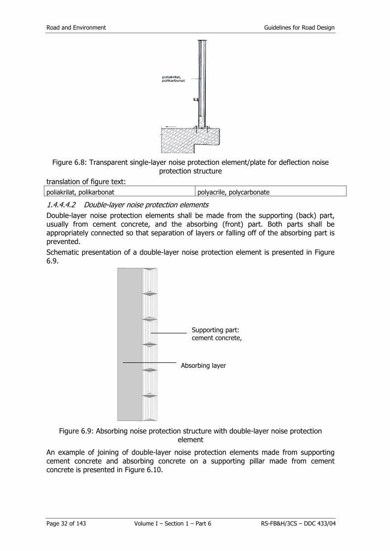
Road and Environment Guidelines for Road Design
Page 32 of 143 Volume I – Section 1 – Part 6 RS-FB&H/3CS – DDC 433/04
Figure 6.8: Transparent single-layer noise protection element/plate for deflection noise
protection structure translation of figure text: poliakrilat, polikarbonat polyacrile, polycarbonate
1.4.4.4.2 Double-layer noise protection elements Double-layer noise protection elements shall be made from the supporting (back) part, usually from cement concrete, and the absorbing (front) part. Both parts shall be appropriately connected so that separation of layers or falling off of the absorbing part is prevented. Schematic presentation of a double-layer noise protection element is presented in Figure 6.9.
Figure 6.9: Absorbing noise protection structure with double-layer noise protection element
An example of joining of double-layer noise protection elements made from supporting cement concrete and absorbing concrete on a supporting pillar made from cement concrete is presented in Figure 6.10.
Supporting part: cement concrete,
Absorbing layer
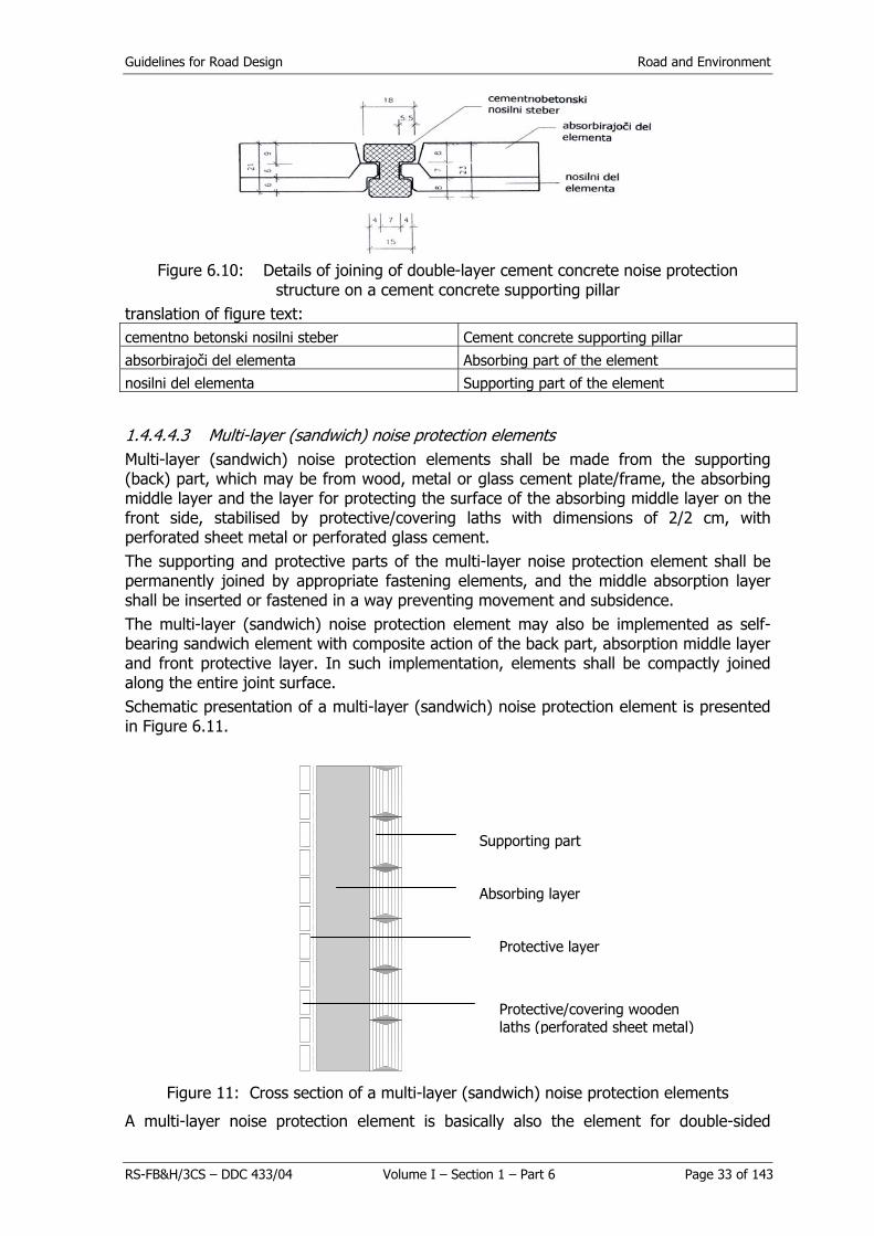
Guidelines for Road Design Road and Environment
RS-FB&H/3CS – DDC 433/04 Volume I – Section 1 – Part 6 Page 33 of 143
Figure 6.10: Details of joining of double-layer cement concrete noise protection
structure on a cement concrete supporting pillar translation of figure text: cementno betonski nosilni steber Cement concrete supporting pillar
absorbirajoči del elementa Absorbing part of the element nosilni del elementa Supporting part of the element
1.4.4.4.3 Multi-layer (sandwich) noise protection elements Multi-layer (sandwich) noise protection elements shall be made from the supporting (back) part, which may be from wood, metal or glass cement plate/frame, the absorbing middle layer and the layer for protecting the surface of the absorbing middle layer on the front side, stabilised by protective/covering laths with dimensions of 2/2 cm, with perforated sheet metal or perforated glass cement. The supporting and protective parts of the multi-layer noise protection element shall be permanently joined by appropriate fastening elements, and the middle absorption layer shall be inserted or fastened in a way preventing movement and subsidence. The multi-layer (sandwich) noise protection element may also be implemented as self-bearing sandwich element with composite action of the back part, absorption middle layer and front protective layer. In such implementation, elements shall be compactly joined along the entire joint surface. Schematic presentation of a multi-layer (sandwich) noise protection element is presented in Figure 6.11.
Figure 11: Cross section of a multi-layer (sandwich) noise protection elements
A multi-layer noise protection element is basically also the element for double-sided
Absorbing layer
Supporting part
Protective layer
Protective/covering wooden laths (perforated sheet metal)

Road and Environment Guidelines for Road Design
Page 34 of 143 Volume I – Section 1 – Part 6 RS-FB&H/3CS – DDC 433/04
protection against noise. Along the supporting part of such element, absorption layers shall be installed on both sides and protective layers and covering layers from perforated sheet metal. glass cement or wooden laths on outer sides. The supporting part – cement concrete plate in a multi-layer (sandwich) element shall be at least 6 cm thick. The supporting part – wooden plate shall be made from small beams with minimum dimensions equalling 8/12 cm. Rust-resistant connecting material or wooden joints shall be used for connecting of the small beams. The supporting part – steel sheet metal shall be connected in the multi-layer noise protection element by a rust-resistant connecting material. The supporting part – glass cement plate shall be manufactured so that independent thermal action of the back (supporting) part and the front part is enabled. Rust-resistant connecting material shall be used for connecting layers in a multi-layer element. The front part of a multi-layer (sandwich) noise protection element shall be acoustically adequate, stable and safe. Wooden laths may be fastened to the wooden frame in any direction in accordance with requirements specified by the designer, they may be coloured or in the colour of wood, and fastened by a rust-resistant material or wooden joints. Sheet metal or glass cement plate in the front part of a multi-layer noise protection element shall be perforated or designed in accordance with the requirements of the competent designer so that it enables good absorption and simultaneous mechanical protection of the protective and absorption layers. Surface of the front layer of a multi-layer noise protection element shall prevent deflection of light, which would exceed values prescribed by the project and the colour shall comply with requirements specified by the designer. Various combinations of perforations shall be permitted on the front side of the noise protection element.
1.4.4.4.4 Embankments from soil or other materials Embankments from soil for protection against noise (noise protection embankments) shall be noise protection structures, which may by appropriate grassing or planting be blended with the environment to the maximum possible extent and their implementation is the simplest. Noise protection embankments can be made from
- Soils; and - Stabilised (strengthened/supported) soils.
Noise protection embankments can be built - On the upper edge of a cut (deepening of the noise source – Figure 6.12); or - By expanding otherwise envisaged embankment for the body of the road and
adequate elevation and – if need be – by adding additional noise protection structure on the top of the noise protection embankment (Figure 6.13).
Figure 6.12: Extension of a cut (deepening of the noise source) with a noise protection embankment on the upper edge

Guidelines for Road Design Road and Environment
RS-FB&H/3CS – DDC 433/04 Volume I – Section 1 – Part 6 Page 35 of 143
translation of figure text: 1:1,5 ali več 1:1.5 or more
Figure 6.13: Extension of the embankment for the body of the road and adequate elevation with an additional noise protection structure at the top of the noise protection embankment translation of figure text: 1:1,5 ali več 1:1.5 or more
Embankments from stabilised (strengthened) soils shall foremost be suitable in cases when the area for placement is limited (Figure 6.14).
Figure 6.14: Noise protection embankments from stabilised soil require less space for placement translation of figure text: širina temelja š Foundation width
Various forms of products from cement concrete (Figure 6.15) and a combination of geotextile and meshes are foremost suitable for stabilisation. They enable optional design and greening (overgrown wall) of the noise protection embankment.
Figure 6.15: Noise protection embankment from soil, on both sides stabilised/boarded with elements/products made from cement concrete

Road and Environment Guidelines for Road Design
Page 36 of 143 Volume I – Section 1 – Part 6 RS-FB&H/3CS – DDC 433/04
1.4.4.4.5 Supporting pillars Supporting pillars/vertical support in noise protection structures can be made from structural steel, strengthened cement concrete or other suitable material. They shall provide for the possibility of fastening of the required rubber sealants (Figure 6.7). Supporting pillars/supports in noise protection structures shall comply with loads envisaged in the static calculation, and the design shall be in line with requirements of the designer of the noise protection structure.
1.4.4.4.6 Foundations All envisaged foundations shall when implemented comply with dimensions adjusted to loads envisaged in the static calculation, and the design of visual parts shall be in line with requirements of the designer of the noise protection structure. Dimensions of the basic cement concrete element built between two adjacent foundations/supporting pillars shall be aligned with the noise protection structure.
1.4.4.4.7 Doors and protection In emergency exits on noise protection structures doors shall be installed (without a lock) so that the longest path to them shall be 150 m1 Doors shall close by themselves. The structure of doors on emergency exits shall provide for similar noise protection as the noise protection structure. Doors on emergency exits shall enable safe passage in all weather conditions. As regards noise protection structures on bridging structures, no doors for emergency exit shall generally be envisaged. Noise protection structures shall be protected on top by appropriate closing elements (e.g. from wood, metal or cement concrete).
1.4.4.5 Requirements for elements of noise protection structures Technical requirements for elements of noise protection structures (supporting, for noise protection, fastening means) are specified in detail in standards, namely:
- As regards mechanical properties and stability, EN 1794-1; and - As regards general safety and protection of the environment, EN 1794-2.
In case of special requirements, the Client and the designer may prescribe additional technical requirements for noise protection elements in accordance with the applicable standards, technical regulations and guidelines (e.g. for installation in tunnels). In cases where loads calculated as a part of checking are not reliable, tests of reliability of noise protection elements shall be performed in the given conditions.
1.4.4.5.1 Mechanical properties and stability Mechanical properties of noise protection elements shall be defined by the elastic area, loading characteristics and safety factors of loading as well as additional requirements in accordance with EN 1794-1. Requirements regarding the mechanical properties of elements of noise protection structures shall be specified for the temperature range between -30 °C and +70 °C. Spatial changes of elements of noise protection structures shall be verified by calculations for checking whether they are within permitted limits. Permitted deformations of elements of noise protection structures resulting from actions of aerodynamic loads and own weights are specified in Table 6.12.

Guidelines for Road Design Road and Environment
RS-FB&H/3CS – DDC 433/04 Volume I – Section 1 – Part 6 Page 37 of 143
Table 6.12: Limit values of deformations of elements of noise protection structures
Type of the element Maximum permitted Maximum permanent deformation of noise protection structures elastic bending after the load has ceased
dmax (mm) dmax (mm)
– Supporting: – Vertical Ls/150 Ls/500 – Inclined Ls/300 Ls/500
– For noise protection: – Vertical < 50 1) LA/500, h/500 – Inclined < 50 1) LA/200, h/200
Legend: Ls – Maximum length of the Structural element (mm) LA – Maximum length of the noise protection element (mm) h – Entire height of the noise protection element (mm) 1) – By length LA and height h
By taking into account the safety factor S = 1.5, the element of the noise protection structure shall in dynamic load
- Not be damaged: bulge, crack, the layer in the element shall not move; and - Not move (fall out): on supports and/or points of fastening.
The specified requirements apply mutatis mutandis also to the quality of fastening means, Structural elements and noise protection elements. As regards loading of the noise protection element with the appropriate own weight and the weight of elements lying thereon, the longitudinal bending shall not exceed h/50 and the vertical bending shall not exceed LA/400. In addition to the above, the element shall also not damage. As regards testing of the noise protection element against impact of rocks, damage shall be limited only to the external surface, cracks shall not be longer than 50 mm and the depth of hollows shall not exceed the thickness of the outer layer or 20 mm. Conditions regarding properties of the noise protection structure for loading in case of impact of a vehicle are specified mutatis mutandis in EN 1317-2. The dynamic load related to clearing of snow shall not cause damage on the protection of elements of the noise protection structure or on the elements themselves (bulging, permanent deformation, movement/falling out from the seat/breaking down).
1.4.4.5.2 General safety and protection of the environment The noise protection structure shall be made from materials, which during production and/or use do not produce any harmful substances and have no adverse effects on general safety of traffic participants as well as on the environment. The basic requirements regarding implementation of noise protection structures, which will provide the required conditions for safety of traffic participants and protection of the environment are specified in item 2.1.6.3.1.3.3.3. Detailed requirements shall be specified in the plan for the noise protection structure based on the static calculation evaluated with regard to loads envisaged in the given conditions and performed preliminary tests, as specified in EN 1794-2.
1.4.5 Providing quality Providing quality of the noise protection structure is subject to the following
- Internal control of the manufacturer/contractor; and - External control of the Client.

Road and Environment Guidelines for Road Design
Page 38 of 143 Volume I – Section 1 – Part 6 RS-FB&H/3CS – DDC 433/04
1.4.5.1 Internal control Internal control of all elements of the noise protection structure shall be provided by the manufacturer/contractor at their own cost. Tests of elements of the noise protection structure as regards the internal control of the manufacturer/contractor are required for establishing of properties of basic materials and elements. Types and scope of tests of properties of basic materials, Structural elements of the structure and noise protection elements, and the noise protection structure as a part of the internal control of the manufacturer/contractor are specified in Tables 6.13 through 6.15.

Guidelines for Road Design Noise Protection
RS-FBiH&3CS – DDC 433/04 Volume I – Section 1 – Part 6 Page 39 of 143
Table 6.13: Types and scope of tests of properties of basic materials for noise protection structures
Type of material
Properties of the material
Unit of measurement Cement Glass Light Artificial Protective Other
concrete Metals cement materials materials materials materials – Compressive strength N/mm2 + - + + - - + – Tensile strength N/mm2 - + - - + + + – Flexural strength N/mm2 - - + - + - + – Elastic modulus N/mm2 + - + + + + + – Expansion in case of destruction % - + - - + - + – Temperature stretch ratio °C-1 + - + + + - + – Flowing pressure N/mm2 - + - - + - + – Chemical analysis - - - - - + - - – Durability OMO Cycle + - - - - - - – Durability OSMO Cycle + - + + - + + – Resistance against fire - - - - + + + + – Alkaline resistance of fibres - - - + - - - - – UV resistance - - - - + + + - – Thickness mm + + + + + + + – Mass/density kg/m3 + - + + + + + – Proportion of humidity m.-% - - + + - - + – Proportion of fibres m.-% - - + - - - - – Transparency % - - - - + - -
Scope of testing 1) - 500 m2 2) 500 m2 2) 2) 2) 2)
1) Identical scope of tests shall be made as regards the internal and external control of production except for cement concrete and glass cement where the
required external control of production is for each 4000 m2. 2) Statement on compliance of material and 1 x for the facility.
The required properties and tests of wood are in dependence on the envisaged loads specified by classes G 4.1 through G 4.3. With regard to the used material, tests for soils are mutatis mutandis specified in special technical conditions for earthwork.
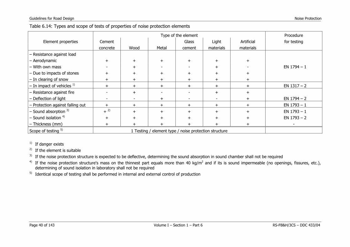
Guidelines for Road Design Noise Protection
Page 40 of 143 Volume I – Section 1 – Part 6 RS-FB&H/3CS – DDC 433/04
Table 6.14: Types and scope of tests of properties of noise protection elements
Type of the element Procedure Element properties Cement Glass Light Artificial for testing
concrete Wood Metal cement materials materials – Resistance against load – Aerodynamic + + + + + + – With own mass - + - - + - EN 1794 – 1 – Due to impacts of stones + + + + + + – In clearing of snow + + + + + + – In impact of vehicles 1) + + + + + + EN 1317 – 2
– Resistance against fire - + - - + + – Deflection of light - - + - - + EN 1794 – 2 – Protection against falling out + + + + + + EN 1793 – 1
– Sound absorption 3) + 2) + + + + + EN 1793 – 1 – Sound isolation 4) + + + + + + EN 1793 – 2 – Thickness (mm) + + + + + + -
Scope of testing 5) 1 Testing / element type / noise protection structure
1) If danger exists 2) If the element is suitable 3) If the noise protection structure is expected to be deflective, determining the sound absorption in sound chamber shall not be required 4) If the noise protection structure's mass on the thinnest part equals more than 40 kg/m2 and if its is sound impermeable (no openings, fissures, etc.),
determining of sound isolation in laboratory shall not be required 5) Identical scope of testing shall be performed in internal and external control of production

Guidelines for Road Design Road and Environment
RS-FB&H/3CS – DDC 433/04 Volume I – Section 1 – Part 6 Page 41 of 143
Table 6.15: Types of testing of properties of noise protection structures
Structure properties Type of testing – Static stability Calculative proof or laboratory tests – Stability against the wind – Bearing capacity Calculative proof for noise protection structure and noise
protection element if the noise protection structure is higher than 5 m
Scope of testing 1) 1 x for each type of noise protection structures 1) Testing shall be performed as a rule within the external control of work implementation.
Proof regarding the appropriate quality of tested basic materials and elements shall be – including upon any change thereof – submitted to the Client by the manufacturer/contractor. Internal control of the manufacturer/contractor shall include the following
- Internal tests; and - Control of production at the plant and upon installation.
The scope of internal controls/testing for checking properties of basic materials, compounds and/or mixtures and elements of noise protection structures shall be specified in the contract concluded between the contractor and the Client. The manufacturer/contractor shall ensure that tests were performed by using the appropriate/established procedures and in sufficient number. Any deviations from requirements shall be eliminated. Internal control of production and installation shall include
- Checking of production procedures in all stages from basic materials to the final product, i.e. element of the noise protection structure, for compliance with the quality requirements;
- Establish evenness and traceability of production; - Check for every 100 supplied elements:
- Dimensions, especially thickness of the wall; - Mass of the element or absorption filling; - Fastening means and other elements (spacers, holders, treenails, sealants,
etc.); - Visual quality of colour, protection of elements against corrosion, etc.; - Seats, installation and fastening of installed elements of the noise protection
structure; - Check for every 1000 supplied elements also:
- Bending under weight of the wind; and - Grip of the coating on the inner and outer side of the element of the noise
protection structure. Upon request of the Client, the manufacturer shall also submit the appropriate proof regarding sound absorption and isolation (on the basis of checking in the sound chamber or laboratory).
1.4.5.1.1 External control of the Client External control performed for the Client by an authorised institution, shall use tests for checking whether properties of basic materials, compounds and/or mixtures and elements of the noise protection structure are complying with contractual provisions.

Road and Environment Guidelines for Road Design
Page 42 of 143 Volume I – Section 1 – Part 6 RS-FB&H/3CS – DDC 433/04
During testing performed as a part of external control of the Client by a certified and authorised institution, a representative of the manufacturer/contractor shall be present. The results of external control of the Client shall form the basis for acceptance and invoicing.
1.4.5.2 Supervision The supervision regarding implementation of noise protection structures shall provide for technically accurate, economical and quality work as specified in the plan.
1.4.5.2.1 Introduction of the contractor into work As regards the introduction of the contractor into work, the supervision shall foremost do the following:
- Review contractual provisions regarding introduction into work; - Prepare the documents required for introduction into work; and - Carry out any required preliminary work (setting out the borders of purchase, the
facility, utility and power lines). - The supervision shall verify whether the performance programe for construction of
the noise protection structure is in all elements brought in line with the instructions for constructing noise protection structures.
1.4.5.2.2 Supervision of compliance with technical regulations The project for construction of the noise protection structure shall specify compliance with the appropriate technical regulations which shall be supervised during performing of work. This shall foremost include
- Checking compliance of construction of noise protection structures with the legislation related to construction of facilities, spatial planning and urban and other spatial development;
- Checking compliance of construction with the building permit; - Checking compliance with conditions specified in approvals; and
The supervision of construction of noise protection structures shall also include participation in the preparation of the project of executed works (PEW) The supervision shall forward any recorded deviations of executed works from the project to the entity preparing the PEW.
1.4.5.2.3 Supervising compliance of construction As regards the supervision of compliance of construction of the noise protection structure with the project documentation (PT, CPP, WEP) the supervision shall
- Co-ordinate with the designer any deviations from the project documentation; - Propose improvements, co-ordinate them with the designer and submit them to
the Client for approval; - Establish and record any decreased or increased volume of performed work,
assess the need for additional work and inform the Client thereof.
1.4.5.2.4 Acceptance of construction products The supervision shall upon acceptance of construction products
- Check the validity of available proofs on compliance of the product or semi-finished product supplied to the construction site;
- Check whether the performed internal and external control of the preliminary work stage was in line with the technical study; and
- Check whether the performed internal and external control of the supplied product was in line with the technical study.

Guidelines for Road Design Road and Environment
RS-FB&H/3CS – DDC 433/04 Volume I – Section 1 – Part 6 Page 43 of 143
1.4.5.2.5 Testing period for new noise protection structures For every newly developed or offered noise protection structure, its technical and economic adequacy shall be timely checked in advance. Detailed conditions regarding the checking are similar to conditions for designing and construction of noise protection structures specified herein. The testing period shall be at least 2 years unless the Client's approval for checking the appropriateness of the structure specifies otherwise. The noise protection structure shall be during the testing period subjected to usual effects of the environment. After conclusion of the testing period, the appropriateness of the noise protection structure as regards its intended use shall be assessed. The assessment committee shall include representatives of the Client, manufacturer, engineer and the institution.
1.5 MAINTENANCE OF NOISE PROTECTION STRUCTURES
1.5.1 General Noise protection structures are permanently exposed to effects of the environment (precipitations, changing temperatures, the sun,. wind) and to a lesser extent directly or indirectly also to impacts of traffic (clearing of snow, impacts of grains from spread gravel, salting, dynamic pressure of passing-by vehicles). The tension caused by the abovementioned impacts on the material and elements of noise protection structures affects their durability and functionality. These two properties to a large extent depend on the care for preservation i.e. adequate and timely maintenance measures. This can be to the greatest possible extent provided by regular inspections and monitoring of the condition of the noise protection structure. All the abovementioned characteristics shall be specified in detail in instructions on maintenance of noise protection structures, which shall be prepared during planning of the noise protection structure (CPP/WEP) as a constituent part of the project of executed works (PEW) prepared by the contractor.
1.5.2 Maintenance instructions In the meaning of instructions specified in guidelines for the contents of the investment-technical documentation, the instructions for maintenance of noise protection structures shall include the following
- Basic data on the noise protection structure; - Provisions regarding control and monitoring of the condition; and - Maintenance instructions for noise protection structures.
1.5.2.1 Basic data on the noise protection structure Basic data on the noise protection structure in the maintenance rules shall include the following
- Basic data on the Client, designer, contractor (including any subcontractors and manufacturers of materials and/or elements of the noise protection structure) and supervision;
- General description and technical properties of the noise protection structure (foundations, structural elements, noise protection elements);
- Planned (calculative) loads; - Characteristics of used materials and/or elements of the noise protection structure;
and - Characteristics of implementation; and - Any special features of the built noise protection structure.

Road and Environment Guidelines for Road Design
Page 44 of 143 Volume I – Section 1 – Part 6 RS-FB&H/3CS – DDC 433/04
The basic data shall also include appropriate graphic presentations of details of the built noise protection structure (situation, ground plan, cross sections, details regarding special features, e.g. emergency exits).
1.5.2.2 Provisions regarding control of condition of noise protection structures Comprehensive control of the condition of the noise protection structure shall provide for its optimal durability, economic benefits and usability, inducing the safety of users and adjacent inhabitants. Maintenance instructions for noise protection structures shall provide details regarding
- Control of the condition of noise protection structures, including the appropriate reports; and
- Measures for maintenance and any repairs of characteristic damage. Control of the condition of noise protection structures shall be generally divided with regard to time and functionality, namely
- Technical examination upon submitting of the noise protection structure in use; - Regular controls to be carried out from time to time in line with the schedule,
specified in the maintenance programme; - Seasonal checkups, as a rule performed in the autumn and after the end of winter; - Main checkups performed at least every five years and before the expiry of the
warranty period; and - Extraordinary controls upon or immediately after any extraordinary events.
All controls specified above shall be provided for by the road management entity or the entity maintaining the noise protection structure. The contractor as the entity providing the warranty shall be present in any extraordinary controls and the checkups prior to expiry of the warranty period.
1.5.2.3 Maintenance instructions for noise protection structures
1.5.2.3.1 Regular maintenance Regular maintenance of noise protection structures is basically determined by results of controls specified in item 1.5.2.2. It shall include foremost small repairs not intervening in the noise protection structure and as regards certain noise protection elements (e.g. transparent) upon call of the road inspector cleaning of the noise protection elements' surface (as a rule in the autumn and spring), which must be simple to carry out. In addition to the measures specified above, regular maintenance also includes providing of undisturbed drainage from the area of the noise protection structure. Smaller repairs of the noise protection structure, which must be simple to carry out, shall particularly include supplements, replacements and repairs of individual worn out, damaged, incomplete or missing parts or elements of the noise protection structure. On critical points (e.g. on edge wreaths of bridging structures and supporting structures) the procedure required for replacement of elements of the noise protection structure must also be fast to carry out. Due to the danger of damage to the noise protection structures in clearing of snow (excess speed of the vehicle with regard to characteristics of snow, distance of the noise protection structure from the edge of the roadway and with regard to the type of plough for clearing of snow), wet snow in particular should be cleared with the plough first only outside the traffic lane and subsequently removed by transport, while dry snow should be if necessary cleared with the appropriate machine for clearing (blower, milling cutter). In case the noise protection structure is built from cement concrete, remainders of salt shall be washed from the (deflective)( surface after the end of winter.

Guidelines for Road Design Road and Environment
RS-FB&H/3CS – DDC 433/04 Volume I – Section 1 – Part 6 Page 45 of 143
All measures implemented as a part of regular maintenance of the noise protection structure shall be just as findings of the control of the condition entered in the maintenance log.
1.5.2.3.2 Extraordinary maintenance Any extraordinary (larger-scale) maintenance and any special work shall also be basically determined by results of controls i.e. any large incompliances or changes in the noise protection structure established in such controls, which foremost relate to its durability and traffic safety. Extraordinary maintenance regarding noise protection structures shall foremost include
- Renewing protection of steel parts against corrosion; - Renewing conditioned colour coatings; - Renewing worn out elements of noise protection structures and fastening means;
and - Repair/replacement of damaged elements of noise protection structures in case of
any impacts of vehicles or any other excessive loads in accordance with item 1.4.3.2


Guidelines for Road Design Road and Environment
RS-FB&H/3CS – DDC 433/04 Volume I – Section 1 – Part 6 Page 47 of 143
GUIDELINES FOR ROAD DESIGN, CONSTRUCTION, MAINTENANCE AND
SUPERVISION
VOLUME I: DESIGNING
SECTION 1: ROAD DESIGNING
Part 6: ROAD AND ENVIRONMENT
GUIDELINE 2: WATER AND SOIL PROTECTION


Guidelines for Road Design Road and Environment
RS-FB&H/3CS – DDC 433/04 Volume I – Section 1 – Part 6 Page 49 of 143
2. WATER AND SOIL PROTECTION
2.1 SUBJECT OF GUIDELINE The preservation of water sources conditions suitable protection of connected surface and underground waters, so that primarily the quality of drinking water would not deteriorate. Water sources are endangered my many polluters. Among them is also traffic on roads routes across the aquifer areas. This specific endangerment of water sources is represented by
- constant pollution on a daily basis and - extraordinary pollution, which is usually the result of a traffic accident.
For this reason underground waters have to be suitably protected by active construction-technical measures. The guidelines state suitable protective measures for restricting and preventing direct impacts of traffic on the quality of underground water sources, which are based on
- the form of pollution, - hydrological bases, - estimate of the sensitivity of the area and - drainage method.
The defined sealing methods in the area of aquifers enable suitable protection of underground water according to the area sensitivity.
2.2 DEFINITION OF TERMS Cleaning of rainwater is collecting, retaining and sedimentation of rainwater from the road surface in reservoirs and biological cleaning (filters, reeds lagoons, local depressions). Exposure of a water source is a parameter determined by hydrogeological properties (notably permeability and porosity) on which transport of potential pollutant from the aquifer in the road area to the water source depends. Top layer of aquifer is the layer of slope or soil laying on the aquifer and represents its top edge. Sensitivity of a water source is the level of human-induced impacts on the quality and regime of a water source and is the result of vulnerability and exposure of a water source. Drainage is the gravity-based draining of rainwater from the roadway by means of open ditches, pipe systems and/or drains. Endangerment of a water source is the risk or potential risk of pollution. Contamination is a one-off extraordinary event. Pollutant is an inorganic or organic substance or remainder of a substance resulting from road traffic, which pollutes the environment. Pollution is an event repeating itself. Permeability is the capacity of soil or slope to conduct liquids. Catchments area of a water source is the area participating in the water balance of the underlying source. Porosity is the ratio between volume of cavities and the entire volume of soil or slope. Vulnerability of a water source is a parameter determined by hydrogeological properties (notably permeability and porosity) on which transport of potential pollutant from the road through rock and/or soil to the underground water in the aquifer depends. Sealing construction is the construction for preventing passing of polluted water from the surface into underground water.

Road and Environment Guidelines for Road Design
Page 50 of 143 Volume I – Section 1 – Part 6 RS-FB&H/3CS – DDC 433/04
Protection area of water sources delimits the areas with the strictest, strict and moderate protection regimes. Water sources are all surface and underground waters. Aquifer is soil or slope, in which due to its porosity water is retained or flowing in quantities suitable for economic utilisation. Aquifer system is the system of various aquifers participating in the water balance of the underlying water source. Protective measures are individual restrictions or technical procedures and solutions intended for protection of a water source.
2.3 FORMS OF POLLUTION Road traffic pollutes an aquifer in two ways: constantly and extraordinarily. Constant pollution conditioned by road traffic comprises
- exhaust gas emissions, - parts of tires and breaks and - conditioned road maintenance procedures (salting of roads).
The scope of pollution depends on - traffic density and - characteristics of the roadway.
Part of permanent pollution spreading over the air cannot be fully controlled. Occasional pollution due to roadway being washed off by rain can be controlled by adequate protective measures, so that run-off water is led to suitable containment facilities. Extraordinary pollution - as a result of an extraordinary event - can have catastrophic consequences for the environment. For this reason preventive protection, which is presented in detail in the guidelines, is important.
2.4 HYDROGEOLOGICAL BASES
2.4.1 Hydrogeological research Hydrogeological research for designing underground water protection against road traffic impact has to be as a rule a constituent part of geotechnical research. Underground water protection is based on the estimate of aquifer sensitivity, which is defined in terms of its vulnerability and exposure. The latter two depend on maximum possible flow of pollutant through a porous centre, specified by Darcy's equation.
imkvef
⋅=
where: v - pollutant flow velocity, ideally mixed with water [m/s] k - permeability ratio of porous centre saturated with water [m/s] mef
- effective porosity of the centre [%]
i - flow gradient [%]
2.4.2 Hydrogeological characteristics In order to estimate hydrogeological characteristics of soil and rock, experiential values stated in tables 6.16 and 6.17 may be adopted.

Guidelines for Road Design Road and Environment
RS-FB&H/3CS – DDC 433/04 Volume I – Section 1 – Part 6 Page 51 of 143
Table 6.16: Experiential values of permeability ratios for soil and rock
Type of soil / rock
Permeability ratio k [m/s]
Permeability estimate
Estimate of the aquifer
- pure gravel / very cracked rock k ≥ 5 x 10⁻³ very good good - pure sand, mixture of sand and
gravel / well cracked and disintegrated rock
5 x 10⁻³ > k > 10-5 good good
- small sand, mixture of sand and clay / rocks with crack porosity
10-5 > k > 10-7 medium poor
- clay sand, very fine sand and clay / rocks with crack porosity
10-7 > k > 10-9 poor poor
- clay / massive rock k ≤ 10-9 very poor / impermeable impermeable
Table 6.17: Experiential values of effective porosity mef for soil and rock
Type of soil / Effective porosity mef [%] rock average maximum minimum
- gravel: coarse 22 26 12 medium 23 26 13 fine, with sand 25 35 21
- alluvial deposits 15 35 5 - sand: coarse 27 35 20
medium 26 32 15 fine 21 28 10
- sandy clay 7 12 3 - deposits of very fine sand 10 20 2 - massive sedimentary rock < 0.5 1 0
For an approximate estimate of vulnerability, the critical permeability depth may be 5 m and in accordance with tables 9.16 and 9.17 the vulnerability rate can be presented for aquifer under soil / rock with various permeability ratios and using experiential average effective porosity values (figure 6.16).
Figure 6.16: Permeability ratios of aquifer under soil / rock with a specific permeability
ratio and vertical passage velocity Translation of figure text: Hitrost vertikalnega precejanja (m/dan) Vertical passage velocity (m/day)

Road and Environment Guidelines for Road Design
Page 52 of 143 Volume I – Section 1 – Part 6 RS-FB&H/3CS – DDC 433/04
Stopnja ranljivosti Vulnerability level Glina Clay prodno peščeni zasip gravel sandy filling meljna do peščena glina very fine to sandy clay apnenci, dolomiti limestone, dolomite peščeno meljni nanos very fine sandy deposit prst soil
Exposure of the source of underground water is based on the estimate of the pollutant's travel time from the site of pollution to collection site. Since the values of underground water flow gradients are in the event of horizontal passage in usual aquifer layers considerably smaller (some ‰ to some %) than in the case of vertical passage (i = 1), the velocities of underground water flow in the saturated zone horizontally are much smaller than presented in figure 6.16. These have to be multiplied by a suitable gradient. On the basis of the above stated experiential values it is possible already in the route variant study phase to approximately estimate the sensitivity of the area which will be crossed by a road route as well as project the necessary measures for optimal implementation of underground water protective measures.
2.5 ESTIMATE OF AREA SENSITIVITY The pollutants spread into aquifers from roads and pertaining facilities through soil and rock. Their impact then depends on hydrogeological characteristics of soil and rock below the underground water, which are defined
- by aquifer vulnerability parameter, - and on the characteristics of the aquifer, which are defined - by the water source exposure parameter.
The vulnerability and exposure parameters together define the sensitivity of a water source.
2.5.1 Vulnerability of an aquifer The aquifer vulnerability criterion is the time needed by the pollutant to penetrate to the depth maximally reached by the paddles of construction machinery needed for rehabilitation. The aquifer vulnerability levels are stated in table 6.18 under the assumption that the rehabilitation of polluted top layer of the aquifer is planned to be carried out by excavation and removal.
Table 6.18: Aquifer vulnerability levels
Vulnerability level Vulnerability of an aquifer
Pollutant passage time
I extremely high < 1 day II high 1 to 5 days III medium 6 to 10 days IV small 11 to 50 days V very small > 50 days
2.5.2 Exposure of a water source Exposure of a water source is defined by hydrogeological characteristics (especially permeability and porosity) of its supply hinterland. It can be defined based on projected consequences of pollution and the time needed for the pollutant to travel over the aquifer in the road route area to the water source. The exposure levels of water sources are specified in detail in table 6.19.

Guidelines for Road Design Road and Environment
RS-FB&H/3CS – DDC 433/04 Volume I – Section 1 – Part 6 Page 53 of 143
2.5.3 Sensitivity of an aquifer The sensitivity of an aquifer, which is defined by its vulnerability and exposure level, is relevant for determining protection. The measures within the scope of road construction have to protect mainly the aquifer area marked with 1, 2 and 3, which are more exposed and vulnerable (table 6.20).
Table 6.19: Exposure levels of a water source
Exposure level Exposure of a water source Importance / type of water source
Passage time / pollution transfer
A extremely high - contained water source: pollution is permanent and/or fatal
< 5 days
B high - contained water source: possible spillage is not fatal
- protected supply hinterland of water sources
- potential water sources
5 to 60 days
C medium - other water sources - unprotected supply hinterland of water
sources - supply hinterland of potential water
sources
> 60 days
D small - other water sources 1 to 10 years
E non-existent > 10 years
Table 6.20: Classification of aquifer sensitivity according to vulnerability and exposure
Exposure Vulnerability I II III IV V
A 1* 1 2/III 4 4
B 1 2/II 3 4 5
C 2/I 3 4* 5 5
D 4 4 5 5 5 E 4 5 5 5 5
Key: 1* - the road should not be routed in this area 1 – very sensitive area 2 – sensitive area 3 – moderately sensitive area 4 – little sensitive area 5 – insensitive area
2.5.4 Bases for aquifer protection Adequate measures have to be defined in order to determine suitable aquifer protection against constant and extraordinary pollution. Classification of bases for constant pollution "C" and extraordinary pollution "E" is stated in table 6.21.

Road and Environment Guidelines for Road Design
Page 54 of 143 Volume I – Section 1 – Part 6 RS-FB&H/3CS – DDC 433/04
Table 6.21: Classification of bases for aquifer protection
Code Pollution method Aquifer protective measures Constant pollution:
C1 - impermissible - protection is not possible as the pollution spreads by air
C2 - needs to be restricted to maximum degree possible
- all polluted rainwater has to be drained from the protected area
C3 - decrease - level 1 - high cleaning and containment level C4 - decrease - level 2 - medium cleaning and containment level C5 - decrease - level 3 - low cleaning and containment level,
controlled sinking underground at point and dispersed
Extraordinary pollution: E1 - eliminate all possibilities of spillage - complete water tightness of the
roadway, cutting slopes and embankment, protection against vehicle running off the protected area or protection damage
E2 - possibility of spillage has to be reduced as much as possible
- watertight road body, prevention of vehicle running off the road by usual measures
E3 - spillage is possible - controlled drainage of possible spillage, piping
E4 - spillage does not have fatal consequences
- rehabilitation only based on previously set procedures and instructions applying to measures in the event of an accident
Informative bases for protecting individual sensitivity levels or areas are stated in table 6.22.
Table 6.22: Classification of area sensitivity
Sensitivity level Sensitivity estimate Constant pollution Extraordinary
pollution
1* extreme C1 E1 1 very high C2 E1
2/I high C2 E2 2/II C3 E2 2/III C3 E3
3 moderate C4 E4
2.6 ROAD DRAINAGE METHODS Proper and timely roadway drainage is important for safe traffic, while proper road drainage is important also for the protection of underground waters. Drainage system can be designed if the following is known
- quantity (intensity) of precipitation, - frequency of precipitation and - coarseness of catchments surface.

Guidelines for Road Design Road and Environment
RS-FB&H/3CS – DDC 433/04 Volume I – Section 1 – Part 6 Page 55 of 143
2.6.1 Surface drainage Gravity-based surface drainage of rainwater is provided by ditches, pointed channels and gutters. These devices are specified in item 2.1.9.5 of these technical conditions. Ditches can drain clean and polluted rainwater, which should be - if possible - separated. Polluted water is to be considered all water running off the roadway. Waste water and effluent from elsewhere (gas stations, motels, etc.) must not be connected to the road drainage system. The exception is water from parking surfaces next to roads.
2.6.2 Deep drainage Pipe systems and passages are designed for deep (subsurface) gravity-based drainage of surface water, effluent and sewage. The conditions for pipe systems (type and cross section of the pipe, cross fall) have to be specified in detail in the project documentation and in accordance with the circumstances in which they are planned to be used. As a rule, the pipe system has to be designed so that the expected water will drain based on gravity. If possible, the pipe system should separately drain clean and polluted rainwater. Deep drainage of clean water and improvement of hydrological conditions in the ground is provided by drainage, the basic conditions of which have to be defined in project documentation.
2.6.3 Trap and containment reservoirs In the area with sensitive and moderately sensitive water source the drainage of polluted water from ditches and pipe system has to be led to a trap or containment reservoir. In the area with very sensitive water sources reservoirs are not allowed to be constructed. Trap and containment reservoirs are intended for mechanical cleaning, sedimentation and retaining of rainwater run-off only from roadways. As spilled liquids arising from traffic and various other spilled liquids and substances of polluted rainwater are led from the road to trap and containment reservoirs, this water is partly and temporarily contained, as a result of which the too fast outflow to the discharge duct decreases, spilled oil is contained and filth sinks. While cement concrete trap and containment reservoirs are designed only for trapping falling substances and sinking filth, the soil trap and containment reservoirs are intended also for water containment. Cement concrete trap and containment reservoirs are needed especially in the following cases:
- before inlet of pipe system water to stronger discharge ducts with: QSNV ≥ 10 Qkrit
where: QSNV – quantity of medium level water flow Qkrit – 10 times the drainage from the road resulting from 15-minute precipitation of one-year return period in the catchments area, reduced by drainage ratio
- in the areas of sensitive and modern sensitive water sources; in such cases an
additional containment chamber has to be provided after trap and containment reservoir for precipitation in excess of qkrit = 15 l/s/ha, so that the water does not run off to the discharge duct too quickly
- if there is not enough room for a larger soil trap and containment reservoir. Soil trap and containment reservoirs are necessary:

Road and Environment Guidelines for Road Design
Page 56 of 143 Volume I – Section 1 – Part 6 RS-FB&H/3CS – DDC 433/04
- before the pipe system drainage into the discharge duct with
QSNV < 10 Qkrit
- before the pipe system drainage into standing waters (lakes, ponds, accumulations, etc.)
- in the areas of sensitive and modern sensitive water sources; in the case of a sensitive water source the mechanic cleaning can be supplemented by biological cleaning (e.g. by containing water in reedy lagoons).
Before the drainage to the discharge duct a coalescence filter (carbohydrate separator) has to be provided at the end of the reservoir with suitable flow rate capacity corresponding to the projected flow through reducers.
2.7 SEALING METHODS
2.7.1 Description Sealing in the area of a water source has to be provided in such a way that it ensures passive protection of ground and underground water against constant pollution as well as extraordinary pollution from the road. The basic elements of ground sealing construction are
- base, - sealing layer and - protective layer.
2.7.1.1 Base The base on which the sealing layer will be placed can be shaped over natural or artificially filled ground. The fundamental purpose of the base is to enable quality sealing layer, reduce the possibilities of sealing layer damage during laying and provide long-term stability of the sealing construction.
2.7.1.2 Sealing layer The sealing layer is part of the sealing construction which ensures impermeability of the surfaces it protects. The thickness of the sealing layer depends on the type and quality of the material used for sealing and the strictness of the requirements applying to the protected area.
2.7.1.3 Protective layer The protective layer is that part of the sealing construction which protects the sealing layer against repeating negative impacts, such as freezing and drying as well as against damage or puncture of the sealing layer on the impact of vehicles.
2.7.2 Materials
2.7.2.1 Base materials Base materials include naturally shaped ground made of rock or soil, previously filled and stabilised coherent and incoherent soil or crushed rock. Base materials must not contain sharp-edged pointy grains, particles or blocks of stone or conglomerate, which could upon laying damage the sealing layer or prevent its quality installation. Before the sealing layer is laid, the base materials have to be stabilised to at least 92% of density by Proctor and the base has to be levelled, so that the deviation from a 4 m measuring lath is no more than 30 mm. The base to which the sealing materials will be laid has to be stable.

Guidelines for Road Design Road and Environment
RS-FB&H/3CS – DDC 433/04 Volume I – Section 1 – Part 6 Page 57 of 143
2.7.2.2 Sealing materials
2.7.2.2.1 Sealing materials for sealing slopes
2.7.2.2.1.1 Clay The basic materials for sealing slopes in all protection regimes are clays, i.e. natural clays obtained by excavations at the route or processed clays or other coherent soil, improved by pure bentonite clay, so that they have similar characteristics as natural clays. The required characteristics of clays or improved soil for clay charge are stated in table 6.23.
Tabel 6.23: Required characteristic of clay
Characteristics requirements - grading:
- to 0.002 mm - to 0.02 mm - to 0.09 mm
- grading of soil ameliorated by bentonite: - do 0.002 mm - do 0.02 mm - do 0.06 mm
≥ 20% m.-%
50 - 90% m.-% 85 - 100% m.-%
≥ 15% m.-% ≥ 20% m.-% ≥ 30% m.-%
- plasticity: - plasticity limit of grain under 0.5 mm - plasticity index of grain under 0.5 mm
≥ 35% m.-% ≥ 12% m.-%
- quotient of water permeability (measured on consolidated soil and with optimal humidity under loading of 50 kPa)
≤ 10 -8 m/s
- sealing clay consolidation ≥ 95% SPP, max humidity 2 m.-% under optimal and max 5 m.-% over optimal
humidity - part of mould or organic admixture ≤ 5 m.-%
2.7.2.2.1.2 Sealing strips The following sealing strips are suitable as basic or auxiliary materials for sealing slopes:
- geomembranes, - bentonite felts, - bitumen strips.
They can be used for sealing slopes in cases when suitable clay is not available or when due to the specific construction the clay cannot be incorporated in the sealing layer. The advantage of sealing strips is their comprehensive sealing effect, controlled and homogenous quality as well as simple laying that is little conditioned by weather. The disadvantage of sealing strips is their great sensitivity to local punctures and difficult repair of damaged sections. When sealing strips are used, special attention has to be paid to the contact between the sealing strip and the protective layer, so that the protective layer does not slide after contact with the sealing layer. 2.7.2.2.1.2.1 Geomembranes – sealing polymer strips The basic polymers from which sealing strips can be made are either thermoplastic or thermoelastic.

Road and Environment Guidelines for Road Design
Page 58 of 143 Volume I – Section 1 – Part 6 RS-FB&H/3CS – DDC 433/04
HDPE (High Density Polyethylene) strips and PVC (Polyvinyl Chloride) strips are mostly used for sealing of slopes. Other polymer strips may also be used provided they have adequate quality and durability. In case the geomembrane is built in as the basic sealing material in the sealing construction, the thickness of the sealing strip shall not be less than 2 mm. In case the geomembrane is built in as the auxiliary sealing material in the construction, the thickness of the sealing strip may be smaller (1 mm), depending on the thickness of other sealing layers. Characteristics of geomembranes, which can be used for sealing are specified in the table 6.24.
Table 6.24: Characteristics of geomembranes for sealing
Characteristics of geomembranes Required value
– Appearance: The surface shall be smooth, without any pores, holes and foreign inserts, it shall unwind smoothly and evenly from the coil.
– Thickness: At least 2 mm, individual values shall not vary by more than 10%.
– Resistance to increased temperatures – Changes in dimensions shall not exceed 2% – Appearance shall not change – Change of tensile characteristics not exceeding 20%
Absorption of water: – ≤ 1 m.-% after 28 days in water – Mechanical properties: – Tensile characteristics: – Single axis strength in elongation – Surface break elongation – Resistance to further tearing – Resistance to puncture – Resistance to low temperatures – Resistance to high temperatures – Hardness of the weld: – In partly crystalline – In amorphous – Resistance to concentrated media: - – Change of mass - Change of tensile characteristics – Resistance to diluted media: – Change of mass – Change of tensile characteristics – Resistance to plants – Resistance to animals
≥ 400 N/ 5 cm > 10 % > 200 N > 750 mm, impervious - 20 0 C, without cracks > 100 N/ 5 cm > 0,9 > 0,6 < 5 m.-% < 25 % < 10 m.-% < 20 % No overgrowing of roots No biting through, damage along the edge < 50 mm
2.7.2.2.1.2.2 Bentonite strips – GCL felts (Geoclay liner) Bentonite strips are strips in which pure bentonite clay in the form of dust or granules is fastened between two layers made from geotextile. With regard to the method of the clay being fastened between the supporting and upper geotextile, we distinguish between glued, sewn and needled GCL felts. In case the supporting layer from geotextile replaces the PEHD or PVC geomembrane, these shall be referred to as combined GCL felts.

Guidelines for Road Design Road and Environment
RS-FB&H/3CS – DDC 433/04 Volume I – Section 1 – Part 6 Page 59 of 143
In case the GCL felt is built in as the basic sealing material in the construction, only sewn or needled GCL strips may be used, whereby the density of stitches shall not be less than 3 x 3 cm. Other characteristics of GCL strips, which can be used for sealing are specified in the table 6.25.
Table 6.25: Characteristics of bentonite strips – GCL felts
Characteristics of bentonite strips Required value
– Type of GCL felt Sewn or needled, max. distance of stitches 3 x 3 cm, Combined GCL – PEHD, glued
– Supporting and upper GCL layers ≥ 200 g – Tensile strength in longitudinal and transversal direction
≥ 10 kN/m2
– Bentonite filling ≥ 3.5 kg/m2 – Type of bentonite filling – Wetness upon delivery – Water absorption by Enslin
Natural or activated sodium montmorilonite ≥ 75 m.-% ≤ 15 m.-% ≥ 650 m.-%
– Water permeability coefficient (under load of 10 kPa)
< 10 –10 m/s
2.7.2.2.1.2.3 Geofelts with bitumen spraying These can be used only as auxiliary sealing strips for preventing drying and for protection of the clay charge. The required coating for bitumen spraying is 1.5 kg/m2 to 2.0 kg/m2 of bitumen coat.
2.7.2.2.1.3 Sealing material for sealing of roadways 2.7.2.2.1.3.1 Asphalt pavement layers The asphalt pavement layer shall be made from surfacing and supporting layers. The asphalt mixture for pavement layer shall when built in have no more than 5 V.-% of cavities. The asphalt mixture for supporting layer shall have in very sensitive areas a maximum of 7 V.-% cavities, while the proportion of cavities is not specified for other areas. 2.7.2.2.1.3.2 Stress absorbing membrane SAM The stress absorbing membrane SAM shall be made by spraying polymer bitumen (1.5 to 2.0 kg/m2), which shall be spread with the appropriate quantity of chippings of adequate size of grains. 2.7.2.2.1.3.3 Sealing of joints Bitumen sealing strips or appropriate mixture for wetting joints (on bitumen or other basis) can be used for sealing joints.
2.7.2.2.1.4 Protective materials Materials for the protective layer may be:
- Natural soils and humus soil; - Natural soils and stone coatings; - Natural soils and cement concrete or other elements.
The minimum thickness of the protective layer shall be 30 cm and shall depend on the requirement for protecting the sealing layer from puncture on impact of vehicles. Any required larger thickness of the protective layer shall be determined on the basis of assessment of typical climate conditions, separately for each facility.

Road and Environment Guidelines for Road Design
Page 60 of 143 Volume I – Section 1 – Part 6 RS-FB&H/3CS – DDC 433/04
In planning of the protective layer on slopes, the stability analysis is required to prove resistance of the protective layer against sliding on the slope. The minimum proven factor of protection against sliding of the protective layer shall be F > 1.2.
2.8 UNDERGROUND WATER PROTECTION METHODS Underground water protection methods depend on sensitivity of the water source to which sealing and drainage methods shall be adjusted, both depending on geometry of the road.
2.8.1 Very sensitive area Due to specific hydrogeological conditions, no universal rules for cleaning can be envisaged for such areas. A detailed sanitary and hydrogeological analysis and the project specifying the required protective measures for the water source in question, which provide for maximum possible protection, shall be prepared for each case individually. The sanitary and hydrogeological analysis shall specify any permitted deviations.
2.8.1.1 Design of sealing systems The priority as regards protection of slopes and roadways shall be given to those systems, which use a larger proportion of natural materials with the proof of their sanitary adequacy.
2.8.1.1.1 Sealing constructions for protection of slopes They may be implemented from - natural materials, such as - clay charge with thickness of 60 cm and a minimum of 30 cm thickness of the
protective layer and/or - artificial materials or a combination of clays and artificial materials in cases where no
appropriate clay is available or when clay cannot be built in the sealing layer due to specific characteristics of the construction, such as
- geomembrane with a minimum of 30 cm thick protective layer, - GCL felt with a safety layer, the thickness of which shall be determined with regard to
climatic conditions and with a minimum of 30 cm thick protective layer, or - bitumen strip with a clay charge with thickness of 40 cm and a minimum of 30 cm
thickness of the protective layer
2.8.1.1.2 Sealing constructions on roadways An asphalt pavement layer may be used, its supporting layer shall have no more than 7 V.-% of cavities. The SAM method and sealing of joints may also be used.
2.8.1.1.3 Design of drainage systems
2.8.1.1.3.1 Ditches and pointed channels Ditches shall be at the bottom and on slopes stabilised and watertight so that any dangerous substances flow on (to the containment chamber) without sinking. Sealing of ditches may be implemented by a clay coating or another at least 60 cm thick sealing coating from coherent soil (clay silts) with the proportion of grains of up to 0.01 mm above 15 m.-% and grains between 0.02/0.06 mm above 20 m.-% or another impervious material (sealing strips). Ditches shall not be planted with trees or bushes with deep roots. The sealing coating of ditches shall be linked to the one protecting the surface between the ditch and the stabilised roadway. In case ditches are stabilised with cement concrete pointed channels via a sealing coating, joints (fissures) shall be sealed by permanently elastic material. Slopes of ditches shall be

Guidelines for Road Design Road and Environment
RS-FB&H/3CS – DDC 433/04 Volume I – Section 1 – Part 6 Page 61 of 143
insulated in at least 4 m wide strip from the middle of the ditch to the adjacent land, this strip shall be inclined towards the ditch by at least 10%. The sealing coating shall be top-soiled and grassed.
2.8.1.1.3.2 Pipe systems Pipe systems shall be fully watertight, thus excluding any possibility for pollution of underground water. Pipe systems for water from the roadway shall be separated from drainage for slopes of embankments and cuts. They shall be made from watertight pipes. For providing protection of underground water and control, pipes may be laid in another pipe of larger diameter or in a cement concrete channel, in accordance with instructions provided by the pipe manufacturer. In any case, regular control of quality of built-in pipes (e.g. by a video camera) is essential. Control and intake shafts shall be watertight, and the same applies to joints between shafts and pipes. Joints shall remain flexible and not coated with concrete. The required strength, water tightness and durability shall be guaranteed by the pipes' producer with a certificate. Pipe system shall be built so that it prevents subsequent subsidence resulting in cracking of joints and pipes.
2.8.1.1.3.3 Drainage Every drainage draining the area of the road body shall be led to the road pipe system.
2.8.1.1.3.4 Reservoirs Building of reservoirs on very sensitive areas shall be prohibited. Channelled rainwater shall be led away from such areas.
2.8.1.1.4 Preparing the intervention measures plan With regard to hydrogeological characteristics of the area, an intervention measures plan shall be prepared for cases of extraordinary pollution, both during the road's construction and operation stages. The intervention measures plan shall specify the responsible persons and institutions to carry out the rehabilitation. Intervention measures shall be envisaged so that they enable removing of pollutants and polluted soil in the shortest period possible. Sensitive area
2.8.1.2 Design of sealing systems The priority as regards protection of slopes and roadways shall be given to those systems, which use a larger proportion of natural materials with the proof of their sanitary adequacy.
2.8.1.2.1 Sealing constructions for protection of slopes They may be implemented from - natural materials, such as a clay charge with thickness of 50 cm and a minimum of 30
cm thickness of the protective layer and/or - artificial materials or a combination of clays and artificial materials in cases where no
appropriate clay is available or when clay cannot be built in the sealing layer due to specific characteristics of the construction, such as
- geomembrane with a minimum of 30 cm thick protective layer, - GCL felt with a safety layer, the thickness of which shall be determined with regard to
climatic conditions and with a minimum of 30 cm thick protective layer, or - bitumen strip with a clay charge with thickness of 30 cm and a minimum of 30 cm
thickness of the protective layer.

Road and Environment Guidelines for Road Design
Page 62 of 143 Volume I – Section 1 – Part 6 RS-FB&H/3CS – DDC 433/04
2.8.1.2.2 Sealing constructions on roadways Asphalt pavement layer and SAM may be used.
2.8.1.3 Design of drainage systems
2.8.1.3.1 Ditches and pointed channels Ditches shall be at the bottom and on slopes stabilised so that any dangerous substances flow off. Ditches may be stabilised by stone coating in cement concrete or by channels, concrete slabs or segments of cement concrete pipes. In steep falls, torrent channels or rough chutes from stone in cement concrete may be used. Joints between stones in cement concrete shall be implemented in quality manner. Expansion of pressure shall be implemented every few meters in order to avoid any subsequent uncontrolled cracks. Expansion and joints of channels (slabs, segments) shall be sealed with permanently elastic material. Slopes above the protection shall be top-soiled and grassed.
2.8.1.3.2 Pipe systems The pipe system shall be implemented by using watertight pipes (e.g. centrifuged cement concrete pipes, pipes from plastic, tesal, etc.), it must have flexible joints (deflection sealant). Pipes shall be laid in accordance with the manufacturer's instructions. Control and intake shafts shall be watertight, and the same applies to joints between shafts and pipes. Joints shall remain flexible and not coated with concrete. The required strength, water tightness and durability shall be guaranteed by the producer with a certificate.
2.8.1.3.3 Drainage Every drainage that drains the area of the road body shall be led to the road pipe system and further to the reservoir.
2.8.1.3.4 Reservoirs It is envisaged and required to build trap reservoirs for receiving channelled rainwater from the road. Before the final outflow of the road pipe system in the environment (discharge duct), a slow biological filter shall be envisaged and before it a rough filter. All of the above conditions the building of an additional containment chamber before the filter in order to reduce dimensions and costs of the filtration field. The reinforced cement concrete sedimentation reservoir shall be as a result of technical regulations regarding cement concrete (aggressive substances) and protection of the environment made watertight (additives to cement concrete, sealing strips on joints of the floor slab and the walls). The soil reservoir in the area with water permeability of soil k ≤ 10-8 m/s shall not require additional sealing, while in the area with greater permeability, additional sealing shall be provided with the replacement soil having the required permeability with the layer thickness of at least 1 m or by placement of other (artificial or natural) sealing coatings. They shall be protected and slopes of the reservoir top-soiled and intensively grassed.
2.8.1.4 Preparing the intervention measures plan With regard to hydrogeological characteristics of the area, an intervention measures plan shall be prepared for cases of extraordinary pollution, both during the road's construction and operation stages. The intervention measures plan shall specify the responsible persons and institutions to carry out the rehabilitation. Intervention measures shall be envisaged so that they enable removing of pollutants and polluted soil in the shortest period possible. Moderately sensitive area
2.8.1.5 Design of sealing systems Various systems may be used for protection of slopes and roadways.

Guidelines for Road Design Road and Environment
RS-FB&H/3CS – DDC 433/04 Volume I – Section 1 – Part 6 Page 63 of 143
2.8.1.5.1 Sealing constructions for protection of slopes They may be implemented from - natural materials, such as a clay charge with thickness of 40 cm and a minimum of 30
cm thickness of the protective layer and/or - artificial materials or a combination of clays and artificial materials in cases where no
appropriate clay is available or when clay cannot be built in the sealing layer due to specific characteristics of the construction, such as
- GCL felts with a minimum of 30 cm thick protective layer, or - bitumen strip: clay charge is replaced by soil in 30 cm thick protective layer
2.8.1.5.2 Sealing constructions on roadways Only asphalt pavement layer may be used.
2.8.1.6 Design of drainage systems
2.8.1.6.1 Ditches and pointed channels Ditches shall be appropriately stabilised in order to prevent erosion, for the purpose of appearance or to achieve the required roughness. In case the bottom of the slope is not stabilised, they shall be top-soiled and grassed.
2.8.1.6.2 Pipe systems Pipe systems shall be made watertight. Meaning that the selected pipes shall be of quality, and pipe systems shall be together with joints made watertight, obligatory with a flexible joint (deflection sealant). Pipes shall be laid in accordance with the manufacturer's instructions. Control and intake shafts shall be watertight, and the same applies to joints between shafts and pipes. Joints shall remain flexible and not coated with concrete. The required strength, water tightness and durability shall be guaranteed by the producer with a certificate.
2.8.1.6.3 Drainage Water from any drainage of this area of the road may be, subject to correct implementation of drainage (ditches, pipe system), released in the environment, separately from the road pipe system.
2.8.1.6.4 Reservoirs It is envisaged and required to build trap reservoirs for receiving channelled rainwater from the road. The selection of reinforced cement concrete or soil reservoir depends on the specified criteria (item 2.1.6.3.2.5.3). The reinforced cement concrete reservoirs shall be as a result of technical regulations regarding cement concrete (aggressive substances) made watertight (additives to cement concrete, sealing strips on joints of the floor slab and the walls). Soil reservoirs do not require any special sealing coating or soil to achieve impermeability. Only slow sinking of incoming water under the angle of the control gear shall be permitted. If possible, the reservoir shall be built in the form of a reeds lagoon. Slopes shall be top-soiled and intensively grassed.
2.8.1.7 Preparing the intervention measures plan With regard to hydrogeological characteristics of the area, an intervention measures plan shall be prepared for cases of extraordinary pollution, both during the road's construction and operation stages. The intervention measures plan shall specify the responsible persons and institutions to carry out the rehabilitation.

Road and Environment Guidelines for Road Design
Page 64 of 143 Volume I – Section 1 – Part 6 RS-FB&H/3CS – DDC 433/04
Intervention measures shall be envisaged so that they enable removing of pollutants and polluted soil in the shortest period possible.
2.8.2 Low sensitivity area In case an area is classified in the sensitivity level of 4*, the following measures shall be carried out.
2.8.2.1 Design of drainage systems Dispersed drainage of polluted rainwater from the roadway is permitted. Conditions for such drainage shall be appropriately substantiated and documented on a case-by-case basis. There is no need for trap/containment reservoirs in such areas. It shall be permitted to collect polluted rainwater from roads in local depressions or other suitable areas, which have been previously engineered so that any local floods outside the road area is prevented. The size of any such area shall also enable natural physical or biochemical process of cleaning the polluted rainwater.
2.8.2.2 Preparing the intervention measures plan As no special protective measures are envisaged for such areas, it is required with regard to hydrogeological characteristics of the area, to prepare an intervention measures plan for cases of extraordinary pollution, which is separated from any intervention measures plans for areas with small sensitivity. The intervention measures plan shall specify the responsible persons and institutions to carry out the rehabilitation. Intervention measures shall be envisaged so that they enable removing of pollutants and polluted soil in the shortest period possible.
2.8.2.3 Preparing the intervention measures plan for other levels of the low sensitivity area
No protective measures are required. Dispersed drainage of polluted rainwater from the roadway is permitted. In case of any extraordinary pollution, it is recommended that intervention measures plans, which shall include allocation of tasks and duties and financial sources for the rehabilitation, be prepared beforehand.
2.8.3 Insensitive area No protective measures are required. Dispersed drainage of polluted rainwater from the roadway is permitted. In case of any extraordinary pollution, it is recommended that intervention measures plans, which shall include allocation of tasks and duties and financial sources for the rehabilitation, be prepared beforehand.

Guidelines for Road Design Road and Environment
RS-FB&H/3CS – DDC 433/04 Volume I – Section 1 – Part 6 Page 65 of 143
GUIDELINES FOR ROAD DESIGN, CONSTRUCTION, MAINTENANCE AND
SUPERVISION
VOLUME I: DESIGNING
SECTION 1: ROAD DESIGNING
Part 6: ROAD AND ENVIRONMENT
GUIDELINE 3: PROTECTION FROM EROSION AND SNOW AVALANCHES

Guidelines for Road Design Road and Environment
RS-FB&H/3CS – DDC 433/04 Volume I – Section 1 – Part 6 Page 67 of 143
3. PROTECTION FROM EROSION AND SNOW AVALANCHES
3.1 SUBJECT OF GUIDELINE As regards roadside arrangement, most often the stress is laid on the biological engineering (bioengineering) measures or these measures are the only ones considered. The basic mission of roadside landscaping is "cleaning" of the road construction site, rehabilitation of damaged land by construction works and its arrangement as a part of road body. In this regard it is not completely justified to refer only to bioengineering arrangement. There is a series of rehabilitation measures which are carried out using inorganic material and constructed facilities, such as various stay and support walls, water arrangement, drainage systems and the like. On the other hand, the list of biological measures contributing to final arrangement of the roadside area is much lengthier than the one usually defined as bioengineering. For this reason, we should rather refer to biotechnical and landscape technical measures. The importance of biotechnical measures in rehabilitation of roadside area is in fact influenced by the fact that roads mostly run through more naturally preserved environment and therefore the biotechnical arrangement of roadside area is most adapted to the characteristics of a wider road environment. It is also the most natural and acceptable for a driver on the road. Bioengineering and landscape technical measures in the arrangement of roadside landscape originate from the basic mission of roadside arrangement and the provision of stable carriageway as well as road structures and roadside land. They arise from a series of requirements to be met by roadside landscape arrangement.
3.2 GENERAL ABOUT PROTECTION
3.2.1 Stability of road and road structures The land on which a road is constructed has to be stabilised so that natural processes cannot endanger the stability of the carriageway itself and the structures such as bridges, embankments and other similar constructions.
3.2.2 Stability of soil on demolished land The stabilisation of slopes of cuts and embankments has to be provided even when their instability by itself does not endanger the road or the traffic on it. This involves sole rehabilitation of damaged land. This request is to be understood as including also the protection against erosion on exposed areas, which can be completely irrelevant to the stability of road and its structures, but is unfavourable for road environment, for instance water courses or adjacent land. The water regime and the surface water drainage regime on damaged areas have to be regulated, since water is the most important cause of land instability.
3.2.3 Arrangement of water courses in roadside area To provide for the stability of the road and its structures, regulation measures have to be introduced most often for passages over water courses or those in contact with water courses. If at all possible, these have to be implemented by bioengineering measures or at least be supplemented by biotechnical arrangement, especially on account of landscape ecological and landscape arrangement requirements.
3.2.4 Greening-grass and/or tree planting The requirement for grass and tree planting on damaged land is unavoidable, if the stability of soil is to be ensured on the damaged land in addition to all other measures. Planting therefore has to be an inseparable part of all bioengineering measures.
3.2.5 Stabilisation of plant forms in roadside area Various types of plants which are due to construction exposed to new growing conditions have to be protected, for instance a forest edge has to be planted for stabilisation,
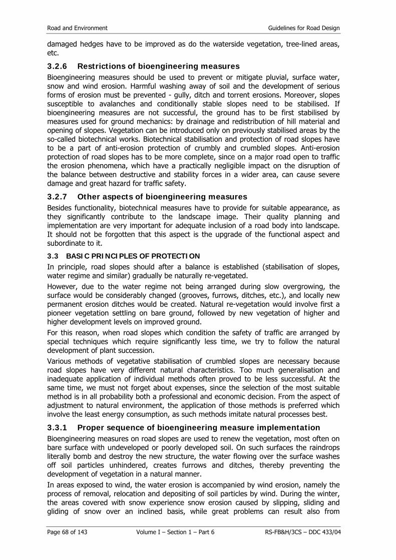
Road and Environment Guidelines for Road Design
Page 68 of 143 Volume I – Section 1 – Part 6 RS-FB&H/3CS – DDC 433/04
damaged hedges have to be improved as do the waterside vegetation, tree-lined areas, etc.
3.2.6 Restrictions of bioengineering measures Bioengineering measures should be used to prevent or mitigate pluvial, surface water, snow and wind erosion. Harmful washing away of soil and the development of serious forms of erosion must be prevented - gully, ditch and torrent erosions. Moreover, slopes susceptible to avalanches and conditionally stable slopes need to be stabilised. If bioengineering measures are not successful, the ground has to be first stabilised by measures used for ground mechanics: by drainage and redistribution of hill material and opening of slopes. Vegetation can be introduced only on previously stabilised areas by the so-called biotechnical works. Biotechnical stabilisation and protection of road slopes have to be a part of anti-erosion protection of crumbly and crumbled slopes. Anti-erosion protection of road slopes has to be more complete, since on a major road open to traffic the erosion phenomena, which have a practically negligible impact on the disruption of the balance between destructive and stability forces in a wider area, can cause severe damage and great hazard for traffic safety.
3.2.7 Other aspects of bioengineering measures Besides functionality, biotechnical measures have to provide for suitable appearance, as they significantly contribute to the landscape image. Their quality planning and implementation are very important for adequate inclusion of a road body into landscape. It should not be forgotten that this aspect is the upgrade of the functional aspect and subordinate to it.
3.3 BASIC PRINCIPLES OF PROTECTION In principle, road slopes should after a balance is established (stabilisation of slopes, water regime and similar) gradually be naturally re-vegetated. However, due to the water regime not being arranged during slow overgrowing, the surface would be considerably changed (grooves, furrows, ditches, etc.), and locally new permanent erosion ditches would be created. Natural re-vegetation would involve first a pioneer vegetation settling on bare ground, followed by new vegetation of higher and higher development levels on improved ground. For this reason, when road slopes which condition the safety of traffic are arranged by special techniques which require significantly less time, we try to follow the natural development of plant succession. Various methods of vegetative stabilisation of crumbled slopes are necessary because road slopes have very different natural characteristics. Too much generalisation and inadequate application of individual methods often proved to be less successful. At the same time, we must not forget about expenses, since the selection of the most suitable method is in all probability both a professional and economic decision. From the aspect of adjustment to natural environment, the application of those methods is preferred which involve the least energy consumption, as such methods imitate natural processes best.
3.3.1 Proper sequence of bioengineering measure implementation Bioengineering measures on road slopes are used to renew the vegetation, most often on bare surface with undeveloped or poorly developed soil. On such surfaces the raindrops literally bomb and destroy the new structure, the water flowing over the surface washes off soil particles unhindered, creates furrows and ditches, thereby preventing the development of vegetation in a natural manner. In areas exposed to wind, the water erosion is accompanied by wind erosion, namely the process of removal, relocation and depositing of soil particles by wind. During the winter, the areas covered with snow experience snow erosion caused by slipping, sliding and gliding of snow over an inclined basis, while great problems can result also from

Guidelines for Road Design Road and Environment
RS-FB&H/3CS – DDC 433/04 Volume I – Section 1 – Part 6 Page 69 of 143
snowdrifts as snow is transported by wind. All factors limiting the development of vegetation need to be previously disabled (water, wind, snow). If the basic expert principles and proper sequence of biotechnical measures are not complied with, the stabilisation of slopes by vegetation is unsuccessful or success is only temporary and much poorer than it could have been. For this reason, the most suitable growing area has to be created on road slopes especially for the introduction and development of vegetation (soil conditions, restriction of soil wash-off, prevention of backward erosion, water regime, restriction of sliding, skidding and gliding of snow, provision of wind protection, etc), which should then in the most suitable manner in terms of ecology and economy be set up and cultivated until it fully assumes all functions, especially the protective function.
3.3.2 Breakdown of bioengineering measures Bioengineering measures consist of works divided into two groups:
- technical works (preparation of the slope, arrangement of water regime, provision of wind protection, restriction of snow movement),
- biotechnical works (provision of vegetation protection against pluvial erosion - by rain drops and surface water erosion - washing off, Figures 6.17 and 6.18).
Vegetative stabilisation of hill sides - road slopes is easier if the major road design is more thorough (unfortunately, the problems related to soil mechanics and re-vegetation are too often underestimated) and if quality stabilisation is provided expertly, which is especially true for high cuts, profiles and embankments.
Figure 6.17: Drawing of furrow development in deep erosion on the slope translation of figure text:
Figure 6.18: Drawing of slope arrangement and stabilisation
Produbljavanje brazda kod erozije Deepening of erosion furrows Nagib padine nasipa 1:1,5 Road embankment inclination 1:1,5
Razvoj dubinske erozije Development of deep erosion

Road and Environment Guidelines for Road Design
Page 70 of 143 Volume I – Section 1 – Part 6 RS-FB&H/3CS – DDC 433/04
3.3.3 Technical works Technical works as a rule have to be implemented before biotechnical works, as they are a precondition for success of biotechnical works. They are implemented only on geomechanically stabilised or stable slope, since vegetation cannot be used to solve soil mechanics problems. If the slopes along roads are to be adjusted to the natural environment, it is very desired that their inclination is not even, but changing as in nature. These changes can be provided expertly only if various slope inclinations are formed, but all have to be less than the natural inclination angle of the hill comprising a road slope or its most unfavourable layer. Furthermore, it is often necessary to implement works to protect the hill foot from undercutting (especially next to water courses and drainage from the road body). Above all, the slopes have to be previously shaped so that in areas with mouldered stone material all ridges and local steep sides exceeding the natural stability angle of the wet hill are eliminated. Furrows and ditches have to be levelled out as well. Special attention needs to be devoted to upper edges of excavation slopes. In order to prevent backward erosion, undercutting by water and sinking of excavation slope as well as unfavourable impact of high trees and frost on the upper excavation edge, the slope has to be shaped as follows (Figure 4.2):
- The excavation edge has to be shaped so that it is rounded with a minimum 5.00 m diameter. Preferably, the rounding diameter should increase as the slope height rises. Thus rounded excavation edges should without a sharp edge pass to above positioned natural vegetated environment of the slope.
Trees have to be cut at least 5.00 m from such rounded upper edge so as to prevent unfavourable impact of them swaying in the wind on the mechanical linkage of the hill.
Figure 6.19: Drawing of slope arrangement and stabilisation
- On the parts of the slope where trees need to be cut, the stumps must not be
pulled out, since otherwise water could collect in the basins resulting from removed stumps and by concentrated soaking of the hill soil lead to it sliding. Favourable impact of stumps is reflected also in mechanical linkage of the soil with its root system, while at the same time the stumps provide the basis for vegetation reproduction and consequently the creation of new forest stands more suitable to the relevant height.
- The water flowing down the slope towards the excavation edge has to be previously captured and redirected to stable land unaffected by construction, or at least suitably dispersed.
Guidelines for Road Design Road and Environment
RS-FB&H/3CS – DDC 433/04 Volume I – Section 1 – Part 6 Page 71 of 143
- Agricultural surfaces where draining surface water is concentrated in isolated furrows, preventing better seepage and increasing the moisture of potential slide layers and sliding of slopes, are not desired above excavation slopes. If due to other interests, especially ownership, the agricultural use of land cannot be replaced, the ploughing should be as shallow as possible on flat sections, and at the same time at least a proportionately wide protective lane has to be preserved above the excavation edge and planted by bushes.
- The next step in expertly proper biotechnical stabilisation and protection of road slopes, both excavation and embankment, is the arrangement of the water regime on slopes. If the slopes are long enough, the water draining down the slope gains sufficient erosion force so that the surface washing off of soil transforms into different forms of deep erosion. First, erosion furrows appear, while continuing concentrations of water courses increase the erosion force and more and more severe types of deep erosion occur - furrows, ditches, etc. A special problem is the backward erosion, which is the consequence of undercutting of water falling over locally more resistant parts of slopes, ending by repositioning of the ditch to a new balance (see Figure 6.17). If the reasons for the occurrence of deep erosion are not eliminated, i.e. the concentration of surface water courses - the limiting ecological factor, each introduction and development of vegetation are destined to fail.
Maximum dispersion of surface water courses is therefore necessary for the prevention of surface and deep water erosion and at the same time welcomed because of improvement of growing conditions. Road slopes are mostly arid vegetation areas, where the lack of water caused by too fast surface drainage and undeveloped soil structure greatly restricts vegetation development. For this reason the dispersion of surface water courses, which at the same time enables maximally uniform moistening of land, is very welcome for the development of vegetation. This is achieved by wattles, live stakes, terraces, steps (Italian "gradon"), shelves, small walls preventing washing off, wattles on shelves, bushy structures, greening by cordon planting and numerous other measures (Figures 6.20 and 6.21). Often the combinations of the above stated technical works are used. It is typical of all that they are implemented more or less by contour lines. They are implemented at a diagonal over a slope only if they restrict small areas and are connected with stabilised channels for drainage of surface waters, since the inclination due to dynamics causes and accelerates the occurrence and development of surface and deep water erosion.
Translation of figure text Poplet Wattle Svježan pruća Brush wattles podloga od grana i batina
brush and shrub base
Žive četke na podlozi od grana i batina
Live stakes on brush and shrub base
Žive ščetke - ojačane Live stakes - strengthened
Žive četke od granja Fascines
Figure 6.20: Measures for the dispersion of water, moistening of land and vegetative stabilisation of slopes

Road and Environment Guidelines for Road Design
Page 72 of 143 Volume I – Section 1 – Part 6 RS-FB&H/3CS – DDC 433/04
Figure 6.21: Diverse arrangement of wattles for water dispersion
The distribution of measures for dispersion of water by contour lines must not be rigid, as from the landscaping point of view the "school book" distribution should be avoided. Freedom of design is very welcome, an example is the forest vegetation in natural environment with bunchy and group distribution, while more or less horizontal line means globally functional restriction. The distance between individual types of technical works for the dispersion of surface waters and moistening of land depends on the composition of the hill and slope inclination. As the grading decreases, hill incoherency increases and the slope inclination rises, the distance between terraces, shelves and similar reduces. Figure 3.5 shows what the distance between them should be. In most common road slope inclination, i.e. 1 : 1.5 and more or less average coherence of hills composing the slopes, they should be provided at every 5.5 m -7.4 m of slope height (see Figure 6.22). Their distribution can be either line or chess-like.
Međusobne udaljenosti banketa (po Saccardyju)
Distances between banquettes (according to Saccardy)
nagib padine slope inclination visinska razlika height difference
horizontalna udaljenost horizontal distance
Figure 6.22: Drawing of a network or anti-erosion ditches (banquettes according to Saccardy)
Guidelines for Road Design Road and Environment
RS-FB&H/3CS – DDC 433/04 Volume I – Section 1 – Part 6 Page 73 of 143
3.3.4 Measures for water dispersion
3.3.4.1 Infiltration terraces (banquettes) They were developed and researched most in France, Algeria and the USA already at the end of the 19th century. They are suitable for less steep slopes with up to 30% inclinations. In cross-section an infiltration terrace is similar to a road composite profile. They are constructed in system, over all slope affected by surface erosion. Longitudinal and transversal fall of the terraces are such that the water which flows to them from intermediate surfaces permeates the ground as much as possible, while the surplus slowly drains towards a basin - even in the event of heavy rain. The effect of terraces is favourable in many respects: surface erosion stops immediately after construction, furrows start closing, water seepage and ground moisture increase, pedogenetic processes re restored. Because the surface water decreases and seepage increases, the level of underground water rises and the water regime of water courses in the vicinity improves, while their carrying power diminishes. The land can be used for agricultural purposes or afforestation. The distance between terraces has to be such that the water between them cannot concentrate too much and start furrowing the surface. Draft data for the calculation of the distance between them are given in the table in Figure 3.5. The length of the terrace is limited by the quantity of water which drains over it to the basin in a controlled manner. The longitudinal fall of the terrace depends on the slope inclination, the quantity of water and absorption capacity of the soil. Completely horizontal terraces are useful on gentle slopes with up to 4% inclinations. Longitudinal falls are usually between 0.2 and 0.5%. Cross-section of the terrace can be shaped as a canal or have an embankment on the outer edge.
3.3.4.2 Terraces (steps) for afforestation Such terraces are intended for preparing the terrain for planting tree seedlings. Usually, they are shaped like shelves 80 to 90 cm wide with a structure base inclined against the slope (around 30% inclination), dug in the direction of contour lines with a longitudinal fall of 0.5% (horizontal only if the terrain is very permeable). In the case of very steep inclinations (over 50%), the terrace embankment has to be supported by a lining or a stone wall or reinforced wattles (see Figure 6.23). The ground on the structure base of the shelf has to be dug through before planting, so that there is better soil where seedlings are planted and at the depth of their roots. Seedlings are planted in a series with the density suitable for the plant species that is used. The most suitable time for planting is in the autumn and for shelf construction in the spring. Such terraces are very suitable for afforestation of slopes with dry and impaired soil on south exposure (to extreme sun). They have a favourable impact on water regime, soil moisture and micro exposure.

Road and Environment Guidelines for Road Design
Page 74 of 143 Volume I – Section 1 – Part 6 RS-FB&H/3CS – DDC 433/04
Gradon za zadržavanje vode i pošumljavanje Shelves (Ital. gradon) for retention of water on slopes and afforestation
Jarak za pronicanje i zadržavanje vode Sinking ditches for retention of water on pastures Polica sa učvrščenom padinom Shelves with stabilised slope Jarci za zadržavanje vode u tlu sa poprečnim pregradcima
Sinking ditches for retention of water in ground by transversal equaliser embankments
Figure 6.23: Steps, shelves, retention ditches
3.3.4.3 Retention ditches They are intended for retaining surface flowing water. The water from the slope drains into ditches where about 75% is held (there it infiltrates or evaporates), while the remaining water drains over the ditch longitudinally to the basin. The best is the American retention (contour) ditch system (see Figure 3.6). The ditches (of trapezoidal profile) are constructed in the direction of contour lines (in the system) at such distance that the water does not erode the surfaces between them. The construction progresses downwards. The excavated material is used for embankment on the outer edge, while all other surfaces have to be grassed. The ditches are longitudinally divided into sections by small transversal embankments whose edge is below the level of the outer embankment edge. All ditches have to lead to basins. Dimensioning of ditches and the distance between them depend on the slope inclination, soil permeability, the quantity of possible precipitations, etc.
3.3.4.4 Wattles (Fascines) Wattles mechanically stabilise soil by roots, promote the creation of fertile soil, retain falling rocks and snow, inhibit water drainage, improve the water regime in the ground - increase moisture, etc. They represent the connection between technical and biotechnical works.

Guidelines for Road Design Road and Environment
RS-FB&H/3CS – DDC 433/04 Volume I – Section 1 – Part 6 Page 75 of 143
They are installed in the same way as for embankment protection by water courses (wooden stakes, driven into the ground (to 2/3), between which willow cuttings are netted and staked to the ground). It is recommended that the stakes are driven more perpendicularly to the slope. They are usually installed in the direction of line contours, in continuous or interrupted parallel lines. They can also be installed in parallel lines at an angle off horizontal, but only when the draining water is thus directed towards the drain channel or ditch. The distance between wattle lines depends on the slope inclination and the type of soil (see Figure 6.20). On very steep slopes it is recommended that wattles are installed on up to 50 cm wide shelves (banquettes), where a wattle is surrounded by live twigs and then covered with soil so that it protrudes from the ground somewhat.
3.3.4.5 Greening by brush mattress It is useful especially for protecting the foot of bare road embankments which can be reached by medium and flood waters or when the ground expands due to moisture (on flysch and the like). This measure is also a combination of technical and biotechnical works, as it enables both dispersion of water flows and more equal moistening of soil and vegetation development. The slope is in the direction of fall lines covered with branches, which should be as straight as possible, their thicker end being put into the ground and anchored with low wattles or a wire over level lines and covered with soil (see Figure 6.19).
3.3.4.6 Bush greening It was developed in France (Demontzey) and it connects technical and biotechnical works. Regenerative twigs are densely planted on previously excavated shelves and covered with soil. The shelves are dug more or less in the direction of the contour lines with a mild inclination towards the slope, while the outer edge is secured by a wattle. In poor and/or dry soil a small trench is dug into the shelf - 30 x 20 cm. Such method of greening is very expensive and is therefore used only in the most difficult growing conditions.
3.3.4.7 Cordon planting This is a simple and efficient procedure (Courturier) connecting technical and biotechnical works. Bushes or rooted plants are planted to about 10 cm deep cut in the slope. The cuts are inclined towards the slope with the excavated part vertical. Planting is made in the upward direction - the lower already planted shelf is covered with excavated material of the next. The surfaces between individual cuts are grassed. Already the first year live bushy fences develop and after a few years the soil improves so much that afforestation is possible between bushes.
3.3.4.8 Live stakes They are cheaper than wattles and soon become effective, because they quickly root and grow shoots. They are a combination of technical and biotechnical works. They are very suitable for sterile and infertile soil. The poorer the soil the more appropriate are live stakes compared to wattles. Cuttings approximately 80 to 120 cm long are planted at an angle off horizontal over previously dug shelves at a distance of 1.50 to 2.50 m. The following procedure is the same as for planting in cordons. They can be installed on rough basis of spruce branches (see Figure 6.19). Strengthened live stakes: on steeper slopes live stakes are strengthened by a low "ground" wattle, which prevents the draining water to furrow the surface. Live stakes made of branches are a simplified form, where instead of cuttings we use up to 3 m long unlopped branches of species that are capable of vegetative reproduction. Live stakes can be combined with various materials, foils, roof plasterboard, sheet metal, etc. These materials are used to direct water to soil and keep it there, to prevent furrowing and washing off of soil and to mechanically stabilise the slope.

Road and Environment Guidelines for Road Design
Page 76 of 143 Volume I – Section 1 – Part 6 RS-FB&H/3CS – DDC 433/04
Live stakes are made of rods and branches of regenerative species of willows, poplar trees, European privet, and laburnum. Since these species have a relatively short life span, it is recommended that between them saplings of pioneer tree species suitable for the growing area are planted: grey and green alder, poplar, common sea buckthorn, rowan tree, elder, snowball tree, wayfaring tree, elm tree, ash tree, hawthorn, dog rose, European privet, etc. This accelerates the successive development of vegetation. Later, the area can afforestated by pine, spruce, larch and other climax tree species.
3.3.4.9 Technical works on conditionally stable land When technical works are implemented with the aim of dispersing surface waters on conditionally stable land, they have to be carried out so that water is dispersed and at the same time over different stabilised impervious channels drained over the slope, whereby undesirable additional soaking of land is prevented.
3.3.4.10 Proper sequence of technical work implementation It is very suitable in technical works if an embankment or a ditch can be shaped at the foot of the slope, so that there is sufficient useful space for stopping subsequently chipped off material. Often this is done to avoid additional protection of friable slopes by traps or rockfall netting (drapery). When the slope and a trap trench are formed, quality drainage has to be provided for surface and ground waters. The proper order in which individual works are carried out on the slope is important for quality implementation of technical and later also biotechnical works. Usually, they are carried out from the upside down, since in the opposite case new would damage previously made works. (Figure 6.24)
translation of figure text: ređanje izrade implementation sequence
pravilno correct nepravilno incorrect
Figure 6.24: Sequence in which works are implemented on the slope
3.3.4.11 Technical measures for surface tying of soil In special circumstances, when due to unfavourable natural characteristics the inclination of, in particular excavation slopes, cannot be shaped more suitably, washing off of soil by water is prevented by simple and branched netting or comb-shaped nets as appropriate technical measures for preventing washing off and more even moistening of soil. These

Guidelines for Road Design Road and Environment
RS-FB&H/3CS – DDC 433/04 Volume I – Section 1 – Part 6 Page 77 of 143
are mostly made of plastic fibres that do not disintegrate easily, some also of degradable materials, either wire netting or natural fibres of organic origin (jute, coconut). Compared to "classic" measures they only "additionally stabilise" the soil, thus increasing the resistance to deep washing off, but do not have a significant impact on dispersion of surface water flows or better infiltration to the soil. It is suitable to use such measures, which can be very expensive, also where at the same time the slope stability problems are being solved (reinforced earth, surface crumbling) or if the soil on the slope is of very fine grain or the hill stable in spite of great inclination (faster drainage of surface water - stronger washing off - mulch seeding is not successful enough without the help of various nets), the surface needs to be additionally stabilised until the vegetation assumes full anti-erosion protection. In the above methods used for protection, a mixture of grass seeds, starting fertilizer, mulch and other additives (grassing methods are described in more detail in the chapter 3.3.5.1) are applied to the slope, and nets of different materials are used for prevention of washing off. Nets can be made of:
- wire netting, - coconut husk, - jute, - plastic fibres.
3.3.4.11.1 Wire nets Nets can be made of zinced wire netting, which can be additionally protected by a thin, 0.40 - 0.60 mm cover of PVC foil. Plasticized wire netting is especially useful for reinforced earth, as it has suitable long life span. Wire nets are distinguished by: - wire radius (2.00 - 3.40 mm), - braid width (2.00 - 4.00 m), - braid length (25 - 100 m), - braiding method (simple crossing, double-twisted). The firmness of wire netting increases as the wire is thicker, and depends also on the braiding method. Palvis netting, characterised by double-twisted wire netting roughly ensures twice the tensile strength in comparison to a comparable simple wire netting.
Figure 6.25: Palvis netting (left), simple netting (right)
The advantage of Palvis netting is also that if the wire gets broken, the net does not get undone. The above characteristics are so important that nets with simple netting should not be used for protection of slopes nor various traps. Wire netting has to be suitably attached to the slope, which is why various forms of anchoring are used, depending on the hill type and the inclination. Anchoring on top, bottom and the slope differ. On top, the net should be attached by anchors with horizontal space in between them from 1.00 to 3.00 m - depending on the hill type and the depth ranging between 0.50 and 1.50 m. The anchors which are, depending on the hill type, in the form of expansion

Road and Environment Guidelines for Road Design
Page 78 of 143 Volume I – Section 1 – Part 6 RS-FB&H/3CS – DDC 433/04
wedges, anchors with hooks from ribbed iron and concreted, are connected between themselves and with the net by steel rods or netted wires. It is recommended that about 0.50 m of the net is on the upper side folded and fastened over the laid net. On the slope the net has to be fixed by anchors. The distance between these anchors depends on the hill and protection type (prevention of washing off, protection against falling fragments, etc.) and ranges between 15 and 30 mZ/per anchor. It is recommended that the anchors and the net are additionally connected by steel rods or, even better, steel grids. On the bottom of the slope the net has to be installed so that fragments of the hill rolling down the slope can be removed occasionally. This can be achieved if a trap trench is dug at the bottom of the slope and 0.50 m of the last net is not fastened or is attached in such a way that it can be simply fixed and removed. One of the most suitable solutions are concrete weights of suitable weight. Installation of rockfall netting -drapes requires special care, because once unfolded, the net cannot be moved directionally because of great friction. Since the nets are in rolls with 2.00-4.00 m in width, the slope has to be covered with a series of nets touching each other, which have to be connected so that suitable firmness of nets all over the slope is provided. Net installation can be either continued with integrated wire netting or joined at different points by clips made of wire netting. (Figure 6.26)
Figure 6.26: Continued joining (left), joining by clips (right)
3.3.4.11.2 Coconut fibre nets Coconut fibre nets cover the grassy surface until the vegetation has been suitably expanded and assumed full protective function. These are suitable on slopes with more favourable growing characteristics, since they disintegrate relatively quickly and in more difficult circumstances they would not provide protection of sufficient duration. They are not effective for protection against large rock fragments and are therefore not used on very friable slopes. Coconut fibre nets are distinguished by:
- braiding method (thick - 1 x 1 cm, nets with openings - most often 5 x 5 cm), - mass (0.4 - 0.9 kgjm2), - braid width (100, 122, 200, 300, 400 cm), - braid length (30, 46, 100 m).
Coconut fibre nets are attached on the slope with wooden piles 4-6 cm thick, which have to be driven into the ground at least 0.5 m deep. Coconut fibre nets are used on slopes made of small mouldered stone material and are suitable especially for the protection of slopes completed in autumn and winter, since the water could by spring wash off many soil particles from unprotected surfaces, particularly the finest colloids, which provide for fertility. When the net is installed, caution is

Guidelines for Road Design Road and Environment
RS-FB&H/3CS – DDC 433/04 Volume I – Section 1 – Part 6 Page 79 of 143
necessary, as these nets are sensitive to moisture and have to be placed so that more material is used to prevent unfavourable consequences of shrinkage.
3.3.4.11.3 Jute nets Jute nets provide similar protection as coconut fibre nets. They are distinguished by:
- braiding method, - mass, - braid width, - braid length.
The sizes are similar as with coconut fibre nets.
3.3.4.11.4 Plastic fibre nets Plastic fibre nets (Figure 6.27) with additional "reinforcement" of soil surface provide protection against washing off, but not sufficient protection against stronger crumbling. Most nets are made of thin fibres which do not degrade; lately nets have been introduced made of fibres which do disintegrate after a certain period. On suitable slopes they provide adequate protection against erosion until a quality anti-erosion protection is established by vegetation. They are less environmentally safe, demanding in terms of energy and considerably costlier than environmentally friendly solutions. A special type are the honeycomb-shaped networks is used to cover slopes (Figure 6.28). These are anchored and the honeycomb structure is coated with soil and grass planted. Usually, the honeycomb structure is made of non-degradable plastic materials, however, jute comb is also available. Instead of these expensive eco-commercial methods of slope rehabilitation, there are numerous environmentally-friendly and a few times cheaper solutions, which is why they should be used only if for appearance sake we would like to make "rock look green".
Figure 6.27: Anti-erosion net of plastic fibres
Figure 6.28: Honeycomb-shaped net
3.3.4.11.5 Pre-vegetated woven mattresses These mattresses involve grass mixtures and fertilizers woven into a machine produced mats made of different substances. Coconut fibres, jute, hemp, straw, wood chips, plastic fibres (mostly propylene) are used, which may be strengthened by wire netting. The mats are placed on planned surfaces. Since they consist of mostly natural materials, they have to overlap by 5 - 10% to prevent unfavourable consequences of shrinkage. Depending on the hill type, they are attached by anchors or special nails. By rain or thorough watering the mattress firmly merges with soil. The seeds are supplied adequate nutrition and moisture, so they germinate very quickly and, if the mattress is of suitable thickness, they

Road and Environment Guidelines for Road Design
Page 80 of 143 Volume I – Section 1 – Part 6 RS-FB&H/3CS – DDC 433/04
extend roots into the underlying layer very fast. From the point of view of environmental protection the mattresses of organic and degradable materials are more suitable. Because of high price their application is suitable on erosion prone sites, which are difficult to access, where various methods of grass planting alone are unsuccessful and have to be accompanied by the installation of mattresses.
3.3.4.12 Protection against sliding and slipping of snow In road design and construction it is often not possible to avoid very high slopes on which, given that snow quantity is sufficient, snow cover can slip and slide. This is possible anywhere in Bosnia and Herzegovina. Sliding and slipping of snow usually occurs on slopes with inclination between 30 and 50 degrees, critical are already 35 m long slopes without suitable forest vegetation. Slopes covered by various nets are even more endangered due to reduced friction between snow and the ground. On such slopes adapted supporting structures have to be used to increase the roughness of the slope. This lessens sliding, slipping and gliding of snow and enables the development of forest vegetation, which will in the long run assume the support of the snow cover on the slope. If, however, snow cover sliding is more intense, it has to be prevented by the construction of support and fixing structures. These should be constructed so as to sustain the pressure of the snow cover and at the same time offer sufficient support. They include snow bridges, snow rakes and snow nets. Forest vegetation is introduced to a stabilised slope. In the long run it should assume the function of supporting structures (see Figure 6.29).
Figure 6.29: Vegetation protection against the consequences of sliding, slipping and gliding of snow by simple supporting structures, which increase the roughness of the
surface.
Figure 6.30: Snow nets and snow rakes support the snow cover on the slope

Guidelines for Road Design Road and Environment
RS-FB&H/3CS – DDC 433/04 Volume I – Section 1 – Part 6 Page 81 of 143
3.3.5 Biotechnical works In previous chapters it was stated that some measures are a combination of technical and biotechnical works. This chapter provides information on biotechnical works, which are most often implemented after the technical or combined works have been carried out. Only exceptionally the water regime on a slope is so favourable that merely biotechnical works suffice for protection. Biotechnical works are divided into afforestation and grass planting works. The long-term goal of protecting crumbled slopes is the establishment of a suitable forest stand to provide for the best possible anti-erosion protection. Since the process of forest stand development is long-term and the slopes along major roads need quick anti-erosion protection, the grass planting works are implemented first and later supplemented by afforestation, if necessary.
3.3.5.1 Grass planting works Grass planting works involve procedures of seeding grass mixtures or sodding. The latter
is a rare and also very expensive measure, applied only in exceptional circumstances.
3.3.5.1.1 Sodding This is the classic greening method. Square or rectangular pieces of sod (20 x 20 to 40 x 40 cm large and 7 to 10 cm thick) are laid on the surface from the bottom upward, in lines horizontally or at an off horizontal angle. If the slope has greater inclination, they are attached by wooden piles. If there is insufficient sod available, it is laid in chess shape or in stripes, while surfaces in between are top-soiled and grass seeded (see Figure 6.31).
Figure 6.31: Sodding of slopes
3.3.5.1.2 Grass mixture seeding When grass mixtures are seeded, various techniques are used depending on the inclination, the erosion level and the characteristics of the soil on treated surface. Roughly, the procedures can be divided into:
- ordinary seeding, - hydroseeding, - mulch seeding, - vegetation pulp seeding.

Road and Environment Guidelines for Road Design
Page 82 of 143 Volume I – Section 1 – Part 6 RS-FB&H/3CS – DDC 433/04
The types of grassing works are stated in the order comparable to growing conditions - from the easiest to the most difficult. More demanding grassing method is suitable also for more difficult sites and proportionately its price increases.
3.3.5.1.3 Ordinary seeding Ordinary seeding involves manual seeding of seed mixture and fertilizer. For quality grassing, at least 4 dag of seed mixture and on average 4 dag of suitable grass fertilizer are necessary per square meter.
3.3.5.1.4 Hydroseeding In hydroseeding a mixture of water, seed mixture, fertilizers and various additives for improving soil structure and binding of seed on the surface is sprayed from the pump on the slope.
3.3.5.1.5 Mulch seeding Mulch seeding involves manual seeding of seed mixture and fertilizer. Then, the mulch is spread and additionally bound, most often by bitumen water emulsion ("biotorquette"). Hay, straw, wood chips, ground bark, corn chopping and other suitable organic substances are used as mulch (see Figure 6.32).
Translation of figure text 1 Slope prepared for greening works
2 Seeding of a mixture of seeds and artificial fertilizer (4 dag of seeds + 4 dag of fertilizer per m2) 3 Laying wetted straw (20-30 dag/m2) over 1.50 - 2.00 m wide stripe
4 Spraying straw and mixture with water bitumen emulsion (75% water : 25% bitumen / 0.5 litre/m2)
Figure 6.32: Mulch seeding and "biotorquette" (according to M. Schiechtel)
3.3.5.1.6 Vegetation pulp seeding
Vegetation pulp seeding is implemented in the same way as hydroseeding, only the mixture of water, seed, fertilizer and additives for improving soil structure and binding of seed on the surface is suitably added ground mulch and fine grain humus soil.

Guidelines for Road Design Road and Environment
RS-FB&H/3CS – DDC 433/04 Volume I – Section 1 – Part 6 Page 83 of 143
3.3.5.1.7 Selection of environmentally suitable grass planting method When the grass planting technique is used and implemented, care should be taken that it is suitable for the environment. Most often grass is planted by different methods of seeding grass seed mixtures. From the ecological point of view it is important that the mixtures include those types of grass which are adjusted to the treated area. When planting grass on very impaired soil, such as is usual on road slopes, only few varieties adapted to difficult ecological conditions are available. However, in a few years seeds automatically spread from neighbouring grassy areas, so that the grass ecosystem on road slopes gradually becomes similar to that in the approximate environment. With all species small quantities of fertilizer are added to the seed mixture. The quantity and frequency of these additives has to be in line with the bearing capacity of the ecosystem. From the ecological point of view, also the selected type of fertilizer is important in addition to quantity and frequency. Compliance with the bearing capacity of the ecosystem means the quantity and quality adding of fertilizers whereby the stability of the ground system and its ability of self-regulation is not destroyed. The most suitable is definitely the use of natural stable manure, which is due to very limited quantity, price and transport problems rarely an option. Various types of artificial fertilizers are used for the most part, lately also the so-called bio fertilizers, which are based on dehydrated chicken manure. Besides the bearing capacity also a suitable quantity and the selection of appropriate type for a certain soil play an important role when an artificial fertilizer is used. The basis for selecting the type of artificial fertilizer should be the results of pedological soil analysis, since only those macro- and microelements may be added which the soil lacks. Attention has to be paid also to "micro location" changeability of soil characteristics. Ecological criteria for ordinary, i.e. manual seeding of seed mixture and fertilizer, by burying or not, have been in fact referred to already above. In addition to these criteria, there is, in hydroseeding, mulch seeding and vegetation pulp seeding, also the question of suitability of the additives from natural or synthetic organic substances, which improve physical, chemical and microbiological conditions of soil and connect soil particles, thus preventing them being washed off and away. To improve physical characteristics, soil is added small quantities of additives, which are the initial input and ecologically neutral, while in difficult ecological circumstances they can represent organogenetic and humidification prone substances, a means for temporarily holding water in arid soil. We also need to explain the suitability of materials used as mulch, which covers the grass planted areas and betters the ecological, in particular microclimate conditions for sprouting and growth of grasses. As mulch we use hay, straw, cellulose and, depending on some special natural and ecological conditions, some other organic substances (chips, bark and similar). All these substances are of organic origin and in the process of natural disintegration gradually subject to humidification, they are therefore ecologically suitable. During degradation, the adequate grasses gradually start replacing their functions in anti-erosion protection and improvement of microclimate conditions. A positive microclimate influence of mulch is reflected in greater humidity, less temperature fluctuations, protection against sun radiation, wind and other. When reflecting on the importance of the use of mulch, the results of recent comparative tests in difficult living conditions (Zvoh above Krvavec, 1,800 metres above see level) have to be mentioned, which revealed a significant change between the areas where mulch was used in seeding and the areas where it was not. In areas with mulch, the results of germination (one month after seeding) and grass development were after one year 3 to 4-times better than in areas without mulch. These results show that by using an ecologically suitable, but not too expensive mulch in grass seeding technique, the use of artificial fertilizers could be further reduced.

Road and Environment Guidelines for Road Design
Page 84 of 143 Volume I – Section 1 – Part 6 RS-FB&H/3CS – DDC 433/04
Mulch was stabilised (so that it was not washed off by water, blown off by wind, eaten by wild animals) by bitumen water emulsion, partially hydrolysed polyvinyl acetate and a cellulose aqueous solution. All these substances function as colloids, which in addition to mulch connect also seeds and soil particles. Bitumen, which is of dark colour, and has a beneficial microclimate effect, in cold environment increases the absorption of sun rays and creates warmer microclimate. On exceptionally warm sites and on sites high above sea level, bitumen aqueous emulsion is not used as it may cause overheating and consequently non-germination of the seed. The above stated substances are added in very small quantities; they are insoluble and disintegrate some quickly, some slowly. On account of these characteristics they may be considered still acceptable for the environment in small quantities.
3.3.5.2 Afforestation works Afforestation works on erosion areas are implemented using different techniques. Success can be achieved with 1st, 2nd and 3rd category of erosion areas, while on areas of 4th category (bare compact rock), afforestation does not bear results. The goal of stabilising slopes by vegetation is not to "green" the rocks where there is normal or geological erosion, but to provide anti-erosion protection of slopes of non-relocated and particularly relocated deposits, where without suitable protection erosion greatly develops very quickly.
3.3.5.2.1 Selection of plant species Proper selection of tree and bush species is the basis of quality and successful ecologically safe afforestation. We have to choose the most site-adjusted species, which are more likely to succeed and more reliably transform into stable phytocenosis. From the ecological point of view, native species have priority and even among them there are varieties which are in terms of resilience to very difficult growing conditions the most suitable (adequate for growing conditions, resistance to negative biotic and abiotic impacts, economic benefit). On road slopes firstly those pioneer varieties are used which can in such difficult natural conditions grow and shape a pre-culture, which, after the task is done, gradually makes room for the forest stand, comprised of tree and bush species suitable for a particular site. The opinion that during the first afforestation on road slopes a greater number of species can be used to create a stable mixed composition is erroneous. Difficult growing conditions characterised by growing conditions unsuitable for numerous plant species narrow down the selection to rare pioneer species.
3.3.5.2.2 Selection of afforestation technique Various seeding and planting methods are used in afforestation. Materials of both seed and vegetative origin are used for planting. The basis of quality, sustainable afforestation is a sufficiently wide selection of seed and plant material. Afforestation techniques have to be adjusted to natural conditions. Machine planting is usually impossible on road slopes because of unfavourable terrain. Different types of manual planting are used, which gradually became established methods. A special example of afforestation is the use of seedlings in containers which should reduce the shock of the plant when transplanted and prolong the period of potential afforestation in a year. Also in this case, the basis is the selection of suitable varieties. Because growing conditions are extreme, the seedlings in containers - tubes are especially suitable for road slopes (see Figure 6.33). The aim of planting is to achieve maximum success, while one of the essential conditions is the reduction of shock as a young plant is transplanted from a tree nursery into natural environment. Besides using seedlings in containers, we try to help young plants by adding soil - humus, peat or fertilizer. All these are suitable, but have to be adjusted to growing conditions. This is a sustainable measure

Guidelines for Road Design Road and Environment
RS-FB&H/3CS – DDC 433/04 Volume I – Section 1 – Part 6 Page 85 of 143
aimed to help plants in the fight for survival, where nature still performs positive selection.
tulac tube a. Razvoj korjenčića sadnica na čistini a. Rooting of seedlings without tube
b. Razvoj korjenčića sadnica u tulcu b. Rooting of seedlings in tube
Figure 6.33: Growing and planting of seedlings in tubes (F. Rainer)
3.3.5.2.3 Nursing young stand In extreme conditions help during planting alone is not enough, but is needed also at least for one to two years and, usually, even much longer. This mostly involves fertilization. Based on pedologic analyses quality fertilizers and nutrients have to be added in the quantities suitable for the site and soil. Nursing of young plants is an irreplaceable part of afforestation.
3.3.5.3 Protection of friable slopes Biotechnical measures are often implemented on slopes which are otherwise stable, but friable - the fragments can fall on road body. Falling rocks can be prevented from hitting the road by a gallery (see Figure 6.34), rockfall wall barriers or nets (see Figure 6.35) or rockfall netting - drapes.
Figure 6.34: A gallery protects the road against falling rocks and snow avalanches
Figure 6.35: Rockfall wall barriers
Galleries are used for road protection only in extremely unfavourable conditions, when a very extensive area is friable or when major rock falls are being solved. Rockfall wall barriers and nets have to be dimensioned to sustain dynamic pressure of falling rocks. These are relatively expensive structures, suitable in difficult circumstances,

Road and Environment Guidelines for Road Design
Page 86 of 143 Volume I – Section 1 – Part 6 RS-FB&H/3CS – DDC 433/04
when rockfall netting - drapes is not suitable for protection against fragments. Preferably, their construction should enable access for removing retained fragments. Due to the possibility of greater compensation of dynamic pressures, the use of rockfall nets has an exceptional advantage especially in more difficult conditions. Rockfall netting - drapes is used to cover friable slopes above roads and is suitably anchored into the basis. It should be installed so that fragments are deposited at the foot of slopes. During maintenance works fragments have to be occasionally removed, otherwise the pressure of erosion gravel becomes too great and the netting gets torn. Installation of rockfall netting - drapes can be combined with various methods of grass planting and afforestation, which have to be provided so that plants develop the root system in the base hill (see Figure 6.36). Different methods where bush and tree seedlings are planted into pockets, tubes, pipes and similar objects are inadequate in expert terms (Figure 6.37). Root system does not develop into the base hill, but where there is "more food", where there are better growing conditions. When the net is worn out, its remains slid over the slope together with tubes, pockets, pipes and similar with seedlings. Moreover, there is no rational and even less so ecologically founded reason for creating temporary, expensive, artificially maintained green curtains on open areas (4th erosion level). At the same time these are disproportionately expensive compared to environmentally suitable biotechnical measures. Their use is justified on sites of great erosion level, if the aim is to provide visible green curtains for aesthetic reasons. Also the consumption of energy for biotechnical fixing of a square metre of road slope is much lower with measures that are more environmentally friendly. Minimum energy consumption in natural circle is the basis of sustainable development and environment-adapted biotechnical rehabilitation of road slopes.
Figure 3.36: Protection of friable slope by rockfall netting - drapes. Introduced vegetation is developing into base (M. Plešnar)
Figure 3.37: Vegetation in pockets develops a shallow root system in the area where there is more food, which is why plants usually do not root in the base and as the net wears out skid down the slope (M. Plešnar)
The selection of quality seeding and planting material as well as of the suitable season for work implementation are of high importance for quality implementation of biotechnical work and biotechnical measures aimed at protecting the road slopes. Moreover, thus treated areas have to be maintained and nurtured for at least 2 years, or, in difficult growing conditions, longer.

Guidelines for Road Design Road and Environment
RS-FB&H/3CS – DDC 433/04 Volume I – Section 1 – Part 6 Page 87 of 143
3.4 PROTECTION OF SLOPES - EXAMPLES
Figure 6.38: Extensive rock fall in Trenta - the major road can be protected only by a gallery
Figure 6.39: Arrangement of slopes by wattles, mulch seeding and afforestation
Figure 5.40: The same slope 3 months later
Figure 6.41: The same slope 30 years later
Figur 6.42: Rehabilitation of slope - slide by wattles, live stakes, grass planting and afforestation
Figure 6.43: The same slope 30 years later
Figure 6.44: Arrangement of surface and deep drainage and biotechnical stabilisation of the slope

Road and Environment Guidelines for Road Design
Page 88 of 143 Volume I – Section 1 – Part 6 RS-FB&H/3CS – DDC 433/04
Slika 6.45: The same slope 30 years later
Slika 6.46: Snow nets above Hrušica Vrba motorway offer protection against rock falls and snow avalanches
Slika 6.47: Protection of Hrušica Vrba motorway against snow avalanches and rock falls by rockfall protection nets made of steel weaving

Guidelines for Road Design Road and Environment
RS-FB&H/3CS – DDC 433/04 Volume I – Section 1 – Part 6 Page 89 of 143
GUIDELINES FOR ROAD DESIGN, CONSTRUCTION, MAINTENANCE AND
SUPERVISION
VOLUME I: DESIGNING
SECTION 1: ROAD DESIGNING
Part 6: ROAD AND ENVIRONMENT
GUIDELINE 4: ANIMAL PASSAGES


Guidelines for Road Design Road and Environment
RS-FB&H/3CS – DDC 433/04 Volume I – Section 1 – Part 6 Page 91 of 143
4. ANIMAL PASSAGES
4.1 BASES FOR PROTECTION PROVISIONS
4.1.1 Provisions of regulations The Protection of Nature Act (Official Journal of the Federation of Bosnia and Herzegovina, no. 33/03) In accordance with Article 7 of the "Protection of Nature Act" all legal entities and natural persons as well as any other organisations shall protect the nature by acting in the direction of preventing activities, which could endanger or harm nature, they shall mitigate any damage, eliminate its consequences and restore damaged nature to its original state. Interests of protecting the nature shall be taken into account in planning of economic development strategy and preparing of spatial planning documents, in accordance with Article 10 of the aforementioned Act. In accordance with Article 12 therein, any interventions in nature and its burdening shall be implemented in a way least polluting or least harmful to the nature. The Federation of BiH has the Red List of Protected Animal Species (»zaštićene životinje sa Crvene liste«) for which, in accordance with Article 35 of the "Protection of Nature Act", the following is prohibited:
a) Any deliberate capturing or killing of individuals of protected species, found in the wild;
b) Any deliberate disturbing, particularly during nursing of offspring, winter rest and migrations;
c) Any deliberate damaging or removal of nests; d) Any damaging or destroying of brood and dwelling; e) Any captivity, transport and sale or exchange of wild species, excluding those
obtained legally prior to entering into force thereof; f) Performing any work which may result in extinction or disturbance of populations
of such species. The prohibition specified in the first paragraph, items a), b) and e) thereunder shall relate to all development stages of animals. With regard to Article 33 therein, individual areas may be by a regulation adopted by the Government of the Federation of BiH, specified as NATURA 2000 sites for the purpose of inclusion in the international environmental network for protection of natural habitats and habitats of individual species. No NATURA 2000 sites have been defined in the Federation of BiH thus far. The Rules on Plants and Facilities for which the Environmental Impact Assessment is Obligatory and Plants and Facilities which can be Built and Allowed Into Use Only Subject to Acquired Environmental Permit (Official Gazette of the FBiH no. 19/04) / The Rules on Plants and Facilities for which the Environmental Impact Assessment is Obligatory and Plants and Facilities which can be Built and Allowed Into Use Only Subject to Acquired Environmental Permit were issued on the basis of paragraph 5 of Article 117, paragraph 1 of Article 56 and paragraph 2 of Article 68 of the Protection of the Environment Act (Official Gazette of FBiH no. 33/03). On the basis of Articles 3 and 4 of the aforementioned Rules, the environmental impact assessment shall be obligatory prior to issuing of the environmental approval by the Federation ministry also for infrastructure projects such as:

Road and Environment Guidelines for Road Design
Page 92 of 143 Volume I – Section 1 – Part 6 RS-FB&H/3CS – DDC 433/04
- Construction of railways for the primary railway lines or railway lines of the I and II category;
- Construction of airport runways intended for take off and landing of aircraft and helicopters with the capacity exceeding 5.7 t;
- Construction or extension of runways with the basic length of 500 m; - Construction of motorways; - Construction of new roads or routes and/or extension of existing roads having two
lanes or less to four lanes or more, where such a new road or newly marked and/or extended part of the road would be 10 km or more in length;
- Inland water routes or ports for inland water transport having permission for vessels exceeding 1,350 t;
- Merchant ports, and loading and unloading ports, linked to land (excluding ferryboat ports) able to accommodate vessels exceeding 1350 t.
The Convention on Biological Diversity (the Decision on Ratification of the Convention on Biological Diversity (Official Gazette of BiH no. 13/02) /Odluka o ratifikaciji Konvencije o biološkoj raznolikosti (Sl. list BiH, št. 13/02)/ The Convention is the first global regulations comprehensively dealing with conservation of biotic diversity (biodiversity) at the global level and sustainable use of natural resources. Objectives of the Convention are specified in Article 1:
- Conservation of biological diversity; - The sustainable use of its components; - The fair and equitable sharing of the benefits arising out of the utilization of genetic
resources. Essential is Article 6 of the Convention defining general measures for conservation and sustainable use of biotic diversity. Each Contracting Party shall develop national strategies, plans or programmes for the conservation and sustainable use of biological diversity and integrate, as far as possible and as appropriate, the conservation and sustainable use of biological diversity into relevant sectoral or cross-sectoral plans, programmes and policies. COST 341 – »Wildlife and traffic« Dealing with the matter of passage of animals across transport infrastructure and reducing the related impacts on the nature has not yet been legislated in Europe. However, extensive research has been done in this field, as reflected in the action COST 341 – Wildlife and traffic, which began in 1998. COST stands for "European cooperation in the field of scientific and technical research" and represents the EU programme being the framework for co-operation of European institutions in linked areas of scientific and technical research. One of the results of the COST 341 action is also the monograph "Wildlife and traffic: A European handbook for identifying conflicts and designing solutions", which is the result of co-operation of 16 European countries. The monograph presents basic guidelines for reducing the impact of transport infrastructure on fragmentation of habitats and the consequences thereof, whereby specifics regarding the diversity of habitats and development of transport infrastructure in individual European countries were taken into account. In addition to the aforementioned monograph, the compilation The European review presented 16 national reports (State of the art reports)on fragmentation of habitats resulting from transport infrastructure prepared by countries participating in the COST 341 action.

Guidelines for Road Design Road and Environment
RS-FB&H/3CS – DDC 433/04 Volume I – Section 1 – Part 6 Page 93 of 143
»Infra Eco Network Europe (IENE)« The Infra Eco Network Europe (IENE) was established in 1996 and represents the European network of links between authorities and other experts dealing with fragmentation of habitats resulting from construction and use of linear transport infrastructure with the emphasis on roads, railways and water courses. The IENE also gave the initiative for the COST 341 action.
4.1.2 Purpose of measures Impacts of construction of transport infrastructure regarding nature are multiple and include numerous aspects:
- Representing physical obstacles for movement of animals; - Increased mortality of animals resulting from running over and collisions on the
roadway; - Cause fragmentation of habitats; - Cause loss and degradation of suitable habitats; - Change microclimatic and hydrological conditions in the area; - Are a source of pollution with organic and inorganic pollutants, light, and noise; - Cause increased human activity in areas near the infrastructure.
Fragmentation of habitats constitutes dividing of natural habitats and ecosystems in smaller and more isolated areas, which is globally recognised as one of the biggest threats to conservation of biological diversity (biodiversity). The fragmentation of habitats mostly results from changed land use. Construction and use of transport infrastructure is one of the main factors causing changes and setting barriers between fragments of habitats. Roads, railways and watercourses represent physical obstacles to movement of numerous animal species, which can lead to isolation of individual animal populations. Long-term consequences may be lower population density, endangerment or even extinction of an entire population. Animals to which a new transport infrastructure (e.g. a motorway) splits continued habitats or animals which during migrations or circulations come across a motorway often attempt to cross the obstacle, i.e. carry out a concrete (running) activity. Providing design and construction of transport infrastructure, which is to the greatest possible extent acceptable from the environmental point of view and environmentally friendly, requires an integrated approach to reducing and/or preventing the aforementioned phenomena. In the future, it is essential to develop appropriate tools and methods for assessing, preventing and mitigating infrastructure's impact on nature, which is the purpose of the European network IENE, the COST 341 action and all existing measures for reducing the impact of transport infrastructure on nature.
4.1.3 Description of the state before the intervention The basis for deciding on required mitigating measures, compensation for the intervention with substitute habitats and compensatory measures or even changing the location of the intervention is the description of the state of the environment before the intervention. The description of the state of the environment before the intervention shall include the following:
- Special protection areas (protected areas, Natura 2000 sites, areas of habitats in the interest of the EU, etc.);
- Rare and endangered animal species (e.g. species from red lists, species listed in various conventions, etc.) and expert evaluation on the size of respective populations, important habitats, allocation of individuals, migration routes, etc.;
- Rare and endangered plant species, rare and endangered habitat types; - Important ecological networks;

Road and Environment Guidelines for Road Design
Page 94 of 143 Volume I – Section 1 – Part 6 RS-FB&H/3CS – DDC 433/04
- Dispersion corridors and areas already fragmented; - River valleys and wetlands; - Other types of important habitats; - High-value natural or cultural landscape.
The description of the initial state also serves for subsequent evaluation of consequences of the intervention and monitoring of the state after the intervention.
4.2 IMPACT EVALUATION The impact evaluation shall be specific with regard to individual locations and separate for each animal species and particular endangered animal species.
- The impact shall be evaluated with and without compensatory and/or mitigating measures.
- In case the transport infrastructure has not yet been built, impacts during construction and operations of the facility shall be evaluated separately.
- The evaluation shall take into account the existing state of burden on the environment prior to the intervention in space used as the starting point.
- The evaluation shall use the evaluation scale set specifically for each subject of evaluation (animals, plants, habitat types) with regard to the following parameters:
- Reduction and fragmentation of populations of endangered species or habitat types;
- Limiting migration of animals; - Indirect impacts on the population (noise, pollution with light, wastewater,
emissions of harmful substances), which all have an impact on living conditions in the area exceeding dimensions of the road facility.
An example of 6-grade evaluation scale for evaluating the impact of roads on animals is presented in Table 6.26.
Table 6,26: An example of 6-grade evaluation scale for evaluating the impact of roads on animals:
Positive impact (+) - Construction and/or operations of the road will have a positive impact on living conditions of animals.
No impact (0) - Construction and/or operations of the road will have no impact on fauna, the road's route is not planned in natural environment.
Small impact (1) - Occasional presence of smaller numbers of endangered, rare and protected species only in areas not directly affected by the intervention and on the edge of the influence area. No fragmentation of compact natural areas, no cutting off of migration routes of animals.
Moderate impact (2) - Permanent presence of small number of endangered, rare or protected species. Minor fragmentation of natural areas, migration routes of animals only partly interrupted.
Great impact (3) - Permanent presence of large number of endangered, rare and protected species, the populations of which are reduced due to the intervention, moderate fragmentation of rare and endangered habitats, interruption and splitting of migration routes. Intervention may be carried out only if appropriate mitigating and/or compensatory measures are adopted.
Massive impact (4) - Permanent presence of large number of endangered, rare and protected species and critical reduction or total extinction of their populations, total cutting off of migration routes of animals. Large probability for extinction of some species. The intervention is not permitted.

Guidelines for Road Design Road and Environment
RS-FB&H/3CS – DDC 433/04 Volume I – Section 1 – Part 6 Page 95 of 143
4.3 ENDANGERED ANIMAL GROUPS This section presents animal groups, in certain cases (mammals) including individual species, which can be the most affected by the road infrastructure.
Table 6.27: Endangered animal groups and measures for their protection
Animal group Measure LAND INVERTEBRATES – Appropriate lighting of facilities, underpasses and
overpasses, extended bridges and viaducts
WATER ORGANISMS – Appropriate regulation of watercourses, bridges, viaducts, appropriate drainage of the roadway
AMPHIBIANS (Amphibia) – Protective fences, underpasses and overpasses, extended bridges and viaducts, traffic signs, appropriate drainage of the roadway
REPTILES (Reptilia) – Protective fences, underpasses and overpasses, extended bridges and viaducts
BIRDS (Aves) – Protective fences, appropriate noise protection fences, overpasses, extended bridges and viaducts
MAMMALS (Mammalia) – Protective fences, underpasses, overpasses, extended bridges and viaducts, traffic signs
Measures related to protection of animal groups are discussed in greater detail in Section 5, as many are unspecific and intended for protection of several animal groups or protection of their habitats.
4.3.1 LAND INVERTEBRATES
4.3.1.1 Issues Insects are drawn by light from the road. The consequence of increased numbers of insects around the roadway is also presence of bats and collision with vehicles, usually with tragic consequences for individuals of both animal groups. Given the fact that many endemic species of invertebrates live in the Federation of BiH, repeated killings of individuals on roads may seriously endanger their existence. As the loss is irreplaceable, special attention should be given to this issue in accordance with the Convention on Biological Diversity. Appearance of endemic species bound to small areas should be determined for particular areas and the impact of construction and operations of infrastructure on the probability of their survival should be assessed.
4.3.1.2 Measures - Lighting of roads (use of directed lighting with the light of appropriate wavelength).
Measures directly related to protection of land invertebrates and bats are discussed in detail in section 4.4.1.4 Lighting of Roads.
4.3.2 Animals bound to water environment (water invertebrates, fish, amphibians, water birds)
4.3.2.1 Issues Transport infrastructure often crosses watercourses thus representing a physical obstacle to migration of animals living in water. Rainwater and wastewater from the roadway are often polluted with organic pollutants (petroleum products and polyaromatic hydrocarbons – PAH) and heavy metals (lead, cadmium). In case of traffic accidents such pollution is even more intense and may affect all animal groups bound to water environment (water invertebrates, fish, amphibians, water birds).

Road and Environment Guidelines for Road Design
Page 96 of 143 Volume I – Section 1 – Part 6 RS-FB&H/3CS – DDC 433/04
4.3.2.2 Measures - Appropriately arranged passages for water animals, bridges, viaducts. - Appropriate drainage by using sand traps with functional oil traps.
Measures directly related to protection of water animals are discussed in detail in section 4.4.2.4.
4.3.3 AMPHIBIANS (AMPHIBIA)
4.3.3.1 Issues Amphibians (Amphibia) are in their life cycle bound both to water as well as land habitats, including spawning areas, summer areas and winter areas. Water habitats may be polluted with organic and inorganic pollutants if the drainage of roads is not implemented properly. All types of areas are equally important parts of the environment of amphibians and animals migrate between them by using more or less established migration routes. Transport infrastructure often cuts off migration routes of amphibians resulting in frequent mass killings of animals on points of interruption. Human intervention in living areas of amphibians is very significant as regards construction and operations of roads, thus protective measures in construction of new, reconstruction of old and on existing roads are urgently required. An integrated approach is required for solving issues related to amphibians and roads. Constant informing of the general public is also required as only support of the general public enables implementation of appropriate solutions required for preventing running over (inclusion of the general public in detection of the so-called black spots – locations of running over). All amphibian species living in Europe are protected and listed either in Appendix II (strictly protected fauna species) or Appendix III (protected fauna species) of the Convention on the Conservation of European Wildlife and Natural Habitats (the Bern Convention). Several amphibian species are also listed either in Annex II (animal and plant species of interest to the EU), the protection of which requires specifying special protected areas or Annex IV of the Habitats Directive (Council Directive 92/43/EEC of 21 May 1992 (animal and plant species of interest to the EU requiring direct protection) thus being protected all over Europe.
4.3.3.2 Measures - Warnings and traffic signs, informing drivers and the general public. - Underpasses for amphibians with permanent protective (directional) fences. - Temporary protective fences during migrations. - Use of buckets ("traps") and carrying of individuals across roads during migrations. - Overpasses, extended bridges and viaducts. - Appropriate drainage of the roadway with functional oil traps.
Measures directly related to protection and migration of amphibians are discussed in detail in sections 4.4.1.6 and 4.4.2.4.
4.3.4 Reptiles (Reptilia)
4.3.4.1 Issues Reptiles are an endangered animal group. Running over is frequent on roads, which is even more true in warmer areas as in such areas this type of fauna is even richer. Increased mortality of reptiles on roads is often the result of their thermoregulation as they depend on temperature in the environment. They use open areas without any vegetation (including roadways) to catch sunlight, particularly in the spring and in the

Guidelines for Road Design Road and Environment
RS-FB&H/3CS – DDC 433/04 Volume I – Section 1 – Part 6 Page 97 of 143
morning. The mortality of reptiles resulting from running over is the biggest during such times. Certain lizards and snakes come to the road also to feed with insects. In the area of the Federation of BiH, reptiles live in many separated patches of habitats, with frequent migrations among them. Construction of transport infrastructure makes such migrations harder, which directly affects the stability of their metapopulations.
4.3.4.2 Measures - Warnings and traffic signs. - Underpasses. - Overpasses. - Extended bridges and viaducts. - Protective (directional) fences.
Measures related to protection of reptiles are described in sections 4.4.1 and 4.4.2.
4.3.5 BIRDS (AVES)
4.3.5.1 Issues Birds have fewer problems in crossing transport infrastructure than other animal groups, however such infrastructure may pose a serious obstacle also for them. Collisions of birds and vehicles are relatively frequent, and birds also often become entangled in protective or anti-noise fences. Particular problem with that regard is posed by transparent anti-noise fences, which are placed in areas where the aim is to enable viewing of the landscape by drivers and passengers. Birds often fail to notice the obstacle and collide with it. In certain cases anti-noise fences are also intended for protection of birds against noise from the roadway (e.g. in nesting areas), which can be disturbing particularly during nesting. Certain bird species avoid areas with increased noise levels. It was proven in Netherlands that bird populations decreased in areas on which traffic noise exceeded 50 dBa and even 40 dBa as regards forest birds. Water birds may also be endangered by wastewater from the roadway and the related pollution of their habitats (e.g. spillage of petroleum products and other pollutants in traffic accidents). Many birds are also disturbed by pollution with light. Lamps with directed light having the emission above the horizontal level limited by a screen are more bird-friendly.
4.3.5.2 Measures - Use of non-transparent anti-noise fences, wherever possible. - Adequate markings on transparent fences preventing collisions of birds. - Use of non-reflective materials for fences. - Placement of anti-noise fences intended for protection of birds against noise. - Appropriate lighting of the roadway (directed light). - Appropriate drainage of the roadway with oil traps.
Measures directly related to protection of birds are discussed in detail in section 4.4.1.1.
4.3.6 Mammals (Mammalia)
4.3.6.1 Issues Habitat Fragmentation Negative impact of construction of transport infrastructure on mammals is shown in various segments of their populations. Notably, mammals require relatively large habitats, as it is the only way to preserve the adequate number of viable populations of individual species. Their primary, relatively homogenous environments are as the result of construction and operation of transport infrastructure facilities divided in individual more

Road and Environment Guidelines for Road Design
Page 98 of 143 Volume I – Section 1 – Part 6 RS-FB&H/3CS – DDC 433/04
or less isolated habitat patches. Such fragmentation of habitats results in small and more or less isolated local populations, which has a negative effect on their vitality. Adequate social, sexual and age structure cannot develop in separated small groups of a population, hence the vitality of individuals is impaired and the probability of extinction of the species is increasing. Barriers impede the dispersion of individuals, in certain areas resulting in overcrowding, while some habitat patches / areas have small number of animals or even none at all. Inbreeding also increases in isolated populations. This negatively affects the gene pool and also increases the expression of recessive genes. Such secondary populations usually experience genetic decline, which may result in wider loss of genetic diversity. As the result of all aforementioned negative effects of habitat fragmentation and creation of barriers, the construction of state-of-the-art infrastructure facilities pays special attention to providing at least minimal passage of individuals across the transport infrastructure. The design stage of transport infrastructure should take into account multiple positive effects stemming from preserving larger areas of basic habitat types. The route of the future facility should also be evaluated from the point of view of impact regarding losing the integrity of primary habitats of particular species. As regards mammals, large beasts are particularly sensitive to destruction and fragmentation of their habitats. Due to predatory feeding habits their population densities are particularly low and require a relatively large and compact area for short-term survival of local populations. Mammal Populations in Bosnia and Herzegovina The primary land habitat in Bosnia and Herzegovina is the forest, consisting of very old and extremely diverse biotopes, the important part of which are also large and medium-sized mammals. Populations of these species inhabiting these areas are significant both at the local and European levels (Dinaric populations) appearing from southeastern Alps at northwest all the way to Montenegro and even further south. Protecting the integrity of forest habitat is a key measure for protecting large mammals important at the European (and even global) level, notably large beasts. Direct Mortality Resulting from Transport Infrastructure In addition to habitat fragmentation, transport infrastructure also poses a direct threat to mammals. As the result of their great mobility, they come on the roadway relatively quickly and are thus often involved in traffic accidents. Loss of such an animal is the loss of a individual from the population affecting the number of animals in a population and consequently their probability for survival. Appearance of large mammals on roads is one of unforeseeable events to which drivers cannot react appropriately. Collisions, notably with large animals, may be very dangerous for humans. The frequency of accidents involving mammals depends on their population density but also on their behavioural and other characteristics. The brown bear (Ursus arctos) is the largest beast and is primarily a night creature although it may often be seen during daytime. He poses a problem with regard to passing across transport infrastructure as he belongs to the animal group with a large individual area of activity. He is not even stopped by a protective fence when crossing a road unless the fence is equipped by an electric fence controller. Although appearing slow and clumsy, it can run very fast, younger and lighter animals are also very good climbers. A bear usually fails to escape collision with vehicles when on a roadway. It usually also takes some time before bears learn to use safer methods of passage across new traffic obstacles on established routes. Adult bears may weigh considerably more than 200 kg. Collision with a vehicle at high speed may be terminal for the animal as well as the driver and passengers. In most European countries the probability of a bear unexpectedly crossing transport infrastructure is relatively small. However, this is not true for Bosnia and Herzegovina, as bears are bound mostly to forest areas of the Dinara Mountains (Dinaric population) and their number is relatively big.

Guidelines for Road Design Road and Environment
RS-FB&H/3CS – DDC 433/04 Volume I – Section 1 – Part 6 Page 99 of 143
The fox (Vulpes vulpes) comes to roads mostly for feeding as many cadavers of various animals lie on or near the roadway, including invertebrates as well as frogs and other vertebrates. By feeding and careless movement on roads, foxes are often run over on roads. Similarly applies to hedgehogs. Hedgehogs react similarly when a vehicle approaches as when meeting with predators (in case of danger they stop and wait for the surroundings to become still), which results in numerous running over. Roadways are a popular place for ungulates during the winter and spring, having no snow cover and salt. The danger of running over also increases because of social interactions between individuals, such as fighting for space, partner, place for bearing offspring or dispersion of offspring. Lighting of transport infrastructure increases density of insects along roadways, which attracts their predators (bats). Collisions of bats with vehicles in most cases end tragically for bats.
4.3.6.2 Endangered mammal groups and their protected status in europe • Insectivores (Insectivora) All species of bats (Chiroptera) living in Europe, except Common Pipistrelle (Pipistrellus pipistrellus), are listed in strictly protected species (the Bern Convention – App. II and the Habitats Directive – Annex IV). Hedgehogs (Erinaceidae) are often victims of road traffic, and other species of insectivores (shrews and moles) are in danger particularly during construction of transport infrastructure. All types of shrews (Soricidae) are protected by the Bern Convention (App. III) as well as the European hedgehog (Erinaceus europaeus). • Rodents (Rodentia) Protected species of rodents (the Bern Convention) include all dormice (Gliridae), red squirrel (Sciurus vulgaris), European beaver (Castor fiber) and certain other species. Dormice and beavers are also strictly protected species in accordance with the Habitats Directive (Annex IV). • Beasts (Carnivora)
Table 6.28: Protection status of beasts (Carnivora)
Species English name (1)FFH (2)BERN *Ursus arctos Brown Bear Annex II App. II *Canis lupus Wolf App. II
Vulpes vulpes Fox Lynx lynx Lynx Annex II App. III
Felis silvestris Wild Cat App. II Lutra lutra Otter Annex II App. II
Martes martes Pine Marten App. III Martes foina Stone Marten App. III
Mustela nivalis Weasel App. III Mustela erminea Stoat App. III
Mustela putorius Polecat App. III Males males Euroasian Badger App. III
Legend : (1)FFH: Council Directive 92/43/EEC of 21 May 1992 on the conservation of natural habitats and of wild fauna and flora: Annex II – Animal and plant species of Community interest whose

Road and Environment Guidelines for Road Design
Page 100 of 143 Volume I – Section 1 – Part 6 RS-FB&H/3CS – DDC 433/04
conservation requires designation of special areas of conservation, species marked by * have the priority; (2)BERN: The Convention on the Conservation of European Wildlife and Natural Habitats (Bern Convention): Appendix II (App. II) – strictly protected animal species; Appendix III (App. III) – protected animal species. • Hoofed mammals or ungulates (Artiodactyla)
Table 6.29: Protection status of hoofed mammals or ungulates (Artiodactyla) Species English name (1)FFH (2)BERN
Sus scropha Boar Cervus elaphus Red Deer App. III
Cervus dama Fallow Deer App. III Capreolus capreolus Roe Deer App. III Ovis ammon Mouflon App. III Rupicapra rupicapra Chamois Annex II App. III
Legend : (1)FFH: Council Directive 92/43/EEC of 21 May 1992 on the conservation of natural habitats and of wild fauna and flora: Annex II – Animal and plant species of Community interest whose conservation requires designation of special areas of conservation; (2)BERN: The Convention on the Conservation of European Wildlife and Natural Habitats (Bern Convention): Appendix III (App. III) – protected animal species.
4.3.6.3 Measures - Warnings and traffic signs. - Protective (directional) fences, electric fence controller. - Adjustment of structures intended for escape of animals already being on the
roadway. - Appropriate arrangement of slopes. - Lighting of roads with directed lighting with the light of appropriate wavelength. - Underpasses. - Overpasses. - Extended bridges and viaducts.
Measures related to protection and passage of mammals are discussed in detail in section 4.4.
4.4 Measure TYPES1 The methods for arranging passage of animals across transport infrastructure and implementation of other mitigating measures for reducing the impact of such infrastructure to fauna varies considerably among different European countries. This partly stems from different traditions, and partly from specific geographic and environmental situation in individual countries. Consequently, no European-wide standards exist with regard to designing, construction and maintenance of such facilities. The effectiveness of existing measures and facilities in operation is inadequately evaluated, hence additional studies are required on the basis of which measure planning will be implemented and existing procedures standardised in the future.
1 Note: Contents of section 5 – Measure Types is partly taken from section 7 in the monograph of COST 341 action – Habitat Fragmentation due to Transportation Infrastructure – »Wildlife and traffic – A European Handbook for Identifying Conflicts and Designing Solutions«.

Guidelines for Road Design Road and Environment
RS-FB&H/3CS – DDC 433/04 Volume I – Section 1 – Part 6 Page 101 of 143
In selection of measure types and their exact location and density, the significance of the area for fauna shall be taken into account (central, border areas of appearance or migration routes, ecologically significant areas, protected areas, etc.). The general rule to be applied is that the intensity and specificity or measures increase with rising importance of the area of intervention, endangered population or migration routes. Equally, the existing situation and the impact of transport infrastructure already in place (total – cumulative impact), which may change after new interventions in space, shall be taken into account in construction of new infrastructure. Additional mitigating measures may be required. Each intervention in space requires specific evaluation of the intervention, adjusted to actual situation at the given location and taking into account needs of the animal group being potentially the most affected by the intervention. For the purpose of this study, measures were divided into two groups, described in detail below:
- Measures preventing/reducing endangerment and mortality of animals resulting from transport infrastructure;
- Measures enabling preservation of links between habitats (reducing habitat fragmentation).
Both groups of measures are not clearly divided and are intertwined.
4.4.1 Measures preventing/reducing endangerment and mortality of animals resulting from transport infrastructure
These measures include those reducing endangerment and consequently mortality of animals resulting from direct impact with vehicles. Such measures also increase safety of traffic participants and reduce the number of traffic accidents. The second group of measures includes those, which reduce endangerment of animals resulting from pollution of their habitats with various pollutants (organic and inorganic pollutants), noise and pollution with light.
4.4.1.1 Fences These are structures intended for preventing animals accessing the roadway. Protective fence – a physical barrier or structure for deterring animals. The fence type is often determined by the type of material used for the fence (mesh, wire, plastic, wood, metal). Electric fence – electric wire for deterring animals (electric fence controller). Anti-noise fence, primarily intended for reducing noise coming from the roadway, may secondarily serve as a protective fence for animals (bricks, wood, concrete, plastic, vegetation). • Target animal groups Mammals, Amphibians and reptiles, Birds • Determining location of facilities Generally, a roadway, except in cases of motorways and highways, shall be fenced only in areas where large numbers of dead animals resulting from collisions with vehicles is expected. Fences are often traps for smaller animals (e.g. impacts of birds, entanglements in meshes, etc.) and at the same time represent an impassable obstacle for animals, hence their planning should be animal-friendly and specifics of a particular area and presence of animal species shall be taken into account. End points of fences are dangerous for animals as they may go around them and wander to the roadway, it is therefore recommended that fences end near large structures (e.g. buildings, bridges, etc.).

Road and Environment Guidelines for Road Design
Page 102 of 143 Volume I – Section 1 – Part 6 RS-FB&H/3CS – DDC 433/04
The locations of existing and potential passages for animals shall be taken into account in determining of locations of fences, whereby such fences shall not impede entering in passages or underpasses. • Technical and Other Characteristics of Facilities 1 Safety fences shall comply with the following characteristics:
(1) Appropriate height – animals shall be prevented from jumping over fences, minimum height: 2.2 m or more (recommended 2.6-2.8 m for red deer, 1.5 m (recommended 1.6 to 1.8 m for roe deer and boar.
(2) Height of fences shall be adjusted specifically, with regard to the terrain. The height is measured on the side where the animals come from. Height of fences shall also take into account the snow cover height in the winter.
(3) Appropriate density of mesh. Use of denser mesh is recommended in the lower third of fences. Distance between horizontal wires: lower part 50-150 mm, upper part 150-200 mm and the distance between vertical wires 150 mm.
(4) Diameter of wires should equal at least 2.5 mm. Material should be corrosion resistant.
(5) Adequate stability of fences and good fixing of mesh to supporters shall be provided.
(6) Lower part of fences shall touch the line of the ground on which it shall also be fixed. Digging of fences in the ground (20-40 cm) is required in certain cases, notably in areas of appearance of boars, badgers and foxes.
(7) Supporters of fences (poles) shall be sufficiently strong and may be made of metal (supporting with diameter exceeding 5 cm) or wooden (supporting with diameter exceeding 12 cm). Intermediate poles may be thinner.
(8) Supporters shall be firmly dug in the ground (approximately 70 cm deep). (9) The distance between poles shall be for 4-6 m for red deer and not more than 4
m for boar. (10) A road or railway shall always be fenced on both sides. (11) Fences shall be maintained operational. They shall be thoroughly inspected at
least once a year, as a part of regular road maintenance and even more frequently in the first year. Particular attention shall be given to holes (to be closed immediately), joints with columns, connection to the ground, paths and hollows indicating regular passages of animals under the fence. In case fences are damaged in a traffic accident or struck by lightning, they shall be repaired immediately.
2 Electric fences are intended mostly for preventing passage of beasts on the roadway (in central or transit areas of appearance of protected species of beasts, which can usually climb over the fence, e.g. bear, lynx, wild cat). They are more appropriate on short sections, where there is great danger for protected species, or may be used as a temporary solution by which we change animal habits in newly constructed road sections.
3 An efficient fence is made from meshed fence having two additional wires under voltage produced by an electric fence controller. One wire is placed on height of 50 cm and another above the mesh (15-20 cm). This measure is relatively cheap, however it requires regular inspections and appropriate maintenance.
Anti-noise fence – see section 4.4.1.2 for more details on impact of anti-noise fences on birds.
4.4.1.2 Anti-noise fences • Target animal groups

Guidelines for Road Design Road and Environment
RS-FB&H/3CS – DDC 433/04 Volume I – Section 1 – Part 6 Page 103 of 143
Birds, Other animal groups (functioning as a protective or directional fence). • Determining location of facilities Anti-noise fences are usually primarily intended for protection of humans living alongside roads, sometimes they are also intended for protection of animals (e.g. protection of colonies of nesting birds along transport infrastructure). • Technical and Other Characteristics of Facilities Anti-noise fences may be either transparent or non-transparent. The downside in both cases is that such fences may increase habitat fragmentation even more than ordinary fences, particularly when erected in non-urban areas. In combination with passages across transport infrastructure they may serve as directional facilities leading animals in the direction of the passage. Transparent noise barriers may represent a big risk for collision of birds with terminal consequences, particularly in cases when natural vegetation is visible through the fence (trees and bushes nearby) and birds fail to recognise such fence as an obstacle. By using appropriate signs (vertical markings of light colour on the outer side of the barrier, away from the road – 2 cm wide lines 10 cm apart or 1 cm wide lines with maximum distance of 5 cm) the number of collisions may be reduced significantly. Silhouettes of predator birds are less effective and work only if present in large numbers. Glass or reflective material shall not be used for transparent fences. Avoid placement of transparent fences as much as possible and replace them with non-transparent ones.
4.4.1.3 Adjustment of facilities enabling animals to escape from the roadway • Target animal groups Mammals, Amphibians and reptiles • Technical and Other Characteristics of Facilities Directional fences are intended mostly for large mammals, such fences enable easy passage only from the roadway while entrance from the outer side is more difficult (one-way passage – mechanical one-way exit doors, fence shaped like a funnel, embankments – ramps enabling animals to exit across the fence). Kerbs along the road may be adjusted so that they provide passage to small invertebrates. A gently ramp enabling animals to climb over it is cut in the kerb. Modification of the drainage system of channels along roads with exit ramps prevents drowning of small animals and reduces the barrier effect of such channels.
4.4.1.4 Lighting of roads • Target animal groups Insects, Birds, Bats, • Technical and other measures All light installations may also emit light where they are not intended. Namely, in the horizontal plain or in the sky. In such a case we speak of pollution with light. Lamps attract insects and consequently their predators (bats, night birds) resulting in high mortality of individuals from both groups. In order to prevent impact of insects, it is recommended that sodium lamps (wherever possible) and directed lighting (shadowed lamps) be used. Shadowed lamps emit all light under the horizontal level. Light emitting is limited at the horizontal level or above it by a reflecting screen reflecting towards the ground all light directed in an unwanted direction thus reducing electricity consumption. Generally, the best solution is to use low-pressure sodium lamps wherever their use is feasible. They emit only in a narrow part of the spectrum in yellow light and are relatively unattractive to insects. Followed as regards suitability for the environment are high-

Road and Environment Guidelines for Road Design
Page 104 of 143 Volume I – Section 1 – Part 6 RS-FB&H/3CS – DDC 433/04
pressure sodium lamps, which have a wider spectrum of emitting and are thus more disturbing. The use of mercury and halogen lamps is not recommended. The reason is strong emitting in border violet part of the spectrum, partly even outside the visible area, where their light provides no benefit to humans but presents a great disturbance to insects. Additionally, mercury lamps emit light in numerous wavelengths making their light impossible to filter; short life and changing of characteristics with ageing are also disturbing factors.
4.4.1.5 Animal repellents • Target animal groups Red deer and roe deer • Technical and other measures Repellents are intended foremost for red deer and roe deer. They are based on optical (mirrors, reflective devices), acoustic (sound) and scent signals (olfactory repellents), their effectiveness is rather limited as regards experience. Reflective devices are simple plates made from sheet metal or purpose-made reflective devices also called reflectors. Both types of reflective devices are placed at the appropriate height (approximately 60 cm) on supporters at the distance equalling 20-50 meters on both sides of the road. While plates from sheet metal only reflect white light of incoming vehicles to road surroundings, reflectors are constructed and placed so that by reflecting light of headlights they form a barrier of white, red and blue green spectrum. The deficiency of light reflecting devices is that they only work during darker parts of the day. If the traffic is very dense, animals will quickly get accustomed to the new light. Reflective devices also require a lot of maintenance and cleaning. Numerous researches were conducted in relation to reflective devices, however results are inconsistent. They point to the conclusion that such warnings are not very effective.
4.4.1.6 Traffic signs and informing of drivers • Target animal groups Amphibians, Birds, Mammals • Technical and other measures Reducing vehicle speed is an effective measure for reducing the frequency and consequences of collisions between vehicles and animals, however on certain roads designed for higher speed such measures are generally unacceptable. Traffic signs warning on presence of animals (mammals, amphibians, birds) are a common measure, however often overlooked by drivers. Temporary signs are used to draw attention of drivers. These may be signs flashing during increased danger or seasonal use of speed limit signs near the sign indicating danger related to game. More advanced systems have been developed in recent years, among other the infrared sensors system for detecting presence of large mammals. When an animal approaches the road, sensor triggers flashing of the speed limit sign placed under the sign indicating danger related to game. Hunting ground managers often use warning signs (silhouettes) for game, which are only effective in the short term. In the initial period, recognition of such silhouettes causes reaction of drivers and reduction of speed, however drivers quickly get accustomed to such signs which may even have an adverse effect in the long term. It may happen that drivers misplace an animal standing next to the road for a silhouette and fail to react to its presence.
4.4.1.7 Adjustment of habitats along traffic connections • Target animal groups Mammals, Birds,

Guidelines for Road Design Road and Environment
RS-FB&H/3CS – DDC 433/04 Volume I – Section 1 – Part 6 Page 105 of 143
• Technical and other measures Cutting of vegetation along transport infrastructure (3-10 m zone) reduces the attractiveness of the habitat for certain large mammals while at the same time increasing view of the terrain and consequently improving visibility of drivers. The reduction of number of animals in road surroundings can also be helped by selection of appropriate plant species (species without fruit attractive to animals etc.) growing near the transport infrastructure. Bushes near fences reduce the possibility for animals jumping over fences, etc.
4.4.2 Measures enabling preserving connection between habitats
4.4.2.1 Overpasses for animals intended exclusively for passage of animals (ecoducts or green bridges)
Ecoducts are purpose-built structures intended for passage of animals across the roadway. They are an expensive but effective method for reducing fragmentation of populations because of traffic routes. The width, shape and vegetation cover of ecoducts depend to a large extent on target animal groups to which the structure is primarily intended (usually mammals but the passage may also be used by other animal groups, they are usually a sort of directional facility for flying animals – birds, bats and invertebrates). The width and location of passages is the most critical with regard to large mammals. When planning ecoducts, spatial analysis of a wider area and the situation regarding populations of target animal groups is crucial. It is particularly important for forest species, which are very reluctant to leave the forest environment when migrating. Ecoducts thus have characteristics of a micro corridor, across which many individuals successfully pass. In environments where roads have no viaducts or tunnels, ecoducts are the key multipurpose mitigating measure related to fragmentation of the environment and play a crucial role in further development of fauna in the wider region. Red deer and boars as well as wolves and lynxes are particularly sensitive to human presence and usually do not use other bridging structures intended also for passage of humans or traffic across the infrastructure facility. Ecoducts usually connect separated habitat fragments and thus play an important role in passage of numerous species of invertebrates and vertebrates. Due to high cost of such structures, it makes sense for them to be intended for the largest possible number of target animal groups. The aim is primarily to connect habitats at the ecosystem level, which requires knowledge and consideration of characteristics of existing habitats also in designing, construction and greening of ecoducts. • Target animal groups Mammals,Amphibians and reptiles, Invertebrates, Birds • Determining location of facilities The facility intended for passage of large mammals shall be in the area of existing corridors of large mammals. The location should also offer the possibility for passage of other animal groups and at the same time avoids areas where significant impact of humans may reduce the functionality of the passage. • Technical and Other Characteristics of Facilities Dimensions of overpasses may vary in accordance with the animal species to which they are intended. Wider passages are generally better. The recommended standard width of passages ranges between 40-50 m (the distance between fences), minimum width equals 20 m in case the corridor is intended for less sensitive species (e.g. roe deer). The recommended width of passages increases with its length (the proportion between width and length shall be more than 0.8).

Road and Environment Guidelines for Road Design
Page 106 of 143 Volume I – Section 1 – Part 6 RS-FB&H/3CS – DDC 433/04
In case of green bridges the recommended width of passages >80 m (possibly up to several hundred meters) enabling establishing of the ecosystem link. The optimal width is determined on case-by-case basis, with regard to specific location of the passage. The vegetation cover of passages is also determined on case-by-case basis with regard to particular location and target animal groups. Facilities for passage of animals may be designed in various forms. The selection of form is usually based on numerous factors (topography of the terrain, stability of the base, costs, etc.). Entry in the facility may be rectangular, in the shape of a parabola or funnel. The latter two enable smaller width of the facility in the middle of the passage. As roots of certain trees may damage the facility, and because conditions for growth of plants are very specific in the facility (due to shallow floor section drought is a common phenomenon) the selection of appropriate plants is also subject to successful growth of plants in underlying conditions. The recommended depths of floor section (growing substrate) are 0.3 m for grasses and herbs, 0.6 m for bushes and 1.5 m for trees. The facility shall have anti-light and anti-noise protection. Screens from plastic are more appropriate on relatively narrow passages. On passages with width of more than 50 m hedge shall be sufficient (if possible planted on a small embankment). The height of screens shall be roughly 2 m on passages wider than 20 m (in such a case no fence is required on the passage), high screens may be disturbing to animals on narrower passages, in such a case a fence is required. Directional fences along the roadway near the passage used for directing animals to the passage are required for optimal functioning of the passage. See section 5.1.1 for more details on these fences. As passages for animals are facilities which have a long-term function (50, 100 years or more), they require careful planning and protection of surroundings of the corridor of animals for which the passage is intended. Consequently, they also require long-term planning of other interventions in space, which could affect the target animal groups. Carefully planned and regularly and expertly implemented maintenance is also required for long-term functioning of passages.
4.4.2.2 Overpasses included in planned traffic overpasses and underpasses included in planned traffic underpasses
Local roads, forest and other ways often have many bridges, which in themselves are rarely used as passages for animals. If a green area is added, their usability as passages for animals may be significantly improved. Appropriately adjusted traffic overpasses and underpasses may be an effective mitigating measure for passage of large numbers of mammals. Depending on the width and design of extension and in case of relatively small traffic volumes (particularly during the night) they are often used by various mammal species (foxes, hares, wild cats, various species of martens and weasels, badgers and otters). In case of appropriate environment along the bridging facility they may also be used by roe deer, bears and less frequently by red deer, lynxes and wolves. Such facilities are relatively seldom used by boars. Researchers have found significant individual differences between particular individuals regarding the use of such facilities. Certain individuals from the same population use them daily while others only exceptionally or even never at all. Target animal groups Mammals (notably small mammals), Amphibians and reptiles, Invertebrates, Birds • Determining location of facilities Similarly to section 5.2.1, although such solutions are not an alternative to specific passages for animals, they may improve passability of barriers resulting from infrastructure and should be included in practice to the greatest possible extent. • Technical and Other Characteristics of Facilities

Guidelines for Road Design Road and Environment
RS-FB&H/3CS – DDC 433/04 Volume I – Section 1 – Part 6 Page 107 of 143
Overpasses (adjusted traffic overpasses) The minimum recommended width of the vegetation zone have roughly the same width as the width of the road or way, and the width also depends on the length of the overpass. Floor section may be roughly 0.3 m deep. In most cases a vegetation cover appearing spontaneously will be sufficient and no additional planting and seeding of plants will be required. The way or road should be located on one of outer edges of the passage, which enables maximum area with the least human disturbance. At the point of the bridge intersecting with the road, placement of an anti-light (anti-noise) fence or an embankment with hedge is also recommended. Entry in the overpass shall not be disturbed or hindered by any other facility. Underpasses (adjusted traffic underpasses or underpasses primarily intended to be used by humans) Such facilities may be used for passage of animals only in case they are wider than 10 m. In any case, improvements are recommended on existing smaller facilities or newly designed facilities, notably those with lower traffic volumes and in case the length of the underpass is not more than 25-30 m. It is recommended to implement a zone of uncovered ground, where hiding places for animals may be located (branches, stumps, etc.), which may be located in the zone along the road or way. The entry in the underpass may be conically extended, while placement of an anti-light fence is recommended above the underpass.
4.4.2.3 Extended bridges and viaducts Bridges and viaducts are usually not primarily intended for passage of animals, however they may also serve such purposes. Many migration routes pass through valleys, particularly if they have watercourses. • Target animal groups Mammals, Amphibians and reptiles, Invertebrates, Birds • Determining location of facilities The designing of viaducts or bridges shall take into account the existing migration routes of animals, which shall not be interrupted. Viaducts are friendlier to the environment even when the second option is building of an embankment (in case transport infrastructure crosses a small, narrow valley, depression, etc.). Building of an embankment permanently interrupts migration routes of many animals. Even in cases where transport infrastructure crosses environmentally highly valued wetland habitats, construction of viaducts is better than building of embankments. • Technical and Other Characteristics of Facilities Any interventions in the area below the viaduct shall be minimal both during construction and operations and any damaged area shall be returned to its natural state. The minimum height of viaducts (bridges) enabling growth of vegetation shall be 5 m and 10 m in forest areas. In case a viaduct crosses a watercourse, a zone for bank vegetation shall be at least 10 m on each side of the watercourse. The area under the viaduct (bridge) shall not be used for storing construction equipment and machinery, farm machinery or any other vehicles, not shall there be any fences or barriers placed under the viaduct (bridge), which would prevent passage of animals. Placement of large rocks helps preventing inappropriate use of these areas.

Road and Environment Guidelines for Road Design
Page 108 of 143 Volume I – Section 1 – Part 6 RS-FB&H/3CS – DDC 433/04
4.4.2.4 Underpasses intended exclusively for passage of animals Dimensions of such underpasses may vary considerably, depending foremost on the animal group to which they are primarily intended, mostly smaller channels intended for passage of amphibians and small mammals are used for these purposes. They may be dry or partially filled with water. They are less suitable than ecoducts for ecosystem connecting of habitats, notably due to the fact that they have no natural light and rainwater, which limits the growth of plants. A general recommendation would be to build specific underpasses intended for a particular animal target group (e.g. underpasses for amphibians). • Target animal groups Amphibians, Mammals, Reptiles, Water animals • Determining location of facilities Locations of underpasses for large and medium-sized animals are determined similarly as described in section 5.2.1. Such underpasses are suitable foremost in hilly areas or where the roadway is on a slope. Underpasses, which are appropriately designed and placed in space are used foremost by various species of medium-sized (e.g. badgers, wild cats, foxes, martens and weasels, otters) and large beasts (bears and also lynxes and wolves). Specific smaller underpasses for small animals (e.g. small mammals, amphibians) are usually required on points where transport infrastructure cuts off usual migration routes of animals thus causing high mortality of animals in certain time periods (e.g. killing of amphibians). They are particularly important in areas with significant levels of biodiversity and large fragmentation of space. An alternative to target underpasses may also be channels intended primarily for road drainage, however they need to be appropriately adjusted. Crossings of transport infrastructure and watercourses are bridges and culverts, which must enable uninterrupted migration of organisms in the water environment. • Technical and Other Characteristics of Facilities (1) Underpasses for large and medium-sized animals
- Dimensions of underpasses are determined by height, width and length. The relative openness of the underpass index is often calculated, which is defined as follows: Relative openness of the underpass index = width x height / length
- In principle this index can only be used as assistance in calculations, the general rule is that the height and width of an underpass increase with its length. General recommendations for dimensioning of larger underpasses are: minimum width 15 m, minimum height 3-4 m, openness index >1.5.
- - The surface in the underpass hall be natural (e.g. soil), vegetation at the entry in
the underpass shall be appropriate with regard to target animal groups to which the underpass is intended, the vegetation may be used to direct the animals and at the same time as protection against noise and pollution with light from the road.
- The part of the road around the underpass shall be fenced by a protective fence, which shall at the same time direct animals in the direction of the underpass.
- No water shall stay in the underpass, and placement of hideouts (branches, stumps, rocks, etc.) is recommended inside the underpass.
- The area under the underpass shall not be used for storing construction equipment and machinery, farm machinery or any other vehicles, not shall there be any fences or barriers placed, which would prevent passage of animals.

Guidelines for Road Design Road and Environment
RS-FB&H/3CS – DDC 433/04 Volume I – Section 1 – Part 6 Page 109 of 143
- Underpasses shall be regularly monitored and maintained operational. Underpasses for small animals
- For small mammals (e.g. martens, hedgehogs and other representatives of insectivores and rodents), such passages are usually channels or pipes with diameter, i.e. width of the passage usually equalling between 0.4 and 2 m. In general, a passage with diameter of 1.5 m or side of 1-1.5 m is suitable for a large number of animal species. Smaller passages (diameter of 0.3-0.5 m) are still acceptable for badgers but less suitable for other species. Also, maintenance of channels with smaller dimensions is more difficult.
- Channels of underpasses may have various shapes (rectangular, square, round, ellipsoid, round with flat bottom, one- or multi-channelled) and can be built from various materials (concrete, wood, plastic). The bottom part of the tube must be filled with appropriate substrate (soil, sand, rocks) so that suitable surface for movement of animals is created.
- Channel of the underpass shall be inclined by a minimal gradient of 1% for the purpose of drainage, inclined surface shall be rough. The channel's bottom shall be above the underground water level.
- Entry in the underpass shall be free and without any artificial lighting. - Animals shall be directed to the underpass by an appropriate directing fence. - Rectangular channels are more appropriate for amphibians as they represent
better directing structure for animals and have at the same time larger surface of the area on which animals move. Nevertheless, many underpasses primarily intended for other animal groups can be used by amphibians. As amphibians are extremely sensitive to drying, long and dry tunnels are inappropriate for them. Dimensions of underpasses for amphibians vary with regard to the underpass's length and its shape. Underpasses shorter than 20 m usually have diameter between 0.7-1 m, and longer underpasses between 1 and 2 m.
- A protective fence placed for directing of amphibians may be temporary due to temporary nature of amphibians. The fence shall not be meshed as animals may climb over it. The height of directional fences for amphibians shall be between 40-60 cm, depending on the protected species, it is recommended that the upper part of the fence is bended as this additionally prevents the animals from crossing the fence. End parts of the fence shall be designed in the shape of the letter U, which prevents animals from escaping from the fenced part.
- The fence may also direct animals in special buckets (30-40 cm in height), buried in the ground, which are carried by volunteers across the road in regular intervals (few hours).
- In case a brook is directed below the road or railway, it shall be implemented so that it is an integrated ecosystem and not only a channel for water, similarly applies to larger watercourses. The flow of water shall remain the same as in the original watercourse and the bottom of the watercourse shall also not be changed. The structure shall enable moving of water organisms in both directions of the watercourse.
- In general, the facility intended for water organisms shall not be too long, too narrow or too steep, and shall end so that there is no falling of water at the channel's end. The entry in the channel shall be at the brook's level. The water level in the channel shall be appropriately high (10-30 cm, depending on the size of individuals).
- All facilities shall be regularly monitored and maintained operational.

Road and Environment Guidelines for Road Design
Page 110 of 143 Volume I – Section 1 – Part 6 RS-FB&H/3CS – DDC 433/04
4.5 MONITORING2 Monitoring is of key importance in construction of transport infrastructure as it represents the mechanism enabling designers to check the effectiveness of measures implemented for the purpose of reducing the impact of infrastructure on nature. The objectives of monitoring are:
- Establish any deficiency in placement, construction or maintenance of measures; - Establish effectiveness of measures with regard to their purpose; - Determine whether the measures reduce the impact of the intervention on species
and habitats in the long term. Results of monitoring may assist in:
- Prevention of recurring mistakes; - Acquiring new information for improving implementation of mitigating measures; - Determining whether measures are optimal, with regard to cost/benefit ratio; - Saving funds in future projects.
Monitoring roughly includes a range of measurements carried out in particular intervals. It shall comply with the following conditions:
- Measurements shall be standardised; - Range of measurements shall suffice for needs of researching ecological processes
or characteristics being the subject of interest; - Time and space intervals between measurements shall be appropriate for
measured variables and shall be appropriate for determining key changes. Conditions specified in the last indent are rather specific and require specialised knowledge on ecological processes in ecosystems, therefore co-operation of experts is required for expert implementation of monitoring. There is a number of various methods used for monitoring different mitigating measures related to transport infrastructure. The most common are those establishing the number of run over animals and those checking the use and effectiveness of certain types of passages across the road.
4.5.1 Monitoring types There are two types of monitoring: monitoring of measures (routine monitoring) and monitoring of effects of measures on species and habitats (ecological monitoring).
4.5.1.1 Monitoring of measures (routine monitoring) This monitoring type focuses on checking the effectiveness of measures with local measurements such as the number of animals using the passage or the number of animals being run over on a one-kilometre section of transport infrastructure. It also includes setting of standards for selection of the location of measure, construction method, use of construction material and maintenance. Such monitoring does not require highly specialised experts for implementation, which reduces the cost of its implementation. Examples of routine monitoring:
- Non-specific identification of use of animal passages; - Determining black spots for running over of animals; - Identification of inadequate structures (fences, traps, etc.) reducing the
effectiveness of measures;
2 Note: Contents of section 6 – Monitoring is partly taken from section 9 in the monograph of COST 341 action – Habitat Fragmentation due to Transportation Infrastructure – »Wildlife and traffic – A European Handbook for Identifying Conflicts and Designing Solutions«.

Guidelines for Road Design Road and Environment
RS-FB&H/3CS – DDC 433/04 Volume I – Section 1 – Part 6 Page 111 of 143
- Determining effectiveness of noise reduction measures, etc.
4.5.1.2 Monitoring of effects of measures on species and habitats (ecological monitoring)
This monitoring type relates to ecological effects of mitigating and compensatory measures. It is used for determining changes in genetic diversity, allocation of species in space, population dynamics, habitats and landscape characteristics. The situation after the intervention is compared with the situation prior to the intervention in the environment. Ecological monitoring requires long-term and extensive approach, including the entire range of implemented measures and their synergy effects. Examples of such monitoring:
- Effect of mortality resulting from transport infrastructure on population dynamics of the target species;
- Evaluation of the barrier effect of the entire infrastructure on animals attempting to cross the facility and those deterred from doing so by traffic;
- Changes in behaviour of indicator species; - Changes in allocation, structure and quality of habitats due to pollutants; - Effects of transport infrastructure on habitat fragmentation.
4.6 SUMMARY The intensified construction of the transport infrastructure network represents one of the main factors causing fragmentation of natural habitats and ecosystems to smaller and more isolated areas. This phenomenon is recognised globally as one of the biggest threats to conservation of biotic diversity (biodiversity), with one of the main objectives of European guidelines related to protection of the environment being conservation of biodiversity and sustainable use of its components. Providing design and construction of transport infrastructure, which is to the greatest possible extent acceptable from the environmental point of view and environmentally friendly, requires an integrated approach to reducing and/or preventing loss, degradation and/or fragmentation of appropriate habitats, reducing direct mortality of animals resulting from running over and other adverse effects. Many such measures also increase safety of road traffic participants as traffic accidents resulting from impacts with wild animals, notably large mammals, represent danger for all traffic participants, which is particularly true in les urbanised areas. There is intensive research in the area of dealing with issues related to passage of animals across transport infrastructure and reducing of its impact on the environment, which is reflected in the COST 341 action – Wildlife and Traffic. No European legislation has been adopted to date, however European guidelines exist, colleted in the monograph COST 341– A European handbook for identifying conflicts and designing solutions. Any intervention in space requires already in the planning stage an expert environmental impact assessment and assessment of acceptability of the intervention with regard to nature. The basis for deciding on required mitigating measures, compensation for the intervention with substitute habitats and compensatory measures or even changing the location of the intervention is the description of the state of the environment before the intervention. This is followed by the expected impact evaluation, which is specific with regard to individual locations and separate for each animal species and particular endangered animal species. The impact shall be evaluated with and without compensatory and/or mitigating measures. In case the transport infrastructure has not yet been built, impacts during construction and operations shall be evaluated separately. The selection of the appropriate mitigating measure depends on the target animal group, species and habitat and ecosystem being the subject of protection. Transport

Road and Environment Guidelines for Road Design
Page 112 of 143 Volume I – Section 1 – Part 6 RS-FB&H/3CS – DDC 433/04
infrastructure may affect all animal groups. Particularly large impact is on land vertebrates with the biggest areas of activity, where their migration routes are often cut off by line facilities such as roads and railroads. Measures can be divided into two main groups: (1) measures preventing/reducing endangerment and mortality of animals due to transport infrastructure and (2) measures enabling maintaining connections between habitats (reducing habitat fragmentation). Both groups of measures are not clearly divided and are intertwined. The first group includes various fences (protective fences, electric fence controller), which prevents the animals from entering the roadway. The protective fence must comply with certain technical characteristics (adequate height and stability, appropriated mesh density, diameter of wires, etc.), and the electric fence controller is used mostly in central and transit areas of appearance of large beasts (bears, lynxes), which could climb over an ordinary fence. Special anti-noise fences are also used mostly for the purpose of protecting humans from noise, but may also serve as protective fences or noise protection for animals (bird nesting areas). Because of great danger of impact with birds, it is recommended that non-transparent or appropriately marked (vertical lines of adequate density) transparent anti-noise fences be used. Other measures related to protection of animals include the use of appropriate traffic signs, adjustment of facilities enabling escape to animals already on the roadway, appropriate lighting of facilities, etc. The second group are measures enabling preservation of links between habitats. These include various overpasses and underpasses for animals, which may serve several animal groups simultaneously or may be specific for a particular animal group (e.g. underpasses for amphibians). Purpose-built facilities enabling connection between ecosystems are green bridges or ecoducts. They may have various dimensions, depending on the location, target animal groups, costs, etc. Such purpose-built facilities, similar to viaducts and extended bridges, enable passage also to those animal species, which are otherwise avoiding contact with humans and rarely use other passages or not use them at all (wolves, boars, red deer). All passages across transport infrastructure should be appropriately placed in space, have adequate dimensions (particularly important is the ratio between width and length) and should be in case of overpasses appropriately greened and regularly maintained. Monitoring is of key importance in construction of transport infrastructure as it represents the mechanism enabling designers to check the effectiveness of measures implemented for the purpose of reducing the impact of infrastructure on nature. The purpose of monitoring is: (1) establish any deficiency in placement, construction or maintenance of measures; (2) establish effectiveness of measures with regard to their purpose; and (3) determine whether the measures reduce the impact of the intervention on species and habitats in the long term. Two main types of monitoring exist, namely (1) monitoring of measures (routine monitoring); and (2) monitoring of effects of measures on species and habitats (ecological monitoring). Routine monitoring does not require highly specialised experts, whereas ecological monitoring requires long-term and extensive approaches, including the entire range of implemented measures and determining of their synergy effects.
4.7 SOURCES Adamič, M., Kobler, A., Jerina, K., 2002. Strokovna izhodišča za gradnjo ekoduktov za prehajanje rjavega medveda (Ursus arctos) in drugih velikih sesalcev preko avtoceste (na odseku Vrhnika-Razdrto-Čebulovica) – Končno poročilo. /Expert Bases for Construction of Ecoducts for Passage of the Brown Bear (Ursus arctos) and Other Large Mammals Across Motorways (the Vrhnika-Razdrto-Čebulovica Section) – Final Report/ Ljubljana, 60 p. Gorenc, T., 2005. Eko prehodi – živalim prijaznejše ceste; diplomska naloga. Univerza v Ljubljani, Fakulteta za gradbeništvo in geodezijo, Ljubljana: 103 str. /Eco Passages – Roads Friendlier to Animals, Graduation thesis, University of Ljubljana, Faculty of Civil Engineering and Geodesy, Ljubljana, 103 p.

Guidelines for Road Design Road and Environment
RS-FB&H/3CS – DDC 433/04 Volume I – Section 1 – Part 6 Page 113 of 143
Iuell et al. (off.) 2003. COST 341 Wildlife and Traffic: A European handbook for identifying conflicts and designing solutions, KNNV Publishers, Utrecht: 173 p. Kos, I., Potočnik, H., Skrbinšek, T., Majić Skrbinšek A., Jozanovič, M., Krofel, M., 2004. Ris v Sloveniji. Strokovna izhodišča za varstvo in upravljanje. Univerza v Ljubljani, BF, Oddelek za biologijo, Ljubljana: /Lynx in Slovenia. Expert Bases for Protection and Management, University of Ljubljana, Faculty of Biology, Biology Department, Ljubljana/ 239 p. Kryštufek, B., 1991. Sesalci Slovenije. Prirodoslovni muzej, Ljubljana, 294 str. /Mammals in Slovenia, Natural Museum, Ljubljana/, 294 p. Kryštufek, B. in Janžekovič, F., 1999. Ključ za določanje vretenčarjev Slovenije. DZS. Ljubljana. /The Key for Determining of vertebrates in Slovenia/ Mainbach – Amphibien-Schutz – Planungsunterlagen. Skoberne, P., 2004. Pregled mednarodnih organizacij in predpisov s področja varstva narave 2004. RS MOPE, Ljubljana, 186 str. /Overview of international Organisations and Regulations Related to Protection of the Environment, the Ministry of Environment, Spatial Planning and Energy of the RS, Ljubljana/ 186 p. Trocmé et al. (off.) 2003: COST 341. The European Review. Zwitter, T., 2001. Tehnični vidiki zunanjega osvetljevanja. Pezelj, J. (ur.), Svetlobno onesnaženje, Državni zbor, Odbor za infrastrukturo in okolje, Ljubljana: /Technical Aspects of External Lighting/ /Pollution with light, the National Assembly, Infrastructure and Environment Committee, Ljubljana/ p. 63-76.

Guidelines for Road Design Road and Environment
RS-FB&H/3CS – DDC 433/04 Volume I – Section 1 – Part 6 Page 115 of 143
GUIDELINES FOR ROAD DESIGN, CONSTRUCTION, MAINTENANCE AND
SUPERVISION
VOLUME I: DESIGNING
SECTION 1: ROAD DESIGNING
Part 6: ROAD AND ENVIRONMENT
GUIDELINE 5: ROADSIDE DESIGN


Guidelines for Road Design Road and Environment
RS-FB&H/3CS – DDC 433/04 Volume I – Section 1 – Part 6 Page 117 of 143
5. ROADSIDE DESIGN This section discusses guidelines for designing landscape in road surroundings. It does not discuss placement of the layout in space, we assume that the road's layout has already been selected. Basic design principles shall be taken into account in designing of road surroundings as a whole. Only exceptionally may the landscape architect include elements of artistic creativity. It is allowed in case it is intended as a reminder on memorial importance of the area through which a road passes or exceptional buildings of cultural heritage, etc.
5.1 PRINCIPLES AND OBJECTIVES OF LANDSCAPE DESIGN OF ROAD SURROUNDINGS
Road surroundings landscape is a form of cultural landscape to which general principles of landscape design apply, with sound knowledge of construction and traffic-technical requirements needed at the same time. The basic principle applying in design of road surroundings is that the road and road surroundings form the cultural landscape. The design should provide that the road and its surroundings will not appear as a foreign object and that it would feel as if it has been placed in the area a long time ago and is an integral part of it. Landscape design of road surroundings shall be adjusted to the characteristics of the surrounding area. In the area of particular landscape types, the design and landscaping shall "catch" the spirit of the place, being adjusted to characteristics of the landscape structure and landscape type. The design for landscaping the area along the road shall follow changes in landscape type. The layout passing from a plane to hills shall be followed by appropriate landscaping of road surroundings. At the same time, it shall provide good orientation in space to drivers, guide them and provide safe and pleasant driving and variegated experience for drivers and passengers. In short, the design of road surroundings shall strive to achieve the following basic goals:
- Providing traffic safety (visibility, stability of ground in road surroundings, etc.); - Providing pleasant driving (optical guiding of drivers, views, etc.); - Providing functionality (maintenance of road surroundings, etc.); - Providing minimal damage to the environment (preventing spreading of influence
from the road to the environment). It requires from the landscape designer to be well familiarised with the typology of landscape and wider landscape area and the possibilities for satisfying the aforementioned construction and traffic-technical requirements. All basic points specified above shall be appropriately used in the integrated design of road surroundings, notably in designing of the relief, planning of planting and designing of facilities. It is crucial that connection and alignment of individual arrangements – engineering-architectural, water management, landscape and architectural – be provided in planning of new constructions and reconstructions of road surroundings.
5.2 GUIDELINES FOR DESIGNING ROAD SURROUNDINGS WITH REGARD TO ARRANGEMENT MEASURES
5.2.1 Guidelines for Designing of the Relief Arrangement of the relief of road surroundings shall in addition to providing stability of the ground also take into account the landscaping aspect. Designing of the relief of road surroundings shall to the greatest possible extent follow the characteristics of the existing relief. The characteristics of geological composition and geomechanical characteristics of the base stone in a particular area shall be taken into account. An appropriate fall of slopes shall be designed accordingly. General bases for designing of the relief:

Road and Environment Guidelines for Road Design
Page 118 of 143 Volume I – Section 1 – Part 6 RS-FB&H/3CS – DDC 433/04
- Design in accordance with natural relief forms; - Smooth transitions from newly formed slopes to the existing terrain (foothill and
top of the slope); - Smooth transitions between slopes with different inclinations.
Bases for designing the relief with regard to morphology and land use: For rocky (mountainous) areas:
- It is recommended that stable rock masses be preserved and natural rock breaking provided. Falls of slopes may be very steep, if the type and composition of base rock allow it.
For hilly areas: - Geometric symmetry and levelling of slopes shall be avoided in these areas. - The slopes' line shall to the greatest possible extent follow the configuration of the
existing terrain i.e. more distant lines, such as ridges of surrounding hills etc. and as offered by views from the road.
- Upper edges of slopes shall be rounded (manual or detailed machined treatment) with smooth transitions to the existing terrain.
For plane areas: - In distinctly plane areas it shall be the most appropriate if the layout is to the
greatest possible extent levelled with the existing terrain i.e. that embankments and cuts be as gentle as possible and very smoothly and gradually carried into the existing flat terrain.
For farming areas (fields, meadows, pastures, orchards, etc.): - The design of slopes in such areas shall follow the basic characteristics of farming
nearby. Meaning – if cultivated terraces are in the area, cuts shall be designed with berms, which shall not be made entirely vertical and shall not be geometrically shaped.
For forest areas: - Slopes in forest areas shall be designed primarily by taking into account the
geomorphologic composition of the ground, namely they must be stable after implementation and not be subject to erosion. Sustainable design of slopes shall ensure higher probability of successful strengthening by vegetation and arrangement of surface water drainage.
- Forest edge shall have sustainable design and shall foremost be strengthened by new planting where the correct selection of species is crucial.
For points of access areas: - As regards points of access areas, it is recommended that embankments be
stretched throughout the available space up to ways and edges of water surroundings or other elements of the road surroundings.
- Smaller empty areas – intermediate spaces appearing between ramps of points of access and the road shall be covered and levelled. Slopes of embankments shall be made in constant strips but with geometrically asymmetric shapes.
For watercourses regulation areas: - Relief design of new slopes shall assume characteristics of the natural morphology
of beds and banks of the water surroundings. In case of reconstruction or regular maintenance of natural watercourses, only limited interventions shall be made in beds by using natural, indigenous materials (vegetation protection of banks, stone, wood).
For urban areas:

Guidelines for Road Design Road and Environment
RS-FB&H/3CS – DDC 433/04 Volume I – Section 1 – Part 6 Page 119 of 143
- Slightly different guidelines apply to arrangement of road surroundings in urban areas. Here, deviations from sustainable design are permitted, characteristics of urban structures (shapes, materials, etc.), small available space, etc. shall be taken into account.
- Design of slopes may thus be more steep, embankments may be strengthened with stay and support structures, concrete pointed channels, in terraces, etc. where particular attention shall be given to correct selection of construction material (stone placements) and the method of planting on or around road surroundings structures.
5.2.2 Design Guidelines for Planning and Implementation of Water Management Arrangements
As regards regulations of watercourses, characteristics of the form of nearby watercourses (meanders, thresholds, etc.) shall be taken into account. Transitions between the existing, unregulated area and the regulated area shall be smooth. New arrangement of the watercourse shall be made as sustainable as possible and planted with indigenous plants.
5.2.3 Design Guidelines for Implementation of Engineering-Biotechnical Measures
The purpose of engineering-biotechnical measures is to strengthen the ground to the extent that natural processes cannot threaten the stability of the roadway and facilities thereon. Foremost, damaging washing away of land and the development of serious forms of erosion must be prevented. Engineering-biotechnical measures are used to create the most appropriate conditions regarding plants. They may be divided into technical and biotechnical work with regard to the type of used material. In implementation of technical work for stabilisation of land, such as dispersive drainage of surface water(3), surface binding of land(4), protection against sliding and slipping of snow and construction of other stay and stopping structures, the design aspect shall foremost take into account the characteristics of adjacent terrain, e.g. structural features of surrounding terrain (forest, geometric plantations, etc.). The purpose of greening is in addition to providing stability of land also as quick as possible restoration of vegetation image of landscape and fulfilment of functional and landscaping requirements. Building interventions in many cases expose plants to new growing conditions. In such cases, these types of plants shall be reconstructed, by for example planting a forest edge, reconstructing damaged hedges, plants near water, tree promenades, etc. The design aspect is also important in implementation of biotechnical work i.e. stabilisation of land with vegetation. The guidelines for selection of trees, time of implementation etc. are discussed in detail in the section below.
5.2.4 Guidelines for Preparing the Planting Plan The placement of vegetation shall take into account the existing typical planting patterns. Placement and quantity of new plants shall be in line with the natural state. As regards placement of vegetation, notably tall plants, one should be aware that the driver is being optically guided and that the view is hindered. The vegetation in the separation lane shall be placed and selected so that drivers are protected from glare from vehicles driving in the opposite direction. The selection of tree and bush species shall be based on the fact that species must be to the greatest possible extent adapted to growing conditions(5). If possible, the choice
(3) Various measures are implemented for that purpose, such as infiltration terraces, retention ditches, bunks, greening with branch coating, greening with bushes, planting in cordons, live brushes, etc. (4) Surface binding of land is implemented by meshes (wire, coconut, plastic fibres) and carpets with interweaved seeding. (5) It should be noted that immediately after construction, growing conditions are unfavourable for immediate planting of climax species. Thus the first choice shall be pioneer species followed by a gradual transition to climax species.

Road and Environment Guidelines for Road Design
Page 120 of 143 Volume I – Section 1 – Part 6 RS-FB&H/3CS – DDC 433/04
should be made from wild vegetation to the greatest possible extent, by taking into account other important criteria, e.g. adjustment to special conditions (salt, exhaust gases, winds), microclimate, soil conditions, etc. In such cases the selection of wild vegetation is severely limited. In which case we use the extent of spreading on phytogeographic area from which microclimatic suitability is evident. It is recommended to use different types of vegetation. Variety of species is particularly important in planting of special areas, such as the reconstruction of forest edges. Such compositions adjust better to the given climate and soil parameters, they are more stable, animal species inhabit them faster, the succession and development of plantation is speedier, etc. Generally, no more than 10% of tree species need to be planted. The use of non-indigenous trees and bushes shall be permitted in urban areas, if the selection stems from the direct surrounding area. The selection is made from species resistant to polluted air and soil, where the aesthetic attractiveness of species also plays an important role (colourfulness of flowers, leaves, trunks). The appropriate planting should achieve covering of large concrete areas, covering of poor views from adjacent dwelling, office and other buildings, etc. The use of hay aggregate from nearby, less well kept meadows, is recommended for greening of grass areas. They should be mowed particularly late for this purpose. Buying seeds abroad is not recommended unless the origin is exactly known and verified. Bases for planting with regard to individual landscape types: Forest areas:
- In forest areas, where the road crosses forest ecosystems, planting of a new forest edge (strengthening) shall be provided, where typical species shall be selected and characteristics of forest edges taken into account. Forest edges shall have soft lines and be unlevelled, which is achieved by organic placement of saplings.
Farming areas: - The use of tree and bush species is permitted only exceptionally, in cases the
purpose is to emphasise or hide something. - In case the area features small groups of bushes and trees, a similar pattern may
be designed for road surroundings, notably in crossings with watercourses and along anti-noise fences.
- On farmland being to a substantial level artificial due to land improvement operation i.e. maximising the area available for cultivation, arrangement of road surroundings landscape may be an opportunity for landscaping of the farming area.
Cultural landscape – terraces: - In areas where cultural landscape with distinctive cultivated terraces prevails, the
pattern of planting shall to the greatest possible extent follow the layout and lines of slopes and berms.
Rocky areas, karst: - Usually, the possibility for successful planting is minimal. Should the terrain allow
it, it is recommended that among rocks in road surroundings pockets with soil are envisaged where firm indigenous plants are planted or the slopes shall be left to be overgrown spontaneously.
Urban areas: - Planting in urban areas shall follow characteristics of their ambient. It is possible
to use concrete mangers, garners, etc. The selection is made between resistant species requiring less maintenance, possibly non-indigenous.
Other guidelines regarding greening of road surroundings:

Guidelines for Road Design Road and Environment
RS-FB&H/3CS – DDC 433/04 Volume I – Section 1 – Part 6 Page 121 of 143
- The selection shall be made between plants, which adapt well to new situation regarding the ground.
- Planting of large infrastructure facilities is usually a big project, hence the vegetation material (saplings) shall be ordered in advance (in many cases they are produced by order).
- Planting distance shall depend on set objectives and conditions on the site. Plants shall be planted in a single row thus facilitating maintenance work, they shall be placed triangularly for achieving increased density. The recommended distance between bush saplings shall be 1 to 1.5 m and tree saplings 3 m. Distance shall be greater on the inner side of curves.
- Grassland shall be planted with a mixture of seeds from various grass types, it is recommended that the mix includes seeds of legume crops and herbs (they enrich the vegetation and thus enhance succession). Germans recommend that seeds be picked from nearby areas (herbs and grasses) and then used to plant bare areas (or such seeds should at least be added to those purchased).
- Selection of grass species should be made carefully. Using seeds of fast growing and tall species provides faster greening, but may later cause problems in maintenance, notably because of large mass of mowed material.
- Use of herbs with high ecological amplitude is recommended for extreme sites. Particularly important are herbs, which are more tolerant of drought, do not require much nitrogen and bind soil much better than grasses. Species with strong and deep roots are suitable.
- High grasses are unsuitable for young trees. Because of their strong growth, they compete with trees for the available water, light and food. Hence it is more appropriate to go for low growing grass species and certain legume crops.
- Soil needs no improvement for grass, rather the selection of species is adjusted to soil conditions.
- In extremely poor soil (digs, embankments with extreme inclination and exposition) desolated meadows are recommended (the advantage being that a single mowing is required each year).
Traffic-technical conditions for preparing the planting plan: Because of traffic-technical requirements (visibility, sight, maintenance, etc.) the greening of road surroundings shall take into account distance of vegetation from the roadway and from existing and planned infrastructure lines and facilities (underground and overhead). The planned planting shall provide for general traffic safety, from visibility of vertical signs, visibility and sight in points of access, to horizontal visibility on the inner side of curves. At the same time, the planting shall provide for unhindered maintenance of the road and its surroundings. Special distances are required for individual infrastructure structures and facilities. In case such distances are not prescribed by legislation at the national level, instructions from individual operators shall be obtained and complied with.
Figure 6.49: Providing visibility is important even if the road is implemented in a plane area.

Road and Environment Guidelines for Road Design
Page 122 of 143 Volume I – Section 1 – Part 6 RS-FB&H/3CS – DDC 433/04
Figures 6.50 and 6.51: In case the layout passes through forest areas, higher and unstable trees shall be removed.
Figure 6.52: Planting of road surrounding in a cut. Figure 6.53: Planting of road surrounding in an embankment.
The general rule is that the area directly near the road is grassed in the width conditioned by mowing machinery (max. length of the handle). The minimum recommended width of grassed areas near roads is 4 m from the edge of the roadway in cuts, 3 m from the edge of the roadway on embankments, and 1 m from the fence on embankments with concrete safety fence (Figure 6.49, Figure 6.50, Figure 6.51).
Figure 6.54: Cross section of the road in a cut without drainage ditch with presented width of mowing.
Figure 6.55: Cross section of the road on an embankment with presented width of mowing.
Figure 6.56: Cross section of the road on an embankment with concrete safety fence with presented width of mowing.
Figure 6.57: Cross section of the road with presented tree height given their distance from the roadway.

Guidelines for Road Design Road and Environment
RS-FB&H/3CS – DDC 433/04 Volume I – Section 1 – Part 6 Page 123 of 143
The second strip is planted with bushes followed by tall trees, if so envisaged in the planting plan. Dimensioning of appropriate distance of trees from the edge of the roadway of not less than 5 m is crucial.
- Along motorways and highways, the road surroundings shall be concluded by a wire protective fence along which a grass area of at least 1m shall be placed.
- On joints with facilities such as overpasses, underpasses, viaducts, bridges, tunnel portals, etc. an area without any trees and bushes of at least 2 m shall be envisaged.
- For the purpose of providing visibility of vertical signs and visibility and sight in points of access, only grass areas and lower bushes shall be envisaged.
- For the purpose of providing adequate horizontal visibility on the inner side of curves, only gassing shall be envisaged. The width of visibility to be provided shall depend on the radius of curve, fall of the road's level and speed limit.
5.2.5 Guidelines for Engineering and Architectural Design Road facilities are among the most important elements of the road's composition also from the aspect of visual perception. The design of larger important facilities and facilities on areas of special importance shall include experts from the field of architectural design. It is recommended that public tenders be used for solutions for such facilities. For the purpose of achieving accomplished design and integrated image of road surroundings, the planning and designing of facilities, relief and landscaping shall be simultaneous and co-ordinated. Materials characteristic for the area shall be used and elements of local architecture taken into account.
5.3 GUIDELINES FOR DESIGNING ROAD SURROUNDINGS WITH REGARD TO INDIVIDUAL ARRANGEMENTS
Arrangement of road surroundings may be divided with regards to individual thematic modules. We distinguish arrangements due to characteristics of the route's layout (cuts, embankments) arrangements near, on and under road facilities (designs near tunnel portals, under viaducts, small bridging structures, stay and support structures), arrangements near service facilities (rest areas, petrol stations, etc.). Facilities for protection of the environment (anti-noise barriers) and public urban equipment (road lighting, information boards, etc.) may be listed as a separate module. Below are guidelines for designing bases for some of the listed modules.
5.3.1 Guidelines for Designing Facilities In principle, road facilities are intended for overcoming spatial, notably relief obstacles. Their characteristic is strong visual presence in space. By appropriate design and planting, facilities in a road corridor may fit better in space as regards design. That reduces their visible exposure. New planting shall be linked to existing vegetation elements in space and should reflect the characteristics of their placement. The use of indigenous species shall be obligatory in open non-urban areas. Below are recommendations for design with regard to the type of road facilities. Stay and support structures: Design of these structures shall be aligned with architectural structures in road surroundings and elements of local architecture (material, colour, texture, etc.). On visually exposed spots the use of "visible" concrete, appropriate surface treatment (division, texture…) or the use of stone composition is required for concrete walls. Compositions shall be placed in open spaces from naturally broken, indigenous stones, wide and roughly fissured or with soil filling between fissures. Viaducts, bridges:

Road and Environment Guidelines for Road Design
Page 124 of 143 Volume I – Section 1 – Part 6 RS-FB&H/3CS – DDC 433/04
In case viaducts or bridges pass over wide and open valleys, they shall be gentle and of slim structures (transparent) with supports as wide apart as possible. On the contrary, in hilly areas, and notably in mountainous areas, they shall be more compact and massive. Overpasses over valleys shall have smooth shapes (separating, light structures) with gradual transition to the existing terrain. Points of access with overpasses: High and dense planting is recommended whereby the accentuation is achieved in the visual presence and at the same the connection of facilities with the landscape is soothed. In distinct valleys, plants should be used to a lesser extent and only as an accentuation. Small bridging structures: In design and planning of small bridging structures, such as bays and underpasses and overpasses for humans and animals, the use of local materials and taking into account of local architectural characteristics are recommended. Portals: Designing of the entry area in tunnels, covered cuts and galleries – notably at the joint between cuts and portals is extremely important. The visual design of portals (specifying materials, method of coating, etc.) shall be made simultaneously with relief designing of the surrounding terrain.
5.3.2 Guidelines for Designing and Greening of Anti-Noise Fences One of the most exposed and disturbing elements of road surroundings is undoubtedly anti-noise fences, with regard to the view from the road as well as the view on the road. They are psychologically uncomfortable for drivers, especially when placed on both sides of the road and very near the roadway as they create a feeling of being trapped. View of them may also be very disturbing from inhabited and recreational areas as barriers visually limit and cut space and prevent visual contact with wider surroundings. The height and type of anti-noise barriers are defined functionally and based on calculations of noise annoyance in a certain planning period. The selection and design of anti-noise barriers are made on the basis of these studies. As applies to design of other road surroundings, the design of anti-noise barriers should follow the landscape type and characteristics of local architecture. Anti-noise fences are for example in mountainous and hilly areas different than in plane areas, they also differ with regard to the fact whether they are placed in urban or near rural areas. It is recommended that the concept for designing anti-noise fences be made for the entire road section in advance, thereby specifying basic guidelines and bases for uniform design. The type (fences, embankments), permitted use of materials, texture, colours, etc. are specified. Below are bases for selection and design of anti-noise fences with regard to individual landscape types.
- The use of anti-noise embankments from soil is recommended especially in hilly and mountainous areas, namely when the height of 2.5 m is sufficient for noise protection and the road surroundings provides adequate space. They shall be made with the gentlest possible fall, have gentler fall on the outer side and shall be implemented into existing terrain. A combination of an embankment with a fence – wooden, transparent, concrete, etc. – is also an option. The use of wooden fences and wooden fences on stone base is recommended particularly in farming areas, near forests, etc. As regards layouts through urban areas, concrete fences or fences from materials used in vicinity are mostly used. The use of steel fences is appropriate in industrial areas.
- Anti-noise fences shall be visually incorporated in the existing design just as if they were its integral part. Transitions shall be gradual, design of fences and design of surroundings shall not be visually separated.

Guidelines for Road Design Road and Environment
RS-FB&H/3CS – DDC 433/04 Volume I – Section 1 – Part 6 Page 125 of 143
- Textures of the surface shall be generally rough or tarnished so that the light reflection (glare) is prevented, rough texture is also recommended for the possibility of planting climbing plants.
- The colour range(6) shall in principle be based on colours appearing in nature in the area in question, notably the colours of stones and the ground, partly also related to the colour of concrete used for construction of facilities. As regards wood, shades of natural wood colours, prevailing in surroundings, are selected.
- As regards designing upgrading of existing anti-noise fences ort their reconstruction, the basis shall be existing quality visual designs. Such solutions shall enable maintenance and provide adequate durability.
- As regards planting on outer sides of anti-noise fences, tree groups shall be planted by taking into account the characteristics of the area, notably on spots where significant differences in heights of fences appear. Climbing plants and bushes may be planted on the inner, road, side, however such planting shall provide for regular inspection and maintenance of fences.
5.3.3 Guidelines for Designing Public Urban Equipment The public urban equipment includes the equipment of road surroundings serving either as protection (eaves on bus stops), rest and recreation (benches, children toys, etc.), utility and other infrastructure equipment (street and other lamps along roads, dustbins and waste baskets, lids of infrastructure shafts, telephone booths, etc.), or information (various information and tourist information boards, commercial signboards, notice-boards and columns for advertising, fuel price lists, etc.) The public urban equipment along roads and service facilities shall be visually uniform and typified in a certain region or town/city. Whereby their functionality and simplicity for use shall be provided. It shall be made from the most durable material available and be simple for placement and maintenance.
5.3.4 Guidelines for Designing Service Facilities Along Motorways, Highways and Other Roads of Higher Categories
Service facilities are an essential part of roads of higher categories and are intended for supply of vehicles and catering to needs of traffic participants. They supplement the equipment of motorways and highways and by all appertaining (tourist, repair, service facilities and particularly the traffic tourist information system) raise the quality of service. The area of motorways, highways and other roads of higher categories provides the passengers with the major part of, and sometimes the only, impression of the country through which they travel. In addition to the basic goal, i.e. providing quality servicing of drivers and passengers (supply with fuel, spare parts, repair, car wash, and catering and retail services), the design of service facilities also follows the objective of giving tourist information in the most effective way and providing for promotion of the country or region. It is recommended that planning of large supply centres include the possibility for overnight stay. The appropriate type of service facility shall be determined on the basis of the projected number of vehicles per day in a particular planning period, with regard to the road's category and passengers' needs. Generally, two-sided service facilities are planned along motorways and highways, which are with regard to the level of services divided into four basic types:
- Type 1 / Rest area - Type 2 / Petrol station
(6) The following colours or colour combinations are particularly recommended: beige grey (RAL 1019), olive grey (RAL 7002), moss grey (RAL 7003), grey beige (RAL 7006), concrete grey (RAL 7023), stone grey (RAL 7030), flint grey (RAL 7032), cement grey (RAL 7033), yellow grey (RAL 7034).

Road and Environment Guidelines for Road Design
Page 126 of 143 Volume I – Section 1 – Part 6 RS-FB&H/3CS – DDC 433/04
- Type 3 / Supply station - Type 4 / Supply centre
Table 6.30: Presentation of programme contents by service facility type
Type/contents
Parking lot
Toilets Tourist informatio
n
Snack bar
Petrol station
Shop Restaurant Accommodation
Recreation
1 X X X X 2 X X X X X X X 3 X X X X X X X X 4 X X X X X X X X X
Should spatial and environmental conditions in a specific location prevent or limit full implementation of a particular programme, particular types of rest areas may be combined. In areas with frequent extreme adverse weather conditions (strong winds, snowdrifts, etc.), which require exclusion of heavy freight vehicles from traffic, a larger number of parking spaces as would usually be the case for the particular type of service facility shall be envisaged. General design guidelines:
- The indicative permitted ground floor area shall be determined with regard to individual types. The longitudinal axis of facilities shall be emphasised /parallel to the road axis). Maximum height shall be specified for individual buildings in service facilities of types 3 and 4.
- The design of service facilities shall appropriately take into account characteristics of typology of architectural regions and the landscape. These can be distinguished from local characteristics of buildings, shapes of roofs and eaves, materials, indigenous vegetation, climate characteristics, etc.
- Traffic and traffic areas (for still traffic) shall be implemented so that freight traffic is separated from the rest of traffic immediately after the entry.
- Particular emphasis in design of individual facilities shall be given to catering facilities (restaurants), shops, sanitary facilities and petrol stations (the latter are usually typified). Additionally, efforts should be made to provide the most rational use of space by taking into account protection of the environment, variety and spatially readability (recognisability), quality integration of all buildings in a service facility, longitudinal design and placement of buildings parallel to the road axis, height alignment (buildings shall not have more than one floor, except for the highest type 4, where a motel is envisaged), separated access for guests and access for employees, etc.
Planning of green areas, notably higher trees and bushes, shall provide for traffic safety, foremost visibility, orientation in space and guiding as well as favourable microclimatic conditions (shadow). Traffic safety shall be provided by designing such green areas, which shall also without regular maintenance provide for visibility, hence lawns and cover plants are used to a greater extent, notably in places where different traffic flows meet (entries, exits). As regards species, the selection favours those resistant to exhaust gases and salt. Driving areas, parking spaces and areas for cyclists and pedestrians shall be separated by dense planting of bushes, which may also be combined with trees and grass. We should be careful to ensure visual contact (virtual separation, partial separation, visibility of the wider area).

Guidelines for Road Design Road and Environment
RS-FB&H/3CS – DDC 433/04 Volume I – Section 1 – Part 6 Page 127 of 143
Figure 6.58: Various separation methods (full, partial, virtual).
Favourable microlocation conditions are provided foremost in rest and recreation areas and near parking spaces (shadow). As regards rest and recreation areas and open terraces of catering facilities, the selection of plant species shall avoid those with poisonous leaves, flowers and fruits and large thorns. In order to provide shadow on parking lots, the selection shall be made from tree species with thick leafy crown and without large fruits. The criterion of multifunctionality has to be observed in designing green areas within the near service facilities. Green areas have designer, connecting / separating (primarily the area between the motorway and the plateau of the near service facility has to be separated), sanitary (anti-noise barriers, wind protection, etc.), recreational function (outdoor relaxation and recreation) as well as the reserve function (within the meaning of reserving the areas for future programme upgrade). When the green areas are designed and planned at near service facilities, suitable functionality of the surface has to be provided in view of the type of landscape and local peculiarities of the existing and created plant growing conditions.
- When green areas are designed, primarily their primary functions have to be considered. Separation areas between the road and the service plateau (sanitary and messaging function) should be flat and shaped like a moderate embankment. Proposed method of plating is planting by free-growing hedge with intermediate discontinuances (empty islands).
- Next to the acceleration lane it is recommended that grass is planted or that low vegetation is planted; low within the meaning of provision of visibility. If noise protection is necessary, a noise reduction embankment planted with bushes should be provided in the interim area, while on the side facing the parking lot trees may be planted.
Figure 6.59: Proposed planting method.
- Green areas between parking rows have to be planted mainly by tall trees with
wide tops that provide shadow for parking spaces. For separation purposes bushes

Road and Environment Guidelines for Road Design
Page 128 of 143 Volume I – Section 1 – Part 6 RS-FB&H/3CS – DDC 433/04
may be planted and for aesthetic purposes low vegetation. If necessary, trees can be replaced by pergolas.
- When the green area is designed in front of restaurants, motels, pumps, a greater quantity of decorative bushes and flowers may be planted.
- The area for outdoor rest has to be arranged so that it enables resting in the shadow and playing in the lawn as well as round path for a short walk has to be provided.
- In the area of contact with other surroundings (behind the fence or plateau) the planting should sensibly connect the existing surrounding area with the newly designed near service facility.
Figure 6.60: The concept which helps us determine the guidelines for designing green areas next to accompanying facilities.
5.4 FORMULATION AND GENERAL CONTENTS OF THE LANDSCAPE ARCHITECTURE PLAN
5.4.1 Phases of preparing landscape architecture plans 1st phase: analysis of the area and its characteristics Before the solutions start being designed, the following has to be analysed:
- existing spatial characteristics, - legislation governing nature, culture, etc. protection, - planning documents applying to the concerned area and - previously acquired designing conditions and recommendations.
2nd phase: relief transformation design - Adopted construction-technical solutions showing cutting and embankment slopes
have to be studied in detail and a proposal for transforming the relief prepared in order to achieve the best integration into the natural terrain and the existing landscape. The basic design is provided taking into account all designing principles and bases with the aim of ensuring favourable psycho-physical influence on the
design
reserve
recreation, rest
sanitary function
connecting and separating
taking into account existing and created plant growing
taking into account the landscape typology
taking into account local specifics
ensuring functionality
defining the green area
intermediate lanes between the motorway and service plateau
green areas of the contact zone
green areas in front of facilities
green areas between parking lanes
green areas between lanes
GU
IDEL
INES
FUNCTIONS TYPES CONDITIONS

Guidelines for Road Design Road and Environment
RS-FB&H/3CS – DDC 433/04 Volume I – Section 1 – Part 6 Page 129 of 143
driver as well as to provide the best possible integration in the existing area and thus a good view of the newly constructed or repaired road.
3rd phase: planting design - Based on the prepared relief of the road side area and taking into account design
solutions for facilities on the route and next to it, a planting concept is planned, which is in line with the characteristics of the natural tree density and combined with the designer solutions for facilities next to and on the road.
4th phase: plan formulation - After all solutions have been harmonised, a detailed plan is prepared in the scope
of the project for acquiring a building permit and the implementation plan, which in great detail defines the location, type and quantity of planting and other material.
- It is important the following is formulated: a plan of protective measures, i.e. the measures which have to be implemented before the road construction starts(7), the plan of measures during the road construction(8) and the plan of measures following the construction works on the road and its facilities9.
5.4.2 Draft contents of the landscape architecture plan An obligatory part of the contents of the design and implementation road project is also the landscape architecture plan (landscape plan which contains the solution for designing the relief and planting plan), the purpose of which is to offer and overview of all the necessary landscape-design measures. In contains the graphic and textual part. The plan is based on previously formulated bases and the design plan of landscape arrangement of road surroundings or it adopts the bases and goals of design included in previously prepared spatial documentation, regulations and norms as well as the findings stemming from the analysis of the area, landscape characteristics and of the planned intervention - implementation plan. The plan of more extensive landscape architecture shows the designs and solutions both within and outside the direct area of road surroundings, namely:
- measures for protecting and preserving the quality of area, - corrective measures for damages or environmental impacts, - damage repair measures (substitute biotopes, substitute cultural areas, etc.), - arrangement and design measures and solutions (relief design and planting plan).
In addition to graphic presentation, the planned solutions have to be described also textually and data have to be provided which are relevant both for the investor and the entity executing works:
- technical report describing solutions, - presentation of the time sequence of arrangement measures (by stage), - list of works and material with preliminary cost estimate, - maintenance method.
(7) These measures can be of a long-term nature (arrangement of a future forest edge, arrangement of habitat of animal population - a few years before the start of the construction), of medium-term nature (preparation of wooden plants for transplanting - one year before planting, protection of waters) and of short-term nature (arrangement of fences for protecting plants, ground and cultural-historical facilities, closing fences for animals and relocation of animal populations or arrangement of substitute biotopes). (8) These involve the removal of quick soil, including warehousing and spreading, repair of damaged water courses, arrangement of all forms of still waters (ponds, pools, etc.), shaping of cuttings and embankment, planting and engenerring biological measures as well as provision of substitute biotopes. (9) These involve the arrangement at access and local roads, repair of damaged ground, planting of sites where the excessive soil is deposited, arrangement of pedestrian paths and bicycle paths and similar.

Road and Environment Guidelines for Road Design
Page 130 of 143 Volume I – Section 1 – Part 6 RS-FB&H/3CS – DDC 433/04
5.4.2.1 Detailed contents of the landscape architecture plan
1. GENERAL (see Volume I, Designing, Section 1: Road designing, Part 1 Planning, Design and Investment Documentation)
- Front page - Contents of the project - Certificates, decisions, and statements - Project documents
- Project task - Notes and records from work meetings - Additional expertise and analyses - Auditors’ reports - Records of audit discussion - Report of the designer on supplementing the documentation following the audit
2. TEXTUAL PART
- Introduction - Objectives and issues of the task - Description of the existing situation (type of landscape where the development is
planned, pedological conditions, the existing characteristic indigenous vegetation, water area, settlement, farming areas, forest, other)
- Description of the planned development (general description of the planned route's layout / position of the point of access, toll stations, rest areas, etc., exact definition of the area of development, position with regard to protection of nature sites, envisaged or existing noise or wind barriers, etc.)
- Basic data on the existing technical and spatial documentation and other expert bases (the road part of the project, overview chart of utility lines, planning guidelines, protection of natural heritage, other)
- Special requirements (special conditions for design of slopes, the greening method, selection of plant material, protected areas, water management conditions for renaturation of slopes, etc.)
- Rehabilitation of abolished paths, channels, covered cuts… (the method for rehabilitation and renaturation of these areas should be envisaged in co-operation with the designer for the road part)
- Description of the project solution – designing of relief and greening (define the construction development, method and conditions of planting, specify planting material, conditions for maintenance of saplings, etc.)
- Listing of works with initial measurements and budgeting (report, specification of plant species, number and size of saplings, recapitulation)
3. GRAPHIC PART10
- Overview site plan in 1:5000 scale - Landscaping plan including rearrangement of the relief in 1:1000 scale - Planting plan with legend in 1:500 (1:250) scale - Details of planting arrangement in 1:50, 1:100 scale - Details of planting implementation in 1:50, 1:100 scale - Details of other arrangements (paving, stairs, park equipment, etc.) in 1:50, 1:100
scale - Characteristic cross sections in 1:100 scale.
10 The measure may also be different with regard to the planned development and requirements specified in the project task.

Guidelines for Road Design Road and Environment
RS-FB&H/3CS – DDC 433/04 Volume I – Section 1 – Part 6 Page 131 of 143
GUIDELINES FOR ROAD DESIGN, CONSTRUCTION, MAINTENANCE AND
SUPERVISION
VOLUME I: DESIGNING
SECTION 1: ROAD DESIGNING
Part 6: ROAD AND ENVIRONMENT
GUIDELINE 6: PROTECTION FROM WIND AND SNOW DRIFTS


Guidelines for Road Design Road and Environment
RS-FB&H/3CS – DDC 433/04 Volume I – Section 1 – Part 6 Page 133 of 143
6. PROTECTION FROM WIND AND SNOW DRIFTS
6.1 SUBJECT OF GUIDELINE The road traffic safety depends to a great extent on wind actions, which can be:
- either direct on vehicles, or - indirect due to snowdrifts (and glazed frost ice).
In both cases, the wind effects depend on: - wind speed (and gusts), and - field conditions.
Both abovementioned actions on the traffic safety can be reduced to a certain extent by adequate barriers, either along the road or on the bridge.
6.2 DIRECT WIND ACTIONS ON VEHICLES The conception of a suitable protection of vehicles from direct actions is quite difficult from both theoretical and practical aspect. To determine a wind barrier (its shape, height, rate of direct protection, and permeability), the maximum (expected) horizontal and vertical wind speed and direction is the extremely important. These parameters shall be, as a rule, defined on the basis of results of long-term wind measurements in concrete filed conditions. To facilitate the decision on the optimum shape, arrangement, and quality of the wind barrier elements, as well as on the width of openings between adjacent elements (informatively, the gap width shall amount to approximately 25 cm), appropriate software can be adopted, such as:
- FLUENT software package for a 2D-calculation, and/or - FlowWorks 2004 for a 2D- and 3D-calculation based on the fluid dynamics CFD
(computational fluid dynamics). In compliance with the EN 1741-1, the calculations shall take account of the aerodynamic loading of wind protection elements.
6.3 SNOWDRIFT FORMATION Snowdrifts can be formed
- already during snowfall, or - after the snowfall, when the snow is drifted by the wind.
Dry snow can already be spread by the wind blowing at the speed of approximately 15 km/h. On the contrary, wet snow cannot be carried by the wind. Snowdrifts occur where filed conditions or artificial barriers reduce the wind speed, thus causing deposition of snow. Such locations are particularly shallow cuts for roads (Fig. 6.61), which can be gradually completely covered with snow transported by the wind. In case there is insufficient space available to deposit the snow in deeper cuts for roads on (steep) slopes, which is also conditioned by the wind speed reduction, a snowdrift can entirely fill up such a cut as well. Due to its reduced speed, the wind can deposit the snow on earth surfaces of fracture as well (Figs. 6.62 and 6.63). The reason of gradual formation of snowdrifts can also be different obstacles along the road, e.g. hedges, structures, and barriers (Fig. 6.64), and, to a certain extent, poles, or material stacks at the roadway, causing vortices. Where the slope or the embankment along the roadway is steep and smooth, the snowdrift can slide from it onto the carriageway.

Road and Environment Guidelines for Road Design
Page 134 of 143 Volume I – Section 1 – Part 6 RS-FB&H/3CS – DDC 433/04
6.4 RETAINING OF SNOW
6.4.1 Barriers to Retain the Snow The formation of snowdrifts in roadway areas can be prevented by:
- permanent or provisonal obtacles, which reduce the wind speed and, in consequence, the wind force, or
- changing the wind direction. Permanent barriers can be
- plantations of trees and/or shrubs, or - walls of stone, cement concrete, or brick.
A correct location of permanent barriers (the distance from the road) as well as their dimensions shall be, as a rule, defined on the basis of a test with movable (provisional) barriers. Combined plantations of trees and shrubs shall be placed at a distance of at least 30 m from the road. It shall be, however, taken into consideration that quite a considerable space is required for really effective plantations for the snow retaining. Provisional snow barriers (palisades) shall be placed in autumn and removed in spring. Due to the reduced wind speed the snow is deposited in front of and behind the palisades. When the provisional barriers are made of palisades placed
- closely one to another, i.e. of low permeability to the wind, a snowdrift is created in front of the barrier, which length is five times the barrier height, while a snowdrift is formed behind the barrier, which length amounts to 8 to 10 times the barrier height (Fig. 6.64);
- apart one from another, i.e. the barrier is filled up approximately to a half (Fig. 6.65), the maximum length of a complete filling up (snowdrift) in front of the barrier amounts to approximately 10 times the barrier height, while behind the barrier it amounts to approximately 15 times the barrier height (Fig. 6.66).
The snow barrier height shall be adjusted to the amount of the snow carried by the wind. If this amount is:
- small, the snow barrier height shall be 1.40 m - large, the snow barrier height shall be 1.80 m - extremely large, the snow barrier height shall be up to 2.50 m.
Materials for snow barriers are different. Timber and meshes are mainly used. Placing of Barriers Basically, placing of snow barriers depends on the directions of winds transporting the snow. It is most effective when a snow barrier is placed perpendicularly to the wind direction. The effect is quite satisfactory as well, when the angle of the snow barrier to the wind direction is greater than 60°. To prevent deposited snow (snowdrift) to extend onto the road, a permeably snow barrier shall be placed at certain distance a from the road edge. This distance can be calculated from the equation below:
kha 521−
= [m]
where: h – snow barrier height [m] k – coefficient depending on the snow barrier filling up; it can be taken from the Table 6.31.

Guidelines for Road Design Road and Environment
RS-FB&H/3CS – DDC 433/04 Volume I – Section 1 – Part 6 Page 135 of 143
Table 6.31: Effect of the snow barrier filling up
Snow barrier filling up 0.3 0.4 0.5 0.6 0.7 Coefficient k 0.74 0.86 1.00 1.14 1.29
In case that the speed of the wind carrying the snow is high, it is recommended to increase the distance a between the snow barrier and the road edge by approximately 5 m. Where a single row of the snow barrier is insufficient to achieve the entire amount of snow to be deposited, it is recommended to place an additional row, which is more favourable than to increase the snow barrier height. The distance between the snow barrier rows shall amount to approximately 10 times the snow barrier height. A snow barrier shall be 80 to 100 m long. If a snow barrier is executed in several rows, the latter shall overlap.
Fig. 6.61: Gradually growing snowdrift in a cut
Fig. 6.62: Gradually growing snowdrift on a cut-and-fill in a slope
Fig. 6.63: Snow depositing at a low fill

Road and Environment Guidelines for Road Design
Page 136 of 143 Volume I – Section 1 – Part 6 RS-FB&H/3CS – DDC 433/04
Fig. 6.64: Gradually growing snowdrift at a full barrier (without opening at the base)
Fig. 6.65: Upright barrier with vertical laths and an opening at the base
Fig. 6.66. Correctly placed barrier with a filling up rate of 0.5 and with an opening at the base

Guidelines for Road Design Road and Environment
RS-FB&H/3CS – DDC 433/04 Volume I – Section 1 – Part 6 Page 137 of 143
GUIDELINES FOR ROAD DESIGN, CONSTRUCTION, MAINTENANCE AND
SUPERVISION
VOLUME I: DESIGNING
SECTION 1: ROAD DESIGNING
Part 6: ROAD AND ENVIRONMENT
GUIDELINE 7: PROTECTION OF STRUCTURES FROM VIBRATIONS


Guidelines for Road Design Road and Environment
RS-FB&H/3CS – DDC 433/04 Volume I – Section 1 – Part 6 Page 139 of 143
7. PROTECTION OF STRUCTURES FROM VIBRATIONS
7.1 SUBJECT OF GUIDELINE Vibrations are defined as mechanical swinging of solids, having potentially harmful and handicapping effects. Vibrations caused by motor vehicles also affect structures at roads. The extent of eventual damages to the structures does not only depend on the traffic but also on numerous factors having influence on the condition of structures, particularly on the following ones:
- on the construction method, - on the age of the structures, and - on how the structures have been maintained.
In the present guideline, two methods are informatively indicated for the analysis of the effects of vibrations resulting from the road traffic:
- a method dealing with the possibility of occurrence of damages to structures due to vibrations, and
- a method dealing with the possibility of increasing the damages to structures, and of the occurrence of non-structural damages due to vibrations.
7.2 ANALYSIS OF STRUCTURAL CONDITION
7.2.1 Bases The adequacy of a structure in view of its stability shall be assessed on the basis of the legislation valid during its construction or reconstruction. To evaluate the structural resistance to vibrational effects the following documents are relevant:
- Rulebook on Provisional Technical Regulations for Construction in Seismic Regions (Official Gazette of SFR Yugoslavia, No. 39/64), and
- Rulebook on Technical Norms for Construction of Buildings in Seismic Regions (Official Gazette of SFR Yugoslavia, No. 31/81).
For structures built before 1967 their static adequacy shall be assessed on the basis of a professional inspection of the particular structure. The following effects shall be especially taken into account:
- construction method, - age of the structure, - how the structure has been maintained, and - foundation.
For structures built after 1967 the suitability in view of their stability shall be evaluated on the basis of the valid building permit.
7.2.2 Assessment of Possibility of Damages The possibility of damages to structures due to vibrations caused by motor vehicles shall be, as a rule, checked by measuring the vibrations and analysing the results of the measurements. The measurements of vibrations shall be carried out and evaluated in compliance with the code DIN 4150-3 Erschütterungen im Bauwesen, Teil 3. Einwirkungen auf bauliche Anlagen (Vibrations in Construction Work, Part 3. Actions on Structures and Buildings). The equipment and instruments to perform measurements shall comply with the codes DIN 45 669-1 and DIN 45 669-2. The assessment of the effects of vibrations on structures shall be carried out by taking account of the limiting values indicated in the code (Table 6.32).

Road and Environment Guidelines for Road Design
Page 140 of 143 Volume I – Section 1 – Part 6 RS-FB&H/3CS – DDC 433/04
Table 6.32: Informative values for the vibration velocity Vi to assess the effect of short-term vibrations on structures
Informative values for the vibration velocity Vi (mm/s) Type of structure Foundations - Frequencies Upper elements
1 – 10 Hz 10 – 50 Hz 50 – 100 Hz All frequencies - industrial, trading 20 20 – 40 40 – 50 40 - residential 5 5 – 15 15 – 20 15 - particularly sensitive 3 3 – 8 8 – 10 8
If the informative limiting values of the vibration velocities indicated in Table 6.32 are exceeded, then the damage to the structure or its members can be assigned to vibrations. If, however, those values are not exceeded, the formation and propagation of damages to the structure shall be assessed on the basis of the following factors:
- type of load bearing walls, - foundations, - interconnection of load bearing walls, - maintenance, - distance of the structure from the road, - average annual daily traffic (AADT), - condition of the carriageway in the area of the structure.
7.2.3 Criteria for Structural Vulnerability The criteria for the assessment of characteristic impacts on structural vulnerability are specified in detail in Table 6.33. The types of load bearing walls (F1) are determined in view of the structural vulnerability according to the principles of sensitivity to vibrations or to the principles of the seismic engineering. When essential damages to the particular structure result from a poor execution of the foundation or from differential settlements, the following shall be considered in any case: F2 = 0. The interconnection of the load bearing walls (F3) is defined by how they are fixed into the floor structures; it is based on the principles of the determination of structural sensitivity to seismic loading; the age of the structure or the time period from the last major reconstruction (e.g. strengthening for seismic actions) is taken into consideration by introducing a factor. As the assessment of the structural maintenance (F4) is subjective, the criteria for the inspection shall be unified. The impact of the traffic on the structure (F5) decreases with the increasing distance from the carriageway edge. Since the decrease of the vibrations depends on the characteristics of the foundation soil, it might be useful to verify this by means of adequate measurements. The relevant traffic loading influencing the occurrence or increase of damages to structures (F6) is the number of heavy lorries and buses per day, which shall be established by appropriate traffic census. The condition of the carriageway (potholes, unevenness) significantly affects the vibrations, to which structures are exposed, and, in consequence, the damages (F7). In case that the results of the measurements of these vibrations are available, they can be taken into account in compliance with the mentioned criteria. In the opposite case, the condition of the carriageway shall be considered as relevant influence on vibration

Guidelines for Road Design Road and Environment
RS-FB&H/3CS – DDC 433/04 Volume I – Section 1 – Part 6 Page 141 of 143
intensity. The condition of the carriageway is defined by the damage factor (modified Swiss index - MSI) to be calculated from the equation below:
MSI = Σn x Ai x Si = 0,5 x Aj x Sj + 0,3 x Ad x Sd + 0,2 x Ar x Sr where: n – influence factor Ai – extent of damage Si – intensity of damage -j – pothole -d – unevenness (deformation) -r - crack The extent of damages Ai is classified in the following three classes:
- up to 10 % of affected surface – 1st class - more than 10 % to 50 % of affected surface – 2nd class - more than 50 % of affected surface – 3rd class
Table 6.33: Assessment of impacts on occurrence of damages to structures due to vibrations
1 Type of load bearing walls F1 Non-reinforced walls – buildings made of stone 4
Non-reinforced walls – rural buildings made of brick 3 Non-reinforced walls – urban buildings made of brick 2
Partly reinforced walls – solid buildings made of brick 1 Reinforced walls 0
2 Foundation F2 Without foundations 4
Under-dimensioned foundations of old buildings (e.g. of piled stone) 3 Foundations of non-reinforced concrete 2
Reinforced concrete strip foundations and foundations slabs 1 Pile foundation 0
3 Interconnection of load bearing walls F3
Timber ceilings without ties 4 Arches in ground floor without ties 3.5
Arches in ground floor with ties 3 Timber ceilings with horizontal ties 2.5
Timber ceilings with horizontal and vertical ties 2 Reinforced concrete ceilings 1
Reinforced concrete ceilings with vertical ties 0
4 Maintenance of he structure F4 Very well maintained 4
Well maintained 3 Poorly maintained 2
Insufficiently maintained 1 Unsuitably – not maintained 0

Road and Environment Guidelines for Road Design
Page 142 of 143 Volume I – Section 1 – Part 6 RS-FB&H/3CS – DDC 433/04
5 Distance of the structure from the roadway edge Metres F5 (shoulder outer edge, 0 – 2 4
gutters or footways) 2 – 4 3 4 – 8 2
8 – 16 1 more than 16 0
6 AADT – average annual daily traffic TV (TT+TTP) > 7 t + buses
(A)/day F6
(shoulder outer edge, more than 1000 4
gutters or footways) 500 – 1000 3 250 – 500 2
10 – 250 1 less than 10 0
7 Intensity of vibrations/ condition Vibrations MSI Carriageway F7
(shoulder outer edge, > 4 mm/s
more than 2.8 very poor 4
gutters or footways) > 3 mm/s
2.2 – 2.8 poor 3
> 2 mm/s
1.6 – 2.2 limiting 2
> 1 mm/s
0.8 – 1.6 good 1
less than 0.8 very good 0
The damage intensity Si is also classified in three classes (Table 6.34).
Table 6.34: Classification of damage intensity on asphalt carriageways
Type of Class damage 1 2 3 - potholes they do not exist or
begin to spring up of size up to 300 cm2, crumbled off/shelled off layer of asphalt mix
of size more than 300 cm2, shelled off layer of asphalt mix
- unevenness/ deformations
they do not exist or are (longitudinally) up to 1 cm deep
longitudinal waves longer than 2 m and up to 3 cm deep
short longitudinal waves (washboard)), long waves of depth more than 3 cm
- cracks they do not exist or are narrow (capillary cracks)
breaks, steps, of height up to 3 cm
breaks, steps, of height more than 3 cm
On the basis of the above mentioned influence factors, the total influence of the vibrations on damages to structures shall be determined using the equation below:
PO = ΣGn x Fn
where: - Gn – weights of individual factors
Guidelines for Road Design Road and Environment
RS-FB&H/3CS – DDC 433/04 Volume I – Section 1 – Part 6 Page 143 of 143
- Fn – number of points with regard to the influence of an individual factor as defined in Table 6.33
The following equation can also be adopted:
PO = POo + POp + POv where: POo – influence of the structure: POo=0.10 x F1+0.10xF2+0.15xF3+0.05xF4 POp – influence of traffic: POp = 0.10F5+0.15F6 POv – influence of carriageway: POv = 0.35 F7 On the basis of the assessed value PO, the vulnerability of the structure to vibrations caused by motor vehicles and road traffic respectively, as indicated in Table 6.35, shall be determined.
Table 6.35: Assessment of vulnerability of structures to vibrations
Vulnerability class
PO value Structural vulnerability
1 up to 0.8 very low 2 above 0.8 up to 1.6 low 3 above 1.6 up to 2.4 medium 4 above 2.4 up to 3.2 high 5 above 3.2 up to 4.0 very high
The aforementioned bases for the assessment of the influence of vibrations on occurrence or propagation of damages to structures are only informative and shall be verified in individual practical cases.