
SPIRAL WOUND GASKETS - Nashville Rubber & Gasket
16
42 * RAGCO supports the autonomy of its locations to select the best products to service their markets. Subtle variations of these specification may exist. Contact your RAGCO affiliate for confirmation. SPIRAL WOUND GASKETS SELECTION GUIDE Style RIR** Style CGI** Raised Face Flat Face Male and Female Tongue and Groove Style CG Style R* Flat Face to Recess FLANGE FACE RECOMMENDED GASKET STYLE For general duties RECOMMENDED GASKET STYLE Style CG Style CGI** Style R* Style R* Style RIR** Style RIR** For high pressure/- temperature duty, also for gaskets with PTFE filler, corrosive or fluctuating pressure or temperature service conditions. * It is essential that Style R gaskets are fitted with a compression stop. Without a correctly dimensioned stop the gasket can easily be over-compressed resulting in failure. To provide a compression stop the depth of the tongue, groove or recess should be controlled to provide optimum compressed gasket thickness with metal to metal contact on the flange faces. GASKET SELECTION What Style of Gasket Should I Select? Style CG - Utilizes an external ring which accurately centers gasket on flange face, provides additional radial strength to prevent gasket blow-out and acts as a compression stop. A general purpose gasket suitable for use with flat face and raised face flanges up to and inclusive of class 2500. Style CGI - A Style CG gasket fitted with internal ring which gives an additional compression limiting stop and provides heat and corrosion barrier protecting gasket windings and preventing flange erosion. Suitable for use with flat face and raised face flanges. Style R - Basic construction type. Inner and outer diameters are reinforced with several plies of metal without filler to give greater stability and better compression and sealing characteristics. Suitable for tongue and groove or male and female or grooved to flat face flange assemblies. Style RIR - Solid inner metal ring acts as a compression stop and fills the annular space between flange bore and the inside diameter of the gasket. Designed to prevent accumulation of solids, reduce turbulent flow of process fluids and minimize erosion at flange faces. Suitable for male and female pipe flanges. Published as an indication of which spiral wound gasket best suits different pipe flange configurations andservice conditions. METAL & BOILER GASKETS
-
Upload
khangminh22 -
Category
Documents
-
view
1 -
download
0
Transcript of SPIRAL WOUND GASKETS - Nashville Rubber & Gasket

42* RAGCO supports the autonomy of its locations to select the best products to service their markets. Subtle variations of these specification may exist. Contact your RAGCO affiliate for confirmation.
•
SPIRAL WOUND GASKETS
SELECTION GUIDE
Style RIR**Style CGI**
Raised Face Flat Face Male and Female Tongue and Groove
Style CG Style R*
Flat Face to Recess
FLANGE FACE
RECOMMENDEDGASKET STYLEFor general duties
RECOMMENDEDGASKET STYLE
Style CG
Style CGI**
Style R* Style R*
Style RIR** Style RIR**
For high pressure/-temperature duty, also for gaskets with PTFE �ller, corrosive or �uctuating pressure or temperature service conditions.
* It is essential that Style R gaskets are fitted with a compression stop. Without a correctly dimensioned stop the gasket can easily be over-compressed resulting in failure. To provide a compression stop the depth of the tongue, groove or recess should be controlled to provide optimum compressed gasket thickness with metal to metal contact on the flange faces.
GASKET SELECTION What Style of Gasket Should I Select?
Style CG - Utilizes an external ring which accurately centers gasket on flange face, provides additional radial strength to prevent gasket blow-out and acts as a compression stop. A general purpose gasket suitable for use with flat face and raised face flanges up to and inclusive of class 2500.
Style CGI - A Style CG gasket fittedwith internal ring which gives anadditional compression limiting stop and provides heat and corrosion barrier protecting gasket windings and preventing flange erosion. Suitable for use with flat face and raised face flanges.
Style R - Basic construction type.Inner and outer diameters are reinforced with several plies of metal without filler to give greater stability and better compression and sealing characteristics.Suitable for tongue and groove or male and female or grooved to flat face flange assemblies.
Style RIR - Solid inner metal ringacts as a compression stop and fills the annular space between flange bore and the inside diameter of the gasket. Designed to prevent accumulation of solids, reduce turbulent flow of process fluids and minimize erosion at flange faces. Suitable formale and female pipe flanges.
Published as an indication of which spiral wound gasket best suits different pipe flange configurations andservice conditions.
METAL & BOILERGASKETS

43* RAGCO supports the autonomy of its locations to select the best products to service their markets. Subtle variations of these specification may exist. Contact your RAGCO affiliate for confirmation.
•
STYLE CG & CGI GASKETS
SPECIAL GASKETSGaskets of special design can be engineered and fabricated using the same basic fundamentals of Spiral Wound Gasket design and construction to cover a wide range of applications in installations for which there are no industry-wide standards. Special gaskets have been designed for valves, pumps, compressors, turbines, boilers, heat exchangers, etc. Consult with your Ragco location as early in the design stage as possible.
GOVERNMENT SPECIFICATIONSSpiral Wound Gaskets are available in accordance with Military Specification MIL-G-24716.
Style CG and CGI Spiral Wound gaskets can be manufactured in accordance with all relevant gasket standards to suit the following flange designations.
Please note that gaskets for non-standard flanges are also readily available.
ASME B16.5BS 1560BS 10ASME B16.47 SERIES B (API 605)ASME B16.47 SERIES A (MSS SP 44)BS 4504DIN FLANGESJIS FLANGES
WHEN ORDERING PLEASE SPECIFY• GASKET STYLE (Example: Flexitallic Style “CGI” Spiral
Wound Gasket)
• NOMINAL PIPE SIZE (NPS) (Example: 4 inches)
• PRESSURE RATING (Example: Class 900)
• GASKET STANDARD (Example: ASME B16.20)
• WINDING MATERIALS (Example: 316SS)
• OUTER RING MATERIAL (Example: Carbon Steel)
• INNER RING MATERIAL (Example: 316SS)
Sealing Element IDSealing Element OD
Guide Ring OD
Sealing Element IDSealing Element OD
Guide Ring OD
Inner Ring ID
All CG and CGI Gaskets for these standard flanges are 0.175 in (4.5mm) thick, fitted with 0.125 in (3.2mm) thick solid metal rings, unless otherwise stated.
Style CG Style CGI
STYLE CG & CGI GASKETS To Suit Standard Raised Face And Flat Face Flanges
METAL & BOILERGASKETS

44* RAGCO supports the autonomy of its locations to select the best products to service their markets. Subtle variations of these specification may exist. Contact your RAGCO affiliate for confirmation.
•
STYLE CG & CGI* TO ASME B16.20
TABLE 1: Style CG & CGI* to ASME B16.20 To Suit ASME B16.5 Flanges (INCHES)OUTSIDE DIAMETER
OF SEALING ELEMENT
INNER DIAMETER OF SEALING ELEMENT OUTER DIAMETER OF CENTERING RING
Nom Pipe Size
Class 150, 300, 400, 600
Class 900, 1500,
2500
Class 150
Class 300
Class 400
Class 600
Class 900
Class 1500
Class 2500
Class 150
Class 300
Class 400
Class 600
Class 900
Class 1500
Class 2500
1/4 7/8 1/2 1/2 1/2 1/2 - - - 1-3/4 1-3/4 1-3/4 1-3/4 - - -
1/2 1-1/4 1-1/4 3/4 3/4 3/4 3/4 3/4 3/4 3/4 1-7/8 2-1/8 2-1/8 2-1/8 2-1/2 2-1/2 2-3/4
3/4 1-9/16 1-9/16 1 1 1 1 1 1 1 2-1/4 2-5/8 2-5/8 2-5/8 2-3/4 2-3/4 3
1 1-7/8 1-7/8 1-1/4 1-1/4 1-1/4 1-1/4 1-1/4 1-1/4 1-1/4 2-5/8 2-7/8 2-7/8 2-7/8 3-1/8 3-1/8 3-3/8
1-1/4 2-3/8 2-3/8 1-7/8 1-7/8 1-7/8 1-7/8 1-9/16 1-9/16 1-9/16 3 3-1/4 3-1/4 3-1/4 3-1/2 3-1/2 4-1/8
1-1/2 2-3/4 2-3/4 2-1/8 2-1/8 2-1/8 2-1/8 1-7/8 1-7/8 1-7/8 3-3/8 3-3/4 3-3/4 3-3/4 3-7/8 3-7/8 4-5/8
2 3-3/8 3-3/8 2-3/4 2-3/4 2-3/4 2-3/4 2-5/16 2-5/16 2-5/16 4-1/8 4-3/8 4-3/8 4-3/8 5-5/8 5-5/8 5-3/4
2-1/2 3-7/8 3-7/8 3-1/4 3-1/4 3-1/4 3-1/4 2-3/4 2-3/4 2-3/4 4-7/8 5-1/8 5-1/8 5-1/8 6-1/2 6-1/2 6-5/8
3 4-3/4 4-3/4 4 4 4 4 3-3/4 3-5/8 3-5/8 5-3/8 5-7/8 5-7/8 5-7/8 6-5/8 6-7/8 7-3/4
3-1/2 5-1/4 5-1/4 4-1/2 4-1/2 4-1/8 4-1/8 4-1/8 4-1/8 - 6-3/8 6-1/2 6-3/8 6-3/8 7-1/2 7-3/8 -
4 5-7/8 5-7/8 5 5 4-3/4 4-3/4 4-3/4 4-5/8 4-5/8 6-7/8 7-1/8 7 7-5/8 8-1/8 8-1/4 9-1/4
4-1/2 6-1/2 6-1/2 5-1/2 5-1/2 5-5/16 5-5/16 5-5/16 5-5/16 - 7 7-3/4 7-5/8 8-1/4 9-3/8 9-1/8 -
5 7 7 6-1/8 6-1/8 5-13/16 5-13/16 5-13/16 5-5/8 5-5/8 7-3/4 8-1/2 8-3/8 9-1/2 9-3/4 10 11
6 8-1/4 8-1/4 7-3/16 7-3/16 6-7/8 6-7/8 6-7/8 6-3/4 6-3/4 8-3/4 9-7/8 9-3/4 10-1/2 11-3/8 11-1/8 12-1/2
8 10-3/8 10-1/8 9-3/16 9-3/16 8-7/8 8-7/8 8-3/4 8-1/2 8-1/2 11 12-1/8 12 12-5/8 14-1/8 13-7/8 15-1/4
10 12-1/2 12-1/4 11-5/16 11-5/16 10-13/16 10-13/16 10-7/8 10-1/2 10-5/8 13-3/8 14-1/4 14-1/8 15-3/4 17-1/8 17-1/8 18-3/4
12 14-3/4 14-1/2 13-3/8 13-3/8 12-7/8 12-7/8 12-3/4 12-3/4 12-1/2 16-1/8 16-5/8 16-1/2 18 19-5/8 20-1/2 21-5/8
14 16 15-3/4 14-5/8 14-5/8 14-1/4 14-1/4 14 14-1/4 - 17-3/4 19-1/8 19 19-3/8 20-1/2 22-3/4 -
16 18-1/4 18 16-5/8 16-5/8 16-1/4 16-1/4 16-1/4 16 - 20-1/4 21-1/4 21-1/8 22-1/4 22-5/8 25-1/4 -
18 20-3/4 20-1/2 18-11/16 18-11/16 18-1/2 18-1/2 18-1/4 18-1/4 - 21-5/8 23-1/2 23-3/8 24-1/8 25-1/8 27-3/4 -
20 22-3/4 22-1/2 20-11/16 20-11/16 20-1/2 20-1/2 20-1/2 20-1/4 - 23-7/8 25-3/4 25-1/2 26-7/8 27-1/2 29-3/4 -
24 27 26-3/4 24-3/4 24-3/4 24-3/4 24-3/4 24-3/4 24-1/4 - 28-1/4 30-1/2 30-1/4 31-1/8 33 35-1/2 -
*For Style CGI - see Table 3 for Inner Ring dimensions.
Gasket sizes 1/4” to 3” Class 300, 400 & 600 as well as sizes 1/2” to 2-1/2” Class 900 & 1500 are identical within their respective nominal pipe sizes, therefore inventories need not be duplicated.
In accordance with ASME B16.20, Inner Rings are mandatory for the following flange designations (see Table 3).• Class 900 - NPS 24 to 48• Class 1500 - NPS 12 to NPS 24• Class 2500 - NPS 4 to NPS 12
• All PTFE filled gaskets• All flexible graphite gaskets unless
otherwise requested by the customer
ASME B16.20 does not include dimensions for NPS ¼, 3 ½, or 4 ½, or Class 400 Flanges up to NPS 3 and Class 900 Flanges up to NPS 2 ½.
0.175”⅛ ” ⅛ ”
BOLT
CENTERING RING
Inner Ring*
Sealing Element Inside Diameter
Sealing Element Outside Diameter
Centering Ring Outer Diameter
METAL & BOILERGASKETS

45* RAGCO supports the autonomy of its locations to select the best products to service their markets. Subtle variations of these specification may exist. Contact your RAGCO affiliate for confirmation.
•
STYLE CG & CGI* TO ASME B16.20
TABLE 2: Style CG & CGI* to ASME B16.20 To Suit ASME B16.5 Flanges (MILLIMETERS)OUTSIDE DIAMETER
OF SEALING ELEMENT
INNER DIAMETER OF SEALING ELEMENT OUTER DIAMETER OF CENTERING RING
Nom Pipe Size
Class 150, 300, 400, 600
Class 900, 1500,
2500
Class 150
Class 300
Class 400
Class 600
Class 900
Class 1500
Class 2500
Class 150
Class 300
Class 400
Class 600
Class 900
Class 1500
Class 2500
1/4 22.2 - 12.7 12.7 12.7 12.7 - - - 44.5 44.5 44.5 44.5 - - -
1/2 31.8 31.8 19.1 19.1 19.1 19.1 19.1 19.1 19.1 47.8 54.1 54.1 54.1 63.5 63.5 69.9
3/4 39.6 39.6 25.4 25.4 25.4 25.4 25.4 25.4 25.4 57.2 66.8 66.8 66.8 69.9 69.9 76.2
1 47.8 47.8 31.8 31.8 31.8 31.8 31.8 31.8 31.8 66.8 73.2 73.2 73.2 79.5 79.5 85.9
1-1/4 60.5 60.5 47.8 47.8 47.8 47.8 39.6 39.6 39.6 76.2 82.6 82.6 82.6 88.9 88.9 104.9
1-1/2 69.9 69.9 54.1 54.1 54.1 54.1 47.8 47.8 47.8 85.9 95.3 95.3 95.3 98.6 98.6 117.6
2 85.9 85.9 69.9 69.9 69.9 69.9 58.7 58.7 58.7 104.9 111.3 111.3 111.3 143 143 146.1
2-1/2 98.6 98.6 82.6 82.6 82.6 82.6 69.9 69.9 69.9 124 130.3 130.3 130.3 165.1 165.1 168.4
3 120.7 120.7 101.6 101.6 101.6 101.6 95.3 92.2 92.2 136.7 149.4 149.4 149.4 168.4 174.8 196.9
3-1/2 133.4 133.4 114.3 114.3 104.8 104.8 104.8 104.8 - 161.9 165.1 161.9 161.9 190.5 187.3 -
4 149.4 149.4 127 127 120.7 120.7 120.7 117.6 117.6 174.8 181.1 177.8 193.8 206.5 209.6 235
4-1/2 165.1 165.1 139.7 139.7 134.9 134.9 134.9 134.9 - 177.8 196.9 193.7 209.6 238.1 231.8 -
5 177.8 177.8 155.7 155.7 147.6 147.6 147.6 143 143 196.9 215.9 212.9 241.3 247.7 254 279.4
6 209.6 209.6 182.6 182.6 174.8 174.8 174.8 171.5 171.5 222.3 251 247.7 266.7 289.1 282.7 317.5
8 263.7 257.3 233.4 233.4 225.6 225.6 222.3 215.9 215.9 279.4 308.1 304.8. 320.8 358.9 352.6 387.4
10 317.5 311.2 287.3 287.3 274.6 274.6 276.4 266.7 270 339.9 362 358.9 400.1 435.1 435.1 476.3
12 374.7 368.3 339.9 339.9 327.2 327.2 323.9 323.9 317.5 409.7 422.4 419.1 457.2 498.6 520.7 549.4
14 406.4 400.1 371.6 371.6 362 362 355.6 362 - 450.9 485.9 482.6 492.3 520.7 577.9 -
16 463.6 457.2 422.4 422.4 412.8 412.8 412.8 406.4 - 514.4 539.8 536.7 565.2 574.8 641.4 -
18 527.1 520.7 474.7 474.7 469.9 469.9 463.6 463.6 - 549.4 596.9 593.9 612.9 638.3 704.9 -
20 577.9 571.5 525.5 525.5 520.7 520.7 520.7 514.4 - 606.6 654.1 647.7 682.8 698.5 755.7 -
24 685.8 679.5 628.7 628.7 628.7 628.7 628.7 616 - 717.6 774.7 768.4 790.7 838.2 901.7 -
*For Style CGI - see Table 3 for Inner Ring dimensions.
Gasket sizes 1/4” to 3” Class 300, 400 & 600 as well as sizes 1/2” to 2-1/2” Class 900 & 1500 are identical within their respective nominal pipe sizes, therefore inventories need not be duplicated.
In accordance with ASME B16.20, Inner Rings are mandatory for the following flange designations (see Table 3).• Class 900 - NPS 24 to 48• Class 1500 - NPS 12 to NPS 24• Class 2500 - NPS 4 to NPS 12
• All PTFE filled gaskets• All flexible graphite gaskets unless
otherwise requested by the customer
ASME B16.20 does not include dimensions for NPS ¼, 3 ½, or 4 ½, or Class 400 Flanges up to NPS 3 and Class 900 Flanges up to NPS 2 ½.
4.53.2 3.2
BOLT
CENTERING RING
Inner Ring*
Sealing Element Inside Diameter
Sealing Element Outside Diameter
Centering Ring Outer Diameter
METAL & BOILERGASKETS

46* RAGCO supports the autonomy of its locations to select the best products to service their markets. Subtle variations of these specification may exist. Contact your RAGCO affiliate for confirmation.
•
STYLE CGI Standard Inside Diameters of Inner Rings
TABLE 3: STANDARD INSIDE DIAMETERS OF INNER RINGS FOR STYLE CGI GASKETS TO ASME B16.20 TO SUIT ASME B16.5 FLANGES (INCHES & MILLIMETERS)
NOM PIPE SIZE
(in)
PRESSURE CLASS
150 300 400 600 900 1500 2500
(in) (mm) (in) (mm) (in) (mm) (in) (mm) (in) (mm) (in) (mm) (in) (mm)
1/2 0.56 14.22 0.56 14.22 0.56 14.22 0.56 14.22 0.56 14.22 0.56 14.22 0.56 14.22
3/4 0.81 20.57 0.81 20.57 0.81 20.57 0.81 20.57 0.81 20.57 0.81 20.57 0.81 20.57
1 1.06 26.92 1.06 26.92 1.06 26.92 1.06 26.92 1.06 26.92 1.06 26.92 1.06 26.92
1-1/4 1.50 38.10 1.50 38.10 1.50 38.10 1.50 38.10 1.31 33.27 1.31 33.27 1.31 33.27
1-1/2 1.75 44.45 1.75 44.45 1.75 44.45 1.75 44.45 1.63 41.40 1.63 41.40 1.63 41.40
2 2.19 55.63 2.19 55.63 2.19 55.63 2.19 55.63 2.06 52.32 2.06 52.32 2.06 52.52
2-1/2 2.62 66.55 2.62 66.55 2.62 66.55 2.62 66.55 2.50 63.60 2.50 63.50 2.50 63.50
3 3.19 81.03 3.19 81.03 3.19 81.03 3.19 81.03 3.10 78.74 3.10 78.74 3.10 78.74
4 4.19 106.43 4.19 106.43 4.04 102.62 4.04 102.62 4.04 102.62 3.85 97.79 3.85 97.79
5 5.19 131.83 5.19 131.63 5.05 128.27 5.05 128.27 5.05 128.27 4.90 124.46 4.90 124.46
6 6.19 157.23 6.19 157.23 6.10 154.64 6.10 154.94 6.10 154.95 5.80 147.32 5.80 147.32
8 8.50 215.90 8.50 215.90 8.10 205.74 8.10 205.74 7.75 196.85 7.75 196.85 7.75 196.85
10 10.56 288.22 10.56 268.22 10.05 255.27 10.05 255.27 9.69 246.13 9.69 246.13 9.69 246.13
12 12.50 317.50 12.50 317.50 12.10 307.34 12.10 307.34 11.50 292.10 11.50 292.10 11.50 292.10
14 13.75 349.28 13.75 349.25 13.50 342.80 13.50 342.90 12.63 320.80 12.63 320.80 - -
16 15.75 400.05 15.75 400.05 15.35 389.89 15.35 389.89 14.75 374.65 14.50 388.30 - -
18 17.69 449.33 17.69 449.33 17.25 438.15 17.25 438.15 16.75 425.45 16.75 425.45 - -
20 19.69 500.13 19.69 500.13 19.25 488.95 19.25 488.95 19.00 482.60 18.75 476.25 - -
24 23.75 603.25 23.75 603.25 23.25 590.55 23.25 590.65 23.25 590.55 22.75 577.85 - -
In accordance with ASME B16.20, Inner Rings are mandatory for the following flange designations (see Table 3).• Class 900 - NPS 24 to 48• Class 1500 - NPS 12 to NPS 24• Class 2500 - NPS 4 to NPS 12
• All PTFE filled gaskets• All flexible graphite gaskets unless
otherwise requested by the customer
ASME B16.20 does not include dimensions for NPS ¼, 3 ½, or 4 ½, or Class 400 Flanges up to NPS 3 and Class 900 Flanges up to NPS 2 ½.
METAL & BOILERGASKETS

47* RAGCO supports the autonomy of its locations to select the best products to service their markets. Subtle variations of these specification may exist. Contact your RAGCO affiliate for confirmation.
•
STYLE CG & CGI To Suit ASME B16.5 & BS 1560 Small Diameter Screwed or Slip-On Flanges
TABLE 4: STYLE CG & CGI To Suit ASME B16.5 & BS 1560 Small Diameter Screwed or Slip-On Flanges (INCHES & MILLIMETERS)
NOM PIPE SIZE
(in)
Inner Ring Diameter
SEALING ELEMENT GUIDE RING OUTSIDE DIAMETER
Inside Dia. Outside Dia. Class 150 Class 300 Class 400 Class 600 Class 900 Class 1500
(in) (mm) (in) (mm) (in) (mm) (in) (mm) (in) (mm) (in) (mm) (in) (mm) (in) (mm) (in) (mm)
1/4 - - 9/16 14.3 7/8 22.2 1-3/4 44.5 1-3/4 44.5 1-3/4 44.5 1-3/4 44.5 - - - -
1/2 9/16 14.3 15/16 23.8 1-1/4 31.8 1-7/8 47.6 2-1/8 54.0 2-1/8 54.0 2-1/8 54.0 2-1/2 63.5 2-1/2 63.5
3/4 13/16 20.6 1-3/16 30.2 1-9/16 39.7 2-1/4 57.2 2-5/8 66.7 2-5/8 66.7 2-5/8 66.7 2-3/4 69.9 2-3/4 69.9
1 1-1/16 27.0 1-7/16 36.5 1-7/8 47.6 2-5/8 66.7 2-7/8 73.0 2-7/8 73.0 2-7/8 73.0 3-1/8 79.4 3-1/8 79.4
1-1/4 1-3/8 34.9 1-7/8 47.6 2-3/8 60.3 3 76.2 3-1/4 82.6 3-1/4 82.6 3-1/4 82.6 3-1/2 88.9 3-1/2 88.9
1-1/2 1-5/8 41.3 2-1/8 54.0 2-3/4 69.9 3-3/8 85.7 3-3/4 95.3 3-3/4 95.3 3-3/4 95.3 3-7/8 98.4 3-7/8 98.4
NOTE: The above style CG & CGI spiral wound gaskets are dimensioned to suit existing screwed or slip-on flanges for NPS 1/4 to 1-1/2 ASME B16.5 & BS 1560 flanges.
0.175”
⅛” ⅛”
METAL & BOILERGASKETS

48* RAGCO supports the autonomy of its locations to select the best products to service their markets. Subtle variations of these specification may exist. Contact your RAGCO affiliate for confirmation.
•
SPIRAL WOUND MANWAY & HANDHOLE GASKETS
STYIE M & MC & MCSSpiral Wound Gaskets for Boiler Manhole Cover Assemblies
The manhole gasket spiral constructions incorporate modifiedcompression values to provide seating loads within the normal range of cover assemblies.
SIZE/RANGE SPECIFICATION: Available in circular, obround, and oval shapes to suit standard manhole plate configurations.
STYLE T Spiral Wound Gaskets for Boiler Handhole and Tubecap Assemblies
The design features of the basic spiral wound construction alleviate the need for sealing compound. Particularly suitable where old and pitted faces have rendered other gaskets ineffective.
SIZE/RANGE SPECIFICATION: Available in several standard shapes - Supplied in thicknesses of 3.2mm (0.125in.) or 4.5mm (0.175 in.). The standard thickness of 4.5mm (0.175in.) is recommended for use in assemblies where the seat is relatively broad and bolting load is low.
Diamond Shaped Handhole GasketElliptical Handhole Gasket Elliptical Manway Gasket
Gaskets for boiler handhole, tubecap and manhole covers incorporating the unique Flexitallic Spiral Wound profile and specially manufactured with graphite filler, are ideal for corrosive, high pressure or temperature duties. Flexitallic’s anticipation of developments in modern steam generating and engineering equipment and ability to design to specific requirements are the guarantee of the perfect seal at minimum maintenance cost with consistently high standards of performance.
• High safety factor related to specific operating conditions
• Compression loadings proportional to safe stresses of
cover assemblies
• Resilient under concentrated and fluctuating loads
• Prolonged trouble-free service
• Reduced seat cleaning time
MATERIALS
Standard materials are Type 304 Stainless Steel and graphite windings. Special materials to suit specific operating conditions are available.
TO ORDER Submit the following with all inquiries: 1) Name of boiler or equipment manufacturer; 2) Gasket style; 3)Dimensions of gasket; 4) Gasket thickness; 5) Flange width of gasket; 6) Pressure service rating; 7)Gasket material preference
Round Obround Oval
Style MC GasketsStyle M Gaskets
Round Obround Square
Oval Diamond Pear
Style T Gaskets
METAL & BOILERGASKETS

49* RAGCO supports the autonomy of its locations to select the best products to service their markets. Subtle variations of these specification may exist. Contact your RAGCO affiliate for confirmation.
•
STYLES M & MC For Manhole Cover Assemblies
STYLES M & MC FOR MANHOLE COVER ASSEMBLIES
STYLE NOMINAL I.D. DIMENSIONS (IN) THICKNESS (IN) FLANGE WIDTH (IN)
M-OvaI 10 x 15 0.250 15/16M-OvaI 10 x 16 0.250 15/16
M-OvaI 11 x 15 0.250 15/16MC-Oval 11 x 15 0.250 13/16
M-Oval 11 x 15 0.175 3/4
M-Oval 11 x 15 0.175 15/16
M-Oval 11 x 15 0.175 1/2
M-Oval 11 x 15 0.175 1-1/4M-Oval 11 x 15 0.250 1-1/4
M-Obround 11-1/16 x 14-7/8 0.250 15/16M-Obround 11-7/16 x 15-1/16 0.250 15/16
M-Oval 12 x 16 0.250 15/16MC-Oval 12 x 16 0.250 13/16
M-Oval 12 x 16 0.175 1/2
M-Oval 12 x 16 0.175 3/4
M-Oval 12 x 16 0.175 15/16
M-Oval 12 x 16 0.175 1-1/4
M-Oval 12 x 16 0.250 1-1/4
M-Obround 12 x 16 0.250 15/16M-Obround 12 x 16 0.250 1-1/4
MC-Oval 12-1/8 x 16-1/8 0.250 13/16M-Obround 14 x 16 0.175 3/4
M-Round 14 0.175 3/4M-Round 16-1/16 0.175 3/4
NOTE: When ordering gaskets specify operating pressure and temperature and type of steel desired.
STYLE MCS SPIRAL WOUND GASKETSIn keeping with our tradition of taking a leadership role in the gasket industry we are pleased to introduce the style MCS spiral wound gasket for use on boiler manhole cover assemblies. The style MCS gasket is an exclusive design, consisting of a spiral wound gasket with an integral solid metal inner ring. The spiral wound sealing element provides resilience, strength, blowout resistance and superior sealability. The solid metal ring prevents over-compression of the gasket, which is especially important on high pressure boilers. In addition, the rings provide stability and facilitate proper positioning of the gasket on the cover which prevents pinching, shouldering, and other gasket damage resulting from misalignment, irregular plate contours and fillets.
Style MCS spiral wound gaskets are available in a wide range of materials for standard, as well as special design manhole cover assemblies, in pressure classes of 0-499 psi, 0-999 psi, and 1000 psi and higher. For additional information or style MCS spiral wound gaskets, contact the Ragco location nearest you.
STYLE M STYLE MC STYLE MCS
METAL & BOILERGASKETS
50* RAGCO supports the autonomy of its locations to select the best products to service their markets. Subtle variations of these specification may exist. Contact your RAGCO affiliate for confirmation.
•
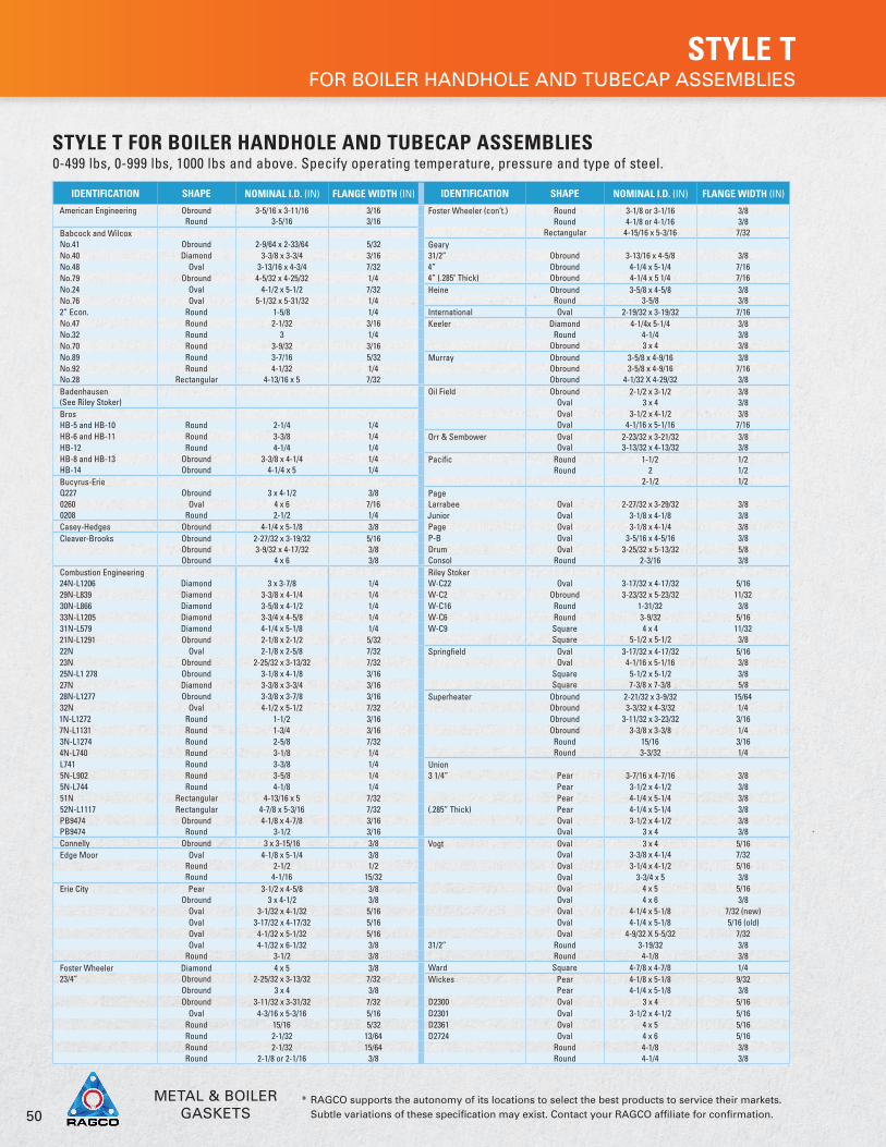
STYLE T FOR BOILER HANDHOLE AND TUBECAP ASSEMBLIES
STYLE T FOR BOILER HANDHOLE AND TUBECAP ASSEMBLIES0-499 lbs, 0-999 lbs, 1000 lbs and above. Specify operating temperature, pressure and type of steel.
IDENTIFICATION SHAPE NOMINAL I.D. (IN) FLANGE WIDTH (IN) IDENTIFICATION SHAPE NOMINAL I.D. (IN) FLANGE WIDTH (IN)
American Engineering Obround 3-5/16 x 3-11/16 3/16 Foster Wheeler (con’t.) Round 3-1/8 or 3-1/16 3/8Round 3-5/16 3/16 Round 4-1/8 or 4-1/16 3/8
Babcock and Wilcox Rectangular 4-15/16 x 5-3/16 7/32No.41 Obround 2-9/64 x 2-33/64 5/32 GearyNo.40 Diamond 3-3/8 x 3-3/4 3/16 31/2” Obround 3-13/16 x 4-5/8 3/8No.48 Oval 3-13/16 x 4-3/4 7/32 4” Obround 4-1/4 x 5-1/4 7/16No.79 Obround 4-5/32 x 4-25/32 1/4 4” (.285" Thick) Obround 4-1/4 x 5 1/4 7/16No.24 Oval 4-1/2 x 5-1/2 7/32 Heine Obround 3-5/8 x 4-5/8 3/8No.76 Oval 5-1/32 x 5-31/32 1/4 Round 3-5/8 3/82” Econ. Round 1-5/8 1/4 International Oval 2-19/32 x 3-19/32 7/16No.47 Round 2-1/32 3/16 Keeler Diamond 4-1/4x 5-1/4 3/8No.32 Round 3 1/4 Round 4-1/4 3/8No.70 Round 3-9/32 3/16 Obround 3 x 4 3/8No.89 Round 3-7/16 5/32 Murray Obround 3-5/8 x 4-9/16 3/8No.92 Round 4-1/32 1/4 Obround 3-5/8 x 4-9/16 7/16No.28 Rectangular 4-13/16 x 5 7/32 Obround 4-1/32 X 4-29/32 3/8Badenhausen Oil Field Obround 2-1/2 x 3-1/2 3/8(See Riley Stoker) Oval 3 x 4 3/8Bros Oval 3-1/2 x 4-1/2 3/8HB-5 and HB-10 Round 2-1/4 1/4 Oval 4-1/16 x 5-1/16 7/16HB-6 and HB-11 Round 3-3/8 1/4 Orr & Sembower Oval 2-23/32 x 3-21/32 3/8HB-12 Round 4-1/4 1/4 Oval 3-13/32 x 4-13/32 3/8HB-8 and HB-13 Obround 3-3/8 x 4-1/4 1/4 Pacific Round 1-1/2 1/2HB-14 Obround 4-1/4 x 5 1/4 Round 2 1/2Bucyrus-Erie 2-1/2 1/2Q227 Obround 3 x 4-1/2 3/8 Page0260 Oval 4 x 6 7/16 Larrabee Oval 2-27/32 x 3-29/32 3/80208 Round 2-1/2 1/4 Junior Oval 3-1/8 x 4-1/8 3/8Casey-Hedges Obround 4-1/4 x 5-1/8 3/8 Page Oval 3-1/8 x 4-1/4 3/8Cleaver-Brooks Obround 2-27/32 x 3-19/32 5/16 P-B Oval 3-5/16 x 4-5/16 3/8
Obround 3-9/32 x 4-17/32 3/8 Drum Oval 3-25/32 x 5-13/32 5/8Obround 4 x 6 3/8 Consol Round 2-3/16 3/8
Combustion Engineering Riley Stoker24N-L1206 Diamond 3 x 3-7/8 1/4 W-C22 Oval 3-17/32 x 4-17/32 5/1629N-L839 Diamond 3-3/8 x 4-1/4 1/4 W-C2 Obround 3-23/32 x 5-23/32 11/3230N-L866 Diamond 3-5/8 x 4-1/2 1/4 W-C16 Round 1-31/32 3/833N-L1205 Diamond 3-3/4 x 4-5/8 1/4 W-C6 Round 3-9/32 5/1631N-L579 Diamond 4-1/4 x 5-1/8 1/4 W-C9 Square 4 x 4 11/3221N-L1291 Obround 2-1/8 x 2-1/2 5/32 Square 5-1/2 x 5-1/2 3/822N Oval 2-1/8 x 2-5/8 7/32 Springfield Oval 3-17/32 x 4-17/32 5/1623N Obround 2-25/32 x 3-13/32 7/32 Oval 4-1/16 x 5-1/16 3/825N-L1 278 Obround 3-1/8 x 4-1/8 3/16 Square 5-1/2 x 5-1/2 3/827N Diamond 3-3/8 x 3-3/4 3/16 Square 7-3/8 x 7-3/8 5/828N-L1277 Obround 3-3/8 x 3-7/8 3/16 Superheater Obround 2-21/32 x 3-9/32 15/6432N Oval 4-1/2 x 5-1/2 7/32 Obround 3-3/32 x 4-3/32 1/41N-L1272 Round 1-1/2 3/16 Obround 3-11/32 x 3-23/32 3/167N-L1131 Round 1-3/4 3/16 Obround 3-3/8 x 3-3/8 1/43N-L1274 Round 2-5/8 7/32 Round 15/16 3/164N-L740 Round 3-1/8 1/4 Round 3-3/32 1/4L741 Round 3-3/8 1/4 Union5N-L902 Round 3-5/8 1/4 3 1/4” Pear 3-7/16 x 4-7/16 3/85N-L744 Round 4-1/8 1/4 Pear 3-1/2 x 4-1/2 3/851N Rectangular 4-13/16 x 5 7/32 Pear 4-1/4 x 5-1/4 3/852N-L1117 Rectangular 4-7/8 x 5-3/16 7/32 (.285” Thick) Pear 4-1/4 x 5-1/4 3/8PB9474 Obround 4-1/8 x 4-7/8 3/16 Oval 3-1/2 x 4-1/2 3/8PB9474 Round 3-1/2 3/16 Oval 3 x 4 3/8Connelly Obround 3 x 3-15/16 3/8 Vogt Oval 3 x 4 5/16Edge Moor Oval 4-1/8 x 5-1/4 3/8 Oval 3-3/8 x 4-1/4 7/32
Round 2-1/2 1/2 Oval 3-1/4 x 4-1/2 5/16Round 4-1/16 15/32 Oval 3-3/4 x 5 3/8
Erie City Pear 3-1/2 x 4-5/8 3/8 Oval 4 x 5 5/16Obround 3 x 4-1/2 3/8 Oval 4 x 6 3/8
Oval 3-1/32 x 4-1/32 5/16 Oval 4-1/4 x 5-1/8 7/32 (new)Oval 3-17/32 x 4-17/32 5/16 Oval 4-1/4 x 5-1/8 5/16 (old)Oval 4-1/32 x 5-1/32 5/16 Oval 4-9/32 X 5-5/32 7/32Oval 4-1/32 x 6-1/32 3/8 31/2” Round 3-19/32 3/8
Round 3-1/2 3/8 Round 4-1/8 3/8Foster Wheeler Diamond 4 x 5 3/8 Ward Square 4-7/8 x 4-7/8 1/423/4” Obround 2-25/32 x 3-13/32 7/32 Wickes Pear 4-1/8 x 5-1/8 9/32
Obround 3 x 4 3/8 Pear 4-1/4 x 5-1/8 3/8Obround 3-11/32 x 3-31/32 7/32 D2300 Oval 3 x 4 5/16
Oval 4-3/16 x 5-3/16 5/16 D2301 Oval 3-1/2 x 4-1/2 5/16Round 15/16 5/32 D2361 Oval 4 x 5 5/16Round 2-1/32 13/64 D2724 Oval 4 x 6 5/16Round 2-1/32 15/64 Round 4-1/8 3/8Round 2-1/8 or 2-1/16 3/8 Round 4-1/4 3/8
METAL & BOILERGASKETS

51* RAGCO supports the autonomy of its locations to select the best products to service their markets. Subtle variations of these specification may exist. Contact your RAGCO affiliate for confirmation.
•
SELF-LOCATOR GASKETS
US NAVY “HYBRID”The SELF LOCATOR gaskets are a complete stainless steel containment of a sealing element offering a true compression seal. The patented design gives you long term reliability without flange welding and eliminates misalignment on installation. Due to its universal sizing, one gasket fits all flange pressure classes, eliminating the chance of incorrect gasket selection. The most important feature of the gasket is the high unit load generated by the narrow sealing area provides a considerably higher flange clamping pressure and a better seal at a lower clamping force. The standard gasket material is 316 SS, with two (2) tracks of Flexible Graphite sealing elements. Specialty gasket material and/or sealing elements are available as options.
TECHNICAL DATA
SIZES ½, ¾, 1, 1¼, 1½, 2, 2½, 3, 3½, 4, 5, 6, 8, 10, 12, 14, 16, 18, 20, 22, 24
FLANGE PRESSURE CLASS 150# to 2500#
THICKNESS1/32" thru 12"1/16" above 12"
TORQUE VALUES 50% to 65% of Bolt Yield
FLANGE SURFACE FINISH 10 to 400 μin RMS (microinches)
SEALING ELEMENTS WIDTH≥1½ (gasket size) 0.125" each side½ to 1¼ (gasket size) 0.100" each side
MIN. SEALING ELEMENT WEB WIDTH 0.670"
"M" AND "Y" VALUESm = 2.85 Y = 2900 psi
LEAK RATE0.005 in mg/m*s(DIN 28090 / 1.2)< 10ppm @ He
TEMPERATURE RANGE
-200°C cryogenic air+500°C in regular atmosphere+650°C in steam+1000°C reducing or inert media
PRESSURE RANGE Full vacuum to +5000 PSI
MIN. SEATING STRESS2900 PSI (20 MPa)23,200 psi (160 MPa)(testing equipment limit)
RECOMMENDED SEATING STRESS 5800 to 8700 psi (40 to 60 MPa)
STANDARDS AVAILABLE ANSI 16.5, DIN 2600, JIS B2220, BS 4505, BS 10, AUS 2129
KEY BENEFITS• Ability to cope against severe thermal cycling and
vibration• Inherent Live Loading capability• Fire, Blow Out and Leak proof• Superior pressure handling• Standardize: one gasket for all pressure classes• Protects against use of wrong gasket
• Lowers total sealing costs• Cannot be over compressed• No need to re-torque• Eliminates fugitive emissions• US Navy approved• ANSI, DIN, JIS, BS and AUS sizes available
METAL & BOILERGASKETS

52* RAGCO supports the autonomy of its locations to select the best products to service their markets. Subtle variations of these specification may exist. Contact your RAGCO affiliate for confirmation.
•
TOPOG-E® GASKETS
The steam boiler market makes extreme demands on gaskets; Topog-E® molded rubber gaskets are specifically formulated to meet and exceed these demands and deliver industry standard performance.
Topog-E® Series 180 gaskets have been refined through a series of over 600 research formulation tests to ensure that they are able to meet the exacting performance standards of the steam boiler industry.
Specifically they:
1. Conform to the topography of the mating surfaces
2. Withstand a boiler’s full, continuous and cycling operating pressures
3. Withstand continuous exposure to water treatment chemicals
4. Withstand continuous exposure to ion and oxygen attack in hot air
5. Prevent all leakage
6. Replace easily, without chiselling or buffing
MATERIALSSpecial, proprietary rubber Composition, black, 80-85 Durometer.
SERVICE SUMMARYSteam boilers: up to 180 psi (12 bar) and 380º F. (193º C) Water, condensate, etc. vessels: 200+ psi (14 bar) and less than 300ºF. (150ºC)
APPLICATIONSWhen used on steam pressure vessels Topog-E® Series 180 gaskets are typically used at operating pressures of up to 180 PSI (12 bar) and saturated steam temperatures up to 380º F. (193º C) for an average service life of one year. When used in other applications (e.g. condensate, water, and air vessels) Topog-E® Series 180 gaskets are sometimes used at pressures above 200 PSI (14 bar) where temperatures are typically more moderate (e.g. below 250ºF./121ºC.). When operating under less severe conditions (e.g. water applications at ambient temperatures) Topog-E® Series 180 gaskets can provide very long service lives. Topog-E® Series 180 gaskets have been used successfully around the world for over forty years. In general, any type of industrial pressure vessel or tank that has inspection openings is a potential application whereTopog-E® Series 180 gaskets can be used as a cost effective sealing device.
METAL & BOILERGASKETS

53* RAGCO supports the autonomy of its locations to select the best products to service their markets. Subtle variations of these specification may exist. Contact your RAGCO affiliate for confirmation.
•
In addition to using them in steam pressure vessels, customers also use Topog-E® molded gaskets and sheet material with great success in many other applications, including:
• Water softeners• Hot water heaters• Steam humidifiers and cookers• Water purifiers and demineralizers• Refrigeration units• Liquid treatment vessels• Carbon absorption and filtering vessels• Dryer cans in paper mills• Water hydrants
• Mixing tanks• Compressed air tanks• Various types of dryers• Air starters and receivers• Deaerators• Hatch covers• Water towers and columns• PVC reactor vessels
INSTALLATION ENVIRONMENT & SUITABILITYTopog-E® Series 180 gaskets are specifically formulated to have excellent resistance to steam and hot and cold water.
They also have good resistance to:
• Alcohols• Ketones• Phosphate esters• Silicone oils and greases• Dilute acids• Bases
• Salts• Glycols• Ammonia• Selected refrigerants• Animal and vegetable fats
Water treatment chemicals, when used in accordance with supplier’s guidelines, should not have a significant effect on the service life of properly installed Topog-E® Series 180 gaskets.
Topog-E® Series 180 gaskets are not recommended for use in applications where they see direct exposure to high concentrations of aromatic hydrocarbons, chlorinated solvents, or petroleum based oils, fuels, and lubricants.
METAL & BOILERGASKETS

54* RAGCO supports the autonomy of its locations to select the best products to service their markets. Subtle variations of these specification may exist. Contact your RAGCO affiliate for confirmation.
•
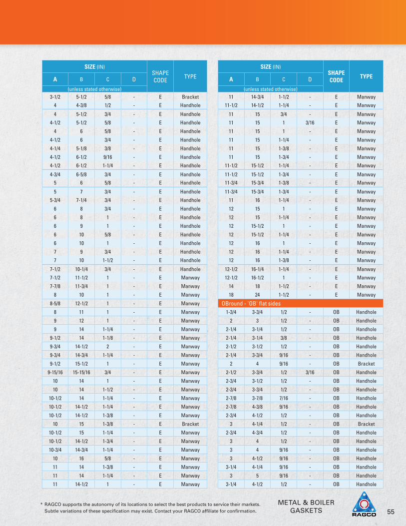
TOPOG-E® GASKET SIZES
SIZE (IN)SHAPE CODE
TYPEA B C D
(unless stated otherwise)Elliptical - 'E'
1-7/8 2-1/2 7/16 - E Handhole
1-3/4 3-3/4 3/8 - E Handhole
2 3 3/8 - E Handhole
2-1/4 3-1/4 1/2 - E Handhole
2-1/4 3-3/4 1/2 - E Handhole
2-1/2 3-1/4 3/8 - E Handhole
2-1/2 3-1/2 1/2 - E Handhole
2-3/4 3-1/2 3/8 3/16 E Handhole
2-1/2 3-3/4 3/8 3/16 E Bracket
2-3/4 3-1/2 1/2 - E Handhole
2-1/2 3-3/4 1/2 - E Bracket
2-3/4 3-3/4 5/8 - E Handhole
2-3/4 3-3/4 1/2 - E Handhole
2-7/8 3-7/8 1/2 - E Handhole
3 3-3/4 1/2 - E Handhole
2-3/4 4-1/2 5/8 - E Handhole
3 4-1/4 5/8 - E Bracket
3 4 5/16 - E Handhole
3 4 1/2 - E Handhole
2-3/4 4-1/4 1/2 - E Bracket
3 4 5/8 - E Handhole
3 4 3/4 - E Handhole
3 4 1-1/2 - E Handhole
3 4-1/2 1/2 - E Handhole
3 4-1/2 5/8 - E Handhole
3 5 9/16 - E Handhole
3-1/4 4-3/4 9/16 - E Bracket
3-1/4 4-1/4 1/2 - E Handhole
3-1/4 4-1/4 3/4 - E Handhole
3 4-1/2 3/4 - E Bracket
3-1/4 4-1/2 1/2 - E Handhole
3-1/4 5 9/16 - E Handhole
3-3/8 4-3/8 7/16 - E Handhole
3-3/8 4-3/8 9/16 - E Handhole
3-1/2 4-1/2 7/16 - E Handhole
3-1/2 4-1/2 1/2 - E Handhole
3-1/2 4-1/2 5/8 - E Handhole
3-1/2 4-1/2 3/4 - E Handhole
3-1/2 4-1/2 1-1/2 - E Handhole
3-1/2 5 1/2 - E Handhole
3-1/2 5 3/4 - E Handhole
3-3/4 4-3/4 9/16 - E Handhole
3-3/4 5-1/2 9/16 - E Handhole
4 5-1/4 9/16 - E Bracket
4 5 5/8 - E Handhole
3-3/4 5-1/4 5/8 - E Bracket
A
B
DC
Elliptical – E
When ordering, be sure to state the twoinside dimensions (A & B), flange width(C), thickness (D), and shape (E, OB, etc.).
OB Round – OB
Round – R
Rectangle – Rect.
Diamond – D
Pear – P
Square – S
Special Square – SPS
Elliptical Turtle – ET
SHAPE CODE
METAL & BOILERGASKETS
55* RAGCO supports the autonomy of its locations to select the best products to service their markets. Subtle variations of these specification may exist. Contact your RAGCO affiliate for confirmation.
•
SIZE (IN)SHAPE CODE
TYPEA B C D
(unless stated otherwise)3-1/2 5-1/2 5/8 - E Bracket
4 4-3/8 1/2 - E Handhole
4 5-1/2 3/4 - E Handhole
4-1/2 5-1/2 5/8 - E Handhole
4 6 5/8 - E Handhole
4-1/2 6 3/4 - E Handhole
4-1/4 5-1/8 3/8 - E Handhole
4-1/2 6-1/2 9/16 - E Handhole
4-1/2 6-1/2 1-1/4 - E Handhole
4-3/4 6-5/8 3/4 - E Handhole
5 6 5/8 - E Handhole
5 7 3/4 - E Handhole
5-3/4 7-1/4 3/4 - E Handhole
6 8 3/4 - E Handhole
6 8 1 - E Handhole
6 9 1 - E Handhole
6 10 5/8 - E Handhole
6 10 1 - E Handhole
7 9 3/4 - E Handhole
7 10 1-1/2 - E Handhole
7-1/2 10-1/4 3/4 - E Handhole
7-1/2 11-1/2 1 - E Manway
7-7/8 11-3/4 1 - E Manway
8 10 1 - E Manway
8-5/8 12-1/2 1 - E Manway
8 11 1 - E Manway
9 12 1 - E Manway
9 14 1-1/4 - E Manway
9-1/2 14 1-1/8 - E Manway
9-3/4 14-1/2 2 - E Manway
9-3/4 14-3/4 1-1/4 - E Manway
9-1/2 15-1/2 1 - E Manway
9-15/16 15-15/16 3/4 - E Manway
10 14 1 - E Manway
10 14 1-1/2 - E Manway
10-1/2 14 1-1/4 - E Manway
10-1/2 14-1/2 1-1/4 - E Manway
10-1/2 14-1/2 1-3/8 - E Manway
10 15 1-3/8 - E Bracket
10-1/2 15 1-1/4 - E Manway
10-1/2 14-1/2 1-3/4 - E Manway
10-3/4 14-3/4 1-1/4 - E Manway
10 16 5/8 - E Manway
11 14 1-3/8 - E Manway
11 14 1-1/4 - E Manway
11 14-1/2 1 - E Manway
SIZE (IN)SHAPE CODE
TYPEA B C D
(unless stated otherwise)11 14-3/4 1-1/2 - E Manway
11-1/2 14-1/2 1-1/4 - E Manway
11 15 3/4 - E Manway
11 15 1 3/16 E Manway
11 15 1 - E Manway
11 15 1-1/4 - E Manway
11 15 1-3/8 - E Manway
11 15 1-3/4 - E Manway
11-1/2 15-1/2 1-1/4 - E Manway
11-1/2 15-1/2 1-3/4 - E Manway
11-3/4 15-3/4 1-3/8 - E Manway
11-3/4 15-3/4 1-3/4 - E Manway
11 16 1-1/4 - E Manway
12 15 1 - E Manway
12 15 1-1/4 - E Manway
12 15-1/2 1 - E Manway
12 15-1/2 1-1/4 - E Manway
12 16 1 - E Manway
12 16 1-1/4 - E Manway
12 16 1-3/8 - E Manway
12-1/2 16-1/4 1-1/4 - E Manway
12-1/2 16-1/2 1 - E Manway
14 18 1-1/2 - E Manway
18 24 1-1/2 - E Manway
OBround - 'OB' flat sides1-3/4 3-3/4 1/2 - OB Handhole
2 3 1/2 - OB Handhole
2-1/4 3-1/4 1/2 - OB Handhole
2-1/4 3-1/4 3/8 - OB Handhole
2-1/2 3-1/2 1/2 - OB Handhole
2-1/4 3-3/4 9/16 - OB Handhole
2 4 9/16 - OB Bracket
2-1/2 3-3/4 1/2 3/16 OB Handhole
2-3/4 3-1/2 1/2 - OB Handhole
2-3/4 3-3/4 1/2 - OB Handhole
2-7/8 3-7/8 7/16 - OB Handhole
2-7/8 4-3/8 9/16 - OB Handhole
2-3/4 4-1/2 1/2 - OB Handhole
3 4-1/4 1/2 - OB Bracket
2-3/4 4-3/4 1/2 - OB Handhole
3 4 1/2 - OB Handhole
3 4 9/16 - OB Handhole
3 4-1/2 9/16 - OB Handhole
3-1/4 4-1/4 9/16 - OB Handhole
3 5 9/16 - OB Handhole
3-1/4 4-1/2 1/2 - OB Handhole
METAL & BOILERGASKETS

56* RAGCO supports the autonomy of its locations to select the best products to service their markets. Subtle variations of these specification may exist. Contact your RAGCO affiliate for confirmation.
•
TOPOG-E® GASKET SIZES
SIZE (IN)SHAPE CODE
TYPEA B C D
(unless stated otherwise)3-1/4 4-1/2 9/16 - OB Handhole
3-1/4 4-3/4 5/8 - OB Handhole
3-1/4 4-3/4 1/2 - OB Handhole
3-1/2 4-1/2 9/16 - OB Handhole
3 4-3/4 9/16 - OB Bracket
3-3/8 4-1/4 3/8 - OB Handhole
3-1/2 5 9/16 - OB Handhole
3-1/4 5-1/4 9/16 - OB Bracket
3-1/2 5-1/2 1/2 - OB Handhole
3-1/2 5-1/2 5/8 - OB Handhole
3-5/8 5-5/8 7/16 - OB Handhole
3-5/8 5-5/8 9/16 - OB Handhole
3-5/8 5-5/8 1 - OB Handhole
4 5 5/8 - OB Handhole
4-1/2 5-1/2 5/8 - OB Handhole
4 6 5/8 - OB Handhole
4-1/2 6 5/8 - OB Handhole
4-1/2 6-1/2 5/8 - OB Handhole
4-1/2 10-1/4 3/4 - OB Handhole
5 6-3/4 1 - OB Handhole
5 7 5/8 - OB Handhole
5 7-1/2 1 - OB Manway
10-1/2 14-1/2 1-5/16 - OB Manway
11 15 1-1/4 - OB Manway
12 16 1-1/2 - OB Manway
Round 'R'
Inner 'D' Outer 'D' C D
1-3/8 2-5/16 - 5/16 R Handhole
2-7/8 3-5/8 - 1/8 R Handhole
2-15/16 3-15/16 - - R Handhole
3 3-5/8 - 3/16 R Handhole
3 3-3/4 - - R Handhole
3 4 - - R Handhole
3-1/4 4 - - R Handhole
3-1/2 4-3/16 - 3/16 R Handhole
3-1/2 4-1/2 - - R Handhole
3-1/2 5 - - R Handhole
3-1/2 5-1/2 - - R Handhole
3-11/16 4-1/2 - 3/8 R Handhole
4 4-3/4 - - R Handhole
4 5 - - R Handhole
4 5-1/4 - 3/16 R Handhole
4-1/4 5-1/16 - - R Handhole
4-1/2 5-1/2 - 3/16 R Handhole
4-3/4 6-3/8 - - R Handhole
5 6 - - R Handhole
SIZE (IN)SHAPE CODE
TYPEInner 'D' Outer 'D' C D
(unless stated otherwise)5-1/4 8 - 5/16 R Handhole
5-7/16 7-9/16 - 5/16 R Handhole
6 7-1/2 - - R Handhole
10-3/4 13-3/8 - 1/8 R Handhole
12-3/4 16-1/8 - 1/8 R Handhole
Special Shapes
1-1/2 3-3/4 - - R, 4 Holes Flange
2 3-1/2 - - S, 4 Holes Flange
7-3/8 7-3/8 5/8 - S Handhole
2 6 1-1/2 - Rect. Handhole
2-13/16 16-7/8 1-1/16 3/16 Rect. Handhole
3-3/4 8-1/2 1/2 - Rect. Handhole
4-1/2 6 1/4 - Rect. Handhole
6-1/4 9-3/4 5/8 - Rect. Handhole
3 4 9/16 - K Handhole
3-3/8 3-3/4 1/4 1/8 D
3-3/8 4-1/4 1/4 - D Handhole
3-1/2 4-1/2 1/4 - D Handhole
4 5 1/2 - D Handhole
4-1/4 5-1/4 13/32 - D Handhole
3-1/2 4-1/2 7/16 - P Handhole
3-3/8 4-3/8 1/2 - P Handhole
3-5/8 4-3/4 1/2 - P Handhole
4 5 1/2 - P Handhole
4 5 9/16 - N.P. Handhole
4 5 5/8 - W.P. Handhole
4-1/4 5-1/8 1/2 - SPU.P Handhole
5-1/4 5-1/4 3/8 - SPS Handhole
7-7/16 7-7/16 9/16 - SPS Handhole
10 16 1-3/4 - ET Manway
8-3/4 14 2-1/4 -E, w 4 Bolt
HolesManway
3-7/8 13-3/8 1-3/16 1/8 OB Flange
DISCLAIMER All information in this data sheet is based on data believed to be reliable, however we make no guarantee or warranty of performance of Topog-E® Series 180 gaskets. Because there are many application-specific factors that can affect service life it is always advisable to first test Topog-E® Series 180 gaskets in a particular application to determine their ultimate suitability.
METAL & BOILERGASKETS

57* RAGCO supports the autonomy of its locations to select the best products to service their markets. Subtle variations of these specification may exist. Contact your RAGCO affiliate for confirmation.
•
NOTES• Standard thickness is 1/4" unless otherwise noted under column D.• All prices are for Topog-E® Gasket Standard Material (refer to separate Material Specification sheet for
more information).• Prices are F.O.B. Tulsa, Oklahoma 74110.• Bracketed gaskets are not stock molded sizes, however, the first stock size can often be used on plates
designed for the bracketed size.• A 25% restocking fee may be charged on all returns.• Special sizes and shapes can be fabricated upon request.• Topog-E® gaskets can be made from other materials – contact us to receive a Materials Specification
Sheet for Alternative Elastomeric Materials.• We also make chemical tank and water hydrant gaskets.
DISCLAIMER Topog-E® gaskets are made and sold for use in steam, water, air, and other selected applications only. Our recommendations for their use are based on tests believed to be reliable and on actual customer experience. Since their installation and use are beyond our control, we cannot guarantee the results, whether or not such use is in accordance with instructions. We disclaim any responsibility.
METAL & BOILERGASKETS