
I - Death, along the famished road - Prem Bhatia Memorial Trust
Upload
khangminh22Category
view
1download
0
CA9800144
CONTAINMENT DESIGN FOB INDIAN PHWRs- EVOLUTION AND FUTURE TRENDS
S.K. Chat terJee, G.R. Srinivasan, M.Das,Prem Prakash, Sharada Mulgund
Nuclear Power Corporation, Bombay-400094, India
ABSTRACT
The design of containment systems for PHWRs in India hasundergone progressive improvements to enhance their reliabilityand effectiveness. The state-of-the-art containment designincorporates a double containment structure for minimizingradioactivity release to the environment, a completely passivevapour suppression system with huge suppression pool for limitingpressure build-up during postulated LOCA and various engineeredsystems for depressurising the containment and cleaning thecontainment environment following an accident. The containmentrelated Engineered Safety Features (ESFs) include ReactorBuilding (RB) coolers, Primary Containment Controlled Discharge(PCCD) system, Primary Containment Filtration and Pump-Back(PCFPB) system and Secondary Containment Filtered Recirculationand Purge (SCFRP) system.
Studies indicate that the unique feature of doublecontainment with huge suppression pool at basement and associatedESFs not only ensures near zero ground level release duringDesign Basis Accident (DBA) conditions, but also providesadequate assurance for containment integrity even in beyond DBAscenarios. In this paper, an outline of the containment designevolution in Indian PHWRs is presented and salient features ofstandardised containment design are highlighted. Importantcontainment related studies are discussed and outstanding safetyissues viz. hydrogen generation and management, containmentventing, containment over pressure capability, etc. areaddressed.

CONTAINMENT DESIGN FOR INDIAN PHWRs- EVOLUTION AND FUTURE TRENDS
S.K. Chatterjee, G.R. Srinivaaan, M.Das,Prem Prakash, Sharada Mulgund
Nuclear Power Corporation, Bonbay-400094, India
1.0 INTRODUCTION
The containment being the ultimate barrier between the reactorsystem and environment, its existing designs are continuouslybeing scruitinized and improved to increase their reliability,effectiveness and to extend their capabilities to manage beyonddesign-basis-accident (DBA) situations. India's PHWR programmestarted with construction of a 2x220 MWe station at RAPS in latesixties with Canadian collaboration. Subsequently, fiveindigenously designed 220 MWe units (MAPS-1&2, NAPS-1&2 and KAPS-1) were built, which are now under operation. Five more 220 MWeunits (KAPP-2, Kaiga-1&2 and RAPP-3&4) and two 500 MWe units(TAPP-3&4) are at various stages of completion and many more areplanned. As also with other safety systems, the design ofcontainment system for PHWRs in India has undergone progressiveimprovement to enhance its reliability and effectiveness.
NAPS type containment design is adopted as the standardiseddesign and the similar philosophy been/being used for allsubsequent 220 MWe and 500 MWe units. The standardisedcontainment design for Indian FHWRs (IPHWRs) is rather unique inthe sense that it uses a complete double containment philosophywith suppression pool conceptni. It also incorporates severalengineered-safety-features (ESFs) for minimising the release ofradioactive materials to the environment under postulatedaccident conditions. Various functional requirements ofcontainment system are identified in Fig. 1. The featuresavailable/used in IPHWR containments to meet each of thesefunctions are also identified in the same. The evolution ofcontainment design and associated ESFs from one station toanother is summarized in Table-1. Fig. 2 shows schematically thevarious features as used in the standardised design.
In the following sections, evolution of the containment systemdesign is presented highlighting the salient design features andexperience with containment Proof Tests (PTs) and Leakage RateTests (LRTs). Important containment related studies (e.g.pressure and temperature transient analysis, activity releaseassessment, suppression pool hydrodynamic analysis, 3D hydrogendispersion analysis, etc.) are discussed. Various containmentrelated issues for IPHWRs viz. hydrogen generation andmanagement, containment venting, containment over pressurecapability, etc. are also addressed.
2.0 CONTAINMENT AND ASSOCIATED ESFsC2,3,4,5]
Various design improvements are described below:
2.1 Containment Envelope:
All IPHWRs use concrete containment buildings with epoxy/vinylcoating for improving leaktightness and ease of decontamination.Though the first two units at RAPS constructed in late sixtiesuse single containment of Reinforcrd Cement Concrete (RCC),improvements have been incorporated in the form of partialSecondary Containment (SO in MAPS to full SC in the subsequentplants at NAPS, KAPP, Kaiga and in 500 MWe design (refer Table-1). The current standardised designs of IPHWRs incorporate apassive suppression pool type Primary Containment (PC)constructed from Prestressed Cement Concrete (PCC), which iscompletely enveloped by an RCC constructed SC on a common baseraft. Figs. 3 and 4 show the typical cross sections of standard220 MWe and 500 MWe Reactor Buildings (RB). The basic purpose ofSC is to reduce the ground level release of radioactivity by wayof holdup and dilution of leakage from PC. Also, the combinedthickness of PC and SC provides adequate sheilding from directradiation. PC is designed to withstand the overpressure caused bythe release of hot coolant from the primary heat transport (PHT)system under DBA condition. The design pressure of SC is decidedbased on continuous holdup of leakage from PC (assumingconservatively high leak rates) during the overpressure periodfollowing DBA. The design pressures and temperatures for variousplants are also indicated in Table-1. The design target leakagerate for both PC and SC envelopes is typically 0.1% of containedvolume per hour at the respective design pressures.
The concept of double containment is extended to cover the entireRB (except the base slab) including the penetrations and pipingsopen to containment atmosphere such as airlocks, ventilationducts and other air handling systems. The annular space betweenthe PC and SC envelopes is provided with a purging arrangement tomaintain a negative pressure in the interspace. This preventsground level release to the environment during accidentconditions involving radioactivity release within the PC.Automatic isolation of the containment is initiated, by closingthe isolation dampers (multiple in series) on all containmentduct penetrations, in the event of (a) pressure rise, or (b)activity build-up in the containment, or (c) ECCS actuation (assensed by fall in pressure of primary coolant system while stillhot). Provisions have been made for testing the functionality ofall active containment isolation devices and an overall systemreliability of over 99.9% is ensured by periodic testing. Withthe above mentioned double containment features, the ground levelradioactivity release in the event of an accident would bereduced by orders of magnitude as compared to a singlecontainment.

2.2 Pressure Suppression System
In RAPS, the pressure rise in RB following LOCA/Stearo Line Break(SLB) is limited by the dousing system consisting of a big (1820m3) water tank (at high elevation) and spray system, used toestablish a curtain of water in the passage of steam flow onsensing the break. Since the functioning of dousing system mainlydepends on a number of active components like fast openingvalves, in MAPS and subsequent reactors, it is replaced by acompletely passive suppression pool system (at basement) fromreliability considerations. This has also helped in reducingloads on structures, particularly during a seismic event. Thoughthe internal layout of MAPS RB is not significantly differentfrom that of RAPS, the entire RB has been divided into twoaccident based volumes viz. VI (i.e. drywell) and V2 (i.e.wetwell) separated by leaktight walls and floors. Volume VIencompasses all enclosures housing high temperature Primary HeatTransport (PHT) system and (in all units subsequent to KAPP) partof the secondary system. The rest of the building constitutesvolume V2. The basement floor accommodates the vapour suppressionpool. The only interconnection between VI and V2 is throughsuppression pool by means of vent system which consists of vent-shafts, distribution-headers and (In some cases) downcomer pipes.The suppression pool system does not perform any function duringnormal operation, however, it condenses a fraction of steamreleased during LOCA/SLB. In addition, the availability of hugesuppression pool at basement serves as a large heat sink insidethe RB for long term decay heat removal by emergency-core-cooling- system (ECCS) in recirculation mode. A good amount ofparticulate activity, soluble active species and tritiumactivity, flushed out from PHT system by discharging fluid, alsogets trapped in the pool water .
2.3 Containment Depressurisatlon:
In order to minimize the integrated out-leakage of radioactivityfrom containment to the environment following an accident, it isdesirable to depressurise the containment in as short a time aspossible. Following ESFs have been provided to handle the aboverequirement.
2.3.1 Reactor Building Coolers:
The high capacity RB coolers, qualified for functioning underharsh LOCA/SLB environment, have been engineered to cool down andthereby depressurise the containment quickly following anaccident. These coolers are supplied from assured process waterand diesel-generator backed (Class-Ill) power supply. Part ofthese coolers are normally operating during reactor operation andthe remaining ones come on sensing increase in RB pressure.
2.3.2 Primary Containment Controlled Discharge fPCCD) System;[*3
If ground level releases are found to take place as a result ofdegradation of containment barriers, the controlled

depressurisation of the PC could be initiated by resorting tofiltered release through stack using PCCD system. This may alsobe used to achieve further depressurisation at low pressures (saybelow 0.05 kg/cm*(g)) which may be difficult to achieve bycooling alone, if the circumstances demand. This system draws airfrom V2 space to avoid release of gas loaded with highconcentration of radioactive materials including aerosols, as maybe the case in volume VI. This reduces ground level release butadds to the release via stack. The system is operated under thesupervision of an advisory group after a minimum delay of 24hours into the accident only after ascertaining the containmentpressure trend, stability of meteorological conditions and extentof ground level releases.
NAPS onwards, the availability of double containment envelopeallows the PC to remain at a small overpressure for extendedduration following LOCA, without adding significantly to groundlevel release. Thus, the need to go for controlled dischargethrough stack can be conveniently delayed. Meanwhile, the primarycontainment cleanup system (refer section 2.4.1) would havesubstantially reduced the concentration of activity in theprimary containment atmosphere, so that stack release associatedwith controlled gas discharge is significantly reduced. Theactivity holdup in the containment also allows the natural decayof short lived radio-nuclides and plate-out of particulateactivities on exposed structural surfaces inside RB.
2. 4 Fission Product Reatoval f ron Containment Atnosphere:
While in RAPS and MAPS, no specific engineered systems areprovided for attending the above requirement, in NAPS andsubsequent reactors, additional means have been incorporated forpost-accident containment atmosphere cleanup on long term basis.These systems are briefly described below:
2.4.1 Primary Containment Filtration and Pump Back (PCFPB)Svatem:
This system has been provided to clean up the PC atmosphere byremoving particulate and iodine isotopes in various forms so thatthe long term activity release following an accident involvingsubstantial release of fission products into the containment canbe controlled to a very low value. The system is designed tofunction under LOCA environment and powered by class III electricsupply. Typical iodine removal half-life of about 3.5 hours wouldbe effected by this system. Operation of the system is underadministrative control after a delay of at least 4 hours into theaccident.
This system draws air from volume VI and the filtered air isdischarged into volume V2. It also serves to promote mixing ofhydrogen between VI and V2 following an accident involvingrelease of hydrogen.

2.4.2 Sftoondarv Contai nment F1 1 t.ftred Recirculation and Purge(SCFRP) System:
SCFRP system provides multi-pass filtration by recirculation (viaredundant HEPA and Iodine filters) within the SC space. It alsomaintains small negative pressure within the SC space by purgingto stack after refiltration, which brings the net ground levelrelease of activity down to virtually zero. The system consistsof (class-Ill powered) fans and filter banks. It startsautomatically after an accident.
3.0 CONTAINMENT PROOF TEST AND LEAKAGE RATE TESTED
In order to ensure the effective performance of the containmentand its associated ESFs, these are required to be tested beforefirst criticality and thereafter periodically during the service.The pre-operational tests on the containment structure includePTs at 115% of design pressure. Besides the demonstration ofstructural integrity, the load-deformation characteristics areevaluated during the PT. For a prototype containment, strains atvarious locations are also monitored in addition to deflections.
LRT on containment structure is mandatory prior to reactorcriticality and thereafter at an interval not exceeding twoyears. LRTs include tests carried out on individual penetrations,closure devices, access airlocks, various joints, etc. beforecommencement of Integrated LRT (ILRT). The pre-operational ILRTis carried out at design pressure (to ensure that leak rate iswithin the permissible limits) at periodic test pressure (i.e.i/srd of design pressure) and at some intermediate pressurepoints to assess the leakage characteristics. Test of passivepressure suppression system involves ascertaining the extent ofbypass between VI and V2. Also, the active isolation devicesconnecting these two volumes are tested for fast isolation. LRTson SC barrier are conducted in a manner quite similar to thosefor PC. However, the test pressures so far have been decidedbased on feasibility, measurability, etc., rather than thepressures resulting from postulated accidents.
Based on the experience gained from the testing of containmentsat RAPS, MAPS and subsequent units, provisions have been made forindividual testing of the penetrations & in-line leak paths anddrastic reduction in leakages through the penetrations wasobserved. Leakage rate measurement and leak detection techniqueswere also improved. It has been observed that in case of RCCcontainments (RAPS 1&2), there has been a deterioration inleakage integrity with time mainly due to deterioration of theconcrete joints. This has necessitated periodic repair of theconcrete joints using epoxy grouting. In case of containmentsconstructed from PCC (MAPS onwards) no deterioration in theconcrete has been observed. On the other hand, consecutive repairworks during plant shutdowns have progressively brought downoverall leakages closer to the design target. Leakages throughconcrete containments have been varied in nature. Of these, the

leakages through the concrete itself are more difficult to arrestand they need to be tackled by appropriate quality assuranceduring construction. The standardised double containment designcan accommodate performance degradation to . quite an extentwithout significantly affecting the post accident dose to public.
4.0 CONTAINMENT STUDIES
In the approach adopted for IPHWRs, the identification of designbasis events for the design of various safety systems is based ondefinitions of 'single ' and 'dual' failures. The single failuresrelevant to containment design are the single process systemfailures (i.e., LOCA/SLB) resulting in substantial loading oncontainment structure and/or release of radioactivity from core.In view of radiological consequences to public, the dual failures(though quite unlikely) are the limiting DBAs and involvesimultaneous failure of a process system along with a safetysystem meant to mitigate the effect of that particular processsystem failure. Following sections describe some of the importantdesign analysis studies carried out for IPHWR containments.
4.1 Containment Pressure and Temperature Transient Analysis:
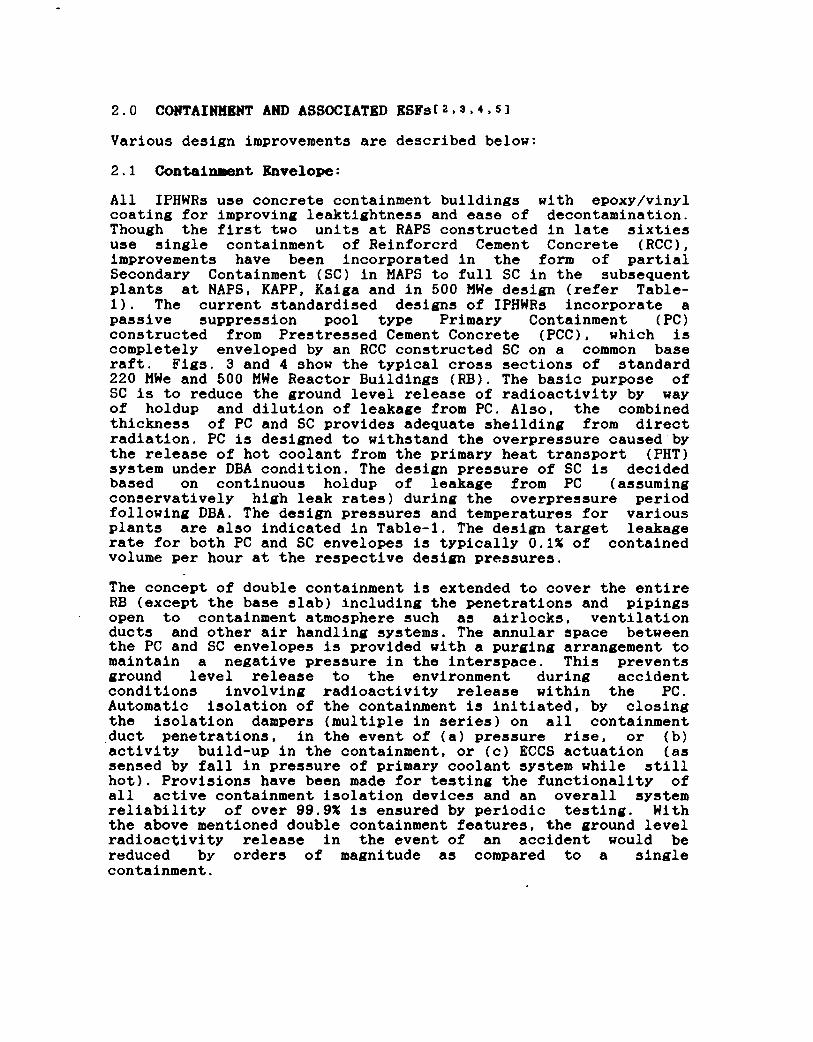
The design of containment system and its internal structuresrequires evaluation of LOCA and SLB induced pressure andtemperature transients in the containmentt8>s,10]. in the case ofpostulated LOCA, the double ended rupture of largest diameterpipe in PHT system (reactor inlet header for 220 MWe PHWRs andpump suction line for 500 MWe PHWRs) has been considered.Similarly, in case of SLB, double ended rupture of one steam lineis considered. The above postulations result in the maximumconceivable discharge rates from primary and secondary systems.In a pressure suppression pool type containment, following arupture in primary/secondary heat transport system, the highenthalpy coolant discharges into volume VI. The resultingpressure rise drives the air-steam mixture into the suppressionpool via the vent-shaft and distribution-header system. The steamcondenses in the pool water and the air gets vented to volume V2compartments. A leakage path (an order of magnitude higher thandesign specifications) between volumes VI and V2 bypassing thesuppression pool is assumed for conservatism.
This analysis has been carried out using the computer code PACSR(Post Accident Containment System Response). The code models thecontainment as two (or more) well mixed volumes representing theVI and V2 with connection via the vent system through suppressionpool. Models for various ESFs for post accident containmentdepressurisation such as RB coolers, PCCD, spray system, etc. areincorporated in this code. Also modeled are the structuralwalls/floors which serve as natural heat sinks. Figs. 5 and 6show the typical pressure and temperature transients simulatedfor 500 MWe containment following LOCA. The code has beenvalidatedt*!J against experiments performed in a modelcontainment facility.

4.2 Activity Release Assessment:
Activity release to atmosphere can take place when there is arelease of radioactivity from failed fuel to containmentatmosphere while the latter is pressurised following a LOCA.Following are the upper bound dual failures analyzed:
4.2.1 LQCA Simultaneous With Impai rment. of ECCS:
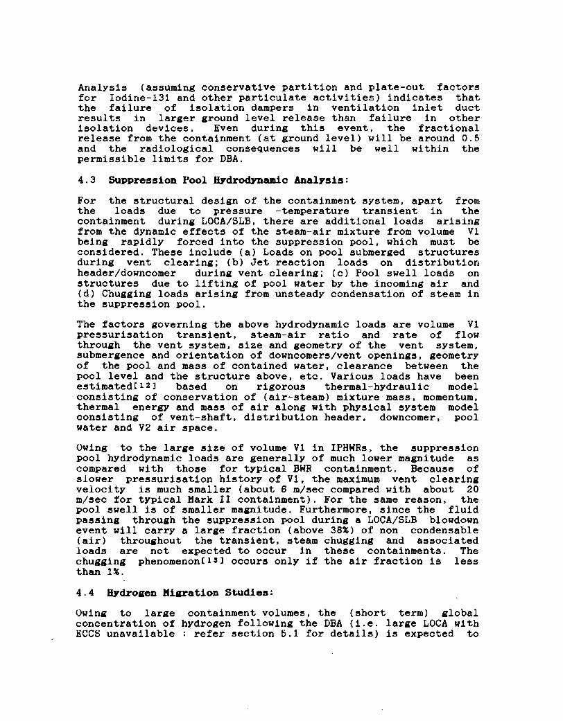
A hypothetical dual failure involving LOCA simultaneous withimpairment of ECCS results in the release of a large fraction offission product inventory from core due to gross fuel failure. Todemonstrate the capability of the containment system forcontrolling the release of radioactivity to the environment,estimates are made for likely releases at the ground level aswell as through the stack. In the analysis, the 'source term'(i.e. the amount of radioactivity released from fuel as a resultof DBA) is given as input. This inventory is conservativelyassumed to be getting released instantaneously from fuel at thetime of accident and mixed uniformly with the containmentatmosphere. Credit is taken for water trapping and plate out ofiodine on the exposed containment surfaces and in the leak pathsas also for the removal by ESFs involving recirculation andfiltration. Plate out, effect of ESFs, etc. are defined throughappropriate removal half lives. The model for release calculationis shown in Fig. 7. Out-leakage of activity from containment isestimated based on (a) the calculated pressure history followingaccident; (b) the containment leakage rate (with conservativemargin) at reference pressure and (c) the leakage rate vspressure correlation applicable to the containment envelope.
Main contribution to activity release through stack is due tomanual operation of PCCD towards the end of the overpressuretransient. A small fraction of stack release is also due to purgeflow from SC space. The above releases take place through Iodinefilters for which an efficiency of 90% is assumed in theanalysis.
4.2.2 LOCA Simultaneous With Impairment pf Containment:
The postulation of dual failure involving LOCA with impairment ofcontainment function (i.e., failure of containment isolation) istreated as one of the limiting accident scenario. Under thisevent, intended functioning of the highly reliable (99.9%) ECCSwill ensure that there will be no gross fuel failure and fueldamage will be limited to clad failure for some hot fuelelements. However, for the purpose of activity release assess-ment, it is conservatively assumed that all the channels connec-ted to affected header will experience low flow leading to sheathfailure in active fuel bundles. Activity release to containmentwill be limited to the activity present in PHT coolant and gapinventory of failed fuel bundles, out of which, a significantfraction of particulate activity and soluble radio-nuclides willremain trapped in PHT coolant and suppression pool water.
Analysis (assuming conservative partition and plate-out factorsfor Iodine-131 and other particulate activities) indicates thatthe failure of isolation dampers in ventilation inlet ductresults in larger ground level release than failure in otherisolation devices. Even during this event, the fractionalrelease from the containment (at ground level) will be around 0.5and the radiological consequences will be well within thepermissible limits for DBA.
4.3 Suppression Pool Hydrodynanic Analysis:
For the structural design of the containment system, apart fromthe loads due to pressure -temperature transient in thecontainment during LOCA/SLB, there are additional loads arisingfrom the dynamic effects of the steam-air mixture from volume VIbeing rapidly forced into the suppression pool, which must beconsidered. These include (a) Loads on pool submerged structuresduring vent clearing; (b) Jet reaction loads on distributionheader/downcomer during vent clearing; (c) Pool swell loads onstructures due to lifting of pool water by the incoming air and(d) Chugging loads arising from unsteady condensation of steam inthe suppression pool.
The factors governing the above hydrodynamic loads are volume VIpressurisation transient, steam-air ratio and rate of flowthrough the vent system, size and geometry of the vent system,submergence and orientation of downcomers/vent openings, geometryof the pool and mass of contained water, clearance between thepool level and the structure above, etc. Various loads have beenestimated!12] based on rigorous thermal-hydraulic modelconsisting of conservation of (air-steam) mixture mass, momentum,thermal energy and mass of air along with physical system modelconsisting of vent-shaft, distribution header, downcomer, poolwater and V2 air space.
Owing to the large size of volume VI in IPHWRs, the suppressionpool hydrodynamic loads are generally of much lower magnitude ascompared with those for typical BWR containment. Because ofslower pressurisation history of VI, the maximum vent clearingvelocity is much smaller (about 6 m/sec compared with about 20m/sec for typical Hark II containment). For the same reason, thepool swell is of smaller magnitude. Furthermore, since the fluidpassing through the suppression pool during a LOCA/SLB blowdownevent will carry a large fraction (above 38%) of non condensable(air) throughout the transient, steam chugging and associatedloads are not expected to occur in these containments. Thechugging phenomenont13] occurs only if the air fraction is lessthan 1%.
4.4 Hydrogen Migration Studies:
Owing to large containment volumes, the (short term) globalconcentration of hydrogen following the DBA (i.e. large LOCA withECCS unavailable : refer section 5.1 for details) is expected to

be much lower compared to deflagaration/detonation threshold andthe basic problem is one of local hydrogen pockets.Identification of potential pockets where hydrogen concentrationmay exceed and its management are the unresolved issues. In orderto assess the above problem, NPC has taken-up development of a 3Dfinite-difference computer code for analysing the details ofhydrogen transport throughout the containment and to evaluate theeffectiveness of hydrogen management systems. This computer modelconsiders history of steam and hydrogen releases, effect ofsuppression pool, sub-compartroentalization, inter-compartmentcommunication, availability of cooling and mixing devices, heattransfer to/from structures, condensation and evaporation, etc.and uses finite-difference fluid dynamic model for solving three-dimensional time-dependent Navier-stokes equations with speciesmass conservation and transport. Nitrogen, Oxygen, Steam andHydrogen are treated as separate species. The effect of moleculardiffusion and turbulence are also taken into account.
4.5 Structural Analysis:
The loads for which the containment structures are designedinclude normal and construction loads, abnormal loads and extremeenvironmental loads. Abnormal loads include pressure andtemperature loads resulting from the DBA, loads due to expansionof pipes at increased temperature, reaction loads due to fluiddischarge, hydrodynamic loads in the suppression pool chamber,loads due to potential pipe whip, etc. Extreme environmentalconditions include winds, tornado, floods and earthquakes.
The seismic loads considered for RAPS and HAPS containments were0.05 g and 0.1 g equivalent static respectively. In case of NAPS(i.e. standard design), however, the design is based on a dynamicanalysis for the Safe Shutdown Earthquake (SSE) with peakhorizontal ground acceleration of 0.3 g. Combinations of LOCAand SSE occurring simultaneously have been considered in MAPS andsubsequent designs.
b . 0 OUTSTANDING ISSUES AND DESIGN TRENDS
The occurrences of accidents at TMI during 1979 and at Chernobylin 1986 have focused the attention on the response of thecontainment under severe accident situations which may load thecontainment to beyond its design capability. The TMI accidentresulted in severe core damage and brought forth the issue ofhydrogen, although the containment performed its intendedfunction, with negligible effect to the environment. TheChernobyl accident on the other hand resulted in extensiveradiological releases. In the Chernobyl design, unlike thenormal practice of providing a containment for the entire reactorsystem, a segmental containment approach was followed to coverthe localized events. Even if the design were different withfull containment, the explosive nature of the accident might haveresulted in failure of its containment.

Some of the containment related issues for IPHWRs associated withsevere accidents and the design approach are outlined in thefollowing sections.
5.1 Hydrogen Generation and Management:
The hydrogen production transients of stylised dual failurescenarios involving rapid loss of primary coolant (large LOCA)and nonavailability of ECCS are far more severe than thoseassociated with other LOCAs and, therefore bound the hydrogenproduction for all accident scenarios. Under such an event, theover-heating of fuel cladding could lead to a rapid generation ofhydrogen due to oxidation of the clad material (i.e. zircaloy).Subsequently, radiolysis of water due to radiations from fissionproduct decay gradually adds hydrogen in the atmosphere of thesealed containment. Beyond certain concentration limits, thishydrogen could form flammable, or even explosive mixture with thecontainment air, leading to high pressure loads on thecontainment, which could jeopardize its integrity. Apart fromensuring that the global concentration in the containment doesnot exceed safe limits, the possibility of high hydrogenconcentration build-up in certain local pockets is also to beconsidered.
The pressure-tube concept used in PHWRs allows the separate low-pressure heavy-water moderator in calandria vessel to act as adistributed low-pressure emergency heat sink surrounding eachfuel channel. Reactor core consists of several hundred pressure(or coolant) tubes (each containing 12 to 13 short fuel bundlesand enclosed by a calandria tube) located horizontally incalandria shell filled with moderator. In case of a DBA (largeLOCA with ECCS unavailable), the core damage effects aresignificantly less severe than PHRs and BWRs. As the coolantchannel balloons/sags and contacts calandria tube, an effectiveheat transfer path from fuel to moderator gets established whichprevents the fuel melting. Heat from moderator system is removedby its cooling system consisting of pumps and heat exchangerssupplied with assured power and process water supplies.
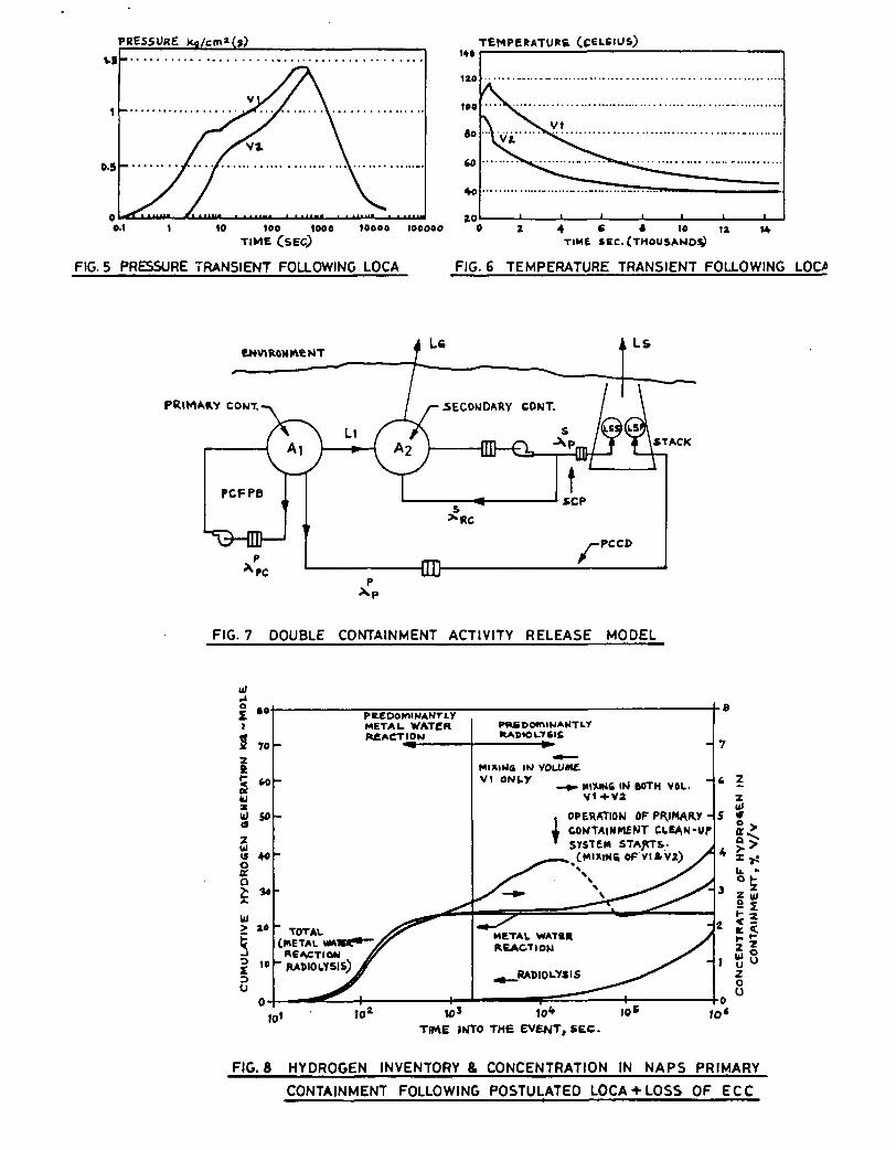
Studies done for NAPS indicate that for limiting DBA, the totalclad oxidation is less than 30% and overall oxidation ofzirconium in fuel bundles (i.e., clad, end caps & end plates)remains limited to 20%. Overall oxidation of coolant tube remainslimited to 0.031% because of low temperature (below 850 deg.C)and much smaller surface area to volume ratio compared tocladding. As a short term measure, if the released hydrogen isdispersed in containment atmosphere (by redundant fan coolerunits), it will result in a concentration less than the lowerflammability limit of 4%. However, additional generation ofhydrogen due to radiolysis of water may gradually build up theconcentration over a period of days. Fig. 8 shows the hydrogenconcentration in NAPP containment for the accident postulatedabove. While the short term hydrogen management features areautomatic, in the long term (i.e. few hours into the accident),operator action may be necessary for management of hydrogen from

the radiolytic decomposition of water. Introduction of a gasscavenging system with venting through the PCCD duct could beconsidered for this purpose. Other alternatives like use ofcatalytic recorobiners are also being considered for effectivehydrogen management.
5.2 Containment Venting:
Lately, containment venting systems are beingincorporated/backfitted to protect the containment from over-pressurization resulting from the severe accidents. Suchaccident sequences include core melt scenarios for PWRs and BWRs,suppression pool bypass scenarios, etc. Whereas the consequencesof a core melt in a large containment as in the case of a PWRwould result in slow pressurization due to generation of steamand other gasses along with addition of energy in the containmentatmosphere, the pressurisation of the containment due to asuppression pool bypass is a rapid one necessitating differentphilosophies for protection of the containment.
The capability of standardised designs of IPHWRs to handle severeaccident is discussed in section 5.4. As far as the suppressionpool bypass scenario is concerned, it may be noted that IndianPHWR containment typically has a large free volume compared tothe rating of the reactor and the suppression pool system iscompletely passive. It is estimated that only about 15 to 25% ofthe energy released immediately following a LOCA, gets absorbedin the suppression pool. The potential bypass paths between VIand V2 volumes are provided with double doors/barriers in series,with alarm annunciation if the path is open. Studies werecarried out to evaluate the effect of impairment ofieaktightness integrity of VI and V2 on the containment peakpressure following LOCA. The results indicate that for this typeof containment, bypassing of suppression pool upto a relativelylarge size of equivalent opening (between VI and V2) would notsignificantly increase the peak accident pressure . Therefore,the need for containment venting system, in the context beingtalked about today, does not appear to exist for IPHWRs.However, as described earlier (in section 2.3.2) a controlled gasdischarge system incorporating absolute (HEPA) and iodine filtersfor depressurisation of primary containment already exists in allunits.
5.3 Containment Overpressure Capability:
Capability of the containment to withstand the loads arising frombeyond DBA scenarios, has been in focus for some time. Most ofthe work done in this area indicates that good margins areavailable for concrete containments particularly of RCCconstruction. In India, assessments were made during the mid-seventiesti4] to gain knowledge on the containment behaviourunder overpressure conditions through model studies. Tests werecarried out on */i2th scale model of MAPS containment aftersimulating the structures for dead loads, large penetrations andplastic liner. Though the first cracking was analytically

predicted to occur in the dome at 1.83 kg/cm2(g), the testindicated appearance of first crack at 1.76 kg/cm2(g). Once thecracks appeared and widened, further pressurisation of the modelwas not possible even with additional compressors. Aninteresting observation was that during the pressure run-downafter the air supply was cut, the cracks showed the tendency ofclosing. However, on subsequent pressurisation, the cracksopened up at somewhat lower pressure.
Studies to evaluate the containment margins for the newgeneration containments of standardised plant design are inprogress.
5.4 Containment Integrity During Severe Accident:£* 5•i*J
Severe accident occur under rare combination of equipment andsystem failure resulting in impairment of fuel heat removalfunction. While in most other reactor designs, LOCA withunavailability of ECCS leads to core melt, in the standardiseddesign of IPHWRs, the core melt scenario is a low probabilityevent owing to the presence of several alternate heat sinks fordecay heat removal from the fuel which can prevent or mitigate asevere accident. IPHWRs have been provided with two highly-reliable (99.9%), fully-independent, fast and diverse actingshutdown systems, either of which can (by itself) safelyterminate the chain reaction following any reactivity insertionaccident including LOCA. All the reactivity devices (controlrods, shut-off rods, etc.) penetrate the calandria shell in lowpressure moderator and are not subjected to any significanthydraulic forces from a LOCA. Therefore, anticipated transientwithout scram (being an extremely unlikely event) is not ofconcern for IPHWRs.
During a severe accident, the presence of moderator in calandriavessel plays the most dominating role in preventing the coremelt. The calandria itself is submerged under a separately cooledwater shield in steel-lined calandria vault. With cold D2Omoderator serving as a backup heat sink even if there is no waterin the fuel channels, though fuel may get severely damaged, thefuel temperatures do not reach the melting point of DO2 and thechannel would remain intact and contain the debris. In case themoderator cooling system is also unavailable, the moderator wouldheatup, start boiling and eventually be expelled from thecalandria through pressure relief duct. As fuel channels areuncovered by moderator expulsion, they sag and fail at relativelylow temperatures and dump the fuel fragments to the bottom of thecalandria, where they are quenched by the remaining moderator.Eventually, all moderator is lost from the calandria and the coredebris begins to heatup. Due to use of natural uranium oxide fuelwith large D2O moderator to fuel ratio, the second criticality isnot an issue for IPHWRs. The study indicates that the hot/moltencore debris would be contained in the calandria vessel whichmaintains its integrity throughout the accident sequence. Eventhe non-availability of shield water cooling system willsignificantly delay the progression of severe core damage

sequence, as its entire inventory must boil off before calandriavessel breaches and core debris melts through thick calandriavault floor to the huge suppression pool in the basement. Themolten core debris, which is considerably diluted withdecomposition products due to core-concrete interaction, wouldget cooled and contained in the suppression pool water thusterminating the severe accident sequence.
The formation of steam during boil off enhances passive heatremoval on structural surfaces, promotes rapid aerosol settlingdue to condensation on air borne particles and impedes thepossibility of hydrogen deflagaration. While the prestressedconcrete primary containment structure, even when pressurisedbeyond design pressure, is unlikely to fail in a catastrophic wayand hence would largely retain the fission products, thesecondary containment would effectively stop ground level releaseto atmosphere.
6.0 CONCLUSIONS
The containment system is an important safety system and it playsa decisive role in mitigating the consequences of unlikelyaccidents involving release of radioactivity from the core. Itsprovision is part of the defense-in-depth philosophy adopted innuclear power industry. Containment system designs arecontinuously being reviewed and improved to extend theircapability to handle even the beyond DBA scenarios.
The containment design for standardised IPHWRs is evolvedkeeping with the latest trends and incorporates severalnoteworthy features. The adoption of double containment conceptalong with the provision of huge suppression pool at the basementand other ESFs not only practically eliminate ground levelrelease to the environment during DBA, but also provides adequateassurance for containment integrity even in beyond DBA scenarios.The PC is of pre-stressed concrete which is known to have aforgiving behaviour even if it were to fail. The design canaccommodate performance degradation of PC to quite an extentwithout significantly affecting the post accident dose to public.
7.0 REFERENCES
L U Report by RSAG, "Safety of the Indian Pressurised HeavyWater Reactors", Nuclear Power Board, India, 1986.
L2] Das M., Bhawal R.N., "Containment Design Requirements andtheir Application to 500 MWe Plant", Second Int. Conf. onContainment Design and Operation Toronto, Canada, 1990.
[3J Surendar Ch., "Safety Aspects of Nuclear Power Plants",National Seminar on Electrical Energy and Environment, NewDelhi, India, 1990.

14] Das M., etal, "Distinctive Safety Aspects of Small andMedium Sized NPPs in India", Third Int. Seminar on smalland Medium Sized Nuclear Reactors, New Delhi, India, 1991.
[5] Bhattacharya D., Bajaj S.S, "Experience with Commissioningof Concrete Containments", Second Int. Conf. on ContainmentDesign and Operation, Toronto, Canada, 1990.
[6] Bhattacharya D., etal, "Filters used in Post AccidentContainment Clean-up System for Indian PHWRs", Second Int.Conf. on Containment Design and Operation, Toronto, Canada,1990.
[7] Bhattacharya D., Bajaj S.S., "Experience with Commissioningof Concrete Containments", Second Int. Conf. on ContainmentDesign and Operation, Toronto, Canada, 1990.
[8] Prem Prakash, Das M., "Estimation of Containment DesignParameters for 500 MWe PHWR", paper to be presented in 12thint. Conf. on SMiRT, Stuttgart, Germany. 1993.
I.9J Bhawal K.N., Das M. , "Pressure and Temperature TransientAnalysis of bOO MWe PHWR Containment by Computer CodePACSR", Second Int. Conf. on Containment Design andOperation, Toronto, Canada, 1990.
110 1 Bhawal R.N., Das M., Prem Prakash, "Estimation ofDifferential Pressure Loading Across R.B. InternalStructures of 500 MWe Containment", Second Int. Conf. onContainment Design and Operation, Toronto, Canada, 1990.
[11J Bajaj S.S., "Comparison of Code Calculations withExperiments on Containment Response During LOCAConditions", Second Int. Conf. on Containment Design andOperation, Toronto, Canada, 1990.
[12] Bajaj S.S., Das M., etal, "Pressure Suppression PoolHydrodynamic Effects in Containment System of IndianPHWRs", Second Int. Conf. on Containment Design andOperation, Toronto, Canada, 1990.
[13] Kutika E., "The non-Condensable gas effects on loss ofcoolant accident steam condensation loads in boiling waterreactor pressure suppression pool", Nuclear Tech., 1983.
114] Appa Rao I.V.S.R., etal, "Tests on a Structural model ofMadras Atomic Power Project Containment", India, 1974.
[15] Bhawai R.N., Mehta P., "First Order Estimate of Consequencefor a Severe Accident in 500 MWe PHWR", National Sym. onSafety of NPPs and Other Facilities, Bombay, India, 1992.
1J6J Snell V.G., etal, "CANDU Safety Under Severe Accidents",Int. Sym. on Severe Accident in Nuclear Power Plants,Sorrento, Italy, 1988.

1.
1.11.2
2.
2.1
2.22.32.4
2.5
3.
CmtiiiMit Т?ве
Betnod of Pressure Suppression
Single/Hultiple envelope
Priun CflitiiiMit hiêl&Be
Baterial/Thickaess (ci)i) Periieter «all11) Doae/top slabCoBtaiaed free-air T O I U M (•')DesliB Pressure (k(/ci>(l))Peak Teiperatare (def. C)(darUf accideet)Tarfet design leak rate (X
ТШ1-1
С01ШП11Т STSÎHS 101
IAPS
DousingSlule
ICC*, 122PCC, 20 to
43,3000.4271
of 0.1contained lol/hr at design press.)
HAPS
Tap. Supp. PoolPartial Double
PCC», 6130 FCC, 2*{B1B)
48,1001.1696
0.1
Ц Ш 1 PJlIi
1APS/UPP
Tap. Supp. Pool
Double
PCC, 61
ICC/PC, 12232,200
1.25120
0.1
IAIGA
Tap. Supp. Pool
Double
PCC, 61
PCC»,8001.73 ft -0.2153
0.1(at 1.06 kf/ciif
for LOCA)
TAPP-3M($00 Hue)
Tap. Supp. Pool
Double
PCC, T5PCC, 35
00,800
1.44 1 -0.15125
0.1
3.1 laterial/thlckaess (ci)(1) FeriKter Kail(ii) Dote
3.2 Coitaiied free-air «lute (•*)3.3 DesifB Fressare (kf/ci'(f))
3.4 Tarfet desifa leak rate (t ofcoaUiaed rol/ir at desifi press.)
4. IniiMMd Sifêtr ttàtutês
iubble Msoaarr,-
5,7000.0073-
IBC, PCCD,
scrp«
71
(at
ICC61ÏCC.1335,000
0.073 к -0.020.1
0.073 k|/eii|)
IBC, PCCDditb delay),
PCffBf.SCFIP*
ICC,61ICC16,650
0.073 к -0.020.1
(at 0.073 kf/ciif)
IBC, PCCD(lith delà/),PCFPB, SCFIF
ICC.61ICC27,000
0.131 к -0.020.1
(at 0.073 kc/ci
IBC, PCCD
(«itk delar),
pcrpB, scrip
a) ICC - leiaforeed Ceieit Coacrete
b) PCC - Prestressed Ceieit Concrete
c) IBC - leactor Boildiif Air-Cooler
d) PCCD - Priurr Coataintent Control Dischariee) SCFP - Secondary CoataiaMtt Filtration and Purge Systeaf) PCFPB - Priurr Coataiaieat Filtration and Puip Back SysteiI) SCFIP - Secondary Contactent Filtration lecirculatioi aid Pune Systea

REDUCINOCONCENTRATION
OP F. P.
DECAY
PLATE - OUT WATER.TRAPPINO * OTHER
NATURAL PHENOMENA
FILTERATION ANDPUMP BACK
CONTAINMENT
—{SUPPRESSION POOL]
REOUCINCLEAKAGE
REDUCINO OVERPRESSURE
LIMITINO PEAKPRESSURE
SUPPRESSIONPOOL
FASTDEPRESSURISATION
COOLING ANDGAS DISCHARGE
INCREASINGEFFECTIVE
LEAK TIGHTNESS
MULTIBARRIER(WITH STACK)
RELEASE
LEAK TIGHTENVELOPE
FIG.1 CONTAINMENT AND RELATED SAFETY SYSTEMS.
SECONDARY CONTAINMENTFILTERED RECIRCULATIONAND PURGE
STACK
i:TYPICAL OPENPENETRATION
VENT SHAFT
VOLUME VI(DRYWELL)
BLOWOUT PANEL
VOLUME V2( WETWELL )
SUPPRESSION POOL
CONTAINMENTCOOLERS
-PRIMARY CONTAINMENTFILTRATION ANDPUMPBACK
STACK
PRIMARY CONTAINMENTCONTROLLED DISCHAROE
1DISTRIBUTIONHEADER 4c DOWNCOMERS
FIG. 2 SCHEMATIC OF CONTAINMENT AND ASSOCIATED
SAFETY FEATURES IN STANDARDIZED DESIGN

ACCESS SHAFTSTRESSING GALLERY
FIG. 3 TYPICAL CROGS SECTION OF 220 MWe REACTOR BUILDING FIG. 4 TYPICAL CROSS SECTION OF 500 MWe REACTOR BUILDING
PRESSURE
1000 10000 100000
FIG. 5 PRESSURE TRANSIENT FOLLOWING LOCA
140
120
190
60
M
4o
to
TEMPERATURE (CELSIUS)
4 « « io uTIME SEC. (THOUSAND*)
FIG. fi TEMPERATURE TRANSIENT FOLLOWING LOC>>
FIG. 7 DOUBLE CONTAINMENT ACTIVITY RELEASE MODEL
u>
70
50
UJ
O
orQ
METAL WATERREACTION
MIKlMfi IM V0LUM£V1 ONtY
MI7UN6 IN BOTH VOL.V1+V2
OPERATION OFCONTAINMENT CLEAN-UPSYSTEM STARTS.
11X1(46 OP VI J.V2)
6 Z
I*
TIME INTO THE EVENT, SEC.
FIG. 8 HYDROGEN INVENTORY & CONCENTRATION IN NAPS PRIMARY
CONTAINMENT FOLLOWING POSTULATED LOCA • LOSS OF ECC
Copyright © 2022 FDOKUMEN