Site M.,anagement Plan - Index of
573
Volume li- ~~~~~~~~~~~~~File: 18G S Volume Ii ~~~~~~~~~~~~~~~~~~~~D. B. Remedial Investigation/Feasfbility Study oai Site M.,anagement Plan Eielson Air Force Base, Alaska- 4 ~~~~~17 June 1991 Prepared by ROC. Box 28 Cor~vallis, OR 97339 under contract to 0 Ba ite itie Environmental Management Operations Richland, Washington
-
Upload
khangminh22 -
Category
Documents
-
view
1 -
download
0
Transcript of Site M.,anagement Plan - Index of

Volume li- ~~~~~~~~~~~~~File: 18GS Volume Ii ~~~~~~~~~~~~~~~~~~~~D. B.
Remedial Investigation/Feasfbility Study oai
SiteM.,anagement PlanEielson Air Force Base, Alaska-
4 ~~~~~17 June 1991
Prepared by
ROC. Box 28Cor~vallis, OR 97339under contract to
0 Ba ite itieEnvironmental Management OperationsRichland, Washington

Site Aanagerner' Pfran DRAFTEieison Air Force fi..o
Appendix A
FIELD SAMPLING PLAN
FOR EIELSON AIR FORCE BASE
-0 CVOR257/03Z.51 -1

She Management Plan DRAFT
Elieson Mir Force Blas.
Page
1.0 Introduction............................................ A.1 .11.1 Background............................................. A. 1.21.2 Purpose and Objective..................................... A. 1.21.3 Contents ............................................... A.1.3
2.0 Field Investigation........................................A.2. 12.1 Data Cc~rnpilatiJon ~tnd Review ................................ A.2.12.2 Field Area Walkover Survey ................................. A.2.12.3 Geodetic/Topographic Survey and Bas&l Map ..................... A.2.2
2.3.1 Objectives....................................... A.2.22.3.2 Survey Locations .................................. A.2.32.3.3 Survey Equipment and Procedures..................... A.2.52.3.4 Data Collection, Interpretation and Reduction .............. A2.5
2.4 Geophysical Methods...................................... A.2.62.4.1 Electromagnetic Induction/Magnetometer (EMIIMAG) Survey ... A.2.8
2.4.1.1 EMI/MAG Survey Objectives ................... A.2.82.4.2.2 EMI/MAG Procedures ........................ A.2.8
K. ~~~~2.4.2 Ground Penetration Radar (GPR) Survey.................A.2.122.4.2.1 GPR Survey Objectives ...................... A.2.1 22.4.2.2 GPR Survey Locations ...................... A.2.122.4.2.3 GPR Data Collection, Reduction, and Interpretation . A.2.14
2.4.3 Seismic Refraction and Reflection Techniques ............. A.2.1 52.4.3.1 Objectives............................... A.2.152.4.3.2 Techniques.............................. A.2.152.4.3.3 Preliminary Considerations ................... A.2.162.4.3.4 Survey Design ............................ A.2.172.4.3.5 Equipment .............................. A.2.17
2.4.4 Electrical Resistivity ................................ A.2.192.4.4.1 Objectives............................... A.2.192.4.4.2 Procedures.............................. A.2.202.4.4.3 Survey Design ............................ A.2.222.4.4.4 Instrumentation ............................ A.2.222. 4. 4.5 Data Reduction........................... A.2.23
2.4.5 Bc-retiole Geophysics .............................. A.2.242.4.S-.1I Objectives............................... A.2.242.4.5.2 Electrical................................ A.2. 2 72.4.5.3 Nuclear ................................ A. 2.3 12.4.5.4 Mechanical .............................. A. 2.3 3
CVOR257/081.51 iii 17 June 1991
Site Management Plan DRAFTEleleon, Air Force Boa*
CONTENTS (Continued)
Page3.8 Laboratory Analyses ...................................... A.3.613.9 Sample Analyses Summary................................. A.3.61
4.0 Field Measurements.......................................A.4.14.1 Parameters.............................................. A.4.14.2 Equipment Calibration ................................ A.4.2
4.2.1 HNu Meter....................................... A.4.24.2.2 pH Meter........................................ A.4.34.2.3 Specific Conductance Meter ........................... A.4.44.2.4 Thermometer or Temperature Probe ..................... A.4.4
4.3 Equipment Maintenance .................................... A.4.54.4 Decontamination ......................................... A.4.5
5.0 Field OSA/QC Program.....................................A.5.15.1 Control Parameters ....................................... A.5.1
5.1.1 Duplicate Sample .................................. A.5.25.1.2 Container Blanks .................................. A.5.25.1.3 Equipment Blanks .................................. A.5.2 a5.1.4 Travel Blanks ..................................... A.5.3 5
5.2 Control Limits............................................ A.5.3
6.0 Site Management........................................ A.6.16.1 Field Program Logistics .................................... A.6.16.2 Site Access ................. ............................ A.6.16.3 Site and Equipment Security ................................. A.6.16.4 Base Support............................................ A.6.2
7.0 Management of Investigation-Derived Wastes................... A.7.17.1 Introduction............................................. A.7.17.2 IDW Management Requirements ............................... A.7.2
7.2.1 Compliance with, ARARs .............................. A.7.27.3 General Policies ,or lOW Management .......................... A.7.2
7.3.1 IDW Minimization .................................. A.7.27.3.2 Consistency/fh Management...........................A.7.47.3.3 Community Concerns............................... A.7.5
7.4 Selection diIDW Disposal Options ............................... A.7.5L/
CVOR257/081.51 vi 17 June 1991

Sit. Mansagement Plan DRAFTDelelon Mir Force Base
. ~CONTENTS (Z~ontinuedl)
Page
8.0 Decontamination Procedures ............................... A.8.18.1 Soaps and Detergents ..................................... A.8.18.2 Personnel............................................... A.8.18.3 Sampling Equipment ...................................... A.8.38.4 Drilling Equipment and Well Construction Materials ................. A.8.5
8.4.1 Drilling Equipment ................................. A.8.58.4.2 CGleaning Monitoring Well Construction Materials, Development
Equipment, and Dedicated Sampling Equipment............ A.8.68.5 Water Level Indicator ...................................... A.8.68.6 Submersible Pumps....................................... A.8.7
TABLES
A.2.1 General Guide to Data Collection Objectives for Borehole Geophysics A.2.26A.2.2 Logging Functions Borehole Limitations.........................A.2.28. ~~A.2.3 Types of Logs, Descriptions, and Uses ......................... A.2.29A.2.4 Soil Physical Parameters for the Site RI/FS...................... A.2.56A.7.1 IDW Disposal Options...................................... A.7.3A.7.2 Presumptions for IDW Management............................ A.7.7
FIGURES
A.2.1 Monitoring Well Drilling and Geologic Log ....................... A.2.51A.2.2 Soil Boring Log ......................................... A.2.52A.2.3 Monitoring Wel-l Construction Drawing .......................... A.2.58A.2.4 Monitoring Well Record Drawing and Construction Log ............. A.2.59A.3.1 Surface Water Sampling Field Data Sheet ....................... A.3.15A.3.2 Surface Water Level Field Data Sheet .......................... A.3.17A. 3. 3 Surface Water Quality Sampling Summary ....................... A.3:1 8A.3.4 Groundwater Level Field Data Sheet ........................... A.3.25A.3.5 Grouindwater Quality Sampling Summary....................... A.3.26A.3.6 Groundwater Field Data Sheet............................... A.3.27A.3.7 Typica:. Sample Identification Label ............................ A.3.39A.3.8 Chain-of-Custody Record Form .............................. A.3.39
CVoF257/0eI .51 vii 17 June 1991

Sit. Management Plan-FSP DRAFTEValon Air Force Baae
@ ~1.0 INTRODUCTION
Tnis Field Sampling Plan (FSP) is Appendix A of the SiteManagement Plan for Eielson Air Force Base. This plan providesdirection for obtaining field samples for implementation of theRI/FS and is designed to be used as a reference in developing theFSPs for the OUs at Eielson AEB. Numerous methodologies arepresented for collecting various types of environmental samples.Other methods may be introduced as the OU FSPs are developedbased on Site conditions, changing technologies, or changingregulations. This FSP will then be modified to include theadditional sampling methods. It is by no means intended that allof the surveys and sampling procedures described in this FSPmanual will be used in the RI/FS for Eielson AFB. Field personnel
* ~~~~~~~should be familiar with this manual and maintain a field copy forguidance during work activities.
The Site Management Plan contains important summaries on thebackground and setting of the Eielson AFB, and a description ofthe objectives and approach to the overall RI/FS. The SiteManagement Plan also contains a list of acronyms andabbreviations that are used in this plan. Field personnel shouldbe aware of the project schedule contained in Section 7.0 of theSite Management Plan (or the most recent update of thatschedule).
The Quality Assurance Prie ct Plan (QAPP, Appendix B) must beused jointly with this FSP. The QAPP references analytical
. I~w/CV08257/026.51 A.1.1 17 June 1991

Site Management Plan-FSP DRAFTEleleon Air Force Base
procedures and quality assurance objectives that must be used to
obtain good representative samples and data of known quality.
Knowledge of the Health and Safety Plan (HSP, Appendix C) is
critical during field sampling, because it specifies procedures for
the occupational health and safety protection of project field
personnel.
1.1 BACKGROUND
Previous investigations of potential areas of environmental
contamination at Eielson Air Force Base (AEB3), located near
Fairbanks, Alaska, identified numerous sites where contamination
by releases of petroleum, oil, and lubricant (POL) products,
including JP-4, motor gasoline, and diesel fuel, may have
occurred. These sites were identified and initially described undera
an IRP Phase I records search investigation conducted in 1982W
and were the subject of a limited Phase 11 field investigation in
1984. Eielson AFB has been divided into six operable units (GUs)
each consisting of numerous source areas. Groundwater, surface
water and sediment, soils, and biota are being addressed for each
OU. Details on the Eielson AFB OUs are presented in the text of
the Site Management Plan.
1.2 PURPOSE AND OBJECTIVE
The purpose of this Field Sampling Plan (,--SP) is to present a
description of flie-ld activities, sampling equipmentl, procedures,
and chemical and physical analyses for the RI/FS to be Conducted
at Eielson AFB. This document shall be used to guide Eielson
tw/CVOR257/026.51 A.1.2 17 June 1991

Site Management Plan-FSP DRAFTEielson Air Force Base
AFB in all environmental investigation activities conducted at theoperable. units. All procedures described in this document maynot be employed at each operable unit. Individual FSPs will bewritten for each operable unit. This FSP was developed in
accordance with the requirements of GEROLA.
1.3 CONTENTS
The FSP contains descriptions of investigation activities includingsampling designations, sampling equipment and procedures. TheFSP for each individual operable unit will define the samplinglocations and frequencies for that specific operable unit. Othersampling techniques may need to be developed.
This FSP is only meant as a reference guide of available
methodology that may be used in the Beleson AEB RIIFS.
. I~W/CV0R257/026.51 A.1.3 17 June 1991

Site Management Plan-FSP DRAMTEselson Air Force Base
2.0 FIELD INVESTIGATION
Field investigation is designed to provide necessary information
regarding the location, function, types of hazardous substancesused o: disposed of, and the structure and integrity of certain
facilities within the operable units.
2.1 DATA COMPILATION AND REVIEW
Source compilation and review does not involve field sampling.Speci'fic items of concern may be the locations of buried fueltanks, routing of underground pipelines, locations of spills. The
results of data compilation and review for each operable unit will
be used to direct subsequent field tasks.
2.2 FIELD AREA WALKOVER SURVEY
The field areas should be walked by trained environmental
assessment personnel, including a geologist. The survey team
shall be equipped with field volatile organic monitoring instruments
and other necessary equipment for health and safety monitoring.
The objective of a walkover survey is to identify subsurface andsurf-ace features of concern to the RI/ES that are not proplerly
located on available records or that have not been identifiE.d in the
records search.
Special attention should be given to areas whE:r-e there is evidence
of past disturbance, mounded or subsidence areas that may
lw/CVOR257/027.51 A.2.1 17 June 1991

Sne Management Plan-FSP DRAFTVEi.son Air Force Basc
indicate buried facilities, old foundations, monuments indicatingthe location of items, and indications of former seepage pits or
drains, etc. Areas of potential concern will be staked and the
locations may be surveyed as described in Section 2.3, Geodetic!
Topographic Survey and Base Map.
The focus will be on visual observation, but verification
measurements of soil vapor concentrations of volatile organics
shouted also be made and recorded. Soil vapor measurements for
volatile organics can be made by opening a small hole with a
shovel and taking a brief measurement with the field instrument, or
using one of the other soil vapor procedures described in
Section 3.1.7.
The information from walking surveys will be used to modify
subsequent tasks to account for information that was not available
from the historic files.
Surface geologic mapping may be performed as part of the
source area walkover.
2.3 GEODETIC/TOPOGRAPHIC SURVEY AND BASE MAP
2.3.1 Objectives
Maps of the operable units will be established for use during
source area characterization, evaluation of corrective measure
alternatives, and engineering design. Geodetic surveys for
elevation and north-south and east-west coordinates will be
IwICVOR2571027.51 A.2.2 17 June 1991

Sit. Manaemernnt Pimn-FSP DRAFTBelson Air Force Base
performed to develop vertical and horizontal controls for RIactivities and data. If necessary, survey monuments will beestablished.
2.3.2 Survey Locations
Source area or operable unit topographic maps will be at a scalethat will allow the precision needed to show elevation contours at2-foot (0.6-in) intervals. Source area features such as theoperable unit boundary, rivers, fence lines, gates, buildings,disposal facilities, pipelines, and roads will be included. TheNational Geodetic Survey vertical datum coordinate system will beused for vertical control. Horizontal locations will be tied to theAlaska state plane coordinates and/or EBelson AFB coordinatesystem. Third-order precision and accuracy will be used todevelop the source area or operable unit maps.
Horizontal control should also be provided for sampling pointsand grids established for the following types of tasks:
* installing groundwater monitoring wells
* area walkover survey (survey marked items)
*electro~magnetic induction/magnetometer (EMI/MAG) survey
* ground penetrating radar (GPR) survey
• soil vapor survey for volatile compounds
Iw/CVOR257/027.51 A. 2.3"' 17 June 1991

Site Management Plen-FSP DRAFTElelton Air Force Bas.
* source sampling and analysis
• test pit soil sampling and analysis
* borehole soil sampling and analysis.
Horizontal control will be established on two points at each grid
location required for the surveys. The horizontal plane survey
accuracy will be ±0.3 meter (1 foot). Relative coordinates for the
remainder of the grids will be obtained by using a tape and
compass traverse or by Global Positioning Satellite instruments
and electronic distance measuring instruments tied to these
reference points. Grid point locations will be staked with
coordinates marked on the stakes. Adequate vertical control will
be provided by the topographic base map.
Locations of soil borings and surface soil samples conducted will
be surveyed for both horizontal coordinates and vertical
elevations. The horizontal plane survey accuracy will be ±1l ft
(±0.3 in). The vertical plane survey must be accurate to ±0.1 ft(±0.03 in). The elevation will be obtained at the ground surface of
the borehole or surface sample locations. The vertical control for
the monitor wells and monitoring well locations will be to a- relative
accuracy of 0.01 ft (0.003 m) tc provide accurate indications of the
groundwater gradient. Due to frost heaving conditions causing
changes in vertical elevations, monitoring wells should be
resurveyed each time before measuring water levels.
lw/CVOR257/027.51 A.2.4 17 June 1991

Site Management Pfan-FSP DRAFTEielscn Air Force Base
0 ~~~~~2.3.3 Survey Equipment and Procedures
Surveys are to be completed by a surveyor who is licensed andregistered in the State of Alaska. Vertical control will bereferenced to a United States Geological Survey (USGS) datumobtained from a permanent benchmark. Third-order planesurveys and horizontal angular measureme-its will be made with a20-second or better transit. Angles will be doubled, with the meanof the doubled angle within 1 0 seconds at the first angle.Distance measurements will be made with a calibrated tapecorrected for temperature and tension or with a calibratedelectronic distance measuring instrument (EDMI). When using anEDMI, the manufacturer's parts per million (ppm) error will beapplied as well as corrections for curvature and refraction. Global
* ~~~~~~Positioning Satellite surveying techniques may also be used.
Additional details on the surveying equipment and proceduresshall be specified in approved participant contractor procedures.
2.3.4 Data Collection, Interpretation, and Reduction
All measurements will be recorded in a field notebook inaccordance with the procedures specified in Section 3.4.2, Field
Notebooks.
The locations of el! surveyed facilities and anomalies will be plottedon topographic bas-e map(s). The base map(s) will include sitefeatures; elevation contours at 2-ft (0.6-in) intervals; locations of
EMI/MAG, CPR, aind soil vapor survey grids and anomalies; and
Iw/CVOR257IO27.51 A.2.5 17 June 1991

Sit. Management Plan-FSP DRAFTEieleon Air Force Ba&4
the locations and elevations of soil borings, surface soil samples,and test pits, as appropriate.
Data and maps will be prepared to be compatible for input intothe developing computerized data base for Eielson AFB.
2.4 GEOPHYSICAL METHODS
This FSP provides general guidance for the planning, selection,and implementation of geophysical surveys that may beconducted during RI investigations at EBelson AFB. Several
commonly used methods are discussed for the standpoint ofapplicability to source area investigations, procedures forimplementation, survey design, and miscellaneous method-specificconsiderations.
Geophysical methods should be used as a tool to guideinvestigations of the OUs. Geophysics is a proven indirectinvestigation technique that should not be viewed as an absoluteanswer. The results are interpretive and need to be confirmed bydirect physical confirmation methods such as test pits and drilling.
Geophysics can be a cost-effective tool in providing extensive low-cost information and project guidance about successive, morecostly phases.
The project manager should confer with a geophysicist todetermine the applicability of the method to source area specific
conditions and objectives. A Site reconnaissance should be
tw/0V0R257/027.51 A.2.6 17 June 1991

Sit. Management PIa.nFSP DRAFTElelson Air Force Base
conducted to identify any problems that may inhibit the study.Cultural features such as powerlines, surface metal, and radiotransmitters may have a detrimental effect on the data azquisitionor interptetation. Any geophysical surveys should be completedin a timely manner so that the information can be used to provideguidance for subsequent tasks.
Most geophysical surveys are carried out over a grid or a seriesof lines within the study area. Stations at which measurementsare taken or energy put into the ground are usually spaced atregular intervals designed to produce the optimum results for thestudy objectives. Although initial line placement may be done inthe office, final line placement will be determined in the field by aqualified geophysicist.
All field work should be done under the supervision of a qualifiedgeophysicist with daily reduction and review being mandatory.The geophysicist should supervise the daily reporting of all fielddata including all field notes, maps, work sheets, and raw datatabulation.
For more detailed theoretical considerations of the geophysicaltechniques, the reader is referred to A Compendium of SuperfundField Operations Methods, EPA, 1987.
Specific geophysical methods are discussed below.
Iw/CVOFQ57/027.51 A.2.7 17 June 1991

Sit. Management Plan-FSP DRAFTEueleon Air Force Base
2.4.1 Electromagnetic InductionlMagnetometer (EMI/MAG)
Survey
2.4.1.1 Electromagnetic Induction/Magnetometer Survey
Objectives
The objective of the EMI/MAG survey is twofold:
* to screen large areas for subsurface items that mayrelate to potential contamination for subsequent
sampling
* to precisely locate buried facilities.
Areas identified as having potential for being contaminated
should be investigated further in the soil investigation.
2.4.1.2 EMI/MAG Procedures
Electromagnetic induction (EMI) equipment measures theelectrical conductivity of subsurface materials. Variations in
conductivfty may be caused by changes in soil moisture
content, porcsity and permeability, the presence of ionic'species, or the presence of metallic objects. Magnetometer
(MAG) equipment detects ferro-nickel metallic objects, such aspipelines, buried beneath the surface. EMI method also
applies both to assessment of natural geohydrologic
conditions and to mapping of many types of contaminantplumes. The areas surveyed should be selected based on the
tWICVOR257/027.51 A.2.8 17 June 1991

Sit. Managemient PIen-FlP DRAFTO ~~EIelson Air Force Bas.
operating history, capabilities of the equipment, and theinvestigation needs of each operable unit.
Electromagnetic methods may be used in many situations fora variety of purposes. The following list includes possible usesrelated to investigations of Eielson AEB:
*defining the location of a contaminant plume (this couldlead to the identification of downgradient receptors,source areas, and flow directions if the conductivity ofthe plume [target] is distinct in comparison to the host[background] hydrogeologic setting)
*locating buried metal objects (e.g., drums, tanks,pipelines, cables, monitoring wells)
• addressing the presence or location of bedrock fault/fracture systems (this is important for identification ofpreferential pathways of water flow in bedrock)
* mapping grain size distributions in unconsolidated
sediments
*mapping buried trenches
*defining lithological (unit) boundaries
*detLerminh-g the rate of plume movement by conductingmultiple surveys over time.
IwICVOF257I027.51 A.2.9 17 June 1991

Site Management Plen-FSP DRAFTEVerson Air Force Bse.
The above list is only partial; in fact, EM methods may be used
wherever a significant change in conductance can be
measured. In general, EM should be considered for use when
any suspected target is anticipated to have a conductivity
significantly different frorm background values. Factors suchas cost, site-specifiz conditizns, and equipment availability
should also be evajuated before deciding to proceed with an
EM survey.
The detail required of an EMI survey is a primary factor in
designing and planning field work. If the purpose of
performing EM work is to define a large geologic feature, then
a grid using a wide (1 00- to 1 .000-foot) line spacing may beneeded, the importance of designing and implementing a grid
system tied to existing permanent features such as roads andObuildings cannot be overstated. This permanent feature will
allow the grid system to be reoccupied in the field to place drillholes and monitoring wells.
The MAG should be primarily used to look for unknown
subsurface pipelines and to better define the location of the
known pipelines (concrete pipelines will not be identified by
this technique). General traverses of suspected areas will bemade to idlentity subsurface pipelines. A listing of known and
suspected locations of pipelines may be identified for each
operable unit as appropriate. The locations of pipelines
should be defined and staked.
IWICVOR257/027.51 A.2.1 0 17 June 1991

Sit. Management Plan-FSP DRAFTElelson Ah, Force Bae.
The EMI survey should be conducted over burial trenches,septic tank absorption fields, and suspected concrete pipelinesfor facilities where there is uncertainty in the location. Prior toperforming the survey for unknown locations, several welldefined systems should be surveyed to 'ground truth" the EMIsystem for this application. Also, a general source areareconnaissance should be conducted prior to field survey workto identify the background noise level at each facility.
Background noise can be a significant factor in the success ofan EMI survey. A high noise level can make interpretationdifficult and may actually cause an anomaly to be overlooked.Noise sources can be divided into two groups: 1) natural,
such as changing grain size distributions, steeply dippingstrata, drastic topography, and unexpected fault zones;2) cultural, such as powerlines, houses, railroads, surfacemetal debris, cars, and radio transmission towers. All EMIinstruments have varying limitations with regard to sensitivityand penetration. Published references, operator's manuals,and field experience should be used to evaluateinstrumentation versus capability.
Electromagnetic techniques have also been adapted fordownhole applications. These techniques can be useful indefining the vertical extent of a contamination zone.
Magnetic measurements are usually taken either at equallyspaced stations located across a rectangular grid or at equalintervals along several profile lines. The spacing of the
Iw/CVOR257Io27.51 A.2.1 1 17 June 1991
Site Mansagement Plan-FSP DRAFTElelson Air Force Base
stations depends on the target size. In general, the spacingbetween stations should be approximately one-fourth of thelateral extent of the target. For a single 55-gallon drum, themaximum distance at which the station can be detected istypically 10 to 15 feet, and the grid spacing can be designedaccordingly. The closer the stations are spaced, the better theresolution becomes and the better the probability of detectinganomalies. An accuracy of 5 percent is generally adequate forstation locations for a MAG survey, thus, a hand transit andtape measure are sufficient to survey the station locations.Wooden stakes or other nonmetallic station marker should be
used.
2.4.2 Ground Penetrating Radar (GPR) Survey
2.4.2.1 Ground Penetrating Radar Survey Objectives
The GPR survey may be used to determine the locations andboundaries of the other buried fea~tures that are not adequatelydefined by historic records, visual identification, and othergeophysical surveys. The GPR survey focuses on locationswhere no metallic objects have been disposed of and wherethe GPR results may be superior to those from an EMI/MAGsurvey, or other geophysical survey.
2.4.2.2 GPR Survey Locations
The following is a partial list of major uses of GPR:
IW/CVOFe67/027.51 A.2.12 17 June 1991

Sit. Management Plan-FSP DRAFTEleleon Air Force Baee
*locate or define buried drums, tanks, cables, and
pipelines
*define boundary of disturbed versus original ground,such as landfill or trench
*map water table (limited reliability)
*delineate stratigraphic layers, such as clay, till, or sands
*define natural subsurface features, such as buried
stream channels, lenses, and voids.
The actual selection of locations will depend on the results ofthe EMI/MAG survey and the additional information providedby the GPR as appropriate for each OU.
Although GPR cannot provide definitive information onsubsurface conditions, the data are desirable for several
reasons. GPR can quickly provide subsurface informationabout the Site. Typical productivity with conventional graphicrecordingq GPR equipment on low relief terrain is several linemiles per day. This productivity rate makes GPR a very cost-effective reconnaissance method. For example, if the objectiveof the survey is to define suspected locations of buried drums,then GPR can be used to define suspected areas and test pits(or other direct methods) can be used to further explore thesuspected areas and provide control for the GPR data.
tw/OVO~t57/027.51 A.2.13 17 June 1991

Site Managementf Plan-FSP DRAFTBels on Air Force Base
The detai! (coverage, resolution) required of a radar survey is a
primary factor in designing and planning field work. If the
survey is to provide reconnaissance information on the
possibility of buried drums onsite, then a grid using a wide
(50- to 200-foot) line spacing may be appropriate. If the
purpose is to define as many drum locations as possible, then
a detailed survey is probably required (10- 20-foot line
spacing). The anticipated size of the target compared with the
proposed survey area should have an impact on the detail of
the GPR survey grid.
Background noise can be a significant factor in the success of
a GPR survey. Evaluation of existing data and a site
reconnaissance will help to determine the background noise
level. If the natural soils have a wide variation in electrical
properties, it would be difficult to pick out subsurface
boundary between natural and backfill materials.
GPR instruments are limited with regard to sensitivity,
resolution, and penetration. Field experience, published
references, and operator's manuals should be used when an
evaluation of instrumentation versus capability is desired.
2.4.2.3 GPR Data Collection, Reduction, and Interpretation
Contin uous strip chart recording equipment will be used to
generate profiles of the, survey. Digital signal processing
equipment may also be used to enhance data interpretation.
Records of all calibrations and procedures will be maintained.
Iw/0V0R257/027.51 A.2.1 4 17 June 1991

Sit. Managemenft Plan-FSP DRAFTBlelson Air Force Base
in the field logbook. A geophysicist experienced in theinterpretation of GPR data will analyze the profiles to determinelocations and depths of anomalies and facility boundaries.This information will be incorporated into a location map andwill be related to the other facility information.
2.4.3 Sc!smic Refraction and Reflection Techniques
2.4.3.1 Objectives
Seismic techniques are useful in assessing the followingsubsurface geohydrologic conditions:
a depth to bedrock
* depth, thickness, dip, and density of lithologic units
* horizontal and vertical extent of anomalous geologic
features (folds, faults, fractures)
*approximate depth to the water table
*delineate subsurface bulk waste trenches as landfill
depths.
2.4.3.2 Techniques
The method of seismic refraction consists of measuring thetravel times of compressional waves that are generated by a
IW~CVOR57/027.51 A.2.1 5 17 June 1991

Site Management Poan-FSP DRAFTEBelson Air Force haue
surface source and that are critically refracted from subsurface
refraction interfaces and received by surface geophones.
First-arrival travel times of seismic energy plotted against
source to receiver distance on a time-distance curve are
characteristic of the material through which they travel. The
number of line segments on the time-distance plot are
characteristic of the number of layers. The inverse slope of the
line-segments indicates the velocities of the layers.
The method of seismic reflection consists of measuring the
two-way travel times of compressional waves that are
generated by a surface source and that are reflected from
subsurface reflecting interfaces. Depths to each reflecting
interfate can be deduced from reflection two-way travel times
integrated with layered velocity information.
2.4.3.3 Preliminary Considerations
The following steps should be considered before planning,
selecting, and implementing a shallow seismic survey:
*review existing subsurface geologic and hydrogeologic
information including physical and chemical soil
characteristics
*define known hazards posing a threat to the safety of
personnel who are conducting the survey
define the purpose of the subsurface investigation
Iw/CV0~t57/027.51 A.2.16 17 June 1991

Wet Management Plan-FSP DRAFTEleloon Air Force Base
*add survey coordinates and elevations of all shot and
geophone locations to be used before the actual
survey.
2.4.3.4 Survey Design
The length of a seismic refraction line must be at least fourtimes the maximum penetration depth desired. This length willensure that head-wave energy will be received from refractorsdown to the maximum penetration depth. The spacingbetween individual geophones controls the degree of
resolution available. A spacing of 3 to 15 meters is commonly
used. Closer spacings may be used for very shallow, high-
resolution profiles.
The major application of seismic reflection is in mapping of theoverburden bedrock interface where the burden thicknessexceeds 30 meters. Reflections from the overburden bedrockinterface show up prominently on seismographs where largecontrasts between acoustic layer velocities exist.
2.4.3.5 Equipment
Shallow seismic surveys at EBelson AEB would not requir elarge energy sources and could be either mechanical or
explosive in nature.
Mechanical or contained sources should be used in populatedareas or when desired penetration depths are less than 100 to
iWICVOR267/027.51 A.2.17 17 June 1991

Site Management Plan)-FSP DRAFTEleleon Air Force Base
300 feet. Hammer surveys are conducted by striking a steelplate coupled to the ground with a sledge hammer. An inertial
switch on the hammer is connected to the seismic data
acquisition system with a cable, enabling the movement of
hammer impact to be accurately recorded. Another technique
commonly used is the weight drop or 'thumper" technique.
Typically, a truck-mounted 3-ton weight is dropped from a
height of 10 feet. The instant of group impact is determined
by a sensor on the weight. A seismic energy source
developed by EG&G Geometrics involves an air-powered
piston striking a steel plate coupled to the ground. This
method has the trade name Dynasource. The Betsy seisgun is
a weak mechanical energy source in which a shotgun shell is
detonated inside a chamber that is coupled to the ground
surface.
Explosive sources are used in sparsely populated areas orwhen penetration depths are greater than 1 00 to 300 feet.
Two types of explosives are commonly used, gelatin dynamite
and ammonium nitrate. These are detonated in seated
boreholes. A charge of about 1 pound of explosives is usually
sufficient to obtain penetration depths ranging from
approximately 1,00 to 300 feet. Explosive sources generate
wave fronts that are very steep and show up as distinct
arrivals on seismograms. These sharp pulses are more likely
to cause damage to nearby structures. It is not advisable to
use explosives sources near buried containers or whereunknown gases may be present.
Iw/CVORt257/027.51 A.2.18 17 June 1991

Sit. Management Ptan-FSP DRAFTElelaon~ Ai.- Force Base
A complete seismic recording systemn or seismograph detects.records, and displays ground motion caused by the passageof a seismic wave. A geophone is commonly a moving-coilelectro-mechanical transducer that detects ground motion.
The selected resonance frequency or natural frequency of thegeophone must be below that of the lowermost frequencyanticipated.
2.4.4 Electrical Resistivity
2.4.4.1 Objectives
Electrical resistivity surveys provide information about thesubsurface distribution of ground resistivity. The information
can be used to infer groundwater quality and lithologic andgeologic information. Both horizontal and vertical changes inground resistivity can be mapped by resistivity surveys.
Although ER is not a definitive technique, the data are usefulfor several reasons. Typical productivity with conventional
resistivity equipment is several thousand line feet per day.This high productivity rate allows a large amount of data to becollected in a relatively short period of time. For example,rather than drilling several dozen monitoring wells or test
borings to develop a complete pia-ure of Site stratigraphy andstructure, a few wells can be drilled for control and informationabout the rest of :n.e Site can be obtained by using resistivitymethods. If the investigation objective is to define a
i1Wcv0R257/027.51 A.2.19 17 June 1991

Site Mnane gmont Pian-FSP DRAFTEieIaon Air Force Bas.
groundwater plume, resistivity techniques could be used to
define the plume, its probable receptors, and its source area.
The following is a partial list of what resistivity methods can be
used for:
• definition of a contaminant plume
* waste pit delineation
* definition of bedrock fault/fracture system
*water table mapping
* stratigraphic mapping of soil layers
• defining bedrock topography.
Electrical resistivity surveys involve the use of metal electrodes
that are driven into the ground and long cables that drag
along the ground. Setup time can be long if the electrode
spacing is large. Electrode arrays are typically set up in one
of several patterns depending on the desired information.
2.4.4.2 Procedures
Electrodes are typically arranged in one of several patterns,
called electrode arrays, depending on the desired information.
Electrical resistivity techniques can determine the vertical
subsurface resistivity distribution beneath a point. In this type
of survey, called vertical electrical soundings, the electrode
array is expanded systematically and symmetrically about a
point. For each set of eleczwode spacings, apparent resistivity
is determined from measurements of potential and input
[w/CVOF257/027.51 A.2.20 17 June 1991

Site Management Plan-FSP DRAFTElelson Air Force Base
current. The resultant plot of apparent resistivity versuselectrode spacing is interpreted to provide the subsurface
resistivity with depth distribution at that one particular point.
The Wenner and Schiumberger arrays are somewhat more
common than the Dipole-Dipole and other arrays. Thesearrays (Wenner, Schlumberger) start with a small electrode
spacing that is increased to permit deeper penetration for
sounding.
The maniner in which the apparent resistivity changes with theelectrode separation can be used to determine formation
conductivity and layer thickness. To increase accuracy, theuser should evaluate the interpretation of resistivity data
against the existing subsurface information. With any set of
apparent resistivity reading, a number of solutions are
possible, so existing data must be used to select the one thatfits best. A formation resistivity may be assigned, but withoutgeological control the materials is not known. Resistivity
electrode arrays can also be used with constant inner-
electrode spacing and to develop a lateral picture of the site
through profiles. Stratigraphic control is even more important
when mapping lateral changes with constant electrode
spacings, because layer thickness changes alone can cause
changes in apparent resistivity. The desired resolution is a
major factor in deciding how closely to space measurements
for a given survey.
In practical application, a resistivity survey target (such as a
a ~~~~~~~~plume or clay lens) should have a resistivity contrast (positive
W I~w/CVOIM57/027.51 A.2.21 17 June 1991

Site Management Plen-FSP DRAFTEVolaon Air Force Base
or negative) over 20 percent from background. This change inresistivity should be 50 percent or more to provide properdetection and delineation. For example, if a resistivity survey
were being conducted to delineate a groundwater contaminantplume (in overburden) with a resistivity of 200 ohm meters, a
background-saturated overburden resistivity of over 400 ohmmeters (for a conductive plume) or under 100 ohm meters (for
a resistive plume) would probably be detected, providing otherfactors (such as depth) are not detrimental.
2.4.4.3 Survey Design
Data can be collected at randomly located stations or along
survey lines. If vertical electrical soundings are performed toobtain resistivity changes with depth, then the soundings are
positioned where the information is most useful. Ifmeasurements are made to map lateral resistivity changes,then the survey is best performed on a grid or on survey lines.The station spacing will be determined from the target size.
2.4.4.4 Instrumentation
For most shallow work, practically any resistivity system will
suffice. Generally, equipment capability becomes important
only when the desired investigative depth exceeds 70 to100 feet. Larger power sources are needed to provide a
measurable electrical potential with a wider eiectrode spacing.
Some newer resistivity units are capable of electronic datastorage, and other features. Often, the peripheral capabilities
tw/CVOR257/027.51 A.2.22 17 June~ 1991

Site ManageMent Plan-FSP Dk~AFTEjelson Air Force Bast
of an ER system may be the deciding factor when purchases
are considered.
Borehole resistivity equipment has been used (in uncasedboreholes) to determine relative formation porosity and other
factors. For more information on this equipment, the readershould refer to the borehole geophysics subsection of this
manual.
2.4.4.5 Data Reduction
The raw data are the measured potential produced by a
known current. To calculate the rho.,, (apparent resistivity),
these above-known quantities are used. The electrode
configuration is also used in the determination of apparentresistivity, which is defined by:
rhoa, = (2 x it x VII) /I (hr1 - Il/t; - 1 R1 + 1/IR2
where:
V = The circuit potential (voltage)
I ~~= Applied! current (amperage)
= Distance between electrode No. 1 and No. 2
(meters)
r2 ~ = Distance between electrode No. 3 and No. 4
(meters)
B, = Distance between electrode No. 1 and No. 3
(meters)
lW/C VOF257/027.51 A.2.23 17 June 1991

Shte Management Pian-FSP DRAFTDelecm Air Force Base
R2 ~= Distance between electrode No. 3 and No. 4
(meters)
rho~ -p Apparent resistivity
Apparent resistivity is the resistivity measured at the ground
surface and usually has units of ohmmeters or ohmfeet. Theapparent resistivity is a function of the distribution of actual
ground resistivities and the electrode geometry.
2.4.5 Borehole Geophysics
2.4.5.1 Objectives
Borehole geophysical techniques provide subsurface
information on rock and unconsolidated sediment properties
and fluid movement. This subsection provides an introduction
to the basic borehole geophysical techniques as they might beapplied to Eielson AFB remedial investigation.
Discussion in this subsection will introduce a variety of
borehole geophysical methods. The general logging
categories discussed are electrical, nuclear, sonic, and
mechanical. Although other borehole techniques are available,
such as three-dimensional vertical seismic profiling, borehole
televiewing, and a variety of crossbor e techniques, these are
not discussed in detail in this FSP.
The following general types of information could be expected
from borehole measurements:
Iw/CVOR257/027.51 A.2.24 17 June 1991

Shte Managemenft Piuv -FSP DRAFTElelson Air Force Bann
*vertical changes in porosity
*relative vertical changes in permeability and
transmissivity
*lithology and structure
*lithologic conditions
*vertical distribution of leachate plumes
*groundwater gradients, flow direction, and rate
*water quality parameters.
To determine a logging program that will enhance evaluationof the source area, the manager must thoroughly evaluate twokey items. First, the manager must identify the regionalbedrock geology (i.e., igneous, sedimentary, metamorphic)and typical surficial units. Then the manager must gather asmuch local information as possible regarding geologic units(i.e., boring logs of monitoring wells, domestic water supplydepths, and well yields) and any hydrogeologic reports orinformation.
Second the manager must identify which logs are applicable inthe source area's geologic setting and which logs will providethe required information for meeting program obj'ectives.Table A.2.1 is a general guide to data collection objectives that
tw/cVOR257I027.51 A.2.25 17 June 1991

Sit. Management Plan-FSP DRAFTEielsor, Air For"e Base
TABLE A.2.1. General Guide to Data Collection Objectivesfor Borehole Geophysics
Data Collection Objectives Available Techniques
Lithology and stratioraphic correlation Electric, caliper, nuclear, and sonic
Total porosity or bulk density Gamma-gamma neutron, and sonic
Effective porosity or true resistivity Long-normal resistivity (records theresistivity beyond the invaded zone)
Clay or shale content Natural gamma
Secondary oermeability (fractures, Caliper, electric, sonic, and boreholesolution openings) televiewer
Specific yields of unconfined aquifer Neutron
Water level and saturated zones Electric, neutron, gamma-gamma_____ ____ ____ _____ ____ ____ ____ temperature, and fluid conductivity
Moisture content Neutron
Dispersion, dilution, and movement of Fluid conductivity and temperaturewaste
Groundwater movement through a Flowmeter (vertical) and chemicalborehole tracers (horizontal)Cementing Caliper, temperature, gamma-gamma,
and sonic
Casing corrosion Caliper
Iw/CV0~t59/01 6.51 A.2.26 17 June 1991

Sit. Management Plan-FSP DRAFTEaisuan Air Force. Bre
will aid in the selection process. Table A.2.2 identifies somelimiting factors for the logs. Table A.2.3 presents the types oflogs, descriptions, and uses.
2.4.5.2 Electrical
Electrical logging includes spontaneous potential and singlepoint resistance.
Spontaneous Potential (SP): The response is the result ofsmall difference,- in voltage caused by chemical and physicalcontacts between the borehole fluid and the surroundingformation. These voltage differences appear at lithologychanges or bed boundaries, and their response is used
* ~~~~~~~quantitatively to determine bed thickness or formation waterresistivity. Qualitative interpretation of the data can helpidentify permeable beds.
The SP log is a graphic plot of potentials between thedlownhole sonde and a surface electrode. The systemconsists of a moveable lead electrode (located in the sonde)that traverses the borehole and a surface electrode (mud plug)that measures potentials in millivolts. Noise and anomalouspotentials are relatively common in SP logs and are discussedin electric log anomalies later in this compendium.
Single-Point Resistance: This technique is based on theprincipal of Ohm's Law (E = Ir) where E is voltage measuredin volts,!I is current measured in amperes, and r is resistance
IW/CVOR257/O27.51 A. 2. 227 17 June 1991

Site Management PlarFSP DRAF7belaon Air Force Boase
TA.BLE A.2.2. Logging Functions Borehole Limitations]
Limiting Factors
Uncased Open Minimum DiameterLogging Function Boreholes (inches) Fluid Filled
Spontaneous potential X 2.5 XSingle-point resistance X 2.5 XNatural gamma __ _ _ _ _ _ _2.5 _ _ _ _ _ _
G-amma-gamma 2.5
Neutron 2.5
Caliper _ _ _ _ _ _ _ 2.0 _ _ _ _ _ _
Temperature X 2.0 X
Fluid conductivity X 2.5 XFluid movement X 2.5 X
Sonic X 2.5
[X = required condition.
Iw/CVOR259/017.51 A.2.28 17 June 1991

Site Management Plan-FSP DRAFTelsine Air Force iiase
TABLE A.2.3. Types of Logs, Descriptions, and Uses
Type of Leg Description Primary Utilization
Caliper A caliper produces a record of the average Used for correction of other logs,diameter of drill hole identification of lithology changes, and
locations of fractures and other openings in________________________ ~~~~~~bedrock
Single-Point Resistivity This log measures the resistance of the earth Used to determine stratigraphic boundaries,material lying between an in-hole electrode changes in lithology, and the identificationand a surface electrode of fractures in resistive rock
Spontaneous Potential SP is a graphic plot of the small differences Used for geologic correlation zetermination(SP) in voltage that develop between the borehole of bed thickness, and separwtDn of
fluid and the surrounding formation nonporous from porous rocks in shale-sandstone and shale-carbonate sequences
Natural Gamma This log measures natjral gamma radiation Ucoed for lithologry identification andemitted from potassium 40, uranium, and stratigraphy correlation; most advantageousthorium decay series elements in detrital sediment environments where t:ie
fine-grained units have the highest gamma____ ____ ____ ____ ____ ____ ____ ____ ____ ___ intensity
Gam~ma-Gamma Gamma photons are induced in the borehole Used for identification of lithology,environments, and the absorption and measurements of bulk density, and porosityscattering are measured to evaluate the of rocksmedium through which they travel
Neutron Neutrons are introduced into the borehole, Used to measure the moisture contentand the loss of energy is measured from above the water table and the total porosityelastic collision with hydrogen atoms below the water table
Temperature A temperature log is the continuous record of Used to determine seasonal recharge to athe thermal gradient of the borehole fluid groundwater systm-
Fluid Conductivity This log provides a measurement of the Used primarily in conjunction with electricconouctivity of the in-hole fluid between the logs to aid in their interpretation; useful forelectrodes identifying saltwater intrusion into freshwater
systems; can be useful in evaluating water_____ _____ ____ _____ _____ ____ _____ ____ quality
Acoustic (sonic) A trant mitter and a receiver or series of Used to measure porosity and identifyreceivers that use various acoustic fractures in igneous and metamnorphic rockfrequencies; these signals are introduced intothe borehole, and the elastic waves aremeasured
0 l~~~w/CVOF159/01 8.51 A.2.29 17 June 1.991

Site Management Plmn-FSP DRAFTBElson Air Fore. Bass
measured in ohms. Single-point resistance measures the
resistance of in situ materials (ot the rock and the fluid)
between an in-hole electrode and a surface electrode.
Resistance logging has a small radius of investigation and is
very sen sitive to the conductivity of the borehole fluid and
changes in hole diameters (caving, washouts, and fractures).
This condition is advantageous for thv. operator in that any
change in the formation (resistance or fractures) will produce a
corresponding change in resistance on the log. These
changes in resistance are interpreted to be a result of lithology
changes. The single-point log is very desirable for geologic
correlation because of its special response to lithology
changes.
Hole enlargement, caving, washouts, and fractures appear as
excursions to the left (indicating less resistance in normal
operation) of the more typical response observed in this log.
The principle of the function is quite simple. The current (I)
remains constant while the voltage (E) is measured between
the moveable lead electrode and the surface electrode.
Voltage is then converted internally to resistance using Ohm's
Law. SP and single-point resistance logs are designed to be
run simultaneous since single-point resistance operates in
alternating current (ac) (11I0-volt) while the SP operates in
direct current (dc).
twICVOR257/027.51 A.2.30 17 June 1991

Sit. Aanagemonf Plan-FSP DRAFTFEieloo, Air Fore.* Baa.
0 ~~~~~~2.4.5.3 Nuclear
Nuclear logging includes natural gamma, gamma-gamma, and
neutron.
Natural Gamma: This log measures the total of naturallyoccurring gamma radiation that is emitted from the decay ofradioisotopes normally found in rocks. Typical elements thatemit natural gamma radiation and cause an increase on thelog are potassium 40 and daughter products of the uraniumand thorium decay series. The primary use of natural gammalogging is lithology identification in dletrital sediments where thefine-grained (most often clay) units have the highest gamma
intensity. A natural gamma log can be quite useful to thehydrologist, hydrogeologist, or geohydrologist, because claytends to reduce permeability and effective porosity within asedimentary unit. This log can also be used to estimate (withinone geohydrologic system) which zones are likely to yield the
most water.
The sensing device is a scintillation-type receiver that convertsthe radioactive energy into electrical current, which istransmitted to the instrument and generates the natural
gamma log.
Natural gamma logs can be run in open or cased boreholesfilled with waster or air. The sensing device is often built intothe same Sonnde that conducts SP and single-point resistance
. ~~w/cvoR2S7/27.51 A.2.31 17 June 1991

She Manse gm.itt Plan-FSP DRAFTEoI.Ion Air Force Bes.
logs. In essence, three functions are available from the use of
one sonde.
Gamma-Gamma: This nuclear log uses an activated source
and measures the effect of the induced radiation and its
degradation. Gamma-gamma logs are widely used to
determine bulk density from which lithologic identification is
based. They may also be used to calculate porosity when the
fluid and grain density are known. The radius of investigation
is dependent on two factors: source strength and source-
detector spacing. Typically, 90 percent of the response isfrom within 6 to 10 inches of the borehole.
Neutron: The neutron log response is primarily a function of
the hydrogen content in the borehole environment and
surrounding formation. This content is measured by
introducing neutrons into the borehole and surroundingenvironment and by measuring the loss of energy caused by
elastic collision. Because neutrons have no electrical charge
and have approximately the same mass as hydrogen,hydrogen atoms are, therefore, responsible for the majority of
energy loss. Neutron logging is typically used to determine
moisture content above the water table and total porosity
below the water tazle. Information derived form this log is
used to determine lithology and stratigraphic correlation ofaquifers and associated rocks. Inferred data can be used to
determine effective porosity and specific yield of unconfined
aquifers. Neutron logging is also very effective for locating
perched water tables.
Iw/CVOFR257/027.51 A.2.32 17 June 1991

Site Management Plan-FSP DRAFTElelson Air Force Base
The equipment is identical to that described for the gamma-gamma log except for use of a different source and the factthat the equipment must be able to handle higher count rates.
2.4.5.4 Mechanical
Mechanical logging includes caliper, temperature, fluidconductivity, and fluid movement.
Caliper: This log is defined as a continuous record of theaverage diameter of a drill hole. Caliper sondes can have fromone to four arms. The two basis types are bowlstrin-lg units,which are connected at two hinges, and finger devices, which'have single hinges.
Temperature: The temperature log provides continuousrecords of the borehole fluid environment. Response iscaused by temperature change of the fluid surrounding the
sonde, which generally relates to the formation watertemperature. The borehole fluid temperature gradient is highlyinfluenced by fluid movement in the borehole and adjacentrocks. In general, the temperature gradient is greater in low-permeability rocks than high-permeability rocks, which isprobably the result of groundwater flow. Therefore,
temperature logs can provide the hydrologist with valuableinformatzon regarding groundwater movement.
Logging speed should be slow enough to allow adequatesonde response with depth, because there is a certain amount
1w/C VOR57/027.51 A.2.33 17 June 1991

Site Munagemera Ptan-FSP DRAFTCoelson Air Force Bas.
of lag time. The probe is designed to be run from top to
bottom (downward) in the borehole to channel water past the
sensor. Because some disturbance is inevitable when the
sonde moves through the water column, repeat temperature
logs should be avoided until the borehole fluid has had time to
reach thermal equilibrium.
Fluid Conductivity: These logs provid-e a continuous
measurement of the conductivity of the borehole fluid between
two electrodes. The contrast is conductivity can be associated
with water quality and possibly with recharge zones.
Conductivity logs are helpful when interpreting electric logs,
because both are affected by fluid conductivity.
The most common sonde measures the ac voltage drop
across closely spaced electrodes. These electrodes actually
measure the fluid resistivity (which is the reciprocal of
conductivity), but they are called fluid conductivity logs to
avoid confusion with resistivity logs. Simply, conductivity logs
actually measure the resistance of the borehole fluid;
resistance logs measure the resistance of the rocks and the
fluid they contain.
Fluid Movement: Fluid movement logging can be broken into
components: horizontal and vertical. Horizontal logging uses
either chemical or radioactive tracers, is most often
unacceptable for hazardous waste investigations, and will not
be discussed.
lW/CVOR257/027.51 A.2.34 17 June 1991

Site Mansagement Plan-FSP DRAFTEiefson Mir Force Base
Vertical movement of fluid in the borehole is measured byeither an impeller flowmeter or chemical tracers. Tracers willnot be discussed in this subsection for the reason mentionedabove. The impeller flowmeter response is affected by thechange in vertical velocity within the borehole. The bestapplication of this log is defining fluid movement in amultiacquiter artesian system.
Sonic: This logging (also called acoustic logging) uses soundwaves to measure porosity and to identify fractures inconsolidated rock. Two general types of measurements areinternal transit time, which is the reciprocal of velocity, andamplitude, which is the reciprocal of attenuation. Theamplitudes of the P- and S-waves are directly related to thedegree of consolidation and porosity and to the extent andorientation of fractures.
The instrumentation of acoustic logging is very complex; itincludes a downhole sonde with a transmitter and two to fourreceivers. Sound waves are emitted from the transmitter andtheir propagation is measured by the receivers.
2.5 BIOTA INVESTIGATIONS
2.5.1 Objectives
The objectives of the biota investigations are to 1) provide data onthe presence and extent of contamination in the environment from
IW/CV0P2571027.51 A.2.35 17 June 1991

Sit. Management Plan-FSP DRAF7Eleleon Air Force Base
the source areas on the Site, 2) determine what, if any, adverse
environmental effects can be attributed to contaminants from the
source areas, 3) provide data necessary for an ecological risk
assessment of the Site, and 4) provide data necessary for
environmental assessment of proposed remedial actions.
2.5.2 Surface Water, Sediment, and Aquatic Organisms
2.5.2.1 Surface Water
Samples will be collected from selected stations in Garrison
Slough, French Creek, Piledriver Slough, and selected lakes
on the site.
All field measurements and sample collection will follow
procedures described by standard operating procedure
manuals issued by EPA and cited in other sections of this
plan. Stream water samples will be collected as near-surface
grabs using appropriate bottles. Sample collectors will stand
on the stream bank or facing upstream to minimize the
potential for disturbance and collection of bottom materials.
Samples from the lakes will be collected as grabs using a
Kemmerer sampling bottle or its equivalent (Section 3.1.5.3).
These samples will be collected near-surface where the depth
is less than 1 meter, or mid-depth in deeper water. Samples
will be preserved as necessary and stored on ice until they
can be transported to the laboratory. Comparable sampling
methods will be applied in the reference study areas.
hv/CVO0;57/027.51 A.2.36 17 June 1991

Site Management Plan-FSP DRAFTEielson Air Force Bate
In situ water quality parameters (temperature, dissolvedoxygen, pH, and conductivity) will be measured near the watersurface where the depth is less than 0.5 meter and near boththe surface and the bottom in deeper water. Dissolved
oxygen, pH, temperature, and conductivity will be measuredwith appropriate electronic instruments calibrated andoperated according to procedures described in Section 4.0.Stream stations will be accessed on foot when possible.Deeper, stations in the creeks and lakes will be sampled from acanoe or other small boat.
2.5.2.2 Sediment
Surface sediment samples for chemical and physical analysis
will be collected at each surface-water station using a coringdevice or dredge. The surface sediments will be placed inseparate containers, iced, and shipped to the laboratory usingprocedures described in Section 5.0 of the QAPP. Chemicaland physical analyses will be performed on whole sedimentsfor contaminants of concern.
The analytical methods and procedures to be used forcollecting samples in this investigation will follow EPA Contract
Laboratory Progr m (CLP) protocols (EPA, SOW No. 787) orEPA methodology for the analysis of water and waste (EPA,1983) as appropriate.
Kw/CVOFt27I027.51 A.2.37 17 June 1991

Sit. Management Pian-FSP D:MtFTbE:son Air Force Bass
2.5.2.3 Aquatic Organisms0
Invertebrates. Aquatic biology sampling stations will
correspond to the surface-water and sediment quality
sampling locations, but the exact number of stations at eachlocation may differ because of sampling methodologies and
objectives. Each stream station will be sampled for
macrobenthos. Habitat type (e.g., riffle/run, submerged logs)will dictate the sampling method used.
If available, riffle/run will be sampled for macroinvertebrates
using a kick net type sampler to collect from approximately
1-meter-square areas. Two such samples will be collected,
one from an area of fast current and one from an area of
slower current. Both samples will be composited for
processing. If riffle/run habitat is not available, submerged
logs, woody debris, and larger rocks will be sampled by handcollection and/or D-frame insect dip net. A coarse particulateorganic matter (OPOM) sample will also be taken at each site
and processed in the field. This sample will consist of leafpacks, twigs, and bark.
Each sample unit will be washed in the field through a U.S.
Standard No. 30 sieve (approximiately 595 1±m mesh; Weber,1973). Each field-processed sample will be placed in a wide-mouthed polyethylene container and preserved with an
appropriate amount of 70 percent ethanol or formalin (Slack et
al., 1973). Each sample will be labeled with the following
wv/cvoR257/02;.51 A.2.38 17 June 1991

Wet Management Plan-FSP DRAFTElelson Air Force Bas.
0 ~~~~~~~~information: location, subhabitat type, date, time of collection,name of collet-or, and sample preservative.
All samples will be placed in shipping containers for transport
to the laboratory facility for processing. Samples will besubsampled if needed. Subsample factors will be held
constant for all stations within each habitat type (a minimum of
1 00 organisms will be picked per sample). Benthic organismswill be identified to the lowest praztics! taxonomic level. A
reference collection wil! be developed as a means of verifying
the benthic community structure.
Fish. Fish will be collected at the same sites as sediment and
surface water. All microhabitats (pools, riffles, submerged
vegetation, etc.) present at each site will be sampled. Fish
samples will be collected using electroshock, gillnets, seines,
or traps as appropriate. Samples will be collected by wading
where possible or by canoe or other small boat.
Individual fish will be identified, weighed, and measured in the
field. Scale samples will be collected from selected individuals.
Fish will be returned to the water where they were caught.
Community structure will be evaluated using metrics such as
species richness community diversity, and community
similarity to determine possible ecological effects from
contaminants.
hNICVOFI57/027.51 A.2.39 17 June 1991

Site Management Plan-FSP DRAFTEielson Air Force Base
2.5.2.4 Toxicity Tests
Water and sediment samples will be collected for toxicity
testing at selected surface-water and sediment quality stations
in all study areas. Water samples will be collected as near-
surface grabs or with a closing sampler in water more than
1 meter deep. Sediments will be collected at these stations
with an Ekman or petite Ponar dredge or with a coring device.
The top 6 cm of undisturbed sediment will be used for testing.
Water and sediment samples will be iced and shipped to the
lab within 24 hours of collection. To measure the acute and
chronic toxicity of surface waters and sediment, the following
protocols will be used as appropriate.
Acute Tests. For surface water, the tests and protocols will
be:
-96-Hour Fathead Minnow (Pimaphales promnelas)Toxicity Test, in Methods for Measuring the Acute
Toxicity of Effluents to Freshwater and Marine
Organisms, Peltier, W. and C. Weber (1 985),
EPA/600I4-85101 3.
-48-Hour Daphnia magna Toxicity Test, in Methods for
Measuring the Acute Toxicity of Effluents to Freshwater
and Marine Organisms, Peltier, W. and C. Weber
(1985): EPAI600I4-85101 3.
lw/C V0R257/027.51 A.2:40 17 June 1991

Shte Management Plen-FSP DRAFTEietson Air Force Baee
-Microtox Test, in Microtox System Instruction Manual,Microbics; Corporation, and other guidance fromn themanufacturer.
Chronic Tests. The tests and protocol will be the 7-DayFathead Minnow Growth and Survival Test, in Short-TermMethods for Estimating the Chronic Toxicity of Effluents
and Receiving Waters to Freshwater Organisms, Weber, C.et al. (1989), EPA./600/4-89/OO1.
Toxicity testing on Site sediment samples will be moreextensive than on surface water because sediments are lessmobile and pose the potential for contaminant releases over alonger period of time. In addition, more contaminants were
detected in sediments than surface waters, including somewhich could be ecologically important.
The tests and protocols for sediment will be:
* 96-Hour Fathead Minnow (Pimephales promelas) ToxicityTest, in Protocols for Short-Term Screening of Hazardous
Waste Sites, February 1989, EPAI600I3-881029.
* 48-Hour Daphnia magn~a Toxicity Test, in Protocols forShort-Term Screening of Hazardous Waste Sites, February1989, EPA/60013-88/029.
WI/CVOR57/027.51 A.2.41 17 June 1991

site Management Plan-nP DRAFTEleleon Air For", Beate
Microtox Test, in Microtox System Instruction Manual,
Microbics Corporation, and other guidance from the
manufacturer.
The solid-phase sediment tests and protocol will be 10-Day
Amphipod (Hyalella azteca) Toxicity Test, in Biological Methods
for Determining Toxicity of Contaminated Freshwater Sediments to
Invertebrates, A.V. Nebeker et al., Environmental Toxicology and
Chemistry, 3, 617-630, (1984).
Quality assurance criteria will be maintained throughout the course
of the toxicity testing as prescribed by EPA guidelines in Quality
Assurance Guidelines for Biological Testing, EPN/600I4-78-043.
To verify that the sensitivity of the test organisms is within normal
limits, reference toxicant tests will be conducted, where possible.
Reference toxicants will include sodium chloride for the fathead
minnow and iDaphnia magna tests, and cadmium or copper for
the Microtox and amnphipod tests.
2.5.2.5 Tissue Analysis
Selection of stations for tissue sampling and analysis will be
made on the basis of surface water, sediment, and toxicity
testing results.
Test organisms from several trophic levels will be selected if
possible. Fish species will be selectedn that are either
significant species or considered good indicators of
contamination. As appropriate, samples for each test species
tw/CVO~t57/027.51 A.2.42 17 June 1991

Shte Management Plsr-FSP DRAFTElelson Air Force Bas.
will be composited from several individuals at each sample
site. Whole body samples will be armi~vzed for invertebratesand nongame fish. To assess possible human health effects,edible tissue samples (fillets) will be analyzed if game fish areincluded as test species. Procedures for sampling, storage,and analysis will follow standard EPA protocol (EPA, 1982).
2452.6 Terrestrial Vegetation, Nesting Waterfowl,Nonmigratory Terrestrial Animals
Detailed sampling and analysis protocols have not yet beenestablished for these potentiall/ affected components of the
Eielson AFB ecological community.
Existing data and historical aerial photography will be reviewed
to develop a survey plan for initial reconnaissance. Detailed
work plans for terrestrial biological investigations will be
developed following a Site visit by qualified wildlife and plant
ecologists to document and verify onsite biological conditions,vegetation, and wildlife habitats in relation to identified source
areas and operable units.
The detailed work plans for terrestrial biological investigationswill be supplied as an addendum.
tw/CVoM57/027.51 A.2.43 17 June 1991

Shte Management Plan-FSP DRAFTVofton Air For" Sao*
2.6 SOIL VAPOR SURVEY FOR VOLATILE COMPOUNDS
2.6.1 Soil Vapor Survey Objectives
The objective of the soil vapor survey is to identify areas where
petroleum products or organic solvents may have been released.
Information from source data compilation and the walkover survey
willl be used to guide this task. Areas where volatile organic
compounds are detected in the soil vapor survey will be further
investigated during the soil investigation.
2.6.2 Soil Vapor Survey Locations and Frequencies
Locations of these surveys will be based on the initial data review
and the walkover for each OU. Exact locations will be determined
in the field by an engineer or hydrogeologist.
Probes will be installed to about 4-ft (1 .3-rn) depth at all locations.
Installation of additional deep probes to about 30 to 40 ft (10 to
13 m) using vibratory techniques will be ei.aluated prior to
initiating the survey. Final depth at any individual location will
depend on subsurface obstructions, such as permafrost.
2.6.3 Sample Designation
Stakes will be used to mark the locations of the soil vapor probes.
Each probe location will be designated with a unique number,
associated with the facility being coverec. by the survey. T'his
number will be followed by the letters "SV' to denote soil vapor,
Iw/CVOR257/O27.51 A.2.44 17 June 1991

Site Mfanagement Plan-FSP DRAFTEielson Air Force Base
and a number indicating the sequence. The sample number will
be marked with indelible ink on each stake for the probe
locations. The sample number will also be used to indicate vapor
samples obtained for analysis.
2.6.4 Sampling Equipment and Procedures
Equipment required to conduct the soil vapor survey includes:(a) stainless steel probes, (b) vapor-tight fittings for the probes.
(c) vacuum pump for purging and sampling, and (d) samplecontainers (may include vapor-tight syringes, stainless steel
cylinders, Tedlar bags, glass sample bulbs). Complete details on
equipment and procedures for soil vapor probe installation,
penetrating and sealing pavement, purge volumes, sample
depths, soil vapor extraction, sample collection, and sample
analysis shall be specified in the FSPs for independent OUs.
2.6.5 Sample Handling and Analysis
Soil vapor samples will be obtained in clean vapor-tight samplecontainers such as Tedlar bags. Screening level analysis for
volatile organics and halogenated compounds will be conducted
onsite using a field portable gas chromatograph (GO) in order toprovide real-time data as the survey proceeds. The field GO will
be equipped with a photo-ioniz.ation detector (PID) and an
electron-capture detector (EGO). The PlO is suitable for detecting
volatile organic compounds and the EGO is capable of detecting
halogenated organic compounds at low concentrations.
IW/CVOR257/027.51 A.2.45 17 June 1991

Sit. Man.agement Plan-FSP DRAFTFelson Air Force Base
2.7 DRILLING
2.7.1 Initial Well Siting
An area survey will be conducted to collect area specific
information and familiarize field personnel with physical features.
This survey will begin, with the completion off the topographic map
developed as described in Section 2.3.
Surface geologic mapping will be performed as necessary usirng
the topographic map prepared as the base map. Mapping will
identify the types and areal extent of surficial deposits within and
adjacent to the operable unit. Aerial photographs will be reviewed
and information from the site walkover observations will be
included. Relevant information from the existing boring logs will
be incorporated into this mapping task.
The necessity of and locations of borings and monitoring wells will
be determined independently for each OU. Boring data provide
information about the geology, hydrogeology and contamination
types, concentrations, and delineations. Data from monitoring
wells provide hydrogeologic and groundwater contamination data.
Specific boring and well locations, access for drilling equipment,
and locations of surface utilities and sources near potential drill
sites will be determined independently for each OU, and
presented in the OU's FSP.
1.dCVOres7Io27.51 A.2.46 17 June 1991

Site Management Plan-FSP DRAFTEVelson Air Force Bse"
2.7.2 Drilling Methods
All boreholes will be monitored for organic vapors and explosivegases during drilling using either a flame or photoionizationdetector in conjunction with an explosimeter. Readings will betaken with both meters at the top of the borehole and in thebreathing zone of the worker closest to the top of the boreholeduring drilling and immediately before sampling operations. Thereadings will be recorded in a field notebook and on the boreholelithologic log. Each soil sample will be screened for organicvapors, and the reading will be recorded on the boring logsadjacent to the sample description.
2.7.2.1 Monitoring Wells
Wells will be drilled with hollow-stem auger, air rotary or cabletool drilling rigs depending on the depth of the boring andamount of gravel expected in the formation. For cable tooland air rotary drilling, each boring will be advanced to totaldepth with a temporary steel casing following the standarddrill-and-onive sequence. Diameters of the boreholes will bedetermined independently for each OU.
Hollow-stem auger drilling shall be used to advance the boringto the required total depth or refusal using hollow-stern augers.Air rotary or cable tool drilling may be usec at locations wheredifficult subsur-ace conditions and deep holes may make
auger drilling impractical. The air-rotary rig would be equippedwith a pneumatic casing advancer, and include a down-hole
0 ~~lw/CV0R257/027.51 A.2.47 17 June 1991

Site Mana gement Pjan-FSP DRAFTEleleon Air Force Base
hammer. In the case of air rotary or cable tool drilling, casing 4will be advanced during drilling in all unconsc:idated
formations to keep ft near the bottom of the hole and avoidsloughing problems.
Boreholes will be drilled by a truck- or track-mounted drill rigusing a minimum 4-1/4-inch hollow-steam augers. If while
drilling the deep monitoring well borings a silt or clay confininglayer is encountered, then portions drilled above the confining
layer will be sealed before drilling resumes.
The method of sealing the upper aquifer is as follows. A largerdiameter borehole will be advanced to the depth of the
confining layer using a minimum 10-1/4-inch-ID hollow-stemaugers. Advance the boring with the larger diameter 1 foot
into the confining layer. Clean borehole of cutting and removedrilling tools. Fill borehole with cement-bentonite grout asdefined in the following paragraph. Introduce grout from thebottom upward via the tremie pipe method. Place 8-inch-diameter, mild steel surface casing in the grouted boreholeand seat ft into the confining layer. Allow grout to cure for a
minimum of 24 hours before continuing to advance boring.
To mix the cement-grout mixture use not more than 6 gallons
of water per 1 00-pound bag of cement; 3 to 4 pounds ofbentonite powder per bag of cement shall be used to reduce
shrinkage.
IWICVOM571027.51 A.2.48 17 June 1991

Sit. Management Plan-FSP DRAFrElelson Air Force Saa.
0 ~~~~~~~The boring will be advanced through the cement-grout mixturewithin the 8-inch-dliameter casing using air rotary drillingmethods. A minimum 6-inch-diameter bit will be used to drill.Upon encountering the confining layer, a split-spoon samplewill be taken. Ther. drilling will continue to advance the boringto total depth sampling every 2-1/5 feet or change in lithology.
A geologist or engineer will supervise the drilling andlithologically log the boring using the Unified Soil ClassificationSystem as described in Section 2.7.3.3.
2.7.2.2 Soil Boring
The soil borings will be drilled using a hollow-stem augerdrilling rig. Soil samples will be obtained at each location forfield geological classification and laboratory testing. Soilborings will generally be advanced to the water table. Theymay be completed as piezometric wells, soil vapor extractionwells, or abandoned.
2.7.3 Drilling Procedures
2.7.3.1 Hwanling of Drilling Residuals
Drill cuttings produced during drilling will be drummed at eachlocation and transported to a staging area. The drums willbecome the responsibility of Eielson AFB for proper handling
and disposal.
. wICVOPQS57IO27.51 A.2.49 17 June 1991

Site Management Plan-FSP DRAFTEleleon Air Force Base
2.7.3.2 Decontamination of Equipment
All drilling equipment will be decontaminated according to the
procedures outlined in Section 8.4 of this FSP.
2.7.3.3 Geologic Logging
All drilling activities will be documented. The field form titled
"Monitoring Well Drilling and Geologic Log" (Figure A.2.1) and
the field notebook will be used for this purpose. CH2M HILL
standard form D1586 (Figure A.2.2), the soil boring log form,
may also be used for field logging. All heading information
must be completely filled out on each log sheet, and alla
technical items in each column must be addressed in the field.3
Forms should be filled out neatly and completely. Instructions
for completing soil boring log, Form 01586, are presented in
CH2M HILL, Geotechnical Engineering, May 1990. This
document will be available for field personnel. The approach
and format for classifying soils should conform to ASTM
o 2488-84. Field classifications of samples should be checked
against the laboratory test results, and corrections should be
noted in red, initialed, and dated on the field log.
2.7.3.4 Geophysical Logging
Methods of geophysical borehole logging are discussed in
Section 2.4 of this FSP.
lW/C VOR257/027.51 A.2.50 17 June 1991

t:\CV030758\C0768F12.DwC ML1NITTRING W'EL!L PRILLING & ~EEDL]3ITC LOG
PROJECT __ _ _ _ _ _ _ _ _ _ _ _ _ _ _ _ _ _ _ _ _ _ _ _ _ PROJECT NO.
YELL NO. __ _ _ _ _ _ _ _ _ _ _ _ _ _ _ _ _ _ _ _ _ _ _ _ _ HYDROGEOLOGIST
ELEVATION, NOVD (Top of Weill Casing) __________ SURFACE ELEVATION (NGVB;__________
WATER LEVEL ELEV/DATE CNSVD)_______________START DATE
DRILLING CONTRACTOR _ _ _ _ _ _ _ _ _ _ _ _ _ _ _ _ _ _ FINISH DATE _ _ _ _ _ _ _ _ _ _ _ _ _ _ _
DRILLING METHOD ______________________ SAMPLING METHOD
Z SAPEGEOLOGIC LOG &~~~~ ~~USZS DESIGNATIONnSlt-ame, cojor, grain C
C< >L size, moisture content, relative WELL
a . C -' density, structure) u Ai CONSTR UCTIONLi- io 3 VI Li SKETCH
U4 ~ ~ ~ IGPEA2.'Mntoin elmDilig n Golgc o

PROJECT NUMBER BORING !ZtMBER-SHEET OF
SOIL BORING LOG
PROJECT __ _ _ _ _ _ _ _ _ _ _ _ _ _ _ _ _ _ _ _ _ _ _ _ _ _ LOCATION _ _ _ _ _ _ _ _ _ _ _ _ _ _ _ _ _ _
ELEVATION __ _ _ _ _ _ _ _ _ _ _ _ _ _ DRILLING CONTRACTOR _ _ _ _ _ _ _ _ _ _ _ _ _ _ _ _ _ _ _ _ _ _ _ _ _
DRILLING METHOD AND EQU;LIPMENT _ _ _ _ _ _ _ _ _ _ _ _ _ _ _ _ _ _ _ _ _ _ _ _ _ _ _ _ _ _ _ _ _ _ _ _ _
WATER LEVELS _ _ _ _ _ _ _ _ _ _ _ _ _ _ START . .___ _ _ FINISH - - -____ LOGGER
3- SAMPLE STANDARD SOIL DESCRIPTION COMMENTS
a: w RSUT SOIL NAME. USCS GROUP SYMBOL, COLOR, DEPTH OF CASING. DRILLING RATE.> ujy > MOISTURE CONTENT, RELATIVE DENSITY DRILLING FLUID LOSS,
IC ~~~ 0 OR CONSiST-ENCY, SOIL STRUCTURE. TESTS AND INSTRUMENTATIONo. a: O 0-) 8"6t-6- MINERALOUY'
FIGURE A.2.2- Soil Boring LogSit e Management Plan, Elelson Air Force Base
(8301 REV 11189 FORM 01586

Site Maneagemenut Plan-FSP DRAFTBeMson Air Force Bas.
2.7.4 Soil Sampling
2.7.4.1 Geological Characterization
Soil samples for geological (stratigraphic) characterization willbe collected from each new boring. Samples will be obtainedduring drilling every 2-1/2 feet from ground surface to total
depth and at changes in lithology. Several methods ofsampling may be employed for sampling soils from monitoringwell borings. Because of the natural variability of geologicmaterials, the most appropriate sampling equipment cannot bespecified in advance. Preferably samples will be taken with aprecleaned split-spoon sampler. Although conditions may
require that less-precise methods be used. For example, theformation may be too coarse to sample with any drive method,so cuttings may be collected from a discrete zone. This maylimit the range of appropriate analyses for such a sample.When a split-spoon sampler can be used, the sampler will be
driven at least 1 foot into the soil ahead of the steel casing oruntil refusal.
After the split-spoon sampler is removed from the borehole, itwill be opened, and the sample will be split lengthwise with a
clean stainless steel knife. The project geologist orhvdrogeologist will record the following information for each
well boring on the soil boring log:
*project name
tw/cv0P057/027.51 A.2.53 17 June 1991

Sit. Management Plan-FSP DRAFTElelson Air Force Baee
* date (start and finish) of drilling
• well number
* sample number, depth, and time collected
* method of advancing sampler
* type anc; size of sampler
*penetration rate and recovery length of sampler
* hammer weight
* description of soil (ASTMV D 2488-84):
- lithology
- grain-size distribution and shape
- sorting
- color (Munsell Color Chart)
- structure
- density or consistency
- moisture content (relative)
* visible indication of contamination (oily sheen,
discoloration, or nonnative appearance)
*descdiipion of layering
IWICVOR257I027.51 A.2.54 17 June 1991

Site Management Pomn.FSP DRAFTEielson Air Fort. ase.
* depth to water surface
a type and make of drill rig
* size of casing, depth of cased hole
* remarks
a contamination monitoring.
All soil sampling equipment will be decontaminated betweensamples according to the procedures outlined in Section 8.3 ofthis FSP. Drive samples will be screened with aphotoionization or flame ionization detector for volatile
I . ~~~~~~~~organics.
2.7.4.2 Physical Characteristic Samples. To assist in thehydrogeologic analysis, Shelby tube samples (ASTMV D-1 587)may be taken for vertical permeability testing (ASTMA D-2434).Stainless steel sleeves may also be inserted into spilt-spoondrive samplers to obtain soil samples.
A list of soil physical parameters and the analysis method ispresented in Table A.2.4.
tw/cvoF2507/o.51 A.2.55 17 June 1991

Sit. Mane gemerrt Plan-FSP DRAFTEliison Air For". Bes"
TABLE A.2.4. Soil Physical Parameters for theSite RIIFS
ASTM Standard/AnalyticalParameter Method
Total porosity D-8154-830-2216-80
Moisture content (above water 0-2216table and in clay zones) _ _ _ _ _ _ _ _ _ _ _ _ _
Grain size distribution, including D-422perceni clay _ _ _ _ _ _ _ _ _ _ _ _ _
Soil clas-:.ication (USCS) D-2487Conoliaton (clay zones only) D-2435
Cation exchange capacity EPA Method 9080_____ ____ _____ ____ _____ ____ (S WA' 846)
Contaminant sorption by soils D-4646-87Vertical hydraulic conductivity
Granular material D-2434-68Cohesive material Geotechnical Testing Journal,
Vol. 7, No. 3, September1984, pp. 113-122 -
~Legend:
ASTM =American Society for Testing MaterialsUSCS =Unified Soil Classification System
2.8 WELL CONSTRUCTION PROCEDURES
This section describes well construction and development
procedures and the associated aquifer testing. Elevation/location
surveying is described in Section 2.3.3.
2.8.1 Well Component Decontamination
All PVC casing, slotted casing, and stainless steel centralizers will
be cleaned with a hot-water pressure washer immediately prior to
1W/CV(R257/027.51 A.2.56 17 June 1991

Sit. Management Plan-FSP DRAFTEloleon Air force Ba.e
installation. The decontamination of the well components will bedocumented in the feld notebook.
2.8.2 Well Construction
Figure A.2.3 illustrates a typical monitoring weB! constructiondrawing. Figure A.2.4 "Monitoring Well Record Drawing and
Construction Log" form sh all be filled out following monitoring wellconstruction.
All casing diameters and well construction materials will bedetermined on an OU-by-OU basis. Some of the factorsdetermining well drilling method and construction include well
depth, stratigraphy, contamination types and depths, and thepurpose of the monitoring well.
For example, a shallow (10- to 20-foot) well for monitoring theupper portion of the aquifer may be drilled by a hollow-stem auger
rig using 5-7/8-inch-diameter ID augers. Well constructionmaterials may consist of 2-inch-diameter Schedule 40 PVC flush-
threaded screen (0.010 to 0.020 slot), coarse silica sand to 2 feetabove the screen, 1 to 2 feet of bentonite pellets, a cement-grout
mixture seal.
Whereas, a well completed into bedrock and screened just abovethe bedrock may be better drilled by air rotary. Casing may be
telescoped with a cement-grout surface seal to prevent uzperaquifer contamination from commingling with the lower portion of
the aquifer while drilling. Well construction materials may consist
lw/C V0R257/0271.51 A.2.57 17 June 1991

r\,TrR _')A Tr
DEEP WELLSHALLOW WELL TELESCOPING CASING
GORUND SURFACE
TEMPORARYCASING
WELL CASING CASINGRAR
TEMPORARYCASING
SAND AND GRAVEL ALLUVIUM
WELL CASING
3E9?OCK
FIGURE A.2.3. Typical Monitoring Well Construction
Site Mancgement Plan, Eielson Air Farce Base
I: \CVC30758\c0768F21owc=1,0

MONITORING WAELL RECORD DRAWING & CONSTRUCTIUN LEGL-
O PROJECT NAME _ _ _ _ _ _ _ _ _ _ _ _ _ PROJECT NO., _ _ _ _ _ _
WE L NC._ _ _ _ _ _ _ FIELD OBSERVERS _ _ _ _ _ _ _ _ _ _ _ _ _ _ _
ELEV, NGVE (top oF well Casing) . SURFACE- E-LEV, NOVI)____
WATER LEVEL ELEV/DATE, NEVEI) ________ START LATE ____
DRILLING CONTRACTOR _____________ FINISH DATE _ ___
DRILLING METHOD _ _ _ _ _ _ _ _ _ _ _ _ _ _ _ _ _ _ _ _ _ _ _ _ _ _
PROTECTIVE SUFC WELL CONSTRUCTION MATERIALS
F T BOREHOLE DIACS> -_____INCHES TK -____FT BGS
GROUND SURPACE -___INCHES TO - FT__ BGS
SURFACE SEAL _____ INCHES TO -____FT BGS
- PROTECT~, IVE CASINO TyPE _ _ _ _ _ _ _ _ _ _ _ _ _
PROTECTIVE CASING DlIAMETER __________
ANNULAR SEAL -'WELL CASING TYPE ~DIAMETER ____
COUPLING TYPE _ _ _ _ _ _ _ _ _ _ _ _ _ _ _ _ _
SCREEN TYPE . ._______DIAMETER _______
SLOT SIZE _______ SCREEN LENGTH _ _____
TOP CAP TYPE _ _ _ _ _ _ _ _ _ _ _ _ _ _ _ _ _ _
WJELL CASINGEND CAP/PLUG TYPE _______________
CENTRALIZER TYPE ________________
CENTRALIZER LOCATJONCS) _ ___________
FILTER PACK TYPE ______ GRADATION
FILTER PACK VOLUME ______ ________
BENTONITE SEALSEL)
SUJR-ACE ..________VOLUME ________
ANNULAR .. ____VOLUME _________
BENTONITE _________VOLUME ________
FILTER PACKa BACK7iLL .._______VOLUME ________
WELL DEVELOPMENT'JELL SCREENF
DATE _ _ _ _ _ _ _ _ _ _ _ _ _ _ _ _ _ _ _ _ _ _ _
CENTRALIZER _____ FT ~METHOD _ _ _ _ _ _ _ _ _ _ _ _ _ _ _ _ _ _ _ _ _
CQ-MMENTS _ _ _ _ _ _ _ _ _ _ _ _ _ _ _ _ _ _ _ _
SUMPI
END Z~AP/PLUG 7
. ~~BACKFILL _ _ _ _ _ _ _ _ _ _ _
NOT TO SCALE
DEPTHS ABOVE/BELOV GROUND SURFACE
FIGURE' A.2.4 Monitoring Well Record Crowing and Constructior. LogI:\CV0_30768\C0768F13DOWG

Site Mansagemnent Plan-FSP DRAFTVEle on Air For"e Be"s
of 2- to 4-inch-diameter Schedule 40 or 80 Pvc and 10 to 15 feet
of 2- to 4-inch-diameter, Schedule 40 PVC, 0.01 0- to 0.020-slot
screen with coarse silica sand fil~tar pack, fine silica sand annulus
seal, pure gold grout annulus seal, and a concrete surface seal.
All casing risers, sumps, and screens will be coupled wt~h
threaded joints using teflon tape to seal the joints; no PVC solvent
or, metal parts will be used. All PVC will be steam cleaned in the
field prior to use.
Shallow wells should be screened with 10-foot screens such that
at least 2 feet of screen extends above the water table. No screen
section will be emplaced that creates an interconnection of two or
more hydrostratigraphic units. Deep wells may be screened
approximately between 50 and 60 feet BGS. Exact screen
location will be determined by the hydrogeologist or engineer in
the field.
The sump, screen, and riser assembly will be lowered through the
hollow-stem auger (or into the 6-inch-diameter casing) to the
proper depth or the bottom of the boring. A filter pack of medium
to coarse, clean silica sand will be placed adjacent to the entire
screen interval and extend at least 2 feet above the top of the
screen. The level of sand will be confirmed by sounding with a
weighted tape. The filter pack will be emplaced" by carefully
pc's-ring it down the annulus between the casing and the hollow-
stern augers. The auger will be pulled as the filter pack is being
emplaced such that sand is always inside of the hollow-stern
WICVOR2571O27.51 A.2.60 17 June 1991

Sit. Management Plan-FSP DRAFTElelson Air Force Saa
augers. This is to prevent caving of the natural formation aroundthe screen.
A minimum 2-foot-thick bentonite pellet seal will be placed abovethe filter pack. The seal will be placed in the same manner as thefilter pack and will be sounded with a weigkted tape. Thebentonite pellets need not be emplaced frozen in the shallow wellsbecause the seal will be emplaced at very shallow depths andabove the water table. Thus, hydration problems are notanticipated. Bentonite pellets may need to be frozen beforeemplacing.
The annulus above the bentonite seal will be grouted with eitherType I portland cement/bentonite slurry or a 2-componentbentonite grout. The grout will be placed to within 2 feet of theground surface in the same manner as the filter pack or after theauger flights have been entirely withdrawn from the hole for theshallow wells. The grout will be pump-tremied into the annulus inthe deep holes and the casinglaugers will be removed as thegrout is being emplaced in such a manner that there is never anopen borehole.
A 4-inch-thick concrete pad will be poured on the ground surfacE'at each well. The installation will be completed by embedding a 5-foot length of 6-inch-dliameter steel pipe with a locking capapproximately 2.5 feet into the concrete cap and over the wellcasing. Locks will be provided by the Base for all w,~ells, and theywill be keyed alike.
. I~w/CVOF757/O27.51 A.2.61 17 June 1991

Site Maen.gemeni Plan-FSP DRAFTVEMIon Air Force Bae.
If the well is in an area of heavy vehicular traffic, three 3-inch-
diameter steel guard pcats will be installed radially from each well
head. The guard posts will be 5 feet in total length and will be
recessed 2 feet into the ground. The protective steel casing will
be painted and the well number will be marked on the steel casing
exterior. Alternatively, the welts may be constructed below grade
and protected by a concrete cover. The PVC well casing will be
cut off below the ground s;urface; a -inch-diameter steel
protective well cover with locking cap, 2.5 feet in length, placed
over the well casing and cemented in below the ground surface;
and a concrete valve box (Christy box), approximately 2 feet
square, with a traffic rated cast iron cover, set flush with the
ground surface and concreted in place. A 1-inch-diameter drain
hole will be provided inside the Christy box to facilitate free
drainage of any water infiltration.
2.8.3 Well Development
The wells will be developed after construction to remove turbidity
created by the drilling and the construction process. Well
development will begin no sooner than 24 hours after construction
is complete to allow bentonite and cement seals to stabilize.
The wells may be developed by means of mechanical surging and
over-pumping with a submersible pump or positive displacement
pump (i.e., BK pump). The pump intake will be set into the
szreened section of the well. The discharge rate may be
periodicaiiy adjusted and the pump will be rapidly raised and
lowered to create a surging action in the well. Development will
tw/C V0R257/027 .51 A.2.62 17 June 1991

Site Management Plan-FSP DRAFTfileson Air Force Bae.
continue as long as the water withdrawn continues to decrease inturbidity or to the satisfaction of the site hydrogeologist.Groundwater produced during development will bE -managed by amethod described in Section 7.0. The development process willbe documented in the field form titled "Soil Boring Log" and irn thefield notebook by the site hydrogeologist. Decontaminationprocedures for pumps are presented in Section 8.0.
Shallow wells may be developed using a stainless steel bailer andsurge block.
2.8.4 Well Surveying
The new monftoring wells will be surveyed for location and
elevation by a licensed surveyor. The elevation of the north sideof the top of the PVC casing will be determined to the nearest±0.01 foot. A mark in indelible ink will be placed on the casing toindicate the location that was surveyed. This mark will be labelled"MP' for measuring point. The horizontal location will bedetermined to the nearest 0.5 foot and referenced to the Alaskastate plane coordinates and/or Eielson AFB coordinates. Allmeasurements will be referenced to the NVGD datum.
2.8.5 Aquifer Testing
Aquifer testing will be conducted as a part of the remedial design.Methods are not included in this FSP.
tW/CVOR257/027.51 A.2.63 17 June 1991

She Mana germ.,,: Plar-FSP DRAFTSelson Air For"~ Base
2.9 METEOROLOGICAL INVESTIGATION
The compilation of existing meteorological data from Eielson AFB
will not involve any field sampling or measurement efforts.
Meteorological data that may be compiled include the following:
*precipitation
*temperature
*wind velocity and direction
*U Uinmetric pressure
*atmosphere stratification and inversions
*magnitude and frequency of extreme weather events
*relative humidity
*evaporation rate
*air quality.
2.10 AIR SAMPLING
Several different types of air sampling may be used throughout
the RIIFS investigations at Eielson AFB, each designed to
accomplish a different objective. An air quality investigation may
serve three purposes:
* to evaluate ambient background conditions
* to evaluate the extent of offsite transport of site-generated
contaminants
tw/CVOR57/027.51 A.2.64 17 June 1991

Sn.e Management Plan-FSP DRAFTEmlson Air Fre.c Bo".
to obtain data that may be needed to evaluate the airquality impact of potential remediation activfties.
The air pathway risk assessment may be based on air qualityimpacts predicted using air dispersion models. Air pollutantemissions data used in the dispersion model will be estimatedfrom shallow soils sampling and analysis results. T' .e airinvestigation may involve air monitor-ig, random sampling -Ifsurface soils, and dispersion modeling.
Methods and procedures for air monftoring will be determined inthe event that air sampling is necessary. These will be discussedin the appropriate OU FSP.
wiwJVOF257/027.51 A.2.65 17 June 1991

Site Management Plan-FSP DRAFTVe~lson Air Force Bow
. 3.0 ENVIRONMENTAL SAMPLING
The following sections describe the general procudures to befollowed by the field team in collecting environmental samplesfrom soil, sediment, surface water, and, groundwater. Additionalprocedures or modifications may be requ.ired during the course ofthe EBelson AFB investigations, and they will be detailed in theSource Sampling Plans as they are developed. The folb.winggeneral procedures ensure that:
• samples are collected in a manner representative of field
conditions
* samples are identified, preserved, and transported properly
to retain sample integrity.
The sampling sites, number and frequency of samples to beobtained, and types of analyses will be determined separately foreach OU-.
3.1 SAMPLING EQUIPMENT COLLECTION PROCEDURES
Sampling procedures will meet EPA standards as outlined inSampling at Hazardous Materials Incidents (EPA, 193-4). Anoverview of concerns about sampling the different matrices andstep-by-step procedures that will most likely be used at EielsonAFB have been extracted from that reference and are summarizedin the following paragraphs.
Iw/CVOR257/028.51 A.3.1 17 June 1991

Site Management Plan-FSP DRAFTFElelson Air Force Base
A clean pair of gloves will be used to collect each sample.
Reusable collection equipment, such as spades and spoons, will
be cleaned and returned to the field team's storage rooms.
Disposal of contaminated materials such as disposable equipment
and clothing used during the sampling process will be
coordinated with the Base Environmental Officer.
3.1.1 Surface Soil Samples (0- to 54aoo depth)
Soil types can vary considerably at source areas. These
variations, along with vegetation, can affect the rate of contaminant
migration through the soil. Therefore, it is important that a
detailed record be maintained during sampling operations of
location, depth, and characteristics such as grain size, color,
visible stains, and odors.
The following procedures apply to all surface soil sampling:
* Check that the teflon liner is present in the cap, if required.
Secure the cap tightly. Label the sample container with the
appropriate tag. Record the sample in the field log book.
* Place the labeled sample in a cooler maintained at
temperatures not to exceed 400 throughout the sampling
and transportation period.
* Decontaminate equipment before and after use. Keep,
equipment oft contaminated surfaces to prevent cross-
IwICVOR2S7/028.51 A.3.2 17 June 1991

Sit. Management Plan-FSP DRAFTVei.Ion Air Force Base
contamination of the samples. Place equipment on
disposable polyethylene plastic sheeting.
3.1.1.1 Hand Implements
Stainless steel scoops, trowels, or spoons can be used assampling tools in most soils types. These implements are also
useful in sampling some homogeneous bulk materials thc-t
might be contained in. or spilled from bags, drums, or hopp~ers.
Soil samples from depths greater than 50 cm become
extremely labor intensive and use of hand implements is not-- recommended. A flat, pointed mason trowel can be used to
cut a block of soil when undisturbed profiles are required.
Care will be exercised to avoid the use of devices plated with
chrome or other materials that may interfere with chemical
analysis.
These procedures shall be followed for using scoop, trowel, or
spoon:
*Carefully remove the top layer of soil to the desiredsample depth with a precleaned shovel or spade.
Remove all twigs, rocks, lifter, and surface vegetation
and the first few centimeters of surface soil to reduce
the impact of surface microbes on the sample.
*Using a precleaned stainless steel scoop, trowel, or
spoon, remove arid discard a thin layer of soil from the
area which comes in -contact with the shovel.
tw/C VOF257/028.51 A.3.3 17 June 1991

Site Management Plan-FSP DRAFTEleison Air Force Base
* Using the stainless steel sampling device, collect the
desired quanitity of soil.
* If compositing a series of grab samples, use a stainless
steel mixing bowl or teflon tray for mixing. Do not use
this step when collecting samples for volatiles analysis.
Samples for volatile anaiysis should be collected with as
little mixing and agitation as possible. Quickly and
directly scoop such soil samples into the- required
sample containers.
* Transfer sample into an appropriate sample container
with a stainless steel lab spoon or equivalent.
3.1.1.2 Thin-walled Tube Samplers
These samplers also can be used to sample surface soils
when the soils are not too rocky. For shallow samples, drive
the corer without preliminary boring. Samples can also be
obtained from depths to 2 meters after preliminary boring, but
care must be tLaken not to brush loose soil back into the bore
hole when removing augers and the drill rod or inserting the
corer.
These procedures shall be followed for using thin-walled tube
samplers:
*Clear the area to be sampled of twigs, rocks, and litter.
(Auger to required depth.)
Iw/CVOR257/028.51 A.3.4 17 June 1991

Sit Mans g~nwnt Plan-FSP DRAFTEIsison~ Air Force Base
* Gradually force precleaned corer into soil.
* Remove corer. Remove soil core from device.
* Discard top of core (approximately 2.5 cm), which
represents any material collected by the corer before
penetration of the layer in que-~stion. Replace remaining
core in appropriate sample container.
3.1.2 Sludge and Sediment Samples
Sludges are defined as semi-dry materials ranging from
dewatered solids to high-viscosity liquids. Sludges can often be
sampled by use of a stainless steel scoop. Frequently, sludges
* ~~~~~~form as a result of settling of higher-density components of a
liquid and still have a layer of liquid above it. When the liquid is
shallow, the sludge may be scooped up by a device such as the
pond sampler described below or a thin-tube sampler described
in the previous section. When the overlying layer is deep, a small
gravity corer, such as those used in limnological studies, is useful.
Sediments are the deposited materials underlying a body of water
and can range from a few inches to mans :eet in depth. Sediment
samples may be collected on this project from streams, creeks,
lakes, and ponds. On occasion, they are exposed by evaporation
or stream loss.
All sediment sampling should progress in an upgradient cotection
with the most downgradient sample collected first. Sediment
. I~wICVO~t57/028.51 A.3.5 17 June 1991

Site Manag. Mont Plan-FSP DRAFTLiaison Air Force Base
samples will be collected only after all overlying water samples0
have been obtained.
The following procedures apply to all sediment or sludgesampling:
*Check that the teflon liner is present in the cap, if required.Secure the cap tightly. Label the sample container with thoappropriate tag. Record the sample in the field log book.
*Place the labeled sample in a cooler maintained at
temperatures not to exceed 400 throughout the samplingand transportation period.
*Decontaminate equipment before and after use. Keepequipment off contaminated surfaces to prevent cross-contamination of the samples. Place equipment ondisposable polyethylene plastic sheeting.
3.1.2.1 Scoops or Trowels
If the water depth is very shallow (a few centimeters), sedimentsamples can be collected using s'.ainless steel scoops ortrowels as described for surface soils. However, this method
can be very disruptive to the water/sediment interface andmight cause alterations in sample integrity if extreme care isnot exercised. Amount of disturbance and any problemsencountered during the collection of the sample should bedocumented in the field log.
lw/CVOR257/028.51 A.3.6 17 June 1991

Sit. Management Plan-FSP DRAFTElelson Air Force Base
3.1.2.2 Hand Corer
A hand corer can also be used to collect sediment. It has theadvantage of collecting an undisturbed sample that can profile 7
any stratification in the sample as a result of changes in
deposition. Some hand corers can be finted with long hariles
to facllftate collection of sediment from under shallow layers ofwater. Most corers can also be adapted tc hold liners
available in brass, polycarbonate plastic, or teflon as required
by the specific analyses. If liners are used, they are removedfrom the corer, capped, labeled, and sent directly tri the
laboratory.
These procedures shall be followed for using a hand corer:
* force precleaned corer in with smooth continuous
motion
* twist corer, then withdraw in a single smooth motion
* remove nosepiece and withdraw sample into a stainless
steel or teflon tray
* transfer sample into appropriate sample container witha stainless steel lab spoon or equivalent.
lw/vVOR257,'2a.51 A.3.7 17 June 1991

Sht, Management Piarn-FSP DRAFTEosqeon Ai, Force Base
3.1.2.3 Ponar Grab/Ekman Dredge0
When the sediment is covered by a deep layer of water, aPonar Grab, Ekman Dredge, or similar device can be used to
collect the sample. The Ponar Grab is a clamshell-type scoopactivated by a counter-lever system . The shell is opened,latched in piace, and slowly lowered to the bottom. When
tension is released on the lowering -cable, the latch releases
and the lifting action on the lever system closes the clamshell.
Penetration by the jrab sampler into the sediments usuallydoes not exceed several centimeters. A disturbed sample is
collected in which the first centimeter of sediment cannot beseparated from that at lower depths. The sampling action ofthese devices causes agitation currents that may resuspend
some settled solids. This disturbance can be minimized by 10slowly lowering the sampler the last half meter and allowing
very slow contact with the bottom.
These procedures shall be followed for using a sediment grab
sampler such as a Ponar:
* Attach a precleaned Ponar to the necessary length of
sample line (usually nylon line at least 5 mm).
* Measure and mark the distance to bottom on the
sample line. A secondary mark, 1 meter shallower, will
indicate proximity so that lowering rate can be reduced,thus prevent unnecessary bottom disturbance.
tw/CVO~t57/028.51 A.3.8 17 June 1991

Site Maneagement Ptan-FSP DRAFTElelson Air Force Ba.e
*Open sampler jaws until latched. From this point on,
support sampler by its lift line or sampler will be tripped
and the jaws will close.
T ie free end of sample line to fixed support to prevent
accidental loss of sampler.
*Begin lowering the sampler until the proximity mark is
reached.
*Slow rate of descent through last meter until contact is
felt.
*Allow sample line to slack several centimeters. In
strong currents, more slack may be necessary torelease mechanism.
*Slowly raise sampler clear of surface.
*Open sampler into stainless steel or teflon tray.
*Collect a suitable aliquot with a precleaned stainless
steel spoon or equivalent and place samole into
appropriate sample container.
W/CvoR2s7Io8.51 A.3.9 17 June 1991

Site Management Plmn-FSP DRAFTElelson Air Forte BSa*.
3.1.3 Borehole Sampling
Borehole soil sampling is also described in Section 2.7.4 of this
FSP. Both surface and subsurface soil samples from boreholes
may be collected using the following procedures:
* Using an auger, advance drill hole to the desired depth.
* Replace auger bit with precleaned, sp!it-spoon drive
sampler on end of drill rod. Operate the hammer of the
drilling rig to force the sampler into the undisturbed soil at
the bottom of the borehole. If the borehole was augered
manually, use a sledge hammer on the top end of the drill
rod to force the sampler into the soil.
*Retrieve the sampler from the hole and detach from drill
rod.
*Retrieve samples from drive sampler in a manner that will
minimize aeration and subsequent loss of volatiles. A small
portion at the top of the sampler will usually be disturbed
and should be discarded. Volatile samples are always
collected first and directly from the sampler with no mixing
into VOA purge vials. For other analyses, duplicate
samples can first be transferred to a stainless steel mixing
bowl, gently homogenized, and then transferred to the
appropriate container.
Iw/CVOR257/028.51 A. 3.1 0 17 June 1991

Site Maneagement Plan-FSP DRAFTVeoI on Air Farcc Bae.
*An alternative scheme is to collect samples in stainless
steel or-brass tubes (usually 6 by 2 inches in diameter)which were placed inside the split spoon prior to samplecollection. The tubes are then capped at each end withPTFE-Iined plastic caps sealed with PVC tape. Labs
receiving the samples should be instructed to unseai thesamples immediately prior to analysis. Either end of thetube may be opened, then discard the top 112 to 1 inch of
soil. All subsamnples should be taken from the center ofthe sample, away from the brass sides. Tubes are notappropriate where sample recovery is expected to be lowor where brass may be thought to affect the chemicalanalyses.
*Check that the teflon liner is present in the cap, if required.
Secure the cap tightly. Label the sample container with the* ~~~~~~~~appropriate tag. Record the sample in the field log book.
*Place the labeled sample in a cooler maintained attemperatures not to exceed 40C throughout the samplingand transportation period.
*Decontaminate equipment before and after use. Keep
equipment off contaminated surfaces to preven' cross-contamination of the samples. Place equipment on
disposable polyethylene plastic sheeting.
Iw/0V0R257/028.51 A.3.11 17 June 1991

Sute Management Plan-FSP DRAFTEVelson Air force Base
3.1.4 Test Pit and Trench Sampling
The backhoe buckets used to dig test pits should be steamcleaned before and after each pit is dug.
Personnel should enter test pits only after the following conditionshave been met:
* test pit walls have stabilized and have been dug toprescribed industry safety standards with respect to inclinefor the type of soil
* ambient air conditions in pits have been tested and are freeof organic vapors, have sufficient oxygen levels, and arefree of explosive conditions
* water is not entering the pit.
If entry into the pit is possible, then soil samples can be collectedfrom the walls and bottom of the pit using the same proceduresas for surface soil sampling. The first few centimeters of disturbedsoil should be removed and discarded.
If entry into the pit is- not feasible, then the edge of the pit shouldbe approached with caution. Precleaned, long-handled scoops ora corer can be used to collect soil samples. Water samples canbe collected with precleaned, long-handled dippers or bailerssimilar to the procedures for surface water collection.
lw/CV0R257/028.51 A.3.12 17 June 1991

Sitc Mana gement Plan-FSP DRAFTWatsoan Air Force Bae"
Soil grab samples can also be collected directly from the backhof~bucket. However, this is not recommended, especially for volatileorganics analyses. Such samiples have been disturbed and their
depth is questionable due to soil falling back into the pit.
3.1.5 Surface Water Samples
When a surface film is visible or suspected, the water surface
should be sampled. Otherwise, a water sample should be takennear the bottom of the body of water to maximize the chance ofrecovering volatiles and some heavier-than-water organic
contaminants that might be present. Vertical water columnsampling of lakes may be helpful in determining the distribution of
contamination in the lake and its entry points.
Surface-film water samples can be collected directly into theprecleaned sample bottle by lowering the open bottle horizontally
into the water at the designated sample point. As water begins to
flow into the bottle, slowly turn the bottle upright, keepihg the lipjust under the surface so that only the top-most surface water iscollected. Lift the bottle out of the water, wipe the outside with a
disposable wiping cloth, and cap the bottle. This method isadvantageous when the sample might be altered during thetransfer from a collection vessel into another container through theloss of volatile organics to the air or adhesion of oil or metals to
the transfer cc-ntainer.
For deeper water samples, a sealed container can be lowered tothe desired sample depth and the lid or stopper removed allowinig
lw/CVOR257/028.51 A.3.13 17 June 1991

Shte Management Plan-FSP DRAFTEleoson Air Force Baee
the container to fill. A peristaltic pump system or a Kemmerer
bottle can also be used.
The following procedures apply to all surface water sampling:
* Preserve the sample, if necessary, following established
guidelines described in the OAPP (Appendix B).
• Check that the teflon liner is present in the cap if required.
Secure the cap tightly. Label the sample container with theappropriate tag. Record the sample in the field log book.
* All information and data associated with surface water fieldwork will be recorded in logbooks or diaries. Surfacewater sample data sheets, surflace water level data sheets,
and surface water quality summary sheets will be filled out
for each sampling event (Figures A.3.1 through A.3.3).
* Place the labeled sample in a cooler maintained attemperatures not to exceed 40C throughout the sampling
and transportation period.
* Decontaminate equipment before and after use. Keep
equipment off contaminated surfaces to prevent cross-
contamination of the samples. Place equipment on
disposable polyethylene plastic sheeting.
IW/CV0R257/028.51 A.3.14 17 June 1991

SURFACE WATER SAMPLINGFIELD DATA. SHEET
PROJECT NAME _ _ _ _ _ _ _ _ _ _ _ _ _ _ _ _ _ JOB NUMBER _ _ _ _ _ _ _ _ _
LOCATION NUMBER _ _ _ _ _ _ _ _ _ _ _ FIELD TEAM _ _ _ _ _ _ _ _ _ _ _ _ _ _
FIELD CONDITIONS
FIELD MEASUREMENT! SERIAL/ID CALIBRATION/COLLECTION EQUIP. MAKE/MODEL NO. COMMENTS
pH METER _ _ _ _ _ _ _ _ _ _ _ _ _ _ _ _ _ _ _ _ _ _ _ _ _ _
CONDUCTIVITY METER ___________
THERMOMETER _ _ _ _ _ _ _ _ _ _ _ _ _ _ _ _ _ _ _ _ _ _ _ _ _ _ _ _
SAMPLER _ _ _ _ _ _ _ _ _ _ _ _ _ _ _ _ _ _ _ _ _ _ _ _ _ _ _ _
DECOlNTAMINATION _ _ _ _ _ _ _ _ _ _ _ _ _ _ _ _ _ _ _ _
SAMPLING INFORMATION
DATE _ _ _ _ _ _ _ _ _ _ _ _ _ START TIME _ _ _ _ _ _ _ _ END TIME _ _ _ _
M E T H O D _ _ _ _ _ _ _ _ _ _ _ _ _ _ _ _ _ _ _ _ _ _ _ _ _ _ _ _ _ _ _ _ _ _ _ _ _ _ _ _
FIELD MEASUREMENTS
TE'MP p H CONDUCTIVITY APPEARANCE/COMMENTS
PRE SAMPLE.ST SAMPLE
FIGURE A.3.1 Surface Water Sampling Field Data Sheet
I: \CV030768\C0768F;4,DWC;

SHIPPING INFORMATION
SHIPPINGSAMPLE NC./ID ANALYSIS LABORATORY CARRIER DATE
COMMENTS AND EXCEPTIONS TO SAP/QAPP
I . z j I .~~~~~~~~~~- ------ --. - -
-t- . . .--- -- -.. ...
----- S - - - -----
_ _ _ _ _ _ _ _ _ _ _ _ _ _ _ _ _ _ - A ->]- I 7 7 7 7 7 _ _ _ _ __~~~~~~~~~~~~~~~~~~~~~~~~~~~~~~~~~~~~~~~~T
I - ~ la
I I~~~' IGURE A.3.1__ Surface W ter Samping FieldData Shet (cont.
L: \T0N76\C758K K.

LLI
Li CI- NI I-</
<4 -~~~~~~~~~~~~~~~~~~~~~~~~~~~~~~~~~~~~~~L
-~~~ I
I- I ~ ~ ~ ~ ~ ~ ~ ~ ~ ~ -
W< < < < <~~~~~~~~~~~~~~~~~~~~~~~~~CLi 0> tDt'$D
Dw z z z z z~~~~~~~~~~2 t 00 00 3 001
H- N' ~ ~4 ~ ~ w< 1
0 U~W> ~ W> =W w ~ W W~, wWC,<N) ~ a xW ~ ~ W C U 'Uzv <<- wj Uj < -LwUJOM~w ~ -w Q =-

SURFACE 'WATER QUALITY SAMPLING SUMMARY
_ _ ~~SAMPLE_ _____
DATE NOJID SAMPLER COMMENTS
FIGURE A.3.3 Surface Water Quality Sampling SummaryI: \2V030763\30768F19 DWC

Site Management Plan-FSP DRAFTEVelaon Air Force Bas.
3.1.5.1 Pond Samplers and Transfer Devices
Surface water can also be collected from streams, creeks,
lakes, ponds, and lagoons with the-use of a stainless steel
dipper, pond sampler, or similar transfer device. A pond
sampler consists of an adjustable clamp attached to the end of
a 2- or 3-piece, telescoping, aluminum tube that. serves as a
handle. The clamp is used to secure a sampling beaker. The
long handle allows for samples to be collected as fz.~r as 3.5 m
from the edge of the ponds. These sampling devices trans~c-r
liquid from their source to the sample bottle, preventing
unnecessary contamination of the outer surface of the sample
bottle that would otherwise result from direct immersion in the
liquid. Long handles (and proper personal protective
* ~~~~~~~garments) allow the sampler to avoid coming in contact with
the liquid. A transfer device can be used in most sampling
situations, except where aeration must be eliminated (such as
volatiles organic analysis) or where significant material may be
lost due to adhesion to the transfer container.
These procedures shall be followed for using a transfer device
or pond sampler:
Assemble the precleaned sampling device. (For the
pond sampler, make sure that the beaker and the bolts
and nuts that secure the clamp to the pole are
tightened properly.)
tw/C V0P2571028.51 A.3.19 17 June 1991
Sit Managemnent Plan-FSP DRAFTBlelson Air Force Bas.
With proper protective garment and equipment, take 19
grab. samples by slowly submerging the samplingvessel with minimal surface disturbance.
* Retrieve the sampling device from the surface waterwith minimal disturbance.
*Remove the-- cap worn the sample bottle and slig-htly tiltthe mouth of the bottle below the sampling device
edge.
*Empty the sampling device slowly, allowing the samplestream to flow gently down the side of the bottle with
minimal entry turbulence.
3.1.5.2 Peristaltic PNmp
The portable pump system consists of a peristaltic pump andteflon tubing for the intake, and can be either battery orgenerator operated. The chief disadvantages of the pumpsystem for deep water sampling is that it can only liftapproximately 25 feet of head or less and may strip volatiles
from the sample.
These procedures shall be followed for using a peristaidLc
pump:
*Install clean, medical-grade silicone tubing in the pumphead, according to the manufacturer's instructions.
KvICVOF257IO28.51 A.3.20 17 June 1991

Site Men.agement Plan-FSP DRAFTEleleon Air Force Best
Allow sufficient tubing on the discharge side to facilitateconvenient dispensation of the liquid into sample bottlesand only enough on the suction end for attachment to
the intake line. This practice will minimize sample
contact with the silicone pump tubing.
*Select the length of suction intake tubing (heavy-walled
teflon) necessary to reach the required sample depthand attach to the intake side of pump tubing.
*Allow several liters of sample to pass through the
system before actual sample collection. Collect this
purge volume and then return to source after thesample aliquot has been withdrawn.
*Fill necessary sample bottles by allowing pump
discharge to flow gently down the side of bottle withminimal entry turbulence. Cap each bottle as filled.
3.1.5.3 Kemmerer Bottle
The Kemmerer bottle is a messenger-activated, deep waw,~rsampling device. In the open position, water flows easily
through the device. Once lowered to the desired depth, a
messenger is dropped down the sample line, tripning therelease mechanism and closing the bottle. In the closed
position, the bottle is seated on both top and bottomn from anyadditional contact with the water column.
W/CVOP257/028.51 A.3.21 17 June 1991

We. Management Plan-FSP DRAFTEleleon Air Force Bae"
These procedures shall be followed for using a Kemmerer
bottle or other bottom filling device:
* Inspect Kemmerer bottle for thorough cleaning and
ensure that sample drain valve is closed (if bottle is so
equipped).
* Measure and then mark sample line at desired
sampling depth.
*Open bottle by lifting top stopper-trip head assembly.
* Gradually lower bottle until desired depth is reached.
• Place messenger on sample line and release.
* Retrieve sampler. Hold sampler by center stem to
prevent accidental opening of bottom stopper.
* Rinse or wipe off exterior of sampler body. Wear
proper gloves and protective clothing.
*Recover sample by grasping lower stopper and
sampler body with one hand (gloved), anc. transfer
sample.
*Allow sample to flow slowly down side of sample bottle
with minimal disturbance.
WIC/VOPQ57/02S.51 A.3.22 17 June 1991

Sit. Management Plan-FSP DRAFTBelslon Air Force Bose
3.1.6 Groundwater Samples
Groundwater samples are most often collected from monitoringwells but can also be collected from drinking water supplies(preferably before the addition of chlorine and other chemicals tothe drinking water), seeps, and springs. Sampling from nearbydrinking water wells at the household taps is very important if thesite investigation has risk assessment as one of its goals. Seepsand springs are generally areas where the surface contourintersects the water table. Surface microbial populations canextend some distance into the aquifer and alter the oxygencontent, pH, nutrient, and metals concentrations of a sample.Hence, samples from seeps and springs at the surface may notbe representative of the groundwater conditions deeper in theaquifer.
Monitoring wells must have been previously developed (purged ofmany gallons of water until physical parameters of pH,conductivity, and temperature have stabilized). Field parameters
(pH, temperature, and conductivity) will be used along withreduction in turbidity to gauge development. A general rule ofthumb is to remove the following volumes of water at a minimum
during development:
lw/CVOF57/028.51 A.3.23 17 June 1991

Site Uan.;eomeni Plen~FSP DRAFTEoleln Air For". Bae.
Diameter of MinimumWell Casing Depth to Water Volume
(inches) Below Ground of Water(gallons)
2 Shallow Aquifer 100
2-4 Middle Aquifer 100-500
4-6 Deep Aquifer 1,000
Once wells are developed, they should not have to be
redeveloped. After development, the wells should be sdlowed to
stabilize for several days. Prior to each sampling event, three to
five volumes of the water in the casing should be purged again to
remove the standing, static water. Wells should be sampled within
24 hours of purging.
3.1.6.1 Documentation
The Groundwater Level Field Data Sheet, Groundwater QualitySampling Summary, and Groundwater Sampling Field Data
Sheets, shown in Figures A.3.4 to A.3.6, will be completed
during sampling at each location. These forms will become
permanent records of sampling activities to document field
sampling quality control procedures.
3.1.6.2 Head Space Screening
Prior to sampling at each well, the head space will be
screened with an OVA or HNu during the c'nening of thesecurity cap and removal of the PVC well cap fcr safety
monitoring during presampling and purging. The results will
tw/CVOF257/028.51 A.3.24 17 June 1991
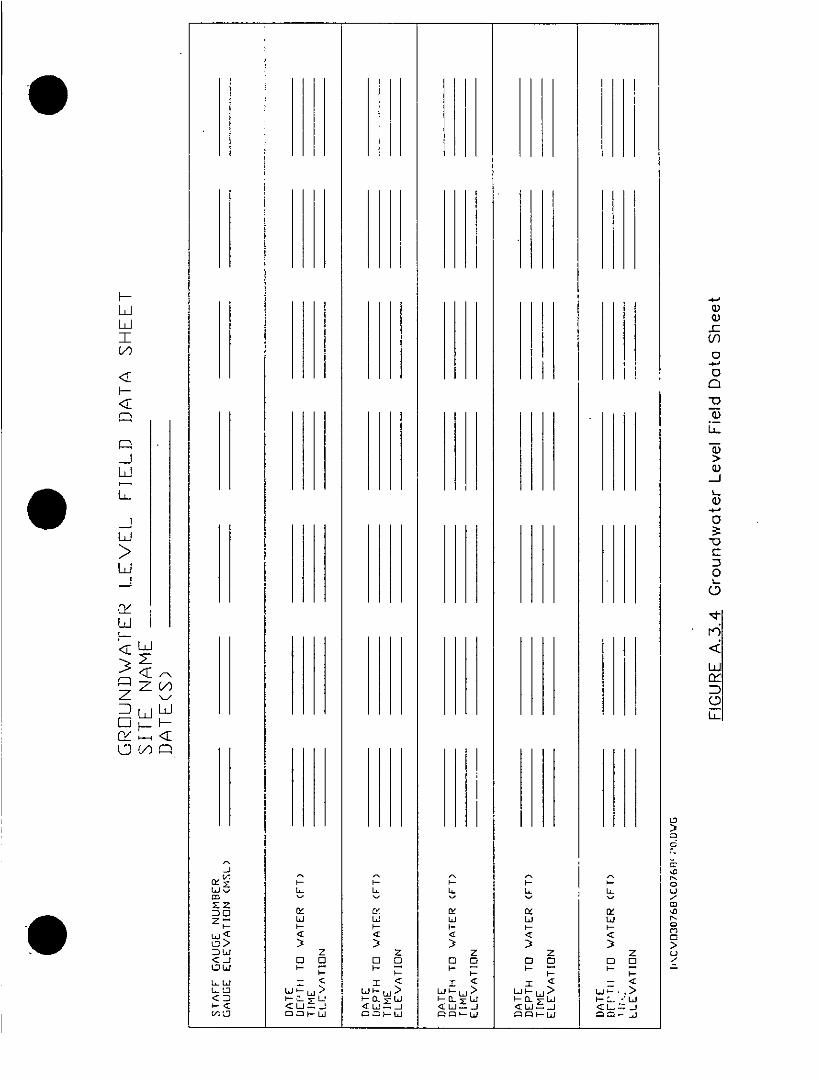
* ' I~I
I~~~~~~~~~~~~~~~~~~~~~~~~~~~~~~~~~~~~~~~
H J>iIawL
C Ii Iiw w 0
D El~~~~~~~~~~~~~~~~~~~~E-I ~ wwL
u a.)~~<<>j
L L.a zz< ~~~~ O O 0 0 0 0 0 0 0 0~~~~~~~~~~~~~~~~CU w ~~~~~~~~~~~~~~: ;_- ~~~~~~~~~~~~~~~~~~~~! r~ ~~~~--
@ 2~~~~~~~ aLi ~ ~ ~ ~ >> W~ -,
Li ~ ) Lrww ~ '-I~~~~~~~~~~~~~~~~ ~<~ -i~>
Lo mm~~~~~w ~~~=~~w m m mm ~ ~ ~ ~ ~ ~ (

GROUNDWATER WATER QUALITY SAMPLING SUMMARY
SAMPLEDATE NO/ID SAMPLER COMMENTS
FIGURE A.3.5 Groundwater Quality Sampling Summary1. \CVC30768\C0768F16.DWG

GROUNDWATER SAMPLINGFIELD DATA SHEET
PROJECT NAME _ _ _ _ _ _ _ _ _ _ _ _ _ _ _ _ _ JOB NUMBER _ _ _ _ _ _ _ _ _
WELL NUMBER _ _ _ _ _ _ _ _ _ _ _ _ FIELD TEAM _ _ _ _ _ _ _ _ _ _ _ _ _ _
FIELD CONDITIONS _ _ _ _ _ _ _ _ _ _ _ _ _ _ _ _ _ _ _ _ _ _ _ _ _ _ _ _ _ _
FIELD MEASUREMENT/ SERIAL/ID CALIBRATIONCOLLECTION EQUIP. MAKE/MODEL NO. CO0M ME-NTS
pH M ETER _ _ _ _ _ _ _ _ _ _ _ _ _ _ _ _ _ _ _ _ _ _ _ _ _ _
CONDUCTIVITY METER _ _ _ _ _ _ _ _ _ _ _ _ _ _ _ _ _ _ _ _ _ _ _ _ _ _
THERMOMETER _ _ _ _ _ _ _ _ _ _ _ _ _ _ _ _ _ _ _ _ _ _ _ _ _ _
WATER LEVEL INDICATOR _ _ _ _ _ _ _ _ _ _ _ _ _ _ __ _ _ _ _ _ _ _ _ _ _
BAILER/PUMP ______ _____
OV A/-HNU _ _ _ _ _ _ _ _ _ _ _ _ _ _ _ _ _ _ _ _ _ _ _ _ _ _ _
DECONTAMINATION _ _ _ _ _ _ _ _ _ _ _ _ _ _ _ _ _ _ _ _ _
PURGE INFORMATIEN OVA/HNU HEADSPACE ________
DATE _ _ _ _ _ _ _ _ _ _ _ _ _ START TIME _ _ _ _ _ _ _ _ END TIME _ _ _ _
INITIAL DEPTH TO WATER _____WELL DEPTH._____EST. WELLBDRE VOL.____
FINAL DEPTH TO WATER-____TOTAL VOL. PURGED .____DISCHARGE RATE____
METHOD _ _ _ _ _ _ _ _ _ _ _ _ _ _ _ PUMP DEPTH _ _ _ _ _ _ _ _ _ _ _ _ _ _ _
VOLUME PURGED TEMP(*C) ,pH CON DUCT(UMHOS) APPEARANCE
* URGE WATER DISPOSAL _ _ _ _ _ _ _ _ _ _ _ _ _ _ _ _ _ _ _ _ _ _ _ _ _ _ _ _ _
FIGURE A.3.6 Groundwater Field Data Sheet
I: \CV030768\CO76SF17.DWG

DATE _ _ _ _ _ _ _ _ _ _ _ _ _ START TIME _ _ _ _ _ _ _ END TIME___F_
ME'THOD
INITIAL DEPTH TO WATER _______ DEPTH TO WATER AFTER SAMPLING ___
FIELD MEASUREMENTS
REPLICATE
NO0. mK TEMP pH CONDUCTIVITY APPEARANCE/COMMENTS
21.
3,
4 . _ _ _ _ _ _ _ _ _ _ _ _ _ _ _ _ _ _ _ _ _ _ _ _ _ _ _ _ _ _ _ _ _ _ _ _ _
SHIPPING INFORMATIONSHIPPING
SAMPLE NOl/ID ANALYSIS LABORATORY CARRIER DATE AND NO.
COMMENTS AND EXCEPTIONS TO SAP/QAPP
----------------.---- - - - --- 4 -. * - -,
- - L * -I - .--. --- ,- - - - - - --.- -~~~~~
- - - - -7--- -7I
* RCRA replicates shoucld be measured fol-Lowing complete purge.
- FIGURE A.3.6 Groundwater Field Data Sheet (cant.)I:\01V030763\CO768F18ODWG

She. Management Plan-PS P DRAFTE~iewn Air Force Boa*e
* ~~~~~~~be documented in the Groundwater Sampling Field Data
Sheet, Figure. A.3.G.
3.1.6.3 Groundwater Elevation Measurements
Water-level measurements will be taken at eac-h well prior to
purging. The wells will be approached with an HNu/OVM andcarefully opened. The HNuIOVM will be used to monitor fororganic vapor released firom the groundwater in the well. Thedepth to water will be measured with an electric water-levelindicator. Water-level measurements will be taken from the top
of the PVC casing at the surveyed measuring point to thenearest one-hundredth foot. Water-level measurements taken
prior to purging will be documented on the Groundwater FieldData Sheet and Groundwater Level Field Data Sheet shown in
Figures A.3.6 and A.3.4.
Frequency of collecting groundwater levels will be determined
as appropriate for each OU.
The water-level indicator will be decontaminated between eachwell as indicated in Section 8.0, Decontamination Procedures.
3.1.8.4 Well Purging
The goal of groundwater sampling is to collect samptes thatare representative of the water present in the water-bearing
zone. To meet this goal, each well will be purged' until the wellcontains fresh water from the formatLion. Prior to purging, the
Kv/CVOP~b7/OM.51 A.3.29 17 June 1991

St,.* Man. pment PfarnFSP DRAFTLiaison Air Force bn.e
depth to groundwater will be measured and recorded todetermine the volume of water in the well bore. Wheneverpossible, wells will be purged a minimum of three well borevolumes prior to sampling or until the field parameters
stabilize.
The wells will be purged with a peristaltic, centrifugal, orsubmersible pump or bailer, If a pump is used, a dledizatedlsuction line will be attached to the inside of the casing tominimize cross contamination between wells. The suction lineor submersible pump intake will be placed near the top of thewell screen so that fresh formation water will move through thescreen and up to the sampling point. Purged water will be
managed as described in Section 7.0. Any purge water that isadrummed will become the property of EBelson AFB. EielsonVAFB will be responsible for proper handling and disposal.
If the well yield is low enough to make purging three well borevolumes impractical, the well will be purged as much as
possible and a sample will be collected after the well hasrecovered.
Well purging details will be recorded on the Groundwater
Sampling Field Data Sheet.
3.1.6.5 Field Parameters
A disposable plastic cup will be filled from the pump dischargeafter each well bore volume during purging. These samples
tw/cvoR2s7/28.51 A.3.30 17 June 1991

Sit. Mlan. gement Ph~n-FSP DRAF-TEiolon At Force Base
will be measured immediately in the field for temperature,specific conductance, and pH, and possibly dissolved oxygenand Eh. Results will be documented in the Groundwater
Sampling Field Data Sheet.
The probes used to take these measurements will be rinsedwith distilled water prior to each measurement. Each probe
will be field-calibrated or checked against standards accordingto the manufacturer's specifications on a daily basis.Monitoring probes will not be placed in the sample containersto be used for laboratory analysis:'
After all laboratory samples are collected, a final field samplewill be collected in a plastic cup, and field parameters will be
remeasured and again documented in the GroundwaterSampling Field Data Sheet.
3.1.6.6 Sample Collection
Sampling is best done with a bladder pump that does not stripvolatiles or with a hand-operated bailer. When a pump is usedfor sample collection, its rate should be controlled to closelymatch the transmissivity of the formation. Excessivedrawdown of the well during sampling may result innonrepresentational samples due to changes in groundwater
flow.
Bucket-type bailers are tall, narrow buckets equipped with acheck va!ve on the bottom. This valve allows water to enter
KvICVOR257/M8.51 A.3.31 17 June 1991

Sit. Management Plan-FSP DRAFTEMelou Air Force Base
from the bottom as the bailer is lowered, then prevents its
release as the bailer is raised. The bailer is particularly useful
when samples must be recovered from depths greater thai:,
the capability of suction-lift pumps, when volatile stripping is of
concern, or when well casing diameters are too narrow to
accept submersible pumps.
These procedures shall be followed for using a bailer:
* Using a clean electronic level indicator, determine the
water level in the well, then calculate the fluid volume in
the casing.
* Purge well of three to five volumes or until physical
parameters stabilize, whichever is greater. The
exception to this is when the well can be bailed dry due
to poor recovery. In that case, bail the well dry at leasttwice before sampling.
* Whenever possible, wells expected to be contaminated
will be sampled first, followed by wells with increasing
levels of contamination.
* Wells will be sampled using stainless steel or teflon
bailers ant nylon line (a new line will be used at each
well). ft is a good idea to secure the loose end of the
line to the well casing so that the bailer will not be
accidently lost down the well.
IWICVOPR2b71028.51 A.3.32 17 June 1991

Sit. Management Pbmn-FSP DRAFTElelson Air Force Base
0 * ~~~~~~~~Lower precleaned bailer slowly until it contalts watersurface. Allow bailer to sink and fill with the minimum of
surface disturbance. Remove the first bailer and
discard (properly dispose of) in order to rinse the bailerwith well water. Repeat as often as necessary to collect
adequate sample volume.
lip bailer to allow slow discharge from top to flowgently down the side of the sample bottles witr. aminimum of entry turbulence. Collect samples in thefollowing order: volatile organics, semivolatiles, otherorganics, inorganics, other parameters. Cap each
bottle after it is filled.
*Preserve the sample if necessary in accordance with
established guidelines.
*Check that the teflon liner is present in the cap ifrequired. Secure the cap tightly. Label the samplecontainer with the appropriate tag. Record the sample
in the field log book.
*Place the labeled sample in a cooler maintained at
temperatures not to exceed 40C throughout the
sampling and transportation period.
This procedure shall be followed for sampling for floatingproduct using a bailer:
Iw/C VO ~S7/8O51 A.3.33 17 June 1991

Sit. Menagpment PIOI,-FSP DRAFT7VEloie. Air Force Ba..
*do not purge well prior to sampling floating product
*use a clear acrylic bailer with a bottom check valve.
*Lower precleaned bailer slowly until it contacts water
surface. Allow bailer to sink and fill with the minimum of
surface disturbance. Rem--ove bailer from well.
*Note the water/product interface in the clean bailer.
*Open bottom check valve to water to escape bailer,
stop when product is at bottom valve.
*Drain product into appropriate sampling containers.
3.1.7 Drum Sampling
Since some of the source areas at Eielson AFB may involve drumburial sites or staging areas, drums with unknown containerized
liquids may be encountered and need to be sampled.
Prior to sampling, drums should be set upright and level in a
staging area to allow easy access. Drums that are ir', good
condition, full, sealed, and labeled as to contents probably do not
need to be sampled, but that information needs to be
documented in the field log. Any standing water or other material
shoul: ne removed from the container top so the representative
nature of the sample is not compromised when the container is
tw/sziRasi02.5 A.3.34 17 June 1991
'A
Site Management Pwan-rwP DRAFTEjelsn A4? Force aSne
0 ~~~~~~opened, and to avoid the possibility of encountering a water-reactive substance.
Drums must be opened with the proper techniques, tools, andsafety equipment. Samplers should stand upwind from the drumand wear appropriate eye, skin, and respiratory protection. Thereis a potential for vapor exposure, skin exposure due to splash orspraying, or even explosion resulting from sparks produze_~ by
friction of the tools against the drum. Drums that are bulging andobviously under pressure shall be opened only by experiencedpersons and, if possible, with remote equipment. Since thecontents of some drums may be under pressure but do notappear to be bulging, the bung should be turned very slowly. If
any hissing is heard, the person opening the drum will back off* ~~~~~~~and waft for the hissing to stop.
A common method of opening drums is with a universal bung
wrench. These wrenches have fittings made to remove nearly all
commonly encountered bungs. They are usually constructed of
cast iron, brass, or a bronze-beryllium, nonsparking alloyformulated to reduce the likelihood of sparks. A "nonsparking"wrench only prevents a spark caused by wrench-to-bung friction;
it cannot prevent sparking between the threads on the drum enrd
the bung.
Containerized liquid sampling will be done with a glass tubecommonly called a "drum thief' or another commercially available
drum sampler. Glass tubes are also convenient to use whensampling fluid from old transformers. The glass tubes are
1w/CO/O~S7/O2.51 A.3.35 17 June 1991

Sit. Management Plan-FSP DRAFTEI.Iaon Atk Force. Ea"
normally 122 cm in length and 6 to 16 mm inside diameter.
Larger diameter tubes may be used for more viscous fluids. The
tuning is broken up and discarded in the container after the
sample has been collected, eliminating difficult cleanup and
disposal problems.
These procedures shall be followed for using glass ty 7e s:
* Remove cover from sample container opening.
* Insert glass tubing almost to the bottom of the container.
Try to keep at least 30 cm of tubing above the top of the
container.
* Allow the waste in the drum to reach its natural level in the
tube.
* Cap the top of the tube with a safety-gloved thumb or a
rubber stopper.
* Carefully remove the capped tube from the drum and insert
the uncapped end in the sample container.
*Retease the thumb or stopper on the tube and allow fluid
to flow into mie sample container. Repeat the steps if rmore
volume is needed to fill the container to approximately 90
percent of its capacity.
N1WCV0R257/028.51 A.3.36 17 June 1991
Sit. Masnagement Plan-FSP DRAFTEiels~on Air Force Baa.
* Remove the tube from the sample container and replacethe tube in the drum.
Check that the teflon liner is present in the cap of thesample container, if required. Secure the cap tightly.
Label the sample container with the appropriate tag.Record the sample in the field log book, along with a
complete description of the drum.
Place the labeled sample in a cooler maintained attemperatures not to exceed 400 throughout the sampling
and transportation period. Preservatives are usually notadded to drum samples because of their assumed high
concentrations of components and consequent lack of
microbial action. In fact, nothing should be added to the
sample until comnpatibility testing has been done.
• Break the glass sampling tube so that all parts of it arediscarded inside the drum. (In some instances, disposal ofthe tube in the drum may interfere with eventual disposal
plans. In this case, alternative sampling methods should
be used.)
* Replace the bung or place plastic over the drums.
* Decontaminate equipment before and after use. Keepequipment off contaminated surfaces to prevent cross
contamination of the samples. Place equipment ondisposable polyethylene plastic sheeting.
IwICVORt257IO28.51 A.3.37 17 June 1991

She Management Plmn-FSP DRAFTElise:o, Air Force Base
3.2 SAMPLE CONTAINERS, PRESERVATION, AND HOLDING TIMES
Sample container, preservative, and holding time requirements arediscussed in the QAPP, Appendix B. Holding time starts at the
time of sample collection in the field.
All samples will be maintained at a sample temperature o'; 40C or
less. Water samples for dissolved metct~ analysis will be filtered
through 0.45 micron filter paper immedtely upon arrivar in the
laboratory using a pressure filtration deuice. lmmedialei~ after
filtration, the metal samples will be preserved by acidifying with
nitric acid. Water samples for total recoverable metals do not
need to be field filtered. Total recoverable metals will only be
analyzed for surface water samples. Samples for other analytesa
will be preserved in the field as required by the standard methods.V
3.3 SAMPLE LABELS
Sample labels (Figure A.3.7) must be completed properly to
prevent misidentification of samples. Labels will be marked with
indelible ink pens and firmly affixed to the sample containers. The
spaces on the label are self explanatory, but the following portions
should be noted:
*Place of Collection. Enter the well or station number.
Enter sampling depth where appropriate.
*Field Information. Indicate the type of analysis, such as
VOA, and sample preservative.
IwICVOR257/028.51 A.3.38 17 June 1991

p1 I-CHEXI RESEARCH
C HEMIV 'WINC)T1-1~ IM 511
SITE NAME DATE
ANALYSIS TIM E
PRESERVATIVE
SPECIALTY CLEANED CONTAINER
FIGURE A .3.7. Example of Typical Szmple Identification LabelSite Management Plan, Eielsan Air Force Base
CKHWILL QUALIWYANALYTICSCHAIN OF CUSTODY RECORDPROJECT NUMBER PROJECT NIME CLIENT ADDRESS MND PNONE WJMBER FORMLBUSE ONLY
CLIENT NAME fANALYSES REQUESTED Ea ~~~~~PROJECT MANAGER COPYTO: o A PROJECTINO.
' V ~~~~~~REQUESTED COMP. DATE WA'.PING REQUIREMENTS A I C EIEIOA NIEES RCRA OTMER N I IQO~
ICITSI R I NO.OFSF MPM]O.OQ0 R I
SIA 1 MjA I SPAMPE DESCRIPTIONSINO iDITU TME P18111 (12CHARACITIRS) I ILIC
IL~~~~~~~~~~~~EAK
EC FKD By W DA;EM-.~~~~~~~~~~~~~~~~~~~~~~~~ SM~~~ I I I_ _ _ _ _ _ _ _ _ _ _ _ _ _ _ i~~~PS s FI~ hEX I _ _ _
I E___RKS__E_____ED_____
I I I~~~~~~~~~~~~~~~~~~~~~~~~~T RIA N ~ TTHIS FORM IS 65% of ORIGINAL SIZE._ I __________ 0
F IIGUEA38 hin-of-Custdy Recor Form _______
I -~~~it angmetPln -i i-[ n Air Foc Ios

Sit. Management Plan-FSP DRAFTElelson Ah Force Sam.
Collector's Sample Number. Enter the sample numberwhich includes the site identifier, the sample description,
the sample number, the date, and if appropriate, the lower
depth.
The sample identification number should also be writt~en withindelible ink on the cap of. the sample bottle in case the sample
label is lost or destroyed.
The sample identification number is unique to a particular sample
and has the following format:
(base) - (sample location) - (month/year) - (lower depth)(base) - (sample # (depth) - (matrix designation)
Example: El -SO-SB-i14B-04/91 -05.0would be aSOilsamplecollected in April 1991 at Elelson AFB from Soil Boring No. 14B3,where the bottom of the drive was at a depth of 5.0 feet.
where:
Month =a 2-digit number, e.g., 01, 12
Year =a 2-digit number, e.g. 92, 93, 94
Base =a 2-letter code for Eielson AFB, e.g. El (This could be
left off the sample label, but should part of the database inputinto the computer and is put at the top of the chain-of-
custody.)
tw/CVOF257I028.51 A.3.40 17 June 1991

Shte Management Pian-FSP DRAFT. E~~~elson Air Force Base
Sample Locatlon= a 2-letter and 2-digit code for the specificsample location where:
SE =Sediment
SW =Surface WaterSB =Soil Boring
MW =Monitor Well
TP = Test Pit
SL = Surface Location not associated with a boring,monitor well, or test pitPZ =Piezometer
WP =Well Point
SG Soil Gas Probe
Notes: The same number would be given to a monitor well orpiezometer that went into a soil boring, just the letter designation
would change.
Give blind location numbers to field replicates and duplicates, solaboratories will not be able to identify them. However, note infield log which samples are related.
Depth = in tenlits of a foot, from 00.0 to 999O.9 feet. For a spit
spoon drive sample, give depth at bottom of drive: if sample istaken from 4.5 to 6 feet, use 6,3 feet. For monitor wells,piezometers, and wlCi points, no sample depths v,.IIi be given.
See Figure A.3.8 for an example of a chain-of-custody form.
iw/cvor257Io28.51 A.3.41 17 June 1991

Sit. Managemfent PIarn-FSP DRAFTVelesn Air Forc. Be".
3.4 SAM.PLE DOCUMENTATION
3.4.1 Sampling Location
Where appropriate, sampling locations will be marked in the field
with wooden stakes, allowing approximately 30 inzh&e. of each
stake to remain visible above ground. The top portion of the
stake will be painted orange and labelet- for identificatizn. If the
exact location cannot be marked (e.g., a sedirmnem sample in The
middle of a creek), then stakes will be placed as close as pessible
to the location with the distance and direction to the sample
marked on the stake and in the field notebook. Sample numbers
can be painted directly on drums. The distance to the sample
location will be measured from at least two permanent structures
(buildings, power poles, survey markers, etc.) to the nearest footwith a measuring tape and recorded in the field log and on a field
map.
3.4.2 Field Notebooks
Bound field notebooks will be issued to the sample manager to bemaintained as a permanent record of daily events, observations,
and measurements, including instrument calibration. Entries will
be made in sufficient detail to allow reconstruction of site activities
without reliance on memory. The language must be descriptive,
objective, factual, and free of personal feelings. Pertinent data
recorded on field worksheets will be trn~tdby the sampling
team leader into the field notebook, signed, and dated.
tw/CVOR257/02B.51 A.3.42 17 June 1991

Sit. Manae gment Plan-FSP DRAFTEofton Air Force Base
Each notebook will contain the following information on its cover:
*person or organization to whom the book is assigned
*book number
*project rimme
*start date
*end date.
This information will either be written on the notebook cover with apermanent marker or on an affixed, weatherproof label.
Entries into the notebook will contain all the information necessaryto recreate the sampling event, including all field observations and
all information that tracks the chain of custody. At the beginning
of each daily entry, the date, start time, weather, names of all fieldpersonnel present, and the signature of the person making the
entry will be entered. Names of visitors to the site, all fieldsampling team personnel, and the purpose of each visit will be
recorded in the field notebook. Each page of the notebook will besigned and dated by all individuals making entries on that page.
Sample information recorded in the log book shall include:
* sample date and time
* field conditions affecting collection, such as weather, wind,
and ambient air temperatures
* location (distance measurements including sample depth)
tw/CVOF257/028.51 .A.3.43 17 June 1991

Shte Management Plan-FSP DRAFTEielson Ali force Bees
* matrix (water, soil, sediment, oil, etc.)
* unique sample ID
* method of collection, including well development and
purging techniques and equipment, grc-. ndwater level prior
to sampling
* field measurements, i.e., pH, conductivity, temperature,
HNu readings, flammability, explosiveness
* number and type of sample containers and tests requested
preservatives
* field observations (color, odor, unusual conditions, etc.)
* collector's name
• references to photographs and field maps.
Additional readings, weather conditions, and field modifications or
decisions will also be recorded. Photographs with the time, date,
location, and task description will also be noted in the log book.
The log book will be written in waterproof ink unless Alaskan
weather (wet or extreme cold) conditions dictate otherwise. No
erasures will be allowed. If an incorrect entry is made, the
Iw/CV0M57I028.51 A.3.44 17 June 1991

SlU. Management Plan-FlP DRAFTEseiwon Air force Bs".
information will be crossed out with a single strike mark and thecorrection will be initialed and dated.
3.4.3 Photographs
Photographs of the location with respect to surrounding area andrelative to objects used to locate thc. ,Y'e will be taken. Thepicture number, roll number, name of photographer, date, andtime will be logged in the field notebook to identify which samplingsite is depi-ted in the photograph. A general description of thesubject and direction faced will also be recorded. The film rollnumber will be identified by taking a photograph of aninformational sign on the first roll number written on it so as toidentify the pictures contained on the roll. A data-back camera
* ~~~~~~that displays the date on the photograph will be used for this
project.
3.4.4 Sample and Investigation Derived Waste (IDW)Management Using Bar Coding
Bar coding for -sample and IDW tracking offers several advantagesover manual methods. Accuracy of records is improved becausethe ercx:) rate for bar codes is on the order of 1 error per1 0,000 records. Time is saved because field bar coding issubstantially quicker than manually recording the necessarysample information needed for tracking and chain of custody. Barcoding is especially beneficial under adverse weather conditionsbecause writing is not needed, and problems with legibility ofhand writing are eliminated, If desired, inventory control of
tw/0V0R257/028.51 A.3.45 17 June 1991

Sit. e )W-, gemwnt Plan-FSP DRAFTEVelm Air Force Bmaa.
containers for billing or reordering is possible. Sta.ndardizedtracking of transactions is assured because only certainoperations are preprogrammed into tine bar code reader. Errorsin keying tracking information into the data base are eliminatedbecause the bar code readers are electronically downloaded at
the end of each day.
Sample tracking using the bar code system will be accomplishedas follows:
The data management system and bar code system will beimplemented concurrently to assure compatibility and
maximum benefit is gained from the interface of the barcode readers with the sample tracking data base.a
Performance specifications for the bar code readers will bewritten to accommodate the environmental conditions
expr.zteod at the Site. Readers will be able to read barcodes through plastic zip-lock bags on curved, wetcontainers in bright sunlight. Sufficient readers will bepurchased to allow each sampling team to retain one withbackups in case of malfunctions. Readers will be
programmed to be user friendly. In particular, it should be
easy to backup step by step at any point in any bar code
transaction and read each step in the transaction on the
bar coder screen. This will reduce 'he probiem f! losing
place when the transaction is interrupted. Readers should
also be able to play back at least 'lie most recent,
transaction so that it is easy to avoid forgetting or doubleentering information. The oar code reader will allow
tw/cvOR257/028.51 A.3.46 17 June 1991

Sit. Management Pian-FSP DRAFTEiMi.on Air Force Be"
S ~~~~~~~~corrections of errors, such as out of sequence bar coding,in the field or shall be programmed so that entry errors are
precluded.
Bar code operations begin with programming the bar codereader and creating menu cards (typically 8-1/2 x I11-inch
sheets with bar codes attached and sealed in plastic) foreach distinct operation. Bar code readers are typicallyprogrammed on an EPROM within each bar code readerusing a special encoder that is secured to preventtampering. Thus, the bar code reader program cannot bechanged without the encoder module. A bar code printer(usually purchased with the system) allows creation of barcode labels that can be affixed to containers, Iogbooks,
and so on, as necessary.
* A program is written or purchased that generates uniquesequential sample container numbers for each container.
These can be printed as needed. Typically, multiple barcode labels are printed and affixed to each container whileassembling sampling kits (coolers) to go to the field.
* A menu card is created for each transaction sequence
prior to starting field activities.
* Prior to field sampling, the containers expected to be usedin the near future are prelabelled with a un-;que bar codedcontainer number. At least two bar code labels (uniquecontainer number copies) are affixed to the container. One
IW/CVOR257/026.51 A.3.47 .17 June 1,991

W/e Managemerr Pisn-FSP DRAFTFiedson Air Force Sase
is permanently attached to the container and one is
permanently attached to the lid. One is also temporarily,
(special peel-off bar code label) attached to be removed
during sampling and pasted into the field book. If desired,
another bar code label can be attached to the cooler in
which a kit of sample containers (enough for one sample)
has been placed. That is sometimes done to facilitate
transfer of filled and sealed coolers.
After the sample team leader (usually the field geologist)
places a sample portion in a particular container, the
container is bar coded into the system with the bar code
reader. This initiates the chain of custody. The geologist
peels off one of the removable labels and puts it into his
field book adjacent to' the sample description. Each
container is bar coded into the system in turn. Each
transaction (bar coding the container into the system in thiscase) involves using the menu card to read in a bar code
which identifies the type of transaction, one bar code to
identify the geologist, one bar code to identify the sample
number, location, depth and any other information that has
been preprogrammed in. It is desirable to preprogram in
as much information as possible, because this information
will be downloaded to the data base at the end ot the day
and will not have to be keyed in later. The reader
automatically stamps every transaction with the exact time
and date.
IW/GVOR257/028.51 A.3.48 17 June 1991
Sfte Management Pian-FSP DRAFTEoison Air Farce Ba"
*The containers are transferred to another's custody by
using preprogrammed bar code menus and the bar codes
assigned to the releaser and recipient. Typically, eachperson who will use the bar code reader will have a
personal identifying bar code attached to a personal
badge.
Placing the containers in interim storage is a similar barcode menu-driven transaction. Sometimes a locked
storage location is given a bar code, just like a person, andcustody is transferred to the storage location.
At the end of the day, the geologist returns and downloads
the bar code reader to the data base. This can be done
by modem if necessary. The data base then prints out a
listing of the day's transactions for the geologist to check
and make immediate corrections to, if necessary. If the bar
code reader is programmed correctly, there should be little
chance for error.
Ideally, a bar code reader is also assigned to the lab and
the chain of custody is continued. When lab results are
completed, they can be electronically transmitted to the
data base and electronically linked to the bar code data
already in the system. If the system (hardware- and
software) is designed carefully and thoroughly, checked
out, there should be no keying of data in the field. The
only writing necessary in the field book is the activity
lw/CVOR257028.51 A.3.49 17 June 1991

Sit. Management Plan-FSP DRAFTBelson Air Force Base
description and the sample description. All other
information is bar coded into the system from menu cards.
3.5 SAMPLE CUSTODY
All samples will be collected under chain-of-custody procedures.
Standard paperwork used for sample tracking and records
include:
* chain-of-custody forms•custody seals
field log ~books
• field worksheets
* s~irface water sampling forms
* groundwater sampling forms0* sample shipment receipt and air bills
* laboratory log book.
Custody of a sample is defined by the following criteria:
* the sample is in your possession or in your view after
being in your possession
* the sample was in your possession and was locked up or
transferred to a designated secure area by you.
Each time the sample bottles change hands, both the ssnder and
the receiver will sign and date the chain-of-custody form and
specify what has changed hands. When a sample shipment is
Iw/CV0FM7/028.51 A.3.50 17 June 1991

Sit. Management Plan-FSP DRAFTVelfon Air Force So"
sent to the laboratory, the top signature copy is enclosed in
plastic with sample documentation and secured to the inside of
the cooler lid. The second copy of the chain-of-custody form will
be retained in the project files. A chain-of-custody record will be
completed for each shipping container. Chain-of-custody
procedures for the laboratory are fo:~.rd in the QAPP, Section 6.0.
A copy of the sample chain-of-custody form used by the field
team during collection of environmental samples is shown onFigure A.3.8.
The following information is included on the chain-of-custody form:
• sample number
* *~~~~~~~ signature of sampler
* date and time of collection
* place of collection
• type of sample
* number and type of container
* inclusive dates of possession
* signature of receiver.
3.5.1 Directions for Completing Chain-of-Custody Form
To assure custody of samples during transport and shipping,
each sample being shipped is recorded on a chain-of-custody
form. Following are step-by-step instructions for completing the
form.
tw/cvoF257/028.51 A.3.51 17 June 1991

Shte Management Plmn-FSP DRAF7Eolelon Air Force So"
1. Project Number. Complete project number, including
region, point, and function, if applicable.
2. Project Name. Print the name of the project.
3. Laboratory. Print the name of the laboratory to which the
samples are being sent.
4. Station Number. Print the sample location identification
number.
5. Date. Print the date of sample collection. For example,
January 12, 1990; enter "12Z' under DATE and enter
"January 1990' under REMARKS at the bottom of the page.
6. Time. Print in military time that the shipment was shipped.
7. Composite/Grab. Check the correct column to indicate
the sample type.
8. Sample Identification. Print the sample identification
number.
9. Number of Containers. Print the number and type o:
containers collected at each station.
10. Untitled. Print the type of analysis requested.
tw/cV0R257/028.51 A.3.52 17 June 1991

Site Management P1an-FSP DRAFTEleteon Air Force Be"
0 ~~~~~~11. Untitled. Print the number of each type of analyticalsample collected at that station.
12. Sampled By and Title (Signature). The sample collectorshould sign and'date this space.
13. Relinquished By (Sir'nature). The person whorelinquished the samples should sign and date this space.
14. Received By (Signature). If the samples are beingshipped by commercial carrier, such as Federal Express,
the box is left blank for the receiving laboratory to sign. Ifthe samples are being received by a courier or theanalytical laboratory, then the person receiving the samples
* ~~~~~~~~should sign his or her name.
15. Sample Shipped Via. Check only the appropritate box. Ifanother method of shipment was used, note this in the
REMARKS section.
16. Air Bus Bill Number. If shipped by air or bus, circle theappropriate term, AIR or BUS, and fill in the shipping billnumber.
17. Remarks. Enter any pertinent remarks concerning the
sample, i.e., 'Well cap found unlocked.'
IWJcvo~tznoa0.51 A.3.53 17 June 1991

Sit. Men. gem. rrt Plen-FSP DRAFTSelson Air Force So.
3.6 SAMPLE HANDLING, PACKING, AND SHIPPING
Sample handling, packing, and shipping are important to
maintaining sample quality. Sample container requirements are
found in the QAPP, Appendix B. The sample container must be of
the correct material, otherwise the sample container may absorb
some of the sample constituents.
At all times the samples must be kept at 40C or lower. Care must
be taken to assure that water samples do not freezit. Collection
of water samples in the winter in Alaska can be tricky since
collection takes place in a natural outdoor fr eezer. Water samples
need to be stored in an area or container that maintains the
temperature above freezing. Likewise, care must be taken to
keep water bottles and vials from direct contact with ice or blue
ice during transport.
To enable a sample to be shipped safely, special care must be
taken when packing to assure that it is not broken or lost in transit
and that the ice chest used to ship the samples is properly
labeled. The following paragraphs describe the proper way to
pack samples and label ice chests for shipment.
3.6.1 Packing Environmental Samples
It is anticipated that most project samples will be shipped as
environmental samples in small volumes. Environm- ental samples
are samples whose contaminant concentrations are significantly
reduced by normal environmental weathering processes such as
lw/0 V0R257/O28.51 A.3.54 17 June 1991

Site Management PIan-FSP DRAFTEM:.aln Air Forc# Bea.
volatilization to the air, degradation due to expcsure to sunlightand microbes, or simply mixing with soil or groundwater. Assuch, the samples present little shipping hazard in terms ofcorrosiveness, flammability, and explosiveness.
To pack environmental samples, the following procedures shall befollowed:
* The sample container caps are checked to assure that theyare properly tightened.
* For samples contained in glass jars, bubble wrap or foam,packing material is placed on the bottom and sides of theice chest to prevent breakage.
* For samples contained in glass jars or polyethylene bottles,
the individual sample containers are wrapped with thebubble wrap or foam packing material. Tape the bubblewrap or foam ends so that it does not unravel. Thisprevents the containers from falling sideways and breaking.
* Place the sampte containers right side up in the ice chest.
* Add additional bubble wrap or foam to prevent the
containers from moving.
• Pour vermiculite or equivalent over the containers to* ~~~~~~~~minimize container movement.
W/CVOR257/02.51 A.3.55 17 June 1991

Sit Management Plan-FSP DRAFTElelson Air Force Sam
Place ice in double-bagged zip-lock baggies and placebaggies over the containers to preserve them, or use blue-
ice if available. Metals samples and some traditional
inorganic parameters do not need to be iced down.
* When packing glass containers, place several layers of
packing material on top.
* Seat the plastic bag by tying a knot using the top of theplastic bag or with a strong adhesive tape (i.e., fiber tape).
* Place the appropriate paperwork (i.e., chain-of-custody)
into a plastic bag, seal the plastic bag, and tape it to theinside lid of the ice chest with the shipping papers.
• Close and lock the chest. Wrap a strong adhesive tape(i.e., fiber tape) around ends of chest to secure it, makingsure to cover the spigots at the bottom of the chest andany open space between the lid and the cooler.
• Affix the proper shipping labels onto the outside of thechest. Do not obscure any labels on the ice chest. Plaze
chain-of-custody seals over the lid.
* Print "Laboratory Samples' and 'This End Up" on top of the
cooler and put upward-pointing arrows on all four sides.
IwICVOF157/028.51 A.3.56 17 June 1991

3it. Management PJan-FSP DRAFTEjelsor Air Force Sea*
3.6.2 Packing Hazardous Samples
Samples of pure products can sometimes be classified ashazardous in terms of shipping regulations. Most of thesesamples have not been affected by environmental dilution andmay have been collected directly from drums, fuel tanks, or othercontainers. Due to their conicentration, only small volumes(usually 2 ounces or less) are required for most analyses.
Hazardous samples should not be stored or shipped in the sameice cooler as other environmental samples, especially if volatileorganics analyses are requested.
When transported by means other than a government vehicle,*these samples must be packaged, marked, labeled, and shipped
according to Department of Transportation (DOT) regulations.Most hazardous samples are classified as flammable liquid orflammable solid shipments and require the following packaging
procedure.
* Place the sample container, properly identified, in apolyethylene bag and seal the bag.
* flace the sample in a metal can, cushion it with vermiculite,and secure the can lid tightly with clips or tape.
* On the metal can, print or in label form show the laboratoryname and address and "Flammable Uiquid, ni.o.s. UN 1993"or "Flammable Solid, ni.o.s. UN 1325."1
Iw/cvoR257028.51 A.3.57 17 June 1991

Sift. Management Plan-FSP DRAFTEleleon Air Force Base
•Place the metal can(s) into the plastic-bag-lined cooler,
surround the can(s) with vermiculite, and seal the outer
plastic bag.
* Documentation accompanying the shipment must beenclosed in a waterproof plastic bag and taped to the
underside of the cooler lid.
* Secure the cooler lid shut with fiber tape and custody seal
tape.
* The following DOT labels should be placed on top of the
cooler: "Flammable Uiquid, n.o.s."' or "Flammable Solid,
n.o.s." A "Cargo Aircraft Only" label is needed if the netsample quantity is greater than 1 quart (liquid) or
25 pounds (solid).
* Print "Laboratory Samples" and 'This End Up" on top of the
cooler and put upward-pointing arrows on all four sides.
3.6.3 Sample Shipping
Samples will be shipped via Federal Express or DHL by overnight
delivery in order to meet laboratory holding times. It is anticipated
that daily shipments will need to be made from the field when
samples are being collected.
IW/cvoR257/028.51 A.3.58 17 June 1991

Site Management Pfan-FSP DRAFTElelson Air Force Base
For environmental samples, no DOT marking, labeling, or shippingpapers are required, nor are there any DOT restrictions on themode of transportation.
For hazardous samples, the following procedures shall befollowed:
Complete a carrier-approved airbill or Shipper'sCertification for Restricted Articles providing the followinginformation in the order listed:
- "Flammable Uiquid, n.o.s. UN 1993' or "FlammableSolid, n.o.s. UN 1325"
- "Limited Ouantity' (or "Ltd. Oty.'3
- Net weight or net volume of total sample material in
cooler
- "Laboratory Samples''
-"'Cargo Aircraft Only''
*Ship by airlines that carry ONLY cargo, such as FederalExpress, etc.
*DOT regulations do not apply to transport by government-owned vehicles, including aircraft (similar DOD regulations
* ~~~~~~~~take precedence).
[w/cvoF257I02a.51 A.3.59 17 June 1991

Site Mansagemnent Pfan-FSP DRAFTVEloson Air Fo'c. Bass
3.7 FIELD QUALITY CONTROL SAMPLES
Quality assurance samples for this project will typically be
collected on a 1 -for-i 0 ratio, unless noted below. The types and
numbers of QA samples that will be collected will be summarized
in the QAPPs. The QA samples to be used for Eielson AFB
include travel blanks, equipmenit blanks, and field duplicates.
Travel blanr-s are sample bottles filled with ASTMV Type 11 Reagent
Water or equivalent organic-free water, transported to the field
site, handled like a sample, and returned to the laboratory for
analysis. Travel blanks are analyzed for volatile organic
compounds only, and are sent at a rate of one per shipment. The
travel blank for soils is Type 11 reagent water or equivalent, as in
the case of water samples.
Equipment blanks are collected when Type 11 reagent water is
poured into the decontaminated sampling device, or pumped
through it (in the case of sampling pumps, transferred to the
sample bottle, and then transported to the laboratory fbr analysis).
Field duplicates are two s~,nples collected independently at a
sampling location during a single act of sampling. Fi-E-;d duplicates
are collected for each sample parameter and media type. They
will be indistinguishable from other analytical samples so that
personne! performing the analyses are not able to determine
which samples are duplicates.
Iw/CVOF257/028.51 A.3.60 17 June. 1991

Site Managomoret Plan-FSP DRAFTEOIeWF. Air Force Des.
3.8 LABORATORY ANALYSES
Laboratory analyses are presented in the QAPP, Appendix B.
3.9 SAMPLE ANALYSES SUMMARY
Each OUMP should have tables summarizing the number and
types of samples and analysis anticipated. Headings on the tableinclude:
* parameter name
* analytical method number and reference
* reporting units.
0 ~~~~~~Rationales should be given in the OUMPs as to why the samplesare being collected and the specific analyses requested. The
analyses must provide the information necessary to achieve thedata quality objectives.
tw/cvoP257/028.51 A.3.61 17 June 1991

Sifte Mane goent Plan-FEP DRAFTElVo~n Air Force L' so
. 4.0 FIELD MEASUREMENTS
As required by the HSP, ambient air quality will be monitored fororganic vapors using either a flame or photoionization detectorduring field activities such as drilling, trenching, and watersampling. Explosivity and oxygen meters are also required by theHSP, and their operation is discussed in that, document. Theorganic vapor analyzers can also be used to field screen soilsamples.
During monitor well purging and sampling, pH, temperature, andspecific conductance will be measured. Dissolved oxygen and Ehmay also be measured.
Is ~~~~~~Instruments will be operated according to the operation manualsprovided by the manufacturers. A backup unit of each instrumentwill be available in the field in case one unit fails. The followingparagraphs present a summary of the calibration, maintenance,and decontamination procedures for the instruments that will beused to measure the field parameters.
4.1 PARAMETERS
The parameiQ':s to be me asured in the field consist of pH,temperature, and specific conductance. Specific brands andmodels of equipment to be used will be identified in. the field logbook. Eh and/or dissolved oxygen may also be measured. The
lw/cV0F257/066.51 A.4.1 17 June 1991

Sit. Mane gemenir Plan-.flP DRAFTElelsoni Agr Force Base
calibration for these will be covered in the OUMP when these
parameters need to be measured.
4.2 EQUIPMENT CALIBRATION
Quality control procedures for field inst rumentse will be limited to
checking the reproducibility of measurements to within 1 0 percent
by taking ;-nuliiple readings and periodic instrument calita_-ion. If
the variatit:!ty among multiple re&A,--ngs at a single site w: t any
instrument is greater than 10 percent, the instrument will be
recalibrated if appropriate, and the measurement will be repeated.
If variability remains unacceptably high and the instrument fails to
calibrate properly, the backup instrument will be calibrated and
used. The field manager will be notified when a piece of
equipment fails so that additional backup units can be sent to the
field.
Records of all calibrations are kept in the field notebook.
4.2.1 HNu Meter
The HNu is a photoionization detector used to measure the
presence and relative level of total volatile organic vapors. At
Elelson AFB, it will be calibrated at the beginning of eac:'-
sampling day. In instances where large daily temper ature
changes occur or moisture levels are high that affect the re-adings
calibration wvill also occur at mid-day and at the end of 6ay. 1Ii
the HNu is being used to measure total organic vapors i
heated head-space of a soi; sample, ttequent calibration
hm/CVOR257I066a51 A.4.2 17 June

Site Management P.an-FSP DRAFTEi.! son Air Force Base.
recommended due to increased temperatures and soil moisture.The HNu is calibrated daily with isobutylene relative to what wouldbe expected if the calibrant had been benzene. An organic vapormeter (OVMV) may be used in the place of an HNu.
4.2.2 pH Meter
The pH meter is used to measure the hydrogen ion concentrationin aqueous solutions. Calibration of the pH meter will be done on
a daily basis as follows:
1. Rinse electrode in distilled water and blot dry.
2. Determine solution temperature and set temperature0 ~ ~~~~~~compensator to the proper reading.
3. Place electrode in a commercial buffer solution with a pH ofapproximately 4 (expected lower range) and adjust calibrationknob until readout displays the proper pH value.
4. Remove probe from solution, rinse with distilled water, and blot
dry.
5. Piace the probe in a second commercial buffer solution with a
pH of 10 (expected upper range) and adjust slope control until
the meter reads tht pH value of the buffer solution.
6. Remove probe from solution, rinse with distilled water, and blot* ~~~~~~~~~dry.
tw/CVOR257/068.51 A.4.3 17 June 1991

Sit. Mmnamgenwnt PiarsFSP DRAFTEjleion Air Force Baso
7. Place probe in a third commercial buffer with a pH of
approximately 7 and record value.
8. If the measured value varies from the expected value bygreater than 0.2 pH units, recalibrate the instrument with fresh
aliquots of buffer solution. If the discrepancy persists, begin
troubleshooting the instrument as prescribed in the operating
instructions.
4.2.3 Specific Conductance Meter
The specific conductance meter is used to measure the electrical
conductance of aqueous solutions. The specific conductance of a
solution provides an indirect estimate of total dissolved solids andcan be useful in determining the extent of a contaminant plume in
the groundwater. Most units require that the instrument probe be
soaked in distilled water at least an hour before use. Specific
conductance is usually recorded relative to 2500. Some metersautomatically convert the conductivity reading to what it would be
at 25CC. Other units need to have reported conductivity calculated
from the measured reading using a cell constant. All conductivity
units are calibrated using salt standards of known cone~ntration.
Calibration should be done at least once each day.
4.2.4 Thermometer or Temperature Probe
Field ambient temperature measur-ements will be made using a
mercury thermometer or temperature probe. No calioration isrequired for the mercury thermometer. If a temperature probe is
1W/CVOR2S7/066.51 A.4A 17 June 1991

LA. Mariagernert PIan-FSF DRAFTEielson Air Force Base
used, it will be calibrated according to the instructions provided bythe manufacturer with the specific meter or against the mercury
thermometer.
4.3 EQUIPMENT MAINTENANCE
Field measurement equipment will be maintained according to the
manufacturer's recommended procedures provided in the
operations manual for each instrument. Common repair tools androutine replacement parts such as batteries, probes, and sensorswill be available to the field crew. At least one person will be
trained and assigned to make sure all equipment is functioningproperly in the field. Any malfunctioning equipment that requires
more than minor field repair will be taken out of service
immediately and conspicuously tagged. The field manager will be
notified so repairs can be scheduled through the manufacturer.
4.4 DECONTAMINATION
Field measurement equipment will be kept as clean as possible toassure accurate performance and reduce cross-contamination.
Sampfling probes that are immersed in sample media will be
rinsed and stored in distilled water during operatin; hours. The
probes will be cleaned daily and stored overnight according to the
manufacturer's recommended procedures.
iw/0V0P2571066.51 A.4.5 17 June 1991

Sit. Management Pkn-~FSP DRAFTE1e1scn Air Force Bee
. ~5.0 FIELD CA/CC PROGRAM
Quality assurance (QA) is discussed in Section 4.0 of the QAPP interms of comoleteness, comparability, representativeness,accuracy, and~ precision. Sections 40and 5 ocf the QAPP
* ~~~~addressee~general descriptions of the methods to be used to-- provide quality control (00) che~cks on the field program. This
section of the FSP discusses QC samples for groundi'cz-er, soils,surface water, and sediments.
5.1 CONTROL PARAMETERS
Quality control (QC) samples will be collected for all samplemedia. Types of QC samples include duplicate samples,S ~ ~~~~~equipment blanks, container blanks, and travel blanks.
Container requirements and 00 sampling requirements forspecific analyses are presented in Section 5.1 of the OAPP.
Both 00 and field sampling activities will be documented in fieldlog books in which descriptions of the sampling procedures,saffpld materials, ihd zampling conditions are recorded; on thechain-of-custody recorW forms, which document the physicaltransfer of samples and requested analyses; on le1jels, whichshow time, data, and location of sampling, the analyticalparameters, and the sample preservation techniques.
ivwICVOFt57/067.51 A.5.1 1 7 June 1991

Sit. Management Prnn-FSP DPAFrEoIsfon Air Pow.e B&A,.
5.1.1 Duplicate Samples
Additional volume is collected on samples at a fiequerz-'y of 1 in10 (with a minimum of one duplicate for each sample parameterfor each media type per day). The duplicates will be blinded andsent to the labs for field precision measurements.
5.1.2 Container Blanks
Bottle lot blanks arc* samples to check possible crosscontamination from the sample containers. One sample containerof each bottle lot will be filled with ultra-pure, organic-free waterand submitted as a blind sample to the laboratory.
5.1.3 Equipmen t Blanks
Rinseates are samples collected to document the effectiveness ofdecontamination procedures and to verify that contamination isnot introduced into wells by various equipment.
Rinseate samples are collected from split spoons, samplers,corers, and other nondedicated sampling equipment. The
piurp6ses of these samples and analyses are to document theeffectiveness of decontamination pro-3edures and tc verTIy theat no
cross contamination of the borehoc -or sample has occurred. Ifsurface water samples are collected direc:y ionto t - ~-mpib
bottles, no equipment blank will be - .nzessarx%
IwICVOFRQ57/087.51 A.5.2 June 199c

Site Management Plan-fSP DRAFTGol.sen Ali Force Bes.
Rinseate samples should be obtained from the appropriate item orpieces of equipment immediately after decontamination and prior
toI the next sampling activity or insertion into the well or hole.
Sampling frequencies will be 1 in 10. Use only ultra-pure, organic-
free water for the samples. Collect the rinseate sample by
passing the water over and through the equipment. Collect the
water directly into the sample containers.
5.1,4 Travel Blanks
Travel blanks will accompany each shipment to the laboratory that
contains two or more volatile organic samples for all sample
media on a daily basis. The purpose of travel blanks is to detect
contamination that may be transferred from one closed sample
container to another, or from the environment into the closedsample container. The contaminants of concern are volatile
organics; other contaminants are much less likely to exhibit thisdegree of mobility.
5.2 CONTROL LIMITS
Duplicate measurements of field parameters will be considesredsuspect if they differ by more than 10 percent.
tw/CVcR2Q57/067.51 A.5.3 17 June 1991

Site Management Plmr.-FWp DRAFTBEMson Air Fore. B...
. ~6.0 SITE MANAGEMENT
6.1 FIELD PROGRAM LOGISTICS
CH2M HILL will be responsible for acquisition and transportationof all equipment needed on this project. USAF equipment ortransport services will only be used when circumstances are irn thebest interest of the USAF.
6.2 SITE ACCESS
Access to proposed work areas will be coordinated by the EielsonAFB point-of-contact and Battelle EMO's project manager. Thiswork may include items such as:
• identification badges for field personnel* vehicle passes and entry permits* utility locates and digging permits
* keys to locks on existing monitor wells.
It is anticipated that base personnel will be available to assist inproblemn resolution and minimizing field down time.
6.3 SITE AND EQUIPMENT SECURITY
Base personnel will be requested to provide heated st..rage spacefor contractor equipment and for contractor equipmentdecontamination.
10 lIw/OVOF157I068.51 A.6.1 17 June 1991

Sit. Management Plan JSP DRAFT
Ello~n Air For"e Base
6.4 BASE SUPPORT
Prior to commencement of sampling activities, Elelson AFB
personnel will be notified to coordinate scheduling, locate
underground utilities, obtain any necessary permits, and provide
necessary staging and parking areas.
It is anticipated that the Eielson AFB point-of-contac will also
provide:
* accumulation points for well development fluids
* existing engineering plans, drawings, diagrams, and aerial
photographs related to this site investigation
* identification badges, vehicle passes, and entry permits as
needed
* a dedicated staging area for storing equipment
*a potable water supply
* an area for decontamination of sampling equipment
* temporary office space and telephone
* keys to locks on existing monitoring wells
IWIOVO~t57I068.51 A.6.2 17 June 1991
Site Managment Plan-FSP DRAFTElelson Air Force* Base
0 ~~~~~~~* temporary construction barriers and parking and trafficcontrols at thK sites, if needed
a written authorization for private property access
* fifty-five-gallon drums in new condition or steam cleaned forcontainment of soil or purge water.
0 '~~w/cvoR2Un08.51 A.6.3 17 June 1991
Site Management plan-nSP DRAFTBlason Air Force So"e
. ~7.0 MANAGEMENT OF INVESTIGATION-DERIVED WASTE5S
7.1 INTRODUCTION
The RI/FS field investigation activities may generate investigation-derived waste (IDW). These wastes may include dri!'l;ng muds,cuttings, and purge water from test pit and well installation; purgewater, soil, and other materials from collection of samples;residues (e.c-.. ash, spent carbon, purge water) from testing oftreatment technologies and pump and treat systems;
contaminated personal protective equipment (PPE); and
decontamination solutions used to clean nondisposable protectiveclothing and equipment. This lOW must be managed to protecthuman health and the environment and may require management0 ~ ~~~~~~in accordance with certain of applicable or relevant andappropriate requirements (ARAR). This section outlines generalprocedures for managing lOW produced during an RI/FS.
Investigation-derived waste (lOW) generated during the EielsonAFB RI/FS phase should be managec. together with the majority ofsite wastes, where possible, using the final remedy selected forthe Site. Managers always should minimize the generation ~)f IDW
as much as possir--e to reduce the need for special storage ordisposal that may generate additional costs and that may have tocomply with ARARs apart from those associated with the finalremedial action. EBelson AEB will be responsible for managing allhazardous waste generated during RI/FS field activities.
tw/cvoR257/09.51 A.7.1 17 June 1991

Site Management Plan-FSP DRAFTEleleon Air Fore* Btee.
7.2 IDW MANAGEMENT REQUIREMENTS
Table A.7.1 outlines options for various types of lDYtJ produced.When selecting a disposal option for lOW, managers are requiredto choose an option that meets two requirements: (1) protectiveof human health and the environment, and (2) in compliance withARARs (to the extent practicable).
7.2.1 Compliance With ARARs
Regulations that may be potential ARARs for lOW at EBelson AFBinclude the -Resource Conservation and Recovery Act (RORA), theClean Water Act (OWA), the Toxic Substance Control Act (TSCA),and state requirements.
7.3 GENERAL POLICIES FOR IDW MANAGEMENT
In addition to the two requirements outlined in Section 7.2, thereare three general policies that apply to the management of lOW:
minimization of lOW, management of lOW consistent with the finalremedy for the Site, and consideration of community concerns.
7.3.1 IDW Minimization
Managers should minimize the amount of lDW that is D~roducedl tothe degree practicable. Generation of lOW can be mninimized
throughl proper planning :4 all -P-eremedial and remediEJ activitiesthat may generate lOW, as well as through use of screeninginformation from the site inspection. Techniques such as
lw/cvoF257/029.51 A.7.2 17 June 1991

Sit. Management Pla-tFSP DRAFTEieieon Air Force Bse.
V________________ TBLEmA.7u. IOW Disposal OptionsType of IOW Generation Process' Disposal Options
soil Well/test pit installation Return to boring/pit immediately after generation
Borehole drilling Spread around boring/pit
Soil sampling Send to onsito existing TDU
Consolidate in a pit (within the AOC)
Send offeite immediately
Store for future disposal
Sludges/sediment Sludge pitsediment sampling Return to boring/pit immediately alter generation
Store for future disposal
Setnd offaite immediately
Aqueous licuids (groundwater, Well installation Discharge to surface watersurface water, wastewaters)
Well purging during pump and Reinject into welltreat telst
Pour onto groundGroundwater/surface watersampling Send to onsite existing treatmient/disposal unit
(rU)
Send to POTW
Send offsfte immediately
Store for future disposal
Disposable PPE (clean) Sampling procedures Send to onsite existing TDU
Place in onsite, industrial dlumpster
Send offsite to appropriate TDU immediately
Store for future disposal
Decontamination fluids Decontamination of PPE and Send to onsite existing TDUequipment
Evaporate (for small amounts fo~'~i lis
Send offaite immediately.
Store for future disposs;
rhe generation processes listed here are provided &s examples. IDW may also be produced z., a result of activities not I
cVCVOR257/030.51 A.7.3 17 June 1991
Sf. Management Ptvsn-FP DRAFTValoon Air Fore* Bae"
replacing solvent-based cleaners with aqueous-based cleaners for
decontamination of equipment, reuse of equipment fwhere ft can
be decontaminated), and careful sampling techniques can help
minimize IDW generation.
7.3.2 Consistency In Management
Managers should select, where possible, a management option for
IDW that is consistent v.'tth the fina; remedy anticipated 1;,r the
Site. This will avoid the need for separate 1'eatrnent arn;;;or
dispos-ai arrangements sucn as the construction of a separate
storage area that may require compliance with RORA design and
operating requirements. Two examples follow:
* A manager knows that wastes will ultimately be sent offsite
for treatment, and that conditions allow lOW to be stored
until the remedial action begins. It may be appropriate to
containerize the lOW and manage it when wastes are
generated from the remedial action.
*The soil contains wastes that will be stabilized onsite during
the remedial action. Sending IDW offsite may not be cost-
effective, because offsite disposal would involve testing and
transport costs for a relatively small amount of waste.
Instead, returning soil lOW to the ground from which it
originated may be an appropriate~option, provided ft is
protective until the stabilization occurs and the action
meets the other conditions outlined in this fact sheet.
Iw/OVOP257/029.51 A.7.4 17 June 1991

Wit. Management Plmn-FSP DRAFT. EM~11*wn Air Force Beau
7.3.3 Communfty Concerns
Residents of communities near this CERCLA site, localgovernments, or Alaska may have concerns about certain disposalmethods or long-term disposal of IDW at the site. Site managersshould evaluate community concerns in order to avoid publicrelations problems. For example, if a community is concerned
about the direct discharge of IDW water to surface water onsite,site managers may want to consider sending the water to aPOTW, if one is located nearby. In some instances, it may beappropriate to prepare fact sheets, include options in othercommunity relations documents, or explain IDW managementdecisions at public meetings prior to actions.
O ~7. SELECTION OF IDW DISPOSAL OPTIONS
Options for IDW disposal can be grouped into two categories:
1. Immediate Disposal. This option can include returning IDW toits source or shipping it offsite immediately after generation.
2. Interim Management. This means temporary management ofthe IDW onsite without returning it to its source or ctherwisedisposing oi it immediately. Interim management may includeconsolidation and containerization of lOW for temporary
storage.
Selection of an appropriate disposal option for IDW depends onseveral factors:
1WICVOP~57/M2.51 A.7.5 17 June 1991

Sit. Mana gement Pln-FSP DFLAF'SElo on Air Force Base
* whether the IDW is a known RCRA hazardous waste
* the anticipated final remedy for the site, if known. (on or
offsite)
* whether the management option is protective
• requirements of ARARs triggered by actions and wi-3tes at
the site
• other factors, such as community concerns and objectives.
Table A.7.2 summarizes EPA's presumptions for how IDW should
be managed and the factors that may modify those presumptions.
Iw/CVOR257/029.5i A.7.6 17 June 19c

Sit. Management Plan-FS P DRAFTEils on Air Force Base
TABLE A.7.2 Presumptions foe lOW Management
Factors Thai May Modity Presumption
Final Manag _ _ _ _ _ _
Waste Remedy oredsupton aqPfr),otmabetmaynbe AAsbjt toheIDW is a nwn to Simm editely(i to nectesr to discare t rCRAACT treatment mmuit
hazardous or ihandedias paftrt sourceisnotapronatue:tv u dinhagc tonld-ojcislistd or unknwn gnerfional remedy). Presene of high POed mayl) pub aymk
characeristcs finl aquous liuids; concentrations) ard/ru hihl subect toio tmoryremedy collect toxic costitetsmy.o preotrieatmentorgeo
nonindlgeous allow inW to belli reunedto requibremernts ffhlow pr~~ourctv(e.g. befs i orte disosal. dipoa0 ~ ~ ~~~~~~~~~~lis pra soe oceticaltioreuns large pent cona insPchagsunti finl reedy groundwatser towl ls the souce rstriactin wapplyor dispost WorkerI safey: lbW StalesbettImmdiaely(ifIt retussrne to dsouarce may o BAnTAtegaatmontcnnot be requIre covr or other requiremen~pts:l
of inl rmey). Prsencurt sof asg nottoMay prhbitcnendrangriorkes rein hghy ujecto tof
atoivionties, t ayno rwratmer.
sitew isW loatedi resirndential qirmet
sore eoedisposal.myb
Known to Drum and store Volume: It may not be State Communitbe offlte. or fuure ofeite posstible to setore large requairmnts cncems
disposal. ~~volumes of IOW (ednsre ma diprohiit ojetinprotecwtienesse uce hazardtous waste maymakSitker safcesscty: IfW blstoaemeitsiture istoae inurcesidntal aimmediate offie ofsaeqrea and/or sitehcess deqisoaoredisposarestricti onsae not possile, retrn hiing top'o ia
simmedis atedi ortesidisposal socemyb
_ _ _ _ _ _ _ _ _ _ _ _ _ _ _ _ _ _ _ _ ___ ___ __ ___ m y b ap ro ria eap p ro p riate .
lw/CVOF~~~Knwn7toDrm a.51toA.7oum 7 17my J e tteCmunei1ty
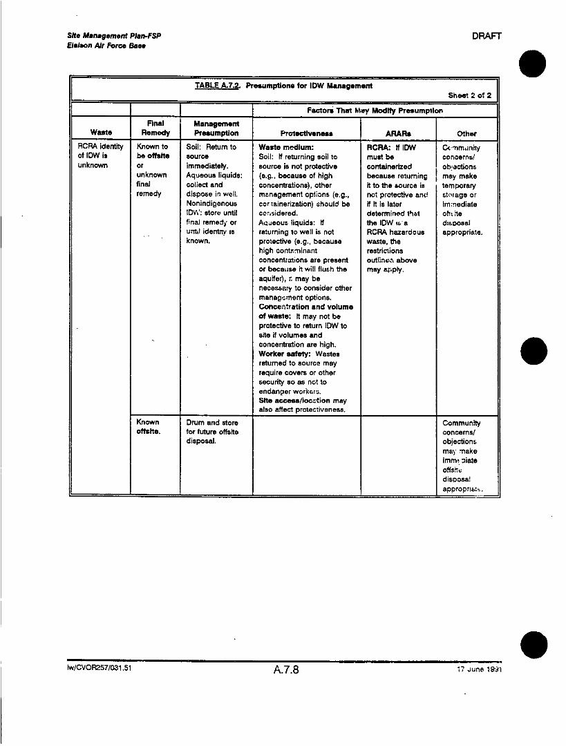
Site Maneagemnent Plan-FSP DRAFTEieiaon Air Force Base
TABLE A.7.2. Presumptions for lOW Management 2
_________ ~~~~~~~~~~Factors That May Modify Presumption
Final ManagementWaste Remedy Presumption Protectiveness ARARs Other
RCRA identity Known to Soil: Return to Waste medium: RCRk- If IDW Cc'mm~nrnftyof low is be omith source Soil: If returning soil to must be concerns/unknown or immediately. source is not protective containerized ob -octions
unknown Aqueous liquids: (e.g., because of high because returning may makefinal collect and concentrations), other It to the source is temporaryremedy dispose in well. management options (e.g., not protective and storage or
Nonindigonous corianinedization) should be if it is later immediateIDVW: store until corasidered. determined that oh.'.tefinal remedy, or Aqueous liquids: If the lDW is a disoosaluntl identin' is returning to well is not RCRA hazardous appropriate.
- known, protective (e.g., because waste, thehigh contaminant restrictionsconcentrations are present outlinv-~ aboveor becausie it will flush the may ar~ply.aquifer), r. may benecess~ary to consider othermanagoment options.Concentration and volumeof waste: It may not beprotective to return ODW tosite if volumes and
- ~~~concentration are high.Worker safety: Wastesreturned to source mayrequire covers or othersecurity so as not toendanger workcasShte access/Ioczation mayalso affect Protectiveness.
Known Drum and store Communityomits, for future offsait concemnsl
disposal. objectionsmay, make
offshdisoosa!
___________ ~~~~~~~~~~~~approprrak
lw/CVOF257/031 .51 A.7.8 17June 1iS~i

Sft. Management Plan-FSP DRAFT. Ei~09eon Atr For"e Ba."
8.0 DECONTAMINATION PROCEDURES
The objectives of decontamination are to prevent the introductionof contamination into samples from sampling equipment or othersamples; to prevent contamination from leaving the sampling site
by way of sampling equipment, personnel, drilling equipment, orconstruction materials; and to prevent exposure of field personnelto contaminated materials. This section discusses generalprocedures to be followed to meet these objectives.
8.1 SOAPS AND DETERGENTS
Alconox or Liquinox will be used as the "detergent' for cleaning allequipment and materials. Use of other products must be
approved by the field manager. Certain elemental impurities, suchas boron and phosphorous, are extremely detrimental even atconcentrations in the ppmn range. These elements are commoningredients in soaps and detergents, which are often used for thecleaning of personnel equipment and sampling equipment.
Therefore, formulations containing these elements must not beused during RIIFS activities at the Eielson AFB site by any
contractor or agency personnel.
8.2 PERSONNEL
Personnel decontamination procedures depend on the level ofprotection specified for a .ziven activity. The Health and Satety
twICVOR257/032.51 A.8.1 17 June 1991

Site Managemnent Ptan-FnP DRAFTEleiwon Air Force Bss.
Plan identifies the appropriate level of protection for each type of
field work involved in this project.
It is anticipated that most of this work will be conducted in Level D
protection, which includes disposable coveralls, neopren e boots
or disposable shoe covers, outer neoprene gloves, and
disposable inner gloves. Decontamination procedures for Level D
include the following steps:
1. Remove disposable shoe covers (if worn) and place in a
secure area for disp3osal by an appropriate method described
in Section 7.0 of this manual.
2. Wash visible soil and contaminated materials from neopreneboots and outer gloves, using tap water and Alconox or
Liquinox.
3. Rinse boots and outer gloves with tap water.
4. Remove outer gloves.
5. Remove disposable overalls and place in a secure area for
disposal by an appropliate method described in Section 7.0 of
this manual.
6. Remove boots.
7. Remove disposable inner gloves.
Iw/CVOR257/032.51 A.8.2 17 June 1991

Site Management Plan-FSP DRAFTEoison Air Force Base
8. Wash hands and face.
In the event that Level C protection is required, respirators willalso be required. The decontamination steps are similar tco thosefor Level 0: remove boot cover s, boots, disposable coveralls,hoods, respirators, and then gloves.
8.3 SAMPLING EQUIPMENT
Decontamination procedurei are designed to remove trace-levelcontaminants from sampling equipment to prevent cross-contamination of samples. This section describes thedecontamination procedures to be used on sampling equipmentbefore it is taken to the project area.
Sampling equipment includes, but is not limited to, the following:
a split spoons1
* Shelby tubes1
* stainless steel knives, spatulas, and mixing bowls
13\ ~ ~ ~ ~ ~ ~~*stainless steel scoops, spoons, and trowels*hand cores and augers
,e- ~~~~~~~sample thieves
*sampling dippers
bailersjetting equipment.
1Only an Alconox-and-water wash is necessary when using this equipment during drilling to collectsoil samples for classification and physical parameters testing.
lwcvoF2as03i A.8.3 17 June 1991

SIte Managemient P1 an-FSP D~rEoieson Al' Force Bs".
Equipment used to collect samples for chemical analyses will be
cleaned before field use and between each sample collection
according to the following procedures:
1 . Detergent (Alconox or Uiquinox) and tap water wash
2. tap water rinse
3. 10 perceant acidic (HNO3) solution rinse 2
4. distilled-deibnized water rinse 2
5. methanol rinse 3
6. air dry3
S3.7. distilled-deionized water rinse
The purpose of the first step, an dletergent-and-water wash, is to
remove all visible particulate matter and residual ails and grease.
This is followed by a tap water rinse to remove the detergent. An 0acid rinse, included if metals samples are to bewiolfected, provides
a low pH medium for trace metals removal. It is Ibllowed by
another distilled-deionized water rinse. If the sarrple is not t-. or
analyzed for metals, this step can be omitted. Nad1 a high-purl:,
solvent rinse is designated for trace organics removal. MetW~
has been chosen because it is an excellent solvatg miscibis
water and is not a targeted parameter in priority golutar'
After the solvent has been allowed to evatoorate fthz
rinsed with distilled-deionized water. This,~ aitr
traces of the solvent.
2Only if sample is to be analyzed far metals.
3Eliminate steps 5, 6, and 7 if samples are not to be analyzed to'
IwICVOP257I032.51 A.8.4

Site Management Plan-FSP DRAFT. ~~~Elelean Air Force Bass
Distilled water, commonly used for water coolers and available in5-gallon plastic carboys, is not acceptable for sampling equipmentdecontamination and will not be used for field and travel blank
water.
8.4 DRILLING EQUI 0 MENT AND WELL CONSTRUCTION MATERIALS
Field decontamination of drilling equipment and well constructionmaterials before use and between sampling locations is critical toprevent cross contamination between monitoring well locations.
~- -- - - - tquipment cleaning will be done in a designated area, which willnot be in the vicinity of borehole locations, monitoring wells, orsampling devices. A description of cleaning procedures follows.
0 ~~~~~~8.4.1 Drilling Equipment
Drilling equipment will be cleaned with hot pressurized water uponproject area entry, between each borehole, and upon project areaexit. The drilling equipment to be cleaned will include:
* casing
* drill rods (if applicable)
* drill bits
*augers
*tamping hammers
*back of the drilling rig
-*-couplings
- * ~~~pumps
* * ~~~~~~hoses
tw/cvOP257/0U.51 A.8.5 17 June 1991

SOt Managoment'-OIanFSP DRAFT7VElaon Air Force Ban
* water lines and hoses
• cables.
Equipment that does not become visibly contaminated during
drilling may be exempted from cleaning at the discretion of the
project hydrogeologist.
8.4.2 Cleaning i'anitoring Well Construction Matterials,
Development Equipment, and Dedicated Sampling E uipment
Before installation into the boreholes, all well construction
materials, development equipment, and dedicated sampling
equipment (if used) will be cleaned with pressurized hot water.
Equipment and materials to be cleaned will include, but not be
limited to, well casing and screens, riser pipes, couplings, fittings,
dedicated pumps and bailers, suction lines, and access tubes.
8.5 WATER LEVEL INDICATOR
Water level indicators will be decontaminated between each well
by using a tap water wash and then a deionized water rinse.
If visible contamination is present or suspected, use a detergent
and tap water wash followed by a tap water rinse, F methanol
rinse, and finally a deionized water rinse.
*'/cVOP257/O32.51 A.8.6 17 June 1991

Shte Management Plan-FSP DRAFTEolelon Al, Force Ila"
8.6 SUBMERSIBLE PUMPS
Submersible pumps used for well development and purging willbe decontaminated to remove trace-level contamination from thepump housing, bowls, and discharge line. The pump will besubmerged in a clear 55-gallon drum partially filled with a solution
of Alconox or Liquinox and water. The exterior of the pump andhose shall be scrubbed with brushes. The pump bowls wiiU becleaned by activating the pump and allowing the Alconox orLiquinox solution to pass througTh the pump and discharge line.The pump will then be placed in clean water and flushed bypumping to remove the Alconox or Liquinox solution.
~WiCsVOR272.51 A.8.7 17 June 1991

Site Management Plan DRAFTEleleon Air Force Baa*
Appendix B
QUALITY ASSURANCE PROJECT PLAN
FOR EIELSON AIR FORCE BASE
CVO~t57/033.51 -2

Sit. Management Plan-OAP DRAFTEleison Air Force Ba.e
. ~CONTENTS-OAPP
Page
1.0 Introduction ........................................... 6B.1.1
2.0 Project Description.......................................6B.2.12.1 Site History and Description ................................. B.2.12.2 Project Objectives ......................................... B.2.1
3.0 Project Organization and Responsibilities.....................6 .3.13.1 Technical Lead Responsibilities ............................... 6.3.13.2 Analytical Laboratories ..................................... B.3.43.3 Other Support Contractors .................................. 6B.3.4
4.0 Quality Assurance Objectives for Measurements.................9.4.14.1 Objectives.............................................. B.4.14.2 Data Quality Objectives.....................................6B.4.14.3 Quality Assurance Objectives ................................ B.4.3
S ~~5.0 Sampling Procedures ..................................... 8.5.15.1 Sample Containers, Preservation, and Holding limes................B.5.3
6.0 Sample Custody and Document Control Procedures..............B.6.16.1 Field Custody Procedures .................................. 6B.6.16.2 Laboratory Custody Procedures ............................... 6.6.26.3 Document Control ........................................ B.6.6
7.0 Calibration Procedures and Frequency........................9.7.17.1 Initial Calibration..........................................6B.7.17.2 Continuing Calibration ..................................... B.7.27.3 Calibration QC........................................... B.7.3
8.0 Analytical Procedures....................................6B.8.1
9.0 Data Reduction, Validation, and Reporting ..................... 6B.9.1
10.0 Internal Quality Control..................................6B.10.110.1 Field Sampling QC Checks ................................. B.1 0.110.2 Laboratory Analysis OC Checks .............................. 6.10.2
WtC VOR257/077.51 iii 17 June 1991

Sn.e Mana gement PIW,-QAPP DRAFTEielxon Air Force Bas.
CONTENTS (Continued)
Page
11.0 Performance and System Audits............................2.11.1
12.0 Preventive Maintenance .................................. 2. 12.1
13.0 Data Assessment Procedures .............................. 8.13.113.1 Precision .............................................. B. 13.11 3.2 Az-cura,-:y.............................................. B. 13.213.3 Completeness .......................................... 8B. 13.3
14.0 Corretive Actions ...................................... B. 14.1
15.0 Quality Assurance Reports to Management....................9.15.1
Attachment 1 Quality Assurance Plan for Analytics Laboratory
ct'CV0R257/077.51 iv 17 June 1991

Sit. Management Plan-QAPP DRAFTEiealon Air Force Base
. ~TABLES
Page
B.4.1 Quality Assurance Objectives for the Analysis of Soils and Sediments ... B3.4.7
83.4.2 Quality Assurance Objectives for the Analysis of Groundwater andSurface Water ........................................... B.4.8
18.4.3 Alternate Volatile Organic and Semivolatile Organic Compound Methodsfor Analyzing. Soil and Sediment Samples ........................ B.4.9
B.4.4 Alternate Volatile Organic and Semivolatile Organic Compound Methodsfor Analyzing Groundwater and Surface Water....................B1.4.1O0
B3.4.5 Method, Target Detection Limit, and Quality Assurance Objectives forthe Characterization of Free-Product Total Hydrocarbon AnalyticalMethods..............................................81.4.12
83.5.1 Container, Preservative, and Holding Time Requirements for Soil andSediment Samples........................................B6.5.4
B.5.2 Container, Preservative, and Holding Time Requirements for Groundwaterand Surface Water Samples ................................. 81.5.5
FIGURES
B.3.1 Project Organization Chart...................................81.3.2
83.6.1 Sample Custody Seal......................................81.6.3
83.6.2 Chain-of-Custody Procedures for Shipment and Analysis of Samples .... E.6.4
CVCVOR257/077.1 v 17 June 1991

Sit. Management PIln-QAPP DRAFTSEIlaon Air Force aSo"
Ol~.O INTRODUCTIONI
This Quality Assurance Project Plan (OAPP) has been prepared in
accordance with the Federal Facility Agreement (FFA) for Ejelson
Air Force Base (AFB). The FFA was signed by the United States
Air Force, U.S. Environmenta! Protection Agency (EPA), and the
Alaska Department of Environmental Conservatio-n (ADEC). The
purpose of this QAPP is to specify the overall procedures andmethods for office and field documentation for field sampling data,
sample handling and custody, recordkeeping, equipment handlingand calibration, and laboratory analyses that will be followed
during the Remedial Investigation/Feasibility Study (RI/FS) to be
conducted for Eielson AFB.
This OAPP was developed in conjunction with, and issupplemented and accompanied by, other documents. They are
as follows:
* Site Management Plan. A document that presents the
objectives and approach to the overall RI/FS, and specifies
the objectives, approach and work scope, and rationale of
the RIIFS process.
* Field Sampling Plan (FSP). A description of anticipated
field activities, including sampling equipment and
procedures. The FSP complements the QAPP, and the
two documents frequently refer to each other.
dWcVoP259/036.51 B3.1.1 17 June 1991

Sitt Management Plan-CAPP DRAFTEleion Air Force Bas.
Health and Safety Plan. A description of procedures to
be used in the fiead to protect field personnel from potential
hazards that investigation activities may present.
Community Relations Plan. A description of the activities
and procedures to be used by USAF to provide
information to the public and solicit public involvement in
the RI/FS process fn:- Eielson AEB.
*Data Management Plan. A description of procedures to
be implemented to construct a working data base lor RI/ES
and historic data:. Requirements for input to the USAF
IRPIMS data base are also discussed.
*Background Sampling Plan. A description of sample
collection requirements and the statistical approach to be
used in. determining background concentrations of
contam inants in soil, groundwater, and surface water.
Attachment 1 follows this QAPP and is the Quality Assurance Plan
for CH-2M HILL's Quality Analytics Laboratory in Redding,
California. This attachment describes the QA/OC used by the
laboratory to generate data of known quality.
cVCVOR259/036.51 B.1.2 17 June 1991

Site Management Ptan-APP DRAFTleileon Air Force Base
. ~2.0 PROJECT DESCRIPTION
The USAF is conducting an RI/FS at the Elelson AFB3 to assess
the nature and extent of contamination from past waste disposaloperations and spill sites on the installation.
2.1 SITE HISTORY AND DESCRIPTION
A description of the Site and its history is included in the Site
Management Plan (SMP). The SMP will detail the investigationobjectives that will be used in each operable unit management
plan (OUMP).
O ~2.2 PROJECT OBJECTIVES
The primary objective of the environmental response actions to be
taken at Eielson AFB is to satisfy the requirements of the FFA,
leading to a sitewide ROD in 1995. In order to meet that deadline,
RI/FS investigations will be conducted for six OUs. Interim actions
may be undertaken for one or more OUs to prevent or minimize ar~e'.ase of a hazardous substance or contaminant. Other actions
may also be required if additional OUs are formed.
The RIIFS investigations will be designed to identity and fill thosedata needs related to preparation of the basewide riskassessment, evaluation of applicable or relevant and appropriate
requiremenis (ARARs), confirmation of the site conceptual rnodel,and completion of the feasibility studies. All field work, including.
ct/CVOR259/037.51 B3.2.1 17 June 1991

Site Management Pgan--OAPP DRAFTEleleon Mir For"e Base
sampling, surveying, and testing, will be geared to fliwng those
needs. Additional siml characterization is not an objective.
Existing data from previous investigations will be used to the
maximum extent technically feasibie.
ct'0-V0R29/037.51 B.2.2 17 June 1991

Sit. Mansagement Plsr.-QAPP DRAFTVElslon Air Force Base
3.0 PROJECT ORGANIZATION AND RESPONSIBILITIES
3.1 TECHNICAL LEAD RESPONSIBILITIES
Figure B.3.1 illustrates the overall project, organization and key
personnel that have been identified for the Elelson AF&~ RI/FS.Key personnel will be identified as project and field team leaders,
and analytical laboratories and subcontractors will be identified
with each OUMP. An organizational chart for CH2M HIL's
Redding, Cailfornia, laboratory is provided in Attachment 1.
Primary responsibility for project quality will rest with the Battelle
EMO and CH2M HILL's project managers. The Quality Assurance
Manager (QAM) and the senior review coordinator will provide
independent quality assurance review.
The Battelle EMO Project Manager has overall responsibility for
work performed for the Air Force under this contract. He is
responsible for project coordination among the Air Force,
regulatory agencies, and consultants. He also provides consultant
overview and direction.
The CH2MV HILL Project Manager has the' responsibility for
accomplishing the scope of work specified in the contract. He
reviews deliverables for quality, assigns resources, and monitors
budgets and schedules. The CH2M HILL Project Manager is also
the point of contact for liaison with the Air Force Project Manager
and the Battelle EMO Project Manager.
wVCVOR259/038.51 B.3.1 17 June 1991

Battelle EMOProj~ect Manage r
Scott Myers
CH2MV HILL CH2M HILL CH2M N'LL- Senior ReviewQA Manage'r IProject Managerrinto
Bob Viens John Martinse Da ln
Project Tam Field Team Analytical SubcontractorLeaders Leaders Laboratories
(to be selected (to be selected) CH2M HILL Quality (to be selected)Analytics LaboratoryRedding, California
FIGURE 3.3.1PROJECT ORGANIZATION CHART
Site Management Plan,Eielson Air Force Base

Site Management Plan.-QAPP DRAFTEieison Air Force Baee
0 ~~~~~~The CH2M HILL Project Manager is responsible for assigningCH2M HILL employees as project and field team leaders. Project
team leaders will be responsible for the prodluc~ion of project
deliverables.
Field Team Leaders will be responsible for sampling activities, field
studies, data base management, field and laboratory testing, and
data analysis.
CH2M HILL's QAM has primary responsibility for developing task
order OA Plans, ensuring that all staff are QA-trained, and that the
OA program is fully implemented. He has authority to stop work
on any task or activfty if the requirements of the QA program are
not being met.
The Senior Review Coordinators assist the project manager by
monitoring the technical execution of task orders, identifying
experts to solve special technical problems, and coordinating
reviews of project deliverables. Senior Review Coordinators are
assisted by technical specialists chosen on the basis of specific
work assignment requirements. They ensure that comprehensive
reviews are conductec expediently and that all review comments
are appropriately addressed.
The CH2M HILL Quality Control Coordinator (QCC) will assure
that all work is performed according to the specifications of the
QAPP. This responsibility includes performing field and laboratory
audits, reporting to the CH2M HILL Project Manager, and
reviewing deliverables.
cVCVOR259/038.51 B.3.3 17 June 1991

Sit. Manaemernnt Plan-QAPP DRAFTEletson Air For" Baas
OA/QC problems or deficiencies identified by the OAM, &nior
Reviewer, or OCC during the review, monitoring, and auditing
processes will be brought to the attention of the CH2MA HILL
Project Manager. If corrective action is required, the CH2M HILL
Project Manager will inform the EMVO Project Manager.
3.2 ANALYTICAL LABO0RATORIES
For the investigations performed by CH2M HILL, OH2M HILL's
Laboratory in Redding, California, is identified as tie primary
analytic;al laboratory. The Redding Laboratory's Quality Assurance
Plan is attached to this document as Attachment 1.
3.3 OTHER SUPPORT CONTRACTORS
If other laboratories are required, they will be identified in the
OUMPs and must meet the QA/QO standards set forth in this
QAPP. The laboratory QA plan for each laboratory will be
reviewed and approved by CH2M HILL and will be included in
OUMPs. Situations that might require the use of an alternative lab
might include short holding times or fast turnaround times for
particular projects.
ctVCVOR259/038.51 B.3.4 17 June 1991

Site Managemenft PiJ8 -..nPp DRAFTEieieon Air Force Oa"e
4.0 OUALITY ASSURANCE OBJECTIVES FOR MEASUREMENTS
4.1 OBJECTIVES
The overall program QA objectives (OAOs) for field and laboratory
activities for the Eielson AFB SMP OAPP are to develop andimplement the following:
project 00 requirements or criteria for laboratory
analyses that are appropriate for obtaining and evaluatingdata that can be used to achieve both program and
specific project objectives
project QO procedures to provide analytical data of known
quality in terms of precision, accuracy, sensitivity,completeness, selectivity, representativeness, and
comparability.
4.2 DATA QUALITY OBJECTIVES
Data quality objectives (DQOs) are related to specific investigation
activities planned for the Eielson AFB Site. DO~s are defined asthe qualitative and quantitative; statements that characterize thedata needed to support a particular data usag-e. Therefore, DQOs
for collection and analysis are based on the end use of the data.
Specific DQOs will not be included in the Eielson AFB SMP QAPP.Specific DQOs include the propo-sed site investigation activities
cVCVOR259/039.51 B3.4.1 17 June 1991

Site Manaemgnent Plmn-QAPP DRAFTEDeleon Air Force Base
and objectives, data uses, and laboratory support requirements
for th~e EBelson AFB. DQOs will be addrecsed in the data needs
section for each OUMP and each OU QAPP. Analytical data will
be obtained in two quality assurance levels: field analysis data
and validated data.
Analytical data will be obtained at several different levels, based
on criterla. provided,. by EPA's Data Quality Objectives documnent.1
Five analytical support levels are defined by the EPA and are
listed below:
* Level VI-Nonstandlard methods
• Level IV--CLP routine analytical service (RAS)
* Level Ill--Laboratory analysis using methods other than
CLP RAS, i.e., SAS
* Level Il--Field analysis (close support laboratory)
• Level 1--Field screening.
A detailed description of what constitutes each level is presented
in EPA's DQO document.
1Data Quality Objectives for Remedial Response Activities, Volume 1 --Development Process,EPA 540/G-87/003A (OSWER) (Directive 9335.O-7B), March 1987.
cVCVOP,259IO39.51 B.4.2 17 June 1991

Sit. Maneagement Plan-CAPP DRAFTEieleon Air Force 6se.
. ~4.3 QUALITY ASSURANCE OBJECTIVES
QA procedures for field measurements are discussed in the FSP.The quality assurance objectives (OAOs) for analytical data
generated from sampling activities will be tracked by the use of
field duplicates and field blanks. These duplicate and bkc~nksamples will be defined and their mothod of collectior. liswsse-d
in the FSP.
Specific OAOs are as follows:
*establish sampling techniques in such a manner that the
analytical results are representative of the media and
conditions being measured
*collect and analyze a sufficient number of duplicate field
samples (two samples that are either temporally or spatiallyseparated and are intended for measurement of station
monitoring variably) to establish a sampling precision of an
average ±20 relative percent difference for all media for all
samples. Field duplicate sample results will help to
establish precision among replicate samples collected from
the same sample location
*coillect and analyze a sufficient number of travel blank,equipment blank, and container blank samples to evaluate
the potential for contamination from ambient air, or from
sampling equipment and sample collection techniques
cVCVOR259/039.51 B3.4.3 17 June 1991

Site Management Plan--QAPP DRAFTBei on Air Force Base
analyze method blanks, laboratory duplicates, and spikes0
to evaluate results and compare to QA goals established
for precision and accuracy.
Another important QAO of this project is to develop and
implement procedures to provide analytical data of known quality.
Data quality is assessed in terms of representativeness,
comparability, precision, accuracy, and complet~-eness. These
criteria are discussed below for analytical supoort levels Ill, IV,
and V.
4.3.1 Representativeness
Representativeness is a measure of how closely the measured
results reflect the actual concentration or distribution of the
chemical constituent in the matrix sampled.
Representativeness is accomplished by choosing sampling
procedures that will produce results that depict as accurately and
precisely as possible the matrix and conditions being measured;
by developing protocols for storage, preservation, and
transportation that preserve the representativeness of the
collected samples; and by using documentation methods that
assure that protocols have been followed and that samp'~es are
properly identified so that their integrity is maintained. Laboratory
SE-MPIE handling, stklrage, and documentation procedures willfollow U.S. EPA Contract Laboratory Program (CLP) protocols.
Ct'CV0R2591039.51 B.4.4 17 June 1991

Site Management Plan-QAPP DRAFTEjeleon Air Force Base
Equipment blanks will be collected once a day for each sampling
method to assess field decontamination procedures or at a
10 percent frequency, whichever is more frequent. Field duplicate
samples will be collected at least once per day for each sample
parameter (and for each media type, if more than one sampled
per day) or at a 1 0 perc~nt frequency, whichever is more frequent,
to assess sampling variation. Travel blanks will be used to assess
the potential for cross contamination by volatile organic
compounds during samrple transport. A travel blank will be
included in each shipping container that contains two or more
samples to be analyzed for volatile organic compounds.
Laboratory method blanks, used to assess the level of laboratory
background contamination, will be analyzed at a frequency
specified by the analytical method.
4.3.2 Comparability
Data developed during the investigation should be either directly
comparable or comparable within defined limitations to literature,
existing data, or any applicable criteria.
Comparability of the data will be maintained by using EPA-defined
procedures in both the sampling activities and the analytical
methods used. The sampling methods are addressed in the SMVP,FSP (Appendix A), and the sampling activities will be described in
each OUIMP. The compounds, analytical methods, and-- target
detection limits for this project are discussed in Section 8.0.
Actual detection limits may vary during the analysis depending on
the nature of the particular sample.
ct/CVOF259/039.51 8.4.5 17 June 1991

Shte Maneagemient Plan-CAPP DRAFTEteleon Air Force Base
4.3.3 Precision
Precision is a measure of the variability of the data when more
than one measurement is made on the same sample. Variability is
commonly attributable to sampling activities and/or chemical
analysis. For duplicate measurements, precision can be
expressed as the relative percent difference (RPD). Analysis of
field duplicate samples measures the precision of sampling
prozedures. Analysis of laboratory duplicate samples .. ill serve to
me,'-sure the p----cision of laboratory procedures. The objectives
for laboratory .: recision for the parameters to be analyzed for in
the Eielson AFB SMP are shown in Tables 6.4.1 through B.4.4.
The frequency at which field duplicate samples should be
collected is 10 percent. Field duplicate collection is addressed in
the FSP. The frequency at which laboratory duplicate samples are
analyzed is specifrd by the analytical method.
4.3.4 Accuracy
Accuracy is a measure of the error between reported test results
and the true sample concentration. Insomuch as true sample
concentrations ar e not known, accuracy is usually inferred from
recovery data as determined by sample spiking.
For the metals and conventional parameter analyses, the
la~-or~atoies will analyze samples spiked with a known
cv: z-_entration of a reference standard to assess laboratory
4 :,zurazy. For the organic analyses, every sample will be spik~ec
with surrogate compounds and selected samples will be spiked
Ct/CV(DR2591039.51 B.4.6 17 June

a ~~~~~~~~~~~~~~~~~~~~~~~~~~~~~~~C -
0~~~~~~~~~~~~~~~~~~~~~~~~0
E 2
C w~~~~~~~~~~~~~~~~~~~~~~~~~~~~~~~C
a -wa.~~. ~ o~ a. N N N N =<c'NNNNq N 5Wi-r
_Q -+ -1 r1 -1 +1+ 1+ 1+
C wc~~~~~~~~~~~~~~~~~~~~~~~~~~c
= Co-a CA~~~~~~~~~~~~~~~~~~~~~~)C
C/ .2 0- EL 0 00 0 0 <<0 0 00000 <.1C0ga a- -0+ +1 + + ¶+IOtI+I+II+I+ COC
C~~~~~~~~~~~~~~~~~~~~~~~~~~~~~~~~~~~~~~~~~~- -oE~0 .0a 00 <0 0 00 00 6=c sC
Z-0- 0)a
o oiZ~~~~~~~~~~~~~~~''- N ogdi . ~.~=C ~ co
0 r- ~~~~~~- .Co) 0
C)~~~~~~~~~~~~~~~~D(U 0)~~~~ L L OC
C ~~0 C N 0 - 0C, 0 6 O- 0(00011' - _~~~~~~~~O ,)N ,)Q
0 CD ~ ~ ~ ~ ~ Cm
ICa ao ) U
w =~~~~NW
C w~~~~~~~~~~~~C ~ .
.a0
E L) E 0 z~~~~~~0)0 z
4 ~~~~~0 c 0 '0 -j
o 0 0 r~~..L~CAI
CC 0 C.,- a-
C, ~ ~ ~ ~~~ 0.0 0~~~~~~- Ct f C) (tV)C _
~~~~ So n E~~~~~ - U c
o a o ~~~~~~~~~~~~~~~~0 o~ oc(0~~~~~~~~~~~
.0 0) e) g = 0 a >-50C) ) _.0 C) L
B.4.

0 C) M L L n r
C8) ~~~~~~~~~~~~~~~~~~~~~~~~~~~~c;
S 0
O *2~~~~~~~~~~~~~~~~
0 Ox' LA LA LA LO LA Lf LAL AALLAALLALLAALLAA0 .-a. (L a. a.C~ N C CV NNNN NN N NN C JN N NN '
W .J -a _ -
0 0 0 rlN I- r- r- r- r- N-r-N -Nr - lr-NNN-NNNN f-NNN-N, r,-
U,~~~~~~~~~~~~~~~~~~~~~~~~~~~~~L
8) ~~~~~~~~~~~~~~~~~~~~~~~~~~~~~~~~~~~~~~~~~~~La
a.a oo0 0 000 0000000000000000 -C .a NCCMNC N NNNNC CJNC'JNC'JNN ClClCY mJqNNNNN tCoo 3C 0o0 +i +I ~++I +I+I 1 +I +I+I +I +I +I +I + +I+I+I+I +I +I+I+I c
o ~~~~~~~~~~~~~~~~~~~~~~~~~~~~~~~~~~o
0 c ~~~ ~~~~~~~~C0 -
0 _ _ _ _ __ _ _ _ _ _ _=_ _
C a.~~~C ( 0 a. OCOj oo oO o OO OO I)-C 0 ~o - "- c~j6 cii L6LALA a L 000 e-00
0 ~~~o 'D - O t- O
- 4) ~ ~ ~ ~ ~ ~ ~ ~ ~ r -0
0) ... ) 0 - C aC cN . 0 O\ C~ I b V
0 0~~~ a. a~~~a.Na. rNN0,i c ci .0r06 0N6cl00.ti 6' . c
* - C0.- C~~~~v 02IT -IrCW o
0A m1 c&0C
0 a,~ c (< co
>. CD oCoL5 aw 9 Co S w~~~~~~~~~'~~(~~g~~~o
Co C V~~~~~~~~~~~~~~~~~~~~~~~~~~~~~~~~~~~c
-~ S ., .~o 0 os, >
a. 0 ct (U mU cnn -Z~~~~~~~~~~~~~~~~~~~~~~~~~~~~~~~~~~~~~~~~~~~~~~~~~~~~~~~~0 u
m ~ ~ 00 c~'eZ~-r 0co Z-
O 0 0 <<000.0"-zzwojO 00 vi 0CD z .-.. ,Uocaa.... 9 ? 2
___ __ __ _ __ _ _ __ _ _ __ _ _ __E__ _ _ __ _ _ __ _ _ __ _ _ _ _ __ _ _ E_ _
B.4.8~~~~~~~~~~~) --

SN.t Mange gment Plan-APP DRAFT. ~~eleion Air Fcrco bate
TABLE BA.4.. Ahternate Volatile Organic and Semnivolatile Organic Compound Methodsfar Analyzing Soil and Sediment Samples ____ ______
TargetDetection Precision Accuracy
Umit (Relative % (% Spike CompletenessParameter Method (pig/kg) Difference) Recovery) (%
Purgeable halogenated 8010 1.0 95volatile organics
Purgeable aromatic volatile 8020 1.0 95organics including ketones 10.0
Phenols 8040 150 a95
Potynuclear aromatic 8100 150 95hydrocarbons
aPrecision and accuracy control limits are stated in the U.S. EPA, Test Methods for EvaluatingSolid Waste, third edition, September 1986.
CtJVCV0R2a/053.51 b.. 17 June 1991

Shte Management Plan-QAPP DRAFTEM Mson Air Force Baa.
TAL .4.4. Alternate Volatile Organi,-. and Semivolatile Organic Compoun- -MethodsF it& =" for Analyzing Groundwate'r and Surface Water Samples _______
Target Precision AccuracyDetection (relative (percent
Umit percent spike CompletenessParameter Method (pg/I) difference) recovery) (%)
Pur;gtuable halogenated 8010 1.0 a9volatile organics I _ _ _ __ _ _ _ __ _ _ _ _ _ _ _
Purgeable aromatic volatile 802$i 1.0 a95
organics includino ketones I10.0Phenols 80As 10.0 95
Polynuclear aromatic 81 OC 10.0 95hydrocarbons _ _ _ _ _ _ _ _ _ _ _ _ _ _ _ _ _ _ _
Precision and accuracy control limits are stated in the U.S. EPA, Test Methods for EvaluatingSolid Waste, third edition, September 1986.
ct/CVOR259/054.51 B.4.1 0 17 June 1991

Shte Management Plan-QAPP DRAFTEielson Air Force Base
duplicate with selected target compound list (TCL) compoundsknown as matrix spike/matrix spike duplicates (MS/MSDs).Perfect accuracy is 1 00 percent recovery; acceptable accuracies
for the parameters of interest to this project are shown inTables B.4.1 through 13.4.5. The frequency at which thelaboratories will analyze spiked samples is specified by the
analytical method.
Table B.4.5 lists the OAOs for analyzing free product. These aremodified analytical methods and are used for the qualitativeidentification of fuels. Therefore, precision and accuracy
objectives are not applicable for these methods. Completenessobjectives will be based upon surrogate spike recovery.
4.3.5 Completeness
Completeness is defined as the total number of samples taken forwhich acceptable analytical data are generated divided by thetotal number of samples analyzed and multiplied by 100. Anoverall completeness goal for this project has been set at95 percent.
cVCVOF;59/039.51 63.4.11I 17 June 1991

0 a I~~~
a~~~~~~~~~~C ~*~~~~~~
C ) .0)0 CD~C C
o 2 w1
0 Co0)
O ~~~~0 WN~~~~~~~~
0) 0 ~~~~~~~0 0 0 (0
a~~~~~~~~~~~~~~~a
- 0. ~ ~ ~ ~ ~~
-~~~~~~~ 0 ~~~~~l c 00
-- 04)0~~~~~~~Ir C0 C
CL 0>
0,: 0C0 0.S~ ~ ~~~ ci,
<-
-0- 000 Wi
CD
0 L~~~~~~~~~~~~~~~~~~0
-- a~~~~~~B41

We. PMa~gement PIan-OAPP DRAFTVeIMon Air Force. be"o
. ~5.0 SAMPLING PROCEDURES
Detailed sampling procedures for soils, sediment, surface water,
groundwater, and biota to be followed at Elelson AFB are
described in the SMP FSP. Sample number, type, frequency,
location, and other considerations shall be as defined in the FSP
prepared for the specific OUMP.
Sampling procedures are designed to ensure that (1) all samples
collected at the site are consistent with project objectives, and
(2) samples are identified, handled, and transported in a manner
such that the data are representative of the actual site conditions
and that information is not lost in sample transferral. The data
collected will ultimately be used to determine the extent and0 ~ ~~~~~~nature of contamination at the site in support of subsequent siteactivities.
To meet project objectives, special consideration is given to
sample procurement, sample containers, holding times and
preservation, field duplicates, equipment decontamination, blanks
(equipment and travel), sample documentation, transport, and
storage. Trace contaminants from sources external to thc. samplemust be minimized through the use of good sampling techniques
and proper cleaning of sampling equipment that comes in contact
with the material being sampled. The use of standa-d operating
procedures detailed in the FSP minimizes collection errors
including cross contamination and promotes the reproducibility of
the data.
GCt~VOR259/04051 B.5.1 17 June 1991

She Management Pfan-QAPP DRAFrEfelson Air Force Be".
Quality assurance objectives for sample collection will be 19
accomplished by a combination of the following items:
•Duplicate Samples. Duplicates will be submitted to
evaluate the precision of sampling procedures. The
number of field duplicates required for this nroject will be
10 percent of the total of each samnle parameter for 'each
media type (groundwater, surface water, sediment, and
solids), and/or one duplicate for ea~zh sample parameter for
each media type per day, whichever is more frequent.
Blank Samples. An equipme nt blank consisting of
dleionized water will be collected once per day or at a
frequency of 1 0 percent of the number of field samples foreach type of sampling method, whichever is more frequent .
All equipment blanks collected for each sampling method
will be analyzed. One travel blank consisting of organic-free water will be collected and carried through the samplehandling and analysis procedures. A travel blank will be
included in each shipping container containing two or more
samples to be analyzed for volatile organic compounds
(VOCs). All travel blanks submitted for analysis wi!! beanalyzed-. One container blank will be submitted for
analysis v,.l;th each lot of containers used.
* Chain-of-Custody. Described in Section 6.0.
* Laboratory QA. Analytical procedures will be evaluated by
analyzing preparation or method blanks, spiked, duplicate,
ctVCV08259/040.51 B.5.2 17 June 1991

She Management Plan-QAPP DRAFTEielson Air Force Bae.
and laboratory control samples. Other evaluation criteria
are discussed in Sections 4.0, 7.0, 8.0, and 10.0.
Data Validation. The analytical data will undergo a data
validation in order to assess the data quality before it is
released to the project (see Section 9.0).
5.1 SAMPLE CONTAINERS, PRESERVATION, AND HOLDING TIMES
Container, preservative, and holding time requirements are listedin Tables B.5.1 and 2.5.2. Holding time starts at the date ofsample collection in the field.
All samples will be maintained at a sample temperature of 40C or
less. Water samples for dissolved metals analysis will be field
filtered through 0.45 micron filter unit using a pressure filtration
device. Immediately after filtration, the metal samples will bepreserved by acidifying with nitric acid. Samples for other
analytes will be preserved in the field as required by standard
methods.
Surface water samples will be analyzed for total recoverable
metals. One liter of sample will be acidified with 5 ml of
concentrated nitrtc acid immediately upo n collection. Analysis
procedures will follow EPA Methods for Chemical Analysis ofWater and W~astes, 600/4-79-020, paragraph 4.1.4 (Metals).
ct`CV0R259/040.51 B.5.3 17 June 1991

Site Management Plan- QAPP DRAFTLielson Air Force Base
TABLE B.E-". Container, Preservative, and Holding Time Requirements for
HoldingParameter Container Preservative Time
Volatile Organic Compounds 1 4-OZ glass Cool 4CC 14 days
Aromatic Volatile Compounds 1 4-oz glass Coot 40C 14 days
Nonhalogenated Volatile Compounds 1I4-oz glass Cool 40C 14 days
Semivolatile Organic Compounds 11 6-oz glass Cool 40C 14 days
Phetx: 1 16-oz glass Cool 40C 14 days
Potyn~uclear Arort~atic Hydrocarbons 1 16-~: glass~ Cool 40C 14 days
Total Petroleum Hydrocarbons 1 4-oz glass Cool 40C 28 days
Metals 1 8-oz glassa Cool 400 6 months
Chromium, hexavalent 1 8-oz glass Cool 040 24 hours
Mercury, Hg 1 8-oz glass Cool 04C 28 days
Cyanide, Cn 1 4-aZ glass Cool 40C 14 days
DH 1I8-oz glassb Cool 40C Immediate
Total Solids 1 8-oz glass Cool 040 7 days
Chloride, Cl 1 8-oz glass Cool 040 28 days
Fluoride, F 1 8-az glass Cool 04C 28 days
Sulfate, SC, 1 8-oz glass Cool 040 28 days
Sulfide. S 1 8-oz glass Cool 040 7 days
Nitrate, as N 1 8-oz glass Cool 040 2 days
Chemical Oxygen Demrand, COD 1 8-oz glass Cool 040 28 days
Total Organic Carbon, TOO 1 8-oz glass Co 028 days
aMercury and hexavalen: can be taken from metals, container.:All conventional parameters can be taken from one 8-ounce glass jar. j
ct/CVORt259/024.51 B.5.4 17 June 1991

Sit. Management PIsrn-QAPP DRAFTVEMIon Air Force faa.
TABLE 8.5.2. ContaIner, Preservative, and Holding Time Requirements for_________________Groundwater______and___Surface___ W ater_____________ Samples___________________________
Sheet 1 of 2Holding
Parameter Container Preservative TimeVolatile Organic Compounds 2 40-mI glass Cool 40C 14 days
Aromatic Volatile Compounds 3 40-ml glass Cool 40C + HCL 14 daysT1S pH <2 ____
Nonhalogenated Volatile Compounds 2 40-mI glass Cool 40C + HCL 14 dlays___________________________ 118 pH < 2
Semivolatlie Organic Compounds 2 2.5 liter Cool 40C 7 days____ ___ ____ ___ ____ ___ ____ ___ a mnberglass TLC
Phenols i 2.5 liter Cool 40C 7 daysamberglass
_____ _____ _____ _____ _____TLC
Polynuclear Aromatic Hydrocarbnns 1 2.5 liter Cool 40C 7 daysamberglass
TLCTotal Petroleum Hydrocarbons 1 1-liter glass Cool 40C + H2S4
_ _ _ _ _ _ _ _ _ _ _ _ _ _ _ _ _ _ _ _ _ _ _ _ _ _ _ _ _ _ _ _ _pH < 2O ~~~Total Metals i 1-liter Cool 40C + 1 -ml 6 monthsMercury polyethylene' HNO3 pH <2 28 days-
Total Recoverable Metals* 1 1 -liter Cool 40C + 5-mI 6 monthsMercury polyethylenea HNO3 pH <2 28 days-
Cyanide I 1-liter Cool 40C + NaGH_____ _____ _____ _____ _____ _____ polyethylene pH >2
Chromium, Hexavalent 1 1-liter Cool 40C 24 hours_____ ____ ____ ____ ____ ____ ____ polyethylene _ _ _ _ _ _ _
Alkalinity I 1-liter Cool 400 14 days____ ____ ____ ___ ____ ____ ____ ___ polyethyleneb _ _ _ _ _ _ _
Hardness 28 daysTDS _______ 7 daysTSS 7 daysChloride, Cl 28 cnysFluoride, F 28 dqfsSulfate, SO, 28 C~avs
Nitrate, as N 48 hoursNitrite, as N .48 hours80D 5, Total Ii1 -liter Cool 40C 48 hours
polyethylene _ _ _ _ _ _ _ _ _ _ _ _ _ _ _ _ _
Ammonia, as N I 1 -liter Cool 400+ H24O 28 days_____ _____ _____ _____ _____ _____ polyethylenec pH <2
. ~~~ctCVOR259/025.51 B.5.5 17 June 1991

She Manag~nerr Pian-4QAPP DRAFTVeMson Air Fore Ilas
TABLE B.5.2. Container, Preservative, and Holding Time Requirements forGroundwater and Surface Water Samples
Sheet 2 of 2Holding
Parameter Container Preservative TimeChernica; Oxygen Demand, COD 28 daysTotal Organic Carbon, TOO 28 daysPhosphorus, Ortho 1 250-mI glass Cool 40 filter 48 hours
TLC immediately _______
Phosphorus, Total 1 250-mI glass Cool 4' + 1 -Mi 28 daysTLC HCLA
Sulfioe, S 530- Ml Cool 40 + Zn 7 dayspolyechylene Acetate and
NaOHpH >9
aMercury can be taken from metals container.bAil nonpreserved parameters can be taken from one container except BOO.cAll H2S0 4 preserved parameters can be taken from one container..Oniy surface water Samples will be collected for Total Recoverable Metals.Notes: Additional containers will be required for collecting MS/MSD samples.
TLC = Teflon-lined septum.TLC = Teflon-lined cap.
cVCVOR259/025.51 B.5.6 17 June 1991

Site Management Pien-QAPP DRA-TEialson Ait Force Basee
0 ~~~~~~~If air sample collection and analysis is required for this Rl/FS, themethod of collection and sample containers will be discussed ineach OUMVP FSP and QAPP, respectively.
CVCVOR259IO40.51 B.5.7 17 June 1991

Site Management Plan-QAPP DRAFTEalsoen Mir Forc a Base
. ~6.0 SAMPLE CUSTODY AND DOCUMENT CONTROL PROCEDURES
Sample custody and document control procedures function toidentify and document the tracking and handling of samples and
sample documents. Samples and documents must be under
custody so that their possession is traceable from samplecollection, transfer or transportation, analysis, disposal, archiving,
and filing. Chain-of-custody and document control procedurestrack sample possession in the field and laboratory and document
the requested analyses (see FSP, Figure A.3.8). Custody of a
sample is defined by the following criteria:
* The sample is in your possession or in your view after
* ~~~~~~~~being in your possession.
* The sample was in your possession and was locked up or
transferred to a designated secure area or sealed to
prevent tampering by you.
6.1 FIELD CUSTODY PROCEDURES
To satisfy custody requirements, field custody procedures should
provide as a minimum:
* field samnpler responsibility until the samples are trarnsferred
• unique field sample identification including sample number,
location, and description
cVCVOF259/O41 .51 B.6.1 17 June 1991

Site Manae gment Plan- Z.A 0pPDrEielswn Air Forc, Base
*sample tags, sampling logs, and, chain-of-custody forms
with essential information and signatures receivers and
relinquishers
* shipping in sealed and secured shipping containers to the
offsite laboratory is an example of a sample custody seal
(Figure B.6.1).
It is anticicated that bar coding procedures will be implemented as
the method for sample tracking and custody procedure s. Bar
coding procedures will be discussed in the SMP FSP when the
method is developed and finalized. To verify bar coding
procedures, samples will also be tracked and maintained under
custody using the manual method.
The steps involved in sending samples to the laboratory and the
routing of forms are shown in Figure B.6.2.
6.2 LABORATORY CUSTODY PROCEDURES
The offsite laboratory shall use procedures essentially equivalent
to those listed below to meet the requirements of this section. To
satisfy custody requirements, the laboratory custody procedures
should provid e as a minimum:
*desicnmvon of laboratory sample and document
custodian(s)l
ct/CVOR259(041 .51 B3.6.2 17 June 1991@

36- 2-91
0
AM= CUSTODY SEAL
Signature
01 ~~~~~FIGURE 8.6.1 Sample Custody Seal
Site Mancgement Roan, Eielson Air Force Base
0*\I006\T L N
n . -- ''

W Cqw~~~~~~~~~~~~~
-~ ~ ~~-
LU -
- U ~ ~ O
(ozwowet- <z Lx
< ~~~~~~~~~~~~~~~~~~~~~0U, 2 4
C.<
Z V- ~ ~ ~ ~ ~ ~ ~ ~ ~ ~ ~ ~ ~ -
W0O~~~~~~~~~~~~~~~~~~~~~~~( 0<
<tcO a~~~~~~~~~~~~~~~(.)w.Ow ZZ 0<
WO. ~~~~oUn.>- <<O OD~~~2 t
o CO~~~~~~~~~~~~~~~~~
0 ~ ~ ~ ~ ~ ~ ~ ~ ~ ~ ~ ~ ~ ~ 0
0~~2w0
E2-~~~~~~~~~~~~~~MC:
- C -C I I
0~~~~~~ - C~~~~~~~~
WCC)< ~ ~ ~C,
E 2~~E
>O - 0 Ct -Wz~~~~~Cc~~~~~~~~c

Site Management Plan-QAPP DRAFTEolelon Air Force flou
* inspection of sample containers for conditions that would
compromise sample integrity
* sample logbook to acknowledge sample relinquishment
and receipt (date, time, signatures), field identification,
sample-description (matrix, characteristics), sample type
(grab, composite), analysis request, corresponding
sequential lc.-oratory identification number, and sample
disposal information
* security for sample storage by laboratory access
constraints, by accompanying visitors, by locking
unattended laboratory facilities or sample storage facilities,
or by-sealing the samples with sample custody seals
* sample tracking using sequential laboratory identification
numbers on work and data sheets, instrument logbooks,
analysis containers, instrument output, and data handling
and reporting hard copy; tracking is sufficiently
documented to enable others to reconstruct the analysis
should the analyst be unable to do so
* internal chain-of-custody procedures through analyst
responsibility for sample dispersement and timely return to
secure storage; through check-in/check-out procedures for
any laboratory operation
*external chain-of-custody procedures for transfer of
samples to disposal location
eVCVOR259/041 .51 B.6.5 -17 June 1991

Site Managemenft Plan-QAPP DRAFTEleleon Air Force Base
sample archiving for purposes of reanalysis, more
extensive or confirmatory analysis at outside laboratory,
evidence retention, etc.; specifying storage procedures,
duration, and disposal authorization
sample disposal procedures in accordance with authorized
instructions and environmental regulations.
6.3 DOCUMENT CONTROL
The offsite laboratory shall be expected to have a document
control program that meets the requirements of this section.
Document control assures that all documents for a specified
project and group of samples are accounted for when the project
is completed.
Accountable document-: include sample and instrument logbooks,
c',iairi-of-custody records, raw and final data (bench sheets,
instrument output, computer hard copy), significant daily journal.
entries, calculation and data reduction forms, reports and QC
summaries, reviews and review summaries, correspondence, and
all other analytical information.
To satisfy custody requirements, document control procedures
should provide as a minimum:
*recording in a clear, comprehensive manner using indelible
ink
ctV0V0R259/041 .51 B.6.6 17 June 1991

Site Management Plan-.QAPP DRAFTEielaon Air Force Baee
*corrections to data and logbooks made by drav-ing a
single line through the error and initialing and dating the
correction
consistency before release of analytical results by
assembling and cross checking the information on the
sample tags, custody records, bench sheets, personal and
instrument logs, and other relevant data to verify that data
pertaining to each sample are consistent throughout the
record
*document archiving in project records in accordance withcontract requirements for retention (storage location,
minimum time, hard copy, photocopy, microfiche, etc.)
observations and results (data) identified with the project
number, date, and analyst, and reviewer signatures on
each line, page, or book as appropriate
*data in bound books or sheaf of numbered pages,
instrument tracings or hard copy, or microcomputer hard
copy
*data tracking through document consolidation and project
inventory of accountable documents: sample logbook,
analysis data book, daily journal, instrument logbook,
narrative and numerical final reports, etc.
ct/cVOR259/041 .51 B.6.7 17 June 1991

Sit. Management Pian-QAPP DRAFTElelson Air Iborce Bse
O ~7.0 CALIBRATION PROCEDURES AND FREQUENCY
Calibration procedures are essential for proper performance offield and laboratory instruments. Calibration procedures functionas the process that ties the analytical system to a knownreference material in order to identify and/or quantify the analyteand to determine how the analytical system is performing. Allinstruments and equipment used during this project will beoperated, calibrated, and maintained according to themanufacturer's guidelines and recommendations.
7.1 INITIAL CALIBRATION
Instruments used by the offsite laboratory will be operated and* ~~~~~~maintained in accordance with the manufacturer's guidelines and
recommendations. This information is combined with theanalytical method requirements to form specific calibrationprocedure.
In general, an initial calibration consists of developing a one- tofive-point calibration curve using reference standards for eachparameter analyzed. The curve contains a zero point and otherpoints resulting from a serial dilution of the standard. Thecalibration may be performed at multiple levels to establish theusable range. In any event, the curve is extended ove- the entirerange of measurements encountered to ensure that the analysesare being performed in the linear portion of the curve. Calibrationoften includes a low-level standard to verify detection limit
ct/CV0P2591042.51 B.7.1 17 June 1991

Sfte Mana gem. 't Plan-caAPP DPAFTEieleon Air Force Bas.
sensitivity. The initial calibration can often be verified by
comparing instrument output to manufacturer criteria or previous
calibrations to help ensure optimal performance of the instrument.
Initial calibration is performed on a frequency schedule required
by the analytical method. In general, it is performed with each
analytical batch o', samples at a minimum of once per day. It may
br~ performed more frequently depending on instrument stlability,.
7.2 CONTINUING C."-LIBRATION
Continuing calibration is performed during the analytical process
to verify that the initial calibration is still applicable. Continuing
calibration is performed using check standard(s), though a
replication of the initial calibration may be required instead. The
ct-wzk standard is a specific concentration used repeatedly.
W-i'hout perfect precision, calibration will change by some degree.
Cajibration criteria are applied to determine if the instrument is
performing acceptably. The criteria are often expressed as a
range of percent difference from the initial calibration value. When
continuing calibration meets the criteria, the normal measurement
process continues. When criteria are not met, the problem is
investigated, cvrrected, and verified before recalibrating and
reana!yzing the samples analyzed since the last in-contrc! i-
or continu-ing calibration.
cV/CVOR259/042.51 B.7.2

She Management Plan-QAPP DRAFTEleleon Air Force Base
@ ~7.3 CALIBRATION QC
In addition to verifying optimal instrument operation, calibration
procedures include other QC requirements to assure the integrity
of the measurement process.
Operation, calibration, and maintenance of the inztruxlnents will be
performed by personnel who have. been properly trained in these
procedures. As noted previously, these persons will perform the
calibration on an established, routine schedule throughout the
duration of the project.
Calibration will be documented in an instrument logbook that
contains:
• date of calibration
* identification of standards used
* personnel performing the calibration
• results of the initial and continuing calibration
* problems and correctJve actions
* preventive and remedial maintenance
*hand-recorded digital or analog data.
Calibration standards will be procured from identified srtirces
traceable to U.S. EPA or NIST standard reference materials. The
purest grade of concentrated standard readily available will be
used in preparing concentrated and diluted interim and working
standards. Documentation of standards preparation will occur in
. ~~ct/CVOR259/042.51 B.7.3 17 June 19,91

Site Mnanegemem Plan-QAPP, DRAFTEjeleon Air Force Bast
the instrument logbook or a standards logbook containing most of
the same essential information.
cVCVOP.259/042.51 B.7.4 17 June 1991
Site Manaemennt Plan-QAPP DRAFTVeleson Air Force Base
8.0 ANALYTICAL PROCEDURES
Criteria for appropriate method selection are discussed with theDO~s in Section 4.0. Specific OQOs are discussed in the dataneeds section and the QAPP for each. OUMP. The selected
methods for each OUMP must satisfy the objectives to producedata of suitable quality for its intended use.
The various pollutant parameters that are anticipated to beencountered, their analytical methods, and target detection limitsare listed in Tables B.4.1 through B.4.5. The groundwater andsurfac6 water parameters to be analyzed for are shown inTable B.4.2. The sediment and soils parameters to be analyzed
are shown in Table B.4.1. The target detection limits shown are
those to be expected when there are no matrix interferants.
Tables B.4.3 and B.4.4 list alternate volatile organic andsemnivolatile organic compound analytical methods and target
detection limits. These methods may be requested by the project
manager or field team leader for the OUMPs. Alternate methodsmay be used when the entire list of volatile organic (Method 8240)
or semnivolatile organic compounds (Method 8270) are notrequired. The. methods listed on Tables B.4.3 and B.4.4 are
performed by gas chromatography and analyze for a snPecific
group of target analytes.
Table B.4.5 lists modified EPA methods and target detection limitsfor the characterization of free product.
0 ~~cVCVOR259/043.51 B.8.1 17 June 1991

Sit Management Plan-OAPP DRAFTBliason Air Force Ba.~
. ~9.0 DATA REDUCTION, VALIDATION. AND REPORTING
The proper management of collected data is of equal importance
to proper analysis and custody procedures in assuring that the
data represent the environment from which the sample was taken.
Data reduction, validation, and reporting procedures function to
control data handling from field through lab and data processing
to the point where data are turned over to the data user. Validity
of analytical data will be determined beased on precision, accuracy,
and completeness objectives, quality assurance objectives, and
data assessment procedures.
Each analyst is responsible for the recording and reduction of all
raw data associated with the analyses. Equations and0 ~ ~~~~~~calculations for data reduction will be performed in accordancewith the procedures detailed in the analytical methods.
Computations and recorded results will carry the common units of
measurement from the methods.
Data reduction will be performed using a programmable calculator
or microcomputer as applicable to the analytical method. The
computational algorithms will be periodically verified through cross
calculation (identical and reordered hand calculations). The units
of the results will be verified using valueless units and canceling
them during the progression of the calculation to see if the
resulting units match the normal reporting units of concentration.
CVCVOR259/044.51 B.9.1 17 June 1991

Site Maneagement Pfan-QAPP DRAFTEMeoon Air Force Bse"
As part of the reduction process, the analyst will proofread all
transcriptions in order to check the accuracy of dlatta transfer,
whether from handwritten form to handwritten form or to
microcomputer form. After reduction, analytical values and
qualifiers will be manually entered by the analyst into a program
data base on a microcomputer.
The offsite laboratory will be required to provid&s copies of all raw
laboratory data including, but not necessarily limited to: raw
chromatograms, mass spectra, tuning performance, sample
preparation logs, initial and continuing calibrations, blanks,
surrogate spike, matrix spike recoveries, laboratory duplicates,
and a case narrative describing any difficulties or unusual
occurrences related to the samples.
The project quality control coordinator (0CC) will validate
analytical data using protocol from the current version of the
Contract Laboratory Program (CLP) Functional Guidelines for
Evaluating Organic and Inorganic Analyses validation) protocol.
The data validation process will include an assessment of the
above-described QA/QO data provided by the laboratory. Upon
completion of the review, the 0CC will be responsible for
developing a QA/OC report describing the usability of the
analytical data based on QA/QC criteria. All data will be stored
and maintained according to the standard procedures of CH2Mi
HILL. Subcontracted laboratories selected will be required to
maintain and deliver data using similar procedures.
CtVCVOR259/044.51 B.9.2 17 June 1991

Sit, Management Plan-OlAPP DRAFTFElslon Air Force Fe".
As part of the data review and validation process, a statistician will
review the data from the oftsite laboratory. The statistician will
select the appropriate techniques for data analysis at the time ofthe review. This review will assess the comparability of the data
from the different sampling methods and different laboratories.
Evaluation may include an assessment of the differnnces between
the two data sets, an overall assessment of precision and
accuracy, and other characteristics the reviewer may deem
significant to meet the project objectives.
ct/CVOR259f044.51 B.9.3 17 June 1991

Site Mana gement Pian-CAPP DRAFTEMolso Air Force Bae"
. ~10.0 INTERNAL OUALITY CONTROL
Internal 00 help monitor and document the performance of
sampling and laboratory activities. 00 checks function to ensure
that the 00 process is in place that establishes the quality of the
data produced.
The 00 acceptance criteria are specific to the operable unit,
matrix, and analytical method. Project-specific 00 checks- and
their frequency are dependent upon the DOOs and the FSPwritten for each OUMP. To ensure that data is of known quality,
the following field and laboratory 00 checks will be implemented.
O ~10.1 FIELD SAMfPLINGOC CHECKS
Sampling checks may be implemented through the following kinds
of samples submitted to the laboratory as unknowns or blind
samples:
* At least one blind duplicate sample of each sample
parameter (for each media if more than one sampled per
day) will be collected each day, or a minimum of
1 0 percent, whichever is greater.
* At least one blind equipment blank will be cc.I,.ected and
analyzed for each type of sampling device used per day.
. ~~ctCVOP,259/047.51 B.1 0.1 17 June 1991

Sit. Manae ment Plan-WPp DRAFTbeison Air Force Bas.
* One pair of travel blanks will be prepared and analyzed for
each container containing volatile organic compounds.
* One container blank will be submitted for analysis for each
lot of sample containers used.
10.2 LABORATORY ANALYSIS QC CHECKS
* For the organic compounds analyses, CLP QAIOC
requirements will be followed for GO and GO/MS tuning,
calibration curve generation, method blank analysis,
surrogate spike analysis, and MS/MSD analysis.
* For the metals analyses, CLP QA/OC requirements will be
followed for calibration, calibration verification, blank
analysis, spiked sample analysis, duplicate sample
analysis, and laboratory control sample analysis.
*For the conventional analyses, the following QA/QO
requirements will be used.
- A multipoint calibration curve will be generated for each
parameter to be measured. Ale appropriate for each
parameter, a new calibration curve will be generated
daily or with each batch of samples analyzed, or a
midrange calibration-curve sample will be analyzed daily
or with each batch of samples analyzed.
cCUVOR2591047.51 B.1O.2 17 June 1991

Site Mana gement Ptan-QAP DRAFTEletson Air Force Base
-Oneset ofmethodblanks will be analyzed daily at a
5 percent frequency or one per set of samples,
whichever is more frequent.
-A duplicate sample will be analyzed at a 5 percent
frequency or one per set of samples, whichever is morefrequent.
-Where applicable, a spiked sample will be analyzed at a5 percent frequency or one per set of samples,whichever is more frequent:,
-An EPA 00 sample or National Bureau of Standards
(NBS) certified sample will be analyzed (if available)
daily or with each batch of samples analyzed.
ct'CV0R2591047.51 B. 1 0.3 17 June 1991

Sit. Maniagemfent Plan-QAPP DRAFTElelsor Air Force Bs".
. ~11.0 PERFORMANCE AND SYSTEMS AUDITS
A system audit consists of an onsite review of a laboratory's
quality assurance system and its physical facilities for sampling,
calibration, measurement, and maintenance of supporting
documentation.
Performance audit., are a systematic check of laboratory
operations and measurement systems by comparing routinely
obtained data with independently obtained data.
This project does not warrant a formal performance audit
(Performance Evaluation Samples) or systems audit (Laboratory
Inspection). In the event that data quality problems arise, or OA
results require verification, a formal performance or systems audit
may be necessary and would be performed by the 0CC.
CH-2M HILL Environmental Laboratory (at Redding, California) willperform the offsite laboratory analyses for toxic organic pollutants,
metals, and general chemical parameters. Performance audits arean integral part of CH2M HILL's laboratory standard operating
procedures. Audit programs in which the laboratory routinelyparticipates include the following:
* U.S. EPA Contract Laboratory Blind Audit Program
• U.S. EPA Safe Drinking Water Act Performance Evaluation
Study
,VCVOR259/048.51 B.1 1.1 17 June 1991

Site Mange gmon Plan-QAPP DRAFTDeleIon Air Form. Be..
State of California Hazardous Waste Testing Laboratory
Certification
Details of CH2M HILL's audit results will be provided upon
request.
ct/CV0Rt259/048.51 B. 11.2

Site Management Plan-QAPP DRAFTEleleon Air Force Base
. ~12.0 PREVENTIVE MAINTENANCE
Routine maintenance procedures and schedules for sampling
equipment are described in the manufacturers' instruction
manuals. All records of inspection and maintenance will be dated
0nd documented in the field notebook.
Maintenance procedures and schedules for all analytical
instruments will be in strict accordance with the recommendations
of the equipment manufacturers. Routine maintenance will be
performed by laboratory personnel as needed. Specialized
inspection and maintenance of major equipment items will be
performed by trained service personnel from the manufacturer in
accordance with instrument service contracts. All records of0 ~ ~~~~~inspection and maintenance will be dated and documented inpermanently bound (with consecutively numbered pages)
laboratory record books.
. oV~CVOR259/049.51 B. 12.1 17 June 1991

Sit. Mana gement Plan-4QAPP DRAFTEBelson Air Force Bs*.
. ~13.0 DATA ASSESSMENT PROCEDURES
Data will be assessed for their precisioRs accuracy, and
completeness. For a more thorough presentation of this statistical
approach, see'EPA's Data Quality Objectives document'.
13.1 PRECISION
The relative percent difference (RPD) is used to assess theprecision of the sampling and the analytical method and iscalculated using the following equation.
RPD XS- XD x 100
S ~~~~~~~~~~~~~(XS + X)2
where:
Xs is the analytical result in mg/I or ppm obtained for the sample
XD is the analytical result in mg/I or ppm obtained for the duplicate
sample
'Data Quality Objectives for Remedial Response Activities, Volume 1 -- Development. ~~Process, EPA 540/G-87/003A (OSWER) (Directive 9335.O-7B3), March 1987.
CtCVO0R25S/050.51 8.13.1 17 June 1991

Site Management Plan-QAPP DRAFTEMison Air Force Base
13.2 ACCURACY
The accuracy of the data set is determined from the analysis of
spiked samples. The accuracy (or percent recovery) is calculated
using the following equation:
A =XSS- XS x 1 00T
where:
Xss is the analytical result in mg/I or ppmn obtained for the spiked
sample
Xs is the analytical result in mg/I or ppm obtained for the sample
T is the true value of the added spike in mg/I or ppm
The overall accuracy is the arithmetic mean of all spiked samples.
It is calculated using the following equation:
n
A-~~1
n
CVCVOR2SS/050.51 B. 13.2 17 June 1991

Sit. Maneagement PIan-GAPP DRAFTBaleen Air Force Bs".
* ~~~~~~where:
A is the mean percent recovery or overal! accuracy
A, is the individual recovery for each spike
n is the number of spiked samples
13.3 COMPLETENESS
Completeness of the data is determined using the following
equation:
Completeness ()=Number of Samples Having Acceptable Data0 ~ ~~~~~~~~~Number of Samples Analyzed x 100
. ~~ctICVOP259/050.51 B. 13.3 17 June 1991

Usi Mane gemen? Plan-OAPP DRAFTbEMion Air Force Base
14.0 CORRECTIVE ACTIONS
lIfthe quality control audit detects unacceptable conditions or data,the Contractor's Project Manager will be responsible for
developing and initiating corrective action. The QAM will benotified if the nonconformance is significant or requires special
expertise. Corrective action may include the following:
* reanalyzing the samples, if holding-time criteria permit
• resampling and analyzing
• evaluating and amending sampling and analytical
procedures
*accepting data and acknowledging level of uncertainty or
inaccuracy by flagging the data and providing an
explanation for its qualification.
Documentation of corrective action steps will include problemidentification, investigation responsibility assignment, investigation,
action taken to eliminate the problem, increased monitoring of theeffectiveness of the corrective action, and verification of problem
elimination.
. ~CVCV0PQ59/051 .51 B. 14.1 17 June 1991

Site Management Plan-QAPP -DRAFT
Elelson Air Force Bowe
. ~15.0 OUALITY ASSURANCE REPORTS TO MANAGEMENT
Technical memoranda and reports generated under EBelson AFBactivities will include the results of the quality assurance workupsand conclusions, and will be summarized in GA reports. The*purpose of a GA report is to document implementation of theOAPP. The GA report will be attached as an appendix to the
operable unit report. It will include:
* QA management (any changes)
* all GA problems and recommended solutions
* corrective actions taken for any problems previously
* ~~~~~~~~~~identified
a results of performance or systems audits if they wereperformed
* assessment of analytical data in terms of precision,accuracy, and completeness
* GA-related training.
Copies of this report will be submitted to CH2M HILL's Project,
Manager for their review. The QAM will discuss with the CH2MHILL Project Manager any corrective actions that need to be
taken.
vct/V0R259/056.51 B. 15.1 17 June 1991

Site Management Plan-OAPP DRAFT
EiesonAi Foce s. All quality assurance reports, final validation reports, and
associated data (with qualifiers) will be submitted to the EPA
Project Officer and the Alaska DEC Project Officer when they are
complete.
oVCVOR259/056.51 B. 15.2 17 June 1991

Sit. Mana gement Plan DRAFTEleleon Air Force Base
Appendix B, At.tachmnent 1
QUALITY ASSURANCE PLAN FOR ANALYTICS LABORATORY
FOR EJELSON AIR FORCE BASE
CVCRt257/033.51 -5

QUALITY ASSURANCE PLAN
Prepared By:
CH2M HILLQuality Analytics Laboratory
5090 Caterpillar RoadRedding, California 96003
S
SC"HILL-

TA~BLE OF CONTENTS
Rev.Panye No. Date
1.0 Introduction I of 1 1.0 2/892.0 Laboratory Organization. Personnel, 1 of 4 1.1 11/90
and Training2.1 Duties and Responsibilities of 1Iof 4 1.1 11/90
Personnel2.2 Personnel Qualifications 4 of 4 1.1 11/902.3 Personnel Training 4 of 4 1.1 11/90
3.0 Laboratory Facilities and Equipment 1 of 3 1.0 8/89Maintenance3.1 Laboratory Facilities 1Iof 3 1.0 8/893.2 Laboratory Equipment 1 of 3 1.0 8/893.3 Equipment Maintenance 3 of 3 1.0 8/89
4.0 Control of Purchased Items and Services 1 of 3 1.0 8/894.1 Chemicals 1Iof 3 1.0 8/894.2 Sample Bottles 2 of 3 1.0 8/89* 0 ~ ~~~~4.3 Laboratory Glassware Cleaning 2 of 3 1.0 8/894.3.1 Glassware for Inorganics 2 of 3 1.0 8/89
4.3.2 Glassware for Organics 2 of 3 1.0 8/1894.4 Laboratory Water 3 of 3 1.0 8/894.5 Subcontracted Laboratory Work 3 of 3 1.0 8/89
5.0 Sample Collection, Identification, Handling, 1 of 8 1.2 11/90Storage, and Chain of Custody5.1 Sample Collection Controls 1Iof 8 1.2 11/905.2 Sampling Kit Preparation 1 of 8 1.2 111905.3 Sample Receipt and Log-In 5 of 8 1.2 111905.4 Internal Chain-of-Custody 8 of 8 1.2 11/905.5 Samphz_ Analysis Tracking 8 of 8 1.2 11/90
6.0 Equipment and Tes: Controls ani Written 1 of 14 1.2 11/90Procedures6.1 Instrumnent Calibration 1 of 14 1.2 11/90
6.1.1 CC/M,"NS Calibration Procedure 1 of 14 1.2 11/906.1.2 Gas Chromnazograph (GC) 5 of 14 1.2 11/90
Calibration Proctcdure6.1.2-.1i Initial Calibration 5 of 14 1.2 11/90
RDD/R59/115.51-2

TABLE OF CONTENTS
(Corntinuz.d)
Rev.
Palge No. Date
6.1.2.2 Continuing 6 of 14 1.2 11/90Calibration
6.1.3 ICPlAtornic Absorption 7 of 14 1.2 11/90Spectrophotometer (AAS)Calibration Procedure
6.1.4 Ultravi.olet/Visible 8 of 14 1.2 11/90Spectrophotorneters. (UV-VIS)Calibra, :on Procedure
6.1.5 Other Calibration Procedures 8 of 14 1.2 11/90
6.2 Control of Software 9 of 14 1.2 11/90
6.3 Laboratory Test Controls 9 of 14 1.2 11/90
6.3.1 Method Blank Analyses 9 of 14 1.2 11/90
6.3.2 Surrogate Spike Analyses 10 of 14 1.2 11/90
6.3.3 Matrix Spike/Matrix Spike 11 of 14 1.2 11/90Duplicate Analyses
6.3.4 Internal Standards Analyses 11 of 14 1.2 11/90
6.3.5 Duplicate Sample Analyses 12 of 14 1.2 11/90
6.3.6 Check Standard Analyses 12 of 14 1.2 11/90
6.3.7 Interference Check Sample 12 of 14 1.2) 11/90Analyses
6.3.8 Quality Control Procedures 13 of 14 1.2 11/90for Air Analyses
6.4 Analytical Procedures 13 of 14 1.2 11/90
7.0 Data Management and Handling of 1 of 10 1.2 11/90
Nonconforming Data7.1 Data Validation 1 of 10 1.2 11/90
7.1.1 GC/MS Volatiles and 1 of 10 1.2 11/90Sernivolatiles7.1.1.1 Holding Times 1 of 10 1.2 11/90
7.1.1.2 Tuning 1 of 10 1.2 11/90
7.1.1.3 Calibration 2) of 10 1.2 11/99
7.1.1.4 Blanks 2 of 10 1.2 11/9C1,
7.1.1.5 Surrogate Recoveries 2 of 10 1.2 11/90
7.1.1.6 Matrix Spike/Matrix 2 of 10 1.2 11/90Spike Duplicate
7.1.1.7 Internal Standards 2 of 10 1.2 11/90
7.1.1.8 Compound Identifi- 2 of 10 1.2 11/90cation and Quanti-tation
RDD/R591115.S1-3

TABLE OF CONTENTS* ~~~~~~~~~~~(Continued)
Rev.Page No. Date
7.1.2 Pesticides by GC 2 of 10 1.2 11/907.1.2.1 Holding Times 2 of 10 1.2 11/907.1.2.2 Instrument 3 of 10 1.2 11/90
Performance7.1.2.3 Calibration 3 of 10 1.2 11/907.1.2.4 Blanks 3 of 10 1.2 11/907.1.2.5 Surrogate Recovery 3 of 10 1.2 11/907.1.2.6 Matrix Spike/Matrix: 3 of 10 1.2 11/90
Spike Duplicate7.1.2.7 Compound Identifi- 3 of 10 1.2 11/90
cation and Quanti-tation
7.1.3 Other GC Analyses 3 of 10 1.2 11/907.1.3.1 Holding Times 3 of 10 1.2 11/907.1.3.2 Calibration 3 of 10 1.2 11/907.1.3.3 Blanks 4 of 10 1.2 11/907.1.3.4 Surrogate Recoveries 4 of 10 1.2 11/907.1.3.5 Matrix Spike/Matrix 4 of 10 1.2 11/90S ~ ~~~~~~~~~Spike Duplicate7.1.3.6 QC Check Sample 4 of 10 1.2 11/907.1.3.7 Compound Identifi- 4 of 10 1.2 11/90
cation and Quanti-tation
7.1.4 Inorganics by AAAICP 4 of 10 1.2 11/907.1.4.1 Holding Times 4 of 10 1.2 11/907.1.4.2 Calibration 4 of 10 1.2 11/907.1.4.3 Blanks 5 of 10 1.2 11/907.1.4.4 ICP Interference 5 of 10 1.2 11/90
Check: Sample7.1.4.5 Laboratory Control 5 of 10 1.2 11/90
Sample7.1.4.6 Duplicate Sample 5 of 10 1.2 11,i90
Analysis7.1.4.7 Matrix Spike 5 of 10 1.2 111/907.1.4.8 Furnace AA Quality 5 of 10 1.2 11/90
Control7.1.4.9 ICP Serial Dilution 5 of 10 1.2 11/907.1.4.10 Sample Results 5 of 10 1.2 11/90
7.2 Validation Status Indicator 5 of 10 1.2 11/90
RDDIRS9/115.51.4

TABLE OF CONTENTS(Continued)
Rev.Page No. Date
7.3 Control Limits 6 of 10 1.2 11/907.3.1 Internal Contro] Limits from 6 of 10 1.2 11/90
Control Charts7.3.1.1 Program Description 6 of 10 1.2 11/907.3.1.2 Handling of 7 of 20 1.2 11/90
Statistically Out-of-Control Events
7.3.2 External Control L-imits 8 of 10 1.2 11/907.4 Corrective Action System 9 of 10 1.2 11/90
8.0 Quality Assurance Objectives 1 of 32 1.1 11/908.1 Accuracy 1 of 32 1.1 111908.2 Precision 1 of 32 1.1 11/908.3 Completeness 2 of 32 1.1 11190
9.0 Limits of Detection l of 7 1.1 8/89
10.0 Levels of Quality Control' Documentation 1 of 1 1.1 8/89
11.0 Surveillance and Audits Iof 2 1.2 11/9011.1 External Performance Evaluation 1 of 2 1.2 11/90
Sample Program11.2 Internal Double-Blind Sample Program 1 of 2 1.2 11/9011.3 Internal Audits 1 of 2 1.2 11/9011.4 QC Chart Monitoring 2 of 2 1.2 11/9011.5 Quality Reports to Management 2 of 2 1.2 11/9011.6 Certifications and Agency Approvals 2 of 2 1.2 11/90
12.0 Document Control and Record Management 1 of 1 1.2 1119012.1 Test Document Control and Storage 1 of 1 1.2 11,19012.2 Control of Standard Operating 1 of 1 1.2 11/90
Procedures
13.0 Laboratory Health and Safety 1 of 4 1.2 11/9013.1 Laboratory Safety Procedures 1 of 4 1.2 11!90
13.1.1 Food. Clothing, and 1 of 4 1.2 11/190Persona] Items
13.1.2 Ventilation 1Iof 4 1.2 11/,9013.1.3 Eye and Clothing Protection 2 of 4 1.2 11/90
RDD/R59/1 15.51-5

TABLE OF CONTENTS(Continued) Rv
Pa~ve No. Date
13.2 Laboratory Safety Provisions 2 of 4 1.2 1119013.3 Physicals 2 of 4 1.2 11/9013.4 Disposal of Samples and Laboratory 2 of 4 1.2 11/90
Wastes13.4.1 Hazardous Sample Disposal 3 of 4 1.2 11/9013.4.2 Nonhazardous Sample Disposal 3 of 4 1.2 11/9013.4.3 Laboratory Waste Disposal 3 of 4 1.2 11/90
13.5 Flammable Solvent Storage 4 of 4 1.2 11/90
APPENDICES
A Method ReferencesB Calibration and Control ChartsC Laboratory FormsD Laboratory Equipment List
* ~~E Key Personnel Resumes
RDDIRS9fl 15.5 1-6
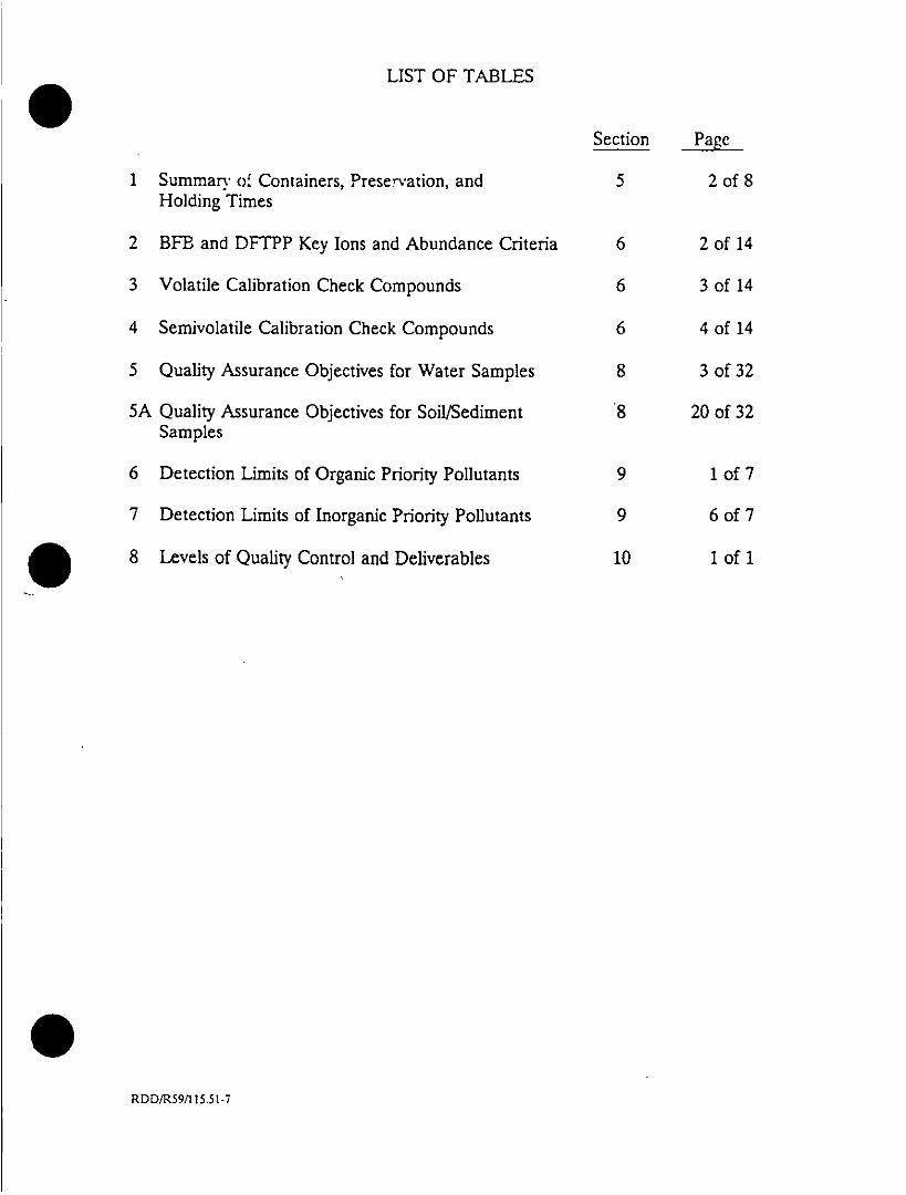
LIST OF TABLES
Section Page
1 Summarv of Containers, Preservation, and 5 2 of 8Holding Times
2 BFB and DFTPP Key Ions and Abundance Criteria 6 2 of 14
3 Volatile Calibration Check Compounds 6 3 of 14
4 Sernivolatile Calibration Check Compounds 6 4 of 14
5 Quality Assurance Objectives for Water Samples 8 3 of 32
5A Quality Assurance Objectives for Soil/Sediment 8 20 of 32Samples
6 Detection Limits of Organic Priority Pollutants 9 1 of 7
7 Detection Limits of Inorganic Priority Pollutants 9 6 of 7
O ~~~8 Levels of Quality Control and Deliverables 10 1 of 1
RDD/R59/115.51-7

LIST OF FIGURES
Section Page i
1 Redding Laboratory Organizational Chart 2 2 of 4
2 Redding Laboratory Floor Plan 3 2 of173
3 Sample Label 5 6 ofS8
4 Chain-of-Custody Record 5 7 of 8
5 QA Audit Checklist, Inorganic Analyses 7 10 of 101
RDD/R59t/115.51-8

Revision No. 1.0Date February 1989Page I of I
1.0 INTRODUCTION
CH2M HILL Redding Laboratory (LRD) is committed to the production of analyticaldata of the highest quality in all environmental analyses. LRD recognizes that qualitydata are a function of an effective and consistent quality assurance program. It is insupport of LRD's commitment to data quality that this Quality Assurance Plan wasprepared.
The different elements of the Quality Assurance Plan are discussed in the remainder ofthis manual. The detailed procedures on how each element of the plan is carried outcan be found in the SOP (Standard Operating Procedures) Manual.
RDD\R59116.51

SCction No. IRevision No. 1.1Date November 1990Page Ilof 4
. ~2.0 LABORATORY ORGANIZATION, PERSONNEL, AND TRAINING
The implementation of the Quality Assurance Plan is achieved through a laboratory-w~ide effort of the entire staff. The Redding laboratory organization and personnel aregeared toward carrying out the objectives of the Quality Assurance Plan. This can beseen in the organization chart in Figure 1 and the descriptions of the staff duties,responsibilities, and qualifications provided in the remainder of this section and inAppendix E.
To strengthen its commitment to the production of quality data, the Redding laboratoryhas established, high qualification standards for employment and provides acomprehensive training program for all its employees. The result is a laboratory staffthat offers a unique blend of scientific and technical expertise, highly capable of servinga wide range of analytical needs in environmental studies.
2.1 Duties and Responsibilities of Personnel
The Laboratory Manager has the responsibility for the overallmanagement of the laboratory. He will interface with clients on allaspects of their projects including progress, problems, and recommendedsolutions. He will also work with the QA coordinator and laboratorychemistry division managers in reviewing progress reports, analyticalreports, financial reports, and QC reports.
The QA Coordinator assists the laboratory in the production of accurate,valid, and reliable data by monitoring the implementation of the labora-tory's quality assurance program. She oversees the execution of qualitycontrol procedures and techniques to assure that the laboratory achievesestablished standards of quality. She is also responsible for evaluatingdata quality and maintaining records on related QC charts to ensureadherence to quality assurance programs. Analytical data, includingstandards, spikes, duplicates, blank, and quality control check standards,and a representative portion of sample results are reviewed by her beforethe reports are released to the client. The portion of sample rnsults tobe reviewed is dictated by need, based on the QA Coordinator'sexperiel`CC from past data review, but shal'i not be less than 10 per_-ent ofall results. She administers interlaboratory QA efforts, reviewsperformance evaluation results, takes corrective actions, and preparesquality assurance reports to management.
RDD\R59/117.51

0 35 ~ 0o
C-~~~~~~~~~~~~~~~F
U z s -~~~z
u Cd~~~~~~~~~~~~~~~~~~uo 2~
z V~i
0 ~ ~ 0
09
0~~~~~~~~~~~~~~~~~
* CO ~0tn
0~~~~~~~~~~
< V
< 0%
Em~ Ucorn U

Seclion No. 2Revision No. 1.1Date November 1990Page 3 of 4
* The Organic Chemistry division manager has the day-to-day technicalresponsibilities for his division. He provides technical direction inconducting laboratory analyses and resolving day-to-day problems. Healso reviews analytical data for clarity, completeness, and validity.
The Inorganic Chemistry division manager has the day-to-day technicalresponsibilities for his division. He provides technical direction in con-ducting laboratory analyses and resolving day-to-day problems. H-e alsoreviews analytical data for clarity and validity.
The section supervisors are responsible for each task identified in thescope of work. They are responsible for organizing and directing thetechnical activities within their task. They are involved in daily laboratoryoperations and are responsible for verifying that laboratory OC andanalytical procedures are being followed as specified for each project.The section supervisors are responsible for the review of data foraccuracy and chemical interpretation. They also advise the departmentmanager of progress, needs, and potential problems of their task.
* The data package coordinator is responsible for organizing, assembling,disseminating, and filing all documents pertinent to the analysis for eachset of samples. The data package coordinator is also responsible forissuing the designated serialized documents and accountability for saiddocuments.
* The analysts perform analytical procedures, data processing, andrecording in accordance with SOPs. They are responsible for calibrationand preventive maintenance of instrumentation, data reduction, datareview, and reporting out-of-control situations.
* The sample custodian is responsible for the proper preparation, shipmentand receipt of sampling kits. When the samples are received into thelaboratory, the sample custodian is responsible for checking anddocumenting the chai-r-of-custody by checking sample descriptions, labelis,and parameters requested against the chain of custody record. If arvdiscrepancies are noted, the sample custodian informs the laboratorymanager, who coordinates with clients. After this information is recordedinto a bound sample log book, the- sample custodian is responsible fordissemination of all appropriate sample documents to the various divisionmanagers.
RDD\R59/I117.51

Secti :>,. 2Revision ~-o. 1.1Date November IL'flPage 4 of 4
2.2 Personnel Qualifications
See Appendix F--Personnel Resumes.
2.3 Personnel Training
To ensure that all personnel involved in analytical activities are able to carry outtheir duties, they are required to undergo a training program. Training isadministered by trainers designated by the Laboratory Manager. The programconsists of two phases: the New Employee Training and the ContinuingEmployee Training.
The first phase of the program is presented to new hires upon employment andmust be completed prior to assumption of assigned duties. It includes moduleson orientation, review of the job description and how the positinn. intimrateswith the overall organization, overview of the CA program, overview of the
safety program, and initial on-the-job training' on the employe's, initial jobassignment. The readiness of the new employee to assume ihitial jobassignments is assessed by the area supervisor. After approval by the areasupervisor, the employee is allowed to begin initial assignments.
The second phase of the training program, the Continuing Employee Training, isa dynamic program which changes according to the employee's and thecompany's perceived needs. It includes both in-house and external training thatthe employee undergoes. In-house training consists of periodic safety and CAtraining as well as all on-the-job training on any new operating proceduresand/or analytical methodologies. External training consists of offsite seminarsand workshops that CH2M HILL encourages its employees to attend as part ofits professional development efforts.
Each employee must complete at least 8 hours of continuing training each year.
Completion of training is documented on the Personnel Training Record which
is maintained for each employee in the personnel file. Each Personnel TrainingRecord is updated on a continuing basis.
RDD\R59/I 17.51

Section No. 3Revision No. 1.0Date August 1989Page Ilof 3
3.0 LABORATORY FACILITIES AND EQUIPMENT MAINTE"NANCE
3.1 Laboratory Facilities
Founded on traditions of excellence in analysis, consulting, and research, theenvironmental laboratories of CH2M HILL play a vital role in the firm'sreputation for water treatment and pollution abatement. From routinemonitoring to application of advanced technology, our qualified professionals areprepared to help clients solve their analytical problems. CH2M HILL's fullyequipped environmental laboratory located in Redding, California, providescomprehensive physical, chemnical, and microbiological services and is capable ofperfo,, ring a wide variety of analyses from routine wet chemistry to complexorganics analysis. The laboratory is equipped with the most advanced analyticalequipment, including gas chromatograph/mass spectrometers (GCiMSZ), highperformance liquid chromatograph (HPLC), gas chromatographs (GC), atomicabsorption spectrophotometers (AAS), inductively coupled argon plasma(ICAP), and ancillary analytical equipment essential to a quality environmentallaboratory. The facility occupies more than 17,400 square feet of laboratory andoffice space designed to accommodate analyses of low to medium hazardenvironmental samples. Figure 2 presents a floor plan of the Redding
* ~~~~~laboratory.
Access to the Redding laboratory is strictly regulated and limited to authorizedpersonnel through an electronic security system.
During normal working hours when a receptionist is on duty, visitor access tothe laboratory is through the monitored reception area at the entrance of thebuilding. Visitors are required to sign in and be accompanied by a laboratoryemployee while in the laboratory. During hours when a receptionist is not onduty, the front door is kept locked. When deliveries are made at the centralsample receiving area of the building, a receiving clerk is required to remainwith the delivery service personnel at all times.
To minimize contamination, all laboratories are maintained at a pressure whichis positive to the adjacent less "clean' areas. The rooms whete volatile organicsare analyzed are segregated by an adjoining air lock.
3.2 Laboratory Equipment
The Redding laboratory is equipped with the most advanced instrumentation forfast, accurate, and precise analyses of water, soil/sediment, and air samples. Alaboratory equipment list is provided in Appendix D.
RDD\R59\l 18.51

-�
C: arNVrL� "4
to 4'4to C
0 4 a:
zU S
Z'a'a
0
±S3A 33L0.dkNI
z
0
z'a
.2
7- ___
'aC
z-J0�
0C-Jii
I
U
C0 c'a C
CC

Revision No. i.0Date August 1989Page 3 o; 3
3.3 Equipment Maintenance
Preventive maintenance, such as lubrication, source cleaning, and detectorcleaning, is per-formed according to the procedures delineated in themanufacturer's instrument manual, including the frequency of such mai-ntenance. Chromatographic carrier gas purification traps, injector liners, andinjector septa are cleaned or replaced on a regular basis. Precision andaccura-v data are examined for trends and excursions beyond control limits todetermine evidence of instrument malfunction. Maintenance is performed whenan instrument begins to degrade as evidenced by the degradation of peakresolution, shift in calibration curves, decreased ion sensitivity, or failure to meetone or another of the quality control criteria.
Instrument maintenance logbooks are maintained in the laboratory at all times.The logbook contains a complete history of past maintenance, both routine andnonroutine. The nature of work performed, the date, and the signature of theperson who performed the work are recorded in the logbook. Preventivemaintenance is scheduled according to each manufacturer's recommendation.Instrument downtime is minimized by keeping adequate supplies of allexpendable items, where expendable means an expected lifetime of less thanone year. A list of these items includes gas tanks, gas line filters, syringes, septa,GG columns and packing, ferrules, printer paper and ribbons, pump oil, jetseparators, MS filaments, etc.
Routine instrument preventive maintenance is handled by the instrumentoperator. Repair maintenance is performed by a full-time instrumentationtechnician.
RD D\R59\118.51I

Section No. 4Revision No. 1.0
Date August 1989Page Ilof 3
4.0 CONTROL OF PURCHASED ITEMS AND SERVICES
4.1 Chemicals
All chemicals are inspected for container integrity upon receipt. The date ofreceipt is recorded on each container. The dating allows use of the chemicalson a first-in-first-out basis.
A control system for receiving and releasing each lot is followed for some criticalchemicals, such as organic solvents, which have a history of background levels ofcontamination. This system consists of logging the information on each lotreceived, and testing a sample for analytes of concern. The lot is released bytagging each container with a colored release sticker and documenting therelease on the logbook. A container cannot be used without a release sticker onit.
All reagents used are of the best possible quality to ensure freedom fromcontamination. They are prepared from Analytical Reagent Grade (AR)chemicals or higher purity grades, unless such purity is not available. Thepreparation of all reagents is documented, including source, mass, and dilutions.Each reagent is clearly labeled with the composition, concentration, dateprepared, initials of preparer, expiration date, and special storage requirements,if any.
Reagent solutions are stored in appropriate glass, plastic, or metal containers.Reagents are stored under conditions designed to maintain their integrity(refrigerated, darK, etc.). Shelf life is listed on the label, and the reagent isdiscarded after it has expired. Dry reagents such as sodium sulfate, silica gel,alumina, and glass wool are either combusted at 4000C or extracted wth solventprior to use for organic chemical analyses. Water used in the laboratory i'sdeionized, and periodically checked for purity. In addition, water u!ed in theorganics area is carbon-filtered or purchased as HPLC wrade. All organic sol-vents used are either glass-distilled or pesticide grade. Solvents and reagentsolutions are checked for contamination by employing reagent blanks, before usein any analysis.
All calibration standards, including internal standards and surrogate standardsused in the Redding laboratory, are obtained from chemical suppliers withcertification of high purity and concentration. The standards are routinelychecked. by the laboratory for traceability to NBS Standard Reference Materials(SRMs) or USEPA Reference Standards. These commercial standards are usedas stock standards. Working standards are made from the stock standards at
RDD\R59\I1i9.5i

Section No. 4Revision No. 1.0
Date Au!~ust 1I9V
P3.te 2 (w:5
appropriate concentrations to cover the linear range of the calibration curve.
The working standards are used for initial calibration curves, continuing
calibration checks, and preparation of analyte spiking solutions.
All working standards prepared for analyses are entered in a bound standard
notebook with all information regarding the preparation of that standard, i.e.,
code number, preparation date, name of each compound and amount used. final
volume, concentration, solvent used, and the name of the individual preparing
the solution. All standard containers are labeled with the standard name and
code, date prepared, preparer's initials, and expiration date if applicable.
4.2 Sample Bottles
Certified clean sample bottles are used. These bottles are cleaned to EPA
specifications and the caps are Teflon lined. Each lot purchased is accompanied
by a certificate of analysis. Sample bottles are never reused.
4.3 Laboratory Glassware Cleaning
43.1 Glassware for Inorganics
Glassware is soaked in hot water containing a phosphate-free detergent
for one-half hour. It is then washed with hot tap water and rinsed three
times with distilled water. It is acid washed with 1:10 nitric acid, rinsed
three times with distilled water, and allowed to dry inverted. It is stored
in a contaminant-free storage area.
43.2 Glassware for Organics
Glassware is rinsed immediately with water after use. If it contains oily
residuals, it is rinsed with acetone. It is scrubbed with a hot, phosphate-
free detergent solution using a brush. 1t is rinsed thoroughly with tap
water. If there is any visual residual, it is soaked for an hour with a
sulfuric acid-dichromate mixture (such as Chromerg4) It is thoroughly
rinsed with tap water at least three tuz.then with distilied water at
least three times, reagent-grade methanol, and reagent-gradt acetone. It
is allowed to air-dry and stored in a contaminant-free, area. Prior to use
it is rinsed with the solvent to be used for extraction-
RDD\R59\119.51

Section No. 4Revision No. 1.0'Date August 1989Page 3 of 3
4.4 Laboratory Water
Only water of appropriate purity is used in all analyses. The laboratorygenerally uses deionized water. In addition to deionizers, carbon filters are usedwhere the water is intended for organic analyses.
The quality of the water in each section of the laboratory is monitored routinelyagainst established acceptance criteria. The parameters monitored, theacceptance criteria, and the frequency of monitoring are dictated by the end useof the water. These are delineated in the appropriate standard operatingprocedure. Minimum monitoring consists of measuring the conductivity.
To further ensure the quality of water used in analyses, method blanks arescheduled for each batch of samples analyzed.
Maintenance of the water system is performed periodically and/or as neededwhen indicated by the monitoring results and/or method blanks.
Logbooks are maintained for recording all monitoring results and maintenance* ~~~~work performed.
4.5 Subcontracted Laboratory Work
In the event that laboratory work has to be subcontracted, only approvedlaboratories are selected. The instructions are documented on a chain-of-custody that is sent with the samples to the subcontracted laboratory. When theanalytical work is completed, the report/data package is subjected to the samereview and approval process normally conducted with in-house data.
RDD\R59\1 19.51

Section No. 5Revision No. 1.2Date November 199Page l ofS8
5.0 SAMPLE COLLECTION, IDENTIFICATION, HANDLING,STORAGE, AND CHAIN OF CUSTODY
5.1 Sample Collection Controls
Special consideration is given to the procurement, storage, and transportation ofsamples to be analyzed. Procedures ensure that the analyte(s) originally presentin the sample matrix has not undergone degradation or concentration, and thatcontaminants which might interfere with the analysis have not been added.Plastic containers are not used for samples to be analyzed by electron capturedetector. Use of metal containers is discouraged since they may contain traceimpurities such as oil films, lacquers, or rosin from soldered joints, that causeinterferences during gas chromatographic analysis. In general, glass jars orbottles with Teflon-lined lids or aluminum foil are the most suitable. samplecontainers. In certain cases, the analyte of interest may be unstable because ofits chemical nature and/or interaction with the sample matrix, and specialpreservatives need to be added during sample collection. Table 1 summarizesthe requirements for sample containers, preservation procedures, and holdingtimes. The references and source documents for these specifications can befound in Appendix A.
5.2 Sampling Kit Preparation
Sampling activities are generally not carried out by CH2M HILL laboratorypersonnel. The procedures, which are project-specific, are carried out by projectfield personnel and are covered by the project plan.
Sampling kits to be used by the field personnel are prepared by CH2M HILLsample custodians following instructions indicated on the Bottle Order Form(BOF). The BOF (sample included in Appendix C) is generated when the clientcontacts a CH2M HILL representative about analyzing samples. Theinstructions on the BOF are therefore unique to the client's requirements.
Al! sample containers used are purchased precleaned to EPA specifications intraceable Jois, with each lot accompanied by a certificate of analysis. Samplecontainers are never reused.
RDO\RS'054.51
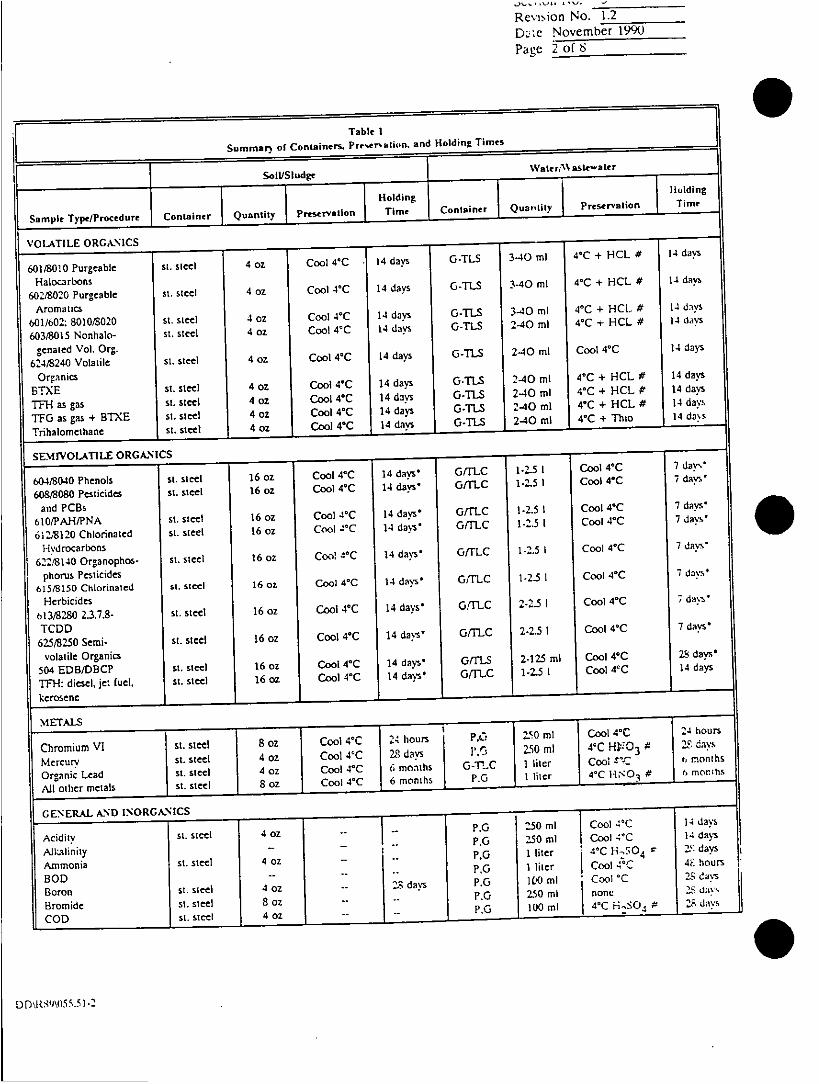
Revision No. 1.2
DWic November 1990page 20 f 8
Table I
Summar) or Containers. Pr~sr.tnain. and Holding Times
Soil/Sludge Water/~Nm\ aslwtr
Holding llldng
Sample Type/Procedure Container Quantity Preservation Time Cotie Qatt Peevton Tme
VOLATILE ORGNS
601/8010 Purgeabl St. Stem 4 oz Coo 4C .4 days GTS 3-40 ml 4C + HCL # 14daS
Halocarbons V
602/8020 Purgeable St. steel 4 oz Co C 14 days -TS 3-40 ml VC + HCL # 14dy
601/602: 8010/3020 st te o ol( 4dn OT.S 34 l 4C+ HCL # 1day
603/815 INonhalo- St. steel 4 oz Coo 4C 14 davs G-L -40 ml 4'C+HC# 14dy
genated Vol. Org. 20m ol4c4I
624/3240 Volatile St. steel 4 02 Cool 4C 14 days G-TL -0m ol( 4dy
Organics40m 4C HL 4d
BTE si. steel 4 oz Cool 4(C 14 day G-~TS 2-4 l ( C 4dy
TF1-I as gas ~~~St. Steel 4 02 Cool 4*C 14 dan G-TLS 2.40 ml 4(C + HCL # 14 days
TGas gas +STX t. steel 402z Cool 4'C 14 days 0-TIS 2-40 ml 4tC + HCL # 14 days
Trhalomethane St. steel 4 02 Cool 4C 14 days 0-TI-S 2-40 ml 41C + Thao1nd~
SEMJVOLAT1L ORAICS
604/8040 Penols sim steZ10 Cool 4(C 14 davs' 0/C 125I ColC7da.
6O08,00 Pesticides Si.mle 16 02 Cool 4(C 14 days, G/TLC 125I Cool 4(C7da
and PCBs 7dy
610/PAH/PNA st te 62 Cool 4'C 14 daysO GiftC 1.5I Cool 4C7dy'a
612.3120 Chlorinated S.steel 1602z Cool -,IC 14 davs' 0/TLC 125I Cool 4`C 7 davsW
Hydrocarlbons7 vs
622/840 Organophos- sI. Steel 16oz Coo! 4(C 14 days' GfrLC 125I Cool 4(C7das
phorus Pesticides7 vs
615/8150 Chlorinated s.tel 16 oz Cool 4'C 14 days' G/TLC 1-2. Cool ('C7dys
Herbicides Co4`dms
613/3280 2.3.7.8- s.tel 16 oz Cool 4*C 14 days' GrinC 2.5I ColC7das
TCDD7das625/8250 Semi- St. steel 16 02 Cool 4'C 14 davs' GiftC 2-2.5 I Cool 4'C 7d
volatile Organics504 EDB/DRCP stI. Steel 16 oz Cool 4'C 14 days' Gift.S 2-125 ml Cool 4C 28 days'
TFH-: diesel, jet fuel, St. steel 16 oz Cool 4'C 14 days' /frl-C 1-2.5 I Cool 4t C 14 days
Cromium VISt. steel 8 02 Cool 4(C 24hours 4, 50m Co (C2ours
Mercury st. steel 4 02 ~~~~~~~~Cool ('C 23dy 2 5 l 4'C H103 t 2 davs
Organic edst te 4 oz Cool 4(C 6 months G -T!..C 111itcr Coolt ± mnh
AlUl other metals St. steel 802z Cool 4(C 6 months P. r I liter 4'C 10( i 6mnh
Acidity si. steel 4oz - ~ ~ ~~~~~~~~~~~~- P.G 250 ml Cool 4'C 14 days
Alkalfinity fiPO 20 l Co~ 14 d" Oays
Ammonia St. Steel 4 CZ .P,G I itr (Ch 2 304 t 2$dy
ROD .. ~~~~~~~~~~~~~~~~~~~~~~ ~~~~~~PG I liter Cool 4'C: 4Fours
Boron St. steel 4 02 .. 23, days P.G 100 ml -Cool 'C2$as
Bromide St. steel 80 CZ -- P.G 2,50 ml nonec3d~
COD St. Steel 40 ozPO 10m ' H,0 3dy
DD\R89V)55.5 1-2

Revision No. 1.2Date November 1990Page .- of 8
Table ISummary or Containers. Preservation, and Holding Times
___________________ ~~~~SoiLfSiudlge Water/Wastrwatrr
GENERAL AND INORGANICS (Continued) I I HoldingI Holding
Sample Type/Procedure ContainerI Quantity Preservation I Time Container Quantity Preseration Time
Chlorine - .-. P.G 250 ml Cool 40C 24 hoursChloride St. steel 4 oz -- 28 days P.G 250 ml -. 28 daysColor . - P.O 250 ml Cool 4'C 48 hour,Coliform - -P.G 125 ml 4o Na,S2 03 6 hour,Cyanide St. Steel 4 oz Cool 4CC 14 davs P.G I liter 4' NaOI- * 14 davs-Fiashpoint St.steel 4 oz - 28 days O-TLC 250 ml 28 dayFluoride (total) St. steel 4 oz -. - P 250 ml -28 daysHardness - -- PG 250 ml HNO 3 or 6 months
H2S04 #Nitrate St. steel 4 oz Cool OCC P.G 100 ml Cool 4CC 48 hoursNitrnte St. Steel 4 oz Cool 4CC - P,G 100 ml Cool 4'C 48 hoursNitrate/Nitrite St. Steel 4 oz Cool 4CC 28 days PG 100 ml1 40 + H2S04 * 28 daysOil and Greasc St. site....4 oz Cool 4C 28 davs G-TLC 3 Iiters@ 40 + H2S04 # 28 daysphe..oJim St. steel 4 oz Cool 4'C 28 days G-TLC 1-2.5 I 4o + H~2SO4 # 28 days
MPhoporus, total St. steel 4 02 Cool 4'C ZS davs G-inC 250 ml Cool 4CC + 28 daysI ml HCIA
Phosphate, ortho St. Stee - - G-TLC 250 ml Filter immc- 48 hoursdiateirycool 4'C
St. Steel 4 oz Cool 4"C -- G 100 ml Cool 4-C imoned.aioilogical - % - ?- PG 1 liter HN0 3 6 months
Reactivity in Acids St. steel 4 oz Cool 40C 28 dayis P.O 500 ml Cool 4CC 7 daysand Bases
Reactivity in Water St. steel 4 oz Cool 4TC 28 days, P.G 250 ml Cool 4CC 28 daysSilica .- . .P 250 ml Cool 4CC 28 daysSolids, dissolved - . P.C, 250 ml Cool 4C 7 daysSolids. Suspended .- .. PG 1 liter Cool 4CC 7 days
Total/VolumeSolids, Total/ . -.. P,G 250 ml Cool 4"C 7 days
VolumeSpecific Conduc- - .- P,G 500 ml Cool VC 28 days
tivitySpecific Gravity St. Steel 4 oz ambient -P,G 25 ml ambient 28 daysSteel Corrosion - -P,G 500 ml Cool 4CC 28 daysSulfate St. steel S oz Cool 4CC - P.O 500 m] Cool 4"C 28 daySulfite - -PG 500 ml Cool 4'C 24 hoursSulfide St. Steel S oz Cool 4'C -PG 500 ml 4CC & 7 daysSurfactanls - .p.O I liter Cool 4CC 48 hourTannins and Lignin St. steel S oz Cool 4CC G 1 liter 4'4-NaOH- 7 days
pH >9TKN St. steel 4 oz - .P.G 1 liter 4' H2S04 # 28 daysTotal Organic Carbon St. steel 4 oz - .PO 250 ml 4' HiSO4 # 28 daysTotal Organic - 'GJLC 500 [ml 40 lA;50 4 # 28 days
HalogenTurbidity P .- JIPI Cool OC 48 hour,
RDD\R89055.5 1.3

Revision No. 1.2
Date No~crnber ~10OPage 4 of 8
Table ISummary of ContLainrs.m preservation, and Holding Tame~s
Soil/Sludge WalerAVasln~3tt
I I ~ ~~tt: Holding I Hodng
Sample Typ/rOCedr Container Quantity jPreservation Time, Container uniy Pe~t~l Tm
NOTES
*Days to extraction. 40 days to analysis after extraction.#pH less than 2.
* pH greater than 12.
@ Need three to do MS and MSD.& Zn acetate and NaOH to pH greater than 9. 1 apc a etse ihla ctt ae
Maximum holding time for water samples is 24 hours when sulfide is present. optionally, allsmlsmyb test dewrt lead l acetatepaer
before adjusting pH to determine if sulfide is present. If sulfide is present. it can be removed with cadmium nitrate odrutlangtv
spot is obtaied. The sample is filtered and then NaOH is added to pH 12.
st--stainless. 0--.glass. P--polyethyliene: TI-C--Tetlon-lincd cap: TI-S--Teflon-lined septum.
CI-2M HILL. Inc. Quality Anahrics5090 Caterpittar Road. Redding, CA 96003 916/244-5227
7201 NW 11th Place. Gainesville. FL 32605 904/377-2442
2567 Fairtand Drive. Montgomery, AL 36116 205/271-1444
-)D\RSO\055.51-4

Revision No. 1.2Date November 1990Page S of 8
Preservatives are added to the sample containers by the sample custodiansaccording to the instructions on the BOF. These preservatives are prepared bythe General Chemistry Laboratory personnel according to the appropriatewritten Standard Operating Procedure. The type of preservative added isindicated on the sample container labels (Figure 3).
Sampling kits are assembled in ice chests containing blue ice.
5.3 Sample Receipt and Log-In
All samples submitted to the Redding laboratory are delivered to thelaboratory's central sample receiving area and are received by the: samplecustodian. Temperature and pH (if required) of the sample are checked andrecorded on the Chain-of-Custody Record. The sample custodian compares thesamples received against the Chain-of-Custody Record (Figure 4).
If a sample discrepancy, e.g., a broken or missing specimen, is observed atcheck-in by the sample custodian, a statement to that effect is written in theremarks section of the Chain-of-Custody Record. At this time, the QACoordinator, the Laboratory Manager, and the Project Officer are notified sothat the problem can be addressed. A followup statement accompanies theChain-of-Custody Record for any sample processed and reported under theseconditions.
All samples received are recorded in a bound sample receipt logbook with thefollowing information: client name, project code, analytical parameterrequested, and a laboratory reference number. The laboratory reference num-ber is a sequential number which is unique to that sample. Samples areprocessed through the laboratory by the laboratory reference number. Thesample custodian then completes a laboratory worksheet detailing specificinformation and requirements of the sample and gives a copy to the sectionsupervisor. These worksheets along with the custody records are placed in amanila folder and sent to the work-in-progress file for scheduling of analyses bythe division manager. Thr2 folder will indicate:
* Laboratory reference number* Client name* Numbers of samples* Parameters to be tested
RDD\R89\054.51

Revision No. _____
Date November 199(1
Page 6 c, zS
(916) 244-5227Quality Analytics Laboratory
5090 Caterpillar RoadRedding, California 96003
CLIENTSAMPLE NO._____________
LOCATION
ANALYSIS
PRESERVATIVEIDATE -______ By
Figure 3
RD D\R89054.51I

I I I~~~~~~~~~~~~~~~~
* [ * I~~~~~~~~U ~ ~ ~ ~ ~ ~~~
.0(3 C~~~~~~~o 0
0. z~~~~~~~~~~~~~~~~~~~~~~~~~~~~~~Z
0 ~~
U ~ ~ U0-'a 'a IL <w 2~~~~~~~~~~
uo -, - 0 -~
0 Z,~~~~~~~xU~j-- -- - - - - - - - - - - ~ ~ ~IO ~
uo ---
IAJ~ ~ ,D
U 0~~~U
UsU
0 Z 0 -
z ~ ~ ~ ~ ~ ~ ~ ~ ~ ~ ~ ~ ~~~~~~~~L CM,
'a-
6_ _ _ _ _ _ _ U

Section- No.Revision No. I12Date No~crmbuF ;v-K)Pare S of S
*Matrix*Date received
Samples are taken by the sample custodian to the designated storage areas.
These areas are locked, with access limited to authonized laboratory personnel
only. Access to the laboratory itself is through a monitored reception area only.
All storage areas are temperature-controlled and monitored; logbooks are
maintained of the recorded temperatures. The location of each sample is
recorded in a logbook.
5.4 Internal Chain-of-Custody
To maintain custody of each sample in the ]aboratory, a check-in/check-out
procedure is followed. Only sample custodians have access to samples. Each
time an analyst needs a sample, a request is made with Sample Custody. The
sample is checked out and checked back in when the analyst is done with it.
This is documented in a bound logbook with the dates and initials of the analyst
and sample custodian involved.
5.5 Sample Analysis Tracking
All reference to a sample is made using the LRD laboratory reference number.
The laboratory reference number affixed to each sample is unique to that sam-
ple. The reference nmber and all pertinent sample information are entered into
the Laboratory Information Management System (LIMS). Samples are tracked
through the laboratory by the Chain-of-Custody and the Work in Progress report
generated by LIMS.
A laboratory notebook detailing all pertinent information about the procedures
and analyses performed is maintained for each test. Sufficient detail is provided
to enable others to reconstruct the analysis should the analyst not be available to
do so. All notebooks have numbered pages.
In summary, the system for tracking samples through preparation and analysis
consists of Chain-of-Custody Records, the- LIMS Work in Progress report,
laboratory worksheets, laboratory notebooks, instrument operation loptozoks,
instrument printouts (raw data), and final analytical reports. This tracking
system ensures that the laboratory's records can be used as valid evidence
should such data become the subject of testimony.
RDD\R89\054.51

Section No. 6Revision No. 1.2Date Novemnber 1990Pagt I of 14
6.0 EQUIPMENT AND TEST CONTROLS ANDIWRITITENPROCEDURES
This section deals with the systems that are in place in the laboratory to ensure that allconditions are in a state of control at the time of analytical data generation.
The operation of each system is documented in written Standard Operating Procedures(SOPs) to ensure consistent execution and compliance at all times. Analyticalprocedures used are based on approved and published methods and are documented inin-house SOPs also. All Standard Operating Procedures have been assembled into anSOP Manual, copies of which are provided at the analysts' bench.
6.1 Instrument Calibration
Specific calibration procedures pertaining to a particular instrument are
described in detail in each analytical method.
6.1.1 GC/MS Calibration Procedure
Mass Calibration--The mass spectrometer is calibrated daily using FC-43as a mass calibration standard. The instrument is first tuned to in-housespecifications of resolution, peak shape, and peak abundance ratios bymanual tuning adjustments while observing the spectrum on anoscilloscope trace. After in-house specifications are achieved, theinstrument is calibrated for mass assignment. The accuracy of the masscalibration is calculated by the computer and stored for future recall.Documentation of the accuracy of the calibration is maintained with allsample analyses.
Tuning Verification-Each day before the analysis of samples, the massspectrometer is checked for proper tuning using EPA-specifiedcompounds as reference materials. Decafluorotriphenylphosphine('DFT'PP) and bromofluorobenzene (BFB) are used to ensure that per-formance criteria listed in Table 2 are met.
Initial Calibration--An initial calibration curve is established for theGCIMS target parameters. The compounds are analyzed in singleinjections over the concentration ranges for the purpose of establishingthe curve. The acceptance criteria for the five-point calibration curve andcontinuing calibration for volatiles and sernivolatiles are listed in Tables 3and 4, respectively. Certain Calibration Check Compounds (C:CC) andother compounds (e.g., benzoic acid, 2,4,5-trichiorophenol, 2-nitroaniline,3-nitroaniline, and 4-nitroaniline, 4,6-dinitro-2-methylphenol) do not
RDD\RS9\120.51

Section No. 6Revision No. 1.2~
Date No~ember I990Page 2 of 1-4
necessarily give a low level respoinse sufficient to use the fift h (low) point.
In this instance, a four-point curve may be used to meet the initial
calibration requirements.
Table 2Ii H~~~~FB and DFFPP Kev Ions and Abundance Criteria
BFBa
Mass Ion Abundance Criteria
50 1.-40.0 percent of the base pel;
7530. -00percent of the base pe2'.!-
D e Ppea pretrltv bnac
513.0-6. percent of mh ass 198k
6Lesthan 2.0 percent of mh ass 69a
70 esse than 20.0 percent of mas bse 69 a
2 5 1.0 - 30.0 percent of mass 1 98
35Greater than 15.0 pretbtls hnIi0 percent of mass 198
301 Presenteb t les fha mass 443
L 42Geate than 4.0 percent of mass 198
4031.0 - 2.0percent of mass 442
IFBas pek Brpelu rben~tfrlatv (50upgaie
BD~fPP = peralcentorihflymphsphsl (0198I
RDD\5\ - 02 eret f as19

Section No. 6Revision No. 1.2Date November 1990
Page 3 of 14
Continuing Calibration--Continuing calibration is checked every12_ hours. Daily response factors for the volatile or the semnivolatile com-pounds are updated each time a continuing calibration standard isanalyzed by the analyst if the response factors meet continuing calibrationcriteria. For selected Calibration Check Compounds (CCC), theresponse factors must not exceed a 25 percent difference (25%D) fromthe average of the corresponding initial calibration response factor. Adifference of 20 percent is considered a warning limit. If the dailyresponse factors do exceed 25%D, the analyst must check instrumentconditions and/or reestablish a new Initial Calibration Curve. Thecalculation for %D is illustrated below. The selected CCC compoundsand criteria for volatile and semnivolatile analyses are given in Tables 3)and 4, respectively.
Table 3Volatile
Calibration Check Compounds
Continuing Calibration Check Compounds (CCC)'
Vinyl Chloride
1,1-Dichloroetbene
Chloroform
1.2-Dichloropropene
Toluene
Ethylbenzene
System Performance Check Compounds (SpCC)b
Chloromethane
1.1-Dichloromnethane
Bromoform,
I1.2,2,2-Tetrachloroethane
IChiorobenzene
3Volatile CCC Specifications:Initial Calibration - Maximum %RSD is 30 percentContinuing Calibration - Maximum %D or 25 percent from Meanof Initial Calibration
bSyStem Performance Check Compound Specifications:Minimum REF is 0.30 (0.25 fro bromoform)
RDD\R59\1220.51

Section Nc( 6Revision N.1.2Date Nove-mber '1990Page 6 o:
The standard deviation (S) and the relative standard deviation (%RSD) of
RRFs for the compounds are calculated using the following equations:
jZ (RRF, - RF 2
RRFj = Individual RRFRRFm = Mean RRFN = Number of RRFs
and
%RSD = S 0RRFm
The relative standard deviation of each compound must be less than
30 percent. This criterion must be achieved for the calibration to bevalid.
If the relative standard deviation is less than 20 percent, the RRF of the
compound can be assumed to be invariant, and the average RRF can beused for calculations.
If the relative standard deviation is between 20 percent and 30 percent,calculations must be made from the calibration curve. Both the slope andthe intercept of the curve must be used to perform calculations.
The_ validity of the calibration curve must be validated further by the
analysis of a QC check sample. The QC check sample must be obtained
from EPA, another vendor, or it must be forom another lot number. The
QC check sample verifies the validity of the concentrations of the
standards used to obtain the initial- calibration.
All parameters in the QC chneck standard must be recovered within 70 to
100 percent. If any parameter exceeds this criterion, then . new
calibration curve must be establised. Al! samrple_ results for a targetanalyte can only be reported from valid initnal cu~t -rations.
6.1.2.2 Continuing Calibration. The working calibration curve or relativeresponse factor for each analyte must be verified daily by the analysis of a
RDD\RS9\120.51

Section No. 6Revision No. 1.2Date November 1990Page 7 of 14
continuing calibration standard. The ongoing daily continuing calibrationmust be compared to the initial calibration curve to verify that theoperation of the measurement system is in control.
Continuing calibration check must be performed for each day of analysisto verify the continuing calibration of the instrument. A day is defined as24 hours from the start run time of the last valid continuing calibration.
Verification of continuing calibration is performed by the analysis of amidpoint standard containing all of the parameters of interest.Verification of continuing calibration of the measurement system is doneby calculating the percent difference (%D) of the continuing calibrationRRF from the mean RRF from the initial calibration curve using thefollowing equation:
%D WmF - RRFJ x 100
RRF,,
* V/~~~~here:
RRFm = The mean relative response factor from the initial calibrationcurve
RRF = The relative response factor from the continuing calibrationstandard
The percent difference (%D) must not be more than 15 percent or mustmeet the acceptance criteria established in the appropriate SOP. If thecriteria are exceeded, a new calibration curve must be established.
6.13 ICP/Atomic Absorption Spectrophotometer (AAS) Calibration Procedure
The ICP/AES is calibrated for the metal(s) of interest by the analysis of acalibration standard of known concentration.
For atomic absorption by cold vapor and gaseous hydride, the instrumentis calibrated using a set of three standards prepared by diluting a stocksolution of known concentration. For atomic absorption by graphitefurnace, five concentrations are used for initial calibration.
Each instrument is calibrated at the beginning of each series of samples
analyzed. The concentration of the calibration standards is chosen so as
RDD\R59\l120.51

Revision Nc. 1.2Date November iVYPage ScU! 14
to cover the working range of the instrument. Subsequently, all samplemeasurements are made within this working range. An EPA referencestandard of known concentration is analyzed to verify initial czilibration.A laboratory check standard or continuing calibration. check standard is
analyzed at a frequency of every 10 samples to verify continuinginstrument calibration. Aiialytes in the continuing calibration standardmust be within ±10 percent of the true value. For each analytical batch,a preparation blank is analyzed. A calibration blank is als'. run afterevery 10 samples.
6.1.4 Ultraviolet/Visible Spectrophotometers (UV-VIS) Calibration Procedure
UJV-VIS spectrophotometers are checked with standard cobr solutionsweekly. A blank and at least four standard concentrations ovanr the linear
r-ange are used for calibration for each analysis. The curve must meeIt the
minimum criteria for correlation coefficient. Each curve is validated using
an EPA reference standard or a laboratory check standard independentlyprepared from the calibration standards.
Minror, grating alignment, and wavelength alignment are checked ifwarranted, such as when deviations of the standard color solutions arenoted.
6.1.5 Other Calibration Procedures
Regular periodic calibrations are per-formed for equipment such as
balances, thermometers, ovens, incubators, and D.O. meters that arerequired in analytical methods, but that are not routinely calibrated as
part of the analytical procedure. All the calibration measurements are
recorded in a dedicated QA instrument log.
* Balances--Checked by Class S weights daily or before each use,whichever is less frequent.
* Incubators, ovens, and waterbaths--Temperature-s checked with an NBSgrade thermometer and necessary adjustments made as required.
* D.O. meters, conductivity bridges, pH meters, and spectrophotometers--Each instrument is checked for calibraticn using pre-establishedstandards.
* Routine titrants--Each titrant is checked and the concen-,ration/normality recorded on the container with the da;te.
RDD\R59\120.51

Section No. 6Revision No. 1.2
Date November 1990
Page 9 of 1.4
6.2 Control of Software
The laboratory uses different kinds of software for data handling and reductionand report generation.
When a program is developed in-house, documentation of the instructions forcarrying out the program is provided.
Before any software is used, it is debugged to ensure that it is able to per-form itsintended tasks properly. The area supervisor's approval is required before thesoftware is put in place. Personnel are trained before they are authorized to usethe software. In spread-sheet-type programs, cell protection is employed whereit is necessary, to prevent inadvertent changes. Any modifications to be mademust be authorized hiy the area supervisor.
Access to software is limited to authorized personnel only.
6.3 Laboratory Test Controls
The laboratory employs control samples to assess the validity of the analyticalresults of the field samples. Determination of the validity of field sample resultsis based on the acceptance criteria being met by the control sample. Theacceptance criteria for each type of control sample are delineated in theappropriate standard operating procedures. These acceptance criteria are basedon the laboratory's statistical process capabilities determined from historical data,and meet the EPA CLP acceptance criteria as a minimum. The control samplesare- analyzed in the same manner as the field samples. They are interspersedwith the field samples at frequencies that are specified by the appropriatestandard operating procedure. The frequencies may be altered to comply withclient-specific requirements.
6.3.1 Method Blank Analyses
A method blank is a "clean" sample (i.e., containing n:- analyte. ofconcern), most often deionized water, to which all reagents are added andanalytical procedures are performed. Method blanks are~ analyzed at arate of one per sample lot or at least every 20 samples. The blank isanalyzed in order to assess possible contamination from the laboratory,and corrective actions are taken, if necessary.
Corrective Actions--The- method blank results should not exceed themethod detection limits. If high blank values are observed, laboratoryglassware and reagents are checked for contamination and the analysishalted until the system is brought under control.
RDD\R59\120.51

Section No.Revision No. ].T99
Date Novtmrbc: 99Page it: of 14
6.3.2 Surrogate Spike Analyses
For certain analyses such as GCIMS, each sample and blank~ are spiked
with one or more "surrogate" compounds prior to preparator) operations
such as purging or extraction. These surrogate standards are chosen so as
to have properties similar to sample analytes of interest, but are most
likely absent from the natural sample. The surrogate spike is used to
evaluate the efficiency of the procedure in analytically recovering the
analytes of interest.
Corrective Actions--The results of surrogate standard determinations are
compared with the true values spiked into the samrn;;,e matrix prior to
extraction and analysis, and the perccn-t recoveries of the SurrOvgztte
standards are determined. Recoveries should meet the upper and lower
control limits as specified for each compound. If control limits are
exceeded for surrogate standards, the following sequence of actions are
taken:
a. The raw data and calculations are checked to ensure that there are no
errors.
b. Internal standards and surrogate spiking solutions are checked for
degradation, contamination, or solvent evaporation.
c. Instrument performance is checked.
d. If b and c fail to reveal the cause of the non-compliant surrogate
recoveries, the sample is repurged Or re-extracted.
e. If all the measures listed above fail to correct the problem for
laboratory blank surrogate analyses, the analytical system is considered
out of control, and the instrument must be recalibrated and examined
for mechanical faults.
f. If all the measures listed abovc.- fail to correct the problem for field
sample surrogate analyses, the deficiency is probably due to sample
interferences, and not due to any procedural or mechanical problems in
the laboratory. The surrogate spike recovery data and the sample data
from both extractions are reported and are flaggeC_"
RDD\R59\1_20 51

Section No. 6Revision No. 1.2Date November 19190Page II of 14
6.33 Matrix Spike/Matrix Spike Duplicate Analyses
To evaluate the effect of the sample matrix on the analyt*ical methodology,two separate aliquo: samples are spiked with a standard mix of com-pounds appropriate to a given analysis. The matrix spike/matrix spikeduplicate (MS/MSD) are analyzed at a frequency of one per lot or oneper 20 samples, whichever is more frequent. The percent recovery for thespiking compounds is calculated. The relative percent difference (%RPD) between the MS/MSD is also calculated.
Corrective Actions--The observed percent recoveries and RPD betweenthe MSIMSD are used to determine the accuracy and the precision of theanalytical method for the sample matrix. If the percent recovery andRPD results exceed the control limits as specified for each spikingcompound, the sample is not reanalyzed. Poor recovery in matrix spikedsamples does not necessarily represent an analytical system out ofcontrol. It is possible that unavoidable interferences and matrix effectsfrom the sample itself preclude efficient recovenies.
For samples with interfering matrices, a special analytical technique calledthe method of standard addition may have to be employed. This isusually done in the analysis of metals. It consists of adding knownincremental amounts of the target analytes to equal aliquots of thesample, and establishing a calibration curve from the responses. Thenative sample concentration is then calculated from the curve.
63.4 Internal Standards Monitoring
In GCIMS analyses, the instrument's response to internal standards ismonitored to provide additional assurance of control. The internalstandard responses must meet the acceptance criteria for area andretention time established by the method, or the analytical system isdeemed out of control. A system that is out of control is brought backinto control by:
* Checking the quality of the internal standards and reanalyzing thesample
* Correcting the malfunctions causing the instrument to fall out ofcalibration
* Recalibrating the system
RDD\R59\1 20.51

Section No. 'b
Revision No. 1.2
Date November 1990Page 14 of I-
7. Handbook for Sampling and Sample Preservation of Water and Wastewa ter, U.S.
EPA, Cincinnati, Ohio, 1982. Publication No. EPA-600/4-82-029.
8. Laboratory Protocols for Evaluating the Fate of Organic Chemicals iii Air and
Water, U.S. EPA, Athens, GA, 1982, Publication No. EPA-600/3-82-022.
9. Manual of Analytical Methods for the Analysis of Pesticides in Humans and
Environmental Samples, U.S. EPA. Research Triangle Park, N.C., 1980,
Publication No. EPA-600/8-80-038.
10. Manual of Analytical Quality Control for Pesticides and Related Compounds, U.S.
EPA, Research Triangle Park, N.C., 1979, Publication No. EPA-600il-79-008.
11. Manual of Chemical Methods for Pesticides and Devices, U.S. EPA, Office of
Pesticide Programs, Beltsville, Maryland, 1982.
12. Methods of Analysis of the Association of Official Analytical Chemists, Thirteenth
edition, 1980.
13. Methods for Chemical Analysis of Water and Wastes, U.S. EPA, Cincinnati, Ohio,
1979, Publication No. EPA-600/4-79-020.
14. Methods for Organic Chemical Analysis of Municipal and Industrial Wastewater.
U.S. EPA, Cincinnati, Ohio, 1982. Publication No. EPA-60014-82-05 7.
15. NIOSH Manuals of Analytical Methods, Vols. 1-7, National Institute for
Occupational Safety and Health, Cincinnati, Ohio, 1981.
16. Oil Spill Identification System, U.S. Coast Guard, Office of Research and
Development, Washington, DC, 1977. Report No. CG-D-52-771.
17. Procedures for Handling and Chemical Analysis of Sediment and Water Samples,
U.S. EPA, 1981, Technical Report EPAICE-81-1.
18. Standard Methods for the ExaminatZion of Water and Wastewater, Water Pollution
Control Federation, 16th Edition, 1985.
19. Test Methods for Evaluating Solid Waste-Physical Chemical Methods. Office of
Solid Waste, U.S. EPA, Washington, DC, SW-846, Third Edition, 1986.
20. The Analysis of Polychlorintated Biphenyls in Transformer Fluid and Waste Oils,
U.S. EPAI`EMSL, Cincinnati, Ohio.
RDD\R59\I' 20.51

Section No. 7Revision No. 1.2Date Novembher 1990Page 1 uf 10
7.0 DATA MANAGEMENT AND HANDLING OFNONCONFORMING DATA
7.1 Data Validation
All data are validated against the acceptance criteria specified by the appropriatestandard operating procedures.
The analyst has the initial responsibility for proper instrument conditions andcalibration, for the data meeting all acceptance cxiiteria, and fo: all calculations tobe accurate, If this is not the case, the analyst has the responsibility to correctall deficiencies at the time 'they are discovered. When acceptance criteria are notmet, appropniate corrective action is taken.
Before analytical results are reported to the client, they are subjected to a datavalidation process by a peer analyst who was not involved in the actual analysis,or by the area supervisor. All data are validated against the acceptance criteriaspecified by the appropriate method.
When data validation is finished, the Quality Assurance Audit checklist (sampleshown in Figure 5) is completed. All reports are approved by the Division Man-ager. A representative portion is independently reviewed by the LaboratoryQuality Assurance Coordinator. All out-of-control conditions are reviewed anddispositioned by the Laboratory Quality Assurance Coordinator and the DivisionManager.
The remainder of this section will discuss how data validation is performed forbroad parameter categonies.
7.1.1 GCQMS Volatiles and Semnivolatiles
The requirements that are checked during validation are lxsted belowA:
7.1.1.1 Holding Times. The laboratory holding time is checked by com-paring the analysis date with the sampling date. It must not exceed theholding time specified in Table 2.
7.1.1.2 Tuning. The ac-curacy of the mass calibration is verified. Thereviewer verifies that the ion abundance criteria are met and that tuningwas performed for each 12-hour period that samples were analyzed.
RDD'R261\026.51

Section No. 7
Revision No. 1.2Date November 1990Page 2 of 10
7.1.13 Calibration. The average response factor and percent relativestandard deviation during initial calibration are verified for one or moretarget compounds. The corresponding response factor and percent differ-ence from the continuing calibration are then verified. All acceptancecriteria for initial and continuing calibrations must be met. The requiredequations and acceptance criteria are specified it Section 6.0.
7.1.1.4 Blanks. Contamination must be absent or at acceptable levels. Ifcontaminants are found in the blank and associated samples, proper flag-ging of the results is verified.
7.1.1.5 Surrogate Recoveries. Sample and blank surrogate recoveries areverified and compared with the acceptable range, which is defined by the
average recovery ±3 times the standard deviation. Reanalysis is manda-tory when at least two surrogates in a base/neutral or acid fraction or onesurrogate in the volatile fraction are out of the EPA acceptable range.
7.1.1.6 Matrix Spike/Matrix Spike Duplicate. The percent recoveries and
relative percent difference are verified and compared with the EPA advi-sory limits. No action is taken on the basis of these results alone. How-ever, the results are used in conjunction with other QC results to validatethe data.
7.1.1.7 Internal Standards. The acceptability of retention times andinternal standard areas is verified. The retention time of any internalstandard must not differ from that of the latest daily calibration standardby more than 30 seconds. The internal standard area must be within - 50percent and + 100 percent of that of the latest daily calibration standard.
7.1.1.8 Compound Identification and Quantitation. The relative reten-tion time of each reported target compound is verified to be within 0.06RRT units of the standard. Random, verification of calculations is done to
ensure that sample dilutions were entered into the calculations. Verifica-tion is done of a proper library search for tentatively identifiedcompounds.
7.1.2 Pesticides by GC
The tequirements that are checked during validation are as follows:
7.1.2.1 Holding Times. Verification that holding time as specified was
met is done by comparing the analysis date with the sampling date.
RDO\R261\026.51

Section N.C. 7Revision No. 1.2Date November '1990Page 3 of 10
7.1.2.2 Instrument Performance. Retention times are verified againstestablished windows. The percent breakdown for endrin and 4,4-DDT areverified to be 20 percent or less in the appropriate standard mixes.
7.1.2.3 Calibration. The initial percent RSDs for one or more com-pounds are verified against the acceptance criteria for linearity. The per-cent difference from the continuing calibration is verified and comparedwith the acceptance criteria. The data are viewed to verify that all stan-dards were analyzed in the 72-hour sequence. If toxaphene or the DDTseries was identified and reported, use of three-point calibration is yeni-fied.
7.1.2.4 Blanks. Contaminants are verified to be absent or at acceptablelevels.
7.1.2.5 Surrogate Recovery. Surrogate recoveries in all samples andblanks are verified to be within the laboratory's acceptable range definedby the average recovery ±3 times the standard deviation.
7.1.2.6 Matrix Spike/Matrix Spike Duplicate. The percent recoveries andrelative percent difference are verified and compared with the advisorylimits. No action is taken on the basis of these results alone, but they areused in conjunction with other OC results to validate the data.
7.1.2.7 Compound Identification and Quantitation. Second-column con-firmation is verified for all positive identification. Retention times areverified to be within the appropriate windows for all positive detects.Random recalculation of results is done to verify that any dilutions werefactored in.
7.1.3 Other GC Analyses
The requirements that are checked during data validation are listedbelow:
7.1.3.1 Holding Times. Holding times are verified by comparing theanalysis date with the sampling date.
7.1.3.2 Calibration. The initial average response factor and percent RSDare verified 'or one or more compounds, and are compared with theacceptance criteria for linearity. The percent difference of the corre-sponding response factor from the continuing calibration is also verified
RDD\R261\02(o.51I

Section No. 7Revision No. 1.2Date November 19Q,'Page 4 of]O
and compared with the acceptance criteria. The required frequency for
analyzing the continuing calibration standard is also verified.
7.133 Blanks. Contaminants are verified to be absent or at acceptablelevels.
7.13.4 Surrogate Recoveries. Surrogate recoveries are verified to be
within the laboratory's acceptable range defined by the average recovery±3 times the standard deviation.
7.1.3.5 Matrix Spike/Matrix Spike Duplicate. The percent recoveries and
relative percent difference are verified and compared wth the acceptable
limits specified by the method or defined by the average recovery =3times the standard deviation.
7.1.3.6 QC Check Sample. This is usually required when the matrix
spike/matrix spike duplicate recoveries are not acceptable. When run, the
QC check sample percent recoveries are verified and compared with the
acceptance criteria. These acceptance criteria are those defined by the
OC check sample source or the average recovery ±3 times the standard0
7.1.3.7 Compound Identification and Quantitation. Retention times ofpositively identified compounds are compared with those of the standard.
If any question of identity exists, confirmation by a second column or byGCIMS is verified. Random recalculation of results is done to verify that
any dilutions were factored in.
7.1.4 Inorganics by AAJICP
The requirements that are checked during validation are listed below:
7.1.4.1 Holding Times. Laboratory holding times are verified by compar-ing the analysis dates with the sampling date-s.
7.1.4.2 Calibration. Daily instrument calibration using the correct
number of standards and blank is verified. The correlation coefficient for
standard curves (NAA) is verified to be acceptable. Random recalculationof percent recoveries in the initial and continuing calibration verification
standards is done to verify that acceptance criteria are met.
RI)MR261\026.51

Se~tion No. 7Revision No. 1.2Date November 1990Page 5 of 10
7.1.43 Blanks. Contaminants are verified to be absent or at acceptablelevels.
7.1.4.4 ICP Interference Check Sample. The percent recoveries are veri-fied to be w;ithin the control limits. The raw data are checked to verifythat there are no results greater than the instrument detection limits foranalytes that are not present in the interference check sample.
7.1.4.5 Labnnmtory Control Sample. One or more percent recoveries arerecalculated to verify that the acceptance criteria are met.
7.1.4.6 Duplicate Sample Analysis. Percent recoveries and relativepercent difference are randomly recalculated to verify that they fall withinthe control limits.
7.1.4.7 Matrix Spike. Percent recoveries are randomly recalculated toverify that they meet acceptance criteria.
7.1.4.8 Furnace AA Quality Control. The raw data are reviewed to verifythat the analysis scheme has been followed. Duplicate injections are veri-fied to be within acceptance limits for percent relative standard deviation
or coefficient of variation. Post-spike recoveries are randomly recalcu-lated, and the results are reviewed to verify proper reporting and/or flag-ging of results. If method of standard addition was done, the results areverified to meet acceptance criteria.
7.1.4.9 ICP Serial Dilution. Where analyte concentrations are sufficientlyhigh, the percent differences between the dilution and the original resultsare randomly recalculated to verify that they meet acceptance criteria.
7.1.4.10 Sample Results. Results are randomly recalculated to verify thatany dilutions were factored in. The raw data are randomly checked toverify that the results fall within the ICF linear range or the calibratedrange for non-ICP parameters. Where contaminants were found in theblanks at acceptable levels, the sample results are-verified to be at levelshigh enough to be valid.
7.2 Validation Status Indicator
No data can be reported before they are validated. The validation status is indi-
* ~~~~cated by the presence of a completed Quality Assurance Audit Checklist.
RDD'R261\026.5i

Section No. 7Revision No. 1.2
Date November 1990Page 6 of JO
7.3 Control Limits
The laboratory uses both internal (developed in-house) and external (published)control limits to assess the validity of data.
The internal control limits are much tighter than the external control limits, so
that corrective action will have been taken before the latter are exceeded. Thetype of corrective action taken is dictated by which control limrits are exceeded.
7.3.1 Internal Control Limits From Control Charts
The laboratory uses a control, chart program to establish and monitorcompliance with internal control limits.
73.1.1 Program Description. The control chart program uses a series of
Lotus macros to perform data processing and control charting. Thesemacros also perform statistical decisions on the acceptability of the data.
The control chart used is a variation of the Shewhart control chart ofaverages. The chart plots individual quantitative results against the orderof time measurement. The plotted values are compared with controllimits determined by the variability about the mean of the standard 'in
control" process. This gives the analyst immediate feedback on the per-formance of the method and the validity of the data set. The controlchart estimates the process mean. and the variability from a movingwindow of 20 to 50 samples. The mean is estimated from the arithmeticaverage of the samples in the current window. The variability is estimatedas the sample standard deviation of the sample values in the currentw~indlow. The program calculates the ±t2 standard deviation (warning) and±3 standard deviation (control) limits and displays, them on the chart.Values outside the control limits are unconditionally rejected from inclu-
sion in the sample window and automatically, documented in a Corrective
Action Report. The Corr~ective Action Report prompts the analys: toinitiate investigation and corrective action.
When the maximum number of samples has accumulated in the currentwindow, the summary statistics of the mean and standard deviation arewritten to the long-term data base. The last 20 samples- in the old w-,indo%-are then transferred to a new window for continued use in the charting
process. The long-term data base charts the mean ± I standard Jieviazlon
error bars.
RDO\R2ol\024,51

Section No. 7Revision No. 1.2Date November I19%Page 7 of 10
Currently, the laboratory is control charting the percent recoveries of OCcheck standards and blank surrogates as a minimum. Othe: charts maybe done to conform to client-specific requirements.
73.1.2 Handling of Statistically Out-of-Control Events. In addition tothe dlecisionmaking performed by the computer program based on thet-statistic limits, manual decisionmaking is made based on the warning(±2 standard deviation) and control (±3 standard deviation) limits. Thelaboratory has identified the following criteria as signals of an out-of-con-trol event and their corresponding corrective action:
Criteria Corrective Action
A point outside ±3 Attempt to determine the source of the thestandard deviations, problem. Verbally report the deviation and
results of preliminary investigation to thesupervisor, the division manager, and theLQAC. who will decide jointly what action totake. After implementing corrective action.complete the Corrective Action Report andsubmit it to the division manager and LOACfor approval. No results can be reported tothe client without approval of both the divi-sion manager and the LQAC.
Three consecutive points Conduct investigation. Check accuracy ofoutside ±2 standard devia- data input, calculations, dilutions, instrument,tions. standards. etc., to locate the source of prob-
lem. Document results in a CorrectiveAction Report. Have the report approved bythe supervisor. No results can be reported tothe client until the Corrective Action Reporthas been approved. Send a copy of th:eCorrective Action Report and a copy of theQC chart to the LQAC.
Eight consecutive points on Conduct investigation. Check accuracy ofthe same side of the average, data input, calculations, dilutions, insiruiment,
standards, etc., to locate the source ofproblem. Document results in a CorrectiveAction Report. No results can be reportedto the client until the Corrective ActionReport has been approved. Send a copy ofthe Corrective Action Report and a copy ofthe QC chart to the LQAC.
RDD\R2CI1\02o.3S1

Section No. 7Revision No. 1.2Date November 19934Page S: of 10
Six consecutive points with Conduct investigation. Check calculations,each point larger (or smaller) data entry. standards, instrument, calibrations,than its immediate etc. Document results in a Corrective Action
predecessor. Report. No results can be reported to theclient until the report is approved. Send acopy of the corrective Action Report and acopy of the QC chart to the LOAC.
Obvious outlier. Conduct investigation. Check accuracy ofdata input, calculations, instrument, stan-dards, etc. Present initial findings to thesupervisor/manager and to the LQAC. T1heywill jointly decide what actions need to betaken. Document the results in a Cor!cctiveAction Report and have it approved by thesupervisor and the LQAC. No results can bereported to the client until the CorrectiveAction Report is approved. Send a copy ofthe Corrective Action Report and a copy ofthe control chart to the LOAC.
Obvious shift in the mean. Conduct investigation. Check calculations.data entry, standards, instrument, calibrations,etc. Document results in a Corrective ActionReport. Have the Corrective Action Reportapproved by your supervisor. No results canbe reported to the client until the report isapproved. Send a copy of the CorrectiveAction Report and a copy of the QC chart tothe LQAC.
Obvious cyclic pattern in the Conduct investigation. Check calculations,points, data entry, standards, instrument, calibrations,
etc. Document results in a Corrective ActionReport. No results can be reported to theclient until the report is approved. Send acopy of the Corrective Action Report and acopy of the QC chart to the LQAC.
73.2 External Control Limits
External control limits are those specified by the published analyticalmethod used as reference for the SOP. When these- are exceeded, cor-rective action consistent with that specified by the method is taken.
RDD\R261\026.51

Section No. 7Revision No. 1.2
Date November 1(90Page 9 of IC
7.4 Corrective Action System
The laboratory has a Corrective Action System that ensures the proper docu-mentation and dispositions of conditions requiring corrective action. The systemalso ensures that the proper corrective action is implemented to preventrecurrence of the condition.
The Corrective Action System applies to all situations that impact data quality.These situations include, but are not limited to, quality control criteria beingexceeded, statistically out-of-control events, deviations from normally expectedresults, suspect data, deviations from the standard operating procedure, andspecial sample handling requirements:
The procedure consists of documenting the condition requiring corrective actionon a Corrective Action Report (see Appendix C for sample form) and imple-menting corrective action based on the results of the investigation performed todetermine the cause of the condition.
When a condition requiring corrective action arises, the Corrective ActionReport is initiated. The initiator describes the condition requiring correctiveaction. An investigation, if necessary, is conducted to determine the cause of thecondition. A corrective action is recommended based on the results of theinvestigation. The Corrective Action Report is reviewed by the division managerand the LQAC who either approve the recommended corrective action orindicate the appropriate corrective action. The originator has the responsibilityof following up and making sure that the corrective action is implemented.Implementation of the corrective action is documented by the Corrective ActionReport being signed and dated by the person who implemented the correctiveaction.
Corrective action conditions are documented, whenever appropriate, on the casenarrative.
RDD\R2ef1\012, 51

Section No. 7Revision No. 1.2Date November 1990Page TO Of -lo
Lab Ref. No. _ __
QA AUDIT CHECKLISTINORGANIC ANALYSES
1. initial calibration acceptable? Yes __ No
2. ICVS results acceptable? Yes No
3. CCVS results acceptable? Yes No
4. Instrument blanks acceptable? Yes No
5. Method blanks acceptable? Yes No
6. LCS results acceptable? Yes __ No
7. MS/MSD results acceptable? Yes No
8. Duplicate results acceptable? Yes No
9. Calculations verified? Yes __ No
10. Blanks and control samples run at
acceptable frequency? Yes No
11. Control charts viewed and no out-of-control conditions/outliers/trendsobserved? Yes No
Any "No" responses to Items 1 through 10 must be supported by a Corrective Action Report approvedby the Division Manager and the LOAC.
Audited by Analyst: _ _ _ _ _ _ _ _ _ _ _ _ _ _ _ _ _ _ _ _
D ate: _ _ _ _ _ _ _ _ _ _ _ _ _ _ _ _ _ _ _ _ _ _ _ _ _ _ _ _ _ _
Audited by Reviewer: ____________________
D ate.: _ _ _ _ _ _ _ _ _ _ _ _ _ _ __ _ _ _ _ _ _ _ _ _ _ _ _ _ _
Figvure 5
RDD\R261\027 SI

Section No. 8Revision No. 1.1Date November 1990Page Ilof 32
8.0 QUALITY ASSURANCE OBJECTIVES
The laboratory's quality assurance objectives of precision, accuracy, and completenessare listed in Tables 5 and 5A. These objectives are based on the laboratory'scapabilities as indicated by historical data or results of validation studies. Wheresufficient data are not available, EPA method control data are used.
8.1 Accuracy
Accuracy is defined as the closeness of the results to the true value.
The average percent recovery of QC check standards is used to evaluate* theaccuracy of an analysis. This average is calculated from historical data or fromreplicate determinations which are done initially to evaluate the accuracy andprecision of the analytical method.
The percent recovery is calculated as:
=Amount Recovered xloo0S ~ ~~~~~~~True Value
The average percent recovery (X) is calculated as:
i=NXi (100)
i=O
N
where:
Xi The individual recovery values
N =Number of determinations
8.2 Precision
Precision is a measure of the mutual agreement among individual measurements
of the same parameters under prescribed similar conditions.
ROO\R261\028.51I

Section No. IRRevision No. 1.1Date Novenmbe: 199(0Page 2 of 32
The precision of an analytical method is calculated as the standard deviation ofthe percent recoveries of OC check standards calculated as described above wi
determining the accuracy of the method.
The standard deviation is calculated as:
(xi - )
i -aN -i
where:
Xi The individual recovery values
X =Arithmetic average of the recovery values
N =Number of determinations
83 Completeness
Completeness is defined as the percent of parameters falling within acceptance
criteria and the results subsequently reported. It is calculated as:
%C=No. of Acceptable parameters x 0
Total number analyzed
RE)D\R2 61\02S.51

.)L IU I f . 0
Revision No. 1.1Date November 1990Page 3 of 32
Table S
Quality Assurance Objectives for Water Samples
Water Samples
Parameter Method Precision' Accuracy' o p e e e s
G ener al A nalyses
p H 150.1. 3 90- 110 90
A l k a l i n i t y 310.1' - - - 9 0
C o l o r 110O
2 - - - - 9 0
C o n d u c t i vi t y 1 2 0 . ? 5 8 5- 1 15 9 0
H a rd n e s s , t o t a l 1 3 0 . 1a 5 8 5 -1 1 5 9 0
T u r b i d i t y 1 8 0 . 1! 2 9 4 - 10 3 90
O d o r 1 4 0 . 1 2 - - - - 9 0
S a t u ra t i o n index (corrosivity) 20-- -- 90
Total dissolved solids 160. la 9 73-126 90
Total suspended solids 160.2' 5 78-110 90
Volatile suspended solids 160.4' -- 90
Total solids 160.3' ---- 90
Cations
Aluminum 200.7' 3 92-110 90
Antimony 200.7' 3 84-104 90
Arsenic 206.3' 8 75-122 90
Arsenic 200.7' 3 92-110 90
'US. EPA. Methods for Chemical Analysis of Water and Wastes. PB 84-128677. March 1983.
bAPHA et al. Standard Methods for the Examination of Water and Wastewater, 16th Edition.
1985.'Code of Federal Regulations, Protection of the Environment. 40 CFR, Appendix A to Part 136.
dqest methods for Evaluating Solid Waste. SW-846, 2nd Edition, revised April 1985 and 3rd
Edition, September 1986.
1. Precision defined as standard deviation of the percent recovery of laboratory check standard
2. Accuracy defined as average percent recovery ± 3 times the standard deviation.3. Completeness defined as percent of parameters falling within quality assurance acceptance
criteria and subsequently being reported.
Note: -- =Not available.
RDD/R261/029.51*3
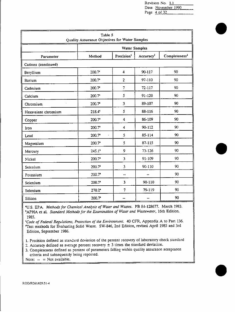
Revision No. 1.1Date November 1990Page 4 of 32
__ ~~~~~~~~~~TableS5Quality Assurance Objectives for Water Samples
Water Sampl es
Parameter Method Precision' Accuracy' Completeness3
Cations (continued) _ _ _ _ _ __ _ _ _ _ _ _ _
Bervllium 200.7' 4 90-117 90
Barium 200.73 2 97-110 90
Cadmium 200.73 7 72-117 90
Calcium 200.7' 5 91-120 90
Chromium 200.7' 3 89-107 90
Hexavalent chromium 218.4' 5 88-116 90
Copper 200.7' 4 86-109 90
Iron 200.7a 4 90-112 90
Lead 200.7' 5 85-114 90
Magnesium 200.7' 5 87-115 90
Mercury 245.1a 9 73-126 90
Nickel 200.7' 3 91-109 90
Selenium 200.7' 3 90-110 90
Potassium 200.7' --- 90
Selenium 200.7' 3 90-110 90
Selenium 270.2' 7 79-119 90
Silicon 200.7 -- -- 90
'U.S. EPA. Methods for Chemical Analysis of Water and Wastes. PB 84-128677. March 1983.bAFPiA et al. Standard Methods for the Examination of Water and Wastewater, 16thEion1985.
'Cade of Federal Regulations, Protection of the Environment. 40 CFR, Appendix A to Part 136.dTest methods for Evaluating Solid Waste. SW-846, 2nd Edition, revised April 1985 and 3rdEdition, September 1986.
1. Precision defined as standard deviation of the percent recovery of laboratory check standard2. Accuracy defined as average percent recovery ± 3 times the standard deviation.3. Completeness defined as percent of parameters falling within quality assurance acceptance
criteria and subsequently being reported.
Note: -- =Not available.
RDD/R261/029.514

Revision No. LI1Date November 19901Page 5 of 32
Table 5
Quality Assurance Objectives for Water Samples
Water Samples
Parameter Method Precision' Accurac9 Completeness3
Cations (continued)
Strontium 200 V - - 90
Silver 200.7- - 90
Sodium 200.7' -- -- 90
Thalliumn 200.7 3 94-113 90
Zinc 200.7 3 87-108 90
Boron 200.7? or 212.3* 3 95-115 90
Manganese 200.?2 3 85-106 90
Cobalt 200.7a 3 93-109 90
Molybdenum 200.7' --- 90
Tin 282P1 or 282.2* '- 90
Titanium 283.?' or 283.2* - -- 90
Vanadium 200.7' 2 90-105 90
Anions
Chlorine 330.59 -- -- 90
330.5* 90
Chloride 325.32 -- -- 90
Fluoride 340.21 6 88-122 90
'U.S. EPA- Methods for Chemical Analysis of Water and Wastes. PB 84-128677. March 1983.APAet al. Standard Methods for the Examination of Water and Wastewater, 16th Edition.
19ggs.'Code of Federal Regulations, Protection of the Environment. 40 CFR, Appendix A to Part 136.'Test methods for Evaluating Solid Waste. SW-846. 2nd Edition, revised April 1985 and 3rdEdition, September 1986.
1. Precision defined as standard deviation of the percent recovery of laboratory check standard2. Accuracy defined as average percent recovery ±t 3 times the standard deviation.3. Completeness defined as percent of parameters railing within quality assurance acceptance
criteria and subsequently being reported.Note: -- =Not available.
RDD/R2611029.51-5
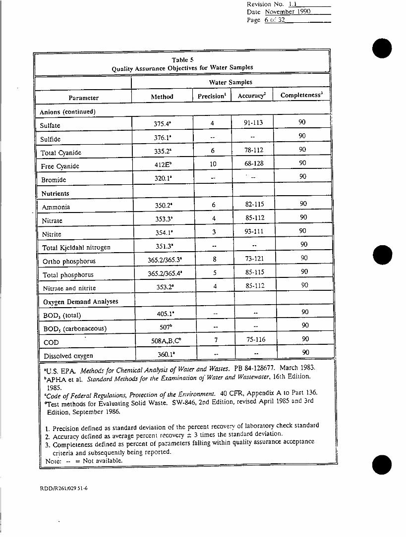
Revision No. 1.1Date November 1990Page 6 o: 32~
Table S
Quality Assurance objectives for Water Samples
Water Samples
Parameter M-ethod Precision' Accuracy9 Completeness 3
Anions (continued) ________
Sulfate 35.4a 4 91-113 90
Sulfide 36.? -- 90
Total Cyanide 35.2' 6 78-112 900-~
Free Cyanide 412Eb 106-289
Bromide 320.? -- - 90
FNutrients
Ammonia 350.2a 6 82-115 9
itrate 353.3a 4 85-112 90
Nitrite 354.14 3 93-111 90
Total Keldah nitrogen 351.3a -- 90
Ortho phosphorus 365.2/365.3a 8 73-121 90
Total phosphorus 365.2/365.4a 5 85-115 90
Nitrate and nitrite 353.2a 4 85-112 90
Oxygen Demand Analyses
BOO5 (total ) 405 .1 - - 90
B O O5 (carbon aceous) -0 - - - 90
CO D 508A B ,Cb 7 75- 116 1 90
D i sso l ved oxy gen 36 . ' - - 90
' U .S . E PA . M e th ods f o r Chemi cal A n aly sis of W ater and W astes. PB 84-12867 7. M ar c h 1983
b AP Hp A et al . Standar d M ethods f or the Ex am in ation of W ate r and Wastewater, 16 th E iti n .
1985.
'Code of Fed er al Regulati ons, Pro tecti on of the En vi ronm ent. 40 CFR, A ppend ix A to Part 136.
~T est m ethod s for E val uat i ng Sol i d W aste. SW -846, 2nd Edi t i o n, revi sed A p ri l 1985 an d 3rd
Ed i t i o n, Sep tem ber 1986.
1. Pr eci si on def i ned as standar d dev iat io n o f the per cen t recov ery of l ab o ratory check stan dard
2. A cc ur ac y defi ned as aver age per cen t r ec ov ery ± 3 t i mes the standar d dev i at io n.
3. Co m p l eten ess def i ned as per c en t of par am eter s fal l i ng w i th i n q uali t y assur ance ac ceptanc e
cr i ter ia and su bseq uen tl y bei ng repo r ted.
N o te : - - = N ot av ai l ab l e.
R D D / R 2611029 51-6

OCUtIt)IINO. 6
Revision No. 1.1Date November 1990Page 7 of 32
Table S
Quality Assurance Objectives for Water Samples
Water Samples
Parameter Method Precision' Accuracy2 C om pleteness'
O rg a n i c A n a l y ses _ _ _ _ _ _ _ _ _ _ _ _ _ _ _ _ _ _ _ _
O i l and grease 413.1' 8 75-121 90
MBAS 425. 1 -- -- 90
Phenols 420.23- -- 90
Purgeable Organics _ _ _ _ _ _ _ _ _ _ _ _ _ _ _ _ _
Chloromethane 601' 37' D-193' 90
Bromomethane 601' 14 54-140 90
Vinyl chloride 601' 28' 28-163' 90
Chioroethane 601' 13 65-142 90
Methylene chloride 601' 20' 25-162c 90
1,1-Dichloroethene 601' 14 75-156 90
1,1-Dichloroethane 601' 9 80-136 90
trans- 1,2-Dichloroethene 601' 16 62-159 90
Chloroform 601' 12 69-143 90
1,2-Dichloroethane 601' 1 0 74-134 90
Carbon tetrachloride 601' 8 86-136 90
Bromodichloromethane 601' 13 71-147 90
'U.S. EPA. Methods for Chemical Analysts of Water and Wastes. PB 84-128677. March 1983.bPAet a]. Standard Methods for the Examination of Water and Wastewater, 16th Edition.
1985.'Code of Federal Regulations, Protection of the Environment. 40 CFR, Appendix A to Part 136.flest methods for Evaluating Solid Waste. SW-846, 2nd Edition, revised April 1985 and 3rdEdition, September 1986.
1. Precision defined as standard deviation of the percent recovery of laboratory check standard2. Accuracy defined as average percent recovery ±t 3 times the standard deviation.3. Completeness defined as percent of parameters falling within quality assurance acceptance
criteria and subsequently being reported.Note: -- =Not available.
RDDmR261A029 51.7

Revision No. 1.1IDate Novemnber 19%~.Page 8 of 32
TableS5
Quality Assurance Objectives for Water Samples
Water Samples
Paramete Method Prciio' curacy9 Completeness3
Purgeable Organics (continued) ________
1,2-Dichoropropafle 60'10 80-138 90
cis1,-Dichoropropene 01 17 50-151 90
Trichloroethene 61' 16 67-161 90
Dibromochloromfethafle 61' 32' 24-191'c9
1.1,2-Trchloroethafle 601' 0 9-3'9
trans-1 -Ochloropropefl 601' 6 2-7'9
2-Chloroethyl vinyl ether60'4'1-6'9
Bromoform 601' 15 49-1390
1,1,2,2.Tetrachloroethafle 601' 46' 8- 184' 90
Tetrachloroethefle 601' 27' 26-162' 90
Benzene 602' 12 81-152 90
oro ezene602' 6 93-129 9
1,2.Dichorobenzene 602' 5 94-122 90
1,3-Dichorobenzene 602' ~ 9 ~ 81-134 ~ 90~
1,4-Dich orobenzene 602' 4 88-114 90
Ethylbenzene 602' 6 94-132. 90
Toluene 602' ------ 14 90
U.S. EPA- Methods for Chemical Analyis of Water and Wastes. PB 84-128677. March 1I9S3.
bApEJA et al. Standard Methods for the Exranination of Wiater and Wastewater, 16th Edition..
1985.'Code of Federal Regulations, Protection of the Environment. 40 CFR. Appendix A to Part 136.
'Test methods for Evaluating Solid Waste. SW-846, 2nd Edition, revised April 1985 and 3rd
Edition, September 1986.
1. Precision defined as stariard deviation of the percent recovery of laboratory check standard
2. Accuracy defined as average percent recovery ± 3 times the standard deviation.
3. Completeness defined as percent of parameters falling within quality assurance acceptance
criteria and subsequently being reported.Note: -- =Not available.
R)DD/1126A)29.51 -8

-~CLtLUiI INC. 05Revision No. 1.1Date November 1990Page 9 of 32
Table S
Quality Assurance Objectives for Water Samples
I ~~~~~Water Samples
Parameter I Method Precision' Accurac92 Completeness3
Purgeable Organics (continued) _ _ _ _ _ _ _ _ _ _ _ _ _ _ _ _ _ _ _ _ _ _ _ _ _ _
Xylene 602' 6 92- 127 90
Tertiary butyl methyl ether 602' 8 84-134 9
GCC/MS Volatiles
Chloromethane 624' 25 22-172 90
Bromnomethane 624' 6 81-119 90
Vinyl chloride 624' 20 37-157 90
Chloroethane 624' 10 69-132 90
Methylene chloride 624' 11 69-134 90
Acetone 624' 31 14-200 90
Carbon disulfide 624' 4 88-113 90
1.1-Dichloroethene 624' 2-0 90
1,1-Dichloroethane 624' 4 91-112 90
trans-1.2-Dichloroerhene 624' 2 95-106 90
Chloroform 624' 3 91-111 90
1,2-Dichloroethane 624' 3 91-111 90
2-Butanone 624' 20 49-171 90
1,1,1-Trichloroethane 624' 6 84-119 90
'U.S. EPA. Methods for Chemical Analysis of Water and Wastes. PB 84-128677. March 1983.bApi{A et al. Standard Methods for the Examination of Water and Wastewater, 16th Edition.
1985.cCode of Federal Regulations, Protection of the Environment. 40 CFR, Appendix A to Part 136.qTest methods for Evaluating Solid Waste. SW-846, 2nd Edition, revised April 1985 and 3rd
Edition, September 1986.
1. Precision defined as standard deviation of the percent recovery of laboratory check standard2. Accurac y defined as average percent recovery ±t 3 times the standard deviation.3. Completeness defined as percent of parameters falling within quality assurance acceptance
criteria and subsequently being reported.Note: -- =Not available.
RDD/R261/29.51 .9

5)CCIIUII INO. 6
Revision No. 1.1
Date November 1990Page 10 of 32
Table S
Quality Assurance Objectives fu.r Water Samples
Water Samples
Parameter Method Precision' ,Accurac92 Completeness 3
CC/MS Volatiles (continued) ________
Carbon tetrachloride 624' =6 8 4-121 90
Vinyl acetate 624c 7 83-125 90
Bromodichloromethafle 624' 6 84-121 90
1,2-Dichloropropane 624' 5 88- 118 90
ttans-1.3- Dichloropropene 624' 6 84-121 90
Trichloroethene 624' 58-116 90
Dibromochloromethanle 624' 6 84-119 90
1, 1,2-Trichloroet hane 624' 6 85-120 90
Benzene 624' 5 88-117 90
cis-1,3-Dichloropropefle 624' 5 1 86-117 90
2-Chloroethyl vinyl ether 624' 6 84-123 90
Bromoform 624' 8 79-124 90
4-Methyl-2-pentano~ne 624' 12 71-141 90
2-Hexanone 624' 15 63-152 90
1,1,2,2.Tetrachloroethafle 624' 8 80-126 90
Tetrachloroetbene 624' 5 85-116 90
Toluene 624' ~ ~ ~~~~~~~5 86-116 1 90
-u.s. EPA. Methods for Chemical Analysis of Water and Wastes. PB 844.128677. March 1983.
bAPHA~ et al. Standard Methods for the Examination of Water and Wastewater, 16th Edition.
1985.'Code of Federal Regulations, Protection-of the Environment. 40 CFR. Appendix A to Pa-: 136.'
f'Test methods for Evaluating Solid Waste. SW-846, 2nd Edition, revised April 1985 and 3rd
Edition, September 1986.
1. Precision defined as standard deviation of the percent recovery of laboratory check standard
2. Accuracy defined! as average percent recovery ±- 3 times the standard deviation.3. Cmpltenss dfind a perentof arameters failing within quality assurance acceptanct
RDDIR261/029.51I-10

Revision No. 1.1Date November 1990Page II of 32
er_________~~~~~~~~~TblQuality Assurance Objectives for Water Samples
Water Samples
L ~Parameter Method Precision' Accuracy2 C om pl eteness3
C C / M S V o la t i l es (co n t i n u e d ) _ _ _ _ _
C h l o ro benz ene 624' 5 85- 118 90
E thy l benz ene 624' 5 86- 116 90
Sty r ene 624' 6 84 -119 90
To ta l xylene s (O & M ) 624 ' 4 88-114 90
GCC M S Sem ivolati les
n- N itr oso dim e thy la mn ine 625 ' 10 70- 127 90
P he no l 625' 8 75- 125 90
A n ilin e 625 ' 9 70 123 90
bi s( 2-C hl o ro ethy l ) e ther 625 ' 7 78- 119 90
2- C hl o ro ph eno l 625 ' 3 89- 109 90
1,3- D i c h l o ro benz ene 62 5' 2 94- 104 90
1,4- D i ch lo ro benz ene 625' 4 90- 111 90
Be nzyl alcohol 625' 5 84-114 90
1,2-Dichlorobenzene 625' .3 91-108 90
2-methylphenol 625' 1 6 81-117 90
Lbis(2-Chloroisopropyl)ether 625' 14 1 58-139 90
.U.S. EPA. Methods for Chemical Analysis of Water and Wastes. PB 84-128677. March 1983.b!yFLA. et al. Standard Methods for the Exramination of Water and Wastewater, 16th Edition.
1985.'Code of Federal Regulations, Protection of the Environment. 40 CFR. Appendix A to Part 136.'Ts methods for Evaluating Solid Waste. SW-846, 2nd Edition, revised April 1985 and 3rd
Edition, September 1986.
1. Precision defined as standard deviation of the percent recovery of laboratory check, standard2. Accuracy defined as average percent recovery ± 3 times the standard deviation.3. Completeness defined as percent of parameters falling within quality assurance acceptance
criteria and subsequently being reported.Note: -- =Not available.
RDD/R261/029.51-I1I

Revision No. 1.1Date November 199(1
Page 12 of 32
Table 5Quality Assurance Objectives for Water Skamples
I ~~~~~Water Samples
Prmter Method Precision' Accuracy' Completeness3
CC/MS Semnivolatiles (continued) ______ ______ _ _ _ _ _ _ _ _
4-Methyiphenol 625' 6 82-117 90
n-Nitroso-di-n-propylaminle 625' 10 67-128 90
Hexachloroethane 62$' 2 92-106 90
Nitrobenzene 625' 8 74-124 90
Isophorone 625' 7 78-119 90
2-Nitrophenol 625' 5 85-115 90
2,4-Dimethylphenol 625' 3 90-107 90
Benzoic acid 625' 13 62-140 90
bis-(2-Chloroethoxy)melhane 625c 4 86-113 90
2,4-Dichlorophenol 625' 3 90-110 90
1,2,4-Trichlorobenzene 625' 5 86-114 90
Naphthalene 625' 3 93-108 90
4-Chloroaniline 625' 3 89-110 90
Hexachlorobutadiene 625' 6 84-117 90
4-Chloro-3-methylpheflol 625' 84-112 90
2-Methylnaphthalene 625' 487-114 90
Hexachlorocyclopentaditfe 62' 167-134T 90
-U.S EPA, Methods for Chemical Analysis of Water and Wastes. PB 84-128677. March 1983.
bApH.JA et al. Standard Methods for the' Examination of Water and W3~astewater, 16th Edition.
1985.'Code of Federal Regaldations, Protection of the Env'ironnment. 40 CrFR, Appendi3x A to Part 136.
'Test methods for Evaluating Solid Waste. SW-846, 2nd Editia)n, revised April 1985 and 3rd
Edition, September 1986.
1. Precision derined as standard deviation of the percent recovery of laboratory check, standardof
2. Accuracy define~d as average percent recovery ± 3 times the stadard deviation.
3. Completeness defined as percent or parameters falling within quality assurance acceptanccs
criteria and subsequently being reported.
Note: -- =Not available.
RQDDR261/029.51-t2

Revision No. 1.1
Date November 1990
Page 13 of 32
Table S
Quality Assurance Objectives for Water Samples
Water Samples
Parameter Method Precision' Accuracy Completeness3
GCC/MS Setnivolatiles (continued) ______
2,4,6-Trichlorophenol 625' 7 78-120 90
2,4.5-Tricblorophenol 625' 9 73-125 90
2-Chloror~aphthalene 625' 4 87-113 90
2-Nitroanilinc 625' 9 69-124 90
Dimethyl phithalate 625' 5 83-115 90
Acenaphthylene 62,5' 3 90-111 90
3-Nitroaniline 625' 8 74-120 90
Acenaphthene 625' 3 90-110 90
2,4-Dinitrophenol 625' 17 49-150 90
4-Nitrophenol 625' 19 41-154 90
Dibenzofuran 625c 4 87-112 90
2,4-Dinitrotoluene 625' 6 79-116 9
2,6-Dinitrotoluene 625' 5 86-114 90
Dierhyl phthalate 625' 4 85-110 90
4-Chlorophenyl phenyl ether 625' 6 80-118 90
Fluorene 625' 4 1 88-112 90
4-Nitroaniline 625' 1 11 68-133 90
'U.S. EPA. Methods for Chemical Analysis of Water and Wastes. PB 84-128677. March 1983.bAPHA et al. Standard Methods for the Exramination of Water and Wastewater, 16th Edition.1985.
'Code of Federal Regulations, Protection of the Environment. 40 CFR, Appendix A to Part 136.'Test methods for Evaluating Solid Waste. SW-S46, 2nd Edition, revised April 1985 and 3rd:3dition, September 1986.
1. Precision defined as standard deviation of the percent recovery of laboratory check standard2. Accuracy defined as average percent recovery ± 3 times the standard deviation.31. Completeness defined as percent of parameters falling within quality assurance acceptance
criteria and subsequently being reported.Note: -- =Not available.
RD)D/R261/029.51-13

5CCIIIIISO11
Revision No. 1.1Date November 1990Page 14 of32
Table SQuality Assurance objectives for Water Samples
Water Samples
Parameter Method Precision' Accuracy' Completeness3
GCCMS Semtivolatiles (continued) _____ _ _ _ _ _ _ _ _ _ _ _ _ _ _
4,6-inito-2-ethypheflol 625' 8 76-124 90
n-Nirosoipheylaifle 625' 5 86-117 90
4-Bromophenyl phenyl ether 625' 4 87-113 90
Hexachlorobenzene 625' 7 82-121 90
Pentachlorophenol 62 5' 1 7 52-151 90
Phenanthrene 625' 5 88-115 90
Anthracene 625' 6 84-120 90
Di-n-butvl phthalate 625' 7 82- 122 90
Fluoranthene 625' 11 71-139 90
rBenzidine 625' 33 0-191 90
Pyrene 625' 14 56-143 90
Butyl benzyl phthialate 625' 15 55-146 90
3,3.Dichlorobenzidine 25' 7 81-121 90
-U.S. EPA. Methods for Chemical Analysis of Water and Wastes. PB 84-128677. March 1983.
bAFI4A et al. Standard Methods for the Examination of Water and Wastewater, 16th Edition.
1985.'Code of Federal Regulations, Protection of the Environment. 40 CFR, Appendix A to Part 136.
~Test methods for Evaluating Solid Waste. SW-846, 2nd Edition, revised April 1985 and 3rd
Edition, September 1986.
1. Precision defined as standard deviation of the percent recovery of laboratory check standard
2. Accuracy defined as average percent recovery ± 3 times the standard deviation.
3. Completeness defined as percent of parameters falling within quality assurance acceptance
criteria and subsequently being reported.Note: -- =Not available.
RI)D/R261/029.51-14

Revision No. 1.1
Date Novemnber 1990~
Page 15 of 32
Table 5Quality Assurance Objectives for Water Samples
Water Samples
Parameter Method Precision' Accuracy' Completeness3
GCIMS Semnivolatiles (continued) _____ ______ ________
Benzo(a)anrhracene 625' 6 83-120 90
bis(2-Ethylhexyl)phthalate 625' 12 64-138 9
Chrysene 625' 5 84-117 90
Di-n-octyl phthalate 625' 20 41-164 90
Benzo(b)fluoranthene 625' 15 55-144 90
Benzo(k)fluoranthene 625' 11 71-139 90
Benzo(a)pyrene 625' 13 63-14 1 90
lndeno(l,2,3-c,d)pryene 625' 10 73-131 90
Dibenzo(a,h)anthracene 625' 9 73-128 90
Benzo(g~h,i)perylene 625' 12 67-136 90
Pesticides
a-BHIC 608' 4 84-110 90
b-BHC 608' 4 83-108 90
g-BHC 608' 4 85-107 90
d-BHC 608' 3 87-107 90
Heptachlor 608' 5 86-116 1 90
'U.S. EPA. Methods for Chemical Analysis of Water and Wastes. PB 84-128677. March 1983.APAet al. Standard Methods for the Eramination of Water and Wastewater, 16th Edition.
1985.'Code of Federal Reguataions, Protection of the Environment. 40 CF'R, Appendix A to Part 136.dTest methods for Evaluating Solid Waste. SW-846, 2nd Edition, revised April 1985 and 3rdEdition, September 1986.
1. Precision defined as standard deviation of the percent recovery of laboratory check standard2. Accuracy defined as average percent recovery ±t 3 timies the standard deviation.3. Completeness defined as percent of parameters falling within quality assurance acceptance
criteria and subsequently being reported.Note: -- =Noi available.
RDDIR261/029.5 I-15

S)ectiol NO. 6Revision No. 1.1Date November 1990Page .16 of 32
Table 5Quality Assurance Objectives for Water Samples
Water Samples
Parameter Method Precision' Accuracy9 Completeness'
Pesticides (continued) ____ __________
Aldrin. 608c 4 88-110 90
Heprachior epoxide 608' 3 89-109 90
Endosulfan I 608' 3 90-107 90
£';cldrin 608' 5 86-114 90
4,4-DDE 608' 3 90-106 90
Endrin 608c 6 77-112 90
Endosulfan 11 608' 6 82-118 90
4,4-DDD 608' 4 88-110 90
Endrin aldehyde 608' 5 81-108 90
Endosulfan sulfate 608' 4 86-109 90
4,4-DDT 608' 5 78-111 90
Methoxychlor 608' 5 80-110 90
Chlorinated Herbicides _____ _ _________
2,4-D 81504/Method j d6387 9
2,4-DB SlS0dI/Method 3d 9412d90
2,4,5-T 8150d/Method 6d 6 7 -1 0 3 d 90
2,4,5-TI' (silvex) 8150d/Method d73y103 d 90
2U.S. EPA. Methods for Chemical Analysis of Water and W{astes. PB 84-128677. March 1983.bAPHA et a]. Standard Methods for the Examination of Water and Wastewazer, 16th Edition.
1 985.'Code of Federal Regulations, Protection of the Environment. 40 CFR, Appendix A to Part 136.
'Test methods for Evaluating Solid Waste. SW-846, 2nd Edition, revised April 1985 and 3rdEdition, September 1986.
1. Precision defined as star.~z.rd deviation of the percent recovery of laboratory check standard2- Accuracy defined as avcr10ge percent recovery ±t 3 times the standard deviation.3. Completeness defined as percent of parameters falling within quality assurance acceptance
criteria and subsequently being reported.Note: -- =Not available.
RDD/R261/029 51-16

Section No. 8Revision No. 1.1Date November 1990Pagc 17 of 32
Table S
Quality Assurance Objectives for Water Samples
I ~~~~~Water Samples
Parameter I Method Precision' IAccurac9 Completeness'
Chlorinated Herbicides (continued) _____________________
Dalapon 8150d/Mvetbod gd 42-90d 90
Dicamba 8150d /Mvethod 7d 5 g1 lod 90
Dichloroprop 815(dIMethod 2d9-0'90
Dinoseb 8150'1lMethod 4d 7 4 9 8 d 90
Phenols
4-Chloro-3-methylphenol 604c18040M510 16d 56.7-113.4' 90
2-Chiorophenol 604'I8040'I35 10 2d 54.1-110.2 d 90
2,4-Dichlorophenol 604c18040tM35 10 51d 97103'90
2,4-Dimethylphenol 604c/S8d0/3510 33.3 50._100Od_9
2,4-Dinitrophenol 604'/8040'f3510 3Od 17121'90
2-Methyl-4,6-d ini trophenol 604______310_25 4 2 .4 .12 3 .6 d go
2-Nitrophenol 604___8__4_d_35 1 22.5d 56.6-103.8d 90
4-Nitrophenol 604c/8040't3510 I9.Od 2.-100 90
Pen tach lorophenol 604c__8_40__3510 32___4__ 56.7_113_5_ 90
Phenol 604'/8040W/3510 14.lId 32.4-100.Od 90
Tetraphenols 60--04d 5-0- 90
-- tAlorophenols 6047/8Q40d/3510 - -90
2,4,6-Trichloro phenol 604c/8040d13510 16.6d 608104d90
'U.S. EPA. Methods for Chemnical Anatysis of Water and Wastes. PB 84-128677. March 18983.'AH et al. Standard Methods for the Eamrination of Water and Wastewater, 16th EItion.195
'Code of Federal Regulations, Protection of the Environment. 40 CFR, Appendix A to Part 136.'Test methods for Evaluating Solid Wastc. SW-846, 2nd Edition, revised April 1985 and 3rdEdition, Septemnber 1986.
1. Precision defined as standard deviation of the percent recovery of laboratory check. standard2. Accuracy defined as average percent recovery ±: 3 times the standard deviation.3. Completeness defined as percent of parameters falling within quality assurance acceptance
criteria and subsequently being reported.* ~~~~Note:- =Not available.
RDD/R261/A)Ž9.51 -17

Revision No. 1.1Date November 1990Page 18 of32
Tal'k 5
Quality Assurance objectives for Water Samples
Water Samples
Parameter MeOthod !Precision' Accurncj Completeness'
Polynuclear Aromatic Hydrocarbons _____
Naphthalene 60/30,50 4.' 2..0.d9
Acenaphthyene 6l0'/8310'3510 5 2112'9
Accnaphthefle to/30150 4.' D15
Fluorene 6I0'/8310'/3510 43.Q - 9
Phenanthrene 610'18310'/3510 37.7' 8.4133.7' 90
Anthracene 6I0'183I0d/3510 28.7' 11.2112.3d 90
Fuoranthene 610t/8310d/3510 30' 27-1 11' 90
tent ~~~~~~~610'/8310'/35 10 34' 14-121' 90
Benzo aanthracefle 610'/8310d/3510 40' 31-116' 90
Crysene 610'/8310't3510 42d D0175'd 90
Benzo(b)fluoraflth fl 610cI8310dI3510 31' 18-138' 90
Benzo(k)fluoranthtfle 610',8310d,3510 50' D0140d 90
Benzo a)pyrene . 61O'/83l0dB1350 40d 2-110 90
Dibenzo a,hanthracefle 610Oc83 1Od13510 30d- 10 90
Benzo(g,h,i perylefe 610'18310'1510 23d 0-107' 90
lndeno(1,,3cdpyrtfle 610'/8310'/510 30d 12-1090
Organophophorus Pesticides
Azirphos methy I 10/50lg 63191 90
Ul.S. EPA.Mthd for Chemical Analysis of Water and Wastes. PB 84-128677. March 1983.
bAPHA et at. Standard Methods for the Examination of Water and Wastewater, 16ih Editin 19.
'Code of Federal Regulations, Protection of the Environment. 40 CFR, Appendix A to Part 136.
'Test methods for Evaluating Solid Waste. SW-846. 2nd Edition, revised April 1985 and 3rd
Edition, September 1986.
1. Precision defined as standard deviation of the percent recovery of laboratory check standard
2 Accuracy defined as average percent recovery -± 3 times the standard deviation.
3. Completeness defined as percent of parameters falling within quality assurance acceptance
criteria and subsequently being reported.Note: -- =Not available.

Revision No. 1.1
Date November 1990Page 19 of 32
Table 5Quality Assurance Objectives ror Water Samples
______________________________________________W ater Samples
Parameter Method Precision' Accuracy' Completeness'
Organophosphorus Pesticides (continued) ___________ ________
Bolstar 810506.3' 45.7-83.5 90
Chlorpyrifos 81406/3510 5.1 81.8.114.8d 90
Cournaphos 81406/3510 12.76d 70.94147.1Id
Demeton 81401/3510 10.56 35.9-98g9 90
Diazinon 8140d/3510 6.0 49.0-85.Od 90
Dichlorvos 81406135 10 7.7' 49.095.2' 90
Disulfoton 81406,3510 9.06 54.9-108.9' 90
Ethoprop 8140d,3510 4.16d 88.2-112.8 d 90
Fensulfothion 8140'/3510 17.16' 42.8145.46 90
Fenthion 8140d/3510 19.9d 9.0-128.4 d 90
Merphos 8140613510 7.96 97.0144 9
Mevinphos 8140dI3510 7.86 33.1-79.9d 90
Naled 81406/3510 8.1d 53.7.102.3 d 90
Parathion methyl 8140'/3510 5.36 80.1-111.9d 90
Phorate 8140'/3510 8.9d 36.0-89.4 d 90
Ronnell 8140d13510 5.66 82.4.116.Od 90
Stirophos (tetrachlorvinphos) 8140d/35 10 5.9d 48.4-83.8d 90
Trichloronate 81401/3510 18.66 49.2160.86 90
'U.S. EPA- Methods for Chemical Analysis of Water and Wastes. PB 84-128677. March 1983.bApl4A et al. Standard Methods for the Examination of Water and Wastewater, 16th Edition. 1985.
'Code of Federal Regulations, Protection of the Environment. 40 CFR, Appendix A to Part 136.
'Test methods for Evaluating Solid Waste. SW-846, 2nd Edition, revised April 1985 and 3rdEdition, September 1986.
1. Precision defined as standard deviation of the percent recovery of laboratory check standard2. Accuracy defined as average percent recovery ± 3 times the standard deviation.3. Completeness defined as percent of parameters falling within quality assurance acceptance
criteria and subsequently being reported.* ~~~~Note:- =Not available.
RDD) /Rl26 1/02 .95 1-19

Section No. 6Revision No. 1.1
Date November 1990
Page 20 of 32
Table SAQuality Assurance Objectines fro SolliSedimenI Samples
Soil/Sediment Samples
Parameter Mebd/xrction Precision' Accuracv Conmpicleness 3
General Analyses
pH- 9045 8/Meihod -- 75-12.5 90
Alkalinity 3 10.1b -- 90
Conductitvt 9050a/Meihod -- 75-125 90
Volatile solidis 160.4b -- 75-125 90
Total solids 16 0 flb -751590
Cations;
Aluminum 601(9,3050 - 51590
Antimony 6 0 1 0a13 0 5 0 -- 7-125 9
Arsenic 7060a/3050 -- 7-125
Arsenic ~~70613/3050 -- 7-125
Bervilium ~60102/3050 -- 75-125
Banum ~~~601 Oa/3050 -75-125 9
Cadmium ~~601(9,13050 -75-125 9
Calcium ~~601021 3050 -- 75-125 90
Chromium 60109I3050 -75-125 90
l-laavaI~le chromium 71963/3050 - 51593
Copper 6010a /3050 - 51590
Iron 601(9/3050 -751590
Lead 6010a ,3050 -- 75-125 90
L~ead 742~12,13050 -- 7-125 90
-Magnesium 601(9,3050 -- 7-125 90
Mercury 74712/3050 -- 75125 90
aTlethads for Ei-aluaung Solid Hasze. SW-846, 2nd Edition, revised Apnil 1985 and 3rd Edition, September 1986; Accurac
epesdas percent recovery based on published method control limits-
%..EPA., Methods for Chemnical Anatvsiu of Water and Wxase. PB 84-128671. March 1983.
1 Irecision defined as standard dCe`ia!on or the percent recovery or laboratory check- standard.
2.Accuracy defined as average percent recovery ± 3 times the standard deviation. unless otherwise specified.
3. Completeness defined as percent of parameters fallfing within quality assurance acceptance criteria and subseunlbig
-reporied.
Note. -- = Not available.
RDfl\R59\127 51-20
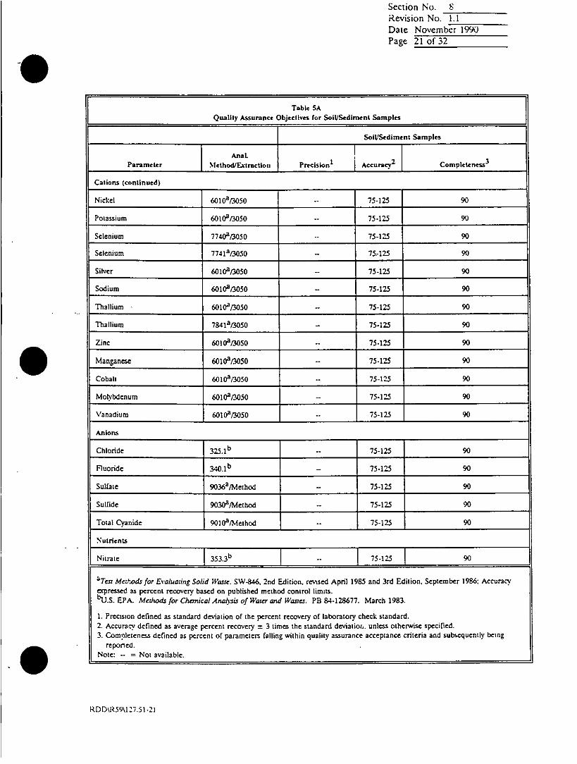
Section No. 8Revision No. 1.1Date November 1990Page 21 of 32
Table SA
Qnallty Assurance Objectives for Soil/SedImentl samples
Soil/Sediment Samples
Parameter T method/Extractlori Precisiont Accuracy2 JCompletene~ss3
Cations (continued)
Nickel 6010a/3050 - ~ 75-125 90
Potassium 6010"/3050 -. 75-125 90
Selenium 77402/3050 -- 75-125 90
Selenium 774la/3050 -- 75.125 90
Silver 60102/3050 -75-125 90
Sodium 6010a/3050 - 75-125 90
T1hallium 60102/3050 - 75-125 90
Thallium 7841a,3050 - 75-125 90
Zinc 601cia/3050 -- 75-125 90
Manganese 6010a/3050 -- 75-125 90
Cobalt 6010",3050 -- 75-12.5 90
Molybdenum 60102/3050 -- 75-12 90
Vanadium 6010a/3050 -- 75-125 90
Anions
Chloride 32 5.1b -- 75-125 90
Fluoride 3401 b -75-125 90
Sulfate 90363/Mcthod -75-125 90
Sulfide 9030a/Method -- 75-125 90
Toal Cyanide 90102/Method -- 75-125 90
Nutrients
Nitrate 353.3 b 75-125 90
aTWs Me&;ods for Evaluaiing Solid Wast. SW4846. 2nd Edition, revsed April 1985 and 3rd Edition, September 1986: Accuracyexpressed as percent recovery base~d on published method control limits.5U.S. EPA. Meihods for Charnical Anatsis of Wate and Watsres. PB 84-128677. March 1983-
1. Precision defined as standard deviation of the percent recovery of laboratory check standard.2. Accuracy defined as average percent recovery ± 3 times the standard deviatior.. unless otherwise specified.3. Completenecss defined as percent of parameters falling within quality assurance acceptance criteria and subsequently being
reported.Note:- = Not available.
RDD\R59\l127.51-21

Section No. 8Revision No. 1.1
Date November 1990Page 22 of 3-
if ~~~~~~~~~~~~~Table5SAQualitv Assursance Objective~s for SoiluSedimeni Samples
Soil/Sedimntft Samples
Anal.
Parameter Method/axtractlofl PrIecision1 Acry 2 Comnpleteness
Nutrients (continued)
Nitrate and nitrite 3 5 3 .3 b -. 74590
Oil and grease972Nthd- 52 90
Prgeahi Organics
Choromethane 80102/5030 -- 193
Bromomethn 801so] 3 D.144a9
Vnyl chlorie 800 030 -- 28,163a9
Chloroethane 81/03- 46-137 9
Mechylene chloride 8010 /5030. 25 4162a 90
I.1.Dichloroetheric 80102/5030 ~ 6 a9
1.1-Dichlorcoethanec 80102/5030 -- 4 7,132a 90
Ftrans.1.2Dichloroethene 80102/5030 -- 38 -155a 9
Chloroforat 80102/5030 -- 49g133'
1.2-Dichloroetaneri 9010"/5030 .- 5 147a9
Carbon terrachloride 80102/5030 -4]4339
Bromodichlomomethafle 80102/5030 4 _ 17_90
1.2-Dichloroprpane 80102/5030 -69
cisd.3-Dichoropropene 01 &/5030 22___17_
Tnchtoroethenc 80102IC/503035169
Dibro ochloromethzne 80102/5030 910
- 39,136a ~~~~~~901.1.2-Trichloroethan: _L8~0125-030 .3
am,-T Methodsjfor £.luading Solid Wane. SW-846, 2nd Edition, revistd April 1985 and 3rd Edition, September 1986: AcCuracy
apriessied as percent rccoery based on published method control limrits.bU.S EPA. Method. for ChanicalAn4his of Wate and Wastes. PB S4.i 23677. March 1983.
1. Precision defined as standard deviation of the percent recovery of laboratory check' standard.
2. Accuracy defined as average percent recovery ± 3 times the standard deviation, unlecss otherwise specified.
3. Completeniess defined as percent of parameters railing withiin quality assurance acceptance criteria and subseqluently being
Neorte: . = taalbe
rep Ntoaaieble
RDD\R59\127.51-22

Revision No. 1.1Date Novembetr 199(1Page 23 of 32
Table SAQu.1111 Assurance, Objectives fro Soil/Sedimewnt Samples
I ~~~~~Soil/Sediment Samples
Anal.IParameter Method/Eiclrnclion Precision1 A cc ur acy 2 Comnp leten ess3
P ur gea ble O r gan ic s ( con ti nued )
tr ans -1.3 -D ich lor op ro pene 80I 0a/5030 - - 22. 178 a 90
2- Ch io ro elth vi vi ny l e t her 80 108/ 5030 - . 14-186 ' 90
B romoforrm 80102/3030 -- 13 -159a9
1 ,1.2,2-T err ac hlor oethiane g& o ai 0 30~s - a- d t 90
T e lra c h lor oetthene 80102/5030 - 26 416 ? 90
B e men te 80202/5030 - - 39 -15 fta 90
C hlor obhe nz ene 80202/ 5030 -- 55. 135a 40
1,2- D ic h lo ro benz en e 80208/5030 -- 37 -154a 90
1. 3-D ichlo r o benzten e 80208/5030 - 50 41418 90
1,4 -D ich lor obc nz cn c 802C0a/5030 - 42.143 " 9 0
E xhvy lben itene 8020 3/5030 - - 32- 160ra 90
T oluen e So2oa/5 030 - - 46 _148a 90
Xvl ene 80 202/ 5030 - - 90
T er niar
v bury! methyl ether 80202/5030 --- 90
Chlorometlhane 82402/5030 - D-273a 90
Bromometrhane 82408/5030 - D-242a 90
Vinyl chloride 82402/5030 - D-2518 90
Chloroethane 82402/5030 - 90
Methvlene chloride 82402/5030 -- D-21 81 90
Acetone 8240a/5030 --. 90
Carbon disulfide 82402/5030 - .90
"Tes Medtods for Evaluading Solid Waste. SW-846, 2nd Edition, revised April 1985 and 3rd EdvirLn, September 1986: Accuracy
ax.pressed as percent recovery based on published method control limits.bu.S EPA. Mezhods for Chemical AnuiVsis c' Wager and Wtate. PB 84-128677. Maz:% 1983.
1. Precsion defincd as standard deviation of the percent recovery of labortator check stzndard.2. Accuracy defined as average percent recovery ± 3 times the standard deviat ion. unless otherwise specified.3. Completeness defined as percent of parameters railing within quality assurance acceptance criteria and subsequently being
repotied.Note:- = Not available.
RODMR59\127.St-23
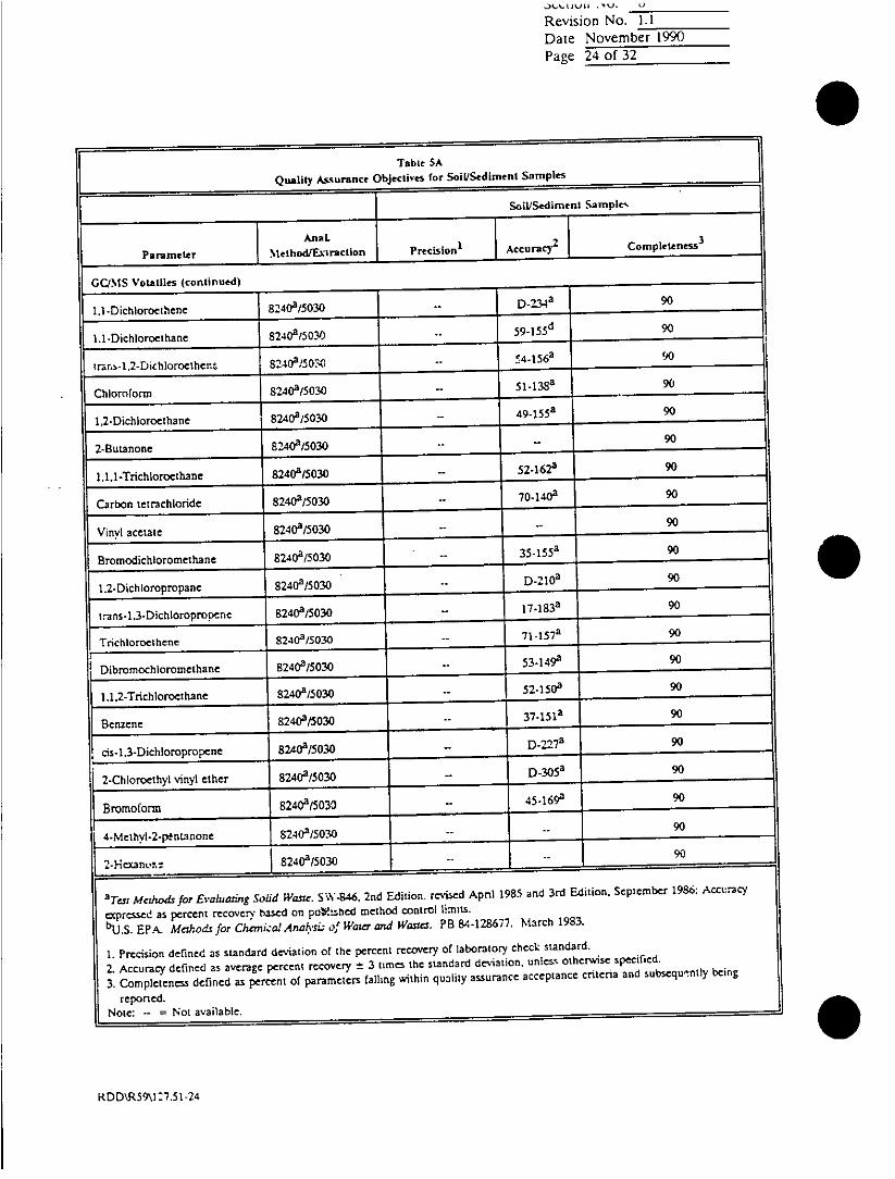
Revision No. 1.1
Dare November 1990Page 24 of 32
Qualiy Assrance Table SA
Qu~aityAmunnceObjeCtives for SoiL'Sedlrenet Samples
Soi])Sedimnenl ratnPlr.
Parsameter Ntelhod/Ex~rlrttion Prcso' Acuay opleteness3
GCJNIS Votatiles (continued)
I.1-Dichoroethene 8240a/5030 .- D2.34a 90
1.1-Dichlonoetne 82408/5030 - 59 1 55d 90
TmrUS-1.2-Dichoro enthe 8, 4a9/50-( - 4 - 5 6 a 90
ChOrom 8240a,5030 51 Si 3sa 90
12Dchoroethane 82(/00- 9 155a 90
2-utanone 82400/5030 -- 90
1.1.1.TicIooehne 824(503 52.1620 90
Carbon tetrachioride 82400/5030 -- 7-14(99
Vinyl acetate 82409/5030 -- 90
Bromodichloromethane 82409/5030 351590
1.2-Dichloropropane 82409/5030 D-21&9
"rns-1.3-DichloroiproPent 8240a/5030 17.1S3 9
Trichlornethene 82403/5030 71451509
IDibrornochloromethane 82409/5030 -531449 90
1.1.2-Trichlorcoethaflt 3(/030 -- 5-15( 90
Benzene 824(/030 -- 7151a 90
cis-1.3-Dichlormpropcfle 80/030 -D-2-73 90
2-ChIoroethyl vinyl ether 82(/030 -D 0 30 5a 90
Bromolormn849(00- 45.169 90
4.Methivl-2-ptntarnone84(500-- 9
3Test Methods for Evaluating Solid Waste. SW-S46, 2nd Edition, revised Apnil 1985 and 3rd Edition. September 19: Acct~raCy
apressed as percent recovery basd on pttV.bed method control limits.
bU.S. EPA.L Methods for Chemical AnaK-si; of Water and Wastes. PB 84-128671. Ma3rch 1983.
1. Precision defined as standard deviation of the percent recovery of laboratoty check standard.
2. Accuracy defined as avenage percent recovery ± 3 times the standard deviation, unless otherwise specified.
3. Completeness defined as percent of parameters falling within quality assurance acceptance criteria and subsequently being
reported.Note: -- = Not available.
RDD'R59\l2 7.5l1-24

Section No. SRevision No. 1.1Date November ~1990Page 25 ol 32
Table 5AQuality Assurnoce Objectives roe Soil/Sediment Samples
SoIL/Sediment samples
Parame:: Method/Extraction Precision' AccuracY2 Completeness3
GUMIS Volalilles(cniud
1.1,2.2-Tetrachloroetharne 824&/5030 4.46-1572 90
Tetrachloroethenc, 8240a/5030 64 -14 8" 90
Toluene 824Oa/5030 47-150& 90
'Chlorobenene 8240a/5030 - 3 7 -1 6 0 a 90
Ethylbenzene 8240A/5030 - 3 7 -16 2 a 90
Scyrene 824CA/5030 - 90
Total xvlenes (O&M S2402/5030 90
GC/MS Semrivoistfies
ni-Nitrosodimetlhvlamine 8270~2S340/3550 90-
Phenol 82t703/3540/3550 - 5.112a 90Aniline 8270aB3540/3550 --- 90
bis(2-Chlorocthyl)clhcr 8270aB540,3550 .- 12-1582 90
2-Chloropnenol 827013540/3550 --- 90
1,3-Dichlorobenzne 8270aa540/3550 -D-172a 90
1.4-Dichloroberizene 82'7&,3540/3550 2012a90
Benzvl alcohol 8270aB3540/3 550 -.- 90
1.2-Dichiorobenzene 827013 540B3550 -32-1293 90
2-inethylphenol C270a/3540/3550 -- 90
bis(2.Chtoroisopruopyl)ether 82 7 0S1 3 5 40 /3 5 5 0 -- 36 _1 66a 90
4-MethNlphenol 82 &341550 -- 90
ni-Nitrvso-di-n-propylamine 827&,3540/3550 L -D-2303- 90
licxchlor~octhane 8-7&B/540Th550 I 011 90
a7'w Merho4, for Evaluating Solid Wanre. SW-846, 2nd Edition, revise April 1985 and 3rd Edition, Septemnber 1986: Accuracyexpresecd as percent recovery based on published method control limits.bU.S. EPA. Methods for Chcniucal Antysis of Waercand Wastes. PB 84-128677. March 1983.
1. Precision defined as standard deviation of the percent recovery of laboratory check standard.2. Accuracy defined as avenage percent recovery ± 3 times the standard deviation, unless otherwise specified.3. Completenecss defined as percent of parameters falling within quaility, asutrance acceptance criteria and subseqtuently being
reported.Note: -. = Not available.
RDD\R5O\127.51-25

Section No. SRevision No. 1.1
Date Novembeitr 1990Page 26 of 3r
Table LAI ~ ~~~~~~~Quality Assurance Objectives for Soil/Sediment Samples
Soil/Sedliment Samples
Parameter ~~Method/Extraction Precisioni Accoru Compettnessv
CC/MS Semrivolatles (continued)
Nitrobeniene 82-70 ?'3540M35S- 540 90
Isophorone 82-W"'354,2 3550 .- 2 1_19,6a 90
2-Nitrophenol 82702,3540/3:50 -29-182a 90
2,4-Dimethylphenol 8270213540/3550)- 32-119" 90
Benzoic acid 8270a/3540/3550 .. 90
bis-(2-Chlorcexhoxy ehae 82702/3540/3550 -- 33-143 90
2.4-Dichlorophenol 82702/3540/3550 - 39 -135" 90
1,2.4-Trichlorobenlene 8276235540/3550 -44.142" 90
Naphihalene 8272350350-21-1339 90
4-Chloroaniline 82703/3540/3550 - -90
Hexachlorobutadiene 8270a22540/3550 -- 24 1162 90
4-Chloro-3-mnelhylnhenol 8270"23540/3550 -- 22*14~7' ~90
2-Methylnaphthalene 8270a/3540/35 50 90
Hexachlorocyclopentadiene 82702/3540/3550 -- 90
2,4.6-Trichlorophenol 82'70a/3540/3550 -3714442 90
2.4.5-Trichlorophcnol 82102,3540/3550 9
2-Chlorcimplithaimne 82'702/3540/3550 -60-1183 90
2-Nitroaniline 82702,3540/3550 -- 90
Dimethyl phzhialate 8270t3540/3550 .- D-11?a 90
Accnaphthivlene 8270a,354023550 -- 33.1452 90
3-Nitroantiline ~ 8270325~40/3550 ______ 90______________
Acenaphthene 82702/3540/3550 1-47,]45 90
3Tear Methods for Eiahl=:ing So/id Waste. SW-846. 2-nd Edition, revised April 193and 3rd Ediuion, Septembcr18:Acrc
apressoed as percent re~covery based on pubi:: ~:d method control limits.bU.S. EPA. Mc.;odfs for Chcrniclc Analysis cJl H'az and Blunts. PB 844128677. March 1983.
1. Prectsion defined as standard deviation of the percent recovery of laboratory check' standard.2. Accvracy defined as avenage percent recovery ± 3 limes the standard deviation. unless otherwise specified.
3. Completeness defined as percent of parameters failing w~ithin quality assurance acceptance criteria and subsequently being
reported.0Note: *.=Not available.
RD D\RS 9\1t27 .5 1 2

SeWCtion NO. 6Revision No. 1.1Date November 1990Page 27 of 32
Table SA
Quality Assurance Objectives for SoIL/Sedimnent Samples
Soil/Sedimrnet Samples
Anal 1 3Parameter j__Mctbod/&xtractlon Precision1 Accura&2 Completeness
GCIMS Semnivolatiles (continued)
2.4-Dinitrophenol 8270a/3540/3550 -- D-191a 90
4-Nitrophenoil 82702/3540/3550 -- D-132a 90
Dibeniofuran 8270a/3540/3550 --- 90
2.4-D)initrotoluene 82702/3540/3550 -- 39-1392 90
2,6-Dinirrotoluene 82702/3540/3550 -- 50-158a 90
Diethyl phithatLate 827OP/3540/35.50 -D-1143 90
4-Chiorophenyl phenyl ether 82702/3540/3550 -25-1582 90
Fluorene 82,70a/3540/3550 - 59 -121a 90
4-Nitroaniline 827OA/3540/3550 -- 90
4.6-Dinitro-2-methylphenoil 82.70a/3540/3550 -. D-1812 90
n-Nitrosodiphenviamine 827'0a/3540/3550 90__ _ __
4-Brornophenvl phenyi ether 8270a/3540/3550 -- 53 -127a 90
Hexchlorobenzene 82701t3540/3550 1- -152" 90
Pentachlorophenol 8270a/3540/3550 -144176a 90
Phenanthrene 82702/354/3550 -- 54-120a 90
Anthr~ccne 8270a/3540/3550 -2741331 90
Di-n-butyl phithalate 82702/3540/3550 - ~ Ia90
l~uomnthene 82-70213540/3550 -. 26437a 90
* rBenidine 8270a/3540/3550 - 90
Pvre~ne 82702/3540/3550 -52.115a 90
Butyl benzyl phithalate 8270a/3540/3550 -- D-152' 90
3.3-Dichlorobenzidine 82702,3540/3550 -- D-262a 90
3T=s Methods for Evaluating, Solid ;l'asr. SW-846, 2nd Edition, revised April 1985 and 3r-Z Edition, September 1986; Accuracyex pressed as percent recovery based on published method control limits.b-U.S. EPA. Methods for Chemical Analysis of Water and Waest. PB 84-128677. March 1983.
1. Precision defined as standard deviation of the percent recovery of laboratory check standard.2. Accuracy defined as average percent recovery ±L 3 times the standard deviation, unless otherwise specified.3. Completeness defined as percent of parameters falling within quality assurance acceptance cniteria and subsequently being
reponed.Note: -- = Not available.
RDMDg59\127.5 1-27

.~tA.IUIII ,lU 0
Revision No. 1.1Date Novemrbe-r 19~k)Page 28 of 32
Table SA
Quality Assurance Objectives for Soil/Sediment Samnples
SoiLtSediment Samples
Parameter NMethod/Exlraction PrecIslon1 Accuracy2 Completeness 3
GC/MS SernIvolatiles (continued)
Bernzo(a)anthracene 8170a13540/3550 -- 33-1432 90________________
bis(2-Ethylhccv)phthalate 8270a1354013550 .-- 8 158a 90
Chrvsene 8270a/3540/3550 -- 17-16S 90
Di-n-ocyi phihalate 82702/3540/35 50 - 44146a 90
Benzo(b)fluc:ntnhene 827&I3540/3550 -- 24-150 ~ 90
Benzo(k)fluoiranthene 8270t3540/3550 1 u-162 90
Benzo(a)pyrene 8270ai3540/3550 - 174163a 90
lndeno(l.2.3-c~d)pzyenc 81.70a/3540/3550 -- D-1713 90
Dtibentzo(axc)anthracene 82702/3540/3550 -D-227" 90
Benzo(g.hJi)pcrylenc 8127&/3540/3550 -- D-219r 90
Pesticides
a-BHC 80802/3550 -- 37-13-43 90
b-BHC 8080a,3550 - 1 7-1-7a 90
g-BHC 808&ai3550 -- 32-12-7a 90
d-BHC 80802/3550 -- 19-1402 90
H-eptachlor 80802/3550 -34-1118 90
Aldrin w8cialm550 424122 90
Heptachlor epoxide 8&q02/3550 -- 37.14?" 90
Endosulfan I S8W.28/3550 -- 45-153 a 90
Dieldrin W8080/3550 i-3.462 90
4.4-DDE 80802/3550 -- 30.1452 90
Endrin 808033550 -- 1290
"am, Mehods for Evaluating Solid WOM-. SW4FAC. 2nd Edition, revised April 1985 and 3rd E-dition. Stptember 1986: Accuracyaprec sd as percent reconvew- baised on. Published method control limits.b"u.S. EPA. Methodisfor ChcrniklAnatysis of Waterrand Was;cs. PB 84-128677. March 1983.
1. Precision defined as standard deviation of the percent recovery of laboratory check, standard.2. Accur,tc- definea~ as average percent recovery = 3 times the standard deviation, uinless otherwise specified.3. Completeness defined as percent of parameters falling within quality assurance acceptance cniteria and subsequently being
reported.SNotel - Not available.
RDMDR59U27.S 1-28
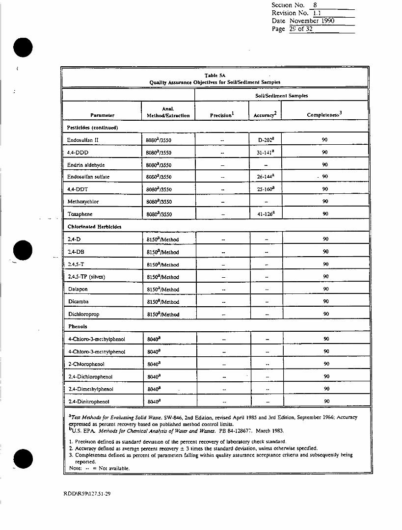
Section No. SRevision No. 1.1
Date November 1990Page 29 of 32
Table SA
Quality Assurance Objectives for Soil/Sediment samples
SolldSedimeni samples
MatFIParameter Method/Extraclion Precision t _Accuracy.2 Comnpletenes)
Pesticides (continued)
Endosulfan II s8 /13550 -. D-2028'9
4.4-DDD I 88 /3550 31-141a 90
Endrin aldehyde 80S0a/3550 -- 90
Endosulfan sulfate 80808/3550 .- 26.1442 -90
4,4-DDT 8080813550 -25-1608 90
Methoxychlor 80821550 -- 90
Toccaphene 808CP/3550 -41-126" 90
Chlorinated Herbicides
2.4-D 81502/Method -. - 9
2.4-DB 81lSO2Mvethod - 90
14.5-T' 8150a/Method - -90
2.4.5-TP (silva) 8150"/Method 9 -
Dalapon 8150a/Method 90 -
Dimmba 8150a/Method 90-
Dichloroprop, 81502/Method - -90
Phenols
4-Chlono-3-methylphcnol SNO4 90
4-Chloro-3-mctn~vlphcnol 80402 90
2-Chlorophenol 80402 - -90
2.4-Dichlorophenol 8042 "- 90
I2.4-Olimethvlphenol 8040--- 90
2.4-Dinitrophenol - 1 802402 - 90
"Test Mcdhods for Evaluating Sdlid Wast. SW-846, 2nd Edition, revised April 1985 and 3rd Edition, September 1966; Accuracyexpressed as percent recovery based on published method control limits.i"US. EPA. Mr-Jtodsfo, ChemikalArolvsbs of Wow'r and W~are. PB 84-128677. March 1983.
1. Precision defined as standard deviation of the percent recovery of laboratory check standard.2. Accuracy defined as avenge percent recovery ± 3 times the standard deviation, unless otherwise specified.3. Complete~ness defined as percent of parameters falling within quality assurance acceptance critenia and subsequently being
Noe: on d o valbereorted. Nt %aiabc
RDD\R59\127.51-29

Section No. SRevision No. 1.1Date Novembher 1990Pagc 30 of 3
Table SA
Qiualityv Assurance Objectives for Soil/Sedimrent Samples
Soil/Sediment Samples
AnaL 3
Paraete MethodlEa1raction Precision1 Accunr&C Completeness
Phenols (continued)
2*Methyl4-4s dinitrophenol 80402
2-Nitrophenol 8040 9-
4-Nitrophenol 8040" 90
Pentachlorophenol 80402 - 90
Phenol 80402 - 90
Teiraphenols 80402 90
2,4.6-Trichlorophenol 8040329
Polynuclear Aromatic Hydrocarbons
Naphthalene 8310 2-D-122 290 I_________ ____________________
Acenaphthvlene 83102"- D-139a 90
Acenaphthenc 83102 D-1243 90
Fluorene 83102- D-1422 90
Phenanthrene 8310a -D15 90
Anthracene 8310a - D-2290
Fluoranthene 83102 -- 14 123a 90
Pyrene E3104 -- D-1403 90
Benzo(a)anthracene 83102 - 12Z135 3 90
Chrvscnc 83102. D-199a 90
Bernto(b)fluoranithene 83102 6 -1502 90
Bernzo(k)fluotranthene 83102 -- -tsr 90
Benzo(a)pyrene 83102 -- v-1S 2 L 90
aiTer Mettods for Evahwsing Solid Waste. SW-846. 2nd Edition, revised April 1985 and 3rd Edition. September l9St Accuracy
a.prcssed as percent recoveryv based on published method control limits."U.S. EPA. Melhods jot Chemical Aralysi of Water and Wavies. PB S4-128677. March 1983.
1. Precision defined as stindard deviation of the percent recovery of laboratory check: standard.2. Accuraicy defined as avenage percent recovery =3 times tie standard deviation, uInless otherwise specified.
3. Completeness defined as percent of parameters railing within quality assurance acceptance criteria and subsequenily beingreported.
Note: -. =Not available.
RD D\R 59\'A27.51 -30

Section No. SRevision No. 1.1
Date November 1990Page 31 of 32
Table SAQuatlity Assurance Objectives for SoiP/Sediment Samples
Soil/Sediment Samples
Paramettr IMethod/Extraction PrecisionI FAccuracy2 Comrpleteness 3
Polynuclear Aromatic Hydrocarbons (continued)
Ditbenzo(a~h)anthracene 8310" -- D-1l0d 90
Benzo(g.h,i)perylene 8310a -- D-116390
lndeno(1,2.3-cd)pyrcne 83109 -- D-1 163 90
Organophosphorus Pesticides
Azinphos methyl 814$ - 90
Boistar 8140A - 90
Chlorpvrifos si~~84$ 90
Conmnaphos 814(9 - -- 90
Demneton 8140a-*- 90
Diazinon 814(9 - 90
Dichioirovos 814(9... 90
Disuffoicon 81409--- 90
Ethoprop 8140a--- 90
Fensulfothion 814$ a- 90
Fenthion 814$ a, 90
Merpho; 8140a- 90
Mevinphos 814$ --a 90
Naled 8140 - - 90
Parathion methyl 814$ - - 90
Phonitc 814$ -"- 90
Ronnell 814$ - - 90
Stirophos (tetrachloirvinphos) 81409 90-, - _______________
aer~ Methodisfor Evaluating Solid Witter. SW-W4. 2nd Edition. rerviscd April 1985 and 3rd Edition, September 1986: Accuracyaxpressed as percent recoverv based on published method control limits.,bubS. EPA. Methods for Ch~mcndcoAnalyis of Water and Wastes. PB 84-128677. March 1933.
1. Precision defined as standard deviation of the percent recovery of laboratory check, standard.2. Accuracy defined as average percent recovery ± 3 times the standard deviation. unles otlherwise specified.3. Comptereness defined as percent of parameters falling within quality assurance acceptance criteria and subsequently being
reported.Note: -- = Not available.
RDD\R59\127,.51 .31

Scction No. SRevision No. 1.1Date November 1990Page 32 of 32
Table SA
Quality Assurance Objectives for SoWlSedimnent Samples
SoiLISediment Samples
Anal.
Parameter Method/Ex-traction Precision1 Acry 2 Completenms 3
Organophosphorus Pesticides (continued)
Trichioronate 904 -
aTW Methods for £valuadin2 Si~,tid H'ase. SW-846, 2nd Edition, revised ApnIl 1985 and 3rd Edition, September 1986: Accrc
expressed as Nrcnt recwver based on published method control limits.
.bU.S EPA. Alethodr for Cherical Aruiai of Watw and Wasttes. PB 84-128677. March 1983.
1. Precision defined as standard deviation of the percent recovery of Laboratory check standard.
2. Accracy defined as average percent recovery ± 3 tumes the standard dleviation., unless othcemise: specified.
3. Completeness defined as percent of parameters falling within quality assurance acceptance criteria and subsequently being
reporled.Note: -=Not available.
RDD\R59\127.51-32

Section No. 9Revision No. 1.1Date August 1989Page lof ?
9.0 LIMITS OF DETECTION
The limit of detection (LOD) is defined as the lowest concentration level that can bedetermined to be statistically different from a blank with a high degree of confidence.Additional concepts to the LOD which are used at the Redding laboratory are the.method detection limit (MDL) and the instrument detection limit (IDL). MDL refersto the lowest concentration that a method can detect reliably. IDL refers to thesmallest signal above background noise that an instrument can detect reliably.
The uncertainty of a quantitative measurement is highest at or near the limit ofdetection. Confidence in a quantitative measurement increases as the analyte signalincreases above the LOD.
The Redding laboratory determines the MDL at least once annually for each analyticalmethod. The procedure consists of running seven replicates of a prepared, 'laboratorystandard in reagent water at a concentration of 1 to 5 times the estimated minimumMDL. The standard preparations are processed through the entire analytical method.The standard deviation of the replicate results is calculated. The MDL is calculated asthe product of the standard deviation and the student's t-value for a 99 percentconfidence level and 6 degrees of freedom -(t = 3.143).
Typical method detection limits of water samples reported by the laboratory for theorganic and inorganic priority pollutants are shown in Tables 6 and 7, respectively.Higher detection limits may at times be reported due to sample matrix interferences.
The laboratory also determines IDL to conform to client-specific protocols.
Table 6
Detection Limits of Organic Priority Pollutants
Method Detection Limit (xgIL)
Base/Neutral Compoun~s
B is(2-chloroe,.hyl)ether 6
1 .3-Dichlorobcnzene 7
1,4-Dichlorobenzene 6
I1,2-Dichlorobenzene 6
Acid Compounds
Bis (2-Ch Luroisopropyl )ei her 6
RDD\RS'\121.51
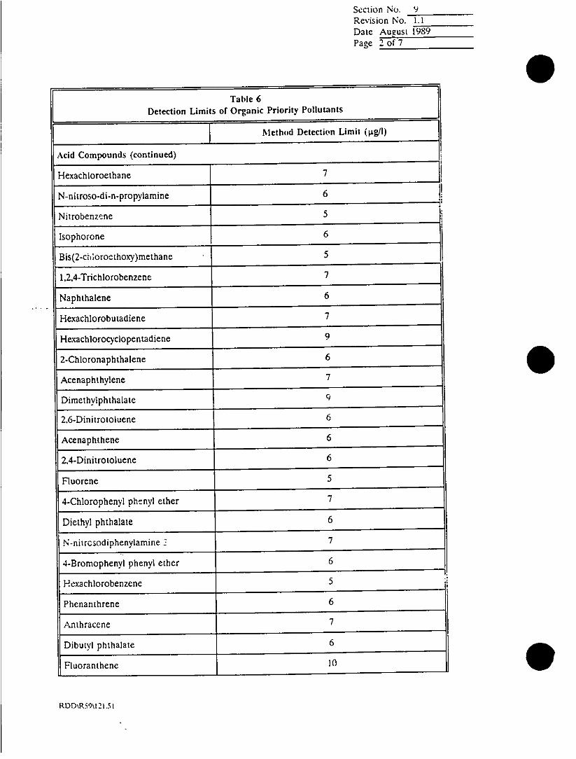
Section No. 9Revision No. 1.1~Date August 1989Page 2 of 7
Table 6Detection Limits of Organic Priority Pollutants
Method Detection Limit (pig/l)
Acid Compounds (continued)
Hexachloroethane 7
N-n itroso-di -n-propylarnine 6
Nitrobenzere 5
Isophorone 6
Bis(2-c'i~oroc-thcoxy)methane 5
1,2,4-Trichlorobenzene 7
Naphthalene 6
Hexachlorobutadiene 7
Hexachlorocyclopentadiene 9
2-Chloronaphthalene 6
Acenaphthylene 7
Dimethyiph tha late 9i
2,6-Dini trotoluene 6
Acenaphthene 6
2.4-Dinitrotoluene 6
Fluorene 5
4-Chlorophenyl phtnyl ether 7
Diethyl phthalate 6
.N-nitrosodiphenylamine 17
4-Bromophenyl phenyl ether 6
Hexachlorobenzene 5
Phenanthrene 6
Anthracene 7
Dibutyl phthalate 6
Fluoranthene 10
RDD;R59\1251.9

Section No. 9Revision No. 1.1Date August 1989Page 3 of 7
Table 6
Detection Limits of Organic Priority Pollutants
Method Detection Limit (p.g/1)
Acid Compounds (continued)
Pyrene 7
Butyl benzyl phthalate 6
Benzo (a) anithracene 6
Chrysene 5
3,3'-Dichlorobenz~idine 6
Bis (2-ethylhexyl) phthalate 6
Di-n-ocryl phthalate 7
Benzo (b) fluoranthene 9
Benzo (k) fluoranthcne 5
Bcnzo (a) pyrene 7
Indeno (1.2,3-cd) pyrene 10
Dibenzo (a~h) anthracene 9
Benzo (g~h,i) perlene 11
N-nitrosodimethylamine 8
Bis (chloromethyl) ether Not Determined
Phenol 10
2-Chlorophenol 9
2-N:-trophenol 8
2-4-Dimnethylphenol 5
2-4-Dichlorophenol 6
4-Ch Ioro-3-met hyiph enol 5
2.4,6-Trichlorophenol 8
2,4-Dini trophenol 7
4-Nitrophenol 10
F2--Methyl-4.6-dinitrophcnol 7
RDD\RS'I\121.51

Section No. 9Revisior Ao. 1.1Date August 1989Page 4 of7
Table 6Detection Limits of Organic Priority Pollutants
Method Detection limit (pg/I)
Acid Compounds (continued)
Pentachlor(,.henol 7
Volatile Compounds
Chloromethane 2
Brornomethane 1
Vinyl Chloride 2
Chloroethane 1
Methylene Chloride 2
1,1 -Dichloroethene 1
1, 1-Dichloroethane I
Trans-1,2-Dichloroethene 1
Chloroform 1
1,2-Dichloro)ethane 1
1.1,1-Trichloroethane 1
Carbon Tetrachloride 1
Bromodichloromethane 1
1,2-Dichloropropane 1
Trans- 1.3-Dichloropropane 1
Trichloroethylene 2
Benzene
Dibromochloromethane1
1.l,2-Trichloroethane1
Cis-1.3-Dichloropropenc
2--Chloroethyl vinyl ether1
Bromoform1
1,1,2.2-TctrachloroeihaneI
RDD'R59\21.51

Section No. 9Revision No. 1.1
Date AugusI 1989
Page S of 7
Table 6Detection Limits or Organic Priority Pollutants
Method Detection Limit (Hig/I)
Volatile Compounds (continued)
Tetrachloroethene I
Toluene 1
Chlorobenzene 1
Ethyl Benzene 1
Pesticides and PCBs
Aldrin 0.01
a-BHC 0.01
b-BHC 0.02
d-BHC 0.01
g-BHC 0.01
Chlordane 0.04
4.4'-DDD 0.01
4,4'-DDE 0.01
4.4'-DDT 0.01
Dieldrin 0.01
Endosulfan I 0.01
IEndosulfan II 0.01
Endlosulfan Sulfate 0.01
E n d rin 0.01
Endrin Aldehyde 0.01
Hepiachlor 0.01
Heptachlor Epoxide 0.01
Toxaphene 0.18
PCB - 1016 Not Determined
PCB - 1221 0.6
RDD\R59AI121.51

Section No. 9Revision No. 1.1Date August 1989Page 6 of 7
Table 6
Detection Limits of Organic Priority Pollutants
Method Detection Limit (pig/i)
Pesti cides and PC~s Compounds
PCB - 1232 Not Determined
PCB - 1242 Not Determined
PCB - 1248 0.5
PCB; - 1254 Not Determintwd
PCB - 1260 0.3
4,4-Methoxychlor 0.01
Table 7
Detection Limits of Inorganic Priority Pollutants
Method Detection Uimit
Element Instrument (mg/I)
Al urninurn ICP 0.017
Antimony ICP 0.12
Arsenic lCP/OFAA 0.0084A30.001 2
Barium ICP 0.0006
Beryllium ICP o.00G5
ICadmium ICP/GFAA 0.00!2/0.000i
Calcium ICP 0.030
Chromium CP0.002
Cobalt ICP.04
Copper IC? 0.002J1
Iron IC? 0.0c
Lead ICP 0.0
Magnesium IP0
Manganese ICP
Mercury AAICV
Molybdenum 1CP
R[)D\R.59\121,51 A

Section No. 9Revision No. 1.1Dare August 1989Page 7 of 7
Table 7Detection Limits of Inorganic Priority Pollutants
Method I'.nection Limit
Element Instrument (migh)
Nickel ICP 0.0084
Potassium IC? 0.60
Selenium !CP/GFAAIGHAA 0.01&0.0007/0.0006
Silver lCP 0.0042
Sodium ICP 0.110
Thai jumn ICP/GFAA 0.012/J.0004
Titanium ICP 0.0012
Vanadium IC? 0.002
Zinc ICP 0.004
Phenol (4AAJ') -0.1
Cyanide (Total) -- 0.005
Total Organic Carbon (TOC) -
IC? = Inductively Coupled Plasma.G FAL- = Graphite Furnace Atomic Absorption.AA/CV = Atomic Absorption Cold Vapor.GHAA = Gaseous Hydride Atomic Absorption.
RDD\R59\1 2 1.5 1

Section No. 10Revision No. 1.1Date August 1989Page I of 1
0 ~~10.0 LEVELS OF QUALITY CONTROL DOCUMENTATION
Data are generally reported in tabular format such as shown in Appendix C. Whenrequired, QC data, such as blank analyses, standard spike recoveries, surrogaterecoveries, and duplicate analyses, are reported with the sample results. Detectionlimit of the analytical method is reported when the sample result is less than thedetection limit. Flagcging consistent with EPA-defined reporting qualifiers is used whenan explanation for reported values is required.
Recognizing the wide range of client needs for report content and format, thelaboratory has identified different levels of quality control and the deliverables incidentto each level. These are listed in Table 8.
The laboratory shaUl meet project-specific QC requirements (control charts, methodblank spikes, etc.) not covered by the routine QC levels.
Table 8Levels of Quality Control and Deliverables
Leve 1: Report of sample results with blanks and surrogateLeve 1: recovery summaries.
Level 2: Report of sample results with all supporting QC datasummaries.
Level 3: Full CLP package with raw data for all samples and QC________performed on each sample delivery group.
RDD\R59\122.51

Section No. 1 1Revision No. 1.2
Date November 1990Page Ilof
11.0 SURVEILLANCE AND AUDITS
Systems are in place to monitor the effectiveness of the laboratory in carrying out theQuality Assurance Plan. These systems are administered by the Laboratory QualityAssurance Coordinator.
11.1 External Performance Evaluation Sample Program
The laboratory participates in the EPA performance evaluation programs, suchas the Super-fund Quarterly Blind, the WS and WP studies, and theradiochemtical inter-comparison study. The laboratory also participates inperformance evaluation studies sponsored by the states in which it is certified.
The results of all performance evaluation samples are reported to managementand the staff by the LOAC. The LQAC also coordinates investigations andcorrective actions on the deficiencies noted.
11.2 Internal Double-Blind Sample Program
The LQAC administers an internal double-blind sample program. This programinvolves the introduction of a double-blind sample into the laboratory on aquarterly basis. The samples are of compositions known only to the LOAC andare disguised as real client samples. Parameters included for analysis aredecided by the LOAC based on perceived problem areas. All sections of thelaboratory are covered by at least one double-blind sample yearly. Evaluation ofthe double-blind sample involves an assessment of the laboratory's adherence toall aspects of quality control from the time the sample is received up to andincluding when the final report is completed. The LQAC audits the chain-of-custody records, holding time compliance, quality control criteria, ^control charts,test documents, and promptness of report generation. All findings aredocumented in a double-blind sample audit report which is submitted tomanagement and circulated to all staff. The LOAC has the responsibility forobtaining responses to all deficiencies noted and for ensuring that correctiveaction is implemented.
113 Internal Audits
Internal audi-s of the laboratory are conducted in two phases.
The first phase is conducted by the District Quality Assurance Manager at leastonce a year. This is usually a 2-day system audit which covers all sections of thelaboratory. An audit report is issued within 2 weeks of completion. The LQAC
* ~~~~has the responsibility for coordinating all responses to the audit findings and for
RDD\R59\123.51

Section No. 11Revision No. 1.2Date Novemnbcr 1I"tPage 2 of 2
following up on the required corrective action. A followup audit is made whendeemed necessary by the District QA Manager.
The second phase consists of semiannual audits performed by the LOAC.These are day-long audits, and are concentrated on specific areas that aredeemed problem areas by the LOAC. An audit report is issued at the
con-:K-etion of the audit. Responses and followup corrective action to the auditfindings are required, and are monitored by the LOACl.
All audit reports are issued to management and circulated to all staff. Copiesare filed with the District Quality Assurance Manager and the LOAC.
11.4 QC Chart Monitoring
OC charts are periodical:.' monitored by the LOAC. When a trend is observe-d,feedback in the form of a written report is given to the appropriate personnelinvolved, with copies supplied to the Laboratory Manager and the District
Quality Assurance Manager. The LQAC has the responsibility for monitoringsubsequent charts for continuance of the trend and for getting corrective actionimplemented, if war-ranted.
11.5 Quality Reports to Management
The performance of the laboratory as assessed by the quality monitoring systemsin place is reported by the LOAC to management both on a periodic basis andas needed (as described above for each monitoring system). Most, if not all,reports are circulated to the staff to keep them informed of the laboratory'sperformance. Copies of all quality reports are maintained in the District QualityAssurance Ma~nager and LOAC files.
11.6 Certifications and Agency Approvals
The laboratory is presently certified in Alaska, Californiia, Florida, I~daho,Nevada, Oregon , Utah, and Washington. It has been approved to submit datato the State of Arizona (this state does not have an accreditation program atthis time).
Thits laboratory has fl-so been granted approval to perform H-AZWRAP(Hazardous Waste Remedial Actions Program) work, administered by the~ UJ.S.Air Force, for the Department of Energy.
ROO\R59\123-51

Section No. 12Revision No. I.2Date Novern:.er 199Page I of I
12.0 DOCUMENT CONTROL AND RECORD MANAGEMENT
12.1 Test Document Control and Storage
When a sample is received, a sample logging procedure is followed by SampleCustody. This involves assigning a unique reference number and the generationof a Chain-of-Custody Record. Sample Custody also generates an analysis sheetwhich contains sample information and a list of the tests required for eachsection of the laboratory. Both the Chain-of-Custody Record and the completedanalysis sheet are reviewed by the Sample Custody supervisor for accuracy andcompleteness. The original documents are sent to the Client File, and copiesare sent to each section of the laboratory involved.
Data reduction is performed by a data system or manually by the analyst. Theresults are transferred to the analysis sheet by the analyst. This becomes theoriginal draft report. All original draft reports, laboratory notebooks, and rawdata sheets are reviewed and approved by the section supervisor or anotheranalyst who was not involved in the analysis. The review / approval process hasbeen described in the section on Data Validation of this Quality Assurance Planand in the appropriate standards operating procedures in the SOP Manual.
N . ~~~~Data review is documented at all times. All test documents (custody records,draft and final reports, laboratory notebooks, standards, and maintenance logs,and raw data sheets) are filed by laboratory reference numbers or chronolog-ically in the laboratory section files for a spe'cified length of time, and eventuallygo into the long-term record storage. Documents are kept in file for a minimumof 5 years, after which they are destroyed.
12.2 Control of Standard Operating Procedures
Each SOP is assigned a unique SOP number and a revision number. Each SOPundergoes - review and approval process before it is issued. Any change to anSOP is made only upon completion and approval of an SOP Change Request.Any change to an SOP is reflected by a change in the SOP revision number.Final review and approval of original SOPs and changes to existing SOPs aremade by the Laboratory Manager and the LOAC. A historical file of each SOPis maintained by the LQAC.
The above system enables the determination of the specific SOP in use at anygiven time for any analysis.
RDD\R59\1 24.51

Section No. 13Revision No. 1.2Date November 1990Page Ilof 4
13.0 LABORATORY HEALTH AN]) SAFETY
13.1 Laboratory Safety Procedures
Laboratory safety rules are matters of common sense and second nature to atrained chemist. However, it is the responsibii;wr of laboratory personnel tofamiliarize themselves with the safety rules and equipment, so that accidentalinjury or damage to property do not occur. Personnel can prevent mostlaboratory accidents by using common sense, following the safety guidelines,taking time, and asking questions when unsure. The purpose of these safety pro-cedures is to present the safety rules in an organized manner and point out- someparticular laboratory hazards. The following covers general safety procedures forthe Redding laboratory.
13.1.1 Food, Clothing, and Personal Items
No smoking in lab areas - Smoking, eating, and beverages are allowedonly in offices, the lab break area, and the office break area. Thebreakroom is equipped with a coffee pot and a refrigerator for FOODONLY--NO chemicals or samples.
Coats, purses, etc., must be stored in coat room.
13.1.2 Ventilation
* Toxic and noxious chemical/samples must be handled under ahood.
* All hoods are for working--not storage.
* All hoods are keyed to the hood light--if the hood light is on--so isthe exhaus.,t fan. Hoods should be turned off when not in use toconserve energy.
* Explosion-proof hoods are located in the extraction lab and main(inorganic) lab. Solvents should be used only in these hoods.
* A velocity meter is routinely used to measure hood velocity and toensure that the hoods are working properly, i.e., 100-150 fpm atthe face. Air flow measurements are made on a weekly basis anddocument any, problems on the face of :he hood.
ROD\R59\125 51

Section No. 13Revision No. 1.2Date November 1990Page 21oi 4
Exercise caution when using a hood. Be sure to work to at least 6to 10 inches inside the face of the hood to avoid vapors escapinginto the room.
13.1.3 Eye and Clothing Protection
* ALL analysts mast wear proper eye protection when working in thelaboratory. If eye wear is not comfortable, an appointment with anoptometrist will be scheduled to correct the problem. For thoseanalysts handling strong acids or bases, a face shield must also beworn.
* Visitors and maintenance personnel must wear protective eve wealrwhen enterinri the laboratories. Eye wear is provided at eachlaboratory.
* Lab coats must be worn when working in the lab areas. Neopreneaprons should be worn when handling strong acids, alkali, or othercorrosive chemicals. These aprons are available in the acid diges-tion lab.
13.2 Laboratory Safety Provisions
Under no exception are chemicals, samples, or contaminated glassware broughtoutside designated areas. All supplies are delivered through the warehouse.Gas cylinders are Stored in designated areas. All cylinders are chained, empty or
fill. All cylinders are tagged as to their status--Full, In Service, or Empty.I
Fire extinguishers, safety showers, and eyewash stations are provided in thelaboratory.
The building is also equipped with fire and smoke detectors. If they are
activated, the fire alarmwil sound. The fire alarm system is also tied via phonedirectly to the fire department.
133 Physicals
Al' laboratory employees undergo yearly physicals to monitor health effects. Theresults are evaluated by the -firm's physician, and the company and; employee arenotified of any problems. Corrective action decisions are thern made bymanagement.
13.4 Disposal of Samples and Laboratory Wastes
RDD\R59\125.51

Section No. 13Revision No. 1.2Date November 1990Page 3 of 4
13.4.1 Hazardous Sample Disposal
On a weekly basis, the Hazardous Waste Technician performs a queryfrom the Laboratory Information Management System (LIMIS) of allsamples whose final reports have been sent out to clients at least30 days prior to the query date. The query report also indicates whichsamples are hazardous based on characterizations previously made bythe Division Manager and entered into LIMS. Hazardouscharacterization is done based on criteria set by the federal regulatir asand the California Code of Regulations. AJI samples determined to behazardous are stored in separate onsite designated areas. The client isnotified and given the responsibility for the return of the hazardous
~-sample to the site of origin. If return is not feasil;.e, the sample isstored in a secured onsite storage container until it cain be transportedto an authorized-disposal area by a licensed transporter.
13.4.2 Nonhazardous Sample Disposal
The sample container labels are defaced to destroy all pertinentinformation. The sample containers are then disposed of into wastecontainers which are hauled away by the City Sanitation Department orwaste disposal company.
13.4.3 Laboratory Waste Disposal
This section covers spent solvents, unused chemicals, reaction products,and sample extracts.
Drain disposal is used for organic compounds that are reasonablysoluble in water (0.2 ml or 0.1 gmn dissolves in 3 ml of water). It is alsoused for dilute solutions of inorganic salts containing one of thefollowing cations and one of the following anions:
Cations Anions
Aluminum BisulfiteCalcium BromideMagnesium CarbonatePotassium ChlorideSodium Hydroxide
IodidePhosphateSulfate
RDD\R59\l25.51

Section No. 13Revision No. 1.2Date November 19%Page 4 of 4
Acids and bases are collected in two underground holding tanks. Thefirst tank overflows into the second tank which in turn overflows intothe sewer. Each tank is connected to a pH meter. The pH meterwhich is connected to the first tank is also a con-troiler and signals theappropriatL amount of acid or base to be metered into the tank tomaintain the required pH range. The pH meter connected to thesecond tank sounds out an audible alarm in the event that the pHrange is exceeded. At that time, valves can be manually shut off. Thereadouts fromt the pH meters are recorded by .,. continuous recordingdevice.
All other substances are handled according to the CH2M HILL
Hazardous \Vaste Management Plan.
13.5 Flammable Solvent Storage
Flammable solvents are stored in designated OSHA-approv'ed explosion-proof
cabinets.
RDD\R59\125.51

APPENDICES
A Method ReferencesB Calibration and Control ChartsC Laboratory FormsD Laboratory Equipment ListE Key Personnel Resumes
0
0

Appendix AMETHOD REFERENCES

TAWA 46.-US! Of AfltOVID IOS0GADSC TEST PR0C1DUJAO
Relfronc. Mlithod No. or Fg.
* ~~~~~~~~~~~~~~~~~SHP~~ram~~l~r CM Units M~~~~tI~~od EP4 MtlhodePefimeler endUn.M Method1979 184h. Ed. A.STM4 USGS' Ote
I* fliditV* as C&C0, Elact,omnetric and poiflmg/I.opLnth~l~
*nd "rx. 306.1 402L.aj Dl0dl-821E3
2. Alkalinity. as C&COt. EIcuome:,vc ormg/L. - colsomt'me. tgtratum.
to pH4 4.5. manual. Ocf 310.1 403 - 01067.8218) 1-1030-84 33,014'Automatod. 310.2 - - 1-2030- 54
3. Aluminurn-Total' DigestionJ Iollowed byMg/I. AA direc1at 8SDISIodV. 202.1 303C -1-3051.84
AA futriace.. 202.2 304--Indudivly"~ coopled - --... .-- 2C?
- plasma. 20.7Colo,,mesivsc (Enchrome - 3068--Cyanl'nl RI.
4. Ammorusa." Nt. Manual diatillta.~ (at pHmg/L. 9.5$1. follow.d t-y 260.2 417A . -- 33.057'
N~zslg.,itio.M 350.2 £178 01 42C-79(A) 1-3520-84 33.057'Titrau.on. 350.2 417rj - -
Elactfode. 350.3 471Ej or F 0142C-79(03Automated phernateor 350.1 A417G 01426-791C) I-A523-SAAutomated elecrode. - -. -Note 6
S. An~timrnoy-TocaP, D-geanon' lollcowa bymg/L. AA direct aspiratinw 204.1 30M -A
A.A(Vrnii. Vor 204.2 304--Inductitny coogleda . ~~~~~~ ~ ~~plasm. - - -.- 200.7'
W e. Arnanic-Toawl', Digestion' fojlowd by 2 -4.8 -
"'g/L. AA gasaoun hy~tidc.. 208.3 303E C.972-"4B) 1-3042-B4AA lurrnaca. 204.2 304 - -
plasma.l - -- 200.7'
ColonmetrncISDOCCl 206.4 3078 D2972-84A4 t-3060-84
7. flaiumr-Tatal'. Cligmsio' Ioflowed bymg/I. A A direct aswiratiai 208.1 303C -1.3084-44
AA lurnac. or 208.2 304-1,ndvc-tively coupledplansm --- 2C.
& Ieryllium-To(.l'. Digestion' followed bym-/IL A A d~inect asipoea:ioo, 210.1 303C .0365494W4A 1-3-095-94
AA furna~ce. 210.2 304 -
Indudiovety, coupledplasma. -r - - 200.7'Cotoutmatric alm o..- 3098
S. B;O-hemnks oxygendearnnd 4800,.L Disuwolvedmg/L. Oyv*' Cepletion. J051 507 - -ILis7t-78' 33.01 9',I. .1 7
10. Boron-To(al. mg/L. Colo.,Th~tr lcurcunminL 212.3 40WA I -31 12-4404 Ircveniinly Cauplodplasma. . ---- . 2.74?
II.- Bromide. mg/i. Titrn-,iir- 320.1 -012445-2'1 . -l Z&-84 P.S-A4'
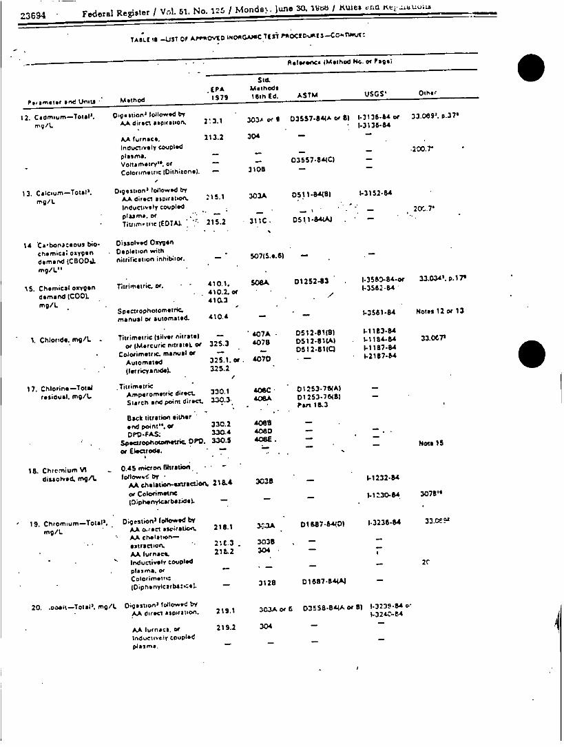
Z3694 Federal Register / VA. 51. No. 125 / MondaN) june 30. 1YtW / iudes cAt -e.>duui&A
TABLE S§ -Uti OF APPROVED iNQAGAWSC Iti Pl0C1D..,ts-CO-nwuJ
Releefwci ~Method No. or Pagel
Sid.E(PA Mathods
Peamet.' end Unot. Method 1979 16th Ed. ASTM USGS. 0th"r
12. C~amium-~Tot*IJ. D.g.atior2fol'l"Oji d by
mg/L. A.A direct a.;irfatlon. 2:.1 3O3,, r B 03557.8M4A w ll 1.2136-H4or 32.089. 0-376
AA furnaCe. 113.2 304
lndu.~zlvhy CO4JPI .2cd
plasma. -.007
Vonasm.iry". or -- 03557.8MCI
Colorim*ltic IDithisonel). - 3)08
I 2. Csle~um-Tdol'l. Oa.9stioA3 loliowad by
mg/L. AA direcd aspirdtbon. 215.1 303A 05,114'48l I.31524SA
Inductively cotuplied 2
Tiutin'slc (EDTAX 215.2 31IC - Ds k I-8MM .
14 Ca'bonl:*Oul bio- Dissoired Oxygen
chemnc8; oxygen Depletion with
deman'd jC800,L nitrificaticfn inhib~tr. - 5.071S.e.6) -
mg/Lit
is. chemical oxygen fliriinetric. mr. - 41 0.1. 0SaA D1252-83 1 -356D-4-or 33.034'. p17I'
demand (COOL 410.23 .f1 56/
mg/L 41.
manual or automatd. AIDA ~ -1.2561-84 Notes 12 W 13
1. Chloride. mig/L. Thrmeri (ji~t 3ir - 407A D0512-810)1 .-I1123-84
ore(Mercuricf'iatl.~ ow 325.3 4075 DS512-SlICM .-I -1)244 33.0Cr
Coiorimaitsc. manijal or - - D51 I iSalCl I-I 187-84
Automated 325. 1.or. 4070 - -V$21744
(letrkiyafl.44 325.2
1 7. Chlotine-4otal Jittimslric
residual. mg/L. Ainperoetri#rC direct 330.1 L06 0 1253.7S4A)
Starch end Pont dijiect 3.20.3 AOSA 01 253.76481
Back tittration either-and point". Or 330.2 A088
DPO-FA.S. 3304.4 4080
SpWotlhotothMiC. OPV. 330.5 406E!.
0r Eleatrods. 7 oe1
18B. Chrcmrium VI -0,45 mearo tratiof. -
dissolved. mg/I. lo~lowe. byAA chelatfln-sWnj t¶.w 211.4 3038 -1-1232-84
or ColCiflflttiC t.-1120-4 307386
(DipherrytcabatidC). 7
1S. Chttomium-Totld'. Digestion' followed byAAO~Isr sdeiretC'J 218.1 y3-$3A OhS.87-6A4l 1-3236-84 33.Ct9S4
mg/I. - L~~A cfleltt'0fl
extraction. - 21ZE.3 . 3035
AAtfurna*ce 21 &2 304lriductinlt coupled
plasma. or -
* . l~~~~~~~~Diphanylcsrba:<c.t - 3128 DI 887844N
20. .ooit-Total', mg/L. Digestion' followed byAA drirec¶ l,59ratiof. 215.1 303Am or 053558.84AM8r 1 1.323?-Mo'w
I-324C-t-4
LAAltrnace. or 219.2 304tndu~ctivtiy coupledp4aimr* -

Federal Register / Vol. 51. No. ':zs / Monday. Juine 30. 1GM6 / Rules and Regulations es
TAhti i -.Ln Of APnOVIO INORGANIC TEST P0OC10tM15-CONnTtDXI
- il.,.nc. IMethod No. or Paeg)
Sid.
Paeiland UM Method 197 161 Ed ASIM USGS' Other
21. Color. olaimnum cobalt CooisrcLD- r 101 24 oe1units -f dominant Plaltinum coato 1. 0A1-12W084
a.8.ljngth. hut, So1c0opacn20rc.lumi~nancet purity.
22. Coooerf-toial'. Ogasi~On lofllowed bymg/I. AA disc aspiration. 220.1 3O3Ao. S 0188.840 a.El 1.3270.94wo 33.089'. P. 370
1-3271-54A.A lurnece. 220.2 304 -
Inductively coupledplasm.. -2-0-7-
Colownm,,trKINeoctluponal, of 3139 Dieu-SAW - ~ I(Bicinchoninsals. N- -,- -
23. Cyanide-Total. Manual din,14ltien, wntfmg/I. MQCI,loatlwed by - 4128
Titrimsetnc or - 412C p-22
So .ci ,oohotometnc.-mnanual or 335.2 412.D D2036.412M) 1-3300.84AutontatscL.t 335.3 - D20L36-182WA
24. Cysnid. amenable to Manual distillation with 335.1 412f 02038-82181 -
chlorination. mg/I. MgCN followd bytitrimetrmcor
Fluoride-Tortal, Manual distillations - 413A-.4 mg/. flol~ced byElectrode, manual.or 340.2 4138 DI 179-80(8J -
16 ~~~~Automated. - - 1 (4327-84Colorimot,ie (SPA0NSI. 34.0.1 413C DIlt7S-BO(A -
ir Awtomna¶.dccompletions. 340.2 413E -
28. Gold-Total2 . mg/i. Digstron' folowend byAA direcs aspirasion. or 231.1 303A -
AA furnacs. 231.2 304--
27. Hatdress-Tosala Automated caoriometric 130.1 -
CaCC. mq/L~ itrim.:rk( EDTAtior 130.2 3148 DI0128.9 I.1338.84 33.0828- Ca plus Mg as their
cartbors.t. by inducael"coupled o*Wuirs of AA
- direcn asoi-ation. (SnPvarmatern ;3 and 33.4
28. Hydrogen io Eleacmirmstrc. 250.1 422 01293-84A(oriB) 1.1586-84 33.008OHLPH.p* units measutrnemrn*of-
Automated elecrtrode. - - -- filte 20
29. tridium-Totai', Digestion' fotlcowed bymg/L AA. direcir sspwat~on. v 235.1 303A-
- AA furnace. 235.2 3CZ -
30. Iron-Total'. mg/I. Digestson' followed byAA. direc aso~ra:.on., 236.1 302AwaB 0106884(Cwif Dlk1.381-84 33.0859'A). lurnac.. 236.2 304- .-
lnduclinty Ccoupledplasma,.*-. 200.7'ColorIn,netrm(Phenanthrolinel. - 3 58 D1OGS-"04J Note 21

23696 Federal Register / Vol. 51. No.- 125,/ Monday. June 30. 1988 / Rule. and Regulations
TAsLi IS -UST Of APPR0V1O WPEOAPOAM T(5? p11ECDURILS-CONIhMtO"
Rlafw~ (Metnud No. or Page)
Sid.EPA Methods
Perarnmeger end Unit. Method 19 79 18Gth Ed. ASTM USGS' Other'
31. KgeldahI n~trogen- Digestion and dintllation 251.3 A20A cir O 03590-844A) -
Total. lot ML mg/k Ivloltwd by -
Titretion. 351.3 -4170 03590-844A1 33.05)'N~eslferzet.cn. -351.3 4178 D3590-"4Al
Electrode.. 251.3 4i7E pir -
Automrned phenate. WA.2 - 1-4551.78'Sem.-aulomated blockdigarlor. or 3521.2 - D3590-a44A)- .
Potvntiomet,'c 351.4 - 02SS06SA4AI
22 Lead-Total'. mg/L Digestion' lofiowed tbyAA dt~eC *$piratiOfl 229.2 303Av B a 035 59-8354A cr61 1-3399-814 33,019'
AA turnace. 239.2 . 304 -
IndvclvIyrCouOledplasma. - - 2-0 -
Voltatnery.6 or -- D3553-81SC)Colorimelric IDithazonek. - 22
33. Magnesiumn-Total', Digestion' followed by
mg/L AA direct aspiration, 242.1 303A - D051I-&dB) 1-3447-84 33.089rInductinliy coupled
plasmat -r- 2DO.7-
Grwimetnic - 3198a 0512-77(A -
34. Manganese-Total'. Digestion' olojowed by
mg/L AA direc aspiration. 243.1 303A or8 0858-8448 or C) 1-3454-84 33.089'
AA furnace. 243.2 304Induc"tvl coupledplasma, or 0- 7
(Persulfatel. of 319B 0858.84A) -33.2 263
(Pefsodete) - . -- Note 22
35. Mercury-Total'. Cokc vapr, manual or 245.1 303F 03f23-50 1-3,462-84 33.0953rng/L Automal.-d 245.2 --
36. Molybdenum- Dsg..uocn' followed byTotal', mg/l. LA direc aspiratbon. 248.1 -303C -1-3490-84.
LA furnace, oir 244.2 304-Inducinrty copledc-plasm~a. --
200.7'
37. Niickel-Tcrlal'. Digestions followe bymg/L AA dirlti aspiralcn. 248.1 303Awor D 0188444Cwor) 1-3499-H4
AA furnace. 24t.2 3.04 - -
Inductively coupledplasma. or -- . 200.7'
Calorimetric(Heptozimfel. - 3218-
38. Nitrate las N3L m/. Colonmetrtc (BruCinet 352.2 D 992.71 -33 OQ3* 419UjtC
g L sullawel. or V.3N't"uf.ntnte NM .miusNwt'n K JSee parameles39 end 4Q".
39. Nitrate-nitrite (as NIL Cadmium roduCliOtt.mg/L. Manual or 353.3 4180 03867.854B)
Automatfed. 353.2 41SBF D386745CM 1-4545-b4Automated hydtflifl. 353.1 -

Federal Regiater / VOL 51. No. 125 if Monday. June 30, 19W5/ Kwuea and Kequabions 3U
TABLE U -tBST Of APPROVED 1b0*AGAC TinEST 4ISCNTAI
1St14innCe (Mellthod NO&of Psge)
lid.EPA ehd
Pa,arnnter and Unit. Method 197$ i Gth Ed. ASTM USGS' Other
4-0. Nigrite (a. N1. mg/L. SpectlovholoenlerrcManual or 354.1 410 Di1254.47 -Not. 24Augomated
l0.ezonaauocl. - - - [.~~~~t454o044
41. Oil and grease-. Gtn"imetic (.zlrscitonL 413.? LolATotal rvconrspi..mg/I.
42. Organic carbon- Combustion or oxid.,,orn. 41 5.3 505 02579-854A or Bi 33.04A'. pt"1Total (TCCC. mg/L.
43. Organi~c nitrogen Toutl Kj*eldahl N -
(as N) mg/L. (Parameter 31) minusammonia N(Pawarameter 4.1
4.4. Onhophosphates Ascotbic acid method.(as P1l. mg/l. Automated oir I 365.1 424G 1-4601.864 33.11IS'
Manual single reagent. 365.2 - 42U 051 5.821A) - 33.111'or Manual two vieiger. 365.3 ---
46. Oslmium-Tocal'. D0lgeatlori folclowed bymg/L AA direcrt aspitraton. or 252.1 303C--
AA furnace. 252L2 304--
48. Otrven. dintotvd. Winkle, (Azid.a g/I modilicaintwne 360.2 4216 098S8I1IC) 1-1575-78' 33.028'
Electrode. 380.1 421F - 1.1578.76'
W Pmalaiium-Toalst. Digestion'3 folio.e bymg/L. AA dircta spiration. or 25-1 - p.S270
AA furnae *.253.2 -- p.Sar
LiS.Phenolh. mg/I. Manual ditilLaticins 420.1 . . 0 1 783-80(A or B) -Note 26foncored by
Calorimetric (4A.AP)manual. or 420.1 - - Note 26Awitomated"l. 420.2 7..-
49. Phosphorus Gas-licluid.(elermental) mq/k chronmsogflplw. --- Not. 27
50. Phroaphcrus-Tosal. Pnruflat. digesuion . 386.1 424C0'4 . -- 33.11 V.mg/k. C f0 Jk-.4 by
Manual or 36S." or 424$ DSlI5-812(AJ365.3
Automnated turbic 366.1 -4243 1-4600.64 31.1 18'2.c~id reduction. carSan.m.i-ou~natod bloccigestor. 365.4 ---
S1. Platinum-Tostal'. Digestions (ojt~wed by,mg/I. A.A direct asopaton or 255.1 303A -
AA furnace. 2t&E.2 304--
52. Potassium-toiai[. Digestion f~llowd bymg/I. AA doeel aspiratIon. 158.1 303A - [3830-84 33.103'
Indunitily coupiadplasma -- 200.-
Flame, photomeltric. or - 3228 01429-IIAI
Caiorime~~~~~~~~~~~~~n31c

23698 Feoderal Register / Vol. 51. No. 125 /1 Monday. June IR8he / Rulet. and 1Regula8ji' .5
TAILS 1I -U.ST.o# A~nOWD INOROAJ.C TEST PtOulDtSS-CO~fMJIO
Relvir,,c. tMethod No. or Pago)
Sid.EPA Merhods
Par imotor i,'d Units MethSd I9fl lih $1 E. AS'TM USGS, Other
53. Re.dvidm-Total. -Gtsa.,inar~ 103.105-C. 160.3 20SA 1 53750-84mg/L
*4. Rosidue-llhfterble. G,.vvnoi,,c. I SrC. 160.1 .2095 1.1750-U4mg/L
$5. R..,due-nonfl~te, rvrnt'. 103.105-C 160.2 2OOC . .378E-&4able. IISSL mg/l. post wAsihing of tasidue.
56. FRasidu.-stlistill.b. Volumetric [IrrhofflConeI 180.5 ZOSE--mg/L. or gravimstric.
&7. Rssidu.-volatIls. Grarvimairic. 5S0C. 180.4 2090 1 53753-1tAmg/k.
58. Rhodium-Totail. Dageslion' followed byvmg/L A&A divecl .tp~rtof. or 265.1 30A -
AA. furnact 265.2 304--
59. lkuthenium-Totlai'. Oigestion followed by - .-
mg/I. AA direct awpirauw, or 267.1 33AA furnaice. 267.2 304 -
60. Selianium-Toial'. Digestion3 folloed bymg/L AA. furnace. 270.2 304-
Inducirv.Iy coupledplasma.Wo - - - 20-7
A). ganeoas hy,*ide. 270.3 3031 03858-84A) 1.3867.54
Si. Silica-Oinsoknd. 0.45 micron filtrationmg/L followed by
Colorimslric. Manual at 370.1 425 DBSS9SBfl) 1-1700-84Automated (Molytdo-silicalil. -r -1--2700-4
Induarnly co,.Irdplasma. 200 -7-
62. Silver-Totaf"., Digniijon' followed bymng/l A). direct asperstnon. 272.1 302A uSr 1-3720-84 33.061. 9 J7
A). furncac.. 2722 304-Co lix more c
-- DithisonC. of - - - 1B-. Ir~lductinlv coupled
plasma. .- 2 -7-
83. Soclium-Total'. Dignstiore' followed bymg/k AA dirwc aspiratoo. 273.1 .3032 . 0-735-8-4 32.107'
Iriducitiwy coupledfplasma. o-- - - 2C7
/ a~~~um. phoiomotrk.i. - 3 2sl4. 0 1428-821A 7
84. Specific condlu~caarcs. Wriastswoen bridgfe. 120.1 20t DI2S82A 1.1780-b4 33.0021inicromhou/cin at25"C
65. Suitsa* (as 04.L Automated colorimetr~c 375.1 - -
mg/L (barium chlorsnilsazs)Gravimoetric or 375.3 426A.ocr 05) 6-621*.1 2331241
* ~~~~~Turbid,meisrK. 275.4 -DS16-821B) -425C".

Fe~deral Register / Vol. 51. No. 125 / Monday. June 30. 1900 / Rules and Regulations 2.3699
TABLE iSf-UiST Of APPROVID 0iOMAGMiC TILST PROCEOUAIS-CoN7dmwuvJo
Aelcince ~eihd heo.., Page)
EPA MethodsParameter Arid Unt.,? Method 1979 16Oth Ed. ASTM USGS' Other
86. Sulfide ams SI. mg/L Titriretric liodmn. oir 376.1 427D 1.3840-84 228A-U Colorimetric Imethytrene
blueL. 376.2 427C
67. Su~lite (as SO,.L Titrimetric (lodine- 377.1 4ZBA Di 339-844C -
mg/k oaa
68. Surf actants. mg/I. Colorimatric (mnethylene 425.1 5128 .D2330.82(A)blue). . -
69. Temperature. -C. Thermometiuc. 170.1 212 -- Note 31
70. Thallium-Totmi, Digestion' Followed by 27.--mg/L. AA direct aspiration. 29 303A
AAifurnace. or 279.2 304 .-
Inductively coupledplasma. - --. 200.7-
71. Tin-Total'i. mg/l. Digestio&3 followed byAA direct aspiration. if 282.1 303A -1.3850-78'
AA furnace. 28t2 304 - -
72. Titanium-Toctaf' Digestion' f ollowed bymg/L. AA direc aspiration. ow 283.1 303C--
AA furnace. 283.2 304 - -
7.Turbidity. NTU Nephelometnic. 01 24A1891138 -4
Vanradium. Tciall', Digestion' followed01891 1 by..mo/L tAA direct aspiratior, 286.1 . 303C - -
AA furnace. 286.2 30.4 --
Inductively coupleod-. 2C7plasma. or 200.7
Color~meriC(Gallic ac4. . 3275 03372-84(A) -
75. Zinc-Total', mg/L Digestion' followed by 281 0 w1 l6t4CeD l3S-43.s.pr.AA direct sasgrartion8. 0Ao B 015 84Co I13O-8 3OV .7AA furtnace. . 289.2 .304-
Indluctiely . . .u- .. -
plasma, Of.e 007Colorirnetric . . .;r -.
(Dithizone) or 328C(zlnconi. -- . -. -Not. 32
"'Methods for Analysis of Inorganic Substmnces In Water and Flirvial Sediensnt; U..S. Depurwtert of the Interim., U.S. Geologkcal Survey.Open-Fl. RAnon 85-495. 1988. unless otherwise muited.
"'Otficiel Methods of Analysis of the Association of Official Analyftsca Chemii methods manual. Idih ed. 119S851.'Fo, the detmrminatiorn of total metals the sample is not littered befote processIng. A digestion procedure is tequired to solubdilie suspendedmaterial and to destroy poesslbe organic-m~ethl comiplexes. Two digesuoni procedures ate given in 'Methods for Chemical Analys& of Waterrinc Wastes 1979.-One (Section 4.1.31.1 is& trigoeovmdigestiort using niric acid.AIes3 vigwouomdigetstion using nitric and hydr~ochloric acids
(Sncoon 4.1.A) is preferret howner. the analsty ehould be caiutiored that this mild digestion may not sutfice lot at samrple types.Panicularly. if a colorimetric procedure isatch be mployed, it is necessary to ensure that at)ogll mtti bonds be broken so thatit'e metal*5 in -Lrfactiv4 stale. In those situations& the igorousd~gesvlon astobepeelerred making ciartmtainsi a no tim. does the sample golodrynessSamples conltaining large amounts of organic materials would alsoibenieflby thievigmorus digesrtion. UWe of the graphite lurnace technique.inductvely coupled plemma. ai well as determinations icc cernain elemerts. much as arsenw- the noble metals. mercury, selenium, andtitanium require a modified digestion and in anl cases the method wrtte-up should be consulted for specific Instruction and/or cautio`ns.
MOlt:, Itthe digestion included It. ones oJ the other approvred referencam is diflmrene than the above, the EPA procedure must be used.
Dissolved metals are delrned as those constituents which wilt passmthrough a 0.45 micron membrmne filter. Fliilowlrng filtration of the sample.the releronced procedure lot total metals must be followed. Sample digestion foe dissolved metals may be omitted lor AA (direc aspiration or
*bvne~ furnace) and IC? analyses provided the sample solution to be analyzed meets the tdomlwng criteria:

Federal Register / Vol. SI.' No. 125 / Monday. )uine 30. 1980 / Rule? 'n:- Regulations 2370'1
3. In I9 :36.3. Table IE it revised to . 134.3 ldenitfcatiOOct IEpof cs9 Pli *t-el%
i read as followaz:
TABUL iE.-Us- oF 1,aovt- RAco~aoGCAL TEST PRO=nVRES
.. ad L,,W~~~~~~~~~~~~~~~awmap..o M
Mt
If~ ~ ~ ~ ~ ~ ~ ~ ~~~~~~~~~~~~~~~~,
5. a) fl~~~dumlot& to pa km scrrbdcProceda' f.or________ De05r CO 9 .o' I%-,uttt
*o"tces.C andomstnt readh asr4 follPowe.sy Water*.' U.S.m EPnvironmentalO3 PIlec ti. U14 "httv~lM e.~thos' o DQ.Cy. rmng n9 o
*~ntwt JJ si f*.c~Euon..S...'4 ..'c A uncy.c EP 5..r-10-3.va nSpi.a Aailab~wle -. vr'cncc S.bsy.ct Ct.in Ravel 7nd Fluvial6
I hrUdentfort a.. p.f trest Prciwdr frpom ORDt Pubic- pn. CM.n 'l i at Uof Sedimnts -N .W .Skou - ad thte r'
Ine fol1ow.3g prageraphe(bJis arevcised (5) Watesriand WPsewceuresjin for Dil arenvere. C Arinto. C VA flM7 Cosubt to.0nt rabestructure IC theforatd Lor rearece, BoMasrd.mercnt ofubioccHealty Aicin dlatm.Inbett change). Table MB.NNote7.
snourcesraned bosy tofereade ast foisAlowE Water.US WovrknsenalPoitecIon. (14it) 'Method. for Analysins ofOgniofreguatio an maybe btaied rom he atenPllu. o Cy-w-ontr2l FeertWo. AnIal SuorganiSusaces in Water."b and. Frluixand
sourcs idetifie .Alcotciear Edition.metlel Avrlcbeto [mm;ICY Amerlania ugenedit rown:U?0 ST . BookS.o C Sa.e Calte
subjTe tuo change ofd tuse bethd verie Ohbio He2 abth Asoiatiot. D5 ftet A3(1W7). Av debit from U.S, GeologicalStree. NW Wasingtn. D 200a. Csit: Survey. Branch of Distribution. 12tX) South
thext ofoallowingrefeprencesdurchar cite-d ofWaren ofaoer ontEioraads Street, Arlington. VA =:.Z Cost 110.9
in Table IA. lB.IC. ID. :~d I.E re - Boad. America Pubicin Heablth LAssoTatlo. (subject to change). Table aB Note?.Tal
aegulatieon andpmayibe obtandfo the W aieof nter Pollto ContbleedeMtin.D.tSubtanes 4nWlr"b.Y.Gelt n
soures iedentlReisted. AR ostm cite are( Edido. 198. AvdilableTbl frBm ANeica EugeneBrown:e USGeS TWR-I.BookS. Capte
fo thiniaesoreTeful"Street.NNW..ashintmn.tCon.DC2- ad C8.FaSurve.ranieodiMestribuntl~ and SOl th
the FderalResiser. oom 601.110 Ia (a) Ibid. 14th Edition. Table MB Notes 318 I'"ae1enesu-ffu ta
Referencers. Source. Coate aned Table (l)ebid -SletedAh yia ehd Preaentatlon.' by H.H. Stevens. Ir.. 1. Ficia.
C;,alion&: ~~~~~~Apprcved and Cited by the United States and C.F. Smoot: USGS TVW'RJ Book 1. Chaplter
(1) The lull texts of Method. OCI-413. 524. Environmental Protection Agency.' S1.1vey Available fisrombu.So. GeolSogica
625. 1624. and ICZ' are printed in Appendix A Supplement to the Stuh Edition of Standard EdSu Srveyr. Brainch tof DiAtriutir 1CC Southof this Par'.138. Tr~efull text for determining Method Jar Lhe Faminationr of Water and Ld tet ~ntn AZQ.~II
4 the method detection limit when usn te Wastewater. 1981. Available frvm Aniaricaut 17 (sSbelttohne)d Mtable Io. Nthe 31.
lest procedures is given in Appendix B of thi Public Health Association. 1015 Fifteenth (17) gselected ethd offAthesiU.SPart- 138. The. full text of Method 2D*7 i Street NW. Washington. DC 2DOM8 Cost Gooia uvyo nlsso
prined n Apendx Cof this Part 1St. Cited available frow publisher. Table IB. Note 1; Wastewetert.' by M.). Fishman and Eultnct7. - Note 2; and abe C.(ot tTal I. otS Brownv U.S. Geological Survey Open Flie
"MbieaL cbiigt a 1) nulBoko2Sadrs.scloii Report 78.-77 (1978). Available from U-S.(2) olthe lMethods for Waier 'Anenian oko Soitynfor Tsigad Geological Survey. Branch of Distribution.
Moniloring;th Environment. Water and Materials. 1918 Race Sret~.L Philadelphia. PA 12C0 South Ead. Street. Arlington. VA 2~2.
Agenc. EPAOW/8-8-017 ir&Available 19103. Cost available t'mpublisher. Tables Cs 1.0(ujc ocag) al !- ,. Agency.EPA vironmen1t-okction L. ID and I Note 2.
*.. Environmental Protection Agency. Cincinnati. (i' Methods for Collection an. Anlyis (1sof~iatio Methods of Analysisa ofChemiaOhio 452&. Table IA. Note *of Acquat:: Biological and Miarolitziloicul Ascaino rcn nltclCeias
(3)o 45Methods for Ch temia Anlsso1 mle.*leWyPS.Cesn A ke. method, manual. 14th Edition (95.Price:
Wate Melnd Wfsesr CheS.a Envilynenta CofIwr. .. Uu, n KV ak.us 145.50. Available from: The Association of
Waloteind Wastey.- EPU.S -?-00. E*itnuina GeologiesI Survey. Techniques of Water Official Analytical Chemicl.11 .1t
Maroch.ion9 Avadbnc fro ORD80/-7" Rjrelne to(U STVB.o . Street. Suite 210. Arlington. VA ZflS. -able
'~ Pulicaions CER. U.. Enironenta 5 V. apter A4 lflV'1. Available irmm U.S. IS. Note 2.
Protc-iion Agency. Cincinnati. Chic. 4.S C., togical Surve,~. Branch o! :ivztibut~on (19) "AericnNtoa Sadr r
* cute It ~~~~~~~~~12lI South Eads '.Itreet. Ariirng'on. VA 222tZ Phoitograpr.4 Proces'ing Efrruents." April 2.
(4) '*h"- thoc, for Ben-;dine. Chlorinated Cost: £2.25 (subject to chantve). Table IA. 17,Aabefom mrcnNtda
Orgfsn' Compcundis. 'tniachlorophenoI and (13) "Methods for Determinto obtnarsrtute3 [Broda. NoewL
Piesti,,aes in Water sod Wasteweler." U.S Inorganic Subatances in Water and Fluvial York. Ne- Y'ork 1ooI& Tabei, Nt
:1 nrir.,nimentsl Protection Agency. I1n. Sediments..' by M.I. Fishman end Unde C- (20) -An tnvesiigation of irmroved
Avi':tnbie from: ORE Publications. CERL. U.S. Friedman. U.S. Geological Survey Open Flile Pr-ocedures for Measurement ef Mill F!fluttnt
Enviru:,menial Protection Agency. Cincinnati. Report B5-495 (1986;. Available from U.S. and Receiving water Color.- NOASI' a ~~~Ohio 4M.Table IC. Note 3: Table ID. Nota Geological Survey. Western Distribution Technical Butletin No. 253. December 1971.
33 . flranch. Box 24525. Denver Federal Center. Available from: National Council of the Paper

?rederal Regwser I Vol. 49. No. 209 I Friday. O;ctober 2s. 1984 / Rules and Regtulations 19
93. 95-98. and lO'-l15 to new Table LB. - form er parameter 14 (Chlorinated entitled tUst of Approved Testentitled "List of Approved Inorganic organic comnpounds, and by entening the Procedures for Pesticides". by including
Test Procedures". adding two new individual chlorinated oqgauic the 2 additional proposed- -* 'icideinorganic parameters. Carbonaceovi compound. into new Table IC. eniV:ed. Parameters, and the two ni,. tesiBiochemical oxygen Demand (CBGDI) "List of Approved Test Procedures for Procedures in Table ID: anic byand Nitrate.Nitnte. including an Non-Pesticide Ogianic Compounds". transfemrng the formier raldiolog:;:aladditional test procedur, based upon trmnsferning old parameters p parameters 99-103 to new Tablse IE.the inductively coupled plasma (Benzid-te) and 94 (Pentachlorophenol) entitled "Approved Radiological Testtechnique in Table LB for 25 of the metal to Tabli. iC. by Including th 7 Procedures", adding an EPA reference toparameter desiignations, by including 10 additIonal proposed non-peeticidal the approved test procedures, andmethods :pproved under the organic parameters and by adding 17 updating the Standard Methioda. AST`M
testprocdurs inTabe IC by and UJSCS reference.. As revised. Tableequivalency provisions of II 138.4(d) new tetpoeue nTbeI y I read, as follows:and 130.5(e). and updating reference. to deleting former parameter gsEPA. Standard Methods. ASTM. AOAC (Pesticides) and by entering the ea jix 1 i.3 Idnmicanort of Tnst Procadur".and USCS teat procedures; by deleting individual pesticides into new Table lfl..
TAea tA.-US? Of AP.0OWD B'otOo.CM. TaiS' PIPaCacuac
P IYA 3-~~~~~~~~~~~~~~~~~~~~~~~~~~s
P~~~~n, n WA' I 3fl~~~~~~~~~~~~~~~~~ Iss Is s
I. cn w- ino - W 1nw %ew.t 3 diit W. 11w Wn OS a W v. I
a- in lla'-W 'y W- wt~t5~ ha 2ea 41,0t W. hW * nia, -e J-~ van Ii4 sold
tLa..~e a - It dn a 3W~ -3W- dkh eatv is ,o a* P.m 13l
P. 143 ~ ~ ~ ~ ~ ~ ~ ~ p t*
PC P A. ina'sii W Ga~aM. 5 tna A S 00 W -. lbisft9 -p&00a .IX 2 0 zz 2i-ADW~ a ss~ of lis NM Aia Oaiio .. W6 MC 1,1111r~ ~a*aasisa ,a aCa. ,o I1 __
IFta*

Federal Regwter I Vol. 49. No. .209 Friday. October 2e. 19 I Ru.le, and Regulatic.. 23
gsa - -*ews
* I * - -s A OM I - . ~ C Slt" .PO a 214. C -, 1 w. .Ut ' w4ft5~~ - - - I - -- U~
A 19 $W t.* WII-, Ialtltr d OM It U . . TflIcn AMaw yott d, mm)
ftn~ . o.,tI -I .M ..s w . I. * - . W%, a w . GIt
o.-. ~ ~ ~ = , , - V - A~~~~~n. Ifl* ' ~ ~I am I1 ' 0 a W o t C u.. n* n - I a L - -twy* 0* Ca-n a-b Pw % .QJ - - " b ... 0olIit ?MIrn Nu IAAW. Om in. ~m* ~~~~ ~~~ -W III, -00 owP0 ef .- 6~7F
* hew.-P' TA. 1 C hd-t ma A .. flS'f Tw PmcaA~ Im N971 .112c SW -ill Co . opop Lon
't - 7 ' (Ira~~~~~~~I Caa..0 f tc ~ 7
* a - u, ci S .na a t . fl 0 I *'L M'S 5 - n0.~~~~~~~~ ~~~~ ~ ~ ~ ~ ~ ~ ~ ~ ~ ~~a MLs~ --21 ,
Is'S.- --.0 w IM t"MIC .. h '. ~ . - . -IS )4l,001M- ----- .w wI Zan. ICM h
I 3 M l yI b 'w w P aA p ta V" - aofl .- If.4 Of .Mb35L
n .. ~ n.ta a ~ P~ L a4 -o 1 10 tQ
is. utws I - 611!it most jVa 'a *ipIIt 0,Vala_ _ _ _ _ _ _ _ _an_ _amt I4s1M O lil0
0 1s- aIt b l m4,. o 0@ 1~~~~3 oWat- n v 4I2_ _ _ __ _ _ _ __ _ _ _oil___ _ _ _ __ _ _ __ _ _ _ __ _ _ _ __ _ _ __ _ _ _ __ _ _ S*oM
M-. u.......
______ t W 'a ew o .
X:)f- b4 fc__
__ _ _ __ _ _ 'at.44
33 or,~~~~~~~~~~~~~~~~~~~I 0. 104 4
. ao_______________ WI, 0(104~~~~~~~~~~~~~L 1Z
amlooI31L 2.3 Ov~~~~~~~~~~~ C5L 14~~~W31. ow.,Umm,~ ~ ~~~~~~W:
St L0WW' AN$
0 4C

24 FederisJ Register I Vol. 49. No. 209 I Friday. October 28. 1SM I Rules and Resrjlatons
TAS4 C.-ujs- ow £n.tono TeST Pa0C:uvf S 'O NO.-P13,tD( OCM"Ic CO'..ousloS--Corrwnd
Gc Wo WS .
_ _ _ _ _ _ _ w~~ ~~~~el a '. --
w. L S Us______
Ga. 013 ~ ~ ~~~~~~~~~~~~ m -Gas
n fie m 'Go
Ism a ItSI SIa --~~~~~~~~~~~~~~~~~~~~~~~~~~~~~~~~~~~~~~~~~~~~~0 LlI -
2~~~~~~~ _ _ _al a2.im -
m WI~~~~~~~~~~~~~~~~~~a
". PCI, I mm am~~~~~~~~~~~~~~~e. ~
I& PCX,= SCIS 3.~~~~~~~~~~~~n. rt C,
$I. PM 60 3616~~~~~~a tb u%
aL Pe .... e,,lei
* Ad W C - ~~~~~~~~~~~~~~~~~~~~~~~~~~ *' e~~~~~~~~~~~~~~~~~eL 3
w IL w. -w. *US b-.-- ft n I S M
~~~~ ~~~~~~ w a - ~ ~ ~ ~ ~ ~ ~ ~ ~ ~ ~ Ca! E
* ~~~~~~ , w V. fl~~~~~~~~~~~~N -mv 0f
vs ~~~~~~- a a 12 5~~~~~~~~~e A Ca-I 41' na i. aaMiwtr - R- f.* .*
~~~ ___ .. ~~~~~~~~~~. *- ........... t~a ....... - a- m 'Sf a a a m .~r
'Ew ~, - Nunl ao a m.".mamm
TAILI c,.-urT O Appamo TOt PC=ExflI . PI~nlC00
....... .. .. ..... . . _ _ _ __ _ _ _
QC 6~~~~~~~~~~~~~~.& :4f .. v,&"
date, * fl ~~~~~~~~~~~~~~~~~~~~~~~G C ,SA.I. .r....... .........------- 1o-c l- I&St
* .0-c - ..........-....-.-.-..... r n i Mxasai j,
'0 A-. -2 0 ------ -e

Federal Register ' Vol. 49. No. 2D9 / Friday. October 2e. 1984 / Rules a-id Revtiaitos 25
TABISID.-US? AP"eovto TEST P.IocLDwE3 PoP PtsTICDVoI-C ,,,
~ ~ ~ ~ ~. - -~~~~CWG . . ................
. ............ .... .... ...~~~~~~~~~~~~~~~~~~~~~~~~~~~~~~~~~~~~~~.............................................................. a~p .i ... n
c~,I- TLC ........ . Ma) IAP ' As . WIt t - .. -.-.-.--..-..... -. .. ........ .... A V.__.___
,, * ~~~~~~~~~~~~~~~~~~~~~~~~ ~~~GC4 . ..... '. . . ..........
N. -- ~ ~ ~ ~ ~ ~ ~ CC ma batp~~~~~~~~~~~tbas-- - -p----CI
~~. h a l _ _ _ _ _ _ _ _ _ _ _ . ~ ~ ~ ~ ~ ~ ~ ~ ~ ~ f l . ' atQC _A a ?.3
K O ~~~~~2., Pm na A c IIA A. Xt 1,II .' 344
x D ~ __ _ __ _ __ _ S- m 1
*4 ~~~~~~C 4 1 it. bat~~~~~~~~~~~0 _ A. am%M DIP ~ I Pma at .? a. o
a, Riom, ' , P. tW. batI ILP. W6.at'-. __~~~~~~~~~~~~~~~~~~~~~o _ _ S__ ____m L I
St. ACTc .~ o a~.Otap.
sc &=. - CC -.
M. we "M__ _ __ _ __ _ __ I' S. Wp. mm a p. P am
C06 TLC.. __ _ "M 2 p. IN. 'a Se.P M* *4~~~A II011CM Santc a 'a S. Wp.? M4
0? tt$.?(SA. C~~~~~~~~~~~~~~~~~~C I S .I At.tIIt%" I r
As. ~~ __ _ _ ia= = I "MI L 0: LS..7 ...... ..........& e. ..... - --- C __ _CA0 L . - A . MI.? AS 3 A
As 1n -mt~ QC ~p.ana Fa.a baaTC m ww--
w. t - We Ia fl s* S t ~~~~~~~~~S - FR ~~~C-ra' S F 1R Z W I ftm W - i
St '"o r-o w.c ~L. %'~.s- W _ ti5
.W oeI A3511 i P'. M M
S4- .S we an. . - . I *. - r. w
St 10 n~n ms a- '- ,-ma Pe lat MM L W r
SI a- I0 SI * c nMc.'a'-,1 w0 -a. Q W r04 PIMPaL c-S

26 Federal Restister I Vol. 49. Nic. 209 / Friday. October 26. 1984/ Rules and R-julations
TAsBU IE-L:ST OF APfl4OVEI RAO.O.OOICAL TEST PROCEDURES
I- ~~~~~~EPA .rj uc
. *0M -F .... o ....... .. o...0 ml 0,~- W IS,V1- n
~~ ...... ca-', nt' - - - - m~~~~~~~~AWaP .. , 600-4 a 3
-. ---- -.-. .rAg.7_M
* rr.'t J S 2nN'E a'e u~ VS<- S.S'ym 0~ A'' a U- L S C...," SinDe. Ac' 1?5. 01741S
5. In, 136.3. paragraph (a) is revised in the Federal Repister. The discharge does not obiect to the use of such
to shcw that the full text of approved parameter values for which reports art alternate test procedure.
test procedures have been incorporated requiried must b' determined by one of 8. lIn 1 138.3. paragraphs (b) and (c)
by refervnce. into the regulation to read the standard analytical test procedures art redesignated as (c) and (d; ;-nd a
as follow:: incorpora ted by reference and ctscrnbed new paragraph (b) is added to :ttmize
in Tables I A. [B. IC. ID. and IE.. or by the references which aNe -1.osjated
I5136.3 leserifioCaon of test PtUCCOWNIt any alternaste test procedure which has by referenc." and to identii-y the sources
(a) Parameters or p~llutants. for which been approved by the Administfltor from which they may be obtained. As
methods are approved. are listed under the provisions of paragraph (d) of added. the new paragraph (b) reads as
together with test procedure this section and sections 136.4 and 136.5 follows:
descriptions and references in Tables of this Part 136. Under certain J Id lCOV of bat~ WottCusi
1A. lb. IC. M. and IL The full text of the circunitances (I11136.3(b) or (c) or 40
icroaebyreferenced tetoprTables a CFR Part 401.13) other test procedures (b) The ful texts of the methods from
incor[orated by andferenTe referenclesan may be used that may be more the following references which are cited
LA. B. C. . ad I Th reerecesand advantageous when such other test in Tables LA. [B. IC. IM. and IE are
the sources from which they are procedures have been previously incorporated by reference into this
available are viven in paragraph (hi of apoebyteRegional Administraor regulation and may be obtakineed from the
this section. These test procedures are apov tedRgo by whc the dshrewl re dniid l ot ie r
incorporated as they exist on the d~y of o h0eini hc h icag il ~ e ~ l ot ie r
approval and a notice of any change'Ln occur. and providing the Director of the subject to change and must be verified
these test procedures will be publisned State in which such discharge will occurl from the indicated sources.
REcnwaPCS. SOIJNCIS. AnC, artn'
la r. ~~~~~~~~~~~~~~a . " ,amnra~ ~
* 5L&' t.'G. 12S.L WM 5.Sa. nA o*
I. L. It. It IL 17-2W. IL aL 22. 1SE C1. &I. -i W la cirowu P I a Edion 1211. AiP
-. ... .a ML aL 32-. U. a1 67. a. 70- a P~ia ,Pe ,oles PVWPe 11 Nif. w
-E -St.V~aI&Yil I 0 -t Ci: SaWe fb1 M' sant- meC 0'
S -. ~~'. 11aC¶ hd~~~ ~ II. 47 r.5ss s A4Vrfl WIE by u,- P Lh P-s
C-Crc Isii1se 12. S Saw~ PP~sNea''i~ Arc,?' LiA l tO' `0 ICfim O pi Sars
C.-.~ W. Se I0 3-?. 52. '4. 'IL 21-fl 23 21-31. 27 5 39 ad, W M L~ w *' IS -&"St M S
ia AL i. a. W. SI. n-4l W a .e ~. ~ ia's Fc ~- li* *,
0 C flss Cc. wn - I SOW E' - I,,N Wa
-9-ADA V.11. 51-41. W71 5a.~~~~~~~eVPL agl b, PE 0in., TA. Do .A~ &f W t~ -,V K W
Po nUet ewaSir.. c .. ' 1" - * = 0o.L
A,,P* SfU% C . Oqm %nv fr S D~ '2W SeA' E-
a rn Pisw Oft) cam 2 aL Pm - -
u,-Pa - OPP, A Pevfl 0 vs~ *e 171 1.4 4-fs
'Om fr.. cm U.S frCPP~t P0 ,mv'C C.-.. O'
.1S-ASTIh I 2 4 & Jo "-'S.2I.2I, ii.b30of -P,,a2,,21 Part S S.l%1 SI W, 3, W T.. -~
ti Is 15_20, 27 11 fl 35. '0Q 54

Federal Register IVol. 49. No. 209 / Friday. October 26. i,8 / Rule, and Regulations 2
RcFrrnvcas. SOUPCe[s. sNO COSTS-Cora,.c
-.,IG L-- ..- . -2 3. d. S..I. ,1. ii. '-s-n. 253 ay 1a. Xd Q. W ~ . 5.w t- %~U4. As 5. 5345~. 57. WA. a. '17 - -* SWUiiI, n t, ua A. to I .
-on. vIOw £ -,V, US. G . a I Z.et
II.I01 -LA VA, a N_M d0 C i %'
S; aitt a1. ro Ma 't, .
* -b~~~~~~a 1... 7 flOIVti .. ' lIt M~0e VArw oZ . 0u
CEP 3 1-4 1 V I. t.30 Z 2. X 2~6.X 7.7)IOW W O,.i . a '
41-011hil, - 0~~~~~~177 1 - bu A m IAA t-One. .q tcJ T w IiAM... Si 7
M.NOA.aC. uVIAMII O' on~*
isZ~ Ca WIT ~ 100
nfl. 0V;V D¶57* TnI flbv I a .w N
3.-ac U I. 'Oacwn. 1ws n~~~~~~~~~~~~~~~~~~~~~~~~c t... a ane Po S. -s. .
am P is S C~a .MV
* ~~~~~~~~~~FNAw atule a9 T s, & oa, IL -A~~ ai Pm
a @ Ism wic C.iivn Ca'in',.cr% D isim 381a. CanS.1M LI~u0q c m
40 M IU P~ 100, bu"II = . tt'" 41,1 1""AtI~`1i~b`
fls k' ~ivIiq.. Cat. 2*V Yus .~ em
I. S U fl~~~~~~11 ASr-41 t PC fl IdIII bI III.q J= M.iIiss - -q0 Moveet pa *isvs a~i -ft.s
24 _ ____ ___ ____ ___ ____ __ t. wm a s pe es i at hnsa g Sii A. On52 a
~I'IIM A - IpI VA ZA. P ~ U SMI2 OILuy u trC-41PA 1.11. 1441L 17-V Two~If ins "M bus. 0A-13 IA la "MI
Informa, on atr om80.10L Peevton Techniquu Kand Holdng containr mK.etenaa.iand mnaxmuma
IFMAVtitmcited inTale . UD.SI. DanEar

Zs ~Federal Register / Vol. 49. No. 209 / Friday. October 26. 1984 I Rules and Regulation,
prescnibed in Table II. A.I'v person may assure such vaniance does not adversely Mon~iorngj and Support LUboraiory. theapply for a variance from the prescnibed affect the integrity of the sample. Such Regional Administrator may grnrtaapreservation techniques. container data will be fcrwvarded by the Regional variance applicable to the specificWmaterial. and maximum holding time, Administrator itt the Director of the discharre to the applicant. A decision toapplicable to Samples taken from a Environmental Monitoring and Suppori approve or deny a variance will bespecific discharge. Application. for Laboratory in Cincinnati. Ohio for made within 9o days of receipt of thevariance, may be made by letter, to the technical review and recommendations application by the RegionalRegionai Administrator in the Rqgion in for action on the variance application. Adminitzator.which the discharge will occur. Upon receipt of the recommendationsSufficient data should be provided to from the Director of the Environtmental
latSL lt.-PgRjIwKRE CONTAJNEAS. Pflso411van~c.. Tat104nu1. nco HO.tOc Tmati
C~~ C . ca a = cqkI* -
Pz . : : & . .. . . _ _
I n ... a w .~~~~~~~~~~~~~t T n ____________ I-- - -- -- -- -- . . ... .. 1
D5an
'7O n -va a' J ,, -a C71 Cc . 0 Ck-.-- -- -... ~co. t aIS. -. p __ __I--_ _ __ __ __ __ ___.
ii 1 Y 7t. . P.' Caa W4 I 4n a 0 4<2'
M St. a 70-n i. it klses 0u~a Y!4e~._ _ __ i -M JIM.I.C P Cait cc.... i
4.4 0 'n ,-c ,Ittt C~ M o. Kan. at i .a .
o"Wn scft - ~~~~~0 upl .
4.. P~. G. -&.. Cas. i-c *m< _ _ .. es.,- na.. ____*.. Ca tif <.......___
35 a w1,1,..a .13 .. ______. ...... ------- ---a____~....~I-35 aS... - P............J..a.............______
*G a........ P_________ .a- j -4 ______1_________CIL_ ' ...ft swu . ..m- P. a - at...,, C a i ___ __ __ ___ __ __ __ a iOW
rain C->V.r .132 'Si-f. a ?4- 2i.47. 31.-fl .4-i?. IL aL L ML *-M. V7 C. S6 'Ca M am t ..,.......ji. ..
6S7W 10 e _ _- . a ............. ... CI 4.aa% Of%446. PI t 0 - CIL2' ...cw ..... -.1..'...... ...000%D23. Ml. i. It W 13. IM.70. i1. f ML M Ws" IL 7 a :a. .... ..... co. '.a .. .~,~
30 .... a .. .........
Id. *7. -4.50-U. flta .......___ __ _ - .-... . .... ......... Cta t .. 41 ?an, It
p7.74 ..... ..... ..... U. ................. .. C i m & *....... ..- Da.11142 -C& -- > - ... .. ............... .. .U.' .~ .-. ....... I
S- SS. U. a ~~~~~~~~... ........... . .C. o. 4-c. 0 % ass a~sDSt3 5$IL3 33.2 55 U.4M. si. a11, . ~
*1 15 3 s-1 ' ' ~ .-.- . . . . ......................... ____._... .. ....
25 25-2? C~~fl. Si 0t ~ - ---- c. cc.............CI
........... ..-... ............... ccr- ......... ..-.
nt ~~~~~~~~~~~~Aa~~~~~~~~~ca Ta ~ ~ ~ ~ ~ ~ ~ sIII'.1 r. bt. .. SCt0

Federal Register / Vol. 49. No. Zn9 / Fnday. October 28. 1964/ Rule3 and Revulations 2s
-h iasa, 0 - a -W% -on v Io - V ~ Mo - ""o'w~W .a~I U 1.0ks, 04 etoII 1.1 n-a sn s- - S o
a p wbasewe e , p sflp fl O% by fe -ew 1 is .I4,ISI I r .~~. f-
- M-N- .-- wII~edS v-to ~ -r- -r Mt-
* -5. 0 *~~ ~ -- ~ - ~s . .r r -Wel a a w 1) - aO .
l*s 3II raeq 41"- fle - W r we.W - fwwICell%~e
eve veI"S we- OII, III~w . to S Is ra - c- WW 5 - W 0 - -sdas"WWMis v = a5 i-~ by WIS d,% an¶ C s
IL pecin A. -. Lo C frl dde to ol bmary Poum - Wo 4 rvi - -tbig at-Twl the"sans oflo
S I rn~s o a be - y.~. pa -I tio - a4.Dzrits f- th weta" WW upLdta pnsol eaodd
& AyscICesI AND.an n de w pITALima ThlumnMethod arsctio levmdt (MM tluhn.oro,-Tuslon ethn elzant, hor floPanT134 to read astoilon cbaaoppbm IL). fpcoretch (GraielGJ coouglardi 6wath rubb cnompnenu in hAPTUEnDX A O All dndisWd TalerLThe K for ib nlau spctc pun. and shpmn 'yew strg.ho fid el svreap1. Sope nd Apliadonwastwat. ma d-ffor ofrnajz fhos mosttd blan Saple.ane beo ncon wteranad bFOR ORGANIC O~GCAL ANALY~tS 01' pof thin porman lithedntoso abtcr..r. dift l crrie tvrug thled saxJs -A heaingmVThicraLbdcvr AND D'4DUSTZIAL o the Thmpe mestro uauclmi hL furari n etylnhoieofA2T purab. dtncedns I An Seco~lc 1113.cretch wetfthd. rticlcao .erni asa la thekO sucpl
The fllowig Pa _______ma b. Usycad Intabe 1 Thpes)Cly Petaind h bpei
applcatlc, ad aprove of lterate am watevr~ reage n, wte and k ee
ow~ng pmnas ten Eay be rymd Those IweLayi pemted shal be , Mr-~ h pI~ anga eieadsmldetermined by this methot wcs&mnd the a marjorcs Oficsc scub17c yrio most bnrnaod byt rcanrcmu wat.. Was Idn" cqer~appicaffcead ipwovel opfr doelc e t W fit ppa bt sml zishS 0 OWheee anw
__413 74._ LAi TIs mtnd a as remstiaogphad Inabyo imul7Cy. conePwnhratdav andI Isal
Ca. - ~~ ~~~~re na1-a3~ thu ierr of raps Chrcmaboplraze. enutared. It should be followed by an
I20 haevrn4 :oin gnmut sccepmable rmulin with thsmethod condintoe~n. F airiap tanmm large0Oewwr1In I 3418 740-43 s uspeded olin. higl bodiW c~pow,4 or
1 ~~~303 to-se Li An Wonepsi ha bubbled IS S- twaou dOh p an deribe iry3wi usa., al. wuter "aml cocitabied km a spedA*b dstapas mobstio ruis it with disi lleda4 llI-fl4 desiged pwIM chamber at Aahb6a water and ten dry it in a IW9C ovenUseI .a." I ne. The hisiiahobacn are ~Md= betrna analyses. The tra and other pans
1. I41110reins at IS-a-a Of~eth Qnn ~ ~ v th irstan are a13 rub~a to304 I.4,4 trapr Phse. nevpo is sap throtoo £ t-~to hrfos rcvn aeu34"I sabs; timpwba ilte -eiooatarea~ h~n.feun ae
, ,~~~~~~~~Unr.~'~ tipad no After p is oumpleted. th neq, sai -o o h tr pamybi-..-. ~~~~~~1111 A Is tntadc and b.ckushsd with theiner.tp required
I 671 C-1" homtgapi ca TI a ITi r toxicity a carcinorenicity O atcad
- 711fl-4 detectiid with a biabde-spodihc dtectar'~ pncsLe"ly dfnthwv ahcmuu-, rv~ Li Tb .. tho Prvie an Woc cocepand should be nraiedad. a potenn..
ck~rom~opep~k ~umn tht ~q ~healt hbazad. Proem th iSewpOinL exPosur,Ii Tb,, isa pup and~~i pe In resokvwpth colundtha owaynbe lelt frm to these chalical. crust be reduced to thechgar pe(C apyflsabh inan Potntmfrenc the oat omay ofitatreu~, C possible level by whate-ver mean.throdewtz,'noot ofC =ipt.wt tefrosta mayOccuravslabWe The laboratory to responsible forabove in mtrnicale and imdusbtoW d fitsltt antmwa T!swrsfieoase prvvidsd under 40 C3fl Irt L wbf this 3 L ip~urita In th 7purga p aod OSHA Nrtrlatkmi rwarding the safemethod t. gsed to analyze o £alla.i ~cmpaid oupo fr th hand1l; of th cemialsspoifled in thiafor any or iU of the compounds aoe Plumbing ahead of th trn icat for th method.A P o&re 1l. of imatana] datacompound idendficadots shocld lic majority of,,,tamjatjm Tvlie.ie handlbs Luaet shoald also be madeaupported by at leas mne addIdteal analiytca: wytam mait be demnntted to aviailable to all paisceda wvched in thequd.uttive tischnique. Thi. m.t.o describes bebe fr,,e ,u ,ama 4cune the aJ nslnys. Additonal ritaearct to. ~~~analyoceal oniditions for a secwod gas wtibctas of the analysis by romini laboratory safety arn ava~ilsble and bar.chro~stopephlc coumn hat can be ue to Ibomtory resagnt blIanks a. dletained in beet idattifeod f4 orth. LnformatIon of '-aconfirm wmeasunmmscts wade with the Sectoc LIi. The use, of ncon-Teflon PLane analyst-

Appendix BCALIBRATION AND CONTROL CHARTS
0
0

- %- 0~~
LI~~~~~~-p :3 N,z 0 B
00 C! ~~~~toC ~~~~~~~~~~~50
CC~~~~~~~C.
0 60
co z~~~~SC) 0~~~~~~~~~~~
F- ui wo~~~~~- I
0~~~~~~~~~~~~
<Dw
06~~~~~~~~~~~~~~~~~~~~~~~~~~~~~~~~~~~~~~~LV( LL
Ir
F-~ ~ ~ ~ ~ ~ ~ ~ ~~~-
Ul) it) In to 06 p 46 Ci 6 - 6 0
6
~3 ON26OS8Y

-I.~~~~~~~~~~~V
K -~ ~ ~ ~ ~~
z £:z31
LL.~~~~~~~~~~~~* .
T-
0~~~D~~N C
-J~~~~~~~~~~~
LL~ ~~~~~S-OMY

I.~~~~~~~~~~~~~~~~~~~~~~~~~~~~~~~~~~~~~~~~~~L
Nj~~~~~~2~~~~~
Cl) I ~~~~~~~~~~~cdddddI
~~~~JC)~~~~~~~L
I~~~
Ji ~0
~~~~~ z~~~~~~~~
LA' C~~~~~~~~~~~~~L
m~~~~~~~~~~~~~~~~~~~~~~~~~~(
0~~~~~~~~~~
I .~ ~~~~~~~~~a
BSNVRNOSSV~~~

'0 0~~~~~~~~i ~
C)~~~~~~~~~~~~~~~.
<~Q rI
LU~~Z
n~~~~~~~~~~~~~~~~~~~~~~~~~~-
0
w
-J
<0
Qrr
o N~~~~~~~~~~~~~~~~~~~~~~~~~~c
C)~~~~~~~,;2O-~1J-QI3

0•
Lii
.~~~~LdJ05
00•0•
rfl N -0 ca' to N~ t) Wc)

Appendix C
LABORATORY FORMS
S

pL iote # _ _ _ _ _
ottle Order Form
icnt: _ _ _ _ _ _ _ _ _ _ _ _ _ _ _ Client Contact: _ _ _ _ _ _ _ _ _ _
ress: _ _ _ _ _ _ _ _ _ _ _ _ _ _ _ _ Phone Number: _ _ _ _ _ _ _ _ _ _ _
W ___ _____ ____ _____ _____ ____ CH2M Hill Contact: _ _ _ _ _ _ _ _ _
Project Number: _____ _______ Date: _ _ _ _ _ _ _
TURN AROUND TIME___________
GA/QC LEVEL_______________ DATE BOTTLES NEEDED: ________
No of Bate otle Total Preserv
Analysis- Matrix Smpls prspsie/typeBote Added
Shipping Address: _ _ _ _ _ _ _ _ _ _ _ _ _ _ _ _ _ _ _ _ _ _ _ _ _ _ _ _ _ _
MPLE CUSTODY USE ONLY: Prepared by: _____________
'M thod Shipped: _____________ Date Bottles Shipped: _ ______
Cooler numbers:
Special Instructions On Back of Page

CORRECTIVE ACTION REPORT (CAR)
CAR NO.: ___ ___
ANALYSIS DATE. REPORTED BY/DATE: _ _________
REFERENCE NO. /PARAMETER: _______________________
CLIENT NAME: _ _ _ _ _ _ _ _ _ _ _ _ _ _ _ _ _ _ _ _ _ _ _ _ _ _ _
DATE SAMPLED (FOR RE-EXTRACTION ONLY):;________________
DESCRIBE CONDITION REQUIRING CORRECTIVE ACTION (INCLUDE RESULTS OF ANY
INVESTIGATION DONE TO DETERMINE CAUSE OF THE CONDITION AND JUSTIFICA-
TION, IF APPLICABLE, FOR RECOOfENDSD CORRECTIVE ACTION)
RECOMMCNDED CORRECTIVE ACTION/DISPOSITION:.
CLIENT NOTIFIED BY/DATE: _ _ _ _ _ _ _ _ _ _ _ _ _ _ _ _ _ _ _ _ _ _
CLIENT NOT NOTIFIED: ______
APPROVED BY r~_r:IS ION KANAGER/DESIGNATE/DA2'E: _____________
APPROVED BY LQAC/DATEr: _ _ _ _ _ _ _ _ _ _ _ _ _ _ _ _ _ _ _ _ _ _
CORRECTIVE ACTION IMPLEMETED BY/DATE:_________________
COMMENTS:
SDD /R2 16 /009

COVER PAGE - INORGANIC-ANALYSES DATA PACKAGE
Lab Name: CH2MHILL_________ Contract: _____
1* de: LRD__ Case No.: __ SAS No.: ___ SDG No.: ___
SU0.: 7/88-
EPA Sample No. Lab Sample ID
0er IC nerlmntcrecin apid e/N E
Were TCP integreleunt corrections applied ? Yes/No YES
If yes - were raw data generated beforeapplication of background corrections 7 Yes/No NO_
Comments:
I certify that this data package is in compliance with the terms andconditions of the contract, both technically and for completeness, forother than the conditions detailed in the case narrative. Re~lease of thedata contained in this data package has been authorized by the LaboratoryManager or his designee, as verified by the following signature. Diskettedeliverables have not been provided for this data package.
Sicnature: ____________ Name: J. E. Hawley______
Date: ____________ Title: Inorganics Division manager
COVER PAGE - IN

1 EPA SAMPLE NO.
INORGANIC ANALYSES DATA SHEET ________
-Lme: CH2MHILL__________ Contract: _____ _________
LV ode: LRD__ Case No.: __ SAS No.: ___ SDG No.: UPRR29
Matrix (soil/water) : __ Lab Sample ID: _____
Level (1o;./'med) : __ Date Received: ____
%Solids: __
Concentration Units (ug/L or mg/kg dry weight): _ _
ICAS No. I Analyte l~nenrtin 2 Q 11 I
FORM I IN ~I_______________ I ____________________ I**-I ______7__8 8-

2AINITIAL AND CONTINUING CALIBRATION VERIFICATION
L ame: CH2MHILL_________Contract: _ ___
Lab Code: LRD__ Case No.: __ SAS No.: ___ SDG No.: _ _
Initial Calibration Source: ______
Continuing Calibration Source: ______
Concentration Units: ug/L
I Initial Calibration Continuing Calibration'~ayte ITrue Found %R11True Found %R(l) Found IR111M
I I I ~~FRMII PRTI INII I-
I 7/88III I -

28BCRDL STAND3Jt'- FOR AA AND ICP
ab Name: CH2MHI-LL________ Contract: _____
.ab code: LRD- Case No.: __ SAS No.: ___ SDG No.: ___
A CRDL Standard Source: _ ____
CP CROL standard Source: ______
Concentration Units: ug/L
CRDL Standard for AA D Snit andr for ICPr11 Initial ~~~Final
Analyte True Found %R True Found %R Found %R
I I I ~~~FRMII (PR 2)I INI I I II I I-I I I~~~~~~~7/8

3BLANKS
-*ame: CH2M4HILL_________ Contract: _____
Lab Code: LRD__ Case No.: __ SAS No.: ___ SDG No.: ___
Preparation Blank Matrix (soil/water): __ _
Preparation Blank Concentration Units (ug/L or mg/kg): _ _
Initial ICalib I Continuing Calibration PreatioBlank Blank (ug/L) ato
'Analyt I IuI) C 1C2 Blank C' M
I I I-I I-~~~FOR II INIIII _ ___ ___ ___ ___ ___I - II - I _ _ _ _ _ _ _ _ _ _ _ _ _ _ _ I - _ _ _ _ _ _ _ _ _ _ _ _ _ _ _ 7I 8 8-

ICP INTERFERENCE CHECK SAMPLE
ab Name: CH2MHILL_________ Contract: _____
ab Code: LRD__ Case No.: __ SAS No: ___ SDG No.: ___
CP ID Number: IC______lS Source: ______
Concentration Units: ug/L
True Initial Found Final Found
Sol. Sol. Sol.. Sol.. Sol.. Sol.
Analyte A AB A ABI B%
I I I I I I I I I VIII - I __________________ I I I ____________ I I I7 I

SPIKE SAMPLE RECOVERY
EPA SAMPLE NO.
.*ae: CH2MHILL_________ Contract: ____
Lab Code: LRD__ Case No.:___ SAS No.: ___ SDG No.: ___
Matrix: _ _ _ _ _ _ _ _ Level (low/med): ____
%Solids for Sample: __
Concentration Units (ug/L or mg/kg dry weight): __
I '~~Controll II ~~Limit 1 Spiked Sample Sample Spike I II
Ana lyte % Result (SSR) C Result (SR) C' Added Sl %R l I M
Comments:~ ~ ~ ~ ~ ~ ~ ~ ~ ~ ~~~'--
FORM V (Part (Sd 'Q'IM

53POST DIGEST SPIKE SAMPLE RECOVERY
EPA SAMPLE NO.
,ab Name: CH2MHILL_ _______ Contract: _ ___
,ab Code: LRD__ Case No.: _ _ SAS No.: ___ SDG No.: ___
latrix: _______ Level (low/med):
concentration Units: ug/L
lControllI
Limit Spiked Sample SampleIIII
Analyt %R Result (SSR) C Result (SR) C'Added (SC %R IQI ml
yte 1C1~~OR V(Prt2 IN(4

6 EPA SAMPLE NO.DUPLICATES ________
L *' me: CH2MI-ILL__________ contract: _____ _______
a de: LRD__ Case No.: __ SAS No.: ___ SDG No.: ___
matrix (soil/water) : _ _ Level (low/med):___
% Solids for Sample: _ _ % Solids for Duplicate: ___
Concentration Units (ug/L or mg/kg dry weight): _ _
Control HHIlAnalyte I Limit 1 Sample (5) C11 Duplicate (r) C11 RPD QIm
FORM~~ VI _____________IN___ III _____________________ I I ____________________7III 8 8-

7
LABORATORY CONTROL SAMPLE
,ab Name: CI-2MHILL_________ Contract: _____
4ab Code: LRO- Case No. : __ SAS No.: ___ SDG No.: ___
;olid LCS Source: ______
\aqueous LCS Source.:______
I I ~~Aqueous (ug/L) Solid (mg/kg)
Analyte True Found %R (True Found C Limits %
I I I I IFORM VII II ________________ I I I I I-I I I~~~~~~~/ 8

8STANDARD ADDITION RESULTS
Laiiane: CH2MHILL_________________ Contract: __________
ode: LRD___ Case No.: _____ SAS No.: ______ SDG No.: ______
Concentration Units: ug/L
EPA I I I I
'Sam 'OADD' 1ADD 2ADD 3�J3 'Final'I NO 1An1 ABS CON ABS CON ABS CON ABS Conc r 101
II I ,1 _______ ________ ____ I I II I-I I I i I _________________ II I-I _______ I ________ I I I I I I I-I
I-I _______ I _________ I I I _______ I _________ I I I I-II-I _______ I ________ I I I I I I I I-I
I I-I _______ I ________ I I I I I I I I-II I-I I I I I I I I I ________
I I-I *I I I I I I I II-I I I I I I I I I I-Ii-I _______ I _________ I I I I I _______ I I I-I
I I�**-****-I I I I I I I I II I-I _______ I _________ I I I I I I I I-II I-I _______ _________ I I I _______ I I I I ________
I I-I I I I I I I I I-II I-I I I I I I I I I I-I
I-I I I I I I I I I ________
I I I I I I I II I I I I I I I-I
_____________ I _______________ I ____________ I _______________ I ____________ I _______________ I I I I-II-I I I I I I I I I I-II-I I I I I I I I I I-II-I I I I I I I I I I-II-I I I I I I I _______ I I I-II-I I I I I I I I I I-I
I I-I I I I I I I I I I-II I-I I I I I I I I I I-II I-I I I I I I I I I I-II I-I I I I I I I I I I-II I-I I I I I I I I I I-II I-I I I I I I I I I I-II I-I I I I I I I I I
I-I I I I I I I I I I-II I�I I I I I I I I I ________
I I I I I I I I _____________
I __________ _______ I ________ I _______ I ________ I _______ I ________ I I _________ I
FORI4 VIII - IN 7/88

9 EPA SAMPLE NO.
ICP SERIAL DILUTION ________
,ab Name: CI-2MHILL_________ Contract: _____
4ab Code: LRD- Case No.: __ SAS No.: ___ SDG No.: ___
latrix (soil/water) : __ Level (lovw/med):___
Concentration Units: ug/L
I I~~~1 Serial I . I I I
"Initial Sample I Dilution ilDiffer- I I
l~nalte 1 Result (I) C't Result (5) CH1 ence 1 QI ml
II I~~- II I________
II I...~FO-,, I-IXIINII I...,II I-l ______________ 11-~* 7-88

10
Instrument Detection Limits (Quarterly)
Lab Name: CH2MHILL________ Contract: ____
.* de:LRD__ Case No.: ___ SAS No..: __ SDG No.: __
ICP ID Number: _______ Date: ___
Flame AA ID Number ______
Furnace AA ID Number ______
'Wave-Ilength' Back-' CROL IDLI
Analyte (nmi) ground (ug/L) (ug/L) 14
FOR IN

11AICP Interelement Correction Factors (Annually)
LaAame: CI-2MHILL_________ Contract: _____
M ode: LARD__ Case No.: __ SAS No.: ___ SUG No.: ___
ICP ID Number: ______ Date: ____
I ~~Wave- Interelement Correction Factors for
Ana ~length A aFAnalyte (nm) AlC eMg AS_
Comments: I
I I ____________FORMIXI (Pr _________________

l1BICP Interelement Correction Factors (Annually)
t10 me: CH2MHILL_________ Contract: _____
L ode: LRD__ Case No.: _ _ SAS No..: ___ SDG No.: ___
ICP ID Number: ______ Date: ____
I I ~Wave- Interelement Correction Factors for
Ana lyte (nra) co_ CR CU MN MO_
I I II I~~~~OR X (Pr 1) I
11B
ICP Interelement Correction Factors (Annually)
ib Name: CH2MHILL___________ Contract: . .____
ib code: LRD- Case No.: _ _ SAS No.: _ _ SDG No.: _ _
:P ID Number: ______ Date: ____
Wave- ~Interelemnent Correction Factors forI
'length
Analyte (nm) NI_ SN TI_ V--
II I FORM XI (Part 1) IN

1 2ICP Linear Ranges (Quarterly)
ITame: CH2MI-ILL________ Contract: _ ___
Lr ode: LRD__ CL-7e No.: __ SAS No..: ___ SDG No.: ___
ICP ID Number: ______ Date: ____
Integ Cncentration
Time Co (ug/L)MAnalyte (se.)I
I IFOR II I

1 3PREPARATION LOG
ab Name: CH2MHILL_________ Contract: _____
ab code: LRD Case No.: ___ SAS No.: _ _ SOC No.: _ _
ethod:.
EPAISample Prpration' Weight Volume
No Date ~~(gram) (mL)
Fo~ xi - IN 7__88

1 4ANALYSIS RUN LOG
rome: CI-2MHILL_________Contract: ____
Lao Code: LRD__ Case No.: ___ SAS No.: ___ SDG No.: ___
Instrument ID Number: _______ Method:
Start Date: ____ End Date: ____
I I I II AnalytesI E P A I_ _ _ __I_ _ __I_ _ __I__ _ _ _ _ _
' sample' 0 /F ITime' % R I111
I No.
I I I I~~~~~OM IVI 78

U.S. EPA - CLP
0 ~~~~~~~~~1 EPA SAMPLE NO.INORGANIC ANALYSES DATA SHEET _______
Lab Name: CH2M HILLIContract:
Matrix (soil/water) : WaterLaboratory I.D.:
Level (low/med):Date Received:
%Solids:
Concentration Units (ug/L or mg/kg dry weight): ug/L
CAS No. Analyte Concentration C Q :
7429-90-5 lmnm7440-36-0 Antimony-7440-38-2 Arsenic_7440-39-3 Barium__7440-41-7 Beryllium7440-43-9 Cadmium_7440-70-2 Calcium_7440-47-3 Chromium_7440-48-4 Cobalt__7440-50-8 Copper__7439-89-6 iron___7439-92-1 Lead___7439-95-4 Magnesium7439-96-5 Manganese7439-97-6 Mercury_7440-02-0 Nickel__7440-09-7 Potassium7782-49-2 Selenium7440-22-4 Silver__7440-23-5 Sodium__7440-28-0 Thallium_7440-62-2 Vanadium_7440-66-6 Zinc___
Cyanide_,____________ C
Color Before: Clarity Before: Texture:
Color After: Clarity After: Artifacts:
Comments:
FORM I - IN 7/88

U.S. EPA - CLP
2A
INITIAL AND CONTINUING CALIBRATION VERIFICATION
Lab Name: CH2M HILL Contract:
Initial Calibration Source: EPA
Continuing Calibration Source: LAB
Concentration Units: ug/L
Initial Calibration Continuing Calibration
lAnalyte True Found %R (1) True Found % R(1) round% R(1) M
Aluminum_Antimony_Arsenic_Barium__BerylliumCadmx-um__Ca2.c: umn_Chro%2,,-umrCobalt__Cappe-rIron___iLeadMagnesiumManganeseMercury-Ni,'ck el___PotassiumSel.enium_Silver__So,.dium__Thallium_Vanadium-.Zinc___Cyanide__
(1) Control Limits: Mercury 80-120; Other Metals 90-110; Cyanide 25-115
FORM II (PART 1) - IN 7

U.S. EPA - CLP
3
B LAN KS
Lab Name: CH2M HILL Contract:
Preparation Blank Matrix (soil/water): Water
Preparation Blank Concentration Units (ug/L or mg/kg): ug/L
InitialCalib. Continuing Calibration Prepa-Blank Blank (ug/L) ration
Analyte (ug/L) iC 1 C 2 C 3 C Blank C M
Aluminum-timony_senic__r iurnm
Bryll~iumCdmium_Clcium__CromiumCbalt-_
Copper_Iron___Lead___IMagnesiumManganese1Mercury_Nickel__PotassiumSeleniumSilver__Sodium__Thallium-VanadiumZinc___Cyanide -C
FORM III -IN 7/88

U.S. EPA - CLP
5A ~~~~EPA SAMPLE NO.
SPIKE SAMPLE RECOVERY _______
Lab Name: CH2M HILL Contract: _______
Matrix (soil/water): Water Laboratory I.D.:Level (low/Thed):
concentration Units (ug/L or mg/kg dry' weight): ug/L
Limit Spiked Sample Sample Spie
Analyte %R Result (SSR) C Result(SR) C Added (SA %R Q
Al-uminum-Antimony_Arsenic__Barium__BerylliumCadmium__
Chromium_
Cobalt__copper.IronLead___MagnesiumManganeseMercury_N,4zkel ___
Pot-assiumSelen ium_S4',ver__Scidium__Thallium_Vanadium_
Comments:
FORM V (PART 1) -IN 7/880

0 ~~~~~~~~U.S. EPA - CLP
6 EPA SAMPLE NO.DUPLICATES ________
Lab Name: CH2M HILL Contract:
Matrix (soil/water): Water Laboratory I.D.,:Level (low/med):
%Solids for Sample:% Solids for Duplicate:
Concentration Units (ug/L o-r mg/kg dry weeight): ug/L
ControlAnalyte Limit Sample (5) C Duplicate (D) C RPD Q M
Al'uminum-AntimonyArsenic_. Barium__BerylliumCadmium_Calcium__Chromium_Cobalt__Copper__Iron___Lead___MagnesiumManganeseMercury_Nickel__PotassiumSelenium-Silver__sodium__Thallium_vanadium_Zinc___Cyanide__ 0-20%
Comments:
0 ~~~~~~~~~FORM VI -IN 7/88

U.S. EPA - CLP7
LABORATORY CONTROL SAfl1PLE
Lab Name: CI-2M HILL Contract:
Solid LCS Source: EPA (ICF)
Aqueous LCS Source: EPA (ICF)
Aqueous (ug/L) solid (mg/kg) %
Analyte True Found %R True Found C Limits
Aluminum_Antimony_Arsenic__Barium__Berylliumcadmium_calcium_Chromium_Cobalt__Copper_IronLeadMagnesiumManganeseMercur- _
Nickel__Pota ss~iumSelenium_silver__Sodium__ThalliumVanadiunmZinc
Cyariide_ 4 .3 6 .9
Comments:
FOMVII -IN78

INITIAL AN~D M~IUM=G CALIBRATION VERIFICATION
(Concentration Units: mrg/1)
Test Date _ _ _ _ _ _ _ _ _ _ _ _ _ _
T.V. Fan-i %R T.V. Fox9%R Fd %R
T. V. = True ValueICVS = Initial Calibration Verification StandardCCVS Continuing Calibration Verification Standard
IC-CVSUM

- 4lU
C~~~~~~CIa 4,~~~~~~~~u
> -u
-j ~~ 4,Q.0J-J~0 0
(0 C 4,04,, v W~
o -V (A 4-U0>0 4-~C-
4, U > V CO
- U -. dO U U~~~~~~~~~~~~~~~~~~~~~~~~.
.4 -~~~~~~~~~~~ 49.rU~~~~~~~~~~~
Cr~~~~~~~~~~~~~~~~
00
~~~~c a C~~~~~~~~~~~~~ 0
o 0' -~~~~~~~~~~~~~~~~~
(A -0 -- C- - - - - - - -

- ~~EngineersPlanners
S~iT~lflEconomistsscientists ORGANICS ANALYSIS DATA SHEET
B ory Name: CH2M HiLLLD Concentration: LOW Date Extracted: 01/09/9]LO ~mple ID: RETHTT-SEANF Sample Matrix: WATEFR Date Analyzed: 0175MClient Sample ID: SBLKWI - Percent Moisture: ____Dilution Factor: ~1.0
SEMIVOLATILE COMPOUNDS
CAS Number ug/ L CAS NumberugLo2-75-9 N-Nitrosodimethylamine I 1 U- IOU-UZ-I 4 -NIhtr-o-phen~ol. . ... ......50U108-95-2 Phenol. .. ..... . ........10 U 132-64-9 Dibenzofuran .. .. ........10 U62-53-3 Aniline ......... 10 U 121-14-2 2,4-Dinitrotoluene .- . . 10 U111-44-4 bis(2-Ch~oroethyl)Ether 10 U 84-66-2 Diethylphthalate ..... 10 U95-57-8 2-Chlorophenol .. .. ......10 U 7005-72-3 4-Chlorophenyl-phenylether 10 U541-73-1 1,3-Dichl1orobenzene . . . 10 U 86-73-7 Fluorene. .. ...... ......10 U106-46-7 1,4-Oichlorobenzene - . . 10 U 1CC-01-6 4-Nitroaniline .. .. ...... 50 U100-51-6 Benzyl Alcohol .. .. ......10 U 534-52-1 4,6-Dinitro-2-methylphenol 50 U95-50-1 1,2-Dichlorobenzene. . .- 10 U 86-30-6 N-Nitrosodi phenylamine (1) 10 U95-48-7 2-Methylohenol - .- 10 U 122-66-7 1,2-Dipheny 1hyd razine . . 10 U108-60-1 bis(2-Chlarciisopropyl)Ether 10 U 101-55-3 4-Bromophenyl-phenylether 10 U106-44-5 4-Methyiphenol .. .. ......10 U 118-74-1 Hexachlorobenzene - . . . 10 U621 -64 -7 N-Nitroso-di-n-propylamine 10 U 87-86-5 Kr'.tachlorcphenol . . . . 50 U67-72-1 Hexachioroethane---------- 10 U 85-01-8 Pnenanthrene .. .. ........10 U98-95-3 Nitrobenzene .. .. ........10 U 120-12-7 Anthracene. .. ... . ......10 U78-59-1 Isophorone---------------.10 U 84-74-2 Di-n-Butylphthalate - .- 10 U88-75-5 2-Nitrophenol. .... ...... 10 U 206-44-0 Fluorant hene-------------' 10 U105-67-9 2,4-Dimethylphenol . . . - 10 U 129-00-0 Pyrene . .- 10 U65-85-0 Benzoic Acid .. .. ........50 U 85-68-7 Butylbenzylphthalate ... 10 U111-91-1 bis(2-Chloraethoxy)Methane 10 U 91-94-1 3,3'-Dich 1orobenzidine . . 20 U19-22,4 -Dichlorophenol - . .- 10 U 56-55-3 Benzo(a)anthracene . . .- 10 U
I 1,2,4-Trichlorobenzene - 10 U 218-01-9 Chrysene ......... 10 U0 3 Naphthalene---------------10 U 117-81-7 bis(2-Ethylhexyl)Phthalate 10 U
106-47-8 4-Chloroaniline. .. ......10 U 117-84-0 Di-n-octyl1phthalate . . . 10 U87-68-3 Hexachlorobutadiene .- . 10 U 205-99-2 Benzo(b)fluoranthene. . . 10 U59-50-7 4-Chloro-3-methylphenol 10 U 207-02-9 Benzo (k) fluoranthene. . . 10 U91-57-6 2-Methylnaphthal ene - . 10 U 50-32-8 Benzo (a )pyrene .. .. ...... 10 U77-47-4 Hexachlorocyclopentadiene 10 U 193-39-5 Indeno (1,2,3-cd)Pyrene - 10 U88-06-2 2,4,6-Trich 1oroo henol .- 10 U 53-70-3 Dibenz Ca,h )Anthracene - 10 U95-95-4 2,4,5-Trichlorop henol . 50 U 191-24-2 Benzo(g,h,i)perylene . .- 10 U91-58-7 2-Chiorona phha 1ene - . . 10 U--------------88-74-4 2-Nitroani line .. .. ......50 U Nitrobenzene-d5- SS. . . 100131-11-3 Dimethyl Phthalate . . . . 10 U 2-Fluorobiphenyl -SS . .100208-906-8 Acenap hthylene------------ 10 U Terphenyl-d14 - SS . . .- 100606-20-2 2,6-Dinitrotoluene .... 10 U Phenol-d5 - SS .. .. ......9599-09-2 3-Nitroaniline .. .. ......50 U 2-Fluorophenol - SS5 . . 9583-32-9 Acenaphthene .. .. ........10 U 2,4,6-Tribromophenol - SS 9551-28-5 2,4-Dinitrophenol - . .- 50 U
(1) - Cannot be separated from diphenyl amine.U -Compound analyzed for but not detected.B - Compound was detected in QC blank.J - Reported value less tran quantitation limit.SS - Surrogate Standard reported as percent recovery.
Form I
CH2M HIILL Redding Quality Analytical Laboratories 5090 Caterpillar Road. Redding. California 96003 016 2d445227

iiMNW Engineers
E!Ifh~iIEconomists
Scientists ORGANICS ANALYSIS DATA SHEET
-~~~ ~Concentration: LOW Date Extracted:boratory N~rne: HMM R
lzd U771
b Sampe ID: RETHUDI-BLANK Sample Matrix: 3~FDate Analyzd 11T
lent Sample ID: M MKWY Percent Moisture: -DiuonFcr:O
VOLATILE COMPOUNDS
5 Number 1~~~~~~u/Kg CAS Number ug/Kg
-87- CNurmebalee14r2 enzene. . . .. .......
:-83-9 Broomethafle........0U 10061-02-6 trans-I,3-Dichloropropene 5U
3-01- Vinyl Chloride.. . .......1 U 710-75-8 2 oChlormeth .i. .eth. . 10.
3-00-3 Chloroethafle........0U 752- rmfr....... ........ U
3-09-2 Methylene Chloride .S U 108-10-1 4-Methyl-2-Pefltanone .. 1
-64-1 Acetone....... .........1 u 591-78-6 2-Hexanofle. .. ... . ...... 10 U
3-15-0 Carbon Disulfide. .. ....... U 127-1- Tercir-tel . .n
S-5-69- Trc1rfUrmta5 U 79-34-5 l,1,2,2-Tetrachloroethane 5 U
3-35-4 1,1richlooluooethefle 5 u 108-SB-3 Toluene. .. .... .......... 5 U
5-3543 1,1-Dichloroethafle 5 .. u 108-90-7 Chlorobenzefle.. ........... 5 U
40-59-0 1,2-Dichloroethefle (total) 5 U 100-41-4 Ethylbenizefle. .. .......... 5 U
7-66-3 Chloroform .. .. .. ........ 5 U 104- tyee. . .. .......... 5 U
37-06- 1,2~Dch~orethafl . . U 1330-_20-7 Xylenes (total).......
3-93-31 2-Butanone (MEK). .. ...... 10 U 54-31 13 ihiorobenzene . . . 5 U
-5-6 l,1,1-Trichloroethafle - 5 U 106-46-7 1,4-Dichlrbf fe ... 5 U
6-23-5 CabnTetrachloride . . . 5 U 95-50-1 1,2-Dichlorobenzefle .. 5U
08-05-4 rViny Actt....... 0U--- --------------------------- 10
5-27-4 Bromodichloromfethafle . . 5 U Tolen-Brm8luro- 55e S 0
8-87-5 1,2.-Dichloropropafle 5. .4 r. 4Urbe~zn -SS 100
o061-01-5, cis 1,3-DichloroprOPefle' 5 U 1,2-Dichloroethale-d4-5 10
9-01-6 Trichioroethene .. ........ 5 U
24-48-1 Dibromochloromethafle . . . 5 U
U - Compound analyzed for but not detected.B - Compound was detected in QC blank.J - Reported value less than quantitationi limit.
SS - Surrogate Standard reported as percent recovery.
Form I
CH2M HILL Redding Quolity Ancitytico( LotorotOrles 5090 cot erpmtor Rood, Redding. Cofiromici 96033 916 22,:45227

Report of Analytical Data - Purgeable Halocarbons/Ar omTatics
Client: NA Laboratory: CH2H Hill/IRD Date Sampled: NA. Project: NA Lab Sampie ID: Method Blank Date Received: NAProj No: NA X Moisture: 100.0 Date Extracted: NAMethod: EPA 601/602 Dilution Factor: I Date Analyzed: 01/01/90Matrix: Water Instrulment ID: GC 3600 Analyst: JJ..Sanpler: NA Date Reported: 01/02/90
Client Sample ID/Description: HA
Reporting Sample Confirnation ReportingGAS WNulter Compound Limit Result Result units
74-87-3 ChLor ome thane 1.0 U HR ug/L74-83-9 Broacioethane 1.0 U HR ug/L75-71-8 Dichtorodiftuoromethane 1.0 U HR ug/L75-01-4 Vinyl chloride 1.0 U HR ug/L75-00-3 Chtoroethane 1.0 U HR ug/L75-09-2 Dichtorocme thane 1.0 U HR ug/L75-69-4 Trichtorofluoromiethane EQ0 U HR ug/L75-35-4 1,1-Dichtoroethene 1.0 U HR ug/L75-34-3 1,1-Dichioroethane 1.0 U HR ug/L156-60-5 trans-1,2-Dichlcoroethene 1.0 U MR ug/L67-66-3 Chloroform 1.0 U HR ug/L107-06-2 1,2-Dichioroethane 1.0 U HR uag/I71-55-6 1,1,1-Trichloroethane 1.0 U NR uag/L56-23-5 --Carbon tetrachloride 1.0 U HR uag/L75-27-4 Bromodichtor omnethane 1.0 U HR uag/I78-87-5 1,2-Dichioropropane 1.0 U HR uag/I10061-01-5 cis-1,3-Dichloropropene 1.O U HR ug/L79-01-6 Trichioroethene EQ0 U HR uag/L124-48-1 Dibroamo chlorome thane 1.0 U HR tag/La 79-00-5 1,1,2-Trichloroethane Ed0 U HR uag/L
10061-02-6 tr-ans-1,3-Dichlor-opropene 1.0 U HR uag/IW 75-25-2 Bromofoarm 1.0 U HR uag/L79-34-5 1,1,2,2-Tetrachloroethane EQ0 U MR uag/L127-18-4 Tetrachloroethene EO0 U HR uag/L108-90-7 ChLorobenzene 1.0 U HR uag/L541-73-1 1,3-Dichlorobenzene 1.0 U HR uag/L95-50-1 1,2-Dichlorobenzene 1.0 U HR ug/L106-46-7 1,4-Dichlorobenzene IED U HR ug/L1634-04-4 tert-Butyl methyl ether 1.0 U HR ug/L71-43-2 Benzene 1.0 U - R tag/L108-88-3 Toluene 1.0 U HR uag/L100-41-4 Ethylbenzene EQ0 U HR uag/L1330-20-7 Total xylenes 1.0 U HR t9AgI
110-56-5 1,4-Dichlorobutane-SS 106 t rec1423-10-5 Fiuorobenzene-SS 96 t ree
U =Coffrpound analyzed for but not detected.SS Surrogate Standard reported as percent recovery.
HR= ot Required. This sarr ze was analyzed by a modified EPA 601/602 Method.
Conrients:
. Reviewed by: _ _ _ _ _ _ _ _ _ _ _ _ _ _ _ _ _ _ _ _
Form I
iD EPA SAMPLE NO.PESTICIDE ORGANICS ANALYSIS DATA SHEET ________
T& me: CH2M HILL/LRD Contract: _ _____
Laxo Code: CH2M Case No.: SAS No.. SDG No.:
Miatrix: (soil/water) Lab Sample ID:
Sample wt/vol: 500.0 (g/mL) ML Lab File ID:
Level: (low/mred) LOW Date Received:
% Moisture: not dec. dec. Date Extracted:
Extraction: (SepF/Cont/Sonc) Date Analyzed:
GPC Cleanup: (YIN) N pH: 0.0 Dilution Factor:
CONCENTRATION UNITS:
GAS NO. COMPOUND (ug/L or ug/Kg) UG/L
319-84-6--------- alpha-BHC___________319-85-7 --------- beta-BHC___________319-86-8--------- delta-BHC___________58-89-9 ---------- gamma-BHC (Lindane) _____
76-44-8 ---------- 1Heptachlor309-00-2 --------- Aldrmin _____________
1024-57-3 -------- Heptachlor Epoxide______O 959-98-8 ---------Endosulfan I_________60-57-1 ---------- Dieldrin___________72-55-9 ---------- 4,4'-DDE_____________72-20-8 ---------- Endrin____________33213-65-9 ------- Endosulfan II72-54-8 ---------- 4,4' -DDD_____________1031-07-8 -------- Endosulfan sulfate______50-29-3 ---------- 4,4 -DDT_____________72-43-5----------- Methoxychlor_________53494-70-5 ------- Endrin ketone_ _______5103-71-9 -------- alpha-Chlordane________5103-74-2 -------- gartma-Chlordane_______8001-35-2 --------Toxaphene___________12674-11-2 -------Aroclor- 101611104-28-2 -------Aroclor-1221__________11141-16-5 -------Aroclor-12322 ________
53469-21-9 -------Aroclor-1242__________12672-29-6 -------Aroclor-1248__________11097-69-1 -------Aroclor-1254__________11096-82-5 -------Aroclor-1260__________
FORM IPEST 1/87 Rev.

2E
WATER PESTICIDE SURROGATE RECOVERi
b Name: CH2M HILL/LRD Contract:
b code: CH2M Case No.: SA'S No.: SDG No.:
EPA Si ~OTHESAMPLE NO. (DBC)#
010203
ADVISORYQC LIMITS
Si (DBC) = Dibutyichlorendate ( -
#Column to be used to flag recovery values
*Values outside of contract required QC limits
D Surrogates diluted out
page 1 of I ~~FORM II PESTl1 1/87 Rev.

3 E
WATER PESTICIDE MATRIX SPIKE/MATRIX SPIKE DUPLICATE RECOVERY
:.ab Name: CH2M HILL/LRD Contract:
d:CH2M Case No.: SAS No.: SDG No.:
4atrix Spike - EPA Sample No.:
SPIKE SAMPLE Ms Ms QCADDED CONCENTRATION CONCLENTRATION % LIMITS
COMPOUND (Ug/L) (ug/L) (Ug/L) REC #REC.
ganmma-BHC (Lindane) __
Heptachlor________Aldrin_________Dieldrin_________Endrin_________4,4' -DDT________
SPIKE MSD MSDADDED CONCENTRATION % QC LIMITS
4 jPOUND (ug/L) (ug/L) REC #RPD # RPD REC.
Wa-BHC (Lindane) __
.ipachlor________Aldrin_________Dieldri~n________
IEndri"n________4.4 '-DDT________
•Column to be used to flag recovery and RPD values with an asterisk
*Values outside of QC limits
RD: cut of 6 outside limitsSpike Recovery: out of 12 outside limits
C OMM¶E NT S
FORM III PEST-i 8/87 Rev.

4 C
PESTICIDE NETi'QD BLANK SUMMARY
tb Name: CE2M HILL/LRD Contract:
ib Code: CH2M Case No.: SAS No.: SDG No.:
7ib Sample ID: Lab File ID:
uitrix: jsoil/water) Level: (low/ned)
ite Extracted: Extraction: (SepF/Cont/Sonc)
ite Analyzed (1) : Date Analyzed (2):
tine Analyzed (1): Time Analyzed (2):
nstruinent ID (1) : Instrument ID (2):
Column ID (1): GC Column ID (2):
THIS METHOD BLANK APPLIES TO THE FOLLOWING SAMPLES, MS AND MSD:
EPA LABDATE ~ D-----ATE
SAMPLE NO. SAMPLE ID ANALYZED 1 ANALYZED 2
0102
OMMENTS:
page 2. of 1 ~ ~ ~ FOR IV PEST 1/87 Rev.

SD
PESTICIDE EVALUATION STANDARDS SUMMAP-Y
Lab Name: CH2M H-ILL/LRD Contract:. ode: CH2M Case No.: SAS No.: SDG No.:
Instrument ID: GC Column ID:
Dates of Analyses: to
Evaluation Check for Linearity
CALIrRATION CALIBRATION I CALIBRA.TION %RSW7PESTICIDE FACTOR FACTOR FACTOR (<1=
EVAL MIX A EVAL MIX B EVAL MIX C 10.0~.)
Aldrin____Endrin____4,4' -DDT(1DBC_____
(1) If > 10.0% RSD, plot a standard curve and determine the ngfor each sample in that set from the curve.
Evaluation Check for 4,4'-DDT/Endrin Breakdown(percent breakdown expressed as total degradation)
I. ~~~~~DATE TIME ENDRIN 4,4'-DDT COMBINEDANALYZED ANALYZED (2)
INITIAL01 EVAL MIX B02 EVAL MIX B03 EVAL MIX B04 EVAL MIX B05 EVAL MIX B06 EVAL MIX B
(2) See Form instructions.
FORM VIII PEST-i 8/87 Rev.

10 EPA 2k-MPLE NO.PESTICIDE/PCB IDENTIFICATION _______
ib Name: CH2M HILL/LRD Contract: _______
.b code: CH2M Case No.: SAS No.: SDG No.:
2 column ID (1): CC column ID (2):
istrument ID (1): Instrument ID (2):
ib Sample ID:
ab File ID: (only if confirmed by GCMS)
PESTICIDE/PCB RETENTION TIME RT WINUDW QUANT? GC/MS?OF STANDWk~D (Y/N) (YIN)FROM TO
01 4,4'-DDE Column 1
02 Column 2
03 4.4'-DDD Column 1
04 Column 2
05 4g4'-DDT Column 1
06 Column 2
comments:
page 1 of 1 FORM X Pr-ST 1/87 Rev.

1.
Appendix D
II ~~~~~LABORATORY EQUIPMENT LIST
I
I
I1
71
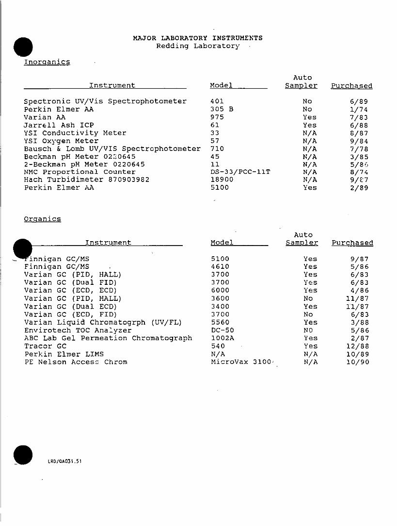
MAJOR LABORATORY INSTRUMENTSRedding Laboratory
Inorcianics
AutoInstrument Model Sampler Purchased
Spectronic UV/Vis Spectrophotometer 401 No 6/89Perkin Elmer AA 305 B No 1/74Varian AA 975 Yes 7/83Jarrell Ash ICP 61 Yes 6/88YSI Conductivity Meter 33 N/A 8/87YSI Oxygen Meter 57 N/A 9/84Bausch & Lomb UV/VIS Spectrcphotometer 710 N/A 7/78Beckman pH Meter 02ni0645 45 N/A 3/852-Beckman pH Meter 0220645 11 N/A 5/86-.NMC Proportional Counter DS-33/PCC-11T N/A 8/74Hach Turbidimeter 870903982 18900 N/A 9/E7Perkin Elmer AA 5100 Yes 2/89
Orgianics
AutoA911k ~Instrument Model Sampler Purchased
Wnnigan GC/MS 5100 Yes 9/87Finnigan CC/MS 4610 Yes 5/86Varian GO (PID, HALL) 3700 Yes 6/83Varian GC (Dual FID) 3700 Yes 6/83Varian GC (ECD, EGO) 6000 Yes 4/86Varian GO (PID, HALL) 3600 No 11/87Varian GC (Dual ECD) 3400 Yes 11/87Varian GC (ECO, FID) 3700 No 6/83Varian Li-quid Chromatogrph (UV/FL) 5560 Yes 3/88Envirotech TOO Analyzer DC-50 NO 5/86ABC Lab Gel Permeation Ohromatograph 1002A Yes 2/87Tracor CO 540 Yes 12/88Perkin Elmer LIMS N/A N/A 10/89PE Nelson Access Chrom MicroVax 3100' N/A 10/90
O ~~LRD/0A031.51

I0
II
II
I Appendix EI' KEY PERSONNEL RESUMES
iI
iiI
II
0
Ii
II
Ij
i
ij
I
i-0

FRED R. BICKELL. ~Metals Analyse-; Supervisor
Education
A.A., Shasta College
Responsibilities
Mr. Bickell is responsible for supervising the sample prep-araticn and subsequent analyses of water, wastewater,sludgc-, soil, sediment, and biological samples for theirmetals content. Mr. Bickell's particular expertise is inthe atomic absorption spectrophotometric (AAS) andinductively coupled plasma atomic emission spectrometricCICPAES) analyses.
Experience
His experience includes conducting pilot plant stu'2ies togather information for the design of advance wastewatertreatment plants, water treatment plants, and wastewatercollection systems. In these studies, Mr. Bickell operated
the pilot plants and performed the laboratory testing.
RDD/R59/110.50
TERRY DA.VISLaboratory Quality Assurance Coordinator
Educati-on
M.S. Programn, Management Engineering, Colegio de San Jose,Philippines
B.S., Chemical Enginedring, Cebu Institute of Technology,Philippines
Responsibilities-
As the Laboratory Quality Assurance Coordinator, Ms. Davisassures the production' of accurate, valid, and reliable databy moritoring the imp2.ementation of the laboratory':: qualityassurance plan. This plan includes the use of apprciw-.edmethodologies, the use of quality control charts anc . associ-ateid corrective action program, establishment of validdetection limits, ev;aluation of data quality and laboratoryperformance through the use of quality control and blindsamples, calibration and maintenance of all measuring andanalytical instruments, and performance of-periodic auditsof the laboratory. The LOAC maintains files to document theimplementation of the quality assurance plan. She alsoissues reports to management to keep them informed of thelaboratory's performance and to alert them of any deviationfrom the quality assurance plan.
Experience
Ms. Davis has had several years of QA/OC experience in thepharmaceutical and medical device industries.
As a chemist and as a supervisor of a laboratory performingstability studies on multivitamin products and prescriptiondrugs, she was involved with performing analyses using wetchemistry, UV, IR, and AA spectrophotometry, and liquid andgas chromatography. She was also involved in the develop-ment of methodologies for vitamin assays and writing ofstandard operating prccedures.
She has worked- as a QA engineer for the medical device andpharmaceutical industries. in'that~capacity, she designedand pe-:formed studies tc& validate the performance of processequipme~fnt ana: manufacturina prozesses. She set up qualitycontrol systems tha-: included sampling plans, a-!. phases ofinspectzon, statistical quality ccntrol chartinc, deviationreporting, and corrective action programs. She alsoperformed internal and vendor audits and developed a vendorrating system. She developed a training manual for QCinspectors in a sterile tilling facility. She wasresponsible for that validation and startup of a completelyautomated sterile filling line and the training of all QCand production personnel.
BRIAN N. GEERSPage 2
"1PCB Analysis of the Fox and Wisconsin Rivers," Special Report.
NcAsi. Inc. March 1980.
"Additions of Substituted Phenylthiyl Radicals to Substituted
a-Methylstyrefles," Tetrahedron. Vol. 36, pp. 997 to 1000. 1980.
"Additions of Substituted Phenylthiyl Radicals to Substituted
a-Methylstyrefles." Oregon State University. 69 rip 1979.

JAMES E. HAWLEY. ~Inorganics Division Manager
Education
M.S. , Analytical Chemistry/Spectroscopy, Oregon State University(1974)B.S., Chemistry, Shippensburg State College (1971)
Responsibilities
Mr. Hawley's primary responsibilities at CH2M HILL are supervisingand managing the inorganics department, which performs extensiveanalytical testing of air, water, wastewater, hazardous waste,soils, ores and biological samples using wet chemistry, atomicspectroscopy, inductively coupled argon plasma spectroscopy,molecular spectroscopy, radiation, fish bioassay, anc: microbiology.
Experience
Mr. Hawley has experience, in baseline water quality design,sampling, and monitoring for the mining industry. He has performedflow studies using fluorescent dyes and fluorometers, and he hasinstalled cipolette weirs for measuring flows from acid minedrainages. Mr. Hawley also has experience in sampling andO ~monitoring acid mine wastes. He has been involved in wastewatertreatment from a uranium mine. He has performed studies to reducehydrogen peroxide and pressurized oxygen and air.
Prior to joining CH2M HILL, Mr. Hawley worked as a teaching andresearch assistant while obtaining his master's degree at OregonState University. Research experience has been related to thedesign of spectroscopic instrumentation to analyze trace metals.Further experience has included qualitative and quantitativeanalyses of proteins binding heavy metals for the AgriculturalChemistry Department at the University. In addition, Mr. Hawleyis familiar with most of the major spectroscopic, electrochemical,and chromatographic techniques and instrumentation involved inchemical analyses.
Member ship in Professional organizations
American Chemical Society
Publications
With J.D. Incle. "Improvements in Cold-Vapor Atomic AbsorptionAnalysis of Mercury."1 Analytical Cheristry, Vol. 47, p.7190. 1975
With J.D. Ingle. "Improvements in Non-Flame Atomic FluorescenceDetermination of Mercury." Analytica Chimi Acta. Vol. 77, p. 71. ~1975

BRYAN H. JONESExtractions Sut:-ervisor
Education
B.S., Soil and Water science, University of California, Davis
Responsibilities
As Extractions Supervisor, Mr. Jones has responsibility for theoperation of the laboratory that extracts samples preparatory toanalyses by GC, HPLC, and CC/MS.
Expbrience
Mr. Jones' experience includes training and supervising technicianson large volume sample loads for various soil analyses (developedwith and for the U.S. Bureau of Reclamation and the U.S. Bureau ofIndian Affairs).
Past responsibilities have included the design and construction ofO ~a fragmented hydraulic conductivity apparatus, adapting USERprocedures to ensure efficient completion of soil analyses, andmodifying laboratory services for analysis of agricultural andforest soils according to U.S. Forest Service procedures.
Prior to joining CH2M HILL, Mr. Jones was employed as manager ofan agricultural laboratory where he was responsible for performingand supervising water, wastewater, plant, and soil analyses. Hisresponsibilities also included field sampling and interpretationof soil and plant analysis. In addition to routine bacteriologicalanalyses, Mr. Jones has in the past performed specializedbacteriological analyses for Fecal Streptococcal and INVIC anddif ferentiation tests, Colif orm Atypical percentages, and completedtests.
While attending college, Mr. Jones was involved in researching theusefulness of agriciltural products. Work included greenhousestudies, field experiments, and laboratory analyses.
Professional Registration
American Water Works Association, California-Nevada section, WaterQuality :Analyst, Grade one certificate 168.
Membership in Professional organizations. ~Professional Soil Scientists Association of California

MONA N4. JONESClient Services Supervisor
Education
B.A., Biochemistry, University of California, San Diego
Responsibilities
As the Client Services supervisor for the Redding Laboratory, Ms.Jones is responsible for overall supervision of client services,including sample custody anc: data packaging. Ms. Jones provideslaboratory prcject management, interfaces with' clients, andpartic-"pates in marketing efforts. Ms. Jones is also. responsiblefor interfacing with the other CH2M HILL laboratories to determinework load levels, and maintaining the laboratory revenue forcast.
Experience
Ms. Jones joined CH2M HILL as the Sample Custody Supervisor inO ~1988. In that position she was responsible for coordinating samplekit preparation, sample log-in, and sample tracking. Ms. Jonesalso coordinated the proper disposal of "time expired" samples andsupervised the Sample Custodians.
Prior to joining CH2M HILL, Ms. Jones taught life and earth scienceat Oceanside High School in Oceanside, California. She also hasexperience as a research technician in the cardiothoracic surgerydivision of the U.S. Veterans Administration Hospital at La Jolla,California.

GREGORY R. JORDAN. ~GC/HPLC SUPERVISCR
Education
B.S., Chemistry, University of Southern California
Re spans ibilititecs
Mr. Jordan's primary responsibility is the surpervision ofthe gas chromatographic and HPLC analyses for volatile andsemivolatile organics.
Experience
Mr. Jordan's experience includes inorganic analyses ofwater, wastewater, and hazardous waste samples, static fishtoxicity bioassay testing for NPDES permits and toxic wastecharacterization, radiological testing of drinking water,and the.m~icrobiological testing of water.
Prior to joining CH2M HILL, Mr. Jordan was a chemist withthe Tahoe-Truckee Sanitation Agency (T-TSA). At T-TSA hewas responsible for much of the testing required to operateatertiary wastewater treatment plant in an environmentallyS ~~sensitive area.
He conducted and participated in many pilot- and bench-scaletests during plant startup and plant expansion. Theseincluded:
o Lime Coagulationo Recarbonationo Alum and Polymer Coagulationo Dual Media Filtrationo Zeclite Ion Exchangeo Phosphorus Removal Kineticso Phostrip Biological Phosphorus Removal System
These techniques were used fcr the remcval of phosphorus andammonia from wastewater.
Membersh~ip in Professional Organizations
American Chemical SocietyCalifornia Water Pollution Conrrol Association
Certifications. ~~Grade 3, Laboratory Technologist, Certificate 68, CWPCA
RDDIPQ4IO?5.50

GREGORY R. JORDAN
Grade 3, Ln:,~.crs~tory Technologist, AVJWA
California :''=un-Ity College Limited Service Credential,
Subject Area: Chemistry, No. 04542
RDPfDTQ4 1075.50

WARREN LEE KIDDorganics Division Manager
Education
B.S., Food Technology, University of Florida, Gainesville
Graduate Studies, Muscle Biochemistry and Physiology and Advanced
Food Chemistry, University of Florida, Gainesville.
Responsibilities
As organics Division Manager, Mr. Kidd has overall responsibilityf or the operation of the GC, HPLC, and GC/MS laboratories.
Experi enc~e
Mr. Kidd has had over nine years of experience in environmentalanalysis of water, soil, sediment, tissue and industrial effluentsamples. This experience includes three years as a CC/MS operatorand over six years as a laboratory super-visor or manager. As aGC/MS operator, he was responsible for the operation andO ~maintenance of a Finnigan 45103 CC/MS system and Hewlett-Packard5985A and 5993 GC/MS systems. He also became proficient in the useof the IBM PC AT/XT for laboratory information management using QAFormaster-Datamaster Software. He has been involved in theanalysis and data management of multi-media environmental samples,both volatile and semi-volatile organics, for the U.S. EPA,Louisiana Department of Environmental Quality and various othergovernment and industrial clients. He has performed samplecharacterization of organic chemical1s in ambient air samples. Hehas also served in various capacities including the following:
* Project Manager for EPA CLP contracts for organics valued at$2.5 million.
* Quality Assurance/Quality Control Off icer for all aspects oforganic chemical analyses.
* Laboratory Coordi-ator for NPDES permitting projects forvarious industrial clients.
Membership in Professional organizations
American Chemical SocietyAmerican Society of Mass Spectrometry

RAYBURN W. PRETTYMANEnvironmental Laboratory Manager
Education
B.S., Chemistry, San Jose State College
Responsibilities
Mr. Prettyman has served for 15 years as manager of theRedding office's Environmental Laboratory, which is certi-fied by the California Department of Health Services forgeneral chemical, organic chemical, radiochemistry,bacteriological, and fish toxicity bioassay analyses.
Experience
Mr. Prettyman played the lead role in establishing this lab-oratory facility and developing protocols for a variety ofanalytical programs to provide quality assurance and con-trol. He also has played a lead role in developing samplingprograms for water quality studies performed by CH2M HILLstaff throughout the western U.S. These have includedgroundwater iron and manganese problems in Wisconsin,Alaska, and California; surface-water and groundwater con-tamination from heavy metal discharges; and groundwatermonitoring studies to determine the fate of organics andnutrients applied to land.
As Manager of Laboratory Services for CH2M HILL's SouthwestDistrict, Mr. Prettyman has responsibility for developingwater quality sampling and analytical programs for projectsthroughout California, Arizona, and Nevada. This includesestablishing the points and frequency of sample collectionand the protocol for analyses of the samples. He has servedin this capacity for 13 years. Currently, his responsibil-ities involve providing overall direction for analysis ofmore than 75,000 water quality samples each year.
Mr. Prettyman's project atsignments have involved baselinewater quality studies, monitoring studies for organic andinorganic pollutants, and bench-scale and pilot-scaletesting of water treatment processes.
He recently directed studies of groundwater and surface-water pollution at a large inactive mine site in ShastaCounty, California. This work was performed for U.S. EPA aspart of the Superfund program.
Other monitoring studies that Mr. Prettyman has directedinclude studies on the Tahoe-Truckee Sanitation Agency leachfield, Truckee, California, to determine nutrient andorganic removals by soil, and stream studies on the Fox andWisconsin Rivers to obtain data for computer modeling.

Sit. Mansagement Plan DRAFTVElson Ah force Bear
Appendix C
HEALTH AND SAFETY PLAN
FOR EIELSON AIR FORCE BASE
0
0

Sn.o Mansagement Plsn-HSP DRAflEjelson Air Force Ba.
. ~CONTENTS-HSP
Page
I. General Information.......................................... 1
II. Site Characteristics........................................... 2
III. Waste Characteristics......................................... 6
IV. Hazard Evaluation .......................................... 13
V. Site Organization........................................... 23
VI. Control Measures........................................... 29
VII. Air Monitoring Program....................................... 30
VIII. Site Procedures and Limitations ................................. 32
O ~~X* Emergency Response Plan.................................... 38
X. Plan Approval ............................................. 46
Form 533 Record of Hazardous Waste Field ActivityAttachment 1 Material Data Safety Sheets
TAB LES
1 Sujmmary of Scou-rce Area Descriptions ............................. 72 Common Chemical Contaminants at Eie~son AFB.................... 163 Levels of Protection ......................................... 314 Required Monitoring Equipm ent and Action Levels of Upgrading Personnel
Protective Equipment (PPE) ................................... 33
FIGURES
1 Genera! Location Map ........................................ 32 Evacuation Routes.......................................... 43
et/CVOF;57/078.51 iii 17 June 1991

CH2M HILL
HEALTH AND SAFETY PLAIN (HSP)
EIELSON AIR FORCE BASE (AFB)
BASE PLAN (JUNE 1991)
The health and safety program for CH2M HILL personnel working at Ejelson Air
Force Base (AFB) consists of a base health and safety plan (HSP) and task specific
addendums. The HSP contains general information which applies to all or most areas
of the site. This document contains: the project &scription, personnel responsibilities,
site hazards, personal protective equipment (PPE), air monitoring guidelines, site con-
trol, decontamination procedures, and an emergency response plan. The task specific
addendums are written to add additional information regarding the specific source
areas and field activities. The addendums not only define the specific field activities
and team members, but they contain changes or clarifications of: the potential hazards,air monitoring requirements, PPE, decontamination procedures, and emergency con-
tacts. The addendums can be more or less restrictive than the base HSP, depending on
the type of field activities being conducted. Neither the base HSP or the addendums
are stand alone documents; both documents contain important information and they
must by used in conjunction with each other.
I. GENERAL INFORMATION
CLIENT: United State:- Air Force
JOB NO: TO BE IDENTIFIED IN THE SPECIFIC ADDENDUMS
PROJECT Ms"-NAGER: John Martinson/CVO
SITE NAME: Eielson Air Force Base (AFB). ~~SITE LOCATION: Alaska
sc7806/063.51/1
6/10/91CVOCOMM/EA063.511

PURPOSE OF FIELD VISIT: TO BE IDENTIFIED IN THE SPECIFIC
ADDENDUMS
DATE OF VISIT: TO BE IDENTIFIED IN THE SPECIFIC ADDENDUMS
BACKGROUND INFORMATION: TO BE IDENTIFIED IN THE SPECIFIC
ADDENDUMS
INFORMATION AVAILABLE FROM: CVO
II. SITE CHARACTERISTICS
A. Site Description
The Eielson AFB; is approximately 26 miles southeast of Fairbanks, Alaska and
encompasses approximately 19,270 acres (see Figure 1). It is isolated from any
major urban areas, however there are two nearby off-base communities. His-a
torically, most of the land was originally wetlands and flood plain areas. EielsonW
AEB currently contains 13 lakes totaling 313 acres, 54 ponds totaling 265 acres,
and 10 designated wetlands totaling approximately 252 acres. One of the lakes
and 6 of the ponds are old borrow pits.
Eielson AEB is built primarily around its north/south runway. This runway is
14,500 feet long, with aircraft aprons, hangars, maintenance facilities, and taxi-
ways to the east. A taxiway loop at the southeast of the runway houses the
A-l0s from 343rd Tactical Fighter Wing, hangars, the hush i',-.use, and other
maintenance and operation facilitie s. The 6th Strategic Reconnaissance Wing
and the 168th Air Refueling Squadron are located along the flightline. East of
the runway, there are industrial areas, administrative offices, hol-sing, and
community/recreation facilit-ies. There are munitions storage areas on Quarry
Hill which is further east. The land surrounding the base is used primarily for
military training.
se78S6/063.5 1/26/10/9CVCOoM2SEAO63.51 2

Ca.0~~~~~~~~~~~~L
4 u
- ~~~~~~LL Ut
0;z
U ~~~0-U Ca~~~~~~L
4 W~~C-
U~~~~~~~~~~Uu

There are four major highways which serve the area. They are: State Highway
2 (Richardson Highway), State Highway 4, Highway 3, and Alcan (trans-Alaska-
Canada) Highway.
The climate of the area is characterized by extreme diurnal and annual tempera-
ture variations, low precipitation, and low humidity. Summer temperatures
range between 45WF and 61fF. and the average temperatures dur'..: the winter
range bctween -14'F and 8WF. Extreme temperatures recorded at Eielson AFB
were 93W' in July and -64WF in January. Annual precipitation in this area aver-
ages 14 inches which intludes 72 inches of snow.
B. Site F istory
Eielson AFB was originally called Mile 26 and was a satellite of Fort Wain-
wright. Mile 26 was constructed between 1943 and 1944. The field was deacti-a
vated at the end of World War II but was reopened in 1947 as a future strategicW
base. From 1947 to 1954 nnny of the base's facilities were constructed. The
base was renamed in 1948. During the 1950s the base was jointly used by the
U.S. Air Force and U.S. Army. Historically Eielson's primary mission has been
tactical air support for the Alaskan Air Command. Today, the host unit at
Eielson AFB is the 343rd Tactical Fighter Wing.
The waste management practices in the past have consisted of disposal of indus-
trial wastes, solid wastes, polychiorinated biphenyls (PBCsj-, pesticides, and
wastewater treatment.
Industrial Wastes: Eielson AEB has generated and continues to, generate
RCRA hazardous wastes. The indi..trial operations which generated wastes
include propulsion shops, pneudralics shops, aerospace ground equipment, main-
tenance shops, nondestructive inspection labs, and vehicle maintenance shops.
se7ON6/063.51/46/10/91CVOCOM2YSEA063.51 4

The operations generate waste oils, fuels, solvents, and cleansers. Prior to 1972
the disposal of industrial wastes included road oiling, burning, and landfilling.
Some solvents and cleansers were discharged into the sanitary sewer system.
Since 1982 wastes oils and spent solvent have been salvaged off'site. Contami-
nated JP-4 fuel continues to be burned during fire department training activities,
and cleansers continue to be discharged into the sanitary sewer. Currently, haz-
ardous wastes are handled, stored, transported, disposed, treated, and recycled
in accordance with RCRA.
Polvchlorinated Biphenyls (PCBs): In the past, transformers, capacitors, and
PCB contaminated soils and liquids were stored in Buildings 2339 and 3424,
however, currently there are no PCB materials stored at the base.
Pesticides: Until DDT was banned Eielson AFB used up to 40-50 drums of
DDT per year. Two hundred unused drums of DDT were hauled from the site
when its use was discontinued. Major pesticides which are Currently in use are:Baygon, D-Tox-4E, Diazinon, Dursan, Malathion, Pyrethrins, and Resmethrin.
Wastewater Treatment: The base sewage treatment plant was built in 1953 and
was expanded to include secondary treatment in 1973. Prior to 1979 the effluent
was discharged into Garrison Slough. Since 1979 the treated effluent has been
diverted to an infiltration pond.
C. Overview of Planned Activities
The investigations which will be completed at Eielson AFB will encompass a va-
riety of field -activities including: soil gas surveys; installation of groundwater
monitoring wells, vapor extraction wells, and piezometers; soil borings; and soil,
groundwater, surface water, sediment, and biota sampling. THE SPECIFIC
sea78O6/063.51/56/10)91cvoCOM2,SEA063.51 5

FIELD ACTIVITIES EACH INVESTIGATION WILL INVQLVE WILL BE
IDENTIFIED IN THE SPECIFIC ADDENDUMIS.
D. Status of Site
Ejelson AFB is on the National Priority List (NPL). Prior to this listing the "buse
conducted several remedial investigations under the Air Force Installation Res-
toration Program (IRP).
The 64 contaminant source areas identified in previous investigaticofs have been
grouped into six op,,trable units (OUs) and three site evaluation report (SER)
groups. Each OU is composed of contaminant source areas with similar charac-
teristics, and the SER groups are grouped by level of available information.
Table 1 shows the source areas, years of activity/status, and waste received and
released.
E. Utilities
The site contains underground electrical powerlines, buried natural gaslines,
buried stormwater and sanitary sewer system, buried water mains, and a septic
system. There are also overhead powerlines in some areas of the site.
III. WASTE CHARACTERISTICS
A. Waste Types
Liquid X Solid X Sludge X Sediment X Vapor X
sea7806/063.51/66/10/91CVOCOM2/sEA063.51 6

J'< Iji I'
0 0 0O~ 0,1 C 0 0 , ,
-- - I - . - . - - -1-1~~~~1~~~~,~*C
o E >. a. * E o~~~E
- -~ ~ ~ ~ ~ S '~~~~~ n -~~
t, 6E oif J- HVI~~~~~~~~~~i
f~~~~~~l~C
U c- 5 ~ .
2 I~~~~~~~~~~~~~~~
1<~~~~~~ 0 I - C ~O ~M

C,~~~~~~~~~~~~~~~~~~~~~~~~~~~F I- -- - .- -.
- -10 a - a a - ~~~~~~~~~~~~~~~~~~~~~0 0
U, U, "~~ ~~~~Z U, Z Z * Z ' ,C 0
- s - 31~~C
C 'a ~~~ tQ ~~s 225 C A
C 13 C~S s 4 ''3 0
E E A U- -U -- --
2 'a C 4 , -
0 C C V~~~~~~~~~~~~~~~~~~~~~~~~~~~~~.~CE
C v U1 V V8 EEL Z- C
t - -- -~~~~~~~~~~ - Z. 'Z r
E'aE ~~~~~ ~~~ 22 E.EZ
C9 V~~~~~~
< -8 ~C. C- I!--''-.- Snv sEWS 5.2.~~~~~~~ C .
-M-~~~ I C~~OECE2 -m u0' ~~~~~~~~~~~~U U~--0 0 - - C S * to~~~~~~~~~~~~~~~~~~~~~~~~~~~~~~~~~~~-C E
0. 0. Q~~~~~~~~~~~~~~~~~~~~~~~~~~~~~~~~~~~~~~~~~~~~~~0
AC 5 UN!
22~~~~~~~~~~~~~~~~~~~~~~~~~I2
o CZP) V0 0 W W~~~~~~~~~~~~~'aL

las M w w 0 z I
a~~~ a
- a U~~~~~~~~-
a -
S m~- 3 ,. 38*
0. ~~~~ ,. a~~~~L dZ
n - ~~ b~ ..
0 *0
- - -- C - ~~~.cU.Zs
C 0
d-CL 0 3Ca g ~~~~~j Zr~~~~ ~~..a~
o ~~.vo 0 ~ :c T Sc
~~~~~~*cZ~~~~~~~~ C - 0~~~~~~~~~~
-< isoz* >O-c
~~~~~~~~~~ ~~~~~~~~~~~~~~~~~~1
U : E Z s ~~~~~~~~~~~~~~~~~~~~~~~ ~~~~~ 10 ct ~~~~~~~~~~~~~~~ - ~~~~~~~~~ ~~~~I
Ca ~~~ ~~;2~~~~0 . rn16.3~~~~~cL.3 c~~~~~io~~C~~o~~c- ~ at:.:w u c 0 LIO. ' ~.
Ln ~ ~ ~ ;~c ~ c.

ALL WASTE TYPES MAY NOT BE PRESENT AT EACH SOURCE AREA.
THE SPECIFIC ADDENDUMS WILL IDENTIFY WHICH WASTE TYPES
ARE OF CONCERN FOR THAT SPECIFIC AREA AND TASK
B. Characteristics
Corrosive X Ignitable X Radioactive X Carcinogenic X
Volatile X Toxic X Reactive X Unknown X
ALL WASTE CHARACTERISTICS MAY NOT BE PRESENT IN EACH
SOURCE AREA. THE SPECIFIC ADDENDUM WILL IDENTIFY WHICH
CHARACTERISTICS ARE APPLICABLE FOR THAT SPECIFIC AREA AND
TASK
IV. HAZARD EVALUATION
A. Overall Hazard Level
THE OVERALL HAZARD IS DEPENDANT ON THE FIELD ACTIVITIES
AND WILL BE IDENTIFIED IN THE SPECIFIC ADDENDUMS.
B. Chemical Hazards
Based on the current information of the past and present waste disposal practi-
ces, five contaminant sources have been identified. They are: spills and re-
leases, land disposal operations, road oiling, pest control, and general ongoing
site activities.
sea7S6/063.51/136/10/91CVoCoM2/5EA063.51 13

Spills and Release: The most common source of chemical contamination is
from leaks in tanks and piping or from incidental release and spills of petro-
leum, oil, or lubricants (POL). At a third of the 64 contaminated areas involve
POL contamination, primarily in the form of diesel, motor gasoline or JP-4.
Incidental low volume spills and releases of solvents have also occurred. In the
past trichloroethene (TCE) was used at the site, and it and its degradation prod-
uct, 1,2-dichloroethene (1,2-DCE), have been detected in the groundwater at
several locations. Currently, 1,1,1-trichloroethane (1,1,1-TCA), methyl ethyl
ketone (MEK), methylisobutyl ketone (MIBK), acetone, and Stoddard solvent
are being used. When solvents are used for cleaning metal, heavy metals are
often associated with the spent solvent.
Land Disposal Operations: There are seven landfill areas on the base that re-
ceive or have received a wide variety of materials. Primarily they received gen-
eral base refuse, but disposal of paints, thinners, and solvents has also been
reported. Some disposal areas have received sludge which contains lead from
tank cleaning operations; power plant ash which contains heavy metals; and
waste grit which contains lead, cadmium, and chromium. Sandblasting wastes
may have been disposed of in other areas on the site as well. There is an area
which contains severaf hundred barrels of asphalt emulsion (tar). The drums
have leaked some of there contents and have form what is known as Asphalt
Lake. There are other areas which contained buried or partially buried drums
of unknown contents. Furthermore, five or six drums of radioactive photo-
graphic chemicals were reportedly placed in the current landfill. There are
reports that small amount of munitions and spent cartridges were placed in an
older landfill. Munitions and cartridge disposal present a potential explosion
hazard, as well as a heavy metals contamination.
Road Oiling: Waste oil, contaminated fuels, and spent solvents were previously
used to oil the roads on the base. It is possibly that PCB contaminated oils
se78061063.51f46/10191CVOCOM2,SEA063.51 14

were also used for this purpose. As mention previously, heavy metals are fre-
quently associated with spent solvent:;.
Pest Control: DDT was used extensively until 1966. DDT application at the
base included aerial spraying. As mentioned above, pesticides which are cur-
rently in use are: Baygon, D-Tox-4E, Diazinon, Dursan, Malathion, P'yrethrins,
and Resrnethrir..
General Site Activities: Due to normal base activities there will be exhaust
particles from vehicle and aircraft traffic. These particulates may contain poly-
aromatic hydrocarbons (PAH) such as benzene, toluene, xylenes, and ethylben-
zene (BTXE). In the past ethylene glycol was used to deice the planes, and
currently, isopropyl alcohol and methanol -are used. Sandblasting operations
which are currently conducted at the base produce waste which contains high
concentrations of lead, cadmium, and chromium. In addition to the waste mate-0 ~ ~~~~rials, hazardous substa nces such as fuel1, solvents, and cleaners are also stored invarious areas of the site.
Table 2 shows the base-wide potential chemicals hazards, the exposure limits,
and the symptoms of overexposure. IN SOME AREAS OF THE BASE SOME
OF THE LISTED CHEMICAL HAZARDS MAY NOT BE PRESENT, WHILE
IN OTHER AREAS THERE WILL BE ADDITIONAL CHEMICAL HAZARDS.
LOCATION AND TASK SPECIFIC CHEMICAL HAZARDS WILL BE IDEN-
TIFIED IN-THE SPECIFIC ADDENDUMS.
D. Physical Hazards
THE PHYSICAL HAZARDS ARE DEPENDANT ON FIELD ACTIVITIES
AND WILL BE IDENTIFIED IN THE SPECIFIC ADDENDUMS.
sca7806/063.51f156fl0/91CVOCOM2/SEA063.51 15

- .~~~~~~~~~~~
to t- -~~~a . .- Cr C
- C ~r Z
C. c.-~~~~~~~~~~ 0 -~~~4 cn? .
to C -~~t cm-o
.0 m E0 OU2 ~ ~ ~ -~~. =a5- m
es -CZ U*~ c.
E S-
O c .2 la 2 ; ~
2 E UE rm- U03 ' P2 mU.
C.-tou~Z " t ld
Z z~~~~~t

-W ~~C in C)I4- 0~~. - "
C~~~~0 Z4) 0 '~~~~~~~~ tot
.c ~~~~~~~ ;%0 oe~ ~~~~~~~0rEEC CC Z 0u
- C~~~~~~Zi.2 " i C
4) C CCr C)'= C) -
MEo C&o -. Ete-~n C ~ ~
... C ~ *~: o~ *ZU .- u,
rm . _C
- S5~o0 '- E 7JL2 9t G
a ctt~~~~~w o cV rC4- VC
N ~~~~~r -4 - eoocE I~~c C'L
C .2 = ~ .e E 6 :r'~-E~~E 0 c. .0 .
u . 0 C 0 C.o ~ ~ ~ ~ EV~~~~ -~~~ 2S6~~ 8~~ CMn 4
Ce~~~~~~~~~in ~~I ow5
2 ~ ~ ~ ~ ro u u ~~~~~~~~ ~~~....~~~"

'� C in a C
*�
Ut) U, C.
tO ��2 .zCCC. - 0> *� EU
a 4 )4 ) � E U in
02-au - >..-u�CtJ - --
02K C) � �=uS 4 ) 02� vS
I- .(.;�,
C) 6 .*C 4) �4)Ca 4)
� 4)0��- a ŽC0 CV
020 -U.CC
CC -
tO � .�2 -�
e in�. CU _
o Va o -- - _
. Eu� � Ut'�-� &"'
02 0 0�Z.0 inCCVC K .� -'
x c�2a F �0C)� *�4)-u
� C � -s
5 t0 .....a .EC�'� .� a.� tn2i C.-. -C,
oC 02 au�C n.C -�
�J CFt.� �-U 00 -
- a 0-
a0 � 98 4) *0�>�0�
-
� C.CJC tO C) -
* .E � Eu�C �o � *-..U, C -.
- .- � *5 KV� n�
o� '"9o� u %� a .2C �J 0 OEC
5, *� '*� .� 2Ž'' 0 - .
0 C U.4) C.
2 � U.� �oj� 0
4 ) C.�.C 4) 0.zv
Cs -.� cCZ
� E 0 � � -�5!a.t� � .a ain�E' -. a CC
o � .2 -.0 �4) 4)0 . -
o � -:7- c-!02�o � >' C
a.. USC e� � V � .00C
p..' 4) �zc a a � K 4)
a u,4)C� 0 u�4) � 0. -� c� CC4) � Sc. >50-i
o - Uw�v,2 .C.. a �
� � CU U C.... '� oOqS aN
02
CU ,� �-E tO
4)0- C a .E'� 04) = � - C -
02 �'.ioV � &�½S� �'A 02 W3 ;q�4) K �.�04) . - 020
- .� 0 C
0 00, 4) C - C � V (04)
C) i.0
CU -a
C. .� � CU >�
0 4) 4) -a .E� �
U CCCCZ � ra04)�
V - 020.�C � u.��E; � .� C) -.0.7.)
E � .�VinC%_____ C�0 � -
C
In - -
So
.0-, E
- C. it) - .- -
in
0)a C
C .0
0UC a
La C)
4)I- Va -ErA
CC . E a .� V
_L.11.�__ ____ _S 02

4.- 0~0o C~~~C
V C~~~~~~~~~~~~~~~~O
4) ~ ~~C rEj0. 4.~~~~~~~~~4
- Cs C~~~~~~~Es
- ', 00~~~~~~~~~~~r MEu
0.
c~~~ C
~~~~~ - ~ ~ ~ ~ EUC~~~zC4 ) - S~ 7:

There are some physical hazards which are common to many of the field activi-
ties are summarized below:
Cold Stress: See Section IVF
Slipping or Falling: Especially during the freezing and thawing seasons, there
will be a potential of personnel slipping and/or falling. To help prevent this
from occurring, personnel will use extreme caution around frozen or wet areas
and will wear boot:; that have good traction.
Falling or Flying Objects: Falling or flying objects can occur when working
underneath something or around heavy equipment. Hard hats and safety glasses
will be worn to help prevent injuries from falling or flying objects from
occurring.
Noise: Because the field activities are being conducted on an Air Force Base,
there will be noise from aircraft taking off and landing. The use of heavy equip-
ment and other vehicular traffic will add additional noise. Personnel will wear
hearing protection and monitor for noise to help prevent injuries from occurring.
Traffic: Because the field work is being conducted on an active Air Force Base,
there will be vehicular traffic. Barricades, cones, flagging, and signs will be used
to divert traffic from the work area. Personnel who work near areas with heavy
vehicular traffic will wear safety vests to increase their visibility to passing
drivers.
Black Bears: Black bears reportedly can come onto the base. Personnel should
be aware that bears are present and could cause injury.
sea7SO/063.5 1/206110/91cvoCOM21SEA063.51 20

Heat Stress: Heat stress is not anticipated to be a significant problem because
the average summer temperatures range between 450F and 61fF. However,
depending on the necessary PPE and the weather, heat stress could present a
problem. IF IT IS ANTICIPATED FOR A SPECIFIC TASK THAT HEAT
STRESS MAY BE A CONCERN, THE SPECIFIC ADDENDUMS WILL IDEN-
TIFY THE HAZARDS AND THE CONTROL MEASURES.
E. Cold Stress Hazard
The potential for cold stress, frostbite and hypothermia, is relatively high all year
at Eielson AFB. The highest potential is during the winter months when the
average temperatures range from -140F to 80F. Extreme cold for a short period
of time can cause severe injury to the surface of the body (frostbite) or result in
profound generalized cooling of the body core (hypothermia) which can result in
* ~~~~death.
Areas such as fingers, toes and ears have a high surface area to volume ratio
and are therefore more susceptible to the effects of cold. The two factors that
influence the development of a cold injury are: ambient air temperature and
wind velocity. Windchill is used to describe the chilling effect of moving air in
combination with low temperature, and as a general rule the greatest incremen-
tal increase in chill occurs when a 5 mph wind increases to 10 mph.
Frostbite: Local injury due to cold is known as frostbite. The onset of frostbite
is painless and gradual, and the injury can occur before the victim is aware that
it has occurred. There are several degrees of frostbite:
Frost nip or incipient frostbite: Characterized by sudden blanch-
ing or whitening of the skin.
se786)063.51T216/10/91CVOCOM2/SEAO63_51 21

* Superficial frostbite: The skin has a waxy or white appearance
and is firm to the touch, but the tissue beneath is resilient.
* Deep frostbite: Tissues are cold, pale, and solid. This is a serious
injury which requires first aid.
To help prevent frostbite from occurring personnel will: keep extremities warm,
wear warm clothing, take rest breaks mna warm area, reduce wind by construc-
tion a wind shield, and check for symptoms. If frostbite occurs, the victim
should be moved to a warm area if moving the victim will not cause serious
harm. The affected areas should be warmed with water (1020F - 1050F) or the
areas covered with warm cloths for 30 minutes, and the victim should drink a
warm liquid (not coffee, tea, or alcohol). If possible elevate the injury. Extreme
care should be take to avoid breaking the blisters, and injured areas should be
covered with sterile, soft, dry material. Keep the victim warm and seek medical
attention immediately. Further injury can be caused if the affected area is
rubbed, if anything cold is placed on the frostbitten area, if the victim is placed
near a hot stove, or if the victim is moved after the affected area has thawed.
Hypothermia: Systemic hypothermia can be caused by exposure to freezing or
rapidly dropping temperatures. Its symptoms are exhibited in five stages:
* Shivering
* Apathy, listlessness, sleepiness, and (sometimes) rapid cooling of the body
to less than 950F
* Unconsciousness, glassy stare, slow pulse, and slow respiration
sea806/063.51t226/10,91cvocoM2/5EA063.51 22

Freezing of the extremities (frostbite)
Death
To treat hypothermia, remove the victim from the cold and get them into a
warm area. Remove wet clothing and cover the victim with dry clothing or
blankets. The body should be warmed up slowly.
F. Hazards Posed by Chemical Substances Provided by CH2M KILL
In accordance: with state and federal regulations, Material Safety Data Sheets
(MSDSs) are provided for the following chemicals: trisodium phosphate (TSP),
liquinox, hexane, methanol, nitric acid, hydrochloric acid, MSA respirator sani-
tizer, isobutylene, and compressed air. Depending on the required monitoring
equipment, all of these chemicals may or may not be present for a particular
task.
V. SITE ORGANIZATION
A. General
Map/Sketch Attached X Site Secured _ Perimeter Identified
Zones of Contamination Identified X
B. CH2MT' HILL Site Personnel
THE TEAM MEMBERS WILL BE IDENTIFIED IN THE SPECIFIC5 ~~~ADDENTDUM.
sra7806M03.511236/los91CVOCOMZ/SEA063.51 23

In the contaminated areas (i.e., exclusion zone), the decontamination areas (i.e.,
contamination reduction zone), and areas where there is a possibility for expo-
sure, all personnel must be under a medical surveillance program and trained in
accordance with 29 CFR 1910.120 and Chapter 10 of the Alaska Occupational
Safety and Health Standards. In addition, at least two personnel in each source
area must be currently certified in first aid and CPR.
Because each OU consists of multiple source areas, there will be more than one
Site Safety Coordinator (SSC) present onsite. A lead SSC will function as the
overall OU SSC and have the responsibility over the source area SSCs. In some
cases, a SSC will not be at a source area during all field activities. However,
with the use of a two way radio the Lead SSC will be in constant communication
with such a field team. Additionally, if a SSC is not present at z source area,
one must be within a 5-minute drive at all times.
Personnel who are not trained in hazardous waste work as required by the fed-
eral and state standards will not be allowed in the exclusion zones or the con-
tamination reduction zones.
C. Subcontractor Personnel
All subcontractor personnel must present certification that they are trained in
accordance with the hazardous waste laws, have been approved by within the
last 12 months by a physician for hazardous waste work, and are fit to wear a
respirator. This can be accomplished by signing a contractual form that states
that the contractor's personnel have been fit tested, trained, and are in 2 medi-
cal monitoring program.
sea7806,t063.511246110191CVOCOM2IEA063.51 24

. ~~D. Pit-entry Safety Training
The lead SSC will conduct a ye-entry safety meeting which at a minimum
covers the information listed below. FOR SOME FIELD ACTIVITIES OTHER
TOPICS MAY NEED TO BE DISCUSSED DURING THE PRE-ENTRY
SAFETY MEETING. IF REQUIRED THESE TOPICS WILL BE IDENTIFIED
IN THE SPECIFIC ADDENDUMS.
a Emergency procedures for perso-nnel injury, or suspected overexposures,
fires, explosions, chemical, and vapor releases.
* Location of onsite emergency equipment and supplies of clean water.
* Local emergency contacts, hospital routes, evacuation routes, and assem-
* ~~~~~~~bly points.
a Site communication including the location of nearest phone to each
source area and location mobile phone.
* The purpose of the two-way radios and what channel to use in the event
of an emergency.
* Names of personnel trained in first aid and CPR in each source area.
* Work zones as they have been established.
* Decontamination procedures.
* Notification procedures for contacting CH12M HILL's medical consultant
and team member's occupational physician.
sea7SO6/63.51/256/10/91CVOCOM2/SEA063.51 25

* The emergency response plan will be rehearsed at least once before site
activities begin, and periodically afterwards.
* New workers on the site will be briefed on the emergency response plan
before entering the exclusion zone.
* The "buddy system" will be enforced for field activities involving potential
exposure to hazardous materials and during any work within the exclusion
zone. Each person will observe his/her partner for symptoms of chemical
overexposure, cold stress, and provide emergency assistance when war-
ranted. Personnel working in the exclusion zone wi]l maintain line of
sight contact or maintain communications (i.e., two-way radios) with the
site support facilities.
Emergency Signals: The following emergency signals shall be used:
Grasping throat with hand Emergency--help me
Thumbs up OK--understood
Grasping buddy's wrist Leave site now
2 short blasts or sounds, repeated All clear
Continual sounding of horn Emergency--leave site
E. Personnel Responsibilities:
All Employees
Each employee who works in the areas of the site where there is a potential
for exposure is responsible for verifying that their medical status and train-
ing are current prior to working in those areas.
se7806/063.5 11266/10191CVOCOM2ISEA063.51 26

All personnel who work on the site must sign in at the CH2M HILL field
office indicating the date hind time of visit and project number.
* All employees will read and agree to follow the Eielson AFB's safety pro-
gram pnior to working on the site.
* All employees will read and agree to follow the CH2M HILL HSP and the
addendums.
* All employees who have been issued TLD badges will wear them when
working at the site.
* All employees will conduct their work in a safe manner.
* Employees are responsible for correcting an unsafe work conditions. If they
are unable to correct the unsafe condition and feel that the condition could
cause serious harm, they may halt the work. If work is halted the employee
must contact the SSC or the project manager.
* Emplovees are responsible for reporting faulty equipment to the SSC or the
project manager and for shutting down the field work until the equipment is
operational and reliable.
* All personnel who work in areas of the site that have potential exposures
are responsible for submit-ting their 533 Forms to Kenna Jonesf'WDC on a
monthly basis.
sea7806/063.5 1r,76/10/91CVOCOM2/SEA063.51 27

ssC
In addition to the above, the SSC is responsible for:
* Documenting that all personnel entering areas where there is a potential for
exposure meet federal and state hazardous waste regulations.
* Holding a pre-entry safety meeting on the source area's specific hazards.
* Completing site entry procedures.
* Conducting (or assigning a qualified person to conduct) the air monitoring
in their area as outlined in the HSP and the addendums.
* Emergency planning.
* Taking the lead in all emergency situations in their source area until a pro-
fessional emergency response team arrives.
* Establishing the work zones for their source area.
* Setting up and maintaining an effective decontamination process for their
source area.
* Documenting that all personnel and equipment leaving the contaminated
areas have been -effectively decontaminated.
Furthermore, in addition to the above, the lead SSC is responsible for:
sea7806013.51026110/91CVOCOM2/5EA063.5 1 28

Coordinating the source area SSCs.
* Verifying that the source area SSCs are following the above guidelines.
* Taking the lead in all emergency situations which occur within the OU until
a professional emergency response team arrives.
* Holding a pre-entry safety meeting.
Project Manager.
* It is the project manager's responsibility to ensure that the project is being
conducted in a safe manner.
* The project manager is responsible for informing all personnel of the safety
precautions required at the site.
* The project manager is responsible for controlling the movement of all
onsite personnel (i.e., keeping untrained personnel in areas where no eXDO-
sure potential is present).
VI. CONTROL MEASURES
A. General
To help reduce employee exposure a combination of engineering controls, work
practices, and personal protective equipment (PPE) will be utilized. Whenever
possible engineering and work practices should implemented prior to using PPE.
se7806/063.51/296/10/91CVOCOM2/SEAO63.51 29

B. Engineering Controls
In establishing the work zones, the type of contaminatinn, the media which is con-
taminated, and the wind direction will be taken into consideration. Most areas will
require an exclusion zone which consists of a minimum of a 25-foot radius around
the invasive activities. The contamination reduction zone will be on the upwind
edge of the exclusion zone. THE SPECIFIC ADDENDUMS WILL CONTAIN A
MAP OF THE WORK ZONES. OTHER ENGINEERING CCNTROLS WHICH
MAY BE APPLICABLE TO THE FIELD ACTIVITIES WILL BE IDENTIFIED IN
THE SPECIFIC ADDENDUIMS.
C. Work Practices
WORK PRACTICES ARE DEPENDENT ON THE FIELD ACTIVITIES AND
W"ILL BE IDENTIFIED IN THE SPECIFIC ADDENDUMS
D. PPE
THE nTYE OF PPE IS DEPENDANT ON THE FIELD ACTIVITIES AND WILL
BE IDENTIFIED IN THE SPECIFIC ADDENDUMS. However, the basic require-
ments for each level of protection are shown in Table 3.
VII. AIR MONITORING PROGRAM
Periodic monitoring of the site is required to determine the effectiveness of engineering
and work practice controls, to re-evaluate levels of protection, and to determine if site
conditions have changed. All instruments will be calibrated in a clean envir-onment pe:
the manufacturer's instructions at the beginning of each day. At the end of each day,
all of the instruments will be charged so they are ready for use when necessary.
se78O6/D63.51I306/10/91CV0COMZ/SEA063.51 30

Table 3Levels of Protection
Level of Protection Required Equipment
Level D (modified) Neoprene steel toed/shank boots. Leather steeltoes/shank boots with boot covers may be subsituted.
Neopr-ene outer gloves.
Latex inner gloves.
Safety glasses. Safety goggles are required when asplash potential is present.
Tyvek coveralls. Coated tyvek are required when asplash potential is present.
Hard hats when overhead hazards are present.
Level C The equpirnent required in Level D as well as a full facerespirator (MSA type cartridges: GMC-H or GMC-S).
£ ~~~~~~~Tyvek wvill be taped to boots and gloves.
Saranax coveralls taped to boots and glovt±s.
Leel B ITh-. equipment required in Level D (unless otherwise
~~~~y ~~~~noted below) as well as a supplied air respirators.
sea7806/070.51
se7806/070.516/I0/9CVOCOM2/SE-AO70.51

At a minimum, monitoring will be conducted at the beginning of each shift, every
30 minutes throughout the field activities, whenever work begins at a new area onsite,
when different contaminants are encountered, or when a different work activity begins.
General monitoring locations and frequencies are given in Table 4. Some field activi-
ties will require all of the equipment mentionesi, while other activities may require only
some of the equipment listed. SPECIFIC MONITORING REQUIREMENTS ARE
DEPENDANT ON THE FIELD ACTIVTIES AND WILL D~E IDENTIFIED IN THE
SPECIFIC ADDENDUMS. CHAkNGES IN THE AIR MONITORING PROGRAM
SUCH AS: THE ADDITION OR DELETION OF MONITORING EQUIPMENT, A
DIFFERENCE IN ACTION LEVELS, OR A CHANGE IN- MONITORING FRE-
QUENCY WILL BE IDENTIFIED IN THLE SPECIFIC ADDENDUMS.
Since the monitoring equipment is the basis for the levels of protection, it is very im-
portant that the equipment be working properly. Each piece of monitoring equipmenta
will be inspected to determine if it is working correctly. If the equipment is not work-W
ing or is not calibrated correctly, the work must be halted until the equipment is oper-
ational and reliable. The project manager will be contacted whenever equipment is
nonoperational.
VIII. SITE PROCEDURES AND LIMITATIONS
A. Site Entry Procedures
* Attend safety briefing before starting field activities.
* Read and agree to follow the base's safety program and the CH2M HILL
HSP and addendums.
se7806/063.51/326/10/01CVOCOM2IEA063.51 32
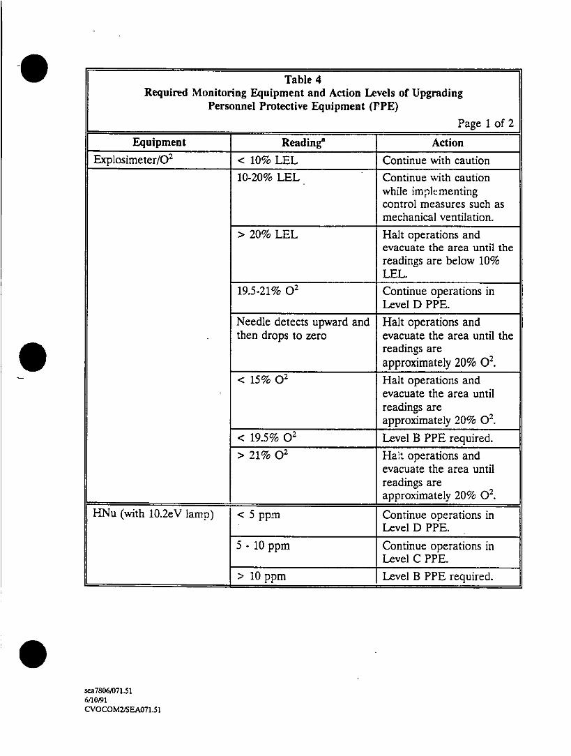
Table 4Required Monitoring Equipment and Action Levels or Upgrading
Personnel Protective Equipment (J'PE)
_______ ______ ______ __ ____ ______ ______ ______P age 1 o f 2
Equipment Reading' ActionExplosimeter/0 2 < 10% LEL Continue with caution
10-20% LEL Continue with cautionwhile impletmentingcontrol measures such asmechanical ventilation.
> 20% LEL Halt operations andevacuate the area until thereadings are below 10%
___ ___ ___ ___ ___ L E L
19.5-21% 02 Continue operations inLevel D PPE.
Needle detects upward and Halt operations andthen drops to zero evacuate the area until the
readings are_____ ____ ____ ____ ____ approximately 20% 02.
< 15% 02 Halt operations andevacuate the area untilreadings areapproximately 20% 02.
< 19.5% 02 Level B PPE required.
> 21% 02 Halt. operations andevacuate the area untilreadings are
_____ ____ _____ ____ ____ approximately 20% 02.
HNu (with 10.2eV lamnp) < 5 ppm Continue operations inLevel D PPE.
5 - 10 ppm Continue operations in____ ____ ___ ____ ___ Level C PPE.
> 10 ppm Level B PPE required.
se7806/071.56/10/91CVOCOM2/SEA071.51
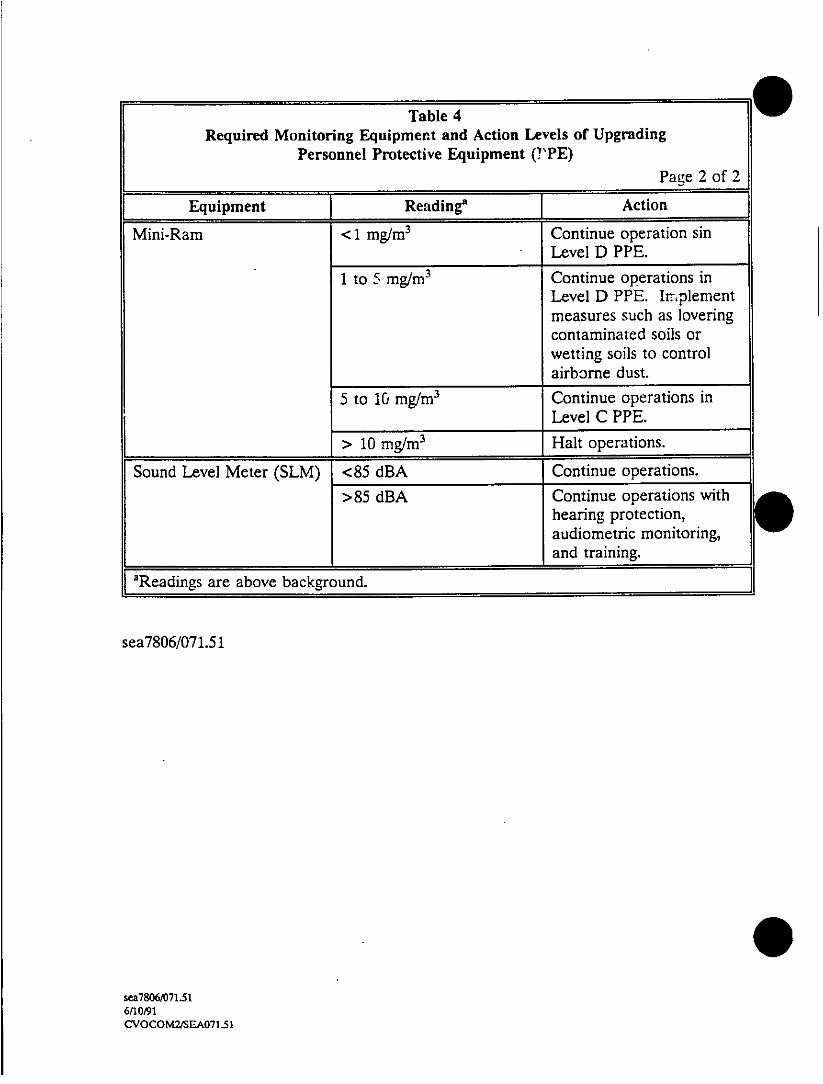
Table 4Required Monitoring Equipment and Action Levels of Upgrading
Personnel Protective Equipment (VPE)
_________________________Pa g~e 2 of 2
Equipment Reading'I Action
Mini-Ram <1 mg/rn 3 Continue operation sinLevel D PPE.
1 to Smg/rn 3 Continue operations inLevel D PPE. Implementmeasures such as lovering
5 to 10 mg/rn3 Continue operations in
_____________ ~ >10 Mg/rn 3 Halt operations.
Sound Leve] Meter (SLM) <85 dIBA Continue operations.
>85 dBA Continue operations withhearing protection,audiomnetric monitoring,and training.
aReadings are above background.
sea78061071.51
se7S06/071.516/10091CVOCOM2/SEA071.51

Locate the telephone which is closest to the field activities tn- be used in the
event of an emergency.
At least one source area will have a mobile phone at all times. Identify
which area has the mobile phone and the procedures for radioing for help
in the event of an emergency.
* Confirm and post the emergency telephone numbers at each source area.
* Determine wind direction, install wind flags, and establish work zones at
each source area.
* Set up decontamination facilities at each source area.
* Conduct site entry monitoring at each source area.
B. Work Limitations
* No eating, drinking, chewing tobacco or gum, or smoking in the source area.
* No contact lenses onsite.
* When respirators are required, personnel can have no facial hair that would
interfere with respirator fit.
Bud:--dy system is effect at all times in exclusion zone.
sa7806,063.51/356fl0091CVOCOM2,SEA063.51 35
Site work will be performed during daylight hours whenever possible. Any
work conducted during hours of darkness will require an addendum which
specifies the lighting requirements.
Fuel supplies will be properly stored and grounded.
C. Decontamination Procedures
The decontamination stations will be set up so that contaminated materials are not
transported to the "clean" areas of the site and samples are not cross contaminated.
THE DECONTAMINATION AREAS WILL BE IDENTIFIED ON A MAP WHICH
IS ATIACHED TO THE SPECIFIC ADDENDUMS.
Personnel
If disposable boot covers are worn, wash with TSP (or liquinox) and water, rinse
with water, and remove. Wash and rinse outer gloves and boots as described
above, and remove outer gloves. If tyvek are worn, remove. If a respirator is
worn, remove and decontaminate as required by the manufacturer. Remove inner
gloves. Employees will wash their hands and face with soap and water. Shower
will be taken as soon as possible.
Monitoring Equipment
Monitoring equipment will be wiped with methanol and then water. If it is antici-
pated that the equipment will become contaminated, it will be wrapped in plastic
to help prevent the insfruments from becoming contaminated, If plastic is used to
protect the equipment, it will be discarded prior to the equipment leaving the con-
tamination reduction zone.
se7806jO63.S 11366/1 0/91CVOCOMM/EA063.51 36

Sampling Equipment
Sampling equipment will be washed with TSP (or liquino,.) and rinsed with water,
distilled water, methanol, and hexane. The equipment will be allowed to air dry
and then it will be rinsed with again with distilled water.
Samples
Usually contaminated sample containers will be wiped with a towel and distilled
water.
Cars and Hea'y Equipment
All vehicles taken to the contaminated areas of the site must be steam cleaned
prior to leaving the site. To reduce contamination inside of vehicles, plastic sheet-0 ~ ~~~ing will be used to cover the floor, seats, and any other areas which may come intocontact with contaminated materials.
D. Disposal of Materials Generated by CH2M HILL
* All soils and liquids generated during the field activities and disposal PPE
will be placed in drums.
* Ultimate responsibility for disposal of the material rests with the Eielson
AFB. CH2M HILL may coordinate analysis, packaging, storage, transport
and disposal of waste material, but will not assume responsibility for the
waste (i.e., sign manifests as generator, etc.). Prior to beginning field work,
the waste handling procedures will be agreed to with the client, site owner,
and/or responsible party.
sea7806/063.51/37
CVOCOM2/SEA063.51 37

Laboratory samples will be returned to the site, client, site owner, or re-
sponsible party for disposa] following analysis unless otherwise specified.
IX. EMERGENCY RESPONSE PLAN
A. Pre-Emnergency Planning
The SSC is to perform the following pre-emergency planning tasks before starting
field activities and will coordinate emergency response with the operating facility
when appropriate:
* Confirm that each field team has at least one two-way radio and identify
which channel will be used for emergencies.
* Confirm that a mobile phone is available for emergency calls.
* Confirm and post emergency telephone numbers (Form 311) and route to
hospital at each source area.
* Post site map marked with locations of emergency equipment and supplies
at each source area.I
* Review contingency plan for applicability to any changed site conditions,
alterations in onsite operations, or pers onnel availability.
* Designate one vehicle as the emergency vehicle at each source area; place
hospital directions and map inside; keep keys in ignition during field
activities.
se78O6/063.51/386/10/91CVOCOM2/SEA063.51 38

Inventory and check-out site emergency equipment and supplies.
Setup personnel decontamination stations at each source area.
The lead SSC is to verify that aUl areas of field work have completed the pre-emer-
gency planning.
B. Emergency Recognition and Prevention
Prevention of emergencies will be aided by the effective implementation of the
health and safety procedures specified in this HSP. The initial site safety briefing
will emphasize recognition of the types of emergencies anticipated onsite. Periodic
safety briefings will be conducted by the SSC as field activities proceed. Hazards
that warrant specific emergency recognition and prevention techniques will be dis-
cussed.
C. Emergency Equipment
The following emergency equipment and supplies will be available at each source
area with the locations marked on the site map and posted in the support zone:
* Mobile phone
* Two-way radios (at least one, for each source area)
£20-lb ABC fire extinguisher
* One first-aid kit
* S-uetcher or b'anket
* Supplies of clean water
* Eye wash
se7lSO/063_51/396/10/91CVOCOM2/SEA063.51 39

D. Contingency Plan 4
The SSC will assume charge in the event of an emergency in their source area and
the lead SSC will assume overall responsibility.
Injury
* Seek medical attenticJ:~ the injured person immediately and remove the
person if exposure to contaminants is occurring or if the person is in im-
mediate danger.
* Decontaminate as much as possible.
* If the SSC is not present, notify the SSC.
* Notify the lead SSC.
* Depending on the type and severity of the injury, notify the occupational
physician.
* Notify the Regional Health and Safety Manager and the injured person's
personnel office.
* The SSC is responsible for submitting a completed inciden~ report form to
the Corporate Health and Safety Director and corporate personnel within
.48 hours.
Fire, Explosion, or Chemical Releases
* Team members will stop work and move to a safe upwind Jocation.
sc7806/063.51/406/10f91CVOCOM2/SEA063.51 40
If the incident originated at the CH2M HILL work area, the SSC shall in-
form the lead SSC and activate the Air Force's emergency plan. If the
accident occurred elsewhere, the SSC will enforce compliance of the Air
Force's emergency plan for CH2M HILL personnel.
* Work will not resume until the Eielson emergency coordinator declares the
incident over.
E. Evacuation Routes and Procedures
ONSITE EVACUATION ROUTES AND ASSEMBLY POINTS WILL BE DESIG-
NATED IN TILE SPECIFIC ADDENDUMS. Personnel will exit the exclusion zone
through contamination reduction zone whenever possible and assemble at the on-
site assembly point in the support zone. The SSC will account for personnel at the
onsite assembly point and notify the lead SSC and local emergency responders.S ~ ~~The SSC will assess the need for site evacuation based on the degree of hazardposed to site personnel remaining in the support zone. A person designated by the
SSC will account for personnel at the offsite assembly point. The SSC and an
assistant will remain onsite in the event of site evacuation (if feasible) to assist local
responders and advise them on the nature and location of the incident.
F. Onsite Local Emergency Response Numbers
T1he local emergency response numbers list below must be posted onsite.
* Ambulance: 911 or 377-2296
* Base Clinic: 911 or 377-2296
5 * ~~~~Poison Control Center: 456-7182
se7806,V6351/416/10/91CVOCOM2/SEA063.51 41

* Base Security: 911 or 377-5133
* Fire: 911 or 377-4266
* Explosive Unit: 911 or 377-1654
G. Offsite Local Emergency Response Numbers
* Fairbanks Memorial Hospital: 451-8>,81
RI. Emergency Route to Hospital
Figure 2 which shows the route to the hospital is attached to this plan and will also
be in all emergency vehicles identified during the pre-entry safety briefing.
DIRECTIONS TO THE BASE HOSPITAL WILL BE IDENTIFIED FOR EACHa
SOURCE AREA IN THE SPECIFIC ADDENDUMS.W
Hospitals
* Eielson Medical and Dental Center
3349 Central Avenue
377-2296
* Fairbanks Memorial Hospital
1650 Koweles
Fairbanks. Alaska
9-452-8181
sea7806/063.5 1/426/10191CVOCOM2/SEA063.51 42

V s~~~~~~~~~~
2 2 T T T~~~~~~~~r Z9. .. .. .. .-..2 El's,
-QFl-i ~Sc*Y.Ž~
.41,. /~~F
- *- 'p' t ' ,k *~~\~ \ zs-I'c

. ~~1. CH2M HILL Emergency Contacts
CH2M HILL Medical Consultant
Dr. Kenneth Chase, Washington Occupational Health Associates, Inc.
202/463-6698 (8-5 EST)
202/463-6440 (after hours answering service; physician will return call within
30 minutes)
CH2M HILL Regional Health and Safety Manager
Mollie Netherland/SEA
206145 3-5000 (X 5342)
9 ~~~~~Occupational Physician for ANC
Dr. Bruce Kiessling
Primary Care Associates
907/562-1234
Team members under his care: ANC team members identified in the spe-
cific addendum.
Occupation Physician for CVO
Corvallis Clinic
503/754-1150
Team members under his care: CVO team members identified in the spe-
cific addendurns
Se7806A)63.51/446/10/91CVOCOMZ/SEA063.51 44

Occupation Physician for PDX
Dr. K~irby Griffin
Northwest Occupational Health Associates
503/246-7030
Team members under his care: PDX team members identified in the spe-
cific addendums
* CH2M HILL Project Manager
John Martinson/CVO
503/752-4271
* Client Contact
*Captain David Walter
377-1164
After Hours 377-1856
* ANC Regional Personnel Office
Joanne Baker
907/278-2551
* CVO Regio-.nal Personnel Office
Lynn Robertson
503/758-0235
sea78O6/063.51/456(10/91CVOCOM2/SEA063.SI 45
PDX Regional Personnel Office
Jon Varney
503/224-8125
* GUM KILL Corporate Health and Safety Director
Marty Mathamel/WDC
703/47 1-1441
* CH12M HILL Corporate Personnel Office
Beth Brown/qDEN
303f771-0900
I. Local Utilities
* Eielson Utilities
377-1856
X. PLAN APPROVAL
This site safety plan has been written for the use of CH2M HILL's employees and
subcontractors. CH2M HILL claims no responsibility for its use by others. The plan is
written for the specific site conditions, purposes, dates, and personnel specified and
must be amended if these conditions change.
The HSP wi'l be reviewed every 6 months. Safety audits to ensure that the HSP is
being followed will be conducted regularly.
se7806/063.51/466/10/91CVOCOM2/5EA063.51 46
PLAIN APPROVED BY: Mollie Netherland Date: June 1991
Distribution of approved plan
* Project Manager (responsible for distribution -to team members and client)
* Health and Safety Manager
sea78061063.5 1
sea7806,1063.5 1/476110/91CV0COM2/SEA063.51 47
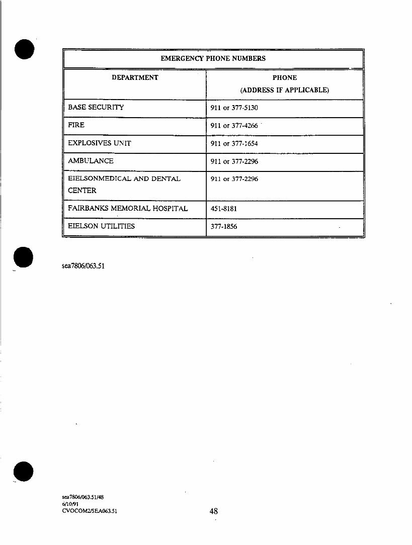
EMERGENCY PHONE NUMBERSJ
DEPARTMENT PHONE
(ADDRESS IF APPLICABLE)
BASE SECURITY 911 or 377-5130
FIRE 911 or 377-42-66
EXPLOSIVES UNIT 911 or 377-1654
AMBULANCE 911 or 377-2296
EIELSONMEDICAL AND DENTAL 911 or 377-2296
CENTER
FAIRBANKS MEMORIAL HOSPITAL 451-8181
EIELSON UTILITIES 377-1856
0 ~~~sea7806/063.5 1
sc7806/063.511486/10/91CVOCOM2/SEA063.51 48

owtou~
W~u
LLI~~~~~~~~~~~~~~~~~~~~~~~~~~~~~~~~~~~~~~~~~~~~~~~~~~~~~~~~~~~~~~~~~~~~~~~~~~~~I
U.
w)> ~~VCL
w 0
X--
C*
> LU~~~~C
LU~~ 7
)~~~~~~~~~~~~~~~~~~~~ w C,
<< '4
W~~~~-
wL eLU LU~~LF-~~~~I
I-~~~~~~~~~~~~~~~~~~~~~~~~~~~~~~~~~~~~~~~~~~~~~~~~~~L
0 L
Co ~~~r >
o w -0o -0 g C-
< 2 z~~~~~~~~~~~~U= WI LI M
0 n L LL
o ZCo, a.ccF

Wet Management Plan DRAFTElelson Air Force Bas.
Appendix C, Attachment 1
MATERIAL SAFETY DATA SHEETS
FOR EIELSON AIR FORCE BASE
0 ~~CV0P2,571033.5I.7

_ _ _ _ _ _ _ _ _ _ _ _ _ _ _ _ _ _ _ _ _ _ _ _ _ _ _ _ _ _ ~SEA
Aieria aeyPBYRNE SPECIALTY GASES 3Material~ ~ ~~~~~~~~~flr*S~sIy a.. c Saet
Data Sheet S..lIIS WaShington 98103 (205) 764-4633
EMERGENCY PHONE: 800---23 9374 IN PENNSYLVANIA: 800-322-90O:2TRADE NAME AND SYNONYMS CHEMICAL NAME AND SYNONYMS
ISSUE DATE Issued. 15 March 1978 Air; Compressed Air; AirCompressed Air, Breathing Quality f
REVISIONS Rev: 10 July 1986 FORMULA CHEMICAL FAMILY RCI~Reconstituted air-approx. 79% N,, N/A - PERSONAL1 fl
21% 0,Compressed-78% N1, 21% O~,Balance: Other atmospheric gases
HEALTH HAZARD DATA4THRESHOLD UNMIT VALUEAir is nontoxic and has no threshold limit value (TLV). Air Is not listed as a carcinogen by NTP, IARC, or OSHA.SYMPTOMS IF INGESTED. CONTACTED WITH SKIN. DR VAPOR INHALEDAir is nbntoxic and is necessary to support life. Inhalation of air at high pressures, such as pressures which may exist inhyperbaric chambers, can result in similar symptoms to those of exposure to oxygen. Inhalation of air at high pressures canalso result in accumulation of nitrogen in the blood which may result in decompression sickness.O TOXICOLOGICAL PROPERITIESExposure to high pressures of air where the partial pressure of oxygen is in excess of two atmospheres may produce a varietyof central nervous system manifestations including tingling of fingers and toes, visual and acoustical disturbances, abnor-mal sensations, impaired coordination, confusion, muscle twitching, and epileptiform seizures. Severe hazards may be pres-ent when confusion and impaired judgment lead to operational errors. Exposure to high pressures may also result in nitrogennarcosis.
-. RECOMMENDED FIRST AID TREATMENTFacilities at which air is breathed under pressure should be prepared to deal with illness related to a hyperbaric environment.Decompression equipment may be required.
FIRE AND EXPLOSION HAZARD DATArL-ASH POINT Imelbm ,uetI AUTO IGNITION TEMP FLAMMABLE LIMITS LEL USLN/A N/A N/A N/A N/AIEXTINGUISHING MEDIA ELECTRICAL CLASSIFICATIONN!A GROUP N/A
I aAEIAL tiRE FIGHIING PROCEDURESN/AUNUSUAL FIRE AND EXPLOSION HAC*ASDCompressed air at hich p:essure can accelerate the burning of materials which are combustible at atmosph-1ric pressure.
PHYSICAL DATABOILING POIN4T I-F.I FREEZING POINT 1flF
©1 atm - 317.9F I- 194.4C) Range: - 351 to - 35SF -213C to - 216C) (Because airis a mixture)
VAPOR PRESSURE ms..i ~ ~ ~ ~ ~SFL5LT (2C) 1WatmE .7%b vlmVIAPO PRSSREFa LUSILTY I W aTE .8% olm
VAPOR ~~:S:TV lit/u'" I SPECIFIC GRAVITY lAIR = 11 LIQUID DENSITY lb/1Cu it) SPECIPlC GRAVITY IH,O.-'~ 68F (C) 0.07520 68SF (20C), 1 atm 1.OO @ boiling point, 1 atm 54.56 @ boiling point, 1 atm 0.874AP'EARANCE AND0 COOP
Gaseous a~r is odorless and colorless.

REACTIVITY DATASTABILITY UNSTABLE CONDITIONS TO AVOID
STABLE X Avoid the use of oil In systems at full cylinder pressure.
None IMIbsIavai1
MAZADUSDCOMPOSITION PRODUCTSNoneMAZADOSMAY OCCU~ CONDITIONS TC AVOIDPOLYMERIZTIOINII
ILL NOT OCCUR I X INone
SPILL OR LEAK PROCEDURESSTEP TO E TKEN IN CASE MATERIAL IS RELEASED OR SPILLED
No hazardWASTE DISPOSAL METHODDo not attempt to dispose of residual air in compressed gas cylinders. Return to Air Products with the cylinder valve tightlyclosed, positive pressure in the Cylinoer, and va've cap In place.
.SPEC!,t PROT.ECTION INFORMvATIONRESPIRATORY PROTECTION ISP.C~lyty IPtINoneVENTILATION LCLEXHAUS SPECIALNone MECHANIALUIGI.netII THE
PROTECTIVE GLOVEFLeather work ;-:ves are recommendlec when handling compressed gas cyl1inders.EYE PROTECTIONSafety glasses are recommended when handling high-pressure cylinders.OTHER PROTECTIVE EQUIPMENTSafety toe shoes are recommended when handling high-pressure cylinders.
SPECIAL PRECAUTIONS*SPECIAL LABELING INFORMATIONCompressed air shipment must be in accordance with Department of Transportation (DOT) regulations using DOT 'NON-FLAMMABLE GAS" label. Consult DOT regulations for details on the shipment of hazardous materials.SPECIAL HANDLING RECOMMENDATIONSCompressed gas cylinders contain gas with extremely high pressure anc should be handled with care. Use a pressure- ,
reducing regulator when connecting to lower pressure piping systems. SeCurt, cylinders when in use. Never use direct flame to kheat a compressed gas cylinder. Use a check valve to prevent backtlow into storace container. Avoid dragging, rolling, orSliding cylinders, even for a shord distance. Use a suitable hand truck. For additional handling recommendations on compress-ed gas cylinders, consult Compressed Gas Association Pamphlet P-i.SPECIAL STORAGE RECOMMENDATIONSKeep cylinders away from sources of heat. Storage should not be in heavy traffic areas to prevent accidental knocking over ordamage from passing or falling objects. Valve-caps should remain on cylinders not connected for use. Segregate full andempty cylinders. Storage areas should be free of combustible material. Avoid exposure to areas where salt or Csrrosivechemicals are present. Consult Compressed Gas Associatron Pamphlet P-i for additional storage recomnmendatior.mSPECIAL PACKAGING RECOMMENDATIONS
ICompressed air cylinders meet DOT specifications.FOFTHER RECOMMENDATIONS OR PRECAUTIONSCompressed gas cylinders shoui.d not be ref illed exce.zt by qualified oroducers of cormpressed gases. Shipment of a com-pressed gas cylinder filled without the permission of mne owner is a violation of Federa! Law.
'Various Government agencies (i.e., Departmenit of Transoortation. Occup~ational Safety and Health Z.--innstration. Fcoca andIDruc ACr.:istration and others) may have soecific regulations concerning the transportation hanc!;n; storage or u sectf this
prccwhich will not be reflected in thils cata Sheet. TIhe customer should review these regulations to ensure that he -s !n full

14~~~~~~~~1
- < '
OCZC~~~~2 ~~a - -
-. ; ir ,
MiN C' If Ml S
CJ 0 cq~~~~~~~~~C ' .C. if
7 w 'F. C~ ~ ~~~F!t -cc 3~ ~~~~~ 1tx:i.
a MOCua~lM~e.~?T
E o~~~~~~~~~~~~~~~~~~~-.rw~~~~~~~~~~~~~~~~~~~~~~~~~~~.q~~~~~~~~~~~~
C~~~~~~~ 0
8 'E~~~~~~~~~~~E Z~~ ~!
C~~~~~~~~~ .;2 a'Ue Z
E 07EZ1 - E E
'Fe t~~~~'
t --- C~~0~-'
CD 24~~~~~~~~~~~~~~~~~~~~~~~~~~
I- U~~~~~~~Z 0 U&
2 o~~~~~~~
cu~~~~~~~~~~~~~~~~~ EU~~~~~~~~~~~~~~~~~~~~~~~~~~~ 5n0
0~~~~~~~~~~~~~~~~~4 <
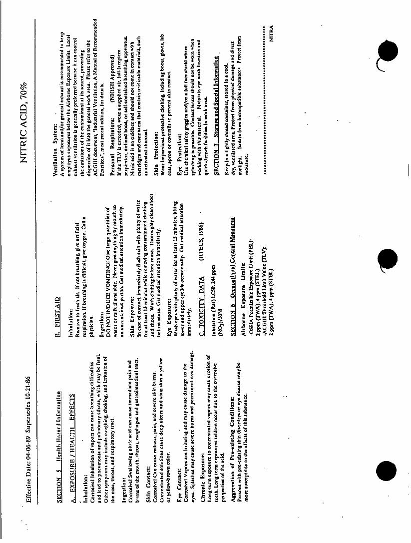
O 0 c
*0~~~~~~~~~~~~~
C~~~~~
0. 2 ~~ ~~~~~ Ec
V -~~~O
~0 .I
E~~~ E0 ML
-a . Wi
uj~~~~~c -U

not
Zo
ot r 0 L0Jc~~3
0
2 -'
P~~~~~~~~~~~~~~~~~~~~~~~~~~~~~~~,I g )
0 uMu o.J
U U
w LI ~~~ ~ ~ ~ ~0~~~~~~0*
CZ~~~~~~~~~~~~~~~~~~~~~~~~~~~~~~~~~~~~~~~~~~~~~~~~~~~~~~~~~~~~~~~~~~~~~~~~~~~~~,
Z =-= '3<
7-- U o)
El V)~~~~~~~4 Z
Z U ~ ~ ~ ~ ~ ~~IC aC4 fl:4<2U Uh
-0 Lu~~Fr4 ~ cO Cf z~~
0~~~~~~
- C~~~~~~~-
< <-

®~BYRNE SPECIALTY GASES
I ~ ~ ~ ~W.Sp.C 9-a.t 9 "'B (206) 764-4633 Date A gs,18 E
aW MAERAuSFTYDAASHE Page 1 of 6
Product Name: PHILLIPS 66 COMPANY LU OPNA SUBSIDIARY OF PHILLIPS PETROLUCOPN
n-PENTA~N E Bartlesville, Oklahoma 74004n PENTA ~~~~Emergency Phone NOS.
(Commercial, Pure 918.661-3865 (duringbuies
and Research ~ ~ N 918-661-8118 (after hours);4and eserchGrades,and ~~~~~~~~~~~~~~~~~~~~~~~~~~~~~~~~PETOM o
and ~~~~~~~~~~~~~~~~~~~~~~~~~~~~~~~PERSONAL
p I~~~~~~~~~~) ~(WORLDWIDEPRTCI
.Pentan e (S) USA AND CANADA OTHERCONFIE'
PRODUCT IDENTIFICATIONSynonyms: Normal Pentane, Pentane
Chemical Name: n-Pentanle
Chemical Fdmily: Aliphatic Hydrocarbon
Chemicad-Formula: Cs H12
- CAS Beg. NO: 109-66-0
Product NoK3O?5500, P05400, P05392
Product and/or Components Entered on EPA's TSCA Inventory: Yes TXNo D1
HAZARDOQUS COMPONENTSGAS OSKA ACGIH
Ingredients Number By Wt. PEL TLV
n-Pentane 109-66-0 * 1000 ppm 600 ppm
Isopentane 78-78-4 N E NE
Related Hydrocarbons NE N E N E
*See additional comments (Page 6) for exact compositions.
NA-NOT APPLICABLE NE-NICT ESTABLISHED FR T-

MATERIAL. SAFETY DATA SHEET Page 2 of 6
PERSONAL PROTECTION INFORMATIONVentilation: Use adequate ventilation to control exposure below recommended lev-
els.
Respiratory Protection: Not generally required. For concentrations exceedingthe recommended exposure level, use NIOSHIMSHA approved air purifying res-pi rato r.
Eye Protection: Chemical goggles if splashes are possible.
Skin Protection: impervious rubber gloves if liquid contact could occur.
NOTE: Personal protection information shown above is based upon general infor-mation as to normal uses and conditions. Where special or unusual uses or con-ditions exist, it is suggested that the expert assistance of an industrial hygienistor other qualified professional be sought.
HANDLING AND STORAGE PRECAUTIONSAvoid inhalation and skin and eye contact. Wear protective equipment and/or gar-ments described above if exposure conditions warrant. Wash hands after handling.
Store in a cool, well-ventilated area away from ignition sources. Provide means forcontrolling leaks. Bond and ground during transfer. Keep containers closed. Laundercontaminated clothing before reuse.
REACTIVITY DATA,Stability: Stable FUnstable7 HConditions to Avoid:
Incompatibility (Materials to Avoid): Oxygen and strong oxidizing agents.
Hazardous Polymerization: Will Not OccurN May OccurE-Conditions to Avoid
. ~~Hazardous Decomposition Products: Carbon oxides formed when burned.
FORM PTS-2

MATERIAL SAFET Y DATA SHEET Page 3 of 6
HEALTH HAZARD DATARECOMM ENDED EXPOSURE LIMITS: OSHA PEL for Pentane isl1000ppm;ACG IH TL2V is 600 ppm.
ACUTE EFFECTS OF OVEREXPOSURE:EYE: Freezing burn if compressed liquid contacts eye. Vapors may be mildly
irritating.
SKIN: Freezing burn if compressed liquid contacts skin.- -
INHALATION: Vapors may be mildly irritating to lungs.
INGESTION: NA
SUBCHRONIC AND CHRONIC EFFECTS OF OVEREXPOSURE:INo known applicable information.
OTHER HEALTH EFFECTS:No known applicable information.
HEALTH HAZARD CATtEGORIES:Animal Human Animal Human
Known Carcinogen C C Toxic C- C3Suspect Carcinogen C- C Corrosive C CMutagen C C1 Irritant CTeratogen f-I Target Organ Toxin C- C~Allergic Sensitizer Specify__________
Highly ToxicCSpcf
FIRST AID -"%ND EMERGENCY PROCEDURES:
EYE: Immediately flush eyes with running water for at least 15 minutes. If irrita-tion develops, seek medical attention.
SKIN: Flush skin with water for 15 minutes. If irritation develops, seek medicalattention.a
INHALATION: Remove from exposure. If breathing ceases, administer artifi W) ~~~respiration followed by oxygen. Seek medical attention.INGESTION: Seek immediate medical attention.

9/MATERIAL SAFETY DATA SHEET Page 4 of 6
PHYSICAL DATAAppearance: Colorless liquidOdor: Mild, gasoline odorBoiling Point: 970F (3600)Vapor Pressure: 15 psia at 100OFVapor Density (Air = 1): 2.48Solubility in Water: NegligibleSpecific Gravity(HiO = 1): 0.63 at 601600FPercent Volatile by Volume: 100. ~~Evaporation Rate ( Butvl Acetate =1): 28.6Viscosity: 0.443Cs at 320F
-~FIRE and EXPLOSION DATAFlash Point (Method Used): c<-40 0F (<.400C) (TCC, ASTM 056)Flammable Limits (% By Volume in Air): LEL ZL.. UEL 7.8Fire Extinguishing Media: Dry chemical, foam or carbon dioxide (COj.
Special Fire Fighting: E-vacuate area of all unnecessary personnel. Use NIOS~HIMSHA self-contained breathing apparatus and other protective equipment*and/or garments described on Page 2 if conditions warrant. Shut off sourceif possible. Water fog or. spray mnay be used to cool exposed~ containers andequipment. Do not spray water directly on fire - product will tioat and couldbe reignited on surface of water.
Fire and Explosion Hazards: Carbon oxides formed when burned. Highly flam-mable vapors which are heavier than air may accumulate in low areas and/orspread along ground away from handling site.
SPILL, LEAK and DISPOSAL PROCEDURESPrecautions. Required if Material is Released or Spilled: Evacuate area of all
unnecessary personnel. Wear protective equipment and/or garmentsdescribed on Page 2 if exposure conditions warrant. Shut off source, if pos-sible and contain spill. Protect from ignition. Keep out of water sources andsewers. Absorb in dry, inert material (sand, clay, sawdust, etc.). Transfer todisposal drums using nonsparking equipment.
Waste Diesnncz;I tin crr~fnnftn,+,.,* AI IA--u-L- !. .-

MATERIAL SAFETY DATA SHEET Page 5 of 6
DOT TRANSPORTATIONShipping Name: PentaneHazard Class: Flammable LiquidID Number: UN 1265Marking: PentanelUN 1265Label: Flammable LiquidPlacard: Flammable/1265Hazardous Substance/RO: NAShipping Description: Pentane, Flammable Liquid, UN 1265Packaging References: 49 CFR 173.118 and 173.119(a)
R CRA CLASSIFICATION (FOR UNADULTERATED PRODUCT AS A WASTE)Ignitable
PROTECTIVE MEASURES DURING REPAIRAND MAINTENANCE OF CONTAMINATEDEQUIPMENT
Wear protective equipment and/or garments described on page 2 if exposure~conditions warrant. Contact immediate supervisor for spez-ific instructionsbefore work is initiated.
HAZARD CLASSIFICATIONTHIS PRODUCT MEETS THE FOLLOWING HAZARD DEFINITION(S) Ar DEFINED By OCCUPA-TIONAL SAFETY AND HEALTH REGULATIONS (29 CFR PART 1910. 1200):C Not Hazardous CFlammable Solid COxidiz-erED combustible Liquid CFlammable Aerosol CPv,:tphoricC Compressed Gas CExplosive CUnstableC3 Flammable Gas CHealth Hazard (see Page 3) C) water Reactive
Fla'mmable Liquid COrganic Peroxide

MATERIAL SAFETY DATA SHEET Page 6 of 6
ADDITIONAL COMMENTS (Continued)Product Ingredients %/ by Weight
n-Pentane n-Pentane 99.4(Pure Grade) Isopentane 0.2
Related Hydrocarbons 0.4
n-Pentane n-Pentane 99.99(Research Grade) Isopentane 0.01
n-Pentane n-Pentane-9. 1(Commercial Grade) Isopentane 0.7
* ~~~~~~~~~~~~~Related Hydrocarbons 0.8
Pentane (S) n-Pentane 98.5(Isopentane 0.7Related Hydrocarbons 0.8
C®BYRNE SPECIALTY GASES
Wl~~~j 514 S.fl1=StteLa"J S.nug1. WttIofl 98105 a (206) 764-4633
Phillips believes that the information contained herein (including data and statements) is accurateas of the date hereof. -O WARRANTY OR MERCHANTABILITY, FITNESS FOP; ANY P-RTICULARPURPOSE, ORANY OTHER WARRANTY, EXPRESS OR IMPLIED, IS MADE AS CONCERNS THEIN FORMATIO1N HEREIN PROVIDED. The information provided herein relates only to the specificproduct designated and may not be valid where such product is used in combination with any othermaterials or in any process. Further, since the conditions and methods of use of the product and theinformation referred to herein are beyond the control of Phillips (references to Phillips including itsdivisions, affiliates, and subsidiaries), Phillips expressly disclaims any and all liability as to anyresults obtained or arising from any use of the product or such information. No statement madeherein shall be construed as a permission or recommendation for the use of any product in a mannerthat might infringe existing patents.

V4ATERIAL SAFETY DATA 7601 54 9 Pn
TRISODIUM PHOSPHATE- ANHYDROUS NP einto 0
00CCC or IAZ.AO"CAL T. a AE TWIT'
EXT.R(ME EI II2 ~ ELLOW)
EMERGENCY TELEPHONES:PLANTS: (91,32 749-8100 LAWRENCE# KS
UiOiI 541-4171. CARfERET, NJCHEH(REC: (PO0) 424-9300 TRANSURIATION PCA
MEDOICAL: (303J 595-9048 ROCKY MTN
REVISIONZ a EFFECTIVE: 09/14/65 PRINI':0 11/018/5
PHYVS £CAL OA TA
MELTING POINT ..............- OVER. 1300C
B.OILING POINT............... :OVER 150OCVAPOR PRESSURE.............NON-VOLATILEVAPOR DENSITY (AIR - lj..: NON-VOLATILE
POOM TEMPERATUREAPPEARANCE AND STATE: WHITE GRANULES OR POWDER
ODOR------------------------: NONEf:'ECIFIC GRAVITY (H20 =I2: BULK DENSITY 1.0 G/Mt
!DLUBLLLTY IN HZQ X BY WT: 12 2 25CtVOLATILES BY VOLUME.... : NON-VOLATILE
~jVAPORATION RATE(BUTYL ACETATE = I).: NON+-VCLAT[ILE
',H (AS [SJ.................. NOT APPLICABLEH c I: SOL UT IONJ ........... 1.
FIRE. EXPLOSION AND REAcTLVITY DATA
nAHPOINT-----------------NON COMBUSTIBLE
I i.'JTOIGNITION TEMPERATURE. NON COlMfBST ISLE
ffiAMABLE LIMITS UPPER-. . NOT APPLICABLE(AIR) LOWER.... NOT APPLICABLE
5~XTLNGUISH-ING MEDIA..... ....NOT APPLICABLE?ECIALFIRETHTING ......- NOT APPLICABLE
PR D-C ED UYR E S,%GREE OF FIRE AND-----:NONE
EXPLOSION HAZARDSITABILITY.................. : STABLE?AZ'AROOUS POLYMERIZATION.: WILL NOT OCCUR
?ONOITIONS TO AVOIO ..O.... : NONE
MiAJOR CONTAMINANTS THAT..: NONE2'ONTRIBUTE TO INSTABILITYINCOMPATIBILITY.------ .----- NONE9!AZAROOUS DEC.OMPOSITION..: NONE
PRODUCTS

SEA083
*-(ERIAL SAFETY DATA 7601 I5E409
NFPA Designst.on 704
TR ISOD IJM .PHaS P4ATEv'AMkYoRO(S
O(GACE Of NAARO
M OOEAATC -
EMERGENCY TELE PHONES:0nSCICHPLANTS: (9 13)J 74 9- 8100 LAWRENCE9 KS
(2011 541-4171 CARTERET, NJCHEMrREC: (6001 424-9300 TRANSPORTATEON SCAMEOLCAL: (3 031 595-90 48 ROCKY MTN
REVISION: 0 EFFECTIVE: 0N/Ii4/5 PRINTED: 11/103185
PREPARED FOR USE BY .. .. ..... NORTH COAST6300 IUrH AVE SOUTH
__________-IDENTIFICATION
INFORMATION PROVIDED BY..: FMC CORPORATION.2000 MARKET STREETa ~~~~~~PHILADELPHIA PA 19103
PROD(JCT INFORMAT ION
SYNONYMS................... : SODIUM PHOSPH-ATE TRiBASIC, TSPSHIPPING NAME DOT........ :SODIUM PHOSPHATE, TRIBASIC
IATA......- SOUIUM PHOSPHATE, TRIBASICIMCO------- SODIUM PHOSPHATE# TRIBASIC
IORM4ULA..................... :NA4iPO4CHEMICAL FAMILY--------------PHOSPHATE
-PRECAUTIONARY INFORMATION
OSH-A XAZ7ASD Cl ASS(FICATIONPRECAUTIONlS ...............-: PRODUCT IS STRONGLY BASIC (ALKALINEAk;!PLEAS"E USE THIS STATEMENT CONTACT WkITH TISSUE MAY CAUSE CHEMICAL BURNS..TO SATISFY THE IEM-PLANT AVOID CONTACT.. WASH THOROUGHLY WITH WATERLABELING REQUIREMENTS TO REbZOVE.OF 7HE OSHA HAZARDCOMMUNLCATIONS STANDARD29CFR 1910-12001
INGREDIENTS ---
£455 AND COMPONENT......... MATERIAL OR COMPONENT: TRLSODIUM PHOSPHATEPERCENT : tooCASE . 7601-54-9HAZARD CLASS IRRITANT

"ATERIAL SAFETY DATA 76 01 5 4 9 *(0
NFPA Designation 704
TRISOUJUM PHOSPHATE ANHYDROUS
DEGREE Of 4AIAAO
dEX!PEM( "'All m EC4W
StiC.iT U.e0 YLL
EEMGf-.GNCY TELEPHONES: 0 tNSiONWiC~fl
PLANTS: (913J 749-8100 LAWRENCE, KS(2013 541-4111 CARrERET, NJ
CHEMTREC. (8001 424-9300 TRANSPORTATIONSPCAMEDICAL: (3 03J 5 95-9048 ROCKY MTN
REVISION: 0 EFFECTIVE: 09/14/85 PRINTED: 11/08/85
ROUTES Or- EXPOSURE!-
EYE CONTACT-----------------IRRITATING TO EYES. CORROSIVE EFFECT AFTER24 HOURS. IN RABBIT.SOURCE: AIHA J. 43 NO. 10 8-51GATE: 1982
ISKIN CONTACT-----------------MODERATE DEGREE CF IRRITATION. 24 HOURSOCCLUDED SKIN (RABBIT).SOURCE: AIHA J. 43 NO. 10 8-51DATE: 1982
.N ABSORPTION............. NO SIGNIFICANT HAZARD. 1050 (RABBIT)>7940 MG/KGSOURCE: AIHA J. 43 8-51DATE: 1982IINHALATION.................- SMALL AMOUNTS OF DUST VERY. IRRITATING.SOURCE: AIHA J. 43 NO. 10 8-51 DATE: 15832
INGESTION................... SLIGHTLY TOXIC 20Z AQUEOUS SOLUTIONL050 (RAT) = 6500 MG/KGSOURCE: AIHA 4. 43 8-SI DATE: 1982DATA FOR ABOVE ROUITES, OF EXPOlSURE IS~ FORSrMrlLt~ PRnODUCT (RrI spoi p9n-ISPHATFr CRYSTAL sL.
-- ~~~EFFECTS OF OVYEREXPOSURE
ACUTE EXPOSURE .......... : INHALATION OF HEAVY OUST MAY IRRiT.ArE NOSEAND THROAT. INGESTION MAY. INJURE MOMN.HTHROAT. AND GASTROINrESTINAL TRACT.. CONTACTWITH EYES PRODUCES LOCAL LRRITATION ANDPOSSIBLE CONJur~rTIVITIS..
CHRONIC EXPOSURE............ ALTHOUGH NO LGriG TEAM HUMAN STUDIES HAVEBEEN REPORTED, THERE ARE NO REPORTED CHRONICEFFECTS THAT WARRANT CONTRAGL BEYOND THATREQUIRED TO AVOID IRRITATION FROM AIRBORNEDUST.

033
'WMATERIAL SAFETY DATA 7601MA&TV 1'MNFPA De5ignalacn 704
rRLSUDIUM PHOSPHATE ANHYORLYJS
OCECACECFOV l&AAo
(STAEM( nAt. 7A EACTIV.tY
2 MOO(AATE cI SLGI~n
EMERGENCY TELEPHONES: O. INS.GNntICA.NTPLANTS: (913) 749-8100 LAWRENCE, KS
(20L3 541-4171 CARTERET, NJCHEMTREC: (80091 424-9300 TRANSPORTATrION SP(CIAL
MEUICAL: (303) 595-9048 ROCKY M4TN HZA
REVISION: 0 EFFCECTIVE: 09/t.4/85 PRINTED: LIioai85
- -- ~~~~EmERG!3NCY AND FIRST' AID PRIOCEDURES
OEMUL_-EN(S MAY PROVIDE SOME RELIEF OF MILDTO MODERATE PAIN; SEVERE PAIN MAY REQUIREOPIATES. TREATMENT OTHERWISE IS SYMPTOMATICAND SUPPORTIVE, WITH ATTENTION TO THE POSSIBLECOMPLICATIONS OF GLOTTAL OBSTRUCTION,ESOPHAGEAL PERFORATION ANG SHO7CK..
n a m i n ~~~SPECIAL PROTECTION
' ENTILATLON REQUIREMENTS.: USE GENERAL ROOM VENTILATLON OR LOCAL EXHAUSTVENTILATION IN PROCESSES OR HANDLING IWHENAIRBORNE DUST IS EXPECTED TO BE RELEASED INTOTHE WORK ENVIRONMENT.IRECOMMENDED PERSONALe.....: SEE BELOW
PROTECTIVE EQUIPMENTRESPIRATORY........ : USE NIOSH/MSHA APPROVED RESPIRATORY
PROTECTION IF AIRBORNE DUST ISEXPECTED..
EYES.........~:WEAR C.HEMICAL GOGGLES, IF AIRBORNE OUSTIS EXPECTED-
GLOVES--------------: NO SPECIAL REQUIREMENT.SPECIAL CLOTHING..: NO SPECIAL REQUIREMENT.
AND EQUIPMENT
--- s ~~~~STORAGZE AND HANDLING -nom
(PLEASE USE THIS STATEMENT USE NIOSN/MSHA APPROVED RESPIRATORY0 .SATIST'r THE IN-PLANT PROTECTION AND CHEMICAL GOGGLES, IF
LABELING REZVUIREMENTS AIRBORNE DUST IS ExPECTED.OF THE OSHA HAZARDCOMMUNICATIONS STANDARD STORE IN A DRY AREA, FOR AROOUCT
19F 910.1200Ji QUALITY ASSURANCE.
- - D~~~~~ISPOSA'L. SPILL OR LEA" PROICEDURES
I ROCEOURE FOUR RELEASE ...-. MATERIALI SHOULD BE SWEPT UP FOR SALVAGEOR SPILL OR DISPOSAL.

=FM@FtA&.UA elkIT Y
MATERIAL SAFETY DATA 7601 5 4 9(RONFPA Designalion 704
TRISQDUMLt PHOSPHATE ANHYOROUS
DEGREE Of 1A~rAn
#44 Al I"PJ#4VI
* (TACUC fIn ll0,
EMERGENCY TELEPHONES: 0 US16N(ICAN'
PLANTS: 1913J 749-8100 LAWRENCE, KS(201) 541-4171 CARUERET. NJ
CHEMIREC: (800) 424-9300 TR AN SPOR TAT IONSPCAM4EDICAL: (3031 595-9048 ROCKY MTN
REVISION: 0 EFFECTIVE: 09/14/85 PRINTED: 11/08/85
-0I.SPGSAL. SPILL OR LEAK PROCEDURES
WASTE DISPOSAL METHOD..-. IF MATERIAL CAN NOT BE SALVAGED. A METHODOF DISPOSAL IS IN A LANDFILL IN ACCOROANCEWITH ALL LOCAL, STATE, AND FEDERALREGULATIONS.
TRANS PORTAT ION DATA
DOT PROPER SHIPPING NAME..: SODIUM PHOSPHATE, TRIBASICDou CLASSIFICATZ'ON-------- :ORM-EDOTo LABELS................. :NOT REQUIRED
0g1 MARKING.-----------:---SODIUM PHOSPHATE, TRIBASIC NA 9148OTPLACARD ...........,... :NOT REQUIRED
*UN NUMBER................. :NA 9148HAZARDOUS SUBSTANCE/R0..-: 5000 LBS. (2270 KG)49 STCC NUMBER ............-: 496163813EMERGENCY ACCIDENT
IPrECAUTIONS AND PROCEDURE: MATERIAL IS STRONGLY BASIC (ALKALINE; TAKECARE TO AVOID CONTACT WITH LARGE AMOUINTS O3F
DUST. SEE INSTRUCTIONS ABOVE FOR. RELEASEOR SPILL.
IPRECAUTIONS TO BE TAKEN..: NONEIN TRANSPORTATICS4j
CMA CHEM4CARD. NUMBER-------: NONETYPE PACKAGES............... MULTI WALL PAPER BAGSOTHER SNIPPING IDS .........
s- ~~~~ADODITIONAL. REGULATORY INFORMATION
MATERIAL IS REPORTED INEPA TSCA INVENTORY LIST? YES
MATERIAL IS LISTED AS A4 CARCINOGEN/POTENTIALCARC[NOGEN IN FOLLOWING
NTP ANNUAL REPORT... 7 NilIARC MONOGRAPHS-------7 NO
OSH 29FRPART 1910OSHA 9CERSUBPART Z 7 NO
FDA GRAS LIST; PERMITTED LN FOOD..

05/02/91 08: 56 'Z'303 752 0276 CH2N HILL CVO SEA t004/008
UPDATED
EM SCIENCE"A O,- - I ..i.nIn
Ill WoodcresE Road, Cherrv Hill, New Jersey 08034-0395, phone (609) 354-9200
MATERIAL SAFETY DATA SHEETEsaentieliy Similar ,o U.S. OeP~rtn'y*0: Of Labor Form OSMA-20
SECTION 1 NAME & PRODUCT
Chemical Name: Catalog Number:
Hydrochloric Acid 314, 315, 317, 321, HX603
Trade Name & Synonyms: Chemical Family:
Muriatic Acid, 230 Be CAS #7647-01-0 Acid
Formula: Formula Weight:
HC1 (approx. 37% in water) 36.46
SECTION 2 PHYSICAL DATA
Hg oi~~l1DC mix0.241 Specific Gravity (H20 = f 2 8f85Ecihn Poin. 760mm Hg constant boiic itue
Melting Paint (CSouiiynH 2 .%by wt. at 20-C Miscibl
Vapor Pressure at 20CC approx. 160 nu ng Appearance and Odor clear, colorless
Vapor Density (air = 1) 1.25 liquid; acrid odor
Percent Valatiles by Volume 37Evaporation Rate (Butyl Acetate =1j1
SECTION 3 FIRE AND EXPLOSION HAZARD DATA
Flash Point (test method) Nonflaznale Flammable Limits ILel N/A Uei N/A
Extinguishing Media Water spray
Special Hazards and Procedures Wear self-contained breathing apparatusWear full protective clothinc
UnuualFir an Exloson azads Contact with metals produces hydrogenUnusal ire nd xplsionHazrds which may 'form exPlosz4ve mixtures with air
SECTION 4 REACTIVITY DATA
Stable x Conditions to Avoid
Unstable None
Materials to Avoid
IIWater (I Acids I XI Bases I ) Corrosives I I Oxidizers
I X) Other lsoecify) Alkalies and amines; contact with metals produces hydrogen
Hazardous Deccmnposition Products toxic hydrogen chloride gas
SECTION 5 SPILL OR LEAK PROCEDURES AND DISPOSALNeutralize with soda ash/slaked lime mixture
Steps to be Taken in Case Material is Released or SpilledFlsarawtwte
Waste Dsposal ethodTo be performed in compliance with all currentWaste Dispsal Methodlocal, state and federal regulations
the shatements contained herein are olfered lot informational outlines only and alte intended to be lollowed only by persons hay ng related technicai skills and at Ihei'own disuetion and risk. Since conditions and manner of use are outside out control. we make no watranutes. express or implied, and assume no liability in conhectiorwith any use ot this inlormatwn.

05/ 02/91 I 08:5 7 TS503 752 0276 CH2M HILL CVO ... SEA la005/008
314, 315. 311, 321. HX060 3
SECTION 6 HEALTH HAZARD DATA
Threshold Limit Value
5 pmT)WS: ihl-hmn LDLO: 1000 PPm/lMorl-'rbt LD50: 900 mg/kg
Effects of Overexposure causes severe irritation of respiratory Passages, dermatitis,
severea and rapid eye damage, chest pain, choking cough. May cause severe burns,
pulmonary edema, circulatory collapse and death.
First Aid ProceduresCE? IMMEDIATE MEDICAL ATTENT.ION FRc ALL CASES OF OVEBZFXPOSURE
Skin: flush with :..xge amounts of water
Eyes: flush with water 15 minutes holding lids open
Inhalation: remove to fresh air
ingestion; do not induce vomiting; give water of milk if conscious
SECTION 7 SPECIAL PROTECTION INFORMATION
Ventilation. Respiratory Protection. Protective Clothing. Eye Protection
Provide adequate general mechanical and local eyxhaust ventilation
Protect eyes and skin with safety goggles and gloveSt
W~ear face shield and impervious clothing including apron and long sleeves
Do not breathe vapor
Do no: get in eyes- on skin, or on clothing
SECTION 3 SPECIAL HANDLING AND STORING PRECAUTIONS
Keep container closed and protected against physical damage
Store in a cool, well-ventilated area separated from incompatible materials
Store separate from oxidizers
Wear vapor-proof goggleswash thnroughly after handling
Handle empty containers with caution
SECTION 9 HAZARDOUS INGREDIENTS(refer to section 3 through 8)
OCT - Corrosive Liquid
SECTION 10 OTHER INFORMATION
NFFA 704: 3 0 0Health Flammuability Reactivity
1 ' . GA~~~~~~~~~0TE ISSUED.__________

SEA65
im materialiSafety Data Sheet U.S. Department of Laboray be used to comply with Occupational Safety and Health Administration
WOSHA's Hazard Communication Standard. -(Non-Manditory Form)29 CFR 1910.1200. Stat-card musi beS Form Approvedconsulted for specific reqluwserners. 0MB No. 1218-0072
IDENTITY (As Used an Lt W0 i St) Now: Biank wpecas ar e noNI"fa anWY NW1 .5 riot &poOa,J154LIOUI-NOX irdinnwmen a avw4at the zoao mAf co mine rot
Section IManutaclurers Name Eregrwcy T~iewohone Numbse
ALCONOX. INC- r7i21 471-, 1nn -
Address (PNrnDe. Stree. Chy. State, an ZIP COW) Tle4ronw Nurno Nor lfllrarc~nir215 PARK AVENUE SOUTH (212) 473-1300 oNEW YORK, NEW YORK 10003 D ia JULY 1. 1987
Section 11 - Hazardous Ingriedientsddenttty InfortmatIon EESOAHazardous Comoruflas (Sconect Chem"l LGenw.t Commo~n Namne~sfl OSMA PEL ACOIH TLV Recorimenoec At (0os
Trwrp Ar ~ N, Tr nrNC TV T.TflTlT-NflY WRTrTC hDP~rAPrn flZrtr nc;T; TmAZ
2g rng lain qI71;P T- 7.
Section III -PhyslcallChernlcai Characteristics
Boiling Point SpecficGrmltyQIH20.1)
Vapo Pressurai (mm Hitj Me"n pout
Vapoo Densaty (AIR - 1) Enaooation Fla________________________ ~~NO DATA (Burl ceate.1) NO DATA
Solubility in WaterCOMPLETELY SOLUBLE IN ALL PROPORTIONS
Aopeartgnce an Odor
YELLOW LIQUID - PRACTICALLY ODOQRLESS;.
Section IV - Fire and FExplosion Hazard DataFlash Point (Menhod Used) T,1 Flarrwnale; Unta LLUEL
Extinguishirng Media
WATERg. DpY CrrmICA,. FOA}¶. ~o. 20 q?3fl/FAPTMSpecial Flee Fighting Prvcedures
a ~~~FOR FIRES TNVOLVTNO; THIS MATERTAL. no NOT rN=r wT;TmTjfiTr
'UnusuM PROTECTIVE EQUIPMENT AND SELF CONTAINED BREATHING APPARATUS.
NONE
(Reproduce locally) OSHA 174 Se:: '925

Section V - Reactivity Data _________________________ _____________
SLiADity Unsable } Conditions to Avvad NONE
Incompatt~iblty iMa tenets to Avoid)
mazrvusDecmmrton r ypoduts MA BE -RELEASED ON BURNING
Hazardous Mam~r I otnt AvoidPo"FIuZZI:Ot ____ NONE
Section VI - Health Hazard Data
Rouls(s) 01 Eritrryn~t Skint?IfglOtwr vrc yrq
hearthi Hazards (Aaif and Cvat)SKIN CONTACT K pgopyr T.t)rLTT~v TRRT'r¶TNc
INGESTICN MAY CAUSE DISCOMFOgr.AN/OP flTApvmrA-
Cwvircgeohcft~~~~~~~~ NTP? ~~LARC hL acrwf lOSHA FLg.atwL&C
Sign, and Symptoms of Expx surem n~mr YNr~TrrMY-rAi~ ;yi: t n UDTM
Medical ConrudgonsGenru~ry Aogrrvated tby Ex==m NONEp
Ems 9 enq arc iRn. Aid P. r gett
EYES-FLUSH WITH PLNYp=W7qr~1 Tr~ SXTN-?TTlqT WT-T J
IGSTION-DRIN 6 ?M c fW1f~ rf~~ ¶vrf\m r,
Section VII - Precatrtiorv. for Safe Handling end Use
Tknin Case Matenej Is Released or S-tledR ALFOAMS P'ROrUSELy. RECOVER AS MTlf" AS DnqqR~Tr WT¶T4- hncCVPnr\¶
M4ATERIAL AND RINSE REMAINDER TO SEWER. MATERIL-I-----S~T ------ pfl-
Warn Disposal Mairod
SMA-LL OUANTIT~rc Mh prfTYfCflp N mr T.A~rr fT1nN¶T7Trq qC1111)~f BE
SOAKED UP WITH AISOPBErP M.L~rrrTAT, ;aim DISPOqrT or ArrflRDTNr Tn 1TrrM ORThW1NCPrecjav¶4'! !o ae Taken In Handl~cainq S bomf W EPEAURS
NONE REQ~UIRED -VISuXIOSITLY OF MATERIAL INCREASES AT VEJRY LO TEPRTES
O'.t,or Precaubtion
NO SPEC:t REQUIREMENTS OTHER -MAN TH lOhf~SBAHY(-ITENS-
AND SA~FEZ'Y PRACTICES EIMPLOYED WITH ANY INDUSmDTA flrP-XTCM
Section Vill - Control Measures
Restratory Pruecamo (S.pec4 Ty)
venlilation Lnca Exhaustpeia
Prowecrve Gloven Eye Prouec' EC)aI-N E
Cirner Pmzectre Cloitdng or EqulprnenNOT REOUIPE
workyq-n~cPradcnwW~fl(M~1C NO SPECIAL PRACTCSR~Tm
Pe" 2 *v~

PRODUCTS ±.Z. ~~Speciaity G a-.0 BYRNE SPECIA LTY GASES Material Safel
£14 S.U ti D ata S hecEham *a~~ 'ca(206) 764-4633
EMRENCY PHONE (80o1 5fl-fl74 POU~A,IN PENNSYLVANIA reoo) 2 22.30t2 PROIOBLyTYAMCARPODUCTS AND CHEMICALS INC. TRACE NAME AND SYNOIyrjS
ALLENTOWN, PA 13105(215) CH427EMI1CAL NAME "Oe SYNONyM.
ISSUE DATE PO~~~~~uu~~ CHEIJ~~~ca FAM~ILY
HEALTH HAZARD DATATIMEEIGHTED AVERAGE EXPOSURE UMIT
tion: Moderate conlcentrafions which exclude ani adequate supply Of Oxygen to Me lungs CauSe dzies-.Owsiness and eventual unconsciousness. It also has a very mild anesthetic effeCt, which mighit cause Lack ofSkin and Eye Contact: It is Mildly irritating to mucous membranes. Due to Its rapid rate of evacoratinI~~yB
Can cause tissue freezing Or frostbite On Contact.tin suyee
TOXICOLOGICAL PROPERTIE'SobUtyfene has a very mild aneSthetic effect. however. the major health hazard is the exclusion of an ad~equateSupply of oxygen to the lungs.Fros~loe effects are a Change in color of tnre skin to gray or white possibly followec by blistering.
RECOMMENDED FIRST AID TREATUMT~
PROMPT M EOICAL ATTENTION IS R EQUIR ED IN ALL CASES OF OVEREXPOSURAEPTPO R'SO8TU1S ENME RE;TS-E
CUE PERSONNEL SHOULD BE EQUIPPED WITH SELC.CONTAINED BREATHINGAP RTUAN MSTEAWARE OF EXTREME FIRE AND EXPLOSION HAZARDinhalatlion. Move exposed personnel to an uncontaminated area. if not breathing, give artificial respiration. prefera.)lv rnouth-to-mouth If breathing is ditlicutt, give oxygen. Medical assistance should be sought immeciately.,,Oaci Or Frostbite: Remove contaminated dloling and flush affected areas with lukewarm water. DO NOT
WATER. A physician should see the patient promptly it the cryogenic "NbM" has caused blistering ofr rdeep tissue freezing.
d tt~~ e r~~ o n~ t~~ o ris k A ll £ tjl o n t e n t: t e o~~~m y
r a , eI o e.:
0,ooa na

MA.ZAROOUS MIXTURES OF OTHER LIQUIDS. SCUIDS. OR GASES
Forms exolosive Mixtures with oxidizers such as oxygen. chloride, or fluorine. Sunlight exolodes a mixture ofchilorine arci metnane (2 volumes of cnlorrne with one of metnanei.
PHYSICAL DATABOILING POINT LIQUID DENSIT AT BOILING POINT
- (-860 161 .50Cm 26.5 lb/ft3 (424.5 kg/rn 3)VAPOR PRESSURE at 70nr (21-1C) jGAS DENSITY AT 70F. I .trrn
Above the critical temoerarure I 0.0417 lb/ht3 (.667 ko/rn3)SOLUBIUITY IN WATER at 680F. 1 atm jFREEZING POINT
3.3 cm'~/100 cm3 I 296.50 F (- 182.5'C)APPEARANCE AND ODOR
Colorless, odorless. tasteless
FIRE AND EXPLOSION HAZARD DATAFLASH POINT (Method usec) AUTO IGNITION TEMPERATURE FLAMMABLE LIMITS % CY VOLUME
Gas I 999PF(537 0C) LIEL 5%~ UEL 1 5%EXTINGUISHING MEDIA ELECTRICAL CLASSIFICATIONA
Carton dioxice or drv chemical D
SPECIAL FIRE FIGHTING PROCEDURES
Stop flow of gas. Use water to keep adjacent areas cool. Allow the fire to burn itself out.
UNUSUAL FIRE AND EXPLOSION HAZARDS
Air containing More than 14% methane burns without noise. Forms explosive mixtures with air or cxvgen.I
REACTIVITY DATASTABILITY C0NDrr:oNS TO AVOID
Uns ol IiI
Stable I X I Do not expose to heat or flame.
INCOMPATIBILITY (Mateniais to a'void)Noncorrosive
HAZARDOUS DECOMPOSITON PRODUCTSEthvlene, acetylene. hvoroaen (onlv at very hiah temoeratures)
HAZARDOuS POLYMERIZATION ICONDITIONS TO AVOWLMay OccurI
Will NotXOccurX
SPILL OR LEAK PROCEDURESSTEPS TO BE TAKEN IN CASE MATERIAL IS REILLASED OR SPILLEDVentilate area to prevent flammable Mixture fr om forming. Remove sources of ignition. heat. sp)arkS. etc. Avoidentering area of fiammaole atmosphere. Carefully remov-e cylinders with slow leaks to a remcre. outOCc- location.aContact Air ProcuctS for assistance.V
WASTE DISPOSAL METhOD
Do not attempt to dispose Of residual methane in cylinders. Return to Air Products for proper dis:)osal with posi-
tive pressure in cylinder, cylinder valve tightly closed and valve caps in place.t

SPECIAL PROTECTION INFORMATIONRESPRATOY PRTE~rOW (p~cty t"pe Positive pressure sed-conraineo Dreaming apparatus should be avatiatle
for emergency use.
VENTILATION LOCAL EXHAUST SPECIALSee last page. See last pace.
MECHANICAL (Gen.) OT HER
PROTECTIVE GLOVESLeather, as reauired, by the Drocess
EYE PROTECTION
Safety Googles Or glassesOTHER PROTECTIVE EQUIPMENT
Safety Shoes. safetv showers. evebathis
SPECIAL PRECAUTIONS'SPECIAL LABEUING INFORMATION
OC..T. Red Label. Fiamnmable Gas
SPECIAL HANDLING RECOMMENDATIONS
Protect containers and ecuipment against Physical damage. Avoid all Sources of ignition.se nlyin wel-vntiate ara. referably a hood with forced ventilation. Never droo cylinders or allow them torik ean ohervioenty. voi drgging or sliding cylinders, even for Short distances. They Should be moved bysuitblehan trck. eeothevale protection cao in place until Cylinder is secured and ready for use. Alwaysinsrt trp o chck-alv inthelin to prevent hazardous back-flow into the cylinder. Use a pressure-reducingreglatr wen onnctig t loerpressure piping systems.
7radditional handling recommencatiOns. consult Air Products Specialty Gas Catalog. Safety and Technical Ifr(mation Sectiorn or Compressed Gas Association Pamphlet P-1. Ifr
SPECIAL STORAGE RECOMMENDATIONS
Store in a cool, well-ventilated area Of nOncomnustlble construction away from all sources of ignition. Isolate fromoxygen. cnlcorine and Oxidizing materials.Protect acains:, physical damnage. Protect cylinoers from excessive temoerature rise. No part of a cylinder shouldbe suolectec to a temperature arbove 1 300F~ (540C). Store cylinders in an uoriagnT position and firmly secured. Seg--recate full ano empty Cylinders.For additional storage reccommenoations consult Air Procucts Soecialty Gas Catalog, Safety and Technical Infor-mation Section or Compressec Gas Association Pamphlet P-1.
SPECIAL PACKAGING RECOMMENDATIONS
Methane is noncorrosive and most common structural materials may be used. Piping and accessories to be usedwith Methane must be designed to withstand the anticipated pressures and temperatures.
OTER RECOMMENOATIONS OR PRECAUTIONS
rAll precautions necessary for the safe handling of any flammable compressed oas must be observed when work-\ ne with methane. Do not expose to heat, flame, or spark. Grounc all lines and equipment used with methane.Incomplete comoustion of methane in a defective gas appliance is likely to produce carton monoxide.

Specialty Gas Detantment AIR aAir Procucts SAC Chemnicals. InC. P? D~ S±Box 5j8. Allentow~n. PA 18105PR D CT.i2151 481.8257
RECOMMENDED FIRST AID TREATMENT (Continued)
First cegree burns (reddening only. as sunburn) or second degree burns (blistering) which are the result of fire-exoosure ana are localized to a portion of an extremity or otho' small area of the body may be immersed in coolwater for 10-20 minutes to relrirve pain. Qo NOT immerse the whole body in a cold bath. All thermal iniurles except-the most minor and localized burns shou'd receive promno: medica! care. Burned areas should be covered with thecleanest material available. such as a clean sheet, prior to transport. Do NOT use burn ointments or greasy mate-rials on ourns which snow more than localized readening.
VENTILATION (Continued)
Natural or mecnanical where gas is present. Methane must not exceed 59% of any air mixture.
SPECIAL (Continued)
Mechanical ventilation must b~e suitable for Class I C-rouo C atmospheres.

SEA- 1~~~~~~~~~~~~~~~~~~~~~~~~~~~~I00
MATERIAL SAFETY DATA SHEET
METHANOL
MSDS Revised 5 November, 1985
ALBERTA GAS CHEMICALS LTD
P.O. BOX 2.100MEDICINE HAT, ALBERTA
TiA 7H1
IN CASE OF EMERGE=~C
24 HR. EMERGENCY TELEPHONE NO. (403) 527-8141
U.S. Chemtrac: (%800) 424-921"
Canada Canutec: (613) 996-6666
I. PRODUCT IDENTIFICATION
PRODUCT NAME: MethanolCHEMAICAL SYNONMS: Methyl Alcohol, Wood AlcoholCHEMICAL FAŽIILY/FORMULA: Alcohols, CH 3 OHCAS REGISTRATION NO: 67-56-1U.N. NO: 1230HAZARD RATING: 1 Health 3 Fire 0 ReactivityN.F.P.A. CODES: (0 least, 1 slight, 2 Moderate, 3 high, 4 extreme)
II. HAZARDOUS COMPONENTS
COMPONENT:. PERCENT ACGIH TIN S.T.E.L.3Methyl Alcohol: 99.85 200 ppm (260mg/rnm 250 ppm (328mg/rn 3 )(SKIN)TOXICITY DATA: Oral (rat) LD 50 = 13,000 mg/kg
Inhalation (monkey) LC 50 - 1000 ppmDermal (rabbit) LD 50 - 20,000 mg/kg
III. PHYSICAL DATA FOR METHANOL
Boiling Point: 64.5% (C1480 F)Vapor Density (air-= 1) 1.1050 15
Melting Point: 97.8~~~ ~~~0 (-4Melting Point: -97.8 C -144 F0 0
Vapor Pressure (mm Hg) : 96 mmeHG @ 200C (68 F)Evaporation Rate (Butyl Aetate= 1): .4..6Solubility in water % by wt.: Totally MiscibleVolatile % by volume: .100%.
Specific Gravity (H 20 1): .792Appearance: clear, colorless liquid with no
suspended matter
* ~~Odor:. slight alcohol odor
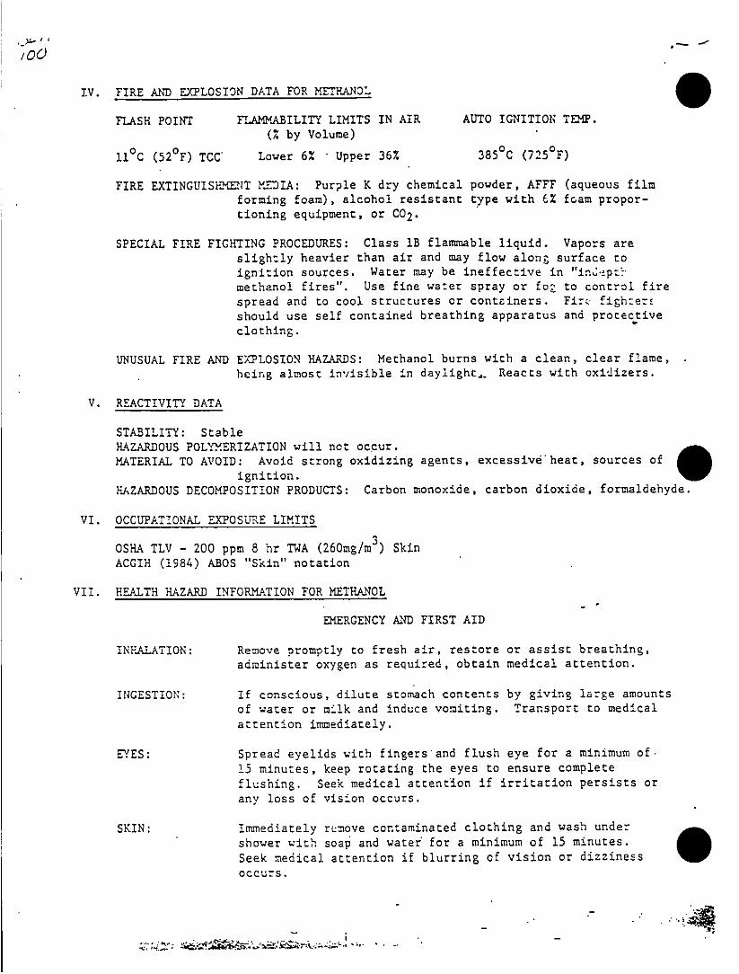
IV. FIRE AND EXPLOSION DATA FOR METHANOqt
FLASH POINT FLAMMASILITY LIMITS IN AIR AUTO IGNITION TEMP.(% by Volume)
ti0h (520F) TCC' Lower 6% -Upper 36% 3850% (7250F)
FIRE EXTINGtJISH2MaT MEDIA: Purple K dry chemical powder, AFFE (aqueous filmforming foam), alcohol resistant type with 6% foam propor-
tioning equipment, or CO2.
SPECIAL FIRE FIGHTING PROCEDURES: Class lB flanmmable liquid. Vapors areslightly heavier than air and may flow along surface to
ignition sources. Water may be ineffective in `in~2Žpt'methanol fires". Use fine water spray or foa to control firespread and to cool structures or contciners. Fir, fighze-should use self contained breathing apparatus and protective
clothing.
UNUSUAL FIRE AND E)TLOSION HAZARDS: Methanol burns with a clean, clear flame,
beirng almost invisible in daylight,.. Reacts with oxidizers.
V. REACTIVITY DATA
STABILITY: StableHAZARDOUS POLYMERIZATION will not occur.MATERIAL TO AVOID: Avoid strong oxidizing agents, excessive heat, sources of
ignition.HAZARDOUS DECOMPOSITION PRODUCTS: Carbon monoxide, carbon dioxide, formaldehyde.
VI. OCCUPATIONAL EXPOSULRE LIMITS
OSHA TLV - 200 ppm 8 hr TWA (260mg/n 3) SkinACGIH (1984) ABOS "Skin" notation
VII. HEALTH HAZARD INFORMiATION FOR MEfTHANIOL
EtERGENCY AND FIRST AID
INHALATION: Re-move promptly to fresh air, restore or assist breathing,administer oxygen as required, obtain medical attention.
INGESTION: If conscious, dilute stomach contents by giving large amountsof water or milk and induce vomiting. Transport to medicalattention inmediately.
EYES: Spread eyelids with fingers and flush eye for a minimum of.15 minutes, keep rotating the eyes to ensure completeflushing. Seek medical attention if irritation persists orany loss of vision occurs.
SKIN: Immediately r~niove contaminated clothing and wash under
shower wIth soap and water' for a mini-mum of 15 minutes.
Seek medical attention if blurring of vision or dizziness 0Occurs.

EFFECTS OF OVER EXPOSUR':
Methanol is harmful by inhalation of vapors, ingestion of liouid or by Prolongedor repeated contact with the skin. In the body, the products formed by itsoxidation are formaldehyde and formic acid, both of which are toxic.
INHALATION: 1,000 ppm may cause irritation of mucous membranes.5,000 ppm may result in stupor (intoxication) or sleepiness.50,000 ppm may result in narcosis Cdeep unconsciousness) in oneor two hours, and eventually result in death.
INGESTION: Can cause blindness, dizziness, headache, nausea. One to fourounces can cause death.
SKIN: Prolonged or repeated contact causes dryness and cracking(dermatitis) of the skin, due to its solvent action.
EYE: Irritation of eye upon contact..
.CARCINOGENICITY: I.A.R..C. monographs do not list methanol as a carcinogen.
MEDICAL CONDITIONS: Inhalation of methanol.-vapor may worsen condition such
as emcgnysema and bronchitis.
NOTE TO PHvSICIAfl: Toxic effects from repeated contact to methanol areaccumulative and affect the central nervous system,especially the optic nerve. Symptoms can be slow toappear, from 9 to 36 hours after exposure and they maylast for several days.
VIII. SPILL OR LEAK PROCEDURE
SPILL CLEANl UP PROCEDURE:
SMALL: Eliminate all ignition sources, stop spill and use absorbentmaterials to soak up spill areas.
LARGE: Eliminate all ignition sources, stop spill at source, containspill area by dikinv, recover methanol or dilute with water toreduce -ire hazard and salvage thje liquid by using recorcaendedabsorbent material. Prevent methanol from entering sewer, drainsor waterways. If methanol has entered these, dilute with verylarge amounts of wazet and notify proper authorities.
WASTE DISPOSAL: Waste material must be disposed of in accordance with yourLocal, State, Provincial or Federal regulations. Contact theproper authorities for specific instructions or contact AGCL's24 hour emergency telephone number: 1-403-527-8141.

IX. SPECIAL PROTECTION INFORMATION
RESPIRATORY PROTECTION: Provide adequate general or local ventilation tomaintain concentration of methanol below 200 ppm. if rLv ofmethanol is exceeded, approved breathing air supply system orself contained breathing apparatus is required.
FACE AND EYE PROTECTION: A minimum standard for handling methanol is faceshield and safety glasses with side shields, and in areas wheretransferring is taking place, chemical splash goggles and faceshields must be worn.
BODY PROTECTION: Wear chemical resistant pants and jacket preferably neoprene.
HAND/FOOT PROTECTION: To prevent repeated or prolonged skin contact wearchemical resistant gloves and boots.
X. SPECIAL PRECAUTIONS AND HANDLING
A. No smoking or open flame in storage handling ares.B. Use explosion proof electrical equipment.C. Safety shower and eye wash must be provided in handling area.D. Ensure that proper grounding procedures are in place.E. Fire fighters should use self contained. breathing equipment.F. Methanol storage tanks should be inert gas blanketed.G. Avoid using materials made of aluminum or lead.H. Gaskets should be flexitalic (spirally wound stainless steel with asbestos).I. Avoid natural rubbers, use neoprene.
REFERENCES USED TO COMffLETE MSDS
ACGIH - Documentation of Threashold Limit Valves,.1980 and updates to 1984.Alberta - 0.11.65 Act (0-2) and Regulations AR-8!82. Proctor and Hughes -Chemical Hazards of the Workplace (1978). SAX - Dangerous Properties ofIndustrial Macertals, 6th Ed. (1984), Clinical Toxiology of ConrnercCa1s Products,5th Edition, Hand Book of Poisons, 11th Edition.
While the information contained in this document is believed to bereliable as of the date of issue, such information is nonethelessof a general nature. The material described can be hazardous ifnot handled and processed properly. Alberta Gas Chemicals Ltd.must rely upon the user of methanol zo utilize the informationsupplied to develop appropriate work and use practices. All state-ments and surg~estions are made without any. warranty, express orimplied regarding the completeness or accuracy off the information,the hazards connected with the use of the material or the resultsto be obtained from the use of the material.

-- MA~~~~4TERIAL 1 A WT\I DATA- SEA EFET 0MAY 2 e 985
SECTION I
PRCOUCT nuis; iMSA CEANER-s~ANITIZ? I>.
Mline Safety AppliancesCopn8590M~~nUFACTURER ~ 600 Penn Center Boulevard-~ COMPLETED B .P eok
Pittsburh PA 1535 22g.rdutStEMERGENCY PHZNE NO. 141K.273L5500- DATE
SECTION 11 - INGREDIENTS
CAS NUM,,BER WI GET.
.ACTIVEI: INGREEDIE4NTS: 5.
SODIUM CAPaO01pAmr 497-19-8 42.2TRISODI[UZ;! PHOSPHATE 7601-54-9- 10.0AZISYL (C14, 50%;-C12, 40%; C16, 10%) -
DIM2T"HYL BENZyL AL4MjONIj2!Tp CIZORIDES 139-08-2 2.5
IŽZT NOREDIENTS: 45.3
SODIUM TRIPOLYPHOSPHATE 7758-29-4SODIUMh BICARBO-NATE. 144-55-8WATER 7732-18-5ISO-N7RIC LINEAR ALCOHOL~S (Cll-cis5)
POL1Y`-Th:OXY ETEHA2NOLS 6813 1-40-8*:WAOL64-17-5
±SCB~~srm ACETA~~ 125-12-2
SECTION III -PHYSiCAL DATADOLING PO:NT I F.) t7A -jSEC;:FIC GRAVITY (H2 O 1) 0.8
VAO _SSUAE (mmn H;.) NA ~VOu:: BYVL.5N
.APOR ENSITY(AIR= II NTA IEVAPORATION RATE ( T) NSlUR, IINW'ATE j 20 Ol p i-iAUOSSLTIN-I95-1%
A A:;C ~ R~a-PTT BLENTD Cv WHITE POWDERS
V ________________ ~~~SECTION IV' - FIRE AND EXPLOSION DATA5HP0rnT 1,7r ttc:ut OFLA SH -TO 2,40 F ILAAMADILE LIMITS Lot. \1 j N~~ E'a~~usk?7 ,~7I w T RS? S'~ Y (-FC-)FOM DRY CH 1iIIOAL. CA~PflONT DIOXIDE
FIS~t;.:nG PROCECDUPES BLAŽThZET FIRE WIT7- E(~TINqGUIS?:Iuo MEIDIUM

-- -- OE~~~~~~~~~~~TIC i V - H.EA~,L>.ArjUr.ot
065
S:-7-cC:u cOTA;CT WITH POWNDEF itL-Y CAUSE BUR2"S. FLUS7H AFFCTED A~a WI*:
:LEEAM ATRCONTACT WITH POW,-DER 1HA'Y CAUSE CORN-EAL BURNS. AVOID :RU~BBING EY7ES
BECAUSE WATER INSOLUBLE PARTICLES M~,Y SCRATCH CORNEA. I!b24,EDIAkTTELY
FLUSH EYES WIT?! CLEAN WATER WHILE 'HOLDING EYELIDS APART. CONTINUE
FLUSHING FOR AT LEAST 15 MINUTES OR UNTIL IR-RITATION SUBSIDES.
CONSULT PiEYSI-CA~N AS SOON AS POSSIBLE.
I-NHAZLATION OF A LARGE ENOUGH QUANTITY TO POSE A SIGNIFICANT =ALTE-
EA:ZAR.D IS IŽIDROBA~BLE-
INGESTION OF POWDER IS EMPŽLU-L~ OR. FATAL. SHOULD INGESTION OCCUR, DRINT
mTIUK:, RAW'. EGG WHITE, OR GETLATIN SOLUTION, OR LARGE QUANT-'ITIES OF WATEER
AVOID ALCOHOL. CONSULT PHYSICIAN AS SOON AS POSSIBLE.
SECTION VI - REACTIVITY DATA
STA~~~iLIT'y ~UNSTABLE I ITr
STABLE Ix AVOID NONSHAZARDOUS IMAY OCCUR I-CONDIINPOLYM4EAIZATION WICLt NOt. OCCUR XAODNN
HA iA;4 O usDECOMPOSITI0DN UNDETER2MINEDPRODUICTS
INCOMPAPAlEILI7Y OXIDIZING AGENTS
(MATERIALS TO AVOID) SOP ŽD TNONI~C StmFACTANTS nrF~T71VLT rfMc-
SECTION VHI - SPILL OR LEAK P.ROCEDURES
~.ES TO SE= TAKEN
IN4 CASE MATERIAL S EP U
W,'ASTE- DISPOSAL RME1v0r TO0 SANITARY LANDFILL AWAY'- FROM~ AE S'UPPLIES
METHOD I ~~DESTROY r-'.ir CON'TAINER'S
SECTION ViII SPECIAL PROTECTION INFOCRMATION
P"SPIRAT:SAY NOT REQUIRZD7~FROTIEC7iON
SKINPRCTErnoN NOT RV2QUP2D
EYE
PROTE flCN NOT RE-QUIRED
SFECTION IX -SPECIAL PRECAUTIONS
SECIAL
HAtJ4cJNG -isNOT REQUIRED
*ECIAC ~~~~~NOT RZEQUIRED. MINIMUM'7L'. S-EL;:' LIFE 6 NhS FO
&JDRACE MXU~~~rG:4 SFrLF LIFE AVOID HIG EutIDIY AND STOrE T;
NOT REQ-UI=rD

Site Management Plan DRAFTEleleon Air Force Baa.
Appendix D
COMMUNITY RELATIONS PLAN
FOR EIELSON AIR FORCE BASE
is ~~CVOR257IO33.51 -7

EIELSON AIR FORCE BASE
COMMUNITY RELATIONS PLAN
DRAFT FINAL

TABLE OF CONTENTS
1.0 INTRODUCTION
2.0 S:TE BACKGROUND -
2.1 Site Location and Descr iption
2.2 Site History
3.3 summary of Environmental Investigations
3.0 COMMUNITY RELATIONS BACKGROU1ID
3.1 Impact on Community
3.2 CommUv.-tY Involvement Profile
3.3 Key community Concerns and Issues
4.0 OBJECTIVES OF THE COMMUNITY RELATIONS PROGRAM
5.0 TECHNIQUES TO ACCOMPLISH COMMUNITY RELATIONS OBJECTIVES
6.0 SCHEDULE OF COMMUNITY RELATIONS ACTIVITIES
Figure 1: Community Relations Techniques/Technical Milestones
7.*0 TECHNICAL REVIEW COMMITTEE
8.0 REFERENCES
Appendices
A TECHNICAL INFORMATION ON 64 SITES
B SITE MAILING LIST
C SAMPLE FORMS
D DOCUMENTS IN THE INFORMATION REPOSITORIES
E MEDIA LIST
F CHARTER, EIELSON AIR FORCE BASE TECHNICAL REVIEW COMMITTEE
List of Illustrations
Plate lA SITE LOCATION YAP
Plate lB SITE LOCATION MAP
Plate 2 MILESTONE GRAPE
2

List of-Contacts. List of Acronyms, Abbreviations, and symbols used in the TextI
Distribution
-0
03

1.0 INTRODUCTIONH
eeo db h
The Superfund community Relations Program
was eePpdb tensr
United States (.)Enironmental protection Agency
(EPA) .to esr
public involvement in all environmental
response idcgoern ent actins.y
The Ar Foce (Al') has been designated as the lead laka goenetAgten
in clean-up efforts at Ejelson Air ForceBe
p(AFB)c Anv laskntinallAsithe
lead agency, the Air Force must ensur comublitc
invatolvmnt iln all isit
related decisions z~t Eielson. This community relations
Planf(rP) is
consistent with federal guidance f or olnt eain fot n
satisfies 'the policies established for Superf'und
remedial activities
by te EP, uder iretion of the Comprehefl.,ive Environmental Re-
sponse, Compensation and LiabilitY Ac
RCL)o 18,a amen edb
the upefundAmedmens ad Reauthorization Act of 1986 (SARA) Th
cRP has been reviewed and approved by both
thw EPA, adteSaeo
Alaska Department of Environmental Conservation
(DEC).
Supefun reuthoizaionlegslation provides for technical
assistance grr,.nts to citizen groups affected by
supinerfund. sites. i
These grants vill enable affected citizens
to obtin dxprtn advic in
reviewing and assessing technical information produced
drn oka
a remedial site. Contact the EPA for
guidance and detailed
information concerninlg technical assistance
grants.
The objectives of the community relations
program are to:
* Assess existing community concerns regarding
planned
and ongoing studies at Eielson AFB, jncluding
all
phases .of clean-up activities, and determine
how and
when the public would like to be involved
inl the
decision making process.
* Establish procedures for accurate and timely
release of
information to potentially affected and interested
citizen groups, elected officials, public
interest
groups ,agency officials, and the media.
* Establish methods to facilitate cofmmlunication1
between
the Air Force and the community at large.
The CR? will respond to current communitY
concerns. This is a
dynamic process. since commnunity concerns
are expected to0 change over
time. As the clean-uap process progresses through
its various
stages--from Reedaio IvstigationiFasbli Studies (RI/ES)
throtugh Record of Decision (ROD), Remedial Design
(RD), a-nd Remedial
Action (PA) -- the Community Relations Plan will evolve to
meet the
public's changing information needs.
4

D.9J 2.0 SITE BACKGROUND
* ~~2.1 Site Location and Description
4. c' Eielson AFB is an active AF' facility approximately 100 milcs* ~south of the Arctic Circle and 26 miles southuast of Fairbanks, Al;
(Plates 1A and lB). The base is approximately two miles east of tiTanana River and is isolated from major urban areas. The communit.closest to the base are Salcha, Moose Creek, North Pole, and Fair-banks.
1± ~~The facility encompasses approximately 19,790 acres of the
Fairbanks North Star Borough (FNSB). Approximately 3,651 acres art4r ~improved or partially improved; 16,139 acres are undeveloped land
encompassing faorests, wetlands, lakes, and ponds. Base topogra,,by* ~generally flat and somewhat featureless with elevat:ions ranging fr,
550 feet above mean sea level (MSL) to 525 feet MSL, sloping downw.to the north-northwest. Elevations on the undeveloped side of thebase are as high as 1,125 feet above HSL.
2.2 Site History
Eielson AFB was originally a satellite installation of Ladd Fin ~(now Fort Wainwright, a U.S. Army installation). Initial construc
of the base began in 1943, with completion in 1944. The base wasdeactivated at the end of World War II and reopened in 1946 as afuture strategic base. From 1947 to 1954, a major construction
a ~~program expanded the facilities at the base. Since the early 1960U ~the primary mission of Eielson AFB has been to provide trained
tactical air support forces for air strike control and direct supp-- of Army ground elements assigned to Alaska.
Since 1950, major industrial operations at Eielson AFB have tperformed to maintain and support resident operations. Propulsionshops, vehicle maintenance shops, and hydraulic shops on base genewaste oils, fuels, solvents, and cleaners. Since 1981, the level
9. ~maintenance activities has increased due to an increased number ofV ~military aircraft at the base. Elelson's mission expanded to provC2~ tactical support to Alaskan Air Command and later to Pacific Air
Forces. Within Eielson's boundaries, these many, sources of contair
nants developed in to several hazardous waste sites. Because ofrindustrial practices, many federally-owned facilities have facedsimilar environmental problems.
V. ~~These past practices have caused ground water contamination aL ~the potential for surface water contamination. In November 1989,
Eielson AFB was listed on the National Priorities List (NPL) becauof existing unlined landfill sites, closed landfills, tank sludgedisposal sites, other disposal areas, past spills, and other poterenvironmental contamination. Altogether, 64 potential contaminati
r sources have been identified.Ys
5

2.: 2. What is your understanding of the specific environmental problemsat Eielson AFBT
tho MHost people had no specifics.
one said he bad full specific knowledge~ based upon DEC reports.
Ph;Teo one said he knew about the ground and air contamination and the
ha: effects it has had on the wildlife.
thiin. Some said they had understood that Eielson had many past
Al; fuel spills and conducted improper disposal in the past.
Pe: one said there was previous PCBs, oils and lubricants spilled onne ~ the base.re:
Si1 One said there were fuel leaks and Benzene deposits on the
tank farm.
Co 3. What is your current major concern(s) regarding the contamination
be at Eielson AFB?AdAd Most had no concerns or viewed the situation as an Eielson AFB
an ~~problem.
to ~Several wanted to know the impact on the water table, .was it
to contaminated?23th Two wanted to know if it was possible that the contaminates SSt be leaking into the Chena or the Tanana Rivers and if there wW
tb possible well contamination off base.
baSi One wanted to know about continued jet fuel leakage and what was
er being done.
tJi One wanted to know the local impact on wildlife and the local
community.
dI one wanted to know when the Al' is going to start cleaning
Al ~up the contamination.
ac one wanted to know who was liable 2f his ground water was
rc contaminated.
St: 4. What is the main source of information by which you have accumfl-
Al lated your level of understanding of the problems at Eielson AFB?
irde Most said from the local newspaper.
RE Two said they received no information.
Ti one said as a member of the borough disaster preparedness team.
8

One from living in the area for many years.
One from the Northern Environnental Center newsletter.
* ~~One from DEC briefings and visits to the base.
5. Do you believe your concerns are representative of the concernsof the community? If not, at what time and with whom did you speak?
Host said that everyone is concerned about the water tablesand that there was a high level of awareness.
Three people said there wasn't much concern for the environ-ment and they thought they were much more concerned thanthe average citizen.
Two said that they didn't know.
6. Have you received or raised any inquires about the contamination'at Eielson AFB? If so, at what time and with whom did you speak?
Almost all people said no.
one said hie spoke with other community leaders on the issue.
one said he called about a DDT issue in the late 60s.
One said he called Eielson six years ago about a pallet oftransformers he found on his property. The AF said thatit was the Army's problem. The transformers are still on theproperty.
7. Have you had any contact with EPA, DEC, or Ejelson officialsabout the site? If so, explain your feelings about their responses.
Almost all said no.
One said he contacted the military and DEC who were both veryprompt.
8. Do you perceive of agency officials as credible and responsive tothe public?
Host said they were not.. but they haven't always been responsive
in the past.
One said no.
Two said they were borderline in responsiveness.
One didn't know.
One didn't know about the AF but EPA and DEC weren't very
responsive.
9

one said EPA and DEC weren't responsive but the Air Force was.
One said EPA and DEC weren't concerned.
One said the military and DEC were responsive but EPA wasn't.
9. How do you think the public, as a whole, typically perceives the
AF, Federal and State officials in the locality?
Most said they had a good opinion of public officials.
Three said they didn't have high regards for public officials.
one said public opinion changes with each incident. People want
to believe the worst.
one said DEC doesn't have a good image.
one said officials sometimes turn their backs on contamination
sites, and other times they prosecute fully. They let MAPCO
slide but prosecute private individuals.
one said locals don't have a high regard for Federal government.Most don't have much experience with the AF but right nowaren't too thrilled with the DEC.
10. In what ways do you feel the community in general is affected by
the contamination problem.?
Host said the community wasn't at risk yet, but felt that
as the concern for the environment increases, the AF wouldhave to accomplish more.
Two felt the perception of contaminated ground water was
real. The perception of problems made the problem real.
One thought the contaminated ground water would affect the commu-
nity and the community later on will have hard feelings towardthe Air Force.
11. Do you think Noose Creek, Salcha, and other specific communities,
drinking water, or any wildlife are especially affected by the contam-ination?
Almost all said no.
One said yes it was possible.
One said Moose Creek water was contaminated but not byEielson AFB.
One said drinking water may be affected.
10
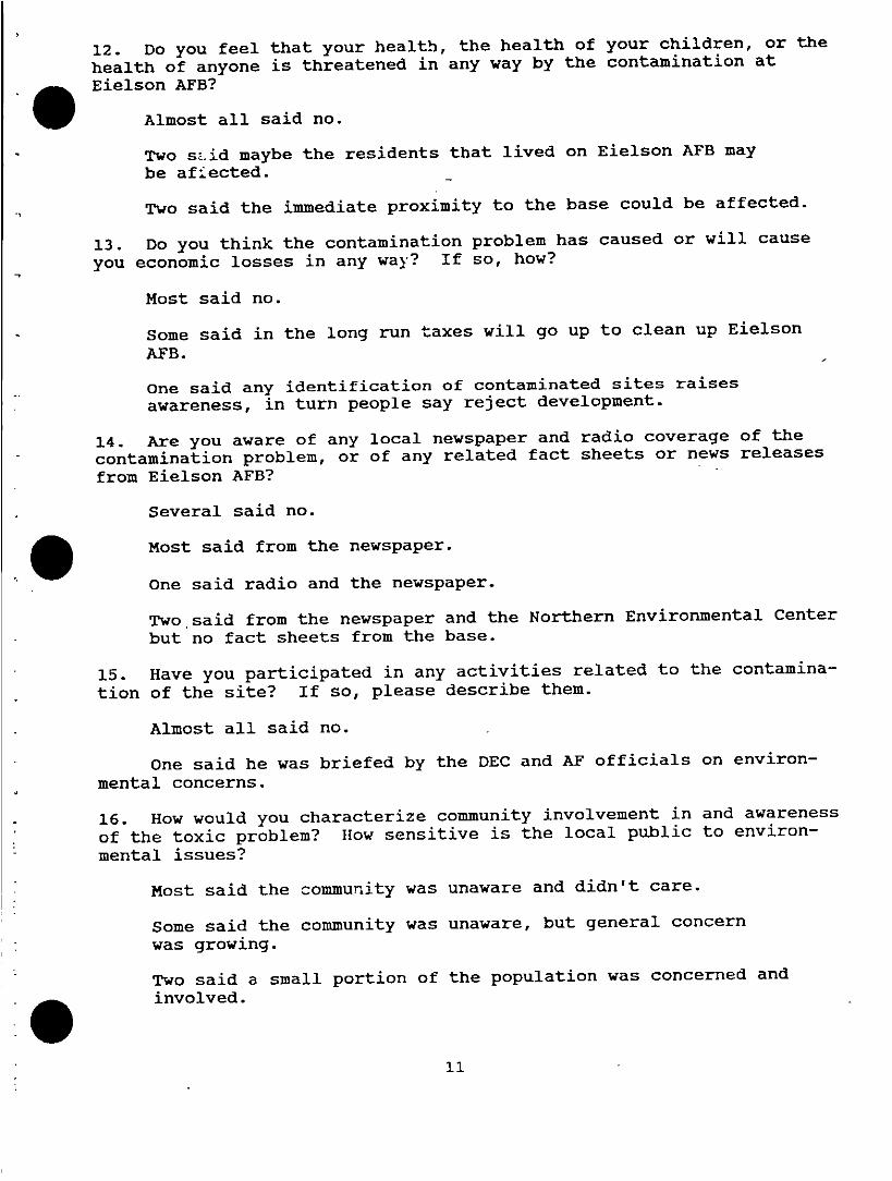
12. Do you feel that your health, the health of your children, or the
health of anyone is threatened in any way by the contamination at
aEjelson AFB?V ~~Almost all said no.
Two s'-'id maybe the residents that lived on Eielson AFB may
be afiected.
Two said the immediate proximity to the base could be affected.
13. Do you think the contamination problem has caused or will cause
you economic losses in any wa~y? If so, how?
Most said no.
Some said in the long run taxes will go up to clean up Eielson
AFB.
One said any identification of contaminated sites raisesawareness, in turn people say reject development.
14. Are you aware of any local newspaper and radio coverage of thecontamination problem, or of any related fact sheets or news releasesfrom Eielson AFB?
Several said no.
* ~~Most said from the newspaper.
One said radio and the newspaper.
Two said from the newspaper and the Northern Environmental Centerbut no fact sheets from the base.
* ~15. Have you participated in any activities related to the contamina-
tion of the site? If so, please describe them.
Almost all said no.
one said he was briefed by the DEC and AF officials on environ-mental concerns.
7 ~16. How would you characterize community involvement in and awareness
of the toxic problem? How sensitive is the local public to environ-mental issues?
Most said the community was unaware and didn't care.
Some said the community was unaware, but general concernwas growing.
Two said a small portion of the population was concerned andinvolved.

17. What kind of information would be most usefut.
to YOU?
Some said no information would be useful.
most said direct contact through the mail.a
some said direct contact through them as elected
Officials.
one said if he had a problem-lie would go directly to
AF
officials.
One said through direct access to the site as
a reporter.
One said through DEC and AF briefinlgs.
18. What kind of information would be most useful
to you;
Several said none or they weren't sure.
most said they wanted to know what the AF was
going to do with
the contaminated sites, how the site is assessed,
potential
cleanup plans, status of cleanup, and precautions against
future
problems.
One said she wanted to know the kind of material
the AF is
dealing with and if it is going to be trucked through North Pole
during the cleanup.
19. What would you consider the best way for you
to receive this in-
formation and communicate it with your community
(i.e., fact sheets,a
newspaper articles, radio announcements, meetings,
etc.).
Most said mail using fact sheets.
Two said there was no best way.
Two said more fact sheets through city hall.
Two said use open forums, fact sheets, and every
means possible.
20. What are your suggestions for other ways of communicating
public
concerns with government and Eielson AFB officialss
Some said an AF open house to view the sites
to include
environmental wprkshops.
Some had no suggestions.
Several wanted public forium and community meetings.
Two wanted more news articles.
One wanted direct contact.
12

21. Where and how often would you like to see community meetings
held? What time of day would be best?
Several said the AF should not have public meetings.
Host said twice yearly and to be held in the evenings at a publicplace (Fairbanks Library).
Four said when the informatidn warrants a meeting during theevening at the local library.
22. An information repository, where you could go to find out moreabout the site's problems as well as current and planned future
* ~activities, is located at Eielson AFB Public Library. Is thislocation convenient for you? Can you suggest an alternative or addi-tional location for an information repository? Would you use such a
* ~repository?
About half said the Eielson AFB Library was convenient, but notsure they would use it.
About half said that it was not convenient. Suggestions where itshould be placed were: Five said the Fairbanks Library, Two saidthe North Pole Library, One said city hail, and one said MooseCreek. Five people said they would use it if more convenient.
23. Can you suggest other individuals or groups who would like tobecome involved, or who should be contacted for further information?
* ~~Several said no.
Several others said local civic groups, and environmental groups,which have been added to the mailing list.
Three named specific individuals which were added to the list.
One named the local utilities and the railroad.
One named the Chamber of Commerce and the Department of Natural
Resources.
13

4 .0 OBJECTIVES OF THE COMMUNITY RELATIONS PROGRAM
The community relations progrzam for the environmental clean-upprocess at Ejelson AFB has five objectives, which were developed basedaon EPA guidance and upon consideration of the information presented inSection 3.0 of this plan. These objectives will guide the communityrelations activities throughout the clean-up process.
1. Provide the Community with Information
The AF' will provide information to citizens about clean-upactivities and respond to inquiries from community members in anaccurate and timely manner. Information will be disseminated toconcerned citizens, public interest groups, elected officials, themedia, and agency officials through fact sheets, information releases,and reports. Additionally, the Air Force will initiate communitymeetings and will establish information repositories including anadministrative record. An administrative record is a detailed filewhich is maintained and contains all information used by the leadagency (AF') to make its decision on the selection of a response actionunder CERCLA. This file contains volumes of comprehensive technicaldata and other information and is kept at the Eielson AFB Library.Key information from the administrative record is provided at a numberof information repositories for public review. Information reposito-ries are provided at the Rasmuson, Noel Wien, and North Pole publiclibraries and a duplicate file is at DEC.
2. Establish Two-Way Communication Between the Air Force, EPA,DEC, Public Affairs, and the Community at Large
Communication with the community during the RI/FS processwill allow the Air Force to understand the community's perspective onissues related to the site, and to become more aware of the com-munity's information needs. The Air Force will respond to communityconcerns and issues by establishing telephone lines with personnelable to field questions and comments. Contact persons representingboth the AF, EPA, and DEC will be available through Public Affairs,Monday through Friday, 7:30 am to 5:00 pm, 907-377-2116, to respond toquestions or comments on technical issues, including any environmentalconcerns. An element of the community relations program at Eijelson,AFB will be the formation of a Technical Review Committee (TRC), whosefunction is to serve as an advisory body for the CERCLA Program atEielson AFB. The purpose of the TRC is to provide review and commenton results of field investigations and proposed remedial actions.
3. Respond to Community Concerns and Needs that Arise Duringthe Cleanup Activities
A major objective oZ the community relations program is toidentify concerns as they develop and to address these concernsquickly and appropriately. Community meetings, the media, andcorrespondence will be used to achieve this objective. In addition,the Air Force will establish a contact person and a telephone line tomonitor community concerns, as noted in objective 2.
14

An Air Force representative will be accessible by telephone five daysa week so that individuals or groups interested in the site can ex-apress their concerns and ask questions.
W ~~4. Provide for Citizen Input and Involvement During the PAProcess.
After issuance of the proposed plan and prior to adoption ofthe final plan in the ROD, if new--information that significantlychanges the basic features of the remedy as originally presented inthe RI/FS and proposed plan with respect to the scope, performance,and cost, the lead agency (Eielson AFB) shall be required to documentthose changes in the ROD. This is accomplished with a ResponsivenessSummary which is a written amendment to the original document.
The Responsiveness Summary serves two functions: first, toprovide the decision-maker with information about the views of thecommunity and potentially responsible parties regarding t'2-e proposedremedial action and any alternatives. Second, it documents how publiccomments have been considered during the decision-making process andprovides anfr~.ers to major comments raised.
The Responsiveness Summary will include summary categories,references to all significant comments, criticisms, and any new datareceived and the AF's position on each issue.
The Responsiveness Summary will'be divided into four
seton.1. Overview.
This will describe the selected remedy and any changesin the proposed plan, feasibility study, and any new alternativessuggested by the public which Eielson AFB has not previously con-sidered.
2. Background on Community Involvement.
This action will provide a brief history of communityinterest in Eielson and will identify key public issues. Publiccomments and concerns on modifications in the investigation or removalactions will be noted. A list of community relations activitiesconducted to date will be included as an attachment to theResponsiveness Summary.
3. Summary of Comments Received and Agency Responses.
This section will include comments received fr-om allinterested parties in the community, the community's technical advi-sors, the EPA, the DEC, and local officials. Included within eachcategory of comments will be the AF's response. Possible categoriesmight Include technical comments, concerns regarding alternativeremedies, and public participation. Significant community concerns
awhich cannot be addressed by the AF because of lack of jurisdiction3will be noted with an explanation of why no agency action will occur.15

4. Provide for Effective Management of the Community RelationsProgram
The CRP will be implemented during the RI/FS and will con-
tinue throughout the entire rem'ediation. The AF will coordinate andimplement all community relations activities. Each activity vill be
carefully monitored and evaluated by the AF, the EPA, and the DEC todetermine its effectiveness in meeting the CRP objectives. Wherenecessary, the AF will modify or revise the community relations pro-gram to ensure that the community's needs are met. These revisionswill be documented as addenda to the CRP.
16

5.0 TECHNIQUES TO ACCOMPLISH COMMUNITY RELATIONS
a 1. Develop a Site Mailing List * Respond to community concerns
V ~~~~~~~~* Information fact sheets will bemailed to those on the list
2. Prepare Information Fact * Provide the community withSheets detailed information about site
activities, announce communitymeetings, information onenvironmental issues, andprovide information on detaileddocuments available at informa-tion repositories and adminis-trative records
* Will include the name, address,and telephone number of an AFrepresentative responsiblefor inquiries about Eielson AFB
3. Establish Information * Each information repository willRepositories contain an identical set of
documents% ~~~~~~* The information is intended to
keep the public informed of theAF's activities at Eielson AFB
* For specialized need, individualrequests for copies of additionaldocuments will be handled on a
case-by-case basis
4. Establish Administrative * Administrative Record willRecord contain detailed documents in
addition to the InformationRepository
* The information is intended tokeep the public informed ofdetailed reports of the AF'sactivities at Eielson AFB
5. Hold Public Meetings * To provide an opportunity forcommunity-wide comnent on siteactivities and to proposealternative cleanup methods
* Keep community informed ofenvironmental progress
17

6. comunitY nvolveent *Help the Al' monitor
6uin DrafuntF Rnoleport communitY concerns.
will be
During Draf FS Reportable to identify specific
citizen groupS who have environ-
mental concerns -a omn
*Provide at least a 30-acoen
period on the proposed cleanup
*cbmment period will be announced
--two weeks in advance in the
newspaper
i. prpare esposivenss *A document that describes
the
summrearye Respos)ns communities' comments
and the
summary~~~ies) ~AF's responses during the
30-day comment period and the
community meetings*The complete Responsiveness
summary will be placed in the
information repositories and the'
administrative file
18

6.0 SCHEDULE OF COMXUNITY RELATIONS ACTIVITIES-
This section provides milestones for putting community relationsatechniques to work. A community relations and technical milestone
Wchart (Figure 2 and Figure 3) maps out community relations activitiesin relation to significant events within the environmental cleanup
program. As more detailed plans are developed, these project mile-stones and related community relations activities will be updated.Changes in schedule, unanticipated7 events, and changes in the level of
2 ~community interest or concern may also dictate a change in frequencyof certain activities.
19

IGUR 1:COMM~hUNITY RELATIONS TECHNIQ'UES/TECHNICAL MILESTONES
ECHICA MILSTNE COMMUNITY RELATIONS ACTIv jTIES
-CriALg dIEvelOpmEntoS Rm * Establish majling
list S
Duiniavlpmnlo em- * EstabliSr information (RI/F
5)
1~~5~jation/Feasibrepositoie
and administrative
\pril-lay 1991 *Prepare
communit eain
plan (CRP) esbra o
*Activate speakesbra
fo
local organizations
*initiate media coverage
*Notify PubliC of Technical
Assistance Grant Program
2. DringRemeial nvesi *update
Mailinlg List stre
ratDuiong(RI) dalIve * Update information
repostre
catine (ReI)r 9 * Establish Technical
Review
* Release reports .oncn
significant findings
* conduct communitY meetings as
required*Maintain
contact with key
elected offcicials and federal
gover'flment agencies about
impotantfindings
* Iplment environmental
newsletterloa*maintain
contact withioa
media.-
3. upon of RI * ~Prepare fact sheet and news
UpnCompletionofR release sum10ariziflg
RI report
octlober-November 1991
* update informatinrpstre
withRI rport and fact sheet
* provide briefing for Publi
meeting/Technical Review
Cormuittee
*Contiflue to meet with community
members and civic leaders to
discuss fjndiflgnta
*Summarize report in Envirr~lna
Newsletter
20

4. During Feasibility Study * Update mailing listDecember 1991-January 1992 * Meet with Technical Review
Committee* Maintain media contact* Maintain contact with keyelected officials and federal
A ~~~~~~~~~~agencies about importantfindings
-- *Hold public meetings asnecessary
5. Upon Completion of Draft *Hold 30-day public comrentFS Report period. Prepare fact sheet,February-April 1992 news release, and environmental
newsletter summarizing draft FSreport and announcing publiccomment period
*Update information repositorywith draft FS report and factsheet
*Announce availability of FSreport through news release
*Provide opportunity for com-munity members to discussproposed alternatives with base,local, and federal officials onan informal basis
*Hold formal public meeting inthe middle of the 30-day comment4 ~ ~~~~~~~~~period to receive written andverbal comments from thecommunity regarding proposedcleanup alternatives
6. Upon Completion of Final FS * Prepare progress reportApril-May 1992 announcing and explaining
proposed plan* Prepare news release* Update information repositorieswith final FS report
* Prepare Responsiveness Summaryto accompany Record of Decision
.7. Prior to Remedial Design/ * Update mailing listRemedial Action * Afnounce plans for implemen-April-May 1992 tation of remedial action in a
progress report and news release* Revise community relations plan
(if necessary)* Prepare fact sheet
21

7.0 TECHNICAL REVIEW COMMITTEE
The AF will establish a PRO. The TRC Will provide revievi and
comment on actions and proposed actions with respect to releases ora
threatened releases of hazardous substances at YE'-eison AFB. Ad-Ci-tion-W
ally, the TRC will serve as an ad\ i4sory committ' e to the Al' on the IRP
at Eielson AFB. The TRC will include representatives from the AF,
EPA, DEC, and the community.
The TRC should include a member representing the University of
Alaska, a representative tram a local environmental group, and a local
elected official, if possible.
The TRC will meet as necessary to discuss the results of field
investigations and to discuss proposals for interim or final cleanup
activities. The charter for the TRO is presented in Appendix F.
22

8.0 REFERENCES
__CH2M Hill, 1982. Installation Restoration Program Records Search,9 ~~Ejelson AFB, Alaska.
Dames and Moore (D & H), 1983. Installation Restoration Program Pre-survey
Report, Eielson AFB, Alaska._
D and H, 1985. Installation Restoration Program, Phase II -
Confirmation/Quantificationl, Stage 1, Eielson AFB, Alaska.
D and M, 1987. Installation Restoration Program, Phase II -
Confirmation/Quantification, Stage 2, Eielson APE, Alaska.
.Harding Lawson Associates (HLA), 1988a. Installation Restoration* ~Program,
Remedial Investigation/Feasibility Study, Stage 3 Wcrk Plan,Eielson AFB, Alaska.
HLA, 1988b. Installation Restoration Program,Remedial Investigation/Feasibility Study, Stage 3, QualityAssurance Project Plan, Ejelson APE, Alaska.
HiLA, 1989. Installation-Restoration Program,Remedial Investigation/Feasibility Study, Stage 3, Eielson AFE,Alaska, April.
The National Contingency Plan (NCP), 40 CFR 300, Feb 1990.
Science Applications International Corporation (SAIC), 1987. Prelimi-nary Evaluation of Site Characterization Data, Phase IV - A Remedial
Action Plan for Eielson AFB, Alaska, July 10.
SAIC, 1988. Interim Remedial Inveskigation Report, Eielson APE,Alaska, April 7.
U.S. AF, 1989. Fiscal Year 1989 Economic Resource ImpactStatement, Eielson AFB, Alaska.
* ~U.S. Environmental Protection Agency (EPA), 1986. Community RelationsIn Superfund: A Handbook, January.
2 3

APPENDIX A
sixty-four sites on Ejelson AFB were identified as having
potential contamination. Host of the sites wore civen a hazzrd score
toa100 tonetbls the potdosAsesentia effectsofcontaminationMonfhumanerbase on thesHazardosh Assessmentia Rafetingf Metodoliatogy(AM fomzeronwelfare and environment. The HARM score has four components: the
receptors of the contaminant (who or what will be impacted); wastecharacteristics; waste management -practices; and the contaminantpathway (how the contamination reaches the receptor). The higher the
score towards 100, the more significant the risk (see Plates lA and lBfor site map).
This is based on the actual or potential release of hazz:rdous
substances from a site through air, surface water, or ground water to
affect people. This score is the primary factor used to decide if a
hazardous waste site should be placed on the NPL schedule for clean-up.
2 4

SITE 1, Original Base Landfill HA.RM 63
This site was used as the main base landfill from 1950 toa 1960 for base refuse. This site is located across the Richardson
Highway, west of Taxiway 4. Several drums were observed in 1988during a site investigation. The original contents of the drumscontained oil, fuel, and other unknown materials. In 1990, it wasfurther identified that most of the drums were rusted and some werefilled with soil. No other potential sources of contamination havebeen found near the monitoring wells located around the site.
SITE 2, Old Base Landfill HARM 63
This site was used to dispose of base refuse near the northend of Arctic Avenue from 1960 to 1967. Presently, base personnel usean area next to this site for recreational purposes during summ er andwinter for off-toad vehicle driving, swimming, and water skiing onHear Lake. Access to the site is unrestricted. All chemicals detect"ed in the ground water and surface soils were chemicals of concern.
* ~Potential exposure to benzene, trans-1-2-dicholoroethane, toluene, andtricholoroethene were detected in the ground water. Soil chemicalsthat were detected were TPH and 4-methyl phenol. Potential exposureto the chemicals were a concern. Hodeling indicates that ground water
* ~from this site will not reach a drinking-water supply well.
SITE 3, Current Base Landfill HARM 73S ~~~This site was used as the main base landfill from 1967 to1987, and for fire department training from 1955 to 1976. The siteoccupies at least 100 acres just east of the southeast runway andnorth of the refueling loop taxiway. The site has been continuallyextended over the years. Access to the site is generallyunrestricted. The landfill received base refuse including householdgarbage, scrap lumber, scrap metal, construction debris, includingempty cans and drums from the flight line industrial shops. It alsoreceived from the 1960s, five or six drums of radioactive photographicchemicals from a base squadron that are buried on this site. Althoughno radiation was detected in 1982 during a study, this site wasidentified as needing further study and action. Further data isrequired to implement full site remediation measures.
SITE 4, Old Army Landfill and Current Munitions Disposal AreaHARM 47
This site was used as a landfill by the Army Battery Stationfrom 1956 to 1959 and is presently used for munitions disposal (EOD)since the late 1960s. General refuse was deposited on this siteincluding metal and empty containers. In addition, the landfillprobably received small quantities of waste oil, solvents, and smallamounts of munitions including spent cartridges.
25

Access is by traveling from Quarry Road to Munitions Road, then onto arestricted area which is fenced off. Carcinogenic and non-carcinogen-ic risks are within EPA acceptable levels. Tihis site will requirefurther soil and water evaluation tests.
SITE 5, Old Army Landfill HARM 49
An Army Battery Station used this site from 1956 to 1959.This area is located near the south end of Runway 21. In 1988, aninvestigation revealed a heavy concentration of approximately 500 to750 drums in and around Pond 3. An addition of 150 to 200 drums wereobserved in a slough east of Pond 3, and six drums were observedaround the shorelines of Ponds 1 and 2. Most of the drums are heavilyrusted and without lids. Types of products that were formerly con-tained in the drums included asphalt, antifreeze, engine. oil, and dry
cleaning solvent. In addition, a small pile of mercury batterier. wereobserved on the ground surface approximately 20 feet southwest c2'Monitoring Well OSM0l. Some mercury was observed on the ground sur-face adjacent to the batteries. An 1990 investigation revealed thatthere was no indication of contaminant concentrations requiriwg, reme-
diation in site soils, sediment, ground water, or surface soils. Thebatteries need to be removed from the site and the ground water moni-toring system needs to be installed.
SITE 6, old Landfill HARM S1
This is a small base secondary landfill that was used from 01959 to 1963 contained buried debris. During this time period, smallquantity of waste paints and drum residuals are suspected to have beendumped on this site. This site is located south of the recreationalvehicle storage area. We currently use this site for snow disposaland access is unrestricted. Site usage is expected to remain un-changed in the future. The buried debris potentially contains chemi-cals that could be released into the environment. Low concentrationsof chemicals are present in Site 6's monitoring wells which may indi-
cate the presence of a gradient contaminant source. A detailed groundwater monitoring system is recommended.
SITE 7, Test Landfill No HARM, Sz~.re
This site was an experimental sanitary landfill for only afew months in 1967. The site is located east of the Arctic Exte2nsion.
Primary household garbage was deposited at this site. The lanJ fill is
covered so human and wildlife access is lisited. This site is located
on the northwest corner of the main base near Manchu Road. Hazardouswastes are not present in sufficient quantfties and there appears to
be no potential for contamination, therefore this site is not rated.Since hazardous wastes are not rresent in sufficient quantity, thereappears to be no potential for contamination and this site was not
rated.
2 6

SITE 8, Original Fire Department Training Area HARM 61
Fire training exercises were thought to be-conducted in thisaarea from 1948 to 1955 and is currently inactive. Located on thissite is an aircraft wreckage, located in the old gravel pit, excavated
Wat water table level. The regional elevation of the water table has
* ~increased over the last 25 years. This site is located near Transmit-ter Road and close to the Alaska Railroad Crossing. Five chemicalswere detected and were identified -as chemical of concern. Benzene wasdetected in the ground water. DDD, DDE, DDTY, and heptachlor weredetected in the soil and sediment. Potential carcinogenic and non-carcinogenic risks were all below EPA's acceptable levels. No remedi-al action were recommended on this site due to human health risks.
SITE 9, Current Fire Department Training Area HARM 64
This site was used for fire training from 1976 to present.Site 9 occupies at least 100 acres just east of the south end of the-runway and north of the northwest portion of the refueling taxiwayloop. Current procedures in the fire training area are to saturatethe ground with 5,000 gallons of water, apply the starter fuel, burnit for 30 seconds, then extinguish the fire with a 6 percent aqueous
* ~film-foam. There is a well located within 240 feet from the trainingarea that is now abandoned and the depth to the water table is shal-low. The frequency of this training varies, but the exercises areconducted quarterly. Fuels used in this area may be contributingchemicals to the soil and water on Sites 3 and 9. Further evaluation-* was recommended and to implement full remedial measures.
SITE 10, POL Lake and E-2 POL Storage Area HARM 73
This site originated from a fuel spill in 1967 and leakingfuel tanks in 1978. Investigation revealed floating hydrocarbon layeron the lake originating from leaks, spills, and sludge disposal aroundthe tanks and a berm. This was discovered during a grounds tour of
* ~the site, providing indirect evidence of contaminant migration. The* ~floating layer appears every spring and summer for the last 4 years.
The high concentrations of VOCs (tricholorethane, toluene, xylene, and* ~ethylbenzene), complex hydrocarbons, and lead are found at water table
(approximately five feet) depth. Two HOGAS storage tanks in the E-2* ~Storage Area (Tanks 20 and 21) were detected leaking approximately 200
gallons of fuel per day. The leaking tanks were fixed in 1978.
SITE 11, Fuel Saturated Area HARM 70
This site is located in the vicinity of Building 3224 andCentral Avenue. In 1975, an oily sheen was observed in GarrisonSlough. An investigation to locate the source revealed a hydrocarbon
layer, primarily diesel fuel, floating on the water table nearbuilding 3224. Significant lead contamination was found in thesurface soil in 1988.
27

Lead in the soil may be attributed to vehicular traffic and previousroad oiling activities. No previous spills have been documented f orthis site. However, during a well installation ilt wan documented thatathere might be a buried tank in the ar~ea. Workers encountered aburied metal object, but it is inconclusive that it was a buried tank.
SITE 12, JP-4 Fuel. Spill, Building 2351 No HARM Score
This site was identifie d when a 5,000 gallon fuel spilloccurred in 1981. All but 100 gallons were contained inside theBuilding 2351. The spill occurred as a result of an open refuelingtruck gate valve. The 100 gallons reached the outside yard areacreating a small spill. Ten ycars after a spill this size, no vola-tile would be expected. The drinking water aquifer is at least 80 to150 feet away and was not affected. An independent agency concludedthat no further action was recommended under CERCLA.
SITE 13, E-4 1/2 Diesel Fuel Spill Area HARM 60
This site originated from small leaks that occurred from the1960s to present from fuel bladder spills and underground storagetanks from Building 1240 located near Oscar Row on the taxiway. Highconcentrations of ethylbenzene, toluene, and xylene remain bound tothe soil particles near Tank 300 and are continually released into theground water. In addition, surface soils contain high concentrationsof lead, ethylbenzene, xylene, and toluene in the vicinity of thewater table.
SITE 14, E-2 Railroad JP-4 Fuel Spill Area HARM 51
This site became contaminated through periodic fuel spillsduring railroad delivery. Contamination appears to be concentrated inthe vicinity of the railroad tracks and within the petroleum fillstands in the southwestern portion of the E-2 POL Storage Area nearQuarry Road. Soil contamination appears to be limited to lead on the
soil surface and complex hydrocarbons at depths of five to ten feet.Significant benzene contamination of the ground water was observed atthe southwestern corner of the E-2 POL Storage Area.
SITE 15, Multi-product Fuel Line Spill HARM 65
The spills on this site include a 5,000 gallon MOGAS spillin 1970 and a 5,000 gallon JP-4 fuel spill in 1973 which both resultedfrom faulty welding on two pipes. Site 15 is located along theeastern portion Quarry Road, west of Building 6254. The onlyapparent source of contamination is the lead remaining in the surfacesoils. None of the sediment or surface water samples have significanttotal VOC or complex hydrocarbon contamination.
2 8

SITE 16, MOGAS Fuel Line Spill HARM 56
-~~~ ~There was a 5,000 gallon MOGAS fuel spill near Building 6214
in 1957. The MOGAS fuel line runs from the E-2 POL Storage Area alongQuarry Road, Industrial Drive, and Division Street to the base vehiclegas station. Twenty-seven soil gas samples were taken during aninvestigation of this site. Concentrations of total hydrocarbons atthis site are low. Site 16 showed, detectable amounts of toluene andthis might indicate some type of fuel source nearby but the low con-centrations in soil gas make the source difficult to determine. Aclear pattern of distribution and sources are not evident through soilanalysis.
SITE 17, Canol Pipeline Spill No HARM Score
In 1957, 20,000 gallons of diesel fuel spilled from apipeline rupture. This source is located along Old Richardson High-way, west of Taxiway No. 3. The nearest well is 2,240 feet with watertable depth less than 10 feet. Eight locations were sampled alongSite 17 which showed background levels on total hydrocarbons and nodetectable toluene or benzene. No surface contamination was evidentfor this site. The exact location of this site is yet to be deter-mined.
SITE 18, Fuel Saturated Area, old Boiler Plant HARM 63
a ~~~During excavation of a series of eight-foot deep holesV accomplished in the mid-1970s, a hydrocarbon layer was detectedfloating on the water table. An oil boiler house (Building 3405) was
* -. the suspected source of the contamination. The old boiler housecontained diesel fuel. Soil and water analysis were accomplishedshowing high concentrations of hydrocarbons. There was no benzene ortoluene detected and there did not appear to be a significant contami-
* ~nation problem on this site.
SITE 19, JP-4 Fuel Line Spill HARM 67
Approximately 200,000 gallons of JP-4 was reportedly spilledon the ground surface as a result of a fuel pipeline rupture in thelate 1950s. There is evidence of vegetative stress within the area.
JI: This site is located along Cargain Road, approximately 2,200 feetsouth cf the E-2 POL Storage Area. A high concentration of hydro-
* ~carbon contamination was evident in the vicinity of the the pipeline,with the highest observed total hydrocarbons exceeding 300,000 ug/l.In 1986, ground water samples discovered significant leve2s of benzeneand total xylene. Contamination is located on the site and is notmigrating because of permafrost in the soils below and around thesoils on Site 19.
29

SITE 20, Refueling Loop Fuel Saturated Area HARM 61
Most aircraft refueling operations were conducted at Sitea
20, the refueling loop. This site includes the Alpha-Delta Row.s,Echo-
Fox Rows, and Gulf-Hotel, Rows refueling pad complexes (underground POL Wstorage tanks). Special flight line passes are required to gain
access to this site. All the pads on this site are covered with
concrete, except for several interior gravel islands, some of which
contain fueling and defueling pipelines. In 1972, a test bole was
drilled encountering hydrocarbons floating on the water table. In
1987, work began on the underground fuel line linking three fuel line
outlets to the main line. At this time, a ditch was excavated expos-
ing a layer of hydrocarbon approximately one foot thick floating on
the ground water. The AF notified DEC of this condition and set up a
pump and well monitoring system to remediate the condition. By 1988,
885 gallons of JP-4 had been recovered from the system. To date, 34
monitoring wells have been installed around this site. Benzene and
toluene were detected from the water tests. No drinking water wells
are located on this site. Although it appears to be lirited to the-
immediate area, the AF will continue to monitor the floating product
and the ground water. Further remedial measures are being considered.
SITE 21, Road Oiling-Quarry Road HARM 52
Prior to 1978, petroleum oil lubricants (POL) waste were
used in road oiling for dust control. The mixture was applied at a
maximum rate of .03 gallons per square yard. This practice was dis-
continued in the early 1980s. Some of the POL waste may also have
percolated into the ground, where biodegradable components would be
assimilated by soil bacteria. Depth to ground water along Quarry Road
is approximately six to ten feet. The closest water well along this
stretch of road is approximately 400 feet.
SITE 22, Road Oiling-Industrial Drive HARM 52
Road oiling was used for dust control prior to 1978. This
site runs from a northwest to southwest direction. Higher concentra-
tions of oil exists along the road bends and intersections due to
grading and plowing. The majority of volatile has dissipated over
time through biodegradable material, dilution, and chemical break-
down. H-uman and wildlife exposure may occur through ingestion (grit,
salt licks). Depth to ground water is approximately six to ten feet.
The closest water well is approximately 400 feet.
SITE 23, Road Oiling-Manchu road HARM 51
oil was also used on this road for dust control. Manchu
Road runs in a north by nn)rtheast to south to southeast direction.
Quantity of oils dispensed on this road is low.
30

Depth to ground water is approximately six to ten feet. The closestwater well is approximately 6,000 feet away. This road crosses wet-;. lands and is within 500 feet of Twin Lakes. Soil samples will becontinued in this area to monitor migration.
SITE 24, Road Oiling-Gravel Haul Road HARM 53
Oil was also used on this road for dust control. Gravel,haul Roads runs in a southwest to southeast direction. Depth toground water along thlis road is approximately six to ten feet. Theclosest water well is approximately 400 feet away. This road crosseswetlands and is within 100 feet of Bear Lake. Quantity of oils on
* ~this road is low. Since the mobility of suspected contamination islow, only samples will be collected during this sampling effort. Todate, no evidence exists of ground water contamination due to roadoiling.
SITE 25, Fuel Tank Sludge Burial Site, E-6 HARM 51
From 1955 to 1980, sludge from eroding storage tanks on Echo6 refueling pad complex resulted from eroded buried tanks. Elevatedamounts of> concentrated hydrocarbons, detectable amounts of benzene
* ~and toluene indicate some type of liquid fuel spill. Ground watersamples also indicate significant amounts of hydrocarbon contamina-tion.
0 ~~SITE 26, E-10 Fuel Tank Sludge Burial Site HARM 51
From 1964 to 1980, there was periodic disposal of sludgefrom weathered AVGAS lead tanks. The tanks were replaced in 1987,where fuel saturated soil was encountered beneath the tanks. The soilwas removed and replaced with clean fill. Fourteen samples were taken
* ~discovering high concentrations of hydrocarbons indicating a liquidpetroleum source on this site. Limited data west of this site make itdifficult to estimate the full extent of contamination in that' direc-tion. The lead found in this area is located southeast of Building1240 (Tank 300) located near the southeast end of the main taxiway.
SITE 27, Fuel Lead Sludge Burial Site, E-11 HARM 51
This site is also considered a source due to sludge from Echo* ~11 refueling complex tanks. The northwest corner of the E-11 POL
Storage Area appears to have had some type of contamination event.Elevated concentrations of total hydrocarbons, detectable amounts of
* ~benzene, and toluere indicate some type of spill occurred on the site.Contamination is isolated to approximately a 600-square foot circulararea northwest of Site 27. Water samples also show hydrocarbon con-tamination but lead concentrations were less than regulatory limits.No VOCs were detected in this area. No further action was recommendedunder IRP.

SITE 28, Fly Ash Disposal Area No HARM Score
This was a disposal site for fly ash generated by the Cen--
tral Heating and Power Plant Building 6203, located at the intersec-
tion of Indust-rial Drive and Quarry Road from 1972 to 1977. This siteW
was originally an old gravel pit which was filled in with fly ash.
Analysis of the fly ash indicated that no hazardous constituents were
present. Since no hazardous materials have been dispensed at this
site, there appears to be no potential for contamination therefore no
rating was given to this site. This site is currently used f or small
arms training and fly ash is still deposited acting as a buffer for
small arms ordance.
SITE 29, Drum Burial Site HARM 54
This site was an old gravel pit used mostly for disposing
55-gallon drums. The site is located west of Bear Lake; along the
northeast side of the Alaska Railroad Track located on base approxi-
mately 1,500 feet south of Transmitter Road. There are approximately
400 to 500 empty drums formerly containing asphalt emulsion. The
drums were covered with fil-.l material recently cleared of f the sit~e.
It was reported that many of the drums were full, and that some may
also have contained residues of industrial solvents and engine oil.
soil analysis indicates the presence of total petroleum hydrocarbon
(TPH). benzoic acid, acenapthalene, antracene, benzol flurorantheses,
benzopyrene, benzoperylene, chyrsene, dibenzofuran, fluroanthefle, indo
pyrene, and phenanthrefle. N4o Phase II work was recommended for thisa
site because no environmental concerns were presented.U
SITE 30, PCB Storage Facility No HARM Score
The source of this site is a PCB storage building. Building
2339 housed out-of-service PCB transformers and capacitors and is
located on Central Avenue. The PCB liquid was stored in 55-gallon
drums within a diked concrete floor within the building. The total
quantity of PCBs (contaminated liquid) in storage at these facilities
is approximately 14,500 gallons. There were no reports of spills in
this area. The area outside and adjacent to the building was used as
a staging area for equipment awaiti--ng storage. Depth to ground water
is approximately six to ten feet. The closest water well 1 s Well No.
12, located ap~roximately 3,000 feet away. Small and unreported
spills could have remained on this site through damaged or cracked
dikes in the building. PCB liquids have low mobility, therefore
samples will be taken at the building entrances at a depth of zero to
12 feet. There appears to be no potcntial for contaminant migration
and there is no rating for this site.
SITE 31, PCB Storage Facility No HARM Score
Building 3424 housed out-of-service PCB transformers and
capacitors and is located near base supply on Central Avenue.
3 2

* ~The PCB liquid was stored in 55-gallon drums on a diked concrete floor* ~within the building. There have been no reports of spills in this
*area. The area outside and adjacent to the building was used as a istaging area for equipment awaiting storage. Depth to ground water i
approximately six to ten feet. The closest water well is Well Bapproximately 200 feet away. Small and unreported spills could haveremained on this site through damaged or cracked dikes in the build-ing. PCB liquids are not very mobile but can be persistent. Sailsamples will continue to be collected at dept-hs of zero to 12 feet.No potential foe contaminant migration and this site was not rated.
SITE 32, Sewage Treatment Plant Spill Ponds HARM 65
This site was used as an intermittent spill pond to protectthe microbial integrity of the plant, located next to Building 2316,from 1970 to present. In the past, illegal discharges of POL wasdiverted to the'spill pond. Sludge from the outlaying septic tankswere also dumped here. All chemicals detected in the ground water,soil, and sediment were included as chemicals of concern. Chloroformwas detected in the ground water; chloroform, methylene chloride,
chlordane, benzol (b) floranthene, benzol (a) pyrene, 1lio (2-ethylhex-yl), phthalate, phenanthrene, and pyrene were all detected in thesoil. Baseline Risk Assessment results identified potential carcino-genic risks within the EPA acceptable range. Residue chemicals-couldhave resulted from aircraft using the Eielson AFB runway. Currently,this site is being further investigated as part of the Sewage Treat-ment Plant upgrade.
SITE 33, Treatment Effluent Filtration Pond No HARM Score
This pond was originally a gravel pit was used as an efflu-ent treatment installation, since 1978. Effluent is discharged yeararound from Building 2316 and percolates into the soil. Prior to
1978, the treated effluent was discharged into Garrison Slough and thefiltration pond was used intermittently during the sunnier.
SITE 34, Sewage Treatment Sludge Drying Beds HARM 43
The drying beds were used from 1953 to present attached to- ~Building 2316, Base Waste Treatment Plant. All chemicals detectced in* ~the ground water, soils, and sediment were chemicals of concern. See
Site 32 for further breakdown of chemicals. Baseline Risk Assessmentresults show potential carcinogenic risks are within EPA acceptablerange.
SITE 35, Asphalt Mixing Area, Asphalt Drum Disposal HARM 55
This site contained an asphalt mixing area located acrossfrom the Prime Beef Buil.ding 3460 from the 1950s to the 1960s, includ-ing a drum disposal area. There are several anomalies which appear to
abe arecs of disturbed soils include potential buried metal and debris.3TPH concentrations were greater than the DEC guideline action level of3 3

100 mg/kg.Pesticides including DDT, DDE, and DDD were found in all the soil and
sediment samples colt-cted on the site. TCE and Benzene were detected
in surface water samples from the Garrison Slough but were not linkeda
to the contamination from this site. This site may require remedial
action to reduce health risks to humans. Ground water is corzinually
monitored for the presence of aromatic gas and hydrocarbons identified
in the field screening process.
SITE 36, Drunn Storage Site HARM 60
This site, located in the recreational vehicle parking lot,
was used from the late 1960s to the mid-1970s as a mixing area for
asphalt and base operations. Evidence of a fuel saturated ground
surface on a pool of water located on the site was observed contami-
nated with POL during a tour of the site. Ax mixing tank was used for
tar and asphalt emulsion for road maintenance, using contaminated fuel
for road operations. In addition, approximately 100 drums were stored
on this site. Approximately 30 to 50 percent of the drums were full.
The drums had a variety of contents including waste oils, hydraulic
fluid, diesel fuel, JP-4, PD-680 (a solvent), and other liquid wastes.
It appears that some flight line industrial shops brought their
drumied waste products to this site. None of the drums were observed
to be leaking and there was indirect evidence of contamination from a
soil gas sample taken.
SITE 37, Drum Storage Site and Asphalt Mixing Area HARM 60
This site was used from the 19605 to 1970s as a asphalt
mixing area and drum storage area. Site 37 is located approximately
100 feet, east of Building 4333. One location near the site showed a
high concentration of total hydrocarbons, essentially all methane.
Some of this could have resulted from decaying plant material. There
was a low concentration in the soil gas tests making it hard to deter-
mine any nearby sources. There was a limited amount of TOE indicating
that this area had a small surface-related spill. This site requires
further monitoring.
SITE 38, Ski Lodge POL Tanks HARM 56
This site receiveCs fuel tank sludge and contaminated fuels
from the 1950s to the 1970s. Site 38 includes the Ski Lodge Building
6395 and approximately 200 acres of south facing hillside containing
an old fuel tank storage area and a fuel disposal pit. Eight 50,000-
gallon tanks were once present on this site. The tanks were con-
structed of bolted steel and 6-inch to 8-inch pipes were fed into the
tanks. The pipes were connected to the Haines-Fairbanks multi-product
pipeline. In 1986, routine ground water sampling of the original Ski
Lodge water supply well indicated a benzene concentration above 100
ppb. The well was taken out of use.
~34

SITE 39, Asphalt Lake HARM 63
B ~~~Over 500 drums of leaking asphalt material were left on this
site in 1948 after runway construction of the base. The drums have
rusted and leaked most of their contents over the years. The area,
approximately 1 acre, is covered with asphalt emulsion 6 to 12 incbes
deep. This asphalt has not harden'ed. The site is located 1 mile
south of the Eielson AFB Main Gate across the Richardson Highway.
The tar covered area is mostly devoid of any vegetation. Observations
during a 1987 site visit indicated the leaked asphalt emulsion lies in
a shallow depression, however, some asphalt flowed outside the central
depression into adjacent bushy areas. Field activities in 1989 in-
cluded evaluating the disposal drums. Analysis detected total petro-
leum hydrocarbon (TPH) and pesticides were found in the soil. Chloro-
methane, 1, 2-dichloroethene, 1,1,2, 2-tetrachloroethane, vinyl chlo-
ride, and TPH were detected in the water.
SITE 40, Power Plant Sludge Pit No HARM Score
The base power plant Building 6205 was located on this site
from the late 1950s to the late 1970s dumping residue from the air
scrubbers including small quantities of sludge generated during acid
treatment to clean boilers. The one acre site was cleaned out approx-
imately once every two years and the sludge was hauled to the base
landfill for disposal. There are low quantities of any hazardous
material present and no potential for human contamination.
SITE 41, Old Auto Hobby Shop HARM 60
This facility Building 4298 was used from the 1960s to 1982
as an auto hobby shop, saturating the ground with oil. The facility
was used by base personnel for maintenance of their private vehicles.
Four 55-gallon drums were located outside the facility for waste oil
and fuel disposal. During a tour of this site, the ground surface
surrounding the waste oil drums were observed saturated with POL. The
* ~careless handling of POL waste resulted in many spills.
SITE 42, Miscellaneous Storage/Disposal Area HARM 51
This site located east of Central Avenue was used as a
disposal site for drums in the 1960s. Three areas of buried metal
were discovered during an 1988 Geophysical Survey. The site included
portions of suspected metal disposal areas, and is largely covered
* with dense vegetation. Partially buried drums were also observed with
a potential that some small quantities of POL waste, including sol-
vents, were present in the drums as residue. The Baseline Risk As-
sessment identified potentially unacceptable carcinogenic risks for
maximum exposure to this site for on-base children. This included
arsenic bearing surface soils. Further evaluation was recommended.
:35

SITE 43, Asbestos Landfill site No HARM Score
This is a permitted site for the disposal of constructiona
rubble containing asbestos. The site has been in operation since MayW
1982, operating in accordance with existing regulations governing the
disposal of asbestos. There are no hazardous materials present in
sufficient quantity, there appears to be no potential for contamina-
tion.
SITE 44, Battery Shop No HARM Score
The Battery Shop, Building 1135, was believed to have had
spills and /or surface drainage runoff from the building and adjacent
flight line operations. The soil samples taken on this site incicate
that TPH is above the DEC target cli~anup level and that the cround
wz.ter contains aromatic a:d bydroczrbons. Lead levels were aetlected
in the soils which appear to be higher at or near the ground surface. -
Non-carcinogenic and carcinogenic risks are below EPA acceptable
level. No remedial actions were required for this site due to inpzict
of human health risks. This site will continue to be monitored for
chemical concentrations and lateral distribution of lead and VOCs in
the surface soil. The HARM Score to be determined.
SITE 45, Photo Laboratory No HARM Score
This site includes a photoa
laboratory in Building 1183, located near the main taxiway along the
west side of Plight Line Avenue, intersecting with Division street.W
Photo chemicals were reportedly discharged in a French drain.
No lab waste water or chemical recovery system is in operation on this
site. To date, seven monitoring well systems have been installed. A
work order was submitted to connect the facility discharge into the
sewer system. Contamination was believed to have come from a dry well
located near Nose Dock 5. The well was removed from service. No fur-
ther investigation was recommended for this site.
SITE 46, 1(C-135 Crash Site/Hursey Gate No HARM Score
The 1962 crash site is located approximately 1,500 feet
northwest of the Main Gate along the west side of the Old Richardson
Highway. The ground water level is~ approximately four to seven feet
below the land surface. Soil and water samples were taken with con-
centrations below the established DEC recommended action levels of 100
mg/kg. No further investigation was recommended for this site.
SITE 47, Commissary Parking Lot Fuel Spill No HARIM Score
Fuel saturation was discovered in 1987 during a foundation
investigation of Building 3335. In 1990, TPH and benzene were identi-
fied in t he ground water samples. No other organic compounds were
3 6

detected above the method detection limits. TPH laden subsurface soil
covers an area approximately 1.2 acres underneath the western half of
athe parking lot. Recommendations included establishing a ground water.5monitoring system. HARM Score to be determined.
SITE 48, Power Plant Fuel Leak No HARM Score
Fuel saturation and strdbg hydrocarbon odors were detected
in 1987 during construction on the west end of the base power plant,Building 6203. The suspected hydrocarbon source was one or two aban-
* ~doned pipelines that run along Industrial Drive and Division Street.
The pipes were drained and purged when they were taken out of serviceimmediately south of the power plant, connected to the bulk storage
tanks under the old military service station. Exploration encountered
areas of surface fill composed of sand and fly ash from the power
* ~plant. In 1989, approximately five gallons of fuel werr recoveredfrom a nearby monitoring well. HARM Score to be determined.
SITE 49, Building 1300 Fuel Leak No HARM Score
This site includes Building 1300 which was a temporarycombat alert hangar complex (CAC) with its own heating unit, electri-cal generator, and a 500-gallon above the ground tank supplying fuel
to the generator. Floor drains are connected to the CAC's hangar bay
floors. Each of these are connected to the septic system leach field
on the southwest side of the building. Diesel fuel was discovered inTO the leach field, from the floor drains in the hangar. Tracer dyestudies did not establish leaks from the floor drain to the leachfield. At least one fuel spill, which resulted from over filling the
day tank, was reported to have entered the floor drain in the utility
room. Monitoring of the ground water has continued to provide data on
the variations of benzene and TCE concentrations. Increased concen-
trations of chemicals could affect the ground water and may include
remedial measures for this site. HARM Score to be determined.
SITE 50, Blair Lakes Fuel Spill No HARM Score
The Blair Lakes Target Range Facility is approximately 30
* ~miles southeast of Eielson Air Force Base. The facility includesportable personnel quarters, operations buildings, a control tower, a
vehicle maintenance shop, a generator building, a fuel storage facili-
* ~ty, and~other plywood storage out buildings. Several years ago, 75
caalons of fuel were reported spilled, but it was estimated that 300
gallons were spilled. A mixture of full drums of unknown materialwere buried immediately west of the main facility pazd. Scrap metal
* ~and wood were buried next to the gravel pit. This site was not iden-tified until 1988. A water supply well is located on the southeast
corner of the site vehicle maintenance shop. The water is treatedwith carbon absorption before entering the water distribution system.
- ~Based on available information and exposure scenarios, carcinogenicand noncarcinogenic risks to exposed workers exceed recommended ground5water acceptable levels.
3 7

This site includes Sites 51, 52, 53, and 54 and are under IRP RI/RSinvestigation.
SITE 51, Blair Lakes Ditch No HAFM Score0
The ditch line at Blair Lakes was excavated in 1986 to lay aconduit from the generator building to an electrical box mounted southof the fuel storage facility. Prior to conduit installation, approxi-mately 1/2 inch of diesel fuel was reported floating on the water inthe ditch. The source of the fuel leak is unclear. See Site 50 forfurther details.
SITE 52, Blair Lakes Diesel Spill No HARM Score
The main diesel fuel storage area located behind the VehicleStorage Building had a fuel spill on this site a few rears ago. Thegenerator system failed, resulting in a 75-gallon spill. Soil set-tling or frosr-: heaving beneath the fuel storage tank was responsiblefor an additional pipe failure. The spill was reported to DEC. SeeSite 50 for further details.
SITE 53, Blair Lakes Fuel-Spill No HARM Score
A small wooden shed is on the site which houses pumpingequipment for helicopter defueling. The shed pad was visibilitystained with fuel in 1987, and some stressed vegetation was observed.An unknown quantity of fuel was spilled, and it is not known if thespills were reported. See Site 50 for further details.
SITE 54, Blair Lakes Drum Disposal Site No HARM Score
A mixture of full and partially full drums of unknown mate-rial were buried immediately west of the main facility pad. The realextent of this site is unknown. See Site 50 for further details.
SITE 55, Birch Lake Burial Site No HARM Score
Years ago, 55-gallon drums were buried in a pit4 at BirchLake. These drums held cleaning compound and other substances. Also,a septic tank leach field is used in this area about three months ayear. HARM Score to be determined.
SITE 56, Engineer Hill Spill Site No HARM Score
This site contains an ammunition storage area located approxi-mately three miles north of the Eielsox:. AFB containment. Buildings6154, 6151, 6156, and 6158 are located on the site. Although thereare no underground storage tanks on this site, there are two aboveground storage tanks in Building 6158.
38

An-initial investigation was accomplished to confirm location of two* ~water supply wells and two test wells. A new well was drilled in 1990
replacing the original well because it was not providing sufficientawater. Water from the new well feeds the heating boilers and bath-
rooms and is not used for human consumption. The area was reviewedW for waste disposal and proper maintenance on the plant's fuel storage
tanks. This was reviewed in March 1991, requiring further analysis.* ~HARM Score to be determined.
SITE 57, Fire Training Parking Lot No HARM Score
The fire station parking lot, located near Building 1206,appeared to have contaminated asphalt discovered during recent re 'pav-ing activities. Further investigation was recommended to identifypotential contaminant sources, pathways, and receptors for this site.Soil contamination was identified to a depth of about six feet.
* ~Further studies will be accomplished. HARM Score to be determined.
SITE 58, Old Q H Ser,;ice Station No HARM Score
This site held a former service station, Building 3213 (oldBuilding 3184), which provided fuel for vehicles on base. It islocated east of the flight line in the developed section of the base.During operation, four 25,000-gallon above ground tanks were used.Two of these thnks contained HOGAS, one contained diesel fuel, and the
t ~fourth held isopropyl alcohol. No previous investigations were accom-plished prior to March 1991. it is suspected that a potential hazardte exists because of previous fuel dispensing methods. Investigation
- - objectives will determine what contaminants, associated with pastoperations on the site, are present in the soil or the ground water.HARM Score to be determined.
SITE 59, Dining Hall No HARM Score
Placement of a new dining facility raised several concernswhen it was discovered to be on a contaminated site. Thirty-sevensoil samples were taken from seven locations on the site. The comn-pounds in the soil samples were fuel components, solvents, and de-greasers which are commonly used on AF bases. The general contamina-tion was classified as diesel fuel or motor oil according to the EPA.This raised serious concerns on human health risks. Prior to con-struction, beginning in the summer of 1991, soil excavation of thebuilding footprint will be removed according to guidelines. Thisremoval is accomplished according to the National Contingency Plan.HARM Score to be determined.
SITE 60, New Auto Hobby Shop No HARM Score
The New Auto Hobby Shop, Building 3360, is used by basepersonnel for maintenance of their private vehicles. An independent
contractor began excavation and removal of a waste oil holding tank.
3 9

Except for reducing the number of surface soil samples collected nearthe leach pit, tank removal had little impact on the planned site
characterization program. Past investigations have not establishedthe existence of chemica~l migration pathways linking chemicals that0were detected in Site 6~j with the chemicals found in Garrison Slough.
Therefore, Site 60 is not believed to be a contributing factor for theslough contamination. Further evaluation is recommended. HARM Scoreto be determined.
SITE 61, Transportation Spill Site No HARM Score
Contaminated fuel products were discovered on this site.
New construction of the vehicle Maintenance Building 3213 is scheduledfor Summer 1991-. All contaminated soil within 20 feet of the newbuilding addition and under the floor slabs shall be removed. Theaverage depth of excavation in expncted to lie approximately eightfeet, with the m~aximum depth limibiA- to the top of the weter table.
The excavation shall be replaced with clean fill. In addition, the -
facility will be designed with a high density polyethylene lineraround the foundation to protect the workers from potential contamina-tion. HARM Score to be determined.
SITE 62, Garrison Slough No HARM Score
Water samples were taken out of Garrison Slough as a result
of Sites 32, 34, 35, 42, and 60. Investigation detected TPH, organicacompounds, and metals in the surface water. Garrison Slough begins ina marshy area at the south end of Eielson AFB, near Site 5, and flowsVnorth-northwest through the developed portion of Eielson AFB beforereaching Moose Creek. The only aromatic chemical detected in the 1988and 1990 surface water samples was benzene. Data has been evaluatedto identify possible source areas that may require additional investi-
gation or implementation of remedial measures. It was further recom-mended that the AF investigate surface and ground water pathways tothe Garrison Slough. Also, implement a surface water monitoringprogram for Garrison Slough identifying significant source areas, andestablishing potential human healthl risks. HARM Score to be deter-mined.
SITE 63, Asphalt Lake Spill Site No HARM Score
This site consists of a spill located just west of AsphaltLake and was formerly part of Site :19. The area immediately surround-ing the leaking asphalt will be cleaned up as Site 39 is cleaned up.Adjacent affected areas will be investigated further as Site 63. Thisarea is densely covered with birch, spruce, and willow trees which are
underlain with brush. Although Site 63 has not been investigated, asof March 1991, the adjacent Site 39 has been studied by two environ-mental contractors. See Site 39 for further details.
40
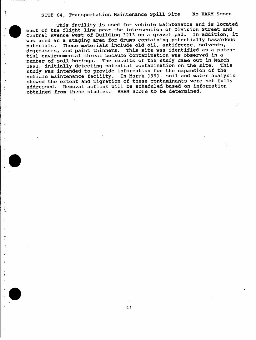
SITE 64, Transportation Maintenance Spill Site No HARM Score
a ~~~This facility is used for vehicle maintenance and is locatedeast of the flight line near the intersection of Division Street andCentral Avenue west of Building 3213 on a gravel pad. In addition, itwas used as a staging area for drums containing potentially hazardousmaterials. These materials include old oil, antifreeze, solvents,degreasers, and paint thinners. This site was identified as a pn)ten-
- ~tial environmental threat because c-ontamination was observed in anumber of soil borings. The results of the study came out in March1991, initially detecting potential contamination on the site. This
- ~study was intended to provide information for the expansion of thevehicle maintenance facility. In March 1991, soil and water analysis
* ~showed the extent and migration of these contaminants were not fully* ~addressed. Removal actions will be scheduled based on information
obtained from these studies. HARM Score to be determined.
41.

Appendix B
Elected fficialsSITE MAILING LIST
Federal:
U.S. Senator Ted Stevens -
Federal Building101 12th AveBox 4Fairbanks AK 99701 (907) 456-0261
U.S. Senator Frank MurkowskiFederal Building101 12th AveBox 7Fairbanks AX 99701 (907) 456-0232
U.S. Representative Don YoungFederal Building101 12th AveBox 10Fairbanks AX 99701 (907) 456-0210
State:
Walter HickelGovernorBox AJuneau AK 99811 (907) 456-3500
Jack CoghillLt GovernorBox AJuneau A-K 99811 (907) 456-3520
Mark BoyerDistrict 20 Representative119 N. Cushman, Suite 205Fairbanks AXK 99701 (907) 456-8161
Bette Fahrenkami,State Senate Representative119 N. Cushman, Suite 201Fairbanks AK 99701 (907) 452-4882
Steve FrankState Senate Reprenentative119 N. Cushman, Suite 213Fairbanks AK 99701 (907) 452-3421
4 2

Nuil KoponenDistrict 21 Representative119 N. Cushman, Suite 101Fairbanks AKt 99701 (907) 456-8161
Hike MillerDistrict 18 Representative119 N. Cushmnan, Suite 101Fairbanks Alt 99701 - (907) 488-0862
Dick ShultzDistrict J RepresentativeBOX 511Tok AK 99780 (907) 883-2345
Tomn MoyerDistrict 19 Representative119 N. Cushman, Suite 203Fairbanks AlK 99701 (907) 452-6275
Bert SharpDistrict 20-A Representative119 N. Cushman, Suite 211Fairbanks AK 99701 (907) 452-7885
Georgianna LincolnDistrict 24 RepresentativeBox VJuneau AlK 99811 (907) 465-3732
North Pole:
Mayor Carleta LewisP0 Box 55109North Pole AK 99705 (907) 488-2281
Grace Ford
P0 Box 55338
North Pole AK, 99705 (907) 488-6439
Karen JohnsonP0 Box 55109North Pole AK 99705 (907) 488-9685
John Arnold2762 ParkwayNorth Pole AK 99705 (907) 488-9260
Karen LaneBox 55109North Pole AK 99705 (907) 488-1479
4 3

craig Lewis1112 Lake DriveNorth Pole AK 99705 (907) 488-2094
Rev Roland PerettiP0 Box 55499 -
North Pole AK 99705 (907) 488-0761
Fairbanks:
Wayne NelsonMayor455 3rd AvenueFairbanks AY 99~701 (907) 456-4230
Jim H-asselbergerDirector Fairbanks Governor's Office478 Terrace DrFairbanks AK 99712 (907) 456-2613
Lowell Purcell, Seat A309 Eureka St.Fairbanks AK 99701 (907) 452-5678
Jerry Norum, Seat B
2720 Ruby Drive0Fairbanks AK 99701 (0)4408
Robert Sundberg, Seat C209 Slater Dr.Fairbanks AX 99701 (907) 452-2995
Bill Walley, Seat D1405 Blueball St.Fairbanks AK 99701 (907) 479-5910
James Hayes, Seat E313 Droz Dr.Fairbanks AK 99701 (907) 452-1568
Jerry Cleworth, Seat F907 Park Dr.Fairbanks AK 99709 (907) 452-5551
Fairbanks North Star Borough:
Juanita HelrisMayor FNSBPC Box 7:267Fairbanks AK 99707 (907) 452-4761
4 4

Hank HoveSeat APO Box 71267
Fairbanks AX 99707 (907) 452-5121
0 ~~Harold GillainSeat BPO Box 71267Fairbanks Ak 99707 (907) 452-2534
Donna GilbertSeat CP0 Box 71267Fairbanks AK 99707 (907) 452-4783
Bob Coghill, Jr.Seat DP0 Box 71267Fairbanks AK 99707 (907) 452-8119
Paul'ChizmarSeat EP0 Box 71267Fairbanks AK 99707 (907) 452-4761
Don LowellSeat FP0 Box 71267Fairbanks AK 99797 (907) 452-4761
S ~~Bonnie WilliamsSeat GPO Box 71267Fairbanks AK 99797 (907) 452-4761
Hank BartosSeat HP0 Box 71267Fairbanks AK 99707 (907) 488-8400
John DaviesSeat IPO Box 71267Fairbanks AX 99707 (907) 452-4761
Walt JohnsonSeat JP0 Box 71267Fairbanks AX 99707 (907) 452-4761
Guy SattleySeat KPO Box 71267
Fairbanks AX 99707 (907) 452-4761
4 5

nnvironnental Organizations:
Rex BlazerNorth Alaska Environmental Center
21V Driveway ~~~~~(907) 452-5021
Fairbanks AK 99707
David KlineAlaska cooperative Research Unit
Biology and Wildlife DepartmentUniversity of Alaska - Fairbanks
209 Irving Building 974467463
Fairbanks AK 99707(974467/63
Diane WorleyArctic Alliance for PeopleAddress Not Available
Alaska Department of Environmental Conservation
Northern Regional officeiooi Noble St
Suite 350 (0)4211
Fairbanks AX 99701 (0)4211
Concerned Individuals:
Randy AccordSyun AkasofuHelenka BriceBernie BrownLouaBulesTBronwCharBulesTBronOWally BurnettFrank X. ChapadosJeff CookMike CookDr Howard CutlerAlan C. EppsMaj Gen Vincent S. Haneman (USAF, Ret)
John HolmHank )HoveMike KellyBill LaneAl LomenEverett LongSteve Lundgr,-fl,Eugene MackinJames A. MesserTom MiklautschRev Don NelsonBrian PhilipsRalph SeekinsCharles WallaceGordon WearGary Wilken
46

Dr William R. Wood
aPeople Contacted for Interviews:V ~~John Arnold
William BlockoiskyEd BostromFra~nk ChapadosDarrell EversmanJames HasselbergerDan JolingDavid KlineCarleta LewisSue HalenJames Messer, Sr.Wayne NelsonLarry PettyEverna Worthen
4 7
0Appendix C
SAMPLE FORMS
This appendix contains the following forms:
Mailing List Addition Coupon
0
.048

AIR FORCE INVESTIGATES HAZARDOUS WASTE AT EIELSON
The United States Air Force has embarked on a comprehensive.environmental investigation at Eielson Air Force Base. The Air Forceis fully committed to meeting its responsibi4lities in maintaining theenvironment and keeping the public informed.
WE WOULD LIKE TO KEEP YOU INFORMED
The Air Force has created a maaiing list of interested personsand groups to receive Information Releases prepared by the Air Force.These Information Releases will tell you about site activities, upcom-ing community meetings, public comment periods, public hearings,public health information, results of investigations, upcoming removalactions, and information on documents available in Information Reposi-tories.
WE WAr," TO HEAR FROM YOU
The Air Force is strongly committed to a solid community rela-tions program. A coupon is included on the bottom of this page. Ifyou would like your name included on the mailing list, please completethe coupon, cut along the dotted line, apply postage and mail. It ispreaddressed. If you are already receiving Information Releases youare on-the mailing list and you need do nothing further to continuereceving them.
THE AIR FORCE LOOKS FORWARD TO WORKING WITH YOU
a ~~Together we can plan and implement the environmental cleanup ofEjelson AFB and make it a more productive asset to the community.Questions? Call Capt. Marta E. Bunch at (907) 377-2116.
---------------------------------------------------------------------------
Please add my name to the mailing list for the Eielson Air Force
Base environmental cleanup effort.
Name:
Address:
City: __ _ _ _ _ _ _ _ _ _ _ _ _State: _ _ _ _ _ _ _ _
Organization (if any): _ _ _ _ _ _ _ _ _ _ _ _ _ _ _ _ _ _ _ _
Comments:
49

THE UNITED STATES AIR FORCE INVITES YOU ...
T1O BECOME A PART OF THE ENVIRONNENTAL CLEMIUP OF EIELBON AIRFORCE BASE
Community Relations DirectorPublic Affairs OfficeEielson APE, Alaska
----------------------------------------------------------------------
CAPT MARTA E. BUNCHCOMMUNITY RELATIONS DIRECTORPUBLIC AFFAIRS OFFICE3112 BROADWAY AVE STE 5ETELSON AFB AK 997C2-1870
50

Appendix D_
DOCUMENTS TEAT ARE OR WILL BE MAINTAINED IN THEADMINISTRATIVE RECORD
See Note #1
Preliminary Assessment Reports -
site investigation Reports
Quality Assurance/Quality Control Data Summary
Data Summary Sheets (Usually Part of the Feasibility study)
Chain of Custody Forms
Quality Assurance Project Plan
initial Work Plan and any Amendments
Community Relations Plan
Fact Sheets
RI Reports
aAny Other Factual Data Relating to Reasons for Selecting the RemedialV Action at the Site
Information From Telephone Logs Relied on in Selecting Response
Guidance Documents and Technical Sources
Feasibility Study
Note 1: Located at:Eielson AFB Library3340 CENTRAL AVE STE 1EIELSON AFB AK 99702-3174(907) 377-3174Hours:
-' ~~~Mon-Wed 11:00 am to 9:00 PMThurs-Sat 11:00 am to 6:00 pmSun 1:00 pm to 5:00 pm
To gain access through the Main Gate of Eielson AFB, Alaska, anescort must be provided. A base escort is available through theEnvironmental Management Office, located at:
2258 CENTRAL AVE STE 1EIELSON AFB AK 99702-2225(907) 377-2922Hours:Mon-Fri 7:30 am to 4:30 pm
52.
Proposed Record of Decision and Brief Analysis of Record of Decision
Notices of Availability of Information
Endangerment Assessment or other Public Health Assessment
Agency for Toxic Substances and Disease Registry Health Assessment
(Draft Versions not included)
Public Comments (including a Late Comments Section)
Documentation of Meetings during which the public presents information
upon which the agency bases its decision on selection of a remedial
action (may be after-the-fact restatement of issues raised)
Documents relating to state involvement and consultation (applicable
or relevant and appropriate regulations determinations, opportunity to
comment on screening of alternatives, feasibility study, proposed
plan, selected remedy, and general correspondence.
Documents relating to the consultatiofl with United States Environmen-
tal Protection Agency (EPA) Region X
Responses to Substantive Comments
Transcript of Required Public Meeting(s) ofl the Proposed Record of
Decision
Transcripts of Discretionary Community Meetings
Record of Decision, including of Statement of Basis and Purpose of
Selected Action; Summary of Alternatives Considered; An Explanation of
why the Agency chose the preferred alternative; Explanation of Signif-
icant Differences Between the Proposed Plan and the ROD
Amendments to the ROD, Information which caused the Agency to change
its decision, Comments, and Res,,onses to those comments
Administrative orders
Index to Documents in Record
52

DOCUMENTS THAT WILL BE MAINTAINED IN THE INFORMATION REPOSITORIES
Community Relations Plan
Fact Sheets
Public Comments Repositories (including a Late Comments Section)
Locations:
North Pole Library601 Snowman Lane
* ~North Pole AY, 99705(907) 488-6101
Elmer E. Rasmuson LibraryUniversity of Alaska FairbanksFairbanks AX 99775(907) 474-7481
Noel Wi en Library1215 Cowles StFairbanks AX 99701(907) 452-5177
SDepartment of Environmental ConservationNorthern Regional Office1001 Noble StFairbanks AX 99701(907) 452-1714
Each information repository will contain an identical set ofdocuments, with the exception that EPA general guidance documents andvoluminous materials (i.e., raw data) will be kept in the Adminis-trative Record.
53

Appendix E
MEDIA LIST
Newspapers
DAILY NEWS MINER200 Cushman StFairbanks AK 99701(907) 456-666
FAIRBANKS TRIBUNE455 3rd AveBox 202Fairbanks AK 99701(907) 456-7434
ALL ALASKA WEEKLY419 2nd AveFairbanks AK 99701
(907) 456-6426, 452-5597
PRUDHOE BAY JOURNALPo Box 890969Fairbanks AX 99708
ANCHORAGE TIMES(907) 263-9175
EIELSON AFB GOLDPANNNER
NORTH POLE INDEPENDENTPo Box 55757North Pole AX 99705(907) 488-0669
Television
KATN (Channel 2)516 2nd AvePo Box 74730Fairbanks AK 99707(907) 452-2125
iC)(Channel 4)PO Box 0North Pole AX 99705(907) 488-2216
KTVF (Channel 11)3530 International St
Fairbanks AK(907) 452-51-21
54

KUAC (Channel 9)University of Alaska Fairbanks
Fairbanks AK 99775-1420
-~~ (907) 474-7491
W Ejelson AFB Public TV
Radio
KIAIK-AM4/KQRX-FMPO Box 73410Fairbanks AK 99707(907) 457-1921
KFAR-AM/KWLF-FM-- P0 Box 70910
Fairbanks A-K 99701(907) 459-5910
ICAYY-FM* ~3504 Industrial Ave
Fairbanks AK 99701-. ~(907) 452-5299
55

Appendix F
CHARTER, EIELSON AIR FORCE BASE TECHNICAL REVIEW COMMITTEE
The Technical Review Committee (TRO) is intended to provide aforum to enhance communication, coordination, and solicit recommenda-tions among community members in response to the Installation Restora-tion Plan (IRP). The members of the working group consist of a desig-nated representative~s) and alternate~s) from Eielson AFB, 11th AirForce, Alaska Department of Environmental Conservation (DEC), AlaskaAttorney General Office (AAGO), Environmental Protection Agency (EPA),contracted IRP project management, current IRP contractors, 56099thCivil Engineering Squadron, Army Corps of Engineers, and one represen-tative from the public.
Vice Wing Commander (Chairperson)343 TFW/CV3112 Broadway Ave Ste 1Eielson AFB AK 99702-1830(907) 377-6101
11th Air Force Environmental Management Office11 AF/DE6900 9th St Ste 103Elmendorf AFB AK 99506-2230(907) 552-4151
Alaska Department of Environmental ConservationNorthern Regional Office1001 Noble StFairbanks AXK 99701(907) 452-1714
Alaska (Eielson) Attorney General office343 TFW/JA2.112 Broadway Ave ste 1Eielson AFB AK 99702-1870(907) 277-4114
Environmental Protection Agency - Region X
Alaska operations office222 W 7th Ave Box 19Anchorage AX 99513(907) 271-5083
5099th Civil Engineering Squadron5099 CEOS21885 2nd StElmendorf AFB AK 997506-4420(907) 552-4854
56

Current IRP Proj ect Managers
aCurrent IRP Contractors
WArmy Corps of EngineersAlaska DistrictPO Box 898Anchorage AXK 99506-0890
Fairbanks North Star Borough Assembly Member(Elected of ficial)Hank Bartos300 N Santa Claus LaneNorth Pole AX 99705(907) 488-8400
57

A-.
.0 GE ee.r� C*�dKO0�
* b..J* �.XaJJZ.Xb S /S So .C� a. 0SC*t. SC .2
-. t�J..J.J.J�Jb' - -- --
.oc '�Th. *CLLLL ., /..cLo..�OcbLL�O �*j. j0� �.
..C..sJn. fl oNy.a�Nr..r.aE�C�e . I * KC�0�0� 0 -
0. a0.MO.'4"L '. -c,1�i..
I-b4�-- a.- I
2.. .- ' -Sw* b * - -
* - 4 - - 0� ac -. - I
4 *-* *- 00� I - * A
: -� / - -
rO�L ... - .
4 Xh. *0C��*�' -- I
- - ,*.�.. C---. * * S� �h.b*fr �0�S-J I A
h� tt �C0*b .i�:a.4t4Lc*�L:ECCt��aOCb I- I
-. 0w V-: I.. Ca-..-.. - C *�fli0
e -t �
/ j K'� * 0- / >1�gr - i
2' I h
*.� I I f
C'.j �.Qb *
am
� -IS- ..
I'... /
/ 4* e-A/ -�
K]00' C-. C
- flC
/.au. '1> *
,
i'N%''-t�- �iI0 -N *,ih;� t x•:z>r �'
* ...j
'I- - v-i '-I
6--- �a> 7/] F -
I -
j<��.�0 S
-- -t-Iae-' I O�- W0
)

CM
E3- u ~ ~ -
U- U-,, __
0~~~LUV-
U~~~~~~~~~~~~~~~~~~~~U
z~~~~0~~~~En~~~~~~e
-i~~~~~~~~~~~-
77-~~~~~~~~~I
C.)~~~~~~~~~~0

MILESTONES CHART 1991
EVENT JAN FEB MAR APR MAY JUN JUL AUG SEP OCT NOV DEC
INTERAGENCYAGREEMENT WIEPA RG
TECHNICALRE VIEWi' CR CRCOMMITTEEESTABLISHED
COMM UNIT YSURVEY CR----------- CRCONDUCTED
CO MMUN I TYRELATIONS CR----------- CRPLAN PREPARED
TECHNICALCOMMITTEE CR CR CRME ET N S
PUBLIC CR CRMEETINGS
PUBLIC COMMENT CR--CR CR- -CRPERIOD
ESTABLISHA DM1INIST RAT IV E CR ------ CRRECORD
ESTABLISHINFORMATION CR ------ CRRESPOSITORIES
KEY:
RQ REGULATORY AGENCY ACTIVITYRM REMEDIAL ACTIONCR COMMUNITY RELATIONS ACTIVITY

0 MILESTONES CHART 1992
EVENT JAN FEB MAR APR MAY JUN JUL AUG SEP OCT NOV DEC
TECHNICALREVIEW CR CRCOMMITTEEMEETINGS
PU BLIC CR CRMEETINGS
PUBLIC COMMENT CR- -CR CR- -OPPERIOD
UPDATEA DM1INIST RAT IV E CR- -CR CR- -CRRECORD
* UPDATEINFORMATION
OR- R- -CRRESPOSITORIESCR-R
KEY:
RG REGULATORY AGENCY ACTIVITYRM REMEDIAL ACTIONCR COMMUNITY RELATIONS ACTIVITY

LIST OF CONTACTS
U.S. AIR FORCE
The designated Eielson Air Force Base contact persons for commu-
nity relations activities are:
Capt Marta E. BunchChief, Public Affairspublic Affairs office
3112 Broadway Ave Ste 3
Eielson AFB AK 99702-1870(907) 377-2116
SSgt Curtis o. RogersPublic Affairs of fice
3112 Broadway Ave Ste 3Ejelson AFB AK 99702-1870(907) 377-1088
The designated Eielson A~ir Force Base cointact persons for techni-
cal questions related to the Remedial Investigation/Feasibility Study
(RI/PS) are:
Capt Bruce SteelyChief, Environmental Management
Environmental Planning office
2258 Central Ave Ste IEjelson AFB AX 99702-2225(907) 377-4361
Capt Kathie GravenhorstEnvironmental PlannerEnvironmental Planning office2258 Central Ave Ste 1
Eielsorl AFB AK 99702-2225(907) 377-2922
Capt Dave WalterEnvironmental Engineer
Environmental Planning office
2258 Central Ave Ste 1
Ejelson AFB AX 99702-2225(907) 377-1689
61

U.S. ENVIRONMENTAL PROTECTION AGENCY
The designated contact person for community relations activities.for Ejelson Air Force Base is:
Ms Grechen SchmidtU.S. Environmental Protection Agency - Region X1200 6th Ave HW1-117Seattle WA 89101 -
(206) 442-1283
The designated contact persons for technical questions related tothe RI/FS at Eielson Air Force Base is:
Mary Jane NearmanU.S. Environmental Protection Agency - Region X1200 6th Ave HW-117Seattle WA 89101(206) 442-1283
Rielle MarkeyAlaska Department of Environmental ConservationNorthern Regional Office1001 Noble StSuite 350Fairbanks AK 99701
(907) 452-1714
6 2

List of Acronyms, Abbreviations, and
Symbols used in the Text
AAC Alaskan Air Command
AF --Air "'orce
AFB Air Force Base
AR Administrative Record
AVGAS Aviation Gasoline
CAC Temporary Combat Alert HangarComplex
CERCLA Comprehensive EnvironmentalResponse Compensation andLiability Act
CRP Community Relations Plan
DDD Dichlorodiphenyl-dichlo-oethane
DEC Department of Environme':talConservation
DDE Dichlorodiphenyl-Cflichloroethylefle
DDT Dichlorodiphenyl-trichloroethane;Dicophane; Chlorophenothafle1, 1, 1,-trichloro-2,Bis (chloropheryl) ethane
DOD Department of Defense
* ~EOD Explosive Ordance Disposal
EPA Environmental Protection Agency
FNS B Fairbanks North Star Borough
HARM Hazardous Az-sessnh-nt RatingMethdology
IRP installation Restoration Program
* - JP-4 Jet Petroleum (fuel)
mg/i Milligrams per Liter
* ~mg/kg Milligrams per Kilogram
MOGAS Motor GasolinemSl Mean Sea Level
NPL National Priorities List
PA Public AffairsPACAF Pacific Air Forces
r ~PA/SI Preliminary Assessment/S iteInspection
PCB Poloychlorinated Biphenyl
PD 680 Petroleum Distillate (Solvent)
POL Petroleum, oil, and Lubricants
ppm/ppb Parts per Million/Parts perBillion
QA Quality Assurance
QAPP Quality Assurance Project Plan
RCRA Resource Conservation and RecoveryAct
RD/RA Remedial Design/Remedial Action
63

RI/FS Remedial Investigation/FeasibilityStudy
ROD Record of Decision
a SARA Superfund Amendments andReauthorizi:tion Act
TOE TrichloroethylefleTPH Total Petroleum HydrocarbonTRC Technicial Review CommitteeUSAF United States Air ForceUST Underground Storage Tankvoc Volatile Organic Compound
64

DISTRIBUTION
Community Relations Plan
Ejelson Air Force BaseFairbanks, Alaska
June 4, 1991
343 TFW/CC (1)343 TFW/CV (1)343 TFW/PA (1)343 TFW/JA (1)343 CSG/CC (1)343 CSG/DE (1)343 CSC/DED (1)343 CSG/DEV (7)
Department of Environmental conservation (1)
U.S. Environmental Protection Agency, Region X (1)
65

STAFF SUMMARY SHEET_______ ~~(computer .generated')
_ TO ACTIONI Signature. Grade & Date I TO 1ACTION1 Signature, Grade & Date
1 34 CSG Coord __ _ _ _ _ _ _ _ _ _ _ _ _ _ 61343 TFW Coord
2 34 CSGCoord -733TWCoord
3 343 TFW Coord _______________81343 CES Actiont
_ JA __ _ _DEV _ _ _
4 343 TFW Coord-9i_ _ __ _ __ __ _ __ _ __ _
*_ PA q_ _ _ _ _ _ _ _ _ _ _ I_ _ _ _ _ _ _
$ 343 CGs Coord __ _ _ _ _ _ _ _ _ _ _ _ _ _ 1 _ _ _ _ _ _ _ _ _ _ _ _ _ _
Surname of Action Officer and Grade Symbol JPhone Initials Suspense DateKathie Gravenhorst, Capt DEV 7-292-2 1smc
Subject Date* Community Relations Plan Final Drzft 2F, May 91
Summary:
1. Attached for your review is the Final Draft of the Community Relations Plan.
JUSTIFICATION:
2. Request a review to address all your concerns, before this is released to the EPA.EPA is requesting this document by 4 JUN 91, therefore, if comments are notreceived by 3 Jun 91, we will assume the information can be sent as written.
RECOMMENDATION:
3. Review and approve as written.
STEY, CpUA
Chief, Environmental Management Branch
AF' Form 1768, SEP 84 Previous editions will be used WINS DOG 1755VPage 1

Sit. Management Plan DRAFTEI.Mon Air Force Base
Appendix E
DATA MANAGEMENT PLAN
FOR EIELSON AIR FORCE BASE
CVOR257/033.51 -3

Shet Management Plan-DRIP DRAFTVEleon Air Force Bass
. ~CONTENTS-DMP
Page
1.0 Introduction ............................................ E.1.11.1 Approach .............................................. E.1.11.2 Report Contents and Organization............................. E.1 .2
2.0 Project Data Types....................................... E.2.12.1 Historical Data........................................... E.2.12.2 Location Data ............................................ 2E.2.12.3 Sample Collection Data .................................... E.2.12.4 Field Analysis Data ........................................ E.2.22.5 Laboratory Analysis ....................................... E.2.22.6 Quality Control Data....................................... E.2.22.7 Project Document Data..................................... E.2.22.8 Well Installation Data....................................... E.2.3
3.0 Data Management Requirements ............................ E.3.13.1 Air Force Requirements .................................... 2E.3.1. ~~3.2 Project Team Requirements .................................. E.3.43.3 Regulatory Agency Requirements .............................. E.3.5
4.0 Data Base System ....................................... E.4.14.1 Data Table Structures...................................... E.4.14.2 Compatibility with IRPIMS ................................... E.4.44.3 Compatibility with AutoCAD Mapping System......................E.4.5
5.0 Data Management Protocols................................E.5.15.1 Data Management Scheme .................................. E.5.15.2 Integrity Checks.......................................... E.5.35.3 Document Tracking ....................................... E.5.35.4 Data Management Responsibilities ............................. E.5.4
CtVCVO~257/079.51 i 17 June 1991

Sit. Manaemgernt Plen-DMP DRAFrEilelon Air Force Bse.
CONTENTS (Continued)
Page
6.0 Data Management Tasks...................................E.6.16.1 Task 1: Loading and Setup of IRPIMS Data Loading Tool and Training . .E.6.1
6.2 Task 2: Loading and Setup of EDMS-P .......................... E.6.16.3 Task 3: Organization and Entry of Historical Data...................E.6.16.4 Task 4: Preparation of Transfer Programs ........................ E.6.26.5 Task 5: Field Dct~,a Entry to IRPIMS ............................. E.6.26.6 Task 6: Laboratory Data Entry to IRPIMS.........................E.6.26.7 Task 7: Transfer of IRPIMS Files to EDMS-P...................... E.6.36.8 Task 8: Data Validation Updates............................... E.6.36.9 Task 9: Sending Files to EPA Region X .......................... E.6.36.10 Task 10: Document Tracking................................. E.6.3
FIGURES
E.4.1 EDMS-P Data Base Design .................................. E.4.2
E.5.1 Document Information Form ................................. E.5.5
ct/CVO0R257/079.51 iv 17 June 1991
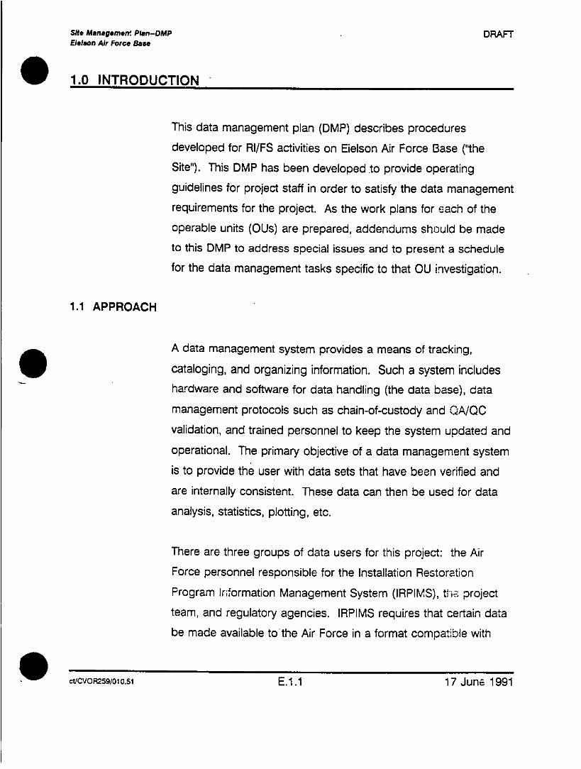
Site Mangme grtwe Ptan-DMP DRAFTElelson Air Force Base
. ~1.0 INTRODUCTION
This data management plan (DMP) describes proceduresdeveloped for RI/FS activities on Eielson Air Force Base ("theSite"). This DMP has been dleveloped to provide operatingguidelines for project staff in order to satisfy the data managementrequirements for the project. As the work plans for each of theoperable units (O1-s) are prepared, addendumns should be madeto this DMP to address special issues and to present a schedulefor the data management tasks specific to that OU investigation.
1.1 APPROACH
A data management system provides a means of tracking,cataloging, and organizing information. Such a system includeshardware and software for data handling (the data base), datamanagement protocols such as chain-of-custody and Q-AYQOvalidation, and trained personnel to keep the system updated andoperational. The primary objective of a data management systemis to provide the user with data sets that have been verified andare internally consistent. These data can then be used for dataanalysis, statistics, plotting, etc.
There are three groups of data users for this project: the AirForce personnel responsible for the Installation RestorationProgram Inflormation Management System (IRPIMS), tije projectteam, and regulatory agencies. IRPIMS requires that certain databe made available to the Air Force in a format compatible with
cVCVoR259/01o0.s1 E.1.1 17 June 1991

Shte Management Plan-DUP DRAFTEVelson Air Force Base
their data base. The project team requires that a subset of the
IRPIMS data (namely sample and analysis information) be
available in a system that can support data queries, reports, and
graphics. The EPA Region X requires well installation information
and results from any groundwater sampling.
To satisfy the data needs of the users, two data management
tools will be used on this project. The IRPIMS Contractor Data
Loading Tool will be used to prepare ASCII files in the correct
format for the Air Force data bc-se. The data delivery s~_hedlule
and valid values lists in the IRPIMS Data Loading Handbook
(Version 2.2) will be followed. Once these files are prepared, they
will be used to load data into a Paradox-based data base
designed for environmental investigations. This data base will be
used by the project team to support data analysis activities. The
EPA Region X data, a subset of the information used by the
project team, will be extracted from the Paradox-based system,
formatted, and sent to EPA Region X.
1.2 REPORT CONTENTS AND ORGANIZATION
This Cata management plan supplements the Sampling and
Analysis Plan (SAP) and the Quality Assurance Project Plan
(OAPP). The scope of work presented in tnki DMP is based on the
sampling and analysis program presented in the SAP.
Ct'CVOR259/01 0.51 E.1.2 17 June 1991

Site Management Plan-DMP DRAFTBeMlon Air Force Bae"
* ~2.0 PROJECT DATA TYPES
2.1 HISTORICAL DATA
The project team will decide what historical data collected atEjelson AFB over the last 1 0 years are pertinent to the RI/FS. This
data must be organized and entered into the data management
system.
2.2 LOCATION DATA
The most important data for a sampling location are its
coordinates. Having coordinates associated with sampling
locations allows the project team to map sample information.
EBelson AEB coordinates will be obtained for all samplinglocations.
2.3 SAMPLE COLLECTION DATA
Sample data includes the location at which the sample was taken,the sampling time and date. upper and lower sample depths (for
soils), sampling method, and sample matrix (e.g., soil).
For this project, each sample at a location will be uniquely
identified by using a sample code and a subsample or SS code inaddition to the location code. The subsample or SS code is used
to identify duplicate samples. For a routine sample, the SS fieldcode is an '1N1.'1 If the sample is a duplicate, then the SS field
. vetCVOF1z59/011.51 E.2.1 17 June 1991

Site Management Plan-.bMP DRAFTEielson Air Force Baee
code is "1FD1.2' If two duplicate samples are taken, the second
duplicate is "FD2'" These codes are consistent with the valid
values from IRPIMS.
2.4 FIELD ANALYSIS DATA
Several types of field data will be collected in the course of the
investigation. The field analysis data differ from the sampleanalysis data in that they do not have any laboratory data
associated with them.
2.5 LABORATORY ANALYSIS
Important laboratory analysis information for a given sample
includes extraction method, analytical method, extraction date,
analysis date, parameter name, parameter value, data qualifier,
and units.
2.6 QUALITY CONTROL DATA
The laboratory will analyze matrix spikes and matrix spike
duplicates to assess the accuracy and precision of the laboratory
data being reported. The analysis of field duplicates will provide a
similar check on field procedures for sample collection.
2.7 PROJECT DOCUrA~E=NT DAT A
RI/F.S projects generatE many dlocuments including planning
documents (FSPS- and QAPFZ.), project notebooks, laboratory data
ct/CVCR259/01 1.51 E.2.2 17 June 1991

Site Management Plan-DMP DRAFTEileson Air Force Bshe
notebooks, field data notebooks, well logs, invoices, and reports.
It is important to keep track of document file location, author, date,document type (e.g., lab data, administrative, etc.), and document
contents.
2.8 WELL INSTALLATION DATA
Data will be gathered from the well logs of new wells beinginstalled at Eie!son AFB. This information will go into a well tableand will comply with the EPA Region X order for groundwater
data. These data include well coordinates, elevation, referencepoint well use, and date of installation.
cVCVOR2S9/O1 1.51 E.2.3 17 June 1991

Site Mantagemenft Plan-LIMP DRAFTEielson Air Force Bass
. 3.0 DATA MANAGEMENT REQUIREMENTS
As mentione d in the introduction, there are three groups of users
for the data from this project: the Air Force Installation RestorationProgram Information Management System (IRPIMS), the project
team, and regulatory agencies. Each of these groups has
different sets of data needs, and the data management system for
the project must be able to satisfy all these needs.
3.1 AIR FORCE REQUIREMENTS
IRPIMS is a relational data base maintained by the Air Force
Hum an Systems Division (HSD) to store, analyze, and report
information used for the Air Force Installation Restoration Program
(IRP). The Air Force IRP program identifies, quantifies, and
remediates environmental contamination at Air Force installations
and facilities.
Contractors are required to submit IRP data to HSD in an
electronic format compatible with IRPIMS. The reporting
requirements are detailed in the IRPIMS Data Loading Handbook.
This handbook specifies a delivery schedule for three groups of
project dlata. These groups and the types of data included are
listed below. Copies of the IRPIMS file formats are included in
Appendix A.
ct/CVO~t591012.51 E.3.1 17 June '1991

Sit. Management Ptan-DMP DRAFTEleleon Air Force Base
3.1.1 IRPIMS Group 1
This group of files must be submitted no later than 30 days after
site and sampling location assignments have been determined or
after well and borehole installations have been completed,
whichever is later.
* Location Definition Information (BCHLD!)--Defines a
sampling location's name, coordinates, elevation,
construction method, borehole depth, etc.
* Site and Location Informat~ion(BCHSLI)--ldentifies site(s)
associated with a sampling location and whether the
location is upgradient, crossgradient, or dlowngradient of
the site.
* Well Completion Information (BCHWCI)--Provides detailedinformation concerning the construction of the well.
3.1.2 IRPIMS Group 2
This group j of files must ne submitted no later than 40 days after
sample collection has taken place in the field or after field tests
have been performed, whichever is later.
*Groundwater Level Data (BCHGWD)--Records data from
gr oundwater level measurements.
et/CVOR259/012.51 E.3.2 17 June 1991

Sit. Management Plan.-DMP DRAFTEielson Air Force B.s.
0 . ~~~~~~Environmental Sampling Information (BCHSAMP)--Providesinformation related to sample collection, including sampling
location, date and time of sample collection, beginning and
ending depth of soil samples, sample method, matrix, and
sample type (identifies field OC samples). A lot control
number is also assigned to each sample identifying the
field QC samples associated with it.
Lithographic Description Information (BCHLTD)--Recordsgeologic information from borehole logs, including
beginning and end depth of a section, lithology code,
ASTMV soil classification code, stratigraphic order code, and
a visual description.
3.1.3 IRPIMS Group 3
This group of filies must be submitted no later than 30 days after
obtaining analytical results from the laboratory.
* Sample Preparation Information (BCHTEST)--Records the
analytical method, extraction method, lab sample ID,
extraction date, analsis date, and laboratory OAIQC lot
control number for each sample to be analyzed.
* Analytical Results (BCHRES)--Identifies the parameter label,
parameter value qualifier, parameter value, and laboratory
detection limi:..
O ~~ct/CV0R259/012.51 E.3.3 17 June 19-91

Site Mane gemrern Plan-DMP DRAFTElelson Air Force base
Each of these tables uses codes to condense the information
being entered. These codes must be on the valid values lists
included in the IRPIMS Data Loading Handbook. For example, in
the valid values list the analytical laboratory code for CH2M HILL's
Redding Laboratory is "CHMR." If the project team needs to add
a code to the list, the IRPIMS staff at Brooks Air Force Base must
be contacted.
IRPIMS provides a data loading tool to prepare ASCII files in the
correct format for the data base. This tool minimizes the data
entry required for analytical data by allowing the user to set up
data forms and to specify detection limit default values.
Instructions for using the tool are provided in the IRPIMS
Contractor Data Loading Tool User's Manual, Version 1.0, April
1991.
The contractor is responsible for ensuring that the data delivered
to HDS is validated and consistent with the IRPIMS reportIng
formats and valid values lists.
3.2 PROJECT TEAM REQUIREMENTS
The data management requirements for the projec.t team differ
from those of the Air Force IRPIMS. In addition to requiring an
internally consistent set of validated datLa, the data must be
organized into a system that allows the project team to query the
data and export files to other systems for analysis, modeling, or
mapping.
cV/CVOR259/O1 2.51 E.3.4 17 June 1991

She Management Plan-OMP DRAFTEielson Air Force Base
The project team is primarily concerned with being able to query
the field observations and sample and analytical data. The data
relating to well completion information and lithology information is
less likely to be queried, so it is not as important to the project
team; however, because the EPA requires this information, it will
be stored in the, data management sys tem. Also, it is not
necessary for the project team to query the laboratory QA/QC
information, since it is only used to assign qualifiers to the data.
Because the data required by the project team are a subset of the
data required by IRPIMS, the data management system can be
geared towards entering the data into IRPIMS and thentransferring the data needed by the project team to a data base
that can support queries and reports. This data base is
discussed in more detail in Section 4.0.
3.3 REGULATORY AGENCY REQUIREMENTS
EPA Region X requires well installation information along with
results from any groundwater sampling done in Region X (in
accordance wit1h Regional Order for Ground-Water Data
Management, dated August 15, 1989). The EPA requires this
information be submitted in electronic form in a specific format for
the well information and another format for the groundwater
contaminants. [The detailed well installation information is not
likel., to be used by the project team but needs to be entered into
the data base so that it can be formatted for the EPA.J This
information can be taken from IRPIMS and transferred to EPA. It
doesn't need to be in EDMS-P. The groundwater analytical data
ctICdOR259/ol12.51 E.3.5 17 June 1991

Site Management Pian-DMP DRAFTElelean Air Force Base
will be part of the overall data management system and will be
extracted from the data base, formatted, and sent to the EPA after
the data have been validated.
cVCVOR259/012.51 E.3.6 17 June 1991

Site Management Plan-DMP DRAFTEleisn Air Force Bas.
0 4.0 DATA BASE SYSTEM
The data base software that will be used by the project team is
EDMS-P, a Paradox-based system developed by CH2M HILL.
The EDMS-P data base design is shown schematically in
Figure E.4.1. It is a relational data base, which means that the
tables are interconnected so that information stored in one table
can be related to another table by a common column. The data
table structures and their compatibility with IRPIMS are discussed
below.
4.1 DATA TABLE STRUCTURES
The detailed EDMVS-P table formats are presented in Appendix B.0 ~ ~~~~~Of the 16 tables included in EDMS-P, 9 are look-up tables used tosupport the system. The other seven are tables for storing the
project data. These seven data tables are described briefly below.
*STATION. This table defines a sampling location name and
stores information regarding its coordinates and elevation.
*SAMPLE. In the sample table, each sample collected is
defined by a three key fields; the station code, a sample
code, and a subsample (SS) code. The conventions used
for these codes we. e explained in Section 2.0. The sample
table -also stores information regarding the date and time a
sample was collected, its upper and lower depths (for
soils), and the sample matrix.
. ~cCVc0R2591013.51 E.4.1 17 June 1991

oh-~~~~~~~~~~~~~~~~~~~~~~o
M~~~~~~~~~~~~~~
> ~ ~ - >
M~~~~~~~~~~~~~t: ~ ~ ~ ~ ~ ~ ~ ~ ~ ~ ~ -

Site Management Plan-DM? DRAFTEaison Air Force Base
*FIELDANA. This table stores data collected in the field. It
includes the station ID for the observation location, the
observation date and time, and the parameter ID, value,
and units. It also allows the user to store information
regarding the instrument used and the person making the*
observation.
ANABATCH. The analytical batch table stores laboratory
information related to a sample. It includes the station,
sample, and SS fields to identity the sample; an entry
group ID that identifies the type of analysis done (volatile
organics, metals, etc.); date received, date analyzed, and
date extracted so that holding times can be evaluated;
dilution factor; laboratory sample ID; a field to indicate if
any tentatively identified compounds (TICS) were found;
and a data validation flag to indicate if the data from that
sample have been validated.
ANAVALUE. This table stores the analytical data from the
samples. It is str uctured so that each analytical result for a
sample is a separate record. Information included in each
record is the station, sample, and SS; the parameter ID,
value, qualifier and units; and the analysis method and
detection limit.
DOCUMENT. This table stores information about project
documents. Each of the other tables in the data base
includes a field for document ID that lets the users know
where they can find the hard copy of the data that was
Ct/CVOR259IO13.51 E.4.3 17 June 1991

Site Management Plan-DMP DRAFTElelson Air Force Base
entered. In the document table these document IlDs are
related to the document title, author, publication or
generation date, project code (project number), document
type, and a brief abstract.
These data table structures are suitable for all of the data types
discussed in Swtion 2.0 except for the geologic and well
construction data. These data will be repcsted to the IR?'IMIS and
the EPA; they will be contained in the data base but are of little
interest to the project team. The analytical data from the
laboratory quality control samples will not be entered into the data
base. These are used only by the project data reviewer to assign
data qualifiers and are not needed by the project team, though
they will also be reported to IRPIMS.
4.2 COMPATIBILITY WITH IRPIMS
Because IRPIMS will generally contain more data than the EDMS-P
system, data will be loaded into IRPIMS using the contractor data
loading tool and will then be transferred to EDMS-P. Tables D.4.1
through D.4.4 show the correlations between the EDMS-P
ST ATION, SAMPLE, ANABATCH, and ANAVALUE tables and the
corresponding IRPIMS tables.
The primary difference in the table structures is that whe:are
EDMS-P uses the station, sample, and SS fields to uniquely
identify a sample, IRPIMIS retains the sample date, urt..-er and
lower sample depth, and the sample rratrix in each taole to
identify the sample. To accommodate mis difference in the
ctVCVOR2591013.51 E.4.4 17 June 1991

Site Management Plan-DMP DRAFTEilelon Air Force Base
0 ~~~~~~transfer of data between IRPIMS and EDMS-P, the sample enddepth (SED) from IRPIMS will be included in the sample field forall soil samples. For air samples, the sample date from IRPIMSwill be included. These fields will then be manually modified tomatch the sample ID conventions described in Section 2.0.
4.3 COMPATIBILITY WITH AUTOCAD MAP,'-ING SYSTEM
All sample information in the EDMVS-P data base can be resated tothe AutoCAD site map via the coordinates stored in the stationtable. To plot data on the map, ASCII files can be generated fromthe system containing the station coordinates and the associatedsample observation. These files can then be loaded onto theAutoCAD system to produce the appropriate overlay on the base
* ~~~~~~~map of the project site.
. ~~ctCVOR259/013.51 E.4.5 17 June 1991

Sit. Management Plan-omp DRAFTEVelon Air Force Base
. 5.0 DATA MANAGEMENT PROTOCOLS
In this section the flow path of data from the field to the projectteam is defined and data management responsibilities are defined.Also, the procedures to be used for checking data integrity andcontrolling project documents are discussed.
5.1 DATA MANAGEMENT SCHEME
The project team may select some of the historical data to beentered into the data management system. These data must becollected and coded to match the data currently being collected.The historical data must be consistent with the data in the data
management system. For example, station location names must
match exactly; MW-i and MW-0l may be the same physicallocation but would not match in the data management system.
The project team must evaluate the data and assign theappropriate codes. The pertinent historical data will be enteredinto the data management system once and will be immediately
available for use by the project team.
The flow path for the field data is fairly simple. The location
information (BCHLDI), site and location information (BCHSLI), wellconstruction data (BOHWCI), lithology data (BCHLTD), andsample data (BCHSAMP) are loaded into the IRPIMS files for
delivery to the Air Foc,-e. Of these files, the location, sampleinformation, and well construction data are loaded into The
ct'CV0R2591014.51 E.5.1 17 June 1991

Sit. Management Plan-DRIP DRAFTVElson Air Force Bae"
EDMS-P data base. The well construction data are then formatted
and sent to EPA Region X.
The flow path for samples that undergo field analysis is a'so fairly
simple. Th e results of the field analysis are recorded in the field
notes and then entered into the sample preparation information
(BCHTEST) and analytical results (B3CHRES) tables in IRPIMS for
delivery to the Air Force. These files ' a then loaded into the
EDMVS-P data base and are available for general project use.
The flow path for the samples that undergo Iabnratory analysis is
complicated by the data valization process. The data-from the
laboratory analysis are reported in a data package. This data
package is reviewed and qualifiers are assigned to the data
indicating their quality. These qualifiers are presented in the data
validation report.
To minimize project, delays, the analytical data will be inp'.t to
IRPIMS and transferred to EDMVS-P at the same time the d4ata are
being validated. During that time, the unvalidlated data P~rn tnt..
data base will be made available to the project team. for limited
use. All data reports generated during that time will be mn~rked
"Not QP d" to warn the user that the quality of the data is
unknown. The data validation flag in the ANABATCH table will
contain a "N" during this time to indicate that the data are not
validated.
Once the data validation report is comnpleted, the data qualifiers ir
both the IRPIMS and the EDMVS-P data files will be updated, and
cVCVOFR259/Oi4.51 E.5.2 17 June 19

Site Management Plan-DMP DRAFTElelson Air Force Bsea
the data validation flag will be changed to a "'V. After this is done,the files can be sent to the Air Force, and the data will be madeavailable for general project use. The validated data will beformatted and sent to EPA Region X at this time also.
5.2 INTEGRITY CHECKS
To detc,,mine whether the data have been entered correctly fromthe data sheet, a checkprinting procedure will be used for eachgroup of data entered. The data report will generated thatcontains all of the data entered. It will then be checked foraccuracy against the original data sheets. The correct values arehighlighted in yellow and corrections marked in red. Anynecessary corrections are made, and a new checkprint is
generated, and the corrected values are checked again. Thisprocess continues until all the data are correct. The reviewer
dates and initials each checkprint, and they are kept as a record-of-revision to the project data base.
5.3 DOCUMENT TRACKING
As discussed in Section 4.0, all of the records in the EDMVS-P havea document number associated with them that identifies where theoriginal information is stored. These documents may be fielddata, laboratory data, well construction data, or survey data.These document numbers will be assigned sequentially from 001to 999 as documents are generated. Other documents such asinvoices, reports, and references will also be assigned documentnumbers. As documents are generated, members of the project
ctICVOP259/01 4.51 E.5.3 17 June 1991

Site Management Ptan-DMP DRAFTEleleon Air Force Bane
team should complete a copy of the document information form
shown in Figure E.5.1. The information on this form will then be
input to the document table in the data base an.d will be available
for document tracking.
5.4 DATA MANAGEMENT RESPONSIBILITIES
The key to ma~.ng the data management scheme and procedures
discussed above work is to have well-defined data management
responsibilities. Listed below are the key people involved in the
data management process and their associated responsibilities.
* Project Manager--Submits prepared data files to the Air
Force HSD and EPA Region X.
* Project Data Coordinator--Oversees data entry andreporting opera-,ions and ensures that only validated data is
used for project decision making. The data coor:'Unator
works with the project data assistant and the sys-tems
analyst to satisfy project needs for queries, reports, and
maps.
*Project Data Assistant--Responsib~ for datka entry and
integrity checks, data validation updates, routine data
queries and reporting, and document tracking.
*Project Data Reviewer--Validates data and provides
updated data qualifiers to project data coordinator.
cVCVOR259/O1 4.51 E.5.4 17 June 1991
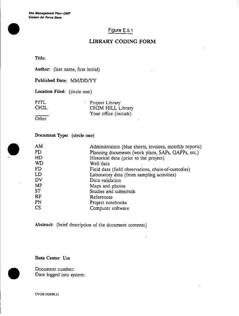
Site Management Plan-DMPEielson Air Force Base
Figure E.5.1
LIBRARY CODING FORM
Title:
Author: (last name, first initial)
Published Date: MM/DDIYY
Location Filed: (circle one)
PJTL -Project LibraryCH2L CH2M HILL Library
_______ ~~~Your office (initials)Other
Document Type: (circle one)
AM Administration (blue sheets, invoices, monthly reports)PD Planning documents (work plans, SAPs, QAPPs, etc.)HD Historical data (prior to the project)WD Well dataFD Field data (field observations, chain-of-custodies)LD Laboratory data (from sampling activities)DV Data validationMP Maps and photosST Studies and submittalsRF ReferencesPN Project notebooksCs Computer software
Abstract: (brief description of the document contents)
Data Center Use
Document number:
Date logged into system:
CV0R192/098.51

Site Management Plan-DMP DRAFTVEleson Air Force Base
Systems Analyst--Responsible for setting up both the0
IRPIMS loading tool and the EDMVS-P data base and for
transferring files between systems.
cVCVOR259/OI14.51 E.5.6 17 June 1991

Sit. Management Plan-DMP DRAFTEBelson Air Force. Bae"
. 6.0 DATA MANAGEMENT TASKS
The work that will be required to develop and implement the data
management system has been organized into 1 0 tasks. Data
validation, and reports and queries, are not included as data
management tasks.
6.1 TASK 1: LOADING AND SETUP OF THE IRPIMS DATA LOADING TOOL ANDTRAINING
The systems analyst will set up the IRPIMS data loading tool on a
corrnputer. Any necessary additions to the valid values lists will be
made at that time in accordance with the Air Force procedures.
Both the project data coordinator and the project data assistant0 ~ ~~~~~~will be instructed by the systems analyst how to enter data intothe files and generate checkprints.
6.2 TASK 2: LOADING AND SETUP OF EDMVS-P
The systems analyst will load the EDMVS-P system onto a
computer. With input from the project data coordinator, the data
structures will be updated or modified as necessary.
6.3 TASK 3: ORGANIZATION AND ENTRY OF HISTORICAL DATA
The project team will determine which, if any, of the historical data
need to be entered into the project data base. The project data
coordinator will then collect and organize these data. This
ctVCVOt259/01 5.51 E.6.1 17 June 1991

Site Management Plan-DIMP DRAFTElelson Air Force Base
includes checking the data for consistency wfth the overall project
naming/numbering scheme. The project data assistant will enter
these data into EDMVS-P.
6.4 TASK 4: PREPARATION OF TRANSFER PROGRAMS
The systems analyst will prepare transfer programs to tr~ansfer
data entered into the IRPIMS files to the appropriate tables in
EDMVS-P. A trial run will be made with a small set at data to
ensure that the transfer is taking place properly.
6.5 -TASK 5: FIELD DATA ENTRY TO IRPINIS
The following sets of data will be entered into IRPIMS files by the
project data assistant: location and well information; sample
information; and lithology information. The project data
coordinator will oversee this data entry.
6.6 TASK 6: LABORATORY DATA ENTRY TO IRPIMS
The first task for the entry of laboratory data is the set up of the
analytical data forms in IRPIMS containing the parameters and
their associated detection limits. Then the information off the
laboratory data sheets is entered into the sampie preparation
information table (BCHTEST) and the analytical results table
(BC1HRES?- Checkprints will be made to check the accuracy of
the data entry. The project data coordinator will oversee this
process.
cvCvORŽ5901o5.51 E.6.2 17 June 1991

Sit. Management Plan-DMAP DRAFTEBelson Air Force Base
O ~6.7 TASK 7: TRANSFER OF IRPIMS FILES TO EDMS-P
Using the transfer programs prepared under Task 4, the systemsanalyst will transfer data from IRPIMS to EDMS-P. The data in
EDMS-P will be checked to determine that it was correctly
transferred.
6.8 TASK 8: DATA VALIDATION UPDATES
The project data reviewer will review the OA/QC data from thelaboratory and assign qualifiers to the data. The project dataassistant will then update the data in both the IRPIMS andEDMS-P files to reflect these changes. The project data
coordinator will oversee these changes.
6.9 TASK 9: SENDING FILES TO EPA REGION X
The project data coordinator along with the project data assistant
will select and format the well construction data and the analytical
groundwater data required by EPA Region X.
6.10 TASK 10: DOCUMENT TRACKING
All project documents will be coded and entered into the EDMS-Pdata base as discussed in Section 5.0. The project da,.a assistant
will be responsible for entering the information into the data baseand labeling and filing the documents. The project data
coordinator will assist by providing document descriptions.
ct'CVOR259/O1 5.51 E.6.3 17 June 1991

Site Management Plan DRAP7Eielon Air Force Oa"e
'0
Appendix F
BACKGROUND SAMPLING PLAN
FOR EIELSON AIR FORCE BASE
0i
0 CV0P2571033.51 -4

Sit. Managemfentf Plan -BSP DRAFTElelson Air Force Baa.
. ~CONTENTS-BSP
Page
1.0 Site Description ......................................... P.1.1
2.0 Objectives of Background Sampling .......................... F.2.1
3.0 Samplin- Procedures, Locations, and Frequency ................ PF.3.13.1 Soils .............. ................................... F.3.13.2 Surface Water and Sediment Background Sampling ................ F.3.63.3 Groundwater............................................ F.3.6
TAB LES
F.3.1 Background Samples to be Taken............................. F.3.4
FIGURES
O ~~F.3.1 General Area of Samplings................................. F.3.2
cvCVOR257/080.51 ii17 June 1991

Shte Management Plan-BSP DRAFTEBalson Air Force. Base
. ~1.0 SITE DESCRIPTION
General information describing the Site is covered in the SiteManagement Plan. Background data acquired by- previousinvestigations are described in the SMVP, Section 6.2.1.
. ~~ctICVOFQ57/069.51 F.1.1 17 June 1991

She Mana gement Plan-DSP DRAFTElelsor. Air Force Base
2.0 OBJECTIVES OF BACKGROUND SAMPLING
Background samples will be used in the RIIFS proc-ess to estimatethe naturally occurring statistical distribution of parameterconcentrations. The distribution of parameter concentrations inthe background may be compared in various ways with samplingresults from potentially contaminated areas. Frequently an upperpercentile of the background distribution for a given parameter isused to indicate when sample results from potentiallycontaminated areas are unusually high. This is the most stringentuse of the background data and represents a conservativeapproach to determining the required number of background
samples.
The number of samples proposed is intended to provide areasonable estimate of the upper percentile of backgroundparameter concentrations in each media without assuming aparticular distribution. If a background population distribution canbe determined after sampling, the confidence level of the estimatemay improve.
ctICVoR257/07~..sl F.2.1 17 June 1991
Sit. Mana geme~nt Plan-asp DRAFTElelson Air Force Base
. ~3.0 SAMPLING PROCEDURES, LOCATIONS, AND FREQUENCY
Background samples will be designated in accordance with thesample numbering system described in the SMP OAPP. Samplingequipment and procedures will be in accordance with the SMPFSP. Sample handling and analysis will be in accordance with the
SMP OAPP.
3.1 SOILS
The low elevation, main part of the base is built on sands andgravels of a glacial fluvial outwash plain. Fill from onsite borrowpits was used extensively in construction of the base. Loessreportedly underlies the portions of the base at higher elevationsS ~~~~~~~(in the northeast and southeast portions of the base). Each ofthese areas will be sampled separately. Tentatively, the GoldenValley Electric Association powerline right-of-way will be used togain access to uncontaminated areas southeast of the main partof the base from which to sample the fluvia: material. The generallocation of sampling is shown on Figure F.3.1 designated as
"Primary Soil Sampling Area."
Alternatively, if sampling in the primary soil sampling area proves
infeasible or inappropriate for any reason (e.g., unexpectedcontamination), background fluvial soil sampling will be conducted
east of the base in the area identified on Figure F.3.1 as"Alternative Soil Sampling Area." This area is accessible from theTrans Alaska Pipeline (TAP) access road.
ct'CVOR257IO7I1.51 F.3.1 17 June 1991

-s - ---- - - --.--~10.5 I C. 7'7"* '" --
Scaile in Miles -i*74<,
-~~ - -V t QA+AL~TERNATE.,~- I "
E-ElESON'AFBBOUNDARY
- -------- -- ~ - ~
AII. ~ ~ ~ ~ -
& ': I~~~~~~~~~~~~~~~~~PRIMARY' D1
'4~~~ 'V k~IR FORCEQ I T,.
V-1~~~~~~~~~~~~
2: 2 ;-PRIMARY»',
LEGEND
I ~~~~~~~~~~~Backgroun Loes~s Soil SamnplingArea"a ~ jjjBackg und FualSoil Sampling Area
-g -u Backgrou dSuriace Wvter andSedimenSampling Loc~azorn
¾ F~~~~~~~~~~~~~~~~~EIGURE 6.2. ,;,Propo~sed Background..Sompling LocationsSite Mcn:oycmen~t F~n ielson Ai r Force Bose

She. Management Plan-DSP DRAFTE~lalon Air For". Boa.
In either case, actual sample locations will be selected asrandomly as possible considering physical limitations.Randomness of sampling is secondary to applying goodjudgement in selecting sampling locations that may be expectedto yield good uncontaminated background samples. A Sitereconnaissance will be performed to assist in developing a rationalrandom sampling technique. Distance off the TAP access road (ifthe alternative sampling area is used) will be governed to somedegree by physical limitations, but must be sufficient to assurethat the sampling location is unaffected by the TAP, its accessroad, or any other contaminant-producing mechanism in the area.In general, it is anticipated that samples will be taken at least
500 feet off the road.
Samples will be taken from a depth of 0 to 6 inches (near surfacesamples) and 18 inches (subsurface samples). One near-surfaceand one subsurface sample will be taken from each hole. Thetotal number of sam pies to be collected and analyses to beperformed are shown in Table F.3.1.
CVOR257/071 .51 F.3.3 17 June 1991

Site Management Plan-BSP DRAFTElels~on Air Force Base
TABLE F.3.1. Background Samples to be Taken
No. of ReplicatesLocation Media Samples (field splits) Analyses
Flwlval Soil 60 6 TPH. DDT, ODE. DODD, lop metals,mercury
Borrow PiR soil 20 2 TPH, DDT, DDE, DODD, ICP metals,mercury
Loess; soil 10 1 TPH, DDT, DOE, DODD, lCP metals,I ~~~~mercury
Creeks and Surfaco 4 1 lop metals, mercury, water qualitySloughs Water parameters
Creeks and Sediments 4 1 TPH, 007, DDE, DOD ICP metals,Sloughs ________mercury
Borrow pit sa mples will be taken to evaluate background
parameters for the fill material upon which the main part of the
base is built. Four borrow pits will be sampled. Selection of the
pits to be sampled will be based on accessibility and feasibility ofa
sampling. Pits will be selected where samples can be takenW
above water, and where there is a high probability that the
samples will be uncontaminated. Factors to be considered
include proximity to heavily travelled roads, prior use of the pit for
disposal, proximity to other contaminant-generating influences. If
possible, pits will be selected that are likely to have contributed
significant fill to the base fill areas now contaminated. Discussions
with knowledgeable base personne& wIl facilitate selection. It may
be found, upon further discussions with base personnel and
reconnaissance of the borrow pits that the borrow mnaterial used
as fill on the base is largelys gravel and impractical to analyze for
chemical contaminants. Borrow sampling will be adjusted or
eliminated if lab analysis is found to be impracticaL-;
cVCVORt257/071 .51 F.3.4 17 June 1991

Wie Manaemgwent Plan-BSP DRAR-Belslon Air Force Oan"
After selection of four pits, a random gridding method will be
developed to select actual sampling locations, if practical. It islikely that physical constraints will restrict the ability to randomize
sampling. Samples will be taken from approximately 1 - to 2-footdepth. The total number of samples to be taken and analyses tobe performed are listed in Table F.3.1. Samples will be distributed
equally between the four pits selected.
Loess sample locations will be selected as randorrily as practicalfrom an upland location. Primary and alternate loess L ?.cckgrcuncl
sampling locations are shown on Figure F.3.1. The primary
sampling location is east of the main part of the base and isaccessible from Manchu Road. The alternate sampling location is
in the northeast corner of the base near the Engineer Hill Ammo
Storage Area. The primary location will be used if access or otherproblems do not preclude its use. Otherwise, the alternative
location will be used.
Two representative uncontaminated areas will be selected in theprimary or secondary location. From each area, samples will be
collected using a random sampling procedure, if practical, at adepth of 18 inches. Randomness is secondary to applying goodjudgement to assure that the samples are true background
samples. The total number of loess samples to be taken and theanalyses to be performed are shown in Table F.3.1. Sarnp-2s will
be equally distributed between the two areas.
Background soil sampling will utilize the methods for collection,
decontamination, chain of custody, and laboratory analysis
CVOR12S7/071 .51 F.3.5 17 June 1991

Sit. Management Plan-BSP DRAFT
Eleleon Air Force Bae.
described in the SMP, FSP, and QAPP. it is anticipated that due
to accessibility, hand augering will be the Most likely sampling
method; however, split-spoon sampling or other methods are
acceptable.
3.2 SURFACE WATER AND SEDIMENT BACKGROUND SAMPLING
One background surface water and one background sediment
sample will be taken upstream of the base on each of the major
streams and sloughs (French Creek, Moose Cr eek. Garrison
Slough, and Piledriver Slough) flowing through the base.
Tentative locations for surface water and sediment samples are
shown on Figure F.3.1 .. Sediment samples will be taken from the
stream bed at the location of the surface water sample. The total
number of samples and the analyses to be performed are listed in
Tabta F.3.1.
Background soil sampling will utilize the methods for collection,
decontamination, chain of custody, and laboratory analysis
described in the SMIP, FSP, and QAPP.
3.3 GROUNDWATER
An assessment of additional groundwater monitoring well needs
will be made upon completion of the first round of sampling. It is
anticipated that some existing wells will be usable as- background
wells. Additional background monitoring wells will be installed
later, if necessary.
cvoR257IO71 .51 F.3.6 17 June 1991

Site Management Plan DRAFTEBelson Air Force Baet
Appendix G
FEDERAL FACILITY AGREEMENT
FOR EIELSON AIR FORCE BASE
0
0 CO27035-