
SIN 489 - Openreach
42
SIN 489 Issue 5.1 June 2022 Suppliers' Information Note For The Openreach Network Optical Spectrum Access™ Service & Interface Description Each SIN is the copyright of British Telecommunications plc. Reproduction of the SIN is permitted only in its entirety, to disseminate information on the Openreach Network within your organisation. You must not edit or amend any SIN or reproduce extracts. You must not remove Openreach trade marks, notices, headings or copyright markings. This document does not form a part of any contract with Openreach customers or suppliers. Users of this document should not rely solely on the information in this document, but should carry out their own tests to satisfy themselves that terminal equipment will work with the Openreach network. Openreach reserves the right to amend or replace any or all of the information in this document. Openreach shall have no liability in contract, tort or otherwise for any loss or damage, howsoever arising from use of, or reliance upon, the information in this document by any person. Due to technological limitations a very small percentage of customer interfaces may not comply with some of the individual characteristics which may be defined in this document. Publication of this Suppliers' Information Note does not give or imply any license to any intellectual property rights belonging to British Telecommunications plc or others. It is your sole responsibility to obtain any licenses, permissions or consents which may be necessary if you choose to act on the information supplied in the SIN. Those Openreach services marked ® indicates it is a registered trade mark of British Telecommunications plc. Those Openreach services marked ™ indicates it is a trade mark of British Telecommunications plc. This SIN is available in Portable Document Format (pdf) from: https://www.openreach.co.uk/orpg/home/helpandsupport/sins/sins.do Enquiries relating to this document should be directed to: [email protected] Openreach logo are trademarks of British Telecommunications plc. © British Telecommunications plc 2022. Openreach Limited, Registered office: Kelvin House, 123 Judd Street, London WCIH 9NP. Registered in England and Wales no. 10690039
-
Upload
khangminh22 -
Category
Documents
-
view
33 -
download
0
Transcript of SIN 489 - Openreach
SIN 489
Issue 5.1
June 2022
Suppliers' Information Note
For The Openreach Network
Optical Spectrum Access™
Service & Interface Description
Each SIN is the copyright of British Telecommunications plc. Reproduction of the SIN is permitted only in its
entirety, to disseminate information on the Openreach Network within your organisation. You must not edit or
amend any SIN or reproduce extracts. You must not remove Openreach trade marks, notices, headings or copyright
markings.
This document does not form a part of any contract with Openreach customers or suppliers.
Users of this document should not rely solely on the information in this document, but should carry out their
own tests to satisfy themselves that terminal equipment will work with the Openreach network.
Openreach reserves the right to amend or replace any or all of the information in this
document.
Openreach shall have no liability in contract, tort or otherwise for any loss or damage, howsoever arising from use
of, or reliance upon, the information in this document by any person.
Due to technological limitations a very small percentage of customer interfaces may not comply with some of
the individual characteristics which may be defined in this document.
Publication of this Suppliers' Information Note does not give or imply any license to any intellectual property
rights belonging to British Telecommunications plc or others. It is your sole responsibility to obtain any
licenses, permissions or consents which may be necessary if you choose to act on the information supplied in
the SIN.
Those Openreach services marked ® indicates it is a registered trade mark of British Telecommunications plc.
Those Openreach services marked ™ indicates it is a trade mark of British Telecommunications plc.
This SIN is available in Portable Document Format (pdf) from:
https://www.openreach.co.uk/orpg/home/helpandsupport/sins/sins.do
Enquiries relating to this document should be directed to: [email protected]
Openreach logo are trademarks of British Telecommunications plc. © British Telecommunications plc 2022.
Openreach Limited, Registered office: Kelvin House, 123 Judd Street, London WCIH 9NP. Registered in England and Wales no. 10690039

SIN489 Issue 5.1 © British Telecommunications plc Page 2 of 42
Contents 1. Introduction .......................................................................................................................................... 4
2. General Service Outline for OSA services ............................................................................................. 4
SPECIAL NOTICE: OSA FSP2000 .............................................................. Error! Bookmark not defined.
2.1. NTE vendor .................................................................................................................................... 4
2.2. Service Outline for OSA FSP3000 services (including Filter Connect) ........................................... 4
2.3. Service Outline for OSA XG210 Filter Connect services ................................................................ 5
3. Bearer types offered on Optical Spectrum Access FSP3000 ................................................................. 5
3.1. 1U Single bearer ............................................................................................................................ 5
Card and channel growth ...................................................................................................................... 5
Protection Options ................................................................................................................................ 5
3.2. 1U standard bearer with 8CSM option ......................................................................................... 6
Card and channel growth ...................................................................................................................... 6
Protection Options ................................................................................................................................ 6
3.3. 7U standard or 7U RO1 bearer ..................................................................................................... 7
Card and channel growth ...................................................................................................................... 7
3.4. 1U standard bearer with 8CSM+ option ....................................................................................... 8
Protection Options ................................................................................................................................ 8
3.5. 7U standard or 7U RO1 bearer with 8CSM+ option ..................................................................... 9
4. Bearer types offered on Optical Spectrum Access XG210 .................................................................... 9
4.1. OSA XG210 DFW (Dual Fibre Working) 8/16 channel standard or RO2 bearer ............................ 9
4.2. OSA XG210 SFW (Single Fibre Working) 16 channel standard or RO2 bearer ............................ 11
5. Services supported on the OSA FSP3000 ............................................................................................ 12
6. OSA FSP 3000 Encryption Service ....................................................................................................... 13
7. Circuit protection ................................................................................................................................ 13
Standard .............................................................................................................................................. 14
Resilience Option 1 (RO1) ................................................................................................................... 14
Resilience Option 2 (RO2) ................................................................................................................... 14
8. Customer Interface – FSP3000 ............................................................................................................ 14
9. Customer Interface – XG210 ............................................................................................................... 20
9.1. XG210 VLAN ................................................................................................................................ 21
9.2. XG210 NTE Frame Forwarding behavior ..................................................................................... 21
9.3. XG210 NTE Transparency Restrictions ........................................................................................ 22
9.4. XG210 NTE Auto-Negotiation and Duplex Settings .................................................................... 22
9.5. XG210 NTE Link Loss Forwarding ................................................................................................ 22

SIN489 Issue 5.1 © British Telecommunications plc Page 3 of 42
10. Synchronisation and PTP support – OSA XG210 Bearers .................................................................... 24
11. Optical power margins for client side optics ...................................................................................... 26
12. OSA Filter Connect network parameters ............................................................................................ 28
12.1. Frequency plan: 4CSM ................................................................................................................ 28
12.2. Frequency plan: 8CSM ................................................................................................................ 29
12.3. Frequency plan: 8CSM+ .............................................................................................................. 29
12.4. Frequency plan: 16CSM-SFW ...................................................................................................... 30
12.5. Channel isolation ........................................................................................................................ 31
12.6. Optical safety limits .................................................................................................................... 31
12.7. Recommended Optical Power levels for non-amplified links ..................................................... 31
12.8. Recommended Optical Power levels for amplified links ............................................................ 31
12.9. Minimum OSNR tolerance for CP equipment ............................................................................. 31
12.10. Minimum optical receiver sensitivity for CP equipment ............................................................ 31
12.11. Worst case Chromatic Dispersion ............................................................................................... 31
12.12. Maximum Reach ......................................................................................................................... 32
12.13. Optical measurements provided on installation of Filter Connect bearers ............................... 32
12.14. Optical interworking ................................................................................................................... 32
13. FSP3000 Transparency and Error propagation ................................................................................... 33
14. Fibre .................................................................................................................................................... 34
15. FSP3000 NTE Power Requirements .................................................................................................... 34
16. FSP3000 NTE Cooling Requirements................................................................................................... 34
17. XG210 Power Supply ........................................................................................................................... 35
17.1. General ........................................................................................................................................ 35
17.2. Installation and Testing ............................................................................................................... 35
17.3. AC Power connection .................................................................................................................. 35
17.4. DC Power Connection ................................................................................................................. 35
17.5. Customer-provided wiring up to the Openreach specified In-Line Connector .......................... 35
17.6. Additional Details ........................................................................................................................ 36
18. OSA XG210 bearer Environmental Specifications ............................................................................... 36
19. Applications ........................................................................................................................................ 36
20. Further Information ............................................................................................................................ 37
21. References .......................................................................................................................................... 37
22. Abbreviations ...................................................................................................................................... 39
23. History ................................................................................................................................................. 41

1. Introduction This Suppliers’ Information Note (SIN) describes the Openreach Optical Spectrum Access (OSA) service,
and its interfaces. Optical Spectrum Access (OSA) is an Openreach product within the Optical Spectrum
Services portfolio.
This SIN covers the OSA service using the current ADVA FSP3000 and XG210 equipment, including OSA
FSP3000 Filter Connect and OSA XG210 Filter Connect services that allows customers to directly connect
to the OSA optical filters for the passing of their own traffic over the same fibre using dedicated
wavelengths.
This document should be read in conjunction with the OSA Product Description available on the
Openreach portal
https://www.openreach.co.uk/orpg/home/products/opticalservices/opticalservices.do
Please note that from 1 June 2022, OSA FSP3000 Resilience Option 1 is not available for new orders. All
other OSA FSP3000 (including Filter Connect) products and OSA XG210 Filter Connect products are
unaffected by this stop sell. Openreach briefing ETH014/22 refers.
2. General Service Outline for OSA services
2.1. NTE vendor
The Network Terminating Equipment (NTE) types currently used for Optical Spectrum Access
service 1U and 7U bearers, is the ADVA FSP3000 platform. The NTE type used for Optical Spectrum
Access service XG210 bearers is the ADVA XG210 platform. However, optical filters used on ADVA XG210
bearers are from the FSP3000 platform, as are amplification components such as amplifier cards,
dispersion compensation modules and chassis.
ADVA offers a choice of service interface cards. Please refer to section 8 and section 9 for further
information.
http://www.openreach.co.uk/orpg/home/products/opticalservices/opticalservices.do
2.2. Service Outline for OSA FSP3000 services (including Filter Connect)
The maximum number of wavelengths supported by the OSA FSP3000 service is 32. This drops to 31 in
the case of Resilience Option 1 ** protected bearers (Optical Multiplex Section Protection) as this
requires Channel 32 for the Optical Supervisory Channel (OSC).
OSA supports Point-to-Point, Hub & Spoke and Aggregated Hub & Spoke service. OSA FSP3000 Filter
Connect supports Point-to-Point services only.
Depending on the distance requirement and the transponder card types selected the bearer will be
deployed without amplification (passive) for short reach distances; preamplifier cards for intermediate
reach distances; and preamplifier and booster amplifier cards for the longest distances.
** RO1 unavailable for new supply after 1 June 2022

SIN489 Issue 5.1 © British Telecommunications plc Page 5 of 42
2.3. Service Outline for OSA XG210 Filter Connect services
The maximum number of wavelengths supported by the OSA XG210 Filter Connect service is 16.
Resilience Option 1 is not available. OSA XG210 Filter Connect supports Point-to-Point services only.
Depending on the distance requirement and the transponder card types selected, the bearer will be
deployed without amplification (passive) for short reach distances, or with amplification for longer reach
distances.
3. Bearer types offered on Optical Spectrum Access FSP3000 Customers can order the following OSA bearer type options:
3.1. 1U Single bearer
For this configuration, the term “single” is used to indicate that 1U high FSP3000 shelves are deployed
without DWDM filters and will only support a single channel. In this configuration Filter Connect is not
applicable.
Customers can choose either an AC or DC powered 1U chassis for either end of a link.
Please note that some FSP3000 wavelengths cards require a ‘high power’ FSP3000 1U chassis. The
FSP3000 1U High Power AC-powered chassis can be subtended off an existing FSP3000 active shelf (any
type). Please refer to Section 8 Customer Interface – FSP3000.
Card and channel growth
Channel growth beyond a single wavelength will require the 1U single bearer type to be converted to a
1U standard type via a modify order to support up to 8 wavelengths. Similarly, channel growth beyond 8
wavelengths will require conversion to a 7U standard bearer via a modify order. Please note any
upgrades from 1U single to 1U Standard or 7U Standard or resilience service will be service effecting
upgrade.
1U single bearer deployments will be limited to fibre route distances that will allow upgrade to 1U
standard supporting growth to 8 wavelengths and 7U standard bearers supporting growth to 31/32
wavelengths. Any changes in the bearer type including the addition of an 8GSM filter to a bearer will
require downtime.
Protection Options
RO1 protection is not supported on this bearer option, though RO2 is supported via an RO2 variant of
the 1U single bearer (OSA 1U Single RO2). RO1 resilience ** will require an upgrade to the 7U RO1 bearer
option, though confirmation that it will be possible to upgrade to RO1, will be subject to survey based
on planning rules based on the bearer fibre route distance and transponder card types used on the
bearer.
** RO1 unavailable for new supply after 1 June 2022
Figure 1: FSP3000 1U Single bearer

SIN489 Issue 5.1 © British Telecommunications plc Page 6 of 42
3.2. 1U standard bearer with 8CSM option
A single 8-channel filter (8CSM) is fitted to this bearer, therefore this service will support (non-traffic
affecting) channel growth to 8 wavelengths. If required, a 4-channel filter (4CSM) can be selected
instead to preserve space in the chassis.
Customers can choose either an AC or DC powered 1U or 7U chassis (7U chassis only valid for
subsequent chassis) for either end of a bearer link. The mixing of AC and DC on a single chassis at the
same location is not permitted.
Please note that some FSP3000 wavelengths cards require a ‘high power’ FSP3000 1U chassis. The
FSP3000 1U High Power AC-powered chassis can be subtended off an existing FSP3000 active shelf (any
type). Please refer to Section 8 Customer Interface – FSP3000.
Card and channel growth
Channel growth beyond 8 wavelengths will require the 1U standard bearer to be upgraded to a 7U
standard bearer via a modify order. The 8-channel Group Splitter Module (8GSM) filter card must also
be ordered at this time. Any 8CSM filters would need to be replaced with 4CSM filters to connect to the
8GSM. This bearer upgrade is traffic affecting, therefore any customer expecting growth beyond 8
wavelengths is encouraged to choose the 7U bearer option with 8GSM band filter card fitted initially to
allow non-traffic affecting growth.
It will be possible to include pre-amplifier and / or booster amplifier cards during the necessary
downtime to compensate for the additional optical loss introduced by the 8GSM filter card or optical
loss introduced by the VSM protection module if converting to 7U RO1 bearer.
If a 7U chassis is ordered as a ‘subsequent’ chassis, this bearer type will still be classed as a 1U standard
bearer, with growth limit of 8 wavelengths. Growth beyond 8 wavelengths will require a Modify order to
convert the “1U standard” bearer to a 7U standard bearer, with an additional order to add the 8 band
filter card and any additional amplifier cards. Upgrade to 7U standard bearer will, in most cases, be
carried out using a Provide and Cease of the chassis with 1U high chassis expected to be recovered. This
upgrade will require downtime but will allow RO1 capability (subject to distance limits not being
exceeded) and will minimize space requirements for bearers containing a moderate number of
wavelengths.
Protection Options
RO1 is not supported on 1U bearers, even if the 1U bearer type contains a (subsequent) 7U high chassis.
RO2 resilience is supported as a 1U RO2 bearer option.
RO1 resilience ** will require an upgrade to the 7U RO1 bearer option. Whilst all bearers will be able to
upgrade to support 31/32 wavelengths, confirmation that it will be possible to upgrade to RO1 will be
Figure 2: FSP3000 1U Standard bearer

SIN489 Issue 5.1 © British Telecommunications plc Page 7 of 42
subject to survey using planning rules based on fibre route distance and transponder card types used on
the bearer.
** RO1 unavailable for new supply after 1 June 2022.
3.3. 7U standard or 7U RO1 bearer
At order stage, customers may opt to have the 8 band filter module (8GSM) pre-deployed for 7U
standard, 7U RO2 and 7U R01 bearer options. Where the 8GSM filter card is not pre-deployed, only a
maximum number of 8 channels can be supported. A capacity increase beyond 8 wavelengths will
require downtime in order to fit an 8GSM filter module and swap existing 8CSM filters to 4CSM filters.
Where the 8GSM filter module is fitted channel growth to 32 wavelengths can be supported without the
need for downtime. Only 31 channels are supported in case of RO1 bearers.
Customers can choose either an AC or DC powered 7U chassis for either end of a bearer link. The mixing
of AC and DC on a single chassis at the same location is not permitted.
Please note that some FSP3000 wavelengths cards require a ‘high power’ FSP3000 1U chassis. The
FSP3000 1U High Power AC-powered chassis can be subtended off an existing FSP3000 active shelf (any
type). Please refer to Section 8 Customer Interface – FSP3000.
Card and channel growth
Channel growth beyond 8 wavelengths will require the 7U standard bearer to contain an 8GSM filter
card. This bearer upgrade is traffic affecting, and in some cases will require additional amplifier cards to
be added to compensate for additional loss introduced by the 8GSM filter card, particularly on longer
links. Any customer expecting growth beyond 8 wavelengths should be encouraged to choose the 7U
bearer option with 8GSM card fitted on initial order.
7U standard bearers may only be deployed over fibre route distances that will allow upgrade to 31/32
wavelengths. It will be possible to include pre-amplifier and / or booster amplifier cards during the
necessary downtime to compensate for the additional optical loss introduced by the 8GSM filter card or
optical loss introduced by the VSM protection module if converting to 7U RO1 bearer **.
** RO1 unavailable for new supply after 1 June 2022
Figure 3: FSP3000 7U Standard/RO1 bearer

SIN489 Issue 5.1 © British Telecommunications plc Page 8 of 42
3.4. 1U standard bearer with 8CSM+ option
Figure 4: FSP3000 1U Standard with 8CSM+ filter
A single 8-channel filter (8CSM+) containing an upgrade port is fitted to this bearer. Therefore, this
service will support non-traffic affecting channel growth to 16 channels with the addition of an 8CSM
filter.
This bearer type will allow customers to access the OSA FSP3000 bearer, via spare ports on the
8CSM/8CSM+ cards, with their own equipment. In this usage case the customer interfaces and service
demarcation point is on the filter ports. These are dual LC.
Customers can choose either an AC or DC powered 1U or 7U chassis (7U chassis only valid for
subsequent chassis) for either end of a bearer link. The mixing of AC and DC on a single chassis at the
same location is not permitted.
Please note that some FSP3000 wavelengths cards require a ‘high power’ FSP3000 1U chassis. The
FSP3000 1U High Power AC-powered chassis can be subtended off an existing FSP3000 active shelf (any
type). Please refer to Section 8 Customer Interface – FSP3000.
Upgrade to 7U standard bearer is supported and will, in most cases, be carried out using a Provide and
Cease of the chassis. The redundant 1U high chassis will be recovered. This upgrade will require
downtime but will allow RO1 capability (subject to distance limits not being exceeded) and will minimize
space requirements for bearers containing a moderate number of wavelengths.
Protection Options
RO1 is not supported on 1U bearers, even if the 1U bearer type contains a subsequent 7U high chassis.
RO2 resilience is supported as a 1U RO2 bearer option.
RO1 resilience ** will require an upgrade to the 7U RO1 bearer option. Confirmation that it will be
possible to upgrade to RO1 will be subject to survey using planning rules based on fibre route distance
and transponder card types used on the bearer.
** RO1 unavailable for new supply after 1 June 2022

SIN489 Issue 5.1 © British Telecommunications plc Page 9 of 42
3.5. 7U standard or 7U RO1 bearer with 8CSM+ option
Figure 5: FSP3000 7U Standard/RO1 with 8CSM+ filter
A single 8-channel filter (8CSM+) containing an upgrade port is fitted to this bearer. Therefore, this
service will support non-traffic affecting channel growth to 16 channels with the addition of an 8CSM
filter.
This bearer type will allow customers to access the OSA bearer, via spare ports on the 8CSM/8CSM+
cards, with their own equipment. In this usage case, the customer interfaces and service demarcation
point, is on the filter ports. These are dual LC.
Customers can choose either an AC or DC powered 7U chassis for either end of a bearer link. The mixing
of AC and DC on a single chassis at the same location is not permitted.
Please note that some FSP3000 wavelengths cards require a ‘high power’ FSP3000 1U chassis. The
FSP3000 1U High Power AC-powered chassis can be subtended off an existing FSP3000 active shelf (any
type). Please refer to Section 8 Customer Interface – FSP3000.
RO1 resilience ** will require an upgrade to the 7U RO1 bearer option. Confirmation that it will be
possible to upgrade to RO1 will be subject to survey using planning rules based on fibre route distance
and transponder card types used on the bearer.
** RO1 unavailable for new supply after 1 June 2022.
4. Bearer types offered on Optical Spectrum Access XG210 Customers can order the following OSA FC XG210 bearer type options:
4.1. OSA XG210 DFW (Dual Fibre Working) 8/16 channel standard or RO2 bearer

SIN489 Issue 5.1 © British Telecommunications plc Page 10 of 42
Figure 6: XG210 (DFW) 8channel bearer with 8CSM filter (optional additional XG210 chassis shown)
Figure 7: XG210 (DFW) with 8CSM+ filter and upgrade capability to 16 channels (optional additional XG210 chassis shown)
The main features of this bearer type are the use of the XG210 NTE that includes support of extended
temperature operation, transport of phase and synchronisation and optional VLAN aggregated
interfaces. An 8-channel filter (8CSM or 8CSM+) is fitted to this bearer.
This filter contains an upgrade port that will allow an 8CSM card to be added, thereby increasing the
maximum number of channels supported to 16. This upgrade in capacity is expected to be non-traffic
affecting.
The XG210 bearer types will allow customers to access the OSA XG210 bearer, via spare ports on the
8CSM/8CSM+ card, with their own equipment. In this usage case, the customer interfaces and service
demarcation point, is on the filter ports. These are dual LC.
Customers can choose either an AC or DC powered NTE. The mixing of AC and DC on a single chassis at
the same location is not permitted.
The maximum number of XG210 NTEs supported on each bearer end is two. Each NTE can support two
service cards, each capable of transporting 8Gbit/s of traffic (8 port card) or 10Gbit/s of traffic (10G port
card) on an individual wavelength. Amplification is available on this bearer type to increase range,
however this must be located in temperature controlled locations. Where one end of a link is not in a
temperature controlled location, single-ended amplification is offered.
This bearer type does not offer RO1 protection.

SIN489 Issue 5.1 © British Telecommunications plc Page 11 of 42
4.2. OSA XG210 SFW (Single Fibre Working) 16 channel standard or RO2 bearer
Figure 8: XG210 (SFW) with 16CSM filter (optional additional XG210 chassis shown)
The main features of this bearer type is the use of the XG210 NTE that includes support of extended
temperature operation, transport of phase and synchronisation, and optional VLAN aggregated
interfaces. A single fibre working 16-channel filter (16CSM) is fitted to this bearer.
The XG210 bearer types will allow customers to access the OSA bearer, via spare ports on the 16CSM
filter card, with their own equipment. In this usage case, the customer interfaces and service
demarcation point, is on the filter ports. These are dual LC.
Customers can choose either an AC or DC powered NTE. The mixing of AC and DC on a single chassis at
the same location is not permitted.
The maximum number of XG210 NTE supported on each bearer end is two, and each NTE can support
two service cards capable of transporting 8Gbit/s of traffic (8 port card) or 10Gbit/s of traffic (10G port
card) on an individual wavelength. Amplification is available on this bearer type to increase range,
however this must be located in temperature controlled locations. Where one end of a link is not in a
temperature controlled location, single-ended amplification is offered.
This bearer type does not offer RO1 protection.

SIN489 Issue 5.1 © British Telecommunications plc Page 12 of 42
5. Services supported on the OSA FSP3000 The service allows the point to point transport of the following services between customer sites:
• STM-64 (9.9532 Gbit/s)
• STM-16 (2.488 Gbit/s)
• STM-4 (622 Mbit/s)*
• STM-1 (155 Mbit/s)*
• Gigabit Ethernet (1.25 Gbit/s)
• 10Gbit/s Ethernet LAN PHY (10.3125 Gbit/s)
• 10Gbit/s Ethernet WAN PHY (9.9532 Gbit/s)
• Fibre Channel / FICON 1Gbit/s FC100 (1.062 Gbit/s)
• Fibre Channel/FICON 2Gbit/s FC200 (2.125 Gbit/s)
• Fibre Channel/FICON 4Gbit/s FC400 (4.25Gbit/s)
• Fibre Channel/FICON 8Gbit/s FC800 (8.50Gbit/s)
• Fibre Channel/FICON 10Gbit/s FC1200 (10.52Gbit/s)
• G.709 OTU2 (10.709 Gbit/s)
• G.709 OTU1 (2.666 Gbit/s)
• ISC-3 Peer Mode (2.125Gbit/s)
Optical Spectrum Access services are intended for connection to standard optical interfaces of 850nm
multimode or 1310nm single-mode / multimode types. No electrical interfaces are offered. Table 2 gives
details of the optical interface / service options for FSP3000.
* Unavailable for new supply after 5 July 2021
SIN489 Issue 5.1 © British Telecommunications plc Page 13 of 42
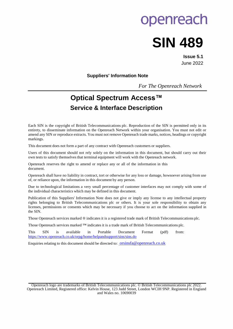
6. OSA FSP 3000 Encryption Service* The OSA FSP 3000 encryption service delivers ultra-low latency wire-speed encryption from 1G up to 10G
LAN PHY for new and existing OSA circuits. The service is built on ADVA Optical Networking's 5TCE-PCN-
10GU+AES10G (previously the 5TCE-PCTN-10G-AES10G) card delivering a range of protocols including
Ethernet, Fibre Channel and ISC-3 all at Layer-1.
Figure 9: FSP3000 Encryption
The 5TCE-PCN-10GU+AES10G card is built around symmetric-key encryption standard Advanced
Encryption Standard AES256 announced by the National Institute of Standards and Technology (NIST).
The encryption solution utilises Diffie Hellman key exchange and a dedicated Openreach security NOC
team.
* Unavailable for new supply after 4 October 2021
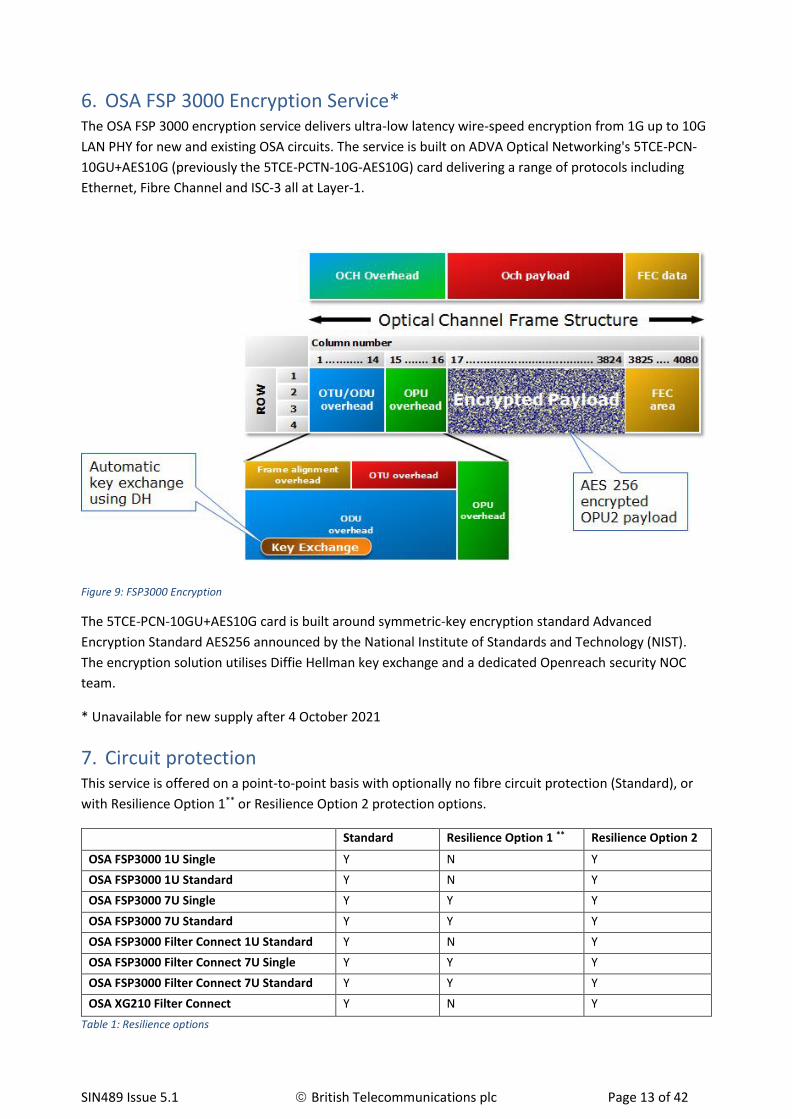
7. Circuit protection This service is offered on a point-to-point basis with optionally no fibre circuit protection (Standard), or
with Resilience Option 1** or Resilience Option 2 protection options.
Standard Resilience Option 1 ** Resilience Option 2
OSA FSP3000 1U Single Y N Y
OSA FSP3000 1U Standard Y N Y
OSA FSP3000 7U Single Y Y Y
OSA FSP3000 7U Standard Y Y Y
OSA FSP3000 Filter Connect 1U Standard Y N Y
OSA FSP3000 Filter Connect 7U Single Y Y Y
OSA FSP3000 Filter Connect 7U Standard Y Y Y
OSA XG210 Filter Connect Y N Y
Table 1: Resilience options

SIN489 Issue 5.1 © British Telecommunications plc Page 14 of 42
Standard consists of a single OSA Bearer between the circuit A-end and B-end addresses with no standby
circuit or path. In the event of a fibre failure service may be lost. It is recommended that a back-up service
is available.
Resilience Option 1 (RO1) ** consists of a single OSA Bearer between the same circuit A-end and B-end
addresses with two diversely routed fibre paths. In the event of a problem occurring on the primary
route, traffic will be automatically switched to the secondary fibre path. The protection is performed on
the fibre link carrying the multiplexed wavelengths. Protection is not provided on a per optical channel
basis. The protection switching will include any Filter Connect wavelengths.
** RO1 unavailable for new supply after 1 June 2022.
Resilience Option 2 (RO2) consists of two individual OSA Bearers delivered using diversely routed fibres
between the same circuit A-end and B-end addresses, or between the same A-end and different B-end
addresses. Customers are free to use each bearer as they wish. It is the customers’ responsibility to
ensure that the traffic carrying capacity of the wavelengths is sufficient to support the resilience of their
service in the event of failure. Note that the two OSA bearers in an RO2 configuration do not perform an
automatic protection switching. If protection switching is required this will need to be supplied by the CP.
The maximum permitted fibre route distance will vary depending on the vendor, wavelength speed and
resilience option used. Refer to the OSA Product Handbook for further information on bearer resilience
options and distance limitations:
http://www.openreach.co.uk/orpg/home/products/opticalservices/opticalservices.do
Protocols with latency sensitivities may require customer reconfiguration following an incident resulting
in a switch to the protection path. The Openreach equipment will continue to function on the protection
path.
8. Customer Interface – FSP3000 The patch panel interface, where used, is the Network Termination Point (NTP), i.e. the point of
connection between the Openreach Network Terminating Equipment (NTE) and the CPE interface.
Customer interfaces for managed services are presented via an optical patch panel using dual LC
interfaces or directly on the NTE wavelength card where different connection types may be used
depending on the service selected. Either a single duplex or a pair of simplex LC cables may be used
where appropriate, though duplex cables with dual LC connectors will ensure that transmit and receive
connections are correctly made the right way round.
Filter Connect is an enhancement to the OSA FSP3000 product that enables customers to access the OSA
bearer, via spare ports on the 4CSM or 8CSM filter card, with their own equipment. In this usage case, the
customer interfaces and service demarcation point, is on the filter ports. These are dual LC. Direct
customer connection to an 8GSM filter card, where fitted, is not permitted.
Single-mode (1310nm) or multimode (850nm) interface options are available depending on the type of
wavelength card selected. The NTE vendor offers a choice of wavelength interface cards, however there
may be differences in the number and types of interfaces supported per card. Additionally, customers can
connect directly to ports on the optical filter where an OSA service has been certified for Filter Connect

SIN489 Issue 5.1 © British Telecommunications plc Page 15 of 42
usage. This will be the service boundary in this instance for own connected cabling.
Please note:
1) The 5TCE-PCTN-10GU+10G, 5TCE-PCTN-10GU+AES10G, 10TCC-PCTN-4GUS+10G, WCC-PCTN-10G,
WCC-PC1N-2G7U, 4TCA-PCN-4GU+4G, 4TCA-PCN-4GUS+4G and 5TCE-PCN-10GU-AES10G cards
are no longer available for new supply.
2) Due to higher power requirements, the 10TCE-PCN-16G+100G (10x 10G Enterprise Card) can only
be installed in an FSP3000 1U High Power chassis. This card occupies both service slots in the
chassis. This card cannot be installed in any 7U chassis.
3) Due to higher power requirements, the 4WCC-PCN-10G (4x 10G Core Card) can only be installed
in an FSP3000 1U High Power chassis. This card occupies a single slot in the 1U high chassis. This
card can be installed in any 7U chassis if a slot is left free on either side of this single width card to
allow sufficient cooling in a 7U chassis, therefore each 4WCC-PCN-10G will require 3
(consecutive) slots to be available in any 7U chassis.

SIN489 Issue 5.1 © British Telecommunications plc Page 16 of 42
Service
Card type
Transparency
Client Port Options Pluggable type / maximum speed / wavelength /Single-Mode(SM) or Multimode (MM) / connector type
Client port Error signal
10G Fibre Channel
5TCE-PCN-10GU+10G *
PCS layer
SFP+/10G/1310S/SM/LC or SFP+/11GU/850I/MM/LC
Loss of Signal
10TCE-PCN-16GU+100G
PCS layer
SFP+CDR/11GU/1310S/SM/LC
Loss of Signal
2WCA-PCN-10G
Physical layer
XFP/11G/1310S/SM/LC or XFP/10G/850I/MM/LC
Loss of Signal
5TCE-PCN-10GU+AES10G *
PCS layer SFP+/11GU/1310S/SM/LC or
SFP+/11GU/850I/MM/LC
Loss of Signal
10G LAN PHY
WCC-PCTN- 10G *
PCS Layer
XFP/11G/1310S/SM/LC
Local Fault as per IEEE802.3
2WCC-PCN-10G
PCS Layer
XFP/11G/1310S/SM/LC or XFP/10G/850I/MM/LC
Local Fault as per IEEE802.3
4WCC-PCN-10G
PCS Layer
SFP+/11GU/1310S/SM/LC or SFP+/11GU/850I/MM/LC
Local Fault as per IEEE802.3
5TCE-PCN-10GU+10G *
PCS layer
SFP+/10G/1310S/SM/LC or SFP+/11GU/850I/MM/LC
Loss of Signal
10TCE-PCN-16GU+100G
PCS layer
SFP+CDR/11GU/1310S/SM/LC or SFP+CDR/10GU/850I/MM/LC
Loss of Signal
2WCA-PCN- 10G
Physical layer
XFP/11G/1310S/SM/LC or XFP/10G/850I/MM/LC
Loss of Signal
5WCA-PCN- 16GU
Physical layer SFP+/11GU/1310S/SM/LC or
SFP+/11GU/850I/MM/LC
Loss of Signal
5TCE-PCN-
10GU+AES10G *
PCS layer SFP+/11GU/1310S/SM/LC or
SFP+/11GU/850I/MM/LC
Loss of Signal
10G WAN PHY / STM-64
WCC-PCTN- 10G *
client signal not modified
XFP/11G/1310S/SM/LC
MS-AIS (ITU-T G.783)
10TCE-PCN-16GU+100G
client signal not modified
SFP+CDR/11GU/1310S/SM/LC
Loss of Signal
2WCC-PCN-10G
client signal not modified
XFP/11G/1310S/SM/LC
MS-AIS (ITU-T G.783)
4WCC-PCN-10G client signal not modified
SFP+/11GU/1310S/SM/LC or SFP+/11GU/850I/MM/LC
MS-AIS (ITU-T G.783)
2WCA-PCN- 10G
Physical Layer
XFP/11G/1310S/SM/LC
Loss of Signal
OTU2
WCC-PCTN- 10G *
client signal not modified
XFP/11G/1310S/SM/LC
AIS-ODU

SIN489 Issue 5.1 © British Telecommunications plc Page 17 of 42
2WCC-PCN-10G
client signal not modified
XFP/11G/1310S/SM/LC
AIS-ODU
4WCC-PCN-10G
client signal not modified
SFP+/11GU/1310S/SM/LC or SFP+/11GU/850I/MM/LC
AIS-ODU
2WCA-PCN- 10G
Physical layer
XFP/11G/1310S/SM/LC
Loss of Signal
8G Fibre Channel
5TCE-PCN-10GU+10G *
PCS Layer
SFP+/10G/1310S/SM/LC or SFP+/11GU/850I/MM/LC
Loss of Signal
10TCE-PCN-16GU+100G
PCS layer
SFP+CDR/11GU/1310S/SM/LC or SFP+CDR/10GU/850I/MM/LC
Loss of Signal
2WCC-PCN-10G
PCS layer
XFP/8G/1310S/SM/LC
Non-valid line code as per ITU-T G.7041
2WCA-PCN- 10G
Physical layer
XFP/8G/1310S/SM/LC
Loss of Signal
5WCA-PCN- 16GU
Physical layer SFP+/11GU/1310S/SM/LC or
SFP+/11GU/850I/MM/LC
Loss of Signal
5TCE-PCN-
10GU+AES10G *
PCS layer SFP+/11GU/1310S/SM/LC or
SFP+/11GU/850I/MM/LC
Loss of Signal
4G Fibre Channel
4TCA-PCN- 4GU+4G *
PCS layer
SFP/4GU/850I/MM/LC or SFP/4GU/1310S/SM/LC
Loss of Signal
5TCE-PCN-10GU+10G *
PCS Layer
SFP/4GU/850I/MM/LC or SFP/4GU/1310S/SM/LC
Loss of Signal
10TCC-PCTN- 4GUS+10G *
PCS layer
SFP/4GU/850I/MM/LC or SFP/4GU/1310S/SM/LC
Non-valid line code as per ITU-T G.7041
2WCA-PCN- 10G
Physical layer
XFP/8G/1310S/SM/LC
Loss of Signal
5TCE-PCN-10GU+AES10G *
PCS Layer
SFP/4GU/850I/MM/LC or SFP/4GU/1310S/SM/LC
Loss of Signal
2G Fibre Channel
4TCA-PCN- 4GU+4G *
PCS layer
SFP/2G1/850I/MM/LC or SFP/2G5U/1310S/SM/LC
Non-valid line code as per ITU-T G.7041
5TCE-PCN-10GU+10G *
PCS layer
SFP/2G1/850I/MM/LC or SFP/2G5U/1310S/SM/LC
Loss of Signal
10TCC-PCTN- 4GUS+10G *
PCS layer
SFP/2G1/850I/MM/LC or SFP/2G5U/1310S/SM/LC
Non-valid line code as per ITU-T G.7041
2TWCC-PCN- 2G7U
Physical layer
SFP/2G1/850I/MM/LC or SFP/2G5U/1310S/SM/LC
Loss of Signal
5TCE-PCN-10GU+AES10G *
PCS layer
SFP/2G1/850I/MM/LC or SFP/2G5U/1310S/SM/LC
Loss of Signal

SIN489 Issue 5.1 © British Telecommunications plc Page 18 of 42
1G Fibre Channel
4TCA-PCN- 4GU+4G *
PCS layer
SFP/2G1/850I/MM/LC or SFP/2G5U/1310S/SM/LC
Non-valid line code as per ITU-T G.7041
5TCE-PCN-10GU+10G *
PCS Layer
SFP/2G1/850I/MM/LC or SFP/2G5U/1310S/SM/LC
Loss of Signal
10TCC-PCTN- 4GUS+10G *
PCS layer
SFP/2G1/850I/MM/LC or SFP/2G5U/1310S/SM/LC
Non-valid line code as per ITU-T G.7041
5TCE-PCN-10GU+AES10G *
PCS Layer
SFP/2G1/850I/MM/LC or SFP/2G5U/1310S/SM/LC
Loss of Signal
2TWCC-PCN- 2G7U
Physical layer
SFP/2G1/850I/MM/LC or SFP/2G5U/1310S/SM/LC
Loss of Signal
Gigabit Ethernet
4TCA-PCN- 4GU+4G *
PCS layer
SFP/2G1/850I/MM/LC or SFP/2G5U/1310S/SM/LC
K30.7 (8B/10B code word) as per ITU-T G.7041 and IEEE802.3
4TCA-PCN- 4GUS+4G *
PCS layer
SFP/2G1/850I/MM/LC or SFP/2G5U/1310S/SM/LC
K30.7 (8B/10B code word) as per ITU-T G.7041 and IEEE802.3
5TCE-PCN-10GU+10G *
PCS Layer
SFP/2G1/850I/MM/LC or SFP/2G5U/1310S/SM/LC
Loss of Signal
5TCE-PCN-10GU+AES10G *
PCS layer
SFP/2G1/850I/MM/LC or SFP/2G5U/1310S/SM/LC
Loss of Signal
10TCC-PCTN- 4GUS+10G *
PCS layer
SFP/2G1/850I/MM/LC or SFP/2G5U/1310S/SM/LC
Default setting: K30.7 (8B/10B code word) as per ITU-T G.7041 and IEEE802.3. Alternatively, Loss of Signal can be requested on CRF
2TWCC-PCN- 2G7U
PCS layer
SFP/2G1/850I/MM/LC or SFP/2G5U/1310S/SM/LC
K30.7 (8B/10B code word) as per ITU-T G.7041 and IEEE802.3
STM-4
4TCA-PCN- 4GUS+4G *
client signal not modified
SFP/2G5U/1310S/SM/LC
Loss of Signal
WCC-PC1N- 2G7U *
client signal not modified
SFP/2G5U/1310S/SM/LC
MS-AIS
10TCC-PCTN- 4GUS+10G *
client signal not modified
SFP/2G5U/1310S/SM/LC
Loss of Signal

SIN489 Issue 5.1 © British Telecommunications plc Page 19 of 42
STM-1
4TCA-PCN- 4GUS+4G *
client signal not modified
SFP/2G5U/1310S/SM/LC
Loss of Signal
WCC-PC1N- 2G7U *
client signal not modified
SFP/2G5U/1310S/SM/LC
MS-AIS
10TCC-PCTN- 4GUS+10G *
client signal not modified
SFP/2G5U/1310S/SM/LC
Loss of Signal
STM-16
WCC-PC1N- 2G7U *
client signal not modified
SFP/2G5U/1310S/SM/LC
MS-AIS
10TCC-PCTN- 4GUS+10G *
client signal not modified
SFP/2G5U/1310S/SM/LC
Loss of Signal
2TWCC-PCN- 2G7U
client signal not modified
SFP/2G5U/1310S/SM/LC
MS-AIS
ISC-3 Peer Mode (2.125G)
5TCE-PCN-
10GU+10G
PCS layer
SFP/2G1/850I/MM/LC or SFP/2G5U/1310S/SM/LC
Loss of Signal
5TCE-PCN-10GU+AES10G *
PCS layer
SFP/2G1/850I/MM/LC or SFP/2G5U/1310S/SM/LC
Loss of Signal
OTU1
WCC-PC1N- 2G7U *
client signal not modified
SFP/2G5U/1310S/SM/LC
AIS-ODU
2TWCC-PCN- 2G7U
client signal not modified
SFP/2G5U/1310S/SM/LC
AIS-ODU
Table 2: FSP3000 customer interface options
* Card unavailable for new supply

SIN489 Issue 5.1 © British Telecommunications plc Page 20 of 42
9. Customer Interface – XG210 Customer interfaces for managed services are presented via a dual LC interfaces directly on the NTE
service card where different connection types may be used depending on the service selected. Either a
single duplex or a pair of simplex LC cables may be used where appropriate, though duplex cables with
dual LC connectors will ensure that transmit and receive connections are correctly made the right way
round.
Each XG210 NTE contains 2 service slots, a service slot can take one of three cards:
1. OSA XG210 10GE Wavelength Card containing a single 10Gbit/s port client port bundled with
either a single-mode or multimode SFP+ pluggable module. The customer traffic for this card is
transmitted using a 10G LAN PHY Ethernet signal on a tuneable DWDM pluggable optic module.
This card is also known as the ADVA XG-1S-CC or F150-ADV-XG-PM-10GE-SFP+ card.
2. OSA XG210 8x1GE Wavelength Card containing 8 x 1Gbit/s client ports bundled with either 8
single-mode SFP or 8 multimode SFP pluggable modules. The customer traffic for this card is
transmitted using a 10G LAN PHY Ethernet signal on a tuneable DWDM pluggable optic module.
This card is also known as the ADVA GE-8S-CC or F150-ADV-XG-PM-GE-8-SFP card.
3. OSA XG210 8x1GE Wavelength Card containing 8 x 1Gbit/s built-in 1000BaseT electrical RJ45
ports. This card is also known as the ADVA GE-8E-CC or F150-ADV-XG-PM-GE-8-RJ45 card.
Optical Spectrum Access services are intended for connection to standard optical interfaces of 850nm
multimode or 1310nm single-mode types. The 8x1GE service is also optionally available with an all-
electrical interface card. Table 3 gives details of the optical interface / service options for the XG210.
The customer equipment Ethernet interface must conform to following IEEE 802.3 standard interfaces:
a. OSA XG210 10GE Wavelength Card containing a single 10Gbit/s port
10GBASE-SR, [850 nm multimode 10G LAN PHY] or
10GBASE-LR, [1310 nm single-mode 10G LAN PHY]
b. OSA XG210 8x1GE Wavelength Card containing 8 1G ports
1000BASE-SX, [850 nm multimode Gigabit Ethernet] or
1000BASE-LX, [1310 nm single-mode Gigabit Ethernet]
c. OSA XG210 8x1GE Wavelength Card containing 8 1G ports
1000BASE-TX, [RJ45 electrical]
The following pairings of service cards are available on OSA XG210 bearers:
1. XG210 10GE wavelength card to XG210 10GE wavelength card
2. XG210 8x1GE wavelength card to XG210 8x1GE wavelength card
3. XG210 10GE VLAN Mux wavelength card to XG210 8x1GE wavelength card
These 3 pairing options are shown in figure 10 (NTE chassis not shown for clarity):

SIN489 Issue 5.1 © British Telecommunications plc Page 21 of 42
Figure 10: XG210 card pairings
9.1. XG210 VLAN
For option 3 above, up to 8 individual 1Gbit/s flows can be handed over at the aggregated 10GE end using
VLAN tags with unique VLAN ID for the outer tag, with each VLAN ID corresponding to ports 1 to 8 on the
8 x 1GE wavelength card as specified in IEEE 802.1q.
Default VLAN identifiers are 4001 to 4008 (corresponding to ports 1 to 8 on the 8 x 1GE card)
CPs can define their own VLAN IDs in the range 0002 to 4093 at time of ordering. VLAN IDs need only be
unique for specific wavelength card pair, there is no restriction regarding reuse of VLAN IDs on another
card in the same XG210 NTE.
The TPID value of the outer VLAN tag will need to be specified at time of ordering, allowable values are
either 0x8100 (C-Tag), or 0x88a8 (S-Tag).
9.2. XG210 NTE Frame Forwarding behavior
The XG210 NTE is capable of transporting frames conforming to IEEE 802.3 [2] with frame sizes from 64
bytes to a maximum of 2000 bytes. This is to maintain compatibility with a number of frame tagging
formats, including VLAN tagging as specified in IEEE 802.1Q [4]. Other than for 10G VLAN interface
variant, the service is transparent to VLAN tags and will forward VLAN tagged frames in the same way as
standard (untagged) frames.
Due to the use of a 4 byte overhead for management purposes, the 10G point to point option is expected
to have a reduction of throughput of up to 1% for Customer frame sizes of 400 bytes and above. For
customer Ethernet frame sizes smaller than 400 bytes the throughput reduction increases to
approximately 6% for 64 byte frames.
Note: The XG210 NTE will pass 9000 byte frames, however as this is not yet a recognised Ethernet
standard, BT will not validate usage at this level until such time as the IEEE provide an endorsement and
published standard for jumbo frames and we have tested against it.
The XG210 NTE will not be configured with IEEE 802.d [3] Bridging functionality, which allows for the
Learning and Filtering of traffic packets destined for those hosts connected at the local end.
Therefore Ethernet frames that would normally be filtered by IEEE 802.1d [3] bridging functionality are

SIN489 Issue 5.1 © British Telecommunications plc Page 22 of 42
instead forwarded across the OSA XG210 link.
9.3. XG210 NTE Transparency Restrictions
All Ethernet frames are passed across the OSA link, other than the following list of known exceptions:
1. Transport of EFM OAM PDUs as defined by IEEE 802.3 [2] over OSA is not supported.
The XG210 uses EFM OAM PDUs internally for the purposes of OAM. And as per the IEEE 802.3 [2]
standards defined behavior for EFM equipment, the end to end transport of customer EFM OAM
PDUs over the OSA link is blocked.
2. Transport of Ethernet flow control / Pause frames over OSA is not supported.
3. Where Synchronous Ethernet and PTP (Precision Time Protocol) is enabled, IEEE 1588v2 messages
(specifically PTP messages transported directly over Ethernet frames) and Synchronous Ethernet
ESMC (Ethernet Synchronization Message Channel) packets will be processed, therefore
transparent transport of these packet types is not supported.
9.4. XG210 NTE Auto-Negotiation and Duplex Settings
In contrast to lower rate Ethernet signals (10, 100 and 1000Mbit/s) the 10Gbit/s Ethernet port option, in
line with standards, does not support auto-negotiate to advertise speed and duplex settings. Instead the
speed is set to 10Gbit/s and the service is “Full Duplex”. Half duplex operation is not supported for any
interface type on this service. For Gigabit Ethernet interface options, the customer will be required to
enable auto-negotiation on their equipment. Additionally in the case of 1000BASE-T interfaces used to
transport Synchronous Ethernet, CP equipment will be required to correctly set itself to either link master
or link slave based on auto-negotiation messages sent by the XG210 NTE during link establishment.
9.5. XG210 NTE Link Loss Forwarding
When a break is detected on the Openreach-side of the network link, all affected customer facing ports
will be forced to a link down condition. This continues until such time as the network break is repaired.
Such a break may occur at the wavelength level or at the bearer level. In the event of a wavelength level
break, only ports on cards transporting traffic on the affected wavelengths will shut down.
In addition, the customer may specify User-User Link Loss Forwarding at the time of ordering, this
feature is only supported for one direction across the bearer. The exact behavior is as follows:
a. OSA XG210 10GE wavelength card to OSA XG210 10GE wavelength card deployments.
A port down condition on the 10Gbit/s port will cause the far end corresponding 10Gbit/s port to
shut down, as long as the propagation direction matches the CP requirements.
b. OSA XG210 8x1GE wavelength card to OSA XG210 8x1GE wavelength card deployments.
A port down condition affecting any of the ports on the 8 port card, will cause the corresponding
ports of the far-end 8 port down to shut down, leaving other ports unaffected. The above
assumes the direction of failure propagation, is as specified by the CP.
c. OSA XG210 10GE VLAN (aggregated port) to OSA XG210 8x1GE wavelength card deployments.
A port down condition on the 10GE port will cause all 8 ports on the far-end 8x1GE wavelength
card to shutdown, as long as this direction of failure propagation is as specified by the CP at order
time. Note propagation of failure in the opposite direction (from any of the 8 x 1GE card ports to
the 10GE aggregated port) is not supported, and cannot be specified by the CP.

SIN489 Issue 5.1 © British Telecommunications plc Page 23 of 42
A summary of the interface options for XG210 is provided in table 3 below:
Service
ADVA Card type
Transparency
Client Port Options Pluggable type / maximum speed / wavelength /Single-Mode(SM) or Multimode (MM) / connector type
Client port Error signal
10G LAN PHY
F150-ADV-XG-PM-10GE-SFP+
Ethernet Frame layer
SFP+/10G/1310S/SM/LC or SFP+/10G/850I/MM/LC
Loss of Signal
10G LAN PHY
VLAN Mux
F150-ADV-XG-PM-10GE-SFP+
VLAN aware
SFP+/10G/1310S/SM/LC or SFP+/10G/850I/MM/LC
Loss of Signal
Gigabit Ethernet (optical)
F150-ADV-XG-PM-GE-8-SFP
Ethernet Frame layer
SFP/GBE/1310S/SM/LC or SFP/GBE/850I/MM/LC
Loss of Signal
Gigabit
Ethernet
(Electrical)
F150-ADV-XG- PM-GE-8-RJ45
Ethernet Frame layer
Not Applicable as 1000BaseT ports
are built-in
Loss of Signal
Table 3: XG210 interface options

SIN489 Issue 5.1 © British Telecommunications plc Page 24 of 42
10. Synchronisation and PTP support – OSA XG210 Bearers For the OSA XG210 bearer, Synchronous Ethernet (SyncE) with Precision Time Protocol (PTP) is an
optional feature which will transport a clock source, provided by the CP, across the service to enable time
and phase recovery. Both features (SyncE and PTP) are either enabled or disabled. Customers cannot
select to only take one feature without the other.
All timing signals will be handled on the first wavelength card on the XG210 NTE supplied as part of the
OSA XG210 bearer (first port in the case of an 8x1G card). A maximum of two ports may be used for input
clock feeds (i.e. a primary and a back-up feed) per NTE. However only a single input clock feed is
supported on each wavelength card, therefore a back-up feed would require that a second wavelength
card is in slot 2 on the NTE.
Only a single timing domain is supported on the XG210 NTE, with both primary (and optional back-up)
timing feeds provided into the service at the same end. The synchronisation output at the far end of the
service will be on all Ethernet traffic ports. The back-up feed will only be used in event of failure of the
primary clock feed from the CP. The CP will be responsible for providing and maintaining the timing
source.
If the optional additional XG210 chassis is added to the XG210 bearer then this can support a separate
timing domain, if required, from the parent XG210. A separate licence fee will be applicable.
The BITS-In frequency port on the XG210 NTE is not supported.
The OSA XG210 bearer service supports Synchronous Ethernet as specified by ITU-T G.8261, ITU-T G.8262
and ITU-T G.8264 and Precision Time Protocol as specified by IEEE 1588v2 and ITU-T G.8275.1 Time and
Phase Standard. The Openreach OSA Filter connect product is a PTP aware Telecom Boundary Clock,
supporting full on Path Support (SyncE ITU-T G.8261, ITU-T G.8262, ITU-T G.8264 and PTP ITU-T
G.8275.1). The Openreach service does not provide the Primary Reference Time Clock (T-GM) or
traceability back to the PRTC for both Phase/Time and Frequency traceability, but is only transporting
Time and Phase with respect to the ITU-T G.8275.1 Telecom Profile standard.
Openreach OSA FC XG210 Phase/Sync service conforms to the Class A T-BC clock as per G.8273.2 and has
a max absolute time error of 100ns. The Openreach service has 2x T-BC, therefore the Openreach service
max absolute time error is 200ns. This timing performance can only be guaranteed on single fibre
deployments.
It is the responsibility of the Customer to provide Time and Phase Traceability back to their PRTC in their
network. Traceability Flags are used as part of the PTP messages to convey status and indicate whether
the T-BC is traceable back to the PRTC, or whether traceability has been lost. If the traceability flag
indicates that the PTP flow is no longer traceable back to the PRTC, then this PTP Port/Flow would no
longer be considered as valid reference input to the Openreach Equipment.
The standards that the Customer needs to adhere to are as below:
• ITU-T G.8275.1
• ITU-T G.8261
• ITU-T G.8262
• ITU-T G.8264

SIN489 Issue 5.1 © British Telecommunications plc Page 25 of 42
The ITU-T G.8275.1 Time and Phase Standard defines the full on-path protocol for the delivery of
Frequency and Phase/Time. It is based on point to point Ethernet multicast communication between
adjacent nodes (IP not supported by the profile).
The customer should feed the following Phase/Sync parameters, shown in the 3 tables below, into the
first Ethernet traffic port on the XG210 wavelength card. Where a secondary (back-up) timing feed
Ethernet traffic port has been ordered by the customer, the Phase/Sync parameters should also be
provided into the first port of the second XG210 wavelength card.
SyncE
Feature Openreach Customer
SyncE Yes Yes
ESM Channel Yes Yes
QL Mode Yes Yes
Table 4: SyncE
PTP Telecom-Boundary Clock Configuration
Feature Openreach Customer Settings
T-BC Enabled T-BC Enabled
PTP Clock Profile G.8275.1 G.8275.1
PTP Clock Type Boundary Clock BC
PTP Clock Domain 24 24
Priority 1 128 128
Priority 2 128 128
Local Priority 128 128
Table 5: PTP Telecom-Boundary clock configuration
PTP Port Configuration
Feature Openreach Customer Setting
Master Clock Type One Step One Step
Local Priority 128 128
Master (Not Slave) Configurable if Master = Enabled Enabled
Dest. MAC ADD. Forwardable Forwardable
Sync Message Rate 16pps 16pps

SIN489 Issue 5.1 © British Telecommunications plc Page 26 of 42
Delay Req/Resp Message Rate 16pps 16pps
Announce Message Rate 8pps 8pps
Announce Receipt timeout 8 intervals 8 intervals
Sync Receipt Timeout 16 intervals 16 intervals
Delay Response Receipt timeout 16 intervals 16 intervals
Table 6: PTP Port configuration
A slight reduction in traffic throughput with SyncE and PTP enabled is expected. For example, where the
link is used to transport 10G traffic, the maximum circuit throughput will be reduced from
9,999,986,000bps to 9,999,296,000bps, due to an additional 384kbps overhead for Sync traffic.
When G.8275.1 ITU-T T-BC is configured, 384Kbps of bandwidth is automatically allocated for the PTP
Flow and all PTP Messages on all Ports that are participating in the T-BC configuration
VLAN Tags shall not be used with the Boundary Clock PTP Flow (G.8275.1 uses Multicast) – regardless of
traffic tagging. The CP shall send in PTP un-tagged to the XG210 NTE.
There will be no Openreach Portal available to the customer for the OSA XG210 bearer service. Additional
alarm notifications to the customer are to be confirmed, but likely to include a “PTP clock time not
traceable” alarm. Holdover is expected up to 1 hour for Boundary clock. Frequency SyncE holdover may
be a number of hours.
11. Optical power margins for client side optics The table below shows details of the Optical power margins for both the Receive and Transmit interfaces
of the client facing optical interfaces. Please note that the CP may be responsible for damage caused by
exceeding the optical parameters listed.
ADVA
Customer interface type Valid Input Range Expected Output from interface
SFP+CDR/11GU/1310S/SM/LC -10.0dBm to -2dBm -6.0dBm to 0dBm
SFP+CDR/10GU/850I/MM/LC -10.0dBm to -2dBm -8.0dBm to -1dBm
XFP/10G/850I/MM/LC -8.0dBm to -2dBm -8.0dBm to -1dBm
SFP+/11GU/1310S/SM/LC -12.0dBm to -2dBm -6.0dBm to 0dBm
SFP+/11GU/850I/MM/LC -10.0dBm to -2dBm -8.0dBm to -1dBm
SFP+/10G/1310S/SM/LC -13.0dBm to -1.0dBm -8.0dBm to -0.5dBm
XFP/11G/1310S/SM/LC -12.0dBm to -2.0dBm -6.0dBm to -1.0dBm
XFP/8G/1310S/SM/LC -9.0dBm to -0.5dBm -6.0dBm to -1.0dBm
SFP/4GU/850I/MM/LC -13.0dBm to -1.0dBm -10.0dBm to -2.5dBm
SFP/4GU/1310S/SM/LC -14.0dBm to -2.0dBm -9.0dBm to -1.0dBm
SFP/2G1/850I/MM/LC -14.0dBm to -4.0dBm -10.0dBm to -3.0dBm
SFP/2G5U/1310S/SM/LC -17.0dBm to -1.0dBm -5.0dBm to 0.0dBm
SFP+/10G/850I/MM/LC -10.0dBm to -2dBm -8.0dBm to -1.0dBm
SFP/GBE/1310S/SM/LC -19.0dBm to -4.0dBm -9.0dBm to -3.0dBm
SFP/GBE/850I/MM/LC -15.0dBm to -1.0dBm -10.0dBm to 0dBm

SIN489 Issue 5.1 © British Telecommunications plc Page 27 of 42
Table 7: Optical power margins

SIN489 Issue 5.1 © British Telecommunications plc Page 28 of 42
12. OSA Filter Connect network parameters The first column in the tables below refers to port labelling on the filter card. The filters used on OSA
connect use 100GHz spacing is designed for both 50GHz and 100GHz ITU-T grid compliant optics capable
of working between 192.00THz and 196.00THz.
The channel numbers indicated in the tables below relate to the channel references on the Customer
Requirement Form (CRF) or other Openreach system used to place orders. The ADVA channel numbering
scheme is different to the ITU-T scheme.
Note, any deviation for the centre frequency from CP equipment should be no more than +/-0.25nm from
the equivalent wavelength for the centre frequency specified on a filter card, for example a deviation of
+/- 0.38nm is expected to incur an additional loss of 1dB. The frequency/wavelength allocations are as
follows:
12.1. Frequency plan: 4CSM
Band ADVA Channel number
A-end and B-end Port number
Centre Frequency (THz)
Equivalent Wavelength (nm)
Band 1 * D01 – D04
1 C1 196.00 1529.55
2 C2 195.90 1530.33
3 C3 195.80 1531.12
4 C4 195.70 1531.90
Band 2 D05 – D08
5 C1 195.50 1533.47
6 C2 195.40 1534.25
7 C3 195.30 1535.04
8 C4 195.20 1535.82
Band 3 D09 – D12
9 C1 195.00 1537.40
10 C2 194.90 1538.19
11 C3 194.80 1538.98
12 C4 194.70 1539.77
Band 4 D13 – D16
13 C1 194.50 1541.35
14 C2 194.40 1542.14
15 C3 194.30 1542.94
16 C4 194.20 1543.73
Band 5 D17 – D20
17 C1 193.80 1546.92
18 C2 193.70 1547.72
19 C3 193.60 1548.51
20 C4 193.50 1549.32
Band 6 D21 – D24
21 C1 193.30 1550.92
22 C2 193.20 1551.72
23 C3 193.10 1552.52
24 C4 193.00 1553.33
Band 7 D25 – D28
25 C1 192.80 1554.94
26 C2 192.70 1555.75
27 C3 192.60 1556.55
28 C4 192.50 1557.36
Band 8 D29 – D32
29 C1 192.30 1558.98
30 C2 192.20 1559.79
31 C3 192.10 1560.61
32 C4 192.00 1561.42

SIN489 Issue 5.1 © British Telecommunications plc Page 29 of 42
Table 8: 4CSM frequency plan
Notes: * Where only a single 4CSM is deployed it will use Band 1 frequencies.
Existing OSA FSP3000 (including Filter Connect) systems installed with either no optical filters (OSA
Singles) or 4CSM optical filters and wavelength cards with fixed frequency network optics, that are
subsequently requested to be upgraded to an 8-channel filter (8CSM or 8CSM+), may require additional
equipment changes. Where a wavelength card has been deployed and the network optic frequency is not
compatible with the corresponding frequencies available on the new 8CSM or 8CSM+ optical filter, that
wavelength card may have to be re-tuned if available or upgraded to a new card with a frequency to
match the new filter. Alternatively, an 8GSM (Group Splitter/Multiplexer) can be added to the OSA
system to combine the existing 4CSM with additional 4CSM to increase the wavelength channel count to
the size required. Please refer to the OSA Product Description for further information.
12.2. Frequency plan: 8CSM
A-end and B-end Port number
ADVA Channel number
Centre Frequency (THz) Equivalent Wavelength (nm)
C1 26 192.70 1555.75
C2 27 192.60 1556.55
C3 28 192.50 1557.36
C4 34 192.40 1558.17
C5 29 192.30 1558.98
C6 30 192.20 1559.79
C7 31 192.10 1560.61
C8 32 192.00 1561.42 Table 9: 8CSM frequency plan
12.3. Frequency plan: 8CSM+
A-end and B-end Port number
ADVA Channel number
Centre Frequency (THz)
Equivalent Wavelength (nm)
C1 2 195.90 1530.33
C2 3 195.80 1531.12
C3 4 195.70 1531.90
C4 33 195.60 1532.68
C5 5 195.50 1533.47
C6 6 195.40 1534.25
C7 7 195.30 1535.04
C8 8 195.20 1535.82 Table 10: 8CSM+ frequency plan

SIN489 Issue 5.1 © British Telecommunications plc Page 30 of 42
12.4. Frequency plan: 16CSM-SFW
A-end / B-end as designated on filter card. A-end and B-end locations will be as defined by CP on CRF.
Channel / Client Port
A-end input B-end input
ADVA
Channel
number
Frequency
(THz)
Wavelength
(nm)
ADVA
Channel
number
Frequency
(THz)
Wavelength
(nm)
C1 1 196.0 1529.55 17 193.8 1546.92
C2 2 195.9 1530.33 18 193.7 1547.72
C3 3 195.8 1531.12 19 193.6 1548.51
C4 4 195.7 1531.90 20 193.5 1549.32
C5 5 195.5 1533.47 21 193.3 1550.92
C6 6 195.4 1534.25 22 193.2 1551.72
C7 7 195.3 1535.04 23 193.1 1552.52
C8 8 195.2 1535.82 24 193.0 1553.33
C9 9 195.0 1537.40 25 192.8 1554.94
C10 10 194.9 1538.19 26 192.7 1555.75
C11 11 194.8 1538.98 27 192.6 1556.55
C12 12 194.7 1539.77 28 192.5 1557.36
C13 13 194.5 1541.35 29 192.3 1558.98
C14 14 194.4 1542.14 30 192.2 1559.79
C15 15 194.3 1542.94 31 192.1 1560.61
C16 16 194.2 1543.73 32 192.0 1561.42
Table 11: 16CSM frequency plan
The A-end 16CSM filter takes the input from the A-end Mux filter and carries 16 channels in the frequency
band 196.00 - 194.20THz to the B-end. Similarly, the B-end 16CSM filter carries 16 channels in the
frequency band 193.80 - 192THz to the A-end. Single fibre working is achieved by the use of a band filter
module to multiplex the two bands over the same physical fibre.
Note the 16CSM-SFW filter requires different frequencies on each end for each optical channel, for this

SIN489 Issue 5.1 © British Telecommunications plc Page 31 of 42
reason this filter type may not be compatible with some CP equipment utilising coherent transceivers
typically used to carry 100G/200G/400G signals.
12.5. Channel isolation
The channel isolation specification for each filter type is given below:
Filter type Adjacent isolation (dB)
Non-adjacent isolation (dB)
4CSM 30 45
4CSM+8GSM (32 channel capable)
30 45
8CSM 30 45
8CSM+ 30 45
16CSM 30 40 Table 12: Channel isolation
12.6. Optical safety limits
The maximum output power for any CP optical channel, shall be no more than +6dBm for any filter
configuration. It will be the CPs responsibility to ensure that light levels for each optical channel do not
exceed this figure.
12.7. Recommended Optical Power levels for non-amplified links
• Acceptable light level range for each channel into OSA FC filter – standard reach -1dBm to +2dBm
12.8. Recommended Optical Power levels for amplified links
For links using amplification, it will be necessary to ensure that minimum and maximum light levels are
tightly controlled. Too low a light level for an optical channel will result in excessive amplifier noise
affecting the optical channel, and too high a level will result in failure of the amplifier to maintain gain, in
the event of more channels are added at a later date.
A range is provided for standard links, and extended reach links. The link engineering rules assume the
use of FEC (Forward Error Correction) on extended reach links, whereas on standard reach links the use of
FEC is not assumed.
Acceptable light level range for each channel into OSA FC filter -1dBm to +2dBm.
12.9. Minimum OSNR tolerance for CP equipment
• Standard reach 25.6dB minimum OSNR
• Extended reach 20.1dB minimum OSNR, typically this type of equipment supports FEC
12.10. Minimum optical receiver sensitivity for CP equipment
• -22dBm as the low threshold for OSNR>30dB (0.1nm). This limit is applicable for non-amplified
links
• -20dBm as the low threshold for OSNR<30dB (0.1nm). This limit is applicable for amplified links.
12.11. Worst case Chromatic Dispersion
The maximum amount of accumulated chromatic dispersion will be less than 1,101ps/nm. The worst case
chromatic dispersion value is equivalent to 64.9km of fibre based on dispersion coefficient of
16.97ps/nm.km for ITU-T G.652 single-mode fibre.

SIN489 Issue 5.1 © British Telecommunications plc Page 32 of 42
However on links that have single-ended amplification no dispersion compensation will be deployed.
12.12. Maximum Reach
Filter type / combination reach (km)
4 channel system
31/32 channel system
8 channel system (upgradeable to 15/16 channels)
16 Channel System (Single Fibre working)
Non-amplified links with standard optics
50 40 40 37
Pre-amp without FEC 70 64 64 53
Pre-amp & Booster without FEC
87 87 87 77
Pre-amp & Booster with FEC
103 103 101 N/A
Single ended amplification without FEC
n/a n/a 59 53
RO1 Non-amplified links with standard optics
35 23 28 N/A
RO1 Pre-amp without FEC
61 56 51 N/A
RO1 Pre-amp & Booster without FEC
86 86 86 N/A
RO1 Pre-amp & Booster with FEC
103 103 101 N/A
Table 13: Maximum reach
Notes: FEC refers to Reed Solomon encoded RS (255,239), as specified in ITU-T G.709.
12.13. Optical measurements provided on installation of Filter Connect bearers
The following optical measurements will be shared via the customer handover pack following the
certification of an OSA Filter Connect bearer to enable customer network planning over the OSA
infrastructure.
• Per site / bearer details to be provided to CP via Customer Handbook:
• Per channel, end-to-end loss for non-amplified bearers
• Per channel, effective gain / loss on amplified bearers
• Total fibre route distance for ITU-T G.652 and details of value of dispersion compensation on link
to determine, end to end Chromatic Dispersion.
12.14. Optical interworking
It is the CPs responsibility to ensure optical signal compatibility between equipment used on either side of
the OSA bearer, particularly if different equipment vendors are used at the a-end and b-end. Where alien
wavelengths are deployed using coherent modulation technology, CPs are strongly advised to confirm
with their system vendors that the wavelengths used are safe to use with filter connect. Some coherent
modulation options are more susceptible to optical crosstalk from neighbouring (intensity-modulated)
wavelengths, than others, therefore channel isolation specifications for the filters are provided in section
12.5

SIN489 Issue 5.1 © British Telecommunications plc Page 33 of 42
13. FSP3000 Transparency and Error propagation The OSA service using FSP3000 is designed to provide as much transparency as possible. OTN and SDH
overhead bytes are not modified by the service. PCS layer transparency allows not only Ethernet and
Fibre Channel bytes to be transported, but also the IFG (also known as IPG) to be transported. Physical
layer transparency description in Table 3: XG210 interface options is used to indicate that transport is at
the binary level. As transport of Ethernet occurs below layer 2, (at line code/PCS level or physical layer),
layer 2 Ethernet control protocols are transported transparently.
Transport of Fibre Channel frame sizes greater than 2148 bytes, and Ethernet frame sizes greater than
9600 bytes is not supported.
In the event of a failure of a client input at one end of the link, an error signal will be propagated to the
far end client port. In the event of a wavelength / bearer failure, an error signal will be generated on the
NTE’s client port at both ends of a link. In most cases this error propagation signal will be an International
Standards defined error signal for some cards, for other cards this will be a laser off/Loss of Signal
condition.
It is strongly advised that interconnecting equipment with Loss of Signal error propagation behavior is
avoided as this scenario will greatly complicate the re-establishment of end to end connectivity.

SIN489 Issue 5.1 © British Telecommunications plc Page 34 of 42
14. Fibre For services employing a single-mode interface, all fibre optic connections to and from the patch panel
will use single-mode fibre 9/125 micron according to ITU-T G.652.
For services employing a multimode interface, all fibre optic connections to and from the patch panel will
use multimode fibre 62.5/125 micron or 50/125 micron according to ITU-T G.651.
The maximum distances supported on 8G/10G multimode interfaces is dependent on the Modal
Bandwidth specification of the multimode cable provided by the customer. Maximum 10G distances for
various multimode cables types are provided in the table below. Distances for 8G interfaces are expected
to be broadly similar.
Multimode fibre type Multimode cable modal bandwidth (MHz•km)
Operating Distance (m)
FDDI 160 26
OM-1 200 33
OM-2 400 66
OM-3 500 82
OM-4 2000 300 Table 14: Multimode cable operating distances
15. FSP3000 NTE Power Requirements The AC powered variants of the NTE will require two 240 Volt AC power supplies using 13 Amp switched
sockets which must be provided within 1.5 metres of the NTE chassis for each chassis provided. A 240
Volt AC power supply using a 13 Amp switched socket is also required within 1.5 metres of the
Openreach remote Network Management equipment.
If the customer wishes the NTE to be powered from a 48V DC supply, it is the customer’s responsibility to
provide and maintain this supply.
In addition to the NTE power requirements, a 50Hz AC mains supply 13amp socket should also be
provided in close proximity to the NTEs, to power Openreach test equipment during both initial
commissioning and subsequent maintenance support activities.
16. FSP3000 NTE Cooling Requirements The maximum power consumption figure for FSP3000 7U chassis when fully loaded is 800W, and for a
fully loaded 1U chassis the power consumption figure is 240W.
Where high density deployments of FSP3000 chassis are expected, the environmental cooling must be
assessed to ensure that is sufficient sized for such deployments. For this reason, it is not recommend to
house more than three 7U high FSP3000 chassis or twelve 1U high FSP3000 chassis in one cabinet, or
indeed any combination of equipment, with power consumption exceeding more than 2500W.

SIN489 Issue 5.1 © British Telecommunications plc Page 35 of 42
17. XG210 Power Supply
17.1. General
The information provided below relates to the XG210 NTE. Powering arrangements for optical
amplification are same as for existing FSP3000 OSA bearer types as this equipment is common for both
bearer types.
By placing an order with Openreach the customer has accepted the conditions placed by BT in relation to
providing power, as defined below.
In relation to powering of equipment, the customer must comply with the requirements of BS7671 and
the details given within the ‘AC/DC Power planning and installation guide’ document.
The XG210 NTE is locally powered and offers AC or DC power options. The CP will be required to provide
either dual local 50Hz AC supply in the form of standard 13 Amp power socket(s); or dual -50 V DC power
distributions and Earth connections, with all wiring colour schemes conforming to BS7671. It will be the
customer’s responsibility to ensure that the power supplies are fused and safe for Openreach to use.
These should be in close proximity to the NTE installation location.
A 240 Volt AC power supply using a 13 Amp switched socket is also required within 1.5 metres of the
Openreach remote Network Management equipment.
17.2. Installation and Testing
In addition to the NTE powering requirements (i.e. AC or DC power as defined below) , a spare 50 Hz AC
mains supply 13A socket should also be provided in close proximity to the NTEs’ to power BT test
equipment during both initial commissioning and subsequent maintenance support activities. A 50 Hz
mains supply 13A socket must also be provided in close proximity to the NTE for the management router.
17.3. AC Power connection
AC power connection between Openreach equipment and the power socket will be made using a power
lead fitted with a standard 13A plug. The NTE itself has dual power supply units internally, and requires
two AC mains supply sockets running off the same phase.
For most installations, this will require two mains connections for each NTE provided, and the
consumption of the Openreach NTE in this managed service arrangement will typically be under 100
watts per NTE. An additional AC mains supply socket will be required for the management router.
17.4. DC Power Connection
The DC in-Line (Molex) connector is specified as the standard method of connecting DC power by
Openreach, and represents the “Demarcation Point” between Openreach and the customer. At is site the
customer is required to provide suitable power and earth connection to, and be responsible for the
supply, wiring and labelling to, the demarcation point. Openreach will not supply or install the DC
distribution system as part of the standard Ethernet installation.
17.5. Customer-provided wiring up to the Openreach specified In-Line Connector
Wiring, MCB isolation or fuse (i.e. C type MCB or Cartridge Fuse) must be provided by the customer, up to
and including the DC in-line connector, as per BT’s requirements stated within the ‘AC/DC Power planning

SIN489 Issue 5.1 © British Telecommunications plc Page 36 of 42
and installation guide’ document with respect to;
• Correctly rated MCB/Fuse (6A),
• Correct labelling of wiring and MCB/fuse positions compliant with BS 7671
• Correct size of cable for required voltage drop at required maximum current
• Separately fused isolatable A & B power supplies, as detailed in the ‘AC/DC Power Planning and
Installation Guide’ document
An additional AC mains supply socket will be required for the management router. Currently the
management router is AC powered only.
17.6. Additional Details
For further details on the provision of DC power see the ‘AC/DC Power planning and installation guide’
available on the Openreach Ethernet website.
https://www.openreach.co.uk/orpg/customerzone/products/opticalservices/opticalspectrumaccess/desc
ription/osaproductdescription.do
If there is a conflict between DC power information contained in the ‘AC/DC Power Planning and
Installation Guide’ and the SIN document, the order of precedence shall be as follows:
a) AC/DC Power Planning and Installation Guide
b) SIN
18. OSA XG210 bearer Environmental Specifications The Temperature and humidity range of the environment used to house the XG210 NTE and associated
equipment (such as amplifiers used on longer reach deployments) must not exceed the following:
• Ambient room temperature: 5°C to +40°C
• Relative humidity 5% to 85%, non-condensing
Upon request, a temperature hardened version of the XG210 NTE can be ordered for use in locations
where the temperature and humidity may exceed the above limits. However in such locations, no other
OSA electronics including optical amplifiers can be deployed at those sites. This NTE is not hardened
against water ingress.
Temperature hardened deployment environmental limits are the following:
• Ambient room temperature: -20°C to +60°C
• Relative humidity 5% to 95%, non-condensing
19. Applications ESCON, FICON and Coupling Link are proprietary storage area protocols from IBM, and are used in many
SAN customer sites. ESCON is not supported on the FSP3000. Currently only the ISC-3 peer mode
(2.125Gbit/s) variant of Coupling Link is supported on FSP3000.

SIN489 Issue 5.1 © British Telecommunications plc Page 37 of 42
20. Further Information For enquiries concerning connection availability between particular sites and for further product
information about this service please visit the website at www.openreach.co.uk or contact your
Openreach Customer Business Manager or BT Account Manager.
If you have enquiries relating to this document then please contact: [email protected]
21. References
ITU-T G.8261 Recommendation ITU-T G.8261/Y.1361 - Timing and synchronization aspects in
packet networks
networks ITU-T G.8262 Recommendation ITU-T G.8262/Y.1362 - Timing characteristics of synchronous
Ethernet equipment slave clock
ITU-T G.8264 Recommendation ITU-T G.8264/Y.1364 - Distribution of timing information through
packet networks
IEEE 1588v2 IEEE standard 1588™-2008 - IEEE Standard for a Precision Clock Synchronization
Protocol for Networked Measurement and Control
Systems
Networked Measurement and Control
Systems
ITU-T G.8273.2 Recommendation ITU-T G.8273.2/Y.1368.2 - Timing characteristics of telecom
boundary clocks and telecom time slave clocks
ITU-T G.8275.1 Recommendation ITU-T G.8275.1/Y.1369.1 - Precision time protocol telecom profile
for phase/time synchronization with full timing support from the network
IEEE 802.1q IEEE Standard 802.1Q™-2014 - Bridges and Bridged Networks
BS 7671 IET Wiring Regulations 17th Edition (BS 7671:2008 incorporating amendment
number 3:2015)
ITU-T G.651 Recommendation G.651 (02/98) – Characteristics of a 50/125 m multimode graded
index optical fibre cable
ITU-T G.7041 Recommendation G.7041/Y.1303 - Generic Framing Procedure (GFP)
IEEE 802.3 IEEE Standard for Information technology-Telecommunications and information
exchange between systems-Local and metropolitan area networks-Specific
requirements Part 3: Carrier Sense Multiple Access with Collision Detection
(CSMA/CD) Access Method and Physical Layer Specifications
ITU-T G.652 Recommendation G.652 (04/97) - Characteristics of a single-mode optical fibre cable
Gigabit Ethernet IEEE 802.3z or SIN 360 Gigabit Ethernet for the BT Network
Fibre Channel ANSI/NCITS X3.288-1996 or SIN 345 Channel Extension Service 1000
2G Fibre Channel Fibre Channel Physical interface (FC-PI), ANSI 212-642-4900 ANSI INCITS 352-2002
ESCON, FICON,
FICON Express,
Coupling Link,
Sysplex Timers
IBM Proprietary as specified in IBM Red Book Standard for GDPS.
ITU-T G.8265.1 Recommendation ITU-T G.8265.1/Y.1365.1- Precision time protocol telecom profile
for frequency synchronization

SIN489 Issue 5.1 © British Telecommunications plc Page 38 of 42
Table 15: References
Please see information available at:
https://www.openreach.co.uk/orpg/home/helpandsupport/sins/sins.do regarding the availability of
Openreach published standards.

SIN489 Issue 5.1 © British Telecommunications plc Page 39 of 42
22. Abbreviations 4CSM 4 Channel Splitter Multiplexer
8CSM 8 Channel Splitter Multiplexer
8GSM 8 Group Splitter Multiplexer
AC Alternating Current
ANSI American National Standards Institute
ASI Asynchronous Serial Interface
ATM Asynchronous Transfer Mode
CPE Customer Premises Equipment
DC Direct Current
DWDM Dense Wavelength Division Multiplexing
ESCON Enterprise Systems CONnectivity architecture [IBM]
ETR External Time Reference
FICON FIbre CONnectivity
Gbit/s Gigabits per second
GDPS Geographically Dispersed Parallel Sysplex [IBM]
IBM International Business Machines
IFG Inter Frame Group
IPG Inter Packet group
IP Internet Protocol
ISC InterSystem Channel (Coupling Link)
ITU-T International Telecommunication Union – Telecommunications Standardization Sector
(formerly CCITT)
LAN Local Area Network
Mbit/s Megabits per second
MUX Multiplexer
NCITS National Committee for Information Technology Standards
NTE Network Terminating Equipment
NTP Network Terminating Point
OSA Optical Spectrum Access
OSEA Optical Spectrum Extended Access
OTN Optical Transport Network" as described in ITU-T G.709 "Interfaces for the Optical
Transport Network (OTN)
PCS Physical Coding Sublayer as described in IEEE 802.3
PHY Physical Layer

SIN489 Issue 5.1 © British Telecommunications plc Page 40 of 42
RO1 Resilience Option 1
RO2 Resilience Option 2
SAN Storage Area Network(s)
SC Structured Connector
SDH Synchronous Digital Hierarchy
SIN Suppliers' Information Note
SONET Synchronous Optical Network
STM Synchronous Transport Module
VSM Versatile Switch Module
WAN Wide Area Network

SIN489 Issue 5.1 © British Telecommunications plc Page 41 of 42
23. History Issue Date Changes
Issue 1.0 4 December 2008 First issue
Issue 2.0 January 2011 Text amended to reflect withdrawal of Nortel as a OSA
supplier
Issue 3.0 January 2012 Introduction of FSP3000 NTE
Issue 3.1 March 2012 Editorial changes made to section 5 in support of Issue 3.1
Issue 3.2 November 2012 Editorial changes to Table of content, update to URL in 3.1,
Amendment in customer interface section 5.1 and Heat limits
added in new section 7.
Issue 3.3 March 2013 Amended to advise no longer available for new supply w.e.f 1
April 2013
Issue 3.4 July 2013 Addition of ISC-3 protocol
Issue 3.5 July 2015 Change SINet site references from http://www.sinet.bt.com
to http://www.btplc.com/sinet/
Issue 3.6 Mar 2017 Inclusion of Encryption service card. Inclusion of Multi-mode
cable operating distances.
Issue 3.7 Dec 2017 Inclusion of 5x10 gb wavelength card 5WCA-PCN- 16GU
Issue 4 March 2018 Updated for OSA Filter Connect (available 3rd April 2018).
General reformatting and section renumbering.
Issue 4.1 May 2018 Section 4.2: Removed Fast Ethernet (125Mbit/s) from list of
supported services on FSP3000.
Section 7, table 2: Input range for SFP+/11GU/850I/MM/LC
updated to -10.0dBm to -2dBm
Section 8, para 2: added "equivalent wavelength"
Section 8, table 3, 4, 5, 6: Added "Channel number" column
Section 8.7: removed reference to extended reach power
levels
Section 8.9: Minimum OSNR figures updated
Section 8.10: Minimum optical receiver sensitivity figures
updated
Section 8.12, table 8: updated
Section 8.14: new section added
4.2 June 2018 Various additions to incorporate XG210 information, including
SyncE/PTP. Sections renumbered.
4.3 August 2018 Inclusion of FSP3000 High Power AC chassis: 4x 10G Core Card
(4WCC-PCN-10G): 10x 10G Enterprise Card (10TCE-PCN-
16G+100G): introduction of 8CSM+ filter

SIN489 Issue 5.1 © British Telecommunications plc Page 42 of 42
4.4 January 2019 Updated Section 8 to show
• The 5TCE-PCN-10GU+10G card replaced the 5TCE-
PCTN-10GU card for new services after October 2018.
• The 5TCE-PCN-10GU+AES10G card replaced the 5TCE-
PCTN-10GU+AES10G card for new services after
November 2018.
Updated Section 10 to clarify that the optional additional
XG210 chassis can support a separate timing domain from the
primary.
4.5 April 2019 Updated Section 12 to clarify that filter upgrades from 4CSM
to 8CSM/8CSM+ may require additional equipment.
4.6 July 2019 Minor update to SPECIAL NOTICE for OSA FSP2000 to confirm that all services are removed. Update to Section 8 table 2 to confirm Multimode support (10GE LANPHY only) for the 2WCC-PCN-10G card. Inclusion of STM64 in table 2 for WCC-PCTN-10G card.
4.7 November 2019 Note added to Section 12 to clarify that the channel numbering scheme used in the Frequency Plan tables refer to the ADVA channel plan and is different to the ITU-T scheme.
4.8 January 2020 Minor update to Section 10 to clarify maximum absolute timing error. Rebrand to Openreach.
4.9 April 2020 Change SINet site references from http://www.btplc.com/sinet/ to https://www.openreach.co.uk/orpg/home/helpandsupport/sins/sins.do
5.0 July 2021 Updates to Sections 5, 8 and Table 2 to reflect withdrawal
from new supply of 4TCA-PCN-4GU+4G, 4TCA-PCN-4GUS+4G and
5TCE-PCN-10GU+AES10G wavelength cards.
Reference to FSP2000 removed from Section 2.
5.1 June 2022 Updated to show RO1 unavailable for new supply from 1 June
2022
< END >