Shivaji University, Kolhapur
56
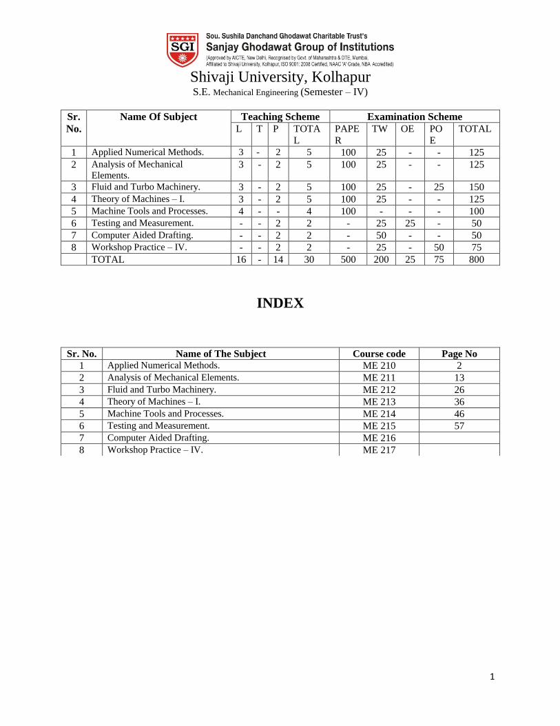
1 Shivaji University, Kolhapur S.E. Mechanical Engineering (Semester – IV) Sr. No. Name Of Subject Teaching Scheme Examination Scheme L T P TOTA L PAPE R TW OE PO E TOTAL 1 Applied Numerical Methods. 3 - 2 5 100 25 - - 125 2 Analysis of Mechanical Elements. 3 - 2 5 100 25 - - 125 3 Fluid and Turbo Machinery. 3 - 2 5 100 25 - 25 150 4 Theory of Machines – I. 3 - 2 5 100 25 - - 125 5 Machine Tools and Processes. 4 - - 4 100 - - - 100 6 Testing and Measurement. - - 2 2 - 25 25 - 50 7 Computer Aided Drafting. - - 2 2 - 50 - - 50 8 Workshop Practice – IV. - - 2 2 - 25 - 50 75 TOTAL 16 - 14 30 500 200 25 75 800 INDEX Sr. No. Name of The Subject Course code Page No 1 Applied Numerical Methods. ME 210 2 2 Analysis of Mechanical Elements. ME 211 13 3 Fluid and Turbo Machinery. ME 212 26 4 Theory of Machines – I. ME 213 36 5 Machine Tools and Processes. ME 214 46 6 Testing and Measurement. ME 215 57 7 Computer Aided Drafting. ME 216 8 Workshop Practice – IV. ME 217
-
Upload
khangminh22 -
Category
Documents
-
view
3 -
download
0
Transcript of Shivaji University, Kolhapur
1
Shivaji University, Kolhapur S.E. Mechanical Engineering (Semester – IV)
Sr.
No.
Name Of Subject Teaching Scheme Examination Scheme
L T P TOTA
L
PAPE
R
TW OE PO
E
TOTAL
1 Applied Numerical Methods. 3 - 2 5 100 25 - - 125
2 Analysis of Mechanical
Elements. 3 - 2 5 100 25 - - 125
3 Fluid and Turbo Machinery. 3 - 2 5 100 25 - 25 150
4 Theory of Machines – I. 3 - 2 5 100 25 - - 125
5 Machine Tools and Processes. 4 - - 4 100 - - - 100
6 Testing and Measurement. - - 2 2 - 25 25 - 50
7 Computer Aided Drafting. - - 2 2 - 50 - - 50
8 Workshop Practice – IV. - - 2 2 - 25 - 50 75
TOTAL 16 - 14 30 500 200 25 75 800
INDEX
Sr. No. Name of The Subject Course code Page No
1 Applied Numerical Methods. ME 210 2
2 Analysis of Mechanical Elements. ME 211 13
3 Fluid and Turbo Machinery. ME 212 26
4 Theory of Machines – I. ME 213 36
5 Machine Tools and Processes. ME 214 46
6 Testing and Measurement. ME 215 57
7 Computer Aided Drafting. ME 216
8 Workshop Practice – IV. ME 217

2
Course Code ME 210 Course Applied Numerical Methods.
Prepared by A.P.Dhawan, S.S.Patil Date 27/11/2017.
Prerequisites Student should have required knowledge of from calculus and linear algebra.
Course Outcomes
At the end of the course the students should be able to:
CO210.1 Acquainted with the basic concept in numerical methods and their uses.
CO210.2 Solve linear algebraic equations using different methods.
CO210.3 Describe Curve fitting technique and statistics.
CO210.4 Solve different problems on numerical differentiation and integration.
CO210.5 Formulate ordinary differential equations.
CO210.6 Solve partial differential equations.
Mapping of Cos with Pos
Pos
Cos
a b c d E f G h i j k l
CO210.1 3 1 1
CO210.2 3 2
CO210.3 2 3 2
CO210.4 1 3
CO210.5 2 3
CO210.6 2 1
Course Contents
Unit No. Title No. of
Hours
Section I
1. Errors:
Introduction, Types of errors, Rules for estimate errors, Error
propagation, Error in the approximation of function
Roots of Equation:
07
3
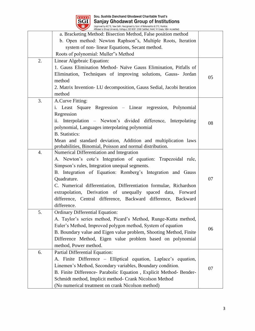
a. Bracketing Method: Bisection Method, False position method
b. Open method: Newton Raphson‟s, Multiple Roots, Iteration
system of non- linear Equations, Secant method.
Roots of polynomial: Muller‟s Method
2. Linear Algebraic Equation:
1. Gauss Elimination Method- Naïve Gauss Elimination, Pitfalls of
Elimination, Techniques of improving solutions, Gauss- Jordan
method
2. Matrix Invention- LU decomposition, Gauss Sedial, Jacobi Iteration
method
05
3. A.Curve Fitting:
i. Least Square Regression – Linear regression, Polynomial
Regression
ii. Interpolation – Newton‟s divided difference, Interpolating
polynomial, Languages interpolating polynomial
B. Statistics:
Mean and standard deviation, Addition and multiplication laws
probabilities, Binomial, Poisson and normal distribution.
08
4. Numerical Differentiation and Integration
A. Newton‟s cote‟s Integration of equation: Trapezoidal rule,
Simpson‟s rules, Integration unequal segments.
B. Integration of Equation: Romberg‟s Integration and Gauss
Quadrature.
C. Numerical differentiation, Differentiation formulae, Richardson
extrapolation, Derivation of unequally spaced data, Forward
difference, Central difference, Backward difference, Backward
difference.
07
5. Ordinary Differential Equation:
A. Taylor‟s series method, Picard‟s Method, Runge-Kutta method,
Euler‟s Method, Improved polygon method, System of equation
B. Boundary value and Eigen value problem, Shooting Method, Finite
Difference Method, Eigen value problem based on polynomial
method, Power method.
06
6. Partial Differential Equation:
A. Finite Difference – Elliptical equation, Laplace‟s equation,
Linemen‟s Method, Secondary variables, Boundary condition.
B. Finite Difference- Parabolic Equation , Explicit Method- Bender-
Schmidt method, Implicit method- Crank Nicolson Method
(No numerical treatment on crank Nicolson method)
07
4
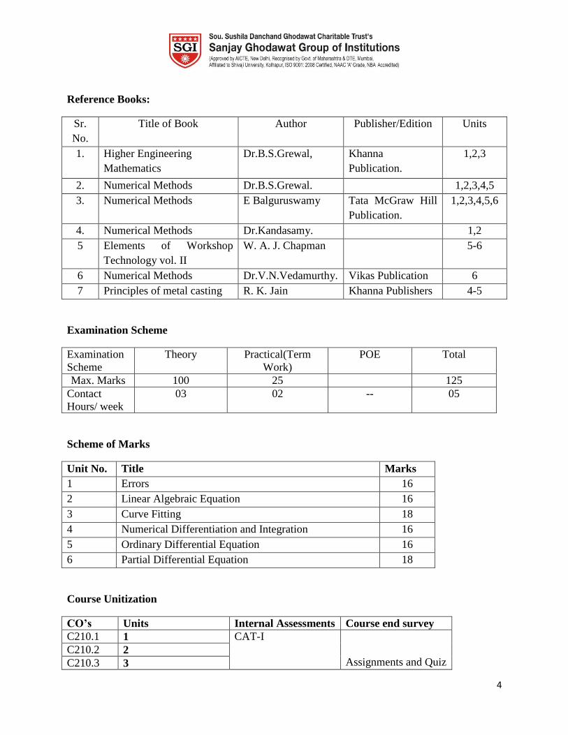
Reference Books:
Sr.
No.
Title of Book Author Publisher/Edition Units
1. Higher Engineering
Mathematics
Dr.B.S.Grewal,
Khanna
Publication.
1,2,3
2. Numerical Methods Dr.B.S.Grewal. 1,2,3,4,5
3. Numerical Methods E Balguruswamy Tata McGraw Hill
Publication.
1,2,3,4,5,6
4. Numerical Methods Dr.Kandasamy. 1,2
5 Elements of Workshop
Technology vol. II
W. A. J. Chapman 5-6
6 Numerical Methods Dr.V.N.Vedamurthy. Vikas Publication 6
7 Principles of metal casting R. K. Jain Khanna Publishers 4-5
Examination Scheme
Examination
Scheme
Theory Practical(Term
Work)
POE Total
Max. Marks 100 25 125
Contact
Hours/ week
03 02 -- 05
Scheme of Marks
Unit No. Title Marks
1 Errors 16
2 Linear Algebraic Equation 16
3 Curve Fitting 18
4 Numerical Differentiation and Integration 16
5 Ordinary Differential Equation 16
6 Partial Differential Equation 18
Course Unitization
CO’s Units Internal Assessments Course end survey
C210.1 1 CAT-I
Assignments and Quiz C210.2 2
C210.3 3

5
C210.4 4 CAT-II
C210.5 5
C210.6 6
Course plan
Section I
Unit No 1 Unit Title Roots of equation Planned
Hrs.
07
Lesson schedule
Class
No.
Details to be covered
1 Basic concept of calculus and linear algebra and Introduction of numerical methods.
2 2. Engineering applications of numerical methods, Basic theory and problems on
Bisection method.
3 3.Basic theory and problems on False position method, Secant method. L4 Basic
theory and problems on 4.Newton Raphson method, Multiple roots.
4 5. Basic theory and problems on System of non linear equation.
5 6. Basic theory and problems on Muller‟s method.
6 Basic concept of calculus and linear algebra and Introduction of numerical methods.
Review Questions
Q1 Find the real root of X-COS X= 0 by bisection method correct upto four
decimal places which lie between 0 and 1. (
CO210.1
Q2 Using Newton Raphson method find the real root of Xlog10 X = 1.2 correct
to 5 decimal places.
Q3 Use Secant method to determine the root of the following equation f(x) =
cos x – x ex = 0 which lies between 0 and 1 correct to three place of
decimal point.
Q4 Perform two iterations of the Newton Raphson method to solve the system
of equations X2
+XY + Y2=7 and X3 + Y3 = 9. Take initial approximation
as X0 = 1.5, Y0 = 0.5.
Q5 Find a positive root of xex= 2 by the method of false which lies in the root
(01,).
Q6 Using Muller‟s method find the root of the equation Y(X) = X3 – 2X – 5 =
0 which lies between 2 &3.
Unit No 2 Unit Title Linear Algebraic Equation Planned
Hrs.
05
Unit Outcomes
At the end of this unit the students should be able to:
UO1 Know how to formulate linear algebraic system of equation using vector
and matrix notation.
CO210.2
UO2 Solve the simultaneous Linear Algebraic equations by using Gauss
elimination method – Naive Gauss Elimination, Gauss Jordon method.
UO3 Solve the simultaneous Linear Algebraic equations by using Matrix
Inversion - LU Decomposition, Matrix Inverse, Gauss Seidel, and Jacobi

6
Iteration Method.
UO4 Solve the simultaneous Linear Algebraic equations Pitfalls of Elimination
method.
UO5 Understand the Techniques of improving solutions.
Lesson schedule
Class
No.
Details to be covered
1 Basic theory and problems on Gauss Elimination method, Pitfalls of Elimination
method.
2 Techniques of improving solutions. Basic theory and problems on Gauss Jordon
method.
3 Basic theory and problems on LU Decomposition method.
4 Basic theory and problems on Matrix Inverse and Gauss Seidel method.
5 Basic theory and problems on Jacobi Iteration method.
Review Questions
Q1 Solve the system of equations by using Gauss Jordon method.
X + Y + Z + W = 2 2X – Y + 2Z – W = -5
3 X + 2Y + 3Z + 4W = 7 X – 2Y – 3Z + 2W = 5
CO210.2
Q2 Solve the system of equations by LU Decomposition method.
X + 5Y + Z = 14 2X + Y + 3Z = 13
3 X + Y + 4Z = 17
Q3 Solve the following set of simultaneous equations by using Gauss
elimination method.
5X + Y + Z + W = 4 X + 7Y + Z + W = 12
X + Y + 6Z + W = -5 X +Y+ Z + 4W = -6
Q4 Solve the following system of equations by Jacobi Iteration method.
X + Y + 54Z = 110 27X + 6Y – Z = 85
6X +15 Y + 2Z = 72
CO210.2
Q5 Solve the following system of equations by Gauss Seidel iterative method
Use initial guess Y = 0, Z = 0
28X + 4Y – Z = 32 X + 3Y + 10 Z = 24
2X +17 Y + 4Z = 35
Unit No 3 Unit Title Curve Fitting Planne
d Hrs.
08
Unit Outcomes
At the end of this unit the students should be able to:
UO1 By fitting a straight line, parabola or second degree curve
CO210.3
UO2 By fitting an exponential curve, a curve of the form Y = aXb
UO3 Know the history of Interpolation and its current uses
UO4 Solve problems using Lagrangian method of interpolation
Lesson schedule
Class Details to be covered
7
No.
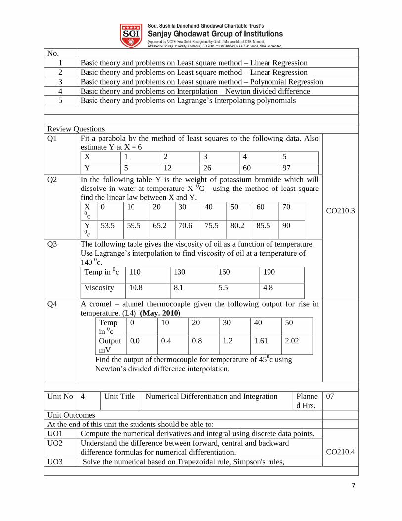
1 Basic theory and problems on Least square method – Linear Regression
2 Basic theory and problems on Least square method – Linear Regression
3 Basic theory and problems on Least square method – Polynomial Regression
4 Basic theory and problems on Interpolation – Newton divided difference
5 Basic theory and problems on Lagrange‟s Interpolating polynomials
Review Questions
Q1 Fit a parabola by the method of least squares to the following data. Also
estimate Y at X = 6
X 1 2 3 4 5
Y 5 12 26 60 97
CO210.3
Q2 In the following table Y is the weight of potassium bromide which will
dissolve in water at temperature X 0C using the method of least square
find the linear law between X and Y.
X 0c
0 10 20 30 40 50 60 70
Y 0c
53.5 59.5 65.2 70.6 75.5 80.2 85.5 90
Q3 The following table gives the viscosity of oil as a function of temperature.
Use Lagrange‟s interpolation to find viscosity of oil at a temperature of
140 0c.
Temp in 0c 110 130 160 190
Viscosity 10.8 8.1 5.5 4.8
Q4 A cromel – alumel thermocouple given the following output for rise in
temperature. (L4) (May. 2010)
Temp
in 0c
0 10 20 30 40 50
Output
mV
0.0 0.4 0.8 1.2 1.61 2.02
Find the output of thermocouple for temperature of 450c using
Newton‟s divided difference interpolation.
Unit No 4 Unit Title Numerical Differentiation and Integration Planne
d Hrs.
07
Unit Outcomes
At the end of this unit the students should be able to:
UO1 Compute the numerical derivatives and integral using discrete data points.
CO210.4
UO2 Understand the difference between forward, central and backward
difference formulas for numerical differentiation.
UO3 Solve the numerical based on Trapezoidal rule, Simpson's rules,
8
Lesson schedule
Class
No.
Details to be covered
1 Newton's Cote's Integration of Equation – Numericals based on Trapezoidal rule,
Simpson's rules, Integration Unequal Segments
2 Study of Integration of equations - Romberg's Integration & Gauss quadrature method
with problems.
3 Differentiation formulae, Richardson Extrapolation, Derivation of unequally spaced
data.
4 Study of Forward difference, Central difference, and Backward difference methods.
Review Questions
Q1 Evaluate ∫
by using Trapezoidal rule & Simpson‟s rule &
obtain value of π.
CO210.3
Q2 Using Simpsons 1/3 rd& 3/8 th
rule, evaluate ∫
by taking h=0.25.
Q3 Use Romberg method to compute I = ∫
with h = 0.5,0.25,0.125
Q4 Evaluate ∫
using number of associated points two by
Gaussian Quadrature. Assume m1 = m2 = 1 and q1 = -0.57735, q2 =
+0.57735
Q5 The table given below revels the velocity v of a body during the time t
specified find its acceleration at 1.1
t 1.0 1.1 1.2 1.3 1.4
v 43.1 47.7 52.1 56.4 60.8
Unit No 5 Unit Title Ordinary Differential Equation Planne
d Hrs.
06
Unit Outcomes
At the end of this unit the students should be able to:
UO1 Know how to convert a higher order ordinary differential equation into an
equivalent system of first order equation.
CO210.5
UO2 Understand the difference between initial and boundary condition. CO210.5
UO3 Solve the numerical based on Taylor‟s Series method, Picard method CO210.5
UO4 Solve boundary value problems by shooting method and Finite Difference
Method.
CO210.5
UO5 Understand how ordinary differential equation techniques can be used to
solve practical engineering problems.
CO210.5
Lesson schedule
Class
No.
Details to be covered
1 Taylor‟s Series method
2 Runge-Kutta methods
3 Boundary Value & Eigen Value Problem
4 Shooting Method
9
5 Eigen Value Problem based on Polynomial Method
Review Questions
Q1 Find out the solution of y1 = 2y + 3 e
x using Taylor‟s series. Initial values
are given as x0=0 and y0=1. Find out value of y when x is 0.1; 0.2; 0.3.
CO210.5
Q2 Solve
given y (0) = 1, obtain the values of y(0.1),y(0.2) using
Picard‟s method.
Q3 Using Finite Difference method solve the boundary value problem
=y
in (0,2) given y (0) = 1, y(2) = 3.63 , subdividing the range of x into 4
equal parts.
Q4 1. Find the largest Eigen value and the corresponding Eigen vector by
Power method.
A=
Q5 Compute y (0.3) for
at y(0) = 1, take h=0.1. Use Runge
Kutta fourth order correct up to 4 decimals.
Q6 Using Predictor – Corrector method find y(0.2) and y(0.1) for
, y (0) =1.
Q7 What is initial Value problem? How is it different from boundary value
problem?
Unit No 6 Unit Title Partial Differential Equation Planne
d Hrs.
07
Unit Outcomes
At the end of this unit the students should be able to:
UO1 Know how to classify linear partial differential equations in to elliptical,
parabolic, and hyperbolic equations.
CO210.6
UO2 Solve the 1D heat equation using the Forward Euler, Backward Euler and
Crank-Nicolson method.
UO3 Understand the conditions under which parabolic methods are stable.
UO4 Solve the problems based on Secondary Variables, Boundary condition
Lesson schedule
Class
No.
Details to be covered
1 Finite difference - Elliptical Equations, Laplace's equation Liebmen Method,
2 Secondary Variables, Boundary condition problems
3 Finite difference - Parabolic Equations
4 Finite difference – elliptical and hyperbolic equations.
5 Explicit Method Implicit Method
6 Explicit Method Implicit Method, Crank Nicolson Method.
Review Questions
10
Q1 Compare explicit and implicit methods
CO210.6
Q2 Explain the Crank – Nicolson method used to solve parabolic equations
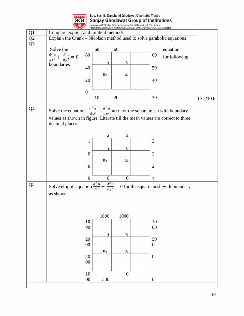
Q3
Solve the equation
for following
boundaries
60
60
60
u1 u2
60
40
u3 u4
50
20
40
0
10
20
30
Q4 Solve the equation
for the square mesh with boundary
values as shown in figure. Literate till the mesh values are correct to three
decimal places.
2 2
1
u1 u2
2
0
u3 u4
2
0
2
0 0 0 1
Q5 Solve elliptic equation
for the square mesh with boundary
as shown.
1000
1000
10
00
u1 u2
10
00
20
00
u3 u4
50
0
20
00
0
10
00
500
0
0

11
Model Question Paper
Course Title : Applied Numerical Methods.
Duration 3 Hours Total
Marks
100
Instructions:
Solve any six Questions.
Marks
1 A Using bisection method, find the negative root of x3 – 4x + 9 = 0. 8
B Use NR method to solve from (x,y) =(0.8,0.4)
x2 – y
2 = y ; x
2 + y
2 = x
8
2 A Solve by the triangularization method (LU), the following system
x + 5y + z = 14, 2x + y + 3z = 13, 3x + y + 4z = 17. 8
B Solve the following system by Gauss Jacobi Method.
10x – 5y – 2z = 3; 4x – 10y + 3z = – 3; x + 6y + 10z = – 3. 8
3 A Fit a curve of the form y = abx to the data.
X : 1 2 3 4 5 6
Y : 151 100 61 50 20 8
8
B Using Newton divided difference formula; find the values of f (2), f (8), and
f (15) given the following table.
x 4 5 7 10 11 13
F(x) 48 100 294 900 1210 2028
8
4 A The mean and standard deviation of 25 observations are 36 and 12
respectively. After calculation it was found that two observations were
wrongly recorded as 53 and 32 instead of 35 and 23. Calculate the correct
mean and standard deviation.
8
B The average no. of phone calls/minutes coming into switch board between 2
to 4 pm is 2.5. Determine the probability that during one particular minute
there will be
I. 0 calls
II. 2 calls
III. 3 calls
IV. 4 calls
V. at most 5 calls
10
12
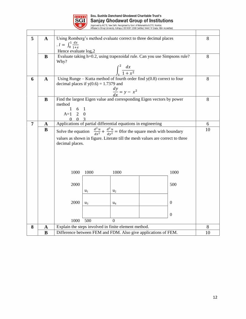
5 A Using Romberg‟s method evaluate correct to three decimal places
. ∫
Hence evaluate loge2
8
B Evaluate taking h=0.2, using trapezoidal rule. Can you use Simpsons rule?
Why?
∫
8
6 A Using Runge – Kutta method of fourth order find y(0.8) correct to four
decimal places if y(0.6) = 1.7379 and
8
B Find the largest Eigen value and corresponding Eigen vectors by power
method
A=
8
7 A Applications of partial differential equations in engineering 6
B Solve the equation
for the square mesh with boundary
values as shown in figure. Literate till the mesh values are correct to three
decimal places.
1000 1000 1000
1000
u1 u2
2000
500
u3 u4
2000 0
0
1000 500 0
10
8 A Explain the steps involved in finite element method. 8
B Difference between FEM and FDM. Also give applications of FEM. 10
13
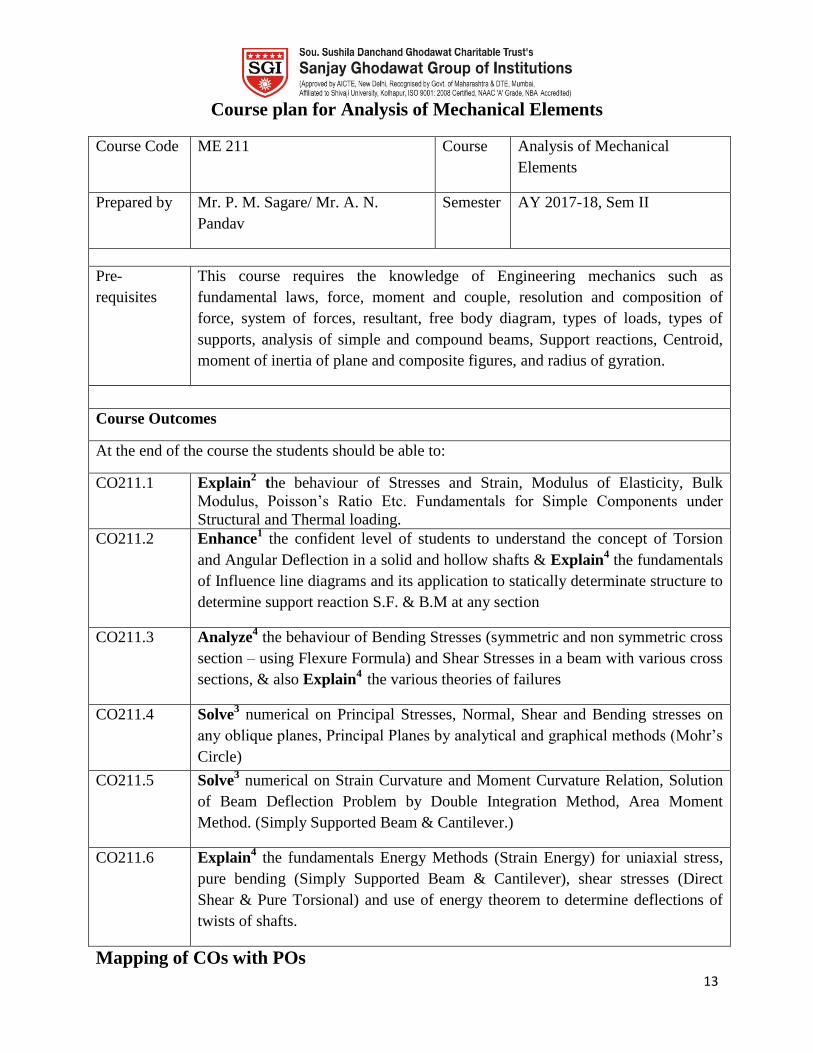
Course plan for Analysis of Mechanical Elements
Course Code ME 211 Course Analysis of Mechanical
Elements
Prepared by Mr. P. M. Sagare/ Mr. A. N.
Pandav
Semester AY 2017-18, Sem II
Pre-
requisites
This course requires the knowledge of Engineering mechanics such as
fundamental laws, force, moment and couple, resolution and composition of
force, system of forces, resultant, free body diagram, types of loads, types of
supports, analysis of simple and compound beams, Support reactions, Centroid,
moment of inertia of plane and composite figures, and radius of gyration.
Course Outcomes
At the end of the course the students should be able to:
CO211.1 Explain2 the behaviour of Stresses and Strain, Modulus of Elasticity, Bulk
Modulus, Poisson‟s Ratio Etc. Fundamentals for Simple Components under
Structural and Thermal loading.
CO211.2 Enhance1 the confident level of students to understand the concept of Torsion
and Angular Deflection in a solid and hollow shafts & Explain4 the fundamentals
of Influence line diagrams and its application to statically determinate structure to
determine support reaction S.F. & B.M at any section
CO211.3 Analyze4 the behaviour of Bending Stresses (symmetric and non symmetric cross
section – using Flexure Formula) and Shear Stresses in a beam with various cross
sections, & also Explain4
the various theories of failures
CO211.4 Solve3 numerical on Principal Stresses, Normal, Shear and Bending stresses on
any oblique planes, Principal Planes by analytical and graphical methods (Mohr‟s
Circle)
CO211.5 Solve3 numerical on Strain Curvature and Moment Curvature Relation, Solution
of Beam Deflection Problem by Double Integration Method, Area Moment
Method. (Simply Supported Beam & Cantilever.)
CO211.6 Explain4 the fundamentals Energy Methods (Strain Energy) for uniaxial stress,
pure bending (Simply Supported Beam & Cantilever), shear stresses (Direct
Shear & Pure Torsional) and use of energy theorem to determine deflections of
twists of shafts.
Mapping of COs with POs

14
POs
COs
a b c d e f g h i j k
CO211.1 3 3 3
CO211.2 3 3 3 1
CO211.3 3 3 3 1
CO211.4 3 3 3 1
CO211.5 3 3 3 1
CO211.6 3 3 3 1
1 Mild correlation 2 Moderato correlation 3 Strong correlation
Course Contents
Unit
No. Title
No. of
Hours
Section I
1. Stresses and Strains
Concept of stress and strain, (Linear, lateral, shear and volumetric), Hooke's
Law, Poisson's ratio, Modulus of Elasticity, Modulus of rigidity', stress-strain
diagram for ductile and brittle material factor of safety, working stress.
Normal and shear stresses, Thermal Stresses. Complementary shear stress,
Bulk Modulus, Inter-relationship between elastic constants.
6
2. A) Torsion: Basic assumptions. Torsion formula. Hollow and solid circular
shafts, Angular deflection
B)Shear Force and Bending Moment Diagram : Concept and definition of
shear force and bending moment in determinate beams due to concentrated,
UDL and uniformly varying load
7
3. Stresses in Beams :
A) Bending stresses - Symmetric pure bending of beams, flexure formula,
moment of resistance of cross-sections, simple built-up section, design of
rectangular and circular (solid and hollow) sections; L, I and T sections
B) Shear stresses : Distribution of shear stresses in beams of various
commonly used sections such as circular, I, T, and angles
7
Section II
4. Principal Stresses and Strains: Normal and shear stresses on any oblique
planes, concept of Principal planes, derivation of expression for Principal 8
15
stresses and maximum shear stress, Positions of principal planes and planes of
maximum shear, Graphical solutions using Mohr‟s circle of stresses,
Combined effect of shear and bending in Beam, Theories of elastic failure
(Without derivation).
5. Deflection of Beams: Strain curvature and moment curvature relation, solution
of beam deflection problem by Double integration method, Area moment
method. (Simply Supported Beam & Cantilever.)
6
6. A)Columns: Euler's formula for different end connections, concept of
equivalent length, eccentric loading, Rankine formula
B)Energy Methods: Strain energy for uniaxial stress, Pure bending (Simply
Supported Beam & Cantilever)Shear stresses (Direct Shear & Pure Torsional),
Use of energy theorem to determine deflections and twists of shafts
6
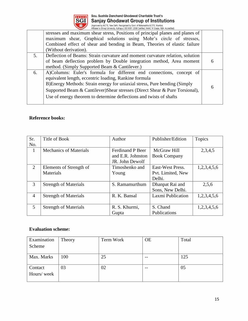
Reference books:
Sr.
No.
Title of Book Author Publisher/Edition Topics
1 Mechanics of Materials Ferdinand P Beer
and E.R. Johnston
JR. John Dewolf
McGraw Hill
Book Company
2,3,4,5
2 Elements of Strength of
Materials
Timoshenko and
Young
East-West Press.
Pvt. Limited, New
Delhi.
1,2,3,4,5,6
3 Strength of Materials S. Ramamurthum Dhanpat Rai and
Sons, New Delhi.
2,5,6
4 Strength of Materials R. K. Bansal Laxmi Publication
1,2,3,4,5,6
5 Strength of Materials R. S. Khurmi,
Gupta
S. Chand
Publications
1,2,3,4,5,6
Evaluation scheme:
Examination
Scheme
Theory Term Work OE Total
Max. Marks 100 25 -- 125
Contact
Hours/ week
03 02 -- 05
16
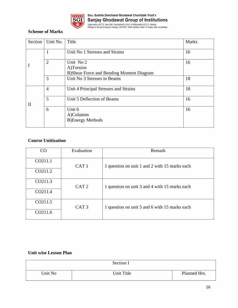
Scheme of Marks
Section Unit No. Title Marks
I
1 Unit No 1 Stresses and Strains 16
2 Unit No 2
A)Torsion
B)Shear Force and Bending Moment Diagram
16
3 Unit No 3 Stresses in Beams 18
II
4 Unit 4 Principal Stresses and Strains 18
5 Unit 5 Deflection of Beams 16
6 Unit 6
A)Columns
B)Energy Methods
16
Course Unitization
CO Evaluation Remark
CO211.1 CAT 1 1 question on unit 1 and 2 with 15 marks each
CO211.2
CO211.3 CAT 2 1 question on unit 3 and 4 with 15 marks each
CO211.4
CO211.5 CAT 3 1 question on unit 5 and 6 with 15 marks each
CO211.6
Unit wise Lesson Plan
Section I
Unit No Unit Title Planned Hrs.

17
1 Simple stresses and strains 06
Lesson schedule
Class No. Details to be covered
1 Introduction of the subject in brief, Revise the basic concepts, fundamental laws,
force, moment and couple, Types of loads, types of supports, Support reactions,
Centroid, moment of inertia etc.
2 Stress and strain, stress-strain curve for ductile and brittle material, Extension of bars
3 Numerical problems Extension of bars
4 Elastic Constants, Relationship between them.
5 Temperature Stresses, Numerical problems
6 Numerical problems on temperature Stresses
Review Questions
Q1 Define Stress and strain?
CO211.1
Q2 Define the terms modulus of elasticity, modulus of rigidity, Bulk modulus?
Q3 Derive the derive the relationship between modulus of elasticity, modulus of
rigidity, Bulk modulus
Q4 Draw the stress strain diagram for ductile material and show the silent points on
them.
Unit No Unit title Planned Hrs.
2 Torsion, SFD & BMD 07
Lesson schedule
Class
No.
Details to be covered
1 Basics & assumptions terminology of hollow and circular shafts
2 Derive torsion formula
3 Solve numerical problems
4 Basics & assumptions terminology of hollow and circular shafts

18
5 Define SFD and BMD, Sign Conventions for different types of beams for standard lading
conditions.
6 Derive the SF and BM and to draw SFD BMD for different types of beams for standard
lading conditions
7 Solve Numerical Problems
Review Questions
Q1 Derive the torsion formula for a circular shaft of length L, radius r, fixed at one
end and subjected to a torque T at the other end.
CO211.2
Q2 Draw the SFD and BMD for the beam as shown in the figure and locate the
point of maximum bending moment
Unit No Unit Title Planned Hrs.
3 Stresses in Beams 07
Lesson schedule
Class
No.
Details to be covered
1 Explain the terms pure bending, assumptions made for pure bending theory, section
modulus, centroid for standard cross sections
2 Derive flexure formula, moment of resistance
3 To solve numerical problems to design the beams for bending stresses of the cross section
4 To solve numerical problems to draw the distribution of beams for bending stresses across
the section
5 Explain the shearing stresses in the beams
6 To solve numerical problems to find the shearing stresses in the built up section
19
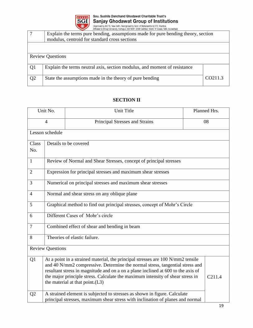
7 Explain the terms pure bending, assumptions made for pure bending theory, section
modulus, centroid for standard cross sections
Review Questions
Q1 Explain the terms neutral axis, section modulus, and moment of resistance
CO211.3 Q2 State the assumptions made in the theory of pure bending
SECTION II
Unit No. Unit Title Planned Hrs.
4 Principal Stresses and Strains 08
Lesson schedule
Class
No.
Details to be covered
1 Review of Normal and Shear Stresses, concept of principal stresses
2 Expression for principal stresses and maximum shear stresses
3 Numerical on principal stresses and maximum shear stresses
4 Normal and shear stress on any oblique plane
5 Graphical method to find out principal stresses, concept of Mohr‟s Circle
6 Different Cases of Mohr‟s circle
7 Combined effect of shear and bending in beam
8 Theories of elastic failure.
Review Questions
Q1 At a point in a strained material, the principal stresses are 100 N/mm2 tensile
and 40 N/mm2 compressive. Determine the normal stress, tangential stress and
resultant stress in magnitude and on a on a plane inclined at 600 to the axis of
the major principle stress. Calculate the maximum intensity of shear stress in
the material at that point.(L3)
C211.4
Q2 A strained element is subjected to stresses as shown in figure. Calculate
principal stresses, maximum shear stress with inclination of planes and normal
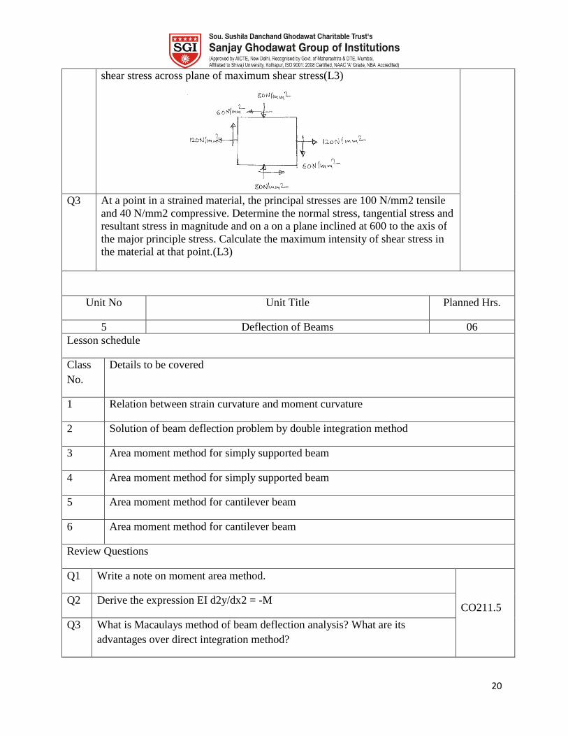
20
shear stress across plane of maximum shear stress(L3)
Q3 At a point in a strained material, the principal stresses are 100 N/mm2 tensile
and 40 N/mm2 compressive. Determine the normal stress, tangential stress and
resultant stress in magnitude and on a on a plane inclined at 600 to the axis of
the major principle stress. Calculate the maximum intensity of shear stress in
the material at that point.(L3)
Unit No Unit Title Planned Hrs.
5 Deflection of Beams 06
Lesson schedule
Class
No.
Details to be covered
1 Relation between strain curvature and moment curvature
2 Solution of beam deflection problem by double integration method
3 Area moment method for simply supported beam
4 Area moment method for simply supported beam
5 Area moment method for cantilever beam
6 Area moment method for cantilever beam
Review Questions
Q1 Write a note on moment area method.
CO211.5 Q2 Derive the expression EI d2y/dx2 = -M
Q3 What is Macaulays method of beam deflection analysis? What are its
advantages over direct integration method?
21
Q4 What is mean by conjugate beam? How it differs from original beam.
Q5 A horizontal steel beam I= 6000cm4 carries a udl of 50kN over its length of
4m. The beam is supported by three vertical steel tie rods, each 1.5 m long.
One at each end and one in the middle, the diameter of each rod being 20mm.
calculate the deflection of the center of the beam below the end points and the
stress in each rod. Take E= 2 X10⁵ n/mm2 .
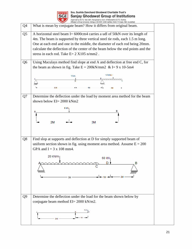
Q6 Using Maculays method find slope at end A and deflection at free end C, for
the beam as shown in fig. Take E = 200kN/mm2 & I= 9 x 10⁻⁵m4
Q7 Determine the deflection under the load by moment area method for the beam
shown below EI= 2000 kNm2
Q8 Find slop at supports and deflection at D for simply supported beam of
uniform section shown in fig. using moment area method. Assume E = 200
GPA and I = 3 x 108 mm4.
Q9 Determine the deflection under the load for the beam shown below by
conjugate beam method EI= 2000 kN/m2.
22
Unit No Unit Title Planned Hrs.
6 Columns, EnergyMethods 06
Lesson schedule
Class
No.
Details to be covered
1 Euler‟s formula for different end conditions
2 Concept of equivalent length
3 Concept of eccentric loading
4 Euler‟s formula for different end conditions
5 Strain energy for uniaxial stresses, Pure bending, shear stresses
6 Energy theorems to determine deflections and twist of shafts
Review Questions
Write a note on strain energy due to shear CO211.6
State assumptions made in Euler‟s column theory
Model Question Paper
Course Title : Analysis of Mechanical Elements
Duration-3 Hrs. Max. Marks: 100
Instructions:
1 Attempt any three questions from each section
2 Figures to the right indicate full marks.
3 Wherever required neat sketches shall be drawn.

23
Marks
1 a Show the Stress-Strain Diagram for ductile material and show the
silent points on them. What is factor of safety and how it is selected?
8
b State and explain elastic constants E, G & K and Derive the
relationship between E, G & K
8
2 a A bar of 20 mm diameter is tested in tension. It is observed that when
a load of 37.7kN is applied, the extension measured over a gauge
length of 200mm is 0.12mm and contraction in diameter is 0.0036mm.
find the Poisson‟s ratio and elastic constants E, G & K
8
b Derive the torsion formula for a circular shaft of length L, radius r,
fixed at one end and subjected to a torque T at the other end
8
c 8
3
a The cross section of a simply supported beam is as shown in the figure
3.1. The beam carries a load of P=10kN as shown n the figure 3.1. Its
self weight is 3.5kN/m. calculate the bending stresses at section a-a
16
Section-II
4 Marks
a Draw the shear force and bending moment diagram for the the beam
as shown in the figure below. Mark typical ordinates on the diagram
and locate the point of inflection if any
16
5
a A rectangular block of material is subjected to stresses on
perpendicular faces as shown in following figure
16
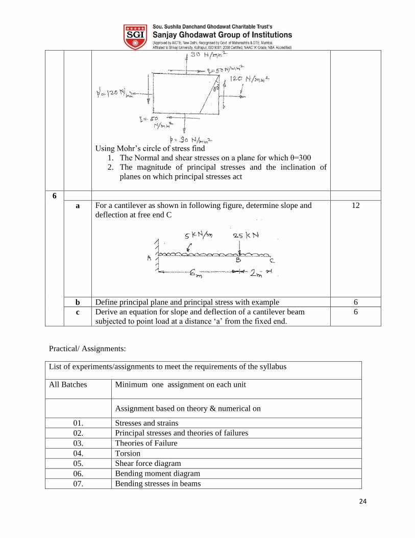
24
Using Mohr‟s circle of stress find
1. The Normal and shear stresses on a plane for which θ=300
2. The magnitude of principal stresses and the inclination of
planes on which principal stresses act
6
a For a cantilever as shown in following figure, determine slope and
deflection at free end C
12
b Define principal plane and principal stress with example 6
c Derive an equation for slope and deflection of a cantilever beam
subjected to point load at a distance „a‟ from the fixed end.
6
Practical/ Assignments:
List of experiments/assignments to meet the requirements of the syllabus
All Batches Minimum one assignment on each unit
Assignment based on theory & numerical on
01. Stresses and strains
02. Principal stresses and theories of failures
03. Theories of Failure
04. Torsion
05. Shear force diagram
06. Bending moment diagram
07. Bending stresses in beams

25
08. Shear stresses in beams
09. Deflection of beams
10. Columns
11. Strain Energy
26
COURSE PLAN
Course Code ME 212 Course Fluid and Turbo
Machinery
Prepared by Mr. Sanjay D. Koorse Date 25/11/2017
Pre-requisites This course requires the student to know the basic concepts of
Thermodynamics and Fluid Mechanics.
Course Outcomes
At the end of the course the students should be able to:
CO212.1 Understand [2]
the basic concepts of fluid & turbo machinery; Classification
of Impulse turbine; Working principle; Design of Pelton wheel; Performance
characteristics and Numerical examples.
CO212.2 Remember [1]
and Understand [2]
the construction and working principles of
Reaction turbines; Differentiate between Impulse and Reaction turbine;
Classification of Draft tubes, Performance analysis and Numerical examples.
CO212.3 Analyze [4]
the working principle of Centrifugal pumps, MPSH and NPSH.
Specific speed and performance characteristics of pumps.
CO212.4 Define and understand [2]
the concept of centrifugal compressor; Axial
compressors and to study the various parameters related to rotodynamic air
compressors.
CO212.5 Analyze [4]
axial compressors and to study the various parameters related to
rotodynamic air compressors, velocity diagrams; performance and
comparision.
CO212.6 Illustrate [3,5]
the working of Gas Turbines, fuels for gas turbine and
introduction to jet engine. Calculating the efficiencies of gas turbines
Mapping of COs with POs
PO
CO‟s 1 2 3 4 5 6 7 8 9 10 11 12 13 14
212.1 1 2
212.2 1 2 3
212.3 1 2 3
212.4 1 2 3
212.5 1
212.6 1 2
Course Contents
Unit No. Title No. of
Hours
Impulse Water Turbines:
Impact of Jet, Euler‟s equation for work done in Rotodynamic
27
1.
Machines classification of water turbines, Pelton wheel, its
construction and working, velocity triangles. Types, Pelton wheel
design bucket dimensions, Number of buckets, jet diameter, wheel
diameter, jet ratio, Speed ratio, Number of jets, Calculation of
efficiency, power, discharge etc. Governing of Pelton wheel, Model
Testing, Unit quantities, Specific speed of turbine and performance
characteristics of turbine.
7
2.
Reaction Water Turbines:
Principle of operation, Construction and working of Francis and
Kaplan Turbine, Effect of modification of velocity triangles on
runner shape, Draft tube, Calculation of various efficiencies, Power,
Discharge, Blade angles, Runner dimensions etc. Governing of
Francis and Kaplan turbine. Draft tube-types and analysis. Model
Testing, Specific speed of turbine and performance characteristics of
turbine.
7
3.
Centrifugal Pumps:
Working principles, Construction, Types, Various heads, Multistage
pumps, Velocity triangles, Minimum starting speed, Cavitations,
Maximum permissible suction head (MPSH) and Net positive suction
head (NPSH). Methods of priming, calculations of efficiencies,
Discharge, Blade angles, Head, Power required Impeller dimensions
etc. Specific speed and performance characteristics of pumps
6
4.
Air Compressors:
Application of compressed air, Classification of compressor,
Reciprocating compressors, construction , Work input, Necessity of
cooling, Isothermal efficiency, Heat rejected, Effect of clearance
volume, Volumetric efficiency, Necessity of multistage, construction,
Optimum intermediate pressure for minimum work required, After
cooler, Free air delivered, air flow measurement, Capacity control.
Roots blower and vane blower(Descriptive treatment)
8
5.
Rotodyanamic Air Compressors:
Centrifugal compressor, velocity diagram. Theory of operation,
losses, Adiabatic efficiency, Effect of compressibility, Diffuser,
Prewhirl, Pressure coefficient, Slip factor, performance. Axial flow
compressors, Velocity diagram, Degree of reaction, polytropic
efficiency, Surging, Chocking, Stalling, performance and
comparison.
7
6.
Gas turbines:
Working principles, Applications, Open, Closed cycle and their
comparison. Cycle modified to Regeneration, Reheat, Intercooling
performance. Calculation of gas turbine work ratio, Efficiency etc.
Types of fuels for gas Turbine Introduction to Jet engine.
5
Text and Reference Books:
Sr. No. Title of Book Author Publisher/Edition Topics

28
1 Fans, compressor and turbine S.M Yahya TMH, 2005 All
2 Fluid Mechanics and Hydraulic
Machines Dr.R.K.Bansal Laxmi Publication 1-3
3 Gas turbines V. Ganeshan TMH, 3rd
Edition
4 Steam andGas Turbines R. Yadav CPH, Allahabad,
6th
Edition, 1997 All
5 Fluid mechanics and hydraulic
machines Modi and Seth
Standard Book
House
6 Thermal Engineering R.K Rajput Laxmi Publication 3-5
7 Fluid Mechanics and Fluid
Power engineering Dr.D.S.Kumar S.K.Kataria& Sons 1-5
8 Fluid Mechanics and
Machinery C.P.Kothandaraman
R.Rudramoorthy New Age
International 1-5
9 Fluid Mechanics and Turbo
Machines Madan Mohan Das PHI 1-3
Examination Scheme
Examination
Scheme
Theory Term Work POE Total
Max. Marks 100 25 25 150
Contact
Hours/ week
3 2 -- 5
Scheme of Marks
Sr. No. Unit No. Title Marks
1. 1. Impulse Water Turbines 16
2. 2. Reaction Water Turbines 20
3. 3. Centrifugal Pumps 20
4. 4. Air compressors 16
5. 5. Rotodyanamic Air Compressors 16
6. 6. Gas turbines 12
Course Unitization
CO’s Units Internal Assessments Course end survey
212.1 1 CAT-I
Assignments and Quiz 212.2 2
212.3 3
212.4 4 CAT-II
212.5 5
29
212.6 4
Course plan
Unit
No.
1. Title Impulse Water Turbines Planned
Hrs.
7
Lesson schedule
Class
No.
Details to be covered
1 Euler‟s equation for work done in Rotodynamic Machines, classification of water
turbines, Pelton wheel, its construction
2 Pelton wheel working, velocity triangles
3 Pelton wheel design bucket dimensions, number of buckets, jet diameter
4 Wheel diameter, jet ratio, speed ratio
5 Number of jets, Governing of Pelton wheel
6 Calculation of efficiency, power, discharge
Review Questions
Q1 Classify the water turbines and list the components of Pelton turbine
with neat sketch
CO212.1
Q2 With neat sketch explain the concept of Euler‟s equation for work done
in Roto-dynamic Machines.
Q3 Explain various design parameters of the Pelton Wheel.
Q4 Derive the expression for the efficiency of the Pelton wheel.
Unit
No.
2 Title Reaction Water Turbines Planned
Hrs.
7
Lesson schedule
Class
No.
Details to be covered
1 Principle of operation, construction and working of Francis Turbine
2 Kaplan Turbine, effect of modification of velocity triangles on runner shape, draft
tube
3 Cavitation, Governing of Francis and Kaplan turbine
4 Draft tube-types and analysis
5 Calculation of various efficiencies, power, discharge
6 Calculation of blade angles, runner dimensions
7 Additional Numerical.
Review Questions
Q1 Classify the water turbines and list the components of Francis turbine
with neat sketch
Q2 Explain the construction and working of the Kaplan Turbine.
30
Q3 What is meant by cavitation and the governing system of the Francis and
Kaplan turbines
CO212.2
Q4 Explain the velocity triangles of the Francis turbine
Unit
No.
3. Title Centrifugal Pumps Planned
Hrs.
6
Lesson schedule
Class
No.
Details to be covered
1 Working principles, Construction, types
2 Various heads, multistage pumps
3 Velocity triangles Minimum starting speed, cavitation, MPSH and NPSH
4 Methods of priming ,Calculations of efficiencies
5 Calculations of discharge, blade angles, head, power required, impeller dimensions
etc
6 Additional Numerical.
Review Questions
Q1 With neat sketch explain the construction and working of the centrifugal
pump.
CO212.3
Q2 Explain with neat sketch the velocity triangles of the pump blades.
Q3 What is meant by multistaging in pumps?
Q4 Derive the expression for minimum starting speed of the pump.
Q5 Explain MPSH and NPSH
Unit
No.
4. Title Air compressors Planned
Hrs.
8
Lesson schedule
Class
No.
Details to be covered
1 Application of compressed air , classification of compressor, reciprocating
compressors
2 Construction , work input, necessity of cooling , isothermal efficiency
3 Heat rejected, effect of clearance volume,
5 Volumetric efficiency Necessity of multistaging,
6 Construction, optimum intermediate pressure for minimum work required
7 After cooler, free air delivered,
8 Air flow measurement, Capacity control.
Review Questions
Q1 Describe the application of the compressed air and classify the
31
compressors.
CO212.4
Q2 Explain the construction and working of the reciprocating compressor.
Q3 Derive the expression for the volumetric efficiency.
Q4 Explain the concept of multistaging and effect of it on the thermal
efficiency.
Q5 Describe with neat sketch the working of roots bower and vane blower.
Q6 Write a short note on “Intercooler in reciprocating compressor”
Q7 Derive expression for minimum work required for two stage
reciprocating compressor with inner cooler
Unit
No.
5 Title Rotodyanamic Air Compressors Planned
Hrs.
7
Lesson schedule
Class
No.
Details to be covered
1 Centrifugal compressor, velocity diagram. Theory of operation
2 Losses, Adiabatic efficiency, effect of compressibility
3 Diffuser, Prewhirl, pressure coefficient
4 Slip factor, performance of compressor
5 Axial flow compressors, velocity diagram, degree of reaction
6 Polytropic efficiency, surging, chocking, stalling
7 Performance, comparison with centrifugal
Review Questions
Q1 Explain the centrifugal compressor with neat sketch.
CO212.5
Q2 Explain axial flow compressor.
Q3 What is mean by surging, chocking and stalling.
Unit
No.
6 Title Gas turbines Planned
Hrs.
5
Lesson schedule
Class
No.
Details to be covered
1 Working principles, applications, open, closed cycle
2 Comparison, Cycle modified to regeneration
3 Reheat, inter cooling performance
4 Calculation of gas turbine work ratio, efficiency
5 Extra problems
Review Questions
Q1 Classify gas turbine and explain construction and working.
Q2 What are the methods to increase the efficiency of the gas turbine
Q3 Draw the schematic diagram of closed cycle gas turbine power plant.
32
State merits and demerits of it CO212.6
Model Question Paper
Course Title : Fluid and Turbo machinery
Duration 3 Hours Total
Marks
100
Instructions:
Solve any three question
Figures to the right indicate full marks
Assume suitable data if required
Section-I
1 A Classify the water turbines and list the components of Francis turbine
with neat sketch
8
B
A single jet Pelton wheel is required to drive a generator to develop
10000 kw. The available head at nozzle is 760 m. Assuming electric
generation efficiency 95%,Pelton wheel efficiency of velocity for
nozzle 0.97,mean bucket velocity of 0.46 of jet velocity, outlet angle
of bucket 15 degree and the relative of the water leaving the buckets
0.85 of that inlet find;
1)The flow in m3/s
2)Diameter of jet
3)The force exerted by the jet on the buckets
8
2 A Show that for reaction turbine with radial vanes at the receiving
circumference, the hydraulic efficiency is given by 2/ (2+tan2α) where
α is the guide blade angle. Assume radial discharge and constant
velocity of flow.
8
B A Kaplan turbine develops 22000kw at an average head of
35m.Assuming speed ratio 2, Flow ratio of 0.6, diameter of the boss
equal to 0.35 times the diameter of the runner and overall efficiency of
88% calculate the diameter, Speed and specific speed of turbine
8
3 A Enlist the different types of impellers used for centrifugal pump and
obtain the expression for minimum starting speed of the centrifugal
pump
8
B
To predict the performance of a large centrifugal pump a scale model
of 1/5th
size was made with following specifications;
Power=30kw,Head=8m,speed=1000rpm.If the prototype pump has to
work against a head of 25m.make the calculations for its working
speed ,the power required to drive it and the ratio of the flow rates
handled by two pump.
8
33
4 Write a short note on any three-
1. Multi-staging of pumps
2. Efficiencies of turbine
3. NPSH and MPSH
4. Draft tubes
18
Section-II
5 A Derive expression for minimum work required for two stage
reciprocating compressor with intercooler
8
B A single cylinder single acting reciprocating air compressor 250mm
bore and 350 mm stroke runs at 180 rpm. The suction and delivery
pressures are 0.98 and 6 bar .Calculate the theoretical power required
to run it under the conditions of compression as
1)Isothermal 2) Polytropic n=1.3 3)Isentropic neglect clearance
8
6 A Explain with neat sketch construction, working of axial flow
compressor
8
B An axial flow compressor having 10 stages works with 50% degree of
reaction. It compresses air with pressure ratio of 5:1.The inlet
condition of air is 25 oC and 100 kN/m
2 .The air enters the compressor
with speed of 110m/s. The mean speed of the rotor blades of the
compressor is 85% Calculate the blade angle and work required by
compressor
8
7 A Draw the schematic diagram of closed cycle gas turbine power plant.
State merits and demerits of it.
8
B In a gas turbine plant operating on Brayton cycle, maximum and
minimum temperature are 25 oC and 825
oC. The pressure ratio is
4.5.If isentropic efficiencies of the compressor and turbine are 85%
and 90 % respectively. Calculate the specific work output, Cycle
efficiency and work ratio. Take Cp=1.005 kj/kgk
8
8 Write a short note on any three-
1. Roots blower and vane blower
2. Centrifugal compressor
3. Classification of compressor
4. Intercooler in reciprocating compressor
5. Application of compressed air
18
Assignments
List of assignments to meet the requirements of the syllabus
Assignment No. 1
Assignment Title
34
Batch I Assignment on unit no. 1& 2
Batch II Assignment on unit no. 1 & 2
Batch III Assignment on unit no. 1 & 2
Batch IV Assignment on unit no. 1 & 2
Assignment No. 2
Assignment Title
Batch I Assignment on unit no. 3 & 4
Batch II Assignment on unit no. 3 & 4
Batch III Assignment on unit no. 3 & 4
Batch IV Assignment on unit no. 3 & 4
Assignment No. 3
Assignment Title
Batch I Assignment on unit no. 5 & 6.
Batch II Assignment on unit no. 5 & 6.
Batch III Assignment on unit no. 5 & 6.
Batch IV Assignment on unit no. 5 & 6.
List of Experiments
List of experiments to meet the requirements of the syllabus
Experiment No. Experiment title CO
1. Study and trial on Pelton wheel 212.1
2. Study and trial on Francis/ Kaplan turbine 212.2
3. Trial on Centrifugal pump 212.3
4. Study and demonstration of reciprocating pump and hydraulic
ram
212.3
5. Study and trial on reciprocating compressor 212.4

35
6. Study and trial on centrifugal blower 212.5
7. Study of hydraulic devices- Intensifier, Accumulator,
hydraulic jacks, press and crane.
212.4
8. Study of other types of pumps- Gear pump, Jet pump,
submersible pump, air lift pump
212.3
9 Industrial visit or hydro power plant visit
36
Mapping of COs with POs
POs
COs
a b c d e f g h i j k l m n o
CO213.1 3 1 3 3 0 0 0 0 0 0 0 1 0 2 0
CO213.2 3 3 3 3 0 0 0 0 0 0 0 0 0 1 0
CO213.3
3 3 3 3 0 0 0 0 0 0 0 0 0 0 0
CO213.4 3 3 3 2 2 0 0 0 0 0 0 0 0 0 3
CO213.5 2 2 3 3 2 0 0 0 0 0 0 0 0 0 3
CO213.6 3 2 3 2 0 0 0 0 0 0 0 0 0 0 3
Course Contents
Unit No. Title No. of
Hours
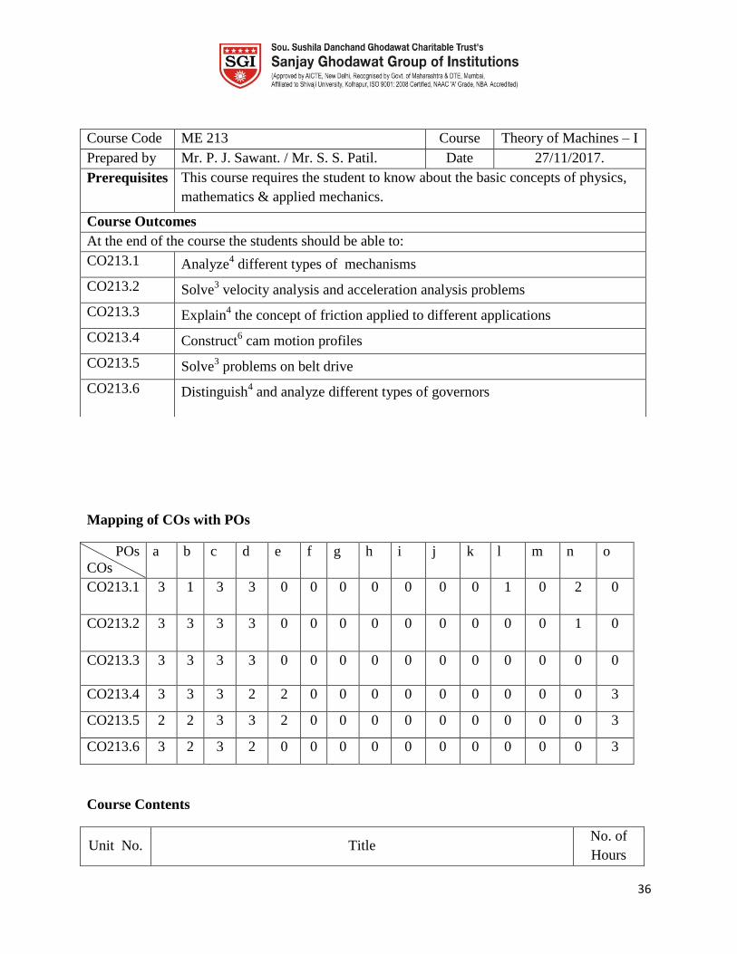
Course Code ME 213 Course Theory of Machines – I
Prepared by Mr. P. J. Sawant. / Mr. S. S. Patil. Date 27/11/2017.
Prerequisites This course requires the student to know about the basic concepts of physics,
mathematics & applied mechanics.
Course Outcomes
At the end of the course the students should be able to:
CO213.1 Analyze4 different types of mechanisms
CO213.2 Solve3 velocity analysis and acceleration analysis problems
CO213.3 Explain4 the concept of friction applied to different applications
CO213.4 Construct6 cam motion profiles
CO213.5 Solve3 problems on belt drive
CO213.6 Distinguish4 and analyze different types of governors

37
1.
Basic Concept of Mechanisms:
Links, kinematic pair (lower and higher), Kinematic chain,
Mechanism, inversion, Types of constraints, Grubber‟s criterion,
Inversions of slider crank chain, Double slider crank chain, Four bar,
Steering gear mechanisms, Analysis of Hooke's joint.
05
2.
Velocity and Acceleration in Mechanisms:
Graphical analysis of Velocity and acceleration for different
mechanisms using relative velocity and acceleration method, Coriolis‟
component of acceleration, Klein's construction for slider crank
mechanism, Velocity analysis by Instantaneous center method.
10
3. Friction:
Introduction of friction, Friction in pivot bearings, Inclined plane
theory, Friction in screws.
05
4. Cams:
Types of cams and followers, Profiles of cams for specified motion of
different followers, Spring load on the follower, Jumping of follower.
08
5.
Belts and Dynamometers:
Types of belt drives, Calculation of power transmitted, Belt tension
ratio, Actual tension in a running belt, Centrifugal and initial tension
in belt, Slip and creep of belt,
Classification of dynamometers, Study of rope brake absorption
dynamometer and belt transmission dynamometer.
06
6.
Governors:
Types of governors, Porter and Hartnell governor, Controlling force
and stability of governor, Hunting, Sensitivity, Isochronism, Governor
effort and power, Insensitiveness of governors.
06
Reference Books:
Sr.
No.
Title of Book Author Publisher/Edition Units
1. Theory of Machines Ratan S.S Tata McGraw-Hill 1,2,3
2. Theory of Machines P.L. Ballany Khanna Publication,
New Delhi.
1,2,3,4,5
3. Theory of Machines V.P. Singh DhanpatRai and Sons 1,2,3,4,5,6
4. Theory of machines Dr. R.K.Bansal Laxmi Publication. 5-6
5 Theory of Machines Thomas Bevan CBS Publishers, New
Delhi.
5-6
6
Theory of Machines and
Mechanism
Shigley McGraw Hill, New
York
6
7 Theory of Machines and
Mechanism
G.S. Rao and
R.V. Dukipatti
"New Age Int.
Publications Ltd. New
4-5
38
Delhi.
Examination Scheme
Examination
Scheme
Theory Term Work POE Total
Max. Marks 100 25 100
Contact
Hours/ week
04 -- -- 4
Scheme of Marks
Unit No. Title Marks
1 Basic Concept of Mechanisms 16
2 Velocity and Acceleration in Mechanisms 18
3 Friction 16
4 Cams 18
5 Belts and Dynamometers 16
6 Governors 16
Course Unitization
CO’s Units Internal Assessments Course end survey
C213.1 1 CAT-I
Assignments and Quiz C213.2 2
C213.3 3 CAT-II
C213.4 4
C213.5 5 CAT-III
C213.6 6
Course plan
Section I
Unit
No
1 Unit Title Basic Concept of Mechanisms Planned
Hrs.
05
Lesson schedule
Class
No.
Details to be covered
1 Links, kinematic pair (lower and higher), kinematic chain, mechanism
2 Inversion, types of constraints, Grubbler‟s criterion

39
3 slider crank chain and its inversions
4 Double slider Crank chain and its inversions
5 Four bar chain and its inversions.
Review Questions
Q1 Sketch and explain inversions of slider crank chain.
CO213.1
Q2 Define kinematic pair and give their classification with suitable example. .
Q3 Explain with neat sketches double slider crank chain and its inversions
Q4 Explain the mobility of mechanisms.
Q5 Define link. Describe in brief the various types of link with examples.
Q6 Classifications of constrained motion with examples.
Unit
No
2 Unit Title Velocity and Acceleration in
Mechanisms
Planned
Hrs.
10
Lesson schedule
Class
No.
Details to be covered
1 Velocity diagram for different mechanisms using relative velocity and acceleration
method
2 Numerical on velocity Analysis
3 Acceleration diagram for different mechanisms using relative velocity and acceleration
method
4 Numerical on Acceleration Analysis
5 Numerical on Acceleration Analysis
6 Coriolis‟ component of acceleration
7 Klein's construction for slider crank mechanism
8 velocity analysis by Instantaneous center method for four bar chain
9 velocity analysis by Instantaneous center method for slider crank chain
10 Problems on acceleration diagram of crank & slotted lever mechanisms
Review Questions
Q1 In a quick return mechanism, as shown in fig, the driving crank AB is 75
mm long and rotating at a uniform speed of 200 rpm in a clockwise
direction. For the position shown, find 1) The velocity of the ram R 2) The
acceleration of the ram R 3) The acceleration of the sliding block A along
the slotted link CD
CO213.2
40
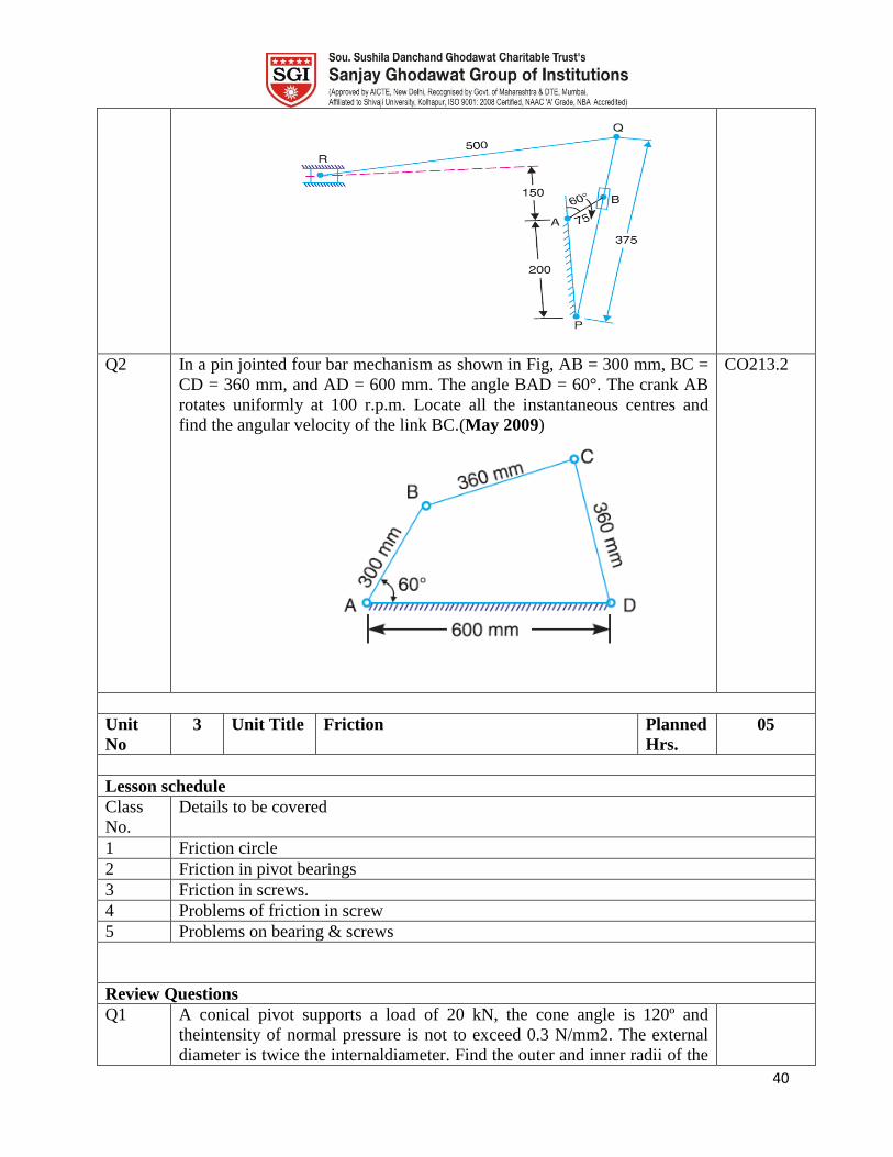
Q2 In a pin jointed four bar mechanism as shown in Fig, AB = 300 mm, BC =
CD = 360 mm, and AD = 600 mm. The angle BAD = 60°. The crank AB
rotates uniformly at 100 r.p.m. Locate all the instantaneous centres and
find the angular velocity of the link BC.(May 2009)
CO213.2
Unit
No
3 Unit Title Friction Planned
Hrs.
05
Lesson schedule
Class
No.
Details to be covered
1 Friction circle
2 Friction in pivot bearings
3 Friction in screws.
4 Problems of friction in screw
5 Problems on bearing & screws
Review Questions
Q1 A conical pivot supports a load of 20 kN, the cone angle is 120º and
theintensity of normal pressure is not to exceed 0.3 N/mm2. The external
diameter is twice the internaldiameter. Find the outer and inner radii of the
41
bearing surface. If the shaft rotates at 200 r.p.m. andthe coefficient of
friction is 0.1, find the power absorbed in friction. Assume uniform
pressure and Uniform wear.
CO213.3
Q2 A thrust shaft of a ship has 6collars of 600 mm external diameter and 300
mm internaldiameter. The total thrust from the propeller is 100 kN.Ifthe
coefficient of friction is 0.12 and speed of the engine90 r.p.m., find the
power absorbed in friction at the thrustblock, assuming l. uniform pressure
; and 2. Uniformwear
Unit
No
4 Unit Title Cams Planned
Hrs.
8
Lesson schedule
Class
No.
Details to be covered
1 Types of cams and followers.
2 Profiles of cams for specified motion of different followers.
3 Profiles of cams for specified motion of different followers
4 Spring load on the follower.
5 Jumping of follower.
6 Problems on cam profiles.
7 Problems on cam profiles.
8 Problems on cam profiles.
Review Questions
Q1 diagram of the follower when it moves uniform acceleration and
retardation
CO213.4
Q2 The following relate to a cam operating on oscillating roller follower, in
which the follower moves with S.H.M. during the lift and
returning.Minimum radius of cam=25mm, Roller radius =10mm, length of
follower arm=70mm, Distance between pivot centre and cam axis =75mm,
Angle of ascent=120, Angle of Descent=120, Angle of dwell=120, Angle
of oscillation of follower=20. Draw the cam profile
Q3 A cam, with a minimum radius of 25 mm, rotating clockwise at a uniform
speed is to be designed to give a roller follower, at the end of a valve rod,
motion described below :
1. To raise the valve through 50 mm during 120° rotation of the cam
;
2. To keep the valve fully raised through next 30°;
3. To lower the valve during next 60°; and
4.To keep the valve closed during rest of the revolution i.e. 150° ;
The diameter of the roller is 20 mm and the diameter of the cam
shaft is 25 mm.
42
Draw the profile of the cam when (a) the line of stroke of the valve rod
passes through the axis of the cam shaft, and (b) the line of the stroke is
offset 15 mm from the axis of the cam shaft.The displacement of the valve,
while being raised and lowered, is to take place with simple harmonic
motion. Determine the maximum acceleration of the valve rod when the
cam shaft rotates at 100 r.p.m. Draw the displacement, the velocity and the
acceleration diagrams for one complete revolutionof the cam
Unit
No
5 Unit Title Belts and Dynamometers Planned
Hrs.
06
Lesson schedule
Class
No.
Details to be covered
1 Types of belt drives
2 Calculation of power transmitted, Belt tension ratio
3 Actual tension in a running belt, Centrifugal and initial tension in belt
4 Slip and creep of belt
5 Classification of dynamometers
6 Study of rope brake absorption dynamometer and belt transmission dynamometer.
Review Questions
Q1 What is difference between absorption and transmission
dynamometer?Give the constructional and operational details of any one?
CO213.5
Q2 Short note on initial and centrifugal tension in belt drives.
Q3 A leather belt is required to transmit 7.5 kW from a pulley 1.2 m in
diameter,running at 250 r.p.m. The angle embraced is 165° and the
coefficient of friction between the belt and the pulley is 0.3. If the safe
working stress for the leather belt is 1.5 MPa, density of leather 1
Mg/m3and thickness of belt 10 mm, determine the width of the belt taking
centrifugal tension into account
Q4 An open flat belt drive connects two parallel shafts 1.2 m apart. Thedriving
and the driven shafts rotate at 350 r.p.m. and 140 r.p.m. respectively and
the driven pulley is400 mm in diameter. The belt is 5 mm thick and 80 mm
wide. The coefficient of friction between thebelt and pulley is 0.3 and the
maximum permissible tension in the belting is 1.4 MN/m2. Determine:
1. diameter of the driving pulley,
2. maximum power that may be transmitted by the belting,and
3. Required initial belt tension.
CO213.5
Unit
No
6 Unit Title Governors Planned
Hrs.
05
Lesson schedule
Class
No.
Details to be covered

43
1 Types of governors.
2 Porter and Hartnell governor
3 Controlling force and stability of governor
4 hunting, sensitivity, isochronisms
5 Governor effort and power, Insensitiveness of governors.
Review Questions
Q1 Explain the effort of a governor and derive the expression for the same for
porter governor.
CO213.6
Q2 Define and explain the term „mean effort and power‟ of porter governor.
Q3 A Hartnell governor having a central sleeve spring and two right-angled
bell crank levers moves between 290 r.p.m. and 310 r.p.m. for a sleeve lift
of 15 mm. The sleeve arms and the ball arms are 80 mm and 120 mm
respectively. The levers are pivoted at 120 mm from the governor axis and
mass of each ball is 2.5 kg. The ball arms are parallel to the governor axis
at the lowest equilibrium speed. Determine: 1. loads on the spring at the
lowest and the highest equilibrium speeds, and 2. stiffness of the spring.
Q4 In a spring loaded governor of the Hartnell type, the mass of each ball is 5
kg and the lift of the sleeve is 50 mm. The speed at which the governor
begins to float is 240 r.p.m., and at this speed the radius of the ball path is
110 mm. The mean working speed of the governor is 20times the range of
speed when friction is neglected. If the lengths of ball and roller arm of the
bell crank lever are 120 mm and 100 mm respectively and if the distance
between the centre of pivot of bell crank lever and axis of governor spindle
is 140 mm, determine the initial compression of the spring taking into
account the obliquity of arms.If friction is equivalent to a force of 30 N at
the sleeve, find the total alteration in speed beforethe sleeve begins to
move from mid-position.
Model Question Paper
Course Title : Theory of Machines – I
Duration 4 Hours Total
Marks
100
Instructions:
All questions are compulsory.
1. A Explain the inversions of single slider crank mechanisms 06
B Define links, pairs and mechanisms 04
C Explain the types of kinematic pairs 06
44
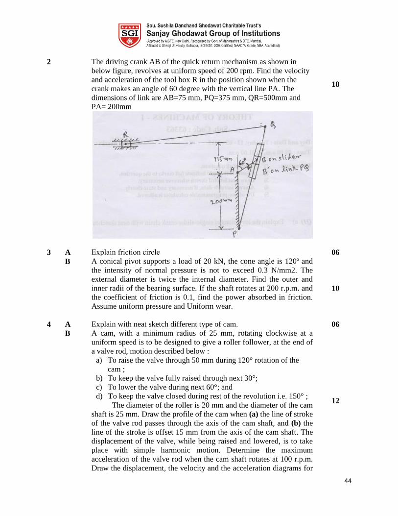
2 The driving crank AB of the quick return mechanism as shown in
below figure, revolves at uniform speed of 200 rpm. Find the velocity
and acceleration of the tool box R in the position shown when the
crank makes an angle of 60 degree with the vertical line PA. The
dimensions of link are AB=75 mm, PQ=375 mm, QR=500mm and
PA= 200mm
18
3 A Explain friction circle 06
B A conical pivot supports a load of 20 kN, the cone angle is 120º and
the intensity of normal pressure is not to exceed 0.3 N/mm2. The
external diameter is twice the internal diameter. Find the outer and
inner radii of the bearing surface. If the shaft rotates at 200 r.p.m. and
the coefficient of friction is 0.1, find the power absorbed in friction.
Assume uniform pressure and Uniform wear.
10
4 A Explain with neat sketch different type of cam. 06
B A cam, with a minimum radius of 25 mm, rotating clockwise at a
uniform speed is to be designed to give a roller follower, at the end of
a valve rod, motion described below :
a) To raise the valve through 50 mm during 120° rotation of the
cam ;
b) To keep the valve fully raised through next 30°;
c) To lower the valve during next 60°; and
d) To keep the valve closed during rest of the revolution i.e. 150° ;
The diameter of the roller is 20 mm and the diameter of the cam
shaft is 25 mm. Draw the profile of the cam when (a) the line of stroke
of the valve rod passes through the axis of the cam shaft, and (b) the
line of the stroke is offset 15 mm from the axis of the cam shaft. The
displacement of the valve, while being raised and lowered, is to take
place with simple harmonic motion. Determine the maximum
acceleration of the valve rod when the cam shaft rotates at 100 r.p.m.
Draw the displacement, the velocity and the acceleration diagrams for
12
45
one complete revolution of the cam
5 A Short note on initial and centrifugal tension in belt drives. 08
B A leather belt is required to transmit 7.5 kW from a pulley 1.2 m in
diameter running at 250 r.p.m. The angle embraced is 165° and the
coefficient of friction between the belt and the pulley is 0.3. If the safe
working stress for the leather belt is 1.5 MPa, density of leather 1
Mg/m3and thickness of belt 10 mm, determine the width of the belt
taking centrifugal tension into account
08
6 A A Hartnell governor having a central sleeve spring and two right-
angled bell crank levers moves between 290 r.p.m. and 310 r.p.m. for
a sleeve lift of 15 mm. The sleeve arms and the ball arms are 80 mm
and 120 mm respectively. The levers are pivoted at 120 mm from the
governor axis and mass of each ball is 2.5 kg. The ball arms are
parallel to the governor axis at the lowest equilibrium speed.
Determine: 1. loads on the spring at the lowest and the highest
equilibrium speeds, and 2. stiffness of the spring.
10
B Explain the Classification the governor. 06
Lab Plan
List of experiments/assignments to meet the requirements of the syllabus
Expt. No Experiment Title CO
1 Study of basic mechanisms. (Demonstration of models, Actual mechanisms) CO213.1
2 One A3 size sheet of Velocity problems by relative velocity method.
( Minimum 4 problems) CO213.2
3 One A3 size sheet of Velocity problems by Kliens construction and
Instantaneous center method. ( Minimum 4 problems) CO213.2
4 One A3 size sheet of Acceleration problems by relative acceleration
method. ( Minimum 4 problems) CO213.2
5 Verification of ratio of angular velocities of shafts connected by Hooks
joint. CO213.2
6 One A3 size sheet of Problems on cam profile. (Minimum 4 problems) CO213.4
7 Experiment on Governor characteristic for Porter or Hartnell governor. CO213.6
8 Experiment on Cam Profile CO213.4
9 Experiment on belt drives. CO213.5
10 Experiment on Dynamometer CO213.5

46
Course Plan
Course Machine Tools and Processes (MTP) Course Code ME 214
Examination
Scheme
Theory Term Work POE Total
Max. Marks 100 -- -- 100
Contact
Hours/ week
04 -- -- 4
Prepared by Ms. P.R.Patil Date 15/11/2017
Prerequisites This course requires the student to know about the basic manufacturing
process and their applications.
Course Outcomes
At the end of the course the students should be able to:
CO 214.1 Describe Importance of casting as manufacturing Process.
CO 214.2 Explain different types of forming and Plastic Shaping processes.
CO 214.3 Study Basic working principle, Configuration, Specification and classification
of machine tools.
CO 214.4 Describes the various machines used in metal cutting operations.
CO 214.5 Explain surface finish and accuracy of primary manufacturing process with
Secondary manufacturing process
CO 214.6 Describe Working Principle and Applications of nontraditional machining.
Course Contents
Unit No. Title No. of
Hours
Section I
1. Casting Processes:
a. Importance of casting as manufacturing Process, advantages and
limitations of casting processes, foundry layouts and mechanization
b. Types of moulding and core making sands and their properties,
Green sand CO2 sand, oil sand, Cold box process, investment casting,
moulding machines and core making machines.
c. Gating
-Components of gating system, functions and importance of runners
and risers, solidification control devices: chills, ceramics bricks,
directional solidification
11

47
d. Introduction to permanent mould casting process
-Gravity and pressure die-casting
-Centrifugal casting
-Continuous casting
e. Melting and Pouring
Types of fuel fired melting furnaces
-Working, Melting practices and Metallurgical control in Cupola
furnace, oil/gas fired furnaces, Induction and Arc Furnace
-Metal pouring equipments
f. Cleaning-fettling and inspection of casting
2. Forming Processes:
a. Rolling – Introduction , Hot and cold Rolling, Rolling Mill
Classification, Defects in Rolling,
b. Forging- Introduction, Hand Forging Operations, Forging Machines
(board Hammer, Air and Steam, Hydraulic Hammer) Open and
Closed Die Forging, Defects in Forging
c. Extrusion- Introduction, Direct , Indirect , Tube , Impact and
Hydraulic Extrusion, Defects in Extrusion
d. Drawing – Introduction and Types of Wire, rod and pipe drawing,
Defects in Drawing.
11
3. Plastic Shaping:
Introduction to blow moulding, injection moulding, extrusion,
calendaring and thermo forming
04
4. Machine Tools for Metal Cutting:
Digital logic, number systems, logic gates, Boolean algebra, a. Lathe:
Introduction, Working principle, types, specifications, principle parts,
accessories, attachments, and various lathe operations, Calculations of
Change gears for thread cutting.
b. Capstan, turret lathe- Principle parts, Working, comparison with
centre lathe, Turret indexing mechanism, Bar feeding mechanism,
Turret tool holders.
c. Boring Machines-Horizontal and vertical boring machine,
Construction and operation, boring tools and bars. Introduction to Jig
boring-machine
d. Drilling Machines - Classification of drilling machines,
Construction and working of radial drilling machine,
Variousaccessories and various operations.
11
5. Machine Tools for Metal Cutting:
a. Shaping Machine - Types-crank shaper, hydraulic shaper, Crank
and slotted link quick return mechanism, Table feed mechanism,
Variousoperations.
b. Planing Machine- Types-standard double housing planer, principle
parts, table drive and feed mechanism, Variousoperations.
c. Milling Machine - Classification of milling machines, construction
and working of column and knee type, milling machines, milling
operations, Study of standard accessories- dividing head, Rotary table,
11
48
Gear cutting on milling machine, Change gear calculations, vertical
milling attachment for horizontal milling machine
d. Gear Manufacturing Processes -Study of various processes like gear
shaping, Gear hobbing. Gear finishing processes –Gear shaving, Gear
burnishing and gear rolling.
6. Nonconventional Machining:
Fundamental principle, machining unit, tool material, advantages,
limitations and applications of Abrasive Jet Machining, Electrical
Discharge machining, Electro- Chemical machining, Laser beam
machining, Ultrasonic machining, Water jet machining
04
Reference Books:
Sr.
No.
Title of Book Author Publisher/Edition Units
1. Manufacturing Technology-
Foundry, Forming and Welding
P. N. Rao Tata McGraw-Hill 1,2,3
2. Principles of Foundry Technology P.L. Jain 1,2,3,4,5
3. A Textbook of Production
Technology (Manufacturing
Processes)
P.C. Sharma 1,2,3,4,5,6
4. Workshop Technology vol. II B.S.
Raghuvanshi
5-6
5 Elements of Workshop Technology
vol. II
W. A. J.
Chapman
5-6
6
Production technology S.K.HajraCh
oudhury and
A.K.
HajraChoudh
ury
6
7 Principles of metal casting R. K. Jain Khanna Publishers 4-5
Scheme of Marks
Unit No. Title Marks
1 Casting Processes
2 Forming Processes
3 Plastic Shaping
4 Machine Tools for Metal Cutting
5 Machine Tools for Metal Cutting
49
6 Nonconventional Machining
Course Unitization
Unit Course
Outcomes
Internal
Assessments
Course end
survey
No. Title
CAT-I
Assignments
and Quiz
1 Casting Processes CO 214.1
2 Forming Processes CO 214.2
3 Plastic Shaping CO 214.3
4 Machine Tools for Metal
Cutting
CO 214.4
CAT-II 5 Machine Tools for Metal
Cutting
CO 214.5
6 Nonconventional
Machining
CO 214.6
Unit wise Lesson Plan
Section I
Unit No 1 Unit Title Casting Processes Planned
Hrs.
11
Unit Outcomes
At the end of this unit the students should be able to:
UO1 Describe Importance of casting as manufacturing Process. CO 214.1
UO2 Explain core making &Cold box process. CO 214.1
UO3 Compare Centrifugal casting & Continuous casting CO 214.1
UO4 Describe Oil/gas fired furnaces & Arc Furnace. CO 214.1
Lesson schedule
Class
No.
Details to be covered
1 Importance of casting as manufacturing Process, advantages and limitations of casting
processes
2 Foundry layouts and mechanization, Types of moulding and core making sands and
their properties
50
3 Green sand CO2 sand, oil sand, Cold box process, investment casting, moulding
machines and core making machines.
4 Components of gating system, functions and importance of runners and risers,
5 Solidification control devices: chills, ceramics bricks, directional solidification
6 Introduction to permanent mould casting process
-Gravity and pressure die-casting
-Centrifugal casting
-Continuous casting
7 Types of fuel fired melting furnaces
8 Working, Melting practices and Metallurgical control in Cupola furnace
9 Oil/gas fired furnaces, Induction and Arc Furnace
10 Metal pouring equipments
11 Cleaning-fettling and inspection of casting
Review Questions
Q1 State advantages and limitations of casting processes. CO1
Q2 Explain the getting system in casting and its importance. CO 214.1
Q3 State the uses of core and the machines used to prepare core. CO 214.1
Q4 List down the properties of green sand. CO 214.1
Q5 Write a short on Centrifugal casting. CO 214.1
Q6 Write a short on Continuous casting. CO 214.1
Q7 Describe Gravity and pressure die-casting process. CO 214.1
Q8 Describe ant one fuel fired melting furnace. CO 214.1
Unit No 2 Unit Title Forming Processes Planned
Hrs.
11
Unit Outcomes
At the end of this unit the students should be able to:
UO1 Compare Hot and cold Rolling CO 214.2
UO2 Describe working of Forging Machines. CO 214.2
UO3 Explain the term extrusion. CO 214.2
UO4 Explain the rod & pipe drawing CO 214.2
Lesson schedule
Class Details to be covered
51
No.
1 Rolling – Introduction
2 Hot and cold Rolling
3 Rolling Mill Classification
4 Forging- Introduction, Hand Forging Operations, Forging Machines
5 Board Hammer, Air and Steam, Hydraulic Hammer
6 Open and Closed Die Forging, Defects in Forging
7 Extrusion- Introduction, Direct , Indirect , Tube , Impact and Hydraulic Extrusion,
8 Defects in Extrusion
9 Drawing – Introduction and Types of Wire
10 Rod and pipe drawing, Defects in Drawing
11 Numerical
Review Questions
Q1 What do you understand by recrystallisation and recrystalisation temp. ? CO 214.2
Q2 What is hot working? What are its advantages & disadvantages? CO 214.2
Q3 Sketch & describes the different types of rolls used in rolling mills. CO 214.2
Q4 Describe the process of hot extrusion of tubes. CO 214.2
Q5 What is impact extrusion? Explain this process and its application. CO 214.2
Q6 Describe with sketch the working of a pneumatic power hammer. CO 214.2
Q7 Explain the drawing process. CO 214.2
Q8 With a neat sketch explain the open & die forging. CO 214.2
Unit No 3 Unit Title Plastic Shaping Planned
Hrs.
03
Unit Outcomes
At the end of this unit the students should be able to:
UO1 Explain injection moulding process. CO 214.3
UO2 Describe Calendaring and thermo forming methods. CO 214.3
Lesson schedule
Class
No.
Details to be covered
1 Introduction to blow moulding, extrusion,
2 Injection moulding
3 Calendaring and thermo forming
52
Review Questions
Q1 With a neat sketch explain blow moulding. CO 214.3
Q2 With a neat sketch explain Injection moulding. CO 214.3
Q3 Write a note on Calendaring and thermo forming. CO 214.3
Unit No 4 Unit Title Machine Tools for Metal Cutting Planne
d Hrs.
11
Unit Outcomes
At the end of this unit the students should be able to:
UO1 Explain the working, construction of different types of lathe. CO 214.4
UO2 Discuss the lathe operations. CO 214.4
UO3 Describe the various accessories and attachments used in lathe machine. CO 214.4
UO4 Discuss difference between capstan and turret lathes CO 214.4
UO5 Explain the attachments related to same. CO 214.4
UO6 Describe the indexing of Capstan and turret lathes CO 214.4
UO7 Explain the working principle of drilling machine. CO 214.4
UO8 Discuss the operations and applications of drilling machine CO 214.4
Lesson schedule
Class
No.
Details to be covered
1 Lathe: Introduction, Working principle, specifications
2 Types of lathes
3 Principle parts &accessories of lathe
4 Attachments, and various lathe operations
5 Calculations of Change gears for thread cutting.
6 Capstan, turret lathe- Principle parts, Working, comparison with centre lathe,
7 Turret indexing mechanism, Bar feeding mechanism, Turret tool holders.
8 Boring Machines-Horizontal and vertical boring machine,
9 Construction and operation, boring tools and bars. Introduction to Jig boring-machine
10 Drilling Machines - Classification of drilling machines, Construction and working of
radial drilling machine,.
11 Variousaccessories and various operations
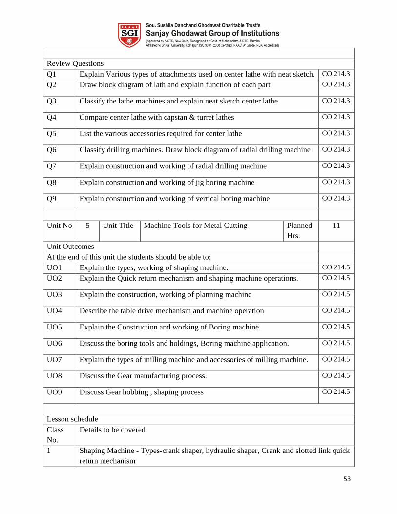
53
Review Questions
Q1 Explain Various types of attachments used on center lathe with neat sketch. CO 214.3
Q2 Draw block diagram of lath and explain function of each part CO 214.3
Q3 Classify the lathe machines and explain neat sketch center lathe CO 214.3
Q4 Compare center lathe with capstan & turret lathes CO 214.3
Q5 List the various accessories required for center lathe CO 214.3
Q6 Classify drilling machines. Draw block diagram of radial drilling machine CO 214.3
Q7 Explain construction and working of radial drilling machine CO 214.3
Q8 Explain construction and working of jig boring machine CO 214.3
Q9 Explain construction and working of vertical boring machine CO 214.3
Unit No 5 Unit Title Machine Tools for Metal Cutting Planned
Hrs.
11
Unit Outcomes
At the end of this unit the students should be able to:
UO1 Explain the types, working of shaping machine. CO 214.5
UO2 Explain the Quick return mechanism and shaping machine operations. CO 214.5
UO3 Explain the construction, working of planning machine CO 214.5
UO4 Describe the table drive mechanism and machine operation CO 214.5
UO5 Explain the Construction and working of Boring machine. CO 214.5
UO6 Discuss the boring tools and holdings, Boring machine application. CO 214.5
UO7 Explain the types of milling machine and accessories of milling machine. CO 214.5
UO8 Discuss the Gear manufacturing process. CO 214.5
UO9 Discuss Gear hobbing , shaping process CO 214.5
Lesson schedule
Class
No.
Details to be covered
1 Shaping Machine - Types-crank shaper, hydraulic shaper, Crank and slotted link quick
return mechanism

54
2 Table feed mechanism &Variousoperations of shaping machine
3 Planing Machine- Types-standard double housing planer, principle parts
4 Table drive and feed mechanism &Variousoperations of planning machine.
5 Milling Machine - Classification of milling machines, construction and working of
column and knee type. Change
6 Various milling machines &milling operations
7 Study of standard accessories- dividing head, Rotary table, Gear cutting on milling
machine
8 gear calculations, vertical milling attachment for horizontal milling machine
9 Gear Manufacturing Processes -Study of various processes like gear shaping, Gear
hobbing.
10 Gear finishing processes –Gear shaving process.
11 Gear burnishing and gear rolling.
Review Questions
Q1 Write a short on planning machine CO 214.5
Q2 Write a short on double housing planner CO 214.5
Q3 Explain table drive and feed mechanism of planner with neat diagram CO 214.5
Q4 Write a short note on table drive and feed mechanism of planner CO 214.5
Q5 Explain with neat sketch construction & working of vertical milling
attachments for horizontal milling machine
CO 214.5
Q6 Write a short note on milling operation CO 214.5
Q7 Describe in detail gear cutting on milling machine CO 214.5
Q8 Explain with neat sketch construction & working of plain dividing head CO 214.5
Q9 List various gear manufacturing process CO 214.5
Q10 Write a short note on
Gear hobbing
Gear shaving
Gear burnishing
CO 214.5
Q11 Explain gear burnishing & gear rolling process with neat sketch CO 214.5
Q12 Explain the process of gear burnishing in detail CO 214.5
Unit No 6 Unit Title Nonconventional Machining Planne
d Hrs.
04
Unit Outcomes

55
At the end of this unit the students should be able to:
UO1 Explain Advantages, limitations and applications of Abrasive Jet
Machining.
CO 214.6
UO2 Describe working of Ultrasonic machining &Water jet machining CO 214.6
Lesson schedule
Class
No.
Details to be covered
1 Fundamental principle, machining unit, tool material, Electrical Discharge machining.
2 Advantages, limitations and applications of Abrasive Jet Machining
3 Electro- Chemical machining, Laser beam machining
4 Ultrasonic machining, Water jet machining
Review Questions
Q1 Explain the electrochemical machining with neat sketch. CO 214.6
Q2 Explain the Laser beam machining with neat sketch. CO 214.6
Q3 With neat sketch explain Ultrasonic machining. CO 214.6
Q4 Write a short note on Water jet machining CO 214.6
Model Question Paper
Course Title : Machine Tools and Processes Duration Marks
3 Hours 100
Instructions:
1] Attempt any three questions from each section.
2] Figure to right indicates full marks.
3] Assume necessary data if required.
Q. Marks
1. A Describe ant one fuel fired melting furnace. 08
B Write a short on Continuous casting. 08
OR
C Explain the getting system in casting and its importance. 08
2. A Describe with sketch the working of a pneumatic power hammer. 08
B What is impact extrusion? Explain this process and its application. 08
OR
C What is hot working? What are its advantages & disadvantages? 08
3 A With a neat sketch explain blow moulding. 10
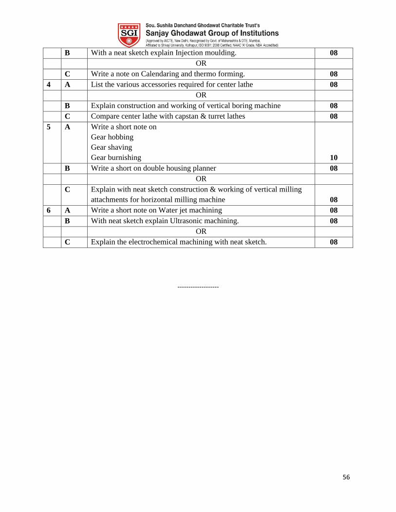
56
B With a neat sketch explain Injection moulding. 08
OR
C Write a note on Calendaring and thermo forming. 08
4 A List the various accessories required for center lathe 08
OR
B Explain construction and working of vertical boring machine 08
C Compare center lathe with capstan & turret lathes 08
5 A Write a short note on
Gear hobbing
Gear shaving
Gear burnishing 10
B Write a short on double housing planner 08
OR
C Explain with neat sketch construction & working of vertical milling
attachments for horizontal milling machine 08
6 A Write a short note on Water jet machining 08
B With neat sketch explain Ultrasonic machining. 08
OR
C Explain the electrochemical machining with neat sketch. 08
-------------------