
Service Manual - Kranlyft Group
358
Service Manual Mini-Crawler Crane 104ME-SM1910-00 The parts numbers and lists written in this service manual are the references for the services such as disassembling and assembling. Be sure to ALWAYS refer to the latest parts catalog (the latest information) before ordering any part, since the parts and the model numbers are subject to change during the endless improvements and changes of our Machine.
-
Upload
khangminh22 -
Category
Documents
-
view
2 -
download
0
Transcript of Service Manual - Kranlyft Group

Service Manual
Mini-Crawler Crane
104ME-SM1910-00
The parts numbers and lists written in this service manual are the references for the services such as disassembling and assembling. Be sure to ALWAYS refer to the latest parts catalog (the latest information) before ordering any part, since the parts and the model numbers are subject to change during the endless improvements and changes of our Machine.

0-1
CONTENTS
Item Page
GENERAL 1-1
1. SPECIFICATION DIMENSIONAL DRAWING 1-2
2. DIMENSIONAL DRAWING OF OUTRIGGER WIDTH 1-3
3. PRINCIPLE SPECIFICATION LIST 1-4
3.1 STANDARD SPECIFICATION 1-4
3.2 ENGINES AND ELECTRIC MOTER SPECIFICATION 1-5
4. WORKING RADIUS AND LIFTING HEIGHT 1-7
5. WORKING RADIUS AND LIFTING HEIGHT (PICK & CARRY) 1-8
6. TOTAL RATED LOAD CHART 1-9
[1] TOTAL RATED LOAD CHART AT WIRE ROPE 4 FALLS 1-9
[2] TOTAL RATED LOAD CHART AT WIRE ROPE 2 FALLS 1-10
[3] TOTAL RATED LOAD CHART AT WIRE ROPE SINGLE FALL 1-11
7. CRANE STANDARD PRESSURE AND OPERATING TIMETABLE 1-12
7.1 OUTRIGGER 1-12
7.2 CRANE 1-12
7.3 TRAVELLING OPERATION 1-12
8. POWER TRAIN DRAWING 1-13
CONSTRUCTION & MAINTENANCE 2-1
1. HYDRAULIC CIRCUIT DIAGRAM 2-3
1.1 HYDRAULIC UNITS LAYOUT DIAGRAM 2-5
2. HYDRAULIC PIPING DIAGRAM 2-8
2.1 CRANE ROTATING PARTS (rotary joint - winch / derricking / telescopic cylinder) 2-8
2.2 CRANE FIXED PARTS (crane control valve - rotary joint / slewing motor) 2-10
2.3 TRAVEL LINE (travel control valve - terminal assembly - travel motor) 2-14
2.4 OUTRIGGER LINES 2-16
[1] Outrigger control valve – OR select valve – OR / Slide cylinder FR out (front right side out) 2-20
[2] Outrigger control valve – OR select valve – OR / Slide cylinder FR in (front right side in) 2-21
[3] Outrigger control valve – OR select valve – OR / Slide cylinder FL out (front left side out) 2-22
[4] Outrigger control valve – OR select valve – OR / Slide cylinder FL in (front left side in) 2-23
[5] Outrigger control valve – OR select valve – OR / Slide cylinder RR out (rear right side out) 2-24
[6] Outrigger control valve – OR select valve – OR / Slide cylinder RR in (rear right side in) 2-25
[7] Outrigger control valve – OR select valve – OR / Slide cylinder RL out (rear left side out) 2-26
[8] Outrigger control valve – OR select valve – OR / Slide cylinder RL in (rear left side in) 2-27
2.5 PUMP LINE 2-28
[1] Hydraulic oil tank - Pump 2-30
[2] Pump - Travel control valve 2-30
[3] Travel control valve – crane control valve / merge valve - OR control valve 2-31
2.6 TANK / DRAIN LINE 2-32
[1] Crane control valve - manifold block - oil cooler - tank (return filter) 2-34
[2] OR Control valve - travel control valve - manifold block 2-34
[3] Travel motor - terminal B - hydraulic oil tank 2-35
[4] Slewing motor - rotary joint - terminal B - hydraulic oil tank” 2-35
[5] Merge valve - speed increase valve - hydraulic oil tank 2-36
2.7 PILOT LINE 2-38
[1] Crane control valve - OR control valve - merge valve 2-40
[2] Travel valve - speed increase valve - travel motor 2-40
0-2
Item Page
2.8 ELECTRIC POWERED LINE 2-42
[1] Hydraulic pump for electric operations - hydraulic pump for engine / hydraulic oil tank 2-43
3. TANK 2-44
3.1 HYDRAULIC TANK 2-44
3.2 FUEL TANK 2-46
3.2.1 FUEL LEVEL SENSOR 2-48
4. RETURN MANI-BLOCK 2-49
5. CHECK VALVE 2-50
6. ENGINE ASSEMBLY 2-52
6.1 ENGINE ASSEMBLY 3TNV88F-EPMB Yanmar 2-52
6.2 ENGINE MODEL 2-53
6.3 NAME OF EACH SECTION 2-54
6.4 CERTIFICATION NAME PLATE 2-55
6.4.1 EMISSION CONTROL CERTIFICATION NAME PLATE 2-55
6.5 DIESEL FUEL 2-56
6.5.1 FUEL SYSTEM 2-56
6.5.2 USE OF ADEQUATE FUELS 2-56
6.5.3 DIESEL FUEL SPECIFICATIONS 2-57
6.5.4 BIO-DIESEL FUELS 2-57
6.5.5 PRIMING THE FUEL SYSTEM 2-58
6.6 COOLANT 2-60
6.6.1 COOLANT SYSTEM 2-60
6.6.2 USE OF ADEQUATE COOLANT 2-60
6.6.3 ENGINE COOLANT SPECIFICATIONS 2-60
6.7 LUBRICATING OIL 2-61
6.7.1 LUBRICATING SYSTEM 2-61
6.7.2 USE OF ADEQUATE LUBRICANT 2-61
6.7.3 ENGINE OIL SPECIFICATIONS 2-62
6.8 PERIODIC MAINTENANCE SCHEDULE 2-63
6.9 TROUBLE SHOOTING 2-64
6.10 FUEL PIPING 2-68
7. HYDRAULIC PUMP 2-70
7.1 HYDRAULIC PUMP FOR ENGINE 2-70
7.1.1 APPEARANCE AND SPECIFICATIONS 2-70
7.2 HYDRAULIC PUMP FOR ELECTRIC OPERATIONS 2-71
7.2.1 APPEARANCE AND SPECIFICATIONS 2-71
7.3 TROUBLE SHOOTING 2-72
8. TRAVEL CONTROL VALVE 2-74
8.1 EXTERIOR VIEW AND SPECIFICATIONS 2-74
8.2 INNER PARTS 2-75
8.3 INSPECTION AND ADJUSTMENT 2-76
8.4 TROUBLE SHOOTING 2-77
9.TRAVELING MOTOR 2-78
9.1 EXTERIOR VIEW AND SPECIFICATIONS 2-78
9.2 INNER PARTS 2-79
9.2.1 OUTLINE 2-79
9.2.2 BASICS OF FUNCTIONALITY 2-80
9.2.3 FUNCTION OF AUTOMATIC CONTROL VALVE 2-82
9.2.4 FUNCTION OF COUNTER BALANCE VALVE 2-84
9.2.5 FUNCTION OF PARKING BRAKE 2-85
0-3
Item Page
9.3 PRECAUTIONS FOR USE 2-86
9.3.1 INSTALLATION 2-86
9.3.2 PIPING 2-86
9.3.3 LUBRICATING OIL FOR GEARS 2-87
9.3.4 GENERAL PRECAUTIONS 2-87
10. CRANE CONTROL VALVE 2-88
10.1 EXTERIOR VIEW AND SPECIFICATIONS 2-88
10.2 HYDRAULIC CIRCUIT DIAGRAM 2-89
10.3 RGB BLOCK 2-90
10.4 ACCELERATOR BLOCK 2-92
10.5 FUNCTION BLOCK (DERRICK, WINCH, TELESCOPIC, SLEWING) 2-92
10.6 SOLENOID VALVE FUNCTIONING PRINCIPLE 2-93
11. OUTRIGGER CONTROL VALVE 2-96
11.1 EXTERIOR VIEW AND SPECIFICATIONS 2-96
11.2 INNER PARTS 2-98
12. OUTRIGGER SELECT VALVE 2-100
12.1 EXTERIOR VIEW AND SPECIFICATIONS 2-100
12.2 INNER PARTS 2-101
13. CRANE CIRCUIT CONFLUENCE VALVE 2-102
13.1 EXTERIOR VIEW and SPECIFICATIONS 2-102
13.2 INNER PARTS 2-103
13.3 INSPECTION AND ADJUSTMENT 2-104
13.4 TROUBLE SHOOTING 2-104
14. TRAVELING SPEED SELECT VALVE 2-106
14.1 EXTERIOR VIEW AND SPECIFICATIONS 2-106
14.2 INSPECTION AND ADJUSTMENT 2-107
14.3 TROUBLE SHOOTING 2-107
15. ROTARY JOINT 2-108
15.1 EXTERIOR VIEW AND SPECIFICATIONS 2-108
15.2 INNER PARTS 2-109
16. HOOK BLOCK 2-110
16.1 HOOK BLOCK INSPECTION 2-112
17. BOOM 2-114
18. TELESCOPIC AND DERRICK CYLINDER 2-118
18.1 TELESCOPIC CYLINDER 2-118
18.2 TELESCOPIC CYLINDER HYDRAULIC CIRCUIT SYSTEM 2-120
18.3 COUNTER BALANCE VALVE (FOR TELESCOPIC AND DERRICK CYLINDER) 2-121
18.3.1 STRUCTURE 2-121
18.3.2 TROUBLE SHOOTING 2-121
18.3.3 FUNCTION 2-122
18.4 SEQUENCE VALVE (FOR TELESCOPIC CYLINDER) 2-123
18.4.1 FUNCTION 2-123
18.5 MECHANICAL CHECK VALVE (FOR TELESCOPIC CYLINDER) 2-124
18.6 LEFT SIDE DERRICK CYLINDER 2-126
18.7 RIGHT SIDE DERRICK CYLINDER 2-128
19. WINCH 2-130
19.1 WINCH EXTERIOR VIEW 2-130
19.2 WINCH UNIT EXTERIOR VIEW 2-132
19.2.1 OUTLINE OF WINCH UNIT 2-133
19.3 HYDRAULIC OIL MOTOR 2-134
0-4
Item Page
19.3.1 INNER PARTS 2-134
19.3.2 OPERATIONAL TEST 2-135
19.3.3 BASICS OF FUNCTIONALITY 2-135
19.3.4 TROUBLE SHOOTING 2-136
19.4 WINCH REDUCTION GEAR 2-138
19.5 OIL REPLACEMENT IN WINCH REDUCTION GEAR CASE 2-139
19.6 REPLACEMENT WINCH WIRE ROPE 2-142
20. SLEWING SYSTEM 2-144
20.1 EXTERIOR VIEW 2-144
20.1.1 SLEWING BEARING WOBBLE LIMIT TOLERANCE 2-145
20.2 SLEWING REDUCTION GEAR 2-146
20.3 HYDRAULIC OIL MOTOR INNER PARTS 2-147
20.4 SLEWING MOTOR TROUBLE SHOOTING 2-148
21. OUTRIGGER 2-150
21.1 FRONT OUTRIGGER 2-150
21.2 REAR OUTRIGGER 2-154
22. OUTRIGGER CYLINDER 2-154
22.1 OUTRIGGER SLIDE CYLINDER 2-154
22.2 SINGLE CHECK VALVE (FOR OUTRIGGER SLIDE CYLINDER) 2-156
22.3 FRONT OUTRIGGER CYLINDER 2-158
22.4 REAR OUTRIGGER CYLINDER 2-160
22.5 DOUBLE CHECK VALVE (FOR OUTRIGGER CYLINDER) 2-162
23. ASSEMBLY AND DISASSEMBLY OF BOOM 2-164
24. ELECTRIC CIRCUIT DIAGRAM 2-171
25. ELECTRICAL WIRING SYSTEM DIAGRAM 2-173
26. ELECTRIC SYSTEM 2-176
26.1 ENGINE HARNESS 2-176
26.2 REMOTE CONTROLLER, VALVE, ELECTRIC HARNESS 2-180
26.3 MOMENT LIMITER HARNESS 2-182
26.4 ELECTRIC HARNESS 2-184
26.5 OVER-WINDING DETECTOR 2-186
26.5.1 OPERATION PRINCIPLE 2-188
26.6 TIP-OVER WARNING DEVICE 2-190
MOMENT LIMITER 3-1
1. MOMENT LIMITER RELATED 3-2
1.1 DISPLAY UNIT AND CONVERTER 3-2
1.2 FRONT OUTRIGGER EXTENSION DETECTOR 3-4
1.3 REAR OUTRIGGER EXTENSION DETECTOR 3-6
1.4 BOOM DISPLACEMENT DETECTOR 3-8
1.4.1 ANGLE SENSOR 3-10
1.4.2 LENGTH SENSOR CODE REEL 3-12
1.5 LOAD DETECTOR 3-14
1. 5.1 PRESSURE SENSORS 3-15
1.6 MOMENT LIMITER ACCESSORY 3-16
1.7 OVER UN-WINDING DETECTOR 3-18
1.8 PICK AND CARRY RELATED 3-20
2. OUTRIGGER SAFETY DEVICE 3-22
2.1 ROTARY POSITION DETECTOR 3-22
2.2 GROUND SETTING DETECTOR 3-24
0-5
Item Page
2.3 BOOM STOWING POSITION DETECTOR 3-26
3. MOMENT LIMITER OVERVIEW AND FEATURES 3-28
4. EXTERNAL VIEW OF MOMENT LIMITER 3-30
4.1 DISPLAY UNIT 3-30
4.2 CONVERTER 3-31
5. BLOCK DIAGRAM 3-32
6. CONNECTOR DIAGRAM 3-33
7. CONNECTOR PIN ASSIGNMENT 3-34
7.1 CONVERTER CONNECTORS 3-34
7.2 DISPLAY UNIT CONNECTORS 3-35
7.2.1 DISPLAY UNIT CONNECTORS (M1) 3-35
7.2.2 DISPLAY UNIT CONNECTORS (M2) 3-35
8. INPUT/OUTPUT 3-36
8.1 CONVERTER 3-36
8.2 DISPLAY UNIT 3-37
8.2.1 DISPLAY UNIT INPUT 3-37
8.2.2 DISPLAY UNIT OUTPUT 3-38
9. DISPLAYS 3-40
10. SWITCHES 3-42
11. DISPLAY UNIT; DETAIL OF EACH SEGMENT 3-44
12. START–UP SEQUENCE 3-46
13. MOMENT LIMITER FUNCTIONS 3-46
14. DISPLAY OF SPECIFIC INDICATORS 3-47
15. OPERATION RANGE LIMITATION CONTROL 3-47
16. CALIBRATION PROCEDURE 3-48
16.1 LIST OF ITEMS 3-48
16.2 PROCEDURE 3-49
16.2.1 CALIBRATION WORK FLOW 3-49
16.2.2 CALL OUT OF CALIBRATION MODE 3-49
16.2.3 CALIBRATION OF BOOM LENGTH 3-50
16.2.4 CALIBRATION OF BOOM ANGLE 3-52
16.2.5 CALIBRATION OF WEIGHING 3-54
16.3 DISPLAY DETAILS AT CALIBRATION MODE 3-57
17. TEST MODE 3-58
17.1 CALL OUT OF TEST MODE 3-58
17.2 L01 (ROM/RAM TEST) 3-59
17.3 L02 (LED TEST) 3-59
17.4 L03 (SWITCH TEST) 3-60
17.5 L04 INPUT SIGNAL TEST 3-61
17.6 L05 OUTPUT SIGNAL TEST 3-62
17.7 L06 (LOAD FACTOR TEST) 3-63
17.8 L07 (VERIFICATION OF INPUT FROM CONVERTER) 3-63
17.9 L08 (TIME SETTING) 3-64
17.10 L09 (DISPLAY OF THE TIME TO REPLACE BUTTERIES) 3-65
18. PC MODE 3-66
18.1 MOMENT LIMITER OPERATION LOG PICKING UP PROCEDURE 3-66
18.2 MOMENT LIMITER OPERATION LOG DELETING PROCEDURE 3-71
18.3 READ MOMENT LIMITER HISTORY 3-73
19. ERROR MESSAGES 3-74
20. TROUBLE SHOOTING 3-76
0-6
Item Page
21. POINTS FOR INPUT VOLTAGE MEASUREMENT OF EACH SENSOR 3-78
INTERACTIVE REMOTE CONTROL 4-1
1. INITIAL MODE SETTING PROCEDURE 4-2
1.1 BUTTON ARRANGEMENT ON CONTROL PANEL 4-2
1.2 ESTABLISHING INITIAL MODE: 4-3
1.3 INITIAL MODE FOR USER (A MODE) 4-4
1.4 INITIAL MODE FOR SERVICE (B MODE) 4-7
1.5 INITIAL MODE FOR MAKER (C MODE) 4-10
1.6 INITIAL MODE SETTING 4-16
2. RECEIVER 4-18
2.1 STATUS DISPLAY 4-18
2.2 CONTROL PRINT CARD LACATIONS 4-20
2.2.1 MAIN PRINT CARD (UPPER SIDE) (MC9141-A) 4-20
2.2.2 MAIN PRINT CARD LCD DISPLAY (UPPER SIDE) (MC9141-A) 4-21
2.2.3 SUB PRINT CARD (LOWER SIDE) (MC9143-A) 4-22
2.2.4 SUB PRINT CARD LCD DISPLAY (LOWER SIDE) (MC9143-A) 4-23
2.3 CONNECTOR PIN ASSIGNMENT 4-24
2.4 VALVE NEUTRAL SETTING PROCEDURE 4-26
2.5 MONITOR DISPLAY MESSAGE 4-28
2.5.1 NORMAL OPERATION MESSAGE 4-28
2.6 FUSE IN THE RECEIVER 4-29
3. VOICE MESSAGES 4-31
4. TROUBLESHOOTING 4-32
ELECTRIC MOTOR 5-1
1. ELECTRIC MOTOR 5-2
2. INVERTER PANEL 5-3
2.1 STRUCTURAL DRAWING 5-4
2.2 EXTERNAL APPEARANCE AND NAME OF EACH SECTION 5-6
2.3 NAME AND CONTENT OF THE DIGITAL OPERATOR 5-7
2.4 DETAIL OF INVERTER SET ITEMS 5-9
2.5 ALARM DISPLAY AND COUNTERMEASURE 5-10
2.5.1 ALARM DISPLAY 5-10
2.5.2 FAULT MONITOR DISPLAY 5-10
2.5.3 METHOD FOR RELEASING (RESETTING) THE TRIP STATUS 5-11
2.6 LIST OF ALARM CODES 5-12
2.7 TROUBLESHOOTING 5-16
2.8 INSPECTION AND MAINTENANCE 5-22
2.8.1 REGULAR INSPECTION 5-22
2.8.2 PERIODICAL INSPECTION 5-23
2.9 DISPOSAL OF THE INVERTER 5-25
3. POWER SUPPLY BOX 5-26
4. ELECTRIC CIRCUIT DIAGRAM 5-28
1-1
GENERAL
1. SPECIFICATION DIMENSIONAL DRAWING 1-2
2. DIMENSIONAL DRAWING OF OUTRIGGER WIDTH 1-3
3. PRINCIPLE SPECIFICATION LIST 1-4
4. WORKING RADIUS AND LIFTING HEIGHT 1-7
5. WORKING RADIUS AND LIFTING HEIGHT (PICK & CARRY) 1-8
6. TOTAL RATED LOAD CHART 1-9
7. CRANE STANDARD PRESSURE AND OPERATING TIMETABLE 1-12
8. POWER TRAIN DRAWING 1-13
1-2
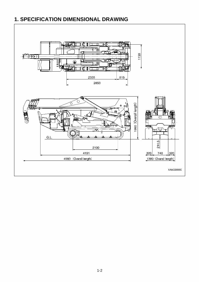
1. SPECIFICATION DIMENSIONAL DRAWING
1-3
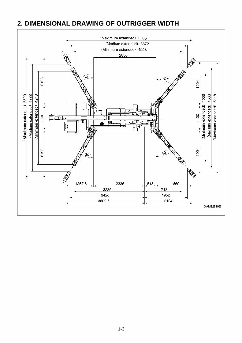
2. DIMENSIONAL DRAWING OF OUTRIGGER WIDTH
1-4
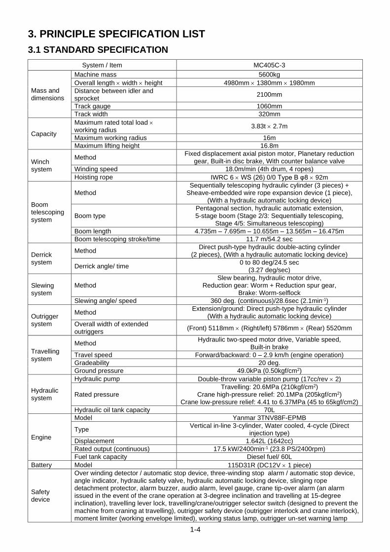
3. PRINCIPLE SPECIFICATION LIST
3.1 STANDARD SPECIFICATION
System / Item MC405C-3
Mass and dimensions
Machine mass 5600kg
Overall length width height 4980mm 1380mm 1980mm
Distance between idler and sprocket
2100mm
Track gauge 1060mm
Track width 320mm
Capacity
Maximum rated total load working radius
3.83t 2.7m
Maximum working radius 16m
Maximum lifting height 16.8m
Winch system
Method Fixed displacement axial piston motor, Planetary reduction
gear, Built-in disc brake, With counter balance valve
Winding speed 18.0m/min (4th drum, 4 ropes)
Hoisting rope IWRC 6 WS (26) 0/0 Type B φ8 92m
Boom telescoping system
Method Sequentially telescoping hydraulic cylinder (3 pieces) +
Sheave-embedded wire rope expansion device (1 piece), (With a hydraulic automatic locking device)
Boom type Pentagonal section, hydraulic automatic extension, 5-stage boom (Stage 2/3: Sequentially telescoping,
Stage 4/5: Simultaneous telescoping)
Boom length 4.735m – 7.695m – 10.655m – 13.565m – 16.475m
Boom telescoping stroke/time 11.7 m/54.2 sec
Derrick system
Method Direct push-type hydraulic double-acting cylinder
(2 pieces), (With a hydraulic automatic locking device)
Derrick angle/ time 0 to 80 deg/24.5 sec
(3.27 deg/sec)
Slewing system
Method Slew bearing, hydraulic motor drive,
Reduction gear: Worm + Reduction spur gear, Brake: Worm-selflock
Slewing angle/ speed 360 deg. (continuous)/28.6sec (2.1min-1)
Outrigger system
Method Extension/ground: Direct push-type hydraulic cylinder
(With a hydraulic automatic locking device)
Overall width of extended outriggers
(Front) 5118mm (Right/left) 5786mm (Rear) 5520mm
Travelling system
Method Hydraulic two-speed motor drive, Variable speed,
Built-in brake
Travel speed Forward/backward: 0 – 2.9 km/h (engine operation)
Gradeability 20 deg.
Ground pressure 49.0kPa (0.50kgf/cm2)
Hydraulic system
Hydraulic pump Double-throw variable piston pump (17cc/rev 2)
Rated pressure Travelling: 20.6MPa (210kgf/cm2)
Crane high-pressure relief: 20.1MPa (205kgf/cm2) Crane low-pressure relief: 4.41 to 6.37MPa (45 to 65kgf/cm2)
Hydraulic oil tank capacity 70L
Engine
Model Yanmar 3TNV88F-EPMB
Type Vertical in-line 3-cylinder, Water cooled, 4-cycle (Direct
injection type)
Displacement 1.642L (1642cc)
Rated output (continuous) 17.5 kW/2400min-1 (23.8 PS/2400rpm)
Fuel tank capacity Diesel fuel/ 60L
Battery Model 115D31R (DC12V 1 piece)
Safety device
Over winding detector / automatic stop device, three-winding stop alarm / automatic stop device, angle indicator, hydraulic safety valve, hydraulic automatic locking device, slinging rope detachment protector, alarm buzzer, audio alarm, level gauge, crane tip-over alarm (an alarm issued in the event of the crane operation at 3-degree inclination and travelling at 15-degree inclination), travelling lever lock, travelling/crane/outrigger selector switch (designed to prevent the machine from craning at travelling), outrigger safety device (outrigger interlock and crane interlock), moment limiter (working envelope limited), working status lamp, outrigger un-set warning lamp
1-5
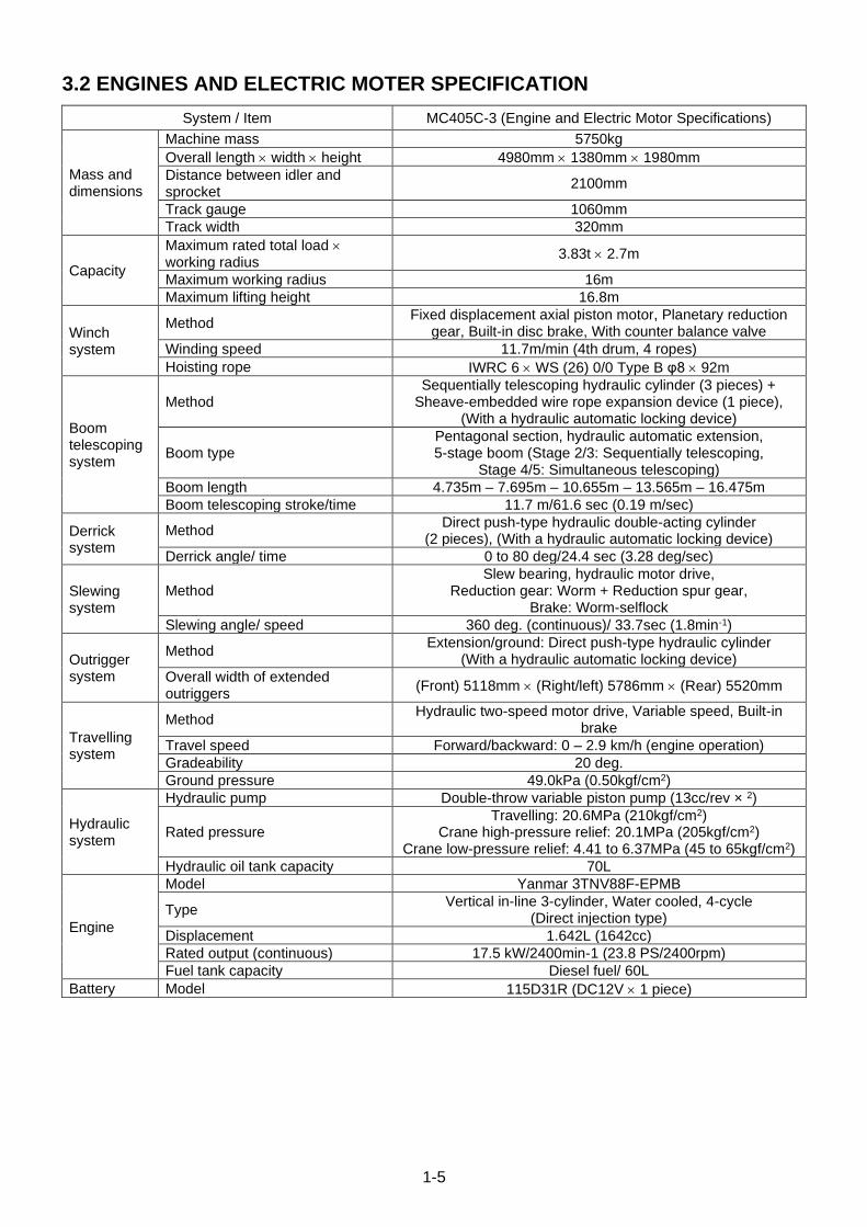
3.2 ENGINES AND ELECTRIC MOTER SPECIFICATION
System / Item MC405C-3 (Engine and Electric Motor Specifications)
Mass and dimensions
Machine mass 5750kg
Overall length width height 4980mm 1380mm 1980mm
Distance between idler and sprocket
2100mm
Track gauge 1060mm
Track width 320mm
Capacity
Maximum rated total load working radius
3.83t 2.7m
Maximum working radius 16m
Maximum lifting height 16.8m
Winch system
Method Fixed displacement axial piston motor, Planetary reduction
gear, Built-in disc brake, With counter balance valve
Winding speed 11.7m/min (4th drum, 4 ropes)
Hoisting rope IWRC 6 WS (26) 0/0 Type B φ8 92m
Boom telescoping system
Method Sequentially telescoping hydraulic cylinder (3 pieces) +
Sheave-embedded wire rope expansion device (1 piece), (With a hydraulic automatic locking device)
Boom type Pentagonal section, hydraulic automatic extension, 5-stage boom (Stage 2/3: Sequentially telescoping,
Stage 4/5: Simultaneous telescoping)
Boom length 4.735m – 7.695m – 10.655m – 13.565m – 16.475m
Boom telescoping stroke/time 11.7 m/61.6 sec (0.19 m/sec)
Derrick system
Method Direct push-type hydraulic double-acting cylinder
(2 pieces), (With a hydraulic automatic locking device)
Derrick angle/ time 0 to 80 deg/24.4 sec (3.28 deg/sec)
Slewing system
Method Slew bearing, hydraulic motor drive,
Reduction gear: Worm + Reduction spur gear, Brake: Worm-selflock
Slewing angle/ speed 360 deg. (continuous)/ 33.7sec (1.8min-1)
Outrigger system
Method Extension/ground: Direct push-type hydraulic cylinder
(With a hydraulic automatic locking device)
Overall width of extended outriggers
(Front) 5118mm (Right/left) 5786mm (Rear) 5520mm
Travelling system
Method Hydraulic two-speed motor drive, Variable speed, Built-in
brake
Travel speed Forward/backward: 0 – 2.9 km/h (engine operation)
Gradeability 20 deg.
Ground pressure 49.0kPa (0.50kgf/cm2)
Hydraulic system
Hydraulic pump Double-throw variable piston pump (13cc/rev × 2)
Rated pressure Travelling: 20.6MPa (210kgf/cm2)
Crane high-pressure relief: 20.1MPa (205kgf/cm2) Crane low-pressure relief: 4.41 to 6.37MPa (45 to 65kgf/cm2)
Hydraulic oil tank capacity 70L
Engine
Model Yanmar 3TNV88F-EPMB
Type Vertical in-line 3-cylinder, Water cooled, 4-cycle
(Direct injection type)
Displacement 1.642L (1642cc)
Rated output (continuous) 17.5 kW/2400min-1 (23.8 PS/2400rpm)
Fuel tank capacity Diesel fuel/ 60L
Battery Model 115D31R (DC12V 1 piece)
1-6
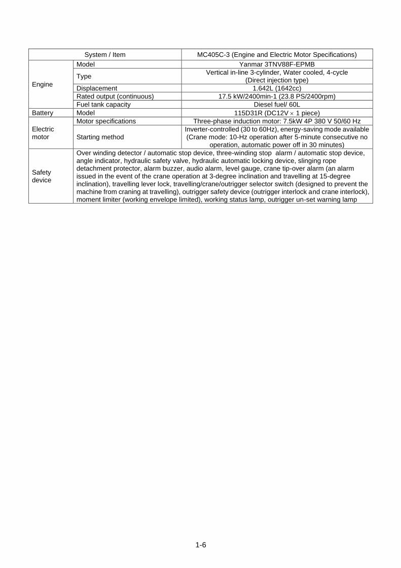
System / Item MC405C-3 (Engine and Electric Motor Specifications)
Engine
Model Yanmar 3TNV88F-EPMB
Type Vertical in-line 3-cylinder, Water cooled, 4-cycle
(Direct injection type)
Displacement 1.642L (1642cc)
Rated output (continuous) 17.5 kW/2400min-1 (23.8 PS/2400rpm)
Fuel tank capacity Diesel fuel/ 60L
Battery Model 115D31R (DC12V 1 piece)
Electric motor
Motor specifications Three-phase induction motor: 7.5kW 4P 380 V 50/60 Hz
Starting method Inverter-controlled (30 to 60Hz), energy-saving mode available (Crane mode: 10-Hz operation after 5-minute consecutive no
operation, automatic power off in 30 minutes)
Safety device
Over winding detector / automatic stop device, three-winding stop alarm / automatic stop device, angle indicator, hydraulic safety valve, hydraulic automatic locking device, slinging rope detachment protector, alarm buzzer, audio alarm, level gauge, crane tip-over alarm (an alarm issued in the event of the crane operation at 3-degree inclination and travelling at 15-degree inclination), travelling lever lock, travelling/crane/outrigger selector switch (designed to prevent the machine from craning at travelling), outrigger safety device (outrigger interlock and crane interlock), moment limiter (working envelope limited), working status lamp, outrigger un-set warning lamp
1-7
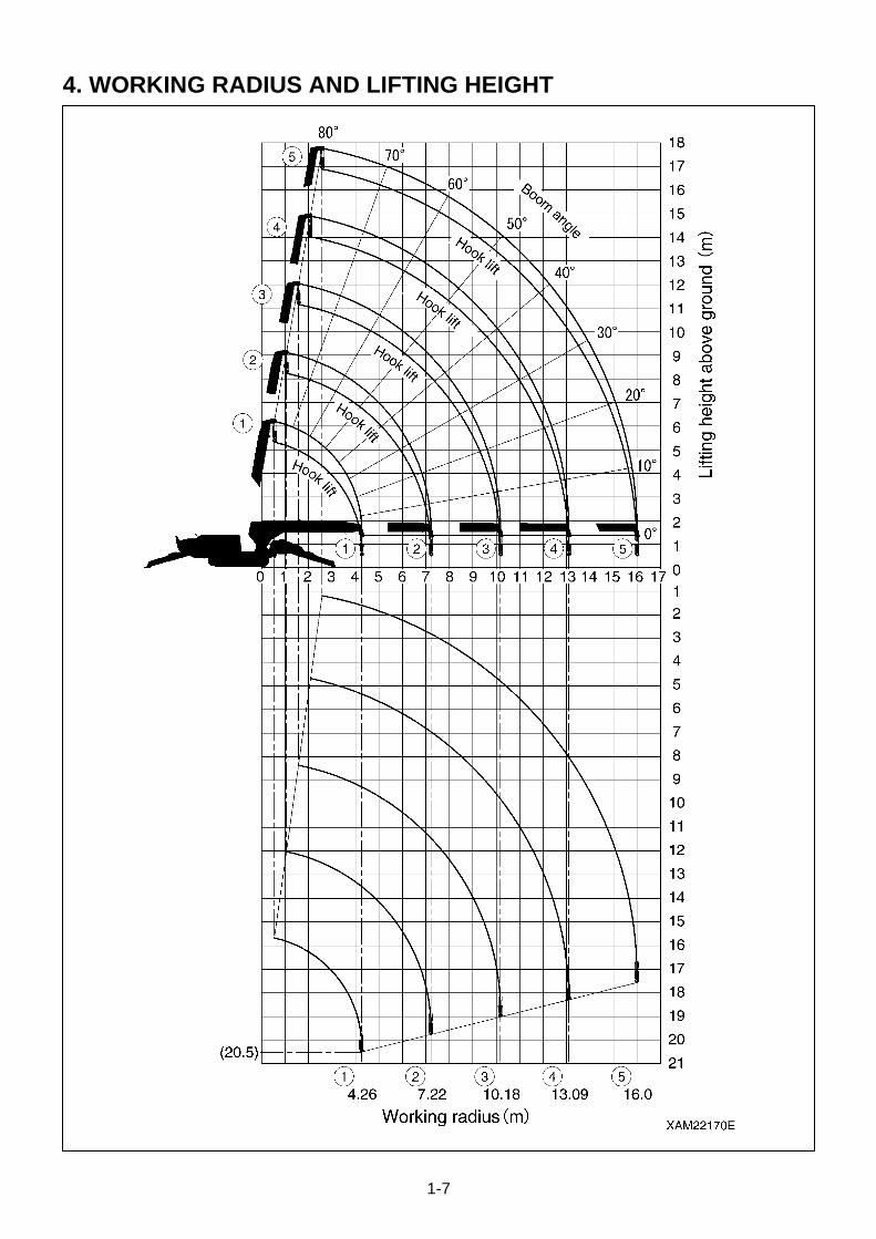
4. WORKING RADIUS AND LIFTING HEIGHT

1-8
5. WORKING RADIUS AND LIFTING HEIGHT (PICK & CARRY)
1-9
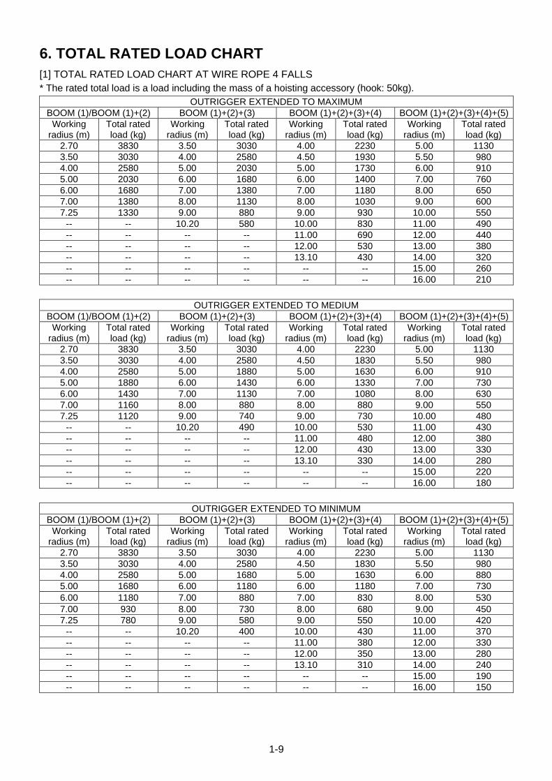
6. TOTAL RATED LOAD CHART
[1] TOTAL RATED LOAD CHART AT WIRE ROPE 4 FALLS
* The rated total load is a load including the mass of a hoisting accessory (hook: 50kg).
OUTRIGGER EXTENDED TO MAXIMUM
BOOM (1)/BOOM (1)+(2) BOOM (1)+(2)+(3) BOOM (1)+(2)+(3)+(4) BOOM (1)+(2)+(3)+(4)+(5)
Working radius (m)
Total rated load (kg)
Working radius (m)
Total rated load (kg)
Working radius (m)
Total rated load (kg)
Working radius (m)
Total rated load (kg)
2.70 3830 3.50 3030 4.00 2230 5.00 1130
3.50 3030 4.00 2580 4.50 1930 5.50 980
4.00 2580 5.00 2030 5.00 1730 6.00 910
5.00 2030 6.00 1680 6.00 1400 7.00 760
6.00 1680 7.00 1380 7.00 1180 8.00 650
7.00 1380 8.00 1130 8.00 1030 9.00 600
7.25 1330 9.00 880 9.00 930 10.00 550
-- -- 10.20 580 10.00 830 11.00 490
-- -- -- -- 11.00 690 12.00 440
-- -- -- -- 12.00 530 13.00 380
-- -- -- -- 13.10 430 14.00 320
-- -- -- -- -- -- 15.00 260
-- -- -- -- -- -- 16.00 210
OUTRIGGER EXTENDED TO MEDIUM
BOOM (1)/BOOM (1)+(2) BOOM (1)+(2)+(3) BOOM (1)+(2)+(3)+(4) BOOM (1)+(2)+(3)+(4)+(5)
Working radius (m)
Total rated load (kg)
Working radius (m)
Total rated load (kg)
Working radius (m)
Total rated load (kg)
Working radius (m)
Total rated load (kg)
2.70 3830 3.50 3030 4.00 2230 5.00 1130
3.50 3030 4.00 2580 4.50 1830 5.50 980
4.00 2580 5.00 1880 5.00 1630 6.00 910
5.00 1880 6.00 1430 6.00 1330 7.00 730
6.00 1430 7.00 1130 7.00 1080 8.00 630
7.00 1160 8.00 880 8.00 880 9.00 550
7.25 1120 9.00 740 9.00 730 10.00 480
-- -- 10.20 490 10.00 530 11.00 430
-- -- -- -- 11.00 480 12.00 380
-- -- -- -- 12.00 430 13.00 330
-- -- -- -- 13.10 330 14.00 280
-- -- -- -- -- -- 15.00 220
-- -- -- -- -- -- 16.00 180
OUTRIGGER EXTENDED TO MINIMUM
BOOM (1)/BOOM (1)+(2) BOOM (1)+(2)+(3) BOOM (1)+(2)+(3)+(4) BOOM (1)+(2)+(3)+(4)+(5)
Working radius (m)
Total rated load (kg)
Working radius (m)
Total rated load (kg)
Working radius (m)
Total rated load (kg)
Working radius (m)
Total rated load (kg)
2.70 3830 3.50 3030 4.00 2230 5.00 1130
3.50 3030 4.00 2580 4.50 1830 5.50 980
4.00 2580 5.00 1680 5.00 1630 6.00 880
5.00 1680 6.00 1180 6.00 1180 7.00 730
6.00 1180 7.00 880 7.00 830 8.00 530
7.00 930 8.00 730 8.00 680 9.00 450
7.25 780 9.00 580 9.00 550 10.00 420
-- -- 10.20 400 10.00 430 11.00 370
-- -- -- -- 11.00 380 12.00 330
-- -- -- -- 12.00 350 13.00 280
-- -- -- -- 13.10 310 14.00 240
-- -- -- -- -- -- 15.00 190
-- -- -- -- -- -- 16.00 150
1-10
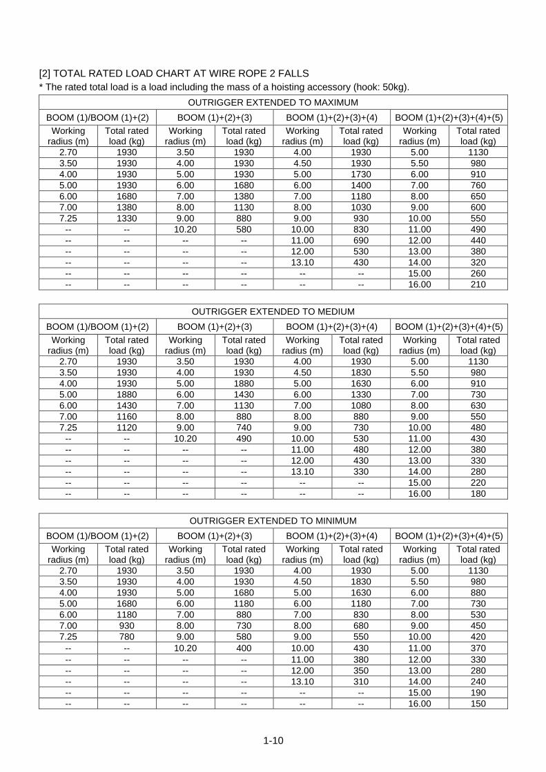
[2] TOTAL RATED LOAD CHART AT WIRE ROPE 2 FALLS
* The rated total load is a load including the mass of a hoisting accessory (hook: 50kg).
OUTRIGGER EXTENDED TO MAXIMUM
BOOM (1)/BOOM (1)+(2) BOOM (1)+(2)+(3) BOOM (1)+(2)+(3)+(4) BOOM (1)+(2)+(3)+(4)+(5)
Working radius (m)
Total rated load (kg)
Working radius (m)
Total rated load (kg)
Working radius (m)
Total rated load (kg)
Working radius (m)
Total rated load (kg)
2.70 1930 3.50 1930 4.00 1930 5.00 1130
3.50 1930 4.00 1930 4.50 1930 5.50 980
4.00 1930 5.00 1930 5.00 1730 6.00 910
5.00 1930 6.00 1680 6.00 1400 7.00 760
6.00 1680 7.00 1380 7.00 1180 8.00 650
7.00 1380 8.00 1130 8.00 1030 9.00 600
7.25 1330 9.00 880 9.00 930 10.00 550
-- -- 10.20 580 10.00 830 11.00 490
-- -- -- -- 11.00 690 12.00 440
-- -- -- -- 12.00 530 13.00 380
-- -- -- -- 13.10 430 14.00 320
-- -- -- -- -- -- 15.00 260
-- -- -- -- -- -- 16.00 210
OUTRIGGER EXTENDED TO MEDIUM
BOOM (1)/BOOM (1)+(2) BOOM (1)+(2)+(3) BOOM (1)+(2)+(3)+(4) BOOM (1)+(2)+(3)+(4)+(5)
Working radius (m)
Total rated load (kg)
Working radius (m)
Total rated load (kg)
Working radius (m)
Total rated load (kg)
Working radius (m)
Total rated load (kg)
2.70 1930 3.50 1930 4.00 1930 5.00 1130
3.50 1930 4.00 1930 4.50 1830 5.50 980
4.00 1930 5.00 1880 5.00 1630 6.00 910
5.00 1880 6.00 1430 6.00 1330 7.00 730
6.00 1430 7.00 1130 7.00 1080 8.00 630
7.00 1160 8.00 880 8.00 880 9.00 550
7.25 1120 9.00 740 9.00 730 10.00 480
-- -- 10.20 490 10.00 530 11.00 430
-- -- -- -- 11.00 480 12.00 380
-- -- -- -- 12.00 430 13.00 330
-- -- -- -- 13.10 330 14.00 280
-- -- -- -- -- -- 15.00 220
-- -- -- -- -- -- 16.00 180
OUTRIGGER EXTENDED TO MINIMUM
BOOM (1)/BOOM (1)+(2) BOOM (1)+(2)+(3) BOOM (1)+(2)+(3)+(4) BOOM (1)+(2)+(3)+(4)+(5)
Working radius (m)
Total rated load (kg)
Working radius (m)
Total rated load (kg)
Working radius (m)
Total rated load (kg)
Working radius (m)
Total rated load (kg)
2.70 1930 3.50 1930 4.00 1930 5.00 1130
3.50 1930 4.00 1930 4.50 1830 5.50 980
4.00 1930 5.00 1680 5.00 1630 6.00 880
5.00 1680 6.00 1180 6.00 1180 7.00 730
6.00 1180 7.00 880 7.00 830 8.00 530
7.00 930 8.00 730 8.00 680 9.00 450
7.25 780 9.00 580 9.00 550 10.00 420
-- -- 10.20 400 10.00 430 11.00 370
-- -- -- -- 11.00 380 12.00 330
-- -- -- -- 12.00 350 13.00 280
-- -- -- -- 13.10 310 14.00 240
-- -- -- -- -- -- 15.00 190
-- -- -- -- -- -- 16.00 150

1-11
[3] TOTAL RATED LOAD CHART AT WIRE ROPE SINGLE FALL
* The rated total load is a load including the mass of a hoisting accessory (hook: 20kg).
OUTRIGGER EXTENDED TO MAXIMUM
BOOM (1)/BOOM (1)+(2) BOOM (1)+(2)+(3) BOOM (1)+(2)+(3)+(4) BOOM (1)+(2)+(3)+(4)+(5)
Working radius (m)
Total rated load (kg)
Working radius (m)
Total rated load (kg)
Working radius (m)
Total rated load (kg)
Working radius (m)
Total rated load (kg)
2.70 970 3.50 970 4.00 970 5.00 970
3.50 970 4.00 970 4.50 970 5.50 970
4.00 970 5.00 970 5.00 970 6.00 900
5.00 970 6.00 970 6.00 970 7.00 750
6.00 970 7.00 970 7.00 970 8.00 640
7.00 970 8.00 970 8.00 970 9.00 590
7.25 970 9.00 870 9.00 920 10.00 540
-- -- 10.20 570 10.00 820 11.00 480
-- -- -- -- 11.00 680 12.00 430
-- -- -- -- 12.00 520 13.00 370
-- -- -- -- 13.10 420 14.00 310
-- -- -- -- -- -- 15.00 250
-- -- -- -- -- -- 16.00 200
OUTRIGGER EXTENDED TO MEDIUM
BOOM (1)/BOOM (1)+(2) BOOM (1)+(2)+(3) BOOM (1)+(2)+(3)+(4) BOOM (1)+(2)+(3)+(4)+(5)
Working radius (m)
Total rated load (kg)
Working radius (m)
Total rated load (kg)
Working radius (m)
Total rated load (kg)
Working radius (m)
Total rated load (kg)
2.70 970 3.50 970 4.00 970 5.00 970
3.50 970 4.00 970 4.50 970 5.50 970
4.00 970 5.00 970 5.00 970 6.00 900
5.00 970 6.00 970 6.00 970 7.00 720
6.00 970 7.00 970 7.00 970 8.00 620
7.00 970 8.00 870 8.00 870 9.00 540
7.25 970 9.00 730 9.00 720 10.00 470
-- -- 10.20 480 10.00 520 11.00 420
-- -- -- -- 11.00 470 12.00 370
-- -- -- -- 12.00 420 13.00 320
-- -- -- -- 13.10 320 14.00 270
-- -- -- -- -- -- 15.00 210
-- -- -- -- -- -- 16.00 170
OUTRIGGER EXTENDED TO MINIMUM
BOOM (1)+(2) BOOM (1)+(2)+(3) BOOM (1)+(2)+(3)+(4) BOOM (1)+(2)+(3)+(4)+(5)
Working radius (m)
Total rated load (kg)
Working radius (m)
Total rated load (kg)
Working radius (m)
Total rated load (kg)
Working radius (m)
Total rated load (kg)
2.70 970 3.50 970 4.00 970 5.00 970
3.50 970 4.00 970 4.50 970 5.50 970
4.00 970 5.00 970 5.00 970 6.00 870
5.00 970 6.00 970 6.00 970 7.00 720
6.00 970 7.00 870 7.00 820 8.00 520
7.00 920 8.00 720 8.00 670 9.00 440
7.25 770 9.00 570 9.00 540 10.00 410
-- -- 10.20 390 10.00 420 11.00 360
-- -- -- -- 11.00 370 12.00 320
-- -- -- -- 12.00 340 13.00 270
-- -- -- -- 13.10 300 14.00 230
-- -- -- -- -- -- 15.00 180
-- -- -- -- -- -- 16.00 140
1-12
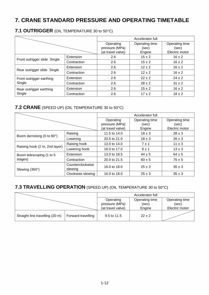
7. CRANE STANDARD PRESSURE AND OPERATING TIMETABLE
7.1 OUTRIGGER (OIL TEMPERATURE 30 to 50°C)
Accelerator full
Operating
pressure (MPa)
(at travel valve)
Operating time
(sec)
Engine
Operating time
(sec)
Electric motor
Front outrigger slide Single Extension 2.6 15 ± 2 16 ± 2
Contraction 2.6 15 ± 2 16 ± 2
Rear outrigger slide Single Extension 2.6 12 ± 2 16 ± 2
Contraction 2.6 12 ± 2 16 ± 2
Front outrigger earthing
Single
Extension 2.6 22 ± 2 24 ± 2
Contraction 2.6 28 ± 2 31 ± 2
Rear outrigger earthing
Single
Extension 2.6 15 ± 2 16 ± 2
Contraction 2.6 17 ± 2 18 ± 2
7.2 CRANE (SPEED UP) (OIL TEMPERATURE 30 to 50°C)
Accelerator full
Operating
pressure (MPa)
(at travel valve)
Operating time
(sec)
Engine
Operating time
(sec)
Electric motor
Boom derricking (0 to 80°) Raising 11.5 to 14.0 18 ± 3 28 ± 3
Lowering 20.5 to 21.0 18 ± 3 26 ± 3
Raising hook (2 m, 2nd layer) Raising hook 13.0 to 14.0 7 ± 1 11 ± 3
Lowering hook 16.0 to 17.0 8 ± 1 13 ± 3
Boom telescoping (1 to 5
stages)
Extension 13.0 to 18.5 44 ± 5 64 ± 5
Contraction 20.0 to 21.5 60 ± 5 75 ± 5
Slewing (360°)
Counterclockwise
slewing 16.0 to 18.0 25 ± 3 35 ± 3
Clockwise slewing 16.0 to 18.0 25 ± 3 35 ± 3
7.3 TRAVELLING OPERATION (SPEED UP) (OIL TEMPERATURE 30 to 50°C)
Accelerator full
Operating
pressure (MPa)
(at travel valve)
Operating time
(sec)
Engine
Operating time
(sec)
Electric motor
Straight line travelling (20 m) Forward travelling 9.5 to 11.5 22 ± 2
1-13
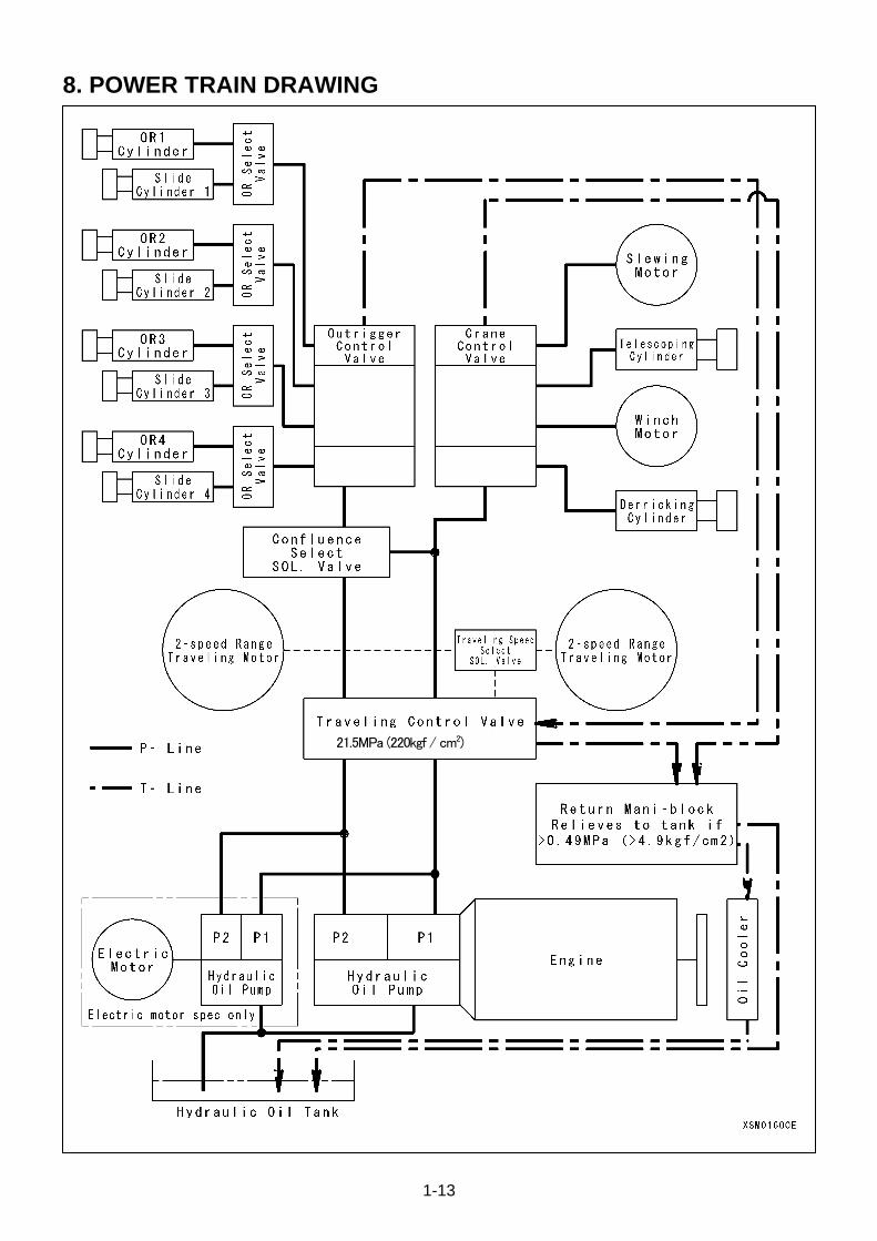
8. POWER TRAIN DRAWING
21.5MPa (220kgf / cm2)

1-14
This Page Intentionally Left Blank.
2-1
CONSTRUCTION & MAINTENANCE
1. HYDRAULIC CIRCUIT DIAGRAM 2-3
2. HYDRAULIC PIPING DIAGRAM 2-8
3. TANK 2-44
4. RETURN MANI-BLOCK 2-49
5. CHECK VALVE 2-50
6. ENGINE ASSEMBLY 2-52
7. HYDRAULIC PUMP 2-70
8. TRAVEL CONTROL VALVE 2-74
9. TRAVELING MOTOR 2-78
10. CRANE CONTROL VALVE 2-88
11. OUTRIGGER CONTROL VALVE 2-96
12. OUTRIGGER SELECT VALVE 2-100
13. CRANE CIRCUIT CONFLUENCE VALVE 2-102
14. TRAVELING SPEED SELECT VALVE 2-106
15. ROTARY JOINT 2-108
16. HOOK BLOCK 2-110
17. BOOM 2-114
18. TELESCOPIC AND DERRICK CYLINDER 2-118
19. WINCH 2-130
20. SLEWING SYSTEM 2-144
21. OUTRIGGER 2-150
22. OUTRIGGER CYLINDER 2-154
23. ASSEMBLY AND DISASSEMBLY OF BOOM 2-164
24. ELECTRIC CIRCUIT DIAGRAM 2-171
25. ELECTRICAL WIRING SYSTEM DIAGRAM 2-173
26. ELECTRIC SYSTEM 2-176

2-2
This Page Intentionally Left Blank.
2-3
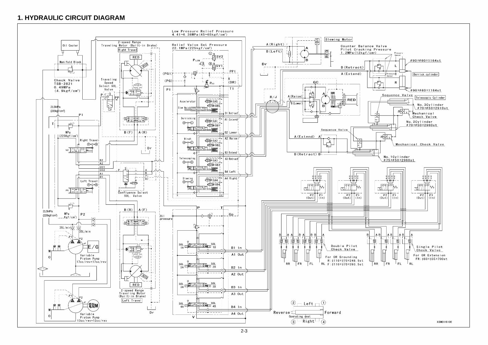
1. HYDRAULIC CIRCUIT DIAGRAM
21.5MPa
(220kgf / cm2)
21.5MPa
(220kgf / cm2)

2-4
This Page Intentionally Left Blank.
2-5
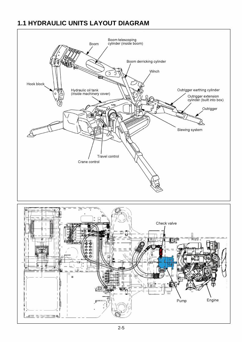
1.1 HYDRAULIC UNITS LAYOUT DIAGRAM
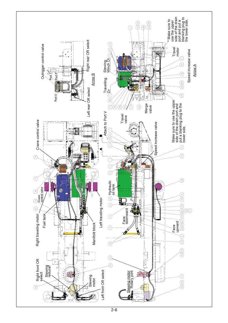
2-6

2-7
This Page Intentionally Left Blank.
2-8
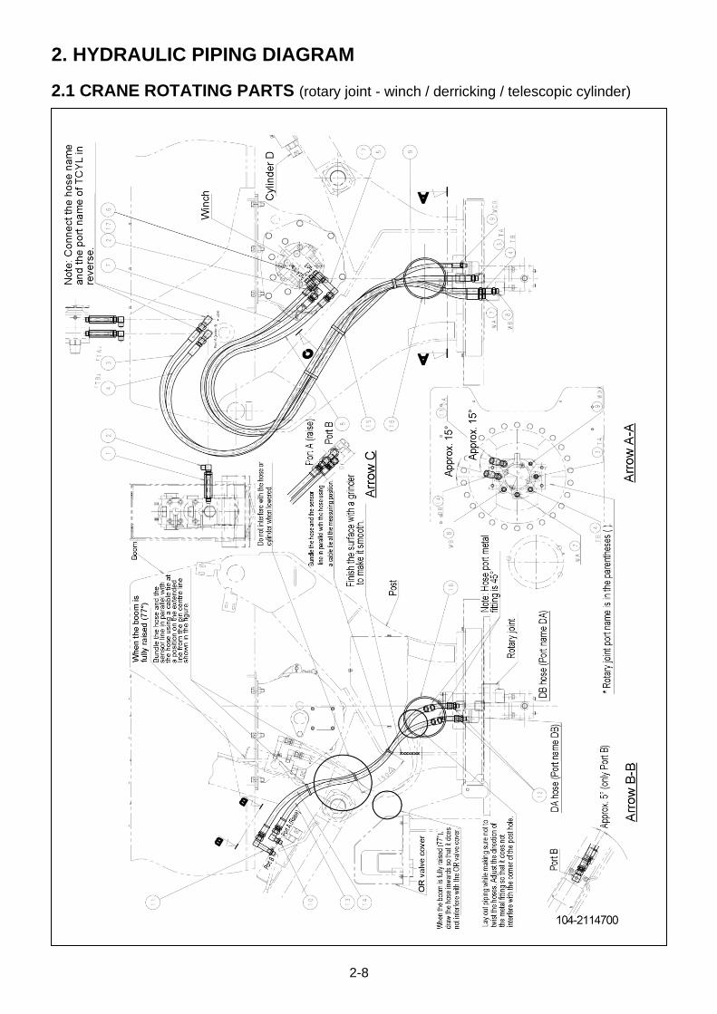
2. HYDRAULIC PIPING DIAGRAM
2.1 CRANE ROTATING PARTS (rotary joint - winch / derricking / telescopic cylinder)
2-9
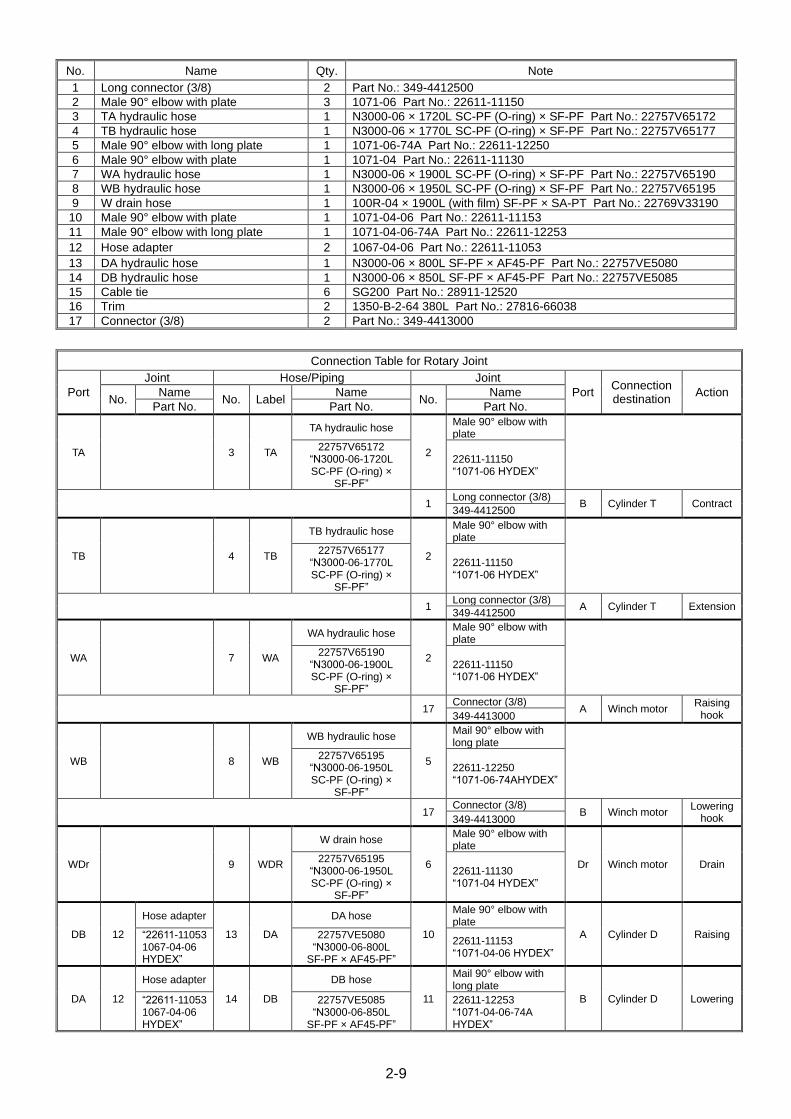
No. Name Qty. Note
1 Long connector (3/8) 2 Part No.: 349-4412500
2 Male 90° elbow with plate 3 1071-06 Part No.: 22611-11150
3 TA hydraulic hose 1 N3000-06 × 1720L SC-PF (O-ring) × SF-PF Part No.: 22757V65172
4 TB hydraulic hose 1 N3000-06 × 1770L SC-PF (O-ring) × SF-PF Part No.: 22757V65177
5 Male 90° elbow with long plate 1 1071-06-74A Part No.: 22611-12250
6 Male 90° elbow with plate 1 1071-04 Part No.: 22611-11130
7 WA hydraulic hose 1 N3000-06 × 1900L SC-PF (O-ring) × SF-PF Part No.: 22757V65190
8 WB hydraulic hose 1 N3000-06 × 1950L SC-PF (O-ring) × SF-PF Part No.: 22757V65195
9 W drain hose 1 100R-04 × 1900L (with film) SF-PF × SA-PT Part No.: 22769V33190
10 Male 90° elbow with plate 1 1071-04-06 Part No.: 22611-11153
11 Male 90° elbow with long plate 1 1071-04-06-74A Part No.: 22611-12253
12 Hose adapter 2 1067-04-06 Part No.: 22611-11053
13 DA hydraulic hose 1 N3000-06 × 800L SF-PF × AF45-PF Part No.: 22757VE5080
14 DB hydraulic hose 1 N3000-06 × 850L SF-PF × AF45-PF Part No.: 22757VE5085
15 Cable tie 6 SG200 Part No.: 28911-12520
16 Trim 2 1350-B-2-64 380L Part No.: 27816-66038
17 Connector (3/8) 2 Part No.: 349-4413000
Connection Table for Rotary Joint
Port
Joint Hose/Piping Joint
Port Connection destination
Action No.
Name No. Label
Name No.
Name
Part No. Part No. Part No.
TA 3 TA
TA hydraulic hose
2
Male 90° elbow with plate
22757V65172
“N3000-06-1720L SC-PF (O-ring) ×
SF-PF”
22611-11150 “1071-06 HYDEX”
1 Long connector (3/8)
B Cylinder T Contract 349-4412500
TB 4 TB
TB hydraulic hose
2
Male 90° elbow with plate
22757V65177
“N3000-06-1770L SC-PF (O-ring) ×
SF-PF”
22611-11150 “1071-06 HYDEX”
1 Long connector (3/8)
A Cylinder T Extension 349-4412500
WA 7 WA
WA hydraulic hose
2
Male 90° elbow with plate
22757V65190
“N3000-06-1900L SC-PF (O-ring) ×
SF-PF”
22611-11150 “1071-06 HYDEX”
17 Connector (3/8)
A Winch motor Raising
hook 349-4413000
WB 8 WB
WB hydraulic hose
5
Mail 90° elbow with long plate
22757V65195
“N3000-06-1950L SC-PF (O-ring) ×
SF-PF”
22611-12250 “1071-06-74AHYDEX”
17 Connector (3/8)
B Winch motor Lowering
hook 349-4413000
WDr 9 WDR
W drain hose
6
Male 90° elbow with plate
Dr Winch motor Drain 22757V65195
“N3000-06-1950L SC-PF (O-ring) ×
SF-PF”
22611-11130 “1071-04 HYDEX”
DB 12
Hose adapter
13 DA
DA hose
10
Male 90° elbow with plate
A Cylinder D Raising “22611-11053 1067-04-06 HYDEX”
22757VE5080 “N3000-06-800L
SF-PF × AF45-PF”
22611-11153 “1071-04-06 HYDEX”
DA 12
Hose adapter
14 DB
DB hose
11
Mail 90° elbow with long plate
B Cylinder D Lowering “22611-11053 1067-04-06 HYDEX”
22757VE5085 “N3000-06-850L
SF-PF × AF45-PF”
22611-12253 “1071-04-06-74A HYDEX”
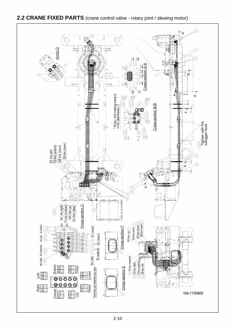
2-10
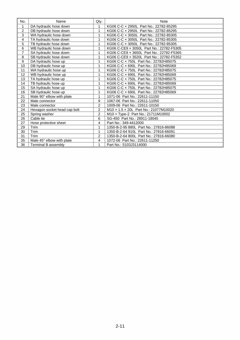
2.2 CRANE FIXED PARTS (crane control valve - rotary joint / slewing motor)
2-11
No. Name Qty. Note
1 DA hydraulic hose down 1 KG06 C-C × 2950L Part No.: 22782-85295
2 DB hydraulic hose down 1 KG06 C-C × 2950L Part No.: 22782-85295
3 WA hydraulic hose down 1 KG06 C-C × 3050L Part No.: 22782-85305
4 TA hydraulic hose down 1 KG06 C-C × 3050L Part No.: 22782-85305
5 TB hydraulic hose down 1 KG06 C-C × 3050L Part No.: 22782-85305
6 WB hydraulic hose down 1 KG06 C-CE9 × 3050L Part No.: 22782-F5305
7 SA hydraulic hose down 1 KG06 C-CE9 × 3650L Part No.: 22782-F5365
8 SB hydraulic hose down 1 KG06 C-CE9 × 3520L Part No.: 22782-F5352
9 DA hydraulic hose up 1 KG06 C-C × 750L Part No.: 22782H85075
10 DB hydraulic hose up 1 KG06 C-C × 690L Part No.: 22782H85069
11 WA hydraulic hose up 1 KG06 C-C × 750L Part No.: 22782H85075
12 WB hydraulic hose up 1 KG06 C-C × 690L Part No.: 22782H85069
13 TA hydraulic hose up 1 KG06 C-C × 750L Part No.: 22782H85075
14 TB hydraulic hose up 1 KG06 C-C × 690L Part No.: 22782H85069
15 SA hydraulic hose up 1 KG06 C-C × 750L Part No.: 22782H85075
16 SB hydraulic hose up 1 KG06 C-C × 690L Part No.: 22782H85069
21 Male 90° elbow with plate 1 1071-06 Part No.: 22611-11150
22 Male connector 9 1067-06 Part No.: 22611-11050
23 Male connector 2 1009-06 Part No.: 22611-10150
24 Hexagon socket head cap bolt 2 M10 × 1.5 × 20L Part No.: 21077M10020
25 Spring washer 2 M10 × Type-2 Part No.: 21711M10002
26 Cable tie 6 SG-450 Part No.: 28911-18045
27 Hose protective sheet 4 Part No.: 349-4412000
29 Trim 1 1350-B-2-95 880L Part No.: 27816-86088
30 Trim 1 1350-B-2-64 910L Part No.: 27816-66091
31 Trim 2 1350-B-2-64 800L Part No.: 27816-66080
35 Male 45° elbow with plate 4 1072-06 Part No.: 22611-11250
36 Terminal B assembly 1 Part No.: S103J3114000
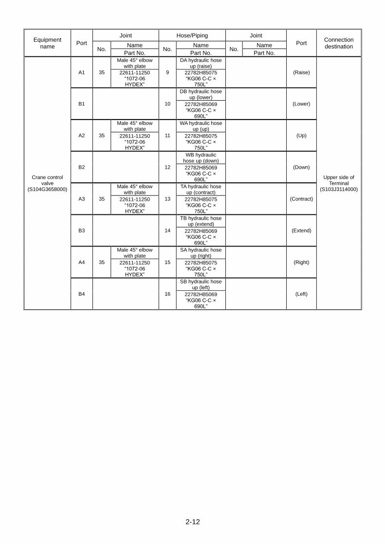
2-12
Equipment name
Port
Joint Hose/Piping Joint
Port Connection destination No.
Name No.
Name No.
Name
Part No. Part No. Part No.
Crane control valve
(S104G3658000)
A1 35
Male 45° elbow with plate
9
DA hydraulic hose up (raise)
(Raise)
Upper side of Terminal
(S103J3114000)
22611-11250 “1072-06 HYDEX”
22782H85075 “KG06 C-C ×
750L”
B1 10
DB hydraulic hose up (lower)
(Lower) 22782H85069 “KG06 C-C ×
690L”
A2 35
Male 45° elbow with plate
11
WA hydraulic hose up (up)
(Up) 22611-11250 “1072-06 HYDEX”
22782H85075 “KG06 C-C ×
750L”
B2 12
WB hydraulic hose up (down)
(Down) 22782H85069 “KG06 C-C ×
690L”
A3 35
Male 45° elbow with plate
13
TA hydraulic hose up (contract)
(Contract) 22611-11250 “1072-06 HYDEX”
22782H85075 “KG06 C-C ×
750L”
B3 14
TB hydraulic hose up (extend)
(Extend) 22782H85069 “KG06 C-C ×
690L”
A4 35
Male 45° elbow with plate
15
SA hydraulic hose up (right)
(Right) 22611-11250 “1072-06 HYDEX”
22782H85075 “KG06 C-C ×
750L”
B4 16
SB hydraulic hose up (left)
(Left) 22782H85069 “KG06 C-C ×
690L”
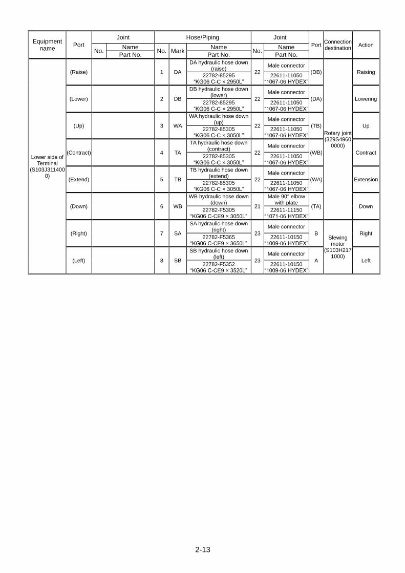
2-13
Equipment name
Port
Joint Hose/Piping Joint
Port Connection destination
Action No.
Name No. Mark
Name No.
Name
Part No. Part No. Part No.
Lower side of Terminal
(S103J3114000)
(Raise) 1 DA
DA hydraulic hose down (raise)
22
Male connector
(DB)
Rotary joint (329S4960
0000)
Raising 22782-85295
“KG06 C-C × 2950L” 22611-11050
“1067-06 HYDEX”
(Lower) 2 DB
DB hydraulic hose down (lower)
22
Male connector
(DA) Lowering 22782-85295
“KG06 C-C × 2950L” 22611-11050
“1067-06 HYDEX”
(Up) 3 WA
WA hydraulic hose down (up)
22
Male connector
(TB) Up 22782-85305
“KG06 C-C × 3050L” 22611-11050
“1067-06 HYDEX”
(Contract) 4 TA
TA hydraulic hose down (contract)
22
Male connector
(WB) Contract 22782-85305
“KG06 C-C × 3050L” 22611-11050
“1067-06 HYDEX”
(Extend) 5 TB
TB hydraulic hose down (extend)
22
Male connector
(WA) Extension 22782-85305
“KG06 C-C × 3050L” 22611-11050
“1067-06 HYDEX”
(Down) 6 WB
WB hydraulic hose down (down)
21
Male 90° elbow with plate
(TA) Down 22782-F5305
“KG06 C-CE9 × 3050L” 22611-11150
“1071-06 HYDEX”
(Right) 7 SA
SA hydraulic hose down (right)
23
Male connector
B Slewing motor
(S103H2171000)
Right 22782-F5365
“KG06 C-CE9 × 3650L” 22611-10150
“1009-06 HYDEX”
(Left) 8 SB
SB hydraulic hose down (left)
23
Male connector
A Left 22782-F5352
“KG06 C-CE9 × 3520L” 22611-10150
“1009-06 HYDEX”
2-14
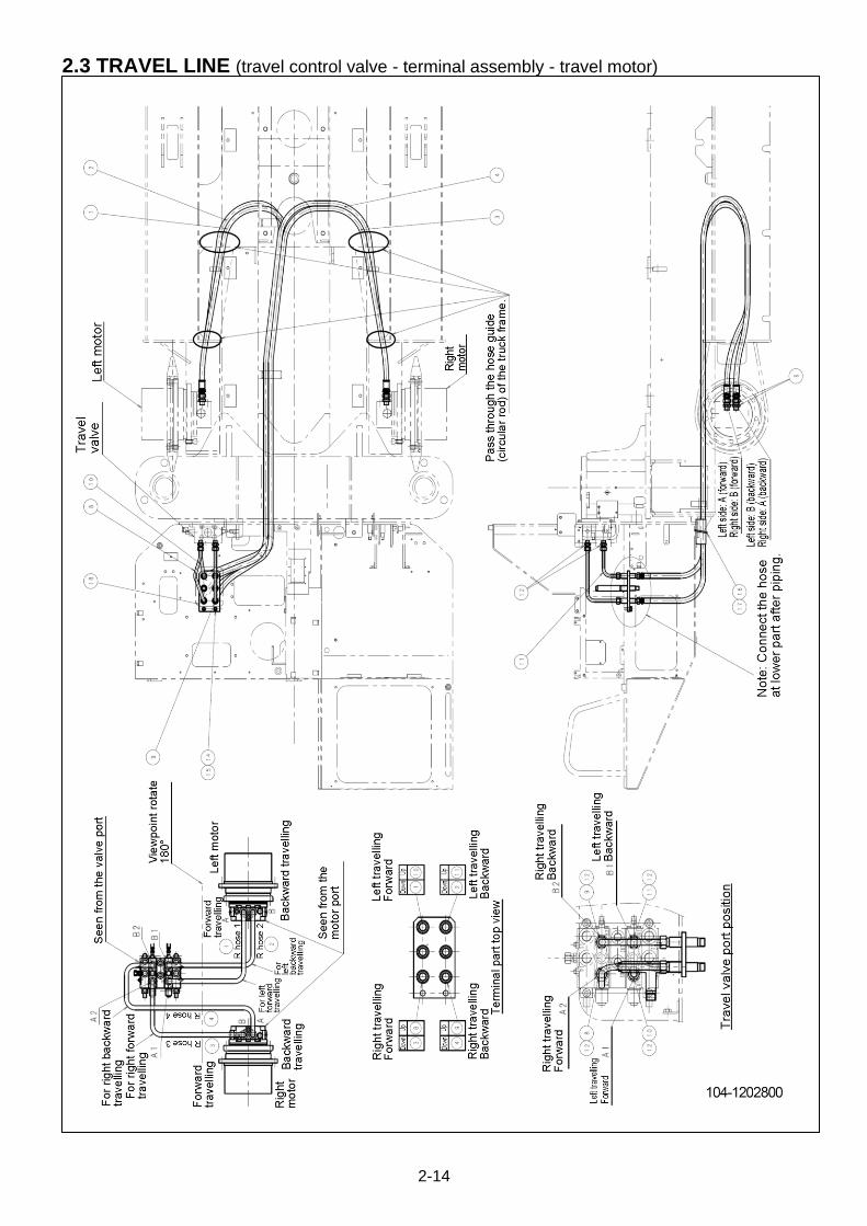
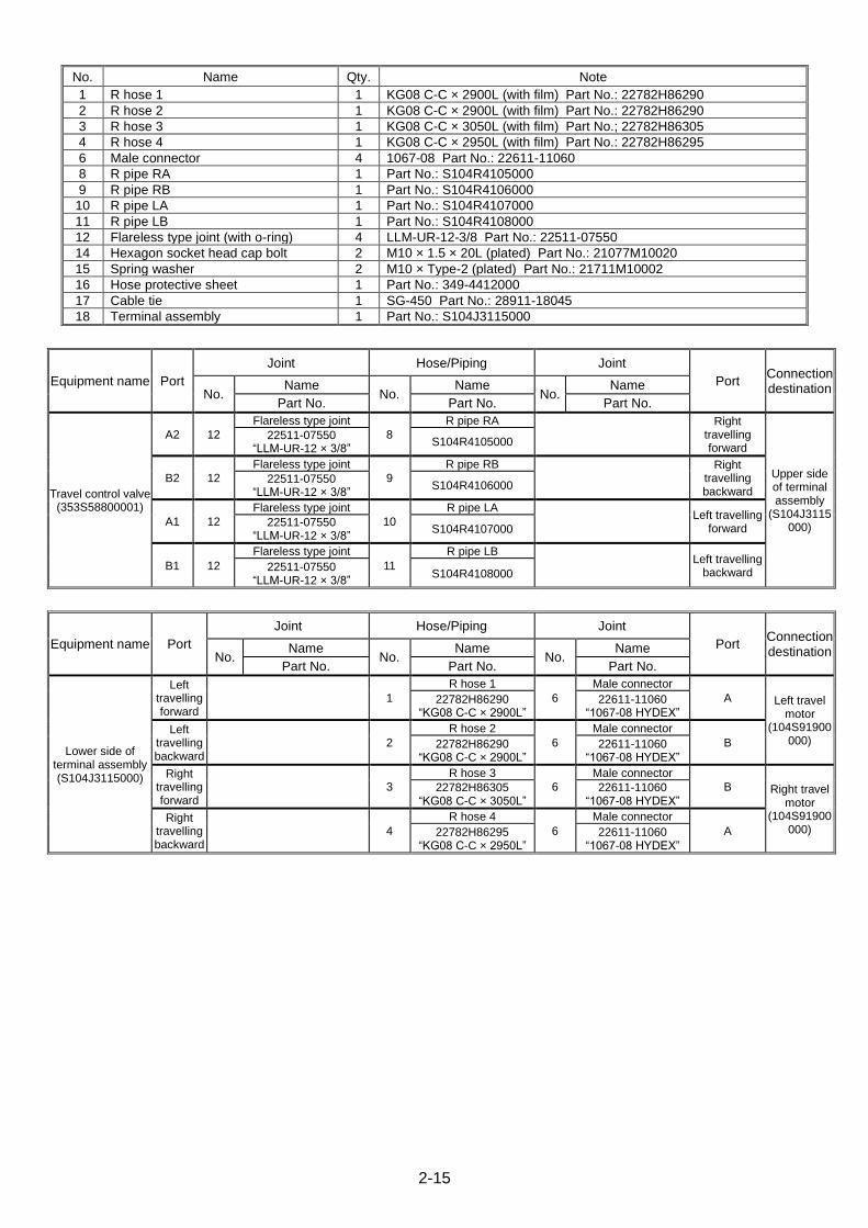
2.3 TRAVEL LINE (travel control valve - terminal assembly - travel motor)
2-15
No. Name Qty. Note
1 R hose 1 1 KG08 C-C × 2900L (with film) Part No.: 22782H86290
2 R hose 2 1 KG08 C-C × 2900L (with film) Part No.: 22782H86290
3 R hose 3 1 KG08 C-C × 3050L (with film) Part No.; 22782H86305
4 R hose 4 1 KG08 C-C × 2950L (with film) Part No.: 22782H86295
6 Male connector 4 1067-08 Part No.: 22611-11060
8 R pipe RA 1 Part No.: S104R4105000
9 R pipe RB 1 Part No.: S104R4106000
10 R pipe LA 1 Part No.: S104R4107000
11 R pipe LB 1 Part No.: S104R4108000
12 Flareless type joint (with o-ring) 4 LLM-UR-12-3/8 Part No.: 22511-07550
14 Hexagon socket head cap bolt 2 M10 × 1.5 × 20L (plated) Part No.: 21077M10020
15 Spring washer 2 M10 × Type-2 (plated) Part No.: 21711M10002
16 Hose protective sheet 1 Part No.: 349-4412000
17 Cable tie 1 SG-450 Part No.: 28911-18045
18 Terminal assembly 1 Part No.: S104J3115000
Equipment name Port
Joint Hose/Piping Joint
Port Connection destination No.
Name No.
Name No.
Name
Part No. Part No. Part No.
Travel control valve (353S58800001)
A2 12
Flareless type joint
8
R pipe RA
Right
travelling forward
Upper side of terminal assembly
(S104J3115000)
22511-07550 “LLM-UR-12 × 3/8”
S104R4105000
B2 12
Flareless type joint
9
R pipe RB
Right
travelling backward
22511-07550 “LLM-UR-12 × 3/8”
S104R4106000
A1 12
Flareless type joint
10
R pipe LA
Left travelling
forward 22511-07550
“LLM-UR-12 × 3/8” S104R4107000
B1 12
Flareless type joint
11
R pipe LB
Left travelling
backward 22511-07550
“LLM-UR-12 × 3/8” S104R4108000
Equipment name Port
Joint Hose/Piping Joint
Port Connection destination No.
Name No.
Name No.
Name
Part No. Part No. Part No.
Lower side of terminal assembly (S104J3115000)
Left travelling forward
1
R hose 1
6
Male connector
A Left travel motor
(104S91900000)
22782H86290 “KG08 C-C × 2900L”
22611-11060 “1067-08 HYDEX”
Left travelling backward
2
R hose 2
6
Male connector
B 22782H86290 “KG08 C-C × 2900L”
22611-11060 “1067-08 HYDEX”
Right travelling forward
3
R hose 3
6
Male connector
B Right travel motor
(104S91900000)
22782H86305 “KG08 C-C × 3050L”
22611-11060 “1067-08 HYDEX”
Right travelling backward
4
R hose 4
6
Male connector
A 22782H86295 “KG08 C-C × 2950L”
22611-11060 “1067-08 HYDEX”

2-16
2.4 OUTRIGGER LINES
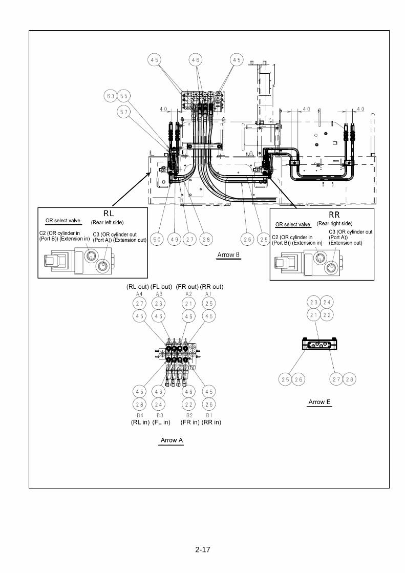
2-17
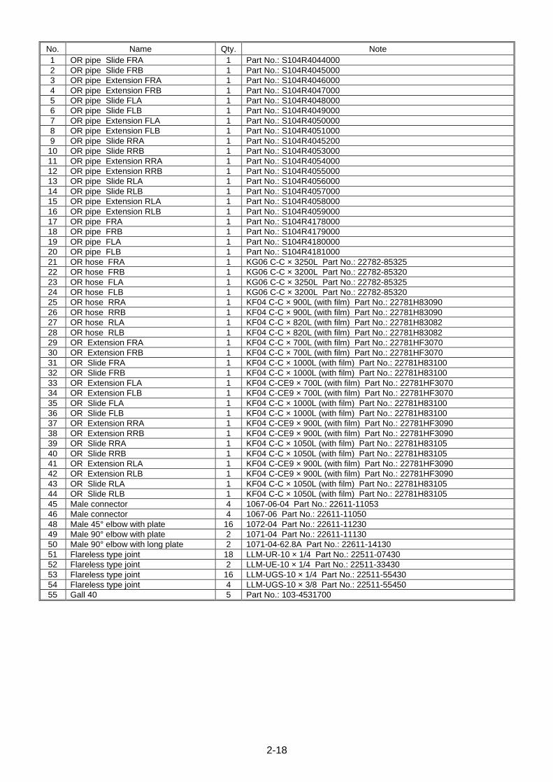
2-18
No. Name Qty. Note
1 OR pipe Slide FRA 1 Part No.: S104R4044000
2 OR pipe Slide FRB 1 Part No.: S104R4045000
3 OR pipe Extension FRA 1 Part No.: S104R4046000
4 OR pipe Extension FRB 1 Part No.: S104R4047000
5 OR pipe Slide FLA 1 Part No.: S104R4048000
6 OR pipe Slide FLB 1 Part No.: S104R4049000
7 OR pipe Extension FLA 1 Part No.: S104R4050000
8 OR pipe Extension FLB 1 Part No.: S104R4051000
9 OR pipe Slide RRA 1 Part No.: S104R4045200
10 OR pipe Slide RRB 1 Part No.: S104R4053000
11 OR pipe Extension RRA 1 Part No.: S104R4054000
12 OR pipe Extension RRB 1 Part No.: S104R4055000
13 OR pipe Slide RLA 1 Part No.: S104R4056000
14 OR pipe Slide RLB 1 Part No.: S104R4057000
15 OR pipe Extension RLA 1 Part No.: S104R4058000
16 OR pipe Extension RLB 1 Part No.: S104R4059000
17 OR pipe FRA 1 Part No.: S104R4178000
18 OR pipe FRB 1 Part No.: S104R4179000
19 OR pipe FLA 1 Part No.: S104R4180000
20 OR pipe FLB 1 Part No.: S104R4181000
21 OR hose FRA 1 KG06 C-C × 3250L Part No.: 22782-85325
22 OR hose FRB 1 KG06 C-C × 3200L Part No.: 22782-85320
23 OR hose FLA 1 KG06 C-C × 3250L Part No.: 22782-85325
24 OR hose FLB 1 KG06 C-C × 3200L Part No.: 22782-85320
25 OR hose RRA 1 KF04 C-C × 900L (with film) Part No.: 22781H83090
26 OR hose RRB 1 KF04 C-C × 900L (with film) Part No.: 22781H83090
27 OR hose RLA 1 KF04 C-C × 820L (with film) Part No.: 22781H83082
28 OR hose RLB 1 KF04 C-C × 820L (with film) Part No.: 22781H83082
29 OR Extension FRA 1 KF04 C-C × 700L (with film) Part No.: 22781HF3070
30 OR Extension FRB 1 KF04 C-C × 700L (with film) Part No.: 22781HF3070
31 OR Slide FRA 1 KF04 C-C × 1000L (with film) Part No.: 22781H83100
32 OR Slide FRB 1 KF04 C-C × 1000L (with film) Part No.: 22781H83100
33 OR Extension FLA 1 KF04 C-CE9 × 700L (with film) Part No.: 22781HF3070
34 OR Extension FLB 1 KF04 C-CE9 × 700L (with film) Part No.: 22781HF3070
35 OR Slide FLA 1 KF04 C-C × 1000L (with film) Part No.: 22781H83100
36 OR Slide FLB 1 KF04 C-C × 1000L (with film) Part No.: 22781H83100
37 OR Extension RRA 1 KF04 C-CE9 × 900L (with film) Part No.: 22781HF3090
38 OR Extension RRB 1 KF04 C-CE9 × 900L (with film) Part No.: 22781HF3090
39 OR Slide RRA 1 KF04 C-C × 1050L (with film) Part No.: 22781H83105
40 OR Slide RRB 1 KF04 C-C × 1050L (with film) Part No.: 22781H83105
41 OR Extension RLA 1 KF04 C-CE9 × 900L (with film) Part No.: 22781HF3090
42 OR Extension RLB 1 KF04 C-CE9 × 900L (with film) Part No.: 22781HF3090
43 OR Slide RLA 1 KF04 C-C × 1050L (with film) Part No.: 22781H83105
44 OR Slide RLB 1 KF04 C-C × 1050L (with film) Part No.: 22781H83105
45 Male connector 4 1067-06-04 Part No.: 22611-11053
46 Male connector 4 1067-06 Part No.: 22611-11050
48 Male 45° elbow with plate 16 1072-04 Part No.: 22611-11230
49 Male 90° elbow with plate 2 1071-04 Part No.: 22611-11130
50 Male 90° elbow with long plate 2 1071-04-62.8A Part No.: 22611-14130
51 Flareless type joint 18 LLM-UR-10 × 1/4 Part No.: 22511-07430
52 Flareless type joint 2 LLM-UE-10 × 1/4 Part No.: 22511-33430
53 Flareless type joint 16 LLM-UGS-10 × 1/4 Part No.: 22511-55430
54 Flareless type joint 4 LLM-UGS-10 × 3/8 Part No.: 22511-55450
55 Gall 40 5 Part No.: 103-4531700

2-19
No. Name Qty. Note
56 Gall 50 2 Part No.: 103-4531800
57 Gall 3 3 Part No.: 349-4400200
58 Gall 4 2 Part No.: 103-4531900
62 Hexagon head bolt with washer 4 M6 × 1.0 × 25L Part No.: 21A12M06025
63 Hexagon head bolt with washer 5 M6 × 1.0 × 55L Part No.: 21A12M06055
64 Hexagon head bolt 2 M10 × 1.5 × 80L (plated) Part No.: 21012M10080
66 Spring washer 2 M10 × Type-2 (plated) Part No.: 21711M10002
67 Hose weight 1 Part No.: 103-3272000
68 Rubber clamp A 2 Part No.: 104-3277900
69 Gall 2 Part No.: 104-4755900
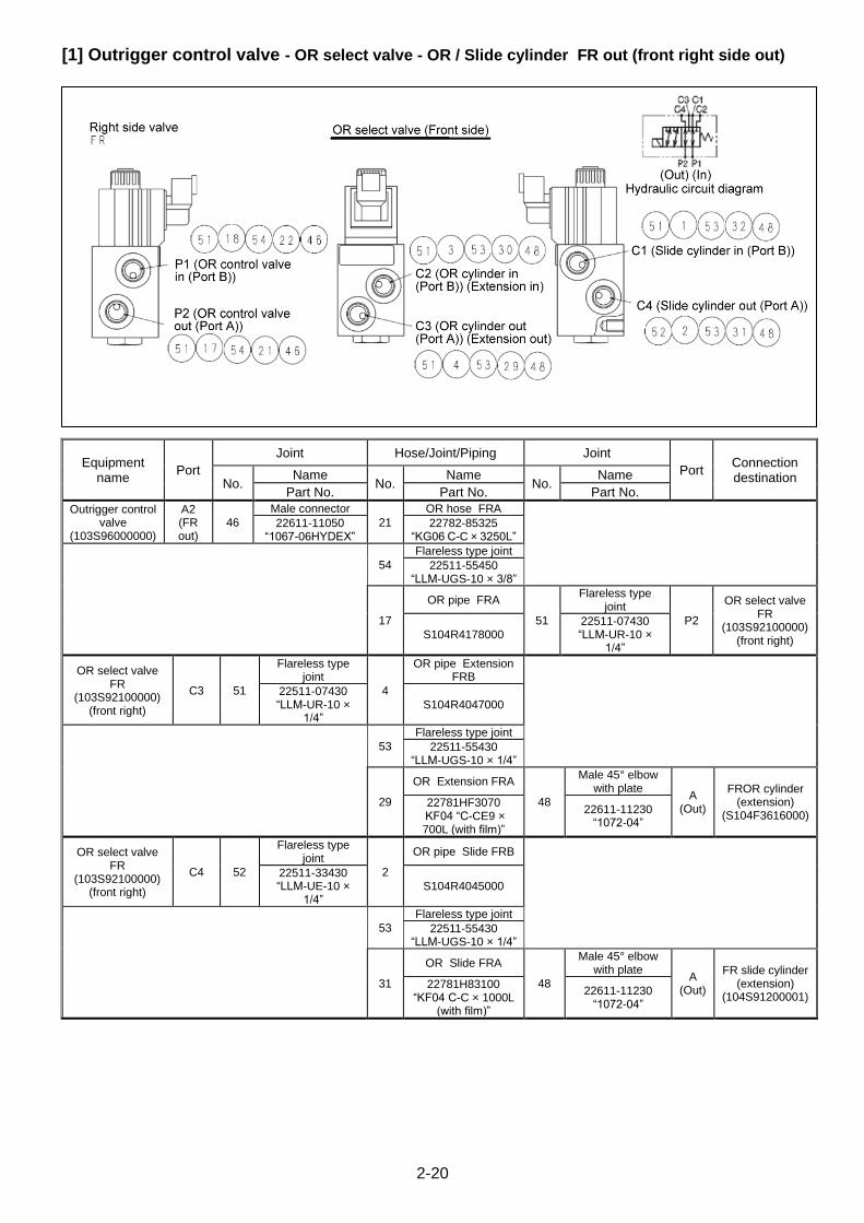
2-20
[1] Outrigger control valve - OR select valve - OR / Slide cylinder FR out (front right side out)
Equipment name
Port
Joint Hose/Joint/Piping Joint
Port Connection destination No.
Name No.
Name No.
Name
Part No. Part No. Part No.
Outrigger control valve
(103S96000000)
A2 (FR out)
46
Male connector
21
OR hose FRA
22611-11050 “1067-06HYDEX”
22782-85325 “KG06 C-C × 3250L”
54
Flareless type joint
22511-55450 “LLM-UGS-10 × 3/8”
17
OR pipe FRA
51
Flareless type joint
P2
OR select valve FR
(103S92100000) (front right)
S104R4178000 22511-07430 “LLM-UR-10 ×
1/4”
OR select valve FR
(103S92100000) (front right)
C3 51
Flareless type joint
4
OR pipe Extension FRB
22511-07430 “LLM-UR-10 ×
1/4” S104R4047000
53
Flareless type joint
22511-55430 “LLM-UGS-10 × 1/4”
29
OR Extension FRA
48
Male 45° elbow with plate
A (Out)
FROR cylinder (extension)
(S104F3616000) 22781HF3070
KF04 “C-CE9 × 700L (with film)”
22611-11230 “1072-04”
OR select valve FR
(103S92100000) (front right)
C4 52
Flareless type joint
2
OR pipe Slide FRB
22511-33430 “LLM-UE-10 ×
1/4” S104R4045000
53
Flareless type joint
22511-55430 “LLM-UGS-10 × 1/4”
31
OR Slide FRA
48
Male 45° elbow with plate
A (Out)
FR slide cylinder (extension)
(104S91200001) 22781H83100
“KF04 C-C × 1000L (with film)”
22611-11230 “1072-04”
2-21
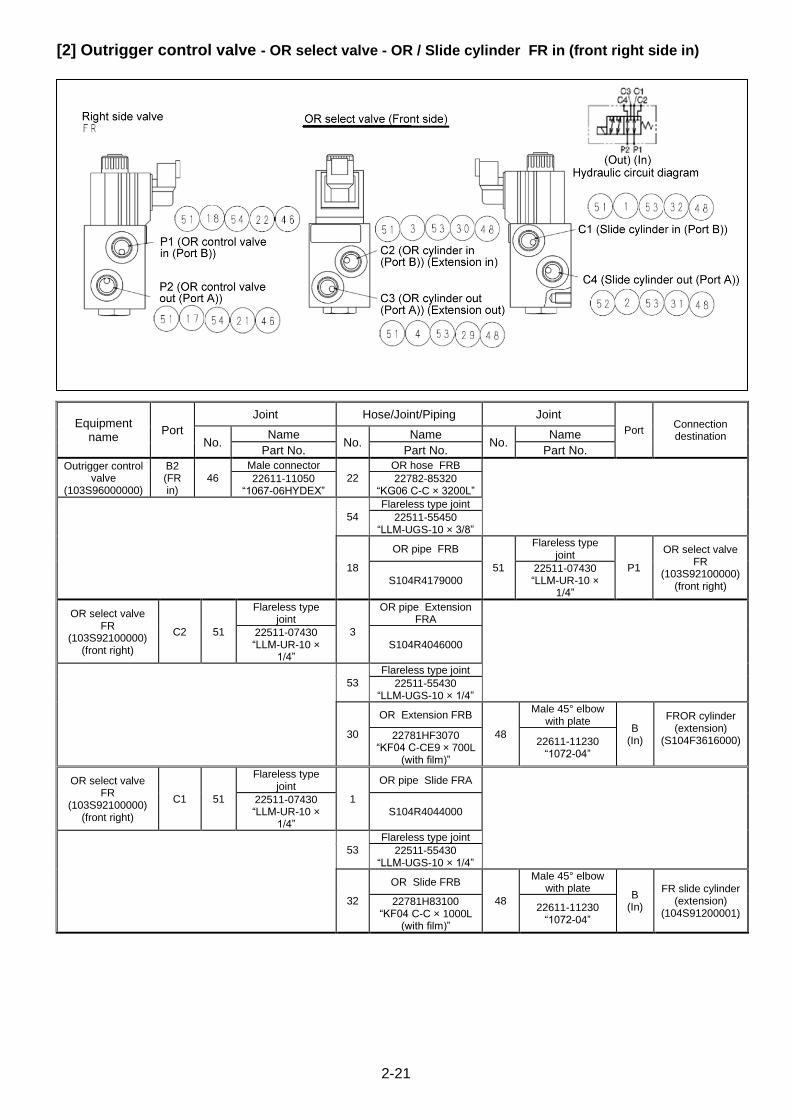
[2] Outrigger control valve - OR select valve - OR / Slide cylinder FR in (front right side in)
Equipment name
Port
Joint Hose/Joint/Piping Joint
Port Connection destination
No. Name
No. Name
No. Name
Part No. Part No. Part No.
Outrigger control valve
(103S96000000)
B2 (FR in)
46
Male connector
22
OR hose FRB
22611-11050 “1067-06HYDEX”
22782-85320 “KG06 C-C × 3200L”
54
Flareless type joint
22511-55450 “LLM-UGS-10 × 3/8”
18
OR pipe FRB
51
Flareless type joint
P1
OR select valve FR
(103S92100000) (front right)
S104R4179000 22511-07430 “LLM-UR-10 ×
1/4”
OR select valve FR
(103S92100000) (front right)
C2 51
Flareless type joint
3
OR pipe Extension FRA
22511-07430 “LLM-UR-10 ×
1/4” S104R4046000
53
Flareless type joint
22511-55430 “LLM-UGS-10 × 1/4”
30
OR Extension FRB
48
Male 45° elbow with plate
B (In)
FROR cylinder (extension)
(S104F3616000)
22781HF3070 “KF04 C-CE9 × 700L
(with film)”
22611-11230 “1072-04”
OR select valve FR
(103S92100000) (front right)
C1 51
Flareless type joint
1
OR pipe Slide FRA
22511-07430 “LLM-UR-10 ×
1/4” S104R4044000
53
Flareless type joint
22511-55430 “LLM-UGS-10 × 1/4”
32
OR Slide FRB
48
Male 45° elbow with plate
B (In)
FR slide cylinder (extension)
(104S91200001) 22781H83100
“KF04 C-C × 1000L (with film)”
22611-11230 “1072-04”

2-22
[3] Outrigger control valve - OR select valve - OR / Slide cylinder FL out (front left side out)
Equipment name
Port
Joint Hose/Joint/Piping Joint
Port Connection destination No.
Name No.
Name No.
Name
Part No. Part No. Part No.
Outrigger control valve
(103S96000000)
A3 (FL out)
46
Male connector
23
OR hose FLA
22611-11050 “1067-06HYDEX”
22782-85325 “KG06 C-C × 3250L”
54
Flareless type joint
22511-55450 “LLM-UGS-10 × 3/8”
19
OR pipe FLA
51
Flareless type joint
P2
OR select valve FL
(103S92100000) (front left)
S104R4180000 22511-07430 “LLM-UR-10 ×
1/4”
OR select valve FL
(103S92100000) (front left)
C3 51
Flareless type joint
8
OR pipe Extension FLB
22511-07430 “LLM-UR-10 ×
1/4” S104R4051000
53
Flareless type joint
22511-55430 “LLM-UGS-10 × 1/4”
33
OR Extension FLA
48
Male 45° elbow with plate
A (Out)
FLOR cylinder (extension)
(S104F3616000) 22781HF3070 “KF04 C-CE9 × 700L (with film)”
22611-11230 “1072-04”
OR select valve FL
(103S92100000) (front left)
C4 51
Flareless type joint
6
OR pipe Slide FLB
22511-07430 “LLM-UR-10 ×
1/4” S104R4049000
53
Flareless type joint
22511-55430 “LLM-UGS-10 × 1/4”
35
OR Slide FLA
48
Male 45° elbow with plate
A (Out)
FL slide cylinder (extension)
(104S91200001) 22781H83100
“KF04 C-C × 1000L (with film)”
22611-11230 “1072-04”

2-23
[4] Outrigger control valve - OR select valve - OR / Slide cylinder FL in (front left side in)
Equipment name
Port
Joint Hose/Joint/Piping Joint
Port Connection destination No.
Name No.
Name No.
Name
Part No. Part No. Part No.
Outrigger control valve
(103S96000000)
B3 (FL in)
46
Male connector
24
OR hose FLB
22611-11050 “1067-06HYDEX”
22782-85320 “KG06 C-C × 3200L”
54
Flareless type joint
22511-55450 “LLM-UGS-10 × 3/8”
20
OR pipe FLB
51
Flareless type joint
P1
OR select valve FL
(103S92100000) (front left)
S104R4081000 22511-07430 “LLM-UR-10 ×
1/4”
OR select valve FL
(103S92100000) (front left)
C2 51
Flareless type joint
7
OR pipe Extension FLA
22511-07430 “LLM-UR-10 × 1/4”
S104R4050000
53
Flareless type joint
22511-55430 “LLM-UGS-10 × 1/4”
34
OR Extension FLB
48
Male 45° elbow with plate
B (In)
FLOR cylinder (extension)
(S104F3616000)
22781HF3070 “KF04 C-CE9 × 700L
(with film)”
22611-11230 “1072-04”
OR select valve FL
(103S92100000) (front left)
C1 52
Flareless type joint
5
OR pipe Slide FLA
22511-07430 “LLM-UR-10 × 1/4”
S104R4048000
53
Flareless type joint
22511-55430 “LLM-UGS-10 × 1/4”
36
OR Slide FLB
48
Male 45° elbow with plate
B (In)
FL slide cylinder
(extension) (104S9120000
1)
22781H83100 “KF04 C-C × 1000L
(with film)”
22611-11230 “1072-04”
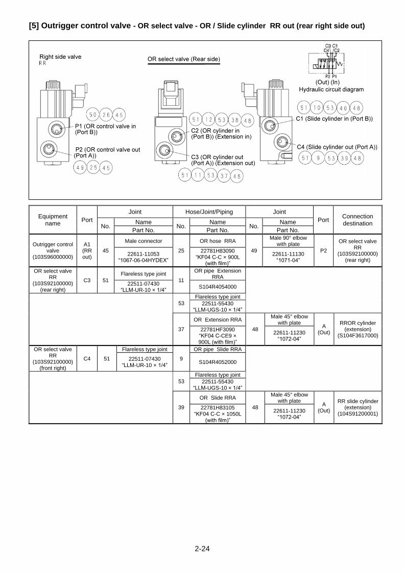
2-24
[5] Outrigger control valve - OR select valve - OR / Slide cylinder RR out (rear right side out)
Equipment name
Port
Joint Hose/Joint/Piping Joint
Port Connection destination No.
Name No.
Name No.
Name
Part No. Part No. Part No.
Outrigger control valve
(103S96000000)
A1 (RR out)
45
Male connector
25
OR hose RRA
49
Male 90° elbow with plate
P2
OR select valve RR
(103S92100000) (rear right)
22611-11053 “1067-06-04HYDEX”
22781H83090 “KF04 C-C × 900L
(with film)”
22611-11130 “1071-04”
OR select valve RR
(103S92100000) (rear right)
C3 51
Flareless type joint
11
OR pipe Extension RRA
22511-07430 “LLM-UR-10 × 1/4”
S104R4054000
53
Flareless type joint
22511-55430 “LLM-UGS-10 × 1/4”
37
OR Extension RRA
48
Male 45° elbow with plate
A (Out)
RROR cylinder (extension)
(S104F3617000) 22781HF3090 “KF04 C-CE9 × 900L (with film)”
22611-11230 “1072-04”
OR select valve RR
(103S92100000) (front right)
C4 51
Flareless type joint
9
OR pipe Slide RRA
22511-07430 “LLM-UR-10 × 1/4”
S104R4052000
53
Flareless type joint
22511-55430 “LLM-UGS-10 × 1/4”
39
OR Slide RRA
48
Male 45° elbow with plate
A (Out)
RR slide cylinder (extension)
(104S91200001) 22781H83105
“KF04 C-C × 1050L (with film)”
22611-11230 “1072-04”

2-25
[6] Outrigger control valve - OR select valve - OR / Slide cylinder RR in (rear right side in)
Equipment name
Port
Joint Hose/Joint/Piping Joint
Port Connection destination No.
Name No.
Name No.
Name
Part No. Part No. Part No.
Outrigger control valve
(103S96000000)
B1 (RR in)
45
Male connector
26
OR hose RRB
50
Mail 90° elbow with long plate
P1
OR select valve RR
(103S92100000) (rear right)
22611-11053 “1067-06-04
HYDEX”
22781H83090 “KF04 C-C × 900L
(with film)”
22611-14130 “1071-04-62.8A”
OR select valve RR
(103S92100000) (front right)
C2 51
Flareless type joint
12
OR pipe Extension RRB
22511-07430 “LLM-UR-10 × 1/4”
S104R4055000
53
Flareless type joint
22511-55430 “LLM-UGS-10 × 1/4”
38
OR Extension RRB
48
Male 45° elbow with plate
B (In)
RROR cylinder (extension)
(S104F3617000)
22781HF3090 “KF04 C-CE9 × 900L
(with film)”
22611-11230 “1072-04”
OR select valve RR
(103S92100000) (front right)
C1 51
Flareless type joint
10
OR pipe Slide RRB
22511-07430 “LLM-UR-10 × 1/4”
S104R4053000
53
Flareless type joint
22511-55430 “LLM-UGS-10 × 1/4”
40
OR Slide RRB
48
Male 45° elbow with plate
B (In)
RR slide cylinder
(extension) (104S9120000
1)
22781H83105 “KF04 C-C × 1050L
(with film)”
22611-11230 “1072-04”
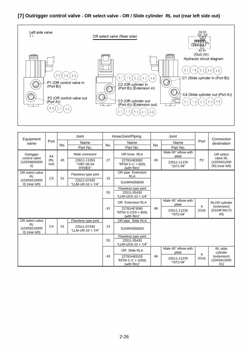
2-26
[7] Outrigger control valve - OR select valve - OR / Slide cylinder RL out (rear left side out)
Equipment name
Port
Joint Hose/Joint/Piping Joint
Port Connection destination No.
Name No.
Name No.
Name
Part No. Part No. Part No.
Outrigger control valve
(103S96000000)
A4 (RL out)
45
Male connector
27
OR hose RLA
49
Male 90° elbow with plate
P2
OR select valve RL
(103S92100000) (rear left)
22611-11053 “1067-06-04
HYDEX”
22781H83082 “KF04 C-C × 820L
(with film)”
22611-11130 “1071-04”
OR select valve RL
(103S92100000) (rear left)
C3 51
Flareless type joint
15
OR pipe Extension RLA
22511-07430 “LLM-UR-10 × 1/4”
S104R4058000
53
Flareless type joint
22511-55430 “LLM-UGS-10 × 1/4”
41
OR Extension RLA
48
Male 45° elbow with plate
A (Out)
RLOR cylinder (extension)
(S104F3617000)
22781HF3090 “KF04 C-CE9 × 900L
(with film)”
22611-11230 “1072-04”
OR select valve RL
(103S92100000) (rear left)
C4 51
Flareless type joint
13
OR pipe Slide RLA
22511-07430 “LLM-UR-10 × 1/4”
S104R4056000
53
Flareless type joint
22511-55430 “LLM-UGS-10 × 1/4”
43
OR Slide RLA
48
Male 45° elbow with plate
A (Out)
RL slide cylinder
(extension) (104S912000
01)
22781H83105 “KF04 C-C × 1050L
(with film)”
22611-11230 “1072-04”
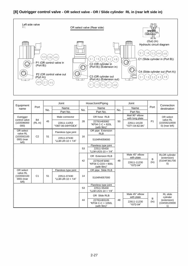
2-27
[8] Outrigger control valve - OR select valve - OR / Slide cylinder RL in (rear left side in)
Equipment name
Port
Joint Hose/Joint/Piping Joint
Port Connection destination No.
Name No.
Name No.
Name
Part No. Part No. Part No.
Outrigger control valve (103S96000
000)
B4 (RL in)
45
Male connector
28
OR hose RLB
50
Mail 90° elbow with long plate
P1
OR select valve RL
(103S92100000) (rear left)
22611-11053 “1067-06-04HYDEX”
22781H83082 “KF04 C-C × 820L
(with film)”
22611-14130 “1071-04-62.8A”
OR select valve RL
(103S92100000) (rear
left)
C2 51
Flareless type joint
16
OR pipe Extension RLB
22511-07430 “LLM-UR-10 × 1/4”
S104R4059000
53
Flareless type joint
22511-55430 “LLM-UGS-10 × 1/4”
42
OR Extension RLB
48
Male 45° elbow with plate
B (In)
RLOR cylinder (extension)
(S104F3617000)
22781HF3090 “KF04 C-CE9 × 900L
(with film)”
22611-11230 “1072-04”
OR select valve RL
(103S92100000) (rear
left)
C1 51
Flareless type joint
14
OR pipe Slide RLB
22511-07430 “LLM-UR-10 × 1/4”
S104R4057000
53
Flareless type joint
22511-55430 “LLM-UGS-10 × 1/4”
44
OR Slide RLB
48
Male 45° elbow with plate
B (In)
RL slide cylinder
(extension) (104S9120000
1)
22781H83105 “KF04 C-C × 1050L
(with film)”
22611-11230 “1072-04”

2-28
2.5 PUMP LINE (P line)
2-29
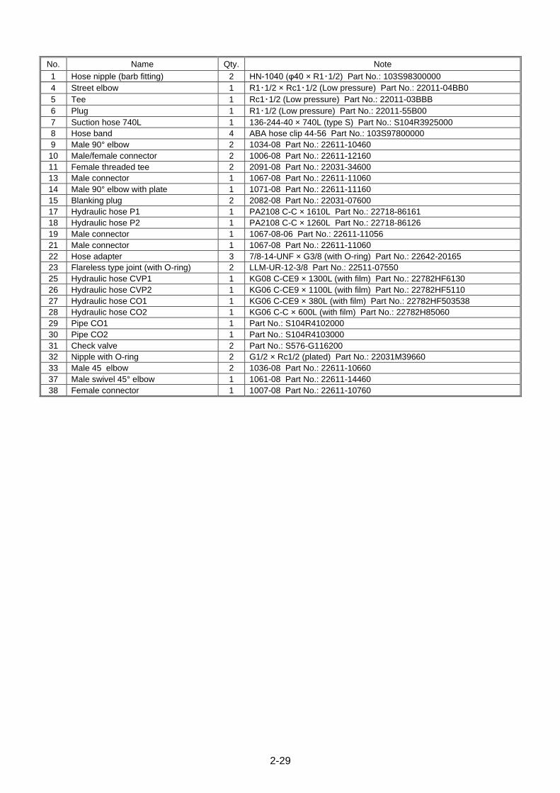
No. Name Qty. Note
1 Hose nipple (barb fitting) 2 HN-1040 (φ40 × R1・1/2) Part No.: 103S98300000
4 Street elbow 1 R1・1/2 × Rc1・1/2 (Low pressure) Part No.: 22011-04BB0
5 Tee 1 Rc1・1/2 (Low pressure) Part No.: 22011-03BBB
6 Plug 1 R1・1/2 (Low pressure) Part No.: 22011-55B00
7 Suction hose 740L 1 136-244-40 × 740L (type S) Part No.: S104R3925000
8 Hose band 4 ABA hose clip 44-56 Part No.: 103S97800000
9 Male 90° elbow 2 1034-08 Part No.: 22611-10460
10 Male/female connector 2 1006-08 Part No.: 22611-12160
11 Female threaded tee 2 2091-08 Part No.: 22031-34600
13 Male connector 1 1067-08 Part No.: 22611-11060
14 Male 90° elbow with plate 1 1071-08 Part No.: 22611-11160
15 Blanking plug 2 2082-08 Part No.: 22031-07600
17 Hydraulic hose P1 1 PA2108 C-C × 1610L Part No.: 22718-86161
18 Hydraulic hose P2 1 PA2108 C-C × 1260L Part No.: 22718-86126
19 Male connector 1 1067-08-06 Part No.: 22611-11056
21 Male connector 1 1067-08 Part No.: 22611-11060
22 Hose adapter 3 7/8-14-UNF × G3/8 (with O-ring) Part No.: 22642-20165
23 Flareless type joint (with O-ring) 2 LLM-UR-12-3/8 Part No.: 22511-07550
25 Hydraulic hose CVP1 1 KG08 C-CE9 × 1300L (with film) Part No.: 22782HF6130
26 Hydraulic hose CVP2 1 KG06 C-CE9 × 1100L (with film) Part No.: 22782HF5110
27 Hydraulic hose CO1 1 KG06 C-CE9 × 380L (with film) Part No.: 22782HF503538
28 Hydraulic hose CO2 1 KG06 C-C × 600L (with film) Part No.: 22782H85060
29 Pipe CO1 1 Part No.: S104R4102000
30 Pipe CO2 1 Part No.: S104R4103000
31 Check valve 2 Part No.: S576-G116200
32 Nipple with O-ring 2 G1/2 × Rc1/2 (plated) Part No.: 22031M39660
33 Male 45 elbow 2 1036-08 Part No.: 22611-10660
37 Male swivel 45° elbow 1 1061-08 Part No.: 22611-14460
38 Female connector 1 1007-08 Part No.: 22611-10760
2-30
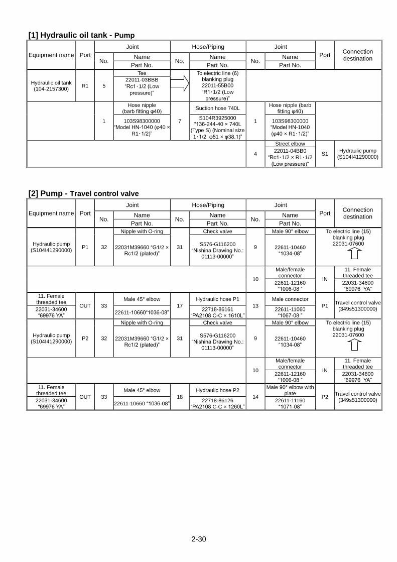
[1] Hydraulic oil tank - Pump
Equipment name Port
Joint Hose/Piping Joint
Port Connection destination No.
Name No.
Name No.
Name
Part No. Part No. Part No.
Hydraulic oil tank (104-2157300)
R1 5
Tee
To electric line (6) blanking plug 22011-55B00
“R1・1/2 (Low
pressure)”
22011-03BBB
“Rc1・1/2 (Low
pressure)”
1
Hose nipple (barb fitting φ40)
7
Suction hose 740L
1
Hose nipple (barb fitting φ40)
103S98300000 “Model HN-1040 (φ40 ×
R1・1/2)”
S104R3925000 “136-244-40 × 740L
(Type S) (Nominal size
1・1/2 φ51 × φ38.1)”
103S98300000 “Model HN-1040
(φ40 × R1・1/2)”
4
Street elbow
S1 Hydraulic pump
(S104I41290000) 22011-04BB0
“Rc1・1/2 × R1・1/2
(Low pressure)”
[2] Pump - Travel control valve
Equipment name Port
Joint Hose/Piping Joint
Port Connection destination No.
Name No.
Name No.
Name
Part No. Part No. Part No.
Hydraulic pump (S104I41290000)
P1 32
Nipple with O-ring
31
Check valve
9
Male 90° elbow To electric line (15) blanking plug 22031-07600
22031M39660 “G1/2 × Rc1/2 (plated)”
S576-G116200 “Nishina Drawing No.:
01113-00000”
22611-10460 “1034-08”
10
Male/female connector
IN
11. Female threaded tee
22611-12160 “1006-08 ”
22031-34600 “69976 YA”
11. Female threaded tee
OUT 33
Male 45° elbow
17
Hydraulic hose P1
13
Male connector
P1 Travel control valve
(349s51300000) 22031-34600 “69976 YA”
22611-10660“1036-08” 22718-86161
“PA2108 C-C × 1610L” 22611-11060
“1067-08 ”
Hydraulic pump (S104I41290000)
P2 32
Nipple with O-ring
31
Check valve
9
Male 90° elbow To electric line (15) blanking plug 22031-07600
22031M39660 “G1/2 × Rc1/2 (plated)”
S576-G116200 “Nishina Drawing No.:
01113-00000”
22611-10460 “1034-08”
10
Male/female connector
IN
11. Female threaded tee
22611-12160 “1006-08 ”
22031-34600 “69976 YA”
11. Female threaded tee
OUT 33
Male 45° elbow
18
Hydraulic hose P2
14
Male 90° elbow with plate
P2 Travel control valve
(349s51300000) 22031-34600 “69976 YA”
22611-10660 “1036-08” 22718-86126
“PA2108 C-C × 1260L” 22611-11160
“1071-08”
2-31
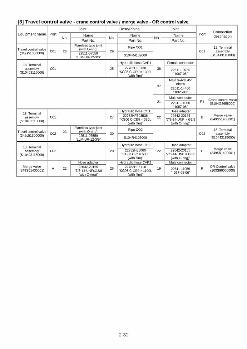
[3] Travel control valve - crane control valve / merge valve - OR control valve
Equipment name Port
Joint Hose/Piping Joint
Port Connection destination No.
Name No.
Name No.
Name
Part No. Part No. Part No.
Travel control valve (349s51300000)
C01 23
Flareless type joint (with O-ring)
29
Pipe CO1
C01 18. Terminal
assembly (S104J3115000)
22511-07550 “LLM-UR-12-3/8”
S104R4102000
18. Terminal assembly
(S104J3115000) C01 25
Hydraulic hose CVP1
38
Female connector
22782HF6130 “KG08 C-CE9 × 1300L
(with film)”
22611-10760 “1007-08”
37
Male swivel 45° elbow
22611-14460 “1061-08”
21
Male connector
P1 Crane control valve (S104G3658000) 22611-11060
“1067-08”
18. Terminal assembly
(S104J3115000) C01 27
Hydraulic hose CO1
22
Hose adapter
B Merge valve
(349S51400001) 22782HF503538
“KG06 C-CE9 × 380L (with film)”
22642-20165 “7/8-14-UNF × G3/8
(with O-ring)”
Travel control valve (349s51300000)
C02 23
Flareless type joint (with O-ring)
30
Pipe CO2
C02 18. Terminal
assembly (S104J3115000)
22511-07550 “LLM-UR-12-3/8”
S104R4103000
18. Terminal assembly
(S104J3115000) C02 28
Hydraulic hose CO2
22
Hose adapter
P Merge valve
(349S51400001) 22782H85060
“KG08 C-C × 600L (with film)”
22642-20165 “7/8-14-UNF × G3/8
(with O-ring)”
Merge valve (349S51400001)
A 22
Hose adapter
26
Hydraulic hose CVP2
19
Male connector
P OR Control valve (103S96000000)
22642-20165 “7/8-14-UNFxG3/8
(with O-ring)”
22782HF5110 “KG06 C-CE9 × 1100L
(with film)”
22611-11056 “1067-08-06”
2-32
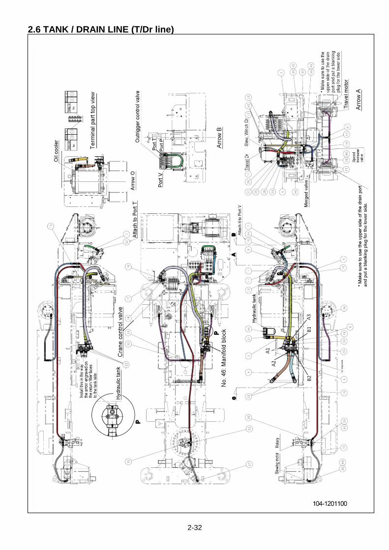
2.6 TANK / DRAIN LINE (T/Dr line)
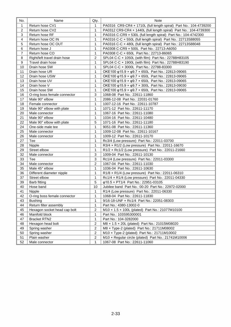
2-33
No. Name Qty. Note
1 Return hose CV1 1 PA0316 CR9-CR4 × 1710L (full length spiral) Part No.: 104-4739200
2 Return hose CV2 1 PA0312 CR9-CR4 × 1440L (full length spiral) Part No.: 104-4739300
3 Return hose RF 1 PA0316 C-CR9 × 530L (full length spiral) Part No.: 104-4742300
4 Return hose OC IN 1 PA0316 C-C × 550L (full length spiral) Part No.: 22713S88055
5 Return hose OC OUT 1 PA0316 C-C × 480L (full length spiral) Part No.: 22713S88048
6 Return hose J 1 PA0308 C-CR9 × 500L Part No.: 22713-A6050
7 Return hose CO 1 PA0308 C-C × 650L Part No.: 22713-86065
8 Right/left travel drain hose 2 SPL04 C-C × 1050L (with film) Part No.: 22788H83105
9 Travel drain hose 1 SPL04 C-C × 1900L (with film) Part No.: 22788H83190
10 Drain hose SW 1 SPL04 C-C × 3000L Part No.: 22788-83300
11 Drain hose UR 1 OKE100 φ15.9 × φ9.7 × 650L Part No.: 22813-09065
12 Drain hose USW 1 OKE100 φ15.9 × φ9.7 × 650L Part No.: 22813-09065
13 Drain hose UV 1 OKE100 φ15.9 × φ9.7 × 650L Part No.: 22813-09065
14 Drain hose V 1 OKE100 φ15.9 × φ9.7 × 300L Part No.: 22813-09030
15 Drain hose SW 1 OKE100 φ15.9 × φ9.7 × 650L Part No.: 22813-09065
16 O-ring boss female connector 3 1068-08 Part No.: 22611-11860
17 Male 90° elbow 1 2086-12-08 Part No.: 22031-01760
18 Female connector 1 1007-12-16 Part No.: 22611-10787
19 Male 90° elbow with plate 1 1071-12 Part No.: 22611-11170
20 Male connector 1 1067-16 Part No.: 22611-11080
21 Male 90° elbow 1 1034-16 Part No.: 22611-10480
22 Male 90° elbow with plate 5 1071-16 Part No.: 22611-11180
24 One-side male tee 1 9051-08 Part No.: 22611-11360
25 Male connector 1 1009-12-08 Part No.: 22611-10167
26 Male connector 1 1009-12 Part No.: 22611-10170
27 Tee 1 Rc3/4 (Low pressure) Part No.: 22011-03700
28 Nipple 1 R3/4 × R1/2 (Low pressure) Part No.: 22011-16670
29 Street elbow 1 R1/2 × Rc1/2 (Low pressure) Part No.: 22011-21660
32 Male connector 3 1009-04 Part No.: 22611-10130
33 Tee 3 Rc1/4 (Low pressure) Part No.: 22011-03300
34 Male connector 2 1067-04 Part No.: 22611-11030
35 Male 45° elbow 1 1036-04 Part No.: 22611-10630
36 Different diameter nipple 1 R1/8 × R1/4 (Low pressure) Part No.: 22011-06310
37 Street elbow 1 Rc1/4 × R1/4 (Low pressure) Part No.: 22011-04330
39 Barb fitting 5 φ10.5 × PT1/4 Part No.: 22951-03105
40 Hose band 10 Jubilee band Part No.: 00-20 Part No.: 22972-02000
41 Nipple 1 R1/4 (Low pressure) Part No.: 22011-06330
42 O-ring boss female connector 1 1068-04 Part No.: 22611-11830
43 Bushing 1 9/16-18-UNF × Rc1/4 Part No.: 22051-08303
44 Return filter assembly 1 Part No.: 4380-13002-0
45 Hexagon socket head cap bolt 2 M10 × 1.5 × 100L (plated) Part No.: 21077M10100
46 Manifold block 1 Part No.: 103S95300001
47 Bracket RTN2 1 Part No.: 104-3282000
48 Hexagon head bolt 2 M8 × 1.5 × 20L (plated) Part No.: 21015M08020
49 Spring washer 2 M8 × Type-2 (plated) Part No.: 21711M08002
50 Spring washer 2 M10 × Type-2 (plated) Part No.: 21711M10002
51 Plain washer 2 M10 × Regular circle (plated) Part No.: 21741M10006
52 Male connector 1 1067-08 Part No.: 22611-11060

2-34
[1] Crane control valve - manifold block - oil cooler - tank (return filter)
Equipment name Port
Joint Hose/Piping Joint
Port Connection destination No.
Name No.
Name No.
Name
Part No. Part No. Part No.
Crane control valve (S104G3658000)
T1 16
O-ring boss female connector
22611-11860 “1068-08”
17
Male 90° elbow
22031-01760 “68279”
18
Female connector
1
Return hose CV1
22
Male 90° elbow with plate
A1 Manifold block
(103S95300001) 22611-10787 “1007-12-16”
104-4739200 “PA0316 CR9-CR4 × 1710 (wind full length
spiral)”
22611-11180 “1071-16”
Manifold block (103S95300001)
A2 22
Male 90° elbow with plate
4
Return hose OC IN
22
Male 90° elbow with plate
IN Oil cooler
(103S90400000) 22611-11180 “1071-16”
22713S88055 “PA0316 C-C × 550L
(wind full length spiral)”
22611-11180 “1071-16”
Oil cooler (103S90400000)
OUT 22
Male 90° elbow with plate
5
Return hose OC OUT
22
Male 90° elbow with plate
B2 Manifold block
(103S95300001) 22611-11180 “1071-16”
22713S88048 “PA0316 C-C × 480L
(wind full length spiral)”
22611-11180 “1071-16”
Manifold block (103S95300001)
B1 20
Male 90° elbow with plate
3
Return hose OC IN
21
Male 90° elbow with plate
IN 4.4 Return filter (4380-13002-0) 22611-11180
“1071-16”
22713S88055 “PA0316 C-C × 550L
(wind full length spiral)”
22611-11180 “1071-16”
[2] OR Control valve - travel control valve - manifold block
Equipment name Port
Joint Hose/Piping Joint
Port Connection destination No.
Name No.
Name No.
Name
Part No. Part No. Part No.
OR Control valve (103S96000000)
T 52
Male connector
7
Return hose CO
24
One-side male tee
22611-11060 “1067-08”
22713-86065 “PA0308 C-C × 650L”
22611-11360 “2612063”
16
O-ring boss female connector
V OR Control valve (103S96000000) 22611-11860
“1068-08”
24. One-side male tee (22611-11360)
- 6
Return hose J
25
Male connector
- 27. Tee
(22011-03700) 22713-A6050
“PA0308 C-CR9 × 500L”
22611-10167 “1009-12-08”
Travel control valve (349s51300000)
T1 16
O-ring boss female connector
29
Elbow
28
Nipple
- 27. Tee
(22011-03700) 22611-11860 “1068-08”
22011-21660 “R1/2 × Rc1/2 (Low
pressure)”
22011-16670 “R3/4 × R1/2 (Low
pressure)”
27. Tee (22011-03700)
- 26
Male connector
2
Return hose CV2
19
Male 90° elbow with plate
A3 Manifold block
(103S95300001) 22611-10170 “1009-12”
104-4739300 “PA0312 CR9-CR4 ×
1440L (wind full length spiral)”
22611-11170 “1071-12”
2-35
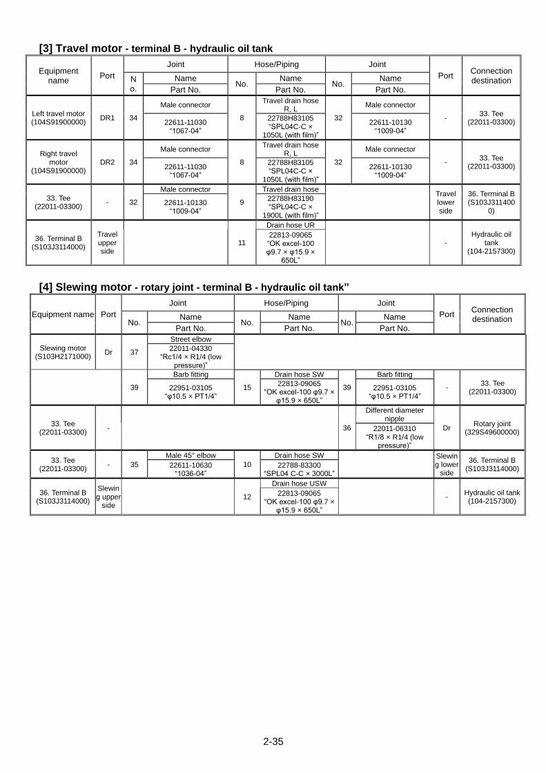
[3] Travel motor - terminal B - hydraulic oil tank
Equipment name
Port
Joint Hose/Piping Joint
Port Connection destination N
o.
Name No.
Name No.
Name
Part No. Part No. Part No.
Left travel motor (104S91900000)
DR1 34
Male connector
8
Travel drain hose R, L
32
Male connector
- 33. Tee
(22011-03300) 22611-11030 “1067-04”
22788H83105 “SPL04C-C ×
1050L (with film)”
22611-10130 “1009-04”
Right travel motor
(104S91900000) DR2 34
Male connector
8
Travel drain hose R, L
32
Male connector
- 33. Tee
(22011-03300) 22611-11030 “1067-04”
22788H83105 “SPL04C-C ×
1050L (with film)”
22611-10130 “1009-04”
33. Tee (22011-03300)
- 32
Male connector
9
Travel drain hose
Travel lower side
36. Terminal B (S103J311400
0) 22611-10130
“1009-04”
22788H83190 “SPL04C-C ×
1900L (with film)”
36. Terminal B (S103J3114000)
Travel upper side
11
Drain hose UR
- Hydraulic oil
tank (104-2157300)
22813-09065 “OK excel-100 φ9.7 × φ15.9 ×
650L”
[4] Slewing motor - rotary joint - terminal B - hydraulic oil tank”
Equipment name Port
Joint Hose/Piping Joint
Port Connection destination No.
Name No.
Name No.
Name
Part No. Part No. Part No.
Slewing motor (S103H2171000)
Dr 37
Street elbow
22011-04330
“Rc1/4 × R1/4 (low pressure)”
39
Barb fitting
15
Drain hose SW
39
Barb fitting
- 33. Tee
(22011-03300) 22951-03105
“φ10.5 × PT1/4”
22813-09065 “OK excel-100 φ9.7 ×
φ15.9 × 650L”
22951-03105 “φ10.5 × PT1/4”
33. Tee (22011-03300)
- 36
Different diameter nipple
Dr Rotary joint
(329S49600000) 22011-06310
“R1/8 × R1/4 (low pressure)”
33. Tee (22011-03300)
- 35
Male 45° elbow
10
Drain hose SW
Slewing lower
side
36. Terminal B (S103J3114000)
22611-10630 “1036-04”
22788-83300 “SPL04 C-C × 3000L”
36. Terminal B (S103J3114000)
Slewing upper
side 12
Drain hose USW
- Hydraulic oil tank (104-2157300)
22813-09065 “OK excel-100 φ9.7 ×
φ15.9 × 650L”
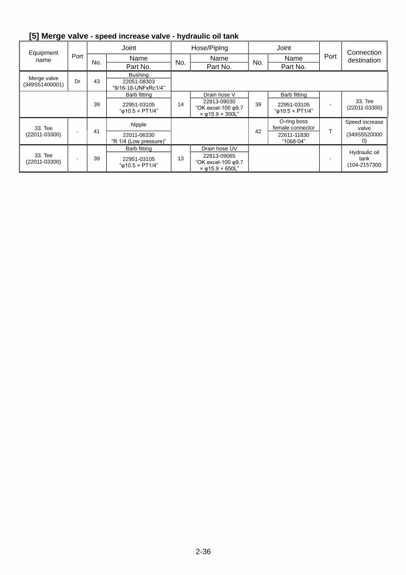
2-36
[5] Merge valve - speed increase valve - hydraulic oil tank
Equipment name
Port
Joint Hose/Piping Joint
Port Connection destination No.
Name No.
Name No.
Name
Part No. Part No. Part No.
Merge valve (349S51400001)
Dr 43
Bushing
22051-08303 “9/16-18-UNFxRc1/4”
39
Barb fitting
14
Drain hose V
39
Barb fitting
- 33. Tee
(22011-03300) 22951-03105
“φ10.5 × PT1/4”
22813-09030 “OK excel-100 φ9.7
× φ15.9 × 300L”
22951-03105 “φ10.5 × PT1/4”
33. Tee (22011-03300)
- 41
Nipple
42
O-ring boss female connector
T
Speed increase valve
(349S55200000)
22011-06330 “R 1/4 (Low pressure)”
22611-11830 “1068-04”
33. Tee (22011-03300)
- 39
Barb fitting
13
Drain hose UV
- Hydraulic oil
tank (104-2157300
22951-03105 “φ10.5 × PT1/4”
22813-09065 “OK excel-100 φ9.7
× φ15.9 × 650L”

2-37
This Page Intentionally Left Blank.
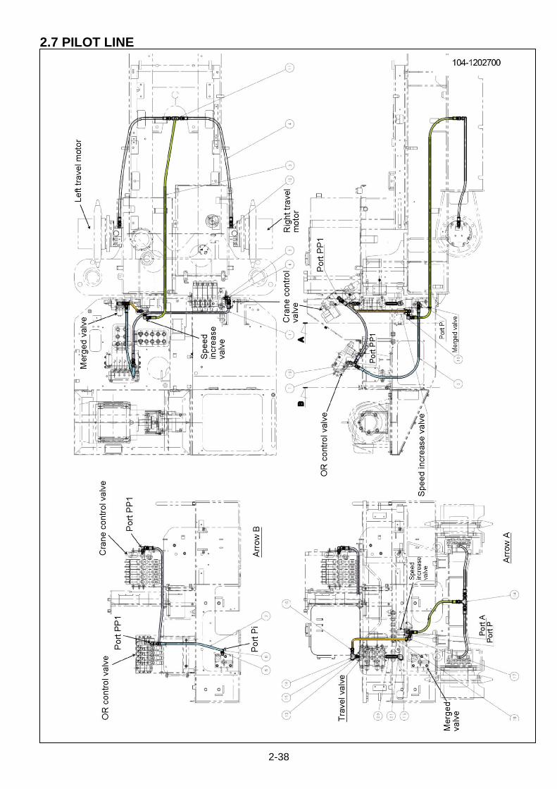
2-38
2.7 PILOT LINE
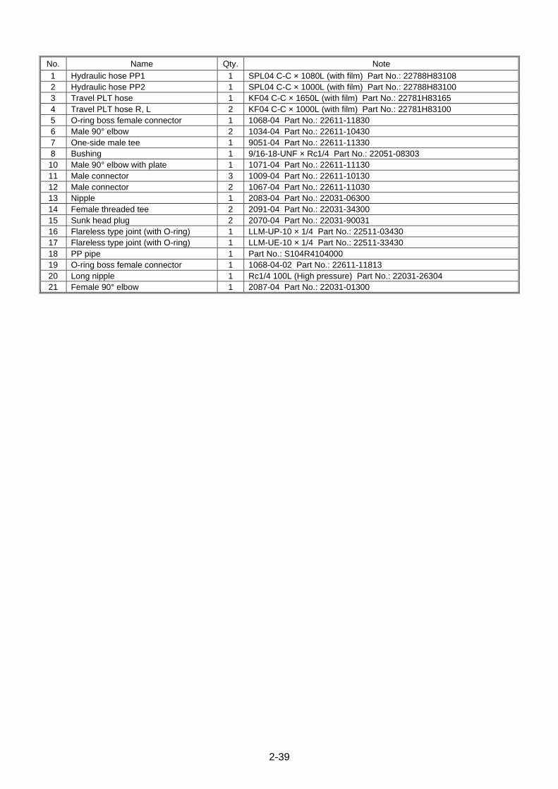
2-39
No. Name Qty. Note
1 Hydraulic hose PP1 1 SPL04 C-C × 1080L (with film) Part No.: 22788H83108
2 Hydraulic hose PP2 1 SPL04 C-C × 1000L (with film) Part No.: 22788H83100
3 Travel PLT hose 1 KF04 C-C × 1650L (with film) Part No.: 22781H83165
4 Travel PLT hose R, L 2 KF04 C-C × 1000L (with film) Part No.: 22781H83100
5 O-ring boss female connector 1 1068-04 Part No.: 22611-11830
6 Male 90° elbow 2 1034-04 Part No.: 22611-10430
7 One-side male tee 1 9051-04 Part No.: 22611-11330
8 Bushing 1 9/16-18-UNF × Rc1/4 Part No.: 22051-08303
10 Male 90° elbow with plate 1 1071-04 Part No.: 22611-11130
11 Male connector 3 1009-04 Part No.: 22611-10130
12 Male connector 2 1067-04 Part No.: 22611-11030
13 Nipple 1 2083-04 Part No.: 22031-06300
14 Female threaded tee 2 2091-04 Part No.: 22031-34300
15 Sunk head plug 2 2070-04 Part No.: 22031-90031
16 Flareless type joint (with O-ring) 1 LLM-UP-10 × 1/4 Part No.: 22511-03430
17 Flareless type joint (with O-ring) 1 LLM-UE-10 × 1/4 Part No.: 22511-33430
18 PP pipe 1 Part No.: S104R4104000
19 O-ring boss female connector 1 1068-04-02 Part No.: 22611-11813
20 Long nipple 1 Rc1/4 100L (High pressure) Part No.: 22031-26304
21 Female 90° elbow 1 2087-04 Part No.: 22031-01300

2-40
[1] Crane control valve - OR control valve - merge valve
Equipment name Port
Joint Hose/Piping Joint
Port Connection destination No.
Name No.
Name No.
Name
Part No. Part No. Part No.
Crane control valve (S104G3658000)
PP1 5
O-ring boss female connector
22611-11830
“1068-04”
6
Male 90° elbow
1
Hydraulic hose PP1
7
One-side male tee
22611-10430 “1034-04”
22788H83108 “SPL04 C-C × 1080L
(with film)”
22611-11330 “2611941”
19
O-ring boss female connector
PP1 OR Control valve (103S96000000) 22611-11813
“1068-04-02”
7. One-side male tee
(22611-11330) - 2
Hydraulic hose PP2
6
Male 90° elbow
22788H83100
“SPL04 C-C × 1000L (with film)”
22611-10430 “1034-04”
8
Bushing
Pi Merge valve
(349S51400001) 22051-08303
“9/16-18-UNF × Rc1/4”
[2] Travel valve - speed increase valve - travel motor
Equipment name Port
Joint Hose/Piping Joint
Port Connection destination No.
Name No.
Name No.
Name
Part No. Part No. Part No.
Travel control valve (349s51300000)
PP1 13
Nipple
22031-06300 “66932”
14
Female threaded tee 15. Sunk head plug
22031-34300 “69854”
22031-90031 “2070-04 (hexagon
socket size 6)”
16
Flareless type joint (with O-ring)
18
PP pipe
17
Flareless type joint (with O-ring)
P Speed increase
valve (349S55200000)
22511-03430 “LLM-UP-10 × 1/4”
S104R4104000
22511-33430 “LLM-UE-10 × 1/4”
Speed increase valve
(349S55200000) A 10
Male 90° elbow with plate
3
Travel PLT hose
11
Male connector
- 14. Female
threaded tee (22031-34300)
22611-11130 “1071-04”
22781H83165 “KF04 C-C × 1650L
(with film)”
22611-10130 “1009-04”
14. Female threaded tee
(22031-34300) - 11
Male connector
4
Travel PLT hose R, L
12
Male connector
PP Left travel motor (104S91900000)
22611-10130 “1009-04”
22781H83100 “KF04 C-C × 1000L
(with film)”
22611-11030 “1067-04”
14. Female threaded tee
(22031-34300) - 11
Male connector
4
Travel PLT hose R, L
12
Male connector
PP Right travel motor (104S91900000)
22611-10130 “1009-04”
22781H83100 “KF04 C-C × 1000L
(with film)”
22611-11030 “1067-04”

2-41
This Page Intentionally Left Blank.

2-42
2.8 ELECTRIC POWERED LINE
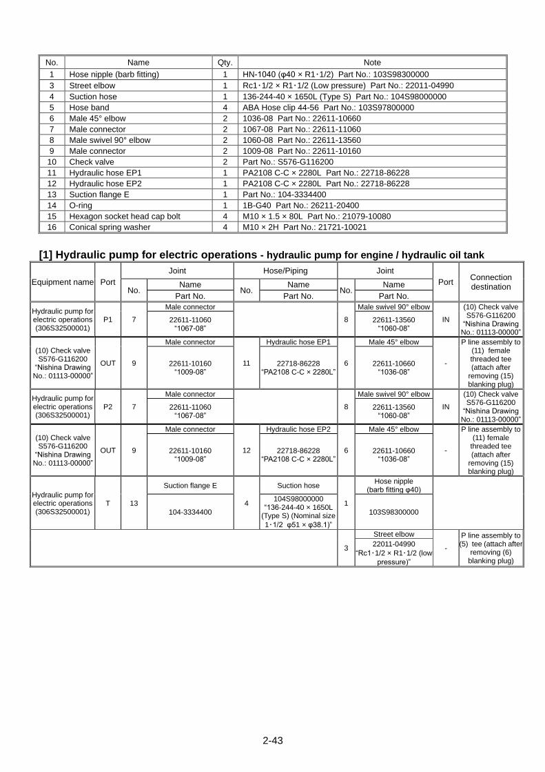
2-43
No. Name Qty. Note
1 Hose nipple (barb fitting) 1 HN-1040 (φ40 × R1・1/2) Part No.: 103S98300000
3 Street elbow 1 Rc1・1/2 × R1・1/2 (Low pressure) Part No.: 22011-04990
4 Suction hose 1 136-244-40 × 1650L (Type S) Part No.: 104S98000000
5 Hose band 4 ABA Hose clip 44-56 Part No.: 103S97800000
6 Male 45° elbow 2 1036-08 Part No.: 22611-10660
7 Male connector 2 1067-08 Part No.: 22611-11060
8 Male swivel 90° elbow 2 1060-08 Part No.: 22611-13560
9 Male connector 2 1009-08 Part No.: 22611-10160
10 Check valve 2 Part No.: S576-G116200
11 Hydraulic hose EP1 1 PA2108 C-C × 2280L Part No.: 22718-86228
12 Hydraulic hose EP2 1 PA2108 C-C × 2280L Part No.: 22718-86228
13 Suction flange E 1 Part No.: 104-3334400
14 O-ring 1 1B-G40 Part No.: 26211-20400
15 Hexagon socket head cap bolt 4 M10 × 1.5 × 80L Part No.: 21079-10080
16 Conical spring washer 4 M10 × 2H Part No.: 21721-10021
[1] Hydraulic pump for electric operations - hydraulic pump for engine / hydraulic oil tank
Equipment name Port
Joint Hose/Piping Joint
Port Connection destination No.
Name No.
Name No.
Name
Part No. Part No. Part No.
Hydraulic pump for electric operations (306S32500001)
P1 7
Male connector
8
Male swivel 90° elbow
IN
(10) Check valve S576-G116200
“Nishina Drawing No.: 01113-00000”
22611-11060 “1067-08”
22611-13560 “1060-08”
(10) Check valve S576-G116200
“Nishina Drawing No.: 01113-00000”
OUT 9
Male connector
11
Hydraulic hose EP1
6
Male 45° elbow
-
P line assembly to (11) female threaded tee (attach after
removing (15) blanking plug)
22611-10160 “1009-08”
22718-86228 “PA2108 C-C × 2280L”
22611-10660 “1036-08”
Hydraulic pump for electric operations (306S32500001)
P2 7
Male connector
8
Male swivel 90° elbow
IN
(10) Check valve S576-G116200
“Nishina Drawing No.: 01113-00000”
22611-11060 “1067-08”
22611-13560 “1060-08”
(10) Check valve S576-G116200
“Nishina Drawing No.: 01113-00000”
OUT 9
Male connector
12
Hydraulic hose EP2
6
Male 45° elbow
-
P line assembly to (11) female
threaded tee (attach after
removing (15) blanking plug)
22611-10160 “1009-08”
22718-86228 “PA2108 C-C × 2280L”
22611-10660 “1036-08”
Hydraulic pump for electric operations (306S32500001)
T 13
Suction flange E
4
Suction hose
1
Hose nipple (barb fitting φ40)
104-3334400
104S98000000 “136-244-40 × 1650L
(Type S) (Nominal size
1・1/2 φ51 × φ38.1)”
103S98300000
3
Street elbow
-
P line assembly to (5) tee (attach after
removing (6) blanking plug)
22011-04990
“Rc1・1/2 × R1・1/2 (low
pressure)”
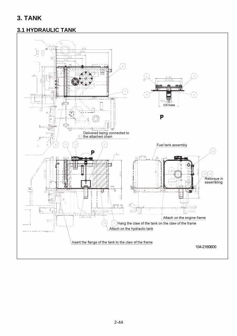
2-44
3. TANK
3.1 HYDRAULIC TANK

2-45
No. Name Qty. Note
1 Hydraulic tank 1 Part No.: 104-2157300
2 Suction filter assembly 1 Part No.: 103S94300000
3 Suction cap 1 Part No.: 103-3348200
4 O-ring 1 Type-1 A, P18 Part No.: 26210-10181
5 Sems bolt 8 M8 × 1.25 × 20L (plated) Part No.: 01024-80820
6 Band assembly 1 Part No.: 104-3340400
7 Heat insulator (left) 1 Part No.: 104-3267100
8 Trim seal 1 4100-B-3 × 16C × 250L Part No.: 27822-01025.
9 Packing 1 Part No.: 233-23171-0
10 Strainer 1 Part No.: 4700-69000-0
11 Cap assembly 1 Part No.: 4700-70000
12 Oil level indicator 1 Part No.: 103-4635400
13 O-ring 1 1A-P14 (For G3/8) Part No.: 26210-10141
14 Plug 1 Part No.: 22611-13350
15 Heat insulator (middle) 1 Part No.: 104-3282700
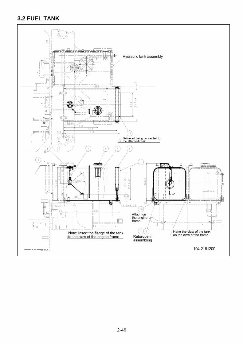
2-46
3.2 FUEL TANK

2-47
No. Name Qty. Note
1 Fuel tank 1 Part No.: 104-2157400
2 O-ring 1 1A-P14 (For G3/8) Part No.: 26210-10141
3 Plug 1 G3/8 equivalent Part No. 22611-13350
4 Strainer 1 Part No.: 4700-69000-0
5 Cap assembly 1 Part No.: 4700-70000
6 Packing 1 Part No.: 353-4438700
7 Fuel sender assembly 1 Part No.: 103S93100000
8 Cross recessed head screw with captive washer
5 M5 × 0.8 × 10L (with PW+SW, plated) Part No.: 2187CM05010
9 Band assembly 1 Part No.: 104-3340400
10 Heat insulator (right) 1 Part No.: 104-3267200 Use a bonding agent to attach
11 Trim seal 1 4100-B-3 × 16C × 250L Part No.: 27822-01025
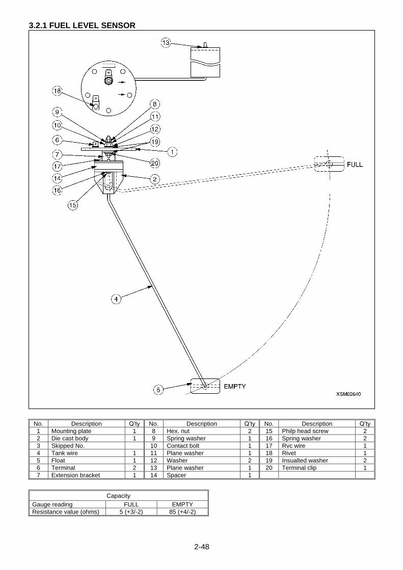
2-48
3.2.1 FUEL LEVEL SENSOR
No. Description Q’ty No. Description Q’ty No. Description Q’ty
1 Mounting plate 1 8 Hex. nut 2 15 Philp head screw 2
2 Die cast body 1 9 Spring washer 1 16 Spring washer 2
3 Skipped No. 10 Contact bolt 1 17 Rvc wire 1
4 Tank wire 1 11 Plane washer 1 18 Rivet 1
5 Float 1 12 Washer 2 19 Insualted washer 2
6 Terminal 2 13 Plane washer 1 20 Terminal clip 1
7 Extension bracket 1 14 Spacer 1
Capacity
Gauge reading FULL EMPTY
Resistance value (ohms) 5 (+3/-2) 85 (+4/-2)
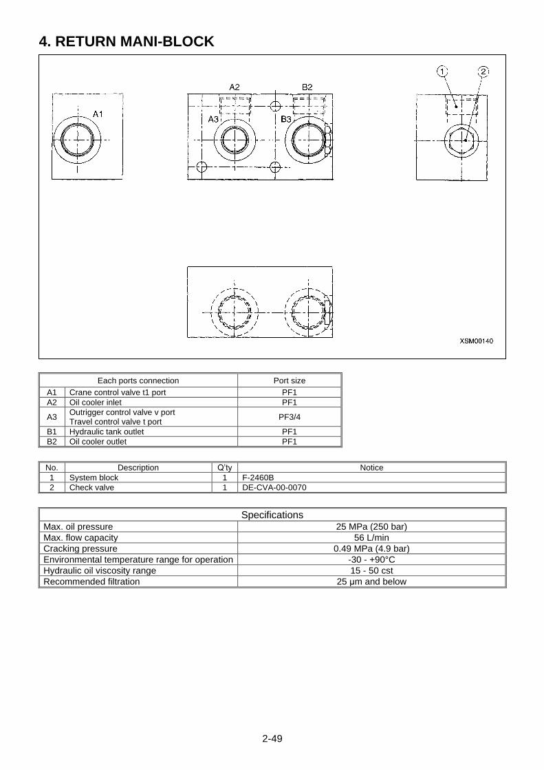
2-49
4. RETURN MANI-BLOCK
Each ports connection Port size
A1 Crane control valve t1 port PF1
A2 Oil cooler inlet PF1
A3 Outrigger control valve v port Travel control valve t port
PF3/4
B1 Hydraulic tank outlet PF1
B2 Oil cooler outlet PF1
No. Description Q’ty Notice
1 System block 1 F-2460B
2 Check valve 1 DE-CVA-00-0070
Specifications Max. oil pressure 25 MPa (250 bar)
Max. flow capacity 56 L/min
Cracking pressure 0.49 MPa (4.9 bar)
Environmental temperature range for operation -30 - +90°C
Hydraulic oil viscosity range 15 - 50 cst
Recommended filtration 25 μm and below
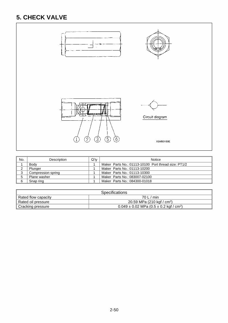
2-50
5. CHECK VALVE
No. Description Q’ty Notice
1 Body 1 Maker Parts No.: 01113-10100 Port thread size: PT1/2
2 Plunger 1 Maker Parts No.: 01113-10200
3 Compression spring 1 Maker Parts No.: 01113-10300
5 Plane washer 1 Maker Parts No.: 083007-02100
6 Snap ring 1 Maker Parts No.: 084300-01018
Specifications Rated flow capacity 70 L / min
Rated oil pressure 20.59 MPa (210 kgf / cm2)
Cracking pressure 0.049 ± 0.02 MPa (0.5 ± 0.2 kgf / cm2)

2-51
This Page Intentionally Left Blank.
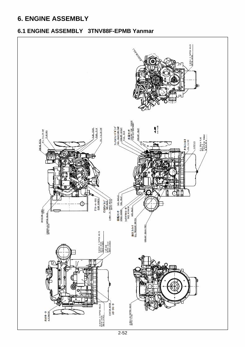
2-52
6. ENGINE ASSEMBLY
6.1 ENGINE ASSEMBLY 3TNV88F-EPMB Yanmar
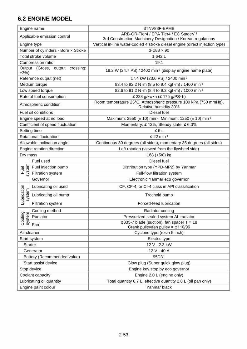
2-53
6.2 ENGINE MODEL
Engine name 3TNV88F-EPMB
Applicable emission control ARB-OR-Tier4 / EPA Tier4 / EC StageV /
3rd Construction Machinery Designation / Korean regulations
Engine type Vertical in-line water-cooled 4 stroke diesel engine (direct injection type)
Number of cylinders - Bore × Stroke 3-φ88 × 90
Total stroke volume 1.642 L
Compression ratio 19.1
Output (Gross, output crossing: ±3%)
18.2 W (24.7 PS) / 2400 min-1 (display engine name plate)
Reference output (net) 17.4 kW (23.6 PS) / 2400 min-1
Medium torque 83.4 to 92.2 N・m (8.5 to 9.4 kgf・m) / 1400 min-1
Low speed torque 82.6 to 91.2 N・m (8.4 to 9.3 kgf・m) / 1000 min-1
Rate of fuel consumption ≤ 238 g/kw・h (≤ 175 g/PS・h)
Atmospheric condition Room temperature 25°C, Atmospheric pressure 100 kPa (750 mmHg),
Relative humidity 30%
Fuel oil conditions Diesel fuel
Engine speed at no load Maximum: 2550 (± 10) min-1 Minimum: 1250 (± 10) min-1
Coefficient of speed fluctuation Momentary: ≤ 12%, Steady state: ≤ 6.3%
Setting time ≤ 6 s
Rotational fluctuation ≤ 22 min-1
Allowable inclination angle Continuous 30 degrees (all sides), momentary 35 degrees (all sides)
Engine rotation direction Left rotation (viewed from the flywheel side)
Dry mass 168 (+5/0) kg
Fuel
syste
m Fuel used Diesel fuel
Fuel injection pump Distribution type (YPD-MP2) by Yanmar
Filtration system Full-flow filtration system
Governor Electronic Yanmar eco governor
Lubricatio
n
syste
m Lubricating oil used CF, CF-4, or CI-4 class in API classification
Lubricating oil pump Trochoid pump
Filtration system Forced-feed lubrication
Coolin
g
syste
m Cooling method Radiator cooling
Radiator Pressurized sealed system AL radiator
Fan φ335-7 blade (suction), fan spacer T = 18
Crank pulley/fan pulley = φ110/96
Air cleaner Cyclone type (resin 5 inch)
Start system Electric type
Starter 12 V - 2.3 kW
Generator 12 V - 40 A
Battery (Recommended value) 95D31
Start assist device Glow plug (Super quick glow plug)
Stop device Engine key stop by eco governor
Coolant capacity Engine 2.0 L (engine only)
Lubricating oil quantity Total quantity 6.7 L, effective quantity 2.8 L (oil pan only)
Engine paint colour Yanmar black
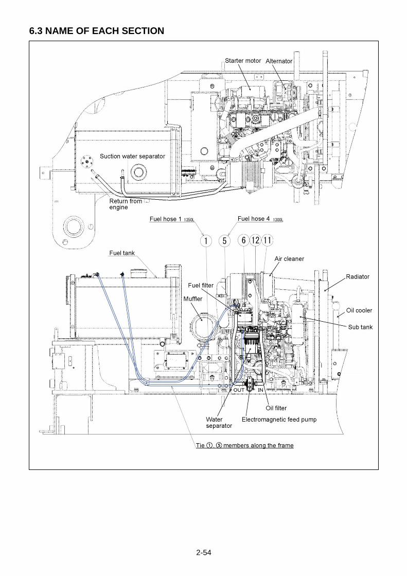
2-54
6.3 NAME OF EACH SECTION

2-55
6.4 CERTIFICATION NAME PLATE
6.4.1 EMISSION CONTROL CERTIFICATION NAME PLATE
Emission control is applied all over the world.
For this reason, it is necessary to clarify which regulations each
engine complies with.
The drawing on the right shows name plates placed on engines.
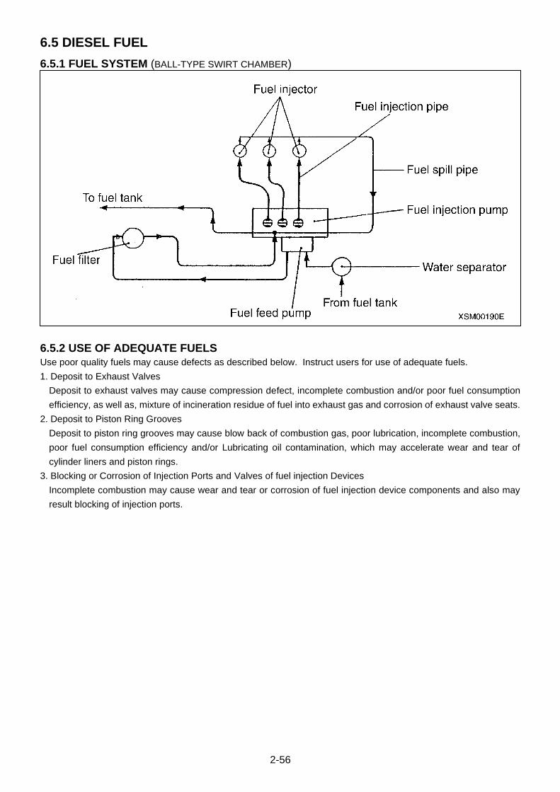
2-56
6.5 DIESEL FUEL
6.5.1 FUEL SYSTEM (BALL-TYPE SWIRT CHAMBER)
6.5.2 USE OF ADEQUATE FUELS
Use poor quality fuels may cause defects as described below. Instruct users for use of adequate fuels.
1. Deposit to Exhaust Valves
Deposit to exhaust valves may cause compression defect, incomplete combustion and/or poor fuel consumption
efficiency, as well as, mixture of incineration residue of fuel into exhaust gas and corrosion of exhaust valve seats.
2. Deposit to Piston Ring Grooves
Deposit to piston ring grooves may cause blow back of combustion gas, poor lubrication, incomplete combustion,
poor fuel consumption efficiency and/or Lubricating oil contamination, which may accelerate wear and tear of
cylinder liners and piston rings.
3. Blocking or Corrosion of Injection Ports and Valves of fuel injection Devices
Incomplete combustion may cause wear and tear or corrosion of fuel injection device components and also may
result blocking of injection ports.

2-57
6.5.3 DIESEL FUEL SPECIFICATIONS
Diesel fuel should comply with the following specifications. The table lists several worldwide specifications for diesel
fuels
Diesel Fuel Specification Location
JIS K2204 Grade No. 2 Japan
No.2-D, No.1-D, ASTM D975-94 USA
EN590: 96 European Union
ISO 8217 DM X International
BS 2869-A1 or A2 United Kingdom
KSM-2610 Korea
GB252 China
[Additional Technical Fuel Requirements]
・ The fuel cetane number should be equal to 45 or higher.
・ The sulfur content must not exceed 0.5% by volume.Less than 0.05% is preferred.
・ Bio-Diesel fuels. See Bio-Diesel Fuels on this page.
・ NEVER mix kerosene, used engine oil, or residual fuels the diesel fuel.
・ Water and sediment in the fuel should not exceed 0.05% by volume.
・ Keep the fuel tank and fuel-handling equipment clean at all times.
・ Poor quality fuel can reduce engine performance and / or cause engine damage.
・ Fuel additives are not recommended. Some fuel additives may cause poor engine performance. Consult your
Yanmar representative for more information.
・ Ash content not to exceed 0.01% by volume.
・ Carbon residue content not to exceed 0.35% by volume. Less than 0.1% is preferred.
・ Total aromatics content should not exceed 35% by volume. Less than 30% is preferred.
・ PAH (polycyclic aromatic hydrocarbons) content should be below 10% by volume.
・ Metal content of Na, Mg, Si, and Al should be equal to or lower than 1 mass ppm. (Test analysis method JPI-44-95)
・ Lubricity: Were mark of WS1.4 should be Max. 0.018 in. (460 μm) at HFRR test.
6.5.4 BIO-DIESEL FUELS
In Europe and in the United States, as well as some other countries, non-mineral oil based fuel resources such as
RME (Rapeseed Methyl Ester) and SOME (Soybean Methyl Ester), collectively known as FAME (Fatty Acid Methyl
Ester), are being used as extenders for mineral oil derived diesel fuels.
Yanmer approves the use of bio-diesel fuels that do not exceed a blend of 5% (by volume) of FAME with 95% (by
volume) of approved mineral oil derived diesel fuel. Such bio-diesel fuels are known in the marketplace as B5 diesel
fuels.
These B diesel fuels must meet certain requirements.
1. The bio-fuels must meet the minimum specifications for the country in which they are used.
・ In Europe, bio-diesel fuels must comply with the European Standard EN14214.
・ In the United States, bio-diesel fuels must comply with the American Standard ASTM D-6751.
2. Bio-fuels should be purchased only from recognized and authorized diesel fuel suppliers.
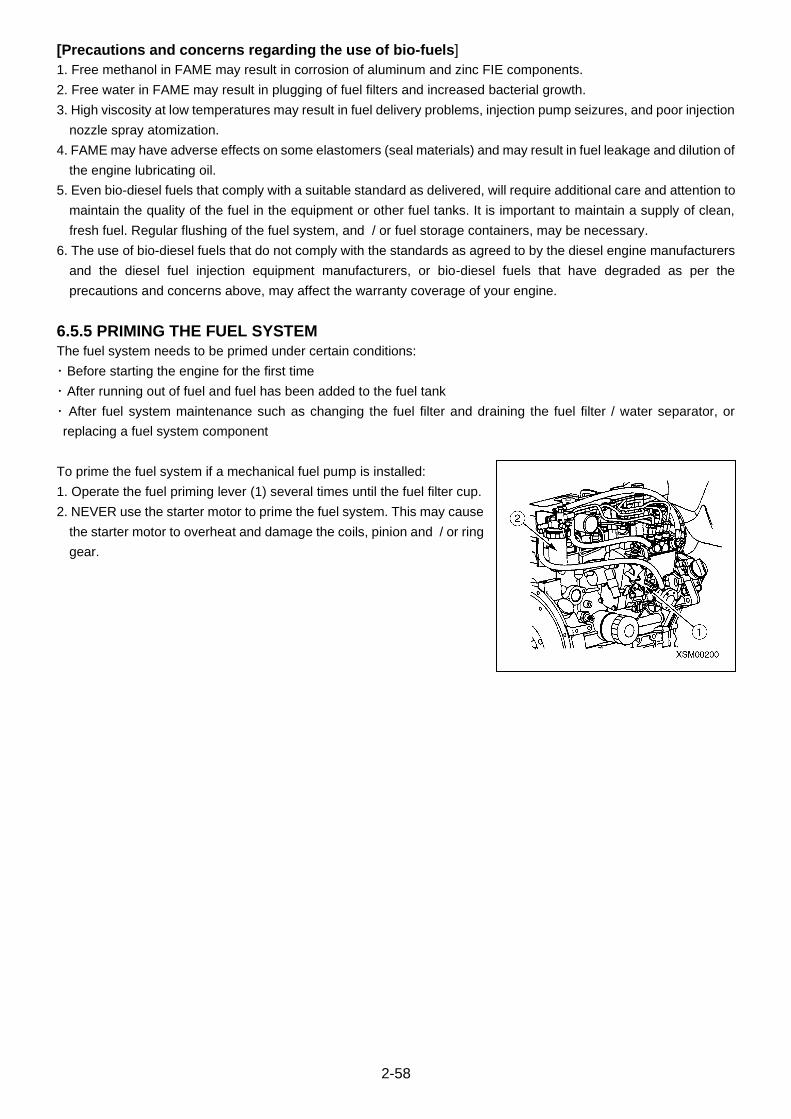
2-58
[Precautions and concerns regarding the use of bio-fuels]
1. Free methanol in FAME may result in corrosion of aluminum and zinc FIE components.
2. Free water in FAME may result in plugging of fuel filters and increased bacterial growth.
3. High viscosity at low temperatures may result in fuel delivery problems, injection pump seizures, and poor injection
nozzle spray atomization.
4. FAME may have adverse effects on some elastomers (seal materials) and may result in fuel leakage and dilution of
the engine lubricating oil.
5. Even bio-diesel fuels that comply with a suitable standard as delivered, will require additional care and attention to
maintain the quality of the fuel in the equipment or other fuel tanks. It is important to maintain a supply of clean,
fresh fuel. Regular flushing of the fuel system, and / or fuel storage containers, may be necessary.
6. The use of bio-diesel fuels that do not comply with the standards as agreed to by the diesel engine manufacturers
and the diesel fuel injection equipment manufacturers, or bio-diesel fuels that have degraded as per the
precautions and concerns above, may affect the warranty coverage of your engine.
6.5.5 PRIMING THE FUEL SYSTEM
The fuel system needs to be primed under certain conditions:
・ Before starting the engine for the first time
・ After running out of fuel and fuel has been added to the fuel tank
・ After fuel system maintenance such as changing the fuel filter and draining the fuel filter / water separator, or
replacing a fuel system component
To prime the fuel system if a mechanical fuel pump is installed:
1. Operate the fuel priming lever (1) several times until the fuel filter cup.
2. NEVER use the starter motor to prime the fuel system. This may cause
the starter motor to overheat and damage the coils, pinion and / or ring
gear.

2-59
This Page Intentionally Left Blank.
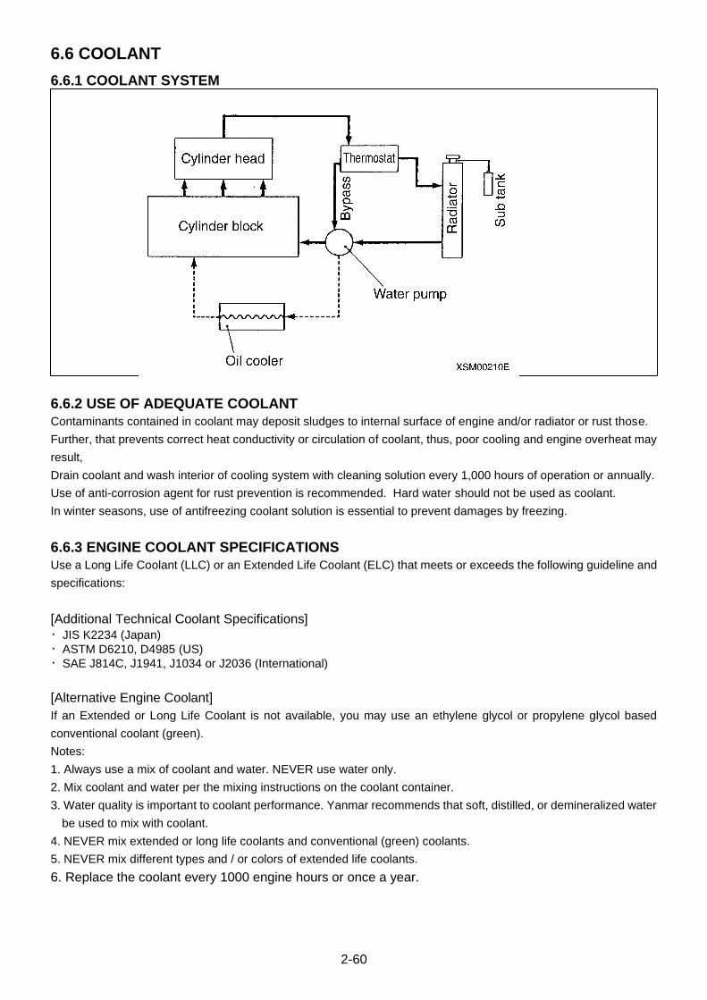
2-60
6.6 COOLANT
6.6.1 COOLANT SYSTEM
6.6.2 USE OF ADEQUATE COOLANT
Contaminants contained in coolant may deposit sludges to internal surface of engine and/or radiator or rust those.
Further, that prevents correct heat conductivity or circulation of coolant, thus, poor cooling and engine overheat may
result,
Drain coolant and wash interior of cooling system with cleaning solution every 1,000 hours of operation or annually.
Use of anti-corrosion agent for rust prevention is recommended. Hard water should not be used as coolant.
In winter seasons, use of antifreezing coolant solution is essential to prevent damages by freezing.
6.6.3 ENGINE COOLANT SPECIFICATIONS
Use a Long Life Coolant (LLC) or an Extended Life Coolant (ELC) that meets or exceeds the following guideline and
specifications:
[Additional Technical Coolant Specifications]
・JIS K2234 (Japan)
・ASTM D6210, D4985 (US)
・SAE J814C, J1941, J1034 or J2036 (International)
[Alternative Engine Coolant]
If an Extended or Long Life Coolant is not available, you may use an ethylene glycol or propylene glycol based
conventional coolant (green).
Notes:
1. Always use a mix of coolant and water. NEVER use water only.
2. Mix coolant and water per the mixing instructions on the coolant container.
3. Water quality is important to coolant performance. Yanmar recommends that soft, distilled, or demineralized water
be used to mix with coolant.
4. NEVER mix extended or long life coolants and conventional (green) coolants.
5. NEVER mix different types and / or colors of extended life coolants.
6. Replace the coolant every 1000 engine hours or once a year.
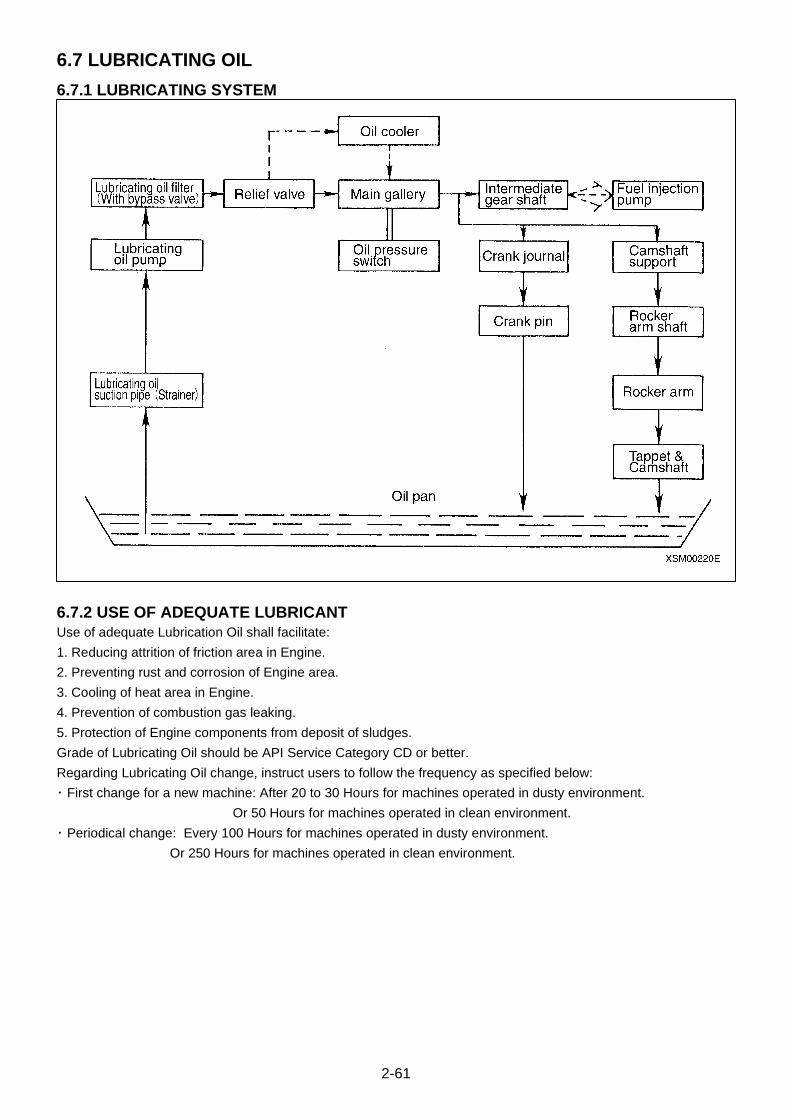
2-61
6.7 LUBRICATING OIL
6.7.1 LUBRICATING SYSTEM
6.7.2 USE OF ADEQUATE LUBRICANT
Use of adequate Lubrication Oil shall facilitate:
1. Reducing attrition of friction area in Engine.
2. Preventing rust and corrosion of Engine area.
3. Cooling of heat area in Engine.
4. Prevention of combustion gas leaking.
5. Protection of Engine components from deposit of sludges.
Grade of Lubricating Oil should be API Service Category CD or better.
Regarding Lubricating Oil change, instruct users to follow the frequency as specified below:
・ First change for a new machine: After 20 to 30 Hours for machines operated in dusty environment.
Or 50 Hours for machines operated in clean environment.
・ Periodical change: Every 100 Hours for machines operated in dusty environment.
Or 250 Hours for machines operated in clean environment.

2-62
6.7.3 ENGINE OIL SPECIFICATIONS
Use an engine oil that meets or exceeds the following guidelines and classifications:
[Service Categories]
・API Service Categories CD or higher
・ACEA Service Categories E-3, E-4, and E-5
・JASO Service Categories DH-1
[Definitions]
・API Classification (American Petroleum Institute)
・ACEA Classification (Association des Constructeurs Europeens d’Automobilies)
・JASO (Japanese Automobile Standards Organization)
[Additional Technical Engine Oil Requirements]
The engine oil must be changed when the Total Base Number (TBN) has been reduced to 1.0 (mgKOH/g) test
method: JIS K-201-5.2-2 (HCI), ASTM D4739 (HCI).
[Engine Oil Viscosity]
Select the appropriate engine oil viscosity based on the ambient temperature and use the SAE Service Grade
Viscosity Chart below.
[Precautions the use of engine oil]
1. Be sure the engine oil, engine oil storage containers, and engine oil filling equipment are free sediments and water.
2. Change the engine oil after the first 50 hours of operation and then every 250 hours thereafter.
3. Select the oil viscosity based on the ambient temperature where the engine is being operated. See the SAE
Service Grade Viscosity Chart.
4. Yanmar does not recommended the use of engine oil “additives”.
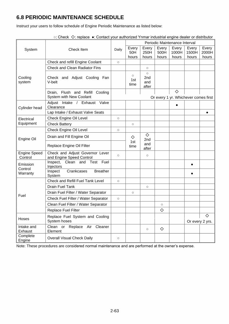
2-63
6.8 PERIODIC MAINTENANCE SCHEDULE
Instruct your users to follow schedule of Engine Periodic Maintenance as listed below:
○: Check ◇: replace ●: Contact your authorized Ynmar industrial engine dealer or distributor
System Check Item Daily
Periodic Maintenance Interval
Every 50H
hours
Every 250H hours
Every 500H hours
Every 1000H hours
Every 1500H hours
Every 2000H hours
Cooling system
Check and refill Engine Coolant ○
Check and Clean Radiator Fins ○
Check and Adjust Cooling Fan V-belt
○
1st time
○ 2nd and after
Drain, Flush and Refill Cooling System with New Coolant
◇
Or every 1 yr. Whichever comes first
Cylinder head
Adjust Intake / Exhaust Valve Clearance
●
Lap Intake / Exhaust Valve Seats ●
Electrical Equipment
Check Engine Oil Level ○
Check Battery ○
Engine Oil
Check Engine Oil Level ○
Drain and Fill Engine Oil ◇
1st time
◇ 2nd and after
Replace Engine Oil Filter
Engine Speed Control
Check and Adjust Governor Lever and Engine Speed Control
○ ○
Emission Control Warranty
Inspect, Clean and Test Fuel Injectors
●
Inspect Crankcases Breather System
●
Fuel
Check and Refill Fuel Tank Level ○
Drain Fuel Tank ○
Drain Fuel Filter / Water Separator ○
Check Fuel Filter / Water Separator ○
Clean Fuel Filter / Water Separator ○
Replace Fuel Filter ◇
Hoses Replace Fuel System and Cooling System hoses
◇
Or every 2 yrs.
Intake and Exhaust
Clean or Replace Air Cleaner Element
○ ◇
Complete Engine
Overall Visual Check Daily ○
Note: These procedures are considered normal maintenance and are performed at the owner’s expense.

2-64
6.9 TROUBLE SHOOTING
This table is a summary of general disorders and causes. It is strongly advised to take adequate actions to prevent
serious accidents whenever an indication of any disorder is detected:
Disorders
Cause
Disorders at Starting
Engine Power Down
Exhaust Gas
Hig
h K
nockin
g N
ois
e
Hig
h E
ngin
e N
ois
e
Irre
gula
r E
xha
ust S
oun
d
Hunting
Eng
ine
not
sta
rtin
g
Engine stall
Exhaust Gas
Operat.
Idlin
g t
ime
Opera
tion t
ime
Smoke
Norm
al
Wh
ite
Bla
ck
Wh
ite
Bla
ck
None
Lig
ht
Heavy
Eng
ine
Syste
m
Improper Valve clearance, Intake/ Exhaust Valves.
○ ○ ○ ○
Combustion gas leak from Valve Seats ○ ○ ○ ○
Intake/ Exhaust Valves Seizure ○ ○ ○ ○ ○ ○ ○
Head Gaskets Blow ○
Seizure or breakage of Piston Rings ○ ○ ○ ○ ○ ○
Wearing of Piston Rings, Pistons and Cylinders
○ ○ ○ ○
Seizure of Crank pin metals and Bearings ○ ○ ○ ○ ○
Piston Ring Joint Clearance Error ○ ○
Reverse assembled Piston Ring ○ ○
Wearing of Crank Pins and Journal Metals ○ ○ ○ ○
Connecting Rod Bolts, Loose ○
Foreign Material in Combustion Chamber ○ ○
Excess Backlash of Gears ○
Wearing of Intake/ Exhaust Valve Guides ○
Mis-adjusting of Governor ○ ○ ○
Intake/ Exhaust Valves, Timing Error ○ ○ ○ ○ ○ ○
Coolin
g S
yste
m Radiator, Over-cool ○
Radiator, Insufficient cooling ○
Coolant Water Shortage ○
Crack in Water Jacket
Fan-belt, loose ○
Thermostat Disorder ○ ○
Lubricatin
g O
il S
yste
m Poor Quality Lubricating Oil ○ ○ ○
Leakage of Lubricating Oil System
Trochoid Pump, Lower Output
Lubricating Oil Filter Clogging
Mis-adjusting of Pressure Control Valves
Lubricating Oil Shortage ○
Excess Lubricant Supply to Crank Case

2-65
Eng
ine
Vib
ration
Poor
Decele
ration R
esponse
Excess F
uel C
onsum
ption
Lubricating Oil
Excess B
low
-by
Coolant Intake
Hig
her
Exh
aust G
as T
em
pera
ture
Counter-action
Excess C
onsum
ptio
n
Dilu
tion b
y F
uel
Leakin
g t
o C
oola
nt
Low
er
Pre
ssure
Overh
eat
Tem
pera
ture
too low
Low
er
Pre
ssure
Hig
her
Pre
ssure
○ ○ Adjust valve clearance
○ ○ ○ ○ Valve seat fitting
○ ○ ○ ○ Repair or replace intake and exhaust valve
○ ○ Replace gasket
○ ○ ○ ○ ○ ○ Replace Piston Ring
○ ○ ○ Honing, or replace to over-sized components
○ ○ Repair or replace
○ ○ Re-adjust Joint position
○ ○ Re-assemble
○ ○ Measure and replace
○ ○ Tighten to designated torque
○ ○ Disassembly and repair
Re-adjust gear interlocking
○ ○ Measure and replace
○ ○ Adjust
Adjust valve clearance
○ ○ Replace thermostat
○ ○ Replace thermostat or loose check fan belt
○ ○ Checking Leakage of coolant system
○ ○ ○ Repair or replace
○ ○ Check belt tension
○ ○ Check or replace
○ ○ ○ Replace to adequate lubricating oil
○ Repair
○ Check and repair
○ ○ Clean or Replace
○ Clean, adjust or replace
○ Refilling adequate lubricating oil
○ Check engine oil
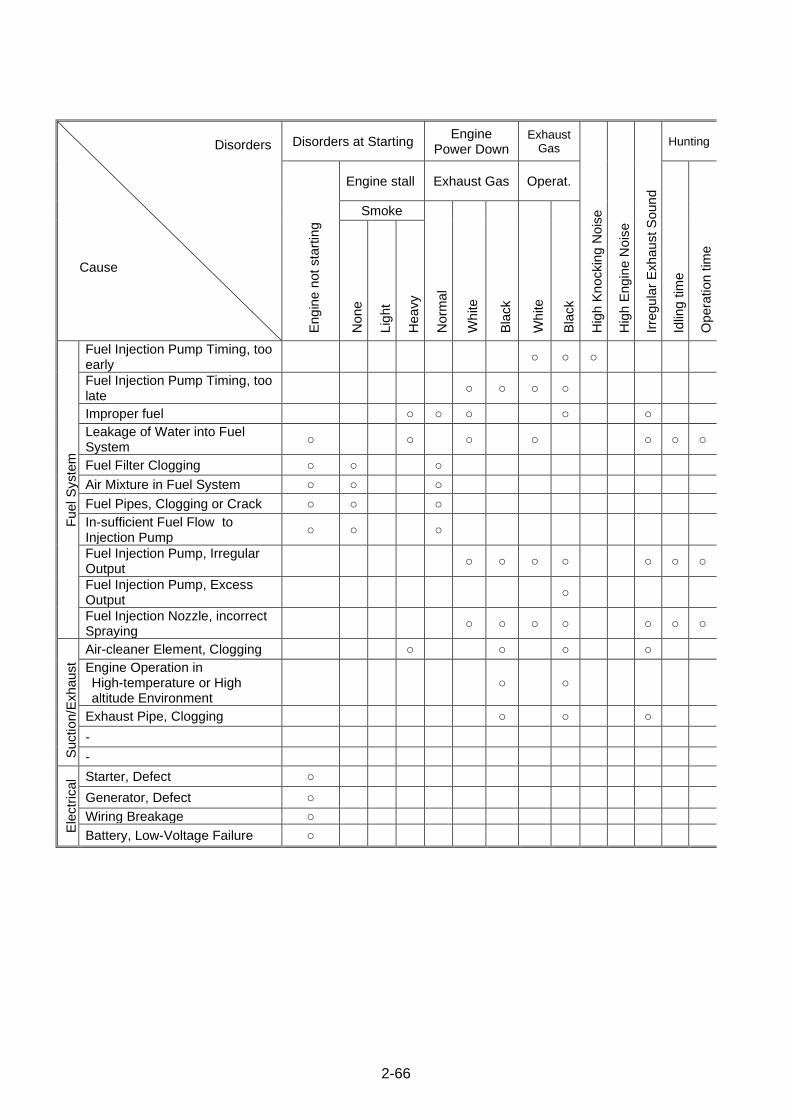
2-66
Disorders
Cause
Disorders at Starting Engine
Power Down Exhaust
Gas
Hig
h K
nockin
g N
ois
e
Hig
h E
ngin
e N
ois
e
Irre
gula
r E
xha
ust S
oun
d
Hunting
Eng
ine
not
sta
rtin
g
Engine stall Exhaust Gas Operat.
Idlin
g t
ime
Opera
tion t
ime
Smoke
Norm
al
Wh
ite
Bla
ck
Wh
ite
Bla
ck
None
Lig
ht
Heavy
Fuel S
yste
m
Fuel Injection Pump Timing, too early
○ ○ ○
Fuel Injection Pump Timing, too late
○ ○ ○ ○
Improper fuel ○ ○ ○ ○ ○
Leakage of Water into Fuel System
○ ○ ○ ○ ○ ○ ○
Fuel Filter Clogging ○ ○ ○
Air Mixture in Fuel System ○ ○ ○
Fuel Pipes, Clogging or Crack ○ ○ ○
In-sufficient Fuel Flow to Injection Pump
○ ○ ○
Fuel Injection Pump, Irregular Output
○ ○ ○ ○ ○ ○ ○
Fuel Injection Pump, Excess Output
○
Fuel Injection Nozzle, incorrect Spraying
○ ○ ○ ○ ○ ○ ○
Suction/E
xhaust
Air-cleaner Element, Clogging ○ ○ ○ ○
Engine Operation in High-temperature or High altitude Environment
○ ○
Exhaust Pipe, Clogging ○ ○ ○
-
-
Ele
ctr
ica
l Starter, Defect ○
Generator, Defect ○
Wiring Breakage ○
Battery, Low-Voltage Failure ○

2-67
Eng
ine
Vib
ration
Poor
Decele
ration R
esponse
Excess F
uel C
onsum
ption
Lubricating Oil
Excess B
low
-by
Coolant Intake
Hig
her
Exh
aust G
as T
em
pera
ture
Counter-action
Excess C
onsum
ptio
n
Dilu
tion b
y F
uel
Leakin
g t
o C
oola
nt
Low
er
Pre
ssure
Overh
eat
Tem
pera
ture
too low
Low
er
Pre
ssure
Hig
her
Pre
ssure
○ Check and adjust
○ ○ Check and adjust
Replace to adequate fuel
Drain fuel filter
Clean or replace
Air bleed
Clean or replace
Check fuel filter and feed pump
○ ○ Check and adjust
○ ○ ○ ○ ○ ○ Check and adjust
○ ○ Check and adjust
○ ○ ○ Clean air cleaner element
○ Verity the matching of power-loss and required loads.
Clean exhaust pipe
-
-
Repair or replace starter motor
Repair or replace generator
Repair the broken wires
Check battery and re-charge
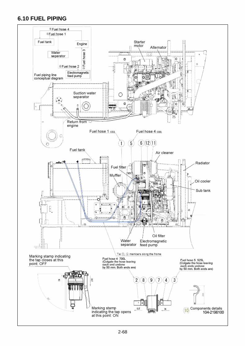
2-68
6.10 FUEL PIPING

2-69
No. Name Qty. Note
1 Fuel hose 1 1 Yokohama fuel hose Nominal size φ8 × φ15 × 1350L Part No.: 22823-31350
2 Fuel hose 2 1 Yokohama fuel hose Nominal size φ8 × φ15 × 490L Part No.: 22823-30490
3 Fuel hose 3 1 Yokohama fuel hose Nominal size φ8 × φ15 × 405L Part No.: 22823-30405
4 Crescent clamp 8 RS8006 Part No.: 22973-00600
5 Fuel hose 4 1 Yokohama fuel hose Nominal size φ8 × φ15 × 1300L Part No.: 22823-31300
6 Water separator 1 Part No.: 129242-55710
7 Solenoid feed pump 1 Part No.: 119225-52102
8 Base plate 1 Part No.: 104-4541400
9 Bolt with washer 4 M6 × 1.0 × 15L (with PW+SW, plated) Part No.: 21A12M06015
10 Spanner for water separator 1 Part No.: 119803-92700
11 Spring washer 1 M8 × Type-2 (plated) Part No.: 21711M08002
12 Hexagon head bolt 1 M8 × 1.25 × 70L (plated) Part No.: 21015M08070

2-70
7. HYDRAULIC PUMP
7.1 HYDRAULIC PUMP FOR ENGINE Type: PVD-1B-34-5933A
7.1.1 APPEARANCE AND SPECIFICATIONS
Specifications
Pump capacity P1+P2 : 17+17 cc/rev Oil used ISO VG 32, 46, 68
Maximum pressure P1: 21.5 Mpa (219 kg/cm2) P2: 21.5 MPa (219 kg/cm2)
Oil temperature range -20 to 80°C
Hydraulic fluid pollution level
Within NAS level 11
Rotation Rated 2400 min-1 Suction strainer 150 mesh
Maximum 2500 min-1 Line filter 10 μm
Variable control mechanism
Fixed horsepower control (P1 + P2)
Vibration level Within 10 G
Direction of rotation Rotate clockwise
Suction pressure
-0.02 to +0.04 MPa
Mass 15 kg (Suction-side slow down within 2 m/sec)
Paint colour Ebony grey colour Oiling Fill the pump case with clean hydraulic fluid before starting the pump.
S104I4129000
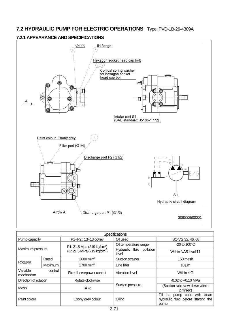
2-71
7.2 HYDRAULIC PUMP FOR ELECTRIC OPERATIONS Type: PVD-1B-26-4309A
7.2.1 APPEARANCE AND SPECIFICATIONS
Specifications
Pump capacity P1+P2 : 13+13 cc/rev Oil used ISO VG 32, 46, 68
Maximum pressure P1: 21.5 Mpa (219 kg/cm2) P2: 21.5 MPa (219 kg/cm2)
Oil temperature range -20 to 100°C
Hydraulic fluid pollution level
Within NAS level 11
Rotation Rated 2600 min-1 Suction strainer 150 mesh
Maximum 2700 min-1 Line filter 10 μm
Variable control mechanism
Fixed horsepower control Vibration level Within 4 G
Direction of rotation Rotate clockwise
Suction pressure
-0.02 to +0.10 MPa
Mass 14 kg (Suction-side slow down within
2 m/sec)
Paint colour Ebony grey colour Oiling Fill the pump case with clean hydraulic fluid before starting the pump.
306S32500001
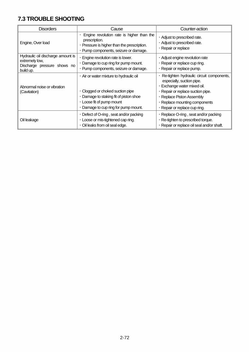
2-72
7.3 TROUBLE SHOOTING
Disorders Cause Counter-action
Engine, Over load
・ Engine revolution rate is higher than the
prescription.
・ Pressure is higher than the prescription.
・ Pump components, seizure or damage.
・ Adjust to prescribed rate.
・ Adjust to prescribed rate.
・ Repair or replace
Hydraulic oil discharge amount is extremely low, Discharge pressure shows no build up.
・ Engine revolution rate is lower.
・ Damage to cup ring for pump mount.
・ Pump components, seizure or damage.
・ Adjust engine revolution rate
・ Repair or replace cup ring.
・ Repair or replace pump.
Abnormal noise or vibration (Cavitation)
・ Air or water mixture to hydraulic oil
・ Clogged or choked suction pipe
・ Damage to staking fit of piston shoe
・ Loose fit of pump mount
・ Damage to cup ring for pump mount.
・ Re-tighten hydraulic circuit components,
especially, suction pipe.
・ Exchange water mixed oil.
・ Repair or replace suction pipe.
・ Replace Piston Assembly
・ Replace mounting components
・ Repair or replace cup ring.
Oil leakage
・ Defect of O-ring , seat and/or packing
・ Loose or mis-tightened cap ring.
・ Oil leaks from oil seal edge.
・ Replace O-ring , seat and/or packing
・ Re-tighten to prescribed torque.
・ Repair or replace oil seal and/or shaft.

2-73
This Page Intentionally Left Blank.
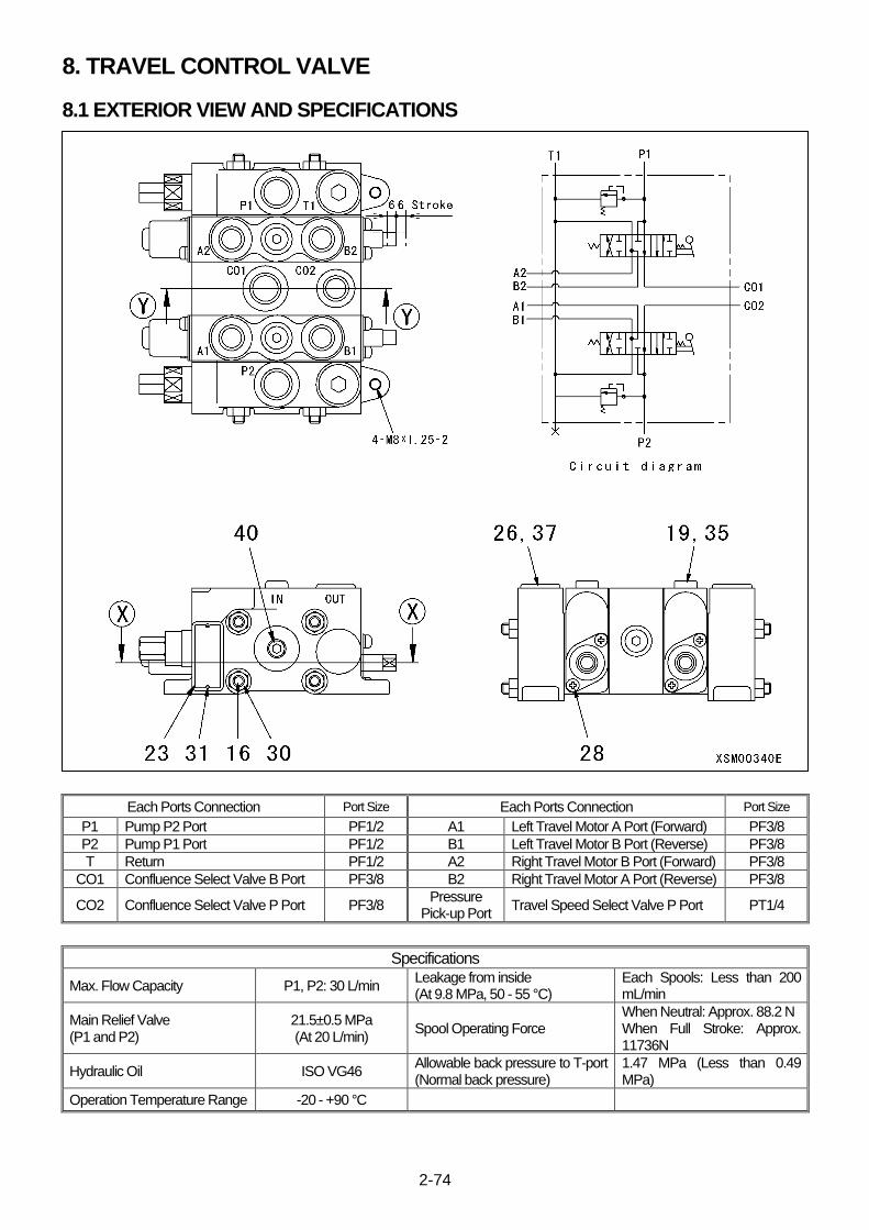
2-74
8. TRAVEL CONTROL VALVE
8.1 EXTERIOR VIEW AND SPECIFICATIONS
Each Ports Connection Port Size Each Ports Connection Port Size
P1 Pump P2 Port PF1/2 A1 Left Travel Motor A Port (Forward) PF3/8
P2 Pump P1 Port PF1/2 B1 Left Travel Motor B Port (Reverse) PF3/8
T Return PF1/2 A2 Right Travel Motor B Port (Forward) PF3/8
CO1 Confluence Select Valve B Port PF3/8 B2 Right Travel Motor A Port (Reverse) PF3/8
CO2 Confluence Select Valve P Port PF3/8 Pressure
Pick-up Port Travel Speed Select Valve P Port PT1/4
Specifications
Max. Flow Capacity P1, P2: 30 L/min Leakage from inside (At 9.8 MPa, 50 - 55 °C)
Each Spools: Less than 200 mL/min
Main Relief Valve (P1 and P2)
21.5±0.5 MPa (At 20 L/min)
Spool Operating Force When Neutral: Approx. 88.2 N When Full Stroke: Approx. 11736N
Hydraulic Oil ISO VG46 Allowable back pressure to T-port (Normal back pressure)
1.47 MPa (Less than 0.49 MPa)
Operation Temperature Range -20 - +90 °C
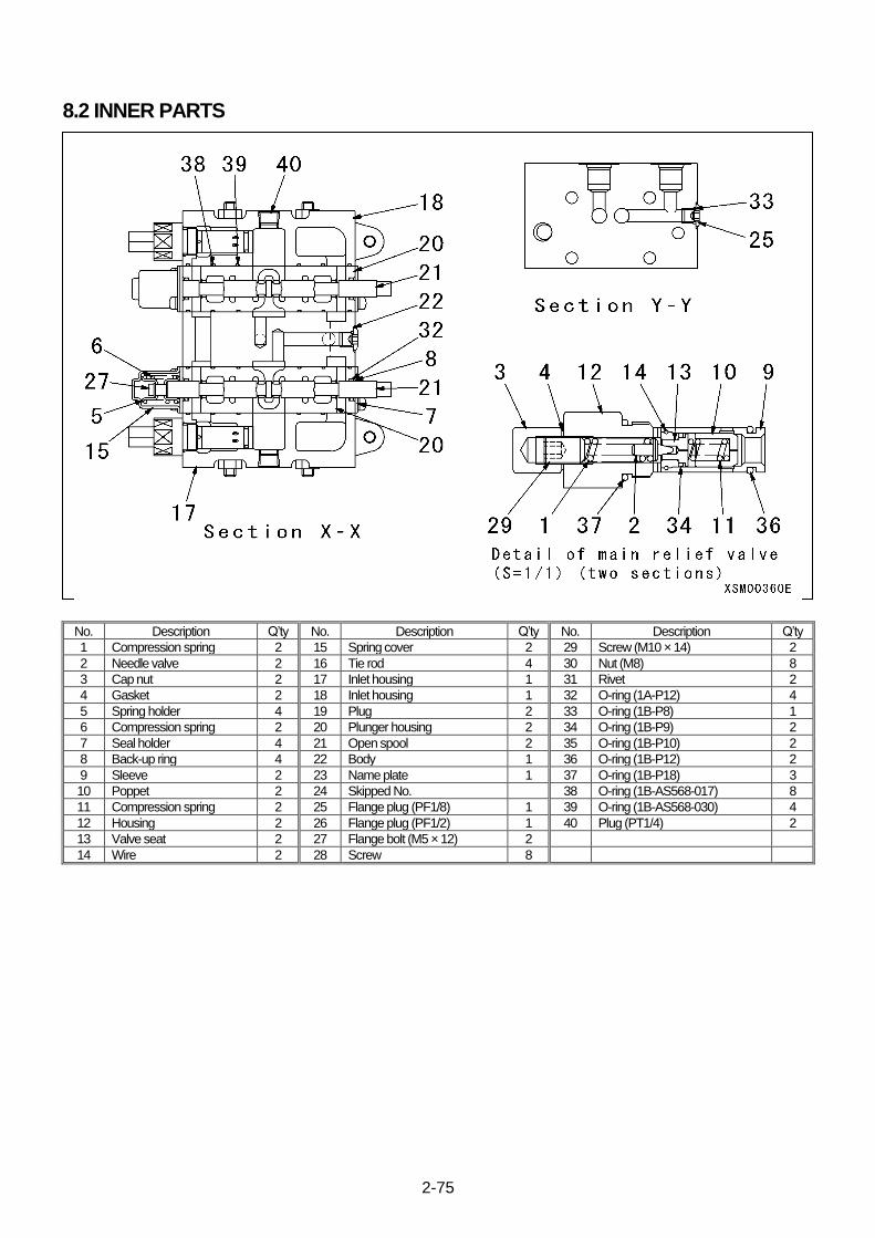
2-75
8.2 INNER PARTS
No. Description Q’ty No. Description Q’ty No. Description Q’ty
1 Compression spring 2 15 Spring cover 2 29 Screw (M10 × 14) 2
2 Needle valve 2 16 Tie rod 4 30 Nut (M8) 8
3 Cap nut 2 17 Inlet housing 1 31 Rivet 2
4 Gasket 2 18 Inlet housing 1 32 O-ring (1A-P12) 4
5 Spring holder 4 19 Plug 2 33 O-ring (1B-P8) 1
6 Compression spring 2 20 Plunger housing 2 34 O-ring (1B-P9) 2
7 Seal holder 4 21 Open spool 2 35 O-ring (1B-P10) 2
8 Back-up ring 4 22 Body 1 36 O-ring (1B-P12) 2
9 Sleeve 2 23 Name plate 1 37 O-ring (1B-P18) 3
10 Poppet 2 24 Skipped No. 38 O-ring (1B-AS568-017) 8
11 Compression spring 2 25 Flange plug (PF1/8) 1 39 O-ring (1B-AS568-030) 4
12 Housing 2 26 Flange plug (PF1/2) 1 40 Plug (PT1/4) 2
13 Valve seat 2 27 Flange bolt (M5 × 12) 2
14 Wire 2 28 Screw 8
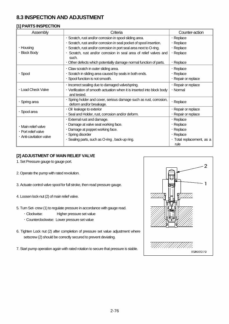
2-76
8.3 INSPECTION AND ADJUSTMENT
[1] PARTS INSPECTION
Assembly Criteria Counter-action
・ Housing
・ Block Body
・ Scratch, rust and/or corrosion in spool sliding area.
・ Scratch, rust and/or corrosion in seal pocket of spool insertion.
・ Scratch, rust and/or corrosion in port seal area next to O-ring.
・ Scratch, rust and/or corrosion in seal area of relief valves and
such.
・ Other defects which potentially damage normal function of parts.
・ Replace
・ Replace
・ Replace
・ Replace
・ Replace
・ Spool
・ Claw scratch in outer sliding area.
・ Scratch in sliding area caused by seals in both ends.
・ Spool function is not smooth.
・ Replace
・ Replace
・ Repair or replace
・ Load Check Valve
・ Incorrect sealing due to damaged valve/spring.
・ Verification of smooth actuation when it is inserted into block body
and tested.
・ Repair or replace
・ Normal
・ Spring area ・ Spring holder and cover, serious damage such as rust, corrosion,
deform and/or breakage. ・ Replace
・ Spool area ・ Oil leakage to exterior
・ Seal and Holder, rust, corrosion and/or deform.
・ Repair or replace
・ Repair or replace
・ Main relief valve
・ Port relief valve
・ Anti-cavitation valve
・ External rust and damage.
・ Damage at valve seat working face.
・ Damage at poppet working face.
・ Spring disorder
・ Sealing parts, such as O-ring , back-up ring.
・ Replace
・ Replace
・ Replace
・ Replace
・ Total replacement, as a
rule
[2] ADJUSTMENT OF MAIN RELIEF VALVE
1. Set Pressure gauge to gauge port.
2. Operate the pump with rated revolution.
3. Actuate control valve spool for full stroke, then read pressure gauge.
4. Loosen lock-nut (2) of main relief valve.
5. Turn Set- crew (1) to regulate pressure in accordance with gauge read.
・ Clockwise: Higher pressure set value
・ Counterclockwise: Lower pressure set value
6. Tighten Lock nut (2) after completion of pressure set value adjustment where
setscrew (2) should be correctly secured to prevent deviating.
7. Start pump operation again with rated rotation to secure that pressure is stable.
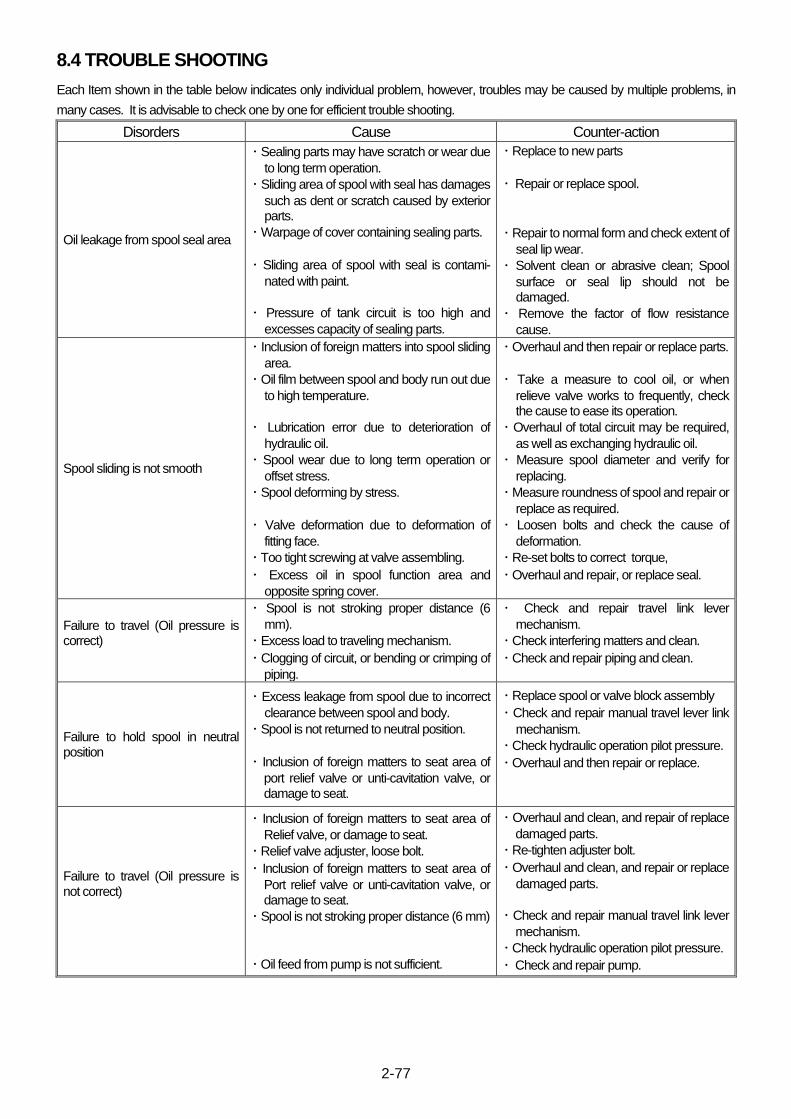
2-77
8.4 TROUBLE SHOOTING
Each Item shown in the table below indicates only individual problem, however, troubles may be caused by multiple problems, in
many cases. It is advisable to check one by one for efficient trouble shooting.
Disorders Cause Counter-action
Oil leakage from spool seal area
・ Sealing parts may have scratch or wear due
to long term operation.
・ Sliding area of spool with seal has damages
such as dent or scratch caused by exterior parts.
・ Warpage of cover containing sealing parts.
・ Sliding area of spool with seal is contami-
nated with paint.
・ Pressure of tank circuit is too high and
excesses capacity of sealing parts.
・ Replace to new parts
・ Repair or replace spool.
・ Repair to normal form and check extent of
seal lip wear.
・ Solvent clean or abrasive clean; Spool
surface or seal lip should not be damaged.
・ Remove the factor of flow resistance
cause.
Spool sliding is not smooth
・ Inclusion of foreign matters into spool sliding
area.
・ Oil film between spool and body run out due
to high temperature.
・ Lubrication error due to deterioration of
hydraulic oil.
・ Spool wear due to long term operation or
offset stress.
・ Spool deforming by stress.
・ Valve deformation due to deformation of
fitting face.
・ Too tight screwing at valve assembling.
・ Excess oil in spool function area and
opposite spring cover.
・ Overhaul and then repair or replace parts.
・ Take a measure to cool oil, or when
relieve valve works to frequently, check the cause to ease its operation.
・ Overhaul of total circuit may be required,
as well as exchanging hydraulic oil.
・ Measure spool diameter and verify for
replacing.
・ Measure roundness of spool and repair or
replace as required.
・ Loosen bolts and check the cause of
deformation.
・ Re-set bolts to correct torque,
・ Overhaul and repair, or replace seal.
Failure to travel (Oil pressure is correct)
・ Spool is not stroking proper distance (6
mm).
・ Excess load to traveling mechanism.
・ Clogging of circuit, or bending or crimping of
piping.
・ Check and repair travel link lever
mechanism.
・ Check interfering matters and clean.
・ Check and repair piping and clean.
Failure to hold spool in neutral position
・ Excess leakage from spool due to incorrect
clearance between spool and body.
・ Spool is not returned to neutral position.
・ Inclusion of foreign matters to seat area of
port relief valve or unti-cavitation valve, or damage to seat.
・ Replace spool or valve block assembly
・ Check and repair manual travel lever link
mechanism.
・ Check hydraulic operation pilot pressure.
・ Overhaul and then repair or replace.
Failure to travel (Oil pressure is not correct)
・ Inclusion of foreign matters to seat area of
Relief valve, or damage to seat.
・ Relief valve adjuster, loose bolt.
・ Inclusion of foreign matters to seat area of
Port relief valve or unti-cavitation valve, or damage to seat.
・ Spool is not stroking proper distance (6 mm)
・ Oil feed from pump is not sufficient.
・ Overhaul and clean, and repair of replace
damaged parts.
・ Re-tighten adjuster bolt.
・ Overhaul and clean, and repair or replace
damaged parts.
・ Check and repair manual travel link lever
mechanism.
・ Check hydraulic operation pilot pressure.
・ Check and repair pump.

2-78
9.TRAVELING MOTOR
9.1 EXTERIOR VIEW AND SPECIFICATIONS
Right Traveling Motor Left Traveling Motor
A Port Reverse B Port Reverse
B Port Forward A Port Forward
Specifications Specifications Of Reduction Gear
Max. Output Torque 4766 N・m (486 kgf・m)
Max. Output Revolution 35.0 / 57.8 min-1
Reduction Ratio 1 / 47.53
Specifications Of Hydraulic Motor
Capacity 35.3 / 21.2 cm3/rev
Max. Common Use Pressure 21.0 MPa (214 kgf/cm2)
Max. Output Revolution 1666 / 2745 min-1
Max. Flow Capacity 60.0 L/min
Speed Range Changing Pressure 1.5 MPa (15 kgf/cm2)
Parking Brake Static Frictional Torque 86.3 N・m (8.8 kgf・m)
Release Pressure 1.5 MPa (15 kgf/cm2)
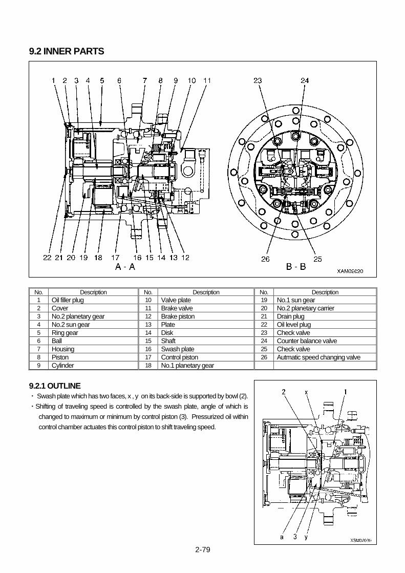
2-79
9.2 INNER PARTS
No. Description No. Description No. Description
1 Oil filler plug 10 Valve plate 19 No.1 sun gear 2 Cover 11 Brake valve 20 No.2 planetary carrier 3 No.2 planetary gear 12 Brake piston 21 Drain plug
4 No.2 sun gear 13 Plate 22 Oil level plug
5 Ring gear 14 Disk 23 Check valve
6 Ball 15 Shaft 24 Counter balance valve
7 Housing 16 Swash plate 25 Check valve
8 Piston 17 Control piston 26 Autmatic speed changing valve
9 Cylinder 18 No.1 planetary gear
9.2.1 OUTLINE
・ Swash plate which has two faces, x , y on its back-side is supported by bowl (2).
・Shifting of traveling speed is controlled by the swash plate, angle of which is
changed to maximum or minimum by control piston (3). Pressurized oil within
control chamber actuates this control piston to shift traveling speed.

2-80
9.2.2 BASICS OF FUNCTIONALITY
1. Low Speed Travel (Motor Swash Plate Angle is Maximum)
・ Pressurized oil shall not flow from travel control valve to PP port since acceleration valve (1) is demagnetized.
・ Pressurized oil shall not flow from travel control valve to PP port since automatic control valve (2) is pressed downward by Spring
(3).
・ Swash plate (6) will be pressed rightward by tension of spring (7) since control chamber a is connected to drain port.
・ Consequently, swash plate which has its pivot in bowl (8) is shifted to its maximum angle and provides low speed travel.
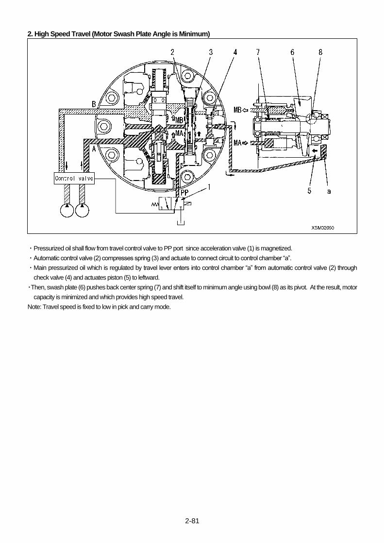
2-81
2. High Speed Travel (Motor Swash Plate Angle is Minimum)
・Pressurized oil shall flow from travel control valve to PP port since acceleration valve (1) is magnetized.
・Automatic control valve (2) compresses spring (3) and actuate to connect circuit to control chamber “a”.
・Main pressurized oil which is regulated by travel lever enters into control chamber “a” from automatic control valve (2) through
check valve (4) and actuates piston (5) to leftward.
・Then, swash plate (6) pushes back center spring (7) and shift itself to minimum angle using bowl (8) as its pivot. At the result, motor
capacity is minimized and which provides high speed travel.
Note: Travel speed is fixed to low in pick and carry mode.

2-82
9.2.3 FUNCTION OF AUTOMATIC CONTROL VALVE
1. Automatic Travel Speed Control from High to Low
・ When shift switch is turned to “High Speed Travel” and machine is traveling in high speed, pressure to actuate motor (Pc) is
introduced into chamber (a) and chamber (b) of automatic control valve.
・ When pressure to actuate motor (Pc) raise, a force is generated by difference of size of pressurized areas of chamber (a) and
chamber (b) (a>b). The force together with tension of spring (2) exceeds force (F3) which is generated by pilot pressure (PP). (F3
<F1-F2)
・ Then automatic control valve (1) is actuated leftward and cuts pressure to actuate motor (A) which flowed into control chamber (c).
・ At the same time, DR port opens to drain oil filled in control chamber (c) which actuated control piston (3) leftward.
・ Consequently, swash plate in motor unit (4) is shifted to maximum angle which provides low speed travel.
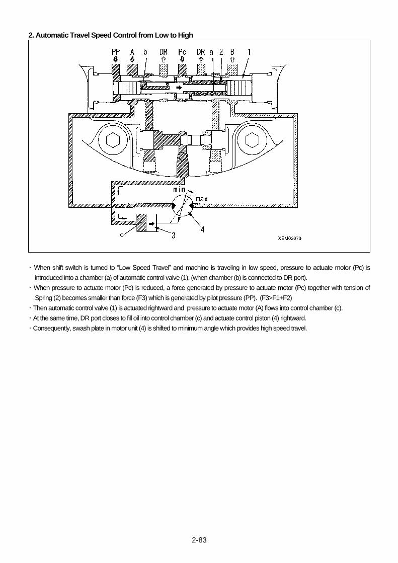
2-83
2. Automatic Travel Speed Control from Low to High
・ When shift switch is turned to “Low Speed Travel” and machine is traveling in low speed, pressure to actuate motor (Pc) is
introduced into a chamber (a) of automatic control valve (1), (when chamber (b) is connected to DR port).
・ When pressure to actuate motor (Pc) is reduced, a force generated by pressure to actuate motor (Pc) together with tension of
Spring (2) becomes smaller than force (F3) which is generated by pilot pressure (PP). (F3>F1+F2)
・ Then automatic control valve (1) is actuated rightward and pressure to actuate motor (A) flows into control chamber (c).
・ At the same time, DR port closes to fill oil into control chamber (c) and actuate control piston (4) rightward.
・ Consequently, swash plate in motor unit (4) is shifted to minimum angle which provides high speed travel.

2-84
9.2.4 FUNCTION OF COUNTER BALANCE VALVE
1. Function of Feed Mode
When travel lever is operated, pressurized oil shall be fed to A port
from control valve which opens check valve (1). Pressurized oil
flows from motor intake port MA to motor exit valve MB.
On the other hand, pressurized oil, entered into chamber (D)
through orifice (C) shall push back tension of spring (2) and
actuate spool (3) rightward.
Then MB port and B port are connected which opens exit side of
motor and makes it rotate.
2. Function of Interrupt Mode
When the travel lever is returned to neutral position, pressurized
oil from control valve is interrupted. At the result, spool (3) is pulled
by tension of spring (2) and starts to return leftward.
Pressurized oil tends to flow into A port through chamber (D) and
orifice (C), however, back pressure generated by choking of
orifice (C) controls rate of this flow.
Motor still tends to keep rotating by moment of inertia after
pressurized oil to A port is interrupted.
Return oil is interrupted gradually by shifting rate of spool (3) and
notched shape, which brakes motor smoothly.
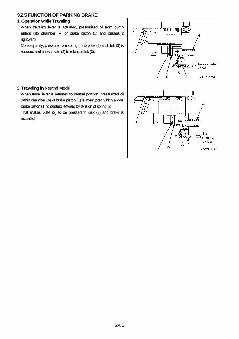
2-85
9.2.5 FUNCTION OF PARKING BRAKE
1. Operation while Traveling
When traveling lever is actuated, pressurized oil from pump
enters into chamber (A) of brake piston (1) and pushes it
rightward.
Consequently, pressure from spring (4) to plate (2) and disk (3) is
reduced and allows plate (2) to release disk (3).
2. Traveling in Neutral Mode
When travel lever is returned to neutral position, pressurized oil
within chamber (A) of brake piston (1) is interrupted which allows
brake piston (1) to pushed leftward by tension of spring (2).
That makes plate (2) to be pressed to disk (3) and brake is
actuated.

2-86
9.3 PRECAUTIONS FOR USE
9.3.1 INSTALLATION
1. Fitting Area (Ref. Figure, right)
Fitting A to Sprocket: 210h8 (0 / -0.072)
Fitting B to Body: 165h8 (0 / -0.063)
2. To install Motor to Body and/or to install Sprocket to Motor, use
mount bolts and fix them mildly, but avoid tapping by hammers.
3. Mount Bolts for Motor and Sprocket should be specified class (11T
or better) and tightened to torque as specified below:
Thread Size Tightening Torque
M14 126 – 170 N・m (12.8 – 17.4 kgf・m)
9.3.2 PIPING
1. Piping to Motor shall follow dimensions of specific ports specified in exterior view drawing. Also, assure the rotation direction.
2. Each port is covered for protection when such equipment is delivered to customers. Please be careful for scales after welding or
dusts and do not let them remain inside.
3. Drain pipe (G/14) is furnished with a plug to only one side of two bents.
When fitting, use the port which is attached to the side where hydraulic oil is filled inside casing. 200 cm3 hydraulic oil shall be
poured before pipe fitting.
4. Drainage back pressure (allowable pressure inside hydraulic oil motor casing) shall be limited by oil seal. Therefore, please be
careful for pipe length and fitting dimensions so that pressure shall not exceed limit of casing, for drainage piping.
Keep allowable pressure for inside of casing within limits of normal “0.29 MPa (3 kgf/cm2)” and surge “0.98 MPa (10 kgf/ cm2)”.
5. Good filtration elongates life of hydraulic system and improves liability. It is recommended to install “10 μm” filter within this
hydraulic circuit.
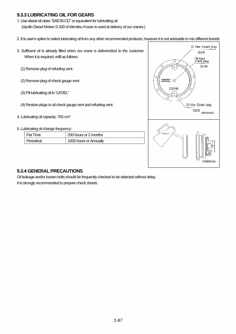
2-87
9.3.3 LUBRICATING OIL FOR GEARS
1. Use diesel oil class “SAE30-CD” or equivalent for lubricating oil.
(Apollo Diesel Motive S-330 of Idemitsu Kosan is used at delivery of our cranes.)
2. It is user’s option to select lubricating oil from any other recommended products; however it is not advisable to mix different brands
3. Sufficient oil is already filled when our crane is delivered\ed to the customer.
When it is required, refill as follows:
(1) Remove plug of refueling vent.
(2) Remove plug of check gauge vent.
(3) Fill lubricating oil to “LEVEL”
(4) Restore plugs to oil check gauge vent and refueling vent.
4. Lubricating oil capacity: 700 cm3
5. Lubricating oil change frequency:
Fist Time 200 hours or 2 months
Periodical 1000 hours or Annually
9.3.4 GENERAL PRECAUTIONS
Oil leakage and/or loosen bolts should be frequently checked to be detected without delay.
It is strongly recommended to prepare check sheets.
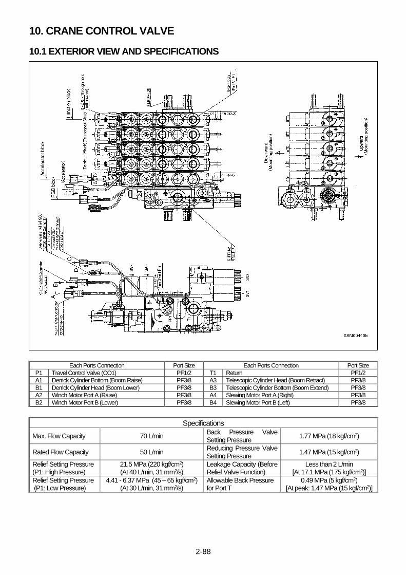
2-88
10. CRANE CONTROL VALVE
10.1 EXTERIOR VIEW AND SPECIFICATIONS
Each Ports Connection Port Size Each Ports Connection Port Size
P1 Travel Control Valve (CO1) PF1/2 T1 Return PF1/2
A1 Derrick Cylinder Bottom (Boom Raise) PF3/8 A3 Telescopic Cylinder Head (Boom Retract) PF3/8
B1 Derrick Cylinder Head (Boom Lower) PF3/8 B3 Telescopic Cylinder Bottom (Boom Extend) PF3/8
A2 Winch Motor Port A (Raise) PF3/8 A4 Slewing Motor Port A (Right) PF3/8
B2 Winch Motor Port B (Lower) PF3/8 B4 Slewing Motor Port B (Left) PF3/8
Specifications
Max. Flow Capacity 70 L/min Back Pressure Valve Setting Pressure
1.77 MPa (18 kgf/cm2)
Rated Flow Capacity 50 L/min Reducing Pressure Valve Setting Pressure
1.47 MPa (15 kgf/cm2)
Relief Setting Pressure (P1: High Pressure)
21.5 MPa (220 kgf/cm2) (At 40 L/min, 31 mm2/s)
Leakage Capacity (Before Relief Valve Function)
Less than 2 L/min [At 17.1 MPa (175 kgf/cm2)]
Relief Setting Pressure (P1: Low Pressure)
4.41 - 6.37 MPa (45 – 65 kgf/cm2) (At 30 L/min, 31 mm2/s)
Allowable Back Pressure for Port T
0.49 MPa (5 kgf/cm2) [At peak: 1.47 MPa (15 kgf/cm2)]
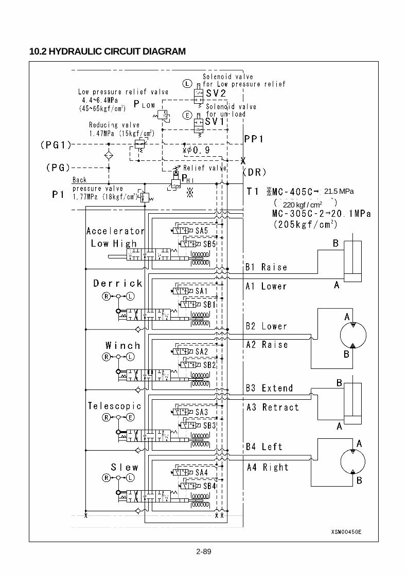
2-89
10.2 HYDRAULIC CIRCUIT DIAGRAM
21.5 MPa
220 kgf / cm2
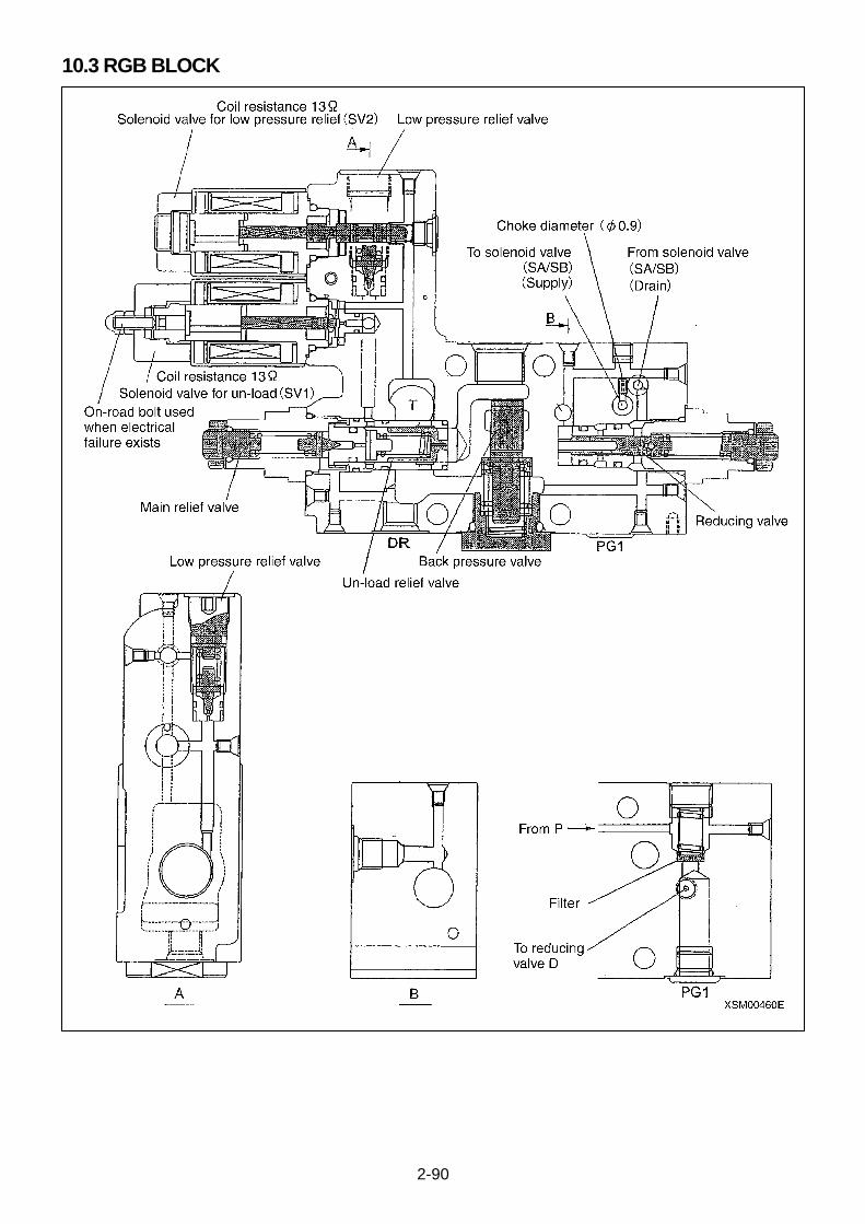
2-90
10.3 RGB BLOCK
2-91
1. Back Pressure Valve
Back pressure valve secures minimum pressure rate of hydraulic oil to actuate control cylinder.
2. Reducing Valve
Reducing valve reduces pressure rate of hydraulic oil to control cylinder to proper level.
3. Main Relief Valve
Main relief valve regulates maximum pressure of pump circuit.
4. Low Pressure Relief Valve
Low pressure relief valve regulates maximum pressure when hook is stowed.
5. Unloading Solenoid Valve (SV1)
Unloading solenoid valve (SV1) is magnetized in case if (1) and (2) below to on-load.
(1) When function switches of remote control transmitter is actuated in remote control mode.
(2) When operation lever of crane body is shifted from neutral position in Manual operation mode.
6. Low Pressure Relief Solenoid Valve (SV2)
Low pressure relief solenoid valve (SV2) is magnetized and circuit is turned on accordingly when hook is stowed.
7. Bolt for Emergency on-load (Temporary measure for equipment disorders)
To rescue from electrical circuit break-down, crane may be on-loaded by mechanical measure.
Tighten this bolt for on-loading and providing manual crane operation.
This is an emergency measure only, to operate crane for retracting and stowing by using “On-load” bolt. Normal operation of crane under such condition is strictly prohibited.
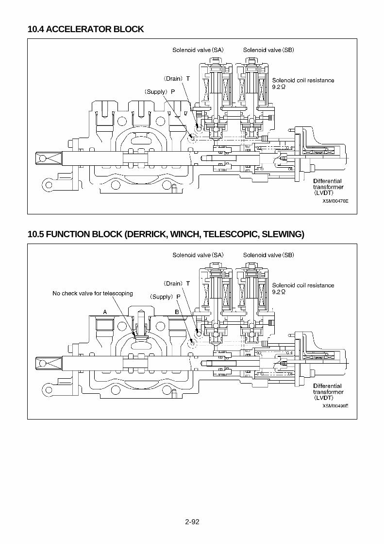
2-92
10.4 ACCELERATOR BLOCK
10.5 FUNCTION BLOCK (DERRICK, WINCH, TELESCOPIC, SLEWING)
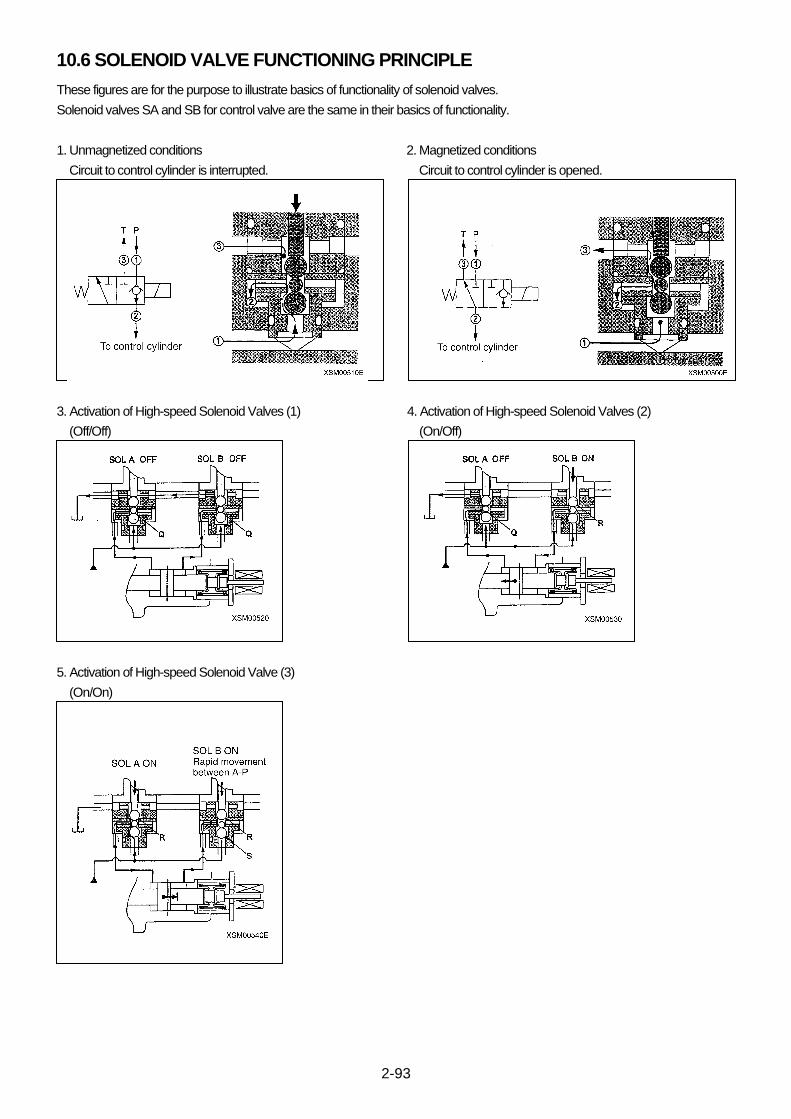
2-93
10.6 SOLENOID VALVE FUNCTIONING PRINCIPLE
These figures are for the purpose to illustrate basics of functionality of solenoid valves.
Solenoid valves SA and SB for control valve are the same in their basics of functionality.
1. Unmagnetized conditions 2. Magnetized conditions
Circuit to control cylinder is interrupted. Circuit to control cylinder is opened.
3. Activation of High-speed Solenoid Valves (1) 4. Activation of High-speed Solenoid Valves (2)
(Off/Off) (On/Off)
5. Activation of High-speed Solenoid Valve (3)
(On/On)

2-94
Computation of Deviations and Pulse Width
Hydraulic unit is controlled as follows:
1. When control is out, a transistor in the receiver is “OFF” and solenoid
valves are attached to a tank.
In this condition control cylinder is held in neutral position by spring
tension.
2. When control starts, 2 transistors for SA and AB are turned to “ON” to
conduct to solenoid valves; they are attached pump.
In this condition control cylinder is held in neutral position by pump
pressure.
3. Then one solenoid valve in the side to be actuated shall be
demagnetized and attached to tank. Another solenoid is still
magnetized and attached to pump.
In this condition, oil flows from pump to control cylinder which actuates
control cylinder.
Time of non-conducting to solenoid valves are determined based on
deviations.
4. After one cycle of pulse emission, “40 ms”, deviation shall be
computed and the non-conducted solenoid valve shall be also
conducted when the deviation is within allowable limits.
In the event that deviation is beyond limits, the valve shall be
non-conducted again for the time in accordance with the deviation.
5. When this deviation is within Allowable and reaches to desired value
of Control Cylinder, both of Solenoids are conducted which holds
Control Cylinder in desired position.

2-95
This Page Intentionally Left Blank.
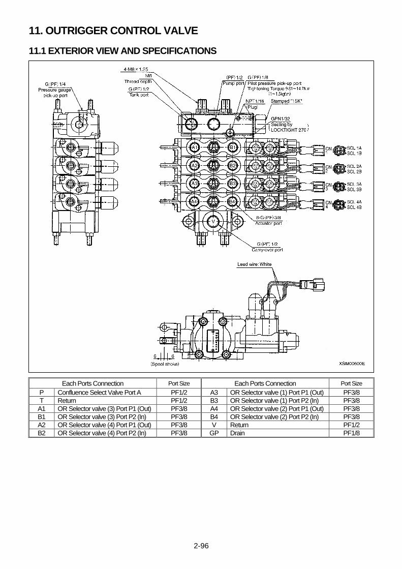
2-96
11. OUTRIGGER CONTROL VALVE
11.1 EXTERIOR VIEW AND SPECIFICATIONS
Each Ports Connection Port Size Each Ports Connection Port Size
P Confluence Select Valve Port A PF1/2 A3 OR Selector valve (1) Port P1 (Out) PF3/8
T Return PF1/2 B3 OR Selector valve (1) Port P2 (In) PF3/8
A1 OR Selector valve (3) Port P1 (Out) PF3/8 A4 OR Selector valve (2) Port P1 (Out) PF3/8
B1 OR Selector valve (3) Port P2 (In) PF3/8 B4 OR Selector valve (2) Port P2 (In) PF3/8
A2 OR Selector valve (4) Port P1 (Out) PF3/8 V Return PF1/2
B2 OR Selector valve (4) Port P2 (In) PF3/8 GP Drain PF1/8
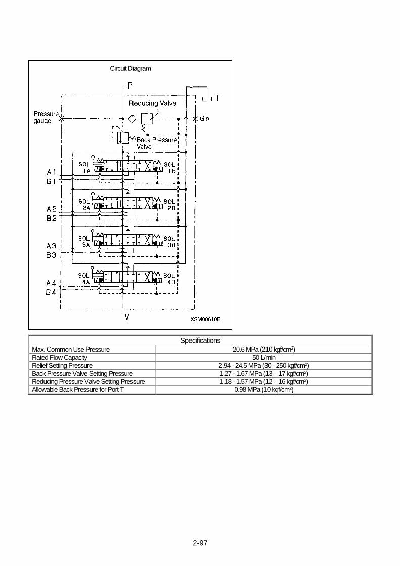
2-97
Specifications Max. Common Use Pressure 20.6 MPa (210 kgf/cm2)
Rated Flow Capacity 50 L/min
Relief Setting Pressure 2.94 - 24.5 MPa (30 - 250 kgf/cm2)
Back Pressure Valve Setting Pressure 1.27 - 1.67 MPa (13 – 17 kgf/cm2)
Reducing Pressure Valve Setting Pressure 1.18 - 1.57 MPa (12 – 16 kgf/cm2)
Allowable Back Pressure for Port T 0.98 MPa (10 kgf/cm2)
Circuit Diagram
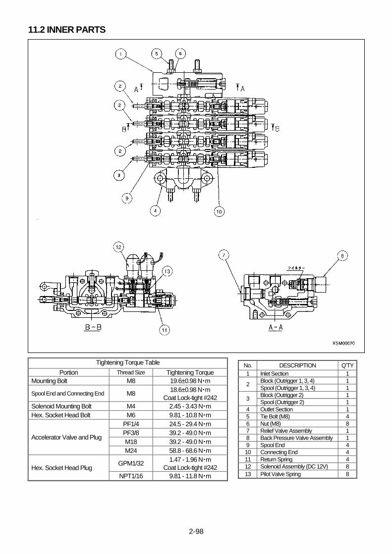
2-98
11.2 INNER PARTS
Tightening Torque Table
Portion Thread Size Tightening Torque
Mounting Bolt M8 19.6±0.98 N・m
Spool End and Connecting End M8 18.6±0.98 N・m
Coat Lock-tight #242
Solenoid Mounting Bolt M4 2.45 - 3.43 N・m
Hex. Socket Head Bolt M6 9.81 - 10.8 N・m
Accelerator Valve and Plug
PF1/4 24.5 - 29.4 N・m
PF3/8 39.2 - 49.0 N・m
M18 39.2 - 49.0 N・m
M24 58.8 - 68.6 N・m
Hex. Socket Head Plug GPM1/32
1.47 - 1.96 N・m
Coat Lock-tight #242
NPT1/16 9.81 - 11.8 N・m
No. DESCRIPTION Q’TY
1 Inlet Section 1
2 Block (Outrigger 1, 3, 4) 1
Spool (Outrigger 1, 3, 4) 1
3 Block (Outrigger 2) 1
Spool (Outrigger 2) 1
4 Outlet Section 1
5 Tie Bolt (M8) 4
6 Nut (M8) 8
7 Relief Valve Assembly 1
8 Back Pressure Valve Assembly 1
9 Spool End 4
10 Connecting End 4
11 Return Spring 4
12 Solenoid Assembly (DC 12V) 8
13 Pilot Valve Spring 8

2-99
This Page Intentionally Left Blank.
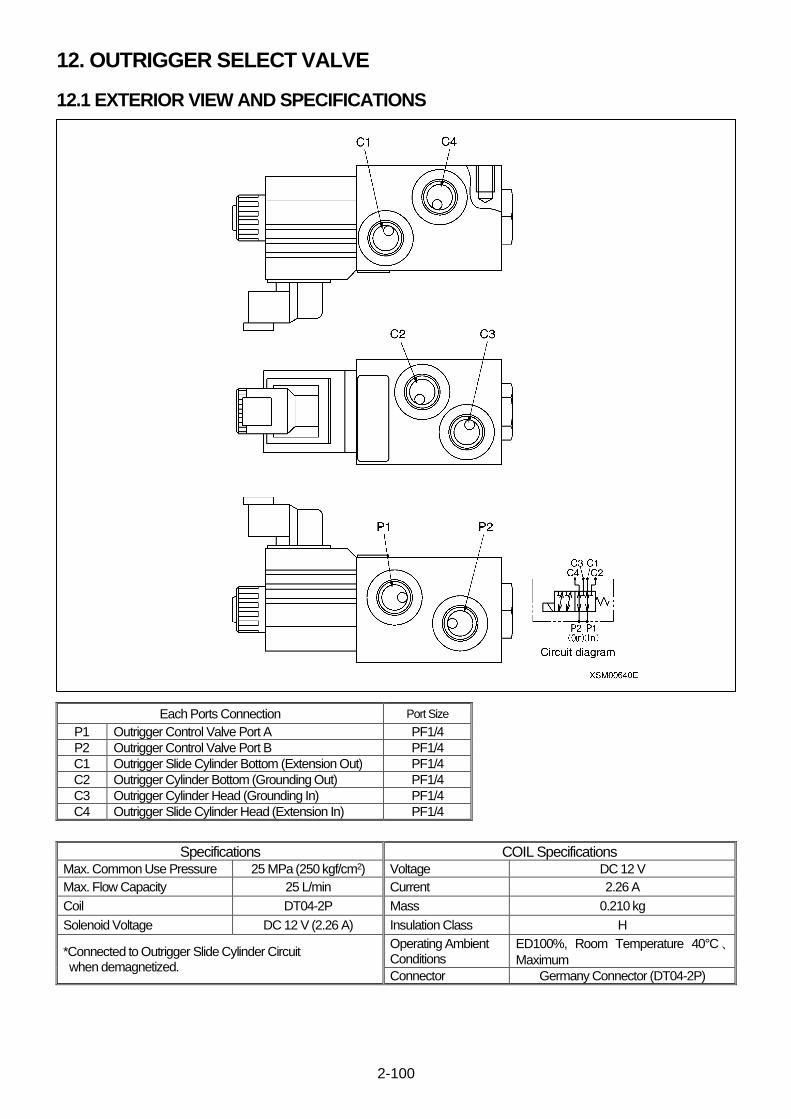
2-100
12. OUTRIGGER SELECT VALVE
12.1 EXTERIOR VIEW AND SPECIFICATIONS
Each Ports Connection Port Size
P1 Outrigger Control Valve Port A PF1/4
P2 Outrigger Control Valve Port B PF1/4
C1 Outrigger Slide Cylinder Bottom (Extension Out) PF1/4
C2 Outrigger Cylinder Bottom (Grounding Out) PF1/4
C3 Outrigger Cylinder Head (Grounding In) PF1/4
C4 Outrigger Slide Cylinder Head (Extension In) PF1/4
Specifications COIL Specifications Max. Common Use Pressure 25 MPa (250 kgf/cm2) Voltage DC 12 V
Max. Flow Capacity 25 L/min Current 2.26 A
Coil DT04-2P Mass 0.210 kg
Solenoid Voltage DC 12 V (2.26 A) Insulation Class H
*Connected to Outrigger Slide Cylinder Circuit when demagnetized.
Operating Ambient Conditions
ED100%, Room Temperature 40°C、Maximum
Connector Germany Connector (DT04-2P)
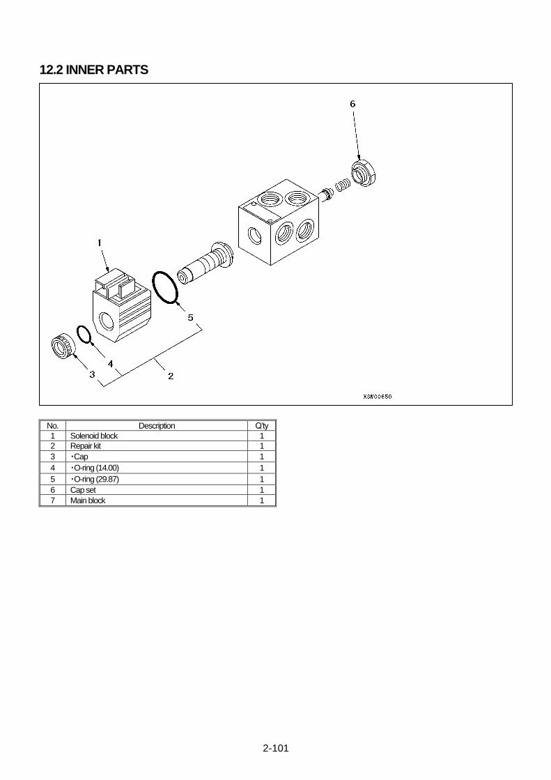
2-101
12.2 INNER PARTS
No. Description Q’ty
1 Solenoid block 1
2 Repair kit 1
3 ・Cap 1
4 ・O-ring (14.00) 1
5 ・O-ring (29.87) 1
6 Cap set 1
7 Main block 1
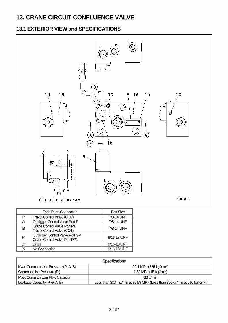
2-102
13. CRANE CIRCUIT CONFLUENCE VALVE
13.1 EXTERIOR VIEW and SPECIFICATIONS
Each Ports Connection Port Size
P Travel Control Valve (CO2) 7/8-14 UNF
A Outrigger Control Valve Port P 7/8-14 UNF
B Crane Control Valve Port P1 Travel Control Valve (CO1)
7/8-14 UNF
Pi Outrigger Control Valve Port GP Crane Control Valve Port PP1
9/16-18 UNF
Dr Drain 9/16-18 UNF
X No Connecting 9/16-18 UNF
Specifications
Max. Common Use Pressure (P, A, B) 22.1 MPa (225 kgf/cm2)
Common Use Pressure (Pi) 1.53 MPa (15 kgf/cm2)
Max. Common Use Flow Capacity 30 L/min
Leakage Capacity (P → A, B) Less than 300 mL/min at 20.58 MPa (Less than 300 cc/min at 210 kgf/cm2)
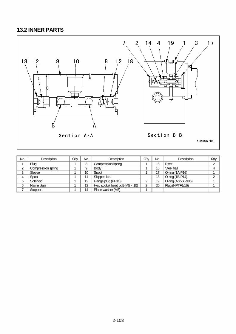
2-103
13.2 INNER PARTS
No. Description Q’ty No. Description Q’ty No. Description Q’ty
1 Plug 1 8 Compression spring 1 15 Rivet 2
2 Compression spring 1 9 Body 1 16 Steel ball 4
3 Sleeve 1 10 Spool 1 17 O-ring (1A-P16) 1
4 Spool 1 11 Skipped No. 18 O-ring (1B-P14) 2
5 Solenoid 1 12 Flange plug (PF3/8) 2 19 O-ring (AS568-906) 1
6 Name plate 1 13 Hex. socket head bolt (M5 × 10) 2 20 Plug (NPTF1/16) 1
7 Stopper 1 14 Plane washer (M5) 1
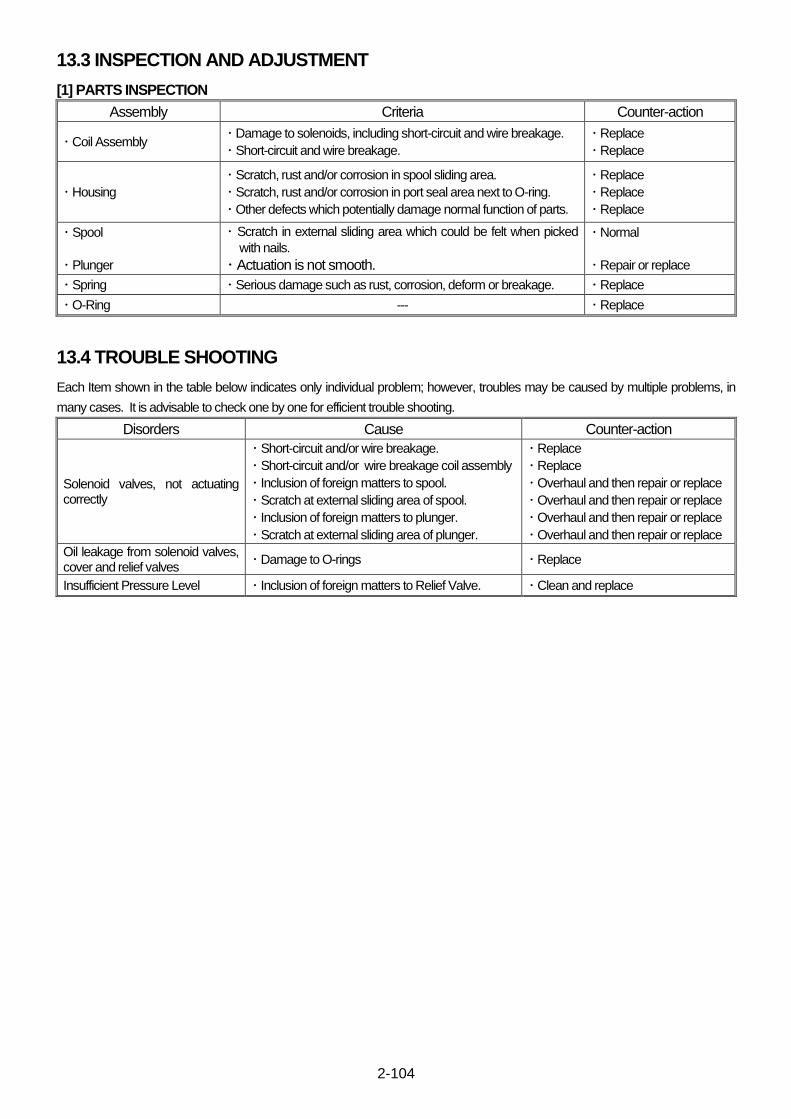
2-104
13.3 INSPECTION AND ADJUSTMENT
[1] PARTS INSPECTION
Assembly Criteria Counter-action
・ Coil Assembly ・ Damage to solenoids, including short-circuit and wire breakage.
・ Short-circuit and wire breakage.
・ Replace
・ Replace
・ Housing
・ Scratch, rust and/or corrosion in spool sliding area.
・ Scratch, rust and/or corrosion in port seal area next to O-ring.
・ Other defects which potentially damage normal function of parts.
・ Replace
・ Replace
・ Replace
・ Spool
・ Plunger
・ Scratch in external sliding area which could be felt when picked
with nails.
・ Actuation is not smooth.
・ Normal
・ Repair or replace
・ Spring ・ Serious damage such as rust, corrosion, deform or breakage. ・ Replace
・ O-Ring --- ・ Replace
13.4 TROUBLE SHOOTING
Each Item shown in the table below indicates only individual problem; however, troubles may be caused by multiple problems, in
many cases. It is advisable to check one by one for efficient trouble shooting.
Disorders Cause Counter-action
Solenoid valves, not actuating correctly
・ Short-circuit and/or wire breakage.
・ Short-circuit and/or wire breakage coil assembly
・ Inclusion of foreign matters to spool.
・ Scratch at external sliding area of spool.
・ Inclusion of foreign matters to plunger.
・ Scratch at external sliding area of plunger.
・ Replace
・ Replace
・ Overhaul and then repair or replace
・ Overhaul and then repair or replace
・ Overhaul and then repair or replace
・ Overhaul and then repair or replace
Oil leakage from solenoid valves, cover and relief valves
・ Damage to O-rings ・ Replace
Insufficient Pressure Level ・ Inclusion of foreign matters to Relief Valve. ・ Clean and replace

2-105
This Page Intentionally Left Blank.
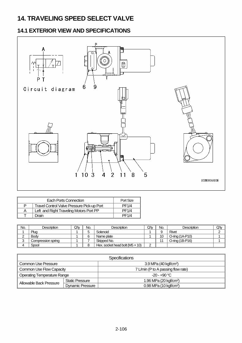
2-106
14. TRAVELING SPEED SELECT VALVE
14.1 EXTERIOR VIEW AND SPECIFICATIONS
Each Ports Connection Port Size
P Travel Control Valve Pressure Pick-up Port PF1/4
A Left and Right Traveling Motors Port PP PF1/4
T Drain PF1/4
No. Description Q’ty No. Description Q’ty No. Description Q’ty
1 Plug 1 5 Solenoid 1 9 Rivet 2
2 Body 1 6 Name plate 1 10 O-ring (1A-P10) 1
3 Compression spring 1 7 Skipped No. 11 O-ring (1B-P16) 1
4 Spool 1 8 Hex. socket head bolt (M5 × 10) 2
Specifications
Common Use Pressure 3.9 MPa (40 kgf/cm2)
Common Use Flow Capacity 7 L/min (P to A passing flow rate)
Operating Temperature Range -20 - +90 °C
Allowable Back Pressure Static Pressure 1.96 MPa (20 kgf/cm2)
Dynamic Pressure 0.98 MPa (10 kgf/cm2)
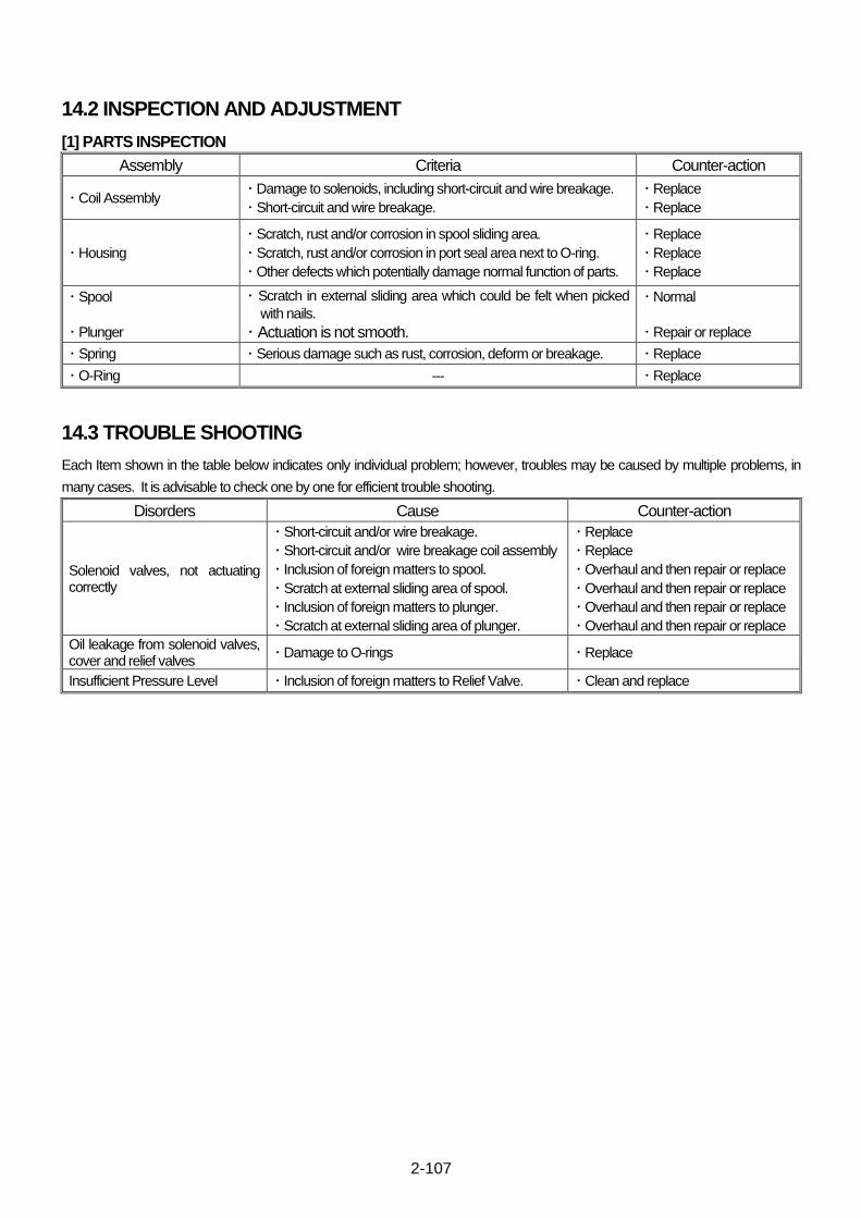
2-107
14.2 INSPECTION AND ADJUSTMENT
[1] PARTS INSPECTION
Assembly Criteria Counter-action
・ Coil Assembly ・ Damage to solenoids, including short-circuit and wire breakage.
・ Short-circuit and wire breakage.
・ Replace
・ Replace
・ Housing
・ Scratch, rust and/or corrosion in spool sliding area.
・ Scratch, rust and/or corrosion in port seal area next to O-ring.
・ Other defects which potentially damage normal function of parts.
・ Replace
・ Replace
・ Replace
・ Spool
・ Plunger
・ Scratch in external sliding area which could be felt when picked
with nails.
・ Actuation is not smooth.
・ Normal
・ Repair or replace
・ Spring ・ Serious damage such as rust, corrosion, deform or breakage. ・ Replace
・ O-Ring --- ・ Replace
14.3 TROUBLE SHOOTING
Each Item shown in the table below indicates only individual problem; however, troubles may be caused by multiple problems, in
many cases. It is advisable to check one by one for efficient trouble shooting.
Disorders Cause Counter-action
Solenoid valves, not actuating correctly
・ Short-circuit and/or wire breakage.
・ Short-circuit and/or wire breakage coil assembly
・ Inclusion of foreign matters to spool.
・ Scratch at external sliding area of spool.
・ Inclusion of foreign matters to plunger.
・ Scratch at external sliding area of plunger.
・ Replace
・ Replace
・ Overhaul and then repair or replace
・ Overhaul and then repair or replace
・ Overhaul and then repair or replace
・ Overhaul and then repair or replace
Oil leakage from solenoid valves, cover and relief valves
・ Damage to O-rings ・ Replace
Insufficient Pressure Level ・ Inclusion of foreign matters to Relief Valve. ・ Clean and replace

2-108
15. ROTARY JOINT
15.1 EXTERIOR VIEW AND SPECIFICATIONS
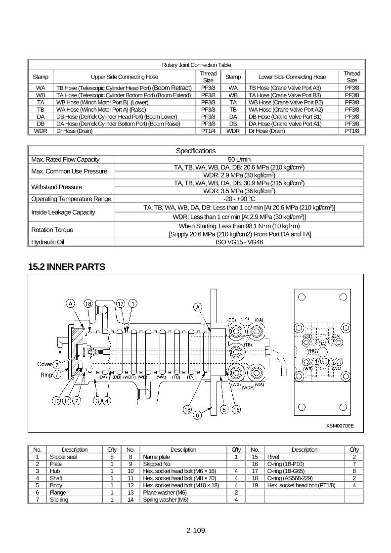
2-109
Rotary Joint Connection Table
Stamp Upper Side Connecting Hose Thread Size
Stamp Lower Side Connecting Hose Thread Size
WA TB Hose (Telescopic Cylinder Head Port) (Boom Retract) PF3/8 WA TB Hose (Crane Valve Port A3) PF3/8
WB TA Hose (Telescopic Cylinder Bottom Port) (Boom Extend) PF3/8 WB TA Hose (Crane Valve Port B3) PF3/8
TA WB Hose (Winch Motor Port B) (Lower) PF3/8 TA WB Hose (Crane Valve Port B2) PF3/8
TB WA Hose (Winch Motor Port A) (Raise) PF3/8 TB WA Hose (Crane Valve Port A2) PF3/8
DA DB Hose (Derrick Cylinder Head Port) (Boom Lower) PF3/8 DA DB Hose (Crane Valve Port B1) PF3/8
DB DA Hose (Derrick Cylinder Bottom Port) (Boom Raise) PF3/8 DB DA Hose (Crane Valve Port A1) PF3/8
WDR Dr Hose (Drain) PT1/4 WDR Dr Hose (Drain) PT1/8
Specifications Max. Rated Flow Capacity 50 L/min
Max. Common Use Pressure TA, TB, WA, WB, DA, DB: 20.6 MPa (210 kgf/cm2)
WDR: 2.9 MPa (30 kgf/cm2)
Withstand Pressure TA, TB, WA, WB, DA, DB: 30.9 MPa (315 kgf/cm2)
WDR: 3.5 MPa (36 kgf/cm2)
Operating Temperature Range -20 - +90 °C
Inside Leakage Capacity TA, TB, WA, WB, DA, DB: Less than 1 cc/ min [At 20.6 MPa (210 kgf/cm2)]
WDR: Less than 1 cc/ min [At 2.9 MPa (30 kgf/cm2)]
Rotation Torque When Starting: Less than 98.1 N・m (10 kgf・m)
[Supply 20.6 MPa (210 kgf/cm2) From Port DA and TA]
Hydraulic Oil ISO VG15 - VG46
15.2 INNER PARTS
No. Description Q’ty No. Description Q’ty No. Description Q’ty
1 Slipper seal 8 8 Name plate 1 15 Rivet 2
2 Plate 1 9 Skipped No. 16 O-ring (1B-P10) 7
3 Hub 1 10 Hex. socket head bolt (M6 × 16) 4 17 O-ring (1B-G65) 8
4 Shaft 1 11 Hex. socket head bolt (M8 × 70) 4 18 O-ring (AS568-229) 2
5 Body 1 12 Hex. socket head bolt (M10 × 18) 4 19 Hex. socket head bolt (PT1/8) 4
6 Flange 1 13 Plane washer (M6) 2
7 Slip ring 1 14 Spring washer (M6) 4

2-110
16. HOOK BLOCK
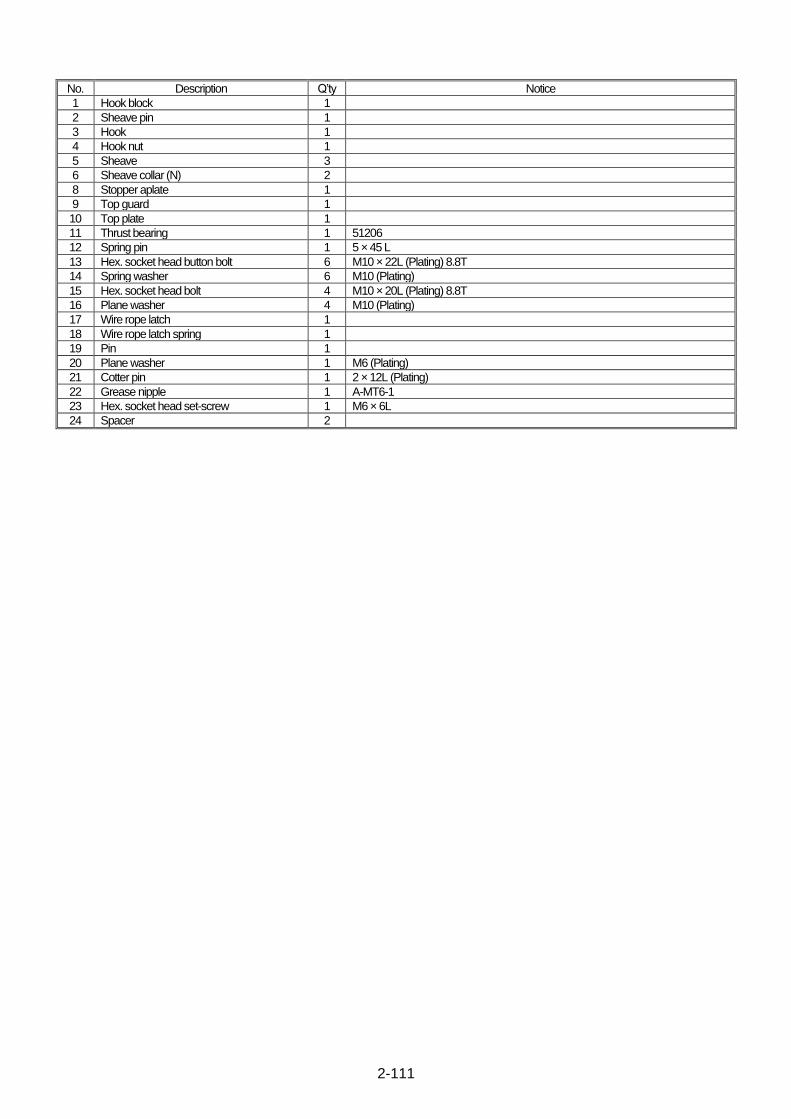
2-111
No. Description Q’ty Notice
1 Hook block 1
2 Sheave pin 1
3 Hook 1
4 Hook nut 1
5 Sheave 3
6 Sheave collar (N) 2
8 Stopper aplate 1
9 Top guard 1
10 Top plate 1
11 Thrust bearing 1 51206
12 Spring pin 1 5 × 45 L
13 Hex. socket head button bolt 6 M10 × 22L (Plating) 8.8T
14 Spring washer 6 M10 (Plating)
15 Hex. socket head bolt 4 M10 × 20L (Plating) 8.8T
16 Plane washer 4 M10 (Plating)
17 Wire rope latch 1
18 Wire rope latch spring 1
19 Pin 1
20 Plane washer 1 M6 (Plating)
21 Cotter pin 1 2 × 12L (Plating)
22 Grease nipple 1 A-MT6-1
23 Hex. socket head set-screw 1 M6 × 6L
24 Spacer 2
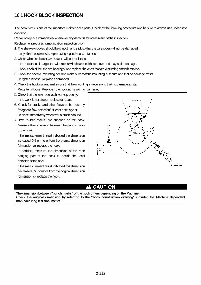
2-112
16.1 HOOK BLOCK INSPECTION
The hook block is one of the important maintenance parts. Check by the following procedure and be sure to always use under safe
condition.
Repair or replace immediately whenever any defect is found as result of the inspection.
Replacement requires a modification inspection prior.
1. The sheave grooves should be smooth and slick so that the wire ropes will not be damaged.
If any sharp edge exists, repair using a grinder or similar tool.
2. Check whether the sheave rotates without resistance.
If the resistance is large, the wire ropes will slip around the sheave and may suffer damage.
Check each of the sheave bearings, and replace the ones that are disturbing smooth rotation.
3. Check the sheave mounting bolt and make sure that the mounting is secure and that no damage exists.
Retighten if loose. Replace if damaged.
4. Check the hook nut and make sure that the mounting is secure and that no damage exists.
Retighten if loose. Replace if the hook nut is worn or damaged.
5. Check that the wire rope latch works properly.
If the work is not proper, replace or repair.
6. Check for cracks and other flaws of the hook by
"magnetic flaw detection" at least once a year.
Replace immediately whenever a crack is found.
7. Two "punch marks" are punched on the hook.
Measure the dimension between the punch marks
of the hook.
If the measurement result indicated this dimension
increased 2% or more from the original dimension
(dimension a), replace the hook.
In addition, measure the dimension of the rope
hanging part of the hook to decide the local
abrasion of the hook.
If the measurement result indicated this dimension
decreased 3% or more from the original dimension
(dimension c), replace the hook.
The dimension between "punch marks" of the hook differs depending on the Machine. Check the original dimension by referring to the "hook construction drawing" included the Machine dependent manufacturing test documents.

2-113
This Page Intentionally Left Blank.
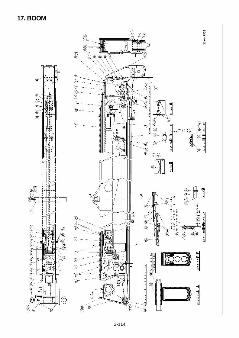
2-114
17. BOOM

2-115
No. Description Q’ty Notice
1 No.1 boom 1
2 No.2 boom 1
3 No.3 boom 1
4 No.4 boom 1
5 No.5 boom 1
6 Wire rope 1
7 Wire rope (for boom extend) 1
8 Wire rope (for boom retract) 1
9 Wire clip assembly 1
10 Wedge 1
11 Wedge socket 1
12 Slide plate (B1 Lower) 4
13 Slide plate (B3 Upper) 4
14 Slide plate (B1 Lower) 2
15 Slide plate (B2 Lower) 2
16 Slide plate (B3 Lower) 4
17 Side slide plate 16
18 Slide plate (S) 2
19 Side stopper plate 16
20 Side stopper plate shim 8
21 Foot pin 1
22 Derrick cylinder pin 1
23 Telescopic cylinder head pin 1
24 No.2 trunnion pin 2
25 No.3 trunnion pin 2
26 No.4 trunnion pin 4
27 Sheave pin (for boom extend) 1
28 Point pin 1
29 Wire pin (for boom extend) 2
30 Snap sheave pin 1
31 Telescopic guide roller pin 1
32 Wedge socket pin 1
33 Sheave assembly 2
34 Sheave (for boom extend) 2
35 Sheave (for boom retract) 2
36 Snap sheave (A) 1
37 Telescopic guide roller 1
38 Sheave (for boom extend) cover 1
39 Sheave (for boom retract) cover 1
40 Wire bracket (for boom extend) 1
41 Boom head cover 1
42 Boom tail cover 1
43 End plate 1
44 End plate 1
45 Arrow 2
46 Sheave collar (N) 4
47 Collar 2
48 No.2 boom wire guide 1
49 No.3 boom wire guide 1
50 No.4 boom wire guide 1
51 Wire guide mounting plate 6
52 Wire adjusting bolt (for boom extend) 1
53 Snap ring 2 For shaft C-40
54 Snap ring 4 For hole C-45
55 Snap ring 4 For hole C-35
56 Snap ring 2 For hole C-17
57 Snap ring 2 For shaft C-12
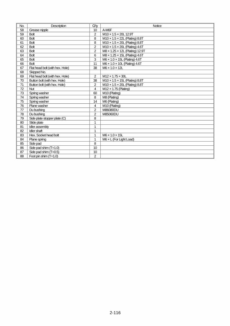
2-116
No. Description Q’ty Notice
58 Grease nipple 10 A-M6F
59 Bolt 2 M10 × 1.5 × 20L 12.9T
60 Bolt 8 M10 × 1.5 × 22L (Plating) 8.8T
61 Bolt 8 M10 × 1.5 × 20L (Plating) 8.8T
62 Bolt 2 M10 × 1.5 × 20L (Plating) 4.6T
63 Bolt 2 M8 × 1.25 × 12L (Plating) 12.9T
64 Bolt 6 M8 × 1.25 × 15L (Plating) 4.6T
65 Bolt 3 M6 × 1.0 × 15L (Plating) 4.6T
66 Bolt 11 M6 × 1.0 × 10L (Plating) 4.6T
67 Flat head bolt (with hex. Hole) 38 M6 × 1.0 × 12L
68 Skipped No.
69 Flat head bolt (with hex. Hole) 2 M12 × 1.75 × 30L
70 Button bolt (with hex. Hole) 38 M10 × 1.5 × 15L (Plating) 8.8T
71 Button bolt (with hex. Hole) 2 M10 × 1.5 × 20L (Plating) 8.8T
72 Nut 4 M12 × 1.75 (Plating)
73 Spring washer 60 M10 (Plating)
74 Spring washer 8 M8 (Plating)
75 Spring washer 14 M6 (Plating)
76 Plane washer 4 M10 (Plating)
77 Du bushing 2 M86080DU
78 Du bushing 2 M85060DU
79 Side plate stopper plate (C) 8
80 Slide plate 1
81 Idler assembly 1
82 Idler shaft 1
83 Hex. Socket head bolt 1 M6 × 1.0 × 15L
84 Plane spring 1 M6 × L (For Light Load)
85 Side pad 8
86 Side pad shim (T=1.0) 10
87 Side pad shim (T=0.5) 10
88 Foot pin shim (T=1.0) 2

2-117
This Page Intentionally Left Blank.
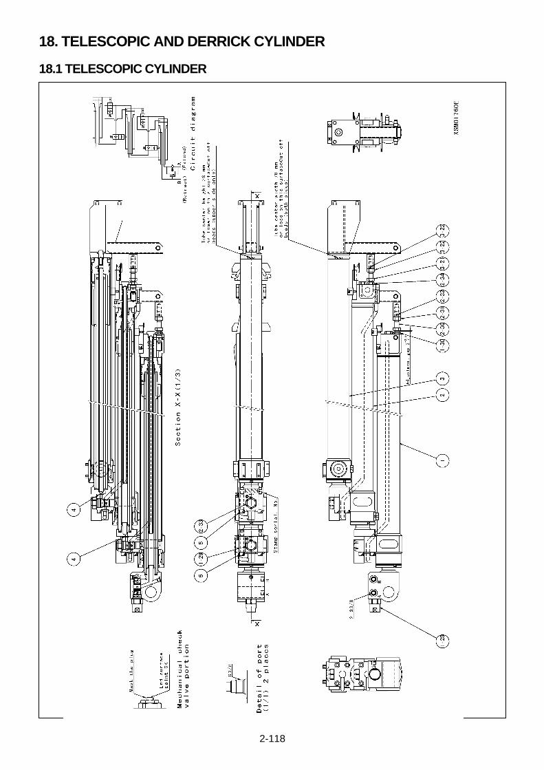
2-118
18. TELESCOPIC AND DERRICK CYLINDER
18.1 TELESCOPIC CYLINDER
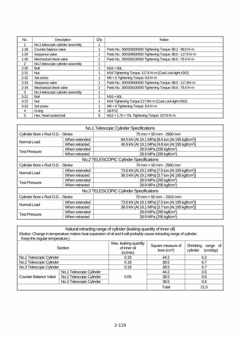
2-119
No. Description Q’ty Notice
1 No.1 telescopic cylinder assembly 1
1-28 Counter balance valve 1 Parts No.: 300S09200000 Tightening Torque: 88.2 - 98.0 N・m
1-29 Sequence valve 1 Parts No.: 300S09000000 Tightening Torque: 98.0 - 117.6 N・m
1-30 Mechanical check valve 1 Parts No.: 300S09100000 Tightening Torque: 68.6 - 78.4 N・m
2 No.2 telescopic cylinder assembly 1
2-30 Bolt 1 M16 × 60L
2-31 Nut 1 M16 Tightening Torque: 117.6 N・m (Coat Lock-tight #262)
2-32 Set screw 1 M6 × 6 Tightening Torque: 9.8 N・m
2-33 Sequence valve 1 Parts No.: 300S09000000 Tightening Torque: 98.0 - 117.6N・m
2-34 Mechanical check valve 2 Parts No.: 300S09100000 Tightening Torque: 68.6 - 78.4 N・m
3 No.3 telescopic cylinder assembly 1
3-21 Bolt 1 M16 × 60L
3-22 Nut 1 M16 Tightening Torque:117.6N・m (Coat Lock-tight #262)
3-23 Set screw 1 M6 × 6 Tightening Torque: 9.8 N・m
4 O-ring 4 1B-P12
5 Hex. Head socket bolt 8 M12 × 1.75 × 75L Tightening Torque: 107.8 N・m
No.1 Telescopic Cylinder Specifications
Cylinder Bore x Rod O.D. - Stroke 75 mm × 50 mm - 2960 mm
Normal Load When extended 84.5 kN (At 19.1 MPa) [8.6 ton (At 195 kgf/cm2)]
When retracted 46.9 kN (At 19.1 MPa) [4.8 ton (At 195 kgf/cm2)]
Test Pressure When extended 28.9 MPa (295 kgf/cm2)
When retracted 28.9 MPa (295 kgf/cm2)
No.2 TELESCOPIC Cylinder Specifications
Cylinder Bore x Rod O.D. - Stroke 70 mm × 50 mm - 2960 mm
Normal Load When extended 73.6 kN (At 19.1 MPa) [7.5 ton (At 195 kgf/cm2)]
When retracted 36.0 kN (At 19.1 MPa) [3.7 ton (At 195 kgf/cm2)]
Test Pressure When extended 28.9 MPa (295 kgf/cm2)
When retracted 28.9 MPa (295 kgf/cm2)
No.3 TELESCOPIC Cylinder Specifications
Cylinder Bore x Rod O.D. - Stroke 70 mm × 50 mm – 2910 mm
Normal Load When extended 73.6 kN (At 19.1 MPa) [7.5 ton (At 195 kgf/cm2)]
When retracted 36.0 kN (At 19.1 MPa) [3.7 ton (At 195 kgf/cm2)]
Test Pressure When extended 28.9 MPa (295 kgf/cm2)
When retracted 28.9 MPa (295 kgf/cm2)
Natural retracting range of cylinder (leaking quantity of inner oil) (Notice: Change in temperature makes heat expansion of oil and it will probably cause retracting range of cylinder. Keep the regular temperature.)
Section Max. leaking quantity
of inner oil (cc/min)
Square measure of bore (cm2)
Shrinking range of cylinder (cm/day)
No.1 Telescopic Cylinder 0.19 44.2 6.2
No.2 Telescopic Cylinder 0.18 38.5 6.7
No.3 Telescopic Cylinder 0.18 38.5 6.7
Counter Balance Valve
No.1 Telescopic Cylinder
0.05
44.2 0.5
No.2 Telescopic Cylinder 38.5 0.6
No.3 Telescopic Cylinder 38.5 0.6
Total 21.5
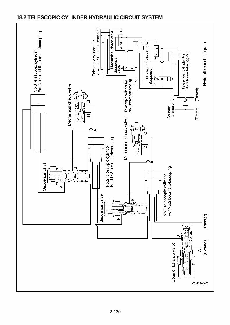
2-120
18.2 TELESCOPIC CYLINDER HYDRAULIC CIRCUIT SYSTEM
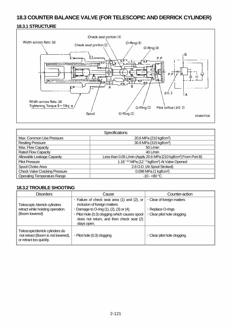
2-121
18.3 COUNTER BALANCE VALVE (FOR TELESCOPIC AND DERRICK CYLINDER)
18.3.1 STRUCTURE
Specifications
Max. Common Use Pressure 20.6 MPa (210 kgf/cm2)
Resiting Pressure 30.9 MPa (315 kgf/cm2)
Max. Flow Capacity 50 L/min
Rated Flow Capacity 40 L/min
Allowable Leakage Capacity Less than 0.05 L/min (Apply 20.6 MPa [210 kgf/cm2] From Port B)
Pilot Pressure 1.18+0.3 MPa (12+3 kgf/cm2) At Valve Opened
Spool Choke Area 2.6 O.D. (At Spool Stroked)
Check Valve Cracking Pressure 0.098 MPa (1 kgf/cm2)
Operating Temperature Range -10 - +80 °C
18.3.2 TROUBLE SHOOTING
Disorders Cause Counter-action
Telescopic /derrick cylinders retract while hoisting operation. (Boom lowered)
・ Failure of check seat area (1) and (2), or
inclusion of foreign matters.
・ Damage to O-ring (1), (2), (3) or (4).
・ Pilot Hole (0.3) clogging which causes spool
does not return, and then check seat (2) stays open.
・ Clear of foreign matters
・ Replace O-rings
・ Clear pilot hole clogging.
Telescopic/derrick cylinders do not retract (Boom is not lowered), or retract too quickly.
・ Pilot hole (0.3) clogging ・ Clear pilot hole clogging.

2-122
18.3.3 FUNCTION
1. When Neutral
2. When Extended
3. When Retracted

2-123
18.4 SEQUENCE VALVE (FOR TELESCOPIC CYLINDER)
Specifications
Rated Flow Capacity 40 L/min
Allowable Leakage Capacity Less than 0.05 L/min (Apply 20.6 MPa [210 kgf/cm2] From Port B)
Pilot Pressure 1.18+0.3 MPa (12+3 kgf/cm2) At Valve Opened
Check Valve Cracking Pressure 2.45 MPa (25 kgf/cm2)
Operating Force 0.65 × Pressure + 20 kg
18.4.1 FUNCTION
1. When Neutral
2. When Sequence Valve Operation
3. When Check Valve Operation
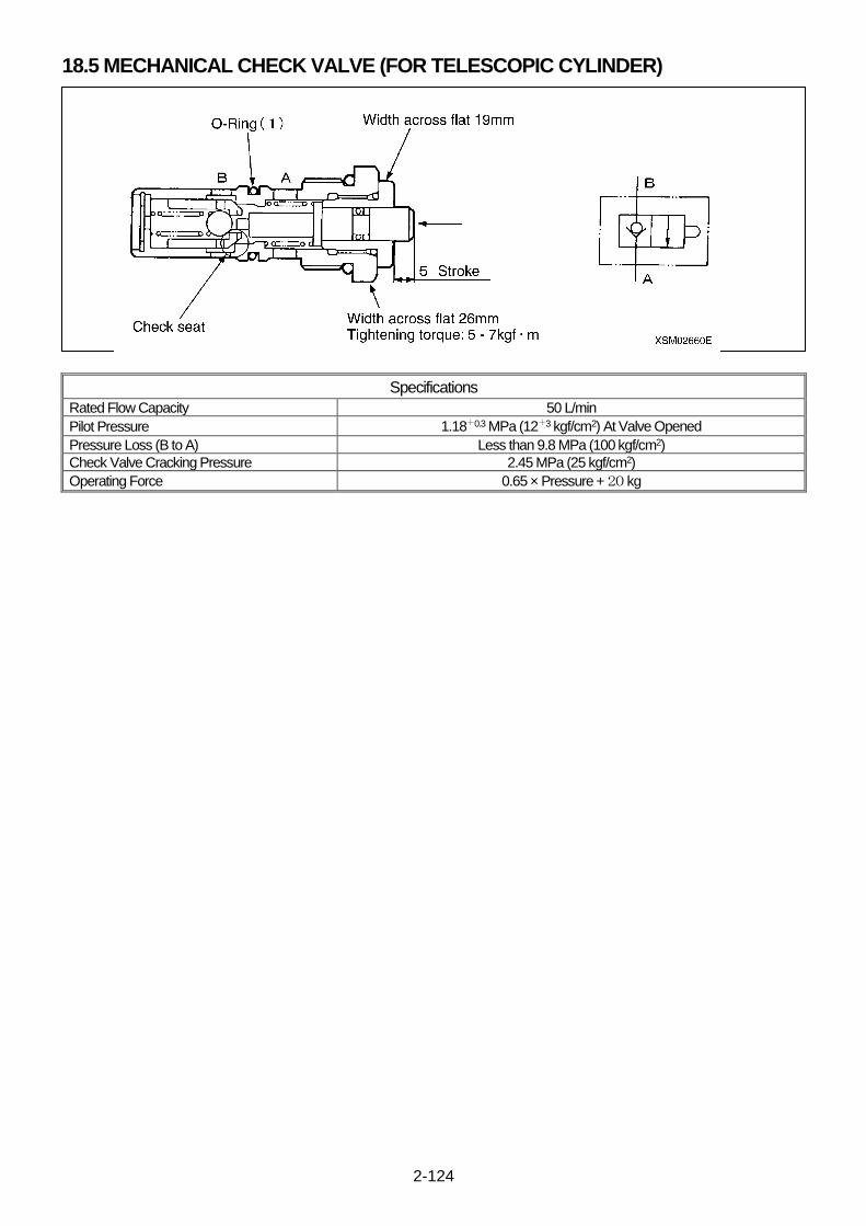
2-124
18.5 MECHANICAL CHECK VALVE (FOR TELESCOPIC CYLINDER)
Specifications
Rated Flow Capacity 50 L/min
Pilot Pressure 1.18+0.3 MPa (12+3 kgf/cm2) At Valve Opened
Pressure Loss (B to A) Less than 9.8 MPa (100 kgf/cm2)
Check Valve Cracking Pressure 2.45 MPa (25 kgf/cm2)
Operating Force 0.65 × Pressure + 20 kg

2-125
This Page Intentionally Left Blank.
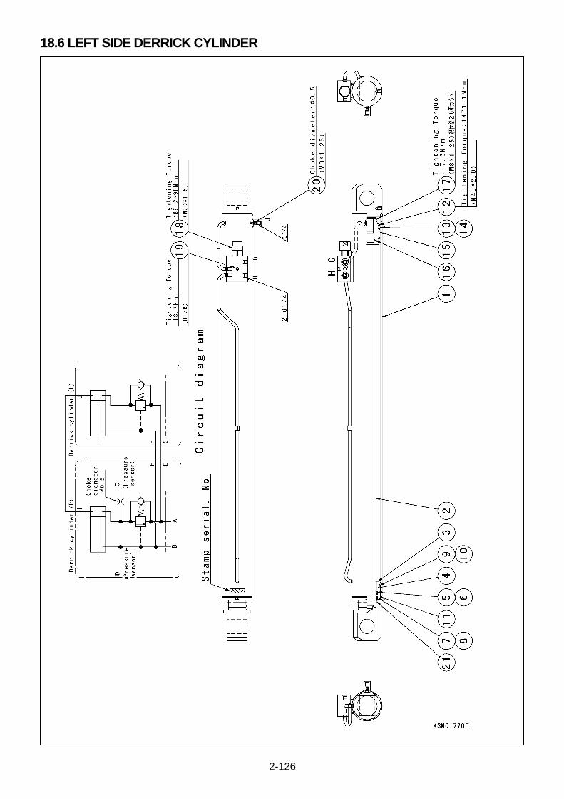
2-126
18.6 LEFT SIDE DERRICK CYLINDER

2-127
No. Description Q’ty Notice
1 Cylinder 1
2 Piston rod 1
3 Cylinder head 1
4 Bushing 1 LFB-6030
5 Rod packing 1 GNY-60
6 Back-up Ring 1 TC-GNY-60
7 Dust seal 1 SCB-60
8 Snap ring 1 AR75
9 O-ring 1 1B-G85
10 Back-up Ring 1 T3-G85
11 O-ring 1 1B-G90
12 Piston 1
13 Piston packing 2 GPY-90
14 Back-up Ring 2 TC-GPY-90
15 Wear ring 1 84,90,25
16 O-ring 1 1B-P48
17 Set screw 1 M8 × 12L
18 Counter balance valve 1 Parts No.: 300S09200000
19 Plug 1 R1/8
20 Orifice 1 M8 (Chock Diameter: 0.5)
21 Cap 1 Paint Protection
Specifications
Cylinder Bore x Rod O.D. - Stroke 90 mm × 60 mm – 1164 mm
Normal Load When extended 131.0 kN (At 20.6 MPa) [72.8 ton (At 210 kgf/cm2)]
When retracted 72.8 kN (At 20.6 MPa) [7.4 ton (At 210 kgf/cm2)]
Test Pressure When extended 30.9 MPa (315 kgf/cm2)
When retracted 30.9 MPa (315 kgf/cm2)
Natural retracting range of cylinder (leaking quantity of inner oil) (Notice: Change in temperature makes heat expansion of oil and it will probably cause retracting range of cylinder. Keep the regular temperature.)
Section Max. leaking quantity of inner oil
(cc/min) Square measure of bore
(cm2) Shrinking range of cylinder
(cm/day)
Derrick Cylinder 0.23 63.6
5.2
Counter Balance Valve 0.05 1.1
Total 6.3
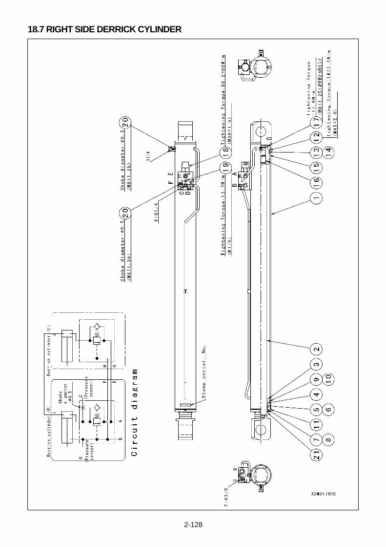
2-128
18.7 RIGHT SIDE DERRICK CYLINDER
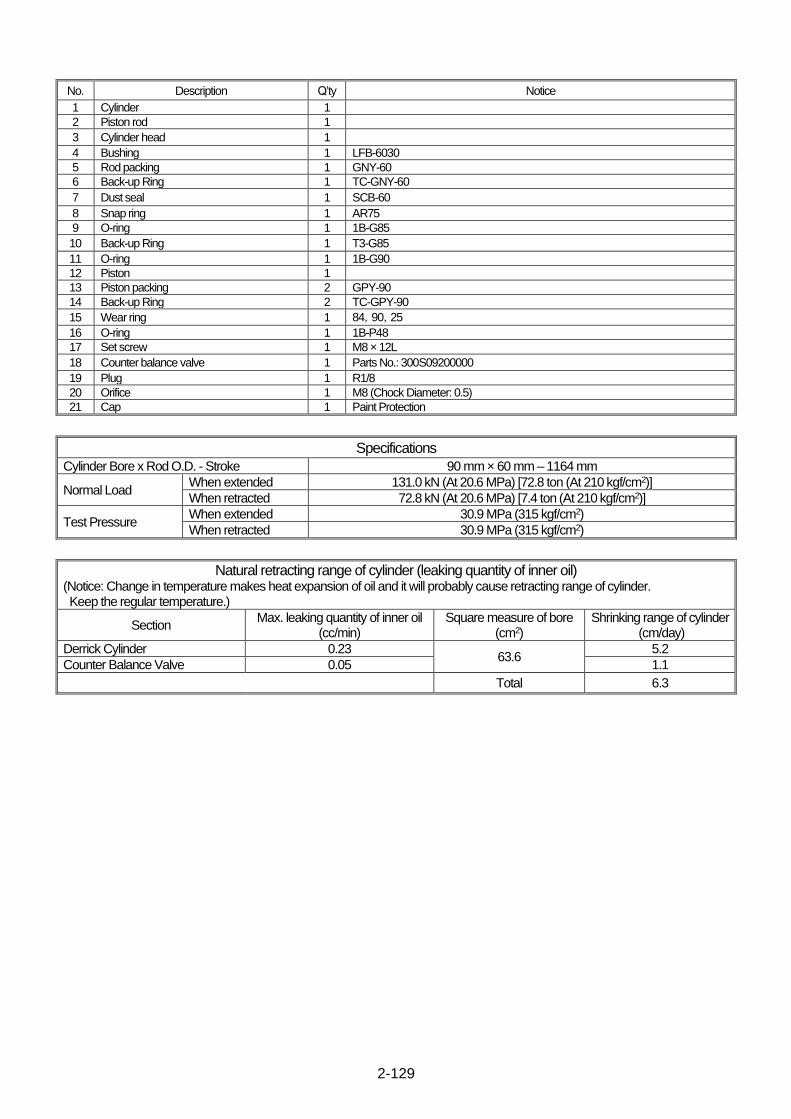
2-129
No. Description Q’ty Notice
1 Cylinder 1
2 Piston rod 1
3 Cylinder head 1
4 Bushing 1 LFB-6030
5 Rod packing 1 GNY-60
6 Back-up Ring 1 TC-GNY-60
7 Dust seal 1 SCB-60
8 Snap ring 1 AR75
9 O-ring 1 1B-G85
10 Back-up Ring 1 T3-G85
11 O-ring 1 1B-G90
12 Piston 1
13 Piston packing 2 GPY-90
14 Back-up Ring 2 TC-GPY-90
15 Wear ring 1 84,90,25
16 O-ring 1 1B-P48
17 Set screw 1 M8 × 12L
18 Counter balance valve 1 Parts No.: 300S09200000
19 Plug 1 R1/8
20 Orifice 1 M8 (Chock Diameter: 0.5)
21 Cap 1 Paint Protection
Specifications
Cylinder Bore x Rod O.D. - Stroke 90 mm × 60 mm – 1164 mm
Normal Load When extended 131.0 kN (At 20.6 MPa) [72.8 ton (At 210 kgf/cm2)]
When retracted 72.8 kN (At 20.6 MPa) [7.4 ton (At 210 kgf/cm2)]
Test Pressure When extended 30.9 MPa (315 kgf/cm2)
When retracted 30.9 MPa (315 kgf/cm2)
Natural retracting range of cylinder (leaking quantity of inner oil) (Notice: Change in temperature makes heat expansion of oil and it will probably cause retracting range of cylinder. Keep the regular temperature.)
Section Max. leaking quantity of inner oil
(cc/min) Square measure of bore
(cm2) Shrinking range of cylinder
(cm/day)
Derrick Cylinder 0.23 63.6
5.2
Counter Balance Valve 0.05 1.1
Total 6.3
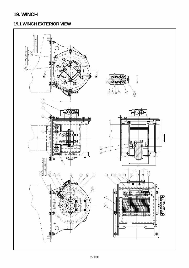
2-130
19. WINCH
19.1 WINCH EXTERIOR VIEW
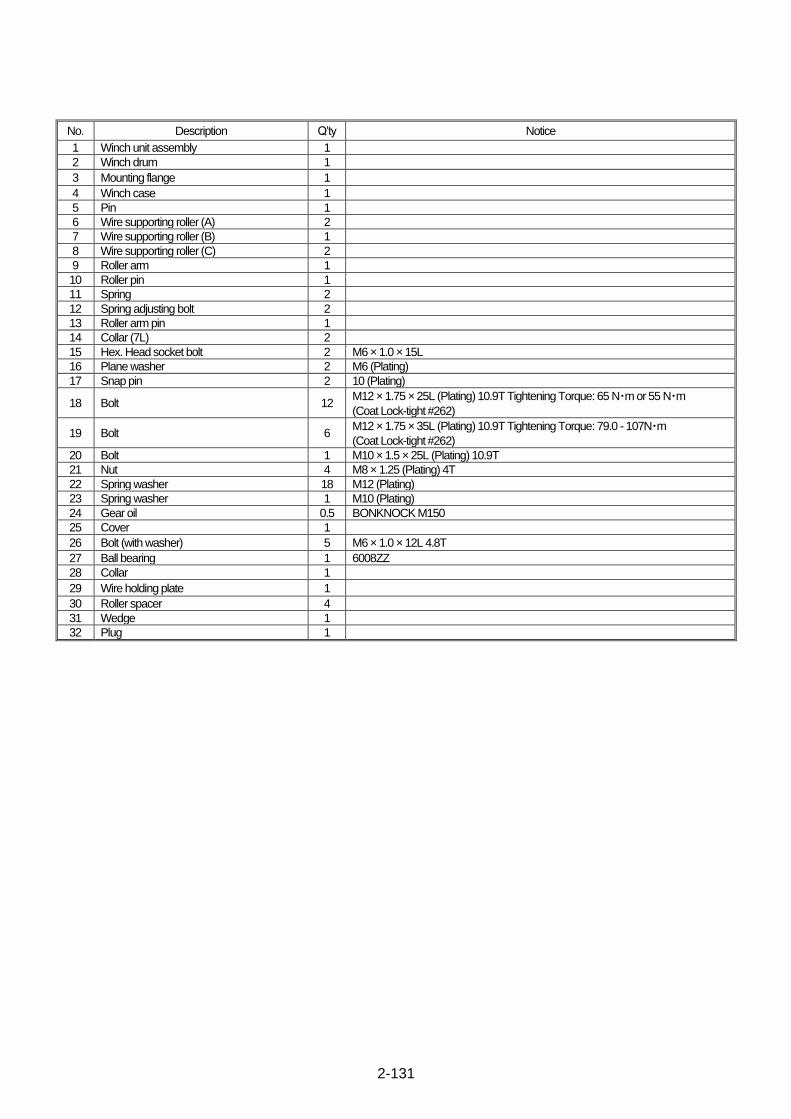
2-131
No. Description Q’ty Notice
1 Winch unit assembly 1
2 Winch drum 1
3 Mounting flange 1
4 Winch case 1
5 Pin 1
6 Wire supporting roller (A) 2
7 Wire supporting roller (B) 1
8 Wire supporting roller (C) 2
9 Roller arm 1
10 Roller pin 1
11 Spring 2
12 Spring adjusting bolt 2
13 Roller arm pin 1
14 Collar (7L) 2
15 Hex. Head socket bolt 2 M6 × 1.0 × 15L
16 Plane washer 2 M6 (Plating)
17 Snap pin 2 10 (Plating)
18 Bolt 12 M12 × 1.75 × 25L (Plating) 10.9T Tightening Torque: 65 N・m or 55 N・m
(Coat Lock-tight #262)
19 Bolt 6 M12 × 1.75 × 35L (Plating) 10.9T Tightening Torque: 79.0 - 107N・m
(Coat Lock-tight #262)
20 Bolt 1 M10 × 1.5 × 25L (Plating) 10.9T
21 Nut 4 M8 × 1.25 (Plating) 4T
22 Spring washer 18 M12 (Plating)
23 Spring washer 1 M10 (Plating)
24 Gear oil 0.5 BONKNOCK M150
25 Cover 1
26 Bolt (with washer) 5 M6 × 1.0 × 12L 4.8T
27 Ball bearing 1 6008ZZ
28 Collar 1
29 Wire holding plate 1
30 Roller spacer 4
31 Wedge 1
32 Plug 1
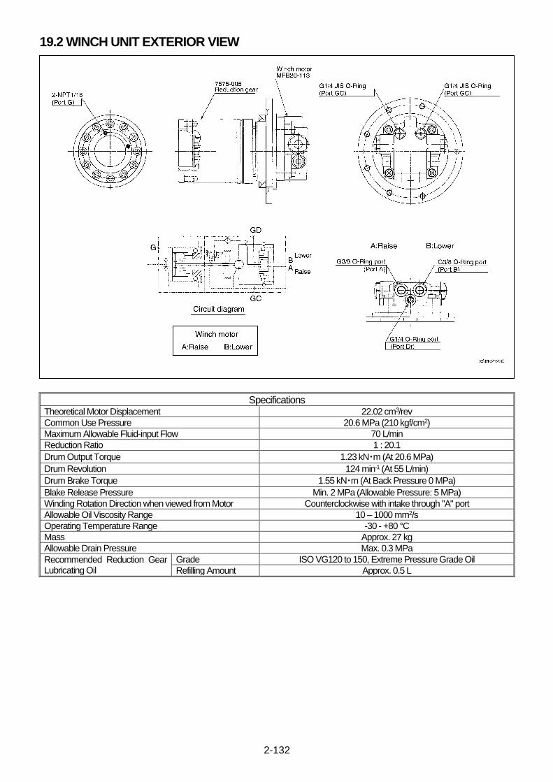
2-132
19.2 WINCH UNIT EXTERIOR VIEW
Specifications Theoretical Motor Displacement 22.02 cm3/rev
Common Use Pressure 20.6 MPa (210 kgf/cm2)
Maximum Allowable Fluid-input Flow 70 L/min
Reduction Ratio 1 : 20.1
Drum Output Torque 1.23 kN・m (At 20.6 MPa)
Drum Revolution 124 min-1 (At 55 L/min)
Drum Brake Torque 1.55 kN・m (At Back Pressure 0 MPa)
Blake Release Pressure Min. 2 MPa (Allowable Pressure: 5 MPa)
Winding Rotation Direction when viewed from Motor Counterclockwise with intake through "A" port
Allowable Oil Viscosity Range 10 – 1000 mm2/s
Operating Temperature Range -30 - +80 °C
Mass Approx. 27 kg
Allowable Drain Pressure Max. 0.3 MPa
Recommended Reduction Gear Lubricating Oil
Grade ISO VG120 to 150, Extreme Pressure Grade Oil
Refilling Amount Approx. 0.5 L
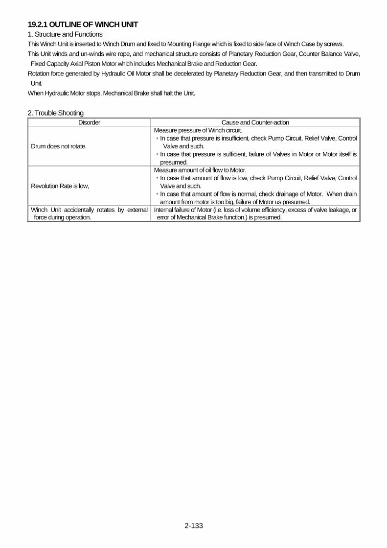
2-133
19.2.1 OUTLINE OF WINCH UNIT
1. Structure and Functions
This Winch Unit is inserted to Winch Drum and fixed to Mounting Flange which is fixed to side face of Winch Case by screws.
This Unit winds and un-winds wire rope, and mechanical structure consists of Planetary Reduction Gear, Counter Balance Valve,
Fixed Capacity Axial Piston Motor which includes Mechanical Brake and Reduction Gear.
Rotation force generated by Hydraulic Oil Motor shall be decelerated by Planetary Reduction Gear, and then transmitted to Drum
Unit.
When Hydraulic Motor stops, Mechanical Brake shall halt the Unit.
2. Trouble Shooting
Disorder Cause and Counter-action
Drum does not rotate.
Measure pressure of Winch circuit.
・In case that pressure is insufficient, check Pump Circuit, Relief Valve, Control
Valve and such.
・In case that pressure is sufficient, failure of Valves in Motor or Motor itself is
presumed.
Revolution Rate is low,
Measure amount of oil flow to Motor.
・In case that amount of flow is low, check Pump Circuit, Relief Valve, Control
Valve and such.
・In case that amount of flow is normal, check drainage of Motor. When drain
amount from motor is too big, failure of Motor us presumed.
Winch Unit accidentally rotates by external force during operation.
Internal failure of Motor (i.e. loss of volume efficiency, excess of valve leakage, or error of Mechanical Brake function.) is presumed.
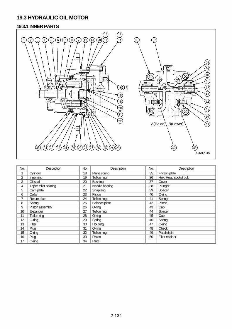
2-134
19.3 HYDRAULIC OIL MOTOR
19.3.1 INNER PARTS
No. Description No. Description No. Description
1 Cylinder 18 Plane spring 35 Friction plate
2 Inner ring 19 Teflon ring 36 Hex. Head socket bolt
3 Oil seal 20 Bushing 37 Cover
4 Taper roller bearing 21 Needle bearing 38 Plunger
5 Cam plate 22 Snap ring 39 Spacer
6 Collar 23 Piston 40 O-ring
7 Return plate 24 Teflon ring 41 Spring
8 Spring 25 Balance plate 42 Piston
9 Piston assembly 26 O-ring 43 Cap
10 Expander 27 Teflon ring 44 Spacer
11 Teflon ring 28 O-ring 45 Cap
12 O-ring 29 Spring 46 Spring
13 Filter 30 Housing 47 O-ring
14 Plug 31 O-ring 48 Check
15 O-ring 32 Teflon ring 49 Parallel pin
16 Plug 33 Piston 50 Filter retainer
17 O-ring 34 Plate
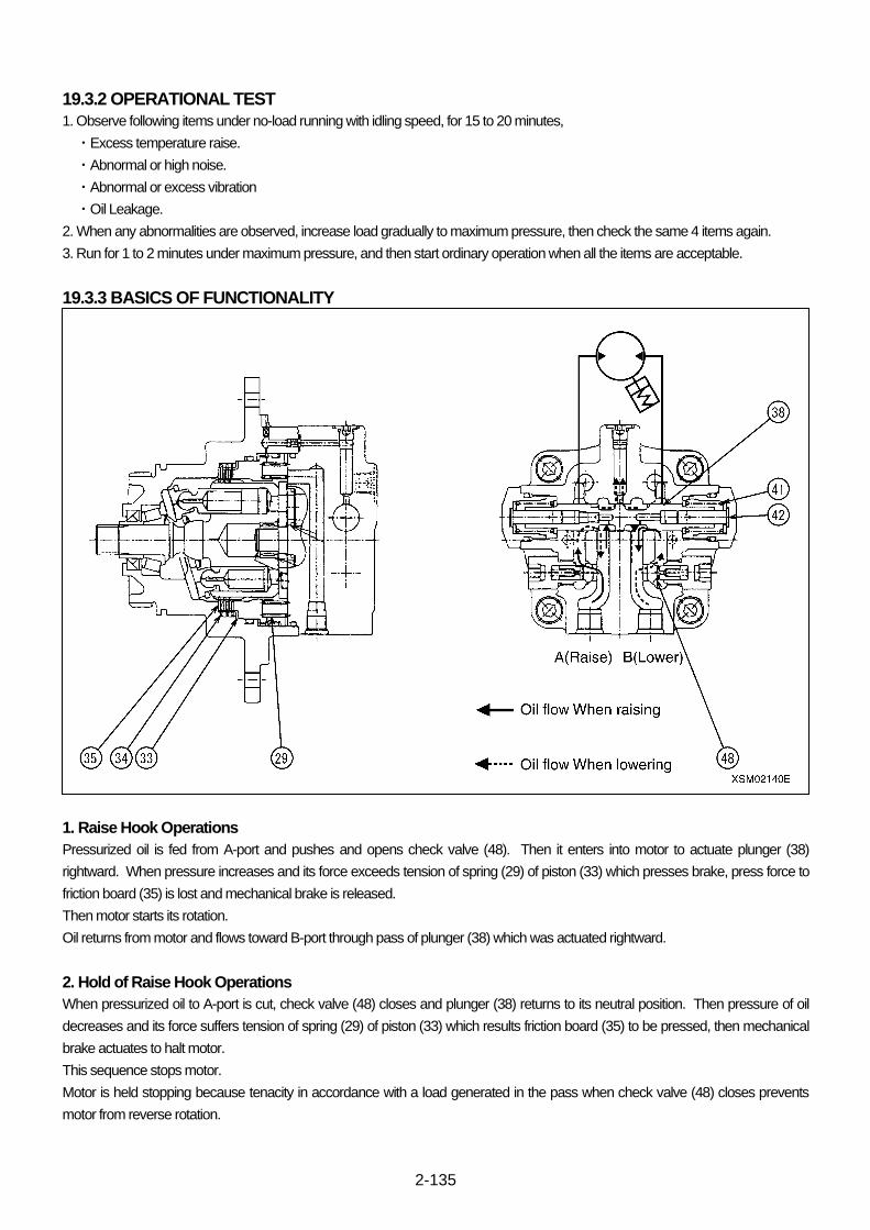
2-135
19.3.2 OPERATIONAL TEST
1. Observe following items under no-load running with idling speed, for 15 to 20 minutes,
・Excess temperature raise.
・Abnormal or high noise.
・Abnormal or excess vibration
・Oil Leakage.
2. When any abnormalities are observed, increase load gradually to maximum pressure, then check the same 4 items again.
3. Run for 1 to 2 minutes under maximum pressure, and then start ordinary operation when all the items are acceptable.
19.3.3 BASICS OF FUNCTIONALITY
1. Raise Hook Operations
Pressurized oil is fed from A-port and pushes and opens check valve (48). Then it enters into motor to actuate plunger (38)
rightward. When pressure increases and its force exceeds tension of spring (29) of piston (33) which presses brake, press force to
friction board (35) is lost and mechanical brake is released.
Then motor starts its rotation.
Oil returns from motor and flows toward B-port through pass of plunger (38) which was actuated rightward.
2. Hold of Raise Hook Operations
When pressurized oil to A-port is cut, check valve (48) closes and plunger (38) returns to its neutral position. Then pressure of oil
decreases and its force suffers tension of spring (29) of piston (33) which results friction board (35) to be pressed, then mechanical
brake actuates to halt motor.
This sequence stops motor.
Motor is held stopping because tenacity in accordance with a load generated in the pass when check valve (48) closes prevents
motor from reverse rotation.
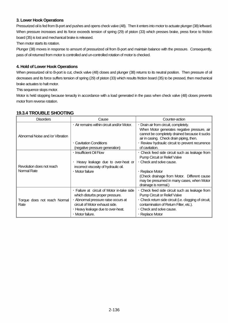
2-136
3. Lower Hook Operations
Pressurized oil is fed from B-port and pushes and opens check valve (48). Then it enters into motor to actuate plunger (38) leftward.
When pressure increases and its force exceeds tension of spring (29) of piston (33) which presses brake, press force to friction
board (35) is lost and mechanical brake is released.
Then motor starts its rotation.
Plunger (38) moves in response to amount of pressurized oil from B-port and maintain balance with the pressure. Consequently,
pass of oil returned from motor is controlled and un-controlled rotation of motor is checked.
4. Hold of Lower Hook Operations
When pressurized oil to B-port is cut, check valve (48) closes and plunger (38) returns to its neutral position. Then pressure of oil
decreases and its force suffers tension of spring (29) of piston (33) which results friction board (35) to be pressed, then mechanical
brake actuates to halt motor.
This sequence stops motor.
Motor is held stopping because tenacity in accordance with a load generated in the pass when check valve (48) closes prevents
motor from reverse rotation.
19.3.4 TROUBLE SHOOTING
Disorders Cause Counter-action
Abnormal Noise and /or Vibration
・ Air remains within circuit and/or Motor.
・ Cavitation Conditions
(negative pressure generation)
・ Drain air from circuit, completely.
When Motor generates negative pressure, air cannot be completely drained because it sucks air in casing. Check drain piping, then.
・ Review hydraulic circuit to prevent recurrence
of cavitation.
Revolution does not reach Normal Rate
・ Insufficient Oil Flow
・ Heavy leakage due to over-heat or
incorrect viscosity of hydraulic oil.
・ Motor failure
・ Check feed side circuit such as leakage from
Pump Circuit or Relief Valve
・ Check and solve cause.
・ Replace Motor
(Check drainage from Motor. Different cause may be presumed in many cases, when Motor drainage is normal.)
Torque does not reach Normal Rate
・ Failure at circuit of Motor in-take side
which disturbs proper pressure.
・ Abnormal pressure raise occurs at
circuit of Motor exhaust side.
・ Heavy leakage due to over-heat.
・ Motor failure.
・ Check feed side circuit such as leakage from
Pump Circuit or Relief Valve
・ Check return side circuit (i.e. clogging of circuit,
contamination of Return Filter, etc.).
・ Check and solve cause.
・ Replace Motor

2-137
This Page Intentionally Left Blank.

2-138
19.4 WINCH REDUCTION GEAR
No. Description No. Description No. Description
1 Ring gear 10 Gear 5 teeth 19 Thrust plate
2 Snap ring 11 Shaft 2 20 Coupling
3 End plate 12 Spring pin 21 Gear 4
4 O-ring 13 O-ring 22 Spring
5 Holder 1 BAS 14 Ball bearing 23 Spacer
6 Holder 2 BAS 15 Oil seal 24 Sun gear
7 Holder 2 16 Snap Ring 25 Hex. head socket bolt
8 Thrust plate 17 Spacer 26 Plug
9 Needle bearing 18 Snap ring
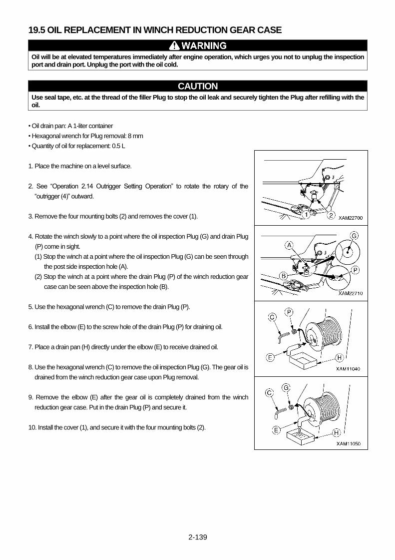
2-139
19.5 OIL REPLACEMENT IN WINCH REDUCTION GEAR CASE
Oil will be at elevated temperatures immediately after engine operation, which urges you not to unplug the inspection port and drain port. Unplug the port with the oil cold.
CAUTION Use seal tape, etc. at the thread of the filler Plug to stop the oil leak and securely tighten the Plug after refilling with the oil.
• Oil drain pan: A 1-liter container
• Hexagonal wrench for Plug removal: 8 mm
• Quantity of oil for replacement: 0.5 L
1. Place the machine on a level surface.
2. See “Operation 2.14 Outrigger Setting Operation” to rotate the rotary of the
“outrigger (4)” outward.
3. Remove the four mounting bolts (2) and removes the cover (1).
4. Rotate the winch slowly to a point where the oil inspection Plug (G) and drain Plug
(P) come in sight.
(1) Stop the winch at a point where the oil inspection Plug (G) can be seen through
the post side inspection hole (A).
(2) Stop the winch at a point where the drain Plug (P) of the winch reduction gear
case can be seen above the inspection hole (B).
5. Use the hexagonal wrench (C) to remove the drain Plug (P).
6. Install the elbow (E) to the screw hole of the drain Plug (P) for draining oil.
7. Place a drain pan (H) directly under the elbow (E) to receive drained oil.
8. Use the hexagonal wrench (C) to remove the oil inspection Plug (G). The gear oil is
drained from the winch reduction gear case upon Plug removal.
9. Remove the elbow (E) after the gear oil is completely drained from the winch
reduction gear case. Put in the drain Plug (P) and secure it.
10. Install the cover (1), and secure it with the four mounting bolts (2).

2-140
11. Pump the gear oil through the oil inspection Plug (G) with the use of the oil pump
(D).
NOTES
Pump the gear oil until it exudes from the oil inspection Plug.
12. Put in the oil inspection Plug (G) and secure it upon completion of oil
replenishment.
NOTES
• Perform a proper break-in with no object hoisted for 5 minutes after oil replacement.
• Wipe off the oil completely if spilled.
13. See “Operation 2.24 Outrigger Stowing Operation” to stow the “outrigger (4)”.

2-141
This Page Intentionally Left Blank.

2-142
19.6 REPLACEMENT WINCH WIRE ROPE
Be sure to attach the rope wedge properly to secure the wire rope. Potential serious accident may occur due to detachment of the wire rope during crane operation if disregarded.
CAUTION • Avoid irregular winding of the wire rope in the winch drum. • Always hoist an object (2.9 to 4.9 KN {300 to 500 kg}) with the boom extended and raised fully immediately after attaching a new rope. Repeat raising and lowering the hook several times until the new rope conforms. • The wire rope is coiled. Exercise caution not to form a kink in the rope when winding it up. Be sure to unrope by rotating the rope to pull it out of the winch drum.
Use the following procedure to attach the wire rope.
1. With the end of the wire rope held, draw the wire rope (5) through the weight of
the over hoist detector, load sheave (1) at the boom end, wire guide (2) of
No.2, 3, and 4 boom, snap sheave (3), and idler sheave (4).
2. Draw the wire rope (5) through the attachment hole of the winch drum (8).
Secure the wire rope (5) to the winch drum (8), following the procedure
provided below.
(1) Draw the wire rope (5) through the winch drum (8) with the rope loose.
(2) The rope wedge (9) should be in position (a). Pass the wire rope (5) around
the rope wedge and yank at the rope in the direction indicated by the
arrow.
Let the wire rope (5) protrude approximately 50 mm out of the narrow hole
in the winch drum (8), then fix the end of the wire rope (5) with the plate
(10).
3. Place the winch lever in the “Up” position (pull it toward you) slowly to wind up
the wire rope (5) in the winch drum (8).
Ensure that the wire rope is coiled between the irregular winding protective
roller (B) and winch drum. The wire rope needs to jut out the boom end
(approx. 10 m).

2-143
4. In response to the number of falls, draw the wire rope through the load sheave
at the boom end, hook block sheave, guide sheave.
5. Secure the end of the wire rope (5) to the wedge socket (3), following the
procedure provided below.
(1) Draw the wire rope (5) through the wedge socket (3) as shown at right.
(2) With the rope wedge (7) in position (a), yank at the wire rope (5) in the
direction indicated by the arrow.
6. Attach the rope clip (4) to the wire rope (5).
7. Secure the wedge socket (3) to the boom with the wedge socket pin (1), and
tighten the wedge socket fixing bolt (2).
8. Place the boom derricking lever in the “Raise” position (pull it toward you) or
the boom telescoping lever in the “Extend” position (pull it toward you) to raise
the hook block.
NOTES
Winch operation is allowed only after the hook block is raised.
9. With the boom extended and raised fully, place the winch lever in the “Down”
position (push it toward the front) to adjust the wire rope (5) until 3 to 4 turns of
wire are left in the winch drum (8).
10. With the wire rope (5) held under tension, place the winch lever in the “Up”
position (pull it toward you) to wind up the wire rope (5) in the winch drum (8).
4-falls
2-falls
1-fall
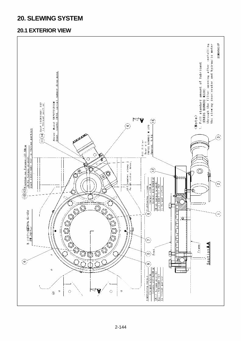
2-144
20. SLEWING SYSTEM
20.1 EXTERIOR VIEW
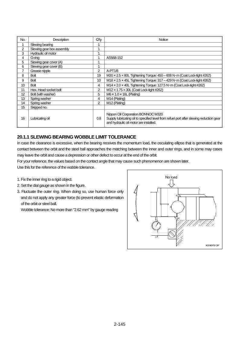
2-145
No. Description Q’ty Notice
1 Slewing bearing 1
2 Slewing gear box assembly 1
3 Hydraulic oil motor 1
4 O-ring 1 AS568-152
5 Slewing gear cover (A) 1
6 Slewing gear cover (B) 1
7 Grease nipple 2 A-PT1/8
8 Bolt 19 M20 × 2.5 × 80L Tightening Torque: 450 – 608 N・m (Coat Lock-tight #262)
9 Bolt 10 M18 × 2.5 × 45L Tightening Torque: 317 – 429 N・m (Coat Lock-tight #262)
10 Bolt 4 M14 × 2.0 × 40L Tightening Torque: 127.5 N・m (Coat Lock-tight #262)
11 Hex. Head socket bolt 2 M12 × 1.75 × 30L (Coat Lock-tight #262)
12 Bolt (with washer) 5 M6 × 1.0 × 16L (Plating)
13 Spring washer 4 M14 (Plating)
14 Spring washer 2 M12 (Plating)
15 Skipped no.
16 Lubricating oil 0.8 Nippon Oil Corporation BONNOC M320 Supply lubricating oil to specified level from refuel port after slewing reduction gear and hydraulic oil motor are installed.
20.1.1 SLEWING BEARING WOBBLE LIMIT TOLERANCE
In case the clearance is excessive, when the bearing receives the momentum load, the osculating ellipse that is generated at the
contact between the orbit and the steel ball approaches the matching between the inner and outer rings, and in some may cases
may leave the orbit and cause a depression or other defect to occur at the end of the orbit.
For your reference, the values based on the contact angle that may cause such phenomenon are shown later.
Use this for the reference of the wobble tolerance.
1. Fix the inner ring to a rigid object.
2. Set the dial gauge as shown in the figure.
3. Fluctuate the outer ring. When doing so, use human force only
and do not apply any greater force (to prevent elastic deformation
of the orbit or steel ball.
Wobble tolerance: No more than "2.62 mm" by gauge reading

2-146
20.2 SLEWING REDUCTION GEAR
Caution for un-installation and installation
・Secure post and frame by a rope or such to prevent
superstructure from accidental slewing when slewing
reduction gear is un-installed.
・Fill gear oil (Nippon Oil Corporation BONNOC M320) to the
center of oil Level gauge.
Slewing Reduction Gear Specifications Reduction ratio 1/35
Input shaft revolution 800 min-1
Output shaft revolution 22.86 min-1
Output shaft rotation torque Rated 391 N・m
Max. 1392 N・m (15 seconds)
Allowable input horsepower 78.5 N・m
Allowable operation time 5000H
Recommended lubricating oil ISO VG 32 : 0.8 L
Hydraulic oil motor SBPC07SS25 × B2964
Estimated efficiency Approx. 40 %
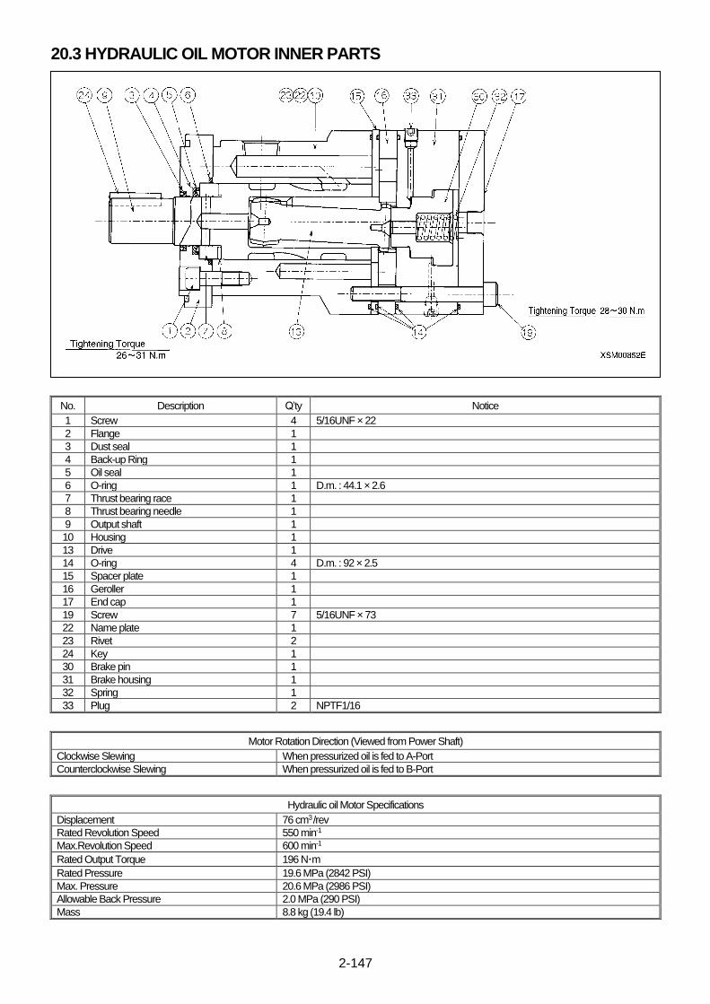
2-147
20.3 HYDRAULIC OIL MOTOR INNER PARTS
No. Description Q’ty Notice
1 Screw 4 5/16UNF × 22
2 Flange 1
3 Dust seal 1
4 Back-up Ring 1
5 Oil seal 1
6 O-ring 1 D.m. : 44.1 × 2.6
7 Thrust bearing race 1
8 Thrust bearing needle 1
9 Output shaft 1
10 Housing 1
13 Drive 1
14 O-ring 4 D.m. : 92 × 2.5
15 Spacer plate 1
16 Geroller 1
17 End cap 1
19 Screw 7 5/16UNF × 73
22 Name plate 1
23 Rivet 2
24 Key 1
30 Brake pin 1
31 Brake housing 1
32 Spring 1
33 Plug 2 NPTF1/16
Motor Rotation Direction (Viewed from Power Shaft)
Clockwise Slewing When pressurized oil is fed to A-Port
Counterclockwise Slewing When pressurized oil is fed to B-Port
Hydraulic oil Motor Specifications
Displacement 76 cm3 /rev
Rated Revolution Speed 550 min-1
Max.Revolution Speed 600 min-1
Rated Output Torque 196 N・m
Rated Pressure 19.6 MPa (2842 PSI)
Max. Pressure 20.6 MPa (2986 PSI)
Allowable Back Pressure 2.0 MPa (290 PSI)
Mass 8.8 kg (19.4 lb)
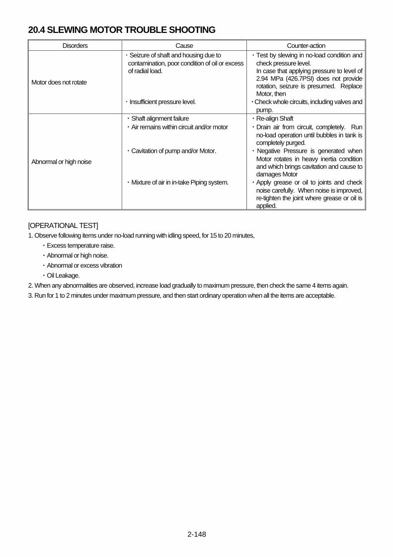
2-148
20.4 SLEWING MOTOR TROUBLE SHOOTING
Disorders Cause Counter-action
Motor does not rotate
・ Seizure of shaft and housing due to
contamination, poor condition of oil or excess of radial load.
・ Insufficient pressure level.
・Test by slewing in no-load condition and
check pressure level. In case that applying pressure to level of 2.94 MPa (426.7PSI) does not provide rotation, seizure is presumed. Replace Motor, then
・Check whole circuits, including valves and
pump.
Abnormal or high noise
・Shaft alignment failure
・Air remains within circuit and/or motor
・Cavitation of pump and/or Motor.
・Mixture of air in in-take Piping system.
・Re-align Shaft
・Drain air from circuit, completely. Run
no-load operation until bubbles in tank is completely purged.
・Negative Pressure is generated when
Motor rotates in heavy inertia condition and which brings cavitation and cause to damages Motor
・Apply grease or oil to joints and check
noise carefully. When noise is improved, re-tighten the joint where grease or oil is applied.
[OPERATIONAL TEST]
1. Observe following items under no-load running with idling speed, for 15 to 20 minutes,
・Excess temperature raise.
・Abnormal or high noise.
・Abnormal or excess vibration
・Oil Leakage.
2. When any abnormalities are observed, increase load gradually to maximum pressure, then check the same 4 items again.
3. Run for 1 to 2 minutes under maximum pressure, and then start ordinary operation when all the items are acceptable.

2-149
This Page Intentionally Left Blank.
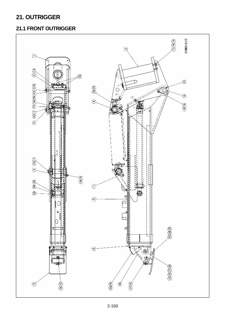
2-150
21. OUTRIGGER
21.1 FRONT OUTRIGGER

2-151
No. Description Q’ty Notice
1 Rotary 1
2 Rotary shaft 1
3 Rotary shaft stopper plate 1
4 Outrigger cylinder head pin 1
5 Outer box 1
6 Outer box pin stopper plate 1
7 Outrigger cylinder rod pin 1
8 Inner box 1
9 Rigger adapter 1
10 Rigger adapter pin 1
11 Rigger adapter end plate 4
12 Position pin 1
13 Button bolt (with hex. hole) 4 M6 × 16L (Plating)
14 Skipped no.
15 Bolt 5 M10 × 18L (Plating) 8.8T
16 Bolt 2 M10 × 25L (Plating) 8.8T
17 Bolt 3 M12 × 25L (Plating) 8.8T
18 Plane spring 4 M6-2L (Plating)
19 Spring washer 7 M10 (Plating)
20 Spring washer 3 M12 (Plating)
21 Grease nipple 1 A-M6F
22 Slide cylinder pin 2
23 Skipped no.
24 Button bolt (with hex. hole) 4 M8 × 15L (Plating) 8.8T
25 Outrigger head 1
26 Outrigger head pin 1
27 End plate 2
28 End plate 4
29 Grounding detector cover 1
30 Bolt (with washer) 4 M6 × 12L (Plating)
31 Wire 1 200L
32 Ring 2
33 Rubber cushion 1
34 Screw 1 M4 × 25L
35 Washer 1 36
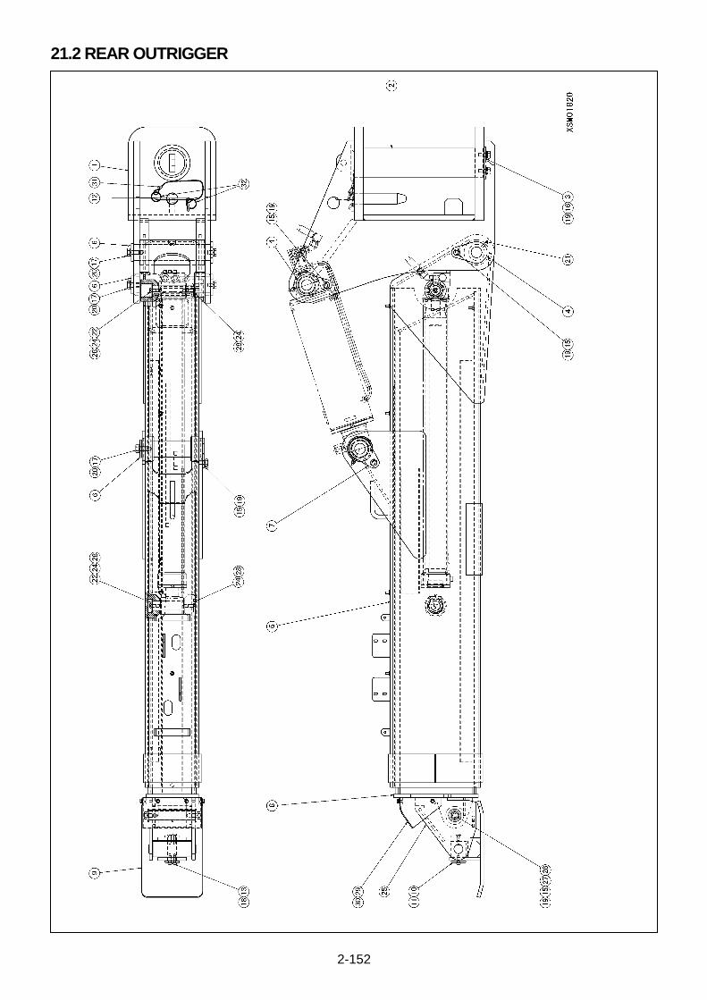
2-152
21.2 REAR OUTRIGGER
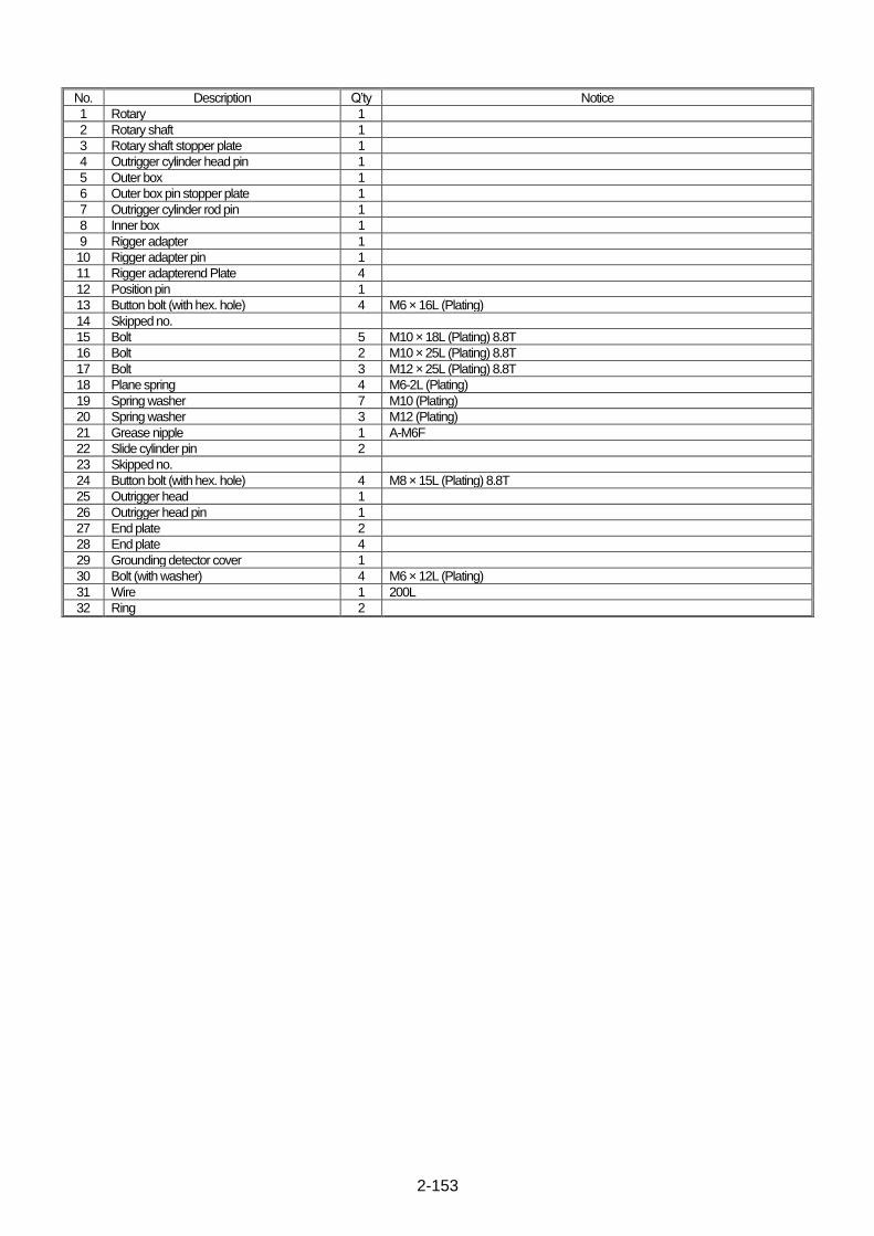
2-153
No. Description Q’ty Notice
1 Rotary 1
2 Rotary shaft 1
3 Rotary shaft stopper plate 1
4 Outrigger cylinder head pin 1
5 Outer box 1
6 Outer box pin stopper plate 1
7 Outrigger cylinder rod pin 1
8 Inner box 1
9 Rigger adapter 1
10 Rigger adapter pin 1
11 Rigger adapterend Plate 4
12 Position pin 1
13 Button bolt (with hex. hole) 4 M6 × 16L (Plating)
14 Skipped no.
15 Bolt 5 M10 × 18L (Plating) 8.8T
16 Bolt 2 M10 × 25L (Plating) 8.8T
17 Bolt 3 M12 × 25L (Plating) 8.8T
18 Plane spring 4 M6-2L (Plating)
19 Spring washer 7 M10 (Plating)
20 Spring washer 3 M12 (Plating)
21 Grease nipple 1 A-M6F
22 Slide cylinder pin 2
23 Skipped no.
24 Button bolt (with hex. hole) 4 M8 × 15L (Plating) 8.8T
25 Outrigger head 1
26 Outrigger head pin 1
27 End plate 2
28 End plate 4
29 Grounding detector cover 1
30 Bolt (with washer) 4 M6 × 12L (Plating)
31 Wire 1 200L
32 Ring 2

2-154
22. OUTRIGGER CYLINDER
22.1 OUTRIGGER SLIDE CYLINDER
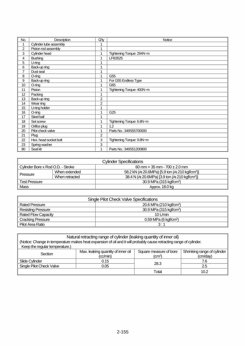
2-155
No. Description Q’ty Notice
1 Cylinder tube assembly 1
2 Piston rod assembly 1
3 Cylinder head 1 Tightening Torque: 294N・m
4 Bushing 1 LFB3525
5 U-ring 1
6 Back-up ring 1
7 Dust seal 1
8 O-ring 1 G55
9 Back-up ring 1 For G55 Endless Type
10 O-ring 1 G65
11 Piston 1 Tightening Torque: 400N・m
12 Packing 1
13 Back-up ring 2
14 Wear ring 2
15 U-ring holder 1
16 O-ring 1 G25
17 Steel ball 1
18 Set screw 1 Tightening Torque: 6.8N・m
19 Orifice plug 1 1.2
20 Pilot check valve 1 Parts No.: 349S55700000
21 Plug 2
22 Hex. head socket bolt 3 Tightening Torque: 9.8N・m
23 Spring washer 3
80 Seal kit 1 Parts No.: 349S51200800
Cylinder Specifications Cylinder Bore x Rod O.D. - Stroke 60 mm × 35 mm - 700 ± 2.0 mm
Pressure When extended 58.2 kN (At 20.6MPa) [5.9 ton (At 210 kgf/cm2)]
When retracted 38.4 N (At 20.6MPa) [3.9 ton (At 210 kgf/cm2)]
Test Pressure 30.9 MPa (315 kgf/cm2)
Mass Approx. 18.0 kg
Single Pilot Check Valve Specifications Rated Pressure 20.6 MPa (210 kgf/cm2)
Resisting Pressure 30.9 MPa (315 kgf/cm2)
Rated Flow Capacity 10 L/min
Cracking Pressure 0.59 MPa (6 kgf/cm2)
Pilot Area Ratio 3 : 1
Natural retracting range of cylinder (leaking quantity of inner oil) (Notice: Change in temperature makes heat expansion of oil and it will probably cause retracting range of cylinder. Keep the regular temperature.)
Section Max. leaking quantity of inner oil
(cc/min) Square measure of bore
(cm2) Shrinking range of cylinder
(cm/day)
Slide Cylinder 0.15 28.3
7.6
Single Pilot Check Valve 0.05 2.5
Total 10.2
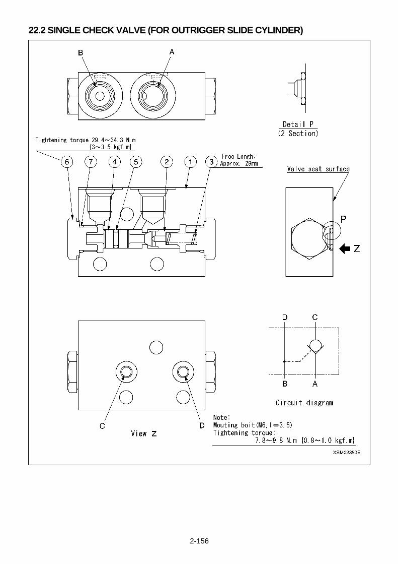
2-156
22.2 SINGLE CHECK VALVE (FOR OUTRIGGER SLIDE CYLINDER)
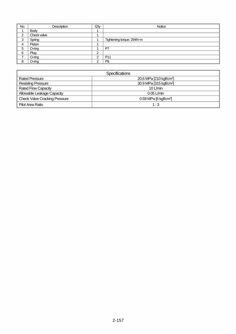
2-157
No. Description Q’ty Notice
1 Body 1
2 Check valve 1
3 Spring 1 Tightening torque: 294N・m
4 Piston 1
5 O-ring 1 P7
6 Plug 2
7 O-ring 2 P11
8 O-ring 2 P8
Specifications Rated Pressure 20.6 MPa [210 kgf/cm2]
Resisting Pressure 30.9 MPa [315 kgf/cm2]
Rated Flow Capacity 10 L/min
Allowable Leakage Capacity 0.05 L/min
Check Valve Cracking Pressure 0.59 MPa [6 kgf/cm2]
Pilot Area Ratio 1 : 3

2-158
22.3 FRONT OUTRIGGER CYLINDER
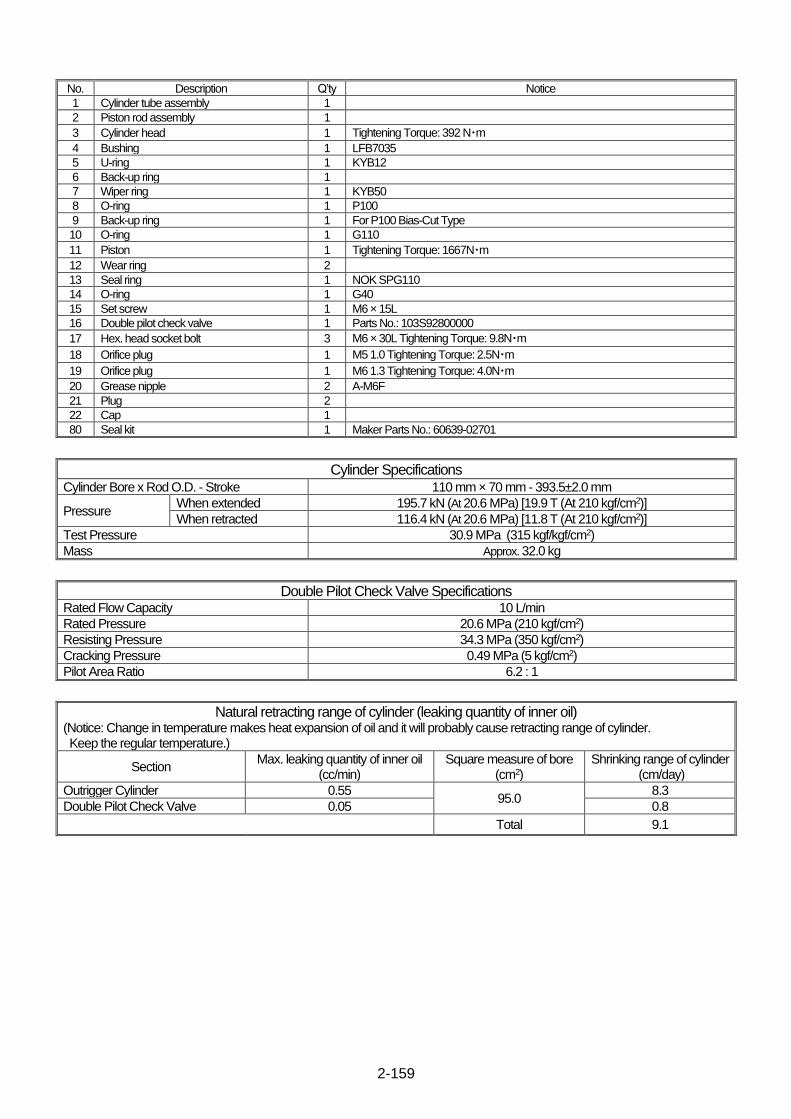
2-159
No. Description Q’ty Notice
1 Cylinder tube assembly 1
2 Piston rod assembly 1
3 Cylinder head 1 Tightening Torque: 392 N・m
4 Bushing 1 LFB7035
5 U-ring 1 KYB12
6 Back-up ring 1
7 Wiper ring 1 KYB50
8 O-ring 1 P100
9 Back-up ring 1 For P100 Bias-Cut Type
10 O-ring 1 G110
11 Piston 1 Tightening Torque: 1667N・m
12 Wear ring 2
13 Seal ring 1 NOK SPG110
14 O-ring 1 G40
15 Set screw 1 M6 × 15L
16 Double pilot check valve 1 Parts No.: 103S92800000
17 Hex. head socket bolt 3 M6 × 30L Tightening Torque: 9.8N・m
18 Orifice plug 1 M5 1.0 Tightening Torque: 2.5N・m
19 Orifice plug 1 M6 1.3 Tightening Torque: 4.0N・m
20 Grease nipple 2 A-M6F
21 Plug 2
22 Cap 1
80 Seal kit 1 Maker Parts No.: 60639-02701
Cylinder Specifications Cylinder Bore x Rod O.D. - Stroke 110 mm × 70 mm - 393.5±2.0 mm
Pressure When extended 195.7 kN (At 20.6 MPa) [19.9 T (At 210 kgf/cm2)]
When retracted 116.4 kN (At 20.6 MPa) [11.8 T (At 210 kgf/cm2)]
Test Pressure 30.9 MPa (315 kgf/kgf/cm2)
Mass Approx. 32.0 kg
Double Pilot Check Valve Specifications Rated Flow Capacity 10 L/min
Rated Pressure 20.6 MPa (210 kgf/cm2)
Resisting Pressure 34.3 MPa (350 kgf/cm2)
Cracking Pressure 0.49 MPa (5 kgf/cm2)
Pilot Area Ratio 6.2 : 1
Natural retracting range of cylinder (leaking quantity of inner oil) (Notice: Change in temperature makes heat expansion of oil and it will probably cause retracting range of cylinder. Keep the regular temperature.)
Section Max. leaking quantity of inner oil
(cc/min) Square measure of bore
(cm2) Shrinking range of cylinder
(cm/day)
Outrigger Cylinder 0.55 95.0
8.3
Double Pilot Check Valve 0.05 0.8
Total 9.1
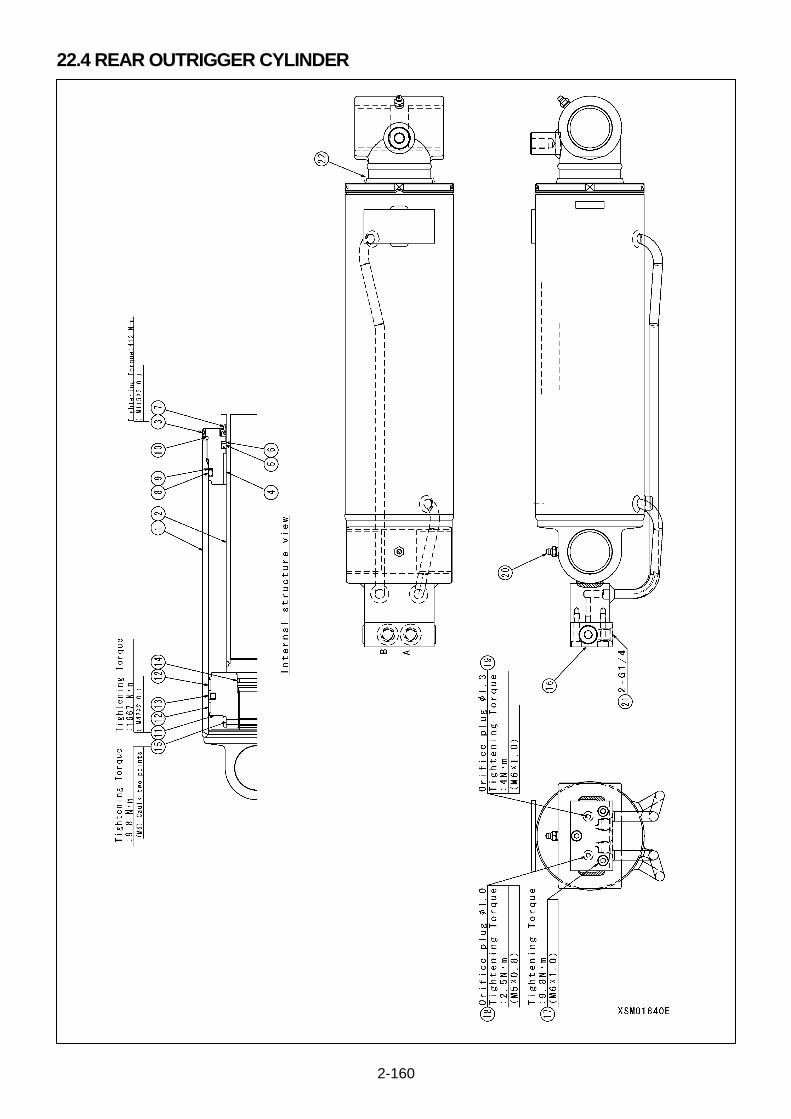
2-160
22.4 REAR OUTRIGGER CYLINDER
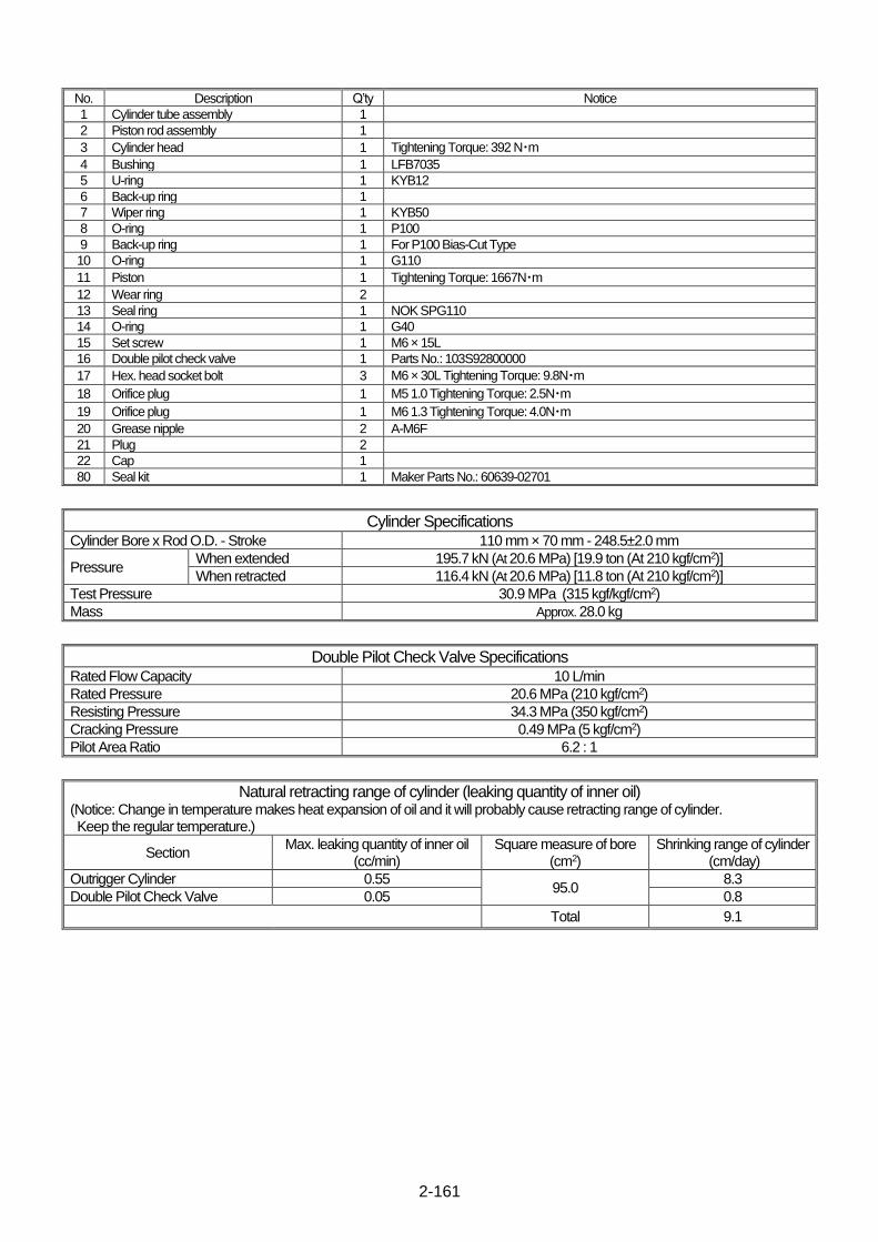
2-161
No. Description Q’ty Notice
1 Cylinder tube assembly 1
2 Piston rod assembly 1
3 Cylinder head 1 Tightening Torque: 392 N・m
4 Bushing 1 LFB7035
5 U-ring 1 KYB12
6 Back-up ring 1
7 Wiper ring 1 KYB50
8 O-ring 1 P100
9 Back-up ring 1 For P100 Bias-Cut Type
10 O-ring 1 G110
11 Piston 1 Tightening Torque: 1667N・m
12 Wear ring 2
13 Seal ring 1 NOK SPG110
14 O-ring 1 G40
15 Set screw 1 M6 × 15L
16 Double pilot check valve 1 Parts No.: 103S92800000
17 Hex. head socket bolt 3 M6 × 30L Tightening Torque: 9.8N・m
18 Orifice plug 1 M5 1.0 Tightening Torque: 2.5N・m
19 Orifice plug 1 M6 1.3 Tightening Torque: 4.0N・m
20 Grease nipple 2 A-M6F
21 Plug 2
22 Cap 1
80 Seal kit 1 Maker Parts No.: 60639-02701
Cylinder Specifications Cylinder Bore x Rod O.D. - Stroke 110 mm × 70 mm - 248.5±2.0 mm
Pressure When extended 195.7 kN (At 20.6 MPa) [19.9 ton (At 210 kgf/cm2)]
When retracted 116.4 kN (At 20.6 MPa) [11.8 ton (At 210 kgf/cm2)]
Test Pressure 30.9 MPa (315 kgf/kgf/cm2)
Mass Approx. 28.0 kg
Double Pilot Check Valve Specifications Rated Flow Capacity 10 L/min
Rated Pressure 20.6 MPa (210 kgf/cm2)
Resisting Pressure 34.3 MPa (350 kgf/cm2)
Cracking Pressure 0.49 MPa (5 kgf/cm2)
Pilot Area Ratio 6.2 : 1
Natural retracting range of cylinder (leaking quantity of inner oil) (Notice: Change in temperature makes heat expansion of oil and it will probably cause retracting range of cylinder. Keep the regular temperature.)
Section Max. leaking quantity of inner oil
(cc/min) Square measure of bore
(cm2) Shrinking range of cylinder
(cm/day)
Outrigger Cylinder 0.55 95.0
8.3
Double Pilot Check Valve 0.05 0.8
Total 9.1
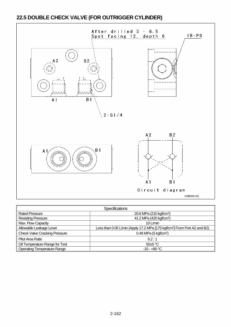
2-162
22.5 DOUBLE CHECK VALVE (FOR OUTRIGGER CYLINDER)
Specifications Rated Pressure 20.6 MPa (210 kgf/cm2)
Resisting Pressure 41.2 MPa (420 kgf/cm2)
Max. Flow Capacity 10 L/min
Allowable Leakage Level Less than 0.05 L/min (Apply 17.2 MPa [175 kgf/cm2] From Port A2 and B2)
Check Valve Cracking Pressure 0.49 MPa (5 kgf/cm2)
Pilot Area Ratio 6.2 : 1
Oil Temperature Range for Test 50±5 °C
Operating Temperature Range -10 - +80 °C

2-163
This Page Intentionally Left Blank.
2-164
23. ASSEMBLY AND DISASSEMBLY OF BOOM
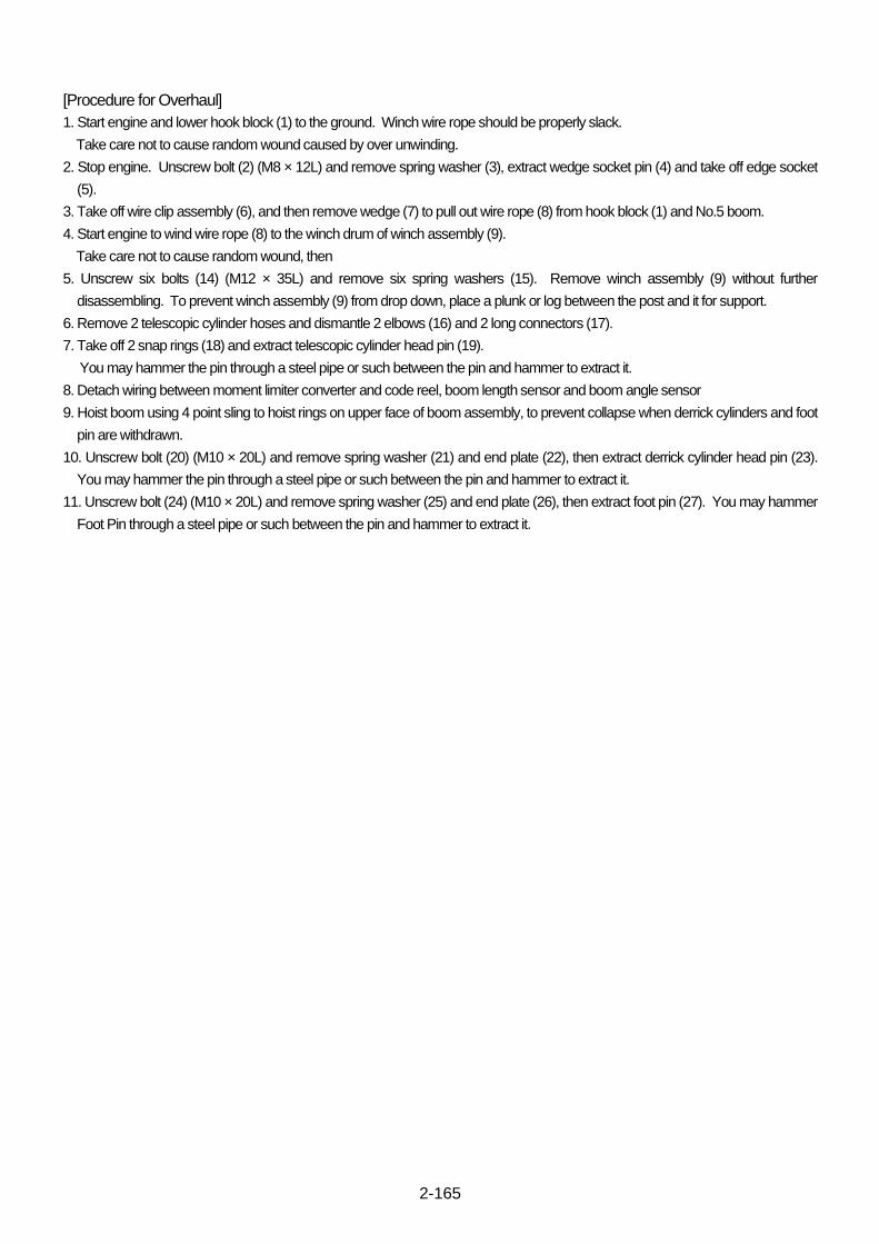
2-165
[Procedure for Overhaul]
1. Start engine and lower hook block (1) to the ground. Winch wire rope should be properly slack.
Take care not to cause random wound caused by over unwinding.
2. Stop engine. Unscrew bolt (2) (M8 × 12L) and remove spring washer (3), extract wedge socket pin (4) and take off edge socket
(5).
3. Take off wire clip assembly (6), and then remove wedge (7) to pull out wire rope (8) from hook block (1) and No.5 boom.
4. Start engine to wind wire rope (8) to the winch drum of winch assembly (9).
Take care not to cause random wound, then
5. Unscrew six bolts (14) (M12 × 35L) and remove six spring washers (15). Remove winch assembly (9) without further
disassembling. To prevent winch assembly (9) from drop down, place a plunk or log between the post and it for support.
6. Remove 2 telescopic cylinder hoses and dismantle 2 elbows (16) and 2 long connectors (17).
7. Take off 2 snap rings (18) and extract telescopic cylinder head pin (19).
You may hammer the pin through a steel pipe or such between the pin and hammer to extract it.
8. Detach wiring between moment limiter converter and code reel, boom length sensor and boom angle sensor
9. Hoist boom using 4 point sling to hoist rings on upper face of boom assembly, to prevent collapse when derrick cylinders and foot
pin are withdrawn.
10. Unscrew bolt (20) (M10 × 20L) and remove spring washer (21) and end plate (22), then extract derrick cylinder head pin (23).
You may hammer the pin through a steel pipe or such between the pin and hammer to extract it.
11. Unscrew bolt (24) (M10 × 20L) and remove spring washer (25) and end plate (26), then extract foot pin (27). You may hammer
Foot Pin through a steel pipe or such between the pin and hammer to extract it.

2-166
12. Unscrew 2 bolts (28) (M6 × 10L), and remove 2 spring washers (29), then take off boom tail cover (30) so that code reel is
revealed
13. Unscrew 3 bolts (31) (M6 × 10L), and remove 3 spring washers (32), then take off boom head cover (33)
14. Detach fasten connector between over hoist detector and code reel. Tie band and corrugated Tube shall be detached from
code then wind code. Keep the end of code stay out of code reel, then.
15. Unscrew 4 bolts (34) (M10 × 20L), and remove 4 spring washers (35), then take off stopper plate (36)
16. Unscrew 8 hexagon socket head button bolts (38) (M10 × 15L), and remove 8 spring washers (39) on both left and right side,
then remove 4 side plate stopper plate (40) and side slide plates (41) respectively, on both left and right side.
17. Unscrew 2 hexagon socket head button bolts (42) (M10 × 15L), and remove 2 spring washers (43), then pull out No.2, 3, 4 and 5
booms and telescopic cylinder assembly from No. 1 boom.
18. Remove 2 slide plates (37) from bottom side of No.1 boom.
19. Detach 2 snap rings (44) and pull out 2 telescopic cylinder trunnion pins (45) on both left and right side, where an M8 bolt
(approximately 30L) may be used. Screw the bolt to M8 tapped hole of trunnion pin (45) and pinch the bolt by a plier to pull out.
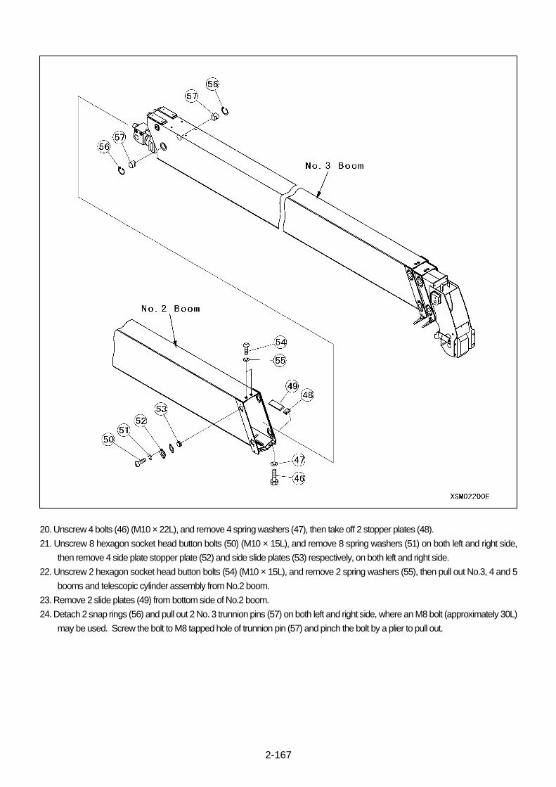
2-167
20. Unscrew 4 bolts (46) (M10 × 22L), and remove 4 spring washers (47), then take off 2 stopper plates (48).
21. Unscrew 8 hexagon socket head button bolts (50) (M10 × 15L), and remove 8 spring washers (51) on both left and right side,
then remove 4 side plate stopper plate (52) and side slide plates (53) respectively, on both left and right side.
22. Unscrew 2 hexagon socket head button bolts (54) (M10 × 15L), and remove 2 spring washers (55), then pull out No.3, 4 and 5
booms and telescopic cylinder assembly from No.2 boom.
23. Remove 2 slide plates (49) from bottom side of No.2 boom.
24. Detach 2 snap rings (56) and pull out 2 No. 3 trunnion pins (57) on both left and right side, where an M8 bolt (approximately 30L)
may be used. Screw the bolt to M8 tapped hole of trunnion pin (57) and pinch the bolt by a plier to pull out.
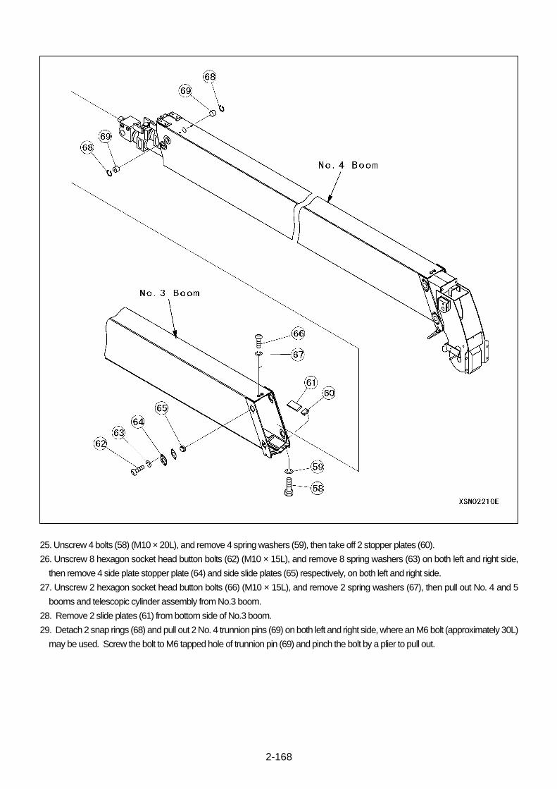
2-168
25. Unscrew 4 bolts (58) (M10 × 20L), and remove 4 spring washers (59), then take off 2 stopper plates (60).
26. Unscrew 8 hexagon socket head button bolts (62) (M10 × 15L), and remove 8 spring washers (63) on both left and right side,
then remove 4 side plate stopper plate (64) and side slide plates (65) respectively, on both left and right side.
27. Unscrew 2 hexagon socket head button bolts (66) (M10 × 15L), and remove 2 spring washers (67), then pull out No. 4 and 5
booms and telescopic cylinder assembly from No.3 boom.
28. Remove 2 slide plates (61) from bottom side of No.3 boom.
29. Detach 2 snap rings (68) and pull out 2 No. 4 trunnion pins (69) on both left and right side, where an M6 bolt (approximately 30L)
may be used. Screw the bolt to M6 tapped hole of trunnion pin (69) and pinch the bolt by a plier to pull out.
2-169
30. Unscrew 4 bolts (70) (M10 × 20L), and remove 4 spring washers (71), then take off 2 stopper plates (72).
31. Unscrew 8 hexagon socket head button bolts (74) (M10 × 15L), and remove 8 spring washers (75) on both left and right side,
then remove 4 side plate stopper plate (76) and side plates (77) respectively on both left and right side.
32. Unscrew 2 hexagon socket head button bolts (78) (M10 × 20L), and remove 2 spring washers (79), then pull out No. 5 boom
and telescopic cylinder assembly from No.4 boom.
33. Remove 2 slide plates (73) from bottom side of No.4 boom.

2-170
34.Remove the hexagon nuts (81) (M12) one by one from the one nearest to the wire tip first while holding down the tip of the boom
retraction wire (80) with a 8 mm spanner, then remove the boom retraction wire from the No. 5 boom.
35. Detach 2 snap rings (82) and pull out 2 No. 4 trunnion pins (83) on both left and right side, where an M6 bolt (approximately 30L)
may be used. Screw the bolt to M6 tapped hole of trunnion pin (83) and pinch the bolt by a plier to pull out.
36.Pull out the telescopic cylinder, boom retraction wire (80) and boom extension wire (85) assembled together out of the No. 5
boom, while paying attention not drop the boom extension wire bracket (84).
The boom disassembly ends here.
[Assembly procedure]
Assemble by following disassembly procedure in reverse.
CAUTION: Make sure that neither of the boom extension wire, boom retraction wire or cord reel cross with each other and suffer
damage during the assembly.
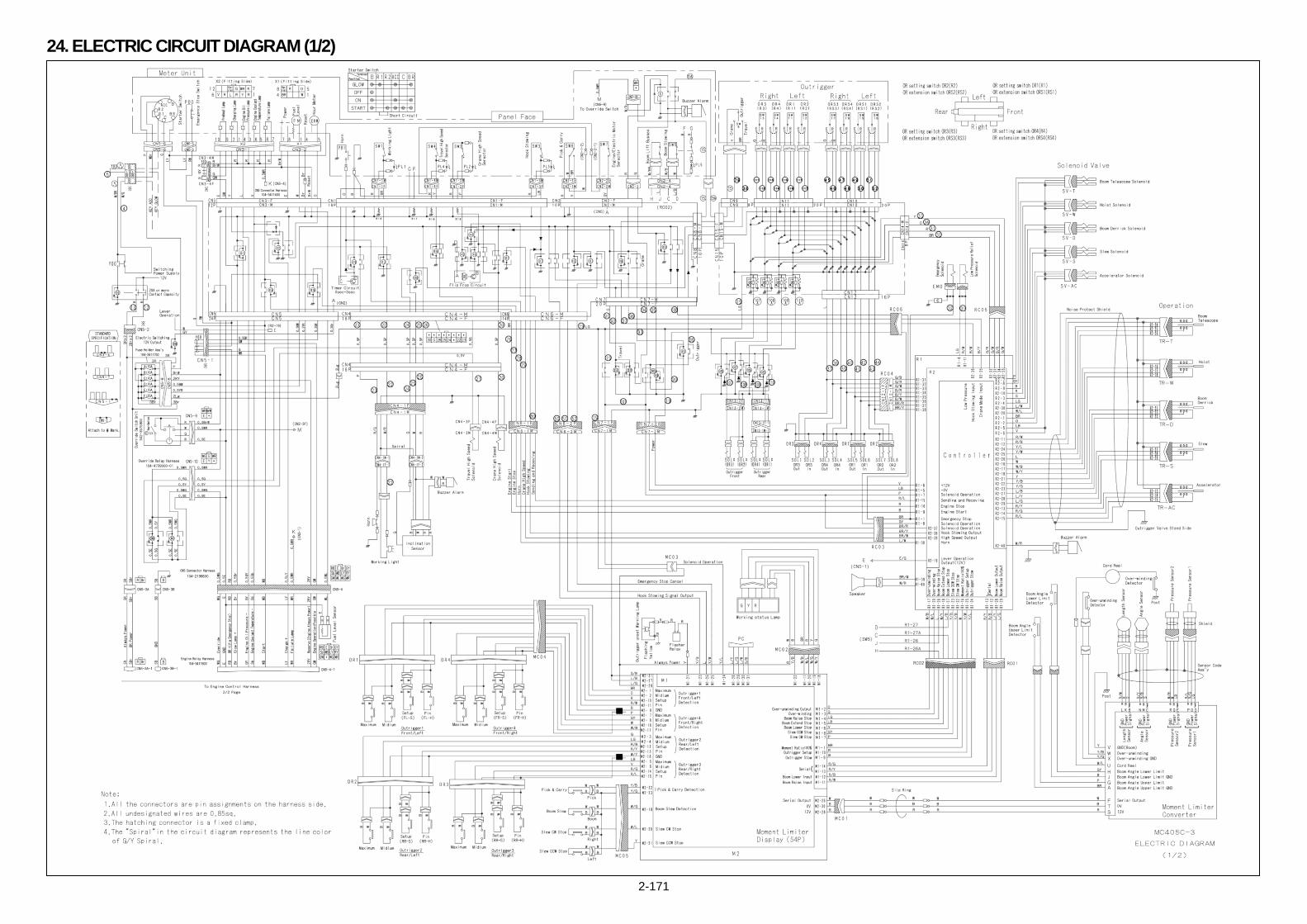
2-171
24. ELECTRIC CIRCUIT DIAGRAM (1/2)

2-172
ELECTRIC CIRCUIT DIAGRAM (ENGINE) (2/2)
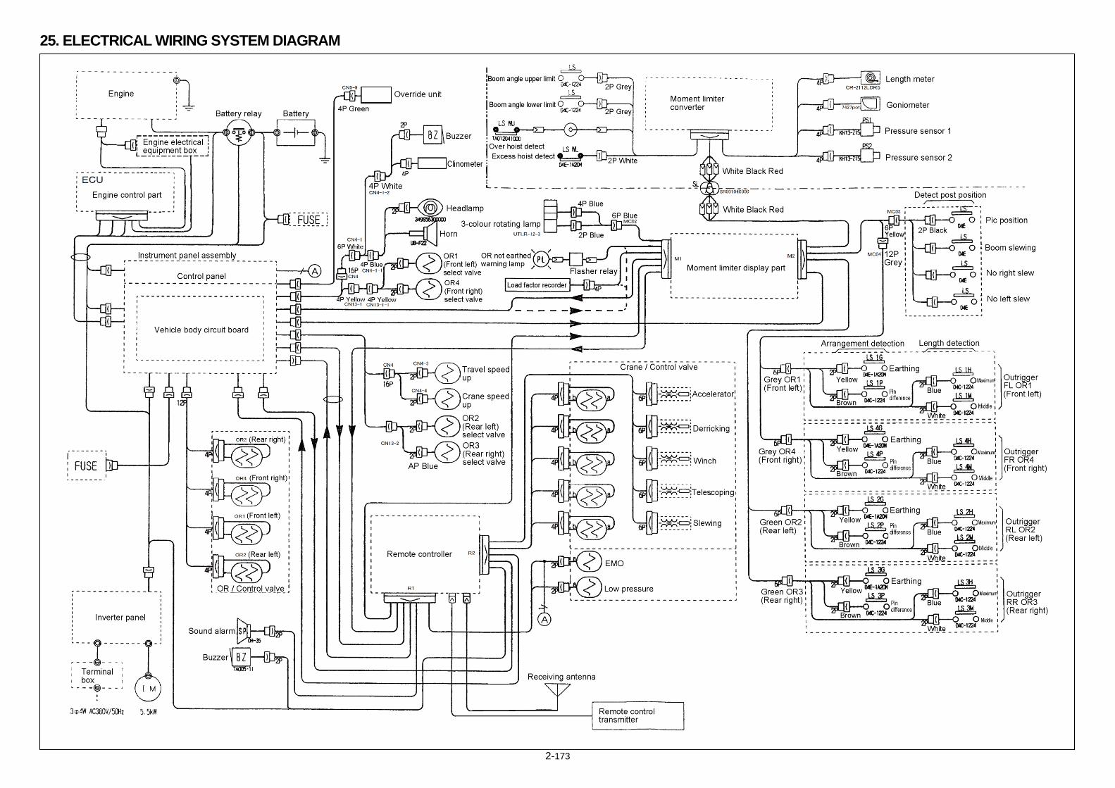
2-173
25. ELECTRICAL WIRING SYSTEM DIAGRAM

2-174
This Page Intentionally Left Blank.

2-175
This Page Intentionally Left Blank.
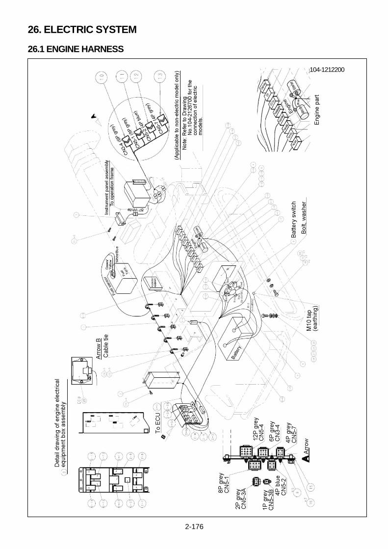
2-176
26. ELECTRIC SYSTEM
26.1 ENGINE HARNESS
104-1212200

2-177
Arrow part A connector details
Connector number Number of pins
/ colour Description
CN5-3A 2 P / grey Power supply + 12 V Electric box ⇔ Operating box
CN5-3B 1 P / grey GND Electric box ⇔ Operating box
CN5-4 12 P / grey Engine electric components Electric box ⇔ Operating box
CN5-1 8 P / grey When electrically-powered: Starting engine NOT available, lever operation
Electric / Operating box ⇒ Inverter panel
CN3-4 6 P / grey When electrically-powered: Meter unit OFF Operating box ⇒ Inverter panel
CN5-2 4 P / blue When electrically-powered: Power on Inverter panel ⇒ Operating box
CN5-7 4 P / grey When electrically-powered: Key switch signal Operating box ⇒ Inverter panel
No. Name Qty. Note
1 Engine relay harness 1 Part No.: 104-3411600
2 Engine electric box 1 Part No.: S104L2114000
2-1 ECU harness 1
2-2 SA-D 1
2-3 Resistor assembly 1
2-4 CN5-3A-1 1
2-5 CN5-3B-1 1
2-6 CN5-4-1 1
2-7 Slow blow fuse 1
2-8 Slow blow fuse 1
2-9 Slow blow fuse 1
2-10 Charge relay 1
2-11 Glow lamp relay 1
2 -12 Main relay 1
2-13 Actuator relay 1
2-14 Starter relay 1
2-15 Glow relay 1
2-16 Accelerator assembly 1
2-17 Fuel feed pump 1
2-18 Glow plug 1
2-19 Hydraulic SW 1
2-20 Rack actuator 1
2-21 Rotary sensor 1
2-22 CSD coil 1
2-23 EGR step motor 1
2-24 Water temperature sensor 1
2-25 Starter B 1
2-26 Starter S 1
2-27 Alternator 1
2-28 Alternator B 1
2-29 Battery (+) terminal 1
2-30 GND 1
2-31 ACC 1
2-32 Battery relay (+) terminal 1
2-33 Battery relay (-) terminal 1
2-34 SPEED1 1
2-35 SPEED2 1
2-36 Short circuit cap 1
3 Battery switch positive code +(4G3) 1 Part No.: S104M4190000
4 Battery starter positive code -(4G4) 1 Part No.: S104M2124000
5 Battery earthing code -(4G5) 1 Part No.: S104M2125000
6 Battery switch 1 Part No.: 349S55625000
7 Fuse holder assembly 1 Part No.: 104-3411700
8 Alternator code 1 Part No.: S104M2127000

2-178
No. Name Qty. Note
9 Fixed clip (grey) 5 Part No.: 6810-0805
10 Coupler for short circuit 6 P grey (CN3-4)
1 Part No.: S103M2131000
11 Coupler for short circuit 8 P grey (CN5-1)
1 Part No.: S103M2132000
12 Coupler for short circuit 4 P blue (CN5-2)
1 Part No.: S103M2133000
13 Coupler for short circuit 4 P grey (CN3-7)
1 Part No.: S103M2134000
14 Washer assembling bolt 4
15 Connector bracket S1 1 Part No.: 103-4544400
16 Washer assembling bolt 2
17 Battery relay cover 1 Part No.: 103-4547300
18 Hexagon head bolt 2 M8 × 1.25 × 30L (plated)
19 Plain washer 2 M8 × 1.25 × 30L (plated)
20 Spring washer 2 M8 × Type-2 (plated)
21 Washer assembling bolt 2 M6 × 1.0 × 16L (PW, SW assembly, plated)
22 Cable tie stay 5 Type: KR8G5W (tighten)
23 Cross-recessed round head screw 5 M6 × 1.0 × 6L (plated)
24 Toothed washer 1 M6 × 1.0 × 6L (plated)
25 ECU 1 Yanmar accessory 129927-75103
26 Hexagon head bolt 1 M10 × 1.5 × 20L (plated)
27 Plain washer 1 M10 × 1.5 × 20L (plated)
28 Spring washer 1 M10 × Type-2 (plated)

2-179
This Page Intentionally Left Blank.
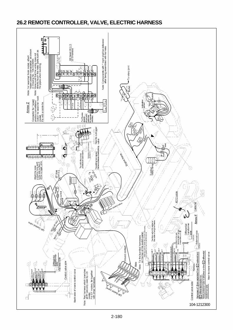
2-180
26.2 REMOTE CONTROLLER, VALVE, ELECTRIC HARNESS
104-1212300
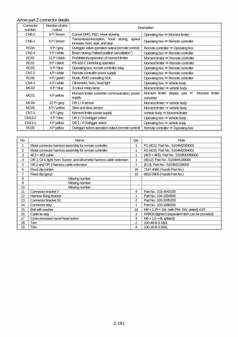
2-181
Arrow part Z connector details
Connector number
Number of pins / colour
Description
CN6-2 4 P / brown Cancel EMO, P&C, Hook stowing Operating box ⇔ Moment limiter
CN6-1 6 P / brown Transmission/reception, hook storing, speed increase, horn, start, and stop
Operating box ⇔ Remote controller
RC04 8 P / grey Outrigger valve operation output (remote control) Remote controller ⇒ Operating box
CN2-4 4 P / white Boom storing (“raised position cancellation”) Operating box ⇔ Remote controller
RC02 12 P / black Prohibition/suspension of moment limiter Moment limiter ⇔ Remote controller
RC01 8 P / black RS-422-C Derricking operation Moment limiter ⇔ Remote controller
RC03 6 P / blue Operating box, remote controller relay Operating box ⇔ Remote controller
CN7-2 4 P / white Remote controller power supply Operating box ⇔ Remote controller
RC06 4 P / green Mode, EMO cancelling SOL Operating box ⇔ Remote controller
CN4-1 6 P / white Clinometer, horn, head light Operating box ⇒ vehicle body
MC02 6 P / blue 3-colour rotary lamp Moment limiter ⇒ vehicle body
MC01 4 P yellow Moment limiter converter communication, power supply
Moment limiter display part ⇔ Moment limiter
converter
MC04 12 P / grey OR 1 / 4 sensor Moment limiter ⇒ vehicle body
MC05 6 P / yellow Slew and stow sensor Moment limiter ⇒ vehicle body
CN7-1 4 P / grey Moment limiter power supply Vehicle body ⇒ Moment limiter
CM13-2 4 P / blue OR 2 / 3 Outrigger select Operating box ⇒ vehicle body
CN13-1 4 P yellow OR 1 / 4 Outrigger select Operating box ⇒ vehicle body
RC05 4 P yellow Outrigger select operation output (remote control) Remote controller ⇒ Operating box
No. Name Qty. Note
1 Metal connector harness assembly for remote controller 1 R1 (4D1) Part No.: S104M2093002
2 Metal connector harness assembly for remote controller 1 R2 (4D2) Part No.: S104M2094001
3 4E3 + 4E5 cable 1 (4E3 + 4E5) Part No.: S103M2099000
4 OR 1, Or 4, light, horn, buzzer, and clinometer harness cable extension 1 (4E12) Part No.: S104M4189000
5 OR 2 and OR 3 harness cable extension 1 (E13) Part No.: S103M2108000
6 Fixed clip (white) 16 7147-4065 (Yazaki Part No.)
7 Fixed clip (grey) 10 6810-0805 (Yazaki Part No.)
8 Missing number
9 Missing number
10 Missing number
11 Connector bracket Y 4 Part No.: 103-4543100
12 Harness fixing bracket 1 Part No.: 104-3284500
13 Connector bracket S2 2 Part No.: 103-3285200
14 Connector stay 1 Part No.: 103-3286300
15 Bolt with washer 16 M8 × 1.25 × 15L (with PW, SW, plated) 4.8T
16 Cable tie stay 3 KR8G5 (tighten) (equivalent item can be provided)
17 Cross-recessed round head screw 3 M6 × 1.0 × 6L (plated)
18 Trim 2 100-48-B-3-180L
19 Trim 4 100-16-B-3-345L
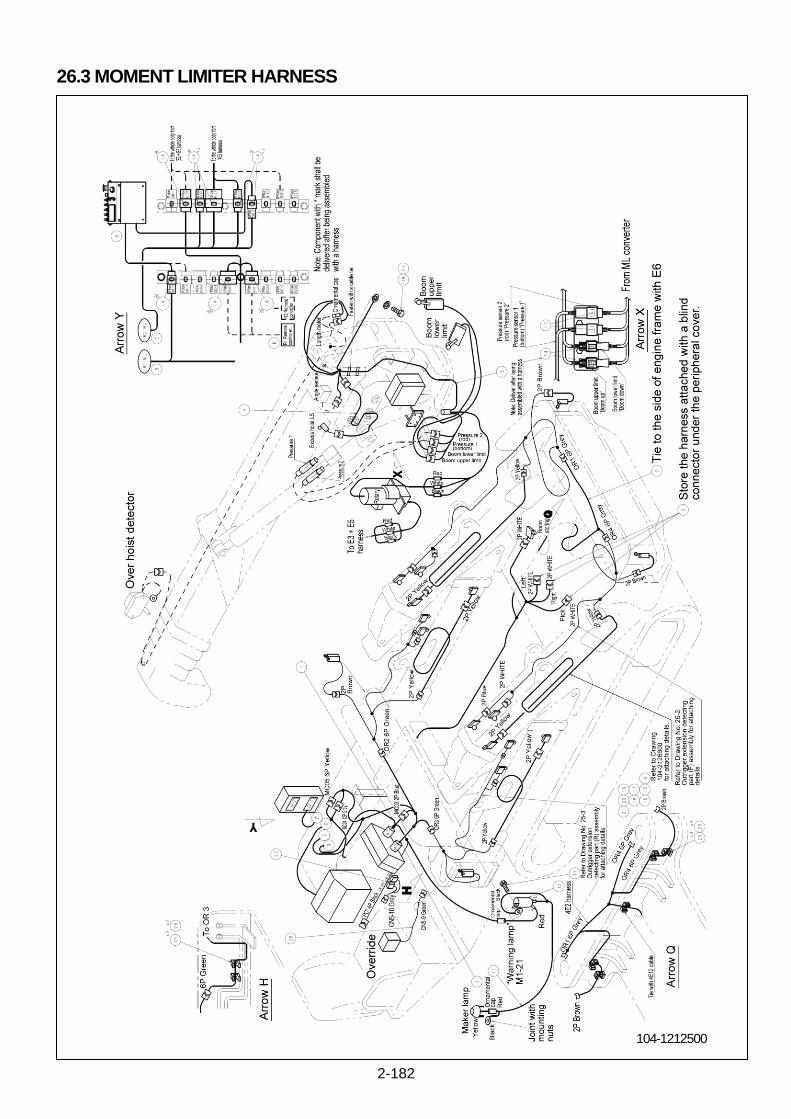
2-182
26.3 MOMENT LIMITER HARNESS
104-1212500
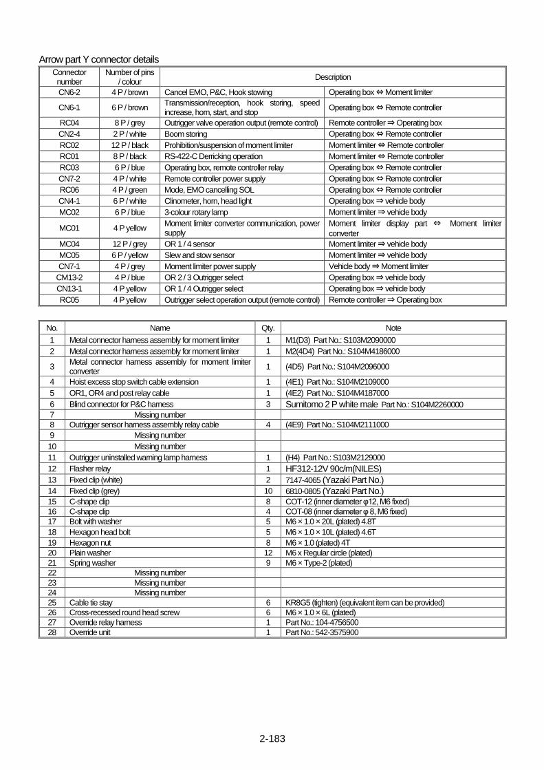
2-183
Arrow part Y connector details
Connector number
Number of pins / colour
Description
CN6-2 4 P / brown Cancel EMO, P&C, Hook stowing Operating box ⇔ Moment limiter
CN6-1 6 P / brown Transmission/reception, hook storing, speed increase, horn, start, and stop
Operating box ⇔ Remote controller
RC04 8 P / grey Outrigger valve operation output (remote control) Remote controller ⇒ Operating box
CN2-4 2 P / white Boom storing Operating box ⇔ Remote controller
RC02 12 P / black Prohibition/suspension of moment limiter Moment limiter ⇔ Remote controller
RC01 8 P / black RS-422-C Derricking operation Moment limiter ⇔ Remote controller
RC03 6 P / blue Operating box, remote controller relay Operating box ⇔ Remote controller
CN7-2 4 P / white Remote controller power supply Operating box ⇔ Remote controller
RC06 4 P / green Mode, EMO cancelling SOL Operating box ⇔ Remote controller
CN4-1 6 P / white Clinometer, horn, head light Operating box ⇒ vehicle body
MC02 6 P / blue 3-colour rotary lamp Moment limiter ⇒ vehicle body
MC01 4 P yellow Moment limiter converter communication, power supply
Moment limiter display part ⇔ Moment limiter
converter
MC04 12 P / grey OR 1 / 4 sensor Moment limiter ⇒ vehicle body
MC05 6 P / yellow Slew and stow sensor Moment limiter ⇒ vehicle body
CN7-1 4 P / grey Moment limiter power supply Vehicle body ⇒ Moment limiter
CM13-2 4 P / blue OR 2 / 3 Outrigger select Operating box ⇒ vehicle body
CN13-1 4 P yellow OR 1 / 4 Outrigger select Operating box ⇒ vehicle body
RC05 4 P yellow Outrigger select operation output (remote control) Remote controller ⇒ Operating box
No. Name Qty. Note
1 Metal connector harness assembly for moment limiter 1 M1(D3) Part No.: S103M2090000
2 Metal connector harness assembly for moment limiter 1 M2(4D4) Part No.: S104M4186000
3 Metal connector harness assembly for moment limiter converter
1 (4D5) Part No.: S104M2096000
4 Hoist excess stop switch cable extension 1 (4E1) Part No.: S104M2109000
5 OR1, OR4 and post relay cable 1 (4E2) Part No.: S104M4187000
6 Blind connector for P&C harness 3 Sumitomo 2 P white male Part No.: S104M2260000
7 Missing number
8 Outrigger sensor harness assembly relay cable 4 (4E9) Part No.: S104M2111000
9 Missing number
10 Missing number
11 Outrigger uninstalled warning lamp harness 1 (H4) Part No.: S103M2129000
12 Flasher relay 1 HF312-12V 90c/m(NILES) 13 Fixed clip (white) 2 7147-4065 (Yazaki Part No.) 14 Fixed clip (grey) 10 6810-0805 (Yazaki Part No.) 15 C-shape clip 8 COT-12 (inner diameter φ12, M6 fixed)
16 C-shape clip 4 COT-08 (inner diameter φ 8, M6 fixed)
17 Bolt with washer 5 M6 × 1.0 × 20L (plated) 4.8T
18 Hexagon head bolt 5 M6 × 1.0 × 10L (plated) 4.6T
19 Hexagon nut 8 M6 × 1.0 (plated) 4T
20 Plain washer 12 M6 x Regular circle (plated)
21 Spring washer 9 M6 × Type-2 (plated)
22 Missing number
23 Missing number
24 Missing number
25 Cable tie stay 6 KR8G5 (tighten) (equivalent item can be provided)
26 Cross-recessed round head screw 6 M6 × 1.0 × 6L (plated)
27 Override relay harness 1 Part No.: 104-4756500
28 Override unit 1 Part No.: 542-3575900
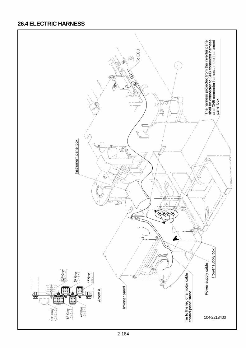
2-184
26.4 ELECTRIC HARNESS
104-2213400

2-185
Arrow part A connector details
Connector number
Number of pins / colour
Description
CN5-3 3 P / grey Power supply + 12 V Electric box ⇔ Operating box
CN5-4 12 P / grey Engine electric components Electric box ⇔ Operating box
CN5-1 8 P / grey When electrically-powered: Starting engine NOT available, lever operation
Electric / Operating box ⇒ Inverter panel
CN3-4 6 P / grey When electrically-powered: Meter unit OFF
Operating box ⇒ Inverter panel
CN5-2 4 P / blue When electrically-powered: Power on Inverter panel ⇒ Operating box
CN5-7 4 P / grey When electrically-powered: Key switch signal
Operating box ⇒ Inverter panel
No. Name Qty. Note
1 Electric motor box input/output relay cable 1 (E8)Part No.: S103M2103000
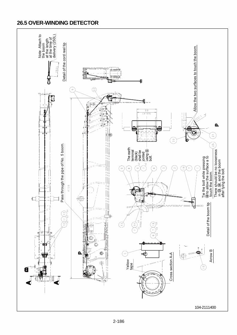
2-186
26.5 OVER-WINDING DETECTOR
104-2111400
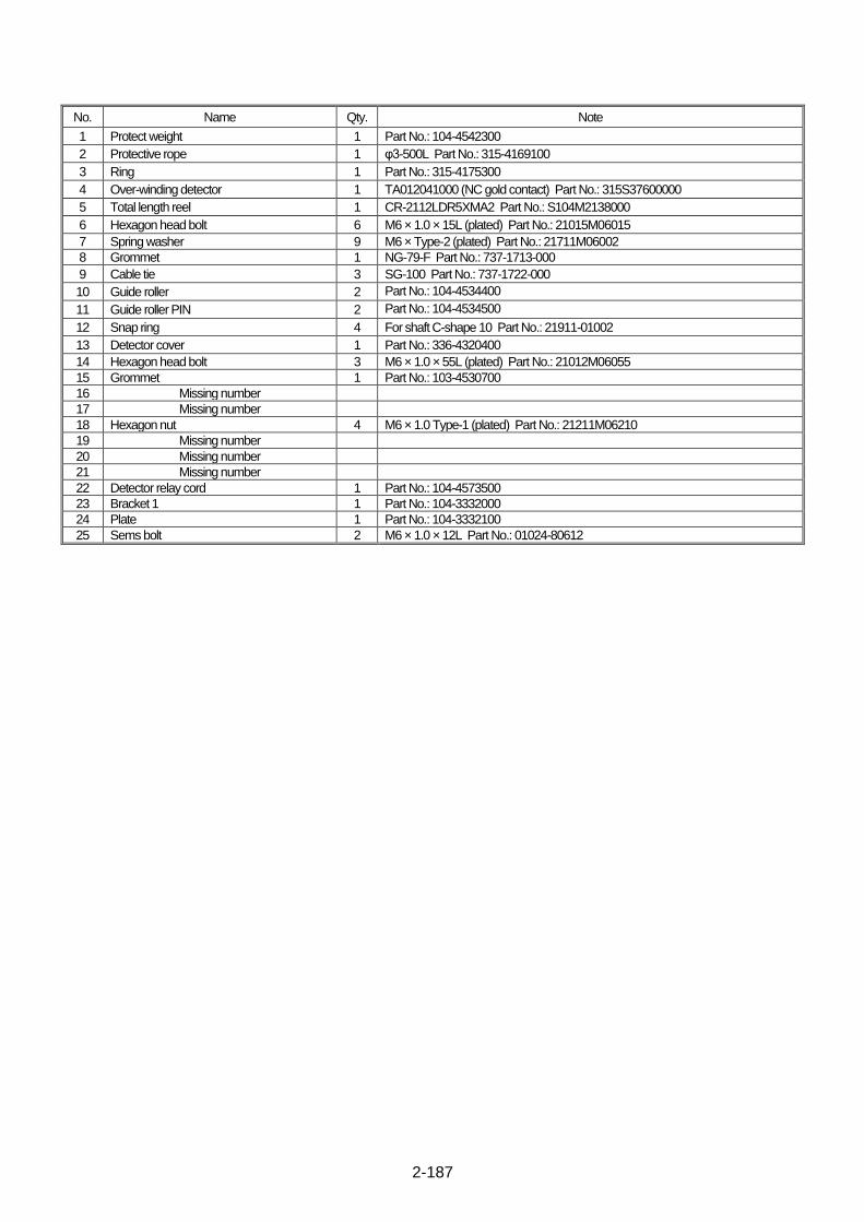
2-187
No. Name Qty. Note
1 Protect weight 1 Part No.: 104-4542300
2 Protective rope 1 φ3-500L Part No.: 315-4169100
3 Ring 1 Part No.: 315-4175300
4 Over-winding detector 1 TA012041000 (NC gold contact) Part No.: 315S37600000
5 Total length reel 1 CR-2112LDR5XMA2 Part No.: S104M2138000
6 Hexagon head bolt 6 M6 × 1.0 × 15L (plated) Part No.: 21015M06015
7 Spring washer 9 M6 × Type-2 (plated) Part No.: 21711M06002
8 Grommet 1 NG-79-F Part No.: 737-1713-000
9 Cable tie 3 SG-100 Part No.: 737-1722-000
10 Guide roller 2 Part No.: 104-4534400
11 Guide roller PIN 2 Part No.: 104-4534500
12 Snap ring 4 For shaft C-shape 10 Part No.: 21911-01002
13 Detector cover 1 Part No.: 336-4320400
14 Hexagon head bolt 3 M6 × 1.0 × 55L (plated) Part No.: 21012M06055
15 Grommet 1 Part No.: 103-4530700
16 Missing number
17 Missing number
18 Hexagon nut 4 M6 × 1.0 Type-1 (plated) Part No.: 21211M06210
19 Missing number
20 Missing number
21 Missing number
22 Detector relay cord 1 Part No.: 104-4573500 23 Bracket 1 1 Part No.: 104-3332000 24 Plate 1 Part No.: 104-3332100 25 Sems bolt 2 M6 × 1.0 × 12L Part No.: 01024-80612

2-188
26.5.1 OPERATION PRINCIPLE
When the hook is raised too much, the weight hoisted through the wire rope is pushed up by the hook, and activates the over hoist
detector switch.
The contact of the over hoist detector switch opens, and the signal thereof enters the moment limiter computer, and causes the hook
raising and boom extension operations to stop. At the same time, the lamp at the moment limiter display flashes, and in this condition,
a short intermittent sound alarm is sounded whenever any hook raising or boom extension operation is attempted.

2-189
This Page Intentionally Left Blank.
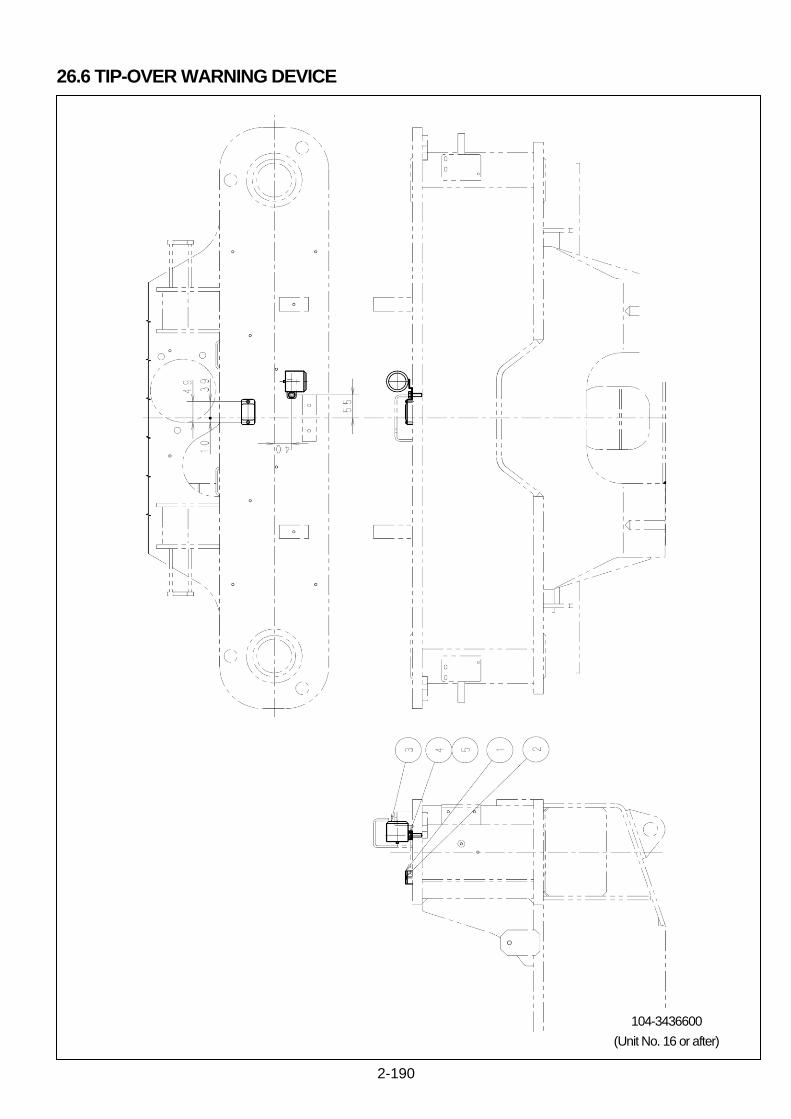
2-190
26.6 TIP-OVER WARNING DEVICE
104-3436600
(Unit No. 16 or after)

2-191
No. Name Qty. Note
1 inclination sensor 1 Part No.: S104M4076000
2 Cross-recessed head machine screw 2 M4 × 0.7 × 20LSW + PW assembly (plated) Part No.: 2187AM04020
3 Buzzer 1 B221G (Kernel-wired) Part No.: S803-M1803000
4 Hexagon head bolt 1 M8 × 1.25 × 25L Part No.: 21012M08025
5 Spring washer 1 M8 × Type-2 Part No.: 21711M08002

2-192
This Page Intentionally Left Blank.
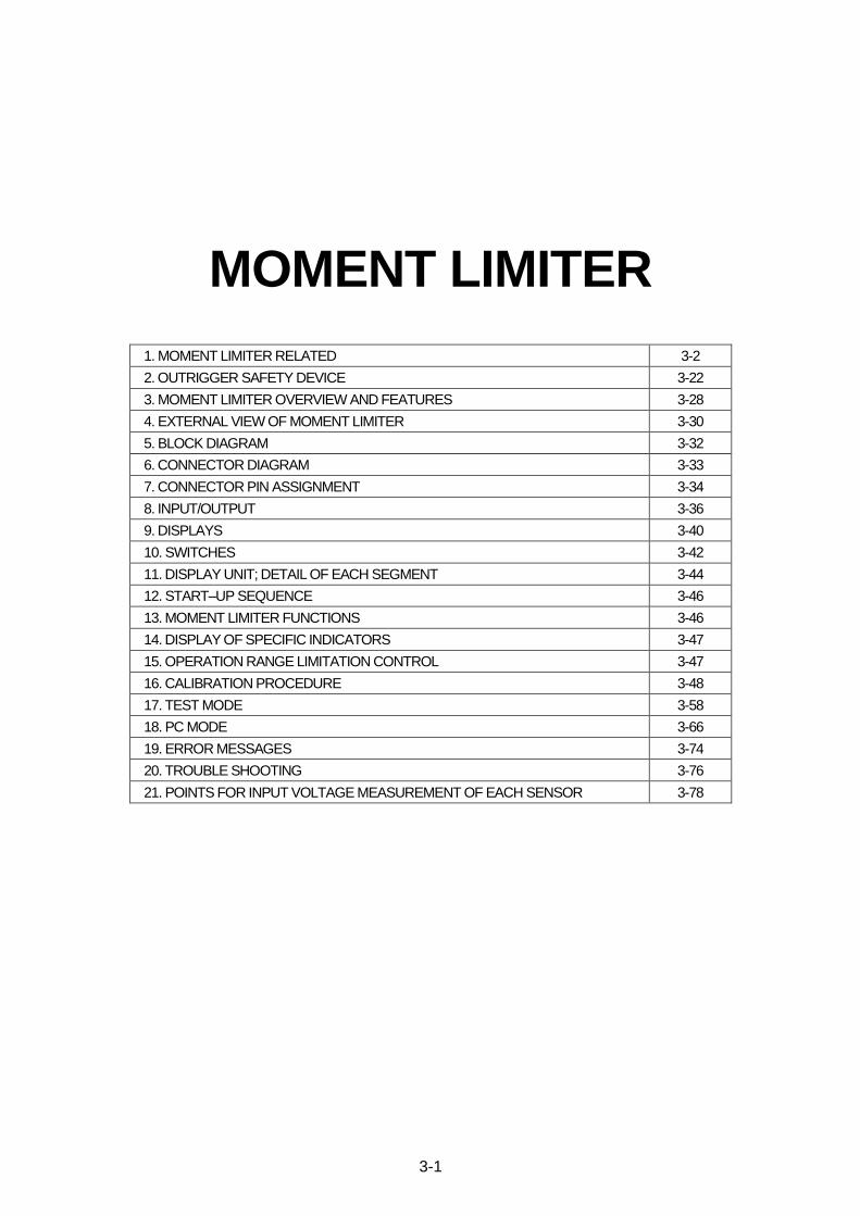
3-1
MOMENT LIMITER
1. MOMENT LIMITER RELATED 3-2
2. OUTRIGGER SAFETY DEVICE 3-22
3. MOMENT LIMITER OVERVIEW AND FEATURES 3-28
4. EXTERNAL VIEW OF MOMENT LIMITER 3-30
5. BLOCK DIAGRAM 3-32
6. CONNECTOR DIAGRAM 3-33
7. CONNECTOR PIN ASSIGNMENT 3-34
8. INPUT/OUTPUT 3-36
9. DISPLAYS 3-40
10. SWITCHES 3-42
11. DISPLAY UNIT; DETAIL OF EACH SEGMENT 3-44
12. START–UP SEQUENCE 3-46
13. MOMENT LIMITER FUNCTIONS 3-46
14. DISPLAY OF SPECIFIC INDICATORS 3-47
15. OPERATION RANGE LIMITATION CONTROL 3-47
16. CALIBRATION PROCEDURE 3-48
17. TEST MODE 3-58
18. PC MODE 3-66
19. ERROR MESSAGES 3-74
20. TROUBLE SHOOTING 3-76
21. POINTS FOR INPUT VOLTAGE MEASUREMENT OF EACH SENSOR 3-78
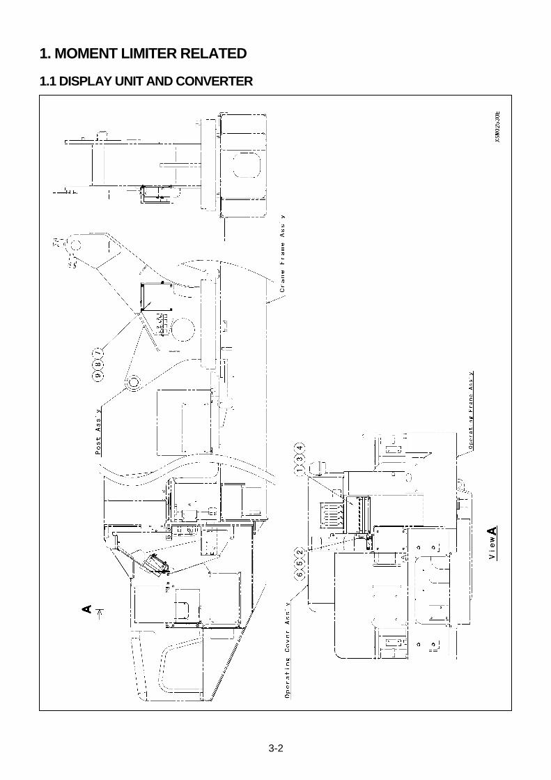
3-2
1. MOMENT LIMITER RELATED
1.1 DISPLAY UNIT AND CONVERTER

3-3
NO. DESCRIPTION Q’TY NOTICE
1 Moment Limiter Display Unit 1
2 Moment Limiter Display Unit Bracket 1
3 Nut 4 M6 (Plating)
4 Spring Washer 4 M6 (Plating)
5 Bolt 2 M8X15L (Plating)
6 Spring Washer 2 M8 (Plating)
7 Moment Limiter Converter 1
8 Screw 4 M14X15L (Plating)
9 Spring Washer 4 M14 (Plating)

3-4
1.2 FRONT OUTRIGGER EXTENSION DETECTOR

3-5
NO. DESCRIPTION Q’TY NOTICE
1 Outrigger Max. Extension Limit Switch 1
2 Outrigger Mid. Extension Limit Switch 1
3 Extension Limit Switch Cover 1
4 Tie Band Stay 4
5 Screw 4 M6X6L (Plating)
6 Tie Band 4
7 Hex. Socket Head Bolt 4 M8X0.8X25L (Plating)
8 Spring Washer 4 M5 (Plating)
9 Plane Washer 4 M5 (Plating)
10 Nut 4 M5
11 Bolt (With Washer) 4 M6X1.0X16L (Plating)
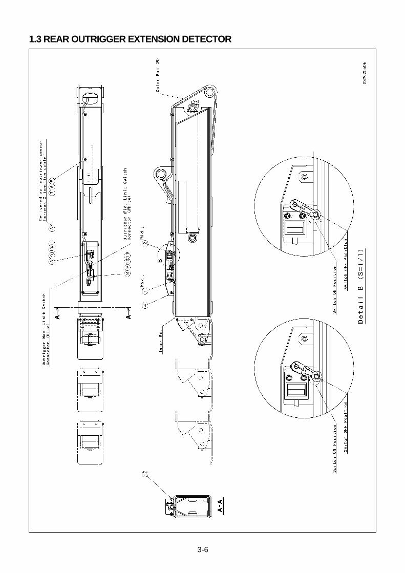
3-6
1.3 REAR OUTRIGGER EXTENSION DETECTOR

3-7
NO. DESCRIPTION Q’TY NOTICE
1 Outrigger Max. Extension Limit Switch 1
2 Outrigger Mid. Extension Limit Switch 1
3 Extension Limit Switch Cover 1
4 Tie Band Stay 4
5 Screw 4 M6X6L (Plating)
6 Tie Band 4
7 Hex. Socket Head Bolt 4 M8X0.8X25L (Plating)
8 Spring Washer 4 M5 (Plating)
9 Plane Washer 4 M5 (Plating)
10 Nut 4 M5
11 Bolt (With Washer) 4 M6X1.0X16L (Plating)
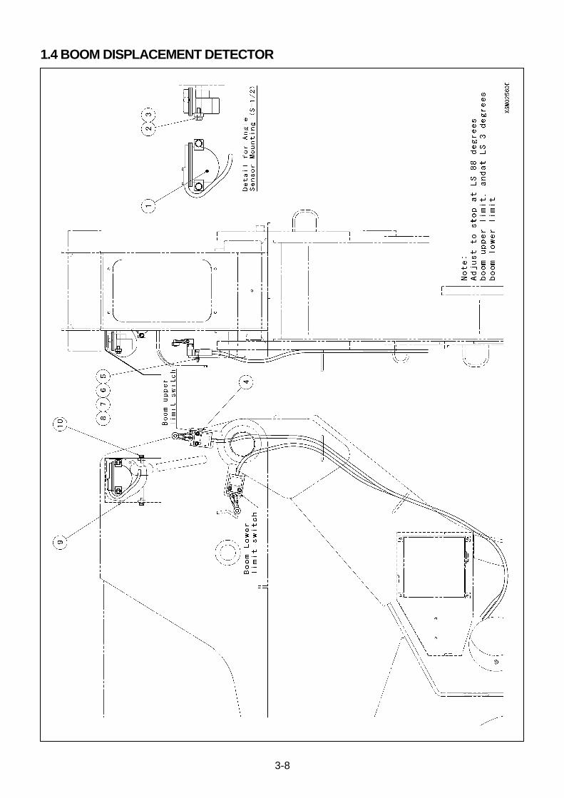
3-8
1.4 BOOM DISPLACEMENT DETECTOR

3-9
NO. DESCRIPTION Q’TY NOTICE
1 Angle Sensor 1
2 Bolt 2 M6X1.0X15L (Plating)
3 Spring Washer 2 M6 (Plating)
4 Boom Angle Detection Limit Switch 2
5 Hex. Socket Head Bolt 4 M8X0.8X25L (Plating)
6 Spring Washer 4 M5 (Plating)
7 Plane Washer 4 M5 (Plating)
8 Nut 4 M5X0.5 (Plating)
9 Angle Sensor Cover 1
10 Bolt (With Washer) 2 M6X1.0X16L (Plating)
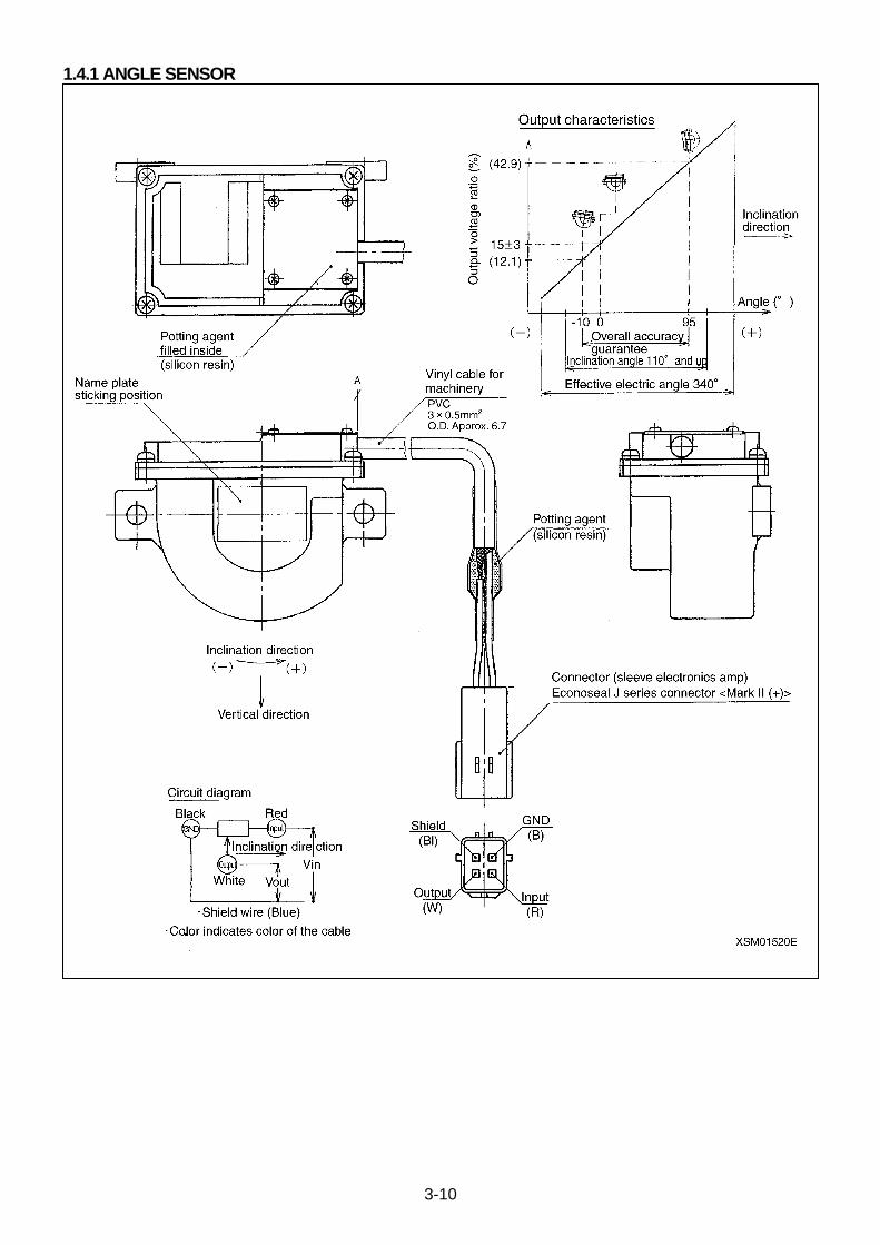
3-10
1.4.1 ANGLE SENSOR

3-11
Specifications
Inclination Angle 110°, min.
(98°, min. to plus range and 12°, min. to minus range, based on 0°of the chart above.)
Total Accuracy ±1% under vibrating conditions (Including linearity and hysteresis).
Response Approx. 1 second at Inclination angle 90°
(Adequate under operation temperature conditions)
Potentiometer (CP-2 or equivalent)
Significant Electrical Angle 340° +2°/-3°
Total Resistance 1 k-ohm ± 20%
Index Point Output to calibrate to 15±3% at the condition of above chart (0°)
Insulation Resistance 200 M-ohm, minimum, DC 500 V
Withstand Voltage AC500V, 1 minute
Rated Current 0.5W/50°C
Resistance to Environment
Operation Temperature Range -30 to 80°C
Stand-by Temperature Range -40 to 80°C
Vibration Resistance 50m/S2 33Hz Each 2 hours to 3 axises
Resistance to Impact 200m/S2 Each 3 impacts for 6 directions
Protection Classification IP64
Damper Oil, used Silicon Oil 500mm2/s (Toshiba Silicon TSF451-500 )
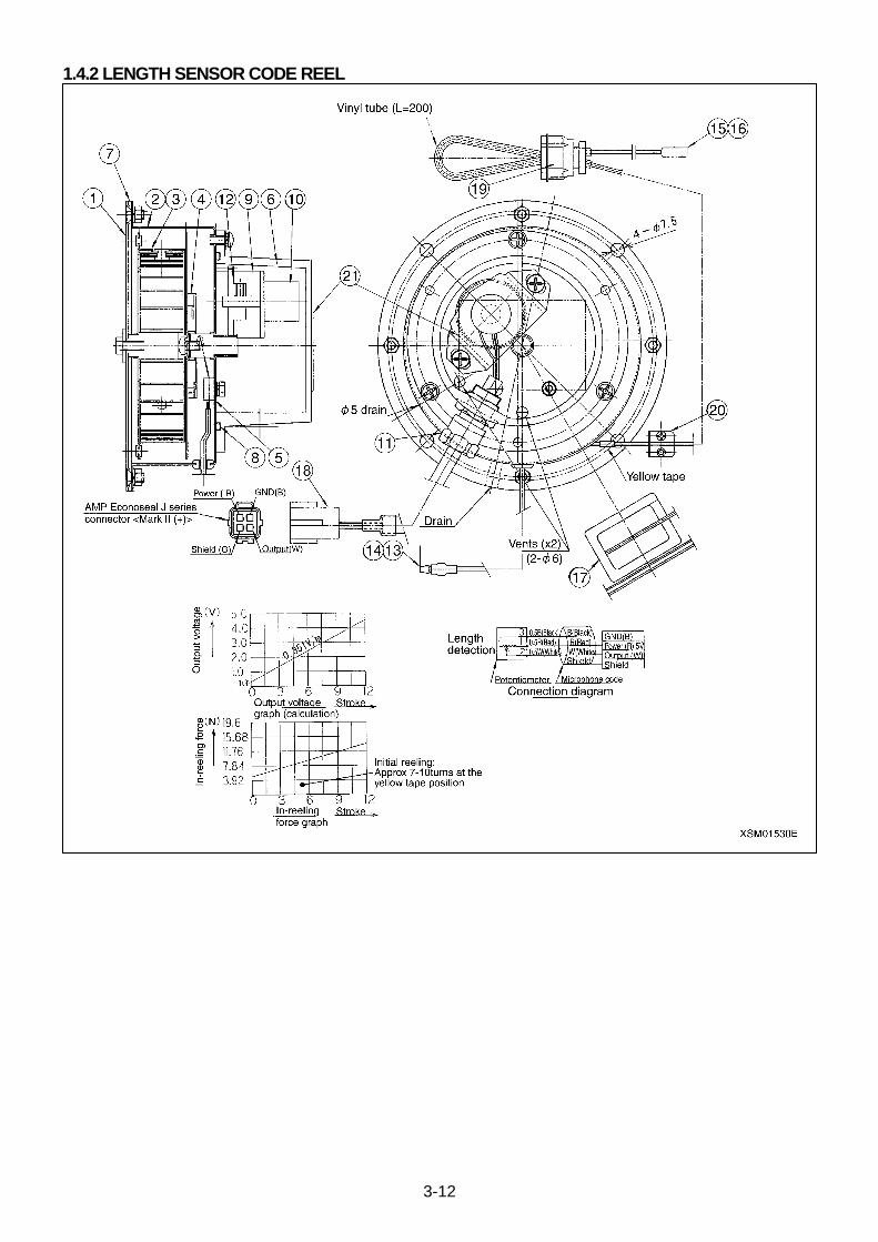
3-12
1.4.2 LENGTH SENSOR CODE REEL
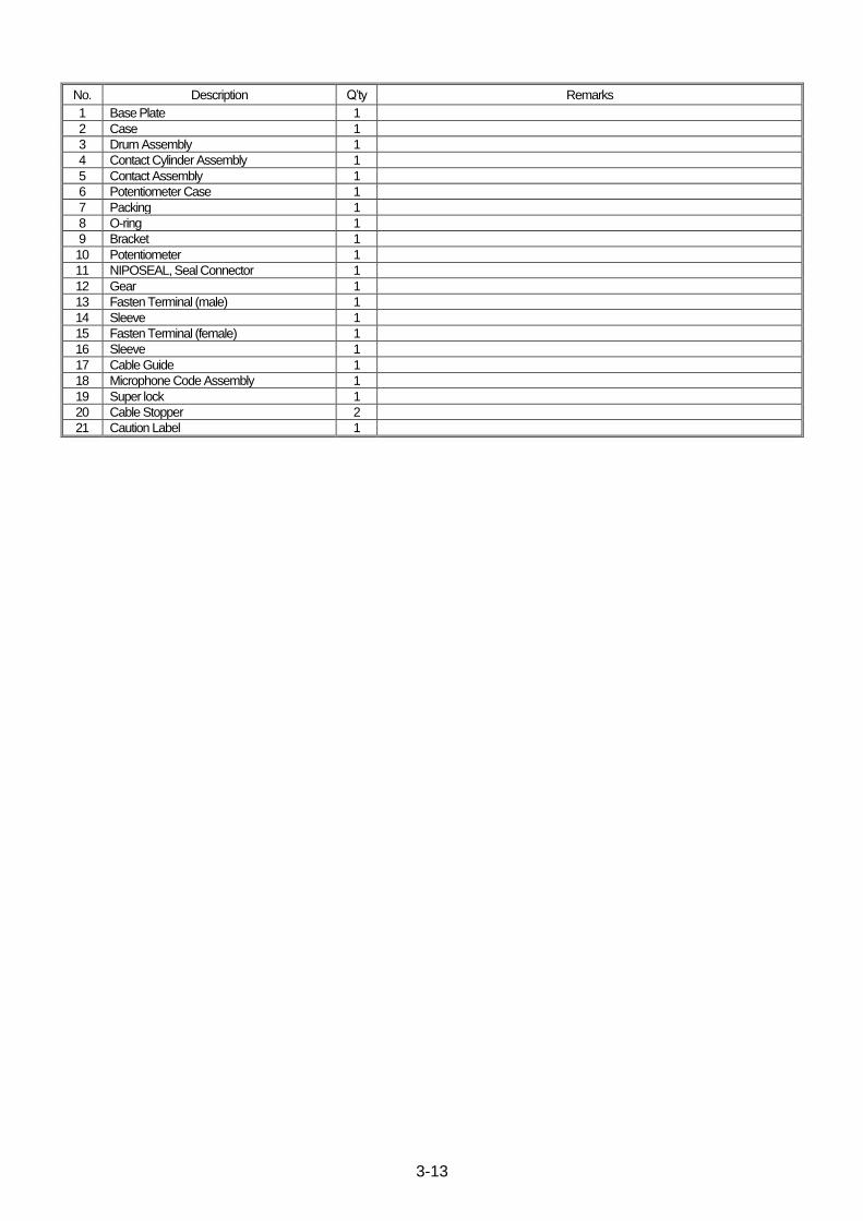
3-13
No. Description Q’ty Remarks
1 Base Plate 1
2 Case 1
3 Drum Assembly 1
4 Contact Cylinder Assembly 1
5 Contact Assembly 1
6 Potentiometer Case 1
7 Packing 1
8 O-ring 1
9 Bracket 1
10 Potentiometer 1
11 NIPOSEAL, Seal Connector 1
12 Gear 1
13 Fasten Terminal (male) 1
14 Sleeve 1
15 Fasten Terminal (female) 1
16 Sleeve 1
17 Cable Guide 1
18 Microphone Code Assembly 1
19 Super lock 1
20 Cable Stopper 2
21 Caution Label 1

3-14
1.5 LOAD DETECTOR
NO. DESCRIPTION Q’TY NOTICE
1 Pressure Sensor 2
2 Pressure Sensor Cover 1
3 Bolt (With Washer) 2 M8X1.25X15L (Plating)

3-15
1. 5.1 PRESSURE SENSORS
Specifications/Capacity
Working range 0 to 35 KPa
Permissible pressure 52.5 MPa
Power Supply Voltage 12V DC ±10%
Power Form 1 to 5 DC 3 wires
Load Resistance 10 K-ohm, min.
Accuracy ±0.1% F.S.
(Including linearity, hysteresis and repeatability at 23±2°C )
Temperature Coefficient, origin
±0.1%F.S./ °C
Temperature Coefficient, span
±0.1%F.S./ °C
Temperature Compensation Range
-20 to +70 °C
Operation Temperature Range
-20 to +70 °C
Stand-by Temperature Range
-20 to +80 °C
Vibration Resistance
66.6miri/S2 (33.3Hz )
X direction 4Hr Y direction 2Hr Z direction 2 Hr
Resistance to Impact 297miri/S2 (11ms or less )
X, Y and Z, 3 impacts each.
Protection Classification IP54 (Except Cables )
Insulation Resistance 100 M-ohm, min. (50V DC )
Power Consumption 100 mA DC, max.
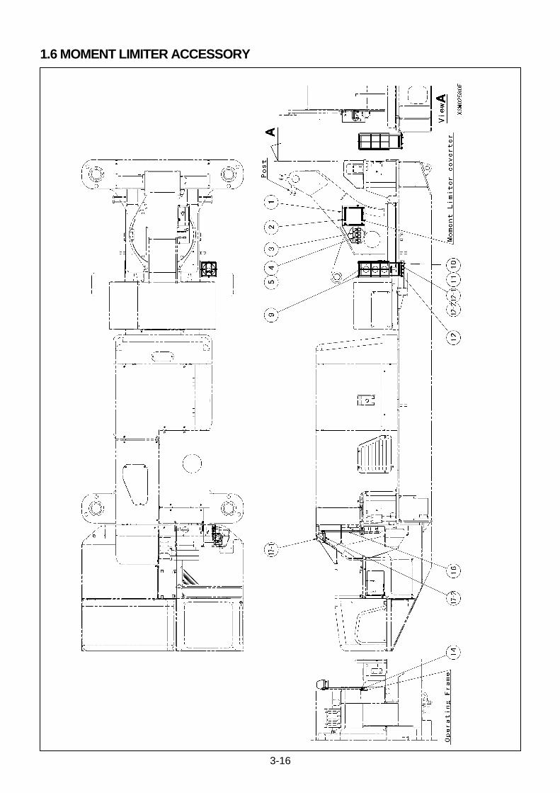
3-16
1.6 MOMENT LIMITER ACCESSORY
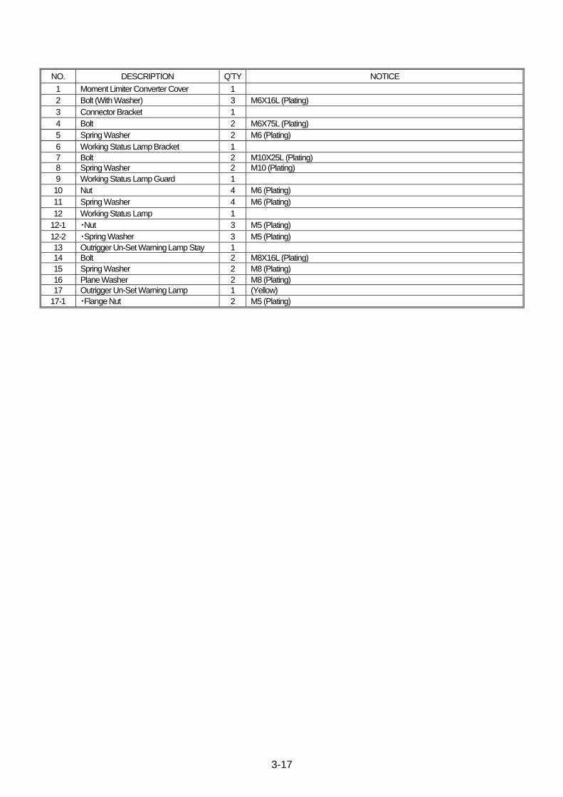
3-17
NO. DESCRIPTION Q’TY NOTICE
1 Moment Limiter Converter Cover 1
2 Bolt (With Washer) 3 M6X16L (Plating)
3 Connector Bracket 1
4 Bolt 2 M6X75L (Plating)
5 Spring Washer 2 M6 (Plating)
6 Working Status Lamp Bracket 1
7 Bolt 2 M10X25L (Plating)
8 Spring Washer 2 M10 (Plating)
9 Working Status Lamp Guard 1
10 Nut 4 M6 (Plating)
11 Spring Washer 4 M6 (Plating)
12 Working Status Lamp 1
12-1 ・Nut 3 M5 (Plating)
12-2 ・Spring Washer 3 M5 (Plating)
13 Outrigger Un-Set Warning Lamp Stay 1
14 Bolt 2 M8X16L (Plating)
15 Spring Washer 2 M8 (Plating)
16 Plane Washer 2 M8 (Plating)
17 Outrigger Un-Set Warning Lamp 1 (Yellow)
17-1 ・Flange Nut 2 M5 (Plating)
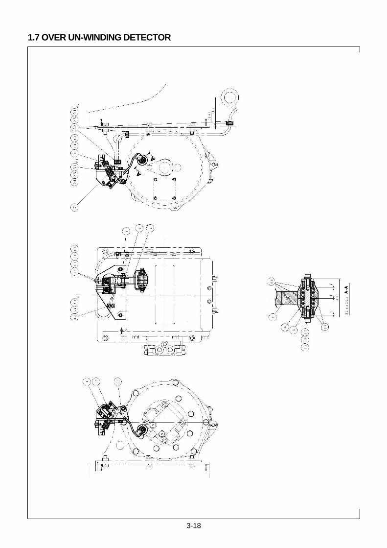
3-18
1.7 OVER UN-WINDING DETECTOR
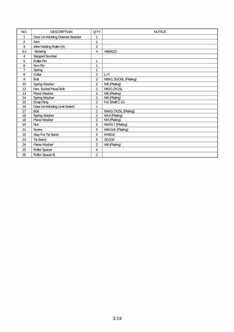
3-19
NO. DESCRIPTION Q’TY NOTICE
1 Over Un-Winding Detector Bracket 1
2 Arm 1
3 Wire Holding Roller (A) 2
3-2 ・Bearing 4 #6000ZZ
4 Skipped Number
5 Roller Pin 1
6 Arm Pin 1
7 Spring 1
8 Collar 2 L=7
9 Bolt 2 M8X1.25X30L (Plating)
10 Spring Washer 2 M8 (Plating)
12 Hex. Socket Head Bolt 2 M6X1.0X15L
13 Plane Washer 2 M6 (Plating)
14 Spring Washer 2 M6 (Plating)
15 Snap Ring 2 For Shaft C-10
16 Over Un-Winding Limit Switch 1
17 Bolt 2 M4X0.7X25L (Plating)
18 Spring Washer 2 M14 (Plating)
19 Plane Washer 2 M4 (Plating)
20 Nut 2 M4X0.7 (Plating)
21 Screw 5 M6X10L (Plating)
22 Stay For Tie Band 5 KR8G5
23 Tie Band 5 SG100
24 Plane Washer 2 M8 (Plating)
25 Roller Spacer 4
26 Roller Spacer B 2
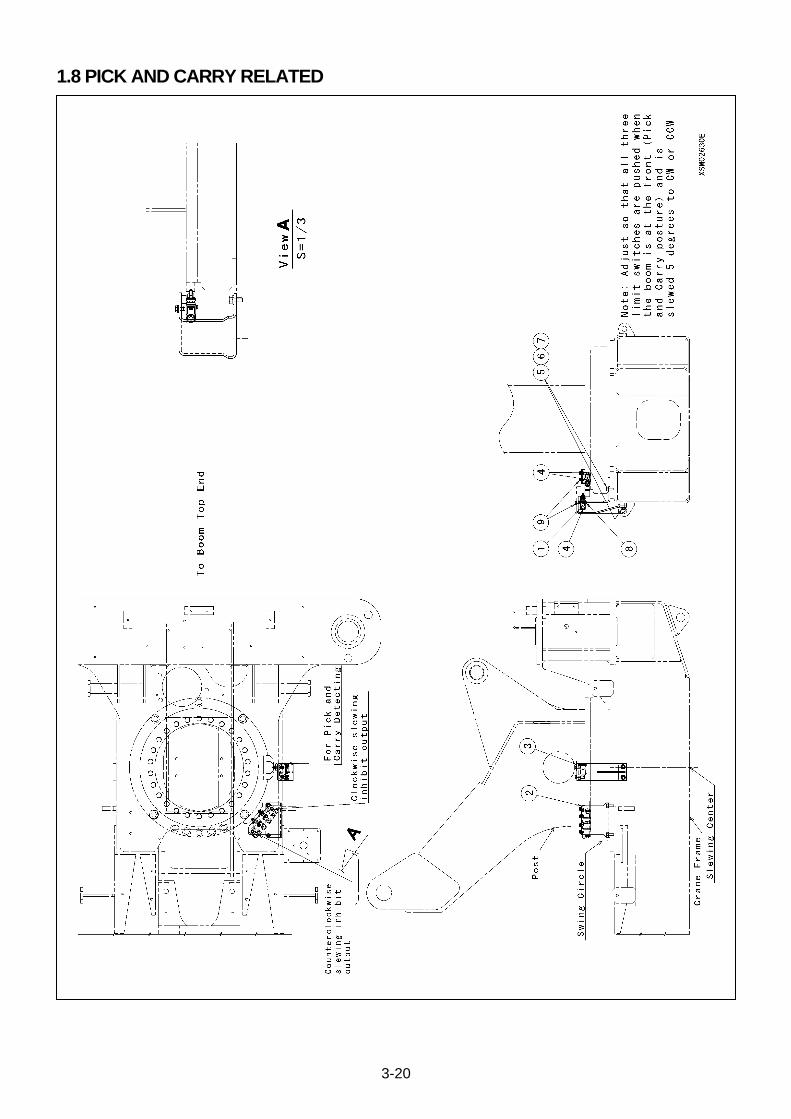
3-20
1.8 PICK AND CARRY RELATED

3-21
NO. DESCRIPTION Q’TY NOTICE
1 Limit Switch Mounting Plate 3
2 10 degrees slewing restriction detection limit switch bracket
1
3 Pick and Carry detective limit Switch 1
4 Outrigger Mid. And Over Un-Winding Limit Switch
3
5 Bolt 4 M8X20L (Plating)
6 Spring Washer 4 M8 (Plating)
7 Plane Washer 4 M8 (Plating)
8 Screw (With Washer) 6 M4X25L (Plating)
9 Bolt (With Washer) 6 M6X12L (Plating)
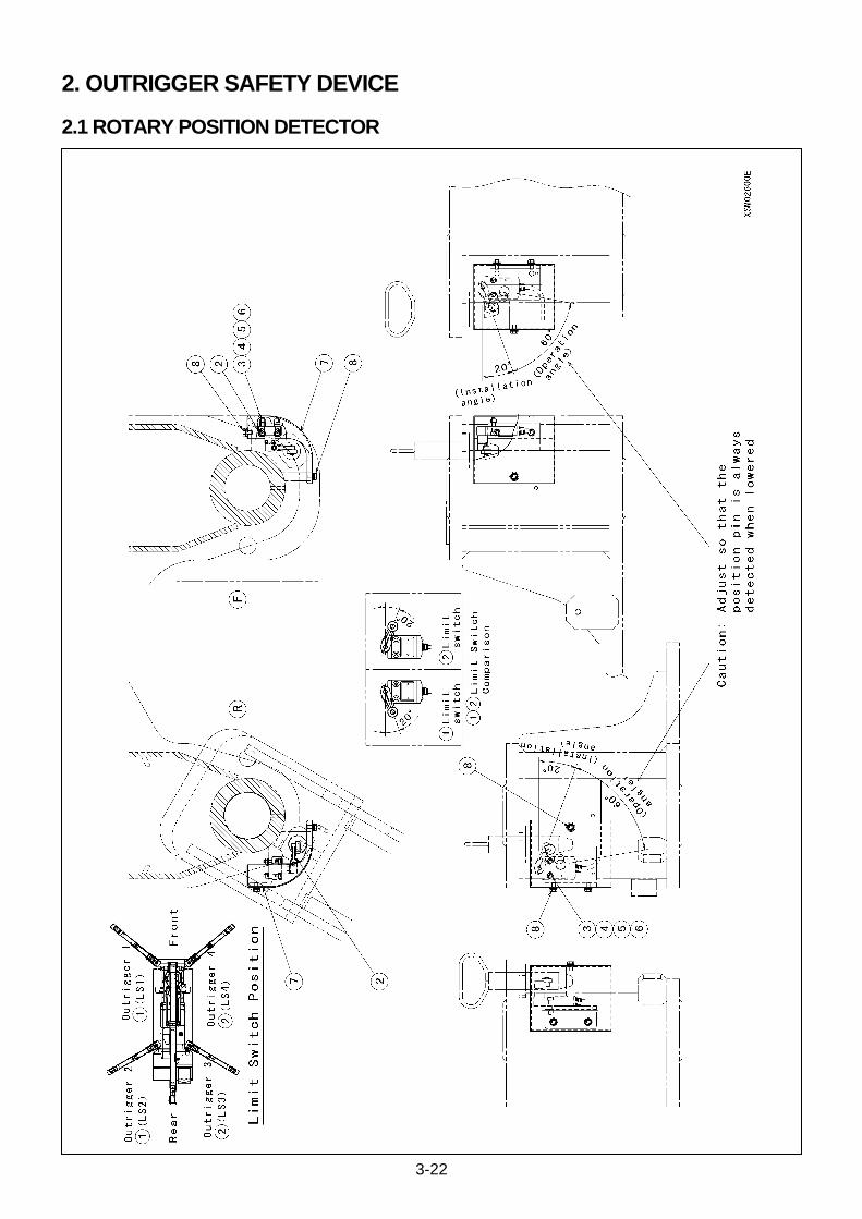
3-22
2. OUTRIGGER SAFETY DEVICE
2.1 ROTARY POSITION DETECTOR

3-23
NO. DESCRIPTION Q’TY NOTICE
1 Pin Insertion Limit Switch (1) 1
2 Pin Insertion Limit Switch (2) 1
3 Hex. Socket Head Bolt 8 M8X0.8X25L (Plating)
4 Spring Washer 8 M5 (Plating)
5 Plane Washer 8 M5 (Plating)
6 Nut 8 M5X0.5 (Plating)
7 Limit switch Cover 4
8 Bolt (With Washer) 16 M6X12L (Plating)
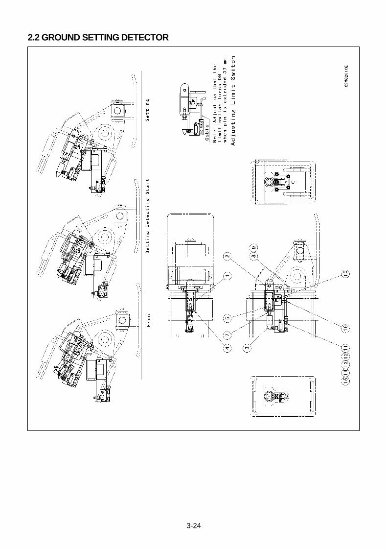
3-24
2.2 GROUND SETTING DETECTOR
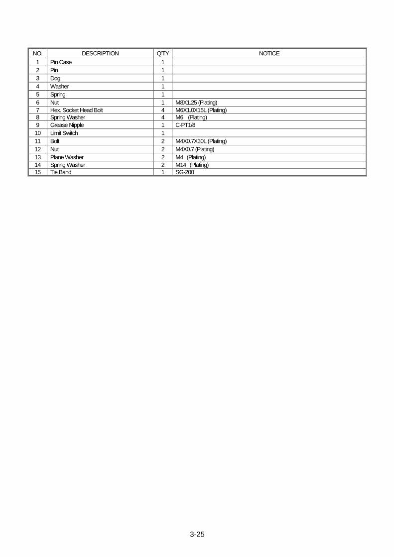
3-25
NO. DESCRIPTION Q’TY NOTICE
1 Pin Case 1
2 Pin 1
3 Dog 1
4 Washer 1
5 Spring 1
6 Nut 1 M8X1.25 (Plating)
7 Hex. Socket Head Bolt 4 M6X1.0X15L (Plating)
8 Spring Washer 4 M6 (Plating)
9 Grease Nipple 1 C-PT1/8
10 Limit Switch 1
11 Bolt 2 M4X0.7X30L (Plating)
12 Nut 2 M4X0.7 (Plating)
13 Plane Washer 2 M4 (Plating)
14 Spring Washer 2 M14 (Plating)
15 Tie Band 1 SG-200

3-26
2.3 BOOM STOWING POSITION DETECTOR

3-27
NO. DESCRIPTION Q’TY NOTICE
1 Limit Switch Mounting Plate 1
2 Boom Stowing Limit Switch Bracket 1
3 Outrigger Mid. And Over Un-Winding Limit Switch
1
4 Bolt 2 M8X1.25X20L (Plating)
5 Spring Washer 2 M8 (Plating)
6 Plane Washer 2 M8 (Plating)
7 Screw (With Washer) 2 M4X0.7X25L (Plating)
8 Bolt (With Washer) 2 M6X1.0X12L (Plating)

3-28
3. MOMENT LIMITER OVERVIEW AND FEATURES
Items MC-405C
Type of Moment Limiter Automatic Cut Out
Crane Rated Load 0 to 3.83 ton (Pressure Range: 0 to 225kg/cm2)
Power Supply DC 12V (DC 10V – 15V)
Max. Power Dissipation Display Panel 0.8 A (at DC 12V)
Converter 0.2A (at DC 12V)
Calibration Electrical Calibration

3-29
This Page Intentionally Left Blank.
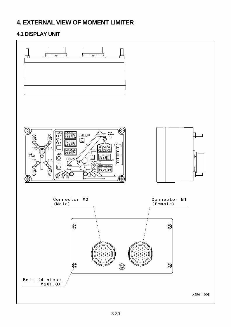
3-30
4. EXTERNAL VIEW OF MOMENT LIMITER
4.1 DISPLAY UNIT

3-31
4.2 CONVERTER
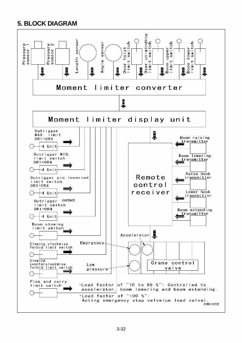
3-32
5. BLOCK DIAGRAM
contact
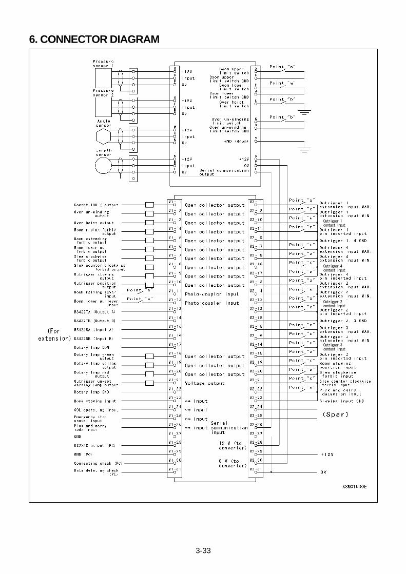
3-33
6. CONNECTOR DIAGRAM
Outrigger 1 contact input
Outrigger 4 contact input
Outrigger 2 contact input
Outrigger 3 contact input
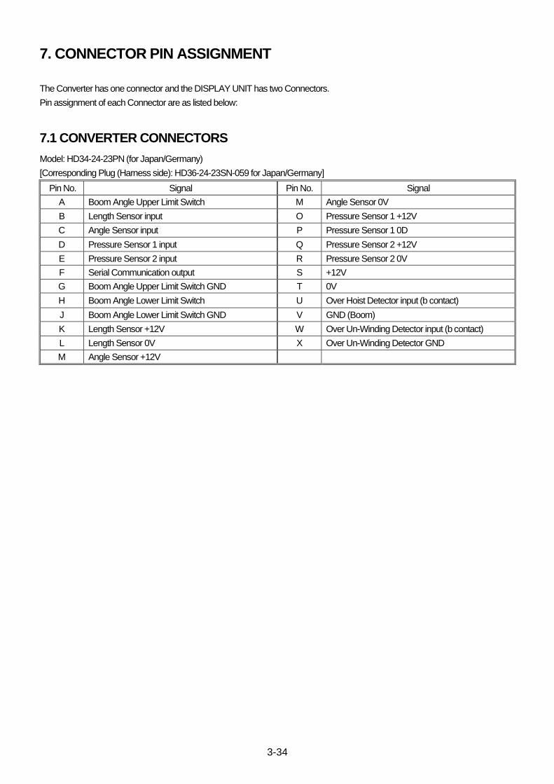
3-34
7. CONNECTOR PIN ASSIGNMENT
The Converter has one connector and the DISPLAY UNIT has two Connectors.
Pin assignment of each Connector are as listed below:
7.1 CONVERTER CONNECTORS
Model: HD34-24-23PN (for Japan/Germany)
[Corresponding Plug (Harness side): HD36-24-23SN-059 for Japan/Germany]
Pin No. Signal Pin No. Signal
A Boom Angle Upper Limit Switch M Angle Sensor 0V
B Length Sensor input O Pressure Sensor 1 +12V
C Angle Sensor input P Pressure Sensor 1 0D
D Pressure Sensor 1 input Q Pressure Sensor 2 +12V
E Pressure Sensor 2 input R Pressure Sensor 2 0V
F Serial Communication output S +12V
G Boom Angle Upper Limit Switch GND T 0V
H Boom Angle Lower Limit Switch U Over Hoist Detector input (b contact)
J Boom Angle Lower Limit Switch GND V GND (Boom)
K Length Sensor +12V W Over Un-Winding Detector input (b contact)
L Length Sensor 0V X Over Un-Winding Detector GND
M Angle Sensor +12V
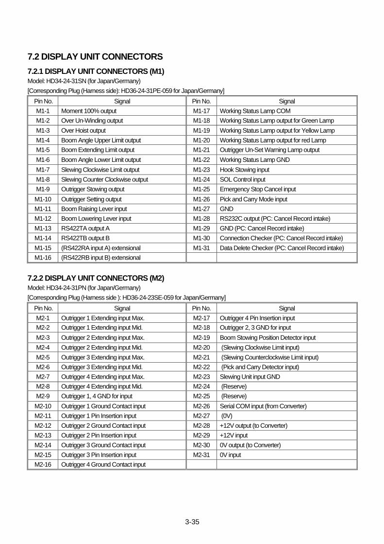
3-35
7.2 DISPLAY UNIT CONNECTORS
7.2.1 DISPLAY UNIT CONNECTORS (M1)
Model: HD34-24-31SN (for Japan/Germany)
[Corresponding Plug (Harness side): HD36-24-31PE-059 for Japan/Germany]
Pin No. Signal Pin No. Signal
M1-1 Moment 100% output M1-17 Working Status Lamp COM
M1-2 Over Un-Winding output M1-18 Working Status Lamp output for Green Lamp
M1-3 Over Hoist output M1-19 Working Status Lamp output for Yellow Lamp
M1-4 Boom Angle Upper Limit output M1-20 Working Status Lamp output for red Lamp
M1-5 Boom Extending Limit output M1-21 Outrigger Un-Set Warning Lamp output
M1-6 Boom Angle Lower Limit output M1-22 Working Status Lamp GND
M1-7 Slewing Clockwise Limit output M1-23 Hook Stowing input
M1-8 Slewing Counter Clockwise output M1-24 SOL Control input
M1-9 Outrigger Stowing output M1-25 Emergency Stop Cancel input
M1-10 Outrigger Setting output M1-26 Pick and Carry Mode input
M1-11 Boom Raising Lever input M1-27 GND
M1-12 Boom Lowering Lever input M1-28 RS232C output (PC: Cancel Record intake)
M1-13 RS422TA output A M1-29 GND (PC: Cancel Record intake)
M1-14 RS422TB output B M1-30 Connection Checker (PC: Cancel Record intake)
M1-15 (RS422RA input A) extensional M1-31 Data Delete Checker (PC: Cancel Record intake)
M1-16 (RS422RB input B) extensional
7.2.2 DISPLAY UNIT CONNECTORS (M2)
Model: HD34-24-31PN (for Japan/Germany)
[Corresponding Plug (Harness side ): HD36-24-23SE-059 for Japan/Germany]
Pin No. Signal Pin No. Signal
M2-1 Outrigger 1 Extending input Max. M2-17 Outrigger 4 Pin Insertion input
M2-2 Outrigger 1 Extending input Mid. M2-18 Outrigger 2, 3 GND for input
M2-3 Outrigger 2 Extending input Max. M2-19 Boom Stowing Position Detector input
M2-4 Outrigger 2 Extending input Mid. M2-20 (Slewing Clockwise Limit input)
M2-5 Outrigger 3 Extending input Max. M2-21 (Slewing Counterclockwise Limit input)
M2-6 Outrigger 3 Extending input Mid. M2-22 (Pick and Carry Detector input)
M2-7 Outrigger 4 Extending input Max. M2-23 Slewing Unit input GND
M2-8 Outrigger 4 Extending input Mid. M2-24 (Reserve)
M2-9 Outrigger 1, 4 GND for input M2-25 (Reserve)
M2-10 Outrigger 1 Ground Contact input M2-26 Serial COM input (from Converter)
M2-11 Outrigger 1 Pin Insertion input M2-27 (0V)
M2-12 Outrigger 2 Ground Contact input M2-28 +12V output (to Converter)
M2-13 Outrigger 2 Pin Insertion input M2-29 +12V input
M2-14 Outrigger 3 Ground Contact input M2-30 0V output (to Converter)
M2-15 Outrigger 3 Pin Insertion input M2-31 0V input
M2-16 Outrigger 4 Ground Contact input
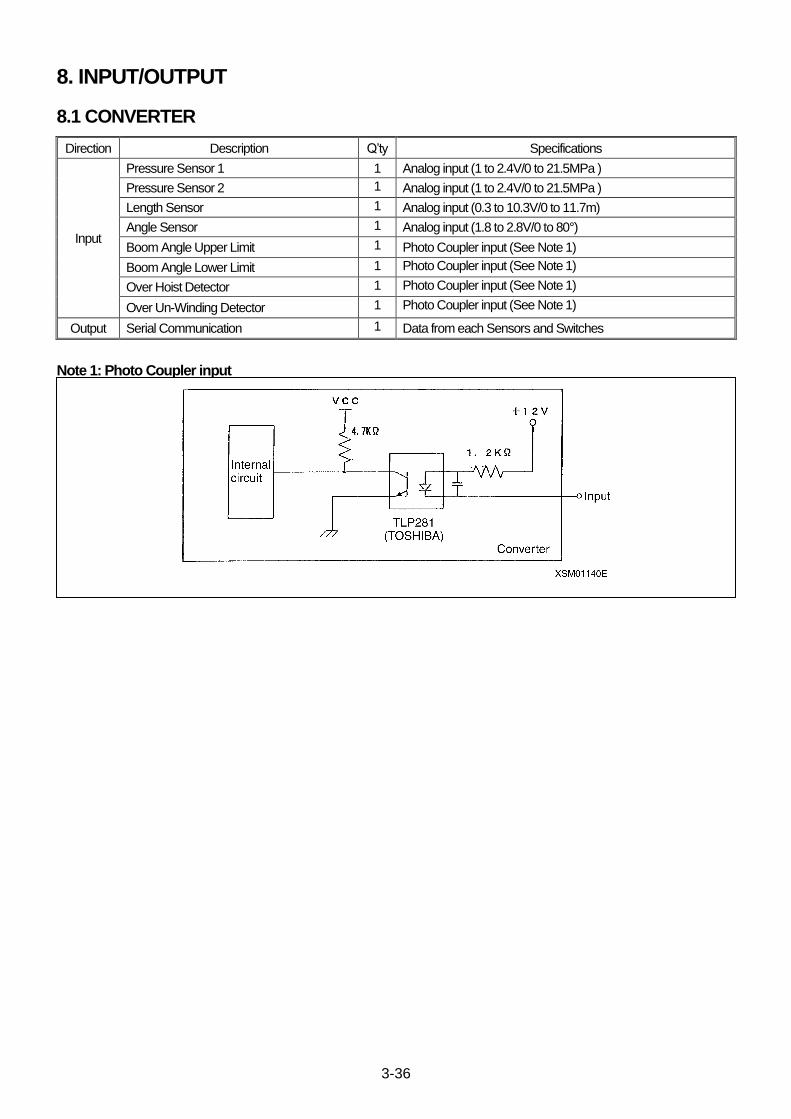
3-36
8. INPUT/OUTPUT
8.1 CONVERTER
Direction Description Q’ty Specifications
Input
Pressure Sensor 1 1 Analog input (1 to 2.4V/0 to 21.5MPa )
Pressure Sensor 2 1 Analog input (1 to 2.4V/0 to 21.5MPa )
Length Sensor 1 Analog input (0.3 to 10.3V/0 to 11.7m)
Angle Sensor 1 Analog input (1.8 to 2.8V/0 to 80°)
Boom Angle Upper Limit 1 Photo Coupler input (See Note 1)
Boom Angle Lower Limit 1 Photo Coupler input (See Note 1)
Over Hoist Detector 1 Photo Coupler input (See Note 1)
Over Un-Winding Detector 1 Photo Coupler input (See Note 1)
Output Serial Communication 1 Data from each Sensors and Switches
Note 1: Photo Coupler input
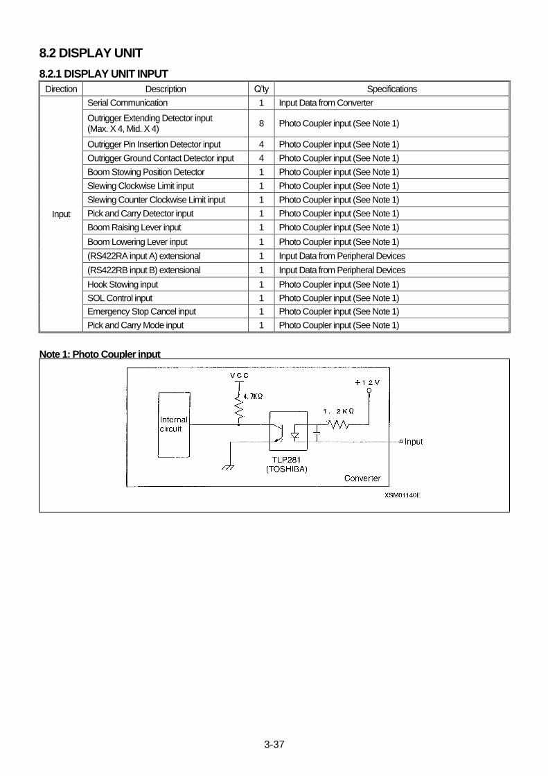
3-37
8.2 DISPLAY UNIT
8.2.1 DISPLAY UNIT INPUT
Direction Description Q’ty Specifications
Input
Serial Communication 1 Input Data from Converter
Outrigger Extending Detector input (Max. X 4, Mid. X 4)
8 Photo Coupler input (See Note 1)
Outrigger Pin Insertion Detector input 4 Photo Coupler input (See Note 1)
Outrigger Ground Contact Detector input 4 Photo Coupler input (See Note 1)
Boom Stowing Position Detector 1 Photo Coupler input (See Note 1)
Slewing Clockwise Limit input 1 Photo Coupler input (See Note 1)
Slewing Counter Clockwise Limit input 1 Photo Coupler input (See Note 1)
Pick and Carry Detector input 1 Photo Coupler input (See Note 1)
Boom Raising Lever input 1 Photo Coupler input (See Note 1)
Boom Lowering Lever input 1 Photo Coupler input (See Note 1)
(RS422RA input A) extensional 1 Input Data from Peripheral Devices
(RS422RB input B) extensional 1 Input Data from Peripheral Devices
Hook Stowing input 1 Photo Coupler input (See Note 1)
SOL Control input 1 Photo Coupler input (See Note 1)
Emergency Stop Cancel input 1 Photo Coupler input (See Note 1)
Pick and Carry Mode input 1 Photo Coupler input (See Note 1)
Note 1: Photo Coupler input
(別紙参照 )
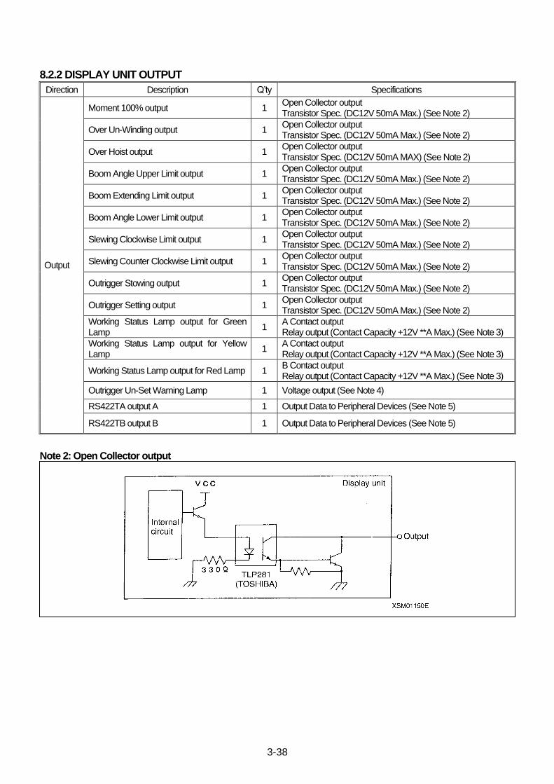
3-38
8.2.2 DISPLAY UNIT OUTPUT
Direction Description Q’ty Specifications
Output
Moment 100% output 1 Open Collector output Transistor Spec. (DC12V 50mA Max.) (See Note 2)
Over Un-Winding output 1 Open Collector output Transistor Spec. (DC12V 50mA Max.) (See Note 2)
Over Hoist output 1 Open Collector output Transistor Spec. (DC12V 50mA MAX) (See Note 2)
Boom Angle Upper Limit output 1 Open Collector output Transistor Spec. (DC12V 50mA Max.) (See Note 2)
Boom Extending Limit output 1 Open Collector output Transistor Spec. (DC12V 50mA Max.) (See Note 2)
Boom Angle Lower Limit output 1 Open Collector output Transistor Spec. (DC12V 50mA Max.) (See Note 2)
Slewing Clockwise Limit output 1 Open Collector output Transistor Spec. (DC12V 50mA Max.) (See Note 2)
Slewing Counter Clockwise Limit output 1 Open Collector output Transistor Spec. (DC12V 50mA Max.) (See Note 2)
Outrigger Stowing output 1 Open Collector output Transistor Spec. (DC12V 50mA Max.) (See Note 2)
Outrigger Setting output 1 Open Collector output Transistor Spec. (DC12V 50mA Max.) (See Note 2)
Working Status Lamp output for Green Lamp
1 A Contact output Relay output (Contact Capacity +12V **A Max.) (See Note 3)
Working Status Lamp output for Yellow Lamp
1 A Contact output Relay output (Contact Capacity +12V **A Max.) (See Note 3)
Working Status Lamp output for Red Lamp 1 B Contact output Relay output (Contact Capacity +12V **A Max.) (See Note 3)
Outrigger Un-Set Warning Lamp 1 Voltage output (See Note 4)
RS422TA output A 1 Output Data to Peripheral Devices (See Note 5)
RS422TB output B 1 Output Data to Peripheral Devices (See Note 5)
Note 2: Open Collector output
(別紙参照 )
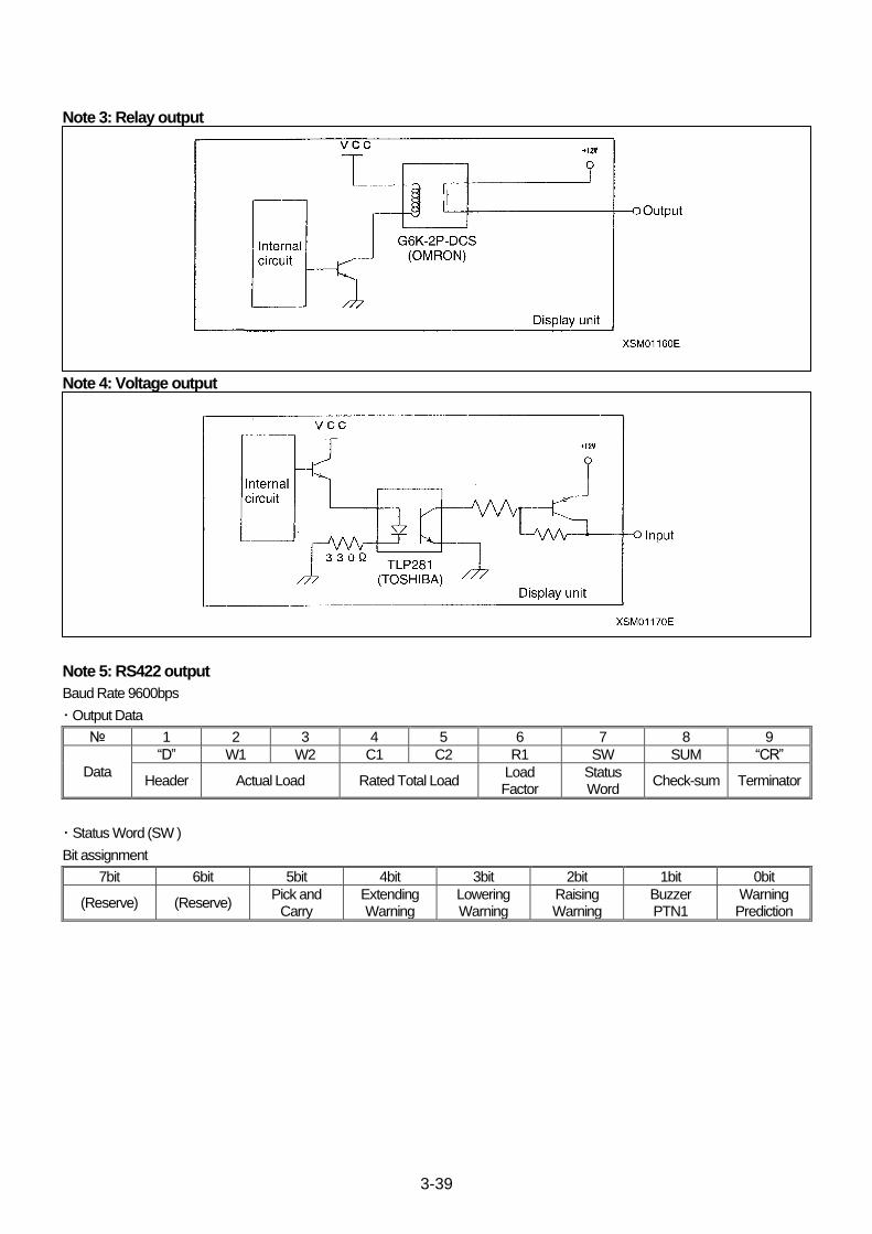
3-39
Note 3: Relay output
(別紙参照 )
Note 4: Voltage output
(別紙参照 )
Note 5: RS422 output
Baud Rate 9600bps
・ Output Data
№ 1 2 3 4 5 6 7 8 9
Data
“D” W1 W2 C1 C2 R1 SW SUM “CR”
Header Actual Load Rated Total Load Load Factor
Status Word
Check-sum Terminator
・ Status Word (SW )
Bit assignment
7bit 6bit 5bit 4bit 3bit 2bit 1bit 0bit
(Reserve) (Reserve) Pick and
Carry Extending Warning
Lowering Warning
Raising Warning
Buzzer PTN1
Warning Prediction

3-40
9. DISPLAYS
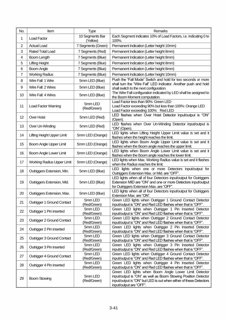
3-41
No. Item Type Remarks
1 Load Factor 10 Segments Bar
(Yellow) Each Segment indicates 10% of Load Factors, i.e. indicating 0 to 100%.
2 Actual Load 7 Segments (Green) Permanent Indication (Letter height 10mm)
3 Rated Total Load 7 Segments (Red) Permanent Indication (Letter height 8mm)
4 Boom Length 7 Segments (Blue) Permanent Indication (Letter height 8mm)
5 Lifting Height 7 Segments (Blue) Permanent Indication (Letter height 8mm)
6 Boom Angle 7 Segments (Blue) Permanent Indication (Letter height 8mm)
7 Working Radius 7 Segments (Blue) Permanent Indication (Letter height 10mm)
8 Wire Fall: 1 Wire 5mm LED (Blue) Push the “Fall Mode” Switch and hold for two seconds or more shall turn the “Wire Fall” LED Indicator. Another push and hold shall switch to the next configuration. The Wire Fall configuration indicated by LED shall be assigned to the Boom Moment computation.
9 Wire Fall: 2 Wires 5mm LED (Blue)
10 Wire Fall: 4 Wires 5mm LED (Blue)
11 Load Factor Warning 5mm LED
(Red/Green)
Load Factor less than 90%: Green LED Load Factor exceeding 90% but less than 100%: Orange LED Load Factor exceeding 100%: Red LED
12 Over Hoist 5mm LED (Red) LED flashes when Over Hoist Detector input/output is “ON” (Open).
13 Over Un-Winding 5mm LED (Red) LED flashes when Over Un-Winding Detector input/output is “ON” (Open).
14 Lifting Height Upper Limit 5mm LED (Orange) LED lights when Lifting Height Upper Limit value is set and it flashes when the height reaches the limit.
15 Boom Angle Upper Limit 5mm LED (Orange) LED lights when Boom Angle Upper Limit value is set and it flashes when the Boom angle reaches the upper limit.
16 Boom Angle Lower Limit 5mm LED (Orange) LED lights when Boom Angle Lower Limit value is set and it flashes when the Boom angle reaches the lower limit.
17 Working Radius Upper Limit 5mm LED (Orange) LED lights when Max. Working Radius value is set and it flashes when the Radius reaches the limit.
18 Outriggers Extension, Min. 5mm LED (Blue) LED lights when one or more Detectors input/output for Outriggers Extension Max. or Mid. are “OFF”.
19 Outriggers Extension, Mid. 5mm LED (Blue) LED lights when all of four Detectors input/output for Outriggers Extension MID are “ON” and one or more Detectors input/output for Outriggers Extension Max. are “OFF”.
20 Outriggers Extension, Max. 5mm LED (Blue) LED lights when all of four Detectors input/output for Outriggers Extension Max. are “ON”.
21 Outrigger 1 Ground Contact 5mm LED
(Red/Green) Green LED lights when Outrigger 1 Ground Contact Detector input/output is “ON” and Red LED flashes when that is “OFF”.
22 Outrigger 1 Pin inserted 5mm LED
(Red/Green) Green LED lights when Outrigger 1 Pin Inserted Detector input/output is “ON” and Red LED flashes when that is “OFF”.
23 Outrigger 2 Ground Contact 5mm LED
(Red/Green) Green LED lights when Outrigger 2 Ground Contact Detector input/output is “ON” and Red LED flashes when that is “OFF”.
24 Outrigger 2 Pin inserted 5mm LED
(Red/Green) Green LED lights when Outrigger 2 Pin Inserted Detector input/output is “ON” and Red LED flashes when that is “OFF”.
25 Outrigger 3 Ground Contact 5mm LED
(Red/Green) Green LED lights when Outrigger 3 Ground Contact Detector input/output is “ON” and Red LED flashes when that is “OFF”.
26 Outrigger 3 Pin inserted 5mm LED
(Red/Green) Green LED lights when Outrigger 3 Pin Inserted Detector input/output is “ON” and Red LED flashes when that is “OFF”.
27 Outrigger 4 Ground Contact 5mm LED
(Red/Green) Green LED lights when Outrigger 4 Ground Contact Detector input/output is “ON” and Red LED flashes when that is “OFF”.
28 Outrigger 4 Pin inserted 5mm LED
(Red/Green) Green LED lights when Outrigger 4 Pin Inserted Detector input/output is “ON” and Red LED flashes when that is “OFF”.
29 Boom Stowing 5mm LED
(Red/Green)
Green LED lights when Boom Angle Lower Limit Detector input/output is “ON” as well as Boom Stowing Position Detector input/output is “ON” but LED is out when either of these Detectors input/output are “OFF”.
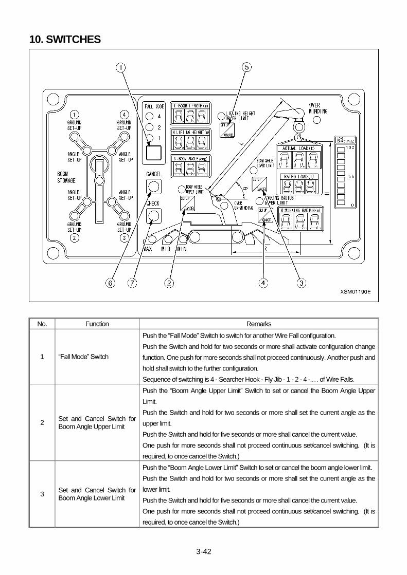
3-42
10. SWITCHES
No. Function Remarks
1 “Fall Mode” Switch
Push the “Fall Mode” Switch to switch for another Wire Fall configuration.
Push the Switch and hold for two seconds or more shall activate configuration change
function. One push for more seconds shall not proceed continuously. Another push and
hold shall switch to the further configuration.
Sequence of switching is 4 - Searcher Hook - Fly Jib - 1 - 2 - 4 -.… of Wire Falls.
2 Set and Cancel Switch for Boom Angle Upper Limit
Push the “Boom Angle Upper Limit” Switch to set or cancel the Boom Angle Upper
Limit.
Push the Switch and hold for two seconds or more shall set the current angle as the
upper limit.
Push the Switch and hold for five seconds or more shall cancel the current value.
One push for more seconds shall not proceed continuous set/cancel switching. (It is
required, to once cancel the Switch.)
3 Set and Cancel Switch for Boom Angle Lower Limit
Push the “Boom Angle Lower Limit” Switch to set or cancel the boom angle lower limit.
Push the Switch and hold for two seconds or more shall set the current angle as the
lower limit.
Push the Switch and hold for five seconds or more shall cancel the current value.
One push for more seconds shall not proceed continuous set/cancel switching. (It is
required, to once cancel the Switch.)
3-43
No. Function Remarks
4 Set and Cancel Switch for Working Radius Upper Limit
Push the “Working Radius Upper Limit” Switch to set or cancel the Working Radius
Upper Limit.
Push the Switch and hold for two seconds or more shall set the current radius as the
upper limit.
Push the Switch and hold for five seconds or more shall cancel the current value.
One push for more seconds shall not proceed continuous set/cancel switching. (It is
required, to once cancel the Switch.)
5 Set and Cancel Switch for Lifting Height Upper Limit
Push the “Boom Angle Upper Limit” Switch to set or cancel the lifting height upper limit.
Push the Switch and hold for two seconds or more shall set the current height as the
upper limit.
Push the Switch and hold for five seconds or more shall cancel the current value of
height.
One push for more seconds shall not proceed continuous set/cancel switching. (It is
required, to once cancel the Switch.)
6 Cancel Switch All the upper and lower limits shall be canceled when this “Cancel Switch” and “Check
Switch” are push and held for five seconds or more, simultaneously.
7 Check Switch
Each one push of this Switches shall indicate values of specific setting.
Each one push shall indicate:
Boom Angle Indicator shows Boom Angle Upper Limit (Boom Angle Upper Limit
LED flashes).
⇒Boom Angle Indicator shows Boom Angle Lower Limit (Boom Angle Lower Limit
LED flashes).
⇒Working Radius Indicator shows Working Radius Upper Limit (Working Radius
Upper Limit LED flashes).
⇒Lifting Height Indicator shows Lifting Height Upper Limit (Lifting Height Upper Limit
LED flashes).
⇒Restored to initial indicating of actual values.
⇒Boom Angle Indicator shows Boom Angle Upper Limit (Boom Angle Upper Limit
LED flashes).
...iteration...
Indicators other than assigned shall be out to blank.
While this Check Switch mode, releasing the Switch for five seconds or more, or
pushing any other Switches shall resume to initial indicating of actual values.
The assigned Indicator may indicate blank in case no limit value is set to the functions.
Except Lifting Height Upper Limit, specific values shall be memorized even if the power is turned off.
3-44
11. DISPLAY UNIT; DETAIL OF EACH SEGMENT
[1] Outriggers Extending Detector input (4 sets)
1. Controls as below shall be active when all of four Outrigger Extending Detectors input for maximum is “ON”:
・ “Outriggers Extension Max.” LED shall light.
・ “Rated Total Load” for “Outriggers Extension Max.” configuration shall be in use.
2. Controls as below shall be active when all of four Detectors input for Outriggers Extension Mid. are “ON” and one or more
Detectors input/output for Outriggers Extension Max. are “OFF”.
・ “Outriggers Extension Mid.” LED shall light.
・ “Rated Total Load” for “Outriggers Extension Mid.” configuration shall be in use.
3. Controls as below shall be active when one or more Detectors input for Outriggers Extension Min. or Max. are “OFF”.
・ “Outriggers Extension Min.” LED shall light.
・ “Rated Total Load” for “Outriggers Extension Min.” configuration shall be in use.
[2] Over Hoist Detector input
Controls as below shall be active when Over Hoist Detector input is “ON”:
・ “Over Winding” LED shall light.
・ Over Hoist Detector output shall be “ON”
[3] Over Un-Winding Detector input
Controls as below shall be active when Over Un-Winding Detector input is “ON”:
・ “Over Un-Winding” LED shall light.
・ Over Un-Winding Detector output shall be “OFF” (Open ).
[4] Boom Angle Upper Limit Detector input
Controls as below shall be active when Boom Angle Upper Limit Detector input is “ON”:
・ Boom Angle Upper Limit Detector output shall be “OFF” (Open ).
[5] Boom Angle Lower Limit Detector input
Controls as below shall be active when Boom Angle Lower Limit Detector input is “ON”:
・ Boom Angle Lower Limit Detector output shall be “ON”.
[6] Load Factor (10 Segments Bar LED)
Load Factor shall be indicated per 10% by 10 Segments Bar in accordance with actual Load Factor.
[7] Load Factor Indicator (5 mm Round LED)
Green indicates Load Factor is less than 90%, Yellow indicates Load Factor is exceeding 90% but less than 100% and Red
indicates Load Factor exceeds100%.
[8] Fall Mode
Push the Switch and hold for two seconds or more shall switch to another Fall Mode configuration. One push for more seconds shall
not proceed continuously.
Another push and hold shall switch to the next configuration. Sequence of switching is 1 - 2 - 4 - Searcher Hook - Fly Jib - 1 -… of
Wire Falls.
1. When 4 wires Indicator (LED) is on, “Rated Total Load” for “4 wires” configuration shall be in use.
2. When 2 wires Indicator (LED) is on, “Rated Total Load” for “2 wires” configuration shall be in use.
3. When 1 wire Indicator (LED) is on, “Rated Total Load” for “1 wire” configuration shall be in use.
4. When all are lit, the "total load" for "searcher hook" is used.
5. When one is flashing, the "total load" for "Fly Jib" is used.
3-45
[9] Outriggers Section
1. Outriggers Ground Contact Detector input [4 sets, (1) to (4)].
Controls as below shall be active when Outriggers Ground Contact Detector input is “ON”:
・ Each “Outrigger Ground Set-Up” Green LED shall light.
Controls as below shall be active when Outriggers Ground Contact Detector input is “OFF”:
・ Each “Outrigger Ground Set-Up” Red LED shall flash.
2. Outriggers Pin Inserted Detector input [4 sets, (1) to (4)].
Controls as below shall be active when Outriggers Pin Inserted Detector input is “ON”:
・ Each “Outrigger Angle Set-Up” Green LED shall light.
Controls as below shall be active when Outriggers Pin Inserted Detector input is “OFF”:
・ Each “Outrigger Angle Set-Up” Red LED shall flash.
3. Boom Angle Lower Limit Detector input + Boom Stowing Position Detector input
Controls as below shall be active when both inputs are “ON”:
・ “Boom Stowage” Green LED shall light.
Controls as below shall be active when both or either of inputs are “OFF”
・ “Boom Stowage” Red LED shall flash.
4. In the event that (2) and (3) are “ON” in the above input conditions, controls as below shall be active:
・ Outriggers Stowing output is “ON”.
5. In the event that (1) and (2) are “ON” in the above input conditions, controls as below shall be active:
・ Outriggers Setting output is “ON”.
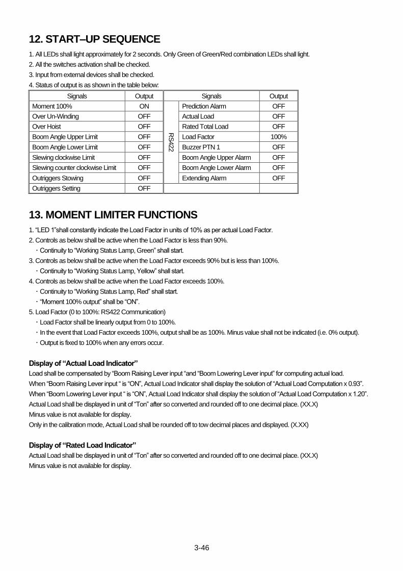
3-46
12. START–UP SEQUENCE
1. All LEDs shall light approximately for 2 seconds. Only Green of Green/Red combination LEDs shall light.
2. All the switches activation shall be checked.
3. Input from external devices shall be checked.
4. Status of output is as shown in the table below:
Signals Output Signals Output
Moment 100% ON
RS
422
Prediction Alarm OFF
Over Un-Winding OFF Actual Load OFF
Over Hoist OFF Rated Total Load OFF
Boom Angle Upper Limit OFF Load Factor 100%
Boom Angle Lower Limit OFF Buzzer PTN 1 OFF
Slewing clockwise Limit OFF Boom Angle Upper Alarm OFF
Slewing counter clockwise Limit OFF Boom Angle Lower Alarm OFF
Outriggers Stowing OFF Extending Alarm OFF
Outriggers Setting OFF
13. MOMENT LIMITER FUNCTIONS
1. “LED 1”shall constantly indicate the Load Factor in units of 10% as per actual Load Factor.
2. Controls as below shall be active when the Load Factor is less than 90%.
・ Continuity to “Working Status Lamp, Green” shall start.
3. Controls as below shall be active when the Load Factor exceeds 90% but is less than 100%.
・ Continuity to “Working Status Lamp, Yellow” shall start.
4. Controls as below shall be active when the Load Factor exceeds 100%.
・ Continuity to “Working Status Lamp, Red” shall start.
・ “Moment 100% output” shall be “ON”.
5. Load Factor (0 to 100%: RS422 Communication)
・ Load Factor shall be linearly output from 0 to 100%.
・ In the event that Load Factor exceeds 100%, output shall be as 100%. Minus value shall not be indicated (i.e. 0% output).
・ Output is fixed to 100% when any errors occur.
Display of “Actual Load Indicator”
Load shall be compensated by “Boom Raising Lever input “and “Boom Lowering Lever input” for computing actual load.
When “Boom Raising Lever input “ is “ON”, Actual Load Indicator shall display the solution of “Actual Load Computation x 0.93”.
When “Boom Lowering Lever input “ is “ON”, Actual Load Indicator shall display the solution of “Actual Load Computation x 1.20”.
Actual Load shall be displayed in unit of “Ton” after so converted and rounded off to one decimal place. (XX.X)
Minus value is not available for display.
Only in the calibration mode, Actual Load shall be rounded off to tow decimal places and displayed. (X.XX)
Display of “Rated Load Indicator”
Actual Load shall be displayed in unit of “Ton” after so converted and rounded off to one decimal place. (XX.X)
Minus value is not available for display.
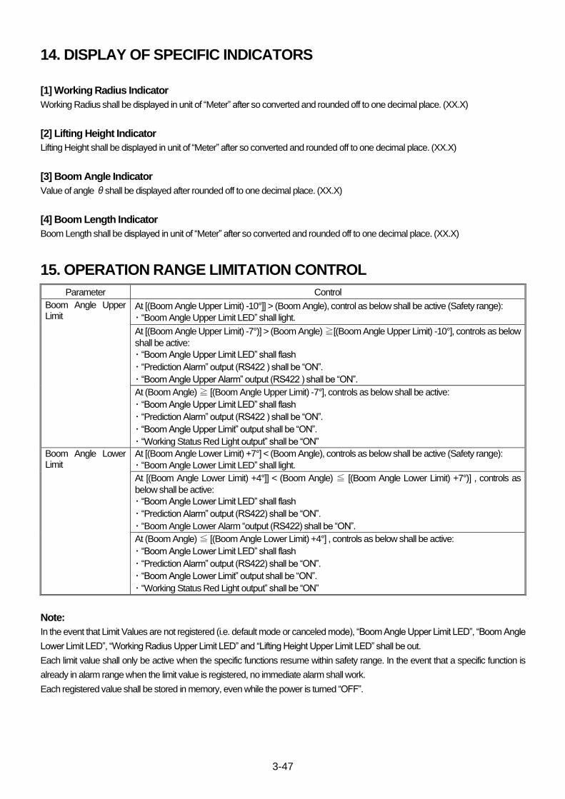
3-47
14. DISPLAY OF SPECIFIC INDICATORS
[1] Working Radius Indicator
Working Radius shall be displayed in unit of “Meter” after so converted and rounded off to one decimal place. (XX.X)
[2] Lifting Height Indicator
Lifting Height shall be displayed in unit of “Meter” after so converted and rounded off to one decimal place. (XX.X)
[3] Boom Angle Indicator
Value of angle θshall be displayed after rounded off to one decimal place. (XX.X)
[4] Boom Length Indicator
Boom Length shall be displayed in unit of “Meter” after so converted and rounded off to one decimal place. (XX.X)
15. OPERATION RANGE LIMITATION CONTROL
Parameter Control
Boom Angle Upper Limit
At [(Boom Angle Upper Limit) -10°]] > (Boom Angle), control as below shall be active (Safety range):
・ “Boom Angle Upper Limit LED” shall light.
At [(Boom Angle Upper Limit) -7°)] > (Boom Angle) ≧[(Boom Angle Upper Limit) -10°], controls as below
shall be active:
・ “Boom Angle Upper Limit LED” shall flash
・ “Prediction Alarm” output (RS422 ) shall be “ON”.
・ “Boom Angle Upper Alarm” output (RS422 ) shall be “ON”.
At (Boom Angle) ≧ [(Boom Angle Upper Limit) -7°], controls as below shall be active:
・ “Boom Angle Upper Limit LED” shall flash
・ “Prediction Alarm” output (RS422 ) shall be “ON”.
・ “Boom Angle Upper Limit” output shall be “ON”.
・ “Working Status Red Light output” shall be “ON”
Boom Angle Lower Limit
At [(Boom Angle Lower Limit) +7°] < (Boom Angle), controls as below shall be active (Safety range):
・ “Boom Angle Lower Limit LED” shall light.
At [(Boom Angle Lower Limit) +4°]] < (Boom Angle) ≦ [(Boom Angle Lower Limit) +7°)] , controls as
below shall be active:
・ “Boom Angle Lower Limit LED” shall flash
・ “Prediction Alarm” output (RS422) shall be “ON”.
・ “Boom Angle Lower Alarm “output (RS422) shall be “ON”.
At (Boom Angle) ≦ [(Boom Angle Lower Limit) +4°] , controls as below shall be active:
・ “Boom Angle Lower Limit LED” shall flash
・ “Prediction Alarm” output (RS422) shall be “ON”.
・ “Boom Angle Lower Limit” output shall be “ON”.
・ “Working Status Red Light output” shall be “ON”
Note:
In the event that Limit Values are not registered (i.e. default mode or canceled mode), “Boom Angle Upper Limit LED”, “Boom Angle
Lower Limit LED”, “Working Radius Upper Limit LED” and “Lifting Height Upper Limit LED” shall be out.
Each limit value shall only be active when the specific functions resume within safety range. In the event that a specific function is
already in alarm range when the limit value is registered, no immediate alarm shall work.
Each registered value shall be stored in memory, even while the power is turned “OFF”.

3-48
16. CALIBRATION PROCEDURE
16.1 LIST OF ITEMS
[Switches]
(1) Fall Mode Selector Switch
(2) Lifting Height Upper Limit Switch
(3) Boom Angle Upper Limit Switch
(4) Boom Angle Lower Limit Switch
(5) Check Switch
[LED Indicators]
(6) Wire Fall LED
(7) Outriggers Status LED
(8) Over Un-Winding LED
(9) Boom Angle LED
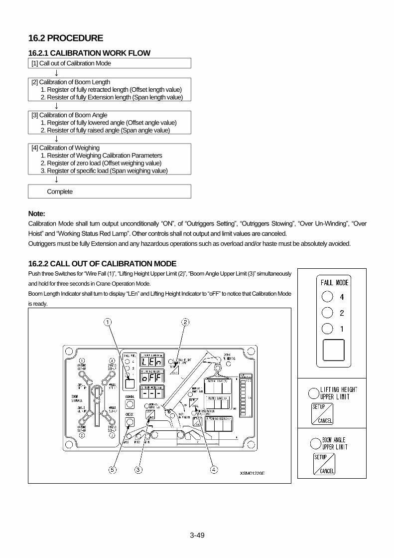
3-49
16.2 PROCEDURE
16.2.1 CALIBRATION WORK FLOW
[1] Call out of Calibration Mode
↓
[2] Calibration of Boom Length 1. Register of fully retracted length (Offset length value) 2. Resister of fully Extension length (Span length value)
↓
[3] Calibration of Boom Angle 1. Register of fully lowered angle (Offset angle value) 2. Resister of fully raised angle (Span angle value)
↓
[4] Calibration of Weighing 1. Resister of Weighing Calibration Parameters 2. Register of zero load (Offset weighing value) 3. Register of specific load (Span weighing value)
↓
Complete
Note:
Calibration Mode shall turn output unconditionally “ON”, of “Outriggers Setting”, “Outriggers Stowing”, “Over Un-Winding”, “Over
Hoist” and “Working Status Red Lamp”. Other controls shall not output and limit values are canceled.
Outriggers must be fully Extension and any hazardous operations such as overload and/or haste must be absolutely avoided.
16.2.2 CALL OUT OF CALIBRATION MODE Push three Switches for “Wire Fall (1)”, “Lifting Height Upper Limit (2)”, “Boom Angle Upper Limit (3)” simultaneously
and hold for three seconds in Crane Operation Mode.
Boom Length Indicator shall turn to display “LEn” and Lifting Height Indicator to “oFF” to notice that Calibration Mode
is ready.
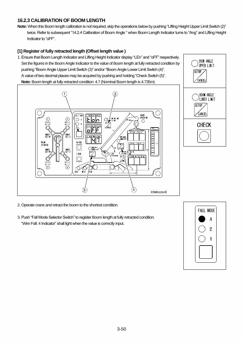
3-50
16.2.3 CALIBRATION OF BOOM LENGTH
Note: When this Boom length calibration is not required, skip the operations below by pushing “Lifting Height Upper Limit Switch (2)”
twice. Refer to subsequent “14.2.4 Calibration of Boom Angle “ when Boom Length Indicator turns to “Ang” and Lifting Height
Indicator to “oFF”.
[1] Register of fully retracted length (Offset length value )
1. Ensure that Boom Length Indicator and Lifting Height Indicator display “LEn” and “oFF” respectively.
Set the figures in the Boom Angle Indicator to the value of Boom length at fully retracted condition by
pushing “Boom Angle Upper Limit Switch (3)” and/or “Boom Angle Lower Limit Switch (4)”.
A value of two decimal places may be acquired by pushing and holding “Check Switch (5)”.
Note: Boom length at fully retracted condition: 4.7 (Nominal Boom length is 4.735m)
2. Operate crane and retract the boom to the shortest condition.
3. Push “Fall Mode Selector Switch” to register Boom length at fully retracted condition.
“Wire Fall: 4 Indicator” shall light when the value is correctly input.
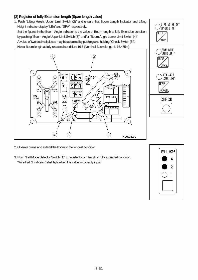
3-51
[2] Register of fully Extension length (Span length value)
1. Push “Lifting Height Upper Limit Switch (2)” and ensure that Boom Length Indicator and Lifting
Height Indicator display “LEn” and “SPA” respectively.
Set the figures in the Boom Angle Indicator to the value of Boom length at fully Extension condition
by pushing “Boom Angle Upper Limit Switch (3)” and/or “Boom Angle Lower Limit Switch (4)”.
A value of two decimal places may be acquired by pushing and holding “Check Switch (5)”.
Note: Boom length at fully retracted condition: 16.5 (Nominal Boom length is 16.475m)
2. Operate crane and extend the boom to the longest condition.
3. Push “Fall Mode Selector Switch (1)” to register Boom length at fully extended condition.
“Wire Fall: 2 Indicator” shall light when the value is correctly input.
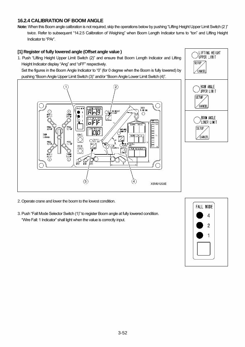
3-52
16.2.4 CALIBRATION OF BOOM ANGLE
Note: When this Boom angle calibration is not required, skip the operations below by pushing “Lifting Height Upper Limit Switch (2 )”
twice. Refer to subsequent “14.2.5 Calibration of Weighing” when Boom Length Indicator turns to “ton” and Lifting Height
Indicator to “PAr”.
[1] Register of fully lowered angle (Offset angle value )
1. Push “Lifting Height Upper Limit Switch (2)” and ensure that Boom Length Indicator and Lifting
Height Indicator display “Ang” and “oFF” respectively.
Set the figures in the Boom Angle Indicator to “0” (for 0 degree when the Boom is fully lowered) by
pushing “Boom Angle Upper Limit Switch (3)” and/or “Boom Angle Lower Limit Switch (4)”.
2. Operate crane and lower the boom to the lowest condition.
3. Push “Fall Mode Selector Switch (1)” to register Boom angle at fully lowered condition.
“Wire Fall: 1 Indicator” shall light when the value is correctly input.
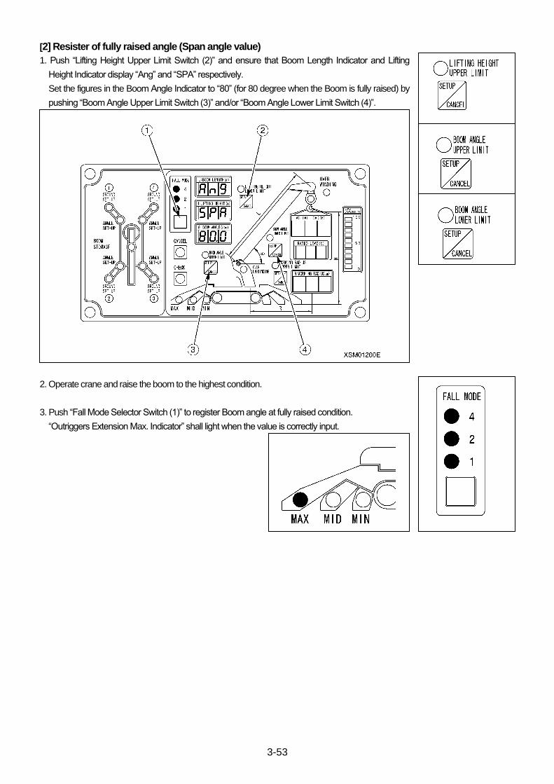
3-53
[2] Resister of fully raised angle (Span angle value)
1. Push “Lifting Height Upper Limit Switch (2)” and ensure that Boom Length Indicator and Lifting
Height Indicator display “Ang” and “SPA” respectively.
Set the figures in the Boom Angle Indicator to “80” (for 80 degree when the Boom is fully raised) by
pushing “Boom Angle Upper Limit Switch (3)” and/or “Boom Angle Lower Limit Switch (4)”.
2. Operate crane and raise the boom to the highest condition.
3. Push “Fall Mode Selector Switch (1)” to register Boom angle at fully raised condition.
“Outriggers Extension Max. Indicator” shall light when the value is correctly input.
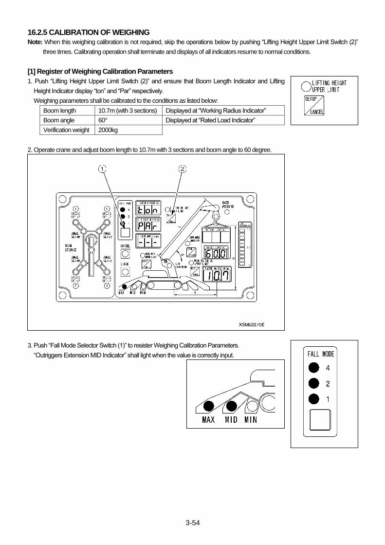
3-54
16.2.5 CALIBRATION OF WEIGHING
Note: When this weighing calibration is not required, skip the operations below by pushing “Lifting Height Upper Limit Switch (2)”
three times. Calibrating operation shall terminate and displays of all indicators resume to normal conditions.
[1] Register of Weighing Calibration Parameters
1. Push “Lifting Height Upper Limit Switch (2)” and ensure that Boom Length Indicator and Lifting
Height Indicator display “ton” and “Par” respectively.
Weighing parameters shall be calibrated to the conditions as listed below:
Boom length 10.7m (with 3 sections) Displayed at “Working Radius Indicator”
Boom angle 60° Displayed at “Rated Load Indicator”
Verification weight 2000kg
2. Operate crane and adjust boom length to 10.7m with 3 sections and boom angle to 60 degree.
3. Push “Fall Mode Selector Switch (1)” to resister Weighing Calibration Parameters.
“Outriggers Extension MID Indicator” shall light when the value is correctly input.
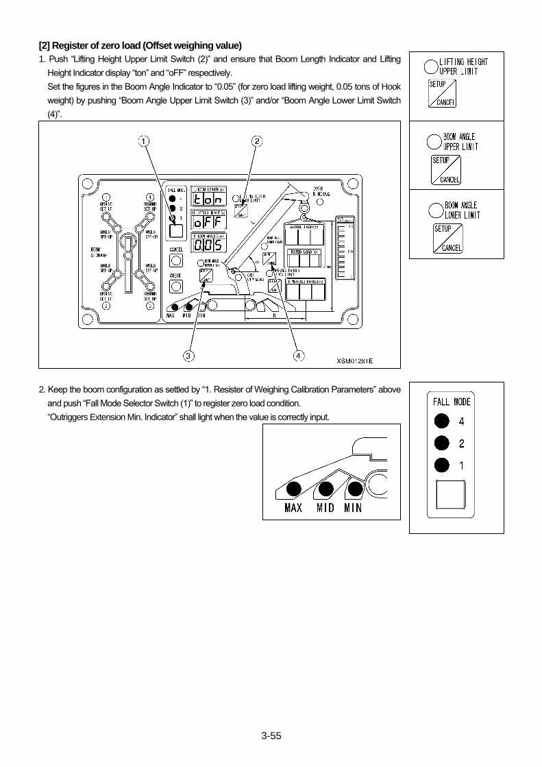
3-55
[2] Register of zero load (Offset weighing value)
1. Push “Lifting Height Upper Limit Switch (2)” and ensure that Boom Length Indicator and Lifting
Height Indicator display “ton” and “oFF” respectively.
Set the figures in the Boom Angle Indicator to “0.05” (for zero load lifting weight, 0.05 tons of Hook
weight) by pushing “Boom Angle Upper Limit Switch (3)” and/or “Boom Angle Lower Limit Switch
(4)”.
2. Keep the boom configuration as settled by “1. Resister of Weighing Calibration Parameters” above
and push “Fall Mode Selector Switch (1)” to register zero load condition.
“Outriggers Extension Min. Indicator” shall light when the value is correctly input.
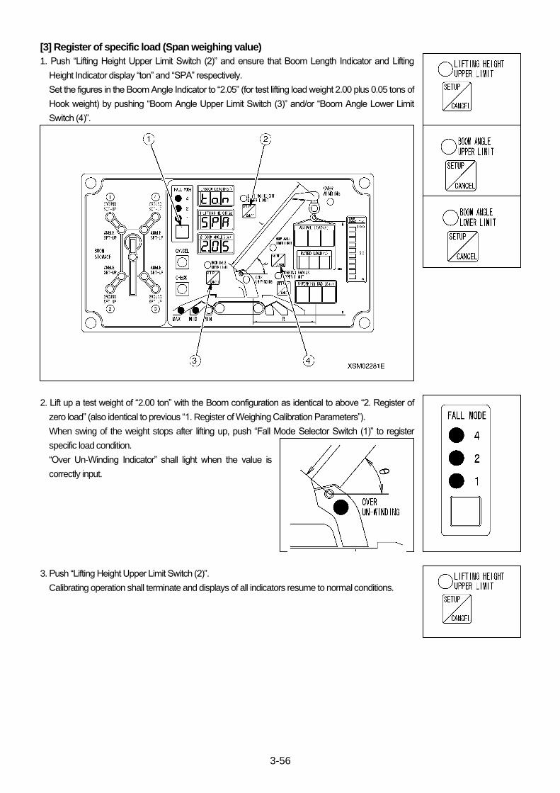
3-56
[3] Register of specific load (Span weighing value)
1. Push “Lifting Height Upper Limit Switch (2)” and ensure that Boom Length Indicator and Lifting
Height Indicator display “ton” and “SPA” respectively.
Set the figures in the Boom Angle Indicator to “2.05” (for test lifting load weight 2.00 plus 0.05 tons of
Hook weight) by pushing “Boom Angle Upper Limit Switch (3)” and/or “Boom Angle Lower Limit
Switch (4)”.
2. Lift up a test weight of “2.00 ton” with the Boom configuration as identical to above “2. Register of
zero load” (also identical to previous “1. Register of Weighing Calibration Parameters”).
When swing of the weight stops after lifting up, push “Fall Mode Selector Switch (1)” to register
specific load condition.
“Over Un-Winding Indicator” shall light when the value is
correctly input.
3. Push “Lifting Height Upper Limit Switch (2)”.
Calibrating operation shall terminate and displays of all indicators resume to normal conditions.
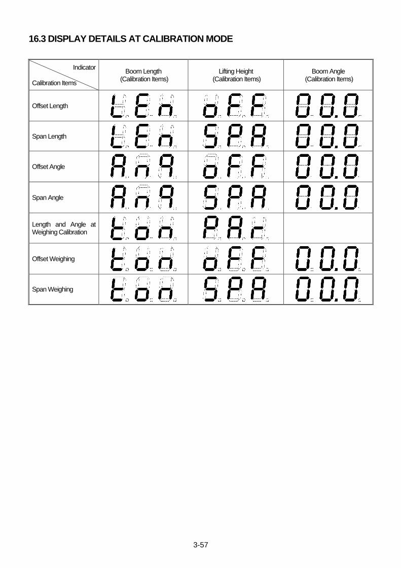
3-57
16.3 DISPLAY DETAILS AT CALIBRATION MODE
Indicator Calibration Items
Boom Length (Calibration Items)
Lifting Height (Calibration Items)
Boom Angle (Calibration Items)
Offset Length
Span Length
Offset Angle
Span Angle
Length and Angle at Weighing Calibration
Offset Weighing
Span Weighing

3-58
17. TEST MODE
Test Mode is provided with this Moment Limiter for the verification of operations and/or signals input/out of each of module.
Test Mode can be called out by a procedure as mentioned below. Once the Test Mode starts, power should be turned off for
resuming Normal Mode.
Note:
Calibration Mode shall turn unconditionally “ON”, output of “Outriggers Setting”, “Outriggers Stowing”, “Over Un-Winding”, “Over
Hoist” and “Working Status Red Light”. Other controls shall not output and limit values are canceled.
Outriggers must be fully Extension and any hazardous operations such as overload and/or haste must be absolutely avoided.
17.1 CALL OUT OF TEST MODE
1. Turn Power “ON” (Key-switch “ON”) while pushing both “Cancel Switch” and “Check Switch” in Crane Mode.
2. Ensure display of “L01” at “Boom Length Indicator”.
3. Each push of “Cancel Switch” shall sequentially switch test items from “L01” to “L09”.
Test Items
Test Items Description
L01 ROM/RAM Test
L02 LED Test
L03 Switch Test
L04 Input Signal Test
L05 Output Signal Test
L06 Load Factor Test (Input from sensors are between 1 and5volts.)
L07 Verification of Input from Converter
L08 Time Setting
L09 Display Of The Time To Replace Butteries
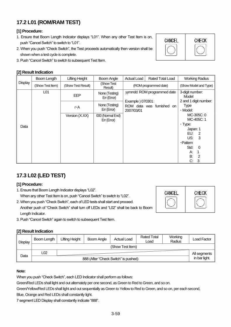
3-59
17.2 L01 (ROM/RAM TEST)
[1] Procedure:
1. Ensure that Boom Length Indicator displays “L01”. When any other Test Item is on,
push “Cancel Switch” to switch to “L01”.
2. When you push “Check Switch”, the Test proceeds automatically then version shall be
shown when a test cycle is complete.
3. Push “Cancel Switch” to switch to subsequent Test Item.
[2] Result Indication
Display Boom Length Lifting Height Boom Angle Actual Load Rated Total Load Working Radius
(Show Test Item) (Show Test Result) (Show Test
Result) (ROM programmed date) (Show Model and Type)
Data
L01 EEP
None (Testing) Err (Error)
yymmdd: ROM programmed date
Example ) 070301: ROM data was furnished on 2007/03/01
3-digit number: Model
2 and 1 digit number: Type
・ Model:
MC-305C: 0 MC-405C: 1
・ Type:
Japan: 1 EU: 2 US: 3
・Pattern
Std: 0 A: 1 B: 2 C: 3
r・A None (Testing)
Err (Error)
Version (X.XX) 000 (Normal End) Err (Error)
17.3 L02 (LED TEST)
[1] Procedure:
1. Ensure that Boom Length Indicator displays “L02”.
When any other Test Item is on, push “Cancel Switch” to switch to “L02”.
2. When you push “Check Switch”, each of LED tests shall start and proceed.
Another push of “Check Switch” shall turn off LEDs and “L02” shall be back to Boom
Length Indicator.
3. Push “Cancel Switch” again to switch to subsequent Test Item.
[2] Result Indication
Display Boom Length Lifting Height Boom Angle Actual Load
Rated Total Load
Working Radius
Load Factor
(Show Test Item)
Data L02 All segments
in bar light. 888 (After “Check Switch” is pushed)
Note:
When you push “Check Switch”, each LED Indicator shall perform as follows:
Green/Red LEDs shall light and out alternately per one second, as Green to Red to Green, and so on.
Green/Yellow/Red LEDs shall light and out sequentially as Green to Yellow to Red to Green, and so on, per each second,
Blue, Orange and Red LEDs shall constantly light.
7 segment LED Display shall constantly indicate “888”.
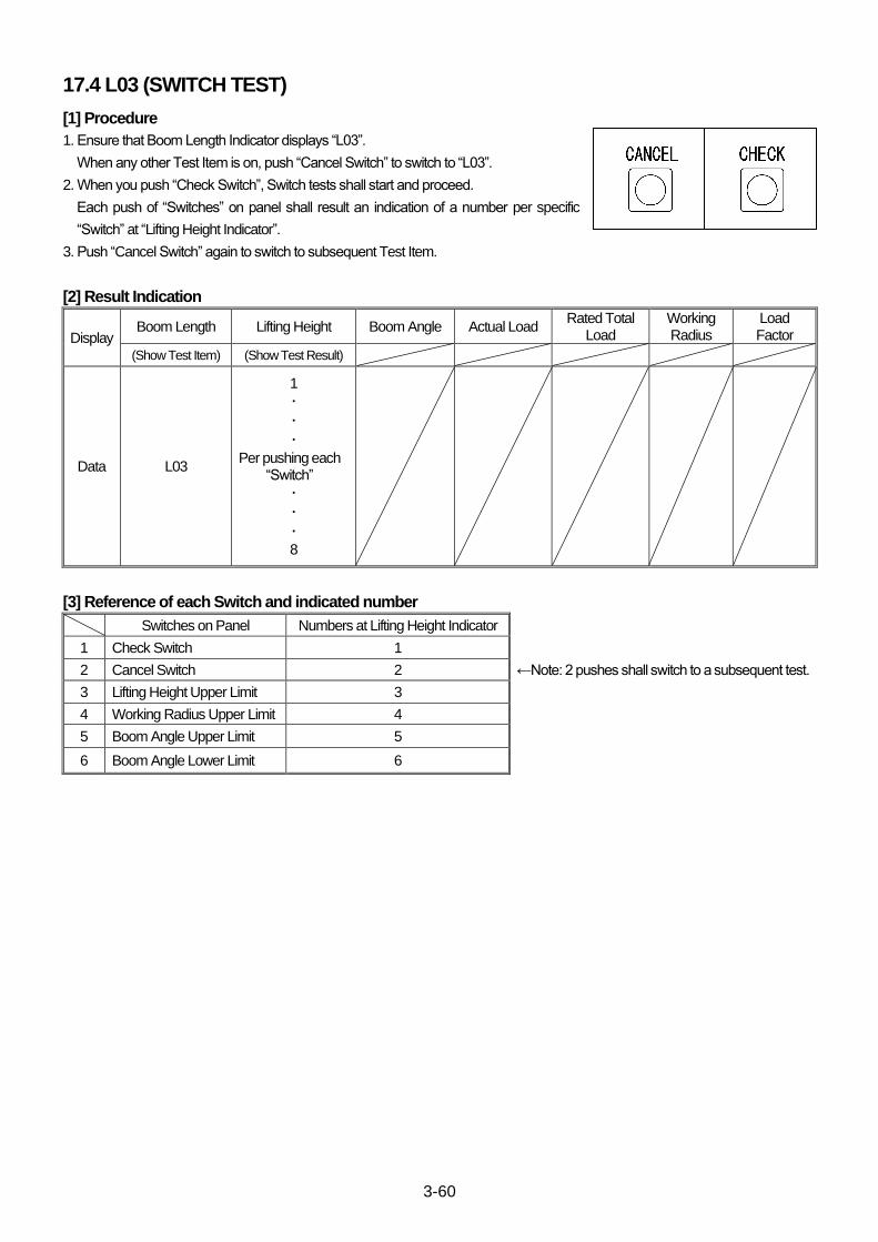
3-60
17.4 L03 (SWITCH TEST)
[1] Procedure
1. Ensure that Boom Length Indicator displays “L03”.
When any other Test Item is on, push “Cancel Switch” to switch to “L03”.
2. When you push “Check Switch”, Switch tests shall start and proceed.
Each push of “Switches” on panel shall result an indication of a number per specific
“Switch” at “Lifting Height Indicator”.
3. Push “Cancel Switch” again to switch to subsequent Test Item.
[2] Result Indication
Display Boom Length Lifting Height Boom Angle Actual Load
Rated Total Load
Working Radius
Load Factor
(Show Test Item) (Show Test Result)
Data L03
1
・
・
・ Per pushing each
“Switch”
・
・
・ 8
[3] Reference of each Switch and indicated number
Switches on Panel Numbers at Lifting Height Indicator
1 Check Switch 1
2 Cancel Switch 2 ←Note: 2 pushes shall switch to a subsequent test.
3 Lifting Height Upper Limit 3
4 Working Radius Upper Limit 4
5 Boom Angle Upper Limit 5
6 Boom Angle Lower Limit 6

3-61
17.5 L04 INPUT SIGNAL TEST
[1] Procedure:
1. Ensure that Boom Length Indicator displays “L04”.
When any other Test Item is on, push “Cancel Switch” to switch to “L04”.
2. When you push “Check Switch”, Tests shall start. Each function shall be verified by
actual processes of “Switches”.
3. Push “Cancel Switch” again to switch to subsequent Test Item.
Note: ”Over Hoist”, “Over Un-Winding”, “Outriggers 1 to 4, Ground Setting” and “Outriggers 1 to 4 Extension” shall be verified in
Normal Operation Mode.
[2] Result Indication
Display Boom Length Lifting Height Boom Angle Actual Load Rated Total Load
Working Radius
Load Factor
(Show Test Item) (Test Result) (Test Result) (Test Result) (Test Result)
Data
Three digits Numbers displayed at “Lifting Height Indicator”
Digit 100 10 1
Functions Boom Derricking Lever Outriggers Mid. Extension Outriggers Max. Extension
Display
Boom Derricking Lever “1” for “Raising” Position “2” for “Lowering” Position Neutral Position has no result indication.
Three digits Numbers displayed at “Boom Angle Indicator”
Digit 100 10 1
Functions Boom Upper/Lower Limit Switch Hook Stowed SOL Control
Display
“1” for Upper Limit Switch “ON”. “2” for Lower Limit Switch “ON”. “OFF” Position has no result indication.
“1” for “ON”. “0” for “OFF”.
“1” for “ON” (Crane/Outriggers Mode). “0” for “OFF” (Traveling Mode).
Three digits Numbers displayed at “Actual Load Indicator”
Digit 100 10 1
Functions Emergency Stop Cancel Switch Pick and Carry Switch Boom Slewing/Stowing Limit Switch
Display “1” for “ON”. “0” for “OFF”.
“1” for “ON”. “0” for “OFF”. “None” for models which is not capable.
“1” for “ON”. “0” for “OFF”.
Three digits Numbers displayed at “Rated Load Indicator”
Digit 100 10 1
Functions Slewing counter clockwise Limit
Switch Slewing clockwise Limit Switch Pick and Carry Limit Switch
Display
“1” for “ON”. “0” for “OFF”. “None” for models which is not applicable.
“1” for “ON”. “0” for “OFF”. “None” for models which is not applicable.
“1” for “ON”. “0” for “OFF”. “None” for models which is not capable.
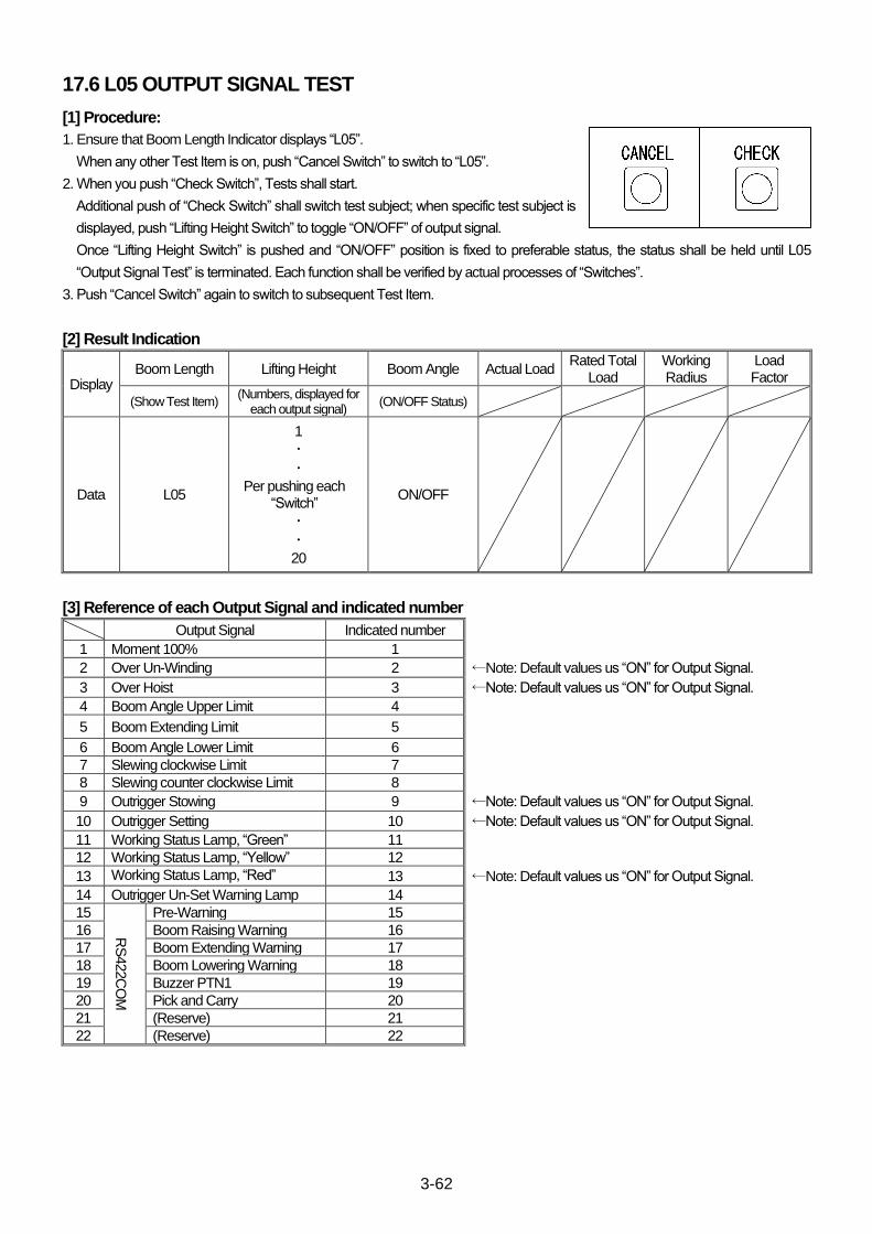
3-62
17.6 L05 OUTPUT SIGNAL TEST
[1] Procedure:
1. Ensure that Boom Length Indicator displays “L05”.
When any other Test Item is on, push “Cancel Switch” to switch to “L05”.
2. When you push “Check Switch”, Tests shall start.
Additional push of “Check Switch” shall switch test subject; when specific test subject is
displayed, push “Lifting Height Switch” to toggle “ON/OFF” of output signal.
Once “Lifting Height Switch” is pushed and “ON/OFF” position is fixed to preferable status, the status shall be held until L05
“Output Signal Test” is terminated. Each function shall be verified by actual processes of “Switches”.
3. Push “Cancel Switch” again to switch to subsequent Test Item.
[2] Result Indication
Display Boom Length Lifting Height Boom Angle Actual Load
Rated Total Load
Working Radius
Load Factor
(Show Test Item) (Numbers, displayed for
each output signal) (ON/OFF Status)
Data L05
1
・
・ Per pushing each
“Switch”
・
・ 20
ON/OFF
[3] Reference of each Output Signal and indicated number
Output Signal Indicated number
1 Moment 100% 1
2 Over Un-Winding 2 ←Note: Default values us “ON” for Output Signal.
3 Over Hoist 3 ←Note: Default values us “ON” for Output Signal.
4 Boom Angle Upper Limit 4
5 Boom Extending Limit 5
6 Boom Angle Lower Limit 6
7 Slewing clockwise Limit 7
8 Slewing counter clockwise Limit 8
9 Outrigger Stowing 9 ←Note: Default values us “ON” for Output Signal.
10 Outrigger Setting 10 ←Note: Default values us “ON” for Output Signal.
11 Working Status Lamp, “Green” 11
12 Working Status Lamp, “Yellow” 12
13 Working Status Lamp, “Red” 13 ←Note: Default values us “ON” for Output Signal.
14 Outrigger Un-Set Warning Lamp 14
15
RS
422C
OM
Pre-Warning 15
16 Boom Raising Warning 16
17 Boom Extending Warning 17
18 Boom Lowering Warning 18
19 Buzzer PTN1 19
20 Pick and Carry 20
21 (Reserve) 21
22 (Reserve) 22
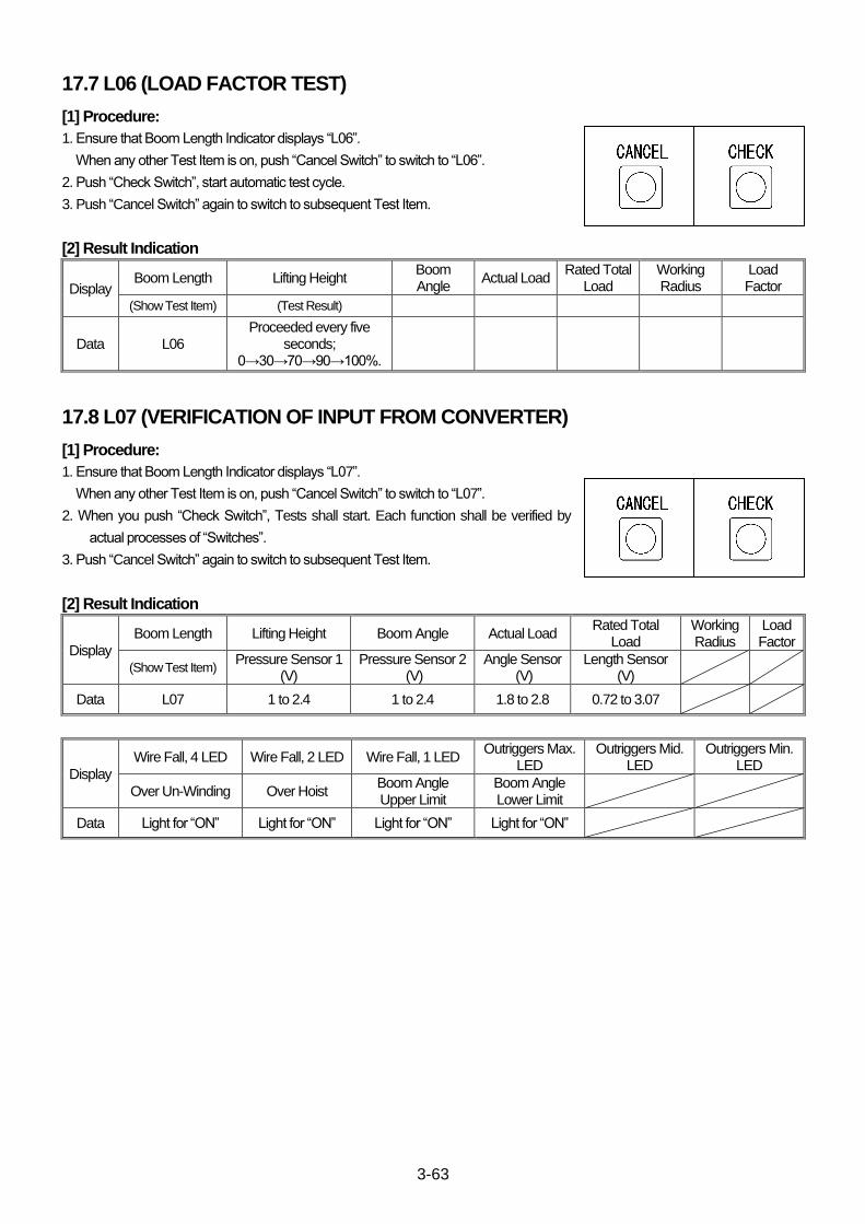
3-63
17.7 L06 (LOAD FACTOR TEST)
[1] Procedure:
1. Ensure that Boom Length Indicator displays “L06”.
When any other Test Item is on, push “Cancel Switch” to switch to “L06”.
2. Push “Check Switch”, start automatic test cycle.
3. Push “Cancel Switch” again to switch to subsequent Test Item.
[2] Result Indication
Display Boom Length Lifting Height
Boom Angle
Actual Load Rated Total
Load Working Radius
Load Factor
(Show Test Item) (Test Result)
Data L06 Proceeded every five
seconds; 0→30→70→90→100%.
17.8 L07 (VERIFICATION OF INPUT FROM CONVERTER)
[1] Procedure:
1. Ensure that Boom Length Indicator displays “L07”.
When any other Test Item is on, push “Cancel Switch” to switch to “L07”.
2. When you push “Check Switch”, Tests shall start. Each function shall be verified by
actual processes of “Switches”.
3. Push “Cancel Switch” again to switch to subsequent Test Item.
[2] Result Indication
Display
Boom Length Lifting Height Boom Angle Actual Load Rated Total
Load Working Radius
Load Factor
(Show Test Item) Pressure Sensor 1
(V) Pressure Sensor 2
(V) Angle Sensor
(V) Length Sensor
(V)
Data L07 1 to 2.4 1 to 2.4 1.8 to 2.8 0.72 to 3.07
Display
Wire Fall, 4 LED Wire Fall, 2 LED Wire Fall, 1 LED Outriggers Max.
LED Outriggers Mid.
LED Outriggers Min.
LED
Over Un-Winding Over Hoist Boom Angle Upper Limit
Boom Angle Lower Limit
Data Light for “ON” Light for “ON” Light for “ON” Light for “ON”
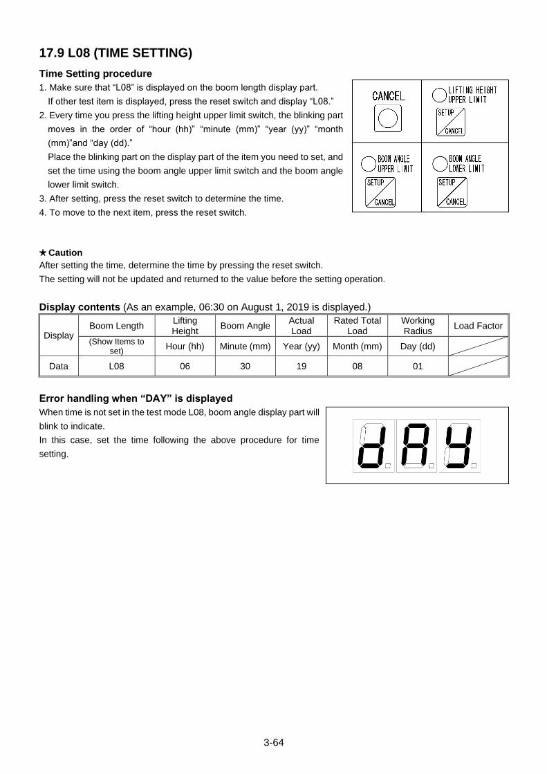
3-64
17.9 L08 (TIME SETTING)
Time Setting procedure
1. Make sure that “L08” is displayed on the boom length display part.
If other test item is displayed, press the reset switch and display “L08.”
2. Every time you press the lifting height upper limit switch, the blinking part
moves in the order of “hour (hh)” “minute (mm)” “year (yy)” “month
(mm)”and “day (dd).”
Place the blinking part on the display part of the item you need to set, and
set the time using the boom angle upper limit switch and the boom angle
lower limit switch.
3. After setting, press the reset switch to determine the time.
4. To move to the next item, press the reset switch.
★Caution
After setting the time, determine the time by pressing the reset switch.
The setting will not be updated and returned to the value before the setting operation.
Display contents (As an example, 06:30 on August 1, 2019 is displayed.)
Display Boom Length
Lifting Height
Boom Angle Actual Load
Rated Total Load
Working Radius
Load Factor
(Show Items to set)
Hour (hh) Minute (mm) Year (yy) Month (mm) Day (dd)
Data L08 06 30 19 08 01
Error handling when “DAY” is displayed
When time is not set in the test mode L08, boom angle display part will
blink to indicate.
In this case, set the time following the above procedure for time
setting.
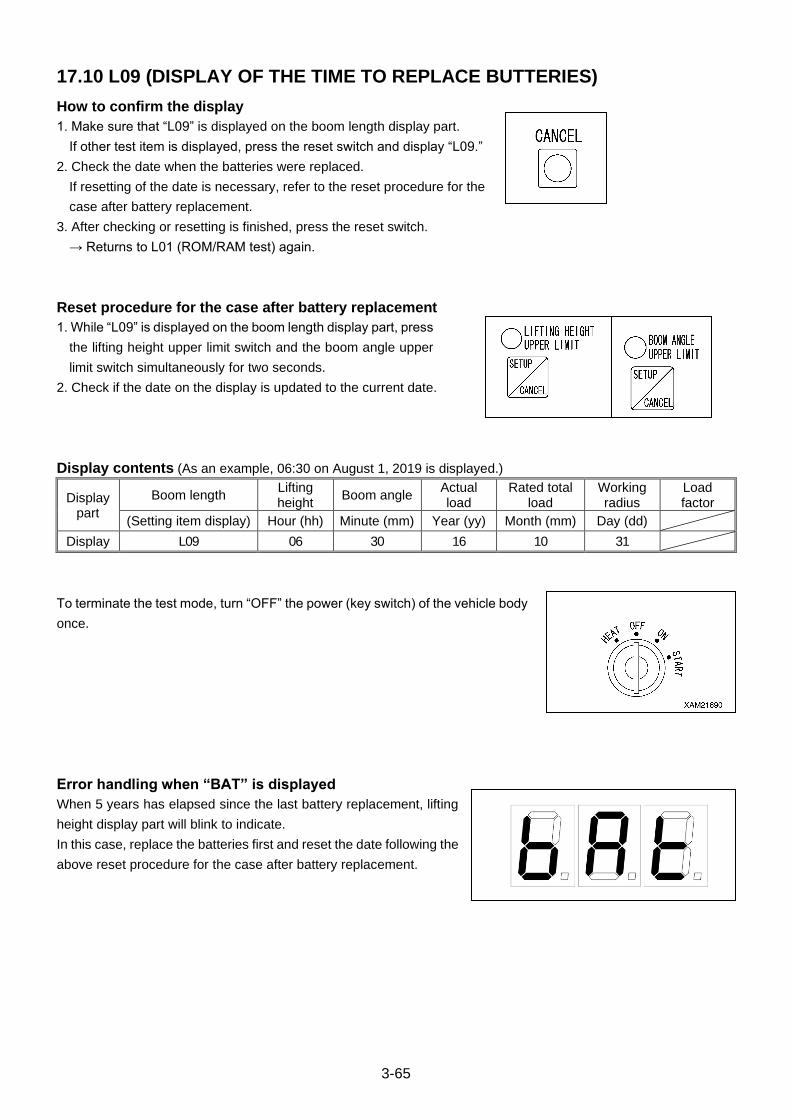
3-65
17.10 L09 (DISPLAY OF THE TIME TO REPLACE BUTTERIES)
How to confirm the display
1. Make sure that “L09” is displayed on the boom length display part.
If other test item is displayed, press the reset switch and display “L09.”
2. Check the date when the batteries were replaced.
If resetting of the date is necessary, refer to the reset procedure for the
case after battery replacement.
3. After checking or resetting is finished, press the reset switch.
→ Returns to L01 (ROM/RAM test) again.
Reset procedure for the case after battery replacement
1. While “L09” is displayed on the boom length display part, press
the lifting height upper limit switch and the boom angle upper
limit switch simultaneously for two seconds.
2. Check if the date on the display is updated to the current date.
Display contents (As an example, 06:30 on August 1, 2019 is displayed.)
Display part
Boom length Lifting height
Boom angle Actual load
Rated total load
Working radius
Load factor
(Setting item display) Hour (hh) Minute (mm) Year (yy) Month (mm) Day (dd)
Display L09 06 30 16 10 31
To terminate the test mode, turn “OFF” the power (key switch) of the vehicle body
once.
Error handling when “BAT” is displayed
When 5 years has elapsed since the last battery replacement, lifting
height display part will blink to indicate.
In this case, replace the batteries first and reset the date following the
above reset procedure for the case after battery replacement.

3-66
18. PC MODE
This Moment Limiter is capable to record operation log by “Emergency Stop Cancel Switch” and also provides PC
Mode which allows an external Personal Computer picking up the log record.
PC Model shall start as stated below. Once the PC Mode is called out, the Moment Limiter can not resume its Normal
Mode, unless its main power is once turned to “OFF” and to “ON” again.
A personal computer to which a specific software, “WinCT”, is installed beforehand is required. “WinCT”is available
for download from a sight of A&D Company, Ltd as introduced in the following list.
Japanese https://www.aandd.co.jp/adhome/support/sup-download.html
English http://www.aandd.jp/products/software/software.htm
“WinCT” is a free-soft (i.e. no support is provided.) Please refer to “Setup.txt” included in a set of downloaded files for required system configuration and/or installation procedure. As well, appropriate application software, such as Microsoft Excel is required. MAEDA SEUSAKUSHO CO., LTD is not responsible for any troubles caused by the use of this software. Note: Microsoft®, WINDOWS®, , EXCEL® and Word®, are registered trademarks of Microsoft Corporation in the
United States and other countries.
Note:
The personal computer is required to have at least one “RS-232 Port”
for a connection with this Moment Limiter.
For personal computer without such serial port, we do not guarantee
use of any commercially available adapters (USB-Serial Converters),
but have verified compatibility of “REX-USB60F (Parts No.:
S103M2162000)” of Ratoc System.
Hence, it is advisable to use “REX-USB60F” when you require a
USB-Serial Converter.
Note: A drawing in the right shows “REX-USB60F” of Ratoc System.
18.1 MOMENT LIMITER OPERATION LOG PICKING UP PROCEDURE
1. Open the fuse-box lid in the left side to Instrument Panel of Crane
main-body and pull out a PC-cable inside.
Remove a cap from a connector when the cable is ready.
2. Connect Moment Limiter to a port of a personal computer (D-Sub 9
pins) using PC-Connect Cable (Parts No.: 103-4560700) included in
attached accessories kit.
Note:
If your personal computer only has USB ports but no serial ports (D-Sub
9 pins), use a USB-Serial Converter as described above.
Note: A PC-connect Cable in a next drawing may look different from the
actual one in the accessories kit.
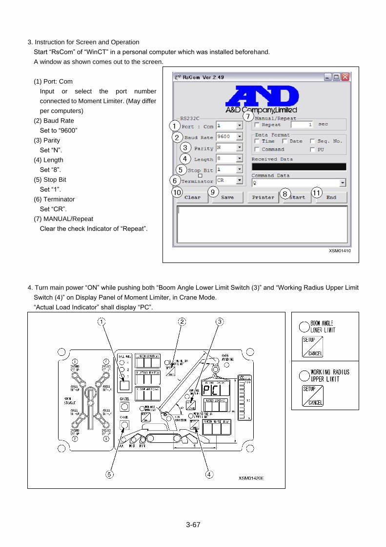
3-67
3. Instruction for Screen and Operation
Start “RsCom” of “WinCT” in a personal computer which was installed beforehand.
A window as shown comes out to the screen.
(1) Port: Com
Input or select the port number
connected to Moment Limiter. (May differ
per computers)
(2) Baud Rate
Set to “9600”
(3) Parity
Set “N”.
(4) Length
Set “8”.
(5) Stop Bit
Set “1”.
(6) Terminator
Set “CR”.
(7) MANUAL/Repeat
Clear the check Indicator of “Repeat”.
4. Turn main power “ON” while pushing both “Boom Angle Lower Limit Switch (3)” and “Working Radius Upper Limit
Switch (4)” on Display Panel of Moment Limiter, in Crane Mode.
“Actual Load Indicator” shall display “PC”.
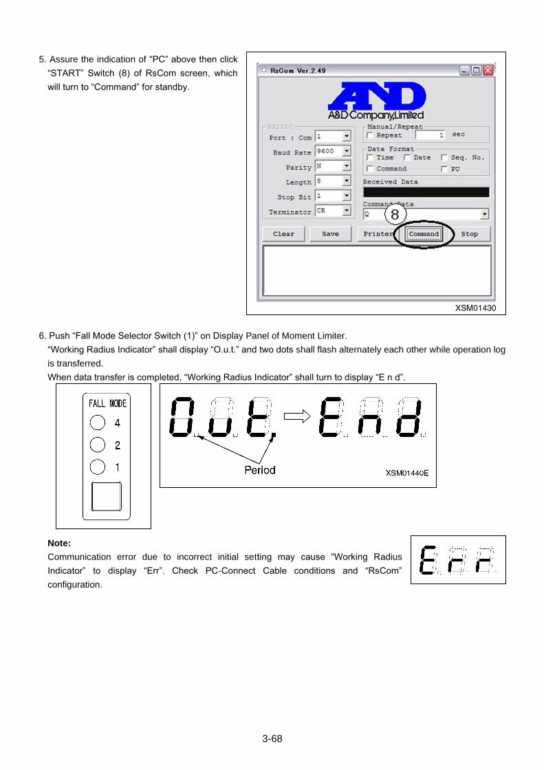
3-68
5. Assure the indication of “PC” above then click
“START” Switch (8) of RsCom screen, which
will turn to “Command” for standby.
6. Push “Fall Mode Selector Switch (1)” on Display Panel of Moment Limiter.
“Working Radius Indicator” shall display “O.u.t.” and two dots shall flash alternately each other while operation log
is transferred.
When data transfer is completed, “Working Radius Indicator” shall turn to display “E n d”.
Note:
Communication error due to incorrect initial setting may cause “Working Radius
Indicator” to display “Err”. Check PC-Connect Cable conditions and “RsCom”
configuration.
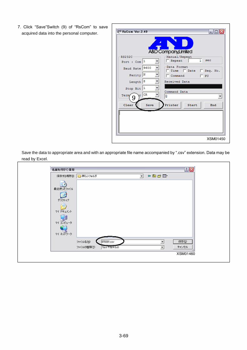
3-69
7. Click “Save”Switch (9) of “RsCom” to save
acquired data into the personal computer.
Save the data to appropriate area and with an appropriate file name accompanied by “.csv” extension. Data may be
read by Excel.
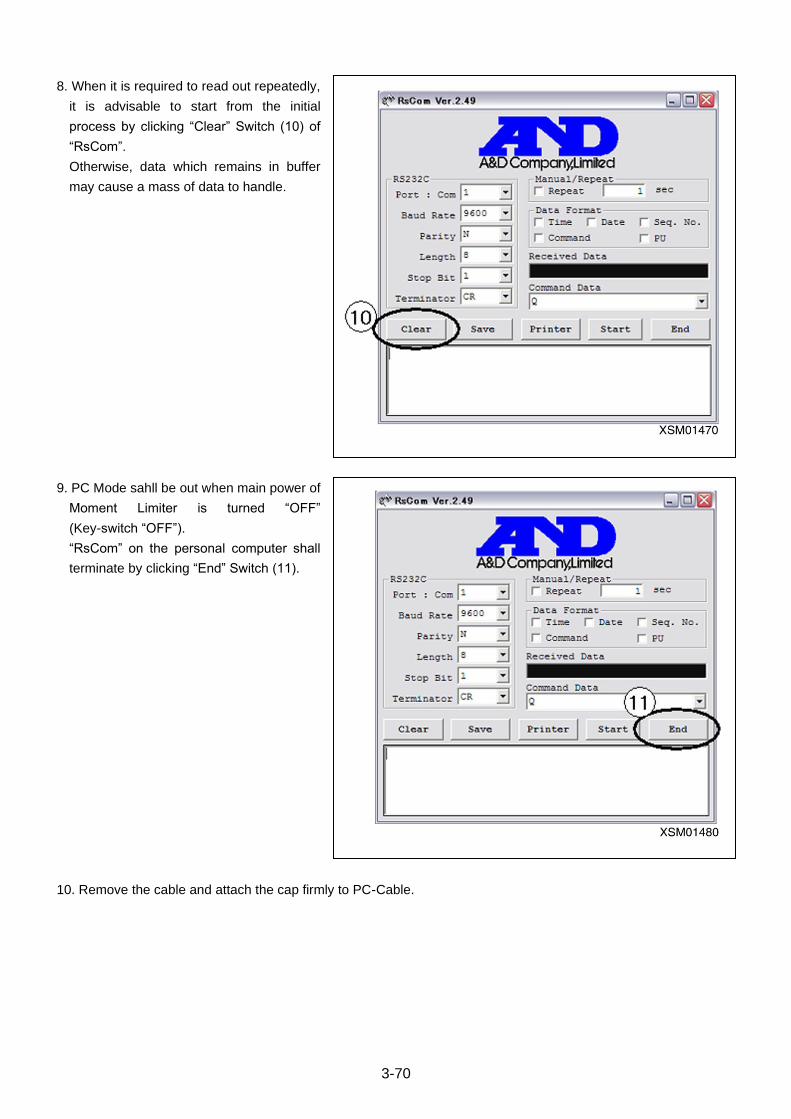
3-70
8. When it is required to read out repeatedly,
it is advisable to start from the initial
process by clicking “Clear” Switch (10) of
“RsCom”.
Otherwise, data which remains in buffer
may cause a mass of data to handle.
9. PC Mode sahll be out when main power of
Moment Limiter is turned “OFF”
(Key-switch “OFF”).
“RsCom” on the personal computer shall
terminate by clicking “End” Switch (11).
10. Remove the cable and attach the cap firmly to PC-Cable.
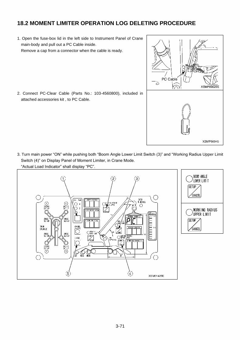
3-71
18.2 MOMENT LIMITER OPERATION LOG DELETING PROCEDURE
1. Open the fuse-box lid in the left side to Instrument Panel of Crane
main-body and pull out a PC Cable inside.
Remove a cap from a connector when the cable is ready.
2. Connect PC-Clear Cable (Parts No.: 103-4560800), included in
attached accessories kit , to PC Cable.
3. Turn main power “ON” while pushing both “Boom Angle Lower Limit Switch (3)” and “Working Radius Upper Limit
Switch (4)” on Display Panel of Moment Limiter, in Crane Mode.
“Actual Load Indicator” shall display “PC”.
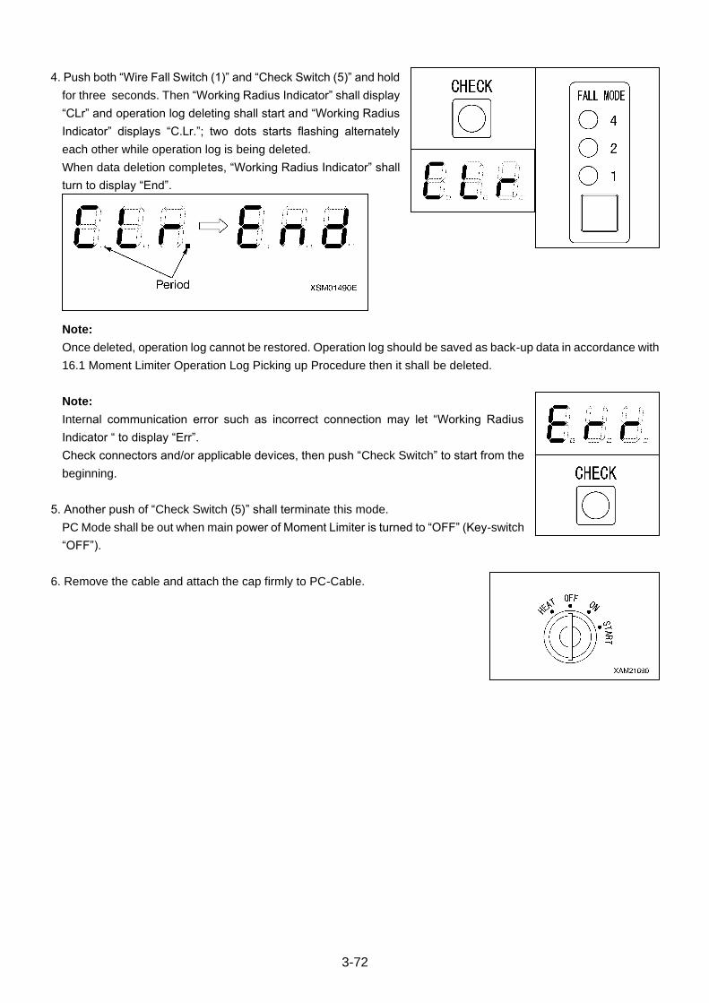
3-72
4. Push both “Wire Fall Switch (1)” and “Check Switch (5)” and hold
for three seconds. Then “Working Radius Indicator” shall display
“CLr” and operation log deleting shall start and “Working Radius
Indicator” displays “C.Lr.”; two dots starts flashing alternately
each other while operation log is being deleted.
When data deletion completes, “Working Radius Indicator” shall
turn to display “End”.
Note:
Once deleted, operation log cannot be restored. Operation log should be saved as back-up data in accordance with
16.1 Moment Limiter Operation Log Picking up Procedure then it shall be deleted.
Note:
Internal communication error such as incorrect connection may let “Working Radius
Indicator “ to display “Err”.
Check connectors and/or applicable devices, then push “Check Switch” to start from the
beginning.
5. Another push of “Check Switch (5)” shall terminate this mode.
PC Mode shall be out when main power of Moment Limiter is turned to “OFF” (Key-switch
“OFF”).
6. Remove the cable and attach the cap firmly to PC-Cable.
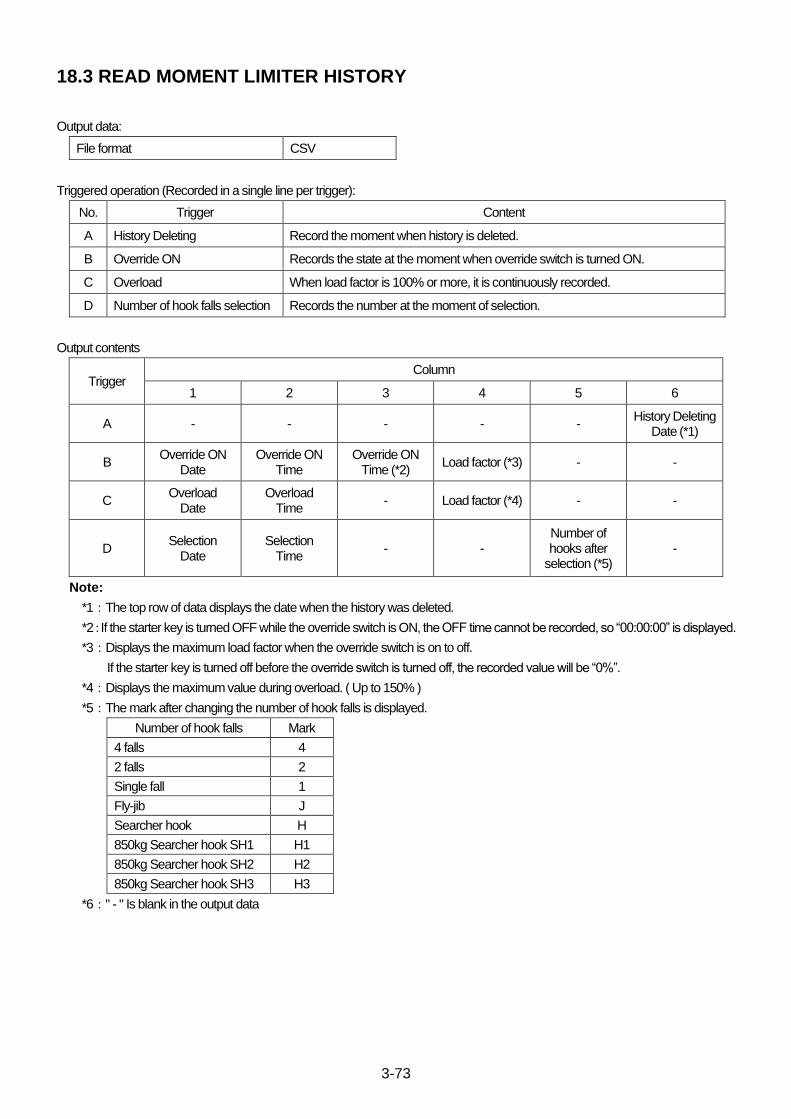
3-73
18.3 READ MOMENT LIMITER HISTORY
Output data:
File format CSV
Triggered operation (Recorded in a single line per trigger):
No. Trigger Content
A History Deleting Record the moment when history is deleted.
B Override ON Records the state at the moment when override switch is turned ON.
C Overload When load factor is 100% or more, it is continuously recorded.
D Number of hook falls selection Records the number at the moment of selection.
Output contents
Trigger Column
1 2 3 4 5 6
A - - - - - History Deleting
Date (*1)
B Override ON
Date Override ON
Time Override ON
Time (*2) Load factor (*3) - -
C Overload
Date Overload
Time - Load factor (*4) - -
D Selection
Date Selection
Time - -
Number of hooks after
selection (*5) -
Note:
*1:The top row of data displays the date when the history was deleted.
*2:If the starter key is turned OFF while the override switch is ON, the OFF time cannot be recorded, so “00:00:00” is displayed.
*3:Displays the maximum load factor when the override switch is on to off.
If the starter key is turned off before the override switch is turned off, the recorded value will be “0%”.
*4:Displays the maximum value during overload. ( Up to 150% )
*5:The mark after changing the number of hook falls is displayed.
Number of hook falls Mark
4 falls 4
2 falls 2
Single fall 1
Fly-jib J
Searcher hook H
850kg Searcher hook SH1 H1
850kg Searcher hook SH2 H2
850kg Searcher hook SH3 H3
*6:" - " Is blank in the output data
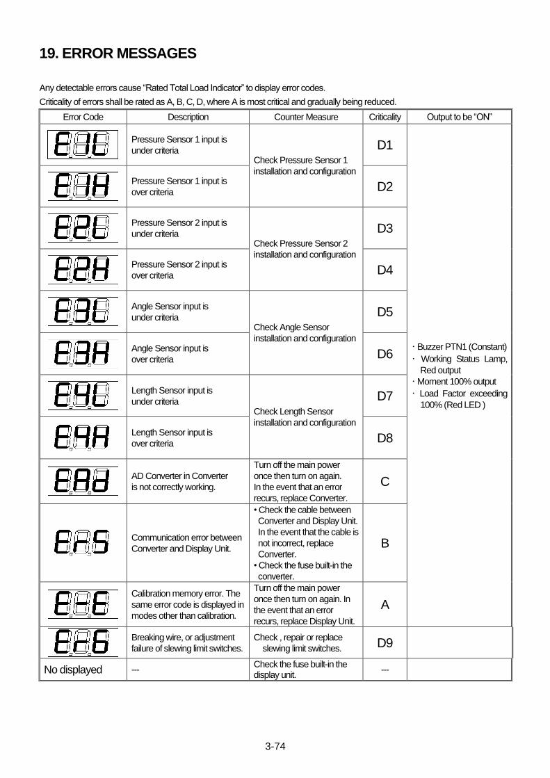
3-74
19. ERROR MESSAGES
Any detectable errors cause “Rated Total Load Indicator” to display error codes.
Criticality of errors shall be rated as A, B, C, D, where A is most critical and gradually being reduced.
Error Code Description Counter Measure Criticality Output to be “ON”
Pressure Sensor 1 input is
under criteria Check Pressure Sensor 1
installation and configuration
D1
・ Buzzer PTN1 (Constant)
・ Working Status Lamp,
Red output
・ Moment 100% output
・ Load Factor exceeding
100% (Red LED )
Pressure Sensor 1 input is
over criteria D2
Pressure Sensor 2 input is
under criteria Check Pressure Sensor 2
installation and configuration
D3
Pressure Sensor 2 input is
over criteria D4
Angle Sensor input is
under criteria Check Angle Sensor
installation and configuration
D5
Angle Sensor input is
over criteria D6
Length Sensor input is
under criteria Check Length Sensor
installation and configuration
D7
Length Sensor input is
over criteria D8
AD Converter in Converter
is not correctly working.
Turn off the main power
once then turn on again.
In the event that an error
recurs, replace Converter.
C
Communication error between
Converter and Display Unit.
• Check the cable between
Converter and Display Unit.
In the event that the cable is
not incorrect, replace
Converter.
• Check the fuse built-in the
converter.
B
Calibration memory error. The
same error code is displayed in
modes other than calibration.
Turn off the main power
once then turn on again. In
the event that an error
recurs, replace Display Unit.
A
Breaking wire, or adjustment
failure of slewing limit switches.
Check , repair or replace
slewing limit switches. D9
No displayed --- Check the fuse built-in the display unit.
---
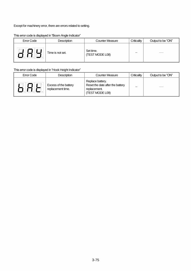
3-75
Except for machinery error, there are errors related to setting.
This error code is displayed in “Boom Angle Indicator”
Error Code Description Counter Measure Criticality Output to be “ON”
Time is not set. Set time.
(TEST MODE L08) - ---
This error code is displayed in “Hook Height Indicator”
Error Code Description Counter Measure Criticality Output to be “ON”
Excess of the battery
replacement time.
Replace battery.
Reset the date after the battery
replacement.
(TEST MODE L09)
- ---
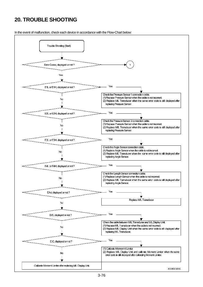
3-76
20. TROUBLE SHOOTING
In the event of malfunction, check each device in accordance with the Flow-Chart below:
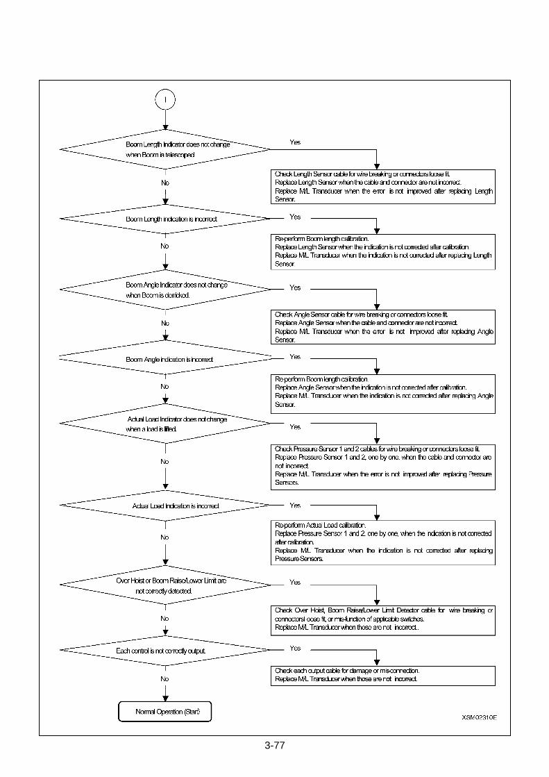
3-77

3-78
21. POINTS FOR INPUT VOLTAGE MEASUREMENT OF EACH SENSOR
The drawing above is the mother board for Converter.
From top to bottom
NF8: Angle Sensor
NF9: Length Sensor
NF7: Pressure Sensor 2
NF6: Pressure Sensor 1
Measure voltage between each of above points and GND.
4-1
INTERACTIVE
REMOTE CONTROL
1. INITIAL MODE SETTING PROCEDURE 4-2
1.1 BUTTON ARRANGEMENT ON CONTROL PANEL 4-2
1.2 ESTABLISHING INITIAL MODE: 4-3
1.3 INITIAL MODE FOR USER (A MODE) 4-4
1.4 INITIAL MODE FOR SERVICE (B MODE) 4-7
1.5 INITIAL MODE FOR MAKER (C MODE) 4-10
1.6 INITIAL MODE SETTING (For interactive remote controller) 4-16
2. RECEIVER 4-18
2.1 STATUS DISPLAY 4-18
2.2 CONTROL PRINT CARD LACATIONS 4-20
2.3 CONNECTOR PIN ASSIGNMENT 4-24
2.4 VALVE NEUTRAL SETTING PROCEDURE 4-26
2.5 MONITOR DISPLAY MESSAGE 4-28
2.6 FUSE IN THE RECEIVER 4-29
3. VOICE MESSAGES 4-31
4. TROUBLESHOOTING 4-32

4-2
1. INITIAL MODE SETTING PROCEDURE
1.1 BUTTON ARRANGEMENT ON CONTROL PANEL
*Alphabetical character on each button corresponds to the button name that appears in the following discussion.
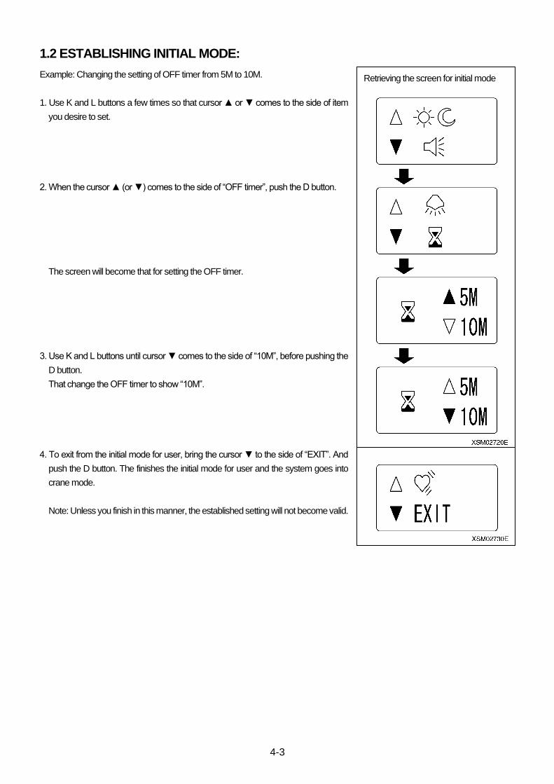
4-3
1.2 ESTABLISHING INITIAL MODE:
Example: Changing the setting of OFF timer from 5M to 10M.
1. Use K and L buttons a few times so that cursor ▲ or ▼ comes to the side of item
you desire to set.
2. When the cursor ▲ (or ▼) comes to the side of “OFF timer”, push the D button.
The screen will become that for setting the OFF timer.
3. Use K and L buttons until cursor ▼ comes to the side of “10M”, before pushing the
D button.
That change the OFF timer to show “10M”.
4. To exit from the initial mode for user, bring the cursor ▼ to the side of “EXIT”. And
push the D button. The finishes the initial mode for user and the system goes into
crane mode.
Note: Unless you finish in this manner, the established setting will not become valid.
Retrieving the screen for initial mode
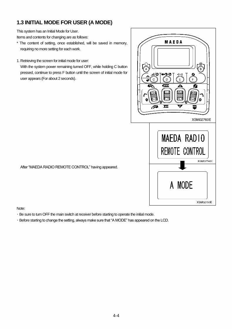
4-4
1.3 INITIAL MODE FOR USER (A MODE)
This system has an Initial Mode for User.
Items and contents for changing are as follows:
* The content of setting, once established, will be saved in memory,
requiring no more setting for each work.
1. Retrieving the screen for initial mode for user:
With the system power remaining turned OFF, while holding C button
pressed, continue to press F button until the screen of initial mode for
user appears (For about 2 seconds).
After “MAEDA RADIO REMOTE CONTROL” having appeared.
Note:
・ Be sure to turn OFF the main switch at receiver before starting to operate the initial mode.
・ Before starting to change the setting, always make sure that “A MODE” has appeared on the LCD.
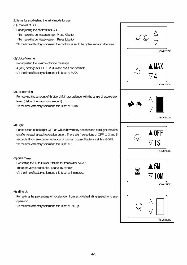
4-5
2. Items for establishing the initial mode for user:
(1) Contrast of LCD
For adjusting the contrast of LCD.
・ To make the contrast stronger: Press K button
・ To make the contrast weaker: Press L button
*At the time of factory shipment, the contrast is set to be optimum for in door use.
(2) Voice Volume
For adjusting the volume of voice message.
4 (four) settings of OFF, 1, 2, 3, 4 and MAX are available.
*At the time of factory shipment, this is set at MAX.
(3) Acceleration
For varying the amount of throttle shift in accordance with the angle of accelerator
lever. (Setting the maximum amount)
*At the time of factory shipment, this is set at 100%.
(4) Light
For selection of backlight OFF as will as how many seconds the backlight remains
on after releasing each operation button. There are 4 selections of OFF, 1, 3 and 5
seconds. If you are concerned about of running down of battery, set this at OFF.
*At the time of factory shipment, this is set at 1.
(5) OFF Timer
For setting the Auto Power Off time for transmitter power.
There are 3 selections of 5, 10 and 15 minutes.
*At the time of factory shipment, this is set at 5 minutes.
(6) Idling Up
For setting the percentage of acceleration from established idling speed for crane
operation.
*At the time of factory shipment, this is set at 0% up.
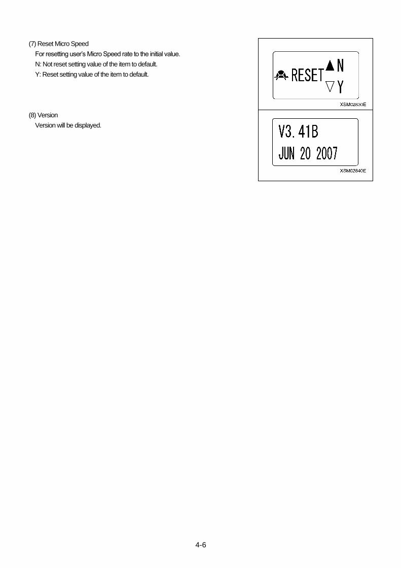
4-6
(7) Reset Micro Speed
For resetting user’s Micro Speed rate to the initial value.
N: Not reset setting value of the item to default.
Y: Reset setting value of the item to default.
(8) Version
Version will be displayed.

4-7
1.4 INITIAL MODE FOR SERVICE (B MODE)
This system has an Initial Mode for Service for the user by service
shop or Rental Company.
Items and contents for changing are as follows:
*The content of setting, once established, will be saved in
memory, requiring no more setting for each work.
1. Retrieving the screen for initial mode for service:
With the system power remaining turned OFF, while holding H
and N buttons pressed, continue to press F button until the
screen of initial mode for user appears (For about 2 seconds).
After “MAEDA RADIO REMOTE CONTROL” having showed up.
”B MODE” appears, before the prompt for password “PASS WORD
0000” comes up.
Each digit corresponds to buttons as shown above.
Operate each buttons to enter [2435], before pressing D button.
Note:
・ Be sure to turn OFF the main switch at receiver before starting to operate the initial mode.
・ Before starting to change the setting, always make sure that “B MODE” has appeared on the LCD.

4-8
2. Items for setting the initial mode for service:
(1) Pattern
Allow you to change the operating pattern. There are 3 patterns of STD, OPT or
US patterns.
*At the time of factory shipment, this is set as STD.
(2) Slew
For changing the gain in slewing.
There are 3 selections of HI, MID and LOW.
・ HI : Increase the gain.
・ MID :
・ LOW: Reduces the gain.
*At the time of factory shipment, this is set at HI.
*Do not set it besides "HI" for reasons of the structure of the valve.
(3) Boom Raising and Lowering
For change the gain in boom raising and lowering.
There are 3 selections of HI, MID and LOW.
・ HI : Increase the gain.
・ MID :
・ LOW: Reduces the gain.
*At the time of factory shipment, this is set at HI.
*Do not set it besides "HI" for reasons of the structure of the valve.
(4) Hook Stow
For selection of availability of hook stowing function. Check the specifications of
your crane.
If it has the function, set is as ON.
If not, set it as OFF.
*At the time of factory shipment, this is set at ON.
OPT pattern
STD pattern
US pattern

4-9
(5) Tow block limit switch
For selection of contacts A and B of over-hoisting limit switch.
For the contact A (NO), set it at ON.
For the contact B (NC), set it at OFF.
If your crane is not provided with hook stowing function, select this OFF.
*At the time of factory shipment, this is set at ON.
(6) Valve neutral position setting (VALVE INT)
For setting valve neutral position.
If you want to abort setting, push D button when the cursor is at OFF.
For details, see “2.4 Valve Neutral Setting Procedure”
(7) Serial Number
Serial number will be displayed.
*At the time of factory shipment, serial number of your transmitter has been
entered. Make sure that it coincides with the serial number label affixed to your
transmitter. This is different from the label number affixed to receiver.
(8) ID Code
ID code will be displayed.
Not used.
(9) Language
For selection of language for the transmitter in use.
・ JP: Japanese
・ EN: English
*At the time of factory shipment, this is set at EN.
(10) Denomination
For selection of Denomination to be indicated in the transmitter.
・ N : ISO unit
・ Y : US unit
*At the time of factory shipment, this is set at N.
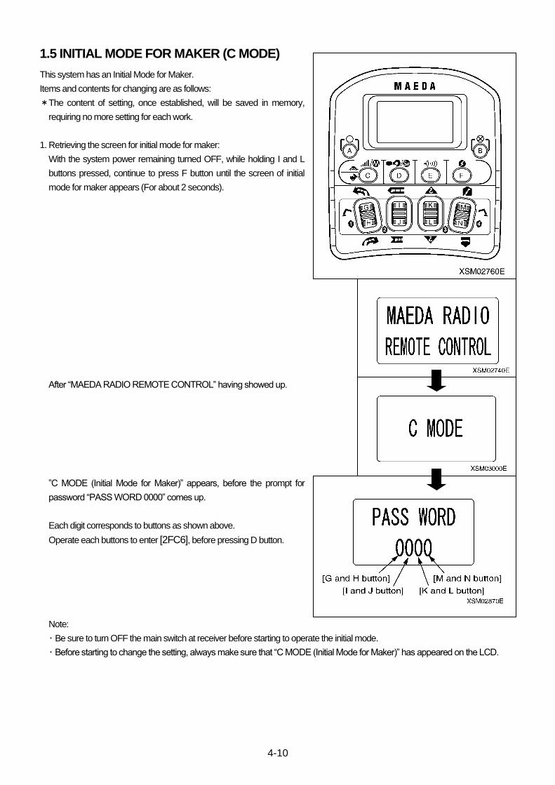
4-10
1.5 INITIAL MODE FOR MAKER (C MODE)
This system has an Initial Mode for Maker.
Items and contents for changing are as follows:
*The content of setting, once established, will be saved in memory,
requiring no more setting for each work.
1. Retrieving the screen for initial mode for maker:
With the system power remaining turned OFF, while holding I and L
buttons pressed, continue to press F button until the screen of initial
mode for maker appears (For about 2 seconds).
After “MAEDA RADIO REMOTE CONTROL” having showed up.
”C MODE (Initial Mode for Maker)” appears, before the prompt for
password “PASS WORD 0000” comes up.
Each digit corresponds to buttons as shown above.
Operate each buttons to enter [2FC6], before pressing D button.
Note:
・ Be sure to turn OFF the main switch at receiver before starting to operate the initial mode.
・ Before starting to change the setting, always make sure that “C MODE (Initial Mode for Maker)” has appeared on the LCD.
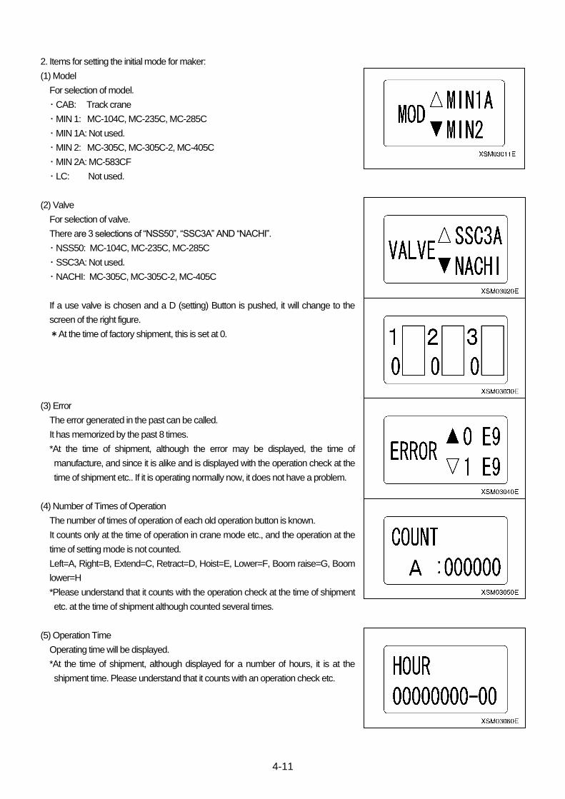
4-11
2. Items for setting the initial mode for maker:
(1) Model
For selection of model.
・ CAB: Track crane
・ MIN 1: MC-104C, MC-235C, MC-285C
・ MIN 1A: Not used.
・ MIN 2: MC-305C, MC-305C-2, MC-405C
・ MIN 2A: MC-583CF
・ LC: Not used.
(2) Valve
For selection of valve.
There are 3 selections of “NSS50”, “SSC3A” AND “NACHI”.
・ NSS50: MC-104C, MC-235C, MC-285C
・ SSC3A: Not used.
・ NACHI: MC-305C, MC-305C-2, MC-405C
If a use valve is chosen and a D (setting) Button is pushed, it will change to the
screen of the right figure.
*At the time of factory shipment, this is set at 0.
(3) Error
The error generated in the past can be called.
It has memorized by the past 8 times.
*At the time of shipment, although the error may be displayed, the time of
manufacture, and since it is alike and is displayed with the operation check at the
time of shipment etc.. If it is operating normally now, it does not have a problem.
(4) Number of Times of Operation
The number of times of operation of each old operation button is known.
It counts only at the time of operation in crane mode etc., and the operation at the
time of setting mode is not counted.
Left=A, Right=B, Extend=C, Retract=D, Hoist=E, Lower=F, Boom raise=G, Boom
lower=H
*Please understand that it counts with the operation check at the time of shipment
etc. at the time of shipment although counted several times.
(5) Operation Time
Operating time will be displayed.
*At the time of shipment, although displayed for a number of hours, it is at the
shipment time. Please understand that it counts with an operation check etc.
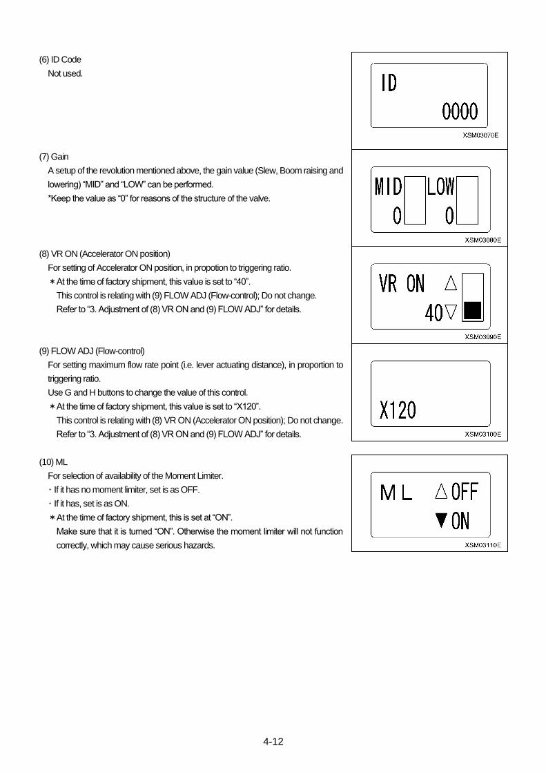
4-12
(6) ID Code
Not used.
(7) Gain
A setup of the revolution mentioned above, the gain value (Slew, Boom raising and
lowering) “MID” and “LOW” can be performed.
*Keep the value as “0” for reasons of the structure of the valve.
(8) VR ON (Accelerator ON position)
For setting of Accelerator ON position, in propotion to triggering ratio.
*At the time of factory shipment, this value is set to “40”.
This control is relating with (9) FLOW ADJ (Flow-control); Do not change.
Refer to “3. Adjustment of (8) VR ON and (9) FLOW ADJ” for details.
(9) FLOW ADJ (Flow-control)
For setting maximum flow rate point (i.e. lever actuating distance), in proportion to
triggering ratio.
Use G and H buttons to change the value of this control.
*At the time of factory shipment, this value is set to “X120”.
This control is relating with (8) VR ON (Accelerator ON position); Do not change.
Refer to “3. Adjustment of (8) VR ON and (9) FLOW ADJ” for details.
(10) ML
For selection of availability of the Moment Limiter.
・ If it has no moment limiter, set is as OFF.
・ If it has, set is as ON.
*At the time of factory shipment, this is set at “ON”.
Make sure that it is turned “ON”. Otherwise the moment limiter will not function
correctly, which may cause serious hazards.
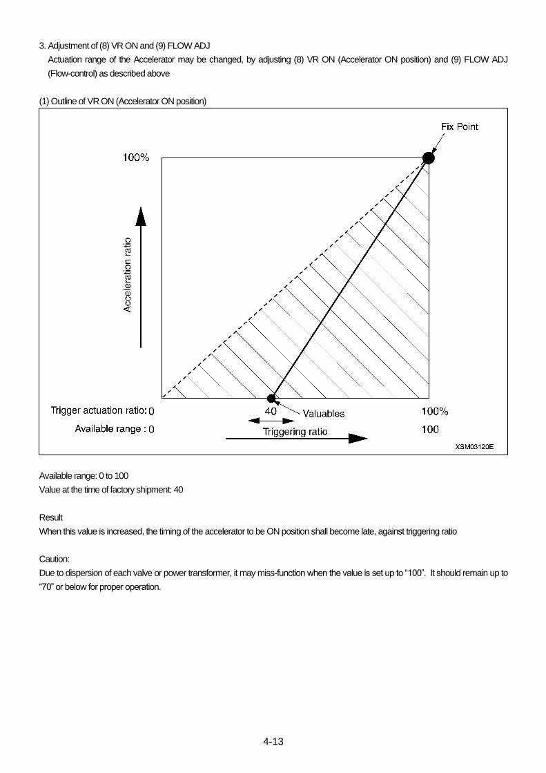
4-13
3. Adjustment of (8) VR ON and (9) FLOW ADJ
Actuation range of the Accelerator may be changed, by adjusting (8) VR ON (Accelerator ON position) and (9) FLOW ADJ
(Flow-control) as described above
(1) Outline of VR ON (Accelerator ON position)
Available range: 0 to 100
Value at the time of factory shipment: 40
Result
When this value is increased, the timing of the accelerator to be ON position shall become late, against triggering ratio
Caution:
Due to dispersion of each valve or power transformer, it may miss-function when the value is set up to “100”. It should remain up to
“70” or below for proper operation.
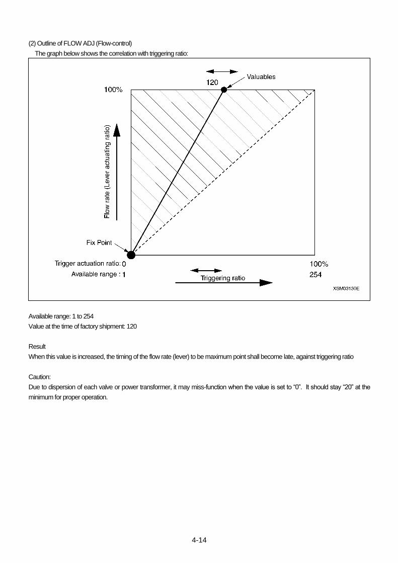
4-14
(2) Outline of FLOW ADJ (Flow-control)
The graph below shows the correlation with triggering ratio:
Available range: 1 to 254
Value at the time of factory shipment: 120
Result
When this value is increased, the timing of the flow rate (lever) to be maximum point shall become late, against triggering ratio
Caution:
Due to dispersion of each valve or power transformer, it may miss-function when the value is set to “0”. It should stay “20” at the
minimum for proper operation.

4-15
(3) Adjustment of VR ON (Accelerator ON position) and FLOW ADJ (Flow-control) standard setting
The graph below shows the correlation with triggering ratio:
Comment:
At first, when it is started triggered, only the flow rate (lever actuating ratio) increases. Just before the flow rate (lever actuating ratio)
reaches its maximum point, the accelerator is started to be ON. This improves manipulability in Micro Speed mode which allows
smooth acceleration up to the maximum speed.
It is not advisable that users change this value, since manipulability may become poor when the balance is lost by changing it.
Advise:
1. In case that VR ON (Accelerator ON position) is set to “0”, the crane speed is picked up in proportion to engine rev, which results
poor manipulability.
2. In general, response of the engine by accelerator is poor in comparison to triggering ratio. This causes tendency of inferior
manipulability in Micro Speed mode. Thus, when it is started triggered, manipulability in Micro Speed mode improves when the
pick up of accelerating is set slower.
3. In case that lapping margin, of Note 1:) in the graph, is not secured, VR ON (Accelerator ON position) and FLOW ADJ
(Flow-control) may generate a certain range where the speed shall not be controlled even when the triggering ratio increases.

4-16
1.6 INITIAL MODE SETTING (For interactive remote controller)
*High-light in “Selective Modes and Values” are the initial values.
Mode Setting Items Selective Modes and
Values Remarks
A MODE (For User)
LCD Contrast Optimum For indoors operation
Voice Volume
OFF
1
2
3
4
MAX
Accelerator 100% Bar chart indicator
Light
OFF
1S
3S
5S
OFF Timer
5M
10M
15M
Idle Up 0% Bar chart indicator
Reset Micro Speed
N
Y
VERSION Version V. 3. 41B
JUL 24 2007
B MODE (For Service)
PTN Pattern STD
OPT
Slewing
HI
MID
LOW
Derrick
HI
MID
LOW
Hook Stowing ON
OFF
LS Over Hoist Limit Switch ON
OFF
VALVE INIT Valve Initial Neutral Setting Mode
SERIAL Serial Number Indication, only
ID ID Code 0000 Indication, only
LANG Language JP
EN
US Denomination Y
N

4-17
*High-light in “Selective Modes and Values” are the initial values.
Mode Setting Items Selective Modes and
Values Remarks
C MODE (For Maker)
MOD Model
CAB
MIN1
MIN1A
LC
MIN2
MIN2A
VALVE Valve
NSS50 Micro Speed:1→0 This value is not effective.
2→0 3→0
SSC3A
NACHI
ERROR Error Indication, only
COUNT Operation Time Number Indication, only
HOUR Operation Time Indication, only
ID ID Code 0000 Indication, only
GAIN Gain MID: 0
LOW: 0
VR ON Accelerator ON Position 40
FLOW ADJ Flow-control X120
ML Moment Limiter OFF
ON
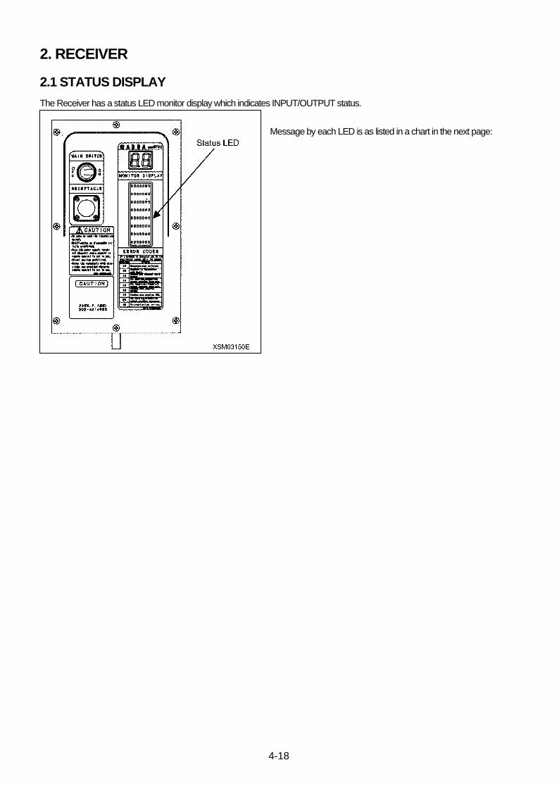
4-18
2. RECEIVER
2.1 STATUS DISPLAY
The Receiver has a status LED monitor display which indicates INPUT/OUTPUT status.
Message by each LED is as listed in a chart in the next page:

4-19
Chart 1
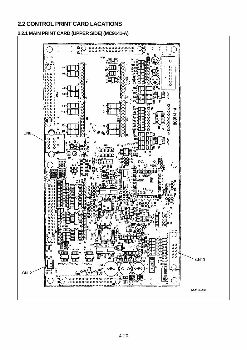
4-20
2.2 CONTROL PRINT CARD LACATIONS
2.2.1 MAIN PRINT CARD (UPPER SIDE) (MC9141-A)
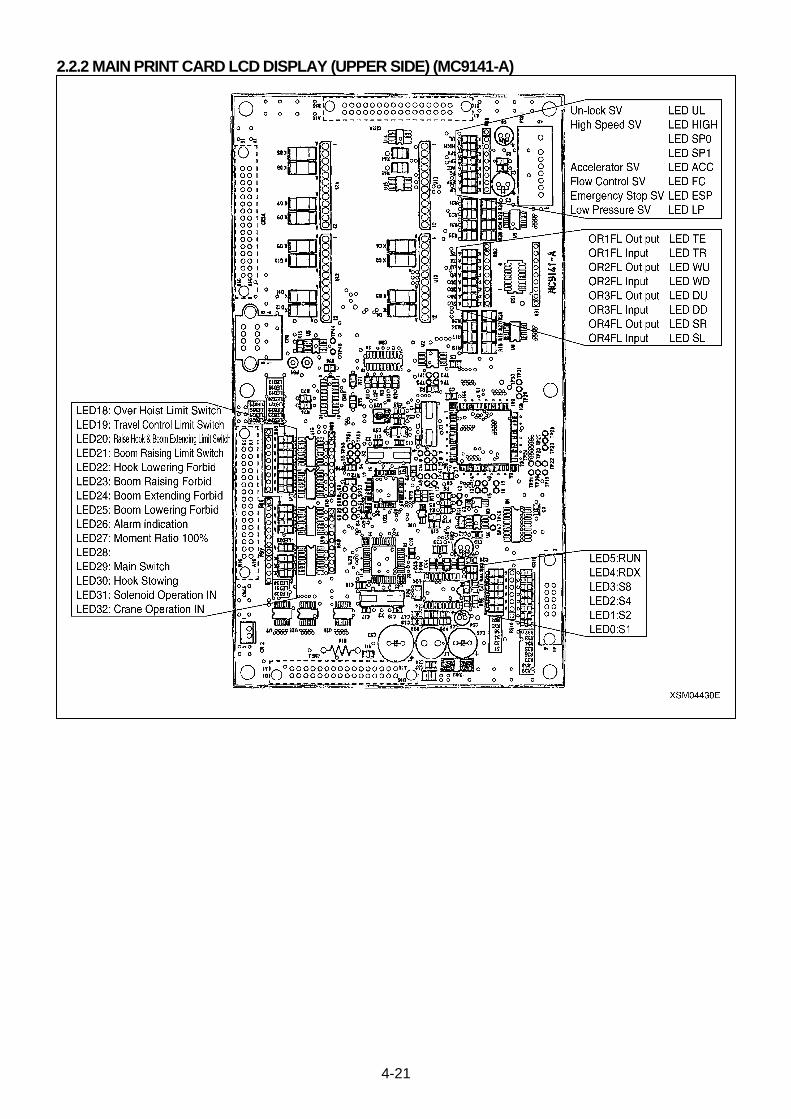
4-21
2.2.2 MAIN PRINT CARD LCD DISPLAY (UPPER SIDE) (MC9141-A)
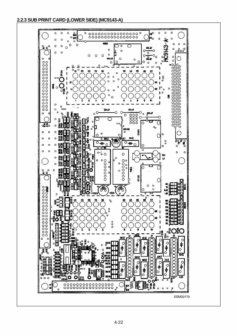
4-22
2.2.3 SUB PRINT CARD (LOWER SIDE) (MC9143-A)
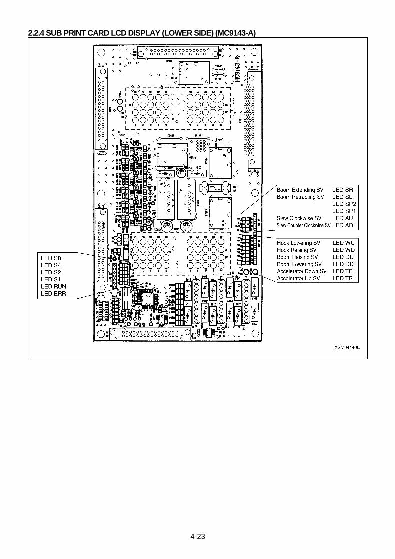
4-23
2.2.4 SUB PRINT CARD LCD DISPLAY (LOWER SIDE) (MC9143-A)
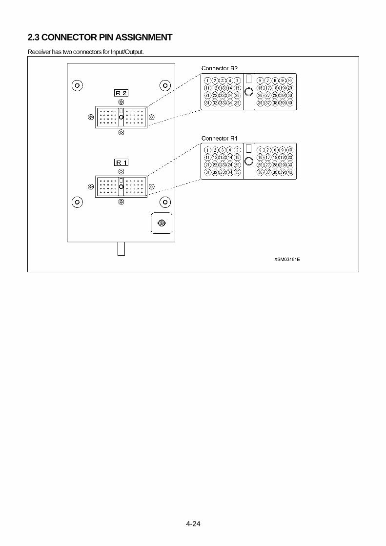
4-24
2.3 CONNECTOR PIN ASSIGNMENT
Receiver has two connectors for Input/Output.

4-25
1. CONNECTOR R1
Pin Description Pin Description
1 Emergency Stop 21
2 22 Right Slewing
3 23 Left Slewing
4 SV GND 24 OR Stowing
5 GND 25 OR Setting
6 +12V 26 Boom Raising
7 Sol. Operation IN 27 Boom Lowering
8 Sol. Operation (Travel OFF) 28 Boom Lower output
9 Engine Start 29 Boom Raising output
10 Engine Stop 30 Horn
11 Low Pressure SV 31 OR1 OUT
12 RS422 A 32 OR1 IN
13 RS422 B 33 OR2 OUT
14 34 OR2 IN
15 Communicate 35 OR3 OUT
16 Moment Ratio 100% 36 OR3 IN
17 Over Un-winding 37 OR4 OUT
18 Extend 38 OR4 IN
19 39 Speaker
20 Over Hoist Limit Switch 40 GND
2. CONNECTOR R2
Pin Description Pin Description
1 ACC Sol. 21 Derrick Differential transformer
2 ACC Sol. 22 Differential transformer
3 Boom Raising Sol. 23 Differential transformer
4 Boom Lowering Sol. 24 Telescopic Differential transformer
5 Sol. GND 25 Differential transformer
6 Sol. GND 26 Differential transformer
7 Boom Extend Sol. 27 Slewing Differential transformer
8 Boom Retract Sol. 28 Differential transformer
9 Rise Hook Sol. 29 Differential transformer
10 Lower Hook Sol. 30 Right Sol.
11 Differential transformer・P5VP 31 OR Select 1
12 Differential transformer・P5VE 32 OR Select 2
13 ACC Differential transformer 33 OR Select 3
14 Differential transformer 34 OR Select 4
15 Differential transformer 35 Crane Mode In
16 Rise Hook Differential transformer 36 Hook Stowing In
17 Differential transformer 37 Sol. Operation In
18 Differential transformer 38 Hook Stowing Output
19 Lever Operation Output 39 Crane High Speed Output
20 Left Sol. 40 Buzzer
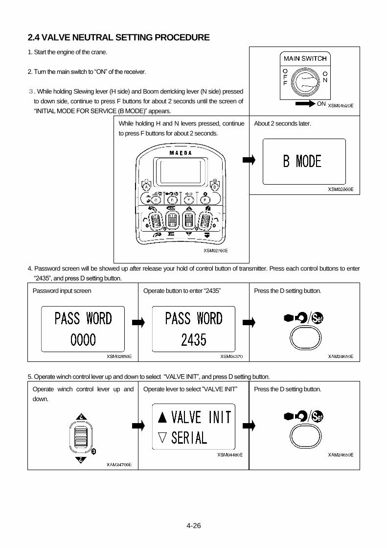
4-26
2.4 VALVE NEUTRAL SETTING PROCEDURE
1. Start the engine of the crane.
2. Turn the main switch to “ON” of the receiver.
3. While holding Slewing lever (H side) and Boom derricking lever (N side) pressed
to down side, continue to press F buttons for about 2 seconds until the screen of
“INITIAL MODE FOR SERVICE (B MODE)” appears.
4. Password screen will be showed up after release your hold of control button of transmitter. Press each control buttons to enter
“2435”, and press D setting button.
5. Operate winch control lever up and down to select “VALVE INIT”, and press D setting button.
Press the D setting button.
Press the D setting button.
While holding H and N levers pressed, continue
to press F buttons for about 2 seconds.
About 2 seconds later.
Operate button to enter “2435”
Password input screen
Operate winch control lever up and
down.
Operate lever to select ”VALVE INIT”
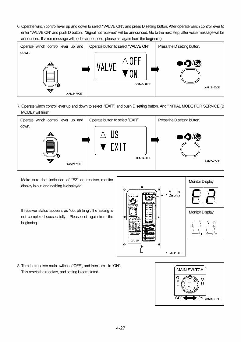
4-27
6. Operate winch control lever up and down to select “VALVE ON”, and press D setting button. After operate winch control lever to
enter “VALVE ON” and push D button, “Signal not received” will be announced. Go to the next step, after voice message will be
announced. If voice message will not be announced, please set again from the beginning.
7. Operate winch control lever up and down to select “EXIT”, and push D setting button. And “INITIAL MODE FOR SERVICE (B
MODE)” will finish.
Make sure that indication of “E2” on receiver monitor
display is out, and nothing is displayed.
If receiver status appears as “dot blinking”, the setting is
not completed successfully. Please set again from the
beginning.
8. Turn the receiver main switch to “OFF”, and then turn it to “ON”.
This resets the receiver, and setting is completed.
Operate winch control lever up and
down.
Operate winch control lever up and
down.
Press the D setting button.
Press the D setting button.
Operate button to select “VALVE ON”
Operate button to select ”EXIT”
Monitor Display
Monitor Display

4-28
2.5 MONITOR DISPLAY MESSAGE
2.5.1 NORMAL OPERATION MESSAGE
[1] Receive status
Display Code Details
Receiving (A dot blinks alternately)
[2] Function display
Display Code Details
Boom extending
Boom retracting
Winch hoisting
Winch un-hoisting
Boom raising
Boom lowering
Boom slewing counter-clockwise
Boom slewing clockwise
Over-hoisted *No indication if over-hoisted from the start. Indication appears when
over-hoisted after released once.
Hook stowing
2.5.2 ERROR MESSAGE
Error Code Details
Emergency stop
Signal receiving error
Breaking of wire within transmitter
Volume position error at resetting
EEPROM error
CPU error
Switch position error at starting-up
ML communication error
Breaking of wire for telescopic control
Breaking of wire for hoisting control
Breaking of wire for derricking control
Breaking of wire for slewing control
Breaking of wire for accelerator
Valve neutral error
d 6

4-29
2.6 FUSE IN THE RECEIVER
CAUTION • For any tests or replacement of a fuse, always turn OFF the Main switch of the Control box, before removing it. • The fuse must be replaced with the same type of grass tube fuses, and of the same rating.
CAUTION A fuse is inserted in the (+) line of the main power supply of the Receiver as a protective circuit of internal devices and prevents circuits from burnt. • A grass tube fuse is employed. In the event where the fuse is corroded and shows white rust, or when a loose condition is recognized, always replace it with a new one.
• When the fuse is blown, never fail to examine the circuit for the cause and repair it before replace the fuse. • The fuse must be replaced with the same type of grass tube fuses, and of the same rating.
The fuse is placed inside the Receiver.
Test and replacement of the fuse shall be practiced as follows:
• Use the following hand tools:
• A screw driver (Philips)
• Jewelers screw driver set (Slotted)
• General hand tools, used to detach the cover of the control box.
[1] REMOVAL OF THE FUSE
1. Detach the cover (1), (2) of the Control box so that the cover of the Receiver can be
detached.
2. Unfasten eight of screws (4) and take away the cover of the Receiver (3).
3. Extract three of connectors (6) in the first PCB (5).
4. Unfasten six of screws (7) and remove the first PCB (5).
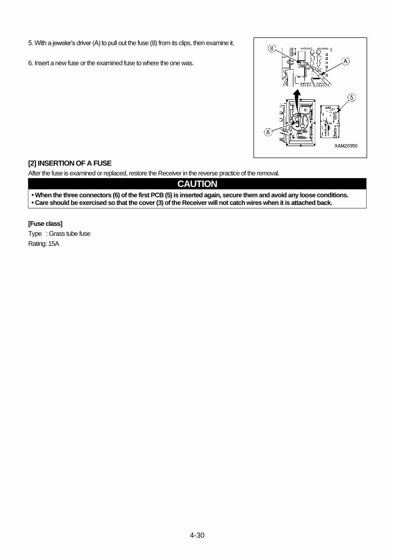
4-30
5. With a jeweler’s driver (A) to pull out the fuse (8) from its clips, then examine it.
6. Insert a new fuse or the examined fuse to where the one was.
[2] INSERTION OF A FUSE
After the fuse is examined or replaced, restore the Receiver in the reverse practice of the removal.
CAUTION • When the three connectors (6) of the first PCB (5) is inserted again, secure them and avoid any loose conditions. • Care should be exercised so that the cover (3) of the Receiver will not catch wires when it is attached back.
[Fuse class]
Type : Grass tube fuse
Rating: 15A
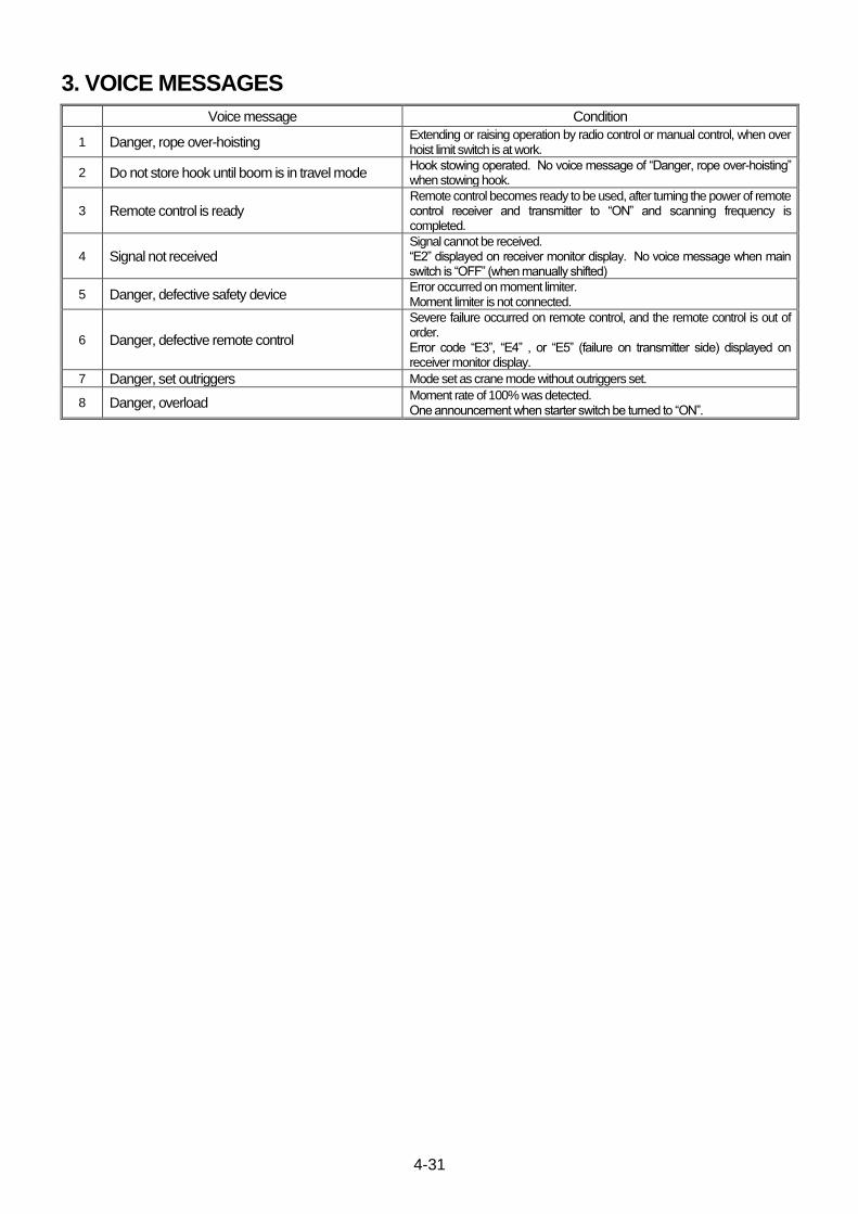
4-31
3. VOICE MESSAGES
Voice message Condition
1 Danger, rope over-hoisting Extending or raising operation by radio control or manual control, when over hoist limit switch is at work.
2 Do not store hook until boom is in travel mode Hook stowing operated. No voice message of “Danger, rope over-hoisting” when stowing hook.
3 Remote control is ready
Remote control becomes ready to be used, after turning the power of remote control receiver and transmitter to “ON” and scanning frequency is completed.
4 Signal not received
Signal cannot be received. “E2” displayed on receiver monitor display. No voice message when main switch is “OFF” (when manually shifted)
5 Danger, defective safety device Error occurred on moment limiter. Moment limiter is not connected.
6 Danger, defective remote control
Severe failure occurred on remote control, and the remote control is out of order. Error code “E3”, “E4” , or “E5” (failure on transmitter side) displayed on receiver monitor display.
7 Danger, set outriggers Mode set as crane mode without outriggers set.
8 Danger, overload Moment rate of 100% was detected. One announcement when starter switch be turned to “ON”.
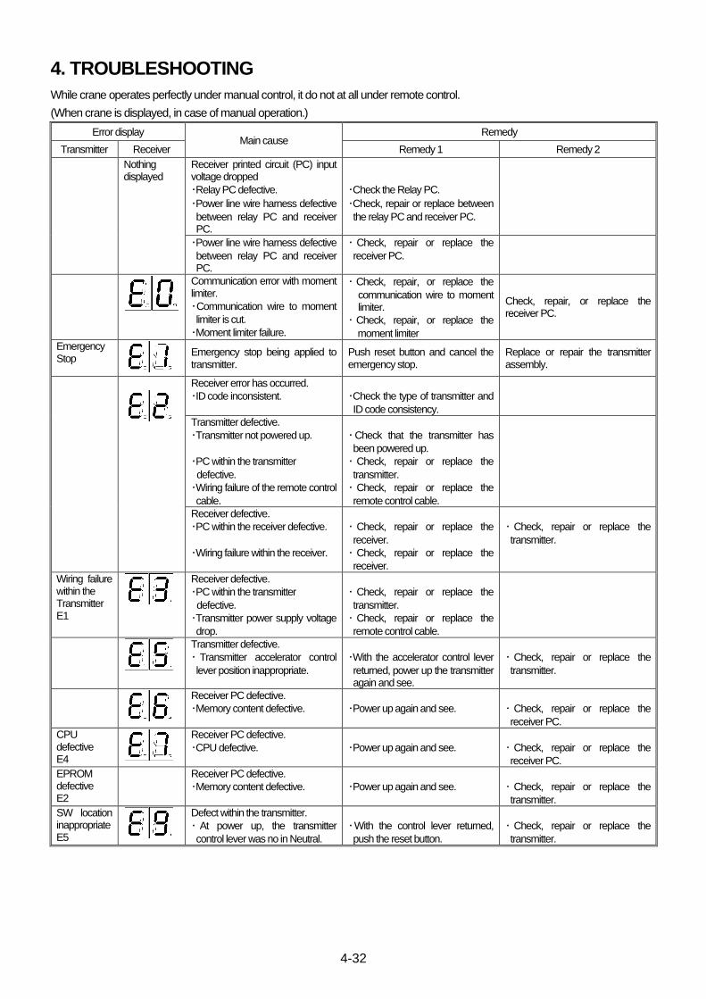
4-32
4. TROUBLESHOOTING
While crane operates perfectly under manual control, it do not at all under remote control.
(When crane is displayed, in case of manual operation.)
Error display Main cause
Remedy
Transmitter Receiver Remedy 1 Remedy 2
Nothing displayed
Receiver printed circuit (PC) input voltage dropped
・Relay PC defective.
・Power line wire harness defective
between relay PC and receiver PC.
・Check the Relay PC.
・Check, repair or replace between
the relay PC and receiver PC.
・Power line wire harness defective
between relay PC and receiver PC.
・ Check, repair or replace the
receiver PC.
Communication error with moment limiter.
・Communication wire to moment
limiter is cut.
・Moment limiter failure.
・ Check, repair, or replace the
communication wire to moment limiter.
・ Check, repair, or replace the
moment limiter
Check, repair, or replace the receiver PC.
Emergency Stop
Emergency stop being applied to transmitter.
Push reset button and cancel the emergency stop.
Replace or repair the transmitter assembly.
Receiver error has occurred.
・ID code inconsistent.
・Check the type of transmitter and
ID code consistency.
Transmitter defective.
・Transmitter not powered up.
・PC within the transmitter
defective.
・Wiring failure of the remote control
cable.
・Check that the transmitter has
been powered up.
・ Check, repair or replace the
transmitter.
・ Check, repair or replace the
remote control cable.
Receiver defective.
・PC within the receiver defective.
・Wiring failure within the receiver.
・ Check, repair or replace the
receiver.
・ Check, repair or replace the
receiver.
・ Check, repair or replace the
transmitter.
Wiring failure within the Transmitter E1
Receiver defective.
・PC within the transmitter
defective.
・Transmitter power supply voltage
drop.
・ Check, repair or replace the
transmitter.
・ Check, repair or replace the
remote control cable.
Transmitter defective.
・ Transmitter accelerator control
lever position inappropriate.
・With the accelerator control lever
returned, power up the transmitter again and see.
・ Check, repair or replace the
transmitter.
Receiver PC defective.
・Memory content defective.
・Power up again and see.
・ Check, repair or replace the
receiver PC.
CPU defective E4
Receiver PC defective.
・CPU defective.
・Power up again and see.
・ Check, repair or replace the
receiver PC.
EPROM defective E2
Receiver PC defective.
・Memory content defective.
・Power up again and see.
・ Check, repair or replace the
transmitter.
SW location inappropriate E5
Defect within the transmitter.
・ At power up, the transmitter
control lever was no in Neutral.
・With the control lever returned,
push the reset button.
・ Check, repair or replace the
transmitter.
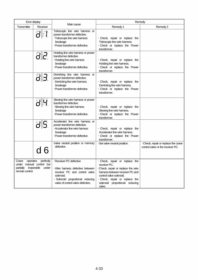
4-33
Error display Main cause
Remedy
Transmitter Receiver Remedy 1 Remedy 2
Telescopic line wire harness or power transformer defective.
・Telescopic line wire harness
breakage
・Power transformer defective.
・ Check, repair or replace the
Telescopic line wire harness.
・ Check or replace the Power
transformer.
Hoisting line wire harness or power transformer defective.
・Hoisting line wire harness
breakage
・Power transformer defective.
・ Check, repair or replace the
Hoisting line wire harness.
・ Check or replace the Power
transformer.
Derricking line wire harness or power transformer defective.
・Derricking line wire harness
breakage
・Power transformer defective.
・ Check, repair or replace the
Derricking line wire harness.
・ Check or replace the Power
transformer.
Slewing line wire harness or power transformer defective.
・Slewing line wire harness
breakage
・Power transformer defective.
・ Check, repair or replace the
Slewing line wire harness.
・ Check or replace the Power
transformer.
Accelerator line wire harness or power transformer defective.
・Accelerator line wire harness
breakage
・Power transformer defective.
・ Check, repair or replace the
Accelerator line wire harness.
・ Check or replace the Power
transformer.
d 6 Valve neutral position or memory defective.
・Set valve neutral position. ・Check, repair or replace the crane
control valve or the receiver PC.
Crane operates perfectly under manual control but partially inoperable under remote control.
・Receiver PC defective
・Wire harness defective between
receiver PC and control valve solenoid.
・ Solenoid proportional reducing
valve of control valve defective.
・ Check, repair or replace the
receiver PC.
・Check, repair or replace the wire
harness between receiver PC and control valve solenoid.
・ Check, repair or replace the
solenoid proportional reducing valve.

4-34
This Page Intentionally Left Blank.

5-1
ELECTRIC MOTOR
1. ELECTRIC MOTOR 5-2
2. INVERTER PANEL 5-3
2.1 STRUCTURAL DRAWING 5-4
2.2 EXTERNAL APPEARANCE AND NAME OF EACH SECTION 5-6
2.3 NAME AND CONTENT OF THE DIGITAL OPERATOR 5-7
2.4 DETAIL OF INVERTER SET ITEMS 5-9
2.5 ALARM DISPLAY AND COUNTERMEASURE 5-10
2.6 LIST OF ALARM CODES 5-12
2.7 TROUBLESHOOTING 5-16
2.8 INSPECTION AND MAINTENANCE 5-22
2.9 DISPOSAL OF THE INVERTER 5-25
3. POWER SUPPLY BOX 5-26
4. ELECTRIC CIRCUIT DIAGRAM 5-28

5-2
1. ELECTRIC MOTOR
(1) Power unit
(2) Electric motor
(3) Coupling
(4) Hydraulic pump
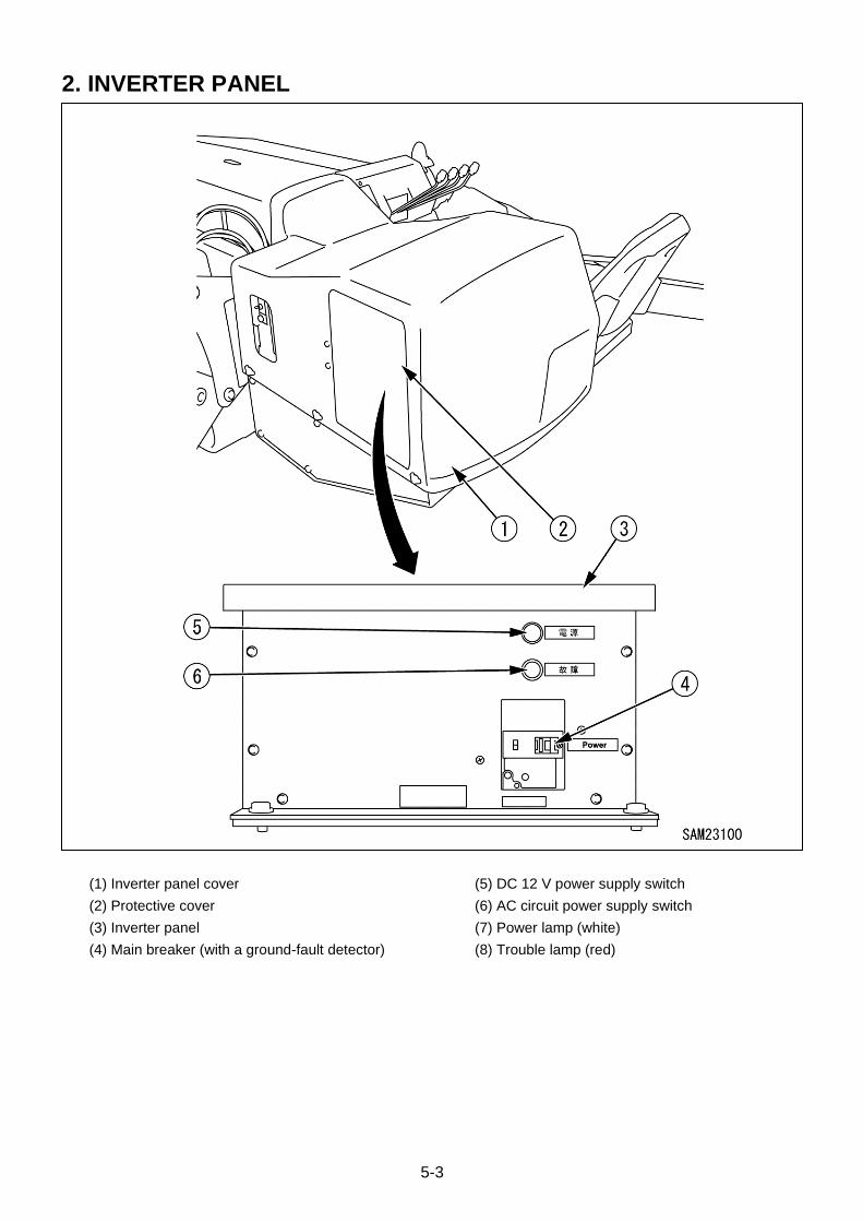
5-3
2. INVERTER PANEL
(1) Inverter panel cover
(2) Protective cover
(3) Inverter panel
(4) Main breaker (with a ground-fault detector)
(5) DC 12 V power supply switch
(6) AC circuit power supply switch
(7) Power lamp (white)
(8) Trouble lamp (red)
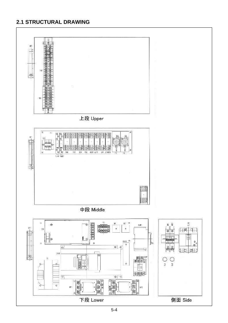
5-4
2.1 STRUCTURAL DRAWING

5-5
Symbol Name Number Part number Type
INV1 Inverter 1 3G3MX2-A4075-V1
ELB1 Ground-fault breaker Terminal cover
1 1
EW50EAG-3P030K BW9BTAA-S3W
CP1 Miniature breaker 1 FAZ-D2/1-RT
CP2 Miniature breaker 1 FAZ-D15/1-RT
T1 Step-down transformer 1 STNO.4 S003 D06621 BB
52HP Electromagnetic contactor 1 SC-4-1/T AC200V 1a
CF1 AC fan Aluminium screen filter High tension cord
1 1 1
B87F-A4A13HP B87F-FL120S R87F-PC
NF1 Noise filter 1 TAH-30-683
NF2 Noise filter 1 TAC-30-683
RNF1 Radio noise filter 1 3G3AZ-ZCL2
CNF1,CNF2 Clamp filter 2 E04SRS251512
PS1 AC/DC power supply 1 PLA300F-15-C
D1,D2 Bridge diode 2 S25VB60
D3,D4 Diode 2 DIN60
30X,PSX421V, EX1,Y1,STARTX
Relay Socket Retainer
6 6 6
MY2 DC12 PYF08A-E PYC-A1
Y00,Y01,Y02 Relay Socket Retainer
3 3 3
MY4 DC12 PYF14A-E PYC-A1
TLR1 Timer Front connection socket
1 1
H3RN-1 DC12 P2RF-05-E
TLR2 Timer Front connection socket
1 1
H3RN-11 DC12 P2RF-05-E
Y0 Power relay W metal fittings
1 1
G7L-2A2B-B DC12 R99-04 FOR G5F
F1,F2 End contact fuse Live part protective cover Fuse-link (spare, attached)
2 2 2
AFaC-5 CG-30 BLA005
SL1 Display lamp 1 AH165-ZMWB2
SL2 Display lamp 1 AH165-ZMRB2
TB1 Terminal block Side plate Signature plate
1 2 1
FP-40 8P FP-2E AM-10
89 mm
TB2 Terminal block Side plate Signature plate
1 2 1
FPS-20 21P FPS-1E AM-10
168 mm
TB3 Terminal block 1 EFPM2003
YUBE1 Sealed tube E06A020 0.2 m
DIN rail (terminal block) 1 C-DINR315-0 315 mm
DIN rail (breaker) 1 C-DINR 70-0 70 mm
Terminal block fastening plate
2 GTY18
Spacing tube (relay fixing plate)
5 ASB-480E
Spacing tube (terminal block) 1 ASB-4130E
Spacing tube (terminal block) 1 ASB-448E
Spacing tube (breaker) 2 ASB-460E
Acrylic name plate 2 Power 40 × 10 mm t = 2 mm
Acrylic name plate 1 Trouble 40 × 10 mm t = 2 mm
Acrylic name plate 1 AC Circuit 40 × 10 mm t = 2 mm
Acrylic name plate 1 DC 12 V 40 × 10 mm t = 2 mm
Warning label 1 PA002M
Earth label 1 GR1-L08

5-6
2.2 EXTERNAL APPEARANCE AND NAME OF EACH SECTION
3G3MX2-A4055-V1
(1) Cooling fan cover
(2) Cooling fan
(3) Cooling fin
(4) Main unit case
(5) Terminal block cover
(6) Option cover
(7) Electric wire drawer panel
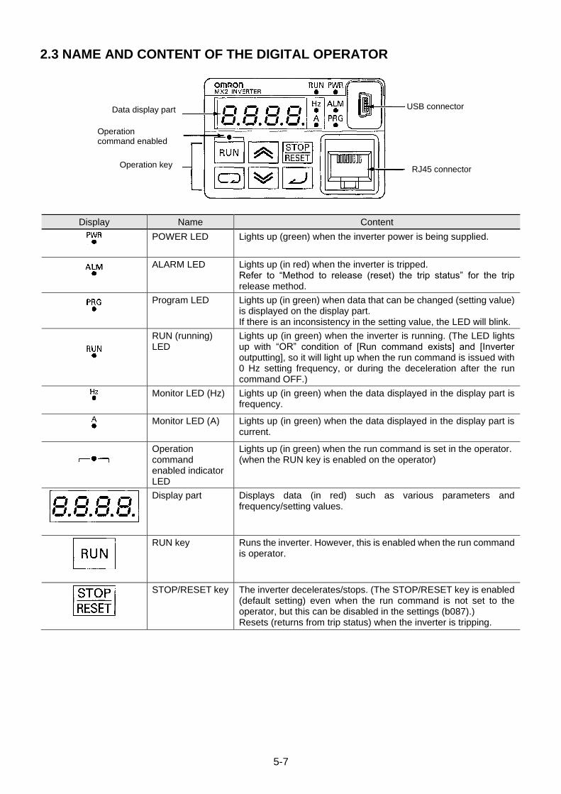
5-7
2.3 NAME AND CONTENT OF THE DIGITAL OPERATOR
Display Name Content
POWER LED Lights up (green) when the inverter power is being supplied.
ALARM LED Lights up (in red) when the inverter is tripped. Refer to “Method to release (reset) the trip status” for the trip release method.
Program LED Lights up (in green) when data that can be changed (setting value) is displayed on the display part. If there is an inconsistency in the setting value, the LED will blink.
RUN (running) LED
Lights up (in green) when the inverter is running. (The LED lights up with “OR” condition of [Run command exists] and [Inverter outputting], so it will light up when the run command is issued with 0 Hz setting frequency, or during the deceleration after the run command OFF.)
Monitor LED (Hz) Lights up (in green) when the data displayed in the display part is frequency.
Monitor LED (A) Lights up (in green) when the data displayed in the display part is current.
Operation command enabled indicator LED
Lights up (in green) when the run command is set in the operator. (when the RUN key is enabled on the operator)
Display part Displays data (in red) such as various parameters and frequency/setting values.
RUN key Runs the inverter. However, this is enabled when the run command is operator.
STOP/RESET key The inverter decelerates/stops. (The STOP/RESET key is enabled (default setting) even when the run command is not set to the operator, but this can be disabled in the settings (b087).) Resets (returns from trip status) when the inverter is tripping.
Data display part
Operation command enabled indicator LED Operation key
USB connector
RJ45 connector
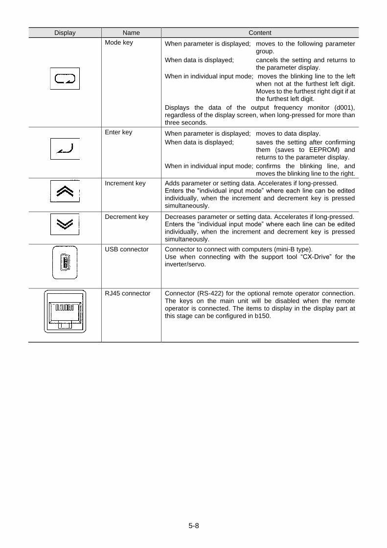
5-8
Display Name Content
Mode key When parameter is displayed; moves to the following parameter group.
When data is displayed; cancels the setting and returns to the parameter display.
When in individual input mode; moves the blinking line to the left when not at the furthest left digit. Moves to the furthest right digit if at the furthest left digit.
Displays the data of the output frequency monitor (d001), regardless of the display screen, when long-pressed for more than three seconds.
Enter key When parameter is displayed; moves to data display.
When data is displayed; saves the setting after confirming them (saves to EEPROM) and returns to the parameter display.
When in individual input mode; confirms the blinking line, and moves the blinking line to the right.
Increment key Adds parameter or setting data. Accelerates if long-pressed. Enters the "individual input mode” where each line can be edited individually, when the increment and decrement key is pressed simultaneously.
Decrement key Decreases parameter or setting data. Accelerates if long-pressed. Enters the “individual input mode” where each line can be edited individually, when the increment and decrement key is pressed simultaneously.
USB connector Connector to connect with computers (mini-B type). Use when connecting with the support tool “CX-Drive” for the inverter/servo.
RJ45 connector Connector (RS-422) for the optional remote operator connection. The keys on the main unit will be disabled when the remote operator is connected. The items to display in the display part at this stage can be configured in b150.
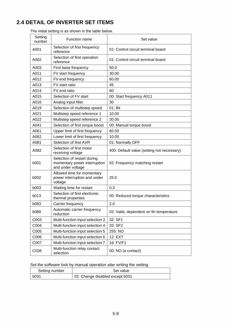
5-9
2.4 DETAIL OF INVERTER SET ITEMS
The initial setting is as shown in the table below.
Setting number
Function name Set value
A001 Selection of first frequency reference
01: Control circuit terminal board
A002 Selection of first operation reference
01: Control circuit terminal board
A003 First base frequency 50.0
A011 FV start frequency 30.00
A012 FV end frequency 60.00
A013 FV start ratio 45
A014 FV end ratio 60
A015 Selection of FV start 00: Start frequency A011
A016 Analog input filter 30
A019 Selection of multistep speed 01: Bit
A021 Multistep speed reference 1 10.00
A022 Multistep speed reference 2 30.00
A041 Selection of first torque boost 00: Manual torque boost
A061 Upper limit of first frequency 60.00
A062 Lower limit of first frequency 10.00
A081 Selection of first AVR 01: Normally OFF
A082 Selection of first motor receiving voltage
400: Default value (setting not necessary)
b001 Selection of restart during momentary power interruption and under voltage
02: Frequency matching restart
b002 Allowed time for momentary power interruption and under voltage
25.0
b003 Waiting time for restart 0.3
b013 Selection of first electronic thermal properties
00: Reduced torque characteristics
b083 Carrier frequency 2.0
b089 Automatic carrier frequency reduction
02: Valid, dependent on fin temperature
C003 Multi-function input selection 3 32: SF1
C004 Multi-function input selection 4 33: SF2
C005 Multi-function input selection 5 255: NO
C006 Multi-function input selection 6 12: EXT
C007 Multi-function input selection 7 16: FV/F1
C036 Multi-function relay contact selection
00: NO (a contact)
Set the software lock by manual operation after writing the setting.
Setting number Set value
b031 02: Change disabled except b031
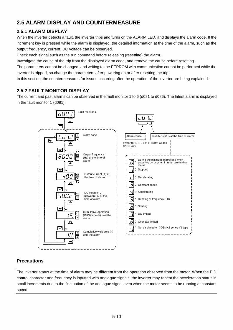
5-10
2.5 ALARM DISPLAY AND COUNTERMEASURE
2.5.1 ALARM DISPLAY
When the inverter detects a fault, the inverter trips and turns on the ALARM LED, and displays the alarm code. If the
increment key is pressed while the alarm is displayed, the detailed information at the time of the alarm, such as the
output frequency, current, DC voltage can be observed.
Check each signal such as the run command before releasing (resetting) the alarm.
Investigate the cause of the trip from the displayed alarm code, and remove the cause before resetting.
The parameters cannot be changed, and writing to the EEPROM with communication cannot be performed while the
inverter is tripped, so change the parameters after powering on or after resetting the trip.
In this section, the countermeasures for issues occurring after the operation of the inverter are being explained.
2.5.2 FAULT MONITOR DISPLAY
The current and past alarms can be observed in the fault monitor 1 to 6 (d081 to d086). The latest alarm is displayed
in the fault monitor 1 (d081).
Precautions
The inverter status at the time of alarm may be different from the operation observed from the motor. When the PID
control character and frequency is inputted with analogue signals, the inverter may repeat the acceleration status in
small increments due to the fluctuation of the analogue signal even when the motor seems to be running at constant
speed.
Fault monitor 1
Alarm code
Output frequency (Hz) at the time of alarm
Output current (A) at the time of alarm
DC voltage (V) between PN at the time of alarm
Cumulative operation (RUN) time (h) until the alarm
Cumulative weld time (h) until the alarm
Alarm cause Inverter status at the time of alarm
During the initialization process when powering on or when in reset terminal on status
Stopped
Decelerating
Constant speed
Accelerating
Running at frequency 0 Hz
Starting
DC limited
Overload limited
Not displayed on 3G3MX2 series V1 type
(“refer to 10-1-2 List of Alarm Codes (P. 10-4)”)

5-11
2.5.3 METHOD FOR RELEASING (RESETTING) THE TRIP STATUS
The following two methods exist for resetting the trip status of the inverter.
• Pressing the STOP/RESET key on the digital operator.
The trip status can be reset if “00: enable” or “02: enable only reset” is set for the stop key selection (b087).
• Enter reset input from the control circuit terminal block.
Set “18: RS (reset)” in one of the multi function input S1 to S7 selection (C001 to C007).
The trip status may not be released depending on the cause.
In that case, turn the power off and turn it on again.
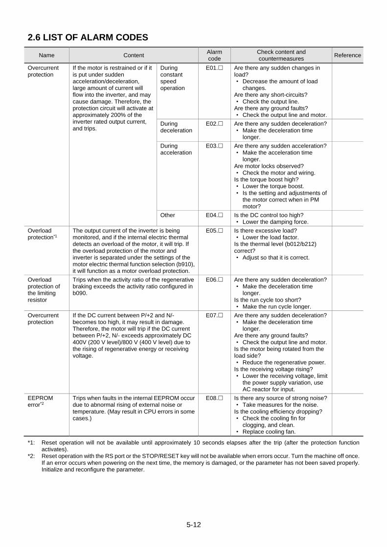
5-12
2.6 LIST OF ALARM CODES
Name Content Alarm code
Check content and countermeasures
Reference
Overcurrent protection
If the motor is restrained or if it is put under sudden acceleration/deceleration, large amount of current will flow into the inverter, and may cause damage. Therefore, the protection circuit will activate at approximately 200% of the inverter rated output current, and trips.
During constant speed operation
E01. Are there any sudden changes in load? • Decrease the amount of load
changes. Are there any short-circuits? • Check the output line.
Are there any ground faults? • Check the output line and motor.
During deceleration
E02. Are there any sudden deceleration? • Make the deceleration time
longer.
During acceleration
E03. Are there any sudden acceleration? • Make the acceleration time
longer. Are motor locks observed? • Check the motor and wiring.
Is the torque boost high? • Lower the torque boost. • Is the setting and adjustments of
the motor correct when in PM motor?
Other E04. Is the DC control too high? • Lower the damping force.
Overload protection*1
The output current of the inverter is being monitored, and if the internal electric thermal detects an overload of the motor, it will trip. If the overload protection of the motor and inverter is separated under the settings of the motor electric thermal function selection (b910), it will function as a motor overload protection.
E05. Is there excessive load? • Lower the load factor.
Is the thermal level (b012/b212) correct? • Adjust so that it is correct.
Overload protection of the limiting resistor
Trips when the activity ratio of the regenerative braking exceeds the activity ratio configured in b090.
E06. Are there any sudden deceleration? • Make the deceleration time
longer. Is the run cycle too short? • Make the run cycle longer.
Overcurrent protection
If the DC current between P/+2 and N/- becomes too high, it may result in damage. Therefore, the motor will trip if the DC current between P/+2, N/- exceeds approximately DC 400V (200 V level)/800 V (400 V level) due to the rising of regenerative energy or receiving voltage.
E07. Are there any sudden deceleration? • Make the deceleration time
longer. Are there any ground faults? • Check the output line and motor.
Is the motor being rotated from the load side? • Reduce the regenerative power.
Is the receiving voltage rising? • Lower the receiving voltage, limit
the power supply variation, use AC reactor for input.
EEPROM error*2
Trips when faults in the internal EEPROM occur due to abnormal rising of external noise or temperature. (May result in CPU errors in some cases.)
E08. Is there any source of strong noise? • Take measures for the noise.
Is the cooling efficiency dropping? • Check the cooling fin for
clogging, and clean. • Replace cooling fan.
*1: Reset operation will not be available until approximately 10 seconds elapses after the trip (after the protection function activates).
*2: Reset operation with the RS port or the STOP/RESET key will not be available when errors occur. Turn the machine off once. If an error occurs when powering on the next time, the memory is damaged, or the parameter has not been saved properly. Initialize and reconfigure the parameter.
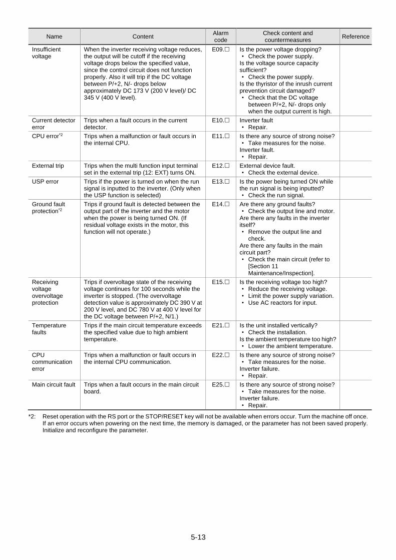
5-13
Name Content Alarm code
Check content and countermeasures
Reference
Insufficient voltage
When the inverter receiving voltage reduces, the output will be cutoff if the receiving voltage drops below the specified value, since the control circuit does not function properly. Also it will trip if the DC voltage between P/+2, N/- drops below approximately DC 173 V (200 V level)/ DC 345 V (400 V level).
E09. Is the power voltage dropping? • Check the power supply.
Is the voltage source capacity sufficient? • Check the power supply.
Is the thyristor of the inrush current prevention circuit damaged? • Check that the DC voltage
between P/+2, N/- drops only when the output current is high.
Current detector error
Trips when a fault occurs in the current detector.
E10. Inverter fault • Repair.
CPU error*2 Trips when a malfunction or fault occurs in the internal CPU.
E11. Is there any source of strong noise? • Take measures for the noise.
Inverter fault. • Repair.
External trip Trips when the multi function input terminal set in the external trip (12: EXT) turns ON.
E12. External device fault. • Check the external device.
USP error Trips if the power is turned on when the run signal is inputted to the inverter. (Only when the USP function is selected)
E13. Is the power being turned ON while the run signal is being inputted? • Check the run signal.
Ground fault protection*2
Trips if ground fault is detected between the output part of the inverter and the motor when the power is being turned ON. (If residual voltage exists in the motor, this function will not operate.)
E14. Are there any ground faults? • Check the output line and motor.
Are there any faults in the inverter itself? • Remove the output line and
check. Are there any faults in the main circuit part? • Check the main circuit (refer to
[Section 11 Maintenance/Inspection].
Receiving voltage overvoltage protection
Trips if overvoltage state of the receiving voltage continues for 100 seconds while the inverter is stopped. (The overvoltage detection value is approximately DC 390 V at 200 V level, and DC 780 V at 400 V level for the DC voltage between P/+2, N/1.)
E15. Is the receiving voltage too high? • Reduce the receiving voltage. • Limit the power supply variation. • Use AC reactors for input.
Temperature faults
Trips if the main circuit temperature exceeds the specified value due to high ambient temperature.
E21. Is the unit installed vertically? • Check the installation.
Is the ambient temperature too high? • Lower the ambient temperature.
CPU communication error
Trips when a malfunction or fault occurs in the internal CPU communication.
E22. Is there any source of strong noise? • Take measures for the noise.
Inverter failure. • Repair.
Main circuit fault Trips when a fault occurs in the main circuit board.
E25. Is there any source of strong noise? • Take measures for the noise.
Inverter failure. • Repair.
*2: Reset operation with the RS port or the STOP/RESET key will not be available when errors occur. Turn the machine off once. If an error occurs when powering on the next time, the memory is damaged, or the parameter has not been saved properly. Initialize and reconfigure the parameter.

5-14
Name Content Alarm code
Check content and countermeasures
Reference
Driver error*2 Error items for driver IC detection equipped in the inverter. Trips to protect the main element, when momentary overcurrent (approximately 350% of the rated current), main element temperature faults are observed, or drops in the main element driving power occur. (Restart run cannot be carried out on this trip.)
E30. Are there any short-circuits? • Check the output line.
Are there any ground faults? • Check the output line and
motor. Is the main element damaged? • Check IGBT. Refer to “Method
for Checking the Inverter and Converter Parts” for the checking method.
Is the cooling fin clogged? • Clean the fin.
Thermistor error When the thermistor input function is enabled, temperature faults are detected from the resistor value of the external thermistor, and trips.
E35. Is the motor temperature too high? • Check the temperature.
Is the thermistor damaged? • Check the thermistor.
Is there noise mixing in the thermistor signal? • Separate the wirings.
Brake error Trips if the inverter fails to detect the ON/OFF of the brake within the brake control operation fault detection time (b124) after the brake release output, when the brake control function is enabled (b120 = 01).
E36. Is the brake performing the ON/OF operation? • Check the brake.
Is the b124 setting short? • Make the b124 long.
Is the brake check signal being inputted? • Check the wirings.
Emergency cutoff*3 Trips when the safety input of GS1 or GS2 has been inputted.
E37. Are there misinputs of the GS1, GS2? • Check the wirings and
sequence. Is the parameter set properly? • Check the settings of the GS
input operation selection (b145).
Low speed range overload protection (inverter overload protection)
The electric thermal in the inverter detects and trips if overload occurs in very low speed ranges below 0.2 Hz. (However, high frequency may remain in the error log.) If the overload protection of the motor and inverter is separated under the settings of the motor electric thermal function selection (b910), it can function as an inverter overload protection as well.
E38. Is there excessive load? • Lower the load factor.
Operator bad connection
Trips when faults or breakages exist at the external operator (optional).
E40. Are there any communication errors? • Check and replace the cables.
This error will not be detected if b165 is set to 02 (ignore).
*2: Reset operation with the RS port or the STOP/RESET key will not be available when errors occur. Turn the machine off once. If an error occurs when powering on the next time, the memory is damaged, or the parameter has not been saved properly. Initialize and reconfigure the parameter.
*3: Releasing with the STOP/RESET key is not available. Release by powering ON again or with the RS (reset) terminal.
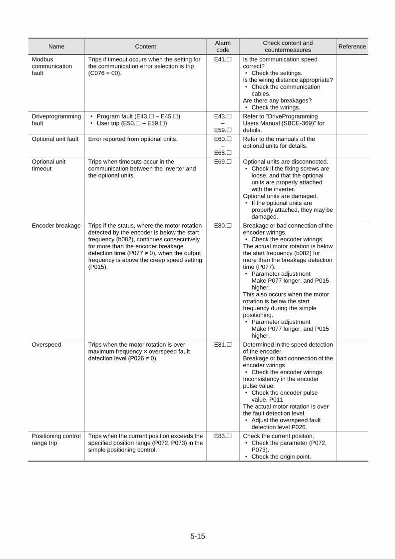
5-15
Name Content Alarm code
Check content and countermeasures
Reference
Modbus communication fault
Trips if timeout occurs when the setting for the communication error selection is trip (C076 = 00).
E41. Is the communication speed correct? • Check the settings.
Is the wiring distance appropriate? • Check the communication
cables. Are there any breakages? • Check the wirings.
Driveprogramming fault
• Program fault (E43. – E45.) • User trip (E50. – E59.)
E43. –
E59.
Refer to “DriveProgramming Users Manual (SBCE-369)” for details.
Optional unit fault Error reported from optional units. E60. –
E68.
Refer to the manuals of the optional units for details.
Optional unit timeout
Trips when timeouts occur in the communication between the inverter and the optional units.
E69. Optional units are disconnected. • Check if the fixing screws are
loose, and that the optional units are properly attached with the inverter.
Optional units are damaged. • If the optional units are
properly attached, they may be damaged.
Encoder breakage Trips if the status, where the motor rotation detected by the encoder is below the start frequency (b082), continues consecutively for more than the encoder breakage detection time (P077 ≠ 0), when the output frequency is above the creep speed setting (P015).
E80. Breakage or bad connection of the encoder wirings. • Check the encoder wirings.
The actual motor rotation is below the start frequency (b082) for more than the breakage detection time (P077). • Parameter adjustment
Make P077 longer, and P015 higher.
This also occurs when the motor rotation is below the start frequency during the simple positioning. • Parameter adjustment
Make P077 longer, and P015 higher.
Overspeed Trips when the motor rotation is over maximum frequency × overspeed fault detection level (P026 ≠ 0).
E81. Determined in the speed detection of the encoder. Breakage or bad connection of the encoder wirings • Check the encoder wirings.
Inconsistency in the encoder pulse value. • Check the encoder pulse
value. P011 The actual motor rotation is over the fault detection level. • Adjust the overspeed fault
detection level P026.
Positioning control range trip
Trips when the current position exceeds the specified position range (P072, P073) in the simple positioning control.
E83. Check the current position. • Check the parameter (P072,
P073). • Check the origin point.
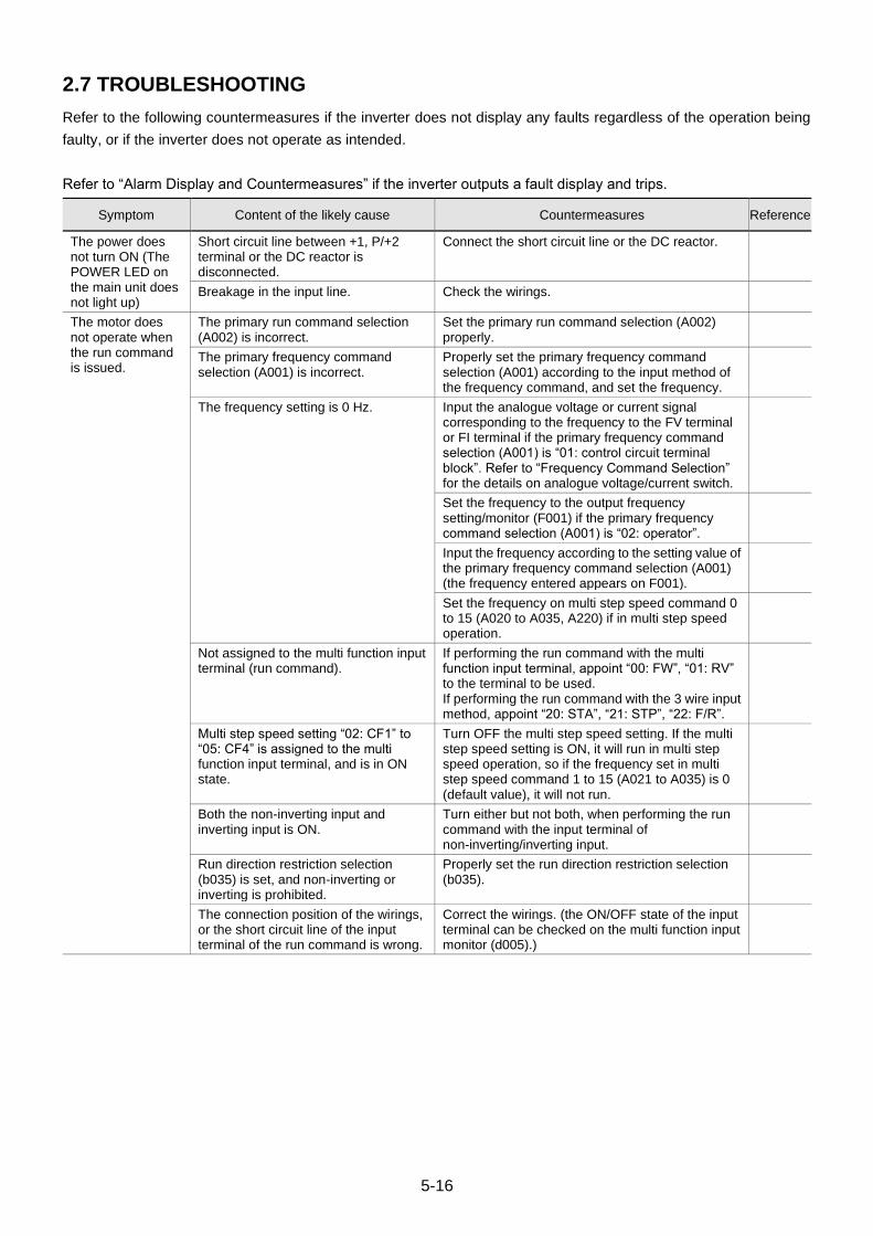
5-16
2.7 TROUBLESHOOTING
Refer to the following countermeasures if the inverter does not display any faults regardless of the operation being
faulty, or if the inverter does not operate as intended.
Refer to “Alarm Display and Countermeasures” if the inverter outputs a fault display and trips.
Symptom Content of the likely cause Countermeasures Reference
The power does not turn ON (The POWER LED on the main unit does not light up)
Short circuit line between +1, P/+2 terminal or the DC reactor is disconnected.
Connect the short circuit line or the DC reactor.
Breakage in the input line. Check the wirings.
The motor does not operate when the run command is issued.
The primary run command selection (A002) is incorrect.
Set the primary run command selection (A002) properly.
The primary frequency command selection (A001) is incorrect.
Properly set the primary frequency command selection (A001) according to the input method of the frequency command, and set the frequency.
The frequency setting is 0 Hz. Input the analogue voltage or current signal corresponding to the frequency to the FV terminal or FI terminal if the primary frequency command selection (A001) is “01: control circuit terminal block”. Refer to “Frequency Command Selection” for the details on analogue voltage/current switch.
Set the frequency to the output frequency setting/monitor (F001) if the primary frequency command selection (A001) is “02: operator”.
Input the frequency according to the setting value of the primary frequency command selection (A001) (the frequency entered appears on F001).
Set the frequency on multi step speed command 0 to 15 (A020 to A035, A220) if in multi step speed operation.
Not assigned to the multi function input terminal (run command).
If performing the run command with the multi function input terminal, appoint “00: FW”, “01: RV” to the terminal to be used. If performing the run command with the 3 wire input method, appoint “20: STA”, “21: STP”, “22: F/R”.
Multi step speed setting “02: CF1” to “05: CF4” is assigned to the multi function input terminal, and is in ON state.
Turn OFF the multi step speed setting. If the multi step speed setting is ON, it will run in multi step speed operation, so if the frequency set in multi step speed command 1 to 15 (A021 to A035) is 0 (default value), it will not run.
Both the non-inverting input and inverting input is ON.
Turn either but not both, when performing the run command with the input terminal of non-inverting/inverting input.
Run direction restriction selection (b035) is set, and non-inverting or inverting is prohibited.
Properly set the run direction restriction selection (b035).
The connection position of the wirings, or the short circuit line of the input terminal of the run command is wrong.
Correct the wirings. (the ON/OFF state of the input terminal can be checked on the multi function input monitor (d005).)
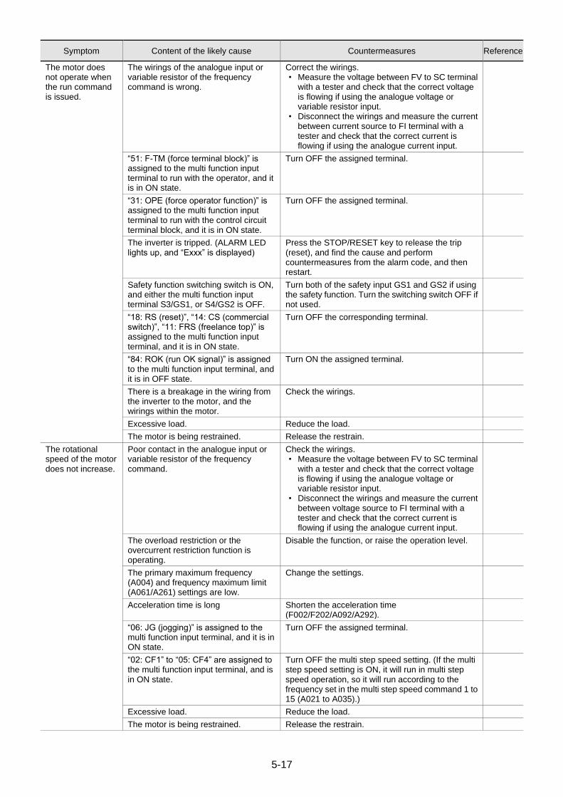
5-17
Symptom Content of the likely cause Countermeasures Reference
The motor does not operate when the run command is issued.
The wirings of the analogue input or variable resistor of the frequency command is wrong.
Correct the wirings. • Measure the voltage between FV to SC terminal
with a tester and check that the correct voltage is flowing if using the analogue voltage or variable resistor input.
• Disconnect the wirings and measure the current between current source to FI terminal with a tester and check that the correct current is flowing if using the analogue current input.
“51: F-TM (force terminal block)” is assigned to the multi function input terminal to run with the operator, and it is in ON state.
Turn OFF the assigned terminal.
“31: OPE (force operator function)” is assigned to the multi function input terminal to run with the control circuit terminal block, and it is in ON state.
Turn OFF the assigned terminal.
The inverter is tripped. (ALARM LED lights up, and “Exxx” is displayed)
Press the STOP/RESET key to release the trip (reset), and find the cause and perform countermeasures from the alarm code, and then restart.
Safety function switching switch is ON, and either the multi function input terminal S3/GS1, or S4/GS2 is OFF.
Turn both of the safety input GS1 and GS2 if using the safety function. Turn the switching switch OFF if not used.
“18: RS (reset)”, “14: CS (commercial switch)”, “11: FRS (freelance top)” is assigned to the multi function input terminal, and it is in ON state.
Turn OFF the corresponding terminal.
“84: ROK (run OK signal)” is assigned to the multi function input terminal, and it is in OFF state.
Turn ON the assigned terminal.
There is a breakage in the wiring from the inverter to the motor, and the wirings within the motor.
Check the wirings.
Excessive load. Reduce the load.
The motor is being restrained. Release the restrain.
The rotational speed of the motor does not increase.
Poor contact in the analogue input or variable resistor of the frequency command.
Check the wirings. • Measure the voltage between FV to SC terminal
with a tester and check that the correct voltage is flowing if using the analogue voltage or variable resistor input.
• Disconnect the wirings and measure the current between voltage source to FI terminal with a tester and check that the correct current is flowing if using the analogue current input.
The overload restriction or the overcurrent restriction function is operating.
Disable the function, or raise the operation level.
The primary maximum frequency (A004) and frequency maximum limit (A061/A261) settings are low.
Change the settings.
Acceleration time is long Shorten the acceleration time (F002/F202/A092/A292).
“06: JG (jogging)” is assigned to the multi function input terminal, and it is in ON state.
Turn OFF the assigned terminal.
“02: CF1” to “05: CF4” are assigned to the multi function input terminal, and is in ON state.
Turn OFF the multi step speed setting. (If the multi step speed setting is ON, it will run in multi step speed operation, so it will run according to the frequency set in the multi step speed command 1 to 15 (A021 to A035).)
Excessive load. Reduce the load.
The motor is being restrained. Release the restrain.
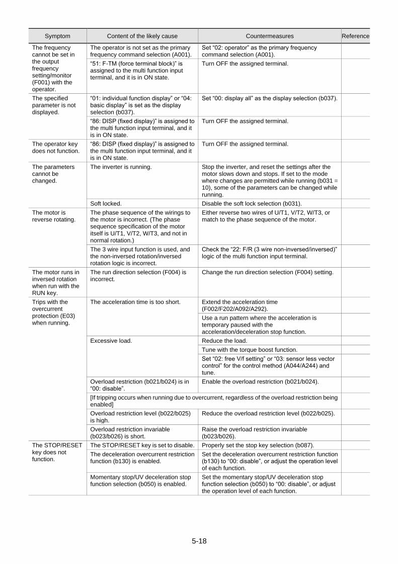
5-18
Symptom Content of the likely cause Countermeasures Reference
The frequency cannot be set in the output frequency setting/monitor (F001) with the operator.
The operator is not set as the primary frequency command selection (A001).
Set “02: operator” as the primary frequency command selection (A001).
“51: F-TM (force terminal block)” is assigned to the multi function input terminal, and it is in ON state.
Turn OFF the assigned terminal.
The specified parameter is not displayed.
“01: individual function display” or “04: basic display” is set as the display selection (b037).
Set “00: display all” as the display selection (b037).
“86: DISP (fixed display)” is assigned to the multi function input terminal, and it is in ON state.
Turn OFF the assigned terminal.
The operator key does not function.
“86: DISP (fixed display)” is assigned to the multi function input terminal, and it is in ON state.
Turn OFF the assigned terminal.
The parameters cannot be changed.
The inverter is running. Stop the inverter, and reset the settings after the motor slows down and stops. If set to the mode where changes are permitted while running (b031 = 10), some of the parameters can be changed while running.
Soft locked. Disable the soft lock selection (b031).
The motor is reverse rotating.
The phase sequence of the wirings to the motor is incorrect. (The phase sequence specification of the motor itself is U/T1, V/T2, W/T3, and not in normal rotation.)
Either reverse two wires of U/T1, V/T2, W/T3, or match to the phase sequence of the motor.
The 3 wire input function is used, and the non-inversed rotation/inversed rotation logic is incorrect.
Check the “22: F/R (3 wire non-inversed/inversed)” logic of the multi function input terminal.
The motor runs in inversed rotation when run with the RUN key.
The run direction selection (F004) is incorrect.
Change the run direction selection (F004) setting.
Trips with the overcurrent protection (E03) when running.
The acceleration time is too short. Extend the acceleration time (F002/F202/A092/A292).
Use a run pattern where the acceleration is temporary paused with the acceleration/deceleration stop function.
Excessive load. Reduce the load.
Tune with the torque boost function.
Set “02: free V/f setting” or “03: sensor less vector control” for the control method (A044/A244) and tune.
Overload restriction (b021/b024) is in “00: disable”.
Enable the overload restriction (b021/b024).
[If tripping occurs when running due to overcurrent, regardless of the overload restriction being enabled]
Overload restriction level (b022/b025) is high.
Reduce the overload restriction level (b022/b025).
Overload restriction invariable (b023/b026) is short.
Raise the overload restriction invariable (b023/b026).
The STOP/RESET key does not function.
The STOP/RESET key is set to disable. Properly set the stop key selection (b087).
The deceleration overcurrent restriction function (b130) is enabled.
Set the deceleration overcurrent restriction function (b130) to “00: disable”, or adjust the operation level of each function.
Momentary stop/UV deceleration stop function selection (b050) is enabled.
Set the momentary stop/UV deceleration stop function selection (b050) to “00: disable”, or adjust the operation level of each function.
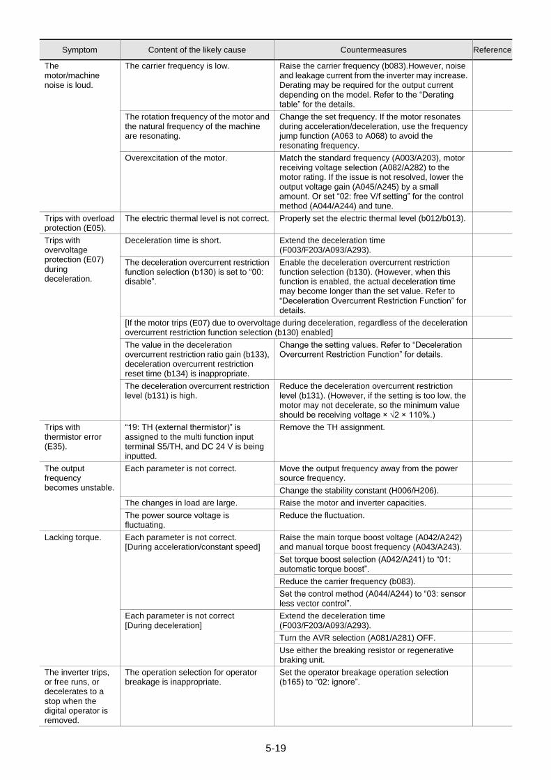
5-19
Symptom Content of the likely cause Countermeasures Reference
The motor/machine noise is loud.
The carrier frequency is low. Raise the carrier frequency (b083).However, noise and leakage current from the inverter may increase. Derating may be required for the output current depending on the model. Refer to the “Derating table” for the details.
The rotation frequency of the motor and the natural frequency of the machine are resonating.
Change the set frequency. If the motor resonates during acceleration/deceleration, use the frequency jump function (A063 to A068) to avoid the resonating frequency.
Overexcitation of the motor. Match the standard frequency (A003/A203), motor receiving voltage selection (A082/A282) to the motor rating. If the issue is not resolved, lower the output voltage gain (A045/A245) by a small amount. Or set “02: free V/f setting” for the control method (A044/A244) and tune.
Trips with overload protection (E05).
The electric thermal level is not correct. Properly set the electric thermal level (b012/b013).
Trips with overvoltage protection (E07) during deceleration.
Deceleration time is short. Extend the deceleration time (F003/F203/A093/A293).
The deceleration overcurrent restriction function selection (b130) is set to “00: disable”.
Enable the deceleration overcurrent restriction function selection (b130). (However, when this function is enabled, the actual deceleration time may become longer than the set value. Refer to “Deceleration Overcurrent Restriction Function” for details.
[If the motor trips (E07) due to overvoltage during deceleration, regardless of the deceleration overcurrent restriction function selection (b130) enabled]
The value in the deceleration overcurrent restriction ratio gain (b133), deceleration overcurrent restriction reset time (b134) is inappropriate.
Change the setting values. Refer to “Deceleration Overcurrent Restriction Function” for details.
The deceleration overcurrent restriction level (b131) is high.
Reduce the deceleration overcurrent restriction level (b131). (However, if the setting is too low, the motor may not decelerate, so the minimum value should be receiving voltage × √2 × 110%.)
Trips with thermistor error (E35).
“19: TH (external thermistor)” is assigned to the multi function input terminal S5/TH, and DC 24 V is being inputted.
Remove the TH assignment.
The output frequency becomes unstable.
Each parameter is not correct. Move the output frequency away from the power source frequency.
Change the stability constant (H006/H206).
The changes in load are large. Raise the motor and inverter capacities.
The power source voltage is fluctuating.
Reduce the fluctuation.
Lacking torque. Each parameter is not correct. [During acceleration/constant speed]
Raise the main torque boost voltage (A042/A242) and manual torque boost frequency (A043/A243).
Set torque boost selection (A042/A241) to “01: automatic torque boost”.
Reduce the carrier frequency (b083).
Set the control method (A044/A244) to “03: sensor less vector control”.
Each parameter is not correct [During deceleration]
Extend the deceleration time (F003/F203/A093/A293).
Turn the AVR selection (A081/A281) OFF.
Use either the breaking resistor or regenerative braking unit.
The inverter trips, or free runs, or decelerates to a stop when the digital operator is removed.
The operation selection for operator breakage is inappropriate.
Set the operator breakage operation selection (b165) to “02: ignore”.
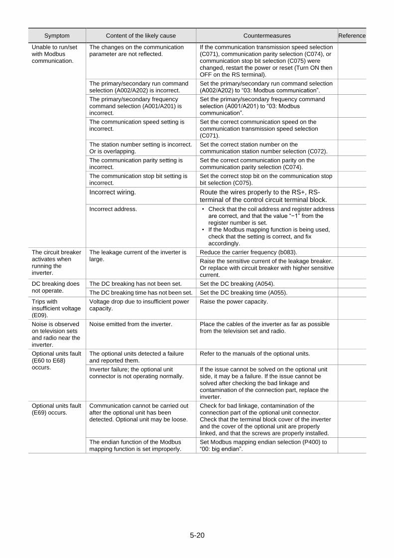
5-20
Symptom Content of the likely cause Countermeasures Reference
Unable to run/set with Modbus communication.
The changes on the communication parameter are not reflected.
If the communication transmission speed selection (C071), communication parity selection (C074), or communication stop bit selection (C075) were changed, restart the power or reset (Turn ON then OFF on the RS terminal).
The primary/secondary run command selection (A002/A202) is incorrect.
Set the primary/secondary run command selection (A002/A202) to “03: Modbus communication”.
The primary/secondary frequency command selection (A001/A201) is incorrect.
Set the primary/secondary frequency command selection (A001/A201) to “03: Modbus communication”.
The communication speed setting is incorrect.
Set the correct communication speed on the communication transmission speed selection (C071).
The station number setting is incorrect. Or is overlapping.
Set the correct station number on the communication station number selection (C072).
The communication parity setting is incorrect.
Set the correct communication parity on the communication parity selection (C074).
The communication stop bit setting is incorrect.
Set the correct stop bit on the communication stop bit selection (C075).
Incorrect wiring. Route the wires properly to the RS+, RS- terminal of the control circuit terminal block.
Incorrect address. • Check that the coil address and register address are correct, and that the value “−1” from the register number is set.
• If the Modbus mapping function is being used, check that the setting is correct, and fix accordingly.
The circuit breaker activates when running the inverter.
The leakage current of the inverter is large.
Reduce the carrier frequency (b083).
Raise the sensitive current of the leakage breaker. Or replace with circuit breaker with higher sensitive current.
DC breaking does not operate.
The DC breaking has not been set. Set the DC breaking (A054).
The DC breaking time has not been set. Set the DC breaking time (A055).
Trips with insufficient voltage (E09).
Voltage drop due to insufficient power capacity.
Raise the power capacity.
Noise is observed on television sets and radio near the inverter.
Noise emitted from the inverter. Place the cables of the inverter as far as possible from the television set and radio.
Optional units fault (E60 to E68) occurs.
The optional units detected a failure and reported them.
Refer to the manuals of the optional units.
Inverter failure; the optional unit connector is not operating normally.
If the issue cannot be solved on the optional unit side, it may be a failure. If the issue cannot be solved after checking the bad linkage and contamination of the connection part, replace the inverter.
Optional units fault (E69) occurs.
Communication cannot be carried out after the optional unit has been detected. Optional unit may be loose.
Check for bad linkage, contamination of the connection part of the optional unit connector. Check that the terminal block cover of the inverter and the cover of the optional unit are properly linked, and that the screws are properly installed.
The endian function of the Modbus mapping function is set improperly.
Set Modbus mapping endian selection (P400) to “00: big endian”.
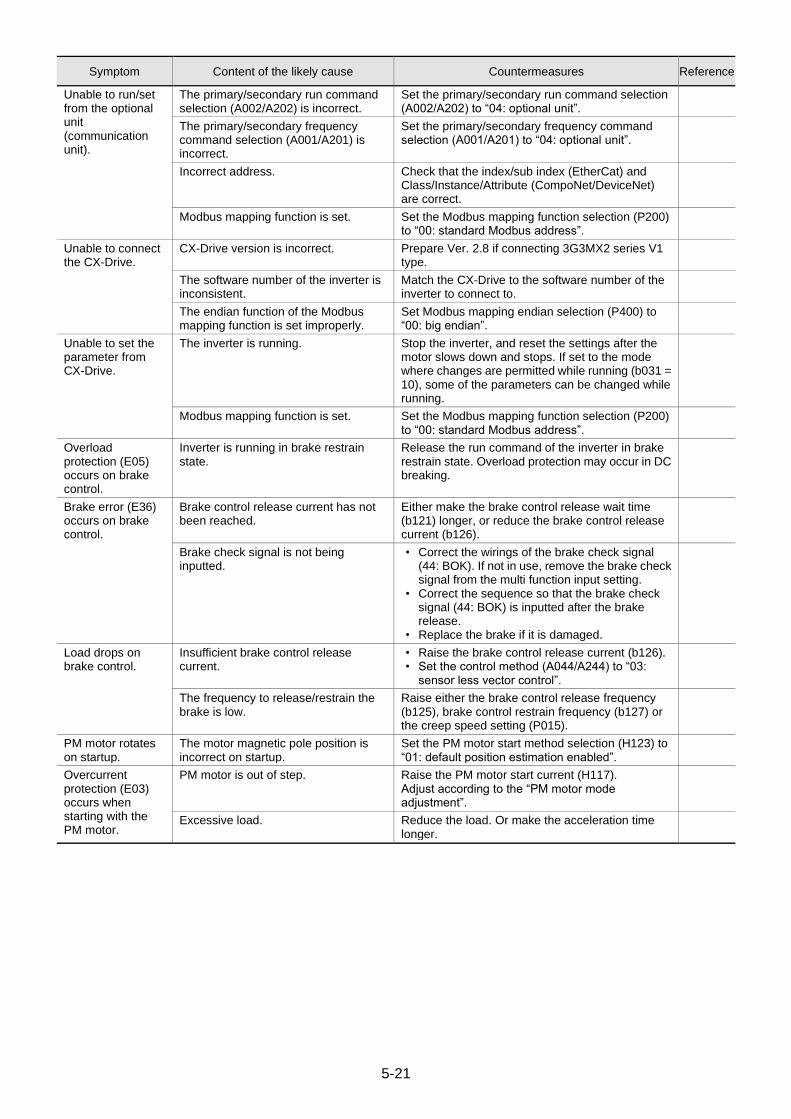
5-21
Symptom Content of the likely cause Countermeasures Reference
Unable to run/set from the optional unit (communication unit).
The primary/secondary run command selection (A002/A202) is incorrect.
Set the primary/secondary run command selection (A002/A202) to “04: optional unit”.
The primary/secondary frequency command selection (A001/A201) is incorrect.
Set the primary/secondary frequency command selection (A001/A201) to “04: optional unit”.
Incorrect address. Check that the index/sub index (EtherCat) and Class/Instance/Attribute (CompoNet/DeviceNet) are correct.
Modbus mapping function is set. Set the Modbus mapping function selection (P200) to “00: standard Modbus address”.
Unable to connect the CX-Drive.
CX-Drive version is incorrect. Prepare Ver. 2.8 if connecting 3G3MX2 series V1 type.
The software number of the inverter is inconsistent.
Match the CX-Drive to the software number of the inverter to connect to.
The endian function of the Modbus mapping function is set improperly.
Set Modbus mapping endian selection (P400) to “00: big endian”.
Unable to set the parameter from CX-Drive.
The inverter is running. Stop the inverter, and reset the settings after the motor slows down and stops. If set to the mode where changes are permitted while running (b031 = 10), some of the parameters can be changed while running.
Modbus mapping function is set. Set the Modbus mapping function selection (P200) to “00: standard Modbus address”.
Overload protection (E05) occurs on brake control.
Inverter is running in brake restrain state.
Release the run command of the inverter in brake restrain state. Overload protection may occur in DC breaking.
Brake error (E36) occurs on brake control.
Brake control release current has not been reached.
Either make the brake control release wait time (b121) longer, or reduce the brake control release current (b126).
Brake check signal is not being inputted.
• Correct the wirings of the brake check signal (44: BOK). If not in use, remove the brake check signal from the multi function input setting.
• Correct the sequence so that the brake check signal (44: BOK) is inputted after the brake release.
• Replace the brake if it is damaged.
Load drops on brake control.
Insufficient brake control release current.
• Raise the brake control release current (b126). • Set the control method (A044/A244) to “03:
sensor less vector control”.
The frequency to release/restrain the brake is low.
Raise either the brake control release frequency (b125), brake control restrain frequency (b127) or the creep speed setting (P015).
PM motor rotates on startup.
The motor magnetic pole position is incorrect on startup.
Set the PM motor start method selection (H123) to “01: default position estimation enabled”.
Overcurrent protection (E03) occurs when starting with the PM motor.
PM motor is out of step. Raise the PM motor start current (H117). Adjust according to the “PM motor mode adjustment”.
Excessive load. Reduce the load. Or make the acceleration time longer.
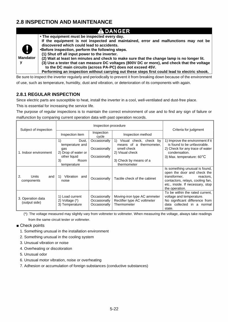
5-22
2.8 INSPECTION AND MAINTENANCE
Mandatory
• The equipment must be inspected every day. If the equipment is not inspected and maintained, error and malfunctions may not be discovered which could lead to accidents.
•Before inspection, perform the following steps. (1) Shut off all input power to the inverter. (2) Wait at least ten minutes and check to make sure that the change lamp is no longer lit. (3) Use a tester that can measure DC voltages (800V DC or more), and check that the voltage
to the DC main circuits (across PA-PC) does not exceed 45V. Performing an inspection without carrying out these steps first could lead to electric shook.
Be sure to inspect the inverter regularly and periodically to prevent it from breaking down because of the environment
of use, such as temperature, humidity, dust and vibration, or deterioration of its components with again.
2.8.1 REGULAR INSPECTION
Since electric parts are susceptible to heat, install the inverter in a cool, well-ventilated and dust-free place.
This is essential for increasing the service life.
The purpose of regular inspections is to maintain the correct environment of use and to find any sign of failure or
malfunction by comparing current operation data with past operation records.
Subject of inspection
Inspection procedure
Criteria for judgment
Inspection item Inspection
cycle Inspection method
1. Indoor environment
1) Dust, temperature and gas
2) Drop of water or other liquid
3) Room temperature
Occasionally Occasionally Occasionally
1) Visual check, check by means of a thermometer, smell check
2) Visual check 3) Check by means of a
thermometer
1) Improve the environment if it is found to be unfavorable.
2) Check for any trace of water condensation.
3) Max. temperature: 60°C
2. Units and components
1) Vibration and noise
Occasionally Tactile check of the cabinet
Is something unusual is found, open the door and check the transformer, reactors, contactors, relays, cooling fan, etc., inside. If necessary, stop the operation.
3. Operation data (output side)
1) Load current 2) Voltage (*) 3) Temperature
Occasionally Occasionally Occasionally
Moving-iron type AC ammeter Rectifier type AC voltmeter Thermometer
To be within the rated current, voltage and temperature. No significant difference from data collected in a normal state.
(*): The voltage measured may slightly vary from voltmeter to voltmeter. When measuring the voltage, always take readings
from the same circuit tester or voltmeter.
■ Check points
1. Something unusual in the installation environment
2. Something unusual in the cooling system
3. Unusual vibration or noise
4. Overheating or discoloration
5. Unusual odor
6. Unusual motor vibration, noise or overheating
7. Adhesion or accumulation of foreign substances (conductive substances)
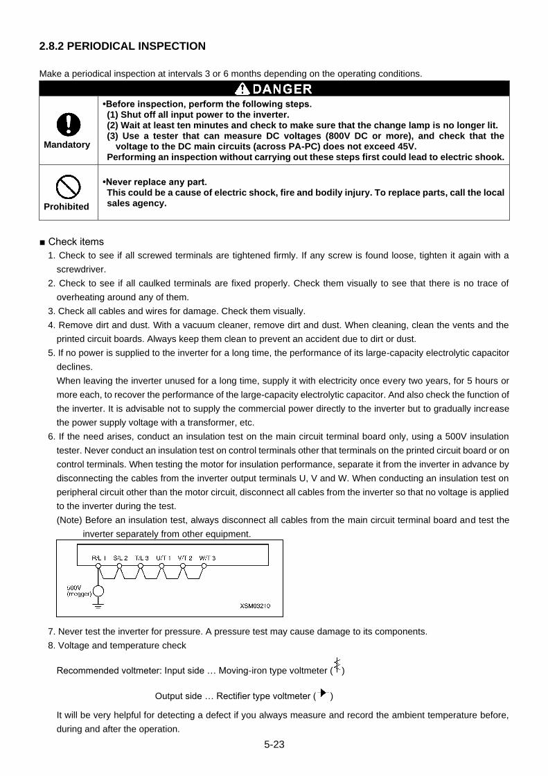
5-23
2.8.2 PERIODICAL INSPECTION
Make a periodical inspection at intervals 3 or 6 months depending on the operating conditions.
Mandatory
•Before inspection, perform the following steps. (1) Shut off all input power to the inverter. (2) Wait at least ten minutes and check to make sure that the change lamp is no longer lit. (3) Use a tester that can measure DC voltages (800V DC or more), and check that the
voltage to the DC main circuits (across PA-PC) does not exceed 45V. Performing an inspection without carrying out these steps first could lead to electric shook.
Prohibited
•Never replace any part. This could be a cause of electric shock, fire and bodily injury. To replace parts, call the local sales agency.
■ Check items
1. Check to see if all screwed terminals are tightened firmly. If any screw is found loose, tighten it again with a
screwdriver.
2. Check to see if all caulked terminals are fixed properly. Check them visually to see that there is no trace of
overheating around any of them.
3. Check all cables and wires for damage. Check them visually.
4. Remove dirt and dust. With a vacuum cleaner, remove dirt and dust. When cleaning, clean the vents and the
printed circuit boards. Always keep them clean to prevent an accident due to dirt or dust.
5. If no power is supplied to the inverter for a long time, the performance of its large-capacity electrolytic capacitor
declines.
When leaving the inverter unused for a long time, supply it with electricity once every two years, for 5 hours or
more each, to recover the performance of the large-capacity electrolytic capacitor. And also check the function of
the inverter. It is advisable not to supply the commercial power directly to the inverter but to gradually increase
the power supply voltage with a transformer, etc.
6. If the need arises, conduct an insulation test on the main circuit terminal board only, using a 500V insulation
tester. Never conduct an insulation test on control terminals other that terminals on the printed circuit board or on
control terminals. When testing the motor for insulation performance, separate it from the inverter in advance by
disconnecting the cables from the inverter output terminals U, V and W. When conducting an insulation test on
peripheral circuit other than the motor circuit, disconnect all cables from the inverter so that no voltage is applied
to the inverter during the test.
(Note) Before an insulation test, always disconnect all cables from the main circuit terminal board and test the
inverter separately from other equipment.
7. Never test the inverter for pressure. A pressure test may cause damage to its components.
8. Voltage and temperature check
Recommended voltmeter: Input side … Moving-iron type voltmeter ( )
Output side … Rectifier type voltmeter ( )
It will be very helpful for detecting a defect if you always measure and record the ambient temperature before,
during and after the operation.
5-24
■ Replacement of expendable parts
The inverter is composed of a large number of electronic parts including semiconductor devices. The following
parts deteriorate with the passage of time because of their composition or physical properties. The use of aged or
deteriorated parts leads to degradation in the performance or a breakdown of the inverter. To avoid such trouble,
the inverter should be checked periodically.
(Note) Generally, the life of a part depends on the ambient temperature and the conditions of use. The life spans
listed below are applicable to parts when used under normal environmental conditions.
1) Cooling fan
The fan, Which cools down heat-generating parts, has a service life of about 30,000 hours (about 2 or 3 years of
continuous operation). The fan also needs to be replaced if it makes a noise or vibrates abnormally.
2) Smoothing capacitor
The smoothing aluminum electrolytic capacitor in the main circuit DC section degrades in performance because
of ripple currents, etc. It becomes necessary to replace the capacitor after it is used for about 5 years under
normal conditions. Since the smoothing capacitor is mounted on a printed circuit board circuit board, it needs to
be replaced together with the circuit board.
<Criteria for appearance check>
・ Absence of liquid leak
・ Safety valve In the depressed position
・ Measurement of electrostatic capacitance and insulation resistance
Note: The operation time is helpful for roughly determining the time of replacement. For the replacement of parts,
contact your nearest Maeda distributor. For safety’s sake, never replace any part on your own. (Parts
replacement alarms can be known by monitor and alarm output, if it is set.)
■ Standard replacement cycles of principal parts
As guides, The table below lists part replacement cycles that wear estimated based on the assumption that the
inverter would be used in a normal use environment under normal conditions (ambient temperature, ventilation
conditions, and energizing time). The replacement cycle of each part does not mean its service life but the number
of years over which its failure rate does not increase significantly.
Part name Standard
replacement cycle Replacement mode and others
Cooling fan 2 to 3 years Replacement with a new one
Main circuit smoothing aluminum electrolytic capacitor
5 years Replacement with a new one
Relay and contactor -
Whether to replace or not depends on the check results
Aluminum electrolytic capacitor mounted on a printed circuit board
5 years Replacement with a new one
Note) The life of a part greatly varies depending on the environment of use.

5-25
2.9 DISPOSAL OF THE INVERTER
Mandatory
• If you throw away the inverter, have it done by specialist in industry waste disposal (*). If you throw away the inverter by yourself, this can result in explosion of capacitor or produce noxious gases, resulting in injury. (*) Persons who specialize in the processing of waste and known as “industrial waste
product collectors and transporters” or “industrial waste disposal persons”. If the collection, transport and disposal of industrial waste is done by someone who is not licensed for that job, it is a punishable violation of the law. (Laws in reqard to cleaning and processing of waste materials)
For safety’s sake, do not dispose of the disused inverter yourself but ask an industrial waste disposal agent.
Disposing of the inverter improperly could cause its capacitor to explode and emit toxic gas, causing injury to
persons.

5-26
3. POWER SUPPLY BOX
(1) Power supply box
(2) Power supply box door
(3) Door handle
(4) Terminal block
(5) Cable inserting hole
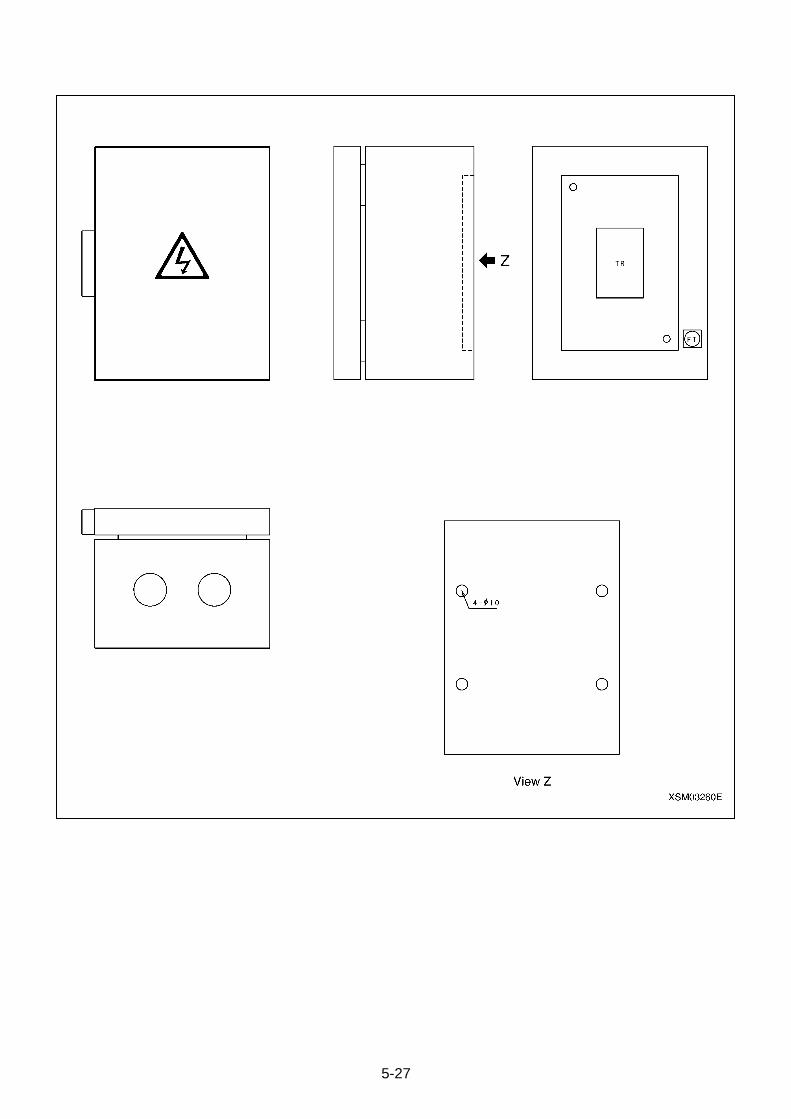
5-27
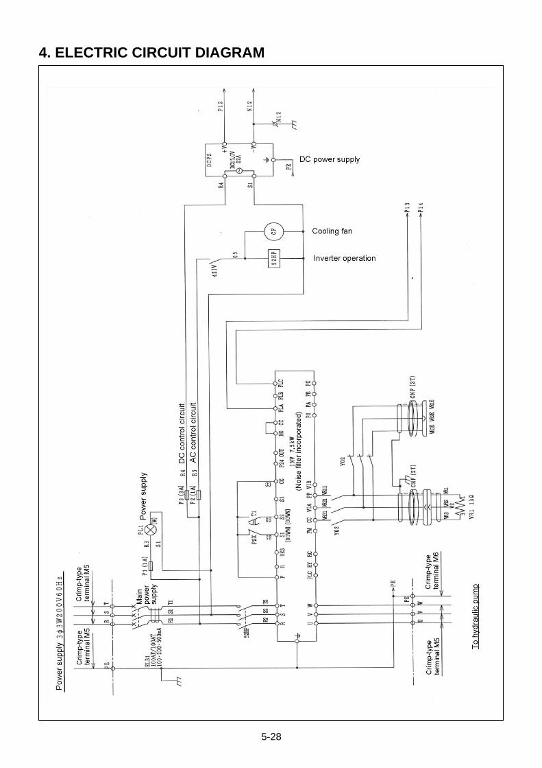
5-28
4. ELECTRIC CIRCUIT DIAGRAM
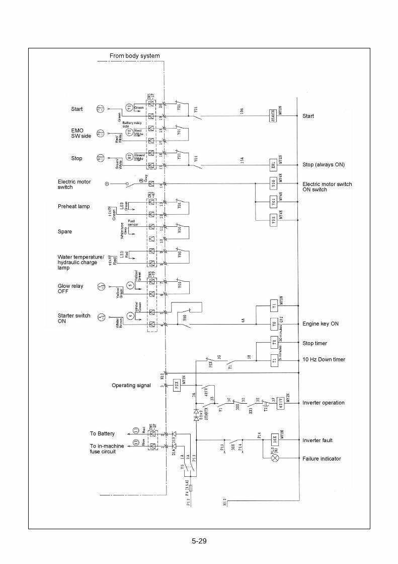
5-29

5-30
This Page Intentionally Left Blank.

MAEDA MINI-CRAWLER CRANE MC405C-3 SERVICE MANUAL
Document No: 104ME-SM1910-00
First edition: October 31, 2019
Issued by Maeda Seisakusho Co., Ltd.
1095 Onbegawa, Shinonoi
Nagano, Nagano 388-8522,
Japan
No part of this manual can be reproduced in any from without permission


