
SERVICE MANUAL - KK-Tec.eu
45
R32 Refrigerant Wall Type Air Conditioners Heat Pump Top Class Models with DC Fan Motor 1 Phase, 220-240V, 50/60Hz Power Supply Series 4 Models: HKEU 264 ZAL HCNI 264 ZA SERVICE MANUAL [ Release 1.1 ] HKEU 354 ZAL HCNI 354 ZA
-
Upload
khangminh22 -
Category
Documents
-
view
2 -
download
0
Transcript of SERVICE MANUAL - KK-Tec.eu

R32RefrigerantWall TypeAir Conditioners
Heat Pump Top Class Models with DC Fan Motor1 Phase, 220-240V, 50/60Hz Power Supply
Series 4 Models:
HKEU 264 ZAL
HCNI 264 ZA
SERVICE MANUAL [ Release 1.1 ]
HKEU 354 ZAL
HCNI 354 ZA

Series 4 Models: “Wall” Type Top Class R32 Refrigerant AC
Table of Contents
Table of Contents
1. PRODUCT DETAILS ............................................................................................................................ 1
2. MODEL REFERENCE ......................................................................................................................... 3
3. DIMENSIONS ..................................................................................................................................... 4
4. ELECTRICAL WIRING DIAGRAMS .................................................................................................... 6
5. OPERATION MODES AND FUNCTIONS........................................................................................... 8
6. TROUBLESHOOTING .......................................................................................................................14
APPENDIX ........................................................................................................................................... 37

- 1 -
Series 4 Models: “Wall” Type Top Class R32 Refrigerant AC
1. PRODUCT DETAILS
Auto clean (X-fan)After BLUAIR shut-down, the internal fan continues to run to favour internal unit exchanger drying. This function prevents the formation of mould that is harmful to the respiratory system.
AutorestartIn case of blackout, the unit resumes operation with the previously selected settings once the power supply is restored.
TOP CLASS DC INVERTERWall
RESIDENTIAL R32
24H timer
This function allows users to select delayed air conditioner on and/or off within 24 hours, either via remote (standard) or via Wi-Fi (optional).
Refrigerant leak detectionActive only in cooling mode, it allows to identify compressor malfunctions following the refrigerant leak.
Cold currents preventionThrough this function in heating mode, it is possible to avoid the introduction of cold air into the room following the defrost cycles.
Anti-freeze function 8° C
In the event of prolonged absence, a minimum temperature level can be guaranteed inside the rooms. By activating the anti-freeze function, when a temperature lower than 8° C is detected in the room, the system starts until this temperature is reached.
Sleep mode
It allows lowering energy consumption at night. In cooling mode, the system increases the ambient temperature within 2 hours, by 2° C (in heating mode the system lowers the temperature by 2°C). At the end of 2 hours the fan of the indoor unit works at low speed. The system keeps the room temperature constant for the next 5 hours.
Silence mode
This function allows the operating speed of the compressor of the outdoor unit and the fan of the indoor unit to be reduced to a minimum, so as to reduce noise and energy consumption to a minimum.
NEW

- 2 -
Series 4 Models: “Wall” Type Top Class R32 Refrigerant AC
TOP CLASS DC INVERTERHKEU 264-354 ZAL
RESIDENTIAL R32
Wall
Models available in 2 power sizes 2.64 ~ 3.52 kW.
Seasonal energy efficiency class in cooling/heating mode: A+++/A++ (2.64 kW); A++/A++ (3.52 kW).
SEER/SCOP values 8.5/4.6 (2.64 kW).
Operating range in cooling and heating: -15~43° C; -30~30° C.
Extremely quiet: 21.5 dB(A) (2.64 kW); 22 dB(A) (3.52 kW).
Compact dimensions: only 189 mm deep.
Installation flexibility: up to 25 m splitting length and 10 m height difference between O.U. and I.U.
Possibility of access to tax deductions and to the thermal account.
"3D" air diffusion Photocatalytic filter Position memorization function louvres
(optional)
Main features
Indoor unit model HKEU 264 ZAL HKEU 354 ZALOutdoor unit model HCNI 264 ZA HCNI 354 ZAType DC-Inverter heat pumpControl Remote controlRated capacity (T=+35°C)
Cooling
kW 2.64 (0.91~4.40) 3.52 (0.93~4.75)Rated absorbed power (T=+35°C) kW 0.60 (0.05~1.55) 0.98 (0.05~1.59)Rated energy eciency coecient EER3 4.40 3.59 Seasonal energy eciency class 626/20111 A+++ A++Seasonal energy eciency index SEER2 8.5 8.1 Annual energy consumption kWh/a 111 155Theoretical load (Pdesignc) kW 2.7 3.5Rated capacity (T=+7°C)
Heating
kW 2.86 (0.79~6.30) 3.81 (0.98~6.50)Rated absorbed power (T=+7°C) kW 0.65 (0.14~2.10) 1.026 (0.17~2.13)Rated energy performance coecient COP3 4.42 3.71 Energy eciency class (average season) 626/20111 A++ A++Seasonal energy eciency class index (average season) SCOP2 4.6 4.6 Annual energy consumption kWh/a 792 852Theoretical load (Pdesignh) kW 2.2 2.8
Operating limits (external temperature) Cooling °C -15~43 -15~43Heating °C -30~30 -30~30
Electrical dataPower Outdoor unit Ph-V-Hz 1Ph - 220/240V - 50HzPower cable Type 3 x 2.5 mm2
Absorbed current (rated) Cooling A 0.5~7.0 0.5~7.0Heating A 1.0~9.2 1.2~9.4
Maximum current A 10 10Maximum absorbed power kW 2.35 2.35Connection wires between I.U. and O.U. no. 5 5Refrigerant circuitRefrigerant (GWP)4 R32 (675) R32 (675)Quantity refrigerant pre-load Kg 0.87 0.87Tons of CO2 equivalent t 0.587 0.587Diameter of refrigerant piping on liquid/gas mm (inches) ø6.35(1/4”) - ø9.52(3/8”) ø6.35(1/4”) - ø9.52(3/8”)Max splitting length m 25 25Max height dierence I.U. /O.U. m 10 10Split length without additional charge m 5 5Additional load g/m 12 12Indoor unit specications
Dimensions LxDxH mm 802x189x297 802x189x297Net weight Kg 8.5 8.5
Sound pressure level (I.U.) Hi/Mi/Lo/ULo dB(A) 42/35/25/21.5 42/35/25/22Sound power level (I.U.) Hi dB(A) 56 56Handled air volume Hi/Mi/Lo m3/h 611/479/360 611/479/360Motor power (Output) W 50 50Specications of outdoor units
Dimensions LxDxH mm 800x333x554 800x333x554Net weight Kg 34.7 34.7
Sound pressure level (O.U.) dB(A) 55.5 55.5Sound power level (O.U.) dB(A) 64 65Handled air (Max) m3/h 2000 2000Motor power (Output) no. x W 40 40Optional partsWired remote control NOCentralised control NOWi-Fi module KK-WIFI KIT
Infrared remote control
1 EU Delegated Regulation No.626/2011 on the new labelling indicating the energy consumption of air conditioners. 2 EU Regulation No.206/2012 - - Value measured according to harmonised standard EN14825. 3 Value measured according to harmonised standard EN14511. 4 Refrigerant leakage contributes to climate change. When released into the atmosphere, refrigerants with a lower global warming potential (GWP) contribute less to global warming than those with a higher GWP. This appliance contains a refrigerant with a GWP of 675. If 1 kg of this refrigerant fluid were released into the atmosphere, therefore, the impact on global warming would be 675 times higher than 1 kg of CO2, over a period of 100 years. Under no circumstances should the user try to intervene on the refrigerant circuit or disassemble the product. Always contact qualified personnel if necessary.

- 3 -
Series 4 Models: “Wall” Type Top Class R32 Refrigerant AC
2. MODEL REFERENCE
Indoor Unit Model Outdoor Unit Model Capacity (Btu/h) Power Supply
9k
12k
HKEU 264 ZAL HCNI 264 ZA
HKEU 354 ZAL HCNI 354 ZA
Refer to the following table to determine the specific indoor and outdoor unit model number of your pur chased equip-ment.
220-240V, 50Hz,1Phase
220-240V, 50Hz,1Phase

- 4 -
Series 4 Models: “Wall” Type Top Class R32 Refrigerant AC
3. DIMENSIONS
3.1 Indoor Units
Models HKEU 264 ZAL, HKEU 354 ZAL
Models W (mm) D (mm) H (mm)
HKEU 264 ZAL
HKEU 354 ZAL
802 189 297
802 189 297
- 5 -
Series 4 Models: “Wall” Type Top Class R32 Refrigerant AC
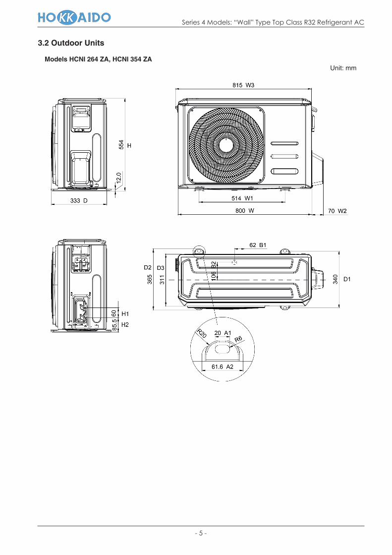
3.2 Outdoor Units
Models HCNI 264 ZA, HCNI 354 ZAUnit: mm
- 6 -
Series 4 Models: “Wall” Type Top Class R32 Refrigerant AC
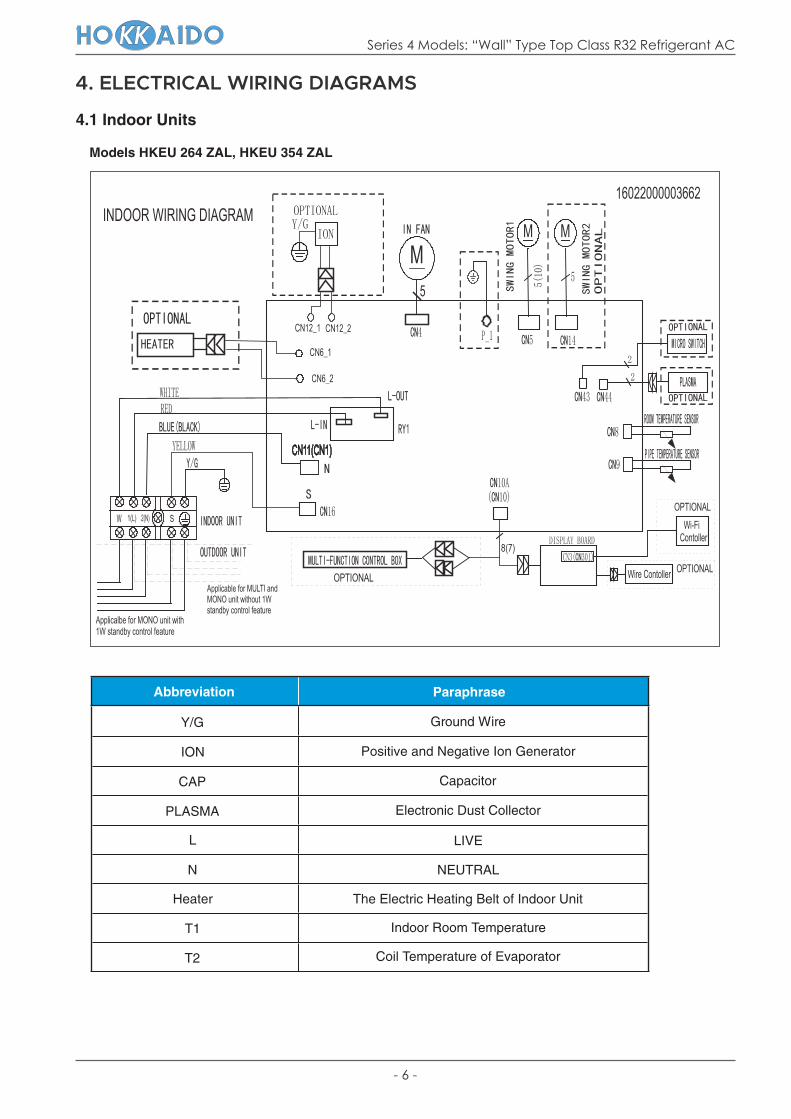
4. ELECTRICAL WIRING DIAGRAMS
4.1 Indoor Units
Models HKEU 264 ZAL, HKEU 354 ZAL
Abbreviation Paraphrase
Y/G Ground Wire
ION Positive and Negative Ion Generator
CAP Capacitor
PLASMA Electronic Dust Collector
L LIVE
N NEUTRAL
Heater The Electric Heating Belt of Indoor Unit
T1 Indoor Room Temperature
T2 Coil Temperature of Evaporator

- 7 -
Series 4 Models: “Wall” Type Top Class R32 Refrigerant AC
4.2 Outdoor Units
Models HCNI 264 ZA, HCNI 354 ZA
Abbreviation Paraphrase
4-WAY Gas Valve Assembly/4-WAY VALVE
AC-FAN Alternating Current (AC) FAN
DC-FAN Direct Current (DC) FAN
CT1 AC Current Detector
COMP Compressor
L-PRO Low Pressure Switch
H-PRO High Pressure Switch
T3 Coil Temperature of Condenser
T4 Outdoor Ambient Temperature
TH Compressor Suction Temperature
TP Compressor Discharge Temperature
EEV Electronic Expansion Valve

- 8 -
Series 4 Models: “Wall” Type Top Class R32 Refrigerant AC
5. OPERATION MODES AND FUNCTIONS
Temperature values abbreviations:
Abbreviation Element
T1 Indoor room temperature
T2 Coil temperature of evaporator
T3 Coil temperature of condenser
T4 Outdoor ambient temperature
TS Set temperature
TP Compressor discharge temperature
5.1 Abbreviation
5.2 Safety FeaturesCompressor 3-minute delay at restartCompressor functions are delayed for up to 1 minute upon the first startup of the unit, and are delayed for up to 3 minutes upon subsequent unit restarts.
Temperature protection of compressor topThe unit will stop working when the compressor top temp. protector cut off, and will restart after the compressor top temp. protector restart.
Automatic shut-off based on discharge temperatureIf the compressor discharge temperature exceeds 108°C for 5 seconds, the compressor ceases operation.
Automatic shut-off based on fan speedIf the indoor fan speed registers below 300RPM for an extended period of time, the unit ceases operation and the corresponding error code is displayed on the indoor unit.
Inverter module protectionThe inverter module has an automatic shut-off mechanism based on the unit’s current, voltage, and temperature. If automatic shut-off is initiated, the corresponding error code is displayed on the indoor unit and the unit ceases operation.
Indoor fan delayed operation• When the unit starts, the louver is automatically activated and the indoor fan will operate after a period of 7 seconds. • If the unit is in heating mode, the indoor fan is regulated by the anti-cold wind function.
Compressor preheating Preheating is automatically activated when T4 sensor is lower than 3°C.
Sensor redundancy and automatic shut-off• If one temperature sensor malfunctions, the air conditio-ner continues operation and displays the corresponding error code, allowing for emergency use.
• When more than one temperature sensor is malfunctio-ning, the air conditioner ceases operation.
Refrigerant leakage detectionThis function is active only when cooling mode is selec-ted. It will detect if the compressor is being damaged by refrigerant leakage or by compressor overload. This is measured using the coil temperature of evaporator T2 when the compressor is in operation.
- 9 -
Series 4 Models: “Wall” Type Top Class R32 Refrigerant AC
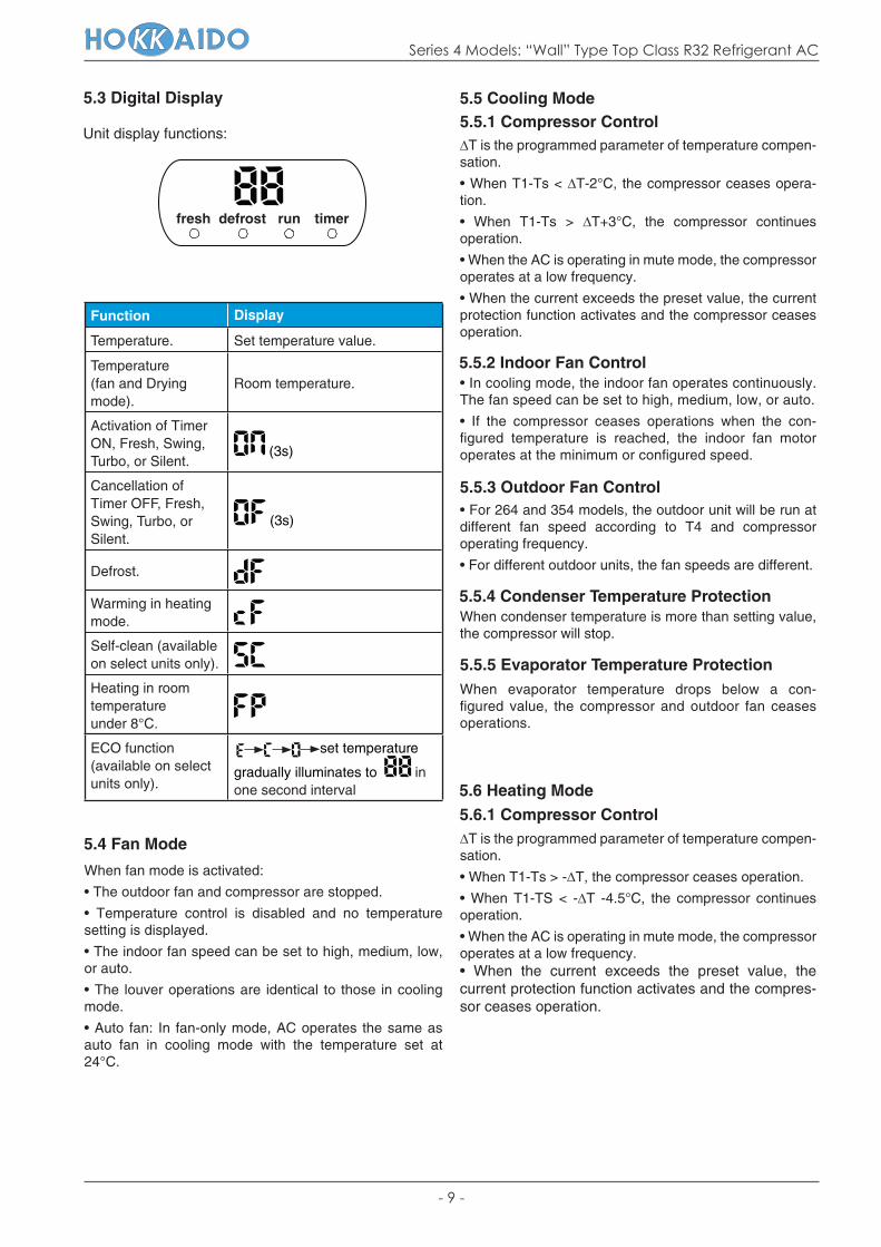
Unit display functions:
Function Display
Temperature. Set temperature value.
Temperature (fan and Drying mode).
Room temperature.
Activation of Timer ON, Fresh, Swing, Turbo, or Silent.
(3s)
Cancellation of Timer OFF, Fresh, Swing, Turbo, or Silent.
(3s)
Defrost.
Warming in heating mode.
Self-clean (available on select units only).
Heating in room temperature under 8°C.
ECO function (available on select units only).
set temperature
gradually illuminates to in one second interval
5.3 Digital Display
5.4 Fan Mode
When fan mode is activated:
• The outdoor fan and compressor are stopped.
• Temperature control is disabled and no temperature setting is displayed.
• The indoor fan speed can be set to high, medium, low, or auto.
• The louver operations are identical to those in cooling mode.
• Auto fan: In fan-only mode, AC operates the same as auto fan in cooling mode with the temperature set at 24°C.
5.5 Cooling Mode5.5.1 Compressor Control∆T is the programmed parameter of temperature compen-sation.
• When T1-Ts < ∆T-2°C, the compressor ceases opera-tion.
• When T1-Ts > ∆T+3°C, the compressor continues operation.
• When the AC is operating in mute mode, the compressor operates at a low frequency.
• When the current exceeds the preset value, the current protection function activates and the compressor ceases operation.
5.5.2 Indoor Fan Control• In cooling mode, the indoor fan operates continuously. The fan speed can be set to high, medium, low, or auto.
• If the compressor ceases operations when the con- figured temperature is reached, the indoor fan motor operates at the minimum or configured speed.
5.5.3 Outdoor Fan Control• For 264 and 354 models, the outdoor unit will be run at different fan speed according to T4 and compressor operating frequency.
• For different outdoor units, the fan speeds are different.
5.5.4 Condenser Temperature ProtectionWhen condenser temperature is more than setting value, the compressor will stop.
5.5.5 Evaporator Temperature ProtectionWhen evaporator temperature drops below a con- figured value, the compressor and outdoor fan ceases operations.
5.6 Heating Mode5.6.1 Compressor Control∆T is the programmed parameter of temperature compen-sation.
• When T1-Ts > -∆T, the compressor ceases operation.
• When T1-TS < -∆T -4.5°C, the compressor continues operation.
• When the AC is operating in mute mode, the compressor operates at a low frequency.• When the current exceeds the preset value, the current protection function activates and the compres-sor ceases operation.
fresh defrost run timer

- 10 -
Series 4 Models: “Wall” Type Top Class R32 Refrigerant AC
∆T Running mode
∆T > 2°C Cooling
-2°C ≤ ∆T ≤ 2°C Fan-only
∆T < -2°C Heating*
5.6.2 Indoor Fan Control• When the compressor is on, the indoor fan can be set to high/medium/low/auto.
• When indoor unit coil temperature is low, the anti-cold air function will start and indoor fan motor will run at low speed, the speed can’t be changed, when the temperature is lower than setting value, the indoor fan motor will stop.
• When the indoor temperature reaches the setting tempe-rature, the compressor will stop, the indoor fan motor will run at the minimum speed or setting speed. (The anti-cold air function is valid).
5.6.3 Outdoor Fan Control• For 264 and 354 models, the outdoor unit will be run at different fan speed according to T4 and compressor ope- rating frequency.
• For different outdoor units, the fan speeds are different.
5.6.4 Defrosting mode For 264 and 354 models:
• The unit enters defrosting mode according to changes in the temperature value of T3 and T4 as well as the com- pressor running time.
• In defrosting mode, the compressor continues to run, the indoor and outdoor motor will cease operation, the defrost light of the indoor unit will turn on, and the “ ” symbol is displayed.
• If any one of the following conditions is satisfied, defro-sting ends and the machine switches to normal heating mode:
• T3 rises above TCDE1°C.• T3 maintained above TCDE2°C for 80 seconds.
• Unit runs for 15 minutes consecutively in defrosting mode.
5.6.5 Evaporator Temperature ProtectionWhen the evaporator temperature exceeds a preset protection value, the compressor ceases operation.
5.7 Auto-mode• This mode can be selected with the remote controller.
• In auto mode, the machine selects cooling, heating, or fan-only mode on the basis of ∆T (∆T =T1-Ts).
(Heating*: In auto mode, cooling only models run the fan.)
• AC will run in auto mode in the below cases:
• Pressing the forced auto button.• If AC is off, it will run in auto mode when the timer on function is active.• After setting the mode, AC will run in auto mode if the compressor keeps not running for certain time.
5.8 Drying mode• Indoor fan speed is fixed at breeze and can’t be chan-ged. The louver angle is the same as in cooling mode.
• In drying mode, if room temperature is lower than 10°C, the compressor will stop and not resume until room temperature exceeds 12°C.
• All protections are active and the same as that in cooling mode.
5.9 Forced operation function• Forced cooling mode:The compressor and outdoor fan continue to run and the indoor fan runs at low speed. After running for 30 minutes, the AC will switch to auto mode with a preset temperature of 24°C.
• Forced auto mode:Forced auto mode operates the same as normal auto mode with a preset temperature of 24°C.• The unit exits forced operation when it receives the fol- lowing signals:
• Switch on.
• Switch off.
• Timer on.
• Timer off.
• Changes in:- Mode.- Fan speed.- Sleeping mode.
- 11 -
Series 4 Models: “Wall” Type Top Class R32 Refrigerant AC
5.10 Auto-Restart function• The indoor unit has an auto-restart module that allows the unit to restart automatically. The module automatically stores the current settings (not including the swing setting) and, in the case of a sudden power failure, will restore those settings automatically within 3 minutes after power returns.
• If the unit was in forced cooling mode, it will run in this mode for 30 minutes and turns to auto mode with tempera-ture set to 24°C.
• If there is a power failure while the unit is running, the compressor starts 3 minutes after the unit restarts. If the unit was already off before the power failure, the compres-sor starts 1 minute after the unit restarts.
5.11 Refrigerant Leakage Detection• With this new technology, the display area will show “EC” when the outdoor unit detects refrigerant leakage.
• When compressor is active, the value of the Coil tempe-rature of evaporator T2 has no change or very little change.
5.12 Louver Position Memory FunctionWhen starting the unit again after shutting down, its louver will restore to the angle originally set by the user, but the precondition is that the angle must be within the allowable range; if it exceeds, it will memorize the maximum angle of the louver. During operation, if the power fails or the end user shuts down the unit in the turbo mode, the louver will restore to the default angle.
5.13 8°C Heating (Optional)In heating mode, the temperature can be set to as low as 8°C, preventing the indoor area from freezing if unoccu-pied during severe cold weather.
5.14 Self Clean (Optional) • If you press “Self Clean” when the unit is in cooling or drying mode:
• For cooling only models, the indoor unit will run in low fan mode for a certain time, then ceases operation.• For these heat pump models, the indoor unit will run in fan-only mode, then low heat, and finally in fan-only mode.
• Self Clean keeps the indoor unit dry and prevents mold growth.
5.15 Follow Me (Optional) • If you press “Follow Me” on the remote, the indoor unit will beep. This indicates the “Follow Me” function is active.
• Once active, the remote control will send a signal every 3 minutes, with no beeps. The unit automatically sets the temperature according to the measurements from the remote control.
• The unit will only change modes if the information from the remote control makes it necessary, not from the unit’s temperature setting.
• If the unit does not receive a signal for 7 minutes or you press “Follow Me”, the function turns off. The unit regula-tes temperature based on its own sensor and settings.
5.16 Silence (Optional)Press “Silence” on the remote control to enable the SILENCE function. While this function is active, the com- pressor frequency is maintained at a lower level than F2. The indoor unit will run at faint breeze, which reduces noise to the lowest possible level.
5.17 Information Inquiry• To enter information inquiry status, complete the fol- lowing procedure within 10 seconds:
• Press LED 3 times.• Press SWING 3 times.• If the proceeding is successful, you will hear beeps for 2 seconds.
• Use the LED and SWING buttons to cycle through information displayed.
• Pressing LED will display the next code in the sequence. Pressing SWING will show the previous.
• The following table (see next page) shows information codes. The screen will display this code for 2 seconds, then the relevant information for 25 seconds.

- 12 -
Series 4 Models: “Wall” Type Top Class R32 Refrigerant AC
Displayed Code Explanation Displayed value Meaning Additional Notes
T1
T2
T3
T4
Tb
TP
TH
FT
Fr
Room temp.
-1F,-1E,-1d,-1c,-1b,-1A
-19—99
A0,A1,…A9
b0,b1,…b9
c0,c1,…c9
d0,d1,…d9
E0,E1,…E9
F0,F1,…F9
-25,-24,-23,-22, -21,-20
-19—99
100,101,…109
110,111,…119
120,121,…129
130,131,…139
140,141,…149
150,151,…159
Indoor coil temp.
Outdoor coil temp.
Ambient temp.
Outlet temp. of indoor coil.
Discharge temp.
Suction temp.
Targeted frequency.
Actual frequency.
IF Indoor fan speed.
0
1,2,3,4
14-FF
OFF N/A
OF Outdoor fan speed.
LA EXV opening angle. 0-FF -
CT 0-FF 0-255 minutes.
ST 0-99
1. All displayed temperatures use actual values.
2. All temperatures are di- splayed in °C regardless of remote used.
3. T1, T2, T3, T4, and T2B display ranges from -25°C to 70°C. TP display ranges from -20°C to 130 °C.
4. The frequency display ran- ges from 0 to 159HZ.
5. If the actual values exceed or fall short of the defined range, the values closest to the maximum and minimum values will be displayed.
Low speed, Medium speed, High speed, Turbo.
Actual fan speed is equal to the display value converted to de- cimal value and mul- tiplied by 10. This is measured in RPM.
Used for some large capacity motors.
Used for some small capaci-ty motors.The display value is 14-FF (hexadecimal). Correspond- ing fan speed ranges from 200RPM to 2550RPM.
Compressor continu-ous running time.
Causes of compres-sor stop.
If the actual value exceeds or falls short of the defined ran- ge, the value closest to the maximum and minimum will be displayed.
Actual EXV opening value is equal to the display value conver-ted to decimal value and then multiplied by 2.
For a detailed expla-nation, contact tech- nical support.
-

- 13 -
Series 4 Models: “Wall” Type Top Class R32 Refrigerant AC
Displayed Code Explanation Meaning Additional Notes
A0
Reserved
0-FF
2-28
5-20
5-25
- -
A1
0
1
2
3
4
5
6
L
A
U
T
A
5
T
Displayed Value

- 14 -
Series 4 Models: “Wall” Type Top Class R32 Refrigerant AC
6. TROUBLESHOOTING
WARNING
6.1 Safety Caution
Electricity remains in capacitors even when the power supply is off. Ensure the capacitors are fully discharged before troubleshooting.
• For other models, connect discharge resistance (approx. 100Ω 40W) or a soldering iron plug between the positi-ve and negative terminals of the electrolytic capacitor.
• The terminals are located on the bottom surface of the outdoor PCB.
Note: This picture is for reference only. Actual appearances may vary.
Discharging position (discharging period is 10 sec. or more)
Plug of soldering iron

- 15 -
Series 4 Models: “Wall” Type Top Class R32 Refrigerant AC
OperationLamp
Timer Lamp
Display Error Information
1 time OFF E0 Indoor unit EEPROM parameter error.
2 times OFF E1 Indoor / outdoor units communication error.
4 times OFF E3 The indoor fan speed is operating outside of the normal range.
5 times OFF E4Indoor room temperature sensor T1 is in open circuit state or has short circuit.
6 times OFF E5Evaporator coil temperature sensor T2 is in open circuit state or has shortcircuit.
7 times OFF EC Refrigerant leak detected.
1 time ON F0 Overload current protection.
2 times ON F1Outdoor ambient temperature sensor T4 is in open circuit state or hasshort circuit.
3 times ON F2Condenser coil temperature sensor T3 is in open circuit state or hasshort circuit.
4 times ON F3Compressor discharge temperature sensor TP is in open circuit state or has short circuit.
5 times ON F4 Outdoor unit EEPROM parameter error.
6 times ON F5 The outdoor fan speed is operating outside of the normal range.
1 time FLASH p0 IPM malfunction or IGBT over-strong current protection.
2 times FLASH p1 Over voltage or too low voltage protection.
3 times FLASH p2 High temperature protection of IPM module.
5 times FLASH p4 Inverter compressor drive error.
6.2 General Troubleshooting
6.2.1 Error Display (Indoor Unit)When the indoor unit encounters a recognized error, the indicator light (Operation Lamp) will flash in a correspon-ding series, the timer indicator (Timer Lamp) may turn on or begin flashing, and an error code will be displayed.
These error codes are described in the following table.
For other errors:
The display board may show a garbled code or a code undefined by the service manual. Ensure that this code is not a temperature reading.
Troubleshooting:
Test the unit using the remote control. If the unit does not respond to the remote, the indoor PCB requires replacement. If the unit responds, the display board requires replacement.

- 16 -
Series 4 Models: “Wall” Type Top Class R32 Refrigerant AC
WARNING
Be sure to turn off unit before any maintenance to prevent damage or injury.
No. Problem
1 Unit will not start.
2 The power switch is on but fans will not start.
3 The temperature on the display board cannot be set.
4 Unit is on, but the wind is not cold (hot).
5 Unit runs, but it shortly stops.
6 The unit starts up and stops frequently.
7 Unit runs continuously but with insufficient cooling (heating) effect.
8 Cooling mode cannot be changed to heating mode.
9 Unit is noisy.
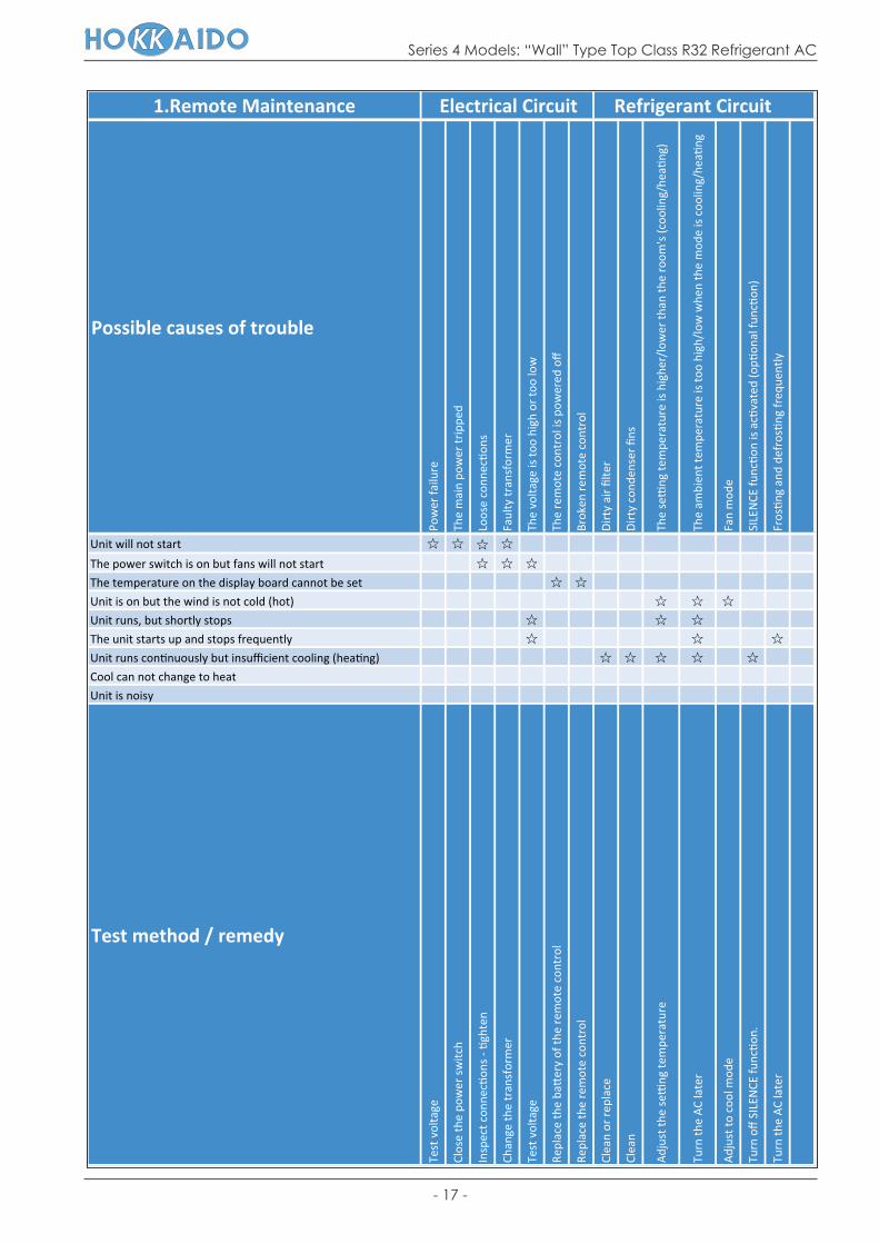
6.3 Error Diagnosis and Troubleshooting Without Error Code
6.3.1 Remote maintenance
SUGGESTION:
When troubles occur, please check the following points with Customers before field maintenance.
- 17 -
Series 4 Models: “Wall” Type Top Class R32 Refrigerant AC
1.Remote Maintenance
Possible causes of trouble
Pow
er fa
ilure
The
mai
n po
wer
trip
ped
Loos
e co
nnec
ons
Faul
ty tr
ansf
orm
er
The
volta
ge is
too
high
or
too
low
The
rem
ote
cont
rol i
s po
wer
ed o
ff
Brok
en r
emot
e co
ntro
l
Dir
ty a
ir fi
lter
Dir
ty c
onde
nser
fins
The
se
ng te
mpe
ratu
re is
hig
her/
low
er th
an th
e ro
om's
(coo
ling/
hea
ng)
The
ambi
ent t
empe
ratu
re is
too
high
/low
whe
n th
e m
ode
is c
oolin
g/he
ang
Fan
mod
e
SILE
NCE
func
on
is a
cva
ted
(op
onal
func
on)
Fros
ng
and
defr
osn
g fr
eque
ntly
Unit will not start
The power switch is on but fans will not start
The temperature on the display board cannot be set
Unit is on but the wind is not cold (hot)
Unit runs, but shortly stops
The unit starts up and stops frequently
Unit runs connuously but insufficient cooling (heang)
Cool can not change to heat
Unit is noisy
Test method / remedy
Test
vol
tage
Clos
e th
e po
wer
sw
itch
Insp
ect c
onne
con
s -
ghte
n
Chan
ge th
e tr
ansf
orm
er
Test
vol
tage
Repl
ace
the
ba
ery
of th
e re
mot
e co
ntro
l
Repl
ace
the
rem
ote
cont
rol
Clea
n or
rep
lace
Clea
n
Adj
ust t
he s
eng
tem
pera
ture
Turn
the
AC
late
r
Adj
ust t
o co
ol m
ode
Turn
off
SIL
ENCE
func
on.
Turn
the
AC
late
r
Refrigerant CircuitElectrical Circuit

- 18 -
Series 4 Models: “Wall” Type Top Class R32 Refrigerant AC
1.Remote Maintenance
Possible causes of trouble
Hea
vy lo
ad c
ondi
on
Loos
en h
old
dow
n bo
lts a
nd /
or
scre
ws
Bad
airp
roof
The
air
inle
t or
outle
t of e
ither
uni
t is
bloc
ked
Inte
rfer
ence
from
cel
l pho
ne to
wer
s an
d re
mot
e bo
oste
rs
Ship
ping
pla
tes
rem
ain
aac
hed
Unit wil l not start
The power switch is on but fans will not start
The temperature on the display board cannot be set
Unit is on but the wind is not cold (hot)
Unit runs, but shortly stops
The unit starts up and stops frequently
Unit runs connuously but insufficient cooling (heang)
Cool can not change to heat
Unit is noisy
Test method / remedy
Chec
k he
at lo
ad
Tigh
ten
bolts
or
scre
ws
Clos
e al
l the
win
dow
s an
d do
ors
Rem
ove
the
obst
acle
s
Reco
nnec
t the
pow
er o
r pr
ess
ON
/OFF
bu
on o
n re
mot
e co
ntro
l to
rest
art o
pera
on
Rem
ove
them
Others

- 19 -
Series 4 Models: “Wall” Type Top Class R32 Refrigerant AC
No. Problem
1
2
3
4
5
6
7
8
9
10
11
12
13
14
15
6.3.2 Field maintenance
Unit will not start.
Compressor will not start, but fans run.
Compressor and condenser (outdoor) fan will not start.
Evaporator (indoor) fan will not start.
Condenser (Outdoor) fan will not start.
Unit runs, but it shortly stops.
Compressor short-cycles due to overload.
High discharge pressure.
Low discharge pressure.
High suction pressure.
Low suction pressure.
Unit runs continuously but with insufficient cooling effect.
Too much cooling effect.
Compressor is noisy.
Horizontal louver cannot revolve.

- 20 -
Series 4 Models: “Wall” Type Top Class R32 Refrigerant AC
2.Field Maintenance
Possible causes of trouble
Pow
er fa
ilure
Blow
n fu
se o
r va
rist
or
Loos
e co
nnec
ons
Shor
ted
or b
roke
n w
ires
Safe
ty d
evic
e op
ens
Faul
ty th
erm
osta
t / r
oom
tem
pera
ture
sen
sor
Wro
ng s
eng
pla
ce o
f tem
pera
ture
sen
sor
Faul
ty tr
ansf
orm
er
Shor
ted
or o
pen
capa
cito
r
Faul
ty m
agne
c c
onta
ctor
for
com
pres
sor
Faul
ty m
agne
c c
onta
ctor
for
fan
Low
vol
tage
Faul
ty s
tepp
ing
mot
or
Shor
ted
or g
roun
ded
com
pres
sor
Shor
ted
or g
roun
ded
fan
mot
or
Unit wil l not start
Compressor will not start but fans run
Compressor and condenser (outdoor) fan will not start
Evaporator (indoor) fan will not start
Condenser (Outdoor) fan will not start
Unit runs, but shortly stops
Compressor short-cycles due to overload
High discharge pressure
Low discharge pressure
High sucon pressure
Low sucon pressure
Unit runs connuously but insufficient cooling
Too cool
Compressor is noisy
Horizontal louver can not revolve
Test method / remedy
Test
vol
tage
Insp
ect f
use
type
& s
ize
Insp
ect c
onne
con
s -
ghte
n
Test
cir
cuits
with
test
er
Test
con
nui
ty o
f saf
ety
devi
ce
Test
con
nui
ty o
f the
rmos
tat /
sen
sor
& w
irin
g
Plac
e th
e te
mpe
ratu
re s
enso
r at
the
cent
ral o
fth
e ai
r in
let g
rille
Chec
k co
ntro
l cir
cuit
with
test
er
Chec
k ca
paci
tor
with
test
er
Test
con
nui
ty o
f coi
l & c
onta
cts
Test
con
nui
ty o
f coi
l & c
onta
cts
Test
vol
tage
Repl
ace
the
step
ping
mot
or
Chec
k re
sist
ance
with
mul
met
er
Chec
k re
sist
ance
with
mul
met
er
Electrical Circuit

- 21 -
Series 4 Models: “Wall” Type Top Class R32 Refrigerant AC
Com
pres
sor
stuc
k
Shor
tage
of r
efri
gera
nt
Rest
rict
ed li
quid
line
Dir
ty a
ir fi
lter
Dir
ty e
vapo
rato
r co
il
Insu
ffici
ent a
ir th
roug
h ev
apor
ator
coi
l
Ove
rcha
rge
of r
efri
gera
nt
Dir
ty o
r pa
ral
ly b
lock
ed c
onde
nser
Air
or
inco
mpr
essi
ble
gas
in r
efri
gera
nt c
ycle
Shor
t cyc
ling
of c
onde
nsin
g ai
r
Hig
h te
mpe
ratu
re c
onde
nsin
g m
ediu
m
Insu
ffici
ent c
onde
nsin
g m
ediu
m
Brok
en c
ompr
esso
r in
tern
al p
arts
Ineffi
cien
t com
pres
sor
Expa
nsio
n va
lve
obst
ruct
ed
Expa
nsio
n va
lve
or c
apill
ary
tube
clo
sed
com
plet
ely
Leak
ing
pow
er e
lem
ent o
n ex
pans
ion
valv
e
Poor
inst
alla
on
of fe
eler
bul
b
Hea
vy lo
ad c
ondi
on
Loos
en h
old
dow
n bo
lts a
nd /
or
scre
ws
Ship
ping
pla
tes
rem
ain
aac
hed
Poor
cho
ices
of c
apac
ity
Cont
act o
f pip
ing
with
oth
er p
ipin
g or
ext
erna
l pla
te
Repl
ace
the
com
pres
sor
Leak
test
Repl
ace
rest
rict
ed p
art
Clea
n or
rep
lace
Clea
n co
il
Chec
k fa
n
Chan
ge c
harg
ed r
efri
gera
nt v
olum
e
Clea
n co
nden
ser
or r
emov
e ob
stac
le
Purg
e, e
vacu
ate
and
rech
arge
Rem
ove
obst
ruc
on to
air
flow
Rem
ove
obst
ruc
on in
air
or
wat
er fl
ow
Rem
ove
obst
ruc
on in
air
or
wat
er fl
ow
Repl
ace
com
pres
sor
Test
com
pres
sor
effici
ency
Repl
ace
valv
e
Repl
ace
valv
e
Repl
ace
valv
e
Fix
feel
er b
ulb
Chec
k he
at lo
ad
Tigh
ten
bolts
or
scre
ws
Rem
ove
them
Choo
se A
C of
lage
r ca
paci
ty o
r ad
d th
e nu
mbe
rof
AC
Rec
fy p
ipin
g so
as
not t
o co
ntac
t eac
h ot
her
orw
ith e
xter
nal p
late
Refrigerant Circuit Others

- 22 -
Series 4 Models: “Wall” Type Top Class R32 Refrigerant AC
Part requiring replacementError Code
E0 E1 E3 E4 E5 EC F0
Indoor PCB x
Outdoor PCB x x x x x
Reactor x x x x x x
Indoor fan motor x x x x x x
Outdoor fan motor x x X x x x x
Temperature sensor x x x x
T2 Sensor x x x x x x
Additional refrigerant x x x x x x x
Compressor x x x x x x
IPM board x x x x x x x
Outdoor unit x x x x x x
Display board x x x x x x x
Part requiring replacementError Code
F1 F2 F3 F4 F5 P0 P1 P2 P4
Indoor PCB x x x x x x x x x
Outdoor PCB
Reactor x x x x x x x x
Indoor fan motor x x x x x x x x x
Outdoor fan motor x x x x x x x x
Temperature sensor x x x X x x
T2 Sensor x x x x x x x x x
Additional refrigerant x x x x x x x x x
Compressor x x x x x x x
IPM board x x x x x x
Outdoor unit x x x x x x x x x
6.4 Quick Maintenance by Error CodeIf you do not have the time to test whether specific parts are faulty, you can directly change the required parts according to the error code.
You can find the parts to replace by error code in the following table.

- 23 -
Series 4 Models: “Wall” Type Top Class R32 Refrigerant AC
Position Resistance Value
Compressor Model KSN98D22UFZ KTN110D42UFZ KSM135D23UFZ KTF235D22UMT
Terminals: Blue - Red
1.57Ω (20°C) 1.82Ω (20°C) 1.72Ω (20°C) 0.75Ω (20°C)
6.5 Troubleshooting by Error Code
6.5.1 Common Check Procedures6.5.1.1 Temperature Sensor Check
Disconnect the temperature sensor from PCB, measure the resistance value with a tester.
Temperature Sensors:Room temp. (T1) sensor.Indoor coil temp. (T2) sensor.Outdoor coil temp. (T3) sensor.Outdoor ambient temp. (T4) sensor.Compressor discharge temp. (TP) sensor.
Measure the resistance value of each temperature sensor by using the multi-meter.
6.5.1.2 Compressor checking
Measure the resistance value of each winding by using the tester.
Terminals: Blue - Black
Terminals: Red - Blue
Input Terminal
Red
Black
Blue
1
2
3
Blue
Red
Black

- 24 -
Series 4 Models: “Wall” Type Top Class R32 Refrigerant AC
Digital tester Normal resistance value
Normal resistance value
Digital tester
(+) Red (+) Red
-
(-) Black (-) Black
∞
P
N U
NU V
V W
W
6.5.1.3 IPM Continuity Check
Turn off the power, let the large capacity electrolytic capacitors discharge completely, and dismount the IPM. Use a digital tester to measure the resistance between P and U, V, W, N; U, V, W and N.
(Several MΩ)
∞(Several MΩ)
- 25 -
Series 4 Models: “Wall” Type Top Class R32 Refrigerant AC
Troubleshooting and repair:
NO
YES
Is it plugged well? NO
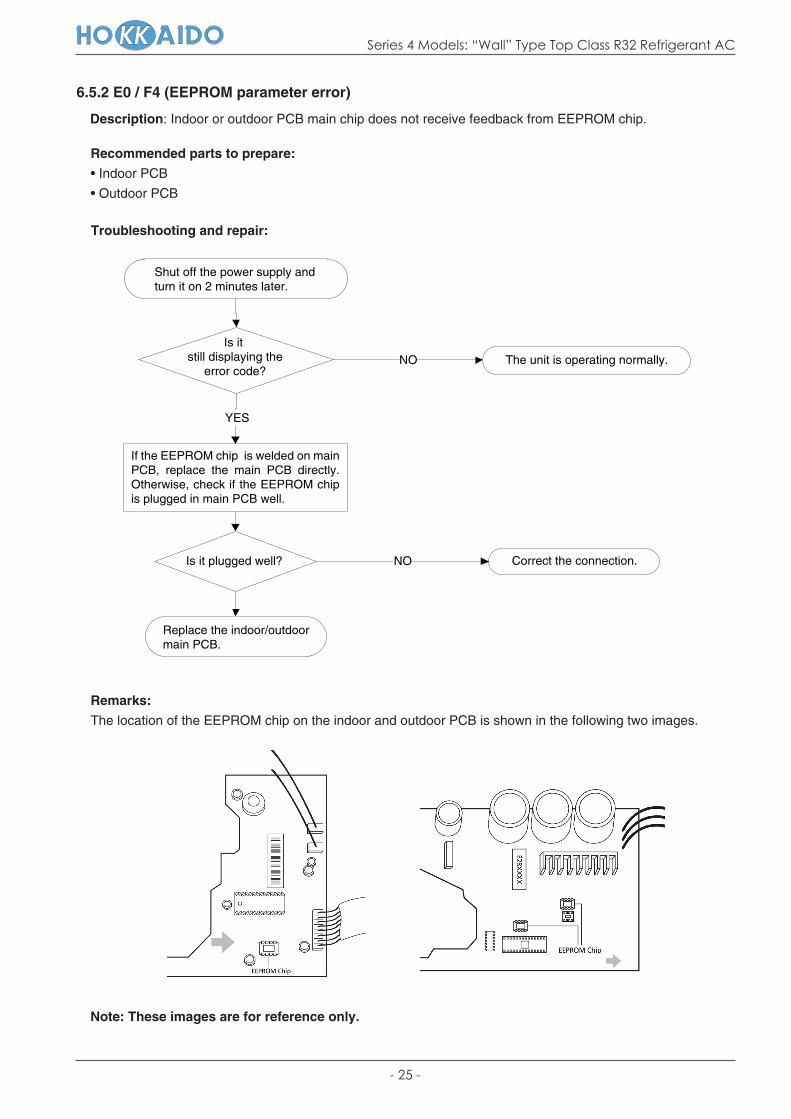
6.5.2 E0 / F4 (EEPROM parameter error)
Description: Indoor or outdoor PCB main chip does not receive feedback from EEPROM chip.
Recommended parts to prepare:
• Indoor PCB
• Outdoor PCB
Remarks:
The location of the EEPROM chip on the indoor and outdoor PCB is shown in the following two images.
Note: These images are for reference only.
Shut off the power supply and turn it on 2 minutes later.
Is it still displaying the
error code?The unit is operating normally.
Correct the connection.
Replace the indoor/outdoormain PCB.
If the EEPROM chip is welded on main PCB, replace the main PCB directly. Otherwise, check if the EEPROM chip is plugged in main PCB well.

- 26 -
Series 4 Models: “Wall” Type Top Class R32 Refrigerant AC
Troubleshooting and repair:
6.5.3 E1 (Indoor and outdoor unit communication error)
Description: The indoor unit has not received feedback from the outdoor unit for 110 seconds, 4 consecuti-ve times.
Recommended parts to prepare:
• Indoor PCB
• Outdoor PCB
• Reactor
Does a problem remain? The unit is operating normally.NO
YES
Check the outdoor wiring connection.
YES
YES
NO
NO
Is it normal?
YES
Is the error resolved?
NO
NO
NO
Power off, then restart the unit after 2 minutes.
Measure Vs. (Vs is the voltage between S and N of outdoor unit. Red pan-S, Black pan-N).
Is the voltage moving alternately between
Positive and Negative?
The voltage moves alternately withpositive value.
The voltage is a certain value.
Check the indoor wiringconnections.
Replace the indoor PCB.Power on.
Replace the outdoor PCB.
Is it normal?
Is it normal?
Check the reactor.
Replace thereactor.
Replace the outdoor PCB.Power on.
Is the error resolved?
Replace the indoor PCB.

- 27 -
Series 4 Models: “Wall” Type Top Class R32 Refrigerant AC
Remarks:
• Use a multimeter to test the DC voltage between 2 port and 3 port of outdoor unit. The red pin of multimeter connects with 2 port while the black pin is for 3 port.
• When AC is normal running, the voltage will move alternately between -25V to 25V.
• If the outdoor unit has malfunction, the voltage will move alternately with positive value.
• While if the indoor unit has malfunction, the voltage will be a certain value.
• Use a multimeter to test the resistance of the reactor which does not connect with capacitor.
• The normal value should be around 0 Ohm. Otherwise, the reactor must have malfunction.

- 28 -
Series 4 Models: “Wall” Type Top Class R32 Refrigerant AC
Troubleshooting and repair:
YES
Does a problem remain? NO
YES
NO
YES
YES
NO
6.5.4 E3 / F5 (Fan speed is operating outside of the normal range)
Description: When the indoor fan speed keeps too low (300RPM) for certain time, the unit will stop and the LED will display the failure (E3). For 18k & 24k models (i.e. not for these Hokkaido models), when the outdoor fan speed registers below 150RPM or over 1500RPM for an extended period of time, the unit will stop and the LED will display the failure (F5).
Recommended parts to check or to prepare:
• Wiring mistake
• Faulty fan assembly
• Faulty fan motor
• Faulty PCB
Power off then restart the unit after 2 minutes.
The unit is operating normally.
Shut off the power supply.Rotate the fan by hand.
Does it turn easily? Find the cause of the problem and resolve it.
Check the wiring of fan motor.
Is it improperly wired? Ensure proper connections.
Measure the voltage for the fanmotor from the PCB.
Is it within normal parameters?
Replace the fan motor.
Replace the indoor / outdoor PCB.

- 29 -
Series 4 Models: “Wall” Type Top Class R32 Refrigerant AC
No. Color Signal Voltage
1 Red Vs/Vm 280V~380V
2 --- --- ---
3 Black GND 0V
4 White Vcc 14-17.5V
5 Yellow Vsp 0~5.6V
6 Blue FG 14-17.5V
Index:
1. Indoor or Outdoor DC Fan Motor (control chip is in fan motor)Power on and when the unit is in standby, measure the voltage of pin1-pin3, pin4-pin3 in fan motor connec-tor. If the value of the voltage is not in the range shown in below table, the PCB must have problems and needs to be replaced.
• DC motor voltage input and output (voltage: 220-240V AC):
2. Outdoor DC Fan Motor (control chip is in outdoor PCB)
Release the U,V W connector. Measure the resistance of U-V, U-W, V-W. If the resistance values are not equal to each other, the fan motor must have problems and needs to be replaced; otherwise the PCB must have problems and needs to be replaced.

- 30 -
Series 4 Models: “Wall” Type Top Class R32 Refrigerant AC
Troubleshooting and repair:
NO
YES
NO
YES
6.5.5 E4 / E5 / F1 / F2 / F3 (Open circuit or short circuit of temperature sensor diagnosis and solution)
Description: If the sampling voltage is lower than 0.06V or higher than 4.94V, the LED will display the failure.
Recommended parts to check or to prepare:
• Wiring mistake
• Faulty sensor
• Faulty PCB
Check the connection betweentemperature sensor and PCB.
Is it properly wired? Ensure proper connections.
Measure the resistance value of the sensor.
Replace the sensor.Is the value
within acceptableparameters?
Replace indoor or outdoor PCB.

- 31 -
Series 4 Models: “Wall” Type Top Class R32 Refrigerant AC
Does a problem remain?
YES
NO
NO
NO
6.5.6 EC (Refrigerant Leakage Detection diagnosis and solution)
Description: Define the evaporator coil temp. T2 of the compressor when it just starts running as “Tcool”. In the beginning 8 minutes after the compressor starts up, if T2 < Tcool - 2°C does not keep for continuous 4 seconds and compressor running frequency higher than 50Hz does not keep for continuous 3 minutes, and this situation happens 3 times, the display area will show “EC” and AC will turn off.
Recommended parts to prepare or to check:
• Faulty T2 sensor
• Faulty indoor PCB
• System problems, such as leakage or blockages
Troubleshooting and repair:
Power off, then restart the unit 2 minutes later.
Put your hands in front of the indoor air outlet.
Is there somecool air blowing out from
indoor air outlet?Check the T2 sensor.
Check system for leakages.
Are any leakages present?
Is the T2 sensorsecurely attached?
Replace theindoor PCB.
Check System for blockagesand clear blockages if present.
Repair the leakage andrecharge the refrigerant.
YES
YES
YES

- 32 -
Series 4 Models: “Wall” Type Top Class R32 Refrigerant AC
Troubleshooting and repair:
YES
NO
YES
NO
YES
NO
YES
YES
NO
6.5.7 F0 (Overload current protection diagnosis and solution)
Description: An abnormal current rise is detected by checking the specified current detection circuit.
Recommended parts to check or to prepare:
• Power supply problems
• System blockage
• Faulty PCB
• Wiring mistake
• Compressor malfunction
Check the power supply.
Is it in working order? Stop the unit.
Check system for blockages.
Do any exist? Clear the blockage.
Check the compressor resistance values.
Replace the compressor.Are they
within acceptableparameters?
Check the connections and wires.
Are they properly connected? Ensure proper connectionsor replace the wires.
Check the reactor.
Replace outdoor PCB.Is it in working order?
Replace the outdoor unit.
NO

- 33 -
Series 4 Models: “Wall” Type Top Class R32 Refrigerant AC
Troubleshooting and repair:
YES
NO
Is it in working order ? NO
YES
NO
YES
Replace the compressor.
YES
NO
6.5.8 P0 (IPM malfunction or IGBT over-strong current protection diagnosis and solution)
Description: When the voltage signal which the IPM sends to the compressor drive chip is abnormal, the display LED shows “P0” and the AC turns off.
Recommended parts to check or to prepare:
• Wiring mistake
• IPM malfunction
• Faulty outdoor fan assembly
• Compressor malfunction
• Faulty outdoor PCB
Check the wiring betweenPCB and compressor.
Does an error exist?Ensure proper connections or replacethe wires and connectors.
Check the IPM.
Replace the IPM board or replace the outdoor PCB.
Check the outdoor fan and the outdoor unit ventilation.
Is it in working order?Please refer to the solution of the “Fan Speed is Out of Control” malfunction.
Check the compressor resistance values.
Replace the outdoor PCB.
Are they within acceptable
parameters?

- 34 -
Series 4 Models: “Wall” Type Top Class R32 Refrigerant AC
Troubleshooting and repair:
NO
YES
NO
YES
NO
YES
YES
6.5.9 P1 (Over voltage or too low voltage protection diagnosis and solution)
Description: Abnormal increases or decreases in voltage are detected by checking the specified voltage detection circuit.
Recommended parts to prepare:
• Power supply issues
• System leakage or blockage
• Faulty PCB
Check the power supply.
Is it in working order? Turn off the unit.
Check the connections and wires.
Are they in working order?Ensure proper connections or replace the wires.
Power on and measure the voltage between P and N.
Replace the IPM board.
While the unit is in standby, is the
voltage between P and N around DC 310V, 340V or 380V?
When starting up the unit, is it in the range
220V~400V?
Check the reactor.
Is it in working order? Replace outdoor PCB.
Replace the reactor.
NO

- 35 -
Series 4 Models: “Wall” Type Top Class R32 Refrigerant AC
Troubleshooting and repair:
NO
YES
6.5.10 P2 (High temperature protection of IPM module diagnosis and solution)
Description: If the temperature of IPM module is higher than setting value, the LED displays this failure code.
Recommended parts to prepare or to check:
• Faulty PCB
• Connection problems
Check the fastening screws on the PCB and IPM radiator.
Replace the outdoor control PCB.
Are they fixed tightly?
Tighten the screws andapply silicon grease.

- 36 -
Series 4 Models: “Wall” Type Top Class R32 Refrigerant AC
YES
NO
NO
YES
NO
YES
NO
YES
6.5.11 P4 (Inverter compressor drive error diagnosis and solution)
Description: An abnormal inverter compressor drive is detected by a special detection circuit, including communication signal detection, voltage detection, compressor rotation speed signal detection and so on.
Recommended parts to prepare ot to check:
• Wiring mistake
• IPM malfunction
• Faulty outdoor fan assembly
• Compressor malfunction
• Faulty outdoor PCB
Troubleshooting and repair:
Check the wiring between the PCB and compressor.
Is it improperly wired?
Check the IPM.
Replace the IPM board or replace the outdoor PCB.
Is IPM functioning properly?
Check the outdoor fan and the outdoor unit ventilation.
Is everythingin good working
order?
Please refer to “Fan Speed Malfunction”.
Check the compressorresistance values.
Replace the compressor.
Are they within acceptable
parameters?
Replace the outdoor PCB.
Ensure proper connections or replacethe wires and connectors.

- 37 -
Series 4 Models: “Wall” Type Top Class R32 Refrigerant AC
APPENDIX
i) Temperature Sensor Resistance Value Table for T1, T2, T3 and T4 (°C – kΩ)
°C °F kΩ °C °F kΩ °C °F kΩ °C °F kΩ
-20 -4 115.266 20 68 12.6431 60 140 2.35774 100 212 0.62973
-19 -2 108.146 21 70 12.0561 61 142 2.27249 101 214 0.61148
-18 0 101.517 22 72 11.5 62 144 2.19073 102 216 0.59386
-17 1 96.3423 23 73 10.9731 63 145 2.11241 103 217 0.57683
-16 3 89.5865 24 75 10.4736 64 147 2.03732 104 219 0.56038
-15 5 84.219 25 77 10 65 149 1.96532 105 221 0.54448
-14 7 79.311 26 79 9.55074 66 151 1.89627 106 223 0.52912
-13 9 74.536 27 81 9.12445 67 153 1.83003 107 225 0.51426
-12 10 70.1698 28 82 8.71983 68 154 1.76647 108 226 0.49989
-11 12 66.0898 29 84 8.33566 69 156 1.70547 109 228 0.486
-10 14 62.2756 30 86 7.97078 70 158 1.64691 110 230 0.47256
-9 16 58.7079 31 88 7.62411 71 160 1.59068 111 232 0.45957
-8 18 56.3694 32 90 7.29464 72 162 1.53668 112 234 0.44699
-7 19 52.2438 33 91 6.98142 73 163 1.48481 113 235 0.43482
-6 21 49.3161 34 93 6.68355 74 165 1.43498 114 237 0.42304
-5 23 46.5725 35 95 6.40021 75 167 1.38703 115 239 0.41164
-4 25 44 36 97 6.13059 76 169 1.34105 116 241 0.4006
-3 27 41.5878 37 99 5.87359 77 171 1.29078 117 243 0.38991
-2 28 39.8239 38 100 5.62961 78 172 1.25423 118 244 0.37956
-1 30 37.1988 39 102 5.39689 79 174 1.2133 119 246 0.36954
0 32 35.2024 40 104 5.17519 80 176 1.17393 120 248 0.35982
1 34 33.3269 41 106 4.96392 81 178 1.13604 121 250 0.35042
2 36 31.5635 42 108 4.76253 82 180 1.09958 122 252 0.3413
3 37 29.9058 43 109 4.5705 83 181 1.06448 123 253 0.33246
4 39 28.3459 44 111 4.38736 84 183 1.03069 124 255 0.3239
5 41 26.8778 45 113 4.21263 85 185 0.99815 125 257 0.31559
6 43 25.4954 46 115 4.04589 86 187 0.96681 126 259 0.30754
7 45 24.1932 47 117 3.88673 87 189 0.93662 127 261 0.29974
8 46 22.5662 48 118 3.73476 88 190 0.90753 128 262 0.29216
9 48 21.8094 49 120 3.58962 89 192 0.8795 129 264 0.28482
10 50 20.7184 50 122 3.45097 90 194 0.85248 130 266 0.2777
11 52 19.6891 51 124 3.31847 91 196 0.82643 131 268 0.27078
12 54 18.7177 52 126 3.19183 92 198 0.80132 132 270 0.26408
13 55 17.8005 53 127 3.07075 93 199 0.77709 133 271 0.25757
14 57 16.9341 54 129 2.95896 94 201 0.75373 134 273 0.25125
15 59 16.1156 55 131 2.84421 95 203 0.73119 135 275 0.24512
16 61 15.3418 56 133 2.73823 96 205 0.70944 136 277 0.23916
17 63 14.6181 57 135 2.63682 97 207 0.68844 137 279 0.23338
18 64 13.918 58 136 2.53973 98 208 0.66818 138 280 0.22776
19 66 13.2631 59 138 2.44677 99 210 0.64862 139 282 0.22231

- 38 -
Series 4 Models: “Wall” Type Top Class R32 Refrigerant AC
ii) Temperature Sensor Resistance Value Table for TP (°C – kΩ)
-20 -4 542.7 20 68 68.66 60 140 13.59 100 212 3.702
-19 -2 511.9 21 70 65.62 61 142 13.11 101 214 3.595
-18 0 483 22 72 62.73 62 144 12.65 102 216 3.492
-17 1 455.9 23 73 59.98 63 145 12.21 103 217 3.392
-16 3 430.5 24 75 57.37 64 147 11.79 104 219 3.296
-15 5 406.7 25 77 54.89 65 149 11.38 105 221 3.203
-14 7 384.3 26 79 52.53 66 151 10.99 106 223 3.113
-13 9 363.3 27 81 50.28 67 153 10.61 107 225 3.025
-12 10 343.6 28 82 48.14 68 154 10.25 108 226 2.941
-11 12 325.1 29 84 46.11 69 156 9.902 109 228 2.86
-10 14 307.7 30 86 44.17 70 158 9.569 110 230 2.781
-9 16 291.3 31 88 42.33 71 160 9.248 111 232 2.704
-8 18 275.9 32 90 40.57 72 162 8.94 112 234 2.63
-7 19 261.4 33 91 38.89 73 163 8.643 113 235 2.559
-6 21 247.8 34 93 37.3 74 165 8.358 114 237 2.489
-5 23 234.9 35 95 35.78 75 167 8.084 115 239 2.422
-4 25 222.8 36 97 34.32 76 169 7.82 116 241 2.357
-3 27 211.4 37 99 32.94 77 171 7.566 117 243 2.294
-2 28 200.7 38 100 31.62 78 172 7.321 118 244 2.233
-1 30 190.5 39 102 30.36 79 174 7.086 119 246 2.174
0 32 180.9 40 104 29.15 80 176 6.859 120 248 2.117
1 34 171.9 41 106 28 81 178 6.641 121 250 2.061
2 36 163.3 42 108 26.9 82 180 6.43 122 252 2.007
3 37 155.2 43 109 25.86 83 181 6.228 123 253 1.955
4 39 147.6 44 111 24.85 84 183 6.033 124 255 1.905
5 41 140.4 45 113 23.89 85 185 5.844 125 257 1.856
6 43 133.5 46 115 22.89 86 187 5.663 126 259 1.808
7 45 127.1 47 117 22.1 87 189 5.488 127 261 1.762
8 46 121 48 118 21.26 88 190 5.32 128 262 1.717
9 48 115.2 49 120 20.46 89 192 5.157 129 264 1.674
10 50 109.8 50 122 19.69 90 194 5 130 266 1.632
11 52 104.6 51 124 18.96 91 196 4.849
12 54 99.69 52 126 18.26 92 198 4.703
13 55 95.05 53 127 17.58 93 199 4.562
14 57 90.66 54 129 16.94 94 201 4.426
15 59 86.49 55 131 16.32 95 203 4.294
16 61 82.54 56 133 15.73 96 205 4.167
17 63 78.79 57 135 15.16 97 207 4.045
18 64 75.24 58 136 14.62 98 208 3.927
19 66 71.86 59 138 14.09 99 210 3.812
°C °F kΩ °C °F kΩ °C °F kΩ °C °F kΩ
- 39 -
Series 4 Models: “Wall” Type Top Class R32 Refrigerant AC
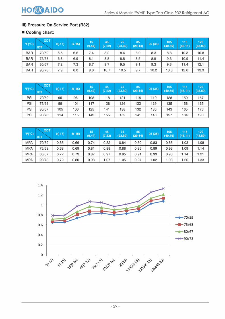
iii) Pressure On Service Port (R32)
Cooling chart:
°F(°C) ODT
IDT0(-17) 5(-15)
15 (9.44)
45 (7.22)
75 (23.89)
85 (29.44)
95 (35)105
(40.56)115
(46.11)120
(48.89)
BAR 70/59 6.5 6.6 7.4 8.2 8.4 8.0 8.3 8.8 10.3 10.8
BAR 75/63 6.8 6.9 8.1 8.8 8.8 8.5 8.9 9.3 10.9 11.4
BAR 80/67 7.2 7.3 8.7 9.7 9.5 9.1 9.3 9.8 11.4 12.1
BAR 90/73 7.9 8.0 9.8 10.7 10.5 9.7 10.2 10.8 12.6 13.3
°F(°C) ODT
IDT0(-17) 5(-15)
15 (9.44)
45 (7.22)
75 (23.89)
85 (29.44)
95 (35)105
(40.56)115
(46.11)120
(48.89)
PSI 70/59 95 96 108 118 121 115 119 128 150 157
PSI 75/63 99 101 117 128 126 122 129 135 158 165
PSI 80/67 105 106 125 141 138 132 135 143 165 176
PSI 90/73 114 115 142 155 152 141 148 157 184 193
°F(°C) ODT
IDT0(-17) 5(-15)
15 (9.44)
45 (7.22)
75 (23.89)
85 (29.44)
95 (35)105
(40.56)115
(46.11)120
(48.89)
MPA 70/59 0.65 0.66 0.74 0.82 0.84 0.80 0.83 0.88 1.03 1.08
MPA 75/63 0.68 0.69 0.81 0.88 0.88 0.85 0.89 0.93 1.09 1.14
MPA 80/67 0.72 0.73 0.87 0.97 0.95 0.91 0.93 0.98 1.14 1.21
MPA 90/73 0.79 0.80 0.98 1.07 1.05 0.97 1.02 1.08 1.26 1.33
0
0.2
0.4
0.6
0.8
1
1.2
1.4
70/59
75/63
80/67
90/73

- 40 -
Series 4 Models: “Wall” Type Top Class R32 Refrigerant AC
Heating chart:
°F(°C) ODT
IDT
57/53 (13.89/11.67)
47/43 (8.33/6.11)
37/33 (2.78/0.56)
27/23 (-2.78/-5)
17/13 (-8.33/-10.56)
0/-2(-17/-19)-17/-18
(-27/-28)
BAR 55 30.9 29.1 25.8 23.3 21.2 18.9 16.8
BAR 65 33.2 30.6 27.1 25.9 23.8 20.9 19.4
BAR 75 34.5 32.1 28.4 26.8 25.4 21.9 20.4
°F(°C) ODT
IDT
57/53 (13.89/11.67)
47/43 (8.33/6.11)
37/33 (2.78/0.56)
27/23 (-2.78/-5)
17/13 (-8.33/-10.56)
0/-2(-17/-19)-17/-18
(-27/-28)
PSI 55 448 421 374 337 308 273 244
PSI 65 480 444 394 375 346 303 282
PSI 75 499 466 411 389 369 318 296
°F(°C) ODT
IDT
57/53 (13.89/11.67)
47/43 (8.33/6.11)
37/33 (2.78/0.56)
27/23 (-2.78/-5)
17/13 (-8.33/-10.56)
0/-2(-17/-19)-17/-18
(-27/-28)
MPA 55 3.09 2.91 2.58 2.33 2.12 1.89 1.68
MPA 65 3.32 3.06 2.71 2.59 2.38 2.09 1.94
MPA 75 3.45 3.21 2.84 2.68 2.54 2.19 2.04
0
0.5
1
1.5
2
2.5
3
3.5
4
55
65
75

Series 4 Models: “Wall” Type Top Class R32 Refrigerant AC
Notes-1
Notes

Series 4 Models: “Wall” Type Top Class R32 Refrigerant AC
Notes-2
Notes

Series 4 Models: “Wall” Top Class R32 Refrigerant AC
Due to on-going technological development of the products by the manufacturer,
we reserve the right to vary the technical specifications at any time without notice.


