Service Manual - daikintech.co.uk
353
ESiE04-01 Service Manual RZQ71~125B7V3B Sky-Air Inverter R-410A B series
-
Upload
khangminh22 -
Category
Documents
-
view
0 -
download
0
Transcript of Service Manual - daikintech.co.uk
ESiE04-01
Service ManualRZQ71~125B7V3BSky-Air Inverter R-410A B series
ESIE04-01
Table of Contents i
3
4
5
1Table of Contents
1Introduction
1.1 About This Manual .................................................................................. i–i1.2 Combination Overview............................................................................ i–ii1.3 Precautions on handling new refrigerants............................................... i–iv
Part 1System Outline
1 General Outline: Outdoor Units
1.1 What Is in This Chapter? ........................................................................ 1–31.2 RZQ71: Outlook and dimensions ........................................................... 1–41.3 RZQ100 and RZQ125: Outlook and dimensions .................................... 1–61.4 RZQ71, RZQ100 and RZQ125: Installation and Service Space............. 1–8
2 General Outline: Indoor Units
2.1 What Is in This Chapter? ........................................................................ 1–112.2 FCQ35B7V1 ~ FCQ71B7V3B................................................................. 1–122.3 FCQ100~125B7V3B ............................................................................... 1–142.4 FFQ35~60BV1B...................................................................................... 1–162.5 FBQ35B7V1 & FBQ50B7V1 ................................................................... 1–182.6 FBQ60B7V1 & FBQ71B7V3B................................................................. 1–202.7 FBQ100B7V3B & FBQ125B7V3B .......................................................... 1–222.8 FDQ125B7V3B ....................................................................................... 1–242.9 FHQ35BUV1 & FHQ50BUV1.................................................................. 1–262.10 FHQ60BUV1 & FHQ71BUV1B ............................................................... 1–282.11 FHQ100BUV1B....................................................................................... 1–302.12 FHQ125BUV1B....................................................................................... 1–322.13 FUQ71BUV1B......................................................................................... 1–342.14 FUQ100~125BUV1B............................................................................... 1–362.15 FAQ71BUV1B......................................................................................... 1–382.16 FAQ100BUV1B....................................................................................... 1–40
ESIE04-01
ii Table of Contents
3
1
4
5
3 Specifications
3.1 What Is in This Chapter? ......................................................................... 1–433.2 RZQ71, RZQ100 and RZQ125 ................................................................ 1–443.3 FCQ ......................................................................................................... 1–473.4 FFQ.......................................................................................................... 1–483.5 FBQ ......................................................................................................... 1–493.6 FDQ ......................................................................................................... 1–503.7 FHQ ......................................................................................................... 1–513.8 FUQ ......................................................................................................... 1–523.9 FAQ ......................................................................................................... 1–53
4 Functional Diagrams
4.1 What Is in This Chapter? ......................................................................... 1–554.2 Pair system ............................................................................................. 1–564.3 Twin System ............................................................................................ 1–584.4 Triple System........................................................................................... 1–604.5 Double Twin System................................................................................ 1–614.6 Indoor piping ........................................................................................... 1–624.7 Pipe connection diameters ...................................................................... 1–644.8 Re-using existing field piping ................................................................... 1–654.9 Piping Components ................................................................................. 1–71
5 Switch Box Layout
5.1 What Is in This Chapter? ......................................................................... 1–735.2 RZQ71B7V3B .......................................................................................... 1–745.3 RZQ100B7V3B ........................................................................................ 1–755.4 FCQ35B7V1 ~ FCQ71B7V3B.................................................................. 1–765.5 FCQ100~125B7V3B................................................................................ 1–775.6 FFQ35~60BV1B ...................................................................................... 1–785.7 FBQ35B7V1 ~ FBQ125B7V3B................................................................ 1–795.8 FDQ125B7V3B ........................................................................................ 1–805.9 FHQ35BUV1 ~ FHQ125BUV1B .............................................................. 1–815.10 FUQ71~125BUV1B ................................................................................. 1–825.11 FAQ71BUV1B.......................................................................................... 1–835.12 FAQ100BUV1B........................................................................................ 1–84
ESIE04-01
Table of Contents iii
3
4
5
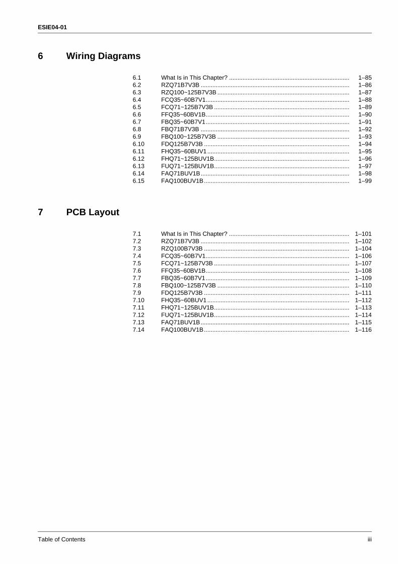
16 Wiring Diagrams
6.1 What Is in This Chapter? ........................................................................ 1–856.2 RZQ71B7V3B ......................................................................................... 1–866.3 RZQ100~125B7V3B ............................................................................... 1–876.4 FCQ35~60B7V1...................................................................................... 1–886.5 FCQ71~125B7V3B ................................................................................. 1–896.6 FFQ35~60BV1B...................................................................................... 1–906.7 FBQ35~60B7V1...................................................................................... 1–916.8 FBQ71B7V3B ......................................................................................... 1–926.9 FBQ100~125B7V3B ............................................................................... 1–936.10 FDQ125B7V3B ....................................................................................... 1–946.11 FHQ35~60BUV1..................................................................................... 1–956.12 FHQ71~125BUV1B................................................................................. 1–966.13 FUQ71~125BUV1B................................................................................. 1–976.14 FAQ71BUV1B......................................................................................... 1–986.15 FAQ100BUV1B....................................................................................... 1–99
7 PCB Layout
7.1 What Is in This Chapter? ........................................................................ 1–1017.2 RZQ71B7V3B ......................................................................................... 1–1027.3 RZQ100B7V3B ....................................................................................... 1–1047.4 FCQ35~60B7V1...................................................................................... 1–1067.5 FCQ71~125B7V3B ................................................................................. 1–1077.6 FFQ35~60BV1B...................................................................................... 1–1087.7 FBQ35~60B7V1...................................................................................... 1–1097.8 FBQ100~125B7V3B ............................................................................... 1–1107.9 FDQ125B7V3B ....................................................................................... 1–1117.10 FHQ35~60BUV1..................................................................................... 1–1127.11 FHQ71~125BUV1B................................................................................. 1–1137.12 FUQ71~125BUV1B................................................................................. 1–1147.13 FAQ71BUV1B......................................................................................... 1–1157.14 FAQ100BUV1B....................................................................................... 1–116
ESIE04-01
iv Table of Contents
3
1
4
5
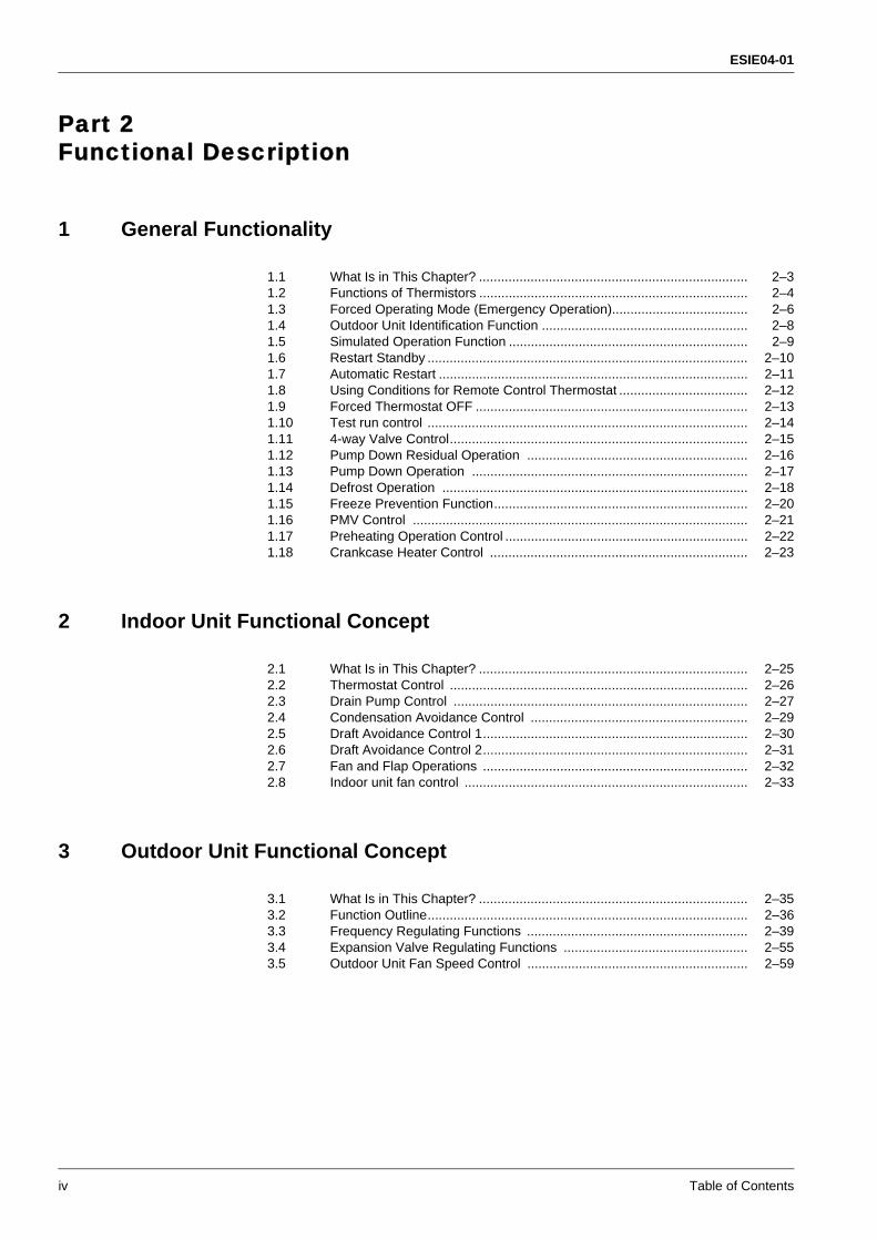
Part 2Functional Description
1 General Functionality
1.1 What Is in This Chapter? ......................................................................... 2–31.2 Functions of Thermistors ......................................................................... 2–41.3 Forced Operating Mode (Emergency Operation)..................................... 2–61.4 Outdoor Unit Identification Function ........................................................ 2–81.5 Simulated Operation Function ................................................................. 2–91.6 Restart Standby ....................................................................................... 2–101.7 Automatic Restart .................................................................................... 2–111.8 Using Conditions for Remote Control Thermostat ................................... 2–121.9 Forced Thermostat OFF .......................................................................... 2–131.10 Test run control ....................................................................................... 2–141.11 4-way Valve Control................................................................................. 2–151.12 Pump Down Residual Operation ............................................................ 2–161.13 Pump Down Operation ........................................................................... 2–171.14 Defrost Operation ................................................................................... 2–181.15 Freeze Prevention Function..................................................................... 2–201.16 PMV Control ........................................................................................... 2–211.17 Preheating Operation Control .................................................................. 2–221.18 Crankcase Heater Control ...................................................................... 2–23
2 Indoor Unit Functional Concept
2.1 What Is in This Chapter? ......................................................................... 2–252.2 Thermostat Control ................................................................................. 2–262.3 Drain Pump Control ................................................................................ 2–272.4 Condensation Avoidance Control ........................................................... 2–292.5 Draft Avoidance Control 1........................................................................ 2–302.6 Draft Avoidance Control 2........................................................................ 2–312.7 Fan and Flap Operations ........................................................................ 2–322.8 Indoor unit fan control ............................................................................. 2–33
3 Outdoor Unit Functional Concept
3.1 What Is in This Chapter? ......................................................................... 2–353.2 Function Outline....................................................................................... 2–363.3 Frequency Regulating Functions ............................................................ 2–393.4 Expansion Valve Regulating Functions .................................................. 2–553.5 Outdoor Unit Fan Speed Control ............................................................ 2–59
ESIE04-01
Table of Contents v
3
4
5
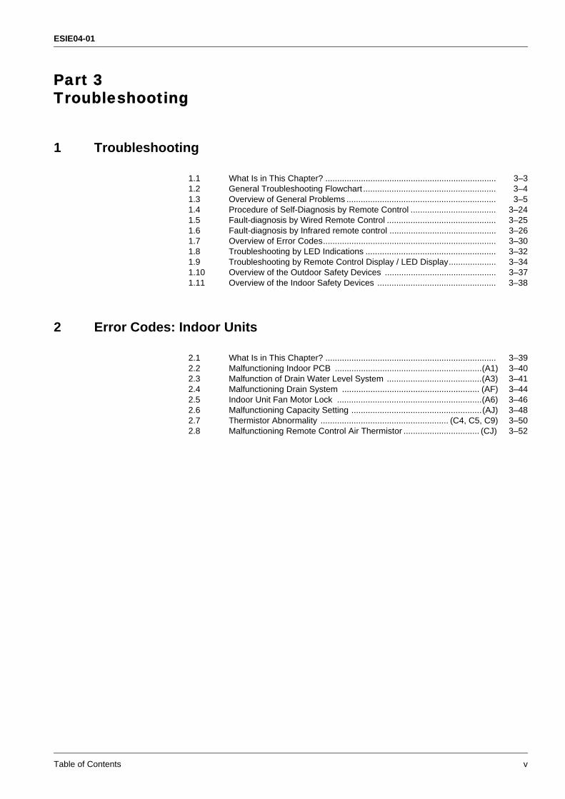
1Part 3Troubleshooting
1 Troubleshooting
1.1 What Is in This Chapter? ........................................................................ 3–31.2 General Troubleshooting Flowchart ........................................................ 3–41.3 Overview of General Problems ............................................................... 3–51.4 Procedure of Self-Diagnosis by Remote Control .................................... 3–241.5 Fault-diagnosis by Wired Remote Control .............................................. 3–251.6 Fault-diagnosis by Infrared remote control ............................................. 3–261.7 Overview of Error Codes......................................................................... 3–301.8 Troubleshooting by LED Indications ....................................................... 3–321.9 Troubleshooting by Remote Control Display / LED Display.................... 3–341.10 Overview of the Outdoor Safety Devices ............................................... 3–371.11 Overview of the Indoor Safety Devices .................................................. 3–38
2 Error Codes: Indoor Units
2.1 What Is in This Chapter? ........................................................................ 3–392.2 Malfunctioning Indoor PCB ..............................................................(A1) 3–402.3 Malfunction of Drain Water Level System ........................................(A3) 3–412.4 Malfunctioning Drain System .......................................................... (AF) 3–442.5 Indoor Unit Fan Motor Lock .............................................................(A6) 3–462.6 Malfunctioning Capacity Setting .......................................................(AJ) 3–482.7 Thermistor Abnormality ...................................................... (C4, C5, C9) 3–502.8 Malfunctioning Remote Control Air Thermistor ................................ (CJ) 3–52
ESIE04-01
vi Table of Contents
3
1
4
5
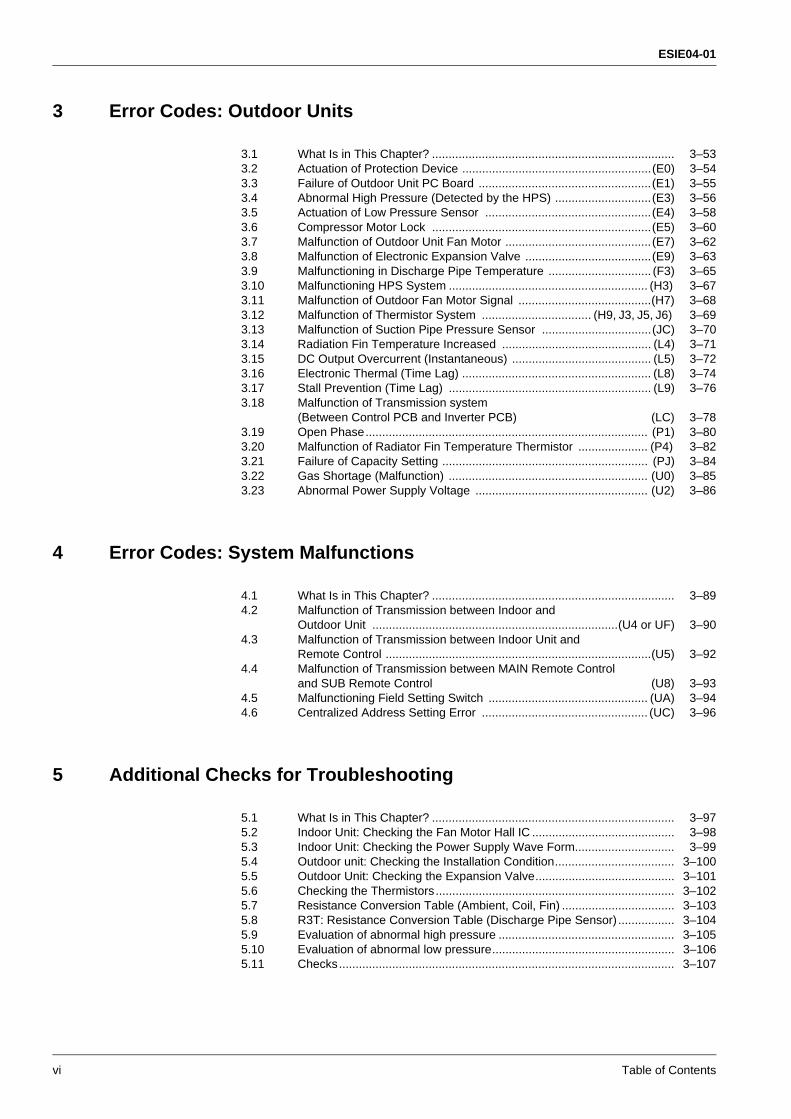
3 Error Codes: Outdoor Units
3.1 What Is in This Chapter? ......................................................................... 3–533.2 Actuation of Protection Device .........................................................(E0) 3–543.3 Failure of Outdoor Unit PC Board ....................................................(E1) 3–553.4 Abnormal High Pressure (Detected by the HPS) .............................(E3) 3–563.5 Actuation of Low Pressure Sensor ..................................................(E4) 3–583.6 Compressor Motor Lock ..................................................................(E5) 3–603.7 Malfunction of Outdoor Unit Fan Motor ............................................(E7) 3–623.8 Malfunction of Electronic Expansion Valve ......................................(E9) 3–633.9 Malfunctioning in Discharge Pipe Temperature ............................... (F3) 3–653.10 Malfunctioning HPS System ............................................................ (H3) 3–673.11 Malfunction of Outdoor Fan Motor Signal ........................................(H7) 3–683.12 Malfunction of Thermistor System ................................. (H9, J3, J5, J6) 3–693.13 Malfunction of Suction Pipe Pressure Sensor .................................(JC) 3–703.14 Radiation Fin Temperature Increased ............................................. (L4) 3–713.15 DC Output Overcurrent (Instantaneous) .......................................... (L5) 3–723.16 Electronic Thermal (Time Lag) ......................................................... (L8) 3–743.17 Stall Prevention (Time Lag) ............................................................. (L9) 3–763.18 Malfunction of Transmission system
(Between Control PCB and Inverter PCB) (LC) 3–783.19 Open Phase..................................................................................... (P1) 3–803.20 Malfunction of Radiator Fin Temperature Thermistor ..................... (P4) 3–823.21 Failure of Capacity Setting .............................................................. (PJ) 3–843.22 Gas Shortage (Malfunction) ............................................................ (U0) 3–853.23 Abnormal Power Supply Voltage .................................................... (U2) 3–86
4 Error Codes: System Malfunctions
4.1 What Is in This Chapter? ......................................................................... 3–894.2 Malfunction of Transmission between Indoor and
Outdoor Unit ..........................................................................(U4 or UF) 3–904.3 Malfunction of Transmission between Indoor Unit and
Remote Control ................................................................................(U5) 3–924.4 Malfunction of Transmission between MAIN Remote Control
and SUB Remote Control (U8) 3–934.5 Malfunctioning Field Setting Switch ................................................ (UA) 3–944.6 Centralized Address Setting Error .................................................. (UC) 3–96
5 Additional Checks for Troubleshooting
5.1 What Is in This Chapter? ......................................................................... 3–975.2 Indoor Unit: Checking the Fan Motor Hall IC ........................................... 3–985.3 Indoor Unit: Checking the Power Supply Wave Form.............................. 3–995.4 Outdoor unit: Checking the Installation Condition.................................... 3–1005.5 Outdoor Unit: Checking the Expansion Valve.......................................... 3–1015.6 Checking the Thermistors........................................................................ 3–1025.7 Resistance Conversion Table (Ambient, Coil, Fin) .................................. 3–1035.8 R3T: Resistance Conversion Table (Discharge Pipe Sensor) ................. 3–1045.9 Evaluation of abnormal high pressure ..................................................... 3–1055.10 Evaluation of abnormal low pressure....................................................... 3–1065.11 Checks..................................................................................................... 3–107
ESIE04-01
Table of Contents vii
3
4
5
1Part 4Commissioning and Test Run
1 Pre-Test Run Checks
1.1 What Is in This Chapter? ........................................................................ 4–31.2 Test Run Checks .................................................................................... 4–41.3 Setting the Infrared remote control ......................................................... 4–5
2 Field settings
2.1 What Is in This Chapter? ........................................................................ 4–92.2 How to Change the Field Settings with the Wired Remote Control......... 4–102.3 How to Change the Field Settings with the Infrared Remote Control...... 4–122.4 Overview of the Field Settings on the Indoor Units ................................. 4–132.5 Overview of the Factory Settings on the Indoor Units............................. 4–142.6 Setting the Ceiling Height ....................................................................... 4–152.7 Setting the Filter Counter ........................................................................ 4–162.8 MAIN/SUB Setting when Using Two Remote Controls ........................... 4–172.9 Setting the Centralized Group No. .......................................................... 4–182.10 The Field Setting Levels ......................................................................... 4–202.11 Overview of the Field Settings on the Outdoor Units .............................. 4–232.12 Overview of the Factory Settings on the Outdoor Units .......................... 4–252.13 Silent Operation ..................................................................................... 4–262.14 I-Demand Function ................................................................................ 4–282.15 Setting for Low Humidity Application ..................................................... 4–302.16 Defrost start setting................................................................................. 4–36
3 Test Run and Operation Data
3.1 General Operation Data.......................................................................... 4–383.2 Operation Range..................................................................................... 4–41
ESIE04-01
viii Table of Contents
3
1
4
5
Part 5Disassembly and Maintenance
1 Disassembly and Maintenance: Outdoor Units
1.1 What Is in This Chapter? ......................................................................... 5–31.2 RZQ71~125B7V3B.................................................................................. 5–4
2 Disassembly and Maintenance: Indoor Units
2.1 What Is in This Chapter? ......................................................................... 5–172.2 FCQ35B7V1 ~ FCQ71B7V3B.................................................................. 5–182.3 FCQ100~125B7V3B................................................................................ 5–202.4 FBQ35~50B7V1....................................................................................... 5–222.5 FBQ60B7V1 ~ FBQ71B7V3B.................................................................. 5–242.6 FBQ100~125B7V3B ................................................................................ 5–262.7 FDQ125B7V3B ........................................................................................ 5–282.8 FFQ35~60BV1B ...................................................................................... 5–302.9 FHQ35~125BUV1(B) ............................................................................... 5–672.10 FUQ71~125BUV1B ................................................................................. 5–822.11 FAQ71BUV1B.......................................................................................... 5–992.12 FAQ100BUV1B........................................................................................ 5–110
ESIE04-01 Introduction
i
3
4
5
Part 0
1 Introduction
1.1 About This Manual
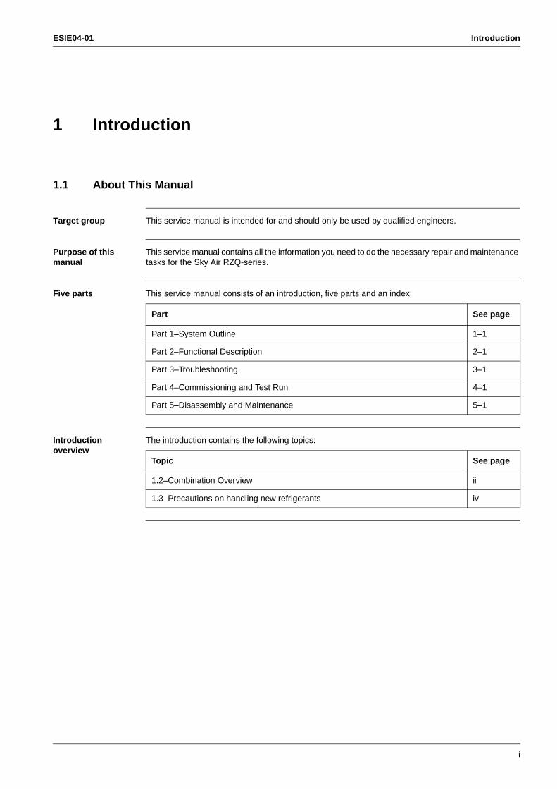
Target group This service manual is intended for and should only be used by qualified engineers.
Purpose of this manual
This service manual contains all the information you need to do the necessary repair and maintenance tasks for the Sky Air RZQ-series.
Five parts This service manual consists of an introduction, five parts and an index:
Introduction overview
The introduction contains the following topics:
Part See page
Part 1–System Outline 1–1
Part 2–Functional Description 2–1
Part 3–Troubleshooting 3–1
Part 4–Commissioning and Test Run 4–1
Part 5–Disassembly and Maintenance 5–1
Topic See page
1.2–Combination Overview ii
1.3–Precautions on handling new refrigerants iv
Introduction ESIE04-01
ii
1.2 Combination Overview
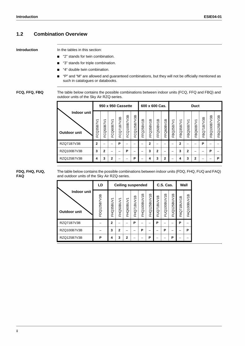
Introduction In the tables in this section:
“2” stands for twin combination.
“3” stands for triple combination.
“4“ double twin combination.
“P” and “M” are allowed and guaranteed combinations, but they will not be officially mentioned as such in catalogues or databooks.
FCQ, FFQ, FBQ The table below contains the possible combinations between indoor units (FCQ, FFQ and FBQ) and outdoor units of the Sky Air RZQ-series.
FDQ, FHQ, FUQ, FAQ
The table below contains the possible combinations between indoor units (FDQ, FHQ, FUQ and FAQ) and outdoor units of the Sky Air RZQ-series.
950 x 950 Cassette 600 x 600 Cas. Duct
FC
Q35
B7V
1
FC
Q50
B7V
1
FC
Q60
B7V
1
FC
Q71
B7V
3B
FC
Q10
0B7V
3B
FC
Q12
5B7V
3B
FF
Q25
BV
1B
FF
Q35
BV
1B
FF
Q50
BV
1B
FF
Q60
BV
1B
FB
Q25
B7V
1
FB
Q35
B7V
1
FB
Q50
B7V
1
FB
Q60
B7V
1
FB
Q71
B7V
3B
FB
Q10
0B7V
3B
FB
Q12
5B7V
3B
RZQ71B7V3B 2 – – P – – – 2 – – – 2 – – P – –
RZQ100B7V3B 3 2 – – P – – 3 2 – – 3 2 – – P –
RZQ125B7V3B 4 3 2 – – P – 4 3 2 – 4 3 2 – – P
Outdoor unit
Indoor unit
LD Ceiling suspended C.S. Cas. Wall
FD
Q12
5B7V
3B
FH
Q35
BU
V1
FH
Q50
BU
V1
FH
Q60
BU
V1
FH
Q71
BU
V1B
FH
Q10
0BU
V1B
FH
Q12
5BU
V1B
FU
Q71
BU
V1B
FU
Q10
0BU
V1B
FU
Q12
5BU
V1B
FAQ
71B
UV
1B
FAQ
100B
UV
1B
RZQ71B7V3B – 2 – – P – – P – – P –
RZQ100B7V3B – 3 2 – – P – – P – – P
RZQ125B7V3B P 4 3 2 – – P – – P – –
Outdoor unit
Indoor unit
ESIE04-01 Introduction
iii
3
4
5
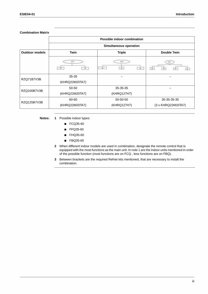
Combination Matrix
Notes: 1 Possible indoor types:
FCQ35-60
FFQ35-60
FHQ35-60
FBQ35-60
2 When different indoor models are used in combination, designate the remote control that is equipped with the most functions as the main unit. In note 1 are the indoor units mentioned in order of the possible function (most functions are on FCQ , less functions are on FBQ).
3 Between brackets are the required Refnet kits mentioned, that are necessary to install the combination.
Possible indoor combination
Simultaneous operation
Outdoor models Twin Triple Double Twin
RZQ71B7V3B35-35
(KHRQ22M20TA7)
– –
RZQ100B7V3B50-50
(KHRQ22M20TA7)
35-35-35
(KHRQ127H7)
–
RZQ125B7V3B60-60
(KHRQ22M20TA7)
50-50-50
(KHRQ127H7)
35-35-35-35
(3 x KHRQ22M20TA7)
OUT
IN IN
OUT
IN IN IN
OUT
IN INININ
Introduction ESIE04-01
iv
1.3 Precautions on handling new refrigerants
1.3.1 Outline
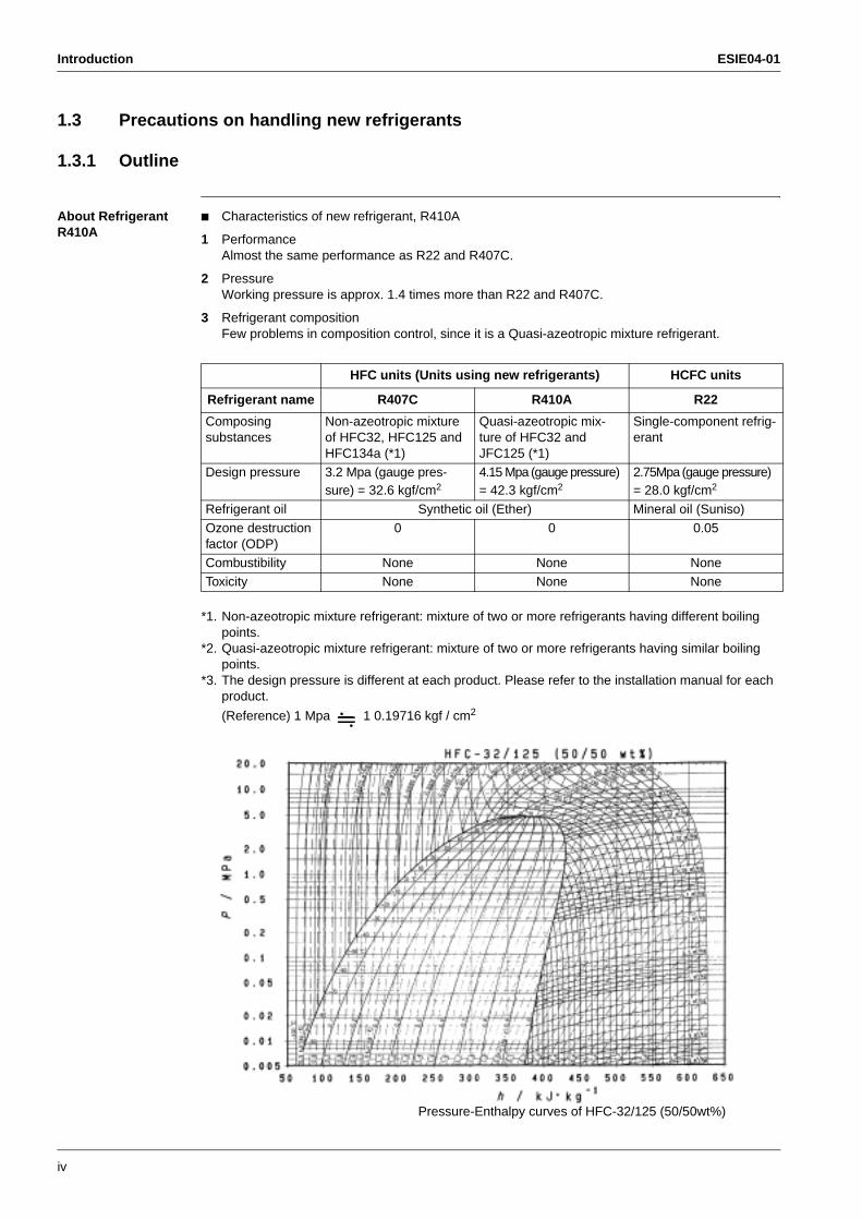
About Refrigerant R410A
Characteristics of new refrigerant, R410A
1 PerformanceAlmost the same performance as R22 and R407C.
2 PressureWorking pressure is approx. 1.4 times more than R22 and R407C.
3 Refrigerant compositionFew problems in composition control, since it is a Quasi-azeotropic mixture refrigerant.
*1. Non-azeotropic mixture refrigerant: mixture of two or more refrigerants having different boiling points.
*2. Quasi-azeotropic mixture refrigerant: mixture of two or more refrigerants having similar boiling points.
*3. The design pressure is different at each product. Please refer to the installation manual for each product.
(Reference) 1 Mpa 1 0.19716 kgf / cm2
HFC units (Units using new refrigerants) HCFC units
Refrigerant name R407C R410A R22
Composing substances
Non-azeotropic mixture of HFC32, HFC125 and HFC134a (*1)
Quasi-azeotropic mix-ture of HFC32 and JFC125 (*1)
Single-component refrig-erant
Design pressure 3.2 Mpa (gauge pres-sure) = 32.6 kgf/cm2
4.15 Mpa (gauge pressure) = 42.3 kgf/cm2
2.75Mpa (gauge pressure) = 28.0 kgf/cm2
Refrigerant oil Synthetic oil (Ether) Mineral oil (Suniso)
Ozone destruction factor (ODP)
0 0 0.05
Combustibility None None NoneToxicity None None None
Pressure-Enthalpy curves of HFC-32/125 (50/50wt%)
ESIE04-01 Introduction
v
3
4
5
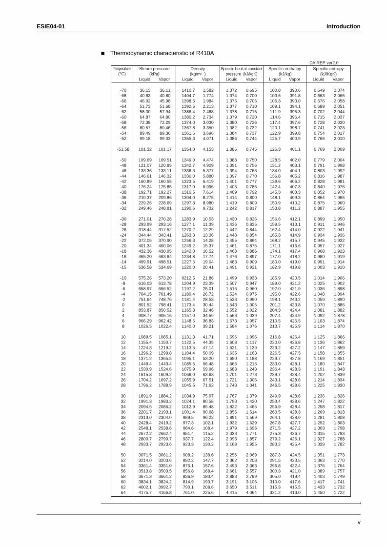
Thermodynamic characteristic of R410A
Temperature(°C)
Steam pressure (kPa)
Liquid Vapor
Density (kg/m3 )
Liquid Vapor
Specific heat at constant pressure (kJ/kgK)Liquid Vapor
Specific enthalpy (kJ/kg)
Liquid Vapor
Specific entropy(kJ/KgK)
Liquid Vapor
-70-68-66-64-62-60-58-56-54-52
-51.58
-50-48-46-44-42-40-38-36-34-32
-30-28-26-24-22-20-18-16-14-15
-10-8-6-4-202468
10121416182022242628
30323436384042444648
5052545658606264
36.1340.8346.0251.7358.0064.8772.3880.5789.4999.18
101.32
109.69121.07133.36146.61160.89176.24192.71210.37229.26249.46
271.01293.99318.44344.44372.05401.34432.36465.20499.91536.58
575.26616.03658.97704.15751.64801.52853.87908.77966.291026.5
1089.51155.41224.31296.21371.21449.41530.91615.81704.21796.2
1891.91991.32094.52201.72313.02428.42548.12672.22800.72933.7
3071.53214.03361.43513.83671.33834.14002.14175.7
36.1140.8045.9851.6857.9464.8072.2980.4689.3699.03
101.17
109.51120.85133.11146.32160.55175.85192.27209.86228.69248.81
270.28293.16317.52343.41370.90400.06430.95463.64498.51534.69
573.20613.78656.52701.49748.76798.41850.52905.16962.421022.4
1085.11150.71219.21290.81365.51443.41524.61609.21697.21788.9
1884.21983.22086.22193.12304.02419.22538.62662.42790.72923.6
3061.23203.63351.03503.53661.23824.23992.74166.8
1410.71404.71398.61392.51386.41380.21374.01367.81361.61355.3
1354.0
1349.01342.71336.31330.01323.51317.01310.51304.01297.31290.6
1283.91277.11270.21263.31256.31249.21242.01234.81227.51220.0
0212.51204.91197.21189.41181.41173.41165.31157.01148.61140.0
1131.31122.51113.51104.41095.11085.61075.91066.01055.91045.5
1034.91024.11012.91001.4989.5977.3964.6951.4937.7923.3
908.2892.2875.1856.8836.9814.9790.1761.0
1.5821.7741.9842.2132.4632.7343.0303.3503.6964.071
4.153
4.4744.9095.3775.8806.4196.9967.6148.2758.9809.732
10.5311.3912.2913.3614.2815.3716.5217.7419.0420.41
21.8623.3925.0126.7228.5330.4432.4634.5936.8339.21
41.7144.3547.1450.0953.2056.4859.9663.6367.5171.62
75.9780.5885.4890.6896.22102.1108.4115.2122.4130.2
138.6147.7157.6168.4180.4193.7208.6225.6
1.3721.3741.3751.3771.3781.3791.3801.3821.3841.386
1.386
1.3881.3911.3941.3971.4011.4051.4091.4141.4191.242
1.4301.4361.4421.4481.4551.4611.4681.4761.4831.491
1.4991.5071.5161.5241.5331.5431.5521.5631.5731.584
1.5961.6081.6211.6351.6501.6661.6831.7011.7211.743
1.7671.7931.8221.8551.8911.9321.9792.0332.0952.168
2.2562.3622.4932.6612.8833.1913.6504.415
0.6950.7000.7050.7100.7150.7200.7260.7320.7370.744
0.745
0.7500.7560.7630.7700.7770.7850.7920.8000.8090.817
0.8260.8350.8440.8540.8640.8750.8860.8970.9090.921
0.9330.9470.9600.9750.9901.0051.0221.0391.0571.076
1.0961.1171.1391.1631.1881.2151.2431.2731.3061.341
1.3791.4201.4651.5141.5691.6291.6961.7711.8571.955
2.0692.2032.3632.5572.7993.1063.5114.064
100.8103.6106.3109.1111.9114.6117.4120.1122.9125.7
126.3
128.5131.2134.0136.8139.6142.4145.3148.1150.9153.8
156.6159.5162.4165.3168.2171.1174.1177.0180.0182.9
185.9189.0192.0195.0198.1201.2204.3207.4210.5213.7
216.8220.0223.2226.5229.7233.0236.4239.7243.1246.5
249.9253.4256.9260.5264.1267.8271.5275.3279.2283.2
287.3291.5295.8300.3305.0310.0315.3321.2
390.6391.8393.0394.1395.3396.4397.6398.7399.8400.9
401.1
402.0403.1404.1405.2406.2407.3408.3409.3410.2411.2
412.1413.1414.0414.9415.7416.6417.4418.2419.0419.8
420.5421.2421.9422.6243.2423.8424.4424.9425.5425.9
426.4426.8427.2427.5427.8428.1428.3428.4428.6428.6
428.6428.6428.4428.3428.0427.7427.2426.7426.1425.4
424.5423.5422.4421.0419.4417.6415.5413.0
0.6490.6630.6760.6890.7020.7150.7280.7410.7540.766
0.769
0.7790.7910.8030.8160.8280.8400.8520.8640.8750.887
0.8990.9110.9220.9340.9450.9570.9680.9800.9911.003
1.0141.0251.0361.0481.0591.0701.0811.0921.1031.114
1.1251.1361.1471.1581.1691.1801.1911.2021.2141.225
1.2361.2471.2581.2691.2811.2921.3031.3151.3271.339
1.3511.3631.3761.3891.4031.4171.4331.450
2.0742.0662.0582.0512.0442.0372.0302.0232.0172.010
2.009
2.0041.9981.9921.9871.9811.9761.9701.9651.9601.955
1.9501.9461.9411.9361.9321.9271.9231.9191.9141.910
1.9061.9021.8981.8941.8901.8861.8821.8781.8741.870
1.8661.8621.8591.8551.8511.8471.8431.8391.8341.830
1.8261.8221.8171.8131.8081.8031.7981.7931.7881.782
1.7731.7701.7641.7571.7491.7411.7321.722
DAIREP ver2.0
Introduction ESIE04-01
vi
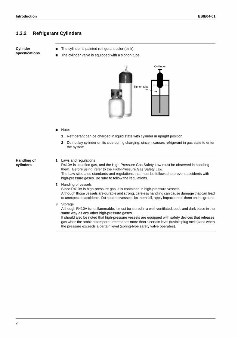
1.3.2 Refrigerant Cylinders
Cylinder specifications
The cylinder is painted refrigerant color (pink).
The cylinder valve is equipped with a siphon tube.
Note:
1 Refrigerant can be charged in liquid state with cylinder in upright position.
2 Do not lay cylinder on its side during charging, since it causes refrigerant in gas state to enter the system.
Handling of cylinders
1 Laws and regulationsR410A is liquefied gas, and the High-Pressure Gas Safety Law must be observed in handling them. Before using, refer to the High-Pressure Gas Safety Law.The Law stipulates standards and regulations that must be followed to prevent accidents with high-pressure gases. Be sure to follow the regulations.
2 Handing of vesselsSince R410A is high-pressure gas, it is contained in high-pressure vessels.Although those vessels are durable and strong, careless handling can cause damage that can lead to unexpected accidents. Do not drop vessels, let them fall, apply impact or roll them on the ground.
3 StorageAlthough R410A is not flammable, it must be stored in a well-ventilated, cool, and dark place in the same way as any other high-pressure gases.It should also be noted that high-pressure vessels are equipped with safety devices that releases gas when the ambient temperature reaches more than a certain level (fusible plug melts) and when the pressure exceeds a certain level (spring-type safety valve operates).
Siphon tube
Cylilinder
ESIE04-01 Introduction
vii
3
4
5
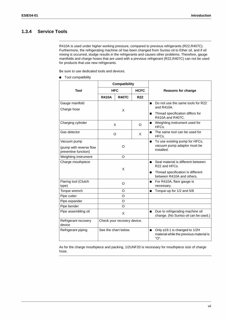
1.3.4 Service Tools
R410A is used under higher working pressure, compared to previous refrigerants (R22,R407C). Furthermore, the refrigerating machine oil has been changed from Suniso oil to Ether oil, and if oil mixing is occurred, sludge results in the refrigerants and causes other problems. Therefore, gauge manifolds and charge hoses that are used with a previous refrigerant (R22,R407C) can not be used for products that use new refrigerants.
Be sure to use dedicated tools and devices.
Tool compatibility
As for the charge mouthpiece and packing, 1/2UNF20 is necessary for mouthpiece size of charge hose.
Tool
Compatibility
Reasons for changeHFC HCFC
R410A R407C R22
Gauge manifold
Charge hose X
Do not use the same tools for R22 and R410A.
Thread specification differs for R410A and R407C.
Charging cylinderX O
Weighting instrument used for HFCs.
Gas detectorO X
The same tool can be used for HFCs.
Vacuum pump
(pump with reverse flow preventive function)
O
To use existing pump for HFCs, vacuum pump adaptor must be installed.
Weighting instrument O
Charge mouthpiece
X
Seal material is different between R22 and HFCs.
Thread specification is different between R410A and others.
Flaring tool (Clutch type)
O For R410A, flare gauge is
necessary.
Torque wrench O Torque-up for 1/2 and 5/8
Pipe cutter O
Pipe expander O
Pipe bender O
Pipe assembling oilX
Due to refrigerating machine oil change. (No Suniso oil can be used.)
Refrigerant recovery device
Check your recovery device.
Refrigerant piping See the chart below. Only φ19.1 is changed to 1/2H material while the previous material is "O".
Introduction ESIE04-01
viii
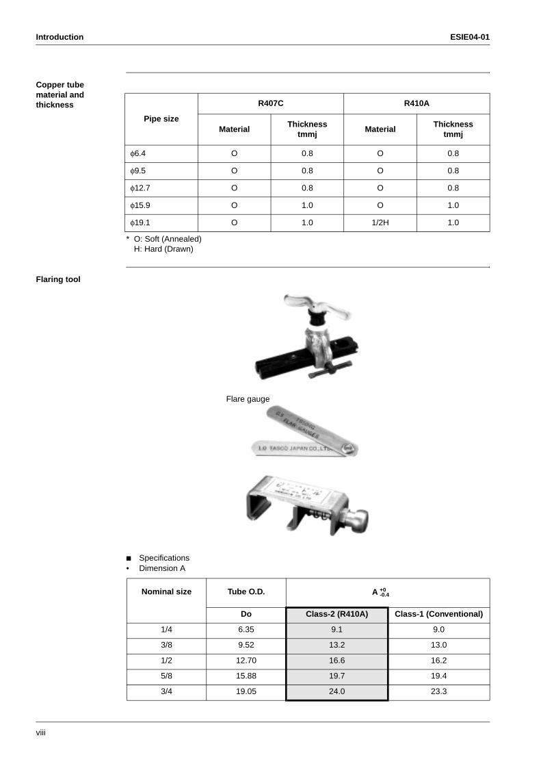
Copper tube material and thickness
* O: Soft (Annealed)H: Hard (Drawn)
Flaring tool
Specifications• Dimension A
Pipe size
R407C R410A
MaterialThickness
tmmjMaterial
Thicknesstmmj
φ6.4 O 0.8 O 0.8
φ9.5 O 0.8 O 0.8
φ12.7 O 0.8 O 0.8
φ15.9 O 1.0 O 1.0
φ19.1 O 1.0 1/2H 1.0
Nominal size Tube O.D. A
Do Class-2 (R410A) Class-1 (Conventional)
1/4 6.35 9.1 9.0
3/8 9.52 13.2 13.0
1/2 12.70 16.6 16.2
5/8 15.88 19.7 19.4
3/4 19.05 24.0 23.3
Flare gauge
+0-0.4
ESIE04-01 Introduction
ix
3
4
5
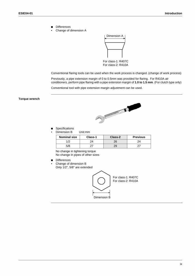
Differences• Change of dimension A
Conventional flaring tools can be used when the work process is changed. (change of work process)
Previously, a pipe extension margin of 0 to 0.5mm was provided for flaring. For R410A air conditioners, perform pipe flaring with a pipe extension margin of 1.0 to 1.5 mm. (For clutch type only)
Conventional tool with pipe extension margin adjustment can be used.
Torque wrench
Specifications• Dimension B Unit:mm
No change in tightening torqueNo change in pipes of other sizes
Differences• Change of dimension B
Only 1/2", 5/8" are extended
Dimension A
For class-1: R407CFor class-2: R410A
Nominal size Class-1 Class-2 Previous
1/2 24 26 24
5/8 27 29 27
For class-1: R407CFor class-2: R410A
Dimension B
Introduction ESIE04-01
x
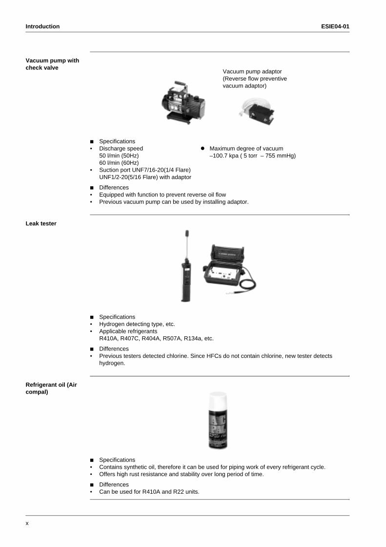
Vacuum pump with check valve
Specifications• Discharge speed ! Maximum degree of vacuum
50 l/min (50Hz) –100.7 kpa ( 5 torr – 755 mmHg)60 l/min (60Hz)
• Suction port UNF7/16-20(1/4 Flare)UNF1/2-20(5/16 Flare) with adaptor
Differences• Equipped with function to prevent reverse oil flow• Previous vacuum pump can be used by installing adaptor.
Leak tester
Specifications• Hydrogen detecting type, etc.• Applicable refrigerants
R410A, R407C, R404A, R507A, R134a, etc.
Differences• Previous testers detected chlorine. Since HFCs do not contain chlorine, new tester detects
hydrogen.
Refrigerant oil (Air compal)
Specifications• Contains synthetic oil, therefore it can be used for piping work of every refrigerant cycle.• Offers high rust resistance and stability over long period of time.
Differences• Can be used for R410A and R22 units.
Vacuum pump adaptor (Reverse flow preventive vacuum adaptor)
ESIE04-01 Introduction
xi
3
4
5
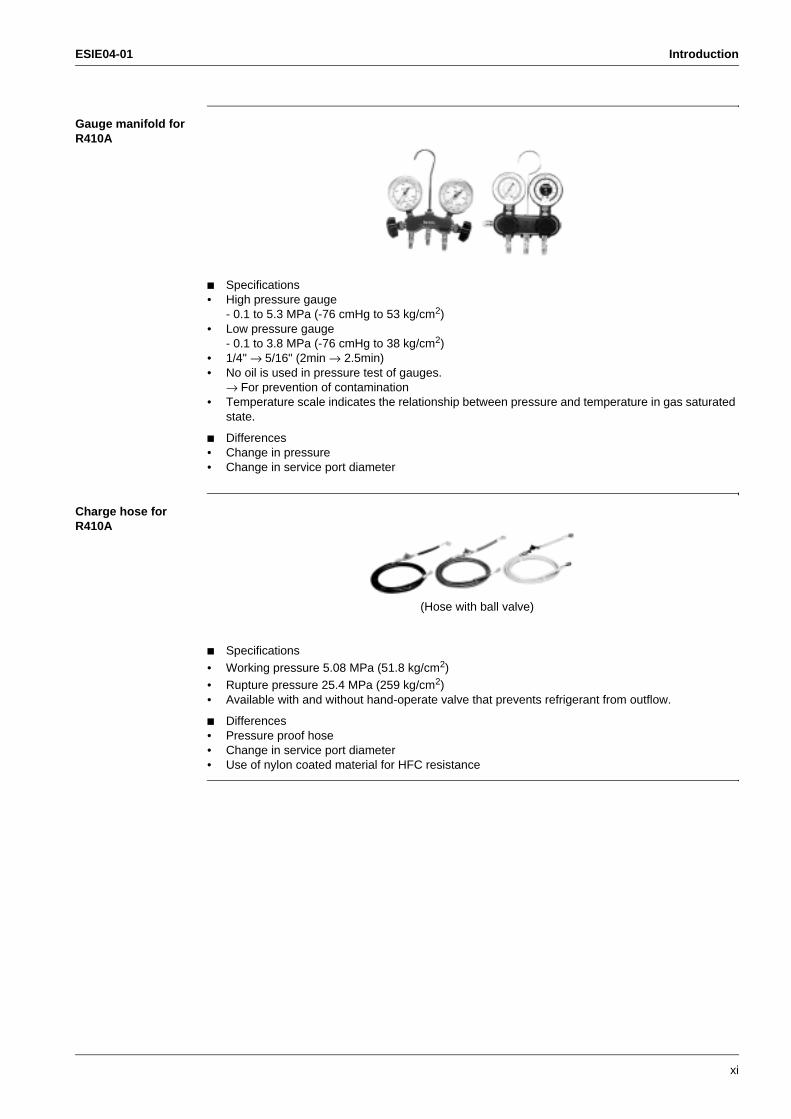
Gauge manifold for R410A
Specifications• High pressure gauge
- 0.1 to 5.3 MPa (-76 cmHg to 53 kg/cm2)• Low pressure gauge
- 0.1 to 3.8 MPa (-76 cmHg to 38 kg/cm2)• 1/4" → 5/16" (2min → 2.5min)• No oil is used in pressure test of gauges.
→ For prevention of contamination• Temperature scale indicates the relationship between pressure and temperature in gas saturated
state.
Differences• Change in pressure• Change in service port diameter
Charge hose for R410A
Specifications• Working pressure 5.08 MPa (51.8 kg/cm2)• Rupture pressure 25.4 MPa (259 kg/cm2)• Available with and without hand-operate valve that prevents refrigerant from outflow.
Differences• Pressure proof hose• Change in service port diameter• Use of nylon coated material for HFC resistance
(Hose with ball valve)
Introduction ESIE04-01
xii
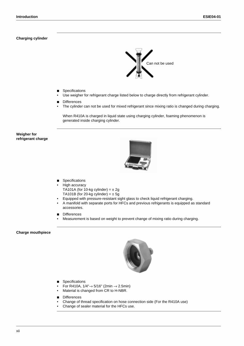
Charging cylinder
Specifications• Use weigher for refrigerant charge listed below to charge directly from refrigerant cylinder.
Differences• The cylinder can not be used for mixed refrigerant since mixing ratio is changed during charging.
When R410A is charged in liquid state using charging cylinder, foaming phenomenon is generated inside charging cylinder.
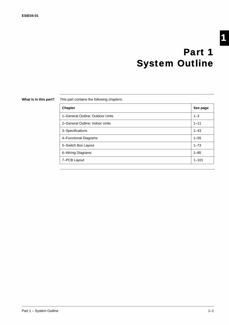
Weigher for refrigerant charge
Specifications• High accuracy
TA101A (for 10-kg cylinder) = ± 2gTA101B (for 20-kg cylinder) = ± 5g
• Equipped with pressure-resistant sight glass to check liquid refrigerant charging.• A manifold with separate ports for HFCs and previous refrigerants is equipped as standard
accessories.
Differences• Measurement is based on weight to prevent change of mixing ratio during charging.
Charge mouthpiece
Specifications• For R410A, 1/4"→ 5/16" (2min → 2.5min)• Material is changed from CR to H-NBR.
Differences• Change of thread specification on hose connection side (For the R410A use)• Change of sealer material for the HFCs use.
Can not be used
ESIE04-01
Part 1 – System Outline 1–1
4
3
4
5
1Part 1
System Outline
What is in this part? This part contains the following chapters:
Chapter See page
1–General Outline: Outdoor Units 1–3
2–General Outline: Indoor Units 1–11
3–Specifications 1–43
4–Functional Diagrams 1–55
5–Switch Box Layout 1–73
6–Wiring Diagrams 1–85
7–PCB Layout 1–101
ESIE04-01
1–2 Part 1 – System Outline
3
11
5

ESIE04-01 General Outline: Outdoor Units
Part 1 – System Outline 1–3
3
1
4
5
Part 1
1 General Outline: Outdoor Units
1.1 What Is in This Chapter?
Introduction This chapter contains the following information on the outdoor units:
Outlook and dimensions
Installation and service space
Components
General outline This chapter contains the following general outlines:
General outline See page
1.2–RZQ71: Outlook and dimensions 1–4
1.3–RZQ100 and RZQ125: Outlook and dimensions 1–6
1.4–RZQ71, RZQ100 and RZQ125: Installation and Service Space 1–8

General Outline: Outdoor Units ESIE04-01
1–4 Part 1 – System Outline
3
11
4
5
1.2 RZQ71: Outlook and dimensions
Outlook and dimensions
The illustration below shows the outlook and the dimensions of the unit (mm).
Installation and service space
See page 1–8.
ESIE04-01 General Outline: Outdoor Units
Part 1 – System Outline 1–5
3
1
4
5
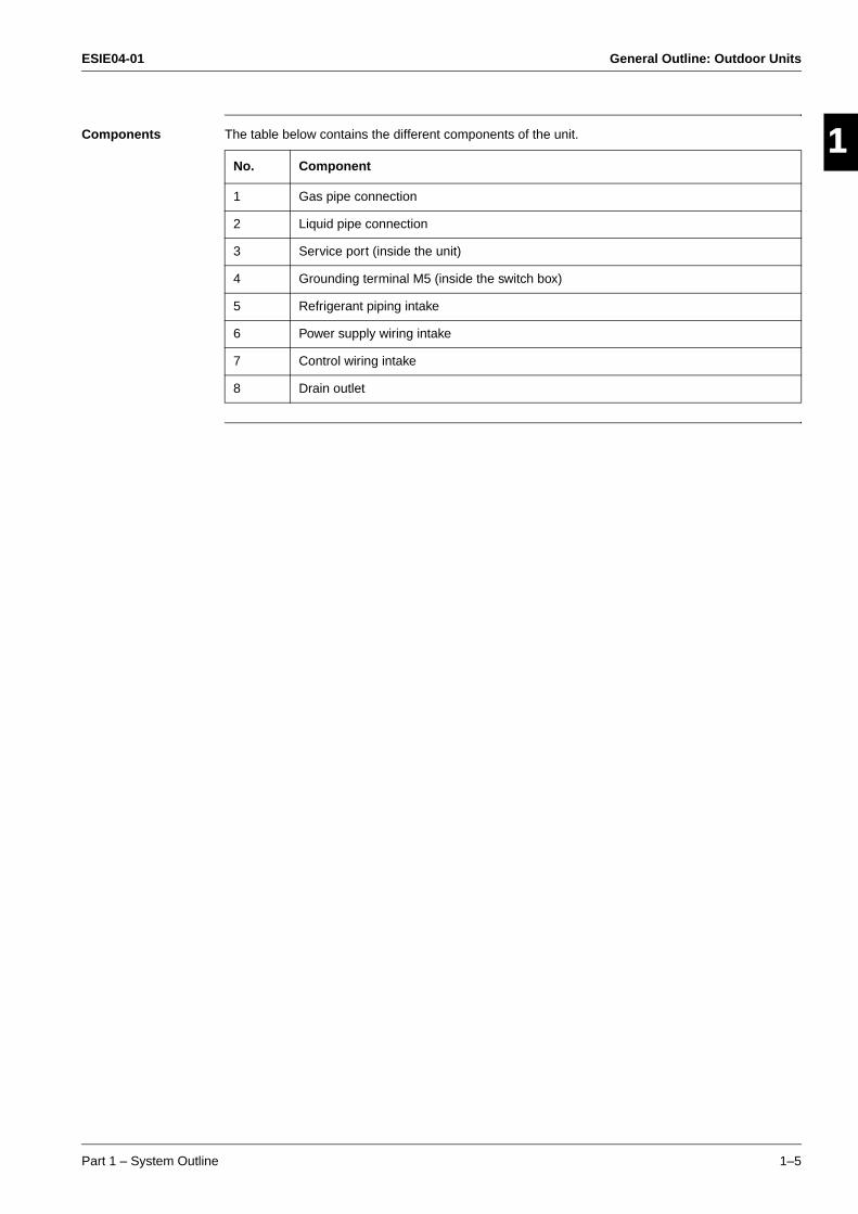
Components The table below contains the different components of the unit.
No. Component
1 Gas pipe connection
2 Liquid pipe connection
3 Service port (inside the unit)
4 Grounding terminal M5 (inside the switch box)
5 Refrigerant piping intake
6 Power supply wiring intake
7 Control wiring intake
8 Drain outlet
General Outline: Outdoor Units ESIE04-01
1–6 Part 1 – System Outline
3
11
4
5
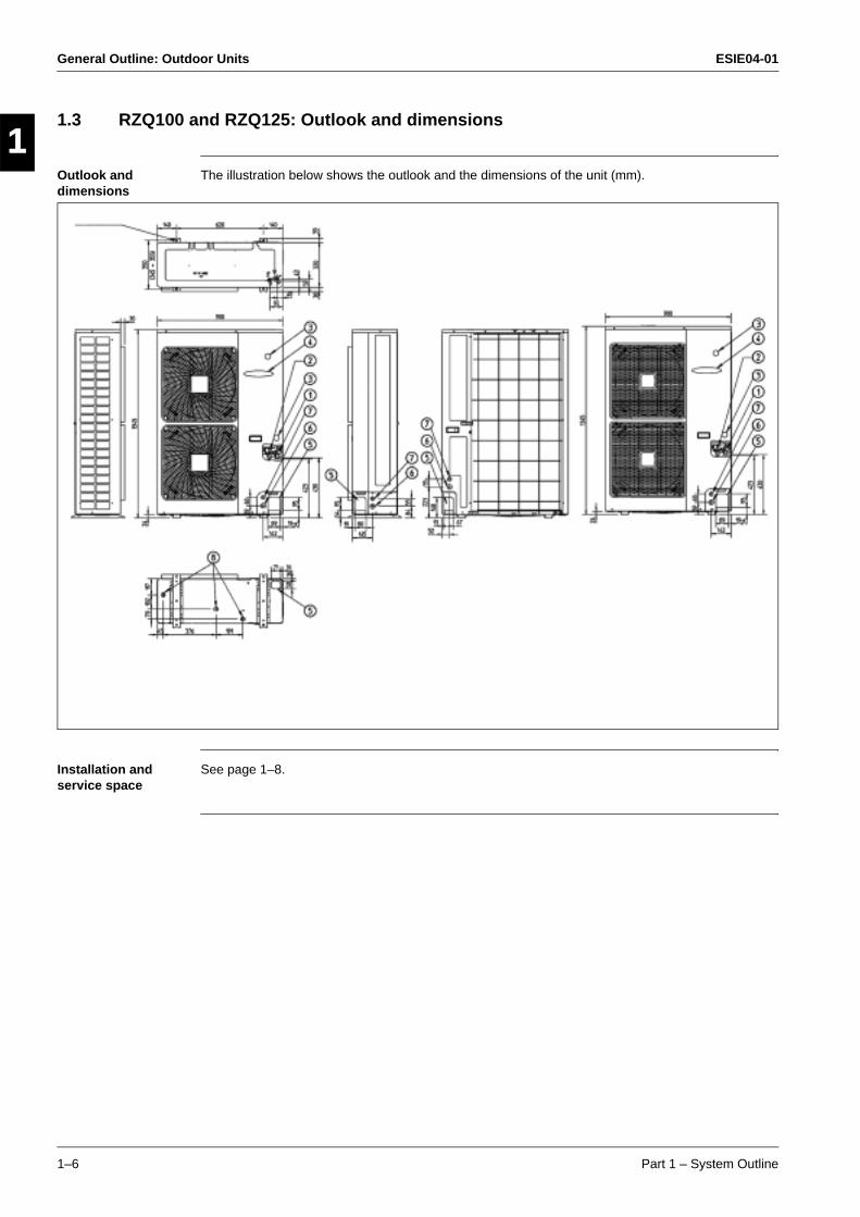
1.3 RZQ100 and RZQ125: Outlook and dimensions
Outlook and dimensions
The illustration below shows the outlook and the dimensions of the unit (mm).
Installation and service space
See page 1–8.

ESIE04-01 General Outline: Outdoor Units
Part 1 – System Outline 1–7
3
1
4
5
Components The table below contains the different components of the unit.
No. Component
1 Gas pipe connection
2 Liquid pipe connection
3 Service port (inside the unit)
4 Electronic connection and grounding terminal M5 (inside the switch box)
5 Refrigerant piping intake
6 Power supply wiring intake
7 Control wiring intake
8 Drain outlet
General Outline: Outdoor Units ESIE04-01
1–8 Part 1 – System Outline
3
11
4
5
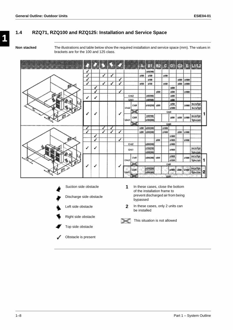
1.4 RZQ71, RZQ100 and RZQ125: Installation and Service Space
Non stacked The illustrations and table below show the required installation and service space (mm). The values in brackets are for the 100 and 125 class.
Suction side obstacle
Discharge side obstacle
Left side obstacle
Right side obstacle
Top side obstacle
Obstacle is present
In these cases, close the bottom of the installation frame to prevent discharged air from being bypassed
In these cases, only 2 units can be installed
1
2
This situation is not allowed

ESIE04-01 General Outline: Outdoor Units
Part 1 – System Outline 1–9
3
1
4
5
Stacked The illustration below shows the required installation and service space (mm). The values in brackets are for the 100 and 125 class.
Do not stack more than one unit.
± 100 mm is required as the dimension for laying the upper outdoor unit’s drain pipe.
Get the portion A sealed so that air from the outlet does not bypass.
Multiple rows The illustration below shows the required installation and service space (mm). The values in brackets are for the 100 and 125 class.
Relation of dimensions of H, A and L are shown in the table below.
Obstacles exist in front of the outlet side Obstacles exist in front of the air inlet
L A
L ≤ H0 < L ≤ 1/2H 150 (250)
1/2H < L 200 (300)
H < L installation impossible
Installation of one unit per row Installing multiple units (2 units or more) in lateral connection per row
General Outline: Outdoor Units ESIE04-01
1–10 Part 1 – System Outline
3
11
4
5
ESIE04-01 General Outline: Indoor Units
Part 1 – System Outline 1–11
3
1
4
5
Part 1
2 General Outline: Indoor Units
2.1 What Is in This Chapter?
Introduction This chapter contains the following information on the indoor units:
Outlook and dimensions
Components
General outline This chapter contains the following general outlines:
General outline See page
2.2–FCQ35B7V1 ~ FCQ71B7V3B 1–12
2.3–FCQ100~125B7V3B 1–14
2.4–FFQ35~60BV1B 1–16
2.5–FBQ35B7V1 & FBQ50B7V1 1–18
2.6–FBQ60B7V1 & FBQ71B7V3B 1–20
2.7–FBQ100B7V3B & FBQ125B7V3B 1–22
2.8–FDQ125B7V3B 1–24
2.9–FHQ35BUV1 & FHQ50BUV1 1–26
2.10–FHQ60BUV1 & FHQ71BUV1B 1–28
2.11–FHQ100BUV1B 1–30
2.12–FHQ125BUV1B 1–32
2.13–FUQ71BUV1B 1–34
2.14–FUQ100~125BUV1B 1–36
2.15–FAQ71BUV1B 1–38
2.16–FAQ100BUV1B 1–40

General Outline: Indoor Units ESIE04-01
1–12 Part 1 – System Outline
3
11
4
5
2.2 FCQ35B7V1 ~ FCQ71B7V3B
Outlook and dimensions
The illustration below shows the outlook and the dimensions of the unit (mm).
RE
QU
IRE
D IN
ST
AL
LA
TIO
N S
PA
CE
WH
EN
TH
E D
ISC
HA
RG
E G
RIL
L IS
CLO
SE
D,
TH
E R
EQ
UIR
ED
SP
AC
E IS
200
mm
OR
MO
RE
.
or m
ore
or m
ore
or m
ore
or m
ore
Bra
nch
duct
co
nnec
tion
Pre
pare
d ho
le
Pre
pare
d ho
le
Bra
nch
duct
co
nnec
tion
(Cei
ling
open
ing)
(Sus
pens
ion
posi
tion)
(Ceiling opening)
(Suspension position)
or le
ss
Pre
pare
d ho
le
Bra
nch
duct
co
nnec
tion
Installation space
Han
ging
bol
t
Adjustable
VIE
W A
VIE
W C
Pre
pare
d ho
le
For
fres
h ai
r in
take
kit
conn
ectio
n (d
irect
in
stal
latio
n ty
pe)
see
note
3
or more
VIE
W B
VIE
W D
NO
TE
S:
1.Lo
catio
n of
the
nam
epla
tes:
- U
nit b
ody:
on
the
bell
mou
th a
t the
insi
de o
f the
suc
tion
grill
.-
Dec
orat
ion
pane
l: on
the
pane
l fra
me
at th
e in
side
of t
he s
uctio
n gr
ill.
2.W
hen
inst
allin
g an
opt
iona
l acc
esso
ry, r
efer
to th
e in
stal
latio
n dr
awin
gs.
- F
or th
e fr
esh
air
inta
ke k
it ...
.. an
insp
ectio
n po
rt is
nec
essa
ry-
For
the
high
effi
cien
cy fi
lter
.....
an in
spec
tion
port
is n
eces
sary
- F
or th
e br
anch
duc
t cha
mbe
r ...
. an
insp
ectio
n po
rt is
nec
essa
ry
3.In
cas
e of
usi
ng a
infr
ared
rem
ote
cont
rol,
this
pos
ition
will
be
a si
gnal
rece
iver
. R
efer
to th
e dr
awin
g of
the
infr
ared
rem
ote
cont
rol f
or m
ore
deta
ils.
4.W
hen
the
cond
ition
s ex
ceed
30°
C a
nd R
H 8
0% in
the
ceili
ng o
r fr
esh
air
is
indu
cted
into
the
ceili
ng, a
n ad
ditio
nal i
nsul
atio
n is
requ
ired
(pol
yeth
ylen
e fo
am,
thic
knes
s 10
mm
or
mor
e).

ESIE04-01 General Outline: Indoor Units
Part 1 – System Outline 1–13
3
1
4
5
Components The table below contains the different components of the unit.
No. Component
1 Liquid pipe connection
2 Gas pipe connection
3 Drain pipe connection
4 Power supply connection
5 Transmission wiring connection
6 Air discharge grille
7 Air suction grille
8 Water supply intake
9 Corner decoration cover
10 Drain hose
General Outline: Indoor Units ESIE04-01
1–14 Part 1 – System Outline
3
11
4
5
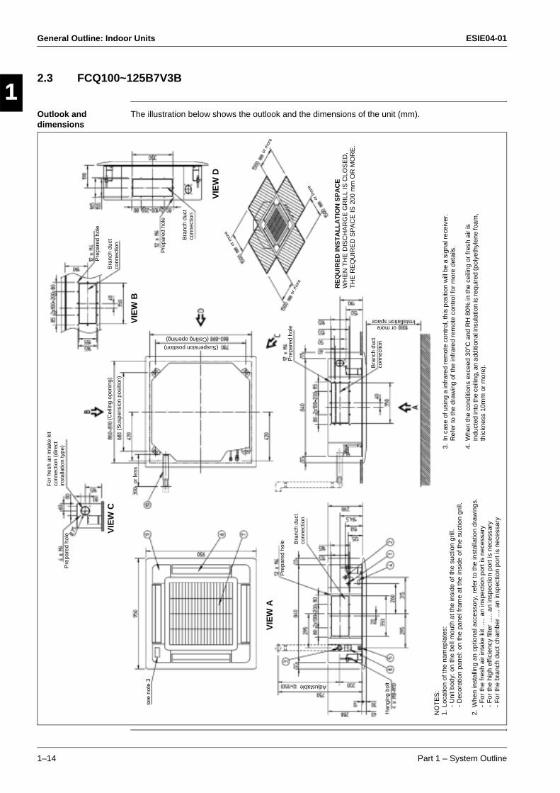
2.3 FCQ100~125B7V3B
Outlook and dimensions
The illustration below shows the outlook and the dimensions of the unit (mm).
Pre
pare
d ho
le
Bra
nch
duct
co
nnec
tion
or moreInstallation space
RE
QU
IRE
D IN
ST
AL
LA
TIO
N S
PA
CE
WH
EN
TH
E D
ISC
HA
RG
E G
RIL
L IS
CLO
SE
D,
TH
E R
EQ
UIR
ED
SP
AC
E IS
200
mm
OR
MO
RE
.
or m
ore
or m
ore
or m
ore
VIE
W D
Pre
pare
d ho
le
Bra
nch
duct
co
nnec
tion
Pre
pare
d ho
le
VIE
W B
(Suspension position)
(Ceiling opening)
Bra
nch
duct
co
nnec
tion
or le
ss
(Cei
ling
open
ing)
(Sus
pens
ion
posi
tion)
For
fres
h ai
r in
take
kit
conn
ectio
n (d
irect
in
stal
latio
n ty
pe)
VIE
W C
Pre
pare
d ho
le
Han
ging
bol
tAdjustable
NO
TE
S:
1.Lo
catio
n of
the
nam
epla
tes:
- U
nit b
ody:
on
the
bell
mou
th a
t the
insi
de o
f the
suc
tion
grill
.-
Dec
orat
ion
pane
l: on
the
pane
l fra
me
at th
e in
side
of t
he s
uctio
n gr
ill.
2.W
hen
inst
allin
g an
opt
iona
l acc
esso
ry, r
efer
to th
e in
stal
latio
n dr
awin
gs.
- F
or th
e fr
esh
air
inta
ke k
it ...
.. an
insp
ectio
n po
rt is
nec
essa
ry-
For
the
high
effi
cien
cy fi
lter
.....
an in
spec
tion
port
is n
eces
sary
- F
or th
e br
anch
duc
t cha
mbe
r ...
. an
insp
ectio
n po
rt is
nec
essa
ry
VIE
W A
Pre
pare
d ho
le Bra
nch
duct
co
nnec
tion
or m
ore
see
note
3
or m
ore
3.In
cas
e of
usi
ng a
infr
ared
rem
ote
cont
rol,
this
pos
ition
will
be
a si
gnal
rece
iver
. R
efer
to th
e dr
awin
g of
the
infr
ared
rem
ote
cont
rol f
or m
ore
deta
ils.
4.W
hen
the
cond
ition
s ex
ceed
30°
C a
nd R
H 8
0% in
the
ceili
ng o
r fr
esh
air
is
indu
cted
into
the
ceili
ng, a
n ad
ditio
nal i
nsul
atio
n is
requ
ired
(pol
yeth
ylen
e fo
am,
thic
knes
s 10
mm
or
mor
e).
ESIE04-01 General Outline: Indoor Units
Part 1 – System Outline 1–15
3
1
4
5
Components The table below contains the different components of the unit.
No. Component
1 Liquid pipe connection
2 Gas pipe connection
3 Drain pipe connection
4 Power supply connection
5 Transmission wiring connection
6 Air discharge grille
7 Air suction grille
8 Water supply intake
9 Corner decoration cover
10 Drain hose

General Outline: Indoor Units ESIE04-01
1–16 Part 1 – System Outline
3
11
4
5
2.4 FFQ35~60BV1B
Outlook and dimensions
The illustration below shows the outlook and the dimensions of the unit (mm).
NO
TE
S:
1.S
ticki
ng lo
catio
n fo
r m
anuf
actu
re’s
labe
lM
anuf
actu
re’s
labe
l for
indo
or u
nit :
on
the
bell
mou
th in
side
suc
tion
grill
Man
ufac
ture
’s la
bel f
or d
ecor
atio
n pa
nel :
on
the
inne
r fr
ame
insi
de s
uctio
n gr
ill
2.In
cas
e of
usi
ng in
frar
ed r
emot
e co
ntro
l, th
is p
ositi
on w
ill b
e a
sign
al r
ecei
ver.
R
efer
to th
e dr
awin
g of
infr
ared
rem
ote
cont
rol i
n de
tail.
3.W
hen
the
tem
pera
ture
and
hum
idity
in th
e ce
iling
exc
eed
30°C
and
RH
80%
or
the
fres
h ai
r is
indu
cted
into
the
ceili
ng o
r th
e un
it co
ntin
ues
24 h
our
oper
atio
n,
an a
dditi
onal
insu
latio
n (t
hick
ness
10m
m o
r m
ore
of g
lass
woo
l or
poly
ethy
lene
fo
rm)
is r
equi
red.
4.T
houg
h th
e in
stal
latio
n is
acc
epta
ble
up to
max
imum
of 6
60m
m s
quar
e ce
iling
op
enin
g, k
eep
the
clea
ranc
e of
45m
m o
r le
ss b
etw
een
the
mai
n un
it an
d th
e ce
iling
ope
ning
so
that
the
pane
l ove
rlap
allo
wan
ce c
an b
e en
sure
d.
Sus
pens
ion
bolt
Adjustable
A A
RR
OW
VIE
W
or le
ssor
less
NO
TE
) 4.
(Required space)or more
From the floor sideor more
FOR HEIGHT INSTALLATIONor more
(Ceiling opening space)
(Suspension position)
(Cei
ling
open
ing
spac
e)
(Sus
pens
ion
posi
tion)
or le
ssN
OT
E)
2.
Dra
in c
onne
ctio
n si
de
Pip
e co
nnec
tion
side
*WH
EN
TH
E D
ISC
HA
RG
E G
RIL
L IS
CLO
SE
D,
TH
E R
EQ
UIR
ED
SP
AC
E IS
200
mm
OR
MO
RE
.
or m
ore*
or m
ore*
or m
ore*
or m
ore*
Out
door
air
inta
ke
(Dire
ct c
onne
ctio
n)
Cei
ling
hole
B A
RR
OW
VIE
W
•RE
QU
IRE
D S
PA
CE

ESIE04-01 General Outline: Indoor Units
Part 1 – System Outline 1–17
3
1
4
5
Components The table below contains the different components of the unit.
No. Component
1 Liquid pipe connection
2 Gas pipe connection
3 Drain pipe connection
4 Power supply connection
5 Remote control code and control wiring connection
6 Air discharge grille
7 Suction grille
8 Drain hose
General Outline: Indoor Units ESIE04-01
1–18 Part 1 – System Outline
3
11
4
5
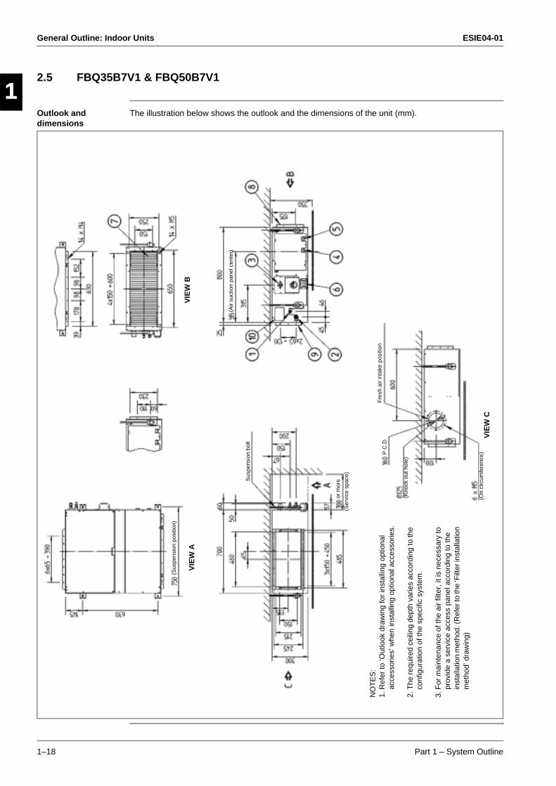
2.5 FBQ35B7V1 & FBQ50B7V1
Outlook and dimensions
The illustration below shows the outlook and the dimensions of the unit (mm).
NO
TE
S:
1.R
efer
to ‘O
utlo
ok d
raw
ing
for
inst
allin
g op
tiona
l ac
cess
orie
s’ w
hen
inst
allin
g op
tiona
l acc
esso
ries.
2.T
he r
equi
red
ceili
ng d
epth
var
ies
acco
rdin
g to
the
conf
igur
atio
n of
the
spec
ific
syst
em.
3.F
or m
aint
enan
ce o
f the
air
filte
r, it
is n
eces
sary
to
prov
ide
a se
rvic
e ac
cess
pan
el a
ccor
ding
to th
e in
stal
latio
n m
etho
d. (R
efer
to th
e ‘F
ilter
inst
alla
tion
met
hod’
dra
win
g)
(Ser
vice
spa
ce)
or m
ore
(On
circ
umfe
renc
e)
(Kno
ck o
ut h
ole)
Sus
pens
ion
bolt
Fre
sh a
ir in
take
pos
ition
(Air
suct
ion
pane
l cen
ter)
(Sus
pens
ion
posi
tion)
VIE
W A
VIE
W B
VIE
W C
P.C
.D.

ESIE04-01 General Outline: Indoor Units
Part 1 – System Outline 1–19
3
1
4
5
Components The table below contains the different components of the unit.
No. Component
1 Liquid pipe connection
2 Gas pipe connection
3 Drain pipe connection
4 Remote control wiring connection
5 Power supply connection
6 Drain hole
7 Air filter
8 Air suction side
9 Air discharge side
10 Nameplate
General Outline: Indoor Units ESIE04-01
1–20 Part 1 – System Outline
3
11
4
5
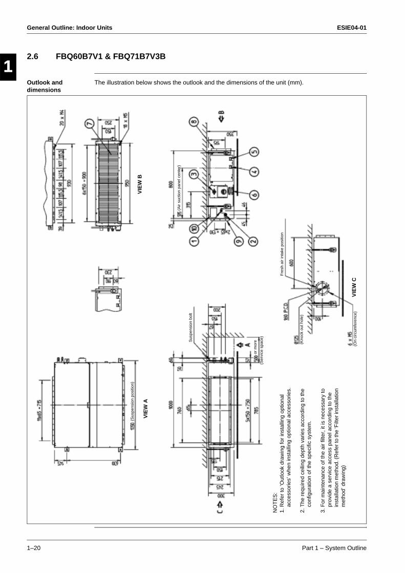
2.6 FBQ60B7V1 & FBQ71B7V3B
Outlook and dimensions
The illustration below shows the outlook and the dimensions of the unit (mm).
NO
TE
S:
1.R
efer
to ‘O
utlo
ok d
raw
ing
for
inst
allin
g op
tiona
l ac
cess
orie
s’ w
hen
inst
allin
g op
tiona
l acc
esso
ries.
2.T
he r
equi
red
ceili
ng d
epth
var
ies
acco
rdin
g to
the
conf
igur
atio
n of
the
spec
ific
syst
em.
3.F
or m
aint
enan
ce o
f the
air
filte
r, it
is n
eces
sary
to
prov
ide
a se
rvic
e ac
cess
pan
el a
ccor
ding
to th
e in
stal
latio
n m
etho
d. (R
efer
to th
e ‘F
ilter
inst
alla
tion
met
hod’
dra
win
g)
(Ser
vice
spa
ce)
or m
ore
(On
circ
umfe
renc
e)
(Kno
ck o
ut h
ole)
Sus
pens
ion
bolt
Fre
sh a
ir in
take
pos
ition
(Air
suct
ion
pane
l cen
ter)
(Sus
pens
ion
posi
tion)
VIE
W A
VIE
W B
VIE
W C

ESIE04-01 General Outline: Indoor Units
Part 1 – System Outline 1–21
3
1
4
5
Components The table below contains the different components of the unit.
No. Component
1 Liquid pipe connection
2 Gas pipe connection
3 Drain pipe connection
4 Remote control wiring connection
5 Power supply connection
6 Drain hole
7 Air filter
8 Air suction side
9 Air discharge side
10 Nameplate
General Outline: Indoor Units ESIE04-01
1–22 Part 1 – System Outline
3
11
4
5
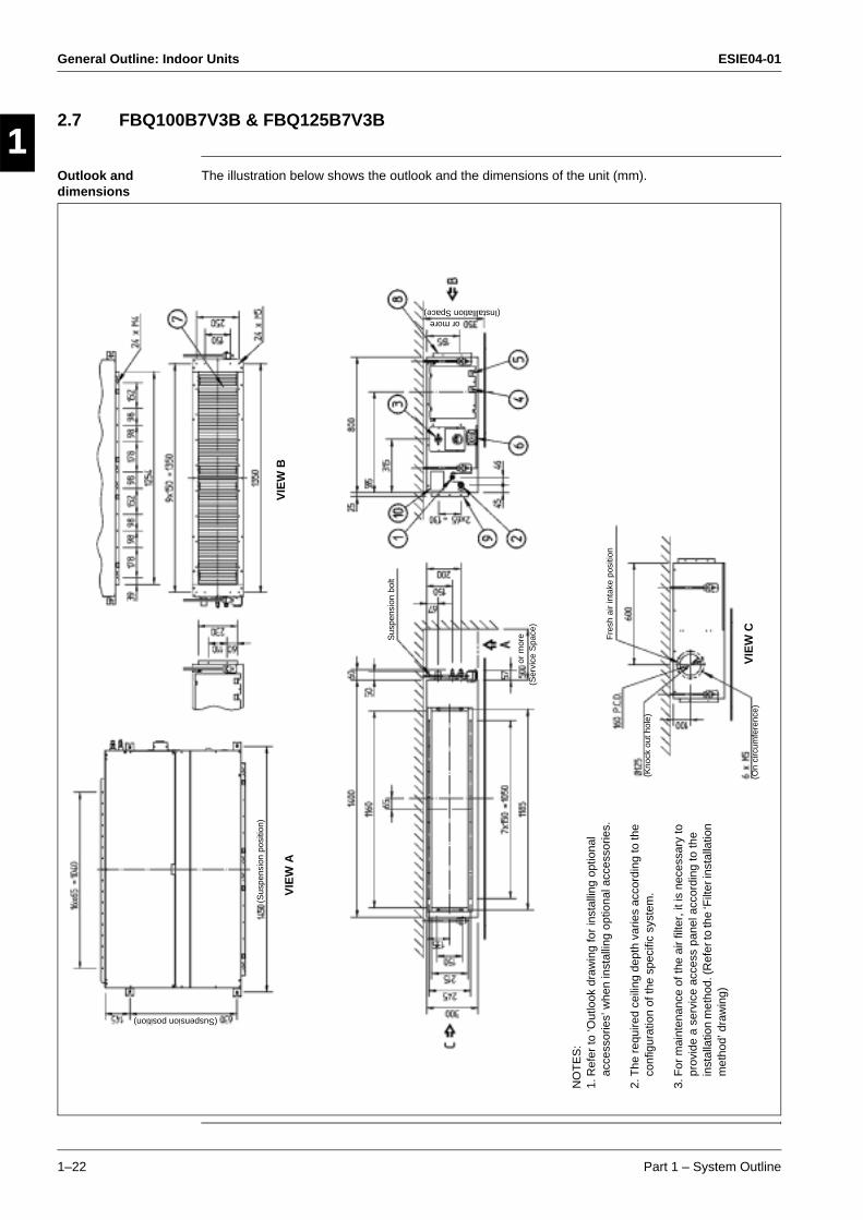
2.7 FBQ100B7V3B & FBQ125B7V3B
Outlook and dimensions
The illustration below shows the outlook and the dimensions of the unit (mm).
(Installlation Space)or more
(On
circ
umfe
renc
e)
(Kno
ck o
ut h
ole)
Sus
pens
ion
bolt
Fre
sh a
ir in
take
pos
ition
(Sus
pens
ion
posi
tion)
VIE
W A
VIE
W B
VIE
W C
(Suspension position)
or m
ore
(Ser
vice
Spa
ce)
NO
TE
S:
1.R
efer
to ‘O
utlo
ok d
raw
ing
for
inst
allin
g op
tiona
l ac
cess
orie
s’ w
hen
inst
allin
g op
tiona
l acc
esso
ries.
2.T
he r
equi
red
ceili
ng d
epth
var
ies
acco
rdin
g to
the
conf
igur
atio
n of
the
spec
ific
syst
em.
3.F
or m
aint
enan
ce o
f the
air
filte
r, it
is n
eces
sary
to
prov
ide
a se
rvic
e ac
cess
pan
el a
ccor
ding
to th
e in
stal
latio
n m
etho
d. (R
efer
to th
e ‘F
ilter
inst
alla
tion
met
hod’
dra
win
g)
ESIE04-01 General Outline: Indoor Units
Part 1 – System Outline 1–23
3
1
4
5
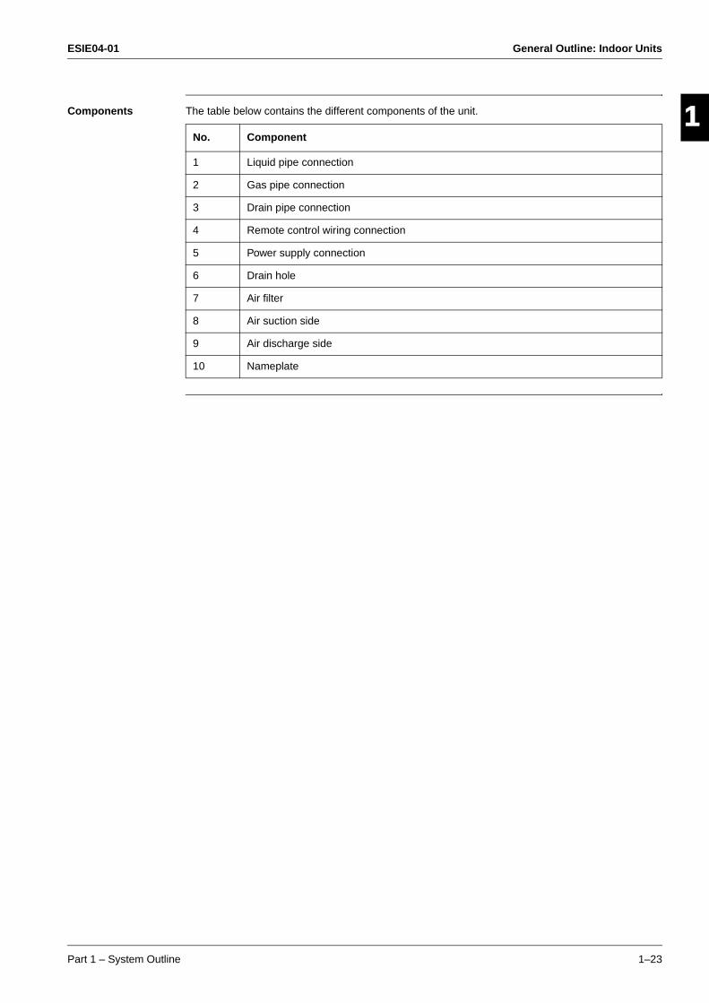
Components The table below contains the different components of the unit.
No. Component
1 Liquid pipe connection
2 Gas pipe connection
3 Drain pipe connection
4 Remote control wiring connection
5 Power supply connection
6 Drain hole
7 Air filter
8 Air suction side
9 Air discharge side
10 Nameplate
General Outline: Indoor Units ESIE04-01
1–24 Part 1 – System Outline
3
11
4
5
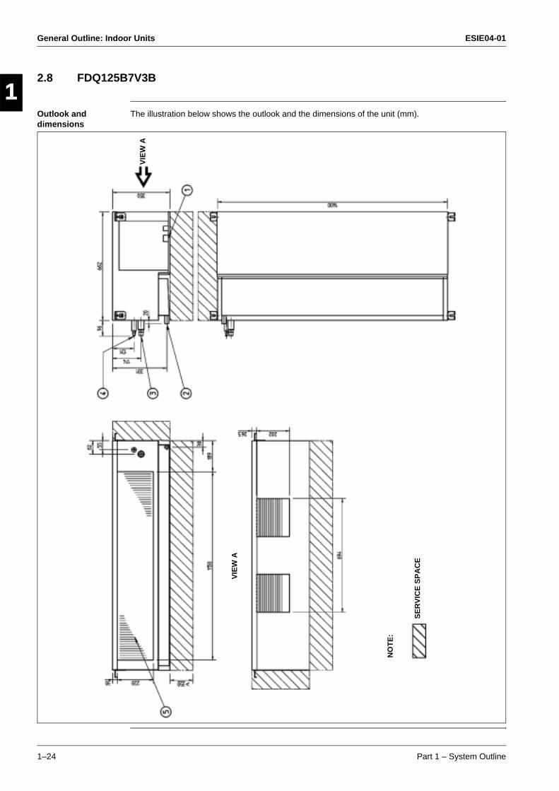
2.8 FDQ125B7V3B
Outlook and dimensions
The illustration below shows the outlook and the dimensions of the unit (mm).
VIE
W A
VIE
W A
SE
RV
ICE
SP
AC
E
NO
TE
:
ESIE04-01 General Outline: Indoor Units
Part 1 – System Outline 1–25
3
1
4
5
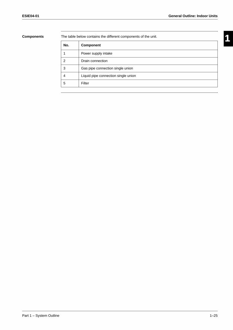
Components The table below contains the different components of the unit.
No. Component
1 Power supply intake
2 Drain connection
3 Gas pipe connection single union
4 Liquid pipe connection single union
5 Filter
General Outline: Indoor Units ESIE04-01
1–26 Part 1 – System Outline
3
11
4
5
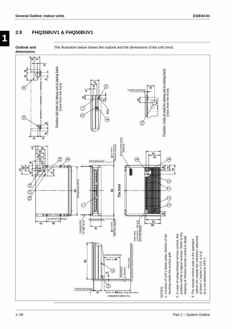
2.9 FHQ35BUV1 & FHQ50BUV1
Outlook and dimensions
The illustration below shows the outlook and the dimensions of the unit (mm).
Pos
ition
slit
hol
e fo
r ta
king
out
in p
ipin
g ba
ck
or m
ore
(Ser
vice
Spa
ce)
Bra
nd n
ame
plat
e(N
ote
2)
Dra
in p
ipe
conn
ectio
n(F
or le
ft pi
ping
)
Th
e fr
on
t
Flo
or s
ide
Obs
tacl
e
(Required space)
or more
For height installation
From the floor sideor more
(Required space)
(Vie
w fr
om th
e fr
ont)
(Han
ging
pos
ition
)
(Hanging position)
Han
ging
bol
t
(Required space)
Pos
ition
: Hol
e of
wal
l for
taki
ng o
ut in
pip
ing
back
(Vie
w fr
om th
e fr
ont)
or m
ore
(Ser
vice
Spa
ce)
NO
TE
S:
1.Lo
catio
n of
uni
t’s N
ame
plat
e: B
otto
m o
f fan
ho
usin
g in
side
the
suct
ion
grill
.
2.In
cas
e of
usi
ng in
frar
ed r
emot
e co
ntro
l, th
is
posi
tion
will
be
a si
gnal
rec
eive
r. R
efer
to th
e dr
awin
g of
infr
ared
rem
ote
cont
rol i
n de
tail.
3.T
he r
emot
e co
ntro
l cod
e is
the
stan
dard
<
abou
t 3m
out
side
the
mac
hine
> a
ttach
ed.
(0.5
mm
² x
2wic
ks x
O.D
. ø 5
.4)
(It i
s no
t atta
ched
to V
RV
.)
ESIE04-01 General Outline: Indoor Units
Part 1 – System Outline 1–27
3
1
4
5
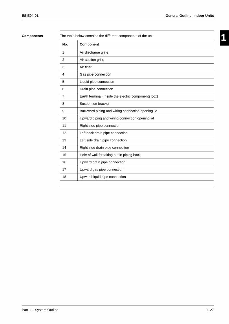
Components The table below contains the different components of the unit.
No. Component
1 Air discharge grille
2 Air suction grille
3 Air filter
4 Gas pipe connection
5 Liquid pipe connection
6 Drain pipe connection
7 Earth terminal (Inside the electric components box)
8 Suspention bracket
9 Backward piping and wiring connection opening lid
10 Upward piping and wiring connection opening lid
11 Right side pipe connection
12 Left back drain pipe connection
13 Left side drain pipe connection
14 Right side drain pipe connection
15 Hole of wall for taking out in piping back
16 Upward drain pipe connection
17 Upward gas pipe connection
18 Upward liquid pipe connection
General Outline: Indoor Units ESIE04-01
1–28 Part 1 – System Outline
3
11
4
5
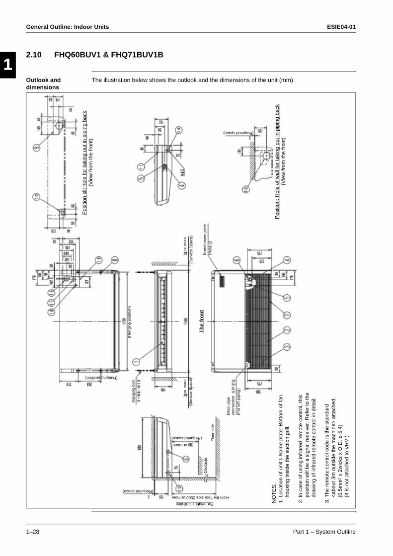
2.10 FHQ60BUV1 & FHQ71BUV1B
Outlook and dimensions
The illustration below shows the outlook and the dimensions of the unit (mm).P
ositi
on s
lit h
ole
for
taki
ng o
ut in
pip
ing
back
or m
ore
(Ser
vice
Spa
ce)
Bra
nd n
ame
plat
e(N
ote
2)
Dra
in p
ipe
conn
ectio
n(F
or le
ft pi
ping
)
Th
e fr
on
t
Flo
or s
ide
Obs
tacl
e
(Required space)
or more
For height installation
From the floor side 2500 or more
(Required space)
(Vie
w fr
om th
e fr
ont)
(Han
ging
pos
ition
)
(Hanging position)
Han
ging
bol
t
(Required space)
Pos
ition
: Hol
e of
wal
l for
taki
ng o
ut in
pip
ing
back
(Vie
w fr
om th
e fr
ont)
or m
ore
(Ser
vice
Spa
ce)
NO
TE
S:
1.Lo
catio
n of
uni
t’s N
ame
plat
e: B
otto
m o
f fan
ho
usin
g in
side
the
suct
ion
grill
.
2.In
cas
e of
usi
ng in
frar
ed r
emot
e co
ntro
l, th
is
posi
tion
will
be
a si
gnal
rec
eive
r. R
efer
to th
e dr
awin
g of
infr
ared
rem
ote
cont
rol i
n de
tail.
3.T
he r
emot
e co
ntro
l cod
e is
the
stan
dard
<
abou
t 3m
out
side
the
mac
hine
> a
ttach
ed.
(0.5
mm
² x
2wic
ks x
O.D
. ø 5
.4)
(It i
s no
t atta
ched
to V
RV
.)

ESIE04-01 General Outline: Indoor Units
Part 1 – System Outline 1–29
3
1
4
5
Components The table below contains the different components of the unit.
No. Component
1 Air discharge grille
2 Air suction grille
3 Air filter
4 Gas pipe connection
5 Liquid pipe connection
6 Drain pipe connection
7 Earth terminal (Inside the electric components box)
8 Suspention bracket
9 Backward piping and wiring connection opening lid
10 Upward piping and wiring connection opening lid
11 Right side pipe connection
12 Left back drain pipe connection
13 Left side drain pipe connection
14 Right side drain pipe connection
15 Hole of wall for taking out in piping back
16 Upward drain pipe connection
17 Upward gas pipe connection
18 Upward liquid pipe connection
General Outline: Indoor Units ESIE04-01
1–30 Part 1 – System Outline
3
11
4
5
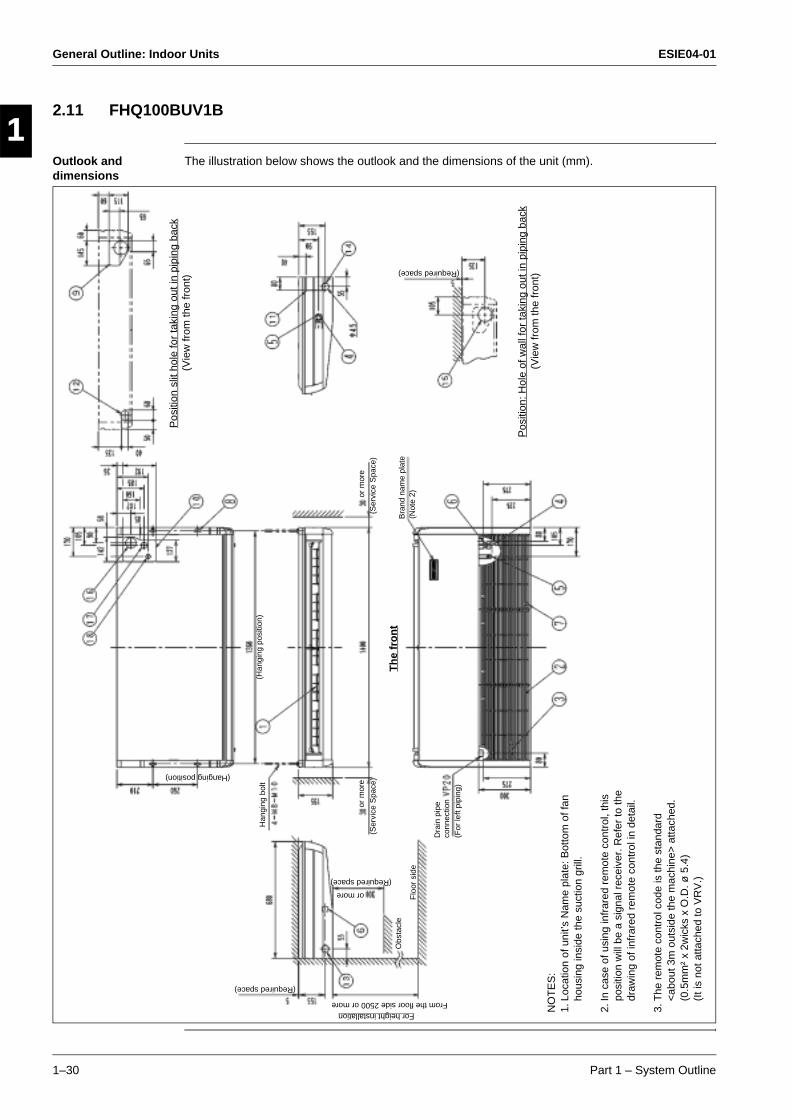
2.11 FHQ100BUV1B
Outlook and dimensions
The illustration below shows the outlook and the dimensions of the unit (mm).P
ositi
on s
lit h
ole
for
taki
ng o
ut in
pip
ing
back
or m
ore
(Ser
vice
Spa
ce)
Bra
nd n
ame
plat
e(N
ote
2)
Dra
in p
ipe
conn
ectio
n(F
or le
ft pi
ping
)
Th
e fr
on
t
Flo
or s
ide
Obs
tacl
e
(Required space)
or more
For height installationFrom the floor side 2500 or more
(Required space)
(Vie
w fr
om th
e fr
ont)
(Han
ging
pos
ition
)
(Hanging position)
Han
ging
bol
t
(Required space)
Pos
ition
: Hol
e of
wal
l for
taki
ng o
ut in
pip
ing
back
(Vie
w fr
om th
e fr
ont)
or m
ore
(Ser
vice
Spa
ce)
NO
TE
S:
1.Lo
catio
n of
uni
t’s N
ame
plat
e: B
otto
m o
f fan
ho
usin
g in
side
the
suct
ion
grill
.
2.In
cas
e of
usi
ng in
frar
ed r
emot
e co
ntro
l, th
is
posi
tion
will
be
a si
gnal
rec
eive
r. R
efer
to th
e dr
awin
g of
infr
ared
rem
ote
cont
rol i
n de
tail.
3.T
he r
emot
e co
ntro
l cod
e is
the
stan
dard
<
abou
t 3m
out
side
the
mac
hine
> a
ttach
ed.
(0.5
mm
² x
2wic
ks x
O.D
. ø 5
.4)
(It i
s no
t atta
ched
to V
RV
.)

ESIE04-01 General Outline: Indoor Units
Part 1 – System Outline 1–31
3
1
4
5
Components The table below contains the different components of the unit.
No. Component
1 Air discharge grille
2 Air suction grille
3 Air filter
4 Gas pipe connection
5 Liquid pipe connection
6 Drain pipe connection
7 Earth terminal (Inside the electric components box)
8 Suspention bracket
9 Backward piping and wiring connection opening lid
10 Upward piping and wiring connection opening lid
11 Right side pipe connection
12 Left back drain pipe connection
13 Left side drain pipe connection
14 Right side drain pipe connection
15 Hole of wall for taking out in piping back
16 Upward drain pipe connection
17 Upward gas pipe connection
18 Upward liquid pipe connection
General Outline: Indoor Units ESIE04-01
1–32 Part 1 – System Outline
3
11
4
5
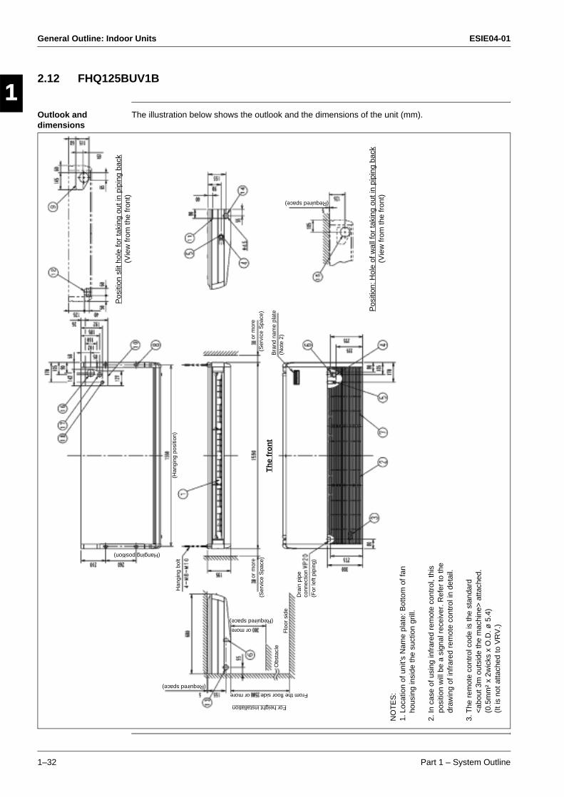
2.12 FHQ125BUV1B
Outlook and dimensions
The illustration below shows the outlook and the dimensions of the unit (mm).P
ositi
on s
lit h
ole
for
taki
ng o
ut in
pip
ing
back
or m
ore
(Ser
vice
Spa
ce)
Bra
nd n
ame
plat
e(N
ote
2)
Dra
in p
ipe
conn
ectio
n(F
or le
ft pi
ping
)
Th
e fr
on
t
Flo
or s
ide
Obs
tacl
e
(Required space)
or more
For height installation
or more
(Required space)
(Vie
w fr
om th
e fr
ont)
(Han
ging
pos
ition
)
(Hanging position)
Han
ging
bol
t(Required space)
Pos
ition
: Hol
e of
wal
l for
taki
ng o
ut in
pip
ing
back
(Vie
w fr
om th
e fr
ont)
or m
ore
(Ser
vice
Spa
ce)
NO
TE
S:
1.Lo
catio
n of
uni
t’s N
ame
plat
e: B
otto
m o
f fan
ho
usin
g in
side
the
suct
ion
grill
.
2.In
cas
e of
usi
ng in
frar
ed r
emot
e co
ntro
l, th
is
posi
tion
will
be
a si
gnal
rec
eive
r. R
efer
to th
e dr
awin
g of
infr
ared
rem
ote
cont
rol i
n de
tail.
3.T
he r
emot
e co
ntro
l cod
e is
the
stan
dard
<
abou
t 3m
out
side
the
mac
hine
> a
ttach
ed.
(0.5
mm
² x
2wic
ks x
O.D
. ø 5
.4)
(It i
s no
t atta
ched
to V
RV
.)
From the floor side

ESIE04-01 General Outline: Indoor Units
Part 1 – System Outline 1–33
3
1
4
5
Components The table below contains the different components of the unit.
No. Component
1 Air discharge grille
2 Air suction grille
3 Air filter
4 Gas pipe connection
5 Liquid pipe connection
6 Drain pipe connection
7 Earth terminal (Inside the electric components box)
8 Suspention bracket
9 Backward piping and wiring connection opening lid
10 Upward piping and wiring connection opening lid
11 Right side pipe connection
12 Left back drain pipe connection
13 Left side drain pipe connection
14 Right side drain pipe connection
15 Hole of wall for taking out in piping back
16 Upward drain pipe connection
17 Upward gas pipe connection
18 Upward liquid pipe connection
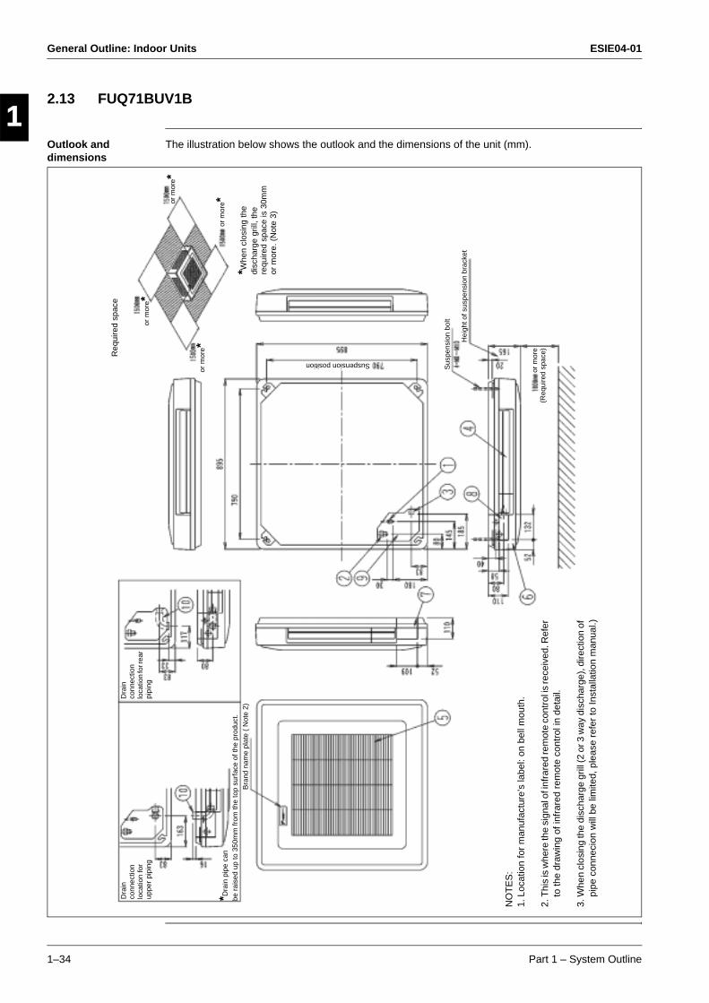
General Outline: Indoor Units ESIE04-01
1–34 Part 1 – System Outline
3
11
4
5
2.13 FUQ71BUV1B
Outlook and dimensions
The illustration below shows the outlook and the dimensions of the unit (mm).
Sus
pens
ion
bolt
Suspension position
Dra
in
conn
ectio
n lo
catio
n fo
r up
per
pipi
ng
*Dra
in p
ipe
can
be r
aise
d up
to 3
50m
m fr
om th
e to
p su
rfac
e of
the
prod
uct.
*Whe
n cl
osin
g th
e di
scha
rge
grill
, the
re
quire
d sp
ace
is 3
0mm
or
mor
e. (
Not
e 3)
or m
ore*
or m
ore*
or m
ore*
NO
TE
S:
1.Lo
catio
n fo
r m
anuf
actu
re’s
labe
l: on
bel
l mou
th.
2.T
his
is w
here
the
sign
al o
f inf
rare
d re
mot
e co
ntro
l is
rece
ived
. Ref
er
to th
e dr
awin
g of
infr
ared
rem
ote
cont
rol i
n de
tail.
3.W
hen
clos
ing
the
disc
harg
e gr
ill (2
or 3
way
dis
char
ge),
dire
ctio
n of
pi
pe c
onne
cion
will
be
limite
d, p
leas
e re
fer
to In
stal
latio
n m
anua
l.)
or m
ore*
Hei
ght o
f sus
pens
ion
brac
ket
or m
ore
(Req
uire
d sp
ace)
Dra
in
conn
ectio
n lo
catio
n fo
r rea
r pi
ping
Req
uire
d sp
ace
Bra
nd n
ame
plat
e (
Not
e 2)

ESIE04-01 General Outline: Indoor Units
Part 1 – System Outline 1–35
3
1
4
5
Components The table below contains the different components of the unit.
No. Component
1 Liquid pipe connection
2 Gas pipe connection
3 Drain pipe connection
4 Air outlet
5 Air suction grille
6 Corner decoration cover
7 Right pipe/wiring connection
8 Rear pipe/wiring connection
9 Pipe through cover
10 Accessory drain elbow
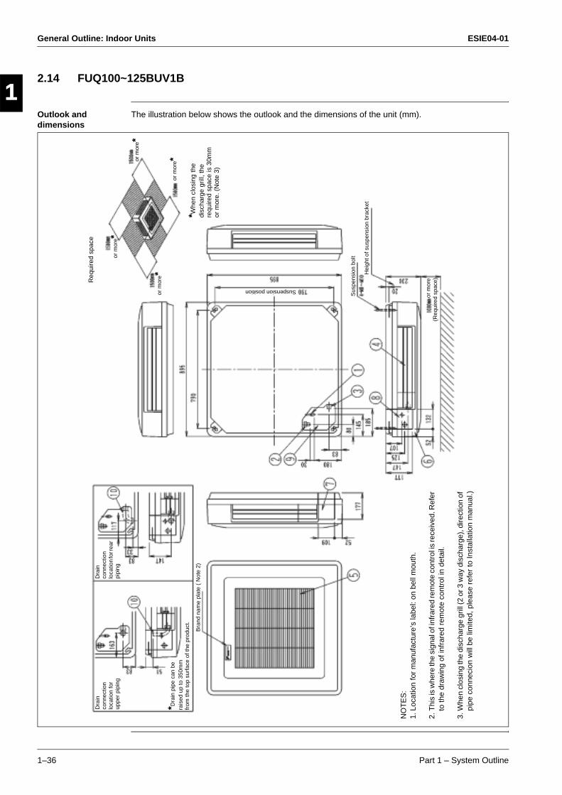
General Outline: Indoor Units ESIE04-01
1–36 Part 1 – System Outline
3
11
4
5
2.14 FUQ100~125BUV1B
Outlook and dimensions
The illustration below shows the outlook and the dimensions of the unit (mm).
Sus
pens
ion
bolt
Suspension position
Dra
in
conn
ectio
n lo
catio
n fo
r up
per
pipi
ng
*Dra
in p
ipe
can
be
rais
ed u
p to
350
mm
fr
om th
e to
p su
rfac
e of
the
prod
uct.
*Whe
n cl
osin
g th
e di
scha
rge
grill
, the
re
quire
d sp
ace
is 3
0mm
or
mor
e. (
Not
e 3)
or m
ore*
or m
ore*
or m
ore*
NO
TE
S:
1.Lo
catio
n fo
r m
anuf
actu
re’s
labe
l: on
bel
l mou
th.
2.T
his
is w
here
the
sign
al o
f inf
rare
d re
mot
e co
ntro
l is
rece
ived
. Ref
er
to th
e dr
awin
g of
infr
ared
rem
ote
cont
rol i
n de
tail.
3.W
hen
clos
ing
the
disc
harg
e gr
ill (2
or 3
way
dis
char
ge),
dire
ctio
n of
pi
pe c
onne
cion
will
be
limite
d, p
leas
e re
fer
to In
stal
latio
n m
anua
l.)
or m
ore* H
eigh
t of s
uspe
nsio
n br
acke
t
or m
ore
(Req
uire
d sp
ace)
Dra
in
conn
ectio
n lo
catio
n fo
r rea
r pi
ping
Req
uire
d sp
ace
Bra
nd n
ame
plat
e (
Not
e 2)

ESIE04-01 General Outline: Indoor Units
Part 1 – System Outline 1–37
3
1
4
5
Components The table below contains the different components of the unit.
No. Component
1 Liquid pipe connection
2 Gas pipe connection
3 Drain pipe connection
4 Air outlet
5 Air suction grille
6 Corner decoration cover
7 Right pipe/wiring connection
8 Rear pipe/wiring connection
9 Pipe through cover
10 Accessory drain elbow
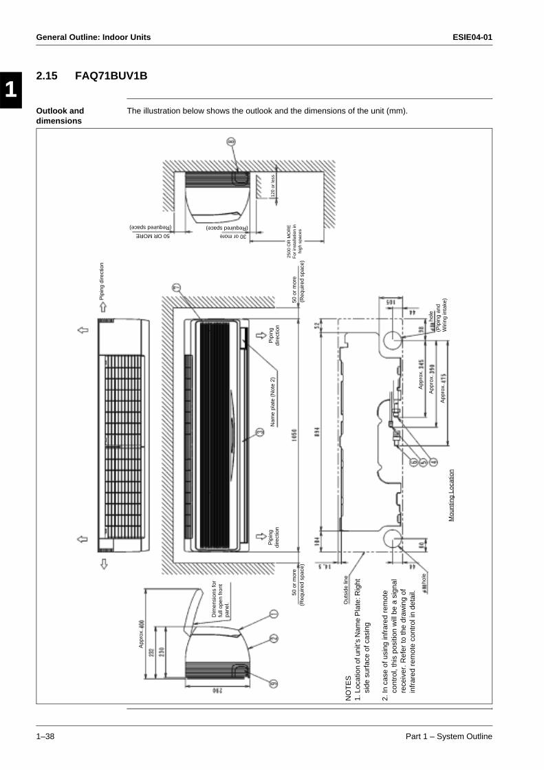
General Outline: Indoor Units ESIE04-01
1–38 Part 1 – System Outline
3
11
4
5
2.15 FAQ71BUV1B
Outlook and dimensions
The illustration below shows the outlook and the dimensions of the unit (mm).
Out
side
line
NO
TE
S1.
Loca
tion
of u
nit’s
Nam
e P
late
: Rig
ht
side
sur
face
of c
asin
g
2.In
cas
e of
usi
ng in
frar
ed r
emot
e co
ntro
l, th
is p
ositi
on w
ill b
e a
sign
al
rece
iver
. Ref
er to
the
draw
ing
of
infr
ared
rem
ote
cont
rol i
n de
tail.
hole
(Req
uire
d sp
ace)
50 o
r m
ore
App
rox.
Nam
e pl
ate
(Not
e 2)
Pip
ing
dire
ctio
nP
ipin
g di
rect
ion
Pip
ing
dire
ctio
n
(Req
uire
d sp
ace)
50 o
r m
ore
Dim
ensi
ons
for
full
open
fron
t pa
nel.
hole
(Pip
ing
and
Wiri
ng in
take
)
App
rox.
App
rox.
App
rox.
Mou
ntin
g Lo
catio
n
2500
OR
MO
RE
F
or in
stal
latio
n in
hi
gh s
pace
s
120
or le
ss
30 or more
(Required space)50 OR MORE
(Required space)
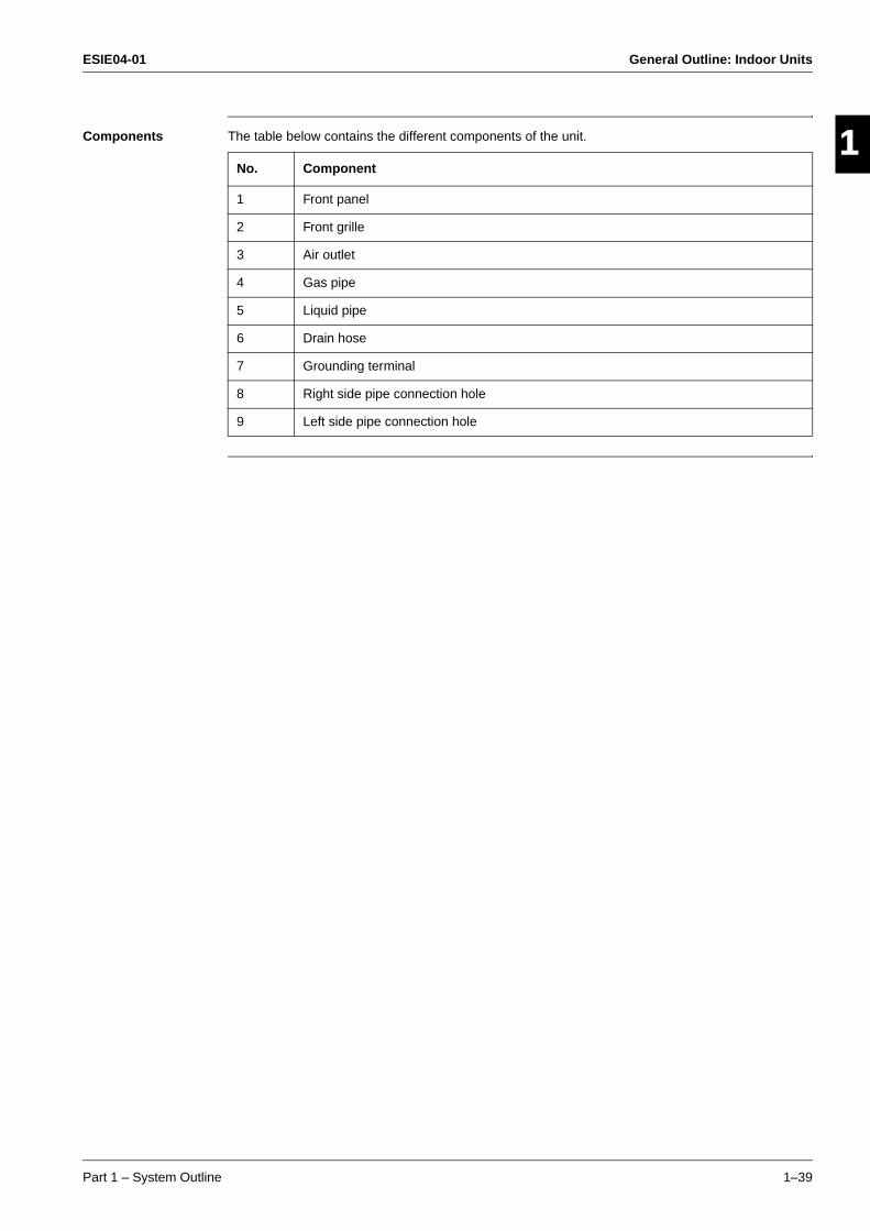
ESIE04-01 General Outline: Indoor Units
Part 1 – System Outline 1–39
3
1
4
5
Components The table below contains the different components of the unit.
No. Component
1 Front panel
2 Front grille
3 Air outlet
4 Gas pipe
5 Liquid pipe
6 Drain hose
7 Grounding terminal
8 Right side pipe connection hole
9 Left side pipe connection hole

General Outline: Indoor Units ESIE04-01
1–40 Part 1 – System Outline
3
11
4
5
2.16 FAQ100BUV1B
Outlook and dimensions
The illustration below shows the outlook and the dimensions of the unit (mm).
NO
TE
S:
1.Lo
catio
n ge
nera
l rat
ed n
ame
plat
e R
ight
sid
e pl
ate
outs
ide
surf
ace
2.In
cas
e of
usi
ng in
frar
ed r
emot
e co
ntro
l, th
is p
ositi
on w
ill b
e a
sign
al
rece
iver
. Ref
er to
the
draw
ing
of
infr
ared
rem
ote
cont
rol i
n de
tail.
(Req
uire
d sp
ace)
50 o
r m
ore
Bra
nd n
ame
plat
e (N
ote
2)
Pip
ing
dire
ctio
n
(Req
uire
d sp
ace)
or m
ore
hole
(Pip
ing
and
Wiri
ng in
take
)
App
rox.
Mou
ntin
g Lo
catio
n
App
rox.
App
rox.
(Required space)
or more
or m
ore
(Ser
vice
spa
ce
for
air
filte
r)
Dire
ctio
n fo
r ai
r fil
ter
draw
out
Ova
l hol
e (F
or w
ood
scre
w)
Ova
l hol
e (F
or w
ood
scre
w)
Cei
ling
surf
ace
Hol
e (F
or w
ood
scre
w)
Hol
e (F
or w
ood
bolt)
Det
ail A
(M
ount
ing
hole
for
inst
alla
tion
plat
e)
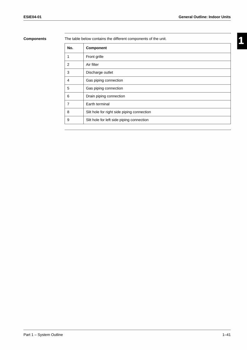
ESIE04-01 General Outline: Indoor Units
Part 1 – System Outline 1–41
3
1
4
5
Components The table below contains the different components of the unit.
No. Component
1 Front grille
2 Air filter
3 Discharge outlet
4 Gas piping connection
5 Gas piping connection
6 Drain piping connection
7 Earth terminal
8 Slit hole for right side piping connection
9 Slit hole for left side piping connection

General Outline: Indoor Units ESIE04-01
1–42 Part 1 – System Outline
3
11
4
5
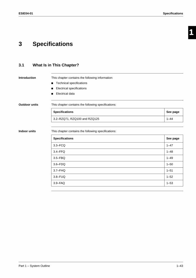
ESIE04-01 Specifications
Part 1 – System Outline 1–43
3
1
4
5
Part 1
3 Specifications
3.1 What Is in This Chapter?
Introduction This chapter contains the following information:
Technical specifications
Electrical specifications
Electrical data
Outdoor units This chapter contains the following specifications:
Indoor units This chapter contains the following specifications:
Specifications See page
3.2–RZQ71, RZQ100 and RZQ125 1–44
Specifications See page
3.3–FCQ 1–47
3.4–FFQ 1–48
3.5–FBQ 1–49
3.6–FDQ 1–50
3.7–FHQ 1–51
3.8–FUQ 1–52
3.9–FAQ 1–53
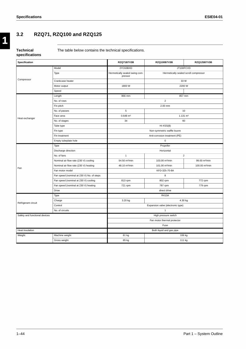
Specifications ESIE04-01
1–44 Part 1 – System Outline
3
11
4
5
3.2 RZQ71, RZQ100 and RZQ125
Technical specifications
The table below contains the technical specifications.
Specification RZQ71B7V3B RZQ100B7V3B RZQ125B7V3B
Compressor
Model 2YC63BXD JT100FCVD
Type Hermetically sealed swing com-pressor
Hermetically sealed scroll compressor
Crankcase heater 33 W
Motor output 1800 W 2200 W
Speed
Heat exchanger
Length 866 mm 857 mm
No. of rows 2
Fin pitch 2.00 mm
No. of passes 5 10
Face area 0.648 m² 1.131 m²
No. of stages 34 60
Tube type Hi-XSS(8)
Fin type Non-symmetric waffle louvre
Fin treatment Anti-corrosion treatment (PE)
Empty tubeplate hole 0
Fan
Type Propeller
Discharge direction Horizontal
No. of fans 1 2
Nominal air flow rate (230 V) cooling 54.50 m³/min 103.00 m³/min 99.00 m³/min
Nominal air flow rate (230 V) heating 48.10 m³/min 101.00 m³/min 100.00 m³/min
Fan motor model KFD-325-70-8A
Fan speed (nominal at 230 V) No. of steps 8
Fan speed (nominal at 230 V) cooling 813 rpm 802 rpm 772 rpm
Fan speed (nominal at 230 V) heating 721 rpm 787 rpm 779 rpm
Drive direct drive
Refrigerant circuit
Type R410A
Charge 3.20 kg 4.30 kg
Control Expansion valve (electronic type)
No. of circuits 1
Safety and functional devices High pressure switch
Fan motor thermal protector
Fuse
Heat insulation Both liquid and gas pipe
Weight Machine weight 61 kg 106 kg
Gross weight 65 kg 111 kg
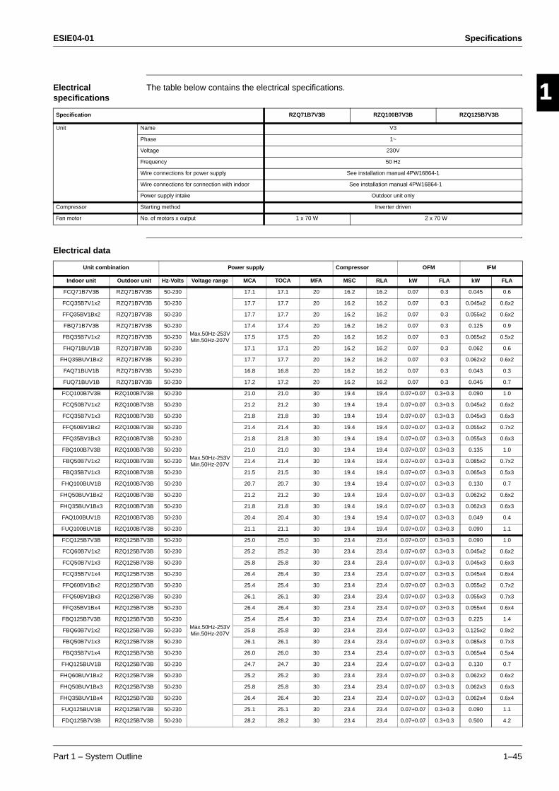
ESIE04-01 Specifications
Part 1 – System Outline 1–45
3
1
4
5
Electrical specifications
The table below contains the electrical specifications.
Electrical data
Specification RZQ71B7V3B RZQ100B7V3B RZQ125B7V3B
Unit Name V3
Phase 1~
Voltage 230V
Frequency 50 Hz
Wire connections for power supply See installation manual 4PW16864-1
Wire connections for connection with indoor See installation manual 4PW16864-1
Power supply intake Outdoor unit only
Compressor Starting method Inverter driven
Fan motor No. of motors x output 1 x 70 W 2 x 70 W
Unit combination Power supply Compressor OFM IFM
Indoor unit Outdoor unit Hz-Volts Voltage range MCA TOCA MFA MSC RLA kW FLA kW FLA
FCQ71B7V3B RZQ71B7V3B 50-230
Max.50Hz-253VMin.50Hz-207V
17.1 17.1 20 16.2 16.2 0.07 0.3 0.045 0.6
FCQ35B7V1x2 RZQ71B7V3B 50-230 17.7 17.7 20 16.2 16.2 0.07 0.3 0.045x2 0.6x2
FFQ35BV1Bx2 RZQ71B7V3B 50-230 17.7 17.7 20 16.2 16.2 0.07 0.3 0.055x2 0.6x2
FBQ71B7V3B RZQ71B7V3B 50-230 17.4 17.4 20 16.2 16.2 0.07 0.3 0.125 0.9
FBQ35B7V1x2 RZQ71B7V3B 50-230 17.5 17.5 20 16.2 16.2 0.07 0.3 0.065x2 0.5x2
FHQ71BUV1B RZQ71B7V3B 50-230 17.1 17.1 20 16.2 16.2 0.07 0.3 0.062 0.6
FHQ35BUV1Bx2 RZQ71B7V3B 50-230 17.7 17.7 20 16.2 16.2 0.07 0.3 0.062x2 0.6x2
FAQ71BUV1B RZQ71B7V3B 50-230 16.8 16.8 20 16.2 16.2 0.07 0.3 0.043 0.3
FUQ71BUV1B RZQ71B7V3B 50-230 17.2 17.2 20 16.2 16.2 0.07 0.3 0.045 0.7
FCQ100B7V3B RZQ100B7V3B 50-230
Max.50Hz-253VMin.50Hz-207V
21.0 21.0 30 19.4 19.4 0.07+0.07 0.3+0.3 0.090 1.0
FCQ50B7V1x2 RZQ100B7V3B 50-230 21.2 21.2 30 19.4 19.4 0.07+0.07 0.3+0.3 0.045x2 0.6x2
FCQ35B7V1x3 RZQ100B7V3B 50-230 21.8 21.8 30 19.4 19.4 0.07+0.07 0.3+0.3 0.045x3 0.6x3
FFQ50BV1Bx2 RZQ100B7V3B 50-230 21.4 21.4 30 19.4 19.4 0.07+0.07 0.3+0.3 0.055x2 0.7x2
FFQ35BV1Bx3 RZQ100B7V3B 50-230 21.8 21.8 30 19.4 19.4 0.07+0.07 0.3+0.3 0.055x3 0.6x3
FBQ100B7V3B RZQ100B7V3B 50-230 21.0 21.0 30 19.4 19.4 0.07+0.07 0.3+0.3 0.135 1.0
FBQ50B7V1x2 RZQ100B7V3B 50-230 21.4 21.4 30 19.4 19.4 0.07+0.07 0.3+0.3 0.085x2 0.7x2
FBQ35B7V1x3 RZQ100B7V3B 50-230 21.5 21.5 30 19.4 19.4 0.07+0.07 0.3+0.3 0.065x3 0.5x3
FHQ100BUV1B RZQ100B7V3B 50-230 20.7 20.7 30 19.4 19.4 0.07+0.07 0.3+0.3 0.130 0.7
FHQ50BUV1Bx2 RZQ100B7V3B 50-230 21.2 21.2 30 19.4 19.4 0.07+0.07 0.3+0.3 0.062x2 0.6x2
FHQ35BUV1Bx3 RZQ100B7V3B 50-230 21.8 21.8 30 19.4 19.4 0.07+0.07 0.3+0.3 0.062x3 0.6x3
FAQ100BUV1B RZQ100B7V3B 50-230 20.4 20.4 30 19.4 19.4 0.07+0.07 0.3+0.3 0.049 0.4
FUQ100BUV1B RZQ100B7V3B 50-230 21.1 21.1 30 19.4 19.4 0.07+0.07 0.3+0.3 0.090 1.1
FCQ125B7V3B RZQ125B7V3B 50-230
Max.50Hz-253VMin.50Hz-207V
25.0 25.0 30 23.4 23.4 0.07+0.07 0.3+0.3 0.090 1.0
FCQ60B7V1x2 RZQ125B7V3B 50-230 25.2 25.2 30 23.4 23.4 0.07+0.07 0.3+0.3 0.045x2 0.6x2
FCQ50B7V1x3 RZQ125B7V3B 50-230 25.8 25.8 30 23.4 23.4 0.07+0.07 0.3+0.3 0.045x3 0.6x3
FCQ35B7V1x4 RZQ125B7V3B 50-230 26.4 26.4 30 23.4 23.4 0.07+0.07 0.3+0.3 0.045x4 0.6x4
FFQ60BV1Bx2 RZQ125B7V3B 50-230 25.4 25.4 30 23.4 23.4 0.07+0.07 0.3+0.3 0.055x2 0.7x2
FFQ50BV1Bx3 RZQ125B7V3B 50-230 26.1 26.1 30 23.4 23.4 0.07+0.07 0.3+0.3 0.055x3 0.7x3
FFQ35BV1Bx4 RZQ125B7V3B 50-230 26.4 26.4 30 23.4 23.4 0.07+0.07 0.3+0.3 0.055x4 0.6x4
FBQ125B7V3B RZQ125B7V3B 50-230 25.4 25.4 30 23.4 23.4 0.07+0.07 0.3+0.3 0.225 1.4
FBQ60B7V1x2 RZQ125B7V3B 50-230 25.8 25.8 30 23.4 23.4 0.07+0.07 0.3+0.3 0.125x2 0.9x2
FBQ50B7V1x3 RZQ125B7V3B 50-230 26.1 26.1 30 23.4 23.4 0.07+0.07 0.3+0.3 0.085x3 0.7x3
FBQ35B7V1x4 RZQ125B7V3B 50-230 26.0 26.0 30 23.4 23.4 0.07+0.07 0.3+0.3 0.065x4 0.5x4
FHQ125BUV1B RZQ125B7V3B 50-230 24.7 24.7 30 23.4 23.4 0.07+0.07 0.3+0.3 0.130 0.7
FHQ60BUV1Bx2 RZQ125B7V3B 50-230 25.2 25.2 30 23.4 23.4 0.07+0.07 0.3+0.3 0.062x2 0.6x2
FHQ50BUV1Bx3 RZQ125B7V3B 50-230 25.8 25.8 30 23.4 23.4 0.07+0.07 0.3+0.3 0.062x3 0.6x3
FHQ35BUV1Bx4 RZQ125B7V3B 50-230 26.4 26.4 30 23.4 23.4 0.07+0.07 0.3+0.3 0.062x4 0.6x4
FUQ125BUV1B RZQ125B7V3B 50-230 25.1 25.1 30 23.4 23.4 0.07+0.07 0.3+0.3 0.090 1.1
FDQ125B7V3B RZQ125B7V3B 50-230 28.2 28.2 30 23.4 23.4 0.07+0.07 0.3+0.3 0.500 4.2
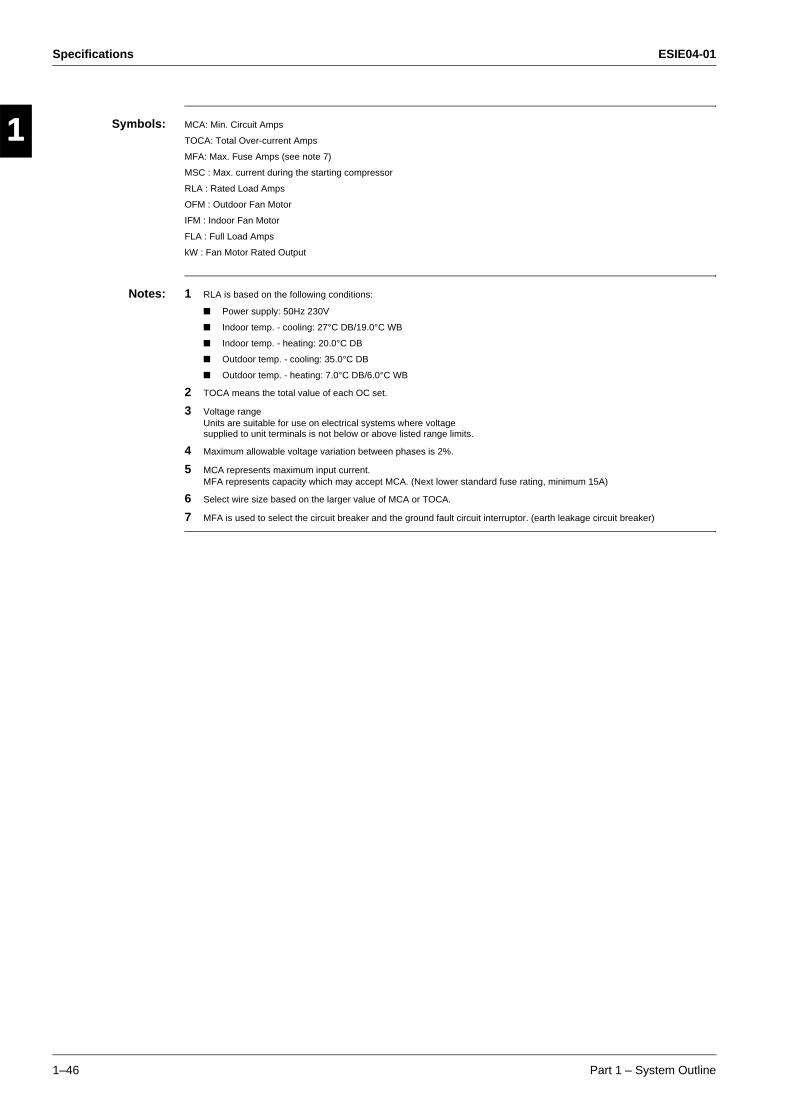
Specifications ESIE04-01
1–46 Part 1 – System Outline
3
11
4
5
Symbols: MCA: Min. Circuit Amps
TOCA: Total Over-current Amps
MFA: Max. Fuse Amps (see note 7)
MSC : Max. current during the starting compressor
RLA : Rated Load Amps
OFM : Outdoor Fan Motor
IFM : Indoor Fan Motor
FLA : Full Load Amps
kW : Fan Motor Rated Output
Notes: 1 RLA is based on the following conditions:
Power supply: 50Hz 230V
Indoor temp. - cooling: 27°C DB/19.0°C WB
Indoor temp. - heating: 20.0°C DB
Outdoor temp. - cooling: 35.0°C DB
Outdoor temp. - heating: 7.0°C DB/6.0°C WB
2 TOCA means the total value of each OC set.
3 Voltage rangeUnits are suitable for use on electrical systems where voltagesupplied to unit terminals is not below or above listed range limits.
4 Maximum allowable voltage variation between phases is 2%.
5 MCA represents maximum input current.MFA represents capacity which may accept MCA. (Next lower standard fuse rating, minimum 15A)
6 Select wire size based on the larger value of MCA or TOCA.
7 MFA is used to select the circuit breaker and the ground fault circuit interruptor. (earth leakage circuit breaker)
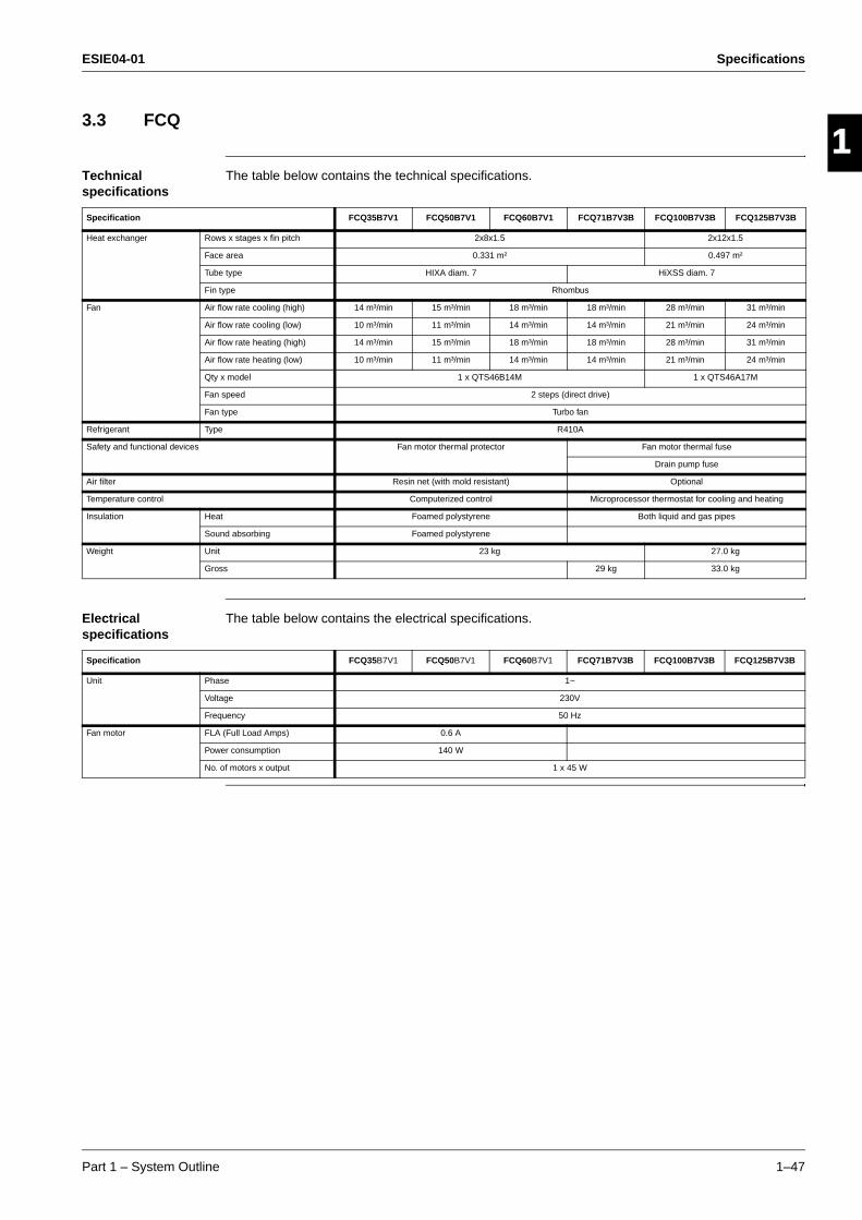
ESIE04-01 Specifications
Part 1 – System Outline 1–47
3
1
4
5
3.3 FCQ
Technical specifications
The table below contains the technical specifications.
Electrical specifications
The table below contains the electrical specifications.
Specification FCQ35B7V1 FCQ50B7V1 FCQ60B7V1 FCQ71B7V3B FCQ100B7V3B FCQ125B7V3B
Heat exchanger Rows x stages x fin pitch 2x8x1.5 2x12x1.5
Face area 0.331 m² 0.497 m²
Tube type HIXA diam. 7 HiXSS diam. 7
Fin type Rhombus
Fan Air flow rate cooling (high) 14 m³/min 15 m³/min 18 m³/min 18 m³/min 28 m³/min 31 m³/min
Air flow rate cooling (low) 10 m³/min 11 m³/min 14 m³/min 14 m³/min 21 m³/min 24 m³/min
Air flow rate heating (high) 14 m³/min 15 m³/min 18 m³/min 18 m³/min 28 m³/min 31 m³/min
Air flow rate heating (low) 10 m³/min 11 m³/min 14 m³/min 14 m³/min 21 m³/min 24 m³/min
Qty x model 1 x QTS46B14M 1 x QTS46A17M
Fan speed 2 steps (direct drive)
Fan type Turbo fan
Refrigerant Type R410A
Safety and functional devices Fan motor thermal protector Fan motor thermal fuse
Drain pump fuse
Air filter Resin net (with mold resistant) Optional
Temperature control Computerized control Microprocessor thermostat for cooling and heating
Insulation Heat Foamed polystyrene Both liquid and gas pipes
Sound absorbing Foamed polystyrene
Weight Unit 23 kg 27.0 kg
Gross 29 kg 33.0 kg
Specification FCQ35B7V1 FCQ50B7V1 FCQ60B7V1 FCQ71B7V3B FCQ100B7V3B FCQ125B7V3B
Unit Phase 1~
Voltage 230V
Frequency 50 Hz
Fan motor FLA (Full Load Amps) 0.6 A
Power consumption 140 W
No. of motors x output 1 x 45 W
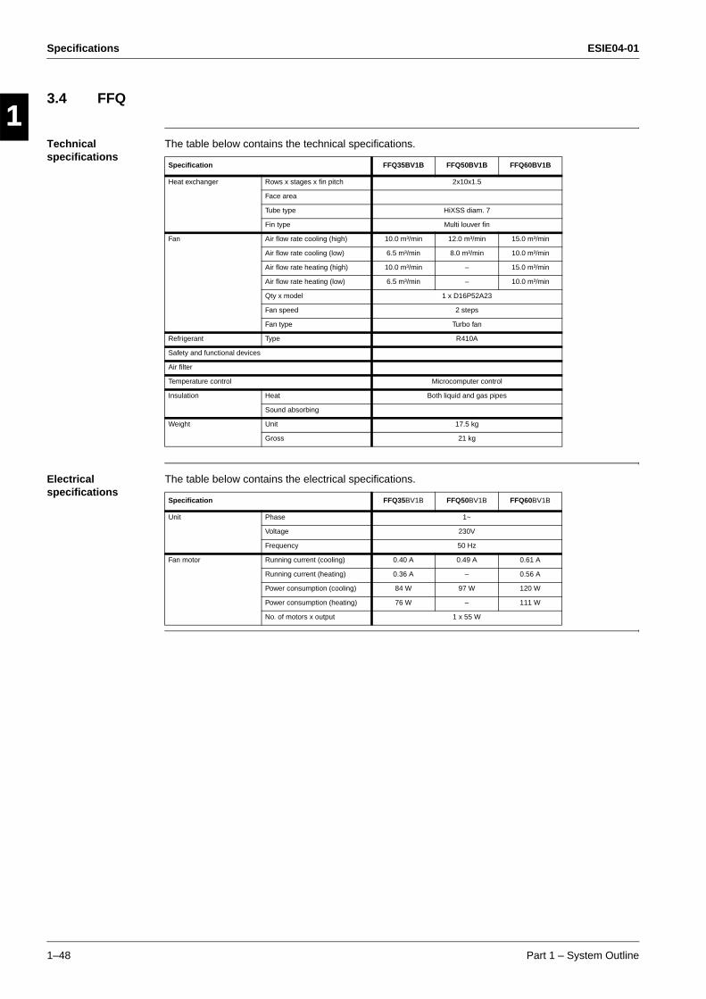
Specifications ESIE04-01
1–48 Part 1 – System Outline
3
11
4
5
3.4 FFQ
Technical specifications
The table below contains the technical specifications.
Electrical specifications
The table below contains the electrical specifications.
Specification FFQ35BV1B FFQ50BV1B FFQ60BV1B
Heat exchanger Rows x stages x fin pitch 2x10x1.5
Face area
Tube type HiXSS diam. 7
Fin type Multi louver fin
Fan Air flow rate cooling (high) 10.0 m³/min 12.0 m³/min 15.0 m³/min
Air flow rate cooling (low) 6.5 m³/min 8.0 m³/min 10.0 m³/min
Air flow rate heating (high) 10.0 m³/min – 15.0 m³/min
Air flow rate heating (low) 6.5 m³/min – 10.0 m³/min
Qty x model 1 x D16P52A23
Fan speed 2 steps
Fan type Turbo fan
Refrigerant Type R410A
Safety and functional devices
Air filter
Temperature control Microcomputer control
Insulation Heat Both liquid and gas pipes
Sound absorbing
Weight Unit 17.5 kg
Gross 21 kg
Specification FFQ35BV1B FFQ50BV1B FFQ60BV1B
Unit Phase 1~
Voltage 230V
Frequency 50 Hz
Fan motor Running current (cooling) 0.40 A 0.49 A 0.61 A
Running current (heating) 0.36 A – 0.56 A
Power consumption (cooling) 84 W 97 W 120 W
Power consumption (heating) 76 W – 111 W
No. of motors x output 1 x 55 W
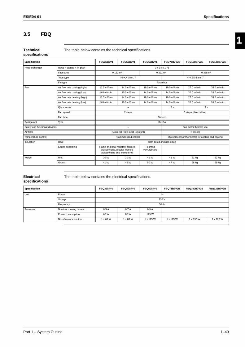
ESIE04-01 Specifications
Part 1 – System Outline 1–49
3
1
4
5
3.5 FBQ
Technical specifications
The table below contains the technical specifications.
Electrical specifications
The table below contains the electrical specifications.
Specification FBQ35B7V1 FBQ50B7V1 FBQ60B7V1 FBQ71B7V3B FBQ100B7V3B FBQ125B7V3B
Heat exchanger Rows x stages x fin pitch 3 x 14 x 1.75
Face area 0.132 m² 0.221 m² 0.338 m²
Tube type HI-XA diam. 7 Hi-XSS diam. 7
Fin type Rhombus
Fan Air flow rate cooling (high) 11.5 m³/min 14.0 m³/min 19.0 m³/min 19.0 m³/min 27.0 m³/min 35.0 m³/min
Air flow rate cooling (low) 9.0 m³/min 10.0 m³/min 14.0 m³/min 14.0 m³/min 20.0 m³/min 24.0 m³/min
Air flow rate heating (high) 11.5 m³/min 14.0 m³/min 19.0 m³/min 19.0 m³/min 27.0 m³/min 35.0 m³/min
Air flow rate heating (low) 9.0 m³/min 10.0 m³/min 14.0 m³/min 14.0 m³/min 20.0 m³/min 24.0 m³/min
Qty x model – 2 x 3 x
Fan speed 2 steps 3 steps (direct drive)
Fan type Sirocco
Refrigerant Type R410A
Safety and functional devices – Fan motor thermal use
Air filter Resin net (with mold resistant) Optional
Temperature control Computerized control Microprocessor thermostat for cooling and heating
Insulation Heat Both liquid and gas pipes
Sound absorbing Flame and heat resistant foamed polyethylene, regular foamed polyethylene and foamed PU
Foamed Polyurethane
Weight Unit 30 kg 31 kg 41 kg 41 kg 51 kg 52 kg
Gross 41 kg 42 kg 50 kg 47 kg 58 kg 59 kg
Specification FBQ35B7V1 FBQ50B7V1 FBQ60B7V1 FBQ71B7V3B FBQ100B7V3B FBQ125B7V3B
Unit Phase 1~
Voltage 230 V
Frequency 50Hz
Fan motor Nominal running current 0.5 A 0.7 A 0.9 A
Power consumption 65 W 85 W 125 W
No. of motors x output 1 x 65 W 1 x 85 W 1 x 125 W 1 x 125 W 1 x 135 W 1 x 225 W
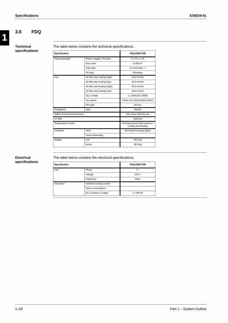
Specifications ESIE04-01
1–50 Part 1 – System Outline
3
11
4
5
3.6 FDQ
Technical specifications
The table below contains the technical specifications.
Electrical specifications
The table below contains the electrical specifications.
Specification FDQ125B7V3B
Heat exchanger Rows x stages x fin pitch 3 x 14 x 1.75
Face area 0.338 m²
Tube type Hi-XSS diam. 7
Fin type Rhombus
Fan Air flow rate cooling (high) 43.0 m³/min
Air flow rate cooling (low) 43.0 m³/min
Air flow rate heating (high) 43.0 m³/min
Air flow rate heating (low) 43.0 m³/min
Qty x model 1 x DPA216-178NB
Fan speed Phase cut control (direct drive)
Fan type Sirocco
Refrigerant Type R410A
Safety and functional devices Fan motor thermal use
Air filter Optional
Temperature control Microprocessor thermostat for cooling and heating
Insulation Heat Both liquid and gas pipes
Sound absorbing
Weight Unit 59.0 kg
Gross 80.0 kg
Specification FDQ125B7V3B
Unit Phase 1~
Voltage 230 V
Frequency 50Hz
Fan motor Nominal running current
Power consumption
No. of motors x output 1 x 500 W
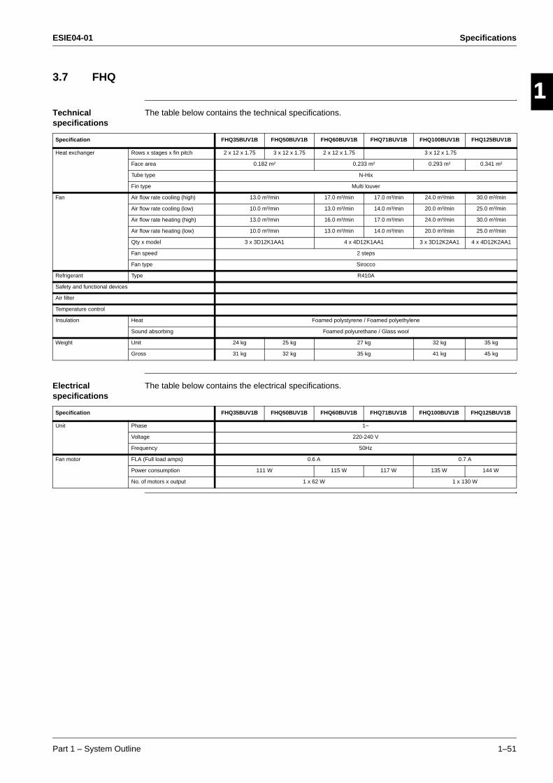
ESIE04-01 Specifications
Part 1 – System Outline 1–51
3
1
4
5
3.7 FHQ
Technical specifications
The table below contains the technical specifications.
Electrical specifications
The table below contains the electrical specifications.
Specification FHQ35BUV1B FHQ50BUV1B FHQ60BUV1B FHQ71BUV1B FHQ100BUV1B FHQ125BUV1B
Heat exchanger Rows x stages x fin pitch 2 x 12 x 1.75 3 x 12 x 1.75 2 x 12 x 1.75 3 x 12 x 1.75
Face area 0.182 m² 0.233 m² 0.293 m² 0.341 m²
Tube type N-Hix
Fin type Multi louver
Fan Air flow rate cooling (high) 13.0 m³/min 17.0 m³/min 17.0 m³/min 24.0 m³/min 30.0 m³/min
Air flow rate cooling (low) 10.0 m³/min 13.0 m³/min 14.0 m³/min 20.0 m³/min 25.0 m³/min
Air flow rate heating (high) 13.0 m³/min 16.0 m³/min 17.0 m³/min 24.0 m³/min 30.0 m³/min
Air flow rate heating (low) 10.0 m³/min 13.0 m³/min 14.0 m³/min 20.0 m³/min 25.0 m³/min
Qty x model 3 x 3D12K1AA1 4 x 4D12K1AA1 3 x 3D12K2AA1 4 x 4D12K2AA1
Fan speed 2 steps
Fan type Sirocco
Refrigerant Type R410A
Safety and functional devices
Air filter
Temperature control
Insulation Heat Foamed polystyrene / Foamed polyethylene
Sound absorbing Foamed polyurethane / Glass wool
Weight Unit 24 kg 25 kg 27 kg 32 kg 35 kg
Gross 31 kg 32 kg 35 kg 41 kg 45 kg
Specification FHQ35BUV1B FHQ50BUV1B FHQ60BUV1B FHQ71BUV1B FHQ100BUV1B FHQ125BUV1B
Unit Phase 1~
Voltage 220-240 V
Frequency 50Hz
Fan motor FLA (Full load amps) 0.6 A 0.7 A
Power consumption 111 W 115 W 117 W 135 W 144 W
No. of motors x output 1 x 62 W 1 x 130 W
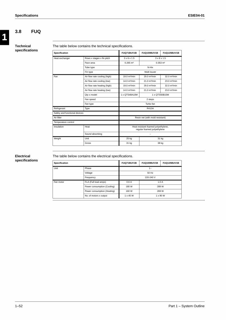
Specifications ESIE04-01
1–52 Part 1 – System Outline
3
11
4
5
3.8 FUQ
Technical specifications
The table below contains the technical specifications.
Electrical specifications
The table below contains the electrical specifications.
Specification FUQ71BUV1B FUQ100BUV1B FUQ125BUV1B
Heat exchanger Rows x stages x fin pitch 3 x 6 x 1.5 3 x 8 x 1.5
Face area 0.265 m² 0.353 m²
Tube type N-Hix
Fin type Multi louver
Fan Air flow rate cooling (high) 19.0 m³/min 29.0 m³/min 32.0 m³/min
Air flow rate cooling (low) 14.0 m³/min 21.0 m³/min 23.0 m³/min
Air flow rate heating (high) 19.0 m³/min 29.0 m³/min 32.0 m³/min
Air flow rate heating (low) 14.0 m³/min 21.0 m³/min 23.0 m³/min
Qty x model 1 x QTS48A10M 1 x QTS50B15M
Fan speed 2 steps
Fan type Turbo fan
Refrigerant Type R410A
Safety and functional devices
Air filter Resin net (with mold resistant)
Temperature control
Insulation Heat Heat resistant foamed polyethylene, regular foamed polyethylene
Sound absorbing –
Weight Unit 25 kg 31 kg
Gross 31 kg 38 kg
Specification FUQ71BUV1B FUQ100BUV1B FUQ125BUV1B
Unit Phase 1~
Voltage 50 Hz
Frequency 220-240 V
Fan motor FLA (Full load amps) 0.6 A 1.0 A
Power consumption (Cooling) 180 W 289 W
Power consumption (Heating) 160 W 269 W
No. of motors x output 1 x 45 W 1 x 90 W
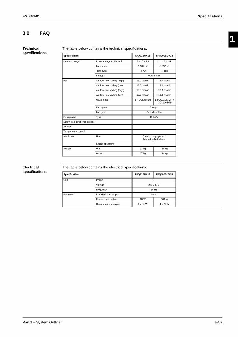
ESIE04-01 Specifications
Part 1 – System Outline 1–53
3
1
4
5
3.9 FAQ
Technical specifications
The table below contains the technical specifications.
Electrical specifications
The table below contains the electrical specifications.
Specification FAQ71BUV1B FAQ100BUV1B
Heat exchanger Rows x stages x fin pitch 2 x 16 x 1.4 2 x 12 x 1.4
Face area 0.289 m² 0.332 m²
Tube type Hi-XA N-Hix
Fin type Multi louver
Fan Air flow rate cooling (high) 19.0 m³/min 23.0 m³/min
Air flow rate cooling (low) 15.0 m³/min 19.0 m³/min
Air flow rate heating (high) 19.0 m³/min 23.0 m³/min
Air flow rate heating (low) 15.0 m³/min 19.0 m³/min
Qty x model 1 x QCL9686M 1 x QCL1163MA + QCL1163MB
Fan speed 2 steps
Fan type Cross flow fan
Refrigerant Type R410A
Safety and functional devices
Air filter
Temperature control
Insulation Heat Foamed polystyrene / foamed polyethylene
Sound absorbing –
Weight Unit 13 kg 26 kg
Gross 17 kg 34 kg
Specification FAQ71BUV1B FAQ100BUV1B
Unit Phase 1~
Voltage 220-240 V
Frequency 50 Hz
Fan motor FLA (Full load amps) 0.4 A
Power consumption 68 W 101 W
No. of motors x output 1 x 43 W 1 x 49 W
Specifications ESIE04-01
1–54 Part 1 – System Outline
3
11
4
5
ESIE04-01 Functional Diagrams
Part 1 – System Outline 1–55
3
1
4
5
Part 1
4 Functional Diagrams
4.1 What Is in This Chapter?
Introduction This chapter contains the following information:
Functional diagrams
Pipe connection diameters.
Functional diagrams
This chapter contains the following functional diagrams:
Functional diagram See page
4.2–Pair system 1–56
4.3–Twin System 1–58
4.4–Triple System 1–60
4.5–Double Twin System 1–61
4.6–Indoor piping 1–62
4.7–Pipe connection diameters 1–64
4.8–Re-using existing field piping 1–65
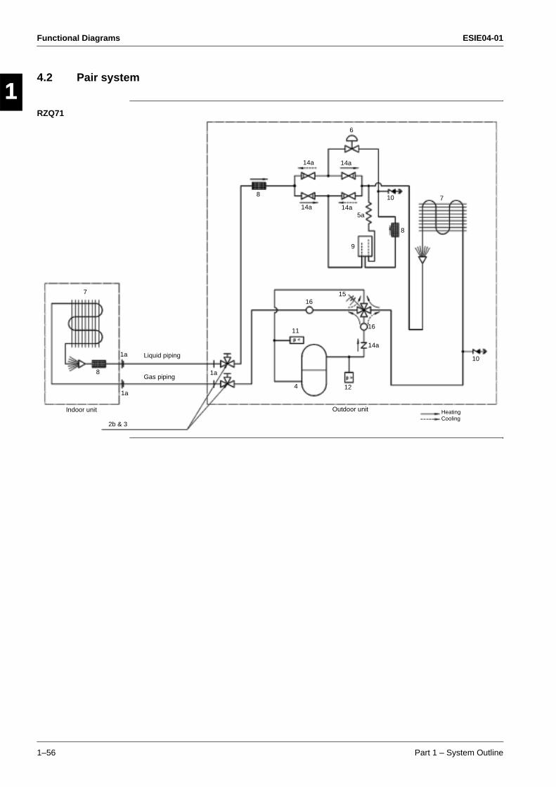
Functional Diagrams ESIE04-01
1–56 Part 1 – System Outline
3
11
4
5
4.2 Pair system
RZQ71
6
15
14a
14a14a
14a
16
8
5a
14a
11
1a
4
16
7
9
10Liquid piping
Indoor unit
2b & 3
HeatingCooling
7
8
Outdoor unit
Gas piping
12
10
1a
1a8
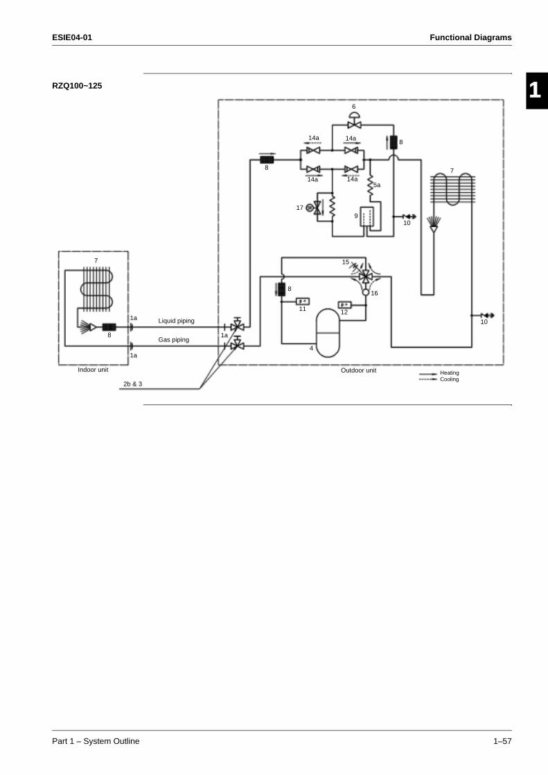
ESIE04-01 Functional Diagrams
Part 1 – System Outline 1–57
3
1
4
5
RZQ100~125
6
15
14a
14a14a
14a
8
5a
11
1a4
16
7
9
10Liquid piping
Indoor unit
2b & 3
HeatingCooling
7
8
Outdoor unit
Gas piping
12
10
8
17
1a
1a8
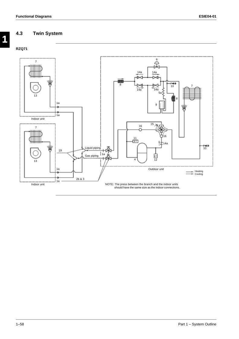
Functional Diagrams ESIE04-01
1–58 Part 1 – System Outline
3
11
4
5
4.3 Twin System
RZQ71
6
15
14a
14a14a
14a
8
5a
11
4
16
7
9
10Liquid piping
Indoor unit
2b & 3
HeatingCooling
7
8
Outdoor unit
Gas piping12
10
Indoor unit
7
13
13
14a
16
NOTE: The press between the branch and the indoor units should have the same size as the indoor connections.
19
1a
1a
1a
1a
1a
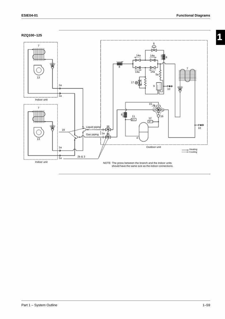
ESIE04-01 Functional Diagrams
Part 1 – System Outline 1–59
3
1
4
5
RZQ100~125
6
15
14a
14a14a
14a
8
5a
11
4
16
7
9
10Liquid piping
Indoor unit
2b & 3
HeatingCooling
7
Outdoor unit
Gas piping
12
Indoor unit
7
13
13
17
10
8
8
19
NOTE: The press between the branch and the indoor units should have the same size as the indoor connections.
1a
1a
1a
1a
1a
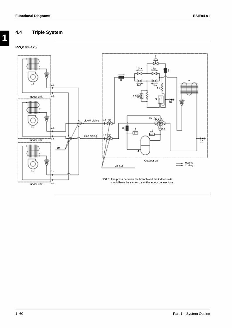
Functional Diagrams ESIE04-01
1–60 Part 1 – System Outline
3
11
4
5
4.4 Triple System
RZQ100~125
6
15
14a
14a14a
14a
8
5a
11
4
16
9
10
Liquid piping
2b & 3HeatingCooling
7
Outdoor unit
Gas piping
12
Indoor unit
7
13
17
10
8
8
Indoor unit
7
13
Indoor unit
7
13
19
8
NOTE: The press between the branch and the indoor units should have the same size as the indoor connections.
1a
1a
1a
1a
1a
1a
1a
1a
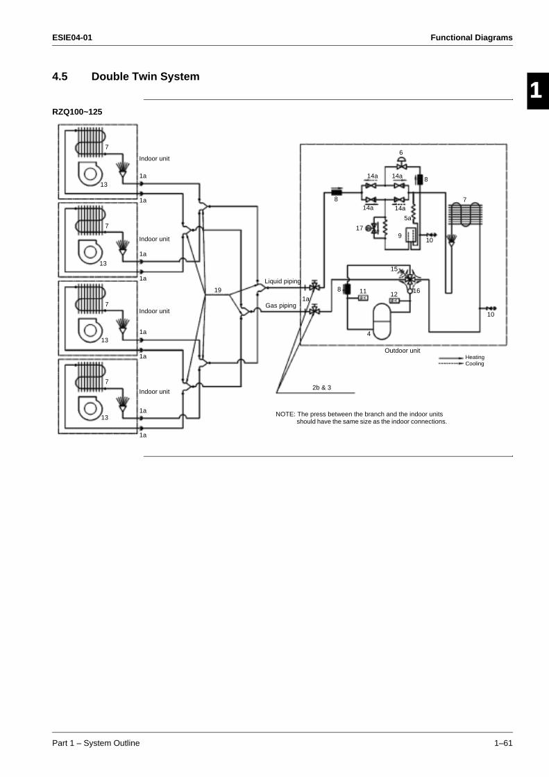
ESIE04-01 Functional Diagrams
Part 1 – System Outline 1–61
3
1
4
5
4.5 Double Twin System
RZQ100~125
6
15
14a
14a14a
14a
8
5a
11
4
16
9
10
Liquid piping
2b & 3
HeatingCooling
7
Outdoor unit
Gas piping
12
17
10
8
Indoor unit
7
13
19
8
NOTE: The press between the branch and the indoor units should have the same size as the indoor connections.
Indoor unit7
13
Indoor unit
7
13
Indoor unit
7
13
1a
1a
1a
1a
1a
1a
1a
1a
1a
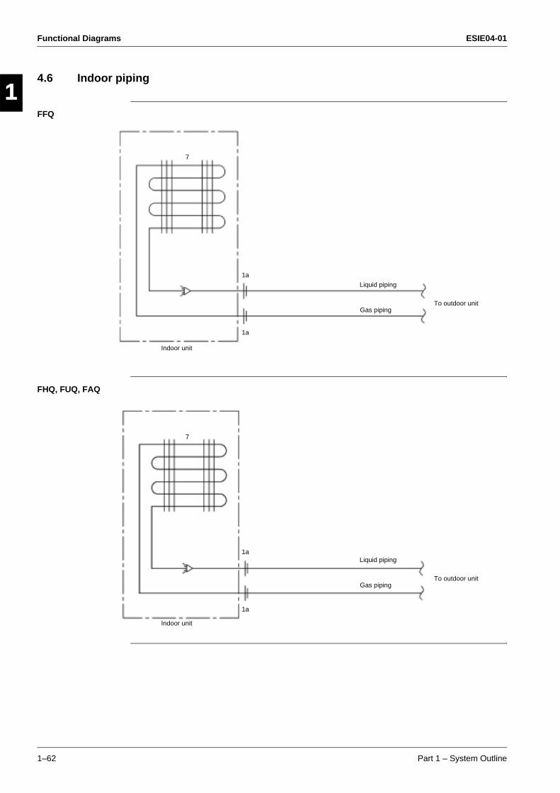
Functional Diagrams ESIE04-01
1–62 Part 1 – System Outline
3
11
4
5
4.6 Indoor piping
FFQ
FHQ, FUQ, FAQ
7
Indoor unit
Liquid piping
Gas pipingTo outdoor unit
1a
1a
7
Indoor unit
Liquid piping
Gas pipingTo outdoor unit
1a
1a
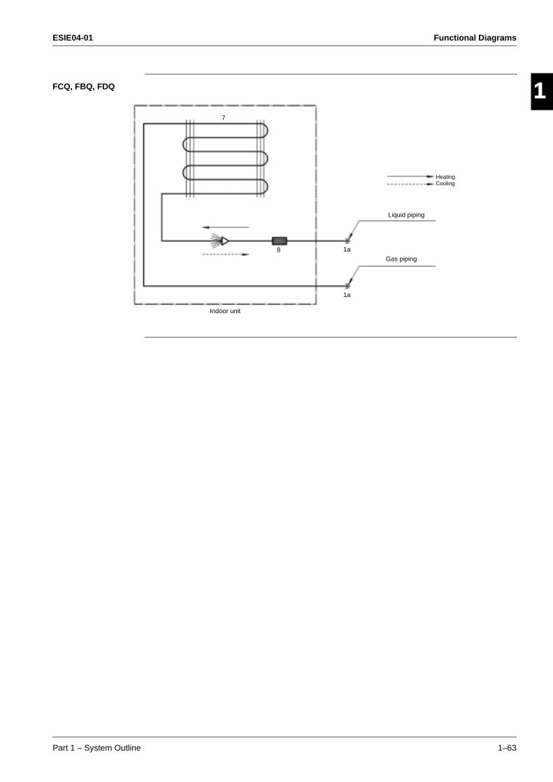
ESIE04-01 Functional Diagrams
Part 1 – System Outline 1–63
3
1
4
5
FCQ, FBQ, FDQ
7
Indoor unit
Liquid piping
Gas piping
HeatingCooling
8 1a
1a
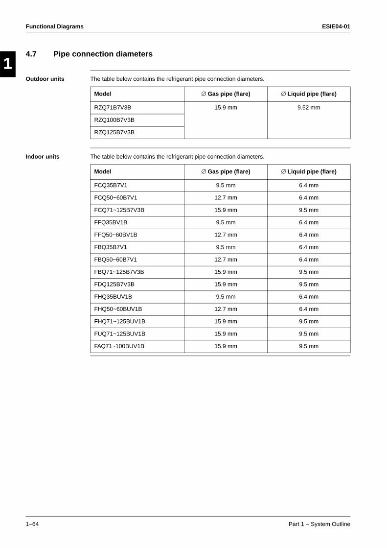
Functional Diagrams ESIE04-01
1–64 Part 1 – System Outline
3
11
4
5
4.7 Pipe connection diameters
Outdoor units The table below contains the refrigerant pipe connection diameters.
Indoor units The table below contains the refrigerant pipe connection diameters.
Model ∅ Gas pipe (flare) ∅ Liquid pipe (flare)
RZQ71B7V3B 15.9 mm 9.52 mm
RZQ100B7V3B
RZQ125B7V3B
Model ∅ Gas pipe (flare) ∅ Liquid pipe (flare)
FCQ35B7V1 9.5 mm 6.4 mm
FCQ50~60B7V1 12.7 mm 6.4 mm
FCQ71~125B7V3B 15.9 mm 9.5 mm
FFQ35BV1B 9.5 mm 6.4 mm
FFQ50~60BV1B 12.7 mm 6.4 mm
FBQ35B7V1 9.5 mm 6.4 mm
FBQ50~60B7V1 12.7 mm 6.4 mm
FBQ71~125B7V3B 15.9 mm 9.5 mm
FDQ125B7V3B 15.9 mm 9.5 mm
FHQ35BUV1B 9.5 mm 6.4 mm
FHQ50~60BUV1B 12.7 mm 6.4 mm
FHQ71~125BUV1B 15.9 mm 9.5 mm
FUQ71~125BUV1B 15.9 mm 9.5 mm
FAQ71~100BUV1B 15.9 mm 9.5 mm
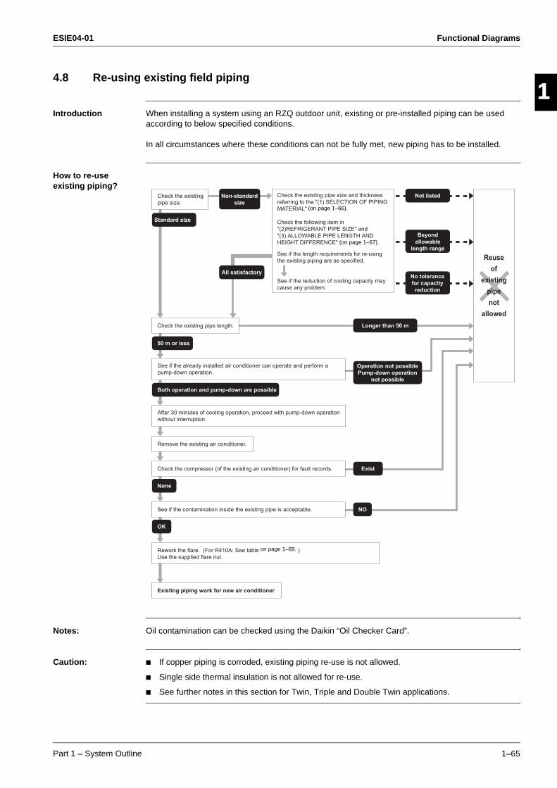
ESIE04-01 Functional Diagrams
Part 1 – System Outline 1–65
3
1
4
5
4.8 Re-using existing field piping
Introduction When installing a system using an RZQ outdoor unit, existing or pre-installed piping can be used according to below specified conditions.
In all circumstances where these conditions can not be fully met, new piping has to be installed.
How to re-use existing piping?
Notes: Oil contamination can be checked using the Daikin “Oil Checker Card”.
Caution: If copper piping is corroded, existing piping re-use is not allowed.
Single side thermal insulation is not allowed for re-use.
See further notes in this section for Twin, Triple and Double Twin applications.
Check the existing pipe length.
Check the compressor (of the existing air conditioner) for fault records.
Remove the existing air conditioner.
See if the contamination inside the existing pipe is acceptable.
Rework the flare. (For R410A: See table )
Use the supplied flare nut.
Existing piping work for new air conditioner
All satisfactory
Longer than 50 m
Standard size
50 m or less
None
Exist
NO
OK
Both operation and pump-down are possible
Not listedCheck the existing pipe size and thickness
referring to the "(1) SELECTION OF PIPING
MATERIAL"
Check the following item in
"(2)REFRIGERANT PIPE SIZE" and
"(3) ALLOWABLE PIPE LENGTH AND
HEIGHT DIFFERENCE"
See if the length requirements for re-using
the existing piping are as specified.
See if the reduction of cooling capacity may
cause any problem.
Check the existing
pipe size.
Non-standard
size
Beyond
allowable
length range
No tolerance
for capacity
reduction
Reuse
of
existing
pipe
not
allowed
See if the already installed air conditioner can operate and perform a
pump-down operation.
After 30 minutes of cooling operation, proceed with pump-down operation
without interruption.
Operation not possible
Pump-down operation
not possible
(on page 1–67).
(on page 1–66).
on page 1–69.

Functional Diagrams ESIE04-01
1–66 Part 1 – System Outline
3
11
4
5
Precautions on refrigerant piping
Do not allow anything other than the designated refrigerant to get mixed into the freezing cycle (air, moisture,... ). If any refrigerant gas leaks while working on the unit, ventilate the room thoroughly immediately.
Use R410A only when adding refrigerant.
Make sure all installation tools are designed for use on R410A refrigerant to withstand the pressure.
Vacuum pump. Use a 2-stage vacuum pump with a non-return valve. Make sure the pump oil does not flow oppositely into the new system while the pump is not working. Use a vacuum pump which can evacuate to -100.7 kPa (5 Torr, -755 mmHg).
Check welded connections for gas leaks, if the local piping has welded connections.
Notes for Twin, Triple and Double Twin
Main piping (L1) can be re-used, size up & size down is allowed (see further in this section for restrictions).
Re-use of branch piping is not allowed.
Branch piping (L2~L7) can be re-used, but standard pipe size only.
Selection of piping material
Construction material: phosphoric acid deoxidized seamless copper for refrigerant.
Temper grade: use piping with temper grade in function of the pipe diameter as listed in table below.
The pipe thickness of the refrigerant piping should comply with relevant local and national regulations. The minimal pipe thickness for R410A piping must be in accordance with the table below.
Ο = Annealed
1/2H = Half hard
H1
L1
H1
H2
L3L1
L2
H1
H2
L4L1
L3
L2
H1
H2
L7L1
L6
L5
L4
L3
L2
Pair Twin Triple Double twin
Pipe φ Temper grade of piping material Minimal thickness t(mm)
6.4 / 9.5 / 12.7 Ο 0.80
15.9 O 1
19.1 1/2H 1
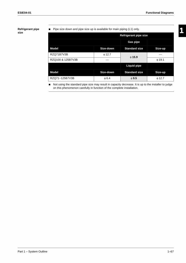
ESIE04-01 Functional Diagrams
Part 1 – System Outline 1–67
3
1
4
5
Refrigerant pipe size
Pipe size down and pipe size up is available for main piping (L1) only.
Not using the standard pipe size may result in capacity decrease. It is up to the installer to judge on this phenomenon carefully in function of the complete installation.
Refrigerant pipe size
Gas pipe
Model Size-down Standard size Size-up
RZQ71B7V3B φ 12.7φ 15.9
––
RZQ100 & 125B7V3B –– φ 19.1
Liquid pipe
Model Size-down Standard size Size-up
RZQ71~125B7V3B φ 6.4 φ 9.5 φ 12.7
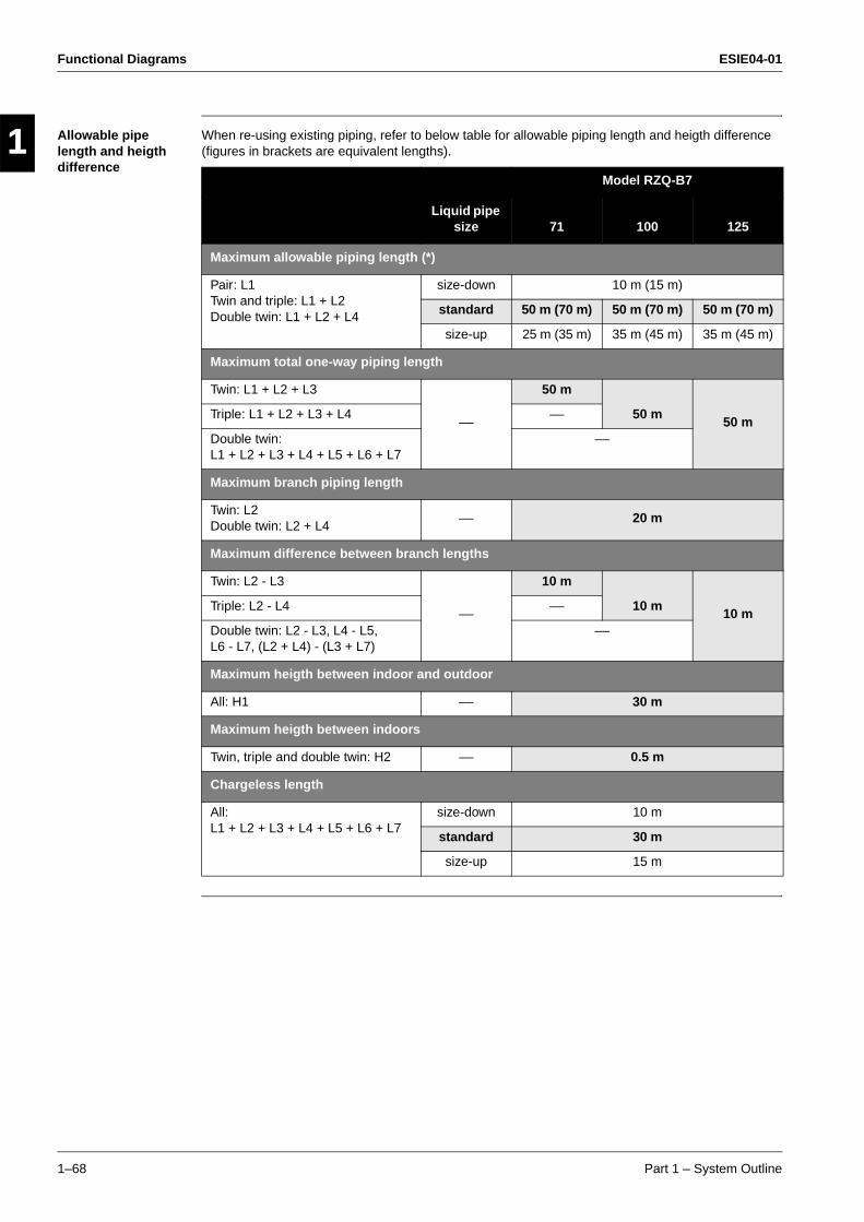
Functional Diagrams ESIE04-01
1–68 Part 1 – System Outline
3
11
4
5
Allowable pipe length and heigth difference
When re-using existing piping, refer to below table for allowable piping length and heigth difference (figures in brackets are equivalent lengths).
Model RZQ-B7
Liquid pipe size 71 100 125
Maximum allowable piping length (*)
Pair: L1Twin and triple: L1 + L2Double twin: L1 + L2 + L4
size-down 10 m (15 m)
standard 50 m (70 m) 50 m (70 m) 50 m (70 m)
size-up 25 m (35 m) 35 m (45 m) 35 m (45 m)
Maximum total one-way piping length
Twin: L1 + L2 + L3
––
50 m
50 m50 m
Triple: L1 + L2 + L3 + L4 ––
Double twin: L1 + L2 + L3 + L4 + L5 + L6 + L7
––
Maximum branch piping length
Twin: L2Double twin: L2 + L4
–– 20 m
Maximum difference between branch lengths
Twin: L2 - L3
––
10 m
10 m10 m
Triple: L2 - L4 ––
Double twin: L2 - L3, L4 - L5, L6 - L7, (L2 + L4) - (L3 + L7)
––
Maximum heigth between indoor and outdoor
All: H1 –– 30 m
Maximum heigth between indoors
Twin, triple and double twin: H2 –– 0.5 m
Chargeless length
All: L1 + L2 + L3 + L4 + L5 + L6 + L7
size-down 10 m
standard 30 m
size-up 15 m
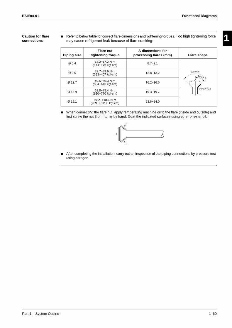
ESIE04-01 Functional Diagrams
Part 1 – System Outline 1–69
3
1
4
5
Caution for flare connections
Refer to below table for correct flare dimensions and tightening torques. Too high tightening force may cause refrigerant leak because of flare cracking:
When connecting the flare nut, apply refrigerating machine oil to the flare (inside and outside) and first screw the nut 3 or 4 turns by hand. Coat the indicated surfaces using ether or ester oil:
After completing the installation, carry out an inspection of the piping connections by pressure test using nitrogen.
Piping sizeFlare nut
tightening torqueA dimensions for
processing flares (mm) Flare shape
Ø 6.4 14.2~17.2 N·m(144~176 kgf·cm) 8.7~9.1
Ø 9.5 32.7~39.9 N·m(333~407 kgf·cm) 12.8~13.2
Ø 12.7 49.5~60.3 N·m(504~616 kgf·cm) 16.2~16.6
Ø 15.9 61.8~75.4 N·m(630~770 kgf·cm) 19.3~19.7
Ø 19.1 97.2~118.6 N·m(989.8~1208 kgf·cm) 23.6~24.0
R=0.4~0.8
45° ±2
90°±0.5
A

Functional Diagrams ESIE04-01
1–70 Part 1 – System Outline
3
11
4
5
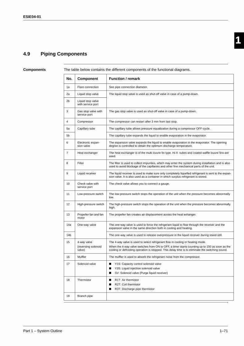
ESIE04-01
Part 1 – System Outline 1–71
3
1
4
5
Part 1
4.9 Piping Components
Components The table below contains the different components of the functional diagrams.
No. Component Function / remark
1a Flare connection See pipe connection diameter.
2a Liquid stop valve The liquid stop valve is used as shut-off valve in case of a pump-down.
2b Liquid stop valve with service port
3 Gas stop valve with service port
The gas stop valve is used as shut-off valve in case of a pump-down.
4 Compressor The compressor can restart after 3 min from last stop.
5a Capillary tube The capillary tube allows pressure equalization during a compressor OFF-cycle.
5b The capillary tube expands the liquid to enable evaporation in the evaporator.
6 Electronic expan-sion valve
The expansion valve expands the liquid to enable evaporation in the evaporator. The opening degree is controlled to obtain the optimum discharge temperature.
7 Heat exchanger The heat exchanger is of the multi louvre fin type. Hi-X -tubes and coated waffle louvre fins are used.
8 Filter The filter is used to collect impurities, which may enter the system during installation and is also used to avoid blockage of the capillaries and other fine mechanical parts of the unit.
9 Liquid receiver The liquid receiver is used to make sure only completely liquefied refrigerant is sent to the expan-sion valve. It is also used as a container in which surplus refrigerant is stored.
10 Check valve with service port
The check valve allows you to connect a gauge.
11 Low-pressure switch The low-pressure switch stops the operation of the unit when the pressure becomes abnormally low.
12 High-pressure switch The high-pressure switch stops the operation of the unit when the pressure becomes abnormally high.
13 Propeller fan and fan motor
The propeller fan creates air displacement across the heat exhanger.
14a One-way valve The one-way valve is used to force the refrigerant liquid to flow through the receiver and the expansion valve in the same direction both in cooling and heating.
14b The one-way valve is used to release overpressure in the liquid receiver during stand-still.
15 4-way valve
(reversing solenoid valve)
The 4-way valve is used to select refrigerant flow in cooling or heating mode.
When the 4-way valve switches from ON to OFF, a timer starts counting up to 150 as soon as the cooling or defrosting operation is stopped. This delay time is to eliminate the switching sound.
16 Muffler The muffler is used to absorb the refrigerant noise from the compressor.
17 Solenoid valve Y1S: Capacity control solenoid valve
Y3S: Liquid injection solenoid valve
SV: Solenoid valve (Purge liquid receiver)
18 Thermistor R1T: Air thermistor
R2T: Coil thermistor
R3T: Discharge pipe thermistor
19 Branch pipe

ESIE04-01
1–72 Part 1 – System Outline
3
11
4
5

ESIE04-01 Switch Box Layout
Part 1 – System Outline 1–73
3
4
5
1Part 1
5 Switch Box Layout
5.1 What Is in This Chapter?
Introduction This chapter shows the switch box components.
Outdoor units This chapter contains the following switch box layouts:
Indoor units This chapter contains the following switch box layouts:
Switch box layout See page
5.2–RZQ71B7V3B 1–74
5.3–RZQ100B7V3B 1–75
PCB layout See page
5.4–FCQ35B7V1 ~ FCQ71B7V3B 1–76
5.5–FCQ100~125B7V3B 1–77
5.6–FFQ35~60BV1B 1–78
5.7–FBQ35B7V1 ~ FBQ125B7V3B 1–79
5.8–FDQ125B7V3B 1–80
5.9–FHQ35BUV1 ~ FHQ125BUV1B 1–81
5.10–FUQ71~125BUV1B 1–82
5.11–FAQ71BUV1B 1–83
5.12–FAQ100BUV1B 1–84

Switch Box Layout ESIE04-01
1–74 Part 1 – System Outline
3
11
4
5
5.2 RZQ71B7V3B
The illustration below shows the switch box layout:
A1P
A2P
X1M
Item Description
A1P Printed circuit board (control)
A2P Printed circuit board (inverter)
X1M Terminal strip

ESIE04-01 Switch Box Layout
Part 1 – System Outline 1–75
3
1
4
5
5.3 RZQ100B7V3B
The illustration below shows the switch box layout:
A1P
A2P
X1M
Item Description
A1P Printed circuit board (control)
A2P Printed circuit board (inverter)
X1M Terminal strip
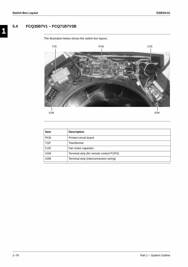
Switch Box Layout ESIE04-01
1–76 Part 1 – System Outline
3
11
4
5
5.4 FCQ35B7V1 ~ FCQ71B7V3B
The illustration below shows the switch box layout:.
T1R PCB C1R
X1M X2M
Item Description
PCB Printed circuit board
T1R Transformer
C1R Fan motor capacitor
X1M Terminal strip (for remote control P1/P2)
X2M Terminal strip (interconnection wiring)
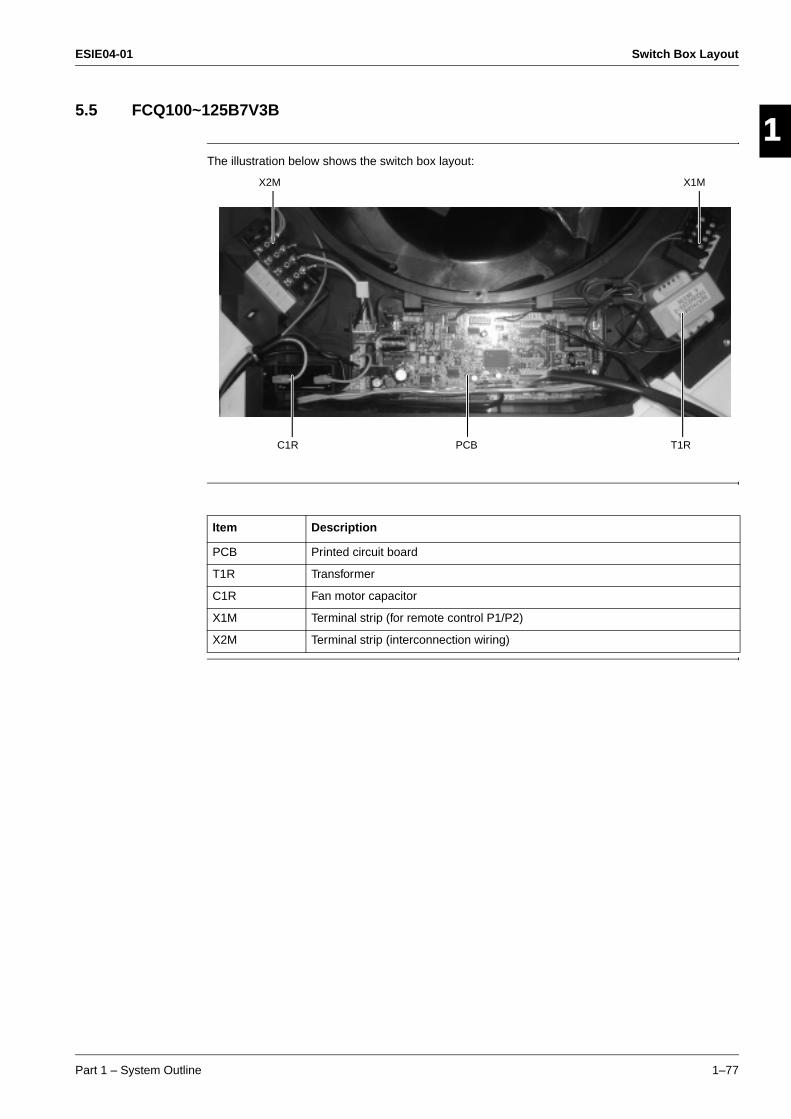
ESIE04-01 Switch Box Layout
Part 1 – System Outline 1–77
3
1
4
5
5.5 FCQ100~125B7V3B
The illustration below shows the switch box layout:
X2M X1M
C1R PCB T1R
Item Description
PCB Printed circuit board
T1R Transformer
C1R Fan motor capacitor
X1M Terminal strip (for remote control P1/P2)
X2M Terminal strip (interconnection wiring)
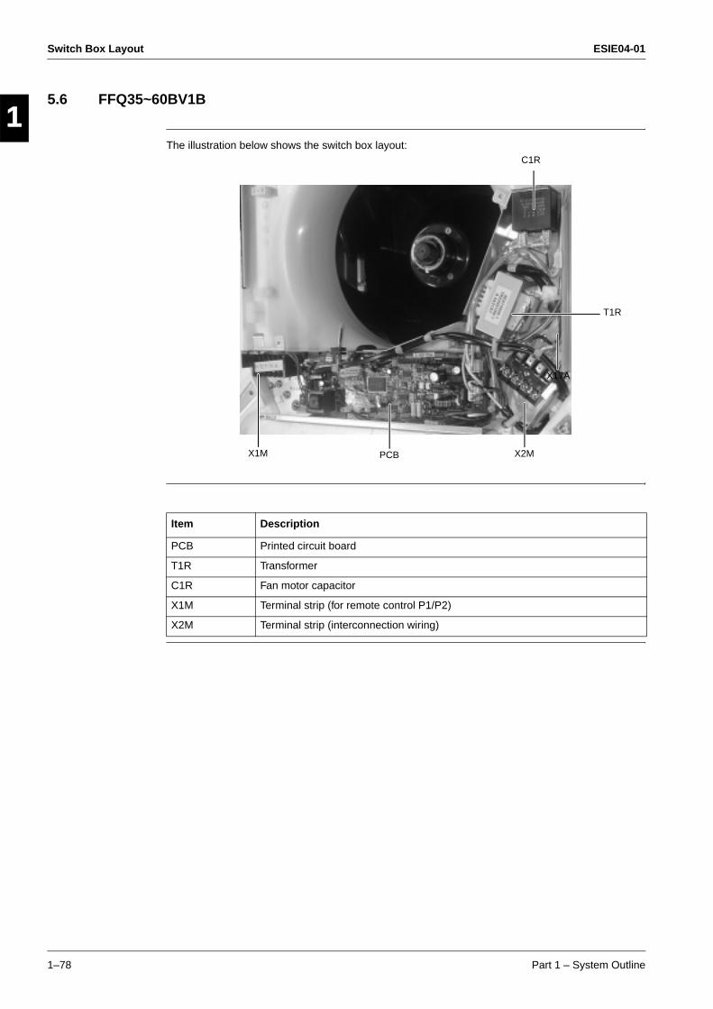
Switch Box Layout ESIE04-01
1–78 Part 1 – System Outline
3
11
4
5
5.6 FFQ35~60BV1B
The illustration below shows the switch box layout:
X17A
T1R
C1R
X2MPCBX1M
Item Description
PCB Printed circuit board
T1R Transformer
C1R Fan motor capacitor
X1M Terminal strip (for remote control P1/P2)
X2M Terminal strip (interconnection wiring)

ESIE04-01 Switch Box Layout
Part 1 – System Outline 1–79
3
1
4
5
5.7 FBQ35B7V1 ~ FBQ125B7V3B
The illustration below shows the switch box layout:.PCB
C1R
X2MT1R X1M
Item Description
PCB Printed circuit board
T1R Transformer
C1R Fan motor capacitor
X1M Terminal strip (for remote control P1/P2)
X2M Terminal strip (interconnection wiring)
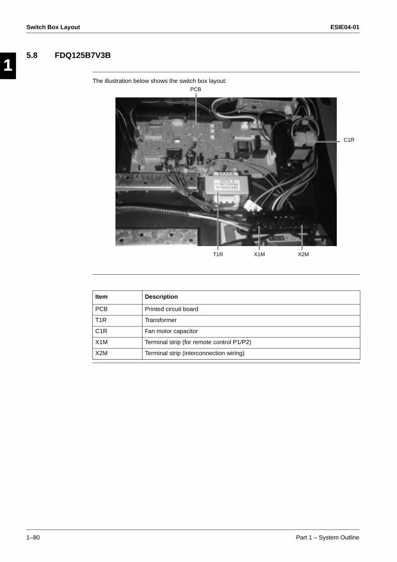
Switch Box Layout ESIE04-01
1–80 Part 1 – System Outline
3
11
4
5
5.8 FDQ125B7V3B
The illustration below shows the switch box layout:PCB
C1R
X1MT1R X2M
Item Description
PCB Printed circuit board
T1R Transformer
C1R Fan motor capacitor
X1M Terminal strip (for remote control P1/P2)
X2M Terminal strip (interconnection wiring)

ESIE04-01 Switch Box Layout
Part 1 – System Outline 1–81
3
1
4
5
5.9 FHQ35BUV1 ~ FHQ125BUV1B
The illustration below shows the switch box layout:
C1R
PCB X1M X2M
T1R
Item Description
PCB Printed circuit board
T1R Transformer
C1R Fan motor capacitor
X1M Terminal strip (for remote control P1/P2)
X2M Terminal strip (interconnection wiring)
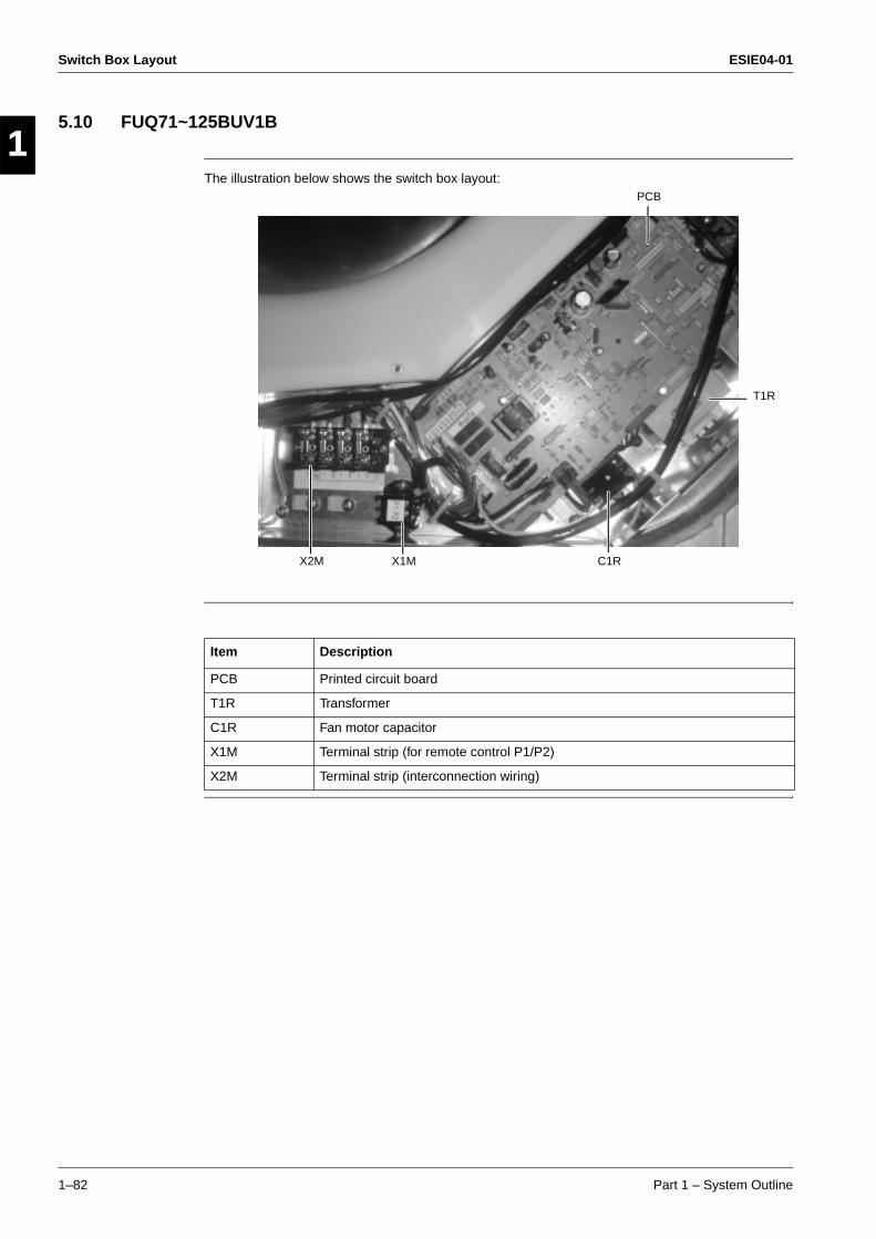
Switch Box Layout ESIE04-01
1–82 Part 1 – System Outline
3
11
4
5
5.10 FUQ71~125BUV1B
The illustration below shows the switch box layout:
C1R
PCB
T1R
X1MX2M
Item Description
PCB Printed circuit board
T1R Transformer
C1R Fan motor capacitor
X1M Terminal strip (for remote control P1/P2)
X2M Terminal strip (interconnection wiring)

ESIE04-01 Switch Box Layout
Part 1 – System Outline 1–83
3
1
4
5
5.11 FAQ71BUV1B
The illustration below shows the switch box layout:
X2M
PCB
X1M
Item Description
PCB Printed circuit board
X1M Terminal strip (for remote control P1/P2, F1/F2, T1/T2)
X2M Terminal strip (interconnection wiring)

Switch Box Layout ESIE04-01
1–84 Part 1 – System Outline
3
11
4
5
5.12 FAQ100BUV1B
The illustration below shows the switch box layout:
PCB X1M
X2M
Item Description
PCB Printed circuit board
T1R Transformer
C1R Fan motor capacitor
X1M Terminal strip (for remote control P1/P2)
X2M Terminal strip (interconnection wiring)

ESIE04-01 Wiring Diagrams
Part 1 – System Outline 1–85
3
1
4
5
Part 1
6 Wiring Diagrams
6.1 What Is in This Chapter?
Introduction This chapter contains the wiring diagrams of the outdoor and indoor units.
Outdoor units: This chapter contains the following wiring diagrams:
Indoor units: This chapter contains the following wiring diagrams:
Wiring diagram See page
6.2–RZQ71B7V3B 1–86
6.3–RZQ100~125B7V3B 1–87
Wiring diagram See page
6.4–FCQ35~60B7V1 1–88
6.5–FCQ71~125B7V3B 1–89
6.6–FFQ35~60BV1B 1–90
6.7–FBQ35~60B7V1 1–91
6.8–FBQ71B7V3B 1–92
6.9–FBQ100~125B7V3B 1–93
6.10–FDQ125B7V3B 1–94
6.11–FHQ35~60BUV1 1–95
6.12–FHQ71~125BUV1B 1–96
6.13–FUQ71~125BUV1B 1–97
6.14–FAQ71BUV1B 1–98
6.15–FAQ100BUV1B 1–99
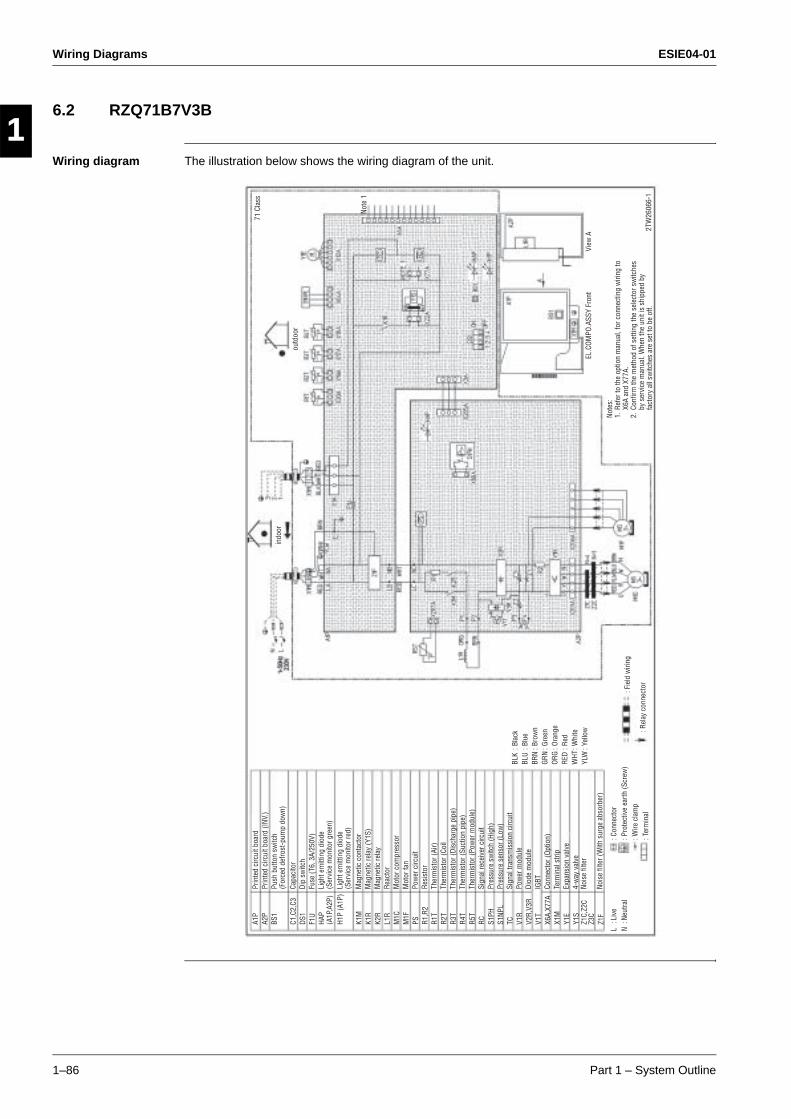
Wiring Diagrams ESIE04-01
1–86 Part 1 – System Outline
3
11
4
5
6.2 RZQ71B7V3B
Wiring diagram The illustration below shows the wiring diagram of the unit.
A1P
A2P
BS1
C1,C
2,C3
DS1
F1U
HAP
(A1P
,A2P
)H1
P (A
1P)
K1M
K1R
K2R
L1R
M1C
M1F
PS R1,R
2R1
TR2
TR3
TR4
TR5
TRC S1
PHS1
NPL
TC V1R
V2R,
V3R
V1T
X6A,
X77A
X1M
Y1E
Y1S
Z1C,
Z2C
Z3C
Z1F
Prin
ted
circ
uit b
oard
Prin
ted
circ
uit b
oard
(INV
.)Pu
sh b
utto
n sw
itch
(For
ced
defro
st-p
ump
dow
n)Ca
paci
tor
Dip
switc
hFu
se (T
6, 3
A/25
0V)
Ligh
t em
ittin
g di
ode
(Ser
vice
mon
itor g
reen
)Li
ght e
mitt
ing
diod
e(S
ervi
ce m
onito
r red
)M
agne
tic c
onta
ctor
Mag
netic
rela
y (Y
1S)
Mag
netic
rela
yRe
acto
rM
otor
com
pres
sor
Mot
or fa
nPo
wer
circ
uit
Resi
stor
Ther
mis
tor (
Air)
Ther
mis
tor (
Coil
Ther
mis
tor (
Disc
harg
e pi
pe)
Ther
mis
tor (
Suct
ion
pipe
)Th
erm
isto
r (Po
wer
mod
ule)
Sign
al re
ceiv
er c
ircui
tPr
essu
re s
witc
h (H
igh)
Pres
sure
sen
sor (
Low
)Si
gnal
tran
smis
sion
circ
uit
Pow
er m
odul
eDi
ode
mod
ule
IGBT
Conn
ecto
r (Op
tion)
Term
inal
stri
pEx
pans
ion
valv
e4-
way
val
veNo
ise
filte
r
Nois
e fil
ter (
With
sur
ge a
bsor
ber)
L : L
ive
N : N
eutra
l: C
onne
ctor
: Pro
tect
ive
earth
(Scr
ew)
: Wire
cla
mp
: Ter
min
al
: Fie
ld w
iring
: Rel
ay c
onne
ctor
BLK
: Bla
ckBL
U : B
lue
BRN
: Bro
wn
GRN
: Gre
enOR
G : O
rang
eRE
D : R
edW
HT : W
hite
YLW
: Ye
llow
indo
or
outd
oor
View
AEL
.COM
PO.A
SSY
Fron
t
Note
s:1.
Ref
er to
the
optio
n m
anua
l, fo
r con
nect
ing
wiri
ng to
X6
A an
d X7
7A.
2. C
onfir
m th
e m
etho
d of
set
ting
the
sele
ctor
sw
itche
s by
ser
vice
man
ual.
Whe
n th
e un
it is
shi
pped
by
fact
ory
all s
witc
hes
are
set t
o be
off.
2TW
2606
6-1
Note
1
71 C
lass
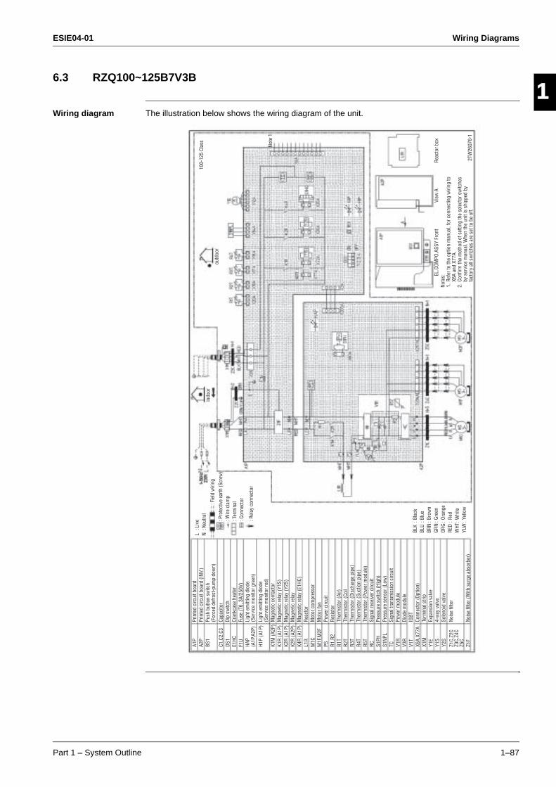
ESIE04-01 Wiring Diagrams
Part 1 – System Outline 1–87
3
1
4
5
6.3 RZQ100~125B7V3B
Wiring diagram The illustration below shows the wiring diagram of the unit.
A1P
A2P
BS1
C1,C
2,C3
DS1
E1HC
F1U
HAP
(A1P
,A2P
)H1
P (A
1P)
K1M
(A2P
)K1
R (A
1P)
K2R
(A1P
)K2
R (A
2P)
K4R
(A1P
)L1
RM
1CM
1F,M
2FPS R1
,R2
R1T
R2T
R3T
R4T
R5T
RC S1PH
S1NP
LTC V1
RV3
RV1
TX6
A,X7
7AX1
MY1
EY1
SY2
SZ1
C,Z2
CZ3
C,Z4
CZ5
CZ1
F
Prin
ted
circ
uit b
oard
Prin
ted
circ
uit b
oard
(INV
.)Pu
sh b
utto
n sw
itch
(For
ced
defro
st-p
ump
dow
n)Ca
paci
tor
Dip
switc
hCr
ankc
ase
heat
erFu
se (T
6, 3
A/25
0V)
Ligh
t em
ittin
g di
ode
(Ser
vice
mon
itor g
reen
)Li
ght e
mitt
ing
diod
e(S
ervi
ce m
onito
r red
)M
agne
tic c
onta
ctor
Mag
netic
rela
y (Y
1S)
Mag
netic
rela
y (Y
2S)
Mag
netic
rela
yM
agne
tic re
lay
(E1H
C)Re
acto
rM
otor
com
pres
sor
Mot
or fa
nPo
wer
circ
uit
Resi
stor
Ther
mis
tor (
Air)
Ther
mis
tor (
Coil
Ther
mis
tor (
Disc
harg
e pi
pe)
Ther
mis
tor (
Suct
ion
pipe
)Th
erm
isto
r (Po
wer
mod
ule)
Sign
al re
ceiv
er c
ircui
tPr
essu
re s
witc
h (H
igh)
Pres
sure
sen
sor (
Low
)Si
gnal
tran
smis
sion
circ
uit
Pow
er m
odul
eDi
ode
mod
ule
IGBT
Conn
ecto
r (Op
tion)
Term
inal
stri
pEx
pans
ion
valv
e4-
way
val
veSo
leno
id v
alve
Nois
e fil
ter
Nois
e fil
ter (
With
sur
ge a
bsor
ber)
L : L
ive
N : N
eutra
l
: Pro
tect
ive
earth
(Scr
ew)
: Wire
cla
mp
: Ter
min
al: C
onne
ctor: Fie
ld w
iring
: Rel
ay c
onne
ctor
BLK
: Bla
ckBL
U : B
lue
BRN
: Bro
wn
GRN
: Gre
enOR
G : O
rang
eRE
D : R
edW
HT : W
hite
YLW
: Ye
llow
indo
or
outd
oor
View
ARe
acto
r box
EL.C
OMPO
.ASS
Y Fr
ont
Note
s:1.
Ref
er to
the
optio
n m
anua
l, fo
r con
nect
ing
wiri
ng to
X6
A an
d X7
7A.
2. C
onfir
m th
e m
etho
d of
set
ting
the
sele
ctor
sw
itche
s by
ser
vice
man
ual.
Whe
n th
e un
it is
shi
pped
by
fact
ory
all s
witc
hes
are
set t
o be
off.
2TW
2607
6-1
Note
1
100-
125
Clas
s
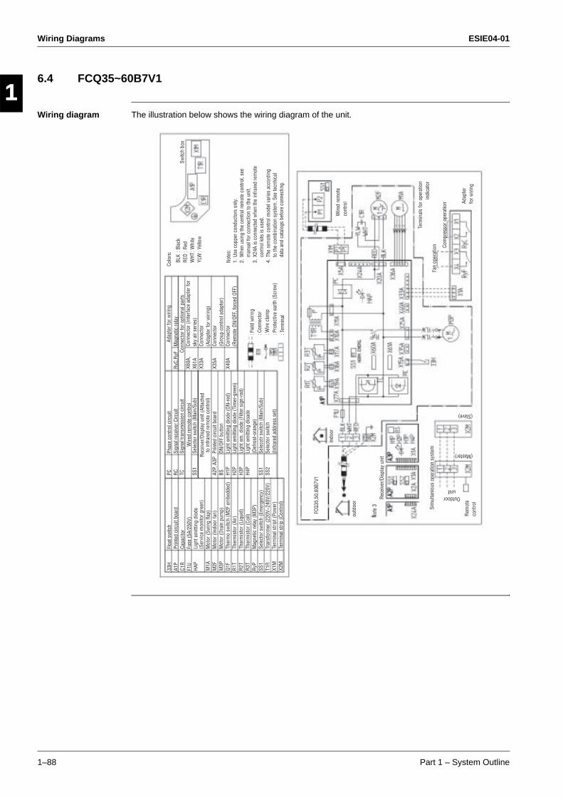
Wiring Diagrams ESIE04-01
1–88 Part 1 – System Outline
3
11
4
5
6.4 FCQ35~60B7V1
Wiring diagram The illustration below shows the wiring diagram of the unit.
33H
A1P
C1R
F1U
HAP
M1A
M2F
M3P
Q1F
R1T
R2T
R3T
RyP
SS1
T1R
X1M
X2M
Floa
t sw
itch
Prin
ted
circ
uit b
oard
Capa
cito
rFu
se (5
A/25
0V)
Ligh
t em
ittin
g di
ode
(Ser
vice
mon
itor g
reen
)M
otor
(Sw
ing
flap)
Mot
or (I
ndoo
r fan
)M
otor
(Dra
in p
ump)
Ther
mo
switc
h (M
2F e
mbe
dded
)Th
erm
isto
r (Ai
r)Th
erm
isto
r (Li
quid
)Th
erm
isto
r (Co
il)M
agne
tic re
lay
(M3P
)Se
lect
or s
witc
h (E
mer
genc
y)Tr
ansf
orm
er (2
20V~
240V
/220
V)Te
rmin
al s
tript
(Pow
er)
Term
inal
stri
p (C
ontro
l)
PC RC TC SS1
A2P,
A3P
BS H1P
H2P
H3P
H4P
SS1
SS2
Phas
e co
ntro
l circ
uit
Sign
al re
ceiv
er C
ircui
tSi
gnal
tran
smis
sion
circ
uit
Sele
ctor
sw
itch
(Mai
n/Su
b)
Prin
ted
circ
uit b
oard
ON/O
FF b
utto
nLi
ght e
mitt
ing
diod
e (O
N-re
d)Li
ght e
mitt
ing
diod
e (T
imer
-gre
en)
Ligh
t em
. dio
de (F
ilter
sig
n-re
d)Li
ght e
mitt
ing
dioa
de(D
efro
st-o
rang
e)Se
leco
tr sw
itch
(Mai
n/Su
b)Se
lect
or s
witc
h(In
frare
d ad
dres
s se
t)
RyC,
RyF
X60A
, X6
1AX3
3A
X35A
X40A
Mag
netic
rela
y
Conn
ecto
r (In
terf
ace
adap
ter f
or
sky
air s
erie
s)Co
nnec
tor
(Ada
pter
for w
iring
)Co
nnec
tor
(Gro
up c
ontro
l ada
pter
)Co
nnec
tor
(Rem
ote
ON/O
FF, f
orce
d OF
F)
: Fie
ld w
iring
: Con
nect
or: W
ire c
lam
p: P
rote
ctiv
e ea
rth (S
crew
): T
erm
inal
Switc
h bo
x
Colo
rs:
BLK
: Bla
ckRE
D : R
edW
HT : W
hite
YLW
: Ye
llow
indo
or
outd
oor
FCQ3
5,50
,60B
7V1
Rece
iver
/Dis
play
uni
t
Sim
ulta
niou
s op
erat
ion
syst
em
Rem
ote
cont
rol
Wire
d re
mot
e co
ntro
l Adap
ter
for w
iring
Term
inal
s fo
r ope
ratio
n in
dica
tor
Fan
oper
atio
n Com
pres
sor o
pera
tion
Outdoor unit
(Master)
(Slave)
Note
s:1.
Use
cop
per c
ondu
ctor
s on
ly.2.
Whe
n us
ing
the
cent
ral r
emot
e co
ntro
l, se
e m
anua
l for
con
nect
ion
to th
e un
it.3.
X24
A is
con
nect
ed w
hen
the
infra
red
rem
ote
cont
rol k
its is
use
d.4.
The
rem
ote
cont
rol m
odel
var
ies
acco
rdin
g to
the
com
bina
tion
syst
em. S
ee te
cnhi
cal
data
and
cat
alog
s be
fore
con
nect
ing.
Note
3
Wire
d re
mot
e co
ntro
l
Adap
ter f
or w
iring
Conn
ecto
r for
opt
iona
l par
ts
Rece
iver
/Dis
play
uni
t (At
tach
ed
to in
frare
d re
mot
e co
ntro
l)
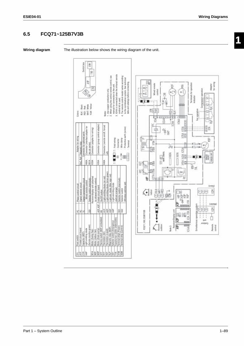
ESIE04-01 Wiring Diagrams
Part 1 – System Outline 1–89
3
1
4
5
6.5 FCQ71~125B7V3B
Wiring diagram The illustration below shows the wiring diagram of the unit.
S1L
A1P
C1R
HAP
M1A
M2F
M3P
Q1F
R1T
R2T
RyP
SS1
T1R
X1M
X2M
Floa
t sw
itch
Prin
ted
circ
uit b
oard
Capa
cito
r (M
2F)
Ligh
t em
ittin
g di
ode
(Ser
vice
mon
itor-
gree
n)M
otor
(Sw
ing
flap)
Mot
or (I
ndoo
r fan
)M
otor
(Dra
in p
ump)
Ther
mo
switc
h (M
2F e
mbe
dded
)Th
erm
isto
r (Ai
r)Th
erm
isto
r (Li
quid
)M
agne
tic re
lay
(M3P
)Se
lect
or s
witc
h (E
mer
genc
y)Tr
ansf
orm
er (2
20V~
240V
/220
V)Te
rmin
al s
tript
(Pow
er)
Term
inal
stri
p (C
ontro
l)
Wire
d re
mot
e co
ntro
l
Note
s:1.
Use
cop
per c
ondu
ctor
s on
ly.2.
Whe
n us
ing
the
cent
ral r
emot
e co
ntro
l, se
e m
anua
l for
con
nect
ion
to th
e un
it.3.
X24
A is
con
nect
ed w
hen
the
infra
red
rem
ote
cont
rol k
it is
use
d.4.
The
rem
ote
cont
rol m
odel
var
ies
acco
rdin
g to
the
com
bina
tion
syst
em. S
ee te
chni
cal
data
and
cat
alog
s be
fore
con
nect
ing.
PC RC TC SSI
BS H1P
H2P
H3P
H4P
SS1
SS2
Phas
e co
ntro
l circ
uit
Sign
al re
ceiv
er c
ircui
tSi
gnal
tran
smis
sion
circ
uit
Sele
ctor
sw
itch
(mai
n/su
b)
On/O
ff bu
tton
Ligh
t em
ittin
g di
ode
(on-
red)
Ligh
t em
ittin
g di
ode
(tim
er-g
reen
)Li
ght e
m. d
iode
(filt
er s
ign-
red)
Ligh
t em
miti
ng d
iode
(def
rost
-ora
nge)
Sele
ctor
sw
itch
(mai
n/su
b)Se
lect
or s
witc
h(W
irele
ss a
ddre
ss s
et)
Rece
iver
/dis
play
uni
t (at
tach
ed
to in
frare
d re
mot
e co
ntro
l)A2
P, A
3P P
rinte
d ci
rcui
t boa
rd
RyC,
RyF
X60A
, X6
1AX3
3A
X35A
X40A
Adap
ter f
or w
iring
Conn
ecto
r for
opt
iona
l par
tsM
agne
tic re
lay
Conn
ecto
r (in
terf
ace
adap
ter f
or
sky
air s
erie
s)Co
nnec
tor (
adap
ter f
or w
iring
)
Conn
ecto
r (gr
oup
cont
rol a
dapt
er)
Conn
ecto
r (re
mot
e on
/off,
forc
ed
off)
Fiel
d w
iring
Conn
ecto
rW
ire c
lam
pPr
otec
tive
earth
(scr
ew)
Term
inal
Switc
h bo
x
Colo
rs:
BLK
: Bla
ckRE
D : R
edW
HT : W
hite
YLW
: Ye
llow
indo
or
outd
oor
FCQ7
1,10
0,12
5B7V
3B
Rece
iver
/Dis
play
uni
t
Sim
ulta
niou
s op
erat
ion
syst
em
Rem
ote
cont
rol
Wire
d re
mot
e co
ntro
l Adap
ter
for w
iring
Fan
oper
atio
n
Com
pres
sor o
pera
tion
Outdoor unit
(Master)
(Slave)
Note
3
Term
inal
s fo
r ope
ratio
n in
dica
tor
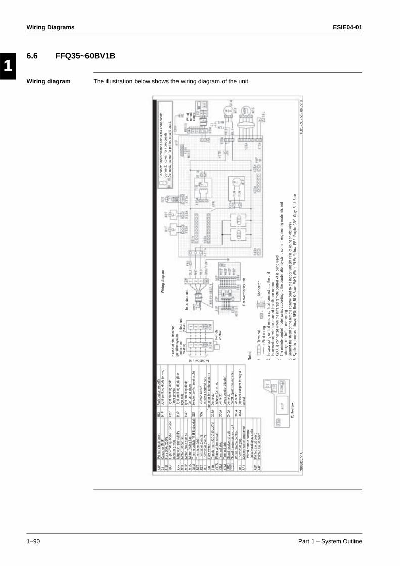
Wiring Diagrams ESIE04-01
1–90 Part 1 – System Outline
3
11
4
5
6.6 FFQ35~60BV1B
Wiring diagram The illustration below shows the wiring diagram of the unit.
A1P
C1 F1U
HAP
KPR
M1F
M1P
M1S
Q1M
R1T
R2T
R3T
S1L
T1R
V1TR
X1M
X2M
RC TC R1T
SS1
A3P
A4P
Prin
ted
circ
uit b
oard
Capa
cito
r (M
1F)
Fuse
(F5A
250
V)Li
ght e
mitt
ing
diod
e (S
ervi
ce
mon
itor g
reen
)M
agne
tic re
lay
(M1P
)M
otor
(ind
oor f
an)
Mot
or (d
rain
pum
p)M
otor
(sw
ing
flap)
Ther
mo
switc
h (M
1F E
mbe
dded
)Th
erm
isto
r (ai
r)Th
erm
isto
r (co
il-1)
Ther
mis
tor (
coil-
2)Fl
oat s
witc
hTr
ansf
orm
er (2
20-2
40V/
22V)
Phas
e co
ntro
l circ
uit
Term
inal
stri
pTe
rmin
al s
trip
Sign
al re
ceiv
er c
ircui
tSi
gnal
tran
smis
sion
circ
uit
Ther
mis
tor (
air)
Sele
ctor
sw
itch
(mai
n/su
b)
Prin
ted
circ
uit b
oard
Prin
ted
circ
uit b
oard
BS1
H1P
H2P
H3P
H4P
SS1
SS2
X33A
X35A
X40A
X60A
X61A
Push
but
ton
(on/
off)
Ligh
t em
ittin
g di
ode
(on-
red)
Ligh
t em
ittin
g di
ode
(tim
er-g
reen
)Li
ght e
mitt
ing
diod
e (fi
lter
sign
-red
)lig
ht e
mitt
ing
diod
e (d
efro
st-o
rang
e)Se
lect
or s
witc
h (m
ain/
sub)
Sele
ctor
sw
itch
(wire
less
add
ress
set
)
Conn
ecto
r(a
dapt
er fo
r wiri
ng)
Conn
ecto
r (g
roup
con
trol a
dapt
er)
Conn
ecto
r(o
n/of
f inp
ut fr
om o
utsi
de)
Conn
ecto
r(in
terf
ace
adap
ter f
or s
ky a
ir se
ries)
Conn
ecto
r for
opt
iona
l par
ts
Wire
d re
mot
e co
ntro
l
Wire
d re
mot
e co
ntro
l (r
ecei
ver/
disp
lay
unit)
Rem
ote
cont
rol
Wiri
ng d
iagr
am
In c
ase
of s
imul
tane
ous
oper
atio
n sy
stem
Indo
or u
nit
(mas
ter)
Indo
or u
nit
(sla
ve)
To outdoor unit
To o
utdo
or u
nit
Rec
eive
r/di
spla
y un
it
Conn
ecto
r dis
crim
inat
ion
colo
ur fo
r com
pone
nts.
Conn
ecto
r col
our f
or c
ompo
nent
s.Co
nnec
tor c
olou
r for
prin
ted
circ
uit b
oard
. Wire
d re
mot
e co
ntro
l
Note
s:
1.
Te
rmin
al
Conn
ecto
r
Fiel
d w
iring
2. I
n ca
se u
sing
cen
tral r
emot
e co
ntro
l, co
nnec
t it t
o th
e un
it
In a
ccor
danc
e w
ith th
e at
tach
ed in
stal
latio
n m
anua
l.3.
X24
A is
con
nect
ed w
hen
the
infra
red
rem
ote
cont
rol k
it is
bei
ng u
sed.
4. T
he re
mot
e co
ntro
l mod
el v
arie
s ac
cord
ing
to th
e co
mbi
natio
n sy
stem
, con
firm
eng
inee
ring
mat
eria
ls a
nd
cata
logs
, etc
. bef
ore
conn
ectin
g.5.
Gro
und
the
shie
ld o
f the
rem
ote
cont
rol c
ord
to th
e in
door
uni
t (in
cas
e of
usi
ng s
hiel
d w
ire)
6. S
ymbo
ls s
how
as
follo
ws:
RED
: Red
BLK
: Bla
ck W
HT: W
hite
YLW
: Yel
low
PRP
: Pur
ple
GRY
: Gra
y B
LU: B
lue
Cont
rol b
ox
3D03
8357
-1A
FFQ
25 -
35 -
50 -
60 B
V1B
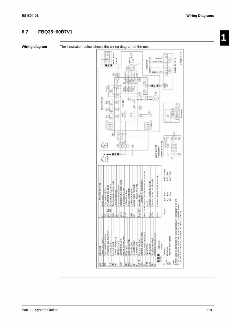
ESIE04-01 Wiring Diagrams
Part 1 – System Outline 1–91
3
1
4
5
6.7 FBQ35~60B7V1
Wiring diagram The illustration below shows the wiring diagram of the unit.
35,5
0,60
Cla
ss33
HA1
PT1
R
C1R
F1U
F1T
HAP
M1F
M1P
R1T
R2T
R3T
RyF1
-4Ry
PSS
1X1
MX2
MRC TC
Floa
t sw
itch
Prin
ted
circ
uit b
oard
Pow
er s
uppl
y tra
nsfo
rmer
(Tra
nsfo
rmer
220
-240
V/21
.8V)
Capa
cito
r (FA
N)Fu
se (5
A, 2
50V)
Ther
mal
Fus
e (1
52°C
)(M
1F E
mbe
dded
)Li
ght E
mitt
ing
Diod
e(S
ervi
ce m
onito
r-gr
een)
Mot
or (f
an)
Mot
or (d
rain
pum
p)Th
erm
isto
r (ai
r)Th
erm
isto
r (liq
uid)
Ther
mis
tor (
coil)
Mag
netic
rela
y (fa
n)M
agne
tic re
lay
(dra
in p
ump)
Sele
ctor
sw
itch
(em
erge
ncy)
Term
inal
stri
pTe
rmin
al s
trip
Sign
al re
ceiv
er c
ircui
tSi
gnal
tran
smis
sion
circ
uit
BS1
BS2
BS3,
BS8
BS4,
BS9
BS6
BS7
BS11
BS12
BS14
H1P
LCD
SS1
RyC,
RyF
X60A
, X61
A
X33A
X35A
X40A
On/O
ff bu
tton
Tim
er m
ode
star
t/sto
pPr
ogra
mm
ing
time
butto
nTe
mpe
ratu
re s
ettin
g bu
tton
Oper
atio
n m
ode
sele
ctor
but
ton
Tim
er o
n/of
f but
ton
Fan
spee
d co
ntro
ll bu
tton
Insp
ectio
n/te
st o
pera
tion
butto
nFi
lter s
ign
rese
t but
ton
Ligh
t em
ittin
g di
ode
(Ser
vice
mon
itor-
red)
Liqu
id c
rista
l dis
play
Sele
ctor
sw
itch
(mai
n/su
b)
Mag
netic
rela
y
Conn
ecto
r (in
terf
ace
adap
ter f
or s
ky a
ir/us
se
ries)
Conn
ecto
r (ad
apte
r for
wiri
ng)
Conn
ecto
r (gr
oup
cont
rol a
dapt
er)
Conn
ecto
r (re
mot
e on
/off,
forc
ed o
ff)
Wire
d re
mot
e co
ntro
l
Adap
ter f
or w
iring
Conn
ecto
r for
opt
iona
l par
ts
Note
s:1.
Whe
n us
ing
the
cent
ral r
emot
e co
ntro
l see
man
ual f
or c
onne
ctio
n to
the
unit
2. T
he re
mot
e co
ntro
l mod
el v
arie
s ac
cord
ing
to th
e co
mbi
natio
n sy
stem
.
See
tech
nica
l mat
eria
ls a
nd c
atal
ogue
s, e
tc. b
efor
e co
nnec
ting.
Fiel
d w
iring
te
rmin
al
Conn
ecto
rW
ire c
lam
pPr
otec
tive
earth
(scr
ew)
Colo
rs:
BLK
: Bla
ckBL
U : B
lue
GRY
: Gre
y
ORG
: Ora
nge
RED
: Red
WHT
: Whi
te
Deta
ils o
f wire
d re
mot
e co
ntro
l (o
ptio
nal a
cces
sory
)
Switc
h bo
x
Adap
ter f
or w
iring
2TW
2511
6-1
A
Term
inal
s fo
r op
erat
ion
indi
cato
r
FAN operation
Compressoroperation
Wire
d re
mot
e co
ntro
l
indo
orou
tdoo
r
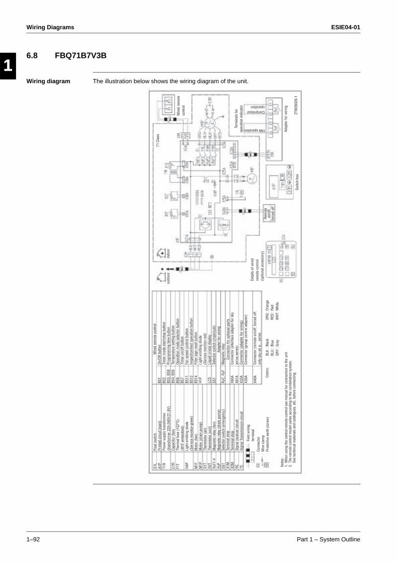
Wiring Diagrams ESIE04-01
1–92 Part 1 – System Outline
3
11
4
5
6.8 FBQ71B7V3B
Wiring diagram The illustration below shows the wiring diagram of the unit.
71 C
lass
S1L
A1P
T1R
C1R
F1T
HAP
M1F
M1P
R1T
R2T
RyF1
-4Ry
PSS
1X1
MX2
MRC TC
Floa
t sw
itch
Prin
ted
circ
uit b
oard
Pow
er s
uppl
y tra
nsfo
rmer
(tran
sfor
mer
220
-240
V/21
.8V)
Capa
cito
r (fa
n)Th
erm
al fu
se (1
52°C
)(M
1F e
mbe
dded
)Li
ght e
mitt
ing
diod
e(S
ervi
ce m
onito
r-gr
een)
Mot
or (f
an)
Mot
or (d
rain
pum
p)Th
erm
isto
r (ai
r)Th
erm
isto
r (co
il)M
agne
tic re
lay
(fan)
Mag
netic
rela
y (d
rain
pum
p)Se
lect
or s
witc
h (e
mer
genc
y)Te
rmin
al s
trip
Term
inal
stri
pSi
gnal
rece
iver
circ
uit
Sign
al T
rans
mis
sion
circ
uit
BS1
BS2
BS3,
BS8
BS4,
BS9
BS6
BS7
BS11
BS12
BS14
H1P
LCD
SS1
RyC,
RyF
X60A
X61A
X33A
X35A
X40A
Wire
d re
mot
e co
ntro
l
Note
s:1.
Whe
n us
ing
the
cent
ral r
emot
e co
ntro
l see
man
ual f
or c
onne
ctio
n to
the
unit
2. T
he re
mot
e co
ntro
l mod
el v
arie
s ac
cord
ing
to th
e co
mbi
natio
n sy
stem
.
See
tech
nica
l mat
eria
ls a
nd c
atal
ogue
s, e
tc. b
efor
e co
nnec
ting.
Fiel
d w
iring
te
rmin
al
Conn
ecto
rW
ire c
lam
pPr
otec
tive
earth
(scr
ew)
BLK
: Bla
ckBL
U : B
lue
GRY
: Gre
y
ORG
: Ora
nge
RED
: Red
WHT
: Whi
te
Deta
ils o
f wire
d re
mot
e co
ntro
l (o
ptio
nal a
cces
sory
)
Switc
h bo
x
Adap
ter f
or w
iring
2TW
2602
6-1
Term
inal
s fo
r op
erat
ion
indi
cato
r
FAN operation
Compressoroperation
Wire
d re
mot
e co
ntro
l
indo
orou
tdoo
r
On/O
ff bu
tton
Tim
er m
ode
star
t/sto
p bu
tton
Prog
ram
min
g tim
e bu
tton
Tem
pera
ture
set
ting
butto
nOp
erat
ion
mod
e se
lect
or b
utto
nTi
mer
on/
off b
utto
nFa
n sp
eed
cont
rol b
utto
nIn
spec
tion/
test
ope
ratio
n bu
tton
Filte
r sig
n re
set b
utto
nLi
ght e
mitt
ing
diod
e(S
ervi
ce m
onito
r-re
d)Li
quid
cris
tal d
ispl
aySe
lect
or s
witc
h (m
ain/
sub)
Mag
netic
rela
y
Conn
ecto
r (in
terf
ace
adap
ter f
or s
ky
air/u
s se
ries)
Conn
ecto
r (ad
apte
r for
wiri
ng)
Conn
ecto
r (gr
oup
cont
rol a
dapt
er)
Conn
ecto
r (re
mot
e on
/off,
forc
ed o
ff,
only
sky
-air
p...
serie
s
Adap
ter f
or w
iring
Conn
ecto
r for
opt
iona
l par
ts
Colo
rs:
Rem
ote
on/o
ff fo
rced
off

ESIE04-01 Wiring Diagrams
Part 1 – System Outline 1–93
3
1
4
5
6.9 FBQ100~125B7V3B
Wiring diagram The illustration below shows the wiring diagram of the unit.
100,
125
Cla
ssS1
LA1
PT1
R
C1R
F1T
HAP
M1F
M1P
R1T
R2T
RyF1
-4Ry
PSS
1X1
MX2
MRC TC
Floa
t sw
itch
Prin
ted
circ
uit b
oard
Pow
er s
uppl
y tra
nsfo
rmer
(tran
sfor
mer
220
-240
V/21
.8V)
Capa
cito
r (fa
n)Th
erm
al fu
se (1
52°C
)(M
1F e
mbe
dded
)Li
ght e
mitt
ing
diod
e(S
ervi
ce m
onito
r-gr
een)
Mot
or (f
an)
Mot
or (d
rain
pum
p)Th
erm
isto
r (ai
r)Th
erm
isto
r (co
il)M
agne
tic re
lay
(fan)
Mag
netic
rela
y (d
rain
pum
p)Se
lect
or s
witc
h (e
mer
genc
y)Te
rmin
al s
trip
Term
inal
stri
pSi
gnal
rece
iver
circ
uit
Sign
al T
rans
mis
sion
circ
uit
BS1
BS2
BS3,
BS8
BS4,
BS9
BS6
BS7
BS11
BS12
BS14
H1P
LCD
SS1
RyC,
RyF
X60A
X61A
X33A
X35A
X40A
Wire
d re
mot
e co
ntro
l
Note
s:1.
Whe
n us
ing
the
cent
ral r
emot
e co
ntro
l see
man
ual f
or c
onne
ctio
n to
the
unit
2. T
he re
mot
e co
ntro
l mod
el v
arie
s ac
cord
ing
to th
e co
mbi
natio
n sy
stem
.
See
tech
nica
l mat
eria
ls a
nd c
atal
ogue
s, e
tc. b
efor
e co
nnec
ting.
Conn
ecto
rW
ire c
lam
pPr
otec
tive
earth
(scr
ew)
BLK
: Bla
ckBL
U : B
lue
GRY
: Gre
y
ORG
: Ora
nge
RED
: Red
WHT
: Whi
te
Deta
ils o
f wire
d re
mot
e co
ntro
l (o
ptio
nal a
cces
sory
)
Switc
h bo
x
Adap
ter f
or w
iring
2TW
2605
6-1
Term
inal
s fo
r op
erat
ion
indi
cato
r
FAN operation
Compressoroperation
Wire
d re
mot
e co
ntro
l
indo
orou
tdoo
r
On/O
ff bu
tton
Tim
er m
ode
star
t/sto
p bu
tton
Prog
ram
min
g tim
e bu
tton
Tem
pera
ture
set
ting
butto
nOp
erat
ion
mod
e se
lect
or b
utto
nTi
mer
on/
off b
utto
nFa
n sp
eed
cont
rol b
utto
nIn
spec
tion/
test
ope
ratio
n bu
tton
Filte
r sig
n re
set b
utto
nLi
ght e
mitt
ing
diod
e(S
ervi
ce m
onito
r-re
d)Li
quid
cris
tal d
ispl
aySe
lect
or s
witc
h (m
ain/
sub)
Mag
netic
rela
y
Conn
ecto
r (in
terf
ace
adap
ter f
or s
ky
air/u
s se
ries)
Conn
ecto
r (ad
apte
r for
wiri
ng)
Conn
ecto
r (gr
oup
cont
rol a
dapt
er)
Conn
ecto
r (re
mot
e on
/off,
forc
ed o
ff,
only
sky
-air
p...
serie
s
Colo
rs:
Rem
ote
on/o
ff fo
rced
off
BRN:
Bro
wn
Fiel
d w
iring
Term
inal
Adap
ter f
or w
iring
Conn
ecto
r for
opt
iona
l par
ts
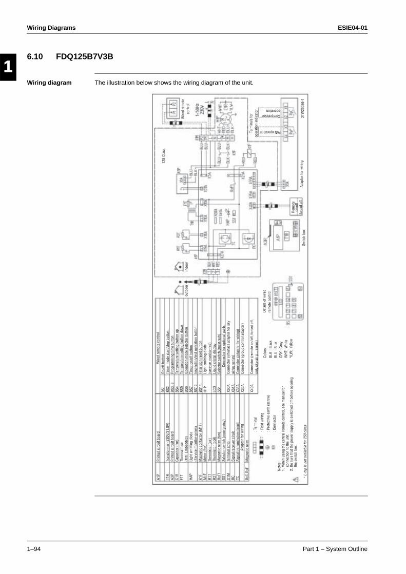
Wiring Diagrams ESIE04-01
1–94 Part 1 – System Outline
3
11
4
5
6.10 FDQ125B7V3B
Wiring diagram The illustration below shows the wiring diagram of the unit.
125
Clas
sA1
P
T1R
A3P
C1R
F1T
HAP
K1F
M1F
R1T
R2T
RyF1
SS1
X1M
RC TC RyC,
RyF
Prin
ted
circ
uit b
oard
Tran
sfor
mer
(230
V/21
.8V)
Prin
ted
circ
uit b
oard
Capa
cito
r (fa
n)Th
erm
al fu
se(M
1F E
mbe
dded
)Li
ght e
mitt
ing
diod
e(S
ervi
ce m
onito
r-gr
een)
Mag
netic
con
tact
or (M
1F)
Mot
or (f
an)
Ther
mis
tor (
air)
Ther
mis
tor (
coil)
Mag
netic
rela
y (fa
n)Se
lect
or s
witc
h (e
mer
genc
y)Te
rmin
al s
trip
Sign
al re
ceiv
er c
iruit
Sign
al tr
ansm
issi
on c
ircui
t
Mag
netic
rela
y
BS1
BS2
BS3,
8BS
4BS
9BS
6BS
7BS
12BS
14H1
P
LCD
SS1
X60A
X61A
X33A
X35A
X40A
Wire
d re
mot
e co
ntro
l
Note
s:1.
Whe
n us
ing
the
cent
ral r
emot
e co
ntro
l, se
e m
anua
l for
co
nnec
tion
to th
e un
it.2.
Be
sure
that
the
pow
er s
uppl
y is
sw
itche
d of
f bef
ore
open
ing
the
switc
h bo
x.
: Pro
tect
ive
earth
(scr
ew)
: Con
nect
orBL
K : B
lack
BLU
: Blu
eGR
Y : G
rey
WHT
: W
hite
YLW
: Ye
llow
Deta
ils o
f wire
d re
mot
e co
ntro
l
Switc
h bo
xAd
apto
r for
wiri
ng2T
W26
036-
1
Term
inal
s fo
r op
erat
ion
indi
cato
r
FAN operation
Compressoroperation
Wire
d re
mot
e co
ntro
lin
door
outd
oor
On/o
ff bu
tton
Tim
er m
ode
star
t/sto
p bu
tton
Prog
ram
min
g tim
e bu
tton
Tem
pera
ture
set
ting
butto
n up
Tem
pera
ture
set
ting
butto
n do
wn
Oper
atio
n m
ode
sele
ctor
but
ton
Tim
er o
n/of
f but
ton
Insp
ectio
n/te
st o
pera
tion
butto
nFi
lter s
ign
rese
t but
ton
Ligh
t em
ittin
g di
ode
(ser
vice
mon
itor-
red)
Liqu
id c
rista
l dis
play
Sele
ctor
sw
itch
(mai
n-su
b)
Conn
ecto
r (in
terf
ace
adap
ter f
or s
ky
air/u
s se
ries)
Conn
ecto
r (ad
apte
r for
wiri
ng)
Conn
ecto
r (gr
oup
cont
rol a
dapt
er)
Conn
ecto
r (re
mot
e on
/off,
forc
ed o
ff,
only
sky
-air
p...
serie
s)
Colo
rs:
Rem
ote
on/o
ff fo
rced
off
: Ter
min
al
: Fie
ld w
iring
Conn
ecto
r for
opt
iona
l par
ts
Adap
ter f
or w
iring
* L-
tap
is n
ot a
vaila
ble
for 2
50 c
lass

ESIE04-01 Wiring Diagrams
Part 1 – System Outline 1–95
3
1
4
5
6.11 FHQ35~60BUV1
Wiring diagram The illustration below shows the wiring diagram of the unit.
A1P
C1 F1U
HAP
KAR
KPR
M1F
M1S
Q1M
R1T
R2T
R3T
S1Q
T1R
V1TR
X1M
X2M RC TC
R1T
SS1
A3P
A4P
Prin
ted
circ
uit b
oard
Capa
cito
r (M
1F)
Fuse
(F5A
250
V)Li
ght e
mitt
ing
diod
e (S
ervi
ce m
onito
r gre
en)
Mag
netic
rela
y (M
1S)
Mag
netic
rela
y (M
1P)
Mot
or (I
ndoo
r fan
)M
otor
(Dra
in p
ump)
Ther
mo
switc
h (M
1F E
mbe
dded
)Th
erm
isto
r (Ai
r)Th
erm
isto
r (Co
il-1)
Ther
mis
tor (
Coil-
2)Li
mit
switc
h (S
win
g fla
p)Tr
ansf
orm
er (2
20-2
40V/
22V)
Phas
e co
ntro
l circ
uit
Term
inal
blo
ckTe
rmin
al b
lock
Sign
al re
ceiv
er c
ircui
tSi
gnal
tran
smis
sion
circ
uit
Ther
mis
tor (
Air)
Sele
ctor
sw
itch
(Mai
n/Su
b)
Prin
ted
circ
uit b
oard
Prin
ted
circ
uit b
oard
BS1
H1P
H2P
H3P
H4P
SS1
SS2
X15A
X25A
X33A
X35A
X40A
X60A
X61A
Push
but
ton
(on/
off)
Ligh
t em
ittin
g di
ode
(on-
red)
Ligh
t em
ittin
g di
ode
(tim
er-g
reen
)Li
ght e
mitt
ing
diod
e (F
ilter
sig
n-re
d)Li
ght e
mitt
ing
diod
e (d
efro
st-o
rang
e)Se
lect
or s
witc
h (M
ain/
Sub)
Sele
ctor
sw
itch
(Wire
less
add
ress
set
)
Conn
ecto
r (Fl
oat s
witc
h)Co
nnec
tor (
Drai
n pu
mp)
Conn
ecto
r(A
dapt
er fo
r wiri
ng)
Conn
ecto
r(G
roup
con
trol a
dapt
er)
Conn
ecto
r(O
N/OF
F in
put f
rom
out
side
)Co
nnec
tor
(Inte
rfac
e ad
epte
r for
sky
air
serie
s)
Conn
ecto
r for
opt
iona
l par
ts
Wire
d re
mot
e co
ntro
l (r
ecei
ver/
disp
lay
unit)
Wire
d re
mot
e co
ntro
l
Wiri
ng d
iagr
am
In c
ase
of s
imul
tane
ous
oper
atio
n sy
stem
Indo
or u
nit
(mas
ter)
Indo
or u
nit
(sla
ve)
To outdoor unitTo
out
door
uni
t
Rec
eive
r/di
spla
y un
it
Rem
ote
cont
rol
Not
e 3
Wire
d re
mot
e co
ntro
l
: Con
nect
or d
iscr
imin
atio
n co
lour
for c
ompo
nent
s.: C
onne
ctor
col
our f
or c
ompo
nent
s.: C
onne
ctor
col
our f
or p
rinte
d ci
rcui
t boa
rd.
Note
s:1.
: T
erm
inal
: C
onne
ctor
: F
ield
wiri
ng2.
In
case
usi
ng c
entra
l rem
ote
cont
rol,
conn
ect i
t to
the
unit
In
acc
orda
nce
with
the
atta
ched
inst
alla
tion
man
ual.
3. X
24A
is c
onne
cted
whe
n th
e in
frare
d re
mot
e co
ntro
l kit
is b
eing
use
d.4.
The
rem
ote
cont
rol m
odel
var
ies
acco
rdin
g to
the
com
bina
tion
syst
em, c
onfir
m e
ngin
eerin
g m
ater
ials
and
cat
alog
s, e
tc. b
efor
e co
nnec
ting.
5. I
n ca
se in
stal
ling
the
drai
n pu
mp
(M1P
), re
mov
e th
e ju
mpe
r con
nect
or o
f X15
A an
d ex
ecut
e th
e ad
diat
iona
l wiri
ng fo
r flo
at s
witc
h an
d dr
ain
pum
p.6.
Sym
bols
sho
w a
s fo
llow
s: R
ED: R
ed B
LK: B
lack
WHT
: Whi
te Y
LW: Y
ello
w P
RP: P
urpl
e G
RY: G
ray
BLU
: Blu
eCo
ntro
l box
FHQ
35 -
50 -
60 B
UV1
B
Not
e 5
Not
e 5
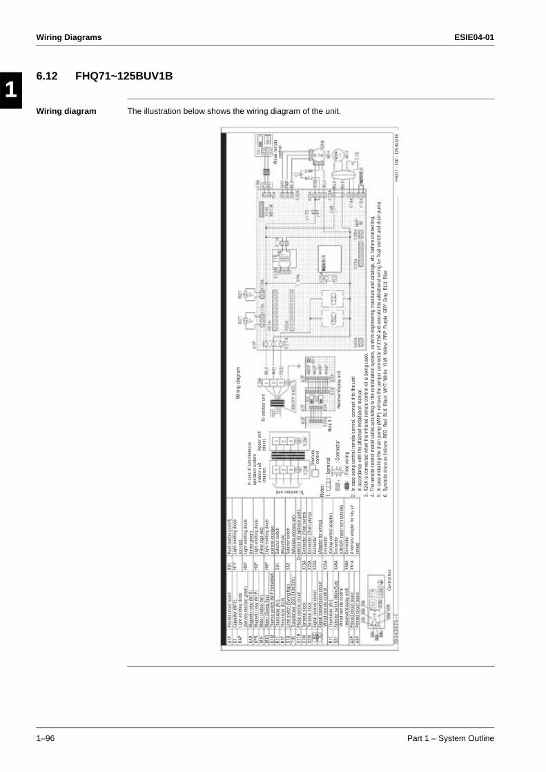
Wiring Diagrams ESIE04-01
1–96 Part 1 – System Outline
3
11
4
5
6.12 FHQ71~125BUV1B
Wiring diagram The illustration below shows the wiring diagram of the unit.
A1P
C1 HAP
KAR
KPR
M1F
M1S
Q1M
R1T
R2T
S1Q
T1R
V1TR
X1M
X2M RC TC
R1T
SS1
A2P
A3P
Prin
ted
circ
uit b
oard
Capa
cito
r (M
1F)
Ligh
t em
ittin
g di
ode
(Ser
vice
mon
itor g
reen
)M
agne
tic re
lay
(M1S
)M
agne
tic re
lay
(M1P
)M
otor
(Ind
oor f
an)
Mot
or (S
win
g fla
p)Th
erm
o sw
itch
(M1F
Em
bedd
ed)
Ther
mis
tor (
Air)
Ther
mis
tor (
Coil)
Lim
it sw
itch
(Sw
ing
flap)
Tran
sfor
mer
(220
-240
V/22
V)Ph
ase
cont
rol c
ircui
tTe
rmin
al b
lock
Term
inal
blo
ckSi
gnal
rece
iver
circ
uit
Sign
al tr
ansm
issi
on c
ircui
t
Ther
mis
tor (
Air)
Sele
ctor
sw
itch
(Mai
n/Su
b)
Prin
ted
circ
uit b
oard
Prin
ted
circ
uit b
oard
BS1
H1P
H2P
H3P
H4P
SS1
SS2
X15A
X25A
X33A
X35A
X40A
X60A
X61A
Push
but
ton
(on/
off)
Ligh
t em
ittin
g di
ode
(on-
red)
Ligh
t em
ittin
g di
ode
(tim
er-g
reen
)Li
ght e
mitt
ing
diod
e (F
ilter
sig
n-re
d)Li
ght e
mitt
ing
diod
e (d
efro
st-o
rang
e)Se
lect
or s
witc
h (M
ain/
Sub)
Sele
ctor
sw
itch
(Wire
less
add
ress
set
)
Conn
ecto
r (Fl
oat s
witc
h)Co
nnec
tor (
Drai
n pu
mp)
Conn
ecto
r(A
dapt
er fo
r wiri
ng)
Conn
ecto
r(G
roup
con
trol a
dapt
er)
Conn
ecto
r(O
N/OF
F in
put f
rom
out
side
)Co
nnec
tor
(Inte
rfac
e ad
epte
r for
sky
air
serie
s)
Conn
ecto
r for
opt
iona
l par
ts
Wire
d re
mot
e co
ntro
l (r
ecei
ver/
disp
lay
unit)
Wire
d re
mot
e co
ntro
lNo
tes:
1.
: Ter
min
al
: C
onne
ctor
: F
ield
wiri
ng2.
In
case
usi
ng c
entra
l rem
ote
cont
rol,
conn
ect i
t to
the
unit
in
acc
orda
nce
with
the
atta
ched
inst
alla
tion
man
ual.
3. X
24A
is c
onne
cted
whe
n th
e in
frare
d re
mot
e co
ntro
l kit
is b
eing
use
d.4.
The
rem
ote
cont
rol m
odel
var
ies
acco
rdin
g to
the
com
bina
tion
syst
em, c
onfir
m e
ngin
eerin
g m
ater
ials
and
cat
alog
s, e
tc. b
efor
e co
nnec
ting.
5. I
n ca
se in
stal
ling
the
drai
n pu
mp
(M1P
), re
mov
e th
e ju
mpe
r con
nect
or o
f X15
A an
d ex
ecut
e th
e ad
diat
iona
l wiri
ng fo
r flo
at s
witc
h an
d dr
ain
pum
p.6.
Sym
bols
sho
w a
s fo
llow
s: R
ED: R
ed B
LK: B
lack
WHT
: Whi
te Y
LW: Y
ello
w P
RP: P
urpl
e G
RY: G
ray
BLU
: Blu
eCo
ntro
l box
Wiri
ng d
iagr
am
In c
ase
of s
imul
tane
ous
oper
atio
n sy
stem
Indo
or u
nit
(mas
ter)
Indo
or u
nit
(sla
ve)
To outdoor unit
To o
utdo
or u
nit
Rec
eive
r/di
spla
y un
it
Rem
ote
cont
rol
Not
e 3
Wire
d re
mot
e co
ntro
l
FHQ
71 -
100
- 125
BU
V1B
Not
e 5
Not
e 5
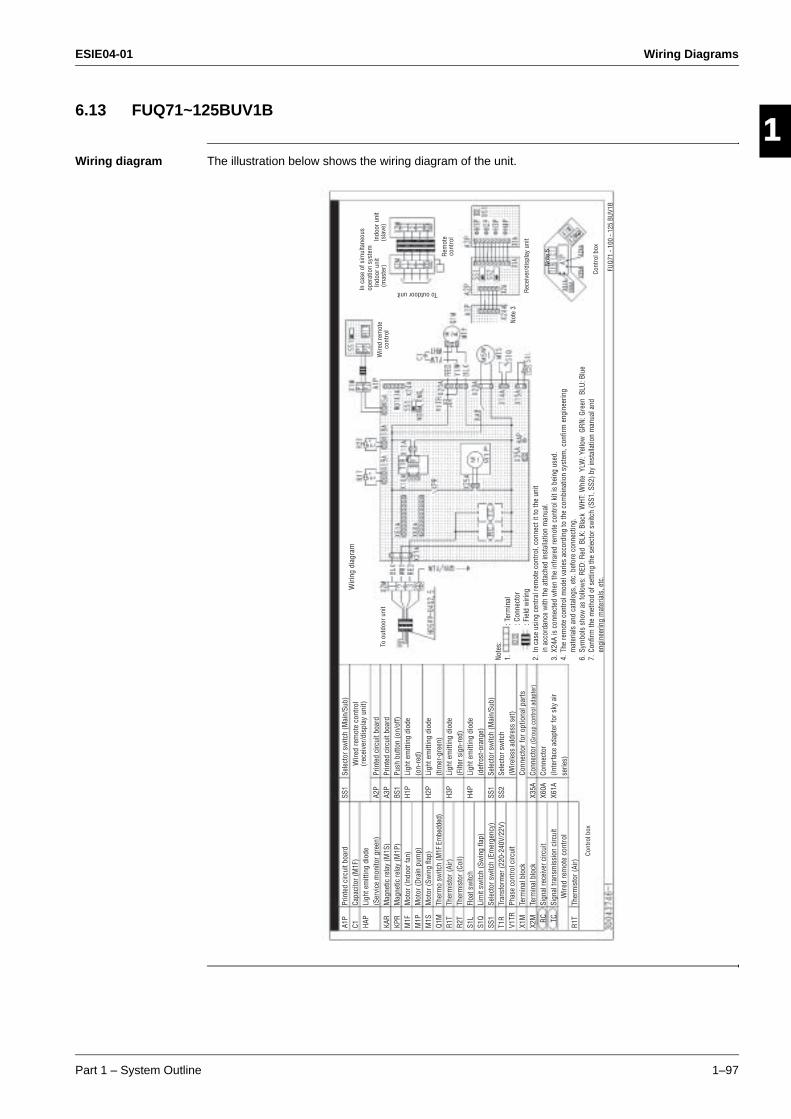
ESIE04-01 Wiring Diagrams
Part 1 – System Outline 1–97
3
1
4
5
6.13 FUQ71~125BUV1B
Wiring diagram The illustration below shows the wiring diagram of the unit.
A1P
C1 HAP
KAR
KPR
M1F
M1P
M1S
Q1M
R1T
R2T
S1L
S1Q
SS1
T1R
V1TR
X1M
X2M RC TC
R1T
Prin
ted
circ
uit b
oard
Capa
cito
r (M
1F)
Ligh
t em
ittin
g di
ode
(Ser
vice
mon
itor g
reen
)M
agne
tic re
lay
(M1S
)M
agne
tic re
lay
(M1P
)M
otor
(Ind
oor f
an)
Mot
or (D
rain
pum
p)M
otor
(Sw
ing
flap)
Ther
mo
switc
h (M
1F E
mbe
dded
)Th
erm
isto
r (Ai
r)Th
erm
isto
r (Co
il)Fl
oat s
witc
hLi
mit
switc
h (S
win
g fla
p)Se
lect
or s
witc
h (E
mer
genc
y)Tr
ansf
orm
er (2
20-2
40V/
22V)
Phas
e co
ntro
l circ
uit
Term
inal
blo
ckTe
rmin
al b
lock
Sign
al re
ceiv
er c
ircui
tSi
gnal
tran
smis
sion
circ
uit
Ther
mis
tor (
Air)
Conn
ecto
r for
opt
iona
l par
ts
Wire
d re
mot
e co
ntro
l (r
ecei
ver/
disp
lay
unit)
Wire
d re
mot
e co
ntro
l
SS1
A2P
A3P
BS1
H1P
H2P
H3P
H4P
SS1
SS2
X35A
X60A
X61A
Sele
ctor
sw
itch
(Mai
n/Su
b)
Prin
ted
circ
uit b
oard
Prin
ted
circ
uit b
oard
Push
but
ton
(on/
off)
Ligh
t em
ittin
g di
ode
(on-
red)
Ligh
t em
ittin
g di
ode
(tim
er-g
reen
)Li
ght e
mitt
ing
diod
e (F
ilter
sig
n-re
d)Li
ght e
mitt
ing
diod
e (d
efro
st-o
rang
e)Se
lect
or s
witc
h (M
ain/
Sub)
Sele
ctor
sw
itch
(Wire
less
add
ress
set
)
Conn
ecto
r (Gr
oup
cont
rol a
dapt
er)
Conn
ecto
r(In
terf
ace
adap
ter f
or s
ky a
ir se
ries)
Note
s:1.
: T
erm
inal
: C
onne
ctor
: F
ield
wiri
ng2.
In
case
usi
ng c
entra
l rem
ote
cont
rol,
conn
ect i
t to
the
unit
in
acc
orda
nce
with
the
atta
ched
inst
alla
tion
man
ual.
3. X
24A
is c
onne
cted
whe
n th
e in
frare
d re
mot
e co
ntro
l kit
is b
eing
use
d.4.
The
rem
ote
cont
rol m
odel
var
ies
acco
rdin
g to
the
com
bina
tion
syst
em, c
onfir
m e
ngin
eerin
g m
ater
ials
and
cat
alog
s, e
tc. b
efor
e co
nnec
ting.
6. S
ymbo
ls s
how
as
follo
ws:
RED
: Red
BLK
: Bla
ck W
HT: W
hite
YLW
: Yel
low
GRN
: Gre
en B
LU: B
lue
7. C
onfir
m th
e m
etho
d of
set
ting
the
sele
ctor
sw
itch
(SS1
, SS2
) by
inst
alla
tion
man
ual a
nd
engi
neer
ing
mat
eria
ls, e
tc.
Cont
rol b
ox
Wiri
ng d
iagr
am
To o
utdo
or u
nit
To outdoor unit
Wire
d re
mot
e co
ntro
l
Rem
ote
cont
rol
FUQ
71 -
100
- 125
BU
V1B
Not
e 5
In c
ase
of s
imul
tane
ous
oper
atio
n sy
stem
Indo
or u
nit
(mas
ter)
Indo
or u
nit
(sla
ve)
Rec
eive
r/di
spla
y un
it
Cont
rol b
ox
Not
e 3
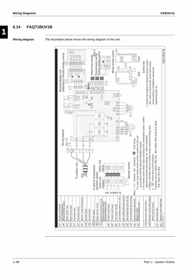
Wiring Diagrams ESIE04-01
1–98 Part 1 – System Outline
3
11
4
5
6.14 FAQ71BUV1B
Wiring diagram The illustration below shows the wiring diagram of the unit.
A1P
HAP
M1F
M1S
R1T
R2T
SS1
X1M
X2M PS RC TC A2P
A3P
BS1
H1P
H2P
H3P
H4P
SS1
SS2
X15A
X35A
R1T
SS1
Prin
ted
circ
uit b
oard
Ligh
t em
ittin
g di
ode
(Ser
vice
mon
itor g
reen
)M
otor
(Ind
oor f
an)
Mot
or (S
win
g fla
p)
Ther
mis
tor (
Air)
Ther
mis
tor (
Coil)
Sele
ctor
sw
itch
(Em
erge
ncy)
Term
inal
blo
ck
Term
inal
blo
ck
Pow
er s
uppl
y
Sign
al re
ceiv
er c
ircui
t
Sign
al tr
ansm
issi
on c
ircui
t
Prin
ted
circ
uit b
oard
Prin
ted
circ
uit b
oard
Push
but
ton
(on/
off)
Ligh
t em
ittin
g di
ode
(on-
red)
Ligh
t em
ittin
g di
ode (
timer
-gre
en)
Light
emitt
ing di
ode (
Filter
sign
-red)
Light
emitt
ing di
ode (
defro
st-or
ange
)
Sele
ctor
sw
itch
(Mai
n/Su
b)Se
lect
or s
witc
h (W
irele
ss a
ddre
ss s
et)
Conn
ecto
r (Fl
oat s
witc
h)
Conn
ecto
r (Gr
oup
cont
rol a
dapt
er)
Ther
mis
tor (
Air)
Sele
ctor
sw
itch
(Mai
n/Su
b)
Infr
ared
rem
ote
cont
rol
(Rec
eive
r/D
ispl
ay u
nit)
Wire
d re
mot
e co
ntro
l
1.
: Ter
min
al
: Con
nect
or
: Fie
ld w
iring
2. In
cas
e us
ing
cent
ral r
emot
e co
ntro
l, co
nnec
t it t
o th
e un
it
in a
ccor
danc
e w
ith th
e at
tach
ed in
stal
latio
n m
anua
l.3.
The
rem
ote
cont
rol m
odel
var
ies
acco
rdin
g to
the
com
bina
tion
syst
em, c
onfir
m
engi
neer
ing
mat
eria
ls a
nd c
atal
ogs,
etc
. bef
ore
conn
ectin
g.4.
X24
A is
con
nect
ed w
hen
the
infra
red
rem
ote
cont
rol k
it is
bei
ng u
sed.
5.
show
s sh
ort c
ircui
t con
nect
or.
6. S
ymbo
ls s
how
as
follo
ws:
RED
: Red
W
HT: W
hite
GRN
: Gre
en B
LK: B
lack
YL
W: Y
ello
w B
LU: B
lue
Note
s:
7. C
onfir
m th
e m
etho
d of
set
ting
the
sele
ctor
sw
itch
(SS1
, SS2
) of w
ired
rem
ote
cont
rol a
nd in
frare
d re
mot
e co
ntro
l by
inst
alla
tion
man
ual a
nd
engi
neer
ing
data
, etc
.
Wiri
ng d
iagr
am
To o
utdo
or u
nit
To outdoor unit
Wire
d re
mot
e co
ntro
l
Rem
ote
cont
rol
FAQ
71BU
V1B
Side
In c
ase
of s
imul
tane
ous
oper
atio
n sy
stem
Indo
or u
nit
(mas
ter)
Indo
or u
nit
(sla
ve)
Rec
eive
r/di
spla
y un
it(A
ttach
ed to
infr
ared
rem
ote
cont
rol)
Fron
t
Cont
rol b
ox
Not
e 2
Not
e 4
Inpu
t fro
m o
utsi
de
Tran
smis
sion
wiri
ng
cent
ral r
emot
e co
ntro
l
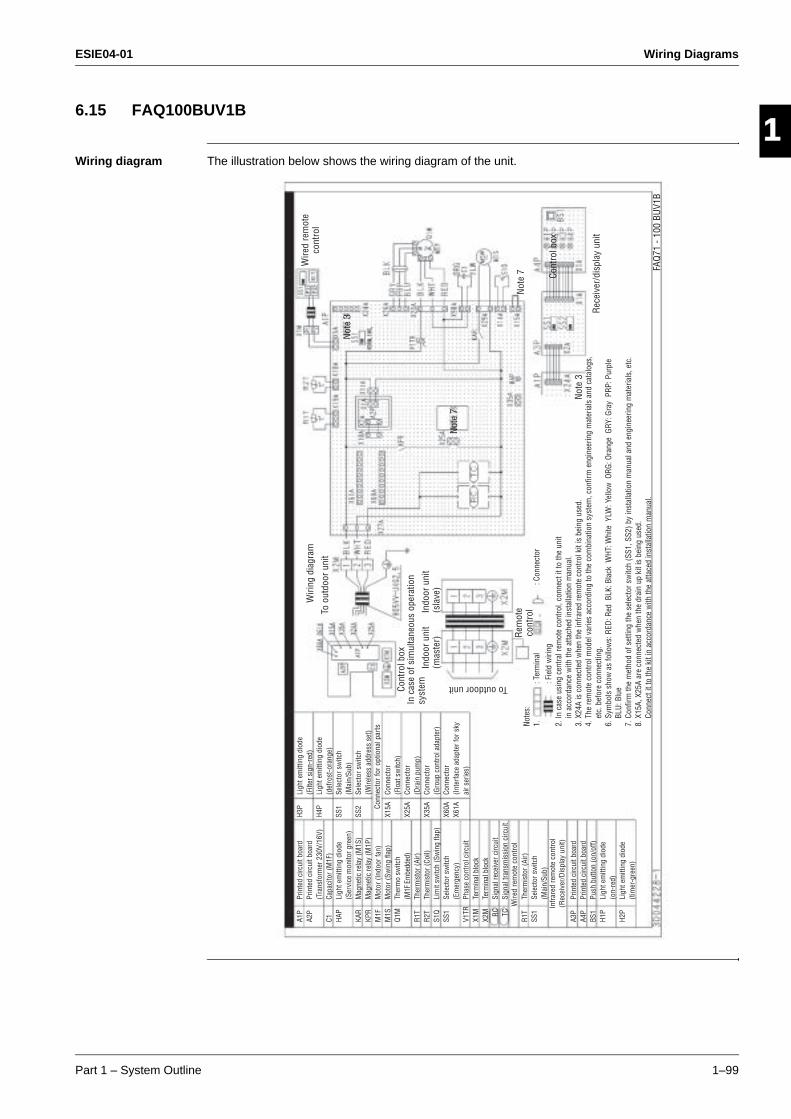
ESIE04-01 Wiring Diagrams
Part 1 – System Outline 1–99
3
1
4
5
6.15 FAQ100BUV1B
Wiring diagram The illustration below shows the wiring diagram of the unit.
A1P
A2P
C1 HAP
KAR
KPR
M1F
M1S
Q1M
R1T
R2T
S1Q
SS1
V1TR
X1M
X2M RC TC
R1T
SS1
A3P
A4P
BS1
H1P
H2P
Prin
ted
circ
uit b
oard
Prin
ted
circ
uit b
oard
(Tra
nsfo
rmer
230
V/16
V)Ca
paci
tor (
M1F
)Li
ght e
mitt
ing
diod
e (S
ervi
ce m
onito
r gre
en)
Mag
netic
rela
y (M
1S)
Mag
netic
rela
y (M
1P)
Mot
or (I
ndoo
r fan
)M
otor
(Sw
ing
flap)
Ther
mo
switc
h(M
1F E
mbe
dded
)Th
erm
isto
r (Ai
r)Th
erm
isto
r (Co
il)Li
mit
switc
h (S
win
g fla
p)Se
lect
or s
witc
h (E
mer
genc
y)Ph
ase
cont
rol c
ircui
tTe
rmin
al b
lock
Term
inal
blo
ckSi
gnal
rece
iver
circ
uit
Sign
al tr
ansm
issi
on c
ircui
t
Ther
mis
tor (
Air)
Sele
ctor
sw
itch
(Mai
n/Su
b)
Prin
ted
circ
uit b
oard
Prin
ted
circ
uit b
oard
Push
but
ton
(on/
off)
Ligh
t em
ittin
g di
ode
(on-
red)
Ligh
t em
ittin
g di
ode
(tim
er-g
reen
)
Conn
ecto
r for
opt
iona
l par
ts
Wire
d re
mot
e co
ntro
l
Infr
ared
rem
ote
cont
rol
(Rec
eive
r/D
ispl
ay u
nit)
H3P
H4P
SS1
SS2
X15A
X25A
X35A
X60A
X61A
Ligh
t em
ittin
g di
ode
(Filt
er s
ign-
red)
Ligh
t em
ittin
g di
ode
(def
rost
-ora
nge)
Sele
ctor
sw
itch
(Mai
n/Su
b)Se
lect
or s
witc
h(W
irele
ss a
ddre
ss s
et)
Conn
ecto
r (F
loat
sw
itch)
Conn
ecto
r(D
rain
pum
p)Co
nnec
tor
(Gro
up c
ontro
l ada
pter
)Co
nnec
tor
(Inte
rfac
e ad
apte
r for
sky
ai
r ser
ies)
Note
s:1.
: T
erm
inal
: C
onne
ctor
: F
ield
wiri
ng2.
In c
ase
usin
g ce
ntra
l rem
ote
cont
rol,
conn
ect i
t to
the
unit
in
acc
orda
nce
with
the
atta
ched
inst
alla
tion
man
ual.
3. X
24A
is c
onne
cted
whe
n th
e in
frare
d re
mot
e co
ntro
l kit
is b
eing
use
d.4.
The
rem
ote
cont
rol m
odel
var
ies
acco
rdin
g to
the
com
bina
tion
syst
em, c
onfir
m e
ngin
eerin
g m
ater
ials
and
cat
alog
s,
etc.
bef
ore
conn
ectin
g.6.
Sym
bols
sho
w a
s fo
llow
s: R
ED: R
ed B
LK: B
lack
WHT
: Whi
te Y
LW: Y
ello
w O
RG: O
rang
e G
RY: G
ray
PRP
: Pur
ple
BL
U: B
lue
7. C
onfir
m th
e m
etho
d of
set
ting
the
sele
ctor
sw
itch
(SS1
, SS2
) by
inst
alla
tion
man
ual a
nd e
ngin
eerin
g m
ater
ials
, etc
.8.
X15
A, X
25A
are
conn
ecte
d w
hen
the
drai
n up
kit
is b
eing
use
d.
Conn
ect i
t to
the
kit i
n ac
cord
ance
with
the
atta
ced
inst
alla
tion
man
ual.
Wiri
ng d
iagr
am
To o
utdo
or u
nit
To outdoor unit
Wire
d re
mot
e co
ntro
l
Rem
ote
cont
rol
Cont
rol b
ox
FAQ
71 -
100
BUV1
B
Not
e 7
Not
e 7
In c
ase
of s
imul
tane
ous
oper
atio
n sy
stem
Indo
or u
nit
(mas
ter)
Indo
or u
nit
(sla
ve)
Rec
eive
r/di
spla
y un
it
Cont
rol b
ox
Not
e 3
Not
e 3

Wiring Diagrams ESIE04-01
1–100 Part 1 – System Outline
3
11
4
5
ESIE04-01 PCB Layout
Part 1 – System Outline 1–101
3
4
5
1Part 1
7 PCB Layout
7.1 What Is in This Chapter?
Introduction This chapter contains the following information:
It describes which unit uses which PCB types
It shows the PCB connectors.
Outdoor units This chapter contains the following PCB layouts:
Indoor units This chapter contains the following PCB layouts:
PCB layout See page
7.2–RZQ71B7V3B 1–102
7.3–RZQ100B7V3B 1–104
PCB layout See page
7.4–FCQ35~60B7V1 1–106
7.5–FCQ71~125B7V3B 1–107
7.6–FFQ35~60BV1B 1–108
7.7–FBQ35~60B7V1 1–109
7.8–FBQ100~125B7V3B 1–110
7.9–FDQ125B7V3B 1–111
7.10–FHQ35~60BUV1 1–112
7.11–FHQ71~125BUV1B 1–113
7.12–FUQ71~125BUV1B 1–114
7.13–FAQ71BUV1B 1–115
7.14–FAQ100BUV1B 1–116
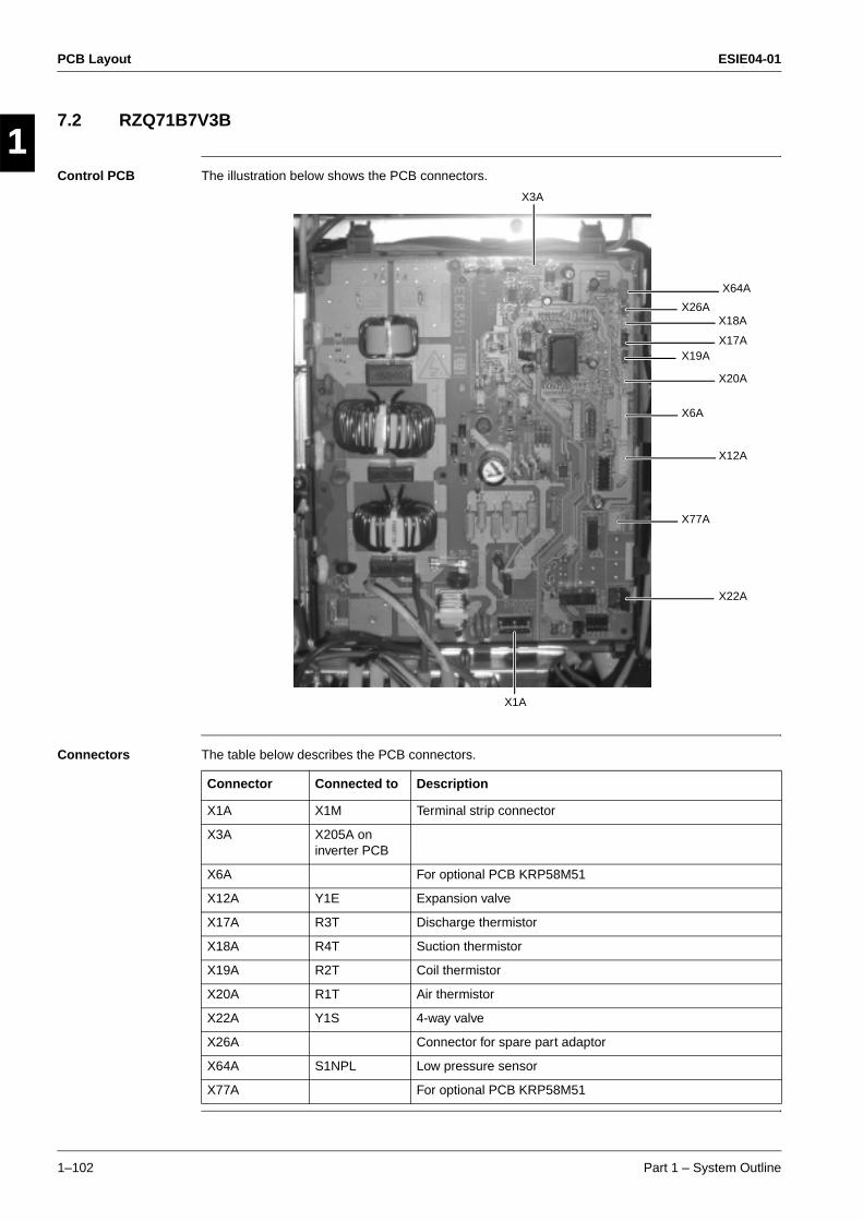
PCB Layout ESIE04-01
1–102 Part 1 – System Outline
3
11
4
5
7.2 RZQ71B7V3B
Control PCB The illustration below shows the PCB connectors.
Connectors The table below describes the PCB connectors.
X64A
X18A
X17AX19A
X20A
X6A
X12A
X77A
X22A
X1A
X3A
X26A
Connector Connected to Description
X1A X1M Terminal strip connector
X3A X205A on inverter PCB
X6A For optional PCB KRP58M51
X12A Y1E Expansion valve
X17A R3T Discharge thermistor
X18A R4T Suction thermistor
X19A R2T Coil thermistor
X20A R1T Air thermistor
X22A Y1S 4-way valve
X26A Connector for spare part adaptor
X64A S1NPL Low pressure sensor
X77A For optional PCB KRP58M51
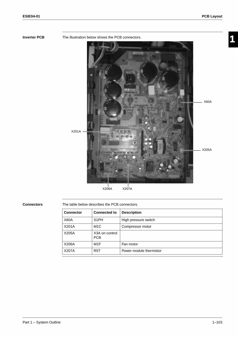
ESIE04-01 PCB Layout
Part 1 – System Outline 1–103
3
1
4
5
Inverter PCB The illustration below shows the PCB connectors.
Connectors The table below describes the PCB connectors.
X60A
X205A
X201A
X206A X207A
Connector Connected to Description
X60A S1PH High pressure switch
X201A M1C Compressor motor
X205A X3A on control PCB
X206A M1F Fan motor
X207A R5T Power module thermistor
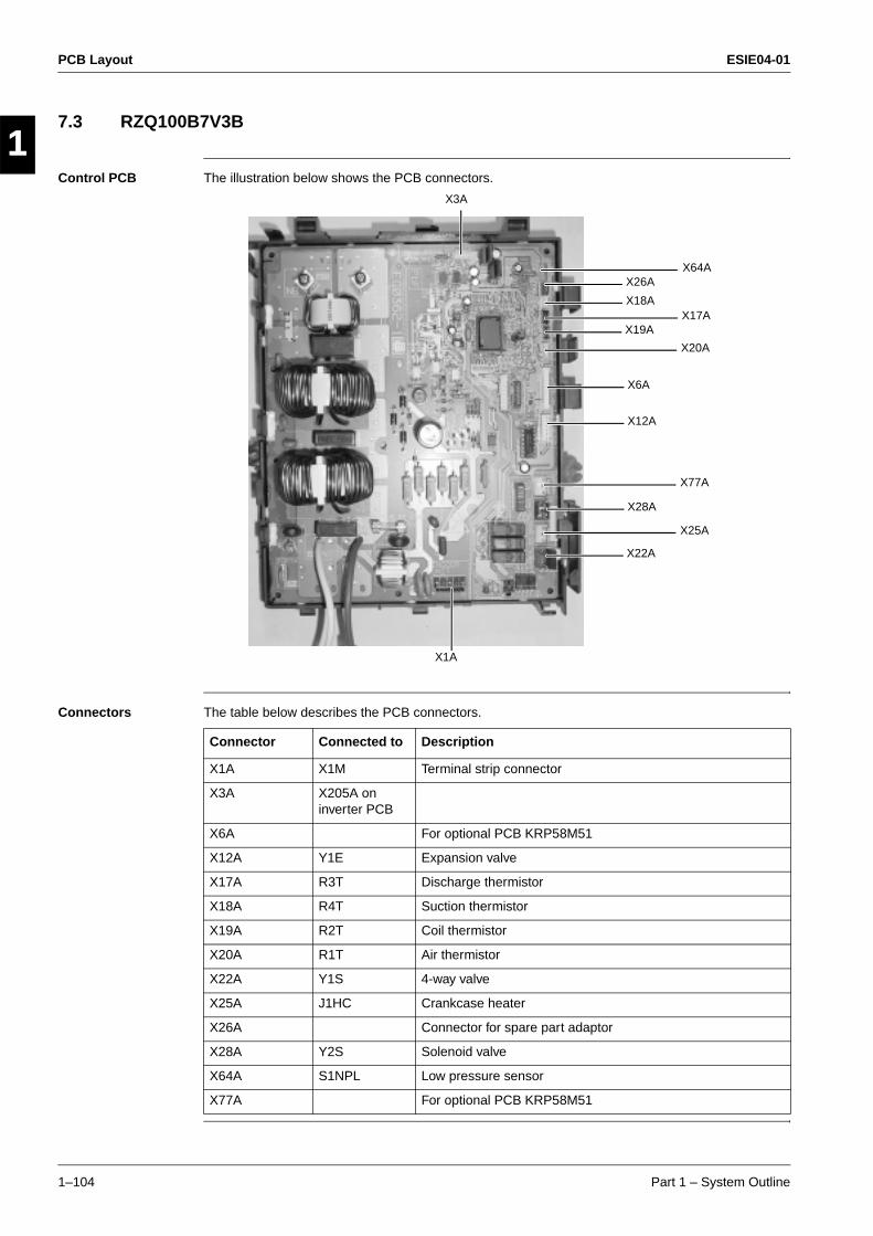
PCB Layout ESIE04-01
1–104 Part 1 – System Outline
3
11
4
5
7.3 RZQ100B7V3B
Control PCB The illustration below shows the PCB connectors.
Connectors The table below describes the PCB connectors.
X1A
X3A
X64A
X18AX17A
X19A
X20A
X6A
X12A
X77A
X28A
X25A
X22A
X26A
Connector Connected to Description
X1A X1M Terminal strip connector
X3A X205A on inverter PCB
X6A For optional PCB KRP58M51
X12A Y1E Expansion valve
X17A R3T Discharge thermistor
X18A R4T Suction thermistor
X19A R2T Coil thermistor
X20A R1T Air thermistor
X22A Y1S 4-way valve
X25A J1HC Crankcase heater
X26A Connector for spare part adaptor
X28A Y2S Solenoid valve
X64A S1NPL Low pressure sensor
X77A For optional PCB KRP58M51
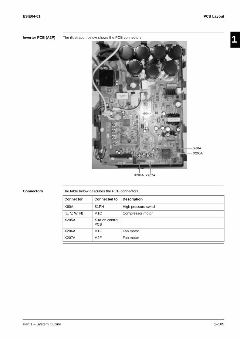
ESIE04-01 PCB Layout
Part 1 – System Outline 1–105
3
1
4
5
Inverter PCB (A2P) The illustration below shows the PCB connectors.
Connectors The table below describes the PCB connectors.
X207A
X205A
X206A
X60A
Connector Connected to Description
X60A S1PH High pressure switch
(U, V, W, N) M1C Compressor motor
X205A X3A on control PCB
X206A M1F Fan motor
X207A M2F Fan motor
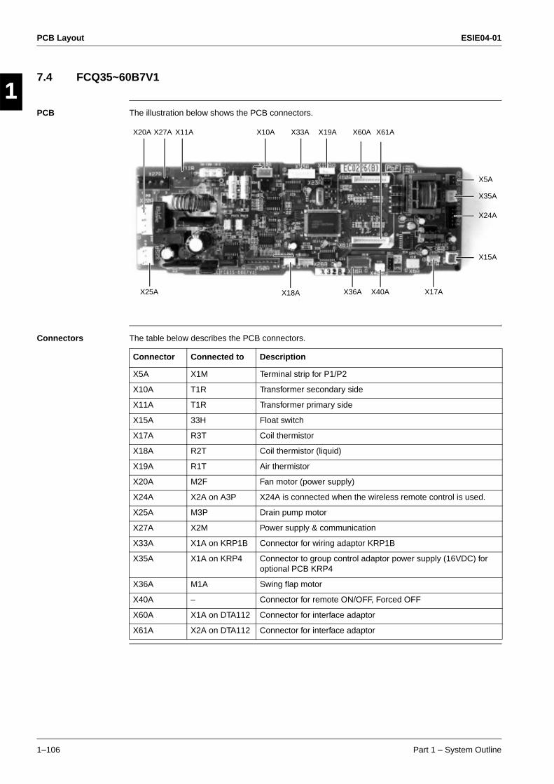
PCB Layout ESIE04-01
1–106 Part 1 – System Outline
3
11
4
5
7.4 FCQ35~60B7V1
PCB The illustration below shows the PCB connectors.
Connectors The table below describes the PCB connectors.
X11A
X5A
X10A X33A X19A
X40A X17AX36AX25A
X35A
X24A
X15A
X20A X27A
X18A
X60A X61A
Connector Connected to Description
X5A X1M Terminal strip for P1/P2
X10A T1R Transformer secondary side
X11A T1R Transformer primary side
X15A 33H Float switch
X17A R3T Coil thermistor
X18A R2T Coil thermistor (liquid)
X19A R1T Air thermistor
X20A M2F Fan motor (power supply)
X24A X2A on A3P X24A is connected when the wireless remote control is used.
X25A M3P Drain pump motor
X27A X2M Power supply & communication
X33A X1A on KRP1B Connector for wiring adaptor KRP1B
X35A X1A on KRP4 Connector to group control adaptor power supply (16VDC) for optional PCB KRP4
X36A M1A Swing flap motor
X40A – Connector for remote ON/OFF, Forced OFF
X60A X1A on DTA112 Connector for interface adaptor
X61A X2A on DTA112 Connector for interface adaptor
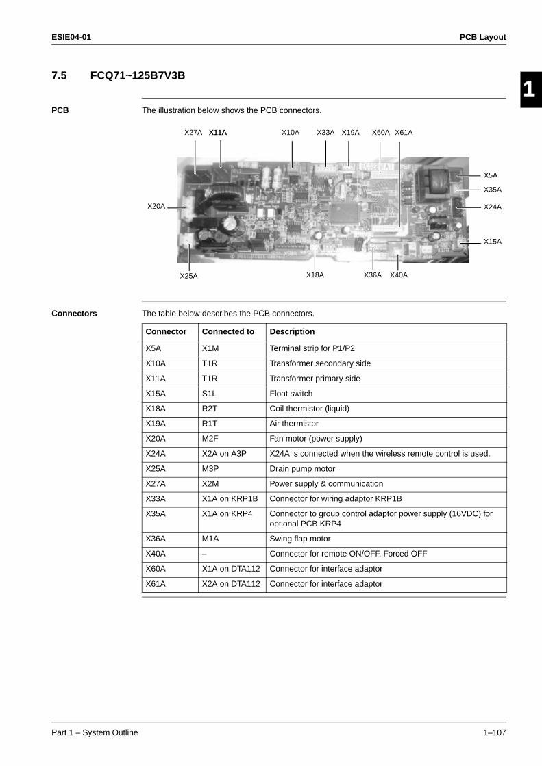
ESIE04-01 PCB Layout
Part 1 – System Outline 1–107
3
1
4
5
7.5 FCQ71~125B7V3B
PCB The illustration below shows the PCB connectors.
Connectors The table below describes the PCB connectors.
X11A
X5A
X10A X19A
X40AX18AX25A
X35A
X24A
X15A
X27A
X36A
X20A
X33A X60A X61AX11A
Connector Connected to Description
X5A X1M Terminal strip for P1/P2
X10A T1R Transformer secondary side
X11A T1R Transformer primary side
X15A S1L Float switch
X18A R2T Coil thermistor (liquid)
X19A R1T Air thermistor
X20A M2F Fan motor (power supply)
X24A X2A on A3P X24A is connected when the wireless remote control is used.
X25A M3P Drain pump motor
X27A X2M Power supply & communication
X33A X1A on KRP1B Connector for wiring adaptor KRP1B
X35A X1A on KRP4 Connector to group control adaptor power supply (16VDC) for optional PCB KRP4
X36A M1A Swing flap motor
X40A – Connector for remote ON/OFF, Forced OFF
X60A X1A on DTA112 Connector for interface adaptor
X61A X2A on DTA112 Connector for interface adaptor
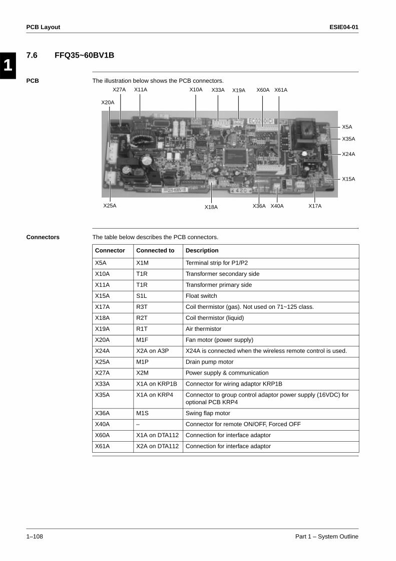
PCB Layout ESIE04-01
1–108 Part 1 – System Outline
3
11
4
5
7.6 FFQ35~60BV1B
PCB The illustration below shows the PCB connectors.
Connectors The table below describes the PCB connectors.
X11A
X5A
X10A X33A X19A
X40A X17AX36AX18A
X35A
X24A
X15A
X27A
X20A
X25A
X60A X61A
Connector Connected to Description
X5A X1M Terminal strip for P1/P2
X10A T1R Transformer secondary side
X11A T1R Transformer primary side
X15A S1L Float switch
X17A R3T Coil thermistor (gas). Not used on 71~125 class.
X18A R2T Coil thermistor (liquid)
X19A R1T Air thermistor
X20A M1F Fan motor (power supply)
X24A X2A on A3P X24A is connected when the wireless remote control is used.
X25A M1P Drain pump motor
X27A X2M Power supply & communication
X33A X1A on KRP1B Connector for wiring adaptor KRP1B
X35A X1A on KRP4 Connector to group control adaptor power supply (16VDC) for optional PCB KRP4
X36A M1S Swing flap motor
X40A – Connector for remote ON/OFF, Forced OFF
X60A X1A on DTA112 Connection for interface adaptor
X61A X2A on DTA112 Connection for interface adaptor
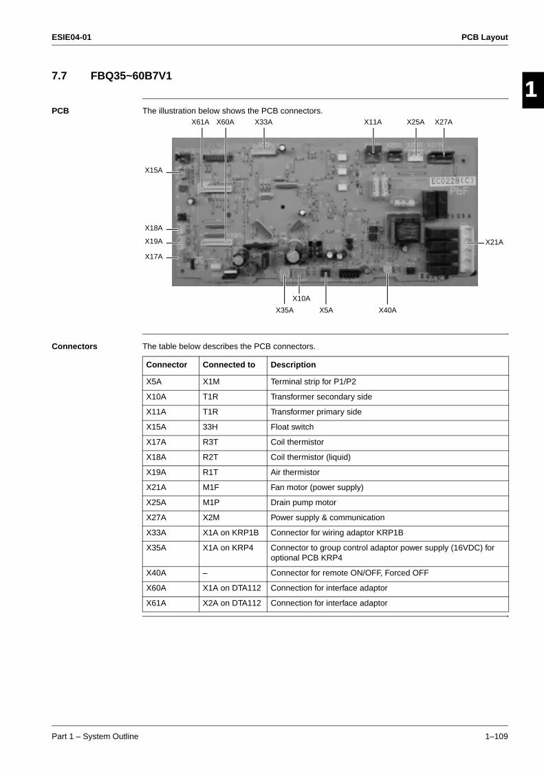
ESIE04-01 PCB Layout
Part 1 – System Outline 1–109
3
1
4
5
7.7 FBQ35~60B7V1
PCB The illustration below shows the PCB connectors.
Connectors The table below describes the PCB connectors.
X61A
X18A
X19A
X15A
X60A X11A X25A X27A
X35A X40A
X10A
X33A
X21A
X17A
X5A
Connector Connected to Description
X5A X1M Terminal strip for P1/P2
X10A T1R Transformer secondary side
X11A T1R Transformer primary side
X15A 33H Float switch
X17A R3T Coil thermistor
X18A R2T Coil thermistor (liquid)
X19A R1T Air thermistor
X21A M1F Fan motor (power supply)
X25A M1P Drain pump motor
X27A X2M Power supply & communication
X33A X1A on KRP1B Connector for wiring adaptor KRP1B
X35A X1A on KRP4 Connector to group control adaptor power supply (16VDC) for optional PCB KRP4
X40A – Connector for remote ON/OFF, Forced OFF
X60A X1A on DTA112 Connection for interface adaptor
X61A X2A on DTA112 Connection for interface adaptor
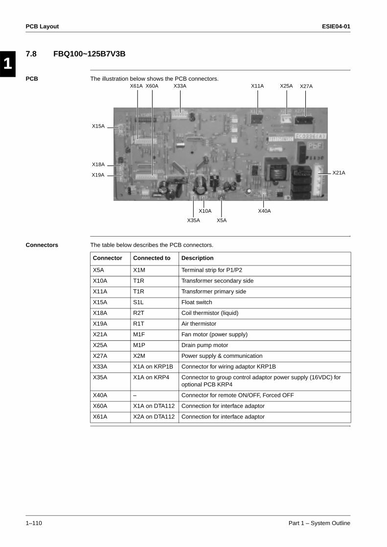
PCB Layout ESIE04-01
1–110 Part 1 – System Outline
3
11
4
5
7.8 FBQ100~125B7V3B
PCB The illustration below shows the PCB connectors.
Connectors The table below describes the PCB connectors.
X61A
X18A
X19A
X15A
X60A X33A X25A
X40A
X35A X5A
X10A
X11A X27A
X21A
Connector Connected to Description
X5A X1M Terminal strip for P1/P2
X10A T1R Transformer secondary side
X11A T1R Transformer primary side
X15A S1L Float switch
X18A R2T Coil thermistor (liquid)
X19A R1T Air thermistor
X21A M1F Fan motor (power supply)
X25A M1P Drain pump motor
X27A X2M Power supply & communication
X33A X1A on KRP1B Connector for wiring adaptor KRP1B
X35A X1A on KRP4 Connector to group control adaptor power supply (16VDC) for optional PCB KRP4
X40A – Connector for remote ON/OFF, Forced OFF
X60A X1A on DTA112 Connection for interface adaptor
X61A X2A on DTA112 Connection for interface adaptor
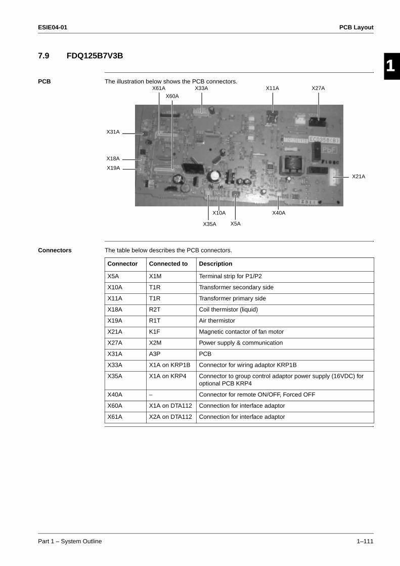
ESIE04-01 PCB Layout
Part 1 – System Outline 1–111
3
1
4
5
7.9 FDQ125B7V3B
PCB The illustration below shows the PCB connectors.
Connectors The table below describes the PCB connectors.
X18A
X19A
X31A
X61A X33A X11A X27A
X21A
X40AX10A
X5AX35A
X60A
Connector Connected to Description
X5A X1M Terminal strip for P1/P2
X10A T1R Transformer secondary side
X11A T1R Transformer primary side
X18A R2T Coil thermistor (liquid)
X19A R1T Air thermistor
X21A K1F Magnetic contactor of fan motor
X27A X2M Power supply & communication
X31A A3P PCB
X33A X1A on KRP1B Connector for wiring adaptor KRP1B
X35A X1A on KRP4 Connector to group control adaptor power supply (16VDC) for optional PCB KRP4
X40A – Connector for remote ON/OFF, Forced OFF
X60A X1A on DTA112 Connection for interface adaptor
X61A X2A on DTA112 Connection for interface adaptor
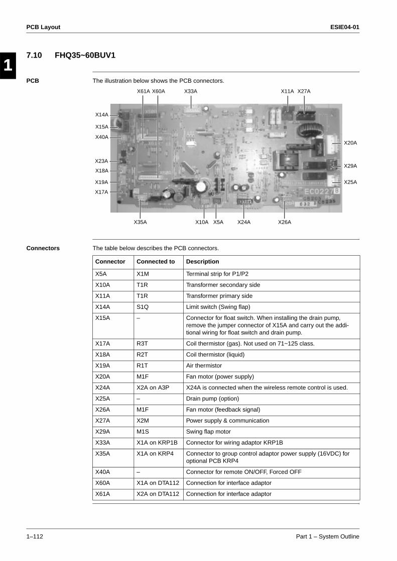
PCB Layout ESIE04-01
1–112 Part 1 – System Outline
3
11
4
5
7.10 FHQ35~60BUV1
PCB The illustration below shows the PCB connectors.
Connectors The table below describes the PCB connectors.
X61A
X18A
X19A
X15A
X33A X11A
X35A
X14A
X40A
X17A
X10A X5A X24A X26A
X60A X27A
X29A
X20A
X25A
X23A
Connector Connected to Description
X5A X1M Terminal strip for P1/P2
X10A T1R Transformer secondary side
X11A T1R Transformer primary side
X14A S1Q Limit switch (Swing flap)
X15A – Connector for float switch. When installing the drain pump, remove the jumper connector of X15A and carry out the addi-tional wiring for float switch and drain pump.
X17A R3T Coil thermistor (gas). Not used on 71~125 class.
X18A R2T Coil thermistor (liquid)
X19A R1T Air thermistor
X20A M1F Fan motor (power supply)
X24A X2A on A3P X24A is connected when the wireless remote control is used.
X25A – Drain pump (option)
X26A M1F Fan motor (feedback signal)
X27A X2M Power supply & communication
X29A M1S Swing flap motor
X33A X1A on KRP1B Connector for wiring adaptor KRP1B
X35A X1A on KRP4 Connector to group control adaptor power supply (16VDC) for optional PCB KRP4
X40A – Connector for remote ON/OFF, Forced OFF
X60A X1A on DTA112 Connection for interface adaptor
X61A X2A on DTA112 Connection for interface adaptor
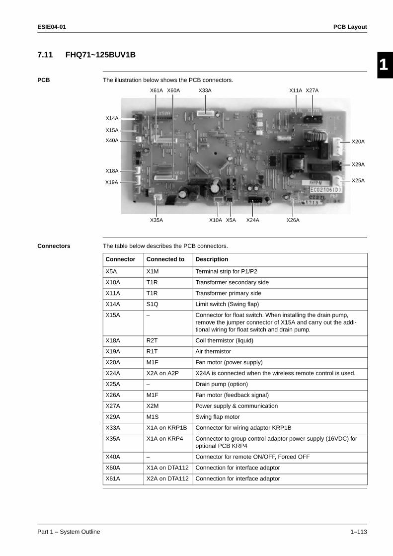
ESIE04-01 PCB Layout
Part 1 – System Outline 1–113
3
1
4
5
7.11 FHQ71~125BUV1B
PCB The illustration below shows the PCB connectors.
Connectors The table below describes the PCB connectors.
X61A
X18A
X19A
X15A
X33A X11A
X35A
X14A
X40A
X10A X5A X24A X26A
X60A X27A
X29A
X20A
X25A
Connector Connected to Description
X5A X1M Terminal strip for P1/P2
X10A T1R Transformer secondary side
X11A T1R Transformer primary side
X14A S1Q Limit switch (Swing flap)
X15A – Connector for float switch. When installing the drain pump, remove the jumper connector of X15A and carry out the addi-tional wiring for float switch and drain pump.
X18A R2T Coil thermistor (liquid)
X19A R1T Air thermistor
X20A M1F Fan motor (power supply)
X24A X2A on A2P X24A is connected when the wireless remote control is used.
X25A – Drain pump (option)
X26A M1F Fan motor (feedback signal)
X27A X2M Power supply & communication
X29A M1S Swing flap motor
X33A X1A on KRP1B Connector for wiring adaptor KRP1B
X35A X1A on KRP4 Connector to group control adaptor power supply (16VDC) for optional PCB KRP4
X40A – Connector for remote ON/OFF, Forced OFF
X60A X1A on DTA112 Connection for interface adaptor
X61A X2A on DTA112 Connection for interface adaptor
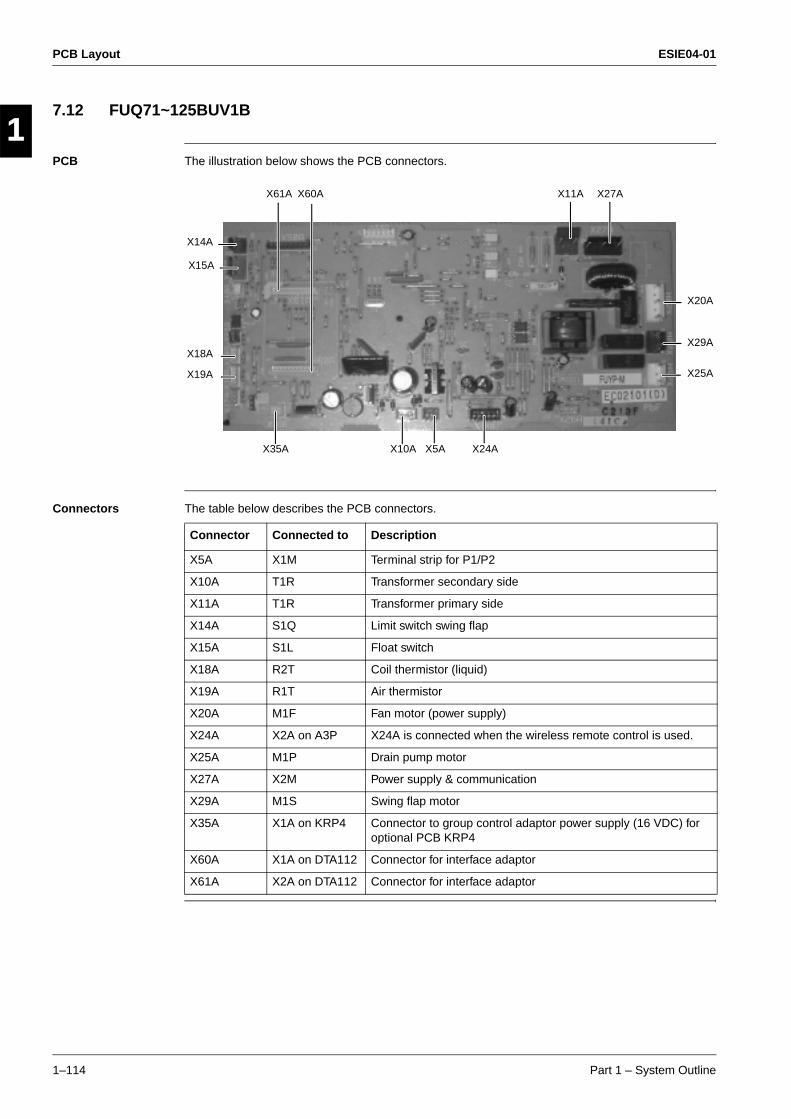
PCB Layout ESIE04-01
1–114 Part 1 – System Outline
3
11
4
5
7.12 FUQ71~125BUV1B
PCB The illustration below shows the PCB connectors.
Connectors The table below describes the PCB connectors.
X14A
X60A X11A X27A
X20A
X29A
X25A
X61A
X15A
X18A
X19A
X35A X10A X5A X24A
Connector Connected to Description
X5A X1M Terminal strip for P1/P2
X10A T1R Transformer secondary side
X11A T1R Transformer primary side
X14A S1Q Limit switch swing flap
X15A S1L Float switch
X18A R2T Coil thermistor (liquid)
X19A R1T Air thermistor
X20A M1F Fan motor (power supply)
X24A X2A on A3P X24A is connected when the wireless remote control is used.
X25A M1P Drain pump motor
X27A X2M Power supply & communication
X29A M1S Swing flap motor
X35A X1A on KRP4 Connector to group control adaptor power supply (16 VDC) for optional PCB KRP4
X60A X1A on DTA112 Connector for interface adaptor
X61A X2A on DTA112 Connector for interface adaptor
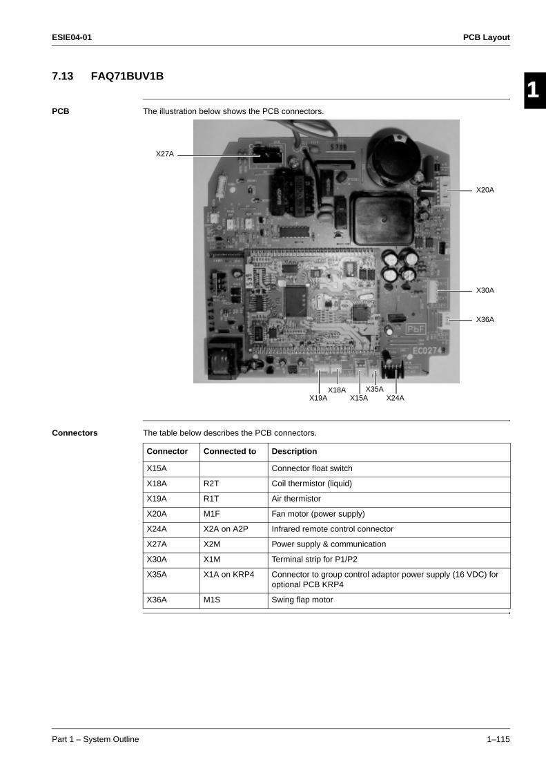
ESIE04-01 PCB Layout
Part 1 – System Outline 1–115
3
1
4
5
7.13 FAQ71BUV1B
PCB The illustration below shows the PCB connectors.
Connectors The table below describes the PCB connectors.
X27A
X20A
X30A
X36A
X19AX18A
X15AX35A
X24A
Connector Connected to Description
X15A Connector float switch
X18A R2T Coil thermistor (liquid)
X19A R1T Air thermistor
X20A M1F Fan motor (power supply)
X24A X2A on A2P Infrared remote control connector
X27A X2M Power supply & communication
X30A X1M Terminal strip for P1/P2
X35A X1A on KRP4 Connector to group control adaptor power supply (16 VDC) for optional PCB KRP4
X36A M1S Swing flap motor
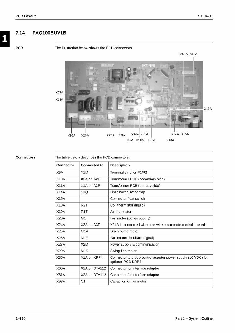
PCB Layout ESIE04-01
1–116 Part 1 – System Outline
3
11
4
5
7.14 FAQ100BUV1B
PCB The illustration below shows the PCB connectors.
Connectors The table below describes the PCB connectors.
X27A
X61A X60A
X19A
X11A
X98A X20A X25A X29A
X5A
X24A
X10A
X35A
X26A X18A
X14A X15A
Connector Connected to Description
X5A X1M Terminal strip for P1/P2
X10A X2A on A2P Transformer PCB (secondary side)
X11A X1A on A2P Transformer PCB (primary side)
X14A S1Q Limit switch swing flap
X15A Connector float switch
X18A R2T Coil thermistor (liquid)
X19A R1T Air thermistor
X20A M1F Fan motor (power supply)
X24A X2A on A3P X24A is connected when the wireless remote control is used.
X25A M1P Drain pump motor
X26A M1F Fan motor( feedback signal)
X27A X2M Power supply & communication
X29A M1S Swing flap motor
X35A X1A on KRP4 Connector to group control adaptor power supply (16 VDC) for optional PCB KRP4
X60A X1A on DTA112 Connector for interface adaptor
X61A X2A on DTA112 Connector for interface adaptor
X98A C1 Capacitor for fan motor

ESIE04-01
Part 2 – Functional Description 2–1
4
3
4
5
2
Part 2Functional Description
What is in this part? This part contains information on the functions used to control the system. Understanding these functions is vital when diagnosing a malfunction that is related to the functional control.
Overview This part contains the following chapters:
Chapter See page
1–General Functionality 2–3
2–Indoor Unit Functional Concept 2–25
3–Outdoor Unit Functional Concept 2–35
ESIE04-01
2–2 Part 2 – Functional Description
3
1
2
5
ESIE04-01 General Functionality
Part 2 – Functional Description 2–3
3
4
5
1
2
Part 2
1 General Functionality
1.1 What Is in This Chapter?
Introduction This chapter will explain all functions not related to the compressor frequency control, outdoor unit fan control and expansion valve control. These functions have been programmed to ensure the unit's reliability and lifetime, enable the operation in case of malfunction, or increase the customer's comfort.
Overview This chapter contains the following topics:
Topic See page
1.2–Functions of Thermistors 2–4
1.3–Forced Operating Mode (Emergency Operation) 2–6
1.4–Outdoor Unit Identification Function 2–8
1.5–Simulated Operation Function 2–9
1.6–Restart Standby 2–10
1.7–Automatic Restart 2–11
1.8–Using Conditions for Remote Control Thermostat 2–12
1.9–Forced Thermostat OFF 2–13
1.10–Test run control 2–14
1.11–4-way Valve Control 2–15
1.12–Pump Down Residual Operation 2–16
1.13–Pump Down Operation 2–17
1.14–Defrost Operation 2–18
1.15–Freeze Prevention Function 2–20
1.16–PMV Control 2–21
1.17–Preheating Operation Control 2–22
1.18–Crankcase Heater Control 2–23
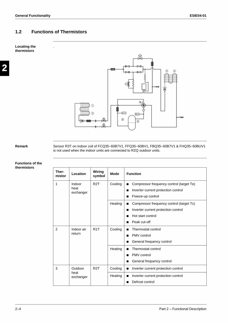
General Functionality ESIE04-01
2–4 Part 2 – Functional Description
3
1
2
4
5
1.2 Functions of Thermistors
Locating the thermistors
.
Remark Sensor R3T on indoor coil of FCQ35~60B7V1, FFQ35~60BV1, FBQ35~60B7V1 & FHQ35~60BUV1 is not used when the indoor units are connected to RZQ outdoor units.
Functions of the thermistors
Ther-mistor
LocationWiring symbol
Mode Function
1 Indoor heat exchanger
R2T Cooling Compressor frequency control (target Te)
Inverter current protection control
Freeze-up control
Heating Compressor frequency control (target Tc)
Inverter current protection control
Hot start control
Peak cut-off
2 Indoor air return
R1T Cooling Thermostat control
PMV control
General frequency control
Heating Thermostat control
PMV control
General frequency control
3 Outdoor heat exchanger
R2T Cooling Inverter current protection control
Heating Inverter current protection control
Defrost control
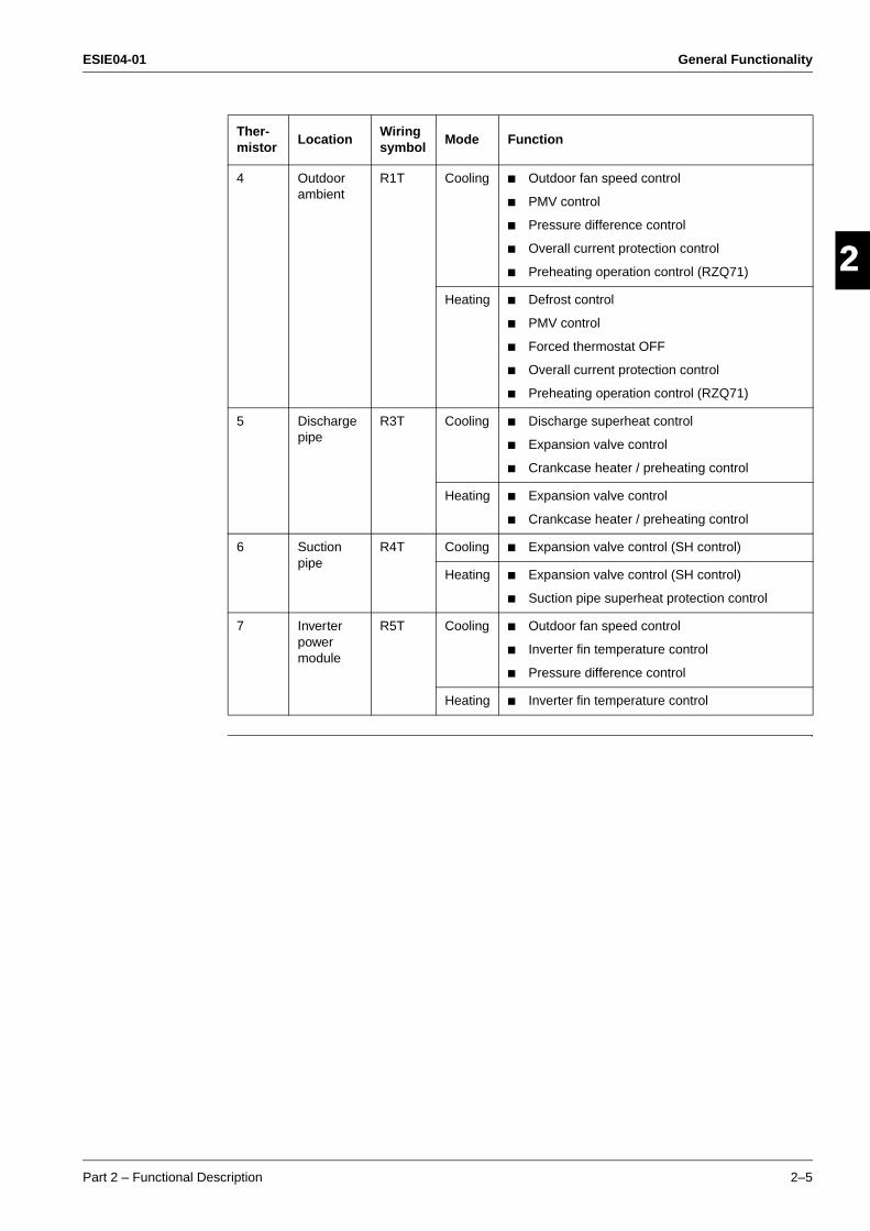
ESIE04-01 General Functionality
Part 2 – Functional Description 2–5
3
2
4
5
14 Outdoor
ambientR1T Cooling Outdoor fan speed control
PMV control
Pressure difference control
Overall current protection control
Preheating operation control (RZQ71)
Heating Defrost control
PMV control
Forced thermostat OFF
Overall current protection control
Preheating operation control (RZQ71)
5 Discharge pipe
R3T Cooling Discharge superheat control
Expansion valve control
Crankcase heater / preheating control
Heating Expansion valve control
Crankcase heater / preheating control
6 Suction pipe
R4T Cooling Expansion valve control (SH control)
Heating Expansion valve control (SH control)
Suction pipe superheat protection control
7 Inverter power module
R5T Cooling Outdoor fan speed control
Inverter fin temperature control
Pressure difference control
Heating Inverter fin temperature control
Ther-mistor
LocationWiring symbol
Mode Function
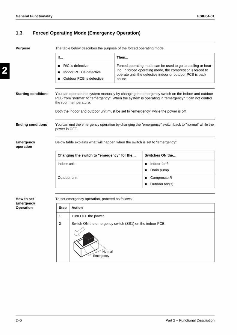
General Functionality ESIE04-01
2–6 Part 2 – Functional Description
3
1
2
4
5
1.3 Forced Operating Mode (Emergency Operation)
Purpose The table below describes the purpose of the forced operating mode.
Starting conditions You can operate the system manually by changing the emergency switch on the indoor and outdoor PCB from "normal" to "emergency". When the system is operating in "emergency" it can not control the room temperature.
Both the indoor and outdoor unit must be set to "emergency" while the power is off.
Ending conditions You can end the emergency operation by changing the "emergency" switch back to "normal" while the power is OFF.
Emergency operation
Below table explains what will happen when the switch is set to "emergency":
How to set Emergency Operation
To set emergency operation, proceed as follows:
If... Then...
R/C is defective
Indoor PCB is defective
Outdoor PCB is defective
Forced operating mode can be used to go to cooling or heat-ing. In forced operating mode, the compressor is forced to operate until the defective indoor or outdoor PCB is back online.
Changing the switch to "emergency" for the… Switches ON the…
Indoor unit Indoor fan§
Drain pump
Outdoor unit Compressor§
Outdoor fan(s)
Step Action
1 Turn OFF the power.
2 Switch ON the emergency switch (SS1) on the indoor PCB.
NormalEmergency
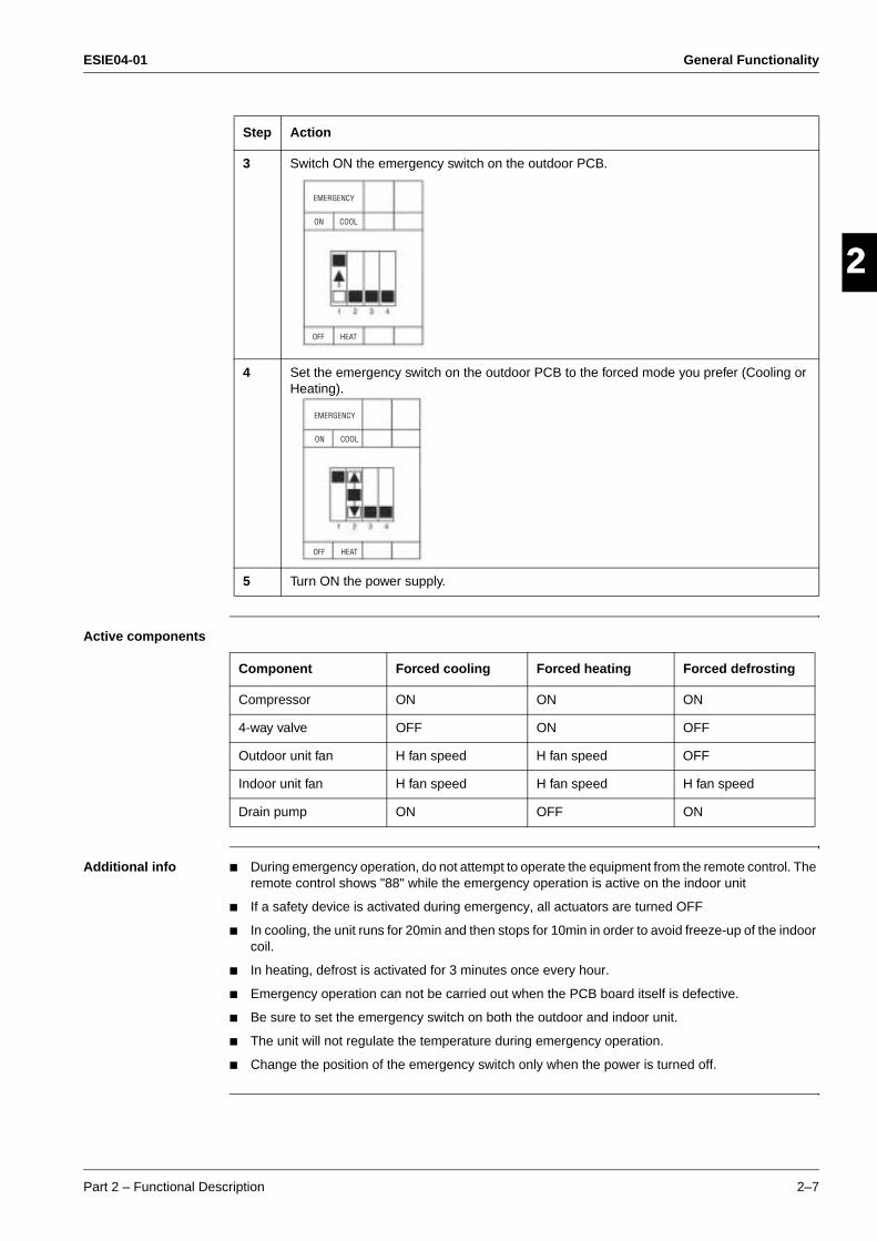
ESIE04-01 General Functionality
Part 2 – Functional Description 2–7
3
2
4
5
1
Active components
Additional info During emergency operation, do not attempt to operate the equipment from the remote control. The remote control shows "88" while the emergency operation is active on the indoor unit
If a safety device is activated during emergency, all actuators are turned OFF
In cooling, the unit runs for 20min and then stops for 10min in order to avoid freeze-up of the indoor coil.
In heating, defrost is activated for 3 minutes once every hour.
Emergency operation can not be carried out when the PCB board itself is defective.
Be sure to set the emergency switch on both the outdoor and indoor unit.
The unit will not regulate the temperature during emergency operation.
Change the position of the emergency switch only when the power is turned off.
3 Switch ON the emergency switch on the outdoor PCB.
4 Set the emergency switch on the outdoor PCB to the forced mode you prefer (Cooling or Heating).
5 Turn ON the power supply.
Step Action
EMERGENCY
ON COOL
OFF HEAT
EMERGENCY
ON COOL
OFF HEAT
Component Forced cooling Forced heating Forced defrosting
Compressor ON ON ON
4-way valve OFF ON OFF
Outdoor unit fan H fan speed H fan speed OFF
Indoor unit fan H fan speed H fan speed H fan speed
Drain pump ON OFF ON

General Functionality ESIE04-01
2–8 Part 2 – Functional Description
3
1
2
4
5
1.4 Outdoor Unit Identification Function
Purpose The purpose of the outdoor unit identification function is to enable the indoor unit to automatically determine which operating mode has to be set in function of the type of connected outdoor unit (c/o or h/p).
Operating modes The possible operating modes are:
Used input The outdoor unit identification function uses the following inputs:
TC: Transmission circuitRC: Receiving circuit
Outdoor unit Operating modes
h/p Fan
Cooling
Dry keep
Heating
c/o Fan
Cooling
Dry keep
InputConnection on indoor PCB
Connection on outdoor PCB
Indoor PCB TC & RC —
Outdoor PCB — TC & RC
ESIE04-01 General Functionality
Part 2 – Functional Description 2–9
3
2
4
5
11.5 Simulated Operation Function
Outline When a malfunction on one of the below thermistors occurs, operation will continue while displaying the applicable alarm on the remote-control. Fin thermistor malfunction is only displayed when pressing the "Inspection" button on the remote-control.
Sensors Outside temperature thermistor
Outdoor heat exchanger thermistor
Fin thermistor
Discharge pipe thermistor
Indoor unit air suction thermistor
Indoor heat exchanger thermistor
Remark Simulated operation will not be conducted in case the low pressure sensor or suction thermistor is malfunctioning.
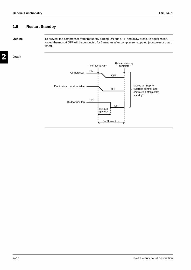
General Functionality ESIE04-01
2–10 Part 2 – Functional Description
3
1
2
4
5
1.6 Restart Standby
Outline To prevent the compressor from frequently turning ON and OFF and allow pressure equalization, forced thermostat OFF will be conducted for 3 minutes after compressor stopping (compressor guard timer).
Graph
Thermostat OFF
Compressor
Electronic expansion valve
Oudoor unit fan
ON
ON
OFF
OFF
OFF
Restart standby complete
Residual operation
For 3 minutes
Moves to “Stop” or “Starting control” after completion of “Restart standby”.

ESIE04-01 General Functionality
Part 2 – Functional Description 2–11
3
2
4
5
11.7 Automatic Restart
Purpose The purpose of the auto-restart function is to automatically resume the same operating mode as when the unit was operating when the power supply is restored after a power failure.
Do not use the "Automatic Restart" function to daily start/stop the unit.
Precautions when turning OFF power
When you have to turn OFF the power supply in order to carry out maintenance, make sure to turn the remote control's ON/OFF switch OFF firstly.
If you turn OFF the power supply while the remote control's ON/OFF switch is still ON, the "automatic restart function" automatically starts the indoor fan immediately and the outdoor unit fan starts automatically 3 minutes after the power supply is turned back ON.
Do not start/stop the unit by disconnecting the power supply.Stop the unit by stop commando from the remote control or optional control before disconnecting the power supply. Be sure that the compressor and the outdoor fans are stopped before disconnecting the power supply so the "Refrigerant Recovery function" has been finished correctly.
When restarting the unit after the power was disconnected for a longer period leave the unit OFF with the power supply connected for about half an hour (See "Crankcase Heater Control" & "Preheating Operation Control").
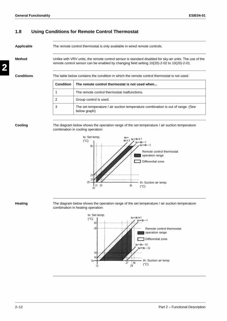
General Functionality ESIE04-01
2–12 Part 2 – Functional Description
3
1
2
4
5
1.8 Using Conditions for Remote Control Thermostat
Applicable The remote control thermostat is only available in wired remote controls.
Method Unlike with VRV units, the remote control sensor is standard disabled for sky-air units. The use of the remote control sensor can be enabled by changing field setting 10(20)-2-02 to 10(20)-2-01.
Conditions The table below contains the condition in which the remote control thermostat is not used:
Cooling The diagram below shows the operation range of the set temperature / air suction temperature combination in cooling operation:
Heating The diagram below shows the operation range of the set temperature / air suction temperature combination in heating operation:
Condition The remote control thermostat is not used when...
1 The remote control thermostat malfunctions.
2 Group control is used.
3 The set temperature / air suction temperature combination is out of range. (See below graph)
Remote control thermostat operation range
Differential zone
th: Suction air temp. (°C)
ts: Set temp. (°C)
Remote control thermostat operation range
Differential zone
th: Suction air temp. (°C)
ts: Set temp. (°C)
ESIE04-01 General Functionality
Part 2 – Functional Description 2–13
3
2
4
5
11.9 Forced Thermostat OFF
Outline The unit will perform the forced thermostat off function in following conditions:
Condition 1 (cooling)
Thermostat off due to freeze-up prevention.
Prevent the indoor unit heat exchanger from freezing in cooling operation when one of the below conditions is applicable:
Indoor unit heat exchanger temperature < -5°C for 1 minute continuously.
Indoor unit heat exchanger temperature < -1°C for 40 minutes accumulated.
Condition 2 (heating)
Thermostat off due to high outdoor temperature.
When the outside temperature is > 30°CDB in heating mode, the unit will conduct a forced thermostat off operation to protect the system.
Reference "Freeze Prevention Function". Refer to page 2-20.
General Functionality ESIE04-01
2–14 Part 2 – Functional Description
3
1
2
4
5
1.10 Test run control
Purpose When operating the RZQ units for the first time after installation, the unit will - depending on the selected operation mode - perform a test run operation first.
Situation 1 Cooling - first operation after installation in "Cooling mode"
Situation 2 Cooling - first operation after installation in "Test run mode"
Situation 3 Heating - first operation after installation in "Heating mode"
Situation 4 Heating - first operation after installation in "Test run mode"
Remarks When running in test run mode, the unit will sense on site installation parameters (e.g.: failure to open stop valves,..) and indicate the applicable malfunction code if required.
If the remote control shows E3, E4 or L8 as an error code, there is possibility that either the stop valve is closed or the air flow outlet is obstructed.
Check the inter unit branch wiring connection (1-2-3 wiring) when the error code U4 or UF is displayed on the remote control.
This "Test Run Control" function is only performed after first power on at installation or after first power on after a pump down by using the pump down switch is.
Cooling thermostat ON
Cooling operation in "Test run mode" for 3 minutes
Normal cooling operation
Cooling Operation by Test run button
Cooling operation in "Test run mode" for 3 minutes
Cooling operation in forced thermostat ON.
Heating thermostat ON
Cooling operation in test run mode for 3 minutes
Normal heating operation
Heating Operation by Test run button
Cooling operation in test run mode for 3 minutes
Heating operation in forced thermostat ON.

ESIE04-01 General Functionality
Part 2 – Functional Description 2–15
3
2
4
5
11.11 4-way Valve Control
Purpose The purpose of the 4-way valve control is to control how the superheated refrigerant passes through the 4-way valve. The 4-way valve control carries out the changeover switching of the 4-way valve. This changeover switching is only carried out during operation, because a certain pressure difference is required to move the internal cylinder.
Method The table below describes the 4-way valve control operation.
Time chart The time chart below illustrates the 4-way valve control.
When... Then the 4-way valve connects the outlet of the compressor with...
Cooling Outdoor heat exchanger
Heating Indoor heat exchanger
In... The 4-way valve is...
Heating, except for defrosting ON
Cooling
Dry keep
Defrosting
OFF
Compressor
4-way valve
Defrosting
Unit mode
ON
OFF
OFF
ON
OFF
ON
HeatingCooling/Dry
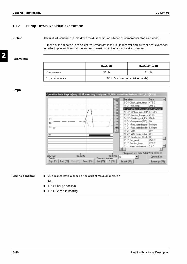
General Functionality ESIE04-01
2–16 Part 2 – Functional Description
3
1
2
4
5
1.12 Pump Down Residual Operation
Outline The unit will conduct a pump down residual operation after each compressor stop command.
Purpose of this function is to collect the refrigerant in the liquid receiver and outdoor heat exchanger in order to prevent liquid refrigerant from remaining in the indoor heat exchanger.
Parameters
Graph
Ending condition 30 seconds have elapsed since start of residual operation
OR
LP < 1 bar (in cooling)
LP < 0.2 bar (in heating)
RZQ71B RZQ100~125B
Compressor 38 Hz 41 HZ
Expansion valve 85 to 0 pulses (after 20 seconds)
ESIE04-01 General Functionality
Part 2 – Functional Description 2–17
3
2
4
5
11.13 Pump Down Operation
Outline Whenever the units need to be moved or removed, perform a pump-down operation before disconnecting the field piping. By performing a pump-down operation, all of the refrigerant will be collected in the outdoor unit.
Procedure
Cautions Pressing the pump down switch (BS1) on the outdoor PCB may cause the outdoor and indoor fan to start operating automatically.
Be sure to open the stop valves after the pipe work has been finished. Be sure not to operate the unit with closed stop valves, or the compressor may brake down.
Procedure Precautions
1 Start "Fan only operation" from the remote control.
Confirm that both the liquid and gas stop valves are open.
2 Push the pump-down button BS1 on the outdoor PCB.
Compressor and outdoor fan will start automatically.
3 Once the operation stops (after 3~5 min-utes) close the liquid gas stop valve first and then the gas stop valve.
After the "Pump Down Operation" has been finished the wired remote control screen may be blank or show "U4" error indication.It will not be able to start the unit from the remote control without switching OFF the power supply first.
Make sure the stop valves are opened before restarting the unit.

General Functionality ESIE04-01
2–18 Part 2 – Functional Description
3
1
2
4
5
1.14 Defrost Operation
Outline When the unit is operating in heating mode, a defrost operation will be conducted in order to avoid ice formation on the outdoor unit heat exchanger.
Defrost starting conditions
Defrost will start when the following conditions have been realized:
Areas Defrost upper limit A
Integrated compressor running time is 25 minutes or more since the completion of the previous defrost operation.
&
OR
Defrost upper limit time A is met.
Low pressure saturated temperature (Te) is within the defrost requesting area.
Outdoor unit heat exchanger area temperature (Tb) is within the defrost requesting area.
Defrost prohibiting area
Defrost permitting area
Evaporating temperature Te (°C)orOutdoor unit heat exchanger temperature Tb (°C)
When slightly quick defrost starting is set
Factory setting
When slightly slow defrost starting is set
When slightly quick defrost starting is set
Defrost requesting area
When slightly quick defrost starting is set
Factory setting
Outdoor Temp. TA °C
When quick defrost starting is set
16(26)-3-03
Factory setting 16(26)-3-01
When slow defrost starting is set
16(26)-3-02
Outdoor temperature > -5°C
40 minutes 3 hours 6 hours
Outdoor temperature ≤ -5°C
40 minutes 6 hours 8 hours
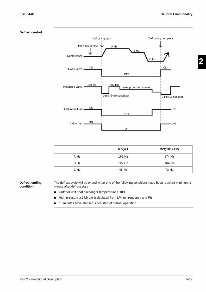
ESIE04-01 General Functionality
Part 2 – Functional Description 2–19
3
2
4
5
1Defrost control
Defrost ending condition
The defrost cycle will be ended when one of the following conditions have been reached minimum 1 minute after defrost start :
Outdoor unit heat exchanger temperature ≥ 10°C
High pressure ≥ 24.5 bar (calculated from LP, inv frequency and PI)
10 minutes have elapsed since start of defrost operation
RZQ71 RZQ100&125
A Hz 162 Hz 174 Hz
B Hz 122 Hz 164 Hz
C Hz 48 Hz 72 Hz
Defrosting start Defrosting complete
Previous control
Compressor
4-way valve
Motorized valve
Outdoor unit fan
Indoor fan
ON
150 pls
ON
ON
480 pls
A Hz
B Hz
C Hz
ON
0 pls (15 seconds)
ON
ON
0 pls (5~60 seconds)
(wet protection control)
OFF
OFF
OFF
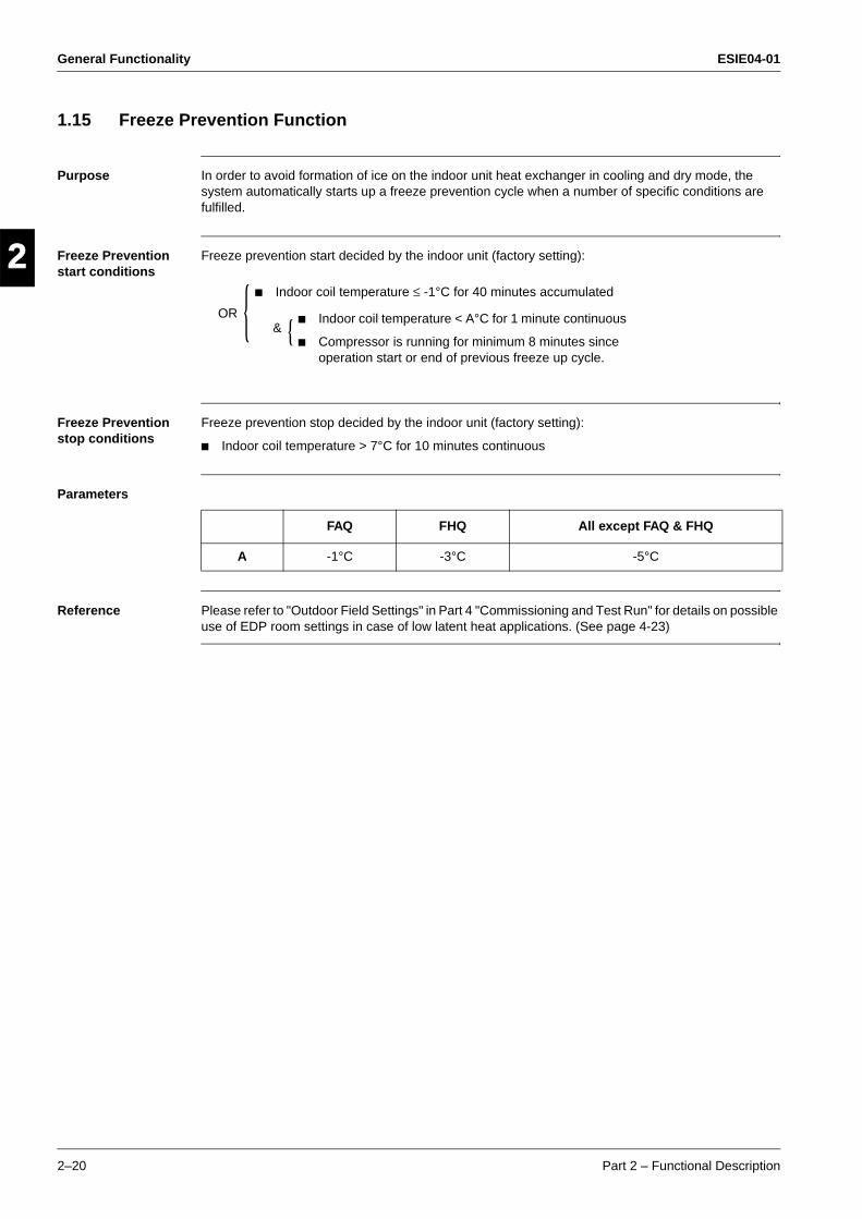
General Functionality ESIE04-01
2–20 Part 2 – Functional Description
3
1
2
4
5
1.15 Freeze Prevention Function
Purpose In order to avoid formation of ice on the indoor unit heat exchanger in cooling and dry mode, the system automatically starts up a freeze prevention cycle when a number of specific conditions are fulfilled.
Freeze Prevention start conditions
Freeze prevention start decided by the indoor unit (factory setting):
Freeze Prevention stop conditions
Freeze prevention stop decided by the indoor unit (factory setting):
Indoor coil temperature > 7°C for 10 minutes continuous
Parameters
Reference Please refer to "Outdoor Field Settings" in Part 4 "Commissioning and Test Run" for details on possible use of EDP room settings in case of low latent heat applications. (See page 4-23)
Indoor coil temperature ≤ -1°C for 40 minutes accumulated
Indoor coil temperature < A°C for 1 minute continuous
Compressor is running for minimum 8 minutes since operation start or end of previous freeze up cycle.
OR&
FAQ FHQ All except FAQ & FHQ
A -1°C -3°C -5°C
ESIE04-01 General Functionality
Part 2 – Functional Description 2–21
3
2
4
5
11.16 PMV Control
Outline When the automatic mode is selected on the remote-control, the unit will automatically activate the PMV control.
The PMV index is a calculated average comfort level.
Refer to ISO 7730 for details.
Function An optimized indoor temperature will be calculated using the following inputs:
Outdoor air temperature
Indoor air temperature
Remote control set temperature
In practice, the set point will be moved with 1 or 2 degrees whenever the conditions change. This will result in a combination of power saving and increased comfort level.
PMV control can be disabled by changing the field settings:From: 11(21)-4-01 to: 11(21)-4-02

General Functionality ESIE04-01
2–22 Part 2 – Functional Description
3
1
2
4
5
1.17 Preheating Operation Control
Applicable units RZQ71
Outline After the compressor has been turned off, the preheating operation will be activated in order to avoid refrigerant from dissolving in the compressor oil.
Trigger conditions
Starting conditions &
or
T2 (Discharge pipe temperature) < 40°C
Ta (Outside temperature) < 40°C
Power supply ON to First operation
60 minutes or more elapsed after compressor stop
Ending conditions or
T2 (Discharge pipe temperature) > 43°C
Ta (Outside temperature) > 43°C
Thermostat ON confirmation
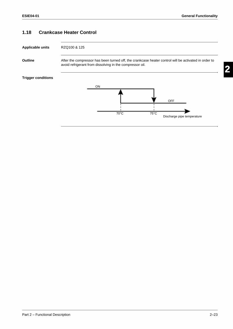
ESIE04-01 General Functionality
Part 2 – Functional Description 2–23
3
2
4
5
11.18 Crankcase Heater Control
Applicable units RZQ100 & 125
Outline After the compressor has been turned off, the crankcase heater control will be activated in order to avoid refrigerant from dissolving in the compressor oil.
Trigger conditions
ON
OFF
Discharge pipe temperature70°C 75°C
General Functionality ESIE04-01
2–24 Part 2 – Functional Description
3
1
2
4
5
ESIE04-01 Indoor Unit Functional Concept
Part 2 – Functional Description 2–25
3
4
5
1
2
Part 2
2 Indoor Unit Functional Concept
2.1 What Is in This Chapter?
Introduction This chapter will explain more details about the various functions that are programmed for the Sky-Air R410A inverter indoor units.
Overview This chapter contains the following topics:
Topic See page
2.2–Thermostat Control 2–26
2.3–Drain Pump Control 2–27
2.4–Condensation Avoidance Control 2–29
2.5–Draft Avoidance Control 1 2–30
2.6–Draft Avoidance Control 2 2–31
2.7–Fan and Flap Operations 2–32
2.8–Indoor unit fan control 2–33
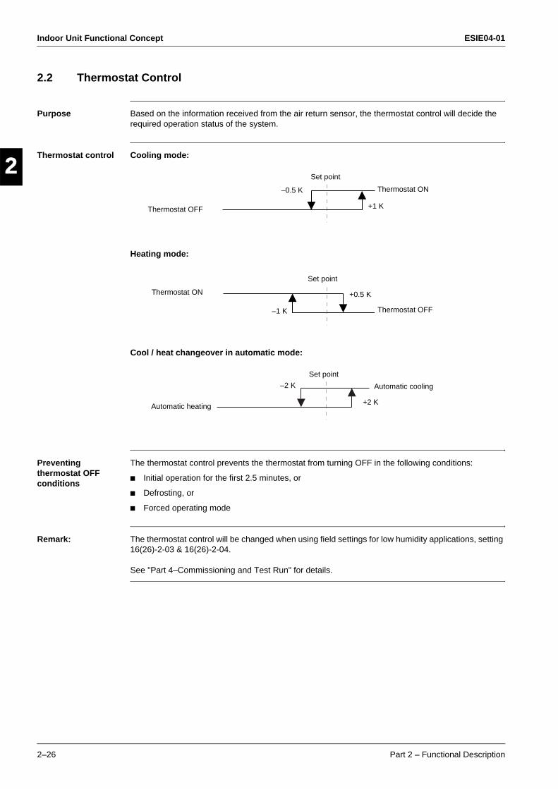
Indoor Unit Functional Concept ESIE04-01
2–26 Part 2 – Functional Description
3
1
2
4
5
2.2 Thermostat Control
Purpose Based on the information received from the air return sensor, the thermostat control will decide the required operation status of the system.
Thermostat control Cooling mode:
Heating mode:
Cool / heat changeover in automatic mode:
Preventing thermostat OFF conditions
The thermostat control prevents the thermostat from turning OFF in the following conditions:
Initial operation for the first 2.5 minutes, or
Defrosting, or
Forced operating mode
Remark: The thermostat control will be changed when using field settings for low humidity applications, setting 16(26)-2-03 & 16(26)-2-04.
See "Part 4–Commissioning and Test Run" for details.
Thermostat OFF
–0.5 K
Set point
+1 K
Thermostat ON
Thermostat ON
–1 K
Set point
+0.5 K
Thermostat OFF
Automatic heating
–2 K
Set point
+2 K
Automatic cooling
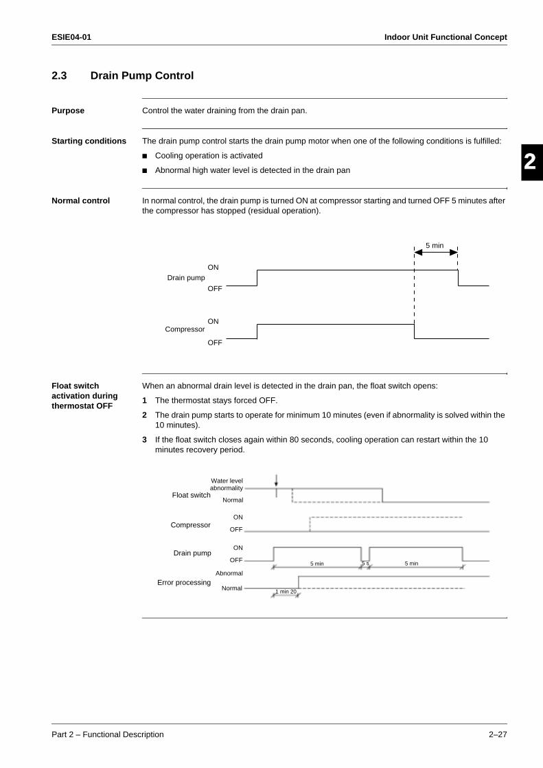
ESIE04-01 Indoor Unit Functional Concept
Part 2 – Functional Description 2–27
3
2
4
5
12.3 Drain Pump Control
Purpose Control the water draining from the drain pan.
Starting conditions The drain pump control starts the drain pump motor when one of the following conditions is fulfilled:
Cooling operation is activated
Abnormal high water level is detected in the drain pan
Normal control In normal control, the drain pump is turned ON at compressor starting and turned OFF 5 minutes after the compressor has stopped (residual operation).
Float switch activation during thermostat OFF
When an abnormal drain level is detected in the drain pan, the float switch opens:
1 The thermostat stays forced OFF.
2 The drain pump starts to operate for minimum 10 minutes (even if abnormality is solved within the 10 minutes).
3 If the float switch closes again within 80 seconds, cooling operation can restart within the 10 minutes recovery period.
Drain pumpON
OFF
CompressorON
OFF
5 min
Water levelabnormality
Abnormal
Normal
5 min 5 min
1 min 20
5 s
NormalFloat switch
Compressor
Drain pump
Error processing
OFF
OFF
ON
ON
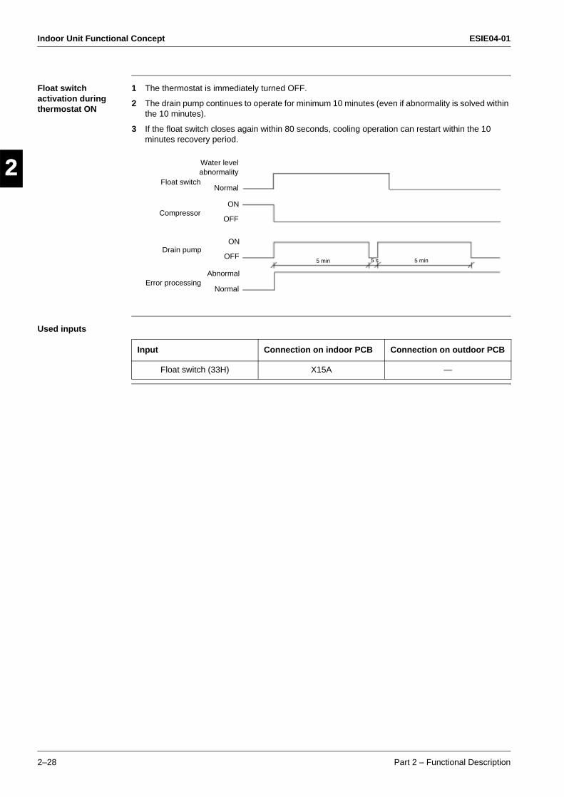
Indoor Unit Functional Concept ESIE04-01
2–28 Part 2 – Functional Description
3
1
2
4
5
Float switch activation during thermostat ON
1 The thermostat is immediately turned OFF.
2 The drain pump continues to operate for minimum 10 minutes (even if abnormality is solved within the 10 minutes).
3 If the float switch closes again within 80 seconds, cooling operation can restart within the 10 minutes recovery period.
Used inputs
Float switch
Water levelabnormality
ON
OFF
Abnormal
Normal
5 min 5 min5 s
ON
OFF
Normal
Compressor
Drain pump
Error processing
Input Connection on indoor PCB Connection on outdoor PCB
Float switch (33H) X15A —
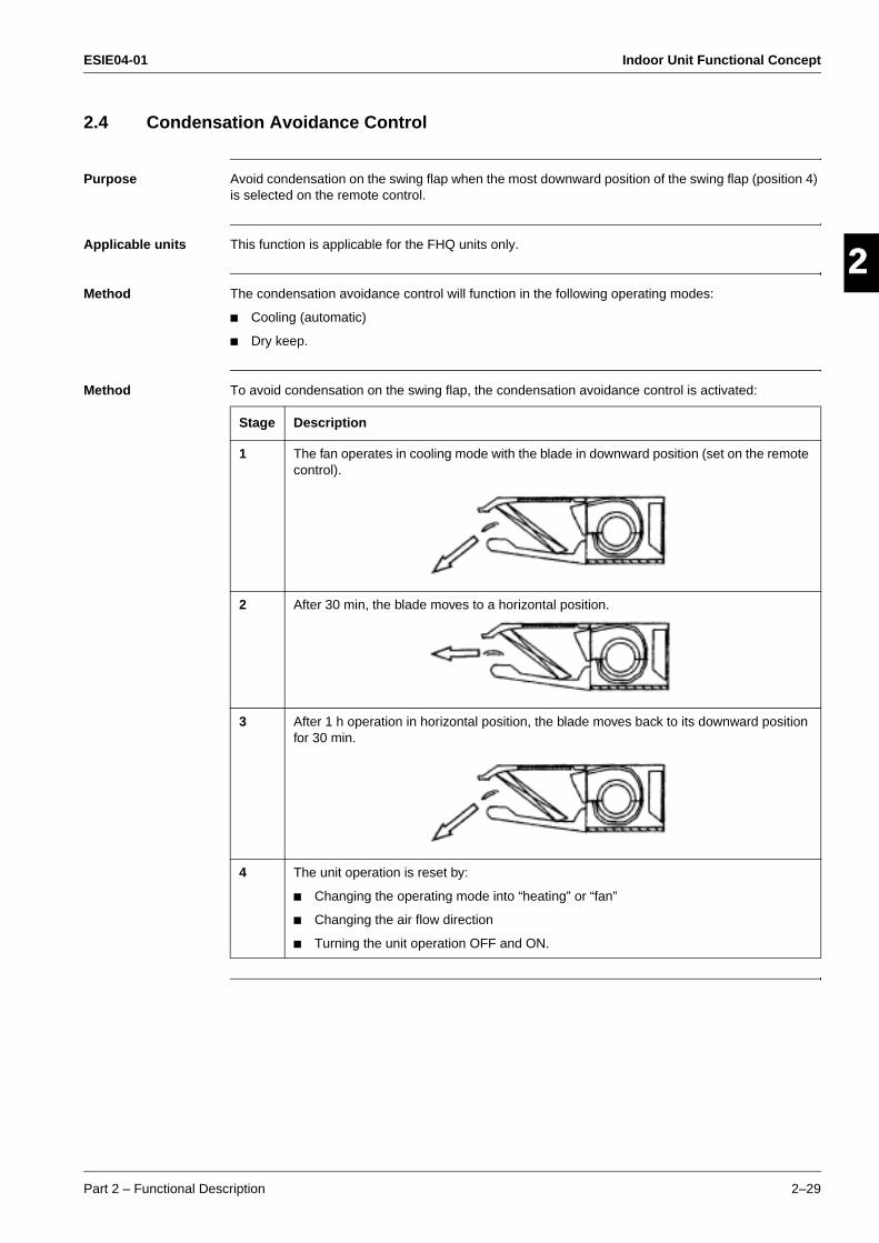
ESIE04-01 Indoor Unit Functional Concept
Part 2 – Functional Description 2–29
3
2
4
5
12.4 Condensation Avoidance Control
Purpose Avoid condensation on the swing flap when the most downward position of the swing flap (position 4) is selected on the remote control.
Applicable units This function is applicable for the FHQ units only.
Method The condensation avoidance control will function in the following operating modes:
Cooling (automatic)
Dry keep.
Method To avoid condensation on the swing flap, the condensation avoidance control is activated:
Stage Description
1 The fan operates in cooling mode with the blade in downward position (set on the remote control).
2 After 30 min, the blade moves to a horizontal position.
3 After 1 h operation in horizontal position, the blade moves back to its downward position for 30 min.
4 The unit operation is reset by:
Changing the operating mode into “heating” or “fan”
Changing the air flow direction
Turning the unit operation OFF and ON.
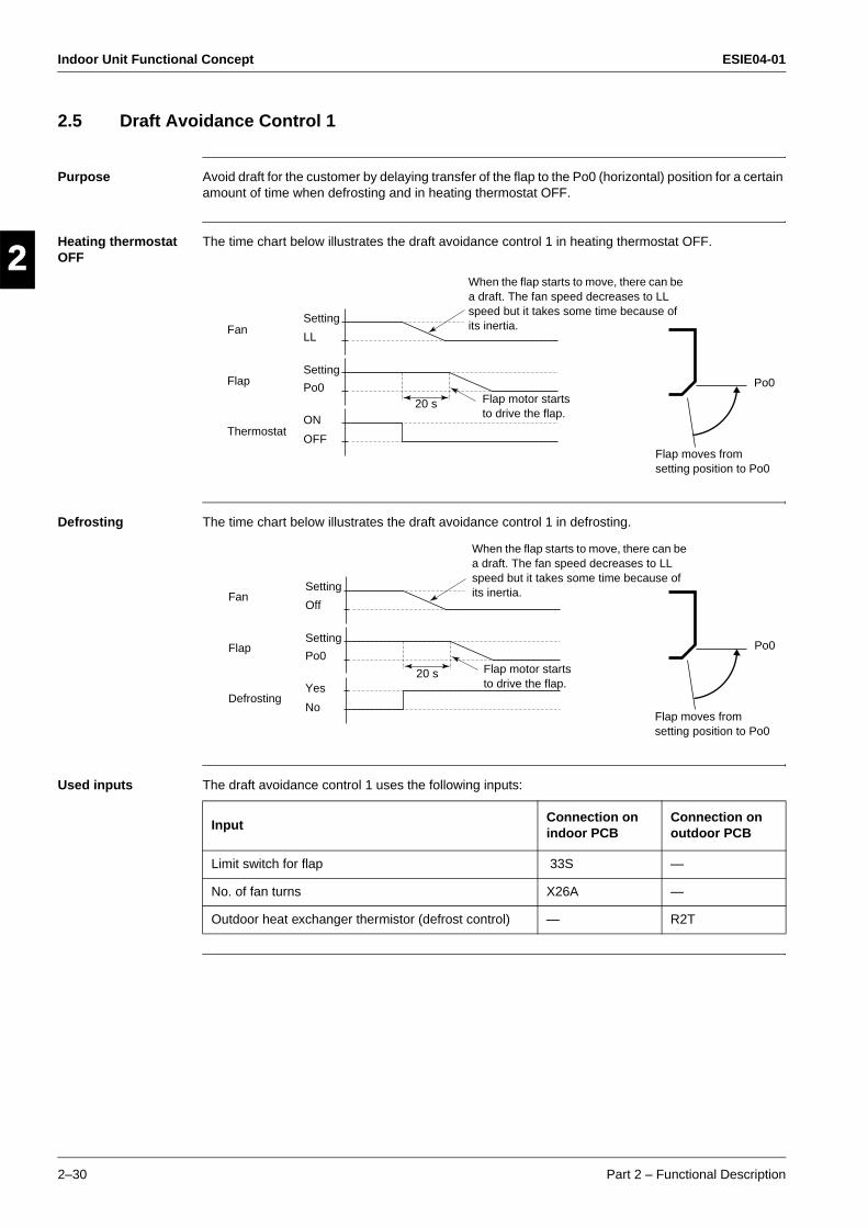
Indoor Unit Functional Concept ESIE04-01
2–30 Part 2 – Functional Description
3
1
2
4
5
2.5 Draft Avoidance Control 1
Purpose Avoid draft for the customer by delaying transfer of the flap to the Po0 (horizontal) position for a certain amount of time when defrosting and in heating thermostat OFF.
Heating thermostat OFF
The time chart below illustrates the draft avoidance control 1 in heating thermostat OFF.
Defrosting The time chart below illustrates the draft avoidance control 1 in defrosting.
Used inputs The draft avoidance control 1 uses the following inputs:
When the flap starts to move, there can be a draft. The fan speed decreases to LL speed but it takes some time because of its inertia. Fan
Flap
Thermostat
Setting
LL
Setting
Po0
ON
OFF
Flap motor starts to drive the flap.
20 s
Flap moves from setting position to Po0
Po0
When the flap starts to move, there can be a draft. The fan speed decreases to LL speed but it takes some time because of its inertia. Fan
Flap
Defrosting
Setting
Off
Setting
Po0
Yes
No
Flap motor starts to drive the flap.
20 s
Flap moves from setting position to Po0
Po0
InputConnection on indoor PCB
Connection on outdoor PCB
Limit switch for flap 33S —
No. of fan turns X26A —
Outdoor heat exchanger thermistor (defrost control) — R2T
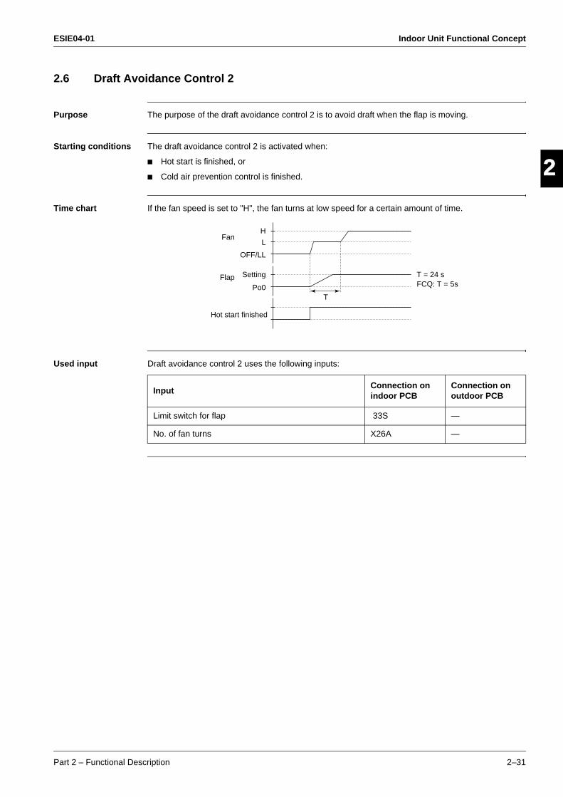
ESIE04-01 Indoor Unit Functional Concept
Part 2 – Functional Description 2–31
3
2
4
5
12.6 Draft Avoidance Control 2
Purpose The purpose of the draft avoidance control 2 is to avoid draft when the flap is moving.
Starting conditions The draft avoidance control 2 is activated when:
Hot start is finished, or
Cold air prevention control is finished.
Time chart If the fan speed is set to "H", the fan turns at low speed for a certain amount of time.
Used input Draft avoidance control 2 uses the following inputs:
Fan
Flap
Hot start finished
Setting
OFF/LL
L
H
Po0T
T = 24 s FCQ: T = 5s
InputConnection on indoor PCB
Connection on outdoor PCB
Limit switch for flap 33S —
No. of fan turns X26A —
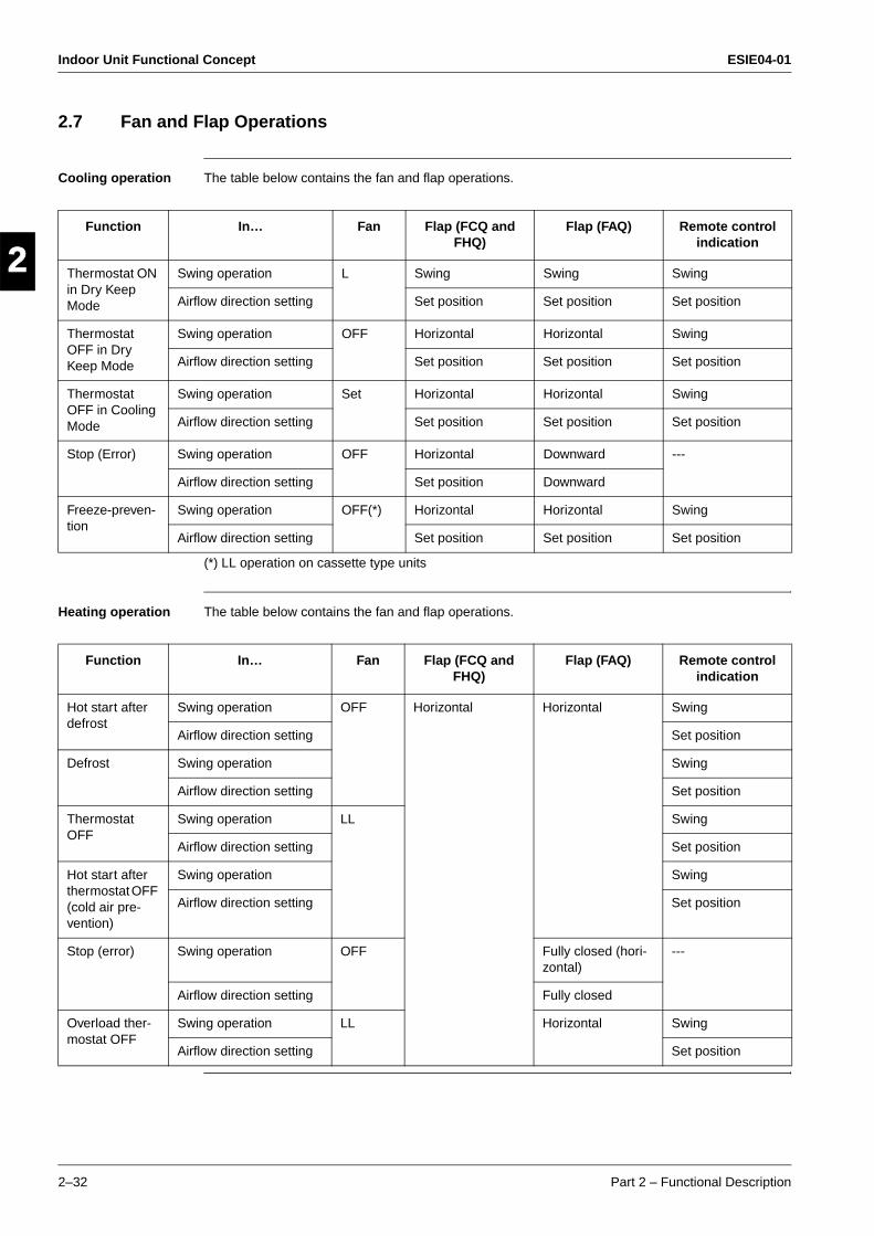
Indoor Unit Functional Concept ESIE04-01
2–32 Part 2 – Functional Description
3
1
2
4
5
2.7 Fan and Flap Operations
Cooling operation The table below contains the fan and flap operations.
(*) LL operation on cassette type units
Heating operation The table below contains the fan and flap operations.
Function In… Fan Flap (FCQ and FHQ)
Flap (FAQ) Remote control indication
Thermostat ON in Dry Keep Mode
Swing operation L Swing Swing Swing
Airflow direction setting Set position Set position Set position
Thermostat OFF in Dry Keep Mode
Swing operation OFF Horizontal Horizontal Swing
Airflow direction setting Set position Set position Set position
Thermostat OFF in Cooling Mode
Swing operation Set Horizontal Horizontal Swing
Airflow direction setting Set position Set position Set position
Stop (Error) Swing operation OFF Horizontal Downward ---
Airflow direction setting Set position Downward
Freeze-preven-tion
Swing operation OFF(*) Horizontal Horizontal Swing
Airflow direction setting Set position Set position Set position
Function In… Fan Flap (FCQ and FHQ)
Flap (FAQ) Remote control indication
Hot start after defrost
Swing operation OFF Horizontal Horizontal Swing
Airflow direction setting Set position
Defrost Swing operation Swing
Airflow direction setting Set position
Thermostat OFF
Swing operation LL Swing
Airflow direction setting Set position
Hot start after thermostat OFF (cold air pre-vention)
Swing operation Swing
Airflow direction setting Set position
Stop (error) Swing operation OFF Fully closed (hori-zontal)
---
Airflow direction setting Fully closed
Overload ther-mostat OFF
Swing operation LL Horizontal Swing
Airflow direction setting Set position
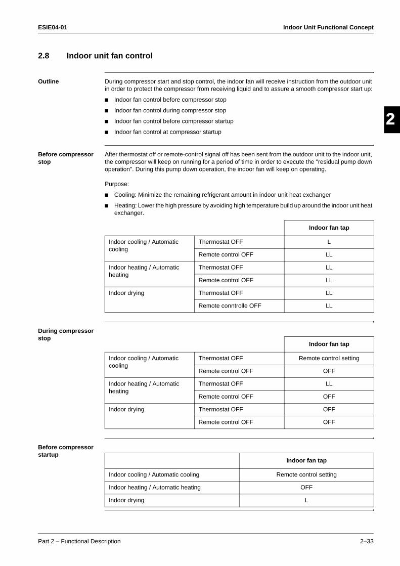
ESIE04-01 Indoor Unit Functional Concept
Part 2 – Functional Description 2–33
3
2
4
5
12.8 Indoor unit fan control
Outline During compressor start and stop control, the indoor fan will receive instruction from the outdoor unit in order to protect the compressor from receiving liquid and to assure a smooth compressor start up:
Indoor fan control before compressor stop
Indoor fan control during compressor stop
Indoor fan control before compressor startup
Indoor fan control at compressor startup
Before compressor stop
After thermostat off or remote-control signal off has been sent from the outdoor unit to the indoor unit, the compressor will keep on running for a period of time in order to execute the "residual pump down operation". During this pump down operation, the indoor fan will keep on operating.
Purpose:
Cooling: Minimize the remaining refrigerant amount in indoor unit heat exchanger
Heating: Lower the high pressure by avoiding high temperature build up around the indoor unit heat exchanger.
During compressor stop
Before compressor startup
Indoor fan tap
Indoor cooling / Automatic cooling
Thermostat OFF L
Remote control OFF LL
Indoor heating / Automatic heating
Thermostat OFF LL
Remote control OFF LL
Indoor drying Thermostat OFF LL
Remote conntrolle OFF LL
Indoor fan tap
Indoor cooling / Automatic cooling
Thermostat OFF Remote control setting
Remote control OFF OFF
Indoor heating / Automatic heating
Thermostat OFF LL
Remote control OFF OFF
Indoor drying Thermostat OFF OFF
Remote control OFF OFF
Indoor fan tap
Indoor cooling / Automatic cooling Remote control setting
Indoor heating / Automatic heating OFF
Indoor drying L
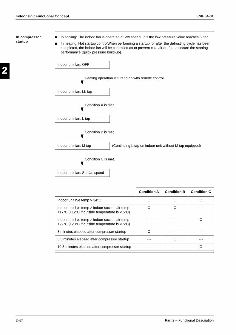
Indoor Unit Functional Concept ESIE04-01
2–34 Part 2 – Functional Description
3
1
2
4
5
At compressor startup
In cooling: The indoor fan is operated at low speed until the low-pressure value reaches 6 bar.
In heating: Hot startup controlWhen performing a startup, or after the defrosting cycle has been completed, the indoor fan will be controlled as to prevent cold air draft and secure the starting performance (quick pressure build-up).
Indoor unit fan: OFF
Heating operation is turend on with remote control.
Indoor unit fan: LL tap
Condition A is met.
Indoor unit fan: L tap
Condition B is met.
Indoor unit fan: M tap (Continuing L tap on indoor unit without M tap equipped)
Condition C is met.
Indoor unit fan: Set fan speed
Condition A Condition B Condition C
Indoor unit h/e temp > 34°C O O O
Indoor unit h/e temp > indoor suction air temp +17°C (+12°C if outside temperature is < 5°C)
O O ---
Indoor unit h/e temp > indoor suction air temp +22°C (+20°C if outside temperature is < 5°C)
--- --- O
3 minutes elapsed after compressor startup O --- ---
5.5 minutes elapsed after compressor startup --- O ---
10.5 minutes elapsed after compressor startup --- --- O
ESIE04-01 Outdoor Unit Functional Concept
Part 2 – Functional Description 2–35
3
2
4
5
1Part 2
3 Outdoor Unit Functional Concept
3.1 What Is in This Chapter?
Introduction This chapter will explain more details about the various functions that are programmed for the sky-air R410A inverter outdoor units.
Overview This chapter contains the following topics:
Topic See page
3.2–Function Outline 2–36
3.3–Frequency Regulating Functions 2–39
3.4–Expansion Valve Regulating Functions 2–55
3.5–Outdoor Unit Fan Speed Control 2–59
Outdoor Unit Functional Concept ESIE04-01
2–36 Part 2 – Functional Description
3
1
2
4
5
3.2 Function Outline
Introduction This chapter will show an overview of all applicable functions in cooling and heating mode.
Content
Topic See page
3.2.1–Function Outline in Cooling Mode 2–37
3.2.2–Function Outline in Heating Mode 2–38
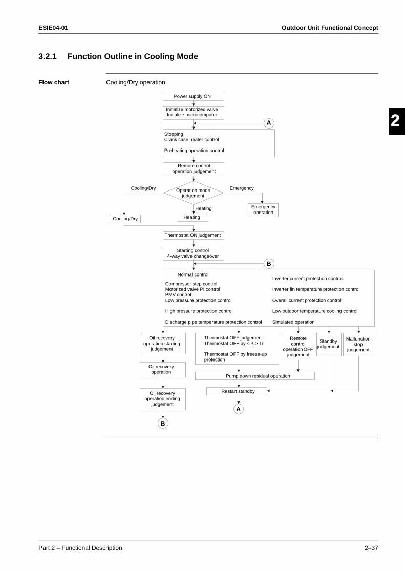
ESIE04-01 Outdoor Unit Functional Concept
Part 2 – Functional Description 2–37
3
2
4
5
13.2.1 Function Outline in Cooling Mode
Flow chart Cooling/Dry operation
Power supply ON
Initialize motorized valve Initialize microcomputer
StoppingCrank case heater control
Preheating operation control
Remote controloperation judgement
Operation mode judgement
Cooling/Dry Heating
Emergency operation
Thermostat ON judgement
Starting control4-way valve changeover
Compressor step controlMotorized valve PI controlPMV controlLow pressure protection control
High pressure protection control
Discharge pipe temperature protection control
Inverter current protection control
Inverter fin temperature protection control
Overall current protection control
Low outdoor temperature cooling control
Simulated operation
Normal control
Oil recovery operation starting
judgement
Oil recovery operation
Oil recovery operation ending
judgement
Remote control
operation OFF judgement
Standby judgement
Malfunction stop
judgement
Thermostat OFF judgementThermostat OFF by < ∆ > Tr
Thermostat OFF by freeze-up protection
Pump down residual operation
Restart standby
A
B
B
A
Cooling/Dry Emergency
Heating
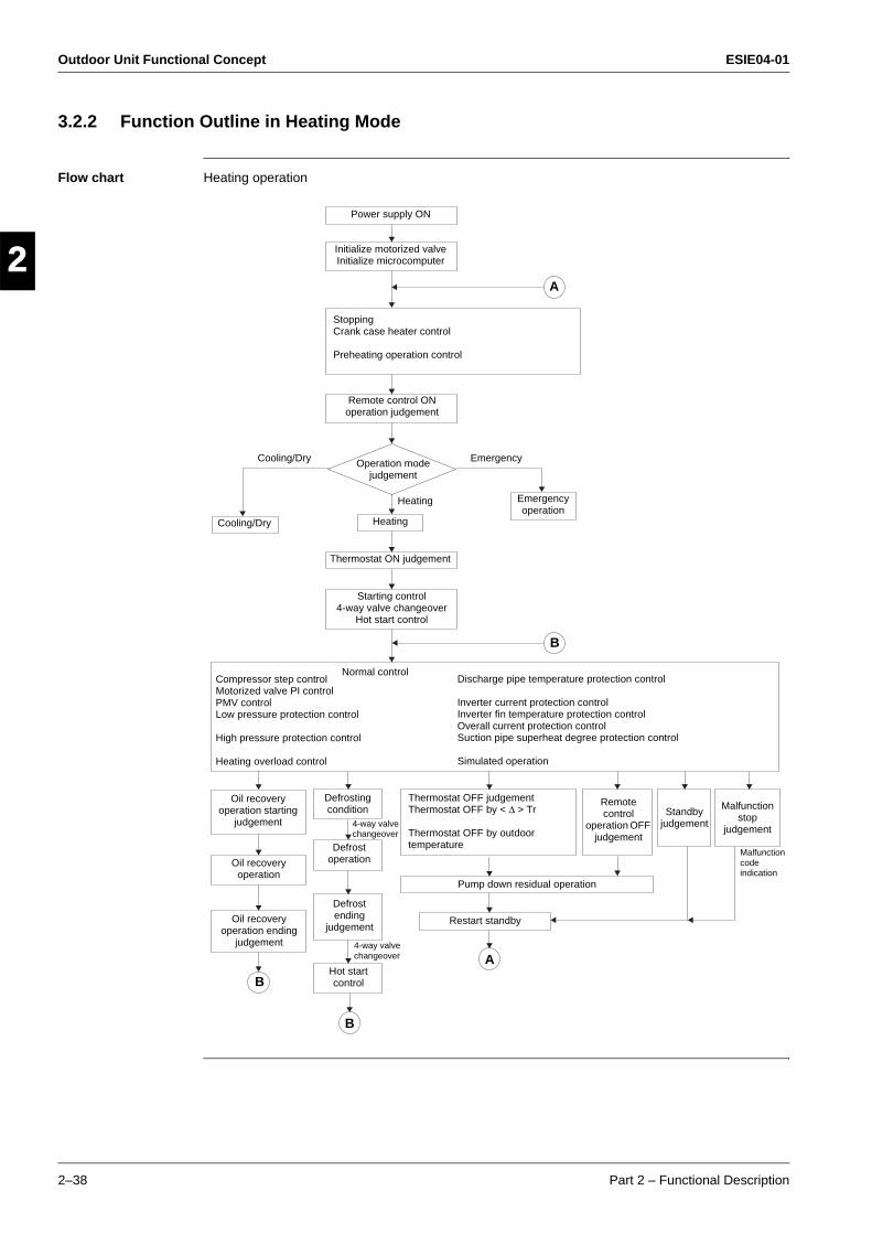
Outdoor Unit Functional Concept ESIE04-01
2–38 Part 2 – Functional Description
3
1
2
4
5
3.2.2 Function Outline in Heating Mode
Flow chart Heating operation
Power supply ON
Initialize motorized valve Initialize microcomputer
StoppingCrank case heater control
Preheating operation control
Remote control ONoperation judgement
Operation mode judgement
Cooling/Dry Heating
Emergency operation
Thermostat ON judgement
Starting control4-way valve changeover
Hot start control
Compressor step controlMotorized valve PI controlPMV controlLow pressure protection control
High pressure protection control
Heating overload control
Discharge pipe temperature protection control
Inverter current protection controlInverter fin temperature protection controlOverall current protection controlSuction pipe superheat degree protection control
Simulated operation
Normal control
Oil recovery operation starting
judgement
Oil recovery operation
Oil recovery operation ending
judgement
Defrosting condition
Defrost operation
Defrost ending
judgement
Hot start control
Remote control
operation OFF judgement
Standby judgement
Malfunction stop
judgement
Thermostat OFF judgementThermostat OFF by < ∆ > Tr
Thermostat OFF by outdoor temperature
Pump down residual operation
Restart standby
A
B
B
B
A
Cooling/Dry Emergency
Malfunction code indication
4-way valve changeover
Heating
4-way valve changeover
ESIE04-01 Outdoor Unit Functional Concept
Part 2 – Functional Description 2–39
3
2
4
5
13.3 Frequency Regulating Functions
Introduction One of the main functions of the µ-control will be the control of the compressor frequency. The next chapter will explain how the compressor frequency is determined.
Content
Topic See page
3.3.1–Starting Frequency Control 2–40
3.3.2–General Frequency Control 2–43
3.3.3–Low Pressure Protection Control 2–45
3.3.4–High Pressure Protection Control 2–46
3.3.5–Discharge Pipe Temperature Control 2–47
3.3.6–Suction Pipe Superheat Protection Control (Heating Mode) 2–48
3.3.7–Inverter Current Protection Control 2–49
3.3.8–Input Current Control 2–50
3.3.9–Inverter Cooling Fin Temperature Control 2–51
3.3.10–Pressure Difference Control 2–52
3.3.11–Oil Recovery Operation 2–54
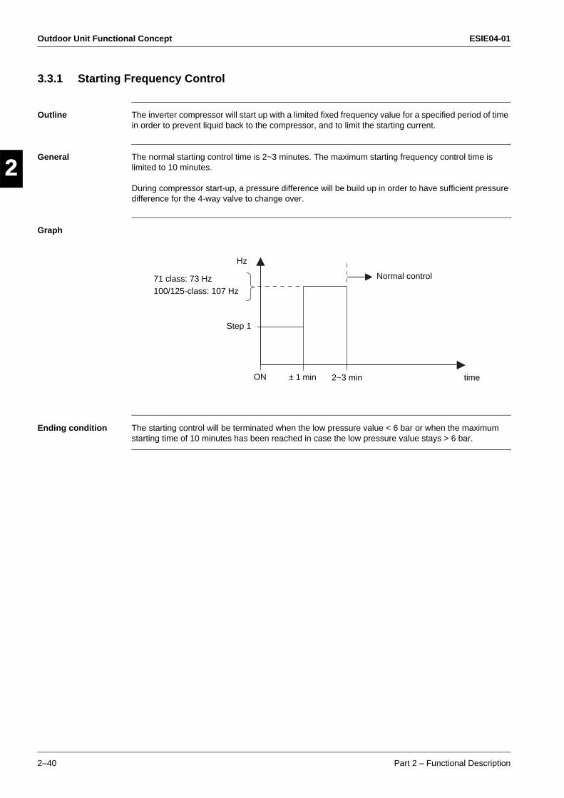
Outdoor Unit Functional Concept ESIE04-01
2–40 Part 2 – Functional Description
3
1
2
4
5
3.3.1 Starting Frequency Control
Outline The inverter compressor will start up with a limited fixed frequency value for a specified period of time in order to prevent liquid back to the compressor, and to limit the starting current.
General The normal starting control time is 2~3 minutes. The maximum starting frequency control time is limited to 10 minutes.
During compressor start-up, a pressure difference will be build up in order to have sufficient pressure difference for the 4-way valve to change over.
Graph
Ending condition The starting control will be terminated when the low pressure value < 6 bar or when the maximum starting time of 10 minutes has been reached in case the low pressure value stays > 6 bar.
71 class: 73 Hz100/125-class: 107 Hz
Hz
Step 1
ON ± 1 min 2~3 min time
Normal control
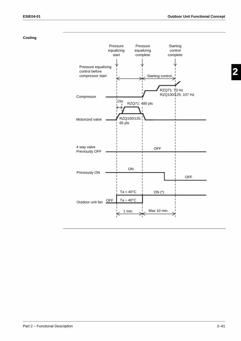
ESIE04-01 Outdoor Unit Functional Concept
Part 2 – Functional Description 2–41
3
2
4
5
1Cooling
Pressure equalizing control before compressor start
Pressure equalizing
start
Pressure equalizing complete
Starting control
complete
Starting control
RZQ71: 73 HzRZQ100/125: 107 Hz
RZQ71: 480 pls
RZQ100/125:65 pls
15s
OFF
ON
OFF
ON (*)Ta ≤ 40°C
OFF
1 min. Max 10 min.
Ta > 40°C
Compressor
Motorized valve
4 way valvePreviously OFF
Previously ON
Outdoor unit fan
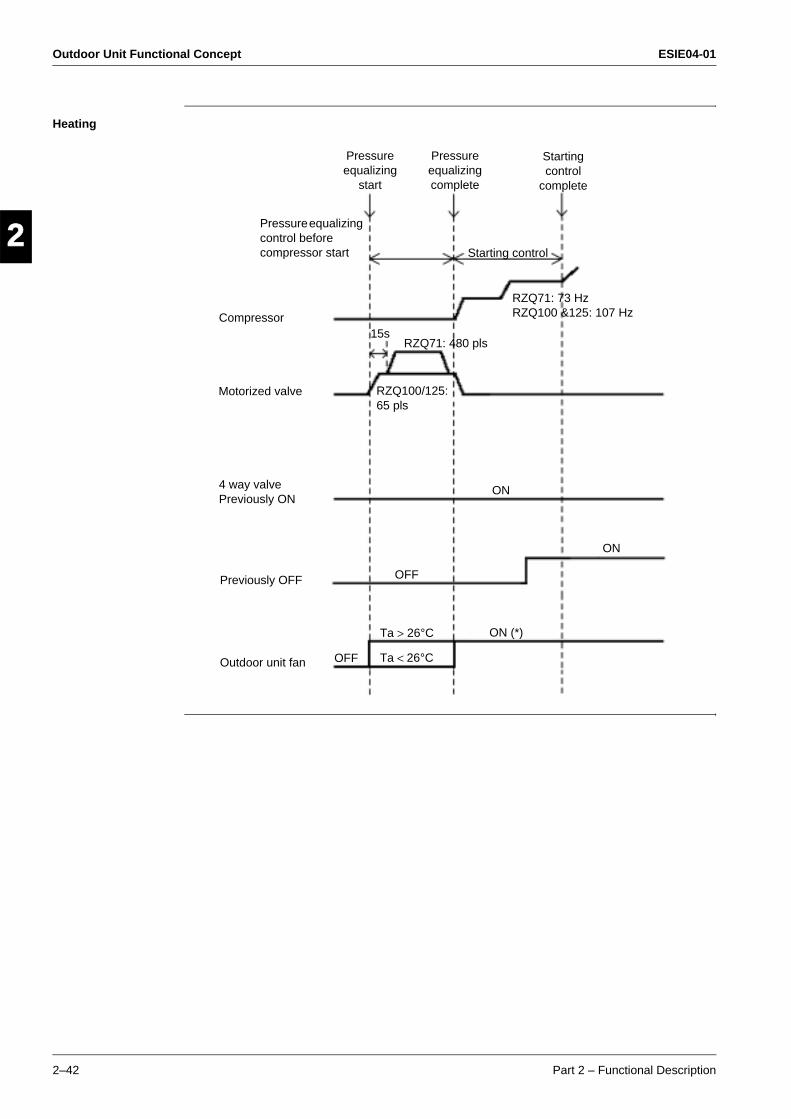
Outdoor Unit Functional Concept ESIE04-01
2–42 Part 2 – Functional Description
3
1
2
4
5
Heating
Compressor
Pressure equalizing control before compressor start
Pressure equalizing
start
Pressure equalizing complete
Starting control
complete
Starting control
RZQ71: 73 HzRZQ100 &125: 107 Hz
RZQ71: 480 pls
RZQ100/125: 65 pls
15s
ON
OFF
ON
ON (*)Ta > 26°C
OFF Ta < 26°C
Motorized valve
4 way valvePreviously ON
Previously OFF
Outdoor unit fan
ESIE04-01 Outdoor Unit Functional Concept
Part 2 – Functional Description 2–43
3
2
4
5
13.3.2 General Frequency Control
Outline After the "Starting frequency control" function has been terminated, the ideal compressor frequency will be determined by the "General frequency control".
General The compressor operation frequency is controlled in order to keep a constant evaporation temperature in cooling and a constant condensing temperature in heating.
The frequency can be changed every 20 seconds.The maximum frequency change = 2 steps/change. (= max 6 steps/min)
During abnormal situations (e.g. inverter current protection) the change per step is also = 2 steps/change, but the 20 seconds interval may be decreased, so a quicker change is possible.
Note When other control functions are activated (e.g. discharge pipe control), they can change the compressor frequency using other inputs than the ones normally being used by the "General frequency control" function.
Cooling In cooling, the target operation frequency will be determined by the indoor ∆t and the evaporating temperature.
∆t cool = Remote control set temperature - Indoor return air temperature.
Depending on the cooling load, the target evaporating temperature (Te) will be a value between 2°C ≤ Te ≤ 20°C.
Heating In heating, the target operation frequency will be determined by the indoor ∆t and the condensing temperature.
∆t heat = Indoor return air temperature - Remote control set temperature.
Depending on the heating load, the target condensing temperature (Tc) will be a value between 42°C ≤ Tc ≤ 51°C.

Outdoor Unit Functional Concept ESIE04-01
2–44 Part 2 – Functional Description
3
1
2
4
5
Frequency steps The operating frequency for the sky-air RZQ inverter units will be a value chosen from a list with fixed frequency settings that is programmed in the unit's memory:
Step No. Compressor operation frequency
RZQ71B RZQ100 ~125B
1 38Hz 41Hz
2 41Hz 44Hz
3 44Hz 48Hz
4 48Hz 52Hz
5 52Hz 57Hz
6 57Hz 62Hz
7 62Hz 67Hz
8 67Hz 73Hz
9 73Hz 78Hz
10 79Hz 84Hz
11 85Hz 90Hz
12 91Hz 94Hz
13 97Hz 98Hz
14 103Hz 102Hz
15 109Hz 107Hz
16 116Hz 112Hz
17 122Hz 117Hz
18 128Hz 123Hz
19 134Hz 131Hz
20 141Hz 139Hz
21 148Hz 147Hz
22 155Hz 155Hz
23 162Hz 164Hz
24 169Hz 174Hz
25 177Hz ---
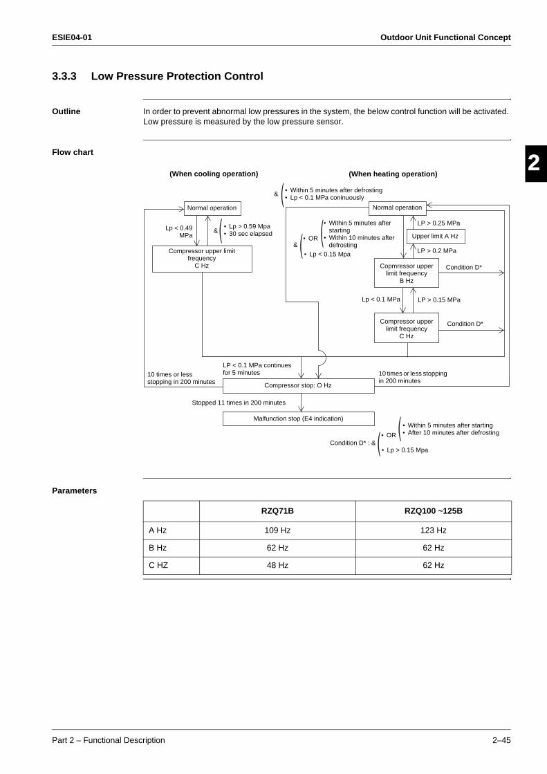
ESIE04-01 Outdoor Unit Functional Concept
Part 2 – Functional Description 2–45
3
2
4
5
13.3.3 Low Pressure Protection Control
Outline In order to prevent abnormal low pressures in the system, the below control function will be activated. Low pressure is measured by the low pressure sensor.
Flow chart
Parameters
Normal operation
Lp < 0.49MPa
Normal operation
&
(When cooling operation) (When heating operation)
• Within 5 minutes after defrosting• Lp < 0.1 MPa coninuously
Upper limit A Hz
Copmressor upper limit frequency
B Hz
Compressor upper limit frequency
C Hz
Compressor upper limit frequency
C Hz
Compressor stop: O Hz
Malfunction stop (E4 indication)
• Within 5 minutes after starting
• Within 10 minutes after defrosting&
• OR
• Lp < 0.15 Mpa
&• Lp > 0.59 Mpa• 30 sec elapsed
10 times or less stopping in 200 minutes
LP < 0.1 MPa continues for 5 minutes 10 times or less stopping
in 200 minutes
Lp < 0.1 MPa LP > 0.15 MPa
Condition D*
Condition D*
LP > 0.25 MPa
LP > 0.2 MPa
Stopped 11 times in 200 minutes
• Within 5 minutes after starting• After 10 minutes after defrosting
Condition D* : &• OR
• Lp > 0.15 Mpa
RZQ71B RZQ100 ~125B
A Hz 109 Hz 123 Hz
B Hz 62 Hz 62 Hz
C HZ 48 Hz 62 Hz
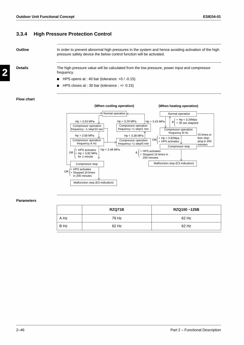
Outdoor Unit Functional Concept ESIE04-01
2–46 Part 2 – Functional Description
3
1
2
4
5
3.3.4 High Pressure Protection Control
Outline In order to prevent abnormal high pressures in the system and hence avoiding activation of the high pressure safety device the below control function will be activated.
Details The high pressure value will be calculated from the low pressure, power input and compressor frequency.
HPS opens at : 40 bar (tolerance: +0 / -0.15)
HPS closes at : 30 bar (tolerance : +/- 0.15)
Flow chart
Parameters
Normal operation
OR
Hp > 3.53 MPa
15 times or less stop-ping in 200 minutes
Normal operation
Compressor operation frequency B Hz
Compressor stop
Malfunction stop (E3 indication)
Malfunction stop (E3 indication)
Compressor stop
Compressor operation frequency A Hz
Compressor operation frequency –1 step/10 sec
Compressor operation frequency +1 step/1 min
Compressor operation frequency +1 step/5 min
Hp > 3.58 MPa
Hp > 3.43 MPa
OR
OR
&
&
Hp < 3.38 MPa• Hp > 3.82Mpa• HPS activates
• HPS activates• Stopped 16 times in
200 minutes
Hp < 3.48 MPa• HPS activates• Hp > 3.82 MPa
for 1 minute
• HPS activates• Stopped 16 times
in 200 minutes
(When cooling operation) (When heating operation)
Hp < 3.29 MPa• Hp < 3.24Mpa• 30 sec elapsed
RZQ71B RZQ100 ~125B
A Hz 79 Hz 62 Hz
B Hz 62 Hz 62 Hz
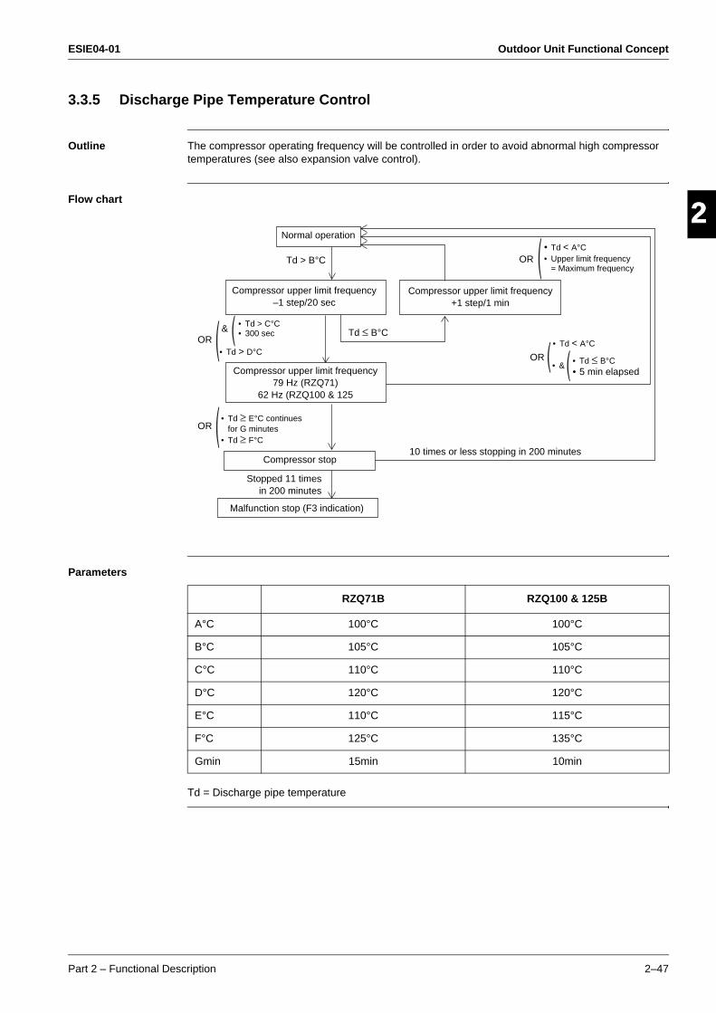
ESIE04-01 Outdoor Unit Functional Concept
Part 2 – Functional Description 2–47
3
2
4
5
13.3.5 Discharge Pipe Temperature Control
Outline The compressor operating frequency will be controlled in order to avoid abnormal high compressor temperatures (see also expansion valve control).
Flow chart
Parameters
Td = Discharge pipe temperature
Normal operation
OR
OR
&OR
OR
Td > B°C
Compressor upper limit frequency–1 step/20 sec
Compressor upper limit frequency+1 step/1 min
Compressor upper limit frequency79 Hz (RZQ71)
62 Hz (RZQ100 & 125
Compressor stop
Malfunction stop (F3 indication)
10 times or less stopping in 200 minutes
Td ≤ B°C
• Td < A°C• Upper limit frequency
= Maximum frequency
• Td ≤ B°C• 5 min elapsed
• Td < A°C
• Td > C°C• 300 sec
• Td ≥ E°C continuesfor G minutes
• Td ≥ F°C
Stopped 11 timesin 200 minutes
• &
• Td > D°C
RZQ71B RZQ100 & 125B
A°C 100°C 100°C
B°C 105°C 105°C
C°C 110°C 110°C
D°C 120°C 120°C
E°C 110°C 115°C
F°C 125°C 135°C
Gmin 15min 10min
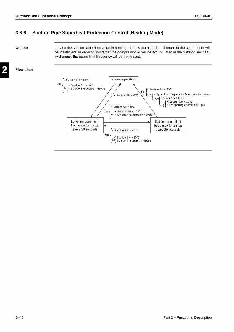
Outdoor Unit Functional Concept ESIE04-01
2–48 Part 2 – Functional Description
3
1
2
4
5
3.3.6 Suction Pipe Superheat Protection Control (Heating Mode)
Outline In case the suction superheat value in heating mode is too high, the oil return to the compressor will be insufficient. In order to avoid that the compressor oil will be accumulated in the outdoor unit heat exchanger, the upper limit frequency will be decreased.
Flow chart
Normal operation
Lowering upper limitfrequency for 1-stepevery 20 seconds
Raising upper limitfrequency for 1-stepevery 20 seconds• Suction SH > 12°C
• Suction SH > 10°C• EV opening degree = 480pls
• Suction SH > 12°C
• Suction SH > 10°C• EV opening degree = 480pls
• Suction SH < 10°C• EV opening degree < 450pls
• Suction SH < 8°C
• Suction SH < 6°C
• Suction SH < 6°C
• Upper limit frequency = Maximum frequency• Suction SH < 8°C
• Suction SH < 10°C• EV opening degree < 450 pls
OR
OR
OR
OR
&
&
&
• &
•OR
• &
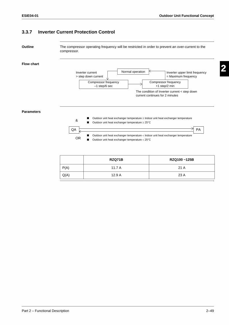
ESIE04-01 Outdoor Unit Functional Concept
Part 2 – Functional Description 2–49
3
2
4
5
13.3.7 Inverter Current Protection Control
Outline The compressor operating frequency will be restricted in order to prevent an over-current to the compressor.
Flow chart
Parameters
Compressor frequency–1 step/6 sec
Normal operation
Compressor frequency+1 step/2 min
Inverter current> step down current
Inverter upper limit frequency= Maximum frequency
The condition of Inverter current < step down current continues for 2 minutes
RZQ71B RZQ100 ~125B
P(A) 11.7 A 21 A
Q(A) 12.9 A 23 A
Outdoor unit heat exchanger temperature ≥ Indoor unit heat exchanger temperature
Outdoor unit heat exchanger temperature ≥ 25°C
Outdoor unit heat exchanger temperature < Indoor unit heat exchanger temperature
Outdoor unit heat exchanger temperature < 25°C
&
OR
PAQA
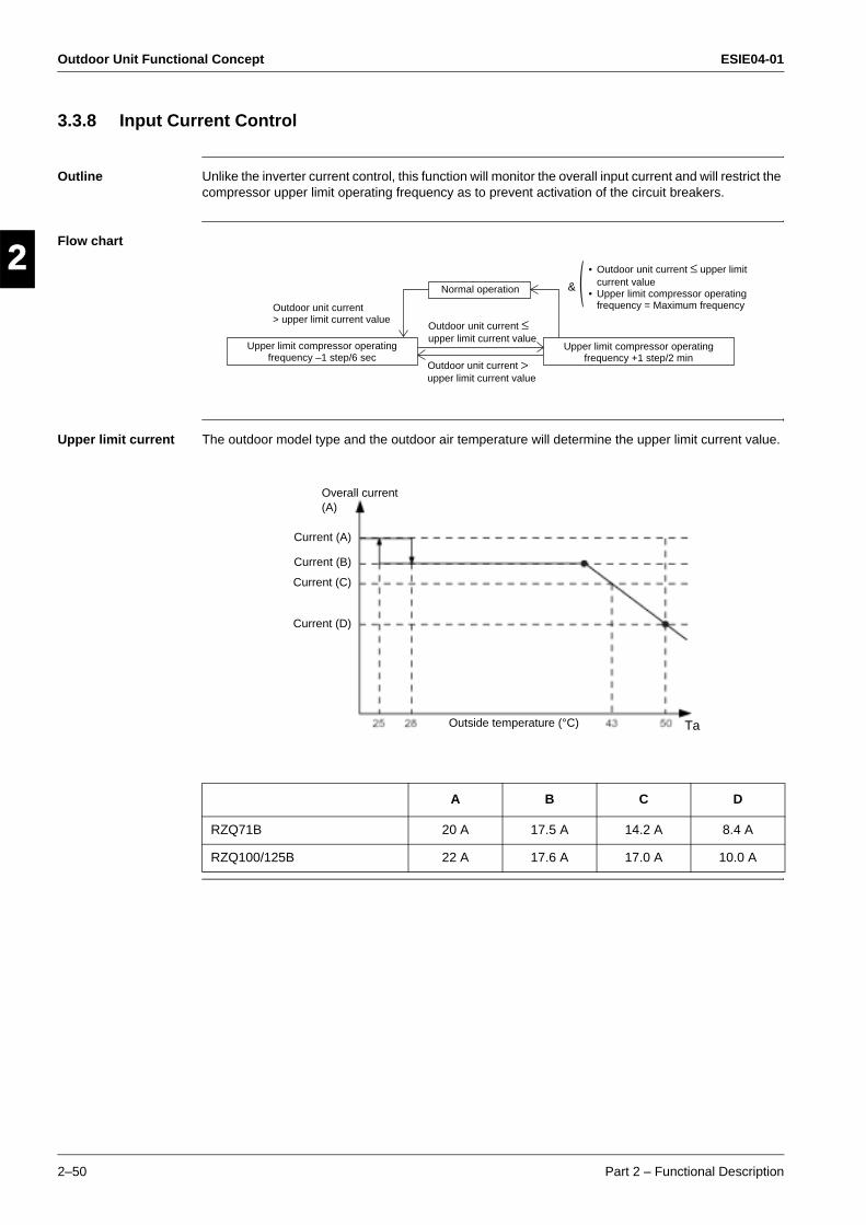
Outdoor Unit Functional Concept ESIE04-01
2–50 Part 2 – Functional Description
3
1
2
4
5
3.3.8 Input Current Control
Outline Unlike the inverter current control, this function will monitor the overall input current and will restrict the compressor upper limit operating frequency as to prevent activation of the circuit breakers.
Flow chart
Upper limit current The outdoor model type and the outdoor air temperature will determine the upper limit current value.
Upper limit compressor operating frequency –1 step/6 sec
Normal operation
Upper limit compressor operating frequency +1 step/2 min
Outdoor unit current> upper limit current value
• Outdoor unit current ≤ upper limit current value
• Upper limit compressor operating frequency = Maximum frequency
&
Outdoor unit current ≤ upper limit current value
Outdoor unit current > upper limit current value
A B C D
RZQ71B 20 A 17.5 A 14.2 A 8.4 A
RZQ100/125B 22 A 17.6 A 17.0 A 10.0 A
Overall current (A)
Current (A)
Current (B)
Current (C)
Current (D)
Outside temperature (°C) Ta
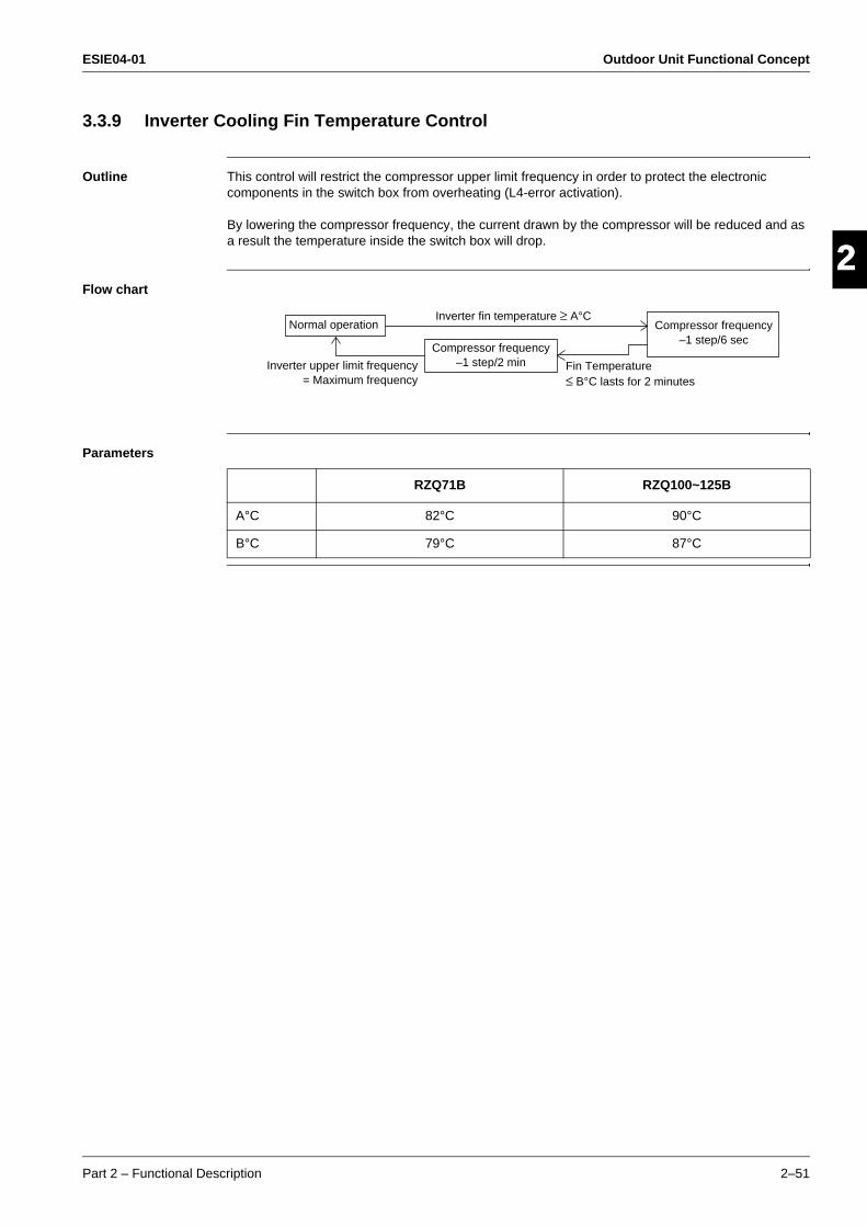
ESIE04-01 Outdoor Unit Functional Concept
Part 2 – Functional Description 2–51
3
2
4
5
13.3.9 Inverter Cooling Fin Temperature Control
Outline This control will restrict the compressor upper limit frequency in order to protect the electronic components in the switch box from overheating (L4-error activation).
By lowering the compressor frequency, the current drawn by the compressor will be reduced and as a result the temperature inside the switch box will drop.
Flow chart
Parameters
Fin Temperature≤ B°C lasts for 2 minutes
Normal operation
Compressor frequency–1 step/2 min
Compressor frequency–1 step/6 sec
Inverter fin temperature ≥ A°C
Inverter upper limit frequency= Maximum frequency
RZQ71B RZQ100~125B
A°C 82°C 90°C
B°C 79°C 87°C
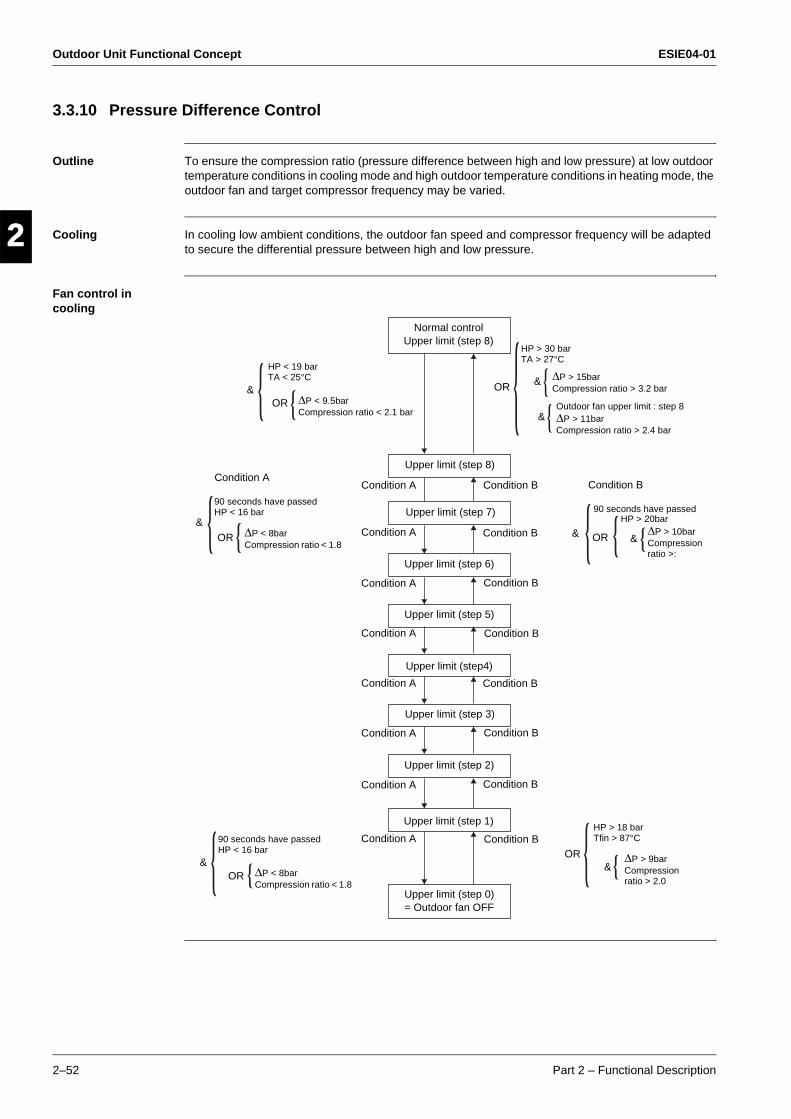
Outdoor Unit Functional Concept ESIE04-01
2–52 Part 2 – Functional Description
3
1
2
4
5
3.3.10 Pressure Difference Control
Outline To ensure the compression ratio (pressure difference between high and low pressure) at low outdoor temperature conditions in cooling mode and high outdoor temperature conditions in heating mode, the outdoor fan and target compressor frequency may be varied.
Cooling In cooling low ambient conditions, the outdoor fan speed and compressor frequency will be adapted to secure the differential pressure between high and low pressure.
Fan control in cooling
∆P > 15barCompression ratio > 3.2 bar
Normal control Upper limit (step 8)
Upper limit (step 8)
Upper limit (step 7)
Upper limit (step 6)
Upper limit (step 5)
Upper limit (step4)
Upper limit (step 3)
Upper limit (step 2)
Upper limit (step 1)
Upper limit (step 0)= Outdoor fan OFF
Condition B
Condition B
Condition B
Condition B
Condition B
Condition B
Condition B
Condition B
Outdoor fan upper limit : step 8∆P > 11barCompression ratio > 2.4 bar
Condition B
90 seconds have passedHP > 20bar
∆P > 10barCompression ratio >:
&
&
&&
HP > 30 barTA > 27°C
OR
OR
&
&
OR
OR
&OR
90 seconds have passedHP < 16 bar
∆P < 8barCompression ratio < 1.8
90 seconds have passedHP < 16 bar
∆P < 8barCompression ratio < 1.8
Condition A
∆P < 9.5barCompression ratio < 2.1 bar
HP < 19 barTA < 25°C
&OR
HP > 18 barTfin > 87°C
∆P > 9barCompression ratio > 2.0
Condition A
Condition A
Condition A
Condition A
Condition A
Condition A
Condition A
Condition A
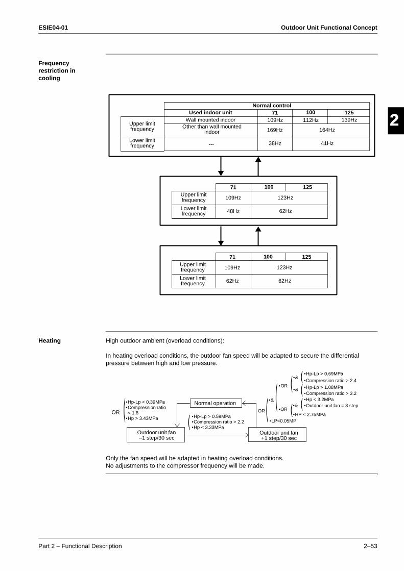
ESIE04-01 Outdoor Unit Functional Concept
Part 2 – Functional Description 2–53
3
2
4
5
1Frequency restriction in cooling
Heating High outdoor ambient (overload conditions):
In heating overload conditions, the outdoor fan speed will be adapted to secure the differential pressure between high and low pressure.
Only the fan speed will be adapted in heating overload conditions.No adjustments to the compressor frequency will be made.
Normal controlUsed indoor unit
Wall mounted indoorOther than wall mounted
indoor
---
Upper limit frequency
Lower limit frequency
71109Hz
169Hz
38Hz
100112Hz
164Hz
41Hz
125139Hz
Upper limit frequency
Lower limit frequency
71
109Hz
48Hz
100
123Hz
62Hz
125
Upper limit frequency
Lower limit frequency
71
109Hz
62Hz
100
123Hz
62Hz
125
Normal operation
Outdoor unit fan –1 step/30 sec
Outdoor unit fan +1 step/30 sec
•Hp-Lp < 0.39MPa•Compression ratio < 1.8
•Hp > 3.43MPaOR OR
•LP<0.05MP
•&
•OR
•OR
•&
•&
•&
•HP < 2.75MPa
•Hp-Lp > 0.69MPa•Compression ratio > 2.4•Hp-Lp > 1.08MPa•Compression ratio > 3.2•Hp < 3.2MPa•Outdoor unit fan = 8 step
•Hp-Lp > 0.59MPa•Compression ratio > 2.2•Hp < 3.33MPa
Outdoor Unit Functional Concept ESIE04-01
2–54 Part 2 – Functional Description
3
1
2
4
5
3.3.11 Oil Recovery Operation
Outline When the compressor operates for a certain period of time at low frequency, the oil level in the compressor may become low due to incomplete oil recovery.To prevent damage to the compressor and in worst case avoid compressor lock, an oil recovery operation will be conducted.
Details During the oil recovery operation, the operation frequency of the compressor will be increased for a time period of 10 minutes.
Example Trigger conditions for 71-class:
In cooling : Compressor frequency = 62 Hz for 10 minutes continuously.
In heating : Compressor frequency = 109 Hz for 10 minutes continuously.
When the above conditions are fulfilled, a calculation of the oil discharge amount will be executed according to the below formula:
Oil discharge amount = inverter frequency (Hz) x D x ∆time(D = constant value depending on outdoor unit type).
When the result of the above calculation is lower than a reference value programmed in the unit's memory, the oil recovery operation will be started:
The compressor will operate at a frequency above 62 Hz in cooling and 109 Hz in heating for 10 minutes continuously.
ESIE04-01 Outdoor Unit Functional Concept
Part 2 – Functional Description 2–55
3
2
4
5
13.4 Expansion Valve Regulating Functions
Introduction This chapter will explain the functions that are used to control the expansion valve opening.
Content
Topic See page
3.4.1–Expansion Valve Control at Startup 2–56
3.4.2–General Expansion Valve Control 2–57
3.4.3–Discharge Pipe Temperature Control 2–58
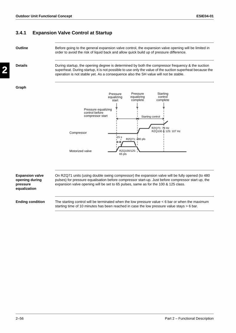
Outdoor Unit Functional Concept ESIE04-01
2–56 Part 2 – Functional Description
3
1
2
4
5
3.4.1 Expansion Valve Control at Startup
Outline Before going to the general expansion valve control, the expansion valve opening will be limited in order to avoid the risk of liquid back and allow quick build up of pressure difference.
Details During startup, the opening degree is determined by both the compressor frequency & the suction superheat. During startup, it is not possible to use only the value of the suction superheat because the operation is not stable yet. As a consequence also the SH value will not be stable.
Graph
Expansion valve opening during pressure equalization
On RZQ71 units (using double swing compressor) the expansion valve will be fully opened (to 480 pulses) for pressure equalisation before compressor start-up. Just before compressor start up, the expansion valve opening will be set to 65 pulses, same as for the 100 & 125 class.
Ending condition The starting control will be terminated when the low pressure value < 6 bar or when the maximum starting time of 10 minutes has been reached in case the low pressure value stays > 6 bar.
Compressor
Motorized valve
Pressure equalizing control before compressor start
Pressure equalizing
start
Pressure equalizing complete
Starting control
complete
Starting control
RZQ71: 73 HzRZQ100 & 125: 107 Hz
RZQ71: 480 pls
RZQ100/125:65 pls
15 s

ESIE04-01 Outdoor Unit Functional Concept
Part 2 – Functional Description 2–57
3
2
4
5
13.4.2 General Expansion Valve Control
Outline After the start up control function has been terminated the general expansion valve control function will regulate the expansion valve opening in function of the target suction SH value (= superheat at evaporator outlet).
The actual discharge SH value will be used to set the target suction SH value during operation.
The measured suction SH value will be used to control the opening of the expansion to the target suction SH value.
Details When the unit is in cooling or heating operation the opening of the expansion valve will be controlled in order to keep the amount of superheat at the evaporator outlet constant. This way the evaporator can be used at maximum efficiency under all conditions. The initial target heat exchanger outlet superheat value = 5°C.
The target heat exchanger outlet superheat value can be increased in case the discharge superheat value decreases.
The target heat exchanger outlet superheat value can be decreased in case the discharge superheat value increases.
Control During "General expansion valve control" 2 parameters will be used to control the actual expansion valve opening degree:
1 Target superheat amount :When the target heat exchanger outlet superheat > actual heat exchanger outlet superheat → the expansion valve will close.When the target heat exchanger outlet superheat < actual heat exchanger outlet superheat → the expansion valve will open.The superheat amount is checked every 10 seconds.
2 Frequency change: At the time of compressor frequency change, the expansion valve opening will be changed with a fixed value. This value will be in function of the amount of compressor frequency change.
Calculations The heat exchanger outlet superheat value is calculated from the saturated suction temperature Te (using LP sensor) and the suction pipe temperature R4T : SH = R4T-Te.
The discharge superheat value is calculated from the saturated discharge temperature Td (HP value calculated out of PI, frequency and LP) and the discharge pipe temperature R3T : SH = R3T-Td.

Outdoor Unit Functional Concept ESIE04-01
2–58 Part 2 – Functional Description
3
1
2
4
5
3.4.3 Discharge Pipe Temperature Control
Outline The expansion valve opening will be controlled in order to avoid abnormal high compressor discharge temperatures (see also compressor operating frequency control).
Details
RZQ71B RZQ100~125B
M°C 95°C 95°C
N°C 80°C
Normal operation
Expansion valve opening+5 pls/2 min when cooling,
1 min when heating.
Td > M°C Td < N°C
ESIE04-01 Outdoor Unit Functional Concept
Part 2 – Functional Description 2–59
3
2
4
5
13.5 Outdoor Unit Fan Speed Control
Introduction This chapter will explain how the outdoor fan speed is determined in cooling and heating operation.
Content
Topic See page
3.5.1–Outdoor Unit Fan Speed Control 2–60

Outdoor Unit Functional Concept ESIE04-01
2–60 Part 2 – Functional Description
3
1
2
4
5
3.5.1 Outdoor Unit Fan Speed Control
Fan speed control The outdoor fan speed will be controlled in function of the actual outdoor ambient temperature, the condensation pressure, pressure difference between low and high pressure and compression ratio.
For details please refer to "Pressure Difference Control".
Fan step table RZQ71
Fan step table RZQ100
Step Cooling Heating
0 0 0
1 200 200
2 250 250
3 300 300
4 360 360
5 430 430
6 515 515
7 620 620
8 790 720
Cooling Heating
Step M1F M2F M1F M2F
0 0 0 0 0
1 250 0 250 0
2 400 0 285 250
3 285 250 335 300
4 360 325 395 360
5 445 410 470 435
6 545 510 560 525
7 660 625 660 625
8 820 785 825 790
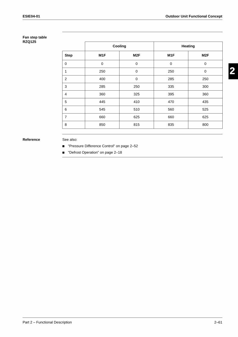
ESIE04-01 Outdoor Unit Functional Concept
Part 2 – Functional Description 2–61
3
2
4
5
1Fan step table RZQ125
Reference See also:
"Pressure Difference Control" on page 2–52
"Defrost Operation" on page 2–18
Cooling Heating
Step M1F M2F M1F M2F
0 0 0 0 0
1 250 0 250 0
2 400 0 285 250
3 285 250 335 300
4 360 325 395 360
5 445 410 470 435
6 545 510 560 525
7 660 625 660 625
8 850 815 835 800
Outdoor Unit Functional Concept ESIE04-01
2–62 Part 2 – Functional Description
3
1
2
4
5

ESIE04-01
Part 3 – Troubleshooting 3–1
4
3
4
5
3
Part 3Troubleshooting
What is in this part? This part contains the following chapters:
Chapter See page
1–Troubleshooting 3–3
2–Error Codes: Indoor Units 3–39
3–Error Codes: Outdoor Units 3–53
4–Error Codes: System Malfunctions 3–89
5–Additional Checks for Troubleshooting 3–97
ESIE04-01
3–2 Part 3 – Troubleshooting
3
1
3
5
ESIE04-01 Troubleshooting
Part 3 – Troubleshooting 3–3
33
4
5
1Part 3
1 Troubleshooting
1.1 What Is in This Chapter?
Introduction When a problem occurs, you have to check all possible malfunctions. This chapter gives a general idea of where to look for malfunctions.
Not all repair procedures are described. Some procedures are considered common practice.
Overview This chapter contains the following topics:
Topic See page
1.2–General Troubleshooting Flowchart 3–4
1.3–Overview of General Problems 3–5
1.4–Procedure of Self-Diagnosis by Remote Control 3–24
1.5–Fault-diagnosis by Wired Remote Control 3–25
1.6–Fault-diagnosis by Infrared remote control 3–26
1.7–Overview of Error Codes 3–30
1.8–Troubleshooting by LED Indications 3–32
1.9–Troubleshooting by Remote Control Display / LED Display 3–34
1.10–Overview of the Outdoor Safety Devices 3–37
1.11–Overview of the Indoor Safety Devices 3–38
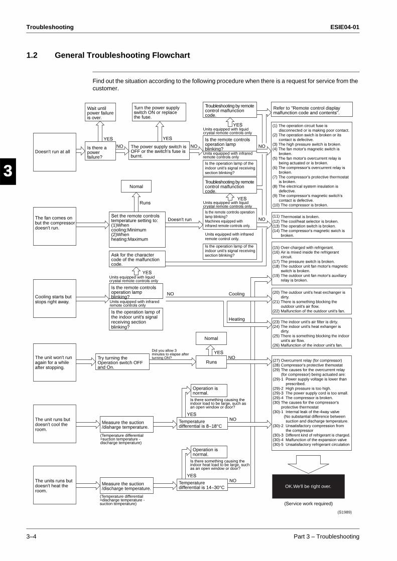
Troubleshooting ESIE04-01
3–4 Part 3 – Troubleshooting
3
1
3
4
5
1.2 General Troubleshooting Flowchart
Find out the situation according to the following procedure when there is a request for service from the customer.
YES
NO NO NO
NO
NO Cooling
Heating
NO
NO
YES
YES
YESRuns
Runs
Nomal
Nomal
Doesn't run
YES
YES
YES
NOYES
(Service work required)
OK.We'll be right over.
(S1989)
Troubleshooting by remote control malfunction code.
Turn the power supply switch ON or replace the fuse.
Wait until power failure is over.
Is there a power failure?
Doesn't run at allThe power supply switch is OFF or the switch's fuse is burnt.
Set the remote controls temperature setting to: (1)When cooling:Minimum(2)When heating:Maximum
The fan comes on but the compressor doesn't run.
Cooling starts but stops right away.
Is the remote controls operation lamp blinking?
Is the remote controls operation lamp blinking?Machines equipped with infrared remote controls only.
Is the operation lamp of the indoor unit's signal receiving section blinking?
Is the operation lamp of the indoor unit's signal receiving section blinking?
Units equipped with infrared remote control only.
Troubleshooting by remote control malfunction code.
Ask for the character code of the malfunction code.
Refer to "Remote control display malfunction code and contents".
Is the remote controls operation lamp blinking?
Try turning the Operation switch OFF and On.
The unit won't run again for a while after stopping.
The unit runs but doesn't cool the room.
Is the operation lamp of the indoor unit's signal receiving section blinking?
Measure the suction /disharge temperature.
Is there something causing theindoor load to be large, such asan open window or door?
Operation is normal.
Temperature differential is 8~18°C
The units runs but doesn't heat the room.
Measure the suction/discharge temperature.
Is there something causing theindoor heat load to be large, such as an open window or door?
Operation is normal.
Temperature differential is 14~30°C
(1) The operation circuit fuse is disconnected or is making poor contact.
(2) The operation swich is broken or its contact is defective.
(3) The high pressure switch is broken.(4) The fan motor's magnetic switch is
broken.(5) The fan motor's overcurrent relay is
being actuated or is broken.(6) The compressor's overcurrent relay is
broken.(7) The compressor's protective thermostat
is broken.(8) The electrical system insulation is
defective.(9) The compressor's magnetic switch's
contact is defective.(10) The compressor is broken.
(11) Thermostat is broken.(12) The cool/heat selector is broken.(13) The operation switch is broken.(14) The compressor's magnetic swich is
broken.
(15) Over-charged with refrigerant.(16) Air is mixed inside the refrigerant
circuit.(17) The pressure switch is broken.(18) The outdoor unit fan motor's magnetic
switch is broken.(19) The outdoor unit fan motor's auxiliary
relay is broken.
(20) The outdoor unit's heat exchanger is dirty.
(21) There is something blocking the outdoor unit's air flow.
(22) Malfunction of the outdoor unit's fan.
(23) The indoor unit's air filter is dirty.(24) The indoor unit's heat exhanger is
dirty.(25) There is something blocking the indoor
unit's air flow.(26) Malfunction of the indoor unit's fan.
(27) Overcurrent relay (for compressor)(28) Compressor's protective themostat(29) The causes for the overcurrent relay
(for compressor) being actuated are:(29)-1 Power supply voltage is lower than
prescribed.(29)-2 High pressure is too high.(29)-3 The power supply cord is too small.(29)-4 The compressor is broken.(30) The causes for the compressor's
protective thermostat(30)-1 Internal leak of the-4way valve (No substantial difference between
suction and discharge temperature.(30)-2 Unsatisfactory compression from
the compressor(30)-3 Different kind of refrigerant is charged.(30)-4 Malfunction of the expansion valve(30)-5 Unsatisfactory refrigerant circulation
Units equipped with liquid crystal remote controls only
Units equipped with infrared remote controls only
Units equipped with liquid crystal remote controls only
Units equipped with liquid crystal remote controls only
Units equipped with infrared remote controls only
Did you allow 3 minutes to elapse after turning ON?
(Temperature differential =suction temperature - discharge temperature)
(Temperature differential =discharge temperature - suction temperature)

ESIE04-01 Troubleshooting
Part 3 – Troubleshooting 3–5
33
4
5
11.3 Overview of General Problems
Overview
Equipment Condition Remedy
1 Equipment does not operate. See page 3-6
2 Fan operates, but compressor does not. See page 3-6
3 Cooling/heating operation starts but stops immediately.
See page 3-10
4 After unit shuts down, it cannot be restarted for a while.
See page 3-12
5 Equipment operates but does not provide cooling.
See page 3-14
6 Equipment operates but does not provide heating.
See page 3-16
7 Equipment discharges white mist. See page 3-18
8 Equipment produces loud noise or shakes. See page 3-19
9 Equipment discharges dust. See page 3-20
10 Remote control LCD displays “88.” See page 3-21
11 Indoor swing flap does not operate. See page 3-22
12 Equipment emits odor. Room smell and cigarette odors accumu-lated inside the indoor unit are discharged with air. Inside of the indoor unit must be cleaned.
13 Flap operates when power is turned on. It is normal. The flap initializes for accurate positioning.
14 Change of operation mode causes flap to move.
It is normal. There is a control function that moves the flap when operation mode is changed.
15 Fan operates in “M” mode during heating even if remote control is set to “Low.”
It is normal. It is caused by the activation of the overload control (airflow shift control).
16 Flap automatically moves during cooling. It is normal. It is caused by the activation of the dew prevention function or ceiling soil-ing prevention function.
17 Indoor unit fan operates in “L” mode for 1 minute in microcomputer-controlled dry mode even if compressor is not operating.
It is normal. The monitoring function forci-bly operates the fan for one minute.
18 In simultaneous ON/OFF multi-system setup, indoor unit (sub) does not operate in sync with the other indoor unit (main).
(Flat, fan, etc.)
It is normal. It is caused by a signal trans-mission lag.
19 Indoor unit fan operates after heating oper-ation stops.
It is normal. The fan operates in the “LL” mode for 60 to 100 seconds to dissipate the residual heat in the heater.
20 Drain pump operates when equipment is not operating.
It is normal. The drain pump continues to operate for several minutes after equip-ment is turned off.
21 Horizontal swing sends air to different directions in cooling and heating even if it is set to the same position.
It is normal. The airflow direction in cool-ing/dry operation is different from that in heating/fan operation.
22 Flap remains horizontal even if it is set to Swing.
It is normal. The flap does not swing in the thermostat OFF mode.
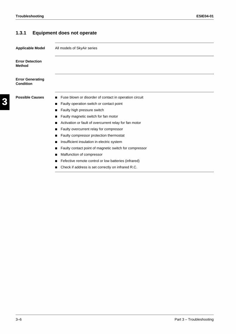
Troubleshooting ESIE04-01
3–6 Part 3 – Troubleshooting
3
1
3
4
5
1.3.1 Equipment does not operate
Applicable Model All models of SkyAir series
Error Detection Method
Error Generating Condition
Possible Causes Fuse blown or disorder of contact in operation circuit
Faulty operation switch or contact point
Faulty high pressure switch
Faulty magnetic switch for fan motor
Activation or fault of overcurrent relay for fan motor
Faulty overcurrent relay for compressor
Faulty compressor protection thermostat
Insufficient insulation in electric system
Faulty contact point of magnetic switch for compressor
Malfunction of compressor
Fefective remote control or low batteries (infrared)
Check if address is set correctly on infrared R.C.
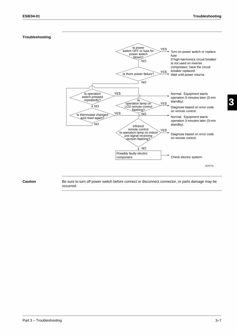
ESIE04-01 Troubleshooting
Part 3 – Troubleshooting 3–7
33
4
5
1Troubleshooting
Caution Be sure to turn off power switch before connect or disconnect connector, or parts damage may be occurred.
Possibly faulty electric component
Turn on power switch or replace fuse.If high-harmonics circuit breaker is not used on inverter compressor, have the circuit breaker replaced.Wait until power returns.
Normal. Equipment starts operation 3 minutes later (3-min standby).
Diagnose based on error code on remote control.
Normal. Equipment starts operation 3 minutes later (3-min standby).
Diagnose based on error code on remote control.
Check electric system.
Is powerswitch OFF or fuse for
power switchblown?
Isoperation lamp on
LCD remote controlflashing?
Is operation switch pressed
repeatedly?
Infraredremote control
Is operation lamp on indoorunit signal receiving
section flashing?
Is thermostat changed and reset again?
Is there power failure?
NO
NO
NO
NO
NO
NO
YES
YES
YES
YES
YES
YES
(S2575)
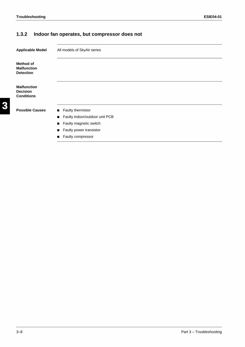
Troubleshooting ESIE04-01
3–8 Part 3 – Troubleshooting
3
1
3
4
5
1.3.2 Indoor fan operates, but compressor does not
Applicable Model All models of SkyAir series
Method of Malfunction Detection
Malfunction Decision Conditions
Possible Causes Faulty thermistor
Faulty indoor/outdoor unit PCB
Faulty magnetic switch
Faulty power transistor
Faulty compressor
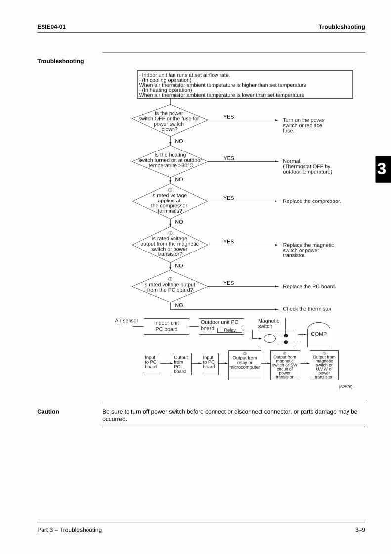
ESIE04-01 Troubleshooting
Part 3 – Troubleshooting 3–9
33
4
5
1Troubleshooting
Caution Be sure to turn off power switch before connect or disconnect connector, or parts damage may be occurred.
YES
YES
YES
NO
NO
YES
NO
NO
YES
NO
Air sensor
RelayCOMP
Input to PC board
Input to PC board
Output from PC board
!Output from
relay or microcomputer
"Output from
magnetic switch or SW
circuit of power
transistor
#Output from
magnetic switch or U,V,W of
power transistor
· Indoor unit fan runs at set airflow rate.· (In cooling operation)When air thermistor ambient temperature is higher than set temperature· (In heating operation)When air thermistor ambient temperature is lower than set temperature
Is the power switch OFF or the fuse for
power switch blown?
"Is rated voltage
output from the magnetic switch or power
transistor?
!Is rated voltage output
from the PC board?
Is the heating switch turned on at outdoor
temperature >30°C
#Is rated voltage
applied at the compressor
terminals?
Indoor unit PC board
Outdoor unit PC board
Replace the magnetic switch or power transistor.
Magnetic switch
Replace the PC board.
Check the thermistor.
Replace the compressor.
Normal. (Thermostat OFF by outdoor temperature)
Turn on the power switch or replace fuse.
(S2576)

Troubleshooting ESIE04-01
3–10 Part 3 – Troubleshooting
3
1
3
4
5
1.3.3 Cooling/heating operation starts but stops immediately.
Applicable Model All models of SkyAir series
Error Detection Method
Error Generating Condition
Possible Cause Excess charge of refrigerant
Air intrudes into refrigerant system
Faulty pressure switch
Faulty magnetic switch for outdoor unit fan motor
Faulty aux. relay for outdoor unit fan motor
Soiled heat exchanger of outdoor unit
There is an interfering item in air flow of outdoor unit
Malfunction of outdoor unit fan
Soiled air filter of indoor unit
Soiled heat exchanger of indoor unit
There is some interfering item in airflow of indoor unit
Malfunction of indoor unit fan

ESIE04-01 Troubleshooting
Part 3 – Troubleshooting 3–11
33
4
5
1Troubleshooting
Caution Be sure to turn off power switch before connect or disconnect connector, or parts damage may be occurred.
Possible causes as follows:∗ Refrigerant overcharge∗ Mixing of air in refrigerant
system∗ Faulty pressure switch
Does the fan rotate?
Is the filter soiled?
NO
NO
Isthe operation
lamp of remote controlflashing?
Is theoperation lamp
of indoor unit photo-sensingsection flashing?
Is the type ofinfrared control wired or
wireless?
Is there any itemdisturbing airflow?
Is the heatexchanger soiled?
YES
NO
YES
YES
YES
YES
Wireless
YES
Heating: Indoor unitCooling: Outdoor unit
wired
[ ]
(S1992)
NO
NO
After vacuum drying, charge correct amount of refrigerantCheck the pressure switch
Cleaning of the heat exchanger
Remove the disturbing item
Cleaning
Malfunction of fan motor Check the magnetic switch and aux. switch for fan motor
Diagnose based on the error code on infrared control

Troubleshooting ESIE04-01
3–12 Part 3 – Troubleshooting
3
1
3
4
5
1.3.4 After unit shuts down, it cannot be restarted for a while.
Applicable Model All models of SkyAir series
Error Detection Method
Error Generating Condition
Possible Cause Overcurrent relay (for compressor)
Compressor protection thermostat
Overcurrent relay may act due to the following reasonsLower voltage of power supplyExcess level of high pressure Insufficient size of power cableMalfunction of compressor
Compressor protection thermostat may act due to the following reasonsInternal leakage of four-way valve (There is no difference between suction and discharge temperature)Insufficient compression of compressorIncorrect refrigerantFaulty expansion valveInsufficient circulation of refrigerant
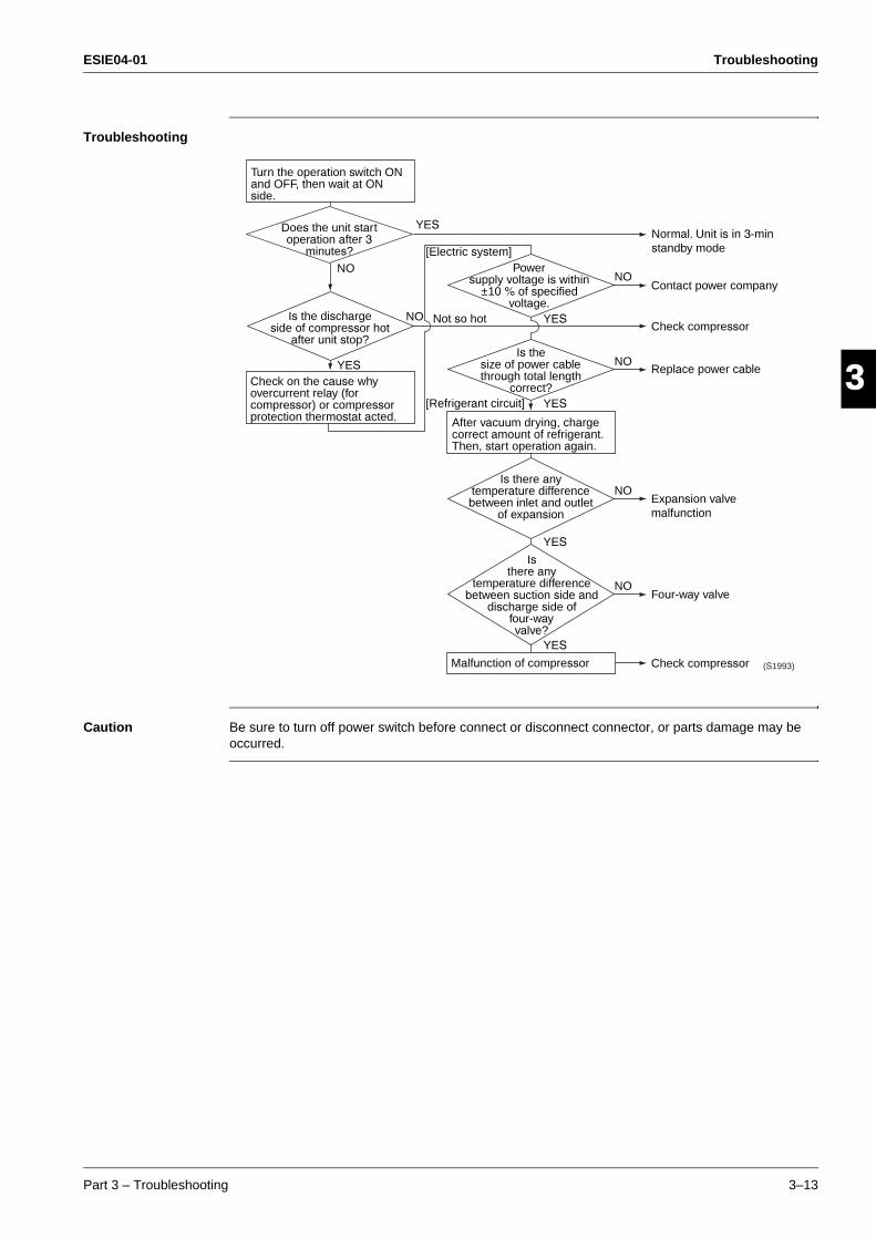
ESIE04-01 Troubleshooting
Part 3 – Troubleshooting 3–13
33
4
5
1Troubleshooting
Caution Be sure to turn off power switch before connect or disconnect connector, or parts damage may be occurred.
Turn the operation switch ON and OFF, then wait at ON side.
After vacuum drying, charge correct amount of refrigerant. Then, start operation again.
NO
YES
YES
YES
Malfunction of compressor
YES
YES
Is there anytemperature differencebetween inlet and outlet
of expansion
Isthere any
temperature differencebetween suction side and
discharge side offour-wayvalve?
Powersupply voltage is within
±10 % of specifiedvoltage.
Is thesize of power cablethrough total length
correct?
NO
NO
NO
NO
YES
[Electric system]
[Refrigerant circuit]
Not so hotNO
(S1993)
Check on the cause why overcurrent relay (for compressor) or compressor protection thermostat acted.
Does the unit start operation after 3
minutes?
Is the discharge side of compressor hot
after unit stop?
Check compressor
Four-way valve
Expansion valve malfunction
Replace power cable
Check compressor
Contact power company
Normal. Unit is in 3-min standby mode
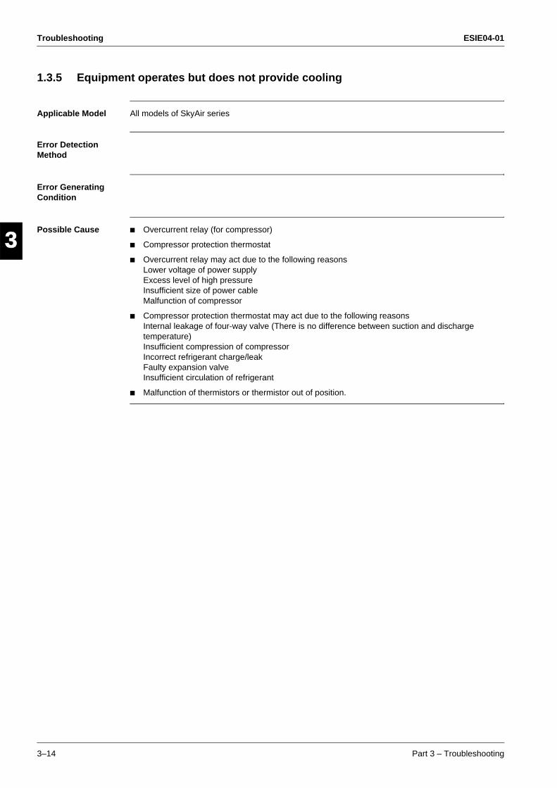
Troubleshooting ESIE04-01
3–14 Part 3 – Troubleshooting
3
1
3
4
5
1.3.5 Equipment operates but does not provide cooling
Applicable Model All models of SkyAir series
Error Detection Method
Error Generating Condition
Possible Cause Overcurrent relay (for compressor)
Compressor protection thermostat
Overcurrent relay may act due to the following reasonsLower voltage of power supplyExcess level of high pressure Insufficient size of power cableMalfunction of compressor
Compressor protection thermostat may act due to the following reasonsInternal leakage of four-way valve (There is no difference between suction and discharge temperature)Insufficient compression of compressorIncorrect refrigerant charge/leakFaulty expansion valveInsufficient circulation of refrigerant
Malfunction of thermistors or thermistor out of position.
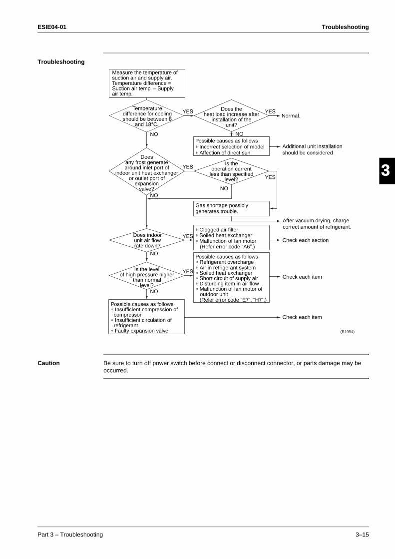
ESIE04-01 Troubleshooting
Part 3 – Troubleshooting 3–15
33
4
5
1Troubleshooting
Caution Be sure to turn off power switch before connect or disconnect connector, or parts damage may be occurred.
Possible causes as follows∗ Incorrect selection of model∗ Affection of direct sun
∗ Clogged air filter ∗ Soiled heat exchanger∗ Malfunction of fan motor
(Refer error code “A6”.)
Possible causes as follows∗ Refrigerant overcharge∗ Air in refrigerant system∗ Soiled heat exchanger∗ Short circuit of supply air∗ Disturbing item in air flow∗ Malfunction of fan motor of outdoor unit
(Refer error code “E7”, “H7”.)Possible causes as follows∗ Insufficient compression of compressor∗ Insufficient circulation of refrigerant∗ Faulty expansion valve
Gas shortage possibly generates trouble.
Doesany frost generatearound inlet port of
indoor unit heat exchangeror outlet port of
expansionvalve?
Is theoperation current
less than specifiedlevel?
Is the levelof high pressure higher
than normallevel?
Does theheat load increase after
installation of theunit?
YES
YES
YES
YES
YES
YES
NO
NO
NO
NO
NO
NO
(S1994)
Temperature difference for cooling should be between 8
and 18°C.
Measure the temperature of suction air and supply air. Temperature difference = Suction air temp. – Supply air temp.
Does indoor unit air flow rate down?
Check each item
Check each item
Check each section
After vacuum drying, charge correct amount of refrigerant.
Additional unit installation should be considered
Normal.
Troubleshooting ESIE04-01
3–16 Part 3 – Troubleshooting
3
1
3
4
5
1.3.6 Equipment operates but does not provide heating
Applicable Model All models of SkyAir series
Error Detection Method
Error Generating Condition
Possible Cause Excess charge of refrigerant
Air intrudes into refrigerant system
Faulty pressure switch
Faulty magnetic switch for outdoor unit fan motor
Faulty aux. relay for outdoor unit fan motor
Soiled heat exchanger of outdoor unit
There is an interfering item in air flow of outdoor unit
Malfunction of outdoor unit fan
Soiled air filter of indoor unit
Soiled heat exchanger of indoor unit
There is some interfering item in airflow of indoor unit
Malfunction of indoor unit fan
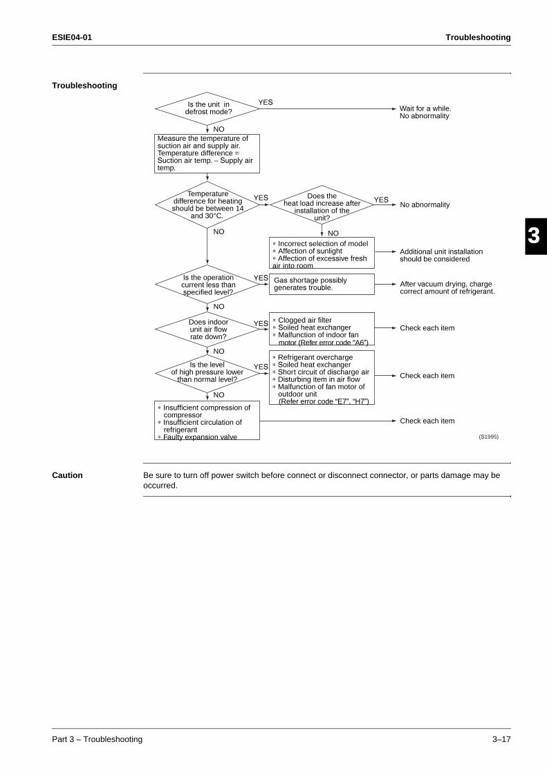
ESIE04-01 Troubleshooting
Part 3 – Troubleshooting 3–17
33
4
5
1Troubleshooting
Caution Be sure to turn off power switch before connect or disconnect connector, or parts damage may be occurred.
Measure the temperature of suction air and supply air. Temperature difference = Suction air temp. – Supply air temp.
Temperature difference for heating should be between 14
and 30°C.
Is the unit in defrost mode?
Is the operation current less than specified level?
Does theheat load increase after
installation of theunit?
YES
YES
YES
YES
YES
YES
∗ Incorrect selection of model∗ Affection of sunlight∗ Affection of excessive fresh air into room
∗ Clogged air filter ∗ Soiled heat exchanger∗ Malfunction of indoor fan
motor (Refer error code “A6”)
∗ Refrigerant overcharge∗ Soiled heat exchanger∗ Short circuit of discharge air∗ Disturbing item in air flow∗ Malfunction of fan motor of outdoor unit
(Refer error code “E7”, “H7”)∗ Insufficient compression of compressor∗ Insufficient circulation of refrigerant∗ Faulty expansion valve
NO
NO
NO
NO
Is the levelof high pressure lower
than normal level?
NO
NO
(S1995)
Does indoor unit air flow rate down?
Gas shortage possibly generates trouble.
Check each item
Check each item
Check each item
After vacuum drying, charge correct amount of refrigerant.
Additional unit installation should be considered
No abnormality
Wait for a while. No abnormality
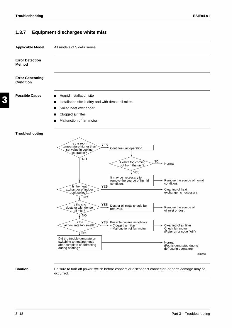
Troubleshooting ESIE04-01
3–18 Part 3 – Troubleshooting
3
1
3
4
5
1.3.7 Equipment discharges white mist
Applicable Model All models of SkyAir series
Error Detection Method
Error Generating Condition
Possible Cause Humid installation site
Installation site is dirty and with dense oil mists.
Soiled heat exchanger
Clogged air filter
Malfunction of fan motor
Troubleshooting
Caution Be sure to turn off power switch before connect or disconnect connector, or parts damage may be occurred.
Is white fog coming out from the unit?
Is the heatexchanger of indoor
unit soiled?
Is the sitedusty or with dense
oil mist?
NONO
NO
Is theairflow rate too small?
NO
NO
YES
YES
YES
YES
Is the roomtemperature higher than
set value in coolingoperation?
YES
Continue unit operation.
It may be necessary to remove the source of humid condition.
Dust or oil mists should be removed.
Possible causes as follows∗ Clogged air filter∗ Malfunction of fan motor
Did the trouble generate on switching to heating mode after complete of defrosting during heating?
(S1996)
Normal(Fog is generated due to defrosting operation)
Cleaning of air filter Check fan motor (Refer error code “A6”)
Remove the source of oil mist or dust.
Cleaning of heat exchanger is necessary.
Remove the source of humid condition.
Normal
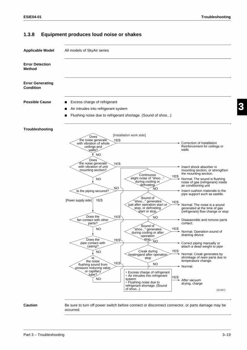
ESIE04-01 Troubleshooting
Part 3 – Troubleshooting 3–19
33
4
5
11.3.8 Equipment produces loud noise or shakes
Applicable Model All models of SkyAir series
Error Detection Method
Error Generating Condition
Possible Cause Excess charge of refrigerant
Air intrudes into refrigerant system
Flushing noise due to refrigerant shortage. (Sound of shoo...)
Troubleshooting
Caution Be sure to turn off power switch before connect or disconnect connector, or parts damage may be occurred.
∗ Excess charge of refrigerant∗ Air intrudes into refrigerant system ∗ Flushing noise due to refrigerant shortage. (Sound of shoo...)
NO
YES
YES
YES
YES
YES
Doesthe noise generate
with vibration of wholeceilings and
walls?
YES
NO
NO
NO
Doesthe noise generatewith vibration of unitmounting section?
Continuousslight noise of "shoo..."
during cooling ordefrosting
YES[Power supply side]
Is the piping secured?
Sound of"shoo..." generates
just after operation start orstop, or defrosting
start or stop.
NO
NO
Does thefan contact with other
parts?Sound of
"shoo..." generatesduring cooling or after
operationstop.
NO
NO
Does thepipe contact with
casing?
Creak duringheatingand after operation
stop
YES
NO
YES
YES
NO
Isthe noise
flushing sound frompressure reducing valve
or capillarytube?
YES
[Installation work side]
(S1997)
After vacuum drying, charge
Normal.
Normal. Creak generates by shrinkage of resin parts due to temperature change.
Correct piping manually or attach a dead weight to pipe
Normal. Operation sound of draining device
Disassemble and remove parts contact.
Normal. The noise is a sound generated at the time of gas (refrigerant) flow change or stop
Insert cushion materials to the pipe support such as saddle.
Normal. The sound is flushing noise of gas (refrigerant) inside air conditioning unit
Insert shock absorber in mounting section, or strengthen the mounting section.
Correction of installation Reinforcement for ceilings or walls
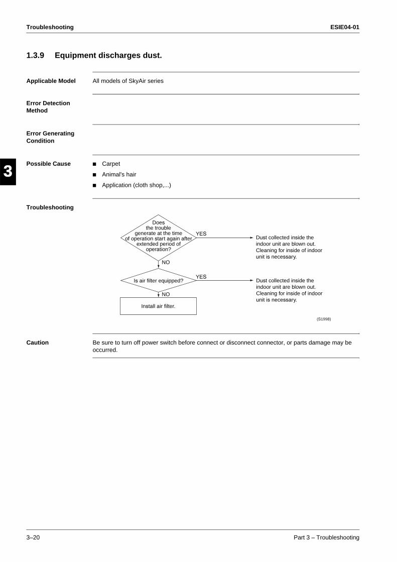
Troubleshooting ESIE04-01
3–20 Part 3 – Troubleshooting
3
1
3
4
5
1.3.9 Equipment discharges dust.
Applicable Model All models of SkyAir series
Error Detection Method
Error Generating Condition
Possible Cause Carpet
Animal's hair
Application (cloth shop,...)
Troubleshooting
Caution Be sure to turn off power switch before connect or disconnect connector, or parts damage may be occurred.
Install air filter.
Doesthe trouble
generate at the timeof operation start again after
extended period ofoperation?
YES
YES
NO
NO
Is air filter equipped?
(S1998)
Dust collected inside the indoor unit are blown out.Cleaning for inside of indoor unit is necessary.
Dust collected inside the indoor unit are blown out.Cleaning for inside of indoor unit is necessary.
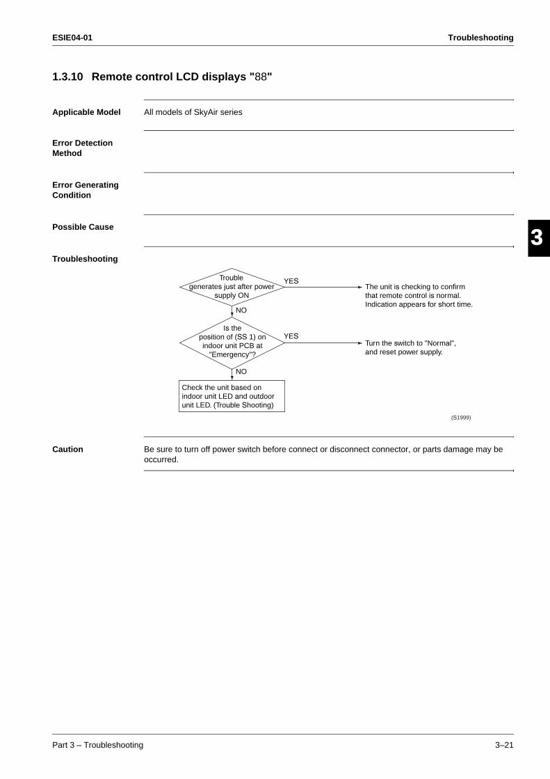
ESIE04-01 Troubleshooting
Part 3 – Troubleshooting 3–21
33
4
5
11.3.10 Remote control LCD displays "88"
Applicable Model All models of SkyAir series
Error Detection Method
Error Generating Condition
Possible Cause
Troubleshooting
Caution Be sure to turn off power switch before connect or disconnect connector, or parts damage may be occurred.
Check the unit based on indoor unit LED and outdoor unit LED. (Trouble Shooting)
Troublegenerates just after power
supply ON
YES
YES
NO
NO
Is theposition of (SS 1) onindoor unit PCB at
"Emergency"?
(S1999)
Turn the switch to "Normal", and reset power supply.
The unit is checking to confirm that remote control is normal. Indication appears for short time.
Troubleshooting ESIE04-01
3–22 Part 3 – Troubleshooting
3
1
3
4
5
1.3.11 Swing flap does not operate
Applicable Models FUQ, FHQ, FAQ100
Method of Malfunction Detection
Utilizes ON/OFF of the limit switch when the motor turns.
Malfunction Decision Conditions
When ON/OFF of the micro switch for positioning cannot be reversed even through the swing flap motor for a specified amount of time (about 30 seconds).
Remark Some functions can force the swing flap into a fixed position, altough swing mode is selected on the remote control. This is not an unit error, but a control function to prevent draft to the customer.
Before starting the troubleshooting, make sure the swing flap is not forced into such a fixed position. (e.g. Hot start, defrost operation, thermostat OFF in heating operation or freeze prevention in cooling operation. For details see "Fan and Flap Operations" on page 2-32 )
Possible Causes Faulty swing motor
Faulty micro switch
Faulty connector connection
Faulty indoor unit PC board
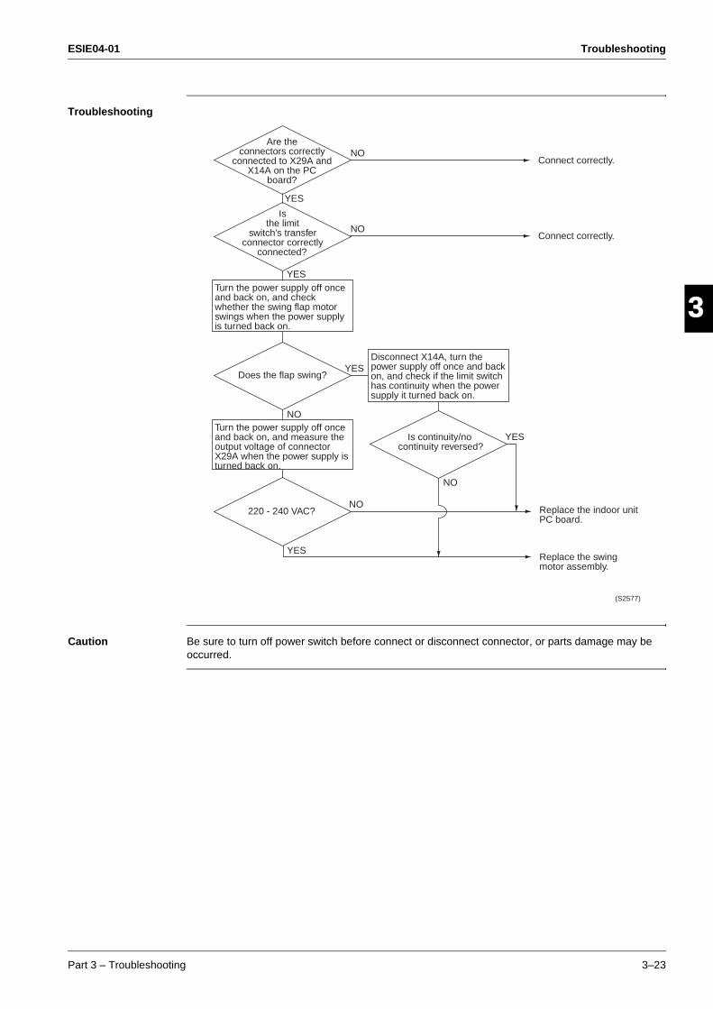
ESIE04-01 Troubleshooting
Part 3 – Troubleshooting 3–23
33
4
5
1Troubleshooting
Caution Be sure to turn off power switch before connect or disconnect connector, or parts damage may be occurred.
Connect correctly.
Connect correctly.
Does the flap swing?
Is continuity/no continuity reversed?
YES
NO
NO
YES
YES
YES
Replace the indoor unit PC board.
Replace the swing motor assembly.
NO
220 - 240 VAC?NO
YES
NO
(S2577)
Is the limit
switch’s transfer connector correctly
connected?
Turn the power supply off once and back on, and check whether the swing flap motor swings when the power supply is turned back on.
Disconnect X14A, turn the power supply off once and back on, and check if the limit switch has continuity when the power supply it turned back on.
Turn the power supply off once and back on, and measure the output voltage of connector X29A when the power supply is turned back on.
Are the connectors correctly
connected to X29A and X14A on the PC
board?
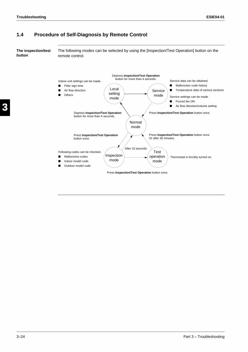
Troubleshooting ESIE04-01
3–24 Part 3 – Troubleshooting
3
1
3
4
5
1.4 Procedure of Self-Diagnosis by Remote Control
The inspection/test button
The following modes can be selected by using the [Inspection/Test Operation] button on the remote control.
Indoor unit settings can be made.
Filter sign time
Air flow direction
Others
Service data can be obtained.
Malfunciton code history
Temperature data of various sections
Service settings can be made.
Forced fan ON
Air flow direction/volume setting
Depress Inspection/Test Operation button for more than 4 seconds.
Following codes can be checked.
Malfunction codes
Indoor model code
Outdoor model code
Press Inspection/Test Operation button once.
Press Inspection/Test Operation button once.
Press Inspection/Test Operation button once.Or after 30 minutes.
Depress Inspection/Test Operation button for more than 4 seconds.
Press Inspection/Test Operation button once.
After 10 seconds
Thermostat is forcibly turned on.
Local setting mode
Service mode
Normal mode
Inspection mode
Test operation
mode
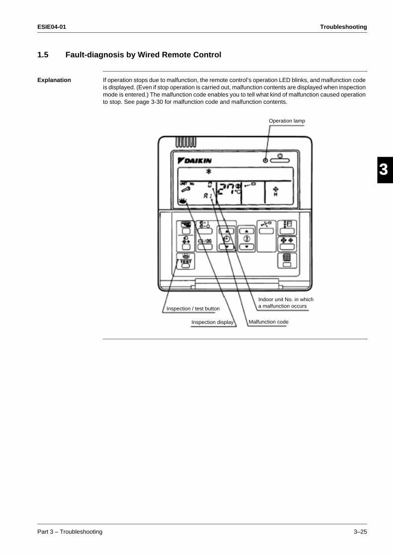
ESIE04-01 Troubleshooting
Part 3 – Troubleshooting 3–25
33
4
5
11.5 Fault-diagnosis by Wired Remote Control
Explanation If operation stops due to malfunction, the remote control’s operation LED blinks, and malfunction code is displayed. (Even if stop operation is carried out, malfunction contents are displayed when inspection mode is entered.) The malfunction code enables you to tell what kind of malfunction caused operation to stop. See page 3-30 for malfunction code and malfunction contents.
Inspection / test button
Inspection display Malfunction code
Indoor unit No. in whicha malfunction occurs
Operation lamp
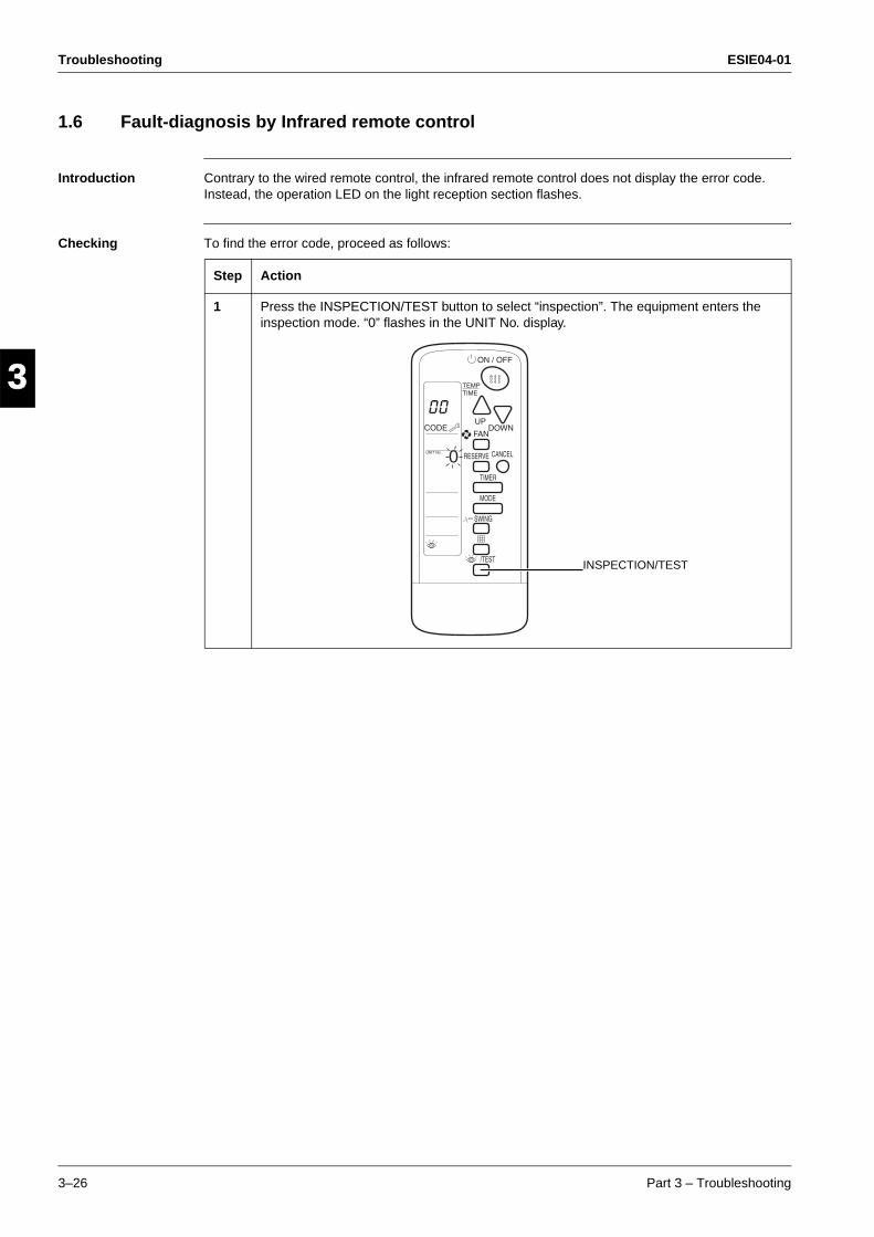
Troubleshooting ESIE04-01
3–26 Part 3 – Troubleshooting
3
1
3
4
5
1.6 Fault-diagnosis by Infrared remote control
Introduction Contrary to the wired remote control, the infrared remote control does not display the error code. Instead, the operation LED on the light reception section flashes.
Checking To find the error code, proceed as follows:
Step Action
1 Press the INSPECTION/TEST button to select “inspection”. The equipment enters the inspection mode. “0” flashes in the UNIT No. display.
0
INSPECTION/TEST
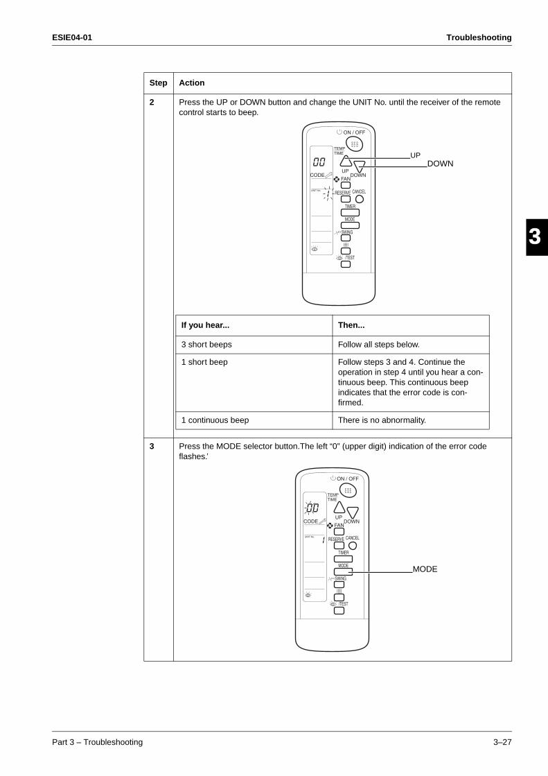
ESIE04-01 Troubleshooting
Part 3 – Troubleshooting 3–27
33
4
5
12 Press the UP or DOWN button and change the UNIT No. until the receiver of the remote
control starts to beep.
3 Press the MODE selector button.The left “0” (upper digit) indication of the error code flashes.’
Step Action
If you hear... Then...
3 short beeps Follow all steps below.
1 short beep Follow steps 3 and 4. Continue the operation in step 4 until you hear a con-tinuous beep. This continuous beep indicates that the error code is con-firmed.
1 continuous beep There is no abnormality.
UPDOWN
MODE
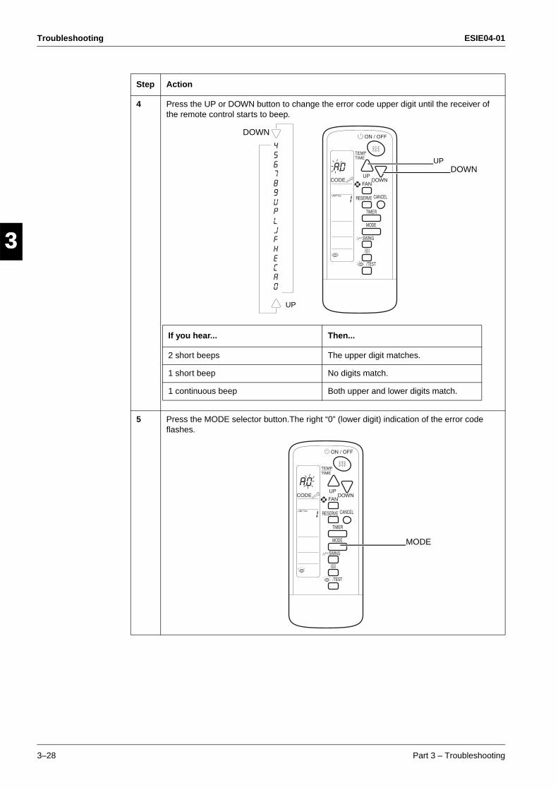
Troubleshooting ESIE04-01
3–28 Part 3 – Troubleshooting
3
1
3
4
5
4 Press the UP or DOWN button to change the error code upper digit until the receiver of the remote control starts to beep.
5 Press the MODE selector button.The right “0” (lower digit) indication of the error code flashes.
Step Action
If you hear... Then...
2 short beeps The upper digit matches.
1 short beep No digits match.
1 continuous beep Both upper and lower digits match.
UPDOWN
UP
DOWN
MODE
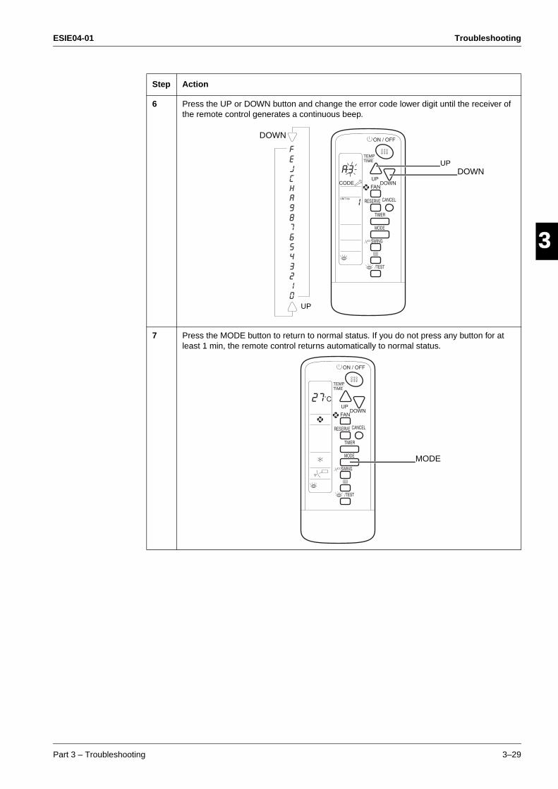
ESIE04-01 Troubleshooting
Part 3 – Troubleshooting 3–29
33
4
5
16 Press the UP or DOWN button and change the error code lower digit until the receiver of
the remote control generates a continuous beep.
7 Press the MODE button to return to normal status. If you do not press any button for at least 1 min, the remote control returns automatically to normal status.
Step Action
UPDOWN
UP
DOWN
MODE
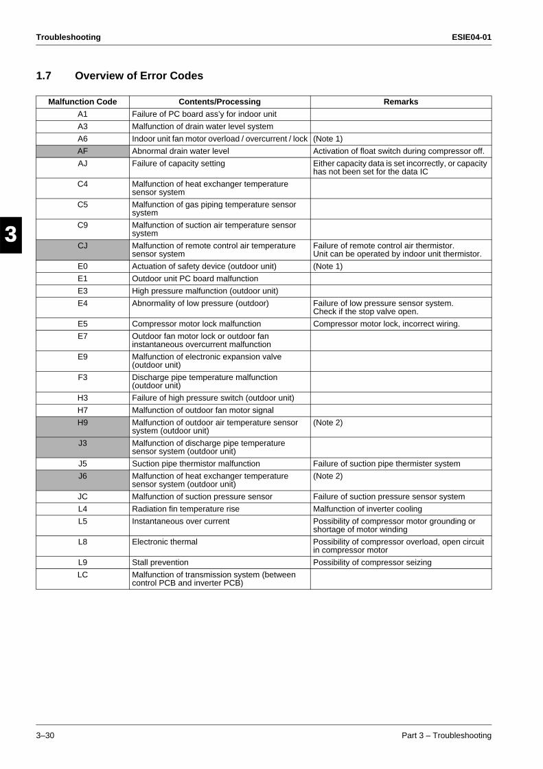
Troubleshooting ESIE04-01
3–30 Part 3 – Troubleshooting
3
1
3
4
5
1.7 Overview of Error Codes
Malfunction Code Contents/Processing Remarks
A1 Failure of PC board ass’y for indoor unit
A3 Malfunction of drain water level system
A6 Indoor unit fan motor overload / overcurrent / lock (Note 1)
AF Abnormal drain water level Activation of float switch during compressor off.
AJ Failure of capacity setting Either capacity data is set incorrectly, or capacity has not been set for the data IC
C4 Malfunction of heat exchanger temperature sensor system
C5 Malfunction of gas piping temperature sensor system
C9 Malfunction of suction air temperature sensor system
CJ Malfunction of remote control air temperature sensor system
Failure of remote control air thermistor.Unit can be operated by indoor unit thermistor.
E0 Actuation of safety device (outdoor unit) (Note 1)
E1 Outdoor unit PC board malfunction
E3 High pressure malfunction (outdoor unit)
E4 Abnormality of low pressure (outdoor) Failure of low pressure sensor system. Check if the stop valve open.
E5 Compressor motor lock malfunction Compressor motor lock, incorrect wiring.
E7 Outdoor fan motor lock or outdoor fan instantaneous overcurrent malfunction
E9 Malfunction of electronic expansion valve (outdoor unit)
F3 Discharge pipe temperature malfunction (outdoor unit)
H3 Failure of high pressure switch (outdoor unit)
H7 Malfunction of outdoor fan motor signal
H9 Malfunction of outdoor air temperature sensor system (outdoor unit)
(Note 2)
J3 Malfunction of discharge pipe temperature sensor system (outdoor unit)
J5 Suction pipe thermistor malfunction Failure of suction pipe thermister system
J6 Malfunction of heat exchanger temperature sensor system (outdoor unit)
(Note 2)
JC Malfunction of suction pressure sensor Failure of suction pressure sensor system
L4 Radiation fin temperature rise Malfunction of inverter cooling
L5 Instantaneous over current Possibility of compressor motor grounding or shortage of motor winding
L8 Electronic thermal Possibility of compressor overload, open circuit in compressor motor
L9 Stall prevention Possibility of compressor seizing
LC Malfunction of transmission system (between control PCB and inverter PCB)
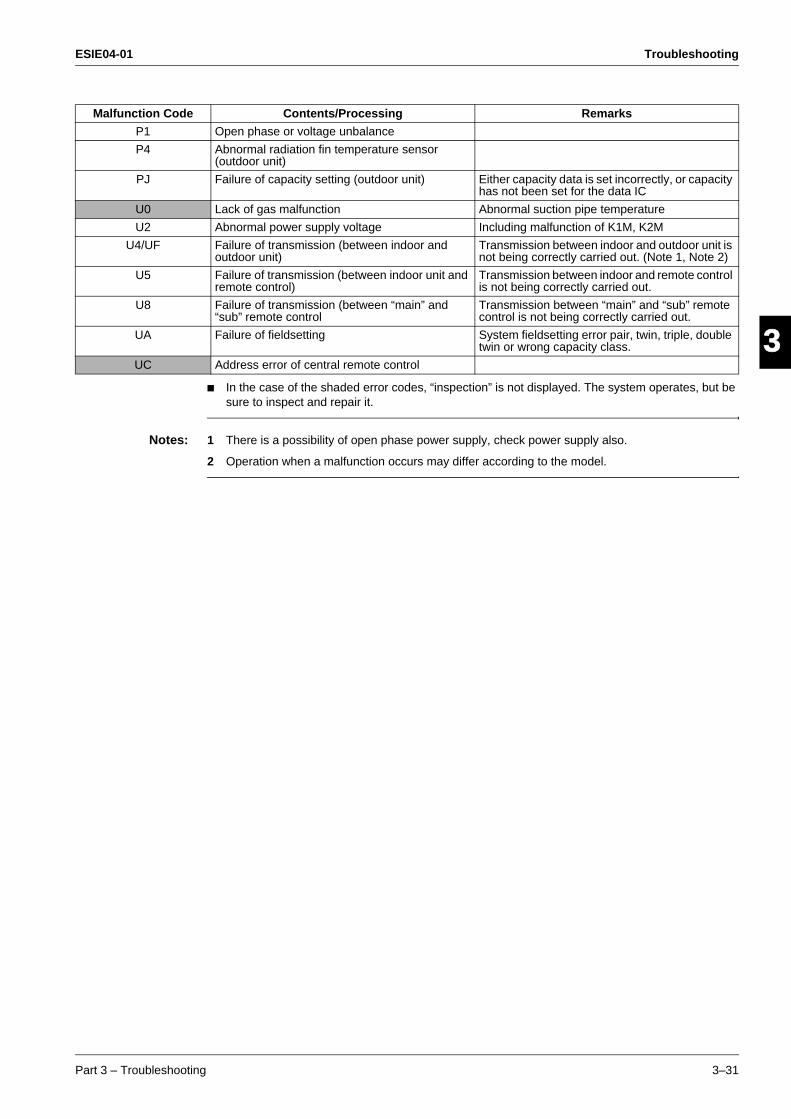
ESIE04-01 Troubleshooting
Part 3 – Troubleshooting 3–31
33
4
5
1
In the case of the shaded error codes, “inspection” is not displayed. The system operates, but be sure to inspect and repair it.
Notes: 1 There is a possibility of open phase power supply, check power supply also.
2 Operation when a malfunction occurs may differ according to the model.
P1 Open phase or voltage unbalance
P4 Abnormal radiation fin temperature sensor (outdoor unit)
PJ Failure of capacity setting (outdoor unit) Either capacity data is set incorrectly, or capacity has not been set for the data IC
U0 Lack of gas malfunction Abnormal suction pipe temperature
U2 Abnormal power supply voltage Including malfunction of K1M, K2M
U4/UF Failure of transmission (between indoor and outdoor unit)
Transmission between indoor and outdoor unit is not being correctly carried out. (Note 1, Note 2)
U5 Failure of transmission (between indoor unit and remote control)
Transmission between indoor and remote control is not being correctly carried out.
U8 Failure of transmission (between “main” and “sub” remote control
Transmission between “main” and “sub” remote control is not being correctly carried out.
UA Failure of fieldsetting System fieldsetting error pair, twin, triple, double twin or wrong capacity class.
UC Address error of central remote control
Malfunction Code Contents/Processing Remarks
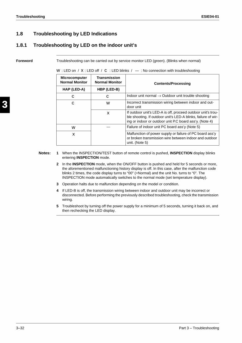
Troubleshooting ESIE04-01
3–32 Part 3 – Troubleshooting
3
1
3
4
5
1.8 Troubleshooting by LED Indications
1.8.1 Troubleshooting by LED on the indoor unit’s
Foreword Troubleshooting can be carried out by service monitor LED (green). (Blinks when normal)
w : LED on / x : LED off / c : LED blinks / — : No connection with troubleshooting
Notes: 1 When the INSPECTION/TEST button of remote control is pushed, INSPECTION display blinks entering INSPECTION mode.
2 In the INSPECTION mode, when the ON/OFF button is pushed and held for 5 seconds or more, the aforementioned malfunctioning history display is off. In this case, after the malfunction code blinks 2 times, the code display turns to “00” (=Normal) and the unit No. turns to “0”. The INSPECTION mode automatically switches to the normal mode (set temperature display).
3 Operation halts due to malfunction depending on the model or condition.
4 If LED-B is off, the transmission wiring between indoor and outdoor unit may be incorrect or disconnected. Before performing the previously described troubleshooting, check the transmission wiring.
5 Troubleshoot by turning off the power supply for a minimum of 5 seconds, turning it back on, and then rechecking the LED display.
Microcomputer Normal Monitor
Transmission Normal Monitor Contents/Processing
HAP (LED-A) HBP (LED-B)
c c Indoor unit normal → Outdoor unit trouble shooting
c w Incorrect transmission wiring between indoor and out-door unit
x If outdoor unit’s LED-A is off, proceed outdoor unit’s trou-ble shooting. If outdoor unit’s LED-A blinks, failure of wir-ing or indoor or outdoor unit P.C board ass’y. (Note 4)
w — Failure of indoor unit PC board ass’y (Note 5)
x Malfunction of power supply or failure of PC board ass’y or broken transmission wire between indoor and outdoor unit. (Note 5)
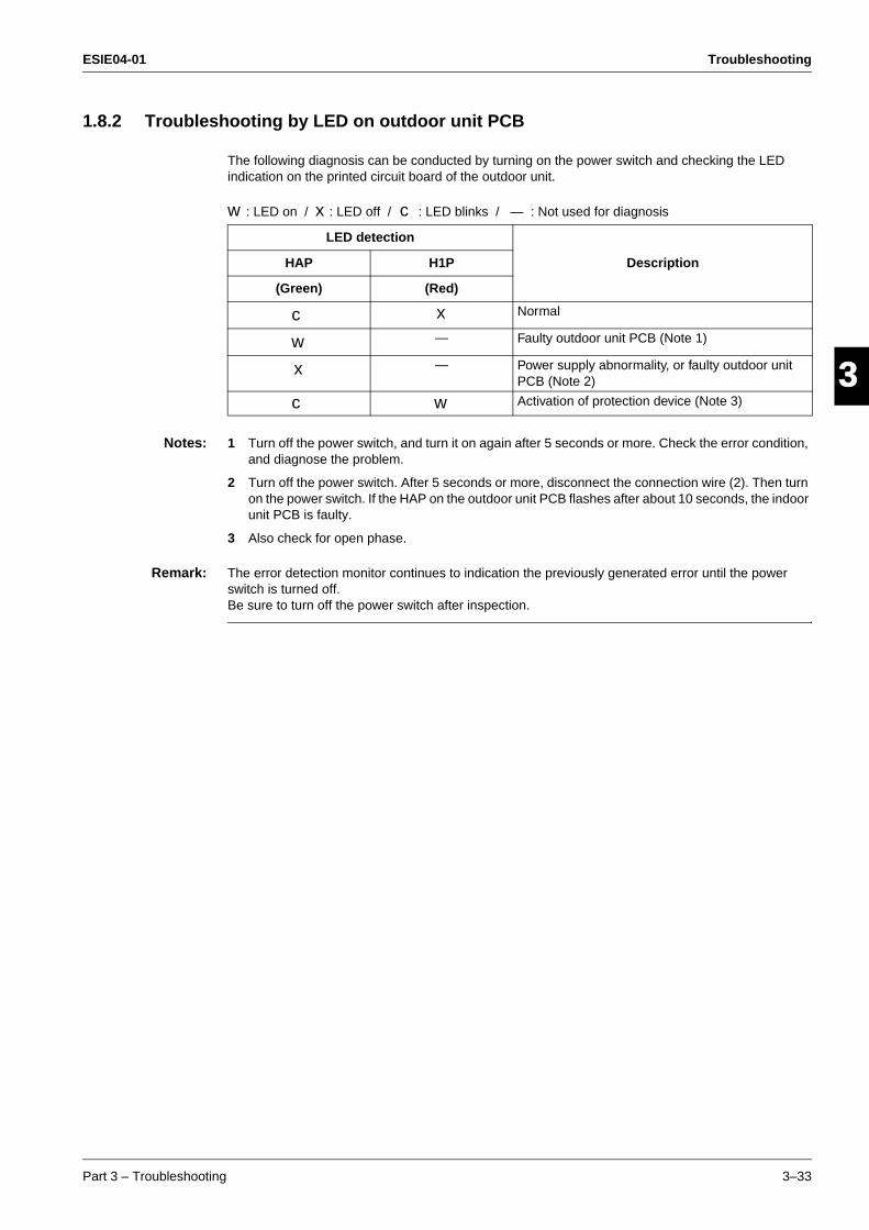
ESIE04-01 Troubleshooting
Part 3 – Troubleshooting 3–33
33
4
5
11.8.2 Troubleshooting by LED on outdoor unit PCB
The following diagnosis can be conducted by turning on the power switch and checking the LED indication on the printed circuit board of the outdoor unit.
w : LED on / x : LED off / c : LED blinks / — : Not used for diagnosis
Notes: 1 Turn off the power switch, and turn it on again after 5 seconds or more. Check the error condition, and diagnose the problem.
2 Turn off the power switch. After 5 seconds or more, disconnect the connection wire (2). Then turn on the power switch. If the HAP on the outdoor unit PCB flashes after about 10 seconds, the indoor unit PCB is faulty.
3 Also check for open phase.
Remark: The error detection monitor continues to indication the previously generated error until the power switch is turned off.Be sure to turn off the power switch after inspection.
LED detection
DescriptionHAP H1P
(Green) (Red)
c x Normal
w — Faulty outdoor unit PCB (Note 1)
x — Power supply abnormality, or faulty outdoor unit PCB (Note 2)
c w Activation of protection device (Note 3)
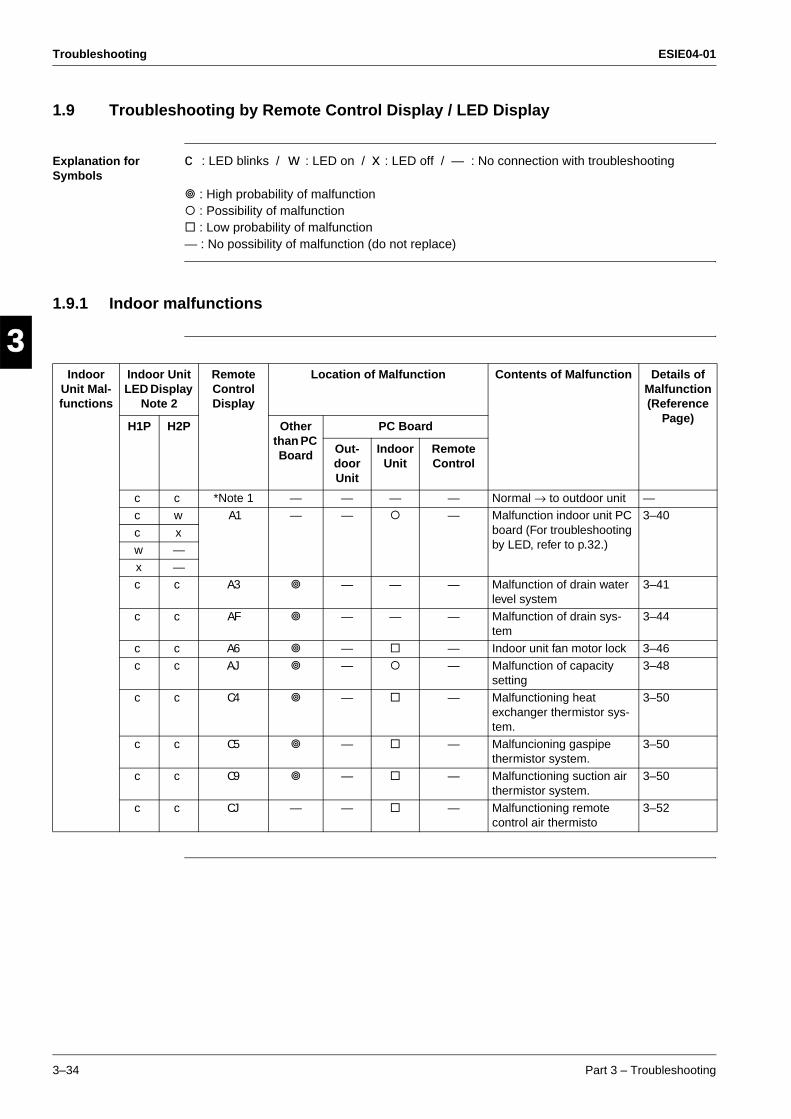
Troubleshooting ESIE04-01
3–34 Part 3 – Troubleshooting
3
1
3
4
5
1.9 Troubleshooting by Remote Control Display / LED Display
Explanation for Symbols
c : LED blinks / w : LED on / x : LED off / — : No connection with troubleshooting
" : High probability of malfunction# : Possibility of malfunction$ : Low probability of malfunction— : No possibility of malfunction (do not replace)
1.9.1 Indoor malfunctions
Indoor Unit Mal-functions
Indoor Unit LED Display
Note 2
Remote Control Display
Location of Malfunction Contents of Malfunction Details of Malfunction (Reference
Page)H1P H2P Other
than PC Board
PC Board
Out-door Unit
Indoor Unit
Remote Control
c c *Note 1 — — — — Normal → to outdoor unit —c w A1 — — # — Malfunction indoor unit PC
board (For troubleshooting by LED, refer to p.32.)
3–40
c x
w —x —
c c A3 " — — — Malfunction of drain water level system
3–41
c c AF " — — — Malfunction of drain sys-tem
3–44
c c A6 " — $ — Indoor unit fan motor lock 3–46
c c AJ " — # — Malfunction of capacity setting
3–48
c c C4 " — $ — Malfunctioning heat exchanger thermistor sys-tem.
3–50
c c C5 " — $ — Malfuncioning gaspipe thermistor system.
3–50
c c C9 " — $ — Malfunctioning suction air thermistor system.
3–50
c c CJ — — $ — Malfunctioning remote control air thermisto
3–52
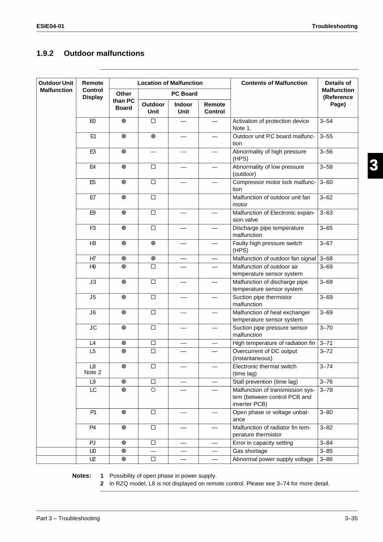
ESIE04-01 Troubleshooting
Part 3 – Troubleshooting 3–35
33
4
5
11.9.2 Outdoor malfunctions
Notes: 1 Possibility of open phase in power supply.2 In RZQ model, L8 is not displayed on remote control. Please see 3–74 for more detail.
Outdoor Unit Malfunction
Remote Control Display
Location of Malfunction Contents of Malfunction Details of Malfunction (Reference
Page)
Other than PC Board
PC Board
Outdoor Unit
Indoor Unit
Remote Control
E0 " $ — — Activation of protection device Note 1.
3–54
E1 " " — — Outdoor unit P.C board malfunc-tion
3–55
E3 " — — — Abnormality of high pressure (HPS)
3–56
E4 " $ — — Abnormality of low pressure (outdoor)
3–58
E5 " $ — — Compressor motor lock malfunc-tion
3–60
E7 " $ Malfunction of outdoor unit fan motor
3–62
E9 " $ — — Malfunction of Electronic expan-sion valve
3–63
F3 " $ — — Discharge pipe temperature malfunction
3–65
H3 " " — — Faulty high pressure switch (HPS)
3–67
H7 " " — — Malfunction of outdoor fan signal 3–68H9 " $ — — Malfunction of outdoor air
temperature sensor system3–69
J3 " $ — — Malfunction of discharge pipe temperature sensor system
3–69
J5 " $ — — Suction pipe thermistor malfunction
3–69
J6 " $ — — Malfunction of heat exchanger temperature sensor system
3–69
JC " $ — — Suction pipe pressure sensor malfunction
3–70
L4 " $ — — High temperature of radiation fin 3–71L5 " $ — — Overcurrent of DC output
(instantaneous)3–72
L8Note 2
" $ — — Electronic thermal switch (time lag)
3–74
L9 " $ — — Stall prevention (time lag) 3–76LC " # — — Malfunction of transmission sys-
tem (between control PCB and inverter PCB)
3–78
P1 " $ — — Open phase or voltage unbal-ance
3–80
P4 " $ — — Malfunction of radiator fin tem-perature thermistor
3–82
PJ " $ — — Error in capacity setting 3–84U0 " — — — Gas shortage 3–85U2 " $ — — Abnormal power supply voltage 3–86
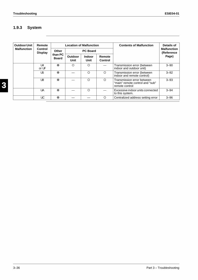
Troubleshooting ESIE04-01
3–36 Part 3 – Troubleshooting
3
1
3
4
5
1.9.3 System
Outdoor Unit Malfunction
Remote Control Display
Location of Malfunction Contents of Malfunction Details of Malfunction (Reference
Page)
Other than PC Board
PC Board
Outdoor Unit
Indoor Unit
Remote Control
U4or UF
" # # — Transmission error (between indoor and outdoor unit)
3–90
U5 " — # # Transmission error (between indoor and remote control)
3–92
U8 " — # # Transmission error between “main” remote control and “sub” remote control
3–93
UA " — # — Excessive indoor units connected to this system.
3–94
UC " — — # Centralized address setting error 3–96
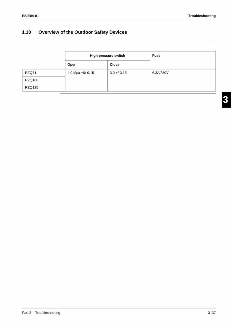
ESIE04-01 Troubleshooting
Part 3 – Troubleshooting 3–37
33
4
5
11.10 Overview of the Outdoor Safety Devices
High pressure switch Fuse
Open Close
RZQ71 4.0 Mpa +0/-0.15 3.0 +/-0.15 6.3A/250V
RZQ100
RZQ125

Troubleshooting ESIE04-01
3–38 Part 3 – Troubleshooting
3
1
3
4
5
1.11 Overview of the Indoor Safety Devices
Thermal protector Thermal fuse fan motor
Abnormal Reset (automatic)
FFQ35~60 >130°C +/-5°C <83°C +/-20°C N.A.
FCQ35~71 >130°C +/-5°C <83°C +/-20°C N.A.
FCQ100/125 >140°C +/-5°C <45°C +/-15°C N.A.
FBQ35~125 N.A. N.A. >152°C
FDQ125 N.A. N.A. >160°C
FHQ35~125 >130°C +/-5°C <83°C +/-20°C N.A.
FUQ71~125 >130°C +/-5°C <83°C +/-20°C N.A.
FAQ71/100 >130°C +/-5°C <83°C +/-20°C N.A.
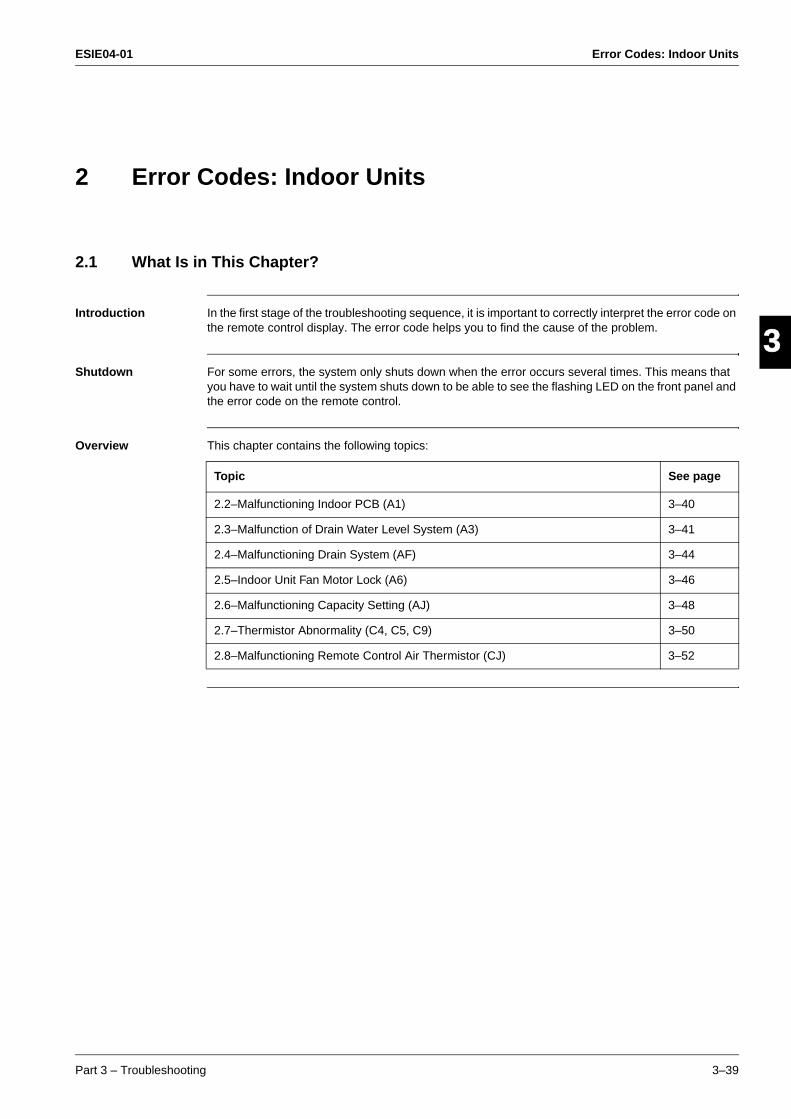
ESIE04-01 Error Codes: Indoor Units
Part 3 – Troubleshooting 3–39
3
4
5
1
3
Part 3
2 Error Codes: Indoor Units
2.1 What Is in This Chapter?
Introduction In the first stage of the troubleshooting sequence, it is important to correctly interpret the error code on the remote control display. The error code helps you to find the cause of the problem.
Shutdown For some errors, the system only shuts down when the error occurs several times. This means that you have to wait until the system shuts down to be able to see the flashing LED on the front panel and the error code on the remote control.
Overview This chapter contains the following topics:
Topic See page
2.2–Malfunctioning Indoor PCB (A1) 3–40
2.3–Malfunction of Drain Water Level System (A3) 3–41
2.4–Malfunctioning Drain System (AF) 3–44
2.5–Indoor Unit Fan Motor Lock (A6) 3–46
2.6–Malfunctioning Capacity Setting (AJ) 3–48
2.7–Thermistor Abnormality (C4, C5, C9) 3–50
2.8–Malfunctioning Remote Control Air Thermistor (CJ) 3–52
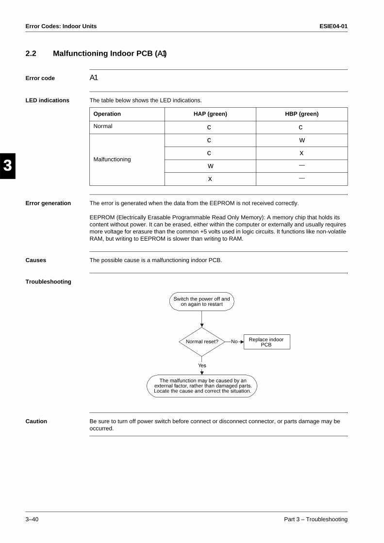
Error Codes: Indoor Units ESIE04-01
3–40 Part 3 – Troubleshooting
3
1
3
4
5
2.2 Malfunctioning Indoor PCB (A1)
Error code A1
LED indications The table below shows the LED indications.
Error generation The error is generated when the data from the EEPROM is not received correctly.
EEPROM (Electrically Erasable Programmable Read Only Memory): A memory chip that holds its content without power. It can be erased, either within the computer or externally and usually requires more voltage for erasure than the common +5 volts used in logic circuits. It functions like non-volatile RAM, but writing to EEPROM is slower than writing to RAM.
Causes The possible cause is a malfunctioning indoor PCB.
Troubleshooting
Caution Be sure to turn off power switch before connect or disconnect connector, or parts damage may be occurred.
Operation HAP (green) HBP (green)
Normal c c
Malfunctioning
c w
c x
w —
x —
Switch the power off and on again to restart
Normal reset?
The malfunction may be caused by an external factor, rather than damaged parts. Locate the cause and correct the situation.
Replace indoor PCB
No
Yes
ESIE04-01 Error Codes: Indoor Units
Part 3 – Troubleshooting 3–41
4
5
1
3
2.3 Malfunction of Drain Water Level System (A3)
Error code A3
LED indications The table below shows the LED indications.
Error generation The error is generated when the water level reaches its upper limit and when the float switch turns OFF.
Causes The possible causes are:
Malfunctioning drain pump
Improper drain piping work
Drain piping clogging
Malfunctioning float switch
Malfunctioning indoor unit PCB
Malfunctioning short-circuit connector X15 on PCB.
Operation HAP (green) HBP (green)
Normal c c
Malfunctioning c c
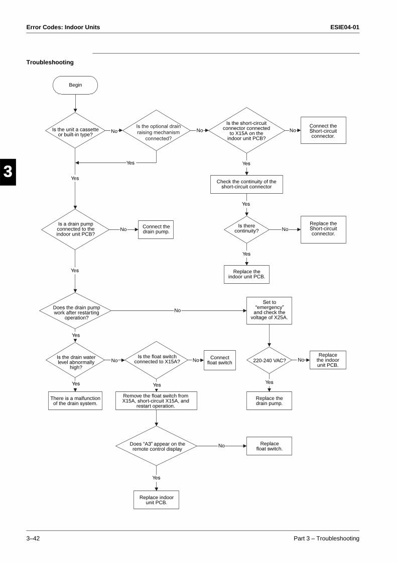
Error Codes: Indoor Units ESIE04-01
3–42 Part 3 – Troubleshooting
3
1
3
4
5
Troubleshooting
Is the optional drain
raising mechanism
connected?
Yes
Yes
No
No
Yes
No
Yes
Replace float switch.
Yes
Yes
Yes
No
Begin
Is the unit a cassette or built-in type?
No
Yes
Is a drain pump connected to the indoor unit PCB?
Yes Yes
Yes
No Connect the drain pump.
Is there continuity? No
Replace the Short-circuit connector.
Replace the indoor unit PCB.
Set to “emergency”
and check the voltage of X25A.
Connect the Short-circuit connector.
Is the short-circuit connector connected
to X15A on the indoor unit PCB?
Check the continuity of the short-circuit connector
No
Replace the indoor unit PCB.
No220-240 VAC?
Replace the drain pump.
Connect float switch
No
Is the float switch connected to X15A?
Does “A3” appear on the remote control display
Remove the float switch from X15A, short-circuit X15A, and
restart operation.
There is a malfunction of the drain system.
Is the drain water level abnormally
high?
Does the drain pump work after restarting
operation?
Replace indoor unit PCB.

ESIE04-01 Error Codes: Indoor Units
Part 3 – Troubleshooting 3–43
4
5
1
3
Remark If "A3" is detected by a PC board which is not mounted with X15A, the PC board is defective.
Caution Be sure to turn off power switch before connect or disconnect connector, or parts damage may be occurred.
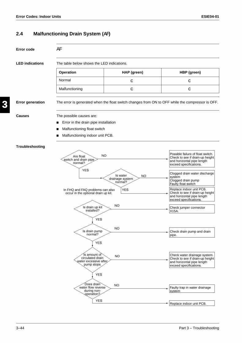
Error Codes: Indoor Units ESIE04-01
3–44 Part 3 – Troubleshooting
3
1
3
4
5
2.4 Malfunctioning Drain System (AF)
Error code AF
LED indications The table below shows the LED indications.
Error generation The error is generated when the float switch changes from ON to OFF while the compressor is OFF.
Causes The possible causes are:
Error in the drain pipe installation
Malfunctioning float switch
Malfunctioning indoor unit PCB.
Troubleshooting
Operation HAP (green) HBP (green)
Normal c c
Malfunctioning c c
Are floatswitch and drain pipe
normal?
Is waterdrainage system
normal?
Possible failure of float switch. Check to see if drain-up height and horizontal pipe length exceed specifications.
Clogged drain water discharge systemClogged drain pumpFaulty float switch
Replace indoor unit PCB. Check to see if drain-up height and horizontal pipe length exceed specifications.
Check jumper connector X15A.
Check drain pump and drain pipe.
Check water drainage system. Check to see if drain-up height and horizontal pipe length exceed specifications.
Faulty trap in water drainage system
Replace indoor unit PCB.
YES
NO
In FHQ and FAQ problems can also occur in the optional drain up kit.
Is drain up kit installed?
NO
NO
NO
NO
NO
YES
YES
YES
YES
YES
Is drain pump normal?
Is amount of circulated drain
water excessive after pump stops
Does drain water flow reverse
during non-operation?
ESIE04-01 Error Codes: Indoor Units
Part 3 – Troubleshooting 3–45
4
5
1
3
Caution Be sure to turn off power switch before connect or disconnect connector, or parts damage may be occurred.
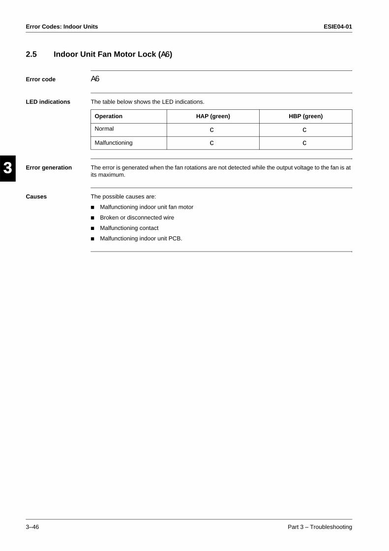
Error Codes: Indoor Units ESIE04-01
3–46 Part 3 – Troubleshooting
3
1
3
4
5
2.5 Indoor Unit Fan Motor Lock (A6)
Error code A6
LED indications The table below shows the LED indications.
Error generation The error is generated when the fan rotations are not detected while the output voltage to the fan is at its maximum.
Causes The possible causes are:
Malfunctioning indoor unit fan motor
Broken or disconnected wire
Malfunctioning contact
Malfunctioning indoor unit PCB.
Operation HAP (green) HBP (green)
Normal c c
Malfunctioning c c
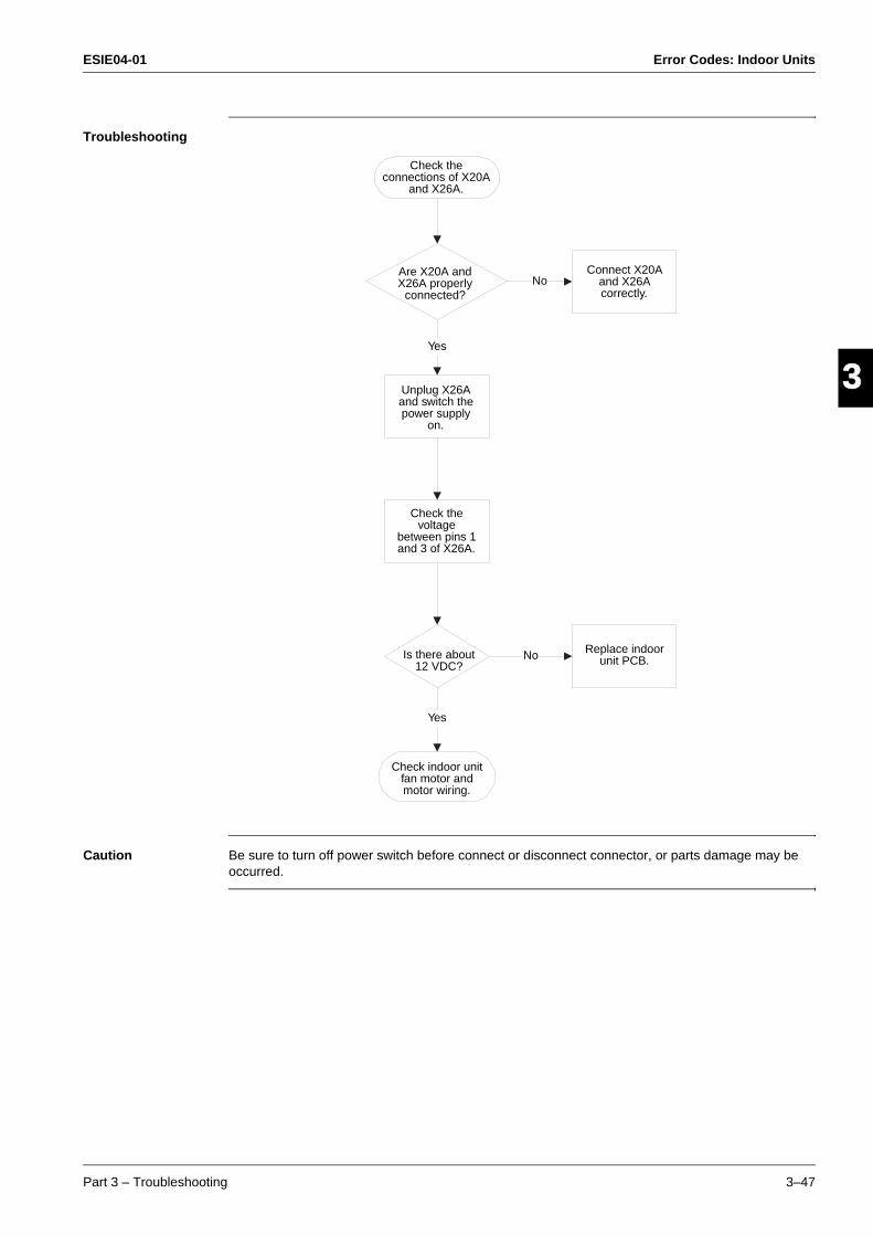
ESIE04-01 Error Codes: Indoor Units
Part 3 – Troubleshooting 3–47
4
5
1
3
Troubleshooting
Caution Be sure to turn off power switch before connect or disconnect connector, or parts damage may be occurred.
Yes
No
Check the connections of X20A
and X26A.
Are X20A and X26A properly
connected?
Unplug X26A and switch the power supply
on.
Check the voltage
between pins 1 and 3 of X26A.
Connect X20A and X26A correctly.
Is there about 12 VDC?
Check indoor unit fan motor and motor wiring.
Replace indoor unit PCB.
Yes
No
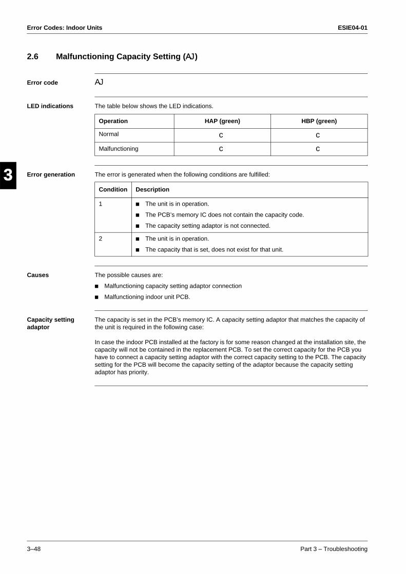
Error Codes: Indoor Units ESIE04-01
3–48 Part 3 – Troubleshooting
3
1
3
4
5
2.6 Malfunctioning Capacity Setting (AJ)
Error code AJ
LED indications The table below shows the LED indications.
Error generation The error is generated when the following conditions are fulfilled:
Causes The possible causes are:
Malfunctioning capacity setting adaptor connection
Malfunctioning indoor unit PCB.
Capacity setting adaptor
The capacity is set in the PCB’s memory IC. A capacity setting adaptor that matches the capacity of the unit is required in the following case:
In case the indoor PCB installed at the factory is for some reason changed at the installation site, the capacity will not be contained in the replacement PCB. To set the correct capacity for the PCB you have to connect a capacity setting adaptor with the correct capacity setting to the PCB. The capacity setting for the PCB will become the capacity setting of the adaptor because the capacity setting adaptor has priority.
Operation HAP (green) HBP (green)
Normal c c
Malfunctioning c c
Condition Description
1 The unit is in operation.
The PCB’s memory IC does not contain the capacity code.
The capacity setting adaptor is not connected.
2 The unit is in operation.
The capacity that is set, does not exist for that unit.
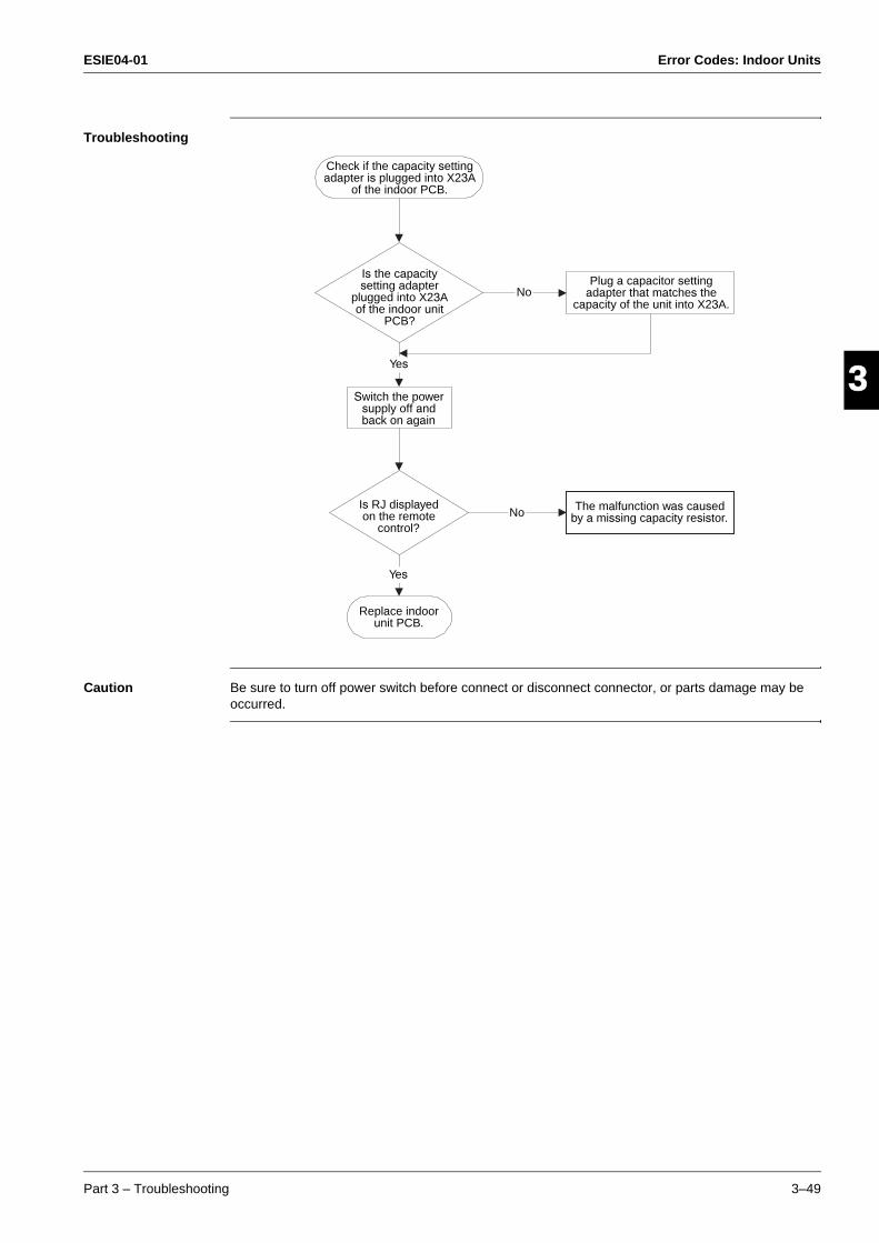
ESIE04-01 Error Codes: Indoor Units
Part 3 – Troubleshooting 3–49
4
5
1
3
Troubleshooting
Caution Be sure to turn off power switch before connect or disconnect connector, or parts damage may be occurred.
Yes
Check if the capacity setting adapter is plugged into X23A
of the indoor PCB.
Plug a capacitor setting adapter that matches the
capacity of the unit into X23A.No
No
Yes
Is the capacity setting adapter
plugged into X23A of the indoor unit
PCB?
Switch the power supply off and back on again
Is RJ displayed on the remote
control?
The malfunction was caused by a missing capacity resistor.
Replace indoor unit PCB.
Error Codes: Indoor Units ESIE04-01
3–50 Part 3 – Troubleshooting
3
1
3
4
5
2.7 Thermistor Abnormality (C4, C5, C9)
Error code The table below describes the two thermistor abnormalities.
LED indications The table below shows the LED indications.
Error generation The error is generated when during compressor operation:
Thermistor input > 4.96 V, or
Thermistor output < 0.04 V.
Causes The possible causes are:
Malfunctioning connector connection
Malfunctioning thermistor
Malfunctioning PCB
Broken or disconnected wire.
Checking thermistors
See page 3–102.
Error Description
C4 Malfunctioning heat exchanger thermistor system.
C5 Malfuncioning gaspipe thermistor system.
C9 Malfunctioning suction air thermistor system.
Operation HAP (green) HBP (green)
Normal c c
Malfunctioning c c
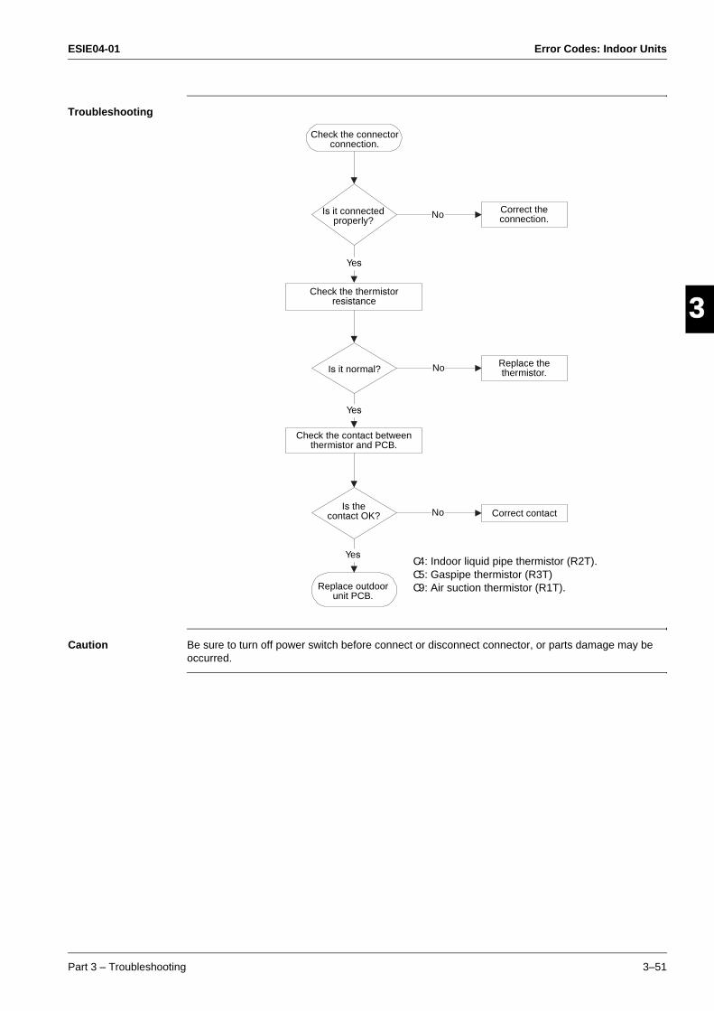
ESIE04-01 Error Codes: Indoor Units
Part 3 – Troubleshooting 3–51
4
5
1
3
Troubleshooting
Caution Be sure to turn off power switch before connect or disconnect connector, or parts damage may be occurred.
Check the connector connection.
Is it connected properly?
Check the thermistor resistance
Correct the connection.
Is it normal?Replace the thermistor.
No
Yes
Yes
No
No
Yes
Check the contact between thermistor and PCB.
Is the contact OK? Correct contact
Replace outdoor unit PCB.
C4: Indoor liquid pipe thermistor (R2T).C5: Gaspipe thermistor (R3T)C9: Air suction thermistor (R1T).
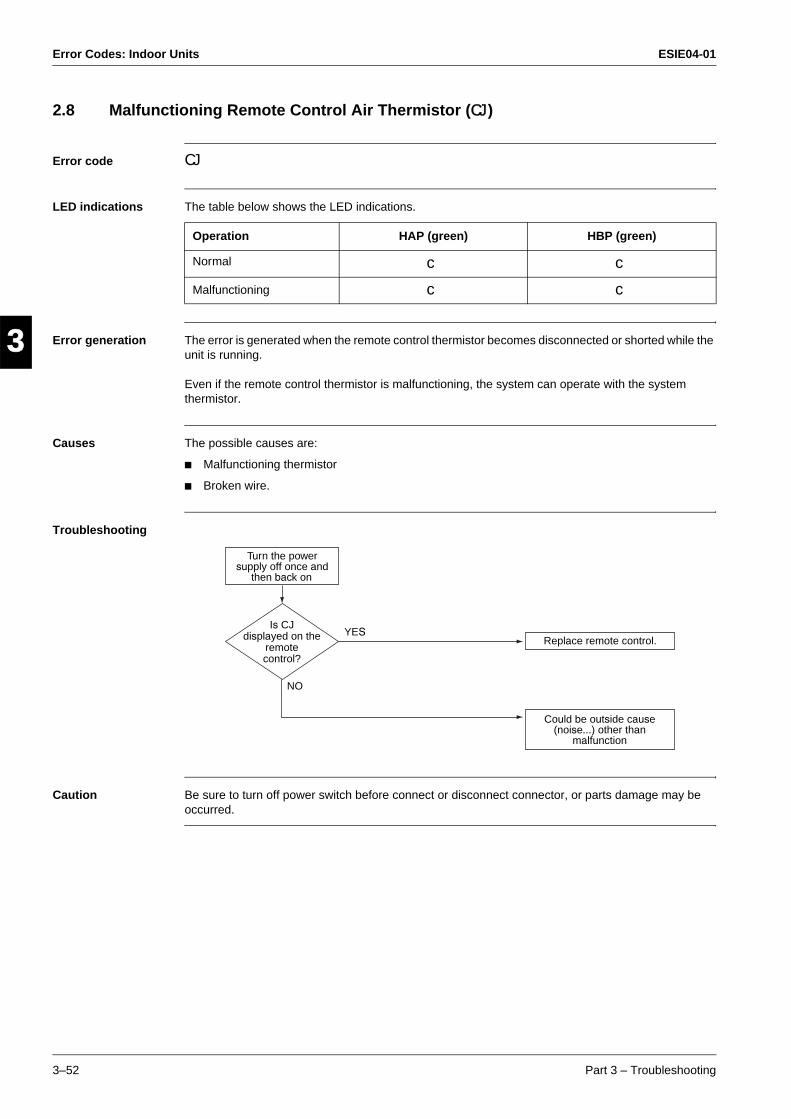
Error Codes: Indoor Units ESIE04-01
3–52 Part 3 – Troubleshooting
3
1
3
4
5
2.8 Malfunctioning Remote Control Air Thermistor (CJ)
Error code CJ
LED indications The table below shows the LED indications.
Error generation The error is generated when the remote control thermistor becomes disconnected or shorted while the unit is running.
Even if the remote control thermistor is malfunctioning, the system can operate with the system thermistor.
Causes The possible causes are:
Malfunctioning thermistor
Broken wire.
Troubleshooting
Caution Be sure to turn off power switch before connect or disconnect connector, or parts damage may be occurred.
Operation HAP (green) HBP (green)
Normal c c
Malfunctioning c c
Is CJdisplayed on the
remotecontrol?
Turn the power supply off once and
then back on
YES
NO
Replace remote control.
Could be outside cause (noise...) other than
malfunction

ESIE04-01 Error Codes: Outdoor Units
Part 3 – Troubleshooting 3–53
33
4
5
1Part 3
3 Error Codes: Outdoor Units
3.1 What Is in This Chapter?
Introduction In the first stage of the troubleshooting sequence, it is important to correctly interpret the error code on the remote control display. The error code helps you to find the cause of the problem.
Overview This chapter contains the following topics:
Topic See page
3.2–Actuation of Protection Device (E0) 3–54
3.3–Failure of Outdoor Unit PC Board (E1) 3–55
3.4–Abnormal High Pressure (Detected by the HPS) (E3) 3–56
3.5–Actuation of Low Pressure Sensor (E4) 3–58
3.6–Compressor Motor Lock (E5) 3–60
3.7–Malfunction of Outdoor Unit Fan Motor (E7) 3–62
3.8–Malfunction of Electronic Expansion Valve (E9) 3–63
3.9–Malfunctioning in Discharge Pipe Temperature (F3) 3–65
3.10–Malfunctioning HPS System (H3) 3–67
3.11–Malfunction of Outdoor Fan Motor Signal (H7) 3–68
3.12–Malfunction of Thermistor System (H9, J3, J5, J6) 3–69
3.13–Malfunction of Suction Pipe Pressure Sensor (JC) 3–70
3.14–Radiation Fin Temperature Increased (L4) 3–71
3.15–DC Output Overcurrent (Instantaneous) (L5) 3–72
3.16–Electronic Thermal (Time Lag) (L8) 3–74
3.17–Stall Prevention (Time Lag) (L9) 3–76
3.18–Malfunction of Transmission system (Between Control PCB and Inverter PCB) (LC)
3–78
3.19–Open Phase (P1) 3–80
3.20–Malfunction of Radiator Fin Temperature Thermistor (P4) 3–82
3.21–Failure of Capacity Setting (PJ) 3–84
3.22–Gas Shortage (Malfunction) (U0) 3–85
3.23–Abnormal Power Supply Voltage (U2) 3–86
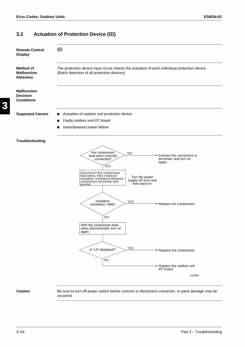
Error Codes: Outdoor Units ESIE04-01
3–54 Part 3 – Troubleshooting
3
1
3
4
5
3.2 Actuation of Protection Device (E0)
Remote Control Display
E0
Method of Malfunction Detection
The protection device input circuit checks the actuation of each individual protection device.(Batch detection of all protection devices)
Malfunction Decision Conditions
Supposed Causes Actuation of outdoor unit protection device
Faulty outdoor unit PC board
Instantaneous power failure
Troubleshooting
Caution Be sure to turn off power switch before connect or disconnect connector, or parts damage may be occurred.
NO
YES
YES
NO
NO
YES
Replace the outdoor unit PC board.
(S2580)
Disconnect the compressor lead wires, then measure insulation resistance between compressor terminals and ground.
Are compressor lead wires correctly
connected?
Turn the power supply off once and
then back on
Connect the connectors or terminals, and turn on again.
Replace the compressor.
Replace the compressor.
Insulation resistance <5MΩ
With the compressor lead wires disconnected, turn on again.
Is “L9” displayed?
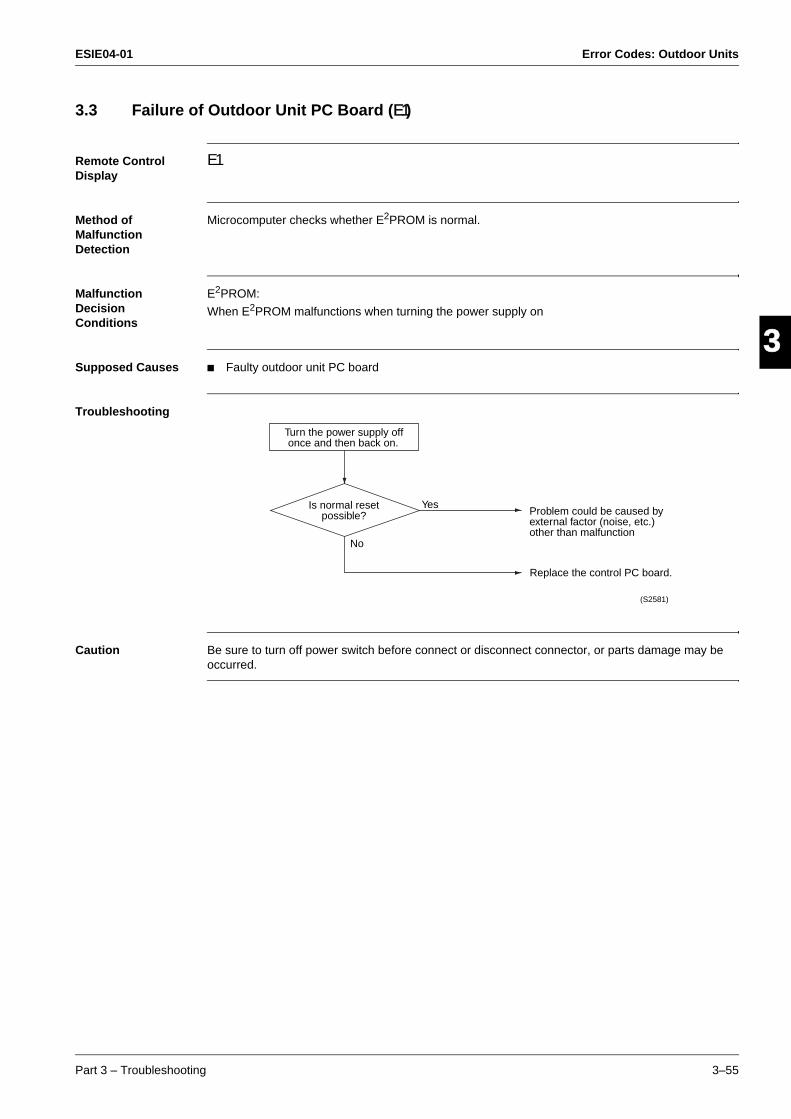
ESIE04-01 Error Codes: Outdoor Units
Part 3 – Troubleshooting 3–55
33
4
5
13.3 Failure of Outdoor Unit PC Board (E1)
Remote Control Display
E1
Method of Malfunction Detection
Microcomputer checks whether E2PROM is normal.
Malfunction Decision Conditions
E2PROM:
When E2PROM malfunctions when turning the power supply on
Supposed Causes Faulty outdoor unit PC board
Troubleshooting
Caution Be sure to turn off power switch before connect or disconnect connector, or parts damage may be occurred.
Turn the power supply off once and then back on.
Is normal reset possible?
No
YesProblem could be caused by external factor (noise, etc.) other than malfunction
Replace the control PC board.
(S2581)
Error Codes: Outdoor Units ESIE04-01
3–56 Part 3 – Troubleshooting
3
1
3
4
5
3.4 Abnormal High Pressure (Detected by the HPS) (E3)
Remote Control Display
E3
Method of Malfunction Detection
The protection device circuit checks continuity in the high pressure switch.
Malfunction Decision Conditions
When the high pressure switch is actuatedActuating pressure:RZQ71~125
Supposed Causes Faulty high pressure switch
Disconnection in high pressure switch harness
Faulty connection of high pressure switch connector
Clogged indoor unit suction filter (in heating operation)
Dirty outdoor unit heat exchanger
Faulty outdoor unit fan
Refrigerant overcharge
Stop valve is left in closed.
HPS settings The table below contains the preset HPS values.
High pressure switch Fuse
Open Close
RZQ71 4.0 Mpa +0/-0.15 3.0 +/-0.15 6.3A/250V
RZQ100
RZQ125
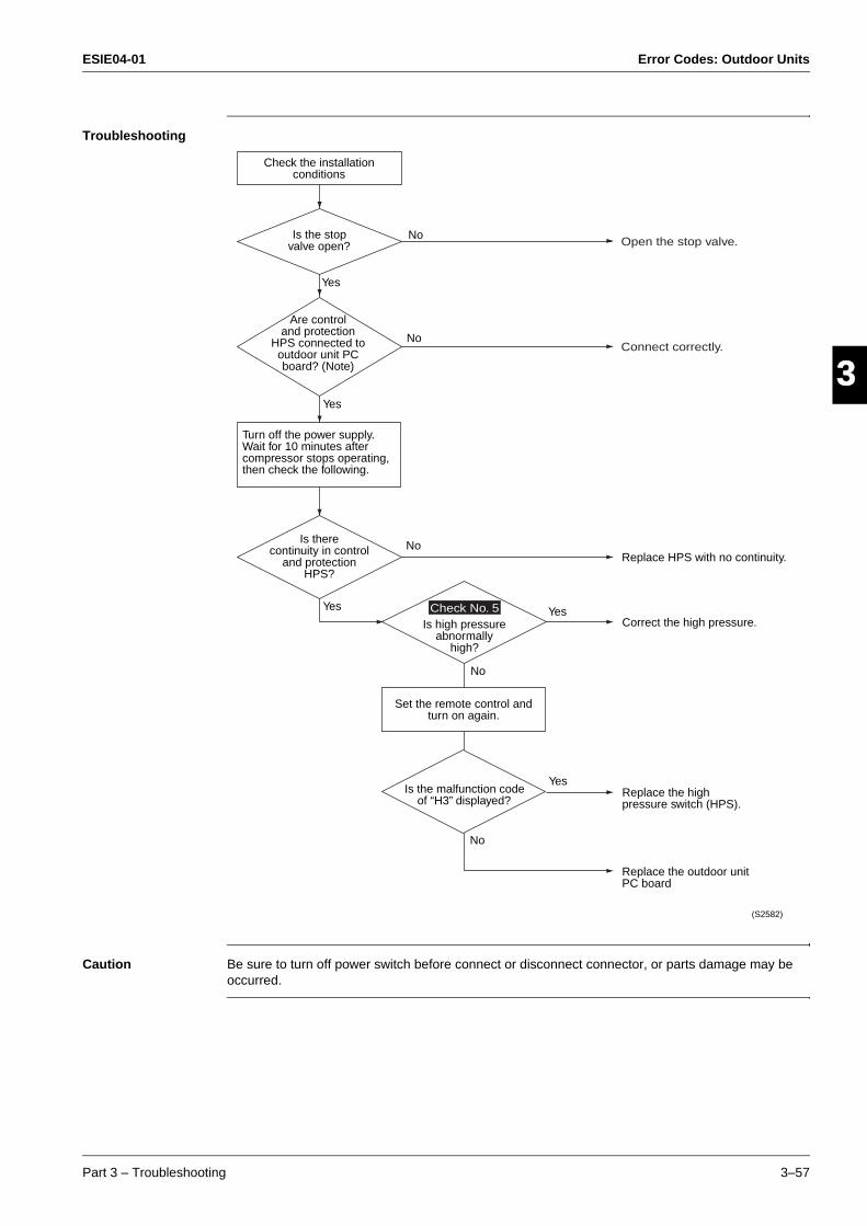
ESIE04-01 Error Codes: Outdoor Units
Part 3 – Troubleshooting 3–57
33
4
5
1Troubleshooting
Caution Be sure to turn off power switch before connect or disconnect connector, or parts damage may be occurred.
Connect correctly.
Open the stop valve.
Check No. 5
Yes
Check the installation conditions
Is the stop valve open?
Are control and protection
HPS connected to outdoor unit PC board? (Note)
No
No
Yes
Yes
Yes
No
No
Turn off the power supply. Wait for 10 minutes after compressor stops operating, then check the following.
Is there continuity in control
and protection HPS?
Yes
No
Is high pressure abnormally
high?
Set the remote control and turn on again.
Is the malfunction code of “H3” displayed?
Replace the outdoor unit PC board
Replace the high pressure switch (HPS).
Correct the high pressure.
Replace HPS with no continuity.
(S2582)
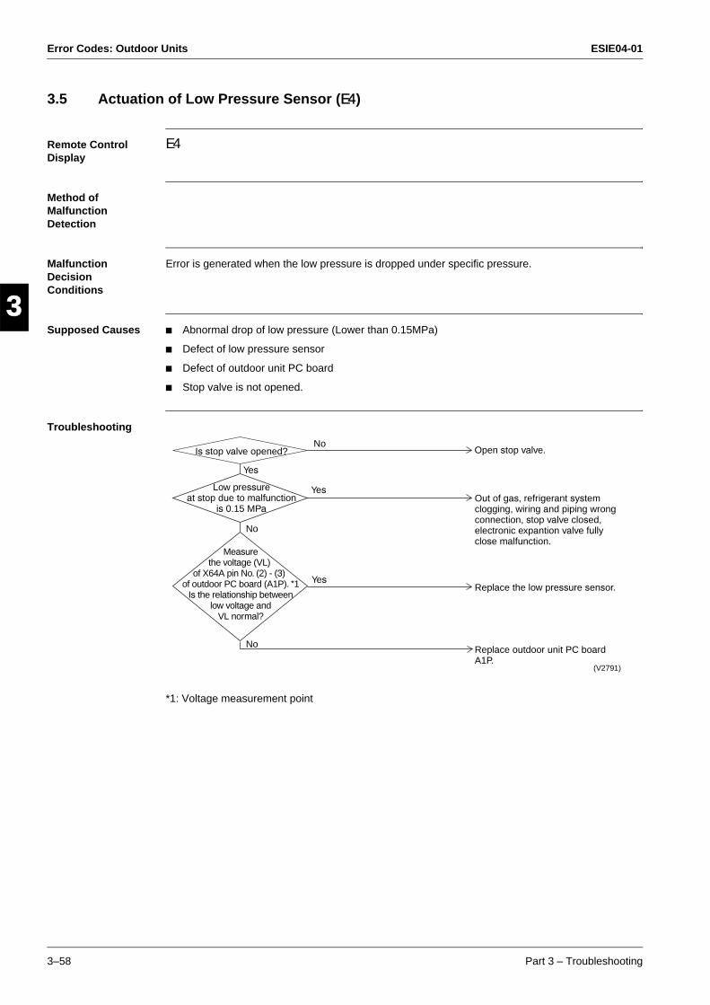
Error Codes: Outdoor Units ESIE04-01
3–58 Part 3 – Troubleshooting
3
1
3
4
5
3.5 Actuation of Low Pressure Sensor (E4)
Remote Control Display
E4
Method of Malfunction Detection
Malfunction Decision Conditions
Error is generated when the low pressure is dropped under specific pressure.
Supposed Causes Abnormal drop of low pressure (Lower than 0.15MPa)
Defect of low pressure sensor
Defect of outdoor unit PC board
Stop valve is not opened.
Troubleshooting
*1: Voltage measurement point
Is stop valve opened?
Low pressure at stop due to malfunction
is 0.15 MPa
Measure the voltage (VL)
of X64A pin No. (2) - (3) of outdoor PC board (A1P). *1
Is the relationship between low voltage and
VL normal?
No
No
No
Yes
Yes
Yes
(V2791)
Open stop valve.
Out of gas, refrigerant system clogging, wiring and piping wrong connection, stop valve closed, electronic expantion valve fully close malfunction.
Replace the low pressure sensor.
Replace outdoor unit PC board A1P.
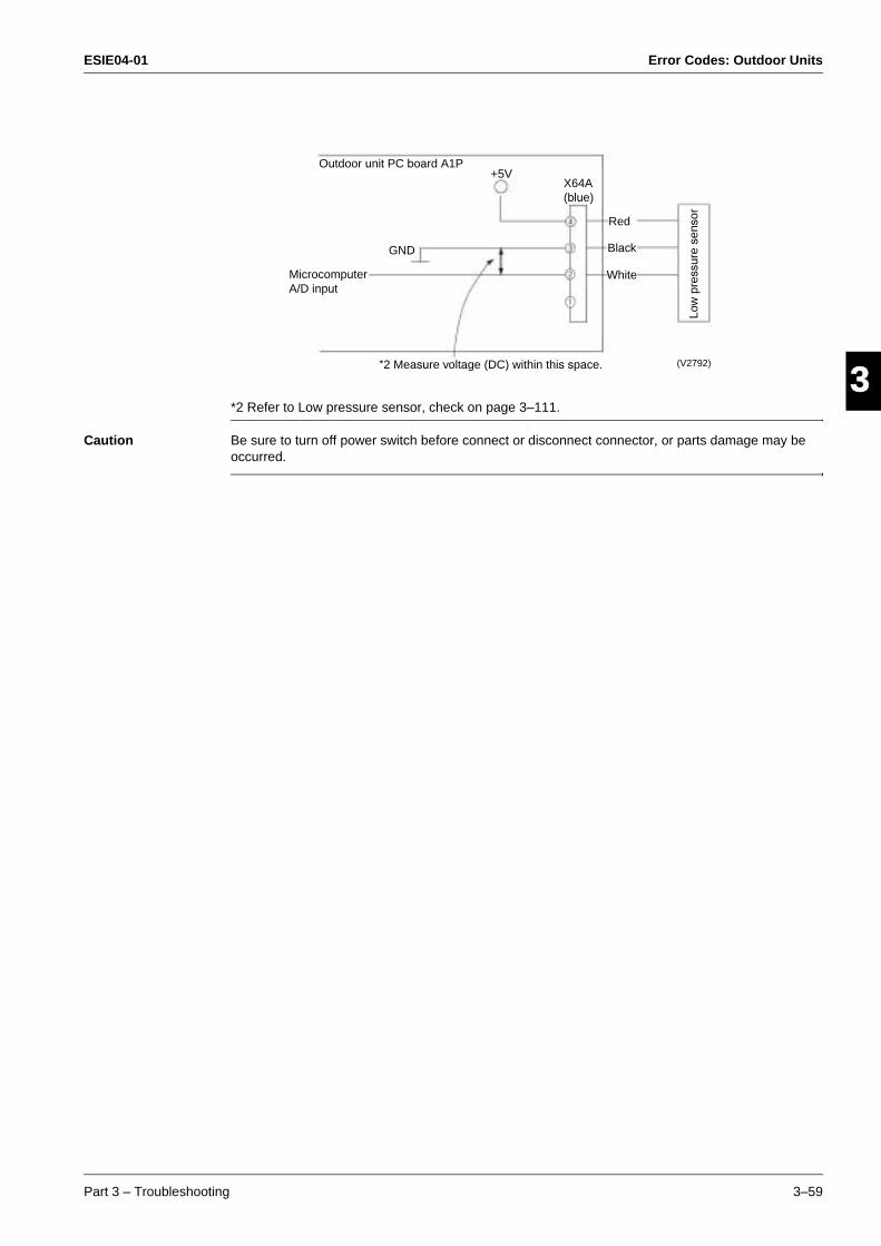
ESIE04-01 Error Codes: Outdoor Units
Part 3 – Troubleshooting 3–59
33
4
5
1
*2 Refer to Low pressure sensor, check on page 3–111.
Caution Be sure to turn off power switch before connect or disconnect connector, or parts damage may be occurred.
Outdoor unit PC board A1P
GND
Microcomputer A/D input
+5VX64A (blue)
Red
Black
White
Low
pre
ssur
e se
nsor
(V2792)*2 Measure voltage (DC) within this space.
Error Codes: Outdoor Units ESIE04-01
3–60 Part 3 – Troubleshooting
3
1
3
4
5
3.6 Compressor Motor Lock (E5)
Remote Control Display
E5
Method of Malfunction Detection
Inverter PC board takes the position signal from UVWN line connected between the inverter and compressor, and detects the position signal pattern.
Malfunction Decision Conditions
The position signal with 3 times cycle as imposed frequency is detected when compressor motor operates normally, but 2 times cycle when compressor motor locks. When the position signal in 2 times cycle is detected
Supposed Causes Compressor lock
High differential pressure (0.5MPa or more) starting
Incorrect UVWN wiring
Faulty inverter PC board
Stop valve is left in closed.
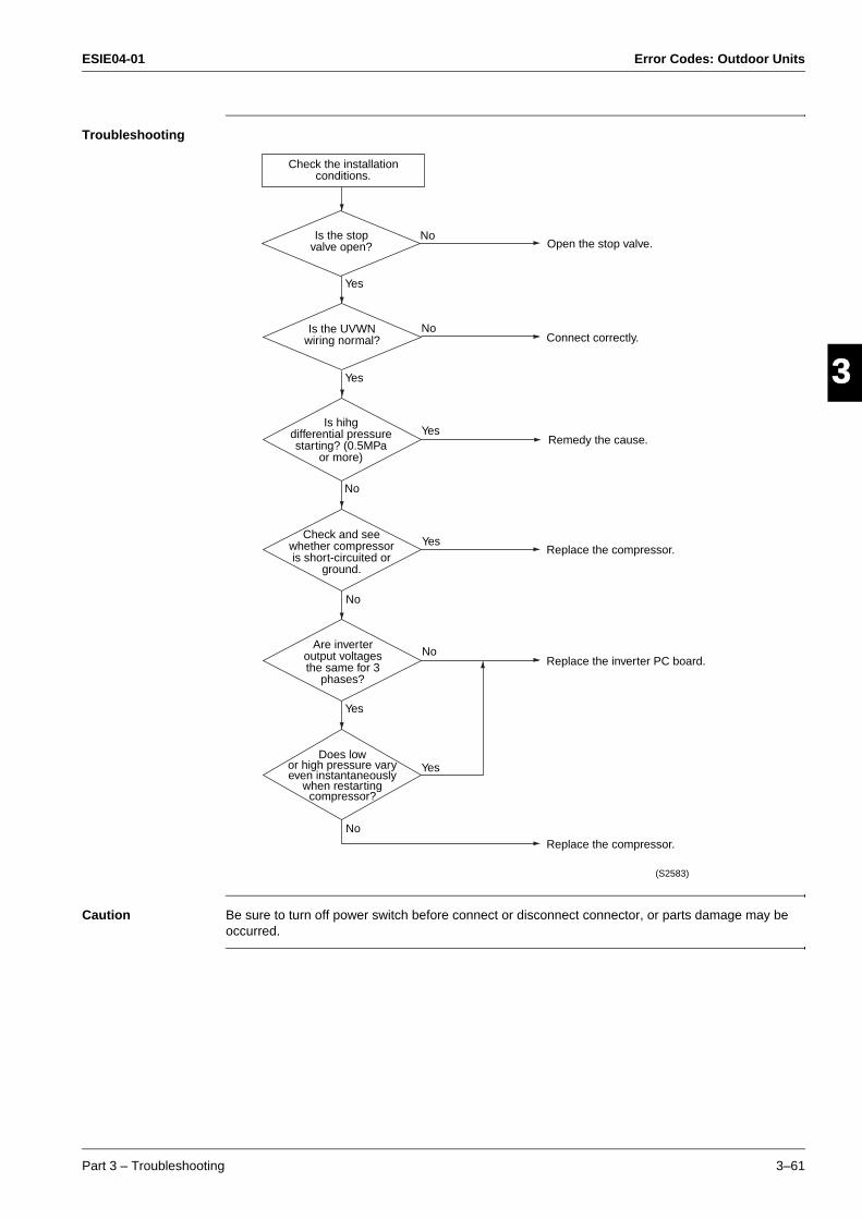
ESIE04-01 Error Codes: Outdoor Units
Part 3 – Troubleshooting 3–61
33
4
5
1Troubleshooting
Caution Be sure to turn off power switch before connect or disconnect connector, or parts damage may be occurred.
Check the installation conditions.
Is the stop valve open?
Is the UVWN wiring normal?
Is hihg differential pressure starting? (0.5MPa
or more)
Check and see whether compressor is short-circuited or
ground.
Are inverter output voltages the same for 3
phases?
Does low or high pressure vary even instantaneously
when restarting compressor?
Yes
No
No
Yes
Yes
No
Yes
No
Yes
Yes
No
NoOpen the stop valve.
Connect correctly.
Remedy the cause.
Replace the compressor.
Replace the inverter PC board.
Replace the compressor.
(S2583)
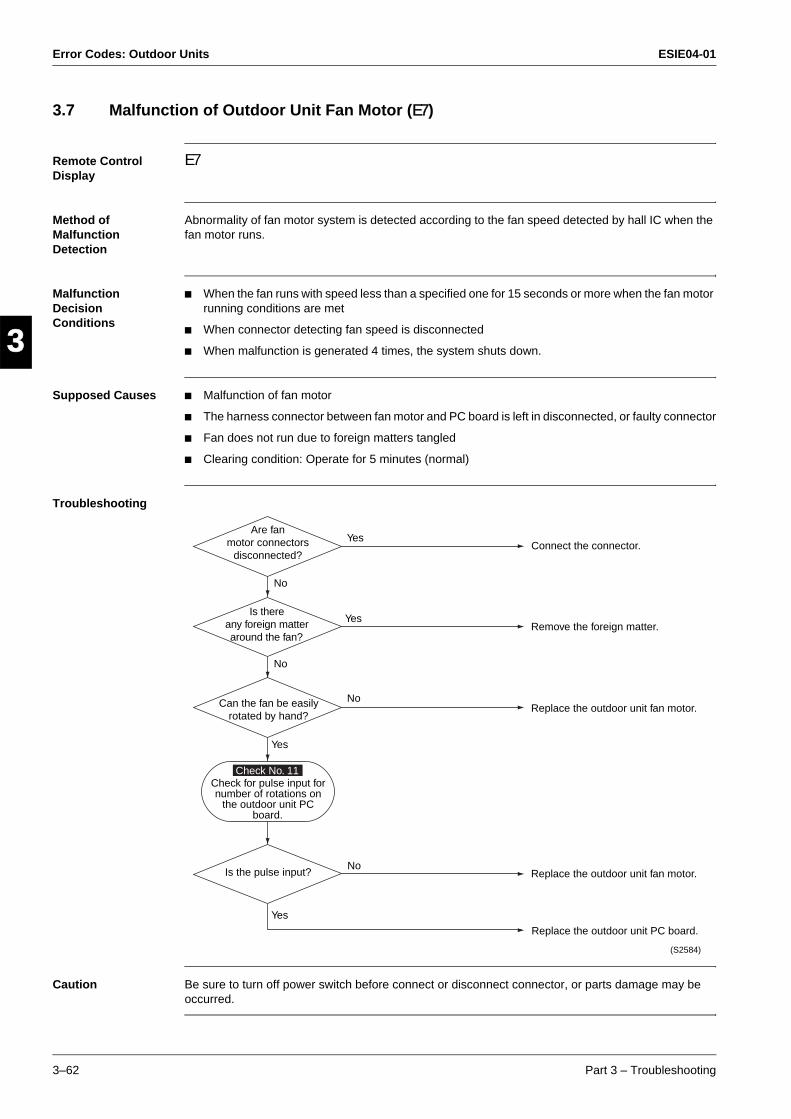
Error Codes: Outdoor Units ESIE04-01
3–62 Part 3 – Troubleshooting
3
1
3
4
5
3.7 Malfunction of Outdoor Unit Fan Motor (E7)
Remote Control Display
E7
Method of Malfunction Detection
Abnormality of fan motor system is detected according to the fan speed detected by hall IC when the fan motor runs.
Malfunction Decision Conditions
When the fan runs with speed less than a specified one for 15 seconds or more when the fan motor running conditions are met
When connector detecting fan speed is disconnected
When malfunction is generated 4 times, the system shuts down.
Supposed Causes Malfunction of fan motor
The harness connector between fan motor and PC board is left in disconnected, or faulty connector
Fan does not run due to foreign matters tangled
Clearing condition: Operate for 5 minutes (normal)
Troubleshooting
Caution Be sure to turn off power switch before connect or disconnect connector, or parts damage may be occurred.
Check No. 11
Yes
No
No
Connect the connector.
Remove the foreign matter.
Replace the outdoor unit fan motor.
Replace the outdoor unit fan motor.
Replace the outdoor unit PC board.
(S2584)
Are fan motor connectors
disconnected?
Is there any foreign matter around the fan?
Can the fan be easily rotated by hand?
Check for pulse input for number of rotations on
the outdoor unit PC board.
Is the pulse input?
Yes
No
No
Yes
Yes
ESIE04-01 Error Codes: Outdoor Units
Part 3 – Troubleshooting 3–63
33
4
5
13.8 Malfunction of Electronic Expansion Valve (E9)
Remote Control Display
E9
Method of Malfunction Detection
Method is determined according to the suction pipe superheat degree and electronic expansion valve opening degree calculated by values of low pressure sensor and suction pipe temperature thermistor.
Malfunction Decision Conditions
When the following conditions are met for 10 minutes
Suction pipe superheat degree < 2°C
Minimum electronic expansion valve opening degree
Supposed Causes Faulty electronic expansion valve
Faulty solenoid valve
Faulty check valve

Error Codes: Outdoor Units ESIE04-01
3–64 Part 3 – Troubleshooting
3
1
3
4
5
Troubleshooting
Caution Be sure to turn off power switch before connect or disconnect connector, or parts damage may be occurred.
1
2
3
4
5
1—52—53—54—5
Turn the power supply off once and back on.
Normal reset?
Is the electronic expansion
valve coil connected to outdoor unit PC
board?
With remote control ON, doesn’t the unit operate and is “E9”
displayed?
Is there difference in
temperature before and after solenoid valve (Y2S)
during operation?
No
No
No
Yes
Yes
Yes
No
Is coil resistance of electronic expansion
valve normal. (40 to 50Ω) (*)
Yes
No
* Measure the resistance between each pin of connector and make sure that the restistance ranges between 40 and 50Ω.
Measurement point
(S2585)
Replace the outdoor unit PC board (A1P)
Replace the electronic expansion valve coil.
Replace the main unit of solenoid valve (Y2S)
Replace the motorized valve coil.
Connect correctly.
Problem could be caused by external factor (noise, etc.) other than malfunction.
ESIE04-01 Error Codes: Outdoor Units
Part 3 – Troubleshooting 3–65
33
4
5
13.9 Malfunctioning in Discharge Pipe Temperature (F3)
Remote Control Display
F3
Method of Malfunction Detection
Abnormality is detected according to the temperature detected by the discharge pipe temperature sensor.
Malfunction Decision Conditions
When the discharge pipe temperature rises to an abnormally high level
When the discharge pipe temperature rises suddenly
Supposed Causes Faulty discharge pipe thermistor
Faulty connection of discharge pipe thermistor
Insufficient refrigerant amount
Faulty compressor
Disconnection of discharge pipe temperature thermistor piping
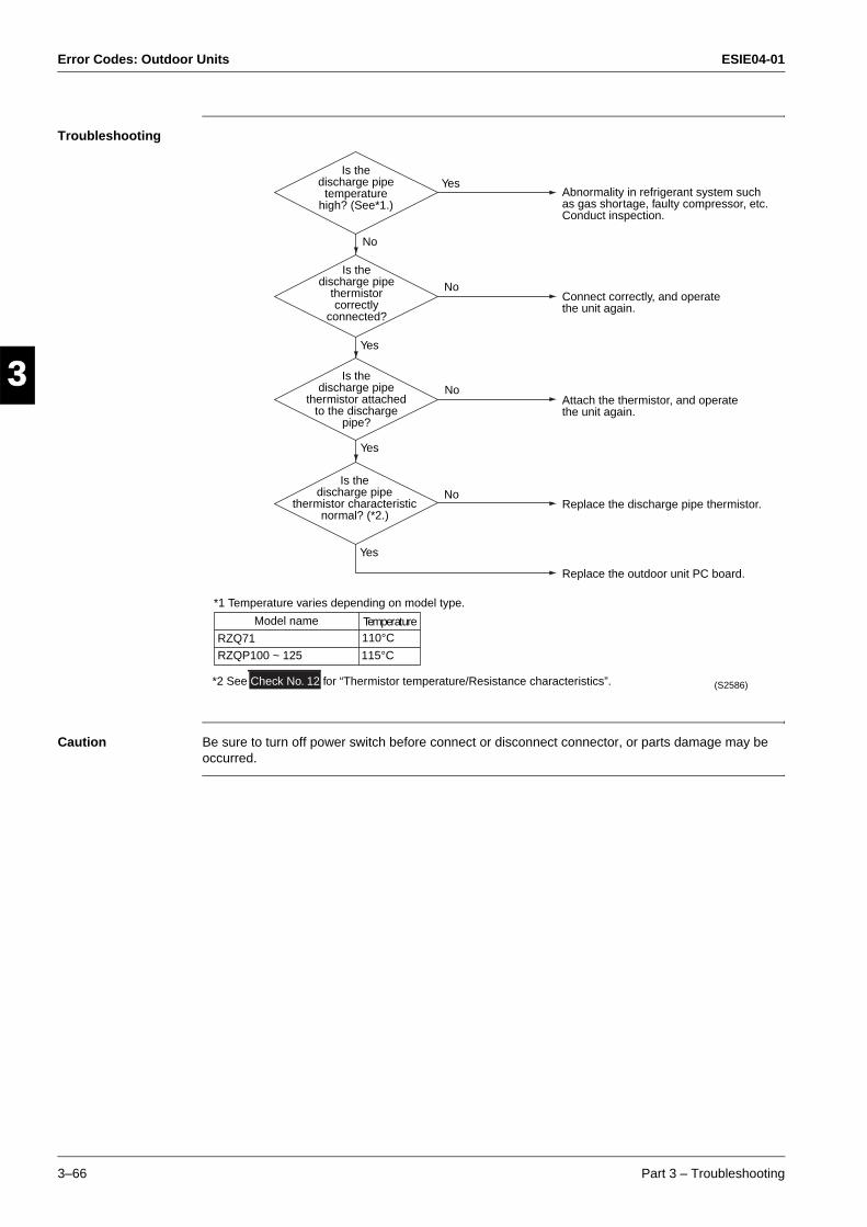
Error Codes: Outdoor Units ESIE04-01
3–66 Part 3 – Troubleshooting
3
1
3
4
5
Troubleshooting
Caution Be sure to turn off power switch before connect or disconnect connector, or parts damage may be occurred.
No
No
No
Is the discharge pipe
temperature high? (See*1.)
Is the discharge pipe
thermistor correctly
connected?
Is the discharge pipe
thermistor attached to the discharge
pipe?
Is the discharge pipe
thermistor characteristic normal? (*2.)
Yes
No
Yes
Yes
YesAbnormality in refrigerant system such as gas shortage, faulty compressor, etc. Conduct inspection.
Connect correctly, and operate the unit again.
Attach the thermistor, and operate the unit again.
Replace the discharge pipe thermistor.
Replace the outdoor unit PC board.
(S2586)
*1 Temperature varies depending on model type.
Model name TemperatureRZQ71
RZQP100 ~ 125
110°C
115°C
*2 See Check No. 12 for “Thermistor temperature/Resistance characteristics”.
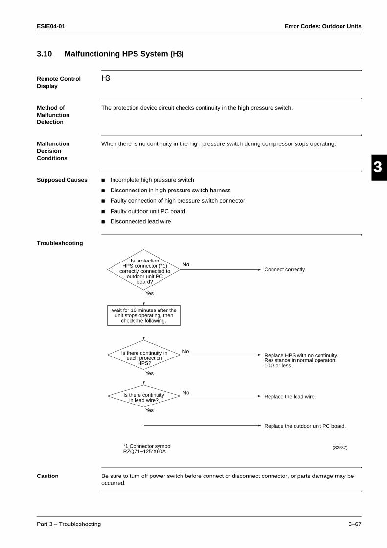
ESIE04-01 Error Codes: Outdoor Units
Part 3 – Troubleshooting 3–67
33
4
5
13.10 Malfunctioning HPS System (H3)
Remote Control Display
H3
Method of Malfunction Detection
The protection device circuit checks continuity in the high pressure switch.
Malfunction Decision Conditions
When there is no continuity in the high pressure switch during compressor stops operating.
Supposed Causes Incomplete high pressure switch
Disconnection in high pressure switch harness
Faulty connection of high pressure switch connector
Faulty outdoor unit PC board
Disconnected lead wire
Troubleshooting
Caution Be sure to turn off power switch before connect or disconnect connector, or parts damage may be occurred.
Yes
No
No
*1 Connector symbol RZQ71~125:X60A
Is protection HPS connector (*1)
correctly connected to outdoor unit PC
board?
Wait for 10 minutes after the unit stops operating, then
check the following.
Is there continuity in each protection
HPS?
Is there continuity in lead wire?
No
Yes
Yes
No
Replace the outdoor unit PC board.
Replace the lead wire.
Replace HPS with no continuity. Resistance in normal operaton: 10Ω or less
Connect correctly.
(S2587)
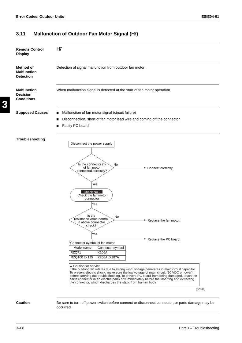
Error Codes: Outdoor Units ESIE04-01
3–68 Part 3 – Troubleshooting
3
1
3
4
5
3.11 Malfunction of Outdoor Fan Motor Signal (H7)
Remote Control Display
H7
Method of Malfunction Detection
Detection of signal malfunction from outdoor fan motor.
Malfunction Decision Conditions
When malfunction signal is detected at the start of fan motor operation.
Supposed Causes Malfunction of fan motor signal (circuit failure)
Disconnection, short of fan motor lead wire and coming off the connector
Faulty PC board
Troubleshooting
Caution Be sure to turn off power switch before connect or disconnect connector, or parts damage may be occurred.
Disconnect the power supply
Connect correctly.
Replace the fan motor.
Replace the PC board.
Is the connector (*) of fan motor
connected correctly?
Check No.9 Check the fan motor
connector
Is the resistance value normal
in above connector check?
No
Yes
No
Yes
Yes
*Connector symbol of fan motorModel name Connector symbol
RZQ71
RZQ100 to 125
X206A
X206A, X207A
Caution for serviceIf the outdoor fan rotates due to strong wind, voltage generates in main circuit capacitor.To prevent electric shock, make sure the low voltage of main circuit (50 VDC or lower) before carrying out troubleshooting. To prevent PC board from being damaged, touch the earth connector in an electric parts box immediately before the inserting and extracting the connector, which discharges the static from human body
(S2588)
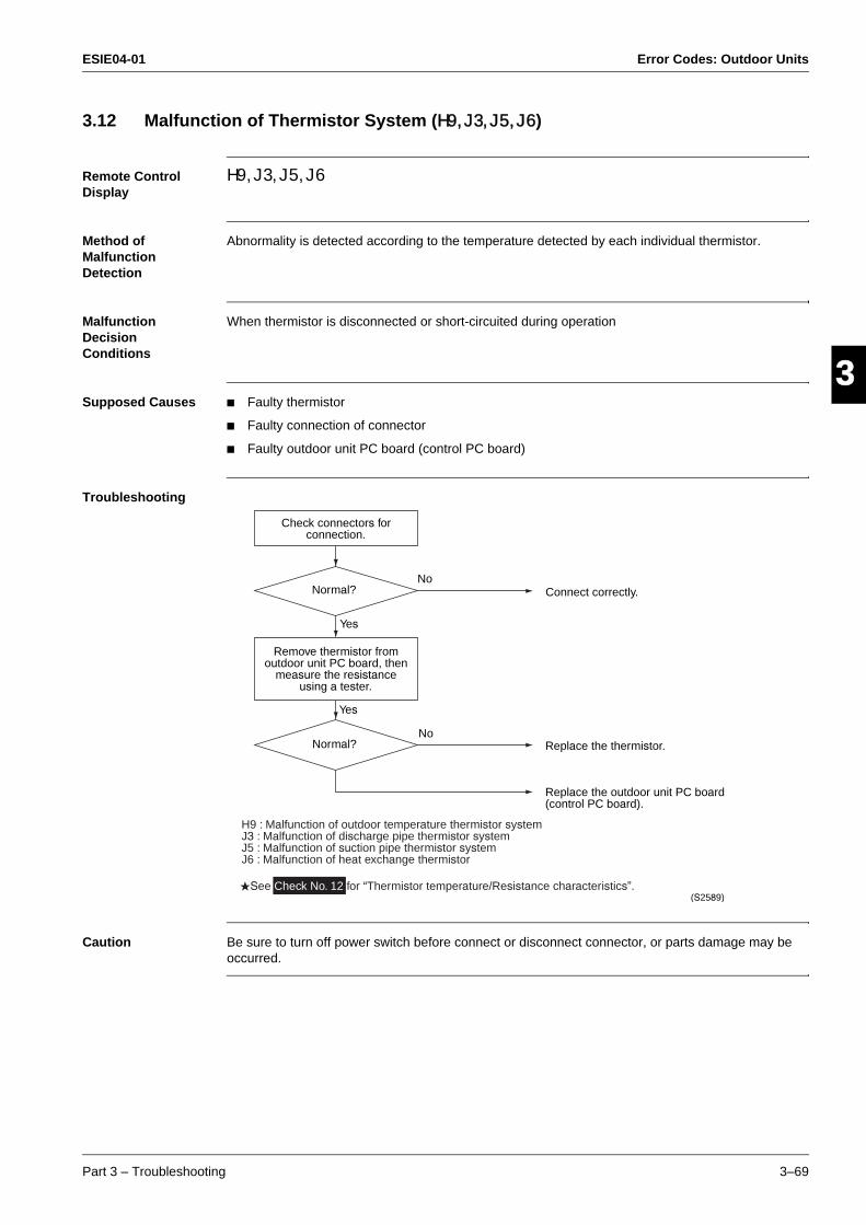
ESIE04-01 Error Codes: Outdoor Units
Part 3 – Troubleshooting 3–69
33
4
5
13.12 Malfunction of Thermistor System (H9, J3, J5, J6)
Remote Control Display
H9, J3, J5, J6
Method of Malfunction Detection
Abnormality is detected according to the temperature detected by each individual thermistor.
Malfunction Decision Conditions
When thermistor is disconnected or short-circuited during operation
Supposed Causes Faulty thermistor
Faulty connection of connector
Faulty outdoor unit PC board (control PC board)
Troubleshooting
Caution Be sure to turn off power switch before connect or disconnect connector, or parts damage may be occurred.
See Check No. 12 for “Thermistor temperature/Resistance characteristics”.
Check connectors for connection.
Normal?
Remove thermistor from outdoor unit PC board, then
measure the resistance using a tester.
Normal?
No
Yes
No
Yes
Connect correctly.
Replace the thermistor.
Replace the outdoor unit PC board (control PC board).
(S2589)
H9 : Malfunction of outdoor temperature thermistor systemJ3 : Malfunction of discharge pipe thermistor systemJ5 : Malfunction of suction pipe thermistor systemJ6 : Malfunction of heat exchange thermistor
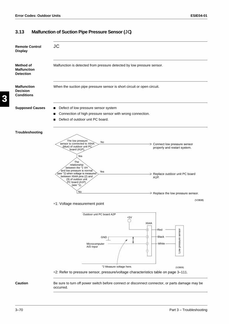
Error Codes: Outdoor Units ESIE04-01
3–70 Part 3 – Troubleshooting
3
1
3
4
5
3.13 Malfunction of Suction Pipe Pressure Sensor (JC)
Remote Control Display
JC
Method of Malfunction Detection
Malfunction is detected from pressure detected by low pressure sensor.
Malfunction Decision Conditions
When the suction pipe pressure sensor is short circuit or open circuit.
Supposed Causes Defect of low pressure sensor system
Connection of high pressure sensor with wrong connection.
Defect of outdoor unit PC board.
Troubleshooting
∗1: Voltage measurement point
∗2: Refer to pressure sensor, pressure/voltage characteristics table on page 3–111.
Caution Be sure to turn off power switch before connect or disconnect connector, or parts damage may be occurred.
The low pressure sensor is connected to X64A
(blue) of outdoor unit PC board (A1P).
The relationship
between the *1 VH and low pressure is normal
(see *2) when voltage is measured between X64A pins (2) and
(3) of outdoor unit PC board (A1P)
(see *1).
No
Yes
No
Yes
Connect low pressure sensor properly and restart system.
Replace outdoor unit PC board A1P.
Replace the low pressure sensor.
(V2808)
Outdoor unit PC board A2P
Microcomputer A/D input
GND
+5V
*2 Measure voltage here.
X64A
Red
Black
White
Low
pre
ssur
e se
nsor
(V2809)
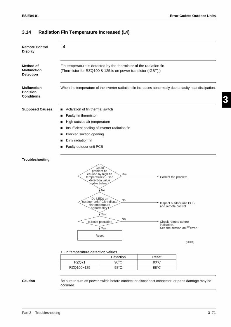
ESIE04-01 Error Codes: Outdoor Units
Part 3 – Troubleshooting 3–71
33
4
5
13.14 Radiation Fin Temperature Increased (L4)
Remote Control Display
L4
Method of Malfunction Detection
Fin temperature is detected by the thermistor of the radiation fin.(Thermistor for RZQ100 & 125 is on power transistor (IGBT).)
Malfunction Decision Conditions
When the temperature of the inverter radiation fin increases abnormally due to faulty heat dissipation.
Supposed Causes Activation of fin thermal switch
Faulty fin thermistor
High outside air temperature
Insufficient cooling of inverter radiation fin
Blocked suction opening
Dirty radiation fin
Faulty outdoor unit PCB
Troubleshooting
∗ Fin temperature detection values
Caution Be sure to turn off power switch before connect or disconnect connector, or parts damage may be occurred.
Detection Reset
RZQ71 90°C 80°C
RZQ100~125 98°C 88°C
Is reset possible?
(S2031)
Do LEDs onoutdoor unit PCB indicate
fin temperatureabnormality?
Reset
Couldproblem be
caused by high fintemperature? ∗ See
detection valuetable below.
Correct the problem.
Inspect outdoor unit PCB and remote control.
Check remote control indication.See the section on error.
No
No
No
Yes
Yes
Yes

Error Codes: Outdoor Units ESIE04-01
3–72 Part 3 – Troubleshooting
3
1
3
4
5
3.15 DC Output Overcurrent (Instantaneous) (L5)
Remote Control Display
L5
Method of Malfunction Detection
Malfunction is detected by converting the current flowing to power transistor into voltage with CT1 (DC current sensor).
Malfunction Decision Conditions
When overcurrent has run to power transistor. (Actuated even by instantaneous overcurrent)
Supposed Causes Faulty compressor coil (disconnection, poor insulation)
Compressor startup malfunction (mechanical lock)
Faulty inverter PC board
Instantaneous fluctuation of power supply voltage
Faulty compressor (if bearing is scratched)
The stop valve is left in closed.
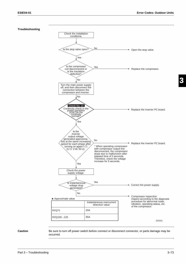
ESIE04-01 Error Codes: Outdoor Units
Part 3 – Troubleshooting 3–73
33
4
5
1Troubleshooting
Caution Be sure to turn off power switch before connect or disconnect connector, or parts damage may be occurred.
Correct the power supply.
Approximate value
* When operating compressor with compressor output line disconnected, the compressor stops due to malfunction after elapsed time of 5 seconds. Therefore, check the voltage increase for 5 seconds.
Check No. 10
(S2592)
Check the installation conditions.
Is the stop valve open?
Is the compressor coil disconnected or
is the insulation defective?
Yes
Yes
Yes
No
No
No
Turn the main power supply off, and then disconnect the
connection between the compressor and inverter.
Continuity check in the power transistor
(IGBT)Is the continuity normal?
Yes
Yes
No
No
Is the inverter
output voltage generated approxima-
tely at the same increasing speed for each phase after
turning on again? (*) (U-V, V-W, W-U)
Check the power supply voltage.
Is instantaneous voltage drop generated?
Open the stop valve.
Replace the compressor.
Replace the inverter PC board.
Replace the inverter PC board.
Compressor inspection Inspect according to the diagnosis procedure for abnormal noise, vibration, operating status, etc. of the compressor.
Instantaneous overcurrent detection value
RZQ71
RZQ100 ~125
20A
65A
Error Codes: Outdoor Units ESIE04-01
3–74 Part 3 – Troubleshooting
3
1
3
4
5
3.16 Electronic Thermal (Time Lag) (L8)
Remote Control Display
L8
Method of Malfunction Detection
Malfunction is detected by converting the current flowing to power transistor into voltage with CT1 (DC current sensor).Inverter PC board detects the disorder of position signal.
Malfunction Decision Conditions
When compressor overload (except for when startup) is detected.
Supposed Causes Compressor overload (during operation)
Disconnected compressor coil
Faulty inverter
Faulty compressor (if bearing is scratched)

ESIE04-01 Error Codes: Outdoor Units
Part 3 – Troubleshooting 3–75
33
4
5
1Troubleshooting
Caution Be sure to turn off power switch before connect or disconnect connector, or parts damage may be occurred.
YES
NO
NOReplace the inverter PC board.
YES
NOReplace the inverter PC board.
YES
* When operating compressor with compressor output line disconnected, the compressor stops due to malfunction after elapsed time of 5 seconds. Therefore, check the voltage increase for 5 seconds.
Detection value
Electronic thermal detection value
Check No. 10
Is the secondary current of
the inverter higher than A (see below) for
each phase?
Turn the main power supply off, and then disconnect the
connection between the compressor and inverter.
Continuity check in the power
transistor (IGBT)Is the continuity
normal?
Is the inverter output
voltage generated approximately at the
same increasing speed on each
phase after turning on again? (*)
(U-V, V-W, W-U)
Compressor inspectionInspect according to the diagnosis procedure for abnormal noises, vibration, operating status, etc. of the compressor.
Compressor overloadInspection of the compressor and refrigerant system is required.
RZQ71
RZQ100 ~ 125
Cooling
Heating
Cooling
Heating
22A × 5 seconds or 13.6A (cooling), 15.1A (heating) × 260 seconds
33A × 5 seconds or 26A × 260 seconds
(S2593)
Error Codes: Outdoor Units ESIE04-01
3–76 Part 3 – Troubleshooting
3
1
3
4
5
3.17 Stall Prevention (Time Lag) (L9)
Remote Control Display
L9
Method of Malfunction Detection
Malfunction is detected by converting the current flowing to power transistor into voltage with CT1 (DC current sensor).Inverter PC board detects the disorder of position signal.
Malfunction Decision Conditions
When compressor overload (except for when startup) is detectedWhen position signal is disordered
Supposed Causes Faulty compressor (lock)
Pressure differential startup
Faulty inverter
The stop valve is left in closed.
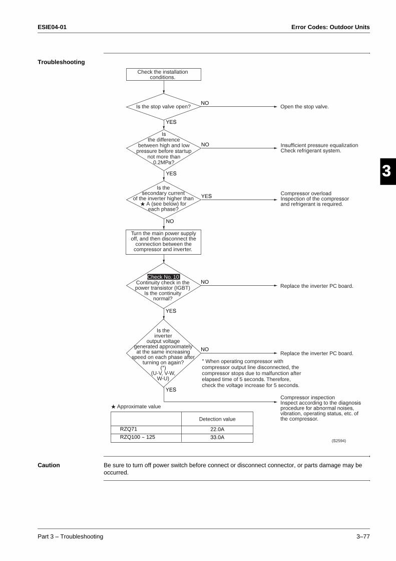
ESIE04-01 Error Codes: Outdoor Units
Part 3 – Troubleshooting 3–77
33
4
5
1Troubleshooting
Caution Be sure to turn off power switch before connect or disconnect connector, or parts damage may be occurred.
NO
YES
YES
NO
Approximate value
Detection value
NOReplace the inverter PC board.
YES
NOReplace the inverter PC board.
YES
* When operating compressor with compressor output line disconnected, the compressor stops due to malfunction after elapsed time of 5 seconds. Therefore, check the voltage increase for 5 seconds.
Check No. 10
NO
YES
Open the stop valve.Is the stop valve open?
(S2594)
Check the installation conditions.
Is the difference
between high and low pressure before startup
not more than 0.2MPa?
Is the secondary current
of the inverter higher than A (see below) for
each phase?
Turn the main power supply off, and then disconnect the
connection between the compressor and inverter.
Continuity check in the power transistor (IGBT)
Is the continuity normal?
Is the inverter
output voltage generated approximately at the same increasing
speed on each phase after turning on again?
(*) (U-V, V-W,
W-U)
Compressor inspectionInspect according to the diagnosis procedure for abnormal noises, vibration, operating status, etc. of the compressor.
Insufficient pressure equalization Check refrigerant system.
Compressor overloadInspection of the compressor and refrigerant is required.
RZQ71
RZQ100 ~ 125
22.0A
33.0A
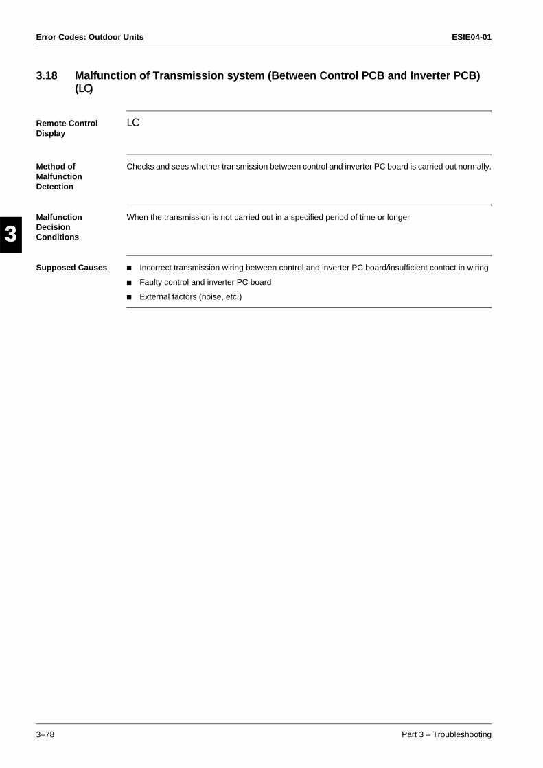
Error Codes: Outdoor Units ESIE04-01
3–78 Part 3 – Troubleshooting
3
1
3
4
5
3.18 Malfunction of Transmission system (Between Control PCB and Inverter PCB) (LC)
Remote Control Display
LC
Method of Malfunction Detection
Checks and sees whether transmission between control and inverter PC board is carried out normally.
Malfunction Decision Conditions
When the transmission is not carried out in a specified period of time or longer
Supposed Causes Incorrect transmission wiring between control and inverter PC board/insufficient contact in wiring
Faulty control and inverter PC board
External factors (noise, etc.)
ESIE04-01 Error Codes: Outdoor Units
Part 3 – Troubleshooting 3–79
33
4
5
1Troubleshooting
Caution Be sure to turn off power switch before connect or disconnect connector, or parts damage may be occurred.
NO
Connect the transmission wiring, and turn on again.
Connect the connector, and turn on again.
YES
YES
Fix the disconnection, and turn on again.
NO
NO
Replace the fan motor.
Inverter transmission malfunctioned due to the malfunction of fan motor.
NOReplace the control PC board.
Replace the inverter PC board.
Check for faulty connector connection in the transmission wiring and for clamps with high tension line.
YES
YES
Is the fan motor connector
connected?
Is the transmission wiring
between the control and inverter PC board
disconnected?
YES
NO
Is “E7” displayed on the remote control? (
“LC” is not displayed?)
NO
YES
Are connectors
connecting the control and inverter PC board
connected securely?
Is the microcomputer
normal monitor (green) on inverter PC board
blinking?
Is the microcomputer normal
LED on control PC board blinking?
Disconnect the fan motor connector, and
turn on again.
(S2595)
Error Codes: Outdoor Units ESIE04-01
3–80 Part 3 – Troubleshooting
3
1
3
4
5
3.19 Open Phase (P1)
Remote Control Display
P1
Method of Malfunction Detection
Malfunction is detected according to the voltage waveform of main circuit capacitor built in inverter.
Malfunction Decision Conditions
When the aforementioned voltage waveform becomes identical with the waveform of the power supply open phase.
Supposed Causes Open phase
Voltage imbalance between phases
Faulty main circuit capacitor
Power unit (Disconnection in diode module)
Faulty outdoor unit PC board
Faulty Magnetic Relay (K11R, K12R)
Improper main circuit wiring
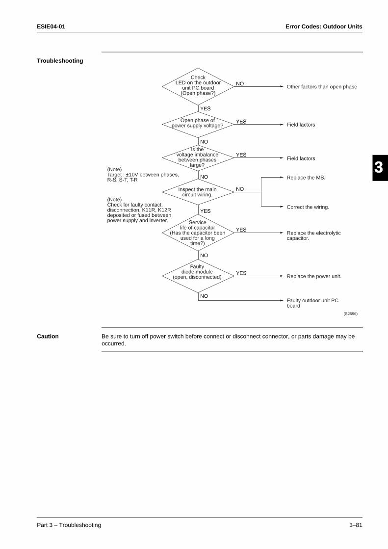
ESIE04-01 Error Codes: Outdoor Units
Part 3 – Troubleshooting 3–81
33
4
5
1Troubleshooting
Caution Be sure to turn off power switch before connect or disconnect connector, or parts damage may be occurred.
Replace the MS.
Correct the wiring.
Replace the power unit.
Other factors than open phase
Field factors
NO
YES
YES
NO
YES
NO
NO
YES
YES
NO
YES
NO
Field factors
(S2596)
(Note) Target : ±10V between phases, R-S, S-T, T-R
(Note)Check for faulty contact, disconnection, K11R, K12R deposited or fused between power supply and inverter.
Check LED on the outdoor
unit PC board (Open phase?)
Open phase of power supply voltage?
Is the voltage imbalance between phases
large?
Inspect the main circuit wiring.
Service life of capacitor
(Has the capacitor been used for a long
time?)
Faulty diode module
(open, disconnected)
Replace the electrolytic capacitor.
Faulty outdoor unit PC board
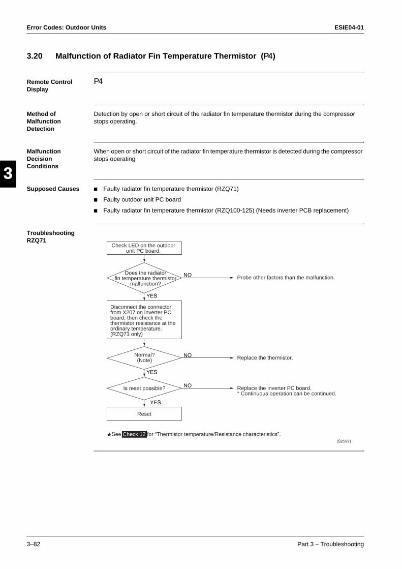
Error Codes: Outdoor Units ESIE04-01
3–82 Part 3 – Troubleshooting
3
1
3
4
5
3.20 Malfunction of Radiator Fin Temperature Thermistor (P4)
Remote Control Display
P4
Method of Malfunction Detection
Detection by open or short circuit of the radiator fin temperature thermistor during the compressor stops operating.
Malfunction Decision Conditions
When open or short circuit of the radiator fin temperature thermistor is detected during the compressor stops operating
Supposed Causes Faulty radiator fin temperature thermistor (RZQ71)
Faulty outdoor unit PC board
Faulty radiator fin temperature thermistor (RZQ100-125) (Needs inverter PCB replacement)
Troubleshooting RZQ71
Replace the thermistor.
Reset
YES
Probe other factors than the malfunction.NO
YES
Is reset possible? NO
NO
YES
Disconnect the connector from X207 on inverter PC board, then check the thermistor resistance at the ordinary temperature.(RZQ71 only)
See Check 12 for “Thermistor temperature/Resistance characteristics”.(S2597)
Check LED on the outdoor unit PC board.
Does the radiator fin temperature thermistor
malfunction?
Normal? (Note)
Replace the inverter PC board.* Continuous operation can be continued.
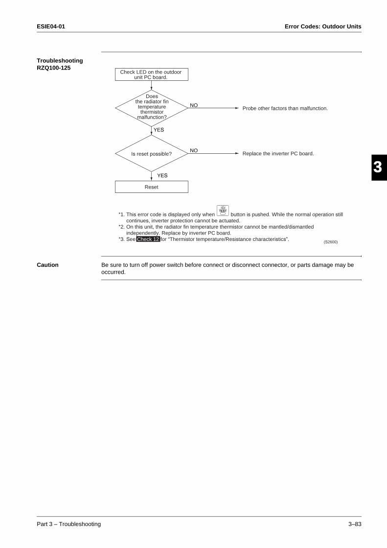
ESIE04-01 Error Codes: Outdoor Units
Part 3 – Troubleshooting 3–83
33
4
5
1Troubleshooting RZQ100-125
Caution Be sure to turn off power switch before connect or disconnect connector, or parts damage may be occurred.
Reset
YES
Probe other factors than malfunction.NO
Replace the inverter PC board.Is reset possible?NO
YES
*1. This error code is displayed only when button is pushed. While the normal operation still continues, inverter protection cannot be actuated.
*2. On this unit, the radiator fin temperature thermistor cannot be mantled/dismantled independently. Replace by inverter PC board.
*3. See Check 12 for “Thermistor temperature/Resistance characteristics”.
TEST
Check LED on the outdoor unit PC board.
Does the radiator fin temperature thermistor
malfunction?
(S2600)
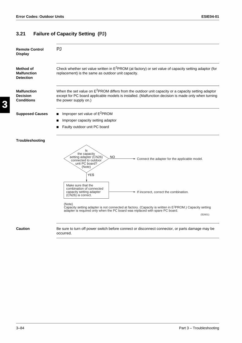
Error Codes: Outdoor Units ESIE04-01
3–84 Part 3 – Troubleshooting
3
1
3
4
5
3.21 Failure of Capacity Setting (PJ)
Remote Control Display
PJ
Method of Malfunction Detection
Check whether set value written in E2PROM (at factory) or set value of capacity setting adaptor (for replacement) is the same as outdoor unit capacity.
Malfunction Decision Conditions
When the set value on E2PROM differs from the outdoor unit capacity or a capacity setting adaptor except for PC board applicable models is installed. (Malfunction decision is made only when turning the power supply on.)
Supposed Causes Improper set value of E2PROM
Improper capacity setting adaptor
Faulty outdoor unit PC board
Troubleshooting
Caution Be sure to turn off power switch before connect or disconnect connector, or parts damage may be occurred.
Connect the adapter for the applicable model.
If incorrect, correct the combination.
NO
YES
(Note) Capacity setting adapter is not connected at factory. (Capacity is written in E2PROM.) Capacity setting adapter is required only when the PC board was replaced with spare PC board.
(S2601)
Is the capacity
setting adapter (CN26) connected to outdoor
unit PC board? (Note)
Make sure that the combination of connected capacity setting adapter (CN26) is correct.
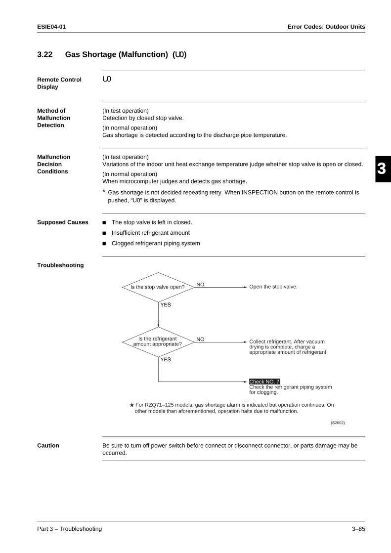
ESIE04-01 Error Codes: Outdoor Units
Part 3 – Troubleshooting 3–85
33
4
5
13.22 Gas Shortage (Malfunction) (U0)
Remote Control Display
U0
Method of Malfunction Detection
(In test operation) Detection by closed stop valve.
(In normal operation) Gas shortage is detected according to the discharge pipe temperature.
Malfunction Decision Conditions
(In test operation) Variations of the indoor unit heat exchange temperature judge whether stop valve is open or closed.
(In normal operation) When microcomputer judges and detects gas shortage.
* Gas shortage is not decided repeating retry. When INSPECTION button on the remote control is pushed, “U0” is displayed.
Supposed Causes The stop valve is left in closed.
Insufficient refrigerant amount
Clogged refrigerant piping system
Troubleshooting
Caution Be sure to turn off power switch before connect or disconnect connector, or parts damage may be occurred.
NO
YES
Open the stop valve.Is the stop valve open? NO
YES
(S2602)
For RZQ71~125 models, gas shortage alarm is indicated but operation continues. On other models than aforementioned, operation halts due to malfunction.
Is the refrigerant amount appropriate? Collect refrigerant. After vacuum
drying is complete, charge a appropriate amount of refrigerant.
Check NO. 7Check the refrigerant piping system for clogging.
Error Codes: Outdoor Units ESIE04-01
3–86 Part 3 – Troubleshooting
3
1
3
4
5
3.23 Abnormal Power Supply Voltage (U2)
Remote Control Display
U2
Method of Malfunction Detection
Malfunction is detected according to the voltage of main circuit capacitor built in the inverter and power supply voltage.
Malfunction Decision Conditions
When the voltage of main circuit capacitor built in the inverter and power supply voltage drop (150-170 VAC) or when the power failure of several tons of ms or longer is generated.* Remote control does not decide the abnormality.
Supposed Causes Drop in power supply voltage (180 V or less)
Instantaneous power failure
Inverter open phase (Phase T)
Faulty main circuit wiring
Faulty outdoor unit PC board
Main circuit parts damaged
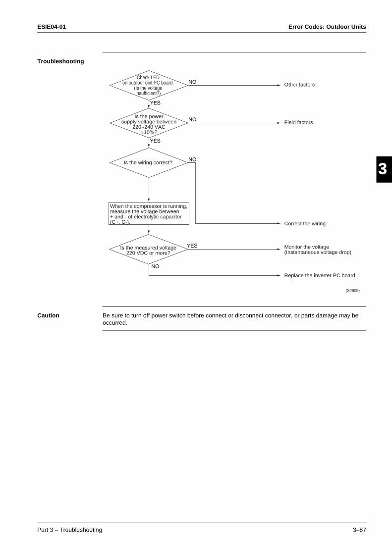
ESIE04-01 Error Codes: Outdoor Units
Part 3 – Troubleshooting 3–87
33
4
5
1Troubleshooting
Caution Be sure to turn off power switch before connect or disconnect connector, or parts damage may be occurred.
NO
NO
YES
YES
YES
NO
NO
When the compressor is running, measure the voltage between + and - of electrolytic capacitor (C+, C-).
(S2605)
Check LED on outdoor unit PC board.
(Is the voltageinsufficient?)
Is the power supply voltage between
220~240 VAC ±10%?
Is the wiring correct?
Is the measured voltage 220 VDC or more?
Monitor the voltage (Instantaneous voltage drop)
Replace the inverter PC board.
Correct the wiring.
Field factors
Other factors
Error Codes: Outdoor Units ESIE04-01
3–88 Part 3 – Troubleshooting
3
1
3
4
5

ESIE04-01 Error Codes: System Malfunctions
Part 3 – Troubleshooting 3–89
33
4
5
1Part 3
4 Error Codes: System Malfunctions
4.1 What Is in This Chapter?
Introduction In the first stage of the troubleshooting sequence, it is important to correctly interpret the error code on the remote control display. The error code helps you to find the cause of the problem.
Overview This chapter contains the following topics:
Topic See page
4.2–Malfunction of Transmission between Indoor and Outdoor Unit (U4 or UF) 3–90
4.3–Malfunction of Transmission between Indoor Unit and Remote Control (U5) 3–92
4.4–Malfunction of Transmission between MAIN Remote Control and SUB Remote Control (U8)
3–93
4.5–Malfunctioning Field Setting Switch (UA) 3–94
4.6–Centralized Address Setting Error (UC) 3–96
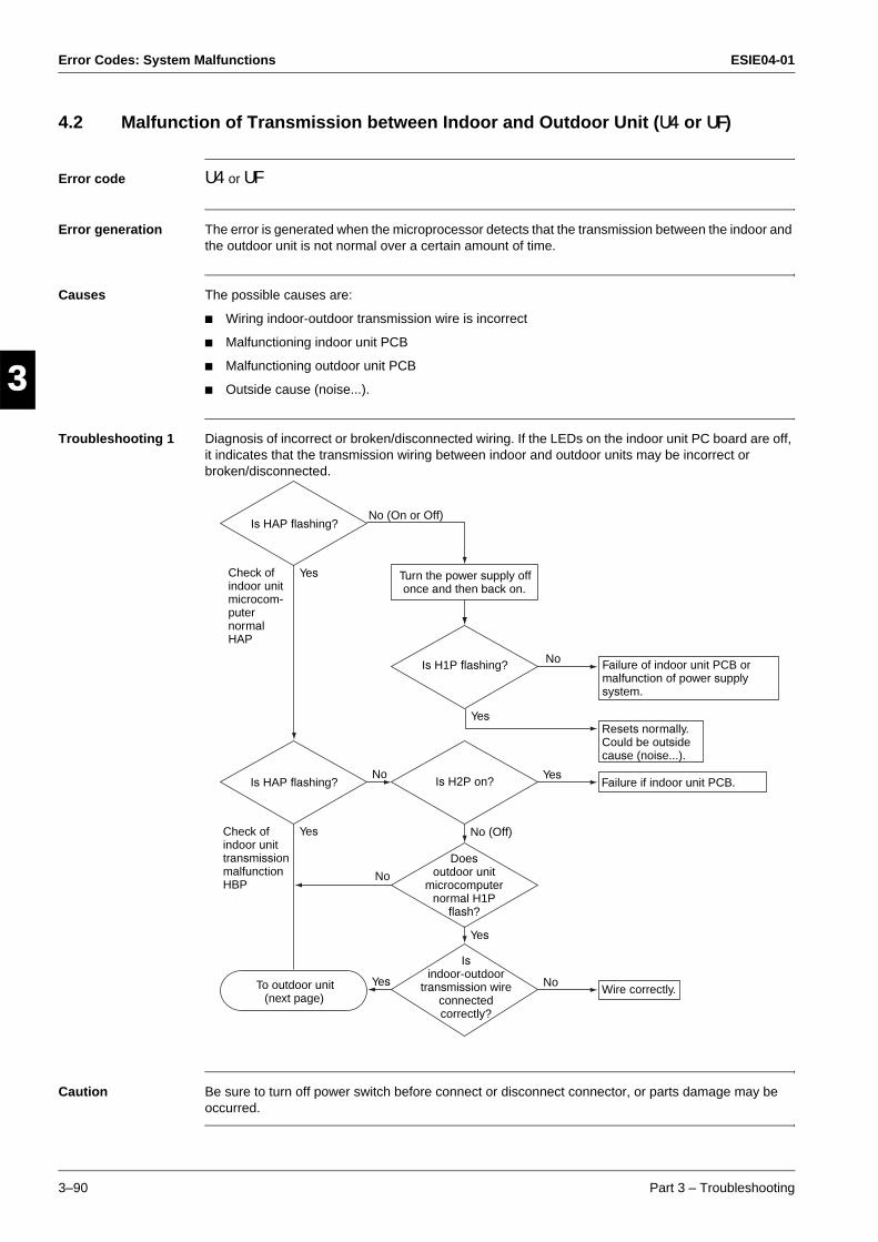
Error Codes: System Malfunctions ESIE04-01
3–90 Part 3 – Troubleshooting
3
1
3
4
5
4.2 Malfunction of Transmission between Indoor and Outdoor Unit (U4 or UF)
Error code U4 or UF
Error generation The error is generated when the microprocessor detects that the transmission between the indoor and the outdoor unit is not normal over a certain amount of time.
Causes The possible causes are:
Wiring indoor-outdoor transmission wire is incorrect
Malfunctioning indoor unit PCB
Malfunctioning outdoor unit PCB
Outside cause (noise...).
Troubleshooting 1 Diagnosis of incorrect or broken/disconnected wiring. If the LEDs on the indoor unit PC board are off, it indicates that the transmission wiring between indoor and outdoor units may be incorrect or broken/disconnected.
Caution Be sure to turn off power switch before connect or disconnect connector, or parts damage may be occurred.
Is HAP flashing?
Check of indoor unit microcom-puter normal HAP
Yes
Is HAP flashing?
Check of indoor unit transmission malfunction HBP
Yes
No
No
No (Off)
Yes
Yes
To outdoor unit (next page)
Yes
Yes
No
Is indoor-outdoor
transmission wire connected correctly?
Does outdoor unit
microcomputer normal H1P
flash?
Is H1P flashing?
Is H2P on?
No
No (On or Off)
Turn the power supply off once and then back on.
Wire correctly.
Failure if indoor unit PCB.
Resets normally. Could be outside cause (noise...).
Failure of indoor unit PCB or malfunction of power supply system.
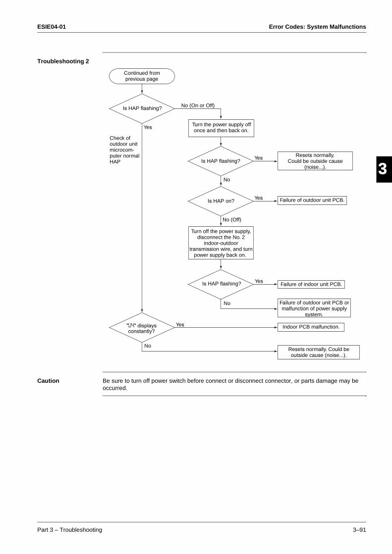
ESIE04-01 Error Codes: System Malfunctions
Part 3 – Troubleshooting 3–91
33
4
5
1Troubleshooting 2
Caution Be sure to turn off power switch before connect or disconnect connector, or parts damage may be occurred.
"U4" displays constantly?
Continued from previous page
Is HAP flashing?
Check of outdoor unit microcom-puter normal HAP
Yes
No (On or Off)
Is HAP flashing?
Is HAP on?
Turn the power supply off once and then back on.
Yes
Yes
No
No (Off)
Turn off the power supply, disconnect the No. 2
indoor-outdoor transmission wire, and turn
power supply back on.
Is HAP flashing? Yes
No
Yes
No
Failure of indoor unit PCB.
Failure of outdoor unit PCB or malfunction of power supply
system.
Indoor PCB malfunction.
Resets normally. Could be outside cause (noise...).
Failure of outdoor unit PCB.
Resets normally.Could be outside cause
(noise...).
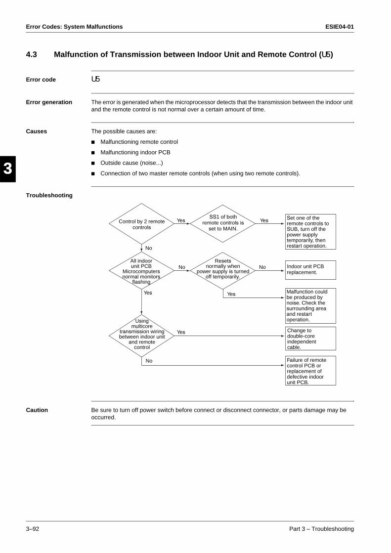
Error Codes: System Malfunctions ESIE04-01
3–92 Part 3 – Troubleshooting
3
1
3
4
5
4.3 Malfunction of Transmission between Indoor Unit and Remote Control (U5)
Error code U5
Error generation The error is generated when the microprocessor detects that the transmission between the indoor unit and the remote control is not normal over a certain amount of time.
Causes The possible causes are:
Malfunctioning remote control
Malfunctioning indoor PCB
Outside cause (noise...)
Connection of two master remote controls (when using two remote controls).
Troubleshooting
Caution Be sure to turn off power switch before connect or disconnect connector, or parts damage may be occurred.
Control by 2 remote controls
All indoor unit PCB
Microcomputers normal monitors
flashing
Using multicore
transmission wiring between indoor unit
and remote control
Yes
No
Yes
Yes
No
No
Yes
No
Yes
SS1 of both remote controls is
set to MAIN.
Resets normally when
power supply is turned off temporarily.
Set one of the remote controls to SUB, turn off the power supply temporarily, then restart operation.
Indoor unit PCB replacement.
Malfunction could be produced by noise. Check the surrounding area and restart operation.
Change to double-core independent cable.
Failure of remote control PCB or replacement of defective indoor unit PCB.
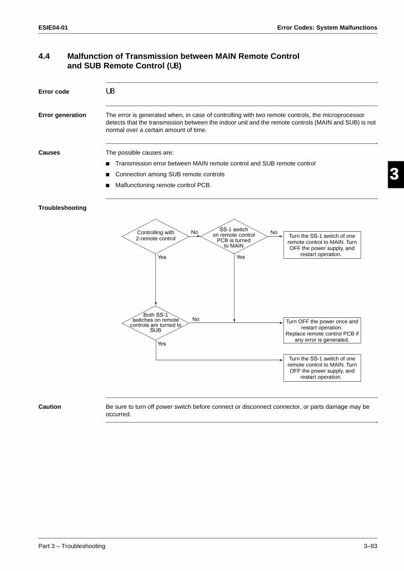
ESIE04-01 Error Codes: System Malfunctions
Part 3 – Troubleshooting 3–93
33
4
5
14.4 Malfunction of Transmission between MAIN Remote Control
and SUB Remote Control (U8)
Error code U8
Error generation The error is generated when, in case of controlling with two remote controls, the microprocessor detects that the transmission between the indoor unit and the remote controls (MAIN and SUB) is not normal over a certain amount of time.
Causes The possible causes are:
Transmission error between MAIN remote control and SUB remote control
Connection among SUB remote controls
Malfunctioning remote control PCB.
Troubleshooting
Caution Be sure to turn off power switch before connect or disconnect connector, or parts damage may be occurred.
Controlling with 2-remote control
No
Yes
No
Yes
Both SS-1 switches on remote
controls are turned to SUB
No
Yes
SS-1 switch on remote control
PCB is turned to MAIN
Turn the SS-1 switch of one remote control to MAIN. Turn OFF the power supply, and
restart operation.
Turn OFF the power once and restart operation.
Replace remote control PCB if any error is generated.
Turn the SS-1 switch of one remote control to MAIN. Turn OFF the power supply, and
restart operation.
Error Codes: System Malfunctions ESIE04-01
3–94 Part 3 – Troubleshooting
3
1
3
4
5
4.5 Malfunctioning Field Setting Switch (UA)
Error code UA
Error generation The error is generated when incorrect field settings have been set for pair/twin/triple/double twin.
Causes The possible causes are:
Malfunctioning indoor or outdoor unit PCB
Malfunctioning power supply PCB
Indoor-outdoor, indoor-indoor unit transmission wiring
Malfunctioning remote control wiring.
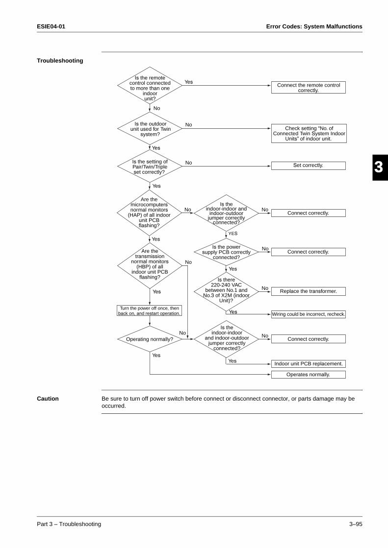
ESIE04-01 Error Codes: System Malfunctions
Part 3 – Troubleshooting 3–95
33
4
5
1Troubleshooting
Caution Be sure to turn off power switch before connect or disconnect connector, or parts damage may be occurred.
YES
Is the remote control connected to more than one
indoor unit?
Yes
Yes
No
NoIs the outdoor unit used for Twin
system?
Is the setting of Pair/Twin/Triple set correctly?
Yes
No
No
No
Yes
Yes
Are the microcomputers normal monitors
(HAP) of all indoor unit PCB flashing?
Are the transmission
normal monitors (HBP) of all
indoor unit PCB flashing?
No
Yes
Turn the power off once, then back on, and restart operation.
Operating normally?
Yes
Yes
Yes
Is the indoor-indoor
and indoor-outdoor jumper correctly
connected?
Is there 220-240 VAC
between No.1 and No.3 of X2M (indoor
Unit)?
Is the power supply PCB correctly
connected?
Is the indoor-indoor and
indoor-outdoor jumper correctly
connected?
No
No
No
No
Operates normally.
Indoor unit PCB replacement.
Connect correctly.
Wiring could be incorrect, recheck.
Replace the transformer.
Connect correctly.
Connect correctly.
Set correctly.
Connect the remote control correctly.
Check setting “No. of Connected Twin System Indoor
Units” of indoor unit.
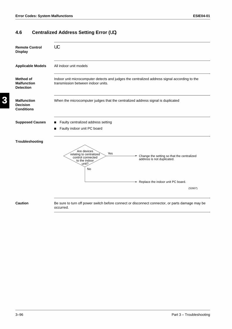
Error Codes: System Malfunctions ESIE04-01
3–96 Part 3 – Troubleshooting
3
1
3
4
5
4.6 Centralized Address Setting Error (UC)
Remote Control Display
UC
Applicable Models All indoor unit models
Method of Malfunction Detection
Indoor unit microcomputer detects and judges the centralized address signal according to the transmission between indoor units.
Malfunction Decision Conditions
When the microcomputer judges that the centralized address signal is duplicated
Supposed Causes Faulty centralized address setting
Faulty indoor unit PC board
Troubleshooting
Caution Be sure to turn off power switch before connect or disconnect connector, or parts damage may be occurred.
Are devices relating to centralized
control connected to the indoor
unit?
Yes
No
Change the setting so that the centralized address is not duplicated.
Replace the indoor unit PC board.
(S2607)
ESIE04-01 Additional Checks for Troubleshooting
Part 3 – Troubleshooting 3–97
33
4
5
1Part 3
5 Additional Checks for Troubleshooting
5.1 What Is in This Chapter?
Introduction This chapter explains how you must check the units to carry out troubleshooting correctly.
Overview This chapter contains the following topics:
Topic See page
5.2–Indoor Unit: Checking the Fan Motor Hall IC 3–98
5.3–Indoor Unit: Checking the Power Supply Wave Form 3–99
5.4–Outdoor unit: Checking the Installation Condition 3–100
5.5–Outdoor Unit: Checking the Expansion Valve 3–101
5.6–Checking the Thermistors 3–102
5.7–Resistance Conversion Table (Ambient, Coil, Fin) 3–103
5.8–R3T: Resistance Conversion Table (Discharge Pipe Sensor) 3–104
5.9–Evaluation of abnormal high pressure 3–105
5.10–Evaluation of abnormal low pressure 3–106
5.11–Checks 3–107
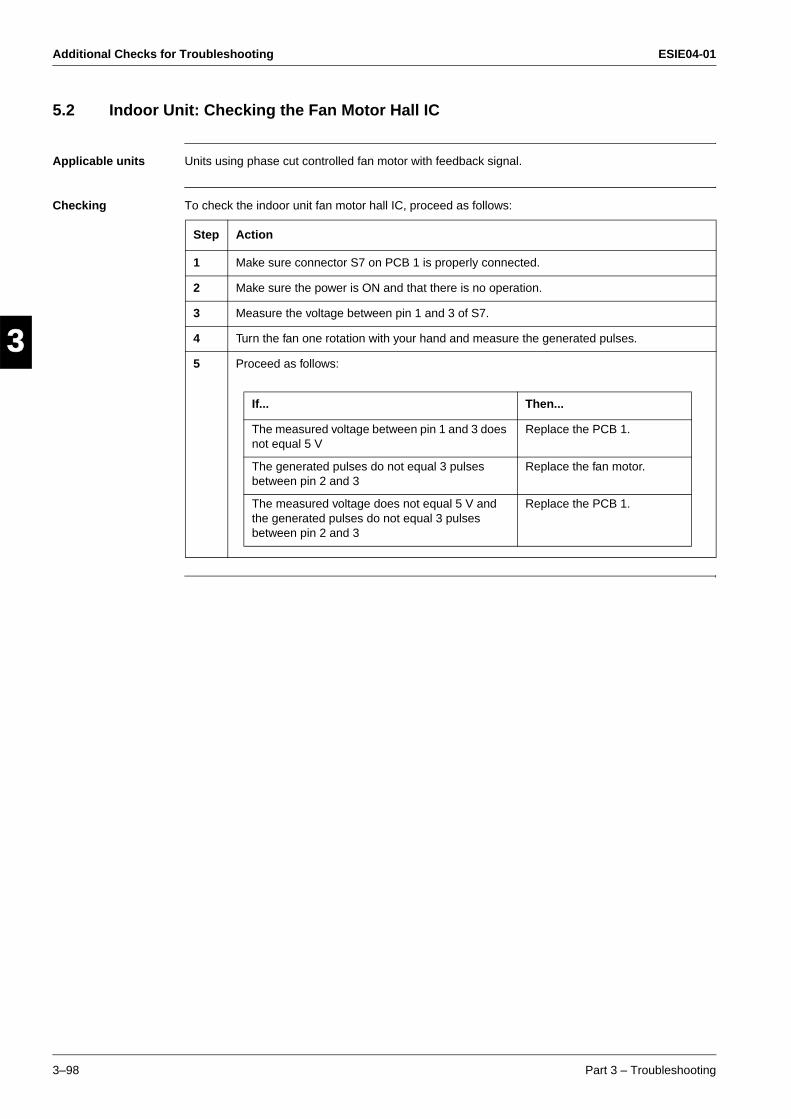
Additional Checks for Troubleshooting ESIE04-01
3–98 Part 3 – Troubleshooting
3
1
3
4
5
5.2 Indoor Unit: Checking the Fan Motor Hall IC
Applicable units Units using phase cut controlled fan motor with feedback signal.
Checking To check the indoor unit fan motor hall IC, proceed as follows:
Step Action
1 Make sure connector S7 on PCB 1 is properly connected.
2 Make sure the power is ON and that there is no operation.
3 Measure the voltage between pin 1 and 3 of S7.
4 Turn the fan one rotation with your hand and measure the generated pulses.
5 Proceed as follows:
If... Then...
The measured voltage between pin 1 and 3 does not equal 5 V
Replace the PCB 1.
The generated pulses do not equal 3 pulses between pin 2 and 3
Replace the fan motor.
The measured voltage does not equal 5 V and the generated pulses do not equal 3 pulses between pin 2 and 3
Replace the PCB 1.
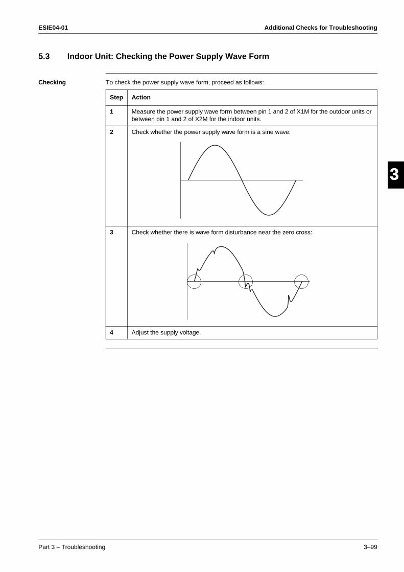
ESIE04-01 Additional Checks for Troubleshooting
Part 3 – Troubleshooting 3–99
33
4
5
15.3 Indoor Unit: Checking the Power Supply Wave Form
Checking To check the power supply wave form, proceed as follows:
Step Action
1 Measure the power supply wave form between pin 1 and 2 of X1M for the outdoor units or between pin 1 and 2 of X2M for the indoor units.
2 Check whether the power supply wave form is a sine wave:
3 Check whether there is wave form disturbance near the zero cross:
4 Adjust the supply voltage.
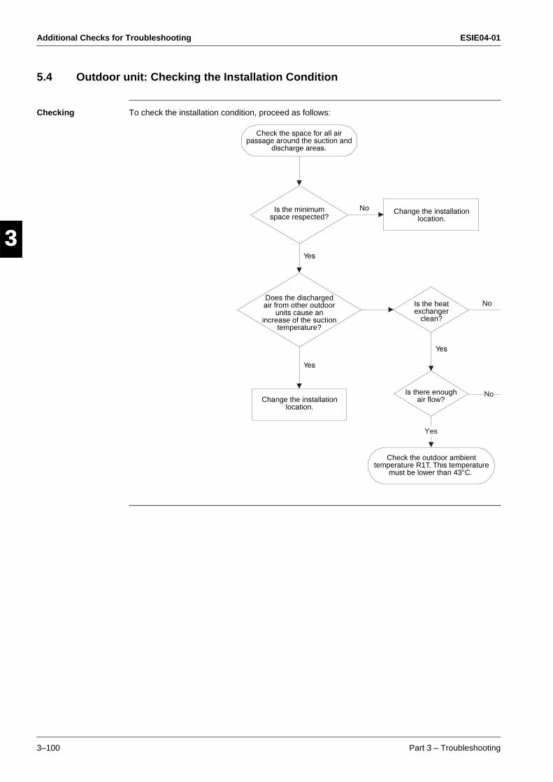
Additional Checks for Troubleshooting ESIE04-01
3–100 Part 3 – Troubleshooting
3
1
3
4
5
5.4 Outdoor unit: Checking the Installation Condition
Checking To check the installation condition, proceed as follows:
Check the space for all air passage around the suction and
discharge areas.
Is the minimum space respected?
Does the discharged air from other outdoor
units cause an increase of the suction
temperature?
Change the installation location.
Yes
Yes
Yes
No
No Change the installation location.
Is the heat exchanger
clean?
Is there enough air flow?
Check the outdoor ambient temperature R1T. This temperature
must be lower than 43°C.
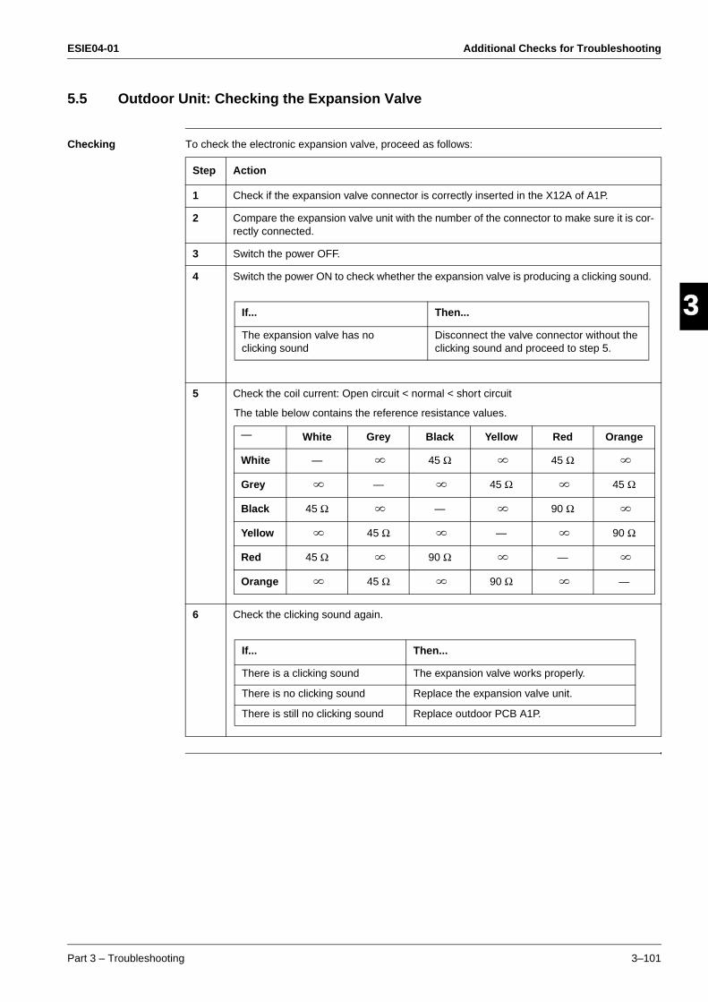
ESIE04-01 Additional Checks for Troubleshooting
Part 3 – Troubleshooting 3–101
33
4
5
15.5 Outdoor Unit: Checking the Expansion Valve
Checking To check the electronic expansion valve, proceed as follows:
Step Action
1 Check if the expansion valve connector is correctly inserted in the X12A of A1P.
2 Compare the expansion valve unit with the number of the connector to make sure it is cor-rectly connected.
3 Switch the power OFF.
4 Switch the power ON to check whether the expansion valve is producing a clicking sound.
5 Check the coil current: Open circuit < normal < short circuit
6 Check the clicking sound again.
If... Then...
The expansion valve has no clicking sound
Disconnect the valve connector without the clicking sound and proceed to step 5.
The table below contains the reference resistance values.
— White Grey Black Yellow Red Orange
White — 45 Ω 45 Ω
Grey — 45 Ω 45 Ω
Black 45 Ω — 90 Ω
Yellow 45 Ω — 90 Ω
Red 45 Ω 90 Ω —
Orange 45 Ω 90 Ω —
If... Then...
There is a clicking sound The expansion valve works properly.
There is no clicking sound Replace the expansion valve unit.
There is still no clicking sound Replace outdoor PCB A1P.

Additional Checks for Troubleshooting ESIE04-01
3–102 Part 3 – Troubleshooting
3
1
3
4
5
5.6 Checking the Thermistors
Thermistors If the cause of the problem is related to the thermistors, then the thermistors should be checked prior to changing the PCB.
For more information about these thermistors, see:
’Wiring Diagrams’’ (outdoor units)
“Functions of Thermistors” on page 2-4.
Overview of thermistors
The table below contains an overview of the thermistors:
Checking To check the thermistors, proceed as follows:
Thermistor Description
Indoor R1T Suction air thermistor
R2T Heat exchanger thermistor
R3T Gas pipe thermistor
Outdoor R1T Ambient air thermistor
R2T Heat exchanger thermistor
R3T Discharge pipe thermistor
R4T Suction pipe thermistor
R5T Power module fin thermistor
Step Action
1 Disconnect the thermistor from the PCB.
2 Read the temperature and the resistor value.
3 Check if the measured values correspond with the values in the table on the next pages.
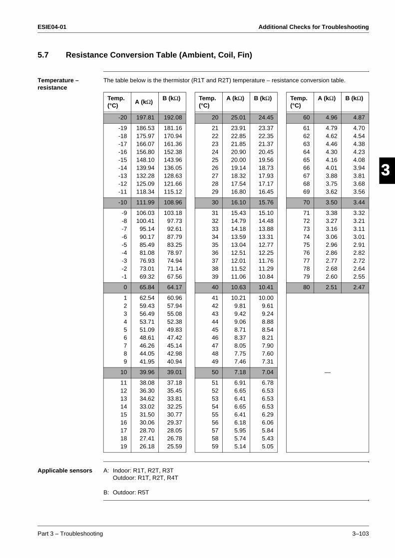
ESIE04-01 Additional Checks for Troubleshooting
Part 3 – Troubleshooting 3–103
33
4
5
15.7 Resistance Conversion Table (Ambient, Coil, Fin)
Temperature – resistance
The table below is the thermistor (R1T and R2T) temperature – resistance conversion table.
Applicable sensors A: Indoor: R1T, R2T, R3TOutdoor: R1T, R2T, R4T
B: Outdoor: R5T
Temp. (°C)
A (kΩ)B (kΩ) Temp.
(°C)A (kΩ) B (kΩ) Temp.
(°C)A (kΩ) B (kΩ)
-20 197.81 192.08 20 25.01 24.45 60 4.96 4.87
-19-18-17-16-15-14-13-12-11
186.53175.97166.07156.80148.10139.94132.28125.09118.34
181.16170.94161.36152.38143.96136.05128.63121.66115.12
212223242526272829
23.9122.8521.8520.9020.0019.1418.3217.5416.80
23.3722.3521.3720.4519.5618.7317.9317.1716.45
616263646566676869
4.794.624.464.304.164.013.883.753.62
4.704.544.384.234.083.943.813.683.56
-10 111.99 108.96 30 16.10 15.76 70 3.50 3.44
-9-8-7-6-5-4-3-2-1
106.03100.41
95.1490.1785.4981.0876.9373.0169.32
103.1897.7392.6187.7983.2578.9774.9471.1467.56
313233343536373839
15.4314.7914.1813.5913.0412.5112.0111.5211.06
15.1014.4813.8813.3112.7712.2511.7611.2910.84
717273747576777879
3.383.273.163.062.962.862.772.682.60
3.323.213.113.012.912.822.722.642.55
0 65.84 64.17 40 10.63 10.41 80 2.51 2.47
123456789
62.5459.4356.4953.7151.0948.6146.2644.0541.95
60.9657.9455.0852.3849.8347.4245.1442.9840.94
414243444546474849
10.219.819.429.068.718.378.057.757.46
10.009.619.248.888.548.217.907.607.31
—10 39.96 39.01 50 7.18 7.04
111213141516171819
38.0836.3034.6233.0231.5030.0628.7027.4126.18
37.1835.4533.8132.2530.7729.3728.0526.7825.59
515253545556575859
6.916.656.416.656.416.185.955.745.14
6.786.536.536.536.296.065.845.435.05
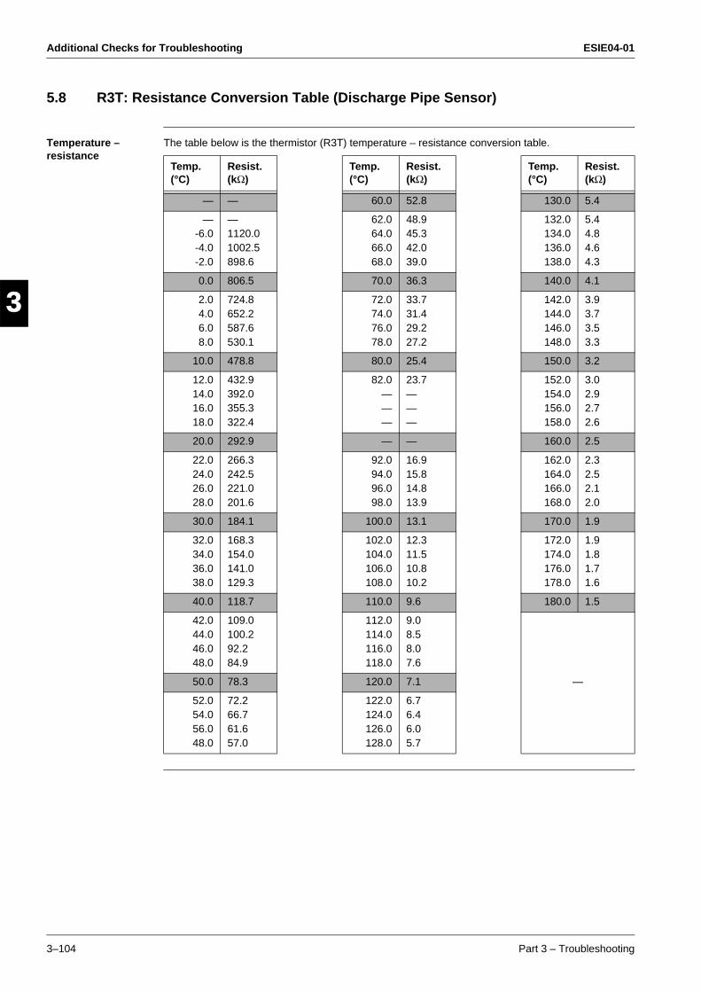
Additional Checks for Troubleshooting ESIE04-01
3–104 Part 3 – Troubleshooting
3
1
3
4
5
5.8 R3T: Resistance Conversion Table (Discharge Pipe Sensor)
Temperature – resistance
The table below is the thermistor (R3T) temperature – resistance conversion table.
Temp. (°C)
Resist. (kΩ)
Temp. (°C)
Resist. (kΩ)
Temp. (°C)
Resist. (kΩ)
— — 60.0 52.8 130.0 5.4
—-6.0-4.0-2.0
—1120.01002.5898.6
62.064.066.068.0
48.945.342.039.0
132.0134.0136.0138.0
5.44.84.64.3
0.0 806.5 70.0 36.3 140.0 4.1
2.04.06.08.0
724.8652.2587.6530.1
72.074.076.078.0
33.731.429.227.2
142.0144.0146.0148.0
3.93.73.53.3
10.0 478.8 80.0 25.4 150.0 3.2
12.014.016.018.0
432.9392.0355.3322.4
82.0———
23.7———
152.0154.0156.0158.0
3.02.92.72.6
20.0 292.9 — — 160.0 2.5
22.024.026.028.0
266.3242.5221.0201.6
92.094.096.098.0
16.915.814.813.9
162.0164.0166.0168.0
2.32.52.12.0
30.0 184.1 100.0 13.1 170.0 1.9
32.034.036.038.0
168.3154.0141.0129.3
102.0104.0106.0108.0
12.311.510.810.2
172.0174.0176.0178.0
1.91.81.71.6
40.0 118.7 110.0 9.6 180.0 1.5
42.044.046.048.0
109.0100.292.284.9
112.0114.0116.0118.0
9.08.58.07.6
—50.0 78.3 120.0 7.1
52.054.056.048.0
72.266.761.657.0
122.0124.0126.0128.0
6.76.46.05.7
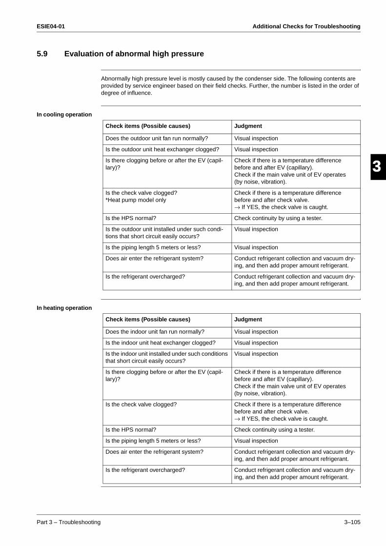
ESIE04-01 Additional Checks for Troubleshooting
Part 3 – Troubleshooting 3–105
33
4
5
15.9 Evaluation of abnormal high pressure
Abnormally high pressure level is mostly caused by the condenser side. The following contents are provided by service engineer based on their field checks. Further, the number is listed in the order of degree of influence.
In cooling operation
In heating operation
Check items (Possible causes) Judgment
Does the outdoor unit fan run normally? Visual inspection
Is the outdoor unit heat exchanger clogged? Visual inspection
Is there clogging before or after the EV (capil-lary)?
Check if there is a temperature difference before and after EV (capillary).Check if the main valve unit of EV operates (by noise, vibration).
Is the check valve clogged?*Heat pump model only
Check if there is a temperature difference before and after check valve.→ If YES, the check valve is caught.
Is the HPS normal? Check continuity by using a tester.
Is the outdoor unit installed under such condi-tions that short circuit easily occurs?
Visual inspection
Is the piping length 5 meters or less? Visual inspection
Does air enter the refrigerant system? Conduct refrigerant collection and vacuum dry-ing, and then add proper amount refrigerant.
Is the refrigerant overcharged? Conduct refrigerant collection and vacuum dry-ing, and then add proper amount refrigerant.
Check items (Possible causes) Judgment
Does the indoor unit fan run normally? Visual inspection
Is the indoor unit heat exchanger clogged? Visual inspection
Is the indoor unit installed under such conditions that short circuit easily occurs?
Visual inspection
Is there clogging before or after the EV (capil-lary)?
Check if there is a temperature difference before and after EV (capillary).Check if the main valve unit of EV operates (by noise, vibration).
Is the check valve clogged? Check if there is a temperature difference before and after check valve.→ If YES, the check valve is caught.
Is the HPS normal? Check continuity using a tester.
Is the piping length 5 meters or less? Visual inspection
Does air enter the refrigerant system? Conduct refrigerant collection and vacuum dry-ing, and then add proper amount refrigerant.
Is the refrigerant overcharged? Conduct refrigerant collection and vacuum dry-ing, and then add proper amount refrigerant.
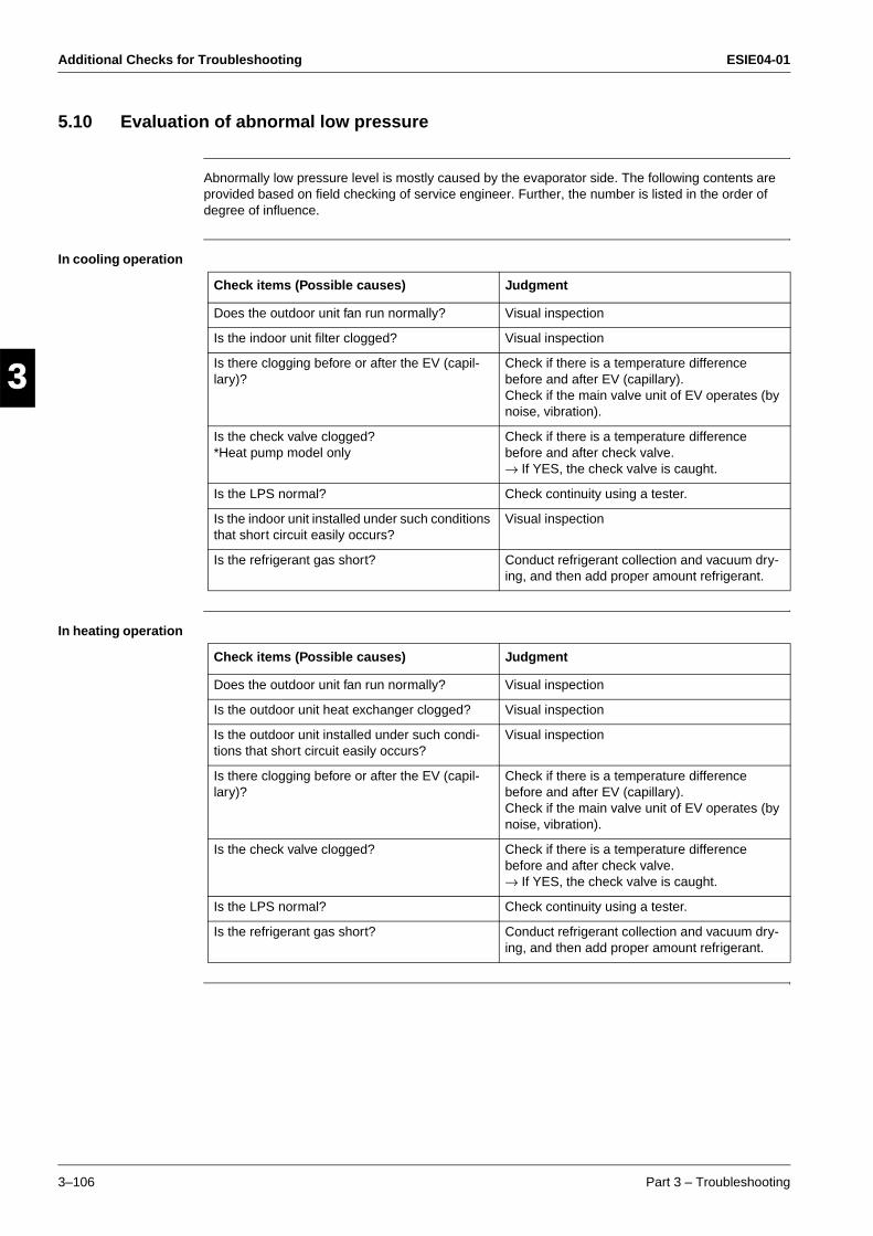
Additional Checks for Troubleshooting ESIE04-01
3–106 Part 3 – Troubleshooting
3
1
3
4
5
5.10 Evaluation of abnormal low pressure
Abnormally low pressure level is mostly caused by the evaporator side. The following contents are provided based on field checking of service engineer. Further, the number is listed in the order of degree of influence.
In cooling operation
In heating operation
Check items (Possible causes) Judgment
Does the outdoor unit fan run normally? Visual inspection
Is the indoor unit filter clogged? Visual inspection
Is there clogging before or after the EV (capil-lary)?
Check if there is a temperature difference before and after EV (capillary).Check if the main valve unit of EV operates (by noise, vibration).
Is the check valve clogged?*Heat pump model only
Check if there is a temperature difference before and after check valve.→ If YES, the check valve is caught.
Is the LPS normal? Check continuity using a tester.
Is the indoor unit installed under such conditions that short circuit easily occurs?
Visual inspection
Is the refrigerant gas short? Conduct refrigerant collection and vacuum dry-ing, and then add proper amount refrigerant.
Check items (Possible causes) Judgment
Does the outdoor unit fan run normally? Visual inspection
Is the outdoor unit heat exchanger clogged? Visual inspection
Is the outdoor unit installed under such condi-tions that short circuit easily occurs?
Visual inspection
Is there clogging before or after the EV (capil-lary)?
Check if there is a temperature difference before and after EV (capillary).Check if the main valve unit of EV operates (by noise, vibration).
Is the check valve clogged? Check if there is a temperature difference before and after check valve.→ If YES, the check valve is caught.
Is the LPS normal? Check continuity using a tester.
Is the refrigerant gas short? Conduct refrigerant collection and vacuum dry-ing, and then add proper amount refrigerant.
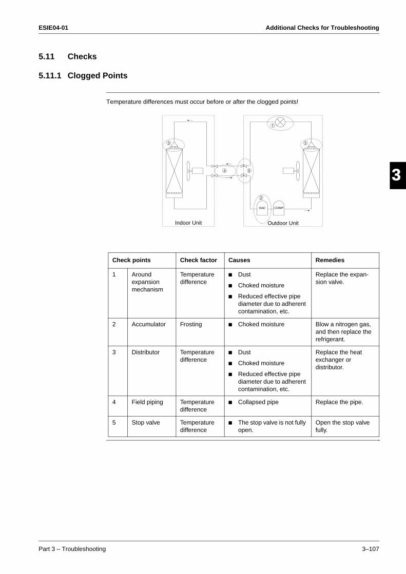
ESIE04-01 Additional Checks for Troubleshooting
Part 3 – Troubleshooting 3–107
33
4
5
15.11 Checks
5.11.1 Clogged Points
Temperature differences must occur before or after the clogged points!
Check points Check factor Causes Remedies
1 Around expansion mechanism
Temperature difference
Dust
Choked moisture
Reduced effective pipe diameter due to adherent contamination, etc.
Replace the expan-sion valve.
2 Accumulator Frosting Choked moisture Blow a nitrogen gas, and then replace the refrigerant.
3 Distributor Temperature difference
Dust
Choked moisture
Reduced effective pipe diameter due to adherent contamination, etc.
Replace the heat exchanger or distributor.
4 Field piping Temperature difference
Collapsed pipe Replace the pipe.
5 Stop valve Temperature difference
The stop valve is not fully open.
Open the stop valve fully.
1
2
33
4 5
Indoor Unit Outdoor Unit
RAC COMP

Additional Checks for Troubleshooting ESIE04-01
3–108 Part 3 – Troubleshooting
3
1
3
4
5
5.11.2 Indoor Unit: Fan Motor Checks (Phase Controlled Motor)
(1) Turn the power supply off.With the relay connector disconnected, measure the resistance between UVW phases of the connector (3 cores) at the motor side, then make sure that the resistance between each phase is balanced and not short-circuited.
5.11.3 Outdoor Unit: Fan Motor Signal Line
For RZQ71~125 models
(1) Turn the power supply off.
(2) With the fan motor connector disconnected, measure the resistance between each pin, then make sure that the resistance is more than the value mentioned in the following table.
Black
Red
White
(S2675)
Measure the resistance between each phase.
W
U
V
Measurement point Judgment
1 - 4 1MΩ or more
2 - 4 100kΩ or more
3 - 4 100Ω or more
4 - 7 100kΩ or more
GND
1 White
2 Orange
3 Brown
4 Blue
5
6
7 Red(S2675)

ESIE04-01 Additional Checks for Troubleshooting
Part 3 – Troubleshooting 3–109
33
4
5
15.11.4 Outdoor unit: Fan Speed Pulse
For RZQ71~125 models
(1) Disconnect the connector X206A with the power supply OFF and Operation OFF.
(2) Is the voltage between pins 4 and 3 of X206A about 15 VDC after turning the power supply on?
(3) Is the voltage between pins 4 and 1 of X206A about 5 VDC?
(4) Connect the connector X206A with the power supply OFF and Operation OFF.
(5) When making one turn of the upper fan motor by hand after turning the power supply on, is a pulse (0 and 5 V) generated 4 times between pins 4 and 1 of X206A? (Measure at the contact terminal on the harness side with the connector connected.)
For RZQ100~125 models
(6) Disconnect the connector X207A with the power supply OFF and Operation OFF.
(7) Is the voltage between pins 4 and 3 of X207A about 15 VDC after turning the power supply on?
(8) Is the voltage between pins 4 and 1 of X207A about 5 VDC?
(9) Connect the connector X207A with the power supply OFF and Operation OFF.
(10)When making one turn of the lower fan motor by hand after turning the power supply on, is a pulse (0 and 5 V) generated 4 times between pins 4 and 1 of X207A?
(2) (7): NO → Faulty PC board → Replace the PC board.
(3) (8): NO → Faulty PC board → Replace the PC board.(5)(10): NO → Faulty hall IC → Replace the DC fan motor.
(2) (3) (5) (7) (8) (10): YES → Replace the PC board.
2
3
4
5
6
7
1 Fan speed pulse input (0V and 5V)
15V
GND
NC
NC
250~350V (during operation)
0V
S2679)
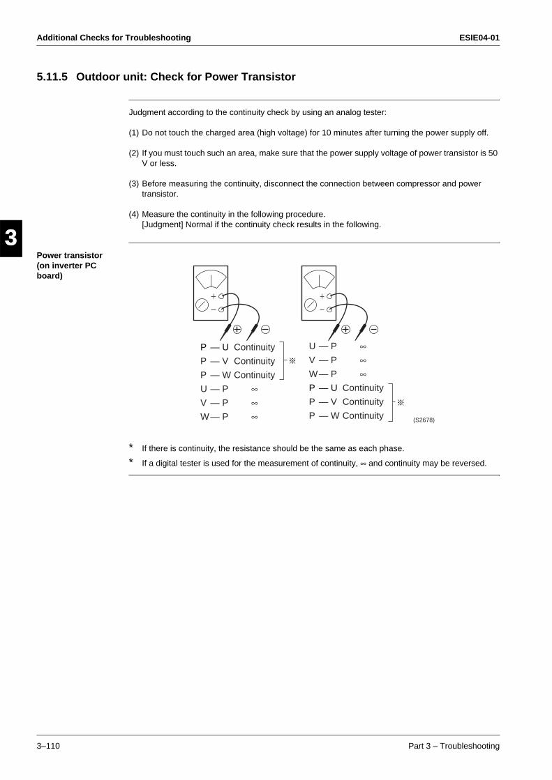
Additional Checks for Troubleshooting ESIE04-01
3–110 Part 3 – Troubleshooting
3
1
3
4
5
5.11.5 Outdoor unit: Check for Power Transistor
Judgment according to the continuity check by using an analog tester:
(1) Do not touch the charged area (high voltage) for 10 minutes after turning the power supply off.
(2) If you must touch such an area, make sure that the power supply voltage of power transistor is 50 V or less.
(3) Before measuring the continuity, disconnect the connection between compressor and power transistor.
(4) Measure the continuity in the following procedure.[Judgment] Normal if the continuity check results in the following.
Power transistor (on inverter PC board)
* If there is continuity, the resistance should be the same as each phase.
* If a digital tester is used for the measurement of continuity, ∞ and continuity may be reversed.
*
*
P — U Continuity
P — V Continuity
P — W Continuity
U — P ∞V — P ∞W — P ∞
U — P ∞V — P ∞W — P ∞P — U Continuity
P — V Continuity
P — W Continuity (S2678)
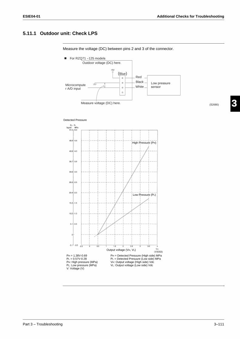
ESIE04-01 Additional Checks for Troubleshooting
Part 3 – Troubleshooting 3–111
33
4
5
15.11.1 Outdoor unit: Check LPS
Measure the voltage (DC) between pins 2 and 3 of the connector.
+5V
For RZQ71 ~125 modelsOutdoor voltage (DC) here.
Measure voltage (DC) here.
Microcomputer A/D input
Low pressure sensor
Red
Black
White
(Blue)
(S2680)
Detected Pressure
Output voltage (VH, VL)
High Pressure (PH)
Low Pressure (PL)
PH = 1.38V-0.69PL = 0.57V-0.28PH: High pressure (MPa)PL: Low pressure (MPa)V: Voltage (V)
PH = Detected Presuure (High side) MPaPL = Detected Presuure (Low side) MPaVH: Output voltage (High side) VdcVL: Output voltage (Low side) Vdc
Additional Checks for Troubleshooting ESIE04-01
3–112 Part 3 – Troubleshooting
3
1
3
4
5
ESIE04-01
Part 4 – Commissioning and Test Run 4–1
4
3
4
5
4
Part 4Commissioning and Test
Run
What is in this part? This part contains the following chapters:
Chapter See page
1–Pre-Test Run Checks 4–3
2–Field settings 4–9
3–Test Run and Operation Data 4–37
ESIE04-01
4–2 Part 4 – Commissioning and Test Run
3
1
4
5
ESIE04-01 Pre-Test Run Checks
Part 4 – Commissioning and Test Run 4–3
3
4
5
1Part 4
1 Pre-Test Run Checks
1.1 What Is in This Chapter?
Introduction This chapter contains the following information:
Checks before test run
Test run checks
Setting the address for the receiver of the infrared remote control
Setting the address for the infrared remote control.
Overview This chapter contains the following topics:
Topic See page
1.2–Test Run Checks 4–4
1.3–Setting the Infrared remote control 4–5

Pre-Test Run Checks ESIE04-01
4–4 Part 4 – Commissioning and Test Run
3
1
4
5
1.2 Test Run Checks
Checks before test run
Before carrying out a test run, proceed as follows:
Test run checks To carry out a test run, check the following:
Check that the temperature setting of the remote control is at the lowest level in cooling mode or use test mode.
Go through the following checklist:
Step Action
1 Make sure the voltage at the primary side of the safety breaker is:
230 V ± 10%
2 Fully open the liquid and the gas stop valve.
Checkpoints Cautions or warnings
Are all units securely installed? Dangerous for turning over during storm.
Possible damage to pipe connections.
Is the earth wire installed according to the applicable local standard?
Dangerous if electric leakage occurs.
Are all air inlets and outlets of the indoor and outdoor units unobstructed?
Poor cooling.
Poor heating.
Does the drain flow out smoothly? Water leakage.
Is piping adequately heat-insulated? Water leakage.
Have the connections been checked for gas leakage? Poor cooling.
Poor heating.
Stop.
Is the supply voltage conform to the specifications on the name plate?
Incorrect operation.
Are the cable sizes as specified and according to local regulations?
Damage of cables.
Are the remote control signals received by the unit? No operation.
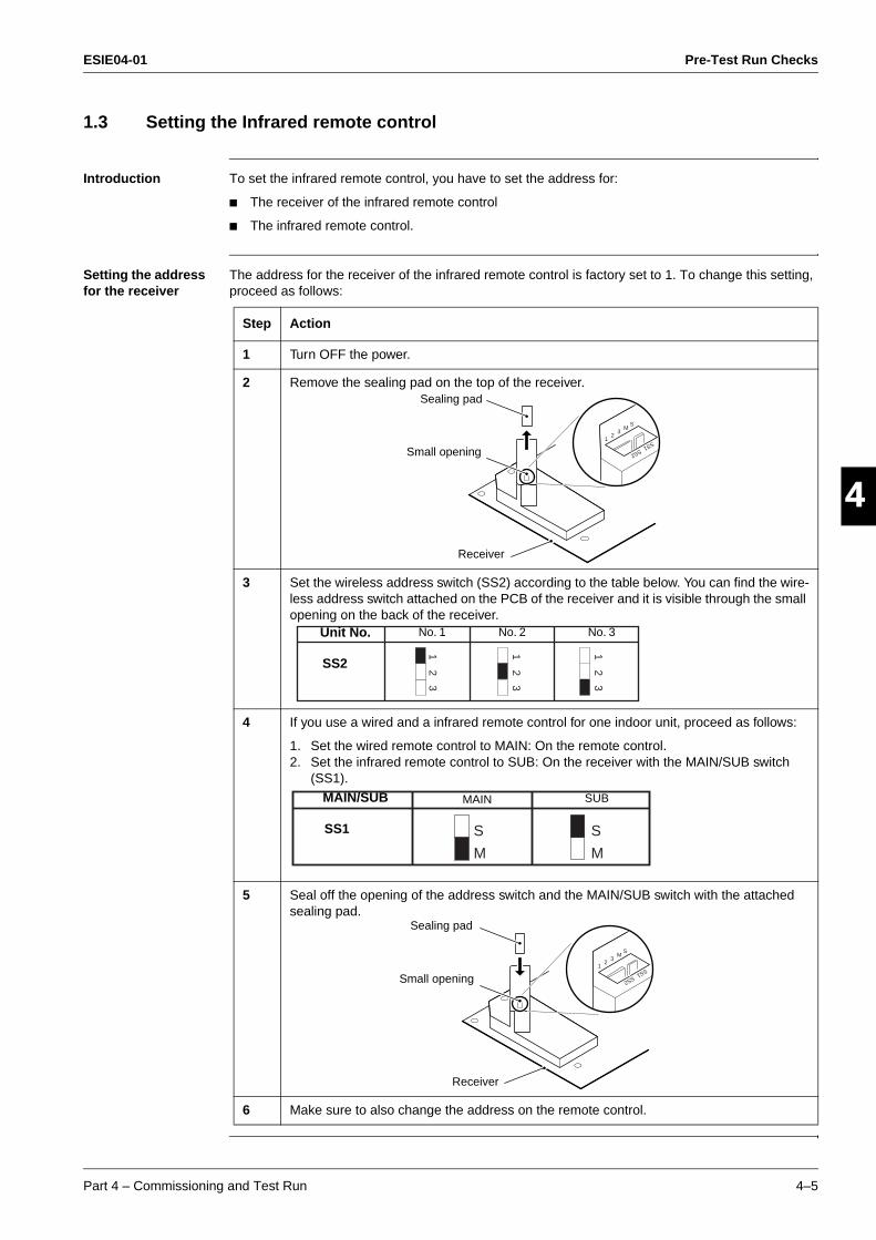
ESIE04-01 Pre-Test Run Checks
Part 4 – Commissioning and Test Run 4–5
3
4
5
11.3 Setting the Infrared remote control
Introduction To set the infrared remote control, you have to set the address for:
The receiver of the infrared remote control
The infrared remote control.
Setting the address for the receiver
The address for the receiver of the infrared remote control is factory set to 1. To change this setting, proceed as follows:
Step Action
1 Turn OFF the power.
2 Remove the sealing pad on the top of the receiver.
3 Set the wireless address switch (SS2) according to the table below. You can find the wire-less address switch attached on the PCB of the receiver and it is visible through the small opening on the back of the receiver.
4 If you use a wired and a infrared remote control for one indoor unit, proceed as follows:
1. Set the wired remote control to MAIN: On the remote control.2. Set the infrared remote control to SUB: On the receiver with the MAIN/SUB switch
(SS1).
5 Seal off the opening of the address switch and the MAIN/SUB switch with the attached sealing pad.
6 Make sure to also change the address on the remote control.
12
3M
SS2
SS1
S
Sealing pad
Small opening
Receiver
12
12
12
3 3 3
Unit No.
SS2
No. 3No. 2No. 1
SM
SM
SS1
MAIN SUBMAIN/SUB
12
3M
SS2
SS1
S
Sealing pad
Small opening
Receiver
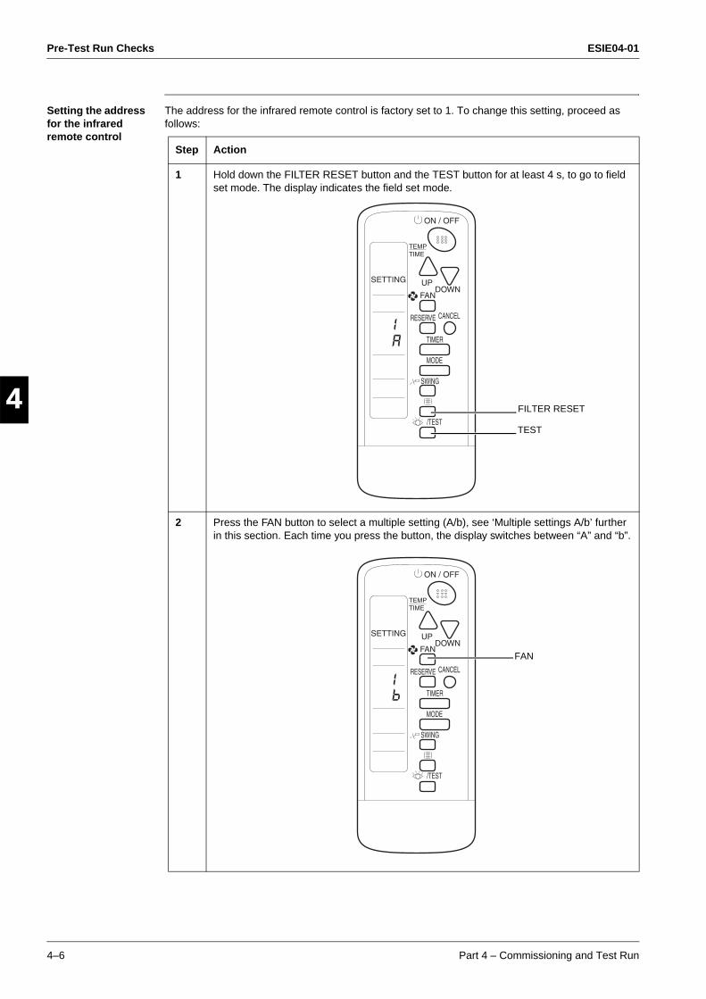
Pre-Test Run Checks ESIE04-01
4–6 Part 4 – Commissioning and Test Run
3
1
4
5
Setting the address for the infrared remote control
The address for the infrared remote control is factory set to 1. To change this setting, proceed as follows:
Step Action
1 Hold down the FILTER RESET button and the TEST button for at least 4 s, to go to field set mode. The display indicates the field set mode.
2 Press the FAN button to select a multiple setting (A/b), see ‘Multiple settings A/b’ further in this section. Each time you press the button, the display switches between “A” and “b”.
FILTER RESET
TEST
FAN
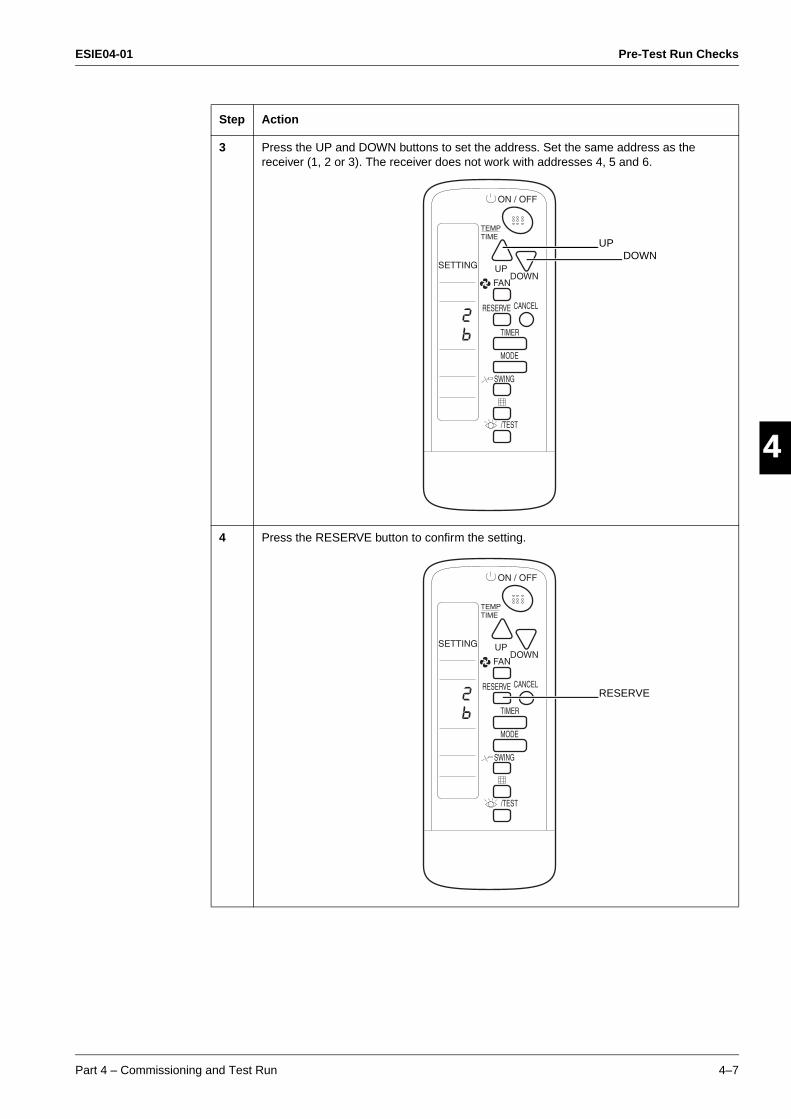
ESIE04-01 Pre-Test Run Checks
Part 4 – Commissioning and Test Run 4–7
3
4
5
13 Press the UP and DOWN buttons to set the address. Set the same address as the
receiver (1, 2 or 3). The receiver does not work with addresses 4, 5 and 6.
4 Press the RESERVE button to confirm the setting.
Step Action
UPDOWN
RESERVE
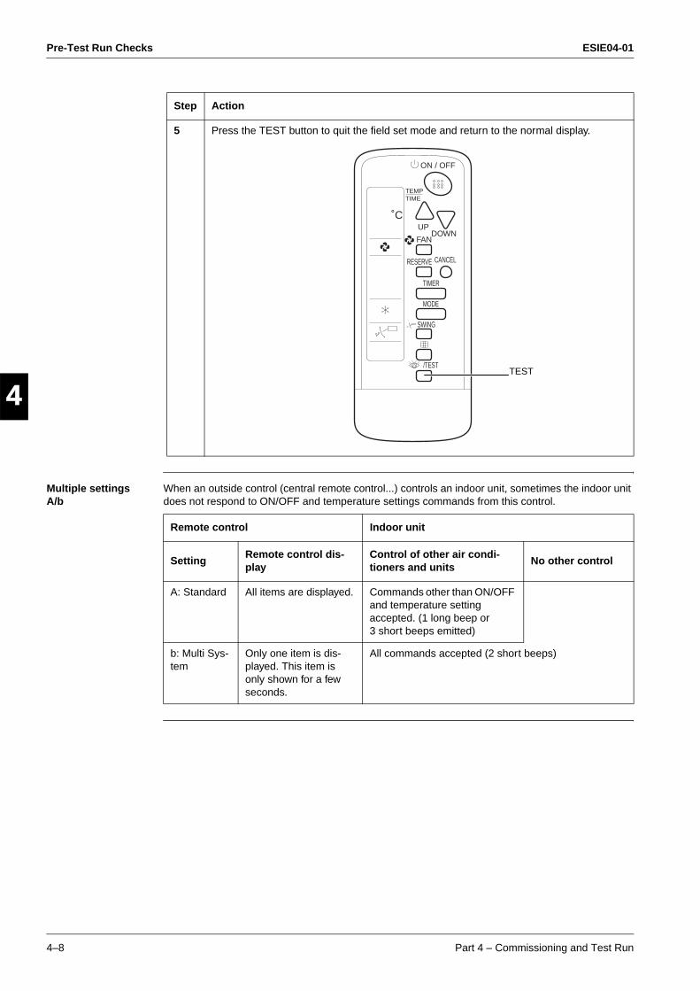
Pre-Test Run Checks ESIE04-01
4–8 Part 4 – Commissioning and Test Run
3
1
4
5 Multiple settings A/b
When an outside control (central remote control...) controls an indoor unit, sometimes the indoor unit does not respond to ON/OFF and temperature settings commands from this control.
5 Press the TEST button to quit the field set mode and return to the normal display.
Step Action
UP
FAN
RESERVE CANCEL
TIMER
DOWN
TEMPTIME
ON / OFF
MODE
SWING
/TEST
˚C
TEST
Remote control Indoor unit
SettingRemote control dis-play
Control of other air condi-tioners and units
No other control
A: Standard All items are displayed. Commands other than ON/OFF and temperature setting accepted. (1 long beep or 3 short beeps emitted)
b: Multi Sys-tem
Only one item is dis-played. This item is only shown for a few seconds.
All commands accepted (2 short beeps)
ESIE04-01 Field settings
Part 4 – Commissioning and Test Run 4–9
3
4
5
1Part 4
2 Field settings
2.1 What Is in This Chapter?
Introduction This chapter contains the following information:
How to change the field settings
The field settings
The factory settings.
Overview This chapter contains the following topics:
Topic See page
2.2–How to Change the Field Settings with the Wired Remote Control 4–10
2.3–How to Change the Field Settings with the Infrared remote control 4–12
2.4–Overview of the Field Settings on the Indoor Units 4–13
2.5–Overview of the Factory Settings on the Indoor Units 4–14
2.6–Setting the Ceiling Height 4–15
2.7–Setting the Filter Counter 4–16
2.8–MAIN/SUB Setting when Using Two Remote Controls 4–17
2.9–Setting the Centralized Group No. 4–18
2.10–The Field Setting Levels 4–20
2.11–Overview of the Field Settings on the Outdoor Units 4–23
2.12–Overview of the Factory Settings on the Outdoor Units 4–25
2.13–Silent Operation 4–26
2.14–I-Demand Function 4–28
2.15–Setting for Low Humidity Application 4–30
2.16–Defrost start setting 4–36
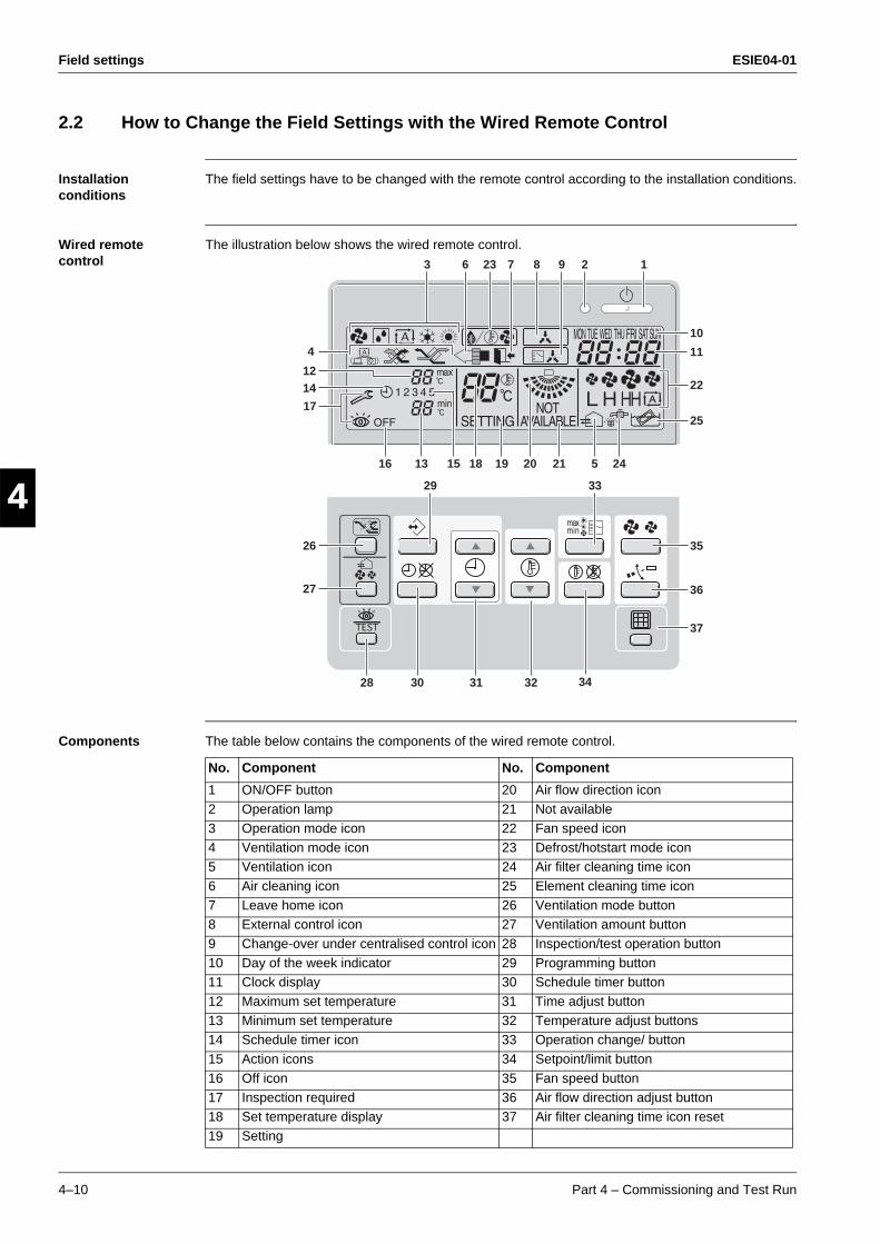
Field settings ESIE04-01
4–10 Part 4 – Commissioning and Test Run
3
1
4
5
2.2 How to Change the Field Settings with the Wired Remote Control
Installation conditions
The field settings have to be changed with the remote control according to the installation conditions.
Wired remote control
The illustration below shows the wired remote control.
Components The table below contains the components of the wired remote control.
1293
25
22
11
10
37
35
27
26
1214
17
34
24520 211816 13 15 19
323130
29
28
4
36
33
823 76
No. Component No. Component
1 ON/OFF button 20 Air flow direction icon2 Operation lamp 21 Not available
3 Operation mode icon 22 Fan speed icon
4 Ventilation mode icon 23 Defrost/hotstart mode icon5 Ventilation icon 24 Air filter cleaning time icon
6 Air cleaning icon 25 Element cleaning time icon
7 Leave home icon 26 Ventilation mode button8 External control icon 27 Ventilation amount button
9 Change-over under centralised control icon 28 Inspection/test operation button
10 Day of the week indicator 29 Programming button11 Clock display 30 Schedule timer button
12 Maximum set temperature 31 Time adjust button
13 Minimum set temperature 32 Temperature adjust buttons14 Schedule timer icon 33 Operation change/ button
15 Action icons 34 Setpoint/limit button
16 Off icon 35 Fan speed button
17 Inspection required 36 Air flow direction adjust button18 Set temperature display 37 Air filter cleaning time icon reset
19 Setting
ESIE04-01 Field settings
Part 4 – Commissioning and Test Run 4–11
3
4
5
1Setting To set the field settings, you have to change:
“Mode No.”
“First code No.”
“Second code No.”.
To change the field settings, proceed as follows:
Step Action
1 Hold down the INSPECTION/TEST button for at least 4 s during normal mode to enter the “Field setting mode”.
2 Press the TEMPERATURE CONTROL button until the desired “Mode No.” appears.
3 If the indoor unit is under group control, all settings for all the indoor units are set at the same time. Use the codes 10 to 15 to apply this group control and proceed to the next step.
If you want to set the indoor units of one group individually or if you want to read out the last settings, use the codes 20 to 25 which are displayed in brackets. Press the TIMER SELECTION button to select the “Indoor unit No.” for which you want to adjust the field settings.
4 Press the upper part of the PROGRAMMING TIME button to select the “First code No.”.
5 Press the lower part of the PROGRAMMING TIME button to select the “Second code No”.
6 Press the CONFIRMATION button to confirm the changed setting.
7 Press the INSPECTION/TEST button to return to “Normal mode”.
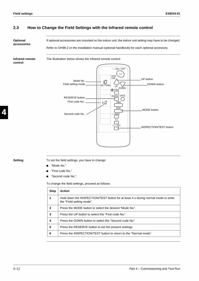
Field settings ESIE04-01
4–12 Part 4 – Commissioning and Test Run
3
1
4
5
2.3 How to Change the Field Settings with the Infrared remote control
Optional accessories
If optional accessories are mounted on the indoor unit, the indoor unit setting may have to be changed.
Refer to OH98-2 or the installation manual (optional handbook) for each optional accessory.
Infrared remote control
The illustration below shows the infrared remote control.
Setting To set the field settings, you have to change:
“Mode No.”
“First code No.”
“Second code No.”.
To change the field settings, proceed as follows:
RESERVE button
INSPECTION/TEST button
Mode No.Field setting mode
UP button
DOWN button
First code No.
Second code No.
MODE button
Step Action
1 Hold down the INSPECTION/TEST button for at least 4 s during normal mode to enter the “Field setting mode”.
2 Press the MODE button to select the desired “Mode No.”.
3 Press the UP button to select the “First code No.”.
4 Press the DOWN button to select the “Second code No.”
5 Press the RESERVE button to set the present settings.
6 Press the INSPECTION/TEST button to return to the “Normal mode”.
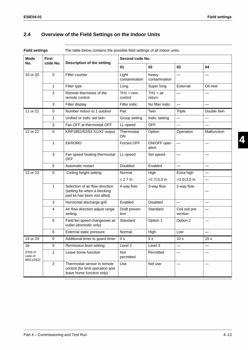
ESIE04-01 Field settings
Part 4 – Commissioning and Test Run 4–13
3
4
5
12.4 Overview of the Field Settings on the Indoor Units
Field settings The table below contains the possible field settings of all indoor units.
Mode No.
First code No. Description of the setting
Second code No.
01 02 03 04
10 or 20 0 Filter counter Light contamination
heavycontamination
— —
1 Filter type Long Super long External Oil mist
2 Remote thermistor of the remote control
TH1 = rem. control
TH1 = air return
— —
3 Filter display Filter indic. No filter indic. — —
11 or 21 0 Number indoor to 1 outdoor Pair Twin Triple Double twin
1 Unified or indiv. set twin Group setting Indiv. setting — —
2 Fan OFF at thermostat OFF LL-speed OFF — —
12 or 22 0 KRP1B51/52/53 X1/X2 output Thermostat ON
Option Operation Malfunction
1 EKRORO Forced OFF ON/OFF oper-ation
— —
3 Fan speed heating thermostat OFF
LL-speed Set speed — —
5 Automatic restart Disabled Enabled — —
13 or 23 0 Ceiling height setting Normal High Extra high —
≤ 2.7 m >2.7≤3.0 m >3.0≤3.5 m —
1 Selection of air flow direction (setting for when a blocking pad kit has been inst alled).
4-way flow 3-way flow 2-way flow —
3 Horizontal discharge grill Enabled Disabled — —
4 Air flow direction adjust range setting
Draft preven-tion
Standard Ceil soil pre-vention
—
5 Field fan speed changeover air outlet (domestic only)
Standard Option 1 Option 2 —
6 External static pressure Normal High Low —
14 or 24 0 Additional timer to guard timer 0 s 5 s 10 s 15 s
1b
(Only in case of BRC1D52)
0 Permission level setting Level 2 Level 3 — —
1 Leave home function Not permitted
Permitted — —
2 Thermostat sensor in remote control (for limit operation and leave home function only)
Use Not use — —
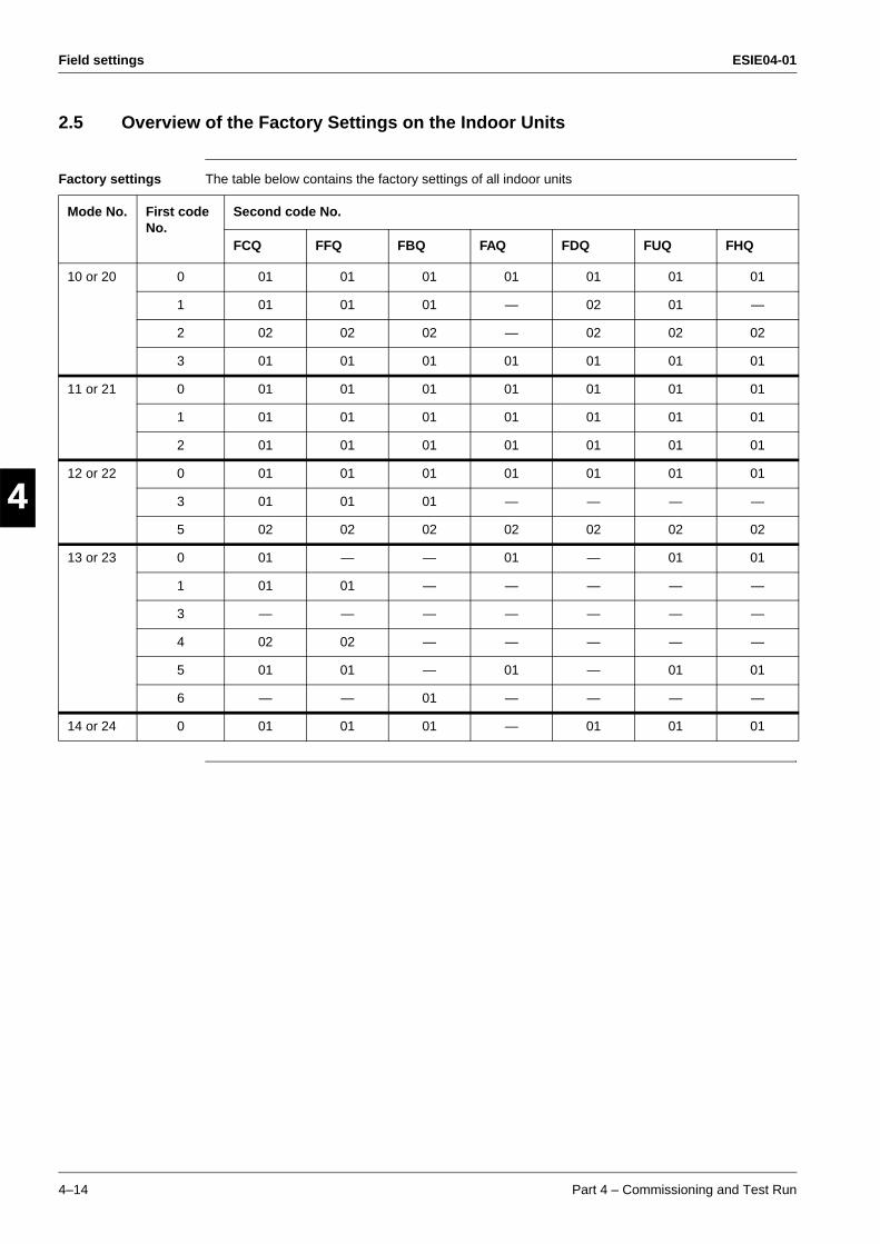
Field settings ESIE04-01
4–14 Part 4 – Commissioning and Test Run
3
1
4
5
2.5 Overview of the Factory Settings on the Indoor Units
Factory settings The table below contains the factory settings of all indoor units
Mode No. First code No.
Second code No.
FCQ FFQ FBQ FAQ FDQ FUQ FHQ
10 or 20 0 01 01 01 01 01 01 01
1 01 01 01 — 02 01 —
2 02 02 02 — 02 02 02
3 01 01 01 01 01 01 01
11 or 21 0 01 01 01 01 01 01 01
1 01 01 01 01 01 01 01
2 01 01 01 01 01 01 01
12 or 22 0 01 01 01 01 01 01 01
3 01 01 01 — — — —
5 02 02 02 02 02 02 02
13 or 23 0 01 — — 01 — 01 01
1 01 01 — — — — —
3 — — — — — — —
4 02 02 — — — — —
5 01 01 — 01 — 01 01
6 — — 01 — — — —
14 or 24 0 01 01 01 — 01 01 01
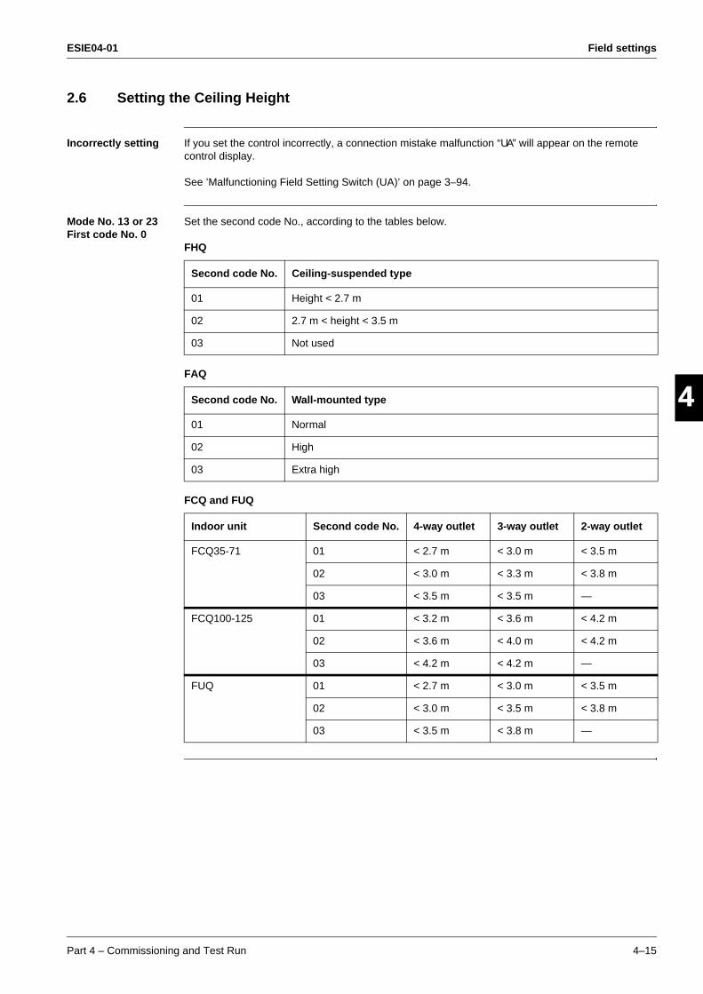
ESIE04-01 Field settings
Part 4 – Commissioning and Test Run 4–15
3
4
5
12.6 Setting the Ceiling Height
Incorrectly setting If you set the control incorrectly, a connection mistake malfunction “UA” will appear on the remote control display.
See ’Malfunctioning Field Setting Switch (UA)’ on page 3–94.
Mode No. 13 or 23 First code No. 0
Set the second code No., according to the tables below.
FHQ
FAQ
FCQ and FUQ
Second code No. Ceiling-suspended type
01 Height < 2.7 m
02 2.7 m < height < 3.5 m
03 Not used
Second code No. Wall-mounted type
01 Normal
02 High
03 Extra high
Indoor unit Second code No. 4-way outlet 3-way outlet 2-way outlet
FCQ35-71 01 < 2.7 m < 3.0 m < 3.5 m
02 < 3.0 m < 3.3 m < 3.8 m
03 < 3.5 m < 3.5 m —
FCQ100-125 01 < 3.2 m < 3.6 m < 4.2 m
02 < 3.6 m < 4.0 m < 4.2 m
03 < 4.2 m < 4.2 m —
FUQ 01 < 2.7 m < 3.0 m < 3.5 m
02 < 3.0 m < 3.5 m < 3.8 m
03 < 3.5 m < 3.8 m —
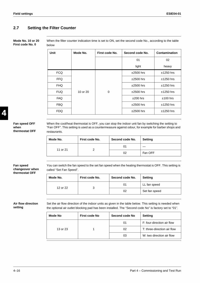
Field settings ESIE04-01
4–16 Part 4 – Commissioning and Test Run
3
1
4
5
2.7 Setting the Filter Counter
Mode No. 10 or 20 First code No. 0
When the filter counter indication time is set to ON, set the second code No., according to the table
below
Fan speed OFF when thermostat OFF
When the cool/heat thermostat is OFF, you can stop the indoor unit fan by switching the setting to “Fan OFF”. This setting is used as a countermeasure against odour, for example for barber shops and
restaurants.
Fan speed changeover when thermostat OFF
You can switch the fan speed to the set fan speed when the heating thermostat is OFF. This setting is
called “Set Fan Speed”.
Air flow direction setting
Set the air flow direction of the indoor units as given in the table below. This setting is needed when
the optional air outlet blocking pad has been installed. The “Second code No” is factory set to “01”.
Unit Mode No. First code No. Second code No. Contamination
01 02
light heavy
FCQ
10 or 20 0
±2500 hrs ±1250 hrs
FFQ ±2500 hrs ±1250 hrs
FHQ ±2500 hrs ±1250 hrs
FUQ ±2500 hrs ±1250 hrs
FAQ ±200 hrs ±100 hrs
FBQ ±2500 hrs ±1250 hrs
FDQ ±2500 hrs ±1250 hrs
Mode No. First code No. Second code No. Setting
11 or 21 201 —
02 Fan OFF
Mode No. First code No. Second code No. Setting
12 or 22 301 LL fan speed
02 Set fan speed
Mode No First code No Second code No Setting
13 or 23 1
01 F: four-direction air flow
02 T: three-direction air flow
03 W: two direction air flow
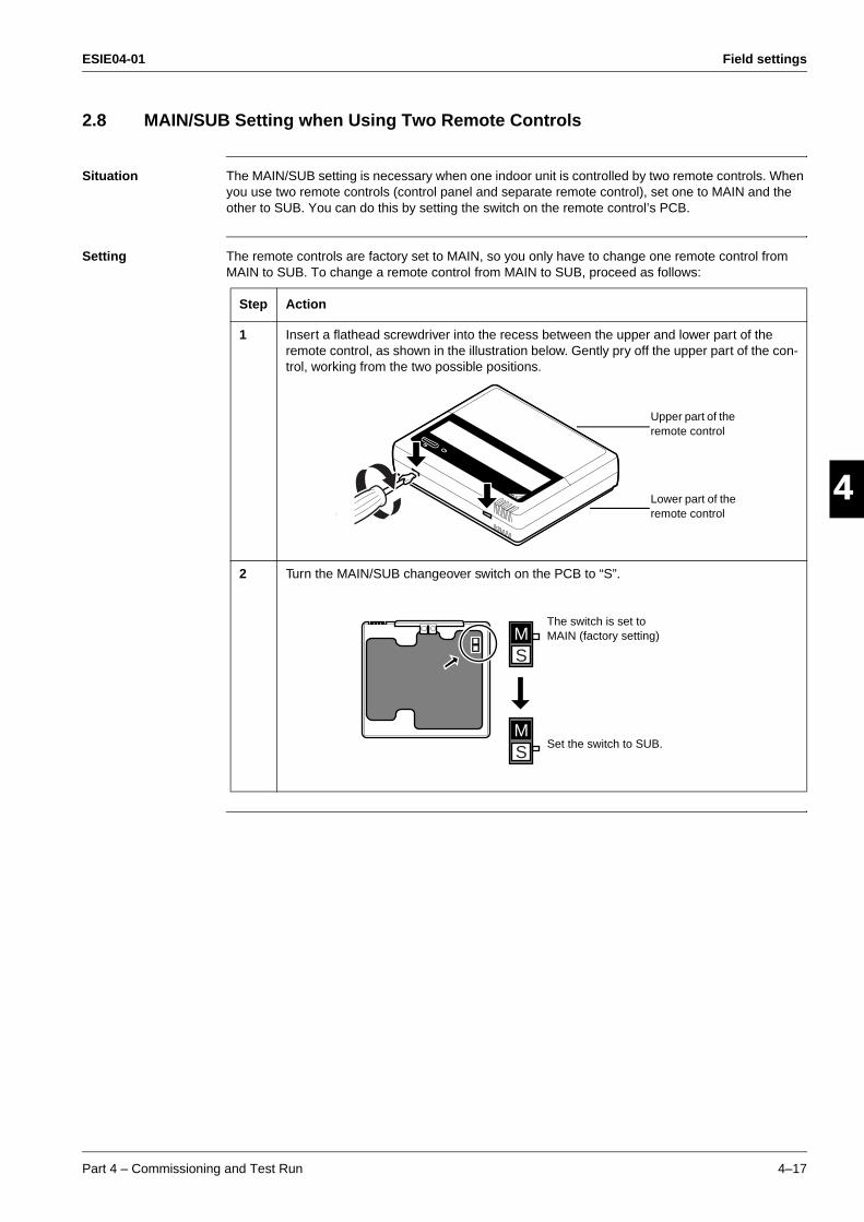
ESIE04-01 Field settings
Part 4 – Commissioning and Test Run 4–17
3
4
5
12.8 MAIN/SUB Setting when Using Two Remote Controls
Situation The MAIN/SUB setting is necessary when one indoor unit is controlled by two remote controls. When you use two remote controls (control panel and separate remote control), set one to MAIN and the other to SUB. You can do this by setting the switch on the remote control’s PCB.
Setting The remote controls are factory set to MAIN, so you only have to change one remote control from MAIN to SUB. To change a remote control from MAIN to SUB, proceed as follows:
Step Action
1 Insert a flathead screwdriver into the recess between the upper and lower part of the remote control, as shown in the illustration below. Gently pry off the upper part of the con-trol, working from the two possible positions.
2 Turn the MAIN/SUB changeover switch on the PCB to “S”.
Upper part of the remote control
Lower part of the remote control
SM
SM
The switch is set to MAIN (factory setting)
Set the switch to SUB.
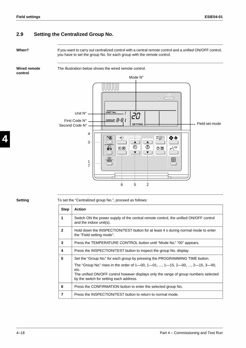
Field settings ESIE04-01
4–18 Part 4 – Commissioning and Test Run
3
1
4
5
2.9 Setting the Centralized Group No.
When? If you want to carry out centralized control with a central remote control and a unified ON/OFF control, you have to set the group No. for each group with the remote control.
Wired remote control
The illustration below shows the wired remote control.
Setting To set the “Centralized group No.”, proceed as follows:
SETTING
UNIT No.
GROUP
3
1
4
56 2
7
Unit N°
First Code N°Second Code N°
Mode N°
Field set mode
Step Action
1 Switch ON the power supply of the central remote control, the unified ON/OFF control and the indoor unit(s).
2 Hold down the INSPECTION/TEST button for at least 4 s during normal mode to enter the “Field setting mode”.
3 Press the TEMPERATURE CONTROL button until “Mode No.” “00” appears.
4 Press the INSPECTION/TEST button to inspect the group No. display.
5 Set the “Group No.” for each group by pressing the PROGRAMMING TIME button.
The “Group No.” rises in the order of 1—00, 1—01, ..., 1—15, 2—00, ..., 2—15, 3—00, etc. The unified ON/OFF control however displays only the range of group numbers selected by the switch for setting each address.
6 Press the CONFIRMATION button to enter the selected group No.
7 Press the INSPECTION/TEST button to return to normal mode.
ESIE04-01 Field settings
Part 4 – Commissioning and Test Run 4–19
3
4
5
1Individually address setting
If the address must be set individually for each unit, set the “Mode No.” to “30”. For example, for power consumption counting.
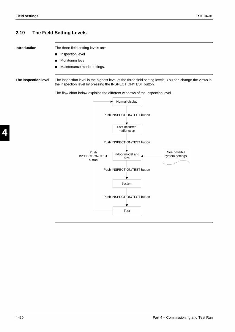
Field settings ESIE04-01
4–20 Part 4 – Commissioning and Test Run
3
1
4
5
2.10 The Field Setting Levels
Introduction The three field setting levels are:
Inspection level
Monitoring level
Maintenance mode settings.
The inspection level The inspection level is the highest level of the three field setting levels. You can change the views in the inspection level by pressing the INSPECTION/TEST button.
The flow chart below explains the different windows of the inspection level.
Normal display
Last occurredmalfunction
Indoor model andsize
System
Test
Push INSPECTION/TEST button
Push INSPECTION/TEST button
Push INSPECTION/TEST button
Push INSPECTION/TEST button
PushINSPECTION/TEST
button
See possiblesystem settings.
ESIE04-01 Field settings
Part 4 – Commissioning and Test Run 4–21
3
4
5
1Possible system settings
The table below contains the possible system settings, which are displayed on the remote control if the TEST button is pushed twice shortly.
Changing the mode settings
To enter the monitoring level and to change the maintenance mode settings, proceed as follows:
SizeSoftware
Type
Settings Display Settings Display
35 35
5
FCQ FJ
45 45 FHQ HJ
60 63 FAQ AJ
71 71 FFQ GJ
100 100 FBQ JJ
125 125 FUQ 3J
200 200 FDQ UJ
250 250 —
Step Action
1 Hold down the INSPECTION/TEST button for at least 4 s to enter the field setting mode.
2 Hold down the INSPECTION/TEST button for at least 4 s to enter the maintenance mode.
3 Press the TEMPERATURE CONTROL buttons as many times as needed to select the mode No. you want.
4 Press the TIMER SELECTION button as many times as needed to select the unit No. you want.
5 Carry out the settings for modes 44 and 45. See “Maintenance Mode Settings” further in this section.
6 Press the CONFIRMATION button to confirm the settings of modes 44 and 45.
7 Press the INSPECTION/TEST button to return to the normal operating mode.
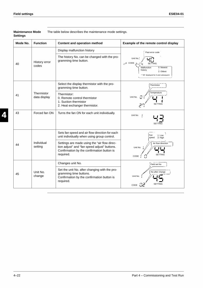
Field settings ESIE04-01
4–22 Part 4 – Commissioning and Test Run
3
1
4
5
Maintenance Mode Settings
The table below describes the maintenance mode settings.
Mode No. Function Content and operation method Example of the remote control display
40History error codes
Display malfunction history
The history No. can be changed with the pro-gramming time button.
41Thermistor data display
Select the display thermistor with the pro-gramming time button.
Thermistor:0. Remote control thermistor1. Suction thermistor2. Heat exchanger thermistor.
43 Forced fan ON Turns the fan ON for each unit individually.
44Individualsetting
Sets fan speed and air flow direction for each unit individually when using group control.
Settings are made using the “air flow direc-tion adjust” and “fan speed adjust” buttons. Confirmation by the confirmation button is required.
45Unit No. change
Changes unit No.
Set the unit No. after changing with the pro-gramming time buttons.Confirmation by the confirmation button is required.
Past error code
Malfunction history
* “00” displayed for 3 and subsequent
0: Newest
2: Oldest
-
CODE SETTING
Unit No.
Unit No.
Thermistor
Temperature
SETTING
Unit No.
SETTING
Unit No.
SETTING
Fan speed
1: Low3: High
Air flow direction
CODE
Unit No.
SETTINGCODE
Field set No
No after change
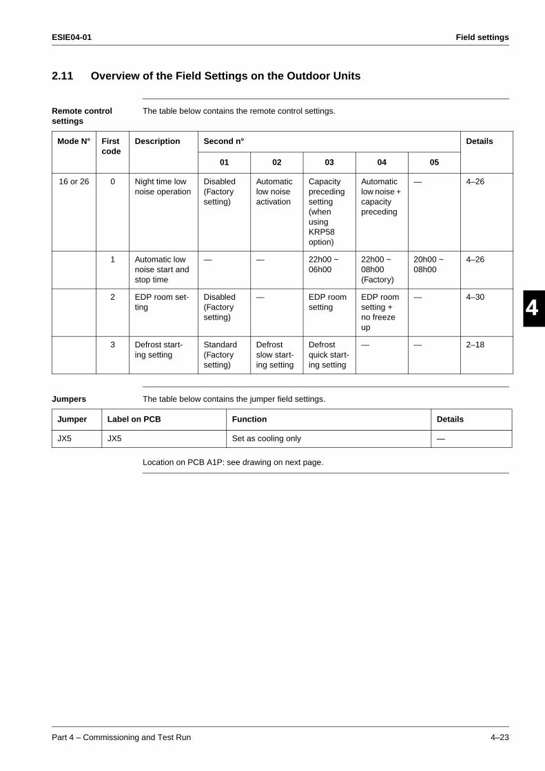
ESIE04-01 Field settings
Part 4 – Commissioning and Test Run 4–23
3
4
5
12.11 Overview of the Field Settings on the Outdoor Units
Remote control settings
The table below contains the remote control settings.
Jumpers The table below contains the jumper field settings.
Location on PCB A1P: see drawing on next page.
Mode N° First code
Description Second n° Details
01 02 03 04 05
16 or 26 0 Night time low noise operation
Disabled (Factory setting)
Automatic low noise activation
Capacity preceding setting (when using KRP58 option)
Automatic low noise + capacity preceding
— 4–26
1 Automatic low noise start and stop time
— — 22h00 ~ 06h00
22h00 ~ 08h00 (Factory)
20h00 ~ 08h00
4–26
2 EDP room set-ting
Disabled (Factory setting)
— EDP room setting
EDP room setting + no freeze up
— 4–30
3 Defrost start-ing setting
Standard (Factorysetting)
Defrost slow start-ing setting
Defrost quick start-ing setting
— — 2–18
Jumper Label on PCB Function Details
JX5 JX5 Set as cooling only —
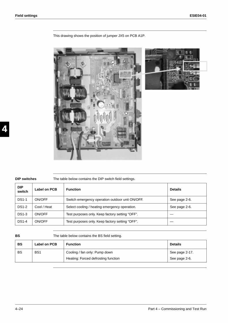
Field settings ESIE04-01
4–24 Part 4 – Commissioning and Test Run
3
1
4
5
This drawing shows the position of jumper JX5 on PCB A1P.
DIP switches The table below contains the DIP switch field settings.
BS The table below contains the BS field setting.
DIP switch
Label on PCB Function Details
DS1-1 ON/OFF Switch emergency operation outdoor unit ON/OFF. See page 2-6.
DS1-2 Cool / Heat Select cooling / heating emergency operation. See page 2-6.
DS1-3 ON/OFF Test purposes only. Keep factory setting “OFF”. —
DS1-4 ON/OFF Test purposes only. Keep factory setting “OFF”. —
BS Label on PCB Function Details
BS BS1 Cooling / fan only: Pump down
Heating: Forced defrosting function
See page 2-17.
See page 2-6.
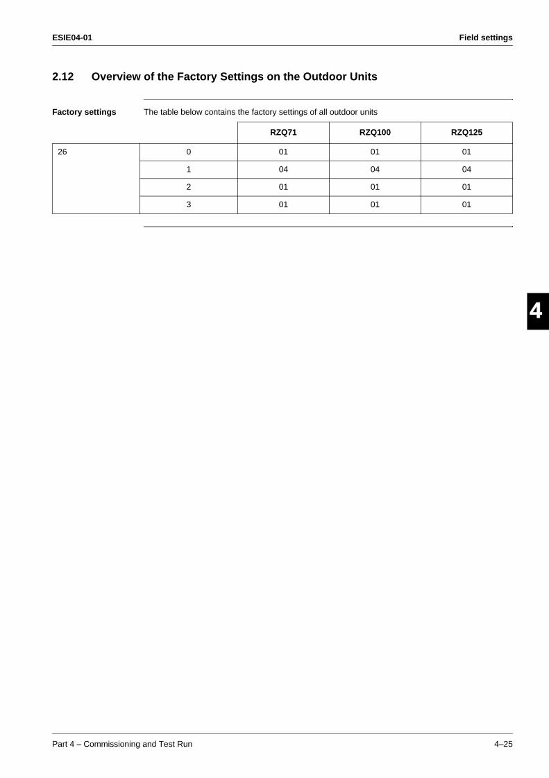
ESIE04-01 Field settings
Part 4 – Commissioning and Test Run 4–25
3
4
5
12.12 Overview of the Factory Settings on the Outdoor Units
Factory settings The table below contains the factory settings of all outdoor units
RZQ71 RZQ100 RZQ125
26 0 01 01 01
1 04 04 04
2 01 01 01
3 01 01 01
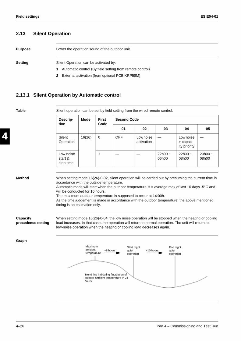
Field settings ESIE04-01
4–26 Part 4 – Commissioning and Test Run
3
1
4
5
2.13 Silent Operation
Purpose Lower the operation sound of the outdoor unit.
Setting Silent Operation can be activated by:
1 Automatic control (By field setting from remote control)
2 External activation (from optional PCB KRP58M)
2.13.1 Silent Operation by Automatic control
Table Silent operation can be set by field setting from the wired remote control:
Method When setting mode 16(26)-0-02, silent operation will be carried out by presuming the current time in accordance with the outside temperature. Automatic mode will start when the outdoor temperature is = average max of last 10 days -5°C and will be conducted for 10 hours.The maximum outdoor temperature is supposed to occur at 14:00h. As the time judgement is made in accordance with the outdoor temperature, the above mentioned timing is an estimation only.
Capacity precedence setting
When setting mode 16(26)-0-04, the low noise operation will be stopped when the heating or cooling load increases. In that case, the operation will return to normal operation. The unit will return to low-noise operation when the heating or cooling load decreases again.
Graph
Descrip-tion
Mode First Code
Second Code
01 02 03 04 05
Silent Operation
16(26) 0 OFF Low noise activation
— Low noise + capac-ity priority
—
Low noise start & stop time
1 — — 22h00 ~ 06h00
22h00 ~ 08h00
20h00 ~ 08h00
Maximum ambient temperature
+8 hoursStart night quiet operation
+10 hoursEnd night quiet operation
Trend line indicating fluctuation of outdoor ambient temperature in 24 hours.
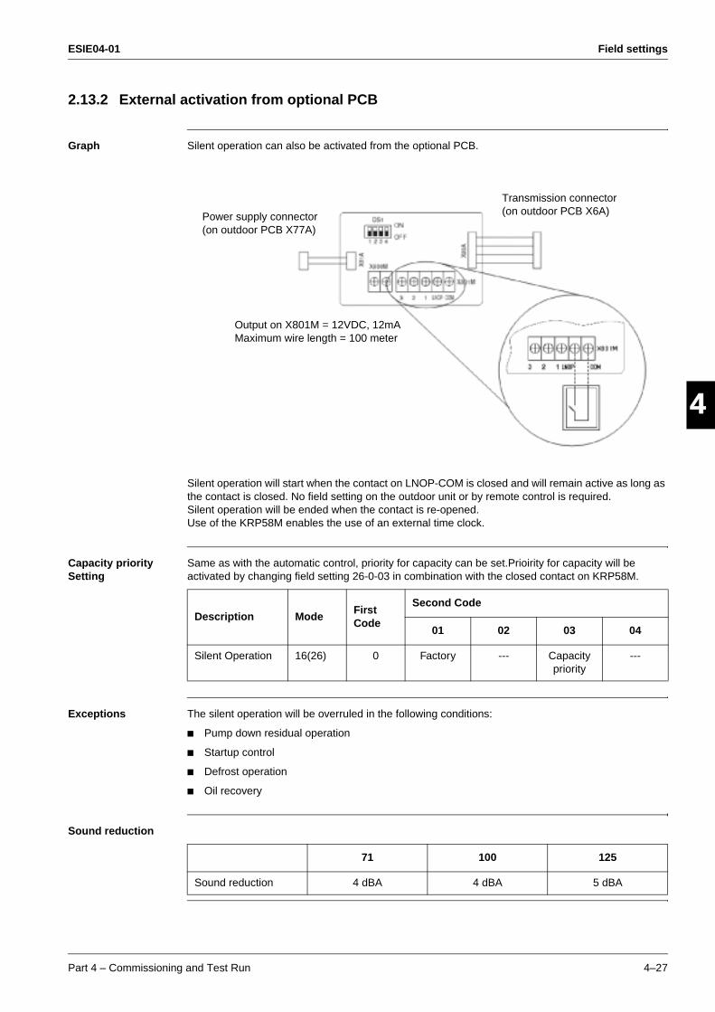
ESIE04-01 Field settings
Part 4 – Commissioning and Test Run 4–27
3
4
5
12.13.2 External activation from optional PCB
Graph Silent operation can also be activated from the optional PCB.
Silent operation will start when the contact on LNOP-COM is closed and will remain active as long as the contact is closed. No field setting on the outdoor unit or by remote control is required. Silent operation will be ended when the contact is re-opened. Use of the KRP58M enables the use of an external time clock.
Capacity priority Setting
Same as with the automatic control, priority for capacity can be set.Prioirity for capacity will be activated by changing field setting 26-0-03 in combination with the closed contact on KRP58M.
Exceptions The silent operation will be overruled in the following conditions:
Pump down residual operation
Startup control
Defrost operation
Oil recovery
Sound reduction
Power supply connector (on outdoor PCB X77A)
Output on X801M = 12VDC, 12mAMaximum wire length = 100 meter
Transmission connector (on outdoor PCB X6A)
Description ModeFirst Code
Second Code
01 02 03 04
Silent Operation 16(26) 0 Factory --- Capacity priority
---
71 100 125
Sound reduction 4 dBA 4 dBA 5 dBA
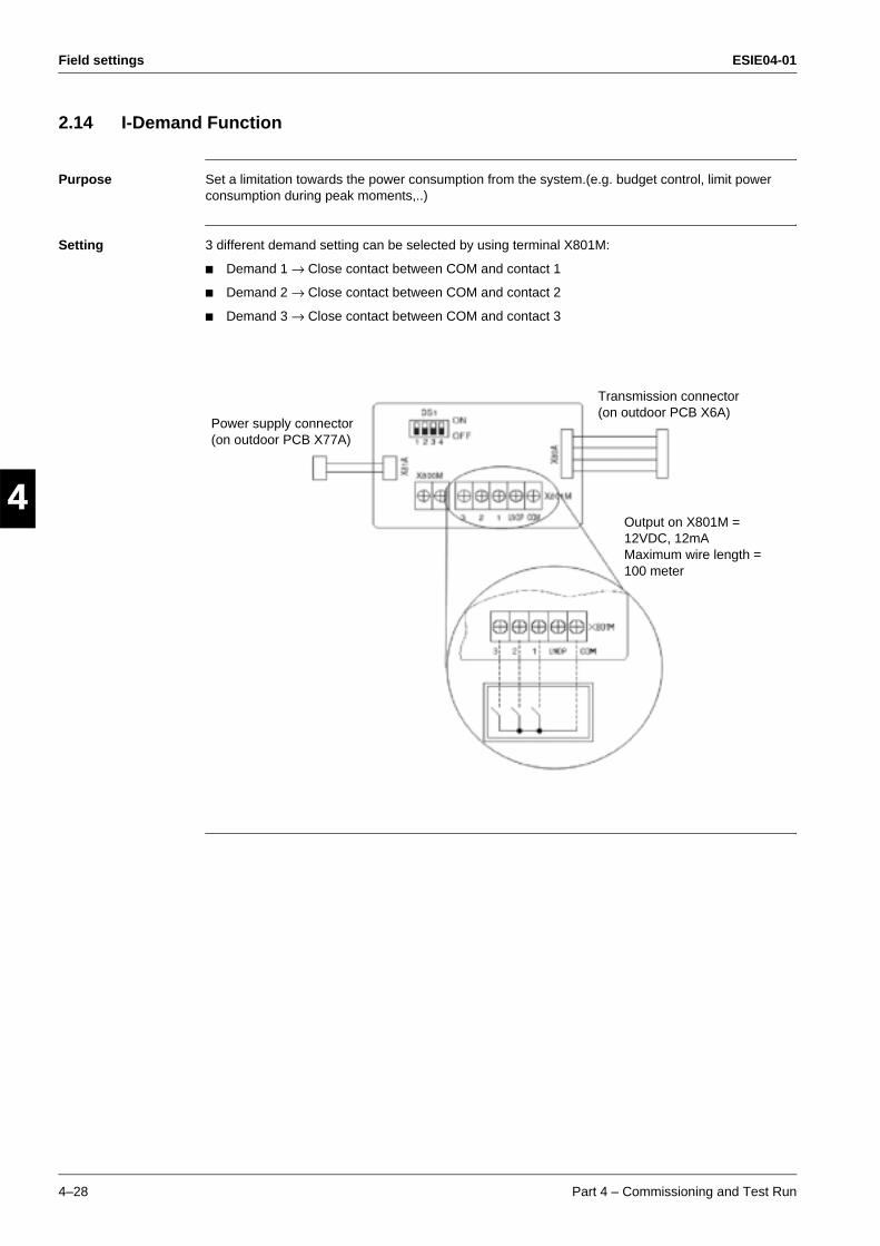
Field settings ESIE04-01
4–28 Part 4 – Commissioning and Test Run
3
1
4
5
2.14 I-Demand Function
Purpose Set a limitation towards the power consumption from the system.(e.g. budget control, limit power consumption during peak moments,..)
Setting 3 different demand setting can be selected by using terminal X801M:
Demand 1 → Close contact between COM and contact 1
Demand 2 → Close contact between COM and contact 2
Demand 3 → Close contact between COM and contact 3
Power supply connector (on outdoor PCB X77A)
Output on X801M = 12VDC, 12mAMaximum wire length = 100 meter
Transmission connector (on outdoor PCB X6A)

ESIE04-01 Field settings
Part 4 – Commissioning and Test Run 4–29
3
4
5
1Demand 1 Power consumption limitation in function of setting on DS1:
Demand 2 Power consumption limitation set to 40%.
Demand 3 Forced thermostat OFF.
DS1 SETTINGMaximum Power
Consumption1 2
OFF OFF 60%
ON OFF 70%
OFF ON 80%
ON ON 100%

Field settings ESIE04-01
4–30 Part 4 – Commissioning and Test Run
3
1
4
5
2.15 Setting for Low Humidity Application
Purpose Can be set when using the RZQ units for year round cooling in low humidity applications such as computerrooms (EDP rooms), technical rooms, etc...to increase the capacity of the unit.
Definition of Low Humidity Area
Caution When using the "LH settings" outside the "Low Humidity Area" there is an increased risk of ice accumulation on the indoor coil or water blowing out from the indoor unit.
Relative Humidity (%)
Setting is only allowed in this area
Indoor side temperature DB (°C)
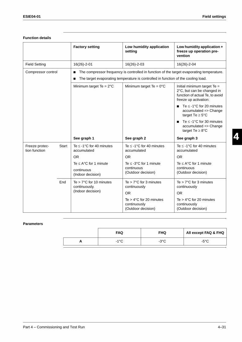
ESIE04-01 Field settings
Part 4 – Commissioning and Test Run 4–31
3
4
5
1Function details
Parameters
Factory setting Low humidity application setting
Low humidity application + freeze up operation pre-vention
Field Setting 16(26)-2-01 16(26)-2-03 16(26)-2-04
Compressor control The compressor frequency is controlled in function of the target evaporating temperature.
The target evaporating temperature is controlled in function of the cooling load.
Minimum target Te = 2°C Minimum target Te = 0°C Initial minimum target Te = 2°C, but can be changed in function of actual Te, to avoid freeze up activation:
Te ≤ -1°C for 20 minutes accumulated => Change target Te ≥ 5°C
Te ≤ -1°C for 30 minutes accumulated => Change target Te ≥ 8°C
See graph 1 See graph 2 See graph 3
Freeze protec-tion function
Start Te ≤ -1°C for 40 minutes accumulated
OR
Te ≤ A°C for 1 minute
continuous (Indoor decision)
Te ≤ -1°C for 40 minutes accumulated
OR
Te ≤ -3°C for 1 minute continuous (Outdoor decision)
Te ≤ -1°C for 40 minutes accumulated
OR
Te ≤ A°C for 1 minute continuous (Outdoor decision)
End Te > 7°C for 10 minutes continuously. (Indoor decision)
Te > 7°C for 3 minutes continuously
OR
Te > 4°C for 20 minutes continuously (Outdoor decision)
Te > 7°C for 3 minutes continuously
OR
Te > 4°C for 20 minutes continuously (Outdoor decision)
FAQ FHQ All except FAQ & FHQ
A -1°C -3°C -5°C

Field settings ESIE04-01
4–32 Part 4 – Commissioning and Test Run
3
1
4
5
Graph 1 Target evaporating temperature control in case of factory setting 16(26)-2-01:
Remote control setting temp.
Te target limitted ≤ 20°C(to protect the comp.)
Te target limitted ≤ Indoor temp. – 11°(not to rising wetbulb)
Te (by LP sensor) target acceptable area Indoor temp. > setting
→ Te target down Indoor temp. < setting
→ Te target up
Te target limitted ≥ 2°C(not to freeze)
Te target limitted ≥ Indoor temp. – 25°(not to sweat)
Freeze protection(40min. integrated coil temp. ≤ -1°C)
Indoor Temp(°C DB)
Te target acceptable area
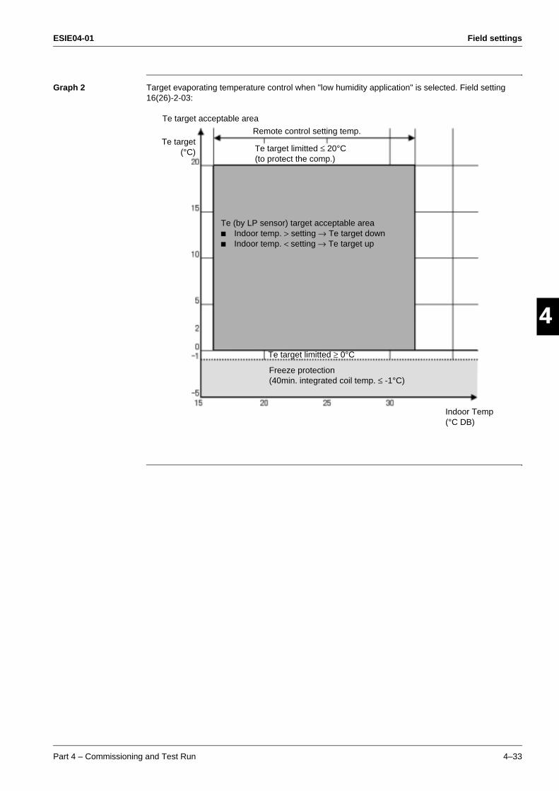
ESIE04-01 Field settings
Part 4 – Commissioning and Test Run 4–33
3
4
5
1Graph 2 Target evaporating temperature control when "low humidity application" is selected. Field setting 16(26)-2-03:
Remote control setting temp.
Te target limitted ≤ 20°C(to protect the comp.)
Te (by LP sensor) target acceptable area Indoor temp. > setting → Te target down Indoor temp. < setting → Te target up
Te target limitted ≥ 0°C
Freeze protection(40min. integrated coil temp. ≤ -1°C)
Te target acceptable area
Te target(°C)
Indoor Temp(°C DB)
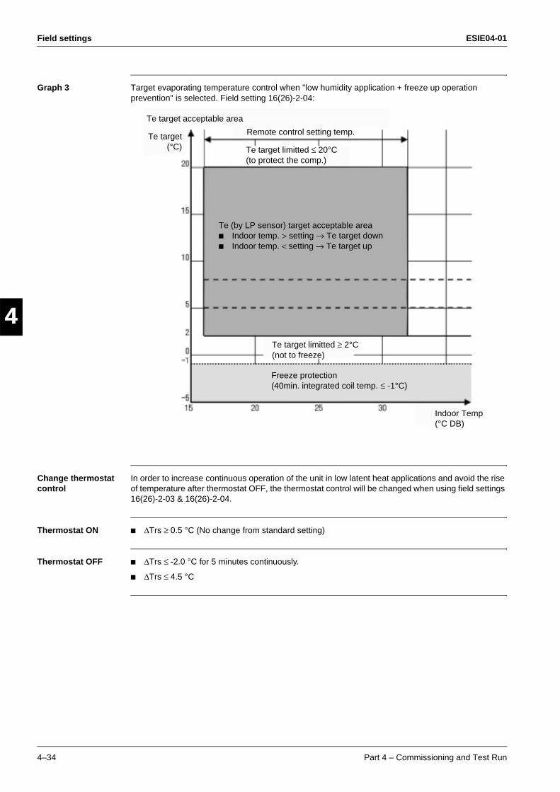
Field settings ESIE04-01
4–34 Part 4 – Commissioning and Test Run
3
1
4
5
Graph 3 Target evaporating temperature control when "low humidity application + freeze up operation prevention" is selected. Field setting 16(26)-2-04:
Change thermostat control
In order to increase continuous operation of the unit in low latent heat applications and avoid the rise of temperature after thermostat OFF, the thermostat control will be changed when using field settings 16(26)-2-03 & 16(26)-2-04.
Thermostat ON ∆Trs ≥ 0.5 °C (No change from standard setting)
Thermostat OFF ∆Trs ≤ -2.0 °C for 5 minutes continuously.
∆Trs ≤ 4.5 °C
Remote control setting temp.
Te target limitted ≤ 20°C(to protect the comp.)
Te (by LP sensor) target acceptable area Indoor temp. > setting → Te target down Indoor temp. < setting → Te target up
Te target limitted ≥ 2°C(not to freeze)
Freeze protection(40min. integrated coil temp. ≤ -1°C)
Te target acceptable area
Te target(°C)
Indoor Temp(°C DB)
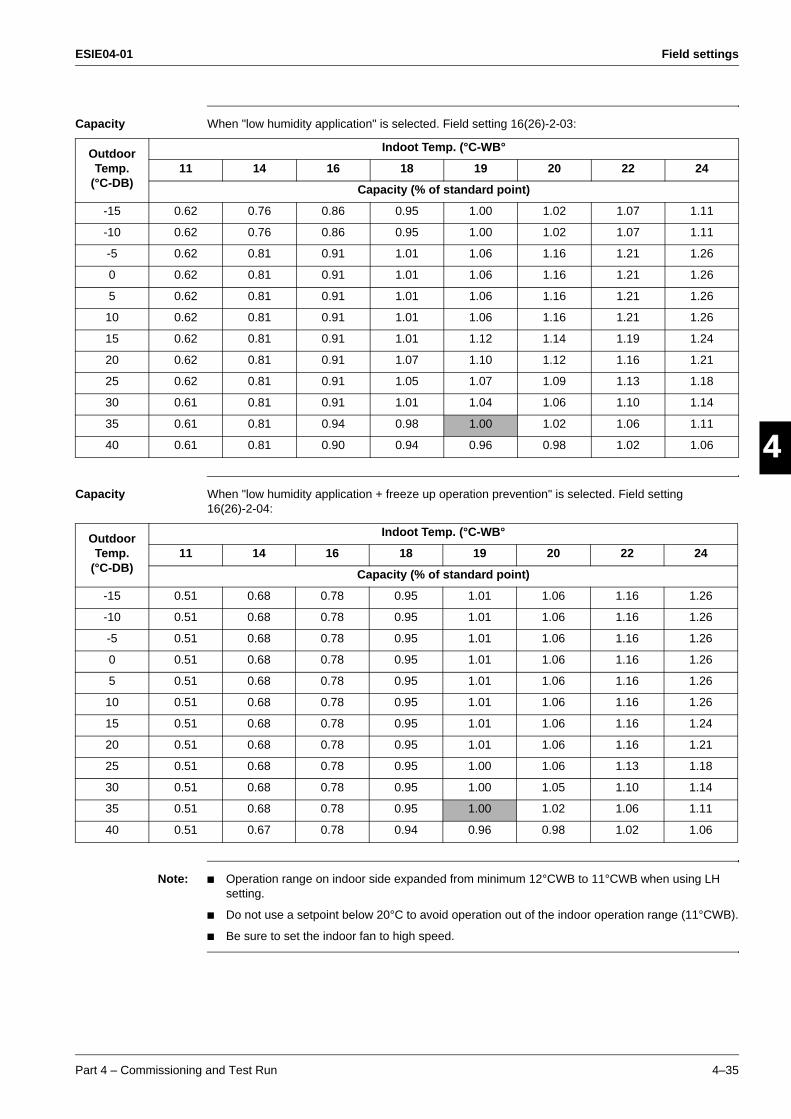
ESIE04-01 Field settings
Part 4 – Commissioning and Test Run 4–35
3
4
5
1Capacity When "low humidity application" is selected. Field setting 16(26)-2-03:
Capacity When "low humidity application + freeze up operation prevention" is selected. Field setting 16(26)-2-04:
Note: Operation range on indoor side expanded from minimum 12°CWB to 11°CWB when using LH setting.
Do not use a setpoint below 20°C to avoid operation out of the indoor operation range (11°CWB).
Be sure to set the indoor fan to high speed.
Outdoor Temp.
(°C-DB)
Indoot Temp. (°C-WB°
11 14 16 18 19 20 22 24
Capacity (% of standard point)
-15 0.62 0.76 0.86 0.95 1.00 1.02 1.07 1.11
-10 0.62 0.76 0.86 0.95 1.00 1.02 1.07 1.11
-5 0.62 0.81 0.91 1.01 1.06 1.16 1.21 1.26
0 0.62 0.81 0.91 1.01 1.06 1.16 1.21 1.26
5 0.62 0.81 0.91 1.01 1.06 1.16 1.21 1.26
10 0.62 0.81 0.91 1.01 1.06 1.16 1.21 1.26
15 0.62 0.81 0.91 1.01 1.12 1.14 1.19 1.24
20 0.62 0.81 0.91 1.07 1.10 1.12 1.16 1.21
25 0.62 0.81 0.91 1.05 1.07 1.09 1.13 1.18
30 0.61 0.81 0.91 1.01 1.04 1.06 1.10 1.14
35 0.61 0.81 0.94 0.98 1.00 1.02 1.06 1.11
40 0.61 0.81 0.90 0.94 0.96 0.98 1.02 1.06
Outdoor Temp.
(°C-DB)
Indoot Temp. (°C-WB°
11 14 16 18 19 20 22 24
Capacity (% of standard point)
-15 0.51 0.68 0.78 0.95 1.01 1.06 1.16 1.26
-10 0.51 0.68 0.78 0.95 1.01 1.06 1.16 1.26
-5 0.51 0.68 0.78 0.95 1.01 1.06 1.16 1.26
0 0.51 0.68 0.78 0.95 1.01 1.06 1.16 1.26
5 0.51 0.68 0.78 0.95 1.01 1.06 1.16 1.26
10 0.51 0.68 0.78 0.95 1.01 1.06 1.16 1.26
15 0.51 0.68 0.78 0.95 1.01 1.06 1.16 1.24
20 0.51 0.68 0.78 0.95 1.01 1.06 1.16 1.21
25 0.51 0.68 0.78 0.95 1.00 1.06 1.13 1.18
30 0.51 0.68 0.78 0.95 1.00 1.05 1.10 1.14
35 0.51 0.68 0.78 0.95 1.00 1.02 1.06 1.11
40 0.51 0.67 0.78 0.94 0.96 0.98 1.02 1.06
Field settings ESIE04-01
4–36 Part 4 – Commissioning and Test Run
3
1
4
5
2.16 Defrost start setting
See ‘Defrost Operation’ on page 2-18.

ESIE04-01 Test Run and Operation Data
Part 4 – Commissioning and Test Run 4–37
3
4
5
1Part 4
3 Test Run and Operation Data
Introduction This chapter contains the following information:
General operation data
Operation ranges.
Overview This chapter contains the following topics:
Topic See page
3.1–General Operation Data 4–38
3.2–Operation Range 4–41
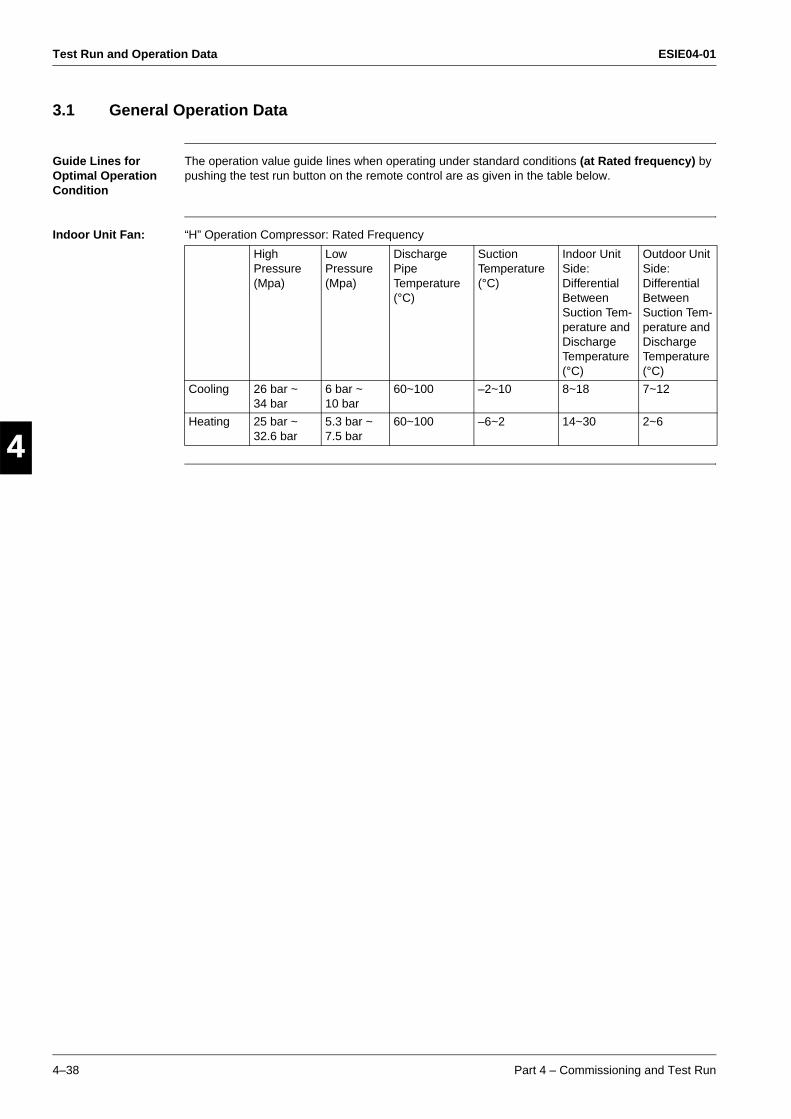
Test Run and Operation Data ESIE04-01
4–38 Part 4 – Commissioning and Test Run
3
1
4
5
3.1 General Operation Data
Guide Lines for Optimal Operation Condition
The operation value guide lines when operating under standard conditions (at Rated frequency) by pushing the test run button on the remote control are as given in the table below.
Indoor Unit Fan: “H” Operation Compressor: Rated Frequency
High Pressure (Mpa)
Low Pressure (Mpa)
Discharge Pipe Temperature (°C)
Suction Temperature (°C)
Indoor Unit Side: Differential Between Suction Tem-perature and Discharge Temperature (°C)
Outdoor Unit Side: Differential Between Suction Tem-perature and Discharge Temperature (°C)
Cooling 26 bar ~ 34 bar
6 bar ~ 10 bar
60~100 –2~10 8~18 7~12
Heating 25 bar ~ 32.6 bar
5.3 bar ~ 7.5 bar
60~100 –6~2 14~30 2~6
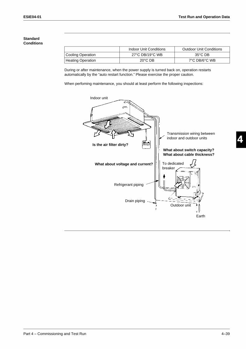
ESIE04-01 Test Run and Operation Data
Part 4 – Commissioning and Test Run 4–39
3
4
5
1Standard Conditions
During or after maintenance, when the power supply is turned back on, operation restarts automatically by the “auto restart function.” Please exercise the proper caution.
When perfoming maintenance, you should at least perform the following inspections:
Indoor Unit Conditions Outdoor Unit Conditions
Cooling Operation 27°C DB/19°C WB 35°C DB
Heating Operation 20°C DB 7°C DB/6°C WB
Indoor unit
Outdoor unit
Earth
Drain piping
Refrigerant piping
Transmission wiring between indoor and outdoor units
To dedicated breaker
Is the air filter dirty?
What about voltage and current?
What about switch capacity?What about cable thickness?
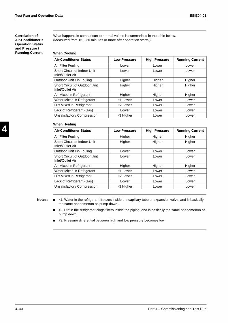
Test Run and Operation Data ESIE04-01
4–40 Part 4 – Commissioning and Test Run
3
1
4
5
Correlation of Air-Conditioner’s Operation Status and Pressure / Running Current
What happens in comparison to normal values is summarized in the table below.(Measured from 15 ~ 20 minutes or more after operation starts.)
When Cooling
When Heating
Notes: ∗1. Water in the refrigerant freezes inside the capillary tube or expansion valve, and is basically the same phenomenon as pump down.
∗2. Dirt in the refrigerant clogs filters inside the piping, and is basically the same phenomenon as pump down.
∗3. Pressure differential between high and low pressure becomes low.
Air-Conditioner Status Low Pressure High Pressure Running Current
Air Filter Fouling Lower Lower Lower
Short Circuit of Indoor Unit Inlet/Outlet Air
Lower Lower Lower
Outdoor Unit Fin Fouling Higher Higher Higher
Short Circuit of Outdoor Unit Inlet/Outlet Air
Higher Higher Higher
Air Mixed in Refrigerant Higher Higher Higher
Water Mixed in Refrigerant ∗1 Lower Lower Lower
Dirt Mixed in Refrigerant ∗2 Lower Lower Lower
Lack of Refrigerant (Gas) Lower Lower Lower
Unsatisfactory Compression ∗3 Higher Lower Lower
Air-Conditioner Status Low Pressure High Pressure Running Current
Air Filter Fouling Higher Higher Higher
Short Circuit of Indoor Unit Inlet/Outlet Air
Higher Higher Higher
Outdoor Unit Fin Fouling Lower Lower Lower
Short Circuit of Outdoor Unit Inlet/Outlet Air
Lower Lower Lower
Air Mixed in Refrigerant Higher Higher Higher
Water Mixed in Refrigerant ∗1 Lower Lower Lower
Dirt Mixed in Refrigerant ∗2 Lower Lower Lower
Lack of Refrigerant (Gas) Lower Lower Lower
Unsatisfactory Compression ∗3 Higher Lower Lower
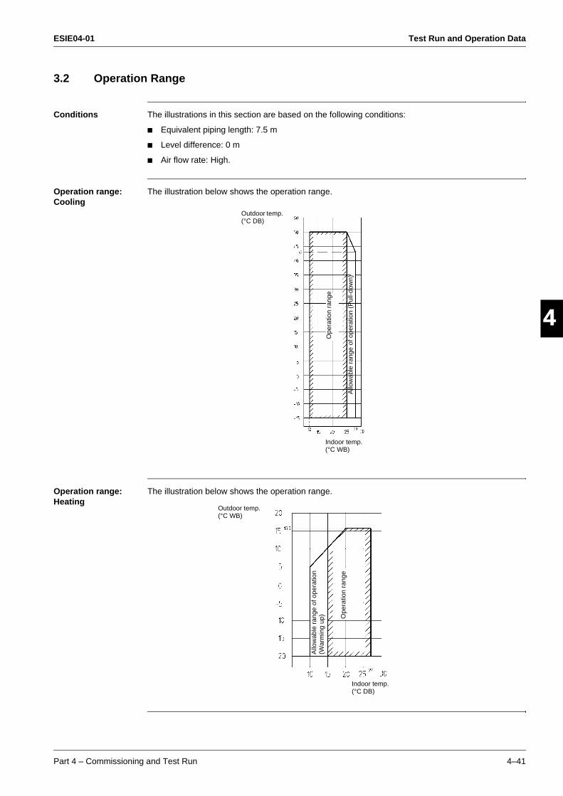
ESIE04-01 Test Run and Operation Data
Part 4 – Commissioning and Test Run 4–41
3
4
5
13.2 Operation Range
Conditions The illustrations in this section are based on the following conditions:
Equivalent piping length: 7.5 m
Level difference: 0 m
Air flow rate: High.
Operation range: Cooling
The illustration below shows the operation range.
Operation range: Heating
The illustration below shows the operation range.
Outdoor temp. (°C DB)
Indoor temp. (°C WB)
Allo
wab
le r
ange
of o
pera
tion
(Pul
l-dow
n)
Ope
ratio
n ra
nge
Outdoor temp. (°C WB)
Indoor temp. (°C DB)
Ope
ratio
n ra
nge
Allo
wab
le r
ange
of o
pera
tion
(War
min
g up
)
Test Run and Operation Data ESIE04-01
4–42 Part 4 – Commissioning and Test Run
3
1
4
5
Notes: Depending on operation and installation conditions, the indoor unit can change over to freeze-up operation (Indoor de-icing).
To reduce the freeze-up operation (Indoor de-icing) frequency it is recommended to install the outdoor unit in a location not exposed to wind.