SECTION 346 STRUCTURAL PORTLAND CEMENT ...
186
SECTION 346 STRUCTURAL PORTLAND CEMENT CONCRETE 346-1 Description. Use a Department-approved concrete mix design composed of a mixture of portland cement, aggregate, water, admixtures, and supplementary cementitious materials. Deliver the portland cement concrete to the site of placement in a freshly mixed, unhardened state. Obtain concrete from a plant that is currently on the Department’s Production Facility Listing. Producers seeking inclusion on the list shall meet the requirements of Section 105. If the concrete production facility’s Quality Control (QC) Plan is suspended, the Contractor is solely responsible to obtain the services of another concrete production facility with an accepted QC Plan or await the reacceptance of the concrete production facility’s QC Plan prior to the placement of any further concrete on the project. There will be no changes in the Contract Time because of the suspension, as described. Bear all delay costs and other costs associated with the concrete production facility’s QC Plan acceptance or reacceptance. 346-2 Materials. 346-2.1 General: Meet the following requirements: Coarse Aggregate.............................................................. Section 901 Fine Aggregate*................................................................ Section 902 Portland Cement and Blended Cement ........................... Section 921 Water ................................................................................. Section 923 Admixtures** .................................................................... Section 924 Supplementary Cementitious Materials .......................... Section 929 *Use only silica sand except as provided in 902. **Use products listed on the Department’s Approved Product List (APL). Do not use materials containing hard lumps, crusts, or frozen matter, or that is contaminated with materials exceeding the specified limits in the above listed Sections. 346-2.2 Types of Cement: Unless a specific type of cement is designated in the Contract Documents, use Type I, Type IL, Type IP, Type IT, Type IS, Type II, Type II (MH) or Type III cement in all classes of concrete. Use Type IL, Type IT, or Type II (MH) for all mass concrete elements. Use only the types of cements designated for each environmental classification in structural concrete as shown in Table 346-1. A mix design for a more aggressive environment may be used in a less aggressive environmental condition. 330 July 2022
-
Upload
khangminh22 -
Category
Documents
-
view
3 -
download
0
Transcript of SECTION 346 STRUCTURAL PORTLAND CEMENT ...

SECTION 346 STRUCTURAL PORTLAND CEMENT CONCRETE
346-1 Description.Use a Department-approved concrete mix design composed of a mixture of portland
cement, aggregate, water, admixtures, and supplementary cementitious materials. Deliver the portland cement concrete to the site of placement in a freshly mixed, unhardened state.
Obtain concrete from a plant that is currently on the Department’s Production Facility Listing. Producers seeking inclusion on the list shall meet the requirements of Section 105. If the concrete production facility’s Quality Control (QC) Plan is suspended, the Contractor is solely responsible to obtain the services of another concrete production facility with an accepted QC Plan or await the reacceptance of the concrete production facility’s QC Plan prior to the placement of any further concrete on the project. There will be no changes in the Contract Time because of the suspension, as described. Bear all delay costs and other costs associated with the concrete production facility’s QC Plan acceptance or reacceptance.
346-2 Materials.346-2.1 General: Meet the following requirements:
Coarse Aggregate.............................................................. Section 901 Fine Aggregate* ................................................................ Section 902 Portland Cement and Blended Cement ........................... Section 921 Water ................................................................................. Section 923 Admixtures** .................................................................... Section 924 Supplementary Cementitious Materials .......................... Section 929 *Use only silica sand except as provided in 902.**Use products listed on the Department’s Approved Product List (APL).Do not use materials containing hard lumps, crusts, or frozen matter, or that is
contaminated with materials exceeding the specified limits in the above listed Sections. 346-2.2 Types of Cement: Unless a specific type of cement is designated in the Contract
Documents, use Type I, Type IL, Type IP, Type IT, Type IS, Type II, Type II (MH) or Type III cement in all classes of concrete. Use Type IL, Type IT, or Type II (MH) for all mass concrete elements.
Use only the types of cements designated for each environmental classification in structural concrete as shown in Table 346-1. A mix design for a more aggressive environment may be used in a less aggressive environmental condition.
330 July 2022

Table 346-1 Cement Use by Environmental Classification
Component Slightly Aggressive Environment
Moderately Aggressive Environment
Extremely Aggressive Environment (1)
Bridge Superstructures Precast Superstructure
and Prestressed Elements
Type I or Type III Type I, Type IL, Type II,
Type III, Type IP, or Type IS
Type II (MH), Type IL, Type III (2), Type IT or
Ternary Blend
Cast in Place Type I Type I, Type IL, Type II, Type IP, or Type IS
Type II (MH), Type IL, Type IT or Ternary
Blend Bridge Substructures, Drainage Structures, and other Structures
All Elements Type I or Type III Type I, Type IL, Type II, Type IP, or Type IS
Type II (MH), Type IL, Type IT or Ternary
Blend Notes: (1) Cements used in a more aggressive environment may also be used in a less aggressive environment. (2) Type III cement may be used in an Extremely Aggressive Environment for precast superstructure and prestressed elements when the ambient temperature at the time of concrete placement is 60°F and below. 346-2.3 Supplementary Cementitious Materials: Supplementary cementitious materials (SCMs) are required to produce binary or ternary concrete mixes in all classes of concrete specified in Table 346-3, except for the following when used in slightly aggressive environments: Class I (Pavement), and Class II. The quantity of SCMs must be on a weight percentage basis of the total cementitious materials in accordance with Table 346-2. When using Type IP, IS or IT blended cements, the total quantity of SCMs, including the blended cement added separately at the concrete plant shall meet the requirements of Table 346-2. 346-2.3.1 Highly Reactive Pozzolans: Materials that have a very high degree of pozzolanic reactivity due to their very fine particle sizes, including silica fume, metakaolin and ultrafine fly ash. 346-2.3.2 Binary Concrete Mixes: Concrete mixes containing portland cement and one SCM. 346-2.3.3 Ternary Concrete Mixes: Concrete mixes containing portland cement and any two SCMs.
331 July 2022

Table 346-2 Cementitious Materials Concrete Mix Proportions (%)
(Environmental classification is extremely aggressive, unless otherwise noted)
Application Portland Cement
Fly Ash Type F Slag
Highly Reactive Pozzolans (4)
Silica Fume Metakaolin Ultra-Fine Fly Ash
General Use
70-82 18-30 66-78 15-25 7-9 66-78 15-25 8-12 66-78 15-25 8-12 30-40 10-20 50-60 30-50 50-70 36-43 50-55 7-9 33-42 50-55 8-12 33-42 50-55 8-12
Precast / Prestressed
70-85 (1) 15-30 (1) 70-82 18-30 66-78 15-25 7-9 66-78 15-25 8-12 66-78 15-25 8-12 30-40 10-20 50-60 30-50 50-70 36-43 50-55 7-9 33-42 50-55 8-12 33-42 50-55 8-12
Drilled Shaft 63-67 33-37 38-42 58-62 30-40 10-20 50-60
Mass Concrete
50-82 (2) 18-50 (2) 50-65 (3) 35-50 (3)
66-78 15-25 7-9 66-78 15-25 8-12 66-78 15-25 8-12 30-40 10-20 50-60 30-50 50-70 36-43 50-55 7-9 33-42 50-55 8-12 33-42 50-55 8-12
Notes: (1) Slightly Aggressive and Moderately Aggressive environments. (2) For Concrete with Core Temperature T≤165°F. (3) For Concrete with Core Temperature T≥165°F. (4) Highly reactive pozzolans may be used below the specified ranges to enhance strength and workability. 346-2.4 Aggregates: Produce all concrete using Size No. 57, 67 or 78 coarse aggregates. Use Size No. 8, and Size No. 89 alone, only when approved by the Engineer.
332 July 2022

Use Size No. 4 or larger blended with smaller size coarse aggregate as two components. 346-2.4.1 Optimized Aggregate Gradation: Improve the aggregate packing density at the Contractor’s option, by adding an intermediate-size coarse aggregate. Meet the requirements of Section 9.2, Volume II of the Materials Manual, on the methods used to produce combined aggregate gradation of fine, intermediate, and coarse aggregate sizes for the concrete mixes. 346-2.4.2 Lightweight fine aggregate (LWFA) for internal curing: At the Contractor’s option, use LWFA to reduce the early-age concrete cracking by replacing some of normal fine aggregate with saturated LWFA. 346-2.5 Admixtures: Ensure admixtures are used in accordance with the manufacturer’s recommendations and meeting the requirements of Section 9.2, Volume II of the Materials Manual.
346-3 Classification of Concrete. 346-3.1 General: The classifications of concrete are designated as Class I (Pavement), Class II, Class II (Bridge Deck), Class III, Class III (Seal), Class IV, Class IV (Drilled Shaft), Class V, Class V (Special), Class VI, and Class VII. The 28-day specified minimum compressive strength, maximum water to cementitious materials ratio and target slump of each class are detailed in Table 346-3. The required air content for all classes of concrete is less than or equal to 6.0%. For purposes of this Specification the concrete is further classified as follows: 1. Conventional Concrete: The target slump is described in Table 346-3 with a tolerance of ± 1.5 inches. 2. Increased Slump Concrete: The maximum target slump is 7 inches with a tolerance of ± 1.5 inches when a Type F, G, I or II admixture is used. 3. Slip-form Concrete: The target slump is 1.5 inches with a tolerance of ± 1.5 inches. 4. Flowing Concrete: Use flowing concrete only in the manufacturing of precast and prestressed products. Request Engineer’s authorization to use flowing concrete for cast-in-place applications. The target slump is 9 inches with a tolerance of ± 1.5 inches. Meet the requirements of Section 8.6 Volume II of the Materials Manual. 5. Self-Consolidating Concrete (SCC): Use SCC only in the manufacturing of precast and prestressed products. The minimum target slump flow is 22.5 inches with a tolerance of ± 2.5 inches. Meet the requirements of Section 8.4 Volume II of the Materials Manual. 346-3.2 Concrete Class Substitutions: The Engineer may allow the substitution of a higher class concrete in lieu of the specified class concrete when the substituted concrete mixes are included as part of the QC Plan, or for precast concrete, the Precast Concrete Producer QC Plan. The substituted higher class concrete must meet or exceed the requirements of the specified class concrete. When the average 28-day compressive strength is less than the 28-day specified minimum compressive strength of the higher class mix design, notify the Engineer. Acceptance is based on the requirements in Table 346-3 for the specified class concrete. 346-3.3 Master Proportion Table: Proportion the materials used to produce the various classes of concrete in accordance with Table 346-3.
333 July 2022

The calculation of the water to cementitious materials ratio (w/cm) is based on the total cementitious materials including portland cement and any SCMs used in the mix.
Table 346-3 Master Proportion Table
Class of Concrete
28-day Specified Minimum
Compressive Strength (f′c) (psi)
Maximum Water to Cementitious
Materials Ratio (pounds per pounds)
Target Slump Value (inches)
I (Pavement) (1) 3,000 0.50 1.5 or 3 II (3) 3,400 0.53 3 (2)
II (Bridge Deck) 4,500 0.44 3 (2) III 5,000 0.44 3 (2)
III (Seal) 3,000 0.53 8 IV 5,500 0.41(4) 3 (2)
IV (Drilled Shaft) 4,000 0.41 8.5 V (Special) 6,000 0.37(4) 3 (2)
6,500 0.37(4) 3 (2) VI 8,500 0.37(4) 3 (2) VII 10,000 0.37(4) 3 (2)
Notes: (1) Meet the requirements of Section 350. (2) Increased slump and slip form concrete as defined in 346-3.1. (3) For precast three-sided culverts, box culverts, endwalls, inlets, manholes and junction boxes, the target slump value and air content will not apply. The maximum allowable slump is 6 inches, except as noted in (2). The Contractor is permitted to use concrete meeting the requirements of ASTM C478 (4,000 psi) in lieu of the specified Class II concrete for precast endwalls, inlets, manholes and junction boxes. (4) When silica fume or metakaolin is required, the maximum water to cementitious material ratio will be 0.35. When ultrafine fly ash is used, the maximum water to cementitious material ratio will be 0.30. 346-3.4 Durability for Concrete Construction: 346-3.4.1 Minimum Cementitious Materials Content: Ensure that the produced concrete meets the minimum amount of cementitious materials content in Table 346-4.
Table 346-4 Minimum Amount of Total Cementitious Materials Content
(pounds per cubic yard of concrete)
Concrete Class Environmental Classification
Extremely Aggressive
Moderately Aggressive
Slightly Aggressive
I (Pavement), II, and III (Seal) 470 II (Bridge Deck), III (1), IV, IV (Drilled
Shaft), V, V(Special), VI and VII 600 550 510 Notes: (1) When precast three-sided culverts, box culverts, endwalls, inlets, manholes or junction boxes require a Class III concrete, the minimum cementitious materials content may be reduced to 470 pounds per cubic yard. 346-3.4.2 Chloride Content Limits: Use the following maximum allowable chloride content limits for the concrete application and/or exposure environment shown:
334 July 2022

Table 346-5 Chloride Content Limits for Concrete Construction
Application/Exposure Environment
Maximum Allowable Chloride Content,
(pounds per cubic yard of concrete)
Non-Reinforced Concrete No Test Needed
Reinforced Concrete Slightly Aggressive Environment 0.70 Moderately or Extremely Aggressive Environment 0.40
Prestressed Concrete 0.40 Suspend concrete placement immediately for every mix design if chloride test results exceed the limits of Table 346-5 until corrective measures are made. Submit an Engineering Analysis Scope in accordance with 6-4 by a Specialty Engineer knowledgeable in the areas of corrosion and corrosion control, to determine if the material meets the intended service life of the structure on all concrete produced from the mix design failing chloride test results to the previous passing test results. 346-3.4.3 Surface Resistivity Test: Ensure that the Class II (Bridge Deck), Class IV, Class V, Class V (Special), Class VI, or Class VII concrete in extremely aggressive environments meets or exceeds a resistivity of 29 kOhm-cm at 28 days, when a highly reactive pozzolan is used.
346-4 Special Types of Concrete. 346-4.1 Drilled Shaft Concrete: Notify the Engineer at least 48 hours before placing drilled shaft concrete. Obtain slump loss test results demonstrating that the drilled shaft concrete maintains a slump of at least 5 inches throughout the concrete elapsed time before drilled shaft concrete operations begin. Perform the slump loss test at the anticipated ambient temperature for drilled shaft placements greater than 30 cubic yards and an elapsed time of greater than five hours. Obtain slump loss test results from an approved laboratory or from a field demonstration. Slump loss test results for drilled shafts requiring 30 cubic yards of concrete or less and a maximum elapsed time of five hours or less may be done in a laboratory. Obtain all other slump loss test results in the field. The concrete elapsed time is defined in Section 455. Obtain the Engineer’s approval for use of slump loss test results including elapsed time before concrete placement begins. Test each load of concrete for slump to ensure that it is within the limits of this Section. Initially cure acceptance cylinders for 48 hours before transporting them to the laboratory. If the elapsed time during placement exceeds the slump loss test data, submit an Engineering Analysis Scope in accordance with 6-4 by a Specialty Engineer knowledgeable in concrete foundations, to determine if the shaft is structurally sound and free from voids. At the direction of the Engineer, excavate the drilled shaft for inspection. Obtain approval from the Engineer before placing any additional shafts. 346-4.2 Mass Concrete: When the Contract Documents designate any structure as mass concrete, use a Specialty Engineer to develop and administer a Mass Concrete Control Plan
335 July 2022

(MCCP). Develop the MCCP in accordance with ACI Publications 207.1R Guide to Mass Concrete, 207.2R Report on Thermal and Volume Change Effects on Cracking of Mass Concrete, and 224R Control of Cracking in Concrete Structures. Ensure that the concrete core temperatures for any mass concrete element do not exceed the maximum allowable temperature of 180°F and that the differential temperatures between the element core and surface do not exceed the maximum allowable temperature differential of 35°F. Submit the MCCP to the Engineer for approval at least 14 calendar days prior to the first anticipated mass concrete placement. Ensure the MCCP includes and fully describes the following: 1. The Financial Project Identification Number (FPID). 2. Contact names and numbers. 3. Names and qualifications of all designees who will inspect the installation of and record the output of temperature measuring devices, and who will implement temperature control measures. 4. The number, type, and dimensions of each mass concrete element to be constructed. 5. A sequential ID number assigned to each element indicating bridge number, element type, element size, and element location. 6. The mix design number of the concrete used to construct each element. 7. Indicate which mass concrete elements will be monitored. 8. Casting procedures, 9. Insulating systems, 10. Type and placement of temperature measuring and recording devices, as well as any remote monitoring devices and software. 11. For each concrete mix design and concrete element, provide information included in Table 346-6, listing the maximum allowable concrete placement temperature for each ambient temperature range at time of placement, in 10°F increments from 40°F and 99°F.
Table 346-6 Maximum Allowable Concrete Placement Temperature Data Sheet
Mix Design No. Maximum Allowable Concrete Placement Temperature (°F)
Ambient Temperature at Time of Placement
Footer Dimensions(1)
W by L by H (ft) Column Dimensions(1)
D by H(ft) 40° - 49°F 50° - 59°F 60° - 69°F 70° - 79°F 80° - 89°F 90° - 99°F
Notes: (1) W = Width, L = Length, H = Height and D = Diameter
12. Measures to prevent thermal shock. 13. Active cooling measures, if used. Do not place concrete until the proposed MCCP has is approved, and fully complies with its requirements. Any modifications must be submitted as addenda to the original
336 July 2022

MCCP and must be approved in writing by the Engineer. Ensure that, prior to the first concrete placement of each concrete element the Specialty Engineer or approved designee personally inspects the installation of the temperature measuring devices and verifies that the temperature data acquisition equipment is properly functioning. The temperature data acquisition equipment must record temperature readings at least once per hour, beginning at the completion of concrete placement and continuing until the core temperature is within 50°F of the ambient temperature. The Specialty Engineer shall be available for immediate consultation during the monitoring period of any mass concrete element. Monitor temperature readings at least once every six hours. Within three workings days of the completion of temperature recording for each concrete element, submit an electronic spreadsheet file, editable report to the Engineer that includes the element identification, date and time of any changes to the temperature control measures, all original temperature readings and curing notes. Also submit data logger summaries and graphs, and results of the visual inspection of each element. If the first element of a group of elements with the same dimensions is placed in accordance with the approved MCCP, without exceeding either the maximum temperature or maximum temperature differential of the concrete, reduced monitoring of the remaining elements may be allowed with written approval from the Engineer. Request approval from the Engineer at least 14 calendar days prior to the anticipated date of reduced monitoring. If approved, temperature monitoring is required only for the initial element of a group of concrete elements meeting all of the following requirements: 1. All elements have the same dimensions. 2. All elements have the same concrete mix design. 3. All elements have the same insulation R value and active cooling measures (if used). 4. Ambient temperatures during concrete placement for all elements are within minus 10°F of the ambient temperature during placement of the initial element. 5. Use the same temperature control measures used for the initial monitored element and keep in place for at least the same length of time as for the initial element. The Contractor and Engineer each have the option to have the temperature monitored to ensure the core temperature is within 50°F of ambient temperature prior to termination of temperature control measures. Install temperature measuring and recording devices for all mass concrete elements. Position the temperature sensors 2.00± 0.25 inches inside the concrete surface for surface temperature measurements and at the expected location of the maximum temperature for core temperature measurements. Place the ambient temperature sensor in a location that protects it from direct exposure to rain, sun, or sources of radiated heat, such as concrete or asphalt pavement surfaces. Temperatures shall be continuously recorded starting at the end of concrete placement and continuing until the core has cooled to within 50°F of the ambient temperature. Resume monitoring of the temperatures for all elements if directed by the Engineer. Instrumentation and temperature monitoring are not required for drilled shafts supporting sign, signal, lighting or intelligent transportation (ITS) structures that meet all of the following requirements: 1. The diameter is six feet or less. 2. The total cementitious materials content of the concrete mix design is less than or equal to 750 pounds per cubic yard.
337 July 2022

Temperature monitoring may be omitted at the Contractor’s option, for any mass concrete substructure element meeting all of the following requirements: 1. The minimum cross-sectional dimension of the element is six feet or less. 2. Insulation with an R-value of at least 2.5 must be provided for at least 72 hours following the completion of concrete placement. 3. The environmental classification of the concrete element is slightly aggressive or moderately aggressive. 4. The concrete mix design meets the mass concrete proportioning requirements of 346-2.3. 5. The total cementitious material content of the concrete mix design is less than or equal to 750 pounds per cubic yard. 6. Temperature of the concrete is 95°F or less at placement. Implement immediate corrective action as directed by the Specialty Engineer when either the core temperature or the temperature differential of any mass concrete element exceeds its maximum allowable value. The approval of the MCCP shall be revoked. Do not place any mass concrete elements until a revised MCCP has been approved in writing by the Engineer. Submit an Engineering Analysis Scope in accordance with 6-4 for approval, which addresses the structural integrity and durability of any mass concrete element that is not cast in compliance with the approved MCCP or which exceeds the allowable core temperature or temperature differential. Submit all analyses and test results requested by the Engineer for any noncompliant mass concrete element to the satisfaction of the Engineer. The Department will make no compensation for additional costs or loss of time due to additional analyses, tests, or other impacts on production caused by the use of reduced monitoring or the Contractor’s option.
346-5 Sampling and Testing Methods. Perform concrete sampling and testing in accordance with the following methods:
338 July 2022

Table 346-7 Concrete Sampling and Testing Methods
Description Method Slump of Hydraulic Cement Concrete ASTM C143 Air Content of Freshly Mixed Concrete by the Pressure Method (1) ASTM C231 Air Content of Freshly Mixed Concrete by the Volumetric Method (1) ASTM C173 Making and Curing Test Specimens in the Field (2) ASTM C31 Compressive Strength of Cylindrical Concrete Specimens ASTM C39 Obtaining and Testing Drilled Core and Sawed Beams of Concrete ASTM C42 Initial Sampling of Concrete from Revolving Drum Truck Mixers or Agitators FM 5-501 Low Levels of Chloride in Concrete and Raw Materials FM 5-516 Density (Unit Weight), Yield and Air Content (Gravimetric) of Concrete ASTM C138 Temperature of Freshly Mixed Portland Cement Concrete ASTM C1064 Sampling Freshly Mixed Concrete (3) ASTM C172 Static Segregation of Self-Consolidating Concrete using Column Techniques ASTM C1610 Slump Flow of Self-Consolidating Concrete ASTM C1611 Relative Viscosity of Self-Consolidating Concrete ASTM C1611 Visual Stability Index of Self-Consolidating Concrete ASTM C1611 Passing Ability of Self-Consolidating Concrete by J-Ring ASTM C1621 Rapid Assessment of Static Segregation Resistance of Self-Consolidating Concrete Using Penetration Test ASTM C1712
Aggregate Distribution of Hardened Self-Consolidating Concrete FM 5-617 Hardened Visual Stability Index of Self-Consolidating Concrete AASHTO R 81 Fabricating Test Specimens with Self-Consolidating Concrete ASTM C1758 Concrete Resistivity as an Electrical Indicator of its Permeability AASHTO T 358 (1) The Department will use the same type of meter for Verification testing as used for QC testing. When using pressure type meters, use an aggregate correction factor determined by the concrete producer for each mix design to be tested. Record and certify test results for correction factors for each type of aggregate at the concrete production facility. (2) Provide curing facilities that have the capacity to store all QC, Verification, and Resolution cylinders simultaneously for the initial curing. Cylinders will be delivered to the testing laboratory in their molds. The laboratory will remove the specimens from the molds and begin final curing. (3) Take the test sample from the middle portion of the batch in lieu of collecting and compositing samples from two or more portions, as described in ASTM C172.
346-6 Quality Control. 346-6.1 General: Perform QC activities to ensure materials, methods, techniques, personnel, procedures and processes utilized during production meet the specified requirements. For precast/prestressed concrete operations, ensure that the QC testing is performed by the producer. Accept the responsibility for QC inspections on all phases of work. Ensure all materials and workmanship incorporated into the project meet the requirements of the Contract Documents. 346-6.2 Concrete Mix Design: Provide concrete that has been produced in accordance with a Department approved mix design, in a uniform mass free from balls and lumps. For slump target values in excess of 6 inches, including flowing concrete and SCC, utilize a grate over the conveyance equipment to capture any lumps or balls that may be present in the mix. The grate must cover the entire opening of the conveyance equipment and
339 July 2022

have an opening that is a maximum of 2-1/2 inches in any one direction. Remove the lumps and balls from the grate and discard them. Discharge the concrete in a manner satisfactory to the Engineer. Perform demonstration batches to ensure complete and thorough placements in complex elements, when requested by the Engineer. Do not place concretes of different compositions such that the plastic concretes may combine, except where the Plans require concrete with a surface resistivity value of 29 kOhm-cm or below and one with higher than 29 kOhm-cm values in a continuous placement. Produce these concretes using separate mix designs. For example, designate the mix with calcium nitrite as the original mix and the mix without calcium nitrite as the redesigned mix. Ensure that both mixes contain the same cement, fly ash or slag, coarse and fine aggregates and admixtures. Submit both mixes for approval as separate mix designs, both meeting all requirements of this Section. Ensure that the redesigned mix exhibits plastic and hardened qualities which are additionally approved by the Engineer as suitable for placement with the original mix. The Engineer will approve the redesigned mix for commingling with the original mix and for a specific project application only. Alternately, place a construction joint at the location of the change in concretes as approved by the Engineer. 346-6.3 Delivery Certification: Ensure that an electronic delivery ticket is furnished with each batch of concrete before unloading at the placement site. The delivery ticket may be proprietary software or in the form of an electronic spreadsheet, but shall be printed. Ensure that the materials and quantities incorporated into the batch of concrete are printed on the delivery ticket. Include the following information on the delivery ticket: 1. Arrival time at jobsite, 2. Time that concrete mix has been completely discharged, 3. Number of revolutions upon arrival at the jobsite, 4. Total gallons of water added at the jobsite, 5. Additional mixing revolutions when water is added, 6. Total number of revolutions. Items (3) through (6) do not apply to non-agitating concrete transporting vehicles. Ensure the batcher responsible for production of the batch of concrete signs the delivery ticket, certifying the batch of concrete was produced in accordance with the Contract Documents. Sign the delivery ticket certifying that the design mix maximum specified water to cementitious materials ratio was not exceeded due to any jobsite adjustments to the batch of concrete, and that the batch of concrete was delivered and placed in accordance with the Contract Documents. 346-6.4 Plastic Property Tolerances: Reject concrete with slump or air content that does not fall within the specified tolerances, except as noted below, and immediately notify the concrete production facility that an adjustment of the concrete mixture is required. If a load does not fall within the tolerances, test each subsequent load and the first adjusted load. If failing concrete is not rejected or adjustments are not implemented, the Engineer may reject the concrete and terminate further production until the corrections are implemented. At the Contractor’s risk, water may be added at the placement site immediately after completion of the initial slump test, either to correct a low slump or to increase the concrete workability, provided the addition of water does not exceed the water to cementitious materials ratio as defined by the mix design.
340 July 2022

After adding water, perform an additional slump test to confirm the concrete is within the slump tolerance range. If the slump is outside the tolerance range, reject the load. If an adjustment is made at the concrete production facility, perform a slump test on the next load to ensure the concrete is within the slump tolerance range. Do not place concrete represented by slump test results outside of the tolerance range. Include water missing from the water storage tanks upon arrival at the project site in the jobsite water added. Do not allow concrete to remain in a transporting vehicle to reduce slump.
346-7 Mixing and Delivering Concrete. 346-7.1 General Requirements: Operate all concrete mixers at speeds and volumes per the manufacturer’s design or recommendation as stipulated on the mixer rating plate. 346-7.2 Transit Truck Mixing: Produce a completely uniform mixed concrete in a truck mixer for 70 to 100 revolutions at the mixing speed designated by the truck manufacturer. Prior to starting the discharge of the concrete at the jobsite, when water is added, record the added quantity and mix the concrete 30 additional drum mixing revolutions. Do not make more than two mix adjustments. Seek approval from the Engineer prior to using a central mixer and depositing the batch into a truck mixer. 346-7.2.1 Transit Time: Ensure compliance with Table 346-8 between the initial introduction of water into the mix and completely discharging all the concrete from the truck. Reject concrete exceeding the maximum transit time. The Engineer may approve an extension of the transit time which will be identified on the approved mix design.
Table 346-8 Maximum Allowable Transit Time
Non-Agitator Trucks Agitator Trucks 45 minutes 60 minutes
75 minutes (1) 90 minutes (1) Note: (1) When a water-reducing and retarding admixture (Type D, Type G, or Type II) is used.
346-7.2.2 Placement Time: All the concrete in a load must be in its final placement position a maximum of 15 minutes after the transit time has expired unless a time extension is approved by the Engineer. For Class IV (Drilled Shaft) mixes, placement time may be extended provided the slump loss time of the first concrete placed is not exceeded throughout the elapsed time. The Engineer may perform Independent Verification (IV) testing to verify the plastic and hardened properties of the concrete when a time extension is granted. 346-7.3 On-site Batching and Mixing: Use a mixer of sufficient capacity to prevent delays that may be detrimental to the quality of the work. Ensure that the accuracy of batching equipment is in accordance with requirements of this Section. 346-7.4 Concreting in Cold Weather: Do not mix or place concrete when the air temperature is below 40ºF. Protect the fresh concrete from freezing in accordance with Section 400. The requirements of concreting in cold weather are not applicable to precast concrete mixing and placement operations occurring in a temperature controlled environment.
341 July 2022

346-7.5 Concreting in Hot Weather: Hot weather concreting is defined as the production, placing and curing of concrete when the concrete temperature at placing exceeds 85ºF but is 100ºF or less. Unless the specified hot weather concreting measures are in effect, reject concrete exceeding 85ºF at the time of placement. Regardless of special measures taken, reject concrete exceeding 100ºF. Predict the concrete temperatures at placement time and implement hot weather measures to avoid production shutdown. 346-7.6 Sample Location: Obtain acceptance samples from the point of final placement. Where concrete buckets are used to discharge concrete directly to the point of final placement or into the hopper of a tremie pipe, samples will be obtained from the discharge of the bucket. When the concrete is discharged directly from the mixer into the bucket and the bucket is discharged within 20 minutes, samples may be obtained from the discharge of the mixer. Where conveyor belts, troughs, pumps, or chutes are used to transport concrete directly to the point of final placement or into the hopper of a tremie pipe, samples will be obtained from the discharge end of the entire conveyor belt, trough, pump, or chute system. Where concrete is placed in a drilled shaft or other element using a tremie pipe and a concrete pump, samples will be obtained from the discharge of the pump line at the location of the tremie hopper. For all other placement methods, prior to each placement, obtain Department approval for sampling at the discharge of the mixer in lieu of sampling at the point of final placement. Submit the sampling correlation procedure to the Engineer for approval prior to the placement of the concrete. Once the comparative sampling correlation is approved by the Engineer, apply this correlation to the plastic properties tolerances for samples obtained from the discharge of mixer. Where a concrete pump is used to deposit concrete directly into a drilled shaft which is a wet excavation without the use of a tremie, or other applications as approved by the Engineer, ensure the discharge end of the pump line remains immersed in the concrete at all times after starting concrete placement.
346-8 Plastic Concrete Sampling and Testing. QC tests include air content, temperature, slump, and preparing compressive strength cylinders for testing at later dates. In addition, calculate the water to cementitious materials ratio in accordance with FM 5-501 for compliance to the approved mix design. Ensure that each truck has a rating plate and a valid mixer identification card issued by the Department. Ensure that the revolution counter on the mixer is working properly, and calibration of the water dispenser has been performed within the last twelve months. Reject any concrete batches that are delivered in trucks that do not have mixer identification cards. Remove the mixer identification card when a truck mixer is discovered to be in noncompliance and the mixer deficiencies cannot be repaired immediately. When the mixer identification card is removed for noncompliance, make note of the deficiency or deficiencies found, and forward the card to the District Materials and Research Engineer who has Producer QC Plan acceptance authority. Perform plastic concrete tests on the initial delivery from each plant of each concrete design mix each day. Ensure QC technicians meeting the requirements of Section 105 are present and performing tests throughout the placement operation. Ensure a technician is present and performing tests throughout the placement operation at each placement site. If a project has
342 July 2022

multiple concrete placements at the same time, identify the technicians in the QC Plan to ensure minimum sampling and testing frequencies are met. Ensure that the equipment used for delivery, placement and finishing meets the requirements of this Specification. When a truck designated for QC testing arrives at the discharge site, a subsequent truck may also discharge once a representative sample has been collected from the QC truck and while awaiting the results of QC testing. Reject non-complying loads at the jobsite. Ensure that corrections are made on subsequent loads. Immediately cease concrete discharge of all trucks if the QC truck has failing test. Perform plastic properties tests of concrete on all trucks prior to the first corrected truck and the corrected truck. When more than one truck is discharging into a pump simultaneously, only the truck designated for QC testing may discharge into the pump to obtain a representative sample of concrete from the QC truck only. Furnish sufficient concrete of each design mix as required by the Engineer for verification (VT) testing. When the Engineer’s VT test results do not compare with the QC plastic properties test results, within the limits defined by the Independent Assurance (IA) checklist comparison criteria, located in Materials Manual Chapter 5, disposition of the concrete will be at the option of the Contractor. On concrete placements consisting of only one load of concrete, perform initial sampling and testing in accordance with this Section. The acceptance sample and plastic properties tests may be taken from the initial portion of the load. If any of the QC plastic properties tests fail, reject the remainder of that load, and any other loads that have begun discharging, terminate the LOT and notify the Engineer. Make cylinders representing that LOT from the same sample of concrete. Following termination of a LOT, obtain samples from a new load, and perform plastic properties tests until the water to cementitious materials ratio, air content, temperature and slump comply with the Specification requirements. Initiate a new LOT once the testing indicates compliance with Specification requirements. Suspend production when any five loads in two days of production of the same design mix are outside the specified tolerances. Increase the frequency of QC testing to one per load to bring the concrete within allowable tolerances. After production resumes, obtain the Engineer’s approval before returning to the normal frequency of QC testing. If concrete placement stops for more than 90 minutes, perform initial plastic properties testing on the next batch and continue the LOT. Cylinders cast for that LOT will represent the entire LOT. When the Department performs Independent Verification (IV), the Contractor may perform the same tests on the concrete at the same time. The Department will compare results based on the Independent Assurance (IA) Checklist tolerances.
346-9 Acceptance Sampling and Testing. 346-9.1 General: Perform plastic properties tests in accordance with 346-8 and cast a set of three QC cylinders, for all structural concrete incorporated into the project. Take these acceptance samples randomly as determined by a random number generator acceptable to the Department. The Department will independently perform VT plastic properties tests and cast a set of VT cylinders. The VT cylinders will be the same size cylinder selected by the Contractor, from a separate sample from the same load of concrete as the Contractor’s QC sample. For each set of QC cylinders verified by the Department, cast two additional cylinders from the same sample, and identify them as the quality control resolution (QR) test cylinders. The Department will also cast two additional verification resolution (VR) test
343 July 2022

cylinders from each VT sample. All cylinders will be clearly identified as outlined in the Sample/LOT Numbering System instructions located on the State Materials Office website. Deliver the QC samples, including the QR cylinders to the final curing facility in accordance with ASTM C31. Concurrently, the Department will deliver the VT samples, including the VR cylinders, to their final curing facility. Test the QC laboratory cured samples for compressive strength at the age of 28 days, in a laboratory meeting and maintaining at all times the qualification requirements listed in Section 105. Ensure the QC testing laboratory input the compressive strength test results into the Department’s Materials Acceptance and Certification (MAC) system within 24 hours after testing. Notify the Engineer when results cannot be inputted into MAC. The Department will compare the VT sample compressive strength test results with the corresponding QC sample test results. 346-9.2 Sampling Frequency: As a minimum, sample and test concrete of each mix design for water to cementitious materials ratio, air content, temperature, slump and compressive strength once per LOT as defined by Table 346-9. The Engineer will randomly verify one of every four consecutive LOTs of each mix design based on a random number generator. The Department may perform Independent Verification (IV) testing to verify compliance with specification requirements. All QC activities, calculations, and inspections will be randomly confirmed by the Department.
Table 346-9 Sampling Frequency
Class Concrete (1) LOT Size
I (Pavement) According to Section 350
II, II (Bridge Deck), III, IV, V (Special), V, VI, VII
50 cubic yards, or one day’s production, whichever is less
IV (Drilled Shaft) 50 cubic yards, or one day’s production, whichever is less (2)
III (Seal) Each Seal placement (1) For any class of concrete used for roadway concrete barrier, the lot size is defined as 100 cubic yards, or one day’s production, whichever is less. (2) Start a new LOT when there is a gap of more than two hours between the end of one drilled shaft placement and the beginning of the next drilled shaft placement. 346-9.2.1 Reduced Frequency for Acceptance Tests: Except for Class I (Pavement), the LOT size may represent 100 cubic yards when produced with the same mix design at the same concrete production facility for the same prime Contractor and subcontractor on a given Contract. As an exception, the requirements for the precast/prestressed production facility will only include the same mix design at the same concrete production facility. The reduced testing frequency of Class I (Pavement) is described in the Section 350. Submit strength test results indicating that the two following criteria are met:
344 July 2022

1. The average of the acceptance compressive strengths is equal to or greater than the specified minimum compressive strength (f′c) plus 2.33 standard deviations minus: a. 500 psi, if f′c is 5,000 psi or less. b. 0.10 f′c, if f′c is greater than 5,000 psi. 2. Every average of three consecutive strength test equals or exceeds the f′c plus 1.34 standard deviations. Base calculations on a minimum of ten consecutive strength test results for a Class IV or higher; or a minimum of five consecutive strength results for a Class III or lower. The average of the consecutive compressive strength test results, based on the class of concrete, can be established using historical data from a previous Department project. The tests from the previous Department project must be within the last calendar year or may also be established by a succession of samples on the current project. Only one sample can be taken from each LOT. Test data must be from a laboratory meeting the requirements of Section 105. Obtain Department approval before beginning reduced frequency LOTs. If at any time a strength test is not verified or the average strength of the previous ten or five consecutive samples based on the class of concrete from the same mix design and the same production facility does not conform to the above conditions, return to the frequency represented by the LOT as defined in Table 346-9. Notify the Engineer that the initial frequency is reinstated. In order to reinitiate reduced frequency, submit a new set of strength test results. 346-9.3 Strength Test Definition: The strength test of a LOT is defined as the average compressive strength tests of at least two companion cylinders cast from the same sample of concrete and tested at the same age. 346-9.4 Acceptance of Concrete: The Engineer will accept the concrete of a given LOT when the compressive strength test results are verified and meets the minimum specified compressive strength in Table 346-3. Ensure that the hardened concrete strength test results are obtained in accordance with 346-9.3. The process of concrete compressive strength verification and acceptance consists of the following steps: 1. Verification of QC and VT data. 2. Resolution of QC and VT data if needed. 3. Structural Adequacy determination. Do not discard a cylinder strength test result based on low strength (strength below the specified minimum strength as per the provisions of this Section). When one of the three QC cylinders from a LOT is lost, missing, damaged or destroyed, determination of compressive strength will be made by averaging the remaining two cylinders. If more than one QC cylinder from a LOT is lost, missing, damaged or destroyed, the Contractor will core the structure at no additional expense to the Department to determine the compressive strength. Prior to coring, obtain Engineer’s approval for coring the structure and its proposed coring location. Acceptance of LOT may be based on VT data at the discretion of the Engineer. For each QC and each QR cylinder that is lost, missing, damaged or destroyed, payment for that LOT will be reduced by $750.00 per 1,000 psi of the specified design strength [Example: loss of two Class IV (Drill Shaft) QC cylinders that has no VT data will require the
345 July 2022

element to be cored and a pay reduction will be assessed (4,000 psi / 1,000 psi) x $750 x 2 = $6,000]. This reduction will be in addition to any pay adjustment for low strength. 346-9.4.1 Small Quantities of Concrete: When a project has a total plan quantity of less than 50 cubic yards, that concrete will be accepted based on the satisfactory compressive strength of the QC cylinders. Submit certification to the Engineer that the concrete was batched and placed in accordance with the Contract Documents. Submit a QC Plan for the concrete placement operation in accordance with Section 105. The Engineer may perform IV testing as identified in 346-9 and evaluate the concrete in accordance with 346-9.7. 346-9.5 Verification: The results of properly conducted test by QC and VT laboratories on specimens prepared from the same sample of concrete are not to differ by more than 14%. Difference (%) = ABS (
QC−VT
QC) 100
Where: Difference (%) is the absolute percentage difference between QC and VT average compressive strength. The procedure consists of verifying if the QC and VT compressive strengths data meet the established comparison criteria: 1. When the difference between the average compressive strength of QC and the average compressive strength of VT is less than or equal to 14%, the QC test results are upheld and verified. The Engineer will accept at full pay only LOTs of concrete represented by plastic property results which meet the requirements of the approved mix design and strength test results which equal or exceed the respective specified minimum strength. 2. When the difference between the average compressive strength of QC and the average compressive strength of VT data exceeds 14%, the compressive strength results are not verified and the Engineer will initiate the resolution procedure. Maintain the QR and VR cylinders for a minimum of 30 days following the testing date of the specified strength. 346-9.6 Resolution: The Engineer will perform the resolution process to identify the reliability of the compressive strength results when the difference between the average compressive strength of QC and the average compressive strength of VT data exceeds 14% as described in 346-9.5(2). The Engineer will correlate the 28-day strength (VR28 and QR28) for the VR and QR cylinders and will compare: 1. The VT sample results with the VR28 cylinders results. 2. The QC sample results with the QR28 cylinders results. Comparison results must not be greater than 17.5%. Core samples of the hardened concrete may be required.
VD (%) = ABS (VT − VR28
VT) 100
QD (%) = ABS (QC − QR28
QC) 100
Where: VD (%) is the absolute percentage difference between VT and VR28. QD (%) is the absolute percentage difference between QC and QR28.
346 July 2022

The resolution procedure will use the above equations. The Engineer will determine through the resolution procedure whether the QC strength test results or the VT strength test are deemed to be the most accurate, LOTs will then be considered to be verified. The Engineer will inform the QC and VT laboratories within three calendar days of the acceptance compressive strength test to transport their QR and VR cylinders to the resolution laboratory. The QC and VT laboratories will transport their own hold cylinders to the resolution testing laboratory within three calendar days after the Engineer notifies the Contractor that a resolution procedure is required. In addition, the Engineer will ensure that the QR and VR cylinders are tested within 14 calendar days of the acceptance strength tests. The Engineer will determine the most accurate strength test result to represent the four or fewer consecutive LOTs as follows: 1. When both results meet the established comparison criteria, both are deemed accurate and the QC strength will represent the LOTs. The Department will pay for cost of the resolution testing. 2. When only the QC result is within the established comparison criteria, the QC strength is deemed as most accurate and will represent the LOTs. The Department will pay for the cost of the resolution testing. 3. When only the VT result is within the established comparison criteria, the VT strength is deemed as most accurate and will represent the LOTs. The Department will assess a $1,000 pay reduction for the cost of the Resolution Investigation. 4. When both results are outside the established comparison criteria, the Engineer, with input from the DMO, will determine if any Department IA evaluations are required and which test results are most accurate. The Department will pay for the cost of the resolution testing. When the Engineer cannot determine which strength test results are the most accurate, the concrete represented by the four consecutive LOTs will be evaluated based on the QC data. The results of the resolution procedure will be forwarded to the Contractor within five working days after completion of the investigation. 346-9.7 Structural Adequacy: The Engineer will evaluate the structural adequacy for verified concrete that does not meet the minimum specified compressive strength of Table 346-3. For standard molded and cured strength cylinders, the compressive strength of concrete is satisfactory provided that the two following criteria are met: 1. The average compressive strength does not fall below the specified minimum compressive strength by more than: a. 500 psi if the specified minimum compressive strength is equal to or less than 5,000 psi. b. 10% of the specified minimum compressive strength if the specified minimum compressive strength is greater than 5,000 psi. 2. The average compressive strength with the previous two LOTs is equal to or exceeds the specified minimum compressive strength. This condition only applies if there are two or more previous LOTs to calculate the average. The Engineer will consider the concrete for a given LOT as structurally adequate and coring will not be allowed when a concrete compressive strength test result falls below the specified minimum strength but has met the above conditions.
347 July 2022

346-10 Investigation of Low Compressive Strength Concrete. When a verified concrete compressive strength test result falls below the specified minimum strength, and does not meet the structural adequacy described in 346-9.7, perform one of the following options: 1. Submit an Engineering Analysis Scope in accordance with 6-4 to establish structural and durability adequacy. When the scope is approved by the Engineer, submit an Engineering Analysis Report (EAR) in accordance with 6-4 that includes a full structural analysis. If the results of the structural analysis indicate adequate strength to serve its intended purpose with adequate durability, and is approved by the Engineer, the Contractor may leave the concrete in place subject to the requirements of 346-11, otherwise, remove and replace the LOT of concrete in question at no additional expense to the Department. 2. At the Engineer’s discretion, obtain drilled core samples as specified in this Section to determine the in-place strength of the LOT of concrete in question, at no additional expense to the Department. The Engineer will determine whether to allow coring of the in-place concrete or require an engineering analysis based on the compressive strength of the test cylinders. 346-10.1 Coring for Determination of Structural Adequacy: Core strength test results obtained from the structure will be accepted by both the Contractor and the Department as the in-place strength of the LOT of concrete in question. The core strength test results will be used in lieu of the cylinder strength test results for determination of structural adequacy. The Department will calculate the strength value to be the average of the compressive strengths of the three individual cores. This will be accepted as the actual measured value. Obtain and test the cores in accordance with ASTM C42.The Engineer will select the size and location of the drilled cores so that the structure is not impaired and does not sustain permanent damage after repairing the core holes. Obtain the Engineer’s written approval before taking any concrete core sample. Notify the Engineer 48 hours prior to taking core samples. Sample three undamaged cores taken from the same approximate location where the questionable concrete is represented by the low strength concrete test cylinders. Repair core holes after samples are taken with a product in compliance with Section 930 or 934 and meeting the approval of the Engineer. Report the test results to the Engineer within two calendar days of testing the core samples. The Engineer, with input from the DMO, will consider the concrete as structurally adequate, in the area represented by core tests at the actual test age, if the average compressive strength of cores does not fall below the specified minimum compressive strength (f′c) by more than: a. 500 psi when the f′c is equal to or less than 5,000 psi. b. 10% of the f′c when the f′c is greater than 5,000 psi. The Engineer may also require the Contractor to perform additional testing as necessary to determine structural adequacy of the concrete.
346-11 Pay Adjustments for Low Compressive Strength Concrete. 346-11.1 General: For any LOT of concrete failing to meet the f′c as defined in 346-3, 346-9, and satisfactorily meeting all other requirements of the Contract Documents, including structural adequacy, the Engineer will individually reduce the price of each low strength LOT in accordance with this Section.
348 July 2022

346-11.2 Basis for Pay Adjustments: The Engineer will determine payment reductions based on the 28 day compressive strength, represented by either acceptance compressive strength or correlated cores strength test results based on the following criteria: 1. When the acceptance compressive strength test result falls below the specified minimum compressive strength, but no more than the limits established in 346-9.7 below the specified minimum strength, do not core hardened concrete for determining pay adjustments. Use the acceptance compressive strength test results. 2. When the acceptance compressive strength test result falls below the specified minimum compressive strength by more than the limits established in 346-9.7, the structure may be cored for determination of structural adequacy as directed by the Engineer. Use the result of the 28 day correlated core compressive strength or the acceptance compressive strength test, whichever is less. A price adjustment will be applied to the certified invoice price the Contractor paid for the concrete or the precast product. The Engineer will relate the strength at the actual test age to the 28 day strength for the design mix represented by the cores using appropriate strength time correlation equations. In precast concrete operations, excluding prestressed concrete, ensure that the producer submits acceptable core sample test results to the Engineer. The producer may elect to use the products in accordance with this Section. Otherwise, replace the concrete in question at no additional cost to the Department. For prestressed concrete, core sample testing is not allowed for pay adjustment. The results of the cylinder strength tests will be used to determine material acceptance and pay adjustment. 346-11.3 Calculating Pay Adjustments: The Engineer will determine payment reductions for low strength concrete accepted by the Department. The 28-day strength is represented by either cylinders or correlated cores strength test results in accordance with 346-11.2. Reduction in Pay is equal to the reduction in percentage of concrete compressive strength below the specified minimum strength: Reduction in Pay (%) = (
f′c−28 day Strength
f′c) 100
For the elements that payments are based on the per foot basis, the Engineer will adjust the price reduction from cubic yards basis to per foot basis, determine the total linear feet of the elements that are affected by low strength concrete samples and apply the adjusted price reduction accordingly.
346-12 Pay Reduction for Plastic Properties. A rejected load in accordance with 346-6.4 is defined as the entire quantity of concrete contained within a single ready mix truck or other single delivery vehicle regardless of what percentage of the load was placed. If concrete fails a plastic properties test and is thereby a rejected load but its placement continues after completion of a plastic properties test having a failing result, payment for the concrete will be reduced. The pay reduction for cast-in-place concrete will be twice the certified invoice price per cubic yard of the quantity of concrete in the rejected load. The pay reduction for placing a rejected load of concrete into a precast product will be applied to that percentage of the precast product that is composed of the concrete in the rejected
349 July 2022

load. The percentage will be converted to a reduction factor which is a numerical value greater than zero but not greater than one. The precast product payment reduction will be twice the Contractor’s billed price from the producer for the precast product multiplied by the reduction factor. If the Engineer authorizes placement of the concrete, even though plastic properties require rejection, there will be no pay reduction based on plastic properties failures; however, any other pay reductions will apply.
350 July 2022

SECTION 350 CEMENT CONCRETE PAVEMENT
350-1 Description.Construct Portland cement concrete pavement in one course, on a prepared subgrade or
base. Use either the fixed-form or the slip-form method of construction. When reinforced cement concrete pavement is specified or required, use concrete reinforced with steel bars or welded wire reinforcement, in accordance with details shown in the Plans. The Engineer may require a demonstration of equipment and paving operations.
If any uncontrolled cracks appear during the life of the Contract, remove and replace the cracked concrete at no expense to the Department. Investigate and implement immediate effective solutions to eliminate further cracks, in consultation with, and subject to the approval of the Engineer.
350-2 Materials.Meet the following requirements except as modified herein:
Concrete................................................................. Section 346 Grinding Concrete Pavement ............................... Section 352 Curing Materials* ................................................. Section 925 Embedded Items ................................................... Section 931 Joint Seal ............................................................... Section 932 *Use products listed on the Department’s Approved Product List (APL).
Provide concrete with a minimum 28-day compressive strength of 3,000 psi and maximum water to cementitious materials ratio of 0.50.
For concrete pavement placed using the slip-form method of construction, utilize concrete with a target slump of 1.5 inches plus or minus 1 inch. For concrete pavement placed by hand in constructed forms, utilize concrete with a target slump of 3 inches plus or minus 1.5 inches. Air content testing for concrete pavement mixes is not required.
350-3 Equipment.350-3.1 General: Ensure the equipment and tools used have the capability of handling
materials and performing all parts of the work and meet the following requirements: To be of such capacity that the paver operates continuously and at a constant rate
of production, with starting and stopping held to a minimum. When equipment operates on the side forms, use scraping devices to clean
accumulations from the top of the forms and wheels. The forms will be a rigid material and mortar tight. Ensure that the alignment and
grade of all forms are in accordance with the contract documents, prior to the placing of concrete.
350-3.2 Slip-Form Paver: Use a self-propelled slip-form paving system consisting of aslip-form paver and if needed, a concrete spreader to distribute, strike-off, consolidate, and screed the freshly placed concrete in one complete pass to produce a dense and homogeneous pavement requiring minimal hand finishing. The slip-form paving machine must extrude concrete into a shape using attached molding components consisting of a profile pan and side forms. The slip-form paving machine must be equipped with the following components:
353 July 2022

1. Automatic controls to regulate line and grade from either or both sides of the machine. 2. Vibrators to consolidate the concrete for the full width and depth of the course placed in a single pass and designed and constructed so no spreading or slumping of the concrete occurs. 3. A positive interlock system to stop all vibration and tamping elements when forward motion of the machine stops. For finishing small areas of concrete pavement, the Contractor may use alternative finishing equipment if approved by the Engineer. This equipment must produce equivalent results including adequate consolidation by internal vibration and an acceptable finish. 350-3.3 Vibratory Equipment: Consolidate the concrete for the full width and depth of concrete in a single pass of an approved internal vibrator system. Operate internal vibrators within a frequency range of 4,000 to 8,000 vibrations per minute (vpm). The Engineer may authorize lowering the minimum vibration frequency to 3,500 vpm for isolated sections of paving such as super elevations. Do not operate vibrators in a manner to cause segregation, either a downward displacement of large aggregate particles or an accumulation of laitance on the surface of the concrete. Reduce the vibrator frequency when forward motion of the paver is decreasing. Stop vibrators whenever forward motion of the paver is stopped. For internal vibrators, set the depth of penetration at the paver screed pan or below while passing above any dowels and dowel baskets. Use an operating position locking device so that no part of the vibrating unit will be in contact with reinforcing steel or tie bars while paving. Meet the manufacturer’s recommendations for the horizontal spacing of the vibrators or 16 inches from center to center of the vibrators, whichever is less. Ensure that the longitudinal axis of the vibrator body is mounted approximately parallel to the direction of paving. Use vibrators that meet or exceed the following specifications at the manufacturer's design frequency of 8,000 vpm: 1. Amplitude (peak to peak) 0.070 inches. 2. Centrifugal force 1,200 pounds. 350-3.4 Vibratory Monitoring Equipment: All projects with concrete paving over 15,000 square yards in area, or 1 mile in length, must use an electronic vibrator monitoring device displaying the operating frequency of each individual internal vibrator. Use a monitoring device with a readout display visible to the paver operator and the Engineer while paving. Display all vibrator frequencies with manual or automatic sequencing among all individual vibrators. Record the clock time, station location, paver track speed, and operating frequency of individual vibrators. Provide an electronic record of the data to the Engineer daily for the first 3 days of paving and weekly thereafter. The Engineer may adjust the frequency submission if necessary. If the electronic monitoring and recording devices fail to operate properly, immediately check the vibrators manually. If the vibrators are functioning properly, paving may continue. Correct the malfunction within 3 days. 350-3.5 Curing Compound Application Equipment: Use equipment for applying membrane curing compound that is self-propelled and capable of uniformly applying the curing
354 July 2022

compound at the specified rate. Use mechanical spray equipment that continuously stirs the curing compound, by effective mechanical means. Thoroughly atomize the curing compound during the spraying operation so that the finished surface of the fresh concrete will not be marred. Cover the entire surface of the pavement and, with slip-form type paving, the vertical faces by a single pass of the machine. Only use spray nozzles that are equipped with appropriate wind guards to ensure uniform application. Power-spray equipment may be used to apply curing compound to areas where it is impracticable to operate the self-propelled equipment.
350-4 Subgrade Preparation. Complete the construction of the subgrade for a distance of at least 500 feet ahead of the paving operation. Maintain the finished subgrade in a smooth, compact condition. Restore any areas which are disturbed prior to placing the concrete. Do not place concrete on a frozen subgrade. Uniformly moisten the subgrade surface ahead of the paving operations with no standing water.
350-5 Setting Forms. For straight forms, use only steel forms intended for concrete pavement. For curved work, use forms approved by the Engineer. Clean forms and apply a release agent in accordance with the manufacturer’s recommendations before use. Align and grade so that the forms rest firmly, throughout their entire length, upon the subgrade surface. Join forms neatly and tightly. Brace the form to resist the pressure of the placed concrete and equipment operating on them. Obtain the Engineer’s approval of the alignment and grade of all forms before and immediately prior to the placing of concrete.
350-6 Protection from Weather. Protect unhardened concrete from effects of inclement weather. Cease production and paving operations in rain. The following will apply during paving in cold and hot weather: 1. During the cold weather paving, do not mix or place concrete when the air temperature is below 40ºF. Protect the fresh concrete from freezing in accordance with Section 400 until the concrete reaches a minimum compressive strength of 1,500 psi. 2. During paving in hot weather, cool the aggregates and mixing water as necessary to maintain the concrete temperature at not more than 100ºF at time of placement with the protective covering.
350-7 Placement Widths. The Contractor may construct the pavement either in lanes as determined by the longitudinal joints shown in the Plans, or for the full width of the pavement in one operation. Construct the pavement to the full width of the lane or slab in a single construction operation. When constructing pavement in separate lanes, do not deviate the junction line from the true line shown in the Plans by more than 1/2 inch at any point.
350-8 Delivery Certification. Ensure that a printed delivery ticket is furnished with each batch of concrete before unloading at the placement site. Include the following information on the delivery ticket:
355 July 2022

1. Mix design number. 2. Time all materials are introduced into mixer. 3. Cubic yards in this load. At the end of each day’s production provide a summary listing all the daily ticket numbers along with the materials and quantities incorporated into each load, water to cementitious materials ratio, and the signature of the plant operator attesting to the accuracy and conformance of each load delivered to the project.
350-9 Sampling and Testing Methods. 350-9.1 General: Meet the requirements of 346-8 and 346-9, with the exception of air content. 350-9.2 Sampling Frequency for Quality Control Tests: Sample and test concrete of each design mix for temperature and compressive strength tests once per LOT. A LOT is defined as the concrete placement of 2,000 square yards or one day’s production, whichever is less. The LOT must be of the same type of placement method, such as slip form or formwork methods. Partial LOTs of less than 500 square yards will be combined with the previous LOT for testing and acceptance purposes. 350-9.2.1 Reduced Frequency for Quality Control Tests: Reduced frequency for testing may be requested in accordance with Section 346. The LOT may represent a maximum production quantity of 4,000 square yards as approved by the Engineer. 350-9.2.2 Sampling Frequency for Verification: The Engineer will verify one of every four consecutive LOTs, randomly selected, for each mix design in accordance with 346-8. The Engineer may perform additional independent verifications tests. All QC activities, calculations and inspections may be randomly confirmed by the Engineer. The Engineer may obtain additional samples for informational purposes.
350-10 Striking-off, Consolidating, and Finishing Concrete. 350-10.1 General Requirements: Immediately after placing the concrete, strike-off, consolidate, and finish it to produce a finished pavement in accordance with the cross-section, width, and surface finish required by the Contract Documents. After screeding while the concrete is plastic, correct all flaws such as cavities, blemishes, marks, or scratches that will not be removed by grinding. Provide a concrete surface true to grade, cross slope and superelevation, and free of irregularities. If the Engineer permits adding water to assist the finishing operations, apply water as a fog spray by means of approved spray equipment. 350-10.2 Hand Methods: Use hand methods in areas of narrow width or irregular dimensions, where operation of a slip-form paver is impracticable or when using fixed form paving. 350-10.2.1 Strike-off and Screeding: Use a portable screed of an approved design, constructed either of metal or of other suitable material shod with metal, to strike-off and screed the concrete. Use a screed that is sufficiently rigid to retain its shape and is at least 2 feet longer than the maximum width of the strip to be screeded. 350-10.2.2 Consolidation: Use hand-operated spud-type vibrators to consolidate. 350-10.3 Work Bridges: Provide work bridges or other devices necessary for access to the pavement surface for the purpose of inspection, finishing, straightedging, and performing corrective work.
356 July 2022

350-10.4 Cross Slope: Control the cross slope using a level with a minimum length of 4 feet or a digital measuring device approved by the Engineer. Make this level or measuring device available at the jobsite at all times during paving operations. Measure the cross slope at a minimum frequency of one measurement every 100 feet. When the difference between the measured cross slope and the design cross slope exceeds plus or minus 0.2% for travel lanes (including auxiliary lanes) or plus or minus 0.5% for shoulders, make any necessary corrections immediately to bring the cross slope for subsequent paving into the acceptable tolerance. Upon approval of the Engineer, the frequency of the cross-slope measurements may be reduced to one measurement every 200 feet during paving operations when the cross slope is consistently within the acceptable tolerance.
350-11 Final Finish. 350-11.1 Finishing: Use a burlap drag that consists of two layers of medium weight burlap with the trailing edge of the lower layer extending approximately 2 inches behind the upper layer. Support the burlap drag in a manner so that a length of at least 3 feet of burlap is in contact with the pavement. Except in areas where using hand methods to construct the pavement, support the lead end of the burlap drag by a traveling bridge. Maintain the drag clean and free from encrusted mortar. Replace the burlap with new material as necessary. Apply a broom or burlap finish to areas constructed using hand methods. 350-11.2 Edging: After applying the final finish, but before the concrete has become nonplastic, carefully round the edges to a 1/4 inch radius on each side of transverse expansion joints and construction joints and along any structure extending into the pavement. Produce a well-defined and continuous radius, and obtain a smooth, dense mortar finish. Completely remove all concrete from the top of the joint filler.
350-12 Curing. 350-12.1 General: After completing the finishing operations and as soon as the concrete has hardened sufficiently to not mar the surface, cure the entire surface and, when the slip-form method is used, cover and cure the edges of the newly placed concrete. Do not leave freshly placed concrete exposed for more than 30 minutes without applying curing protection. Failure to provide sufficient curing materials to adequately cure the concrete in place in a timely manner may result in the suspension of paving operations. Continuously cure the freshly placed concrete for a period of 72 hours, exclusive of any periods when the temperature of the surface of the concrete falls below 50ºF. 350-12.2 White-Pigmented Curing Compound: Uniformly apply a Type 2 white-pigmented curing compound meeting the requirements of Section 925 to the surfaces to be cured, including the edges of slip-form produced paving, in a single coat of continuous film, at the minimum rate of 1 gallon per 200 square feet. During application, thoroughly mix the compound in accordance with the manufacturer’s recommendation. Do not apply curing compound during periods of rainfall. Do not apply curing compound to the inside faces of joints to be sealed. Should the film become damaged from any cause within the required curing period, repair the damaged portions immediately with additional compound. If using forms, upon their removal, immediately coat the sides of the slabs exposed to provide a curing treatment equal to that provided for the surface.
357 July 2022

350-12.3 Removal of Forms: Do not remove forms from freshly placed concrete for at least 12 hours after placement. Remove forms carefully so as to avoid damage to the pavement. After removing the forms, immediately cure the sides of the slab in the same manner as the surface of the pavement.
350-13 Joints. 350-13.1 General: Construct joints at the locations and in accordance with the details shown in Standard Plans, Indexes 350-001 and 370-001 and the Contract Documents. 350-13.2 Longitudinal Joints: Construct longitudinal construction joints in accordance with the details shown in the Plans. Construct longitudinal lane-tie joints within the limits of the pavement placed, in accordance with the details shown in the Plans by sawing a groove in the surface of the hardened concrete. 350-13.2.1 Tie Bars: Place deformed steel tie bars at the required depth, parallel to the finished surface, at right angles to the joint and at the uniform spacing required in the Plans. Place them in the plastic concrete using approved equipment, or rigidly support them on the subgrade by approved devices capable of preventing displacement prior to placing of the concrete. Do not paint or coat the bars with any material before placing them in the concrete. Use Grade 40 reinforcing steel when placing tie bars along a longitudinal construction joint by inserting bars with a 90 degree bend in the edge of the plastic concrete. When the concrete hardens, straighten the bar and replace any bar broken while being straightened in an approved manner. Do not insert steel tie-bars into the unsupported side of the freshly formed slab. The Contractor may place tie-bars into position prior to extrusion from the paver by insertion through a temporary support form placed against the form slab, or by other means approved by the Engineer. Use a method that results in placement of the tie-bars at the specified locations without damaging or disrupting the plastic concrete. 350-13.3 Transverse Joints: 350-13.3.1 Load-Transfer Devices: Provide dowel load-transfer devices in all transverse joints. Firmly hold dowel bars in a position parallel to the surface in the longitudinal direction of the pavement and the centerline of the slab depth, by approved steel supports and spacers. Allow the dowels to be free to move in one slab as the concrete contracts and expands. Wait a minimum of 7 days before coating one-half of the dowel with a petroleum based lubricant grease to inhibit bonding to the concrete. Provide a cap for the free end of expansion joint dowels. Use dowel bars coated in accordance with 931-2.3. Ensure that the bars are straight, round, smooth, and free from burrs or other deformations detrimental to the free movement of the bar in the concrete. Provide a cap for the free end of expansion joint dowels. Position each dowel such that: 1. Fits final deviation from parallel to the surface of the pavement does not exceed 1/2 inch. 2. Final deviation from parallel to the longitudinal centerline of the pavement does not exceed 1/2 inch. 3. Final deviation from being centered on the joint does not exceed 2 inches, and at no point in its length does it deviate from the surface of the pavement as shown in the Plans in excess of 1 inch. Confirm the position of dowel bars by suitable means acceptable to the Engineer.
358 July 2022

350-13.3.2 Transverse Construction Joints: Construct transverse construction joints at the end of all pours and at other locations where the paving operations are stopped for 30 minutes or longer. Do not place construction joints within 7 1/2 feet of any other transverse joint or within 7 1/2 feet of either end of a section of pavement. If sufficient concrete has not been placed to form a slab at least 7 1/2 feet long, remove the excess concrete, back to the last preceding joint. Form the joints in place, in a plane perpendicular to the profile and centerline of the pavement. Saw or form construction joints, in a manner similar to contraction joints, so that a groove will be formed for holding the joint sealing compound. Check all joints with a straightedge before the concrete has become non-plastic. Make corrections as necessary if one side of the joint is higher than the other, or the entire joint is higher or lower than the adjacent slabs. 350-13.3.3 Transverse Contraction Joints: Construct transverse contraction joints at the interval in accordance with the Standard Plans, Index 350-001. Ensure that the sawing equipment does not damage the pavement and saw the transverse contraction joints as soon as the pavement has hardened to the degree that tearing and raveling are not excessive and before uncontrolled shrinkage cracking begins. Accomplish the joint sawing in two steps. Make the initial cut 1/8 inch wide by a depth at least 1/3 of the pavement thickness and as soon as possible but in no case longer than 12 hours after placing the concrete. Make a second saw cut, to provide the joint dimensions indicated in the Plans, just prior to final grinding and sealing the joint. Repair any uncontrolled cracks at no expense to the Department by removing and replacing the pavement across the full width of all affected lanes or shoulders and to the nearest transverse joint in each direction. 350-13.3.4 Transverse Expansion Joints: Form transverse expansion joints using preformed joint filler, and provide them with dowel load transfer, in accordance with the details shown on the Standard Plans, or in the Plans. Form the joints during the placing of the concrete, by securely staking a metal bulkhead accurately in place at the joint location or by other methods which will securely brace and support the joint filler. Where using approved devices to keep the expansion joint filler and dowels securely in place, the Engineer will not require a bulkhead. For concrete pavement using the Special Select soil base option, protect all transverse expansion joints at the bottom and side edges by a sheet metal strip as specified in 931-2.1 and as shown in the Contract Documents. Cut the filler to the crown and shape of the slab cross-section and extend it to the subgrade. After installation, ensure that the top is not less than 1 inch, and not more than 1.25 inches, below the finished surface. Furnish the joint filler in lengths not less than the lane widths being poured, except that the Engineer will not require lengths greater than 12 feet. Where more than one section is allowed and used in a joint, securely lace or clip the sections together. Place the filler normal to the pavement surface. Stake the assembly into position in such a way as to hold the assembly securely in position throughout construction. Ensure that the assembly is true to the line prescribed, subject to a tolerance of 1/4 inch in the width of the slab. Obtain the Engineer’s approval of the assembly and its installation before placing any concrete against it. Obtain the Engineer’s approval of the cross-section and length of the stakes.
359 July 2022

When laying the pavement in partial width slabs, place transverse joints in the succeeding slab in line with the like joints in the first slab. In the case of widening existing pavement, place transverse joints in line with like joints in the existing pavement or as otherwise shown in the Plans. 350-13.4 Expansion Joints Around Structures at Manholes, Meter Boxes and other Projections: Form expansion joints by placing premolded expansion joint material around all structures and features projecting through, into or against the pavement. Ensure that such joints are 3/4 inch in width. 350-13.4.1 Bridge Approach Expansion Joints: Construct in accordance with Standard Plans, Index 370-001. 350-13.5 Cleaning Joints and Cracks: 350-13.5.1 Cleaning Joints in New Pavement: 350-13.5.1.1 Sawed Joints: Immediately after the final saw cut, completely remove the resulting slurry from the joint and the immediate area by flushing with a pressure washer and by using other tools as necessary. 1. After flushing, blow out the joints with compressed air. 2. Patch all spalled edges with an epoxy compound. 3. Immediately prior to joint seal installation, clean the joints using compressed air to remove all traces of debris and dust within and on the joint surfaces. 350-13.5.1.2 Non-Sawed Joints: Thoroughly clean joints which require sealing of all foreign material for the full depth of the seal installation. With the exception of slurry removal due to sawing, meet the cleaning requirements as specified for sawed joints. 350-13.5.2 Cleaning Joints in Existing Pavement: Remove all existing joint-sealing material and foreign material for the full depth of the new joint seal by sawing, wire brushing, sandblasting, or other methods approved by the Engineer. Remove any existing sealant or parting strip material below the tape or backer rod bond breaker and replace it with additional bond breaker. When conditions require removal and replacement with additional bond breaker below the new joint seal, obtain the Engineer’s approval of the type of bond breaker and its installation procedure. Perform cleaning by any method or combination of methods, as detailed in the Plans. Flush the joint with a pressurized jet of water, and use other tools as necessary, to remove loose remnants and debris. After flushing, blow out the joints with compressed air. After the flushed joints have dried, sandblast the joint faces to thoroughly remove all foreign material. Perform sandblasting in two passes, once for each face. Patch all spalled edges with an epoxy compound. Immediately prior to joint seal installation, clean the joints using compressed air to remove all traces of debris and dust within and on the joint surfaces. 350-13.5.3 Cleaning Random Cracks in Existing Pavement: Do not begin cleaning random cracks in existing pavement until all other concrete pavement repairs have progressed to the point where those operations will not adversely affect the installation of the new seal. Cut the random cracks to be repaired and sealed into grooved joints to the depth and width detailed in the Plans. Clean the joints in accordance with 350-13.5.2.
360 July 2022

350-13.6 Sealing Joints and Cracks: Clean joints in accordance with 350-13.5 prior to final grinding and sealing. When using silicone and non-silicone sealants in the transverse and longitudinal joints, respectively, use the silicone sealants first to prevent contamination at the intersection of the joint faces. Remove non-silicone sealant 1 foot in each direction from the transverse joints and replace it with silicone sealant. 350-13.6.1 Hot-Poured Type Sealant: When the Plans require hot poured sealant for specific joints, fill the joint thoroughly, without trapping air, ensuring the sealant is recessed 1/4 inch below the pavement surface Control the pouring rate to avoid spilling of sealant onto the adjacent pavement surface. If any spilling of sealant occurs, immediately remove and clean the entire surplus amount from the pavement surface. Place the poured material when the ambient air temperature is 50ºF or greater. Use an indirect heating or double boiler type heating kettle that uses oil as a heat transfer medium, for hot poured sealer. Use a heating kettle that has a thermostatically controlled heat source, a built-in automatic agitator, and thermometers installed to indicate both the temperature of the melted sealing material and that of the oil bath. 350-13.6.2 Low Modulus Silicone Sealant: Use low modulus silicone sealant of either Type A non-sag (non-self-leveling), or Type B and/or Type C (self-leveling silicone sealant). Install and tool the sealant as necessary until firm contact is achieved and appropriately formed with the joint faces as specified. Provide the required depth of recess above the sealant surface and below the pavement surface. Install the silicone sealant at ambient air temperatures above 40ºF.
350-14 Surface Requirements. Produce, by grinding in accordance with Section 352, a pavement surface that is true to grade and uniform in appearance with a longitudinal line type texture.
350-15 Thickness Determinations. 350-15.1 General: After completing the concrete pavement, including any corrective work to meet ride requirement, determine the thickness by core boring or non-destructive testing. The Engineer will select the locations for testing and make the determination of thickness. Sample locations will be taken at various offsets from the centerline such that each test represents an area not exceeding 2,500 square yards. Provide traffic control, non-destructive equipment, coring equipment, and operator to obtain the samples. 350-15.1.1 Core Borings: Drill cores from the pavement and measure thickness in accordance with ASTM C174 to determine the actual thickness. Replace the portions of the pavement removed by the borings at no expense to the Department. 350-15.1.2 Non-destructive Testing: Measure the thickness of the pavement in accordance with ASTM C1383 using the impact-echo method. The initial thickness measurement will be validated by having a core boring taken at that the same location in accordance with 350-15.1.1. If the results from the impact-echo test vary by plus or minus 0.15 inches from the core boring, then the non-destructive test method cannot be used on the pavement. In such case, the core boring will be used for acceptance of that LOT of concrete. The Engineer has the option to verify the accuracy of the results at any time. 350-15.2 Method of Calculating Average Thickness: The Engineer will determine the average thickness of the pavement by using the following method of calculation:
361 July 2022

1. Areas of pavement which are left in place, but for which no payment will be made, will not be taken into account. 2. The specified thickness plus 1/2 inch will be considered in the calculation when the thickness of the pavement is more than 1/2 inch greater than the specified thickness. 3. The average thickness for the entire job will be calculated as a unit.
350-16 Deficient Thickness. 350-16.1 General: The Department will not pay for any pavement which is more than 1/2 inch less than the specified thickness. When the pavement contains no longitudinal construction joint, the Department will not pay for the area of such pavement that is the product of the full width of the strip placed as a unit times the sum of the distances each way from the short core or cores to the cores on each side which show measurements within the tolerance limits. When the pavement contains longitudinal construction joints, for the width, the Department will use the width between longitudinal construction joint and the edge of pavement. 350-16.2 Deficient Pavement Requiring Removal: The Engineer will evaluate areas of pavement found deficient in thickness by more than 1/2 inch and if, in his judgment, the deficiency is enough to seriously impair the anticipated service life of the pavement, remove such areas and replace them with concrete of the thickness shown in the Plans. The Department will not pay for the area of pavement removed or for the materials or labor involved in its removal. When removing a section of pavement, remove the full length between transverse joints and the full lane width. Grind replaced sections in accordance with 350-14. 350-16.3 Deficient Pavement Left in Place: If the Engineer determines that the deficiency will not seriously impair the anticipated service life of the pavement, the pavement may be left in place, at no compensation. 350-16.4 Additional Borings: If the number of cores taken is not sufficient to indicate the thickness of the pavement, additional boring locations may be requested, with prior approval from the Engineer at no cost to the Department.
350-17 Pay Reductions for Low Compressive Strength Concrete. Payment reductions for low compressive strength concrete will be assessed in accordance with Section 346. The payment reductions of 346-12 do not apply.
350-18 Opening Pavement to Traffic. Construct an earth berm along longitudinal free edges of the pavement within 36 hours, when newly placed concrete pavement is constructed on a granular base of an erodible material. Build the berm to the full height of the pavement and at least 18 inches wide. Sufficiently compact the berm to prevent underwash of the pavement. Maintain the berm until the final shoulders are complete. Keep the pavement closed to traffic, including construction operations until one of the following has been met: 1. Fourteen calendar days after placement of the concrete. 2. Test cylinders, made in accordance with ASTM C31 and tested in accordance with ASTM C39, indicate a compressive strength of at least 2,200 psi (cure these test cylinders in a manner identical to the corresponding section of pavement). 3. Provide a strength-maturity relationship curve as outlined by FM 3-C1074 for opening to traffic determined during design mix verification. Use the maturity method specified in this Section to:
362 July 2022

a. Determine if the concrete has achieved 2,200 psi and can be opened to traffic. b. Verify the strength of the last slab of each day’s placement. Fabricate three test cylinders for strength and maturity curve correlation testing. The compressive strength cylinders and maturity curve correlation testing will be performed at the first day of production or at the discretion of the Engineer.
350-19 Method of Acceptance. Acceptance will be based on compressive strength of cylinders at placement in accordance with Section 346 and pavement thickness in accordance with 350-15.
350-20 Method of Measurement. 350-20.1 Concrete Pavement: The quantities to be paid for will be the plan quantity, in square yards, of plain cement concrete pavement and of reinforced cement concrete pavement, omitting any areas not allowed for payment under the provisions of 350-16.3 and adjusted for average thickness as provided herein. For purposes of payment, the average thickness of pavement will determine the final pay quantities for this pavement as follows: The area of pavement represented by the difference between the calculated average thickness and the specified thickness will be converted into equivalent square yards of specified thickness pavement, and the quantity thereby obtained will be added to, or deducted from, the quantity of pavement to be paid for, subject to the limitation that the maximum average of over-thickness permitted in the adjustment of the quantity of pavement to be paid for will be 1/4 inch. Where the Plans call for cement concrete pavement that is to be covered with asphalt concrete surface course, payment will be made for the total thickness of the combination as plain cement concrete pavement. In such cases, price and payment will also include all costs of the asphalt concrete surface course constructed in accordance with Section 334. Reinforcing steel, placed and accepted, will be measured and paid for as provided in Section 415. 350-20.2 Joints and Cracks: For cleaning and sealing joints in new or existing concrete pavement, the quantity to be paid will be the length in feet, as determined by field measurement along the joints. Payment for the joints between concrete pavement and curb will be made under Section 520. For cleaning and sealing random cracks in existing concrete pavement, the quantity to be paid will be the length in feet, as determined by field measurement along the cracks. 350-20.3 Bridge Approach Expansion Joint: The quantity to be paid for will be plan quantity, in feet of bridge approach expansion joint installed in accordance with Standard Plans, Index 370-001, calculated across the pavement at right angles to the centerline of the roadway pavement, completed and accepted.
350-21 Basis of Payment. Prices and payments will be full compensation for all work specified in this Section, including any preparation of the subgrade not included in the work to be paid for under another Contract item; all transverse and longitudinal joint construction, including tie-bars and dowel
363 July 2022

bars; the furnishing of test specimens; repair of core holes; and all incidentals necessary to complete the work. Payment will be made under:
Item No. 350- 3- Plain Cement Concrete Pavement - per square yard. Item No. 350- 4- Reinforced Cement Concrete Pavement - per square yard. Item No. 350- 5- Cleaning and Sealing Joints - per foot. Item No. 350- 6- Cleaning and Sealing Random Cracks - per foot. Item No. 350- 30- Cement Concrete Pavement for Roundabout Apron - per
square yard.
364 July 2022
SECTION 352 GRINDING CONCRETE PAVEMENT
352-1 Description.Grind existing concrete pavement in the areas designated on the Plans. Grind new concrete pavement the full width of the travel lanes. Do not grind shoulders or
roundabout aprons unless indicated in the Plans or required to promote drainage.
352-2 Equipment.Provide a power driven self-propelled machine that is specifically designed to grind
portland cement concrete pavement with diamond-impregnated grinding blades. Provide, operate, and maintain in working condition all necessary equipment to ensure performance of the work in the allotted time. Use equipment of the size, shape, and dimensions that does not restrict the movement of traffic in areas outside the designated limits of construction. The equipment will be of a size that can cut or plane at least 3 feet wide or as approved by the Engineer. Use equipment that is capable of grinding specified surfaces without causing spalls at cracks, joints, or other locations. The equipment will be capable of removing any slurry or residue resulting from the grinding operation.
352-3 Construction Methods.Schedule and proceed with the construction operation in a manner that produces a
uniform finished surface. Grind in a manner that eliminates joint or crack faults while providing positive lateral drainage by maintaining a constant cross-slope between grinding extremities in each lane. Grind transition, auxiliary or ramp lane as required from the mainline edge to provide positive drainage and an acceptable riding surface.
Grind parallel to the centerline until the pavement surfaces of adjacent sides of transverse joints and cracks are in the same plane. Grind the concrete pavement to eliminate the faulting at joints and cracks, maintain the overall smoothness within the limits specified, and texture over the majority of the pavement surface. Take all necessary precautions to minimize the number of minor depressions in the first place and only resolve to grind such areas if necessary. Continue grinding if accumulated total areas of minor depressions exceed 30% of the total area of a 0.1 mile section or if directed by the Engineer. Maintain the cross slope of the pavement as shown in the Plans.
Establish and obtain the Engineer’s approval for a means to continuously remove grinding residue.
Remove solid residue from pavement surfaces before traffic action or wind blows such residue. Do not allow residue to flow across lanes or shoulders used by public traffic or into gutters or other drainage facilities. Do not allow the discharge of any residue runoff into adjacent rivers, streams, lakes, ponds, or other bodies of water.
352-4 Final Surface Finish.After the curing period, use a grinding process that produces a pavement surface that is
true to grade and uniform in appearance with a longitudinal line type texture. Provide a line type texture that contains parallel longitudinal corrugations that present a narrow ridge with a corduroy type appearance. Provide a surface finish with the peaks of the ridges approximately 1/32 inch higher than the bottoms of the grooves and with approximately 60 evenly spaced grooves per foot.
365 July 2022

Grind to produce areas of uniform and neat surface appearance, beginning and ending at lines perpendicular to the pavement centerline.
352-5 Acceptance Testing for Surface Tolerance. Test the pavement surface for smoothness with a 10 foot long straightedge, a 10 foot long rolling straightedge, or a California Type Profilograph while the Engineer observes the operations as described below. For pavement surfaces not meeting the smoothness requirements, provide corrective work and retesting to ensure conformity approved by the Engineer. 1. Testing with a 10 foot straightedge: Use this straightedge for longitudinal profiling, parallel to centerline, within 15 feet of a bridge approach or existing pavement which is being joined. Use it for all transverse profiling of cross slopes, approaches, and as otherwise directed with respect to (2) or (3) below. Furnish and operate a 10 foot straightedge. When portland cement concrete pavement abuts bridge approaches or pavement not under this Contract, ensure that the longitudinal slope deviations of the finished pavement do not exceed 1/8 inch in 10 foot length. Produce transverse slope deviations of the finished pavement that do not exceed 1/8 inch with the straightedge laid in a direction perpendicular to the centerline. 2. Testing with a 10 foot rolling straightedge: Use this straightedge for longitudinal profiling of short pavement sections up to 250 feet long, including mainline and non-mainline sections on tangent sections and on horizontal curves with a centerline radius of curve less than 1,000 feet and the pavement within the superelevation transition of such curves, turn lanes, ramps, tapers, and other non-mainline pavements as directed. Furnish and operate the straightedge. Provide and operate a 10 foot rolling straightedge of a design acceptable to the Engineer, able to accurately measure surface irregularities exceeding 1/8 inch in a 10 foot effective length of the straightedge. When tested with a straightedge, ensure that the finished pavement profile provides a uniform surface with no deviation greater than 1/8 inch in a 10 foot length. Perform the profiling in lines parallel to the centerline, at not more than 4 foot transversal spacing, and extending across the transverse joints. The Contractor may confine checking through traffic lanes with the straightedge to joints and obvious irregularities as directed. 3. Testing With A California Type Profilograph: a. General: Use the profilograph on all longitudinal profiling of mainline full width pavement lanes longer than 250 feet and as otherwise directed. The following terms are defined: 1. Profilograph: A longitudinal profile testing apparatus used to measure a pavement’s surface profile deviations. 2. Profile Trace or Profilogram: A surface profile record generated along the individual wheel paths using a profilograph. Such a record is analyzed to determine the rate of roughness (or smoothness) and to identify changes in the longitudinal pavement surface elevation that exceed a specified threshold along the pavement length traversed by the profilograph. 3. Profile Index (PI): A profile measurement is a series of numbers representing elevation relative to a specified reference. A Profile Index (PI) is a summary value calculated from these numbers above and below a blanking band over a specified length of pavement.
366 July 2022

4. Blanking Band: A band of 0.2 inch uniform height with its longitudinal center positioned optimally between the highs and the lows of the profilogram depicting at least 100 ft of pavement. b. Equipment: Furnish, calibrate, and operate a California Type Profilograph device in accordance with FM 5-558E. The electronic model of a California Type Profilograph performs computerized data analysis, and is manufactured by Cox and Sons, Inc. of Colfax, California - Model CS 8200 or better. c. Surface Test: Produce a riding surface meeting the requirements of FM 5-558E and having a Profile Index meeting the requirements herein. Start and terminate the profile 15 feet from each bridge approach or existing pavement, which is being joined. Take at least two pavement profile traces with bump option turned on. Locate the position of the profiles in the traffic wheel paths. Take the profiles in the direction of the traffic and parallel to and approximately 3 feet from the outside edges of each traffic lane. The Contractor may take additional profiles to define the limits of an out-of-tolerance surface variation. Upon completion of each day’s testing, submit the profilograms to the Engineer for review to determine the pavement section in compliance with these requirements. The Engineer will retain those profilograms meeting these requirements. The Engineer will return profilograms with deficiencies to the Contractor for use to correct section deficiencies. The Engineer will retain the corrected profilograms, along with the deficient profilograms, for comparison purposes of the circumstances between the two profilograms. Ensure that pavement tested meets the Profile Index requirements and is applicable to the profilogram for each profile trace: 1. Ensure that pavement on tangent alignment and horizontal curves having a centerline radius of curve 2,000 feet or more has a Profile Index of 5 inches per mile or less. 2. Ensure that pavement on horizontal curves having a centerline radius of curve 1,000 feet or more but less than 2,000 feet and pavement within the superelevation transition of such curves has a Profile Index of 7 inches per mile or less. 3. Ensure that the pavement riding surfaces have all deviations in excess of 0.3 inch in 25 feet removed. The Engineer will evaluate the pavement in 0.1 mile consecutive sections. Grind all areas represented by individual points having deviations in excess of 0.3 inch in 25 feet or less pavement length, until such points do not exceed 0.3 inch. After removing all individual deviations in excess of 0.3 inch in 25 feet, perform additional grinding as necessary to reduce the Profile Index to the specified requirements. Surface smoothness tests with a California Type Profilograph on bridges are specified in 400-15. Ensure that the pavement within 15 feet of a bridge approach (or existing pavement which is being joined) complies with the testing requirements of a 10 foot straightedge. Visually inspect transverse joints and random cracks to ensure that the adjacent surfaces are in the same plane. Where misalignment of the planes of the surfaces on adjacent sides of the joints or cracks is in excess of 1/16 inch, grind the pavement until the surfaces are flush.
367 July 2022

352-6 Surface Corrections. After the curing period, test the surface for pavement surface smoothness in accordance with 352-5. Plainly mark all variations from the required tolerances. Where pavement surfaces do not meet the smoothness requirements, the Engineer will require corrective work and retesting to ensure conformity. Eliminate high spots exceeding 1/8 inch in 10 feet, but not in excess of 0.3 inch in 25 feet, by grinding either with an approved machine or with a carborundum brick and water. Do not use bush-hammering or other destructive means for removing irregularities. As directed by the Engineer, retexture corrected high areas to give skid resistance comparable to the surrounding area. Operate all milling, cutting, or grinding equipment to produce a reasonably uniform finished surface without spalling the pavement joints within corrected areas. The Engineer will not require extra grinding to eliminate minor depressions in order to provide 100% texturing of the pavement surface. Maintain the cross slope of the pavement as shown in the Plans. Repair all joint seals destroyed by grinding at no expense to the Department. Remove and replace any area of pavement which, after grinding, still shows a deviation in excess of the allowable tolerance. Ensure that the area removed and replaced is the full length between transverse joints and the full width of the lane involved. Replace any area of concrete pavement with concrete that meets the requirements of Sections 353. Bear the costs of all surface corrections required and of all required removal and replacement of defective surface concrete. If the grinding operation removes more than a total length of 100 consecutive feet of the grooves, then re-groove the entire width of the pavement for the deficient area.
352-7 Method of Measurement. The quantity to be paid for will be the plan quantity, in square yards, completed and accepted.
352-8 Basis of Payment. Price and payment will be full compensation for all work and materials specified in this Section, including furnishing all labor, materials, tools, equipment, testing, and incidentals and for doing all work involved in grinding existing or new concrete pavement, removing residue, and cleaning the pavement, including necessary disposal of residue and furnishing any water or air used in cleaning the pavement. Contract Unit Price adjustments will be made in accordance with the following schedules.
Average Profile Index (inches/mile) per 0.1 mile Section Contract Unit Price Adjustments
Percent of Pavement Unit Bid Price
Curvature Radius ≥2,000 ft
1,000 ft ≤ Curvature Radius < 2,000 ft
PI ≤ 2 PI ≤ 4 103 2 < PI ≤ 5 4 < PI ≤7 100
PI > 5 PI > 7 Corrective work required Pay (Price) Adjustments for Incentives will be based on the initial measured average Profile Index, prior to any corrective work.
368 July 2022

The Unit Bid Adjusted Price will be computed using the plan surface area of grinding concrete pavement. This Unit Bid Price will apply to the total area of the 0.1 mile section for the lane width represented by the profilograms for the average Profile Index. Payment will be made under:
Item No. 352- 70- Grinding Concrete Pavement - per square yard.
369 July 2022

STRUCTURES
SECTION 400 CONCRETE STRUCTURES
400-1 Description.Construct concrete structures and other concrete members, with the exception of
pavement and incidental concrete construction (which are specified in other Sections). Refer to Section 450 for prestressed construction requirements additional to the
requirements of this Section. For precast concrete structures meet the requirements of Section 450 for inserts and
lifting devices, handling, storage, shipping, and erection. Obtain incidental precast products from a plant that is currently on the Department’s
Production Facility Listing. Producers seeking inclusion on the list shall meet the requirements of Section 105.
400-2 Materials.Meet the following requirements:
Concrete................................................. Sections 346 and 347 Penetrant Sealer .................................................... Section 413 High Molecular Weight Methacrylate (HMWM)** ............................................................................... Section 413 Reinforcing for Concrete ...................................... Section 415 Water ..................................................................... Section 923 Curing Materials*,** ............................................ Section 925 Epoxy Bonding Compounds** ............................ Section 926 Post Installed Anchor Systems** ........................ Section 937 Joint Materials**................................................... Section 932 Bearing Pads ......................................................... Section 932 Non-Shrink Grout** ............................................. Section 934 Class 5 Applied Finish Coatings** ..................... Section 975 Galvanizing Compound** ................................... Section 562 Dowel Bar Assembly**........................................ Section 931 Filter Fabric** ....................................................... Section 985 *The Engineer will allow clean sand and sawdust for certain curing, when and asspecified.**Use products listed on the Department’s Approved Product List (APL).
400-3 Depth of Footing.Refer to Section 455, “D. SPREAD FOOTINGS”.
400-4 Falsework.400-4.1 Plans: At the Engineer’s request, submit detailed plans for falsework or
centering to the Department. The Contractor is responsible for results obtained by using these plans.
400-4.2 Design and Erection: Design and construct all falsework to provide thenecessary rigidity and to support the loads without appreciable settlement or deformation. Use
380 July 2022

screw jacks or hardwood wedges to take up any settlement in the framework, either before or during the placing of concrete. If any weakness develops and the centering shows undue settlement or distortion, stop the work, remove any affected concrete, and strengthen the falsework before resuming work. Support falsework which cannot be founded on a satisfactory footing on piling. Space, drive, and remove the piling in an approved manner. 400-4.3 Camber: Provide camber to correct for settlement and deflection of falsework. Give bridges permanent camber only when shown in the Plans. 400-4.4 Bridge Deck Overhang Falsework for Steel I-Girders: Locate the lower contact point of bridge deck overhang falsework supporting screed rails within 6 inches above the bottom flange. If the lower contact point of the overhang falsework bears more than 6 inches above the bottom flange and/or if the deck overhang is 4 feet or greater, submit shop drawings and calculations to the Engineer in accordance with Section 5 and Chapter 11 of the Structures Design Guidelines (SDG). The deck overhang is measured from the centerline of the girder supporting the overhang falsework to the outside edge of the concrete deck.
400-5 Forms. 400-5.1 General: Provide forms, either of wood or metal, that are as follows: externally secured and braced where feasible; substantial and unyielding; of adequate strength to contain the concrete without bulging between supports and without apparent deviation from the neat lines, contours, and shapes shown in the Plans. Design forms to withstand the additional forces of vibration without apparent deviation from the desired shape or position. Assemble forms to be mortar-tight. If using lumber forms, construct them of dressed wood of uniform thickness. Use form liners on wooden forms where Class 3 surface finish is specified. Construct assembled forms to render a concrete surface of smooth, uniform finish. Make provisions to remove forms without injury to concrete surfaces. Remove blocks and bracing with the forms, and do not leave any portion of the forms in the concrete. Use the same form system for a type of work throughout. 400-5.2 Inspection and Approval: Do not place concrete in a form until the form has been inspected and approved. Although the Engineer inspects and approves the forms, the Contractor is responsible for obtaining satisfactory concrete surfaces, free from warping, bulging, or other objectionable defects. Pay special attention to the ties and bracing. Where the forms appear to be insufficiently braced or unsatisfactorily built, stop and correct defects to the satisfaction of the Engineer. 400-5.3 Non-metallic Form Materials: 400-5.3.1 Lumber: For all surfaces, use lumber that is not less than 3/4 inch in thickness, dressed, and free of knot holes, loose knots, cracks, splits, warps, and other defects. Proportion the spacing of studs, joists, and wales to exclude warps and bulges and to produce true and accurate concrete surfaces. Only use structurally sound lumber. 400-5.3.2 Form Liners: Use form liners of durable, abrasion resistant materials that are unaffected by water. Use liners with a hard surface texture capable of rendering concrete surfaces of a smooth, uniform texture, without grain marks, patterns, or blemishes. Use form liner material of sufficient thickness to eliminate the reflection of irregularities, undesirable patterns, and marks from the forms to the surfaces. Replace liners as necessary to produce a consistent concrete surface texture. Use form liners in large sheets and with true, tight-fitted joints which are logically located. Obtain the Engineer’s approval of the layout of sheets. Do not use liners which have been patched. Use liner material of the same stock throughout.
381 July 2022

400-5.3.3 Plywood: The Contractor may use plywood of not less than 5/8 inch in thickness manufactured with waterproof glue or protected with an approved impervious coating. Do not use pieces with bulged plies or raveled, untrue edges. 400-5.4 Special Requirements: 400-5.4.1 Re-entrant Angles: Use chamfered forms for exterior concrete corners and filleted forms for interior concrete corners. Use chamfers and fillets that are 3/4 by 3/4 inch and are mill-dressed on all sides to uniform dimensions. The Contractor may use plastic or metal chamfers and fillets provided they perform satisfactorily in producing uniform, smooth concrete corner surfaces without honeycomb. 400-5.4.2 Handrails, Concrete Barriers, Traffic Railings, and Parapets: Construct in accordance with Section 521. 400-5.4.3 End-bent Caps: Do not place forms for end-bent caps until the embankment has been constructed to within 12 inches of the bottom of the cap. Place a mass of embankment that is sufficient to produce the subsidence, displacement, and settlement which may result from the construction of the total embankment. 400-5.4.4 Footings: Where footing concrete can be placed in dry excavation, the Contractor may omit cribs, cofferdams, and forms, subject to compliance with the following limitations and conditions: 1. Use this procedure only in locations not exposed to view from traveled roadways. 2. Obtain required elevations shown in the Plans. 3. Obtain neat line dimensions shown in the Plans. 4. Fill the entire excavation with concrete to the required elevation of the top of the footing. 5. The Engineer will determine the volume of footing concrete to be paid for from the neat line dimensions shown in the Plans. 400-5.5 Form Alignment, Bracing, and Ties: Construct forms in such manner that they may be adequately secured for alignment, shape, and grade. Use bracing systems, ties, and anchorages that are substantial and sufficient to ensure against apparent deviation from shape, alignment, and grade. Do not drive nails into existing concrete. Do not use bracing systems, ties, and anchorages which unnecessarily deface or mark, or have an injurious or undesirable effect on surfaces that will be a part of the finished surface. If metal ties and anchorages are to remain in the concrete, construct them so as to permit the removal of metal to at least 1 inch beneath the finished surface of concrete. Use accessories for metal ties and anchorages that allow the removal of metal to the prescribed depth while leaving the smallest possible repairable cavity. When using wire ties, cut or bend them back from the finished surface of the concrete a minimum of 1 inch. Do not use internal ties of wire when forming surfaces that are exposed to view. 400-5.6 Preparation and Cleaning: Meet the following requirements for the condition of forms at the time of beginning concrete casting: 1. Treat all forms with an approved form-release agent before placing concrete. Do not use material which adheres to or discolors the concrete. 2. Clean forms of all concrete laitance from previous use and all dirt, sawdust, shavings, loose wire ties and other debris. 3. Close and secure all inspection and cleanout holes.
382 July 2022

400-5.7 Stay-In-Place Metal Forms: 400-5.7.1 General: Utilization of stay-in-place metal forms is permitted in lieu of removable forms to form concrete bridge decks between beams and between the webs of individual box girders when designated in the Plans. Stay-in-place metal forms may be of the cellular, non-cellular or non-cellular with top cover sheet type. The flutes of non-cellular stay-in-place metal forms may be filled with polystyrene foam or concrete. When polystyrene foam is used to fill the forms, fill form flutes completely; do not allow any portion of the polystyrene foam to extend beyond the limits of the flutes. Ensure that the polystyrene foam remains in its required position within flutes during the entire concrete placement process. Do not use reinforcing supports or other accessories in such a manner as to cause damage to the polystyrene foam. Replace all damaged polystyrene foam to the satisfaction of the Engineer. Apply polymer sheeting to stay-in-place metal forms in accordance with the requirements in the following table. Apply polymer sheeting to all faces and edges (including sheared edges) of support angles used on bridges with Moderately and Extremely Aggressive Superstructure Environmental Classifications (as shown in the Plans). No polymer sheeting is required for beam attachment straps or clips partially embedded in concrete, and for support angles used on bridges with a Slightly Aggressive Superstructure Environmental Classification. Use polymer sheeting materials and application methods as described herein.
Table 400-1 Polymer Sheeting Usage Requirements
Form Type Superstructure Environmental Classification (as shown in Plans) Slightly Aggressive Moderately Aggressive Extremely Aggressive
Non-cellular form with concrete filled flutes
No polymer sheeting required
Polymer sheeting required on bottom side2
Polymer sheeting required on bottom side2
Non-cellular form with polystyrene foam filled flutes
Polymer sheeting required on top side1
Polymer sheeting required on both sides1,2
Polymer sheeting required on both sides1,2
Non-cellular
form with Top
Cover Sheet
Top Cover Sheet
Polymer sheeting required on bottom side
Polymer sheeting required on bottom side
Polymer sheeting required on bottom side
Non-cellular
form
Polymer sheeting required on top side
Polymer sheeting required on both sides2
Polymer sheeting required on both sides2
Cellular form No polymer sheeting allowed or required
Cellular form not permitted
Cellular form not permitted
1 Polymer sheeting not required on top side of form when foam filled flutes are used only at interior supports on continuous decks and the remainder of the flutes are concrete filled. 2 Polymer sheeting not required on bottom side of form located within box girders and U-beams. Prior to using stay-in-place metal forms, submit detailed plans for approval of the forming system, including method of support and attachment and method of protecting the supporting structural steel components from welding effects. Submit design calculations for the forming system, which have been signed and sealed by the Specialty Engineer. Detail stay-in-place metal forms such that they in no way infringe upon the concrete
383 July 2022

outline of the slab shown on the Plans. Use stay-in-place metal forms that provide and maintain the dimensions and configuration of the original slab in regards to thickness and slope. Do not weld stay-in-place metal form supports and connections to the structural steel components. Do not connect polymer coated angles or other hardware that support polymer coated metal forms to the beam attachment straps or clips by welding. Electrical grounding to steel reinforcing or fiber reinforced polymer (FRP) reinforcing is prohibited. Protect structural steel components from damage by using a shield to guard against weld splatter, weld overrun, arc strikes, or other damaging effects of the welding process. Upon completion of welding, rest the metal form support flush on the supporting steel component. Should any weld spatter, weld overrun, arc strike, or other effects of the welding process be evident or occur to the structural steel component, immediately stop in-place welding of the metal form supports for the remainder of the work. In this event, weld all metal form supports off of the structure and erect the forms after prefabrication, or use an alternate approved method of attaching the form supports. Remove improper weldment, repair the supporting steel component for any improper welding. Perform all required verification and testing at no expense to the Department and to the satisfaction of the Engineer. Do not use stay-in-place metal forms until the forming system has been approved by the Engineer. The Contractor is responsible for the performance of the stay-in-place forms. Structures designed, detailed, and dimensioned for the use of removable forms: Where stay-in-place metal forms are permitted, the Contractor is responsible and shall obtain the approval of the Engineer for any changes in design, etc. to accommodate the use of stay-in-place forms. The Engineer will compute pay quantities of the various components of the structure which are paid on a cubic yard basis from the design dimensions shown in the Plans with no allowance for changes in deflection or dimensions necessary to accommodate the stay-in-place forms or concrete to fill the form flutes. The Engineer will limit pay quantities of other Contract items that the Contractor increases to accommodate the use of stay-in-place forms to the quantity required for the original plan design. Submit all changes in design details of bridge structural members that support stay-in-place forms, showing all revisions necessary to enable the supporting components to withstand any additional weight of the forms and the weight of any extra concrete that may be required to fill the forms. Include with the design calculations a comparative analysis of the stresses in the supporting components as detailed on the Plans and as modified to support the forms. Use the identical method of analysis in each case, and do not allow the stresses in the modified components to exceed those of the component as detailed in the Plans. Include with the design the adjusted cambers for any changes in deflection over those shown on the original Plans. Modify the beams to provide additional strength to compensate for the added dead loads imposed by the use of stay-in-place forms. Obtain the additional strength by adding strands to the pre-stressed beams or by adding steel material to increase the section modulus of steel girders. Substantiate the added strength by the comparative calculations. Do not use stay-in-place forms until the forming system and all necessary design revisions of supporting members have been approved by the Engineer. Structures designed, detailed, and dimensioned for the use of stay-in-place metal forms: Prior to using stay-in-place metal forms, submit detailed plans for approval of the forming system (including method of support and attachment) together with
384 July 2022

design calculations. Include an analysis of the actual unit weight of the proposed forming system over the projected plan area of the metal forms. If the weight thus calculated exceeds the weight allowance for stay-in-place metal forms and concrete required to fill the forms shown on the Plans, then modify the supporting components to support the excess weight as specified by the Contractor’s Specialty Engineer. For all structures utilizing structural steel supporting components, paint the vertical sides of the top flange prior to installation of the stay-in-place metal forms in accordance with Section 560. For non-polymer sheeting form surfaces, use zinc paint coating in accordance with Section 562 to all accessories cut from galvanized sheets, which are not embedded in concrete. 400-5.7.2 Design: Meet the following criteria for the design of stay-in-place bridge deck forms: 1. The maximum self weight of the stay in place metal forms, plus the weight of the concrete or expanded polystyrene required to fill the form flutes (where used), shall not exceed 20 psf. 2. Design the forms on the basis of dead load of form, reinforcement, and plastic concrete plus 50 pounds per square foot for construction loads. Use a unit working stress in the steel sheet of not more than 0.725 of the specified minimum yield strength of the material furnished, but not to exceed 36,000 psi. 3. Do not allow deflection under the weight of the forms, reinforcement, and plastic concrete to exceed 1/180 of the form span or 1/2 inch, whichever is less, for form spans of 10 feet or less, or 1/240 of the form span or 3/4 inch, whichever is less, for form spans greater than 10 feet. In all cases, do not use a total loading (psf) that is less than 20 plus the product of the deck thickness measured in inches times 12.5. 4. Use a design span of the form equal to the clear span of the form plus 2 inches. Measure the span parallel to the form flutes. 5. Compute physical design properties in accordance with requirements of the AISI Specifications for the Design of Cold Formed Steel Structural Members, latest published edition. 6. For all reinforcement, maintain the design concrete cover required by the Plans. 7. Maintain the plan dimensions of both layers of primary deck reinforcement from the top surface of the concrete deck. 8. Do not consider the permanent bridge deck form as lateral bracing for compression flanges of supporting structural members. 9. Do not use permanent steel bridge deck forms in panels where longitudinal deck construction joints are located between stringers. 10. Secure forms to the supporting members by means other than welding directly to the member. 400-5.7.3 Materials: 400-5.7.3.1 Metal Forms: Fabricate stay-in-place metal forms and supports from steel meeting the requirements of ASTM A653 having a coating designation G165. Do not use form materials that are less than 0.03 inch uncoated thickness. 400-5.7.3.2 Polymer Sheeting: Use polymer sheeting comprised of at least 85% ethylene acrylic acid copolymer capable of being applied to both G165 and G210 steel
385 July 2022

sheet as described in ASTM A742. Ensure that the polymer sheeting has a nominal thickness of 12 mils as manufactured and a minimum thickness of 10 mils after lamination to the steel sheet. Ensure that the polymer sheeting remains free of holes, tears and discontinuities and sufficiently flexible to withstand the forming process without any detrimental effects to bond, durability or performance. Ensure that the polymer sheeting is UV stabilized and contains antioxidants. Ensure that the as-manufactured polymer sheeting (prior to application) has an Oxidative Induction Time (OIT) of 60 to 75 minutes at 170°C in air when tested according to ASTM D3895. Perform additional OIT tests on samples taken from the finished product (polymer sheeting applied to forms) resulting in a minimum OIT according to ASTM D3895 of 32 minutes at 170°C in air. Ensure that the polymer sheeting adheres to galvanized metal sufficient to prevent undercutting at penetrations made through the polymer sheeting or metal forms to the satisfaction of the Engineer. Ensure that edges subjected to shear cutting are coated by the form manufacturer with two coats of a compatible liquid coating repair material before delivery to the site. Ensure that steel used to produce polymer laminated metal forms is appropriately cleaned and prepared per NCCA (National Coil Coating Association) standard continuous coil coating practices. Ensure that pretreatment for use in conjunction with the manufacturer’s polymer sheeting material is approved as compatible by the polymer sheeting manufacturer. Apply pretreatment in accordance with the polymer sheeting manufacturer’s procedures. Apply polymer sheeting in accordance with the manufacturer’s recommendations and procedures. Ensure that all steel has the polymer sheeting applied prior to fabrication of the stay-in-place forms and accessories. Ensure that the screws to be used in the fastening of the stay-in-place laminated metal forms have a corrosion resistant cladding that will not have an adverse effect to the system due to the contact of dissimilar metals. 400-5.7.3.3 Certification: Submit a written certification from the manufacturer stating the product meets the requirements of this specification along with the delivery of the coated forms to the jobsite. Ensure that the certification conforms to the requirements of Section 6. Ensure that the manufacturer has a quality control program conforming to ISO 9001 2000 standards. 400-5.7.3.4 Polystyrene Foam: Use polystyrene foam comprised of expanded polystyrene manufactured from virgin resin of sufficient density to support the weight of concrete without deformation. Extrude the polystyrene foam to match the geometry of the flutes and provide a snug fit. Use polystyrene foam that has a density of not less than 0.8 pounds per cubic foot. Use polystyrene foam that has water absorption of less than 2.6% when tested according to ASTM C272. Submit a written certification from the manufacturer stating the product meets the requirements of this Specification along with the delivery of the product. 400-5.7.4 Construction: Install all forms in accordance with approved fabrication and erection plans. Do not rest form sheets directly on the top of the stringer of floor beam flanges. Fasten sheets securely to form supports, and maintain a minimum bearing length of 1 inch at each end for metal forms. Place form supports in direct contact with the flange of the stringer or floor beam. Make all attachments for coated metal forms by bolts, clips, screws, or other approved means. 400-5.7.4.1 Form Galvanizing Repairs: For any permanent exposed steel where the galvanized coating has been damaged, thoroughly clean, wire brush, and paint it with
386 July 2022

two coats of galvanizing compound in accordance with Section 562 to the satisfaction of the Engineer. Do not touch up minor heat discoloration in areas of welds. 400-5.7.4.2 Polymer Sheeting Repairs: Inspect and identify areas for damage to the polymer sheeting and repair with liquid polymer coating similar and compatible with respect to durability, adhesion and appearance in accordance with ASTM A762, as furnished by the stay-in-place form manufacturer. Ensure that the inspection includes checking the polymer sheeting for cuts, tears, cracking, surface pits, peeling, dirt, grease, oil, stains, rust or bare areas. Reject any panels that show coating blistering, peeling or cracking. Repair all polymer sheeting damage according to the following: 1. Surface Preparation: Ensure that all surfaces to be repaired are clean and free of any deleterious substances. Remove all traces of dirt, soil, oil deposits, greases, and other surface contaminates in accordance with the polymer sheeting and coating manufacturer’s written specifications prior to touch-up and recoating. 2. Application Procedures: Ensure that the liquid polymer repair coating is applied to a clean dry surface and in accordance with the manufacturer’s written specifications. Apply the repair coating using a suitable paintbrush or other means acceptable to the Engineer. Apply a first coat of product to the surface at 2-4 mils in thickness. Let the first coat air dry. Apply a second coat to form a complete layer and increase the thickness, immediately after verifying the first coat is dry to the touch (15 - 25 minutes depending on the local air drying temperature and atmospheric conditions). Apply the second coat at the same coating thickness as the first at 2-4 mils. Ensure that the total dry film thickness of the two coats is not less than 6 mils. Apply additional coats in this same manner until desired coating thickness is achieved. 400-5.7.5 Placing of Concrete: Vibrate concrete to avoid honeycomb and voids, especially at construction joints, expansion joints, valleys and ends of form sheets. Use approved pouring sequences. Do not use calcium chloride or any other admixture containing chloride salts in the concrete. 400-5.7.6 Inspection: The Engineer will observe the Contractor’s method of construction during all phases of the construction of the bridge deck slab, including the installation of the metal form system; location and fastening of the reinforcement; composition of concrete items; mixing procedures, concrete placement, and vibration; and finishing of the bridge deck. Should the Engineer determine that the procedures used during the placement of the concrete warrant inspection of the underside of the deck, remove at least one section of the metal forms in each span for this purpose. Do this as soon after placing the concrete as practicable in order to provide visual evidence that the concrete mix and the procedures are obtaining the desired results. Remove an additional section in any span if the Engineer determines that there has been any change in the concrete mix or in the procedures warranting additional inspection. If, in the Engineer’s judgment, inspection is needed to check for defects in the bottom of the deck or to verify soundness, sound the metal forms with a hammer as directed by the Engineer after the deck concrete has been in place a minimum of two days. If sounding discloses areas of doubtful soundness to the Engineer, remove the metal forms from such areas for visual inspection after the concrete has attained adequate strength. Remove metal bridge deck forms at no expense to the Department. At locations where sections of the metal forms have been removed, the Engineer will not require the Contractor to replace the metal forms. Repair the adjacent metal forms and supports to present a neat appearance and to ensure their satisfactory retention and
387 July 2022

where they are polymer sheeted, coat all exposed surfaces of stay-in-place metal form system elements that are not coated or are damaged with a field applied liquid polymer coating as specified in 400-5.7.4.2. As soon as the form is removed, the Engineer will examine the concrete surfaces for cavities, honeycombing, and other defects. If irregularities are found, and the Engineer determines that these irregularities do not justify rejection of the work, repair the concrete as directed, and provide a General Surface Finish in accordance with 400-15. If the Engineer determines that the concrete where the form is removed is unsatisfactory, remove additional metal forms as necessary to inspect and repair the slab, and modify the method of construction as required to obtain satisfactory concrete in the slab. Remove and replace all unsatisfactory concrete as directed, at no expense to the Department. If the method of construction and the results of the inspections as outlined above indicate that sound concrete has been obtained throughout the slabs, the amount of sounding and form removal may be reduced when approved by the Engineer. Corrosion of assembly screws will not be considered a structural or aesthetic problem and is considered acceptable. Provide the facilities for the safe and convenient conduct of the inspection procedures. 400-5.8 Stay-In-Place Concrete Forms: 400-5.8.1 General: Permanent stay-in-place precast reinforced concrete forms may be used in lieu of removable forms to form concrete bridge deck slabs subject to the conditions contained herein. Precast reinforced concrete stay-in-place forms are not permitted to construct a composite concrete deck. Do not use precast prestressed concrete stay-in-place forms to form any permanent bridge decks. When detailed Plans for structures are dimensioned for the use of removable forms, provide additional slab thickness, elevation changes, changes in design, etc. to accommodate the use of stay-in-place forms, subject to the Engineer’s approval. The Engineer will compute pay quantities of the various component members of the structure which are paid on a cubic yard basis from the design dimensions shown in the Plans with no allowance for changes in deflection and changes in dimensions necessary to accommodate the stay-in-place forms. The Engineer will limit pay quantities of other Contract items which are increased to accommodate the use of stay-in-place forms to the quantity required for the original plan design. Prior to using stay-in-place forms, submit for approval detailed plans of the forming system and design calculations. Indicate on the plans the form panel sizes, placing patterns, type of mastic or felt bearing material and type and method of caulking between panels. Also, submit appropriate changes in design details of structural members supporting stay-in-place forms showing any revisions necessary to enable the supporting components to withstand the additional weight of the forms and perform equally as contemplated in the Plans. All calculations and details submitted shall be sealed by the Contractor’s Engineer of Record. Modify the beams to provide additional strength to compensate for the added dead loads imposed by the use of stay-in-place forms. Obtain this strength by adding additional strands to prestressed girders or increasing the section modulus for steel girders. Do not use stay-in-place forms until the forming system and any necessary design revisions of supporting structural members have been approved by the Engineer. The Department is not responsible for the performance of the stay-in-place forms by its approval. 400-5.8.2 Materials: Construct permanent concrete forms of precast reinforced concrete with a Class 3 Surface Finish. As a minimum, use the same class of concrete and
388 July 2022

28-day minimum compressive strength as being used to construct the bridge deck. Use welded steel wire reinforcement meeting the requirements of Section 931. 400-5.8.3 Design: Use the following criteria for the design of permanent bridge deck forms: 1. Design the forms on the basis of deadload of form, reinforcement, and plastic concrete plus an unfactored live load of 50 psf for construction loads. Meet the AASHTO design requirements for service loads and ultimate loads as applicable. 2. Deflection under the weight of the forms, reinforcement, and the plastic concrete shall not exceed 1/180 of the form span or 1/2 inch, whichever is less. In all cases, do not use a loading that is less than 120 psf total. 3. Use a design span of the form equal to the clear span of the form between supports. Measure the span of concrete forms parallel to the centerline of the form panels. 4. Compute physical design properties of concrete forms in accordance with current AASHTO design procedures. 5. Ensure that all reinforcement contained in the cast-in-place concrete has the minimum cover shown in the Plans or not less than one inch, whichever is greater. Measure the minimum cover normal to the plane of the bottom of the cast-in-place concrete. For stay-in-place concrete forms with other than plane surfaces in contact with the cast-in-place concrete, such as regularly spaced geometrical shapes projecting above the plane of the bottom of the cast-in-place concrete, meet the following special requirements: a. Space geometrical shapes projecting above the bottom plane of the cast-in-place concrete used to provide support for reinforcement no closer than 3 feet apart and of sufficient height to maintain the required concrete cover on the bottom mat of reinforcing bars. b. Construct all other geometrical shapes projecting above the plane of the bottom of the cast-in-place concrete to provide a minimum vertical clearance of 3/4 inch between the closest surface of the projections and the secondary longitudinal reinforcing bars in the deck slab. c. Do not allow a minimum horizontal distance from the surface of any transverse reinforcing bars to surfaces of the stay-in-place form of less than 1 1/2 inches. For all reinforcement for the stay-in-place form panels, provide a minimum of 1 inch concrete cover except that, for construction in a salt or other corrosive environment, provide a minimum of 1 1/2 inches concrete cover. 6. Maintain the plan dimensions of both layers of primary deck reinforcement from the top surface of the concrete deck. Measure the minimum cover of the bottom mat of reinforcement normal to the top of the precast concrete form panel. 7. Do not consider the permanent bridge deck form as lateral bracing for compression flanges of supporting structural members. 8. Do not use permanent concrete bridge deck forms in panels where longitudinal deck construction joints are located between stringers. 9. Do not allow the maximum weight of the concrete form to exceed 40 pounds per square foot of form surface. 400-5.8.4 Construction: Install all forms in accordance with approved fabrication and erection plans.
389 July 2022

For concrete forms, provide a minimum bearing length of at least 1 1/2 inches but not exceeding 2 1/2 inches. Support concrete forms on the beams or girders by continuous layers of an approved mastic or felt bearing material that will provide a mortar tight uniform bearing. Use a mastic or felt bearing material that has a minimum width of 1 inch and a maximum width of 1 1/2 inches. Seal joints between concrete form panels with caulking, tape, or other approved method. 400-5.8.5 Placing of Concrete: Place the concrete in accordance with the requirements of 400-5.7.5. Immediately prior to placing the slab concrete, saturate concrete stay-in-place form panels with water. 400-5.8.6 Inspection: Inspect the concrete in accordance with the requirements of 400-5.7.6. After the deck concrete has been in place for a minimum period of two days, inspect the forms for cracks and excessive form deflection, and test for soundness and bonding of the forms by sounding with a hammer as directed by the Engineer. Remove, for visual inspection, form panels found to be cracked that show evidence of leakage and form panels which have a deflection greater than adjacent panels by 1/2 inch or more which show signs of leakage. If sounding discloses areas of doubtful soundness to the Engineer, remove the form panels from such areas for visual inspection after the concrete has attained adequate strength. Remove permanent bridge deck form panels at no expense to the Department. At locations where sections of the forms have been removed, the Engineer will not require the forms to be replaced. Repair the adjacent forms and supports to present a neat appearance and to ensure their satisfactory retention. As soon as the form is removed, the Engineer will examine the concrete surfaces for cavities, honeycombing, and other defects. If irregularities are found, and the Engineer determines that these irregularities do not justify rejection of the work, repair the concrete as directed and provide a General Surface Finish in accordance with 400-15. If the concrete where the form is removed is unsatisfactory, as determined by the Engineer, additional forms shall be removed as necessary to inspect and repair the slab, and modify the methods of construction as required to obtain satisfactory concrete in the slab. Remove and replace all unsatisfactory concrete as directed at no expense to the Department. If the methods of construction and the results of the inspections as outlined above indicate that the Contractor has obtained sound concrete throughout the slabs, the Contractor may moderate the amount of sounding and form removal, when approved. Provide all facilities for the safe and convenient conduct of the inspection procedures.
400-6 Underdrain and Weep Holes. Provide weep holes in all abutments and retaining walls. Provide a continuous underdrain for box culverts in accordance with Standard Plans, Index 400-289. Provide weep holes that are at least 3 inches in diameter and not more than 10 feet apart. Place the outlet ends of the weep holes just above the finish graded surface in front of abutments and retaining walls. Cover the inlet ends of all weep holes with galvanized wire mesh and a minimum of 2 cubic feet of clean, broken stone or gravel wrapped in Type D 3 filter fabric, to allow free drainage but prevent the fill from washing through.
400-7 Placing Concrete. 400-7.1Weather Restrictions:
390 July 2022

400-7.1.1 Concreting in Cold Weather: Do not place concrete when the air temperature at placement is below 40ºF. Meet the air temperature requirements for mixing and placing concrete in cold weather as specified in Section 346. During the curing period, if NOAA predicts the ambient temperature to fall below 35ºF for 12 hours or more or to fall below 30ºF for more than 4 hours, enclose the structure in such a way that the air temperature within the enclosure can be kept above 50ºF for a period of 3 days after placing the concrete or until the concrete reaches a minimum compressive strength of 1,500 psi. Assume all risks connected with the placing and curing of concrete. Although the Engineer may give permission to place concrete, the Contractor is responsible for satisfactory results. If the placed concrete is determined to be unsatisfactory, remove, dispose of, and replace the concrete at no expense to the Department. 400-7.1.2 Concreting in Hot Weather: Meet the temperature requirements and special measures for mixing and placing concrete in hot weather as specified in Section 346. Spray reinforcing bars and metal forms with cool fresh water just prior to placing the concrete in a method approved by the Engineer. Assume all risks connected with the placing and curing of concrete. Although the Engineer may give permission to place concrete, the Contractor is responsible for satisfactory results. If the placed concrete is determined to be unsatisfactory, remove, dispose of, and replace the concrete at no expense to the Department. 400-7.1.3 Wind Velocity Restrictions: Do not place concrete for bridge decks if the forecast of average wind velocity at any time during the planned hours of concrete placement exceeds 15 mph. Obtain weather forecasts from the National Weather Service “Hourly Weather Graph” for the city closest to the project site. 400-7.2 Lighting Requirements: Provide adequate lighting for all concrete operations conducted at night. Obtain approval of the lighting system prior to starting the concrete operations. 400-7.3 Inspections before Placing Concrete: Do not place concrete until the depth and character of the foundation and the adequacy of the forms and falsework have been approved by the Engineer. Do not deposit any concrete until all reinforcement is in place and has been inspected and approved by the Engineer. 400-7.4 Exposure to Water: Do not expose concrete other than seal concrete in cofferdams to the action of water before final setting. Do not expose such concrete to the action of salt or brackish water for a period of seven days after placing the concrete. Protect the concrete during this period by keeping salt or brackish water pumped out of cofferdams. 400-7.5 General Requirements for Placing Concrete: Deposit concrete as nearly as possible in its final position. Do not deposit large quantities at one point and then run or work it along the forms. Take special care to fill each part of the forms, to work coarse aggregate back from the face, and to force concrete under and around reinforcing bars without displacing them. Use a method and manner of placing concrete that avoids the possibility of segregation or separation of aggregates. If the Engineer determines that the quality of concrete as it reaches its final position is unsatisfactory, remove it and discontinue or adjust the method of placing until the Engineer determines that the quality of the concrete as placed is satisfactory. Use metal or metal-lined open troughs, chutes, or other means of concrete conveyance which have no aluminum parts in contact with the concrete. As an exception, chutes made of aluminum for ready mixed concrete trucks, no longer than 20 feet, may be used. This
391 July 2022

exception does not apply to any other means of concrete conveyance. Where steep slopes are required, use chutes that are equipped with baffles or are in short lengths that reverse the direction of movement. Where placing operations would involve dropping the concrete freely more than 5 feet, deposit it through pipes, troughs, or chutes of sheet metal or other approved material. Use troughs, chutes, or pipes with a combined length of more than 30 feet only with the Department’s authorization. Keep all troughs, chutes, and pipes clean and free from coatings of hardened concrete by thoroughly flushing them with water after each run or more often if necessary. Place concrete against supporting material that is moist at the time of concrete placement. If additional water is required, uniformly apply it ahead of the concrete placement as directed by the Engineer. Do not place concrete on supporting material that is frozen. The Contractor may use a moisture barrier in lieu of controlling the foundation grade moisture when approved by the Engineer. 400-7.6 Placing Concrete by Belt Conveyor: Place concrete by means of a belt conveyor system with written Department authorization. Remove conveyor belt systems which produce unsatisfactory results before continuing operations. Take concrete samples for assurance testing at the discharge end of the belt conveyor system. Make available to the Engineer the necessary platform to provide a safe and suitable place for sampling and testing. Remove any concrete placed in an unsatisfactory manner at no expense to the Department before continuing operations. Use conveyor belt systems that do not exceed a total length of 550 feet, measured from end to end of the total assembly. Arrange the belt assembly so that each section discharges into a vertical hopper arrangement to the next section. To keep segregation to a minimum, situate scrapers over the hopper of each section to remove mortar adhering to the belt and to deposit it into the hopper. Equip the discharge end of the conveyor belt system with a hopper and a chute or suitable deflectors to cause the concrete to drop vertically to the deposit area. In order to avoid delays due to breakdowns, provide stand-by equipment with an alternate power source prior to the beginning of the placement. After the beginning of the placement, direct the discharge from the belt conveyor so that the concrete always falls on freshly placed concrete. 400-7.7 Placing Concrete by Pumping: In general, use concrete pumping equipment that is suitable in kind and adequate in capacity for the work proposed. Use a pump discharge line that has a minimum diameter of 4 inches. Use a pump and discharge lines that are constructed so that no aluminum surfaces are in contact with the concrete being pumped. Operate the pump to produce a continuous stream of concrete, without air pockets. When using cement slurry or similar material to lubricate the discharge line when pumping begins, collect such material at the point of discharge. Dispose of the collected slurry in areas provided by the Contractor. Control the pump discharge locations so that the placement locations of the various LOTs of concrete represented by strength test cylinders can be identified in the event the test cylinders indicate deficient strength. When concrete is placed by pumping, take all test samples of concrete at the end of the discharge line, except in accordance with the provisions of Section 346. 400-7.8 Consolidation: Consolidate the concrete by continuous working with a suitable tool in an acceptable manner, or by vibrating as set forth in 400-7.11. When not using vibrators, thoroughly work and compact all thin-section work with a steel slicing rod. Spade all faces, and flush the mortar to the surface by continuously working with a concrete spading implement.
392 July 2022

400-7.9 Obstructions: In cases where, because of obstructions, difficulty is encountered in puddling the concrete adjacent to the forms, bring the mortar content of the mix into contact with the interior surfaces by vibrating the forms. Produce the vibrations by striking the outside surfaces of the forms with wooden mallets or by other satisfactory means. In placing concrete around steel shapes place it only on one side of the shape until it flushes up over the bottom flange of the shape on the opposite side, after which place it on both sides to completion. After the concrete has taken its initial set, exercise care to avoid jarring the forms or placing any strain on the ends of projecting reinforcing bars. 400-7.10 Requirements for Successive Layers: Place concrete in continuous horizontal layers, approximately 20 inches thick. To avoid obtaining a plane of separation or a cold joint between layers, vibrate the concrete in accordance with 400-7.11. 400-7.11 Vibration of Concrete: 400-7.11.1 General: Consolidate all concrete except seal, steel pile jackets, and concrete for incidental construction by the use of mechanical vibrators. 400-7.11.2 Vibrators: Provide adequate vibrators on the project that are approved by the Engineer before beginning concrete work. Generally, provide vibrators of the internal type. For thin sections, where the forms are especially designed to resist vibration, the Contractor may use external vibrators. Use a vibrator with a minimum frequency of 4,500 impulses per minute with sufficient intensity and duration to cause complete consolidation of the concrete without causing segregation of the materials. For vibrating thin, heavily reinforced sections, use heads of such size to secure proper vibration of the concrete without disturbance of either the reinforcing bars or the forms. 400-7.11.3 Number of Vibrators Required: Use a sufficient number of vibrators to secure the compaction of each batch before the next batch is delivered, without delaying the delivery. In order to avoid delays due to breakdowns, provide at least one stand-by vibrator, with an appropriate power source. 400-7.11.4 Method of Vibration: Use vibrators to consolidate properly placed concrete. Do not use them to move concrete about in the forms. Insert the vibrators in the surface of concrete at points spaced to ensure uniform vibration of the entire mass of the concrete. Insert the vibrator at points that are no further apart than the radius over which the vibrator is visibly effective. Allow the vibrator to sink into the concrete by its own weight, and allow it to penetrate into the underlying layer sufficiently so that the two layers are thoroughly consolidated together. After thoroughly consolidating the concrete, withdraw the vibrator slowly to avoid formation of holes. 400-7.11.5 Hand Spading: When necessary in order to secure well-filled forms, free from aggregate pockets, honeycomb, bubbles, etc., spade the concrete by hand, along the surfaces of the forms and in all corners, following the vibration. 400-7.12 Columns: Place concrete in columns in one continuous operation for each lift as shown in the Plans. 400-7.13 Slabs and Bridge Decks: 400-7.13.1 Bulkheads, Screed Rails, and Screeding Devices: Strike-off the concrete using an approved metal screed operating on rails or bulkheads. Use devices which do not contain aluminum parts. Prior to placing concrete, provide an approved screed capable of striking-off and screeding the surface of the slab or deck to the required shape. Set all necessary bulkheads and screed rails to the required grade. Use bulkheads, screed rails, and screeding devices that permit vertical profile adjustment to the grade, satisfactory for providing straight
393 July 2022

transverse slopes, differing transverse slopes broken as shown in the Plans and/or transverse slopes with changing grade along the longitudinal length of slab or deck. Locate the screed rails so the entire placement surface can be screeded to grade without using intermediate screed rails, unless approved otherwise by the Engineer. Use a screed consisting of a truss or heavy beams that will retain it’s shape under all working conditions, and a set of rotating drums with a diameter sufficient to carry a 2 inch mortar roll in front of and parallel to the axis of the drums, while making an initial pass. Adjust the drums to prevent mortar buildup forming behind the trailing edges of the drums. For long bridges, as defined in 400-15.2.5.1, provide a device that automatically smoothes the concrete surface to an untextured finish and that is attached to, and is moved by, the rolling drum screed. As an alternate to the drum type screed, a mechanical screed with a metal strike-off may be used. Equip the mechanical screed with mechanical vibrators to provide continuous uniform vibration to the entire length unless otherwise authorized by the Engineer. Small and irregularly shaped areas that cannot be mechanically screeded may be screeded in a manner approved by the Engineer. 400-7.13.2 Screed Demonstration: Subsequent to the placement of all reinforcing bars and prior to placing any slab or deck concrete, demonstrate that the proposed equipment and methods can finish the concrete to the specified grades while maintaining the specified cover over the reinforcement. Provide the demonstration over the entire length and width of the spans to be placed. 400-7.13.3 Screeding Operations: Perform concrete placement and screeding as independently controlled mechanical operations. Ensure that the passing of the screed and forward movement of the screeding equipment are independent of the movement of concrete placement equipment. Level the concrete in front of the screed as near to the finished grade as possible to prevent the screed from rising off the rail and forming uneven ridges behind the screed. Pass the screed over the slab or deck as many times as necessary to obtain a satisfactory surface and provide a concrete surface true to grade and crown, and free of irregularities. Do not add water to the concrete surface to assist in finishing operations unless specifically authorized by the Engineer. If the Engineer permits the addition of water, apply only a fog mist, above the concrete surface, by means of approved power driven spray equipment. For long bridges, as defined in 400-15.2.5.1, do not manually or mechanically float the concrete surface or apply a texture by broom or any other device to the concrete surface produced by the screeding process. Correct isolated surface irregularities in accordance with 400-15.2.5.3. 400-7.13.4 Placing Operations: Select an approved concrete design mix which ensures complete placement of all slab or deck concrete between construction joints before initial set begins in the plastic concrete. On placements of 50 yd3 or less, the minimum placement rate is 20 cubic yards per hour. On placements of greater than 50 cubic yards, the minimum placement rate is 30 cubic yards per hour. The Engineer will not permit slab or deck placements until an acceptable plan for meeting the minimum placement rate is approved. 400-7.13.5 Concrete Decks on Steel Spans: Where concrete decks are placed on steel spans, release the temporary supports under the bridge before placing any concrete.
394 July 2022

400-7.13.6 Concrete Decks on T-Beams: For cast-in-place T-beam construction, cast the slabs and beams in one continuous operation. As an exception, where special shear anchorage or keys are provided for in the Plans or approved by the Engineer, the beams and slabs may be constructed in successive placements. 400-7.13.7 Diaphragms: Place concrete diaphragms at least 48 hours before the bridge deck slabs are placed unless otherwise indicated in the Plans. 400-7.13.8 Weather Protection: Provide an approved means of protecting unhardened concrete from rain. Position the protection system to shield the concrete from rain and running water. Provide a shield impervious to water over the slab or deck concrete, of sufficient size to protect all areas of slab or deck concrete subject to water damage, and include a means of intercepting and diverting water away from freshly placed concrete. Arrange the equipment so that the weather protection system can be erected over unhardened concrete. When there is a possibility of rain during concrete placement operations, place the weather protection system in stand-by readiness, capable of being deployed in a timely manner. Use the weather protection immediately when rain begins so that slab or deck concrete damage will not occur. Do not place concrete during rain. Assume responsibility for damage to the slab or deck in the case of failure of the weather protection system. 400-7.14 Concrete Box Culverts: In general, place the base slab or footing of concrete box culverts, and allow them to set before constructing the remainder of the culvert. In this case, make suitable provision for longitudinal keys. Construct bottom slabs, footings, and apron walls as a monolith if practicable. Where transverse construction joints are necessary, place them at right angles to the culvert barrel, and make suitable provision for keys. In the construction of box culverts having walls 6 feet or less in height, the sidewalls and top slab may be constructed as a monolith or may place the concrete in the walls and allow it to set before placing the top slab concrete. Where the height of the box culvert walls exceed 6 feet, place the walls, and allow the concrete to set at least 12 hours before placing the top slab concrete. In such cases, form keys in the sidewalls. When casting the walls and top slabs of box culverts as a monolith, ensure that any necessary construction joints are vertical. Design all construction joints with formed keys. Provide keys that are beveled as shown in the Plans or as directed, but do not allow the edge of the beveled material forming the key to be less than 1 1/2 inches from the edge of the concrete. Construct each wingwall, if possible, as a monolith. Ensure that construction joints, where unavoidable, are horizontal and so located that no joints will be visible in the exposed face of the wing above the finished graded surface. Precast box culvert sections may be used in lieu of cast-in-place box culvert construction provided the provisions in Section 410 are satisfied.
400-8 Seals. 400-8.1 General: Wherever practicable, dewater all foundation excavations, and deposit the concrete in the dry as defined in 455-15.2. Where conditions are encountered which render it impracticable to dewater the foundation before placing concrete, the Engineer may authorize the construction of a concrete foundation seal of the required size. Then, dewater the foundation, and place the balance of the concrete in the dry. When required to place seal concrete, the Contractor is responsible for the satisfactory performance of the seal in providing a watertight excavation for placing structural
395 July 2022

concrete. The Department will provide and pay for the seal concrete as an aid to the construction of the structure. Repair seal concrete as necessary to perform its required function at no expense to the Department. 400-8.2 Method of Placing: Carefully place concrete deposited under water in the space in which it is to remain by means of a tremie, a closed-bottom dump bucket of not less than 1 cubic yard capacity, or other approved method. Do not disturb the concrete after depositing it. Deposit all seal concrete in one continuous placement. Do not place any concrete in running water, and ensure that all form work designed to retain concrete under water is watertight. 400-8.3 Use of Tremie: Use a tremie consisting of a tube having a minimum inside diameter of 10 inches, constructed in sections having water-tight joints. Do not allow any aluminum parts to have contact with the concrete. Ensure that the discharge end is entirely seated at all times, and keep the tremie tube full to the bottom of the hopper. When dumping a batch into the hopper, keep the tremie slightly raised (but not out of the concrete at the bottom) until the batch discharges to the bottom of the hopper. Stop the flow by lowering the tremie. Support the tremie such as to permit the free movement of the discharge end over the entire top surface of the work and to permit its being lowered rapidly when necessary to choke off or retard the flow. Provide a continuous, uninterrupted flow until completing the work. Exercise special care to maintain still water at the point of deposit. 400-8.4 Time of Beginning Pumping: Do not commence pumping to dewater a sealed cofferdam until the seal has set sufficiently to withstand the hydrostatic pressure, and in no case earlier than 72 hours after placement of the concrete.
400-9 Construction Joints. 400-9.1 Location: Make construction joints only at locations shown in the Plans or in the placement schedule, unless otherwise approved in writing. If not detailed in the Plans or placement schedule, or in case of emergency, place construction joints as directed. 400-9.2 Provisions for Bond and Transmission of Shear: Use shear key reinforcement where necessary to transmit shear or to bond the two sections together. 400-9.3 Preparations of Surfaces: Before depositing new concrete on or against concrete which has hardened, re-tighten the forms. Roughen the surface of the hardened concrete in a manner that will not leave loosened particles, aggregate, or damaged concrete at the surface. Thoroughly clean the surface of foreign matter and laitance, and saturate it with water. 400-9.4 Placing Concrete: Continuously place concrete from joint to joint. Carefully finish the face edges of all joints which are exposed to view true to line and elevation. 400-9.5 Joints in Sea Water or Brackish Water: For concrete placed in sea water or brackish water, do not place any construction joints between points 2 feet below the mean low water elevation and 6 feet above the mean high water elevation. 400-9.6 Joints in Long Box Culverts: For long concrete box culverts, vertical construction joints may be placed at a spacing not less than 30 feet. When using transverse construction joints, ensure that longitudinal reinforcing is continuous through the joint and that the joint is vertical. 400-9.7 Crack Control Grooves in Concrete Bridge Decks: When the Plans require crack control grooves in the top surface of decks, either install a tooled “V” groove prior to initial concrete set or saw a groove using an early entry dry cut saw. When using an early entry dry cut saw, operate in accordance with the manufacturer’s recommendations. Commence sawing as soon as the concrete has hardened enough to permit standing on the surface without leaving visible tracks or impressions and before uncontrolled concrete cracks occur.
396 July 2022

400-10 Expansion Joints. 400-10.1 General: After meeting the smoothness criteria in 400-15, construct expansion joints to permit absolute freedom of movement. Carefully remove all loose or thin shells of mortar likely to cause a spall with movement at a joint from all expansion joints as soon as possible. 400-10.2 Sealed Joints: Fill expansion joints with a preformed joint filler. Cut the filler to conform to the cross-section of the structure, and furnish it in as few pieces as practicable, using only a single piece in each curb section. Do not use small pieces that would tend to come loose. Prepare joints to be sealed and apply the sealer in accordance with approved manufacturer’s directions. 400-10.3 Joint System Installation: Install expansion joints before or after the deck planing required by 400-15.2.5.5 following the manufacturer’s instructions. When installed after deck planing, install the edge rail assemblies in the blockouts on a profile tangent between the ends of the deck and/or approach slab to within a plus 0 and minus1/4 inch variation. When installed before deck planing, install the edge rail assemblies 3/8 inch, plus or minus 1/16 inch, below the top surface of the deck or approach slab to compensate for concrete removal during planing.
400-11 Contact and Bearing Surfaces. 400-11.1 Separation of Surfaces: In general, separate all contact surfaces between superstructure and substructure or end walls and between adjacent superstructure sections by a layer of ASTM D6380 Class S, Type III organic felt. When an organic felt bond breaker is specified for other structures, use either one layer of ASTM D6380 Class S, Type III or two layers of ASTM D226 Type II organic felt. 400-11.2 Finishing of Bearing Surfaces: Construct bearings surfaces (areas) to the tolerances as specified herein and in the other parts of the Contract Documents. When using neoprene bearing pads, finish the concrete surface to a uniform ‘rough’ texture using a burlap drag, fine bristle broom or float. For metal or high load rotational bearings, fill minor depressions, 1/8 inch maximum, caused by finishing, bush hammering, or grinding with a low-viscosity epoxy meeting the requirements of 926-1, Type F-2, applied by the use of a squeegee. Bearing surfaces may be ground to final position with carborundum. Check all bearing surfaces with a metallic straightedge prior to setting bearings or neoprene pads. 400-11.2.1 Deviation from Specified Elevations for Steel Beam Superstructures: Construct to the elevation shown on the Plans plus or minus 0.01 feet and do not exceed a 0.01 feet difference between specified elevations of bearing areas of adjacent bearings measured between the centerlines of bearing areas. 400-11.2.2 Deviation from Specified Elevations for Concrete Beam Superstructures: Construct to the elevation shown on the Plans plus or minus 0.02 feet. 400-11.2.3 Projecting Irregularities: Projecting irregularities will not exceed 1/16 inch. 400-11.2.4 Variations in Flatness for Neoprene Pads: In any direction, the pad is to be flat to within 1/16 inch. Pads designated to be sloped are not to deviate from the theoretical slope by the same amount. 400-11.2.5 Variations in Flatness for Metal or High Load Rotational Bearings: Construct the bearing area to the tolerance indicated for the measured length along the orthogonal axes. Bearing area length up to 30 inches long to plus or minus 1/16 inch.
397 July 2022

Bearing area length over 30 inches up to 45 inches long to plus or minus 3/32 inch. Bearing area length over 45 inches long to plus or minus 1/8 inch. 400-11.3 Bearing Pads: Use bearing pads for seating bridge shoes, ends of beams, and slabs of the types specified or required in the Plans. Furnish and install neoprene pads as detailed in the Plans. Place neoprene pads, where specified or required, directly on concrete surfaces finished in accordance with the requirements of this Article. Ensure that pads, bearing areas of bridge seats, and metal bearing plates are thoroughly cleaned and free from oil, grease, and other foreign materials. Exercise care in fabrication of related metal parts to avoid producing conditions detrimental to the performance of the pads, such as uneven bearing, excessive bulging, etc. The Engineer will evaluate the degree of deformation and condition of bearing pads in the completed bridge on or before the final inspection required by 5-10 or when requested by the Contractor. As directed by the Engineer, correct horizontal bearing pad deformations that at the time of inspection exceed 50% of the bearing pad thickness or that the Engineer predicts will exceed 50% of the bearing pad thickness during future high or low temperature periods. Payment for this correction effort will be considered extra work in accordance with 4-3.
400-12 Anchor Bolts and Dowels. Set anchor bolts and dowels as specified in Section 460. Galvanize all anchor bolts as specified in Section 962.
400-13 Epoxy Bonding Compounds. Where epoxy bonding compounds for bonding concrete are specified or required, apply the epoxy bonding materials only to clean, dry, structurally sound concrete surfaces. Provide surface preparation, application, and curing of epoxy bonding compound in strict accordance with the manufacturer’s recommendations for each particular application.
400-14 Removal of Forms. Use the table below as the criterion for minimum time or compressive strength required before removal of forms or supports. When using the time period criterion, include in the time period all days except days in which the temperature falls below 40ºF. Use the specified 28-day minimum compressive strength value as stated in 346-3.1 for each Class of Concrete utilized.
Table 400-2
Location of Concrete Placement Minimum Time for Form Removal for any Strength
Concrete*
Minimum (%) of 28-day Compressive Strength for
Form Removal (1) Deck slabs, top slabs of culverts and bottom of caps, forms under sidewalks, and safety curb overhangs extending more than 2 feet (a) Class II Bridge Deck 7 days** 75** (b) Class II (Other than Bridge Deck) 7 days 75 (c) Class III 7 days 70 (d) Class IV 7 days 60
398 July 2022

Table 400-2
Location of Concrete Placement Minimum Time for Form Removal for any Strength
Concrete*
Minimum (%) of 28-day Compressive Strength for
Form Removal (e) Class V 7 days 50 (2) Walls, piers, columns, sides of beams and other vertical surfaces 24 hours*** 50***
(3) Front face form of curbs 6 hours 70 * For mass concrete, remove forms in accordance with 346-3.3 ** Reference 400-16.4 ***Do not place additional load on the section until 70% of the specified 28-day concrete strength is attained. Also, refer to 400-7.4. When using the percent of required strength, cast test cylinders for each mix for compressive strength determination, develop a curing concrete strength versus time curve (S/T Curve) or a strength-maturity curve. Either curve may be used in lieu of multiple test cylinders to determine when the percent of required strength has been met. Prior to use, obtain the Engineer’s approval of the S/T Curve and its supporting data. An approved testing laboratory may be used to provide this information with approval of the Engineer. Plot S/T Curves using at least three different elapsed times that begin once test cylinders are cast; however, one of the elapsed times must be prior to the Contractor’s intended form removal. Each elapsed time plotted must have a corresponding compressive strength computed by averaging the compressive strength of two test cylinders. Cure such test cylinders as nearly as practical in the same manner as the concrete in the corresponding structural component, and test them in accordance with ASTM C39 and ASTM C31. Perform cylinder casting, curing, and testing at no expense to the Department and under the observation of the Engineer. When the S/T Curve indicates a compressive strength equal to or greater than the percentage of specified strength shown in the table above for form removal, the Contractor may remove the forms. When the ambient air temperature falls 15ºF or more below the ambient air temperature that existed during development of a S/T Curve, use a S/T Curve that corresponds to the lower temperature and that is developed in accordance with this section. Prior to using the strength-maturity method, obtain the Engineer’s approval of the strength-maturity curve and its supporting data. Estimate the strength development of concrete using the strength-maturity method in accordance with ASTM C1074. An approved testing laboratory may be used to provide this information with approval of the Engineer. Develop the strength-maturity curves at no expense to the Department. Do not remove forms at any time without the consent of the Engineer. Even when the Engineer provides consent to remove the forms, the Contractor is responsible for the work.
400-15 Finishing Concrete. 400-15.1 General Surface Finish (Required for All Surfaces): After placing and consolidating the concrete, strike-off all exposed surfaces to the lines and grades indicated in the Plans in a manner that will leave a surface of uniform texture free of undesirable surface irregularities, cavities, and other defects. Cut back metal ties supporting reinforcement, conduit, and other appurtenances a minimum of 1 inch from finished surface. After removing excess mortar and concrete and while the concrete is still in a workable state, carefully tool all
399 July 2022

construction and expansion joints. Leave joint filler exposed for its full length with clean edges. Ensure that finished work in addition to that specified above is compatible and complementary to the class of surface finish required. Remove all laitance, loose material, form oil and curing compound from exposed surfaces that do not require forming and from exposed surfaces requiring forming, after form removal. Remove fins and irregular projections flush with the surface. Clean, saturate with water, and fill all holes, tie cavities, honeycomb, chips and spalls. Prior to filling, prepare the surface to ensure that patching mortar will bond to the existing concrete. Exercise care during the roughening process to prevent excessive defacement and damage to the surface of the existing concrete. Use patching mortar blended from the mix ingredients of the existing concrete. Ensure the patching mortar closely matches the color of the existing concrete when fully cured. As an alternative, mortar consisting of the following materials may be used: 4 parts of ordinary gray portland cement, 1/2 part of white portland cement, 1 part of fly ash and 2 to 4 parts of sand. The blended mortar must closely match the color of the filled element once fully cured and the proportion of white portland cement may be adjusted to achieve as close a match as possible. Regardless of the type patching mortar used, provide a mortar surface closely resembling the existing surface. Cure the newly placed mortar using a curing blanket or a Type I clear curing compound at a uniform coverage as recommended by the manufacturer, but not less than 0.06 gallon per square yard. In the event unsatisfactory surfaces are obtained, repair these surfaces by methods approved by the Engineer or the affected concrete will be rejected. Repair any surface or remove rejected concrete at no expense to the Department. 400-15.2 Surface Finishes: 400-15.2.1 General: In addition to the general surface work specified for all exposed concrete surfaces, the Engineer may require one of the classes of surface finish listed below. For all such exposed surfaces, begin finish work for the applicable class specified, along with the general finish work, immediately after removal of the forms. In order to further ensure the required quality of the finish, remove forms no later than the minimum time specified for the forms to remain in place. Satisfactorily repair finished concrete surfaces which are subsequently disfigured or discolored at no expense to the Department. Provide the required class of surface finish for the various items of structural concrete as shown in the Plans. 400-15.2.2 Class 1 Surface Finish: As soon as the pointing has sufficiently set, thoroughly saturate the exposed surfaces with water, and rub them with a medium coarse carborundum stone. Continue rubbing until the surface has been ground to a paste and remove all form marks, irregularities, and projections. In this process, do not introduce any additive material other than water. After the rubbing has produced a smooth surface of uniform color, allow the material which has been ground to a paste to reset under proper curing conditions. Subsequently, as a second operation, re-saturate the concrete surfaces with water, and thoroughly rub them with a fine carborundum stone. Continue this rubbing until the surface has a smooth, fine grain texture of uniform color. The Contractor may substitute a Class 5 applied finish coating in accordance with 400-15.2.6 as an alternate surface finish on all areas where Class 1 surface finish is specified.
400 July 2022

400-15.2.3 Class 2 Surface Finish: As soon as pointing has sufficiently set, thoroughly saturate the exposed concrete surfaces with water and rub them with a medium coarse carborundum stone. Continue rubbing until the surface has been ground to a paste and remove all form marks, irregularities, and projections. In this process, do not introduce any additive material other than water. After rubbing has produced a smooth surface finish, of uniform color, carefully brush the material which has been ground to a paste to a uniform texture, and allow it to reset under proper curing conditions. Carefully protect these surfaces from disfigurement and discoloration during subsequent construction operations. 400-15.2.4 Class 3 Surface Finish: Where this surface finish is specified, use forms with a form liner. Where specified or required on the Plans, use No. 89 coarse aggregate for concrete. After concrete has been placed in the forms and compacted, finish all exposed surfaces which are not contained by the forms to produce a surface texture as nearly equal to that produced by the form as practicable. Generally, finish unformed surfaces to a smooth, dense surface with a steel trowel. Perform all work, including general surface finish work, in a manner that will preserve the same surface texture and color produced by the form liner. Pointed areas may be rubbed with a dry carborundum stone. 400-15.2.5 Class 4 Deck Finish: 400-15.2.5.1 General: Apply a Class 4 finish on bridge decks and concrete approach slabs. On Short Bridges (bridges having a length less than or equal to 100 feet), and on Miscellaneous Bridges (Pedestrian, Trail and Movable Spans) regardless of length, meet the finish and smoothness requirements of 400-15.2.5.2 and 400-15.2.5.4. On Long Bridges (bridges having a length greater than 100 feet) meet the finish and smoothness requirements of 400-15.2.5.3 and 400-15.2.5.5. When an existing bridge deck is widened, see the Plans for the finish and smoothness requirements of the existing bridge deck and its new widened section. After meeting the screeding requirements of 400-7.13 and curing requirements of 400-16 and the smoothness requirements, herein, groove the bridge deck and approach slabs. Regardless of bridge length, finish decks with less than 2 1/2 inches of top cover in accordance with the requirements for Short Bridges. 400-15.2.5.2 Plastic Surface Finish for Short and Miscellaneous Bridges: After screeding is completed, check the surface of the plastic concrete with a 10 foot straightedge, positioning and half-lapping the straightedge parallel to the centerline to cover the entire surface. Immediately correct deficiencies of more than 1/8 inch, measured as an ordinate between the surface and the straightedge. Finish the concrete surface to a uniform texture using a burlap drag, fine bristle broom or float. Finish the deck to a smooth surface having a sandy texture without blemishes, marks or scratches deeper than 1/16 inch. 400-15.2.5.3 Plastic Surface Finish for Long Bridges: Do not moisten, manually float or apply texture to the concrete surface after the screed, with attached smoothing device, has passed unless correction of isolated surface irregularities is warranted and this should be done as soon as possible after screeding while the concrete is plastic. Correct all flaws such as cavities, blemishes, marks, or scratches that will not be removed by planing. If the Engineer permits the addition of water when correcting flaws, apply moisture to the concrete surface only if required and only in the immediate vicinity
401 July 2022

of the isolated irregularity. Apply a quantity of moisture not greater than what is needed to facilitate correction of the irregularity and apply only a fog mist, above the concrete surface, by power driven spray equipment approved by the Engineer. 400-15.2.5.4 Smoothness Requirements for Short Bridges and Miscellaneous Bridges (including approach slabs): Perform a final straightedge check with a 10 foot straightedge, positioning and half-lapping the straightedge parallel to the centerline, approximately 5 feet apart to cover the entire surface. Correct all irregularities greater than 3/16 inch measured as an ordinate to the straightedge, by grinding. Perform grinding by the abrasive method using hand or power tools or by machine, to leave a smooth surface within a 1/8 inch tolerance. 400-15.2.5.5 Smoothness Evaluation and Concrete Surface Planing, Long Bridges (including approach slabs): Prior to planing, provide a smoothness evaluation of the completed bridge deck and exposed concrete surfaces of approach slabs by a computerized Cox California-type profilograph in accordance with the criteria herein and FM 5-558E. Furnish this evaluation through an independent provider approved by the Engineer, using equipment calibrated by the Engineer. All bridge deck and concrete approach slab surfaces to within 2 feet of gutter lines are subject to this smoothness evaluation. Prior to initial profilograph testing, complete work on the bridge deck and approach slabs. Thoroughly clean and clear the bridge deck and approach slab areas to be evaluated for smoothness of all obstructions and provide the smoothness evaluation. Ensure that no radio transmissions or other activities that might disrupt the automated profilograph equipment are allowed during the evaluation. Average the Profile Index Value for the bridge deck, including the exposed concrete surfaces of the approach slabs, for the left and right wheel path of each lane. The maximum allowable Profile Index Value for acceptable smoothness is 10 inches per mile utilizing the 0.2 inch blanking band. Apply these criteria to a minimum of 100 feet of each lane. Additionally, correct individual bumps or depressions exceeding a cutoff height of 0.3 inch from a chord of 25 feet (see ASTM E1274) on the profilograph trace. Ensure that the surface meets a 1/4 inch in 10 feet straightedge check made transversely across the deck and approach slabs if determined necessary by the Engineer. Provide additional profilograph testing as necessary following longitudinal planing and any other actions taken to improve smoothness, until a profile meeting the acceptance criteria is obtained. Regardless of whether expansion joints are installed before or after deck planing is complete, plane off the concrete deck surface to a minimum depth of 1/4 inch and also meet or exceed the profilograph smoothness criteria. Longitudinally plane the entire bridge deck and exposed concrete surfaces of the approach slabs using a self-propelled planing machine with gang mounted diamond saw cutting blades specifically designed for such work. Use the profilograph generated smoothness data, to establish the optimum planing machine settings. Plane the deck surface to within 2 feet of the gutter line so that there is a smooth transition, without vertical faces or sudden surface discontinuities, from the fully planed surface to the unplaned surface. Use a machine with a minimum wheel base length of 15 feet, constructed and operated in such manner that it does not cause strain or damage to deck or approach slab surfaces, excessive ravels, aggregate fractures or spalling. The equipment shall be approved by the Engineer. Perform longitudinal planing parallel to the roadway centerline, and provide a consistent, textured surface. Clean the surface of all slurry/debris generated during this work concurrently with operation of the machine.
402 July 2022

After the deck has been planed the minimum 1/4 inch, reevaluate the surface smoothness using the profilograph testing described above. Perform cycles of planing and profilograph retesting as necessary until the deck and exposed concrete surfaces of approach slabs are in compliance with the smoothness criteria but do not exceed the maximum concrete removal depth of 1/2 inch. 400-15.2.5.6 Grooving: After the concrete surface profile, as required by 400-15.2.5, has been accepted by the Engineer, and prior to opening the bridge to traffic, groove the bridge deck and approach slabs perpendicular to the centerline of the structure. Do not groove the deck surface of pedestrian or trail bridges unless otherwise shown in the Contract Documents. Cut grooves into the hardened concrete using a mechanical saw device which will leave grooves nominally 1/8 inch wide and 3/16 inch deep. Space the grooves apart in random spacing center of grooves in the following sequence: 3/4 inch, 1-1/8 inch, 5/8 inch, 1 inch, 5/8 inch, 1-1/8 inch, 3/4 inch in 6 inch repetitions across the width to be grooved in one pass of the mechanical saw device. One 6 inch sequence may be adjusted by 1/4 sequence increments to accommodate various cutting head widths provided the general pattern is carried out. The tolerance for the width of the grooves is plus 1/16 inch to minus 0 inch and the tolerance for the depth of grooves is plus or minus1/16 inch. The tolerance for the spacing of the grooves is plus or minus1/16 inch. Cut grooves continuously across the deck or approach slab to within 18 inches of gutter lines at traffic railing, curb line and median divider. At skewed metal expansion joints in bridge deck surfaces, adjust groove cutting by using narrow width cutting heads so that all grooves of the bridge deck surface or approach slab surface end within 6 inches, measured normal to centerline of the joint, leaving no ungrooved surface adjacent to each side of the joint greater than 6 inches in width. Ensure that the minimum distance to the first groove, measured normal from the edge of the concrete joint or from the junction between the concrete and the metal leg of the armored joint angle, is 1 inch. Produce grooves that are continuous across construction joints or other joints in the concrete surface less than 1/2 inch wide. Apply the same procedure described above where the gutter lines at traffic railing, curb lines and median dividers are not parallel to the centerline of the bridge to maintain the 18 inches maximum dimension from the grooves to the gutter line. Cut grooves continuously across formed concrete joints. 400-15.2.6 Class 5 Applied Finish Coating: 400-15.2.6.1 General: Place an applied finish coating upon all concrete surfaces where the Plans indicate Class 5 applied finish coating. Apply the finish coating after completion of the general surface work specified for all exposed concrete surfaces. 400-15.2.6.2 Material: For the coating material, use a commercial product designed specifically for this purpose. Use only coating material that is manufactured by one manufacturer and delivered to the job site in sealed containers bearing the manufacturer’s original labels. Submit the manufacturer’s written instructions to the Engineer. 400-15.2.6.3 Surface Preparation: Prepare the surface prior to the application of an applied finish coating by providing a surface finish in accordance with the requirements of 400-15.1. The Engineer will not require surface voids that are 1/4 inch or less in width and depth to be grouted prior to application of the finish coating. Fill surface void larger than 1/4 inch in width and depth an approved high strength, non metallic, non shrink grout meeting the requirements of Section 934, mixed and applied in accordance with the manufacturer’s recommendations. Apply the grout by filling the surface voids using burlap pads,
403 July 2022

float sponges, or other acceptable methods. As soon as the grout has taken its initial set, brush the surface to remove all loose grout, leaving the surface smooth and free of any voids. Ensure that the surface to be coated is free from efflorescence, flaking coatings, curing compound, dirt, oil, and other substances deleterious to the applied finish coating. Prior to application of the finish coating onto precast or cast-in-place concrete surfaces, test the concrete surface at 30 foot intervals for the presence of curing compound using one or two drops of muriatic acid placed on the concrete surface. If curing compound is present, there will be no reaction between the acid and the concrete. If there is no reaction, remove the compound by pressure washing the concrete surfaces. Prepare the surfaces in accordance with the manufacturer’s recommendations, and ensure that they are in a condition consistent with the manufacturer’s requirements. Clean surfaces of existing structures in accordance with 400-19. 400-15.2.6.4 Application: Apply the finish coating utilizing a method recommended by the manufacturer. When applying the finish coating by spraying, supply heavy duty spray equipment capable of maintaining a constant pressure necessary for proper application. Mix and cure all coating materials in accordance with the manufacturer’s written instructions. Apply the finished coating at a rate of 50, plus or minus 10 square feet per gallon. 400-15.2.6.5 Finished Product: Produce a texture of the completed finish coat that is generally similar to that of rubbed concrete. Ensure that the completed finished coating is tightly bonded to the structure and presents a uniform appearance and texture. If necessary, apply additional coats to produce the desired surface texture and uniformity. Upon failure to adhere positively to the structure without chipping, flaking, or peeling, or to attain the desired surface appearance, remove coatings entirely from the structure, and reapply the finish coating after surface preparation until achieving the desired finished product. Do not allow the average thickness of the completed finish coating to exceed 1/8 inch. 400-15.2.6.6 Material Tests and Certification: Before any portion of any shipment of finish coating is applied on the project, submit to the Engineer a certificate from the manufacturer attesting that the commercial product furnished conforms to the same formula as that previously subjected to the tests specified in Section 975. In addition, submit the following product analysis, obtained from the manufacturer, for each batch of the material used: 1. Weight per gallon. 2. Consistency (Krebs Units). 3. Weight percent pigment. 4. Weight percent vehicle solids. 5. Infra-red spectra of vehicle solution. 400-15.2.7 Final Straightedging for Surfaces to Receive Asphalt Concrete Surface: Test the slab surfaces of poured-in-place decks which are to be surfaced with an asphalt concrete wearing course for trueness with a 10 foot straightedge, as specified above. As an exception, correct only irregularities of more than 1/4 inch measured as an ordinate (either above or below the general contour of the surface). The Engineer will not require belting or brooming of slabs that are to be surfaced with an asphalt concrete wearing course. For curing, meet the requirements specified for other deck slabs. 400-15.2.8 Finishing Bridge Sidewalks: Finish bridge sidewalks in accordance with the applicable requirements of Section 522.
404 July 2022
400-16 Curing Concrete. 400-16.1 Internal curing: At the Contractor’s option use internal curing in combination with one or more of the external curing methods listed in this Section. Use lightweight fine aggregates from Department-approved sources meeting the requirements of ASTM C1761. 400-16.2 External curing: Cure cast-in-place and precast (non-prestressed) concrete as required herein for a minimum duration of 72 hours. If forms are loosened or removed before the 72 hour curing period is complete, expand the curing to cover these surfaces by either coating with curing compound or extending the continuous moist cure area. Until curing has begun, retain concrete surface moisture at all times by maintaining a surface moisture evaporation rate less than 0.1 pound per square foot per hour. Periodically, at the site of concrete placement prior to and during the operation, measure the ambient air temperature, relative humidity and wind velocity with industrial grade weather monitoring instruments to determine the on-site evaporation rate. If the evaporation is, or is likely to become 0.1 pound per square foot per hour or greater, employ measures to prevent moisture loss such as application of evaporation retarder, application of supplemental moisture by fogging or reduction of the concrete temperature during batching. Compute the evaporation rate by using the nomograph in the ACI manual of Concrete Practice Part 2, Section 308R Guide to Curing Concrete, or by using an evaporation rate calculator approved by the Engineer. 400-16.2.1 Methods: Except where other curing methods are specified, select from the following options the chosen method(s) for curing all concrete components. 1. Continuous Moisture: Place burlap on the surface and keep it continuously saturated for the curing period by means of soaker hoses or automatic sprinklers. Water flow may be metered to cycle repetitively for five minutes on and five minutes off during the 72 hour curing period. Do not apply moisture manually. If side forms are loosened or removed during the curing period, extend the burlap so as to completely shield the sides of the members. 2. Membrane Curing Compound: Apply a white Type 2 curing compound to all surfaces at a uniform coverage as recommended by the manufacturer but not less than 0.06 gallon per square yard. Allow surfaces covered by the membrane curing compound to remain undisturbed for the curing period. Recoat any cracks, checks or other defects in the membrane seal which are detected during the curing period within one hour. If side forms are loosened during the curing period, maintain surface moisture and remove the forms within one hour and immediately coat the formed surfaces with a membrane curing compound. Bottom surfaces shall be similarly coated after removal of or from the forms. If curing compound is to be applied by spraying, use a compressor driven sprayer of sufficient size to provide uniform mist. Standby equipment is required in case of mechanical failure and hand held pump-up sprayers may be used only as standby equipment. 3. Curing Blankets: Curing blankets may be used for curing the top surfaces of members while the member side forms remain in place. Do not use curing blankets which have been torn or punctured. Securely fasten all edges to provide as tight a seal as practical. Should the system fail to maintain a moist condition on the concrete surface, discontinue use of the blankets and continue curing using another method. Keep curing blankets in place for the duration of the curing period. 4. Accelerated Cure:
405 July 2022

a. General: Accelerated curing of the concrete can be achieved by use of either low pressure steam curing, radiant heat curing or continuous moisture and heat curing. If accelerated curing is completed before the 72 hour curing period has elapsed, continue curing for the remaining part of the 72 hour curing period in accordance with one of the curing methods listed above. If accelerated curing is used, furnish temperature recording devices that will provide accurate, continuous and permanent records of the time and temperature relationship throughout the entire curing period. Provide one such recording thermometer for each 200 feet of placement length or part thereof. Initially calibrate recording thermometers and recalibrate at least annually. The preheating period shall equal or exceed the time of initial set as determined by ASTM C403 and shall not be less than 4 hours. When the ambient air temperature is above 50ºF, allow the member to remain undisturbed in the ambient air for the preheating period. If the ambient air temperature is below 50ºF, apply heat during the preheating period to hold the air surrounding the member at a temperature of 50 to 90ºF. To prevent moisture loss from exposed surfaces during the preheating period, enclose members as soon as possible after casting or keep the surfaces wet by fog mist or wet blankets. Use enclosures for heat curing that allow free circulation of heat about the member with a minimum moisture loss. The use of tarpaulins or similar flexible covers may be used provided they are kept in good repair and secured in such a manner to prevent the loss of heat and moisture. Use enclosures that cover the entire placement. During the application or removal of the heat, do not allow the temperature rise or fall within the enclosure to exceed 40ºF per hour. Do not allow the curing temperature throughout the enclosure to exceed 160ºF. Maintain the curing temperature within a temperature range of 130 to 160ºF until the concrete has reached the required form removal strength for precast and cast-in-place components or the required release strength for prestressed concrete components. b. Low-Pressure Steam: The steam used shall be in a saturated condition. Do not allow steam jets to impinge directly on the concrete, test cylinders, or forms. Cover control cylinders to prevent moisture loss and place them in a location where the temperature is representative of the average temperature of the enclosure. c. Curing with Radiant Heat: Apply radiant heat by means of pipes circulating steam, hot oil or hot water, or by electric heating elements. Do not allow the heating elements to come in direct contact with the concrete or the forms. Distribute sources of heat in a manner that will prevent localized high temperatures above 160ºF. To prevent moisture loss during curing, keep the exposed surfaces wet by fog mist or wet blankets. d. Continuous Moisture and Heat: This method consists of heating the enclosure in combination with the continuous moisture method described above. In addition to the curing blankets, an auxiliary cover for retention of the heat will be required over the entire placement. Support this cover at a sufficient distance above the placement being cured to allow circulation of the heat. 400-16.3 Silica Fume Concrete: Cure silica fume concrete a minimum of 72 hours using continuous moisture cure. No substitution of alternative methods nor reduction in the time period is allowed. After completion of the 72 hour curing period, apply a membrane curing compound to all concrete surfaces. Apply curing compound according to 400-16.2.
406 July 2022

400-16.4 Bridge Decks and Approach Slabs: Cure bridge decks and approach slabs for a duration of seven days. Apply a membrane curing compound to the top surface in accordance with 400-16.2 using a compressor driven sprayer. In general, apply curing compound when the surface is damp and after all pooled water has evaporated. For Short bridges, begin applying curing compound immediately after the initially placed concrete has been floated, straightedged, textured and a damp surface condition exists and continue applying compound as concrete placement progresses with as little interruption as possible until the entire top surface has been coated with compound. For Long bridges, begin applying curing compound to the initially placed concrete as soon as a damp surface condition exists and continue applying compound as concrete placement progresses with as little interruption as possible until the entire top surface has been coated with compound. For all bridges, the elapsed time between the initial placement of deck or approach slab concrete and the completed application of curing compound must not exceed 120 minutes. The 120 minute limit may be extended by the Engineer if project specific factors (cool temperatures, high humidity, retarding admixtures, etc.) prolong wet surface conditions. Prior to the first deck or approach slab placement, submit to the Engineer the method that will be used to periodically measure the rate of application of curing compound in, gallons per square foot as the concrete placement progresses. Prior to the placement of each deck or approach slab, submit to the Engineer the anticipated quantity of curing compound in gallons along with the corresponding square feet of concrete to be covered to meet the coverage rate in 400-16.2. Compute the actual quantity of curing compound applied at the conclusion of each concrete placement and submit the quantity to the Engineer. Apply the curing compound from a work platform. Place curing blankets on all exposed surfaces which are not formed as soon as possible with minimal effect on the surface texture. Place the curing blankets with sufficient overlapping seams to form an effective moisture seal. Before using curing blankets, mend tears, splits, or other damage that would make them unsuitable. Discard curing blankets that are not repairable. Wet all curing blankets immediately after satisfactorily placing them and maintain them in a saturated condition throughout the seven-day curing period. Supply sufficient quantity of water meeting the requirements of Section 923 at the job site for wetting the blankets. Where a bridge deck or approach slab is to be subjected to walking, wheeling or other approved construction traffic within the seven-day curing period, protect the curing blankets and the concrete surface from damage by placing wooden sheeting, plywood or other approved protective material in the travel areas. When the ends of the curing blankets are rolled back to permit screeding of adjacent concrete, keep the exposed surfaces wet throughout the period of exposure. Bridge deck bottom and side forms may be removed after 72 hours upon compliance with 400-14. Approach slab side forms may be removed after 72 hours. Apply membrane curing compound to all surfaces stripped of forms within one hour of loosening. Apply curing compound according to 400-16.2. 400-16.5 Construction Joints: Cure construction joint areas using either the continuous moisture or curing blankets method. 400-16.6 Concrete Barriers, Traffic Railings, Parapets and End Post: Ensure concrete is cured in accordance with 400-16.2(2), except that a clear Type 1-D curing compound that must contain a fugitive dye may be used in lieu of Type 2. If Type 1-D is used, its removal per 400-15.1 during finishing is not required. When construction is by the slip form method, coat
407 July 2022

all concrete surfaces with a curing compound that meets the requirements of 925-2, either within 30 minutes of extrusion or before the loss of water sheen, whichever occurs first. Ensure a curing compound coating period of not less than seven days after application. Prior to each concrete placement, submit to the Engineer the method that will be used to periodically measure the rate of application in gallons per square foot. Also, prior to each placement, submit to the Engineer the anticipated quantity of curing compound in gallons that will be used to meet the coverage rate specified in 400-16.2 along with the corresponding square footage of concrete barriers, traffic railings, parapets and end posts to be coated with that quantity. Measure the actual quantity of curing compound that is applied during each concrete placement and submit the quantity to the Engineer. Applied finish coatings that are flagged as permitted for use as a curing compound, may be used in lieu of a curing compound. If an applied finish coating is used in lieu of a curing compound, have a backup system that is in full compliance with 400-16.2(2) available at all times to ensure that an effective alternative system will be immediately available if the applied finish coating cannot be applied within 30 minutes of extrusion or before the loss of water sheen. 400-16.7 Removal of Membrane Curing Compounds: Provide the longest possible curing duration; however, remove curing compound on portions of members to be bonded to other concrete. Compounds may be removed by either sand or water blasting. Water blasting requires the use of water meeting the requirements of Section 923 and a minimum nozzle pressure of 2,900 psi.
400-17 Protection of Concrete. 400-17.1 Opening to Traffic: Do not open concrete bridge decks, approach slabs, or culverts to traffic for at least 14 days after concrete placement. During placement operations, concrete may be wheeled across previously placed slabs after they have set for 24 hours and plank runways are used to keep the loads over the beams. 400-17.2 Storing Materials on Bridge Slabs: Do not store heavy equipment or material, other than light forms or tools, on concrete bridge slabs or approach slabs until 14 days after they have been placed. Obtain approval from the Engineer prior to storing materials, tools or equipment on bridge decks at any time. Disperse any such loads to avoid overloading the structure. 400-17.3 Time of Placing Superstructure: Do not place the weight of the superstructure or beams on concrete substructure elements for at least 10 days after placement. 400-17.4 Alternate Procedure: As an alternative to the time delay periods set forth in 400-17.1 and 400-17.3, test cylinders may be prepared and tested by the Contractor in accordance with 346-5 and a determination made using one of the following methods: 1. When the cylinder test results indicate the minimum 28 day compressive strength shown in the Plans, concrete bridge decks, approach slabs, and culverts may be opened to traffic or the superstructure and beams may be placed on caps. 2. Submit signed and sealed calculations, prepared by a Specialty Engineer, demonstrating that the concrete caps can safely support the weight of the girders for the current concrete strength to the Engineer for approval. In any event, comply with the curing provisions of 400-16.
400-18 Precast Planks, Slabs, and Girders. 400-18.1 General: Where so shown in the Contract Documents, the Contractor may construct concrete planks, slabs, girders, and other structural elements by precasting. In general,
408 July 2022

use a method that consists of casting structural elements in a casting yard, curing as specified in 400-16, transporting them to the site of the work, installing them on previously prepared supports and, where so shown in the Plans, joining them with poured-in-place slabs or keys. Handle and install precast prestressed members as specified in Section 450. 400-18.2 Casting: Cast precast elements on unyielding beds or pallets. Use special care in casting the bearing surfaces on both the elements and their foundations in order that these surfaces shall coincide when installing the elements. Check bearing surfaces on casting beds with a level and a straightedge prior to the casting. Similarly check corresponding surfaces on the foundations during finishing operations. 400-18.3 Poured-in-Place Keys: Where precast elements are to be joined with poured-in-place keys, carefully align the elements prior to pouring the keys. 400-18.4 Surface Finish: Finish the surface as specified in 400 15, except that where precast slabs and poured-in-place keys form the riding surface, give the entire surface a broomed finish. 400-18.5 Moving, Placing, and Opening to Traffic: Reinforced precast members may be moved from casting beds, placed in the structure, and opened to traffic at the ages shown in the following table:
Handling from casting beds to storage areas ............... 7 days Placing in structure ...................................................... 14 days
Opening to traffic: Precast elements ........................................................... 14 days Cast-in-place slabs over precast girders ..................... 14 days Cast-in-place keys joining precast slabs....................... 7 days
As an alternate procedure, in lieu of the time delay periods set forth above, test beams may be cast from representative concrete, and cure them identically with the concrete in the corresponding structural component. Test the test beams in accordance with ASTM C31 and ASTM C78. When the test results indicate a flexural strength of 550 psi, or more, any of the operations listed above may proceed without completing the corresponding time delay period. 400-18.6 Setting Prestressed Slabs: Before permitting construction equipment on the bridge to erect slab units, submit sketches showing axle loads and spacing and a description of the intended method of setting slab units to the Engineer for approval. Do not use axle loads, spacing, and methods of setting which produce stresses in the slab units greater than the allowable stress. 400-18.7 Protection of Precast Elements: The Contractor is responsible for the safety of precast elements during all stages of construction. The Engineer will reject any precast elements that become cracked, broken, seriously spalled, or structurally impaired. Remove rejected precast elements from the work at no expense to the Department. 400-18.8 Form Material: Form material used to form hollow cores may be left in place. Ensure that the form material is neutral with respect to the generating of products harmful to the physical and structural properties of the concrete. The Contractor is responsible for any detrimental effects resulting from the presence of the form material within the precast element.
400-19 Cleaning and Coating Concrete Surfaces of Existing Structures. For the purposes of this article, an existing structure is one that was in service prior to the start of the project to which this specification applies. For existing structures, clean concrete surfaces that are designated in the Contract Documents as receiving Class 5 applied finish coating by pressure washing prior to the application of coating. Use pressure washing equipment
409 July 2022

producing a minimum working pressure of 2,500 psi when measured at or near the nozzle. Do not damage or gouge uncoated concrete surfaces or previously coated concrete surfaces during cleaning operations. Remove all previously applied coating that is no longer adhering to the concrete or that is peeling, flaking or delaminating. Ensure that after the pressure wash cleaning and the removal of non-adherent coating, that the cleaned surfaces are free of efflorescence, grime, mold, mildew, oil or any other contaminants that might prevent proper adhesion of the new coating. After cleaning has been successfully completed, apply Class 5 Applied Finish Coating in accordance with 400-15.2.6 or as otherwise specified in the Plans.
400-20 Approach Slabs. Construct approach slabs at the bridge ends in accordance with the applicable requirements of Section 350 using Class II (Bridge Deck) concrete. Place the reinforcement as specified in 350-7 and Section 415.
400-21 Disposition of Cracked Concrete. 400-21.1 General: The disposition of cracked concrete is described in this Article and applies to all cast-in-place concrete members, and once installed, to the precast and prestressed concrete members that are produced in accordance with 410, 450, 521, 534, 548 and 641. 400-21.2 Investigation, Documentation and Monitoring: The Engineer will inspect concrete surfaces as soon as surfaces are fully visible after casting, with the exception of surfaces of precast concrete products produced in offsite plants, between 7 and 31 days after the component has been burdened with full dead load, and a minimum of 7 days after the bridge has been opened to full unrestricted traffic. The Engineer will measure the width, length and depth of each crack and establish the precise location of the crack termination points relative to permanent reference points on the member. The Engineer will determine if coring of the concrete is necessary when an accurate measurement of crack depth cannot be determined by use of a mechanical probe. The Engineer will monitor and document the growth of individual cracks at an inspection interval determined by the Engineer to determine if cracks are active or dormant after initial inspection. The Engineer will perform all final bridge deck crack measurements once the deck is free of all debris and before transverse grooves are cut and after planing is complete for decks that require planing. Provide the access, equipment and personnel needed for the Engineer to safely perform this work at no expense to the Department. Core cracks for use by the Engineer in locations and to depths specified by the Engineer at no expense to the Department. 400-21.3 Classification of Cracks: The Engineer will classify cracks as either nonstructural or structural. In general, nonstructural cracks are cracks 1/2 inch or less deep from the surface of the concrete; however, the Engineer may determine that a crack greater than 1/2 inch deep is nonstructural. In general, structural cracks are cracks that extend deeper than 1/2 inch. As an exception, all cracks in concrete bridge decks that are supported by beams or girders will be classified as nonstructural and repair will be in accordance with 400-21.5.1. However, if the Engineer determines that repair under 400-21.5.1 is unacceptable, repair in accordance with 400-21.5.2. A crack that is fully or partially underwater at any time during its service life will be classified as a structural crack unless the Environment note on the General Notes sheet in the Plans categorizes the substructure as slightly aggressive, in which case, the nonstructural crack criteria may apply as determined by the Engineer.
410 July 2022

Review and comment on the Engineer’s crack classification; however, the Engineer will make the final determination. 400-21.4 Nonstructural Cracking Significance: The Engineer will determine the Cracking Significance. The Cracking Significance will be determined on the basis of total crack surface area as a percentage of total concrete surface area. Cracking significance will be categorized as Isolated, Occasional, Moderate or Severe according to the criteria in Tables 400-3 and 400-4. Cracking Significance will be determined on a LOT by LOT basis. A LOT will typically be made up of not more than 100 square feet and not less than 25 square feet of concrete surface area for structures other than bridge decks or typically not more than 400 square feet or not less than 100 square feet for bridge decks. A LOT will not extend beyond a single Elevation Range as shown in Table 400-3 or 400-4. Review and comment on the Engineer’s determination of Cracking Significance; however, the Engineer will make the final determination. 400-21.5 Repair Method: Repair or remove and replace cracked concrete as directed by the Engineer. Additional compensation or time will not be granted for repair or removal and replacement of cracked concrete when the Engineer determines the cause to be the responsibility of the Contractor. 400-21.5.1 Nonstructural Cracks: Repair each crack using the method as determined by the Engineer for each LOT in accordance with Table 400-3 or 400-4. When further investigation is required to determine repair or rejection, submit an Engineering Analysis Scope in accordance with 6-4, signed and sealed by a Specialty Engineer, to determine the strength and durability of the proposed repair. Upon approval of the Engineering Analysis Report (EAR) and final determination of the Engineer, repair or remove and replace the cracked concrete in accordance with the EAR. 400-21.5.2 Structural Cracks: Submit an Engineering Analysis Scope in accordance with 6-4, signed and sealed by the Contractor’s Engineer of Record, to determine the strength and durability of the proposed repair. Upon approval of the EAR and final determination of the Engineer, repair or remove and replace the cracked concrete in accordance with the approved EAR.
411 July 2022

Table 400-3 DISPOSITION OF CRACKED CONCRETE OTHER THAN BRIDGE DECKS [see separate Key of Abbreviations and Footnotes for Tables 400-3 and 400-4]
Elev. Range
Crack Width Range (inch)
(2)
x = crack width
Cracking Significance Range per LOT (1)
Isolated Less than 0.005%
Occasional 0.005%
to<0.017%
Moderate 0.017%
to<0.029%
Severe 0.029% or gtr.
Environment Category SA MA EA SA MA EA SA MA EA SA MA EA
Elev
atio
n: 0
to 6
ft A
MH
W
x ≤ 0.004 NT NT PS (6)
NT PS (6)
PS (6)
PS (6)
PS (6)
0.004< x ≤ 0.008
NT PS (6)
EI (3)
PS (6)
EI (3)
EI (3)
PS (6)
0.008< x ≤ 0.012
NT PS (6)
EI
0.012< x ≤ 0.016
PS (6)
0.016< x ≤ 0.020
0.020< x ≤ 0.024
0.024< x ≤ 0.028
x > 0.028
Elev
.: M
ore
Than
6 ft
to 1
2 ft
AM
HW
Crack Width SA MA EA SA MA EA SA MA EA SA MA EA x ≤ 0.004 NT NT PS
(6) NT PS
(6) PS (6)
PS (6)
PS (6)
PS (6)
PS (6)
0.004< x ≤ 0.008
NT PS (6)
EI (3)
PS (6)
PS (6)
EI (3)
PS (6)
EI (3)
0.008< x ≤ 0.012
NT PS (6)
EI EI EI
0.012< x ≤ 0.016
PS (6)
EI EI EI
0.016< x ≤ 0.020
EI
0.020< x ≤ 0.024
0.024< x ≤ 0.028
x > 0.028
Elev
.: O
ver
Land
or
Mor
e Th
an
12 ft
A
MH
W
Crack Width SA MA EA SA MA EA SA MA EA SA MA EA x ≤ 0.004 NT NT NT NT PS
(6) PS (6)
PS (6)
PS (6)
PS (6)
PS (6)
0.004< x ≤ 0.008
NT PS (6)
PS (6)
PS (6)
PS (6)
EI (3)
PS (6)
EI (3)
EI (3)
PS (6)
Investigate to Determine Appropriate Repair (4, 5) or Rejection
Reject and Replace
Reject and Replace
Investigate to Determine Appropriate Repair (4, 5) or Rejection
412 July 2022

0.008< x ≤ 0.012
NT PS (6)
EI EI EI EI EI EI
0.012< x ≤ 0.016
PS (6)
EI EI EI EI EI
0.016< x ≤ 0.020
EI EI EI EI
0.020< x ≤ 0.024
EI
0.024< x ≤ 0.028
x > 0.028
Investigate to Determine Appropriate Repair (4, 5) or Rejection
Reject and Replace
413 July 2022

Table 400-4 DISPOSITION OF CRACKED CONCRETE BRIDGE DECKS
[see separate Key of Abbreviations and Footnotes for Tables 400-3 and 400-4]
Elev. Range
Crack Width
Range (inch) (2)
x = crack width
Cracking Significance Range per LOT (1)
Isolated less than 0.005%
Occasional 0.005%
to<0.017%
Moderate 0.017% to<0.029%
Severe 0.029% or
gtr. Environment Category
SA
MA EA SA MA
EA SA MA EA SA
MA
EA
Elev
atio
n: 1
2 fe
et o
r Les
s AM
HW
x ≤ 0.004 NT
NT NT NT NT NT NT NT NT
0.004< x ≤ 0.008
NT
NT EI/M
NT NT EI/M EI/M
EI/M
EI/M
0.008< x ≤ 0.012
NT
NT EI/M
NT EI/M
EI/M EI/M
EI/M
0.012< x ≤ 0.016
NT
NT EI/M
NT EI/M
0.016< x ≤ 0.020
EI/M
EI/M
EI EI
0.020< x ≤ 0.024
EI/M
EI EI
0.024< x ≤ 0.028
EI/M
EI
x > 0.028
Elev
atio
n: O
ver L
and
or M
ore
Than
12
feet
AM
HW
Crack Width SA
MA EA SA MA
EA SA MA EA SA
MA
EA
x ≤ 0.004 NT
NT NT NT NT NT NT NT NT
0.004< x ≤ 0.008
NT
NT NT NT NT EI/M NT EI/M
EI/M
0.008< x ≤ 0.012
NT
NT EI/M
NT NT EI/M EI/M
EI/M
0.012< x ≤ 0.016
NT
NT EI/M
NT EI/M
0.016< x ≤ 0.020
NT
EI/M
EI EI/M
0.020< x ≤ 0.024
NT
EI/M
EI
0.024< x ≤ 0.028
NT
EI/M
x > 0.028
Reject and Replace
Investigate to Determine Appropriate Repair (4, 5) or
Rejection
Reject and Replace
Investigate to Determine Appropriate Repair (4, 5) or
Rejection
414 July 2022

Key of Abbreviations and Footnotes for Tables 400-3 and 400-4 Type Abbreviation Abbreviation Definition
Repair Method
EI Epoxy Injection M Methacrylate NT No Treatment Required PS Penetrant Sealer
Environment Category EA Extremely Aggressive MA Moderately Aggressive SA Slightly Aggressive
Reference Elevation AMHW Above Mean High Water Footnotes
(1) Cracking Significance Range is determined by computing the ratio of Total Cracked Surface Area (TCSA) to Total Surface Area (TSA) per LOT in percent [(TCSA/TSA) x 100] then by identifying the Cracking Significance Range in which that value falls. TCSA is the sum of the surface areas of the individual cracks in the LOT. The surface area of an individual crack is determined by taking width measurements of the crack at 3 representative locations and then computing their average which is then multiplied by the crack length.
(2) Crack Width Range is determined by computing the width of an individual crack as computed in (1) above and then identifying the range in which that individual crack width falls.
(3) When the Engineer determines that a crack in the 0.004 inch to 0.008 inch width range cannot be injected then for Table 400-3 use penetrant sealer unless the surface is horizontal, in which case, use methacrylate if the manufacturer's recommendations allow it to be used and if it can be applied effectively as determined by the Engineer.
(4) (a) Perform epoxy injection of cracks in accordance with Section 411. Seal cracks with penetrant sealer or methacrylate as per Section 413. (b) Use only methacrylate or penetrant sealer that is compatible, according to manufacturer's recommendations, with previously applied materials such as curing compound or paint or remove such materials prior to application.
(5) When possible, prior to final acceptance of the project, seal cracks only after it has been determined that no additional growth will occur.
(6) Methacrylate shall be used on horizontal surfaces in lieu of penetrant sealer if the manufacturer's recommendations allow it to be used and if it can be applied effectively as determined by the Engineer.
(7) Unless directed otherwise by the Engineer, repair cracks in bridge decks only after the grinding and grooving required by 400-15.2.5 is fully complete.
400-22 Method of Measurement. 400-22.1 General: The quantities of concrete to be paid for will be the volume, in cubic yards, of each of the various classes shown in the Plans, in place, completed and accepted. The quantity of precast anchor beams to be paid for will be the number in place and accepted. The quantity of bridge deck grooving to be paid for will be the area, in square yards of bridge deck and approach slab, completed and accepted. The quantity of bridge deck grooving and planing to be paid for will be the area, in square yards of bridge deck and approach slab, completed and accepted. Except for precast anchor beams, for any item of work constructed under this Section and for which measurement for payment is not to be made by the volume of concrete, measurement and payment for such work will be as specified in the Section under which the work is specified in detail. No separate payment will be made for obtaining the required concrete finish. 400-22.2 Calculation of Volume of Concrete: 400-22.2.1 Dimensions: The quantity will be computed by the plan dimensions of the concrete, within the neat lines shown in the Plans, except that no deduction will be made for weep holes, deck drains, or encroachment of inlets and pipes in box culverts, and no chamfers, scorings, fillets, or radii 1 1/2 in2 or less in cross-sectional area will be taken into account. 400-22.2.2 Pay Quantity: The quantity to be paid for will be the original plan quantity, measured as provided in 400-22.2.1.
415 July 2022

400-22.2.3 Items not Included in Measurement for Payment: No measurements or other allowances will be made for work or material for forms, falsework, cofferdams, pumping, bracing, expansion-joint material, etc. The volume of all materials embedded in the concrete, such as structural steel, pile heads, etc., except reinforcing bars or mesh, will be deducted when computing the volume of concrete to be paid for. For each foot of timber pile embedded, 0.8 cubic feet of concrete will be deducted. The cost of furnishing and placing dowel bars shall be included in the Contract unit price for the concrete. 400-22.2.4 Deck Girders and Beam Spans: In computing the volume of concrete in deck girders and beam spans, the thickness of the slab will be taken as the nominal thickness shown on the drawings and the width will be taken as the horizontal distance measured across the roadway. The volume of haunches over beams will be included in the volume to be paid for. 400-22.2.5 Stay-in-Place Metal Forms: When using stay-in-place metal forms to form the slab of deck girder and beam spans, the volume of concrete will be computed in accordance with the provisions of 400-22.2.4 except that the thickness of the slab over the projected plan area of the stay-in-place metal forms will be taken as the thickness shown on the drawings above the top surface of the forms. The concrete required to fill the form flutes will not be included in the volume of concrete thus computed. 400-22.3 Bridge Deck Grooving: The quantity to be paid for will be plan quantity in square yards, computed, using the area bound by the gutter lines (at traffic railings, curbs and median dividers) and the beginning and end of the bridge or the end of approach slabs, whichever is applicable, constructed, in place and accepted. 400-22.4 Bridge Deck Grooving and Planing: The quantity to be paid for will be plan quantity in square yards, computed, using the area bound by the gutter lines (at traffic railings, curbs and median dividers) and the beginning and end of the bridge or the end of approach slabs, whichever is applicable, constructed, in place and accepted. 400-22.5 Composite and Plain Neoprene Bearing Pads: The quantity to be paid for will be the original plan quantity, computed using the dimensions of the pads shown in the Plans. 400-22.6 Cleaning and Coating Concrete Surfaces: The quantity to be paid for will be the plan quantity in square feet for the areas shown in the Plans.
400-23 Basis of Payment. 400-23.1 Concrete:
400-23.1.1 General: Price and payment will be full compensation for each of the various classes of concrete shown in the Contract Documents. 400-23.1.2 Concrete Placed below Plan Depth: Authorized concrete placed in seal or footings 5 feet or less below the elevation of bottom of seal or footing as shown in the Plans will be paid for at the Contract price set forth in the Contract Documents under the pay items for substructure concrete. Authorized concrete used in seal (or in the substructure where no seal is used) at a depth greater than 5 feet below the bottom of seal or footing as shown in the Plans will be paid for as Unforeseeable Work. Such payment will be full compensation for the cofferdam construction, for excavation, and for all other expenses caused by the lowering of the footings. 400-23.1.3 Seal Concrete Required but Not Shown in Plans: When seal concrete is required as provided in 400-8 and there is no seal concrete shown in the Plans, it will be paid for as Unforeseeable Work.
416 July 2022

400-23.2 Precast Anchor Beams: Price and payment will be full compensation for the beams, including all reinforcing and materials necessary to complete the beams in place and accepted. No separate prices will be allowed for the various types of anchor beams. 400-23.3 Reinforcing: Reinforcing bars, wires and mesh will be measured and paid for as provided in Section 415, except that no separate payment will be made for the welded wire reinforcement used in concrete jackets on steel piles or reinforcement contained in traffic railings, concrete barriers, traffic separators or parapets. Where so indicated in the Plans, the Department will not separately pay for reinforcing used in incidental concrete work, but the cost of such reinforcement shall be included in the Contract unit price for the concrete. 400-23.4 Bridge Deck Grooving: Price and payment will be full compensation for all grooving, equipment, labor, and material required to complete the work in an acceptable manner. 400-23.5 Bridge Deck Planing: Price and payment will be full compensation for all planing, equipment, labor, and material required to complete the work in an acceptable manner. 400-23.6 Composite and Plain Neoprene Bearing Pads: Price and payment will be full compensation for all work and materials required to complete installation of the pads, including sampling and testing. 400-23.7 Cleaning and Coating Concrete Surfaces: Price and payment will be full compensation for all work and materials required. The cost of coating new concrete will not be paid for separately, but will be included in the cost of the item to which it is applied. 400-23.8 General: The above prices and payments will be full compensation for all work specified in this Section, including all forms, falsework, joints, weep holes, drains, pipes, conduits, bearing pads, setting anchor bolts and dowels, surface finish, and cleaning up, as shown in the Plans or as directed. Where the Plans call for water stops, include the cost of the water stops in the Contract unit price for the concrete. Unless payment is provided under a separate item in the Contract Documents, the above prices and payments will also include all clearing and grubbing; removal of existing structures; excavation, as provided in Section 125; and expansion joint angles and bolts. The Department will not change the rate of payment for the various classes of concrete in which steel or FRP may be used due to the addition or reduction of reinforcing. The Department will not make an allowance for cofferdams, pumping, bracing, or other materials or equipment not becoming a part of the finished structure. The Department will not pay for concrete placed outside the neat lines as shown in the Plans. When using stay-in-place metal forms to form bridge decks, the forms, concrete required to fill the form flutes, attachments, supports, shoring, accessories, and all miscellaneous items or work required to install the forms shall be included in the Contract unit price of the superstructure concrete. 400-23.9 Payment Items: Payment will be made under:
Item No. 400- 0- Class NS Concrete – per cubic yard. Item No. 400- 2- Class II Concrete - per cubic yard. Item No. 400- 3- Class III Concrete - per cubic yard. Item No. 400- 4- Class IV Concrete - per cubic yard. Item No. 400- 6- Precast Anchor Beams - each. Item No. 400- 7- Bridge Deck Grooving - per square yard. Item No. 400- 8- Class V Concrete - per cubic yard.
417 July 2022

Item No. 400- 9- Bridge Deck Planing - per square yard. Item No. 400- 16- Class VI Concrete - per cubic yard. Item No. 400-143- Cleaning and Coating Concrete Surfaces - per square foot. Item No. 400-147- Composite Neoprene Pads - per cubic foot. Item No. 400-148- Plain Neoprene Bearing Pads - per cubic foot.
418 July 2022

SECTION 413 SEALING CRACKS AND CONCRETE STRUCTURE SURFACES
413-1 Description.Seal concrete surfaces and cracks in concrete using materials, surface preparation, and
application of penetrant sealers and high molecular weight methacrylates (HMWM) as specified in this Section and in accordance with the manufacturer recommendations. Consult with the FDOT State Materials Office (SMO) in the event of conflict between the manufacturer’s recommendations and this Specification. Perform surface preparation and application to all areas as shown in the Plans or as directed by the Engineer.
413-2 Penetrant Sealers.413-2.1 Materials: Use alkylalkoxysilane penetrant sealers, with 40 percent solids and
active materials dispersed in water that meet the following:
Table 413-1 Physical Properties of Penetrant Sealers
Appearance White, or light gray color or fugitive dye VOC content (EPA method 24) Less than 350 g/l
Flash Point (ASTM 3278) Greater than 200°F SETA
Resistance to Chloride ion penetration AASHTO T 259 and T 260
Less than 0.52 pounds/yd3(criteria of 1.5) at 1/2 inch level; 0.00 pounds/yd3 (criteria of 0.75) at 1 inch level
Water absorption test (ASTM C642) 0.50% maximum/48 hours; 1.5% maximum/50 days
NCHRP 244 Series II - cube test Water weight gain 85% reduction minimum Absorbed chloride 87% reduction minimum
Series IV - Southern climate Absorbed chloride 95% reduction minimum
Scaling resistance (ASTM C672) (non - air - entrained concrete) 0 rating “No Scaling” (100 cycles)
413-2.2 Surface Preparation for Penetrant Sealer:413-2.2.1 General: Prepare concrete surfaces to receive a penetrant sealer in
accordance with these Specifications dependent on whether the surfaces are of recently cast concrete (new construction) or of existing concrete.
413-2.2.2 Surface Preparation for New Construction: Remove substances suchas dust, grime, dirt, curing compounds, form oil, debris, etc. by water blasting, light sandblasting, wire brushing, or other methods acceptable to the Engineer, all in accordance with the penetrant sealer manufacturer’s recommendations. When using cleaning methods other than water blasting, wash the cleaned surfaces with water meeting the requirements of Section 923, as a final cleaning operation.
413-2.2.3 Surface Preparation for Existing Concrete: Remove substances suchas dust, grime, dirt, stains, mineral deposits, oil, bituminous materials, debris, and all other
436 July 2022

deleterious material by using water blasting equipment of sufficient operating capacity and pressure, all in accordance with the penetrant sealer manufacturer’s recommendations. 413-2.2.4 Cleaning Equipment: Use approved water blasting equipment to clean existing concrete surfaces. Use water blasting equipment which is specifically manufactured to clean concrete surfaces. Use equipment that has a minimum rated nozzle capacity of 6,000 psi using the spray head proposed for use in the work. 413-2.2.5 Water for Blasting: Use water meeting the requirements of Section 923. 413-2.2.6 Concrete Surface Cleaning Operation: Exercise sufficient care during the cleaning operation to minimize the removal of the concrete matrix. Furnish hand tools, power grinders, and other similar equipment to remove materials which cannot be removed by water blasting without abrading the concrete matrix beyond acceptable limits. Wash concrete surfaces cleaned by methods other than water blasting with water blasting equipment as the final cleaning operation. Limit the duration of water blasting to provide a light abraded surface. Do not allow surface abrasion to exceed 0.016 inch. The Engineer will not require further cleaning of stains still apparent after abrading to a depth of 0.016 inch. Avoid exposure of coarse aggregate by water blasting. Reclean concrete surfaces which become contaminated before applying the penetrant sealer at no expense to the Department prior to applying the penetrant sealer. 413-2.3 Application of Penetrant Sealer Materials: Apply the penetrant sealer only to surfaces which have been prepared in accordance with these Specifications and approved by the Engineer. For application of the penetrant sealer, meet these Specifications and the penetrant sealer manufacturer’s recommendations. Prior to application of any penetrant sealer, cure concrete for a minimum of 21 days. Apply penetrant sealer no later than ten days after completion of the surface preparation and prior to any contamination of the prepared surfaces as determined by the Engineer. 413-2.3.1 Application Equipment: Apply the penetrant sealer using any suitable air or airless sprayer with an operating pressure of approximately 20 psi. 413-2.3.2 Application Limitations: Apply the penetrant sealer material only when the ambient air temperature is between 50 and 90ºF. Apply the penetrant sealer only to concrete surfaces which have dried a minimum of 48 hours after water from any source last contacted the concrete surfaces. Do not apply the penetrant sealer when winds are blowing 25 mph or more, during rainfall, or when water spray or mist is present. 413-2.3.3 Application: Apply the penetrant sealer only to concrete surfaces that have been prepared in accordance with the requirements and limitations set forth in these Specifications. Determine the actual coverage rate in square feet per gallon on the basis of field trials. Conduct a field trial to determine coverage rate at the beginning of any penetrant sealer application operation. Conduct additional confirmation field trials at a frequency of once for every 5,000 ft2 applied, each production day of application, or when the character of the work changes, whichever is sooner. For each field trial, determine the optimum coverage rate for 500 ft2 of surface area. Maintain the penetrant sealer application rate between 155 and 225 ft2 covered per gallon of penetrant sealer used. Apply the penetrant sealer in a uniform manner
437 July 2022

without puddling and skips. Redistribute any penetrant sealer which is applied and subsequently puddles in low areas over the concrete surfaces by use of a squeegee. Begin the application of the penetrant at the lowest elevation and proceed upward toward higher elevations unless otherwise approved by the Engineer. Maintain operating pressures in the sprayers used for application of the penetrant sealer material sufficiently low so that atomization or misting of the material does not occur. Saturate cracks to refusal when used as crack sealer per 400-21.
413-2.4 Control of Materials: 413-2.4.1 Packaging and Identification: Deliver the penetrant sealer to the project in unopened, sealed containers with the manufacturer’s label identifying the product and with numbered seals intact. Ensure that each container is clearly marked by the manufacturer with the following information: 1. Manufacturer’s name and address. 2. Product name. 3. Date of manufacture. 4. Expiration date. 5. LOT identification number. 6. Container serial number. 413-2.4.2 Manufacturer’s Certification: Submit to the Engineer a certification conforming to the requirements of Section 6 from the manufacturer, confirming that the penetrant sealer meets the requirements of this Section. Do not incorporate these materials into the project until the Engineer has accepted and approved the certification for the material. Submit such certification for each LOT of material delivered to the project. In each certification, identify the serial or LOT numbers of the containers certified. 413-2.4.3 Materials Sampling for Tests: The Engineer may require samples from each LOT or container of materials delivered to the project or from containers at the point of use. When samples are required, furnish samples in accordance with the Engineer’s instructions. 413-2.4.4 Storage of Materials: Store materials delivered to the job site in original unopened containers within an appropriate storage facility. Use a storage facility that provides protection from the elements, and safe and secure storage of the materials. 413-2.4.5 Unused Material in Opened Containers: Do not return unused material in opened containers to storage for later use. Either apply such material to appropriate areas on concrete surfaces or remove and dispose of it at offsite locations provided by the Contractor. 413-2.5 Acceptance: The Engineer will accept penetrant sealer application when it is determined that the Contractor has properly cleaned all surface areas to be sealed and has applied the penetrant sealer within the required rates of application.
413-3 High Molecular Weight Methacrylate (HMWM). 413-3.1 General: Perform the surface preparation and application of a high molecular weight methacrylate to seal cracks on horizontal and slightly sloped concrete surfaces as approved by the Engineer. Applications on bridge decks and other riding surfaces will require the addition of sand over the treated areas to increase the surface friction number (FN) measured as described by AASHTO T242. The rate of application (ft2 of concrete per gallon) and the application method and equipment to achieve a minimum average penetration of 1 inch must be approved by the SMO
438 July 2022

prior to commencement of work based on the size, depth and the internal condition of cracks. Submit a written sealer application plan based on the above described crack characteristics for approval by the SMO. In addition, provide a minimum of 14 days advanced notice so that personnel from the SMO may be present at the beginning of work to evaluate the cracks and submit final approval of the application rate if such is requested by the Engineer. Make arrangements with the material manufacturer to provide an on-site technical representative with a minimum of ten previous projects with experience in the application and formulation of the methacrylates for the initial application and certify that the mixing ratio, application methods, and sand broadcasting are correct and in accordance with their recommendations. The representative shall then visit the site to provide quality assurance observations every two weeks for applications lasting longer than two weeks. Maintain a daily log of used resin material to be verified by the Engineer. Include the drum or container identification number in the log as well as the date and location of use. Retain the containers at the jobsite until the Engineer verifies its use and authorizes removal from the site. 413-3.2 Materials: Use a methacrylate system that has a three component formulation consisting of methacrylate monomer, cumene hydroperoxide (CHP) initiator, and cobalt promoter. The methacrylate system cannot contain wax. Use a HMWM system that is approved by the Department and included on the Department’s Approved Product List (APL). Manufacturers seeking evaluation of their products must submit an application conforming to the requirements of Section 6 along with the following documentation: 1. Manufacturer’s material installation instructions showing the product can be installed in accordance with this Section. 2. Independent laboratory test data and results showing the product has been tested in accordance with the requirements of this Section and meets the requirements. 3. Qualification of their on-site representatives. 413-3.2.1 Properties: Use a methacrylate system that meets the following physical and performance requirements:
Table 413-2 Physical Properties of Methacrylate System
Density (ASTM D1481) 8.5 - 9.0 lb/gl at 77o F Flash Point (ASTM D93) > 200oF (Pensky Martens CC)
Odor Low Bulk Cure Speed 3 Hours @ 73oF (max.)
Surface Cure 8 Hours @ 73oF (max.) Gel Time(1) 60 minutes (max.) @ 73.4 ± 1.8oF
Tack Free Time 4-6 Hours (max.) (at 72oF and 50% Relative Humidity
Compressive Strength (ASTM D695) 6,500 psi (min) Tensile Strength (ASTM D638) 1,300 psi (min)
Shear Bond Adhesion (ASTM C882) 600 psi (min) Elongation(2) (ASTM D638) Report
Physical Properties of Methacrylate monomer (Part A) Viscosity (ASTM D2196, Method A) 14-20 cps using Ultra Low Adapter
439 July 2022

1. Use a test method capable of measuring the gel time to the nearest 0.5 minute. 2. Do not use methacrylate with elongation less than 20% for concrete decks supported by steel girders. The monomer shall have a shelf life of no less than 12 months and shall be no more than 8 months old at the time of application. Provide each container shipped to the job site with the following information on a manufacturer’s label: manufacturer’s name, product name, LOT or batch number, date of production, and drum serial number. Identify the catalysts by their generic classification and provide the date of manufacture. 413-3.2.2 Sand: Use uniformly graded 6-20 (or similar), clean, bagged, blast sand for spreading over the applied polymer on bridge decks and other riding surfaces. Certify that the sand has a maximum moisture content that does not exceed 0.25% and that the maximum amount of dust or other material that may pass through a No. 200 sieve -200 content) is not greater than 0.75%. Store the sand at a location that will preserve the above described conditions and characteristics of the sand until applied. 413-3.2.3 Identifier: Use methacrylates with a fluorescent dye when applying methacrylate over previously sealed cracks. The fluorescent dye shall be part of the manufacturer formulation and be clearly fluorescent under a UV light source provided by the Contractor. 413-3.3 Surface Preparation: 413-3.3.1 Cleaning: On the day of application, thoroughly power sweep the area to be treated to remove all dust, dirt or debris present. On bridge decks and other riding surfaces, use a tractor mounted (or similar) power broom with non-metallic bristles suitable for the intended purpose. Use a power vacuum after sweeping when sealing cracks on grooved bridge decks. Re-clean the deck as necessary immediately prior to the application as debris may be blown back onto the work area by adjacent traffic or other means. If present, remove oils and oil based substances from the concrete surface using an approved solvent. 413-3.3.2 Containment: Provide adequate containment to prevent the sealer material from flowing beyond the designated area of application. Plug any drain holes or openings within the work area. Prevent airborne material from dispersing onto open traffic lanes or outside the work area. 413-3.3.3 Raised Pavement Markers (RPMs): Protect by masking or clean after application, all existing RPMs affected by the application of the methacrylate. Alternatively, remove and replace such RPMs as indicated in the Contract Documents. 413-3.4 Application: 413-3.4.1 Equipment: Apply the methacrylate material according to the manufacturer’s specifications using mobile equipment capable of distributing material on large areas of decks and riding surfaces. Apply the material by hand using adequate containers for isolated or localized applications. 413-3.4.2 Mixing: Mix the methylmethacrylate material following the manufacturer’s specified mixing proportions for the catalysts. Perform the initial mixing by equally dividing the resin to be used into two separate containers. In all instances, mix the initiator (CHP) at the HMWM manufacturer’s specified volume with 50% of the monomer resin in one container and the cobalt promoter at the HMWM manufacturer’s specified volume with the other 50% in the second container. After properly blending, combine the two resins and mix as per manufacturer’s instructions. For spray bar application, mix the activator/resin blend and
440 July 2022

the promoter/resin blend through a static mixer in the feed line located ahead of the material distribution bars where polymerization would start. Calibrate the valves to the static mixer to ensure a one to one mixing ratio of the two blends. 413-3.4.3 Polymer Application (Mobile Distribution): Distribute the monomer uniformly over the work area using a pressure nozzle or spray head distribution bar system. Provide feed to the distribution bar(s) using positive displacement pumps moving equal amounts of the two monomer blends from two calibrated drums. Calibrate the equipment to mix the two monomer blends to the recommended ratio (by volume) within plus or minus 5%. The discharge volume shall be calibrated to the moving speed to provide a discharge rate capability ranging from 50 to 200 square feet per gallon at a pressure ranging from 15 to 60 psi. The typical application rate of the material is approximately 100 square feet per gallon. Prior to application of the monomer, the SMO will approve the final production application rate based on the internal characteristics of the cracks as determined from Contractor supplied cores that the Engineer approves as being representative of the overall cracking conditions. 413-3.4.4 Polymer Application (Localized Distribution): Distribute the material by hand over the work area using pails or other suitable containers adequate for the size of the area. This only applies to localized small areas or areas where the use of mobile distribution equipment would be considered impractical as approved by the Engineer. Do not re-use containers or mixing paddles fully or partially contaminated with polymerized methacrylate. 413-3.4.5 Sealing of Cracks: Regardless of the method used to apply the material over the concrete surface, work the material back and forth over the cracks to maximize the amount of material to be absorbed by the cracks. Move the material over the cracks using brooms, squeegees or paint brushes as appropriate, based on the size of the area. Commence this operation immediately after distributing the material on the concrete surface. Continue this operation until no additional material is flowing inside the cracks or the material begins to exhibit signs of polymerization. Do not distribute material over areas larger than what the available personnel can effectively work over the cracks within the limits of the pot life. 413-3.4.6 Sand Distribution: Apply sand over the monomer treated area within a timely period following the application of the polymer based on the manufacturer’s recommendations for the existing conditions. Use equipment that will produce a uniform distribution of the sand over the treated area. If wheel mounted, use a sand spreader that has pneumatic tires compatible with the treatment material such that no tire footprints are left on the deck surface. Use an initial application rate of 1.0 (plus or minus 0.05) pounds of sand per square yard of treated area and adjust the rate as necessary to produce a friction number (FN) of no less than FN40R greater than or equal to 35 at 7 days. If friction numbers below those specified are obtained, completely remove all loose sand from the surface and re-apply the polymer at a rate of 150 square feet per gallon and spread additional sand as necessary to achieve the specified friction numbers. Remove the surface material by grinding, shot blasting, or other approved method if satisfactory friction values are not achieved. Friction tests must be conducted in accordance with AASHTO T242, using the ribbed tire option. Secure the services of an
441 July 2022

independent enterprise with prior experience on roadway friction testing with the equipment described to perform the friction tests. 413-3.5 Opening Riding Surfaces to Traffic: Protect the sand covered area from vehicular traffic until the polymer has fully cured. After curing, power vacuum to remove excess sand from the riding surface, before opening to traffic. 413-3.6 Acceptance Tests: Verify penetration of the methacrylate into the cracks by extracting a 2 inch diameter core (1-1/2 inch deep) for every 1,000 square feet or less (if application is less than 1,000 square feet) of sealed concrete. Use caution to prevent cutting the reinforcing steel. Frequency of verification may be reduced by the SMO with the concurrence of the Engineer. Test curing on the treated area using a cotton strand or cotton ball. Consider the material fully cured and ready for traffic when polymer does not adhere to the cotton ball when pressed against the treated surface and then pulled away. Obtain approval from the Engineer prior to reopening area to traffic. 413-3.7 Limitations: Apply the material only under weather conditions recommended by the manufacturer and when no rainfall has occurred during the previous 48 hours and no rain is expected for the next 6 hours following completion of the application.
413-4 Method of Measurement. Prestressed, precast items designated in the Plans to be sealed with penetrant sealer, will not be measured for separate payment. The Contractor shall include the cost of cleaning, sealing, and applying penetrant sealer with the cost of the prestressed, precast items. For cast-in-place surfaces to be sealed with penetrant sealer, the quantities to be paid for will be the volume, in gallons, of penetrant sealer as determined by use of the field measured area satisfactorily sealed divided by the approved application rate based on field trials, and the area, in square feet, of cleaning and sealing concrete surfaces as determined by field measurement, completed and accepted. Quantities of high molecular weight methacrylate to be paid will be based on the volume in gallons of monomer resin material (not including the promoter, initiator, and fluorescent dye) actually used to seal the cracked surfaces at the approved application rate, and the dimensions of the treated areas in square feet. The area of application will be computed based on the plan dimensions of concrete surface sealed with methacrylate. For localized application, the Engineer will determine the method of measurement that most accurately reflects the area of application in square feet.
413-5 Basis of Payment. Prices and payments will be full compensation for all work specified in this Section, including cleaning, furnishing and applying the material required to satisfactorily clean and seal cracks and designated surface areas, testing, and miscellaneous related costs including storage, handling, etc. No additional compensation will be made for material, reapplication or removal due to Contractor error, or to correct deficient friction values. Payment will be made under:
Item No. 413-149- Penetrant Sealer - per gallon Item No. 413-151- Methacrylate Monomer - per gallon Item No. 413-154- Cleaning and Sealing Concrete Surfaces - per
square foot
442 July 2022

SECTION 415 REINFORCING FOR CONCRETE
415-1 Description.Furnish and place steel and fiber reinforced polymer (FRP) reinforcing of the quality,
type, size, and quantity designated. Obtain all FRP reinforcing bars from a producer on the Department’s Production Facility Listing.
415-2 Materials.Meet the following requirements:
Steel Bar Reinforcement ............................................. 931-1.1 Steel Welded Wire Reinforcement ............................. 931-1.2 FRP Bar Reinforcement ................................................. 932-3
415-3 Protection of Material.415-3.1 Steel Reinforcing: Store steel reinforcement above the surface of the ground,
upon platforms, skids, or other supports, and protect it from mechanical injury and surface deterioration. Ensure that the steel reinforcement is free from loose rust, scale, dirt, paint, oil, and other foreign material prior to incorporation into the work.
415-3.2 Fiber Reinforcing Polymer (FRP) Reinforcing: Store FRP reinforcementabove the surface of the ground, in boxes or upon platforms, skids, or other supports, and protect it from mechanical injury and direct exposure to UV light. Ensure that the FRP reinforcement is free from dirt, paint, oil, and other foreign material prior to incorporation into the work.
415-4 Bending, Splicing, and Cutting.415-4.1 Steel Reinforcing: Fabricate reinforcing bars as prescribed in the CRSI Manual
of Standard Practice. Shop bend the reinforcement cold to the shapes indicated in the Plans. Do not bend the reinforcement to shape in the field. Minor bending adjustments may be performed in the field with the approval of the Engineer.
Do not hot bend or straighten, weld, or thermal cut reinforcing steel. 415-4.2 Fiber Reinforcing Polymer (FRP) Reinforcing: No field fabrication of FRP
reinforcing bars is permitted except tying and field cutting per ACI 440.5. Do not bend or straighten, couple, thermal cut, or shear cut FRP reinforcing bars.
415-5 Placing and Fastening.415-5.1 General: Unless otherwise specified in the Contract Documents, the tolerance
for bar spacing is plus or minus 1 inch from the plan position and the tolerance for concrete cover is minus 1/4 inch or plus 1/2 inch from the plan dimensions. Construct all tie patterns referenced by this Section in accordance with the CRSI Manual of Standard Practice.
415-5.2 Concrete Blocks for Spacing: Use precast concrete blocks to space and supportthe reinforcing bars. Use concrete blocks with a strength equal to or greater than the concrete in which they are to be placed and have wires cast into them for fastening to the reinforcing bars. Moist-cure the blocks for at least three days.
Submit a certification verifying the class of concrete used to fabricate the concrete blocks, and identifying the batch and load of concrete from which the concrete blocks were cast.
443 July 2022

415-5.3 Tying: 415-5.3.1 Steel Reinforcing: Tie steel reinforcing using pliable steel wire that readily bends and twists without breaking and that provides a tie of sufficient strength to hold the steel reinforcing in its proper position. Tie stainless reinforcing steel using plastic coated pliable steel wire; or stainless steel wire meeting the requirements of ASTM A276, UNS S31600. Non-metallic fasteners for steel reinforcing may be used in precast concrete products upon approval by the appropriate District Materials Office (DMO). 415-5.3.2 Fiber Reinforcing Polymer (FRP) Reinforcing: Tie FRP reinforcing using self-locking plastic straps; or plastic coated pliable steel wire that readily bends and twists without breaking and that provides a tie of sufficient strength to hold the FRP reinforcing in its proper position. 415-5.4 Splices: Where splices are authorized, rigidly clamp the bars or tie them in a manner meeting the Engineer’s approval. Use the lap splice length as shown on the Plans. 415-5.4.1 Steel Reinforcing: Do not use welded splices for steel reinforcing except as specifically authorized by the Engineer and meeting the requirements of AWS D 1.4 Structural Welding Code - Reinforcing Steel. Use mechanical couplers or splice devices for steel reinforcing that are listed on the Department’s Approved Product List (APL). 415-5.4.2 Fiber Reinforcing Polymer (FRP) Reinforcing: Do not use mechanical couplers for FRP reinforcing. Use lap splices only. 415-5.5 Footings: 415-5.5.1 Supports: Support footing mat reinforcing with concrete blocks having dimensions not greater than 4 by 4 inches by plan clearance. Fasten concrete blocks to the steel using the cast-in wires. 415-5.5.2 Tolerances: Place footing mat reinforcing within 1/2 inch vertically from the plan bottom clearance and within 1 inch from the plan side clearance. 415-5.5.3 Tying: Tie footing mat reinforcing with a double-strand single tie at all intersections on the periphery and at alternate intersections within the mat. 415-5.6 Dowel Bars for Columns and Walls: 415-5.6.1 Supports and Positioning: Position dowel bars projecting into columns and walls so as to allow splicing of the vertical bars to the dowels and to tie the dowel bars in their plan position. Support the dowel bars by a rigid template such that concrete placement does not disturb their position. Support the reinforcing prior to placement of the footing concrete and do not insert dowel bars into the plastic concrete. 415-5.6.2 Tolerances: Place the dowels within 1/2 inch of their plan position and with a side clearance tolerance not exceeding 1/4 inch. 415-5.7 Verticals and Hoops for Columns: 415-5.7.1 Spacing-off from Side Forms: Space column reinforcing bars from the side forms by concrete blocks of dimensions not exceeding 2 inches by 2 inches by clearance dimension. Securely fasten each block to the reinforcing. 415-5.7.2 Tolerances and Clearance: 1. Column Verticals: Place column verticals within 1/2 inch of their plan position. Ensure that the side form clearance is within 1/4 inch of the specified clearance. 2. Column Hoops: Place every hoop within 1 inch of the plan position for the specific hoop, with no accumulation of such tolerance caused by the spacing between any
444 July 2022

two hoops. Ensure that side form clearance for any hoop is within 1/2 inch of its specified clearance. 415-5.7.3 Tying: Tie the column hoops to the column verticals at each intersection, by a cross tie or figure 8 tie. 415-5.8 Wall Reinforcing (Not Including Dowel Bars): 415-5.8.1 Supports: Space wall reinforcing bars from the side forms by concrete blocks of dimensions not greater than 2 inches by 2 inches by clearance dimensions. Fix the spacing between wall mats by means satisfactory to the Engineer. 415-5.8.2 Tolerance: Except when necessary to clear a fixture, place reinforcing bars within 1 inch of plan position. Ensure that the number of bars in any affected unit is as specified, and place the remainder of the bars (not thus affected) within 1 inch of plan location. 415-5.8.3 Tying: Tie retaining wall reinforcing bars with a cross tie or figure 8 tie at each intersection on the periphery and at every third intersection within the mat. If workmen use the reinforcing as a ladder, provide additional ties as directed by the Engineer. Tie noise and perimeter wall reinforcing bars with a single tie at each intersection on the periphery and at every third intersection within the mat. 415-5.9 Beams and Caps: 415-5.9.1 Supports: Maintain bottom clearances by approved heavy beam bolsters. Support additional layers of main longitudinal reinforcing bars from the lower layers by heavy upper-beam bolsters, placed directly over low supports. Begin the spacing of beam bolsters at not more than 2 feet from the end of the beams or caps and space the additionally required bolsters at not more than 4 feet. Use concrete blocks, having dimensions not greater than 2 inches by 2 inches by specified clearance, fastened to the reinforcing bars by the cast-in wires, for spacing the upper main longitudinal bars below the top bars. Maintain the side clearance by concrete blocks, having dimensions not greater than 2 inches by 2 inches by required clearance, fastened to the reinforcing bars by the cast-in wires. 415-5.9.2 Tolerances: Place the main longitudinal reinforcing bars so as to provide a bottom and top clearance within 1/4 inch of the plan vertical dimensions for all layers. Space the bars from side forms within 1/2 inch of the specified spacing. Place stirrups within 1 inch of the plan position for each individual stirrup and do not allow the tolerance to accumulate. 415-5.9.3 Tying: Tie all intersecting bars with a double-strand single tie. 415-5.10 Deck Slabs: 415-5.10.1 Supports: 1. Bottom Mats: Support the bottom mat of reinforcing bars using slab bolsters or concrete blocks. Use one row of slab bolsters placed 6 inches from the edge of the slab and two rows down each deck section between beams. Do not allow the spacing between rows to exceed 4 feet, measured center to center. Use concrete blocks 2 inches by 2 inches by clearance dimensions. Space concrete blocks 4 feet on center as a maximum. 2. Top Mats: Support the top mats of reinforcing bars by either continuous or individual high chairs. Provide high chairs along both sides of each beam and approximately 6 inches back from the edge of the beam. Place the outside row of high chairs 6 inches from the edge of the slab. If using individual high chairs, do not allow the longitudinal spacing to be greater than 4 feet.
445 July 2022

As an alternate to the above, on prestressed beam construction, the Contractor may support the top mat of reinforcing bars on the shear connectors bent to the proper elevation with one line of high chairs centered between the beams. 3. Truss Bars: Support truss bars at each end of the top bends by continuous high chairs or by individual high chairs spaced longitudinally at not more than 4 feet. 415-5.10.2 Tolerances: Ensure that top and bottom clearances are within 1/4 inch from those shown in the Plans. Ensure that end and bottom clearances are within 1/4 inch from those shown in the Plans. Ensure that end and edge clearances are within 1/4 inch of the clearance specified. Place curb bars within 1/4 inch in any direction of the plan position. 415-5.10.3 Tying: Tie all reinforcing bars in each layer with a double-strand single tie at every intersection on the periphery and at every third intersection in the interior area. Alternatively, at the Contractor’s option, tie all reinforcing bars in each layer with a single-strand single tie at every intersection on the periphery and at every other intersection within the interior area. If encountering difficulty in maintaining the reinforcing bars in position during the placing of concrete, tie additional intersections as necessary to hold the reinforcing bars secure. 415-5.11 Box Culverts: 415-5.11.1 Supports: 1. Bottom Slabs: In the bottom slabs of box culverts, provide supports for single-mat reinforcing bars and for bottom-mat reinforcing bars, including placement and spacing, as specified for footing mat steel in 415-5.5. In addition, where the Plans call for more than one mat of reinforcing bars in the bottom slab of the culvert, support the top mat away from the bottom mat, either by upper beam bolsters or by other means satisfactory to the Engineer. 2. Walls: Place, space and support the reinforcing bars in walls of box culverts in accordance with the requirements of 415-5.8. 3. Top Slabs: In the top slabs of box culverts, support the bottom mats of reinforcing bars by a row of slab bolsters 12 inches from the inside face of the walls and with additional rows of bolsters at spacings not exceeding 4 feet, center to center. As an exception, unless the Engineer deems the use of the slab bolsters as necessary to obtain proper support, the Contractor may use concrete blocks as the supporting device. Use blocks of dimensions not greater than 2 inches by 2 inches by the required clearance, with spacings not exceeding 4 feet in any direction. Fasten blocks to the reinforcing steel by the cast-in wires. 4. Truss Bars: Support truss bars as specified in 415-5.10. 415-5.11.2 Tolerances: Use tolerances in placing the reinforcing bars in box culvert slabs as specified for deck slabs in 415-5.10. Use tolerances for placing bars in walls as specified in 415-5.8. 415-5.11.3 Tying: Tie reinforcing bars in box culverts as specified for deck slabs in 415-5.10. 415-5.12 Cleaning: Before placing any concrete, clean all mortar from the reinforcement. 415-5.13 Bar Supports: 415-5.13.1 General: Provide reinforcing bar supports manufactured in accordance with all requirements of the CRSI Manual of Standard Practice. Use bar supports of
446 July 2022

adequate strength to withstand a 300 pound concentrated load without permanent deformation or breakage, with deflection less than 5% of the support height. Ensure that no more than 5% of the reinforcing bar supports exhibit unsatisfactory performance, breakage, or permanent deformation during bar tying and/or concrete placement operations. If a bar support does not achieve this level of performance, reduce the average spacing between bar supports by 15%, or remove that product from use on the job. Ensure that bar supports do not move during concrete placing operations. To prevent movement, tie supports to the reinforcing bars. When using bar supports on corrugated metal stay-in-place forms, use supports specifically designed for the form being used. For structural elements located in extremely aggressive environments, do not use metal bar supports in contact with removable forms or floor surfaces to support reinforcing bars. 415-5.13.2 Metal Bar Supports: For metal bar supports in contact with removable forms, provide supports constructed with molded plastic legs or plastic protected metal legs or bolster rails. Do not allow any portion of the bar support other than the molded plastic leg or plastic protected portion of the metal leg or bolster rail to be closer than 1/2 inch from the removable form surface for concrete to be cast. Submit certification verifying that all metal bar supports meet the following requirements: 1. That they are manufactured from cold drawn steel wire in accordance with the wire sizes and geometrical dimensions shown in the CRSI Manual of Standard Practice, Chapter 3. 2. That the plastic used for protection of the steel legs or bolster rails has a thickness of 3/32 inch or greater at points of contact with the form work. Provide plastic protection by a dipping operation, by adding premolded plastic tips to the legs of the support or by molding plastic to the top wire of the support. Ensure that the plastic material used for protection of steel legs does not chip, crack, deform, or peel during use. Do not use metal bar supports to support FRP reinforcing bars. 415-5.13.3 Plastic Bar Supports and Spacers: Use non-stackable plastic bar supports and spacers. Bar supports shall be able to meet the concentrated load requirements of 415-5.13 within a working temperature range of 20 to 150°F. Spacers shall be able to provide sufficient strength to support reinforcing steel in the required position without deformation and relaxation under job conditions. For drilled shafts, use wheel spacers with a smooth perimeter surface. Submit protection from sunlight until placed in the form and mold in a configuration which does not restrict concrete flow and consolidation. All plastic bar supports and spacers shall have a maximum water absorption of 0.5% at 7 days as per ASTM D570. Plastic bar supports and spacers made of recycled plastic products must meet the additional requirements of Section 972. Submit to the Engineer independent lab test data and certification verifying that the plastic spacers meet the requirements specified herein. Use plastic bar supports listed on the Department’s APL. Provide each individual bar support with an identification number unique to the particular model permanently
447 July 2022

marked on the surface as included in the APL. Manufacturers seeking evaluation of products for inclusion on the APL must submit an application in accordance with Section 6 and include certified test reports from an independent laboratory showing that the plastic bar supports meet all the requirements specified herein.
415-6 Welded Deformed Steel Wire Reinforcement. 415-6.1 General: Provide welded deformed steel wire reinforcement as shown in the Plans or as a substitute for deformed bar reinforcement when approved on the shop drawings. Propose substitutions of welded deformed steel wire reinforcement in a manner that provides a cross-sectional area per foot of welded deformed steel wire equal to that provided in the Plans for deformed bar reinforcement. Orient the deformed wires of welded deformed steel wire reinforcement in the same position as bar reinforcement detailed in the Plans. Cross wires of welded deformed steel wire reinforcement may be deformed or smooth and must have a cross-sectional area at least 35% greater than the area of the deformed wire. 415-6.2 Design: When welded deformed steel wire reinforcement is substituted for deformed bar reinforcement, ensure that the development length, splices, shear reinforcement, and distribution meet the requirements of the AASHTO LRFD Bridge Design Specifications.
415-7 Method of Measurement. 415-7.1 Reinforcing Steel: The quantity to be paid for will be the plan quantity, in pounds, of reinforcing steel, stainless reinforcing steel, or low carbon chromium reinforcing steel incorporated into the completed work and accepted, subject to any changes approved by the Engineer. The quantity will not include the reinforcing steel (all types) in any item of work for which the basis of payment already includes the steel reinforcement. No additional payment will be made for substitutions of welded deformed wire reinforcement proposed by the Contractor. No separate payment will be made for reinforcing steel (all types) in pipe endwalls. No deduction will be made from reinforcing steel (all types) quantities for encroachment of inlets and pipes in box culverts. The lengths to be used in the calculation will be the detailed lengths of bars as shown in the Plans. 415-7.2 Unit Weights of Steel Bars: The unit weights used will be CRSI Standard Reinforcing Steel Bar Weights. 415-7.3 Welded Wire Reinforcement: Where welded wire reinforcement is to be paid for by weight, the quantity to be paid for will be the product of the area, in square feet, of the welded wire reinforcement incorporated into the completed work and accepted, multiplied by the manufacturer’s standard weight per square foot. When welded deformed steel wire reinforcement is substituted for deformed bar reinforcement, the quantity to be paid for will be the quantity which would be paid for if bar reinforcement as detailed in the Plans were utilized, based on plan quantity. 415-7.4 Fiber Reinforcing Polymer (FRP) Reinforcing: The quantity to be paid for will be the plan quantity, in linear feet, of bar incorporated into the completed work and accepted, subject to any changes approved by the Engineer. The quantity will not include the FRP bar in any item of work for which the basis of payment already includes the FRP bars. The lengths to be used in the calculation will be the detailed lengths of bars as shown in the Plans.
448 July 2022

415-8 Basis of Payment. Price and payment will be full compensation for all work specified in this Section, including all welding, all clips, spacers, ties, mechanical couplers, etc., and wire or other material used for fastening the reinforcement in place. If spliced bars are used when full length bars might reasonably be required, the quantity paid for will be only that which would be obtained if full length bars were used, with no allowance for lap. Payment will be made under:
Item No. 415- 1- Reinforcing Steel - per pound. Item No. 415- 2- Stainless Reinforcing Steel - per pound. Item No. 415- 3- Low Carbon Chromium Reinforcing Steel - per pound. Item No. 415- 10- Fiber Reinforced Polymer Reinforcing Bar - per linear foot.
449 July 2022

SECTION 449 PRECAST CONCRETE DRAINAGE PRODUCTS
449-1 Description.Precast concrete drainage products hereinafter called products, may include but are not
limited to, round concrete pipe, elliptical concrete pipe, underdrains, manholes, endwalls, inlets, junction boxes, three-sided precast concrete culverts, and precast concrete box culverts.
Ensure that all precast drainage products are designed and manufactured in accordance with the requirements of the Contract Documents.
Obtain precast concrete pipes, box culverts, and drainage structures from a plant that is currently on the Department’s Production Facility Listing. Producers seeking inclusion on the list shall meet the requirements of Section 105.
At the beginning of each project, submit a notarized certification statement to the Engineer from a company designated representative certifying that the plant will manufacture the products in accordance with the requirements set forth in the Contract Documents and Producer Quality Control (QC) Plan. The Quality Control Manager’s stamp on each product indicates certification that the product was fabricated in conformance with the Producer QC Plan, the Contract, and this Section. Ensure that each shipment of precast concrete products to the project site is accompanied with a QC signed or stamped delivery ticket providing the description and the list of the products.
When the Producer Quality Control Program is suspended by the Department, accept responsibility of either obtaining products from a plant with an approved Quality Control Program, or await re-approval of the plant. The Engineer will not allow changes in Contract Time or completion dates as a result of the plant’s loss of qualification. Accept responsibility for all delay costs or other costs associated with the loss of the plant’s qualification.
449-2 Materials.Ensure that the materials used for the construction of the precast drainage products have a
certification statement from the source, showing that they meet the applicable requirements of the Specifications with the following modifications:
Reinforcing Bar..................................................... Section 415 Coarse Aggregate*................................................ Section 901 Fine Aggregate* .................................................... Section 902 Portland Cement and blended cement ................. Section 921 Water ..................................................................... Section 923 Admixtures ............................................................ Section 924 Supplementary Cementitious Materials .............. Section 929 Gasket Material ..................................................... Section 942 Blended Hydraulic Cements ....................... AASHTO M 240 Welded Wire Reinforcement ............................... Section 931 Wire for Site Cage Machines ............................... Section 931 Liner Repair Systems ........................................... Section 948 *For concrete pipes the gradation requirements of concrete aggregates as set forth
in Sections 901 and 902 are not applicable.
482 July 2022

449-3 Construction Requirements. Unless otherwise stipulated within the Contract Documents, meet the following requirements for concrete mix, product design, fabrication, transportation, and installation:
Three-Sided Precast Culverts ............................... Section 407 Precast Concrete Box Culvert .............................. Section 410 Pipe Culverts and Storm Sewers .......................... Section 430 French Drains ........................................................ Section 443 Inlets, Manholes, and Junction Boxes .................................................. Section 425 and ASTM C478 Underdrains ............................. Section 440 and ASTM C444 Steel Reinforced Round Concrete Pipe ............... ASTM C76 Reinforced Elliptical Concrete Pipe .................. ASTM C507 Non-reinforced Concrete Pipe ........................... ASTM C985
Meet the special requirements for the applicable pipes as described in 449-4 and 449-5.
449-4 Concrete Pipe. 449-4.1 Special Requirements for Steel Reinforced Concrete Pipe: Use pipe meeting the requirements of ASTM C76 with the modifications as described in 449-4.2. Use Special Designed pipe meeting the requirements of ASTM C655. Use Class S pipe meeting the requirements of ASTM C655. Ensure all pipes are properly marked. 449-4.2 Modifications to ASTM C76 and ASTM C507: The following supersedes the provisions of ASTM C76 and ASTM C507: 1. Ensure all materials used in concrete are certified from the source and conform to the requirements of 449-2. 2. Ensure all Joint Reinforcement requirements are in accordance with the Standard Plans. 3. When membrane curing compounds are used, ensure that the requirements of 925-2 are met and the membrane curing compounds are applied in accordance with 400-16 immediately after the pipe has been removed from the form. 4. Ensure the manufacturer has a suitable apparatus for testing each product in accordance with ASTM C497 and performs all tests outlined in ASTM C497 when requested by the Engineer. 5. Ensure that the variation of laying lengths of two opposite sides of pipe is not more than 1.04% of the diameter, with a maximum of 1/2 inch in any length of pipe, except where beveled-end pipe for laying on curves is specified. 6. Ensure that the type of wall markings is included on all precast pipes. 7. Ensure all repairs are made in accordance with Section 449-5.4. 449-4.3 Special Requirements for Non-Reinforced Concrete Pipe: Ensure the requirements of ASTM C985 are met with the following exception: Modify material requirements set forth in ASTM C985 with the material requirements set forth in 449-2. Ensure all pipes are properly marked. 449-4.4 Special Requirements for Reinforced Elliptical Concrete Pipe: Use elliptical concrete pipes conforming to the requirements of ASTM C507, except for the exceptions and modifications as specified in 449-4.2. Ensure the requirements of Table I of ASTM C507 for standard elliptical pipe, the requirements of Class HE-III and Class HE-IV of Table I of ASTM C507 for standard elliptical pipe and special elliptical pipe, respectively are met and the joint design requirements set forth in Article 7 of ASTM C443 are met.
483 July 2022

449-4.5 Concrete Underdrain Pipe: Use perforated concrete pipe for underdrains meeting the requirements of ASTM C444, with the following modifications: 1. Strength of finished pipe: Underdrain pipe will not be required to be reinforced, and will not be tested for strength of the finished pipe. Approval of the strength of the finished pipe will be based on visual inspection and check. 2. Perforations: The perforations must be molded into the pipe at the time of fabrication, and any undue chips, fractures, incurred thereby, either in the interior of the pipe or on the periphery, which are sufficient to significantly impair the strength or efficiency, will be cause for rejection of the pipe. Ensure the perforations are circular, and of the diameter called for below, with a tolerance of plus or minus 1/16 inch. Furnish all pipe included in any single order, or for any single installation operation, such diameter is reasonably uniform.
Table 449-1 Schedule of Perforations For Concrete Underdrain Pipe
Internal Diameter of Pipe
Diameter of Perforations *(Design)
Number of Rows
**Approximate distance between
Rows
**Spacing within Rows
6 inches 3/8 inch 4 4 inches 5-6 inches 6 inches 1/4 inch 4 4 inches 4-5 inches 8 inches 3/8 inch 4 5 inches 5-6 inches 8 inches 1/4 inch 4 5 inches 4-5 inches
*1/16 inch fabrication tolerance, over and under. **Perforations to be staggered in alternate rows. The spacing between rows must be uniform. 449-4.6 Rejection of Concrete Pipe: Specific causes for rejection of concrete pipe, in addition to any failure to meet the general requirements specified in the Contract Documents, are as follows: 1. Failure to meet the requirements listed in ASTM C76 for permissible variations in dimensions with the modifications outlined in 449-4.1 and 449-4.2. 2. Occurrence of defects listed in ASTM C76.
449-5 Requirements for Pipe Joints When Rubber Gaskets Are to Be Used. 449-5.1 Design of Joint: Use pipe joint of the bell-and-spigot type or the double spigot and sleeve type, meeting the requirements called for in the Standard Plans. Ensure the joint is so proportioned that the spigot, or spigots, will readily enter the bell or sleeve of the pipe. Ensure the joint ring forms for forming the joint surface are made of either heavy steel, cast iron, or aluminum, and accurately machined to the dimensions of the joint. They must be a true circular form within a tolerance of 1/32 inch. Dimensional checks of joint ring form will indicate for each size pipe a length of spigot, or tongue, not more than 1/8 inch shorter than the bell, or groove, depth. The pipe will be so manufactured that joint surfaces are concentric with the inside of the pipe within a tolerance of 3/32 inch. The shape and dimensions of the joint must be such as to provide compliance with the following requirements: 1. The joint must be so dimensioned that when the gasket is placed on the spigot it will not be stretched more than 20% of its original length, or the maximum stretch length that is recommended by the manufacturer, whichever is lower.
484 July 2022

2. The space provided for the gasket must be a groove in the spigot end of the pipe and such space, when the joint is made, it cannot be more than 110% of the volume of the gasket. 3. The joint must be designed so that when the outer surface of the spigot and the inner surface of the bell come into contact at some point on the periphery, the diametric deformation in the gasket at the point of contact cannot be greater than 50% of the normal gasket diameter, and the diametric deformation in the gasket at a point opposite the contact point cannot be less than 20% of the normal gasket diameter. 4. When the pipes are joined, there must be parallel surfaces on both the bell and the spigot, extending from the outside edge of the gasket toward the bell face for a distance of not less than 3/4 inch. These parallel surfaces cannot be farther apart than 1/8 inch, when the spigot is centered in the bell. The tapers on these surfaces cannot exceed three degrees. 5. The inside surface of the bell at the end of the bell must be flared to facilitate joining the pipe sections without damaging or displacing the gasket. 449-5.2 When Rubber Gaskets are Used: Ensure that the pipe joints have been tested at the plant hydrostatically and shown to meet the requirements of Section 6.2 of the Materials Manual, which is available at the following URL: https://www.fdot.gov/programmanagement/Implemented/URLinSpecs/Section62V2.shtm. 449-5.3 When Profile Rubber Gaskets are Used: Ensure the joint design meets the requirements set forth in Article 7 of ASTM C443. 449-5.4 Tolerances in Imperfections, and Permissible Repairs for Joint of Concrete Gasketed Pipe: Ensure that all surfaces of near-contact of the jointed pipes are free from air holes, chipped or spalled concrete, laitance, and other such defects. Pipes showing minor manufacturing imperfections or handling injuries to the bell or spigot may be acceptable if such defects are acceptably repaired as prescribed below. Individual air holes (trapped air), or spalled areas with a length of up to one-half the pipe radius, or 12 inches whichever is less, may be repaired by careful use of a hand-placed, stiff, pre-shrunk, 1-to-1 mortar of cement and fine sand, and with no additional preparation other than a thorough washing with water of the defect. Curing will be done either by moisture curing under wet burlap or by application of an approved membrane curing compound. Such repaired pipe which is sound, properly finished and cured, and which otherwise conforms to specification requirements will be acceptable. Exposed reinforcing and minor spalling in the spigot groove may be accepted if repaired in the following manner: The spalled areas will be chipped back to solid concrete. Exposed reinforcing will be cleaned of all laitance and scale. The entire area is to be coated with an approved epoxy at a thickness of 5 to 10 mils. The coating must be smooth and conform to the shape of the groove. The epoxy must be a Type F-1 as specified in Section 926.
485 July 2022

SECTION 530 REVETMENT SYSTEMS
530-1 Description.530-1.1 Riprap: Construct riprap composed of sand-cement or rubble (consisting of
broken stone or broken concrete) as shown in the Standard Plans and in the Plans. 530-1.2 Articulating Concrete Block (ACB) Revetment Systems: Furnish and install
an ACB revetment system in accordance with this Section and in conformance with the lines, grades, design, and dimensions shown in the Plans. Submit vendor drawings for review and approval by the Engineer. Submit signed and sealed calculations of the block and cable sizing design for approval. Comply with the National Concrete Masonry Association’s Design Manual for Articulating Concrete Block Revetment Systems, Second Edition, or the National Highway Institute, Hydraulic Engineering Circular (HEC) No. 23, Publication No. FHWA NHI 09-110. Use a minimum Factor of Safety of 1.5 and 0.5 inch for the block projection.
Blocks must be open cell and non-tapered unless otherwise stated in the Plans. Revetment cabling must be bi-directional or, for mono-directional cabling, the block installation must include a permanent mechanism within the block matrix to prevent lateral displacement of the installed blocks. Cabling must be polyester and free to move within the block.
Use only ACB revetment systems currently listed on the Department’s Approved Product List (APL). Manufacturers seeking evaluation of their product shall submit an application in accordance with Section 6, and include certified test reports from an independent test laboratory certifying the ACB revetment system meets the requirements of this Section.
If the ACB revetment system is intended for use as bridge abutment protection, include the following drawings with the APL submittal:
1. At the corner transition between the front and side slopes.2. For anchorages, geotextile fabric, treatment of voids between adjacent
blocks, limits on void size between adjacent blocks and other special details required to successfully install the ACB.
3. For areas adjacent to bridge abutments, detail mat placement aroundcurves, connections, protection of mat ends, and splicing of mat.
530-1.3 Gabions: Furnish and install gabions, including gabion baskets and gabionmattresses, filled with rock in accordance with this Section and in conformance with the lines, grades, design, and dimensions shown in the Plans.
530-2 Materials.530-2.1 Riprap:
530-2.1.1 Filter Fabric: Meet the following requirements:Type D-2 Geotextile Fabric* ................... Section 985 *Use products listed on the Department’s APL.
Schedule work so that covering the fabric with the specified material does not exceed the manufacturer’s recommendations for exposure to ultraviolet light or five days, whichever is less. If the Engineer determines the exposure time was exceeded, the Contractor shall replace the fabric at no expense to the Department.
Place the filter fabric (fabric) at locations as shown in the Plans, in accordance with the manufacturer’s directions. Place the fabric on areas with a uniform slope that are
729 July 2022

reasonably smooth, free from mounds, windrows, and any debris or projections which might damage the fabric. Loosely lay the material. Do not stretch the material. Replace or repair any fabric damaged or displaced before or during placement of overlying layers. Repair in accordance with the manufacturer's instructions. The Contractor may sew the seams to reduce overlaps as specified in 985-3. Follow the manufacturer’s instructions for all seams and overlaps. 530-2.1.2 Prepackaged Sand-Cement Bags: Provide prepackaged sand-cement bags that meet the following requirements: 1. Evenly proportioned sand and cement in the ratio of five cubic feet of sand to 94 pounds of cement. Material proportioned by mass shall use a sand density of 85 pounds per cubic foot. 2. Sealed package of 80 pounds of sand-cement in a bag. 3. Bag made of scrim-reinforced paper capable of holding the sand-cement without leakage. 4. Sand meets requirements of Section 902-3.3 5. Type I/II cement meets requirements of Section 921. Prepackaged Sand-Cement Bags shall be one of the products listed on the Department’s Approved Product List. Manufacturers seeking evaluation of their product shall submit an application in accordance with Section 6. Include with the submittal a product data sheet, safety data sheet, product label, and a self-certified statement the product meets the requirements of this Section. 530-2.1.3 Rubble: 530-2.1.3.1 Rubble (Bank and Shore Protection): Provide sound, hard, durable rubble, free of open or incipient cracks, soft seams, or other structural defects, consisting of broken stone with a bulk specific gravity of at least 2.20. Ensure that stones are rough and angular. For this application, use broken stone meeting the following gradation and thickness requirements:
Weight Maximum Pounds
Weight 50% Pounds
Weight Minimum Pounds
Minimum Blanket Thickness in Feet
670 290 60 2.5 Ensure that at least 97% of the material by weight is smaller than Weight Maximum pounds]. Ensure that at least 50% of the material by weight is greater than Weight 50% pounds]. Ensure that at least 85% of the material by weight is greater than Weight Minimum pounds. 530-2.1.3.2 Rubble (Ditch Lining): Use sound, hard, durable rubble, free of open or incipient cracks, soft seams, or other structural defects, consisting of broken stone or broken concrete with a bulk specific gravity of at least 1.90. Ensure that stones or broken concrete are rough and angular. Use broken stone or broken concrete meeting the following gradation and thickness requirements:
730 July 2022
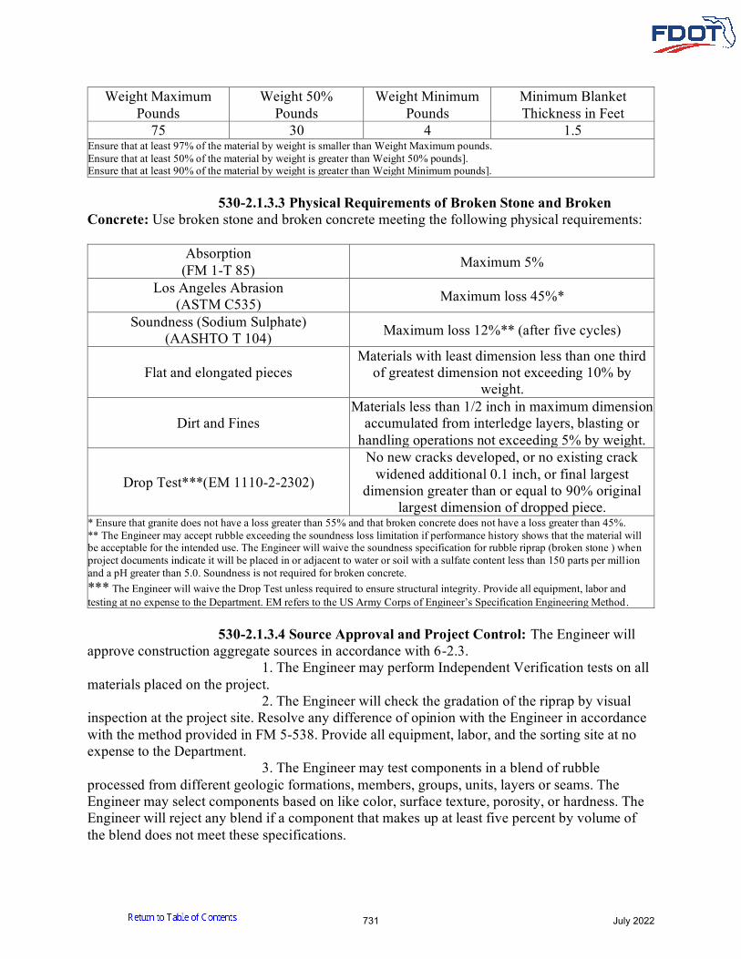
Weight Maximum Pounds
Weight 50% Pounds
Weight Minimum Pounds
Minimum Blanket Thickness in Feet
75 30 4 1.5 Ensure that at least 97% of the material by weight is smaller than Weight Maximum pounds. Ensure that at least 50% of the material by weight is greater than Weight 50% pounds]. Ensure that at least 90% of the material by weight is greater than Weight Minimum pounds]. 530-2.1.3.3 Physical Requirements of Broken Stone and Broken Concrete: Use broken stone and broken concrete meeting the following physical requirements:
Absorption (FM 1-T 85) Maximum 5%
Los Angeles Abrasion (ASTM C535) Maximum loss 45%*
Soundness (Sodium Sulphate) (AASHTO T 104) Maximum loss 12%** (after five cycles)
Flat and elongated pieces Materials with least dimension less than one third
of greatest dimension not exceeding 10% by weight.
Dirt and Fines Materials less than 1/2 inch in maximum dimension
accumulated from interledge layers, blasting or handling operations not exceeding 5% by weight.
Drop Test***(EM 1110-2-2302)
No new cracks developed, or no existing crack widened additional 0.1 inch, or final largest
dimension greater than or equal to 90% original largest dimension of dropped piece.
* Ensure that granite does not have a loss greater than 55% and that broken concrete does not have a loss greater than 45%. ** The Engineer may accept rubble exceeding the soundness loss limitation if performance history shows that the material will be acceptable for the intended use. The Engineer will waive the soundness specification for rubble riprap (broken stone ) when project documents indicate it will be placed in or adjacent to water or soil with a sulfate content less than 150 parts per million and a pH greater than 5.0. Soundness is not required for broken concrete. *** The Engineer will waive the Drop Test unless required to ensure structural integrity. Provide all equipment, labor and testing at no expense to the Department. EM refers to the US Army Corps of Engineer’s Specification Engineering Method. 530-2.1.3.4 Source Approval and Project Control: The Engineer will approve construction aggregate sources in accordance with 6-2.3. 1. The Engineer may perform Independent Verification tests on all materials placed on the project. 2. The Engineer will check the gradation of the riprap by visual inspection at the project site. Resolve any difference of opinion with the Engineer in accordance with the method provided in FM 5-538. Provide all equipment, labor, and the sorting site at no expense to the Department. 3. The Engineer may test components in a blend of rubble processed from different geologic formations, members, groups, units, layers or seams. The Engineer may select components based on like color, surface texture, porosity, or hardness. The Engineer will reject any blend if a component that makes up at least five percent by volume of the blend does not meet these specifications.
731 July 2022

530-2.1.4 Bedding Stone: Use Bedding Stone of either a durable quality limestone or other quarry run stone, with a bulk specific gravity of not less than 1.90 and that is reasonably free from thin, flat and elongated pieces. Ensure that the bedding stone is also reasonably free from organic matter and soft, friable particles. Meet the following gradation limits:
Standard Sieve Sizes - Inches Individual Percentage by Weight Passing
12 inches 100 10 inches 70 to 100 6 inches 60 to 80 3 inches 30 to 50 1 inch 0 to 15
The Engineer will conduct source approval and project control of bedding stone as specified in 530-2.1.3.4. In lieu of limestone or other quarry run stone, the Contractor may substitute non-reinforced concrete from existing pavement that is to be removed and which meets the above requirements for commercial bedding stone. 530-2.2 Articulating Concrete Block (ACB) Revetment Systems: Obtain all precast block, cabling, anchors, and necessary incidental materials from the same manufacturer. ACB revetment systems must meet the requirements of ASTM D6684, ASTM D7276 and ASTM D7277. Submit to the Engineer certification from the manufacturer that the ACB revetment system meets the requirements of this Section. ACB system components must meet the following requirements:
Concrete ...................................... Section 347, ASTM D6684 Cables and Fittings ........................................... ASTM D6684 Type D-2 Geotextile Fabric * .............................. Section 985 Granular Underlay ................................................ Section 901 *Use products listed on the Department’s APL.
Cables must maintain at least 85% of original tensile strength (ASTM D638) after 1,000 hours exposure to a saturated solution of calcium hydroxide (pH greater than or equal to 11) at 73°F, plus or minus three degrees. Cables must not exceed a maximum of 0.5% moisture absorption at seven days, per ASTM D570. Cable crimps must be aluminum or stainless steel Type 304 or 316. 530-2.3 Gabions: 530-2.3.1 General: Provide gabions meeting the requirements of ASTM A974 and ASTM A975 as modified herein.
732 July 2022

Allowable Gabion Wire and Connector Material Substructure Environmental Classification Polymeric Any Metallic Slightly Aggressive
Metallic – Galvanized and PVC coated Slightly Aggressive Moderately Aggressive
Metallic – Type 304 Stainless Steel, Size W1.4 (MW10) or larger
Slightly Aggressive Moderately Aggressive
Extremely Aggressive (< 2,000 ppm Chlorides)
Metallic – Type 316 Stainless Steel, Size W1.4 (MW10) or larger Any
530-2.3.2 Metallic Gabions: The components of metallic gabions must meet the following requirements:
Wire Mesh and Fabric* ..................... ASTM A974 and A975 Spiral Binders, Lacing Wire, Stiffeners, and Ring Wire Fasteners ............................................ ASTM A974 and A975 Stainless Steel Wire, Wire Fabric, and Lacing Wire ............. ........................................................................... ASTM A1022
*Wire mesh must be Style 1 or Style 3. Wire fabric must be Style 1 or Style 5. 530-2.3.3 Polymeric Gabions: Polymeric gabions must be constructed in general accordance with ASTM A974 using a single layer of structural geogrid instead of welded wire, and polymeric braid instead of ring wire fasteners. The structural geogrid must be Type R-1, 2, 3, 4, or 5 meeting the requirements of Section 985 and the following:
Tensile Strength @2% strain MD* ........................... 575 lb/ft Tensile Strength @ 2% strain XD** ......................... 575 lb/ft Junction Strength (% of Tensile Strength)...................... 90% Min UV Stability .............................................................. 85% Min. Carbon Black Content (by Weight) ..........................2% *MD = machine direction **XD = cross direction
Polymeric braid for seeming polymeric gabions or connecting metallic gabions must have a minimum tensile strength of 400 pounds for a 36 inch long specimen and contain at least 2% carbon black by weight. 530-2.3.4 Gabion Rock: Use rock meeting the requirements of ASTM D6711 to fill gabions. The rock must be reasonably free from thin, flat or elongated pieces. Rock size must be at least 1.25 times greater than the aperture size of the wire mesh or fabric. Each range of sizes may allow for a variation of 5% oversize rock by weight, 5% undersize rock by weight, or both.
Physical Property Requirements Acceptable Range
Los Angeles Abrasion and ASTM C535 Maximum loss 40% Bulk Specific Gravity Minimum 2.20
Absorption, ASTM C127 and ASTM C128 Maximum 3%
733 July 2022

530-2.3.5 Miscellaneous Components: Miscellaneous components for gabion installations must meet the following requirements:
Type D-2 Geotextile Fabric* ............................... Section 985 Granular Underlay ................................................ Section 901 Anchors .... Section 451 or manufacturer’s recommendations
*Use products listed on the Department’s APL.
530-3 Construction and Installation. 530-3.1 Geotextile Fabric: Overlap adjacent strips of fabric a minimum of 24 inches, and anchor them with securing pins (as recommended by the manufacturer) inserted through both strips of fabric along a line through the midpoint of the overlap and to the extent necessary to prevent displacement of the fabric. Place the fabric so that the upstream (upper) strip of fabric overlaps the downstream (lower) strip. Stagger vertical laps a minimum of 5 feet. Use full rolls of fabric whenever possible in order to reduce the number of vertical laps. Do not drop bedding stone or riprap from heights greater than 3 feet onto the fabric. 530-3.2 Sand-Cement Bags: 530-3.2.1 Placing: Place the bags with their ends all in the same direction. Lay the bags with broken joints, in a regular pattern. Ram or pack the bags against each other so as to form a close and molded contact. Remove and replace bags ripped or torn in placing with sound, unbroken bags. Then, thoroughly saturate all bags with water. 530-3.2.2 Grouting: Immediately after watering, fill all openings between bags with dry grout composed of one-part Portland cement and five parts sand. 530-3.2.3 Toe Walls: Use sand-cement bags for the toe walls if required. Fill the entire trench excavated for the toe walls with sand-cement bags. 530-3.3 Rubble: Dump rubble in place forming a compact layer conforming to the neat lines and thickness specified in the Plans. Ensure that rubble does not segregate so that smaller pieces evenly fill the voids between the larger pieces. 530-3.4 Bedding Stone: Place a minimum one foot thick layer of bedding stone under all rubble riprap without puncturing or tearing the geotextile fabric. The Engineer will allow an in place thickness tolerance of plus or minus one inch. Remove and replace geotextile fabric damaged as a result of operations at no expense to the Department. 530-3.5 Articulating Concrete Block (ACB) Revetment System: Install the ACB revetment system in accordance with ASTM D6884 and the manufacturer’s recommendations, unless directed otherwise by the Engineer. Prior to installation, construct the area to be stabilized to an elevation such that, upon completion of stabilizing operations, the completed stabilized subgrade will conform to the lines, grades and cross slope shown in the Plans. Bring the subgrade surface to a plane approximately parallel to the plane of the proposed finished surface, such that, upon placement of the mat, no individual block within the ACB mat will protrude more than one-half inch from any adjacent block. Uniformly compact each subgrade layer to achieve the density required in the Plans. If the Plans do not provide for stabilizing, compact the subgrade in both cuts and fills, to the density specified in ASTM D6884.
734 July 2022

Embed anchors at least six feet into the subgrade at a 45 degree angle into the bank with a minimum pullout resistance of 875 pounds. In the presence of the Engineer, perform on-site anchor strength testing to verify the required pull out resistance is achieved. Anchor strength testing must be performed on the first two and final two installed anchors, and randomly throughout the installation operation such that 5% of all installed anchors are tested for pullout resistance. If any anchor fails to meet the pullout resistance requirement, test every subsequent installed anchor until a revised installation plan is proposed and approved by the Engineer. Anchor spacing cannot exceed four feet. Immediately prior to placing the geotextile fabric and ACB system, inspect the prepared subgrade to ensure it is free of loose material and the surface is smoothly compacted. Place the geotextile fabric directly on the prepared area, in intimate contact with the subgrade and free of folds or wrinkles. Do not glue or physically bond the geotextile fabric to the ACB mat. Install a six inch thick layer of bedding stone under the geotextile fabric, when called for in the Plans. When installing ACB systems around curves, the mats shall be matched up to the greatest extent possible. Gaps greater than one block size shall be filled with a block and grouted the depth of the block with non-structural grout. Do not install blocks with chips that result in any block weighing less than 95% of the manufacture specified weight. 530-3.6 Gabions: Install double-twisted wire mesh gabions in accordance with ASTM D7014. Install welded wire fabric gabions and polymeric gabions in accordance with the manufacturer’s recommendations. Prior to installation, complete any required excavation and preparation of the foundation as shown in the Plans or as directed. Install soil anchors as specified in the Plans. All adjoining gabion units shall be connected along the perimeter of their contact surfaces to obtain a monolithic structure. If more than one tier, stagger the vertical joints of subsequent rows by one half cell length and adjoin the empty gabions to the top of the lower tier along the front and back edges of the contact surface. Fill gabions in a manner that minimizes voids, protects against local deformation of the basket or mattress and prevents damage to PVC coating. At no point in the filling process may rock be mechanically placed from a height of over 36 inches from machine to fill area. Uniformly overfill gabions by 1 to 2 inches to compensate for future rock settlements. Any damage to the basket, mattress, or coatings during assembly, placement, or filling shall be repaired promptly in accordance with the manufacturer’s recommendations or replaced with undamaged gabion baskets.
530-4 Method of Measurement. 530-4.1 Sand-Cement Bags: The quantity to be paid for will be the volume, in cubic yards, calculated from the minimum dimensions shown in the Plans or Standard Plans, satisfactorily placed and accepted. 530-4.2 Rubble and Bedding Stone: The quantities to be paid for will be the weight, in tons, in surface dry natural state, by railroad scales, truck scales, or barge displacement. The Contractor shall determine the weights as follows: 1. Railroad Weights: The Contractor shall weigh railroad cars on railroad scales, before and after loading or before and after unloading. If weighed by other than the Engineer, a
735 July 2022

certified statement of weights will be required. Certificates of weight, furnished by the railroad company, will be acceptable without further certification. 2. Truck Weights: The Contractor shall weigh trucks on certified scales, loaded and empty, as prescribed above for railroad weights. The Contractor shall weigh trucks in the presence of the Engineer, or submit certificates of weights. 3. Barge Displacement: The Engineer will measure each barge. The Contractor shall fit each barge with gauges graduated in 0.10 foot increments. The Contractor shall locate a gauge at each corner of the barge near the lower end of the rake. The Contractor shall furnish additional gauges amidships if the Engineer deems necessary. The Engineer will compute all weights. 530-4.3 Articulating Concrete Block (ACB) Revetment System: The quantity to be paid for will be the plan quantity, in square yards, completed and accepted, subject to the provisions of 9-3.2. No allowance will be made for ACB placed outside the Plan dimensions, unless the additional placement is ordered by the Engineer. 530-4.4 Gabions: For mattress type applications, the quantity to be paid for will be the plan quantity, in square yards, placed in the final locations. For stacked basket applications, the quantity to be paid for will be the plan quantity, in cubic yards, placed in the final locations.
530-5 Basis of Payment. 530-5.1 Sand-Cement: Price and payment will be full compensation for all work specified in this Section, including all materials, labor, hauling, excavation, and backfill. Include the cost of dressing and shaping the existing fills (or subgrade) for placing riprap in the Contract unit price for riprap (sand-cement). 530-5.2 Rubble: Price and payment will be full compensation for all work specified in this Section, including all materials, hauling, excavation, and backfill. Include the cost of dressing and shaping the existing fills (or subgrade) for placing riprap in the Contract unit price for riprap (rubble). As an exception to the above, concrete that is shown to be removed from an existing structure and subsequently disposed of by being used in the embankment as riprap will not be paid for under this Section. Include the cost of such work under removal of existing structures. 530-5.3 Bedding Stone: Price and payment will be full compensation for all work specified in this Section, including all materials and hauling. Include the cost of dressing and shaping the existing fills (or subgrade) for placing bedding stone in the Contract unit price for riprap (rubble). 530-5.4 Geotextile Fabric: Include the cost of materials and installation of the geotextile fabric, including any repairs or replacement, in the Contract unit price for riprap or ACB revetment system. 530-5.5 Articulating Concrete Block (ACB) Revetment System: Price and payment will be full compensation for all work specified in this Section, including all materials, labor, hauling, excavation and backfill. 530-5.6 Gabions: Price and payment will be full compensation for all work specified in this Section, including all materials, labor, hauling, excavation and backfill. 530-5.7 Payment Items. Payment will be made under:
Item No. 530- 1- Riprap Sand-Cement Bags - per cubic yard. Item No. 530- 3- Riprap (Rubble) - per ton.
736 July 2022

Item No. 530- 4- Articulating Concrete Block Revetment System - per square yard.
Item No. 530- 5- Gabion Item No. 530- 74- Bedding Stone - per ton.
737 July 2022

DIVISION III
Materials
AGGREGATES
SECTION 901 COARSE AGGREGATE
901-1 General.901-1.1 Composition: Coarse aggregate shall consist of naturally occurring materials
such as gravel, or resulting from the crushing of parent rock, to include natural rock, slags, expanded clays and shales (lightweight aggregates) and other approved inert materials with similar characteristics, having hard, strong, durable particles, conforming to the specific requirements of this Section.
Materials substantially retained on the No. 4 sieve, shall be classified as coarse aggregate.
Approval of mineral aggregate sources shall be in accordance with 6-2.3. 901-1.2 Deleterious Substances: All coarse aggregates shall be reasonably free of clay
lumps, soft and friable particles, salt, alkali, organic matter, adherent coatings, and other substances not defined which may possess undesirable characteristics. The weight of deleterious substances shall not exceed the following percentages:
Coal and lignite (AASHTO T 113) ................................. 1.00 Soft and friable particles (AASHTO T 112)* ................. 2.00 Clay lumps (AASHTO T 112)* ....................................... 2.00 Plant root matter (visual inspection in AASHTO T 27)**** ...................................................... 0.005 Wood and wood matter (visual inspection in AASHTO T 27)**** ...................................................... 0.005 Cinders and clinkers ......................................................... 0.50 Free shell** ....................................................................... 1.00 Total Material passing the No. 200 sieve (FM 1-T011) At Source with Los Angeles Abrasion less than or equal to 30 ................................................................................... 2.50 At Source with Los Angeles Abrasion greater than 30 ....................................................................................... 1.75 At Point of Use.................................................................. 3.75 Fine-Grained Organic Matter (AASHTO 194) ............... 0.03 Chert (less than 2.40 specific gravity SSD) (AASHTO T 113)*** ....................................................... 3.00 * The maximum percent by weight of soft and friable particles and clay lumps
together shall not exceed 3.00. ** Aggregates to be used in asphalt concrete may contain up to 5% free shell.
Free shell is defined as that portion of the coarse aggregate retained on the No. 4 sieve consisting of loose, whole, or broken shell, or the external skeletal remains of other marine life, having a
1001 July 2022

ratio of the maximum length of the particle to the shell wall thickness exceeding five to one. Coral, molds, or casts of other shells, and crushed clam and oyster shell indigenous to the formation will not be considered as free shell. *** This limitation applies only to coarse aggregates in which chert appears as an impurity. It is not applicable to aggregates which are predominantly chert. **** Plant root matter, and wood and wood matter shall be considered deleterious when any piece exceeds two inches in length or 1/2 inch in width. The weights of deleterious substances for reclaimed Portland cement concrete aggregate shall not exceed the following percentages:
Bituminous Concrete ........................................................ 1.00 Bricks ................................................................................. 1.00 Wood and other organic substances (by weight)*****.... 0.1 Reinforcing Steel and Welded Wire Reinforcement ........ 0.1 Plaster and gypsum board .................................................. 0.1 Joint Fillers .......................................................................... 0.1 ***** Supersedes requirement for other coarse aggregate
901-1.3 Physical Properties: Coarse aggregates shall meet the following physical property requirements, except as noted herein:
Los Angeles Abrasion (FM 1-T096) ..... maximum loss 45% Soundness (Sodium Sulfate) AASHTO T 104 ....................... ................................................................ maximum loss 12%* Flat or elongated pieces** .............................. maximum 10% * For source approval - aggregates exceeding soundness loss limitations will be rejected unless performance history shows that the material will not be detrimental for portland cement concrete or other intended usages. ** A flat or elongated particle is defined as one having a ratio between the maximum and the minimum dimensions of a circumscribing prism exceeding five to one.
901-1.4 Gradation: Coarse aggregates shall conform to the gradation requirements of Table 901-1, when the stone size is specified. However, Table 901-1 is waived for those aggregates intended for usage in bituminous mixtures, provided the material is graded on sieves specified in production requirements contained in 6-2.3, and meets uniformity and bituminous design requirements.
1002 July 2022
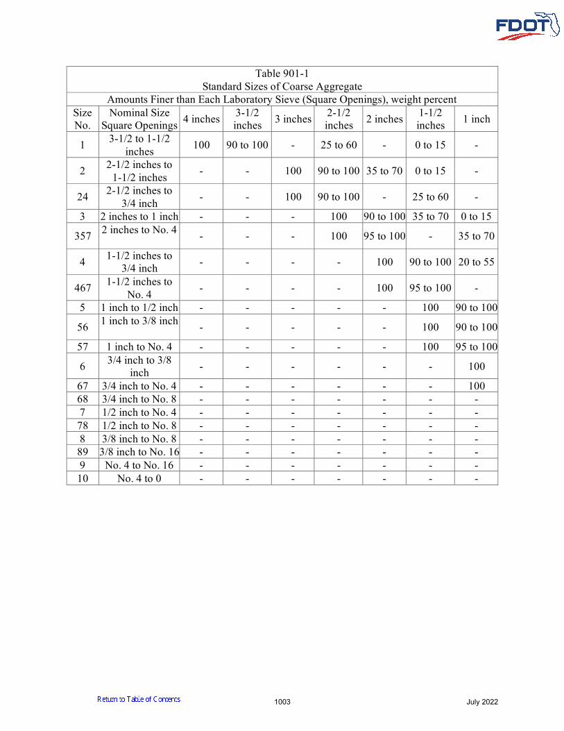
Table 901-1 Standard Sizes of Coarse Aggregate
Amounts Finer than Each Laboratory Sieve (Square Openings), weight percent Size No.
Nominal Size Square Openings 4 inches 3-1/2
inches 3 inches 2-1/2 inches 2 inches 1-1/2
inches 1 inch
1 3-1/2 to 1-1/2 inches 100 90 to 100 - 25 to 60 - 0 to 15 -
2 2-1/2 inches to 1-1/2 inches - - 100 90 to 100 35 to 70 0 to 15 -
24 2-1/2 inches to 3/4 inch - - 100 90 to 100 - 25 to 60 -
3 2 inches to 1 inch - - - 100 90 to 100 35 to 70 0 to 15
357 2 inches to No. 4 - - - 100 95 to 100 - 35 to 70
4 1-1/2 inches to 3/4 inch - - - - 100 90 to 100 20 to 55
467 1-1/2 inches to No. 4 - - - - 100 95 to 100 -
5 1 inch to 1/2 inch - - - - - 100 90 to 100
56 1 inch to 3/8 inch - - - - - 100 90 to 100
57 1 inch to No. 4 - - - - - 100 95 to 100
6 3/4 inch to 3/8 inch - - - - - - 100
67 3/4 inch to No. 4 - - - - - - 100 68 3/4 inch to No. 8 - - - - - - - 7 1/2 inch to No. 4 - - - - - - - 78 1/2 inch to No. 8 - - - - - - - 8 3/8 inch to No. 8 - - - - - - - 89 3/8 inch to No. 16 - - - - - - - 9 No. 4 to No. 16 - - - - - - - 10 No. 4 to 0 - - - - - - -
1003 July 2022

Table 901-1 (Continued) Standard Sizes of Coarse Aggregate
Amounts Finer than Each Laboratory Sieve (Square Openings), weight percent
Size No.
Nominal Size Square
Openings 3/4 inch 1/2 inch 3/8 inch No. 4 No. 8 No. 16 No. 50
1 3-1/2 inches to 1-1/2 inches 0 to 5
2 2-1/2 inches to 1-1/2 inches 0 to 5
24 2-1/2 inches to 3/4 inch 0 to 10 0 to 5
3 2 inches to 1 inch - 0 to 5
357 2 inches to No. 4 - 10 to 30 - 0 to 5
4 1-1/2 inches to 3/4 inch 0 to 15 - 0 to 5
467 1-1/2 inches to No. 4 35 to 70 - 10 to 30 0 to 5
5 1 inch to 1/2 inch 20 to 55 0 to 10 0 to 5
56 1 inch to 3/8 inch 40 to 85 10 to 40 0 to 15 0 to 5
57 1 inch to No. 4 - 25 to 60 - 0 to 10 0 to 5
6 3/4 inch to 3/8 inch 90 to 100 20 to 55 0 to 15 0 to 5
67 3/4 inch to No. 4 90 to 100 - 20 to 55 0 to 10 0 to 5
68 3/4 inch to No. 8 90 to 100 - 30 to 65 5 to 25 0 to 10 0 to 5
7 1/2 inch to No. 4 100 90 to 100 40 to 70 0 to 15 0 to 5
78 1/2 inch to No. 8 100 90 to 100 40 to 75 5 to 25 0 to 10 0 to 5
8 3/8 inch to No. 8 - 100 85 to 100 10 to 30 0 to 10 0 to 5
89 3/8 inch to No. 16 - 100 90 to 100 20 to 55 0 to 30 0 to 10 0 to 5
9 No. 4 to No. 16 - - 100 85 to 100 10 to 40 0 to 10 0 to 5 10 No. 4 to 0 - - 100 85 to 100 - - -
The gradations in Table 901-1 represent the extreme limits for the various sizes indicated which will be used in determining the suitability for use of coarse aggregate from all sources of supply. For any grade from any one source, the gradation shall be held reasonably uniform and not subject to the extreme percentages of gradation specified above.
1004 July 2022

901-2 Natural Stones. Coarse aggregate may be processed from gravels, granites, limestones, dolomite, sandstones, or other naturally occurring hard, sound, durable materials meeting the requirements of this Section. 901-2.1 Gravels: Gravel shall be composed of naturally occurring quartz, free from deleterious coatings of any kind. The minimum dry-rodded weight AASHTO T 19 shall be 95 pounds per cubic foot. Crushed gravel shall consist of a minimum of 85%, by weight, of the material retained on the No. 4 sieve, having at least three fractured faces. 901-2.2 Granites: Coarse aggregate produced from the crushing of granites shall be sound and durable. For granites to be used in bituminous mixtures and surface treatments, the Los Angeles Abrasion requirement of 901-1.3 is modified to permit a maximum loss up to 50 (FM 1-T096). Maximum amount of mica schist permitted is 5% (FM 5-584). 901-2.3 Limestones, Dolomite and Sandstone: Coarse aggregates may be produced from limestone, dolomite, sandstones, and other naturally occurring hard, durable materials meeting the requirements of this Section. When used as a friction course, crushed limestone shall have a minimum acid insoluble content of 12% (FM 5-510). Other materials must meet the approval requirements for friction course determined by Rule 14-103.005(1), Florida Administrative Code (FAC). Pre-Cenozoic limestones and dolomite shall not be used as crushed stone aggregates either coarse or fine for asphalt concrete friction courses, or any other asphalt concrete mixture or surface treatment serving as the final wearing course. This specifically includes materials from the Ketone Dolomite (Cambrian) Newala Limestone (Mississippian) geologic formations in Northern Alabama and Georgia. As an exception to the above, up to 20% fine aggregate from these materials may be used in asphalt concrete mixtures other than friction courses which serve as the final wearing course. 901-2.4 Cemented Coquina Rock: For cemented coquina rock to be used in bituminous mixtures, the Los Angeles Abrasion requirement of 901-1.3 is modified to permit a maximum loss up to 50 (FM 1-T 096) provided that the amount of material finer than No. 200 generated during the Los Angeles Abrasion test is less than 18%.
901-3 Manufactured Stones. 901-3.1 Slags: Coarse aggregate may be produced from molten nonmetallic by-products consisting essentially of silicates and aluminosilicates of calcium and other bases, such as air-cooled blast-furnace slag or phosphate slag, provided it is reasonably uniform in density and quality, and reasonably free from deleterious substances as specified in 901-1.2. In addition, it must meet the following specific requirements:
Sulphur content .................................................... not more than 1.5% Dry rodded weight AASHTO T 19 ...................... minimum 70 lb/ft3 Glassy Particles ..................................................... not more than 10% Slag shall not be used as an aggregate for Portland cement concrete. For air-cooled blast furnace slag, the Los Angeles Abrasion requirement of 901-
1.3 is modified to permit a maximum loss up to 50 (FM 1-T096) provided that the amount of material finer than No. 200 sieve generated during the Los Angeles Abrasion test is less than 18%.
1005 July 2022

901-4 Lightweight Aggregates. 901-4.1 Lightweight Coarse Aggregate for Bituminous Construction: Lightweight coarse aggregate may be produced from naturally occurring materials such as pumice, scoria and tuff or from expanded clay, shale or slate fired in a rotary kiln. It shall be reasonably uniform in quality and density, and free of deleterious substances as specified in 901-1.2, except that the term cinders and clinkers shall apply to those particles clearly foreign to the extended aggregate in question. In addition, it must meet the following specific requirements:
Material passing the No. 200 Sieve .................................. maximum 3.00%, (FM 1-T011) Dry loose weight (AASHTO T 19)* ....... 33-55 lb/ft3 Los Angeles Abrasion (FM 1-T096) . maximum 35% Ferric Oxide (ASTM C641) .......... maximum 1.5 mg
* Source shall maintain dry-loose unit weight within plus or minus 6% of Quality Control average. Point of use dry-loose unit weight shall be within plus or minus 10% of Source Quality Control average. 901-4.2 Lightweight Coarse Aggregate for Structural Concrete: The requirements of 901-4.1 are modified as follows: Aggregates shall not be produced from pumice and scoria. Los Angeles Abrasion (FM 1-T096, Section 12) shall be 45%, maximum. Gradation shall meet the requirements of AASHTO M 195 for 3/4 inch, 1/2 inch and 3/8 inch.
901-5 Recycled Concrete Aggregate (RCA). RCA shall be crushed and processed to provide a clean, hard, durable aggregate having a uniform gradation free from adherent coatings. RCA can be used as coarse aggregate in pipe backfill under wet conditions, underdrain aggregate, or concrete meeting the requirements of Section 347. RCA can only be used in bituminous mixtures if the RCA originated from a concrete mix which was produced and placed in accordance with Section 346. RCA shall be asbestos free. The Contractor’s (Producer’s) crushing operation shall produce an aggregate meeting the applicable gradation requirements. The physical property requirements of 901-1.3 for soundness shall not apply and the maximum loss as determined by the Los Angeles Abrasion (FM 1-T096) is changed to 50. The sources of reclaimed portland cement concrete will be treated as a mine and subject to the requirements of Section 6 and Section 105.
901-6 Exceptions, Additions and Restrictions. Pertinent specification modifications, based on material usage, will be found in other Sections of the specifications.
1006 July 2022

SECTION 902 FINE AGGREGATE
902-1 General.902-1.1 Composition: Fine aggregate shall consist of natural silica sand, screenings,
local materials, or subject to approval, other inert materials with similar characteristics, or combination thereof, having hard, strong, durable particles, conforming to the specific requirements of this Section.
Approval of construction aggregate sources shall be in accordance with 6-2.3. 902-1.2 Deleterious Substances: All fine aggregate shall be reasonably free of lumps of
clay, soft or flaky particles, salt, alkali, organic matter, loam or other extraneous substances. The weight of deleterious substances shall not exceed the following percentages:
Shale .................................................................................... 1.0 Coal and lignite ................................................................... 1.0 Cinders and clinkers ........................................................... 0.5 Clay Lumps ......................................................................... 1.0
902-2 Silica Sand.902-2.1 Composition: Silica sand shall be composed only of naturally occurring hard,
strong, durable, uncoated grains of quartz, reasonably graded from coarse to fine, meeting the following requirements, in percent total weight.
Table 902-1 Sieve Opening Size Percent Retained Percent Passing
No. 4 0 to 5% 95 to 100% No. 8 0 to 15% 85 to 100%
No. 16 3 to 35% 65 to 97% No. 30 30 to 75% 25 to 70% No. 50 65 to 95% 5 to 35% No. 100 93 to 100% 0 to 7% No. 200 minimum 96% maximum 4%
Silica sand from any one source, having a variation in Fineness Modulus greater than 0.20 either way from the Fineness Modulus of target gradations established by the producer, may be rejected.
902-2.2 Organic Impurities: Silica sand shall be subject to the colorimetric test fororganic impurities. If the color produced is darker than the standard solution, the aggregate shall be rejected unless it can be shown by appropriate tests that the impurities causing the color are not of a type that would be detrimental to portland cement concrete. Such tests shall be in accordance with AASHTO T 21 and AASHTO T 71. When tested for the effect of organic impurities on strength of mortar, the strength ratio at seven and 28 days, calculated in accordance with Section 11 of AASHTO T 71, shall not be less than 95%.
1007 July 2022

902-3 Sands for Miscellaneous Uses. 902-3.1 Anchor Bolts and Pipe Joints: Sand for setting anchor bolts, pipe joints or other similar uses shall meet the quality requirements of 902-2, except that gradation requirements are waived. 902-3.2 Brick Masonry: Sand for brick masonry shall meet the quality requirements of 902-2, except for gradation requirements. All the materials shall pass the No. 8 sieve, and be well graded from coarse to fine. 902-3.3 Sand-Cement Riprap: Sand for sand-cement riprap shall meet the quality requirements of 902-2, except for gradation requirements. The material shall meet the following gradation limits:
Table 902-2 Sieve Size Percent Passing
No. 4 minimum 97% No. 100 maximum 20% No. 200 maximum 5%
902-4 Filter Material for Underdrains. Silica sand for use as filter material for Types I through IV underdrains shall meet the requirements of 902-2, except that the requirements of 902-1.2 and 902-2.2 shall not apply. The aggregate shall be reasonably free of organic matter and other deleterious materials. The gradation requirements of 902-2.1 shall apply except no more than 2% shall pass the No. 200 sieve. Filter material for Type V underdrain shall meet the above requirements except that there shall be no more than 1% of silt, clay and organic matter, that the aggregate shall have a Uniformity Coefficient of 1.5 or greater, and that 10% diameter shall be No. 70 to 35 sieve. The Uniformity Coefficient shall be determined by the ratio D60 divided by D10, where D60 and D10 refer to the particle diameter corresponding to 60% and 10% of the material which is finer by dry weight.
902-5 Screenings. 902-5.1 Composition: Screenings shall be composed of hard, durable particles, either naturally occurring, such as gravel screenings, or resulting from the crushing or processing of the parent rock, to include natural rock, slags, expanded clays or shales (lightweight aggregates), or other approved inert materials with similar characteristics. Aggregates classified as screening shall conform to the following gradation requirements:
Table 902-3 Sieve Size Percent Passing
3/8 in. 100% No.4 75 to 100%
902-5.2 Specific Requirements: 902-5.2.1 Screenings from Department Approved Sources of Coarse Aggregate: Processed screenings from fully approved sources of coarse aggregate are subject to
1008 July 2022

gradation. Should coarse aggregate source approval status change, or unsatisfactory in-service history develop, additional control requirements may be implemented. Screenings for use in hot bituminous mixture may consist of screenings from the processing of reclaimed portland cement concrete pavement to produce coarse aggregate. 902-5.2.2 Screenings from Other Sources: Screenings, from sources other than Department Approved Sources of Coarse Aggregate, must meet the following additional general requirements:
Modified Los Angeles Abrasion: 95% statistical probability of meeting maximum loss of 23%.
Specific Gravity* Absorption* Soundness* Sulfur* Phosphate* Extraneous Substances*
*Specific specification requirements based on material usage found in appropriate Bituminous or Portland Cement Sections. Based on specific material characteristics, processing techniques and in-service history on Department projects, specific source requirements may be assigned. 902-5.2.3 Screenings for Use in Portland Cement Concrete: Screenings produced from either the Miami Oolite, Miami Ft. Thompson, or Loxahatchee Ft. Thompson Formations may be substituted for silica sand for use in concretes, except for concrete pavements, approach slabs, bridge decks and precast superstructure segments. (However, screenings will be permitted in the concrete when the bridge deck or approach slab is to be covered with an asphalt concrete surface course.) These screenings must meet the gradation requirements of AASHTO M 6, Section 6.1, as well as the maximum percent passing the No. 200 sieve, Fineness Modulus, and Organic requirements of 902-2 Silica Sand. In addition, the saturated, surface dry specific gravity shall be at least 2.48.
902-6 Local Materials. Local materials shall be composed of hard, strong, durable particles, either naturally occurring, such as natural sands, or resulting from the crushing or processing of parent rock, to include natural sand and rock, slags, expanded clays or shales (lightweight aggregate), or other approved inert materials with similar characteristics. Aggregates classified as local material shall conform to the following gradation requirements:
Table 902-4 Sieve Size Percent Passing
3/8 in. 100% No. 10 85 to 100% No. 200 maximum 15%
1009 July 2022

In addition to meeting the requirements of 902-1.2, the material shall not contain excessive quantities of other deleterious substances, such as roots, cans, debris, etc. If clay size material is present, it shall not exceed 7%, as determined by AASHTO T 88, and it shall be of a type which will not produce clay balls when used. The aggregate must be suitable for designated use, as determined by laboratory tests. If the deposit consists of stratified layers of varying characteristics and gradation, the producer shall employ such means as necessary to secure a uniform material. Local materials will not be required to be produced under the requirements of 6-2.3, provided they can meet the above requirements.
902-7 Lightweight Fine Aggregate for Internal Curing. Fine lightweight aggregate suitable for internal curing shall meet the requirements of ASTM C1761.
902-8 Exceptions, Additions and Restrictions. Other specification modifications, based on material usage may be found in the appropriate sections of the Specifications.
1010 July 2022

MATERIALS FOR PORTLAND CEMENT CONCRETE (STRUCTURAL, PAVEMENT, AND MISCELLANEOUS)
SECTION 921 PORTLAND CEMENT AND BLENDED CEMENT
921-1 General.Cement shall conform to the requirements of AASHTO M 85 or AASHTO M 240, as
applicable, except as provided in this Section. 921-1.1 Type of Cement: Cement may be Types I, II, II (MH), III, IV, V (as defined by
AASHTO M 85), or IL, IP, IS, IT (as defined by AASHTO M 240). Cement type shall be selected based on component and environmental conditions in accordance with Section 346. Different brands of cement, cement of the same brand from different facilities, or different types of cement shall be stored separately, identified, and shall not be mixed.
921-1.2 Heat of Hydration: The cement heat of hydration for Type II (MH), Type IT,and Type IL shall be tested in accordance with ASTM C1702 and reported at three days.
921-2 Definitions.The following definitions are applicable to the production and Quality Control (QC) of
cement: 1. Approved Laboratory: A laboratory that is currently inspected by the Cement
and Concrete Reference Laboratory (CCRL), is actively participating in the CCRL proficiency program and which has all deficiencies noted at the time of inspection corrected. The laboratory must also authorize CCRL to submit their inspection reports to the State Materials Office (SMO).
2. Cement Producer: A cement supplier, including but not limited to a plant, aterminal, or a transfer facility, that has been qualified by the SMO. The Cementitious Materials Production Facility Listing will be maintained by the SMO.
3. Mill Test Report: A certification from the cement supplier showing that thecement meets the requirements of Section 921. The mill test report must include, at a minimum, the following information:
a. The type of cement.b. The production period.c. Chemical and physical analysis of the cement.d. The silo identification where the cement is stored.e The base cement phase composition, except for blended cements.f. Amount of limestone and/or inorganic processing additions used,
expressed as a percentage of the cement mass, as applicable. g. The oxide composition of the limestone and/or inorganic processing
additions, as applicable. h. The specific gravity of cement reported as an average of the last twelve-
monthly tests, updated every six months. i. The heat of hydration at three days, as applicable.j. The approved laboratory that performed all tests.
An acceptable mill test report is available in the appendix of AASHTO M 85.
1023 July 2022

4. Purchaser: The term “purchaser” in the AASHTO requirements shall be taken as the Department.
921-3 Quality Control Program. 921-3.1 General: Develop a Producer QC Program as specified in Section 105. Cement producers shall submit a proposed QC Plan to the SMO for acceptance. Complete the Cementitious Materials Producer QC Plan Checklist (Appendix B02) and submit it along with the QC Plan, in a separate file. The checklist can be found on the SMO website: https://www.fdot.gov/materials/quality/programs/qualitycontrol/checklists/index.shtm. In addition to the QC Plan, the producer must submit monthly mill test reports from an approved laboratory which certifies that the cement in current production or supply conforms to the requirements of this Section. Cement producer with an accepted QC Plan will appear on the Cementitious Materials Production Facility Listing. QC test data that does not comply with the specification will not be a reason for rejection of the material if the cement producer’s QC Plan indicated that material will be diverted and not used for Department work. 921-3.2 Sampling and Testing: An approved laboratory shall perform one QC test per day. Mill test reports representing no more than one month’s production shall be submitted to the SMO on a monthly basis, for foreign cement, refer to 921-5. Representatives from the Department may take verification samples at the cement producer’s plant, terminal, distribution facility or the concrete production facility. Samples shall be obtained by one of the methods described in FM 5-503. Sample size shall be a minimum of one-gallon. At the concrete production facility, cement samples shall be jointly obtained by the Department inspector and the concrete producer’s representative. Upon request of the Department, the producer shall provide split samples of the cement collected for QC testing. Split samples shall be delivered to the SMO and shall be identified as representing a designated LOT of cement. Notification of failing verification sample test results will be distributed to the cement producer and concrete producer, if applicable. Split samples of the initial sample may be provided to the cement supplier and concrete producer upon request, as available. 921-3.3 Limestone and Inorganic Processing Additions: Producers intending to use limestone and/or inorganic processing additions as component materials in the production of cement shall describe the type, source, and the target amount, expressed as a percentage of cement mass. In addition, the producer shall display the information required in 921-2 on the mill test report. Samples of any pulverized limestone and/or inorganic processing additions shall be provided to the SMO for evaluation upon request.
921-4 Shipping and Storage. Cement shall be delivered in bags or in bulk. Portland cement from a producer on the Cementitious Materials Production Facility Listing shall be shipped on the basis of mill test reports meeting the requirements of this Section. Ensure that each shipment is accompanied by a delivery ticket that is traceable to the mill test report and includes, at a minimum, the following information: 1. FDOT Facility Identifier 2. Type of cement 3. Date shipped
1024 July 2022

4. Silo Identification The storage building, bin or silo shall be weatherproofed.
921-5 Foreign Cement Acceptance. Cement being imported from a foreign source shall conform to all requirements of this section and will be subject the following process: 1. The proposed QC Plan and the QC Plan Check list (Appendix B02) referenced in 921-3.1 shall be sent to the SMO and will include information regarding the QC, sampling, storage, and handling of the cement at the arrival terminal as well as the shipping control to and from the arrival terminal. In addition, the QC Plan from the foreign source shall be translated to English and will be included with the proposed QC Plan for the arrival terminal. 2. An initial one-gallon sample of the imported cement shall be sent to the SMO for chemical and physical verification testing. 3. When the first ship is being loaded from foreign source, a one-gallon verification sample will be obtained and shipped to the SMO for chemical and physical property testing. The material will be accepted for use on Department projects provided that the QC Plan has been accepted, and the results of the initial and verification samples have been confirmed to meet the requirements of this Section. Upon receiving the shipment of cement at the arrival terminal, the Department will be notified, and a Department representative may obtain another verification sample. Mill test reports representing each shipment shall be sent to the SMO.
921-6 Rejection of Material: The entire container which holds cement that does not meet the requirements of this Section or has been damaged, is partially set, lumpy or caked shall be rejected. Bagged cement which varies more than 5% from the designated weight, or if the average weight of 50 sacks, taken at random, is less than the designated weight, the cement shall be rejected.
1025 July 2022

SECTION 923 WATER FOR CONCRETE
923-1 General Requirements.Water for use with cement shall be clear and free from oil, and injurious amounts of acid,
alkali, chlorides, organic matter, and other deleterious substances. It shall not be salty or brackish. Water that contains quantities of substances which makes it discolored or smell unusual or objectionable, shall not be used unless approved by the Department. Water sources permitted include potable water supplies that are approved by a public health department, open bodies of water, well water, reclaimed water, and recycled water. Reclaimed water shall be as defined in Chapter 62-610, F.A.C. Open bodies of water are defined as naturally occurring rivers, lakes, and ponds. Recycled water includes wash water from mixer washout operations and stored in a lined settling pond. All other sources of water not listed above shall be considered recycled and reclaimed water.
923-2 Evaluation of Water for Concrete.923-2.1 General: Water from potable water supplies approved by a public health
department may be used without additional testing. The concrete producer shall submit test data of water samples from other sources. To determine chemical properties, the concrete producer shall use a laboratory accredited by the Construction Materials Engineering Council Accreditation Program including accreditation on referred chemical tests on Table 923-1 and 923-2.
923-2.2 Initial Sampling and Testing Frequency: Open bodies of water and well watershall be initially sampled once prior to use. Recycled and reclaimed water shall be tested once per week for four weeks initially, and thereafter once per month for four months prior to its use, provided that the results of the test samples comply with all the applicable limits. Failing test results will result in restarting initial sampling and testing.
923-2.3 Production Sampling and Testing Frequency: Open bodies of water andrecycled water shall be tested monthly. Well water and reclaimed water shall be tested once every three months. If the last eight consecutive well water and reclaimed water samples meet the requirements, then the sample frequency may be reduced to one sample every six months, as approved by the Department. If a well water or reclaimed water sample fails once the frequency has been reduced, then the sampling frequency shall revert to once every three months.
923-3 Chemical Requirements.923-3.1 Testing: All chemical analysis shall be performed in accordance with the test
methods listed in Tables 923-1 and 923-2 or equivalent Standard Methods for the Examination of Water and Wastewater (SM). Inorganic Anions (Chlorides and Sulfates) shall be determined simultaneously using SM 4110B Ion Chromatography or separately using SM 4500 Cl- B and SM 4500 SO42- E. ASTM D516 may be used as an alternative method for sulfates. The test method used shall be included in the concrete producer report.
923-3.2 Recycled and Reclaimed Water: Recycled and reclaimed water shall be testedbefore use and shall not exceed the limits in Table 923-1:
1026 July 2022

Table 923-1 Chemical Test Test Method Maximum (%) Total Solids SM 2540 B 5.00
Total Chlorides as Cl- SM 4500 Cl- B or SM 4110 B 0.05
Total Sulfates as SO42- ASTM D516 0.30 923-3.3 Open Bodies of Water and Well Water: Open bodies of water and well water shall be tested before use and shall not exceed the limits of Table 923-2:
Table 923-2
Chemical Test Test Method Maximum (%)
Alkalinity Calculated in terms of Calcium Carbonate SM 2320 B 0.05 Total Organic Solids SM 2540 E 0.05
Total Inorganic Solids SM 2540 E 0.08
Total Chlorides as Cl- SM 4500 Cl- B or SM 4110 B 0.05
923-4 Physical Requirements for Mortar. 923-4.1 General: To determine physical properties, use a laboratory accredited by the Construction Materials Engineering Council Accreditation Program or inspected by the Cement and Concrete Reference Laboratory. 923-4.2 Testing: Mortar shall be tested in accordance with ASTM C109 with the following exception: the mortar shall not be tested for flow. The mortar, composed of the sampled water, shall have a compressive strength of not less than 90% when compared to a mortar prepared using distilled water and tested at seven days. Water of a questionable quality, as determined by the Department, shall be subject to the acceptance criteria for time of set as required by ASTM C1602, Table 1.
1027 July 2022

SECTION 924 ADMIXTURES FOR CONCRETE
924-1 General.This Section covers admixtures for specific concrete applications. Admixtures shall
comply with applicable ASTM specifications and the requirements of this Section. Admixtures that have been previously qualified for Department use are listed on the Department’s Approved Product List (APL).
924-2 Acceptance of Admixtures.924-2.1 Approved Product List (APL): All admixtures must be listed on the
Department’s Approved Product List (APL). Manufacturers seeking evaluation of their products shall submit an application is accordance with Section 6 and include product data sheets, certified independent test data showing the product meets the requirements of this Section, safety data sheet (SDS), and a certification of the average solids content and specific gravity.
Admixtures shall meet the following requirements: Air-Entraining - ASTM C260 Type A Water-Reducing - ASTM C494 Type C Accelerating - ASTM C494 Type D Water-Reducing and Retarding - ASTM C494 Type E Water-Reducing and Accelerating - ASTM C494 Type F High Range Water Reducing - ASTM C494 Type G High Range Water-Reducing and Retarding - ASTM C494 Type I - Plasticizing - ASTM C1017 Type II - Plasticizing and Retarding - ASTM C1017 Type S Specific Performance - ASTM C494 and the performance
requirements of this Section. Corrosion Inhibitors – ASTM G109 and the requirements of this Section.
The inclusion of any specific product on the APL, as specified in 6-1, indicates that the product has been given contingent approval, as evidenced by previous tests and apparent effectiveness under field conditions.
Unless otherwise specified, no further testing will be required for any product on the APL unless there is indication in actual field use of inadequate or unreliable results.
924-2.2 Additional Requirements for Corrosion Inhibitors: Calcium nitrite is achemically reactive admixture used in concrete to inhibit the corrosion of embedded reinforcing steel and other metallic components. The calcium nitrite supplier shall submit to the Engineer test certificates from an independent laboratory indicating compliance with this Specification. The test certificate shall include corrosion inhibiting properties per ASTM G109 and results of physical tests included in this section. Calcium nitrite shall be supplied by the same manufacturing source throughout the project. If a single primary source of calcium nitrite cannot be maintained throughout the project, new test certificates shall be submitted. The Engineer will determine specification compliance of a new supplier’s product, and evaluate the effectiveness of the new calcium nitrite product before approving the source.
The active ingredient shall be calcium nitrite Ca(NO2)2. The calcium nitrite shall be furnished in solution containing not less than 29%
calcium nitrite solids. The concentration of the calcium nitrite solution shall be verified by
1028 July 2022

spectrophotometric analysis or other comparable methods. The nitrite concentration shall be measured in accordance with Standard Methods for the Examination of Water and Waste Water, 18th Edition. A volume of one gallon of calcium nitrite solution shall weigh within the range of 10.40 to 11.92 lb. The calcium nitrite solution shall be added to the concrete mixture at a rate of 4.50 to 4.60 gal/yd3 of concrete. The addition of calcium nitrite to the concrete mix shall not adversely affect the properties of fresh and hardened concrete. Calcium nitrite concrete shall meet the following physical requirements when mixed and tested in accordance with ASTM C494:
Table 924-1 Water Content, % of control 95 to 100 Time of setting, allowable deviation from control, h:min: Initial: at least not more than 1:00 earlier nor 1:30 later Final: at least not more than 1:00 earlier nor 1:30 later Compressive Strength, min. % of control: shall be 100 for all ages Flexural strength, min, % of control: shall be 100 for all ages
Length change, max Shrinkage (alternative requirements): % of control 135
Increase over control 0.010 Relative durability factor, min 80 The following table lists the corrosion inhibiting test result limits for calcium nitrite concrete tested in accordance with ASTM G109:
Table 924-2 Maximum Allowable Test Results of Calcium Nitrite Concrete
Measured average macrocell current any time during the test 10 μA Average macrocell current at test completion 2 μA
Average visible corrosion measured as percent corroded area of control 85% 924-2.3 Type S (Specific Performance): Trial batches shall use concrete meeting the requirements of ASTM C494. Additional trial batches may be required. Dosage rate shall be the same for all testing. 924-2.3.1 Workability Retention: Workability retention admixtures are used to extend workability and slump life without retarding the setting time. The dosage rate used shall be capable of maintaining 80% of the initial measured slump after 60 minutes. Perform an initial slump test, hold the trial batch in the mixer for 60 minutes, remix for 30 seconds and perform a second slump test. Workability retention shall be calculated as the percent difference in the initial slump and the slump at 60 minutes. 924-2.3.2 Shrinkage Reducing: Shrinkage reducing admixtures are used to minimize the shrinkage of plastic and hardened concrete. The dosage rate used shall reduce shrinkage a minimum of 50% after dry curing for 28 days. Shrinkage shall be determined in accordance with ASTM C157, except omit curing period in ASTM C157(10.3). Air storage for
1029 July 2022

the 28-day curing period shall be in accordance with ASTM C157(11.1.2). Shrinkage reduction shall be calculated as the percent difference in the control mix length change and the test mix length change. 924-2.3.3 Viscosity Modifying: Viscosity modifying admixtures are used primarily in flowing and self-consolidating concrete to maximize the rheology of plastic concrete and reduce segregation. The dosage rate used shall reduce static segregation to a minimum of 10%. A flowing concrete control mix shall be established by adding a compatible high range water-reducing or plasticizing admixture to increase the slump to 10 inches, plus or minus 0.5 inches. To establish the test mix, the control mix shall be reproduced with the addition of the viscosity admixture. The static segregation for both mixes shall be determined in accordance with ASTM C1610. Static segregation shall be calculated as the percent difference of the control mix static segregation to the test mix static segregation. 924-2.3.4 Rheology Modifying: Rheology modifying admixtures are used to maximize the rheology of plastic concrete. The dosage rate used shall be based on the manufactures recommendation and may vary for a specific application.
924-3 Retesting. The approved admixtures are required to be tested for their uniformity and equivalence whenever there is an indication of erratic results. The tests shall be performed in accordance with the following procedure. The admixture shall be checked for comparison between infrared spectrophotometry, pH value, specific gravity, and solids content. Any marked variation from the original curve, pH value, specific gravity, or solids content will be considered sufficient evidence that the chemistry of the original material has been changed and, therefore, the use of this material will be rejected and the material will be removed from the APL.
1030 July 2022

SECTION 925 CURING MATERIALS FOR CONCRETE
925-1 Burlap.Burlap for curing concrete shall consist either of two layers, each weighing 10 to
18 ounces/10 square feet, or of four layers, each weighing 6 to 7 ounces/10 square feet. Burlap which has been used as a container for sugar shall not be used. Burlap that is being used for the first time shall be thoroughly washed in order to remove starches used in sizing the material. Burlap shall be furnished in strips of at least 3 feet wide and shall be at least 3 feet longer than the width of surface to be covered.
925-2 Membrane-Forming Curing Compound.925-2.1 General: Membrane-forming curing compound shall conform to requirements of
ASTM C309 and the following requirements:
Table 925-1
Requirement Test Method Test Value
Water Loss@72 hours ASTM C156 0.55 kg/m2 Deleterious Reaction with Concrete ASTM C309 None
Reflectance ASTM E1347 60% minimum* Drying Time ASTM C309 4 hours maximum
Non-Volatile Content ASTM D1644 (Method A) (informational) Density, lbs/gal ASTM D1475 (informational)
*Type 2 (White) compounds only.
The membrane-forming curing compound shall be of a consistency suitable for spraying at temperatures prevalent at the time of application, and which forms a continuous, uniform film. It shall be free from precipitated matter caused by conditions of storage or temperature. Thoroughly agitate the curing compound in accordance with the manufacturer’s recommendations prior to shipment from manufacturer’s plant and prior to use at job site.
Curing compound delivered to the jobsite shall be in the manufacturer’s original container and clearly labeled with the following information:
1. manufacturer’s name2. product name (trade name)3. type4. batch or LOT number5. date of manufacture
925-2.2 Product Acceptance: Acceptance of membrane-forming curing compound shallbe based on the product being listed on the Department’s Approved Product List (APL).
925-2.2.1 Approved Product List: Manufacturers seeking evaluation of theirproduct must submit an application in accordance with Section 6 and include product data sheets, material safety data sheets (SDS) and certified test reports from an independent laboratory showing the product meets the requirements of this Section. Testing in accordance with the
1031 July 2022

National Transportation Product Evaluation Program (NTPEP) Project Work Plan for the Laboratory Testing of Liquid Membrane-Forming Compounds for Curing Concrete shall be acceptable as independent laboratory data. Include an Infrared Spectrophotometry (IR) Scan and a certification stating the nominal minimum percentage of non-volatile material for the product formulation. Deviation of the non-volatile material below this certified value shall be considered a change in formulation and shall be grounds for removal from the APL. 925-2.2.2 Certification: Prior to use, the Contractor shall submit to the Engineer a certification from the manufacturer conforming to the requirements of Section 6 that the requirements of this Section are met. 925-2.3 Product Life: Store the curing compound in accordance with the manufacturer’s recommendations. Curing compounds not used within one year of the date of manufacture shall not be incorporated into the work.
925-3 Sheet Materials. 925-3.1 General: Waterproof paper, polyethylene film and white burlap-polyethylene sheet, for curing concrete shall meet the requirements of ASTM C171, with the additional requirements for waterproof paper and for polyethylene film as shown below. 925-3.2 Additional Requirements for Waterproof Paper: The paper as prepared for use shall be in such dimensions that each unit as laid will extend at least 18 inches beyond the edges of the slab. If laid longitudinally, paper not manufactured in sizes which will provide this width shall be securely sewed or cemented together; the joints being sealed in such manner that they do not open up or separate during the curing period. At the option of the Contractor, instead of the single longitudinal strip specified above, the blanket may be furnished in three strips; one strip being the neat width of the pavement, with two side strips. 925-3.3 Additional Requirements for Polyethylene Sheeting: The sheets, as prepared for use, shall be of such dimensions that each unit as laid will extend beyond the edges of the slab by at least twice the thickness dimension of the pavement edge, and the sheets shall overlap by at least 18 inches. No sheet may be reused except after individual inspection and approval by the Engineer. Any sheets determined by the Engineer to be so damaged as to not afford the protection to the concrete in preventing moisture loss during the curing period will be rejected.
925-4 Certification. For burlap or white burlap-polyethylene, the Contractor shall submit to the Engineer a certification conforming to the requirements of Section 6 from the manufacturer confirming that the requirements of this Section are met. Each certification shall cover only one type of burlap or white burlap-polyethylene sheeting.
1032 July 2022

SECTION 926 EPOXY COMPOUNDS
926-1 Types of Compounds.Epoxy resin-based compounds for application to portland cement concrete, bituminous
cement concrete, metals and other type surfaces shall be applicable for the following types as designated. Products may only be used for applications recommended by the manufacturer.
Table 926-1 Type Description AB* An epoxy resin, for bonding fresh or hardened concrete to hardened concrete and
constructing doweled splices in precast prestressed concrete piles. E* A fluid epoxy for crack injection in the repair of old structures. F
F-1*F-2**
An epoxy for repairing spalled areas on concrete bridge structures with these subtypes: A non-sagging gel type for vertical surfaces. A pourable type for repairs where forms are to be used.
H** An epoxy for structural bonding where asphalt overlays are to be in contact with the hardened compound.
K* An epoxy for underwater sealing of the bottom of the jacket of an integral pile jacket system.
M*** A coal tar epoxy coating for steel sheet piles and H piles (water immersion) and hot applied coal tar epoxy tape.
PSE* A two-part epoxy system to match the cast faces of joints between precast segmental concrete superstructure and/or substructure segments.
Q* An epoxy for use in post tensioning anchorage protection systems. *Accepted by APL**Accepted by certified test report***Accepted by certification
926-2 Epoxy Design Requirements.926-2.1 General: All types of compounds, except for Type M, shall be thermosetting
containing no volatile solvent, and be pure reactive material. All types of compounds except for Type M shall have simple mix ratios of one to one, two to one, or shall be supplied in pre-proportioned containers in which all the contents are to be mixed.
All types of compounds shall be labeled with the manufacturer’s name, brand name, component type (resin, hardener or filler), mix ratio, mixing directions, date manufactured, shelf life, and the manufacturer’s LOT number. Potential hazards shall be stated on each package in accordance with the Federal Hazardous Products Labeling Act.
Certain terms used in this specification shall have these meanings: low modulus - the stress-strain property for which ultimate tensile strength
is attained at over 10% elongation. high modulus - the stress-strain property for which ultimate tensile
strength is attained at under 6% elongation. non-sagging gel - grades of mixed compounds which will not perceptibly
flow under their own weight on a vertical surface in the unhardened state. pourable - grades of mixed compound sufficiently fluid that they (either
neat or filled) can be cast into and will take the shape of a mold.
1033 July 2022

Fillers for mixing mortars and grouts shall be recommended by the manufacturer of the epoxy compound and supplied as packages accompanying the epoxy or premixed. 926-2.2 Approved Product List (APL): All epoxy materials shall be one of the products listed on the Department’s Approved Product List (APL) unless an alternative acceptance is identified in this Specification. Manufacturers seeking evaluation of their product shall submit an application in accordance with Section 6 and identify the epoxy type. Include with the submittal product data sheets, safety data sheets (SDS), and certified test reports from an independent laboratory showing the product meets the requirements of this Section. Manufacturers may submit performance test reports from the National Transportation Product Evaluation Program (NTPEP) as acceptable independent laboratory data. Upon request, submit product samples to the Department for confirmatory testing and Infrared (IR) analysis.
926-3 Specific Requirements for Type AB Epoxy Compounds. 926-3.1 Mixing and Application: Type AB epoxy compounds are used for bonding fresh or hardened concrete to harden concrete and constructing doweled splices in precast prestressed concrete piles. 926-3.2 Performance Tests: Meet the requirements of ASTM C881 Type IV and V, Class C, when tested at 73° ± 2° F.
926-4 Specific Requirements for Type E Compounds. Epoxies for crack injection shall meet the requirements of ASTM C881 Type IV compound with these additional requirements:
Table 926-2 Viscosity five minutes after mixing 300 to 600 cps at 77F by ASTM D2556
Wet bond strength to concrete, minimum 250 psi at seven days by FM 5-518
926-5 Specific Requirements for Type F Compounds. 926-5.1: Repairing Spalled Areas: Epoxies for repairing spalled areas shall meet the requirements in this Section. 926-5.2: Subtype F-1: Subtype F-1 epoxy is used for repairing vertical and other surfaces and shall be a trowelable low modulus, non-sagging gel epoxy compound capable of bonding to wet surfaces with these properties:
Table 926-3 Color Shall match gray color No. 36622 of FED-STD-595
Consistency Gel Maximum sand loading Recommended by the manufacturer Elongation in tension
minimum 10% by ASTM D638, seven-day cure
Wet bond to Steel and Concrete minimum 250 psi by Florida Test Method FM 5-518
1034 July 2022

926-5.3: Subtype F-2: Subtype F-2 epoxy is used for filling larger spalls where a form is required to build back to the original surface. Materials shall be a pourable low modulus type compound capable of bonding to wet surfaces with these properties:
Table 926-4 Color Shall match gray color No. 36622 of FED-STD-595-
Maximum sand loading Recommended by the manufacturer Elongation in tension,
minimum 10% by ASTM D638, seven-day cure
Exotherm 110F by ASTM D2471, 1 pint sample Wet bond strength 250 psi at seven days by FM 5-518
Type F-2 epoxy compounds will be accepted by certified test report. Submit to the Engineer testing from the manufacturer of the product for each LOT of material to be incorporated in the project. The test results will indicate that the material is in conformance with the Specifications, and will include actual values from the required tests. Obtain approval from the Engineer before incorporating material into the project.
926-6 Specific Requirements for Type H Compounds. Type H epoxies for structural bonding where bituminous pavement overlays will come in contact with the hardened compound shall meet the requirements for Types AB compounds above. Submit from the manufacturer test data showing that cutback and emulsified asphalts, asphalt cement, and bituminous mixes shall bond to but not soften or otherwise damage the epoxy after a curing period of four days. Type H epoxy compounds will be accepted by certified test report. Submit to the Engineer testing from the manufacturer of the product for each LOT of material to be incorporated in the project. The test results will indicate that the material is in conformance with the Specifications and will include actual values from the required tests. Obtain approval from the Engineer before incorporating material into the project.
926-7 Specific Requirements for Type K Compounds. Type K epoxies are used for sealing the bottom of integral pile jackets in the repair of concrete piles. These epoxies will be extended with the aggregate supplied by the manufacturer. The epoxy shall be factory pre-proportioned including factory supplied aggregate and meet the following requirements:
Table 926-5 Compressive strength at seven days, minimum by
ASTM C579B 4,500 psi
Bond Strength by FM 5-518 to wet concrete, minimum 250 psi
to wet pile jacket, minimum 150 psi Viscosity of mixed epoxy component at 77F,
five minutes by ASTM D2556 1,000-2,000 cps
1035 July 2022

The epoxy shall be capable of flowing through water in the void area of the jacket and hardening under water so as to provide a water tight seal of the depth indicated in the Plans or approved shop drawings and to maintain this seal during subsequent construction steps.
926-8 Specific Requirements for Type M Compounds. Type M Coal Tar epoxy coatings for steel sheet and H piles used in bridges, fender systems and other structures subject to immersion in water shall comply with the requirements of SSPC Paint 16 with Type 1 pitch. Application of the epoxy coating shall meet the requirements of Section 560 for a coal tar epoxy coating. Hot applied coal tar epoxy tape used to protect tie back rods on sheet pile walls and bulkheads shall comply with the requirements of American Water Works Association standard C203. Application shall be according to the manufacturers published recommendations. Submit to the Engineer a manufacturer certification, confirming that the coal tar epoxy meets the requirements of this Section. The certification shall conform to the requirements of Section 6. Do not incorporate these materials into the project until the Engineer has accepted and approved the certification for the material. Submit such certification for each LOT of material delivered to the project. In each certification, identify the serial or LOT numbers of the containers certified.
926-9 Specific Requirements for Type PSE Epoxy Compounds. Precast Segmental Epoxy (PSE) compounds are used for match-cast joints between precast concrete segments. Normal set PSE shall remain workable for a short open time (about one hour) and meet the requirements of ASTM C881, Type VI Grade 3. Slow set PSE shall remain workable over an extended open time (about eight hours), meet the requirements of ASTM C881, Type VII Grade 3, and have a compressive yield strength of 6,000 psi at 14 days. PSE compounds shall be factory pre-proportioned and formulated to provide application temperature ranges which are suitable for the erection of match cast segments with substrate temperatures between 40°F and 105°F with a minimum of at least two, but preferably three, formulations dividing the range into approximately equal subranges which overlap by at least 5ºF.
926-10 Specific Requirements for Type Q Compounds. Type Q epoxy compounds are used to protect the anchorages of post-tensioning tendons or bars and other uses indicated in the Plans. The material shall produce a low exothermic reaction and have flow and fill characteristics suitable for machine base plate applications. The material shall be factory pre-proportioned including factory supplied aggregate. Mix with the full aggregate loading unless the use of less aggregate is approved by the Engineer. The epoxy grout plus aggregate mix shall meet or exceed the specified physical properties stated herein as determined by the following standard ASTM test methods.
1036 July 2022

Table 926-6 Property Test Value Test Method
Compressive Strength at 7-day Cure at 77F 10,000 psi ASTM C579B
Tensile Strength at 7 days, Cure at 77ºF 2,100 psi ASTM C307
Flexural Strength at 7days Cure at 77ºF > 3,600 psi ASTM C580
Modulus of Elasticity 7 days Cure at 77ºF < 2,100,000 psi ASTM C580
Coefficient of Thermal Expansion at 74 to 210F
< 20 x 10 -6 in/in/ºF ASTM C531
Peak Exotherm, Specimen 12 x 12 x 3 in.
< 150ºF ASTM D2471
Slant Shear at 7 days (Bond Strength to Concrete) > 3000 psi FM 5-587
Thermal Compatibility 90% of control FM 5-609 Linear Shrinkage at 7 days 0.025% ASTM C531
Flowability and Bearing Area 90% Contact area ASTM C1339 Gel Time, Specimen
12 x 12 x 3 in. < 4:00 (hr.) ASTM D2471
1037 July 2022

SECTION 929 SUPPLEMENTARY CEMENTITIOUS MATERIALS
929-1 General.Supplementary cementitious materials (SCMs) shall conform to the requirements of this
Section. SCMs shall be used in concrete mix designs in accordance with Section 346. Repulpable bags may be accepted by the Engineer, provided a successful demonstration
by the producer has indicated complete degradation of the repulpable bags during the mixing operation and before the mix is discharged.
The Engineer may require additional testing beyond the requirements of this Section prior to the acceptance of any SCM sources.
929-1.1 Definitions.The following definitions are applicable to the production and quality control
(QC) of SCMs: 1. Approved Laboratory: A laboratory that is currently inspected by the
Cement and Concrete Reference Laboratory (CCRL), is actively participating in the CCRL proficiency program and has corrected all deficiencies noted at the time of inspection. The laboratory must authorize the CCRL to send a copy of the final inspection report and proficiency sample results to the State Materials Office (SMO).
2. SCM Producer: Indicates an SCM supplier, including but not limited toa plant, a terminal, or a transfer facility, that has been qualified by the SMO. The Cementitious Materials Production Facility Listing will be maintained by the SMO.
3. Test Report: A certification from the SCM producer showing that theSCM meets the requirements of this Section. The test report must include, at a minimum, the following information:
a. The Type of SCM.b. The production period.c. Chemical and physical analysis of the SCM.d. The silo numbers where the SCM is stored.e. The specific gravity of the SCM.f. The approved laboratory that performed all tests.
4. Purchaser: The term “purchaser” in the ASTM requirements shall betaken as the Department.
929-2 Quality Control Program.929-2.1 General: Develop a Producer QC Program as specified in Section 105.
SCM producers shall submit a proposed QC Plan to the SMO for acceptance. Complete the Cementitious Materials Producer QC Plan Checklist (Appendix
B02) and submit it along with the QC Plan, in a separate file. The checklist can be found on the SMO website: https://www.fdot.gov/materials/quality/programs/qualitycontrol/checklists/index.shtm.In addition to the QC Plan, the SCM producer must submit monthly test reports from an approved laboratory which certifies that the SCM in current production or supply conforms to the requirements of this Section.
SCM producers with an accepted QC Plan will appear on the Cementitious Materials Production Facility Listing.
1038 July 2022

QC test data that does not comply with the Specification will not be reason for rejection of the material if the SCM producer’s QC Plan indicates that material will be diverted and not used for Department projects. 929-2.2 Sampling and Testing: Representatives from the Department may take verification samples at the SCM producer’s plant, terminal, distribution facility or the concrete production facility. Samples shall be obtained by one of the methods described in FM 5-503. Sample sizes shall be a minimum of one gallon by volume. At the concrete production facility, cementitious samples shall be jointly obtained by the Department inspector and the concrete producer’s representative. Upon request of the Department, the SCM producer shall provide split samples of the cementitious material collected for QC testing. Split samples shall be delivered to the SMO and shall be identified as representing a designated LOT of the SCM. Notification of failing verification sample test results will be distributed to the SCM producer and concrete producers (if applicable). Split samples of the initial sample may be provided to the SCM producer and concrete producer upon request.
929-3 Fly Ash. 929-3.1 General: Sampling and testing of fly ash shall follow the requirements of ASTM C311. Fly ash shall not include the residue resulting from the burning of municipal waste or any other refuse with coal, or the burning of industrial or municipal waste in incinerators. 929-3.2 Fly Ash (Class F): Fly ash derived from the combustion of ground or powdered coal shall meet the requirements of ASTM C618 Class F fly ash. 929-3.3 Fly Ash (Class C): Fly ash derived from the combustion of ground or powdered coal shall meet the requirements of ASTM C618 Class C fly ash. 929-3.4 Acceptance Testing of Fly Ash: Acceptance of fly ash from sources operating under an accepted QC Plan shall be based on the monthly test reports meeting the chemical and physical requirements of ASTM C618 Class F or Class C and this Section. When the loss on ignition exceeds 5.0%, the Supplementary Optional Physical Requirements shall be mandatory. Fly ash meeting the requirements of ASTM C618 Class F may be used with no further testing. Petroleum coke, bark ash, or Class C fly ash may be used if the concrete test results provide an improvement or comparable compressive strength, sulfate resistance, corrosion protective properties and other durability requirements, when compared to concrete containing Class F fly ash. 929-3.4.1 Concrete/Mortar Testing: Six concrete mixes shall be prepared by an accredited laboratory, three control batches using an approved Class F fly ash and three comparison batches with petroleum coke, bark ash, or Class C fly ash, while all other constituents remain the same except for small adjustments to get the mix to yield. Follow the below criteria for each mix: 1. Use a previously approved FDOT Class IV (5,500 psi) mix design. 2. Size No. 57 Coarse Aggregate from an approved FDOT source. 3. 18 to 22% fly ash replacement. 4. Water/cementitious materials ratio of 0.41. The following testing shall be performed on each concrete mix, as appropriate.
1039 July 2022

Table 929-1 Concrete Testing Requirements
Test Description Standard Test Method Test Age
Surface Resistivity AASHTO T 358 28 days
Compressive Strength ASTM C39 28 days
Chloride Diffusion ASTM C1556 or NT Build 443 6 months, 12 months (1)
Length Change ASTM C157 28 days(2) (1) Upon completion of all 28 day and 6-month testing, the SCM producer may present the data to the SMO for acceptance. The12 month data shall be provided to the SMO upon completion. (2) Follow the Air Storage procedure.
Sulfate Resistance testing shall be performed on a mortar mix in accordance with ASTM C1012 and results reported after 6 and 12 months of testing.
929-4 Slag Cement. Slag cement (ground granulated blast furnace slag, GGBFS) is the quenched, ground by-product of the iron ore refinement process conducted in blast furnaces. It is primarily an amorphous material of calcium aluminosilicate constituents. 929-4.1 General: Slag cement and reference cement used for determination of slag activity tests shall meet the requirements of ASTM C989. Sampling and testing procedures shall follow the requirements of ASTM C989. 929-4.2 Acceptance Testing of Slag Cement: Acceptance of slag cement from sources operating under an accepted QC Plan shall be based on the monthly test reports meeting the chemical and physical requirements of ASTM C989 and this Section. The test report shall include: 1. For slag granules, provide X-ray Fluorescence (XRF) elemental analysis of the granules, presented in oxide form. Include CaO, SiO2, Al2O3, MgO, Mn2O3, TiO2, Fe2O3, and sulfur (as sulfide). 2. For slag cement, provide XRF elemental analysis, presented in oxide form. Include CaO, SiO2, Al2O3, MgO, Mn2O3, TiO2, Fe2O3, sulfur as sulfide (S), sulfate sulfur (SO3), and total sulfur as sulfate (SO3). 3. The results of all testing listed under Test Methods section of ASTM C989. 4. Indicate the amount of any additions introduced during grinding of the slag granules and report compliance with Section 6 of ASTM C989. a. Amount of limestone added and its CaCO3 content. b. Amount of other inorganic processing addition. 5. For calcium sulfate additions, indicate: a. Amount of calcium sulfate added. b. Form of calcium sulfate. c. SO3 content. d. Method used to determine the amount of calcium sulfate that was added. 929-4.2.1 Assessment of Sulfate Resistance: Following guidance in ACI 233R-17 Guide to the Use of Slag Cement in Concrete and Mortar, slag cements with Al2O3 contents
1040 July 2022

greater than 11% should be interground with calcium sulfate to avoid an undersulfated cementitious system. Provide ASTM C1012 data with a 50:50 portland cement-slag cement blend, using a Type II (MH) portland cement on the Department’s Production Facility Listing, with an alkali content of no more than 0.6%, when any of the following conditions occur: 1.The Al2O3 content of the slag cement is equal to or greater than 12%. 2. The slag cement is a blend of slag granules from more than one source that are interground during production of the slag cement and for which one or more of the following are true: a. The Al2O3 contents of both slag sources are equal to or greater than 12%. b. The average Al2O3 content of the blend is equal to or greater than 12%. c. One of the slag sources has an Al2O3 content that is equal to or greater than 14%. The Department will consider the ASTM C1012 data acceptable when the results indicate no more than 0.10% expansion at 12 months. The Department may grant provisional acceptance if the expansion does not exceed 0.05% at 6 months. For any slag cements with Al2O3 content equal to or greater than 12%, perform a retest of ASTM C1012 if the monthly test report indicates that any of the following conditions have occurred: 1. The Al2O3 content increases by greater than or equal to 1.0% of the content measured during qualification of the sulfate resistance. 2. The sulfate sulfur (SO3) content decreases by 0.25% less than that measured during qualification of the sulfate resistance. 3. The Blaine fineness increases by 50 m2/kg greater than that measured during qualification of the sulfate resistance. The Department may grant provisional acceptance of the slag cement source if ASTM C1012 data is required for any of the above retesting conditions.
929-5 Calcined Clay. 929-5.1 General: Sampling and testing of calcined clay shall follow the requirements of ASTM C311. Calcined clay shall meet the requirements of ASTM C618 Class N. 929-5.2 Acceptance Testing of Calcined Clay: Acceptance of calcined clay from sources operating under an accepted QC Plan shall be based on the monthly test reports meeting the chemical and physical requirements of ASTM C618 Class N and this Section. Calcined clay may be used in concrete if the test results provide an improvement or comparable compressive strength, sulfate resistance, corrosion protective properties, and other durability requirements of concrete, when compared to ASTM C618 Class F fly ash concrete. 929-5.2.1 Concrete/Mortar Testing: Six concrete mixes shall be prepared by an accredited laboratory, three control batches using an approved Class F fly ash and three comparison batches with the calcined clay, while all other constituents remain the same except for small adjustments to get the mix to yield. Follow the below criteria for each mix: 1. Use a previously approved FDOT Class IV (5,500 psi) mix design. 2. Size No. 57 Coarse Aggregate from an approved FDOT source. 3. Control batches: Replace 18 to 22% of the portland cement with Class F fly ash.
1041 July 2022

4. Comparison batches: Replace a portion of portland cement with a quantity of calcined clay sufficient to produce properties comparable to those for the control batches. 5. Water/cementitious materials ratio of 0.41 Testing shall be performed in accordance with Table 929-1. Sulfate Resistance testing shall be performed on a mortar mix in accordance with ASTM C1012 and results reported after 6, 12, and 18 months of testing.
929-6 Ground Glass. 929-6.1 General: Sampling and testing of ground glass shall follow the requirements of ASTM C311. Ground glass shall meet the requirements of ASTM C1866. Sampling and testing procedures shall follow the requirements of ASTM C1866. 929-6.2 Acceptance Testing of Ground Glass: Acceptance of ground glass from sources operating under an accepted QC Plan shall be based on the monthly test reports meeting the chemical and physical requirements of ASTM C1866 and this Section. Ground glass may be used in concrete if the test results provide an improvement or comparable compressive strength, sulfate resistance, corrosion protective properties, and other durability requirements of concrete, when compared to ASTM C618 Class F fly ash concrete. 929-6.2.1 Concrete/Mortar Testing: Six concrete mixes shall be prepared by an accredited laboratory, three control batches using an approved Class F fly ash and three comparison batches with the ground glass, while all other constituents remain the same except for small adjustments to get the mix to yield. Follow the below criteria for each mix: 1. Use a previously approved FDOT Class IV (5,500 psi) mix design. 2. Size No. 57 Coarse Aggregate from an approved FDOT source. 3. Control batches: Replace 18 to 22% of the portland cement with Class F fly ash. 4. Comparison batches: Replace a portion of portland cement with a quantity of ground glass sufficient to produce properties comparable to those for the control batches. 5. Water/cementitious materials ratio of 0.41. Testing shall be performed in accordance with Table 929-1. Sulfate Resistance testing shall be performed on a mortar mix in accordance with ASTM C1012 and results reported after 6, 12, and 18 months of testing.
929-7 Highly Reactive Pozzolans. 929-7.1 Silica Fume: 929-7.1.1 General: Silica Fume shall meet the requirements of ASTM C1240 using the referenced test methods and frequencies. 929-7.1.2 Acceptance Testing of Silica Fume: Acceptance of silica fume from sources operating under an accepted QC Plan shall be based on monthly test reports that the material meets the requirements of ASTM C1240 and this Section. 929-7.2 Metakaolin: 929-7.2.1 General: Metakaolin shall meet the requirements of ASTM C618 Class N with the following modifications: 1. The sum of SiO2 + Al2O3 + Fe2O3 shall be at least 85%. 2. The loss on ignition shall be less than 3.0%. 3. The available alkali’s, as equivalent Na2O, shall not exceed 1.0%.
1042 July 2022

4. The strength activity Index, at 7 days, shall be at least 85%. 929-7.2.2 Acceptance Testing of Metakaolin: Acceptance of metakaolin from sources operating under an accepted QC Plan shall be based on the monthly test reports meeting the chemical and physical requirements of ASTM C618 Class N, as modified herein, and this Section. 929-7.3 Ultra Fine Fly Ash: 929-7.3.1 General: Sampling and testing of the ultra fine fly ash shall follow the requirements of ASTM C311. Ultra fine fly ash derived from the combustion of ground or powdered coal shall meet the requirements of ASTM C618 as a Class F fly ash with the following modifications: 1. The pozzolanic activity index, at 7 days, shall be at least 85% of the control and the pozzolanic activity index, at 28 days, shall be at least 95% of the control. 2. The amount of material retained when wet-sieved on a 45-µm sieve shall be less than 6.0%. 3. The moisture content shall be less than 1.0%. 4. The loss on ignition shall be less than 2.0%. 929-7.3.2 Acceptance Testing of Ultra Fine Fly Ash: Acceptance of fly ash from sources operating under an accepted QC Plan shall be based on the monthly test reports meeting the chemical and physical requirements of ASTM C618 Class F fly ash and this Section. When the loss on ignition exceeds 2.0%, the Uniformity Requirements in the Supplementary Optional Physical Requirements shall be mandatory.
929-8 Shipping and Storage. SCMs may be delivered in bags or in bulk. SCMs from an SCM producer on the Cementitious Materials Production Facility Listing shall be shipped on the basis of test reports meeting the requirements of this Section. Ensure that each shipment is accompanied by a delivery ticket that is traceable to the test report and includes, at a minimum, the following information: 1. FDOT Facility Identifier 2. Type of material (e.g. Class F fly ash or Grade 120 slag) 3. Date shipped 4. Silo Identification The storage building, bin or silo shall be weatherproofed.
929-9 Foreign Supplementary Cementitious Material Acceptance. SCMs being imported from a foreign source shall conform to all requirements of this Section and will be subject the following process: 1. The proposed QC Plan shall be sent to the SMO and will include information regarding the QC, sampling, storage, and handling of the material at the arrival terminal as well as the shipping control to and from the arrival terminal. In addition, the QC Plan from the foreign source shall be translated to English and will be included with the proposed QC Plan for the arrival terminal. 2. An initial one gallon by volume sample of the imported SCM shall be sent to the SMO for chemical and physical testing. 3. When the first ship is being loaded from the foreign source, a one gallon by volume verification sample will be obtained and shipped to the SMO for chemical and physical property testing.
1043 July 2022

The material will be accepted for use on Department projects provided that the QC Plan has been accepted, and the results of the initial and verification samples have been confirmed to meet the requirements of this Section. Upon receiving the shipment of cement at the arrival terminal, the Department will be notified, and a Department representative may obtain another verification sample. Test reports representing each shipment shall be sent to the SMO.
1044 July 2022

SECTION 930 MATERIALS FOR CONCRETE REPAIR
930-1 Description.This Section covers cementitious materials used to repair concrete including defects or
purposely placed openings in concrete elements. Materials containing organic compounds, such as bitumen and epoxy resin as the principal binder are not included. The requirements for epoxy resin materials are covered in Section 926. Any depth larger than the manufacturer’s recommendation for the specific material shall be repaired with portland cement concrete meeting the requirements of Section 346.
930-2 Product Acceptance on the Project.930-2.1 Product Acceptance: Use only products listed on the Department’s Approved
Product List (APL). Manufacturers seeking evaluation of products must submit an application in accordance with Section 6 and include independently certified test reports that the material meets the requirements of this Section. The application package must describe detailed quality control requirements for installation including, but not limited to: maximum water to cementitious material ratio, formulation for two or more component systems, special materials and/or equipment, recommendations for all surface preparation, and curing requirements.
Provide the Engineer certification conforming to the requirements of Section 6 from the manufacturer confirming that the materials used meets the requirements of this Section and is the appropriate product for the intended use.
When specified in the Contract Documents, submit a report of test results from an independent laboratory on samples taken from material shipped. Ensure the test was performed within 45 days prior to the shipping date of the material.
930-2.2 Material Supply, Storage, and Marking: The material shall be pre-proportioned including aggregate. Deliver products in original, unopened containers with manufacturer’s name, date of manufacture, and clearly marked with all information described below. Store the material in an elevated dry and weather protected enclosure in full compliance with the manufacturer’s recommendations. Material must be used within manufacturer’s recommended shelf life.
The material from which the containers are made shall have water vapor transmission not greater than 100 g/m2 in 24 hours as determined in accordance with Procedure B of ASTM E96.
All containers shall be marked with the following information: 1. LOT identification number and material expiration date2. Directions for use shall include but are not limited to the following:
a. The type and kind of adhesive recommended (if any) to bond freshrepair material to the concrete or mortar being repaired.
b. The recommended amount of resin, other liquid component, or both, tobe mixed with the package contents.
c. The recommended length of mixing time or sequence of mixing andresting times in minutes.
3. Date the material was packaged.4. The yield in cubic feet or yield in ft2/in. thickness when mixed with the
recommended amount of liquid.
1045 July 2022

5. The net weight in each container. The contents of any container shall not vary by more than 2% from the weight stated in the declarations. The average weight of filled containers in a LOT shall be not less than the individual weight stated in the declarations. 6. Instructions for the maximum and minimum water (or solutions) to cementitious material ratio. 7. State the approximate working time. 930-2.3 Sampling, Mixing, and Additional Testing: A LOT is the packaged repair material normally placed on a pallet. A unit sample is a single container or package of material randomly selected from the LOT. Mix and install the materials in accordance with the manufacturer’s recommendations. Manufacturers will be required to provide field representation upon request by the Engineer. The Department reserves the right to conduct further field testing on any approved material. 930-2.4 Rejection: All broken containers will be rejected. Material that fails to meet any of the requirements of this Specification will be rejected. Report all materials failing to meet this specification and state the reasons for rejection in writing to the Engineer and the producer or supplier. Material in local storage in the hands of a vendor for more than six months after testing will be retested before use, except for the scaling resistance test and length change immersed in sulfate solution test for magnesium ammonium phosphate concrete. Retested material will be rejected if it fails to conform to any of the requirements of this Specification.
930-3 Laboratory Specimen Preparation. 930-3.1 Mixing and Fabrication: Mechanically mix the dry packaged materials with liquid components in accordance with the manufacturer’s recommendations. 930-3.2 Length Change: Make and cure the test specimens in accordance with ASTM C157, except omit the curing period in Section 10.3; however both 11.1.1 and 11.1.2 shall apply for 28 day curing period. 930-3.3 Manifestly Faulty Specimens: Visually examine each group of specimens representing a given test or a given age of test, including tests of freshly mixed concrete, before or during the test, or both, whichever is appropriate. Discard any specimen found to be manifestly faulty by such examination without testing. Visually examine all specimens representing a given test at a given age after testing, and should any specimen be found to be manifestly faulty the test results thereof shall be disregarded. Should more than one specimen representing a given test at a given age be found manifestly faulty either before or after testing, the entire test shall be disregarded and repeated. The test result reported shall be the average of the individual test results of the specimens tested or, in the event that one specimen or one result has been discarded, it shall be the average of the test results of the remaining specimens.
930-4 Materials for Repair of Predominately Horizontal Surfaces. 930-4.1 General: This material is intended to be used to repair concrete where the area to be treated will be on a horizontal surface. Examples of the type of locations for these materials are bridge decks, portland cement concrete pavements and other locations required by the Contract Documents. Follow the manufacturer’s recommendations for preparing the surfaces, mixing, placing, and curing the repair material unless otherwise directed in the Contract Documents. 930-4.2 Classification: The materials to be considered under this classification shall meet the following requirements:
1046 July 2022

930-4.2.1 Rapid Hardening: Moderate compressive strength for repairing concrete with an in-place compressive strength less than or equal to 4,000 psi. 930-4.2.2 Very Rapid Hardening: High compressive strength for repairing concrete with an in-place compressive strength greater than 4,000 psi. This material may be used in lieu of rapid hardening materials. 930-4.3 Physical Properties: The repair material shall meet or exceed the physical properties stated in Table 930-1 as determined by the specified test methods.
1047 July 2022

930-4.4 Specimen Preparation: 930-4.4.1 Flow/Slump: Testing for flow/slump will be completed in 15 minutes, plus or minus 1/2 minute, after the start of mixing liquid with the rapid hardening materials or 5 minutes, plus or minus 1/2 minute, after mixing the liquid with the very rapid hardening materials.
Table 930-1 Physical Properties of Repair Materials for Horizontal Surfaces
Requirement Test Method Rapid Hardening
Very Rapid Hardening
Minimum Compressive Strength, psi
3 hours
ASTM C39* or ASTM C109*
N/A 2,000
24 hours 2,000 4,000 7 days 4,000 6,000
28 days Greater than or equal to strength at 7 days.
Maximum Length Change, % Allowable expansion at 28 days when water cured compared to length at one
day ASTM C157**
0.12 0.12
Allowable shrinkage at 28 days when air cured compared to length at one day -0.12 -0.12
Allowable difference between increase in water and decrease in air 0.20 0.20
Minimum Slump (Concrete), inches ASTM C143*** 3 3
Minimum Flow (Mortar), % ASTM C1437*** 100 80
Time of Setting (Initial), minutes ASTM C191* or ASTM C403*
Minimum 30 10 to 29
Coefficient of Thermal Expansion, in/in/°F
ASTM C531* or AASHTO T 336
3.0x 10⁻⁶ to 9.0 x 10⁻⁶
3.0 x 10⁻⁶ to 9.0 x 10⁻⁶
Minimum Bond Strength by Slant Shear, psi 24 hours
FM 5-587 400 450
7 days Greater than or equal to strength at 24 hours.
Maximum Allowable Total Chlorides lb/yd3 FM 5-516 0.40
* as applicable ** Make and cure the test specimens in accordance with ASTM C157, except omit the curing period in Section 10.3; however both 11.1.1 and 11.1.2 shall apply for 28 day curing period. *** Testing for flow/slump will be completed in 15 plus or minus 1/2 minute after the start of mixing liquid with the rapid hardening materials or 5 plus or minus 1/2 minute after mixing the liquid with the very rapid hardening materials.
1048 July 2022

930-5 Materials for Repair of Predominately Vertical Surfaces. 930-5.1 General: This material is intended to be used to repair concrete where the area exposed in the field to be treated will be on a vertical surface. If an element has both horizontal and vertical surfaces, then the repair used will be for vertical surfaces. If it is not apparent which material is to be used, the vertical application will prevail. Examples of the type of locations for these materials are columns, caps, beams, piles, incidental concrete products, drainage structures and other locations required by the Contract Documents. Follow the manufacturer’s recommendations for preparing the surfaces and for mixing, placing and curing the repair material. 930-5.2 Classification: The materials to be considered under this classification shall meet the following requirements: 930-5.2.1 High Performance: Moderate compressive strength for repairing concrete with a designed compressive strength greater than or equal to 5,000 psi. 930-5.2.2 Ultra-high Performance: High compressive strength for repairing concrete with a designed compressive strength greater than 5,000 psi. These materials may be used in lieu of high performance vertical materials. 930-5.3 Physical Properties: The repair material shall meet or exceed the physical properties stated in Table 930-2 as determined by the specified test methods.
1049 July 2022

Table 930-2 Physical Properties of Repair Materials for Vertical Surfaces*
Requirement Test Method High Performance
Ultra-high Performance
Minimum Compressive Strength, psi 24 hours
ASTM C39** or ASTM C109**
1,000 2,000 7 days N/A 5,000
28 days 5,000 Greater than or
equal to strength at 7 days
Maximum Length Change, % Allowable expansion at 28 days when water cured compared to length at one
day ASTM C157** 0.12 0.12
Allowable shrinkage at 28 days when air cured compared to length at one day -0.08 -0.08
Maximum Slump (Concrete), inches ASTM C143 3**** 3**** Maximum Flow (Mortar), % ASTM C1437 100**** 100****
Time of Setting (Initial), minutes ASTM C191** or ASTM C403** 10 to 180**** 10 to 180****
Coefficient of Thermal Expansion, in/in/°F
ASTM C531*** or AASHTO T 336*** 3.0 x 10⁻⁶ to 9.0 x 10⁻⁶
Minimum Bond Strength by Slant Shear, psi, 24 hours FM 5-587 450 750 7 days 750. 750
Minimum Flexural Strength (at 7 days), psi ASTM C580 500 700
Maximum Absorption (Mortar at 7 days), % ASTM C413 4 4
Minimum Surface Resistivity (Concrete at 28 days), kohm-cm AASHTO T 358 N/A 22
Maximum Allowable Total Chlorides lb/yd3 FM 5-516 0.40
* Use cement-based materials modified with polymers and silica fume for extremely aggressive environments ** Make and cure the test specimens in accordance with ASTM C157, except omit the curing period in Section 10.3; however both 11.1.1 and 11.1.2 shall apply for 28 day curing period. *** As applicable **** For pump and pour applications, the maximum flow, slump and time of setting can be adjusted according to the manufacturer’s recommendation.
930-6 Material for Repair of Concrete in High Stress Concentration Areas. 930-6.1 General: This material is intended to be used to repair block-outs and voids in post-tensioned elements, load bearing area of a beam, and other locations required by the Contract Documents. This material may be used for the repair of horizontal or vertical surfaces. Follow the manufacturer’s recommendations for preparing the surfaces and for mixing, placing and curing the concrete. This material shall be a magnesium ammonium phosphate based concrete (MAPC) or a magnesium potassium phosphate based concrete (MPPC).
1050 July 2022

930-6.2 Physical Properties: The MAPC and MPPC materials shall meet or exceed physical properties stated in Table 930-3 as determined by the specified standard test methods.
Table 930-3 Physical Properties of Repair Material in High Stress Areas
Requirement Test Method Test Value Minimum Compressive Strength (at 28 days), psi ASTM C109* 8,500
Minimum Flexural Strength (at 28 days), psi ASTM C348* 600 Minimum Slant Shear Bond (at 14 days), psi FM 5-587* 2,500 Time of Setting (Initial), minutes ASTM C191** 15 to 60 Maximum Scaling Resistance ASTM C672 No scaling
Maximum Length Change, % Allowable expansion at 28 days when water cured compared to length at one day
ASTM C157*** 0.03
Allowable shrinkage at 28 days when air cured compared to length at one day -0.03
Maximum Allowable Total Chlorides lb/yd3 FM 5-516 0.40 * The test methods for compressive strength (ASTM C109), flexural strength (ASTM C348), and Slant Shear Bond (FM 5-587) shall be modified so that the specimens are air cured instead of moist cured. All of these samples shall be air cured until the time of testing.
** Initial time of set for MAPC or MPPC will be tested in accordance with ASTM C191 with the following modification. The initial time of set shall be tested at 95° plus or minus 5°F.
*** Make and cure the test specimens in accordance with ASTM C157, except omit the curing period in Section 10.3; however both 11.1.1 and 11.1.2 shall apply for 28 day curing period.
930-6.3 Curing of Compressive Strength, Flexural Strength and Slant Shear Bond Specimens: The test methods for compressive strength (ASTM C109), flexural strength (ASTM C348), and Slant Shear Bond (FM 5-587) shall be modified so that the specimens are air cured instead of moist cured. All of these samples shall be air cured until the time of testing.
930-7 Special Fillers. 930-7.1 General: This material is intended to be used as filler material and for rapid repairs to pile jacket structures and other locations specified in the Plans. Meet the requirements of the contract documents for preparing the surfaces, placing, sampling, testing, and curing the concrete. Mix the material in accordance with the manufacturer’s recommendations. 930-7.2 Classification: The materials to be considered under this classification shall meet the following requirements: 930-7.2.1 Cathodic Protection (CP) Filler: Provide cementitious based materials with a minimum cement content of 900 pounds of cement per cubic yard of mix. Material formulation must not contain fly ash, slag, silica fume or other mineral admixtures which may produce increased electrical resistance. The material shall not contain any substances corrosive to metals.
1051 July 2022

930-7.2.2 Non-Cathodic Protection (Non-CP) Filler: Provide cementitious based materials with a minimum cement content of 650 pounds of cement per cubic yard of mix. The material shall not contain any substances corrosive to metals. 930-7.2.3 Extended Materials: Where concrete filler materials are specified, approved mortar materials may be extended using size number 89 gradation aggregates from a certified FDOT approved source. 930-7.3 Physical Properties: The repair material shall meet or exceed the physical properties stated in Table 930-4 as determined by the specified standard test methods. If extended, materials shall meet the minimum requirements of Table 930-4. 930-7.4 Constructability: Submit to the Engineer for approval shop drawing as may be required to complete repairs in compliance with the design shown in the Plans and the manufacturer’s recommended repair system.
Table 930-4 Physical Properties of Special Fillers
Requirement Test Method Cathodic Protection
Non-Cathodic Protection
Minimum Compressive Strength, psi 24 hours ASTM C39* or
ASTM C109* 1,500 2,000
28 days 5,000 5,000 Maximum Length Change, %
Allowable expansion at 28 days when water cured compared to length at one day
ASTM C157**
0.12 0.12
Allowable shrinkage at 28 days when air cured compared to length at one day -0.12 -0.12
Allowable difference between increase in water and decrease in air 0.20 0.20
Slump (Concrete), inches ASTM C143 7-9 7-9 Minimum Flow (Mortar), % ASTM C1437 100 100
Time of Setting (Initial), minutes ASTM C191* or ASTM C403* 200 to 400 200 to 400
Minimum Bond Strength by Slant Shear (at 7 days), psi FM 5-587 450 450
Minimum Flexural Strength (at 7 days), psi ASTM C580 700 700 Minimum Tensile Strength (at 7 days), psi ASTM C307 200 200 Surface Resistivity (at 28 days), kohm-cm AASHTO T 358 15 or less 22 or greater Maximum Allowable Total Chlorides lb/yd3 FM 5-516 0.40
* as applicable
** Make and cure the test specimens in accordance with ASTM C157, except omit the curing period in Section 10.3; however both 11.1.1 and 11.1.2 shall apply for 28 day curing period.
1052 July 2022

ACCESSORY MATERIALS FOR CONCRETE PAVEMENT AND CONCRETE STRUCTURES
SECTION 931 METAL ACCESSORY MATERIALS FOR
CONCRETE PAVEMENT AND CONCRETE STRUCTURES
931-1 Reinforcement Steel (for Pavement and Structures).931-1.1 Steel Bars:
931-1.1.1 Carbon Steel Bars: Carbon steel bars for concrete reinforcement shallconform to the requirements of ASTM A615 Grades 60 or 80.
931-1.1.2 Stainless Steel Bars: Stainless steel bars for concrete reinforcementshall conform to the requirements of ASTM A955, Grades 60 or 75; or ASTM A276, UNS S31653 or S31803.
931-1.1.3 Low-Carbon Chromium Steel Bars: Low-carbon chromium steel barsfor concrete reinforcement shall conform to the requirements of ASTM A1035 Grade 100.
931-1.1.4 Special Requirements: The following special requirements shallapply:
1. Unless otherwise specified or shown in the Plans all reinforcing barsNo. 3 and larger shall be deformed bars.
2. Twisted bars shall not be used.3. Wherever in the Specifications the word “purchaser” appears it shall be
taken to mean the Department. 931-1.1.5 Acceptance of Steel Bars: Acceptance of reinforcing steel shall be
based on the manufacturer being on the National Transportation Product Evaluation Program (NTPEP) list of compliant producers, samples taken by the Department, and manufacturer’s certified mill analysis. The test results shall meet the specification limits of the ASTM or AASHTO designation for the size, grade and any additional requirements. The manufacturer’s certified mill analysis for each heat, size, and grade per shipment of reinforcing steel shall be provided to the Engineer prior to use.
The Engineer will select samples representing each LOT of reinforcing steel. A sample is defined as the reinforcing steel and the certified mill analysis corresponding to the sample. A LOT is defined as the weight of all bars, regardless of size, grade or pay item in consecutive shipments of 100 tons or less. Samples shall be cut from bundled steel that is shipped to the jobsite.
Projects with less than two tons of bars do not require Department sampling.
931-1.2 Wire Reinforcement:931-1.2.1 Carbon Steel Wire Reinforcement: Plain and deformed carbon steel
wire reinforcement shall meet the requirements of ASTM A1064. Deformed carbon steel wire shall be Grade 75.
931-1.2.2 Stainless Steel Wire Reinforcement: Plain and deformed stainlesssteel wire reinforcement shall meet the requirements of ASTM A276, UNS S30400.
931-1.2.3 Acceptance of Wire Reinforcement: Acceptance of wirereinforcement shall be based on the manufacturer’s certified mill analysis certifying that the test results meet the specification limits of the ASTM designation for the sizes and any additional
1053 July 2022

requirements. Prior to use, submit to the Engineer the manufacturer’s certified mill analysis for each heat and size per shipment. 931-1.3 Carbon Steel Welded Wire Reinforcement: 931-1.3.1 Carbon Steel Welded Wire Reinforcement: Welded wire reinforcing steel shall meet the requirements of ASTM A1064. 931-1.3.2 Acceptance of Carbon Steel Welded Wire Reinforcement: Acceptance of welded wire reinforcement shall be based on the manufacturer’s certified mill analysis certifying that the test results meet the specification limits of the ASTM designation for the sizes and any additional requirements. Prior to use, submit to the Engineer the manufacturer’s certified mill analysis for each heat and size per shipment. 931-1.4 Couplers for Steel Bars: 931-1.4.1 Approved Product List (APL): The couplers used shall be a product included on the Department’s APL. Manufacturers seeking approval of their product shall demonstrate the performance of their product in accordance with the requirements in 931-1.4.2 through 931-1.4.4 as applicable and 931-1.4.5. 931-1.4.2 Couplers for Carbon Steel Bars: Couplers for use with carbon steel bars shall be fabricated from an alloy that is electrochemically compatible with bars that meet the requirements of 931-1.1.1. 931-1.4.3 Couplers for Stainless Steel Bars: Couplers for use with stainless steel bars shall be fabricated from an alloy that is electrochemically compatible with bars that meet the requirements of 931-1.1.2. 931-1.4.4 Couplers for Low-Carbon Chromium Steel Bars: Couplers for use with low-carbon chromium steel bars shall be fabricated from an alloy that is electrochemically compatible with bars that meet the requirements of 931-1.1.3. 931-1.4.5 Special Requirements: Couplers shall develop at least 125% of the specified yield strength of the bar being spliced.
931-2 Metal Materials for Joints in Concrete Pavement. 931-2.1 Sheet Metal Bottom Strips: For concrete pavement using the special select soil base option, the sheet metal strip for protecting the bottom and side edges of transverse expansion joints shall be composed of galvanized sheet metal of 0.0157 inches minimum thickness and shall conform to the requirements of ASTM A653. The sheets shall be furnished in accordance with the dimensions shown in the Plans. They may be in one continuous piece, or spliced. When splicing is used the metal shall be lapped not less than 3 inches and securely fastened, by welding or otherwise, in such manner as to leave the spelter undamaged and produce a smooth sliding surface in contact with the pavement slab. The splices shall be spaced not less than 10 feet apart and not less than 5 feet from either end. The complete sheet shall not vary from a straight line by more than 1 inch from end to end. The Contractor shall submit to the Engineer a certified mill analysis from the manufacturer of the sheet metal bottom strips including test results for thickness, dimension, grade, length, size, and spacing. Each certified mill analysis shall cover only one type of metal material for joints. 931-2.2 Bars and Chairs for Longitudinal Joints: Transverse reinforcing steel across the joint shall be deformed steel bars conforming to the requirements of 931-1.1 except that the bars may be any grade shown in ASTM A615.
1054 July 2022

These bars, and the chairs to hold them in place, shall be of the type and spacing as indicated in the Plans. 931-2.3 Dowel Bars: Dowel bars must meet the requirements of Table 931-1. They shall be of the length, size and spacing as shown in the Plans. The Contractor shall submit to the Engineer a certified test report from the manufacturer of the dowel bars confirming that the requirements of this Section are met. The certified test report shall conform to the requirements of Section 6 and include metallurgical mill analysis, grade, length and size. Each certification shall cover only one LOT for dowel bars. 931-2.4 Chairs and Metal Expansion Caps: The chairs and metal expansion caps shall be of an approved type as shown in the Plans. Dowel bars for expansion joints shall have a metal cap on one end so placed to provide ample space for movement of the slab. Continuous sleeves covering one half of the length of the bar will not be permitted. Other fasteners may be approved. Dowel bars shall be coated with an approved material to break the bond.
931-3 Metal Dowel Bar Assemblies for Joints in Concrete Pavement. 931-3.1 Approved Product List (APL): The dowel bars and basket assembly must meet the requirements of Table 931-1 and shall be a product included on the Department’s APL. Manufacturers seeking evaluation of their product shall submit an application in accordance with Section 6 and shall submit product photo and drawings, technical data sheets, and certifications that demonstrate the performance of their products in accordance with the requirements in 931-3.1 thru 931-3.5.
Table 931-1 Material Requirement for Dowel Bar and Basket Assemblies Component Base Metal Coating
Dowel Bar ASTM A615 ASTM A775 or SSPC Paint 20
Wire Basket Assembly ASTM A1064
ASTM A775 or SSPC Paint 20 or
Primer with ≥ 40% Solids (by weight) Produce dowel bars coated in the shop. Wire basket assemblies may be coated in the shop or the field. For welded wire basket assemblies fabricated after coating, apply touch-up coating in the shop or field over all welded connections. All field applied coatings must have a volatile organic compound (VOC) content ≤ 420g/L. 931-3.2 Rigidity: The dowel bars shall be supported by an approved welded assembly possessing sufficient rigidity to hold the dowel bars in position to such accuracy that error or deviation from its required position in any bar in the entire installation after the pavement has been finished shall be no greater than 1/2 inch. The assembly shall have continuous parallel spacer bars and two continuous parallel bearing members of no less than 1/4 inch diameter wire. One spacer bar shall be located at or near each end of the dowel. Alternate ends of dowels shall be welded to a spacer bar in such a manner as to maintain the dowels parallel to each other and permit sliding movement in the joint.
1055 July 2022

The free ends of each dowel shall be retained securely in place by means of wire loops or metal tubes welded to the other spacer bar. An expansion cap shall be installed on one end of each bar if the dowels are being used in an expansion joint. Suitable struts or ties shall be provided to hold the assembly in correct position during installation. The assembly shall have an upright support welded to the spacer bar and continuous bearing member at the end of each dowel and a continuous bearing member. If the upright support consists of a single vertical wire, the support shall be no less than 5/16 inch diameter wire. Otherwise, the support shall be no less than 1/4 inches in diameter. 931-3.3 Sand Plates: Sand plates, if required, shall be made from no less than 3/8 inch sheet steel. Each plate shall have no less than 0.1 square feet of bearing area. The plates shall be furnished in sufficient number to provide uniform support for the complete assembly. They may be furnished separate from the assembly units or attached thereto by welding, suitable clips, or other approved means. 931-3.4 Welds: The welds of the assembly shall be made securely. A broken weld will be cause for rejection of the length of section of the assembly where it occurs. 931-3.5 Assembly Placement: When the dowel bar assembly is in place, it shall act as a rigid unit with each component part securely held in position relative to the other member of the assembly. The entire assembly shall be held securely in place during placing, consolidating, and finishing the concrete by means of metal pins. Pins used on granular subbase or cold mixed bituminous stabilized subbase shall penetrate at least 12 inches below the dowel bar assembly. The pins shall be of no less than 1/4 inch diameter wire and shall be provided with a hook or arm welded to the pin in such a manner that it shall secure the assembly in place. Nail securing systems may be used as an anchoring device on hot bituminous stabilized subbase. The nail shall be no less than 1/8 inch in diameter, no less than 2 inches in length and the nail head or attached washer shall be not less than 1/2 inch outside diameter. The nail shall be driven through both ends of a metal strap after it has been placed around one of the lower transverse bars on the dowel bar assembly. At least eight pins or nails shall be used for each 12 foot section (a lane width) of assembly. Sand plates, if required, shall be drilled to receive the pins. The Contractor shall provide the equipment and personnel necessary to verify dowel bar location after the concrete is placed and has received the initial screeding.
931-4 Wire for Site Cage Machines. The wires for site cage machines shall meet the requirements of ASTM A1064 or ASTM A706.
1056 July 2022

SECTION 932 NONMETALLIC ACCESSORY MATERIALS
FOR CONCRETE PAVEMENT AND CONCRETE STRUCTURES
932-1 Joint Materials.932-1.1 Preformed Joint Filler for Pavement and Structures: Preformed joint filler
shall meet the requirements of AASHTO M 153, ASTM D8139, AASHTO M 213, or cellulose fiber types meeting all the requirements of AASHTO M 213 (except for the asphalt content) is acceptable provided they contain minimums of 0.2% zinc borate as a preservative and 1.5% waterproofing wax. For AASHTO M 153, unless a particular type is specified, either Type I, Type II or Type III may be used.
Preformed joint fillers shall have a thickness equal to the width of the joint required, and shall be furnished in lengths equal to the widths of the slabs in which they are to be installed, except that strips which are of a length not less than the distance between longitudinal joints, or between longitudinal joint and edge, may be used if laced or clipped together in a manner approved by the Engineer. The depth and shape of the joint filler shall conform to the dimensions shown in the Plans. For doweled joints, proper provision shall be made for the installation of the dowels.
932-1.1.1 Certification: The Contractor shall submit to the Engineer acertification confirming that the preformed joint filler meets the requirements of this Section. The certification shall conform to the requirements of Section 6.
932-1.2 Joint Sealer for Pavement and Structures:932-1.2.1 General: This Specification covers joint sealer intended for use in
sealing joints in asphaltic concrete pavement and portland cement concrete pavement. These materials may also be used to seal joints in portland cement concrete bridges and other structures.
932-1.2.2 Material: The joint sealant shall be composed of a mixture ofmaterials, typically but not limited to bituminous based, that will melt when heated for application and then solidify to form a resilient and adhesive compound capable of sealing joints in portland cement concrete and asphaltic concrete against the infiltration of moisture and foreign materials throughout normal pavement conditions and at ambient temperatures. The manufacturer shall have the option of formulating the material according to their Specifications. However, the requirements delineated in this Specification shall apply regardless of the type of formulation used. The material shall cure sufficiently to not flow from the joint or be picked up by vehicle tires after 3 hours at 77°F. The material shall be capable of a uniform application consistency suitable for filling joints without the inclusion of large air holes or discontinuities and without damage to the material.
Materials for pavement joints shall be tested according to ASTM D5329. 932-1.2.2.1 Physical Requirements of Joint Sealants for Portland
Cement Concrete Only:
1057 July 2022

Table 932-1 Parameter Limits
Pour Point At least 20°F lower than the safe heating temperature as stated by the manufacturer.
Cone-Penetration, Non-immersed at 77°F, 150 g, 5 s Less than or equal to 90 mm
Flow at 140°F, 5 h Less than or equal to 5.0 mm Bond, Non-immersed, 0°F for 5 cycles*
No cracking, separation, or opening that at any point is over 1/4 inch deep, in the sealant or between the sealant and the substrate.
*The depth of a crack, separation or opening shall be measured perpendicular to the side of the sealant showing the defect. At least two test samples in a group of three representing a given sample of sealant shall meet this requirement. 932-1.2.2.2 Physical Requirements of Joint Sealants for Portland Cement Concrete and/or Asphaltic Concrete:
Table 932-2 Parameters Limits
Pour Point At least 20° lower than the safe heating temperature as stated by the manufacturer.
Cone-Penetration, Non-immersed at 77°F, 150 g, 5 s Less than or equal to 90 mm
Flow at 140°F, 5 h Less than or equal to 3.0 mm
Bond, Non-immersed, -20°F for 3 cycles, 50% extension*
No cracking, separation, or opening that at any point is over 1/4 inch deep, in the sealant or between the sealant and the substrate.
Resilience at 77°F Recovery greater than or equal to 60%
Asphaltic Concrete Compatibility at 140°F
No failure in adhesion, formation of an oily exudates at the interface between the sealant and the asphaltic concrete, or softening or other deleterious effects on the asphaltic concrete or sealant.
*The depth of a crack, separation or opening shall be measured perpendicular to the side of the sealant showing the defect. At least two test samples in a group of three representing a given sample of sealant shall meet this requirement. 932-1.2.3 Approved Product List (APL): The joint sealant materials used shall be one of the products listed on the Department’s APL. Manufacturers seeking evaluation of their products shall submit product datasheets, performance test reports from an independent laboratory showing the product meets the requirements of this section, and a APL application in accordance with Section 6. Information on the APL application must identify the sealant type. 932-1.2.4 Shipment: The material shall be delivered in containers plainly marked with the manufacturer’s name or trademark product name, LOT number and date of expiration. 932-1.2.5 Bond Breaker Rod: The bond breaker rod shall be a closed cell, expanded polyethylene foam rod of the size and dimensions shown in the Plans. It shall be compatible with the joint sealant and no bond or reaction shall occur between the rod and the sealant. All bond breaker rods installed shall be covered by a sealant at the end of each work day.
1058 July 2022

Bond breaker tape approved by the sealant manufacturer may be used in lieu of bond breaker rod when sealing random cracks. 932-1.3 Low Modulus Silicone Sealant Materials: 932-1.3.1 Low Modulus Silicone Sealants: Silicone sealant shall be furnished in a one part or pre-measured two-part formulation meeting the requirements specified herein. Acetic acid cure sealants are not acceptable. A primer as specified in 932-1.4 for bonding sealant to concrete shall be used if required by the manufacturer. When a manufacturer’s product is tested and approved by the Department using a primer, primer will be required for project installation. Do not use Low Modulus Silicone Sealants Types A, B or C for bridge expansion joints. Silicones shall be identified in the following manner: Type A - A low modulus, non-sag (non-self-leveling) silicone formulation, used in sealing horizontal and vertical joints in cement concrete pavements and bridges (i.e., concrete-concrete joints). Tooling is required. Type B - A very low modulus, self-leveling silicone formulation, used in sealing horizontal joints (including joints on moderate slopes) in cement concrete pavements and bridges (i.e., concrete-concrete joints). Tooling is not normally required. Type C - An ultra-low modulus, self-leveling silicone formulation, used in sealing horizontal joints (including joints on moderate slopes) in cement concrete pavements and bridges (i.e., concrete-concrete joints). It can also be used to seal the joints between cement concrete pavements and asphalt concrete shoulders (including asphalt-asphalt joints). Tooling is not normally required. Type D - An ultra-low modulus, self-leveling silicone formulation, cold-applied, rapid-cure, used to seal expansion joints that experience both thermal and/or vertical movements. The material must cure by chemical reaction and not by evaporation of solvent or fluxing of harder particles. Tooling shall not be required. Use in accordance with Standard Plans, Index 458-110 for bridge deck expansion joints with backer rods or as shown in the Plans for other joints with or without backer rods. 932-1.3.2 Physical Requirements:
Table 932-3 Silicone Sealant Type Test Method Type A Type B Type C Type D
Flow ASTM d5893 No Flow Slump (maximum) ASTM d2202 0.3 inches
Extrusion rate (minimum) ASTM C1183, Procedure A 20 ml/min 20 ml/min 20 ml/min 20 ml/min
Tack-free time at 77 ± 3ºF and 45 to 55% Relative Humidity ASTM C679 90 minutes
maximum 180 minutes,
maximum 180 minutes,
maximum 20 – 60 minutes
Specific gravity ASTM D792, Method A 1.1 to 1.515 1.10 to 1.40 1.1 to 1.5 1.26 to
1.34 Durometer hardness, Shore A (Cured seven days at 77 ± 3ºF and 50 ± 5% Relative Humidity)
ASTM D2240 10-25
1059 July 2022

Table 932-3 Silicone Sealant Type Test Method Type A Type B Type C Type D
Durometer hardness, Shore 00 (Cured 21 days at 77 ± 3ºF and 50 ± 5% Relative Humidity)
ASTM D2240 40-80 20-80
Tensile stress (maximum) at 150% elongation
ASTM D412 (Die C) 45 psi 40 psi 15 psi
Elongation (Cured seven days at 77 ± 3ºF and 50 ± 5% Relative Humidity)
ASTM D412 (Die C)
800% minimum 600%
minimum
Elongation (Cured 21 days at 77 ± 3ºF and 50 ± 5% Relative Humidity)
ASTM D412 (Die C) 800%
minimum 800%
minimum
Ozone and Ultraviolet Resistance ASTM C793 No chalking, cracking or bond loss after
5,000 hours, minimum. Bond to cement mortar briquets (primed if required) (Cured seven days at 77 ± 3ºF and 50 ± 5% Relative Humidity)
AASHTO T 132 50 psi minimum
Bond to cement mortar briquets (Cured 21 days at 77 ± 3ºF and 50 ± 5% Relative Humidity)
AASHTO T 132 40 psi minimum
35 psi minimum
Movement Capability ASTM C719 No adhesive or cohesive failure and adhesion, 10 cycles at -50 to +100%
No adhesive
or cohesive failure
and adhesion, 10 cycles at +100/-
50 % Portland Cement Mortar: Briquets shall be molded and cured 28 days minimum in accordance with AASHTO T 132. Saw cut cured briquets in half, clean, and dry at 230°, plus or minus 5ºF. Bond the two halves together with a thin section of sealant. After cure of sealant, briquets shall be tested in accordance with AASHTO T 132. 932-1.3.3 Field Cure: Six-inch samples of the sealant shall be taken by the Engineer from the joint at the end of a two week curing period and tested for durometer hardness (by FM ANSI/ASTM D2240), except that the requirements of a 1 inch sample width shall not apply. A minimum hardness of 7.0 is required as evidence of adequate cure. 932-1.3.4 Approved Product List: The low modulus silicone sealant used shall be one of the products listed on the APL. Manufacturers seeking evaluation of their products shall submit product datasheets, performance test reports from an independent laboratory
1060 July 2022
showing the product meets the requirements of this Section, an infrared identification curve (2.5 to 15 μm) and an APL application in accordance with Section 6. Information on the APL application must identify the sealant type. 932-1.3.5 Shipment: The material shall be delivered in containers plainly marked with the manufacturer’s name or trademark product name, LOT number and date of expiration. 932-1.3.6 Primer: When required by the manufacturer’s product, a primer shall be used. The manufacturer shall perform quality control tests on each LOT of sealant primer material furnished to each project and submit a certified report that each LOT of primer material furnished to a project meets the company’s specifications for that product and the primer is suitable for its intended use. Sealant primer material shall be delivered in containers plainly marked with the manufacturer’s name or trademark and product name, LOT number and date of expiration. 932-1.3.7 Backer Rod and Tape Bond Breakers: Backer rods and tape shall be compatible with the joint sealant and approved by the sealant manufacturer. No bond or reaction shall occur between the rod and the sealant. 932-1.3.8 Installation: Installation, material selection, joint dimensions, bond breaker suitability (by type and project) shall be in agreement with the requirements of Standard Plans, Indexes 350-001 and 458-110. Any modifications or exceptions to these requirements shall be shown in the Plans. For new construction projects or general use where the joints to be sealed have uniform width, a closed cell, expanded polyethylene foam backer rod bond breaker shall be required. For rehabilitation projects and similar joint seals where the joints to be sealed have irregular width, an open cell, expanded polyethylene foam backer rod bond breaker with an impervious skin shall be required. The backer rod shall be compatible with the joint sealant. No bond or reaction shall occur between the rod and the sealant. Tape bond breaker approved by the sealant manufacturer may be used in lieu of backer rod bond breaker when sealing joints and/or random cracks, as required. Type D Silicone sealant shall be placed when the ambient temperature is rising and is between 55°F and 85°F and the temperature is expected to rise for the next three hours minimum to provide to adequate joint opening and compression of the sealant during curing. All installed bond breakers shall be covered by sealant at the end of each work day. A tolerance in cross-sectional height at midpoint of minus 1/16 inches to plus 3/16 inches will be allowed to the nominal values shown for each joint width on the plan sheet. The Engineer shall check one joint for each 1,000 feet of roadway by cutting out specimens. If the cross section of the cut specimen is out of the allowable range, additional specimens shall be taken as follows: One joint every 100 feet of pavement, not to exceed 500 feet. If the average of the specimens is out of tolerance, the Contractor shall remove and replace the entire 500 foot section at no additional expense to the Department. Installation tolerance shall be verified at 1,000 foot intervals. 932-1.4 Pre-cured Silicone Sealant:
1061 July 2022

932-1.4.1 General: Pre-cured silicone sealants are intended for sealing vertical joints on concrete surfaces. Type V1 sealant is intended for contraction joints or joints with movements less than 1/4 inches. Type V2 sealant is intended for expansion joints not exceeding 200% of the nominal joint opening. Type V2 sealant may be substituted for Type V1 sealant. The joint sealant must be listed on the APL. 932-1.4.2 Physical Requirements: Sealant material shall be a nominal 1/16 inches thick, available in standard widths from 1 inch to 6 inches, colored to match the finish surface coating of the concrete, and meet the following minimum testing requirements:
Table 932-4 Test Property Description Test Method Type V1 Type V2
Minimum Movement, Cohesion/Adhesion ASTM C1523 100% 200%
Dry/Room Temperature Loss of Adhesion/Cohesion ASTM C1523 None None
Water Immersion Loss of Adhesion/Cohesion ASTM C1523 None None
Frozen Loss of Adhesion/Cohesion ASTM C1523 None None
Heat Loss of Adhesion/Cohesion ASTM C1523 None None
Artificial Weathering Loss of Adhesion/Cohesion ASTM C1523 None None
Tear Propagation ASTM C1523
NT or PT (No Tear or
Partial/Knotty Tear)
NT or PT (No Tear or
Partial/Knotty Tear)
Ultimate Elongation ASTM D412 250% 500%
932-1.4.3 Approved Product List: The pre-cured silicone sealant used shall be one of the products listed on the APL. Manufacturers seeking evaluation of their product shall submit an application in accordance with Section 6. Applications must include test results, an infrared identification curve (2.5 to 15 µm), and a product data sheet with the recommended adhesive and installation requirements. 932-1.5 Compression Seals and Adhesive Lubricant 932-1.5.1 Preformed Elastomeric Compression Seals: Preformed Elastomeric Compression Seals shall meet the requirements of ASTM D2628 except that immersion oil IRM 903 may be substituted for Oil No. 3 in the Oil Swell test procedure. 932-1.5.2 Compression Seal Adhesive Lubricant: Compression seal adhesive lubricant shall meet the requirements of ASTM D4070. The material shall be fluid from 5°F to 120°F (-15°C to 49°C). 932-1.5.3 Certification: The manufacturer shall submit a certified test report for each LOT of material furnished to each project along with a statement certifying that the material
1062 July 2022

conforms to this specification and identifying the project number and manufacturer’s LOT number. 932-1.5.4 Verification Samples: Provide verification samples in accordance with Section 6.
932-2 Structure Bearing Pads. 932-2.1 General: Furnish elastomeric structure bearing pads as shown in the Contract Documents. Elastomeric bearings as defined herein shall include plain pads (elastomer only) and laminated bearings with steel or fabric laminates. Flash tolerance, finish and appearance of bearings shall meet the requirements of the latest edition of the Rubber Handbook as published by the Rubber Manufacturer’s Association, Inc. RMA-F3-T.063 for molded bearings, and RMA-F2 for extruded bearings. 932-2.2 Materials: Use elastomer that is Grade 2 or higher, as defined in the AASHTO LRFD Bridge Design Specifications, crystallization resistant, 100% virgin polychloroprene (neoprene). Use only new materials; reclaimed material is not allowed in the finished product. No wax, anti-ozonants, or other foreign material may accumulate or be applied to the surfaces of the bearing. The steel layers of the laminated pads shall utilize 10 gauge steel sheet (0.1345 inches thick). The steel utilized for the steel layers and for external load bearing plates (if specified) shall meet the requirements of ASTM A36 or ASTM A1011 Grade 36 Type I steel sheet. External load bearing plates shall be finished or machined flat to within 0.01 inches. The bottom surfaces of external load plates (masonry plates) designed to rest on bearing pads shall not exceed an out of flatness value of 0.0625 inches. External load bearing plates shall be protected from rust until all exposed surfaces can be field painted. Any rust inhibitor shall be removed from all surfaces prior to welding. 932-2.3 Sampling: A sampling LOT shall consist of a maximum of 100 bearing pads of a single type of bearing (plain, steel laminates, fabric laminates), of the same design, materials, thickness, and manufacturer, referred to here as “like pads”, delivered to the project site or to an offsite storage facility within the State of Florida in reasonable proximity to the project site as determined by the Engineer. Organize stockpiled pads into groups of like pads by LOT so that they can be readily identified and sampled by the Engineer. 932-2.3.1 Ancillary Structure Pads: Sampling is not required and acceptance is by certification. 932-2.3.2 Bridge Structure Pads: When the total number of like pads, as defined in 932-2, consists of a LOT of 10 or less, sampling is not required and acceptance is by certification. Submit to the Engineer a certification conforming to the requirements of Section 6 stating that the structure bearing pads meet the requirements of this Section. For LOT sizes of like pads that exceed 10, two bridge bearing pads per LOT will be selected by the Engineer, one for testing and one for verification in the event of a failing test result. LOTs will be sampled only after all like pads in the LOT are at the project site or in an offsite storage facility. Samples shall consist of complete pads as detailed in the Plans. Furnish additional complete bridge bearing pads to replace those selected for testing. Bridge bearing pads shall be available for sampling a minimum of three weeks prior to their installation. Submit the sample bridge bearing pads to a Department approved independent laboratory for testing. Shipping and testing will be at the Contractor’s expense 932-2.4 Dimensional Tolerances: Fabricate elastomeric bearings within the dimensional tolerances specified below or as designated in the Plans. If any of the dimensions are outside the limits specified, the bearing pad shall be rejected.
1063 July 2022

Table 932-5
Measurement Tolerance (inches)
1. Overall vertical dimensions Design thickness ≤1.25 inches -0, +0.125 Design thickness 1.25 inches -0, +0.25
2. Overall horizontal dimensions measurements ≤36 inches -0, +0.25 measurements 36 inches -0, +0.50
3. Thickness of individual layers of elastomer (laminated bearings only) at any point within the bearing ±0.125
4. Variation from a plane parallel to the theoretical surface (as determined by measurements at the edge of the bearings)
Top (slope relative to bottom) ≤0.005 radians
Sides 0.25
5. Position of exposed connection members ±0.125 6. Edge cover of embedded laminates of connection members -0, +0.125 7. Position and size of holes, slots, or inserts ±0.125 Note: If the variation in thickness of individual layers of elastomer is greater than that allowed in the tolerance for Measurement (3) (±0.125 in.), use the following equation to determine compliance: 7.5θ + v/hr <0.35 provided θ ≤ 0.02 where θ (radians) and v (in) are absolute values of steel laminate rotation and vertical displacement. If the specified layer elastomeric layer thickness is hr, the bearing length is L, and H1 and H2 are the measured maximum and minimum thicknesses at the edges of the layer, then v=|hr-1/2(H1+H2)| and θ=|(H1-H2)/2L| for interior layers and θ=|(H1-H2)/L| for top and bottom layers provided that the minimum elastomer layer thickness H2≥0.2 in.
932-2.5 Ancillary Structures - Plain, Fiber Reinforced, or Fabric Laminated Bearing Pads: 932-2.5.1 Plain Pads: Plain pads shall be either molded, extruded, or vulcanized in large sheets and cut to size. Cutting shall not heat the material and shall produce a smooth finish conforming to ANSI B46.1, 6.3 µm (0.248 mils). Plain pads shall be molded or extruded to the finished thickness. Plying pads of lesser thickness together shall not be permitted. External load plates, when used, shall be protected from rusting and shall be hot bonded by vulcanization during the primary molding process. The finished pads shall withstand a minimum uniform compressive load of 1200 psi when tested in accordance with FM 5-598. 932-2.5.2 Fiber Reinforced or Fabric Laminated Pads: Fiber reinforced pads shall be constructed with a homogeneous blend of elastomer and random-oriented high strength synthetic fiber cords. Bearing pads may be molded and vulcanized in large sheets and cut to size. Cutting shall be performed so as to prevent heating and must produce a smooth finish conforming to ANSI B46.1. Fabric laminated bearings shall be constructed of multiple layers of fabric and elastomer. The fabric shall be composed of 8 ounce cotton duck and the pads manufactured in accordance with Military Specification MIL-C-882. Ensure the fabric is free of folds or ripples and parallel to the top and bottom surfaces. Fiber reinforced and fabric pads shall withstand a minimum uniform compressive load of 2,400 psi when tested in accordance with FM 5-598. 932-2.5.3 Certification: The Contractor shall submit to the Engineer a certification conforming to the requirements of Section 6 stating that the ancillary structure pads meet the requirements of this Section and the physical and heat resistance properties of Section 6
1064 July 2022

of FM 5-598. For bearing pads to be used under metal railings, submit certification indicating compliance with either, ASTM D2000 M1 BC (suffix grade 1 - basic requirements, type B, class C) or the physical and heat resistance properties of FM 5-598. 932-2.6 Bridge Structures - Elastomeric Bearing Pads: Bearings with steel laminates shall be cast as a unit in a mold and bonded and vulcanized under heat and pressure. Bearings with steel laminates which are designed to act as a single unit with a given shape factor must be manufactured as a single unit. The mold shall have a standard shop practice mold finish. The internal steel laminates shall be blast cleaned to a cleanliness that conforms to SSPC-SP6 at the time of bonding. Plates shall be free of sharp edges and burrs and shall have a minimum edge cover of 0.25 inches. External load plates (sole plates) shall be hot bonded to the bearing during vulcanization. Edges of the embedded steel laminates, including the laminate restraining devices and around holes and slots shall be covered with not less than 3/16 inches of elastomer or the minimum edge cover specified in the Plans. All exposed laminations or imperfections that result in less than the specified elastomer cover of any surface of the steel laminations shall be repaired by the manufacturer at the point of manufacture. The repair shall consist of sealing the imperfections flush on the finished pads with a bonded vulcanized patch material compatible with the elastomeric bearing pad. Repairs employing caulking type material or repairing the bearings in the field will not be permitted. 932-2.6.1 Testing: Test bridge bearing pads in accordance with FM 5-598. Laminated bridge bearings must meet a minimum compressive load of 2,400 psi and non-laminated (plain) pads must meet a minimum compressive load of 1,200 psi. If any properties are identified as noncompliant with the criteria specified, the bearing shall be rejected and the verification sample tested. If the verification sample test results are also noncompliant, the LOT shall be rejected. A list of approved testing laboratories can be found on the Department’s website. The URL for obtaining this information, if available, is: https://mac.fdot.gov/reports. 932-2.6.2 Marking: Each elastomeric bearing pad shall be permanently marked. The marking shall consist of the order number, LOT number, pad identification number, elastomer type, and shear modulus or hardness (when shear modulus is not specified). Where possible, the marking shall be on a face of the bridge bearing pad that will be visible after erection of the structure. 932-2.6.3 Certified Test Results: For bridge bearing pads, the Contractor shall submit to the Engineer complete certified test results from the independent laboratory for all tests specified, properly identified by LOT and project number. 932-2.6.4 Certification: The Contractor shall submit to the Engineer a certification conforming to the requirements of Section 6 stating that the bearing pads, (plain, fiber reinforced or elastomeric) meet the requirements of this Section. The certification shall designate the bearings in each LOT and state that each of the bearings in the LOT was manufactured in a reasonably continuous manner from the same batch of elastomer and cured under the same conditions.
932-3 Fiber Reinforced Polymer (FRP) Reinforcing Bars. 932-3.1 General: Obtain FRP reinforcing bars from producers currently on the Department’s Production Facility Listing. Producers seeking inclusion on the list shall meet the requirements of Section 105. Use only solid, round, thermoset basalt fiber reinforced polymer (BFRP), glass fiber reinforced polymer (GFRP) or carbon fiber reinforced polymer (CFRP) reinforcing bars.
1065 July 2022

Single or multi-wire CFRP strands are permitted as spirals for reinforcing in concrete piling where specified in the Contract Documents. Bars shall be manufactured using pultrusion, variations of pultrusion, or other suitable processes noted in the producer’s Quality Control Plan, subject to the approval of the State Materials Office (SMO). For BFRP and CFRP bars only vinyl ester or epoxy resin systems are permitted. For GFRP, use only bars manufactured using vinyl ester resin systems and glass fibers classified as E-CR or R that meet the requirements of ASTM D578. 932-3.2 Bar Sizes and Loads: The sizes and loads of FRP reinforcing bars shall meet the requirements in Table 932-6. The measured cross-sectional area, including any bond enhancing surface treatments, shall be determined according to Table 932-7.
Table 932-6 Sizes and Tensile Loads of FRP Reinforcing Bars
Bar Size Designation
Nominal Bar
Diameter (in)
Nominal Cross
Sectional Area (in2)
Measured
Cross-Sectional Area (in2)
Minimum Guaranteed Tensile Load
(kips)
Minimum Maximum BFRP and GFRP Bars
CFRP (Type II) Single & 7-Wire Strands
CFRP (Type I)
Bars
2.1-CFRP 0.21 0.028 0.026 0.042 - 7.1 - 2 0.250 0.049 0.046 0.085 6.1 - 10.3
2.8-CFRP 0.280 0.051 0.048 0.085 - 13.1 - 3 0.375 0.11 0.104 0.161 13.2 - 20.9
3.8-CFRP 0.380 0.09 0.087 0.134 - 23.7 - 4 0.500 0.20 0.185 0.263 21.6 - 33.3 5 0.625 0.31 0.288 0.388 29.1 - 49.1 6 0.750 0.44 0.415 0.539 40.9 - 70.7
6.3-CFRP 0.630 0.19 0.184 0.242 - 49.8 - 7 0.875 0.60 0.565 0.713 54.1 - -
7.7-CFRP 0.770 0.29 0.274 0.355 - 74.8 - 8 1.000 0.79 0.738 0.913 66.8 - - 9 1.128 1.00 0.934 1.137 82.0 - - 10 1.270 1.27 1.154 1.385 98.2 - -
932-3.3 Material Requirements: Producers shall submit to the State Materials Office (SMO), a test report of the physical and mechanical property requirements in Table 932-7 and Table 932-8 as applicable for the types and sizes of FRP reinforcing produced. Qualification testing shall be conducted by an independent laboratory approved by the Department for performing the FRP test methods. Three production LOTS shall be randomly sampled at the production facility by a designee of the SMO. The minimum number of specimens per production LOT shall be as
1066 July 2022

indicated in Table 932-7 and Table 932-8. The coefficient of variation (COV) for each test result shall be less than 6%. Outliers shall be subject to further investigation per ASTM E178. If the COV exceeds 6%, the number of test specimens per production LOT may be doubled, a maximum of two times, to meet the COV requirement. Otherwise, the results shall be rejected. A production LOT is defined as a LOT of FRP reinforcing produced from start to finish with the same constituent materials used in the same proportions without changing any production parameter, such as cure temperature or line speed.
1067 July 2022

Table 932-7 Physical and Mechanical Property Requirements for Straight FRP Reinforcing Bars
Property Test Method Requirement Specimens per LOT
Fiber Mass Fraction ASTM D2584 or ASTM D3171 ≥70% 5n
Short-Term Moisture Absorption
ASTM D570, Procedure 7.1; 24 hours immersion at 122°F ≤0.25% 5m
Long-Term Moisture Absorption
ASTM D570, Procedure 7.4; immersion to full saturation at 122°F ≤1.0% 5m
Glass Transition Temperature (Tg)
ASTM D7028 (DMA) or ASTM E1356 (DSC; Tm)/ASTM
D3418 (DSC; Tmg)
≥230°F
≥212°F 3m
Total Enthalpy of Polymerization (Resin)
ASTM E2160
Identify the resin system used for each bar size and report the average
value of three replicates for each system
--
Degree of Cure ASTM E2160 ≥95% of Total polymerization enthalpy 3n
Measured Cross-Sectional Area
ASTM D7205
Within the range listed in Table 932-6
10n
Guaranteed Tensile Loada
≥ Value listed in Table 932-6
Tensile Modulus
≥6,500 ksi for BFRP and GFRP
≥18,000 ksi for CFRP (Type I) Bars
> 22,400 ksi for CFRP (Type II) Strands
Alkali Resistance with Load
ASTM D7705; Procedure B, set sustained load to 30% of value in
Table 932-6; 3 months test duration, followed by tensile strength per
ASTM D7205
≥ 70% Tensile strength retention for BFRP &
GFRP ≥ 95% Tensile strength
retention for CFRP
5m
Transverse Shear Strength ASTM D7617 >22 ksi 5n
Horizontal Shear Strengthp ASTM D4475 >5.5 ksi 5n
Bond Strength to Concrete, Block Pull-Out
ACI 440.3R, Method B.3 or ASTM D7913
>1.1 ksi for Bars >0.9 ksi for Strands 5m
a – Guaranteed tensile load shall be equal to the average test result from all three LOTs minus three standard deviations. n – Tests shall be conducted for all bar sizes produced. m – Tests shall be conducted for the smallest, median, and largest bar size produced. p – Only required for BFRP bars.
1068 July 2022

932-3.3.1 Additional Requirements for Bent FRP Bars: For all bars produced by bending straight solid FRP bars before the resin is fully cured, the minimum inside bend radius shall be at least three times the nominal diameters for bar sizes 2 through 8; and four times the nominal diameters for sizes 9 and 10. The straight portion of a bent FRP reinforcing bar shall be extracted with sufficient length for tensile testing according to Table 932-8. When the bent shape does not allow for the tensile testing of one of its straight portions, test specimens produced at the same time during the same production LOT shall be used.
Table 932-8 Physical and Mechanical Property Requirements for Bent FRP Reinforcing Bars
Property Test Method Requirement Specimens per LOT
Fiber Mass Fraction – Bent Portionb
ASTM D2584 or ASTM D3171 ≥70% 5m
Short-Term Moisture Absorption – Bent Portionb
ASTM D570, Procedure 7.1;
24 hours immersion at 122°F
≤0.25% 5m
Long-Term Moisture Absorption – Bent Portionb
ASTM D570, Procedure 7.4;
immersion to full saturation at 122°F
≤1.0% 5m
Glass Transition Temperature – Bent Portionb
ASTM E1356 (DSC; Tm) /ASTM D3418
(DSC; Tmg) ≥212°F 3m
Degree of Cure – Bent Portionb ASTM E2160 ≥95% of Total polymerization enthalpy 3m
Measured Cross-Sectional Area – Straight Portion
ASTM D7205
Within the range listed in Table 932-6
5m
Guaranteed Tensile Loada
– Straight Portion ≥ Value listed in
Table 932-6
Tensile Modulus – Straight Portion
≥6,500 ksi for BFRP and GFRP
≥18,000 ksi for CFRP (Type I) Bar
> 22,400 ksi for CFRP (Type II) Strand
Alkali Resistance without Load – Straight Portion
ASTM D7705; 3 months test duration, followed by tensile strength per
ASTM D7205
≥ 80% Tensile strength retention 5m
1069 July 2022

Table 932-8 Physical and Mechanical Property Requirements for Bent FRP Reinforcing Bars
Property Test Method Requirement Specimens per LOT
Strength of 90° Bends ACI 440.3, Method B.5 or ASTM D7914
> 60% Guaranteed tensile load listed in Table 932-6 5m
Transverse Shear Strength – Straight Portion ASTM D7617 >22 ksi 5m
Horizontal Shear Strengthp ASTM D4475 >5.5 ksi 5m a – Guaranteed tensile load shall be equal to the average test result from all three LOTs minus three standard deviations. b – Bent portion specimens shall be extracted from a central location within a 90° bend. m – Tests shall be conducted for the smallest, median, and largest bent bar size produced. p – Only required for BFRP bars. 932-3.4 Material Acceptance: Submit to the Engineer a certificate of analysis for each production LOT from the producer of the FRP reinforcing bars, confirming compliance with the requirements of this Section. 932-3.4.1 Sampling: The Engineer will select a minimum of six straight bars with minimum lengths of 7 feet each and a minimum of five bent bars or spiral bends/revolutions from each shipment, representing a random production LOT, per bar size of FRP reinforcing for testing in accordance with Table 932-9. Testing shall be conducted, at the Contractor’s expense, by a Department approved independent laboratory. Each test shall be replicated a minimum of three times per sample. Submit the test results to the Engineer for review and approval prior to installation. Testing will not be required for bars to be used solely as reinforcement for sheet pile bulkheads, but LOT samples will still be selected and retained by the Engineer until final acceptance of the work.
1070 July 2022

Table 932-9 Testing Requirements for Project Material Acceptance of FRP Reinforcing Bars
Property Test Method Requirement Test Required
for Straight Bar
Test Required for Bent Bar
Fiber Mass Fraction
ASTM D2584 or
ASTM D3171 ≥70% Yes Yes – bent
portionb
Short-Term Moisture
Absorption
ASTM D570, Procedure 7.1; 24
hours immersion at 122°F
≤0.25% Yes Yes – bent portionb
Glass Transition Temperature
ASTM D7028 (DMA)
or ASTM E1356
(DSC; Tm)/ ASTM D3418
(DSC; Tmg)
≥230°F
≥212°F Yes Yes – bent
portionb
Degree of Cure ASTM E2160 ≥95% of Total polymerization enthalpy Yes Yes – bent
portionb
Measured Cross- sectional Area
ASTM D7205
Within the range listed in Table 932-6 Yes Yes – straight
portion Guaranteed Tensile
Loada
≥ Value listed in Table 932-6 Yes No
Tensile Modulus
≥6,500 ksi for BFRP and GFRP
≥18,000 ksi for CFRP (Type I) Bars
≥22,400 ksi for CFRP (Type II) Strands
Yes No
a – Guaranteed tensile load shall be equal to the average test result from all three LOTs minus three standard deviations. b – Bent portion specimens shall be extracted from a central location within a 90° bend.
932-4 FRP Spirals for Concrete Piling. FRP Spirals for reinforcing in concrete piling shall be CFRP conforming to the requirements of Section 933 or 932-3 for CFRP (Type II).
932-5 Polymer Slurries for Drilled Shafts. 932-5.1 General Requirements: Synthetic polymer slurry are products that can be used to facilitate the construction of drilled shafts. The type of synthetic polymers used in drilling slurry are long chain-like hydrocarbon molecules which interact with each other, with the soil, and with the water to effectively increase the viscosity of the fluid. Commercial polymer products may come in powder, granular or liquid forms and shall be fully mixed with potable water prior to introducing it to the drilled shaft excavation. 932-5.2 Product Acceptance: All materials shall be one of the products listed on the Department’s Approved Product List (APL). Manufacturers seeking evaluation of products for
1071 July 2022

inclusion on the APL shall submit an application in accordance with Section 6 and including documentation that meets the requirements of Table 932-10. A separate application must be submitted for each product type to be evaluated, showing that the product meets the applicable requirements.
Table 932-10 Documentation Requirements
Documentation Requirements Installation Instructions Include mixing and disposal instructions and
the Safety Data Sheet (SDS). Product Photo Displays the significant features of the product
as required in this section. Displays location of Manufacturer name and model number.
Product Label Photo Displays the Product Name Technical Data Sheet Uniquely identifies the product and includes
product specifications, storage instructions, and recommended installation materials and equipment as applicable.
Test Reports Submit test results and reports as required by Materials Manual, Vol 2 Section 2.4
1072 July 2022

SECTION 934 NON-SHRINK GROUT
934-1 Scope.This Section covers only prepackaged non-shrink cementitious grout for structural
use.
934-2 Type Permitted.Only non-metallic formulations of grouts are allowed. Gas producing, metal
oxidizing and expansive aggregate grouts are not allowed.
934-3 Sampling and Testing Methods.Perform concrete sampling and testing in accordance with the following methods:
Making and Curing Concrete Test Specimens in the Laboratory ................................................ ASTM C192 Time of Setting Concrete Mixtures by Penetration Resistance ....................................... ASTM C403 Determining Low-Levels of Chloride in Concrete and Raw Materials .......................................................... FM 5-516 Compressive Strength of Hydraulic Cement Mortars ................................................................ ASTM C109 Flow of Grout for Preplaced Aggregate Concrete (Flow Cone Method) .......................................... ASTM C939 Measuring Changes in Height of Cylindrical Specimens from Hydraulic Cement Grout .................................. ASTM C1090 Expansion and Bleeding of Freshly Mixed Grout for Preplaced Aggregate Concrete in the Laboratory .............. ASTM C940
934-4 Requirements.When tested as provided in 934-3, the grout shall meet the following
requirements:
Table 934-1 Property Test Value
Compressive strength one day 2,500 psi minimum 3 days 5,000 psi minimum
Time of set, final 8 hours maximum Chloride Content 0.40lb/yd3 maximum
Hardened Height Change at 1, 3, 14, and 28 Days 0.0% to 0.3%
Hardened Height Change at 1, 3, and 14 Days Height Change @ 28 Days Expansion 2.0% @ 3 Hours
Bleeding, Final 0.0% @ 3 Hours
1077 July 2022

934-5 Product Acceptance on the Project. Non-shrink grout used shall be one of the products listed on the Department’s Approved Product List (APL). Manufacturers seeking evaluation of their product shall submit an application in accordance with Section 6. Acceptance will be made in accordance with the products listed on the APL.
934-6 Rejection. Materials shall be rejected at the point of use if the materials are caked, lumpy, or show any signs of deterioration. Materials shall be rejected if the grout does not achieve the design fluidity or consistency when mixed according to the manufacturer’s recommendations. All broken or open packages shall be rejected.
934-7 Packaging. Cementitious materials for grouts must be packaged in suitable moisture resistant containers and clearly labeled. Where applicable, manufacturers recommendations, limitations and cautions shall be clearly visible on each label.
1078 July 2022

SECTION 948 OPTIONAL DRAINAGE PRODUCTS AND
REPAIR SYSTEMS
948-1 Polyvinyl-Chloride (PVC) Pipe, or Acrylonitrile-Butadiene-Styrene (ABS) PlasticsPipe.
948-1.1 For Bridge Drains: PVC pipe shall conform to the requirements ofASTM D1785, for Type I, Grade 1, Schedule 80 PVC pipe with a minimum polymer cell classification of 12454 per ASTM D1784 and a minimum of 1.5% by weight of titanium dioxide for UV protection.
948-1.2 Pressure Pipe: Pressure pipe for direct burial under pavement shall conform tothe requirements of ASTM D1785, for Type I, Grade I, Schedule 40, for sizes up to and including 2-1/2 inches, and Schedule 80 for sizes up to 4 inches. Pressure pipe 4 inches in diameter and larger shall conform to the requirements of AWWA C900-75, DR18, and ASTM D1785, Type I, Grade I or other types as may be specifically called for in the Plans or Special Provisions.
948-1.3 Pipe Marking: All PVC pipe shall be marked as required by Article 8 ofASTM D1785, and acceptance of the pipe may be based on this data.
948-1.4 Nonpressure Pipe: PVC pipe and ABS pipe intended for direct-burial orconcrete encasement, shall meet the following requirements:
1. PVC Pipe: ASTM D3034, SDR-35, or ASTM F949, profile wall withoutperforations.
2. ABS Pipe: ASTM D2680.The manufacturer of the PVC or ABS pipe shall submit to the Engineer the mill
analysis covering chemical and physical test results. 948-1.5 Underdrain: PVC pipe for use as underdrain shall conform to the requirements
of ASTM F758 or ASTM F949. Also, PVC underdrain manufactured from PVC pipe meeting ASTM D3034, perforated in accordance with the perforation requirements given in AASHTO M 36 or AASHTO M 196 will be permitted.
948-1.6 Edgedrain: PVC pipe for use as edgedrain shall conform to the requirements ofASTM F758, ASTM F949 or ASTM D3034 pipe shall be perforated in accordance with the perforation requirements given in AASHTO M 36 or AASHTO M 196. Additional perforations will be required as indicated in Standard Plans, Index 446-001 for pipes designated under ASTM F758 and ASTM D3034. PVC pipe intended for direct burial in asphalt shall meet the following requirements:
1. ASTM D3034, SDR-35, or ASTM F9492. NEMA TC-2 (pipe material and compounds) and NEMA TC-3 (pipe fittings)
for PVC (90ºC electrical conduit pipe) NEMA ECP-40 and NEMA ECP-80. Underwriter Laboratory Specifications referenced under NEMA specifications for electrical conductivity are not required.
3. Pipe shall withstand asphalt placement temperatures specified withoutpermanent deformation.
4. Perforations shall be in accordance with AASHTO M 36 or AASHTO M 196.948-1.7 PVC Pipe (12 Inches to 48 Inches): PVC pipe for side drain, cross drain, storm
drain and other specified applications shall conform to AASHTO M 278 for smooth wall PVC pipe or ASTM F949 and AASHTO M 304 for PVC ribbed pipe with plant certification from the
1094 July 2022

National Transportation Product Evaluation Program (NTPEP). Resin shall contain a minimum of 1.5% by weight of titanium dioxide for UV protection. Post-consumer and post-industrial recycled resins are not allowed. Mitered end sections are not to be constructed of PVC. PVC pipe shall be installed within two years from the date of manufacture. Obtain pipe from a production facility that is listed on the Department’s Production Facility Listing. Producers seeking inclusion shall meet the requirements of Section 105. 948-1.7.1 Material Acceptance: Prior to use, submit to the Engineer a material certification from the manufacturer confirming that the requirements of this Section are met. The certification shall conform to the requirements of Section 6. Project sampling shall be performed in accordance with 430-9.
948-2 Corrugated Polyethylene Tubing and Pipe. 948-2.1 General: For underdrain, corrugated polyethylene tubing and fittings shall meet the requirements of AASHTO M 252. For edgedrain, corrugated polyethylene tubing and fittings shall meet the requirements of AASHTO M 252, except as modified in 948-2.2. For storm drain side drain, french drain and cross drain corrugated polyethylene pipe shall meet the requirements of AASHTO M 294 and 948-2.3. The tubing or pipe shall not be left exposed to sunlight for periods exceeding the manufacturer’s recommendation. 948-2.2 Edgedrain (4 Inches to 10 Inches): The requirements for edgedrain as specified in AASHTO M 252 are modified as follows: 1. Coiling of tubing 6 inches in diameter or greater is not permitted. Tubing shall have a minimum pipe stiffness of 46 psi at 5% deflection. 948-2.3 Corrugated High Density Polyethylene (HDPE) Pipe (12 Inches to 60 Inches): 948-2.3.1 General: Class I (50-year design service life) corrugated HDPE pipe used for side drain, storm and cross drain or french drain shall meet the requirements of AASHTO M 294(V) with plant certification from the NTPEP. Corrugations shall be annular. Pipe resin shall conform to ASTM D3350 with a minimum cell classification 435400C and between 2% to 4% carbon black. Post-consumer and post-industrial recycled resins are not allowed. Mitered end sections are not to be constructed of polyethylene. Obtain pipe from a production facility that is listed on the Department’s Production Facility Listing. Producers seeking inclusion shall meet the requirements of Section 105. 948-2.3.2 Additional Requirements for Class II (100-Year Design Service Life), Type S HDPE Pipe: Class II HDPE pipe shall meet the requirements in Table 948-1 in addition to those in 948-2.3. Perforations will not be allowed. Manufacturers may only use ground Class II HDPE pipe for reworked plastic.
1095 July 2022

Table 948-1 Stress Crack Resistance of Pipes
Pipe Location Test Method Test Conditions Requirement
Pipe Liner FM 5-572, Procedure A
10% Igepal solution at 122°F and 600 psi applied stress,
5 replicates
Average failure time of the pipe liner shall be
≥18.0 hours, no single value shall be less than 13.0 hours.
Pipe Corrugation(1),
(molded plaque) ASTM F2136
10% Igepal solution at 122°F and 600 psi applied stress,
5 replicates
Average failure time shall be ≥24.0 hours, no single value shall be less than
17.0 hours.
Junction FM 5-572,
Procedure B and FM 5-573
Full Test(2)(3) Test at 3 temperature/stress
combinations: 176°F at 650 psi 176°F at 450 psi 158°F at 650 psi;
5 replicates at each test condition
Determine failure time at 500 psi at 73.4°F
100 years (95% lower confidence) using 15 failure
time values(4) The tests for each condition
can be terminated at duration equal to or greater than the following criteria: 110.0 hr at 176°F 650 psi 430.0 hr at 176°F 450 psi 500.0 hr at 158°F 650 psi
Single Test(5): Test temperature 176°F and applied stress of 650 psi.;
5 replicates
The average failure time must be equal to or greater
than 110.0 hr
Longitudinal Profiles(6)
FM 5-572, Procedure C, and
FM 5-573
Full Test(2)(3): Test at 3 temperature/stress
combinations: 176°F at 650 psi 176°F at 450 psi 158°F at 650 psi;
5 replicates at each test condition
Determine failure time at 500psi at 73.4°F ≥ 100 years
(95% lower confidence) using 15 failure time
values(4). The tests for each condition
can be terminated at duration equal to or greater than the following criteria: 110.0 hr at 176°F 650 psi 430.0 hr at 176°F 450 psi 500.0 hr at 158°F 650 psi
Single Test(5): Test temperature 176°F and applied stress of 650 psi.;
5 replicates
The average failure time must be equal to or greater
than 110.0 hr (no value shall be less than 55.0 hours)
1096 July 2022

Table 948-1 Stress Crack Resistance of Pipes
Oxidation Resistance of Pipes Pipe Location Test Method Test Conditions Requirement
Liner and/or Crown(7)
OIT Test (ASTM D3895)
2 replicates (to determine initial OIT value) on the as
manufactured (not incubated) pipe.
25.0 minutes, minimum
Liner and/or Crown(7)
Incubation test FM 5-574 and OIT test (ASTM D3895)
Three samples for incubation of 265 days at 176°F(8) and applied stress of 250 psi.
One OIT test per each sample
Average of 3.0 minutes(9) (no values shall be less than
2.0 minutes)
Liner and/or Crown(7)
MI test (ASTM D1238 at 190oC/2.16Kg)
2 replicates on the as manufactured (not incubated) pipe.
< 0.4 g/10 minutes
Liner and/or Crown(7)
Incubation test FM 5-574 and MI
test (ASTM D1238
at 190°C/2.16Kg)
2 replicates on the three aged sampled after incubation of
265 days at 176°F(8) and applied stress of 250 psi
MI Retained Value(9)(10) shall be greater than 80%
and less than 120%.
Note: FM = Florida Method of Test. (1) Required only when the resin used in the corrugation is different than that of the liner. (2) A higher test temperature (194°F) may be used if supporting test data acceptable to the State Materials Engineer is submitted and approved in writing. (3) Full test shall be performed on alternative pipe diameter of pipe based on wall profile design, raw material cell classification, and manufacturing process. Full test must be performed on maximum and minimum pipe diameters within a manufacturing process. (4) Computer program to predict the 100 year SCR with 95% lower confidence can be obtained from FDOT. (5) Single test for the junction and longitudinal profile may be used on alternating pipe sizes within a manufacturing process. Single point tests may not be used on maximum and minimum pipe sizes within a manufacturing process except by approval of the Engineer. Single point tests may be used for quality assurance testing purposes. (6) Longitudinal profiles include vent holes and molded lines. (7) OIT and MI tests on the crown are required when resin used in the corrugation is different than that of the liner. (8) The incubation temperature and duration can also be 196 days at 185°F. (9) The tests for incubated and “as-manufactured” pipe samples shall be performed by the same lab, same operator, the same testing device, and in the same day. (10) The MI retained value is determined using the average MI value of incubated sample divided by the average MI value of as-manufactured pipe sample. 948-2.3.3 Material Acceptance: Meet the requirements of 948-1.7.1. 948-2.3.4 Laboratory Accreditation: Manufacturers seeking evaluation of a product in accordance with Departmental procedures must submit test reports conducted by a laboratory qualified by the Geosynthetic Accreditation Institute-Laboratory Accreditation Program (GAI-LAP) or qualified by ISO 17025 accreditation agency using personnel with actual experience running the test methods for Class II HDPE pipe. Submit the test reports to the State Materials Office. 948-2.4 Steel Reinforced Polyethylene Ribbed Pipe: 948-2.4.1 General: Steel reinforced polyethylene ribbed pipe used for side drain, storm and cross drain, or french drain shall meet the requirements of AASHTO M 335 with plant certification from the NTPEP and the testing requirements for stress crack and oxidation
1097 July 2022

resistance in Table 948-1. Pipe resin shall conform to ASTM D3350 with a minimum cell classification 435400C and between 2% to 4% carbon black. Post-consumer and post-industrial recycled resins are not allowed. Mitered end sections are not to be constructed of steel reinforced polyethylene ribbed pipe. Obtain pipe from a production facility that is listed on the Department’s Production Facility Listing. Producers seeking inclusion shall meet the requirements of Section 105. 948-2.4.2 Material Acceptance: Meet the requirements of 948-1.7.1. 948-2.4.3 Laboratory Accreditation: Meet the requirements of 948-2.3.4 except use personnel with actual experience running the test methods for steel reinforced polyethylene ribbed pipe. 948-2.5 Steel Reinforced Polyethylene Corrugated Pipe: 948-2.5.1 General: Class I (50-year design service life) steel reinforced polyethylene corrugated pipe used for side drain, storm and cross drain must meet the requirements of AASHTO MP 42 with plant certification from the National Transportation Product Evaluation Program (NTPEP), provided such certification for this category of pipe is available. Pipe resin must conform to ASTM D3350 with a minimum cell classification of 334452C or E and between 2% to 4% carbon black. Thermosetting polyurethane materials used for pipe joints must be polyester-based and meet the requirements of Table 948-2. Post-consumer and post-industrial recycled resins are not allowed. Perforations are not allowed. Mitered end sections are not to be constructed of steel reinforced polyethylene corrugated pipe. Obtain pipe from a production facility that is listed on the Department’s Production Facility Listing. Producers seeking inclusion to the listing shall meet the requirements of Section 105.
1098 July 2022

Table 948-2 Polyurethane Component Requirements
Test Methods Test Conditions Requirement
ASTM D2240 Durometer Hardness
1-inch Thick Specimens
Initial ≥60
After 6 Months Exposure to Each Condition*
No more than 10% reduction from measured
initial value
ASTM D695 Compressive Properties
0.1 inch per minute Load Rate
Initial ≥200 psi
After 6 Months Exposure to Each Condition*
No more than 10% reduction from measured
initial value ASTM D1623
Yield Tensile Strength Type B Specimens
0.1 inch per minute Load Rate
Initial ≥300 psi
After 6 Months Exposure to Each Condition*
No more than 30% reduction from measured
initial value *Exposure Conditions:
Solution pH Resistivity (Ohm-cm), Minimum
Chloride Content (ppm), Maximum
Temperatures (°C)
5.5 1,000 300 60, 80, 90 7 1,000 300 60, 80, 90 12 1,000 300 60, 80, 90
948-2.5.2 Project Material Acceptance: Prior to use, submit to the Engineer a material certification from the manufacturer confirming that the requirements of this Section are met. The certification shall conform to the requirements of Section 6. 948-2.5.3 Laboratory Accreditation: Manufacturers seeking evaluation of a product in accordance with Departmental procedures must submit test reports conducted by a laboratory qualified by the Geosynthetic Accreditation Institute-Laboratory Accreditation Program (GAI-LAP) or qualified by ISO 17025 accreditation agency using personnel with actual experience performing the test methods for steel reinforced polyethylene pipe. Submit the test reports to the State Materials Office.
948-3 Fiberglass Reinforced Polymer Pipe. 948-3.1 For Bridge Drains: Fiberglass pipe shall conform to the requirements of ASTM D3262, ASTM D2996 or ASTM D2310, for Type I, Grade 2, Class E, using polyvinyl ester as the only resin. The minimum hoop stress designation shall be A. The resin shall contain UV stabilizers or a two-part 100% solids polyurethane coating.
948-4 Ductile Iron Pipe. 948-4.1 For Bridge Drains: Ductile iron pipe shall conform to the requirements of AWWA C151.
948-5 Hot Dip Galvanized Steel Pipe. 948-5.1 For Bridge Drains: Hot dip galvanized steel pipe shall conform to the requirements of ASTM A53.
1099 July 2022

948-6 Flexible Transition Couplings and Pipe. 948-6.1 For Bridge Drains: Flexible transition couplers and pipe shall conform to the requirements of ASTM C1173.
948-7 Profile Wall Polypropylene (PP) Pipe (12 Inches to 60 Inches). 948-7.1 Class I PP: Class I (50-year design service life) PP pipe used for side drain, cross drain, storm drain, and french drain shall meet the requirements of AASHTO M 330 with plant certification from the NTPEP. Corrugations shall be annular. Polypropylene compound shall conform to the requirements of ASTM F2881. Post-consumer and post-industrial recycled resins are not allowed. Mitered end sections are not to be constructed of polypropylene. Obtain pipe from a production facility that is listed on the Department’s Production Facility Listing. Producers seeking inclusion shall meet the requirements of Section 105. 948-7.2 Additional Requirements for Class II (100-Year Design Service Life) PP Pipe: Meet the requirements in Table 948-3 in addition to those in 948-7.1. Manufacturers may only use ground Class II PP for reworked plastic.
1100 July 2022

Table 948-3 Stress Crack Resistance
Pipe Location Test Method Test Conditions Requirement
Pipe Liner FM 5-572, Procedure A
10% Igepal solution at 50°C and 600 psi applied stress,
5 replicates
Average failure time of the pipe liner shall be
≥100 hours, no single value shall be less than
71 hours.(1)
Oxidation Resistance Pipe Location Test Method Test Conditions Requirement
Pipe Liner and/or Crown(2)
OIT Test (ASTM D3895)
2 replicates (to determine initial OIT value) on the as
manufactured (not incubated) pipe.
25.0 minutes, minimum
Pipe Liner and/or Crown(2)
Incubation test FM 5-574 and OIT test (ASTM D3895)
Three samples for incubation of 264 days at 85°C(3). One OIT test per each sample
Average of 3.0 minutes(4) (no values shall be less than
2.0 minutes)
Pipe Liner and/or Crown(2)
MI test (ASTM D1238 at 230oC/2.16Kg)
2 replicates on the as manufactured (not incubated) pipe.
< 1.5 g/10 minutes
Pipe Liner and/or Crown(2)
Incubation test FM 5-574 and MI
test (ASTM D1238
at 230°C/2.16Kg)
2 replicates on the three aged sampled after incubation of
264 days at 85°C(3)
MI Retained Value(4)(5)(6) shall be greater than 80%
and less than 120%.
Note: FM = Florida Method of Test. (1) If due to sample size this test cannot be completed on the liner then testing shall be conducted on a molded plaque sample. Samples can be removed if test time exceeds 100 hours without failure. (2) OIT and MI tests on the crown are required when resin used in the corrugation is different than that of the liner. (3) The incubation temperature and duration can also be 192 days at 90°C or 140 days at 95°C. (4) The tests for incubated and “as-manufactured” pipe samples shall be performed by the same lab, same operator, the same testing device, and in the same day. (5) Within each replicate set of tests, the discrepancy range shall be within 9%. If an out-of-range discrepancy occurs, repeat the two MI tests on the same pipe sample. If insufficient material is available, a repeat of one test is acceptable. (6) The MI retained value is determined using the average MI value of incubated sample divided by the average MI value of as-manufactured pipe sample. 948-7.3 Material Acceptance: Meet the requirements of 948-1.7.1. 948-7.4 Laboratory Accreditation: Meet the requirements of 948-2.3.4 except use personnel with actual experience running the test methods for profile wall polypropylene pipe.
948-8 Filter Fabric Sock for Use with Underdrain. For Type I underdrain specified in Standard Plans, Index 440-001, filter sock shall be an approved strong rough porous, polyester or other approved knitted fabric which completely covers and is secured to the perforated plastic tubing underdrain in such a way as to prevent infiltration of trench backfill material.
1101 July 2022

The knitted fabric sock shall be a continuous one-piece material that fits over the tubing like a sleeve. It shall be knitted of continuous 150 denier yarn and shall be free from any chemical treatment or coating that might significantly reduce porosity and permeability. The knitted fabric sock shall comply with the following physical properties:
Table 948-4 Weight, applied (oz/sq. yd.) 3.5 min ASTM D3887 Grab tensile strength (lbs.) 50 min.* ASTM D5034
Equivalent opening size (EOS No.) 25 min.** Corps of Engineers CW-02215-77
Burst strength (psi) 100 min.** ASTM D3887 *Tested wet. **Manufacturer’s certification to meet test requirement. The knitted fabric sock shall be applied to the tubing in the shop so as to maintain a uniform applied weight. The tubing with knitted fabric sock shall be delivered to the job site in such manner as to facilitate handling and incorporation into the work without damage. The knitted fabric sock shall be stored in UV resistant bags until just prior to installation. Torn or punctured knitted fabric sock shall not be used.
948-9 Repair Systems for Rehabilitation of Pipe and Other Drainage Structures. 948-9.1 General: Repair systems shall have at least the minimum stiffness required for the intended application in accordance with the AASHTO LRFD Bridge Design Specifications. 948-9.2 Folded Liner: Folded liner shall be manufactured in an out of form state, usually collapsed circumferentially, and folded on the long axis. After installation in a host structure, the liner is formed by means of heat and pressure to fit the host structure. When installed, folded liner shall extend from one structure to the next in one continuous length with no intermediate joints. 948-9.2.1 Polyethylene: Folded polyethylene liner shall meet the requirements of ASTM 2718 or ASTM F714 with a minimum cell classification of 335420 and between 2% to 4% carbon black. 948-9.2.2 PVC: Folded PVC liner shall meet the requirements of ASTM F1504 (meet all the requirements for cell classification 12334 or 13223) or ASTM F1871 (meet all the requirements for cell classification 12111). 948-9.2.3 Cured-In-Place: Folded resin impregnated flexible tubing shall meet the requirements of ASTM F1216 and ASTM D5813. 948-9.3 Prefabricated (Slip) Pipe Liner: When used in slip lining applications, prefabricated liner shall be round, flexible or semi-rigid liner, manufactured in lengths that may be joined in a manhole or access pit before insertion in a host pipe. 948-9.3.1 Polyethylene: 1. Solid wall polyethylene pipe liner shall meet the requirements of ASTM F714 or AASHTO M 326 and shall have a minimum cell classification of 345464 and between 2% to 4% carbon black. 2. Profile wall polyethylene pipe liner shall meet the requirements of AASHTO M 294 and shall have a minimum cell classification of 435400 and between 2% to 4% carbon black.
1102 July 2022

3. Steel reinforced polyethylene pipe liner shall meet the requirements of AASHTO MP 20-13, ASTM F2562 or ASTM F2435 and shall have a minimum cell classification of 334452 and between 2% to 4% carbon black. 948-9.3.2 PVC: 1. Solid wall PVC pipe liner shall meet the requirements of ASTM D2729 and shall have a minimum cell classification of 12454. 2. Profile wall PVC pipe liner shall meet the requirements of ASTM F794, ASTM F949, or AASHTO M 304 and shall have a minimum cell classification of 12454. 948-9-3.3 Fiberglass: Prefabricated fiberglass pipe liner shall meet the requirements of ASTM D3262. 948-9.4 Spiral-Wound Liner: Spiral-wound liner shall consist of coils of profile strips or one piece profile strips that are wound directly into a host pipe helically 948-9.4.1 Polyethylene: Polyethylene spiral-wound liner shall meet the requirements of ASTM F1697 or ASTM F1735, except the resin shall conform to ASTM D3350 with a minimum cell classification of 335420 and between 2% to 4% carbon black. 948-9.4.2 PVC: PVC spiral-wound liner shall meet the requirements of ASTM F1697 or ASTM F1735 and shall have a minimum cell classification of 12454. 948-9.4.3 Steel Reinforced: Steel reinforced spiral-wound liner shall meet the requirements of ASTM F1697 or ASTM F1735, except the resin shall conform to ASTM D3350 with a minimum cell classification of 335420 and between 2% to 4% carbon black. The steel reinforcement shall be fully encapsulated to prevent exposure to corrosive elements. 948-9.5 Segmental Panel Liner: Segmental panel liner consists of custom fit flat or curved panels that are formed to the inside wall of a host structure. 948-9.5.1 Polyethylene: Polyethylene segmental panel liner shall meet the requirements of ASTM F1735, except the resin shall conform to ASTM D3350 with a minimum cell classification of 345464 and between 2% to 4% carbon black. 948-9.5.2 PVC: PVC segmental panel liner shall meet the requirements of ASTM F1735 and shall have a minimum cell classification of 12454. 948-9.6 Point Repair Systems: Point repair systems may be used to repair and rehabilitate an isolated portion of an existing structure and may consist of any materials covered by this specification. Materials that shall be used as primary components of point repair apparatus are: 1. Stainless steel, which shall meet the requirements of AASHTO M 167M, ASTM A167, or ASTM A240 2. Aluminum, which shall meet the requirements of AASHTO M 196 3. Rubber, which shall meet the requirements of ASTM C923. 948-9.7 Spray Applied Repair Systems: Spray applied repair systems consist of liquid, slurry, foam or gel that is sprayed over the interior surface or injected into specific locations of an existing structure or pipe to rehabilitate it, with or without fiber reinforcement. Spray applied repair system installers shall submit to the Department proof of experience for on-site supervision and previously completed contracts including the following: 1. Project name and location 2. Names of contracting parties 3. Owner’s names 4. A brief description of the work 5. Dates of completion of spray applied liner work
1103 July 2022

Materials that may be used for spray applied lining are: 1. Hydrophilic urethane-based foams or gels which shall meet the requirements of ASTM F2414. 2. Epoxy resins and unsaturated styrene-based resins which shall meet the resin material requirements of ASTM F1216. 3. Cementitious materials, as recommended by the manufacturer, including: annular backfill, low density cellular concrete, shotcrete, gunite, centrifugally cast, and pre-packaged grout. 4. High-strength, low-porosity geopolymer materials, as recommended by the manufacturer.
1104 July 2022

SECTION 972 RECYCLED PLASTIC PRODUCTS
972-1 Description.Recycled plastic products shall include certified test reports from an approved
independent test laboratory that shows the material meets all specifications herein and the manufacturer shall certify the following:
1. The source of the recycled plastic waste, including the state (FL, GA, etc.) fromwhich the recycled plastic was obtained, and type of waste (consumer or industrial).
2. The total percent of recycled plastic in the final product.
972-2 Definitions.972-2.1 Recycled Plastic: Those plastics composed of post-consumer material or
recovered industrial material only, or both, that may or may not have been subjected to additional processing steps designed to afford products such as regrind or reprocessed or reconstituted plastics.
972-2.2 Post-Consumer Materials: Those products generated by a business or consumerthat have served their intended end use and that have since been separated or diverted from solid waste for the purpose of collection, recycling, and re-disposition.
972-2.3 Recovered Material: Materials and by-products that have been recovered ordiverted from solid waste, but not including those materials and by-products generated from, and commonly used within, an original manufacturing process.
972-3 Materials.The materials used for recycled plastic products shall consist of a minimum of 70% by
weight of recycled plastic. The products shall exhibit good workmanship and shall be free of burns, discoloration, contamination, and other objectionable marks or defects which affect appearance or serviceability. Only chemicals, including fillers and colorants, designed to inhibit photo degradation, biological/biochemical decomposition, insect infestation, or burning will be permitted to enhance durability. The use of sufficient additives to inhibit photo degradation over the lifetime of the product is required.
972-4 Sampling.One additional product per 1,000, or a minimum of one per order shall be included in the
order for Department testing.
1155 July 2022

SECTION 985 GEOSYNTHETIC MATERIALS
985-1 Description.Geosynthetic materials are used for nonstructural and structural applications and shall be
either geotextiles (woven or non-woven) or geogrids (woven or extruded) that are used for drainage, erosion control, reinforcement, separation or stabilization.
985-2 General Requirements.985-2.1 Product Acceptance: All geosynthetic materials shall be one of the products
listed on the Department’s Approved Product List (APL). Manufacturers seeking evaluation of products for inclusion on the APL shall submit an application in accordance with Section 6 and include the following documentation. A separate application must be submitted for each geotextile type to be evaluated, showing that the product meets the applicable requirements.
Documentation Requirements Installation Instructions Include surface preparations, installation, overlap
or sewing instructions, and repair procedures. NTPEP Audit Report, for Structural Geosynthetic Materials Only
manufacturer’s facility included on NTPEP’s list of compliant producers.
NTPEP Test Results Product meets requirements of this Section Product Label Photo Displays the Product Name Product Photo Displays the significant features of the product as
required in this section. Displays location of Manufacturer name and model number.
Technical Data Sheet Uniquely identifies the product and includes product specifications, reporting requirements, and storage instructions
Products will be listed on the APL according to the geosynthetic application type. 985-2.2 Material Application: In addition to the general requirements, meet the
following physical requirements: Drainage ...................................................................................................985-3 Erosion Control .......................................................................................985-4 Structural .................................................................................................985-5
985-2.3 Materials: The geosynthetic material shall be a woven, non-woven or extrudedmaterial consisting of long-chain polymeric filaments or yarns such as polypropylene, polyethylene, polyester, polyamides or polyvinylidene chloride formed into a stable network such that the filaments or yarns retain their relative position to each other. The base plastic shall contain stabilizers and/or inhibitors to make the filaments resistant to deterioration due to ultra-violet light, heat exposure and potential chemically damaging environment. The edges of the material shall be selvaged or otherwise finished to prevent the outer yarn from pulling away from the material and shall be free of any treatment which may significantly alter its physical properties.
985-2.4 Physical Requirements: Each geosynthetic material shall be tested by anindependent third party in accordance with the methods shown. All testing and reported values,
1174 July 2022

except Apparent Opening Size (AOS), are to be minimum average roll values in the weakest principal direction, unless indicated otherwise in this Section. Values for AOS are maximum average roll values. 985-2.5 Packaging and Labeling: Geosynthetics shall be packaged in a protective covering sufficient to protect the material from temperatures greater than 140 F, sunlight, dirt, and other debris during shipment and storage. The manufacturer’s name, product name, style number, roll dimensions and LOT numbers must be clearly labeled on all packaging. 985-2.6 Overlaps and Seams: Overlaps shall be in accordance with the manufacturer’s recommendations, unless specified otherwise in the Contract Documents for a particular application. To reduce overlaps, the geosynthetic material may be sewn together in accordance with the manufacturer’s recommendations. Sew the seams with thread meeting the chemical requirements and minimum seam strength requirements for the application.
985-3 Drainage. 985-3.1 Application: Select geotextile materials based on the following applications:
Table 985-1 Drainage Applications
Geotextile Type Description Standard Plans
Index
D-1 Revetment (Special)
Rock, Rubble without bedding stone Ditch Pavement (Rubble Riprap) without bedding stone 524-001
D-2
Revetment (Standard) Articulating Block
Gabions 524-001 Rock, Rubble, and Broken Concrete with bedding stone
Ditch Pavement (Rubble Riprap) with bedding stone 524-001 Joint Cover for Mechanically Stabilized Retaining Wall with
Coarse Aggregate Backfill
Joint Cover for Mechanically Stabilized Retaining Wall Supporting Spread Footing Foundations
D-3
Underdrain: Types II, III, and V 440-001 French Drain 443-001
Sheet Piling Filter Filter Fabric Jacket (Culvert) 430-001
Box Culvert Joints 400-289 and 400-291
Concrete Pavement Subdrainage 446-001 Joint Cover for Mechanically Stabilized Retaining Wall with
Sand or Limerock Backfill
D-4 Slope Pavement Ditch Pavement (Sand-Cement Riprap or Concrete) 524-001
D-5 Separation Geotextile
1175 July 2022

Table 985-1 Drainage Applications
Geotextile Type Description Standard Plans
Index Cast-In-Place Retaining Wall
985-3.2 Physical Requirements: Materials for drainage applications must be tested in accordance with and meet the following physical requirements:
Table 985-2 Geotextile Selection
In-situ Soil Type or Drainage Application Class for Type D1, D2, D3 Materials < 15% passing a No. 200 Sieve* a
15% to 50% passing a No. 200 Sieve* b > 50% passing a No. 200 Sieve* c
> 50% passing a No. 200 Sieve* with Plastic Index >7 d MSE Joint Cover for Sand or Limerock Backfill e MSE Joint Cover for Coarse Aggregate Backfill f
*as per AASHTO T88.
1176 July 2022

Table 985-3 Drainage Geotextiles
Test Methods and Requirements for Types D-1, D-2 and D-3 Property/Test
Method D-1 D-2 D-3
Limitation Woven
Monofilament Geotextiles only
Woven Geotextiles only. No Slit Film Geotextiles No Slit Film Geotextiles
Minimum Permittivity (Sec - 1)
per ASTM D4491
D-1a = 0.7 D-1b = 0.2 D-1c = 0.1 D-1d = 0.1 D-1e = 0.25 D-1f = 1.5
D-2a = 0.7 D-2b = 0.2 D-2c = 0.1 D-2d = 0.1 D-2e = 0.25 D-2f = 1.5
D-3a = 0.5 D-3b = 0.2 D-3c = 0.1 D-3d = 0.1 D-3e = 0.7
Maximum AOS (mm, US Sieve No.) per ASTM D4751
D-1a = 0.425 (40) D-1b = 0.250 (60) D-1c = 0.212 (70) D-1d = 0.300 (50) D-1e = 0.212 (70) D-1f = 0.600 (30)
D-2a = 0.425 (40) D-2b = 0.250 (60) D-2c = 0.212 (70) D-2d = 0.300 (50) D-2e = 0.212 (70) D-2f = 0.600 (30)
D-3a = 0.425 (40) D-3b = 0.250 (60) D-3c = 0.212 (70) D-3d = 0.300 (50) D-3e = 0.212 (70)
Minimum Grab Tensile Strength
(lbs) per ASTM D4632
315
Woven Monofilament = 248
Other Woven Geotextiles = 315
Elongation <50% = 248 Elongation ≥50% = 158
Mass per Unit Area (oz/sy)
per ASTM D5261 Provide Test Result Provide Test Result Provide Test Result
Minimum Puncture Strength (lbs)
per ASTM D6241 618
Woven Monofilament = 495
Other Woven Geotextiles = 618
Elongation <50% = 495 Elongation ≥50% = 309
Minimum Trapezoidal Tear
(lbs) per ASTM D4533
113
Woven Monofilament = 57
Other Woven Geotextiles: = 113
Woven Monofilament = 57 Other Geotextiles:
Elongation <50% = 90 Elongation ≥50% = 57
Minimum UV Resistance
per ASTM D4355 (% Retained
Strength)
50% @500 hours 50% @500 hours 50% @500 hours
1177 July 2022

Table 985-4 Test Methods and Requirements for Drainage Geotextiles
Types D-4 and D-5 Property/Test Method D-4 D-5
Minimum Permittivity (Sec-1) per ASTM D4491 0.5 0.5 Maximum AOS (mm, US Sieve No.) per ASTM D4751 0.425 (40) 0.212 (70) Minimum Grab Tensile Strength (lbs) per ASTM D4632 180 90
Mass per Unit Area (oz/sy) per ASTM D5261 Provide Test Result
Provide Test Result
Minimum Puncture Strength (lbs) per ASTM D6241 223 223 Minimum Trapezoidal Tear (lbs) per ASTM D4533 70 40
Minimum UV Resistance per ASTM D4355 (% Retained Strength) 50% @500 hours 50%@500 hours
985-4 Erosion Control. 985-4.1 Application: Materials may contain natural fibers added to acceptable plastic erosion mats for the sole purpose of facilitating turf growth. However, materials used for erosion control applications must be tested without any natural fiber components in accordance with and meet the physical requirements Table 985-6.
Table 985-5 Erosion Control Applications
Type Description E-1 Staked Silt Fence E-2 Wind Screen E-3 Plastic Erosion Mat (Turf Reinforcement Mat) (Type 1) E-4 Plastic Erosion Mat (Turf Reinforcement Mat) (Type 2) E-5 Plastic Erosion Mat (Turf Reinforcement Mat) (Type 3)
985-4.2 Physical Requirements: Each geosynthetic material shall meet the following requirements:
Table 985-6 Test Methods and Requirements for Erosion Control Materials
Property/Test Method E-1 E-2 E-3 E-4 E-5 Permittivity (Sec -1) per ASTM D4491 0.05 0.05 NA NA NA
Grab Tensile Strength (lbs) per ASTM D4632 90 90 NA NA NA
Minimum UV Resistance per ASTM D4355
(% Retained Strength)
80% @500 hours
80% @150 hours 80% @500 hours
Tensile Strength **(lbs/ft)
per ASTM D6818 or D5035
NA NA 135x70 275x135 550x275
1178 July 2022

Table 985-6 Test Methods and Requirements for Erosion Control Materials
Property/Test Method E-1 E-2 E-3 E-4 E-5
Filtration Efficiency (%) per ASTM D5141
75% and min. flow rate of
0.3 gal/sf/min NA NA NA NA
Design Shear*** NA NA ≥2.1 psf ≥3.6 psf ≥5.0 psf **Tensile Strength is expressed in units of measure of lbs/ft, in machine direction and cross direction as MD x CD. ***Design Shear limits for Erosion mats must be determined by 30 minutes sustained flow in an unvegetated state as determined
by tests performed by Utah State University, Texas Transportation Institute or an independent testing laboratory approved by the State Drainage Engineer.
985-5 Structural. 985-5.1 Applications: Materials for reinforcement, separation and stabilization applications must be tested in accordance with and meet the physical requirements below. The ultimate tensile strength of all R-1 materials must be at least 4800 pounds per foot in both the machine and cross machine directions.
Table 985-7 Reinforcement, Separation and Stabilization Applications
Type Description R-1 Geosynthetic Reinforced Soil (GRS-IBS) R-2 Reinforcement of Foundations over Soft Soils R-3 Reinforced Soil Slopes R-4 Reinforced Embankment R-5 Construction Expedient
985-5.2 Physical Requirements: Each geosynthetic material shall be tested in accordance with the following requirements:
Table 985-8 Test Methods and Reporting Requirements for Structural Geosynthetics
Property/Test Method Structural
Application Type
Test Methods for Woven Geotextiles
Test Methods for Woven or Extruded
Geogrids Permittivity (sec-1) R - 1, 2, 3, 4, 5 ASTM D4491 NA
UV Stability (Min Retained Strength @500 hr) R - 3 ASTM D4355 ASTM D4355
Puncture Strength (lbs) R - 5 ASTM D6241 NA Grab Strength (lbs) R - 5 ASTM D4632 NA
Opening Size R - 1, 2, 3, 4, 5 AOS (US Sieve No.) ASTM D4751
Aperture Size (in x in)
Tensile Strength (lbs/ft)
ASTM D4595 ASTM D6637 Machine Direction Ultimate, (Tult) 2% Strain R - 1, 3 5% Strain R - 2, 3, 4, 5
1179 July 2022

Table 985-8 Test Methods and Reporting Requirements for Structural Geosynthetics
Property/Test Method Structural
Application Type
Test Methods for Woven Geotextiles
Test Methods for Woven or Extruded
Geogrids 10% Strain R - 1, 2, 3, 4, 5
Cross Direction Ultimate 2% Strain R - 1, 3, 5% Strain R - 2, 3, 4, 5 10% Strain R - 1, 2, 3, 4, 5
Strain @ Ultimate Tensile Strength R - 1, 2, 3, 4, 5
Tear Strength (lbs) ASTM D4533 NA Machine Direction R - 5
Cross Direction R - 5 Soil-Geosynthetic Friction R - 1, 2, 3 ASTM D5321 ASTM D5321/6706
Pullout Resistance R - 3 ASTM D6706 ASTM D6706 Creep Resistance-Tcreep (lbs/ft) R - 2, 3 ASTM D5262 ASTM D5262
Creep Reduction Factor (Tult/Tcreep)
R - 2, 3 NA NA
Installation Damage (RFID) AASHTO R69 AASHTO R69 Sand R - 2, 3, 4
Limestone R - 2, 3, 4 Durability (RFD)
AASHTO R69 AASHTO R69 Chemical R - 2, 3, 4 Biological R - 2, 3, 4
Joint Strength (RFj)
Mechanical R - 2, 3 GRI: GT7 GRI: GG4(a) & GG4(b)
Sewn R - 2, 3 ASTM D4884 NA
1180 July 2022