
SCHOOL, OF PHYSICAL SCIENCES
29
SCHOOL, OF PHYSICAL SCIENCES AN EXPERIMENTAL INVESTIGATION OF CURRENT PRODUCTION BY MEANS OF ROTATING MAGNETIC FIELDS W.N. HUGRASS, I.R. JONES AND M.G.R. PHILLIPS FUPH-R-168 AUGUST, 1980
-
Upload
khangminh22 -
Category
Documents
-
view
0 -
download
0
Transcript of SCHOOL, OF PHYSICAL SCIENCES

S C H O O L , OF P H Y S I C A L S C I E N C E S
AN EXPERIMENTAL INVESTIGATION OF CURRENT PRODUCTION BY MEANS OF ROTATING MAGNETIC FIELDS
W.N. HUGRASS, I.R. JONES AND M.G.R. PHILLIPS
FUPH-R-168 AUGUST, 1980

AN EXPERIMENTAL INVESTIGATION OF CURRENT PRODUCTION BY MEANS OF ROTATING MAGNETIC FIELDS
N.N. Hugrass, I.R. Jones and M.G.R. Phillips The School of Physical Sciences
The Flinders University of South Australia South Australia, 5042.
ABSTRACT
An investigation of current production by means of a rotating
magnetic field is made in an experiment in which the technique is
used to generate a theta-pinch like distribution of field and plasma.
Detailed measurements are made of both the generated unidirectional
azimuthal electron current and the penetration of the rotating field
into the plasma. The experimental results support the theoretical
prediction that a threshold value of the amplitude of the applied
rotating field exists for setting the electrons into rotation.

1.
1. INTRODUCTION
Significant theoretical extensions to the early work of Blevin and
Thonemann (1962) on the generation of plasma currents by means of rotating
magnetic fields are presented in the two preceding papers (Jones and
Hugrass 1980; Hugrass and Grimm 1980). These theoretical studies show
that provided the amplitude and frequency of an externally imposed
rotating field are suitably chosen, the field will penetrate a plasma
column to an extent greater than that predicted by the usual classical
skin effect, the degree of penetration depending on the amplitude of the
rotating field. This enhanced penetration is accompanied by the
generation of an azimuthal electron current. The amount of generated
current is a nonlinear function of the amplitude of the rotating field;
it saturates at a value corresponding to complete penetration of the
field and the perfect synchronous rotation of the electrons (see, for
example. Fig. 1 in Hugrass and Grimm 1980).
The rotating magnetic field technique can, in principle, be used to
generate the steady equilibrium currents appropriate to a variety of
plasma/field configurations. In two earlier publications (Hugrass,
Jones and Phillips 1979; Hugrass et al. 1980), the feasibility of using
this technique to drive plasma currents in the screw-pinch and compact
torus configuration was demonstrated. Since the purpose of these two
papers was to stress the application of the technique, little experimental
detail is to be found in them regarding the basic physics of the current
drive mechanism. We remedy this situation in the present paper where
an experiment is described in which the rotating field technique is used
to generate a theta-pinch like distribution of field and plasma.
Detailed measurements made in this experiment illustrate the most important
features of the theoretical investigations presented in the two preceding
papers. In particular, they indicate the existence of the nonlinear

2.
characteristic which links the generated plasma current to the amplitude of the rotating field.
2. THEORY
Provided the angular frequency, fa), of an applied transverse rotating magnetic field lies between the ion and electron cyclotron frequencies (u ., u ; calculated with reference to the amplitude of the rotating field) and provided the electron-ion momentum transfer collision frequency is much less than the electron cyclotron frequency, then the magnetic field can completely penetrate a cylindrical plasma column and entrain the electrons so as to produce a steady azimuthal current. At any radial position r, the electron drift velocity is no and hence the azimuthal current density is
j Q(r) = n e(r) |e| no (1)
The component, B (r), of the total axial magnetic field, B (r), which is generated solely by the rotating electrons is given by
u |e|u> N(r) B„(r) e v * 2TT
where
N(r) = 2mr n g(r) dr (3) r
is the line density of electrons lying between r and R; R is the radius of the plasma column. Note that
%l el u N0 B e(R) - 0, B e(0) = 2* ( 4 )
where N is the electron line density. The direction of B (r) depends on the sense of rotation of the
rotating field. For the experiment described in this paper, B (r) must 6

3.
be in the opposite direction to an initially applied steady axial
Magnetic field, B in order to achieve magnetic confinement. The total
axial field is thus given by
B z(r) = B a - B e(r) (5)
It should be noted that provided B (0) < B , the total axial magnetic
field is unidirectional and decreases from the discharge tube wall to
the centre.
The discharge tube which is used in the present experiment is
equipped with a set of tightly fitting and closely spaced conducting
rings which is located close to the outside surface of the tube and
coaxial with it. Each ring is electrically insulated from its neighbours.
This system of rings acts as a conducting shell conducting only in the
azimuthal direction; it conserves the axial magnetic flux. The presence
of these rings modifies (5) in the following manner. During the period
when azimuthal electron current is driven in the plasma, current must
flow in the system of conducting rings in order to conserve the initial
axial magnetic flux, tfR*B (R is the radius of the conducting rings).
The flux due to the electron current in the plasma is R
l*e| - " 0|e|w | N(r) dr (6) o
Hence the current in the conducting rings must produce an uniform
magnetic field
1 B C < c l<»el (7)
in the opposite direction to B g(r) to cancel this flux. The total axial
magnetic field is now given by
B z(r) - B a • B c - B e(r) (8)
The various components of B_(r) are shown in Pig. 1. Note that
B z(r) - Bfl • B c (9)

4.
f or R < r < R and it is clear that the effect of the conducting rings c
is simply to increase the effective value of the initial bias field, B g.
Fig. 1 shows that the axial field configuration obtained in this
manner resembles that of a theta pinch but with a broader field
distribution. The on-axis value of 0 is 2
0(0) - 1 - 1 -B e(0)
(B • B ) v a c1
= 1 1 - 2ir (K * B ) *• a c
(10)
This quantity can therefore be controlled at will by varying the values
of to. B and N . a o
APPARATUS
Fig. 2 is a schematic diagram of the apparatus used in this
experiment. The discharge vessel consisted of a 50 mm internal diameter
Pyrex tube. This tube was equipped with two orthogonal dipole coils
which were located on the outer wall of the discharge tube at a radius
of 30 mm. The dipole coils, which were 0.75 m in length, were made
of 10 mm wide, 1.2 mm thick copper strips covered with two layers of
heat shrinkable plastic tubing for insulation purposes. The discharge
tube was also equipped with a set of closely spaced conducting rings
which were insulated from each other and which were wound closely over
the dipole coils. Each ring was made of PVC insulated, 0.74 mm diameter,
single strand copper wire. The time constant of this set of rings
was long enough to conserve the axial magnetic flux during the period
of an experimental discharge and yet was short enough to allow an
initially applied, quasi-steady, bias magnetic field, B . (produced by
an external solenoid not shown in Fig. 2) to penetrate the discharge
region.

5.
The discharge tube was connected to a conventional vacuus systea;
the base pressure was 2 x 10~ Torr. Prior to an experimental shot,
the discharge tube was isolated fro* the vacuus system by aeans of a gate
valve and a controllable amount of gas was admitted through a fast
piezoelectric valve. In the experiments reports here, argon was used
as the filling gas both to ensure that the necessary inequality u > tn.
was well satisfied and to take advantage of its relative ease of ionization
at the low filling pressures (1 - 10 mTorr) which were used. No pre-
ionization arrangement was provided; the breakdown of the neutral gas was
initiated by the electric field associated with the rotating magnetic
field. Satisfactory ionization could be achieved for filling pressures
greater than about 2.5 mTorr. Experience showed that it was possible
to achieve acceptable shot-to-shot reproducibility provided that the
filling pressure was kept constant to within ±0.05 mTorr.
A transverse magnetic field which rotated about the axis of the
discharge tube was produced by passing r.f. currents of the same frequency
and amplitude, but dephased by 90 , through the two orthogonal dipole
coils. In past experiments (Blevin and Thonemann 1962; Davenport et
al. 1966) the r.f. currents have beeT< generated by means of conventional
ringing capacitor discharges. This technique has the major disadvantage
that the envelope of the r.f. current waveform is sensitive to the load.
Therefore, when one is studying rotating field discharges of different
initial conditions, the envelope of the r.f. pulse will, of necessity,
vary. It becomes difficult to separate effects which are due to
different plasma parameters from those which are solely due to different
r.f, pulse shapes. Ideally, experiments should be conducted using
continuous (CW) r.f. generators operating in a constant current mode
(i.e. generator impedance much larger than load impedance). Since the
cost and scale of such r.f. generators are, however, well beyond the

6.
scope of the present work, a compromise solution was adopted wherein
the r.f. currents were generated by means of pulsed, high-power r.f.
line generators of the type pioneered by the Swiss plasma physics group
at Lausanne (Weibel 1964, Lietti 1969 and Keller 1965). In the
experiments reported here, the required r.f. currents were obtained
from Neibel type r.f. line generators which were modified in such a
manner as to reduce the necessary number of spark gaps. This modification
eased considerably the construction and operation of the line generators.
A detailed description of these modified Weibel line generators can be
found in Hugrass, Jones and Phillips 1980.
Each of the two line generators could produce a short r.f. current
pulse consisting of eight periods at a frequency of 0.67 MHz. The
required 90 phase difference was achieved by triggering one line
generator one quarter of a cycle after the other. The equivalent
generator impedance and root-mean-square open circuit voltage of each
generator was 9.70 and 14.1 kV, respectively. No attempt was made to
match the generators to the loads. Measurements verified that the
load impedance was at all times a small fraction of the generator
impedance. The generators therefore behaved as constant current sources
and the applied rotating magnetic field was independent of the plasma
discharge parameters.
Experience showed that it was not convenient to check the phase
difference between the two line generators by direct measurements from
an oscillogram of the two r.f. generator currents, I«(t) and I 2(t).
However, the phase difference, $, between two oscillatory currents,
I. and l~, of equal amplitude and frequency, is related to the amplitudes
of their sum and difference through the equation
*s 2 tan w^ (11)

7.
If the phase angle is 90 , the signals I~ + I. and I. - I, have equal
amplitudes and hence phase quadrature can be monitored by comparing the
magnitudes of these two signals. Fig. 3 shows the measured line
generator currents, I. and I.; the measured sum and difference of the
r.f. currents, I. • I_ and I. - l~, are also shown in this figure.
Note the steady decrease in amplitude during the r.f. pulse followed by
one cycle of increased amplitude. The occurrence of current increase
at the end of the r.f. pulse is a characteristic of this type of line
generator.
A calibrated magnetic probe located at various radial positions
and with appropriate orientations was used to measure the time-varying
axial (B ) and azimuthal (B Q) components of the magnetic field across
a horizontal diameter in the central plane of the discharge tube.
A ceramic tube of 2 mm outer diameter served as a guide for the magnetic
probe. The probe signal was filtered by a balanced low pass RC filter
and integrated with a passive RC integrator. The filter was used to
eliminate high frequency interference caused by the spark gaps of the
r.f. line generators.
4. RESULTS
(i) The dependence of AB on the filling pressure
From an experimental viewpoint, the quantity AB , defined by if
AB Z = B2(R) - B 2(0) (12)
is easily measured. Using (8) and (4),
AB Z = Be(0) (13)
If all the electrons rotate synchronously with the field, then
M wJe|w N

8.
(The superscript M is used to emphasize the fact that the above value
represents the maximum) attainable value of AB ) . Any 'slip' between
electrons and field leads to a saaller value of AB .
With the Magnetic probe orientated to Measure the B component it
of the magnetic field, the following quantities
[B (0) - BJ(probe located at r = 0) c c
and [-B ](probe located r = R), c
were measured for different values of the argon filling pressure.
Note that the measured signals do not include a contribution due to the
bias magnetic field, B (- 280 gauss in these experiments), because the
time constant (~ 100 usee) of the integrator was much smaller than the
period of the bias field (8 msec). The results of these measurements
are shown in Fig. 4.
The peak values of the signals obtained at r = 0 and r = R are
plotted against the filling pressure in Fig. 5(a). The difference between
these two curves, AB , is plotted in Fig. 5(b). The ideal linear relation M between AB and the filling pressure (obtained from (14) assuming that
each argon atom contributes one electron to the plasma) is also plotted
in Fig. 5(b). It appears that for filling pressures in the range M 3 - 5 mTorr, AB = AB , and the electrons are 'tied' to the rotating
field.
A quantitative comparison between the experimental results and the
predictions of the theoretical studies (Jones and Hugrass, 1980; Hugrass
and Grimm 1980) is not possible for the following reasons:
(a) The number density and collision frequency were assumed uniform
and constant in the theoretical model.
(b) In the theoretical model, the ions were assumed to form a fixed
neutralizing background of positive charge. In the experiment,
however, dynamical effects occur during the formation of the

9.
magnetically confined plasma column,
(c) The amplitude of the rotating field was not constant during the
experiment (see, for example, the current waveforms shown in
Fig. 3).
(dj In the theoretical model it was assumed that the rotating field
was applied to a completely ionized plasma column. In practice,
the initially neutral filling gas was ionized by the electric
field associated with the rotating magnetic field.
Despite the above comments, a qualitative explanation of the
experimental results, especially regarding the time-dependence of
AB , can be given in terms of the following physical picture. ?ig. 6(a) M
shows a sketch of three curves of AB /AB as a function of the amplitude
of the rotating field, B , for three different values of v .. Theory
indicates that these curves have the general shape shown in this
diagram (see Fig. 1, Hugrass and Grimm 1980). Below this sketch is
another which shows the time variation of B during the course of one u
r.f. pulse. If one makes the assumption that time variations in AB follow instantaneously any variation in B , then the curves of Fig. 6(a)
M can be used to construct the AB (t)/AB curves shown in Fig. 6(b).
Three types of behaviour can be recognised:
(a) For curve I, the value of v . is such that the threshold value
of B is less than the amplitude of the rotating field at all
time during the r.f. pulse. The corresponding AB (t) curve is it M therefore flat with a magnitude which corresponds to AB .
(b) For curve II, the range of the rotating field amplitudes in the
r.f. pulse lies within the transition region. The peak of the M corresponding AB (t) curve is less than AB . A noteworthy
' Z
feature of this case is the increase of AB which accompanies
the momentary rise in B at the end of the r.f. pulse.

10.
(c) For curve III, the rotating field amplitude is always audi less
than the thieshold value. Consequently, the m i — value of N
AB-(t) is only a saell fraction of AB
The three types of behaviour outlined above can be identified in
the experimental results. In the pressure range 3 - 5 •Torr oscillogram
of the type shown in Fig. 7(a) were obtained. It is seen that, after
an initial period during which the gas is ionized and the electrons are
brought into rotation, AB reaains at an essentially constant value until
the end of the r.f. pulse. As seen froa Fig. 5(b) this constant value M of AB corresponds to AB The behaviour in this present range
corresponds to that described in (a) above.
In the pressure range 5 - 9 aTorr, oscillograms of the type shown
in Fig. 7(b) were obtained. It is seen that the aaxiaua value of AB M is considerably less than AB . Note also the momentary increase in AB
towards the end of the r.f. pulse. In this pressure range, the situation
is as described in (b) above.
Finally, for filling pressure higher than about 9 aTorr, behaviour
of the type outlined in (c) was observed (see Fig. 7(c)).
This correspondence between the experimental results and the simple
physical picture presented in Fig. o is consistent with the reasonable
assunption that the effective vulue of v . increases with increasing
filling pressure.
(ii) The radial dependence of B
The magnetic probe, orientated to measure the axial coaponent of
the magnetic field, was used to measure the quantity [B (r) - B ] at
various radial positions. The data required to plot a radial profile
of the magnetic field was accumulated from a large number of discharges
(typically 20), the probe being relocated at a different radial position
for each shot. The total axial aagnetic field was obtained using the

11.
equation
B z(r) = B a - [B e(r) - B c] (8)
The measurements and the radial profile of B_(r) shown in Fig. 8 were
obtained with B = 280 gauss and p = 3.7 raTorr. The conditions for
this experiment have been so chosen that B + B„ and B (0) nearly cancel
on the axis i.e. the on-axis value of 8 for this configuration is ~ 1.0.
An estimate of the total azimuthal electron current generated in
this experiment can be made using the following equation which relates
I„, the total current/unit length, to AB„: o z
h - r - A B z < 1 5 )
H o
For AB Z = 320 gauss and a discharge length of 0.75 m, the total azimuthal
current is calculated to be 19.1 kA.
(iii) The penetration of the rotating magnetic field into the plasma
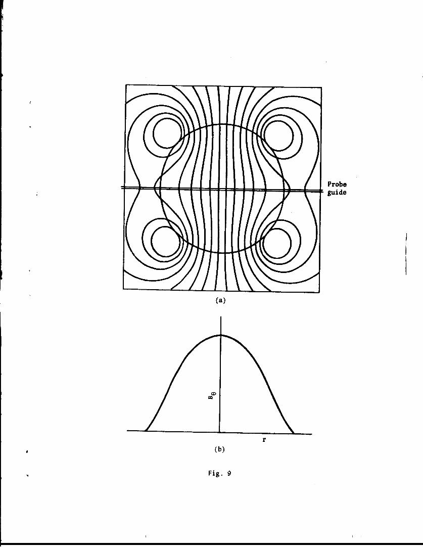
Fig. 9(a) shows a plot of the computed vacuum magnetic field lines
of the rotating field generated by the dipole coils. The lines are
plotted at an instant of time when the 0-component of the field, as
measured by a suitably orientated probe located in the indicated probe
guide, is a maximum. The corresponding computed radial profile, B 0(r),
is shown in Fig. 9(b).
The penetration of the rotating magnetic field into the plasma column
was investigated by measuring the 8-component of the field across the
diameter indicated in Fig. 9(a). Fig. 10 shows the waveforms of B Q(t)
at various radial positions for filling pressures of 3.7 and 6.0 mTorr
argon and for an experimental run made with the discharge tube evacuated.
The value of B a was 280 gauss for this set of experimental data. ft
The penetration can be assessed by comparing the measured Bfl(r)
profiles obtained with plasma in the discharge tube to those obtained with

12.
the discharge tube evacuated. For each oscillogram, successive peak-
to-peak values of the signal were measured. Examples of the radial
profiles of the amplitude of B Q (defined as half the measured peak-to-peak
value) for the 3.7 mTorr and the vacuum case are shown in Fig. 11. The
peak-to-peak values corresponding to these profiles are idem., fied in
Fig. 10.
For the 3.7 mTorr case, the rotating field penetrates into the
plasma (curves a, b, and c in Fig. 11) during the r.f. pulse. The
azimuthal current, and the associated axial magnetic field, produced by
the rotating electrons consequently remain fairly constant for the
duration of the r.f. pulse. When the applied rotating field begins to
decay at the end of the r.f. pulse, it fails to sustain the azimuthal
electron current and the axial magnetic field pulse also decays. At
this time, the rotating field begins to be excluded from the plasma
(curve d, Fig. 11) by the action of an induced axial screening current.
This screening current manifests itself through an enhancement of the
value of BQ in the outer regions of the plasma column.
For the 6.0 mTorr argon case, the rotating field initially penetrates
the plasma (curves e and f, Fig. 11). However, for these conditions,
the amplitude of the applied rotating field becomes smaller than the
threshold value during the r.f. pulse itself. When this happens, both
the rotating field is excluded (curves g and h, Fig. 11) and the axial
field pulse decays.
5. DISCUSSION
Theoretical studies predict a threshold condition for setting plasma
electrons into rotation with a transverse rotating field. If one wishes
to generate substantial azimuthal electron current by this technique then
the existence of a threshold value for the amplitude of the applied

13.
rotating field assumes great practical importance; it is this threshold
value which determines the parameters of the costly r.f. generators
used to produce the rotating field.
The experimental results presented here provide convincing
qualitative evidence for the existence of a threshold value for the
amplitude of the applied rotating field. They are consistent with the
following simple physical picture. As long as the rotating field
amplitude is above the threshold value, the electrons are in essence
tied to the field lines and they rotate nearly synchronously producing
a considerable azimuthal current. The effective frequency of the
rotating field in a frame of reference rotating with the electrons is
essentially zero; the corresponding skin depth is, in this case, much
larger than the plasma radius. On the other hand, when the rotating
field amplitude becomes less than the threshold value, the azimuthai
electron motion decreases and the effective frequency of the rotating
field, in a frame of reference rotating with the electrons, approaches
that measured in the laboratory frame of reference. The effective skin
depth in this case can be much smaller than the radius of the plasma
column and the rotating field amplitude inside the plasma is attenuated
accordingly.
We wish to acknowledge financial support for this work from the
Australian Institute of Nuclear Science and Engineering and the Australian
Research Grants Committee.

14.
REFERENCES
BLEVIN, H.A. and THON! ANN, P.C. 1962, Nucl. Fusion, 1962 Suppl.,
Part I, p.55.
DAVENPORT, P.A., FRANCIS, G., MILLAR, W. and TAYLOR, A.G. 1966
U.K.A.E.A. Culham Report CLM-R65.
HUGRASS, W.N. and GRIMM, R.C. 1980.
HUGRASS, W.N., JONES, I.R., McKENNA, K.F., PHILLIPS, M.G.R.,
STORER, R.G. and TUCZEK, H., 1980 Phys.Rev.Lett. 4£, 1676.
HUGRASS, W.N., JONES, I.R. and PHILLIPS, M.G.R. 1979 Nucl. Fusion 19̂ , 1546.
HUGRASS, W.N., JONES, I.R. and PHILLIPS, M.G.R. 1980
J.Phys.E:Sci. Instrum. 13, 276.
JONES, I.R. and HUGRASS, W.N. 1980.
KELLER, R. 1965 Helv.Phys.Acta 38_, 328.
LIETTI, P. 1969 Rev.Sci.Instrum. 40, 473.
WEIBEL, E.S. 1964 Rev.Sci.Instrum. 35, 173.

15.
FIGURE CAPTIONS
Fig. 1. The axial magnetic field distribution for a 6-pinch-like
rotating field discharge
R is the inner radius of the discharge tube
R is the effective radius of the flux conserving rings
B is the initial bias axial magnetic field
B is the axial magnetic field produced by the current
induced in the flux conserving rings
B (r) is the axial magnetic field produced by the
azimuthal electron current
Fig. 2. Schematic diagram of the apparatus
Fig. 3. r.f. current waveforms
(a) Line generator current waveforms
(b) Sum and difference of the line generator currents
Horizontal scale 2 usec/div; Vertical scale 2.9 kA/div
Fig. 4. The axial magnetic field on the axis (r = 0) and at the
wall (r = 25 mm) for different values of the argon filling
pressure. The two bottom traces show the r.f. current pulse.
B = 280 gauss
Fig. 5. (a) The measured axial magnetic field on the axis (r = 0)
and at the wall (r = 25 mm) plotted against the filling
pressure M
(b) AB and AB plotted against the filling pressure
Fig. 6. AB z(t) waveforms for different values of v . AD
(a) Sketches of the ( Z/AB-M) and (B ,t) relationships. AB
(b) Sketch of derived ( Z/AB ZM. t) relationship

16.
The measured axial magnetic field on the discharge tube
axis for three different values of the filling pressure.
Upper trace [Be(0) - B j 175 gauss/div
Lower trace r.f. current 2.9 kA/div
Horizontal scale 5 usec/div
(a) The measured axial field signal at various radial
positions for B = 280 gauss and filling pressure -
3.7 mTorr.
(b) The radial profile of the axial magnetic field measured
in the interval t : 9-li usee (t = 0 corresponds to
the start of the r.f. current).
(a) The magnetic field lines generated by the two orthogonal
dipole coils
(b) The computed radial variation of B 0 along the indicated
diameter.
The rotating field component BQ(r,t) for
(a) evacuated discharge tube
(b) 3.7 mTorr filling pressure
(c) 6.0 mTorr filling pressure
The top traces show B on-axis; the bottom traces show K + I 2 <
B a =280 gauss; Horizontal scale 2 ysec/div
B e(r] 1 for:
(a) 1 (e) 1 (b) (c) (d) J
Vacuum and
3.7 mTorr
O
•
(f) (g) (h) J
Vacuum and
6.0 mTorr •

j R c ^ B j
1 R ••»
\ I u
BQ \ * \ B 0
\
\ 1 / BO
ea
I
Fig. 1

Steady bias field, B a
Flux conserving rings
r.f. coils
Fig. 2

(a)
(b)
CM ( - 1 +
CM
I
Fig. 3

r = 0 (mTorr)
2.2
r = 25 nan
2.7
3.0
3.3
3.8
4.5
5.2
19
^W
Gauss/div
35
35
35
35
35
35
35
35
''///yw\A
5 psec/div 5 psec/div
Fig. 4

Gauss 400 r
3001-
200
100
CBe(0) - B C]
H h 8 12
+ H 16 20 mTorr • •
C-Bc]
400 h
20 mTorr
Fig. 5

on <
N <
0)
(a)
1.0
2 N
09 <J
N 0.5 -
3
(b)
Fig. 6

"V^ (a)
Cb)
(c)
3.5 mTorr
6.2 mTorr
13.0 mTorr
Fig. 7

• \ 300 - Jm
1 3 700 -\ ^̂
\ B 0
V 100 . •/
jS*
I 1 1 1 1 1 __i .. • 25 20 IS 10 5 0 5
rO-0
(b)
10 IS 20 25
r.f. current pulse
(a)
Fig. 8
Probe guide
(a)
(b)
Fig. 9

Gauss/div Tube evacuated 3.7 mTorr 6.0 mTorr
165
74
186
186
186
186
186
186
186
186
b J T e f g h
Fig. 10

• i
(a)
• • • • • • • •
• • 200 ° o ( l o o 0 • •
• 0 • 0 ° • o o
(A o 100 _ 0
• aus 0
o* DO o
CQ I
0 1 1 1 1 1 1 1 1
(b)
20 10 0 10 20 r(nun)
»• • 8°
I I I I
• •
°o,» • °8 I |
o • O *
o 8|
I I I 1
(e)
(f)
to
* i ° o8* »• ••° t»« o
I
i i i i I I I I
{ •••! I * 8o 0 o 1
1° • • 8 • 8 "8 t(
o» o <
• 1 l 1 1 1 1 1 1
(c)
(d)
I f O . n O
. o ! • 0°°B»
I I I I
8 «8 • 5 . 8o
I I I I
oo 0
,6 f • I
« 0 0 o f l
8 , #
• • - • • • , 0
f t • ••• ° i i ' i I i i i i
(g)
(h)
igi / . • •
i i i i
0 f i t
I I I I
rig. n