
RTO-AG-300 Vol. 22 AC/323(SCI-038)TP/53 NORTH ATLANTIC TREATY ORGANISATION RESEARCH AND TECHNOLOGY...
126
RTO-AG-300 Vol. 22 AC/323(SCI-038)TP/53 NORTH ATLANTIC TREATY ORGANISATION RESEARCH AND TECHNOLOGY ORGANISATION BP 25, 7 RUE ANCELLE, F-92201 NEUILLY-SUR-SEINE CEDEX, FRANCE RTO AGARDograph 300 Flight Test Techniques Series – Volume 22 Helicopter/Ship Qualification Testing (Les essais de qualification h´ elicopt` ere/navire) This AGARDograph has been sponsored by the SCI-055 Task Group, the Flight Test Technology Team of the Systems Concepts and Integration Panel (SCI) of RTO. Published February 2003 Distribution and Availability on Back Cover RTO-AG-300 Vol. 22 Single copies of this publication or of a part of it may be made for individual use only. The approval of the RTA Information Management and Systems Branch is required for more than one copy to be made or an extract included in another publication. Requests to do so should be sent to the address above. © RTO/NATO 2003
-
Upload
independent -
Category
Documents
-
view
0 -
download
0
Transcript of RTO-AG-300 Vol. 22 AC/323(SCI-038)TP/53 NORTH ATLANTIC TREATY ORGANISATION RESEARCH AND TECHNOLOGY...

RTO-AG-300 Vol. 22AC/323(SCI-038)TP/53
NORTH ATLANTIC TREATY ORGANISATION
RESEARCH AND TECHNOLOGY ORGANISATION
BP 25, 7 RUE ANCELLE, F-92201 NEUILLY-SUR-SEINE CEDEX, FRANCE
RTO AGARDograph 300
Flight Test Techniques Series – Volume 22
Helicopter/Ship Qualification Testing(Les essais de qualification helicoptere/navire)
This AGARDograph has been sponsored by the SCI-055 Task Group, the Flight Test TechnologyTeam of the Systems Concepts and Integration Panel (SCI) of RTO.
Published February 2003
Distribution and Availability on Back Cover
RT
O-A
G-3
00 V
ol. 2
2
Single copies of this publication or of a part of it may be made for individual use only. The approval of the RTA Information Management and Systems Branch is required for more than one copy to be made or an extract included in another publication. Requests to do so should be sent to the address above.
© RTO/NATO 2003

This page has been deliberately left blank
Page intentionnellement blanche

RTO-AG-300 Vol. 22AC/323(SCI-038)TP/53
NORTH ATLANTIC TREATY ORGANISATION
RESEARCH AND TECHNOLOGY ORGANISATION
BP 25, 7 RUE ANCELLE, F-92201 NEUILLY-SUR-SEINE CEDEX, FRANCE
RTO AGARDograph 300
Flight Test Techniques Series – Volume 22
Helicopter/Ship Qualification Testing(Les essais de qualification helicoptere/navire)
Edited by
G.D. Carico, R. Fang, R.S. Finch, W.P. Geyer Jr., Cdr. (Ret.) H.W. Krijns and K. Long
This AGARDograph has been sponsored by the SCI-055 Task Group, the Flight Test TechnologyTeam of the Systems Concepts and Integration Panel (SCI) of RTO.

The Research and TechnologyOrganisation (RTO) of NATO
RTO is the single focus in NATO for Defence Research and Technology activities. Its mission is to conduct and promotecooperative research and information exchange. The objective is to support the development and effective use of nationaldefence research and technology and to meet the military needs of the Alliance, to maintain a technological lead, and toprovide advice to NATO and national decision makers. The RTO performs its mission with the support of an extensivenetwork of national experts. It also ensures effective coordination with other NATO bodies involved in R&T activities.
RTO reports both to the Military Committee of NATO and to the Conference of National Armament Directors. It comprises aResearch and Technology Board (RTB) as the highest level of national representation and the Research and TechnologyAgency (RTA), a dedicated staff with its headquarters in Neuilly, near Paris, France. In order to facilitate contacts with themilitary users and other NATO activities, a small part of the RTA staff is located in NATO Headquarters in Brussels. TheBrussels staff also coordinates RTO’s cooperation with nations in Middle and Eastern Europe, to which RTO attachesparticular importance especially as working together in the field of research is one of the more promising areas of initialcooperation.
The total spectrum of R&T activities is covered by the following 7 bodies:
• AVT Applied Vehicle Technology Panel
• HFM Human Factors and Medicine Panel
• IST Information Systems Technology Panel
• NMSG NATO Modelling and Simulation Group
• SAS Studies, Analysis and Simulation Panel
• SCI Systems Concepts and Integration Panel
• SET Sensors and Electronics Technology Panel
These bodies are made up of national representatives as well as generally recognised ‘world class’ scientists. They alsoprovide a communication link to military users and other NATO bodies. RTO’s scientific and technological work is carriedout by Technical Teams, created for specific activities and with a specific duration. Such Technical Teams can organiseworkshops, symposia, field trials, lecture series and training courses. An important function of these Technical Teams is toensure the continuity of the expert networks.
RTO builds upon earlier cooperation in defence research and technology as set-up under the Advisory Group for AerospaceResearch and Development (AGARD) and the Defence Research Group (DRG). AGARD and the DRG share common rootsin that they were both established at the initiative of Dr Theodore von Karman, a leading aerospace scientist, who early onrecognised the importance of scientific support for the Allied Armed Forces. RTO is capitalising on these common roots inorder to provide the Alliance and the NATO nations with a strong scientific and technological basis that will guarantee asolid base for the future.
The content of this publication has been reproduceddirectly from material supplied by RTO or the authors.
Published February 2003
Copyright RTO/NATO 2003All Rights Reserved
ISBN 92-837-1093-2
Printed by St. Joseph Print Group Inc.(A St. Joseph Corporation Company)
1165 Kenaston Street, Ottawa, Ontario, Canada K1G 6S1
ii

Helicopter/Ship Qualification Testing(RTO AG-300 Vol. 22 / SCI-038)
Executive Summary
NATO’s rotorcraft aviation forces rely heavily on ship-based operations for both military andcommercial applications. The requirements to provide surveillance, supplies and force projectionoptions in areas where land-based operations are not available also dictate aircraft/ship operations.These multi-national forces operate from a variety of different aircraft and ships in both weather andvisibility extremes.
Basic helicopter flight limitations are usually determined in a land-based environment by the aircraftmanufacturer and/or by the procuring activity. The land-based limitations are not valid in the shipboardenvironment due to the individual factors including ship air wake/turbulence, ship motion, confinedlanding areas and visual cue limitations and due to the combined effects of these factors. Future NATOoperators and force commanders may require the maximum helicopter/ship operational capability thatcan be accomplished in any environmental condition.
The purpose of this AGARDograph is to document the helicopter/ship qualification test proceduresincluding the preparation, execution and data analysis of helicopter/ship flight testing that should beemployed, combined with best safety practices to obtain that maximum operational capability.Attention is focused on helicopter take-off and landing, which constitutes the main part of the testprogramme.
The following topics are described:
• the factors influencing the helicopter/ship operations;
• how these factors are determined in various qualification programme elements;
• how these factors are used to set up a flight test programme on board the ship;
• how the ship-borne flight tests, within the constraints of safety and efficiency, are carried out;
• in what way, during the tests, repeated use is made of the data obtained in the previous qualificationprogramme elements and of the experience of the test team, resulting in the smallest possiblenumber of flying hours without affecting the quality of the results.
A brief outline of helicopter/ship qualification programmes as carried out by the Netherlands’ NationalAerospace Laboratory (NLR) at Amsterdam, the United Kingdom’s Defence Evaluation & ResearchAgency (DERA) at Boscombe Down and the United States’ Rotorcraft Shipboard Suitability Branch ofthe Naval Air Systems Command at Patuxent River, Maryland are given. It describes how detailedinformation of the helicopter capabilities, ship’s motion characteristics and the wind-climate above theship’s flight deck is used to set up and to execute a safe and efficient flight test programme. Theprogramme leads to a safe and maximum operational availability of the helicopter on board the ship interms of take-off and landing capabilities as a function of relative wind and sea-state.
iii

Les essais de qualification helicoptere/navire(RTO AG-300 Vol. 22 / SCI-038)
Synthese
Les flottes d’aeronefs a voilure tournante de l’OTAN sont fortement tributaires des operationsembarquees pour valider leurs applications militaires et commerciales. La mise en œuvre d’aeronefs apartir de navires est egalement dictee par la necessite de disposer de capacites de surveillance,d’approvisionnement et de projection de force dans des zones ou l’utilisation de bases terrestres estexclue. Ces forces multinationales mettent en œuvre une grande variete d’aeronefs et de plates formesmaritimes et ce, dans des conditions meteorologiques et de visibilite souvent extremes.
D’une facon generale, les limites de vol standard des helicopteres sont fixees par l’avionneur et/ou parles services des approvisionnements en fonction d’un environnement terrestre. Or, ces limitations nesont pas adaptees a l’environnement maritime embarque en raison de facteurs propres tels que lesturbulences de sillage et les mouvements des plates formes, l’exiguıte des aires d’atterrissage et leslimitations des reperes visuels, sans compter les effets combines de tous ces facteurs. Les futursequipages et commandants de forces de l’OTAN auront probablement besoin d’une synergieoperationnelle la plus grande possible entre helicopteres et navires, quel que soit l’environnement.
Cette AGARDographie a pour objet de repertorier en les documentant les procedures pour les essais dequalification des helicopteres a la mer, et notamment la preparation, l’execution et l’analyse desdonnees des essais en vol des helicopteres, ainsi que les meilleures procedures de securite, afin dedisposer de cette synergie operationnelle maximale. L’accent est mis sur le decollage et l’atterrissagedes helicopteres car ils constituent l’essentiel du programme d’essais.
Les sujets suivants sont abordes :
• les facteurs ayant une influence sur les operations des helicopteres a la mer;
• la prise en compte de ces facteurs dans differents elements des programmes de qualification;
• l’integration de ces facteurs dans l’etablissement d’un programme d’essais en vol dans le cadre d’unembarquement a la mer;
• l’execution de ces essais en vol a partir de navires, compte tenu des contraintes de securite etd’efficacite associees;
• le recours repete durant les essais aux donnees obtenues lors de l’execution des programmes dequalification precedents, ainsi qu’a l’experience de l’equipe d’essais, de facon a reduire au minimumles heures de vol necessaires sans nuire a la qualite des resultats.
Un bref apercu est donne des programmes de qualification des helicopteres a la mer tels qu’ils sontconduits par le Netherlands National Aerospace Laboratory (NLR) d’Amsterdam, le DefenceEvaluation and Research Agency (DERA) de Boscombe Down au Royaume-Uni et par le RotorcraftShipboard Suitability Branch du Naval Air Systems Command de Patuxent River aux Etats-Unis. Cetapercu decrit aussi comment les informations detaillees sur les capacites de l’helicoptere, lescaracteristiques des mouvements du navire et celles du vent sur le pont d’envol sont exploitees en vuede la preparation et l’execution d’un programme d’essais en vol dans de bonnes conditions de securiteet d’efficacite. Ce programme permettra d’assurer en toute securite une disponibilite operationnellemaximale de l’helicoptere embarque du point de vue de ses capacites de decollage et d’atterrissage enfonction du vent relatif et de l’etat de la mer.
iv

Contents
Page
Executive Summary iii
Synthese iv
AGARDograph Series 160 and 300 vi
Foreword vii
Acknowledgements viii
Part 1: Dutch/British Clearance Process 1-1
Part 2: American Clearance Process 2-1
Annex AGARD and RTO Flight Test Instrumentation and Flight Test Techniques Series A-1
1. Volumes in the AGARD and RTO Flight Test Instrumentation Series, AGARDograph 160
2. Volumes in the AGARD and RTO Flight Test Techniques Series, AGARDograph 300
v

AGARDograph Series 160 and 300
The Systems Concepts and Integration (SCI) Panel has a mission to distribute knowledge concerning advancedsystems, concepts, integration, engineering techniques, and technologies across the spectrum of platforms andoperating environments to assure cost-effective mission area capabilities. Integrated defence systems, includingair, land, sea, and space systems (manned and unmanned) and associated weapon and countermeasure integrationare covered. Panel activities focus on NATO and national mid- to long-term system level operational needs. Thescope of the Panel covers a multidisciplinary range of theoretical concepts, design, development, and evaluationmethods applied to integrated defence systems.
One of the technical teams formed under the SCI Panel is dedicated to Flight Test Technology. Its mission is todisseminate information through publication of monographs on flight test technology derived from best practiceswhich support the development of concepts and systems critical to maintaining NATO’s technological andoperational superiority. It also serves as the focal point for flight test subjects and issues within the SCI Paneland ensures continued vitality of the network of flight test experts within NATO.
These tasks were recognized and addressed by the former AGARD organization of NATO in the form of twoAGARDograph series. The team continues this important activity by adding to the series described below.
In 1968, as a result of developments in the field of flight test instrumentation, it was decided that monographsshould be published to document best practices in the NATO community. The monographs in this series arebeing published as individually numbered volumes of the AGARDograph 160 Flight Test Instrumentation Series.
In 1981, it was further decided that specialist monographs should be published covering aspects of Volume 1 and2 of the original Flight Test Manual, including the flight testing of aircraft systems. The monographs in thisseries (with the exception of AG 237, which was separately numbered) are being published as individuallynumbered volumes of the AGARDograph 300 Flight Test Techniques Series.
At the end of each AGARDograph 160 Flight Test Instrumentation Series and AGARDograph 300 Flight TestTechniques Series volume is an annex listing all of the monographs published in both series.
vi

Foreword
Introduction to the subjectShips have been used for commercial and military sea-based applications for many centuries. The airplane has gainedfame during the twentieth century for both commercial and military applications. Helicopter/ship operations have beenongoing since the middle of the twentieth century. Many countries and numerous commercial activities use thehelicopter to extend the capability of ships. The helicopter is often considered a very versatile aircraft with few flightlimitations. Basic helicopter flight limitations are usually determined in a land-based environment by the aircraftmanufacturer and/or by the procuring activity. The land-based limitations are not valid in the shipboard environmentdue to the individual factors listed below and due to the combined effects of the following factors:
• Ship airwake/turbulence• Ship motion• Confined landing area• Visual cue limitations
Operators request the maximum helicopter/ship operational capability that can be exercised in any environmentalcondition. To obtain the maximum operational capability, combined with best safety practices, helicopter/shipqualification testing is required. Helicopter/ship qualification testing, sometimes referred to as “dynamic interface (DI)testing” or as the “clearing process”, is used to develop safe operational envelopes for helicopters operating off shipsunder a variety of weather conditions. The results of helicopter/ship qualification testing are referred to as the ShipHelicopter Operating Limitations (SHOLs).
Contributions from three countries in two separate partsHelicopter/ship testing is considered high risk testing that should only be performed by agencies that have specializedflight test and research teams that are knowledgeable of, and have experience in, this type of testing. In NATO theseconditions are fulfilled only in a limited number of countries amongst which are The Netherlands, the UnitedKingdom and the United States of America. Specialists from those countries have contributed to this AGARDograph.All three countries have several similar procedures related to determining SHOLs. At the same time some of theprocedures differ, with the NL/UK flight test programs being more similar to each other than to the proceduresemployed by the US. To accommodate these differences it was decided to split the AGARDograph into two parts, onecovering the NL/UK clearance process and the other dealing with the process in the US. Although as a consequence ofthis approach some overlap will be found comparing the two parts, the big advantage is that the process described ineach part is consistent in its nomenclature and its sequence and that each part can be read independently from theother.
The Netherlands National Aerospace Laboratory (NLR) in Amsterdam and the UK Defense Evaluation ResearchAgency (DERA) at Boscombe Down have conducted numerous helicopter/ship qualification tests on national, as wellas foreign, contractor aircraft/ship types to establish the SHOLs.
The Naval Air Warfare Center, Aircraft Division at Patuxent River, MD, in the USA has used Dynamic Interface (DI)testing over the past several years to try to eliminate a large helicopter/ship test backlog.
For some time, prior to the actual helicopter/ship flight testing, the Dutch have successfully used a combination ofwind tunnel data (ship model), full-scale airwake data, and land-based helicopter data to predict operating limits. TheUK and USA rely primarily on basic helicopter/ship testing.
Future developmentsFuture developments are expected in the field of increased application of simulation. The ability to predicthelicopter/ship operational envelopes analytically represents one of the more difficult challenges associated withflight-testing. Inspired by the cost of testing and the inability to readily control test conditions, both the UK and USAhave strong ongoing analytic efforts to help support future helicopter/ship qualification testing. With 3 new shipclasses operating with 5 types of aircraft anticipated within the coming decade, the UK has initiated a First of ClassFlying Trials program in 1997, which includes developing an advanced simulation capability. In the USA DI testingcontinues, with more emphasis being placed on simulation and wind tunnel efforts as potential test support tools of thefuture. The USA initiated an Office of Secretary of Defense (OSD) sponsored Joint Helicopter Ship IntegrationProgram (JHSIP) in 1998. This program focuses on validating and evaluating joint service helicopter/ship operationalcapabilities, with some work in the area of DI simulation.
vii

Acknowledgements
The Netherlands contribution to the AGARDograph was only possible due to the valuable assistance andcontribution received from the Royal Netherlands Navy in the course of the years. The author wishes to expresshis appreciation for the valuable contribution received from the following departments of the Royal NetherlandsNavy:
MOD-NL Naval Air (MARSTAF LUVRT)Department of Naval Aircraft Engineering and Maintenance (DMKM-VLITECH)Naval Air Squadron VGSQ 860 at Naval Air Station “De Kooy”
The UK contribution to the AGARDograph is the combination of many years of close co-operation with theRoyal Navy. In particular, the UK author wishes to record his appreciation for the valuable support receivedfrom Lt Cdr (retired) Peter Symonds, a former RN Sea King pilot and colleagues at DERA Boscombe Down,particularly Bryan Finlay, Richard Blake and Jez Quirk of the Rotary Wing Aircraft Dynamics Group.
The US authors would like to thank Bill Reedy (formerly of NAWCAD) for all his initial work on the US part ofthe AGARDograph. The authors would also like to acknowledge all the suggestions and contributions of theNAVAIR Dynamic Interface Team, especially the many suggestions from Chuck Slade and the computationalfluid dynamics ship airwake work performed by Susan Polsky of the NAVAIR advanced aerodynamics group.
viii

1-1
Part 1
DUTCH / BRITISH CLEARANCE PROCESS
by
R. FangNational Aerospace Laboratory NLR
AmsterdamThe Netherlands
Cdr. (Ret.) H. W. KrijnsRoyal Netherlands Navy
R. S. FinchQinetiQ (formerly DERA)
Boscombe DownEngland

1-2
Contents of Part 1
Contents of Part 1 1-2
List of Figures of Part 1 1-5
List of Tables of Part 1 1-6
List of Abbreviations of Part 1 1-7
1 Introduction 1-8
2 Experience 1-10
3 Basic Set-up 1-11
3.1 General 1-11
3.2 Starting point in the Netherlands & UK 1-11
3.2.1 Procedures 1-11
4 Helicopter Ship-borne Operational Procedures 1-13
4.1 Helicopter sortie o/b a ship 1-13
4.2 Navy procedures 1-18
4.2.1 Take-off and landing 1-18
4.2.2 Role of Flight Deck Officer (FDO) 1-23
5 Qualification Programme 1-24
5.1 Objectives 1-24
5.2 Activities 1-24
6 Scope of Test Programme 1-26
6.1 General 1-26
6.2 Land-based vs. ship-borne helicopter operations 1-27
6.3 Factors affecting ship-borne helicopter operations 1-29
6.4 Main elements determining the scope of qualification programmes 1-30

1-3
7 Factors Affecting Ship-borne Helicopter Control and Handling 1-31
7.1 General 1-31
7.2 The effect of the ship on the environment for helicopter operations 1-31
7.3 Hover performance 1-33
7.4 Yaw control 1-34
7.5 Landings on an oscillating deck 1-34
7.6 High wind speed from ahead 1-34
7.7 Low relative wind speed 1-34
7.8 Strong tail wind 1-36
7.9 Blade sailing 1-37
7.10 Hot exhaust gas ingestion 1-37
7.11 Pilot field of view and visual orientation 1-37
7.12 Approach aids 1-38
7.13 Piloting skills 1-38
7.14 Candidate flight envelope 1-38
8 Testing 1-40
8.1 General 1-40
8.2 Wind-tunnel tests on a scale model of the ship 1-40
8.3 Full-scale ship’s wind climate and motion tests 1-41
8.4 Helicopter 1-42
8.5 Flight testing 1-44
8.6 Drafting SHOLS/Constructing Wind Envelopes 1-48
9 Establishment of Helicopter Operational Envelopes for Ship-borne Operations 1-49
10 Simulating the Helicopter/Ship Interface 1-51
10.1 International research activity 1-51
10.2 Modelling ship motion 1-51
10.3 Ship air wake modelling 1-52
10.4 Helicopter simulation 1-53
10.5 Summary 1-54
11 Concluding Remarks 1-55
1-4
Annex A: Instrumentation as Applied by NLR 1-56
A1 Wind climate and ship motion full scale tests 1-56
A1.1 NLR wind data acquisition system 1-56
A1.2 Wind measurements above the flight deck 1-56
A1.3 Reference system at the bow of the ship 1-56
A1.4 Information from ship system 1-57
A1.5 NLR data processing system 1-57
A2 Instrumentation in flight trials 1-59
A2.1 Ship instrumentation 1-59
A2.2 Helicopter instrumentation 1-60
A2.3 Communication 1-60

1-5
List of Figures of Part 1
Fig. 1 Helicopter operations on board a ship in a rough environment 1-8
Fig. 2 Helicopter stowed and secured in hangar 1-13
Fig. 3A Ranging (manoeuvring) the helicopter to the flight deck 1-13
Fig. 3B Positioning the helicopter for a relative wind (into-wind) take-off 1-14
Fig. 4 Helicopter secured on deck preparing for engine start and blade unfolding 1-14
Fig. 5A Helicopter blades are unfolded automatically.
To avoid blade damage manual support is deemed essential 1-15
Fig. 5B Manual unfolding the helicopter blades 1-15
Fig. 6 Rotor Running Refuelling (Hot refuelling) 1-17
Fig. 7 Helicopter secured and lashed on deck in rough weather 1-17
Fig. 8A Example of fore/aft take-off and landing paths 1-18
Fig. 8B Fore/aft take-off to port 1-19
Fig. 9A Relative or into wind take-off and landing flight paths.
Approach either from port or starboard. 1-19
Fig. 9B Relative wind (into wind) procedure facing port 1-20
Fig. 10A Cross-deck take-off and landing flight paths. Approach either from port or starboard 1-20
Fig. 10B Cross-deck facing port procedure 1-21
Fig. 11 Positioning the helicopter for a stern take-off following the aft/fore procedures 1-22
Fig. 12 Marshalling the helicopter during dual spot operations 1-23
Fig. 13 Information presented to the FDO by means of repeater instruments 1-23
Fig. 14 Set-up of helicopter-ship qualification programme as carried out by NLR 1-26
Fig. 15 Flight deck and hangar lay-out o/b a Royal Netherlands Navy ship (forced roll situation) 1-28
Fig.16 Typical relative low wind speed envelope as provided by the manufacturer 1-32
Fig. 17 Detail results from land based hover tests 1-32
Fig. 18 General set-up during land based flight trials 1-33
Fig. 19 Turbulence level above the deck as a function of relative wind 1-35
Fig. 20 Relative wind conditions during which spray & exhaust gas may occur 1-35
Fig. 21 Example of ship’s pitch & roll amplitudes as a function of ship’s speed and course 1-36
Fig. 22 Spray resulting from down wash and re-circulating airflow 1-36
Fig. 23 Candidate flight envelope to be tested o/b a ship 1-39
Fig. 24 Stack & exhaust gas nuisance investigation on a wind tunnel model 1-40
Fig. 25 NLR moveable mast as used during ship airwake measurements 1-41

1-6
Fig. 26 Composition of possible wind envelopes for various helicopter approach headings
with respect to the ship 1-42
Fig. 27 Resultant candidate relative wind envelope to be tested
during helicopter flight testing on board the ship. 1-43
Fig. 28 Relative wind envelope for fore/aft take-off and landing to be tested o/b the ship.
Corrected for ship anemometer system 1-43
Fig. 29 Flight test procedure o/b the ship 1-46
Fig. 30 Take-off and landing limitations for fore/aft procedure (NL-presentation) 1-49
Fig. 31 Limitations for daytime operations (NL-presentation) 1-50
Fig. 32 Limitations for daytime operations (UK-presentation) 1-50
Fig. A1 Block diagram wind climate and ship motion data acquisition and processing system 1-58
Fig. A2.1 NLR o/b data acquisition and processing system 1-59
Fig. A2.2 Block diagram data acquisition and processing system
as used during helicopter-ship testing 1-61
List of Tables of Part 1
Table 1 Comparison of take-off & landing area characteristics 1-28
Table 2 Factors affecting ship-borne helicopter Operators 1-29
Table 3 Torque, Pedal & Cyclic Rating Scales 1-47
Table 4 QinetiQ Pilot Rating Scale 1-47
Table A1 Ship parameters recorded during wind climate & ship motions measurements 1-57
Table A2 Helicopter parameters recorded during flight testing 1-59

1-7
List of Abbreviations of Part 1
A/F Aft/Fore
AFS Advanced Flight Simulator
AGL Above Ground Level
CC Command & Control Centre [UK: Opsroom; USA: Combat Information Centre]
CVS(G) Aircraft Carriers (Guided Missiles)
F/A Fore/Aft
FDO Flight Deck Officer
GPI Glide Path Indicator
GSI Glide Slope Indicator
HCO Helicopter Control Officer
HEDAS Helicopter Data Acquisition System
HIFR Helicopter In Flight Refuelling
IGE In Ground Effect (hover)
NAWCAD Naval Air Warfare Center Aircraft Division
NLR Nationaal Lucht- en Ruimtevaartlaboratorium
(National Aerospace Laboratory NLR - the Netherlands)
OAT Outside Air Temperature
o/b on board
OGE Out of Ground Effect (hover)
PC Personal Computer
PD Project Definition
RAF Royal Air Force
RFA Royal Fleet Auxiliary
RN Royal Navy
RNLN Royal Netherlands Navy
RMDU Remote Multiplexing/Digitizer Unit
RRR Rotors Running Refuelling
RW Relative Wind
SHOLs Ship Helicopter Operational Limitations
T&E Test and Evaluation
UVW Orthogonal velocity components of a local wind velocity vector
Vertrep Vertical replenishment
WAU Wind data Acquisition Unit
XD Cross Deck

1-8
1. Introduction
In recent years operations with a large variety of helicopter types from various classes of naval shipshave steadily increased world-wide. The improved capabilities of present-generation helicopters offer awide range of possibilities for ship-helicopter combinations to cope with the growing demand being puton modern maritime forces. Many even relatively small vessels are being equipped with a helicopterflight deck.
Sometimes an almost marginal facility is provided for take-off, landing and deck handling. Yet, helicopteroperations may be required in a wide range of operational conditions (day, night, sea-state, wind, visibil-ity etc) with the highest possible payload. Nowadays, in line with the increasing importance of helicop-ter/ship operations the helicopter manufacturer sometimes additionally provides limitations of a generalnature for helicopter-ship operations.
The limitations for land-based operations (determined after extensive factory testing) are based amongstothers on a rigid and unobstructed landing site. On the other hand, the limitations for ship-borne opera-tions are to be based on an obstructed landing site (flight deck) which may show random oscillatorymovement and where amongst others extremely turbulent wind conditions can prevail.
Because of the unique characteristics of each helicopter-type/class-of-ship combination and the innumer-able combinations possible it is understandable that usually no (extensive) testing has been carried out bythe helicopter manufacturer for all combinations that may be of interest. It follows that the limitationsgiven, if any, must be considered as general guidelines, with large safety margins with respect to thehelicopter capabilities and pilot ability to control the helicopter, and thus do not provide a maximumoperational availability of the helicopter on board the ship. It is expected that the actual limitations, i.e.those that allow maximum availability of the helicopter within the constraints of safety, are lying some-where between the limitations for land-based and those for ship-borne operations as given by the manu-facturer. To determine these limitations a dedicated helicopter-ship qualification programme is to beexecuted. Figure 1 shows an example of helicopter operations in rough weather.
Fig. 1 Helicopter operations on board a ship in a rough environment.

1-9
In this AGARDograph an overview is given about the factors influencing helicopter-ship operations, theway they are determined in various qualification programme elements and how they are used to set up aflight test programme on board the ship.Described is:
• How the execution of the ship-borne tests is within the constraints of safety and efficiency;
• The use made of data obtained in the previous programme elements;
• The use made of the experience of the test team.The result is the smallest possible number of flying hours that does not affect the quality of the results.The attention is focused on helicopter take-off and landing which in fact constitute the main part of thetests. Finally some results are given.

1-10
2. Experience
The Royal Netherlands Navy (RNLN), being one of the first operators of ship-borne helicopters on smallships and operating world-wide, pioneered in concert with the aeronautics home laboratory NLR, thedevelopment of helicopter-ship qualification procedures. This collaborative effort has led to a four-stepqualification programme described in this volume.
The “Nationaal Lucht- en Ruimtevaartlaboratorium” (NLR) is the Netherlands expert institute on aero-space technology and related subjects. From 1968 to date it actively participated in twenty-one (21)qualification programmes. Six (6) of these programmes were carried out in co-operation with four (4)international operators.
In the period from 1982 up to 2002 dedicated qualification procedures have been applied by NLR forhelicopter-ship qualification testing. The applied methodology has been successfully used in elevenqualification programmes for agencies at home and abroad. Four types of helicopters and eight classes ofships were involved. Helicopter maximum take-off mass ranged from 4040 kg (8900 lbs) to 9715 kg(21400 lbs). Ship’s maximum water displacement ranged from 485 tons to 17000 tons. The most extremehelicopter-ship combination worth mentioning was a 4040 kg (8900 lbs) helicopter on a 485-ton shipequipped with a flight deck of 7 by 7.6 m.
In the UK, The Royal Navy (RN) has been operating ship-borne helicopters on small ships world-widefor almost half a century. The UK Aircraft Test & Evaluation Centre at “QinetiQ” Boscombe Down(former Defence Evaluation & Research Agency’s site) is responsible for conducting trials to determinethe limitations appropriate to UK Military Ship Helicopter Operations (SHOLs).
Starting in the mid 1950s, Boscombe Down has conducted ship trials using almost every helicopter typethat has seen service with the UK Armed Forces, including the Whirlwind, Wasp, Wessex, Sea King,Scout, and Gazelle. The techniques used by the UK have been developed since the late 1960s and al-though refinements have been made, the same basic techniques have been used successfully and safelyfor nearly 30 years.
Since 1977, when Boscombe Down conducted the first RN Lynx trial, it has undertaken a total of 19Lynx Ship Trials, including a trial for the Brazilian Government on their Mk 10 Frigate Class and twofurther trials for other NATO navies. In addition, starting in 1987, Boscombe Down has undertaken anumber of trials to clear RAF Chinook helicopters to operate on both RN and RFA flight decks. In the1990s Boscombe Down and NLR collaborated successfully to clear RN helicopters onto a number ofRNLN ships.

1-11
3. Basic Set-up
3.1 GeneralOne of the most important staff requirements for helicopter compatible ships is the helicopter type to beoperated from a given class of ship. This requirement implicitly defines the deck sizing, hangar spacingand technical support features for optimal and safe helicopter operations.
A ship can be considered as an isolated island, which is in turn domicile and working area of severaldisciplines. Each discipline has its own specific requirements.
The designers of a ship attempt to meet all requirements within predefined constraints. The final draft bythe design office will therefore be a compromise, within which each discipline must strive to fulfil itstasks.
As the helicopter is one of the many systems of a ship, it is obvious that helicopter operations are to beperformed within the constraints of the aforementioned compromise.
For a better understanding of the methodology as applied in the Netherlands and the United Kingdom,the factors/subjects in connection with helicopter ship operations, as described in the following para-graphs, are of importance.
3.2 Starting point in the Netherlands & UKBoth nations have dedicated Flight Operational and Technical procedures laid down in national regula-tions which are applied to ensure safe and optimal usage of the helicopter/ship combination.
3.2.1 Procedures
Flight procedures• The standard Dutch flight operations are carried out according to the "single pilot concept". This implies
the following Dutch crew composition:- one pilot (right-hand cockpit seat);- one tactical co-ordinator (left-hand cockpit seat);- one sensor operator (at the sensor console in the cabin).
• The standard UK military flight procedures call for the Pilot in the right-hand seat to conduct take offsand landings at sea. Indeed for the Lynx and Merlin helicopters the “right-hand seat - single pilot con-cept,” (as per the Dutch) is standard. For the Sea King, two pilots are used and depending on the type oflanding being flown, either pilot may “be in control”.
• During standard recovery / flight operations, ship controlled approaches are carried out up to ¼ milefrom the ship, using a nominal 3-deg glide slope.
• During the recovery from ¼ mile up to land-on (touch down) and during launch up to transition toforward flight, the Flight Deck Officer (FDO) directs the pilot by marshalling signals and by radiocommunication.
• During standard flight (launch & recovery) operations the ship's Command & Control Centre (CC), thehelicopter and the FDO are always on one dedicated communication frequency.

1-12
Technical procedures• Before flight operations are permitted o/b a "NEW" or "CONVERTED" class of ship, the following
activities are mandatory:- Harbour flight acceptance trials. Confirmation that all required technical and logistic features for
helicopter operations are available and operational. Operator's responsibility, NLR or QinetiQ inputonly on request.
- Flight acceptance trials at sea. Confirmation that all systems (ship and helicopter) are operating ac-cording to standard. Operator's responsibility with NLR or QinetiQ input.
- Execution of helicopter flight trials o/b the ship in relation to standard operational procedures. Deter-mination of Ship Helicopter Operational Limitations (SHOLs) for a "NEW"-class of ship and if appli-cable updating of the SHOLs for a "CONVERTED" class of ship. Joint programme between operatorand NLR or QinetiQ.

1-13
Fig. 2 Helicopter stowed and secured in hangar
Fig. 3A Ranging (manoeuvring) the helicopter to the flight deck
4. Helicopter Ship-borne Operational Procedures
4.1 Helicopter sortie o/b a shipA helicopter sortie o/b a ship (day and night) can be divided into the following phases:
Stowed (Fig.2)Helicopter stowed and secured in hangar. Generally the main rotor and tail are folded.
Traversing (=Ranging) (Figs. 3A & 3B)Folded helicopter is moved from hangar to the landing spot on the flight deck using a suitable traversingsystem.

1-14
Secured (=Lashed/Tie Down) (Fig. 4)The folded helicopter is secured to the deck using lashings and / or a deck locking system.
Fig. 3B Positioning the helicopter for a relative wind (into-wind) take-off
Fig. 4 Helicopter secured on deck preparing for engine start and blade unfolding

1-15
Fig. 5A Helicopter blades are unfolded automatically.To avoid blade damage, manual support is deemed essential
Fig. 5B Manual unfolding of the helicopter blades
Unfolding (=Spreading) ( Figs. 5A & 5B)Helicopter blades and tail are unfolded automatically or manually. When automatic blade unfolding isapplied, engine start up is performed first.
Engine Start/Rotor EngagementEngine or engines are started and rotors are coupled.

1-16
Take-offWhen conditions are inside the SHOLs and Command has issued take-off permission, deck crew removesnylon lashings, whereupon the pilot, when applicable, disengages the deck lock system.Helicopter lifts off into a hover over the deck and moves clear of the ship.
DepartureOnce the helicopter is clear of the ship's superstructure it transits to forward flight and departs from theship.
MissionThe helicopter crew carry out their mission.
ApproachAfter the helicopter mission is completed, a specific pattern is followed to set-up for a landing. Theapproach phase ends as the helicopter is hovering in a waiting position in the vicinity of the ship.
LandingThe helicopter moves from the waiting position to the flight deck and lands. On touch down the pilotimmediately engages the deck lock system. Lashings can be employed for further securing. Some opera-tors also employ a haul down system to recover the helicopter.
Engine Shut Down/Rotor DisengagementEngines are shut down. The rotors are disengaged and stopped, normally using a rotor brake.
FoldingThe helicopter blades and tail are folded.
Traversing (=Ranging)The folded helicopter is moved from the flight deck to the hangar using a traversing system.
StowedThe helicopter is secured in the hangar using tie down chains.
During a mission, the helicopter can return to the ship for example for refuelling or to pick up or releaseexternal cargo. Picking-up or releasing external cargo is called vertical replenishment (“VERTREP”).
Apart from VERTREP it is for most types of helicopters possible to transfer persons and (small) loads bymeans of a winch (“winching”).
Refuelling can be done on deck with engines and rotors running (hot refuelling - “RRR”) (Fig.6) orhovering close to the ship (helicopter in flight refuelling - “HIFR”).
For safe operations and optimal operational use of the helicopter, it is of essential importance to deter-mine the limitations for each of the afore-mentioned phases.

1-17
The significant result of shipboard helicopter compatibility testing is at least one or all of the followingenvelopes: engage/disengage, Vertical Replenishment, Helicopter In-Flight Refuelling, and launch/recovery. Once developed, these envelopes largely establish the allowable range of wind/ship motionsconditions that safely permit routine shipboard helicopter operations. Conversely, for any given ambientwind condition, the envelopes permit a ship operator to safely operate helicopters from a wider variety ofship course/speed combinations, optimizing his tactical and operational flexibility.
An example of a secured and lashed helicopter on deck in rough weather between two sorties is shown infigure 7.
Fig. 6 Rotor Running Refuelling (Hot refuelling )
Fig. 7 Helicopter secured and lashed on deck in rough weather

1-18
Landing Landing
ApproachApproach
Ahead
Relat. wind Relat. wind
Take-off Take-off
Ahead
1 Fore/aft procedure
Helicopter alignedwith ship long. axis
Approach to portor starboard
Day and night
The following subsections discuss the various procedures for the take-off, departure, approach andlanding phases.
4.2 Navy procedures
4.2.1 Take-off and landingIn general take-off and landing with a helicopter are easiest into the wind. However, on small ships thisprocedure is not always possible and furthermore it does not always provide optimal results because ofthe presence of obstacles. Therefore different take-off and landing procedures are applied to increase theoperational availability of the helicopter on board the ship. To the authors' knowledge there are sixdifferent procedures which are being applied worldwide. The three most common procedures applied inthe Netherlands and in the UK are visualized and compared below. The other three procedures will bebriefly highlighted.
1) Fore/aft or forward facing procedure (F/A)(Fig. 8)A fore/aft take-off is performed as follows:• align the helicopter with the ship's centre-line, with its nose in the sailing direction;• hover above the flight deck with initial ship's heading;• fly sidewards to hover position alongside the ship either to port or starboard (windward side);• turn away 30° from ship's heading;• climb out.
A fore/aft landing is performed as follows:• approach the ship to a hover wait position alongside the ship (preferably to port because of pilot's view
over the flight deck). The helicopter's longitudinal axis is parallel to the ship's centre-line;• fly sidewards to the hover position over the landing spot;• land
Fig. 8A Example of fore/aft take-off and landing paths

1-19
2) Relative-wind or into wind procedure (RW)(Fig. 9)The relative-wind take-off is performed as follows:• swivel (if possible) the helicopter with its nose into the relative wind direction;• hover with this heading above the flight deck;• if necessary to avoid obstacles (e.g. the hangar), fly sidewards to a hover position alongside the ship;• climb out.
The relative-wind landing is performed as follows:• approach the ship from the leeward side;• continue flight up to the hover position above the landing spot (helicopter nose into the relative wind);• land.
Fig. 8B Fore/aft take-off to port
Fig. 9A Relative or into wind take-off and landing flight paths. Approach either from port or starboard.
2 Relative wind procedure
Helicopter facing intorelative wind
Daytime only
Approach
Take-off
Landing
Ahead Relative wind

1-20
Fig. 9B Relative wind (into-wind) procedure facing starboard
Fig. 10A Cross-deck take-off and landing flight paths. Approach either from port or starboard
3 Cross deck procedure
Helicopter facingathwartship
Daytime only
Approach
Ahead
Take-off
Landing
Relative wind
3) Cross-deck procedure (XD)(Fig. 10)This procedure is not common to the Royal Navy.The cross-deck take-off is performed as follows:• swivel (if possible) the helicopter until its longitudinal axis is perpendicular to the ship's centre-line;• lift off and climb out at this heading.
The cross-deck landing is performed as follows:• approach the ship from abeam either from port or starboard (leeward side);• continue flight up to the hover position above the landing spot;• land.
Note:XD is not RW at 90°. The XD-procedures are related to (and executed perpendicular to) the ship’slongitudinal axis. The relative wind (speed and direction) can vary independently with respect to thehelicopter longitudinal axis.
Comparing the various take-off and landing procedures, the following remarks can be made:• The F/A procedure has the advantage that the pilot’s view over the flight deck is rather good, especially
during the approach (to the port side of the ship) and sidewards flight before landing. For that reason, theprocedure can also be carried out at night . However, this procedure is only applicable if the cross-windcomponent with respect to the helicopter (and thus also to the ship) does not exceed the helicopterlimitations. More details on this subject are given in chapter 5.

1-21
Fig. 10B Cross-deck facing port procedure
• During the RW procedure where no or only small cross-wind components are present, yaw control is nota limiting factor. However, during this procedure the pilot's view over the flight deck is rather poorespecially during the approach from port. In spite of the fact that wind is from ahead it is expected that alower wind speed limit will apply compared to the F/A procedure. The same holds for ship’s motion. TheRW procedure is only carried out by day.
• During the XD procedure cross-wind components can be encountered. Therefore yaw control has to bewatched very carefully. Besides, the pilot's view over the flight deck is, compared to that during the RWprocedure, rather restricted, especially during the approach from port. Because of this, the wind speed-and ships' motion limits are expected to be even lower than those for the RW procedure. The XD proce-dure is only carried out by day.
The following three less common procedures are briefly discussed.
4) Aft/Fore or facing astern procedure (A/F)(Fig. 11)An aft/fore take-off is performed as follows:• the helicopter is aligned with the ship's centre-line, with its nose facing the stern of the ship;• lift off and climb out at this heading.
An aft/fore landing is performed as follows:• approach the ship under approximate 45° from ahead, to a hover wait position alongside the ship
(preferably to starboard because of pilot's view over the flight deck);• align the helicopter's longitudinal axis parallel to the ship's centre-line (helicopter still facing the stern of
the ship);• fly sidewards to the hover position over the landing spot;• land.
NOTE:This procedure has been applied on ships with a relative large flight deck in comparison to the heli-copter. The pilot’s visual orientation and reference is difficult when carrying out the Aft/Fore proce-dures.

1-22
5) Astern procedure.The astern take-off is performed as follows:• align the helicopter with the ship's centre-line, with its nose in the sailing direction;• hover above the flight deck with initial heading;• fly backwards relative to ship's heading to hover wait position aft of the ship;• turn away approximately 30° from ship's heading;• climb out.
The astern landing is performed as follows:• approach the ship from astern. The approach path is along the ship's centre-line;• continue flight up to the hover position over the landing spot;• land.
NOTE:In the Netherlands the astern landing is only used for precautionary or emergency landing. The shipspeed is then increased to maximum obtainable and a "Semi-running" landing is carried out.In the UK the astern procedure (take-off or landing) is not commonly used.
6) Oblique proceduresThe oblique procedures are carried out either over port or starboard. The helicopter longitudinal-axis isunder an angle of either 30° or 45°, with respect to the ship's centre-line.
The oblique take-off and landing are carried out in the same manner as the relative wind procedures,however with the restriction that the helicopter heading is predetermined and fixed.
Fig. 11 Positioning the helicopter for a stern take-off following the aft/fore procedures

1-23
Fig. 12 Marshalling the helicopter during dual spot operations
Fig. 13 Information presented to the FDO by means of repeater instruments
4.2.2 Role of Flight Deck Officer (FDO)The FDO in the RNLN & RN has several tasks during helicopter operations. His tasks are:• controlling all activities on the flight deck;• being interlocutor between ship's command and flight deck personnel;• acting as safety officer during standard helicopter operations and emergencies;• marshalling the helicopter during take-off and landing (Fig. 12)
During helicopter operations the FDO is assisted by the flight deck chief.The FDO has repeater indicators (Fig. 13) on ship data.

1-24
5. Qualification Programme
5.1 ObjectivesThe main objectives of a qualification programme are:• the determination of operational limitations, regarding flight as well as deck handling etc., for a specific
helicopter-ship combination;• the adjustment of standard operations;• the establishment of additional rules and procedures if applicable;• the establishment of a data base for future flight activities.
The determined SHOLs contain in general the following information:• helicopter type / day or night / flight condition (launch/recovery or traversing/ranging the helicopter
from hangar to flight deck and vice versa, etc.).• applied flight procedures during launch/recovery;• allowable maximum all-up masses of the helicopter;• wind limitations. The data are presented as a polar diagramme, the radius representing the wind speed
and the azimuth the wind direction as measured by the ships' systems;• allowable ship motions.
The execution of a qualification programme as described in this part of the AGARDograph may seem tobe rather expensive at first instant. However the advantages that are gained in the long run are enormous.Once a ship and a helicopter have been qualified for ship-borne operations, updating the SHOLs aftermodifications on the helicopter or on the ship is relatively easy as only the relevant parts of the qualifica-tion programme have to be carried out. The same holds for the determination of SHOLs for a new heli-copter type or a new class of ship put into service with the operator. In this respect the reader should beaware of the following:1. The life cycle of a helicopter was at least 15 to 20 years, and nowadays 30 to 35 years.2. The lead-time for the design and building of a ship is approximately 8 years.3. The life cycle of a ship is at least 25 to 35 years.
5.2 ActivitiesHelicopter• Land-based flight testing to obtain relevant information on helicopter performance, control margins and
handling qualities in addition to the data provided by manufacturer.
ShipProject definition phase (PD) of the ship• Determination of required flight deck dimensions based amongst others on estimated air-borne scatter
and landing scatter.• Wind tunnel testing on a scale model of the ship to determine optimal exhaust stack and funnel design
(location, shape and sizing) with respect to exhaust gas nuisance (smoke and temperature) over the flightdeck and at the air intakes of various ship systems.

1-25
Design and Development phase of the ship• Wind tunnel testing on a scale model (as established in the PD phase) of the ship to determine:
- Optimal anemometer positions.- Air flow deviations at various predefined positions above and around the ship.- Air wake characteristics above the flight deck and behind the ship.- Temperature increment above flight deck (as a result of the ship's exhaust gasses).
• Technical assistance (on request) in the evaluation of deck handling systems.
Operational phase of the ship• Full-scale air flow pattern and ship motion testing.• Calibration of ship's wind measuring systems.• Correlation of the full-scale air flow data with the data obtained in the wind tunnel.
Mid-life modernisation of the ship• Wind tunnel testing on the modified scale model of the ship if applicable.• Updating of SHOLs based on these wind tunnel data.
Helicopter-ShipOperational state• Determination of SHOLs for specific helicopter types on board specific classes of ships.• Determination of "Cross-ops". These are limited SHOLs for non-organic helicopters o/b a specific class
of ship for "foreign" helicopter operators.

1-26
6. Scope of Test Programme
6.1 GeneralAn important aspect of helicopter-ship qualification testing is safety. The problem is to define this inquantitative terms, taking into account the limitations imposed by the environment, the capabilities of thehelicopter and the capabilities of the pilot. In order to obtain the required data in a safe and efficient way,a programme of preparatory measurements, analysis and flight testing is executed. The scheme presentlyin use is depicted in figure 14.
Fig. 14 Set-up of helicopter/ship qualification programme as carried out by NLR
Environment
Defined environment
Wind tunnel testwith scale model ship
Helicopter
Defined helicoptercapabilities for
shore-based operations
Shore-Basedhover trials
Estimation of operational limitationsfor helicopter/ship operations
Minimum number oftest conditions
Full-Scale testwith ship at sea
Preparation of flight tests
Effect of environmenton helicopter
Candidate flight envelopefor helicopter on board ship
Minimum number oftest conditions
Flight testson board ship
Safe and maximum operational availabilityof helicopter on board ship
QinetiQ also essentially follows the NLR scheme shown in figure 14. Apart from the shore-based hovertests conducted by Boscombe Down prior to tests with an aircraft and a ship, other trials are conductedby other UK Agencies, which provide data to assist in pre-trial planning. The requirements for these testsvary depending upon the type of ship being considered and some or all of the following may be availableprior to helicopter tests.

1-27
Airflow trials are conducted on every ship prior to helicopter tests. The aim of this test is to establish themagnitude of errors in the ship's anemometer system. Such information is vital since, unless the system isto a required accuracy, helicopter operations from that ship will not be recommended.
Air pattern trials are normally only conducted on multi-spot ships, i.e. those with more than one landingspot such as an aircraft carrier {CVS(G)}. These trials, which would be conducted at the same time asAirflow tests, map the variation in wind speed and direction compared to free stream, along and acrossthe flight deck at the various landing points. This can give an indication of areas where there may bedifficulty in operating but more importantly it can show the variation between landing spots and thusdetermine the degree of read-across between spots. This would reduce the amount of separate testingrequired on each landing spot during subsequent tests with a helicopter.
Wind tunnel test results of ship models can be used in a similar way to air pattern results. Flow visualisa-tion across the flight deck can show areas of turbulence and down draughting air, which may createproblems for an aircraft. Such results are useful but are treated with caution by Boscombe Down, asevidence to show a correlation with the real ship is not usually available. Consequently any areas orconditions of likely turbulence would not be excluded from testing but these test points would be ap-proached in an extremely cautious and progressive way. The tunnel test results may also explain unusualresults obtained with the aircraft during trials at sea.
The nature of the problems that may be encountered are discussed in this chapter. The preparatorymeasurements and analyses that can be carried out to estimate the preliminary operational envelope forhelicopter/ship operations are discussed in the following sections.
6.2 Land-based vs. ship-borne helicopter operationsAs a result of the take-off and landing environment characteristics, land-based helicopter operationsgenerally differ from ship-borne operations. A survey of the main differences is shown in table 1.
Note that unlike land-based take-offs and landings, ship-borne take-offs and landings occur in winds fromany direction relative to the helicopter. The freedom of naval ships to manoeuvre is normally oftenlimited by operational constraints, thus creating relative winds in which the helicopter is forced to takeoff or land in non-ideal conditions.
Figure 15 is a picture of a launch/recovery platform "flight deck" aboard a ship of the Royal NetherlandsNavy. Typical land-based helicopter platforms are normally large, flat, open spaces which are conduciveto low atmospheric wind turbulence. Conversely, a ship's superstructure always creates air-wake turbu-lence over the flight deck and the platform attitude is never stationary. In addition, the interaction of theambient environment (true winds and sea motion) with the ship, which creates the operational environ-ment for the helicopter, is not the same for every class of ship.
For land-based helicopter operations, the manufacturer provides the operational limitations and proce-dures. These are laid down in the manuals.
As the oscillations of the landing platform on a moving vessel are strongly dependent on the ships'characteristics and the operational environment, the helicopter manufacturer can only provide somegeneral guidance for ship-borne helicopter operations. Dedicated operational limitations for ship-borneoperations are therefore the responsibility of the operator.

1-28
Ashore o/b Ships
Take-off, approach and Into wind Varying relative wind w.r.t.landing procedure Helicopter
Air flow Smooth Turbulent & Gusty
Clear PollutedSmoke & Spray
Landing site Open & Spacious Confined area & ObstaclesCharacteristics
Fixed slopes Varying pitch, roll &Vertical motion (heave)
Operational limitations Helicopter & Helicopter/class of ship &Terrain Operational environment
Aircrew manual Operational In some cases only roughLimitations guidelines
Fig. 15 Flight deck and hangar lay-out o/b a Royal Netherlands Navy ship (forced roll situation)
Table 1: Comparison of take-off & landing area characteristics
1-29
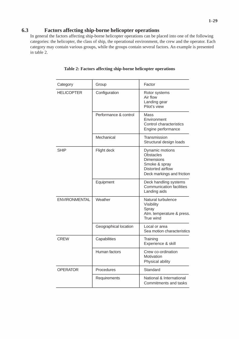
6.3 Factors affecting ship-borne helicopter operationsIn general the factors affecting ship-borne helicopter operations can be placed into one of the followingcategories: the helicopter, the class of ship, the operational environment, the crew and the operator. Eachcategory may contain various groups, while the groups contain several factors. An example is presentedin table 2.
Category Group Factor
HELICOPTER Configuration Rotor systemsAir flowLanding gearPilot’s view
Performance & control MassEnvironmentControl characteristicsEngine performance
Mechanical TransmissionStructural design loads
SHIP Flight deck Dynamic motionsObstaclesDimensionsSmoke & sprayDistorted airflowDeck markings and friction
Equipment Deck handling systemsCommunication facilitiesLanding aids
ENVIRONMENTAL Weather Natural turbulenceVisibilitySprayAtm. temperature & press.True wind
Geographical location Local or areaSea motion characteristics
CREW Capabilities TrainingExperience & skill
Human factors Crew co-ordinationMotivationPhysical ability
OPERATOR Procedures Standard
Requirements National & InternationalCommitments and tasks
Table 2: Factors affecting ship-borne helicopter operations

1-30
6.4 Main elements determining the scope of qualification programmesThe scope of a qualification programme is defined by the following elements:• Operator's requirements• Operator's standard operating procedures for helicopter & ship• Operational environment (geographic region & class of ship)• Helicopter capabilities & performance• Efficiency• Safety
Taking these elements into account a qualification programme as described in the following chapters canbe executed.

1-31
7. Factors Affecting Ship-borne Helicopter Control and Handling
7.1 GeneralA helicopter operating on board a ship is subjected to a very adverse and turbulent environment. Acomparison between land-based and ship-borne platforms was made and a brief overview of the shipenvironment in which a helicopter operates has been given in previous chapters.
The problem is to define the limitations imposed by the environment in quantitative terms. In order toobtain the required data, wind-tunnel and full-scale measurements are carried out to determine the envi-ronment above the flight deck.
7.2 The effect of the ship on the environment for helicopter operationsThe major factor limiting the helicopter operations on ships compared to land-based operations is thesmall flight deck for take-off and landing, which is:• moving (pitch, roll & heave)• obstructed by obstacles (mainly the hangar in front of the flight deck) which, apart from collision risk,
generate:- distorted air flow- a complicated turbulence field (in addition to natural turbulence)- influence of spray, causing a reduced view over the flight deck and possibly resulting in engine surg-
ing or even engine flame out• and where stacks and funnels are in the near vicinity generating:
- exhaust gas, which may cause:
* additional turbulence
* an increase of the ambient air temperature above the flight deck (increase of density altitude)
* reduced view over the flight deck
Although the ship's course and speed as such do not constitute limiting factors for helicopter operations,they may create, in combination with sea-state, wave/swell direction and true wind a limiting condition.
Since the ship’s environment is much more complex than the environment ashore, it should be deter-mined in what way the take-off and landing envelope as provided in the flight manual for land-basedoperations (Fig. 16) is affected. To evaluate the effect of the ship environment on the helicopter perform-ance, detailed data of the helicopter capabilities are needed. If not available in advance, these are ob-tained during land-based hover tests. These tests are used to evaluate yaw control performance in crosswind conditions and also at high torque values needed in the low-speed region. Furthermore helicopterpitch and bank angles needed for hover at high wind speeds from all directions relative to the helicopterare determined. Finally tests are carried out in those wind conditions where main-/ tail-rotor interferencemight exist, causing helicopter oscillations. It is understood that these tests are executed within thelimitations for land-based operations as given by the helicopter manufacturer (Fig. 16). The data obtainedshould indicate where, within the land-based envelope, regions exist where the margin between availableand required helicopter performance is small. An example of torque and yaw control performance ob-tained from such tests is given in figure 17.

1-32
Area of inadequateyaw control
StarboardPort
Ahead
Relative wind speed withrespect to helicopter
Fig.16 Typical relative low wind speed envelope as provided by the manufacturer
Fig. 17 Detailed results from land-based hover tests
Maximum helicopter all-up massZero density altitude
AreaA High engine torque; much yaw controlB Main / tail rotor interference (yaw oscillations)C Large bank angleD Large pitch-up angleE Inadequate yaw control
PortStarboard
CB
E
D
A
A
Relative wind speed withrespect to helicopter
Ahead

1-33
Knowing the ship environment and the relevant performance of the helicopter, the effects on helicopteroperations can be estimated, if not quantitatively, then at least qualitatively. Such effects can be groupedinto two classes:• effects that may result in hazardous flight conditions, which will have to be avoided;• effects which will create a difficult and demanding situation for the pilot.These effects should be evaluated carefully and the operational applicability should be evaluated bymeans of flight testing.
7.3 Hover performanceThe purpose of the so called “hover ladder” flight test (Fig.18) is to compare the torque required to hoverat various gross weights with those predicted by the helicopter operator’s manual both in ground effect(IGE) and out of ground effect (OGE). Manuals in general do not provide adequate detailed informationto derive optimum limitations for combinations of specific helicopter types on board a specific class ofship.
The test is performed at altitudes of 5, 15, and 50 to 60 feet above ground level (AGL), yawing thehelicopter relative to the ambient wind in 45 degree increments, starting at the nose of the helicopter andworking around from 0° to 405° (360 + 45 degrees). When a stable hover condition is reached, enginetorque, rotor rpm, helicopter attitudes, and flight control positions are recorded in addition to ambientconditions (pressure altitude, OAT, ambient winds etc., etc.). The result of this test provides a goodbaseline to work from to predict helicopter power and control performance requirements out at sea.
Fig. 18 General set-up during land-based flight trials

1-34
7.4 Yaw controlSimilar to helicopter performance, good handling qualities and control are necessary to counteractturbulence and ship's motions adequately. During transitions to and from forward flight, take-off andlanding, a control margin is required to maintain controllability during any unexpected situation (gusts,turbulence,...). In most cases, control margin limitations occur for pedal controls. For helicopters thatemploy tail rotors, yaw control is an area of concern. Conditions where inadequate yaw control exists(area E in Figure 17) must be avoided. Therefore a decelerating flight from approach speed to hover,while the relative wind above the flight deck is situated in the shaded area under area E (Fig. 17), must beavoided as the relative wind condition of the area E will be traversed. Such an approach to an obstructedflight deck with inadequate yaw control is hazardous.
Wind conditions close to those areas where inadequate yaw control exists must be approached verycarefully because of yaw control variations needed to counteract turbulence and ship motions adequately.
7.5 Landings on an oscillating deckMost helicopter manufacturers provide sloped landing limitations for take-off and landing operationsoutside unprepared helicopter landing sites. In most land-based operations, pilots can adjust the helicop-ter heading to land either up-slope, down-slope, or cross-slope depending on the safest option. Similarly,limitations may restrict helicopter ship-borne operations due to the relative geometric attitude of thehelicopter to the ship.
In the Netherlands the Flight Deck Officer will launch & recover the helicopter during a quiescentmotion period of the ship, with the deck in an almost horizontal position. It must be remarked that beforetake-off and directly after the land-on the helicopter is secured to the flight deck by means of a harpoon-grid system (in some navies known as "Talon"-system). The system greatly increases the allowable shipmotions. For those operators where the helicopter crew lacks the assistance of a Flight Deck Officer tolaunch and land the helicopter, the deck slope aspect is of great importance in order to avoid dynamic rollover.
7.6 High wind speed from aheadAnother factor that will affect helicopter handling qualities and control is air-wake turbulence due to highwind speeds from the forward sector. In this case, the turbulence caused by the ship superstructure affectsthe helicopter such that the pilot cannot maintain sufficient control for safe take-off or landing.Relative wind conditions where very heavy turbulence exists (Fig. 19; high wind speed from ahead), incombination with spray nuisance (Fig. 20; reducing pilot's view over the flight deck) and rather large shipamplitudes, especially in pitch (Fig. 21; inherent to the accompanying high sea-state), have to be avoided.In such cases the control inputs required to counteract the helicopter response to turbulence in combina-tion with manoeuvring, necessary to avoid collision with parts of the oscillating ship may be too large(overtorqueing, maximum control margin), and create a hazardous condition.
7.7 Low relative wind speedHigh engine power is needed at low relative wind speed and at high helicopter mass (area A in Figure17). The power and yaw control margins in that condition might be too small to counteract adequately acertain amount of ship's motions. Therefore helicopter mass and density altitude should be watched verycarefully during helicopter ship operations. Furthermore, at low relative wind speed the down-wash ofthe rotor generates spray, which is most bothersome when the helicopter hovers alongside the flight deck(Fig.22).

1-35
Fig. 19 Turbulence level above the deck as a function of relative wind
Fig. 20 Relative wind conditions during which spray and exhaust gas may be bothersome
StarboardPort
Ahead
Undisturbed relativewind speed withrespect to ship
Very heavyHeavy
Light to moderate
Negligible
Light
Moderate
StarboardPort
Ahead
Undisturbed relativewind speed withrespect to ship
SprayExhaust gas

1-36
7.8 Strong tail windTaking into consideration the presence of obstacles near the flight deck, strong tail-wind conditions (areaD in Figure 17) can create a hazardous situation. Moreover, such wind conditions result in large helicop-ter pitch-up angles reducing pilots view over the flight deck. For these reasons strong tail-winds (above10 kts) should be tested with extreme caution. When areas of the land-based relative-wind diagram inwhich either of the hazardous conditions may occur are left out, a candidate ship-operation-relative-winddiagram results of which an example is shown in figure 23. It should be noted that such a diagram resultsfrom measurement of the ship's environment, helicopter performance measurements and analyses.Whether or not the diagram can be used operationally has to be determined by means of dedicated flighttests. To determine those areas in which testing has to be carried out an evaluation (also based on themeasurements and analysis mentioned above) of the following conditions, where difficult and demandingsituations will occur for the pilot, has to be made.
Fig. 21. Example of ship’s pitch and roll amplitudes as a function of ship’s speed and course
Shi
p’s
pitc
hing
am
plitu
de
Shi
p’s
rolli
ng a
mpl
itude
�
Sea-state Sea-state
Ship’s speed
�
Ship’s speed� �
� = 0o, 180o
� =45o, 135o
� =90o� =90o
� =45o, 135o
� = 0o, 180o
� = Relative wave direction
Fig. 22 Spray resulting from downwash and recirculating airflow

1-37
7.9 Blade sailingEspecially helicopters with a fully articulated main rotor system are subjected to blade sailing duringrotor start up and/or shut down in a turbulent/gusty wind environment. The problems associated withblade sailing are: tunnel and/or forward cockpit strike and the risk of decapitation of deck personnel.
There are no specific test procedures for this subject in the Dutch & British procedures. The only precau-tions which are taken during flight testing are:• never exceed manufacturer's limitations and• start up and shut down main rotor in optimal obtainable wind and ship motion conditions during flight
testing.
In practice, this problem has not been met in the Dutch nor in the British experience.
7.10 Hot exhaust gas ingestionAnother factor that affects helicopter performance is hot exhaust gas ingestion. There are two types ofshipboard problems associated with hot exhaust gas.
The first is the helicopter ingesting hot gases from the ship propulsion or energy generating systems.During wind-tunnel testing on a ship's model and during full-scale wind climate testing (Chaps. 6.2 and6.3) close attention is paid to this subject.
The second is the helicopter re-ingesting its gas turbine exhaust due to recirculation.Helicopter problems may be a result of a combination of the two. Hot exhaust gas ingestion decreases thehelicopter’s available power.
7.11 Pilot field of view and visual orientationField of view analysis in preparation for a shipboard flight test is usually not a critical issue unless thetest helicopter is a prototype or the purpose of the test is to evaluate a new deck marking configurationfor ship-borne operations.
Visual cues provide the pilot with situational awareness and the ability to manoeuvre the helicopter overthe landing spot. The situational awareness can be degraded by several factors.
At high cross-winds from port, during fore and aft landing from port, the helicopter will bank to the left(port). On the other hand the ship's list will be over right (starboard). This results in a deteriorated pilot'sview over the flight deck (Fig.17 Area C).
When operating in high tail winds the increased nose-up attitude of the helicopter will also result in adeterioration of pilot's view.
Other factors that will degrade the pilot's view of the flight deck during approach and hover are the saltspray generated by the ship's hull (Sect. 5.7) and by the recirculation of the downwash of the rotor in lowrelative wind speeds.
Degradation of pilot's view and visual cues will result in a high to unacceptable pilot's workload and is alimiting factor for helicopter ship-borne operations.

1-38
7.12 Approach aidsShipboard lighting, if not properly managed, can pose a significant problem at night to a pilot approach-ing the ship in darkness. Normally for night flying operations a "darkened ship" routine is maintained,which implies that all exteriour lighting is switched off, ship's navigation lights are dimmed if necessaryand only flight essential lighting is on. In the Royal Netherlands Navy and Royal Navy this consists of:• A glide slope/path indicator (GSI or GPI). The GSI is a semistabilized indicator showing vertically a
green sector with an inclination between 2 deg. and 4 deg. for the correct 3 deg. glide path. Above 4 deg.it shows amber and below 2 deg. it shows red. The horizontal sector is 15 deg. centred around the(predetermined) approach line to the ship.
• A fixed horizon bar consisting of fixed dimmable white bulb lights which are mounted above the hangardoor.
7.13 Piloting skillsControlling the helicopter in the conditions encountered during ship-board operations is a demanding job.The workload depends both on the helicopter flight characteristics and on the amount of ship (flightdeck) motion, the turbulence level encountered, the view over the flight deck, visibility and lightingconditions (day or night). In this highly dynamic environment the workload of the pilot may become toohigh, and conflict with the flight safety. Excessive workload situations may result in further or additionaloperational limitations. To evaluate the dynamic behaviour of the helicopter/pilot combination in thecomplex turbulent environment of the moving flight deck of a ship, the execution of actual flight tests isthe only means available at present. To establish optimal and safe limitations it is crucial that the tests arecarried out by pilots with maximum experience in ship-borne helicopter operations. Apart from that the"test" pilot has to take into account the capabilities and skill of the "average' pilot who has to operate upto the limitations which are produced.
Although during the qualification flight tests the pilot is backed up by recordings of the helicopterperformance and behaviour, his opinion remains one of the most important contributions to the process ofdetermining operational limitations due to high workload and dynamic response effects.
Furthermore the safety of the flight testing ultimately rests on his ability to properly judge the severity ofthe actual conditions in which the testing takes place.
7.14 Candidate flight envelopeThe relative wind envelope in which the "difficult" areas are indicated, is the basis for the flight testprogramme to be carried out on board the ship. It is shown in figure 23.
At high relative wind speed from ahead, the accompanying turbulence (moderate to heavy; area B) andespecially the large pitch amplitudes of the ship need much control effort of the pilot which might resultin such large power variations that the maximum allowable continuous torque is often exceeded.Besides, the presence of spray and exhaust gas (areas C, D), reducing the pilot's view over the flightdeck, increases his workload even more. Hot exhaust gasses above the flight deck and along the helicop-ter flight path close to the ship, have a similar effect on the helicopter rotor and engine performances asincreased density altitude.
At low relative wind speeds, high power and large control inputs are required to precisely control thehelicopter, while the ship's stabilization system being generally less effective causes additional controlinputs (areas A, C & E) to correct for ship motions.

1-39
The candidate relative wind envelopes for ship-borne testing, based on the manufacturer’s low speedflight envelope (Fig. 16), are divided into various aircraft mass bands for each type of landing to beevaluated (Sect 4.2.1). Generally speaking, an aircraft will have a wider (larger) operating envelope atlight all up mass (AUM) than at heavy AUM due to reduced control and power margins as the helicoptermass increases. The aircraft mass bands are decided upon before any trials take place and depend uponthe particular aircraft. The aim is to produce 4 to 5 bands covering the range of masses at which theaircraft will be required to operate. This range normally extends some way beyond the maximum permit-ted AUM of the aircraft to account for non-standard atmospheric conditions. The test mass, calculated interms of M/(σω2) (mass divided by relative density and rotor speed ratio squared) is referred to as COR-RECTED MASS. The trials are conducted at various values of M/(σω2) and used to produce the “cor-rected envelopes” which are issued by the operators.
Fig. 23 Candidate flight envelope to be tested o/b a ship
Area Difficult conditionsA High engine torque; much yaw controlB Heavy and moderate turbulenceC Spray nuisanceD Exhaust gas nuisanceE Yaw control
CB E
D
A
A
Ahead
C
E
Port Starboard
Relative wind speed withrespect to helicopter
Maximum helicopter all-up masszero density altitude

1-40
8. Testing
8.1 GeneralThis section gives a brief description of the tests to be carried out in a qualification programme.
8.2 Wind tunnel tests on a scale model of the shipWind tunnel tests on ship models are carried out to determine the airflow characteristics (airflow devia-tions with respect to the undisturbed oncoming relative wind, turbulence) above the flight deck and in thepossible approach paths of the helicopter to the ship as function of the relative wind. The relative wind isthe wind vector resulting from the true wind and ship's course and speed. Furthermore the ship's exhaustplume paths and prediction of plume temperature (by plume dispersion measurement) as a function ofship's power settings and relative wind conditions are determined. Finally the position error of the ship'sanemometer is determined which is, apart from the instrumentation error of the anemometer, needed toestablish the relation between the undisturbed relative wind conditions and those prevailing above theflight deck and at the helicopter approach paths.
An example of a wind tunnel investigation on stack and funnel design in relation to smoke nuisance, ispresented in figure 24. The figure shows the original design (bottom part) and the proposed designdetermined from the wind tunnel investigation. Both situations presented are for identical head wind andexhaust gas dispersion.
Note:By carrying out these tests in the design stage of the ship it is often possible to determine that, by asmall change to the superstructure the airflow patterns above the flight deck can be improved and theexhaust gas nuisance can be decreased, so that costly modifications of the existing ship may beprevented. The same holds for the position of the ship's anemometers on a yard of a mast and inrelation to other sensors.Furthermore one must keep in mind that an optimum stack/funnel design for flight operations does notautomatically include an optimum for Infra Red Signature and/or Radar Reflection Cross-Section, sooften compromises have to be made.
Fig. 24 Stack & exhaust gas nuisance investigation on a wind tunnel model

1-41
8.3 Full-scale ship's wind climate and motion testsWind climate tests on board the ship are carried out to verify the wind-tunnel test results concerning theair flow characteristics above the flight deck. For these tests two movable masts with wind measuringsystems including temperature probes and data acquisition units are used. One mast contains one measur-ing and acquisition system at 3m height above the flight deck. The second mast contains two systems atheights of 5 m and 10 m above the flight deck (Fig. 25). With the established relation between the windtunnel test results and full-scale ship test results, the real wind climate in the various helicopter approachpaths and over the flight deck is predicted.
The instrumentation error of the ship's anemometer is determined and the position error, as establishedduring the wind tunnel tests, is verified. With the information obtained, an unambiguous relation betweenthe anemometer readings, the air flow conditions above the flight deck and in the helicopter approachpaths and the undisturbed relative wind condition is determined.
Ship motion characteristics (pitching, rolling and heaving motions) are determined as a function of seastate, wave/swell direction and ship's speed. Examples of results concerning ship motion, turbulence,exhaust gas and spray above the flight deck have been discussed and presented in chapter 5 (Figs. 19-21).
Fig. 25 NLR moveable mast as used during ship airwake measurements

1-42
8.4 HelicopterFrom the analyses described in the previous chapters a number of take-off and landing procedures result,with for each of these a candidate relative wind diagram (see example in Fig. 26).
Fig. 26 Composition of possible wind envelopes for varioushelicopter approach headings with respect to the ship
Relative wind envelopesfor approachesfrom starboard not shown
Port Starboard
Ahead
Approachfor XD
Approachfor F/A
F/A: Fore/Aft procedureXD: Cross-Deck procedureRW: Relative Wind procedure
Undisturbedrelative wind speed with
respect to ship
Approachfor RW
These diagrams then are combined to form a candidate helicopter-ship operations envelope. Since over-laps of the relative-wind diagrams for the various procedures will occur, a choice is made, taking intoaccount the relative size of each of the overlapping sectors (maximizing the ship-borne operations enve-lope) and the expected ease of operating the helicopter. The trade-off is made, using operator require-ments, engineering and pilot judgement. An example of a typical Dutch candidate helicopter-ship opera-tions diagram is shown in figure 27.
Using ship anemometer calibration data, obtained during wind climate measurements, this operationalenvelope is related to relative wind indications available on the ship in relation to actual wind conditionsabove the flight deck. An example of such an envelope (valid for the fore/aft procedure Fig. 23) is shownin figure 28.
This candidate operational envelope will contain a number of areas for which the analyses indicate arequirement for testing. The problems that may occur are identified and the test procedure and instrumen-tation, required to investigate these areas safely, are determined.
These areas result in a total number of conditions, which all are preferably to be tested.

1-43
Port Starboard
Ahead
BBD C
E
E
E
A
A
C
Ship’s indicatedrelative wind speed
Maximum helicopter all-up masszero density altitude
Area Difficult conditionsA High engine torque; much yaw controlB Heavy and moderate turbulenceC Spray nuisanceD Exhaust gas nuisanceE Yaw control
Since the flight-testing is to be carried out on board a ship in a limited period of time, the exact condi-tions at which tests can take place cannot be determined beforehand. Conditions that will be testeddepend on the sea-state and wind conditions that are present in the area where the tests are taking place.Of course, the area and time of the year are selected to maximize the probable occurrence of the desiredtest conditions. However, this still usually does not provide the experimenter with a free hand to vary histest conditions at will.
Fig. 27 Resultant candidate relative wind envelope to be tested duringhelicopter flight testing on board the ship.
F/A: Fore/Aft procedureRW: Relative Wind procedureXD : Cross-Deck procedure
F/A
RWRW
XD
Ahead
Port Starboar
XD
Undisturbedrelative wind speed with
respect to ship
Fig. 28 Relative wind envelope for fore/aft take-off and landing to be tested o/b the ship,corrected for ship anemometer system

1-44
8.5 Flight testingAs evident from the previous paragraph, the flight-test programme has to be defined in an interactive wayduring the testing period. The actual execution of the flight-test programme is governed by two mainaspects:• safety• efficiency.
Safety is principally obtained by starting the flight tests in conditions easy for aircraft and ship personnel,leading to test team familiarization:• low helicopter mass• relative-wind conditions well inside the boundaries of the candidate relative-wind envelope (no "tough"
conditions; e.g. Fig. 28)• fore/aft procedure (the easiest)• fair weather• first by day, later on by night.
After a thorough familiarization, efficiency is obtained by making adequate use of the information thatbecomes available during the flight tests and by analyzing, on board the ship, that information in con-junction with the data base obtained prior to the flight tests. Thus maximum use is made of the informa-tion obtained from the tests, and the number of test flights required can be minimized.
During the test period the selection of test conditions is a major task. Based on the analyzed results of thetests that have already been carried out, a number of alternatives for the next test condition are defined.This exercise is carried out in parallel for test conditions related to each of the potential problem areas ofthe candidate operational envelope, thus yielding a large selection of usable test conditions. The choiceof the next test condition then depends on the available forecast wind/sea state conditions in the areawithin reach of the ship. Problems like judging the reliability of weather forecast versus time of the shipto travel to the area of interest are to be solved.
Given certain environmental conditions (wind, sea state, temperature) a number of conditions can becreated by changing ship speed and heading relative to the wind (relative wind conditions) and waves(flight deck motion), although these cannot always be changed independently. The only parameter thatcan be changed independently appears to be helicopter mass.
Clever use of information obtained on board, in conjunction with thorough knowledge of the factors thatlimit operations, is used to minimize the problems created by the difficulty to establish the most desirabletest conditions. Often it is not a matter of demonstrating the capability to operate the helicopter at thecondition specified, but to obtain data at differing conditions and interpolating or extrapolating the resultsto the conditions required.
The following data are normally acquired during the tests:• actual data of helicopter parameters:
- engine torques- control deflections- pitch and bank angles- heading- radar altimeter- doppler velocities- engine inlet temperature- type-dependent additional parameters

1-45
• actual data of ship parameters such as:- speed- heading- wave/swell direction (estimation)- pitching and rolling angles- anemometer readings (relative wind condition)- stabilization data- propulsion mode- vertical and lateral acceleration at the flight deck
• pilot's comment on workload, influenced by:- take-off and landing procedure- ship's motions- turbulence- view over the flight deck- spray and exhaust gas nuisance.
Pilot's workload is expressed in the following adjectival rating scale:• low• high• just unacceptable• beyond unacceptable
Note that two types of data become available: quantitative data on helicopter performance and shipbehaviour, and qualitative data on pilot workload and helicopter controllability. The latter should bereferenced to the average pilot skill level.
Within the constraints imposed by the environment in which the tests have to be carried out, all effort ismade to carry out the testing as efficient as possible. To this end the nominal procedure as depicted infigure 29 is used. For each condition tested, the results are evaluated and subsequently the requiredincrease in severity of the conditions of the next test condition is determined. Of course in this processboth engineering insight and flight technical skill (of the pilot) is involved.
With the knowledge available in advance and the data obtained during the previous test flight, the influ-ence of a given test condition on the helicopter limitations can be predicted rather well.
A prediction of the increase in pilot workload is only possible to a certain extent. If, for example, theworkload in a certain condition is "low", the permitted increase in difficulty of the next test conditionwill be greater than in the case for "high" workload. The same rule is applied (in reverse) in the case acondition is considered "unacceptable". If it is "beyond unacceptable" (occurring sporadically), a largedecrease in difficulty is applied whereas if the condition is considered "just unacceptable" a small de-crease in difficulty is applied. With the application of these prediction methods, good engineering judge-ment and the experience of pilot and test team, the number of flying hours can be reduced to a minimum,and a maximum of results will be obtained in the shortest possible time.
Typical rating scales for a specific helicopter type, as used in the UK are shown in tables 3 and 4. Eachtake-off and landing is assessed for control and power margins as well as pilot handling qualities.

1-46
Yes
No
Unacceptable
High Low
Acceptable
Within helicopter limitations?
Change conditionaccording to reason
Execution of helicopter operation in certain condition
Small decrease indifficulty of condition,according to reason
Small increase indifficulty of condition,according to reason
Large increase indifficulty of condition,according to reason
Justunacceptable
Beyondunacceptable
Pilot
Test team
Large decrease indifficulty of condition,according to reason
Work load
The assessment of control generally means the evaluation of tail rotor pitch or rudder pedal marginswhere it has been determined that cyclic and collective margins are adequate. Power is evaluated usingtorque values, thus the rating scale is based on indicated torque values in relation to transmission orengine limits.
In table 3, it can be seen that five-point scales are used. It can also be seen that both mean and maximumtorque, pedal and cyclic values are rated. The more limiting value is used to assess the take-off or land-ing.
Torque and tail rotor considerations on their own are not adequate to cover all eventualities, and it isnecessary for the pilots to assess the handling difficulty or workload associated with a take-off andlanding.
For pilot handling a six-point scale, as given in table 4, is used.
To attempt to assess all wind conditions at all masses would be a very large if not untenable task. Thephilosophy therefore allows for this by permitting landings at different masses to be read across (extrapo-lated) to other procedures. However, there are rules for this and not all take-offs or landings can be readacross.
Fig. 29 Flight test procedure o/b the ship

1-47
Rating Description Explication
1 NO PROBLEM Minimal pilot effort required resulting in aneasy task.
2 SATISFACTORY Landing carried out with low pilot workload.
3 LIMIT(S) Safe landings can be carried out, but limits ofAPPROACHED power etc approached or reached;
OR pilot workload moderate.4 REACHED Situation becoming difficult due to one or
more factors. These points define the fleetlimits recommended by QinetiQ.
5 UNACCEPTABLE Test pilot able to land helicopter undercontrolled conditions, but limits of power etc
are exceeded.High pilot workload.
6 DANGEROUS Test pilot attempting the landing causesaircraft limitations to be exceeded.
Excessive pilot workload.
In essence take-offs or landings which are rated as unacceptable at low mass (>4 on the rating scale) arealso read up to higher masses as unacceptable. Take-offs or landings which are rated as acceptable at highmass (3 or less on the rating scale) are read down to lower masses. The reasoning behind this is perhapsobvious; an easy landing at high mass is also likely to be easy (if not easier) at a lower mass. Equally alanding which is rated as unacceptable at low mass because of lack of power or control margins will notbe any better at a higher mass and the same is considered to be true of handling issues. This provides arational basis for expanding the evidence available at any one mass without conducting a particular testpoint at that mass.
RATING MEAN % PEAK %
TORQUE
1/2 < 95 < 1053 95-98 105-1104 89-100 110-1155 > 100 > 115
PEDAL POSITION
1/2 > 12 > 103 12-10 10-54 10-5 5-05 < 5 0
F/A CYCLIC POSITION
1/2 > 20 > 103 20-16 10-154 16-14 5-25 < 14 < 2
Table 3: Torque, Pedal & Cyclic Rating Scales
Table 4: QinetiQ Pilot Rating Scale
NOTE:Ratings of 1 to 4 are acceptable; rating 5 is unacceptable.

1-48
8.6 Drafting SHOLs/Constructing Wind EnvelopesThe operational wind envelopes are drawn up around the acceptable test points attained during the trials.When constructing the wind envelopes, ratings of 1-3 are included, ratings 5/6 are excluded. Rating 4denotes the limit of acceptability in each case. Where necessary the envelopes are rationalised in theinterests of simplicity. The complete SHOL comprises both the wind envelopes and the ship motionlimitations.
Different envelopes are produced for use by day and by night. The main difficulty with landing at night isdue to the scotopic vision of the human eye in these conditions. At low light levels the visual acuity ofthe eye is degraded so that distance and hence speed/closure rate are difficult to judge. For this reasonwinds from astern are not cleared for night operations, because Boscombe Down experience has shownthat there are too many errors of judgement leading to overtorqueing and/or overshooting the approach.In general this is the only difference between day and night wind envelopes, but during tests at sea it isassessed, to ensure that other areas can be included at night. The deck motion limits applied at nightmight also be somewhat lower than those permitted by day.

1-49
9. Establishment of Helicopter Operational Envelopes for Ship-borne Operations
At the completion of the flight tests on board the ship, a fair idea about the operational limitations hasusually been obtained. For final results, measured data (of helicopter and ship) together with pilot'scomment are analysed in detail. The operational limitations are presented in the form of graphs. Exam-ples of these graphs are given in the figures 30 and 31.
In figure 30, limitations are given for the fore/aft take-off and landing procedure while in figure 31 theresult is shown for the total relative wind envelope optimized within the constraints of safety and maxi-mum operational usability of the helicopter.
Fig. 30 Take-off and landing limitations for fore/aft procedure (NL-presentation)
Following the determination of acceptable wind envelopes and ship motion limits, the SHOLs for a rangeof aircraft Corrected All Up Mass (CAUM) are issued to the operators, together with advice concerningmodifications to the ship such as improved deck markings or lighting and any warnings about turbulence.Should any helicopter deficiencies have come to light during the trials then these would also be broughtto the attention of the appropriate authority. An example of an operational SHOL diagram is shown inFigure 32.
A3
A2
A1
Zero density altitude
Port Starboard
Ship’s indicatedrelative wind speed
Ahead
Percentage of max.Helicopter all-up mass
94
97
100
100
Allowable helicopter mass and ship’s oscillations
Area
A1
A2
A3
Amplitudes of ship’soscillations
Pitching (deg) Rolling (deg)
3.0 9.0
1.0 1.5
5.0 9.0
5.0 7.0
{

1-50
Zero density altitude
Percentage of max.
Helicopter all-up mass
9497
1001009497
1001009497
1001009497
1009497
100
Allowable helicopter mass and ship’s oscillations
Area
A1
A2A3
B1
B2
B3
B4
B5B6
C1
C2
C3
C4
Amplitudes of ship’soscillations
Pitching (deg) Rolling (deg)
3.0 9.01.0 1.55.0 9.05.0 7.02.0 8.01.0 1.55.0 9.04.0 9.01.5 6.01.0 1.53.5 8.03.0 6.02.0 7.01.0 1.55.0 8.01.5 5.01.0 1.53.0 6.0
{
{
{
{
{
Port Starboard
Ahead
A3
A2
A1
RW RW
F/AXD XD
F/A
C3
B4B1
C1
B2 B5
B3 B6
Ship’s indicatedrelative wind speed
C4
C2
Fig. 31 Limitations for daytime operations (NL-presentation)
Fig. 32 Limitations for daytime operations (UK-presentation)
50
10
20
Deck motion limits = +/- 2o Pitch+/- 5o Roll
CAUM AB > AC > B
Ship s indicatedrelative wind speed [kn]
Ahead
Aircraft type 2BC - Ship class F
Day forward facingPort & Starboard approach
30
40Turbulence
20
Red Green
10

1-51
10. Simulating the Helicopter/Ship Interface
10.1 International research activitySo far this AGARDograph has described the process of determining SHOLs using a combination of windtunnel, land-based and ship-based testing. Neither the Dutch nor the UK Test Agencies currently makeuse of any related simulation capability. With the increasing defence budget constraints now facing manycountries, it is appropriate to undertake a review of simulation approaches to the determination of SHOLsto see if there is a more cost-effective way of achieving the same end result.
The defence research community, both in the UK and abroad has, for some years, been actively pursuinga programme of work aimed at developing helicopter/ship dynamic interface simulation. The results ofthis work, once it is seen to be sufficiently mature, could be of great benefit to the Test and Evaluation(T&E) community. In the UK, QinetiQ has played a leading part in this international collaborative effort,whose aims are to:• improve existing helicopter and ship models• develop common data formats• share trials data and research findings• develop and promote common pilot rating scales• invest in model fidelity and validation issues• encourage an exchange programme of both test pilots and engineers for both simulator and flight trials
Over the past few years research conducted at QinetiQ’s Bedford site, utilising the Advanced FlightSimulator (AFS), has been directed at improving ship motion models, ship air-wake and turbulencemodelling, visual scene content and development of improved helicopter mathematical models. Theresearch activity is aimed, at some future date, at being able to carry out some ship/helicopter compatibil-ity testing using simulation. For example, simulation could be used to indicate potential 'hot spots' in theship/helicopter operating envelope. Subsequent flight tests could then be concentrated in and around suchareas, thereby reducing flight test time, easing the difficulties of ship availability and the vagaries of theweather and increasing the effectiveness of sea trials.
In a SHOL these ‘hot spots’ are identified on the basis of helicopter power performance and controllabil-ity as a function of mass and density altitude and wind relative to the helicopter. The determination of thewind relative to the helicopter is obtained by using the air flow data from the wind tunnel testing on aship’s model and/or full scale wind flow measurements on board the trials ship. An outcome of thisresearch could, in the future, bring significant benefit to the Royal Navy, in terms of the cost of thehelicopter/ship flight test clearance activity and in providing dedicated ships for trials.
10.2 Modelling ship motionThe application of improved ship motion modelling could provide T&E with an important tool in thedetermination of future ship motion limits for SHOLs. Although ship designers are carrying out researchprogrammes to improve the ship stabilisation systems in order to decrease the severity of ship motions,such motion is and will continue to be an important feature of helicopter deck operations. Pilots musttake off and land inside limits promulgated by the helicopter Design Authority to ensure that structural,and other limits are not exceeded. In a simulator this means that a realistic presentation of ship motion isvery important. The wind direction and speed, the direction that the sea is running and the ship's speedare all important parameters. To date this area has received little specific attention, primarily becausedeck landing was not part of the usual suite of tasks for naval helicopter training simulators. Most currentsimulators either provide simple harmonic motion driven models or crude models using a small numberof superimposed sine waves. A 'real wave' environment can be complex because it can consist of a longwavelength swell, induced by a wind that has been blowing, perhaps a few hundred miles away, in
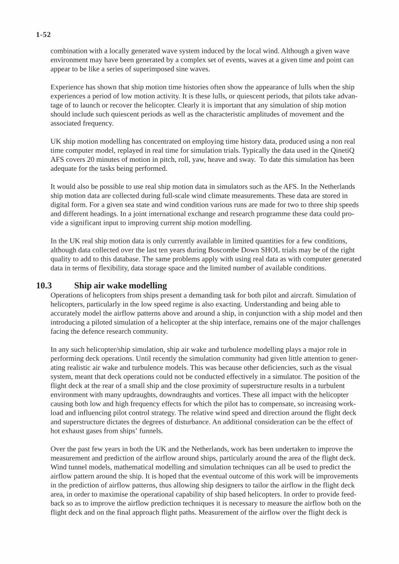
1-52
combination with a locally generated wave system induced by the local wind. Although a given waveenvironment may have been generated by a complex set of events, waves at a given time and point canappear to be like a series of superimposed sine waves.
Experience has shown that ship motion time histories often show the appearance of lulls when the shipexperiences a period of low motion activity. It is these lulls, or quiescent periods, that pilots take advan-tage of to launch or recover the helicopter. Clearly it is important that any simulation of ship motionshould include such quiescent periods as well as the characteristic amplitudes of movement and theassociated frequency.
UK ship motion modelling has concentrated on employing time history data, produced using a non realtime computer model, replayed in real time for simulation trials. Typically the data used in the QinetiQAFS covers 20 minutes of motion in pitch, roll, yaw, heave and sway. To date this simulation has beenadequate for the tasks being performed.
It would also be possible to use real ship motion data in simulators such as the AFS. In the Netherlandsship motion data are collected during full-scale wind climate measurements. These data are stored indigital form. For a given sea state and wind condition various runs are made for two to three ship speedsand different headings. In a joint international exchange and research programme these data could pro-vide a significant input to improving current ship motion modelling.
In the UK real ship motion data is only currently available in limited quantities for a few conditions,although data collected over the last ten years during Boscombe Down SHOL trials may be of the rightquality to add to this database. The same problems apply with using real data as with computer generateddata in terms of flexibility, data storage space and the limited number of available conditions.
10.3 Ship air wake modellingOperations of helicopters from ships present a demanding task for both pilot and aircraft. Simulation ofhelicopters, particularly in the low speed regime is also exacting. Understanding and being able toaccurately model the airflow patterns above and around a ship, in conjunction with a ship model and thenintroducing a piloted simulation of a helicopter at the ship interface, remains one of the major challengesfacing the defence research community.
In any such helicopter/ship simulation, ship air wake and turbulence modelling plays a major role inperforming deck operations. Until recently the simulation community had given little attention to gener-ating realistic air wake and turbulence models. This was because other deficiencies, such as the visualsystem, meant that deck operations could not be conducted effectively in a simulator. The position of theflight deck at the rear of a small ship and the close proximity of superstructure results in a turbulentenvironment with many updraughts, downdraughts and vortices. These all impact with the helicoptercausing both low and high frequency effects for which the pilot has to compensate, so increasing work-load and influencing pilot control strategy. The relative wind speed and direction around the flight deckand superstructure dictates the degrees of disturbance. An additional consideration can be the effect ofhot exhaust gases from ships’ funnels.
Over the past few years in both the UK and the Netherlands, work has been undertaken to improve themeasurement and prediction of the airflow around ships, particularly around the area of the flight deck.Wind tunnel models, mathematical modelling and simulation techniques can all be used to predict theairflow pattern around the ship. It is hoped that the eventual outcome of this work will be improvementsin the prediction of airflow patterns, thus allowing ship designers to tailor the airflow in the flight deckarea, in order to maximise the operational capability of ship based helicopters. In order to provide feed-back so as to improve the airflow prediction techniques it is necessary to measure the airflow both on theflight deck and on the final approach flight paths. Measurement of the airflow over the flight deck is
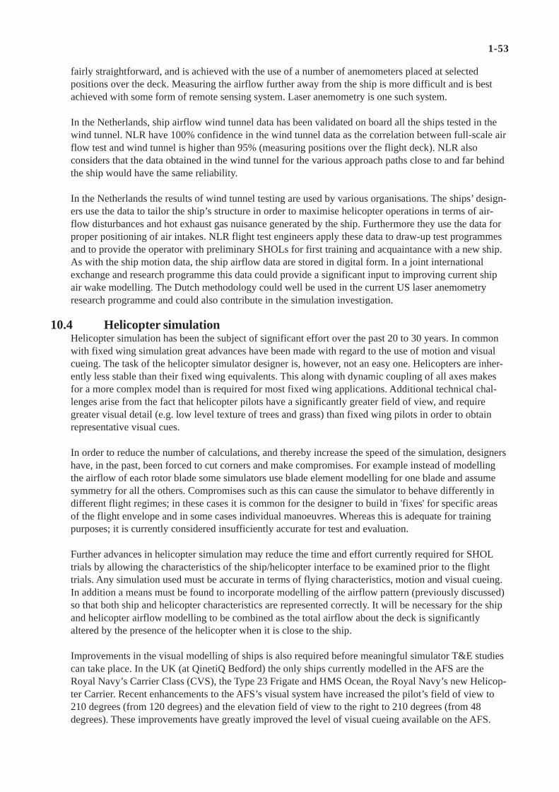
1-53
fairly straightforward, and is achieved with the use of a number of anemometers placed at selectedpositions over the deck. Measuring the airflow further away from the ship is more difficult and is bestachieved with some form of remote sensing system. Laser anemometry is one such system.
In the Netherlands, ship airflow wind tunnel data has been validated on board all the ships tested in thewind tunnel. NLR have 100% confidence in the wind tunnel data as the correlation between full-scale airflow test and wind tunnel is higher than 95% (measuring positions over the flight deck). NLR alsoconsiders that the data obtained in the wind tunnel for the various approach paths close to and far behindthe ship would have the same reliability.
In the Netherlands the results of wind tunnel testing are used by various organisations. The ships’ design-ers use the data to tailor the ship’s structure in order to maximise helicopter operations in terms of air-flow disturbances and hot exhaust gas nuisance generated by the ship. Furthermore they use the data forproper positioning of air intakes. NLR flight test engineers apply these data to draw-up test programmesand to provide the operator with preliminary SHOLs for first training and acquaintance with a new ship.As with the ship motion data, the ship airflow data are stored in digital form. In a joint internationalexchange and research programme this data could provide a significant input to improving current shipair wake modelling. The Dutch methodology could well be used in the current US laser anemometryresearch programme and could also contribute in the simulation investigation.
10.4 Helicopter simulationHelicopter simulation has been the subject of significant effort over the past 20 to 30 years. In commonwith fixed wing simulation great advances have been made with regard to the use of motion and visualcueing. The task of the helicopter simulator designer is, however, not an easy one. Helicopters are inher-ently less stable than their fixed wing equivalents. This along with dynamic coupling of all axes makesfor a more complex model than is required for most fixed wing applications. Additional technical chal-lenges arise from the fact that helicopter pilots have a significantly greater field of view, and requiregreater visual detail (e.g. low level texture of trees and grass) than fixed wing pilots in order to obtainrepresentative visual cues.
In order to reduce the number of calculations, and thereby increase the speed of the simulation, designershave, in the past, been forced to cut corners and make compromises. For example instead of modellingthe airflow of each rotor blade some simulators use blade element modelling for one blade and assumesymmetry for all the others. Compromises such as this can cause the simulator to behave differently indifferent flight regimes; in these cases it is common for the designer to build in 'fixes' for specific areasof the flight envelope and in some cases individual manoeuvres. Whereas this is adequate for trainingpurposes; it is currently considered insufficiently accurate for test and evaluation.
Further advances in helicopter simulation may reduce the time and effort currently required for SHOLtrials by allowing the characteristics of the ship/helicopter interface to be examined prior to the flighttrials. Any simulation used must be accurate in terms of flying characteristics, motion and visual cueing.In addition a means must be found to incorporate modelling of the airflow pattern (previously discussed)so that both ship and helicopter characteristics are represented correctly. It will be necessary for the shipand helicopter airflow modelling to be combined as the total airflow about the deck is significantlyaltered by the presence of the helicopter when it is close to the ship.
Improvements in the visual modelling of ships is also required before meaningful simulator T&E studiescan take place. In the UK (at QinetiQ Bedford) the only ships currently modelled in the AFS are theRoyal Navy’s Carrier Class (CVS), the Type 23 Frigate and HMS Ocean, the Royal Navy’s new Helicop-ter Carrier. Recent enhancements to the AFS’s visual system have increased the pilot’s field of view to210 degrees (from 120 degrees) and the elevation field of view to the right to 210 degrees (from 48degrees). These improvements have greatly improved the level of visual cueing available on the AFS.

1-54
10.5 SummaryIn today’s austere financial climate the test and evaluation community is under increasing pressure toreduce flight clearance costs, whilst continuing to provide the high standard of product that the customerhas learnt to expect. Simulation techniques as outlined above, could be considered as one tool that haspotential to support future SHOL flight testing. However, before simulation and modelling can be usedby the T&E community to generate the evidence to underpin SHOL clearances, certain advances arerequired:a) The scope of the air flow models must be extended to cover all areas now explored by flight testing.
These must include the approach, landing, take-off and overshoot. Each air flow model must be validatedto ensure the accuracy of the prediction throughout the required range.
b) The simulation must reflect the changes in airflow close to the deck caused by the interaction of thehelicopter, ship's structure and the airflow.
c) Helicopter simulation must be improved to adequately represent the helicopter.d) The helicopter model must be configured to react to the input from the air pattern model correctly. An
independent validation must be made to ensure that the helicopter/ship simulation adequately replicatethe characteristics of the helicopter in the ship environment.

1-55
11. Concluding Remarks
A description of the four step approach as applied by NLR in the Netherlands is given together with anoutline of the aspects to be tested and the influences of various factors on each aspect. The programmebuild up is such that an operator can decide on the issues to comply with his requirements.
In the period from 1982 to 2002 the four-step approach has been systematically and successfully appliedfor eleven qualification programmes for agencies at home and abroad. Four types of helicopter and eightclasses of ship were involved. Helicopter maximum take-off mass ranged from 4040 kg (8900 lbs) to9715 kg (21400 lbs). Ship's maximum water displacement ranged from 485 tons to 17000 tons.
For three classes of ship the operational envelopes had to be adjusted due to mid-life modifications to theship's superstructure. It was deemed necessary to perform some additional wind tunnel testing. Thereafterit was possible to estimate new operational envelopes, which were finally validated by means of flighttesting on board. It showed that the applied methodology has led to the desired results.
In conclusion it may be stated that the qualification of helicopters for use on board ships can be carriedout safely and efficiently when applying the methodology as described in this volume. The effort to beinvested in the helicopter flight programme on board the ship is minimized by a thorough preparation,which consists of obtaining detailed information about the helicopter capabilities including experimentalflight tests, ship's motion characteristics and the wind-climate above the ship's flight deck.
In the UK, The Royal Navy (RN) has been operating ship-borne helicopters on small ships world-widefor almost half a century. Starting in the mid 1950s, Boscombe Down has conducted ship trials usingalmost every helicopter type that has seen service with the UK Armed Forces, including the Whirlwind,Wasp, Wessex, Sea King, Scout, Gazelle, Lynx, Chinook and, most recently, the Merlin. The techniquesused by the UK and described in this volume have been developed since the late 1960s and althoughrefinements have been made, the same basic techniques have been used successfully and safely for nearly30 years.

1-56
Annex A: Instrumentation as Applied by NLR
A1 Wind climate and ship motion full scale testsDuring the wind climate and ship motion measurements NLR installs a data-acquisition and processingsystem on board the ship.
On-line processing is carried out to monitor the various parameters and to adapt the test programme ifrequired.
A block diagram of the instrumentation set-up is given in figure A1. The list of parameters, as recordedduring these tests is given in table A1.
In the following sections a brief description of the data acquisition and processing systems is given.
A1.1 NLR wind data acquisition systemThe wind measurements are performed with low-inertia Gill-Young anemometer units. These unitsconsist of three orthogonal propellers (UVW) and are used to measure the local wind velocities in threeperpendicular directions. The units are sealed and incorporate internal blowers to maintain positivepressure within the unit to limit environmental contamination of the bearings.
In the base of each anemometer unit a temperature sensor is installed to measure the local air tempera-ture.
A small, ruggedized and salt spray resistant Wind data Acquisition Unit (WAU) is developed by NLR. Inthis unit the analogue signals of the wind- and temperature sensors are multiplexed and converted into adigital form. Depending on the application, the digitizing process may include conversion to engineeringunits. Hereafter, the data is serially put out through a serial communication interface, following the RS-422 protocol, to the host processor system for logging of the data and further processing.
Although the wind sensor assemblies require 115 VAC power, for safety reasons the supply voltage to thedata acquisition unit has been kept below 42 VAC. Therefore the required 115 VAC is derived from theinput voltage using a step up transformer in the data acquisition unit.
A1.2 Wind measurements above the flight deckThe wind measurements above the flight deck are performed by means of a movable mast fitted withlow-inertia Gill-Young anemometers at two heights (5 m and 10 m) above the flight deck and a WAU atthe base.
The general procedure for collecting data is as follows. For a particular true wind the moveable mast isplaced on a predefined position on the flight deck. This position is similar to a position as measured inthe wind tunnel. Depedent on sea state a ship speed is defined and ship's heading is into the wind. Dataare collected during a 5-minute period. After this period only the ship's heading is changed and again dataare collected. After several changes in heading (approximately 210°) a new ship speed and heading isselected and data collection continues as described. The mast is then placed on a new position and theprocess is repeated.
A1.3 Reference system at the bow of the shipAs a reference position, for the calculation of the undisturbed relative wind the top of the jack staff at thebow is chosen.
A third set of Gill-Young low-inertia anemometers fitted with a WAU is used to measure the air flow atthis position.

1-57
Parameter Location Range
Velocity components UVW Bow & Flight deck 0/50 m/sLocal temperature Bow & Flight deck -30/70 oCIndicated wind speed Port & Starboard 0/60 m/sIndicated wind direction Port & Starboard 0/360 degSelected wind sensor Port or Starboard - - - -Atmospheric pressure - - - - 900/1100 hPaShip speed - - - - 0/50 m/sShip heading - - - - 0/360 degShip pitch angle - - - - +/-20 degShip roll angle - - - - +/-30 deg
This reference position is chosen for the following reasons:• Correction factors to be applied are known, as a calibrated system and position is used.• Information is acquired to determine the atmospheric boundary layer correction coefficient.• The air flow deviations, due to the presence of the ship are minimal over a wide range of azimuth angles.
A1.4 Information from ship systemThe following parameters acquired from the ships's systems are (Tab. A1 & Fig. A1):• Port indicated wind direction.• Port indicated wind speed.• Starboard indicated wind direction.• Starboard indicated wind speed.• The wind sensor selector switch position.
• Heading.• Speed.• Pitch angle.• Roll angle.
NOTE:Generally a ship is equiped with two anemometer systems providing redundancy and avoiding errone-ous readings.
The afore-mentioned nine signals are fed into a computerized acquisition unit. The output of this unit tothe NLR data processing system follows the RS-422 protocol.
A1.5 NLR data processing systemThe NLR data processing system consists of two ruggedized personal computer systems. One system isused for data logging and storage and real time monitoring of various relevant parameters. The raw dataare calibrated and are stored as engineering units on magnetic media (floppy disk) for post processing.The second system, which also provides quick look results, is used for on-line processing.
Table A1 Ship parameters recorded during wind climate & ship motions measurements

1-58
Fig. A1 Block diagram of wind climate and ship motion data acquisition and processing system
Integral wind dataacquisition unit
Commsu Processor
A/D converterFilter
Windvelocity UWindvelocity-VWindvelocity-WTemperature
5 meter
MEASURING MAST 1
Integral wind dataacquisition unit
NLRWindsensors-Helideck
Commsu Processor
A/D converterFilter
Windvelocity UWindvelocity-VWindvelocity-WTemperature
10 meter
�
RS422
Personal computer system Printer
Data processing system
� Floppy disk
STATION 1
Personal computer system Printer
Data processing system
� Floppy disk
STATION 2
Personal computer system Printer
Data processing system
Ship’stelephoneCommunication
NLR - Bridge �
�
Personal computer system Printer
Data acquisition system
Integral wind dataacquisition unit
Commsu Processor
A/D converterFilter
Windvelocity UWindvelocity-VWindvelocity-WTemperatureBow
NLRWindsensors-Bow
RS422/RS232
NLR dataacquisition unit
BarometicPressure
Ship’s speed
Wind speed& directionSelectedWind system
PowerComms
u ProcessorComms
Comms
NLR Transducer
Ship’s systems
Ship’s anemometersystem
HeadingRoll, Pitch
24VDC
Power115VAC
NLRWindsensors-Helideck
MEASURING MAST 2
Integral wind dataacquisition unit
Windvelocity UWindvelocity-VWindvelocity-WTemperature
3 meter
Commsu Processor
A/D converterFilter
Junction box
�24 VDC
�24 VDC
�24 VDC
RS422
RS422
RS422
24 VDC

1-59
Fig. A2.1 NLR o/b data acquisition and processing system
Parameter Range
Pedal position +/- 100 %Collective position 0/100 %Cyclic Fore/Aft position +/-100 %Cyclic lateral position +/-100 %Heading 0/360 degRoll attitude +/-360 degPitch attitude +/-360 degDoppler velocities: longitudinal (Vx) -30/120 kts lateral (Vy) +/-40 ktsEngine torque Port & Starboard 0/180 %Engine inlet temperature -30/100 oCRadio altimeter 0/1000 ft
A2 Instrumentation in flight trialsIn helicopter/ship qualification testing NLR instrumentation is used on board the ship and in the helicop-ter in order to record the required parameters. Simultaneously, quick look processing (Fig A2.1) is carriedout to monitor the various parameters and to adapt the test programme if required.The parameters as recorded in the helicopter are presented in table A2.
In the following sections a brief description is given of the instrumentation systems on board both theship and the helicopter.
A2.1 Ship instrumentationDuring the helicopter/ship flight trials, the NLR-data acquisition and processing system used, is based onthe system used during the wind climate measurements (Annex A1). However, the movable mast isomitted. A block diagram of the instrumentation set up during the helicopter-ship qualification pro-gramme is given in figure A2.2.
Table A2 Helicopter parameters recorded during flight testing

1-60
A telemetry system with a receiving antenna is added to receive real-time helicopter data transmitted bythe instrumentation system in the airborne helicopter.
As back-up for the telemetry system, the helicopter data are also recorded on tape in the helicopter.
A2.2 Helicopter instrumentationThe instrumentation package installed on board the helicopter (upper left Fig. A2.2) is based on a stand-ard instrumentation system as developed for flight testing with various helicopters. The major componentin the system is the Remote Multiplexer/Digitizer Unit (RMDU). This RMDU scans all input channels,digitizes the analog channels and outputs them on one serial digital data-stream. In the RMDU a timecode generator has been installed to maintain synchronization with the data recording on board the ship.
The data acquisition system in the helicopter acquires the parameters as listed in table A2.
To avoid signal reconstruction errors due to the sampling process it is necessary to remove unwanteddynamic components from the input signal by filtering. Also, some signal levels are too low for directdigitization by the RMDU and have to be amplified. Pre-sample filter cards as installed in the Pre-Sample Filter Unit (PSFU) provide these two functions. Next to the filter cards the PSFU can accommo-date AC filter boards and/or frequency to DC voltage converter cards. These cards convert a frequencymodulated square wave input signal into a DC voltage. The various signals, coming from the sensors inthe helicopter have been applied to these two systems by means of a series of input connector panels.
The digital data-stream from the RMDU is transmitted to both a small data cartridge recorder for datastorage and to a telemetry transmitter, transmitting the helicopter data to the ship's host processingsystem.
The instrumentation can be controlled by means of a knee-mounted remote control panel .
Potentiometers are mechanically linked to the collective and pedal levers to gather the movement of thesecontrols. A pedal deflection display is installed in the cockpit. To measure the engine inlet temperature, atemperature probe is mounted on the helicopter cabin roof just forward of the starboard engine.
For the engine torque signals, split cables between the torque indicators and the torque comparator areinstalled. The other helicopter parameters are directly hooked up to the helicopter systems using terminalconnections.
In order to connect helicopter systems, additional sensors and remote controls to the NLR instrumenta-tion system, an additional wiring harness is temporally installed in the helicopter.
A2.3 CommunicationTwo-way voice communication between NLR and the airborne helicopter is provided by means of a VHF(130.1) air-band transceiver. Communication between the ship and helicopter on deck by means of aclosed loop telephone system (“telebrief”) is monitored by NLR. Two-way communication between NLR- bridge and NLR -Opsroom is generally realized by telephone (ship's system). During the tests, use ismade of the following communication links between the NLR observers/bridge/helicopter/FDO:telebrief : bridge - FDO - Helicopter;VHF (130.1) : helicopter - NLR;UHF : helicopter - ship;Telephone : NLR - bridge.

1-61
Saabrecorder
Parameters:Engine torquesControl deflectionsAttitude anglesRadaltDoppler velocityEngine inlet temperature
Heli VHF comms130.1 MHz
HEDASC
onne
ctor
pan
els
Pedaldisplay
Presamplefilter unit
Remotemultiplexerdigitizer unit
Remotecontrol
Powermodule
T/Mxmitter
T/M-NLR
HELICOPTERI.C.W.
Preflight Calibrations
Lap top PC
SAABReproducer
T/M-NLR CommsBit/Framesychronizer
�T/M receiver
STATION 1
Data acquisition system
�
Personal computer system Printer
� Floppy disk
Personal computer system PrinterData presentation system
Personal computer system PrinterData processing system
PowerComms
u ProcessorComms
Comms
NLR dataacquisition unit
BarometicPressure
Ship’s speed
NLR Transducer
Ship’s anemometersystem
Ship’s systems
Wind speed& direction
HeadingRoll, Pitch
SelectedWind system
RS422 RS422/RS232
Commsu Processor
A/D converter
Filter
Windvelocity UWindvelocity-VWindvelocity-WTemperature
NLRAnemometer-Bow
Integral wind dataacquisition unit
SHIP
STATION 2
�
24VDCRS422
Junction box
24VDC
Power115VAC
Communication
KINGVHF comms130.1 MHz
Bridge
FDO
Data processing systemPersonal computer system Printer
Fig. A2.2 Block diagram of data acquisition and processing system as used during helicopter/ship testing

This page has been deliberately left blank
Page intentionellement blanche

Part 2
AMERICAN CLEARANCE PROCESS
by
W. P. Geyer, Jr.
K. Long
D. Carico
Naval Air Systems CommandPatuxent River, MD
USA

2-2
Contents of Part 2
Contents of Part 2 2-2
List of Figures of Part 2 2-4
List of Tables of Part 2 2-4
List of Abbreviations of Part 2 2-5
1. Introduction 2-6
1.1 Background 2-6
1.2 U.S. Navy Acquisition 2-7
1.3 U.S. Rotorcraft/Ship Integration Process 2-7
1.3.1 New Ship 2-7
1.3.2 New Aircraft 2-8
1.3.3 Modified Aircraft/Ship 3 2-8
1.3.4 Current Fleet Operability Enhancements/Joint Operations 2-8
1.4 Dynamic Interface Test Objectives 2-9
1.5 Scope of a Typical DI Test Program 2-10
1.6 DI’s Experience 2-11
2. Initial Test Considerations 2-12
2.1 General 2-12
2.2 The Ship Environment 2-12
2.3 Helicopter Performance 2-13
2.4 Helicopter Handling Qualities and Control 2-14
2.5 Visual Cues 2-14
2.6 Helicopter/Ship Geometric Interface Limitations 2-14
2.7 The Pilot 2-14
2.8 On Deck Issues 2-15
3. Helicopter Shipboard Operational Procedures 2-16
3.1 General 2-16
3.2 Launch & Recovery Operations 2-17
3.3 RAST Launch/Recovery Operations 2-18
3.4 Role of LSE 2-19

2-3
4. Helicopter Shipboard Flight Test Procedures 2-20
4.1 Preparations 2-20
4.1.1 Historical Data 2-20
4.1.2 Pilot Field of View 2-20
4.1.3 Land-Based Build-up Test 2-22
4.2 Launch/Recovery Envelope Development 2-23
4.2.1 General 2-23
4.2.2 Daytime Test Progression Philosophy 2-27
4.2.3 Nighttime Test Progression Philosophy 2-28
5. DI Test Factors 2-29
5.1 Planning 2-29
5.2 Test Equipment 2-29
5.3 Test Location 2-30
5.4 Test Team Status 2-30
5.5 Test Limitations 2-30
6. Establishment of Shipboard Launch/Recovery Envelopes 2-31
7. Modeling and Simulation 2-33
7.1 Background 2-33
7.2 U.S. Navy Small Business and Related Efforts 2-33
7.3 JSHIP 2-34
7.4 Computational Fluid Dynamics 2-34
7.5 Wind Tunnel 2-36
7.6 Full Scale Measurements 2-40
7.7 M&S Summary 2-42
8. Concluding Remarks 2-43
References 2-44
Annex A: DI Instrumentation 2-45
A.1 Ship Airwake Measurement 2-45
A.2 Ship Instrumentation 2-45
A.3 Helicopter Instrumentation 2-45

2-4
List of Figures of Part 2
Fig. 1 CH-53E, CH-46E, and AH-1W aboard LHD 1, USS WASP 2-6
Fig. 2 DI General Envelope 2-9
Fig. 3 DI Launch/Recovery Operational Envelope 2-10
Fig. 4 Typical DI Test Program Components 2-11
Fig. 5 Location of Flight Deck and VERTREP Areas on a Typical Surface Combatant 2-12
Fig. 6 Typical RAST Capable DD 963 Class Flight Deck 2-17
Fig. 7 SH-60B Performing an RA Landing on a DD 963 Class Ship 2-18
Fig. 8 2-D Field of View Diagram for the SH-60B on a RAST Capable FFG 7 Class Ship 2-21
Fig. 9 SH-60B Performing a RA Landing at the EFP 2-22
Fig. 10 Dynamic Interface Launch/Recovery Envelope Fairing 2-32
Fig. 11 Comparison of Shipboard to Landbased Torque Requirements 2-32
Fig. 12 CFD Iso-Surfaces of Vorticity Surfaces for LHA with WOD 30 kt at 000 deg 2-34
Fig. 13 CFD Iso-Surfaces of Vorticity Surfaces for LHA with WOD 30 kt at 030 deg 2-35
Fig. 14 CFD Comparison to Wind Tunnel for Steady Airwake 2-35
Fig. 15 LHD Ship Model with Parked Aircraft 2-37
Fig. 16 Wind Tunnel Oil Flow Patterns on LHD Flight Deck 2-38
Fig. 17 Wind Tunnel Oil Flow Patterns with Parked Aircraft on Flight Deck 2-39
Fig. 18 Particle Image Velocimetry for DDG Airwake in Wind Tunnel 2-40
Fig. 19 Stereo Lithography Apparatus 2-40
Fig. 20 Ship Airwake Measurement System on Amphibious Class Ship 2-41
List of Tables of Part 2
Table 1 Ship Motion Characteristics for Sea State 5 2-13
Table 2 Dynamic Interface Pilot Rating Scale 2-23
Table 3 Deck Interface Pilot Effort Scale (DIPES) 2-24
Table 4 Turbulence Scale 2-25
Table 5 Vibration Scale 2-26
Table 6 Visual Landing Aids Rating Scale 2-26

2-5
List of Abbreviations of Part 2
AGL Above Ground Level
ANVIS Aviators Night Vision Imaging Systems
CAD Cartridge Actuated Device
CG Center of Gravity
DI Dynamic Interface
EFP Elevated Fixed Platform
FA Fore Aft
FFG Guided Missile Fast Frigate
FOV Field Of View
GW Gross Weight
HCO Helicopter Control Officer
IGE In Ground Effect (hover)
LHA Amphibious Assault ship
L/R Launch / Recovery
LSE Landing Signalman Enlisted
LSO Landing Safety Officer
NAVAIR Naval Air Systems Command
NAWCAD Naval Air Warfare Center Aircraft Division
NVD Night Vision Device
NVG Night Vision Goggles
OAT Outside Air Temperature
OGE Out of Ground Effect (hover)
PC Personal Computer
PRS Pilot Rating Scale
RAST Recovery Assist, Secure Traverse
RW Relative Wind
SAMS Ship Airwake Measurement System
SMP Ship Motion instrumentation Package
TFCP Trimmed Flight Control Position
VLA Visual Landing Aids
WOD Wind Over Deck

2-6
1. Introduction
1.1 Background
U.S. rotorcraft/ship operations started in May 1943 when an Army pilot landed a Sikorsky XR-4 aboardthe converted tanker SS BUNKER HILL [1]. Early helicopters were under powered and difficult tocontrol and no ship wanted one at this time. Rotorcraft technology improved rapidly and 20 years later, itseemed like no ship could do without a helicopter. U.S. Navy helicopter/ship operations increased duringthe 1950’s due to the Korean War and in the late 1960’s and in the 1970’s as a result of the Vietnam War. Helicopter/ship operations were also spurred on by the advent of the SH-2F Light Airborne Multi-PurposeSystem (LAMPS MK1) program in the 1970’s, and by the SH-60B LAMPS MK3 helicopter programduring the 1980’s. Considerable visual landing aids and launch/recovery helicopter/ship testing wereconducted by the Naval Air Test Center at Patuxent River, MD during the 1970’s. A separate DynamicInterface Section was established in 1982 to speed up the conventional helicopter/ship testing and to startdeveloping an analytic capability to support helicopter/ship testing. The U.S. Navy and Marine Corpsoperates a large variety of helicopters from the relatively light Super Cobra (AH-1W) to the giant SeaDragon (MH-53E) with a maximum gross weight of 73,500 lbs. These helicopters must routinely operateaboard ships ranging from small surface combatants to aircraft carriers to meet the operational needs ofthe U.S. Navy. Figure 1 shows typical shipboard operations aboard an U.S. amphibious class ship.
Fig. 1 CH-53E, CH-46E and AH-1W aboard LHD 1, USS WASP
The large number of helicopter/ship combinations presents the U.S. Navy with a unique challenge toensure all helicopter/ship combinations required to operate have the operational flexibility necessary tocomplete their mission in the most adverse weather conditions. Throughout the years, the development oftest and evaluation methods have changed and grown to meet this challenge. Carico and Madey [2] andLong and Williams [3] discuss helicopter/ship compatibility testing, analytic options, and the evolvement
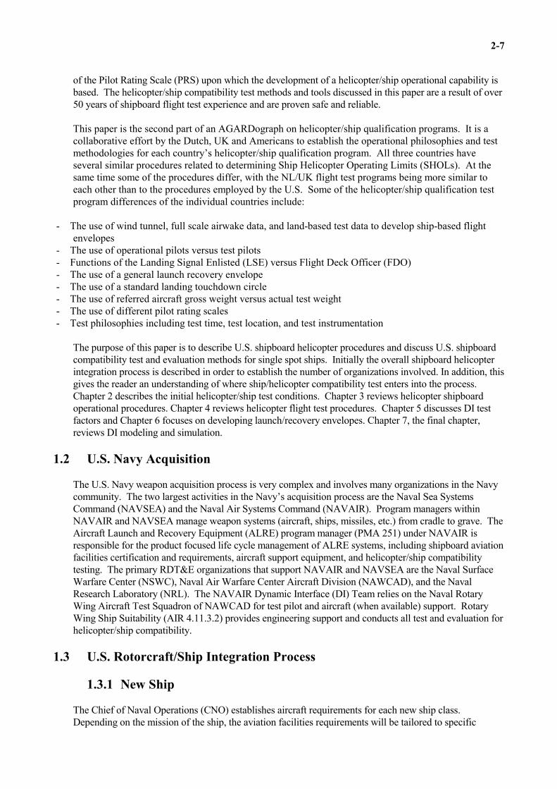
2-7
of the Pilot Rating Scale (PRS) upon which the development of a helicopter/ship operational capability isbased. The helicopter/ship compatibility test methods and tools discussed in this paper are a result of over50 years of shipboard flight test experience and are proven safe and reliable.
This paper is the second part of an AGARDograph on helicopter/ship qualification programs. It is acollaborative effort by the Dutch, UK and Americans to establish the operational philosophies and testmethodologies for each country’s helicopter/ship qualification program. All three countries haveseveral similar procedures related to determining Ship Helicopter Operating Limits (SHOLs). At thesame time some of the procedures differ, with the NL/UK flight test programs being more similar toeach other than to the procedures employed by the U.S. Some of the helicopter/ship qualification testprogram differences of the individual countries include:
- The use of wind tunnel, full scale airwake data, and land-based test data to develop ship-based flightenvelopes
- The use of operational pilots versus test pilots- Functions of the Landing Signal Enlisted (LSE) versus Flight Deck Officer (FDO)- The use of a general launch recovery envelope- The use of a standard landing touchdown circle- The use of referred aircraft gross weight versus actual test weight- The use of different pilot rating scales- Test philosophies including test time, test location, and test instrumentation
The purpose of this paper is to describe U.S. shipboard helicopter procedures and discuss U.S. shipboardcompatibility test and evaluation methods for single spot ships. Initially the overall shipboard helicopterintegration process is described in order to establish the number of organizations involved. In addition, thisgives the reader an understanding of where ship/helicopter compatibility test enters into the process. Chapter 2 describes the initial helicopter/ship test conditions. Chapter 3 reviews helicopter shipboardoperational procedures. Chapter 4 reviews helicopter flight test procedures. Chapter 5 discusses DI testfactors and Chapter 6 focuses on developing launch/recovery envelopes. Chapter 7, the final chapter,reviews DI modeling and simulation.
1.2 U.S. Navy Acquisition
The U.S. Navy weapon acquisition process is very complex and involves many organizations in the Navycommunity. The two largest activities in the Navy’s acquisition process are the Naval Sea SystemsCommand (NAVSEA) and the Naval Air Systems Command (NAVAIR). Program managers withinNAVAIR and NAVSEA manage weapon systems (aircraft, ships, missiles, etc.) from cradle to grave. TheAircraft Launch and Recovery Equipment (ALRE) program manager (PMA 251) under NAVAIR isresponsible for the product focused life cycle management of ALRE systems, including shipboard aviationfacilities certification and requirements, aircraft support equipment, and helicopter/ship compatibilitytesting. The primary RDT&E organizations that support NAVAIR and NAVSEA are the Naval SurfaceWarfare Center (NSWC), Naval Air Warfare Center Aircraft Division (NAWCAD), and the NavalResearch Laboratory (NRL). The NAVAIR Dynamic Interface (DI) Team relies on the Naval RotaryWing Aircraft Test Squadron of NAWCAD for test pilot and aircraft (when available) support. RotaryWing Ship Suitability (AIR 4.11.3.2) provides engineering support and conducts all test and evaluation forhelicopter/ship compatibility.
1.3 U.S. Rotorcraft/Ship Integration Process
1.3.1 New Ship
The Chief of Naval Operations (CNO) establishes aircraft requirements for each new ship class. Depending on the mission of the ship, the aviation facilities requirements will be tailored to specific

2-8
aircraft types. For example, a new class of ship with a mission which only specifies the employment of anH-60 for Anti Submarine Warfare (ASW) will be capable of supporting an H-60 detachment for a sixmonth deployment, but it may not have a hangar large enough to fit an H-3. PMA-251 provides guidanceto NAVSEA on the aviation facilities and deck sizing with support from the In-Service EngineeringDepartment of NAWC. Deck strength issues are handled by Surface Ship Structural Integrity Department(NAVSEA 05P1). NRL investigates the hazard of the ship exhaust plume on flight deck personnel usingcomputational fluid dynamics (CFD). However the ship airwake effects on helicopter operations are notinvestigated during the design phase of the new ship. Historical data of helicopter operations on similarship classes are used in seakeeping studies conducted by the Hydrodynamics Group (NAVSEA 05H) withassistance from Naval Surface Warfare Center Carderock Division Code 55 to estimate the helicopteroperability. Lastly all aircraft certified to operate on the new ship class are tested by the DI Team toevaluate compatibility of the aviation facilities and develop launch/recovery envelopes for specific shipclasses.
1.3.2 New Aircraft
A new aircraft must go through extensive prerequisite testing and certification before it is authorized tooperate aboard any ship class. During the acquisition phase, the Electromagnetic Environmental EffectsDivision of NAWCAD conducts landbased tests to ensure the aircraft can operate in the harsh shipboardelectromagnetic environment. The In-Service Engineering Department of NAWC investigates clearanceissues and facility requirements for certification aboard all qualified ships classes. NAVSEA 05P1certifies the aircraft aboard all ship classes capable of handling the aircraft’s weight. In addition, theAeromechanics and Flight Controls competency of NAVAIR determines the performance and lowairspeed handling qualities of the aircraft. Lastly the DI Team conducts DI tests to determine the aircraft’sshipboard compatibility and develop launch/recovery envelopes for specific ship classes.
1.3.3 Modified Aircraft/Ship 3
The ship/aircraft integration process for a modified aircraft or ship depends on the suspected impact of themodification on ship/helicopter operations. At the very least, aircraft/ship modifications may require DItesting to determine the impact of the change on current launch/recovery envelopes.
1.3.4 Current Fleet Operability Enhancements/Joint Operations
The US Navy and Marine Corps operates 8 helicopter types and the Navy operates 37 ship classes [3]. Therefore the number of aircraft/ship combinations is too large to develop operating envelopes for allcombinations. Only a prioritized list of aircraft/ship combinations required to operate together (asdetermined by the CNO) is tested to expand launch/recovery envelopes. All other helicopters certified foroperations aboard a ship class, including joint operations between other U.S. armed services helicoptersand U.S. Navy ships, are typically allowed to operate in a conservative launch/recovery envelope, termedthe “general envelope” as shown in figure 2.

2-9
Fig. 2 DI General Envelope
1.4 Dynamic Interface Test Objectives
A helicopter ship qualification program, which the U.S. defines as a Dynamic Interface test, evaluates,improves, and/or develops all aspects of shipboard helicopter compatibility. Preparations for a shipboardhelicopter compatibility test may include model-scale and full-scale ship airwake and exhaust plumesurveys, flight simulation, and helicopter performance testing. Issues addressed during a test may includethe adequacy, effectiveness, and safety of shipboard aviation support facilities and/or procedures for allpotential ship-based helicopter types. Typical examples of support facilities evaluated are the flight deck,deck fittings, deck safety nets, aircraft hangars, and maintenance work spaces, as well as, refueling,firefighting, and helicopter control stations. Procedures that are qualitatively evaluated include thoserelated to deck handling, repositioning, tiedown, refueling, and maintenance tasks. Additionally,shipboard helicopter tests may include evaluations of ship airwake, exhaust gas, and electromagneticinterference effects on shipboard helicopter operations. Investigations of shipboard visual cues such asflight deck markings and visual landing aid (VLA) lighting packages are also essential parts of shipboardhelicopter test efforts. The testing of VLA lighting packages typically includes the evaluation,development, and optimization of existing lighting schemes and/or procedures for both Night VisionGoggle (NVG) and non-NVG operations.
The significant result of shipboard helicopter compatibility testing could be an engage/disengage orlaunch/recovery envelope. Optimal Helicopter In Flight Refueling (HIFR) and Vertical Replenishment(VERTREP) wind conditions have been established and are universal. Typically initial DI tests of a newship/aircraft combination will include HIFR and VERTREP evaluations but are not required. Oncedeveloped, these envelopes greatly increase the allowable range of wind/ship motion conditions that safelypermit routine shipboard helicopter operations. Similarly, for any given ambient wind conditions, theenvelopes permit a ship operator to safely operate helicopters from a wider variety of ship course/speedcombinations, greatly increasing the tactical and operational flexibility.
The U.S. take-off and landing wind diagrams are termed launch/recovery wind envelopes. A sample windenvelope is shown in Figure 3. Note that the relative Wind Over Deck (WOD) direction is defined by thedotted radial lines relative to the ship's bow and the wind over deck speed is defined by the dottedconcentric circles. The approach line graphically illustrates the type of approach to be executed for thisparticular launch/recovery envelope. The shaded region indicates the wind over deck conditions for safenight helicopter/ship operations. All envelopes are valid for all gross weights and center of gravity unlessotherwise noted. In some cases the aircraft may require more torque to operate shipboard than what isindicated by the landbased torque requirements in the aircraft operating handbook. These cases are noted
000 350-25 KT* 010
340
315
270
045
J090
PITCH ±2o ROLL ±40

2-10
on the envelope so that the pilot can account for the difference in performance for shipboard operations. The launch/recovery envelope also lists the maximum ship roll and pitch limits for safe helicopter/shipoperations. Launch/recovery envelopes are published for day and night operations and each approach type(stern, port-to-starboard, or starboard-to-port). In the case of a Recovery Assist Secure and Transverse(RAST) capable aircraft and ship combination, separate envelopes are published for recovery assist (hauldown and deck lock) and free deck (deck lock only) operations.
Fig. 3 DI Launch/Recovery Operational Envelope
1.5 Scope of a Typical DI Test Program
In the U.S. test programs, the typical scope for a new aircraft/ship combination includes: an evaluation ofthe shipboard aviation facilities and procedures; an evaluation of the ship airwake, exhaust gas, andelectromagnetic interference effects on shipboard helicopter operations; and most importantly, thedevelopment of launch/recovery envelopes. An overview of a typical DI process in terms of test programcomponents is presented in figure 4.
C A U T IO N :U N R E S T R A IN E D F L IG H T D E C K S A F E T YN E T S M A Y R IS E U P R IG H T F O R W IN D S0 3 5 -3 2 5 E X C E E D IN G 3 0 K T S .
E n tire E n v e lo p e : d a y .S h a d e d A re a : n ig h t.
P IT C H (+ /-) 5R O L L (+ /- ) 8
5
1 0
1 5
2 0
2 5
3 0
3 5
4 0 K T
S T E R NA P P R O A C H
3 4 5
3 3 0
2 8 0
2 4 5
1 2 5
0 7 0
0 3 0
0 2 0
2 7 0 0 9 0

2-11
Fig. 4 Typical DI Test Program Components
1.6 DI’s Experience
NAWCAD Pax River has conducted over 170 test programs in the past 45 years for the U.S. Navy andMarine Corps as well as the Army and Coast Guard which encompassed 39 classes of ships and 17 typesof helicopters.
R e c e iv e T e s tT a s k in g
R e q u e s tT e s t A s se ts
P re T e s tC o m p o n e n ts
P o s tT e s tC o m p o n e n ts
C o n d u c tP re T e s t
C o n fe re n c e sW rite /R o u te
T e s t P la n
C o n d u c tP re T e s t D a ta
A n a ly s is
C o n d u c tT e s t
P la n n in g
T e s t P la n R e v ie wB o a rd s
T e s t T e a mA rr iv e s a t
S h ip
S e t u p T e s tIn s tru m e n ta tio n C o n d u c t
U n d e rw a y ,S h ip b o a rd
F lig h t T e s tsP a ck ,D e p a r t fo r
H o m eR e m o v e T e s t
In s tru m e n ta tio n
A rr iv eH o m e ,
U n P a c k
E n te r D a tain to D I
D a ta b a s e
B e g in T e s tD a ta
A n a lys is
D ra ft,P u b lis h
M e s s a g eR e p o rt
W rite /P u b lis hR e p o rt o f T e s t
R e s u lts
B rie fS p o n s o rs
T e s tC o m p o n e n ts
P a c k , D e p a r tfo r T e s t

2-12
2. Initial Test Considerations
2.1 General
When operating aboard ship, one must know what phenomenon and hazards are associated with the shipenvironment and factors affecting the helicopters operation in this adverse environment. This chapter isintended to give the reader a basic knowledge of the shipboard environment. Next the factors affectinghelicopter operation in the shipboard environment are divided into categories and described. In reality,these factors affecting the aircraft combine to create a very complex flying environment. The test pilotmust evaluate the factors affecting the aircraft in all of these categories and rate the difficulty of the launchand recovery. Lastly, several on-deck issues are discussed.
2.2 The Ship Environment
During shipboard operations, a helicopter is subjected to a very adverse and turbulent environment withmany constraints. In comparison with land-based take-offs and landings, ship-based take-offs andlandings occur in winds from any direction relative to the helicopter. Relative Wind-Over-Deckconditions may be constrained by ship operational requirements forcing the aircraft to land in non-idealwind conditions. Typically land-based helicopter platforms are large, flat, open spaces which areconducive to low atmospheric wind turbulence. Figure 5 is a picture of flight deck aboard an USSSPRUANCE class destroyer that is on average 69 feet long and 41 feet wide. At a minimum, the SH-60Brotor tips may be approximately 4 feet from the nearest obstruction or the tail wheel may be 2.5 feet fromthe aft deck edge. Also note that the ship superstructure is not conducive to low airwake turbulence levelsand the platform attitude is never fixed. In addition, the interaction of the ambient environment (truewinds and sea state) with the ship which creates the operational environment for the helicopter is not thesame for every ship class.
Fig. 5 Location of Flight Deck and VERTREP Areas on a Typical Surface Combatant
Ship motion characteristics for ships depend on ship hull geometry, loading and ambient conditions andare fairly similar for air capable ships. The maximum amplitudes and periods for pitch and roll for sea

2-13
state 5 are given in Table 1. The pitch and roll characteristics of an aircraft carrier are also given toprovide a comparison between different sizes of ships. The sea state scale with values ranging from 1 to 8was developed by the World Meteorological Organization to characterize sea conditions. In sea state 5,the seas are very rough with average wave heights of approximately 12 feet and winds are moderate toalmost gale force ranging from 27 to 40 knots.
Table 1: Ship Motion Characteristics for Sea State 5
Pitch Roll
ClassLength(feet)
Displacement(tons)
Max Amp.(deg.)
Period(secs)
Max Amp.(deg.)
Period(secs)
FFG 7 445 4100 2.4 5 17.6 13
DD 963 563 8040 2.0 7 20.5 17
CG 47 567 9466 1.9 7 19.1 17
CVN 68 1092 91487 0.8 10 5.0 21
Note: The maximum amplitudes and periods for ship pitch and roll were calculated using U.S. Ship Motion Program95
For most air capable ships, several distinct features remain consistent and play a significant role in shipairwake characteristics. Wind anemometers located on the ship's mast measure the relative winds used todefine safe helicopter/ship operations. Even though the anemometers are typically 60 feet above the flightdeck, they are still contained within the ship airwake; therefore not measuring the true relative freestreamwind velocity. In addition, the relative wind-over-deck conditions do not reflect the local windcharacteristics over the flight deck. In most cases, a flat faced, sharp cornered hangar is placedimmediately forward of the flight deck. A typical hangar height is approximately 15 feet. The verticalface of the hangar causes large flow recirculation zones over the flight deck. In addition, the sharpcorners, railings, and masts create a highly turbulent airwake. Ship's exhaust stacks are placed amidshipswhich for some WOD conditions is upstream of the aircraft approach or departure path. In some cases,ship's service gas turbine generator stacks are placed immediately forward or aft of the flight deck thatmay raise the local air temperature over the flight deck or along the approach path. Separately, theelements of the ship environment are complex and difficult to predict; however, the environment is evenmore complex due to the interaction of these elements. For example, airwake due to the ship motion wasseen in the mast mounted anemometer measurements and most likely will be seen in the ship airwakeenvironment over the flight deck.
2.3 Helicopter Performance
A helicopter operating landbased requires the most power hovering in still or low speed winds andexperiences a reduction in power required hovering in ground effect. When operating shipboard, anaircraft hovering in still or low speed relative winds may require more power than the predicted out ofground effect hover power. In order to gain the power savings due to ground effect, aircraft must behovering in low relative winds within one rotor diameter of an infinite, smooth ground surface. Therefore,one of the factors affecting a helicopter's power requirements is the lack of the necessary conditions toobtain power savings due to ground effect. In addition, higher torque requirements may be needed whenhovering or transitioning to or from forward flight in low relative wind speeds or turbulence. Higherpower requirements reduces power margins that may be needed to counteract adequately a certain amountof ship's oscillation to avoid collision with the obstacles.

2-14
Another factor that affects aircraft performance is hot exhaust ingestion. There are two types of shipboardproblems associated with hot exhaust. The first is the aircraft ingesting hot gases from the ship gas turbinegenerator or exhaust stacks. The second is the aircraft re-ingesting its gas turbine exhaust. Aircraftproblems may be a result of a combination of the two. Unlike the affects of low relative wind speed andlack of ground effect which increase power required, hot exhaust ingestion limits the aircraft poweravailable.
2.4 Helicopter Handling Qualities and Control
Adequate handling qualities are imperative in the shipboard environment due to the confined landing area. In order to maintain safe distances from obstacles, the aircraft’s forward landing gear must be placed in astandard 24 foot diameter touchdown circle with the aircraft aligned with the lineup line. (The 24 foottouchdown circle is based on qualitative engineering assessments made during the late 1960's.) For H-60recoveries into the Rapid Securing Device (RSD), the RAST probe must be placed in the RSD trap that is3 foot wide and 3 foot long. In most cases handling quality limitations are caused by ship airwaketurbulence. Adequate control margins are also required to counteract unanticipated situations such asgusts or turbulence. Similar to the Dutch, the U.S. requires a 10% control margin during any shipboardoperations. In most cases control limitations are caused by pedal limits.
2.5 Visual Cues
Visual cues provide the pilot with situational awareness and the ability to accurately position the aircraftover the landing spot. Lack of or degraded visual cues is dangerous in the shipboard environment due tothe small landing area and small clearances with the ship's superstructure. When approaching the ship intailwinds, it is common for the pilots to feel as though they are being pushed into the ship. In addition,larger aft stick inputs are required throughout the approach and hover phase that causes a higher nose upattitude. The higher nose up attitude limits the pilot's downward field of view that also may affect thevisual cues. Factors that may degrade the pilot's view of the flight deck during approach and hover are thesalt spray generated by the downwash of the rotor in low relative wind speeds and smoke generated by theship's exhaust stacks. Lastly the pilot’s ability to maintain a steady hover behind the ship depends largelyupon the view of a distinct horizon. Lack of a distinct horizon may be caused by fog, precipitation, hazeor nighttime operations.
2.6 Helicopter/Ship Geometric Interface Limitations
Most helicopter manufacturers provide sloped landing limitations for take-off and landing operations outof unprepared helicopter landing sites. In most land-based operations, pilots can adjust the aircraftheading to land up-slope, down-slope, or cross-slope depending on the safest option. Similarly, limitationsmust be determined for the relative geometric attitude of the aircraft to the ship. However, ship-basedoperations may be more restrictive depending on aircraft trim hover attitude, ship maximum pitch and roll,and aircraft lineup. For example, an aircraft ship-based sloped landing limit for a fore/aft lineup may be apitch of 5 degrees and a roll limits of 15 degrees. However, the aircraft sloped landing limit for an obliquelineup may be decreased due to the ship pitch and roll combining to create a larger slope along the lineupline.
2.7 The Pilot
The most important factor that affects helicopter operations in the shipboard environment is the pilotbecause ultimately he/she is the one that must process the information given and manipulate the controls tolaunch and recover safely. Therefore the envelopes must consider pilots with various levels of experienceand skill. A qualitative parameter used to evaluate the difficulty of a shipboard task is pilot workload. Typically high pilot workload results from handling qualities and visual cues and can include effects of theenvironment like ship motion. Pilot comfort level may also play a role in determining safe shipboard

2-15
operating conditions. For example, an AH-1W test pilot was conducting a recovery to an LHA spot underhigh winds and rated the landing as unsatisfactory due to the uncomfortable attitude of the aircraft upontouchdown. Although rating the human ability is subjective, using trained test pilots provides theobjectivity to consistently judge the skill level of the average fleet pilot.
All U.S. test pilots are required to attend an accredited Test Pilot School before participating in any Navyflight testing. The United States Naval Test Pilot School (USNTPS), located at Naval Air Station,Patuxent River, MD, is an intense ten month flight test and evaluation course that trains experienced fleetpilots and flight test engineers how to be better and more effective testers. The pilots are taught specificthought process and incremental/build up techniques that can be applied when evaluating any givenaircraft. They fly many different aircraft to provide a breadth of experience in aircraft with various flightcharacteristics, which provides a baseline for comparison with other aircraft. Throughout the course theylearn an awareness of the control inputs and aircraft response and how it relates to the aircraft flyingcharacteristics. Pilots are taught about the various rating scales and how to apply them in a consistentmanner and the importance of mission relation. This rigorous training provides the pilots the necessarytools for flight testing but most importantly teaches them how to objectively rate mission tasks, such asshipboard launch/recovery operations, keeping in mind the experience and ability of the average fleetpilot.
2.8 On Deck Issues
There are two helicopters in the US military that are tandem rotor and operate from ships. These are theUS Navy H-46 Sea Knight and the US Army H-47 Chinook. The H-46 helicopter is currently detachedaboard ships throughout the Navy. The main problem associated with H-46 helicopters in a shipboardenvironment is tunnel strikes. A “tunnel strike” occurs when flight deck turbulence drives the aft rotorblades to flap to the point of striking the synch shaft connecting the aft and forward transmissions on theaircraft. Tunnel strikes commonly occur upon startup (rotor engagement) or shutdown (rotordisengagement). Testing can be performed to identify wind over deck conditions that exacerbate rotorflapping. The procedure involves spotting an H-46 on the flight deck, chocked and chained, and engagingthe rotors. The aircraft is fitted with a wood and Teflon “greasy board”, which is fitted to the forwardportion of the synch shaft and protects the shaft from the blade flapping to an extreme. Various lengthstyrofoam “frangible” pegs are set up in a vertical fashion on the synch shaft to determine the minimumdistance of the blades to the shaft. The aircraft rotors are engaged and disengaged under one windcondition with a blade clearance scale applied to reflect the maximum blade deflections over the synchshaft. The wind condition is then systematically varied to develop an engage/disengage envelope.

2-16
3. Helicopter Shipboard Operational Procedures
3.1 General
It is important to understand the many phases of shipboard helicopter operations for a typical mission. Although they do not involve helicopter flight, they can have a large impact on helicopter operability andhelicopter/ship compatibility. The typical phases of any USN helicopter mission are shown below and arevery similar to the Dutch phases.
TRAVERSEAircraft with blades and tail folded is moved from the hangar to the launch/recovery spot using theRecovery Assist, Secure Traverse (RAST) system, a winch system, or manual push method dependingon the aircraft. Aircraft is secured to the deck using the Rapid Securing Device (RSD) and/or tie downchains.
UNFOLDAircraft rotor blades and tail are automatically or manually unfolded into a flight-ready configuration.
ENGINE START/ROTOR ENGAGEMENTEngines are started and rotors are engaged.
LAUNCHRSD beams are opened and/or tie down chains are removed. Aircraft lifts off into a hover over thedeck.
DEPARTUREAircraft transitions into forward flight and flies away from ship.
MISSIONTypical maritime missions include airborne mine countermeasures, antiship surveillance and targeting,antisubmarine warfare, reconnaissance, vertical replenishment and search and rescue.
APPROACHOnce aircraft mission is complete, aircraft follows a specified path to prepare for a landing. Theapproach phase ends once the aircraft is in a hover over the landing spot.
RECOVERYThe aircraft lands and the RSD beams close and/or tie down chains are employed. In adverse weatherand sea states, a RAST system may also be employed to recover the aircraft.
ENGINE SHUTDOWN/ROTOR DISENGAGEMENTEngines are shutdown. The rotors are disengaged and a rotor brake is used to quickly slow the rotorsto a stop.
FOLDAircraft blades and tail are automatically or manually folded.
TRAVERSEAircraft with blades and tail folded is moved from the launch/recovery spot to the hangar using theRAST system, a winch system, or manual push method depending on the aircraft. Aircraft is securedto the hangar deck using tie down chains.

2-17
Aside from shipboard approach, recovery, launch, and departure (launch/recovery) operations, shipboardvertical replenishment (VERTREP) operations and shipboard Helicopter In Flight Refueling (HIFR)operations also require dynamic and complicated ship/helicopter interaction. The U.S. Navy and MarineCorp operate both single and dual piloted aircraft. Generally the U.S. Navy conducts two types oflaunch/recovery operations aboard air-capable ships: RAST and Non-RAST. RAST is the RecoveryAssist, Secure Traverse system employed by surface combatants to recover U.S. Navy H-60 helicoptersand move them to and from the hangar. The launch and recovery phases of the typical mission describedabove are conducted differently depending on RAST or Non-RAST launch/recovery operations. Thissection describes the approach, recovery, launch, and departure operations, RAST launch/recoveryoperations, and LSE’s role in launch/recovery operations.
3.2 Launch & Recovery Operations
The two typical rotorcraft approach orientations to US Navy air capable ships are oblique and stern. Shipvisual landing aids (VLA) are arranged based on approach orientation. Figure 6 shows the typical deckmarkings for RAST capable DD 963 class ships. The line-up lights and approach line deck markings on aship designed for a stern approach are offset to the right of the ship centerline, usually supplemented withextended drop-line lights mounted vertically on the fantail below the flight deck. A stern launch/recoverysequence would proceed as follows: The right or left seat pilot would lift off, directed by the LSE, andestablish a steady hover 10-15 ft above the flight deck. If a starboard WOD is present, the pilot wouldthen pedal turn to starboard, establish steady rate of ascent and forward airspeed, and enter a starboardracetrack (clockwise oval) flight pattern. Once on final in the pattern, the pilot would establish a 3 degglide slope and 80 kts ground speed 1.2 NM directly aft of the ship. Arresting the rate of closure andcrossing the fantail, the pilot would establish a 10-15 ft hover and position the aircraft over the recoverycircle with the aid of the LSE on the flight deck. He would then descend vertically and land with theforward landing gear or forward skid cross-tube within the recovery circle, and with the aircraft centerlineparallel to the ship line-up line. The restriction of landing within the recovery circle guarantees the properaircraft/rotor clearances to the nearest ship obstruction. The glide slope and airspeed conditions used foran oblique launch/recovery sequence are identical to the stern approach. However, in this case, the pilotwould approach the ship 33-45 degrees offset to port or starboard of the ship centerline, depending on theorientation of the landing line-up line of the particular ship class. A limited number of ship classesemploy an extreme case of an oblique approach where the line-up line is 90 degrees relative to the shipcenterline.
Fig. 6 Typical RAST Capable DD 963 Class Flight Deck

2-18
Another more uncommon approach is the ordnance angled offset approach. Pilots are required to performthis approach when they are carrying hung or misfired forward firing ordnance. Hung ordnance is amissile that ignites and expends its propellant but never leaves the rail. Misfired forward firing ordnanceis a missile that fails to ignite when initiated by the pilot. For ship classes incorporating both the sternapproach and the oblique approach, the pilot is required to maintain a gradually increasing sideslip relativeto the line-up line to avoid aiming the weapon at any portion of the ship in the event of an inadvertentlaunch. If properly executed for a typical stern approach flight deck, the aircraft's ground track remainsexactly "up the stern" (identical to that used during non-ordnance evolutions) throughout the ordnanceangled offset approach. However, the aircraft nose will always be aligned at some minimum yaw anglerelative to the deck lineup line, increasing as the aircraft approaches the ship. No launch/recoveryenvelopes are developed for such an uncommon occurrence as misfired forward firing ordnance.
3.3 RAST Launch/Recovery Operations
The approach and departure phases of RAST launch/recovery operations are the same as Non-RASToperations. The main differences are in the recovery and launch phases. The two types of RASTrecoveries are Recovery Assist (RA) and Free Deck (FD). For an RA landing, the aircraft must hover overthe deck while two enlistedmen ground the aircraft’s messenger cable and hook it to the ship’s hauldowncable. The Landing Safety Officer (LSO), the operator of the ship’s RAST system, instructs the pilot’s toreel in and lock the hauldown cable. The RAST cable provides a stabilizing moment for the hoveringhelicopter. As the pilot holds a steady hover over the RSD, the LSO select the preset hauldown tensionand the helicopter comes down into the RSD, and the trap beams close. Lastly the hauldown cable isreleased in preparation for lift-off. Figure 7 shows an SH-60B performing RA landing.
Fig. 7 SH-60B Performing an RA Landing on a DD 963 Class Ship

2-19
For a FD landing, the pilot establishes a high hover, approximately 10-15 ft, over the flight deck. Onceready to land, the pilot lowers his hover height to 3-5 ft and positions the aircraft over the RSD. The LSOprovides conning calls to position the aircraft probe over the RSD, instructs the pilot when to land andcloses the RSD beams to hold the helicopter on the deck. If the aircraft probe does not enter the RSD, theLSO instructs the pilot to lift into a low hover and attempts to guide the pilot into the RSD again.
There is only one way to launch for RAST launch/recovery operations. Once the pilot is ready to lift, theLSO opens the RSD beams and instructs the pilot to lift. The pilot lifts into a hover and the departurephase is the same as a Non-RAST departure.
3.4 Role of LSE
In the US Navy, the LSE has two primary duties. The first is to ensure the general safety conditions of theflight deck, to include control of the flight deck crew. The second is to communicate to the pilot at thecontrols, through various hand signals, directions to the proper aircraft placement on the flight deck,fuelling, and deck handling. The signals the LSE provides to the pilot for proper placement on the flightdeck are advisory in nature. The only LSE signals which the pilot is required to heed are waveoff andhold. The LSE does not have direct verbal communication to the pilot in the aircraft, but can communicateto the HCO or LSO via the “phonetalker.” The phonetalker is an enlisted man equipped with a sound-powered phone. For RAST launch/recovery operations, the LSE is present on the deck for all operationswhile the H-60 is trapped in the RSD. However, the LSE is not required for the approach, recovery,launch, and departure phases of RAST helicopter operations.

2-20
4. Helicopter Shipboard Flight Test Procedures
4.1 Preparations
4.1.1 Historical Data
The DI database was developed in 1988 as an efficient means to store, access, manipulate, and analyzelarge amounts of DI shipboard helicopter flight test data. The database holds both general and specificinformation from over 180 DI tests. Currently, 120 parameters are listed for every launch/recovery event.This information is valuable for many purposes. In preparation for a flight test with a CH-46E helicopteraboard an LHA 1 class ship, an engineer could query the database to produce a list of any H-46 variantaboard an LHA. From there he could ferret out all the limiting pilot ratings to evaluate possible troublespots for the test aircraft. One could find the pedal and lateral cyclic input requirements for every CH-46EDI test recovery conducted to LHA 2 class ships since 1985 in which the aircraft's gross weight exceeded19,500 lb, the ship roll was greater than 9 deg, and the relative winds exceeded 30 kt. In addition to usingthe database as a tool for flight test preparation, the flight test engineer can also use it for datapresentation. Once all of the shipboard test information is entered into the database, it can automaticallydevelop a data fairing of PRS ratings. It can also automatically calculate necessary pieces of data based onother inputs, such as density altitude given OAT and pressure altitude, and aircraft gross weight and CGlocation given fuel weight. Based on pilot comments and supporting engineering data, an envelope will beproduced and printed out through the database.
4.1.2 Pilot Field of View
Field of view analysis in preparation for a shipboard flight test is usually not a critical issue unless the testaircraft is a prototype or the purpose of the test is to evaluate a new marking configuration aboard the testship. Simulation is one useful way to evaluate prototype VLA configurations, saving the cost of paint,flight time, travel, labor, per diem, etc. Some simulators have a limited field of view compared to theaircraft to be tested and therefore do not adequately predict the field of regard of a hovering pilot. Field ofview is fixed for a given aircraft model. It is based on the relation of the design eye point of the pilot withrespect to the edges of the cockpit windows, door windows, or chin bubbles or anything inside the cockpitthat may obstruct the pilots view outside the cockpit such as the glare shield. Field of regard is what thepilot sees based on the aircraft’s field of view and attitude. A simpler and less expensive PC-basedanalysis technique involves knowledge of the specific geometric field of view of the aircraft. Projectinglines from the aircraft design eye point along the periphery of the cockpit windscreen, chin bubble, andwindows to the flight deck below provides a "snapshot" of what the pilot can and cannot see on andaround the flight deck. All of this information is then input into a program containing the FOV data ofvarious airframes and flight deck lay-outs of major ship classes. Program inputs allow the engineer toadjust the helicopter height above deck, aircraft pitch, roll, and yaw angles as well as longitudinal andlateral position of the aircraft relative to the flight deck recovery spot. Figure 8 depicts the field of view ofan SH-60B aboard an FFG 7 class ship in a 15 ft hover, 5 ft aft of the touchdown circle. The dark arearepresents the portion of the flight deck obstructed to the right seat pilot. Unlike the program with a fixeddesign eye point, a human pilot can crane his neck, sit up straight, and rotate his head to see aroundaircraft obstructions. The program provides a good initial analysis of field of view and field of regard of ahovering pilot over a flight deck.

2-21
Fig. 8 2-D Field of View Diagram for the SH-60B on a RAST Capable FFG 7 Class Ship

2-22
4.1.3 Land-Based Build-up Test
Elevated Fixed Platform
In preparation for flight tests aboard FFG 7 class ships, an elevated fixed platform is used as a practicedeck for pilot familiarity flights before the at-sea flight test. This platform is a full scale, land based FFGflight deck with a hangar face and complete VLA. The EFP maintains an operable landing safety officer(LSO) station (moved laterally outboard from its actual shipboard location for safety reasons), and fullyfunctional recovery, assist, secure and traverse (RAST) equipment, thereby producing a realistic land-based RAST system virtually identical to that of a RAST equipped ship. The platform does not allowengineers to control certain variables present in the shipboard environment such as ship motion andlimited spatial cueing with the sea. It is especially valuable for pilot/LSO training, proficiency, or inpreparation for NVD operations where pattern work and crew coordination is crucial. Practicing on theplatform enables the pilots to have a better idea of ship motion limitations before going out to sea. Figure9 illustrates the EFP.
Fig. 9 SH-60B Performing a RA Landing at the EFP
Critical Azimuth Testing
Land-based critical azimuth flight tests are conducted prior to shipboard test operations. It is an evaluationof control margins and pilot workload with variation in airspeed and relative wind azimuth. The qualitativeevaluation of trim changes and pilot workload is an integral part of the test. Data are collectedsimultaneously with trimmed flight control positions (TFCP) in low airspeed flight. Of specific interest arethe control margins and pilot workload to accomplish the task of hovering the helicopter withinpredetermined tolerances at various speeds and directions relative to the airframe. Areas of limited controlmargin or high pilot workload are noted in preparation for shipboard flight test operations. The test isperformed in ambient winds of 4 kts or less. Commonly, the aircraft is flown behind a pace truck, which isinstrumented to measure ground speed, with the airframe flown at various azimuths relative to thedirection of flight to simulate hovering in different wind conditions. True winds are measured at an onsitemeasuring device, usually the control tower. Variables adjusted during the test include aircraft height

2-23
AGL, airspeed, and azimuth. Flight control positions, aircraft attitudes, engine torque, airframe azimuthand airspeed, height AGL and ambient conditions are recorded.
Hover Performance
The purpose of the hover ladder flight test is to compare in ground effect (IGE) and out of ground effect(OGE) torque required to hover at various gross weights with those predicted by the aircraft operator’smanual. Typically, the test is performed at altitudes of approximately 5, 15, and 50 to 60 feet aboveground level (AGL), yawing the aircraft relative to the ambient wind in 45 degree increments, starting atthe nose of the aircraft and working around to +/- 90 degrees. When a stable hover condition is reached,engine torque, rotor rpm, aircraft attitudes, and flight control positions are recorded in addition to ambientconditions (pressure altitude, OAT, ambient winds.
4.2 Launch/Recovery Envelope Development
4.2.1 General
Launch/recovery envelope development tests consist of data collection at various relative wind and shipmotion conditions. Each test event normally consists of an approach and recovery followed immediatelyby a launch and departure, all conducted by the same pilot at the controls with the same WOD conditions.Parameters of concern for each event include a variety of qualitative and quantitative factors, including butnot limited to pilot visual cues, pilot workload, flight control activity, flight control margins, aircraftattitude, aircraft power requirements, landing dispersion, ship airwake turbulence intensity, ship motionand aircraft landing loads. Because each of these and other parameters cannot be isolated and evaluatedindividually during full-scale flight test, a comprehensive rating is assigned by the aircrew after each eventwhich rates the overall difficulty of the combined set of conditions for that sequence. The pilot ratingscale, shown in Table 2, has four difficulty levels. A rating of PRS-2 or less indicates safe events. For anyevent rated higher than PRS-1, the aircrew is required to provide supplemental comments to indicatewhich parameters contributed to the elevated difficulty of that event. A review of the development andapplication of the Dynamic Interface Pilot Rating Scale is presented in reference 3. As a result on ongoingThe Technical Cooperation Program (TTCP) work a revised pilot rating scale for DI testing wasdeveloped to enhance sharing DI test results by different countries. The new scale is known as the DeckInterface Pilot Effort Scale (DIPES), and is a 5 point scale where ratings 1-3 are acceptable pilot ratingsand 4-5 are unacceptable. The Deck Interface Pilot Effort Scale (Table 3) was accepted byNAVAIRSYSCOM in 2001, and is being used on new start programs. Additional scales used in DItesting include a vibration scale, turbulence scale, and visual landing aids scale, as presented in Tables 4-6.
Table 2: Dynamic Interface Pilot Rating Scale
PRSNumber Pilot Effort Rating Description1 Slight No problems; minimal pilot effort required to conduct consistently safe
shipboard evolutions under these conditions2 Moderate Consistently safe shipboard evolutions are possible under these conditions.
These points define the fleet limits recommended by theNAVAIRWARCENACDIV Patuxent River.
3 Maximum Evolutions are successfully conducted only through maximum effort ofexperienced test pilots using proven test methods under controlled testconditions. Successful evolutions could not be consistently repeated by fleetpilots under typical operational conditions. Loss of aircraft system or shipsystem is likely to raise pilot effort beyond capabilities of average pilot.
4 Unsatisfactory Pilot effort and/or controllability reach critical levels; repeated safe evolutionsby experienced test pilots are not probable, even under controlled testconditions.

2-24
Table 3: Deck Interface Pilot Effort Scale (DIPES)
EFFORT GUIDANCE DIPES
Slight to Moderate
Reasonable compensation required. Trackingand positioning accuracy is consistentlymaintained throughout the operation. Fleetpilots will have enough spare capacity toconduct ancillary tasks.
1
Considerable
Significant compensation required. Trackingand positioning accuracy occasionally degradesduring peaks in ship motion, sea spray orturbulence. Fleet Pilots will have difficultyconducting ancillary tasks.
2
Highest Tolerable
Highest tolerable compensation required.Tracking and positioning accuracy degradesregularly during peaks in ship motion, seaspray or turbulence. Fleet pilots will be able tokeep up with task requirements but no more.Degraded operations (ship or aircraft) willprobably require an abort. Repeated safeoperations are achievable. This point definesthe recommended limit.
3
Excessive
Excessive compensation required. Accuracy ispoor in one or more axes. Fleet Pilots will bepurely reacting to external influences ratherthan anticipating them. A safe abort may notbe possible if an aircraft or ship system is lostduring a critical phase of the evolution. Fleetpilots under operational conditions could notconsistently repeat these evolutions safely.
4
Dangerous
Extreme compensation required. Repeatedsafe evolutions are not possible even undercontrolled test conditions with fully proficientcrews.
5
Acceptable ( DIPES 1-3 ) Unacceptable ( DIPES 4-5 )
Note: Each DIPES rating may be given one or more suffixes to describe the cause(s)of the increased workload:
Pitch control: P Height control: HTurbulence: T Spray: SRoll control: R F/Aft positioning: FDeck Motion: D Torque Control: QYaw control: Y Lateral positioning: LVisual Cues: V Funnel Exhaust: EA/C Attitude: A

2-25
Table 4: Turbulence Scale
Intensity Aircraft Reaction Reaction Inside Aircraft
Light TURBULENCE: The aircraft momentarily experiencesslight, erratic changes in altitude or attitude.
CHOP: The aircraft experiences slight, rapid, andsomewhat rhythmic bumpiness without appreciablechanges in altitude or attitude.
Occupants may feel a slightstrain against seat belts orshoulder straps. Unsecuredobjects may be displacedslightly.
Moderate TURBULENCE: The aircraft experiences changes inaltitude or attitude, but remains in positive control at alltimes. The aircraft also usually experiences variationsin indicated airspeed.
CHOP: The aircraft experiences rapid bumps or joltswithout appreciable changes in altitude and/or attitude.
Occupants feel definitestrains against seat belts orshoulder straps. Unsecuredobjects are displaced.
Severe The aircraft experiences large, abrupt changes inaltitude and/or attitude. The aircraft also usuallyexperiences large variations in indicated airspeed. Aircraft may be momentarily out of control.
Occupants are forcedviolently against seat belts orshoulder straps. Unsecuredobjects are tossed about.
Extreme The aircraft is violently tossed about and is practicallyimpossible to control. It may cause structural damage.

2-26
Table 5: Vibration Scale
DEGREE OFVIBRATION DESCRIPTION
PILOTRATING
NONE No discernible vibration 0
SLIGHTNot apparent to experienced aircrew fully occupied by their tasks,but noticeable if their attention is directed to it or if not otherwiseoccupied.
1
2
3
MODERATEExperienced aircrew are aware of the vibration, but it does notaffect their work, at least over a short period.
4
5
6
SEVEREVibration is immediately apparent to experienced aircrew evenwhen fully occupied. Performance of primary task is affected, ortasks can only be done with difficulty.
7
8
9
INTOLERABLE Sole preoccupation of aircrew is to reduce vibration level. 10
Note: Based on the Subjective Vibration Assessment Scale developed by the Aeroplane and ArmamentExperimental Establishment (A&AEE), Boscombe Down, England
Table 6: Visual Landing Aids Rating Scale (Reference RW-14R-90)
VLARating
Visual CuesAdequacy
Rating Description
1 Good Configuration provides visual cues that require little or no pilot effortto interpret; recoveries are slightly more difficult than those attemptedin daylight.
2 Satisfactory Configuration provides minimum amount of visual cues necessary forroutine safe fleet recovery operations.
3 Adequate Configuration is adequate for fleet use in non-routine basis. Usewhen operationally necessary and with prior pilot training on theconfiguration.
4 Marginal Configuration provides inadequate visual cues for consistently safefleet recovery operations; recoveries could be conducted withsignificantly increased risk in critical or wartime situations.
5 Unsatisfactory Configuration provides insufficient visual cues for safe recovery;unacceptable risks associated with recovery attempts in theseconditions.

2-27
4.2.2 Daytime Test Progression Philosophy
Launch/recovery envelope development tests are by definition conducted outside of existing approvedoperating envelopes; therefore, standardized test progression procedures are required in order to ensurethat a safe, incremental buildup is used to approach potentially high workload test conditions. Inpreparation for each event, the ship's crew maneuvers the ship onto a specific course and speed to providethe desired WOD and ship motion conditions for that event, as determined by the test coordinator andproject engineers on the ship. Other conditions desired for that event such as configuration and intensityof flight deck lighting or other visual landing aids are set as necessary by the ship's crew and projectengineers. All conditions for that event are then maintained to the greatest extent possible for the durationof the event. The test aircraft, which typically will have been flying in a holding pattern up to this point,now begins its approach to the ship for the new event. The approach, recovery, launch, and departuresequence is carried out, throughout which the pilot not at the controls is monitoring and recording cockpitdata parameters, and project engineers on the ship are monitoring and recording data parameters for theirrespective stations. Following completion of the event, when the aircraft is again away from the ship in aholding pattern, the pilot and copilot assign the overall pilot rating to the event, and communicate theirratings and recorded parameters by radio to the project engineers on the ship. The test coordinator andproject engineer makes the determination of the test conditions for the next event on the bridge, and theprocess described above is repeated for the next event.
In general terms, the typical data point progression for envelope development consists of firstincrementally building up to a certain WOD speed along one azimuth (normally either the aircraft landinglineup line or ship centerline). The end WOD speed is limited by one of the following: 1) no greaterWOD speed is desired along that azimuth, 2) no greater WOD speed is attainable along that azimuth withthe available true wind conditions and ship maneuvering capability, or 3) the current WOD condition isassigned an unsatisfactory pilot rating (PRS-3 or PRS-4)(DIPES 4-5). If a PRS-3 or PRS-4 (DIPES 4-5) isreached, the end speed of WOD speed buildup on that azimuth is considered to be the WOD condition ofthe previous PRS-1 or PRS-2 (DIPES 1-3). After reaching that end point, the progression then focuses onincrementing in azimuth while maintaining that value of WOD speed. As the progression moves fartheroff the bow, the true wind conditions and ship maneuvering capability may not provide the means tomaintain that WOD speed. When that is the case, the closest WOD speed attainable becomes the targetWOD speed for subsequent events. Building out on the other side of the initial azimuth is conducted later. This order of envelope development is generally used because it is a time-efficient method for developinga reasonably large envelope.
There are two other guidelines used to determine the target WOD speed and azimuth conditions for eachevent. At the start of a test period for development of an envelope, the initial WOD condition must bewithin the approved envelope for fleet use or located within the boundaries of conditions previously testedand rated as safe (PRS-1 or PRS-2)(DIPES 1-3). Second, each new/target relative WOD condition mayonly be either 5 knots in WOD speed OR 15 degrees in WOD azimuth from any WOD condition within anapproved envelope, or previously tested and rated as safe. These guidelines are established to ensure asafe and gradual development of a new launch/recovery envelope.

2-28
4.2.3 Nighttime Test Progression Philosophy
Night launch/recovery test methods are generally similar to day test methods, and must follow the samerules for data point progression as described for day launch/recovery tests. Several additional safetyprecautions are also required for night launch/recovery testing. First, pilots are not required to record testdata on pilot data cards during night test operations. Second, tape measure directional control (pedalposition) instrumentation may not be used during any night operations. Finally, night launch/recovery testsequences may only be conducted with WOD and ship motion conditions which are within a daylaunch/recovery envelope.
The use of night vision devices (NVD) for USN rotorcraft night shipboard operations has increasedsignificantly over the past few years. This increase has led to the application of night vision compatibleblue lighting to be incorporated on some ship classes. Night vision goggles (NVG) (aviators night visionimaging system generation 9, commonly known as ANVIS 9’s) are used throughout launch/recoveryoperations. NVG's are worn by the pilot and are mounted on the forward part of the helmet. They arecapable of flipping in front of the eyes, or rotated to a vertical position above the eyes. These two lightintensification tubes limit the pilot's field of view requiring more head movement to scan the same areawithout goggles. Despite the limited field of view, experienced NVG pilots tend to prefer aided flight tounaided for safety and comfort level.
Shipboard lighting poses a significant problem to approaching pilots wearing NVG’s. Common shiplights (stern, masthead, navigation) are very bright and cause NVG images to bloom and/or shutdown. An approaching NVD aided pilot would prefer a "dark" deck, one with no illumination. The inherentproblem is the safety and efficiency of the flight deck crew. It is important that night lighting systemsprovide the flight deck crew (LSE, chock runners, refueling and maintenance personnel) with thecapability to see the aircraft and surrounding flight deck while providing the goggled pilots and aircrewthe ability to see flight deck visual cue required to land the aircraft. A VLA pilot rating scale ispresented in Table 6.
2-29
5. DI Test Factors
5.1 Planning
A variety of related factors must be taken into account for a successful helicopter/ship ship testprogram. Detailed planning is essential to bring all the different program elements together. The USNavy DI program starts with a comprehensive test plan that includes the program background, purpose,description of test equipment, program scope, test methodology, and includes safety and test hazardscheck lists. The test plan is reviewed by test team members and by approval officials representing themany disciplines addressed by the test program. No testing can take place until all planning has beencompleted and the test plan has been signed.
5.2 Test Equipment
DI test equipment includes the rotorcraft, the ship, and the test instrumentation. The aircraft must becertified to operate aboard the ship before any testing can commence. The Naval Air Warfare CenterAircraft Division at Lakehurst, N.J, performs the ship aviation certification. Certification addressesboth the aircraft environmental conditions and the ship aviation missions. The helicopter’s design,including land-based low speed handling qualities and hover characteristics, are important factors in DItesting, as previously discussed. Helicopter related DI test factors include:
Aircraft – Should be marinized for the shipboard environmentBlade fold – Required for storage (flight deck and hangar)Rotor brake – Required especially for gusting wind conditionsBlade design – Blades that flex easily may result in blade/fuselage strikesLanding gear design – Wheel or skid and sliding/turn-over characteristics
Tail wheel location with respect to deck edgeCockpit – Field-of-view is important, as previously discussedShip interface – Electrical systems and refueling system
Electro Magnetic Compatibility (EMC)
The ship provides a dynamic landing platform for the helicopter. Several ship-related factors influenceDI testing, including:
Size – How big is the ship and the landing spots? Are any obstructions near the landing pad, approach, or take-off corridors? How high the flight deck above the water? How high are the ship anemometers above the flight deck? What are the ship motion characteristics?
Flight Deck – Markings and lighting for pilot visual cuesShip Interface – Ability to connect test equipment and get access to required data
Deck Handling - Most flight deck handling issues can be evaluated through a paper analysis, with scaledrawings and information on aircraft turning radius and ship motion characteristics of the ship. Somemodifications to the airframe warrant shipboard operational evaluation. If a missile is mounted on ahelicopter, clearance issues, ordnance upload /download, and aircraft re-spotting become important. Procedures must be developed to safely download ordnance from the aircraft to the magazine aboardthe ship. Aircraft tiedown must be evaluated to avoid chain contact with ordnance, or require flightdeck personnel to reach underneath a missile equipped with CADs for emergency jettison.

2-30
5.3 Test Location
General - Test location and test date will have a big impact on the size the launch/recovery developedduring a specific DI test. Some areas, like the North Atlantic in winter, produce higher wind/sea stateconditions than many other areas. DI tests are usually scheduled many months in advance and are oftenconducted in areas where the ships are located which may result in benign sea/wind conditions.
Ship Motion - In many cases during relative wind envelope development tests, ship motion parameters areamong the conditions that are not controlled but are simply recorded for each event. However, whenpossible it may be desirable to conduct dedicated test periods for the purpose of evaluating ship rollmotion limits at particular WOD conditions. For this process, a range of WOD conditions is selected fromthose previously tested and rated as satisfactory. At each selected WOD condition a series of events isconducted which increments the magnitude of ship roll motion until a limiting value is reached. Shipmotion development tests follow the same rules for data point progression, data recording process, andcriteria for assignment of pilot ratings as described for relative wind envelope development tests. However, in this case the test progression increments ship roll magnitude under a fixed WOD speed andazimuth. The means by which the ship roll motion is generated is controlled by the helmsman on thebridge and is referred to as "rudder kicks. Repeated oscillation of the ship's rudder is performed with arapid and symmetric motion to avoid an alteration in the ship's course and speed. The rate and magnitudeof these rudder kicks for a given set of sea conditions and ship course and speed determine the magnitudeof the resultant ship roll motion. The increment in ship roll motion for each event should be on the orderof 2 degrees. The helmsman's ability to make a small, precise change in the value of roll magnitude mayvary by event depending on the sea conditions and ship course and speed required for a target WOD. Foreach WOD condition, it may be decided that the end point of ship roll motion development has beenreached when any of the following criteria apply: 1) the test team or ship's crew determines that no greatership roll angle is desired at that WOD condition, 2) no greater ship roll angle is attainable at that WODcondition with the available sea conditions and ship maneuvering capability, or 3) the current ship rollmagnitude has been assigned an unsatisfactory pilot rating (PRS-3 or PRS-4)(DIPES 4-5). The ruddergenerated roll tends to be predictable and should not be substituted for high sea state actual test conditions.
5.4 Test Team Status
The test team is the key factor in any flight test program, and especially for a DI flight test program. Thehelicopter/ship test group provides the test continuity and retains the knowledge base associated withmany years of experience. The test team consists of test pilots, flight test engineers, and others asrequired. Test team members are required to schedule aircraft, ship, and support equipment, pluscoordinate actual testing and any follow-on reporting.
5.5 Test Limitations
Helicopter/ship testing is high risk testing and safety must be paramount in each program. The test teammay include both day and night testing for a specified ship. If the testing is delayed due to weather (lowtrue winds) or aircraft (maintenance), the test team may not be able to complete all the planned data points. The nature of DI testing results in a fast paced test program once flight testing begins. It is important foreach test team member to think safety, and if some action has the potential to result in an unsafe condition,to stop the testing and review the situation.

2-31
6. Establishment of Shipboard Launch/Recovery Envelopes
Once the test team returns, all data is entered into the DI database. The WOD condition with the pilot rating isplotted as shown in Figure 10. Most limiting parameters such as control margin, pilot workload, and visualcues are assessed by the pilot during the test and subsequently included in the launch/recovery rating. In mostcases, flight control, torque and pertinent data is not digitally acquired. Therefore control activity cannot beexamined to accurately determine control margins during tested launch/recovery sequences. Engineersdetermine a boundary for all PRS-1 and PRS-2 (DIPES 1-3) test points which becomes the launch/recoveryenvelope similar to the one shown in Figure 10.
As mentioned earlier, pilots record average hover torque values during daytime test periods. These data areused to evaluate shipboard hover torque requirements against landbased data. The difference between theshipboard and landbased hover torque is shown in Figure 11. This tool is used to determine WOD conditionswhere shipboard torque requirements exceed published landbased requirements. This difference is assumed tobe independent of GW.
Recall that launch/recovery envelopes are valid for all GW’s. However the pilots are cautioned or warned forregions of WOD conditions where shipboard torque requirements exceed publish landbased requirements. Thisis necessary to ensure pilots have adequate torque margins to launch under all GW conditions. These cautionsor warnings are listed on the published envelope similar to the caution in Figure 11.

2-32
Fig. 10 Dynamic Interface Launch/Recovery Envelope Fairing
Fig. 11 Comparison of Shipboard to Landbased Torque Requirements

2-33
7. Modeling and Simulation
7.1 Background
The US Navy initiated the concept of combined quantitative and qualitative evaluations of rotorcraftsimulators in the mid 1970’s. These operational flight trainers (OFT) and weapon systems trainers (WST)featured cockpits, motions systems, visual systems, and related air vehicle math models. The goal was touse simulator time to reduce the actual flight time required in an era of fuel shortage. The flight simulatorswere designed to train in all Navy helicopter missions, including shipboard landing scenarios. Thisrigorous flight test evaluation approach pointed out OFT/WST shortcomings and it also suggested optionsfor improved fidelity [5]. The basic OFT/WST air vehicle performance and flying qualities, engines, andavionics could be evaluated quantitatively based on flight test data. At this time, no shipboard landingdata were available to quantitatively evaluate this important Navy mission scenario. The shipboard landingtask was evaluated qualitatively by one or more pilots. The subjective nature of the early flight trainership airwake model development and test process tended to reduce the credibility of US Navy flighttrainers for ship based training applications.
The Navy established a helicopter/ship or Dynamic Interface test group at Patuxent River in 1982, with thegoal of conducting a combined flight test and analytical effort [2]. The large helicopter/ship test backlog,limited available funding, and low interest in analysis, limited the early analytic effort. The early flightsimulators were very limited in their ability to support helicopter/ship training and testing due tolimitations in visual systems, aerodynamics models, and ship airwake models [6]. Problems associatedwith ship airwake models were identified for both fixed wing and helicopter flight trainers [7].
Simulation continues to advance at a rapid pace and has a good potential and may become an excellenttool in the future for evaluating various shipboard helicopter compatibility issues and for preparing forflight tests. Simulation can be an economical way to evaluate new shipboard landing aid marking orlighting configurations. Pilots can perform repeated launch/recovery operations to various lighting ormarking configurations and optimize them for safety and operational efficiency. Simulation can assistpilots in preparation for shipboard operational procedures and improve comfort level with low light levelNVG flights, various VLA configurations, or a high sea state/ship motion environment. In addition,simulation can provide a pilot with a “sight picture” to aid in positioning a large aircraft aboard a smallship properly. Long and Williams [8] provide many detailed examples of how visual simulationtechnology is used to design and optimize aviation facilities, train pilots for shipboard operations, andinvestigate other clearance issues. During shipboard flight testing, crew coordination becomes critical,especially during low light level aided and unaided operations. Practicing pattern work, typical radio calls,and data collection improves the overall efficiency and safety of the flight test. An evaluation of thisnature does not require an accurate aircraft aerodynamic model, however, field of view should be the sameor similar to the aircraft model that operates from the particular ship
7.2 U.S. Navy Small Business and Related Efforts
The U.S. Navy has made much progress over the past few years in developing an analytic capability tohelp support future helicopter air vehicle flight testing in general. Small business and related programshave been used to develop several analytic enhancements. These improvements include rotor blade androtor map comparisons, tail rotor loss of effectiveness analysis, off-axis coupling analysis, vortex ring statemodeling, improved fuselage load prediction, and improved validation options. One program focuses onsetting-up a blade element V-22 model on the NAVAIR Manned Flight Simulator to investigate therotorcraft and airwake model level of complexity required to simulate the shipboard landing task. Theprogram also focuses on developing an analytic test tool to support future rotorcraft/ship testing.

2-34
7.3 JSHIP
The Joint Ship Helicopter Integration Process (JSHIP) Test and Evaluation Navy program was initiated in1998. This 5 yr program addresses joint service helicopter/ship operability issues and includes a DynamicInterface Modeling and Simulation (DIMSS) effort. The DIMSS effort included demonstrating an ArmyUH-60A helicopter model operating with an LHA class ship and NAVAIR CFD airwake on the NASAAmes Vertical Motion Simulator. DIMSS variables included simulation system motion, visual system,and aural cues, with fixed ship airwake methodology (CFD) and fixed helicopter model (UH-60). Pilotcomments were favorable during the simulation session conducted during the 2000-2001 time frame.
7.4 Computational Fluid Dynamics
Computational Fluid Dynamics (CFD) provides an analytic option to generate airwake data for thecomplete ship environment. Accurate ship airwake modeling may be helpful in improving the fidelity ofshipboard simulation. NAVAIR [9] applied the unstructured-grid Navier-Stokes CFD solver COBALT, inconjunction the Monotone Integrated Large Eddy Simulation (MILES) turbulence model to define theairwake for an LHA class ship for the JSHIP DIMSS program. The complexity of the LHA CFD solutionin terms of iso-surfaces of vorticity for winds over the bow and at 030 deg is shown in figures 12 and 13. Note the large variation in flow characteristics as a function of wind over the deck direction. The CFDsteady u, v, and w airwake components compared favorably to wind tunnel data for the same conditions,as shown in figure 14. A recently (2001) initiated long term NAVAIR ship airwake CFD modelenhancement program sponsored by the Office of Naval Research should have a positive impact.
Fig. 12 CFD Iso-Surfaces of Vorticity Surfaces for LHA with WOD 30 kt at 000 deg
Full Scale Unsteady CFD
Iso-SnrTares orVortici^ Efiectofidand
Ship with opaque iso-suifaces of Torlicitf
Periodic AcdtSng from bow
SeparaticD offbow

2-35
Fig. 13 CFD Iso-Surfaces of Vorticity Surfaces for LHA with WOD 30 kt at 030 deg
Fig. 14 CFD Comparison to Wind Tunnel for Steady Airwake
Full Scale Unsteady CFD
Iso-Surfaces of Vorticity
0"WOD
30"WOD
Shedding off island
CFD Comparison with Wind Tunnel
E D
O >^ ±: u D
1 2
1 0
0 e
0 6
0 4
0 2
0 0
■D 2
V, & W Mean Velocity Component Comparisons
J a
z= 0 2; 31 5 m, > ;=2 3 5 m
v^^ r->^r 1- III?OcIV - EipvrimVtl
> u u?OclV - EipvrimVtl
A ■! uvlocHv- Eipvrin V tl
1 U^OCIV -CFD
- - U U^OcIV -CFD
— "1 U^IOCHV-CF D
w"*"*;
T~ 1 1 1 1 1 1 -15 -10 5 0 5
Y (inches)
1 0 1 5

2-36
7.5 Wind Tunnel
The U.S. has studied ship airwake phenomenon on ship models both in wind tunnels and in water tunnelsbeginning in the early 1960's. Each model has distinct advantages and disadvantages. At full scale windover deck velocities, air acts as an incompressible fluid. Water can be a satisfactory substitute for air inthis case. Because of Reynolds number scaling, water tunnel studies have an advantage over wind tunnelstudies because of the difference in the kinematic viscosity of the two fluids. If the tests are run at thesame Reynolds number for the wind and water tunnels, the same boundary layer growth along the walls ofthe tunnel will exist. Historically, water tunnels were used to study both the steady flow and the waketurbulence with static and oscillating ship models. Wind tunnel measurements were typically made ofsteady flow characteristics with a static ship model. Flow visualization studies were performed usingneutrally buoyant helium bubbles, special lighting, and time lapse photography. The problem researchersfaced were a way to develop a realistic atmospheric boundary layer. Healey [10] developed a convincingscale atmospheric boundary layer by placing several hundred 1/2 by 3 inch dowel rods upwind of the shipmodel. The rods tripped the flow to simulate that of sea water tripped atmospheric boundary layer. Airwake velocities along glide path of an approaching helicopter were measured using a hot wireanemometer. Data from tests such as these are manipulated in the frequency domain to find powerspectral densities (PSD's) of the airwake which indicate the frequencies that contain the highest energy. Knowing the PSD spatial variation, coupled with ship motion effects on the flowfield, the simulationengineer can develop, through random number generation and various filters, a real-time flow variation or"airwake" modeling the ship class studied in the wind tunnel.
At the same time, the U.S. Navy has a very strong ongoing wind tunnel effort, in conjunction with NASAAmes, to support DI testing. This effort has included over 3000 hr of wind tunnel tests between July 1998and Sep 2001. The focus has been on LHD and DDG class ships and on the V-22, H-60, and H-46rotorcraft. Figure 15 shows a variety of aircraft models on an LHD class ship in the NASA Ames FluidMechanics Lab wind tunnel. The basic LHD model showing the airwake vortex using oil flow techniquesis presented in figure 16. The variation of the flow vortex caused by parked aircraft is shown in figure 17. The recent availability of Particle Image Velocimetry (PIV) technology (figure 18) is expected to greatlyenhance wind tunnel data acquisition in the future. The advent of stereo lithography technology (figure19) presents the option of going from electronic computer aided design (CAD) data of a ship to an actualwind tunnel model of the ship overnight. The integration of ongoing and future air vehicle modelenhancements with improved PIV and stereo lithography wind tunnel options, and enhanced CFD options,should result in an analytic capability that will help the future test teams explore helicopter/ship optionsthat are not available to current test team members.

2-37
Fig. 15 LHD Ship Model with Parked Aircraft

2-38
Fig. 16 Wind Tunnel Oil Flow Patterns on LHD Flight Deck

2-39
Fig. 17 Wind Tunnel Oil Flow Patterns with Parked Aircraft on Flight Deck

2-40
Fig. 18 Particle Image Velocimetry for DDG Airwake in Wind Tunnel
Fig. 19 Stereo Lithography Apparatus
7.6 Full Scale Measurements
In the past, the U.S. Navy has used the Ship Airwake Measurement System (SAMS) for full-scale shipairwake measurement [11] [12], as shown in figure 20 and described in Appendix A. Nine ship airwakesurveys have been conducted aboard eight classes of ships. However, this system is limited tomeasuring only the airwake over the deck and can only measure three points simultaneously. Quantifying the airwake of an air capable ship for one WOD condition takes approximately one hourand fifteen minutes. This method of ship airwake quantification is a very tedious process and requiresthe ship to maintain specific WOD conditions. Ship airwake quantification should be conducted on anot to interfere basis with the ship's operational commitments. However, once at sea, the test teamcoordinates with the ship's crew to obtain the level of support required.
Curing Chamber
Growth Chamber

2-41
The JSHIP program developed a ship airwake measurement system that consisted of four eighteen footpoles with R.M. Young ultrasonic anemometers mounted atop the poles [13]. This system was used toacquire full scale ship airwake data aboard USS PELELIU (LHA 5) as shown in figure 21. Testsaboard LHA 5 were also used to determine the ship’s bow boundary layer reattachment point. The goalwas to acquire full scale ship airwake data under controlled conditions to provide validations optionsfor the computational fluid dynamics derived ship airwake data.
The concept of scanning lasers may present future options to measure full scale 3-D ship airwake data. The Shipboard Aircraft LIDAR Turbulence Sensor (SALTS) system has been underdevelopment/testing for some time. The goal of the SALTS program is to be able to measure future 3-D ship airwake data both in the helicopter approach and touchdown areas.
Fig. 20 Ship Airwake Measurement System on Amphibious Class Ship
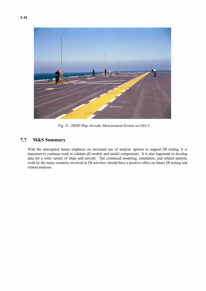
2-42
Fig. 21 JSHIP Ship Airwake Measurement System on LHA 5
7.7 M&S Summary
With the anticipated future emphasis on increased use of analytic options to support DI testing, it isimportant to continue work to validate all models and model components. It is also important to developdata for a wide variety of ships and aircraft. The continued modeling, simulation, and related analyticwork by the many countries involved in DI activities should have a positive effect on future DI testing andrelated analyses.

2-43
8. Concluding Remarks
This AGARDograph describes the U.S. approach to helicopter/ship qualification testing that has been usedsuccessfully over many years to help provide aircraft and ship operators with expanded operational envelopesfor their mission requirements. It is difficult to schedule ships for testing and it is not possible to control theweather in the ship environment. It is also important to work to minimize test cost. NAVAIR continues toconduct conventional DI testing, while working to acquire improved instrumentation plus an improvedhelicopter/ship simulation/analysis capability. The helicopter/ship qualification testing in the future is sure topresent some very interesting challenges to the test teams involved in the programs. This AGARDographprovides a sound foundation to help ensure safe and cost effective DI testing in the future.

2-44
References
1. Thomason, Tommy, "The History of Helicopters in the U.S. Navy," American Helicopter Society,VERTIFLITE, May/June 1984.
2. Carico, Dean and Madey, S.L., Jr, "Dynamic Interface: Conventional Flight Testing Plus a NewAnalytical Approach," AHS National Specialist's Meeting on Helicopter Testing Technology, Williamsburg,VA, Oct/Nov 1984.
3. Long, K. R. and Williams, S. L., “Dynamic Interface Flight Tests and the Pilot Rating Scale,”presented at the AHS 53rd Forum, VA Beach, VA, May 1997.
4. Long, K. R. and Williams, S. L., “ADS-33 and Shipboard Rotorcraft Operations: A USN Flight Testand Simulation Perspective,” presented at the AHS 53rd Forum, VA Beach, VA, May 1997.
5. Woomer, C, and Carico, D., "A Program for Increased Flight Fidelity in Helicopter Simulation," 33rd
AHS Annual Forum, Washington, D.C., May 1977.
6. Carico, Dean, et al, "Dynamic Interface Flight Test and Simulation Limitations," 11th EuropeanRotorcraft Forum, London, England, Sep 1985.
7. Galloway, R.T., et al, “The Ship Environment Simulation Problem,” AIAA 90-3171, AIAAConference, Dayton, OH, Sept 1990.
8. Long, K. R. and Williams, S. L., “The US Navy’s Use of Visual Simulation Technology to Optimizeand Refine Shipboard Rotorcraft Compatibility,” presented at the AHS 53rd Forum, VA Beach, VA, May1997.
9. Polsky, Susan and Bruner, Christopher, “Time-Accurate Computational Simulations of an LHA ShipAirwake,” AIAA-200-4126, Modeling and Simulation Technologies Conference, Denver, Co., Aug 2000.
10. Healey, J. V., “Establishing a Database for Flight in the Wakes of Structures,” Journal of Aircraft, Vol.29, No. 4, July-Aug. 1992, pp. 559-564.
11. Geyer, W.P., Jr. and Burgess, M.S., Ship Airwake Measurement System Dynamic Interface Testingboard USS CARON (DD 970), NAWCAD Report No. TM 93-85 RW of Dec 1993.
12. Burgess, M. Scott, Ship Airwake Measurement System Dynamic Interface Testing Aboard USSSAIPAN (LHA 2) and USS WASP (LHD 1), NAWCAD Report No. RW-96R-92 of Feb 1993.
13. VanderVliet, Gary and Sheriff, Denver, Ship Airwake Tests Aboard USS PELELIU (LHA 5), ReportNo. OSD/JSHIP-TRPT-D1-DIMSS-12/2000 of Dec 2000.

2-45
Annex A: DI Instrumentation
A.1 Ship Airwake Measurement
Ship airwake is one of the most critical parameters affecting the difficulty of helicopter launch/recoveryoperations. Gaining an understanding of a full scale ship flowfield is approached two different ways. These are flow visualization and flow measurement. Flow visualization provides a basic idea of the grossflow patterns, whereas flow measurement provides quantitative information. The US Navy emphasizesflow measurement to apply to shipboard rotorcraft flight simulation. In the past, the instrument used bythe US Navy was called the ship airwake measurement system (SAMS). SAMS consisted of a 30 footpole, with 3 sets of 3 orthogonal Gill UVW propeller anemometers mounted at 10, 20, and 30 feet aboveground level. The units were sealed and incorporate internal blowers to maintain positive pressure withinthe unit to limit environmental contamination of the bearings. The procedure for collecting ship airwakedata included establishing and maintaining a particular wind over deck condition. The SAMS mast wasthen moved to the first designated flight deck measurement location, secured to the flight deck, andremained for 5 minutes to collect data. The data collection software was then reset and the mast wasmoved to the next location. When all of the data collection locations had been completed, a new windover deck was arrived at and the process repeated. True wind was continually monitored throughout thedata collection period to assure it remained constant. The data collection package not only measured windbut also collected ship course and speed, and wind over deck speed and direction from the ship repeaters. The critical information recorded from these tests was then reduced to statistical averages, scale lengths,and intensity factors. The scale length describes the distance between turbulent eddies (thus establishing acharacteristic “frequency” of the flow). Intensity factor describes statistical variation of the flow velocity. Together, these parameters are used to simulate spatially and temporally varying ship airwake turbulencein a flight simulator.
A.2 Ship Instrumentation
The most common shipboard instrumentation used during a DI flight test is the ship motioninstrumentation package (SMP). The DI SMP was designed to collect and store time histories of specificship parameters. The sensors of the SMP are contained in a small, portable housing that may be set upanywhere on the test ship, with the ship center of buoyancy the optimal location. When placed other thanthe center of buoyancy, coordinate transformations are performed to determine motion at the helicopterlanding spot.Sensors organic to the SMP are:
a. Pitch and roll angle pendulumsb. Pitch, roll, and yaw rate gyroc. Linear accelerometers
Wind over deck speed and direction along with ship course and ship speed are recorded directly fromthe ships repeaters. Repeater signals are passed through synchro to analog converters and thenprocessed with the other signals. Four blank channels are provided so that additional sensor inputs(such as flight deck mounted anemometers or pitch and roll information from the ships gyros) may berecorded. Output for the sensor package is then passed to a portable computer. The computer providespost-processing capabilities along with data storage.
A.3 Helicopter Instrumentation
Quantitative helicopter/ship test data are needed for envelope development and for validating analysisand simulation models used to support DI testing. NAWCAD rotorcraft typically have extensiveinstrumentation. These aircraft normally are not used for DI testing because they may be required tosupport other test programs, may be considered a “dry” aircraft, or the DI test location may be too far

2-46
from NAWCAD. A portable instrumentation system that can be easily installed and removed from fleetaircraft is needed to support remote site DI testing.A small business program was used to develop a prototype Portable Aircraft Flight Test InstrumentationSystem (PINS) during the 1997-1999 time frame. PINS is designed to be installed, calibrated, andoperational in just a few hours. It features an INS/GPS unit for acceleration, rates, velocities, angles, andpositions. It can be attached to a MIL-STD 1553 bus if one is available in the rotorcraft. It also includesvideo monitoring that reads the cockpit displays and converts the reading to digital data. Typical examplesof cockpit data include altitude, airspeed, vertical velocity, engine torque, and fuel quantity. Controlposition and control force data are also available. The PINS package weights approximate 115 lbs andwas designed to be easily installed in fleet aircraft.

A-1
Annex
AGARD and RTO Flight Test Instrumentation and Flight Test Techniques Series
1. Volumes in the AGARD and RTO Flight Test Instrumentation Series, AGARDograph 160
Volume Title PublicationNumber Date1. Basic Principles of Flight Test Instrumentation Engineering (Issue 2)
Issue 1: edited by A. Pool and D. Bosman 1974Issue 2: edited by R. Borek and A. Pool 1994
2. In-Flight Temperature Measurements 1973 by F. Trenkle and M. Reinhardt
3. The Measurements of Fuel Flow 1972 by J.T. France
4. The Measurements of Engine Rotation Speed 1973 by M. Vedrunes
5. Magnetic Recording of Flight Test Data 1974 by G.E. Bennett
6. Open and Closed Loop Accelerometers 1974 by I. Mclaren
7. Strain Gauge Measurements on Aircraft 1976 by E. Kottkamp, H. Wilhelm and D. Kohl
8. Linear and Angular Position Measurement of Aircraft Components 1977 by J.C. van der Linden and H.A. Mensink
9. Aeroelastic Flight Test Techniques and Instrumentation 1979 by J.W.G. van Nunen and G. Piazzoli
10. Helicopter Flight Test Instrumentation 1980 by K.R. Ferrell
11. Pressure and Flow Measurement 1980 by W. Wuest
12. Aircraft Flight Test Data Processing - A Review of the State of the Art 1980 by L.J. Smith and N.O. Matthews
13. Practical Aspects of Instrumentation System Installation 1981 by R.W. Borek
14. The Analysis of Random Data 1981 by D.A. Williams
15. Gyroscopic Instruments and their Application to Flight Testing 1982 by B. Stieler and H. Winter
16. Trajectory Measurements for Take-off and Landing Test and Other Short-Range 1985Applications by P. de Benque D'Agut, H. Riebeek and A. Pool
17. Analogue Signal Conditioning for Flight Test Instrumentation 1986 by D.W. Veatch and R.K. Bogue
18. Microprocessor Applications in Airborne Flight Test Instrumentation 1987 by M.J. Prickett
19. Digital Signal Conditioning for Flight Test 1991 by G.A. Bever

A-2
2. Volumes in the AGARD and RTO Flight Test Techniques Series
Volume Title PublicationNumber Date
AG237 Guide to In-Flight Thrust Measurement of Turbojets and Fan Engines by the MIDAP 1979Study Group (UK)
The remaining volumes are published as a sequence of Volume Numbers of AGARDograph 300.
Volume Title PublicationNumber Date
1. Calibration of Air-Data Systems and Flow Direction Sensors 1988 by J.A. Lawford and K.R. Nippress
2. Identification of Dynamic Systems 1988 by R.E. Maine and K.W. Iliff
3. Identification of Dynamic Systems - Applications to AircraftPart 1: The Output Error Approach 1986
by R.E. Maine and K.W. Iliff
Part 2: Nonlinear Analysis and Manoeuvre Design 1994by J.A. Mulder, J.K. Sridhar and J.H. Breeman
4. Determination of Antenna Patterns and Radar Reflection Characteristics of Aircraft 1986 by H. Bothe and D. McDonald
5. Store Separation Flight Testing 1986 by R.J. Arnold and C.S. Epstein
6. Developmental Airdrop Testing Techniques and Devices 1987 by H.J. Hunter
7. Air-to-Air Radar Flight Testing 1992 by R.E. Scott
8. Flight Testing under Extreme Environmental Conditions 1988 by C.L. Henrickson
9. Aircraft Exterior Noise Measurement and Analysis Techniques 1991 by H. Heller
10. Weapon Delivery Analysis and Ballistic Flight Testing 1992 by R.J. Arnold and J.B. Knight
11. The Testing of Fixed Wing Tanker & Receiver Aircraft to Establish their 1992Air-to-Air Refuelling Capabilities by J. Bradley and K. Emerson
12. The Principles of Flight Test Assessment of Flight-Safety-Critical Systems in Helicopters 1994 by J.D.L. Gregory
13. Reliability and Maintainability Flight Test Techniques 1994 by J.M. Howell
14. Introduction to Flight Test Engineering 1995 Edited by F. Stoliker
15. Introduction to Avionics Flight Test 1996 by J.M. Clifton
16. Introduction to Airborne Early Warning Radar Flight Test 1999 by J.M. Clifton and F.W. Lee
17. Electronic Warfare Test and Evaluation 2000 by H. Banks and R. McQuillan
18. Flight Testing of Radio Navigation Systems 2000 by H. Bothe and H.J. Hotop
19. Simulation in Support of Flight Testing 2000 by D. Hines
20. Logistics Test and Evaluation in Flight Testing 2001 by M. Bourcier

A-3
21. Flying Qualities Flight Testing of Digital Flight Control Systems 2001 by F. Webster and T.D. Smith
22. Helicopter/Ship Qualification Testing 2002 by D. Carico, R. Fang, R. S. Finch and W. P. Geyer Jr., Cdr. (Ret.) H. W. Krijns, K. Long
At the time of publication of the present volume, the following volumes are in preparation:
Optical Air Flow Measurement in Flight
Flight Test Measurement Techniques for Laminar Flow
Flight Testing of Night Vision Systems
Unique Aspects of Flight Testing of Unmanned Aerial Vehicles/Unmanned Combat Aerial Vehicles
Aircraft-Stores Certification Testing
Selection of a Flight Test Instrumentation System
Testing of Precision Airdrop Systems
Flight Testing of Tactical Laser Systems

This page has been deliberately left blank
Page intentionnellement blanche

REPORT DOCUMENTATION PAGE
1. Recipient’s 2. Originator’s References 3. Further Reference 4. Security ClassificationReference of Document
RTO-AG-300 ISBN 92-837-1093-2 UNCLASSIFIED/AC/323(SCI-038)TP/53 UNLIMITEDVolume 22
5. Originator Research and Technology OrganisationNorth Atlantic Treaty OrganisationBP 25, F-92201 Neuilly-sur-Seine Cedex, France
6. TitleHelicopter/Ship Qualification Testing
7. Presented at/sponsored by
the SCI-055 Task Group, the Flight Test Technology Team of the Systems Conceptsand Integration Panel (SCI) of RTO.
8. Author(s)/Editor(s) 9. Date
G.D. Carico, R. Fang, R.S. Finch, February 2003W.P. Geyer Jr., Cdr. (Ret.) H.W. Krijns and K. Long
10. Author’s/Editor’s Address 11. Pages
Multiple 126
12. Distribution Statement There are no restrictions on the distribution of this document.Information about the availability of this and other RTOunclassified publications is given on the back cover.
13. Keywords/Descriptors
Dynamic interface Operational effectivenessFlight Deck Qualification Sea statesFlight decks SeakeepingFlight maneuvers Ship decksFlight tests Ship maneuveringHelicopter flight tests Ship motionHelicopter/Ship Clearance Shipboard landingHelicopter/Ship Qualification SHOL (Ship Helicopter Operating Limitations)Helicopters Trials
14. Abstract
The purpose of this AGARDograph is to document the preparation, execution, and data analysisof helicopter/ship flight-testing. The attention is focused on helicopter take-off and landingwhich constitutes the main part of the test programme.
Described are:• the factors influencing the helicopter/ship operations;• how these factors are determined in various qualification programme elements;• how these factors are used to set up a flight test programme on board the ship;• how the ship-borne flight tests, within the constraints of safety and efficiency, are carried out;• in what way, during the tests, repeated use is made of the data obtained in the previous
qualification programme elements and of the experience of the test team, resulting in thesmallest possible number of flying hours without affecting the quality of the results.
A brief outline of helicopter-ship qualification programmes as carried out by the NetherlandsNational Aerospace Laboratory (NLR), by QinetiQ (formerly the UK Defence Evaluation &Research Agency (DERA) at Boscombe Down in the UK and by the US Naval Air WarfareCenter Aircraft Division (NAWCAD) at Patuxent River is given. It describes how detailedinformation of the helicopter capabilities, ship’s motion characteristics and the wind-climateabove the ship’s flight deck, is used to set up and to execute a safe and efficient flight testprogramme. The programme leads to a safe and maximum operational availability of thehelicopter on board the ship in terms of take-off and landing capabilities as a function ofrelative wind and sea-state.

This page has been deliberately left blank
Page intentionnellement blanche

NORTH ATLANTIC TREATY ORGANISATION
RESEARCH AND TECHNOLOGY ORGANISATION
BP 25 • 7 RUE ANCELLE DIFFUSION DES PUBLICATIONS
F-92201 NEUILLY-SUR-SEINE CEDEX • FRANCE RTO NON CLASSIFIEES
Telecopie 0(1)55.61.22.99 • E-mail [email protected]
L’Organisation pour la recherche et la technologie de l’OTAN (RTO), detient un stock limite de certaines de ses publications recentes, ainsique de celles de l’ancien AGARD (Groupe consultatif pour la recherche et les realisations aerospatiales de l’OTAN). Celles-ci pourronteventuellement etre obtenues sous forme de copie papier. Pour de plus amples renseignements concernant l’achat de ces ouvrages,adressez-vous par lettre ou par telecopie a l’adresse indiquee ci-dessus. Veuillez ne pas telephoner.
Des exemplaires supplementaires peuvent parfois etre obtenus aupres des centres nationaux de distribution indiques ci-dessous. Si voussouhaitez recevoir toutes les publications de la RTO, ou simplement celles qui concernent certains Panels, vous pouvez demander d’etreinclus sur la liste d’envoi de l’un de ces centres.
Les publications de la RTO et de l’AGARD sont en vente aupres des agences de vente indiquees ci-dessous, sous forme de photocopie oude microfiche. Certains originaux peuvent egalement etre obtenus aupres de CASI.
CENTRES DE DIFFUSION NATIONAUX
ALLEMAGNE FRANCE PAYS-BASStreitkrafteamt / Abteilung III O.N.E.R.A. (ISP) Royal Netherlands MilitaryFachinformationszentrum der 29, Avenue de la Division Leclerc Academy LibraryBundeswehr, (FIZBw) BP 72, 92322 Chatillon Cedex P.O. Box 90.002
Friedrich-Ebert-Allee 34 4800 PA BredaGRECE (Correspondant)D-53113 Bonn
Defence Industry & Research POLOGNEBELGIQUE General Directorate Armament Policy Department
Etat-Major de la Defense Research Directorate 218 Niepodleglosci Av.Departement d’Etat-Major Strategie Fakinos Base Camp 00-911 WarsawACOS-STRAT-STE – Coord. RTO S.T.G. 1020
PORTUGALQuartier Reine Elisabeth Holargos, AthensEstado Maior da Forca AereaRue d’Evere, B-1140 Bruxelles HONGRIE SDFA - Centro de Documentacao
Department for ScientificCANADA AlfragideAnalysisDSIGRD2 P-2720 Amadora
Institute of Military TechnologyBibliothecaire des ressources du savoirREPUBLIQUE TCHEQUEMinistry of DefenceR et D pour la defense Canada
DIC Czech Republic-NATO RTOH-1525 Budapest P O Box 26Ministere de la Defense nationaleVTUL a PVO Praha305, rue Rideau, 9e etage ISLANDE Mladoboleslavska ul.Ottawa, Ontario K1A 0K2 Director of Aviation Praha 9, 197 06, C
∨eska republika
c/o FlugradDANEMARKROYAUME-UNIReykjavikDanish Defence Research Establishment
Dstl Knowledge ServicesRyvangs Alle 1, P.O. Box 2715 ITALIE Kentigern House, Room 2246DK-2100 Copenhagen Ø Centro di Documentazione 65 Brown StreetTecnico-Scientifica della DifesaESPAGNE Glasgow G2 8EX
Via XX Settembre 123aINTA (RTO/AGARD Publications)00187 Roma TURQUIECarretera de Torrejon a Ajalvir, Pk.4
Millı Savunma Bas,kanli i (MSB)28850 Torrejon de Ardoz - Madrid LUXEMBOURG ARGE Dairesi Bas,kanli i (MSB)Voir BelgiqueETATS-UNIS 06650 Bakanliklar - AnkaraNASA Center for AeroSpace NORVEGEInformation (CASI) Norwegian Defence Research
Parkway Center Establishment7121 Standard Drive Attn: BiblioteketHanover, MD 21076-1320 P.O. Box 25, NO-2007 Kjeller
AGENCES DE VENTE
NASA Center for AeroSpace The British Library Document Canada Institute for Scientific andInformation (CASI) Supply Centre Technical Information (CISTI)
Parkway Center Boston Spa, Wetherby National Research Council7121 Standard Drive West Yorkshire LS23 7BQ AcquisitionsHanover, MD 21076-1320 Royaume-Uni Montreal Road, Building M-55Etats-Unis Ottawa K1A 0S2, Canada
Les demandes de documents RTO ou AGARD doivent comporter la denomination “RTO” ou “AGARD” selon le cas, suivie dunumero de serie (par exemple AGARD-AG-315). Des informations analogues, telles que le titre et la date de publication sontsouhaitables. Des references bibliographiques completes ainsi que des resumes des publications RTO et AGARD figurent dans lesjournaux suivants:
Scientific and Technical Aerospace Reports (STAR) Government Reports Announcements & Index (GRA&I)STAR peut etre consulte en ligne au localisateur de publie par le National Technical Information Serviceressources uniformes (URL) suivant: Springfield
http://www.sti.nasa.gov/Pubs/star/Star.html Virginia 2216STAR est edite par CASI dans le cadre du programme Etats-UnisNASA d’information scientifique et technique (STI) (accessible egalement en mode interactif dans la base de
donnees bibliographiques en ligne du NTIS, et sur CD-ROM)STI Program Office, MS 157ANASA Langley Research CenterHampton, Virginia 23681-0001Etats-Unis
Imprime par Groupe d’imprimerie St-Joseph inc.(Membre de la Corporation St-Joseph)
1165, rue Kenaston, Ottawa (Ontario), Canada K1G 6S1

NORTH ATLANTIC TREATY ORGANISATION
RESEARCH AND TECHNOLOGY ORGANISATION
BP 25 • 7 RUE ANCELLE DISTRIBUTION OF UNCLASSIFIED
F-92201 NEUILLY-SUR-SEINE CEDEX • FRANCE RTO PUBLICATIONS
Telefax 0(1)55.61.22.99 • E-mail [email protected]
NATO’s Research and Technology Organisation (RTO) holds limited quantities of some of its recent publications and those of the formerAGARD (Advisory Group for Aerospace Research & Development of NATO), and these may be available for purchase in hard copy form.For more information, write or send a telefax to the address given above. Please do not telephone.
Further copies are sometimes available from the National Distribution Centres listed below. If you wish to receive all RTO publications, orjust those relating to one or more specific RTO Panels, they may be willing to include you (or your organisation) in their distribution.
RTO and AGARD publications may be purchased from the Sales Agencies listed below, in photocopy or microfiche form. Original copiesof some publications may be available from CASI.
NATIONAL DISTRIBUTION CENTRES
BELGIUM GREECE (Point of Contact) POLANDEtat-Major de la Defense Defence Industry & Research Armament Policy DepartmentDepartement d’Etat-Major Strategie General Directorate 218 Niepodleglosci Av.ACOS-STRAT-STE – Coord. RTO Research Directorate 00-911 WarsawQuartier Reine Elisabeth Fakinos Base Camp
PORTUGALRue d’Evere, B-1140 Bruxelles S.T.G. 1020Estado Maior da Forca AereaHolargos, Athens
CANADA SDFA - Centro de DocumentacaoDRDKIM2 HUNGARY AlfragideKnowledge Resources Librarian Department for Scientific P-2720 AmadoraDefence R&D Canada Analysis
SPAINDepartment of National Defence Institute of Military TechnologyINTA (RTO/AGARD Publications)305 Rideau Street, 9th Floor Ministry of DefenceCarretera de Torrejon a Ajalvir, Pk.4Ottawa, Ontario K1A 0K2 H-1525 Budapest P O Box 2628850 Torrejon de Ardoz - Madrid
CZECH REPUBLIC ICELANDTURKEYDirector of AviationDIC Czech Republic-NATO RTO
Millı Savunma Bas,kanli i (MSB)c/o FlugradVTUL a PVO PrahaARGE Dairesi Bas,kanli i (MSB)ReykjavikMladoboleslavska ul.06650 Bakanliklar - AnkaraPraha 9, 197 06, C
∨eska republika
ITALYUNITED KINGDOMCentro di DocumentazioneDENMARK
Dstl Knowledge ServicesTecnico-Scientifica della DifesaDanish Defence ResearchKentigern House, Room 2246Via XX Settembre 123aEstablishment65 Brown Street00187 RomaRyvangs Alle 1, P.O. Box 2715Glasgow G2 8EXDK-2100 Copenhagen Ø
LUXEMBOURGUNITED STATESSee BelgiumFRANCE
NASA Center for AeroSpaceO.N.E.R.A. (ISP)NETHERLANDS Information (CASI)29 Avenue de la Division Leclerc
Royal Netherlands Military Parkway CenterBP 72, 92322 Chatillon CedexAcademy Library 7121 Standard Drive
P.O. Box 90.002GERMANY Hanover, MD 21076-13204800 PA BredaStreitkrafteamt / Abteilung III
Fachinformationszentrum derNORWAYBundeswehr, (FIZBw)
Norwegian Defence ResearchFriedrich-Ebert-Allee 34EstablishmentD-53113 Bonn
Attn: BiblioteketP.O. Box 25, NO-2007 Kjeller
SALES AGENCIESNASA Center for AeroSpace The British Library Document Canada Institute for Scientific and
Information (CASI) Supply Centre Technical Information (CISTI)Parkway Center Boston Spa, Wetherby National Research Council7121 Standard Drive West Yorkshire LS23 7BQ AcquisitionsHanover, MD 21076-1320 United Kingdom Montreal Road, Building M-55United States Ottawa K1A 0S2, CanadaRequests for RTO or AGARD documents should include the word ‘RTO’ or ‘AGARD’, as appropriate, followed by the serialnumber (for example AGARD-AG-315). Collateral information such as title and publication date is desirable. Full bibliographicalreferences and abstracts of RTO and AGARD publications are given in the following journals:
Scientific and Technical Aerospace Reports (STAR) Government Reports Announcements & Index (GRA&I)STAR is available on-line at the following uniform published by the National Technical Information Serviceresource locator: Springfield
http://www.sti.nasa.gov/Pubs/star/Star.html Virginia 22161STAR is published by CASI for the NASA Scientific United Statesand Technical Information (STI) Program (also available online in the NTIS BibliographicSTI Program Office, MS 157A Database or on CD-ROM)NASA Langley Research CenterHampton, Virginia 23681-0001United States
Printed by St. Joseph Print Group Inc.(A St. Joseph Corporation Company)
1165 Kenaston Street, Ottawa, Ontario, Canada K1G 6S1
ISBN 92-837-1093-2