
Ring of Masters (ROM): A new ring structure for Bluetooth scatternets with dynamic routing and...
17
This article appeared in a journal published by Elsevier. The attached copy is furnished to the author for internal non-commercial research and education use, including for instruction at the authors institution and sharing with colleagues. Other uses, including reproduction and distribution, or selling or licensing copies, or posting to personal, institutional or third party websites are prohibited. In most cases authors are permitted to post their version of the article (e.g. in Word or Tex form) to their personal website or institutional repository. Authors requiring further information regarding Elsevier’s archiving and manuscript policies are encouraged to visit: http://www.elsevier.com/copyright
Transcript of Ring of Masters (ROM): A new ring structure for Bluetooth scatternets with dynamic routing and...
This article appeared in a journal published by Elsevier. The attachedcopy is furnished to the author for internal non-commercial researchand education use, including for instruction at the authors institution
and sharing with colleagues.
Other uses, including reproduction and distribution, or selling orlicensing copies, or posting to personal, institutional or third party
websites are prohibited.
In most cases authors are permitted to post their version of thearticle (e.g. in Word or Tex form) to their personal website orinstitutional repository. Authors requiring further information
regarding Elsevier’s archiving and manuscript policies areencouraged to visit:
http://www.elsevier.com/copyright
Author's personal copy
Pervasive and Mobile Computing 4 (2008) 546–561
Contents lists available at ScienceDirect
Pervasive and Mobile Computing
journal homepage: www.elsevier.com/locate/pmc
Ring of Masters (ROM): A new ring structure for Bluetooth scatternetswith dynamic routing and adaptive scheduling schemesTarek Hassan, Ayman Kayssi, Ali Chehab ∗
Department of Electrical and Computer Engineering, American University of Beirut, Beirut 1107 2020, Lebanon
a r t i c l e i n f o
Article history:Received 15 February 2005Received in revised form 25 February 2008Accepted 26 February 2008Available online 12 March 2008
Keywords:Bluetooth technologyScatternetsAd hoc networksRing structures
a b s t r a c t
This paper attempts to address the scatternet problem in Bluetooth through acomprehensive approach. We propose a new decentralized ring structure to combat theformation of traffic bottlenecks. The adopted construction protocol ensures flexibility ofnode selection and a good level of fault tolerance. The routing protocol combines bothsimplicity and robustness by taking advantage of the ring structure and relying on thecollectivememory of piconets tomake forwarding and discarding decisions. The intra- andinter-piconet scheduling algorithm, called ROM adaptive scheduling (RAS), dynamicallyallocates time slots and is responsive to the varyingworkload conditions.We demonstrate,through analysis and simulations, that the various components of ROM yield a system thathas good performance in terms of throughput, latency, delivery, and link utilization.
© 2008 Elsevier B.V. All rights reserved.
1. Introduction
With a history of more than three decades, the field of ad hoc networking has undergonemajor changes in terms of goalsand applications depending on the main research directions and the revolutions in microelectronics and VLSI technology.Originally, ad hoc networks were designed to be used in situations either where there is no infrastructure at all or wheresuch infrastructure cannot be used because of damage, security, cost, or safety reasons. A shift in this paradigm towardscommercial use of such networks started to appear in the early 1990’s with the debut of the ubiquitous computing conceptand its requirements.
Broadly defined, ad hoc networking refers to the ability of the different neighboring nodes (possibly mobile nodes) toconfigure themselves and form a fully functional network on the fly independently from any fixed or wired infrastructure.In such a network, some pairs may be out of range of each other. Thus, there is a need to relay packets by intermediate nodesfrom source to destination, which is referred to as “multi-hopping” [15]. Such features imply many advantages that includeeasy installation and low-cost operation and maintenance.
Ad hoc networks could be classified into two types [13]. The conventional type is composed of a group of peer entities thatare in range of each other and share the same channel. All nodes receive all traffic on this network. The second type, on theother hand, divides the existing nodes into groups each of which has its own channel even if the nodeswerewithin the samearea. Communication between the different groups can take place by gateway nodes that sequentially spend time in eachgroup on a time-division basis. It is denoted as the scatter type and provides many benefits such as increased throughputand low power consumption but poses severe challenges such as increased interference and delays.
However, the other side of the coin is not as much pleasant. A brief scan of the literature in the field shows that widedeployment of ad hoc networks still needs more time to mature or will remain limited to certain applications (military,for example) as long as we could not reach an acceptable common denominator in the characteristics of the participating
∗ Corresponding author. Tel.: +961 1 374 374; fax: +961 1 744 462.E-mail addresses: [email protected] (T. Hassan), [email protected] (A. Kayssi), [email protected] (A. Chehab).
1574-1192/$ – see front matter© 2008 Elsevier B.V. All rights reserved.doi:10.1016/j.pmcj.2008.02.003
Author's personal copy
T. Hassan et al. / Pervasive and Mobile Computing 4 (2008) 546–561 547
nodes. Most of the time, heterogeneity of the communicating devices is reflected into increased complexity of routing andnetworking algorithms to fulfill the different, or sometimes contradicting, requirements of these devices.
In 1998, a group of leading manufacturers in the computing and telecom industry took an ambitious step by introducingan open standard for short range wireless connectivity that works in an ad hoc fashion. This new technology was namedBluetooth and it was hoped that it would contribute significantly to “uniting” neighboring devices the same way HaraldBluetooth, a 10th century king, succeeded in uniting the warring Viking tribes [26].
Key features of Bluetooth (BT) system are robustness, low power, and low cost. Moreover, many features were madeoptional to give some room for product differentiation. The core system consists of an RF transceiver, baseband, and protocolstack. The system offers services that enable the connection of devices and exchange of a variety of classes of data betweenthese devices.
Since its inception and official announcement, the BT system was described by regularly updated versions ofspecifications. The first public version appeared on July 1999 and the last one beforewriting this paper is dated onNovember2004 [4]. The noticeable changes in newer versions are the improved consistency and readability starting from v1.2, and theintroduction of enhanced data rates (EDR) that can offer up to 2Mbps and 3Mbps depending on a new set of packet types,according to v2.0.
While the BT specification described the details of forming a wireless personal area network (piconet), it merely alludedto the concept of internetworking multiple piconets (called a scatternet), and it did not indicate how it was to be formed.This left researchers with a host of challenges to solve before scatternets could become a reality. In this paper, we describethe various facets of this issue and we propose a comprehensive approach.
The rest of the paper is organized as follows. In Section 2, we define the BT technology and we focus on the features andprocedures that are relevant to this work. Section 3 explores the scatternet design problem and the previous proposalsmadeto address its different aspects. In Section 4, we present our proposed ring structure in detail and we compare it with someprevious ones. Section 5 shows and discusses the simulation results and we conclude the paper in Section 6.
2. The Bluetooth system basics
In this section, we briefly describe the general aspects and properties of the BT system especially those related to ourwork. For more details, the reader is referred to [4]. The BT radios operate in the unlicensed ISM band at 2.4 GHz, which isglobally available, and they use frequency hopping spread spectrum (FHSS) to combat interference. Hopping consists of 79channels in the band with 1 MHz spacing at a rate of 1600 hops per second, which means that each transmission dwells ateach carrier for 625 µs.
All BT units are peers with identical hardware and software interfaces. They can be distinguished by the IEEE-type 48 bitaddress that is engravedduringmanufacturing and cannot bemodified.Moreover, each device is equippedwith a 28 bit clockthat ticks once every 312.5 µs which corresponds to half the residence time in a hop frequency. These two parameters, theBT device address (BD_ADDR) and the clock, are practically involved in all aspects of BT communications where devicesacquire and exchange these data during link setup.
The Bluetooth specification has defined two types of ad hoc networks: a small networkwith limited range andpopulation,called piconet, and a second type, called scatternet that interconnects the different neighboring piconets to form a larger andmore capable network. A piconet is a star-shaped network that is composed of one coordinating node, calledmaster, whichdeploys a central polling scheme to regulate the traffic and eliminate collisions among the transmissions of the remainingnodes, called slaves. The master and slave transmissions alternate in 625 µs time slots resulting in a time-division duplex(TDD) system. To guarantee quality of service (QoS) within a piconet, the maximum number of participating nodes waslimited to eight.
A scatternet, on the other hand, is intended to interconnect several piconets by gateway nodes, called PMPs (ParticipantsinMultiple Piconets), that sequentially participate in these piconets in a time-division basis. The key parameters a node usesto synchronize itself to the frequency hopping (FH) sequence of a certain piconet are the identity (unique device address)and clock offset of the master that are acquired during piconet formation. As a result, a bridge or PMP node maintains a setof identities and offsets for the masters of the piconets to which it belongs in order to select the proper pair when switchingfrom one piconet to another [14].
When the Bluetooth device is not participating in a piconet, it is in a standby mode. To engage in communications, theBluetooth specifications have defined two phases to accomplish this: the inquiry phase and the paging phase. The inquiryphase is used for device discovery while the paging phase is used to establish the connection. Both of these procedures areasymmetric in the sense that for two nodes to set up a connection they should have different initial states: the inquirerand the inquired (called discoverable) as well as the pager and the paged (called connectable). To solve this problem, theBluetooth specifications define the initial state for each device in all usage scenarios.
To be able to exchange messages, any two nodes should agree to a common channel-hopping sequence as well as to acertain clock phase. The process starts with the discoverable devices using inquiry scan channels that are limited in number(32 out of 79) and slow in hopping rate. This allows the inquiring device to cover all carriers in a reasonable period of timeand get responses from devices within its range. The information collected by the inquiring device (potential master) fromthe inquired devices (potential slaves) primarily consists of their identities and native clocks. Next, in the paging phase, thepager (formerly, the inquirer) sends its identity and native clock to the remaining devices to tune themselves to a common

Author's personal copy
548 T. Hassan et al. / Pervasive and Mobile Computing 4 (2008) 546–561
hopping sequence that is unique to the forming piconet since it depends on the unique identity of the master. It is alsopossible for active piconet members to carry the above mentioned procedures to get connected to other devices as long asQoS requirements are not affected.
Concerning bandwidth utilization, allowing only the pure TDD scheme to take place results in wasting half of thebandwidth if only one of the two communicating parties has data to send. For this reason, multi-slot packets have beendefined by Bluetooth specifications. Such packets could cover 3 or 5 slots provided that a single-hop carrier is maintainedduring the whole transmission time. After a multi-slot packet, the channel continues on the hop sequence as if single-slotpackets were used all the time. We used multi-slot packets in our scheduling scheme under certain conditions to increaselink utilization, in addition to their inherent advantage of reducing packet collisions due to interference [11].
3. The scatternet problem and previous work
In this section, we pave the way towards discussing our proposed work by first presenting the multi-faceted problem ofscatternet design, followed by a literature review that spans the last few years.
3.1. The scatternet design problem
Designing a scatternet requires paying special attention to a number of large-scale networking functions that should betailored to the specifics of the Bluetooth standard and to the envisioned applications of scatternets, which differ from thoseof classical ad hoc networks. Most of the time, scatternets are anticipated to be quasi-static, short-lived, and small whichaffects directly their traffic characteristics, mobility patterns, and scaling requirements [3].
Since 2001, the scatternet problem received an increasing attention in the research community. The main issuesaddressed in the last few years were:
• Scatternet formation: How should units gather to form a scatternet? Can we assume all units to be initially in standbymode or preferably divide them into three categories: standby nodes, piconetmembers, and scatternetmembers?Whichsub-group of nodes should share a common channel and which nodes should act as relays to forward traffic from onepiconet to another?
• Topology structure: Should we care for a certain shape for our scatternet? Doesn’t it make more sense if we devote ourefforts to ensure some desirable network specifications letting the formation protocol build a shapeless scatternet thatfulfills our needs? Advocates of the first approach think their top-down design method is more logical since it is basedon analyzing known topologies that have known features.
• Scalability and range: What is themaximum number of units a network can accommodate and still provide an acceptablelevel of service? Should all units be within radio range of each other, or will relaying packets fill the gap among distantnodes?
• Partition and merge: After a scatternet is formed and due to the highly dynamic nature of the network, a node or a groupof nodes may enter or leave this scatternet. How can the network integrate its new members into its fabric? How can agroup of units leave the scatternet without losing data or without disrupting the operation on both sides?
• Interference: In addition to other devices using the ISM band such as cordless phones and microwave ovens, operatingpiconets should show some resistance to interference from other piconets when present in the same place. In otherwords, scatternets not only offer more throughput, but also introduce more interference.
• Packet routing: Node mobility and dynamic topologies make table-driven routing an impractical choice. However, evenif demand-driven protocols were implemented, the question of addressing remains at surface: should we use the uniqueBluetooth device addresses in routing or should we try to deploy a mobile IP hierarchy to guarantee harmony with theexisting IP backbone infrastructure?
• Intra- and inter-piconet scheduling: Bridge transitions between unsynchronized piconets result in some wasted time.These transitions should be able to adapt to traffic variability while keeping an optimized utilization of buffers forresource-limited devices.
Furthermore, in the absence of scatternet formation criteria and topology standards, general guidelines were proposedto address the above-mentioned issues efficiently [25,30,41]:
• The number of piconets should always be kept as small as possible to reduce inter-piconet interference andcommunication complexity.
• A bridge node may only connect two piconets in order not to become an overloaded bottleneck.• Two piconets should not be connected by more than one bridge in order to keep scheduling and routing tasks simple.• Efficient and simple routing should be used tominimize themaximumnumber of hops between any pair of nodes (known
as network diameter), to reduce delays and conserve power.• The resulting network should be mobility- and fault-tolerant.
Author's personal copy
T. Hassan et al. / Pervasive and Mobile Computing 4 (2008) 546–561 549
3.2. Previous work
A brief scan of the extensive literature on the topic of Bluetooth scatternets leads us to classify the proposals into fourmain categories:
• Formation protocols with mesh structures.• Predefined topologies with special formation protocols.• Scatternet-wide routing protocols.• Scheduling algorithms for existing topologies.
Note that our discussion list is not exhaustive but rather limited to the approaches that are relevant to the presentedwork.
3.2.1. Formation protocols with mesh structuresThe Bluetooth topology construction protocol (BTCP) was one of the first formation protocols proposed for Bluetooth
environments [30]. It is composed of three phases, it assumes all nodes to be in radio range of each other, and it applies adistributed election algorithm that ends with a central coordinating node that assigns roles for the rest of the nodes.
A similar protocol is the LMS algorithm [23,24]. LMS, however, allows the existence ofmore than one “leader” node. Theseleaders eventually merge into one connected-mesh scatternet with some desirable properties such as a minimum numberof piconets. Similar to BTCP, LMS does not deal with dynamic environments where nodes may join or leave the networkarbitrarily.
The Bluenet scheme [36] goes beyond the local Bluetooth coverage by making the master nodes ask their slaves toset outgoing links (i.e. inviting other nodes) at the end of three successive phases similar to those of BTCP. The authorsdemonstrated the superiority of their protocol as compared to tree structures in terms of path length and network datacapacity.
Another protocol in [2,29] proceeds in three phases: device discovery, network partitioning into piconets (calledBlueStars), and interconnection of the piconets into amesh-structured scatternet (called BlueConstellation). A salient featurein this algorithm is the “mutual knowledge” established amongparticipating nodes during the device discovery phase,whichenables more appropriate role assignment to achieve enhanced network robustness.
The Two-Phase Scatternet Formation (TPSF) protocol [22] presents a novel idea to support dynamic topology changeswhilemaintaining high aggregate throughput andminimumend-to-end delay. The TPSF suggests the formation of a “controlscatternet” that collects node and route information in an on-demand fashion to support the establishment of a dedicated“on-demand scatternet” for each communication session. An enhanced version, TPSF+, that supports nodemobility appearedin [40] and showed better performance than BTCP and Bluenet.
The authors in [18] propose a dynamic formation protocol that establishes amesh structure capable of supportingmulti-hop scatternets while strictly conforming to the original BT specification.
Finally, note that some valuable efforts, as in [28], surveyed and classified the various scatternet formation protocolsto date, while others, as [17], went a step further by working on providing an online benchmarking facility for Bluetoothscatternets that can be used in the development, testing, and comparison of decentralized scatternet formation protocols.
3.2.2. Predefined topologies with special formation protocolsSeveral authors have suggested the use of a tree structure using various formation techniques [27,35,39]. The
Bluetree [39], for example, generates a spanning tree structure where nodes are not in radio range of each other. Twovariations of the Bluetree algorithm build the scatternet either by selecting a unique root node (called Blueroot) fromwhichthe tree grows gradually, or by allowing multiple Blueroots to exist at the same time and that merge at the end into a singletree, which speeds up the formation process. The Tree Scatternet Formation (TSF) protocol [35] also tries to form a robusttree structure referred to as a forest of connected tree components. In the TSF, every node acts autonomously by runningthe same state-machine algorithm and trying to contact another free node or an already formed tree. The different treesfinally converge to form one bigger and stable tree according to the proposed formation rules. The SF-DeviL [27], on theother hand, builds its tree based on link and device characteristics. It classifies devices according to energy efficiency and toanticipated traffic loads and it tries simultaneously to make Bluetooth links that take place between close devices in orderto reduce the interference and transmission energy. In spite of their easy routing schemes, tree structures suffer from twomajor drawbacks where root or parent nodes are very likely to become traffic bottlenecks in addition to being critical failurenodes as well.
A more recent protocol in [9] exhibits a different look to the tree structure by introducing a formation paradigm thatcombines a quick tree scatternet setup with a distributed scatternet optimization algorithm, which gives rise to meshedtopologies. A logical tree structure is thenmaintained to perform dynamical reconfiguration of the networkwhen necessary.
A Bluetooth chain structure is presented in [12] where the formation algorithm runs repeatedly until a series piconetconnection is formedwhere each piconet has only two bridges to exchange packetswith its two direct neighboring piconets.It is a multi-hop scatternet with rapid formation procedure and small piconet count but its structure intrinsically yields alonger network diameter.

Author's personal copy
550 T. Hassan et al. / Pervasive and Mobile Computing 4 (2008) 546–561
Ring structures with loop formation protocols are presented in [8,25,41]. The Loop Scatternet Formation (LSF)algorithm [41] works in two phases similar to those of the LMS algorithm mentioned in the previous subsection. The firstphase allows separate devices to form piconets and then the piconets will form rings. In the second phase, all availablecomponents (isolated nodes, piconets, and rings) converge into one large loop structure. An important feature of LFS is thatit only uses slave/slave bridges to connect the piconets.
The BlueRings paper [8] suggests connecting all the nodes in a ring structure by allowing each device to play the role of amaster/slave bridge. However, this serial connection of nodes introduces interference that grows linearly with the numberof participating devices. Moreover, the simple routing needs to be supported by some scheduling algorithm to show howpackets could be relayed efficiently through this loop. A more mature BlueRing structure appeared later in [25] where theBTCPwas adopted for scatternet formation.We called the former BlueRing1, and the other BlueRing2. In BlueRing2, commonslaves are used to form the ring structure that interconnects the different piconets. Maintenance, scheduling, and routingprocedures were developed to guarantee high throughput and small delay.
An innovative small-scale approach to the problem of topology determination appears in [7]. The authors implement athree-phase formation protocol that leads to a specific topology (star, ring, line, or mesh) according to certain predefinedparameters such as themaximum number of slaves per piconet andwhether loops are permitted in the resulting scatternet.
3.2.3. Scatternet-wide routing protocolsVery few papers tackled the problem of scatternet-wide packet routing. Table-driven routing was used in tree
structures [39]. The drawback of such tables is the large size and critical data stored in the root node that may fail at anytime leaving the scatternet elements in a chaos state. Other authors suggest that the unique path between any pair of nodesin the tree topology facilitates the use of higher-layer destination identifiers, such as IP addressing, that any node can obtainby an address resolution protocol (ARP) query [35]. Although better than table-driven routing, this solution requires ARPcaches for all nodes. The Bluetooth Network Encapsulation Protocol (BNEP), developed by the Bluetooth PANworking group,is intended to provide an Ethernet-like interface to IP [19]. BNEP utilizes the unique BT device addresses to build broadcastsegments that are independent of rearrangements of network memberships. In its first release, BNEP worked with piconetsonly, but had the potential to extend its functionality towards scatternets. An enhanced Ad-hoc On-demandDistance-Vector(AODV) was proposed in [31] but the flooding of AODV to discover routes is not preferred in ad hoc environments. Anapproach similar to Dynamic Source Routing (DSR) was proposed in [3]. The problem of DSR protocols is the unboundedheader size needed to store route information in packets. This introduces huge header overhead into the small Bluetoothpackets in addition to the use of flooding in a similar way to AODV. A location-aware routing protocol in [6] tries to benefitfrom the location technology supported by commercial handheld devices to collect and calculate source–destination routeinformation in order to minimize the number of hops and therefore obtain faster data flow with more efficient powerconsumption. The ring topology of BlueRings [8,25] and ROM [16] significantly contributes to the simplicity of routing.No routing tables are needed provided that source and destination addresses are included in the packets to prevent looping.The ROM routing protocol to be presented uses only one algorithm to be run bymaster nodes as compared to two algorithmsneeded in the very close ring structure in [25].
3.2.4. Scheduling algorithms for existing topologiesThe scheduling issues in the Bluetooth technology start at the piconet level wheremany polling schemeswere developed
and discussed to provide efficient and fair policies [5,10,20,37,38]. In addition to the new or enhanced policies, these paperscompared the well-known schemes such as the pure round robin (PRR), exhaustive round robin (ERR), and the exhaustivepseudo-cyclic master queue length (EPM). The performance of these algorithms was tested using the different versions ofTCP under varying loads. The chief conclusion from all these experiments is that dynamic policies that can adapt to thechanging traffic and topology conditions are the most efficient ones.
Regarding scatternets, a locally coordinated scatternet (LCS) scheduling algorithmwas proposed in [34]. It dealswith treestructures and tries to effectively coordinate one-hop neighbors to converge to an efficient scatternet-wide communicationschedule. The LCS uses the history of transmissions to optimize slot allocations in order to achieve the highest throughputwith minimum end-to-end latencies.
The authors of [1] propose a destination-based scheduling algorithm for Bluetooth scatternets where each master nodepolls its slaves according to its maximum capacity in delivering packets per cycle. This dictates that a master node maysometimes specify whether it wishes to receive intra- or inter-piconet packets from its slaves. As soon as the bridge nodejoins the piconet, the master uses an exhaustive polling mechanism to benefit from its availability.
A recent inter-piconet scheduling algorithm, the Traffic-Aware Scatternet Scheduling (TASS) protocol [32], uses the sniffmode as the operating mode for the bridge to switch among piconets. In TASS, each master maintains a scheduling table,which contains the traffic information of all masters that the bridge is connected to. According to the continuously updatedscheduling table, each master can figure out the time it can use the bridge, and can calculate the time it needs not to pollthe bridge in the following sniff slots. This scheme of bridge operation enhances the efficiency by tailoring time sharing ofa bridge node according to the varying needs of master nodes it serves.
An integrated algorithm is presented in [21] for both intra- and inter-piconet scheduling, which is implemented using theHOLD mode of Bluetooth. A key component of this scheme is that fairness issues are considered in the scheduling activity.
Author's personal copy
T. Hassan et al. / Pervasive and Mobile Computing 4 (2008) 546–561 551
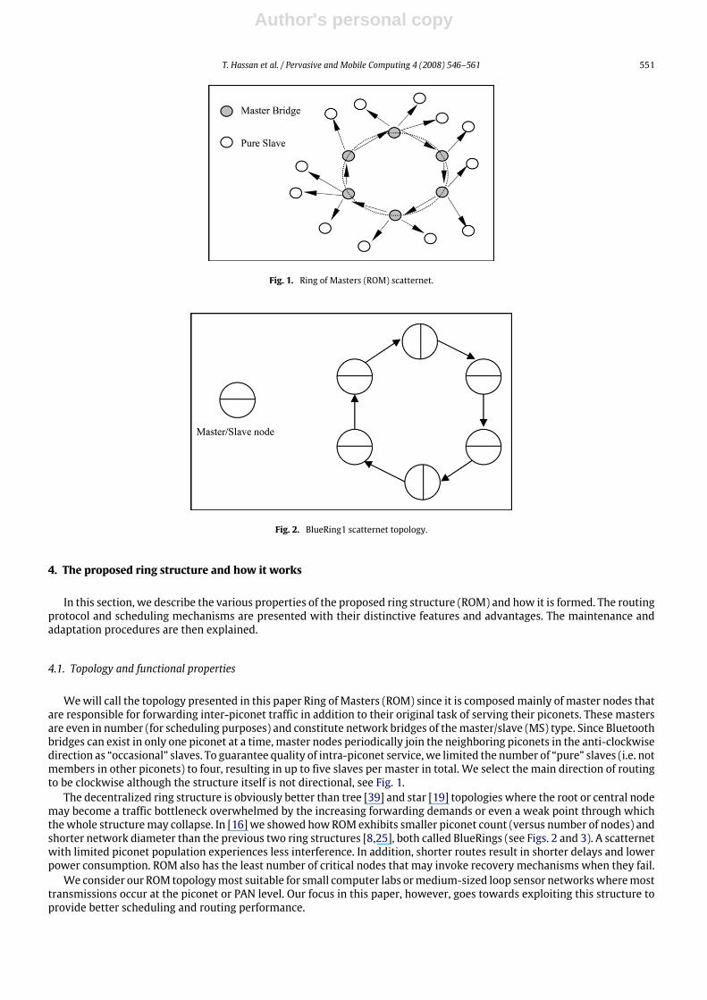
Fig. 1. Ring of Masters (ROM) scatternet.
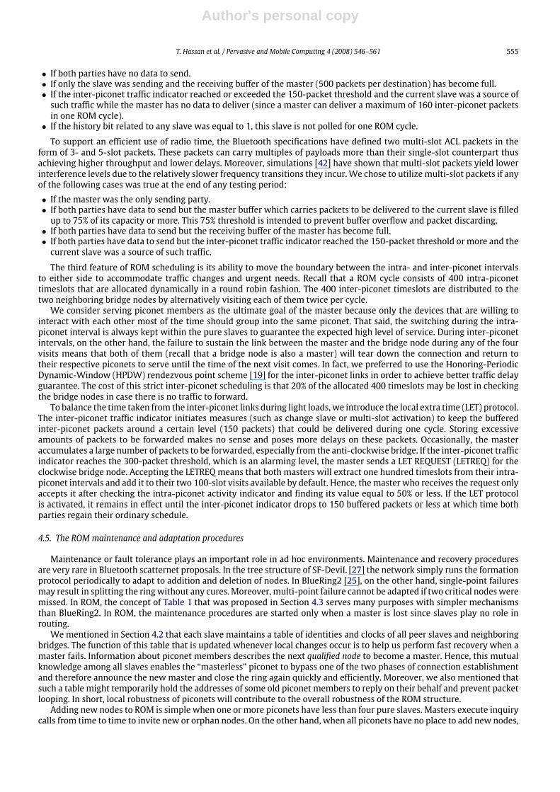
Fig. 2. BlueRing1 scatternet topology.
4. The proposed ring structure and how it works
In this section, we describe the various properties of the proposed ring structure (ROM) and how it is formed. The routingprotocol and scheduling mechanisms are presented with their distinctive features and advantages. The maintenance andadaptation procedures are then explained.
4.1. Topology and functional properties
Wewill call the topology presented in this paper Ring of Masters (ROM) since it is composedmainly of master nodes thatare responsible for forwarding inter-piconet traffic in addition to their original task of serving their piconets. These mastersare even in number (for scheduling purposes) and constitute network bridges of themaster/slave (MS) type. Since Bluetoothbridges can exist in only one piconet at a time, master nodes periodically join the neighboring piconets in the anti-clockwisedirection as “occasional” slaves. To guarantee quality of intra-piconet service, we limited the number of “pure” slaves (i.e. notmembers in other piconets) to four, resulting in up to five slaves per master in total. We select the main direction of routingto be clockwise although the structure itself is not directional, see Fig. 1.
The decentralized ring structure is obviously better than tree [39] and star [19] topologies where the root or central nodemay become a traffic bottleneck overwhelmed by the increasing forwarding demands or even a weak point through whichthewhole structuremay collapse. In [16]we showed howROMexhibits smaller piconet count (versus number of nodes) andshorter network diameter than the previous two ring structures [8,25], both called BlueRings (see Figs. 2 and 3). A scatternetwith limited piconet population experiences less interference. In addition, shorter routes result in shorter delays and lowerpower consumption. ROM also has the least number of critical nodes that may invoke recovery mechanisms when they fail.
We consider our ROM topologymost suitable for small computer labs ormedium-sized loop sensor networkswheremosttransmissions occur at the piconet or PAN level. Our focus in this paper, however, goes towards exploiting this structure toprovide better scheduling and routing performance.

Author's personal copy
552 T. Hassan et al. / Pervasive and Mobile Computing 4 (2008) 546–561
Fig. 3. BlueRing2 scatternet topology.
Fig. 4. The pseudo-code for the first phase in BTCP.
4.2. The adopted formation protocol
To construct a ROM, we adopted the Bluetooth Topology Construction Protocol (BTCP) [30] as a centralized formationalgorithm that can be used to virtually construct any topology. Moreover, the BTCP conforms to the general guidelines ofscatternet design that we mentioned in Section 4.2, and it is composed of three phases as described below.
Phase 1 (Coordinator Election) starts by users pressing the “on” button of their devices thus having the Bluetooth nodesalternate between the inquiry and inquiry scan states in time periods of arbitrary length. As soon as any two nodes meet incomplementary states, they go into one-to-one confrontation by comparing the value of a predefined variable called VOTES(initially set to 1). In each set of pair-wise elections, the node with higher VOTES value wins and collects data about theloser node and other nodes won previously by that node. In other words, if node x won the confrontation with node y, thenVOTES(x) increase by VOTES(y). If both nodes have identical values, the one with a higher address (BD_ADDR) becomes thewinner. The winner nodes continue the same process until a timeout occurs while the losers enter the page scan state, thusbecoming out of elections, and wait to be paged in a coming phase. The election process ends with a central coordinatorthat has successfully collected necessary information about all other nodes during confrontations. The frequency hoppingsequence (FHS) packet is the defined type of packets in Bluetooth specifications to exchange data during communicationsetup procedures. The pseudo-code for this phase is shown in Fig. 4.
During Phase 2 (Role Determination), the coordinator uses the available information to calculate the number of piconetsand to determine which nodes are best fit to becomemasters or bridges. Recalling that Phase 1 ends with all nodes in a page

Author's personal copy
T. Hassan et al. / Pervasive and Mobile Computing 4 (2008) 546–561 553
Fig. 5. The pseudo-code for the second phase in BTCP.
Fig. 6. The ROM routing protocol used by master nodes.
scan state except the final winner, this winner node sends each assigned master a list of its slaves. The pseudo-code for thisphase is shown in Fig. 5.
Finally, in Phase 3 (Scatternet Establishment) each master pages its slaves and bridges and a connected structure isobtained.
The BTCP assumes all nodes to be within radio range of each other and gives no details about how nodes are selected tobecomemasters or bridges. It also suggests the formation of a “fully-connected”meshwhere any two piconets are separatedby no more than one bridge node. This last constraint limits the maximum number of participating nodes to 36.
For the ROM structure, we suggest the following modifications for the BTCP:
• After the establishment of ROM, there is no need to keep all nodes within radio range of each other. Each master needsonly to be in contact with its two left and right neighbor bridges in addition to its piconet member slaves. This way, theROM can cover more physical space than the original BTCP mesh structure.
• The VOTES election variable should be an expression of the combined device and link properties such as battery level,traffic-generation rate, and mobility likelihood as in [27]. In other words, the VOTES variable in its current state as thenumber of acquired nodes does not represent an efficient criterion for election from a functional point of view.
• The ROM is not a fully-connected topology. Thus, it is not limited to a population size of 36 like BTCP.• A direct problem could stem from the previous point where the coordinator may have more than seven slaves to deal
with during Phase 2 of the formation process. This could be solved by using the park mode which allows up to 256 nodesto be in contact with one master provided that only seven of them are active at the same time.
• After ROM formation, an “internal” step could be added where each master broadcasts within its piconet the identitiesand clocks of its slaves and neighboring masters. This procedure increases the robustness of the network as will bediscussed when talking about recovery mechanisms in Section 4.5.
Finally, the choice of BTCP for ROM construction is suitable because both the algorithm and the topology assume theconference scenario where nodes are quasi-static. Moreover, the average delay experienced by each user was roughlyestimated to be 5.5 s for 30 nodes provided that all devices are turned on from the start [30].
4.3. The ROM routing protocol
The implemented routing protocol is simple in the sense that neither does it require routing tables nor does it storerouting information in packet headers. Moreover, it prevents looping and adapts to dynamic environments. Only mastersparticipate in routing by checking the source and destination addresses (48-bit unique numbers) of each packet to determinewhether it should be routed to their piconets, discarded, or forwarded as inter-piconet flow (see Fig. 6).
To accommodate the changing piconet membership efficiently, the address of any leaving node is kept for a while in itspiconet in order to:

Author's personal copy
554 T. Hassan et al. / Pervasive and Mobile Computing 4 (2008) 546–561
Table 1Suggested table for piconet robustness and routing efficiency
BD_ADDR Clock Description Priority
48-bit value 28-bit value Peer slave 148-bit value 28-bit value Peer slave 248-bit value 28-bit value Bridge (right) N/A48-bit value 28-bit value Bridge (left) N/A48-bit value N/A Old member N/A48-bit value N/A Old member N/A
Fig. 7. ROM scheduling cycle.
Fig. 8. The five testing periods during a complete master–slave session.
• Reply on behalf of lost destination nodes indicating that they are no more available.• Discover and discard orphan packets if their sources have left and their destinations are no more “remembered” in their
piconets.
It is worth noting here that the storage time of addresses of leaving nodes is not constant. It should be dynamicallydetermined according to mobility conditions and join-and-leave activities. Finding an expression for this important factorcould be a future work. By adding the stored addresses for routing efficiency to those we mentioned for fault-tolerance, wemay obtain a table similar to Table 1.
4.4. Intra- and inter-piconet scheduling mechanisms
Since masters are responsible for forwarding both intra- and inter-piconet packets, a complex scheduler is needed tomake a balance between both types of transmissions to guarantee best bandwidth utilization and minimum packet delayor discard. We developed the ROM adaptive scheduling (RAS) algorithm to handle these issues. The RAS protocol in eachmaster starts by assigning an equal number of slots (400 slots) for intra- and inter-piconet intervals. The combination ofthese two intervals creates what is called “ROM cycle” that lasts for half a second (800 slots) as shown in Fig. 7.
The relation between amaster and any of its slaves (pure or bridge) in eachmeetingmay last for a hundred time slots thatare divided into five intervals called “testing periods” as shown in Fig. 8. This arrangement helps in allocating the necessarynumber of slots according to network conditions in a dynamic-weighted round robin fashion.
We can summarize the main criteria used in RAS by the following points:
• Master queue status: indicates how many packets are to be delivered to the current slave.• Receiving queue status: monitors the receiving buffer for overflow conditions during a master–slave session.• History bit: records the identities of inactive slaves in the last round.• Intra-piconet activity indicator: calculates the current ratio between the “full” slots and the total number of slots spent
within a piconet.• Inter-piconet traffic indicator: monitors the accumulation of inter-piconet traffic within a master regardless of its origins.
Based on all or some of the above criteria, a master may switch from a slave to another, use multi-slot packets, or movethe boundary between the intra- and inter-piconet intervals in either direction using a special mechanism called local extratime (LET) protocol.
To consume the full hundred time slots, the master and the slave, or the master alone, should have data to send. If onlythe slave was sending, four testing periods (equivalent to 80 slots) would be used in order to minimize the wasted slotscoming from the master side as a result of the time-division duplex (TDD) scheme. More specifically, the master switchesto a new slave if one of the following conditions was met at the end of any testing period:
Author's personal copy
T. Hassan et al. / Pervasive and Mobile Computing 4 (2008) 546–561 555
• If both parties have no data to send.• If only the slave was sending and the receiving buffer of the master (500 packets per destination) has become full.• If the inter-piconet traffic indicator reached or exceeded the 150-packet threshold and the current slave was a source of
such traffic while the master has no data to deliver (since a master can deliver a maximum of 160 inter-piconet packetsin one ROM cycle).
• If the history bit related to any slave was equal to 1, this slave is not polled for one ROM cycle.
To support an efficient use of radio time, the Bluetooth specifications have defined two multi-slot ACL packets in theform of 3- and 5-slot packets. These packets can carry multiples of payloads more than their single-slot counterpart thusachieving higher throughput and lower delays. Moreover, simulations [42] have shown that multi-slot packets yield lowerinterference levels due to the relatively slower frequency transitions they incur.We chose to utilizemulti-slot packets if anyof the following cases was true at the end of any testing period:
• If the master was the only sending party.• If both parties have data to send but the master buffer which carries packets to be delivered to the current slave is filled
up to 75% of its capacity or more. This 75% threshold is intended to prevent buffer overflow and packet discarding.• If both parties have data to send but the receiving buffer of the master has become full.• If both parties have data to send but the inter-piconet traffic indicator reached the 150-packet threshold or more and the
current slave was a source of such traffic.
The third feature of ROM scheduling is its ability to move the boundary between the intra- and inter-piconet intervalsto either side to accommodate traffic changes and urgent needs. Recall that a ROM cycle consists of 400 intra-piconettimeslots that are allocated dynamically in a round robin fashion. The 400 inter-piconet timeslots are distributed to thetwo neighboring bridge nodes by alternatively visiting each of them twice per cycle.
We consider serving piconet members as the ultimate goal of the master because only the devices that are willing tointeract with each other most of the time should group into the same piconet. That said, the switching during the intra-piconet interval is always kept within the pure slaves to guarantee the expected high level of service. During inter-piconetintervals, on the other hand, the failure to sustain the link between the master and the bridge node during any of the fourvisits means that both of them (recall that a bridge node is also a master) will tear down the connection and return totheir respective piconets to serve until the time of the next visit comes. In fact, we preferred to use the Honoring-PeriodicDynamic-Window (HPDW) rendezvous point scheme [19] for the inter-piconet links in order to achieve better traffic delayguarantee. The cost of this strict inter-piconet scheduling is that 20% of the allocated 400 timeslots may be lost in checkingthe bridge nodes in case there is no traffic to forward.
To balance the time taken from the inter-piconet links during light loads, we introduce the local extra time (LET) protocol.The inter-piconet traffic indicator initiates measures (such as change slave or multi-slot activation) to keep the bufferedinter-piconet packets around a certain level (150 packets) that could be delivered during one cycle. Storing excessiveamounts of packets to be forwarded makes no sense and poses more delays on these packets. Occasionally, the masteraccumulates a large number of packets to be forwarded, especially from the anti-clockwise bridge. If the inter-piconet trafficindicator reaches the 300-packet threshold, which is an alarming level, the master sends a LET REQUEST (LETREQ) for theclockwise bridge node. Accepting the LETREQ means that both masters will extract one hundred timeslots from their intra-piconet intervals and add it to their two 100-slot visits available by default. Hence, themaster who receives the request onlyaccepts it after checking the intra-piconet activity indicator and finding its value equal to 50% or less. If the LET protocolis activated, it remains in effect until the inter-piconet indicator drops to 150 buffered packets or less at which time bothparties regain their ordinary schedule.
4.5. The ROM maintenance and adaptation procedures
Maintenance or fault tolerance plays an important role in ad hoc environments. Maintenance and recovery proceduresare very rare in Bluetooth scatternet proposals. In the tree structure of SF-DeviL [27] the network simply runs the formationprotocol periodically to adapt to addition and deletion of nodes. In BlueRing2 [25], on the other hand, single-point failuresmay result in splitting the ringwithout any cures. Moreover, multi-point failure cannot be adapted if two critical nodesweremissed. In ROM, the concept of Table 1 that was proposed in Section 4.3 serves many purposes with simpler mechanismsthan BlueRing2. In ROM, the maintenance procedures are started only when a master is lost since slaves play no role inrouting.
We mentioned in Section 4.2 that each slave maintains a table of identities and clocks of all peer slaves and neighboringbridges. The function of this table that is updated whenever local changes occur is to help us perform fast recovery when amaster fails. Information about piconet members describes the next qualified node to become a master. Hence, this mutualknowledge among all slaves enables the “masterless” piconet to bypass one of the two phases of connection establishmentand therefore announce the newmaster and close the ring again quickly and efficiently. Moreover, we also mentioned thatsuch a table might temporarily hold the addresses of some old piconet members to reply on their behalf and prevent packetlooping. In short, local robustness of piconets will contribute to the overall robustness of the ROM structure.
Adding new nodes to ROM is simple when one or more piconets have less than four pure slaves. Masters execute inquirycalls from time to time to invite new or orphan nodes. On the other hand, when all piconets have no place to add new nodes,

Author's personal copy
556 T. Hassan et al. / Pervasive and Mobile Computing 4 (2008) 546–561
more complicated procedures are executed to establish new piconets and retain the even number of piconets at the sametime. This could be achieved by running a split act that consists of a three-way handshake procedure:
• Upon recognizing the presence of a new node, a master node selects one of its pure slaves to become one of the two newmasters, equips it with the appropriate table and sends a request to the neighboring master about what has been done.
• The neighboring master acknowledges the request by doing identical procedures with one of its slaves and sendingrelevant data about it. Therefore, both of the new masters have full knowledge of the new environment.
• The old connection is torn down as soon as the initiating master confirms the reception of necessary information fromits neighbor.
• The two newmasters take their new places and contact each other. Then they start inviting new nodes for their piconets.
5. Performance testing and simulation results
Webuilt the networkmodel using SimJava [33], a discrete-event object-oriented simulation package. The simulated ROMnetwork is stationary and consists of four full piconets, i.e. 20 nodes. Single- and multi-slot ACL packets were used with asimulation time of 96,000 time slots (equivalent to 60 s). All the simulations consist of randomly selected source–destinationpairs where no two sources can send to the same destination. This last restriction was imposed in order to have a nearlyconstant two-way data ratewith respect to each node, thus having similar pattern to that in [25] withwhich the comparisonis made. Each pair represents a connection between two devices in the network that lasts till the end of the simulation time.Every source transmits 366-bit packets at a constant bit rate (CBR) of 800 packets per second exceptwhenmulti-slot deliveryis used bymaster nodes. It is worth noting here that multi-slot packets are treated at the packet level with respect to single-slot packets since dealing with data at the bit level complicates the simulation and makes measuring delays infeasible.
For simplicity, we assume that collisions due to frequency overlapping do not happen. Moreover, each filled time slot isequivalent to 366 bits including the access code, header, payload header, payload, and CRC.
The next section gives the results of simulations for such type of networks and compares themwith a competing topology.Then, we go deeper in testing the internal details of our algorithms by studying the link utilization factor.
5.1. Routing and scheduling efficiency
We investigated the performance of ROM in two major dimensions: the number of simultaneous connections and theworkload emphasis. The number of connections varies from 4 to 16 while the traffic conditions range from intra- to inter-piconet concentration (Figs. 9 and 10, respectively). The main three metrics used to evaluate our work are:
• The network throughput.• The average end-to-end latency.• The delivery rate.
We compared our results to those of BlueRing [25], which use the same testing parameters, although the authors didnot mention anything about their deployed scheduling scheme. For each number of simultaneous connections, a set of 20simulations was performed; and the average was calculated. For the sake of fair comparison we carried the same set ofsimulations twice. Only single-slot packets were used in the first time (denoted as ROM_s) in order to resemble the case ofBlueRing2 [25]. The effect of using multi-slot packets was explored in the second set of simulations (denoted as ROM_m)where this type of packets represent an added value to our work because of its direct relation with the scheduling algorithmresponding to the varying load conditions.
While the comparison between ROM_s and ROM_m spans all the following figures, BlueRing2 (denoted as BR2) onlyappears in the first twometrics that werementioned in the original paper [25]. Simulation results of BR2were taken directlyfrom their respective graphs without any simulations on our side.
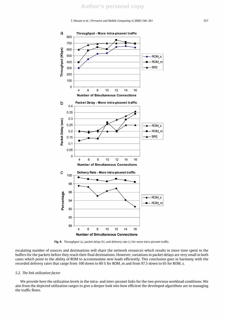
In the first condition, 3:1 of the traffic is within piconets (intra-piconet). We expect to have substantial increase inthroughput together with very low delays. Here, ROM_m outperforms BR2 in throughput for more than 12 connections andin delay for less than 10 connections. This indicates that ROM_m succeeded using its LET protocol to increase the throughputat the expense of relatively longer delays.
The case of ROM_s shows some deficiency in operation in terms of throughput and packet delay compared to ROM_mand BR2. This is because of the lost advantage of multi-slot packet delivery available in ROM_m simulations.
When the inter- to intra-piconet traffic constitutes 3:1 of the packet flow, packets have to travel longer distances and thusexperience longer delays. In this case, we obtain a clearer image of the ROM forwarding capabilities. While the throughputin BR2 saturates at about 320 Kbps, the ROM_m values start at 375 Kbps for 6 connections until it reaches 450 Kbps for 16connections. This higher throughput is accompanied with lower delays for all numbers of connections.
While this time ROM_s results appear to be comparable to those of BR2 in terms of throughput, the rise and fall of packetdelay in ROM_s illustrates how the LET protocol responds to heavy inter-piconet traffic.
We notice that the network throughput starts with small values since the ROM scheduling and routing capabilities arenot used to their full extent. Then, the throughput increases until it reaches a saturation value. The average packet delay,on the other hand, increases a little bit as more simultaneous connections are added. This behavior is expected since an
Author's personal copy
T. Hassan et al. / Pervasive and Mobile Computing 4 (2008) 546–561 557
Fig. 9. Throughput (a), packet delay (b), and delivery rate (c) for more intra-piconet traffic.
escalating number of sources and destinations will share the network resources which results in more time spent in thebuffers for the packets before they reach their final destinations. However, variations in packet delays are very small in bothcases which point to the ability of ROM to accommodate new loads efficiently. This conclusion goes in harmony with therecorded delivery rates that range from 100 down to 80 % for ROM_m and from 97.5 down to 65 for ROM_s.
5.2. The link utilization factor
We provide here the utilization levels in the intra- and inter-piconet links for the two previous workload conditions. Weaim from the depicted utilization ranges to give a deeper look into how efficient the developed algorithms are in managingthe traffic flows.

Author's personal copy
558 T. Hassan et al. / Pervasive and Mobile Computing 4 (2008) 546–561
Fig. 10. Throughput (a), packet delay (b), and delivery rate (c) for more inter-piconet traffic.
(a) More intra-piconet trafficThe prevailing intra-piconet traffic results in the highest utilization of intra-links and the lowest utilization of inter-
links, as shown in Figs. 11 and 12.(b) More inter-piconet traffic
Contrary to the previous condition, the inter-links here exhibit the highest utilization since most of the traffic passesthrough them, as shown in Figs. 13 and 14. The intra-link utilization is not much affected because the intra-links willeventually be used to deliver packets to their final destinations. This case of more inter-piconet traffic shows an increasefollowed by a decrease of inter-link utilization. This is due to the activation of the LET protocol until the communicatingpairs increase in number and make LET’s activation impossible, because the intra-piconet activity has the priority.

Author's personal copy
T. Hassan et al. / Pervasive and Mobile Computing 4 (2008) 546–561 559
Fig. 11. Intra-link utilization for more intra-piconet traffic.
Fig. 12. Inter-link utilization for more intra-piconet traffic.
Fig. 13. Intra-link utilization for more inter-piconet traffic.
It is noticeable that the utilization graphs show high coincidence in results between ROM_m and ROM_s except for thelast case of inter-piconet linkswhen inter-piconet traffic prevails. Again, this disparity can be attributed to the lost advantageof multi-slot packet delivery by master nodes, especially when the LET protocol increases inter-piconet interaction time by25 to 50% for this specific case.
In the presented workloads, the utilization of intra-links increases gradually as the number of connections increases. Thewide ranges of this factor reflect the use of the multi-slot protocol that enables the master nodes to utilize up to 80% of the

Author's personal copy
560 T. Hassan et al. / Pervasive and Mobile Computing 4 (2008) 546–561
Fig. 14. Inter-link utilization for more inter-piconet traffic.
bandwidth if the other party has no data to send. Highest values naturally appear when the intra-piconet traffic is prevalentwhile the lowest ones occur when it shrinks to 1/4 of the network traffic. Utilization of the inter-links, on the other hand,shows a constant behavior most of the time. This is a direct result of the honored periodic rendezvous points in time thatforce all bridge nodes to periodically check with each other to see if there is any inter-piconet traffic to forward regardlessof the current status of inter-piconet indicator.
6. Conclusions
Interconnecting neighboring devices into useful combinations using wireless ad hoc links is a great leap into the future.By introducing cheap, small, and low-power chips to realize this vision, the Bluetooth wireless technology gets closer tobecome the de facto standard of embedded wireless connectivity. Although delayed, the Bluetooth products started toappear in the market to provide innovative solutions for old problems and to open new horizons for machine–machineand human–machine interaction.
In this paper, we addressed the on-going research issue of how to extend the powerful features of Bluetooth piconets toreach a reliable large-scale scatternet. More specifically, we addressed the following three problems:• Scatternet topology and efficient formation.• Scatternet-wide robust routing.• Fair intra- and inter-piconet scheduling.
Comparisons and simulation results show that the ROM topology provides a decentralized andmore practical alternativeto many of the previous structures. The ROM-tailored routing protocol is an example of simplicity and robustness. Thedynamic scheduling algorithms mitigate the artificial delay created by allocation schemes and offer an acceptable level ofutilization for the airtime. Finally, the BTCP formation protocol with the suggested enhancements comes to provide a stronglayout for a reliable scatternet where each node shares in protecting its piconet and is fitted in the right place.
However, the wide spectrum of hardware and software involved in the process, together with the highly dynamicenvironments still impose severe challenges. Moremature formation, routing, and healing are expectedwhen the Bluetoothlocal-positioning profile emerges. Moreover, some node arrangements, not necessarily regular, seem to bemore suitable forspecific scenarios or applications. This fuels the discussion to see whether there is a certain topology that is always suitable.We also think that keeping the user chained to a certain topology disagrees with the usability goals of new technologies thattry always to insure a space of options for the user to innovate. Hence, we predict that the future Bluetooth specificationswill only provide general design guidelines. The remaining details will be left for the user to enjoy the experience of eitherconstructing the topology manually or downloading BT-SIG-certified topologies and algorithms the same way he gets newring tones for his mobile phone!
References
[1] J. Agbakwuru, A. Fapojuwo, Bridge dwell-time and packet destination based scheduling algorithm for Bluetooth scatternet, in: Canadian Conferenceon Electrical and Computer Engineering, 2003.
[2] S. Basagni, C. Petrioli, A scatternet formation protocol for ad hoc networks of Bluetooth devices, in: Proceedings of the IEEE Semiannual VehicularTechnology Conference, 2002.
[3] P. Bhagwat, A. Segall, A routing vector method (RVM) for routing in Bluetooth scatternets, in: IEEE International Workshop on Mobile MultimediaCommunications, MoMuC ’99, 1999.
[4] Bluetooth SIG, Bluetooth Core Specifications v2.0, available at: http://www.bluetooth.com.[5] A. Capone, M. Gerla, R. Kapoor, Efficient polling schemes for Bluetooth picocells, in: IEEE International Conference on Communications, ICC ’01, 2001.[6] C.-Y. Chang, P. Sahoo, S.-C. Lee, LARP: A novel routing protocol for the Bluetooth scatternet, in: Second IFIP International Conference on Wireless and
Optical Communications Networks, WOCN, March 2005.[7] H. Chen, T. Sivakumar, L. Huang, T. Kashima, Topology-controllable scatternet formation method and its implementation, in: 2004 International
Workshop on Wireless Ad-Hoc Networks, 2004.

Author's personal copy
T. Hassan et al. / Pervasive and Mobile Computing 4 (2008) 546–561 561
[8] F. Chun-Choong, C. Kee-Chaing, BlueRings–Bluetooth scatternets with ring structures, in: IASTED Canada, WOC, 2002.[9] F. Cuomo, T. Melodia, I. Akyildiz, Distributed self-healing and variable topology optimization algorithms for QoS provisioning in scatternets, IEEE
Journal on Selected Areas in Communications 22 (7) (2004).[10] A. Das, A. Ghose, A. Razdan, H. Saran, R. Shorey, Enhancing performance or asynchronous data traffic over the Bluetooth wireless Ad-Hoc network, in:
IEEE INFOCOM, 2001.[11] A. El-Hoiydi, Interference between Bluetooth networks-upper bound on the packet error rate, IEEE Communications Letters 5 (6) (2001).[12] Y. Fan, W. Ke, Q. Zhihong, A chain structure Bluetooth scatternet topology formation algorithm and simulations, in: IEEE Global Telecommunications
Conference, GLOBECOM ’05, 2005.[13] J. Haartsen, Bluetooth-Ad Hoc networking in an uncoordinated environment, Ericsson Research, in: IEEE ICASSP, 2001.[14] J. Haartsen, Bluetooth — the universal radio interface for ad hoc wireless connectivity, Ericsson Review 3 (1998).[15] Z. Haas, Guest editorial, in: Wireless Networks, IEEE JSAC 17 (8) (1999) (special issue).[16] T. Hassan, A. Kayssi, Ring of Masters (ROM): A new ring structure for Bluetooth scatternets, in: IEEE International Midwest Symposium on Circuits
and Systems, Dec. 2003.[17] L. Hodge, R. Whitaker, Assessing Bluetooth scatternet formation, in: IEEE Vehicular Technology Conference, Sept. 2004.[18] D. Jayanna, G. Zaruba, A dynamic and distributed scatternet formation protocol for real-life Bluetooth scatternets, in: Proceedings of the 38th Annual
Hawaii International Conference on System Sciences, HICSS ’05, Jan. 2005.[19] P. Johansson, M. Kazantzidis, R. Kapoor, M. Gerla, Bluetooth: An enabler for personal area networking, IEEE Network (Sept–Oct) (2001).[20] M. Kalia, D. Bansal, R. Shorey, MAC scheduling and SAR policies for Bluetooth: Amaster-driven TDD pico-cellular wireless system, in: IEEEMoMuC’99,
1999.[21] R. Kapoor, A. Zanella, M. Gerla, A fair and traffic dependent scheduling algorithm for Bluetooth scatternets, ACMMANET Journal 9 (1) (2004).[22] Y. Kawamoto, V. Wong, V. Leung, A two-phase scatternet formation protocol for Bluetooth wireless personal area networks, in: IEEE Wireless
Communications and Networking Conference, 2003.[23] C. Law, A. Mehta, k. Siu, Performance of a new Bluetooth scatternet formation protocol, in: ACM Symposium on Mobile Ad Hoc Networking and
Computing, October 2001.[24] C. Law, K. Siu, A Bluetooth scatternet formation algorithm, in: IEEE Global Telecommunications Conference, GLOBECOM ’01, 2001.[25] T. Lin, Y. Tseng, K. Chang, C. Tu, Formation, routing, and maintenance protocols for the Bluering scatternet of Bluetooths, in: HICSS-36, 2003.[26] B. Miller, C. Bisdikian, Bluetooth Revealed, 2nd edition, Prentice Hall, 2002.[27] C. Pamuk, E. Karasan, SF-DeviL: Distributed Bluetooth scatternet formation algorithm based on device and link characteristics, in: IEEE International
Symposium on Computers and Communications, 2003.[28] K. Persson, D. Manivannan, M. Singhal, Bluetooth scatternet formation: Criteria, models and classification, in: First IEEE Consumer Communications
and Networking Conference, CCNC ’04, 2004.[29] C. Petrioli, S. Basagni, I. Chlamtac, Configuring BlueStars: Multihop scatternet formation for Bluetooth networks, IEEE Transactions on Computers 52
(6) (2003).[30] T. Salonidis, P. Bhagwat, L. Tassiulas, R. LaMaire, Distributed topology construction of Bluetooth personal area networks, in: IEEE INFOCOM, 2001.[31] L. Shek, Y. Kwok, An integrated approach to scatternet traffic management in Bluetooth Ad Hoc networks, in: IEEE International Computer Software
and Applications Conference, 2003.[32] J.-P. Sheu, K.-P. Shih, S.-C. Tu, C.-H. Cheng, A traffic-aware scheduling for Bluetooth scatternets, IEEE Transactions on Mobile Computing (July) (2006).[33] SimJava. Available at: http://www.dcs.ed.ac.uk/home/hase/simjava/.[34] G. Tan, J. Gottag, A locally coordinated scatternet scheduling algorithm, in: IEEE Conference on Local Computer Networks, November 2002.[35] G. Tan, A. Miu, J. Gottag, H. Balakrishnan, Forming scatternets from Bluetooth personal area networks, MIT Technical Report, 2001.[36] R. Thomas, Z. Wang, Z. Haas, Bluenet — A New Scatternet Formation Scheme, in: HICSS-35, 2002.[37] R. Yaiz, G. Heijenk, Polling in Bluetooth: A simplified best effort case, in: Proceedings of the 7th Annual CTIT Workshop, 2001.[38] R. Yaiz, G. Heijenk, Polling best effort traffic in Bluetooth, in: Proceedings 4th International Symposium on Wireless Personal Multimedia
Communications WPMC’01, Aalborg, Denmark, September 2001.[39] G. Zaruba, S. Basagni, I. Chlamtac, Bluetrees — scatternet formation to enable Bluetooth-based Ad Hoc Networks, in: IEEE International Conference on
Communications, ICC ’01, 2001.[40] C. Zhang, V. Wong, V. Leung, TPSF+: A new two-phase scatternet formation algorithm for Bluetooth Ad Hoc networks, in: IEEE Global
Telecommunications Conference, GLOBECOM ’04, 2004.[41] H. Zhang, J. Hou, L. Sha, A Bluetooth loop scatternet formation algorithm, in: IEEE International Conference on Communications, ICC ’03 2003.[42] S. Zurbes, Considerations on link and system throughput of Bluetooth networks, in: IEEE International Symposium on Personal, Indoor and Mobile
Radio Communications, 2000.
Tarek Hassan is a faculty member in the Computer and Communications Engineering Department of the Business and ComputerUniversity (BCU) College. He earned his B.Eng. degree in communications and electronics engineering from Beirut Arab Universityin 2000, and his M.Eng. degree in computer and communications engineering from the American University of Beirut in 2004.While at AUB, his research and thesis work focused on building reliable ad hoc networks from Bluetooth scatternets. He’s amember of IEEE Computer Society, Communications Society, and Society on Social Implications of Technology. Contact him [email protected].
Ayman Kayssiwas born in Lebanon in 1967. He received his B.E. with distinction in 1987 from the American University of Beirut,Lebanon and anM.SE. in 1989 and Ph.D. in 1993 from the University ofMichigan, Ann Arbor, USA, all in electrical engineering. He iscurrently professor and chairman of electrical and computer engineering at the American University of Beirut, where he has beenworking since 1993.His research and teaching interests are in the areas of information security and trust, wireless networking,and digital system testing.
Ali Chehab received his Bachelor degree inn E.E. from the American University of Beirut (AUB) in 1987, the Master’s degree in E.E.from Syracuse University, and the Ph.D. degree in ECE from the University of North Carolina at Charlotte, in 2002. From 1989 to1998, he was a lecturer in the ECE Department at AUB. He rejoined the ECE Department at AUB as an assistant professor in 2002.His research interests are VLSI design and test, information security, and wireless networking.