Repair Instruction and Spare Parts Lists for the Stationary ...
107
Repair Instruction and Spare Parts Lists for the Stationary sheet metal punch HSTL-880 04750\R04eng 1000
-
Upload
khangminh22 -
Category
Documents
-
view
0 -
download
0
Transcript of Repair Instruction and Spare Parts Lists for the Stationary ...
Repair Instructionand
Spare Parts Listsfor the
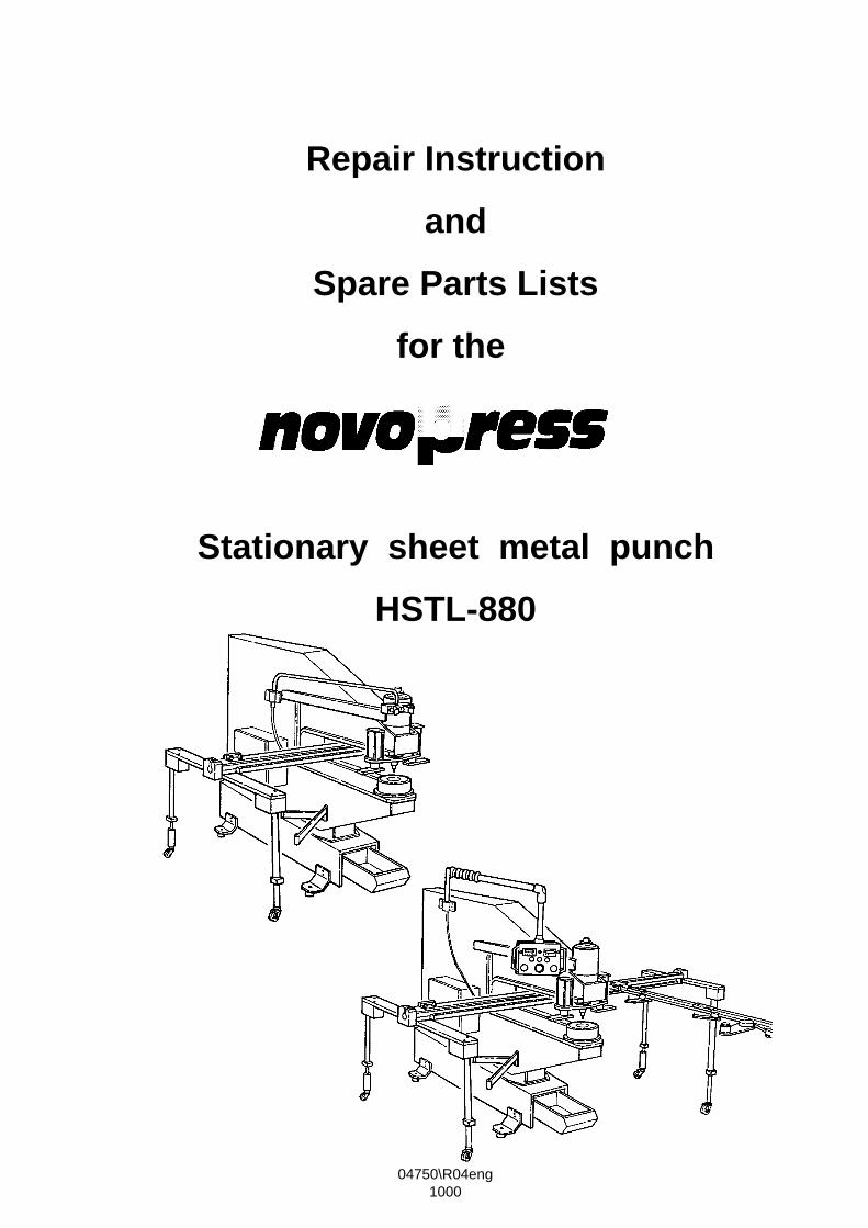
Stationary sheet metal punchHSTL-880
04750\R04eng1000

Contents
Article Page
Safety regulations
Stationary sheet metal punch 1
Stop device AV2 21
Stop device AV4 / AV4 long 33
Stop device AV5 / AV5 long 53
Two-handed control with digital display for AV5 90

009NP004.DOC
GENERAL SAFETY REGULATIONS
Read all safety regulations and instructions!
1. Keep the place of work clean.Disorderly work-places and work-benches invite accidents.Ensure that lighting is good.
2. Keep children away.Do not allow unauthorised persons to touch the device or the cable.Keep unauthorised persons away from your place of work.
3. Wear suitable working clothing.Do not wear any wide clothes nor jewellery - they may get caught up in moving parts.When working in the open it is recommended that you wear rubber gloves and non-slipfootwear. Wear a hair- net if you have long hair.
4. Always be alert.Only use a device after having been instructed in its operation.Concentrate on your work. Proceed sensibly.Do not use the device when you are distracted.
5. Do not lean too far forward. Avoid abnormal stance.Make sure that you have a secure standing position, and maintain balance at all times.
6. Leave safety devices where they belong.
7. Hand tools may not be installed as fixtures.
8. Repair and maintenance.Have repairs and maintenance work carried out in an authorised NOVOPRESS specialistworkshop.Only use original and identical NOVOPRESS spare parts.We reject all responsibility and liability for work carried out by third- party personnel.
009NP006.DOC
SAFETY INSTRUCTIONS FOR HYDRAULIC EQUIPMENT
1. Please read the operating instructions.Acquaint yourself with the hydraulic equipment.
2. Provide the equipment with the necessary care.Always keep the equipment in operational condition.Cleanness is an essential requirement for good and safe working.
3. Switch off the electric power supply to the hydraulic equipment,• when the equipment is not in use• when maintenance work is to be carried out.
4. Avoid unintentional switching - on.Keep hands and feet away from the switch when the equipment is not being used.
5. Do not use the equipment in a manner in contravention of the instructions.Never carry the equipment by the pipe or pull on the pipe.Protect the piping from heat, oil, sharp edges and high levels of weight strain.
6. Use only piping, fittings and accessories wich have been designed for the operating pressure ofthe hydraulic unit.BURSTING PRESSURE OR TEST PRESSURE IS NOT OPERATING PRESSURE!Avoid squashing or bending of the piping.Piping must not be painted over.
7. Replace the hydraulic piping• when cracks, squashed or bent points are to be seen• when blistering is established• when hydraulic fluid escapes• when pipe fittings are damaged• when discolouration is established on the outer layer,
e.g. due to the influence of solvents.
8. The hydraulic fluid used in the system is kerosene-based.This requires particular care and attention.
• Avoid continuous contact with the skin• ensure that the hydraulic fluid does not get into the eyes or mouth.
Hydraulic pipes have to be replaced after 5 years of usage, despite of the circumstance that nodamages should be remarkable.
9. The equipment must not be operated, if it has leaks and there is a danger of hydraulic fluidcoming into contact with persons, open fire, heating equipment, electric cabling, ground water,foods and other substances which are intended for human consumption.
10. Hydraulic units with petrol engines• must not be operated in closed rooms, due to the
DANGER OF INTOXICATION!• do not pour in petrol while the motor is running or in the vicinity of open fire.
DANGER OF EXPLOSION!
009NP005.DOC
SAFETY TIPS FOR ELECTRIC TOOLS
ATTENTION: In order to avoid electric shock, danger of injury and burning the followingbasic safety measures are always to be taken when using electric tools.Read and observe the notes before using the device. Keep the safety tips ina safe place.
1. Take influences of the surroundings into account.Do not expose electric devices to rain.Do not use electric devices in damp or wet surroundings.Do not use electric devices in the vicinity of flammable liquids or gases.
2. Protect yourself from electric shock.Do not fix additional rating plates or symbols with rivets or screws.Use adhesive signs. When working with electric devices avoidbody contact with earthed objects such as pipes, heating appliances, refrigerators etc.
3. Use the correct tools.Only use the tools and accessories outlined in the operating instructions.Do not use the electric device to do work for which it is not intended.
4. Secure the work piece.Use gripping devices or vice grips to hold the work piece steady.It is more securely held than by hand and you can operate the device with two hands.
5. Do not overload your electric device.You can work better and more securely in the indicated power range.
6. Do not use the cable for purposes for which it is not intended.Do not carry the electric device by the cable.Do not use the cable in order to pull the plug out of the socket. Protect the cable from heat, oil,acids and sharp edges.For working in wet rooms or in the open only use the authorised extension cables with thecorresponding marking.
7. Avoid unintentional starting.Ensure that the electric device is switched off before connecting the mains plug.Do not carry the electric device in such a way as that your finger is on the switch.Do not use the electric device if the ON/OFF switch does not work perfectly.
8. Disconnect the mains plug:• if the device is not in use• before maintenance of the electric device• when changing tools
9. Carefully maintain the electric device. The best and most secure work is guaranteed if you:• keep the electric device clean• observe the instructions for greasing, changing the tools and ancillary equipment• regularly check the connection cable and the extension cable• have damaged cables repaired by a specialist• keep hand grips dry, clean and free form oil and fat• have the electric device examined and cleaned by a specialist after 900 operating hours.

009NP005.DOC
10. Keep electric devices in a safe place.Store electric tools and accessories out of the reach of children, in dry, high-lying places or inlocked rooms.
11. Electric devices are often used by more than one person. Therefore before beginning to workyou should check:
• the socket to ensure it is securely fixed and is not damaged in such a way as can beseen from the outside
• the connection cable for outward damage to the insulation and for sharp kinks• that the cable is securely fixed to the device and whether the insulating plastic tube is
damaged• that the switch is secure and shows no outward signs of damage• whether protective appliances or damaged parts function properly• whether movable parts jam or are damaged• do not use the device in the event of finding defects• only allow the device to be repaired by a specialist or in an authorised NOVOPRESS
specialist work-shop• only use original and identical NOVOPRESS spare parts.
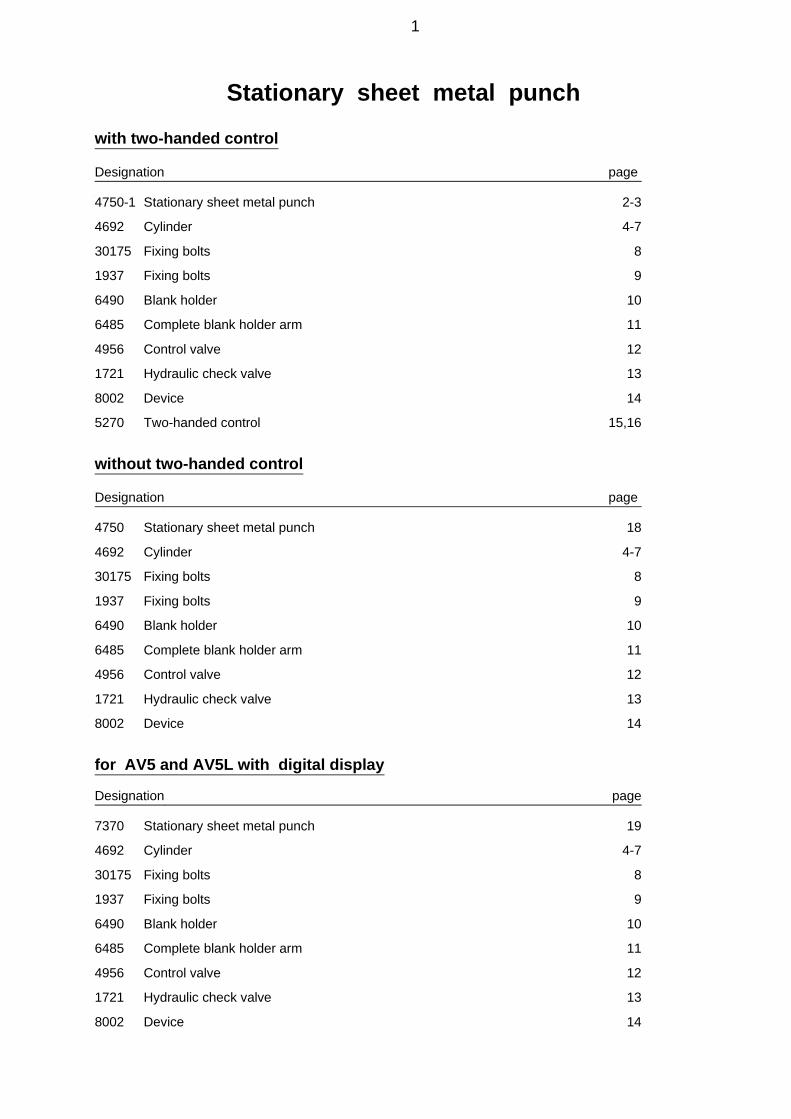
Stationary sheet metal punch
with two-handed control
Designation page
4750-1 Stationary sheet metal punch 2-3
4692 Cylinder 4-7
30175 Fixing bolts 8
1937 Fixing bolts 9
6490 Blank holder 10
6485 Complete blank holder arm 11
4956 Control valve 12
1721 Hydraulic check valve 13
8002 Device 14
5270 Two-handed control 15,16
without two-handed control
Designation page
4750 Stationary sheet metal punch 18
4692 Cylinder 4-7
30175 Fixing bolts 8
1937 Fixing bolts 9
6490 Blank holder 10
6485 Complete blank holder arm 11
4956 Control valve 12
1721 Hydraulic check valve 13
8002 Device 14
for AV5 and AV5L with digital display
Designation page
7370 Stationary sheet metal punch 19
4692 Cylinder 4-7
30175 Fixing bolts 8
1937 Fixing bolts 9
6490 Blank holder 10
6485 Complete blank holder arm 11
4956 Control valve 12
1721 Hydraulic check valve 13
8002 Device 14
1

4750-1 Stationary sheet metal punch HSTL 880 with two-handed control
Item Designation Order no. Quantity
1 Column 4691 12 Cylinder HSTL 4692 13 Blank holder 6490 15 Control valve HRV - HSTL 4956 16 Eyebolt M 16 11721 17 Name plate HTSL 4334 18 Two-handed control for HSTL 5270 19 Bar 1449 110 Hose clip 1722 311 Socket head bolt M 6x10 11270 312 Centering ring 1622 113 Washer A 10,5 11175 414 Socket head bolt M 10x30 11320 415 Hexagonal screw M 16x110 11176 116 Hexagonal nut M 16 12362 217 Washer A 17 12363 118 Nameplate Novopress 11181 119 Nameplate Novopress 12035 120 Drive stud 2x6 11120 221 Drive stud 3x10 11182 222 Console HSTL 7555 1
2
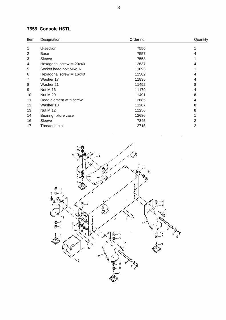
7555 Console HSTL
Item Designation Order no. Quantity
1 U-section 7556 12 Base 7557 43 Sleeve 7558 14 Hexagonal screw M 20x40 12637 45 Socket head bolt M6x16 11095 16 Hexagonal screw M 16x40 12582 47 Washer 17 11835 48 Washer 21 11492 89 Nut M 16 11179 410 Nut M 20 11491 811 Head element with screw 12685 412 Washer 13 11207 813 Nut M 12 11256 814 Bearing fixture case 12686 116 Sleeve 7845 217 Threaded pin 12715 2
3

4692 Cylinder
Item Designation Order no. Quantity
2 Piston to HSTL 1615 15 Plate 5842 16 Support ring for HSTL 1619 17 Fitting piece 1620 18 Adjustment ring for HSTL 2269 110 Protective sleeve 1623 113 Bush 1433 114 Spacer 1432 115 Clamping nut 1429 116 Spring plate 1430 117 Feather key 1435 123 Retaining ring 3116 124 Retaining bolt for HSTL 1937 126 Cylinder head 4695 127 Flange 5845 128 Compr. spring 10x125x205 11160 129 Wiper 40x50x57 11162 130 Oil seal 40x56x10 11163 131 Oil seal 95x115x15 11164 132 Circlip A 35 11166 133 Socket bolt M 6x16 11095 136 Retaining ring 60x2 11167 137 Socket head bolt M 8x20 11094 438 Socket head bolt M 4x10 11171 139 Countersunk screw M 8x35 12239 450 Stud M 8x16 11180 251 Stud M 6x12 11624 152 Stud M 6x10 12182 153 Stud M 8x10 11624 2
4

4692 Cylinder
5

HSTL- Cylinder
Changing the oil seals
If oil is discharged from the HSTL cylinder, the oil seals are faulty.The oil seals must be replaced as follows:Items see drawing nos. 4751 and 4692
1. Dismantling
1.1 Loosen the screws item 37 (4 ea.) and remove the complete blank holder (3).
1.2 Pull out the tool holding rod item 24.
1.3 Screw out the return stroke limit screw item 15 (drawing no. 4750-1).
1.4 Screw the clamping nut item 15 as far down as required to release the circlip item 32.
1.5 Remove the circlip item 32 and the retaining ring item 23.
1.6 Please apply the device, drawing no. 8002, page 13 as shown on the sketch at the sidebefore unscrewing the clamping nut item 15.
WARNING: Danger of injuryThe release spring is pretensioned with approx. 950 N.
1.7 Unscrew the clamping nut item 15
1.8 Loosen the nut "N" until the release spring isslack.
1.9 Remove the device and support the piston usinga wood block on the bottom tool.
1.10 Remove parts 10,14,15,16,23,24,28 and 32(Drawing no. 4692).
1.11 Mark the exact position of the adjusting ring item 8 (drawing no. 4692) to the cylinder head item 26.
1.12. Loosen the screws item 39 (x4) and the screw item 51.Use a 3 mm hollow screw spanner for the screw item 51.
1.13 Unscrew the hydraulic connection item 5 from the cylinder.
1.14 Remove the wood block.
1.15 Dismantle the piston item 2 and the adjusting ring item 8 from the cylinder.
1.16 Mark the exact position of the cylinder to the pedestal.
1.17 Unscrew the bolts item 50 with a 4 mm hollow screw spanner.
1.18 Remove the cylinder and check whether there are tooling marks on the bearing surface. If necessary, polish the bearing surface until smooth.
6

2. Assembly
2.1 Change the oil seal item 30.
2.2 Insert the oil seal item 31 into the cylinder head.
2.3 Insert the piston item 2 and the adjusting ring item 8 in the cylinder head.
2.4 Adjust the adjusting ring in such a way that the spot drill at the adjusting ring is aligned with the tappedhole in the cylinder head.
2.5 Fix the adjusting ring item 8 with the screw item 51.
2.6 Insert the cylinder into the pedestal and hold it tight.
2.7 Screw down the flange item 27 to the pedestal with the spot face at the back.Do not tighten the No. 39 bolt.
2.8 Adjust the cylinder in such a way that the spot drills on the cylinder are exactly aligned with the tappedholes in the pedestal.
2.9 Screw down the bolts item 50 and tighten them.
2.10 Tighten screws item 39.
2.11 Assemble a profile tool as a check and drive the piston slowly downwards by hand until the top toolprojects into the bottom tool. Now check whether the cutting edges of the top tool are parallel to the cutting edges of the bottom tool. If they are not parallel to each other, it is necessary to repeat adjustments to the adjusting ring and the cylinder head.
2.12 Take out the top tool.
2.13 Drive the piston high and support it with a wood block on the bottom tool.
2.14 Place items 10,14,28,16,15 and 23 (Drawing no. 4692) on the cylinder.
2.15 Use the device, page 13 (drawing no. 8002) as shown on page 6 and pretension the release spring somuch as to be able to screw on the clamping nut.
2.16 Screw the clamping nut item 15 so far down as to enable the circlip item 32 to be inserted.
2.17 Compressed air must be applied once to the cylinder, to ensure the correct positioning of the oil seal,item 30, until the piston moves a few millimeters downwards.
2.18 Screw the hydraulic connection to the cylinder.
2.19 Turn in the return stroke limit screw item 15.
2.20 Fasten the blank holder item 3 using the screws item 37.
7

30175 Fixing bolts for HSTL from device no.: 520
Item Designation Order no. Quantity
1 Fixing bolt 9191 12 Centering bolt 9192 13 Retaining ring JZ9/16" 12343 15 Ball knob M10 11189 16 Stud M 6x16 11737 17 Sleeve 33619 1
30175 Fixing bolts for HSTL from device no.: 452 to device no.: 519
Item Designation Order no. Quantity
1 Fixing bolt 9191 12 Centering bolt 9192 13 Retaining ring JZ9/16" 12343 24 Washer A 7,15 13365 15 Ball knob M10 11189 16 Stud M 6x16 11737 1
8

1937 Fixing bolts for HSTL to device no.: 451
Item Designation Order no. Quantity
1 Fixing bolt 1431 12 Centering bolt 1438 13 Compr. spring 1,25x10x93,5 11218 34 Compr. spring 1,25x10x16 2751 15 Washer A 7,4 11225 16 Retaining ring JZ9/16" 12343 17 Clamping sleeve 8x22 11365 1
9

6490 Blank holder
Item Designation Order no. Quantity
1 Blank holder plate 5839 12 Cover 1507 23 Blank holder piston 1509 24 Blank holder arm complete 6485 25 Spacer sleeve 1512 26 Socket head bolt M 8x16 11170 47 Socket head bolt M 6x16 12241 68 Compression spring 6,3x40x195 11161 29 Socket head bolt M 8x170 11172 810 Washer A 8,4 11174 811 Bush 5840 2
1. Dismantle blank holder
Unscrew the bolts item 7 (x6) and remove the complete blank holder.
2. Dismantle complete blank holder arm item 4
Remove the screws item 6 (x2) and remove the blank holder arm.
10

3. Dismantle blank holder piston item 3
WARNING! Danger of injuryItem 2 is under spring pretension
3.1 Unscrew two diagonally oppositescrews item 9
3.2 Insert two threaded pins M 8x280(see sketch)Check the threaded pins on the blank holder plate item 1 using a nut.
3.3 Remove the rest of the screwsitem 9.
3.4 Loosen the nuts on the threadedpins alternately until the compression spring becomes slack.
6485 Complete blank holder arm
Item Designation Order no. Quantity
1 Blank holder arm 5844 12 Insert 5843 13 Rail for HSTL 2738 14 Socket head bolt M 5x20 11010 25 Socket head bolt M 5x16 11096 26 Washer A 5,3 11066 27 Key 4878 18 Compression spring 0,9x6,6x35 1300 1
11

4956 Control valve HRV-HSTL
Item Designation Order no. Quantity
1 Hydraulic check valve 1721 12 Spacer 1723 23 Socket head bolt M 6x60 11364 24 Adjustable angle fitting 11528 16 Straight fitting 10x1x300 11722 17 Coupling plug M 16x1,5, 3659 18 Adjustable angle fitting 11212 19 Hexagonal nut 1725 110 Dust seal for plug end 1514 111 Hexagonal nut 11043 112 Cutting ring 11214 1
12

1721 Hydraulic check valve
Item Designation Order no. Quantity
1 Housing 1640 12 Connection 3248 23 Pipe fitting 1642 14 Lever 1641 15 Piston 3251 16 Compr. spring 1,3x10x33 1298 17 Stop 1385 18 Bush 3247 19 Shaft bolt M 6x30 12463 110 Clamping sleeve 6x12 13291 111 Oil seal 5x11x5 11420 112 O-ring 6,1x1,6 11421 1
13

14

5270 Two-handed control HSTL - AV4
Item Designation Order no. Quantity
1 Complete control cabinet 7390 12 Pivot arm with pushbutton 7798 1
15
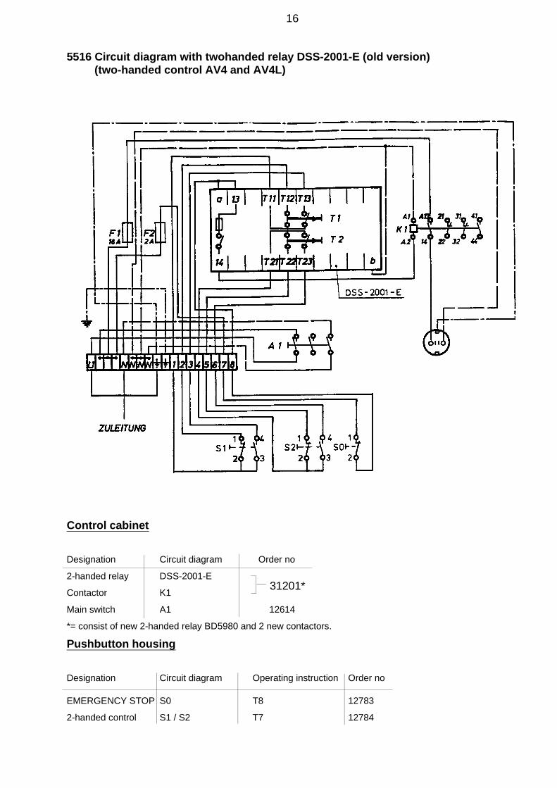
5516 Circuit diagram with twohanded relay DSS-2001-E (old version) (two-handed control AV4 and AV4L)
Control cabinet
Designation Circuit diagram Order no
2-handed relay DSS-2001-E
Contactor K1
Main switch A1 12614
*= consist of new 2-handed relay BD5980 and 2 new contactors.
Pushbutton housing
Designation Circuit diagram Operating instruction Order no
EMERGENCY STOP S0 T8 12783
2-handed control S1 / S2 T7 12784
31201*
supply
16

4750Bl.3 Circuit diagram with twohanded relay BD5980 (new version) (two-handed control AV4 and AV4L)
Control cabinet
Designation Circuit diagram Order no
2-handed relay BD 5980 N 14122
Contactor K1 14123
Contactor K2 14123
Main switch A1 12614
Pushbutton housing
Designation Circuit diagram Operating instruction Order no
EMERGENCY STOP S0 T8 12783
2-handed control S1 / S2 T7 12784
supply
17
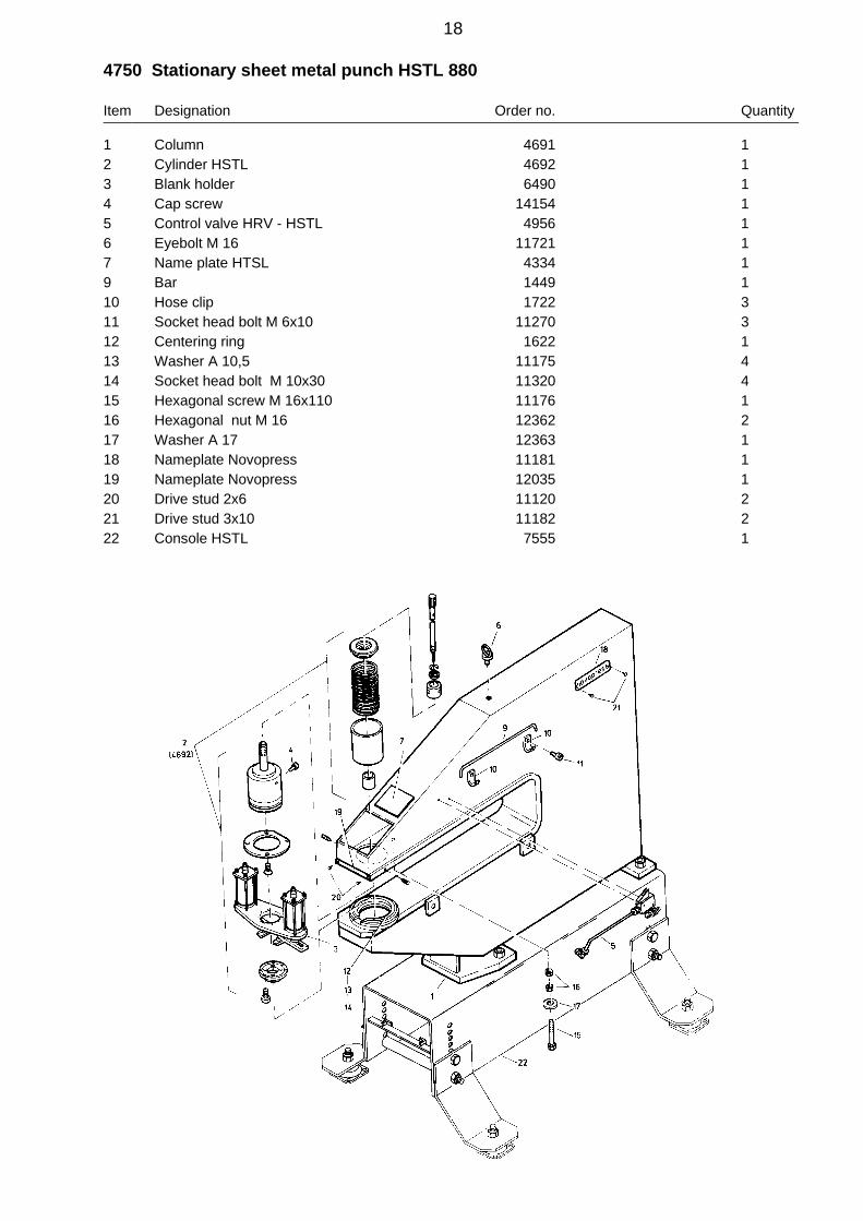
4750 Stationary sheet metal punch HSTL 880
Item Designation Order no. Quantity
1 Column 4691 12 Cylinder HSTL 4692 13 Blank holder 6490 14 Cap screw 14154 15 Control valve HRV - HSTL 4956 16 Eyebolt M 16 11721 17 Name plate HTSL 4334 19 Bar 1449 110 Hose clip 1722 311 Socket head bolt M 6x10 11270 312 Centering ring 1622 113 Washer A 10,5 11175 414 Socket head bolt M 10x30 11320 415 Hexagonal screw M 16x110 11176 116 Hexagonal nut M 16 12362 217 Washer A 17 12363 118 Nameplate Novopress 11181 119 Nameplate Novopress 12035 120 Drive stud 2x6 11120 221 Drive stud 3x10 11182 222 Console HSTL 7555 1
18
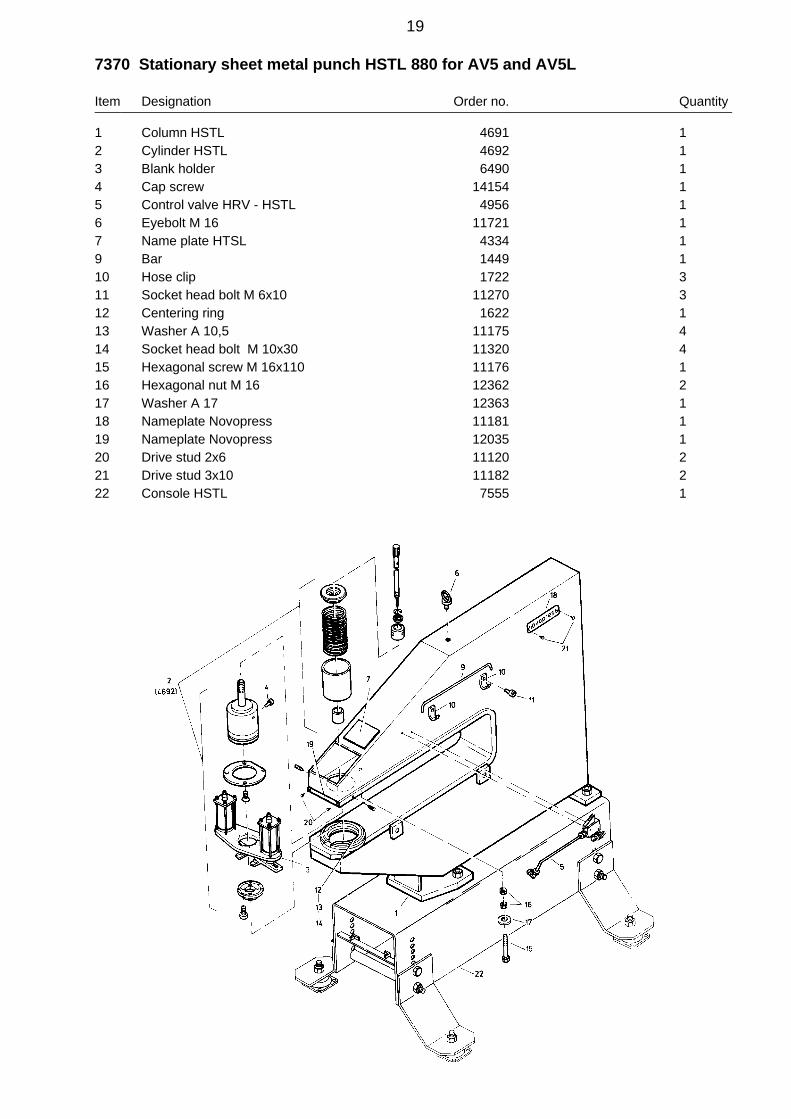
7370 Stationary sheet metal punch HSTL 880 for AV5 and AV5L
Item Designation Order no. Quantity
1 Column HSTL 4691 12 Cylinder HSTL 4692 13 Blank holder 6490 14 Cap screw 14154 15 Control valve HRV - HSTL 4956 16 Eyebolt M 16 11721 17 Name plate HTSL 4334 19 Bar 1449 110 Hose clip 1722 311 Socket head bolt M 6x10 11270 312 Centering ring 1622 113 Washer A 10,5 11175 414 Socket head bolt M 10x30 11320 415 Hexagonal screw M 16x110 11176 116 Hexagonal nut M 16 12362 217 Washer A 17 12363 118 Nameplate Novopress 11181 119 Nameplate Novopress 12035 120 Drive stud 2x6 11120 221 Drive stud 3x10 11182 222 Console HSTL 7555 1
19

20

Stop device AV2
Designation Page
2080-1 Stop device AV2 2231079 Support roller cpl. 2531081 Eccentric support roller 265031 Measuring fixture 275370 Support and clamping fixture 295372 Pedestal 305375 Clamping fixture 315525 Carriage brake 32
21

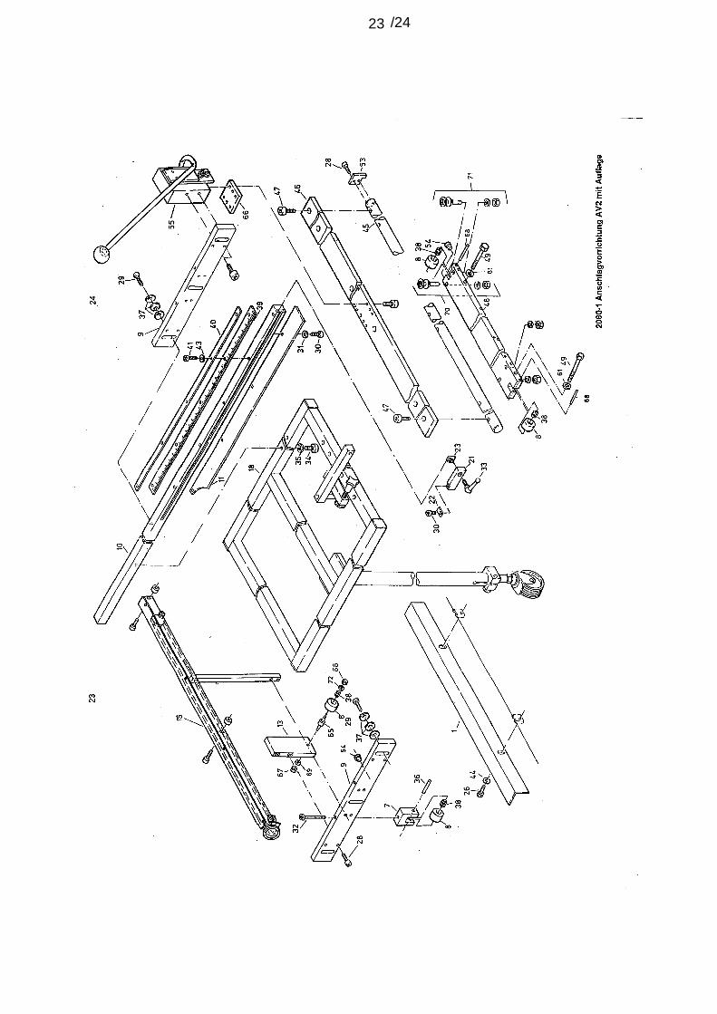
2080-1 Stop device AV 2
Item Designation Order no. Quantity
1 Angle bracket, left hand 5169 17 Bearing block 2048 18 Support roller 2049 49 Cross head stop 4731 110 Stop rail 2051 111 Location rail 5368 113 Tie panel, left hand 4987 115 Measuring fixture 5031 118 Support & clamping fixture 5370 121 Side stop 2062 122 Pointer 2069 123 T-piece M 6 11188 126 Hexagonal screw M 12x30 11670 228 Socket head bolt M 8x20 11094 1129 Socket head bolt M 10x35 11187 330 Socket head bolt M 6x12 11259 531 Washer A 6.4 11203 532 Hexagonal screw M 8x100 11202 133 Clamping lever 11191 134 Socket head bolt M 6x10 11270 335 Spring washer A 6 11652 336 Stud 8 m 6x40 11206 137 Spring disc 28x10,2x1,25 11201 938 Needle bearing NK8/16TN 11209 439 Scale, rustpr. 19x0,6x1000 11192 140 Locking rail 2081 141 Socket head bolt M 5x12 11039 842 Washer A 8,4 11230 643 Washer A 5,3 11083 944 Washer A 13 11871 245 Steel shaft 5521 146 Carriage sheet 5522 147 Socket head bolt M 12x25 11988 648 Bridge 5523 149 Socket head bolt M 12x90 13689 253 End stop 5695 154 Stop button M 4 11739 355 Carriage stop 5525 161 Spring washer A 12 13555 265 Eccentric bolts 4843 166 Compensation plate 5742 167 Hexagonal nut M8 11367 168 Socket head bolt 8 m 6x60 11204 269 Spring washer A 8 11235 170 Support roller cpl. 31079 271 Eccentric support roller 31081 272 Washer A 6,4 11273 1
22
/2423

31079 Support roller cpl.
Item Designation Order no. Quantity
1 Support roller shaft 4989 12 Steel ball dia. 4 11116 263 Support roller 4588 14 Support roller disc 4958 15 Countersunk screw 4321 16 Stud 11138 17 Spring washer A 12 11672 18 Hexagonal nut 11256 1
25

31081 Eccentric support roller
Item Designation Order no. Quantity
1 Support roller shaft 4589 12 Steel ball dia. 4 11116 263 Support roller 4588 14 Support roller disc 4958 15 Countersunk screw 4321 16 Stud 11138 17 Spring washer A 12 11672 18 Hexagonal nut 11256 1
26

5031 Measuring fixture
Item Designation Order no. Quantity
1 Holder 5032 12 Guide roller 5033 23 Bolt 5034 24 Guard 5035 15 Socket head bolt 11190 26 Peripheral tape measure 5146 17 Driver 5036 18 Spacer 5037 29 Adjusting pin 5038 110 Holder 5147 111 Lock ring 5046 113 Socket head bolt M 3x10 11269 314 Lens dia. 50 11682 115 Pointer 5148 116 Drive stud 2x6 11120 217 Socket head bolt M 4x6 11268 418 Washer A 6,4 11203 219 Tension spring 0,8x5,0x27,6 2176 120 Hexagonal nut M 10 11429 221 Spring washer A 10 11630 222 Socket head bolt M 5x10 11081 123 Socket head bolt M 4x6 11268 124 Socket head bolt M 8x30 12590 2
27

Adjusting the "Y" axis (5031) of the measuring fixture
1. Set a distance of 200 mm between the corner points and the stop rail.
2. Lock the carriage using the brake.
3. Slightly loosen screw item 22.
4. Hold the dimensions set using the adjusting pin item 9 (drawing 5031).
5. Lock the adjusting pin again with the screw item 22 (drawing 5031)
28
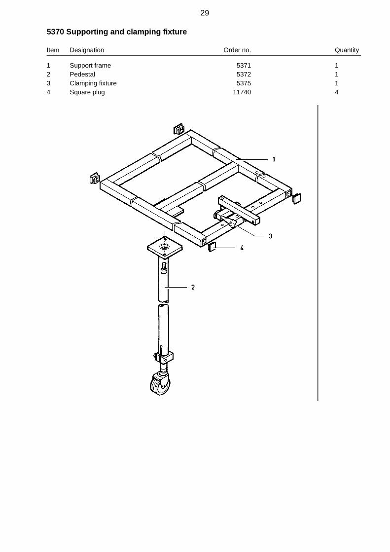
5370 Supporting and clamping fixture
Item Designation Order no. Quantity
1 Support frame 5371 12 Pedestal 5372 13 Clamping fixture 5375 14 Square plug 11740 4
29

5372 Pedestal
Item Designation Order no. Quantity
1 Support tube 5373 12 Socket head bolt M 10x25 11248 23 Telescopic bar for height 5374 14 Double guide roller dia. 50
with rear hole 11618 15 Spring washer A 10 11630 16 Hexagonal nut M 10 11429 17 Socket head bolt M 8x35 11086 1
30

5375 Clamping fixture
Item Designation Order no. Quantity
1 Clamping arm 5376 12 Clamping bolt M 10 11738 13 Stop button M 4 11739 14 Socket head bolt M 5x10 11081 1
31
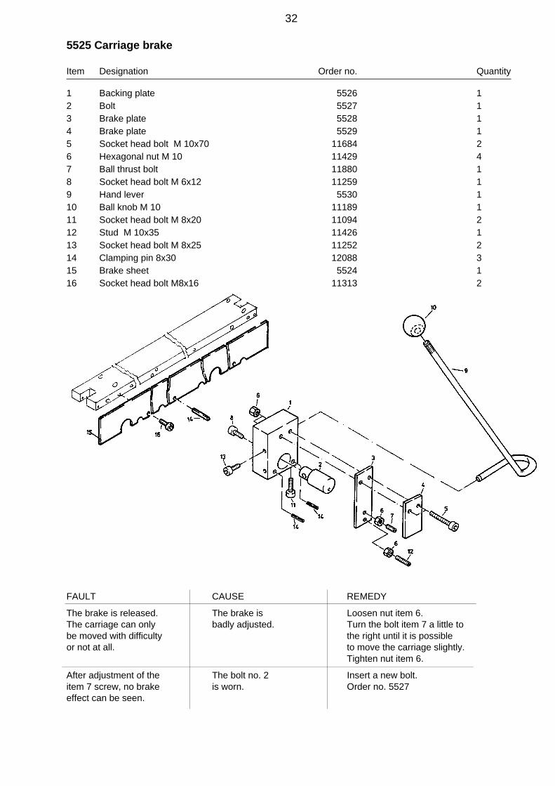
5525 Carriage brake
Item Designation Order no. Quantity
1 Backing plate 5526 12 Bolt 5527 13 Brake plate 5528 14 Brake plate 5529 15 Socket head bolt M 10x70 11684 26 Hexagonal nut M 10 11429 47 Ball thrust bolt 11880 18 Socket head bolt M 6x12 11259 19 Hand lever 5530 110 Ball knob M 10 11189 111 Socket head bolt M 8x20 11094 212 Stud M 10x35 11426 113 Socket head bolt M 8x25 11252 214 Clamping pin 8x30 12088 315 Brake sheet 5524 116 Socket head bolt M8x16 11313 2
FAULT CAUSE REMEDY
The brake is released. The brake is Loosen nut item 6.The carriage can only badly adjusted. Turn the bolt item 7 a little tobe moved with difficulty the right until it is possibleor not at all. to move the carriage slightly.
Tighten nut item 6.
After adjustment of the The bolt no. 2 Insert a new bolt.item 7 screw, no brake is worn. Order no. 5527effect can be seen.
32
Stop device AV4 - AV4LStop device AV4
Designation Page
5031 Measuring fixture 27-28*1 5525 Carriage brake Y-axis 32
4585 Stop device AV 4 35-385109 Cross rail 394831 Cross rail support 406055 Lens holder 41
Measuring fixture "X" adjusting 42*1 4665 Brake X-axis 43
5116 Clamping fixture 447857 Articulated support 459190 Tension device X-axis 469205 Articulated support 519220 Tension device Y-axis 52
*2 7780 Prescision setting X-axis 72-73*2 7770 Prescision setting Y-axis 74-77
8540 Support left 82
Stop device AV4 L
Designation Page
5031 Measuring fixture 27-28*1 5525 Carriage brake 32
5109 Cross rail 394831 Cross rail support 406055 Lens holder 41
Measuring fixture "X" adjusting 42*1 4665 Brake 43
5116 Clamping fixture 447857 Articulated support 459190 Tension device X-axis 467440 Stop device AV 4 L 47-509205 Articulated support 519220 Tension device Y-axis 52
*2 7780 Prescision setting X-axis 72-73*2 7770 Prescision setting Y-axis 74-77
7856 Pedestral 808540 Support left 828130 Support right 83
Remark! The stop devices AV4 and AV4L can be assembled either with the brake *1or with the presicion setting *2.
33

34

4585 Stop device AV 4
Item Designation Order no. Quantity
1 Angle bracket , left hand 5169 14 Hexagonal screw M 12x30 11670 25 Washer A 13 11871 26 Socket head bolt M 8x20 11094 107 Washer A 8,4 11174 313 Cross head stop 4586 114 Rail 4994 115 Socket head bolt M 8x25 11252 316 Socket head bolt M 8x30 12590 222 Spring washer A 12 13555 225 Tie panel, left hand 4987 127 Steel shaft 5115 128 Location rail 5108 129 Socket head bolt M 8x40 11392 630 Pintail 4672 231 Clamping panel 4671 332 Countersunk screw M 6x16 11673 635 Shim 9x15x1 11676 236 Setting bolt 4673 537 Stop pin 4669 538 Spring disc 23x10,2x0,9 11127 1039 Washer A 6,4 11273 540 Countersunk screw M 6x10 11044 2141 Cross rail 5109 142 Distance bushing 5117 843 Distance piece 5118 244 Supporting plate 5119 245 Support 5120 446 Support roller 2049 447 Bearing block 2048 148 Hexagonal screw M 8x100 11202 149 Stop pin 5832 250 Stud 8 m 6x40 11206 151 Stud 8 m 6x60 11204 252 Socket head screw M 5x10 11081 1254 Cross rail support 4831 155 Lens holder 6055 157 Clamping fixture 5116 158 Articulated support 7857 159 Needle bearing NK8/16TN 11209 4
35

Item Designation Order no. Quantity
60 Tension device 9190 161 End stop X 7167 162 Socket head bolt M 8x20 11094 264 Measuring fixture 5031 165 Hexagonal nut M 8 11367 166 Spring washer A 8,4 11235 167 Steel shaft 5521 168 Carriage plate 5522 169 Socket head bolt M 12x25 11988 670 Bridge 5523 171 Hexagonal screw M 12x90 13689 275 End stop 5695 176 Stop button M 4 11739 379 Eccentric pin 4843 180 Hexagonal nut M 6 11383 181 Washer A 6,4 11273 183 Centering pin 7642 184 Support left 8540 185 Articulated support 9205 186 Pintail accorting to pos. 84 9211 187 Tension device 9220 1106 Support roller cpl. 31079 4107 Eccentric support roller 31081 4
36

/3837
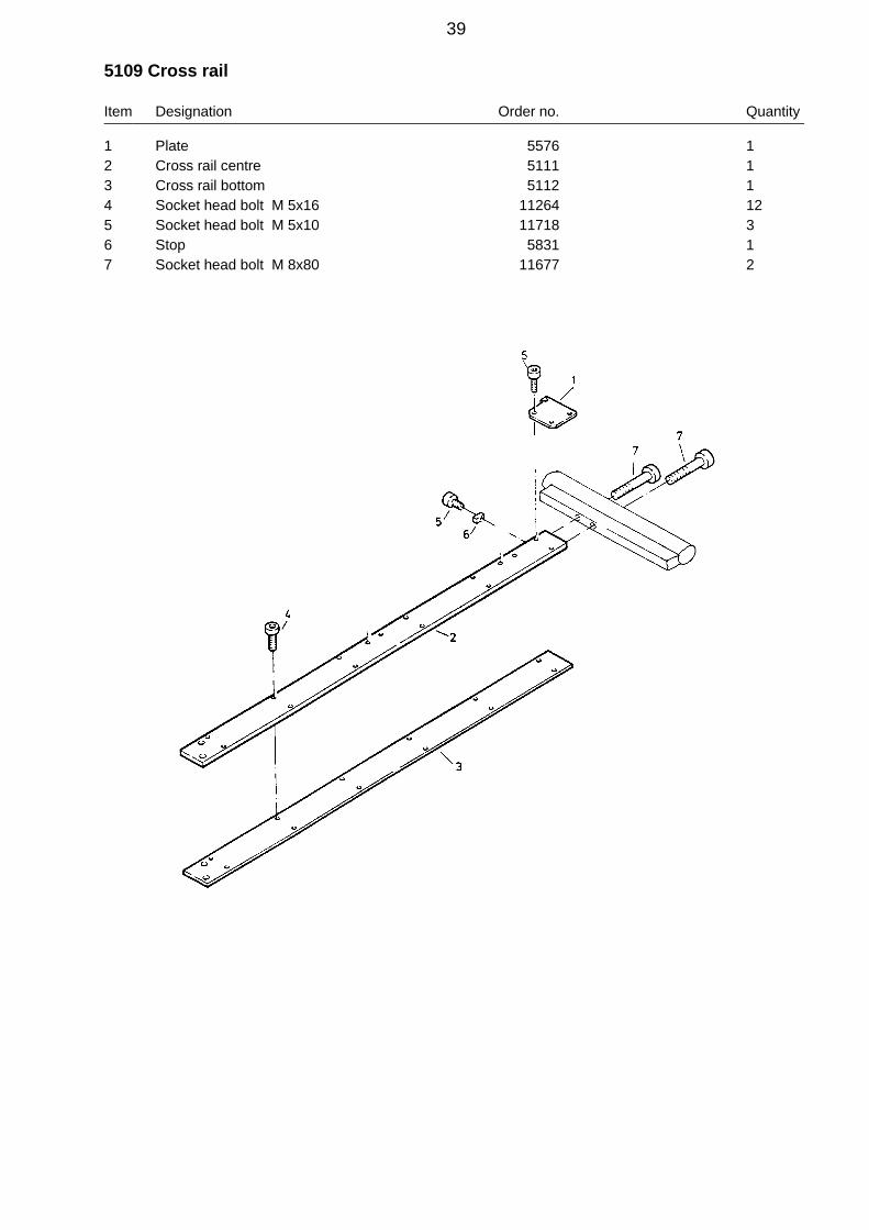
5109 Cross rail
Item Designation Order no. Quantity
1 Plate 5576 12 Cross rail centre 5111 13 Cross rail bottom 5112 14 Socket head bolt M 5x16 11264 125 Socket head bolt M 5x10 11718 36 Stop 5831 17 Socket head bolt M 8x80 11677 2
39
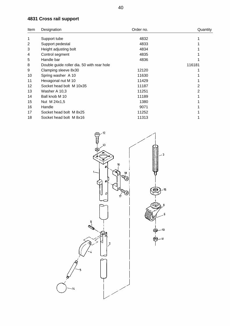
4831 Cross rail support
Item Designation Order no. Quantity
1 Support tube 4832 12 Support pedestal 4833 13 Height adjusting bolt 4834 14 Control segment 4835 15 Handle bar 4836 18 Double guide roller dia. 50 with rear hole 1161819 Clamping sleeve 8x30 12120 110 Spring washer A 10 11630 111 Hexagonal nut M 10 11429 112 Socket head bolt M 10x35 11187 213 Washer A 10,3 11251 214 Ball knob M 10 11189 115 Nut M 24x1,5 1380 116 Handle 9071 117 Socket head bolt M 8x25 11252 118 Socket head bolt M 8x16 11313 1
40

6055 Lens holder
Item Designation Order no. Quantity
1 Clamping panel 6056 12 Socket head bolt M 5x25 11323 23 Washer A 5,3 11350 34 Holder 6057 15 Clamping clip 6058 16 Socket head bolt M 5x16 11264 27 Lens, biconvex 75 mm/6.0 12139 18 Pointer for HSTL 4840 19 Drive stud 2x6 11120 210 Lens mounting 6059 111 O-ring 72x3 12138 1
41

Adjusting the "X" axis of the measuring fixture
1. Punch a plate (400x200 mm) at a distance of 200 mm.
2. Place this plate in the stop attachment and fasten it using the clamping fixture.
3. Adjust the stop attachment in order that the centering points of the top tool can dipinto the centre punch.
4. Hold the stop attachment using the brakes.
5. Loosen screws item 2 and set the pointer on the lens holder to the set dimension.
6. Tighten screws item 3
42
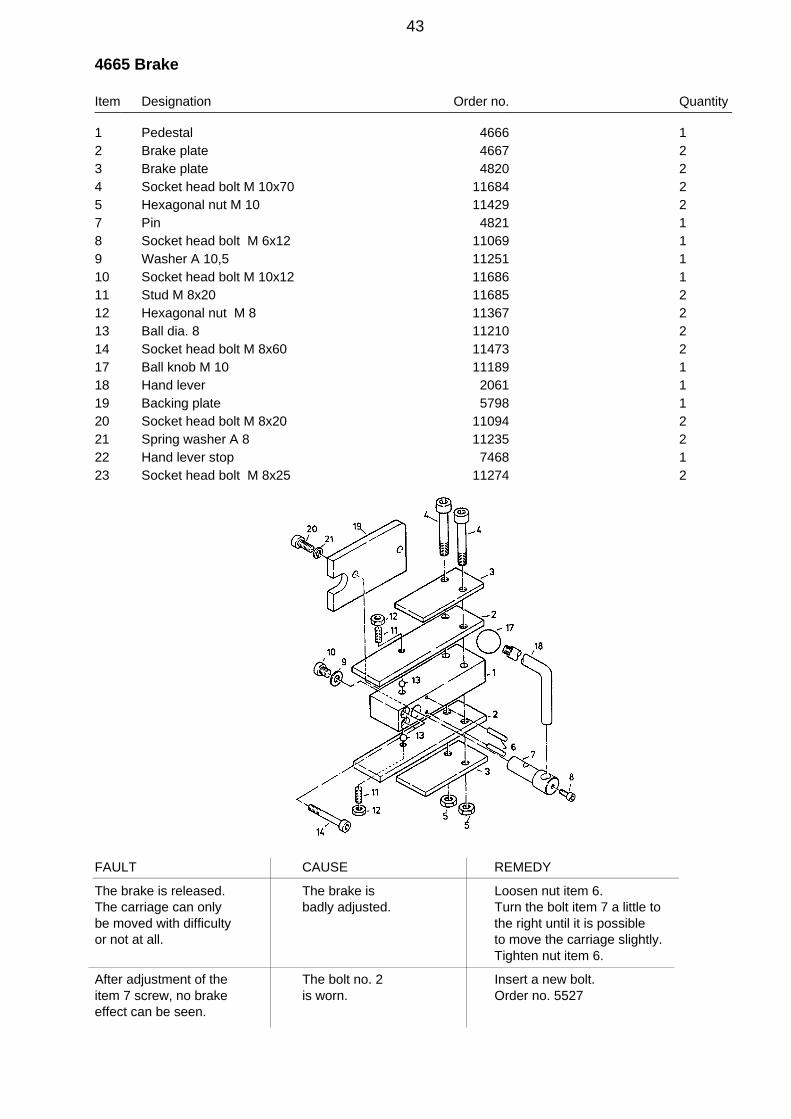
4665 Brake
Item Designation Order no. Quantity
1 Pedestal 4666 12 Brake plate 4667 23 Brake plate 4820 24 Socket head bolt M 10x70 11684 25 Hexagonal nut M 10 11429 27 Pin 4821 18 Socket head bolt M 6x12 11069 19 Washer A 10,5 11251 110 Socket head bolt M 10x12 11686 111 Stud M 8x20 11685 212 Hexagonal nut M 8 11367 213 Ball dia. 8 11210 214 Socket head bolt M 8x60 11473 217 Ball knob M 10 11189 118 Hand lever 2061 119 Backing plate 5798 120 Socket head bolt M 8x20 11094 221 Spring washer A 8 11235 222 Hand lever stop 7468 123 Socket head bolt M 8x25 11274 2
FAULT CAUSE REMEDY
The brake is released. The brake is Loosen nut item 6.The carriage can only badly adjusted. Turn the bolt item 7 a little tobe moved with difficulty the right until it is possibleor not at all. to move the carriage slightly.
Tighten nut item 6.
After adjustment of the The bolt no. 2 Insert a new bolt.item 7 screw, no brake is worn. Order no. 5527effect can be seen.
43

5116 Clamping fixture
Item Designation Order no. Quantity
1 Clamping lever 5180 12 Eccentric cam 6797 13 Retaining ring A 35x1,5 12361 14 Clamping piece 5122 15 Stud 5123 16 Guide pin 5124 27 Spring washer A 8 11235 28 Hexagonal nut M 8 11367 212 Handle bar 4828 113 Ball knob M 10 11189 114 Clamping washer 6799 115 Clamping bush 6801 216 Clamping sleeve 6x26 12364 120 Plate 9803 121 Pintail 30994 122 Clamping panel 4671 123 Stop pin 4669 124 Setting bolt 4673 125 Countersunk screw M 6x16 11673 226 Countersunk screw M 6x10 11044 127 Spring disc 11127 228 Socket head screw M 5x12 11039 229 Washer A 6,4 11273 1
44
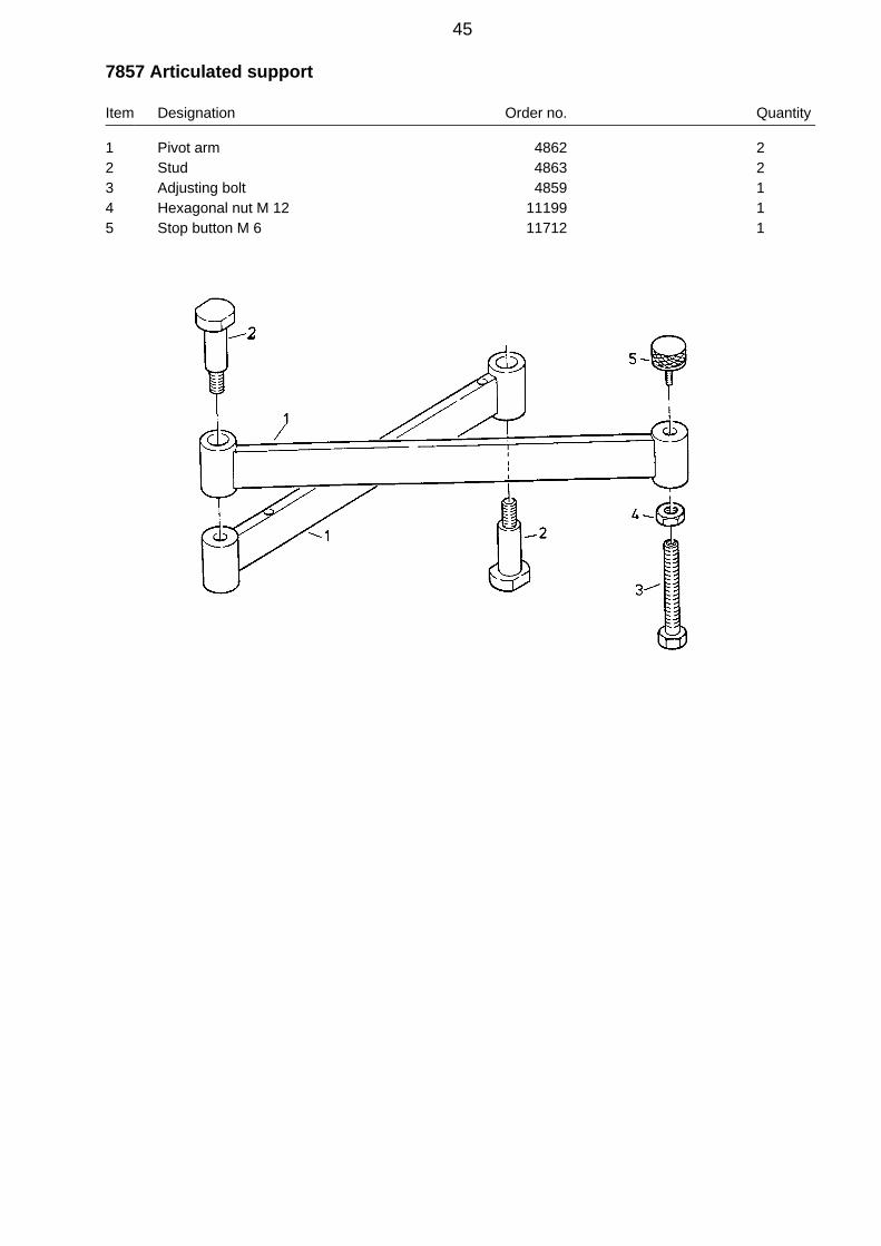
7857 Articulated support
Item Designation Order no. Quantity
1 Pivot arm 4862 22 Stud 4863 23 Adjusting bolt 4859 14 Hexagonal nut M 12 11199 15 Stop button M 6 11712 1
45

9190 Tension device X-axis
Item Designation Order no. Quantity
1 Support 9193 12 Bolt 9194 13 Bolt 9195 14 Horiz. tension device 9201 15 Support 9196 16 Spindle 9197 17 Clamping piece 9198 18 Knurled nut 9199 19 Locking ring 13326 110 Countersunk screw M 5x16 12755 211 Socket head bolt M 5x14 12234 212 Hexagonal nut M 5 11065 213 Dowel pin 11637 214 Pressure spring 13325 115 Stop button M4 11739 1
46

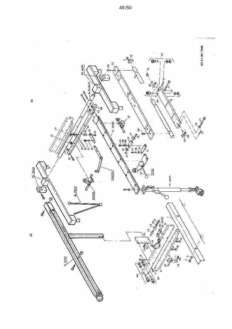
7440 Stop device AV 4 L
Item Designation Order no. Quantity
1 Angle bracket , left hand 5169 14 Hexagonal screw M 12x30 11670 25 Washer A 13 11871 26 Socket head bolt M 8x20 11094 107 Washer A 8,4 11174 313 Cross head stop 4586 114 Rail 4994 115 Socket head bolt M 8x25 11252 316 Socket head bolt M 8x35 11086 222 Spring washer A 12 13555 225 Tie panel, left hand 4987 129 Socket head bolt M 8x40 11086 830 Pintail 4672 431 Clamping panel 4671 432 Countersunk screw M 6x16 11673 835 Shim 9x15x1 11676 236 Setting bolt 4673 637 Stop pin 4669 638 Spring disc 23x10,2x0,9 11127 1239 Washer A 6,4 11273 640 Countersunk screw M 6x10 11044 2341 Cross rail 5109 142 Distance bushing 5117 1043 Distance piece 5118 244 Supporting plate 5119 245 Support 5120 446 Support roller 2049 447 Bearing block 2048 148 Hexagonal screw M 8x100 11202 149 Stop pin 5832 250 Stud 8 m 6x40 11206 151 Stud 8 m 6x60 11204 252 Socket head screw M 5x10 11081 1254 Cross rail support 4831 155 Lens holder 6055 157 Clamping fixture 5116 158 Articulated support x-axis AV4 + AV5 long 7857 159 Needle bearing NK8/16TN 11209 460 Tension device 9190 1
47
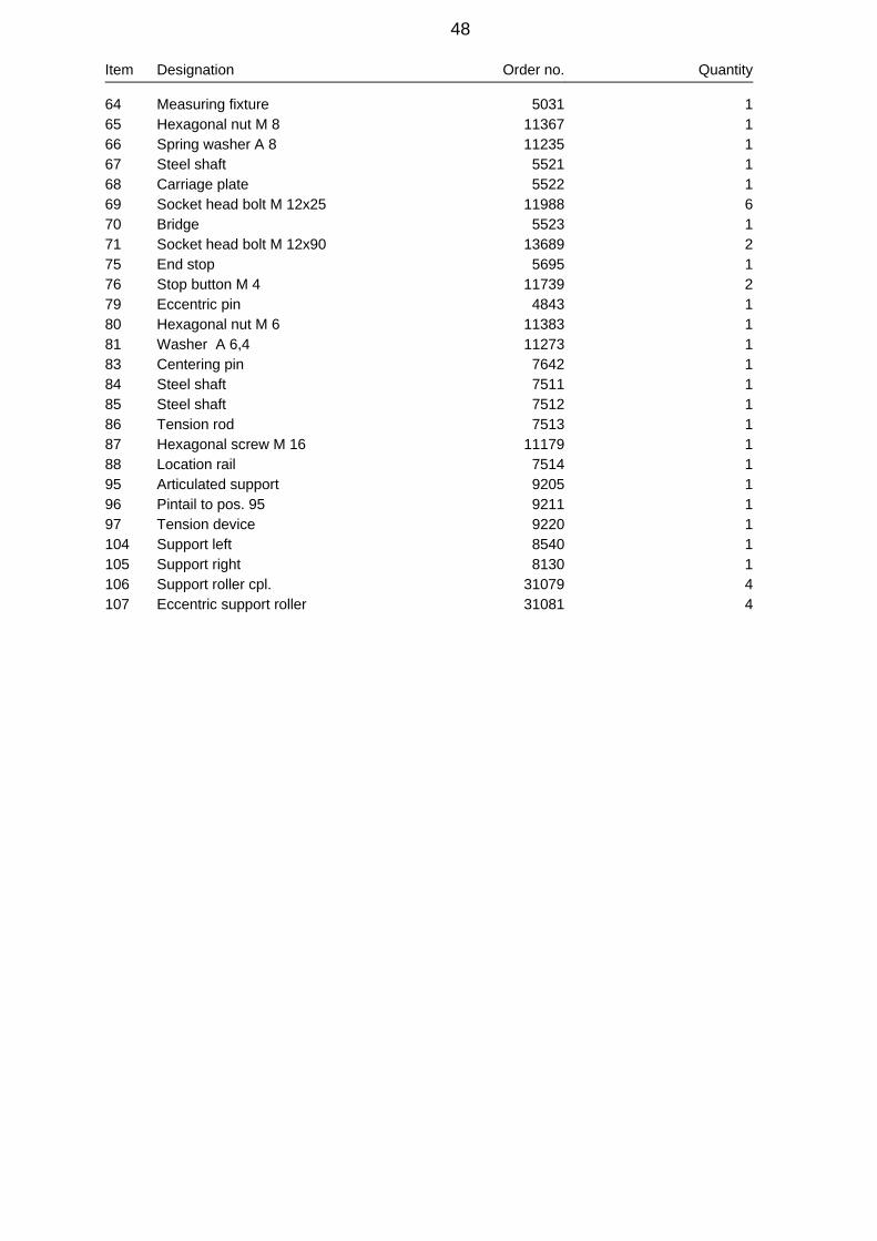
Item Designation Order no. Quantity
64 Measuring fixture 5031 165 Hexagonal nut M 8 11367 166 Spring washer A 8 11235 167 Steel shaft 5521 168 Carriage plate 5522 169 Socket head bolt M 12x25 11988 670 Bridge 5523 171 Socket head bolt M 12x90 13689 275 End stop 5695 176 Stop button M 4 11739 279 Eccentric pin 4843 180 Hexagonal nut M 6 11383 181 Washer A 6,4 11273 183 Centering pin 7642 184 Steel shaft 7511 185 Steel shaft 7512 186 Tension rod 7513 187 Hexagonal screw M 16 11179 188 Location rail 7514 195 Articulated support 9205 196 Pintail to pos. 95 9211 197 Tension device 9220 1104 Support left 8540 1105 Support right 8130 1106 Support roller cpl. 31079 4107 Eccentric support roller 31081 4
48
/5049

9205 Articulated support
Item Designation Order no. Quantity
1 Support arm I 9206 12 Support arm II 9207 13 Washer 9208 14 Spring disc 12453 15 Countersunk screw M 8x25 13333 16 Bolt 9209 17 Stop buffer M 6 11712 1
51
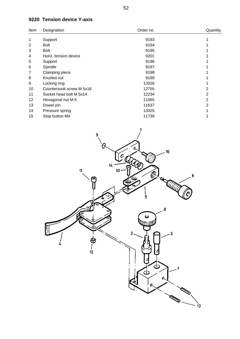
9220 Tension device Y-axis
Item Designation Order no. Quantity
1 Support 9193 12 Bolt 9194 13 Bolt 9195 14 Horiz. tension device 9201 15 Support 9196 16 Spindle 9197 17 Clamping piece 9198 18 Knurled nut 9199 19 Locking ring 13326 110 Countersunk screw M 5x16 12755 211 Socket head bolt M 5x14 12234 212 Hexagonal nut M 5 11065 213 Dowel pin 11637 214 Pressure spring 13325 115 Stop button M4 11739 1
52
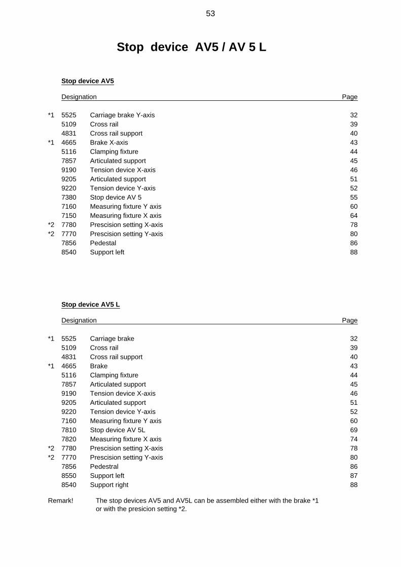
Stop device AV5 / AV 5 L
Stop device AV5
Designation Page
*1 5525 Carriage brake Y-axis 325109 Cross rail 394831 Cross rail support 40
*1 4665 Brake X-axis 435116 Clamping fixture 447857 Articulated support 459190 Tension device X-axis 469205 Articulated support 519220 Tension device Y-axis 527380 Stop device AV 5 557160 Measuring fixture Y axis 607150 Measuring fixture X axis 64
*2 7780 Prescision setting X-axis 78*2 7770 Prescision setting Y-axis 80
7856 Pedestal 868540 Support left 88
Stop device AV5 L
Designation Page
*1 5525 Carriage brake 325109 Cross rail 394831 Cross rail support 40
*1 4665 Brake 435116 Clamping fixture 447857 Articulated support 459190 Tension device X-axis 469205 Articulated support 519220 Tension device Y-axis 527160 Measuring fixture Y axis 607810 Stop device AV 5L 697820 Measuring fixture X axis 74
*2 7780 Prescision setting X-axis 78*2 7770 Prescision setting Y-axis 80
7856 Pedestral 868550 Support left 878540 Support right 88
Remark! The stop devices AV5 and AV5L can be assembled either with the brake *1or with the presicion setting *2.
53

54
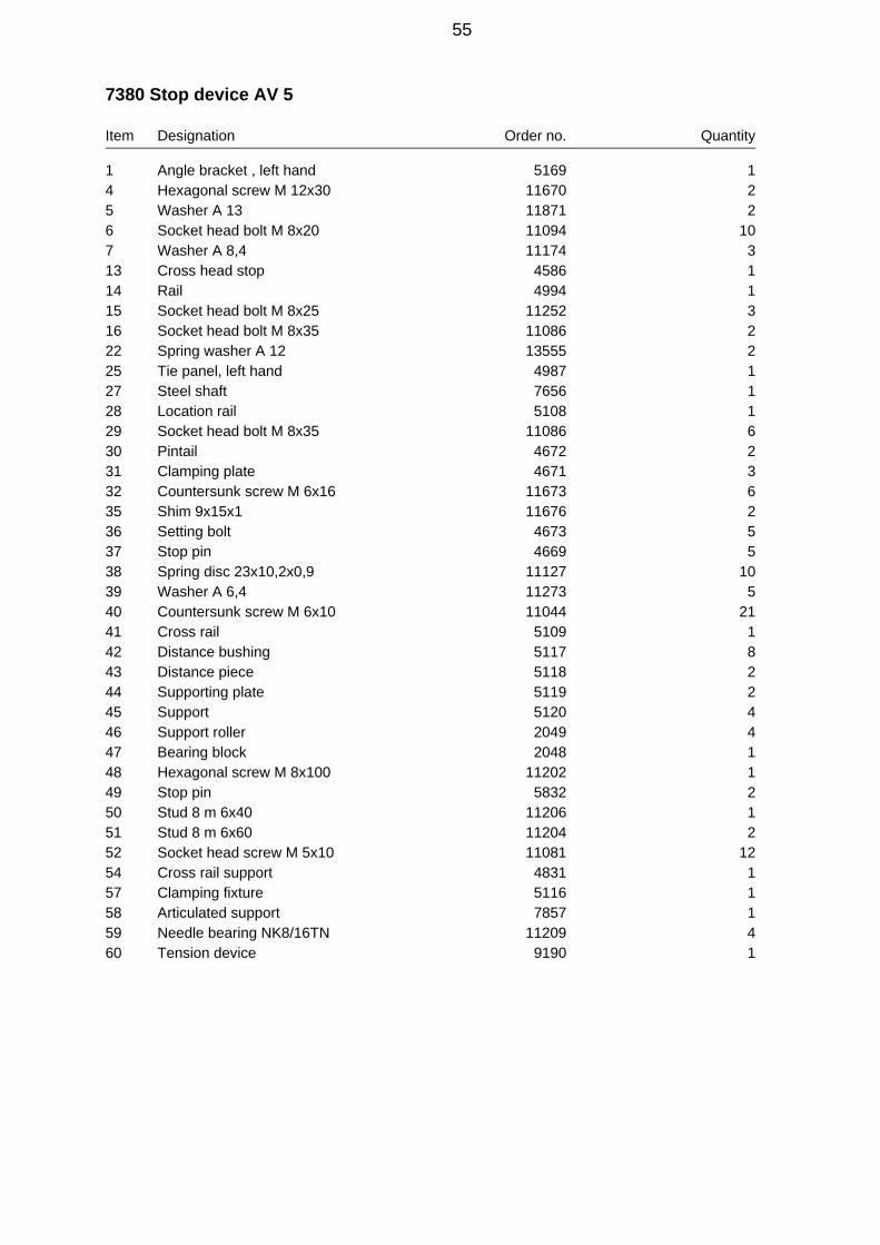
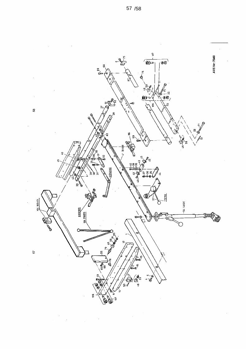
7380 Stop device AV 5
Item Designation Order no. Quantity
1 Angle bracket , left hand 5169 14 Hexagonal screw M 12x30 11670 25 Washer A 13 11871 26 Socket head bolt M 8x20 11094 107 Washer A 8,4 11174 313 Cross head stop 4586 114 Rail 4994 115 Socket head bolt M 8x25 11252 316 Socket head bolt M 8x35 11086 222 Spring washer A 12 13555 225 Tie panel, left hand 4987 127 Steel shaft 7656 128 Location rail 5108 129 Socket head bolt M 8x35 11086 630 Pintail 4672 231 Clamping plate 4671 332 Countersunk screw M 6x16 11673 635 Shim 9x15x1 11676 236 Setting bolt 4673 537 Stop pin 4669 538 Spring disc 23x10,2x0,9 11127 1039 Washer A 6,4 11273 540 Countersunk screw M 6x10 11044 2141 Cross rail 5109 142 Distance bushing 5117 843 Distance piece 5118 244 Supporting plate 5119 245 Support 5120 446 Support roller 2049 447 Bearing block 2048 148 Hexagonal screw M 8x100 11202 149 Stop pin 5832 250 Stud 8 m 6x40 11206 151 Stud 8 m 6x60 11204 252 Socket head screw M 5x10 11081 1254 Cross rail support 4831 157 Clamping fixture 5116 158 Articulated support 7857 159 Needle bearing NK8/16TN 11209 460 Tension device 9190 1
55

Item Designation Order no. Quantity
61 End stop X 7167 162 Socket head bolt M 8x20 11094 265 Hexagonal nut M 8 11367 166 Spring Washer A 8,4 11235 167 Steel shaft 5521 168 Carriage plate 5522 169 Socket head bolt M 12x25 11988 670 Bridge 5523 171 socket head bolt M12x90 13689 275 End stop 5695 176 Stop button M 4 11739 279 Eccentric pin 4843 180 Hexagonal nut M 6 11383 181 Washer A 6,4 11273 183 Centering pin 7642 184 Articulated support 9205 185 Pintail accorting to pos. 84 9211 186 Tension device 9220 1102 Plug gange 7357 1104 Supporting left 8540 1106 Support roller cpl. 31079 4107 Eccentric support roller 31081 4
56
/5857

59

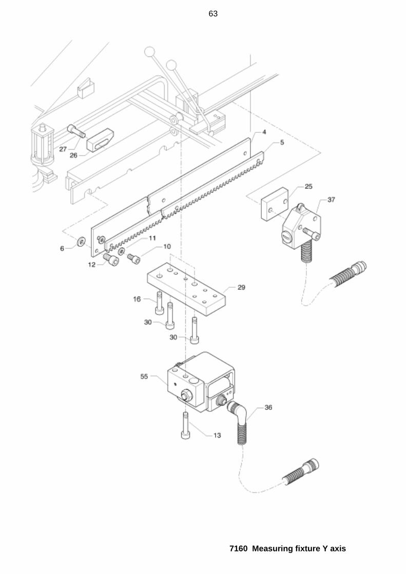
7160 Measuring fixture Y axis up to unit number: 546
Item Designation Order no. Quantity
1 Case 2 7149 12 Bearing bolts 7147 13 Washer 7148 14 Gear rack holder Y 7151 15 Gear rack Y 7152 16 Spacer bottom 7153 47 Spacer top 7154 58 Sensor housing 7155 19 Spring bolts 7156 110 Socket head bolt M 5x14 11234 511 Spring washer A 5 11038 512 Socket head bolt M 8x20 11094 413 Socket head bolt M 8x50 11085 214 Hexagonal nut M 12 11256 115 Spring washer A 12 11672 116 Socket head bolt M 8x30 12590 117 Axial separator 12798 218 Cup spring 28x14.2x1 11277 419 Clamping sleeve 11637 120 Tension spring 1.4x10x26.9 12459 121 Hexagonal nut M 5 11065 122 Spring washer A 5 11038 123 Socket head bolt M 4x12 12460 324 Spring washer B 4 12461 325 Spacer plate Y 7159 126 Trip cam Y 7158 127 Socket head bolt M 6x20 11009 228 Socket head bolt M 5x25 11323 229 Base plate 7144 130 Socket head bolt M 8x40 11280 231 Protective angle 7161 132 Countersunk screw M 4x8 12472 235 Angular momentum encoder 12502 136 Connecting cable 3 for encoder Y axis 7353 137 Limit switch with cable 2 Y axis 7354 139 Measuring pinion 9161 140 Threaded pin M 3x4 12770 142 Sealing washer 9162 143 Gasket 9163 144 O-ring 18x1,5 13324 1
60

7160 Measuring fixture Y axis
61

7160 Measuring fixture Y axis from unit number: 547
Item Designation Order no. Quantity
4 Gear rack holder Y 7151 15 Gear rack Y 7152 16 Spacer bottom 7153 47 Spacer top 7154 510 Socket head bolt M 5x14 11234 511 Spring washer A 5 11038 512 Socket head bolt M 8x20 11094 413 Socket head bolt M 8x50 11085 216 Socket head bolt M 8x30 12590 125 Spacer plate Y 7159 126 Trip cam Y 7158 127 Socket head bolt M 6x20 11009 229 Base plate 7144 130 Socket head bolt M 8x40 11280 236 Connecting cable 3 for encoder Y axis 7353 137 Limit switch with cable 2 Y axis 7354 155 Encoder compl. Y-axis AV5 36608 1
62
7160 Measuring fixture Y axis
63

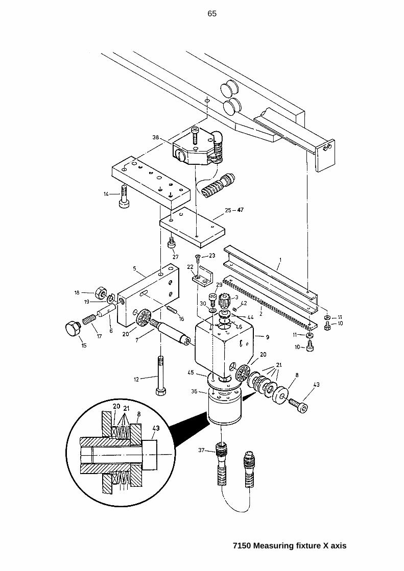
7150 Measuring fixture X axis for AV 5 up to unit number: 546
Item Designation Order no. Quantity
1 Gear rack holder X 7141 12 Gear rack 7142 13 Measuring pinion 9161 15 Case 1 7145 16 Spring bolts 7146 17 Bearing bolts 7147 18 Washer 7148 19 Encoder housing 7155 110 Hexagonal screw M 5x8 11498 1411 Retaining washer 5 12451 1412 Socket head bolt M 8x70 11008 214 Socket head bolt M 8x30 12590 115 Hexagonal screw M 12x12 12452 116 Stud M 5x16 12471 117 Compress. spring 1.25x8x22 11263 118 Hexagonal nut M 12 11256 119 Spring washer A 12 11672 120 Axial separator 12798 221 Cup spring 28x14.2x1 11277 422 Protective angle 7161 123 Countersunk screw M 4x8 12472 225* Spacer plate X 7166 127 Socket head bolt M 8x20 11094 429 Socket head bolt M 4x12 12460 330 Spring washer B 4 12461 336 Angular momentum encoder 12502 137 Connecting cable 4 for encoder X axis 7351 138 Limit switch with cable 5 for X axis 7352 142 Stud M 3x4 12770 143 Socket head bolt M 8x30 11226 144 Sealing washer 9162 145 Gasket 9163 146 O-ring 18x1,5 13324 147* Spacer plate X 7889 1
* AttentionItem 25 only AV5 with brake, no. 4665Item 47 only AV5 with precision setting, no. 7780
64
7150 Measuring fixture X axis
65

7150 Measuring fixture X axis for AV 5 from unit number: 547
Item Designation Order no. Quantity
1 Gear rack holder X 7141 12 Gear rack 7142 110 Hexagonal screw M 5x8 11498 1411 Retaining washer 5 12451 1412 Socket head bolt M 8x70 11008 214 Socket head bolt M 8x30 12590 125* Spacer plate X 7166 127 Socket head bolt M 8x20 11094 437 Connecting cable 4 for encoder X axis 7351 138 Limit switch with cable 5 for X axis 7352 147* Spacer plate X 7889 155 Encoder compl. X-axis AV5 36607 1
* AttentionItem 25 only AV5 with brake, no. 4665Item 47 only AV5 with precision setting, no. 7780
66

67

68

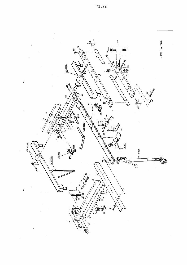
7810 Stop attachment AV5 L
Item Designation Order no. Quantity
1 Angle bracket , left hand 5169 14 Hexagonal screw M 12x30 11670 25 Washer A 13 11871 26 Socket head bolt M 8x20 11094 107 Washer A 8,4 11174 313 Cross head stop 4586 114 Rail 4994 115 Socket head bolt M 8x25 11252 316 Socket head bolt M 8x35 11086 222 Spring washer A 12 13555 225 Tie panel, left hand 4987 129 Socket head bolt M 8x35 11086 830 Pintail 4672 331 Clamping panel 4671 432 Countersunk screw M 6x16 11673 835 Shim 9x15x1 11676 236 Setting bolt 4673 637 Stop pin 4669 638 Spring disc 23x10,2x0,9 11127 1239 Washer A 6,4 11273 640 Countersunk screw M 6x10 11044 2341 Cross rail 5109 142 Distance bushing 5117 1043 Distance piece 5118 244 Supporting plate 5119 245 Support 5120 446 Support roller 2049 447 Bearing block 2048 148 Hexagonal screw M 8x100 11202 149 Stop pin 5832 250 Stud 8 m 6x40 11206 151 Stud 8 m 6x60 11204 252 Socket head screw M 5x10 11081 1254 Cross rail support 4831 157 Clamping fixture 5116 158 Articulated support 7857 159 Needle bearing NK8/16TN 11209 460 Tension device 9190 1
69
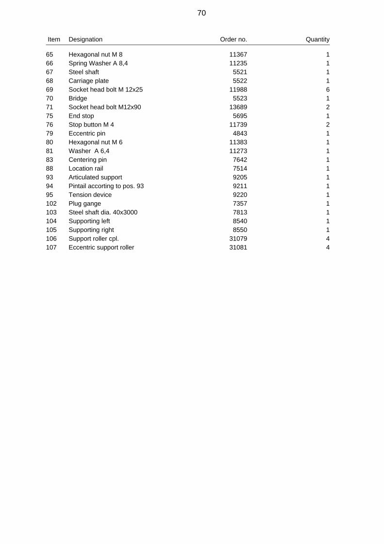
Item Designation Order no. Quantity
65 Hexagonal nut M 8 11367 166 Spring Washer A 8,4 11235 167 Steel shaft 5521 168 Carriage plate 5522 169 Socket head bolt M 12x25 11988 670 Bridge 5523 171 Socket head bolt M12x90 13689 275 End stop 5695 176 Stop button M 4 11739 279 Eccentric pin 4843 180 Hexagonal nut M 6 11383 181 Washer A 6,4 11273 183 Centering pin 7642 188 Location rail 7514 193 Articulated support 9205 194 Pintail accorting to pos. 93 9211 195 Tension device 9220 1102 Plug gange 7357 1103 Steel shaft dia. 40x3000 7813 1104 Supporting left 8540 1105 Supporting right 8550 1106 Support roller cpl. 31079 4107 Eccentric support roller 31081 4
70
/7271

73

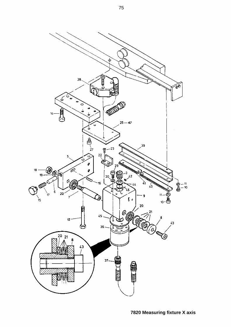
7820 Measuring fixture X axis for AV5L up to unit number: 546
Item Designation Order no. Quantity
3 Measuring pinion 9161 15 Case 2 7145 16 Spring bolts 7146 17 Bearing bolts 7147 18 Washer 7148 19 Encoder housing 7155 110 Hexagonal screw M 5x8 11498 2211 Retaining washer 5 12451 2212 Socket head bolt M 8x70 11008 214 Socket head bolt M 8x30 12590 115 Hexagonal screw M 12x12 12452 116 Stud M 5x16 12471 117 Compress. spring 1.25x8x22 11263 118 Hexagonal nut M 12 11256 119 Spring washer A 12 11672 120 Axial separator 12798 221 Cup spring 28x14.2x1 11277 422 Protective angle 7161 123 Countersunk screw M 4x8 12472 225* Spacer plate X 7166 127 Socket head bolt M 8x20 11094 429 Socket head bolt M 4x12 12460 330 Spring washer B 4 12461 336 Angular momentum encoder 12502 137 Connecting cable 4 for encoder X axis 7351 138 Limit switch with cable 5for X axis 7352 139 Gear rack holder X 7518 140 Gear rack 3 7811 141 Gear rack 4 7812 142 Stud M 3x4 12770 143 Socket head bolt M 4x16 11313 144 Sealing washer 9162 145 Gasket 9163 146 O-ring 18x1,5 13324 147* Spacer plate X 13324 1
* AttentionItem 25 only AV5 with brake, no. 4665Item 47 only AV5 with precision setting, no. 7780
74
7820 Measuring fixture X axis
75

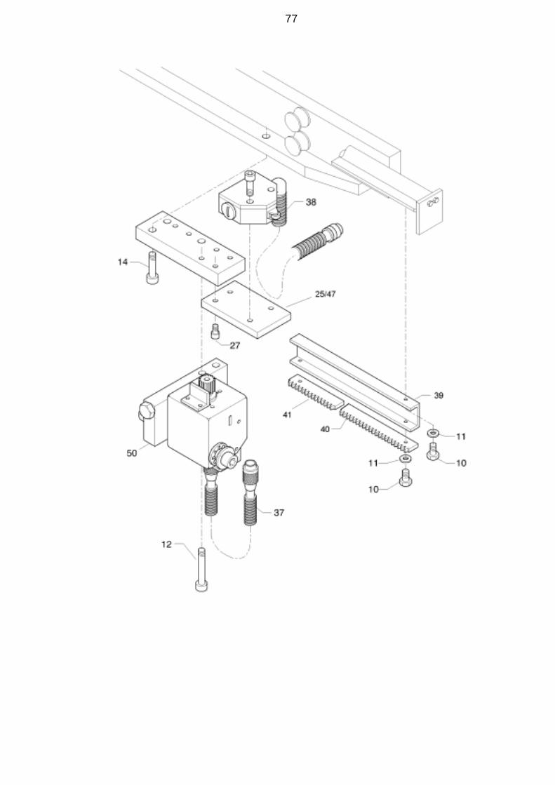
7820 Measuring fixture X axis for AV5L from unit number: 547
Item Designation Order no. Quantity
10 Hexagonal screw M 5x8 11498 2211 Retaining washer 5 12451 2212 Socket head bolt M 8x70 11008 214 Socket head bolt M 8x30 12590 125* Spacer plate X 7166 127 Socket head bolt M 8x20 11094 437 Connecting cable 4 for encoder X axis 7351 138 Limit switch with cable 5for X axis 7352 139 Gear rack holder X 7518 140 Gear rack 3 7811 141 Gear rack 4 7812 147* Spacer plate X 13324 150 Encoder comol. X-Axis AV5 36607 1
* AttentionItem 25 only AV5 with brake, no. 4665Item 47 only AV5 with precision setting, no. 7780
76
77
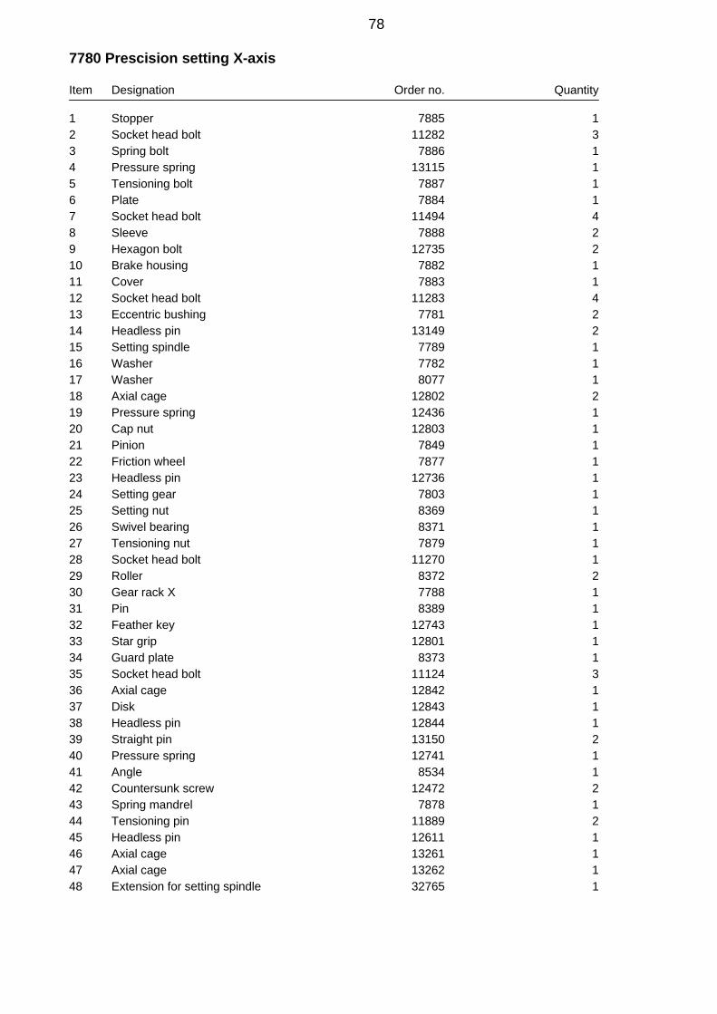
7780 Prescision setting X-axis
Item Designation Order no. Quantity
1 Stopper 7885 12 Socket head bolt 11282 33 Spring bolt 7886 14 Pressure spring 13115 15 Tensioning bolt 7887 16 Plate 7884 17 Socket head bolt 11494 48 Sleeve 7888 29 Hexagon bolt 12735 210 Brake housing 7882 111 Cover 7883 112 Socket head bolt 11283 413 Eccentric bushing 7781 214 Headless pin 13149 215 Setting spindle 7789 116 Washer 7782 117 Washer 8077 118 Axial cage 12802 219 Pressure spring 12436 120 Cap nut 12803 121 Pinion 7849 122 Friction wheel 7877 123 Headless pin 12736 124 Setting gear 7803 125 Setting nut 8369 126 Swivel bearing 8371 127 Tensioning nut 7879 128 Socket head bolt 11270 129 Roller 8372 230 Gear rack X 7788 131 Pin 8389 132 Feather key 12743 133 Star grip 12801 134 Guard plate 8373 135 Socket head bolt 11124 336 Axial cage 12842 137 Disk 12843 138 Headless pin 12844 139 Straight pin 13150 240 Pressure spring 12741 141 Angle 8534 142 Countersunk screw 12472 243 Spring mandrel 7878 144 Tensioning pin 11889 245 Headless pin 12611 146 Axial cage 13261 147 Axial cage 13262 148 Extension for setting spindle 32765 1
78

7780 Prescision setting X-axis
79

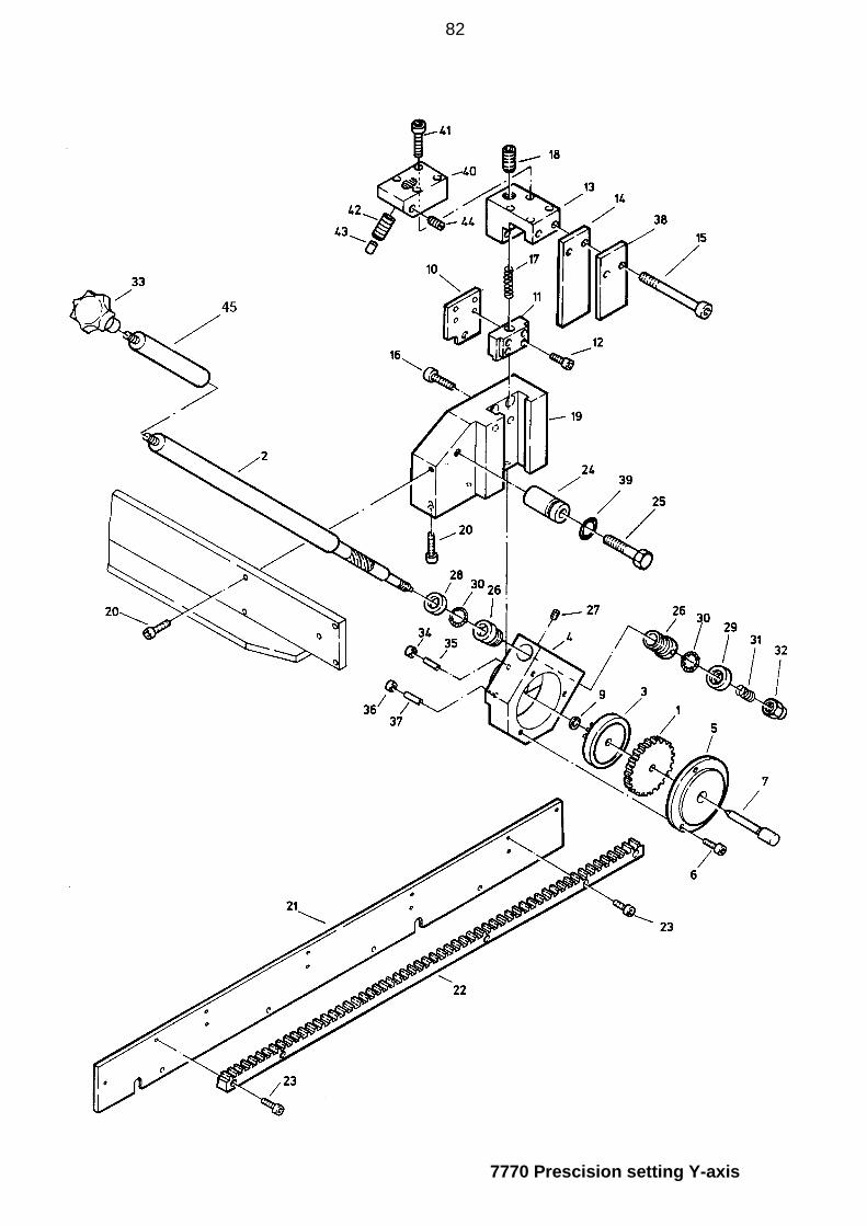
7770 Prescision setting Y-axis
80
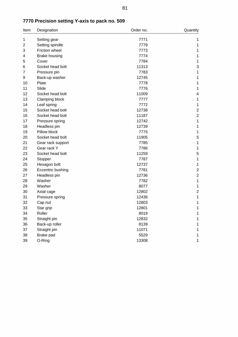
7770 Precision setting Y-axis to pack no. 509
Item Designation Order no. Quantity
1 Setting gear 7771 12 Setting spindle 7779 13 Friction wheel 7773 14 Brake housing 7774 15 Cover 7784 16 Socket head bolt 11313 37 Pressure pin 7783 19 Back-up washer 12745 110 Plate 7778 111 Slide 7776 112 Socket head bolt 11009 413 Clamping block 7777 114 Leaf spring 7772 115 Socket head bolt 12738 216 Socket head bolt 11187 217 Pressure spring 12742 118 Headless pin 12739 119 Pillow block 7775 120 Socket head bolt 11905 521 Gear rack support 7785 122 Gear rack Y 7786 123 Socket head bolt 11259 524 Stopper 7787 125 Hexagon bolt 12737 126 Eccentric bushing 7781 227 Headless pin 12736 228 Washer 7782 129 Washer 8077 130 Axial cage 12802 231 Pressure spring 12436 132 Cap nut 12803 133 Star grip 12801 134 Roller 8019 135 Straight pin 12832 136 Back-up roller 8139 137 Straight pin 11071 138 Brake pad 5529 139 O-Ring 13308 1
81
7770 Prescision setting Y-axis
82
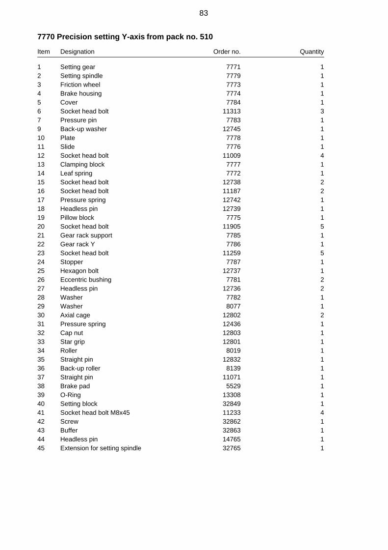
7770 Precision setting Y-axis from pack no. 510
Item Designation Order no. Quantity
1 Setting gear 7771 12 Setting spindle 7779 13 Friction wheel 7773 14 Brake housing 7774 15 Cover 7784 16 Socket head bolt 11313 37 Pressure pin 7783 19 Back-up washer 12745 110 Plate 7778 111 Slide 7776 112 Socket head bolt 11009 413 Clamping block 7777 114 Leaf spring 7772 115 Socket head bolt 12738 216 Socket head bolt 11187 217 Pressure spring 12742 118 Headless pin 12739 119 Pillow block 7775 120 Socket head bolt 11905 521 Gear rack support 7785 122 Gear rack Y 7786 123 Socket head bolt 11259 524 Stopper 7787 125 Hexagon bolt 12737 126 Eccentric bushing 7781 227 Headless pin 12736 228 Washer 7782 129 Washer 8077 130 Axial cage 12802 231 Pressure spring 12436 132 Cap nut 12803 133 Star grip 12801 134 Roller 8019 135 Straight pin 12832 136 Back-up roller 8139 137 Straight pin 11071 138 Brake pad 5529 139 O-Ring 13308 140 Setting block 32849 141 Socket head bolt M8x45 11233 442 Screw 32862 143 Buffer 32863 144 Headless pin 14765 145 Extension for setting spindle 32765 1
83
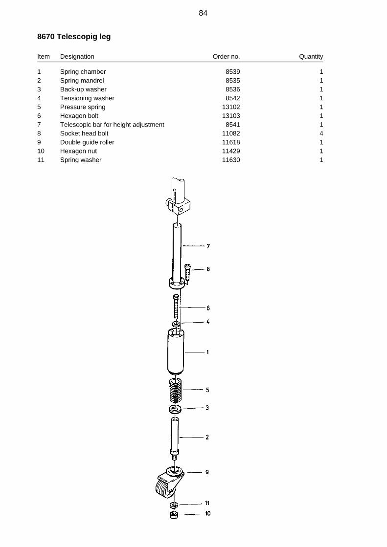
8670 Telescopig leg
Item Designation Order no. Quantity
1 Spring chamber 8539 12 Spring mandrel 8535 13 Back-up washer 8536 14 Tensioning washer 8542 15 Pressure spring 13102 16 Hexagon bolt 13103 17 Telescopic bar for height adjustment 8541 18 Socket head bolt 11082 49 Double guide roller 11618 110 Hexagon nut 11429 111 Spring washer 11630 1
84
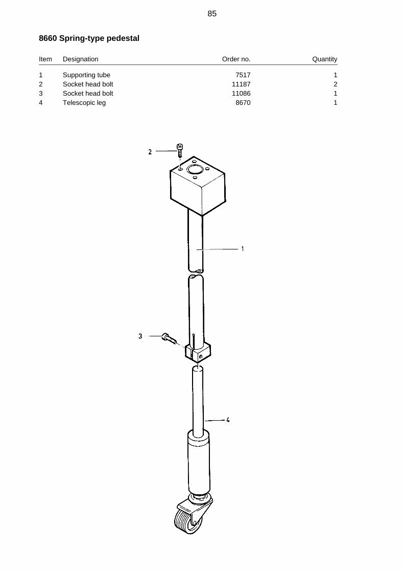
8660 Spring-type pedestal
Item Designation Order no. Quantity
1 Supporting tube 7517 12 Socket head bolt 11187 23 Socket head bolt 11086 14 Telescopic leg 8670 1
85

7856 Pedestal
Item Designation Order no. Quantity
1 Supporting tube 7517 12 Socket head bolt 11187 23 Telescopic bar for height adjustment 5374 14 Double guide roller dia. 50 with rear hole 11618 15 Spring washer 10 11630 16 Hexagon nut M10 11429 17 Socket head bolt M 8x35 11086 1
86

8550 Right-hand support for AV5L only
Item Designation Order no. Quantity
1 Right-hand cross rail 8546 12 Swivel bearing 7515 13 Socket head bolt 11252 44 End stopper, long 8545 15 Steel shaft 8543 16 Tensioning washer 8544 17 Socket head bolt 13104 28 Pedestal 7856 19 Spring-type pedestal 8660 1
87

8540 Left-hand support AV4 + AV4L - AV5 + AV5L
Item Designation Order no. Quantity
1 Supporting rail 7516 12 Swivel bearing 7515 13 Socket head bolt 11252 44 Pedestal 7856 15 Spring-type pedestal 8660 16 Holder 4861 17 Socket head bolt 11187 1
88
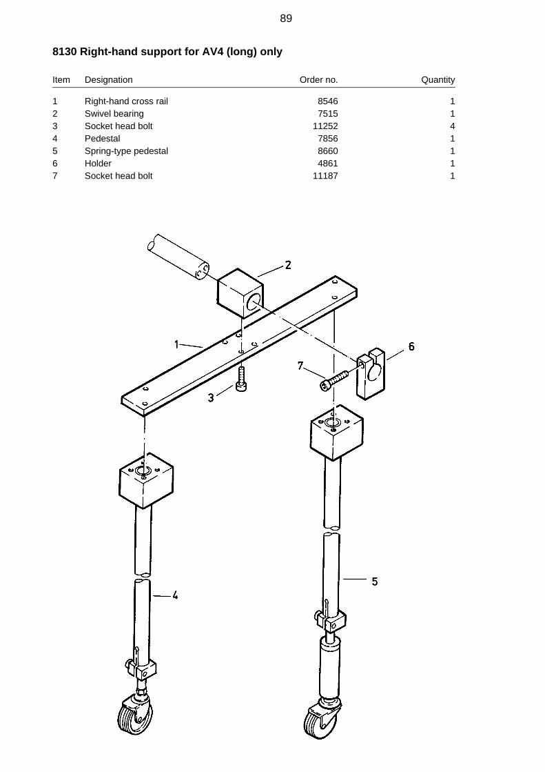
8130 Right-hand support for AV4 (long) only
Item Designation Order no. Quantity
1 Right-hand cross rail 8546 12 Swivel bearing 7515 13 Socket head bolt 11252 44 Pedestal 7856 15 Spring-type pedestal 8660 16 Holder 4861 17 Socket head bolt 11187 1
89

Two-handed control with digital display for AV5 and AV5 L
Designation Page
7140 Two-handed control with digital display 91Operating faults and their remedies 96
90

7140 Two-handed control with digital display for AV5 and AV5 L
Item Designation Order no. Quantity
1 Control cabinet compl. for HSTL 220V 7390 12 Pivot arm complete 7330 13 Control panel, complete 220V 7300 14 Distributor box, controller HSTL-D 7480 15 Control cable set compl. plugs 10+ 16-pole 7799 1
Limit switch
Encoder
Encoder
Limit switch
91

2 = Limit switch Y-axis
3 = Encoder Y-axis
4 = Encoder X-axis
5 = Limit switch X-axis
pilot circuit
supply pilot circuit
92
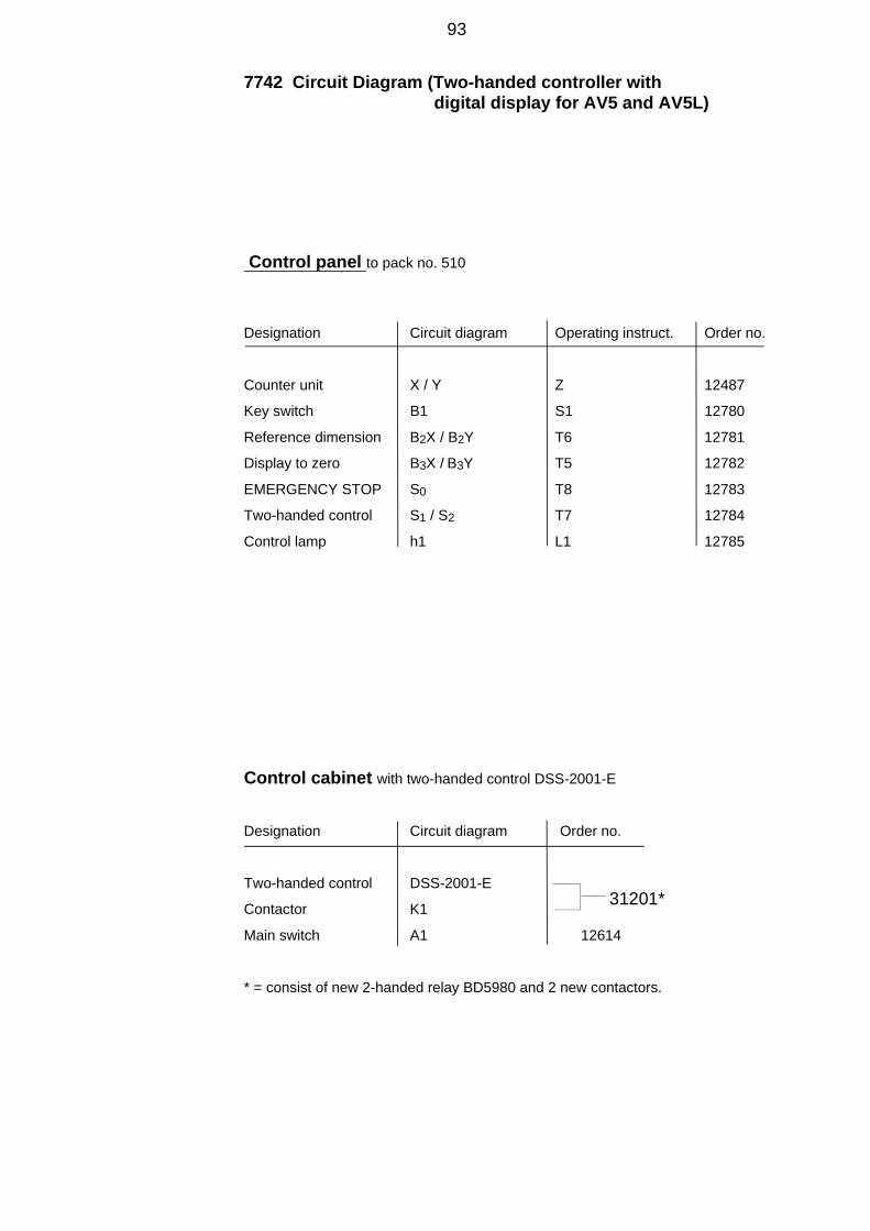
7742 Circuit Diagram (Two-handed controller with digital display for AV5 and AV5L)
Control panel to pack no. 510
Designation Circuit diagram Operating instruct. Order no.
Counter unit X / Y Z 12487
Key switch B1 S1 12780
Reference dimension B2X / B2Y T6 12781
Display to zero B3X / B3Y T5 12782
EMERGENCY STOP S0 T8 12783
Two-handed control S1 / S2 T7 12784
Control lamp h1 L1 12785
Control cabinet with two-handed control DSS-2001-E
Designation Circuit diagram Order no.
Two-handed control DSS-2001-E
Contactor K1
Main switch A1 12614
* = consist of new 2-handed relay BD5980 and 2 new contactors.
31201*
93

2 = Limit switch Y-axis
3 = Encoder Y-axis
4 = Encoder X-axis
5 = Limit switch X-axis
pilot circuit
supply
pilot circuit

4750 Bl. 1 + 2 Circuit Diagram (Two-handed controller with digital display for AV5 and AV5L)
Control panel from pack no. 511
Designation Circuit diagram Operating instruct. Order no.
Counter unit X / Y Z 14667
Display to zero B3X / B3Y T5 12782
EMERGENCY STOP S0 T8 12783
Two-handed control S1 / S2 T7 12784
Control lamp H1 L1 12785
Control cabinet with two-handed control BD5980
Designation Circuit diagram Order no.
Two-handed control BD 5980 N 14122
Contactor K1 14123
Contactor K2 14123
Main switch A1 12614
95
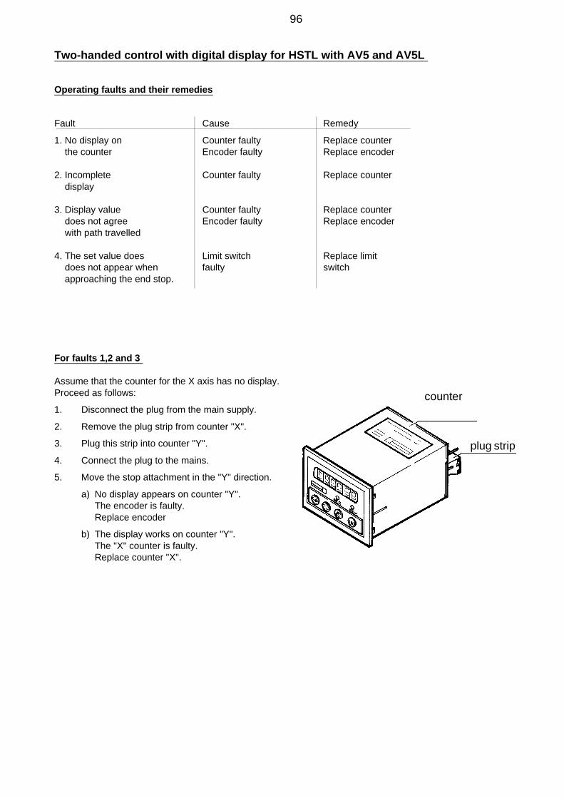
Two-handed control with digital display for HSTL with AV5 and AV5L
Operating faults and their remedies
Fault Cause Remedy
1. No display on Counter faulty Replace counter the counter Encoder faulty Replace encoder
2. Incomplete Counter faulty Replace counter display
3. Display value Counter faulty Replace counter does not agree Encoder faulty Replace encoder with path travelled
4. The set value does Limit switch Replace limit does not appear when faulty switch approaching the end stop.
For faults 1,2 and 3
Assume that the counter for the X axis has no display. Proceed as follows:
1. Disconnect the plug from the main supply.
2. Remove the plug strip from counter "X".
3. Plug this strip into counter "Y".
4. Connect the plug to the mains.
5. Move the stop attachment in the "Y" direction.
a) No display appears on counter "Y". The encoder is faulty.
Replace encoder
b) The display works on counter "Y".The "X" counter is faulty.Replace counter "X".
counter
plug strip
96

6. Change "X" axis encoder (see drawing no. 7150, page 65, and 7820, page 75)
6.1 Disconnect mains plug.
6.2 Undo connection cable screw cap on rotary shaft encoder anddisconnect cable (37) from rotary shaft encoder (36 and 50 respectively).
6.3 Remove 2 screws (12).
6.4 Remove encoder assembly.
6.5 Attach new encoder with 2 screws (12).
6.6 Holding rotary shaft encoder steady with one hand, unscrew transport brace. Slowly move rotary shaft encoder towards steel shaft until the rotary shaft encoder’s pinion engages into the rack.
6.7 Connect cable (37) to rotary shaft encoder.Pull out mains plug
6.2 Loosen the screw cap of the connecting cable and remove the cable (37) from angularencoder (36 or 50).
6.7 Connect the cable (37) to the encoder.
7. Change "Y" axis encoder (drwg. 7160, page 61)
7.1 Disconnect mains plug.
7.2 Detach connection cable from rotary shaft encoder (35 and 55 respectively).
7.3 Disengage tension spring (20).
7.4 Undo both screws (13) and remove segment (1) withrotary shaft encoder.
7.5 Secure new encoder in place with 2 screws (13).
7.6 Engage tension spring (20).
7.7 Connect cable (37) to rotary shaft encoder.
8.1 Change counter (up to device no.: 510)
8.1.0 Disconnect mains plug.
8.1.1 Open command housing.
8.1.2 Disconnect plug connector (1).
8.1.3 Disconnect earthing cable (E).
8.1.4 Unscrew knurled nuts (R).
8.1.5 Remove clip (B).
8.1.6 Pull counter (Z) out towards front.
97

8.1.7 Using a file, increase size of cut-out by 2 mm on left or right.
8.1.8 Insert new counter.
8.1.9 Unscrew straps from rear panel.
8.1.10Screw both knurled nuts (R) into straps and firmly clamp counter in place.
8.1.11Connect earthing cable (E).
8.1.12Connect cable adapter.
8.1.13Push plug connector (1) onto cable adapter.
8.1.14Plug black 3-pin plug into counter.
98

8.2 Change counter (from device no.: 511)
8.2.0 Disconnect mains plug.
8.2.1 Open command housing.
8.2.2 Disconnect plugs (1), (2) and (3).
8.2.3 Disconnect earthing cable (E).
8.2.4 Unscrew knurled nuts (R) from straps.
8.2.5 Undo straps and turn them so they arepositioned behind rear panel of counter.
8.2.6 Pull counter (Z) out towards front.
8.2.7 Insert new counter.
8.2.8 Unscrew straps from rear panel.
8.2.9 Screw both knurled nuts (R) into straps and firmly clamp counter firmly in place.
8.2.10Connect earthing cable (E).
8.2.11Connect plugs (1), (2) and (3).
For fault no. 4
9. Replace limit switch (see drawings 7150 and 7820)
9.1 Remove mains connection
9.2 Disconnect the cable no. 5 from the distributor box
9.3 Unscrew both screws M 5x25 and remove the limit switch and cable.
9.4 Fasten the new limit switch and connect it to the distributor box.
9.5 After replacing the limit switch, correct the set value- as described in points 10, 11 and 12.
99

10. Checking procedure
10.1. Remove the top and bottom dies.
10.2. Mount the supplied test-mandril (d=50 mm/1.968") in the top die’s place.
10.3. X-Axis
10.3.1.Push the stop device to the left to the end limit (reference point).(Direction minus X)The reference value for the X-axis appears, for example -201.9.
10.3.2.Push the stop device to the right until the cross rail is on the right side of the punch.
10.3.3.Set the return valve’s lever in the upright position, see picture.
10.3.4.Lower the test-mandril to approx. 5 mm beneath the stop rail. See picture 5
10.3.5.Push the cross rail with the plastic stop to the test-mandril. See picture.
The value
If a different value is displayed after the test-mandril has been touched, then the referencevalue for the X-axis must be corrected.
2 5 .0 ± 0.1 mm .9 8 4 inches should be displayed
Stop rail
Testpicture 5
Test
Plastic stop
100
EXAMPLE 3 (mm) EXAMPLE 3 (inches)
Test-mandril’s radius 25,0 Test-mandril’s radius 0.984Displayed value 25,7 Displayed value 1.011Reference value -201,9 Reference value -7.949Mandril minus display = difference Mandril minus display = difference25,0 - 25,7 = - 0,7 .984 - 1.011 = -.027
Corrected reference value Corrected reference value
- 201,9 + (- 0,7) = - 202,6 -7.949 + (-.027) = -7.976
EXAMPLE 4 (mm) EXAMPLE 4 (inches)
Test-mandril’s radius 25,0 Test-mandril’s radius .984Displayed value 24,8 Displayed value .976Reference value -202,8 Reference value - 7.984Mandril minus display = difference Mandril minus display = difference25,0 - 24,8 = 0,2 .984 - .976 = .008
Corrected reference value Corrected reference value
- 202,8 + 0,2 = - 202,6 -7.984 + .008 = -7.976
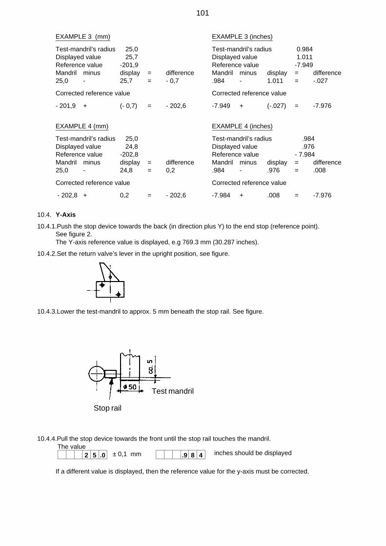
10.4. Y-Axis
10.4.1.Push the stop device towards the back (in direction plus Y) to the end stop (reference point).See figure 2.The Y-axis reference value is displayed, e.g 769.3 mm (30.287 inches).
10.4.2.Set the return valve’s lever in the upright position, see figure.
10.4.3.Lower the test-mandril to approx. 5 mm beneath the stop rail. See figure.
10.4.4.Pull the stop device towards the front until the stop rail touches the mandril. The value
If a different value is displayed, then the reference value for the y-axis must be corrected.
2 5 .0 ± 0,1 mm .9 8 4 inches should be displayed
Test mandril
Stop rail
101

11. ENTERING THE CORRECTED REFERENCE VALUE to pack no: 510
11.1. X-Axis
11.1.1.Push the stop device a few centimeters away from the mandril to the right.
11.1.2.Unlock the left counter unit. (Turn the S1 key to the left.)
11.1.3.Press the T6 button. The reference value is displayed. For example:
in mm in inches
11.1.4.Press button T1. The decimal point flashes after the first digit.
11.1.5.Move the decimal point to the digit to be altered with button T1 and enter the corrected value
11.1.6.Move the decimal point with button T1 and enter the corrected value
11.1.7.Store the new value with the T6 button.
11.1.8.Then press the T1 button, the following value is displayed:
11.1.9.Push the stop device to the end stop (reference point). The X-axis is now set to the new reference value.The following is displayed when the mandril touches the plastic stop (figure page 101):
11.2. Y-Axis
11.2.1.Push the stop device back a few centimeters away from the mandril.
11.2.2.Unlock the right counting unit.
11.2.3.Press the T6 button. The reference value is displayed. For example:
11.2.4.Press the T1 button. The decimal point flashes behind the first digit.
11.2.5.Move the decimal point to the digit to be altered with the T1 button and enter the corrected value with the T2 button.
11.2.6.Store the new value with the T6 button.
11.2.7.Then press the T1 button. The value
11.2.8.Push the stop device to its end limit at the back (reference point). The Y-axis is now set to its new reference value.
11.2.9.When the mandril is touched by the stop rail (figure page 87) the value
The Y-axis is set correctly.
The X-axis is set correctly.
is displayed.
with the T2 button.
is displayed.
2 0 1 .9 7 .9 4 9
0. 0 2 0 1 9 0. 0 7 9 4 9
0 0 2 0 2. 9 0 0 7 9 8. 8
0 0 2 0 2 6. 0 0 7 9 7 6.
2 0 2 .6 7 .9 7 6
2 5 .0 .9 8 4
7 6 9 .3 3 0 .2 8 7
0. 0 7 6 9 3 0. 3 0 2 8 7
0 0 7 6 9 1. 0 3 0 2 7 9.
7 6 9 .1 3 0. 2 7 9
2 5 .0 .9 8 4
102

Control panel
Figure 1
Z Counter unit
S1 Key-operated switch
- for punching
- keyboard for the right counter unit for Y-axis unlocked
- keyboard for the left counter unit for X-axis unlocked
T1 Selects figure display
T2 Enters the figure value
T3 Selects absolute or incremental value
T4 Selects unit of measure - millimeters or inches
T5 Sets the display to zero (only in incremental-value mode)
T6 Stores the reference size
T7 Two-hand control
T8 EMERGENCY - STOP
L E D - D I S P L A Y S
D1 Negative X-axis sector
D2 Incremental dimensions
D3 Dimensions in inches
Remark regarding the key-operated switch S1:
Only the T3, T5, T7 and T8 keys will operate if the key-switch is set for punchingor if the key has been removed.
All other buttons are blocked. The key can only be removed when the switch isin the "punching" position.
103
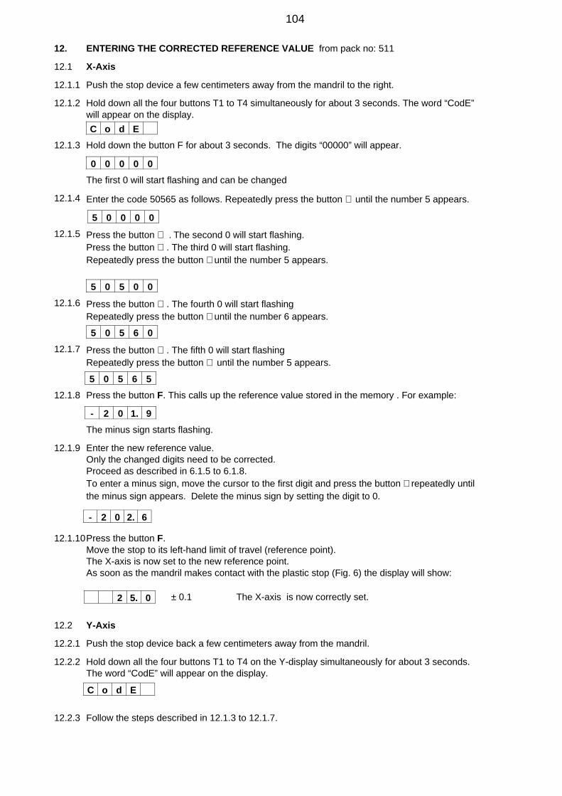
12. ENTERING THE CORRECTED REFERENCE VALUE from pack no: 511
12.1 X-Axis
12.1.1 Push the stop device a few centimeters away from the mandril to the right.
12.1.2 Hold down all the four buttons T1 to T4 simultaneously for about 3 seconds. The word “CodE” will appear on the display.
12.1.3 Hold down the button F for about 3 seconds. The digits “00000” will appear.
The first 0 will start flashing and can be changed
12.1.4 Enter the code 50565 as follows. Repeatedly press the button ⇑ until the number 5 appears.
12.1.5 Press the button ⇒ . The second 0 will start flashing.Press the button ⇒ . The third 0 will start flashing.Repeatedly press the button ⇑ until the number 5 appears.
12.1.6 Press the button ⇒ . The fourth 0 will start flashingRepeatedly press the button ⇑ until the number 6 appears.
12.1.7 Press the button ⇒ . The fifth 0 will start flashingRepeatedly press the button ⇑ until the number 5 appears.
12.1.8 Press the button F. This calls up the reference value stored in the memory . For example:
The minus sign starts flashing.
12.1.9 Enter the new reference value.Only the changed digits need to be corrected.Proceed as described in 6.1.5 to 6.1.8.To enter a minus sign, move the cursor to the first digit and press the button ⇑ repeatedly until the minus sign appears. Delete the minus sign by setting the digit to 0.
12.1.10Press the button F.Move the stop to its left-hand limit of travel (reference point).The X-axis is now set to the new reference point.As soon as the mandril makes contact with the plastic stop (Fig. 6) the display will show:
± 0.1 The X-axis is now correctly set.
12.2 Y-Axis
12.2.1 Push the stop device back a few centimeters away from the mandril.
12.2.2 Hold down all the four buttons T1 to T4 on the Y-display simultaneously for about 3 seconds. The word “CodE” will appear on the display.
12.2.3 Follow the steps described in 12.1.3 to 12.1.7.
C o d E
0 0 0 0 0
5 0 0 0 0
5 0 5 0 0
5 0 5 6 0
5 0 5 6 5
- 2 0 1. 9
- 2 0 2. 6
2 5. 0
C o d E
104
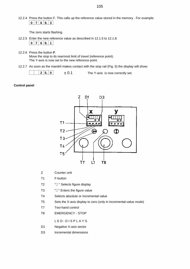
12.2.4 Press the button F. This calls up the reference value stored in the memory . For example:
The zero starts flashing.
12.2.5 Enter the new reference value as described in 12.1.5 to 12.1.8.
12.2.6 Press the button F.Move the stop to its rearmost limit of travel (reference point).The Y-axis is now set to the new reference point.
12.2.7 As soon as the mandril makes contact with the stop rail (Fig. 5) the display will show:
± 0.1 The Y-axis is now correctly set.
Control panel
Z Counter unit
T1 F-button
T2 "⇒ " Selects figure display
T3 "⇑ " Enters the figure value
T4 Selects absolute or incremental value
T5 Sets the X-axis display to zero (only in incremental-value mode)
T7 Two-hand control
T8 EMERGENCY - STOP
L E D - D I S P L A Y S
D1 Negative X-axis sector
D3 Incremental dimensions
0 7 6 9. 3
0 7 6 9. 1
2 5. 0
105

Repairs / Service
Scharnhorststraße 1 Postfach 101163D-41460 Neuss D-41411 Neuss
Telex 8 518 015Tel. 02131 / 288-0
Federal Republic of Germany Telefax 02131 / 28855