Receive antenna impact on spatio-temporal availability in satellite-to-indoor broadcasting
7
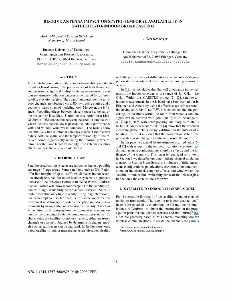
RECEIVE ANTENNA IMPACT ON SPATIO-TEMPORAL AVAILABILITY IN SATELLITE-TO-INDOOR BROADCASTING Marko Milojevi´ c, Giovanni Del Galdo, Nuan Song, Martin Haardt Ilmenau University of Technology, Communications Research Laboratory, P.O. Box 100565, 98684 Ilmenau, Germany [email protected] Albert Heuberger Fraunhofer Institute Integrierte Schaltungen IIS Am Wolfsmantel 33, 91058 Erlangen, Germany [email protected] ABSTRACT This contribution studies spatio-temporal availability in satellite- to-indoor broadcasting. The performance of both theoretical and measured single and multiple antenna receivers with var- ious polarimetric radiation patterns is compared for different satellite elevation angles. The spatio-temporal satellite to in- door channels are obtained via a 3D ray tracing engine and a geometry-based channel modeling tool. Moreover, the influ- ence of coupling effects between closely spaced antennas on the availability is studied. Under the assumption of a Line- Of-Sight (LOS) connection between the satellite and the wall where the possible window is placed, the indoor performance with and without windows is compared. The results show quantitatively that additional antennas placed at the receiver reduce both the spatial and the temporal variability of the re- ceived power, significantly reducing the transmit power re- quired for the same target availability. The antenna coupling effects increase the required link margin. 1. INTRODUCTION Satellite broadcasting systems are attractive due to a possible coverage of large areas. Some satellites, such as XM Radio, offer link margins of up to 18 dB which makes indoor recep- tion already feasible. For future satellite systems, a significant increase of the Effective Isotropic Radiated Power (EIRP) is planned, which will allow indoor reception of the satellite sig- nals with high availability for broadband services. Since in mobile reception only time diversity (using long interleavers) has been employed so far, there is still some room for im- provement in stationary or portable reception in indoor envi- ronments by using spatial or polarization diversity. The char- acterization of the propagation environment is very impor- tant for the planning of satellite communication systems. To characterize the satellite-to-indoor channels, either measured channels or channels obtained by deterministic channel mod- els such as ray-tracers can be analyzed. In the literature, only a few satellite-to-indoor measurements are discussed dealing with the performance of different receive antenna strategies, polarization diversity, and the influence of moving persons or objects. In [1], it is concluded that the wall attenuation influences mostly the indoor coverage in the range of 1.1 GHz - 1.6 GHz. Within the MAESTRO project [2], [3], satellite-to- indoor measurements in the L-band have been carried out in Erlangen and Athens by using the Worldspace Afristar satel- lite having an EIRP of 48 dBW. It is concluded that the per- centage of positions within the room from which a satellite signal can be received with good quality is in the range of 30 % up to 80 % with corresponding link margins of 10 dB to 16 dB. Measurement results in [4] show that the received electromagnetic field is strongly diffused in the interior of a building. In [5], it is shown that the polarization state of the propagation wave changes significantly inside the room. In this paper we extend the investigations carried out in [6] and [7] with respect to the temporal variation, elevation, ad- ditional antenna configurations, coupling effects, and the in- fluence of the windows. This paper is organized as follows: in Section 2 we describe our deterministic channel modeling concept. In Section 3, we discuss the influence of different an- tenna configurations, polarizations, elevations, temporal vari- ations of the channel, coupling effects, and windows on the satellite-to-indoor link availability for realistic link margins. In Section 4 the conclusions are drawn. 2. SATELLITE-TO-INDOOR CHANNEL MODEL Fig. 1 shows the flowchart of the satellite-to-indoor channel modeling framework. The satellite-to-indoor channel coef- ficients are obtained by combining the 3D ray-tracing simu- lation tool WinProp 1 to obtain the information on the prop- agation paths for the defined scenario and the IlmProp 2 [8], a flexible geometry-based MIMO channel modeling tool for wireless communications, to create the channels for various 1 http://www.awe-communications.com 2 http://www.tu-ilmenau.de/nt/en/ilmprop 48 978-1-4244-1757-5/08/$25.00 c 2008 IEEE
-
Upload
independent -
Category
Documents
-
view
2 -
download
0
Transcript of Receive antenna impact on spatio-temporal availability in satellite-to-indoor broadcasting
RECEIVE ANTENNA IMPACT ON SPATIO-TEMPORAL AVAILABILITY INSATELLITE-TO-INDOOR BROADCASTING
Marko Milojevic, Giovanni Del Galdo,Nuan Song, Martin Haardt
Ilmenau University of Technology,
Communications Research Laboratory,
P.O. Box 100565, 98684 Ilmenau, Germany
Albert Heuberger
Fraunhofer Institute Integrierte Schaltungen IIS
Am Wolfsmantel 33, 91058 Erlangen, Germany
ABSTRACT
This contribution studies spatio-temporal availability in satellite-to-indoor broadcasting. The performance of both theoreticaland measured single and multiple antenna receivers with var-ious polarimetric radiation patterns is compared for differentsatellite elevation angles. The spatio-temporal satellite to in-door channels are obtained via a 3D ray tracing engine and ageometry-based channel modeling tool. Moreover, the influ-ence of coupling effects between closely spaced antennas onthe availability is studied. Under the assumption of a Line-Of-Sight (LOS) connection between the satellite and the wallwhere the possible window is placed, the indoor performancewith and without windows is compared. The results showquantitatively that additional antennas placed at the receiverreduce both the spatial and the temporal variability of the re-ceived power, significantly reducing the transmit power re-quired for the same target availability. The antenna couplingeffects increase the required link margin.
1. INTRODUCTION
Satellite broadcasting systems are attractive due to a possiblecoverage of large areas. Some satellites, such as XM Radio,offer link margins of up to 18 dB which makes indoor recep-tion already feasible. For future satellite systems, a significantincrease of the Effective Isotropic Radiated Power (EIRP) isplanned, which will allow indoor reception of the satellite sig-nals with high availability for broadband services. Since inmobile reception only time diversity (using long interleavers)has been employed so far, there is still some room for im-provement in stationary or portable reception in indoor envi-ronments by using spatial or polarization diversity. The char-acterization of the propagation environment is very impor-tant for the planning of satellite communication systems. Tocharacterize the satellite-to-indoor channels, either measuredchannels or channels obtained by deterministic channel mod-els such as ray-tracers can be analyzed. In the literature, onlya few satellite-to-indoor measurements are discussed dealing
with the performance of different receive antenna strategies,polarization diversity, and the influence of moving persons orobjects.
In [1], it is concluded that the wall attenuation influencesmostly the indoor coverage in the range of 1.1 GHz - 1.6GHz. Within the MAESTRO project [2], [3], satellite-to-indoor measurements in the L-band have been carried out inErlangen and Athens by using the Worldspace Afristar satel-lite having an EIRP of 48 dBW. It is concluded that the per-centage of positions within the room from which a satellitesignal can be received with good quality is in the range of30 % up to 80 % with corresponding link margins of 10 dBto 16 dB. Measurement results in [4] show that the receivedelectromagnetic field is strongly diffused in the interior of abuilding. In [5], it is shown that the polarization state of thepropagation wave changes significantly inside the room.
In this paper we extend the investigations carried out in [6]and [7] with respect to the temporal variation, elevation, ad-ditional antenna configurations, coupling effects, and the in-fluence of the windows. This paper is organized as follows:in Section 2 we describe our deterministic channel modelingconcept. In Section 3, we discuss the influence of different an-tenna configurations, polarizations, elevations, temporal vari-ations of the channel, coupling effects, and windows on thesatellite-to-indoor link availability for realistic link margins.In Section 4 the conclusions are drawn.
2. SATELLITE-TO-INDOOR CHANNEL MODEL
Fig. 1 shows the flowchart of the satellite-to-indoor channelmodeling framework. The satellite-to-indoor channel coef-ficients are obtained by combining the 3D ray-tracing simu-lation tool WinProp1 to obtain the information on the prop-agation paths for the defined scenario and the IlmProp2 [8],a flexible geometry-based MIMO channel modeling tool forwireless communications, to create the channels for various
1http://www.awe-communications.com2http://www.tu-ilmenau.de/nt/en/ilmprop
48
978-1-4244-1757-5/08/$25.00 c© 2008 IEEE

WinProp
Indoor layout andmaterial properties
IlmProp
IndoorDatabase
Receive antennapatterns
Path parameters
Channelcoefficients
Received signalevaluation
Temporalvariation
Linkmargin
Conclusions
WinProp
Indoor layout andmaterial properties
IlmProp
IndoorDatabase
Receive antennapatterns
Path parameters
Channelcoefficients
Received signalevaluation
Temporalvariation
Linkmargin
Conclusions
Fig. 1. Block diagram of our analysis
antenna configurations. In [9], [10], and [11] WinProp hasbeen validated with the help of measurements. WinProp takesinto account transmission, reflection, and diffraction. Afterthe satellite-to-indoor scenario is defined and modeled by theWinProp, the path strength and spatial information of eachpath is fed to the IlmProp. The trajectory of each path is mod-eled by means of point-like scatterers which represent pointsof interaction. The IlmProp supports different receive an-tenna patterns and allows us to compare their performance.In our simulations, a left-hand circularly polarized satellitesignal with carrier frequency 2.0 GHz is received by a station-ary indoor receiver. The polarization for Non-Line-Of-Sight(NLOS) paths becomes random due to diffractions and reflec-tions, while the LOS component is set to be Left Hand Cir-cularly Polarized (LHCP). In fact, in [4], it is concluded thatin the satellite-to-indoor scenario the electromagnetic field isdiffuse and the circular polarization is not preserved in the farfield away from the window. In [6], more details on the de-terministic channel modeling components can be found. Ad-ditionally, we take into account temporal variations of the re-ceive power due to the man movement in the vicinity of the re-ceiver. The parameters characterizing man movement are ob-tained from the satellite-to-indoor measurements. The personmovement, without blocking the incoming signal, increasesthe received signal standard deviation in all available datasets. The Probability Density Function (PDF) of the differ-ence between the received power in measurements with andwithout person movement is well approximated by the PDF ofa truncated normal distribution with zero mean and standarddeviation in the range from 0.7 dB up to 1.5 dB, depending onthe environment, as reported in [7]. In the following, the PDFof a truncated normal distribution with zero mean, a standarddeviation of 0.9 dB, and truncation at ±2.3 dB is used.
3. PERFORMANCE COMPARISON OF DIFFERENTRECEIVE ANTENNAS
In this section we compare the performance of different re-ceive antenna schemes with respect to the Cumulative Distri-
bution Function (CDF) of the fade depth. We study a roomoriented towards the satellite, i.e., there is a LOS between thesatellite and the window. The carrier-to-noise ratio at the re-ceiver, denoted by C/N , is defined as the difference betweenthe received signal power C and the received noise power N ,i.e.,
C/N = C − N [dB]. (1)
The value of the Fade Depth FD is estimated as the differ-ence between a reference carrier-to-noise ratio C/N ref andthe carrier-to-noise ratio at the receiver C/N , i.e.,
FD = (C/N ref − C/N) [dB], (2)
where C/N ref refers to a position outside of the room in apure LOS regime. The Link Margin LM is defined as the dif-ference between the reference carrier-to-noise ratio C/N ref
and the minimum carrier-to-noise ratio C/Nmin needed forgood reception of the signal, i.e.,
LM = (C/N ref − C/Nmin) [dB]. (3)
If the fade depth is higher than the link margin we say that thecommunication link is not available, otherwise it is available.In Fig. 2 we show the predicted average receive signal powerin the room for a satellite elevation of 40◦ and an azimuth ϕof 45◦. There are three different areas of receive signal powerthat are denoted as A, B, and C in Fig. 2:
• The area A is dominated by the LOS channel compo-nent impinging through the window. The fade depthis low and exhibits a very low spatial variation. As aresult, a very high availability is achieved.
• The area B is characterized by rays impinging afterpenetration through the walls. The received power issignificantly lower than in area A, and the spatial vari-ation of the signal power is higher.
• In the area C most of the signal power arrives afterpenetration through the wall or window followed bysome reflections and diffractions. The spatial variationis higher than in areas A and B.
The WinProp is used to obtain the information on the in-coming signal components with a resolution of 8 cm in theroom. For each point, the IlmProp uses this information toproduce the channel impulse responses in a window of size2λ × 2λ by using a Uniform Rectangular Array (URA) ofsize 16 × 16, resulting in 256 subchannels. A temporal vari-ation is included to model man movement . The goal of thesimulations is to estimate the possible improvements of thespatio-temporal signal availability when different receive an-tenna configurations are used.
The following theoretical receiver antennas are studied:vertically polarized dipoles (denoted as ‘V’), horizontally po-larized dipoles (‘H’), a combination of vertically and hori-zontally polarized dipoles (‘V-H’), and circularly polarized
2008 International ITG Workshop on Smart Antennas (WSA 2008) 49

0 2 40
2
4
6-145-148-151-154-157-160-163-166-169-172
Receivepower [dBW]
Window
6[m]
[m]
incidenceangle
windows
walls
ϕ
A
A
B
B B
C
Fig. 2. Average receive power in dBW simulated by WinProp
antennas (‘C’). Additionally we study the use of realistic mea-sured vertically (‘W’) and circularly (‘Z’) polarized antennasfor the reception of satellite signals. The measured verticallypolarized antenna has a very narrow radiation pattern with apeak at 40◦ elevation. Finally, the measured beampatterns ofcircular antennas with the coupling effect (‘CO’) are consid-ered. ‘CO max’ and ‘CO min’ denote the circular antennasmentioned above having its beampattern maximum and min-imum in the LOS direction, respectively. The 3D radiationpatterns of the considered antennas are shown in Fig. 3, Fig. 4,and Fig. 5.
−10
1
−10
1
−0.50
0.5
xy
z
0
0.5
1
1.5
(a)
−10
1
−10
1
0
1
2
xy
z
0.5
1
1.5
2
(b)
Fig. 3. Theoretical antenna patterns: (a) vertically / horizon-tally polarized dipole, (b) circularly polarized antenna
The 3D integral of the radiation patterns is equal to 4π for allstudied antennas, i.e.,
∫S2
r(ϕ, θ) dΩ = 4π, (4)
where the integral is calculated over the solid angle Ω on theentire surface of the unit sphere S2.
The receiver is assumed to have a uniform linear array(ULA) with various combinations of the antennas specifiedabove. Antenna arrays of one, two, and four antenna elements
are considered at the receiver. The array names give informa-tion about its elements, e.g., ‘Z-Z’ is an ULA of two ‘Z’ an-tenna elements, ‘4-Z’ is an ULA of four ‘Z’ antenna elements,etc. Maximum Ratio Combining (MRC) is performed at thereceiver assuming perfect instantaneous channel state infor-mation. The transmitted satellite signal is left hand circularlypolarized. The penetration losses of the window, brick walls,and the concrete ceiling are 2 dB, 12 dB, and 17 dB, respec-tively.
−20
24
−20
2
0123
xy
z
1
2
3
4
5
(a)
−20
2
−2−1
01
0
2
4
xy
z
1
2
3
4
5
(b)
Fig. 4. Radiation patterns of realistic antennas for the recep-tion of satellite signals: (a) vertically polarized antenna, (b)circularly polarized antenna
−1 0 1 2
−20
20
2
4
xy
z
1
2
3
4
5
Fig. 5. Radiation pattern of circularly polarized antenna withcoupling effect: the distance between identical antenna ele-ments is 0.5 wavelengths.
The correlation coefficient between adjacent antennas isan important metric to observe because it influences the di-versity gain and the antenna array gain: low values of thecorrelation coefficient lead to a high diversity gain and a lowarray gain, and high values lead to a high array gain and a lowdiversity gain. The complex correlation coefficient ρ of twocomplex processes H1 and H2 is defined as:
ρ =E[H1H
∗
2]−E[H1]E[H∗
2]q
(E[H1H∗
1 ]−E[H1]E[H∗
1 ])(E[H2H∗
2 ]−E[H2]E[H∗
2 ]), (5)
where E [·] denotes the expectation operator, H1 and H2 ob-tained from IlmProp simulations are the channels of the firstand second antenna, respectively, and {·}∗ denotes complexconjugation.
50 2008 International ITG Workshop on Smart Antennas (WSA 2008)

0 0.5 1 1.5 20
0.2
0.4
0.6
0.8
1
antenna distance in λ
|ρ|
C−C, ’’A’’
H−H, ’’A’’
V−V, ’’A’’
V−H, ’’A’’
W−W, ’’A’’
Z−Z, ’’A’’
CO−CO, ’’A’’
C−C, ’’C’’
H−H, ’’C’’
V−V, ’’C’’
V−H, ’’C’’
W−W, ’’C’’
Z−Z, ’’C’’
CO−CO, ’’C’’
Fig. 6. Averaged spatial correlation coefficient as a functionof the distance (in wavelengths) between adjacent antenna el-ements for different receive antenna schemes in the areas Aand C. The satellite elevation is 40◦.
In Fig. 6, the averaged spatial correlation coefficients be-tween different antenna types are depicted as a function of theadjacent antenna distance (in wavelengths) within the area Aand within the area C. For the coupled antennas, only the cor-relation coefficient for a distance of 0.5 wavelengths is avail-able: we only have measured radiation patterns of coupledantennas for that distance between antenna elements. Sincethe coupling influence is higher for lower antenna distancesbetween adjacent antenna elements [12], for higher distancesthe correlation coefficient should approach the correlation co-efficient between two measured circularly polarized antennas‘Z-Z’. In Fig. 7 and Fig. 8 the CDF of the fade depth withinthe whole room for two and four antenna schemes is shown,respectively. For comparison we show also the performanceof a receiver with one vertically polarized antenna in bothFig. 7 and Fig. 8. Moreover, figures with the zoomed low andhigh region of the CDF for all studied two and four receive an-tenna schemes are shown in Fig. 9 and Fig. 10, respectively.
In the area A, all observed correlation coefficients havevery high values that drop slowly with the increase of the dis-tance between antennas. In the area C the correlation coeffi-cient between two circularly polarized closely spaced anten-nas (‘C-C’, ‘CO-CO’, or ‘Z-Z’) is higher than for two ver-tically or two horizontally polarized dipoles with the sameseparation. The correlation coefficient between one verticallyand one horizontally polarized dipole within area C is verylow for all antenna distances. The correlation coefficient withinarea A is significantly higher than in area C for all observedantenna configurations. Therefore and due to the fact that thediversity gain increases at higher availabilities, at lower CDFvalues of the fade depth the array gain is dominant, while athigh CDF values the diversity gain is dominant.
−10 0 10 20 30 40 500
0.2
0.4
0.6
0.8
1
CD
F
Fade depth [dB]
V
V-V
V-H
C-C
Z-Z
W-W
CO-CO min
CO-CO max
Fig. 7. Cumulative distribution function of the fade depth fortwo antenna receiver schemes. The satellite elevation is 40◦.
−10 0 10 20 30 40 500
0.2
0.4
0.6
0.8
1
CD
F
Fade depth [dB]
V4-VV-H-V-H4-C4-Z4-W4-CO min4-CO max
Fig. 8. Cumulative distribution function of the fade depth forfour antenna receiver schemes. The satellite elevation is 40◦.
−15 −10 −5 0 5 10 150
0.05
0.1
0.15
0.2
0.25
0.3
CD
F
Fade depth [dB]
V
4-VV-V
V-HV-H-V-HCC-C4-CZZ-Z4-ZWW-W4-WCO maxCO-CO max4-CO maxCO minCO-CO min4-CO min
Fig. 9. Zoom of the low CDF region for 40◦ elevation.
2008 International ITG Workshop on Smart Antennas (WSA 2008) 51

20 25 30 35 400.8
0.85
0.9
0.95
1
Fade depth [dB]
CD
F
Fig. 10. Zoom of the high CDF region for 40◦ elevation. Thelegend is the same as in Fig. 9
For the investigation of the CDF of the fade depth, the dis-tance between adjacent antenna elements is set to half of thewavelength (λ). The combinations of circularly polarized an-tennas (‘4-CO max’, ‘4-Z’, ‘4-C’, and ‘4-CO min’ ) offer thebest availability in the area A (corresponds to the low CDFregion in Fig. 8) since they have the same polarization as thetransmitted signal and high radiation pattern values at an el-evation of 40◦. Moreover, the signals between two or morecircularly polarized antennas of the same type are highly cor-related, introducing an additional array gain at low CDF val-ues. Also the ‘4-W’ array shows a good performance in areaA due to its high radiation pattern values at 40◦ elevation andthe high correlation coefficient. It can be seen that the cou-pling effect can both improve and decrease the performancedepending on the antenna positions and the direction of arrivalof the LOS component. This means that in satellite-to-indoorbroadcasting a link margin increase is needed to compensatethe possible coupling effect if the receiver consists of multi-ple closely spaced antennas. For very low distances betweenadjacent antenna elements (lower than half of a wavelength)the other option to compensate coupling is to perform the de-coupling at the receiver, as done in [12]. Such a decouplingnetwork performs well only for channels with low bandwidths(on the order of a few percents of the used carrier frequency).At medium CDF values (around 50 %) the ‘4-W’ and ‘4-COmax’ arrays show the best performance. In high availabilityregimes (region of high CDF values) in Fig. 10 the best per-formance is achieved with the use of the V-H-V-H array dueto its low correlation coefficient and the fact that the diversitygain increases with higher availabilities. At an availability of99 %, it has a 3 dB gain over the ‘4-V’ and ‘4-C’ array, a6 dB gain over ‘4-CO max’, and a 7 dB gain over the ‘C-C’scheme. It is known from the literature [2] that the link mar-gin of 15 dB is realistic in existing systems. For this link mar-
gin (represented with blue vertical lines in Fig. 7 and Fig. 8),the highest availability of 68 % is achieved with the ‘4-W’array, while the ‘4-CO max’, ‘4-CO min’, and ‘4-C’ antennaconfigurations have availabilities in the range between 52 %and 64 %. For the antenna configuration ‘C-C’, the avail-ability within the area A equals 100 %, within the area B 39%, and within the area C 10 %. Obviously, the best place toput the receiver is just behind the windows, anywhere withinthe area A. The performance of measured circularly polar-ized antenna beampattern fits well with the performance ofthe theoretical circularly polarized antenna beampattern. Theimpact of the coupling effect is lower for higher availabili-ties, since in the NLOS area the rays impinge on the receiverfrom all directions. For the performance of the two antennareceiver schemes depicted in Fig. 7 very similar conclusionscan be drawn as for the four antenna receiver schemes.
0 0.5 1 1.5 20
0.2
0.4
0.6
0.8
1
antenna distance in λ
|ρ|
C−C, ’’A’’H−H, ’’A’’V−V, ’’A’’V−H, ’’A’’W−W, ’’A’’Z−Z, ’’A’’CO−CO, ’’A’’C−C, ’’C’’H−H, ’’C’’V−V, ’’C’’V−H, ’’C’’W−W, ’’C’’Z−Z, ’’C’’CO−CO, ’’C’’
Fig. 11. Averaged spatial correlation coefficient as a func-tion of the distance between adjacent antenna elements fordifferent receive antenna schemes in the areas A and C. Thesatellite elevation is 70◦.
In Fig. 11, the spatial correlation coefficients between dif-ferent antenna types within the area A and within the areaC are shown for a satellite elevation of 70◦. In Fig. 12 andFig. 13 the CDF of the fade depth within the whole room forthe two and four antenna schemes is shown, respectively. Athigher elevations the size of the area A decreases. There-fore, the steep increase of the CDF for lower values of thefade depth is significantly reduced. The correlation coeffi-cient between one horizontally and one vertically polarizedantenna is very close to zero for all elevations and antennadistances. The correlation coefficients between two horizon-tally (‘H-H’), two vertically (‘V-V’, ‘W-W’), and two circu-larly polarized antennas (‘C-C’, ‘CO-CO’) decrease for 70◦
satellite elevation if compared to the values for 40◦ elevation.Therefore, the diversity gain difference between ‘V-H-V-H’and other antenna configurations with the same number of el-ements in middle and high areas of the corresponding CDF
52 2008 International ITG Workshop on Smart Antennas (WSA 2008)

−10 0 10 20 30 40 500
0.2
0.4
0.6
0.8
1
CD
F
Fade depth [dB]
V
V-V
V-H
C-C
Z-Z
W-W
CO-CO min
CO-CO max
Fig. 12. Cumulative distribution function of the fade depthfor two antenna receiver schemes. The satellite elevation is70◦.
of the fade depth is reduced in comparison to the case of 40◦
elevation.
−10 0 10 20 30 40 500
0.2
0.4
0.6
0.8
1
CD
F
Fade depth [dB]
V
4-V
V-H-V-H
4-C
4-Z
4-W
4-CO min
4-CO max
Fig. 13. Cumulative distribution function of the fade depthfor four antenna receiver schemes. The satellite elevation is70◦.
The radiation pattern of the circularly polarized antennas(‘4-CO max’, ‘4-CO min’, ‘4-C’, and ‘4-Z’) at an elevation of70◦ is higher than the radiation patterns of vertically or hor-izontally polarized antennas. Moreover, the diversity gain of‘V-H-V-H’ is only slightly higher than the diversity gain ofthe other four antenna schemes at 70◦ elevation. These twofacts are the reason that the antenna arrays consisting of cir-cularly polarized antennas (‘4-CO max’, ‘4-CO min’, ‘4-C’,and ‘4-Z’) outperform the other antenna arrays with an equalnumber of antenna elements at higher elevations for all CDFvalues. Due to the narrow radiation pattern pointing to el-
evations close to 40◦ the arrays consisting of ‘W’ elementsshow a poor performance at higher elevations. For the per-formance of two antenna receiver schemes shown in Fig. 12similar conclusions can be drawn as for the four antenna re-ceiver schemes.
In Fig. 14, the averaged predicted receive power differ-ence is depicted for a room with and without windows wherethe receiver has one vertically polarized antenna. The areaA from Fig. 2 does not exist in a room without windows:it transforms into area B and has significantly lower receivepower, on the order of 10 dB. On the other hand, in the areaC there is no significant difference with respect to the aver-aged received power. Therefore, the removal of the windowsdecreases significantly the availability for link margins lowerthan 15 dB, while at higher link margins (higher values in theCDF) this decrease is almost negligible. In other words, if thetarget availability is very high (e.g., 99%) the existence of thewindows is of a rather small significance.
0
2
4
6
[m]
0 2 4 6[m]walls
Powerdifference [dB]
121086420
-2-4
�=10 dB
�=10 dB
��1,5 dB
�=0 dB
windows
Fig. 14. Averaged received power difference in a room withand without windows, both with the LOS to the satellite.
4. CONCLUSIONS
This paper presents the results of study on the influence of thereceive antenna array type on the spatio-temporal availabilityin satellite-to-indoor broadcasting communications. Numer-ous antenna array receivers with various polarimetric radia-tion patterns and coupling effect are compared for differentsatellite elevation angles. The study is carried out on the basisof a 3D ray tracing engine and of a geometry-based channelmodeling tool. The developed flexible test-bed for a satellite-to-indoor system is able to predict the link margin required toachieve target availability. Additional antennas placed at thereceiver reduce the spatio-temporal variability of the channel,and therefore improve the system performance. In the LOS
2008 International ITG Workshop on Smart Antennas (WSA 2008) 53

areas, the best performance is achieved by multiple circu-larly polarized receive antennas, whereas in the NLOS areas,a combination of horizontally and vertically polarized anten-nas is a good candidate, especially if very high availabilitiesare considered. Moreover, the influence of coupling effect be-tween closely spaced antennas on the availability is studied.The antenna coupling effect can both increase or decrease thesystem performance, depending on the distance between ad-jacent antenna elements, and the orientation of the receive an-tenna array. In general, the harmful antenna coupling effectsshould be handled by increasing the needed link margin or byperforming the decoupling at the receiver. Also, the perfor-mance in rooms with and without windows is compared fora LOS connection to the satellite: the windows cause a sig-nificant performance difference in the LOS area of the roomwhile outside of it the impact is not significant.
5. REFERENCES
[1] F. Pérez-Fontán, B. Sanmartín, A. Steingaß, A. Lehner, J. Selva, E. Ku-bista, and B. Arbesser-Rastburg, “Measurements and modeling of thesatellite-to-indoor channel for Galileo,” in European Navigation Con-ference GNSS 2004, Rotterdam, The Netherlands, May 2004.
[2] T. Heyn and C. Wagner, “Propagation channel characterisation - Finalreport,” IST Integrated Project No 507023 - MAESTRO, Jan. 2005.
[3] T. Heyn, A. Heuberger, and C. Keip, “Propagation measurements forthe characterisation of a hybrid mobile channel in S-band,” in Proc. ISTMobile Summit Conference, Dresden, Germany, June 2005.
[4] B. G. Molnár, I. Frigyes, Z. Bodnár, Z. Herczku, Zs. Kormányos,J. Bérces, I. Papp, and L. Juhász, “A detailed experimental study of theLEO satellite to indoor channel characteristics,” International Journalof Wireless Information Networks, April 1999.
[5] L. Farkas and L. Nagy, “Satellite-to-indoor wave propagation chan-nel simulation. First results - the polarization characteristics of theindoor wave,” Personal, Indoor and Mobile Radio Communica-tions, PIMRC’2000, Sept. 2000.
[6] N. Song, G. Del Galdo, M. Milojevic, M. Haardt, and A. Heuberger,“Spatial availability in satellite-to-indoor broadcasting communica-tions,” in Proc. 7th Workshop Digital Broadcasting, Erlangen, Ger-many, Sept. 2006, pp. 113–118.
[7] M. Milojevic, G. Del Galdo, N. Song, M. Haardt, and A. Heuberger,“Spatio-temporal availability in satellite-to-indoor broadcasting,” inEuropean Conference on Wireless Technology (ECWT2007), Munich,Germany, 2007.
[8] G. Del Galdo, Geometry-based Channel Modeling for Multi-UserMIMO Systems and Applications, Ph.D. thesis, Ilmenau University ofTechnology, Ilmenau, Germany, ISBN: 978-3-938843-27-7, availableto download at http://www.delgaldo.com.
[9] G. Wölfle, B. E. Gschwendtner, and F. M. Landstorfer, “Intelligent raytracing - A new approach for the field strength prediction in microcells,”47th Vehicular Technology Conference (VTC) 1997, May 1997.
[10] R. Hoppe, T. Hager, T. Heyn, A. Heuberger, and H. Widmer, “Simula-tion and measurement of the satellite to indoor propagation channel atL- and S-band,” in Proc. EuCAP 2006, France, Nice, Nov. 2006.
[11] G. Wölfle, R. Hoppe, and F. M. Landstorfer, “A fast and enhanced rayoptical propagation model for indoor and urban scenarios, based on anintelligent preprocessing of the database,” in Proceedings of the 10thIEEE International Symposium on Personal, Indoor and Mobile RadioCommunications (PIMRC), Osaka, Japan, Sept. 1999.
[12] C. Volmer, J. Weber, R. Stephan, K. Blau, and M. A. Hein, “An eigen-analysis of compact antenna arrays and its application to port decou-pling,” IEEE Transactions on Antennas and Propagation, vol. 56, Feb.2008.
54 2008 International ITG Workshop on Smart Antennas (WSA 2008)