PUMA TT2100SYY PUMA TT1300SY/SYY - Syracuse Supply
80
PUMA TT2100SYY / SYYB PUMA TT1300SY / SYY PUMA TT1300SYB / SYYB PUMA TT2100SYY PUMA TT1300SY/SYY High productivity 5, 6, 8, 10inch 2spindle 2turret with Y axis Turning center
-
Upload
khangminh22 -
Category
Documents
-
view
4 -
download
0
Transcript of PUMA TT2100SYY PUMA TT1300SY/SYY - Syracuse Supply

PUMA TT2100SYY / SYYBPUMA TT1300SY / SYYPUMA TT1300SYB / SYYB
PUMA TT2100SYYPUMA TT1300SY/SYYHigh productivity 5, 6, 8, 10inch 2spindle 2turret with Y axis Turning center

PUMA TT2100SYY PUMA TT1300SY/SYYPUMA TT2100SYY, TT1300SY/SYY are 42~81mm (5 to 10inch) bar capacity high productivity horizontal turning center equipped with twin opposed spindles and upper / lower turrets with Y-axis. The left and right spindles can process work pieces independently to achieve excellent productivity. The work pieces processed by the left and right spindles are discharged via an automatic system. The PUMA TT Series has become one of DOOSAN’s bestselling products and is favored by customers all around the world.
Product Overview
Basic Information
Basic Structure
Line-up /
Processing
Detailed Information
Options
Applications
Capacity Diagram
Specifications
Customer SupportService
PUMA TT2100SYY PUMA TT1300SY/SYY
02 /
Contents
02 Product Overview
Basic Information
04 Basic Structure08 Line-up / Processing
Detailed Information
11 Standard / Optional Specifications
14 Applications16 Capacity Diagram24 Machine / NC Unit Specifications
26 Customer Support Service
Sample
03 02 /
Productivity doubled with the adoption of upper and lower turret wih Y axis and left and right spindle.
The left and right spindles and the upper and
lower turrets operate independently to double
the machine’s productivity.
Lower Y axis increased the productivity 20%
more than having only upper Y-axis
Various size from 42mm~81mm for Bar capacity.
5, 6, 8, 10inch chuck size and 42~81mm
bar capacity offer various range to choice
the automation machine for customer.
Equipped with an advanced finished-part automatic unloader system for both spindles!
The left and right spindles are equipped
with independent upgraded part catcher and
unloader systems provide a fully automated
manufacturing system.
Especially parts unloader system enhanced 33% higher productivity than previous model.

Product overview
Basic Information
Basic Structure
Line-up /
Processing
Detailed Information
Options
Applications
Capacity Diagram
Specifications
Customer SupportService
With the adoption of two opposing spindles and upper / lower turrets, the Puma TT Series can cut both first and second operations simultaneously. Furthermore, the axis travel system, which is designed with high rigidity roller guide ways and fast federate of 40m/min, provides a high level of thermal stability.
One machine, Two Processes
Designed as a wide-rib torque-tube structure to prevent twisting and deformation.
Two opposing spindles and upper and lower turrets installed on one machine
PUMA TT2100SYY PUMA TT1300SY/SYY

Feed Axes Constitution
High productivity is achieved with a process-intensive structure comprising opposing types of spindles and upper and lower turrets.
All axes equipped with roller LM guide ways for increased rigidity and high speed, there by providing maximum productivity.
Basic Structure
Description Unit PUMA TT2100SYY PUMA TT1300SY / SYY
Travel distance
X1, X2 axes mm (inch) X1 : 165 (6.5) / X2: 165 (6.5) X1 : 135 (5.3) / X2 : 135 (5.3) (PUMA TT1300SYY)X1 : 135 (5.3) / X2 : 150 (5.9) (PUMA TT1300SY)
Z1, Z2 axes mm (inch) Z1 : 700 (27.6) / Z2: 700 (27.6) Z1 : 530 (20.9) / Z2: 530(20.9)
Y axis mm (inch) 100 (±50) (3.9 (±2.0)) 80(±40) (3.1(±1.6))
A axis mm (inch) 730 (28.7) 540 (21.3)
Rapid traverse rate
X1, X2 axes m/min (ipm) 30 (1181.1)
Z1, Z2 axes m/min (ipm) 40 (1574.8)
Y axis m/min (ipm) 15 (590.6)
A axis m/min (ipm) 40 (1574.8)
LM Guide
high rigidity / high speed structure with roller LM guides
Ball Screw
The effects of changes of temperature on the travel system have been minimized with the optimized low friction balls crew design.
05 04 /
C1 aixs C2 aixs
A aixs
Z1 aixs
Z2 aixs
Y2 aixs
X2 aixsY1 aixs
X1 aixs

Spindle High rigid low vibration belt spindle design applied taper roller and 2 angular bearing enhance the reliability for spindle. Best torque and power give us the best experience with high performance of cutting.
C axis AccuracyThe positioning and repeatability accuracy of the C axis has been enhanced by high level ofC-axis detecting sensor and applying advanced skill of DOOSAN MACHINE TOOLS.
Polar coordinate interpolation Cylindrical interpolation
C-axis C-axis
X-axisZ-axis
Left spindle
Right spindle
(164.6 ft-lbs)
Max spindle power and torque for left spindleMax spindle speed
PUMA TT1300SY/SYY
6000 r/minPUMA TT2100SYY
5000 r/min(68.6 ft-lbs)
PUMA TT1300SY/SYY
11/7.5 kW
93 N.m
(14.8/7.4 Hp)
PUMA TT2100SYY
25/15 kW
223 N.m
(33.5/20.1 Hp)
PUMA TT1300SYYB
15/11 kW
116 N.m
(20.1/10.1 Hp)
(85.6 ft-lbs)
PUMA TT2100SYYB
22/18.5 kW
244 N.m
(29.5/24.8 Hp)
(180.1 ft-lbs)
PUMA TT2100SYY PUMA TT1300SY/SYY
Product Overview
Basic Information
Basic Structure
Line-up /
Processing
Detailed Information
Options
Applications
Capacity Diagram
Specifications
Customer SupportService

Turret with increased speed and rigidity
The upper and lower turrets double machine productivity by allowing independent, simultaneous operation.
Features stronger and faster turrets; upgraded servo motors for faster and more accurate tool rotation; and a stabilized structure for higher productivity and heavier-cutting capability.
Turret
Turret indexing time (1 face)
0.12s
No. of tool station (the same for the upper and lower turrets)
12station
No. of index positions(the same for the upper and lower turrets)
24index position
Turret with Upgraded Speed and Rigidity
The new turret has passed stricter speed and side loading tests. In addition, the cross-roller bearing reduces backlash and improves accuracy due to improved rigidity. Indexing time has been reduced by 20-30% compared with previous models.
Rotary Tool Structure Highly Resistant to Thermal Error
The milling turret including rotary tools features a BMT design standard for higher rigidity. In addition, the minimization of thermal error due to oil and air lubrication of the rotary tools delivers the best milling, drilling and tapping performance in its class.
10%Reduced non-cutting time
Higher indexing speed
Improved accuracy
0706 /

PUMA TT2100SYY PUMA TT1300SY/SYY
Rotary tools can be selected for milling, tapping and drilling, while Y axis can be used for cutting slanting or curved surfaces.A process-intensive turning center capable of conducting multiple processes, further widening the choices of machining processes.
Diverse Line-upLarge capability
Product overview
Basic Information
Basic Structure
Line-up /
Processing
Detailed Information
Options
Applications
Capacity Diagram
Specifications
Customer SupportService
PUMA TT2100SYY PUMA TT1300SY/SYY

ㅡ
Variation, processing PUMA TT1300 / 2100SYY Max turning Capa.
Multi tasking with Right /Left spindle and Upper /Lower turret optimizes productivity.
Cutting Concept Long shaft machining concept by synchronising the rotation of both spindles
PUMA TT Series turning centers can double the user’s productivity by holding long workpieces securely with synchronized control of the left and right spindles and simultaneous cutting with the upper and lower turrets.
Turning at the same position is carried out with the upper and lower turrets simultaneously.
Different cutting processes can be carried out on a single work piece with the upper and lower turrets simultaneously.
Max
. tur
ning
dia
Max
. tur
ning
dia
Max. turning length
PATH1 PATH2
Max. turning length
Y-axis Milling
Wide variety of multi axis milling cycles can be achieved using the Y axis.
Y1/Y2-axis rapid traverse
15 m/min
PUMA TT2100SYY
100 (±50) mm
PUMA TT1300SY/SYY
80 (±40) mm
(3.9 (±2.0) inch)
(3.1 (±1.6) inch)
(590.6 ipm)
Y1/Y2-axis stroke
Groove finish cutting using the Y-axis
Y axis
X axisMulti-face cutting
Y axis
X axis
Y & X axes circular interpolation
X1 +Y axis
Milling in an eccentric position
Y axis
X axis
09 08 /
Max turning diameter/ length for each path
PUMA TT1300SY/SYY PUMA TT2100SYY
Ø175 / 120 mm Ø230 / 230 mm(Ø6.9 / 4.7 inch) (Ø9.1 / 9.1 inch)

Product Overview
Basic Information
Basic Structure
Line-up /
Processing
Detailed Information
Options
Applications
Capacity Diagram
Specifications
Customer SupportService
one machine, two parts concept (same process, same cutting)
PUMA TT Series turning centers double the user’s productivity thanks to the independent yet simultaneous operation of the left and right spindles and the upper and lower turrets.
First process Part transfer Second processRear side cutting with the right spindle(First process have being cutting with left spindle)
Cutting with the left spindle Synchronized rotation and parts feed using the left and right spindles
Complex machining with left and right hand spindles, upper and lower turrets
Upper / Lower turret simultaneously machining with left spindle
Upper / Lower turret simultaneously machining with right spindle
Gear hobbing and polygon turning
Internal slotting operation
Left spindle Right spindle
first process and second process simultaneously machining conceptit can time milled features from spindle to spindle (example : bolt hole pattern on right spindle to a keyway machined from the left spindle)
PUMA TT2100SYY PUMA TT1300SY/SYY
10 /

Standard / Optional Specifications ● Standard ◦ Optional X N/A
Various options are available to satisfy all the customers’ requirements.
*For further details of the range of options, please contact Doosan.
NO Description Features PUMA TT2100SYY
PUMA TT2100SYYB
PUMA TT1300SY/
SYY
PUMA TT1300SYB/
SYYB
1 Chuck (Left) 135 mm (5 inch) X X ◦ X
165 mm (6 inch / TT1300SYYB : 170 mm) X X ◦ ◦
210 mm (8 inch) ◦ X X X
254 mm (10 inch) X ◦ X X
2 None ● ● ● ●
3 Chuck (Right) 135 mm (5 inch) X X ● ●
165 mm (6 inch) X X ◦ ◦
210 mm (8 inch) ● ● X X
254 mm (10 inch) X X X X
4 None ◦ ◦ ◦ ◦
5 Jaws (Left / Right)
Soft Jaws ● ● ● ●
6 Hardened & Ground Hard Jaws ◦ ◦ ◦ ◦
7 Chucking option Dual Pressure Chucking ◦ ◦ ◦ ◦
9 Chuck Clamp Confirmation ◦ ◦ ◦ ◦
10 Tailstock Tail Center For Turret ◦ ◦ ◦ ◦
11 Coolant Pump (60 / 50Hz)
4.5 Bar ● ● ● ●
12 Power Up(7/10/14.5/28/70 Bar) ◦ ◦ ◦ ◦
13 Coolant options Oil Skimmer ◦ ◦ ◦ ◦
14 Coolant Pressure Switch ◦ ◦ ◦ ◦
15 Coolant level switch : Sensing level - Low ◦ ◦ ◦ ◦
16 Cooling Flow Switch ◦ ◦ ◦ ◦
17 High Coolant Interface ◦ ◦ ◦ ◦
18 Chuck Coolant (Left/Right) ◦ ◦ ◦ ◦
19 TSC For Spindle (Left/Right) ◦ ◦ ◦ ◦
20 Coolant Gun ◦ ◦ ◦ ◦
21 Chip processing options
Chip Conveyor_Side Type ◦ ◦ ◦ ◦
22 Chip Conveyor_Rare Type ◦ ◦ ◦ ◦
23 Chip Bucket ◦ ◦ ◦ ◦
24 Air Blow (Left/Right) ◦ ◦ ◦ ◦
25 Mist Collector ◦ ◦ ◦ ◦
26 Precision enhanced option
Thermal compensation function(sensor type)
◦ ◦ ◦ ◦
27 Coolant Chiller ◦ ◦ ◦ ◦
28 Linear Scale (X1,X2,Z1,Z2,Y1,Y2) ◦ ◦ ◦ ◦
28 Measurement & Automation
Tool Setter(Manual / Auto) ◦ ◦ ◦ ◦
29 Parts Catcher And Box ◦ ◦ ◦ ◦
30 Parts Unloader And Conveyor ◦ ◦ ◦ ◦
31 Work Ejector ◦ ◦ ◦ ◦
32 Parts unloader operating while main spindle cutting(Real time customer macro)
◦ ◦ ◦ ◦
33 Auto Door ◦ ◦ ◦ ◦
34 Cut-Off Confirmation ◦ ◦ ◦ ◦
35 Work/Tool Counter ◦ ◦ ◦ ◦
36 Robot Interface (PMC I/O, Profibus) ◦ ◦ ◦ ◦
37 Bar Feeder Interface ◦ ◦ ◦ ◦
38 Optional devices Tool Load Monitoring ◦ ◦ ◦ ◦
39 Signal Tower ◦ ◦ ◦ ◦
40 Air Gun ◦ ◦ ◦ ◦
41 Air Conditioner For Electric Cabinet ◦ ◦ ◦ ◦
42 Light For Electric Cabinet ◦ ◦ ◦ ◦
43 Extra M-Code (4ea) ◦ ◦ ◦ ◦
44 Auto Power Off ◦ ◦ ◦ ◦
45 Quick change tooling(CAPTO) ◦ ◦ ◦ ◦
11 10 /

Product Overview
Basic Information
Basic Structure
Line-up /
Processing
Detailed Information
Options
Applications
Capacity Diagram
Specifications
Customer SupportService
Chip Conveyor (right side)
The chip conveyor boasts excellent chip disposal performance, a stable design, and superior operation and maintenance convenience. Users can select the optimal type for specific requirements to improve the efficiency of their work space.
Peripheral equipments
Name Hinged belt Magnetic scrapper Drum filter (single type) Drum filter (double type)
Application Steel Cast steel, iron CastSteel, cast, nonferrous metals
Features
- General use- Suitable for steel works producing 30 mm chips or longer
- Easy-to-understand manual- Chips are scraped up and discharged
- Suitable for sludge- Suitable for nonferrous metals
- Suitable for long and short chips- Cooling water filtering function
Shape
Optional devices
Coolant Chiller (recommended)
A detachable-type coolant chiller is recommended to control temperature and minimize thermal error.
70 Bar High Pressure Coolant
70 bar high pressure coolant suitable for high productivity.
Quick change CAPTO
The Quick Change Tool system simplifies tool change operation. Recommended for users who need to change tools frequently or reduce the set-up time.
Coolant chiller
Coolant tank
Auto tool setter Coolant Blower Singnal tower Collet Chuck
Work EjectorID/OD Special Holder(Each turret 12ea/Tool 24ea)
Milling Special Holder(Each turret 12ea/Tool 24ea)
PUMA TT2100SYY PUMA TT1300SY/SYY

Parts Conveyor
Finished workpieces are transferred to the indexable output belt conveyor which discharges them to a receiving container.
Right Spindle Parts Unloader and Work Ejector
Work processed by the right spindle is delivered to the parts unloader by the work ejector and then discharged to the parts conveyor.
Left Spindle Parts Catcher
Single operation part produced on the left spindle, or bar remnant can be ejected into the bucket.
(2.6 inch)
(5.9 inch)
(6.6 lb)
(2.0 inch)
(3.9 inch)
(3.5 lb)
Maximum material size for unloader / conveyor system
Max. work diameter
ø65 mm
Max. work length
150 mm Max. work weight
3kg
PUMA TT2100SYY
Max. work diameter
ø51 mm
Max. work length
100 mm Max. work weight
1.6kg
PUMA TT1300SYY
1312 /

Product Overview
Basic Information
Basic Structure
Line-up /
Processing
Detailed Information
Options
Applications
Capacity Diagram
Specifications
Customer SupportService
Real time custom macro function
During operation of the parts unloader of the right spindle, this function allows the lower turret to conduct the cutting operation for the left spindle. This function also further improves the productivity.
Left spindle Right spindle
Upper turret
Lower turret
DOOSAN Fanuc i Plus
DOOSAN Fanuc i Plus is optimized for maximizing customer productivity and convenience.
DOOSAN Fanuc i Plus 15 inch color display Intuitive and user-friendly design
USB & PCMCIA card QWERTY keyboard EZ-guide i standard Ergonimic operator panel 2MB Memory Hot key
15 inch screen + New OP
DOOSAN Fanuc i Plus' operation panel enhances operating convenience by incorporating common-design buttons and layout, and features the Qwerty keyboard for fast and easy operation.
iHMI Touch screen
iHMI provides an intuitive interface that utilizes a touch screen for quick and easy operation
Variety of applications Providing various applications related to PLANNING, MACHINING, IMPROVEMENT, and UTILITY for customer convenience.
PUMA TT2100SYY PUMA TT1300SY/SYY
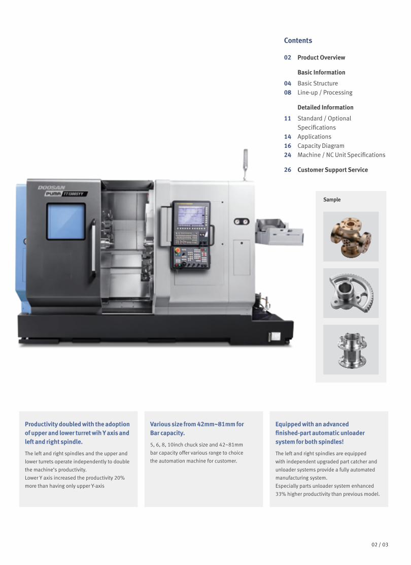
A cutting program is automatically created with the entered values.
Example programming
Cutting shape
Automatic creation of cutting program
O7000 (SAMPLE PROGRAM) ;∤∤∤M3 S1500 ;G0 X50. Y125. ;G0 Z30. ;G1040 T0.5 J3. H0.2 K0.5 ∤∤∤ ;G1020 H120. V50. U37. W68. ∤∤∤ ;G0 Z80. ;M5 ;
Enter the dimensions of the shape.
EZ-Guide i screen
Parts unloader maintenance and service screen
Convenience of Maintenance and Service
The condition and service procedures of the sensors are provided for easy maintenance and servicing of major units.
Tool monitoring screen
Tool Load Monitoring Function
During cutting operation, abnormal load caused by wear or damage of the tool is detected and an alarm is triggered to prevent further damage.
EZ-Guide i
Using the DOOSAN EZ-Guide i, users can create a cutting program for any desired shape, including patterns, by entering figures only.
Easy Operation Package
Doosan's Easy Operation Package (EOP) supports the user with functions relating to tool data, error diagnostics, set up and machine monitoring.
15 14 /

Spindle speed : r/min
PUMA TT2100SYY PUMA TT2100SYYB
PUMA TT1300SY/SYY PUMA TT1300SYYB
223 (164.6)
134 (98.9)165 (121.8)
S3 25%S2 10min, S3 60%S1 Cont.
S3 25%S2 30min, S3 60%
S1 Cont.
1071500 3214 50004286
100
200
350
10
50
18.6 (24.9) 15 (20.1) 11(14.8) 10 (13.4)
35 (46.9)
20 (26.8)
5
1
400
100 10
40
5
1
200
10500
50
861 35003444
21.6 (29.0) 22(29.5) 20 (26.8) 18 (24.1) 18.5 (24.8)
S2 30min S3 60%S1 Cont.205 (151.3) S1 Cont.
244 (180.1) S2 30min, S3 60%
8.7 (11.7) 9 (12.1)
6.2 (8.3)
15 (20.1)
11 (14.8)
7.5 (10.1)
100
50
50 1
5
10
1234 600037014934
116 (85.6)
85 (62.7)
58 (42.8)
S3 15%
S2 30min, S3 60%
S1 Cont.
S3 15%
S2 30min, S3 60%
S1 Cont.
100
10 1500 1000
5
10
1125 3376 6000
S3 25%
S3 60%, S2 30min
S1 Cont.
93 (68.6) 64 (47.2)
47 (34.7)
S3 25%
S3 60%, S2 30min
S1 Cont.
7.5 (10.1)
11 (14.8)
5.5 (7.4) O
utpu
t : k
W (H
p)
Torq
ue :
N. m
(ft-l
bs)
Spindle speed : r/min
Out
put :
kW
(Hp)
Torq
ue :
N. m
(ft-l
bs)
Spindle speed : r/min
Out
put :
kW
(Hp)
Torq
ue :
N. m
(ft-l
bs)
Spindle speed : r/min
Out
put :
kW
(Hp)
Torq
ue :
N. m
(ft-l
bs)
Spindle speed : r/min
Spindle Power-Torque Diagram
Rotary tool
Product Overview
Basic Information
Basic Structure
Line-up /
Processing
Detailed Information
Options
Applications
Capacity Diagram
Specifications
Customer SupportService
PUMA TT1300SY/SYY : 6000 r/min PUMA TT1300SY/SYY : 10000 r/min
PUMA TT2100SYY
Spindle speed : r/min Spindle speed : r/min
23.5 (17.3) 3.7 (5.0) 3.7 (5.0)
2.2 (3.0)
1.0
0.10.1 11
1.00.9 (1.2) 1.1 (1.5) 1.1 (1.5)
7 (5.2)
23.5 (17.3)
7 (5.2)
S2 10minS3 25%
S2 10minS3 25%
S2 10minS3 25%
Cont.
S2 10minS3 25%
Cont.
Cont.Cont.10
100
10
100 10
15001500 6000 8000 10000*100
23.5 (17.3) 3.7 (5.0) 3.7 (5.0)
2.2 (3.0)
1.0
0.10.1 11
1.00.9 (1.2) 1.1 (1.5) 1.1 (1.5)
7 (5.2)
23.5 (17.3)
7 (5.2)
S2 10minS3 25%
S2 10minS3 25%
S2 10minS3 25%
Cont.
S2 10minS3 25%
Cont.
Cont.Cont.10
100
10
100 10
15001500 6000 8000 10000*100
47.7 (35.2) 50 (36.9) 7.5 (10.1)
5 (6.7)
1.5 (2.0) 16.9 (12.5) 14.3 (10.6)
2.9 (2.1)
5min
S1 Cont.
5min
S1 Cont.
1001
110
10100
8501500 5000
Out
put :
kW
(Hp)
Out
put :
kW
(Hp)
Torq
ue :
N. m
(ft-l
bs)
Out
put :
kW
(Hp)
Torq
ue :
N. m
(ft-l
bs)
Torq
ue :
N. m
(ft-l
bs)
*Special milling holder are required
PUMA TT2100SYY PUMA TT1300SY/SYY
16 /
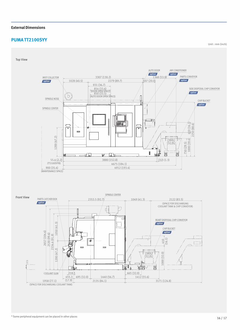
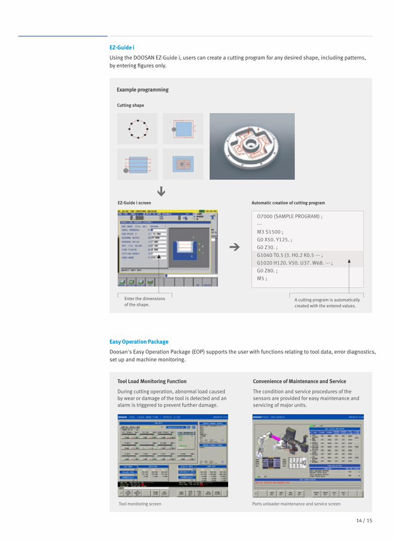
External Dimensions
PUMA TT2100SYY
* Some peripheral equipment can be placed in other places
Unit : mm (inch)
Top View
Front View
3307 (130.2)
3880 (152.8) 55.4 (2.2)
1200
(47.
2) 22
50 (8
8.6)
41
0 (1
6.1)
10
00 (3
9.4)
410
(16.
1)
1000
(32.
0)
2657
(104
.6)
2530
(99.
6)
2334
.6 (9
1.9)
1050
(41.
3)
1200
(47.
2)
750
(29.
5)
4675 (184.1)
2353.5 (92.7)
1958 (77.1) 2135 (84.1) 3171 (124.8) 1440 (56.7) 1412 (55.6)
665 (32.0) 695 (32.0) 455.3
(17.9)
218.5
1049 (41.3) 2122 (83.5)
4912 (193.4) 900 (35.4)
(32) (1.3)
(380L) (32.0L)
(380L) (32.0L)
931 (36.7) 854 (33.6)
850 (33.5)
MIST COLLECTOR
PARTS CATCHER BOX
SPINDLE NOSE
(DOOR OPEN SPACE)
(AUTO DOOR OPEN SPACE)
AUTO DOOR AIR CONDITIONER
PARTS CONVEYOR
SIDE DISPOSAL CHIP CONVEYOR
REART DISPOSAL CHIP CONVEYOR
(SPACE FOR DISCHARGING COOLANT TANK & CHIP CONVEYOR)
COOLANT GUN
(SPACE FOR DISCHARGING COOLANT TANK)
CHIP BUCKET
CHIP BUCKET
SPINDLE CENTER
SPINDLE CENTER
(TT2100SYYB)
(MAINTENANCE SPACE)
1368 (53.9) 1028 (40.5) 2279 (89.7) 507 (20.0)
17 16 /

External Dimensions
PUMA TT1300SY/SYY
* Some peripheral equipment can be placed in other places
Unit : mm (inch)
Top View
Front View
2901 (114.2)
3405 (134.1) 78 (3.1)
1160
(45.
7)
2070
(81.
5)
410
(16.
1)
1000
(39.
4)
750
(29.
5)
4292 (169.0) 4527 (178.2) 900 (35.4)
(27) (1.1)
(380L)(15.0L)
731 (28.8) 655 (25.8)
650 (25.6)
MIST COLLECTOR
SPINDLE NOSE
(DOOR OPEN SPACE)
(AUTO DOOR OPEN SPACE)
AUTO DOOR AIR CONDITIONER
PARTS CONVEYOR
SIDE DISPOSAL CHIP CONVEYOR
CHIP BUCKET
SPINDLE CENTER
(TT1300SYYB)
(MAINTENANCE SPACE)
1391 (54.8) 943 (37.1) 1958 (77.1) 512
(20.2)
410
(16.
1)
1036
(40.
8)
2477
(97.
5)
2379
(93.
7)
2183
.6 (8
6.0)
910
(35.
8)
1160
(45.
7)
2293.5 (90.3)
1753 (69.0) 3350 (131.9) 2105(82.9) 1535 (60.4) 342.9 (13.5) 695 (27.4)
188.5 (7.4) 792 (31.2) 1410 (55.5)
1240 (48.8) 2110 (83.1)
(380L)(15.0L)
PARTS CATCHER BOX
REART DISPOSAL CHIP CONVEYOR
(SPACE FOR DISCHARGING COOLANT TANK & CHIP CONVEYOR)
(SPACE FOR DISCHARGING COOLANT TANK)
CHIP BUCKET
SPINDLE CENTER
Product Overview
Basic Information
Basic Structure
Line-up /
Processing
Detailed Information
Options
Applications
Capacity Diagram
Specifications
Customer SupportService
PUMA TT2100SYY PUMA TT1300SY/SYY
18 /

PUMA TT2100SYYUnit : mm (inch)
(5)
(1)
(1)
(7)
(2)
(2)
(2)
(2)
(2)
(1)(2)
(2)(1)
(1)
(1)
(2)
UPPER TURRETBMT 55P
TURNING TOOL
OD, FACE, CUT-OFF
SINGLE OD TOOL HOLDER
DOUBLE OD TOOL HOLDER
(BOTH SIDE)
DOUBLE OD TOOL HOLDER
FACE TOOL HOLDER
CUT-OFF TOOL HOLDER
SINGLE ID TOOL HOLDER
TRIPLE ID TOOL HOLDER
OD/ID TOOL HOLDER
ID HOLDER
OD/ID HOLDER
ROTARY TOOL
PLUG
LOWER TURRETBMT 55P
STRAIGHT MILLING HEAD FOR SIDE CUTTING
HOLDER COVERFOR U-DRILL
ø10 x H25 ø12 x H25ø16 x H25 ø20 x H25
ø10 x H25 ø12 x H25ø16 x H25 ø20 x H25
BORING BAR SLEEVES
BORING BAR SLEEVES
ANGULAR MILLING HEADFOR FACE CUTTING
DUMMY PLUG
CUTTING TOOL
BORING BAR SLEEVES
BORING BAR
U-DRILL
DRILL
LIVE CENTER(MT#3)
U-DRILL SLEEVES
OD TOOL
COLLET CHUCK
MILLING ARBOR ADAPTER
MILLING COLLET (ER25)
(ø3 ~ø16)
WELDON ADAPTER(ID16)
ø10 - H32ø16 - H32ø25 - H32
ø20 - H32ø25 - H32
DRILL SOCKETMT NO.1MT NO.2MT NO.3
ø12 - H32ø20 - H32
OD TOOL( 20)
( 20)
( 20)
Tooling System
Standard
19 18 /

Tooling System
PUMA TT1300SY/SYYUnit : mm (inch)
Product Overview
Basic Information
Basic Structure
Line-up /
Processing
Detailed Information
Options
Applications
Capacity Diagram
Specifications
Customer SupportService
PUMA TT2100SYY PUMA TT1300SY/SYY
20 /
(5)
(1)
(1)
(7)
(2)
(2)
(2) (2)
(2)(1)
(1)
(1)
(2)
UPPER TURRETBMT 45P
OD HOLDER
SINGLE OD TOOL HOLDER
DOUBLE OD TOOL HOLDER
(BOTH SIDE)
DOUBLE OD TOOL HOLDER
FACE TOOL HOLDER
CUT-OFF TOOL HOLDER
SINGLE ID TOOL HOLDER
LIVE CENTERHOLDER
ID HOLDER
ROTARY TOOL
PLUG
LOWER TURRETBMT 45P
STRAIGHT MILLING HEAD FOR SIDE CUTTING
HOLDER COVERFOR U-DRILL
ANGULAR MILLING HEADFOR FACE CUTTING
DUMMY PLUG
CUTTING TOOL
BORING BAR
U-DRILL
DRILL
LIVE CENTER(MT#3)
U-DRILL SLEEVES
COLLET CHUCK
MILLING ARBOR ADAPTER
WELDON ADAPTER(ID12)
MT NO.1MT NO.2
ø10 - H25 ø12 - H25
OD TOOL( 20)
( 20)
(2)
DOUBLE ID TOOL HOLDER (2)
DRILL SOCKET
BORING BAR SLEEVES
ø16 - H25 ø20 - H25
ø10 - H25 ø12 - H25ø16 - H25 ø20 - H25
LIVE CENTER HOLDER
DRILL SOCKET
MILLING COLLET (ER25)
(ø2 ~ø13)
Standard

Tool Interference Diagram
PUMA TT2100SYY
PUMA TT1300SY/SYY
Unit : mm (inch)
Unit : mm (inch)
Double OD Tool HolderTriple ID Tool Holder
Double OD Tool Holder(B)
ø25(Boring Bar Dia.)(ø1.0)
ø230(Max. turning Dia.) (ø9.3)
ø583(Max. Swing Dia.)(ø23.0)
Max. 16 (0.6)
57(2.2)
68(2.7)
ø32(Boring Bar Dia.) (ø1.3)
165 (6.5) 165 (6.5) (X1-axis Travel)
103(4.1)
141(5.6)
60(2.4)
24 (0.9)
141 (5.6) 165 (6.5)
(X2-axis Travel)103 (4.1) 165 (6.5)
30(1.2)
73(2.9) 24(0.9)
ø110 (ø4.3)
ø95 (
3.7)
ø100 (3.9)
ø110(ø4.3) ø110(ø4.3)
ø195(ø7.7)
ø165(ø6.5)
85 (3.3) 165 (6.5)
ø175 (ø6.9)
ø235
(ø9.3
) ø235 (ø9.3)
(0.8)
(0.8)
(0.8)
165 (6.5)
73(2.9)
30
(1.2) 73
(2.9
) 30
(1.2
)
100 (3.9)
65 (2.6)
Max.ø16 (ø0.6) 68 (2.7
) 57 (2.2
)
291
(11.
5)
291
(11.
5)
50 (2.0
) 6
(0.2
)
348
(13.
7)
165
(6.5
) 10
0 (3
.9)
50 (2.0
) 41 (1.6
)
383
(15.
1)
ø583 (Max.Swing Dia)(ø23.0)
Upper turret Lower turret
Double ID Tool Holder
Double OD Tool Holder(B)
ø25(Boring Bar Dia.)(ø1.0)
ø175(Max. turning Dia.)(ø6.9)
ø502 (Max.Swing Dia)(ø19.8)
Max.ø13 (ø0.5)
50(2.0)
50(2.0)
ø25(Boring Bar Dia.)(ø1.0)
150 (2.4) 90(3.5)
135 (X1-axis Travel)105 (60.0)
40(1.6)
30 (1.2)
105 (4.1) 135 (X2-axis Travel)(5.3)
90 (3.5) 150 (5.9)
30 (1.2) 30 (1.2) 60 (2.4)
ø96 (ø3.8) ø82
(ø3.2)
ø98 (ø3.9) ø88 (ø3.5) ø88 (ø3.5)
ø170 (ø6.7)
ø198 (ø7.8)
150 (5.9)
65 (2.6)
ø212
(ø8.3
)
ø146
(ø5.7)
ø212 (ø8.3) 150 (5.9)
30
(1.2)
65
(2.6)
75 (3.0)
50 (2.0
) 50 (2.0
)
251
(9.9
)
251
(9.9
) 40 (1.6
) 34 (1.3
) 32
5 (1
2.8)
15
0 (5
.9)
75 (3
.0)
40 (1.6
) 76
(3
.0)
367
(14.
4)
ø502 (Max.Swing Dia)(ø19.8) Max.ø13 (ø0.5)
Double OD Tool Holder*
(0.8)
(0.8)
(0.8)
Upper turret Lower turret
21 20 /

Working Range DiagramProduct Overview
Basic Information
Basic Structure
Line-up /
Processing
Detailed Information
Options
Applications
Capacity Diagram
Specifications
Customer SupportService
PUMA TT2100SYYUnit : mm (inch)
980 (38.6) (Distance between spindle nose)
700 (27.6) (Z1-axis stroke)
730 (28.7) (A-axis Travel)
43(1.7)
113(4.4)
700 (27.6) (Z2-axis stroke)16
5 (6
.5) (
X2-a
xis s
troke
)
165(
X1-a
xis s
troke
)24
(0.9
)
ø210
(8.3
)
141
(5.6
) 10
3 (4
.1)
141(
5.6)
24
(0.9
)
205(8.1)
75 (3.0)
75 (3.0)
103 (4.1)
8inch Chuck(PUMA TT2100SYY)
8inch Chuck(PUMA TT2100SYY/SYYB)
10inch Chuck(PUMA TT2100SYB)
39(1.5)
205 (8.1) 980 (38.6) (Distance between spindle nose)
700 (27.6) (Z1-axis stroke)
730 (28.7) (A-axis Travel)
43(1.7)
113(4.4)
700 (27.6) (Z2-axis stroke)
165
(6.5
) (X2
-axi
s stro
ke)
165(
X1-a
xis s
troke
)24
(0.9
)
ø21
0 (8
.3)
141(
5.6)
141(
5.6)
24
(0.9
)
130(5.1)
75 (3.0)
75 (3.0)
75 (3.0)
75 (3.0)
103 (4.1)
8inch Chuck
10inch Chuck
39(1.5)
130(5.1)
980 (38.6) (Distance between spindle nose)700 (27.6) (Z1-axis stroke)
730 (28.7) (A-axis Travel)
43(1.7)
113(4.4)
700 (27.6) (Z2-axis stroke)
165
(6.5
) (X2
-axi
s stro
ke)
165(
X1-a
xis s
troke
)21 ø2
10 (8
.3)
141
(5.6
) 10
0(3
.9)
141(
5.6)
24
(0.9
)
120 (4.7) 80(3.1)
80 (3.1)
80(3.1)
80(3.1)
103 (4.1)
8inch Chuck
Max. 120 (4.7) Max. 120 (4.7)
Max. 90 (3.5) 10inch Chuck
39(1.5)
120(4.7)
980 (38.6) (Distance between spindle nose)
700 (27.6) (Z1-axis stroke)
730 (28.7) (A-axis Travel)
43(1.7)
113(4.4)
700 (27.6) (Z2-axis stroke)
Spindle Center
165 (6.5) (X1-axis Travel) 165 (6.5) (X2-axis Travel)
165
(6.5
) (X2
-axi
s stro
ke)
165(
X1-a
xis s
troke
)
100
(3.9
) (Y1
-axi
s tra
vel)
100
(3.9
) (Y2
-axi
s tra
vel)
50 (2
.0) 5
0 (2
.0)
50 (2
.0) 5
0 (2
.0)
50 (2
.0) 5
0 (2
.0)
50 (2
.0) 5
0 (2
.0)
6 (0
.2)
ø210
(8.3
)
159
(6.3
) 85
(3.3
)
159
(6.3
) 85
(3.3
) 6
(0.2
)
160 (6.3)
215 (8.5) 215 (8.5)
115(4.5)
22 (0.9) 22
(0.9) 115 (4.5)
Spindle Center
100
(3.9
) (Y1
-axi
s tra
vel)
100
(3.9
) (Y2
-axi
s tra
vel)
215 (8.5)
215 (8.5) 6 (0.2) 159 (6.3)
6 (0.2) 159 (6.3)
109 (4.3) 109 (4.3)
60 (2.4) 60 (2.4)
60(2.4)
160(6.3)
103 (4.1)
8inch Chuck
10inch Chuck
39(1.5)
80 (3.1)
60 (2.4)
980 (38.6) (Distance between spindle nose)
700 (27.6) (Z1-axis stroke)
730 (28.7) (A-axis Travel)
43(1.7)
113(4.4)
700 (27.6) (Z2-axis stroke)
165
(6.5
) (X2
-axi
s stro
ke)
165(
X1-a
xis s
troke
)22
(0.9
)
ø210
(8.3
)
22 (0
.9)
140(5.5)
140(5.5)
140(5.5)
140(5.5)
103 (4.1)
8inch Chuck
Max. ø16(ø0.6)
Max
. 68
(2.7
)
10inch Chuck
39(1.5)
Single OD Tool holder
ID Tool holder
Straight milling head
Double OD Tool holder
Angular milling head
Y-axis Travel distance
Straight milling head
Angular milling head
Upper turret
Upper turret
Lower turret
Lower turret
PUMA TT2100SYY PUMA TT1300SY/SYY
22 /

530 (20.9) (Z1-axis stroke) 530 (20.9) (Z1-axis stroke)
5inch Chuck(PUMA TT1300SYY/SYYB)
5inch Chuck(PUMA TT1300SYY)
6inch Chuck(PUMA TT2100SYY/SYYB)
6inch Chuck
6inch Chuck 6inch Chuck
6inch Chuck
5inch Chuck
5inch Chuck
5inch Chuck
5inch Chuck
6inch Chuck(PUMA TT1300SYY A=165 (6.5) ,PUMA TT1300SYYB A=170(6.7))
47(1.9)
59 (2.3)
59 (2.3) 43 (1.7)
47(1.9)
173 (6.8)
173 (6.8)
47(1.9)
47(1.9)
91(3.6)
26(1.0)
91(3.6)
26(1.0)
91(3.6)
26(1.0)
91(3.6)
26(1.0)
91(3.6)
32.5(1.3)
91(3.6)
32.5(1.3)
91(3.6)
32.5(1.3)
91(3.6)
91(3.6)
26(1.0)
32.5(1.3)
91(3.6)
32.5(1.3)
161 (6.3)
106 (4.2) 114 (4.5)
114 (4.5)
106 (4.2)
161 (6.3) 177 (7.0)
177 (7.0)
175 (6.9)
95 (3.7)
90 (3.5) 90 (3.5)
95 (3.7) 9 (0.4)
9 (0.4)
175 (6.9)
175 (6.9)
175 (6.9)
130 (5.1) 130 (5.1)
5 (0.2) 5 (0.2)
43 (1.7)
173 (6.8)
173 (6.8)
750 (29.5)(Distance between spindle nose)
530 (20.9) (Z1-axis stroke)
750 (29.5)(Distance between spindle nose)
530 (20.9) (Z1-axis stroke)
750 (29.5)(Distance between spindle nose)
750 (29.5)(Distance between spindle nose)
530 (20.9) (Z1-axis stroke)
750 (29.5)(Distance between spindle nose)
135
(5.3
) (X1
-axi
s st
roke
)
135
(5.3
) (X1
-axi
s st
roke
)
135
(5.3
) (X1
-axi
s st
roke
)
135
(5.3
) (X1
-axis
stro
ke)
135
(5.3
) (X1
-axi
s st
roke
)
135
(5.3
) (X2
-axi
s st
roke
)
ø135
(ø5.
3)
ø135
(ø5.
3)
ø135
(ø5.
3)
ø135
(ø5.
3)
ø135
(ø5.
3)
15 (0
.6)
50 (2
.0)
10 (0
.4)
10 (0
.4)
120
(4.7
) 75
(3.0
)
øA
40 (1
.6)
40 (1
.6)
95 (3.7
)
95 (3
.7)
95 (3
.7) 4
0 (1
.6)
135
(5.3
) (X2
-axi
s st
roke
)
135
(5.3
) (X
2-ax
is s
troke
)13
5 (5
.3) (
X2-a
xis
stro
ke)
135
(5.3
) (X2
-axi
s st
roke
)
95 (3
.7)
120
(4.7
) 15
(0.6
)
130
(5.1
)
130
(5.1
)
65 (2
.6)
40 (1
.6)
40 (1
.6)
40 (1
.6) 4
0 (1
.6)
40 (1
.6) 4
0 (1
.6)
40 (1
.6) 4
0 (1
.6)
65 (2
.6)
5 (0
.2)
5 (0
.2)
40 (1
.6) 10
0 (3
.9)
540 (21.3) (A-axis travel)
540 (21.3) (A-axis travel)
530 (20.9) (Z2-axis stroke)
540 (21.3) (A-axis travel)
530 (20.9) (Z2-axis stroke)
540 (21.3) (A-axis travel)
530 (20.9) (Z2-axis stroke)
530 (20.9) (Z2-axis stroke)
540 (21.3) (A-axis travel)
530 (20.9) (Z2-axis stroke)
Max. ø13
Max
. 49
(1.9
)
Spindle Center
Spindle Center
80 (3
.1) (
Y1-a
xis t
rave
l)80
(3.1
) (Y1
-axi
s tra
vel)
135 (5.3) (X1-axis Travel) 135 (5.3) (X2-axis Travel)
80 (3
.1) (
Y2-a
xis t
rave
l)80
(3.1
) (Y2
-axi
s tra
vel)
(ø0.5)
Single OD Tool holder
ID Tool holder
Straight milling head
Double OD Tool holder
Angular milling head
Y-axis Travel distance
Straight milling head
Angular milling head
Upper turret
Upper turret
Lower turret
Lower turret
PUMA TT1300SY/SYY
23 22 /

Machine SpecificationsUnit : mm (inch)
PUMA TT2100SYY PUMA TT1300SY/SYY
24 /
Product Overview
Basic Information
Basic Structure
Line-up /
Processing
Detailed Information
Options
Applications
Capacity Diagram
Specifications
Customer SupportService
Description UnitPUMA
TT2100SYYPUMA
TT2100SYYBPUMA
TT1300SY/SYYPUMA
TT1300SYB/SYYB
Capacity Swing over bed mm (inch) 230 (9.1) 175 (6.9)
Swing over saddle mm (inch) 230 (9.1) 175(6.9)
Recom. Turning diameter mm (inch) 210 (8.3) 135 (5.3) 170 (6.7)
Max. Turning diameter mm (inch) Upper turret : 230 (9.1) / Lower turret :230 (9.1)
Upper turret : 175 (6.9) / Lower turret :175 (6.9)
Max. Turning length mm (inch) 230 (9.1) 120 (4.7)
Chuck size(Left spindle) inch 8 / 8 10 / 8 5 / 5 6 / 5
Bar working diameter mm (inch) 65 / 65 (2.6 / 2.6) 81 / 65 (3.2 / 2.6) 42 / 42 (1.7 / 1.7) 51 / 42 ( 2.0 / 1.7)
Travel
Travel distance
X1/X2-axis mm (inch) 165 (6.5) 135 / 135 (5.3/5.3) (PUMA TT1300SYY)135 / 150 (5.3/5.9) (PUMA TT1300SY)
Z1/X2-axis mm (inch) 700 (27.6) 530 (20.9)
Y-axis mm (inch) 100(±50) (3.9(±2.0)) 80(±40) (3.1(±1.6))
A-axis mm (inch) 730 (28.7) 540 (21.3)
Feedrates
Rapid Traverse Rate
X1/X2-axis m/min(ipm) 30 (1181.1) 30 (1181.1)
Z1/X2-axis m/min(ipm) 40 (1574.8) 40 (1574.8)
Y-axis m/min(ipm) 15 (590.6) 15 (590.6)
A-axis m/min(ipm) 40 (1574.8) 40 (1574.8)
Left spindle Max. Spindle speed r/min 5000 3500 6000
Max. Spindle power kW (Hp)
25 / 18.5 / 15(44.9 / 24.8/ 20.1)
(S3 25% / S3 60% /Cont.)
22 / 18.5(44.9 / 24.8)
(S3 60% / Cont.)
11 / 7.5 / 5.5(14.8 / 10.1 / 7.4)
(S3 25%/ S3 60% / Cont)
15 / 11 / 7.5(20.1 / 14.8 / 10.1)
(S3 25%/ S3 60%/ Cont)
Max. Spindle torque N·m(ft-lbs) 223 (164.6) 244 (180.1) 93 (68.6) 116 (85.6)
Spindle nose ASA A2 #6 A2 #8 A2 #5
Spindle bearing diameter (Front) mm (inch) 110 (4.3) 130 (5.1) 80 (3.1) 90 (3.5)
Spindle through hole mm (inch) 76 (3.0) 91 (3.6) 53 (2.1) 61 (2.4)
Min. spindle Indexing angle(C-axis) deg 0.001 0.001
Right spindle
Max. Spindle speed r/min 5000 6000
Max. Spindle power kW (Hp) 25 / 18.5 / 15 (44.9 / 24.8 / 20.1) (S3 25% / S3 60% / Cont.)
11 / 7.5 / 5.5 (14.8 / 10.1 / 7.4) (S3 25% / S3 60% / Cont)
Max. Spindle torque N·m(ft-lbs) 223 (164.6) 93 (68.6)
Spindle nose ASA A2 #6 A2 #5
Spindle bearing diameter (Front) mm (inch) 110 (4.3) 80 (3.1)
Spindle through hole mm (inch) 76 (3.0) 53 (2.1)
Min. spindle Indexing angle(C-axis) deg 0.001 0.001
Turret No. of tool stations (Upper+Lower) ea 24 +24 position 24 +24 position
Holder mount type - BMT55P BMT45P
OD tool size mm (inch) 20 x 20 (0.8 x 0.8) 20 x 20 (0.8 x 0.8)
Max. boring bar size (Main/Sub) mm (inch) Ø32 (Ø1.3) Ø25 (Ø1.0)
Turret Indexing time (1 station swivel) s 0.12 0.12
Max. Rotary tool speed r/min 5000 6000
Max. Rotary tool speed power kW (Hp) 7.5 / 1.1 (10.1 / 1.5)
(S2 5min / Cont)3.7 / 1.1 (5.0 / 1.5)
(S3 25% / Cont)
Max. Rotary tool speed torque
N·m(ft-lbs) 47.7 (35.2) 17.5 (12.9)
Power source
Electric power supply(rated capacity) kVA 75.21 36.54
Machine Dimensions
Length mm (inch) 3880 (152.8) 3405 (134.1) 3510 (138.2)
Width mm (inch) 2360 (92.9) 2300 (90.6)
Height mm (inch) 2250 (88.6) 2070 (81.5)
Weight kg (lb) 10000 (22045.9) 8000 (17636.7) 8100 (17857.2)
CNC NC system DOOSAN Fanuc i Plus {Fanuc 31i}*
PUMA TT2100SYY PUMA TT1300SY/SYY
* { } : option

● Standard ◦ Optional X Not applicable
NC Unit Specifications
FANUC NO Division Item Spec.SY/SYY
DOOSAN Fanuc i Plus Fanuc 31i
1
Controlled axis
Synchronous/Composite control (C1 & C2 Synchro Control)
● ●
2 Torque control Included in axis control by PMC ● ●
3 Increment system A,B0.001 mm, 0.001 deg, 0.0001 inch
● ●
4 Inch/metric conversion ● ●
5 Stored limit check before move ● ◦
6 Chamfering on/off ● ●
7 Unexpected disturbance torque detection function
● ●
8 Position switch ● ●
9
Operation
DNC operation Included in RS232C interface. ● ●
10 DNC operation with memory card ● ●
11 Tool retract and recover ◦ ◦
12 Wrong operation prevention ● ●
13 Manual handle feed 1-unit 1 unit ● ●
14 Handle interruption ◦ ◦
15 Manual handle retrace ◦ ◦
16
Interpolation functions
Nano interpolation ● ●
17 Linear interpolation ● ●
18 Cylindrical interpolation ● ●
19 Helical interpolation ● ●
20 Thread cutting, synchronous cutting ● ●
21 Multi threading ● ●
22 Thread cutting retract ● ●
23 Variable lead thread cutting ● ◦
24 Circular thread cutting ◦ ◦
25 Polygon machining with two spindles ● ●
26 High-speed skip Input signal is 8 points. ◦ ◦
27 2nd reference position return G30 ● ●
28 3rd/4th reference position return ● ●
29 Balanced cuttingOnly for more than 2 path control
● ●
30
Feed function
Rapid traverse overrideF0, 25, 100%(SWIS TURN F0,1,5,25,100%)
● ●
31 Override cancel ● ●
32 AI contour control I G5.1 Q0/Q1_, 40 Blocks ● ●
33 AI contour control II G5.1 Q0/Q1_, 200 Blocks ◦ ◦
34
Program input
Optional block skip 9 pieces ● ◦
35 Absolute/incremental programming Combined use in the same block ● ●
36 Automatic coordinate system setting ● ●
37 Workpiece coordinate system G52 - G59 ● ●
38 Chamfering/Corner R ● ◦
39 Custom macro ● ●
40 Addition of custom macro common variables
#100 - #199, #500 - #999 ● ●
41 Custom macro common variables between each path
Only for more than 2 path control. Included in Custom macro.
● ●
42 Canned cycle ● ●
43 Multiple repetitive cycles G70~G76 ● ●
44 Multiple repetitive cycles II Pocket profile ● ●
45 Direct input of coordinate system shift ● ●
46 Real time custom macro ◦ ◦
47 Pattern data input ● ◦
48
Others
Machine alarm diagnosis ● X49 CNC screen display ● ●
50Part program storage size & Number of registerable programs
1280M (512KB)_1000 programs X ●
51 5120M (2MB)_1000 programs ● ◦
525120M (2MB)/10240M (4MB)/20480M (8MB)_4000 Programs
X ◦
53 Fast Ethernet ◦ ◦
54Display unit
15" color LCD ● ●
55 15" color LCD with Touch Panel ◦ X56 Robot interface with PMC I/O module ◦ ◦
57 Robot interface with PROFIBUS-DP ◦ ◦
25 24 /

Doosan Machine Tools’ Global Network, Responding to Customer’s Needs nearby, Anytime, Anywhere
Doosan machine tools provides a system-based professional support service before
and after the machine tool sale by responding quickly and efficiently to customers’ demands.
By supplying spare parts, product training, field service and technical support, we can provide top class support
to our customers around the world.
Responding to Customers Anytime, Anywhere
Global Sales and Service Support Network
4
Corporations
167
Dealer Networks
51
Technical CentersTechnical Center: Sales Support, Service Support, Parts Support
200
Service Post
3
Factories
Changwon FactoryHead Office
AMERICA EUROPE
CHINA (Yantai)
CHINA (Shanghai)
INDIA
Product Overview
Basic Information
Basic Structure
Line-up /
Processing
Detailed Information
Options
Applications
Capacity Diagram
Specifications
Customer SupportService
PUMA TT2100SYY PUMA TT1300SY/SYY

Doosan Machine ToolsCustomer Support ServiceWe help customers to achieve success by providing a variety of professional services from pre-sales consultancy to post-sales support.
Technical Support Supports machining methods and technology Responds to technical queries Provides technical consultancy
Training Programming / machine setup and operation Electrical and mechanical maintenance
Applications engineering
Supplying Parts Supplying a wide range of original Doosan spare parts Parts repair service
Field Services On site service Machine installation and testing Scheduled preventive maintenance Machine repair
2726 /
Rotary tool
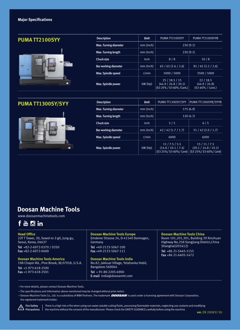
Major Specifications
PUMA TT2100SYY Description Unit PUMA TT2100SYY PUMA TT2100SYYB
Max. Turning diameter mm (inch) 230 (9.1)
Max. Turning length mm (inch) 230 (9.1)
Chuck size inch 8 / 8 10 / 8
Bar working diameter mm (inch) 65 / 65 (2.6 / 2.6) 81 / 65 (3.2 / 2.6)
Max. Spindle speed r/min 5000 / 5000 3500 / 5000
Max. Spindle power kW (Hp)25 / 18.5 / 15
(44.9 / 24.8 / 20.1) (S3 25% / S3 60% /Cont.)
22 / 18.5(44.9 / 24.8)
(S3 60% / Cont.)
ver. EN 200831 SU
Head Office22F T Tower, 30, Sowol-ro 2-gil, Jung-gu,Seoul, Korea, 04637
Tel +82-2-6972-0370 / 0350Fax +82-2-6972-0400
Doosan Machine Tools America19A Chapin Rd., Pine Brook, NJ 07058, U.S.A.
Tel +1-973-618-2500 Fax +1-973-618-2501
Doosan Machine Tools EuropeEmdener Strasse 24, D-41540 Dormagen, Germany
Tel +49-2133-5067-100 Fax +49-2133-5067-111
Doosan Machine Tools IndiaNo.82, Jakkuar Village, Yelahanka Hobil, Bangalore-560064
Tel + 91-80-2205-6900 E-mail [email protected]
Doosan Machine Tools ChinaRoom 101,201,301, Building 39 Xinzhuan Highway No.258 Songjiang District,China Shanghai(201612)
Tel +86 21-5445-1155Fax +86 21-6405-1472
*For more details, please contact Doosan Machine Tools.
*The specifications and information above-mentioned may be changed without prior notice.* Doosan Machine Tools Co., Ltd. is a subsidiary of MBK Partners. The trademark is used under a licensing agreement with Doosan Corporation,
the registered trademark holder.
There is a high risk or fire when using non-water-soluble cutting fluids, processing flammable materials, neglecting use coolants and modifying the machine without the consent of the manufacturer. Please check the SAFETY GUIDANCE carefully before using the machine.
Fire Safety Precautions
www.doosanmachinetools.com
PUMA TT1300SY/SYY Description Unit PUMA TT1300SY/SYY PUMA TT1300SYB/SYYB
Max. Turning diameter mm (inch) 175 (6.9)
Max. Turning length mm (inch) 120 (4.7)
Chuck size inch 5 / 5 6 / 5
Bar working diameter mm (inch) 42 / 42 (1.7 / 1.7) 51 / 42 (2.0 / 1.7)
Max. Spindle speed r/min 6000 6000
Max. Spindle power kW (Hp)11 / 7.5 / 5.5
(14.8 / 10.1 / 7.4) (S3 25%/ S3 60%/ Cont)
15 / 11 / 7.5(20.1 / 14.8 / 10.1)
(S3 25%/ S3 60%/ Cont)

PUMA TT1800 seriesPUMA TT1800MS PUMA TT1800SY
PUMA TT1800 seriesHorizontal Multi turret Turning Center

Product Overview
Basic Information
Basic Structure
Line-up /
Processing
Detailed
Information
Options
Applications
Capacity Diagram
Specifications
Customer Support
Service
PUMA TT1800 series
02 /
PUMA TT1800 seriesThe Puma 1800 Series is a 65mm (2.6 inch) bar capacity high productivity horizontal turning center equipped with twin opposed spindles and upper / lower turrets. The left and right spindles can process work pieces independently to achieve excellent productivity. The work pieces processed by the left and right spindles are discharged via an automatic system. The PUMA TT Series has become one of DOOSAN’s bestselling products and is favored by customers all around the world.

Contents
02 Product Overview
Basic Information
04 Basic Structure08 Line-up / Processing
Detailed Information
11 Standard / Optional Specifications
14 Applications17 Capacity Diagram22 Machine / NC Unit Specifications
26 Customer Support Service
03 02 /
Sample
Productivity doubled with the adoption of a right spindle and a lower turret!
The left and right spindles and the upper and
lower turrets operate independently to double
the machine’s productivity.
Excellent rigidity and power implemented with axis travel system optimization technology!
The product’s rapid traverse rate of 40 m/min
and High rigidity roller LM guide ways are
designed to meet the required characteristics of
machines whose users require a very high level of
productivity.
Equipped with an advanced finished-part removal system for both spindles!
The left and right spindles are equipped
with independent part catcher and unloader
systems to provide a fully automated
manufacturing system.

With the adoption of two opposing spindles and upper / lower turrets, the Puma TT Series can cut both first and second operations simultaneously. Furthermore, the axis travel system, which is designed with high rigidity roller guide ways and fast federate of 40m/min, provides a high level of thermal stability.
One machine, Two Processes
Designed as a wide-rib torque-tube structure to prevent twisting and deformation.
Two opposing spindles and upper and lower turrets installed on one machine
Product overview
Basic Information
Basic Structure
Line-up /
Processing
Detailed
Information
Options
Applications
Capacity Diagram
Specifications
Customer Support
Service

A axis
Y axis
C1 axis
C2 axis
X1 axis
X2 axis
Z1 axis
Z2 axis
Feed Axes Constitution
High productivity is achieved with a process-intensive structure comprising opposing types of spindles and upper and lower turrets.
The Z, A axes are equipped with roller LM guide ways for increased rigidity and high speed, while the X and Y axes are equipped with box guide way for optimum rigidity, there by providing maximum productivity.
Basic Structure
Description Unit PUMA TT1800MS PUMA TT1800SY
Travel distance
X1, X2 axes mm (inch) X1: 165 (6.5) / X2: 190 (7.5)
Z1, Z2 axes mm (inch) Z1: 700 (27.6) / Z2: 720 (28.3)
Y axis mm (inch) - 100 (±50) (3.9 (±2.0))
A axis mm (inch) 770 (30.3)
Rapid traverse rate
X1, X2 axes m/min (ipm) 20 (787.4)
Z1, Z2 axes m/min (ipm) 40 (1574.8)
Y axis m/min (ipm) - 7.5 (295.3)
A axis m/min (ipm) 40 (1574.8)
LM Guide
high rigidity / high speed structure with roller LM guides on the Z and A axes.
Ball Screw
The effects of changes of temperature on the travel system have been minimized with the optimized low friction balls crew design.
05 04 /

High productivity achieved with high-speed, high-power spindle motor.
Spindle Built-in Structure
The PUMA TT series is equipped with built-in spindles to deliver high speed and responsiveness. Two opposing spindles provide the same turning performance characteristics using the same motors.
C axis AccuracyThe positioning accuracy of the C axis has been enhanced by careful assembly of C-axis sensor and applying improved servo tuning.
Polar coordinate interpolation Cylindrical interpolation
Left spindle, Right spindle (8 inch)
Max. Speed
5,000 r/minMax. Power
22 / 15 kW(29.5 / 20.1 Hp)
Left spindle Right spindle
C-axis C-axis
X-axisZ-axis
Product Overview
Basic Information
Basic Structure
Line-up /
Processing
Detailed
Information
Options
Applications
Capacity Diagram
Specifications
Customer Support
Service
06 /
PUMA TT1800 series

Turret with increased speed and rigidity
The upper and lower turrets double machine productivity by allowing independent, simultaneous operation.
Features stronger and faster turrets; upgraded servo motors for faster and more accurate tool rotation; and a stabilized structure for higher productivity and heavier-cutting capability.
Turret
Turret with Upgraded Speed and Rigidity
The new turret has passed stricter speed and side loading tests. In addition, the cross-roller bearing reduces backlash and improves accuracy due to improved rigidity. Indexing time has been reduced by 20-30% compared with previous models.
Turret indexing time (1 face)
0.15s
No. of tool station (the same for the upper and lower turrets)
12station
No. of index positions(the same for the upper and lower turrets)
24index position
Rotary Tool Structure Highly Resistant to Thermal Error
The milling turret including rotary tools features a BMT design standard for higher rigidity. In addition, the minimization of thermal error due to oil and air lubrication of the rotary tools delivers the best milling, drilling and tapping performance in its class.
10%Reduced non-cutting time
Higher indexing speed
Improved accuracy
0706 /

Rotary tools can be selected for milling, tapping and drilling, while Y axis can be used for cutting slanting or curved surfaces.A process-intensive turning center capable of conducting multiple processes, further widening the choices of machining processes.
Diverse Line-upLarge capability
Variation
Specification PUMA TT1800MS PUMA TT1800SY
Chuck Size 8 inch 8 inch
Left spindle O O
Right spindle O O
Upper / lower turrets O O
Rotary tool O O
Upper Y axis X O
◦ Standard X Not Applicable
Product overview
Basic Information
Basic Structure
Line-up /
Processing
Detailed
Information
Options
Applications
Capacity Diagram
Specifications
Customer Support
Service

a
b
(a) max. turning diameter of
(b) max. turning length of
bar working diameter of
ㅡ
Variation, processing
Y-axis Milling
Wide variety of multi axis milling cycles can be achieved using the Y axis on the top turret.
Mill-turning- Live tool holders are a BMT standard, with many tool holder configurations available. (angled holders, multi spindle holders, etc)
- Polar milling and Cylindrical milling are standard on machine.
Y-axis stroke
100 (±50) mm
Y-axis rapid traverse rate
7.5 m/min Y & X axes circular interpolation
X1 +Y axis
Groove finish cutting using the Y-axis
Y axis
X axisMulti-face cutting
Y axis
X axis
Milling in an eccentric position
Y axis
X axis
Large capability
Multi tasking with Right /Left spindle and Upper /Lower turret optimizes productivity.
Cutting Concept Long shaft machining concept by synchronising the rotation of both spindles
PUMA TT Series turning centers can double the user’s productivity by holding long workpieces securely with synchronized control of the left and right spindles and simultaneous cutting with the upper and lower turrets.
Turning at the same position is carried out with the upper and lower turrets simultaneously.
Different cutting processes can be carried out on a single work piece with the upper and lower turrets simultaneously.
(3.9 (±2.0) inch)
(295.3 ipm)
(9.1 inch)
(9.1 inch)
(2.6 inch)
230mm
230mm
65mm
09 08 /

one machine, two parts concept (same process, same cutting)
PUMA TT Series turning centers double the user’s productivity thanks to the independent yet simultaneous operation of the left and right spindles and the upper and lower turrets.
First process Part transfer Second processRear side cutting with the right spindle(First process have being cutting with left spindle)
Cutting with the left spindle Synchronized rotation and parts feed using the left and right spindles
Complex machining with left and right hand spindles, upper and lower turrets
Upper / Lower turret simultaneously machining with left spindle
Upper / Lower turret simultaneously machining with right spindle
Gear hobbing and polygon turning
Internal slotting operation
Left spindle Right spindle
Product Overview
Basic Information
Basic Structure
Line-up /
Processing
Detailed
Information
Options
Applications
Capacity Diagram
Specifications
Customer Support
Service
first process and second process simultaneously machining conceptit can time milled features from spindle to spindle (example : bolt hole pattern on right spindle to a keyway machined from the left spindle)
PUMA TT1800 series
10 /

NO. Description Features PUMA TT1800series
1Chuck (Left / Right)
210 mm (8 Inch) ●
2 None ◦
3Jaws (Left / Right)
Soft Jaws ●
4 Hardened & Ground Hard Jaws ◦
5Chucking option
Dual Pressure Chucking ◦
6 Chuck Clamp Confirmation ●
7 Tailstock Tail Center For Turret ◦
8Coolant Pump (60 / 50Hz)
4.5 / 3.0 Bar ●
9 7 / 5, 10 / 7, 14.5 / 10, 28 / 19.5, 70 / 70 bar ◦
10
Coolant options
Oil Skimmer ◦
11 Coolant Chiller ◦
12 Coolant Pressure Switch ◦
13 Cooling Flow Switch ◦
14 High Coolant Interface ◦
15 Chuck Coolant (Left / Right) ◦
16 Through Spindle Coolant(T.S.C) For Spindle (Left / Right) ◦
17 Coolant Gun ◦
18
Chip processing options
Chip Conveyor_Side Type ◦
19 Chip Conveyor_Rear Type ◦
20 Chip Bucket ◦
21 Air Blow (Left / Right) ◦
22 Mist Collector ◦
23
Measurement & Automation
Tool Setter (Manual / Auto) ◦
24 Parts Catcher And Box ◦
25 Parts Unloader And Conveyor ◦
26 Work Ejector ◦
27 Auto Door ◦
28 Cut-Off Confirmation ◦
29 Work / Tool Counter ◦
30 Robot Interface (PMC I/O, Profibus) ◦
31 Bar Feeder Interface ◦
32
Optional devices
Tool Load Monitoring ◦
33 Linear Scale (X1, X2, Z1, Z2, Y) ◦
34 Signal Tower ◦
35 Air Gun ◦
36 Air Conditioner For Electric Cabinet ◦
37 Light For Electric Cabinet ◦
38 Extra M-Code (4ea) ◦
39 Auto Power Off ◦
40 Quick change tooling(CAPTO) ◦
41
Customized Special Option
Coolant level switch : Sensing level - Low ◦
42 Parts Unloader And Conveyor_Gripper Type ◦
43 Automatic Top Door ◦
44 Chip Coveyor_Drum Filter Type ◦
45 Shower Coolant ◦
46 Air Limit Sensing On Chuck_Preparation ◦
47 Rotary Type Window Wiper_Eletrical ◦
48 TSA (LEFT / Right) ◦
49 Work & Tool Counter ◦
50 Tool Setter Extension For Special Chuck ◦
51 Spindle Air Curtain (LEFT) ◦
52 Spindle Air Curtain (RIGHT) ◦
53 MQL System ◦
54 Chuck Pressure Switch ◦
Various options are available to satisfy all the customers’ requirements.
*For further details of the range of options, please contact.
Standard / Optional Specifications ● Standard ◦ Optional X N/A
11 10 /

Chip Conveyor (right side)
The chip conveyor boasts excellent chip disposal performance, a stable design, and superior operation and maintenance convenience. Users can select the optimal type for specific requirements to improve the efficiency of their work space.
Peripheral equipments
Name Hinged belt Magnetic scrapper Drum filter (single type) Drum filter (double type)
Application Steel Cast steel, iron CastSteel, cast, nonferrous metals
Features
- General use- Suitable for steel works producing 30 mm chips or longer
- Easy-to-understand manual- Chips are scraped up and discharged
- Suitable for sludge- Suitable for nonferrous metals
- Suitable for long and short chips- Cooling water filtering function
Shape
Optional devices
Product Overview
Basic Information
Basic Structure
Line-up /
Processing
Detailed
Information
Options
Applications
Capacity Diagram
Specifications
Customer Support
Service
Coolant Chiller (recommended)
A detachable-type coolant chiller is recommended to control temperature and minimize thermal error.
70 Bar High Pressure Coolant
70 bar high pressure coolant suitable for high productivity.
Quick change CAPTO
The Quick Change Tool system simplifies tool change operation. Recommended for users who need to change tools frequently or reduce the set-up time.
Coolant chiller
Coolant tank
Auto tool setter Coolant Blower Singnal tower
Work Ejector
Collet Chuck
ID/OD Special Holder(Each turret 12ea/Tool 24ea)
Milling Special Holder(Each turret 12ea/Tool 24ea)
PUMA TT1800 series

Parts Conveyor
Finished workpieces are transferred to the indexable output belt conveyor which discharges them to a receiving container.
Right Spindle Parts Unloader and Work Ejector
Work processed by the right spindle is delivered to the parts unloader by the work ejector and then discharged to the parts conveyor.
Max. work diameter
ø65 mm
Max. work length
150 mm Max. work weight
3kg
Maximum material size for unloader / conveyor system
Left Spindle Parts Catcher
Single operation part produced on the left spindle, or bar remnant can be ejected into the bucket.
(2.6 inch)
(5.9 inch)
(6.6 lb)
13 12 /

Real time custom macro function
During operation of the parts unloader of the right spindle, this function allows the lower turret to conduct the cutting operation for the left spindle. This function also further improves the productivity.
Left spindle Right spindle
Upper turret
DOOSAN Fanuc i Plus
DOOSAN Fanuc i Plus is optimized for maximizing customer productivity and convenience.
Doosan Fanuc i Plus 15 inch color display Intuitive and user-friendly design
USB & PCMCIA card QWERTY keyboard EZ-guide i standard Ergonimic operator panel 2MB Memory Hot key
15 inch screen + New OP
DOOSAN Fanuc i Plus' operation panel enhances operating convenience by incorporating common-design buttons and layout, and features the Qwerty keyboard for fast and easy operation.
iHMI Touch screen
iHMI provides an intuitive interface that utilizes a touch screen for quick and easy operation
Variety of applications
Providing various applications related to PLANNING, MACHINING, IMPROVEMENT, and UTILITY for customer convenience.
Product Overview
Basic Information
Basic Structure
Line-up /
Processing
Detailed
Information
Options
Applications
Capacity Diagram
Specifications
Customer Support
Service
PUMA TT1800 series

A cutting program is automatically created with the entered values.
Example programming
Cutting shape
Automatic creation of cutting program
O7000 (SAMPLE PROGRAM) ;∤∤∤M3 S1500 ;G0 X50. Y125. ;G0 Z30. ;G1040 T0.5 J3. H0.2 K0.5 ∤∤∤ ;G1020 H120. V50. U37. W68. ∤∤∤ ;G0 Z80. ;M5 ;
Enter the dimensions of the shape.
EZ-Guide i screen
Turret maintenance and service screen
Convenience of Maintenance and Service
The condition and service procedures of the sensors are provided for easy maintenance and servicing of major units.
Tool monitoring screen
Tool Load Monitoring Function
During cutting operation, abnormal load caused by wear or damage of the tool is detected and an alarm is triggered to prevent further damage.
EZ-Guide i
Using the DOOSAN EZ-Guide i, users can create a cutting program for any desired shape, including patterns, by entering figures only.
Easy Operation Package
Doosan's Easy Operation Package (EOP) supports the user with functions relating to tool data, error diagnostics, set up and machine monitoring.
15 14 /

Product Overview
Basic Information
Basic Structure
Line-up /
Processing
Detailed
Information
Options
Applications
Capacity Diagram
Specifications
Customer Support
Service
SIEMENS 840D Large 19-inch Screen
Two path programs are displayed simultaneously in the large 19-inch screen for enhanced user convenience.
Conversational Convenient function
The machining monitoring function developed on the basis of the Shop Turn – an interactive machining support function of SIEMENS – provides users with cutting, servicing and maintenance screens for easy and convenient machine operation.
SIEMENS CNC optimizedfor DOOSAN machinetools maximizes usersʼproductivity.
19-inch display
4GB user memory
USB (standard)
QWERTY keyboard
Cutting and operation support functionThis function shows a cutting and tool pathsimulation of a cutting program on a real-time basis.
Operation safety functionProtection Zone Synchronized Actions checks the interference between the turret and the spindle to prevent collisions that can be caused by the operator.
Machining accuracy improvementThe NC controls spindle speed at an optimal level forprecision threading and turning, making it possible toimprove surface roughness automatically.
The automation units (parts catcher, parts unloader) can be easily controlled via interactive windows.
Maintenance and service convenience functionMaintenance and service of major units and peripheraldevices, timer setting and parts counter setting can beeasily carried out on a convenient screen.
Shop-turn mode[various]
[attachments]
[offset]
[operating parameter]
[TC service]
[Custom]
[Protection zones]
[various]
[attachment]
[DSSV]
Before applying thefunction
After applying thefunction
PUMA TT1800 series
16 /

Max. spindle speed : 5000 r/min
Max. power : 22 kW (29.5 Hp)
Max. spindle speed : 5000 r/min
Max. power : 22 kW (29.5 Hp)
Max. spindle speed : 5000 r/min
Max. power : 7.8 kW (10.5 Hp)
Max. spindle speed : 5000 r/min
Max. power : 5.5kW (7.4 Hp)
Left and Right spindles (built-in)
Left and Right spindles (built-in) Rotary tool
Rotary tool
S6 25%S6 40%S6 60%Cont.
955 1200 50001100 1250
220 (162.4)
22 (29.5)21.9 (29.4)21.4 (28.7)19.6 (26.3)190 (140.2)
170 (125.5)150 (110.7)
S6 25%
S6 60%
S6 40%
Cont.
S6 25%
Cont
S6 25%
Cont
1500 5000
49 (36.2)
26 (19.2)
7.8 (10.5)
4.1 (5.5)
S2 30min22kW
18.5kW
15kW
11kW
S1 Cont.S2 30min
S1 Cont.
S3 40%
30
25
20
15
10
5
1
206 N∙m
156 N∙m
140 N∙m104 N∙m
87 N∙m
50004500
20001400
11001000
910750
688100
40
5.5 (7.4)
14 (10.3)
47 (34.7)
1.1 (1.5)
7501115
25004000
5000
S3 25%
S3 25%
Cont.
Cont.
Torq
ue :
N. m
(ft-l
bs)
Torq
ue :
N. m
(ft-l
bs)
Torq
ue :
N. m
(ft-l
bs)
Torq
ue :
N. m
(ft-l
bs)
Out
put :
kW
(Hp)
Out
put :
kW
(Hp)
Out
put :
kW
(Hp)
Out
put :
kW
(Hp)
Spindle speed : r/min
Spindle speed : r/min Spindle speed : r/min
Spindle speed : r/min
S3 40%
S2 30min
S2 30min
S1 Cont.
S1 Cont.
S1 Cont. S1
S2 30minS3 40% S2 30min S3 40%
S2 30min
S2 30min
S1 Cont.
S1 Cont.
S1 Cont. S1
S2 30minS3 40% S2 30min
40 100 750
688 910 4500
1400 50001
10
1518.522
11100105140157208
88
10
1000 200040 100 750
688 910 4500
1400 50001 (1.3)
10 (13.4)
15 (20.1)18.5 (24.8)22 (29.5)
11 (14.8)100 (73.8)105 (77.5)
140 (103.3)157 (115.9)208 (153.5)
88 (64.9)
10 (7.4)
1000 2000
Spindle Power-Torque Diagram
FANUC
SIEMENS
17 16 /

Unit : mm (inch)
Top View
Front View
3255 (128.1)3905 (153.7)
4595 (180.9)
2070
(81.
5)55
9 (2
2.0)
2080
(81.
9)
Rear chip conveyor
Side chip conveyor
External Dimensions
PUMA TT1800 MS / SY
* Some peripheral equipment can be placed in other places
PUMA TT1800 series
18 /
Product Overview
Basic Information
Basic Structure
Line-up /
Processing
Detailed
Information
Options
Applications
Capacity Diagram
Specifications
Customer Support
Service

Tooling System
PUMA TT1800 MS / SYUnit : mm (inch)
(5)
(1)
(1)
(7)
(2)
(2)
(2)
(2)
(2)
(1)(2)
(2)(1)
(1)
(1)
(2)
UPPER TURRETBMT 55P
TURNING TOOL
OD, FACE, CUT-OFF
SINGLE OD TOOL HOLDER
DOUBLE OD TOOL HOLDER
(BOTH SIDE)
DOUBLE OD TOOL HOLDER
FACE TOOL HOLDER
CUT-OFF TOOL HOLDER
SINGLE ID TOOL HOLDER
TRIPLE ID TOOL HOLDER
OD/ID TOOL HOLDER
ID HOLDER
OD/ID HOLDER
ROTARY TOOL
PLUG
LOWER TURRETBMT 55P
STRAIGHT MILLING HEAD FOR SIDE CUTTING
HOLDER COVERFOR U-DRILL
ø10 x H25 ø12 x H25ø16 x H25 ø20 x H25
ø10 x H25 ø12 x H25ø16 x H25 ø20 x H25
BORING BAR SLEEVES
BORING BAR SLEEVES
ANGULAR MILLING HEADFOR FACE CUTTING
DUMMY PLUG
CUTTING TOOL
BORING BAR SLEEVES
BORING BAR
U-DRILL
DRILL
LIVE CENTER(MT#3)
U-DRILL SLEEVES
OD TOOL
COLLET CHUCK
MILLING ARBOR ADAPTER
WELDON ADAPTER(ID16)
ø10 - H32ø16 - H32ø25 - H32
ø20 - H32ø25 - H32
DRILL SOCKETMT NO.1MT NO.2MT NO.3
ø12 - H32ø20 - H32
OD TOOL( 20)
( 20)
( 20)
PUMA TT1800MS/SY
MILLING COLLET(ER25)
ø3 ~ø16
19 18 /

Tool Interference Diagram
PUMA TT1800 MS / SYUnit : mm (inch)
Double ID tool holder
ø112 (4.4)
165
(6.5
)16
5 (6
.5) (
X1-a
xis
stro
ke)
24 (0
.9)
166
(6.5
)
141
(5.6
)
ø215 (8.5)
24 (0
.9)
103
(4.1
)
ø583 (23.0) (Max. swing dia.)
68 (2.7
)57 (2.2
)
352 (13.9)
291 (11.5)50 (2.0)
11 (0.4)
max. ø16 (0.6)
85 (3.3)
100 (3.9)ø110 (4.3)
ø110 (4.3)
ø583 (23.0)
ø240 (9.4)
ø240 (9.4)
ø95 (3.7)
ø175 (6.9)
ø230 (9.1)
Double OD tool holder
ø230 (Max. turning dia)
190
(7.5
) (X2
-axi
s st
roke
)10
3 (4
.1)
165
(6.5
)
ø25 (1.0) (Boring bar dia.)
ø32 (1.3) (Boring bar dia.) ø583 (Max. swing dia.)
165 (6.5)100 (3.9)
57
(2.2
)68 (2.7
)
165 (6.5)100 (3.9)
max. ø16 (0.6)
Upper turret
Lower turret
PUMA TT1800 series
20 /
Product Overview
Basic Information
Basic Structure
Line-up /
Processing
Detailed
Information
Options
Applications
Capacity Diagram
Specifications
Customer Support
Service

700 (27.6)(Z1 axis travel distance)
700 (27.6) (Z1 axis travel distance)
700 (27.6) (Z1 axis travel distance)
140(5.5)
140(5.5)
700 (27.6) (Z1 axis travel distance)
205 (8.1)
120(4.7)
80(3.1)
80(3.1)
103(4.1)
39(1.5)
103(4.1)
39(1.5)
103(4.1)
39(1.5)
103(4.1)
39(1.5)
75(3.0) 770 (30.3)
(A axis travel distance)
720 (28.3) (Z2 axis travel distance)
720 (28.3) (Z2 axis travel distance)
720 (28.3) (Z2 axis travel distance)
140 (5.5)120(4.7)
720 (28.3)(Z2 axis travel distance)
720 (28.3) (Z2 axis travel distance)
165
(6.5
) (X1
axi
s tra
vel d
ista
nce)
190
(7.5
) (X
2 ax
is tr
avel
dis
tanc
e)
166
(6.5
)24
(0.9
)
141
(5.6
)24
(0.9
)ø2
10 (8
.3)
165
(6.5
) (X1
axi
s tra
vel d
ista
nce)
165
(6.5
) (X1 a
xis
trave
l dis
tanc
e)14
4 (5
.7)
21 (0
.8)
ø210
(8.3
)
22 (0
.9)
ø210
(8.3
)
185(7.3)
100(3.9)
80(3.1)
80(3.1)
75 (3.0) 75 (3.0)
130(5.1)
55 (2.2)
165
(6.5
) (X1 a
xis
trave
l dis
tanc
e)14
1 (5
.6)
24 (0
.9)
ø210
(8.3
)
700 (27.6) (Z1 axis travel distance)
75(3.0)
75(3.0)
130(5.1)
139(5.5)
39(1.5)
190
(7.5
) (X
2 ax
is tr
avel
dis
tanc
e)
166
(6.5
)24
(0.9
)max.120 (4.7)max.120 (4.7)
max.90 (3.5)
21 (0
.8)
169
(6.7
)19
0 (7
.5)
(X2
axis
trav
el d
ista
nce)
165
(6.5
) (X1 a
xis
trave
l dis
tanc
e)
6 (0
.1)
159
(6.3
)ø2
10 (8
.3)
160(6.3)
60(2.4)
60 (2.4)
80(3.1)
6 (0
.2)
85 (3.3
)184
(7.2
)19
0 (7
.5) (
X2 a
xis
trave
l dis
tanc
e)40
(1.6)60
(2.4)160(6.3)
Straight milling head Angular milling head
Spindle center Spindle center251.6 (9.9)
6
22 (0.9)
165(6.5)
78.4 (3.1)
50 (2
.0)
46.5
(1.8
)50 (2.0
)
245.66
165(6.5)
85 (3.3)
72.4 (2.9)159 (6.3)6
(0.2)
50 (2
.0)
46.5
(1.8
)50
(2.0
)
190
(7.5
) (X2 a
xis
trave
l dis
tanc
e)22
(0.9
)max.ø16 (0.6)
max
.67
(2.6
)700 (27.6)
(Z1 axis travel distance)
700 (27.6) (Z1 axis travel distance)
700 (27.6) (Z1 axis travel distance)
140(5.5)
140(5.5)
700 (27.6) (Z1 axis travel distance)
205 (8.1)
120(4.7)
80(3.1)
80(3.1)
103(4.1)
39(1.5)
103(4.1)
39(1.5)
103(4.1)
39(1.5)
103(4.1)
39(1.5)
75(3.0) 770 (30.3)
(A axis travel distance)
720 (28.3) (Z2 axis travel distance)
720 (28.3) (Z2 axis travel distance)
720 (28.3) (Z2 axis travel distance)
140 (5.5)120(4.7)
720 (28.3)(Z2 axis travel distance)
720 (28.3) (Z2 axis travel distance)
165
(6.5
) (X1
axi
s tra
vel d
ista
nce)
190
(7.5
) (X
2 ax
is tr
avel
dis
tanc
e)
166
(6.5
)24
(0.9
)
141
(5.6
)24
(0.9
)ø2
10 (8
.3)
165
(6.5
) (X1
axi
s tra
vel d
ista
nce)
165
(6.5
) (X1 a
xis
trave
l dis
tanc
e)14
4 (5
.7)
21 (0
.8)
ø210
(8.3
)
22 (0
.9)
ø210
(8.3
)
185(7.3)
100(3.9)
80(3.1)
80(3.1)
75 (3.0) 75 (3.0)
130(5.1)
55 (2.2)
165
(6.5
) (X1 a
xis
trave
l dis
tanc
e)14
1 (5
.6)
24 (0
.9)
ø210
(8.3
)
700 (27.6) (Z1 axis travel distance)
75(3.0)
75(3.0)
130(5.1)
139(5.5)
39(1.5)
190
(7.5
) (X
2 ax
is tr
avel
dis
tanc
e)
166
(6.5
)24
(0.9
)
max.120 (4.7)max.120 (4.7)max.90 (3.5)
21 (0
.8)
169
(6.7
)19
0 (7
.5)
(X2
axis
trav
el d
ista
nce)
165
(6.5
) (X1 a
xis
trave
l dis
tanc
e)
6 (0
.1)
159
(6.3
)ø2
10 (8
.3)
160(6.3)
60(2.4)
60 (2.4)
80(3.1)
6 (0
.2)
85 (3.3
)184
(7.2
)19
0 (7
.5) (
X2 a
xis
trave
l dis
tanc
e)
40(1.6)
60 (2.4)
160(6.3)
Straight milling head Angular milling head
Spindle center Spindle center251.6 (9.9)
6
22 (0.9)
165(6.5)
78.4 (3.1)
50 (2
.0)
46.5
(1.8
)50 (2.0
)
245.66
165(6.5)
85 (3.3)
72.4 (2.9)159 (6.3)6
(0.2)
50 (2
.0)
46.5
(1.8
)50
(2.0
)
190
(7.5
) (X2 a
xis
trave
l dis
tanc
e)22
(0.9
)max.ø16 (0.6)
max
.67
(2.6
)
700 (27.6)(Z1 axis travel distance)
700 (27.6) (Z1 axis travel distance)
700 (27.6) (Z1 axis travel distance)
140(5.5)
140(5.5)
700 (27.6) (Z1 axis travel distance)
205 (8.1)
120(4.7)
80(3.1)
80(3.1)
103(4.1)
39(1.5)
103(4.1)
39(1.5)
103(4.1)
39(1.5)
103(4.1)
39(1.5)
75(3.0) 770 (30.3)
(A axis travel distance)
720 (28.3) (Z2 axis travel distance)
720 (28.3) (Z2 axis travel distance)
720 (28.3) (Z2 axis travel distance)
140 (5.5)120(4.7)
720 (28.3)(Z2 axis travel distance)
720 (28.3) (Z2 axis travel distance)
165
(6.5
) (X1
axi
s tra
vel d
ista
nce)
190
(7.5
) (X
2 ax
is tr
avel
dis
tanc
e)
166
(6.5
)24
(0.9
)
141
(5.6
)24
(0.9
)ø2
10 (8
.3)
165
(6.5
) (X1
axi
s tra
vel d
ista
nce)
165
(6.5
) (X1 a
xis
trave
l dis
tanc
e)14
4 (5
.7)
21 (0
.8)
ø210
(8.3
)
22 (0
.9)
ø210
(8.3
)
185(7.3)
100(3.9)
80(3.1)
80(3.1)
75 (3.0) 75 (3.0)
130(5.1)
55 (2.2)
165
(6.5
) (X1 a
xis
trave
l dis
tanc
e)14
1 (5
.6)
24 (0
.9)
ø210
(8.3
)
700 (27.6) (Z1 axis travel distance)
75(3.0)
75(3.0)
130(5.1)
139(5.5)
39(1.5)
190
(7.5
) (X
2 ax
is tr
avel
dis
tanc
e)
166
(6.5
)24
(0.9
)
max.120 (4.7)max.120 (4.7)max.90 (3.5)
21 (0
.8)
169
(6.7
)19
0 (7
.5)
(X2
axis
trav
el d
ista
nce)
165
(6.5
) (X1 a
xis
trave
l dis
tanc
e)
6 (0
.1)
159
(6.3
)ø2
10 (8
.3)
160(6.3)
60(2.4)
60 (2.4)
80(3.1)
6 (0
.2)
85 (3.3
)184
(7.2
)19
0 (7
.5) (
X2 a
xis
trave
l dis
tanc
e)
40(1.6)
60 (2.4)
160(6.3)
Straight milling head Angular milling head
Spindle center Spindle center251.6 (9.9)
6
22 (0.9)
165(6.5)
78.4 (3.1)
50 (2
.0)
46.5
(1.8
)50 (2.0
)
245.66
165(6.5)
85 (3.3)
72.4 (2.9)159 (6.3)6
(0.2)
50 (2
.0)
46.5
(1.8
)50
(2.0
)
190
(7.5
) (X2 a
xis
trave
l dis
tanc
e)22
(0.9
)max.ø16 (0.6)
max
.67
(2.6
)
700 (27.6)(Z1 axis travel distance)
700 (27.6) (Z1 axis travel distance)
700 (27.6) (Z1 axis travel distance)
140(5.5)
140(5.5)
700 (27.6) (Z1 axis travel distance)
205 (8.1)
120(4.7)
80(3.1)
80(3.1)
103(4.1)
39(1.5)
103(4.1)
39(1.5)
103(4.1)
39(1.5)
103(4.1)
39(1.5)
75(3.0) 770 (30.3)
(A axis travel distance)
720 (28.3) (Z2 axis travel distance)
720 (28.3) (Z2 axis travel distance)
720 (28.3) (Z2 axis travel distance)
140 (5.5)120(4.7)
720 (28.3)(Z2 axis travel distance)
720 (28.3) (Z2 axis travel distance)
165
(6.5
) (X1
axi
s tra
vel d
ista
nce)
190
(7.5
) (X
2 ax
is tr
avel
dis
tanc
e)
166
(6.5
)24
(0.9
)
141
(5.6
)24
(0.9
)ø2
10 (8
.3)
165
(6.5
) (X1
axi
s tra
vel d
ista
nce)
165
(6.5
) (X1 a
xis
trave
l dis
tanc
e)14
4 (5
.7)
21 (0
.8)
ø210
(8.3
)
22 (0
.9)
ø210
(8.3
)
185(7.3)
100(3.9)
80(3.1)
80(3.1)
75 (3.0) 75 (3.0)
130(5.1)
55 (2.2)
165
(6.5
) (X1 a
xis
trave
l dis
tanc
e)14
1 (5
.6)
24 (0
.9)
ø210
(8.3
)
700 (27.6) (Z1 axis travel distance)
75(3.0)
75(3.0)
130(5.1)
139(5.5)
39(1.5)
190
(7.5
) (X
2 ax
is tr
avel
dis
tanc
e)
166
(6.5
)24
(0.9
)max.120 (4.7)max.120 (4.7)
max.90 (3.5)
21 (0
.8)
169
(6.7
)19
0 (7
.5)
(X2
axis
trav
el d
ista
nce)
165
(6.5
) (X1 a
xis
trave
l dis
tanc
e)
6 (0
.1)
159
(6.3
)ø2
10 (8
.3)
160(6.3)
60(2.4)
60 (2.4)
80(3.1)
6 (0
.2)
85 (3.3
)184
(7.2
)19
0 (7
.5) (
X2 a
xis
trave
l dis
tanc
e)40
(1.6)60
(2.4)160(6.3)
Straight milling head Angular milling head
Spindle center Spindle center251.6 (9.9)
6
22 (0.9)
165(6.5)
78.4 (3.1)
50 (2
.0)
46.5
(1.8
)50 (2.0
)
245.66
165(6.5)
85 (3.3)
72.4 (2.9)159 (6.3)6
(0.2)
50 (2
.0)
46.5
(1.8
)50
(2.0
)
190
(7.5
) (X2 a
xis
trave
l dis
tanc
e)22
(0.9
)max.ø16 (0.6)
max
.67
(2.6
)
700 (27.6)(Z1 axis travel distance)
700 (27.6) (Z1 axis travel distance)
700 (27.6) (Z1 axis travel distance)
140(5.5)
140(5.5)
700 (27.6) (Z1 axis travel distance)
205 (8.1)
120(4.7)
80(3.1)
80(3.1)
103(4.1)
39(1.5)
103(4.1)
39(1.5)
103(4.1)
39(1.5)
103(4.1)
39(1.5)
75(3.0) 770 (30.3)
(A axis travel distance)
720 (28.3) (Z2 axis travel distance)
720 (28.3) (Z2 axis travel distance)
720 (28.3) (Z2 axis travel distance)
140 (5.5)120(4.7)
720 (28.3)(Z2 axis travel distance)
720 (28.3) (Z2 axis travel distance)
165
(6.5
) (X1
axi
s tra
vel d
ista
nce)
190
(7.5
) (X
2 ax
is tr
avel
dis
tanc
e)
166
(6.5
)24
(0.9
)
141
(5.6
)24
(0.9
)ø2
10 (8
.3)
165
(6.5
) (X1
axi
s tra
vel d
ista
nce)
165
(6.5
) (X1 a
xis
trave
l dis
tanc
e)14
4 (5
.7)
21 (0
.8)
ø210
(8.3
)
22 (0
.9)
ø210
(8.3
)
185(7.3)
100(3.9)
80(3.1)
80(3.1)
75 (3.0) 75 (3.0)
130(5.1)
55 (2.2)
165
(6.5
) (X1 a
xis
trave
l dis
tanc
e)14
1 (5
.6)
24 (0
.9)
ø210
(8.3
)
700 (27.6) (Z1 axis travel distance)
75(3.0)
75(3.0)
130(5.1)
139(5.5)
39(1.5)
190
(7.5
) (X
2 ax
is tr
avel
dis
tanc
e)
166
(6.5
)24
(0.9
)
max.120 (4.7)max.120 (4.7)max.90 (3.5)
21 (0
.8)
169
(6.7
)19
0 (7
.5)
(X2
axis
trav
el d
ista
nce)
165
(6.5
) (X1 a
xis
trave
l dis
tanc
e)
6 (0
.1)
159
(6.3
)ø2
10 (8
.3)
160(6.3)
60(2.4)
60 (2.4)
80(3.1)
6 (0
.2)
85 (3.3
)184
(7.2
)19
0 (7
.5) (
X2 a
xis
trave
l dis
tanc
e)
40(1.6)
60 (2.4)
160(6.3)
Straight milling head Angular milling head
Spindle center Spindle center251.6 (9.9)
6
22 (0.9)
165(6.5)
78.4 (3.1)
50 (2
.0)
46.5
(1.8
)50 (2.0
)
245.66
165(6.5)
85 (3.3)
72.4 (2.9)159 (6.3)6
(0.2)
50 (2
.0)
46.5
(1.8
)50
(2.0
)
190
(7.5
) (X2 a
xis
trave
l dis
tanc
e)22
(0.9
)max.ø16 (0.6)
max
.67
(2.6
)
Single OD Tool holder
ID Tool holder
Straight milling head
Double OD Tool holder
Angular milling head
Y axis travel distance
Straight milling head Angular milling head
Working Range Diagram
PUMA TT1800 MS / SYUnit : mm (inch)
21 20 /
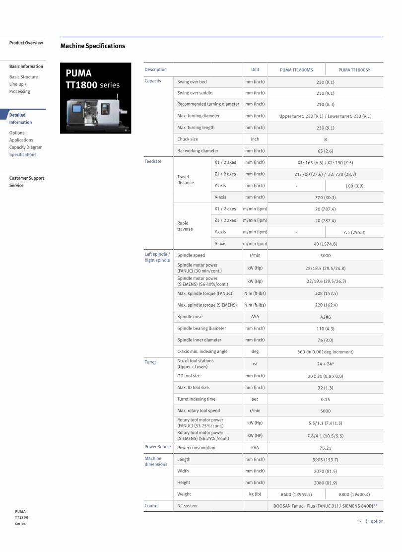
* { } : option
Machine Specifications
PUMA TT1800 series
PUMA TT1800 series
22 /
Product Overview
Basic Information
Basic Structure
Line-up /
Processing
Detailed
Information
Options
Applications
Capacity Diagram
Specifications
Customer Support
Service
Description Unit PUMA TT1800MS PUMA TT1800SY
Capacity Swing over bed mm (inch) 230 (9.1)
Swing over saddle mm (inch) 230 (9.1)
Recommended turning diameter mm (inch) 210 (8.3)
Max. turning diameter mm (inch) Upper turret: 230 (9.1) / Lower turret: 230 (9.1)
Max. turning length mm (inch) 230 (9.1)
Chuck size inch 8
Bar working diameter mm (inch) 65 (2.6)
Feedrate
Travel distance
X1 / 2 axes mm (inch) X1: 165 (6.5) / X2: 190 (7.5)
Z1 / 2 axes mm (inch) Z1: 700 (27.6) / Z2: 720 (28.3)
Y-axis mm (inch) - 100 (3.9)
A-axis mm (inch) 770 (30.3)
Rapid traverse
X1 / 2 axes m/min (ipm) 20 (787.4)
Z1 / 2 axes m/min (ipm) 20 (787.4)
Y-axis m/min (ipm) - 7.5 (295.3)
A-axis m/min (ipm) 40 (1574.8)
Left spindle / Right spindle
Spindle speed r/min 5000
Spindle motor power (FANUC) (30 min/cont.)
kW (Hp) 22/18.5 (29.5/24.8)
Spindle motor power (SIEMENS) (S6 40%/cont.)
kW (Hp) 22/19.6 (29.5/26.3)
Max. spindle torque (FANUC) N·m (ft-lbs) 208 (153.5)
Max. spindle torque (SIEMENS) N.m (ft-ibs) 220 (162.4)
Spindle nose ASA A2#6
Spindle bearing diameter mm (inch) 110 (4.3)
Spindle inner diameter mm (inch) 76 (3.0)
C-axis min. indexing angle deg 360 (in 0.001deg.increment)
Turret No. of tool stations (Upper + Lower)
ea 24 + 24*
OD tool size mm (inch) 20 x 20 (0.8 x 0.8)
Max. ID tool size mm (inch) 32 (1.3)
Turret Indexing time sec 0.15
Max. rotary tool speed r/min 5000
Rotary tool motor power(FANUC) (S3 25%/cont.)
kW (Hp) 5.5/1.1 (7.4/1.5)
Rotary tool motor power (SIEMENS) (S6 25% /cont.)
kW (HP) 7.8/4.1 (10.5/5.5)
Power Source Power consumption kVA 75.21
Machine dimensions
Length mm (inch) 3905 (153.7)
Width mm (inch) 2070 (81.5)
Height mm (inch) 2080 (81.9)
Weight kg (lb) 8600 (18959.5) 8800 (19400.4)
Control NC system DOOSAN Fanuc i Plus {FANUC 31i / SIEMENS 840D}**

NC Unit Specifications
SIEMENS NO. Division Item Spec.S 840D
PUMA TT series
1
Control axes
Simultaneously controlled axes Positioning (G00) / Linear interpolation (G01) : 3 axesCircular interpolation (G02, G03) : 2 axes
●
2 Backlash compensation ●
3 Leadscrew error compensation ●
4 Measuring system error compensation ●
5 Feedforward control velocity-dependent ●
6 Follow up mode ●
7 Programmable acceleration ●
8 Least command increment 0.001mm (0.0001 inch) ●
9 Least input increment 0.001mm (0.0001 inch) ●
10
INTERPOLATION & FEED FUNCTION
2nd reference point return G75 FP=2 ●
11 3rd / 4th reference return G75 FP=3, 4 ●
12 Linear interpolation Max. 4 ●
13 Circular interpolation G02, G03 ●
14 Helical interpolation ●
15 Universal interpolator NURBS ●
16 Polynomial interpolation ○
17 Spline interpolation (A, B and C splines) ●
18 Involute interpolation ○
19 Separate path feed for corners and chamfers ●
20 SPINDLE FUNCTION
Retraction for rigid tapping ●
21 Rigid tapping ●
22
TOOL FUNCTION
3D Tool radius compensation ○
23 Number of tools / cutting edges in tool list 600 / 1500
24 Tool length compensation ●
25 Replacement tools for tool management ○
26 Monitoring of tool life and workpiece count ●
27 Manual measurement of tool offset ●
28 Loading and unloading of tools ●
29
PROGRAMMING & EDITING FUNCTION
Number of subroutine passes <= 9999 ●
30 Polar coordinates ●
31 Dimensions metric/inch, changeover manually or via program ●
32 Dynamic preprocessing memory FIFO ●
33 Look ahead number of blocks 150
34 Geometry axes, switchable online in the CNC program ●
35 Parts programs on NCU, max. number 1000
36 Workpieces on NCU, max. number 250
37 ShopTurn / ShopMill Machining step programming ●
38 Technology cycles for drilling/milling ●
39 Pocket milling free contour and islands stock removal cycle ●
40 2D simulation ●
41 3D simulation, finished part ●
42 Simultaneous recording ●
43
OTHERS FUNCTIONS(Operation, setting & Display, etc)
Execution from USB or CF card interface on operator panel front
●
44 Execution from HMI memory on NCU CF card ●
45 19.0" color display ●
46 Multi-channel display ●
47 2D representation of 3D protection areas / work areas ●
48 Software and hardware limit switches ●
49 Position monitoring ●
50 2D / 3D protection zones ●
51 Contour monitoring ●
52 Alarms and messages ●
53 RCS Commander (viewer function) ●
54 Automatic measuring cycles ●
56 Contour handwheel ○
57Integrate screens in SINUMERIK Operate with SINUMERIK Integrate Run MyScreens
●
58 MDynamics 3-axis ●
● Standard ◦ Optional X Not applicable
23 22 /

NC Unit Specifications● Standard ◦ Optional X Not applicable
FANUC NO. Division Item Spec.DOOSAN Fanuc i Plus Fanuc 31i
MS SY MS SY1
Controlled axis
Control paths 2 Path 2 Path 2 Path 2 Path
2 Controlled axes7 (X1,Z1,
C1,X2,Z2C2,A)
8 (X1, Z1, C1, Y, X2, Z2,
C2, A)
7 (X1, Z1, C1, X2, Z2, C2, A)
8 (X1, Z1, C1, Y, X2, Z2,
C2, A)3 Simultaneously controlled axes 4 axes 4 axes 4 axes 4 axes4 Axis control by PMC ● ● ● ●5 Cs contouring control ● ● ● ●
6 Synchronous/Composite control (C1 & C2 Synchro Control)
● ● ● ●
7 Arbitrary angular axis control X ● X ●
8 Torque control (토크 제어)Included in axis control by PMC
● ● ● ●
9 Increment system A,B0.001 mm, 0.001 deg, 0.0001 inch
● ● ● ●
10 HRV2 control ● ● ● ●11 Inch/metric conversion ● ● ● ●12 Stored limit check before move ● ● ○ ○13 Chuck and tail stock barrier ● ● ○ ○14 Chamfering on/off ● ● ● ●15 Interference check for rotary area X X ● ●16 Unexpected disturbance torque ● ● ● ●17 detection function ● ● ● ●18
Operation
Tool retract and recover ○ ○ ○ ○19 Dry run (드라이 런) ● ● ● ●20 Single block (싱글 블록) ● ● ● ●21 Handle interruption ○ ○ ○ ○22 Incremental feed x1,x10,x100 ● ● ● ●23 Manual handle retrace ○ ○ ○ ○24 Active block cancel ○ ○ ○ ○25
Interpo-lation functions
Nano interpolation ● ● ● ●26 Linear interpolation (리니어 보간) ● ● ● ●27 Circular interpolation G02 ● ● ● ●28 Polar coordinate interpolation ● ● ● ●29 Cylindrical interpolation ● ● ● ●30 Helical interpolation ● ● ● ●
31 Thread cutting, synchronous cutting
● ● ● ●
32 Multi threading ● ● ● ●33 Thread cutting retract ● ● ● ●34 Continuous threading ● ● ● ●35 Variable lead thread cutting ● ● ○ ○36 Circular thread cutting ○ ○ ○ ○
37 Polygon machining with two spindles
● ● ● ●
36 High-speed skip Input signal is 8 points.
○ ○ ○ ○
37 3rd/4th reference position return ● ● ○ ○
38 Balanced cuttingOnly for more than 2 path control
● ● ● ●
39 General purpose retract ● ● ○ ○
40
Feed function
Bell-shaped acceleration/deceleration after cutting feed interpolation
● ● ● ●
41 Override cancel (오버라이드 취소) ● ● ● ●
42 AI contour control I G5.1 Q_, 40 Blocks
● ● ● ●
43 AI contour control II G5.1 Q_, 200 Blocks
○ ○ ○ ○
44 Rapid traverse block overlap ● ● ● ●
45
Program input
Optional block skip (선택적 블록 스킵)
9 pieces ● ● ○ ○
46 Absolute/incremental programming
Combined use in the same block
● ● ● ●
47 Diameter/Radius programming X-axis ● ● ● ●
48Automatic coordinate system setting(자동 좌표계 설정)
● ● ● ●
49 Workpiece coordinate system (좌표계 입력)
G52 - G59 ● ● ● ●
50 Workpiece coordinate system preset
● ● ○ ○
51 Addition of workpiece coordinate system 48 pairs X X ○ ○
52 Addition of workpiece coordinate system 300 pairs X X ○ ○
53 Direct drawing dimension programming
● ● ● ●
PUMA TT1800 series
24 /
Product Overview
Basic Information
Basic Structure
Line-up /
Processing
Detailed
Information
Options
Applications
Capacity Diagram
Specifications
Customer Support
Service
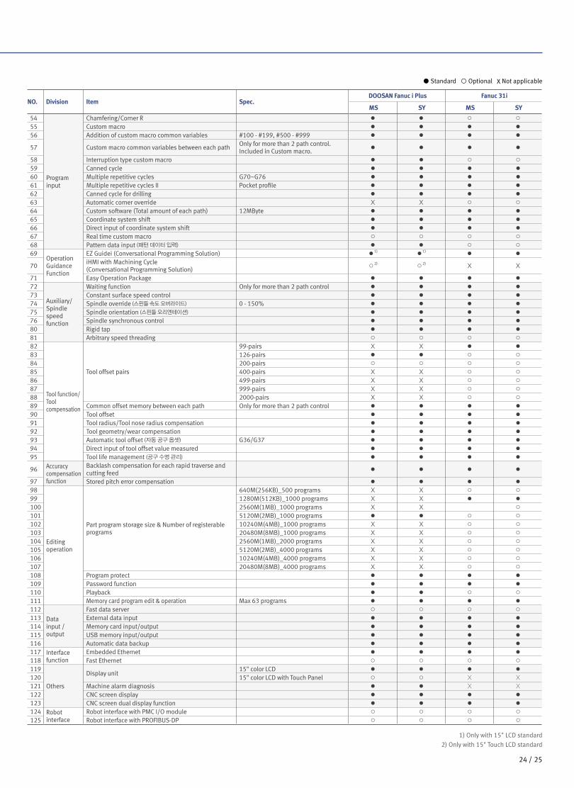
● Standard ◦ Optional X Not applicable
1) Only with 15" LCD standard2) Only with 15" Touch LCD standard
NO. Division Item Spec.DOOSAN Fanuc i Plus Fanuc 31i
MS SY MS SY
54
Program input
Chamfering/Corner R ● ● ○ ○55 Custom macro ● ● ● ●56 Addition of custom macro common variables #100 - #199, #500 - #999 ● ● ● ●
57 Custom macro common variables between each path Only for more than 2 path control. Included in Custom macro.
● ● ● ●
58 Interruption type custom macro ● ● ○ ○59 Canned cycle ● ● ● ●60 Multiple repetitive cycles G70~G76 ● ● ● ●61 Multiple repetitive cycles II Pocket profile ● ● ● ●62 Canned cycle for drilling ● ● ● ●63 Automatic corner override X X ○ ○64 Custom software (Total amount of each path) 12MByte ● ● ● ●65 Coordinate system shift ● ● ● ●66 Direct input of coordinate system shift ● ● ● ●67 Real time custom macro ○ ○ ○ ○68 Pattern data input (패턴 데이터 입력) ● ● ○ ○69
Operation Guidance Function
EZ Guidei (Conversational Programming Solution) ●1) ●1) ● ●
70 iHMI with Machining Cycle (Conversational Programming Solution)
○2) ○2) X X
71 Easy Operation Package ● ● ● ●72
Auxiliary/Spindle speed function
Waiting function Only for more than 2 path control ● ● ● ●73 Constant surface speed control ● ● ● ●74 Spindle override (스핀들 속도 오버라이드) 0 - 150% ● ● ● ●75 Spindle orientation (스핀들 오리엔테이션) ● ● ● ●76 Spindle synchronous control ● ● ● ●80 Rigid tap ● ● ● ●81 Arbitrary speed threading ○ ○ ○ ○82
Tool function/Tool compensation
Tool offset pairs
99-pairs X X ● ●83 126-pairs ● ● ○ ○84 200-pairs ○ ○ ○ ○85 400-pairs X X ○ ○86 499-pairs X X ○ ○87 999-pairs X X ○ ○88 2000-pairs X X ○ ○89 Common offset memory between each path Only for more than 2 path control ● ● ● ●90 Tool offset ● ● ● ●91 Tool radius/Tool nose radius compensation ● ● ● ●92 Tool geometry/wear compensation ● ● ● ●93 Automatic tool offset (자동 공구 옵셋) G36/G37 ● ● ● ●94 Direct input of tool offset value measured ● ● ● ●95 Tool life management (공구 수명 관리) ● ● ● ●
96 Accuracy compensation function
Backlash compensation for each rapid traverse and cutting feed
● ● ● ●
97 Stored pitch error compensation ● ● ● ●98
Editing operation
Part program storage size & Number of registerable programs
640M(256KB)_500 programs X X ○ ○99 1280M(512KB)_1000 programs X X ● ●100 2560M(1MB)_1000 programs X X ○101 5120M(2MB)_1000 programs ● ● ○ ○102 10240M(4MB)_1000 programs X X ○ ○103 20480M(8MB)_1000 programs X X ○ ○104 2560M(1MB)_2000 programs X X ○ ○105 5120M(2MB)_4000 programs X X ○ ○106 10240M(4MB)_4000 programs X X ○ ○107 20480M(8MB)_4000 programs X X ○ ○108 Program protect ● ● ● ●109 Password function ● ● ● ●110 Playback ● ● ○ ○111 Memory card program edit & operation Max 63 programs ● ● ● ●112
Data input / output
Fast data server ○ ○ ○ ○113 External data input ● ● ● ●114 Memory card input/output ● ● ● ●115 USB memory input/output ● ● ● ●116 Automatic data backup ● ● ● ●117 Interface
functionEmbedded Ethernet ● ● ● ●
118 Fast Ethernet ○ ○ ○ ○119
Others
Display unit15" color LCD ● ● ● ●
120 15" color LCD with Touch Panel ○ ○ X X121 Machine alarm diagnosis ● ● X X122 CNC screen display ● ● ● ●123 CNC screen dual display function ● ● ● ●124 Robot
interfaceRobot interface with PMC I/O module ○ ○ ○ ○
125 Robot interface with PROFIBUS-DP ○ ○ ○ ○
25 24 /

Doosan Machine Tools’ Global Network, Responding to Customer’s Needs nearby, Anytime, Anywhere
Doosan machine tools provides a system-based professional support service before
and after the machine tool sale by responding quickly and efficiently to customers’ demands.
By supplying spare parts, product training, field service and technical support, we can provide top class support
to our customers around the world.
Responding to Customers Anytime, Anywhere
Global Sales and Service Support Network
4
Corporations
167
Dealer Networks
51
Technical CentersTechnical Center: Sales Support, Service Support, Parts Support
200
Service Post
3
Factories
Changwon FactoryHead Office
AMERICA EUROPE
CHINA (Yantai)
CHINA (Shanghai)
INDIA
PUMA TT1800 series
Product Overview
Basic Information
Basic Structure
Line-up /
Processing
Detailed
Information
Options
Applications
Capacity Diagram
Specifications
Customer Support
Service

Doosan Machine ToolsCustomer Support ServiceWe help customers to achieve success by providing a variety of
professional services from pre-sales consultancy to post-sales support.
Technical Support Supports machining methods and technology Responds to technical queries Provides technical consultancy
Training Programming / machine setup and operation Electrical and mechanical maintenance
Applications engineering
Supplying Parts Supplying a wide range of original Doosan spare parts Parts repair service
Field Services On site service Machine installation and testing Scheduled preventive maintenance Machine repair
2726 /

Major Specifications
PUMA TT1800 series Description Unit PUMA TT1800 MS / SY
Max. turning diameter mm (inch) 230 (9.1)
Max. turning length mm (inch) 230 (9.1)
Chuck size inch 8
Bar working diameter mm (inch) 65 (2.6)
Spindle speed (Left spindle / Right spindle)
r/min 5000
Spindle motor power (Left spindle / Right spindle)
kW (Hp)22/15 (30 min/cont.) (29.5/20.1) (FANUC)
22/19.6 (S6 40%/cont.) (29.5/26.3) (SIEMENS)
ver. EN 200831 SU
Head Office22F T Tower, 30, Sowol-ro 2-gil, Jung-gu,Seoul, Korea, 04637
Tel +82-2-6972-0370 / 0350Fax +82-2-6972-0400
Doosan Machine Tools America19A Chapin Rd., Pine Brook, NJ 07058, U.S.A.
Tel +1-973-618-2500 Fax +1-973-618-2501
Doosan Machine Tools EuropeEmdener Strasse 24, D-41540 Dormagen, Germany
Tel +49-2133-5067-100 Fax +49-2133-5067-111
Doosan Machine Tools IndiaNo.82, Jakkuar Village, Yelahanka Hobil, Bangalore-560064
Tel + 91-80-2205-6900 E-mail [email protected]
Doosan Machine Tools ChinaRoom 101,201,301, Building 39 Xinzhuan Highway No.258 Songjiang District,China Shanghai(201612)
Tel +86 21-5445-1155Fax +86 21-6405-1472
*For more details, please contact Doosan Machine Tools.
*The specifications and information above-mentioned may be changed without prior notice.* Doosan Machine Tools Co., Ltd. is a subsidiary of MBK Partners. The trademark is used under a licensing agreement with Doosan Corporation,
the registered trademark holder.
There is a high risk or fire when using non-water-soluble cutting fluids, processing flammable materials, neglecting use coolants and modifying the machine without the consent of the manufacturer. Please check the SAFETY GUIDANCE carefully before using the machine.
Fire Safety Precautions
www.doosanmachinetools.com

PUMA TT2500 seriesMulti-Axis Turning Center
PUMA TT2500 seriesPUMA TT2500MSPUMA TT2500SY

Product Overview
Basic Information
Basic Structure
Line-up /
Processing
Detailed
Information
Options
Applications
Capacity Diagram
Specifications
Customer Support
Service
PUMA TT2500 seriesHigh performance turning center featuring first & second spindle that have the same power and capacity, with upper & lower turrets on the grounded box type bed. Simultaneous machining on two faces with both spindles and turrets and virtual realization of Y-axis function will bring you double productivity.
PUMA TT2500 series
02 /

Contents
02 Product Overview
Basic Information
04 Basic Structure08 Line-up / Processing
Detailed Information
10 Standard / Optional Specifications
11 Applications14 Capacity Diagram19 Machine / NC Unit Specifications
22 Customer Support Service
Sample
Equipped with an advanced finished-part removal system for both spindles!
The left and right spindles are equipped
with independent part catcher and
unloader systems to provide a fully
automated manufacturing system.
Excellent rigidity and power implemented with axis travel system optimization technology!
All guide ways are wide wraparound
rectangular type for unsurpassed long
term rigidity and accuracy.
Productivity doubled with the adoption of a right spindle and a lower turret!
The left and right spindles and the upper
and lower turrets operate independently
to double the machine’s productivity.
03 02 /

Basic Structure Machine construction
Perfect integration of multi-process and high productivity are achieved by Left & right spindle of the same power and capacity, with upper & lower turrets on the grounded box type bed.
Robust Design
All guide ways are wide wraparound rectangular type for unsurpassed long term rigidity and accuracy.
Achievement of PUMA TT machines
Continuous process accuracy, Shorten setting time, Optimal distribution of cycle and Automated works
The heavily ribbed torque tube designprevents twisting and deformation.
Z1 axis
X1 axis
Y axisC1 axis
C2 axisX2
axis
Z2 axis
B axis
FEM (Finite Element Method) Analysis
Product Overview
Basic Information
Basic Structure
Line-up /
Processing
Detailed
Information
Options
Applications
Capacity Diagram
Specifications
Customer Support
Service
PUMA TT2500 series
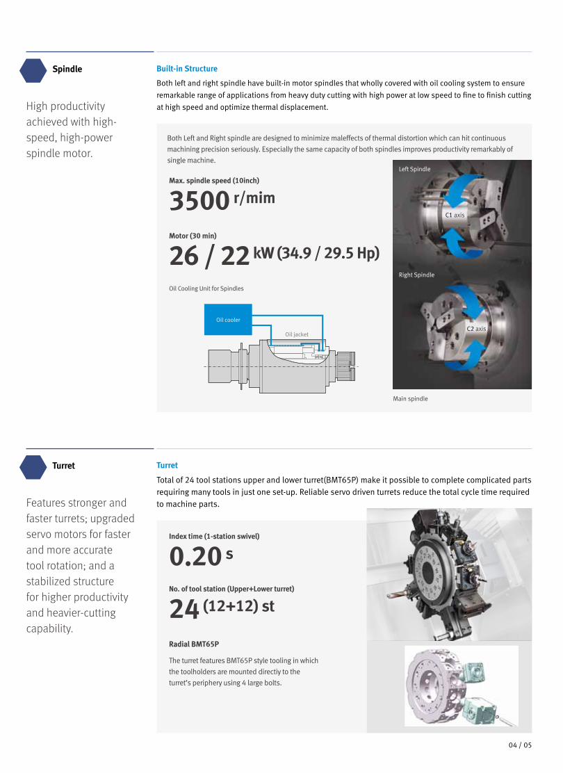
High productivity achieved with high-speed, high-power spindle motor.
Features stronger and faster turrets; upgraded servo motors for faster and more accurate tool rotation; and a stabilized structure for higher productivity and heavier-cutting capability.
Spindle
Turret
Built-in Structure
Both left and right spindle have built-in motor spindles that wholly covered with oil cooling system to ensure remarkable range of applications from heavy duty cutting with high power at low speed to fine to finish cutting at high speed and optimize thermal displacement.
Turret
Total of 24 tool stations upper and lower turret(BMT65P) make it possible to complete complicated parts requiring many tools in just one set-up. Reliable servo driven turrets reduce the total cycle time required to machine parts.
Motor (30 min)
26 / 22 kW (34.9 / 29.5 Hp)
No. of tool station (Upper+Lower turret)
24 (12+12) st
Max. spindle speed (10inch)
3500 r/mim
Index time (1-station swivel)
0.20 s
Both Left and Right spindle are designed to minimize maleffects of thermal distortion which can hit continuous machining precision seriously. Especially the same capacity of both spindles improves productivity remarkably of single machine.
Oil Cooling Unit for Spindles
Oil cooler
Oil jacket
Main spindle
Left Spindle
C1 axis
C2 axis
Right Spindle
Radial BMT65P
The turret features BMT65P style tooling in which the toolholders are mounted directiy to theturret’s periphery using 4 large bolts.
0504 /

Axis Features Travel
Machining range
X 1-axis (Upper turret)
255 mm (10.0 inch)
A : Max. turning dia.(on Upper turret)
390 mm (15.4 inch)
X 2-axis (Lower turret)
190 mm (7.5 inch)
(on Lower turret)
300 mm (11.8 inch)
Z 1-axis (Upper turret)
800 mm (31.5 inch)
B : Max. turning length
350 mm (13.8 inch)
Z 2-axis (Lower turret)
900 mm (35.4 inch)
C : Max. bar working dia.
81 mm (3.2 inch)
C1-axis
Left spindle Right spindle
Upper turret
Lower turret
Y-axis
Z1-axis
C2-axis
A-axis
Z2-axis
X2-axis
A -axis
810 mm (31.9 inch)
B
Ø A Ø CØ C
B
Product Overview
Basic Information
Basic Structure
Line-up /
Processing
Detailed
Information
Options
Applications
Capacity Diagram
Specifications
Customer Support
Service
PUMA TT2500 series

Rapid Traverse
Variation, processing Virtual y-Axis Function
Y-axis addition to upper turret on SY series brings complex machining to completion in just one set-up. Synchronous interpolation of X1-axis and Ys-axis in double ways structure creates the Y-axis function.
X-axis
20 m/min(787.4 ipm)
Y-axis travel
120 (±60) mm (4.7 (±2.4) inch)
Z-axis
24 m/min(944.9 ipm)
Y-axis rapid
7.5 m/min (295.3 ipm)
Outstanding rigidity for high feedrates
Y-axis Working Range
Y-axis Working Range
By simultaneous X-Y-Z-axis feed control and C-axis function to guide precisecircular orientation of spindle, Y/X axes circular interpolation simplifies themachining of complex shapes in faster cycle time. Y&X-axis
circular interpolation
X1+Y-axis
Poly-side machine
Y-axis
X-axisOn-center face groove
Y-axis
X-axis
Off-center side groove
Y-axis
X-axis
Spindle center 348.923 (13.7)
141.077 (5.6)
6.923 (0.3)
100(3.9)
10 (0.4) 245 (9.6)
255 (10.0) (X1-axis travel)
Interference area withRight spindle
60 (2.4
)50
.229
(2.0
)
60 (2.4
)
Angular Milling unit moving area
Unit : mm (inch)
07 06 /

Machine Capacity
Chip removal rate
348 Cm3/min (21.2 inch3/min)
Chip removal rate
367 Cm3/min (22.4 inch3/min)
Roundness
0.40 ㎛
Cutting depth
10 mm (0.4 inch)Cutting depth
5 mm x 2 (0.2 inch)
Roughness
0.23 ㎛Ra
Heavy-Duty Cutting, OD (Left spindle & upper turret)
Making full use of the high output motor, heavy-duty O.D. cutting is powerful and precise even with large workpieces.
Balanced Cutting, OD (Left spindle & upper - lower turret)
The synchronous control of Upper and Lower turrets makes O.D. cutting with high precision balanced cutting.
Material Cutting speed (m/min (ipm))
Feedrate(mm/rev (ipr))
Spindle speed (r/min)
Carbon steel, SM45C 120 (4724.4) 0.36 (0.0) 320
Tool Ø 20 HSS drill
MaterialCarbon steel
SM45CRotary tool spindle speed (r/min) 1,000
Feedrate (mm/rev (ipr)) 0.3 (0.0)Chip removal rate(cm3/min (inch3/min))
60 (3.7)
Drilling depth (mm (inch)) 10 (0.4)
Tool M16×2.0
MaterialSM45C
(JIS S45C)Rotary tool spindle speed (r/min)
600
Feedrate (mm/min (ipm)) 1200 (47.2)
Material Cutting speed (m/min (ipm))
Feedrate(mm/rev (ipr))
Spindle speed (r/min)
Carbon steel, SM45C 120 (4724.4) 0.36 (0.0) 320
Drilling
Machining examples
High productivity
Reliable Long-Run Machining Accuracy
Tapping
생
Cycle Time
Actual cutting Non-cutting operations
Non-cutting operations
Actual cutting
1 turret
TT series
Productivity
x 1.7
Tool Ø 20 HSS drill
Material AL2024
Outer diameter (mm (inch)) 60 (2.4)
Spindle speed (r/min) 1,300
Feedrate (mm/rev (ipr)) 0.05 (0.0)
*The machining accuracy indicated is just for reference. Depending on cutting and environmental conditions during
measurement, the results can be different.270°
90°
0°180°
0.5㎛
Product Overview
Basic Information
Basic Structure
Line-up /
Processing
Detailed
Information
Options
Applications
Capacity Diagram
Specifications
Customer Support
Service
PUMA TT2500 series

Ergonomic Design
Balanced Cutting, OD (Left spindle & upper - lower turret)
Safety & Operability
Eco-Friendly Design
Safety window on front door
High maintainability
Oil Skimmer
Another suggestion to prolong the life time of the coolant water. A belt-driven type oil skimmer picks up and removes waste oil from the coolant tank that is easily drained.
Viewing window is designed and was tested under heavy condition to protect operator against possible dangersduring real cutting thanks to its shock absorbing laminated glass and double panel construction. The window without grating also provides a clear view of the machine inside.
Swivel type operator panel
Operator oriented designwith 90˚swivel
Collection of Waste Lubrication Oil
Less waste lubrication oil extends the life time of the coolant water and cut down the grime and offensive smell of the machine inside.
No Coolant Leakage
Rigorously designed, manufactured and tested machine covers do not permit coolant leakage in any condition. The factory always keeps our environment clean.
0~90°
Pressure control forLeft spindle chucking
Pressure control for Rightspindle chucking (or Tail stock)
Separate coolant tank
Lubrication tank
Tempered glass Metal plate
Polycarbonate
Resin
NBR
Outside
09 08 /

Standard / Optional Specifications
NO. Description Features PUMA TT2500series
1Chuck (Left / Right)
10 Inch ●
2 None ◦
3Jaws (Left / Right)
Soft Jaws ●
4 Hardened & Ground Hard Jaws ◦
5Chucking option
Dual Pressure Chucking ◦
6 Chuck Clamp Confirmation ●
7 Tailstock Tail Center For Turret ◦
8Coolant Pump
1.5 bar ●
9 4.5 / 7 / 10 / 14.5 / 28 bar ◦
10
Coolant options
Oil Skimmer ◦
11 Coolant Chiller ◦
12 Coolant Pressure Switch ◦
13 Cooling Flow Switch ◦
14 High Coolant Interface ◦
15 Chuck Coolant (Left / Right) ◦
16 Through Spindle Coolant(T.S.C) For Spindle (Left / Right) ◦
17 Coolant Gun ◦
18
Chip processing options
Chip Conveyor_Side Type ◦
20 Chip Conveyor_Rear Type ◦
21 Chip Bucket ◦
22 Air Blow (Left / Right) ●
23 Mist Collector ◦
24
Measurement & Automation
Tool Setter (Manual / Auto) ◦
25 Parts Catcher And Box ◦
26 Parts Unloader And Conveyor ◦
27 Work Ejector ◦
28 Auto Door ◦
29 Cut-Off Confirmation ◦
30 Work / Tool Counter ◦
31 Robot Interface (PMC I/O, Profibus) ◦
32 Bar Feeder Interface ◦
33
Optional devices
Tool Load Monitoring ◦
34 Linear Scale (X1, X2, Z1, Z2, Y) ◦
35 Signal Tower ◦
36 Air Gun ◦
37 Air Conditioner For Electric Cabinet ◦
38 Light For Electric Cabinet ◦
39 Extra M-Code (4ea) ◦
40 Auto Power Off ◦
41 Quick change tooling(CAPTO) ◦
42
Customized Special Option
Coolant level switch : Sensing level - Low ◦
43 Parts Unloader And Conveyor_Gripper Type ◦
44 Automatic Top Door ◦
45 Coolant Gun ◦
46 Coolant Chiller ◦
47 Chip Coveyor_Drum Filter Type ◦
48 Shower Coolant ◦
49 Air Limit Sensing On Chuck_Preparation ◦
50 Rotary Type Window Wiper_Eletrical ◦
51 TSC For Main/Left Spindle ◦
52 TSC For Sub/Right Spindle ◦
53 TSA For Main/Left Spindle ◦
54 TSA For Sub/Right Spindle ◦
55 Work & Tool Counter ◦
56 Tool Setter Extension For Special Chuck ◦
57 Main/Left Spindle Air Curtain ◦
58 Sub/Right Spindle Air Curtain ◦
59 MQL System ◦
60 Chuck Pressure Switch ◦
● Standard ◦ Optional X N/A
Various options are available to satisfy all the customers’ requirements.
*For further details of the range of options, please contact.
Product Overview
Basic Information
Basic Structure
Line-up /
Processing
Detailed
Information
Options
Applications
Capacity Diagram
Specifications
Customer Support
Service
PUMA TT2500 series
10 /

* Can be limited depends on holder position
* Depending on the chuck and cylinder spec. used in the machine, the bar working dia. can be reduced.
Optimal Support System of Automatic Operation
Peripheral equipments
Optional devices
COLLET CHUCK Auto tool pre-setter Coolant blower
ID/OD Special Holder(Each turret 12ea/Tool 24ea)
Milling Special Holder(Each turret 12ea/Tool 24ea)
Quick change tooling(CAPTO)Work measurement
Parts unloader & conveyorParts unloader system built inside the machine can receiveworkpieces from both spindles. Automated operation is realizedperfectly when the system is coupled with bar feeder system.
Bar feeder systemAutomated bar working is possible by bar feeder system. When parts unloader system is added, its value of use will be in the best.
Max. work diameter Ø81 mm (3.2 inch)
Max. work length 160 mm (6.3 inch)
Max. work weight 4kg (8.8 lb)
Max. Bar Working dia
ø81 mm (3.2 inch)
1110 /

Product Overview
Basic Information
Basic Structure
Line-up /
Processing
Detailed
Information
Options
Applications
Capacity Diagram
Specifications
Customer Support
Service
Real time custom macro function
During operation of the parts unloader of the right spindle, this function allows the lower turret to conduct the cutting operation for the left spindle. This function also further improves the productivity.
Left spindle Right spindle
Upper turret
DOOSAN Fanuc i Plus
DOOSAN Fanuc i Plus is optimized for maximizing customer productivity and convenience.
Doosan Fanuc i Plus 15 inch color display Intuitive and user-friendly design
USB & PCMCIA card QWERTY keyboard EZ-guide i standard Ergonimic operator panel 2MB Memory Hot key
15 inch screen + New OP
DOOSAN Fanuc i Plus' operation panel enhances operating convenience by incorporating common-design buttons and layout, and features the Qwerty keyboard for fast and easy operation.
iHMI Touch screen
iHMI provides an intuitive interface that utilizes a touch screen for quick and easy operation
Variety of applications
Providing various applications related to PLANNING, MACHINING, IMPROVEMENT, and UTILITY for customer convenience.
PUMA TT2500 series

A cutting program is automatically created with the entered values.
Example programming
Cutting shape
Automatic creation of cutting program
O7000 (SAMPLE PROGRAM) ;∤∤∤M3 S1500 ;G0 X50. Y125. ;G0 Z30. ;G1040 T0.5 J3. H0.2 K0.5 ∤∤∤ ;G1020 H120. V50. U37. W68. ∤∤∤ ;G0 Z80. ;M5 ;
Enter the dimensions of the shape.
EZ-Guide i screen
Turret maintenance and service screen
Convenience of Maintenance and Service
The condition and service procedures of the sensors are provided for easy maintenance and servicing of major units.
Tool monitoring screen
Tool Load Monitoring Function
During cutting operation, abnormal load caused by wear or damage of the tool is detected and an alarm is triggered to prevent further damage.
EZ-Guide i
Using the DOOSAN EZ-Guide i, users can create a cutting program for any desired shape, including patterns, by entering figures only.
Easy Operation Package
Doosan's Easy Operation Package (EOP) supports the user with functions relating to tool data, error diagnostics, set up and machine monitoring.
13 12 /

Spindle Power-Torque Diagram
Max. spindle speed : 3500 r/min
Max. power : 26 kW (34.9 Hp)
(Built-in)
PUMA TT2500MS / SY
Rotary tool spindle
Torq
ue :
N. m
(ft-l
bs)
Out
put :
kW
(Hp)
Spindle speed : r/min
Max. spindle speed : 5000 r/min
Max. power : 5.5/1.5 kW
(7.4/2.0 Hp) (15min/Cont.)
PUMA TT2500MS / SY
Torq
ue :
N. m
(ft-l
bs)
Out
put :
kW
(Hp)
Spindle speed : r/min
Max. spindle speed : 5000 r/min
Max. power : 7.5/1.5 kW
(10.1/2.0 Hp) (5min/Cont.)
PUMA TT2500MS / SY
Torq
ue :
N. m
(ft-l
bs)
Out
put :
kW
(Hp)
Spindle speed : r/min
Product Overview
Basic Information
Basic Structure
Line-up /
Processing
Detailed
Information
Options
Applications
Capacity Diagram
Specifications
Customer Support
Service
S2 30minS3 25%S2 30minS1 Cont.S2 30minS1 Cont.
S2 30min
S2 25%
22 (29.5)26 (34.9)
15 (20.1)
S1 ContS1 Cont.
20 100 1000 35001 (1.3)
10 (13.4)
30001060570485
433 (319.6)369 (272.3)296 (218.4)234 (172.7)198 (146.1)
20 100 1100 5000
S2 15min
S1 Cont.
S2 15min
S1 Cont.
5.5 (7.4)
1.5 (2.0)
10 (7.4)
10 (7.4)
10 (7.4)
34 (25.1)
48 (35.4)
0
3000750425
100 (73.8)
100 (73.8)
95 (70.1)
1.5 (2.0)
7.5 (10.1)
3.7 (5.0)
110 100 1000
S2 5min
S1 Cont.
S2 5min
S1 Cont.
5000
3000750425
PUMA TT2500 series
14 /

External Dimensions
Top View
Front View
Side View
Unit : mm (inch)
RIGHT DISPOSAL CHIP CONVEYOR(OPTION)
REAR DISPOSAL CHIP CONVEYOR(OPTION)
SPINDLE CENTER
2590
(102
.0)
1310
(51.
6)
1210
(47.
6)
4194 (165.1) 905 (35.6)
1092
.1 (4
3.0)
410
(16.
1)
2490
(98.
0)
1163 (45.8)
77(3.0)
168(6.6)
3644.5 (143.5)
855 (33.7) (DOOR OPEN SPACE)
1100 (43.3) (DISTANCE BETWEEN SPINDLE NOSE)1454.5 (57.3)
633(24.9) 3018 (118.8)
1020 (40.2)2284 (89.9)
286 (11.3)
1090
(42.
9)
REAR DISPOSAL CHIP CONVEYOR(OPTION)
RIGHT DISPOSAL CHIP CONVEYOR(OPTION)
FL(RIGHT SIDE TANK):0FL(REAR SIDE TANK):0
RIGHT SPINDLE NOSELEFT SPINDLE NOSE
882
(34.
7)22
10 (8
7.0)
73 (2
.9)
1250 (49.2)1190 (46.9) 280
(11.0)350
(13.8)
2350(92.5)
545(21.5)
733
(28.
9)46
2(1
8.2)
1585
(62.
4)
280
(11.
0)35
0(1
3.8)
203
(8.0
)
165
(6.5
)
R 894
(35.2)R 334(13.1)
15 14 /
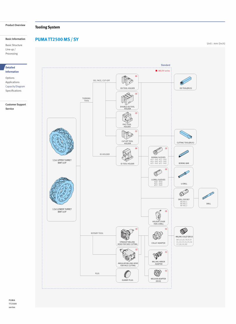
Unit : mm (inch)
Tooling System
PUMA TT2500 MS / SY
Standard
■: MS/SY series
OD, FACE, CUT-OFF
TURNING TOOL
ID HOLDER
12st UPPER TURRETBMT 65P
12st LOWER TURRETBMT 65P
ROTARY TOOL
PLUG
DOUBLE OD TOOL HOLDER
FACE TOOL HOLDER
CUT-OFF TOOL HOLDER
ID TOOL HOLDER
OD TOOL HOLDER
CUTTING TOOL(ER25)
BORING BAR
U-DRILL
DRILL
OD TOOL(ER25)
U-DRILL SLEEVESø20 - H40ø25 - H40ø32 - H40
BORING SLEEVESø10 - H40ø16 - H40ø25 - H40
ø12 - H40ø20 - H40ø32 - H40
DRILL SOCKETMT NO.1MT NO.2MT NO.3
STRAIGHT MILLING HEAD FOR SIDE CUTTING
ANGULAR MILLING HEADFOR FACE CUTTING
DUMMY PLUG
COLLET ADAPTER
MILLING ARBOR ADAPTER
HOLDER COVERFOR U-DRILL
WELDON ADAPTER(ID20)
MILLING COLLET (ER32)
(ø3,4,5,6,7,8,9,1011,12,13,14,15,1617,18,19,20)
(6)
(2)
(2)
(1)
(9) (2)
(2)
(2)
(2)
(2)
(1)
(1)
(1)
Product Overview
Basic Information
Basic Structure
Line-up /
Processing
Detailed
Information
Options
Applications
Capacity Diagram
Specifications
Customer Support
Service
PUMA TT2500 series
16 /

Tool Interference Diagram
PUMA TT2500 MS / SYUnit : mm (inch)
ø40 (1.6)
(Boring bar d
ia.)
448.
5 (1
7.7)
110.
5(4
.4)
115(4.5)
182.5(7.2)
182.5(7.2)
130(5.1)
190 (7.5) (X2-axis travel)
40(1.6)
150(5.9)
40(1.6)
90(3.5)
90(3.5)
115(4.5)67 (2
.6)
405
(15.
9)
182.5(7.2)
182.5(7.2)
130(5.1)
255 (10.0) (X1-axis travel)
40(1.6)
215(8.5)
40(1.6)
ø260 (10.2)
ø270 (10.6)
95(3.7) 7
(0.3)
ø260
(10.2)
ø230 (9.1)
ø390 (15.4)(Upper Turret:Max. turning dia.) ø300 (11.8) (Lower Turret:Max. turning dia.)
ø676 (26.6)(Max. swing dia.)
ø40
(1.6
)(B
orin
g ba
r dia
.)
7(0.3) 95(3.7)
ø676 (26.6)(Max. swing dia.)
448.
5 (1
7.7)
110.
5(4
.4)
115(4.5)
182.5(7.2)
182.5(7.2)
130(5.1)
190 (7.5) (X2-axis travel)
40(1.6)
150(5.9)
40(1.6)
90(3.5)
67 (2.6
)
405
(15.
9)
115(4.5)
182.5(7.2)
182.5(7.2)
130(5.1)
255 (10.0) (X1-axis travel)
90(3.5)
40(1.6)
215(8.5)
40(1.6)
95(3.7) 7
(0.3)
95(3.7)
7(0.3)
ø260 (10.2)
Max. ø20 (0.8)
ø230 (9.1)
95
(3.7)
59
(2.3)
100
ø270(10.6)
ø260 (10.2)
ø250 (9.8)
ø390 (15.4) (Upper Turret:Max. turning dia.) ø300 (11.8) (Lower Turret:Max. turning dia.)
ø676 (26.6)(Max. swing dia.)
ø40
(1.6
) (Bo
ring
bar d
ia.)
ø676(Max. swing dia.)
ø40 (Borin
g bar dia.)
17 16 /
UPPER TURRET LOWER TURRET

Product Overview
Basic Information
Basic Structure
Line-up /
Processing
Detailed
Information
Options
Applications
Capacity Diagram
Specifications
Customer Support
Service
PUMA TT2500 series
18 /
Working Range Diagram
PUMA TT2500 MS / SYUnit : mm (inch)
1100 (43.3) (Distance between spindle nose)800 (31.5) (Z1-axis travel)
27 (1
.1)
40(1
.6)
150 (
5.9)
190
(7.5
) (X
2-ax
is tr
avel
)19
0 (7
.5)
(X2-
axis
trav
el)
190
(7.5
) (X
2-ax
is tr
avel
)
190
(7.5
) (X
2-ax
is tr
avel
)40
(1.6
)15
0 (5.9
)
190
(7.5
) (X
2-ax
is tr
avel
)
27(1
.1) 130
(5.1
)
10 (0.4
)
10 (0
.4)
215
(8.5
)
255
(10.
0) (X
1-ax
is tr
avel
)25
5 (1
0.0)
(X1-
axis
trav
el)
255
(10.
0) (X
1-ax
is tr
avel
)
255
(10.
0) (X
1-ax
is tr
avel
)40 (1.6
)
215
(8.5
)40 (1.6
)
100 86
10
255
(10.
0) (X
1-ax
is tr
avel
)
186 (7.3)186 (7.3)
140 (5.5)7 (0.3)7 (0.3)27
(1.1)
100(3.9)
900 (35.4) (Z2-axis travel) 150(5.9)
50(2.0)
800 (31.5)100 (3.9)
150(5.9)
150(5.9)
31 (1
.2)
31 (1
.2)
80(3.1)
115
(4.5
)23
0(9
.1)
25 (1.0
)
40 (1
.6)
155 (
6.1)
25 (1
.0)
162 (
6.4)
40 (1
.6)
115
(4.5
)
5(0.2)
128(5.0)
83(3.3)
74(2.9)
771 (30.4)900 (35.4) (Z2-axis trabel) 80
(3.1)80
(3.1)30
(1.2)
Max.140(5.5)
Max.140(5.5)
90(3.5)
129(5.1)
129(5.1)
90(3.5)
130(5.1) 66
(2.9)29
(1.1)
100
(3.9
)24
5(9
.6)
10 (0.4
)
20 (0
.8)
20 (0.8
)
10 (0
.4)18
0 (7
.1)
100 (
3.9)
168
(6.6
)
84(3.3)
147(5.8)
172 (6.8) 728 (28.7)900 (35.4) (Z2-axis travel) 66
(2.6)134(5.3)
193 (7.6)
34(1.3)
63(2.5)
93(3.7)
84 (3.3)
66(2.9)
168(6.6)
27 1815
130
130
73(2.9)
73(2.9)
73(2.9)
154(6.1)
73(2.9)
73(2.9)
127(5.0)
127(5.0)
125(4.9)
74(2.9)
89(3.5)
85(3.3)
130(5.1)
227(8.9)
900 (35.4)(Z2-axis travel) 900 (35.4)(Z2-axis travel)
1100 (43.3) (Distance between spindle nose)800 (31.5) (Z1-axis travel)
800 (31.5) (Z1-axis travel)800 (31.5) (Z1-axis travel)
800 (31.5) (Z1-axis travel)
1100 (43.3) (Distance between spindle nose)1100 (43.3) (Distance between spindle nose)
1100 (43.3) (Distance between spindle nose)
Single OD Tool holder
Single ID Tool holder
Straight milling head
Double OD Tool holder
Angular milling head

* { } : option
Description Unit PUMA TT2500MS PUMA TT2500SY
Capacity Swing over bed mm (inch) 800 (31.5)
Swing over saddle mm (inch) 620 (24.4)
Max. turning diameterOn upper turret mm (inch) 390 (15.4)
On lower turret mm (inch) 300 (11.8)
Recommended turning diameter mm (inch) 255 (10.0)
Max. turning length mm (inch) 350 (13.8)
Bar working diameter mm (inch) 81 (3.2)
Spindle (Left/Right)
Spindle speed r/min 3500
Spindle nose ASA A2-8
Spindle bearing diameter (front) mm (inch) 130 (5.1)
Spindle through hole diameter mm (inch) Letf : 91 (3.58) / Right : 86 (3.4)
C1-axis minimum indexing increment deg 0.001
Travels X1-axis mm (inch) 255 (10.0)
Z1-axis mm (inch) 800 (31.5)
A-axis mm (inch) 810 (31.9)
X2-axis mm (inch) 190 (7.5)
Z2-axis mm (inch) 900 (35.4)
C1, C2-axis deg 360
Y-axis mm (inch) - 120 (±60) (4.7 (±2.4))
Rapid traverse rate
X1, 2-axis m/min (ipm) 20 (787.4)
Z1, 2-axis m/min (ipm) 24 (944.9)
A-axis m/min (ipm) 24 (944.9)
C1, C2-axis r/min - 200
Y-axis m/min (ipm) - 75 (2952.8)
Turret (Upper/Lower)
Number of tool stations ea 12
OD tool size mm (inch) 25 x 25 (1.0 x 1.0)
Max. boring bar size mm (inch) Ø40 (Ø1.6)
Turret indexing time 1 station swivel sec 0.2
Max. rotary tool speed r/min 5000
Motor Spindle motor power (Left/Right) kW (Hp) 26 / 22 (34.9 / 29.5) (30min/Cont.)
Servo motor power
X1-axis kW (Hp) 4 (5.4)
X2-axis kW (Hp) 3 (4.0)
Z1, 2-axis kW (Hp) 4 (5.4)
A-axis kW (Hp) 4 (5.4)
Y-axis kW (Hp) - 3 (4.0)
Coolant pump motor power kW (Hp) 0.4 (0.5)
Power source Required power capacity kVA 95.77
MachineDimensions Machine size
Floor space mm (inch) 4050 x 2210 (159.4 x 87.0)
Height mm (inch) 2480 (97.6)
Machine weight (Net) kg (lb) 12700 (27998.3)
Control CNC system DOOSAN Fanuc i Plus {Fanuc 31i} *
19 18 /
Machine Specifications
PUMA TT2500 series

NC Unit Specifications● Standard ◦ Optional X Not applicable
FANUC
Product Overview
Basic Information
Basic Structure
Line-up /
Processing
Detailed
Information
Options
Applications
Capacity Diagram
Specifications
Customer Support
Service
NO. Division Item Spec.DOOSAN Fanuc i Plus Fanuc 31i
MS SY MS SY
1
Controlled axis
Control paths 2 Path 2 Path 2 Path 2 Path
2 Controlled axes7 (X1,Z1,
C1,X2,Z2C2,A)
8 (X1, Z1, C1, Y, X2, Z2,
C2, A)
7 (X1, Z1, C1, X2, Z2, C2, A)
8 (X1, Z1, C1, Y, X2, Z2,
C2, A)3 Simultaneously controlled axes 4 axes 4 axes 4 axes 4 axes4 Axis control by PMC ● ● ● ●5 Cs contouring control ● ● ● ●
6 Synchronous/Composite control (C1 & C2 Synchro Control)
● ● ● ●
7 Arbitrary angular axis control X ● X ●
8 Torque control Included in axis control by PMC
● ● ● ●
9 Increment system A,B0.001 mm, 0.001 deg, 0.0001 inch
● ● ● ●
10 HRV2 control ● ● ● ●11 Inch/metric conversion ● ● ● ●12 Stored limit check before move ● ● ○ ○13 Chuck and tail stock barrier ● ● ○ ○14 Chamfering on/off ● ● ● ●15 Interference check for rotary area X X ● ●16 Unexpected disturbance torque ● ● ● ●17 detection function ● ● ● ●18
Operation
Tool retract and recover ○ ○ ○ ○19 Dry run ● ● ● ●20 Single block ● ● ● ●21 Handle interruption ○ ○ ○ ○22 Incremental feed x1,x10,x100 ● ● ● ●23 Manual handle retrace ○ ○ ○ ○24 Active block cancel ○ ○ ○ ○25
Interpo-lation functions
Nano interpolation ● ● ● ●26 Linear interpolation ● ● ● ●27 Circular interpolation G02 ● ● ● ●28 Polar coordinate interpolation ● ● ● ●29 Cylindrical interpolation ● ● ● ●30 Helical interpolation ● ● ● ●
31 Thread cutting, synchronous cutting
● ● ● ●
32 Multi threading ● ● ● ●33 Thread cutting retract ● ● ● ●34 Continuous threading ● ● ● ●35 Variable lead thread cutting ● ● ○ ○36 Circular thread cutting ○ ○ ○ ○
37 Polygon machining with two spindles
● ● ● ●
36 High-speed skip Input signal is 8 points.
○ ○ ○ ○
37 3rd/4th reference position return ● ● ○ ○
38 Balanced cuttingOnly for more than 2 path control
● ● ● ●
39 General purpose retract ● ● ○ ○
40
Feed function
Bell-shaped acceleration/deceleration after cutting feed interpolation
● ● ● ●
41 Override cancel ● ● ● ●
42 AI contour control I G5.1 Q_, 40 Blocks
● ● ● ●
43 AI contour control II G5.1 Q_, 200 Blocks
○ ○ ○ ○
44 Rapid traverse block overlap ● ● ● ●45
Program input
Optional block skip 9 pieces ● ● ○ ○
46 Absolute/incremental programming
Combined use in the same block
● ● ● ●
47 Diameter/Radius programming X-axis ● ● ● ●
48 Automatic coordinate system setting
● ● ● ●
49 Workpiece coordinate system G52 - G59 ● ● ● ●
50 Workpiece coordinate system preset
● ● ○ ○
51 Addition of workpiece coordinate system 48 pairs X X ○ ○
52 Addition of workpiece coordinate system 300 pairs X X ○ ○
53 Direct drawing dimension programming
● ● ● ●PUMA TT2500 series
20 /

NO. Division Item Spec.DOOSAN Fanuc i Plus Fanuc 31i
MS SY S MS
54
Program input
Chamfering/Corner R ● ● ○ ○55 Custom macro ● ● ● ●56 Addition of custom macro common variables #100 - #199, #500 - #999 ● ● ● ●
57 Custom macro common variables between each path Only for more than 2 path control. Included in Custom macro.
● ● ● ●
58 Interruption type custom macro ● ● ○ ○59 Canned cycle ● ● ● ●60 Multiple repetitive cycles G70~G76 ● ● ● ●61 Multiple repetitive cycles II Pocket profile ● ● ● ●62 Canned cycle for drilling ● ● ● ●63 Automatic corner override X X ○ ○64 Custom software (Total amount of each path) 12MByte ● ● ● ●65 Coordinate system shift ● ● ● ●66 Direct input of coordinate system shift ● ● ● ●67 Real time custom macro ○ ○ ○ ○68 Pattern data input ● ● ○ ○69
Operation Guidance Function
EZ Guidei (Conversational Programming Solution) ●1) ●1) ● ●
70 iHMI with Machining Cycle (Conversational Programming Solution)
○2) ○2) X X
71 Easy Operation Package ● ● ● ●72
Auxiliary/Spindle speed function
Waiting function Only for more than 2 path control ● ● ● ●73 Constant surface speed control ● ● ● ●
74 Spindle override 0 - 150% ● ● ● ●
75 Spindle orientation ● ● ● ●
76 Spindle synchronous control ● ● ● ●80 Rigid tap ● ● ● ●81 Arbitrary speed threading ○ ○ ○ ○82
Tool function/Tool compensation
Tool offset pairs
99-pairs X X ● ●83 126-pairs ● ● ○ ○84 200-pairs ○ ○ ○ ○85 400-pairs X X ○ ○86 499-pairs X X ○ ○87 999-pairs X X ○ ○88 2000-pairs X X ○ ○89 Common offset memory between each path Only for more than 2 path control ● ● ● ●90 Tool offset ● ● ● ●91 Tool radius/Tool nose radius compensation ● ● ● ●92 Tool geometry/wear compensation ● ● ● ●93 Automatic tool offset G36/G37 ● ● ● ●94 Direct input of tool offset value measured ● ● ● ●95 Tool life management ● ● ● ●
96 Accuracy compensation function
Backlash compensation for each rapid traverse and cutting feed
● ● ● ●
97 Stored pitch error compensation ● ● ● ●98
Editing operation
Part program storage size & Number of registerable programs
640M(256KB)_500 programs X X ○ ○99 1280M(512KB)_1000 programs X X ● ●100 2560M(1MB)_1000 programs X X ○ ○101 5120M(2MB)_1000 programs ● ● ○ ○102 10240M(4MB)_1000 programs X X ○ ○103 20480M(8MB)_1000 programs X X ○ ○104 2560M(1MB)_2000 programs X X ○ ○105 5120M(2MB)_4000 programs X X ○ ○106 10240M(4MB)_4000 programs X X ○ ○107 20480M(8MB)_4000 programs X X ○ ○108 Program protect ● ● ● ●109 Password function ● ● ● ●110 Playback ● ● ○ ○111 Memory card program edit & operation Max 63 programs ● ● ● ●112
Data input / output
Fast data server ○ ○ ○ ○113 External data input ● ● ● ●114 Memory card input/output ● ● ● ●115 USB memory input/output ● ● ● ●116 Automatic data backup ● ● ● ●117 Interface
functionEmbedded Ethernet ● ● ● ●
118 Fast Ethernet ○ ○ ○ ○119
Others
Display unit15" color LCD ● ● ● ●
120 15" color LCD with Touch Panel ○ ○ X X121 Machine alarm diagnosis ● ● X X122 CNC screen display ● ● ● ●123 CNC screen dual display function ● ● ● ●124 Robot
interfaceRobot interface with PMC I/O module ○ ○ ○ ○
125 Robot interface with PROFIBUS-DP ○ ○ ○ ○
● Standard ◦ Optional X Not applicable
1) Only with 15" LCD standard2) Only with 15" Touch LCD standard
21 20 /

Doosan Machine Tools’ Global Network, Responding to Customer’s Needs nearby, Anytime, Anywhere
Doosan machine tools provides a system-based professional support service before
and after the machine tool sale by responding quickly and efficiently to customers’ demands.
By supplying spare parts, product training, field service and technical support, we can provide top class support
to our customers around the world.
Responding to Customers Anytime, Anywhere
Global Sales and Service Support Network
4
Corporations
167
Dealer Networks
51
Technical CentersTechnical Center: Sales Support, Service Support, Parts Support
200
Service Post
3
Factories
Changwon FactoryHead Office
AMERICA EUROPE
CHINA (Yantai)
CHINA (Shanghai)
INDIA
Product Overview
Basic Information
Basic Structure
Line-up /
Processing
Detailed
Information
Options
Applications
Capacity Diagram
Specifications
Customer Support
Service
PUMA TT2500 series

Doosan Machine ToolsCustomer Support ServiceWe help customers to achieve success by providing a variety of
professional services from pre-sales consultancy to post-sales support.
Technical Support Supports machining methods and technology Responds to technical queries Provides technical consultancy
Training Programming / machine setup and operation Electrical and mechanical maintenance
Applications engineering
Supplying Parts Supplying a wide range of original Doosan spare parts Parts repair service
Field Services On site service Machine installation and testing Scheduled preventive maintenance Machine repair
2322 /

Major Specifications
PUMA TT2500 series Description Unit PUMA TT2500S / MS / SY
Max. turning diameter mm (inch) Upper turret:390 (15.4) / Lower turret: 300 (11.8)
Max. turning length mm (inch) 350 (13.8)
Bar working diameter mm (inch) 81 (3.2)
Chuck size inch 10
Spindle speed r/min 3500
Spindle motor power (Left / Right) kW (Hp) 26/22 (34.9/29.5) (30min/Cont.)
ver. EN 200831 SU
Head Office22F T Tower, 30, Sowol-ro 2-gil, Jung-gu,Seoul, Korea, 04637
Tel +82-2-6972-0370 / 0350Fax +82-2-6972-0400
Doosan Machine Tools America19A Chapin Rd., Pine Brook, NJ 07058, U.S.A.
Tel +1-973-618-2500 Fax +1-973-618-2501
Doosan Machine Tools EuropeEmdener Strasse 24, D-41540 Dormagen, Germany
Tel +49-2133-5067-100 Fax +49-2133-5067-111
Doosan Machine Tools IndiaNo.82, Jakkuar Village, Yelahanka Hobil, Bangalore-560064
Tel + 91-80-2205-6900 E-mail [email protected]
Doosan Machine Tools ChinaRoom 101,201,301, Building 39 Xinzhuan Highway No.258 Songjiang District,China Shanghai(201612)
Tel +86 21-5445-1155Fax +86 21-6405-1472
*For more details, please contact Doosan Machine Tools.
*The specifications and information above-mentioned may be changed without prior notice.* Doosan Machine Tools Co., Ltd. is a subsidiary of MBK Partners. The trademark is used under a licensing agreement with Doosan Corporation,
the registered trademark holder.
There is a high risk or fire when using non-water-soluble cutting fluids, processing flammable materials, neglecting use coolants and modifying the machine without the consent of the manufacturer. Please check the SAFETY GUIDANCE carefully before using the machine.
Fire Safety Precautions
www.doosanmachinetools.com