PORCELAIN BUSHINGS MV Series - Reinhausen
29
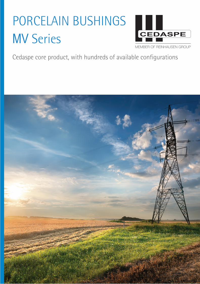
PORCELAIN BUSHINGS MV Series Cedaspe core product, with hundreds of available configurations
-
Upload
khangminh22 -
Category
Documents
-
view
0 -
download
0
Transcript of PORCELAIN BUSHINGS MV Series - Reinhausen
BUSHINGS AND ACCESSORIES FOR DISTRIBUTION AND POWER TRANSFORMERS
PORCELAIN BUSHINGSMV SeriesCedaspe core product, with hundreds of available configurations

UNCONTROLLED COPY Rev. 1/2021
BUSHINGS: GENERAL INFORMATION
1.0 Electrical characteristics (Ir = rated current; Ur = rated voltage) 1.1Standard insulation levels (IEC 60137 ed 6.0)
Rated voltage Ur
kV (r.m.s.)
One minute power frequency withstand voltage wet (dry)
kV (r.m.s.)
Dry lighting impulse withstand voltage dry
(1,2/50 ms) kV
1 3,6 12 24 36 52
10 10 (15) 28 (30) 50 (55) 70 (77) 95 (105)
20 40 75
125 170 250
1.2 Standard values of rated thermal short time current (Ith) 25 times the rated current (Ir) for 2 s; for Ir equal or greater than 4000A, Ith is always 100kA 1.3 Overload conditions (IEC 354): Bushing selected with Ir not less than 120% of the rated current of the transformers are considered to be able to withstand the overload conditions according to IEC 354. 2.0 Mechanical characteristic 2.1 Cantilever operating load (bushing installed less than 30° from vertical)
Ur Ir kV 800 A 1600 A 2500 A 3150 A 36 52
500 N 500 N
625 N 625 N
1000 N 1000 N
1575 N 1575 N
2.2 Cantilever operating load (bushing installed more than 30° from vertical)
Ur Ir kV 800 A 1600 A 2500 A 3150 A 36 52
300 N 300 N
375 N 375 N
600 N 600 N
945 N 945 N
2.3 Cantilever test load
Ur Ir kV 800 A 1600 A 2500 A 3150 A 36 52
1000 N 1000 N
1250 N 1250 N
2000 N 2000 N
3150 N 3150 N

UNCONTROLLED COPY Rev. 1/2021
3.0 Tightening torque (suggested values, +/- 10% depending on the quality of the tank cover surface) 3.1 On the central conductor LV/MV in brass or copper
3.2 On the steel fixing stud of MV bushings
Size Torque M10 M12 M16
15 Nm 25 Nm 40 Nm
3.3 On the locking bolts of the flags
Size Torque M10 M12 M16
25 Nm 40 Nm 90 Nm

UNCONTROLLED COPY Rev. 1/2021
4.0 Surface treatment of active metallic parts Standard scope of supply does not include any surface treatment or plating. Upon request, particularly for use in highly polluted environmental conditions or in tropical climate, all metal parts (in copper or brass) air side can be supplied with 6-8 micron thickness electrolytic tinplating 5.0 Gaskets During the impregnation of the transformer, it is possible to reach the max temperature of 110°C in oil and 120°C in air for 24 hours, without damaging the gaskets. Unless contrary request, the material normally used for the gaskets is NBR (nitrile rubber) suitable for use with mineral oils with MIN ambient temperature of -30°C and MAX temperature of +120°C (up to 130°C during drying process/vapour phase). Upon request available cork rubber impregnated gaskets, or in Viton, or in silicon rubber. NBC (Cork TD1120): Temp. range: -30°C/+120°C (up to 130°C during drying process/vapour phase). Cork TD7000: Temp. range: -45°C/+120°C (up to 130°C during drying process/vapour phase) VITON: Temp. range: -20°C/+150°C (recommended when bushing is installed inside a cable box or a cable duct) Fluoro Silicone: Temp. range: -60°C/+150°C 6.0 Centering ring All our bushings MV 1000 to 4500 A are fit by default with a ring to center the conductor in the lower part, The advantages offered by this solution are a better distribution of the electric field in the fixation area and a better release of the mechanical stress due to the connections under oil This ring is made by default in nylon PA6; on demand we can supply it in pressboard For high current bushings 5 to 12,5kA the ring is always in pressboard
UNCONTROLLED COPY Rev. 1/2021
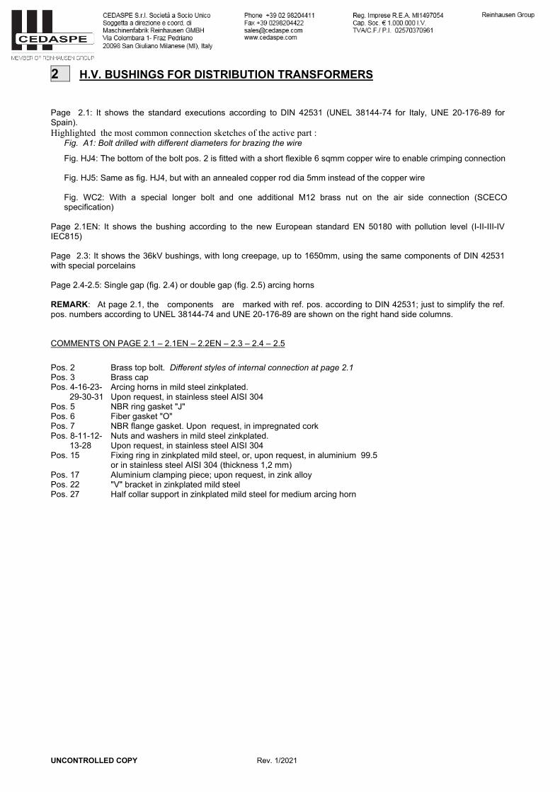
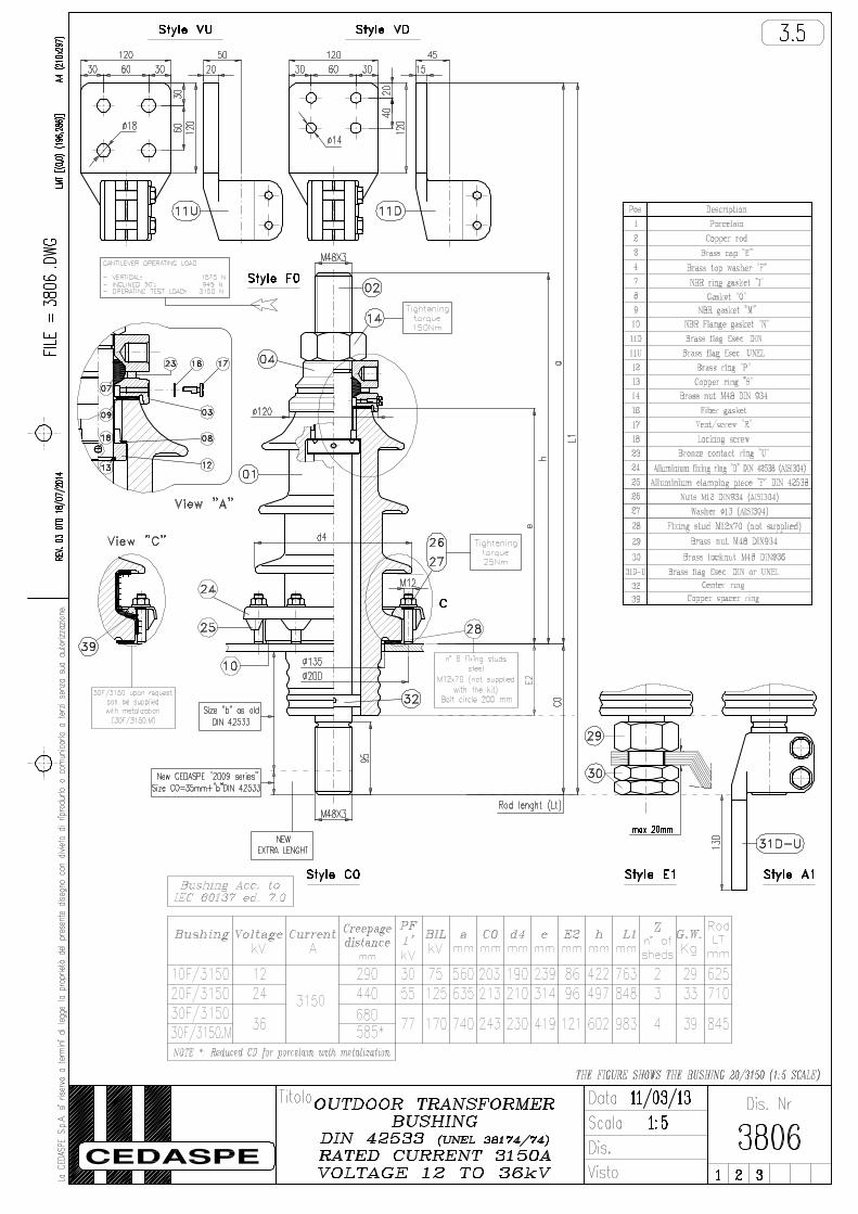
2 H.V. BUSHINGS FOR DISTRIBUTION TRANSFORMERS Page 2.1: It shows the standard executions according to DIN 42531 (UNEL 38144-74 for Italy, UNE 20-176-89 for Spain). Highlighted the most common connection sketches of the active part :
Fig. A1: Bolt drilled with different diameters for brazing the wire
Fig. HJ4: The bottom of the bolt pos. 2 is fitted with a short flexible 6 sqmm copper wire to enable crimping connection Fig. HJ5: Same as fig. HJ4, but with an annealed copper rod dia 5mm instead of the copper wire Fig. WC2: With a special longer bolt and one additional M12 brass nut on the air side connection (SCECO specification)
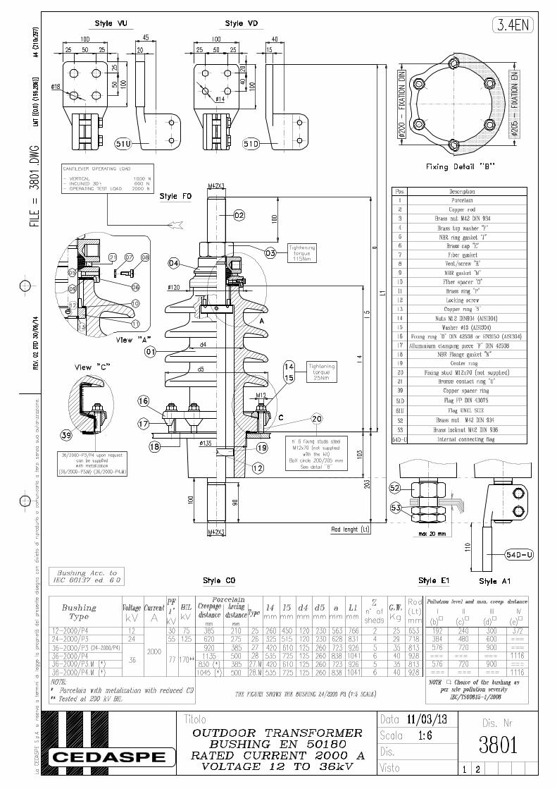
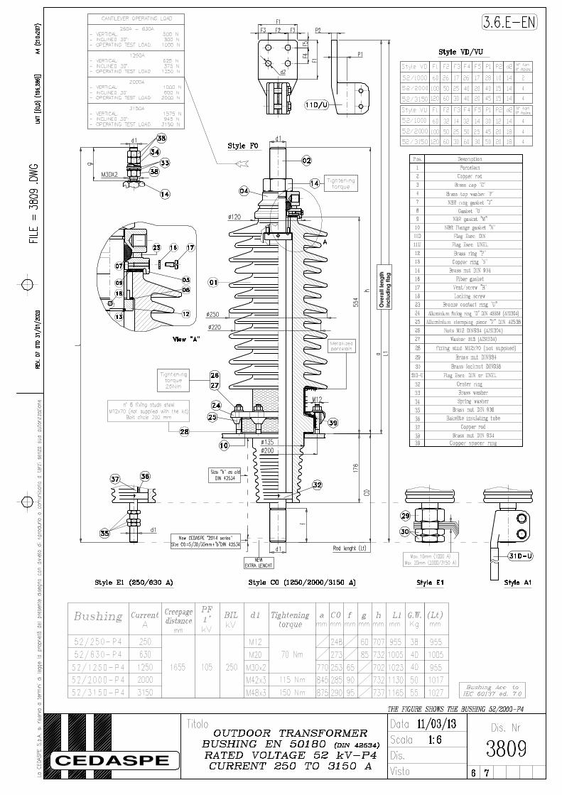
Page 2.1EN: It shows the bushing according to the new European standard EN 50180 with pollution level (I-II-III-IV IEC815) Page 2.3: It shows the 36kV bushings, with long creepage, up to 1650mm, using the same components of DIN 42531 with special porcelains Page 2.4-2.5: Single gap (fig. 2.4) or double gap (fig. 2.5) arcing horns REMARK: At page 2.1, the components are marked with ref. pos. according to DIN 42531; just to simplify the ref. pos. numbers according to UNEL 38144-74 and UNE 20-176-89 are shown on the right hand side columns. COMMENTS ON PAGE 2.1 – 2.1EN – 2.2EN – 2.3 – 2.4 – 2.5 Pos. 2 Pos. 3 Pos. 4-16-23- 29-30-31 Pos. 5 Pos. 6 Pos. 7 Pos. 8-11-12- 13-28 Pos. 15 Pos. 17 Pos. 22 Pos. 27
Brass top bolt. Different styles of internal connection at page 2.1 Brass cap Arcing horns in mild steel zinkplated. Upon request, in stainless steel AISI 304 NBR ring gasket "J" Fiber gasket "O" NBR flange gasket. Upon request, in impregnated cork Nuts and washers in mild steel zinkplated. Upon request, in stainless steel AISI 304 Fixing ring in zinkplated mild steel, or, upon request, in aluminium 99.5 or in stainless steel AISI 304 (thickness 1,2 mm) Aluminium clamping piece; upon request, in zink alloy "V" bracket in zinkplated mild steel Half collar support in zinkplated mild steel for medium arcing horn

UNCONTROLLED COPY Rev. 1/2021
3 BUSHINGS FOR LARGE DISTRIBUTION TRANSFORMERS Page 3.1: Bushings 10-20-30-40/630 according to DIN 42532 or UNEL38159-74 Page 3.1-B: Bushings 12-24-36/630 according to the new European standard EN50180 pollution level I-II-III-IV (IEC815) Page 3.2: Arcing horn kit to suit above bushings COMMENTS ON PAGE 3.1 - 3.2 Normally supplied according fig. A1 pag 3.1, draw lead type, without a/horns, with brass bolt "D" tapped M20x2,5 (Style A1) for the connection to the copper wire. Upon request, the bushing can be supplied according to fig T1 pag 3.1 with long rigid rod, and/or with arching horns (see page 3.2) with "V" bracket for bottom a/horn (UNEL execution) or without bracket (DIN style). COMPONENT LIST FIG. A1
POS. Din Ref.
POS. UNEL Ref. DESCRIPTION
Pos. 1 Pos. 2 Pos. 3 Pos. 5 Pos. 6 Pos. 7 Pos. 8 Pos. 9 Pos. 11 Pos. 12 Pos. 13 Pos. 14 Pos. 15 Pos. 17 Pos. 18 Pos. 23
(1) (2) (4) (7) (8)
(21) (22) (10) (8)
(20) (19) (17) (18) (14)
(16)
(15)
Porcelain Brass bolt "D" (usually DIN execution, on request execution "EL"). Cap "E" Ring gasket "J" Fiber gasket "O” Vent screw Nylon or fiber gasket Flange gasket "N" Brass nut M20 DIN 934 Brass washer dia 21 DIN 125 Spring washer dia 21 DIN 127 Mild steel zinkplated nut M10 Mild steel zinkplated washer dia 10,5 mm Fixing ring "B" DIN 42531 (in mild steel zinkplated or, upon request, in aluminium) Welding stud M10x55 (not supplied) Aluminium clamping piece "E" DIN 42538
FIG. T1
POS. Din Ref.
POS. UNEL Ref. DESCRIPTION
Pos. 19 Pos. 20 Pos. 21 Pos. 22
(3) (9)
(12) (13)
Rigid copper rod Brass locknut M20 DIN 936 Brass washer Insulating tube C.B.

UNCONTROLLED COPY Rev. 1/2021
4 FLAG CONNECTORS Page 4.2: Flags EP - FP DIN 43675 from 1000 to 6300 A and flags 1000-2000-3150 UNEL 38137-67 Page 4.3: Flags ER - FR DIN 43675 from 1000 to 4500 A Page 4.4: Flags 250 & 630 A – different styles Page 4.5: ANSI clamp, with eyebolt and special flags NOTE: All flags are fitted with locking bolts and washers in high tensile steel zinkplated chromium passivated; Upon request, in stainless steel AISI 304. Tightening torque on the locking bolts of the flags (suggested values, +/- 10%)
Size Torque M10 M12 M16
25 Nm 40 Nm 90 Nm


Special CT Accornodation
:I:
AT1250 R
CT 150 CT 300 CT 500 E FUT=65
L2=300 L3=450 L4=650 F Bushing L\ (Rod Leng\h)
4 lOF/1000 687 837 1037 D 2
I 5 20F/1000 762 912 1112 N3
30F/1000 867 1017 1217 3
E 12/1250-P4 722 872 1072
g �
N 24/1250-P3 787 937 1137
5 24/1250-P4
882 1032 1232 o 36/1250-P3 1 36/1250-P4 997 1147 1347 B 52/1250-Pl /P3 957 1107 1307 o
52/1250-P4 1002 1152 1352
AT2000 R
CT 150 CT 300 CT 500 E FUT=90
L2=350 L3=500 L4=700 F Bushing L\ (Rod Leng\h)
JIl
l..J..J l _J
LL :,::,
4 lOF/2000 767 917 1117 D 2
I 5 20F/2000 842 992 1192 N3
30F/2000 947 1097 1297 3
E 12/2000-P4 800 950 1150 N 24/2000-P3 865 1015 1215
5 24/2000-P4
960 1110 1310 o 36/2000-P3 1 36/2000-P4 1075 1225 1425 B 52/2000-Pl /P3 1037 1187 1387 o
52/2000-P4 1082 1232 1432
AT3150
t;
R CT 150 CT 300 CT 500
E FUT=95 L2=350 L3=500 L4=700 F
Bushing L\ (Rod Length) 4 lOF/3150 772 922 1122
D 2
I 5 20F/3150 847 997 1197 N3
30F/3150 952 1102 1302 3
E 12/3150-P4 824 974 1174 N 24/3150-P3 889 1039 1239
i1:1
5 24/3150-P4
984 1134 1334 o 36/3150-P3 1 36/3150-P4 1099 1249 1449
52/3150-Pl /P3 1042 1192 1392 o
52/3150-P4 1087 1237 1437
� Standard Split Rad ·�--------------------------------------------------.....
o
e .,
o
,h ·� -w1
o
o .e "=
·e
o
., ·se '6
e o o
D e
., '6
Titolo Special Rod f or MV Bushing
Bushing F G N°
of Type of
mm mm screws screws
E AT 1250 69 70 2 M10x20
N
5
o AT 2000 79 80 2 M12x30
1
8
o AT 3150 109 110 3 M12x30
4 AT 1250 69 70 2 M10x20
D 2
I 5 AT 2000 79 80 2 M12x30
N 3
3 AT 3150 109 110 3 M12x30
THE FIGURE SHOWS THE BUSHING 24/2000 P3
Data 30/01/14 Dis. Nr Scala ----------
3928 Dis.
Visto 1 2