Pmic
Transcript of Pmic


ProgrammingMicrocontrollers in C
Ted Van Sickle
p u b l i c a t i o n s
MOTOROLASeries in Solid State Electronics

Motorola reserves the right to make changes without further notice to any productsherein to improve reliability, function, or design. Motorola does not assume anyliability arising out of the application or use of any product or circuit describedherein; neither does it convey any license under its patent rights nor the rights ofothers. Motorola products are not authorized for use as components in life supportdevices or systems intended for surgical implant into the body or intended to sup-port or sustain life. Buyer agrees to notify Motorola of any intended use whereuponMotorola shall determine availability and suitability of its product or products forthe use intended. Motorola is a registered trademark of Motorola, Inc. Motorola,Inc. is an Equal Opportunity/Affirmative Action Employer.
Copyright © 1994 by HighText Publications, Inc. All rights reserved. No part ofthis book may be reproduced, in any form or means whatsoever, without permissionin writing from the publisher.
The material in Appendix D is reprinted with the permission of Motorola, Inc.,Semiconductor Products Sector.
ISBN: 1-878707-14-0
Library of Congress catalog number: 94-075549
Motorola Series in Solid State Electronics number: TB328
Printed in the United States of America
Cover design: Brian McMurdo, Ventana Studio, Valley Center, CAInterior design and production services: Greg Calvert, Artifax, San Diego, CA
HighText is a registered trademark of LLH Technology Publishing.
RT 2 Box 99MEagle Rock, VA 24085
p u b l i c a t i o n s c
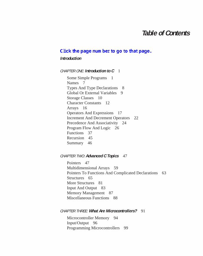
Table of Contents
Introduction
CHAPTER ONE: Introduction to C 1
Some Simple Programs 1Names 7Types And Type Declarations 8Global Or External Variables 9Storage Classes 10Character Constants 12Arrays 16Operators And Expressions 17Increment And Decrement Operators 22Precedence And Associativity 24Program Flow And Logic 26Functions 37Recursion 45Summary 46
CHAPTER TWO: Advanced C Topics 47
Pointers 47Multidimensional Arrays 59Pointers To Functions And Complicated Declarations 63Structures 65More Structures 81Input And Output 83Memory Management 87Miscellaneous Functions 88
CHAPTER THREE: What Are Microcontrollers? 91
Microcontroller Memory 94Input/Output 96Programming Microcontrollers 99

CHAPTER FOUR: Small 8-Bit Systems 111
Microcontroller Memory 113Timers 125Analog To Digital Converter Operation 150Pulse Width Modulator System 155Other Program Items 160Summary 162
CHAPTER FIVE: Programming Large 8-Bit Systems 163
Header File 163The Intermetrics Compiler 172Sorting Programs 176Data Compression 189Timer Operations 195Summary 231
CHAPTER SIX: Large Microcontrollers 233
The MC68HC16 234System Integration Module (SIM) 240A Pulse Width Modulation Program 242Intermetrics MC68HC16 Compiler 247Table Look-Up 259Digital Signal Processor Operations 265
APPENDIX A: MC68HC05 Header Files 283
APPENDIX B: typedef Example 291
APPENDIX C: MC68HC11 Background 295
APPENDIX D: MC68HC11E9 Support Information 319
APPENDIX E: MC68HC16Z1 Register Summary 329
APPENDIX F: Header Files For MC68HC16 Family 373
INDEX 391
DISKS ORDERING FORM 395

Introduction
Early detractors of the C language often said that C was little more than an over-grown assembler. Those early disparaging remarks were to some extent true and alsoprophetic. C is indeed a high level language and retains much of the contact with theunderlying computer hardware that is usually lost with a high level language. It isthis computer relevance that makes people say that C is a transform of an assembler,but this computer relevance also makes C the ideal high level language vehicle to dealwith microcontrollers. With C we have all of the advantages of an easily understoodlanguage, a widely standardized language, a language where programmers are readilyavailable, a language where any trained programmer can understand the work ofanother, and a language that is very productive.
The main purpose of this book is to explore the use of C as a programming toolfor microcontrollers. We assume that you are familiar with the basic concepts of pro-gramming. A background in C is not necessary, but some experience with a program-ming language is required. I have been teaching C programming for microcontrollersfor several years, and have found that my students are usually excellent programmerswith many years of experience programming microcontrollers in assembly language.Most have little need or interest in learning a new language. I have never had a classyet where I was able to jump into programming microcontrollers without providingsubstantial background in the C language. In many instances, students believe that ahigh-level language like C and microcontrollers are incompatible. This forces me,unfortunately, to turn part of my class into a sales presentation to convince somestudents that microcontrollers and C have a future together. I am usually able to showthat the benefits gained from using C far outweigh the costs attributed to its use. Thefirst two chapters are included for those who are unfamiliar with C. If you are alreadyfamiliar with C, feel free to skip ahead to Chapter 3.
C is a very powerful high level language that allows the programmer access to theinner workings of the computer. Access to computer details, memory maps, registerbits, and so forth, are not usually available with high level languages. These featuresare hidden deliberately from the programmer to make the languages universal andportable between machines. The authors of C decided that it is desirable to haveaccess to the heart of the machine because it was intended to use C to write operatingsystems. An operating system must be master of all aspects of the machine it iscontrolling. Therefore, no aspect of the machine could be hidden from the program-mer. Features like bit manipulation, bit field manipulation, direct memory address-ing, and the ability to manipulate function addresses as pointers have been includedin C. All of these features are used in programming microcontrollers. In fact, C is
v
vi Introduction
probably the only popular high level language that can be conveniently used for amicrocontroller.
Every effort has been made to present the C aspects of programming thesemachines clearly. Example programs and listings along with their compiled resultsare presented whenever needed. If there are problems hidden in the C code, theseproblems are explored and alternate methods of writing the code are shown. Generalrules that will result in more compact code or quicker execution of the code aredeveloped. Example programs that demonstrate the basis for these rules will beshown.
C is a rich and powerful language. Beyond the normal high level languagecapability, C makes extensive use of pointers and address indirection that is usuallyavailable only with assembly language. C also provides you with a complete set of bitoperations, including bit manipulations and bit fields in addition to logical bit opera-tions. In C, the programmer knows much about the memory map which is often underprogrammer control. A C programmer can readily write a byte to a control register ofa peripheral component to the computer. These assembly language-like features ofthe C language serve to make C the high level language of choice for the microcontrollerprogrammer.
As a language, C has suffered many well-intended upgrades and changes. It waswritten early in the 1970s by Dennis Ritchie of Bell Laboratories. As originallywritten, C was a “free wheeling” language with few constraints on the programmer. Itwas assumed that any programmer using the language would be competent, so therewas little need for the controls and hand-holding done by popular compilers of theday. Therefore, C was a typed language but it was not strongly typed. All functionreturns were assumed to be integer unless otherwise specified. Function argumentswere typed, but these types were never checked for validity when the functions werecalled. The programmer could specify an integer argument and then pass a floatingpoint number as the argument. These kinds of errors are made easily by the bestprogrammer, and they are usually very difficult to find when debugging the program.
Another set of problems with the language was the library functions that alwaysaccompanied a compiler. No standard library was specified. C does not have built-ininput/output capability. Therefore, the basic C standard contained the specificationsfor a set of functions needed to provide sensible input/output to the language. A fewother features such as a math library, a string handling library, and so forth startedout with the language. But these and other features were included along with otherenhancements in a helter-skelter manner in different compilers as new compilerversions were created.
In 1983, an ANSI Committee (The X3J11 ANSI C Standards Committee) wasconvened to standardize the C language. The key results of the work of this commit-tee has been to create a strongly typed language with a clear standard library. One ofthe constraints that the ANSI committee placed upon itself was that the existing base

viiIntroduction
of C code must compile error free with an ANSI C compiler. Therefore, all of theANSI dictated typing requirements are optional under an ANSI C compiler. In thistext, it is always assumed that an ANSI compliant compiler will be used, and theANSI C form will be used throughout.
C compilers for microcontrollers—especially the small devices—must compro-mise some of the features of a compiler for a large computer. The small machineshave limited resources that are required to implement some of the code generated by acompiler for a large computer. When the computer is large, the compiler writer neednot worry about such problems as limited stack space or a small register set. But whenthe computer is small, these limitations will often force the compiler writer to takeextraordinary steps just to be able to have a compiler. In this book, we will discuss theC programming language, not an abbreviated version that you might expect to usewith some of the smaller microcontrollers. In the range of all microcontrollers, youwill find components with limited register sets, memory, and other computer neces-sary peripherals. You will also find computers with many megabytes of memoryspace, and all of the other important computer features usually found only on a largecomputer. Therefore, we will discuss the language C for the large computer, andwhen language features must be abbreviated because of computer limitations, thesepoints will be brought out.
All of the programs found in this book have been compiled and tested. Usuallysource code that has been compiled has been copied directly from computer disks intothe text so that there should be few errors caused by hand copying of the programsinto the text. The compilers used to test these programs are available from Byte CraftLtd. of Hamilton, Ontario, Canada (for the MC68HC05) and Intermetrics of Cam-bridge, Massachusetts (for the MC68HC11 and MC68HC16). If you wish to developserious programs for any of these microcontrollers, you should purchase the appro-priate compiler from the supplier.
The example problems found in this book will show different aspects of program-ming microcontrollers in C. For your convenience, you can get the source files listedin this book. These files can be purchased on either a 5.25 inch floppy or a 3.5 inchfloppy. Each chapter has its own directory on these disks. Also on these disks areincluded demonstration copies of the three compilers used in this book. Thesecompilers will compile any of the program listings in this book. This disk is availablefor $30.00 from
Automation Technology ServicesP. O. Box 501645Indianapolis, IN 46250
VISA/MC will be accepted. See order form at the end of the book for more details.How does one partition a book on C programming for microcontrollers? First, the
text must contain a good background on the C language. Second, it is necessary to
viii Introduction
include a rather extensive background on some microcontrollers. Finally, C must beused to demonstrate the creation of code for the specified microcontrollers. Thisapproach is used here. The C background is complete. The background on the chosenmicrocontrollers is presented briefly, as this book is not intended to be a text onmicrocontrollers. Therefore, the chapters that cover specific microcontrollers are tothe point. The references found in each chapter contain texts and data books that willcover the various microcontrollers discussed. This book grew out of my teachingactivities, so chapters include several exercises suitable for classroom as well asindividual use. The only way to learn programming is to program, and the exercisesare designed to let you put the material in each chapter to use in typical micocontrollerprogramming situations.
Chapters 1 and 2 contain a background on ANSI C. Data in these chapters is basicto all C programs. There is no specific coverage for microcontroller programming.Chapter 3 contains a brief background on microcontrollers, and it also containsgeneral programming guidelines that should be used when writing code formicrocontrollers.
Chapter 4 is devoted to writing programs for the MC68HC05 family. In thischapter, the use of microcontroller specific header files is introduced. These headerfiles are written for a specific part, and must be included in any program for the part.
In Chapter 5 you will find techniques for programming the MC68HC11 family ofparts. Several of the peripherals on these parts are examined, and code to access theseperipherals is written.
More complex microcontrollers are found in the MC68HC16 and the MC68300families. Programming the MC68HC16 is discussed in Chapter 6. This part containsan internal bus with several peripherals placed on this bus. Access to these peripher-als is through memory mapped registers and how these peripherals are accessed willbe found in Chapter 6.
There are several appendices. Appendix A contains several header files that areuseful in programming MC68HC05 programs. Appendix B contains some code thatdemonstrates the power of the types defined by structures, and how these types can bemade into very convenient new types by the typedef keyword.
One of the advantages of a high level language is that it isolates the programmerfrom the details of the computer being programmed. There are both plusses andminuses to this idea. First, as a programmer, you do not need to know details of theregister map and the programmers model of the computer being programmed becausethe language takes care of these details for you. On the other hand, microcontrollersall have peripherals and other components that must be accessed by the program. Theprogrammer must be able to write C code that will set and reset bits and flags incontrol registers for these parts. It would be desirable to write this book with nodetailed discussion of the insides of the microcontrollers you will be programming;however, I could not do it. I needed a careful discussion of the ways peripheral

ixIntroduction
components are used. Appendix C and Appendix E contain detailed descriptions ofthe MC68HC11 and the MC68HC16 family parts respectively. I am particularlyindebted to Motorola Semiconductor Products, Inc. for the contents of Appendix E.This Appendix is a very slightly modified version of the Appendix D found in theMC68HC16Z1 users manual.
Appendix C contains a header file for the MC68HC11Ex series, and Appendix Fcontains several header files needed to program the MC68HC16 components.
This book has taken entirely too much time to write. As the author, it is my fault,and I have been a burden to those around me while I have labored on this task. Thebasis for the text comes from about three years of teaching classes on programmingmicrocontrollers in C. This class has been taught as a three or four day course, mainlyto Motorola customers. I am amazed that it is possible to learn from every class that Iteach. During the time I have been writing, I have learned object oriented program-ming and the C++ language, and I have also taught classes on this subject. It isdifficult to move from one language to another, especially languages with similarroots like C and C++, and not get them mixed up. I am comfortable that this book ison C without C++ spilling into the material.
I have received much help in writing this book. My dear wife, who understandsnothing about computers, has read most of the book and made comments about thecontents. If this text is more readable than usual, it is her contribution. Any problemsthat you find are my responsibility entirely.
Motorola has provided me much time and support that I appreciate. Most of thephotographs found in the book are from Motorola files. My manager, Neil Krohn, hasencouraged me at every phase in the preparation of this manuscript. Neil and Motoroladeserve my heartfelt thanks.


1
Chapter 1
Introduction to CProgramming is a contact sport. Programming theory is interesting, but you must
sit at a keyboard and write code to become a programmer. The aim of this introduc-tory section will be to give you a brief glimpse of C so that you can quickly writesimple programs. Later sections will revisit many of the concepts outlined here andprovide a more in depth look at what you are doing. For now, let’s start writing code.
Some Simple ProgramsC Program Form
C is a function based language. You will see that C uses far more functions thanother procedural languages. In fact, any C program itself is merely a function. Thisfunction has a name declared by the language. In C, parameters are passed tofunctions as arguments. A function consists of a name followed by parenthesesenclosing arguments, or perhaps an empty pair of parentheses if the function requiresno arguments. If there are several arguments to be passed, the arguments are sepa-rated by commas.
The mandatory program function name in C is main . Every C program musthave a function named main , and this function is the one executed when the programis run. Examine the following program:
#include <stdio.h>
void main(void){
printf("Microcontrollers run the world!\n");}
This program contains all of the elements of a C program. Note first that C is a “freeform” language. Spaces, carriage returns, tabs, and so forth are for the programmer’sconvenience and are ignored by the compiler. The first line of the program
#include <stdio.h>
1

2 Chapter 1 Introduction to C
is called a preprocessor command. Preprocessor commands are identified by the #at the beginning of the line. In this case, #include tells the preprocessor to openthe file stdio.h and read it into the program to be compiled with the remainder ofthe program. The file name is surrounded by angle brackets < >. These delimiters tellthe compiler to search for the file in a region designated by the operating system asSET INCLUDE. Had the file name been delimited by double quotes, " ", theoperating system would have searched only the default directory for the file. Thedefault directory is, of course, the directory from which you are operating.
The next line of the program is a definition for a function named main . In ANSIC, as opposed to classic C, each function definition must inform the compiler of thereturn type from the function, and the type of the function’s arguments. In this case,the function main has no return and it expects no arguments. The type void wasdefined in ANSI C to take care of this situation. The statement
void main(void)
tells the compiler that main has no return, and it requires no arguments.The line following the function definition contains an opening brace {. This brace
designates the beginning of a block or a compound statement. The next line of theprogram contains a function call to the function printf() . This function is madeavailable to the program by the inclusion of the header file stdio.h, and it is afunction that writes a message to the computer terminal screen. In this case, themessage to be sent to the screen is
Microcontrollers run the world!
The escape character '\n' at the end of the message informs the program toinsert a new line at that point. The complete message including the new line escapecharacter is enclosed in double quotes. These double quotes identify a string, and thestring is the argument to the function printf() . Note that the statement beginningwith printf is closed with a semicolon. In C, every statement is terminated with asemicolon.
The program is closed by the inclusion of a closing brace, }, at the end. Therecould be many statements within the block following main() creating a programof any complexity. The closing brace is the terminator of a compound statement.The compound statement is the only case in C where a complete statement closuredoes not require a semicolon.

3
Additional ExamplesAnother program example is as follows:
#include <stdio.h>
void main (void){
int a,b,c,d;
a=10;b=5;c=2;
d=a*b*c;printf("a * b * c = %d\n", d);
d=a*b+c;printf("a * b + c = %d\n", d);
d=a+b*c;printf("a + b * c = %d\n", d);
}
Before discussing this bit of code, we need to talk about the numbers used in it.Like most high-level languages, C provides for different classes of numbers. Theseclasses can each be variable types. The first class is the integer type and the secondis the floating point type. We will examine these number classes in more detaillater, but for now let us concentrate on the integer types. These numbers usually havea numeric range of +/- 2n-1, where n is usually the number of bits that contains theinteger type. Integer types do not “understand” or permit fractions. Any fraction thatresults from a division operation will be truncated and disappear from the calculation.
All variables must be declared to be a specific type prior to their use in a program.The first line of code in main
int a,b,c,d;
declares the variables a, b, c, and d to be integer types. Declaration statementscause memory to be allocated for each variable, and a label name to be assigned eachlocation.
Some Simple Programs

4 Chapter 1 Introduction to C
The three assignment statements
a=10;b=5;c=2;
assign initial values to the variables a, b, and c. The equal sign signifiesassignment. The value 10 is placed in the memory location designated as a, etc. Thenext statement
d=a*b*c;
notifies the compiler to generate code that will cause the integer stored in location a tobe multiplied by the integer in b and the result of that product to be multiplied by theinteger found in c. Usually, the name a, b, or c is used to designate the contentof the memory location assigned to the label name. This integer result will be storedin the location identified by d.
The print statement
printf("a * b * c = %d\n", d);
is similar to the same statement in the first example. In this case, however, the datastring
"a * b * c = %d\n"
contains a printer command character %d. This character notifies the printffunction that it is to take the first argument following the data string, convert it to adecimal value, and print it out to the screen. The result of this line of code will be
a * b * c = 100
printed on the screen.The line of code
d=a*b+c;
demonstrates another characteristic of the language. Each operator is assigned aprecedence that determines the order in which an expression is evaluated. Theparenthesis operators are of the highest precedence. The precedence of the * operatoris higher than that of the + operator, so this expression will be evaluated as
d=(a*b)+c;

5
In other words, the product indicated by * will be executed prior to the additionindicated by the +. The expression that follows later in the code
d=a+b*c;
will be evaluated as
d=a+(b*c);
causing the result of the third calculation to differ from that for the second.The result obtained when running this program is as follows.
a * b * c = 100a * b + c = 52a + b * c = 20
Here is another example that demonstrates a primitive looping construct:
#include <stdio.h>
void main(void){
int i;
i=1;printf("\ti\ti\ti\n");printf("\t Squared Cubed\n\n");while(i<11){
printf("\t%d\t%d\t%d\n", i, i*i, i*i*i);i=i+1;
}}
This example was designed to produce a simple table of the values of the first tenintegers, these values squared, and these values cubed. The lines
printf("\ti\ti\ti\n");printf("\t Squared Cubed\n\n");
combine to produce a header that identifies the contents of the three columns gener-ated by the program. The escape character \t is a tab character that causes the screencursor to skip to the next tab position. The default tab value in C is eight spaces.
Some Simple Programs

6 Chapter 1 Introduction to C
The command
while(i<11).....
causes the argument of the while to be evaluated immediately, and if the argumentis TRUE, the statement following the while will be executed. The argument shouldbe read “i is less than 11.” The initially assigned value for i was 1, so the argumentis TRUE. The compound statement
{printf("\t%d\t%d\t%d\n", i, i*i,i*i*i);i=i+1;
}
will start execution with the value of i being equal to 1. Once this statement isevaluated, control is passed back to the while and its argument is evaluated. If theargument is TRUE, the statement following will be evaluated again. This sequencewill repeat until the argument evaluates as FALSE.
In this expression, the string argument of the printf function contains three%d commands. Each %d command causes the corresponding argument followingthe string to be printed to the screen. There are tab characters ,\t, to separate thevarious printed values on the screen. The first %d will cause the value of i to beprinted on the screen. The second %d will cause the value i*i, or i 2, to beprinted to the screen. The third %d will print the value of i*i*i, or i 3 to beprinted. When C executes the function call, the values of the arguments are calculatedprior to the call, so arguments like i*i are evaluated by the calling program andpassed by value to the function.
The statement
i=i+1;
is an example of the use of both precedence and association—the direction in whichexpressions are evaluated—in C. The equal sign here is an operator just like the +symbol. The + operator is evaluated from left to right, and the = operator is evaluatedfrom right to left. Also, the + operator has higher precedence than the = operator.Therefore, the above statement will add one to the value stored in i and then assignthis new value to the variable i. This expression simply increments the variable i.
The above statement is the terminating statement of the compound statementfollowing the while. Since i had an initial value of 1, control will be returned tothe while with a value of 2 for i. 2, of course, is less than 11, so the statementfollowing the while will be executed again and new values will be printed to thescreen. This sequence will be repeated until the incremented value for i equals 11, atwhich time i<11 will be FALSE. At that point in the program, the statement followingthe while will be skipped, and the program will have reached its end.

7
The result of executing the above program is shown in the following table:
i i 2 i 3
1 1 12 4 83 9 274 16 645 25 1256 36 2167 49 3438 64 5129 81 72910 100 1000
EXERCISES1. Write, compile, and execute each of the example programs shown in this section.
2. Write a program to calculate the Fahrenheit temperature for the Celsius valuesbetween 0° degrees and 100° in steps of 10° each. The conversion formula isF=9*C/5+32. Use integer variables, and examine the result when you use F=C*(9/5) + 32. What went wrong?
NamesVariables and constants in C are named, and the program controls operations
on these named variables and constants. Variables and constants are called oper-ands. Before a variable or constant can be used by a program, it must be given atype. The names for variables and constants can be as many as 31 characters long.The characters that make up the name can be the upper and the lower case letters,the digits 0 through 9, and the underscore character '_'. Because most C compilersand libraries use the underscore character as a name’s first character as a namingconvention, you should avoid its use as the first character for either function orvariable names. Compilers usually allow the names to be unique in the first 31characters. Unfortunately, some linkers used to link various program modulesrequire that the names be unique in the first six or eight characters depending onthe linker.
Names

8 Chapter 1 Introduction to C
C has a collection of keywords that cannot be used for names. These keywords arelisted below:
KEYWORDSauto double int structbreak else long switchcase enum register typedefchar extern return unionconst float short unsignedcontinue for signed voiddefault goto sizeof volatiledo if static while
Types and Type DeclarationsC has only a few built-in types. Here they are:
char —a byte which is usually eight bits is capable of storing a single character.
int —an integer is usually the size of the basic unit of storage for the machine.
float —a single precision floating point number.
double —a double precision floating point number.
Additional qualifiers are used to modify the basic types. These qualifiers include:
short —modifies an int , and usually produces a variable size that is smallerthan the normal int . For example, on a 32-bit machine, an int might be 32 bits anda short int could be 16 bits.
long —modifies an int , and usually produces a variable size that is larger thanthe normal int . For example, on a 16-bit machine, an int might be 16 bits, and along int could be 32 bits. long can also modify a double to specify an extendedprecision floating point number.
signed —modifies the type char or int and produces a range of numbers thatcontains both positive and negative numbers. For example, if the type char is 8 bits,a signed char can contain the range of numbers -128 to +127. Default for charand int is signed when they are declared.
unsigned —modifies the type char or int and produces a range of numbersthat are positive only. For example, if the type char is 8 bits, an unsigned charcan contain the range of numbers 0 to +255.
There are other qualifiers that can be used. These qualifiers will be discussedlater in the text. It is not necessary to include the type int with the qualifiers shortor long . Thus, the following statements are the same:

9Global or External Variables
long int a,c;short int d;
and
long a,c;short d;
When a variable is declared, space is allocated in memory for its storage. Thebasic variable size is implementation dependent, and especially for microcontrollers,you will find that this variability will show up when you change from one microcom-puter to another.
Each variable must be declared prior to being used. A variable may be declared atthe beginning of any code block, and the variable’s scope is the block in which it isdeclared. When the block in which the variable is declared is exited, the variable goesout of existence. There is no problem with declaring variables with the same name indifferent blocks. The compiler will make certain that these variables do not get mixedup in the execution of the code.
Global or External VariablesVariables declared outside of the program blocks are called global or external
variables, and the scope of global variables is the entire program. Any functioncontained within the file that contains a global declaration can access a globalvariable directly. If there is a global variable that is declared in one file that is to beaccessed by a function defined in another file, the function must notify the compilerthat the variable is global with the use of the keyword extern. The following is anexample of such an access.
In file 1:
int able;
void main(void){
long quickstart(void);long r;...able=17;l=quickstart();..
}

10 Chapter 1 Introduction to C
In file 2:
long quickstart(void){
extern int able;...return result;
}
When the file 1 is compiled, the variable able is marked as global, and memoryis allocated for its storage. When the file 2 is compiled, the variable able isrecognized to be global because of the extern keyword, and no memory is allo-cated for the variable. When the link phase of the compilation is completed, alladdress references to able in file 2 will be assigned the address of able that wasdefined in file 1.
Storage ClassesAdditional modifiers are called storage classes and designate where a variable is
to be stored and how it is initialized. These storage classes are auto (forautomatic), register, and static.
For local variables defined within a function, the default storage class is auto.An automatic variable has the scope of the block in which it is defined, and it isuninitialized when it is created. Automatic variables are usually stored on the pro-gram stack, so space for the variable is created when the function is entered. When thestack is cleaned up prior to the return at the end of the function, all variables stored onthe stack are deleted.
As we saw in our first program example, variables can be initialized at the time ofdeclaration by assigning the variable an initial value:
int rupt=17;
An automatic variable will be assigned its initial value each time the block inwhich it is declared is entered. If the variable is not initialized at declaration, it willcontain the contents of uninitialized memory which can be any value.
Sometimes you might want to assign a value to a variable and have it retain thatvalue for later function calls. Such a variable can be created by calling it staticat its declaration. static variables have a scope of the function in which they aredefined, and they are initialized to 0 when they are created. Inside of a function, thefollowing declaration is made:
static int keep = 1;

11
Note that keep is not stored on the stack, but rather stored is a static datamemory area. Being a static variable, keep is initialized to the value 0 when theprogram is loaded. The first time that the function is entered, the value 1 is assigned tokeep. Thereafter, each time the function is entered, keep will not be initialized andit will retain the value assigned to it the last time the function was executed.
Another automatic storage class is register. Integer variables can be de-clared to be stored in register by a declaration like:
register int roger=10;
These variables can be long, short, or char. When a variable is declaredto be register, the compiler will attempt to store it in an available computerregister. Such variables can be accessed quicker than variables stored in memory, sovariables used in tight loops might best be register variables. Of course, register spacein computers is limited, especially in small microcontrollers. Therefore, registers willnot often be available for data storage. When the compiler senses that there is noavailable register for data storage, it makes the variable a normal automatic variableand provides for its storage in memory.
Global variables are initialized to zero when the program is loaded. Thesevariables have the scope of the entire program. Global variables act like staticvariables in that their values will be initialized either to zero or an initially assignedvalue when created. Subsequent change in a global variable will be the result of aspecific programmed assignment.
Global variables can be designated as static. A global variable that is staticis similar to a conventional global variable with the exception that it can be accessedonly from the file in which it is declared. The example above in which the declaration
extern int able;
allowed access to able from the file 2 will not work if able had been declared asfollows in file 1:
static int able;
An additional qualifier is const. When const is used as a qualifier on thedeclaration of any variable, an initialization value must be declared. This valuecannot be changed by the program. Therefore the declaration
const double PI = 3.14159265;
will create the value for the mathematical constant pi and store it in the locationprovided for PI. Any attempt to change the value of PI by the program will causecompiler error.
Storage Classes

12 Chapter 1 Introduction to C
Conventions for writing constants are straightforward. A simple number with nodecimal point is an int. To make a number long, you must suffix it with an l or anL. For example, 6047 is an int and 6047L is a long. The u or U suffix on a numberwill cause creation of a proper unsigned number.
A floating point number must contain a decimal point or an exponent or both. Thenumbers 1.114 and 17.3e-5 are examples of floating point numbers. All floating pointnumbers are of the type double unless a suffix is appended to the number. Anynumber suffixed with an f or an F is a single precision floating point number, and asuffix of l or L on a floating point number will generate a type long double.
Octal (base 8) and hexadecimal (base 16) numbers can be created. Any numberthat is prefixed with a 0—a leading zero—is taken to be an octal number. Hexadeci-mal numbers are prefixed with a 0x or a 0X. The rules above for L and U also applyto octal and hexadecimal numbers.
Character ConstantsCharacter constants or escape sequences are data that can be stored in memory
locations designated as char. A character constant is identified by a backslashpreceding the character. We have seen the use of the character constants '\n' and'\t' in previous examples. Several of these escape sequences shown in the follow-ing table have predefined meanings.
Escape MeaningSequence\a bell character\b backspace\f form feed\n new line\r carriage return\v vertical tab\t horizontal tab\\ back slash\’ single quote\” double quote\ooo octal number\xxx hexadecimal number
If these constants are used within a program, they must be identified by quotes. Inthe earlier example, the new line character was a part of a string. Therefore, iteffectively was contained in quotes. If a single character constant is to be generated,the constant must be included in single quotes. For example, a test might include astatement like

13
if(c!='\t')....
This statement causes the variable c to be compared with the constant '\t' , andthe statement following the if will be executed if they are not the same.
Another preprocessor command is #define. With the #define command,you can define a character sequence that will be placed in your code sequencewhenever it is encountered. If you have character constants that you wish to use inyour code, these constants can be identified as
#define CR '\x0d'#define LF '\x0a'#define BELL '\x07'#define NULL '\x00'
and so forth.We’ll discuss the #define preprocessor command further later. The following
program shows use of an escape character.
/* Count lines of text in an input */
#include <stdio.h>
void main(void){
int c,nl=0; /* the number of lines is in nl */while((c=getchar())!=EOF)
if(c=='\n')nl++;
printf("The number of lines is %d\n",nl);}
Often you will want to leave “clues” as to what the program or line of code issupposed to do. Comments within the code provide this documentation. A C com-ment is delimited by
/* . . . . . . . */
and the comment can contain anything except another comment. In other words,comments may NOT be nested. The first line of code in the above program is acomment, and the sixth line contains both code and a comment. The compiler ignoresall information inside the comment delimiters.
Character Constants

14 Chapter 1 Introduction to C
This program uses two integer variables c and nl. The variable c is thetemporary storage location in which input data are stored, and nl is where thenumber of input lines are counted.
The while statement contains a rather complicated argument. At any point in aC program when a value is calculated, it can be stored in a specified location. Forexample in the while expression
while((c=getchar()) != EOF)
the inner expression
c=getchar()
causes the function getchar() to be executed. The return from getchar() is acharacter from the input stream. This character is assigned to the variable c. Afterthis operation is completed, the result returned from getchar() is compared withthe constant EOF. EOF means end-of-file, and it is the value returned by getchar()when a program tries to read beyond the end of the data stream. It is defined in the filestdio.h. The symbol != is read “is not equal to.” Therefore, the argument of thewhile will be TRUE so long as getchar() does not return an EOF and thestatement following the while will be continually executed until an EOF is returned.
Operators in an expression that have the higher precedence will be executedbefore the lower precedence operators. In the expression
c= getchar() != EOF
the operator != has a higher precedence than that of the = operator. Therefore, whenthis expression is evaluated, the logical portion of the expression will be evaluatedfirst, and the result of the logical evaluation—either TRUE or FALSE—will beassigned to the variable c. This result is of course incorrect. To avoid this problem,use
(c = getchar()) != EOF
as the while argument. In this case, the parenthesis group the c=getchar()expression and it will be completed prior to execution of the comparison. Thevariable c will have the correct value as returned from the input stream. If the aboveexpression is logically true, then the value that was returned from the input stream istested to determine if it is a new line character. If a new line character is found, thecounter nl is incremented. Otherwise, the next character is read in and the sequencerepeated until an EOF is returned from the getchar().

15
The final statement in the program
printf("The number of lines is %d\n",nl);
prints out the number of new line characters detected in reading the input file.The name enum is used in C in a manner similar to the #define preprocessor
command. The enum call
enum state ( OUT, IN);
produces the same result as
#define OUT 0#define IN 1
Here, the name state is called the tag name. In this case OUT will be given avalue of 1 and IN a value 1. In the enum() form, unless specifically assigned, themembers will be given successively increasing values and the first will be given avalue 0. Values can be assigned by an enum():
enum months (Jan =1,Feb, Mar, April, May, June, July, Aug,Sept, Oct, Nov, Dec);
will cause Jan to be 1, Feb 2, and so forth up to Dec which will be 12. Each membercan be assigned a different value, but whenever the programmer assignments stop,the values assigned to the variables following will be successively increase. Thesevalues are, by default, of the int type. Another example is
enum (FALSE, TRUE, Sun=1,Mon, Tues,Wed,Thur,Fri,Sat);
will result in FALSE being 0, TRUE 1, Sun 1, Mon 2, and so forth to Sat 7. Notethat it is not necessary to assign a tag name to an enum.
An enum can be typed at declaration time. Therefore, the values created byan enum are indeed numerical values. This differs from the #define because thestatement
#define FALSE 0
will cause the character ‘0’ to be inserted into the code whenever the label FALSEis encountered. As such, the #define construct is a character substitution tech-nique or a macro expansion. The result of an enum is a numerical substitution. The#define construct, being a simple character substitution, has no typing attachedto its arguments. Constants created by an enum can be typed, and therefore, willavoid many of the potential hazards of dealing with untyped variables.
Character Constants

16 Chapter 1 Introduction to C
ArraysAn array is a collection of like types of data that are stored in consecutive
memory locations. An array is designated at declaration time by appending a pair ofsquare brackets to the array name. If the size of the array is to be determined at thedeclaration, the square brackets can contain the number of elements in the array.Following are proper array declarations.
extern int a[];long rd[100];float temperatures[1000];char st[]={"Make a character array"};float pressure[]={ 1.1, 2.3, 3.9, 3.7, 2.5, 1.5, 0.4};
As you can see, the size of an array must be designated in some manner beforeyou can use empty square brackets in the designation. In the first case above, the arraya[] is defined in global memory, so all that is necessary for the compile to know isthat a[] is an array. The argument of an array is sometimes called its index. It is anumber that selects a specific entry into an array. Array arguments start with zeroalways. Therefore, when an array of 100 elements is created, these elements areaccessed by using the arguments 0 to 99. The element corresponding to 100 will notbe a part of the array, and its use will cause unpredictable results.
Arrays can be initialized at declaration. The initialization values must be en-closed in braces, and if there are several individual numerical values, these valuesmust be separated by commas. In the case of a string initialization, it is necessary toinclude the string in quotes and also enclose the string along with its quotation markswithin the braces. In both of these cases, the size of the array is calculated at compiletime, and it is unnecessary for the programmer to figure the size of the array.
A string is a special case of an array. Whenever a string is generated in C, anarray of characters is created. The length of the array is one greater than the length ofthe string. The individual characters from the string are placed in the array entries. Tobe a proper C string, the array’s last character must be a zero or a NULL. All strings inC are NULL terminated. If you as a programmer create a string in your program, youmust append a NULL on the end of the character array to be guaranteed that C willtreat the array as a string.
C provides you with no array boundary checking. It is the programmers responsi-bility to guarantee that array arguments do not violate the boundaries of the array.
EXERCISES1. Write a program that reads all of the characters from an input file and prints the
characters on the screen. Use the getchar() function used earlier to read theinputs and the putchar(c) to print the results to the screen.

17
2. Modify the above program to count the number of characters in an input stream.
3. Write a program that reads the characters from an input file and counts in an arraythe occurrences of each letter. Make the program “case insensitive” by treating allupper case letters as lower case.
Operators and ExpressionsThe variables and constants discussed in the previous section are classed as
operands. They are values or objects that are operated upon by a program. Theoperations that take place are specified by operators. This section contains a discus-sion of several types of operators.
Operators abound in C. All of the symbols involved in the language are operators.Each has a precedence and an associativity. This section is concerned with howoperators and operands are put together to interact in a manner desired by theprogrammer.
Arithmetic OperatorsThe arithmetic operators are those used to perform arithmetic operations. These
operators are:
• +• -• *• /• %
These operators are called binary operators because they are always used withtwo operands. These operands are placed on either side of the operator.
The symbol + designates arithmetic addition, and the - symbol designatessubtraction. The symbols * and / designate multiplication and division respectively.These operators are clearly different for different variable types. The compiler under-stands these differences and creates correct code for the operand types involved. Themodulus operator % returns the remainder after an integer division. The modulusoperator works only on integer types—int, char, and long. It cannot beapplied to types long or double.
Two unary operators are + and –. These operators are of higher precedence thanthe normal arithmetic operators. They operate on only the operand written to the rightof the operator and are therefore called unary. The unary minus sign causes thenegative value of the operand to be calculated, and the unary positive sign causes nocalculation to take place.
Among the binary operators, * , / , and % have equal precedence, which is higherthat of + and - . The unary operators + and - have a higher precedence than * , / , or %.
Operators and Expressions

18 Chapter 1 Introduction to C
The arithmetic operators will work with any of the arithmetic types. Because theoperations needed to an integer operation differ from those needed for the corre-sponding double operation, the compiler will place the proper arithmetic routines inthe code do perform the specified operation.
The concept of a fraction is almost unknown to an integer type. If a division oftwo integers is executed, the result is rounded down. Therefore, the result of 1/2 is 0as is 9999/10000. This characteristic is often used in programming.
The only way that you can handle fractions with integer operations is to make useof the modulus operation. The result of a % b is the remainder that is left over after ais divided by b. The modulus operation can provide insight into fractional value ofwhat is left over after an integer divide.
EXERCISES1. Write a program that evaluates
f(x) = X2 - 3X + 2
for values of X in 0 < = X < = 3 for in steps of 0.1.
2. The roots of a quadratic equations can be evaluated by the equation
x = (-b + sqrt(b2 - 4ac))/2a
and
x = (-b - sqrt(b2 - 4ac))/2a
where the quadratic equation is ax2 + bx + c = 0. Write a program that will evaluatethe roots of such an equation. Note that the term
sqrt(b2 - 4ac)
is called the discriminant. If its argument is not positive, the square root of anegative number is imaginary and the equation has complex roots. Handle bothreal and complex roots in your program.
Relational or Logical OperatorsThe relational operators are all binary operators. When contained in an expres-
sion, the program will evaluate the left operand and then the right operand. Theseoperands will be compared, and if the comparison shows that the meaning of theoperator is correct, the program will return 1. Otherwise, the program will return a 0.In the vocabulary of C, FALSE is always zero. If calculated by a logical expression,TRUE will always be one. However, if the argument of a conditional expression isanything but zero, it will respond as if the argument is TRUE. In other words, FALSEis always zero and TRUE is anything else.

19
The relational operators are:
• < (less than)• <= (less than or equal to)• > (greater than)• >= (greater than or equal to)
These operators all have the same precedence, which is slightly higher than thefollowing equality operators:
• == (is equal to)• != (is not equal to)
The logical operators are && and || . The first operator indicates a logical ANDand the second a logical OR. A logical AND will return TRUE if both of its operandsare TRUE, and a logical OR will return TRUE if either of its operands is TRUE. Thelogical OR has lower precedence than the logical AND. The precedence of the logicalAND is lower than the precedence of the relational operators and the equalityoperators.
In the evaluation of long logical expressions, the program starts on the left side ofthe expression and evaluates the expression until it knows whether the whole expres-sion is true or false, and it then exits the evaluation and returns a proper value. Forexample, suppose there is a character c , and it is necessary to determine if thischaracter is letter. In such a case, the following logical expression might be used:
if( c >= 'A' && c <= 'Z' || c >= 'a' && c <= 'z')
The logical and operator && has lower precedence than any of the relationaloperators, so the relational expressions will each be evaluated prior to the &&operations. If upon entering this expression, c is equal to the character '5' , which isarithmetically smaller than any of the letters, the first term c >= 'A' will beFALSE. Therefore, the result of the first logical and expression is known to beFALSE without evaluating the term c <= 'Z' . The evaluation will then skip to thethird term c >= 'a' , and the term c <= 'Z' will not be evaluated. In this case, thecharacter '5' will be smaller than the character 'a' so that the second and expres-sion will also be FALSE. Therefore, the logical value will be known after evaluationof only two of the logical terms of the argument rather than having to evaluate all fourof the terms.
EXERCISES1. Write a function that converts a character that is a letter to lower case.
2. Leap years occur every four years unless the year happens to be divisible by 100.Any year divisible by 400 is a leap year, however. Write a logical expression thatwill return TRUE if the given year is a leap year and FALSE if it is not.
Operators and Expressions

20 Chapter 1 Introduction to C
Type Conversions Within ExpressionsImplied in our earlier discussions on variable types, different data types not only
occupy different width in memory, some may be completely incompatible whenattempting to execute operations involving mixed data types. In earlier languages, itwas up to the programmer to guarantee that the data types involved with an operationwere the same. C resolves this problem, and the compiler will select the proper datatype to complete operations on mixed data types.
Each data type has an implied width. When an operation is to be executed onmixed data types, the widths of the two types are evaluated, and the lesser widthoperand is promoted to the type of the greater width operand prior to execution of theoperation. Thus, if the program called for d = a * b , where d is of type long , a istype int , and b is type long , a will be converted to the type long prior to themultiplication.
This logic carries over to mixing of float and double types as well. If forexample a program called for the division a/b where a is of the type int and b is ofthe type double , the program would convert a to the type double before execu-tion of the divide.
There might be times when the programmer will want to change the type of avariable. C provides a cast operator which forces the program to convert the type of avariable to a different type. This unary operator has the form.
(type name) expression
where the results of the evaluation of expression will be converted to the named typecontained within the parenthesis preceding the expression.
Bitwise OperatorsOperators that work on the individual bits within a variable are called bitwise
operators. Following is a table of all of these operators:
• & bitwise AND • >> right shift• | bitwise Inclusive OR • << left shift• ^ bitwise Exclusive OR • ~ one’s complement
The first three bitwise operators are traditional binary operators. These binaryoperators operate in integer type (char , int , long , etc.) operands, and the twooperands must be of the same type.
If a bitwise AND is executed, those locations in the result where both operandshave bit values of 1 will have a value of 1. All other locations will be 0. For a bitwiseinclusive OR, each bit in the result will be 1 when either or both operand bits are 1.All locations where both operand bits are 0 will be 0. The exclusive OR is similar to

21
an addition with no carry. Whenever the bits in the operands are different, the resultbit will be 1. If both operand bits are the same, either both bits 1 or both bits 0, theresult will be 0.
The right shift operator and the left shift operator are also binary operators. Herethe types of the operands need not be the same. the expression
x >> 3
causes the variable x to be shifted to the right by three bits prior to its use. Likewise,
y << 5
will cause y to be shifted to the left by five bits. In all number systems, a left shift byone digit corresponds to a multiplication by the number base. Similarly, a shift to theright by one digit causes a division by the number base. We are using the binarysystem in this case, so a shift left by one bit causes the number to be multiplied bytwo. Unlike most number systems, the binary system (or two’s complement system)allows the sign of the number to be contained in the binary representation of thenumber itself. These considerations lead to two different types of shifts for a systemof binary numbers. A shift in which bits vacated by the shift are replaced by zeros iscalled a logical shift. All left shifts are logical shifts. As the shift progresses towardthe left, bits that fill the number from the right will all be zero. Bits that shift out of thenumber on the left side are lost. A right shift can be either a logical or an arithmeticshift. If the type being shifted is signed, the sign bit—which is the leftmost bit—willpropagate, retaining a number of the same sign. This is an arithmetic sign. If thenumber being shifted in unsigned, zeros are filled into the number from the left as thesift proceeds. In all cases, bits shifted out of a number by a shift operation will be lost.
The one’s complement operator ~ is a unary operator that causes the bits in avariable to be reversed. Every 1 is replaced by a 0, and every 0 is replaced by a 1.
The bitwise AND and OR operations are used to turn bits on and off. Supposethat we have a character variable r, and we wish to turn the least significant three bitsoff. Try
r = r & ~7;
In this case, the number 7 has each of the least significant bits turned on or 1.Therefore, the term ~7 has all of the bits in the number but the least significantturned on and these three bits are turned off or 0. When this mask is ANDed with r ,all of the bits of r , with the exception of the least significant three bits, will beANDed with a 1, and these bit values will remain unchanged. The least significantthree bits will be ANDed with 0 and the result in these three bits will be 0.
The bitwise OR will turn bits on. Suppose you wanted to turn bits 2 and 3 of rabove on. Here you would use
r = r | 0x0c;
Operators and Expressions

22 Chapter 1 Introduction to C
The hexadecimal number 0x0c is a number that has bits 2 and 3 turned on and allother bits turned off. This OR operation will leave bits 2 and 3 on and all other bitswill remain unchanged.
Suppose that you want to complement a bit in a variable. For example, bit 0 thememory location PORTA must be toggled each time a certain routine is entered. Theexpression
PORTA = PORTA ^ 1;
will perform this operation. All of the bits except for bit 1 of PORTA will remainunchanged because the exclusive OR of any bit with a 0 will not change the bit value.However, if bit 1 is 1 in PORTA the exclusive OR will force this bit to 0. If this bit is0, the exclusive OR will force this bit to a 1. Therefore, the above expression willcomplement bit 0 of PORTA each time it is executed.
The bitwise operators &, | , and ̂ are of lower precedence than the equalityoperators, and higher precedence that the logical AND operator. The bit shift opera-tors are of the same precedence, of lower precedence than the arithmetic operators +and - , and of higher precedence than the relational operators.
Increment and Decrement OperatorsWhen the C language was written every effort to write a language that is concise
and yet unambiguous. Several powerful short-hand operators were included in thelanguage that will shorten the program. The increment and decrement operators areexamples of such short-hand operators. In the examples earlier there were instancesof expressions such as
i = i + 1;
Here the i value stored in memory is replaced by one more than the value foundthere at the beginning of execution of the expression. The C expression
++i;
will do exactly the same thing. The increment operator ++ causes 1 to be added to thevalue in the memory location i . The decrement operator -- causes 1 to be subtractedfrom the value in the memory location. The increment and decrement operators canbe either prefix or postfix operators. If, like above, the ++ operator precedes thevariable, it is called a prefix operator. If the variable is used in an expression, it will beincremented prior to its use. For example, suppose i = 5 . Then the expression
j = 2 * ++i;

23
will leave a 12 for the value j and 6 for i . On the other hand, if i again is 5, theexpression
j = 2 * i--;
will leave a value of 10 for j and 4 for i .
Assignment OperatorsAnother shorthand that was included in C is called the assignment operator.
When you are programming, you will find that expressions such as
i = i+2;
or
x = x<<1;
are used often. Almost any binary operator can be found on the right side of theexpression. A special set of operators were created in C to simplify these expressions.The first expression can be written
i += 2;
and the second
x <<= 1;
These expressions use what is defined as an assignment operator. The operatorsthat can be used in assignment operators are
• + • >>• - • <<• * • &• / • ^• % • |
If you have two expressions e1 and e2, and let the operand $ represent anybinary C operator, then
e1 $= e2;
is equivalent to
e1 = (e1) $ (e2);
The precedence of all of the operator assignments are the same and less than theprecedence of the conditional operator discussed in the next section. These operatorsassignments and the = operator are associated from right to left.
Increment and Decrement Operators

24 Chapter 1 Introduction to C
The Conditional ExpressionAnother code sequence found frequently is
if(exp1)exp2 ;
elseexp3 ;
The logical expression exp1 is evaluated. If that expression is TRUE, exp2 isexecuted. Otherwise, exp3 is executed. In the compact notation of C, the above codesequence can be written
exp1 ? exp2 : exp3;
This expression is read if exp1 is TRUE, execute exp2 . Otherwise, executeexp3 . This expression accomplishes exactly the same as the above if sequence.
The conditional expression is found often in macro definitions, which we’lldiscuss later.
EXERCISES1. Write a program to determine if a number is even or odd.
2. Write a program that will rotate the bits in the number 0x5aa5 to the left by n bits.A rotate differs from a shift in that the most significant bit will be shifted into theleast significant bit during the rotation. A shift merely shifts zeros into the leastsignificant bit.
3. An arithmetic right shift propagates the most significant bit to the right when thenumber is shifted right. If zeros are shifted into the most significant bit, the shift iscalled a logical right shift. Write a program that determines whether your compilerimplements a logical or arithmetic right shift with the operator >> with both signedand unsigned arithmetic.
4. Write a function toupper(c) that determines if the character c is a letter, and, ifit is a lower case letter, returns the upper case version.
5. If you used the if() else construct in problem 4, rewrite the function to use theconditional expression.
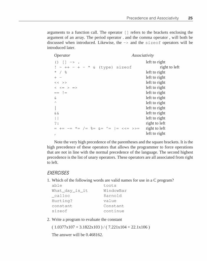
Precedence and AssociativityHere is a summary of the rules of both precedence and association of all C
operators. The higher an operator falls in the table, the higher its precedence. Opera-tors that fall on the same line are all of the same precedence. All symbols used in Care operators. Therefore, the operator () refers to the parenthesis enclosing the
25
arguments to a function call. The operator [] refers to the brackets enclosing theargument of an array. The period operator . and the comma operator , will both bediscussed when introduced. Likewise, the -> and the sizeof operators will beintroduced later.
Operator Associativity
() [] -> . left to right! ~ ++ — + - * & (type) sizeof right to left* / % left to right+ - left to right<< >> left to right< <= > => left to right== != left to right& left to right^ left to right| left to right&& left to right|| left to right?: right to left= += -= *= /= %= &= ^= |= <<= >>= right to left, left to right
Note the very high precedence of the parentheses and the square brackets. It is thehigh precedence of these operators that allows the programmer to force operationsthat are not in line with the normal precedence of the language. The second highestprecedence is the list of unary operators. These operators are all associated from rightto left.
EXERCISES1. Which of the following words are valid names for use in a C program?
able tootsWhat_day_is_it WindowBar_calloc 8arnoldHurting? valueconstant Constantsizeof continue
2. Write a program to evaluate the constant
( 1.0377x10⁷ + 3.1822x10³ ) / ( 7.221x10⁴ + 22.1x10⁶ )
The answer will be 0.468162.
Precedence and Associativity

26 Chapter 1 Introduction to C
3. Write a function that raises the integer x to the power n. Name the functionx_to_the_n , and write a program that evaluates x_to_the_n for severaldifferent values of both x and n.
4. Write a program that will examine a specified year and determine if it is a leapyear.
5. Write a program that will count the number of digits in an input file. Record andprint out the number of occurrences of each digit.
6. In C the term white space refers to the occurrence of a space, a tab character, or anew line character. Write a program that will evaluate the number of white spacecharacters in an input file.
Program Flow and ControlProgram flow and control comprise several different means to control the execu-
tion of a program. Looping constructs, for example, control the repeated execution ofa program segment while adjusting parameters used in the execution at either thebeginning or the end of the loop. Two way branches are created by if/elsestatements, and the choice of one of many operations can be accomplished with theelse if or switch/case statements. The following paragraphs will provide aquick look at each of these program flow and control methods.
The While StatementThere are three looping constructs available to the C programmer: the while()
statement, the for(;;) statement and the do/while() statement. The followingprogram demonstrates the use of the while looping construct along with some otherconcepts. We have seen the while statement earlier, but the following program willprovide a new look at its use.
#include <stdio.h>
void main(void){
int guess,i;
i=1;guess = 5;while(guess != i)

27
{i = guess;guess = (i + (10000/i))/2;
}printf("The square root of 10000 is %d\n",guess);
}
As in the first example, the #include statement is used to bring standardinput/output features into the program, and the program starts with the functiondefinition main() .
Inside of the main program, the first statement is
int guess,i;
This statement identifies the variables guess and i as integers. No value is assignedto i at this time, but a space in memory is allocated to guess and i and the space issufficient to store an integers. The first executable statement in the program is
i=1;
This statement is called an assignment statement. The equal sign here is amisnomer. The statement is read “replace the contents of the memory locationassigned to i with a 1.” The next statement
guess = 5;
assigns a value 5 to the variable guess .The statement
while(guess != i)
invokes a looping operation. The while operation will cause the statement follow-ing to execute repeatedly. At the beginning of each loop execution, the whileargument guess!=i is checked. This argument is read “guess is not equal to i .”So long as this argument is TRUE, the statement following the while will beexecuted. When guess becomes equal to i , the statement following the while willbe skipped.
The while is followed by a compound statement that contains two statements:{
i=guess;guess = (i + (10000/i))/2;
}This calculation is known as a Newton loop. It states that if i is a guess at the
square root of 10000, then (i+(10000/i))/2 is a better guess. The loop willcontinue to execute until i is exactly equal to guess . At this time the compoundstatement will be skipped.
Program Flow and Control

28 Chapter 1 Introduction to C
When the statement following the while is skipped, program control is passedto the statement
printf("The square root of 10000 is %d\n",guess);
this statement prints out the value of the last guess which will be the square root of10000.
The For LoopMany times, a sequence of code like
statement1;while(statement2){
.
.
.statement3;
}
will be found. This exact sequence was seen in the above example. There is a short-hand version of this sequence that can be used. It is as follows:
for(statement1;statement2;statement3)
The for construct takes three arguments each separated by semicolons. Inoperation, the for construct is compiled exactly the same as the above sequence.In other words, statement1 is executed followed by a standard while withstatement2 as its argument. The compound statement that follows will havestatement3 placed at its end, so that statement3 is executed just prior tocompletion of the statement following the while construct.
The for construct can be used to write the above program in the followingmanner:
#include <stdio.h>
void main(void){
int guess,i;
for(i=1,guess=5;i!=guess;){

29
i=guess;guess=(i+(10000/i))/2;
}printf("The square root of 10000 = %d\n",guess);
}
Recall that the for allows three arguments. Not all arguments are necessary forproper execution of the for . In this case, only two arguments are included. The firstargument is really two initialization arguments separated by a comma operator. Whenthe comma operator is used, the statements separated by commas are each evaluateduntil the semicolon is found. At this time, the initialization is terminated. By the way,the comma operator can be used in normal code sequences so that you can stringseveral statements in a row without separating them with semicolons. The secondargument of the for construct is i != guess . The for loop will execute so longas this expression is TRUE. Note that there is no third statement in the for invoca-tion.
This argument is where you would normally place the change in i that is to takeplace at the end of each loop. In this case, the operation on i is i=guess . If thisexpression were used for the third argument, at the end of the first loop, the secondargument would be FALSE, and execution of the calculation would be prematurelyterminated.
The Do/While ConstructAnother looping structure is the do/while loop. Recall that the argument of a
while statement is tested prior to executing the statement following. If the argumentof the while is FALSE to begin with, the statement following will never beexecuted. Sometimes, it is desired to execute the statement at least once whether theargument is TRUE or not. In such a case, the argument should be tested at the end ofthe loop rather than at the beginning as with the while . The do/while constructaccomplishes this operation. The construction of a do-while loop is as follows
.
.do{
.
.
.} while (expression);.
The program will enter the do construct and execute the code that follows up to
Program Flow and Control

30 Chapter 1 Introduction to C
the while statement. At that time, the expression is evaluated. If it is TRUE,program control is returned to the statement following the do . Otherwise, if theexpression evaluates to FALSE, control will pass to the statement following thewhile . Notice that there is a semicolon following the while(expression) .This semicolon is necessary for correct operation of the do-while loop.
The following function converts the integer number n into the correspondingASCII string. The function has two parts: the first part converts the number into anASCII string, but the result is backward in the array; the second part reverses the datain the array so that the result is correct.
/* convert an integer to an ASCII string; valid for positivenumbers only */
void itoa(int n, char s[]){
int i=0,j=0,temp;
/* convert the number to ASCII */
do{
s[i++] = '0' + n % 10;n /=10;
} while ( n != 0);s[i]=0;
/* but it is backwards in the array — reverse t*/
i—; /* don't swap the NULL */while( i > j){
temp = s[j];s[j++] = s[i];s[i— ] = temp;
}}
The function uses three integer variables. The variables i and j are both initial-ized to zero, and the variable temp does not need to be initialized. The first portionof the program contains a do-while loop. Within this loop, the number is con-verted into a string. The statement

31Program Flow and Control
s[i++] = '0' + n % 10;
first calculates the value of the integer modulo 10. This value is the number of 1s inthe number. Adding that value to the character ‘0’ will create the character thatcorresponds to the number of 1s. This value is stored in the location s[i] with i=0and then i is incremented.
The second statement in the loop replaces n with n divided by 10. This coderemoves any 1s that were in the number originally, and now the original 10s are in the1s position. Since this division is an integer division, if the result is between 0 and 1 itwill be rounded to 0. Therefore, the test in the while argument allows the above twostatements to repeat until the original number n is exhausted by repeated divisionsby 10.
When the do-while loop is completed, s[i] will be the character immedi-ately following the string of characters. A string is created by placing a 0 or a NULLin this location of the array.
To reverse the data, the program starts by decrementing i so that s[i] is the lastentry in the array. This entry is the most significant character in the number, and itmust be placed in the first array location s[0]: . Likewise, the character in s[0]must be placed in s[i]: and so forth. The while loop that follows accomplishesthis requirement.
EXERCISES1. Write a program atoi(s[]) that starts with a character string and converts this
string to an int . Assume that the string contains no sign.
2. Write a program that reads a text file a character at a time and counts the number ofwords in the file.
The If/Else StatementThe if/else statement has the general form
if(expression)statement1;
elsestatement2;
If the logical evaluation of the expression that is the argument of the if is TRUE,statement1 will be executed. After statement1 is executed, program controlwill pass to the statement following statement2 , and statement2 will not beexecuted. If the evaluation of statement is FALSE, statement2 will be executed,and statement1 will be skipped. The else statement is not necessary. If there is
32 Chapter 1 Introduction to C
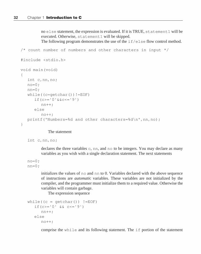
no else statement, the expression is evaluated. If it is TRUE, statement1 will beexecuted. Otherwise, statement1 will be skipped.The following program demonstrates the use of the if/else flow control method.
/* count number of numbers and other characters in input */
#include <stdio.h>
void main(void){
int c,nn,no;no=0;nn=0;while((c=getchar())!=EOF)
if(c>='0'&&c<='9')nn++;
elseno++;
printf("Numbers=%d and other characters=%d\n",nn,no);}
The statement
int c,nn,no;
declares the three variables c , nn, and no to be integers. You may declare as manyvariables as you wish with a single declaration statement. The next statements
no=0;nn=0;
initializes the values of no and nn to 0. Variables declared with the above sequenceof instructions are automatic variables. These variables are not initialized by thecompiler, and the programmer must initialize them to a required value. Otherwise thevariables will contain garbage.
The expression sequence
while((c = getchar()) !=EOF)if(c>='0' && c<='9')
nn++;else
no++;
comprise the while and its following statement. The if portion of the statement

33
tests the value of c and determines if it is a number. A character constant is identifiedas a specific value by placing the character value in single quotes. Therefore, theexpression c>=’0' determines if the character in the location c is greater than orequal to the character 0. If it is, the result of this expression is TRUE. Otherwise, theresult is FALSE. The expression c<=’9' determines if the input character is lessthan or equal to the character 9. If both of these logical expressions are TRUE, thenthe AND of the two will be TRUE, and the statement nn++ will be executed to countthe numbers found in the input stream. Program control will then skip to the end ofthe if statement and continue to execute the while loop. If, on the other hand,either of these expressions are FALSE, then the AND of the two results will beFALSE and the statement no++ will be executed. This statement keeps count of thenumber of characters that are not numbers found in the input stream.
At the conclusion of the program, the getchar() will return an EOF characterand the program will fall out of the while loop. It will then execute the followingstatement:
printf("Numbers=%d and other characters=%d\n",nn,no);
The string contained within the double quotes in this argument causes a combina-tion of text plus calculated values of variables to printed out. Suppose that theprogram would have found 51 numbers and 488 other characters. The printout fromthe program would then be:
Numbers=51 and other characters=488
Each %d is associated with its corresponding argument and converted to anumerical value before it is sent to the screen.
The If-Else If StatementSometimes it is necessary to select among several alternatives. One of the
methods that C offers is the if-else if sequence. Examine the following programthat counts the number of occurrences of each vowel in an input. The program alsocounts all other characters found in the input.
/* Count the number of occurrences of each vowel found inan input and also count all other characters. */
#include <stdio.h>
void main(void){
int na=0,ne=0,ni=0,no=0,nu=0;
Program Flow and Control

34 Chapter 1 Introduction to C
int nother=0,c;
while ((c=getchar())!=EOF)if(c=='A' || c=='a')
na=na+1;else if(c=='E' || c=='e')
ne=ne+1;else if(c=='I' || c=='i')
ni=ni+1;else if(c=='O' || c=='o')
no=no+1;else if(c=='U' || c=='u')
nu=nu+1;else
nother=nother+1;printf( "As=%d, Es=%d, Is=%d, Os=%d, Us=%d and"
" Others=%d\n",na,ne,ni,no,nu,nother);}
This program shows several new features of C. The first is found in the programlines
int na=0,ne=0,ni=0,no=0,nu=0;int nother=0,c;
When the variables na and so forth are declared, they are assigned initial valuesof 0. Such an initialization is always possible when variables are declared. The nextstatement of the program is
while ((c=getchar())!=EOF)if(c=='A' || c=='a')
na=na+1;else if(c=='E' || c=='e')
ne=ne+1;else if(c=='I' || c=='i')
ni=ni+1;else if(c=='O' || c=='o')
no=no+1;else if(c=='U' || c=='u')
nu=nu+1;else
nother=nother+1;
This single statement has quite a few lines of code associated with it, and thereare some new concepts here. First, the arguments of the ifs are combinations of two

35
logical expressions. The expression
c=='A' || c=='a'
says that if c is equal to uppercase a or if c is equal to lowercase a the argument isTRUE. The vertical bars || are the logical operator OR.
The first if statement is evaluated. If its argument is TRUE, the statementfollowing the if is executed and program control moves to the end of the ifstatements. Otherwise, the first else if statement argument is evaluated. If thisargument is TRUE, the following statement is executed and program control movesto the end of the if statements. This process is repeated until one of the arguments isfound to be TRUE, or all of the else if statements are evaluated. At that time, thefinal statement following the else entry is evaluated. The final else is not re-quired.
The printf function call
printf("As=%d, Es=%d, Is=%d, Os=%d, Us=%d and"" Others=%d\n",na,ne,ni,no,nu,nother);
has the normal printf arguments. Note however that the string is not confined toone line. C compilers will not allow a string to be split among several lines in aprogram. However, ANSI C causes two adjacent strings to be concatenated into asingle string so the above code will compile without error.
Break, continue, and gotoThese commands will cause a C program to alter its program flow. If a break
statement is encountered, the program will exit the loop in which it is executing.Break can be used to exit for , while , do-while , and switch statements.An example of the use of the break statement is shown in the next section.
The continue statement causes the next iteration of a for , while , or a do-while loop to be started. In the case of the for statement, the last argument isexecuted, and control is passed to the beginning of the for loop. For both the whileand the do-while , the argument of the while statement is tested immediately,and the program proceeds according to result of the test.
The break statement is seen frequently, and the continue statement israrely used. Another statement that is even more rarely used is the goto . In C, theprogrammer can create a label at any location by typing the label name followed by asemicolon. If it is necessary, the goto <label> can be used to transfer control ofthe program from one location to another. In general, C provides enough structuredlanguage constructs that the use of the goto <label> sequence will rarely beneeded. One place where the goto can be used effectively is when the program isnested deeply and an error is detected. In such a case, the goto statement is an
Program Flow and Control

36 Chapter 1 Introduction to C
effective means of unwinding the program from a deep loop to an outer loop toprocess the error.
The Switch StatementA second approach to selection between several alternates is the switch state-
ment. This approach is sometimes called the switch/case statement. Followingis a program that accomplishes exactly the same as the above program. In this case,the switch statement is used.
/* Count the number of occurrences of each vowel found in aninput and also count all other characters. */
#include <stdio.h>
void main(void){
int na=0,ne=0,ni=0,no=0,nu=0;int nother=0,c;
while ((c=getchar())!=EOF)switch( c){
case 'A':case 'a': na=na+1;
break;case 'E':case 'e': ne=ne+1;
break;case 'I':case 'i': ni=ni+1;
break;case 'O':case 'o': no=no+1;
break;case 'U':case 'u': nu=nu+1;
break;default:
nother=nother+1;}
printf("As=%d, Es=%d, Is=%d, Os=%d, Us=%d and"

37
" Others=%d\n" ,na,ne,ni,no,nu,nother);}
This program performs exactly the same function as the earlier one. The data areread in a character at a time as before. Here, however, the switch statement is used.The statement switch(c) causes the argument of the switch to be comparedwith the constants following each of the case statements that follows. When a matchoccurs, the next set of statements to follow a colon will be executed. Once theprogram starts to execute statements, all of the following statements will be executedunless the programmer does something to cause the program to be redirected. Thebreak instruction does exactly this operation for us. When a C program encountersa break , it jumps to the end of the current block. Therefore, the breaks followingthe executable statements above will cause the program to jump out of the executingsequence and return to get the next character from the input stream.
When all options have been exhausted without a match, the statements followingthe default line will be executed. It is not necessary to have a default line.
EXERCISES1. Write a program that counts the number of lines, words, and characters in an input
stream.
2. Extend the program from the exercise above to calculate the percentage usage ofeach character in the alphabet.
3. A prime number is a number that cannot be evenly divided by any number. Forexample, the numbers 1, 2, and 3 are all prime numbers. Write a program that willcalculate and print out the first 200 prime numbers.
FunctionsThe function is the heart of a C program. In fact, any C program is merely a
function named main . The purpose of a function is to provide a mechanism to allowa single entry of a code sequence that is to be repeated many times. A function is themost reusable element in the C language. Properly written and debugged functionscan be collected into a program when needed. Therefore, the use of functions willallow the programmer to write smaller programs and it is not necessary to rewritecommon functions that are used often.
A function can have many arguments or none whatsoever. Function argumentsare contained in parentheses following the function name. The values of the argu-ments are the parameters needed to execute the function. A function can return avalue, or perhaps it will not have a return value. An example of a function that returns
Functions

38 Chapter 1 Introduction to C
a value is getchar() which will return a character from the input stream. Afunction the will return no value is putchar(c) which puts the character c onto theoutput stream.
A function may not be nested inside another function. Therefore, any functionmust be created outside of the boundaries of any other function or program structure.Functions have only one entry point, and they return only one return item. The returncan be of any type that C supports. Functions can have several arguments. Thearguments can be of any valid C type.
In ANSI C, the use of a function requires the use of a function prototype. Afunction prototype is a statement of the following form:
type function_name(type, type, type,...);
The first type preceding the function name is the type to be returned from thefunction. The several types found in the argument are the types of the correspondingarguments that are sent to the function. Variable names may or may not be used forthe arguments of a function prototype. The type list is the important item. The typesin the argument list are separated by commas.
Thus far, it might seem that we have been blindly using functions like printf() ,getchar() , and putchar() without the benefit of function prototypes. Not so!The header file stdio.h contains the function prototypes of all input/outputrelated functions, so it is not necessary for you to put a function prototype in yourcode for these functions.
Compilers will differ. If a programmer attempts to send the wrong type of data toa function through its argument, the compiler might consider it an error or it mightwell convert the argument to the correct type prior to calling the function. In eithercase, the compiler will not let a program use the wrong type of data as an argument toa function.
Data returned from a function will always be converted to the correct type beforeit is passed to the program. If you wish to have a different type returned, the castoperator can be used to change the return data type to any type desired.
ANSI C defined the type void . This type is used in several different ways. Ifthere is no function return, the prototype must identify the function as type void .Also when there are no function arguments, the argument list must contain the typevoid . This use of the keyword void will prevent problems is function calls.
Note that the function prototype above is terminated with a semicolon. Thesemicolon is needed in the function prototype, but it is not to be used after the name ofthe function in the code where the function is defined.
The philosophy in C is to use functions with little provocation. Using manyfunctions produces code that is easy to read and follow. Often it is easier to debugmany small functions rather than a larger program. One must temper these ideassomewhat when writing code for small microcontrollers. Calling a function requiressome overhead that is repeated each time the function is accessed. If the total

39
overhead is more than the length of the function, it is better to use in-line code. In-linecode implies that the function code is repeated in-line every time that it is needed. Ifthe function code is much greater than the calling overhead, the function should beused. In between these limits, it is difficult to determine a hard-and-fast rule. Inmicrocontroller applications, it is probably best to use function calls to a singlefunction if there is a net savings of memory as a result. This savings is calculated byfirst determining the code needed prior to calling the function, the code needed toclean up the process after the function call, the number of times the function is called,and the length of the function. The in-line code will be smaller than the correspondingfunction code. Therefore, if the total code for the number of function calls listed firstexceeds the total in-line code required to accomplish the same operations, then usethe in-line code. Otherwise, use function calls.
The above argument is valid for microcontroller applications code. It does notnecessarily follow for code written for large computers. When writing for a largecomputer, there are usually few memory constraints. In those cases, it is probablybest to use more function calls and not be worried about the memory space taken upby function calls unless there is a serious speed constraint. When speed is a problem,the programmer must go through an analysis similar to that above with the dependentparameter being time rather than memory space. In small computers where severalregisters can be saved and restored when a function is entered and exited, singleinstructions can require many clock cycles. When deciding whether to use a functionor in- line code, the programmer must assess the total time lost to entering and exitinga function each time it is entered, and weight that time lost as a fraction of the totaltime the program resides in the function. If this time is large, and the program requirestoo much execution time, consider the use of in-line functions.
It is always good to write small functions and create simple calling programs toexercise the small functions. These programs are used to debug the functions, andthey are discarded after the functions are debugged. If later, the program constraintsdictate that in-line code should be used, the essential code of the function can bewritten into the program wherever it is needed. Another approach that will bediscussed in the next chapter is to use a macro definition to specify a small function.With a macro definition, the function code is written in-line to the program wheneverthe function is invoked.
Let us revisit an example used earlier. Write a program to calculate and displaythe square root of each integer less than 11:
/* Calculate and display the square roots of numbers 1 <= x <=10 */
#include <stdio.h>
#define abs(t) (((t)>=0) ? (t) : -(t))#define square(t) (t)*(t)
Functions

40 Chapter 1 Introduction to C
double sqr ( double );
void main(void){
int i;double c;
for(i=1;i<11;i++){
c=sqr(i);printf("\t%d\t%f\t%f\n",i,c,square(c));
}}
double sqr( double x ){
double x1=1,x2=1,c;
do{
x1=x2;x2=(x1 + x/x1)/2;c=x1-x2;
}while(abs(c) >= .00000001);return x2;
}
The result of this calculation is shown below:
1 1.000000 1.000000 2 1.414214 2.000000 3 1.732051 3.000000 4 2.000000 4.000000 5 2.236068 5.000000 6 2.449490 6.000000 7 2.645751 7.000000 8 2.828427 8.000000 9 3.000000 9.000000 10 3.162278 10.000000
The second line of code

41
#define abs(t) (((t)>=0) ? (t) : -(t))
is called a macro definition. In this case, the macro definition has the appearance ofa simple function. This function will calculate the absolute value of the argument t.The absolute value of the argument is a positive value. If the argument is positive, itis returned unchanged. If it is negative, it is multiplied by -1 before it is returned.A macro definition is a type of character expansion. Whenever the function abs(x)is found in the code, the character string (((x)>=0) ? (x) : -(x)) is put inits place. The argument x can be any valid C expression. This function returns theabsolute value of its argument. The macro definition
#define square(t) (t)*(t)
returns the square of t . Since these arguments can be any valid C expression, it isnecessary to be cautious when writing the macro definitions. Suppose that theparenthesis were left out of the above expression, and the macro were written
#define square(t) t*t
Also suppose that the code using this function were as follows:
x=square(y+3);
The character expansion of this expression would be
x=y+3*y+3;
The result of this calculation is 4*y+3 and not (y+3)*(y+3) as expected.When writing macro definitions, surround all arguments and functions created by themacro with parentheses so that all arguments are evaluated prior to use in the macrodefinition function.
Note that there is no semicolon at the end of the macro definition. There shouldnot be. If a semicolon were placed at the end of a macro definition, and a semicolonplaced at the end of an expression using the macro definition, extra semicolons wouldbe entered into the expression with unpredictable results.
The function prototype
double sqr( double );
notifies the compiler that the function returns a double and takes a double argument.Inside of the main function, the for loop
for(i=1;i<11;i++){
c=sqr(i);
Functions

42 Chapter 1 Introduction to C
printf("\t%d\t%f\t%f\n",i,c,square(c));}
is used to calculate the several results. The variable c is of the type double , and i isan int . The expression c=sqr(i) will be accepted by the compiler. This functionreturns a double which can be stored in c . The argument is an int , but the com-piler recognizes that sqr requires a double argument and converts i to a doublebefore it is sent to the function sqr() .
The code in the function sqr() is a restatement of a square root operation thatwe saw earlier. In this case, the function processes floating point numbers rather thanthe integers used before. Three double variables are needed. The variables x1 andx2 are the current and last values found in the Newton iteration. As the resultconverges to the correct value for the square root, several things happen. Variablesx1 and x2 become equal. The square of x2 , or x1 for that matter, becomes equal tox . The product of x1 and x2 become equal to x . Any of these tests can be used todetermine if the estimate has been through enough iterations to be accurate.
The macro definition abs(x) is used to test for the end of the loop. You will notethat the argument is evaluated three times for the expansion of the macro. If we placea lot of calculation within the argument of a macro definition, the expansion of themacro may cause the code to calculate the argument to be repeated several times. Forthis reason, the expression
c = x1 - x2;
is placed inside of the while loop, and the test to determine loop termination usesarg(c) .
At the end of a function, a return statement will cause the value of the expres-sion following the word return to be evaluated and returned to the calling function. Ifthis expression is not of the type specified by the function prototype and the functiondefinition, it will be converted to the correct type prior to being returned to the callingfunction. The expression following the return statement can be enclosed in paren-theses or not.
Another example will show the use of static external variables.
/* Read in a string from the keyboard and print it out in reverse order. */
#include <stdio.h>
/* some function prototypes */void push(int);int pull(void);
void main(void){

43
int c;push(NULL);while((c=getchar())!='\n')
push(c);
printf("\n");while((c=pull())!=NULL)
putchar(c);printf("\n");
}
The following code is to be compiled in a separate file from the code above:
#define MAX 100
static int buffer[MAX];static int sp;
void push(int x){
if(sp < MAX)buffer[sp++]=x;
else{
printf("stack overflow\n");exit(1);
}}
int pull(void){
if(sp > 0)return buffer[—sp];
else{
printf("stack underflow\n");exit(1);
}}
A stack is a last in, first out (LIFO) structure. Therefore, a stack can be used toreverse the order of data sent to it. The above program uses a stack operation. Thefunctions push and pull identified in the function prototypes perform the stackingoperations for the main program. In the main program, a NULL is pushed onto the
Functions

44 Chapter 1 Introduction to C
stack to identify the end of the data as it is pulled off of the stack a character at a time.Data are read in a character at a time, and as each character is read in, it is pushed ontoa stack. When a new line character is detected, the input phase is stopped, and the datawritten to the stack is pulled off and printed. When the NULL is detected, the datahave all been pulled off the stack, and the program is ended.
In the function above, the function exit() is used. This function is similar tothe return function. Whenever a call to the function exit is called, the argumentis evaluated, any files open for write are flushed and closed, and the control of thecomputer is returned to the operating system. The evaluation of the argument isreturned to the operating system. Whenever a return is encountered, the expressionfollowing the return call is evaluated and returned to the calling function. Ifcontrol is in main() when the return is encountered, the evaluation of theexpression is returned to the operating system. Also, from main() all files open forwrite are flushed and closed.
In a separate compilation, the stack functions are compiled. In that function, themacro definition MAX is defined as 100. Macro definitions can be used to define anycharacter string that is needed in a program. They are not limited to defining pseudo-functions. Two global variables are defined in this file: an array of MAX integersnamed buffer and an int called sp . These variables are declared to be static .As such, these variables can be accessed by any function in the file, but they are notavailable to any function outside of the file. The variable sp is used as an index intothe array buffer . When a push is executed, a test to determine if sp is less than MAXis completed. If sp is less than MAX, the data are stored at the sp location in bufferand sp is then incremented. Otherwise, an error message that indicates that a stackoverflow has occurred and the program is exited.
The pull() function is the reverse of the push() operation. First a check ismade to see if there are some data on the stack to be pulled off. If there are data, thestack pointer is decremented, and the content of the buffer at that location is returnedto the calling program. In the event that sp is 0 when the pull operation is executed, astack underflow message is sent to the screen prior to exiting the program.
The advantage to our making the buffer and the stack pointer in the stackfunctions static can be easily seen. Suppose that these variables could be accessedfrom anywhere in the program. In that case, it would not be necessary for theprogrammer to call the functions push or pull to stack and unstack data. If sev-eral different programmers were using the same stack for different tasks in onelarge program, it would be possible for different programmers to access the stackas expected, or from their own tasks. Suppose a programmer would make the mistakeof pre-decrementing the stack pointer on stacking and post-incrementing the stackpointer on unstacking. The whole program would suddenly be in chaos. Therefore,masking these variables from the rest of the program can reduce serious debugging

45
problems.
RecursionA recursive routine is one that calls itself. The C language is supposed to produce
recursive code. Compilers for large machines usually support recursion, but recursionis often one of the first casualties on small microcontrollers. Automatic variables arecreated when a function is entered, and they are stored on the stack. Therefore, eachtime a function is called, a new stack frame is created, and variables in place from anearlier execution of the function are unaltered. Such a function is called re-entrant,and re-entrant functions are also recursive. An example of a simple recursive functionis the factorial:
n! = n*(n-1)*(n-2)*....*2*1
An interesting observation that can be made of factorial is that
n! = n*(n-1)!
or n factorial equals n times n-1 factorial. Also, the factorial of 0 is defined as 1.With these definitions, it is possible to write the following recursive function tocalculate the factorial of a number:
long factorial( int n){
if(n==0)return 1;
elsereturn n*factorial(n-1);
}
This surprisingly simple function calculates the factorial. Whenever you write arecursive routine, it is important to have means of getting out of the routine. In theabove case, when the argument reaches zero, the function returns a result rather thancalling itself again. At that time the routine will work itself back a level at a time untilit reaches the initial factorial call, and the calculation will be done.
Recursion can create some elegant code in that the code is very simple—often toosimple. There is a cost in the use of recursive code, and that is stack space. Each timea function call is made, the argument is placed on the stack and a subroutine call isexecuted. As a minimum, the return address is two bytes, and the value of the argu-ment is also two bytes. Thus at least four bytes of stack space are needed for eachfunction call. That is no problem when the factorial of a small number is calculated.(The factorial of 13 is larger than can be held in a long, so only small numbers can beconsidered for a factorial) However, if a recursive function is written that calls itselfmany times, it is possible to get into stack overflow problems.
Another interesting recursive routine is the function to calculate a Fibonacci
Recursion

46 Chapter 1 Introduction to C
number. A Fibonacci number sequence is described by the following function:
long fib(int n){
if(n==1)return 1;
else if(n==0)return 1;
elsereturn fib(n-1) + fib(n-2);
}
This sneaky function calls itself twice. Some interesting characteristics of thisfunction are left to the exercises that follow.
EXERCISES1. Write a function to calculate the Fibonacci number for 10, 20, 30, and 40.
2. Devise a means for determining the number of times the fib function is called inthe above program. What is this number for fib(20) ?
3. A separate problem from the number of times the function is called is the numberof times the function is called without exiting through the bottom of the function.This term is called the depth of the function. Determine the maximum depth of thefib() function in calculating fib(20) .
4. Repeat problem 1, but rewrite the Fibonacci number function so that it does notemploy recursion. How does the time to execute this version of the fib(30)compared to that above?
SummaryThe basics of writing programs in C have been discussed in this chapter. Several
important concepts have been skipped over in this presentation and will be covered inChapter 2.
If you have not done so, it is recommended that you enter and compile eachexample shown. These programs will be all compile and run under the MIXPowerC Compiler, Microsoft Quick C, Borland Turbo C, Turbo C++, or BorlandC++ Version 3.1.
The ANSI version of the language is the current standard, and none of theclassical C constructs have been introduced in this text. It is not to the programmer’sadvantage to use the classical version of the language, even though programs thatconform to classical C will compile on an ANSI compliant compiler. Any version ofC++ structured to compile C code will also compile ANSI C code. If you are usingany of the C++ compilers listed above the example programs should compile whetheras C programs or C++ programs.

47
Chapter 2
Advanced C Topics
PointersThe use of pointers sets the C language apart from most other high level lan-
guages. Pointers, under the name of indirect addressing, are commonly used inassembly language. Most high level languages ignore completely this powerfulprogramming technique. In C, pointers are simply variables that are the addresses ofother variables. These variables can be assigned, be used as operands, and treatedmuch the same as regular variables. Their use, however, can simplify greatly many ofthe truly difficult problems that arise in day-to-day programming. Let’s discusspointers with the view that they offer us a powerful new tool to make our program-ming jobs easier.
How To Use PointersA pointer to a variable is the address of a variable. Thus far in our discussion of
variables, the standard variable types were found to occupy 8-, 16-, or 32-bitsdepending on the type. Pointers are not types in the sense of variables. Pointers mightoccupy 16- or 32-bits, and their size is implementation dependent. In fact, there arecases of pointers to like types having different sizes in the same program dependingon context.
If the variable px is a pointer to the type int and x is an int , px can beassigned the address of x by
px = &x;
The ampersand (&) notifies the compiler to use the address of x rather than thevalue of x in the above assignment. The reverse operation to that above is
x = *px;
Here the asterisk (*) is a unary operator that applies to a pointer and directs thecompiler to use the integer pointed to by the pointer px in the assignment. The unary* is referred to as the dereference operator. With these two operators, it is possible tomove from variable to pointer and back again with ease.
47

48 Chapter 2 Advanced C Topics
A pointer is identified as a pointer to a specific type by statements like
int *px,*pa;long *pz;float *pm;
In the above declarations, each of the variables preceded by the unary asteriskidentifies a pointer to the declared type. The pointers px and pa are the addresses ofintegers. pz is the address of a long , and pm is the address of a floating pointnumber. Always remember: if pk is a pointer to an integer, *pk is an integer.Therefore, the declarations in the above examples are correct and do define int s,long s and float s. However, when the compiler encounters the statement
int *pi;
it provides memory space for a pointer to the type int , but it does not provide anymemory for the int itself. Suppose that a program has the following declaration:
int m,n;int *pm;
The statement
m = 10;pm = &m;
will assign the value 10 to m and put its address into the pointer pm. If we then makethe assignment
n = *pm;
the variable n will have a value 10.Another interesting fact about pointers is shown in the following example:
int able[10];int *p;
After it has been properly declared, when the name able is invoked without thesquare brackets, the name is a pointer to the first location in the array. So thefollowing two statements are equivalent:
p = &able[0];
and
p = able;
Of course, the nth element of the array may be addressed by
p = &able[n];

49
The unary pointer operators have higher precedence than the arithmetic opera-tors. Therefore,
*pi = *pi + 10;y = *pi + 1;*pi += 1;
all result in the integers being altered rather than the pointers. In the first case, theinteger pointed to by pi will be increased by 10. The second case, y will be replacedby one more than the integer pointed to by pi . Finally, the integer pointed to by piwill be increased by 1. The statement
++*pi;
causes the integer pointed to by pi to be increased by 1. Both ++ and the unary *associate from right to left, so in the following case
*pi++;
the pointer pi is incremented after the dereference operator is applied. Therefore, thepointer is incremented in this case, and the integer *pi remains unaltered. If youwish to post-increment the integer *pi , use
(*pi)++;
At times, it is necessary to pre-increment the pointer before the dereference. Inthese cases, use
*++pi;
Pointers work with arrays. Suppose that you have
int *pa;int a[20];
As we have already seen,
pa = a;
assigns the address of the first entry in the array to the pointer pa much the same as
pa = &a[0];
does. To increment the pointer to the next location in the array, you may use
pa++;
or
pa = pa + 1;
Pointers

50 Chapter 2 Advanced C Topics
In any case, the pointer that is 1 larger than pa points to the next element in thearray. This operation is true regardless of the type that pa points to. If pa points at aninteger, pa++ points to the next integer. If pa points at a long , pa++ points to thenext long . If pa points to a long double , pa++ points to the next longdouble . In fact, if pa points to an array of arrays, pa++ points to the next array inthe array of arrays. C automatically takes care of knowing the number that must beadded to a pointer to point to the next element in an array.
In the above case, since a is an array of 20 integers, and pa points to the firstentry in the array, it follows that pa+1 points to the second element in the array, andpa+2 points to the third element. Similarly, *(pa+1) is the second element in thearray and *(pa+2) is the third element.
There is a set of arithmetic that can be applied to pointers. This arithmetic isdifferent from the normal arithmetic that can be applied to numbers. In all cases, thearithmetic applies to pointers of like types pointing to within the same array only.When these conditions are met, the following arithmetic operations can be completed:
• Pointers can be compared. Two pointers to like types in the same array can becompared in a C logical expression.
• Pointers can be subtracted. Two pointers to like types in the same array can besubtracted with a C arithmetic expression. The result of the subtraction will be thenumber of elements between the two pointers not the difference in the values of thepointers.
• Pointers can be incremented and decremented. A pointer into an array can beeither incremented or decremented. The result will be a pointer that points to anadjacent element in the array.
• Pointers can be assigned. A pointer can be assigned to another pointer of the sametype.
Pointers cannot be added, multiplied, divided, masked, shifted, or assigned a pointervalue of an unlike type. Pointers can be assigned to another pointer of the type void .
The name of an array is a pointer to the first element in this array. This type ofvariable occupies a special place in C. The name can always be used as a pointer, andassigned to another pointer, but it cannot be assigned to. Any attempt to assign a newvalue to the array name would upset the beginning of the array to the program.Therefore, an array name as a pointer can be used as a value on the right side of anassignment equal sign, but it cannot be used on the left side of the equal sign. Cvariables are broken into the types rvalue and lvalue . All C variables, with theexception of the names of functions and arrays, are both rvalues and lvalues .They can be used on either side of an equal sign in an assignment statement. Functionnames and array names are rvalues and can be used only on the right side of the equalsign in an assignment statement. Variables declared as constants and constantscreated by the #define statement are also rvalues .

51
The type void* has a special meaning when applied to pointers. A void pointer(sometimes referred to as a generic pointer) is a pointer that does not point at anytype. Some functions will return void pointers, and to use these pointers, they must becast onto the type that they represent. Therefore, a pointer of the type void* can beassigned the value of a typed pointer. However, unless the void* pointer is cast ontothe specified type, the increment, decrement, subtraction, and so forth will not work.A void pointer can be used in expressions, but it is impossible to alter its value.
Pointers and Function ArgumentsValues passed to functions as arguments are copies of the real values. The data to
be passed to a function are pushed on the stack prior to the function call. Therefore, ifthe function should modify any of the arguments, this modification would notpropagate to the calling function. Therefore, a function like
void swap(int x, int y){
int temp;
temp = x;x = y;y = temp;
}
does nothing but swap two values on the stack, and those values are never returned tothe calling program. This performance is good as well as bad. The bad situation isshown above when the function simply does not work as expected. The good side isthat it is not easy to inadvertently change variable values in the calling program. Theuse of pointers permits this problem to be avoided. The technique is called passingparameters by reference. Consider the following function:
void swap(int* px, int* py){
int temp;
temp = *px;*px = *py;*py = temp;
}
Here the integers pointed to by px and py are swapped. These integer are thevalues in the calling program. The pointer values in the calling program are unaltered.
Pointers

52 Chapter 2 Advanced C Topics
C makes extensive use of passing parameters by reference. Recall the firstprogram in Chapter 1. That program has the line
printf("Microcontrollers run the world!\n");
We now know that the string "Microcontrollers run the world!\n"is nothing more than a character array terminated by a zero. The compiler creates thatarray in the memory of the program. That array is not passed to printf . A pointer tothat array is passed to printf . printf prints the characters to the standard outputand increments through the array until it finds the NULL terminator. Then it quits. Inother instances, arguments like s[] were used. In these cases, C automaticallyknows to pass a pointer to the array. It is interesting. If you have an array ints[nn] and pass that array to a function as s, you can use an argument int* p in thefunction and then in the function body deal with the array p[] . The C language isextremely flexible in the use of pointers. An example of this type of operation is asfollows:
/* Count the characters in a string */
#include <stdio.h>
int strlen(char *);
void main(void){
int n,s[80];
gets(s);n=strlen(s);printf("The string length = %d\n",n);
}
int strlen( char *p){
int i=0;
while(p[i]!=0)i++;
return i;}
The above version of strlen() will return the number of characters in the

53
string not including the terminating NULL. The function gets() is a standardfunction that retrieves a character string from the keyboard. The prototype for thisfunction is contained in stdio.h . It is interesting to note that the function strlen()can be altered in several ways to make the function simpler. The index i in thefunction can be post-incremented in the argument so that it is not necessary to havethe statement following the while() . This function will be
int strlen(char *p){
int i=0;
while(p[i++]!=0);return i;
}
Because the while() argument is evaluated as a logical statement, any valueother than 0 will be considered TRUE. Therefore,
int strlen(char *p){
int i=0;
while(p[i++]);return i;
}
provides exactly the same performance. Yet another viewpoint is found by
int strlen(char* p){
int i;
for(i=0;*p++;i++);return i;
}
Each of the above functions using strlen() show a different operation involv-ing passing arguments by reference.
Let us examine another use of passing arguments by pointers. The followingfunction compares two strings. It returns a negative number if the string p is less thanthe string q, 0 if the two strings are equal, and a positive number if the string p isgreater than the string q.
Names

54 Chapter 2 Advanced C Topics
int strcomp(char* p, char* q){
while( *p++ == *q++);if(*p-1 == '\0') /* The strings are equal */return 0; /* zero */return *p - *—q; /* The strings are unequal
return the correct value*/}
Here the while() statement will examine each character in the string untilthe argument is not equal. Note, that the pointers p and q are incremented afterthey are used. The test for equality will not occur until after the pointers areincremented, so it is necessary to decrement the pointer p to determine if the lastequal value in the two strings is a zero character. If the last value is a NULL, thetwo strings are equal, and a 0 is returned. If the last tested character is not a NULL,the two strings are not equal and the difference between the last character in p andthe last character in q is returned. This choice will give the correct sign needed tomeet the function specification.
Another approach can be used that eliminates the increments and decrementswithin the program and confines them to the argument of a for construct. Consider
int strcomp(char* p, char* q){
for( ; *p==*q ; p++, q++)if( *p == '\0')
return 0;return *p - *q;
}
The pointers p and q are both incremented after the test in the if statement.Therefore, the pointer values are correct for the if statement as well as for calcula-tion of the return value when the strings are not equal.
C is completely unforgiving if you exceed the boundaries of the array in yourcalculations. C does not have intrinsic boundary checks, and it is possible to incre-ment pointers right off the end of an array. For that matter, the array index can bedecremented to addresses below the beginning of the array. When a program makessuch a mistake, it will destroy other data, perhaps destroy the program being ex-ecuted, or in the worse case, the program can crash the operating system. The simplesingle tasking computers that run MS-DOS or similar operating systems have nomemory protection feature that protects one task from another. In such cases, aprogram that runs wild and overwrites memory not assigned to it can destroy othertasks that are loaded in memory whether they are running or not.

55Pointers
EXERCISES1. Write several versions of a function that copies one string into another.
2. Write a function that concatenates two strings. Concatenation of two strings meansthat one string will be written at the end of the other. Write this function with andwithout the use of pointers. What is the advantage of the pointer version of thefunction?
Let us consider a problem that will be analyzed in more detail later. Suppose thata function is needed that will sort the contents of an array into ascending (ordescending) order. There are several sort functions, and each has its own set ofadvantages and disadvantages. The simplest and probably most intuitive is called thebubble sort. In a bubble sort, a swap flag is reset. The first entry in the array iscompared with the second, and if they are in the wrong order, they are swapped. Thenthe second entry is compared with the third, and they are swapped or not. If a swapever occurs, the swap flag is set. The elements of the array are successively comparedand swapped until all of the elements in the array have been compared. If a swap hasoccurred during the scan of the array, the swap flag is reset, and the whole process isrepeated. This process repeats until the scan of the array causes no swaps to occur. Atthat time, the array is in order.
If the array contains n elements, this approach requires on the order of n squaredcompares and swaps. For large arrays, the time to sort an array with a bubble sort isinordinate. Another approach was discovered by D. L. Shell. The Shell sort allows thearray to be sorted with n times the logarithm base two of n. This difference can besubstantial. For example, if the array contains 1000 elements, the bubble sort willrequire on the order of 1,000,000 compares and swaps while the Shell sort will needonly 10,000. Therefore, the bubble sort should not be used to sort large arrays.
Another sort technique that is used was discovered by C. A. R. Hoare. Thistechnique is called the quick sort. The quick sort uses a recursive approach toaccomplish the sort, and it also requires n log base 2 of n compares and swaps. Theshell sort and the quick sort usually require about the same time to accomplish thesort. We will demonstrate a shell sort now.
The code for a shell sort follows. Note that extensive use of pointers is used inthis version of the shell sort.
/* shell_sort(): sort the contents of the array *v into as-cending order */
void shell_sort(int* v, int n){
int gap, i, j, temp;

56 Chapter 2 Advanced C Topics
for( gap = n/2; gap > 0; gap /= 2)for( i=gap; i < n; i++)
for( j=i-gap; j>=0 && *v > *(v+j+gap);j -= gap)
{temp = *(v+j);*(v+j) = *(v+j+gap);*(v+j+gap) = *(v+j);
}}
The shell sort receives as arguments a pointer to an array of integers and aninteger n which is the length of the array.
This sort works by successively dividing the array into subarrays. The firstoperation divides the whole array into two parts; the second divides each of the twosubarrays into two new subarrays, for a total of four arrays; and so forth.
The corresponding elements in each subarray are compared, and if they are out oforder, they are swapped. At the close of this operation, a new set of subarrays arecreated, and the process is repeated over these subarrays. Eventually, the gap betweenelements in the subarrays will be reduced to one, and the array contents will be sorted.
The outer for loop above controls the splitting of the arrays into the subarrays.The second loop steps along the elements. The innermost loop successively comparesthe elements that are separated by gap in the subarrays. If elements are found that areout of order, they are reversed or swapped in the array.
EXERCISES1. Restate the shell sort above to use arrays rather than pointers to arrays.
2. Write a program that reads in characters from the input stream and record thenumber of occurrences of each character. Calculate the percentage occurrenceof each character, and print out the result in ascending order of percentage ofoccurrence.
Functions can return pointers. For example, prototype to a function that returns apointer is:
int *able(char* );
Here able returns a pointer to an integer.In C, a NULL pointer is never used. A NULL pointer implies that something is to
be stored at the address zero. This address is never available for data storage, so nofunction can return a valid NULL pointer. The NULL pointer can be used as a flag oran error return. The programmer should never allow a NULL pointer to be dereferencedwhich implies that data are read or stored at 0.

57
Pointers to PointersIf C will support a pointer to a variable, it requires but little imagination to reason
that C will support pointers to pointers. In fact, there is no limit in the language to thedepth of dereference C will support. C will also allow arrays of pointers, and pointersto functions. (We discussed pointers to arrays in the preceding section.)
An array of pointers can be very useful when needed. A most obvious use for anarray of pointers is to read the contents of a command line to a program. So far in ourdiscussion of programs, there have been no provisions for reading the content of acommand line that is written to the screen when the program is executed. A commandline can be read by the program. The definition of the program name main whenextended to read in a command line is as follows
void main ( int argc, char *argv[])
The integer variable argc is the number of entries on the command line. Thearray of pointers to the type char argv[] contains pointers to strings. Whenentering arguments onto the command line, they must be separated by spaces. Thefirst string pointed to by argv[0] is the name of the program from the commandline. The successive pointer values point to additional character strings. These stringsare each NULL terminated, and they point to the successive entries on the commandline. The value of argc is the total number of command line entries including theprogram name. It must be remembered that each entry in argv[] is a pointer to astring. Therefore, if a number is entered on the command line, it must be convertedfrom a string to an integer, or floating point number, prior to its use in the program.
Let us see how this concept can be used. Earlier, we wrote a function to calculatea Fibonacci number. Let’s use this function in a program in which the argument forthe Fibonacci calculation is read in from the command line:
#include <stdio.h>#include <stdlib.h>
long fib( int ); /* Fibonacci number function prototype */
void main( int argc, char* argv[] ){
int i;i = atoi(argv[1]);printf("The Fibonacci number of %d = %ld\n",i,
fib(i));}
Pointers

58 Chapter 2 Advanced C Topics
We will not repeat the code for fib(i) . A new header file, stdlib.h , isincluded with this program. The function prototype for atoi() is contained withinthis header file. The standard command line arguments are used in the call tomain() . The line
i = atoi(argv[1]);
causes the function atoi —ASCII to integer conversion—to be executed with apointer as an argument. This pointer points to the first argument following theprogram name on the command line. In this case, it will be pointing to an ASCIIstring that contains the number to be used as an argument for the fib() call. Thisstring must be converted to an integer before fib() can operate on it, which isexactly what the atoi() function accomplishes. The final line in this program printsout the result of the calculation.
Another example of use of the command line arguments is to print out thecommand line. The following program will accomplish this task.
#include <stdio.h>
void main( int argc, char* argv[] ){
int i;for(i=0; argc—; i++)
printf("%s ",argv[i]);printf("\n");
}
The arguments to main() are the same as before. This program enters a forloop that initializes i to zero. It decrements argc each time it tests its value, andexecutes until the loop in which argc is decremented to 0. The printf call
printf("%s ",argv[i]);
prints out the string to which argv[i] points. Notice the space in the string "%s " .This space will force a space between each argument as it is printed. The program iswritten so that there are no new line characters printed. Arguments will all be on oneline, and they will each be separated by a space. The printf() statement afterexecution of the for() loop will print out a single new line so that the cursor willreturn to the next line after the program is executed.
Command line entry is but a simple example of use of arrays of pointers. Anotherarea in which arrays to pointers are needed is in ordering strings of data. For example,it is possible to collect a large number of words in memory, say from an input stream.Suppose that it is needed to alphabetize these words. We saw earlier, that the shellsort will order the contents of an array, so it might be possible to simply modify theshell sort to do this job.

59
First, a comparison is needed that will determine if the lexical value of a one wordis smaller, equal, or larger to that of another word. Such a compare routine wasoutlined above. Second, a swap routine that will swap the words that are in the wrongorder. Here is a case where an array of pointers can be quite useful. Assume that theprogram that reads in the data will put each word into a separate memory location andkeep an array of pointers to the beginning of each word rather than just the array ofthe words themselves. Then in the shell sort, when a swap is required, rather thanswapping the words, swap the pointers in the array. Swap routines that swap pointersin the array are very easy to implement. On the other hand, swap routines to swap twostrings in memory are difficult and slow. Therefore, we can create a sort routine thatis much more efficient if we use an array of pointers rather than an array of strings.
/* shell_sort(): sort the contents of the array char*v[] into ascending order */
void shell_sort(char* v[], int n){
int gap, i, j;char* temp;for( gap = n/2; gap > 0; gap /= 2)
for( i=gap; i < n; i++)for( j=i-gap; j>=0 &&
strcmp(v[j],v[j+gap]); j -= gap){
temp = v[j];v[j] = v[j+gap];v[j+gap] = v[j];
}}
Here the strcmp() routine is used to determine if a swap is needed. strcmp()is identified in the header file string.h) . When needed, the contents of the arrayof pointers to the beginning of the words is swapped rather than swapping the wordsthemselves.
Multidimensional ArraysC supports multidimensional arrays. Programmers often find that much of the
need for multidimensional arrays will go away with the availability of pointers.Multidimensional arrays in C are thought of as arrays of arrays. This idea can beextended to more than two dimensions, but most compilers will limit the dimension-ality of an array to five or less. A two dimensional array is identified as
Multidimensional Arrays

60 Chapter 2 Advanced C Topics
array[x][y]; /* [row][column] */
The first argument to the right can be thought of as the row dimension, and thesecond the column dimension. Elements specified by the rightmost argument arestored in adjacent memory locations.
An array can be initialized at declaration time. For example:
int array [3][4] = { {10,11,12,13},{14,15,16,17},{18,19,20,21} };
It is equally valid to initialize the array as follows:
int array [3][4]={10,11,12,13,14,15,16,17,18,19,20,21};
Either form of initialization will place the proper numbers in the proper locationin memory, and the two dimensional indices will work properly in either case.
Frequently, it is needed to know the size of a variable in C. This variable can be abasic type, an array, a multiple dimensional array, or even a structure that will beintroduced later. C provides an operator that has much the appearance of a functioncalled sizeof() . To determine the size of any variable, use the sizeof()operator as follows:
a = sizeof(array);
which will return the number of bytes contained in array[][] above.An example program that is frequently found with two dimensionally arrays is to
determine the Julian date. The Julian date is simply the day of the year. The followingfunction is one that allows counting the number of days that have passed in a year.
int month_days[2][13] = {{0,31,28,31,30,31,30,31,31,30,31,30,31},{0,31,29,31,30,31,30,31,31,30,31,30,31}
};
int Julian_data(int month, int date, int year){
int i,leap;
leap = year%4==0 && year%100!=0 || year%400==0;
for(i=1;i<month;i++)day += month_days[leap][i];
return day;}

61
The declaration
int month_days[2][13] = {{0,31,28,31,30,31,30,31,31,30,31,30,31},{0,31,29,31,30,31,30,31,31,30,31,30,31}
};
types month_days as an array of 26 integers. This array is a two-dimensional arrayof two rows of 13 columns each. The values assigned are shown. The extra 0 entry atthe beginning of each array is to allow the conventional month designations 1 through12 to be used as indices and not have to worry about the fact that arrays in C start witha 0 index.
The introduction of the program is normal. The function returns an int andexpects to receive three int arguments; one for the month, one for the day of themonth, and one for the year. Note that the year must be the full year, like 2013, ratherthan merely 13. The first executable statement is the logic statement:
leap = year%4==0 && year%100!=0 || year%400==0;
Leap years are usually every four years. However, a small discrepancy still existswith the “once each four years” correction. To further correct the error, the calendarmakers have decided that years divisible by 100 will not be a leap year unless the yearis divisible by 400. The above statement is a logical statement that determines first ifthe year is divisible by 4. If it is divisible by 4, it is then checked to determine if it isdivisible by 100. The result of this much of the analysis will be TRUE for any yeardivisible by 4, and not divisible by 100. If this portion of the calculation is TRUE,leap will be assigned a value TRUE, or 1, and the evaluation will terminate. If theresult of the first portion of the calculation is FALSE, it will be necessary to evaluatethe last term to determine if the whole statement is TRUE or FALSE. The variableleap will be assigned the result of
year%400==0
in this case.leap is assigned a value of 1 or 0 according to the result of the logic evaluation.
This value can be used as an index into the two dimensional array to determine if thenumber of month days in a leap year or a nonleap year will be used in the calculationof the Julian date.
Pointers and Multidimensional ArraysPerhaps one of the most widely misunderstood and therefore mysterious aspects
of pointers and C has to do with multidimensional arrays. These problems are reallynot difficult. A multidimensional array must always be understood as being arrays ofarrays of arrays and so forth. For example, the declaration
Multidimensional Arrays

62 Chapter 2 Advanced C Topics
int ar[3][5];
defines three arrays of five elements each. We have already seen that data stored inthis array is column major. The second argument points to a column in the two-dimensional array, and ar[n][0] and ar[n][1] are stored in adjacent memorylocations. Following the logic of array names and pointers, the array name ar is apointer to the first element in the array. The value obtained when using ar as anrvalue is &ar[0][0] . The order of evaluation of the square brackets is from leftto right so that *(ar+1) is a pointer to the element ar[1][0] in the array. Thinkof the two-dimensional array as being *(ar+n)[i] where n has a range from 0 to 2and i has a range from 0 to 4. An increment in n here will increment the absolute valueof the pointer by 5*sizeof(int) .
These ideas can be carried to the next level. The element *(ar+n) is a pointer tothe first element of a five element array. Therefore, the evaluation of *(*(ar+n)+i)is the value found in the location ar[n][i] . The important item is that the right-most argument in multiple dimensional arrays point to adjacent memory locations,and the increments of the left arguments step the corresponding pointer value fromarray to array to array.
These ideas can be extended to arrays of more than two dimensions. Had thearray been
double br[3][4][5];
then *(*(*(br+1)+2)+3) would be the element br[1][2][3] from the abovearray, and *(*(br+1)+2)+3 is a pointer to this element.
EXERCISES1. Write a function that will receive the year and the Julian date of that year, and
calculate the month and date.
2. Write a function that will calculate the product of a 4 by 4 matrix and a scalar. Thescalar product requires multiplication of each element in the matrix by the scalarvalue.
3. Write a function that will calculate the vector product of two 1 by 4 matrices. Thevector product of two arrays is the sum of the products of the correspondingelements of the two arrays.
4. Write a function that will calculate the matrix product of two 4 by 4 matrices. Thematrix product is a matrix whose i,j element is the vector product of the i th rowof the first matrix and the j th column of the second matrix. As such, the product oftwo 4 by 4 matrices is a 4 by 4 matrix.

63
Pointers to Functions and Complicated DeclarationsC has pointers to functions. A common use for pointers for functions is in
creating vector tables for microcontrollers. Most microcontroller applications willinvolve the use of interrupts. When an interrupt occurs, the machine status is saved,and program control is transferred to an interrupt service routine. At the close of theinterrupt service routine, the machine status is returned to the earlier condition, andcontrol is returned to the interrupted program. An address table in memory called thevector table contains the addresses of each interrupt service routine. It is the program-mers responsibility to fill the vector table with the proper addresses for the variousinterrupt service routines. Pointers to functions allow the programmer access to theaddresses of the interrupt service routines. We will see several different methods tocreate the vector tables in the chapters on the individual microcontrollers that follow.
A pointer to a function is identified by
int (*function_ptr)();
The above declaration says that function_ptr is a pointer to a function thatreturns a type int . The arguments are not declared here. The parentheses surround-ing *function_ptr are required. If they were not included, the declaration woulddeclare function_ptr as a function that returns a pointer to the type int . Iffunction_ptr is a valid pointer to a function, the function can be accessed by
(*function_ptr)(args);
The above declaration form can be used for arrays as well as functions. Thedeclaration
char (*array_ptr)[];
states that array_ptr is a pointer to an array of char . The declaration
char* array[];
states that array is an array of pointers to the type char . Although you will rarelyfind it used, these declarations can be combined to create very complicated declara-tions.
One construct from the general area of complicated declarations is so importantto microcontroller code that it must be covered. C supports variable types calledlvalues . As mentioned earlier, an lvalue is a type of variable that can be thedestination for an assignment. Most variables in C are lvalues . Notable exceptionsare function names and array names. If a program deals with a number that can be amemory address, it can be made accessible to the language by casting the address toan appropriate type. For example, suppose that a special table is located at the address0x1000 in memory. Further, suppose that the type to be stored at that address is aninteger. Here, the code sequence
Pointers to Functions and Complicated Declarations
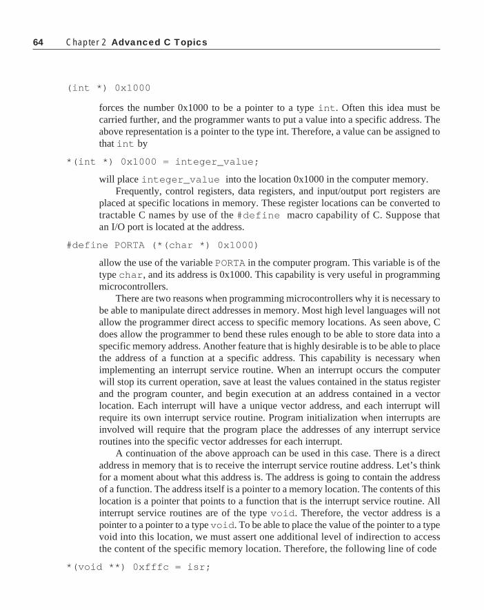
64 Chapter 2 Advanced C Topics
(int *) 0x1000
forces the number 0x1000 to be a pointer to a type int . Often this idea must becarried further, and the programmer wants to put a value into a specific address. Theabove representation is a pointer to the type int. Therefore, a value can be assigned tothat int by
*(int *) 0x1000 = integer_value;
will place integer_value into the location 0x1000 in the computer memory.Frequently, control registers, data registers, and input/output port registers are
placed at specific locations in memory. These register locations can be converted totractable C names by use of the #define macro capability of C. Suppose thatan I/O port is located at the address.
#define PORTA (*(char *) 0x1000)
allow the use of the variable PORTA in the computer program. This variable is of thetype char , and its address is 0x1000. This capability is very useful in programmingmicrocontrollers.
There are two reasons when programming microcontrollers why it is necessary tobe able to manipulate direct addresses in memory. Most high level languages will notallow the programmer direct access to specific memory locations. As seen above, Cdoes allow the programmer to bend these rules enough to be able to store data into aspecific memory address. Another feature that is highly desirable is to be able to placethe address of a function at a specific address. This capability is necessary whenimplementing an interrupt service routine. When an interrupt occurs the computerwill stop its current operation, save at least the values contained in the status registerand the program counter, and begin execution at an address contained in a vectorlocation. Each interrupt will have a unique vector address, and each interrupt willrequire its own interrupt service routine. Program initialization when interrupts areinvolved will require that the program place the addresses of any interrupt serviceroutines into the specific vector addresses for each interrupt.
A continuation of the above approach can be used in this case. There is a directaddress in memory that is to receive the interrupt service routine address. Let’s thinkfor a moment about what this address is. The address is going to contain the addressof a function. The address itself is a pointer to a memory location. The contents of thislocation is a pointer that points to a function that is the interrupt service routine. Allinterrupt service routines are of the type void . Therefore, the vector address is apointer to a pointer to a type void . To be able to place the value of the pointer to a typevoid into this location, we must assert one additional level of indirection to accessthe content of the specific memory location. Therefore, the following line of code
*(void **) 0xfffc = isr;

65
will place the beginning address of the function isr into the memory location 0xfffc.A convenient method of executing this operation is to create a macro. The
following macro definition works:
#define vector(isr, address) (*(void **)(address)=(isr))
Now the function call
vector(timer, 0xffd0);
will place the address of the function named timer into the location 0xffd0 in thecomputer memory map. It is important that timer be defined as a function that returnsa type void .
StructuresAnother feature of C not found in many high level languages is the structure. A
structure is similar to an array, but far more general. A structure is a collection of oneor more variables identified by a single name. The variables can be of different types.Structures are types in the sense that an int is a type. Therefore, if you have properlydeclared a structure, you may declare another structure of the same type. Examine thefollowing structure:
struct person{
char name[20];char address[20];char city[20];char state[2];char zip[10];int height;int weight;float salary;
};
This structure contains some of the features that describe a person. The person’sname and address are given as character strings. The person’s height and weight areintegers, and the salary is a floating point number. The structure declaration must befollowed by a semicolon. This combination of variables is created every time astructure of the type person is declared. The name person following the structdeclaration is called the structure tag or merely the tag. Tags are optional. Once a tagis used, it may be used to declare other structures of the same type by
struct person ap,bp,cp;
Structures

66 Chapter 2 Advanced C Topics
Here ap , bp , and cp are structures of the type person . A single instance of astructure can be declared by
struct {....} a;
In this case a is a structure with the elements defined between the braces.The elements that make up a structure are called its members. Members of a
structure can be accessed by appending a period followed by the member name to thestructure name. For example the name of the person represented by ap is accessed by
ap.name[]
and that person’s salary is
ap.salary
A pointer to a structure can be used. The pointer pperson is created by
struct person *pperson;
If a pointer to a structure is used, members of the structure can be accessed by theuse of a special operator -> . This operator is created by use of the minus sign (-)followed by the right circumflex character (>) . The height of a person identified bythe pointer pperson is accessed by
pperson->height
Arrays of structures are used, and when dealing with pointers to arrays ofstructures, to increment the pointer will move the pointer to the next structure. If aprogram has
struct person people[20], *pp;
and pp is made to point at people[0] by
pp=people
then
people[1].name
is the same as
++pp->name
A structure can have another structure as a member element. Consider
struct point{
int x;int y;
};

67
where point contains two integer elements, x and y . A circle can now be defined by
struct circle{
struct point center;int radius;
};
In this case access to the members of center is by
circle.center.x
or
circle.center.y
Of course the radius is accessed by
circle.radius
Functions can take structures as arguments and they can return structures. Forexample the function make_point() that follows returns a structure.
struct point make_point(int x, int y){
struct point hold;
hold.x=x;hold.y=y;return hold;
}Observe that the struct point is treated as a type with no difficulty in this
function. The return type is struct point , and within the body of the function holdis also a type struct point . The x argument passed to the function is placed inthe x member of hold as is the y argument placed in the y member. Then thestruct hold is returned to the calling function. All of these operations are legal.
Since structures create types, structures can have members that are structures. Forexample, suppose that the struct rect for a rectangle is defined as
struct rect{
struct point p1;struct point p2;
};Let’s outline a program that will inscribe a circle within a rectangle. The circle is
to be centered in the rectangle, and to be tangent to the sides that make up thenarrowest dimension of the rectangle.
Structures

68 Chapter 2 Advanced C Topics
/* Inscribe a circle in a rectangle */
struct point{
int x;int y;
};
struct circle{
struct point center;int radius;
};
struct rect{
struct point p1;struct point p2;
};
struct circle make_circle( struct point ct, int rad ){
struct circle temp;
temp.center.x = ct.x;temp.center.y = ct.y;temp.radius = rad;return temp;
}
#define min(a,b) (((a)<(b)) ? (a) : (b))#define abs(a) ((a)<0 ? -(a) : (a))
void draw_rectangle(struct rect);void draw_circle(struct circle);
void main ( void ){
struct circle cir;struct point center;struct rect window = { {80,80},{600,400} };int radius,xc,yc;

69
center.x = (window.p1.x+window.p2.x)/2;center.y = (window.p1.y+window.p2.y)/2;
xc = abs(window.p1.x -window.p2.x)/2;yc = abs(window.p1.y -window.p2.y)/2;radius = min(xc,yc);
cir=make_circle(center,radius);
draw_rectangle(window);draw_circle(cir);
}
At the beginning of the program, several important struct types are defined.These include a point, a rectangle, a circle, and a function to make circle given itscenter and its radius. Two macro definitions are needed. The first is the calculationfor the minimum value of a and b and the second returns the absolute value of theargument. Two function prototypes are included. These functions will draw a rect-angle and a circle to the screen, respectively.
Inside the main program cir is declared to be of the type struct circle ,center is struct point , and window is of the type struct rect . Whenwindow is defined, it is initialized to the values shown. This type of initialization isacceptable to structures as well as arrays. The rectangle is defined by two points. Thepoint {80,80} is the lower left hand corner of the rectangle, and the point {600,400}is the upper right corner. These locations are implementation dependent, and in somecases might represent the upper left corner {80,80} and the lower right corner{600,400} .
The center of the window is calculated by determining the average value of the xmembers of each point along with the average value of the y members. These valuesare the exact center of the rectangle. The center of the inscribed circle will lie at thispoint. The radius of the inscribed circle will be one-half the length of the shortestdimension of the rectangle. The two potential value are calculated as xc and yc . Herethe absolute value is used, because in general, it is impossible to know that therectangle will be specified by the lower left hand corner in p1 and the upper righthand corner in p2. If these points were interchanged, negative values would becalculated. The selection of the positive result through the abs() macro avoids thisproblem. The final choice for radius is the minimum value of xc or yc .
The above calculations provide enough information to specify the circle, so ciris calculated as the return value from make_circle() . Finally, two compilerspecific functions, draw_rectangle() and draw_circle , are used to drawthe calculated figures to the screen.
Structures

70 Chapter 2 Advanced C Topics
While it would not be difficult to execute these calculations without the use ofstructures, it is obvious that the structure formulation of the program makes a muchsimpler and easier to follow program. The variables and program elements are objectshere rather than mere numbers.
C has a command called typedef . This command can rename a specified typefor the convenience of the programmer. It does not create a new type, it merelyrenames an existing type. For example,
typedef int MILES;typedef char BYTE;typedef int WORD;typedef long DWORD;
are all valid typedef statements. After the above invocations, a declaration
MILES m;BYTE a[20];WORD word;DWORD big;
would make m an int , a an array of 20 characters, word the type int , and big along . All that has happened is that these types are a redefinition of the existingtypes. New types defined by typedef s are usually written in all upper case letters.This is a tradition, not a requirement of the C language.
Structures used earlier could be modified by use of the typedef . Consider
typedef struct{
int x;int y;
} POINT;
This typedef redefines the earlier struct point as POINT. The judicioususe of typedef s can make a program even easier to read than the simple use ofstruct s. The program that follows is the same as that above where all of thestructures are typedef new names.
/* Inscribe a circle in a rectangle */
typedef struct{
int x;int y;
}POINT;

71
typedef struct{
POINT center;int radius;
}CIRCLE;
typedef struct{
POINT p1;POINT p2;
}RECT;
CIRCLE make_circle( POINT ct, int rad ){
CIRCLE temp;
temp.center.x = ct.x;temp.center.y = ct.y;temp.radius = rad;return temp;
}
#define min(a,b) (((a)<(b)) ? (a) : (b))#define abs(a) ((a)<0 ? -(a) : (a))
void draw_rectangle(RECT);void draw_circle(CIRCLE);
void main ( void ){
CIRCLE cir;POINT center;RECT window = { {80,80},{600,400} };int radius,xc,yc;
center.x = (window.p1.x+window.p2.x)/2;center.y = (window.p1.y+window.p2.y)/2;xc = abs(window.p1.x - window.p2.x)/2;yc = abs(window.p1.y - window.p2.y)/2;radius=min(xc,yc);
cir=make_circle(center,radius);draw_rectangle(window);draw_circle(cir);
}
Structures

72 Chapter 2 Advanced C Topics
The function make_circle() returns a type CIRCLE and requires argumentsPOINT and int . CIRCLE is used to declare the variable temp in make_circle() .Within the main program CIRCLE , POINT , and RECT are used as types in thedeclaration of the several structure type variables used in the program. With thetypedef declarations, there is no basic change to the program, but it is easier toread and follow.
The two functions draw_rectangle() and draw_circle() are not stan-dard C functions. These functions are programmed and the listing of the finalprogram is shown in Appendix B.
Self Referential StructuresA structure cannot contain itself as a member. Structure definitions are not
recursive. However, a structure can contain a pointer to a structure of the same type.This capability has proven quite useful in dealing with complicated sort or listingproblems. One sort problem that can be easily treated is the binary tree sort. A treesort receives data, such as a word. Within the tree there is a root node that contains aword. The node also contains a count of the number of times the word has been seenand two pointers to additional nodes. These nodes are called child or descendentnodes. Traditionally, the node to the left contains a word that is less than the rootword, and the node to the right contains a word that is greater than the root node. Thenew word is compared with the root word. If it is equal to the root word, the count inthe node is incremented, and a new word is received. If the word is not the same and isless than the root word, the node to the left is accessed and the comparison isrepeated. This process is repeated until a match is found or a node with no descen-dants is found. If a match is found, the count of that node is incremented. If no matchis found a new node is created and placed at the bottom location, and the word isinserted into the new node. This process is repeated with the smaller words alwaysgoing to the left and the larger words always going to the right.
Eventually a tree that contains all of the different words entered into the programwill have been created. The tree has several properties. Since each node has two childnodes, the tree builds in a binary manner. The root level has exactly one entry, thesecond level has two entries, the third level has four entries, and so forth. If the tree isbalanced, each level will have a power of two entries. However, if word data aretaken in randomly, it is possible that some tree branches will terminate early andothers will extend to a depth or level that exceeds some.
Once the data are placed into the tree, it is possible to sort it or to arrange thewords in alphabetical order. If we traverse the tree from the root node to the extremeleft, we will find the word that is smallest. Immediately above that word will be thenext larger word. To the right of the second word will be words larger than itself butsmaller than the word in the next node above. Therefore, the right path must betraversed to the left to find the next larger words. All of this—right and left, larger and

73
smaller—sounds complicated. It is not.Here is a case where a little thought and recursive code will help things along
easily. The code that follows is a complete function to alphabetize and count thenumber of times that each word is used in a document. Several new concepts will beshown in this program, so it will be broken into short blocks and described in thesesmall pieces of code rather than trying to bite into the whole program at one time.
The structure tnode is listed below.
typedef struct tnode{ /* the tree node */
char *word; /* points to text */int count; /* occurrences */struct tnode *left;/* pointer to left child */struct tnode *right; /* pointer to right child*/
}TNODE;
The first two elements to this structure are a pointer to the word contained in thenode, and the number of times that the word has been seen. The last two elements arepointers to structures of the type tnode . Note that in the typedef of the structtnode , the structure tag was used. It is necessary to use the tag in this case becausethe self-referential pointers inside of the structure needs the tag to find the correcttype. For the remainder of the program, the typedef TNODE is used.
Some new files are included in the include files. These files will be discussed in afollowing section. The first is ctype.h. This program uses several character teststhat are identified in ctype.h. There are string operations found in string.h ,and there are standard functions defined in stdlib.h.
#include <stdio.h>#include <ctype.h>#include <string.h>#include <stdlib.h>
The list of function prototypes for the functions written in this program follow:
TNODE *addtree(TNODE *, char *);TNODE *talloc(void);void treeprint( TNODE *);int getword(char *, int);char *strsave(char *);
The first function is the function that is used to add a tree to the program.*talloc() is a function that allocates memory for a TNODE. The functiontreeprint() prints out the tree, and getword() reads in a word from the inputstream. There are two function prototypes defined within the program getword() .These functions are used by getword() only. The final function above saves thestring pointed to by the argument in a safe place and returns a pointer to the word
Structures

74 Chapter 2 Advanced C Topics
location in memory.The main program is relatively simple. The constant MAXWORD is the maximum
number of characters that can be allowed in a word. Within main() a pointer to astructure TNODE named root is declared along with a character array named wordand an integer i .
/* word frequency count */
#define MAXWORD 100
int main(void){
TNODE *root;char word[MAXWORD];int i;
root=NULL;while(getword(word,MAXWORD) != EOF)
if(isalpha(word[0]))root=addtree(root,word);
treeprint(root);return 0;
}
A NULL value is assigned to root , and the program enters a loop that readswords from the input stream. It is assumed that if the first character of the word is aletter, that a word has been read in. The function isaplha() returns a TRUE if itsargument is a letter, and a FALSE if it is not. If the input is a letter, the routineaddtree is executed with the arguments root and word . The first time that thisfunction is executed, root is a NULL. This loop is repeatedly executed untilgetword() receives an EOF character from the input stream. At that time the inputloop terminates, and the function treeprint() is executed. When treeprint()is completed, main() returns a 0 to the calling program or the operating system.This signal can be used to notify the operating system that the program has executedcorrectly.
The function addtree() is the most complicated function in this program. Thisfunction receives a pointer to a TNODE and a pointer to a character string asarguments. It returns a pointer to a TNODE. If the TNODE pointer argument is aNULL on entry to the function, the first if loop is executed. Within that loop, talloc()returns a pointer to a new TNODE. The function strsave() copies the string into asafe place and returns a pointer to this location. This pointer is put into the wordpointer location in the new TNODE. A value of 1 is put into the count location, andthe pointers to the left and right child TNODEs are set to NULL. At this time, the word

75
has been put into the TNODE , and the pointer to this TNODE is returned to the callingprogram.
/* addtree: add a node with w, at or below p */
TNODE *addtree(TNODE *p, char *w){
int cond;
if(p == NULL) /* new word has arrived */{
p=talloc(); /* make a new node */p->word=strsave(w);p->count=1;p->left=p->right=NULL;
}else if((cond = strcmp(w,p->word)) == 0 )
p->count++; /* repeated word */else if(cond <0) /* less than into left subtree*/p->left = addtree(p->left,w);else /* greater than into right subtree */
p->right = addtree(p->right,w);return p;
}
Suppose now that at a later time addtree() is called and this time p is nolonger a NULL. In this case, a string compare test will be executed to determine if theword that has been passed is equal to that in the TNODE pointed to by p. If it is equal,it is a repeated word for that node, so the word count is incremented and control isreturned to the calling program. If it is not equal (say, it is lexically less than the wordof the node), it is necessary to either traverse to the node on the left or add a new nodeon the left if there is none there. The code
p->left = addtree(p->left,w);
does exactly what is needed in this case. This recursive call to addtree() willdescend to the left TNODE if one exists. If one does not exist, the pointer to the leftTNODE will be NULL, so addtree() will create a new node for this location.addtree() returns a pointer to the new node, so it will be placed in the left pointerof this node.
Had the lexical value of the word been greater than that of the word stored in thenode, the addtree() call would work on the pointer to the right child node.Therefore, the function addtree() will start at the root node and traverse down the
Structures

76 Chapter 2 Advanced C Topics
tree to the right or left child nodes depending on the size of the word relative to thesizes of the words in the tree. If the word is found in the tree, its count is incremented.If control proceeds down the tree, and the word is not found, eventually, a TNODEwith a NULL pointer to the direction that the path must move. A that time a newTNODE is created and the word is assigned to that TNODE.
When all of the data to be input into the tree are read in, control is passed to thefunction treeprint() . The argument of treeprint() is a pointer to the rootnode and treeprint() returns nothing to the calling program. Efficient printingout of the data requires another recursive routine. The function treeprint()shown below shows this routine. treeprint() is called with the root pointer as anargument. The root pointer will not be a NULL, so the code following the if statementwill be executed. The first
/* treeprint: in-order print of tree p */
void treeprint(TNODE *p){
if(p !=NULL){
treeprint(p->left);printf("%4d%15s\n",p->count,p->word);treeprint(p->right);
}
}statement of this code is a recursive call to treeprint() with the pointer to the leftchild pointer as an argument. This recursive call will cause control to propagate to thelowest and leftmost level of the tree. At this time treeprint() will returnnormally, and the word pointed to in the TNODE will be printed out by the printf()call. The program will then start a recursive treeprint() to the right of this node.Control will immediately go to the left side of the right branch and will descend thelowest level and print out the word found. This routine will repeat up and down untilthe whole tree content has been printed.
The function strsave() copies the word passed to it as an argument into asave place and returns a pointer to this memory location to the calling program. Cprovides for dynamic allocation of memory. Up to this point, all memory access
char *strsave(char *s) /* make a duplicate of s */{
char *p;
p = (char *)malloc(strlen(s)+1);if(p != NULL)
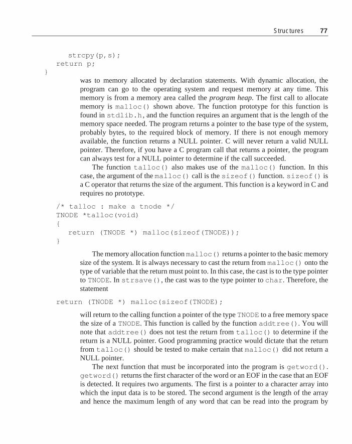
77Structures
strcpy(p,s);return p;
}was to memory allocated by declaration statements. With dynamic allocation, theprogram can go to the operating system and request memory at any time. Thismemory is from a memory area called the program heap. The first call to allocatememory is malloc() shown above. The function prototype for this function isfound in stdlib.h , and the function requires an argument that is the length of thememory space needed. The program returns a pointer to the base type of the system,probably bytes, to the required block of memory. If there is not enough memoryavailable, the function returns a NULL pointer. C will never return a valid NULLpointer. Therefore, if you have a C program call that returns a pointer, the programcan always test for a NULL pointer to determine if the call succeeded.
The function talloc() also makes use of the malloc() function. In thiscase, the argument of the malloc() call is the sizeof() function. sizeof() isa C operator that returns the size of the argument. This function is a keyword in C andrequires no prototype.
/* talloc : make a tnode */TNODE *talloc(void){
return (TNODE *) malloc(sizeof(TNODE));}
The memory allocation function malloc() returns a pointer to the basic memorysize of the system. It is always necessary to cast the return from malloc() onto thetype of variable that the return must point to. In this case, the cast is to the type pointerto TNODE. In strsave() , the cast was to the type pointer to char . Therefore, thestatement
return (TNODE *) malloc(sizeof(TNODE);
will return to the calling function a pointer of the type TNODE to a free memory spacethe size of a TNODE. This function is called by the function addtree() . You willnote that addtree() does not test the return from talloc() to determine if thereturn is a NULL pointer. Good programming practice would dictate that the returnfrom talloc() should be tested to make certain that malloc() did not return aNULL pointer.
The next function that must be incorporated into the program is getword() .getword() returns the first character of the word or an EOF in the case that an EOFis detected. It requires two arguments. The first is a pointer to a character array intowhich the input data is to be stored. The second argument is the length of the arrayand hence the maximum length of any word that can be read into the program by

78 Chapter 2 Advanced C Topics
getword() . Two functions are accessed by getword() . The first is getch()which returns a character from the input stream. The second is ungetch() whichrestores a character back onto the input stream. We will see later that for this functionto work correctly, it must pull one more character than the length of the word in somecases. When that happens, the extra character must be put back onto the input streamso that it will be available for the next getch() call.
/* getword: get next word or character from input */int getword(char *word, int lim){
int c, getch(void);void ungetch(int);char *w=word;while(isspace(c=tolower(getch())));if(c!=EOF)
*w++=c;if(!isalpha(c)){
*w=NULL;return c;
}for( ; —lim >0 ; w++)
if(!isalnum(*w=tolower(getch()))){
ungetch(*w);break;
}*w=NULL;return word[0];
}
The first executable statement
while(isspace(c=tolower(getch())));
includes two standard C functions. The function isspace() has its prototype in theheader file ctype.h. This function returns a TRUE if its argument is a space andFALSE otherwise. The second function, tolower() , is also prototyped in ctype.h.It tests the argument and returns a lower case letter if the argument is upper case and alower case letter if the argument is an upper case letter. Therefore, this operation willloop until it receives a nonspace input, and the lower case version of the letter inputwill be stored in c.

79
If c is not an EOF, it is put into the next open location of the word array and thepointer into this array is incremented. If the return is an EOF, the second ifstatement will execute. The if statement
if(!isalpha(c)){
*w=NULL;return c;
}
tests to determine if the character from the input stream is a letter. isalpha()returns a TRUE if its argument is a letter and a false otherwise. If the character takenfrom the input stream is an EOF, isalpha() will return a FALSE and the statementfollowing the if will be executed. In this case, a NULL is written to the word, andthe EOF is returned to the calling function.
If the return is a letter, the following sequence will be executed:
for( ; —lim >0 ; w++)if(!isalnum(*w=tolower(getch()))){
ungetch(*w);break;
}
The central loop here is the if statement. Its argument executes getch() toread in characters from the input stream. These inputs are converted to lower case andstored into the array location pointed to by w. The result is then checked to determineif it is a letter or a number. If it is not, it is put back onto the input stream and the loopis exited by the break instruction. If it is a letter or a number, the pointer to the outputarray w is incremented and the maximum length of the array is decremented. If thislast result is greater than zero, the next character is read in. Otherwise, the ifstatement is skipped.
The last two statements in the function are
*w=NULL;return word[0];
The last entry of the character array is made a NULL to satisfy the C requirementthat a string must terminate with a 0, and the first character of the word is returned tothe calling program. This value is returned just to guarantee that an EOF is notreturned.
There are two final functions required for this program. These functions worktogether to form the getch()/ungetch() pair. A global buffer with an argument
Structures

80 Chapter 2 Advanced C Topics
BUFSIZE is created, and a global integer bufp is declared. bufp is initialized to 0.Since these variables are global, they are initialized at the beginning of the program,and they will not be changed when control is returned to a calling function.
In getch() , the value of bufp is tested. If it is greater than 0, the characterreturned is taken from the buffer and the bufp is decremented. Otherwise, a newcharacter is read from the input stream by getchar() .
#define BUFSIZE 100
char buf[BUFSIZE]; /* buffer for ungetch */int bufp=0; /* next free position in buffer */
int getch(void)/* get the next character from the buffer */{
return(bufp>0) ? buf[—bufp] : getchar();}
void ungetch(int c) /* put character back onto input */{
if(bufp>=BUFSIZE)printf("ungetch: too many characters \n");
elsebuf[bufp++]=c;
}
When ungetch() is executed, a test is made to determine if this store wouldexceed the buffer length. If bufp will be greater that BUFSIZE after it is incre-mented, an error return is executed. Otherwise, the return character is put in the bufferand it is there to be read the next time getch() is executed.
This program has introduced several C functions. In fact, C has a ungetchar()that does the same function as ungetch() above. It has given examples of struc-tures containing pointers to like structures, recursive functions to process data, anddynamic memory management.
EXERCISES1. With an editor, enter the tree program and compile it. To run this program, use an
input redirection such as
c:>tree < (filename)
2. Modify the above program to determine the number of levels, and record the levelnumber with each word. Print out the levels when the output is printed. Hint. thelevels can be determined in the addtree() function, and the printout of thelevels require a modification of treeprint() .

81
3. Add a histogram to the above program that shows the number of entries in eachlevel. Count the total number of different words in the document tested.
More StructuresThere are two more important considerations that should be placed under struc-
tures. The first of these is the union, and the second is bit manipulations and bit fields.
UnionsA union is defined much the same as a struct . There is a significant differ-
ence, though. A union can have several different arguments, each of which is adifferent type. The compiler, when it sees a union declared, provides enoughmemory to hold the largest argument of the union . When different arguments areused, the different types occupy the same memory location. Consider the followingsequence:
struct bothints{
int hi,lo;};
union both{
long l;struct bothints b;
}compound;
This sequence will cause the compiler to generate a structure that contains twoint s. The union both will provide space for whichever is larger, a long or astruct bothints. Of course, a long is the size of struct bothints , soenough memory will be provided to store a long . In use, a sequence like
compound.b.hi = a;compound.b.lo = b;
will place the int a into the upper location of compound , and b will go into thelower location of compound. After these operations, compound.l will contain ain its upper word, and b in its lower word. If compound.l were used as avariable, it would be this combination.
Unions are most often thought of as a method of saving memory. If several
More Structures

82 Chapter 2 Advanced C Topics
variables are completely independent and never used at the same time, a union thatcontains these several variables will allow the programmer to store each in the samememory location.
BitfieldsThe concepts of bitfields fall loosely under structures. The first built-in opera-
tions that allow bit manipulations from C involves an enum. Consider the followingenum:
enum {PB1=1,PB2=2,OUT1=4,OUT2=8};int PORTA;
Notice that the different elements of the enum are each powers of 2. We canthen use an expression like
PORTA |= PB1 | PB2;
to turn on bits corresponding PB1 and PB2 in the integer PORTA. Or, thesecorresponding bits might be turned off in PORTA by
PORTA &= ~(PB1 | PB2);
Tests can be executed like
if(PORTA & (PB1 | PB2) == 0)
Here the argument of the if call will be TRUE if both bits corresponding to PB1and PB2 are turned off in PORTA.
These manipulations are not really special bit manipulations. What is seen here ismerely creation of bit like operations using normal C. C does support bit fields. Bitfields are created in the form of a struct. The following struct defines severalbit fields:
struct{
unsigned int PB1 : 1;unsigned int PB2 : 1;unsigned int OUT1: 1;unsigned int OUT2: 1;unsigned int ALL : 4;
} FLAGS;
This struct consists of several bit fields. The colon that follows the field namedesignates the size of the bit field. The first four fields are each 1 bit wide, and thefinal field ALL is 4-bits wide. These bits can be turned on by:

83
FLAGS.OUT1 = FLAGS.OUT2 = 1;
or off
FLAGS.OUT1 = FLAGS.0UT2 = 0;
and they can be tested
if(FLAGS.PB1 == 0 && FLAGS.PB2 == 1)...
Some of the compilers have special bit constructs. These constructs are usuallystructs that have either 8- or 16-bits within the field. These structs are usefulas Boolean variables.
When setting up a microcontroller program, the programmer will frequently wantto have bit fields at specific locations in memory. These bit fields can be used is I/Oports, control registers and even arrays of bits to be used internally as flags. Anapproach to this problem is found in the bit array.
typedef struct{
bit_0 :1;bit_1 :1;bit_2 :1;bit_3 :1;bit_4 :1;bit_5 :1;bit_6 :1;bit_7 :1;
} BITS:
A macro definition is used to create a variable:
#define PORTA (*( BITS *) 0x1000)
With these definitions, instruction statements like
PORTA.bit_7 = 0;
if(PORTA.bit_3 == 1 && PORTA.bit_2 == 0)
etc. can be used in dealing with the bits within this memory location.
Input and OutputC has no provision for either input or output within the language. Any such
Input and Output

84 Chapter 2 Advanced C Topics
operations must be programmed as functions that are called from the programs. Thereare several standard I/O functions that are always included with a complete Ccompiler. However, in many instances, compilers for very small microcontrollerswill have no built-in input/output capability.
File accesses are through a set of functions and a special structure. The structFILE is a structure that contains all parameters needed to access a file. The pointer toFILE is usually called a file handle in MS-DOS or PC-DOS vernacular. The filehandle is given a value by
FILE *fp;FILE *fopen(char* name, char* mode);
Here name is a pointer to a character array that contains the name of the file. Thisname can be simply the file name if the file resides in the default directory, or it canbe the complete path name-file name combination for files elsewhere in the filesystem. The string pointed to by mode is a one or two character string. The variousmodes are
"r" read only"w" write only"a" append
and sometimes
"b" binary"rw" read/write
To open a file, the program must contain a statement
fp=fopen(name,mode);
where fp is declared as a pointer to the type FILE . Once the file is opened, all fileaccesses will use fp as an argument in some way. There are two single character fileaccess functions:
int getc(FILE* fp);int putc(int c, FILE* fp);
The first function returns a character from an open file fp and the second puts acharacter c onto an open file fp . There are three special file handles that are createdby the operating system when a program is loaded. These three file handles arestdin , stdout , and stderr. stdin is the standard input, and defaults to thekeyboard. stdout in the standard output and defaults to the terminal screen, andstderr is the standard error output which defaults to the terminal screen. Thesedefaults can be redirected by the operating system through the use of redirectionoperators and pipe operators when the program is executed.

85
The functions getchar() and putchar() are macro definitions:
#define getchar() getc(stdin)#define putchar(c) putc(c,stdout)
Therefore, getchar() will read a single character from the keyboard, andputchar() will put a single character to the terminal screen.
There are string I/O with the file functions. A string can be put to a file by
int fputs(char* string, FILE* fp);
This function returns an EOF if an error occurs. Otherwise, it returns a zero whenthere is no error.
A string can be read from a file by
int fgets(char* string, int maxline, FILE* fp);
fgets returns the next input line from the file fp . This data are written into string,and can at most maxline- 1 characters. The string is NULL terminated. fgets willreturn a zero when an error occurs. If there is no error, fgets returns the pointerstring.
Another important file access function is
int fclose(FILE* fp);
This function releases the file handle fp and it causes any data written to the file,but not written to the final destination, to be written. For example, most disk filesystems use a buffer to store up a significant amount of data before it is written to thedisk. If data are buffered when the fclose() routine is executed any buffered datais written to the disk and the program connection to the file system is dissolved.
Different compilers have several file handling routines. To obtain the maximumadvantage of these routines, you should consult the manual that comes with yourspecific compiler.
We have seen several instances of input/output functions. The most common isthe printf() function. This function is but one of several functions that can begrouped together under the category of formatted input/output. The formatted outputfunctions include
int printf(char* format, arg1, arg2,...);int sprintf(char* string, char* format, arg1,arg2,...);int fprintf(FILE* fp, char* format, arg1, arg2,...);
The function printf() has been used throughout the text so far, and thereshould be little question as to its use. This function prints data to the terminal screen.The pointer format points to a character string that contains the information to printout. Within the format, there can be conversion commands identified by a percentsign %. These commands will be discussed in detail later. The number or arguments,
Input and Output

86 Chapter 2 Advanced C Topics
arg1 , arg2 , etc. depend on the number of commands within the format string.The second function above, sprintf() , performs exactly the same conversion
as printf() . Rather than printing the result to the screen, it is written into thecharacter array string in memory.
Data can be printed to a file with the third function fprintf() . Here fp is thefile handle of an open file, and the remainder of the arguments are exactly the same aswith the printf() function.
The following is a list of all the conversion commands and their meanings. If thecharacter following the % in a format string is not found in the table, functionbehaviors will be undefined.
Character Printed asd,i int: decimal numbero int: unsigned octal numberx,X int: unsigned hexadecimal numberu int: unsigned decimal numberc int: single characters char* : print characters from string until NULL is detected.f double: floating point [-]m.dddd where the number of ds is
given by precision. Default precision is 6.e,E double: floating point [-]m.ddddExx where the number of
ds is given by the precision, and the power of 10 exponent canbe plus or minus. Default precision is 6.
g,G Uses e or f format which ever requires least space.% No argument is converted. Print as a %
Additional formatting capability exists. A decimal number can be placed betweenthe % sign and the conversion command. Suppose this number is f.p . Here the fieldwidth provided for the conversion is f , and the precision—the number of decimalplaces—is p. If the conversion requires a field width greater than f , the programtakes the space needed. Therefore, if the programmer is careless and tries to squeezemore information into a field than can fit, the program automatically provides acorrect result with the format disrupted. If this number is preceded by a negative sign,the data output will be started at the left side of the field. Otherwise, the output will bejustified to the right edge of the field.
This formatting approach works with strings as well as numerical outputs. If astring output contains a field width or a precision, it works much the same as anumerical output. If the field width specified is not long enough to hold the outputstring, the specified field with is ignored. The complete string is printed out. With astring, precision specifies the number of output characters. If the precision is smallerthan the field width, the width of the output field will be the precision specification. Aminus sign applied to field width will cause the data to printed to the left edge of thefield. Otherwise, the data will print to the extreme right edge of the field.

87
Formatted input is also provided in C. The three formatted input functions areint scanf(char* format,arg1,arg2,...);int sscanf(char* string,char* format,arg1,arg2,...);int fscanf(FILE* fp,char* format,arg1,arg2,...);
The first of these functions read formatted data from the standard input, thesecond reads formatted data from a string in memory and the third reads formatteddata from an open file fp . There is a significant difference between the formattedinputs and outputs. Recall that the arguments in the formatted outputs are data values.In the formatted inputs, all arguments must be pointers to locations in memory thatcan hold the data types specified in the data string. If the program should contain
int i;...scanf("%d",i); /* BAD */
the program will probably compile, most compilers will not note an error, and theprogram will not run correctly because the scanf() argument is not a pointer.
Memory ManagementThere are two functions in C that allow dynamic memory management. The
function
void* malloc(size_t n);
returns a pointer to a block of memory that is n bytes long. This memory is uninitialized.malloc() (and calloc() below) returns a pointer to a block of memory of thetype void. Therefore, before it can be used, the return pointer must be cast onto thedata type that the program requires. If this step is not taken, none of the usual pointerarithmetic will work. If the memory is not available to be allocated, the allocationprogram will return a NULL.
A second dynamic memory allocation function is
void* calloc(int number, size_t n);
This function returns a pointer to a type void . It takes two arguments. The firstargument is the number of items and the second argument is the size of the specificitem. Therefore, if you wished to allocate space for ten TNODEs from the aboveproblem, you should use
Memory Management

88 Chapter 2 Advanced C Topics
(TNODE *) calloc(10, sizeof(TNODE));
calloc() differs from malloc() in that it returns a pointer to initialized space.The calloc() function initializes all memory assigned by the function to zero.
When memory is allocated by either malloc() or calloc() , this memorymust be returned to the operating system. If allocated memory is not returned to theoperating system, eventually all of the available memory will be allocated. Furtherattempts to allocate memory will fail. If the return pointer from the allocationfunction is not tested and properly handled when a NULL is returned, the programcan destroy portions of the operating system. This problem can be avoided bydeallocating memory when it is no longer needed by the program. The function
void free(void* );
will release allocated memory. The argument in this case must be a pointer that wasreturned from an allocate function, either malloc() or calloc() .
Miscellaneous FunctionsC provides several sets of miscellaneous functions that are very useful. As
mentioned earlier, the input/output functions that are prototyped in stdio.h are notparts of the language, but instead are separate functions. The miscellaneous functionsare prototyped is several different header files. These functions are macros wheneverpossible, and if they are, the macro definitions are contained in the header file.
The header file string.h contains several functions that have to do with stringmanipulations and operations.
STRING OPERATIONS—Defined in string.h
strcat(s,t) concatenate t to sstrncat(s,t,n) concatenate n characters of t to sstrcmp(s,t) return negative, 0, or positive
for s< t , s==t , or s>t respectivelystrncmp(s,t,n) compare n characters of t and sstrcpy(s,t) copy t to sstrncpy(s,t,n) copy n characters of t to sstrchr(s,c) point to the first c in s or NULLstrrchr(s,c) point to last c in s or NULL
Another set of useful miscellaneous functions is defined in ctype.h. Thesefunctions deal with individual characters.

89
CHARACTER TESTS—in ctype.h
isalpha(c) non-zero if c is alphabetic, 0 if notisupper(c) non-zero if c is uppercase, 0 if notislower(c) non-zero if c is lowercase, 0 if notisdigit(c) non-zero if c is a digit, 0 if notisalnum(c) non-zero if c is a digit or alphabetic, zero if notisspace(c) non-zero if c is a blank, tab, newline,
return, formfeed, vertical tab, 0 if nottoupper(c) return c converted to upper casetolower(c) return c converted to lower case
A final set of functions are defined in the header math.h.
MATH FUNCTIONS—in math.h
sin(x) sine of x , x in radianscos(x) cosine of x , x in radiansatan2(x,y) four quadrant arctan of y/x , in radiansatan(x) two quadrant arctan of x , in radiansexp(x) exponential function of xlog(x) logarithm base e of xlog10(x) common logarithm of xsqrt(x) square root of xfabs(x) absolute value of x
These functions all require double arguments and return double values.There are two other functions provided by the standard C that are quite useful.
The first is the system command. The function prototype for this function is:
void system(char* s);
The argument of the system command is a string that contains an operatingsystem command. When the operating system command is completed, control isreturned to the calling program. This function can operate any function in the defaultdirectory, or the directory from which the system is operating. If it is necessary toexecute a function from a different path, the complete path name must be includedwith the file name.
A useful system() call is often
system("c:\command.com");
This function call will return control of the computer to the operating system.When the operator is completed with the operating system, you can return control tothe calling program by merely typing “exit” on the keyboard.
Most ANSI C compilers contain many additional functions for the programmers
Miscellaneous Functions


91
Chapter 3
What are Microcontrollers?A microcontroller differs from a microprocessor in several important ways. The
early name for a microcontroller was a microcomputer. The big difference between amicroprocessor and a microcomputer/microcontroller is the completeness of themachine each represents. A microprocessor was simply the “heart” of a computer. Toput a microprocessor into use, the designer required memory, peripheral chips, andserial and parallel ports to make a completely functional computer. By contrast, themicrocomputer was designed to be a complete computer on a single chip. Necessarymemory and peripheral components were integrated onto the chip so that a completecomputer based system could be built with a minimum of external components. Abasic microcontroller is shown in block diagram form in Figure 3-1.
Figure 3-1: A Typical Microcontroller Block Diagram
The central control unit of the microcontroller is the arithmetic logic unit (ALU).Figure 3-1 shows that the ALU is connected to three different blocks. The first is theinput/output block (I/O), the second is the program memory, and the third is the datamemory. Most Motorola microcontrollers combine the last three blocks into one
91
ProgramMemory
ArithmeticLogic Unit
Data Memory
Input/Output

92 Chapter 3 What are Microcontrollers
block. The architecture shown above is known as a Harvard architecture, as opposedto the more common Von Neumann architecture. The Harvard architecture is acomputer configuration in which the memory area that contains the program instruc-tions for the computer is separated from the memory area in which data are stored. Bycontrast, the Von Neumann architecture has just one memory space where bothprogram and data re stored.
The main functional difference between Harvard and Von Neumann architec-tures is in their ultimate operating speeds. Both architectures require that the ALUaccess memory once each instruction to get the next instruction to execute. Oftenthe instruction being executed will also require an access to memory. Reading datainto a register, storing data in a memory address, and accessing a location in memorythat is in fact an input/output register are examples of operations that require mem-ory accesses in addition to the normal memory fetches. As seen in Figure 3-1, theHarvard architecture will have two or more internal data busses over which thesedifferent accesses can take place. There are usually two such internal busses: one forinstruction access, and one for other data access. The processor can easily tell whichdata bus to use. If the access is to fetch an instruction, it is relative to the programcounter. These accesses will go to the program memory area. All other memoryaccesses will go to the data memory area. It is entirely possible to have two or morememory accesses simultaneously with a Harvard architecture.
The Von Neumann architecture is somewhat simpler than the Harvard architec-ture. On a Von Neumann processor, there is only one memory bus. All memoryaccesses must go through this single path on the system. With such a system, theprocessor can never process more than one memory access at a time and all memoryaccesses—instruction, data, or input/output—must pass through a single data bus.This is the origin of the term “Von Neumann bottleneck.” The multiple accesses tomemory for each instruction ultimately limit the maximum speed of a Von Neumannarchitecture processor. However, the speed of such processors can be many millionsof instructions per second, so there are numerous excellent, fast microcontrollersconstructed with the Von Neumann architecture. The Von Neumann architecture hasbeen the mainstay of microcontrollers and will be the only microcontroller configura-tion available until at least the mid-1990s.
A microcontroller has its program stored internally, and the ALU reads aninstruction from memory. This instruction is decoded by the ALU and executed. Atthe completion of the execution of the instruction, the next instruction is fetchedfrom memory and it is executed. This procedure is repeated until the end of the pro-gram is found, or the program gets into a loop where it is instructed to branch back toa beginning point. In this case, the machine will stay in the loop forever or untilsomething happens to release it from the never-ending loop.
There are three ways for a machine locked in a loop to be removed from the loopso it can execute code outside of the loop. These operations are called exceptions. Thefirst is to reset the part with a reset signal. A reset signal usually requires connecting

93
the reset pin of the part to a logic low signal. A logic low is usually ground. When thiscondition is detected, several internal registers are set to predetermined values, andthe microcontroller fetches the address of the reset routine from a specific memorylocation. This address is placed in the program counter, and the program starts toexecute. There is a table in memory that contains the addresses of several routinesaccessed when exceptions occur. These are the addresses of the interrupt serviceroutines, reset routines, etc. This table is called the vector table, and the addresses arecalled vectors.
A second means of forcing the part out of the loop is for the part to detect anexternal interrupt. An external interrupt occurs when the interrupt request (IRQ) pinon the part is set low. This pin is tested at the beginning of the execution of eachinstruction. Therefore, if an instruction is being executed when an IRQ is asserted, theinstruction will complete before the IRQ signal is processed. Processing for the IRQconsists of first determining if IRQs are enabled. If they are, the status of the machineis saved. All interrupts are disabled by setting the interrupt mask bit in the statusregister of the microcontroller. Then the address stored in the IRQ vector location isfetched. This address, the address of the interrupt service routine (ISR) is placed inthe program counter. The ISR then executes.
The process of saving the status of the machine is to push the contents of allmachine registers onto the machine stack. Therefore, the ISR can safely use any ofthe central machine resources without disrupting the operation of the main line ofcode when control is returned. When exiting an ISR, it is necessary to use a specialinstruction called a return from interrupt. This instruction restores the status of themachine from the stack and picks up execution of the code from the instructionfollowing the one where the interrupt occurred.
The third means exiting the main loop of the program is from internal interrupts.The microcontroller peripherals can often cause interrupts to occur. An internalinterrupt causes exactly the same sequence of operations to occur as an externalinterrupt. Different interrupt vectors are used for each of the several internal periph-eral parts so the cause of the interrupt is generally known and control is directed to thespecific ISR for each of the several possible internal interrupts.
Data are transferred, information is passed, or events are handled either synchro-nously or asynchronously. The difference between these two methods of data transferhas mainly to do with how the clocking of the data is handled. The most commonform of synchronous data transfer is with a three wire serial link. One of the wires is aclock, and the other two are input data and output data respectively. For a synchro-nous transfer, the value of the input is usually sampled at one edge of the clock signal(such as the fall of the clock) and the value of the bit to be sent out is guaranteed to becorrect at the fall of the clock signal. Any synchronous system must set its output atsuch a time that it will be stable while the clock is high, and hold it in that conditionuntil the clock signal falls. To receive a bit, the condition of the input line must belatched into the system as the clock signal falls from high to low.
What are Microntrollers?

94 Chapter 3 What are Microcontrollers
Within the computer, there is another distinction for synchronous. Often an inputis allowed to set a bit when it occurs. If this happens, the program will not expedi-tiously observe the fact that the bit is set. In fact, the program will test the state of thebit according to the program timing requirements. This type of operation is alsocalled synchronous because the test is synchronized with the program.
Asynchronous operation, on the other hand, usually depends on a prearrangedseries of events to cause the data transfer. Serial data communications is a commonexample of asynchronous data transfer. Here, an input line can have two states: markand space. A line is held at the mark state whenever no data are being transferred.When data are to be transferred, the data line is transitioned to the space state and heldthere for a specified time. This period is called the start bit. From that time onward,the data bits are placed on the line a bit at time so that at the specified time intervalsthe receiving device can examine the data line and determine the bit sequence.
Asynchronous operation means that there is no computer clock related specifica-tion as to the time that events will occur. Another example of asynchronous transferoccurs within the computer. Generally, events and data transfers that are initiated byinterrupts are considered to be asynchronous. Most of the peripheral devices that arefound on Motorola microcontrollers will allow either synchronous or asynchronousnotification of the program that the peripheral business is completed.
The following sections contain brief discussions of microcontroller memory andseveral of the standard peripherals found on these devices. These discussions areintended to be qualitative and provide a broad overview of these parts of themicrocontroller. Detailed descriptions of how to access and use these several periph-erals will be found in later chapters.
Microcontroller MemoryIn a microcontroller, the program instructions are usually stored in a memory
type called read only memory (ROM). ROM is usually programmed by a specialmask during the manufacture of the microcontroller and is called masked ROM. ROMis the least expensive means of storing a program in a microcontroller, especially forhigh volume manufacturing.
There are at least two means for the end user of the microcontroller to place theprogram memory into the chip. The first is called erasable programmable read onlymemory (EPROM). EPROM is a memory technology that can be erased by exposingit to high energy ultraviolet light. The EPROM requires the application of a highvoltage to be programmed. The memory can be programmed with either a develop-ment system or a special programming board designed specifically to program themicrocontroller.
Packages that contain EPROM have a quartz glass window through which theultraviolet light can pass with minimum attenuation. These packages are quite expen-

95
sive, and therefore, microcontrollers with EPROM are usually too expensive to use inmass production, but they are affordable for use to develop a system. During develop-ment, there are only a few microcontroller components needed, but it is very desirableto be able to change the microcontroller program easily. Therefore, the added cost ofEPROM is worthwhile for development purposes.
For limited production purposes, a less expensive version of the EPROM chip isavailable. This is the one time programmable (OTP) chip. An OTP chip has the exactsame silicon component as an EPROM, but it is packaged in a standard plasticpackage. This package is much less expensive than the windowed package discussedpreviously. However, once the chip has been programmed, the program contentscannot be changed.
There is yet another means of storing program or in some instances data in amicrocontroller. This technique is called electrically erasable programmable readonly memory (EEPROM). EEPROM is programmable from instructions within themicrocontroller. EEPROM also requires a high programming voltage. If there arelarge blocks of EEPROM on the chip, the programming voltage is usually appliedduring the programming cycle through a pin connected to an external voltage source.In cases where the amount of EEPROM to be programmed is relatively small, acharge pump on the microcontroller chip will allow the EEPROM to be programmedwith no externally applied voltage. The amount of EEPROM that can be programmedwith an on-board charge pump is usually so small that it is not useful for storingprogram instruction. But on board EEPROM can be quite useful in the storage of datagenerated by the program that must be saved through a power down cycle.
Sometimes in the execution of the program, some data are generated that must besaved for later use. These data are called volatile data or variables. These data areusually stored in random access memory (RAM). Careful design of a program willusually result in the need for much less RAM than ROM. In most microcontrollers,the amount of RAM is usually 60 to at most a few hundred bytes. The amount ofROM, EPROM or EEPROM usually runs from 1000 bytes upwards to a few tens ofthousands of bytes.
The architecture of Motorola microcontrollers is strictly Von Neumann. Thatis, internally within the microcontroller chip, there is only one data bus over whichall program, data, and input/output must pass. In a Harvard architecture system,each of these different data types will have a dedicated bus over which the informa-tion will pass. Therefore, the Harvard architecture microcontroller is able to accessdata, program, and I/O simultaneously. The simultaneous availability of thesedifferent data paths can result in a significant increase in overall processor speed. Italso increases the area of the microcontroller die, and hence, the cost of themicrocontroller. In general, most of the applications to which the microcontrollersare directed do not require extreme speed. Thus, the Von Neumann architecture iscompletely satisfactory.
Microcontroller Memory

96 Chapter 3 What are Microcontrollers
Input/OutputThe Motorola microcontrollers use an architecture called memory mapped I/O.
Each I/O device input and output registers, its control registers, and status registersare mapped into memory locations. I/O transactions require no special computerinstructions. It is merely necessary to know the memory locations of the pertinentregisters and the uses of the register bits to be able to handle any I/O function. Listedbelow are brief descriptions of several microcontroller I/O peripherals found onMotorola microcontrollers. Not all of these peripheral systems are found on eachmicrocontroller. It is possible to pick and choose between needs for the several periph-eral systems and select a microcontroller that has exactly those peripherals required.
Timer SubsystemsThere are two popular timer systems that you will find on different
microcontrollers. The first is a general purpose timer. Motorola refers to the generalpurpose timers as either 8- or 15-bit timers. These timers are different. The 8-bitsystem contains a prescaler that counts down from system clock. The output from theprescaler is fed into a counter that counts down from it the value stored in it. When thecounter underflows, a flag is set, and an interrupt can be executed.
The 15-bit timer is even simpler than the 8-bit timer. This timer has a 15-bitminimally programmable prescaler. An interrupt can be taken from two locations inthis ripple counter.
A second class of timer is the 16-bit timer. These timers contain a 16-bit counterthat is clocked by the system clock. There are two associated subsystems: the first iscalled an input capture system, and the second is the output compare.
The input capture system simply captures the value of the system timer counterwhen an input occurs. These inputs can set a flag or request an interrupt so the inputcan be processed either synchronously or asynchronously. The important fact is thatthe exact time of the input relatively to the 16-bit clock is saved when the inputoccurs. Applications for input capture systems are interpulse period measurements orfrequency measurements.
The output compare system allows the programmer to specify a time relative tothe 16-bit counter when an output is to occur. This time is calculated by adding thetime offset value to the current value of the 16-bit counter. This result is stored in theoutput compare register. When the 16-bit counter counts to the value in the outputcompare register, the output occurs, a bit is set, and an interrupt can be processed ifdesired.
Input capture and output compare functions are sometimes called high-speedinputs and outputs. The number of input captures and output compare systems varyfrom as few as one each to as many as 16 programmable timers each of which can beeither input capture or output compare.

97
There is another style of timer subsystem that is used on high-end microcontrollers.This system is called the timer processor unit (TPU). In most conventional comput-ers, the contents of a memory location is called an operand, and the processor hasbuilt-in operators that operate on the operands. A TPU is also a computer, but ratherthan using memory location contents as operands, time is the main operand used bythe TPU.
Another timer function found on most microcontrollers is the computer operatingproperly (COP) or watchdog timer. Most microcontrollers are placed in embeddedcontrols. That is, the microcontroller is a part of a larger system, and usually anoperator never deals directly with the microcontroller. Even though great care hasbeen taken into the design of the microcontroller, it is possible to cause these devicesto get lost from the program that they are executing. The power might dip, or a largetransient magnetic field might cause the part to go into abnormal operation. In such acase, the easiest way to restore normal operation is to send the part through a resetsequence. Such a sequence will restore all of the initial internal status of the micro-controller, execute the initialization code procedure of the program, and restart theexecution of the application loop. A COP timer provides just this function.
A COP timer is a timer with a relatively long period. Once the COP timer isstarted, it is necessary for the main program to reset the COP periodically prior to theexpiration of the COP period. The COP timer is never allowed to time- out. If thecomputer gets lost, the program no longer resets the COP, so the timer will eventuallyoverflow, and this operation causes the microcontroller to reset. Therefore, if the partever gets lost from its normal program sequence, the COP will force a reset andrestore the normal operation of the system.
Digital Input/OutputMost microcontrollers have several digital I/O ports. Usually a port consists of
eight or less bits, and the bits in these ports can be outputs, inputs, or often bitprogrammable as either input or output bits. If a port has programmable I/O, it willhave an associated data direction register—DDRA, DDRB, etc. The ports are usuallynamed PORTA, PORTB, and so forth. DDRA is associated with PORTA. Each bit inDDRA has a corresponding bit in PORTA. If a bit in DDRA is set, the correspondingbit in PORTA is an output. The same is true for PORTB, PORTC, PORTD, PORTE,and so forth if these ports exist on the part.
A port pin can be made into an output. When this occurs, this pin becomes alatched output. In other words, when this bit is set it will remain set until it is reset bythe program, and vice versa. Just because a port pin is designated to be an output doesnot mean that its state cannot be read by the computer. When a port is read in, the stateof all of the outputs as well as the state of the inputs will be shown in the result.
Some I/O pins are multiplexed and serve multiple functions. For example,microcontrollers with analog to digital converters, ADC, usually allow the ADC pins
Input/Output

98 Chapter 3 What are Microcontrollers
to serve as digital input pins as well. In that case you need merely read the input port,and those pins that are above the high threshold will indicate one, and those belowthe low threshold will indicate zero. Reading the port does not affect the ADCoperation at all.
Analog to Digital ConvertersThe ADC subsystem on most microcontrollers consists of a single successive
approximation analog to digital converter preceded by a analog multiplexer that canswitch the converter to any of several input pins. The program controls this switch-ing. The electromagnetic environment of the surface of a microcontroller die is aboutas bad as can be found anywhere. Therefore, attempts to do fine resolution measure-ments of analog voltages in these parts is fraught with problems. Most ADCs use aresistive ladder to as a digital to analog converter. The inputs to this ladder aresequenced in a prescribed manner to build a voltage that matches the voltage beingmeasured. The input to the D to A is then the digital equivalent to the voltage beingmeasured.
Precision resistors are very difficult to manufacture on silicon, and even preci-sion matching between resistors is extremely difficult. While making precisioncapacitors is very difficult on a silicon die, it is possible to make several capacitorswith highly accurate ratios between the capacitor values. Therefore, the approach isto use a set of matched capacitors and a charge balance technique to accomplish thesuccessive approximation of the analog voltage. This method works well, and 8- and10-bit systems are available on microcontrollers with plus or minus one half bitaccuracy.
Serial Input/OutputWhere would the computer be without serial input/output? The serial system was
probably the first direct human interface with any computer system. It has expanded,and today, relatively low speed asynchronous serial interfaces are used for terminaland modem and network interfaces. High speed synchronous serial links are used forall of the above plus inter computer connections, hardware peripheral communica-tions, and other types of devices where high speed, secure communications isrequired.
Many microcontrollers have both asynchronous and synchronous communi-cations peripherals built in. Usually, an asynchronous interface is called a serialcommunications interface (SCI) while the synchronous interface is called a serialperipheral interface (SPI).
Typically SCI systems can communicate at any of the popular asynchronousserial bit rates. These systems have built in baud rate generators, double bufferedinput and output registers, and all of the error detection found on a universal

99Programming Microcontrollers
asynchronous receiver-transmitter (UART) chip. These I/O devices can be eitherpolled or interrupt driven by the computer portion of the microcontroller.
The SPI is designed to communicate at high speeds with other microcontrollersor perhaps with hardware devices with a synchronous serial interface. These devicestypically run at megabit per second rates. Since synchronous systems require asystem clock, each microcontroller SPI can act as either a master or a slave. The maindifference between the master and the slave is which chip generates the system clock.The master generates the system clock, and the data are clocked into and out of theslave by the system clock. Communications with the microcontroller and the SPI canbe either polled (synchronous) or via interrupt controller (asynchronous).
Different ControllersNot all of these peripheral systems is found on each microcontroller. It is possible
to pick and choose between needs for the several peripheral systems and select amicrocontroller that has exactly those peripherals required. The smallest microcontrollerhas only a 15-bit timer, and the most complete MC68HC05 part has everything but aSPI system. All varieties in between these extremes exist. In the larger chips, some ofthe basic requirements for the microcontroller change. We will see these larger chipsin later chapters.
Programming MicrocontrollersThe preceding brief description of what microcontrollers are shows a rather
bleak picture of a potential programming environment from a computer standpoint.Most programmers are use to having an operating system that handles such mundanethings as I/O, memory management, time management, program loading, error pro-cessing, interdevice or intertask communications, and so forth. Be prepared for agiant step backwards when you address the microcontroller. There is usually nooperating system, no libraries of useful functions, no I/O handling, nothing but abare-bones computer with a bunch of hard-to-tame peripheral components onboardthe single chip device.
C compilers for the microcontrollers have been available long enough that theyare thoroughly tested and do a good job of creating proper code. Anyone who hasprogrammed a microcontroller in assembly language knows that the programs mustbe very direct and have no fancy overhead. Memory is strictly limited, and thecompiler must generate assembly code that is as resourceful as can be created by anythoroughly qualified assembly language programmer for the machine.
The development environment, while quite sophisticated in terms of how itworks, does little for the programmer in terms of direct help in debugging a program.There are two different types of development systems that are in common use. Bothof these systems require a host computer to run the device. The simplest of these

100 Chapter 3 What are Microcontrollers
systems goes by names like evaluation module, evaluation system, or evaluationboard. These devices are usually board level products that require a power supply inaddition to a host computer.
The software to run the development boards from MS-DOS systems is merely agood terminal emulator. Assemblers and linkers for the different chips are providedas part of the development board. The programmer writes the code for the part in thehost computer. This code is assembled, compiled, and linked in the host computer.The code is then down-loaded to the development board through either a serial or aparallel link depending upon the individual system.
The development board has the microcontroller that is to be emulated on board.This microcontroller is operating in a nonuser mode that allows internal bus access. Asecond computer on the development board controls the operation of themicrocontroller. Code delivered from the host is put into memory accessed by themicrocontroller, and the microcontroller can operate as if the code were containedwithin its internal memory. All of the I/O lines associated with the microcontrollerare brought to a header on the development board, and a cable can be attached to thisheader to a plug in device which plugs into a target board. This target system thenoperates as if it had a programmed microcontroller plugged into its socket.
The microcomputer on the development board has a complete monitor system inits firmware. This monitor provides communications with the host, down-loading andup-loading capability, and most important complete debugging firmware for themicrocontroller.
There is a single line assembler and disassembler in the firmware. This packageallows the programmer to examine and change memory in assembly mnemonics. Themicrocontroller program can be single stepped, run, address breakpointed, and thememory can be displayed in normal hexadecimal format. The microcontroller runs atfull speed when emulating operation in a target board.
An experienced programmer will be able to debug code in a microcontroller withthe help of such a development board. There is additional software available thatprovides a nice display of all pertinent information in a single screen on the hostcomputer. In this area, you will also find that the microcontroller can be controlledfrom a display of C source code on the host computer. This technique is called sourcelevel debugging.
All of the above capabilities are available with the development boards. Anotherlevel of capability is available. These devices are box level, and usually have a built inpower supply. Most development systems require a host computer, and usually theycome with special software to interface with the host computer. Most systems host toMS-DOS computers.
These systems have all of the capabilities outlined above plus some significantimprovements. The breakpoint capability of these systems is much improved over thesimple address breakpoint above. Here a complicated breakpoint can be employedthat will break the program operation on read or write, at any data or address location,

101
on access of data or program, or access of a range of data or address locations. Also,the breakpoint can occur after a specified number of occurrences of the breakpointconditions.
Another major difference in the development systems is the trace buffer. A tracebuffer is a memory that is as many as 48 or 64 bits wide. Each clock cycle of themicrocontroller the condition of all address bits, the data bus, the internal micro-controller control bus, and as many as 16 external test point lines are captured in thetrace buffer.
Usually, the trace buffer is 4 to 16 kilowords deep, so it can hold a significantnumber of microcontroller clock cycles. Even if the microcontroller is runningslowly, one million clock cycles per second, such a trace buffer represents aninsignificant execution time. To help make the data contained in the trace buffer,trace buffer capture can be controlled by a system that is the same as the breakpointoperation. Therefore, the portion of the program that is traced is under the detailedcontrol of the programmer.
The data in the trace buffer can be displayed in several different manners. Thesimplest, of course, is to print to the computer screen the I/0 pattern of all the linescaptured. This type of display is extremely difficult to interpret, but it is useful insome cases. To help the programmer determine where the microcontroller is operat-ing, it is possible to read the data bits, and display a disassembled version of the codebeing read into the microcontroller. This display is also quite useful in debuggingthe code.
Yet another display is called a logic analyzer. A logic analyzer is an oscilloscopedisplay that shows the logical status of the various lines captured in the trace buffer. Alogic analyzer is a separate device, but it can have a built in disassembler that displaysthe disassembled code along with the condition of the designated lines.
The devices with logic analyzers and trace buffers are quite a bit more expensivethan the development boards discussed earlier. Some of the development systemsprovide source level debugging capability for high level languages like C.
Another approach to development systems has been made available is some ofthe newer microcontrollers. The microcontrollers from the MC68HC16 family, andthose from the MC68300 family all have a background mode of operation. Whenoperating in the background mode, these chips stop their normal computing and startserial communications with an external computer. The background mode can beentered as the result of an internal command or an external signal. There are enoughdebug commands that can be communicated over this port to allow complete debugof any program that the microcontroller might be running. Minimum external cir-cuitry is needed to support the debug mode, so that these high powered chips canoperate as their own development environment. Here the development support ismostly software contained within the host computer, and deliverable system cancontain all of the essential components of a development system.
Programming Microcontrollers

102 Chapter 3 What are Microcontrollers
Coding Tips for MicrocontrollersOne of the major tasks facing a programmer when writing code in a high-level
language for any microcontroller is to make the resulting program as readable aspossible. Other people who might later need to read or modify your code must be ableto understand what is going on in your program. It is extremely important thatmnemonics be used as much as possible when dealing with various registers, their bitcontents, and special memory addresses throughout your programs; otherwise, theresulting code will be a “quasi-C” program filled with many numbers and funny-looking cast operations that will be largely incomprehensible to others trying tomaintain your program.
Modern large 8-bit systems are very nearly as complete as yesterday’s mini-computers. Programs for microcontrollers are also getting large, and they are increas-ingly being written by a team of programmers instead of a single programmer. Themanagement of the programming task is much more important when a team isinvolved because the person-to-person interface is the most “dangerous” in all pro-gramming. It is easy for people to make mistakes; misspelled words, interchangedorder of parameters in a function argument, passing incorrect data to a function, etc.,are all problems that can (and often will ) arise when several people try to write asingle program. Each person on the team can probably keep a maximum of six orseven function interfaces in mind, and even then mistakes will be made. When theprogram is really large, there will be dozens of function interfaces and sources ofpossible error will abound. For example, programmers will most of the time try to usewhat is in mind rather than look up a questionable function call.
How can these problems be minimized? Fortunately, there are several steps youcan take to keep errors down to a manageably low level. A big one is to make certainthat an ANSI-certified compiler can be used for any program and that the computerwill enforce strict type checking in the program. Doing so will cause most of theerrors due to carelessness or simple accidents to be caught at compile time and notduring the debugging phase. If such errors are not caught by the compiler, they areamong the most difficult to find when they show up at run time.
Programs can be improved by following these conventions:
1. Use a consistent constant definition naming convention. Use all capital lettersfor the names of constants defined in #define statements.
2. Make all function names thoroughly descriptive. Use several words for eachname if possible, and capitalize the first letter of each word so that the words canbe distinguished easily. For example, a function that returns the time should havea name like TimeOfDay() or Time_Of_Day() . The important thing is thatthe name must describe the function in some detail. Be consistent with namingconventions. If you start with names having no underscores, keep this conventionthroughout the entire program.

103
3. Make use of typedef and the fact that structures create new types. Wherepossible, create a type that is descriptive to your program. For example, in the Clanguage the interface to all input/output and files is through the type FILE.FILE in this case is simply a type that has been made available to the programthrough a typedef statement of a structure that contains all of the essentialelements needed for file input/output. It is recommended that types created bytypedef statements involving a structure should have names with the first lettercapitalized. The names of these types should be brief and should be one word only.
4. Many programmers make use of a Hungarian system for naming conventions.This system lets programmers identify the type of a variable from its name. Ituses a set of single letter prefixes added to normal variable names. Here is a tableof recom-mended prefixes to be used with the Hungarian convention:
Prefix Data Typec charby unsigned charn short or inti intb Boolean (int )w word (unsigned int )l longfn functions stringsz string terminated by zeroh handlep pointer
For example, if TimeOfDay is a long pointer to a zero terminated string, thenthe name that would be used would be lpszTimeOfDay. You can createadditional abbreviations as necessary for a program so long as all participatingprogrammers understand and use those prefixes.
5. The C macro gives us the ability to create functions that will be compiled in-line.This is very useful, but remember there is no type checking for macro definedfunctions and you do not know what will be returned from a macro function. Thisdoes not mean to avoid macro functions, but it does mean that with no typechecking we have a part of the program that does not get the normal scrutiny weexpect with most function calls. Be careful when using macros—you, not thecompiler, must make certain that the argument types and the return type are allcorrect.
6. Use as few global variables as possible. Global variables seem to be an easy wayto avoid using function arguments, but they also can make debugging extremely
Programming Microcontrollers

104 Chapter 3 What are Microcontrollers
difficult. Parameters should be passed to functions as arguments. This approachwill give the programmer some assurance that compile time checking will catchany typing errors, and will eliminate the problems of “side effects” found withglobal variables.
7. Be consistent. When designing function calls, make the order of the parameters inthe argument list logical and be consistent throughout the whole program. Somefunctions may need a handle and several variables. Place the handle at a consis-tent location in the variable list. Do not send the handle as the first argument inone function call and as the last argument in another.
8. Avoid complicated argument lists. If it becomes necessary to send many vari-ables to a function, create a structure that contains all of the arguments and send apointer to the argument structure as a parameter rather than the argumentsthemselves. Since the members of the structure are all mnemonics with—hope-fully!—meaningful names, the filling of the structure should result in a moreaccurate creation of the parameter list than would be found if the parameters areall listed in the function argument.
9. Be courteous—document your code. There is no need for a comment for everyline of code, but it is unconscionable that a program should go page after pagewith no comments. Every function should have a comment header that explainswhat the function does in the program. The header should contain a list of thefunction arguments and a record of modifications to the function. If there is somenonobvious code in the program, this code should be documented to explain whatis happening.
10. Kernigan and Ritchie, the developers of C, gave us a language that is rich withshorthand notation. While often useful, this is a tool that can be badly misused.Don’t write code in a convoluted manner using tricky shorthand notations so thatnobody can understand what you’re trying to do. You might be the one who hasto maintain the resulting code a decade later!
11. Always create mnemonics for addresses and bit variables used in the program.
12. Use assembly language only when C cannot accomplish necessary operations.
13. Microcontrollers usually work with unsigned variables. Often the microcontrollercan create more efficient code when doing compares with unsigned variables.Therefore, use unsigned variables everywhere unless it is necessary to use signedvariables. A few typedef operations will help keep the use of unsigned vari-ables in mind:
typedef WORD unsigned int;typedef BYTE unsigned char;

105
In writing code for a microcontroller, you must be able to deal with ports at somespecific address location, the bits within these ports, control registers, certain dataregisters, and other important control functions. The program can be easily written ifthe names of all registers, ports, bits, and so forth are taken from the componentspecification and not be made subject to the whim of the programmer. Therefore, ifall of the ports and bits have the name given in the microcontroller reference manual,then any variable used will be defined in one place and the programmer need onlyfind the appropriate register along with the definition of its bits in the referencemanual to understand what is being done in the program. The reference manualbecomes part of your documentation.
We saw back in Chapter 2 how to create mnemonics for address locations. It isnecessary for programmers to write a series of define statements which identifyall of the register locations, port addresses, and bit names for the microcontroller. Itis best if all of these preliminary data are placed in a header file specific to a deviceand then it can be included at the beginning of programs for the device. This approachis convenient because it gives the programmer the ability to use mnemonics through-out the program. It also provides some limited portability. If a second device in thesame family has somewhat different register and port locations, it is possible to writea new header file for this second device and code written for the original devicewill probably work with the second device when the proper header file is included.We will discuss header files further as we examine the programming of specificmicrocontrollers.
TestingIn future chapters we will see many programming examples developed. The code
in such examples has been tested and runs on the microcontroller it was designed for.The hardware interface used to test these programs has been a series of evaluationboards built by Motorola. The four different boards used each represent a differentapproach to an inexpensive development environment. For the MC68HC05 family, Iused the MC68HC05EVM and MC68HC05EVS series. The EVM is an evaluationmodule for many of the older MC68HC05 family of microcontrollers. This familygrew so large and so many different devices were introduced into the product line thatit was impossible for a single board to provide the development services needed forthe whole family. A new series designated as the EVS family was developed to meetthese expanding needs. The EVS is comprised of a base board with many of theneeded interface components. A daughter containing all of the “component unique”capability of the system is plugged into the base board.
These systems provide excellent development environments. Each system con-tains a microcontroller of the type being developed. In the case of the MC68HC05family, the on-board components are operating in a special mode called the non-user
Programming Microcontrollers

106 Chapter 3 What are Microcontrollers
mode. In the non-user mode, the device reorganizes its pins to provide an expandedbus operation so that memory and external control can be used on what is usually asingle chip microcontroller. For these parts, a special chip is used that is called a portreplacement unit, or PRU, is put onto the expanded bus, and its outputs are exactlythe same as what would be seen on the ports if the chip were operating in the normalmode. With this capability, RAM can be substituted for internal ROM on themicrocontroller and the software implications of this change are unlimited. Forexample, programs can be loaded into the memory at will, memory access breakpointcan be implemented, the program can be started at any point, the contents of thememory can be changed, and so forth.
A firmware monitor is placed on the evaluation board. A serial port is added, andthe board, under the control of the monitor, communicates with a host computer. As amatter of fact, the host need only be a terminal in the most basic case. The monitorprovides several important debug and development functions. Code can be down-loaded from the host computer into the memory of the evaluation board. The monitorcontains a single line assembler/disassembler module. With this software available,the user can examine the code in the microcontroller memory in either hexadecimalor mnemonic form. Also, memory contents can be changed in either hexadecimal ormnemonic form. Breakpoints can be inserted into the code, and the operation of theprogram can be observed from the terminal of the host computer.
In addition to the evaluation capability of these boards, they also each haveextension headers that allow the board to be plugged into a target system. Whenoperated in this manner, the target system operates as if it has a programmedmicrocontroller in its socket. Of course, the code in the microcontroller is that in thememory on the evaluation module. The emulation of the microcontroller in this caseis excellent. The microcontroller on board the evaluation module is executing thecode for the target system. The microcontroller resources used in the target systemare those found on board the microcontroller in the evaluation module. In most cases,the lines connected to the target system are connected directly to either the evaluationmodule microcontroller or PRU. The PRU is designed to emulate the pin operation ofthe microcontroller as well as possible. Therefore, the loads presented to the targetsystem by the emulator and the signal responses of these pins very nearly duplicatethose of the microprocessor being emulated.
Figures 3-2 and 3-3 are photographs of the MC68HC05EVM and theMC68HC05EVS, respectively. Note that Figure 3-2 shows a single board systemwhile Figure 3-3 shows a two-board device. All of the development devices discussedhere require an external power supply. Any device suffixed “EVM” needs a +5 voltsupply as well as +12 and -12 volt sources. The higher voltage supplies are neededonly to drive the RS232 communications signals needed to communicate with thehost computer. On the EVS and the MC68HC16EVB boards, only a +5 volts supplyis needed. Most of the components being emulated by these boards can have some on-board nonvolatile memory, such as EEPROM or EPROM. The evaluation boards

107
each provide a means of programming these memories. Usually, a high voltage isneeded. This voltage will vary from part-to-part and it must be applied as a separatevoltage on the board.
Programming Microcontrollers
Figure 3-3: MC68HC05EVS Two-Board Development System.
Figure 3- 2: MC68HC05EVM Single Board Development System.

108 Chapter 3 What are Microcontrollers
The discussion above is aimed at the MC68HC05 development boards. TheMC68HC11 also has an EVM. This EVM operates exactly the same as that discussedabove. There are several EVMs for the different parts in the MC68HC11 family.Figure 3-4 shows a photograph of the MC68HC11EVM.
In all of the devices we’ve discussed, communications with the host computer isthrough an RS232 serial link from the board. The development work can be done witha terminal emulator on the host computer. Such a terminal emulator might be found inthe software programs PROCOMM or KERMIT. certainly, any terminal emulatorcan do the job, and those mentioned here are just two of many.
Development through a simple terminal emulator is usually not the easiestapproach. Motorola ships a software package with each evaluation device. Thissoftware package is written by P & E Microcomputer Systems, Inc. It provides a“windowed” environment which shows the conditions of many internal features ofthe device being evaluated. All of the internal microcontroller registers are displayed,a listing of the breakpoints that have been set are shown, a block of the code beingdebugged is displayed, and a control screen is also available. The display will differwith various devices, but in general the screen interface is easy to use and understand.
Figure 3-4:MC68HC11EVM Development System.

109
In some cases, a complete symbolic debug environment can be established. P & EMicrocomputer Systems, Inc., has a file system that allows transfer of source code tothe program. This source code is displayed in the code window. It helps during thedebug procedure to see the source code while stepping through it. This capability isavailable with the compiler used for the MC68HC05, but not for the MC68HC11 andMC68HC16 families.
Development is enhanced if the host computer has multitasking capability. Thiscapability can come from any of the popular operating systems, such as MicrosoftWindows, IBM OS/2 2.1 or later version, or X Windows. In such a case, it is possibleto keep an editor with the listing file of the program being debugged in a windowalong with the P & E display in another window. This approach provides both insightinto the code being developed along with the condition of the hardware as theexecution of the code proceeds. It is recommended that this approach be used whendebugging programs on evaluation boards.
Unfortunately, none of these evaluation boards allows access to the operation ofthe component being debugged when the device is executing the test code. Toachieve this level of operation would increase the complexity of the developmentboard significantly. Also note there is no provision for a trace buffer on these boards.The newer boards, EVS and MC68HC16EVB, provide headers that can be connectedto a logic analyzer that can act as a trace buffer and provide many of the functionsusually found in the more comprehensive development devices.
One last development device used is the MC68HC16EVB, shown in Figure 3-5.This board differs from the others in one significant way. The MC68HC16 family ofdevices (as well as those found in the MC68300 family) provide a capability not
Programming Microcontrollers
Figure 3-5: MC68HC16EVB Development System.

110 Chapter 3 What are Microcontrollers
usually found in most microcontrollers. These devices can be placed into a back-ground debug mode that facilitates development of the code. In all of the abovedevelopment boards, the monitor software must execute on the microcontroller beingdeveloped. This operation means there must be either memory bank switching or themonitor must occupy some of the normal memory space of the microcontroller. Ineither case, the presence of the monitor software can be seen in the operation of themicrocontroller. In the background debug mode (BDM) of the larger devices, thismemory sharing between the monitor and the code being debugged is unnecessary.
When a device is placed into BDM, its normal operation ceases and all communi-cations with the device is through a special serial port. Through this serial port, thecondition of the device can be examined, memory can be accessed and changed,breakpoints can be established, etc., just like the invasive technique. However, whenthe device is returned to operation, there is no way the presence of the monitor can beseen by the running program.
Another advantage to using the BDM is that all communications between the hostand the device is through an 8-wire bus. This bus can be accessed in any device, sothese devices become their own development systems and no development system isreally needed to work on the final target system.
The MC68HC16EVB uses the BDM operation. Communications with the hostcomputer is through the parallel, or printer, port on the computer. P & E has writtenan interface for “PC clone” computers that uses the parallel port. Its operation isessentially as for the MC68HC05EVM and MC68HC11EVM devices. P & E has alsomade an additional device which can connect to the 8-wire BDM bus and connectdirectly to the host computer parallel port. It requires a +5 volt power source andtakes its voltage through the lines to the target system.
All of the programs in the chapters that follow were tested on the appropriatedevelopment boards. These programs are relatively small because each is designed toshow some feature of either the microcontroller or the language as applied to themicrocontroller; larger programs were not appropriate to the tutorial aims of thisbook. With judicious use of the boards along with a “two window” developmentenvironment on the host computer, these programs were easy to develop and debug.

111
Chapter 4
Small 8-Bit SystemsNot surprisingly, writing code for any microcontroller—whether in assembly
language or a high level language like C—requires a detailed knowledge of the micro-controller being programmed. Usually, a high level programming language requireslittle knowledge of the underlying computer on the part of the programmer. Thisapproach allows the programmer to concentrate on the nature of the problem beingsolved rather than how to squeeze the problem into a specific computer. However, theessence of any microcontroller is the special on-board peripherals that it provides.A programming technique must allow use of these peripherals or it is valueless.
Three distinct levels of microcontrollers will be covered in different sections ofthis text. The simplest microcontroller is embodied in the MC68HC05 family. These8-bit devices are usually completely self-contained and do not support an expandedbus. Another level of complexity is found in the MC68HC11 family. This is also an8-bit machine, but has more registers than the MC68HC05 family and supports anexpanded data bus. With the expanded data bus, the MC68HC11 can have externalmemory and peripherals in addition to those within the chip itself. (The nature of theperipherals on the MC68HC11 are little different from those found on the MC68HC05.)
The step up in computer power is the MC68HC16 microcomputer. This computeris a 16-bit machine and its peripheral components are nearly all different from thosefound on the 8-bit machines. This MC68HC16 is a superset of the MC68HC11; it willexecute MC68HC11 code, but the hardware computer extensions and new peripheralcomponents are significant.
To successfully program a microcontroller using a high level language, theprogrammer must be able to access various control and status registers in the com-puter. The program must force the language to place both program and data memoryaddresses in the proper locations in the memory map. Vectors associated with inter-rupt service routines, and the service routines themselves, must be handled directlyby the program. This is difficult to do with most high level languages, but C allowsaccess to these things without extensions. However, most C compilers for microcom-puters have extensions that allow such special features to be easily treated.
The compiler used in this chapter is called C68051. C6805 was written to supportthe MC68HC05 family of devices. Be forewarned: some MC68HC05 microcontroller
111
1Byte Craft Limited, 421 King Street North, Waterloo, Ontario, Canada, N2J 4E4

112 Chapter 4 Small 8-Bit Systems
instructions have no counterpart in the standard C language. Special directives iden-tify unique microcontroller characteristics to the compiler. Listed in the Table 4-1below are nine assembly instructions available to the 68HC05. These instructionshave no equivalent C call. They can be accessed as either a single instruction (alluppercase) or as a function call as shown. The function call requires a pair of closedparentheses to follow the name of the instruction.
A pragma is a C preprocessor command not defined by the language. As such,the compiler writer can use the #pragma command to satisfy a need not specificallyidentified by the language. C6805 uses pragma s to identify microcontroller specificcharacteristics. Table 4-2 contains a list of pragma s used by C6805. The format of apragma directive here is
#pragma portxx portname @ address
where portxx can be portr , portw , or portrw which shows whether the port is
Function OperationCLC or CLC() clear carry bitSEC or SEC() set carry bitCLI or CLI() clear interrupt flag (turn interrupts on)SEI or SEI() set interrupt flag (turn interrupts off)NOP or NOP() no operationRSP or RSP() reset stack pointerSTOP or STOP() STOP instructionSWI or SWI() software interruptWAIT or WAIT() WAIT instruction
Table 4-1: Assembly Codes Directly Callable By C6805
read, write, or both. portname is the name used in the program for the port. The atsymbol (@) identifies a memory address. #pragma mor identifies the contents ofthe masked option register used on field programmable chips. There are someinstructions that are not found across the whole MC68HC05 family. In particular,some devices may not have the MUL, the DIV , the STOP, and the WAIT instruction.
The #pragma has is a preprocessor call that identifies the instructions fromthis set in the particular microcontroller.
pragma Function#pragma portxy I/O port definition#pragma memory RAM/ROM definition#pragma mor mask option register#pragma has instruction set options#pragma options compiler directives#pragma vector interrupt vector definitions
Table 4-2: C6805 pragma Directives

113
This compiler has certain options that can be inserted from the command line or ifneeded by the programmer, the #pragma options preprocessor command canalso be used to set the appropriate compiler options. Finally, the #pragma vectoridentifies a given function name as an interrupt service routine. When the compilercompiles the name specified, it will place the address of the function into the definedvector location. Another modification in the compiled code will take place when#pragma vector is used. All returns from a function identified by a vectorpragma will use the return from interrupt instruction rather than the usual return fromsubroutine.
Another directive pair that is useful is the #asm and the #endasm. The codeenclosed in a block that starts with #asm and ends with #endasm must be instandard assembly language. Variables defined in the C program can be used safely.
C can accomplish almost everything that the assembly language program can.You will find that the C6805 compiler will create tight, efficient code that is prob-ably as good as can be written by a competent assembly programmer. There are, how-ever, some items that are absolutely foreign and inaccessible to a compiler. A primeexample is the contents of the status register of the microcontroller. Usually, statusregister contents are not directly important to the conduct of the program. But laterwe’ll see an example where the ability to manipulate the carry bit of the status registercan save many bytes of code. Therefore, it is important to be able to use someassembly code as well as C.
This chapter will concentrate on small 8-bit microcontrollers. Subsystems such astimers, analog-to-digital converters, computer operating properly (COP) timers, etc.found on the 8-bit systems will be outlined and their programming discussed. Whilethe main details of the central processor in the microcontroller are important to theassembly language programmer, they are of little interest to the C programmer. Thisobservation is true at least at the C level. If it becomes necessary to enter an assemblylanguage program for optimization of code size or other considerations, then theprogrammer is required to have detailed knowledge of the programming model andthe internal architecture of the computer.
Let’s start by discussing important microcontroller peripheral components thatyou can expect to find. We’ll begin with probably the most important single con-sideration in the selection of a microcontroller to do a job—the device memory. Thisdiscussion will be followed by sections on other important peripherals such as timers,analog-to-digital and digital-to-analog converters, serial communications devices,and simple digital input/output lines.
Microcontroller MemoryMost microcontrollers have memory on-board the chip. The memory is in the
form of random access memory (RAM), read-only memory (ROM), erasable pro-
Microntroller Memory

114 Chapter 4 Small 8-Bit Systems
grammable read-only memory (EPROM), and electrically erasable read-only memory(EEPROM). Each of these memory types is discussed in the following paragraphs.
Random Access Memory (RAM)In a microcontroller, onboard RAM is static random access memory. It is always
volatile—when the power to the microcontroller is removed, the contents of thismemory disappears. Sometimes, special provisions are made to deliver power toRAM when the processor is in the “off” state. This provision is called battery backed-up RAM, and it is one of the alternative ways that a small amount of important datacan be saved when power is removed from the main system.
The requirement for RAM in typical microcontroller applications is modest tosmall. Available RAM is usually limited to a few hundred bytes, and often there willbe as little as a few tens of bytes of RAM. In the design of the microcontroller, priceis a major consideration. The total silicon area of the computer die often drives thefinal price of the component. In most computers, a base page is the first 256 bytesof memory. This page is unique because it requires only 8-bits of address to reachany location. Silicon area needed to construct the address decoding for the upperaddress bits is not required to address base page memory. Therefore, onboard RAM isusually located in the computer base page. There are some other functions that areusually assigned to the base page. Generally, you will find that the amount of RAM islimited to less than 256 bytes.
Read-Only Memory (ROM)Programs and other data that can never be changed are stored in ROM. ROM is
programmed during the manufacture of the chip, and its contents can not be changedonce the microcontroller is delivered to the customer. The ROM program is installedas a mask layer and is called masked ROM.
Most microcontroller applications require more program memory space thanRAM space. The smallest microcontroller usually has about 512 bytes of ROM, whilethe largest can contain as much as 32,000 bytes (32 kilobytes, or 32K). Sometimes,the programmer will find it desirable to have a small amount of ROM that can beaccessed from the computer base page. To meet these requirements, the microcontrollerdesigners will place a few bytes of ROM in the base page memory map.
Erasable Programmable Read-Only Memory (EPROM)EPROM is a form of programmable memory that permits the programmer to
change the program contents and, if necessary, return and change it later after testing.As the name implies, it is possible to reprogram EPROM. First, this memory must beerased. The erasing procedure involves allowing ultraviolet light to fall upon thememory area of the die. This high energy light removes stored charge that is placedon each memory gate during programming.

115
EPROM programming requires that a higher than normal voltage be applied tothe chip, and the code be systematically placed in each memory location. Theprocedure is slow because the code must be left in place for several milliseconds foreach memory location stored. Often, a separate programmer board is used to transfercode from an EPROM to the microcomputer EPROM. These programming boardscan program as many as one to eight parts at a time.
EPROM requires a larger silicon die area than the corresponding amount ofROM. Therefore, it is somewhat more expensive. Also, the window package thatallows the EPROM to be erased is expensive. This additional expense makes itimpractical to use normal EPROM for production volumes. The window packageEPROM devices are excellent for development purposes, though. The modestlyhigher cost of these devices is not a serious impediment to their use in developmentprograms.
The economics of production sets the smallest production volume for a maskedROM microcontroller at about one to five thousand units. An alternative to the use ofmasked ROM at smaller levels of production is called the one-time programmable(OTP) chip. These devices use the standard EPROM technology for their programmemories. They are programmed in the same manner as EPROM chips. Theirpackages, however, have no windows to allow erasure of the program once it is put inplace. These devices cost somewhat more than masked ROM, but they are enoughless expensive than the EPROM parts to allow economic production of rather smallquantities. They do have the disadvantage that, once programmed, they can never beused for a different program.
Electrically Erasable Programmable Read-Only Memory (EEPROM)EEPROM is a technology that uses a memory cell that is similar to the standard
EPROM cell. These cells are somewhat larger than the standard EPROM, and aretherefore more expensive. It is possible to erase an EEPROM electrically without thehigh energy ultraviolet light. EEPROM requires a high voltage in programming anderasing the memory. Some microcontrollers have EEPROM that can be programmedwithout an externally applied high voltage. This programming is accomplished by theuse of an onboard charge pump to generate the programming voltage. Such chargepumps are not capable of delivering much current, so the amount of EEPROM thatcan be programmed from an onboard system is usually limited to a maximum of 512bytes. This EEPROM is used for the storage of information gathered after themicrocontroller has been placed into a system. This memory is not often used for thestorage of program.
The smaller block of EEPROM can be programmed with the use of the onboardcharge pump, and can be programmed “on the fly” during the normal executionof program. Devices with EEPROM are moderately expensive because EEPROMrequires the largest silicon area of any memory technology.
Microntroller Memory

116 Chapter 4 Small 8-Bit Systems
Other Memory ConsiderationsNot all microcontrollers have enough onboard memory to suffice in some jobs. In
these cases, an expanded bus part can be used. Expanded bus parts allows theprogrammer to access memory that is external to the microcontroller. None of thesmall microcontrollers currently provide for expanded bus operation. The largermicrocontrollers—large 8-bit, 16-bit, or 32-bit—provide expanded bus. In someinstances, they provide no onboard memory at all. As we will see later, pins on amicrocontroller are at a premium. An expanded bus operation means that some of thecomponent pins will be used to access memory and will not be available for othermicrocontroller features. (Pin usage, bus expansion, and pin multiplexing will bediscussed in later sections.) The important consideration at this point is that thelimited program memory area usually associated with a microcontroller should notcause serious concern. If the program grows to exceed the available size of onboardmemory for a microcontroller family, it is always possible to get a larger microcon-troller that can handle any additional memory requirements. The programming goal,though, is usually to confine the program in the smallest possible program memoryspace so that the least expensive microcontroller will do the job.
Using Microcontroller MemoryIn our discussion on variables in Chapter 1, it was shown that C treats all auto-
matic variables as local to the block in which they are declared. The scope of thesevariables is the block where they are declared. Since these variables exist only in theblock where they are declared, the memory locations dedicated to the storage of thesevariables can be freed when the variables go out of scope. These rules create an idealsituation for storage on the program stack. Memory space is easily created on thestack at the beginning of a block, and it is equally easily destroyed at the close of theblock. This operation is exactly what is needed, but it cannot be used in a typicalsmall microcontroller. Most microcontrollers have quite limited RAM, and the stackarrangement in them is completely different from that you will find on a largecomputer.
Most small 8-bit microcontrollers have a limited stack that is used only forstorage of the processor status when an interrupt occurs or to store the return addressfrom a jump to a subroutine. These computers do not usually have a stack pointer thatthe program can move at will to provide storage space for automatic variables. It isset to its initial value on microcontroller reset, and the occurrence of an interrupt ora jump to subroutine instruction are the only ways that the stack pointer can bechanged.
In the larger machines, the stack pointer is set to a value that points to a memorylocation. This pointer will be automatically incremented and decremented by theequivalent of stack push or pull operations. The program can arbitrarily change the

117
stack pointer value so that room for automatic variables can be easily provided oreliminated. In the small microcontrollers, automatic variables are stored in RAM andtheir scope is not limited to the block in which they are defined. Their access islimited to their block, however. Consider the following code segment:
main(){
int i;...
}
void able(void){
int i;...
}
The two occurrences of the variable i in this case will cause no trouble becauseeach i will be given a unique location in RAM and the scoping arrangement willinsure that any reference to i in main() will not be confused with the i in able()and vice versa.
An important implication of this change in storage: recursion is no longer avail-able! Only one memory location is available for each variable in the program. When astack is used to store automatic variables, a function can call itself and a new block iscreated each time the function is entered. Thus, each time a function calls itself, a newstack frame which contains space for all automatic storage in the function is created.The function can call itself repeatedly as long as there is space on the stack to createnew stack frames for the successive calls. Without stack space for variable storage,recursion is impossible.
A second limitation that occurs is in the available arguments for function calls.Most compilers for the MC68HC05 family define an int as an 8-bit number and along as a 16-bit number. Since the stack cannot be used to pass arguments, theymust be passed in either registers or as global variables. If they are passed inregisters, only two bytes can be passed. The arguments can be either two int s or onelong. Function return values have the same limitations. Of course, the program canuse global variables to pass information to or from a function. A global variabledefined external to any function can be accessed by any function in the program.
Most C compilers for the MC68HC05 family provide automatic placement ofvariables in the available RAM of the part. Specific memory addresses are identified
Microntroller Memory

118 Chapter 4 Small 8-Bit Systems
to the compiler by the #pragma memory directives. The following code segmentshows an example of how the memory is defined within an MC68HC05 program:
#pragma memory ROMPAGE0 [48] @ 32;#pragma memory ROMPROG [5888] @ 2048;#pragma memory RAMPAGE0 [176] @ 80;#pragma memory RAMPROG [256] @ 256;
This sequence of code will be used to identify the memory map of theMC68HC05B6. This part has 48 bytes of ROM in page zero starting at address 32.There are 5888 bytes of program ROM starting at address 2048. The 176 bytes ofpage zero RAM starts at address 80. There is 256 bytes of EEPROM in this part thatbegins at the address 256. Here we treat EEPROM as program RAM because it isprogrammable and is outside of the zero page.
Inclusion of the above code lines will identify the necessary memory locationsfor the compiler, and further concerns about memory locations should be unneces-sary. The compiler will automatically place the code in the ROMPROG area andthe RAM requirements will fall at the starting address identified by RAMPAGE0.Programmers who wish to make use of the ROMPAGE0 memory can do so by acommand like
const int table[]={—,—,—,...,—} @ 32;
This instruction will place the specified array of data in the ROMPROG0 area andwill start it at the address 32.
Programming EEPROMEEPROM is read like any other memory in the microcontroller. There can be
two different types of EEPROM found on a microcontroller: program memory anddata storage memory. Program memory usually cannot be programmed without theaid of an externally applied programming voltage. Data storage memory can beprogrammed from within the program and requires no externally applied program-ming voltage. In the case of the MC68HC805B6, there are 5888 bytes of programEEPROM and 255 bytes of data storage EEPROM. Other than the reduced size of thedata storage memory, this memory is no different from the program memory. It ispossible to write code to the data storage EEPROM and execute this code.
One additional byte of data storage EEPROM exists and is called the OPTIONregister. This register content is saved in EEPROM which is read into a latchedregister during the initialization of the microcontroller. The address of this register is0x100. The bits in this register control the security option of the part and controls a

119
block protect region in the data storage EEPROM that will prevent accidental writingof data into the protected memory area. A description of these bits follows:
SEC Bit 0 Security Bit. When the SEC bit is programmed to zero, the contentsof the EPROM are secured by preventing access to the test mode.The only way to erase the SEC bit to a one state is to enter the self-check mode. In this event, the data on EEPROM will all be erased.When the SEC bit is changed, its new value will have no effect untilafter the next chip
EE1P Bit 1 EEPROM Block Protect Bit. The EEPROM is in two parts: 0x101 toox11f is part 1 and 0x120 to 0x1ff is part 2. The EE1P bit allows part2 to be protected. If this bit is in the erased state, (1), part 2 of theEEPROM will be protected. This memory area can be read as usual,but any attempt to write to this area will fail. The protection remainsin effect after this bit is erased until after the next chip reset.
Control of the EEPROM programming is through the EEPROM CTL registerfound at address 0x07. The bits in this register are as follows:
E1PGM Bit 0 EEPROM Program Bit. This bit turns the internal Vpp charge pumpon and off. When this bit is 0, the charge pump is turned off, andwhen it is at 1, the charge pump is turned on. The charge pumpvoltage can be measured on the pin Vpp1. This bit cannot be set untilafter the program data are latched in place by asserting the E1LATbit. Resetting the E1LAT bit will also reset the E1PGM bit.
E1LAT Bit 1 EEPROM Data/Address Latch. When this bit is reset to zero, boththe E1PGM bit and the E1ERA bit are reset to zero. When the E1LATbit is reset, data can be read from the EEPROM. The first data writeto the EEPROM array after this bit is set is latched until the E1LATbit is reset. Data can be latched only when the E1PGM bit is reset tozero. This operation allows programming of the EEPROM. E1LATis automatically reset when the chip is reset or when the STOPinstruction is executed.
Microcontroller Memory
Options Reg Bit 7 Bit 6 BIt 5 Bit 4 Bit 3 Bit 2 Bit 1 Bit 0
0x0100 EE1P SEC
EEPCTL/CLK Bit 7 Bit 6 BIt 5 Bit 4 Bit 3 Bit 2 Bit 1 Bit 0
0x07 0 0 0 0 ECLK E1ERA E1LAT E1PGM

120 Chapter 4 Small 8-Bit Systems
E1ERA Bit 2 EEPROM Erase Bit. If the bit E1ERA is reset to zero when E1LATand E1PGM are set to one, data are programmed into the EEPROM.Otherwise, if E1ERA is set to one and E1LAT and E1PGM are set toone, the specified address in the EEPROM will be erased. E1ERAcannot be set before E1LAT, and resetting E1LAT to zero will causeE1ERA to be reset.
Let us now examine a possible sequence of code that can be used to program anderase locations in EEPROM. First, several macro definitions should be used to definethe various parameters used.
/* pragmas to identify EEPROM control registers */
#pragma portrw EEPROM_CTL @ 0x07;#pragma portrw OPTIONS @ 0x100;
.
.
./* EEPROM programming specific defines */
#define E1PGM 0#define E1LAT 1#define E1ERA 2#define PROG_TIME 10
.
./* some function prototypes */
void delay(unsigned long);void program(int ,int);void erase(int );
.
.
.int EEPROM[0xff] @ 0x101; /* Identify the EEPROM */void program(int address,int value){
EEPROM_CTL.E1LAT=1; /* set the E1LAT bit */EEPROM[address]=value;/* put the data and address
in place */EEPROM_CTL.E1PGM=1; /* turn on the charge pump */delay(PROG_TIME); /* delay programming time */

121
EEPROM_CTL.E1LAT=0; /* reset the E1LAT alsoresets the E1PGM bit */
} /* return when done */
void erase(int x){
EEPROM_CTL.E1LAT=1; /* set the E1LAT bit */EEPROM_CTL.E1ERA=1; /* set the E1ERA erase bit */EEPROM[x]=0; /* select the address */EEPROM_CTL.E1PGM=1; /* turn on the charge pump*/delay(PROG_TIME); /* wait the appropriate time*/EEPROM_CTL.E1LAT=0; /* reset the E1LAT bit turns
off both E1PGM and E1ERA bits */
} /* return when done */
The above program sequences are compiled and listed below.The function delay is not included or linked into this program. To handle this type
of problem, the registers are set up for the function call, and the instruction JSR$**** is executed. A later linking will replace the unknown function address withthe correct value. An appropriate delay() function will be written in the timersection. The instructions for this function call are found at addresses 0x80c to0x80f in the following listing.
0020 0030 #pragma memory ROMPAGE0 [48] @ 32;0800 1700 #pragma memory ROMPROG [5888] @ 2048;0050 00B0 #pragma memory RAMPAGE0 [176] @ 80;0100 0100 #pragma memory RAMPROG [256] @ 256;
/* pragmas to identify EEPROM control registers */
0007 #pragma portrw EEPROM_CTL @ 0x07;0100 #pragma portrw OPTIONS @ 0x100;
/* EEPROM programming specific defines */
0000 #define E1PGM 00001 #define E1LAT 10002 #define E1ERA 2000A #define PROG_TIME 10
/* some function prototypes */
Microcontroller Memory

122 Chapter 4 Small 8-Bit Systems
void delay(long); void program(int,int ); void erase(int );
0101 0101 00FF int EEPROM[0xff] @0x101;
void program(int address, int value)0050 0051 {0801 BF 50 STX $500803 B7 51 STA $510805 12 07 BSET 1,$07 EEPROM_CTL.E1LAT=1;0807 D7 01 01 STA $0101,X EEPROM[address]=value;080A 10 07 BSET 0,$07 EEPROM_CTL.E1PGM=1;080C 5F CLRX delay(PROG_TIME);080D A6 0A LDA #$0A080F CD 00 00 JSR $****0812 13 07 BCLR 1,$07 EEPROM_CTL.E1LAT=0;
0814 81 RTS }
void erase(int x)0052 {0815 B7 52 STA $520817 12 07 BSET 1,$07 EEPROM_CTL.E1LAT=1;0819 14 07 BSET 2,$07 EEPROM_CTL.E1ERA=1;081B 97 TAX EEPROM[x]=0;081C 4F CLRA081D D7 01 01 STA $0101,X0820 10 07 BSET 0,$07 EEPROM_CTL.E1PGM=1;0822 5F CLRX delay(PROG_TIME);0823 A6 0A LDA #$0A0825 CD 00 00 JSR $****0828 13 07 BCLR 1,$07 EEPROM_CTL.E1LAT=0;
082A 81 RTS }
The function program() requires 20 bytes and the function erase requires22. Here is a good point to explore some of the C programming practices that can leadto poor MC68HC05 family compiled code. The MC68HC05 family is a family of 8-bit machines. There has been no discussion of the programmers’ register model of

123
these devices. Programmer models of the larger microcontrollers will be discussedbecause knowledge of the programmers model might help in crafting good C code.For these small machines, the watchword is 8-bit. The internal structure of the systemis all 8-bit. The width of the single index register is 8-bits, and the width of theaccumulator is also 8-bits. The program counter is more than 8-bits in most cases, butit is wide enough to address only the range of the internal computer memory. In fact,the width of the stack pointer in the MC68HC05Bx family is only 6-bits. There is noluxury of spare bits in any register.
Therefore, when writing code for the MC68HC05 family, keep foremost in yourmind that you are dealing with an 8-bit device. If at all possible, avoid 16-bitoperations because they will always result in larger memory and or code usage. Thefollowing code demonstrates an example of the careless use of 16-bit implied code inan 8-bit machine.
Consider the erase() routine from above. This function could have beenwritten as follows:
void erase(int *x){
EEPROM_CTL.E1LAT=1; /* set the E1LAT bit */EEPROM_CTL.E1ERA=1; /* set the E1ERA erase bit */*x=0; /* select the address */EEPROM_CTL.E1PGM=1; /* turn on the charge pump*/delay(PROG_TIME); /* wait the appropriate time*/EEPROM_CTL.E1LAT=0; /* reset the E1LAT bit turns
off both E1PGM and E1ERA bits */
} /* return when done */
The only change in this version is to pass the integer *x to the function byreference. Remember, since all addresses in the MC68HC05 family of parts aregreater than 8-bits, the compiler must handle the transfer of the pointer x as a 16-bitnumber. The statement *x=0; compiles into an inline function at the address range0x81d to 0x82c in the compiled version of the code shown below. This functioncreates a subroutine that does an indexed store with a 16-bit offset. First, the value tobe programmed is placed in the accumulator. Then the op code, 0xd7, to do a store theaccumulator indexed with a 16-bit offset is created at the location 0x56 in memory.The 16-bit offset is the address passed to the function in the combination of the xregister and the accumulator. This address is placed in the memory locations 0x58and 0x57, completing the store instruction. At the address 0x59, a return fromsubroutine instruction, 0x81, is placed to complete the function. The index register iscleared, and this two instruction subroutine is executed to store the appropriate dataprior to the program setting the latch bit.
Microcontroller Memory

124 Chapter 4 Small 8-Bit Systems
void erase(int* x)0052 {0815 BF 52 STX $520817 B7 53 STA $530819 12 07 BSET 1,$07 EEPROM_CTL.E1LAT=1;081B 14 07 BSET 2,$07 EEPROM_CTL.E1ERA=1;081D B7 58 STA $58 *x=0;081F 9F TXA0820 B7 57 STA $570822 4F CLRA0823 AE D7 LDX #$D70825 BF 56 STX $560827 AE 81 LDX #$810829 BF 59 STX $59082B 5F CLRX082C BD 56 JSR $56082E 10 07 BSET 0,$07 EEPROM_CTL.E1PGM=1;0830 5F CLRX delay(PROG_TIME);0831 A6 0A LDA #$0A0833 CD 00 00 JSR $****0836 13 07 BCLR 1,$07 EEPROM_CTL.E1LAT=0;0838 81 RTS }
This code sequence requires 36 bytes, plus 4 bytes of uncommitted RAM space,to accomplish what required 22 bytes in the earlier example of the same operation.
You must not avoid the use of pointers because of this one example. There arecases when proper pointer usage will provide the best code that you can generate.When writing code for microcontrollers, use many relatively small functions that youcan compile individually and examine if they create outlandish code. Once thesesmall functions are all debugged, you can integrate them into your program as eitherinline code or as function calls. Hence, the fundamental rule of writing good highlevel code for a microcontroller: the production of good C code for a microcontrolleris a joint effort between the programmer and the compiler writer.
Erasure of EEPROM causes component wear, and most EEPROMs will wear outafter a large number of erasures. The nature of the degradation is that the componentrefuses to erase after many erasures. There has been no evidence that data retention isaffected by repeated erasures. The number of erasures that can cause problems istemperature sensitive. Most of these devices are rated for 10,000 write erase cycles atthe maximum rated temperature for the part. At room temperature, the number ofwrite erase cycles without damage can grow to several hundred thousand. In lightof these facts, it is important that programs use care in rewriting the contents ofEEPROM.

125
EXERCISES 1. The EEPROM in microcontrollers erase to the 1 state. Write a function that
checks to determine if an erasure cycle erases the contents of a given location inmemory.
2. Write a function that compares data to be programmed into EEPROM anddetermine if it is necessary to erase a byte containing data before it is repro-grammed. This approach will extend the life of the EEPROM.
TimersThe systems of timers placed on microcontrollers are among the most creative
engineering efforts most people will ever see. The functions of these timers coverliterally dozens of different operations. This set of peripheral components mainlyrelieve the computer of much work associated with execution of the peripheralfunction. We will start with the simplest timer and outline different timer capabilitiesin increasing complexity. The most basic timer in the MC68HC05 family is calledthe 15-bit timer, and probably the most advanced timer system is the 16-bit timer.These different timer systems are literally unrelated in the features they offer. An-other timer feature offered in some microcontrollers is the computer operatingproperly (COP) timer. Each of the systems will be examined in some detail in thefollowing paragraphs.
Multifunction Timer—15-Bit TimerA timer of this nature can be found on the smallest of the MC68HC05 compo-
nents such as the MC68HC05J1 or the MC68HC05P8, and it is not found on theMC68HC05Bx devices discussed previously. This timer consists of an 8-bit ripplecounter followed by an additional 7-bit counter. This counter chain is driven by asignal that is at one-fourth the internal clock frequency of the microcontroller. Theinternal clock frequency in turn is half the crystal frequency. This portion of thecounter is completely uncontrolled. The program can, however, read the value of thiscounter at any time. A block diagram of this type of timer is shown in Figure 4-1.
Two timer interrupts are provided. The first interrupt can occur each time the 8-bit portion of the counter chain overflows. This interrupt is called the timer overflow(TOF) interrupt. The second interrupt occurs when a programmed value in the upperthree bits of the 7-bit portion of the timer overflows. This interrupt is called the realtime interrupt (RTI) . Proper programming of bits in the timer control status register(TCSR) allows the programmer to select any of four different RTI rates. Note thatthere are two registers used to control the timer. The first is the timer count register
Timers

126 Chapter 4 Small 8-Bit Systems
÷2 ÷2 ÷2 ÷2 ÷2 ÷2 ÷2 ÷2
÷2 ÷2 ÷2 ÷2 ÷2 ÷2 ÷2
÷2 ÷2 ÷2
Internal Processor
Clock(XTAL ÷2)
Least Significant Eight Bits of 15 Stage Ripple Counter
MSB
Timer Count Register
FixedDivide By
4
TOF RTIF TOFE RTIE 0 0 RT1 RT0
RTI Rate Select
$0008TCSR
$0009TCR
Most Significant Seven Bits of 15 Stage Ripple Counter
LSB
COP Timeout-GenerateInternal MCU Reset
QS
RService (Clear)COP Watchdog
Figure 4-1: 15-Bit Timer Block Diagram.
(TCR) and is found at the address 0x09. This read only register contains the currentvalue stored in the first 8-bits of the ripple counter. The second register is the timercontrol/status register (TCSR) . It is through this register that theprogrammer can control the timer system. This register is found at memory location0x08. The bits in this register are shown in the following diagram, and their functionis outlined below.
STATUS REG Bit 7 Bit 6 BIt 5 Bit 4 Bit 3 Bit 2 Bit 1 Bit 0
0x08 TOF RTIF TOFE RTIE 0 0 RT! RT0

127
RT0 Bit 0 Real Time Interrupt Select Rates. These bits control the rate at whichRT1 Bit 1 the real time interrupt and the COP reset time will occur. Note that
these two bits are delivered to the RTI Rate Select register in thediagram. Table 4-3 shows the various RTI and COP rates that can beobtained for different values of RT1 and RT0. Reset sets both bitsso that the periodic rates will be the slowest possible when the partcomes out of reset. It is expected that these bits will not be changedIf these bits are altered, the first cycle following the change will bewrong.
RTIE Bit 4 Real Time Interrupt Enable. When this bit is set, a CPU interruptrequest is generated whenever the RTIF is set.
TOFE Bit 5 Timer Overflow Enable. When this bit is set, a CPU interrupt requestis generated whenever the TOF is set.
RTIF Bit 6 Real Time Interrupt Flag. This bit is set whenever the output fromthe selected divider stages is set. If the RTIE is also set, setting ofthis bit will request a CPU interrupt. This bit is cleared by reset or bywriting a zero to it. It is not possible to write a 1 to this bit.
TOF Bit 7 Timer Overflow Flag. This bit is set whenever the 8-bit ripple counteroverflows from a 0xff to a 0x00. This bit is cleared by reset or bywriting a zero to it. It is not possible to write a 1 to this bit. Thetiming that results from selection of values for RT1 and RT0 areshown in Table 4-1. This table also shows the real time interrupt ratefor different values of the real time interrupt select rate bits.
The timer counter register at address 0x09 contains the value found in the 8-bitripple counter. The contents of this counter can be read at any time, but it cannot bewritten to. When the part comes out of reset, the timer counter register contains azero. 4096 clock cycles will follow, during which the TCR will count at the minimumrate. At the close of this period, the initialization of the part is complete, and the TCRis again reset to zero prior to execution of the code identified by the reset vector.Whenever the RESET line is asserted, the TOF will be loaded with zeros.
Any program can read the TCR, so it is possible to generate asynchronous timeevents faster than the TOF or the RTIF would indicate.
When the processor enters the WAIT mode after execution of a WAIT instruction,the CPU clock halts, but the timer clock continues to execute. If the interrupts are notmasked, a timer interrupt, an external interrupt or a reset will cause the device to exitthe WAIT mode.
Timers

128 Chapter 4 Small 8-Bit Systems
Table 4-3: RTI And COP Rates For F xtal = 4.0 MHz
RT1 RT0 RTI Rate MinimumCOP Reset
0 0 8.2 ms 57.3 ms0 1 16.4 ms 114.7 ms1 0 32.8 ms 229.4 ms1 1 65.5 ms 458.8 ms
If a STOP instruction is executed, the timer clock is halted along with the CPUclock. The STOP mode is exited when an external interrupt occurs or the RESET lineis asserted. In this case, the part performs as described above.
Most microcontrollers are placed in operation where there is no operator to inter-vene in the event of a problem. A COP timer will provide one means of recovering ifthe operation of the microcontroller gets lost. “Gets lost”? The situation that cancause a microcontroller to get lost is usually some type of voltage spike or glitch inthe power supply operation. The program counter usually ends up with a valueoutside of the program, and no one knows what will happen. The COP is simply atimer that counts for a specified amount of time. If the COP timer has not been resetbefore the specified time elapse, the COP timer overflow causes an internal reset ofthe microcontroller. If the cause of the problem is a drop in power or other error,in most instances forcing a reset will bring the microcontroller back into normaloperation.
The COP control register is located at address 0x7f0 in the MC68HC05J1. Toservice the COP from the program, the program must merely write a zero to bit 0 ofthis address to reset the COP portion of the timer system.
Good programming practice dictates that microcontroller-specific information beplaced in a header file like that shown below:
#pragma portrw PORTA @ 0x00; #pragma portrw PORTB @ 0x01; #pragma portrw DDRA @ 0x04; #pragma portrw DDRB @ 0x05; #pragma portrw TCST @ 0x08; #pragma portrw TCR @ 0x09;
#pragma portrw __COPSVS @ 0x7f0; #pragma vector __TIMER @ 0x07f8; #pragma vector __IRQ @ 0x07fa; #pragma vector __SWI @ 0x07fc ; #pragma vector __RESET @ 0x07fe;

129Timers
#pragma has STOP ; #pragma has WAIT ; #pragma has MUL ;
#pragma memory RAMPAGE0 [64] @ 0xc0; #pragma memory ROMPROG [1024] @ 0x300;
#define RT0 0 /* TSCR Bits */ #define RT1 1 #define RTIE 4 #define TOFE 5 #define RTIF 6 #define TOF 7
Listing 4-3: Header File For The MC68HC05J1
The #pragma and several important #define commands are microcontrol-ler specific. Therefore, to change the program from one microcontroller to another,the programmer need only change the microcontroller header file. Listing 4-3 aboveis a header file for the MC68HC05JJ1 controller. The first six entries identify thelocations of the I/O ports, the data direction registers, timer status/control register,and the timer counter Register. The next five entries specify the COP service addressand the vector locations for this part. Note that the names associated with the vectorlocations all start with a double underscore. These names are also listed in all upper-case letters. These entries are the names of the various interrupt service routines.Since C is case sensitive, the names of the functions to be used as interrupt serviceroutines must have the same form.
The three #pragma entries identified as has notifies the compiler that themicrocontroller has the STOP, WAIT, and MUL instructions. The next pair of entriesdefines the memory map for this microcontroller. Finally, the next six entries are#defines that identify the bits in the TCSR. Therefore, mnemonic representationsof all registers and bits can be used in the C program.
Several header files for the MC68HC05 family are listed in Appendix A. Theconventions in these files is to use bit names and register names that are identical tothose used in the technical data books that describe the devices. Therefore, the pro-grammer can safely use register names and bit names found in the books withouthaving to look up the values in the header files. These files include commands toprevent listing of these files in the compiler listing output files.
Listed below is a simple program that shows the use of the 15-bit timer in theMC68HC05J1. This program is not aimed at doing more than showing the use of thetimer operation. The system will create an inaccurate clock in which the time in

130 Chapter 4 Small 8-Bit Systems
hours, minutes, and seconds will be recorded in memory, but no provision to displaythese values or even set the values will be considered at this time.
Most clocking operations should be interrupt driven. If a periodic interrupt can begenerated, the operation of the clock will be transparent to any other operations beingconducted in the microcontroller.
#include "hc05j1.h"
#define TRUE 1#define FALSE 0#define FOREVER while(TRUE)
/* define the global variables */
int hrs,mts,sec;int count;
main(void){
count=0; /* start count at zero */TCST.RT0=0; /* 57.3 ms cop timer */TCST.RT1=0; /* 8.192 ms RTI */TCST.RTIE=1; /* Turn on the RTI */TCST.RTIF=0; /* Reset interrupt */TCST.TOF=0; /* flags */CLI(); /* turn on interrupt */
FOREVER{
if(sec>=60) /* do clock things */{
sec=0;if(++mts==60){
mts=0;if(++hrs==13)hrs=1;
}}
/* here is where any applications program should be placed. */
}}

131
void __TIMER(void) /* routine executed every RTI (8.192 ms)*/
{TCST.RTIF=0; /* reset interrupt flag */if (++count==122){
sec++; /* increment seconds */count=0; /* reset the count each second */
}}
Listing 4-4: A Time Of Day Program Based On The 15-bit Timer.
Several global variables are used in this program: hrs , mts , sec , and count.These variables are all changed in the main program, but they are available in anyother part of the program if needed. For example, the count variable is initialized tozero in the main program and incremented and reset in the interrupt service routine.
One point should be noted in this program: the main program has all of the timecalculations based on the current contents of sec. The variable sec is incrementedeach second in the interrupt service routine. Some programmers would put thecomplete time service within the interrupt service routine. That is, they would resetsec when it reaches 60, increment mts , and so forth within the interrupt serviceroutine. Either approach will provide the same result, and each takes the same totalcomputer time. It is, however, better to keep the time that the program is controlled bythe interrupt service routine at a minimum. Interrupts are disabled when a program isin an interrupt service routine. If there are several competing interrupts, execution ofan interrupt service routine prevents other interrupts from being processed. Quickestresponse to all interrupts will be obtained if all of the interrupt service routines are asshort as possible.
Program OrganizationA compiled version of this program is listed below. Note that the compiler listing
routine prints out the contents of the include file. The memory map #pragmas putsthe RAM in page 0 beginning at 0xc0 and the program memory starts at 0x300. Notethat the compiler places the global variables in 0xc0 through 0xc3, and the executableprogram begins at 0x300 as one would expect.
The first several instructions clear the count location and set or reset proper bitsin the TSCR. The instruction CLI is an instruction that clears the interrupt bit in thestatus register of the microcontroller. When this bit is cleared, interrupts will detectedand processed.
The beginning of the loop defined by the macro command FOREVER is ataddress 0x30d. This macro causes no code at the beginning of the loop. At the end
Timers

132 Chapter 4 Small 8-Bit Systems
of the loop, address 0x32b, there is an instruction BRA 0x30d which causes controlof the program to start at the beginning of the loop. That is the total code created bythe macro FOREVER. Within this loop, the code created by the compiler is straight-forward and little different from that would be created by a competent assemblylanguage programmer.
#include "hc05j1.h"0000 #pragma portrw PORTA @ 0x00;0001 #pragma portrw PORTB @ 0x01;0003 #pragma portr PORTD @ 0x03;0004 #pragma portrw DDRA @ 0x04;0005 #pragma portrw DDRB @ 0x05;0008 #pragma portrw TCST @ 0x08;0009 #pragma portrw TCNT @ 0x09;
07F0 #pragma portrw __COPSVS @ 0x7f0;07F8 #pragma vector __TIMER @ 0x07f8;07FA #pragma vector __IRQ @ 0x07fa;07FC #pragma vector __SWI @ 0x07fc ;07FE #pragma vector __RESET @ 0x07fe;
#pragma has STOP ; #pragma has WAIT ; #pragma has MUL ;
00C0 0040 #pragma memory RAMPAGE0 [64] @ 0xc0;0300 0400 #pragma memory ROMPROG [1024] @ 0x300;
0000 #define RT0 00001 #define RT1 10004 #define RTIE 40005 #define TOFE 50006 #define RTIF 60007 #define TOF 7
0001 #define TRUE 10000 #define FALSE 00001 #define FOREVER while(TRUE)
00C0 00C1 00C2 int hrs,mts,sec;00C3 int count;

133
main(void) {
0300 3F C3 CLR $C3 count=0;0302 11 08 BCLR 0,$08 TCST.RT0=0;0304 13 08 BCLR 1,$08 TCST.RT1=0;0306 18 08 BSET 4,$08 TCST.RTIE=1;0308 1D 08 BCLR 6,$08 TCST.RTIF=0;030A 1F 08 BCLR 7,$08 TCST.TOF=0;030C 9A CLI CLI();
FOREVER {
030D B6 C2 LDA $C2 if(sec==60)030F A1 3C CMP #$3C0311 25 18 BCS $032B
{0313 3F C2 CLR $C2 sec=0;0315 3C C1 INC $C1 if(++mts==60)0317 B6 C1 LDA $C10319 A1 3C CMP #$3C031B 26 0E BNE $032B
{031D 3F C1 CLR $C1 mts=0;031F 3C C0 INC $C0 if(++hrs==13)0321 B6 C0 LDA $C00323 A1 0D CMP #$0D0325 26 04 BNE $032B0327 A6 01 LDA #$01 hrs=1;0329 B7 C0 STA $C0 }
}032B 20 E0 BRA $030D }032D 81 RTS }
void __TIMER(void)07F8 03 2E {032E 1D 08 BCLR 6,$08 TCST.RTIF=0;0330 3C C3 INC $C3 if (++count==122)0332 B6 C3 LDA $C30334 A1 7A CMP #$7A0336 26 04 BNE $033C
{
Timers
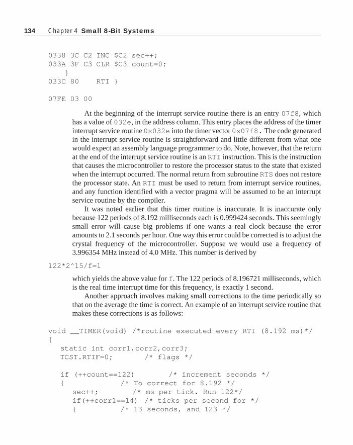
134 Chapter 4 Small 8-Bit Systems
0338 3C C2 INC $C2 sec++;033A 3F C3 CLR $C3 count=0;
}033C 80 RTI }
07FE 03 00
At the beginning of the interrupt service routine there is an entry 07f8 , whichhas a value of 032e , in the address column. This entry places the address of the timerinterrupt service routine 0x032e into the timer vector 0x07f8. The code generatedin the interrupt service routine is straightforward and little different from what onewould expect an assembly language programmer to do. Note, however, that the returnat the end of the interrupt service routine is an RTI instruction. This is the instructionthat causes the microcontroller to restore the processor status to the state that existedwhen the interrupt occurred. The normal return from subroutine RTS does not restorethe processor state. An RTI must be used to return from interrupt service routines,and any function identified with a vector pragma will be assumed to be an interruptservice routine by the compiler.
It was noted earlier that this timer routine is inaccurate. It is inaccurate onlybecause 122 periods of 8.192 milliseconds each is 0.999424 seconds. This seeminglysmall error will cause big problems if one wants a real clock because the erroramounts to 2.1 seconds per hour. One way this error could be corrected is to adjust thecrystal frequency of the microcontroller. Suppose we would use a frequency of3.996354 MHz instead of 4.0 MHz. This number is derived by
122*2^15/f=1
which yields the above value for f . The 122 periods of 8.196721 milliseconds, whichis the real time interrupt time for this frequency, is exactly 1 second.
Another approach involves making small corrections to the time periodically sothat on the average the time is correct. An example of an interrupt service routine thatmakes these corrections is as follows:
void __TIMER(void) /*routine executed every RTI (8.192 ms)*/{
static int corr1,corr2,corr3;TCST.RTIF=0; /* flags */
if (++count==122) /* increment seconds */{ /* To correct for 8.192 */
sec++; /* ms per tick. Run 122*/if(++corr1==14) /* ticks per second for */{ /* 13 seconds, and 123 */

135
corr1=0; /* for the 14th second */if(++corr2==80) /* With this algorithm */{ /* there are 14.000128 */
corr2=0; /* actual seconds per */if(++corr3==4) /* 14 indicated. Then */{ /* run 79 of these */
count=1; /* cycles followed by */corr3==0; /* one cycle of 14 */
} /* seconds with 122 ticks */else /* per second. The */
count=0; /* elapsed time for this*/} /* cycle is 1120.002048 */else /* seconds for and */
count=(-1); /* the count is 1120 */} /* seconds. Repeat this */else /* cycle 4 times and on */
count=0; /* the last cycle drop */} /* one tick makes the */
} /* indicate and elapsed *//* time exactly 4480 sec.*/
The three static variables corr1 , corr2 , and corr3 are used to keep track ofthe number of times the several different loops in the algorithm are executed. C willalways initialize these variables to zero and then their value will be retained from callto call of the function.
16-bit TimersThe multifunction timer discussed in the previous section provides for implemen-
tation of relatively simple timing functions. Let’s assume that the microcontrollerclock frequency is 4.0 MHz. The fastest interrupt time with this system is 0.512milliseconds, and the granularity of the interrupt times is in large, power of twoblocks for the RTI system. Also, the relation of the interrupt times to unity is not“clean”; complicated algorithms or special frequency crystals are needed to get thedevice to respond accurately in seconds.
Often microcontroller applications must provide more than one time function.The 15-bit timer is set up to provide only one time base. Of course, a programmer canprogram the timer to control many different functions and at many different times.The limits on the functions and times are difficult to determine. It is clear that thefastest practical time base in the 15-bit timer is 0.512 milliseconds. To obtain anyfiner time resolution, the programmer would have to compare the TCR bits to aspecified value on a cycle-by-cycle basis. This type of program will completely
Timers

136 Chapter 4 Small 8-Bit Systems
consume the microcontroller and leave no processing time for other functions duringthe execution of the timing program. If the time base must be other than somemultiple of 0.512 milliseconds and not one of the standard RTI times, the processorcan probably service only one time function. If the required times can fall on theabove values, the processor can execute several time-based functions limited by thetotal time required to execute the functions and the microcomputer interruptlatency time.
ICF1 TDFOCF1 ICF2 OCF2
OLVL1IEDG1OLVL2FOLV1FOLV2TOIEOCIEICIE
MC68HC05B6 Internal Bus
Internal Processor
Clock 8-bitBuffer
÷ 4
CounterAlternateRegister
OutputCompareRegister 1
OutputCompareRegister 2
InputCapture
Register 1
InputCapture
Register 2
OutputCompareCircuit 1
OutputCompareCircuit 2
EdgeDetect
Circuit 1
EdgeDetect
Circuit 2
TCAP2Pin
TCAP1Pin
TCMP2Pin
TCMP1Pin
DQ
C
Latch
Latch
D
C
Q
InputCapture Interrupt$1FF8.9
OutputCompareInterrupt$1FF6.7
OverflowInterrupt$1FF4.5
Timer ControlRegister$12
TimerStatus
Register$13
7 6 5 4 3
To PLM
Internal Timer Bus
HighByte
LowByte
HighByte
LowByte
HighByte
LowByte
HighByte
LowByte
HighByte
LowByte
$18$19
$16$17
$1E$1F
$14$15
$1C$1D
$1A$1B
OverflowDetectCircuit
16-bitFree Running
Counter
Figure 4-2: 16-Bit Timer For The MC68HC05B6.

137
The 16-bit timer addresses these problems. A block diagram of this type of timeris shown in Figure 4-2. This style of timer contains an internal 16-bit counter that isclocked at some fraction of the microcontroller crystal frequency. An input captureoperation detects the occurrence of an input and transfers the contents of the 16-bitcounter into the input capture register. This transfer will always set a flag, and it cancause a CPU interrupt if desired. With an input capture system, precise measurementof time interval is possible. Details such as phase between two waveforms can bedetermined or slight differences in frequencies between several signals can be de-tected. The input capture provides far more accurate time measurement than can beobtained with either synchronous polling or asynchronous interrupt time measure-ments. There is a tiny inherent delay between the occurrence of the input and thesetting of the input capture register. Such a measurement made by polling an inputwould require that the computer have a free running counter available to interrogatewhen the input is detected. Then, the computer would have to be assigned totally tothe job of watching the input for the impending transition. When the transition isdetected, the value of the counter would have to be read to determine the time of thetransition. Of course, this sequence of operations would require several computerclock cycles per test, and also several cycles would be required to read the counter.Therefore, the accuracy of the time measurement would be compromised by thesenecessary time delays.
An asynchronous interrupt method to determine the time interval is better than apolled method, but even this method has built in errors that make it an impracticalmeans to measure time intervals accurately. The input capture register input systemresolves most of the problems associated with accurate measurement of time intervalswith a microcomputer.
Another type of timing problem exists. Suppose that the time that an event is tooccur has been calculated. If the time of occurrence is to be accurate, we have asituation like that discussed above. The processor will have to spend all of its timewatching the clock to determine when the correct time has arrived. Any time spent onother tasks during this measurement interval will be a latency during which theprocessor cannot determine if the specified time has arrived. In this case, the accuracyof the event time will be degraded by the time spent on other tasks.
The 16-bit timer avoids this type of problem nicely. An output compare system isused. The time of occurrence is calculated relative to the internal 16-bit counter. Thisvalue is placed into an output compare register. The content of the counter iscompared automatically by the microcontroller to the value in the output compareregister at each count of the counter. When the two values are equal, a flag is set, anoutput occurs, and if desired, the CPU is interrupted. The output compare system canbe used to generate waveforms, to control phases between different waveforms, to
Timers

138 Chapter 4 Small 8-Bit Systems
control events based on calculated times.Different microcontrollers will have differing numbers of input capture and out-
put compare registers. In the discussions that follow, details of a single input captureand output compare register will be discussed. It is assumed that these registers arepart of an MC68HC05B6, so there are two input captures and two output compareson the microcontroller. For details on access to the second register set, refer to theappropriate data manual. Later we will see microcontrollers that have many moreinput capture and output compare systems (up to 16 on one microcontroller).
Timer Control RegisterThe timer control register (TCR) is located at the address 0x12 . This read/write
register controls the operation of the 16-bit timer system. Shown below is a diagramof this register, and a listing of the functions of the various register bits.
OLVL1 Bit 0 Output Level 1. The contents of this bit will be copied to the outputlevel latch the next time an output compare occurs. This result willappear at TCMP1. This bit and the output level latch are clearedwhen the part is reset.
IEDG1 Bit 1 Input Edge 1. This bit determines the transition direction that willcause an input to occur on Input Capture 1:IEDG1 = 0 Falling EdgeIEDG1 = 1 Rising EdgeThe contents of this bit are undetermined and unaffected at reset.
OLVL2 Bit 2 Output Level 2. The contents of this bit will be copied to the outputlevel latch the next time an output compare occurs. This result willappear at TCMP2. This bit and the output level latch are clearedwhen the part is reset.
FOLV1 Bit 3 Forced Output Compare 1. This bit always reads zero. A one writtento this position will force the OLVL1 bit to be copied to the outputlevel latch. This result will appear at TCMP1. A forced outputcompare does not affect the OCF1 bit in the timer status register.This bit is cleared at reset.
FOLV2 Bit 4 Forced Output Compare 2. This bit always reads zero. A one writtento this position will force the OLVL2 bit to be copied to the outputlevel latch. This result will appear at TCMP2. A forced outputcompare does not affect the OCF2 bit in the timer status register.This bit is cleared at reset.
TCR Bit 7 Bit 6 BIt 5 Bit 4 Bit 3 Bit 2 Bit 1 Bit 0
0x12 ICIE OCIE TOIE FOLV2 FOLV1 CLVL2 IEDG1 OLVl1

139
TOIE Bit 5 Timer Overflow Interrupt Enable. If the TOIE is set, the timer over-flow interrupt is enabled and an interrupt will occur when the TOFflag is set in the timer status register. This bit is cleared at reset andthe interrupt is inhibited.
OCIE Bit 6 Output Compare Interrupt Enable. If the OCIE bit is set, the outputcompare interrupt is enabled, and an interrupt will occur whenevereither the OCF1 or the OCF2 is set in the timer status register. Thisbit is cleared at reset and the reset is inhibited.
ICIE Bit 7 Input Capture Interrupt Enable. If the ICIE bit is set, the inputcompare interrupt is enabled and an interrupt will occur whenevereither the ICF1 or the ICF2 is set in the timer status register. Thisbit is cleared at reset and the reset is inhibited.
Timer Status RegisterThis register—TSR—is an 8-bit register. The most significant five bits of this
register contain read only status information. These bits describe the condition of the16-bit timer system. Their function is outlined below:
OCF2 Bit 3 Output Compare Flag 2. This bit is set when the content of the free-running counter matches the contents of output compare register 2.OCF2 is cleared by accessing the TSR (specifically the OCF2) fol-lowed by an access to the low byte of the output compare register 2,0x1f. The output compare flag 2 is undetermined at power on and isunaffected by reset.
ICF2 Bit 4 Input Capture Flag. This bit is set when a negative edge is sensed atTCAP2. It is cleared by an access of the timer status register fol-lowed by an access of the low byte of the input capture register,0x1d. The input capture 2 flag is undetermined at power on and isunaffected by reset.
TOF Bit 5 Timer Overflow Bit. This bit is set by a transition of the free-runningcounter from a 0xffff to a 0x0000. It is cleared by accessing the TSRwith the TOF set followed by an access of the free-running counterlow byte, 0x19. The TOF bit is undetermined at power on and isunaffected by reset.
Timers
TSR Bit 7 Bit 6 BIt 5 Bit 4 Bit 3 Bit 2 Bit 1 Bit 0
0x13 ICF1 OCF1 TOV ICF2 OCF2

140 Chapter 4 Small 8-Bit Systems
OCF1 Bit 6 Output Compare Flag 1. This bit is set when the content of the free-running counter matches the contents of output compare register 1.OCF2 is cleared by accessing the TSR (specifically the OCF1) fol-lowed by an access to the low byte of the output compare register 1,0x17. The output compare flag 1 is undetermined at power on and isunaffected by reset.
ICF1 Bit 7 Input Capture Flag 1. This bit is set when the proper edge is sensed atTCAP1. The edge is selected by the IEDG1 bit in the TCR. It iscleared by an access of the timer status register followed by an accessof the low byte of the input capture register, 0x15. The input capture1 flag is undetermined at power on and is unaffected by reset.
To clear bits in the TSR, the program must first access the TSR followed byan access of the LSB of the register associated with the bit that must be reset in theTSR. This sequence can lead to problems in dealing with the counter register.Suppose you are attempting to measure an elapsed time and are reading the counterregister at random times and you also will read the TSR to service timer requirements.It is possible in these circumstances to accidentally reset the TOF bit when it isundesired. To avoid this problem, an alternate counter register has been designed intothe MC68HC05 devices. The alternate register always contains the same valuesas the prime register, but the TOF bit in the TSR is not reset when the alternateregister is read.
Counter RegisterThe counter register is found in the memory locations 0x18 and 0x19. The least
significant byte of the counter is in 0x19. An alternate counter register is found inaddresses 0x1a and 0x1b with 0x1b being the least significant byte of this register.These registers are clocked at the same time and are incremented from low values tohigher values. The counters are clocked at one-fourth of the internal processor clock,which in turn is one-half the oscillator frequency. The clocking frequency is one-eighth the crystal frequency, and the clocking period is 2 microseconds when thecrystal frequency is 4 MHz. These ratios are not adjustable in the MC68HC05B6.
The free running counter values can be read at any time. A read sequence thatreads only the least significant byte will receive the count value at the time of theread. If the most significant byte of either counter is read, the count value will bereceived and the contents of the least significant byte will be transferred to a buffer.This value will remain in the buffer until the program reads the contents of the leastsignificant byte of the register. The value received for this read is the buffered valuesaved when the most significant byte was read. The most significant byte, MSB, can

141
be read several times prior to reading the least significant byte, LSB, and the contentsof the buffer will remain unchanged. After the MSB has been read and the LSB hasbeen buffered, the free running counter continues to be incremented at its normal rate.If the MSB/LSB read sequence is started, it is necessary to read the LSB to completethe sequence.
The counter is 16-bits, and when the register overflows form 0xffff to 0x0000,the timer overflow (TOF) bit is set. This event can cause an interrupt if the TOIE bitis set. Since the register is clocked at 2 microseconds, the interval between TOF is0.131072 seconds.
Input Capture RegistersThere are two input capture registers called ICR1 and ICR2. ICR1 is found at
addresses 0x14 and 0x15, and ICR2 is located at addresses 0x1c and 0x1d. The loweraddress always contains the MSB of a 16-bit number. With the exception of the edgedetection system discussed in the TCR section, these two registers operate the same.ICR1 can be set to respond to either a rising edge or a falling edge on the timercompare input pin TCAP1. If IEDG1 is 0, ICR1 responds to a falling edge onTCAP1. Otherwise, if IEDG1 is 1, ICR1 responds to a rising edge on TCAP1. ICR2responds only to a falling edge on TCAP2. An interrupt will also accompany an inputcapture if the corresponding ICIE bit is set in the TCR.
The contents of the free-running counter are transferred to the input captureregisters each clock cycle. Therefore, the registers contain a value which correspondsto the most recent input capture. After a read of the most significant byte of the inputcapture register, the transfer of new data to the least significant byte of the inputcapture register is inhibited until this byte is read. At no time during this sequence isthe counter register inhibited.
Output Compare RegistersThere are two output compare registers. OCR1 is found at address locations 0x16
and 0x17 while OCR2 is located at 0x1e and 0x1f. Again the lower addresses containthe MSB of these 16 bit numbers. These registers may be read or written at any timeregardless of the timer hardware. If the output compare functions are not utilized,these four bytes can be used for data storage. Their contents are not altered at reset.There is only one output compare interrupt bit that is used for both output comparesin the system.
The contents of the output compare registers are compared with the contents ofthe counter register each cycle of the counter register. If a match is found with eitheroutput compare register, the corresponding output compare flag—OCF1 or OCF2—bit is set. Also, the value of proper output level bit—OLVL1 or OLVL2—is trans-ferred to the proper output pin, TCMP1 or TCMP2. If the OCIE bit is set in the timercontrol register, an interrupt will accompany the output compare.
Timers

142 Chapter 4 Small 8-Bit Systems
There are times when it is desirable to force an output compare from a program.The FOLV1 and FOLV2 bits can be used for this purpose. These bits will always read0, but writing a 1 to these bits in the TCR will cause transfer of the correspondingOLVL1 or OLVL2 bit to the specified output compare bit, either TCMP1 or TCMP2.This output does not affect the compare flags, so no interrupt is generated.
Programming the 16-bit TimerWe will examine several different uses of the 16-bit timer system in this section.
The first is merely a repeat of the simple timer programmed in the section on the 15-bit system. Here we merely want to keep track of time, hours, minutes, and seconds inmemory. No provisions are made yet for reading the time values or to change thevalues; these problems will be discussed later.
A listing of this program is shown below. In this case, the header file for theMC68HC05B6 is used. A listing of this file is found in Appendix A. This programwill make use of an output compare to generate periodic interrupts to the micro-controller. We will use output compare register 1. It will be set up so that when thefirst output compare interrupt occurs, the contents of the output compare register willbe incremented by 500. Since the clocking time of the counter register is 2 microsec-onds, 500 two microsecond periods will allow an output compare every 1 millisec-ond. This occurrence will be treated in the interrupt service routine.
#include "hc05b6.h"
int hrs, mts, sec; /* global variables */long count=1000;
struct bothbytes /* 16 bit int structure */{
int hi;int lo;
};
union both /* and union */{
long l;struct bothbytes b;
};
union both time_count;registera ac;
void main(void)

143
{TCR.OCIE=1; /* enable output compare interrupt */CLI(); /* enable all interrupts */
FOREVER{
if(sec>=60) /* do clock things each minute */{
sec=0;if(++mts==60){
mts=0;if(++hrs==13)
hrs=1;}
}WAIT();
}}
void __TIMER_OC(void) /* time interrupt service routine */
{if(TSR.OCF2==1) /* is this interrupt due to OC2?*/{
ac=OCLO2; /* Yes. read OCLO2 to disable */return; /* the interrupt and exit */
} /* the routine *//* the program gets here every millisecond */
time_count.b.hi = OCHI1;ac = TSR; /* Arm OCF1 bit clear */time_count.b.lo = OCLO1; /* Clear OCF1 bit */time_count.l += 500; /* 500 counts per ms */OCHI1 = time_count.b.hi;OCLO1 = time_count.b.lo;
if(--count==0)return ;
else{
sec++; /* here every second */count=1000;/* reset count to 1 second */
}}
Listing 4-4: Timer Using Output Compares
Timers

144 Chapter 4 Small 8-Bit Systems
The above listing shows that microcontroller executing programs are broken intothree distinct sections. The first section is referred to as the initialization section, Inthis case, the initialization section is the first two lines following the main()invocation. In the initialization section, the code executed sets up the operation of themicrocontroller. Generally, this code is executed only once. Therefore, initializationof volatile memory values, setting up of interrupts, establishment of I/O ports anddata direction registers are all completed in the initialization of the program. Unlessthere is a pressing reason, the main system interrupts should not be enabled duringinitialization.
The second section is the applications section. The applications section isusually a loop that contains all of the code to be handled routinely by the microcon-troller. All input or output operations should take place within the applicationssection.
The third section of the program is the collection of interrupt service routines(asynchronous service section). These routines are called when appropriate interruptsare generated. In general, interrupt service routines should be short and do as little aspossible to service the specified interrupt. When an interrupt is serviced, the statusregister of the microcontroller is saved and the system interrupt is disabled. There-fore, unless the programmer takes special care to re-enable the interrupts, no otherinterrupt can be serviced while the microcontroller is executing an interrupt serviceroutine. This operation does not lead to missed interrupts, but it can cause aninordinate delay in service of an interrupt.
In some cases, it is possible that data might be lost if an interrupt is not handledexpeditiously. For example, a high-speed serial port might notify the microcontrollerthat its receiving data buffer is full by an interrupt when the interrupt is disabled. Insuch a case, if the interrupt service routine being executed is not completed before thenext serial data are received, the data in the buffer will be lost.
Sometimes it is necessary to pass data between the applications portion of theprogram and the interrupt service routine. These data can be stored in global memory,and both routines can access them. Here is a case where you must examine theassembly code generated by the compiler to make certain that no problems will begenerated in passing of data between these routines. Problems can be created bypassing information this way, but they can be avoided if the program rigorouslyavoids loading data that is changed in an interrupt service routine into a register in theapplication section of the program. We will see instances of this problem later.
If you go back to Listing 4-4, you’ll see that the above program organization isalso used. This organization will be found for every program in this book. We willrefer to the initialization, the applications, and the asynchronous service sections ofthe program. This arrangement works quite well, and is reliable. There should be astrong justification if alternate program forms are to be used.
When programming the 15-bit timer, we found that asking a compiler designed

145
specifically for an 8-bit machine to work in 16-bit quantities often created unwieldycode. A programmer, however, does not always have the freedom to work with 8-bitquantities only. All of the time registers in this system are 16-bits wide, and the timevalues contained in these registers must be processed. These registers are alwayslocated in two adjacent 8-bit memory locations. One method that handles the 8-/16-bit dichotomy is to use a union. The code sequence
struct bothbytes{ int hi; int lo;};
creates a structure that contains two bytes. This structure is combined with a typelong in the union below. Remember that a union provides space to hold its largestmember and the different members of the union will occupy the same memory space.Therefore, the memory space to store the long l is the exact same memory to storethe structure b. b.hi will occupy the most significant byte of l , and b.lo willoccupy the least significant byte of l . It is now easy to deal with the bytes of the16-bit quantity when moving the data around, and equally easy to invoke 16-bitarithmetic operations on the long combination of the two bytes.
union both{ long l; struct bothbytes b;};
The statement
union both time_count;
declares that time_count is a union of the type both. In the interrupt serviceroutine, the members of time_count are handled with little difficulty, as shownbelow.
The type registera defined as ac above is unique to the MC68HC05compiler. This type specifies that the variable ac will be stored in the accumulator.There is also a registerx type for the index register.
In the main program, the output compare interrupt is enabled and the systeminterrupt is enabled with the CLI() instruction in the initialization section. Theprogram then enters an endless loop in which the clock is serviced every time secbecomes 60. The parameter sec will be changed by the interrupt service routine everysecond so that the system should be a satisfactory clock. This loop is the initializationsection.
The last instruction in the FOREVER loop is a WAIT() instruction. This instruc-
Timers

146 Chapter 4 Small 8-Bit Systems
tion places the processor into the wait mode. In this mode, processor operations arehalted and the microcontroller operation is configured to reduce energy consump-tion. The operation of the internal timers proceed as usual. The part is removedfrom the wait mode by either a reset or the occurrence of an interrupt. The interruptcan be either an internal or an external interrupt. Since the output compare timer is setup and its interrupt is enabled, when the internal counter matches the contents of theoutput compare register, an interrupt will occur and remove the processor from thewait mode.
Sometimes, it is desirable to get a measure of the fraction of the time that themicrocontroller is used to execute its program. The use of the wait mode provides anexcellent mechanism for measurement of this usage. If there is an extra output portpin available, this pin can be set just prior to entering the wait mode. The pin can thenbe reset as the first instruction in the interrupt service routine. To make this measure-ment more accurate, you can set another output pin to the on condition all of the time.Measure these two outputs with an averaging DC voltmeter. One hundred times theratio of the cycling output to the fixed output is the percentage of time that themicrocontroller is available to execute other code.
Examine the following code sequence:
time_count.b.hi = OCHI1;ac = TSR; /* Arm OCF1 bit clear*/time_count.b.lo = OCLO1; /* Clear OCF1 bit */time_count.l += 500; /* 500 counts per millisecond */OCHI1 = time_count.b.hi;OCLO1 = time_count.b.lo;
The first instruction copies the high byte of the output compare register into thehigh byte of the structure b in the union time_count. When the TSR is copiedinto the a register, the system is set up to clear the OCF1 bit. Then, the low byte of theoutput compare register is moved into the low byte of the structure b. These opera-tions leave the 16-bit contents of the output compare register in the uniontime_count.l. Note that the high byte is moved from OCHI1, the TSR isaccessed, and then the low byte is moved from OCLO1. This sequence, accessingOCLO1 after the TSR has been accessed will clear the output compare flag 1, OCF1,and remove the interrupt source. 500 is added to this 16-bit number, and the result iscopied back into the output compare register 1 a byte at a time.
While it is usually best to keep the interrupt service routines short, sometimes,other operations can be completed within these routines that can be useful. Recall thatin the EEPROM programming routine there was a function called delay. A delayfunction can be integrated into a time interrupt service routine easily. The interruptservice routine above is entered every millisecond. We specified a function delay thathad an unsigned long argument that corresponds to the required delay in millisec-onds. Such a function could be implemented as:

147
void delay(unsigned long);
unsigned long time=0;void delay(unsigned long del){
time = del; /* place the delay time in the globalmemory */
while(time>0);}
Now we must add one code sequence to the interrupt service routine above:
if(--count==0){ if(time>0)
--time; return ;}
The function delay() places the value of the required delay in the unsignedlong location time. The program then hangs on the while statement so long astime is greater than 0. Every time the ISR is entered—which is every millisecond—the long unsigned value time will be decremented. When the proper time haspassed, the delay() function will return to the calling program.
The function delay() does something that many programmers do not like: theprogram hangs in a loop until a specified time has passed. This operation may seem towaste the microcontroller resource. Note, however, that the program does not spendall of the time in the loop; interrupts are being serviced during this time. We will seethat the timer interrupt is only one of many potential interrupts that will be workingon the part at all times. Placing the device into a wait loop for a few milliseconds maystop the main program in its tracks, but the background operations being serviced bythe interrupts will continue to be processed unhindered. In this case, a global variablehas been used to transfer data between an interrupt service routine and the applica-tions portion of the program. The variable time is set in the applications program, andthe completion of the time delay is evaluated in the applications portion of theprogram, and time itself is decremented in the interrupt service routine.
It is possible to create errors in operation with this type of procedure. One placewhere a nasty bug can creep into your code is when you are dealing with bitmanipulations in both the application portion of the program and the interrupt serviceroutine. Suppose that you want to toggle a bit when an event was detected in theapplication, and simultaneously, you need a periodic bit toggle that is controlled bycode in the interrupt service routine. The code sequence might appear as follows:
Timers

148 Chapter 4 Small 8-Bit Systems
.
.PORTA.BITAPP = !PORTA.BITAPP;..
In the interrupt service routine, the code could be
.
.PORTA.BITINT = !PORTA.BITINT;
In each case, this code will compile into
lda PORTAeor 2^BITNUMBERsta PORTA
The same code sequence will appear in both the application and the interruptservice routine with the BITNUMBER appropriately chosen. Suppose that we are inthe application, and have just executed the lda PORTA instruction when theinterrupt occurs. In the interrupt service routine, the above code will be executedproperly, and when control is returned to the program main line, it will continue withthe eor instruction. However, the contents of PORTA will have been changed by theinterrupt service routine, so the value that was loaded by the lda instruction prior tothe interrupt is no longer valid. The earlier loaded value of PORTA will be restored bythe above sequence in the application code, and the change made in the interruptservice routine will be undone.
This bit of interplay between the applications program and the interrupt serviceroutine is a type of software race. It can be easily avoided. Whenever a variable ischanged in both the applications code and in an ISR, the erroneous set/reset can beavoided if the program disables all interrupts before the offending instruction in theapplications code. The interrupts must then be re-enabled after the code execution. Inthis case, the code will be
··SEI ();PORTA.BITABB=!PORTA.BITAPP;CLI();·

149
·in the applications code. In this case, there can be no interrupt to interfere with theproper handling of PORTA in the application.
In the above timer routine, there is what some might call a glaring oversight. Thetimer was not initialized in the initializing routine of the program. The first lines ofcode merely enabled the timer interrupt and then proceeded into the FOREVER loop,which is the applications portion of the program. The initial state of the TCR and theOCR registers is not established at reset. There is no way of knowing when the firstoutput compare will take place. If the initial value of the OCR happens to be one lessthan that of the TCR, there will be an output compare about 0.13 seconds after theinterrupts are enabled, and from then on the interrupt period will be accurate. If it isimperative that the first output compare occur at exactly the specified time, then thecode for initialization of the output compare registers must be included in theinitialization routine. Otherwise, if this error in the initial timing can be tolerated, itwill save bytes of code space that might be desperately needed for another portion ofthe program.
EXERCISES 1. Write a program that uses an output compare system to generate an accurate
waveform with a 1000.0 second period.
2. Devise a convenient method to test the performance of the program in Exercise 1above.
3. Write a program to generate two waveforms. One output is to be at twice thefrequency of the other. The duty factors of the two signals is to be equal to 50%.The frequency of the slowest wave is to be 1000 Hz. The phase of the higherfrequency signal is to be such that its rising edge is to occur 260 microsecondsfollowing the rising edge of the first signal.
4. Two DC motors are running. Each motor has an optical interrupter on its shaftwith 15 interrupts per revolution of the shaft. All but one of the interrupts occupyone-sixteenth of the circumference of the rotation. The fifteenth interrupt occu-pies one eight of the circumference. Using input capture registers, measure thespeed of the two motors, and provide a slow down or speed up signal that can beused on either motor to synchronize the rotation of the two motors with the wideinterrupter positions on the shafts being in lock-step.
5. What microcontroller characteristics will control the maximum speed at whichthe motors in Example 3 can run? The minimum speed?
Timers

150 Chapter 4 Small 8-Bit Systems
Analog to Digital Converter OperationThe analog to digital converter (ADC) found on the MC68HC05 family is
moderately simple in its operation. There are few important items that must beremembered when dealing with the ADC. Most important is that the ADC must beturned on for at least 100 microseconds prior to reading a value. If 100 microsecondshas not elapsed, it is guaranteed that the value read will be in error. The ADC isturned on by setting the ADON bit in the ADC control/status register. This register isreferred to as AD_CTST. The following code sequence will turn the ADC on:
AD_CTST=0;AD_CTST.ADON=1;
The following function will provide a reading of a single channel of the ADCinput:
unsigned int read_adc(int k){
AD_CTST &=~0X7;AD_CTST |=k;while(AD_CTST.COCO==0);return AD_DATA;
}
The argument k is the channel that is to be read, and k can have a value of 0 to 7to read the external channels.
The first two lines of code in the above function will place the channel number tobe read in the channel bits of AD_CTST. These bits must be cleared by an instructionsequence that will not alter the upper bits of AD_CTST because the ADON bit is inthe upper portion of AD_CTST. This bit cannot be reset while the ADC operationis continuing. The first line of code clears the least significant three bits, and thesecond line places the channel number in these bits.
Writing to AD_CTST will cause the ADC conversion to start. Therefore, all thatmust be done is to wait until the conversion is completed to read the data into theprogram. The line of code
while(AD_CTST.COCO==0);
will keep control of the microcontroller in that instruction sequence until the COCObit, which is the conversion completion bit, is set. At that time the value found inAD_DATA will be the result of the latest conversion.
Often, the ADC results must be subjected to some processing to remove un-wanted characteristics of the signal being measured. Here is a case where careful use

151
of assembly language procedures can make a big difference in the execution speed aswell as the amount of code needed. An example that is often used is to average thepast values of the data. A reasonably simple approach is to allow the latest ADCreading to have a 50% weight and all of the past readings to have a 50% weight. Thefollowing example code will accomplish this task in three different ways:
#include "hc05b6.h"
unsigned adc_data[8];unsigned read_adc(int);
void main(void){
unsigned int j;
AD_CTST=0;AD_CTST.ADON=1;
for(j=0;j<8;j++){
adc_data[j]=(read_adc(j)+adc_data[j])/2;adc_data[j] >>= 1;adc_data[j] += read_adc(j)>>1;
#asmldx jlda jjsr read_adcadd adc_data,xrorasta adc_data,x
#endasm
}
}
Listing 4-5: Three Different ADC Averaging Routines
The first attempt to read and average the data approaches the problem as simplyas practical. The data are read in from the ADC, added to the corresponding storeddata in the array adc_data , the result is divided by two, and the final average is putback into the proper location in the array. The following line of code is all that isnecessary to accomplish this task:
Analog to Digital Converter Operations

152 Chapter 4 Small 8-Bit Systems
adc_data[j]=(read_adc(j)+adc_data[j])/2;
Hidden in this code is the fact that both read_adc and adc_data areunsigned results. When two unsigned numbers are added together, the most signifi-cant bit of each can be 1 so there can be an carry or overflow when the addition takesplace. Problems from this carry can be avoided in this case by merely using a longor double precision add routine in adding the two numbers. Then, when the result isdivided by 2, if a bit is carried into the upper byte of the result it will be shifted backinto the lower byte. The result of this operation is correct and will fit int a singleunsigned int.
The compiled version of the above program with read_adc() merged into itfollows:
#include "hc05b6.h"
0050 0008 unsigned adc_data[8]; unsigned read_adc(int);
void main(void) {
0058 unsigned int j;
0100 3F 09 CLR $09 AD_CTST=0;0102 1A 09 BSET 5,$09 AD_CTST.ADON=1;
0104 3F 58 CLR $58 for(j=0;j<8;j++)0106 B6 58 LDA $580108 A1 08 CMP #$08010A 24 36 BCC $0142
{010C CD 01 43 JSR $0143 adc_data[j]=(read_adc(j)+
adc_data[j])/2;010F BE 58 LDX $580111 EB 50 ADD $50,X0113 AE 02 LDX #$020115 CD 01 57 JSR $01570118 9F TXA0119 BE 58 LDX $58011B E7 50 STA $50,X
011D BE 58 LDX $58 adc_data[j]>>= 1;011F E6 50 LDA $50,X0121 44 LSRA

153
0122 BE 58 LDX $580124 E7 50 STA $50,X0126 B6 58 LDA $58 adc_data[j]+=
read_adc(j)>>1;0128 CD 01 43 JSR $0143012B 44 LSRA012C BE 58 LDX $58012E EB 50 ADD $50,X0130 E7 50 STA $50,X
#asm
0132 BE 58 ldx j0134 B6 58 lda j0136 CD 01 43 jsr read_adc0139 EB 50 add adc_data,x013B 46 rora013C E7 50 sta adc_data,x
#endasm
}013E 3C 58 INC $580140 20 C4 BRA $01060142 81 RTS }
unsigned int read_adc(int k)0059 {0143 B7 59 STA $590145 B6 09 LDA $09 AD_CTST&=~0X7;0147 A4 F8 AND #$F80149 B7 09 STA $09014B B6 09 LDA $09 AD_CTST |=k;014D BA 59 ORA $59014F B7 09 STA $090151 0F 09 FD BRCLR 7,$09,$0151 while(AD_CTST.COCO==0);0154 B6 08 LDA $08 return AD_DATA;0156 81 RTS
}
0157 BF 5A STX $5A0159 B7 5B STA $5B
Analog to Digital Converter Operations

154 Chapter 4 Small 8-Bit Systems
015B 4F CLRA015C 5F CLRX015D 5C INCX015E 38 5B LSL $5B0160 49 ROLA0161 B0 5A SUB $5A0163 24 03 BCC $01680165 BB 5A ADD $5A0167 99 SEC0168 59 ROLX0169 24 F3 BCC $015E016B 53 COMX016C 81 RTS
1FFE 01 00
The assembly code to execute this single line of C code is found in the addressrange $10c to $11b , or 17 bytes of code. However, there is a call to the doubleprecision add routine at address $115. This routine occupies the address range$157 to $16c , or 22 additional bytes of code hidden from the main routine.Therefore, this requires 37 bytes of code for its execution.
The next approach is to avoid the overflow problem by dividing by 2 each of theterms to be added prior to the addition. Division by 2 is accomplished by shifting eachof the terms to the right by one bit. This approach guarantees that there will be nooverflow into the higher byte because the most significant bit of each number will be0 after the shift, and no binary addition can cause more than a one bit overflow.Therefore, the sum will at most have its most significant bit turned on. This number isthen stored in the location adc_data[j].
The assembly code created by the compiler for this approach is in the addressrange $11d to $130. This code uses 21 bytes of memory. Careful examination ofthis code will show that the instruction at $122 is unneeded, so the code could havebeen completed in 17 bytes.
The assembly version of the same routine merely adds the two unsigned num-bers, and then rotates the result right 1 bit to accomplish the divide by 2. The one bitrotate accomplishes the same thing as a right shift by one bit with the exception thatthe carry bit is shifted into the most significant bit of the result. The only way thecarry bit could be set is by the most significant bits of both addends being 1. Theassembly version of the code resides in $132 to $13c and requires 12 bytes of code.
Here is a case where judicious choice of assembly code will provide a significantimprovement in the amount of code needed to execute a specific program. The mainreason that the assembly version is shorter is that the carry bit in the condition coderegister is available to the programmer from assembly. This bit is completely hiddenfrom the programmer in any high level language. Therefore, tricks like rotating a bit

155
from the carry into a register are not available in the high level language.
EXERCISE 1. Write a routine to average readings from the ADC on a microcontroller, but
weight the current reading three time that of the past average.
Pulse Width Modulator SystemIn this section on programming of the timers, two approaches to the generation of
a pulse width modulation (PWM) signal will be discussed. These approaches both usethe output compare system of the 16-bit timer.
What is a PWM system? A PWM signal is a periodic signal where the signal isset high for a calculated duty factor, and then the output will go low for the remainderof the period. If you measure a PWM signal with averaging voltmeter it will have avalue equal to the peak voltage times the duty factor of the PWM. Here the dutyfactor is defined as the ratio of the on time to repetition period of the signal. Thus, wehave created a simple digital to analog converter. Many control applications needanalog control signals for parts of the system. PWM systems on microcontrollersprovide an excellent means for providing these analog voltages so long as thelimitations we will discuss below are acceptable to the total system design.
The built-in PWMs in the MC68HC05Bx family of devices will provide you withone of two pulse periods: the programmable timer clock frequency divided by 256 or4096. These frequencies are fixed, and the interval is divided into 256 parts. There-fore, the analog frequency ranges—and the accuracy of the analog reproduction—islimited to one part in 256 over the range of the output.
When using the output compare system to create a PWM, it is possible to achievea finer analog resolution at slower frequencies, or perhaps a faster signals with pooreraccuracy. A PWM created from an output compare system is somewhat more flexiblethan the usual built-in PWM. With the PWM systems built around the output com-pare system, the computer is responding to frequent interrupts. When an interruptoccurs, the system status is pushed onto the stack and the address of the interruptservice routine is placed into the program counter. It takes approximately 10 clockcycles to respond to an interrupt after the completion of the executing instruction.Return from an interrupt requires 9 clock cycles. Therefore, it is not possible toaccomplish the full goal of a PWM with an output compare system. The goal in thiscase is to achieve full on at the one extreme input level and full off at the other. Thetimes required to process an interrupt will limit the performance at one extreme, theother or perhaps both when a PWM is implemented with an output compare system.
A first example is shown in the following listing. This example shows theinterrupt service routine along with the necessary defines only. It is assumed that theoutput compare interrupt bit along with the interrupt bit are properly set to allow the
Pulse Width Modulator System

156 Chapter 4 Small 8-Bit Systems
output compare 2 to interrupt the processor. Also shown in this example is code tocontrol a second output compare—1—to provide the system with a fixed time base.
In operation, the applications portion of the program must place a pair of comple-mentary numbers, pwm_number and off_count , in place. The sum of these twonumbers must equal a constant that establishes the period for the PWM signal. For theMC68HC05B4, the period will be 2 microseconds times the total count value. Prior tostarting use of the PWM, the bit flag.ON should be reset and the value for countwhich is the main time base period count should be set.
/* bits in flag */
#define ON 0
union both time_cnt;unsigned long off_count,pwm_number,count;bits flag;
void __TIMER_OC(void){
if( TSR.OCF2==1) /* accesses the TSR */{
if(flag.ON==0){
flag.ON=1;TCR.OLVL2=0; /* Timer Compare 2 off*/time_cnt.b.hi=OCHI2;/* get start time */time_cnt.b.lo=OCLO2; /* reset the OCF */time_cnt.l +=pwm_number;OCHI2=time_cnt.b.hi;OCLO2=time_cnt.b.lo;return;
} else {
flag.ON=0;TCR.OLVL2=1;/* Timer Compare 2 to on */time_cnt.b.hi=OCHI2;/* get start time */time_cnt.b.lo=OCLO2; /* reset the OCF */time_cnt.l +=off_count;OCHI2=time_cnt.b.hi;OCLO2=time_cnt.b.lo;

157
return; }
}else /* must be that OCF1==1 rather than OCF1 */{
time_cnt.b.hi=OCHI1; /* output compare */time_cnt.b.lo=OCLO1; /* get lo byte */time_cnt.l +=count; /* time for interrupt */OCHI1=time_cnt.b.hi;OCLO1=time_cnt.b.lo;/* reset the OCF */ms_10++;return;
}}
Listing 4-6: ISR For PWM System
Since the interrupt bits are set to allow output compare interrupts, an interruptwill occur. The interrupt service routine will be entered, and the instruction sequence
if( TSR.OCF2==1) /* accesses the TSR */{
.
.
.
accomplishes two things. First, it determines if the output compare 2 caused theinterrupt, and, secondly, it accesses the TSR and arms the reset of the OCFX when theproper lower byte of the output compare register is read later.
For the moment, assume that OCF2 bit is set: the interrupt was caused by acompare in output compare register 2. In this case a test is made to determine ifflag.ON is reset. Since the initialization routine reset this bit, it will be 0. There-fore, the code sequence
flag.ON=1;TCR.OLVL2=0; /* Timer Compare 2 to turn off*/time_cnt.b.hi=OCHI2; /* get the start time */time_cnt.b.lo=OCLO2; /* reset the OCF */time_cnt.l +=pwm_number;OCHI2=time_cnt.b.hi;OCLO2=time_cnt.b.lo;return;
will be executed. This code is the “on” code for the PWM system. The first instruc-
Pulse Width Modulator System

158 Chapter 4 Small 8-Bit Systems
tion in this sequence will set the bit flag.ON , so that this code will not be executedin the next execution of the interrupt service routine. The bit TCR.OLVL2 is the statethat will be transferred to TCMP2 pin when an output compare occurs. TCR.OLVL2is then set to 0 so that TCMP2 will be set low when the next output compare occurs.The code sequence that follows gets the contents of the output compare register 2,increments this value by pwm_number, and places this new value back into outputcompare register 2. Thus, the time of the output compare is established and theinterrupt service routine is exited.
Eventually, the next output compare 2 interrupt will occur. Since the bit flag.ONhas been set, the following code will be executed. This code is the “off” code for thePWM system. The first business to take care of is to reset the bit flag.ON so that theon portion of PWM code will be executed the next time into the ISR. TCR.OLVO2is set so that TCMP2 will go on when the next output compare occurs.
flag.ON=0;TCR.OLVL2=1; /* Timer Compare 2 to turn on */time_cnt.b.hi=OCHI2; /* get the start time */time_cnt.b.lo=OCLO2; /* reset the OCF */time_cnt.l +=off_count; /*complete the cycle*/OCHI2=time_cnt.b.hi;OCLO2=time_cnt.b.lo;return;
The contents of OCR2 are handled as above, but this time their value is incrementedby the contents of off_count. The main line code is then re-entered by the use ofthe return instruction.
In this sequence, two interrupts occur and are processed. The first interruptoccurs when the output is turned on, and the second occurs when the output is turnedoff. There must be enough time after the occurrence of each interrupt for the interruptservice routine to be entered, it must be executed and the RTI instruction at the end ofthe ISR must be executed before the main line of code can be re-entered. If the offsettime in the above routines, pwm_number and off_count , are not large enough, toallow the execution of the ISR to be completed, the value stored in the outputcompare register can be smaller than the contents of the count register when the RTIis completed. In such a case, the interrupt will not occur at the specified time butabout 0.13 seconds later. This delay occurs because the timer counter must count untilit overflows and then count to the correct value before the interrupt occurs. Remem-ber that to enter an ISR and to return from one requires about 19 bus cycles or 9.5microseconds. The time needed to execute either of the above sequences withoutsome assembly compacting will require about 40 microseconds. The minimum off orthe minimum on time must be about 50 microseconds. Therefore, 100 microseconds

159
of the base period is not available. If the period is long—say 10,000 microseconds—this loss of range might be insignificant. However, if the program is attempting togenerate high frequency analog signals, this loss of time range can be devastating.
There is another approach to generation of PWM signals with output comparesystems that will materially aid this problem. However, this approach requires twooutput compare systems. One output compare system is used to create the time baseand the other is used to generate the on or off time. Let’s examine the followinginterrupt service routine. Output compare 1 is used here to generate the PWM period.The way that this routine works, it is possible for an interrupt to occur as a result of acompare on output compare 2. This interrupt is to be ignored, and the first five linesof the code below tests for this condition and clears interrupt when it occurs. Thisinterrupt occurs at the end of the on time. Control of the program must be out of thisportion of the ISR and in the main line code before the next interrupt caused by OCF1occurs. The time required for the first five lines of code here is about 18 microsecondswhich is the minimum on time.
void __TIMER_OC(void){
if(TSR.OCF2==1){
ac=OCLO2; /* if interrupt is caused by output*/return; /* compare 2 reset it and return */
}time_cnt.b.hi=TCHI; /* get in the TCR */time_cnt.b.lo=TCLO; /* get lo byte */time_cnt.l +=count; /* bump the time counter for next*/OCHI1=time_cnt.b.hi;/* interrupt */OCLO1=time_cnt.b.lo;/* reset the OCF */if(flag.PWM==1){
TCR.OLVL2=1;/* Timer Compare 2 to set output */TCR.FOLV2=1;/* turn on Timer compare 2 output */TCR.OLVL2=0;/* Timer Compare 2 to reset output*/time_cnt.b.hi=TCHI; /* get the start time */time_cnt.b.lo=TCLO;time_cnt.l +=pwm_number;OCHI2=time_cnt.b.hi;OCLO2=time_cnt.b.lo;
}
Pulse Width Modulator System

160 Chapter 4 Small 8-Bit Systems
}
Listing 4-7: Alternate PWM ISR
The next sequence is the code required to establish the time base. This time baseoperates on output compare 1. This routine is similar to those discussed above. A bitin the bit field flag is tested to determine if the PWM signal is to be turned on. Ifflag.PWM is set, the PWM code will be executed. When this routine is entered,TCMP2 will be reset to zero. The first instruction sets TCR.OLVL2 so that TCMP2will be on the at the next output compare. The next instruction, TCR.FOVL2=1 , setsthe force overflow bit for TCMP2 which will cause this bit to be turned on sinceTCR.OLVL2 is set. This time is the beginning of the on period of the PWM signal.The next instruction
TCR.OLVO2=0;
so that TCMP2 will go off or be reset at the next output compare 2. Control is thenpassed to the main line of code. When TCMP2 occurs, the output will return to 0 andan interrupt will occur. This interrupt is detected by the first lines of the interruptservice routine.
One could write a code sequence that would generate the mirror image signal tothat above. That is, the off time would be controlled by TCMP2 and the on timewould be the difference between the time of TCMP2 and the main time base.
Other Program ItemsSeveral other small programs come to mind that are very useful in programming
microcontrollers. With these small parts, it is usually desirable to avoid libraryfunctions and, if possible, use a bag of tricks to arrive at the desired results. Forexample, dealing with numbers for either input or output offers a good place toexercise some experience over expedience. One case where it is often important tominimize code space is in generating binary coded decimal (BCD) numbers frominteger numbers to output from a computer. Perhaps the most direct approach toaccomplish this conversion is as follows:
/* convert a binary number less than 100 to BCD */
char convert_bcd(unsigned char n){
unsigned int result;
if(n>99) return 0xff;result=n/10<<4;result |= n%10;return result;

161
}Listing 4-8: First BCD Conversion
This small function takes an 8-bit character n that is less than 99 and converts thenumber into one 8-bit result. The upper nibble is the number of tens in the numberand the lower nibble is the number of units. A hexadecimal number 0xff is returned ifthe number is greater than 99. Note that the calculation requires an integer divideoperation and a modulus operation which is equivalent to a divide operation. Thecode to execute the divide and modulus operations must be associated with thisfunction to complete its task.
Another approach is shown below. This approach avoids any external functioncalls and actually requires less total code than the version in Listing 4-8, even thoughthe C code is somewhat longer. In this case, the while loop essentially divides theinput number by 10 and places the result in the most significant nibble of the result.After the tens have been removed from the number, all that is left is the units. Thisvalue—the number of units—is ORed on the result before it is returned.
/* convert a binary number less than 100 to BCD */
char convert_bcd(unsigned char n){
unsigned int result;
if(n>99) return 0xff;result=0;while((n-+10)>=0)
result+=0x10;n+=10;result |= n;return result;
}
Listing 4-9: Second BCD Conversion
The function shown below was originally written for use on a MC68HC05, butwas later used on a MC68HC11 as well. A two-digit number must be sent to a seven-segment LED display. The number to be shown is contained in the memory locationsfor tens and units. The numeric display takes four inputs that are merely the BCDvalue of the number to be shown. With this particular display, a 4-bit number betweenthe values of 0 and 9 will be displayed. If each of the four input lines to the display isturned on, the display will be turned off. The parameters passed to the function—highand low—are flags to indicate whether the corresponding output is to be turned on.
Other Program Items
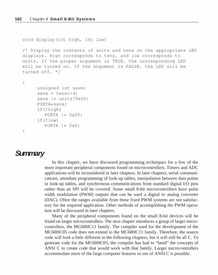
162 Chapter 4 Small 8-Bit Systems
void display(int high, int low)
/* Display the contents of units and tens on the appropriate LEDdisplays. High corresponds to tens, and low corresponds tounits. If the proper argument is TRUE, the corresponding LEDwill be turned on. If the argument is FALSE, the LED will beturned off. */
{unsigned int save;save = tens<<4;save |= units70x0f;PORTA=save;if(!high)
PORTA |= 0xf0;if(!low)
PORTA |= 0xf;}
SummaryIn this chapter, we have discussed programming techniques for a few of the
more important peripheral components found on microcontrollers. Timers and ADCapplications will be reconsidered in later chapters. In later chapters, serial communi-cations, attendant programming of look-up tables, interpolation between data pointsin look-up tables, and synchronous communications from standard digital I/O pinsrather than an SPI will be covered. Some small 8-bit microcontrollers have pulsewidth modulation (PWM) outputs that can be used a digital to analog converter(DAC). Often the ranges available from these fixed PWM systems are not satisfac-tory for the required application. Other methods of accomplishing the PWM opera-tion will be discussed in later chapters.
Many of the peripheral components found on the small 8-bit devices will befound on larger microcontrollers. The next chapter introduces a group of larger micro-controllers, the MC68HC11 family. The compiler used for the development of theMC68HC05 code does not extend to the MC68HC11 family. Therefore, the sourcecode will look a little different in the following chapters, but it will still be all C. Togenerate code for the MC68HC05, the compiler has had to “bend” the concepts ofANSI C to create code that would work with that family. Larger microcontrollersaccommodate more of the large computer features so use of ANSI C is possible.

163
Chapter 5
Programming Large 8-Bit SystemsThis chapter on the programming of large 8-bit systems will make use of the
MC68HC11, a moderately complicated microcontroller. It is absolutely necessarythat any programmer understand the device when writing code for a microcontrol-ler application, so Appendix C is included to provide detailed background on theMC68HC11 series. If you are not familiar with the MC68HC11 family, then turn toAppendix C now and read it to familiarize yourself with the general layout andoperation of the MC68HC11.
Header FileAppendix D contains the C header file HC11E9.H. This file should be included
for any program that is going to be used on the MC68HC11E9 or the MC68HC711E9.The first instruction in the file is
#ifndef HC11E9#define HC11E9
and the last entry in the file is
#endif
These lines of code are useful to prevent multiple definitions of the items definedwithin the file. If the header file has not been previously compiled as a part of theprogram when the above statement is seen, HC11E9 will not be defined. The firstinstruction determines if HC11E9 is not defined, and if it is not, the second linedefines it. Then all of the code until the matching #endif will be compiled. IfHC11E9 is already defined, then the compiler will skip the code lines until thematching #endif is found. Therefore, the programmer can put an
#include <hc11E9.h>
at the beginning of each program module, and it will be used in the program onlyonce even if several modules are combined into one and the above statement isincluded several times in a single file. This approach is convenient because it allowseach module to be compiled and tested and then the several modules can be mergedand compiled as a unit without worry about multiply defined variables and valuesfound in header file.
163

164 Chapter 5 Programming Large 8-Bit Systems
This file consists of four parts. The first is a simple typedef and definition of astructure called Register . This structure contains eight single-bit entries. Each ofthese bits corresponds to a specific bit in a register field, and the bits are given thenames bit0 , bit1 , . . . bit7 . Therefore, when dealing with specific bits within atype Register , the programmer should use bit x, where x is the number of the bitbeing referenced.
The second portion of the file contains the definition of all of the I/O registersof this part. The global variable Register_Set is given a value 0x1000 . Thisvalue is the initial location of the I/O register map in the system. In the MC68HC11,bit manipulation assembly instructions have a one byte address that can be an offsetfrom an index register. With the indexed version of the instruction, any single byte orbit in the entire memory map can be accessed or tested with a single instruction.However, the address operation must be indexed. If you use a single address with off-sets to each of the registers as is done in Appendix D, the compiler will automaticallyplace the value of Register_Set into an index register and use the offsetsspecified to allow indexed access to the data in the registers from anywhere in theprogram.
The value of Register_Set is not fixed by the microcontroller. It can bechanged within the first 64 clock cycles following reset. To make this change, theprogrammer must assign the correct value to the INIT register in the I/O memoryspace. This value should be changed in the initialization routine for the program,which is usually written in assembly language. After the INIT register is changed, anew proper value assigned to Register_Set will allow the desired access to allregisters and bits in the I/O memory map.
The compiler used to compile code for this chapter is the MC68HC11 C Com-piler produced by Intermetrics1. This compiler was originally written in France byCOSMIC Software for Whitesmiths. Since then, Intermetrics has purchasedWhitesmiths and distributes their compilers under the Whitesmiths name. This par-ticular compiler has intrinsic definitions of all of the default register locations.However, not all compilers offer this convenience. Therefore, the header file inAppendix D will be used because it can be used by those compilers that do not havethe convenience of built in register definitions. The approach used here createsportable code. Recall from Chapter 2 that any memory address can be used as anlvar if it is properly cast. The various registers addresses are each cast onto theproper type and then dereferenced to receive a value in the register definition macros.For example,
#define PORTA (*(Register*)(Register_Set+0))
casts the number Register_Set +0 to a pointer to the type Register . Thisvalue is dereferenced so that it can receive the value assigned to it. Therefore, ifRegister_Set is the default value of 0x1000 , then the C expression__________________________________________________
1 Intemetrics Microsystems Software, Inc. 733 Concord Ave. Cambridge MA 02138

165
TOC1=0x37fe;
will place the hex value 0x37fe into the address 0x1016 because TOC1 is locatedat Register_Set + 0x16.
The compiler optimizer that is a part of the Intermetrics C compiler does anexcellent job of reducing code size. One of the steps involved is to remove code thatrequires values to be changed that are not changed by the program. The followingcode sequence will show this problem:
volatile char able;char baker
test(void){
char dog;
dog = able;dog = able;able = 0;able = 0;dog = baker;dog = baker;baker = 0;baker = 0;
}
Note that the above function makes multiple assignments of dog , able , andbaker . The assignments involving able will show how the compiler responds to avolitile variable, and baker with a nonvolatile variable. The following listing is thecompilation of the above program:
1 ; Compilateur C pour MC68HC11 (COSMIC-France) 32 .include"macro.h11" 3 .list + 4 .psect _text 5 ; 1 volatile char able; 6 ; 2 char baker ; 7 ; 3 8 ; 4 test(void) 9 ; 5 { 10 _test: 11 0000 3C pshx 12 0001 34 des
Header File

166 Chapter 5 Programming Large 8-Bit Systems
13 0002 30 tsx 14 .set OFST=1 15 ; 6 char dog; 16 ; 7 17 ; 8 dog = able; 18 0003 F60000 ldab _able 19 LL4: 20 0006 E700 stab OFST-1,x 21 ; 9 dog = able; 22 0008 F60000 ldab _able 23 LL6: 24 000B E700 stab OFST-1,x 25 ; 10 able = 0; 26 000D 7F0000 clr _able 27 LL01: 28 ; 11 able = 0; 29 0010 7F0000 clr _able 30 LL21: 31 ; 12 dog = baker; 32 0013 F60001 ldab _baker 33 ; 13 dog = baker; 34 0016 E700 stab OFST-1,x 35 ; 14 baker = 0; 36 ; 15 baker = 0; 37 0018 7F0001 clr _baker 38 ; 16 } 39 001B 31 ins 40 001C 38 pulx 41 001D 39 rts 42 ; 17 43 .public _test 44 .psect _bss 45 _baker: 46 0000 .byte [1] 47 .public _baker 48 .psect _data 49 _able: 50 .byte [1] 51 .public _able 52 .end
Lines 17 through 24 correspond to the two lines

167
dog = able;dog = able;
The memory location of able in the program is _able , and the memory locationfor dog is at OFST-1,x . Note that the value in _able is read and placed into dogtwice as the program stated. Also, the instruction clr _able is executed twice toaccount for the two lines
able = 0;able = 0;
This code is what you should expect when the volatile keyword is usedwhen able is declared. On the other hand, lines 31 through 34 show the compila-tion of the two C lines
dog = baker;dog = baker;
In this case, you will note that the value for baker , stored at _baker , isplaced into the address of dog only once even though the code line is repeated.Similarly, the two lines
baker = 0;baker = 0;
results in assembly code that clears the location _baker only once.This type of optimization will save you much code space. It is certainly a problem
whenever there is a memory location that can be changed from outside of theprogram. The volatile keyword will cause the optimization operation to skip over allvariables that can be changed by the hardware portion of the system without knowl-edge of the program.
Any location that is defined as a type Register is truly a collection of bitsand each bit must be processed individually. Therefore, an expression like
PORTA = 0x3f;
will result in an illegal assignment error because PORTA is of the type Register ,not char .
If you must make assignments to ports defined in the above manner as either abyte-wide field or as bit fields, it is possible. Return to the initial definition of aregister in Appendix D:
typedef struct{
Header File

168 Chapter 5 Programming Large 8-Bit Systems
signed char bit 0 :1;. . .
unsigned char bit 7 :1;
} Register;
We can now define:
typedef union{
char byte;Register bits;
} Mix_Register;
and thus
#define PORTA(*volatile Mix_Register*)(Register_Set +0)
will allow the programmer to use
PORTA.byte = 0x2E
to set the value of all bits in the port with one instruction and in the same program use
PORTA.bits.bit3 = 1;
to set, reset, or test the individual bits inside of the port. In this book, we will use thebit fields only as shown in Appendix D.
Since PORTA is of the type Register , it is possible to deal with the individualbits within this location by normal C constructs such as
PORTA.bit3 = 1;if(PORTA.bit6 == 0)
...
Of course, it is much better to define practical names to the various bits within theport to achieve even clearer code:
#define ON TRUE#define MOTOR bit3#define PUSH_BUTTON bit6
.
.
.

169
PORTA.MOTOR = ON; /* turn the motor on */...
if(PORTA.PUSH_BUTTON==ON){
do push button things}
With this compiler, an int is a 16-bit value. Therefore, the registers that are twobytes are cast onto the type int . Usually these registers are accessed as int s onlyand there is no need to have the individual bit access afforded by the use of theRegister type. The timer counter register (TCNT) is one such register that isaccessed as an int only. There are also a few one byte, or 8-bit, registers that areaccessed as bytes only. No bit accesses within these registers are needed. In thesecases, the register is cast onto the type char . The several ADRx registers areexamples of this type. The ADRx registers contain the result of an analog-to-digitalconversion that is usually handled as an 8-bit unit only.
In most instances, register locations that are of the type char should be un-signed char . The ADRx registers mentioned above are all going to contain theresult of analog-to-digital conversions. These results are all unsigned. Therefore,these registers should be cast as unsigned char .
The next section of the header file contains the definitions of the various bitnames used within the registers. This same type of define was used extensively in theprogramming of the MC68HC05 in earlier chapters. Note that all of the individualbit x entries for each register is given a name that corresponds to the bit. The namesassigned to the bits are taken from the data manual on the part whenever the namewill meet the requirements of the C language. A few / characters are used in thenames or registers or bits in the manual for this part. In every case the / character wasnot used in the final name.
The final section of the file contains several macros that are helpful in handlinginterrupt service routines. The first macro is
#define vector(a,b) ((*(void **)b) = (a))
This macro is used to place the address of an interrupt service routine into avector address. The argument a is a pointer to the interrupt service routine, and b isthe vector address. If one asks what b is, you must say that b is a pointer to a loca-tion that contains the address of the interrupt service routine. The interrupt serviceroutine address is also a pointer to function that has no (void) return. Therefore, thevector address is a pointer to a pointer to the type void and must be cast as suchbefore it can be used. This value must be dereferenced to be able to place the addressof the interrupt service routine into it. You can use the macro vector(a,b) to
Header File

170 Chapter 5 Programming Large 8-Bit Systems
place the address of each interrupt service routine used into the proper vectorlocation. At the end of Appendix D, you will find a table of all of the interrupt vectorsfor the MC68HC11 family. These addresses will be needed for the vector(a,b)function.
This macro will create code that copies the address of an interrupt service routineto the specified memory location. This operation is needed whenever the vector tableis stored in RAM, so that the vector table must be rebuilt each time the microcontrolleris powered up. Another approach must be used to place interrupt service routineaddresses in the vector table when this table is contained in ROM. This latter case isprobably more common than the former.
In this case, we are trying to fill a memory array with the values of the addressesof the several interrupt service routines that the program might use. One way to dothis operation is to build an array that contains these addresses, compile this array,and then at link time force the array to be linked to the memory location correspond-ing to the beginning of the vector table. Consider the following code sequence.
extern void IC1_Isr(), OC3_Isr(),_stext();void (* constvector[])()={0,0,0,0,0,0,0,OC3_Isr,0,0,0,0,IC1_Isr,
0,0,0,0,0,0,0,_stext};
This two line sequence identifies three functions, each of which returns nothing.The first two are interrupt service routines that will process interrupts from inputcapture 1 and output compare 3 respectively. The third entry is the name of the entrypoint in the start-up routine that is linked to the C program. The second line of codeindicates that vector is an array of pointers to functions of the type void . Thereis one entry in this array for each interrupt vector and the reset vector for the micro-controller. This array is initialized with either zeros or the addresses of the interruptservice routines in the proper locations. The address of the start-up routine is placedin the last location in the array. This little program will be compiled and linked tothe final program. The name of the file that contains this file is interrup.c , and itmust be modified for each program in which it is used. At link time, the address ofvector[ ] will be forced to 0xffd6 which is the beginning of the vector table inthe MC68HC11 family.
Some programmers will initialize the vector table with a known address ratherthan 0. In the event that a spurious interrupt occurs and takes the processor to anunused vector location, the processor would certainly get lost if the vector table werefilled with zeros. Placing a known program into all unused vector locations willprevent this problem from happening.
Another problem can occur in the operation of unattended microcontrollers. It ispossible that control of the microcontroller could be diverted to unused ROMlocations by serious noise spikes. Such a loss of control would not be devistating if

171
the system uses a computer operating properly (COP) system. However, anothersafety back-up that the programmer can incorporate into the program is to fill allunused memory with the one-byte instruction swi (software interrupt). This instruc-tion will cause the program to save the machine status and pass control to the functionaddressed in the SWI vector location. If this value contains the address of the start-upprogram, the system will be restarted immediately if control is accidently moved tounused ROM.
There are several small routines associated with the processing of interrupts thatare not in the C library. These routines are written as functions to make it easier toaccess these important operations. The cli() and sei() functions allow theprogram to clear or set the interrupt bit in the CCR. The programmer can with thesetwo functions and the interrupt masks in the I/O memory map control all interruptoperations of the part.
The compiler must be notified that a function is to be an interrupt service routine.An interrupt service routine can have no arguments, and it must return nothing.Therefore, the function prototype of an interrupt service routine might look like
void isr_clock( void );
The compiler would still have no way of knowing that the above function is aninterrupt service routine. The reason that the compiler must know an isr is that theMC68HC11 family will stack the complete machine status when an interrupt isaccepted by the device. This status must be restored when the program control isreturned to the interrupted program. The machine status is restored when an rtiinstruction is executed. Therefore, any return from an interrupt must be the assemblyinstruction rti rather than the instruction rts usually used to return from a func-tion. An interrupt service routine is identified to the compiler by the sequence @portahead of the definition of the function in the function prototype. The functionprototype of an interrupt service routine should be
@port void isr_clock( void );
This flag will cause all returns from the function to be rti instructions.There is no guarantee that there will be macro definitions for useful numbers and
functions. Macro definitions for TRUE , FALSE , and FOREVER are included in theheader file just to guarantee that they are defined for use in the program.
EXERCISES1. Write a header file that contains definitions of all vectors shown in Appendix D.
This file should be included with any program that is intended to make use ofinterrupts.
2. Create a small program that uses the function vector(a,b) . Compile the
Header File

172 Chapter 5 Programming Large 8-Bit Systems
function and observe the assembly language code generated to accomplish thisoperation.
The Intermetrics CompilerThe Intermetrics compiler used for the MC68HC11 family is somewhat more
complicated to use than the ByteCraft compiler used with the MC68HC05. Thecompiler should be installed using the install program that comes with it. You shouldallow the compiler to modify your autoexec.bat and config.sys files unlessyou plan to do it yourself. The system path should contain the path to the bindirectory in the directory that contains the compiler. There are also two set commandsthat should be inserted into the autoexec.bat file. These changes, once com-pleted, will make compilation of programs rather easy. This compiler creates anintermediate assembly language program that must be assembled. The result of theassembly is a relocatable object module. This module must be linked with othermodules of the program and basic library modules to comprise the final program. Thelinking phase of the compilation places all of the parts of the program in their propermemory location.
Fortunately, the compiler can make use of command files to control the compila-tion sequence. These files relieve the programmer of the need to remember thedozens of little details that must go into each compilation. We will start with thehighest level of the command files and work down into the lower levels. The basiccommand file to compile a program and create an S Record version of the programis as follows:
c -dlistcs +o %1.clnkh11 < %1.lnkhexh11 -s -o %1.hex %1.h11
This file is called comp.bat and it is invoked by
comp <filename>
The %1 in the command file will be replaced by <filename> when thecommand file is run. The first line of the command file tells the compiler, named c , toexecute with the options -dlistcs and +o. The name of the file will be thefilename entered on the command line with a .c extension. The -dlistcs optioncauses a listing file to be generated and saved in a file of the same name filename butwith an extension .ls . The +o option informs the compiler to create a relocatableobject module of the program.
The basic invocation syntax of the compiler is
c [options] file.[c | s | o ] [filen. [ c | s | o ] ]

173
Any portion of the command line in the above sequence that is enclosed in squarebrackets [ ] is optional. Therefore, the only required command line entry followingthe c call is the file name. (Refer to the compiler manual for the variety of optionsthat can be used on this command line.)
Several files can be included on the command line. Each of these files can haveone of three extensions, c , s , or o. If the extension is .c , the compiler expects a Cprogram. If it is .s , the compiler will process an assembly language program. Whenthe extension is .o , the compiler invokes the linker.
The compiler creates a relocatable object module which is linked by the next linein the command file.
lnkh11 < %1.lnk
The direct call to the linker lnkh11 is handed a command file to control thelinking. Each program must have its own link command file, and the extension of thisfile is .lnk . An example linker command file is shown below. This command file isfor a program developed later in this chapter.
## link command file for motorfr program#+h # multi-segment output-o motorfr.h11 # output file name+text -b 0xd000 # program start address+data -b 0x0000 # data start addresscrtsmot.o # start-up routinemotorfr.o # application programlibi.h11 # integer librarylibm.h11 # machine library+text -b 0xffd6 # vectors start addressinterrup.o # interrupt vectors+def __memory=__bss__ # symbol used by library
Comment lines are preceeded with a # in this command file. The first executableline of code in the file contains a command +h which notifies the linker that theprogram will be in multiple memory segments rather than in a single block inmemory. The second line
-o motorfr.h11
tells the linker to write the output file to motorfr.h11 . This particular linker fileis for a program named motorfr . The +text option places the beginning of thecode portion of the next module to be linked at the offset 0xd000 . The +dataoption will place the data memory for the next module at the offset 0x0000 . Finally,
The Intermetrics Compiler

174 Chapter 5 Programming Large 8-Bit Systems
the name of the modules to be linked are next. The module crtsmot.o is a relo-catable object module version of a start-up program. This routine will be discussedbelow. The next module to be linked is motorfr.o which is the output of thecompiler. This line is followed by the invocation of two library calls. The first is tothe integer library, and the second is to the machine library. These libraries willprovide necessary code for function calls that are not contained directly in the pro-gram. Another library named libf.h11 contains floating point operations thatmight be needed in your program.
Another +text option will force the beginning of the code linked next to theaddress 0xffd6 . This address is the beginning of the MC68HC11 vector table, andthe code linked at this point is the vector function discussed earlier. This entry willcreate the vector table at the correct location in memory, and it will also place theaddresses of the designated vectors in the proper locations in the table.
The start-up routine mentioned earlier is shown below. This routine is patternedafter one provided with the compiler. This assembly language program contains all ofthe code necessary to begin the operation of the C program to which it is linked. Butnote this point on syntax: within C, all function and memory names generated by thecode are modified by the addition of an underscore _ at the beginning of the name.Therefore, if the function main() in the C program were to be referred to by anassembly program, the assembly program would be required to use _main . You willnotice that there are many names beginning with both single and double under-scores. For example _main has a single underscore, and __memory has a doubleunderscore in the external statement that follows. Whenever an assembly languagememory location or function name has underscores preceeding the name, one of theunderscores must be discarded when this same memory or function name is used in aC program to be linked to the module.
An example of this linkage has already been seen. In a previous section where thevector table was programmed, the entry point into the program was the function_stext() . Note in the code that follows that the function name in the assemblylanguage part of the program is __stext with a double underscore. This start-uproutine has been modifiied for use with a program that we will use later in the text.The most significant modification is the first two executable instructions which setthe y register to the beginning of the I/O register memory area and then sets bits 0 and1 of the location offset 36 (0x24) from the y register content. These instructions setthe prescaler of the timer counter to 4 so that the timer will increment at the slowestpossible rate. These two instructions modify the contents of TFLG2 and they must bechanged within 64 bus cycles after the microcontroller exits reset. These changes andothers needed in the INIT register, the OPTION register, and the CONFIG registermust be placed in this location in the program. These registers become read onlymemory locations after the first 64 bus cycles following reset.
The value __memory is calculated in the command file motorfr.lnk and it isthe number of bytes of memory that the program uses for volatile memory. The startof the base memory section is _sbss and it is zero for this program. The instruction

175
sequence starting with ldx #__sbss and ending with bne zbcl will clear all ofthe volatile memory used by the program. Finally the stack pointer is set to a value of0xff and the C program is executed by the jsr _main call.
.processor m68hc11;; C START-UP FOR MC68HC11;
.external _main, __memory
.public _exit, __stext, __return;
.psect _bss__sbss:
.psect _text__stext:
ldy #4096bset 1,36,y ; set the prescaler to /4clra ; reset the bssldx #__sbss ; start of bssbra loop ; start loop
zbcl:staa 0,x ; clear byteinx ; next byte
loop:cpx #__memory ; up to the endbne zbcl ; and loop
prog:sts __sdata ; save sp for monitor returnxgdx ; initialize stack pointerldd #00ffH ; put stack pointer at ff for HC11E9xgdxtxsjsr _main ; execute main
_exit:lds __sdata ; restore stack pointerrts ; and return to calling program
__return:rti ; used by default interrupt vector
;.psect _data
The Intermetrics Compiler

176 Chapter 5 Programming Large 8-Bit Systems
__sdata:.word 0 ; avoid any pointer to null
.end
The start-up program must be written to account for any special problems thatmight be needed for your program. Through this routine, memory can be initializedwith data stored in ROM, the special registers that must be processed within the first64 bus cycles can be set, the stack can be placed where the programmer desires, andso forth. The code at the end of the routine restores the stack pointer to the value itcontained when the start-up routine was entered and executes an rts , return tosubroutine, to return control of the processor to a monitor that started the program ifone exists.
The location __sdata is the first byte following the volatile memory used bythe program. This value will be used by the memory allocation functions to providememory on the system heap.
Finally, the last line of the compiler command file
hexh11 -s -o %1.hex %1.h11
causes execution of the program hexh11 which converts the object module frommachine code to an S record format that can be written into an evaluation module orused to burn an EPROM version of the microcontroller. This S record file can also bedelivered to the factory and used to define a mask for a mask ROM version of themicrocontroller. The file created by this line of code will have an extension .hex .
EXERCISES1. Write and compile a small program that will show some bit manipulations in
PORTA. Make the program test, set, and clear bits in this port. Does the assemblylanguage generated by the compiler appear to be efficient?
2. Write and compile a program that uses Output Compare 3 to generate a periodicinterrupt. This interrupt should occur each millisecond.
3. With the time tick generated by the results of Example 2 above, create a clockthat will keep track of the time of day accurate to the nearest one-hundreth of asecond.
Sorting ProgramsYou might not expect that sorting routines would be important when program-
ming microcontrollers, but there have been several instances in my experience where

177
sorting of a list of data was needed in a microcontroller application. Therefore, let’sexamine some sorting routines that can be used with a microcontroller and determinewhich of several popular approaches is best for use in a microcontroller program.
There are several sorting routines that are popular with programmers. The threemost used routines are named the entry sort, the Shell sort, and the quick sort. Theentry sort is a routine that is thoroughly discredited because it is extremely slow whencompared with the other routines. An entry sort orders the contents of an array inplace. The first entry in the array is compared with the remaining entries, and if anyarray entry is smaller than the first, these values are swapped. This operation is thenrepeated for the second entry in the array followed by the third entry in the array untilall entries in the array are compared with all others. When this sequence is completed,the array is sorted. If there are n entries in the array, the first scan involves ncompares, the second involves n-1 compares, the third n-2 and so forth. Therefore,the total number of compares is
n+(n-1)+(n-2)+...1
The value of this sum is n*(n-1)/2. In other words, the entry sort requires on theorder of n2 compares.
The Shell sort was discovered in the 1959 by D. L. Shell. Like the entry sort, theShell sort orders the contents of an array in place. The Shell sort splits the n elementarray into two halves. The contents of these two halves are compared entry-by-entry,and if the value in the one half is larger than that in the other, the entries are swapped.These arrays are then split again, and the contents of the four arrays are scanned andordered two at a time as above. Then the four arrays are split into eight arrays and thescan and ordering operation is repeated again. This operation of splitting the arraysand ordering the contents is repeated until there are n/2 arrays of 2 elements each.After this last scan and sort operation, the array will be ordered.
There are n/2 compares completed each scan of the array. However, the sort willbe completed after the logarithm based 2 of n times through the array. Therefore, thetime to execute a Shell sort of an array of n items will be proportional to n*ln(n)/2.For even medium sized arrays, this time is significantly shorter that for the entry sort.For example, an array of 1000 entries will require time on the order of 1000000 toexecute an entry sort and 10000 to execute a Shell sort.
Another sort is the quick sort developed by C. A. R. Hoare in 1962. This sort is arecursive routine. It sorts an array in place. Assume that the array runs from left toright and we want to sort the array in ascending values from left to right. An arrayscan will place at least one of the array values in the proper final array location. Thisentry is called the pivot entry. As the scan is completed, all entries larger than thepivot value are swapped to the right end of the array and smaller values are placed inthe left end of the array. When this operation is completed, the two portions of the
Sorting Programs

178 Chapter 5 Programming Large 8-Bit Systems
array—excluding the pivot entry—are again quick sorted and the result of thisrecursive operation will be that the final result will be sorted. This sorting operationalso requires time proportional to n*ln(n)/2.
The question now arises whether we should use a Shell sort or a quick sort whenwriting code for a microcontroller. Let us examine these functions. The code for aShell sort is as follows:
/* shell_sort(int v[ ], int i): sort the array v of ithings into ascending order */
void swap ( int *, int *);void shell_sort(int v[ ], int i){
int split,m,n;
for( split = i/2 ; split > 0; split /=2 )for( m = split ; m < i ; m++)
for ( n = m-split; n >=0 &&v[n] > v[n+split]; n -= split)swap(v+n,v+n+split);
}
The outer loop in the above routine controls the way that the array is split. It firstsplits the array in half and then shrinks the arrays by halves until the sub arraysbecome zero in width. The second loop steps along the elements of the arrays, and thethird loop compares the elements that are separated by split and swaps them whennecessary.
The quick sort is:
/* quick_sort( int v[ ], int left, int right) : sort the array v into ascending order */
void quick_sort(int v[ ], int left, int right){
int i,pivot;
if(right > left){
swap(v+left, v+(right+left)/2); /* chose the value atcenter to pivot on */
pivot = left;for(i=left+1; i<=right; i++)

179
if(v[i] < v[left])swap(v+(++pivot), v+i);
swap(v+left, v+pivot); /* put the partitionelement in place*/
quick_sort(v,left, pivot-1);quick_sort(v,pivot+1,right);
}}
The swap routine for both of these sorts is the same
/* swap(int *, int *) : swap two integers in an array */
void swap(int *i, int *j){
int temp;
temp = *i;*i=*j;*j=temp;
}
One of the nice things about both of these programs is that the swap operation isnot built into the program. Therefore, you can swap values as was done above, butalso, you can swap pointers from an array of pointers to order a set of data that wouldbe difficult to swap. For example, if you had a collection of words, you could use asrtcmp() routine to determine whether one word was lexically larger than theother and then write a swap routine that merely swapped the pointers to these wordsrather than swapping the words themselves. This approach to sorting a list of words isrelatively simple. On the other hand, it would be extremely difficult—nearly impos-sible, in fact—to sort a list of words that are packed into memory.
The following program is used to test the performance of the above sort routines.The program simply makes an array of 11 entries and sorts the array by both the Shellsort and the quick sort. The result of this program is printed out below.
#include <stdio.h>
main(){
int v[]={81,99,23,808,3,77,18,27,128,360,550};int i,k[11];
Sorting Programs
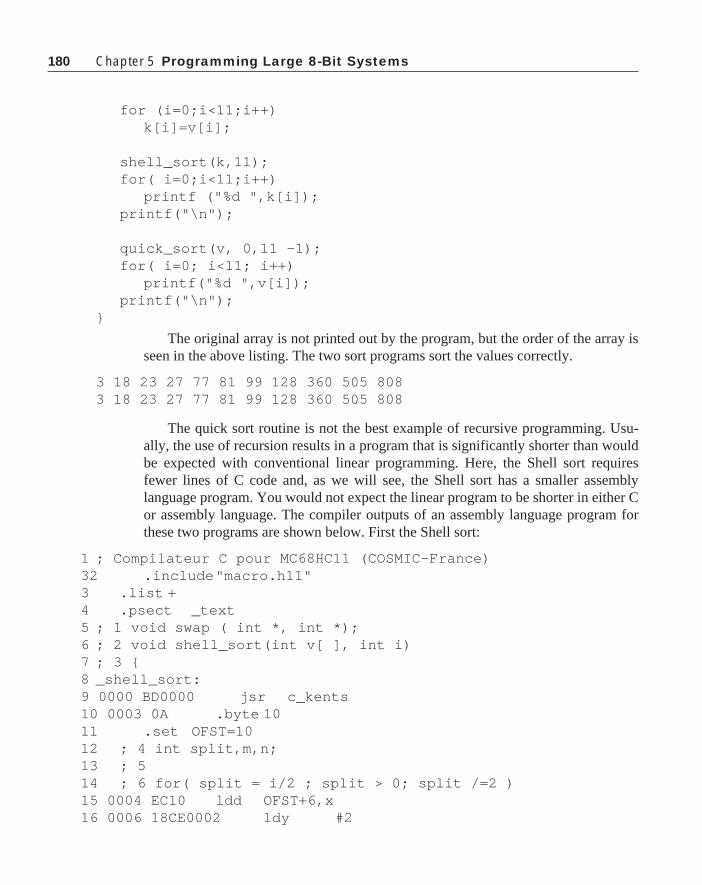
180 Chapter 5 Programming Large 8-Bit Systems
for (i=0;i<11;i++)k[i]=v[i];
shell_sort(k,11);for( i=0;i<11;i++)
printf ("%d ",k[i]);printf("\n");
quick_sort(v, 0,11 -1);for( i=0; i<11; i++)
printf("%d ",v[i]);printf("\n");
}
The original array is not printed out by the program, but the order of the array isseen in the above listing. The two sort programs sort the values correctly.
3 18 23 27 77 81 99 128 360 505 8083 18 23 27 77 81 99 128 360 505 808
The quick sort routine is not the best example of recursive programming. Usu-ally, the use of recursion results in a program that is significantly shorter than wouldbe expected with conventional linear programming. Here, the Shell sort requiresfewer lines of C code and, as we will see, the Shell sort has a smaller assemblylanguage program. You would not expect the linear program to be shorter in either Cor assembly language. The compiler outputs of an assembly language program forthese two programs are shown below. First the Shell sort:
1 ; Compilateur C pour MC68HC11 (COSMIC-France) 32 .include"macro.h11" 3 .list + 4 .psect _text 5 ; 1 void swap ( int *, int *); 6 ; 2 void shell_sort(int v[ ], int i) 7 ; 3 { 8 _shell_sort: 9 0000 BD0000 jsr c_kents 10 0003 0A .byte 10 11 .set OFST=10 12 ; 4 int split,m,n; 13 ; 5 14 ; 6 for( split = i/2 ; split > 0; split /=2 ) 15 0004 EC10 ldd OFST+6,x 16 0006 18CE0002 ldy #2

181Sorting Programs
17 000A BD0000 jsr c_idiv 18 000D ED08 std OFST-2,x 19 L1: ; line 6, offset 15 20 000F EC08 ldd OFST-2,x 21 0011 2F62 ble L11 22 ; 7 for( m = split ; m < i ; m++) 23 0013 ED06 std OFST-4,x 24 L14: ; line 7, offset 27 25 0015 EC06 ldd OFST-4,x 26 0017 1AA310 cpd OFST+6,x 27 001A 2C44 bge L12 28 ; 8 for ( n = m-split; n >=0 && 29 001C A308 subd OFST-2,x 30 001E ED04 std OFST-6,x 31 L101: ; line 8, offset 40 32 ; 9 v[n] > v[n+split]; n -= split) 33 0020 A604 ldaa OFST-6,x 34 0022 2D49 blt L16 35 0024 EC04 ldd OFST-6,x 36 0026 E308 addd OFST-2,x 37 0028 05 lsld 38 0029 E30A addd OFST+0,x 39 002B 188F xgdy 40 002D 18EC00 ldd 0,y 41 0030 ED02 std OFST-8,x 42 0032 EC04 ldd OFST-6,x 43 0034 05 lsld 44 0035 E30A addd OFST+0,x 45 0037 188F xgdy 46 0039 18EC00 ldd 0,y 47 003C A302 subd OFST-8,x 48 003E 2F2D ble L16 49 ; 10 swap(v+n,v+n+split); 50 0040 EC08 ldd OFST-2,x 51 0042 05 lsld 52 0043 ED02 std OFST-8,x 53 0045 EC04 ldd OFST-6,x 54 0047 05 lsld 55 0048 E30A addd OFST+0,x 56 004A E302 addd OFST-8,x 57 004C 37 pshd 36

182 Chapter 5 Programming Large 8-Bit Systems
58 004E EC04 ldd OFST-6,x 59 0050 05 lsld 60 0051 E30A addd OFST+0,x 61 0053 BD0000 jsr _swap 62 0056 31 ins 63 0057 31 ins 64 0058 EC04 ldd OFST-6,x 65 005A A308 subd OFST-2,x 66 005C ED04 std OFST-6,x 67 005E 20C0 bra L101 68 L12: ; line 6, offset 105 69 0060 EC08 ldd OFST-2,x 70 0062 18CE0002 ldy #2 71 0066 BD0000 jsr c_idiv 72 0069 ED08 std OFST-2,x 73 006B 20A2 bra L1 74 L16: ; line 7, offset 119 75 006D 6C07 inc OFST-3,x 76 006F 26A4 jbne L14 77 0071 6C06 inc OFST-4,x 78 0073 20A0 bra L14 79 L11: ; line 10, offset 127 80 ; 11 } 81 0075 AE00 lds 0,x 82 0077 38 pulx 83 0078 39 rts 84 ; 12 85 .public _shell_sort 86 .external _swap 87 .external c_kents 88 .external c_idiv 89 .end
Next the quick sort:
1 ; Compilateur C pour MC68HC11 (COSMIC-France) 32 .include"macro.h11" 3 .list + 4 .psect _text 5 ; 1 /* quick_sort( int v[ ], int left, int right) : sort the 6 ; 2 array v into ascending order */ 7 ; 3

183
8 ; 4 void quick_sort(int v[ ], int left, int right) 9 ; 5 { 10 _quick_sort: 11 0000 BD0000 jsr c_kents 12 0003 08 .byte 8 13 .set OFST=8 14 ; 6 int i,value; 15 ; 7 16 ; 8 if(right > left) 17 0004 EC10 ldd OFST+8,x 18 0006 1AA30E cpd OFST+6,x 19 0009 2E03 jble L1 7E00A7 20 000B; 9 { 21 ; 10 swap(v+left, v+(right+left)/2); /* chose the value at 22 000E E30E addd OFST+6,x 23 0010 18CE0002 ldy #2 24 0014 BD0000 jsr c_idiv 25 0017 05 lsld 26 0018 E308 addd OFST+0,x 27 001A 37 pshd 36 28 001C EC0E ldd OFST+6,x 29 001E 05 lsld 30 001F E308 addd OFST+0,x 31 0021 BD0000 jsr _swap 32 0024 31 ins 33 0025 31 ins 34 ; 11 center to partition on*/ 35 ; 12 value = left; 36 0026 EC0E ldd OFST+6,x 37 0028 ED04 std OFST-4,x 38 ; 13 for(i=left+1; i<=right; i++) 39 002A C30001 addd #1 40 002D ED06 std OFST-2,x 41 L11: ; line 13, offset 51 42 002F EC06 ldd OFST-2,x 43 0031 A310 subd OFST+8,x 44 0033 2E39 bgt L12 45 ; 14 if(v[i] < v[left]) 46 0035 EC0E ldd OFST+6,x
Sorting Programs

184 Chapter 5 Programming Large 8-Bit Systems
47 0037 05 lsld 48 0038 E308 addd OFST+0,x 49 003A 188F xgdy 50 003C 18EC00 ldd 0,y 51 003F ED02 std OFST-6,x 52 0041 EC06 ldd OFST-2,x 53 0043 05 lsld 54 0044 E308 addd OFST+0,x 55 0046 188F xgdy 56 0048 18EC00 ldd 0,y 57 004B A302 subd OFST-6,x 58 004D 2C17 bge L13 59 ; 15 swap(v+(++value), v+i); 60 004F EC06 ldd OFST-2,x 61 0051 05 lsld 62 0052 E308 addd OFST+0,x 63 0054 37 pshd 36 64 0056 6C05 inc OFST-3,x 65 0058 2602 bne LL6 66 005A 6C04 inc OFST-4,x 67 LL6: 68 005C EC04 ldd OFST-4,x 69 005E 05 lsld 70 005F E308 addd OFST+0,x 71 0061 BD0000 jsr _swap 72 0064 31 ins 73 0065 31 ins 74 L13: ; line 13, offset 108 75 0066 6C07 inc OFST-1,x 76 0068 26C5 jbne L11 77 006A 6C06 inc OFST-2,x 78 006C 20C1 bra L11 79 L12: ; line 16, offset 116 80 ; 16 swap(v+left, v+value); /* put the partition element inplace*/ 81 006E EC04 ldd OFST-4,x 82 0070 05 lsld 83 0071 E308 addd OFST+0,x 84 0073 37 pshd 36 85 0075 EC0E ldd OFST+6,x

185
86 0077 05 lsld 87 0078 E308 addd OFST+0,x 88 007A BD0000 jsr _swap 89 007D 31 ins 90 007E 31 ins 91 ; 17 quick_sort(v,left, value-1); 92 007F EC04 ldd OFST-4,x 93 0081 C3FFFF addd #-1 94 0084 37 pshd 36 95 0086 EC0E ldd OFST+6,x 96 0088 37 pshd 36 97 008A EC08 ldd OFST+0,x 98 008C BD0000 jbsr _quick_sort 99 008F 31 ins 100 0090 31 ins 101 0091 31 ins 102 0092 31 ins 103 ; 18 quick_sort(v,value+1,right); 104 0093 EC10 ldd OFST+8,x 105 0095 37 pshd 36 106 0097 EC04 ldd OFST-4,x 107 0099 C30001 addd #1 108 009C 37 pshd 36 109 009E EC08 ldd OFST+0,x 110 00A0 BD0000 jbsr _quick_sort 111 00A3 31 ins 112 00A4 31 ins 113 00A5 31 ins 114 00A6 31 ins 115 L1: ; line 20, offset 173 116 ; 19 } 117 ; 20 } 118 00A7 AE00 lds 0,x 119 00A9 38 pulx 120 00AA 39 rts 121 ; 21 122 .public _quick_sort 123 .external _swap 124 .external c_kents
Sorting Programs

186 Chapter 5 Programming Large 8-Bit Systems
125 .external c_idiv 126 .end
Note that the Shell sort requires 0x78 (120) bytes of code while the quick sortneeds 0xaa (170) bytes of code. This amount of extra code would not be a seriouscost if that were the end of the costs. However, each time a recursive routine callsitself it must establish an argument set that contains all of the variables to be passedto the function. Notice from lines 104 through 114 above that two of the parametersare placed on the stack and one of the parameters is placed in the D register prior tocalling the function quick_sort . When quick_sort returns control to thecalling program, the stack pointer is corrected by four increment stack instructions.quick_sort will continue calling itself repeatedly while the value of the parameterright is greater than the value of the parameter left when the function is entered. Eachtime the function is called, the program will create a new stack frame which must bemade available from RAM. Unfortunately, RAM is usually a more precious com-modity than ROM to a microcontroller.
It is possible to get an idea about how much RAM is needed to do a quick sort.The stack frame consisting of six bytes—four bytes for parameters plus two bytes forthe return address—must be created each time quick sort is entered. It is possible tocount the maximum depth of entry into any recursive routine. The maximum depth isthe number of times the function is called before a normal return to the calling func-tion is executed. The depth is found by incrementing a count each time the function isentered. Whenever, control is passed back to the calling function through the normalreturn sequence at the end of the function, the depth will be evaluated to determine ifit is the largest value seen so far, and then the depth will be returned to zero. The twolistings below incorporate these modifications.
/* quick_sort( int v[ ], int left, int right) : sort the array v into ascending order */
void quick_sort(int v[ ], int left, int right){
int i,value;extern calls, depth, max_depth;
calls++; /* count the number of times called */depth++;if(right > left){
swap(v+left, v+(right+left)/2); /* chose the value atcenter to partition on */

187
value = left;for(i=left+1; i<=right; i++)
if(v[i] < v[left])swap(v+(++value), v+i);
swap(v+left, v+value); /* put the partition element in place*/
quick_sort(v,left, value-1);quick_sort(v,value+1,right);
}if(depth>max_depth)
max_depth=depth;depth=0;
}
void swap ( int *, int *);void quick_sort(int v[ ], int left, int right) ;
#include <stdio.h>int calls, depth, max_depth;
main(){
int v[11]={81,99,23,808,3,77,18,27,128,360,550};int i;
quick_sort(v, 0,11 -1);for( i=0; i<11; i++)
printf("%d ",v[i]);printf("\n");printf ("calls=%d \nmax_depth=%d\n",calls,max_depth);
}
Note that the global variables calls and depth are incremented each timequick_sort() is called. When quick_sort() is exited through its normalreturn procedure at the end of the routine, depth is examined to determine if it isgreater than max_depth . If it is, max_depth is replaced by depth. depth isreset to zero prior to returning through the end of the quick_sort() routine. Theresult of this program is as follows:
3 18 23 27 77 81 99 128 360 550 808calls=15max_depth=4
Sorting Programs
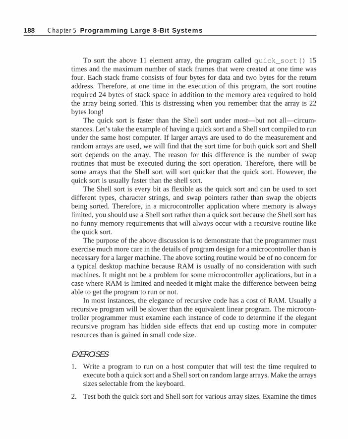
188 Chapter 5 Programming Large 8-Bit Systems
To sort the above 11 element array, the program called quick_sort() 15times and the maximum number of stack frames that were created at one time wasfour. Each stack frame consists of four bytes for data and two bytes for the returnaddress. Therefore, at one time in the execution of this program, the sort routinerequired 24 bytes of stack space in addition to the memory area required to holdthe array being sorted. This is distressing when you remember that the array is 22bytes long!
The quick sort is faster than the Shell sort under most—but not all—circum-stances. Let’s take the example of having a quick sort and a Shell sort compiled to rununder the same host computer. If larger arrays are used to do the measurement andrandom arrays are used, we will find that the sort time for both quick sort and Shellsort depends on the array. The reason for this difference is the number of swaproutines that must be executed during the sort operation. Therefore, there will besome arrays that the Shell sort will sort quicker that the quick sort. However, thequick sort is usually faster than the shell sort.
The Shell sort is every bit as flexible as the quick sort and can be used to sortdifferent types, character strings, and swap pointers rather than swap the objectsbeing sorted. Therefore, in a microcontroller application where memory is alwayslimited, you should use a Shell sort rather than a quick sort because the Shell sort hasno funny memory requirements that will always occur with a recursive routine likethe quick sort.
The purpose of the above discussion is to demonstrate that the programmer mustexercise much more care in the details of program design for a microcontroller than isnecessary for a larger machine. The above sorting routine would be of no concern fora typical desktop machine because RAM is usually of no consideration with suchmachines. It might not be a problem for some microcontroller applications, but in acase where RAM is limited and needed it might make the difference between beingable to get the program to run or not.
In most instances, the elegance of recursive code has a cost of RAM. Usually arecursive program will be slower than the equivalent linear program. The microcon-troller programmer must examine each instance of code to determine if the elegantrecursive program has hidden side effects that end up costing more in computerresources than is gained in small code size.
EXERCISES1. Write a program to run on a host computer that will test the time required to
execute both a quick sort and a Shell sort on random large arrays. Make the arrayssizes selectable from the keyboard.
2. Test both the quick sort and Shell sort for various array sizes. Examine the times

189
required to execute the sorts for several random arrays. Explain what is happen-ing when arrays of 4090, 4095, and 4096 entries are sorted.
Data CompressionAnother program problem the can arise with microcontroller applications is to
handle displays in which there are many phrases and names each consisting of severalletters. The question that must be considered is the most efficient method of storingthese phrases and names in memory so that they can be recalled for display. Theoldest and yet very effective method of compressing the data for storage is to use aHuffman code. This code is developed based on the statistical occurrence of eachletter in the alphabet. A letter that occurs frequently will be given a short codesequence. A letter that is seen infrequently can be assigned a long code which will notappreciably affect the number of bits per letter in the message.
Huffman codes are self-synchronizing. A long string of characters can be repre-sented as a series of bits, and the decoding program can find each character in thesequence without any special flags to designate the end of each character. Messagesstored as ASCII characters require at least seven bits per character, and because ofthe nature of storage in a computer 8-bits are usually assigned to each character. Witha Huffman code, it is possible to reduce the average number of bits per character forthe whole English language to about 4.5 bits per character. Sometimes even fewerbits are needed with limited messages.
The programmer does all of the Huffman encoding and the computer mustdecode the messages for display. Huffman decoding requires extensive bit manipula-tion, so C is an ideal language to decode the messages.
A Huffman decoding scheme can be represented by a strictly binary tree. Abinary tree is comprised of a collection of nodes. Each node has two descendentsoften called the right and left descendents (thus the term binary tree). The terminatingnode in a tree is called a leaf. In a strictly binary tree, every nonleaf node has both aright and left descendent. If a strictly binary tree has n leafs, it has a total of 2n-1nodes.
The Huffman code is decoded in this manner. The sequence always starts at theroot node. The code sequence to be decoded is examined a bit at a time. If the bit is a0, move to the left node. If the bit is a 1, move to the right node. The tree is traverseduntil a leaf is found which contains the desired character. The sequence is thenrestarted at the root node. If the tree is not known, the sequence of bits is bewildering.Usually it is found that the occurrence of ones and zeros is about equally likely, sono statistical analysis can be applied to decode the sequence easily. A disadvantageis that if a single bit in the sequence is lost, the remainder of the code stream is
Data Compression

190 Chapter 5 Programming Large 8-Bit Systems
undecipherable. Of course, the advantage to the Huffman code is that it takes some-where between one-quarter and one-half the number of bits to represent a message asis required by the ASCII code. A Huffman Code tree is shown in Figure 5-1. The bitsequence 111111100101111010100000 as decoded by this tree is seen to spell theword “committee”. This sequence requires 23 bits, and the ASCII code needed torepresent committee would be 72 bits long. Of course, this tree was designed specifi-cally for the word “committee,” but try to encode other words that can be made ofthese same letters such as “tic,” “me,” “come,” “tom,” “mite,” etc. and you will findthat every word that can be derived from this tree requires fewer bits than thecorresponding ASCII sequence would need.
If you look at Figure 5-1, you will note that the letters e, m, and t require only twobits each to determine the value. These letters were selected to be represented by 2-bitvalues because they are the most frequently occurring letters in the message. Theremainder of the letters require more bits but they do not occur so often in themessage.
Figure 5-1: Huffman Code Tree
The code must be designed specifically for the messages to be represented. First,all of the characters in all of the messages are collected into an histogram of theoccurrence of each character. Remember to include spaces and other such charactersin the list. Once you have determined the number of different characters in the list,you can design a tree that will compress the code. If the list contains n differentcharacters, there will be 2n-1 nodes in the tree. Each level in the tree, starting from theroot node at the zeroth level, can contain 2k nodes or leafs. This tree cannot be bal-anced like a binary sort tree because we want some of the leafs to be determined byas few as two bits, and we do not care about the number of bits needed to determine acharacter that occurs infrequently. In the above diagram, levels 0 and 1 contain onlynodes with no leaves. Level 0 contains three leaves and one node. It is through this
coo
t
l
e m

191
single node that all of the remainder of the characters must be found.A series of avionics related items were put together and an analysis of the
frequency of characters in these messages was completed. A Huffman code that willencode these data effectively was created. This code is shown in Table 5-1.
Frequently occurring letters like e, i, or a are encoded with only two or three bits.On the other hand, letters that occur very infrequently—like c or v—require nine bitsto encode. Even though some letters require more than eight bits to encode, theaverage number of bits per character for this particular message set is only 4.032.
Decoding a Huffman code with a program is relatively easy. The program mustcontain the Huffman tree with all of its nodes and leaves. If we want the entirealphabet and a space, a period, a comma and an end of message, there will be 59entries in the tree. This or an equivalent tree is an overhead that must be carried forevery Huffman program. Assume that the statistical analysis of the messages alongwith the construction of the Huffman tree is complete. The approach taken to buildthis tree in memory is to allow one byte for each node. The tree is searched from theroot node which is the lowest address. The message to be decoded is examined. If thebit in the message is a zero, the node pointer is incremented by one and the next bit isexamined. If the bit in the message is a one, the node pointer is incremented by thecontent of the node. All printable characters are entered into the tree as negativenumbers. The content of the node are examined. If the content of the node is positive,the next bit from the message is examined and so forth. Whenever the content of anode is negative, its most significant bit is removed, and the character is sent to theoutput. At that time, the node pointer is returned to the root node, and the sequence isrepeated until an end of message is found.
Character Code Character Code
E 00 D 110000I 01 ‘ ‘ 110001A 100 G 111100‘\n’ 101 U 111101N 11001 L 1111100R 11010 O 1111101T 11011 F 11111100M 11100 H 11111101S 11101 P 11111110
C 111111110V 111111111
Table 5-1: Huffman Code
The listing shown below is a simple Huffman encoded routine to print out to thescreen several aircraft oriented terms that might be used in an on-board avionics
Data Compression

192 Chapter 5 Programming Large 8-Bit Systems
system. The first part of the function is a list of the several words or phrases.
#include <stdio.h>/* The messages to send out */static unsigned char M1[]={0x9f,0x36,0xef,0xdc,0x0a};static unsigned char M2[]={0xfd,0x26,0x0e,0x7c,0xa0};static unsigned char M3[]={0xc1,0xee,0xe6,0x7f,0xc6,0x3a,0x39,
0x1c,0xb9,0xf2,0x80 };static unsigned char M4[]={0xfc,0xf4,0xf9,0x8e,0x8e,0x47,0x2e,
0x7c,0xa0};static unsigned char M5[]={0x8e,0xb1,0xef,0xf0,0x61,0x40};static unsigned char M6[]={0x73,0x8f,0xef,0xdf,0x75,0xda};static unsigned char M7[]={0xdb,0xc2,0x80};static unsigned char M8[]={0x3b,0xb7,0x93,0x66,0x18,0xed,0xe1,
0x8f,0xdf,0xcc,0x66,0xb4,0xff,0xe7,0xca};static unsigned char M9[]={0xf3,0x5f,0x7d,0xce,0x18,0xf7,0xf8,
0x30,0xa0};
/* The Huffman tree */const static charNode[]={4,2,'E'|0X80,'I'|0X80,4,2,'A'|0X80,'\n'|0X80,10,6,4,2,
'D'|0X80,' '|0X80,'N'|0X80,2,'R'|0X80,'T'|0X80,4,2,'M'|0X80,'S'|0X80,4,2,'G'|0X80,'U'|0X80,4,2,'L'|0X80,'O'|0X80,4,2,'F'|0X80,'H'|0X80,2,'P'|0X80,2,'C'|0X80,'V'|0X80};
void decode(unsigned char *M){
unsigned char mask = 0x80;char i=0,k=0,l=0; /* l is the node pointer, i is the byte
pointer, M is the message pointer */
while(k !='\n'){
if((mask & M[i])==0) l++; /* use next node entry if bit is zero */
else l+=Node[l];/*jump to designated node when one */
if(Node[l]<0){ /* if a printable, send it out */
putchar(k=Node[l]&0x7f);l=0; /* also go to the root node */
}if((mask>>=1)==0) /* if the mask is zero, turn on MSB */{
mask = 0x80; i++; /* and get the next byte from message */

193
}}
}Listing 5-1: Huffman Decode Function
The next part of the program is the Huffman tree needed to decode the data. Thistree was constructed to decode data specifically for the nine messages of this prob-lem. You will note that each byte in the table is a node. There are intermixed in thetable numbers that dictate jumps to the next node depending on whether the incomingbit is a zero or a one. The leaves each contain a negative number that is generated bythe inclusive OR of the character to be printed and the number 0x80 .
The messages are sent to the function decode as a pointer to a bit array. The datamust be examined one bit at a time to implement the decoding. The bit selection isaccomplished by ANDing the data in the incoming message with the contents of thevariable mask. Mask is initially set to 0x80 , so the most significant bit of the firstbyte of the incoming data is selected. Late in the routine, the value of mask will beshifted right to select other bits in the incoming sequence. The variable k is loadedwith the character to be output during the program. The linefeed character '\n' wasused to determine the end of message, so the decoding sequence will be executeduntil the character that was output from the program is a '\n' . Recall the way thatthe tree was built. If an incoming bit is 0, the next node in the tree will be taken. If theincoming bit is 1, the content of the current node will be added to the node pointer todetermine the next node in the tree. If at any time a negative number is found in thetree, a leaf has been found. The data portion of this byte, bits 0 through 6, will be sentout to the screen.
After each bit is processed, the next bit in the sequence must be processed. Thenext bit is selected by shifting the mask byte to the right one bit. If the result of thisshift creates a zero mask, a new mask with a value of 0x80 is created and the nextbyte from the incoming message code is selected when i is incremented.
The simple program below causes the nine messages to be printed on the screen:
main(){
decode(M1);decode(M2);decode(M3);decode(M4);decode(M5);decode(M6);decode(M7);decode(M8);decode(M9);
}
Listing 5-2: Message Printing Program
Data Compression

194 Chapter 5 Programming Large 8-Bit Systems
The result of execution of this program is shown below. The nine messages contain124 characters that would require 992 bits of memory to store the messages instandard ASCII format. The encoded sequence requires 500 bits or 63 bytes of storage.
ALTITUDEHEADINGDISTANCE REMAININGFUEL REMAININGAIR SPEEDIN HOURSTIMEESTIMATED TIME OF ARRIVALGROUND SPEED
The function below was written to show the difference in memory required forthe Huffman code and conventional ASCII coding. This program was compiled as afunction to be run on the MC68HC11. The function decode is given in Listing 5-1
#include <stdio.h>char M1[]="ALTITUDE";char M2[]="HEADING";char M3[]="DISTANCE REMAINING";char M4[]="FUEL REMAINING";char M5[]="AIR SPEED";char M6[]="IN HOURS";char M7[]="TIME";char M8[]="ESTIMATED TIME OF ARRIVAL";char M9[]="GROUND SPEED";
void decode(char *M){
while(*M !=0)putchar(*M++);
putchar('\n');}
Listing 5-3: Nonencoded Output Function
was compiled to MC68HC11 code. The result of these two compilations showed thatListing 5-1 created an object module that was 255 bytes long, and Listing 5-2 createdan object module that was 277 bytes long. The Huffman code for even the smallmessage list in this case provided nearly 10% reduction in code size. A larger

195
message list would provide an even greater memory savings because the coderequired to decode the messages would be allocated over more message characters tobe sent out.
EXERCISES1. How could the tree in Listing 5-1 be altered to reduce its size by 8 bytes? What
effect would this change have on the routine decode? Would there be a netsavings in overall code?
2. Do an analysis of a substantial piece of writing and create a Huffman code thatwill encode the data efficiently. It is recommended that the first three pages of anovel be used for this analysis. Compute the average number of bits per characterthat this code generates. Hint: you might want to write a program in C for the hostcomputer to calculate the histogram and help create the Huffman codes.
3. Write a program that will implement the above code so that an operator can typethe data into a computer and the Huffman code sequences will be generated. Youshould break the message sequences into moderate size bit strings, 500 to 1000bits, and restart.
4. Create a Huffman tree table as was used in Listing 5-1 to decode the Huffmancode developed in Exercise 2.
5. How can you double the number of entries in a Huffman tree by adding only onebit to the code strings?
6. Show how to double the number of entries in a Huffman tree while adding onlyone bit to the length of the codes.
Timer OperationsThe programs written in the preceding sections on sorting and data compression
were more computer programs than microcontroller programs. The code writtenwould work on a desktop system or a mainframe computer if needed. In this section,we graduate to true microcontroller programming. The set-up of the MC68HC11family requires that the programmer have a detailed knowledge of the operation ofthe device. Even though the program is written in a high level language, it is theresponsibility of the programmer to properly set all of the necessary control bits tomake the device work as desired. Unfortunately, there are few helpful tools that canguide you through this portion of the program. You must first understand what youwant the device to do and then dig through its specifications to find the necessary bits
Timer Operations

196 Chapter 5 Programming Large 8-Bit Systems
to be set to make it perform as desired. Appendix C contains a very brief descriptionof this device, but you cannot really learn how to program it from this appendix. It ishighly recommended that prior to an attempt at programming this device that youfamiliarize yourself with the technical data manual for it as well as the referencemanual for the family.
The timer subsystem in the MC68HC11 family contains both input capture oper-ations and output compare functions. In this section, we will explore these subsystemsassociated with the MC68HC11Ex series. The main difference between the Ex seriesand the other devices lies in the number of output compare and input capture systemson each device. The Ex series has four output compares, three input captures, and onetimer that can be programmed as either output compare or input capture. The otherdevices have three input captures and five output compares.
In addition to understanding the nature of the microcontroller being programmed,the programmer must also understand the compiler being used. In this case, there is aproblem that will cause the program to have some minor twists. When you examineAppendix C (which contains a descripiton of the MC68HC11), you will find thatthere are two control registers that work differently from the remainder of the part.Motorola microcontrollers use memory-mapped input/output. All registers and portsare merely locations in memory, and in general they all operate the same way.However, in the case of the MC68HC11, there are two registers that are differentfrom the remainder of the memory. These registers are TFLG1 and TFLG2. Theseregisters require that a 1 be written to a bit to turn it off. The remainder of the registersrequire that a zero be written to the bit to turn it off. The normal bit clear and bit setassembly commands will work with all memory locations with the exception of thesetwo registers.
The Intermetrics compiler handles bit manipulations very well in the usualmemory locations. Let us examine the code that will be produced by the followingcode sequence that is extracted from Appendix D:
typedef struct{ unsigned char bit0 : 1; unsigned char bit1 : 1; unsigned char bit2 : 1; unsigned char bit3 : 1; unsigned char bit4 : 1; unsigned char bit5 : 1; unsigned char bit6 : 1; unsigned char bit7 : 1;} Register;
unsigned int Register_Set=0x1000 ;

197
#define PORTA (*(volatile Register*)(Register_Set+0))#define PIOC (*(Register*)(Register_Set+2))#define PORTC (*(volatile Register*)(Register_Set+3))#define PORTB (*(volatile Register*)(Register_Set+4))
This code is the first few lines of the header file HC11E9.H . Note that thestandard bit manipulation capability of C is used to create the register bit map. Thelocation of the register map is placed at the address 0x1000 by assigning a value0x1000 to the global variable Register_Set . This value can be changed by theprogram; however, if it is to be changed, the change must be accomplished within thefirst 64 clock cycles following a reset. Examine the definition of PORTA. This macrodictates that PORTA is of the type register and is located at Register_Set + 0 .For this program, the programmer can use constructs like
PORTA.bit7=1;PORTA.bit3=0;
and
if(PORTA.bit2==1){
.
.
to manipulate the bits within this register.Since the registers are all identifiied as relative to the value contained in
Register_Set , the compiler is able to access all registers in an indexed mode. Inother words, the value of Register_Set will be placed in an index register, andthe access to the register will be offset from this index register. This operation isexactly what is needed, because offset from an index register is the only mechanismby which the bit manipulation instructions can access all of the bits in the memorymap.
So much for the normal bit manipulation operations. How about those tworenegade registers TFLG1 and TFLG2? These registers require that a one be writtento the bit to reset the bit. The normal bit manipulation instructions will mess up theregisters unless some change is made in the code to prevent the problems. Thecompiler cannot be expected to recognize that these two registers are different fromthe rest of the memory map. Therefore, the programmer must program these bitsdifferently from the rest. In Appendix D, your attention is directed to the bit defini-tions for TMSK2 and TFLG1. TMSK2 is defined in the usual manner in which each bitused in the register is given the name found in the data manual. TFLG1 as well asTFLG2 are defined as unsigned char and their bits are given names that are onebyte wide with the specific bit turned on. Therefore, to reset a bit in the TFLG1register, you must use a construct like
Timer Operations

198 Chapter 5 Programming Large 8-Bit Systems
TFLG1=OC2F;
You will see this construct used in the timer interrupt service routines that follow.This approach is needed to reset each of the interrupt flags associated with the
timer system. These registers are the only ones in the MC68HC11 that require thisspecial handling.
Output Compare SubsystemsWhat does an output compare do? The explanation of the timer subsystem must
always begin with the 16-bit timer counter called TCNT that is always counting atsome fraction of the system bus frequency. The bus frequency is always one-forth ofthe system crystal frequency. The prescaler frequency is set to the bus frequencydivided by either 1, 4, 8, or 16 depending on the bits PR1 and PR0 in the registerTMSK2. The timer counter register can be read at any time but it cannot be written to.
The Output Compare 1 is special. All of the discussion that follows is valid for alloutput compares, but—as will be shown later—Output Compare 1 has capabilitybeyond the others.
Associated with each output compare system there is a single 16-bit output com-pare register containing the time that the program needs an event to occur. WhenTCNT contents matches that of OCx, an OCx event occurs. Note that I say an event,not output. What happens when the contents of the TCNT is up to the program.Associated with each output compare is a pin that can be set, reset, or toggled whenan output compare occurs. When an output compare occurs, the corresponding OCxFflag bit is set in the TFLG1 register. This bit can be examined synchronously by theprogram to determine whether an output compare has occurred. If the correspondingbit in the TMSK1 register is set when the OCxF flag bit is set, an interrupt will berequested by the part and the event will be processed asynchronously. These are theoperations of all output compare subsystems in the part.
There are three input captures, four output compares, and one timer that can beprogrammed as either an output or an input. This timer is controlled by the I4O5 bitin the PACTL register. When this bit is a zero, the programmable timer is an outputcompare. Otherwise when the bit is set, the programmable timer is an input capture.
Often it is desirable to have an output compare operation be initiated by thecompletion of another output compare. Output Compare 1 is set up in just thismanner. The bits in the OC1M and the OC1D registers control the coupling betweenthe Output Compare 1 and the other output compare subsystems. When one of themask bits, say OC1M5, is set in the OC1M and a compare occurs on OC1, in additionto the normal operation that usually occurs when OC1 happens, the contents of thecorresponding bit, OC1D5, in the OC1D register will sent to the output compare pinwhich in this case will be OC3. Completely independent of the operation of OC1, OC3could be set to toggle at some time. Output Compare 3 could be programmed to be aPWM output where Output Compare 1 establishes the period of the output, and

199
Output Compare 3 establishes the on time.The applications for use of the coupled output compares are unlimited. An
accurate PWM is but one of several. These outputs could be set up to establish anoutput sequence to drive a stepper motor. The control of acceleration or decelerationof the motor is easily controlled by merely selecting the base time used with OC1.
If you recall the output compare-based PWM system discussed for the MC68HC05had several limitations. For example, that system required that the system operatefrom interrupt service routines. The latency time of interrupt service was so long thatthe minimum pulse width was considerably longer than one would expect. Also, theinterrupt service timing dictated the maximum on time for the pulse which again wasnot nearly 100%. Let us look at how we would do a PWM system with the coupledoutput compare systems.
#include "hc11e9.h"
/* This program will provide a PWM output to OC3, or PA5. The period will be the integer value found in period, and the on time will be the integer value found in time_on. Keep time_on less than period. */
WORD period=0x1000, time_on=0x0800;
main(){
OC1M.OC1M7=1; /* sent OC1 out to PA7 */OC1M.OC1M5=1; /* couple OC1 to OC3 */OC1D.OC1D5=1; /* turn on OC3 when OC1 occurs */TCTL1.OL3=1; /* toggle OC3 when OC3 occurs */PACTL.DDRA7=1; /* make OC1 an output to PA7 */TOC1=TCNT+period; /* set OC1 to the period */TOC3=TOC1+time_on; /* set OC3 to the time on */FOREVER{
if(TFLG1&OC1F){
TFLG1=OC1F; /* reset OC1 interrupt flag */TOC1+=period;if(OC1D.OC1D7==1)
OC1D.OC1D7=0; /* causes OC1 to toggle */else
OC1D.OC1D7=1;}if(TFLG1&OC3F){
Timer Operations

200 Chapter 5 Programming Large 8-Bit Systems
TFLG1=OC3F; /* reset OC3 interrupt flag */TOC3=TOC1+time_on;
}}
}Listing 5-4: Pulse Width Modulation Routine PWM.C
This routine starts with the inclusion of the header file hc11e9.h . It is createdas a main program to demonstrate how it will work, but should be changed to asubroutine later. The period and time_on interval are declared as global vari-ables. They are declared to be the type WORD. WORD is a typedef synonym forthe type unsigned int . The main program begins with a series of five initializa-tion instructions. The first two instructions
OC1M.OC1M7=1;OC1M.OC1M5=1;
declares that the output of OC1 should be sent to the outside which will be to pin PA7and that whenever OC1 occurs, OC3 through pin PA5 should be activated.
The instruction
OC1D.OC1D5=1;
indicates that the OC1 occurs, OC3 should be turned on. The next instruction
TCTL1.OL3=1;
is to cause OC3 to toggle when its time expires, and the instruction
PSCTL1.DDRA7=1;
sets the DDRA7 bit so that signals from OC1 will be sent to the output pin PA7.TOC1 and TOC3 are initialized by the next two instructions. TOC1 is given a
value that the contents of period greater than the contents of the timer counter registerTCNT. TOC3 is set equal to the contents of TOC1 plus the time_on .
The routine then enters an endless loop. Within this loop, two flags are examinedand if they are set, they are reset. Also, new times are calculated for when the nextoutput compares should occur. The OC1F flag in TFLG1 is set whenever an OutputCompare 1 occurs. This flag must then be reset. The instruction sequence
if(TFLG1 & OC1F){
TFLG1 = OC1F;..

201
will accomplish the required assembly instructions to test the bit and reset it if the bitis turned on.
The time of the next OC1 is calculated as TOC1+period . In this particularinstance, the bit OC1D.OC1D7 is complemented so that the output observed on PA7will toggle with the occurrence of each OC1. TFLG1.OC3F is tested to determineif an Output Compare 3 has happened. If it has, this bit is reset, and TOC3 is set to anew value of TOC1+time_on . With this setup, OC3—PA5—will go on when eachOC1 occurs, and will be reset an amount corresponding to time_on after it goes on.Therefore, the period of this system can be set and the on time can be any value lessthan the period.
Normally, the operation of a PWM would be to generate an analog signal that ispresent continuously. The above program does perform this task, but it also assumesthat the computer does not have much else to do. Other tasks could be built into theabove program, but it is absolutely necessary that the program have a cycle time thatis shorter than the period of the PWM signal. If the loop time of the FOREVER loopis less than the PWM period, then you can use the above synchronous approach. Itmakes no difference when in the cycle that the two if statements in the FOREVERloop are executed. It is necessary that they must be executed prior to the occurrence ofthe OC1 that designates the end of the period. If it becomes necessary to include somuch code in the FOREVER loop that it is impossible to guarantee that the loop timewill always be less than the period, then an asynchronous approach should be used.
This program was compiled and executed on an evaluation module. The value oftime_on was adjusted to determine the range of outputs that could be createdwith this program. The minimum time on must be greater than the time required toexecute the code
if(TFLG1&OC3F){
TFLG1=OC3F; /* reset OC3 interrupt flag */TOC3=TOC1+time_on;
}
when OC3F is found on. The reason for this timing is that TOC3 must be updatedafter TOC1 is given a new value and the update must be complete prior to the passingof time_on . Otherwise, the period of TOC1 will pass before the OC3 will occur.This time was measured, and it was found to be 6 clock cycles. Therefore, reliableperformance is obtained with a minimum time on of 6 clock cycles.
The maximum time on was found to be 0xffe with the above code. The outputsignal at 0xfff was on all of the time with no single cycle off period as the programwould indicate.
An interrupt can be requested whenever an output compare occurs. We areservicing two output compares in this case. Ones initial thought might be to have twointerrupts. In this case one for OC1 and one for OC3. Is this approach really neces-
Timer Operations

202 Chapter 5 Programming Large 8-Bit Systems
sary? If it is guaranteed that the time_on parameter is always less than period,then an approach that can be used is to delay the reset of the OC1 flag until the OC3has occurred. OC3 will always happen after OC1. The problem with this approach isthat of OC3 occurs very near the end of the period, there might not be enough time toreset the OC1 interrupt flag prior to the expiration of the period. The followingprogram can be used to demonstrate this approach:
#include "hc11e9.h"
/* This program will provide a PWM output to OC3, or PA5. The period will be the integer value found in period, and the on time will be the integer value found in time_on. Keep time_on less than period. This program uses asynchronous service of output compare occurrences. */
WORD period=0x1000, time_on=0x0800;
@port void OC3_Isr(void); /* need a prototype for the ISR */
main(){
OC1M.OC1M7=1; /* sent OC1 tout to PA7 */OC1M.OC1M5=1; /* couple OC1 to OC3 */TMSK1.OC3I=1; /* enable the OC3 interrupt */OC1D.OC1D5=1; /* turn on OC3 when OC1 occurs */TCTL1.OL3=1; /* toggle OC3 when OC3 occurs */PACTL.DDRA7=1; /* make OC1 an output to PA7 */TOC1=TCNT+period; /* set OC1 to the period */TOC3=TOC1+time_on; /* set OC3 to the time on */cli(); /* enable the system interrupts */FOREVER{ /* wait here forever */}
}
@port void OC3_Isr( void){
TFLG1=OC1F; /* reset OC1 interrupt flag */TOC1+=period;if(OC1D.OC1D7==1)
OC1D.OC1D7=0;else

203
OC1D.OC1D7=1;TFLG1=OC3F; /* reset OC3 interrupt flag */TOC3=TOC1+time_on;
}
Listing 5-5: System Using Asynchronous Time Service PWM1.C
Notice that this code is very similar to the earlier program shown in Listing 5-4.The interrupt service handling is setup by use of the @port construct and the twoadded instructions which first enables the OC3 interrupt and then enables the systeminterrupts. The code that was contained within the FOREVER loop in Listing 5-4 hasbeen moved into the interrupt service routine in this program.
This program was run, and it was experimentally determined that the maximumvalue that can be allowed for time_on is 0xff0 when period is 0x1000 . Thismaximum value indicates that 16 clock cycles or 8 microseconds at an 8 MHz crystalis needed to service the interrupt prior to the occurrence of an OC1. The minimum ontime found here is slightly better than found with the code in Listing 5-4. In this case,the minimum on time is 1 clock cycle which is the expected minimum value.
We have already seen that a significant time is required to process an interrupt,and it is usually impossible to have an output event occur during the interrupt serviceroutine. We have seen with the above code that it is easy to have a minimum on timeof one clock cycle. This small time is accomplished by having the setting of theoutput signal not be attended by an interrupt. The interrupt will occur when the outputsignal is reset. Therefore, when the coupled output signal with OC1 goes high, theoutput compare on the coupled channel will have its event even if the time is as shortas one clock cycle beyond the occurrence of OC1. Assume that the coupled channel isOC3. When the event occurs on OC3, an interrupt will occur. In this interrupt serviceroutine, both OC1 and OC3 will have to be set up to operate in the correct manner.
This operation has a problem with long on times. If the event associated with OC3occurs a few clock cycles prior to the occurrence of the OC1 event, and the interrupt iscaused by OC3, then the OC1 set-up might not be completed when the next OC1 timearrives. In this case, the whole base period would go out of kilter, and there would beat least one cycle of the output that would be based on the timer overflow cycle ratherthan the desired time base.
As is often found in engineering operations, there is a choice that can be made. Ifthe interrupt is based on the reset time of the PWM cycle, then a minimum on periodof one cycle can be achieved. With this choice of operation, the maximum on timewill be several clock cycles—perhaps 20 to 30—short of 100% on. On the other hand,if the interrupt is based on the set time of the PWM cycle, the minimum on time ispoor and the maximum on time can be up to one clock cycle shy of the base period. Ifyou wish to have good performance at both ends, minimum on time at the same time
Timer Operations

204 Chapter 5 Programming Large 8-Bit Systems
as maximum on time, you can examine the on time in your program and if it is lessthan 50% of the base time period, control the PWM by an interrupt on reset.Otherwise, control the PWM by an interrupt on set. Implementation of the code forthis approach is left to the exercises.
Output compare operations OC2 through OC4 and the programmable timersubsystem I4O5 are all identical. These versatile timers can be used to generatecomplex timing waveforms that are useful in keeping time, running stepper motors,etc. The examples shown above demonstrate how these outputs can be converted intoa PWM digital to analog output. The coupling between OC1 and the other outputsprovides an excellent mechanism for synchronizing two time events for the outsidecircuitry. Of course, these subsystems can create events in time, but they are com-pletely unable to measure time. We will later examine the analysis of timed eventsthat can be measured with the help of the input capture subsystems.
EXERCISES1. Write the code that will determine from the on time for the PWM the interrupt
operation that will allow the minimum off and maximum on time simultaneously.
2. Modify the code in Listing 5.4 to eliminate the need for a conditional test if(OC1D.OC1D7 == 1) .
Input Capture SubsystemsOn the MC68HC11EX family, there are three input capture timers and one timer
that can be programmed as either an input capture or an output compare. These sub-systems are used to measure time interval. The same 16-bit timer used in the outputcompare systems is used to support the input captures. When an input occurs on oneof the input capture pins, the value contained in the 16-bit timer is saved in a registerdesignated for that pin, a flag is set, and the processor can request an interrupt.
With input captures, we can measure period and hence frequency (or speed). Oneof the leading applications where the input capture is used is in automatic brakingsystems. We shall choose a somewhat simpler system for an example, but the generalapproach used here is much the same as will be used in the design of an automaticbraking system.
Suppose that we have a DC motor that is being controlled by an MC68HC11E9and wish to be able to set the speed of the motor. The motor will have a magneticsensor whose output will cycle once each rotation of the motor. To determine thespeed of the motor, we must measure the cycle time of the output from the sensor.
Let us examine the minumum speed of the motor. The TCNT register is beingclocked at a frequency that is either one-fourth of the crystal frequency of the systemor it can be altered by a prescaler value of either 4, 8, or 16. The 16-bit TCNT register

205
will overflow every 65,536 clocks at its input. Therefore, if we use an 8 MHz clock,the timer overflow period will be 32.768 ms with no prescaler, 131.072 ms with aprescaler value of 4, 262.144 ms with a prescaler value of 8, or 524.288 ms with aprescaler value of 16. The minimum speed at which the motor can move and still bedetected unambiguously must be greater than one revolution in the timer overflowtime. If the motor rotates any slower than this value, the differences in times betweentwo inputs will be such that the program cannot tell if the period is longer than oneTCNT overflow time or a very short time. It is possible to extend the minimumunambiguous time that can be measured by the system through the use of a timeroverflow interrupt, but let’s examine an approach without these steps and then look atthe time extended approach later.
The maximum practical time to be measured with the divide-by-16 prescaler is500 milliseconds. The minimum rotation speed must be greater than 1 revolution per500 milliseconds or 120 revolutions per minute. The motor that we will use in thisexample has a minimum speed of 1000 rpm, so that the prescaler need not be as greatas 16. We will use a prescaler value of four which will provide about a minimumspeed of 500 rpm so that there is a safety factor in our measurement.
With the divide-by-four prescaler, the minimum time that can be measured is ( 4[crystal to bus frequency division]* 4 [prescaler divide ratio ]/ 8MHz [clock fre-quency] ) is 2 microseconds. At this time interval, the maximum speed of the motorshaft that can be measured is one revolution in 2 microseconds, or 500000 * 60revolutions per minute. It is quite clear that such a system is better suited to handlehigh speed operations than low speed. If there is no clear reason otherwise, it isusually best to operate a control system at the maximum possible speed. One reasonthat is important is the operation of the PWM DAC that accompanies the operation ofthe control system. It is usually best to have a PWM run at the highest practical speed.If the PWM is slow, then conversion of the pulse output from the system to a DCvoltage is difficult and not very accurate on an instantaneous basis.
The following code segment might be used as an interrupt service routine tohandle the input capture operation.
@port void IC1_Isr( void){
TFLG1=IC1F; /* reset IC1 interrupt flag */measured_period=TIC1-time1;time1=TIC1;
}
Here it is assumed that the maximum time between input captures is less than thetime of a timer overflow. In this case, the time is merely the difference between thecurrent value and the preceeding value which is stored in time1 .
This approach has only one major problem. Most inputs such as will be obtained
Timer Operations

206 Chapter 5 Programming Large 8-Bit Systems
from reed switches, push buttons, and even optical interrupt type devices will benoisy when the contact is closed. This noise is called switch bounce, and it willalways be present with a contact closure. Therefore, the switch must be debounced insome manner before its data are reliable.
The most common way of debouncing a contact closure is to observe the closure,and then wait a time and observe if the contact is still closed. If closed, it is assumedthat the contact is good, otherwise, another wait period in allowed to elapse and thecontact is observed again. This procedure is repeated until the contact is closed on apair of successive observations. Only then is it assumed that the contact is closed. Thetime between observations is the subject of much engineering debate. Often thedesigner can place an oscilloscope on the contact and repeatedly close and open it.With proper synchronization of the instrument, it is possible to see signal caused bythe bouncing contacts. If this time can be measured, then having a debounce time ofperhaps twice the bounce time will probably give a safe time for the debounce.However, you should not assume that this value will be correct over the lifetime ofthe contact. As the mechanism ages, it is possible that the bounce time will change,and it will always change in the worst possible way. Therefore, be safe, and keep thedebounce time at least twice the bounce time, and perhaps longer for the sake ofsafety. The range of values used for debounce times ranges from 2 to 30 milliseconds.
This system is measuring the time of an input. How can we stick an arbitrary timefor debounce into our measurement equation and be reliable? It is possible to do thedebounce and not have the time as part of the measured interval. The contact closurewill cause an observable input. Our real concern with debounce is to guarantee that noadditional inputs occur after the initial input has been processed. Therefore, we canimplement a debounce by merely not re-enabling the input capture interrupt until thedebounce time has passed. This way, the time of the first edge seen in the inputsequence is processed, and all other inputs caused by bounce will not be processedbecause the input capture interrupt is disabled. The time that the interrupt is disabledcan also be adjusted to meet the particular needs of the program. For example, in thesystem we will construct below, the speed is measuered with a reed switch and amagnet on the motor shaft. The circuit will be built such that the closing of the switchwill cause a voltage to fall from +12 volts to 0 volts. There is a resistor between the 12volt supply and the switch. The bottom side of the switch is grounded, and as theswitch is closed and opened, the voltage measured at the top of the switch will changefrom 12 volts to ground. When the switch closes, it is expected that it will bounce andthe voltage will “chatter” between 0 and 12 volts. Surprizingly, the opening of theswitch, while it will exhibit less bounce, will also generate these unwanted signals. Ifwe want to block out all of the error signals that can be introduced by the bounce, it isnecessary that the time following the initial signal drop be protected, as well as a timearound the signal rise that occurs midway during the shaft rotation. In the firstexample, we will provide a fixed time for the debounce. Later when the program ismeasuring the speed of the motor, we will provide a debounce time that is somewhat
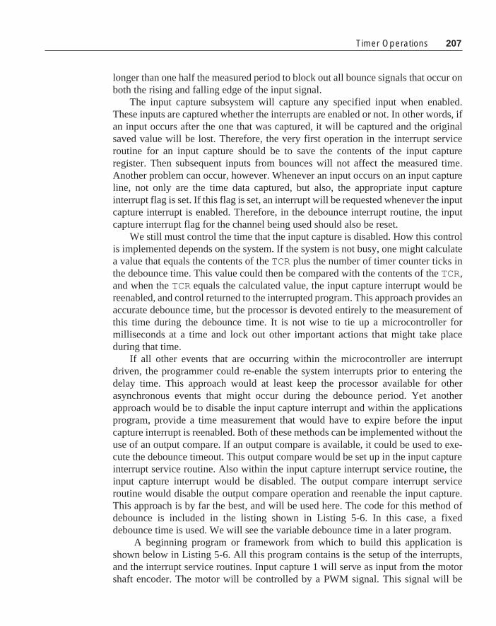
207
longer than one half the measured period to block out all bounce signals that occur onboth the rising and falling edge of the input signal.
The input capture subsystem will capture any specified input when enabled.These inputs are captured whether the interrupts are enabled or not. In other words, ifan input occurs after the one that was captured, it will be captured and the originalsaved value will be lost. Therefore, the very first operation in the interrupt serviceroutine for an input capture should be to save the contents of the input captureregister. Then subsequent inputs from bounces will not affect the measured time.Another problem can occur, however. Whenever an input occurs on an input captureline, not only are the time data captured, but also, the appropriate input captureinterrupt flag is set. If this flag is set, an interrupt will be requested whenever the inputcapture interrupt is enabled. Therefore, in the debounce interrupt routine, the inputcapture interrupt flag for the channel being used should also be reset.
We still must control the time that the input capture is disabled. How this controlis implemented depends on the system. If the system is not busy, one might calculatea value that equals the contents of the TCR plus the number of timer counter ticks inthe debounce time. This value could then be compared with the contents of the TCR,and when the TCR equals the calculated value, the input capture interrupt would bereenabled, and control returned to the interrupted program. This approach provides anaccurate debounce time, but the processor is devoted entirely to the measurement ofthis time during the debounce time. It is not wise to tie up a microcontroller formilliseconds at a time and lock out other important actions that might take placeduring that time.
If all other events that are occurring within the microcontroller are interruptdriven, the programmer could re-enable the system interrupts prior to entering thedelay time. This approach would at least keep the processor available for otherasynchronous events that might occur during the debounce period. Yet anotherapproach would be to disable the input capture interrupt and within the applicationsprogram, provide a time measurement that would have to expire before the inputcapture interrupt is reenabled. Both of these methods can be implemented without theuse of an output compare. If an output compare is available, it could be used to exe-cute the debounce timeout. This output compare would be set up in the input captureinterrupt service routine. Also within the input capture interrupt service routine, theinput capture interrupt would be disabled. The output compare interrupt serviceroutine would disable the output compare operation and reenable the input capture.This approach is by far the best, and will be used here. The code for this method ofdebounce is included in the listing shown in Listing 5-6. In this case, a fixeddebounce time is used. We will see the variable debounce time in a later program.
A beginning program or framework from which to build this application isshown below in Listing 5-6. All this program contains is the setup of the interrupts,and the interrupt service routines. Input capture 1 will serve as input from the motorshaft encoder. The motor will be controlled by a PWM signal. This signal will be
Timer Operations

208 Chapter 5 Programming Large 8-Bit Systems
filtered to provide a DC signal that can drive the motor. As with the MC68HC05programs, this code is broken into three basic parts: 1) the initialization section, 2) theapplications section, and 3) the asynchronous service section. In this case, there is noapplications section, so it is designated by a FOREVER command followed by anempty block.
The program begins with the inclusion of the HC11E9.H header file. Immedi-ately following this entry are the prototype entries for all of the interrupt serviceroutines. The declarations of the global variables follows. The first set of variables areall associated with the input capture, and the second line of variables controls theoutput compare portion of the program.
Notice that the bit set-up instructions are all grouped so that the bits from eachregister are set in the same location. It is not necessary to group these instructions;however, if they are grouped by register as is done here, the compiler will use a singlebit manipulation instruction to set all of the bits in each register. The first 8-bitmanipulation instructions in the following code will require only six assembly in-structions as they are grouped.
#include "hc11e9.h"
@port void IC1_Isr(void);@port void OC2_Isr(void);@port void OC3_Isr(void);
WORD measured_period, time1, delpc;WORD PWM_period=0x1000, time_on=0x0800;
main(){
TCTL2.EDG1B=1; /* capture falling edge only */OC1M.OC1M7=1; /* sent OC1 tout to PA7 */OC1M.OC1M5=1; /* couple OC1 to OC3 */TMSK1.OC3I=1; /* enable the OC3 interrupt */TMSK1.IC1I=1; /* enable the IC1 interrupt */OC1D.OC1D5=1; /* turn on OC3 when OC1 occurs */TCTL1.OL3=1; /* toggle OC3 when OC3 occurs */PACTL.DDRA7=1; /* make OC1 an output to PA7 */TOC1=TCNT+PWM_period; /* set OC1 to the period */TOC3=TOC1+time_on; /* set OC3 time on */cli(); /* enable the system interrupts */
FOREVER{

209
/* put application code here */}
}
@port void IC1_Isr( void){
TFLG1=IC1F; /* reset IC1 interrupt flag */measured_period=TIC1-time1;time1=TIC1;TOC2=TCNT+1500; /* 3 ms debounce time */TMSK1.IC1I=0; /* disable IC1 interrupt */TMSK1.OC2I=1; /* enable OC2 interrupt */
}
@port void OC2_Isr(void){
TFLG1=IC1F|OC2F; /* reset IC1 & OC2 interrupt flag */TMSK1.OC2I=0; /* disable OC2 interrupt */TMSK1.IC1I=1; /* enable IC1 interrupt */
}
@port void OC3_Isr( void){
TFLG1=OC1F; /* reset OC1 interrupt flag */TOC1+=PWM_period;if(OC1D.OC1D7==1)
OC1D.OC1D7=0;else
OC1D.OC1D7=1;TFLG1=OC3F; /* reset OC3 interrupt flag */TOC3=TOC1+time_on;
}
Listing 5-6: Motor Control Program Framework
The interrupt service routine for IC1 resets the IC1F bit in the TFLG1 register.Then the elapsed time from the last input capture time is calculated. The result of thiscalculation is saved in period1 which is the current elapsed time required for themotor to rotate one revolution. At the end of this calculation, the contents of the inputcapture register is saved in time1 to be used as the old time in the next calculation.
The PWM output from OC3 will be used to drive motor 1 whose shaft sensor isfed into IC1 . The value in speed will be the desired speed of the motor in revolutions
Timer Operations

210 Chapter 5 Programming Large 8-Bit Systems
per minute. The range of this number will be 1000<=RPM<=10000, and it will haveto be put in place through a debugger for this test. This range of motor speed waschosen to satisfy the speed of a small DC motor used in the final system. Let us plan aservo type operation where the motor is driven by a feedback loop that is controlledby the speed error. Therefore, within the applications loop, there must be code tocheck and control the PWM signal to force the speed1 parameter to match theinput speed parameter.
The input speed is measured in RPM, and the values measured by themicrocontroller are all times. A question that should be considered is whether numberplaced in speed1 will actually be times or should this number be RPM. To calculatethe time, note that there is one interrupt per revolution of the shaft and one minute is60 seconds, so RPM/60 will be revolutions per second. What we need is the numberof bus cycles in the time corresponding to this period. With a prescaler count of four,the clocking speed of the TCNT register is one count every two microseconds, or500,000 counts per second. Therefore, the conversion from RPM to time for arevolution of the shaft in bus cycle counts is
500000 * 60 30000000Counts =__________ = __________
RPM RPM
At 3000 RPM, the count value will be 10000 while at 16000 RPM the count valuewill be 1875. These numeric values can be handled by the timer system in theMC68HC11.
The above expression can be used to calculate RPM from the count value as
30000000RPM = __________
Counts
Neither calculation is convenient in a microcontroller. The numerator is largerthan an int but smaller than a long. Both Counts and RPM have a range that can becontained in an int . One would expect that the conversion to time should be done onthe input speed. That way, the division would be done only once for each speedsetting. If the measured times were converted to RPM each time a time weremeasured, the computer program would be loaded with complicated divisions its realtime application portion. But let’s examine the nature of the error with the differenttypes of measures. Suppose the input RPM were converted to time and the measure-ments were based on time. Then the error signal, which is the difference between themeasured value and the desired value, would have a wrong sense. That is if the motoris moving too slowly then the error signal would be negative which would cause themotor to go even slower. If the calculation were done based on RPM and the motorwere going too slow, the error signal would be positive. In this case, the controlwould drive the motor faster which is the needed correction.
The difficulty with the time based system could be solved by using the negative
( )

211
value of the error signal for the feedback control. A simple analysis will show thepotential problem with this approach. Suppose that we work with two counts, Cd andC
m. Let us use the value K for the constant in the above equation. Therefore,
1 1e = C
d - C
m = K _____ – _____
RPMd
RPMm
The error signal is seen to be
RPMm - RPM
de = K _____________RPM
d * RPM
m
When the two speeds are nearly the same, this expression is very nearly propor-tional to the difference between the two speeds. However, when one of the speedsdeviates significantly from the other, it will cause the resultant error signal to be lesssensitive to difference than would be expected. Also, there is the problem that occursif the motor is stopped and the error signal in that case is undefined.
If the counts are converted to RPM prior to calculation of the error signal, thereduction of sensitivity for large errors would not be a problem. The problem thatoccurs when the motor is stopped still exists. In this case, no input capture wouldoccur when the motor is not rotating, and the count value would be undefined.
There seems to be no clear-cut reason to choose the time or the velocity measure-ment. Each has advantages and each has drawbacks. The drawbacks are about thesame for each, so we will choose the case that has the simplest program. Therefore,the time based or count based system will be used.
Now comes the interesting problem of the calculation of 3000000/RPM. Eachtime the desired speed of the motor is input to the system, this calculation must becompleted. The straightforward calculation of this value will yield code as follows:
#include "hc11e9.h"
WORD count(WORD RPM){
unsigned long num = 30000000;
return num/RPM;}
The listing file of the compiled version of this function is
1 ; Compilateur C pour MC68HC11 (COSMIC-France) 32 .include"macro.h11" 3 .list +
Timer Operations
( )

212 Chapter 5 Programming Large 8-Bit Systems
4 .psect _text 5 ; 1 #include "hc11e9.h" 6 .psect _data 7 _Register_Set: 8 0000 1000 .word 4096 9 ; 2 10 ; 3 WORD count(WORD RPM) 11 ; 4 { 12 .psect _text 13 _count: 14 0000 BD0000 jsr c_kents 15 0003 0C .byte 12 16 .set OFST=12 17 ; 5 unsigned long num = 120000000; 18 0004 CC0E00 ldd #3584 19 0007 ED0A std OFST-2,x 20 0009 CC0727 ldd #1831 21 000C ED08 std OFST-4,x 22 ; 6 23 ; 7 return num/RPM; 24 000E EC0C ldd OFST+0,x 25 0010 6F02 clr 2,x 26 0012 6F03 clr 3,x 27 0014 ED06 std OFST-6,x 28 0016 EC02 ldd 2,x 29 0018 ED04 std OFST-8,x 30 001A EC08 ldd OFST-4,x 31 001C ED02 std 2,x 32 001E EC00 ldd 0,x 33 0020 C3FFF7 addd #-9 34 0023 188F xgdy 35 0025 EC0A ldd OFST-2,x 36 0027 BD0000 jsr c_ludv 37 002A AE00 lds 0,x 38 002C 38 pulx 39 002D 39 rts 40 ; 8 } 41 ; 9 42 .public _count 43 .public _Register_Set 44 .external c_kents 45 .external c_ludv

213
46 .end
This function requires 0x2d bytes (45 bytes) of code and that does not countthe functions c_ludv and c_kents that must be linked to this function. Our innoc-uous little one-line piece of code creates a rather formidable piece of assembly code.If at all possible, it would be desirable to shorten this function.
A slight modification of the above function code is
#include "hc11e9.h"
WORD count(WORD RPM){
return 30000000lu/RPM;}
The compiled version of this program is
1 ; Compilateur C pour MC68HC11 (COSMIC-France) 32 .include"macro.h11" 3 .list + 4 .psect _text 5 ; 1 #include "hc11e9.h" 6 .psect _data 7 _Register_Set: 8 0000 1000 .word 4096 9 ; 2 10 ; 3 WORD count(WORD RPM) 11 ; 4 { 12 .psect _text 13 _count: 14 0000 BD0000 jsr c_kents 15 0003 08 .byte 8 16 .set OFST=8 17 ; 5 return 120000000lu/RPM; 18 0004 EC08 ldd OFST+0,x 19 0006 6F02 clr 2,x 20 0008 6F03 clr 3,x 21 000A ED06 std OFST-2,x 22 000C EC02 ldd 2,x 23 000E ED04 std OFST-4,x 24 0010 CC0727 ldd #1831 25 0013 ED02 std 2,x 26 0015 EC00 ldd 0,x
Timer Operations

214 Chapter 5 Programming Large 8-Bit Systems
27 0017 C3FFFB addd #-5 28 001A 188F xgdy 29 001C CC0E00 ldd #3584 30 001F BD0000 jsr c_ludv 31 0022 AE00 lds 0,x 32 0024 38 pulx 33 0025 39 rts 34 ; 6 } 35 ; 7 36 .public _count 37 .public _Register_Set 38 .external c_kents 39 .external c_ludv 40 .end
Note that this version differs from the first only in that the number 30000000 isnot created in a declaration, but rather is created in line when it is needed. Thisversion requires 37 bytes of code.
The purpose of this exercise is to demonstrate that there are usually manydifferent ways that any part of a program can be approached. If the programmer grabsthe first idea and plods through without any careful examination of the code beinggenerated by the compiler, the program will almost always suffer. The assemblylistings of programs should be examined, and where it seems as if the compiler iscreating clumsy code, a new approach should be considered. Writing C code for amicrocontroller is a joint exercise by the programmer and the compiler to create themost efficient overall program.
Let’s return to the problem: we wish to set the speed of a motor and themeasurable control signal is the time of a revolution. Most servo type devices work toposition an output. Ours must set a speed which is a different problem from most. Theinput will be an RPM which will be converted to a time. Our system must comparethe desired time with the measured time and correct the speed to make the two timesmatch. A signal to drive the motor will be generated based on the desired time, andthis signal will be adjusted by the error signal calculated as the difference between themeasured time and the desired time. The following psuedocode sequence will accom-plish the desired operation.
FOREVER{
doconvert to time;calculate the required PWM output count;

215
apply calculated time error to PWM count;read in the motor speed;
while ( motor speed does not change);}
For the moment, let us defer the problem of getting the desired motor speed. Thisvalue will be converted to time by use of the count() routine and will be saved inmotor_period . Next, we need to calculate the required motor voltage. For thiscalculation, let us revert to an expermental technique that can be used usefully. Anopen loop system was set up to test the operation of the motor system. Several inputvalues were entered, and the performance of the motor was recorded. The table belowshows the result of these measurements.
The data for the table above were gathered by the use of an M68HC11EVM anda simple motor driver. This driver is a demonstration board provided by Motorola toshow the use of the MC33033 pulse width motor driver and the MPM3002 FETmotor driver H bridge. A small DC motor with a speed range of 1000 to 11000 rpmwas mounted on the board, and the appropriate circuitry was added to interface theboard to the computer. This interface consisted of a simple RC integrator to receivethe PWM signal from the computer board and a circuit to measure the rotation of themotor. This latter circuit was quite crude. A magnetic reed switch was mounted nearthe motor shaft and a magnet cemented to the shaft. For each rotation of the shaft, thereed switch would close and open one time. A resistor was connected between the 12volts of the motor driver and one side of the switch; the other side of the switch was
PWM_Count PWM_count icap period period ms voltage RPM
Hex decimal counts
0x700 1792 15812 31.62 2.186 1897
0x780 1920 11405 22.81 2.341 2630
0x800 2048 8581 17.17 2.498 3494
0880 2176 6841 13.68 2.653 4385
0x900 2304 5616 11.23 2.809 5342
0x980 2432 4759 9.52 2.964 6304
0xa00 2560 4059 8.12 3.118 7391
0xa80 2688 3530 7.06 3.273 8499
0xb00 2816 3085 6.17 3.424 9724
0xb80 2944 2736 5.47 3.578 10965
Timer Operations

216 Chapter 5 Programming Large 8-Bit Systems
M6811C11EVM
OC1
OC3
IC1
PWM Output
Time-Input
33k
1µƒ
Pin g
33033
+5V
33k
8.2k.01
12V
Magnet Switch
MC33033 - MPM3002 Motor Drive
Figure 5-7: Schematic Diagram of Motor Driver Test Circuit.
grounded. Therefore, during each rotation the top side of the switch would jump from12 volts to 0 volts and back. This voltage is larger than the maximum input for themicrocontroller, so the 12 volt square wave was clamped to a maximum high valuewith a resistor and a diode connected to the +5 volt power supply of the EVM11board. The schematic diagram for this test setup is shown in Figure 5-7 and aphotograph of the complete system is shown in Figure 5-8.
Figure 5-8: Photograph OfAssembled Motor Driver Test Circuit.

217
The program used to obtain the data in the above table was a slight modificationof the motor control program listing given in Listing 5-6. The only change in thisprogram was that the function @port void IC1_Isr(void) from Listing 5-7was used. This routine stores in the location measured_period a value equal tothe average of the last eight measured periods.
For several reasons, a reed switch is probably the worst example of an inputsensor that you can find for a microcontroller. I chose this input because is thepoorest, and the result has been satisfactory. With reed switches, there is seriousdebounce on both the rising and falling edges of the signals. The life expectancy for areed switch is relatively small, about ten million closures. During the course ofpreparing this text, I broke one reed switch and had probably a total of several hoursof service out of the two used for these experiments. In practice, it is recommendedthat rotational measurements be made with optical interrupters. Do not, however,think that an optical interrupter is free from bounce problems. An optical interrupterwill exhibit both bounce and it can also have a relatively slow rise time. In such acase, it is necessary to use a software debounce techinque and also an externalSchmidt trigger circuit to create a quick and stable rise time that can be captured bythe microcontroller.
The data for the above table was measured on the circuit shown in Figure 5-7.It was found that the PWM to voltage conversion was very accurate and repeatablewith many changes in the system. For example, the prescaler value was changedfrom the value of 4 discussed above to 2 and up to 16. No difference could be notedin the PWM to voltage conversion over this range. Also, the input capture valueswere quite stable. The program in Figure 5-6 was compiled and used to complete themeasurements. The PWM_count value was changed manually over the range of valuesshown above. The value for icap period is the value found in measured_periodin the program. The voltage measured was the integrated value that was sent into theinput of the MC33033 motor driver. The RPM was calculated as
60000RPM = ____________
measured_period
Data from this table are used to create an equation that relates RPM to thePWM_count. This equation will be used in the program to close the loop and regu-late the motor speed. The relation that can be derived from the above data is
RPM + 12528PWM_count = ____________
7.875
This expression is accruate to about 1% across the range of interest. The mea-
Timer Operations

218 Chapter 5 Programming Large 8-Bit Systems
sured data is the input capture count which we will call p. What we must do is tocalculate a new value for the PWM_count from a measured p. An error in p is calledp and this expression means a change in p. The PWM_count will be designated aspc and also means a change in pc . We shall now attempt to arrive at an equation thatexpresses the necessary change in pc to correct for an error in p. The error in p is thedifference between the desired cycle time and the measured cycle time. RPM in theabove expression is converted to cycle time p by noting that the RPM is 60000 / shaftcycle time in milliseconds, and that the clock is ticking 500 times per millisecond.Therefore, we have
1 12528 +60000*500pc =
_____ _______________7.875 p
If there is a error in the cycle time say, ∆p, then the change in pc , ∆pc, is seen tobe
3809500p
c+∆ p
c = 1591 + ________
p+∆ p
This expression, after some simplification and approximation reduces to
∆ p∆ p
c = -3809500 ___ (5-1)
p2
This value calculated by the above expression will be used to change thePWM_count that drives the motor. The data contained in measured_periodare placed there by the input capture interrupt service routine. It is assumed that thedata there are always current.
The calculation to determine the PWM_count correction is substantial. We shalluse this approach here to determine the correction, but recognize that there is anotherapproach that probably requires less total calculation. This approach is to use a look-up table. We will see the look-up table in some detail in Chapter 6.
We will probably run into overflow problems if care is not exercised in thecalculation of the correction ∆p
c. In Equation 5-1 above, p is the time of a shaft
rotation in milliseconds. This number can vary from 1000 to 20000 depending on themotor speed. The best approach we could use is to divide the constant -3809500 bythe value of p. Then multiply the the result by ∆p and finally divide the result by p asecond time. This approach will minimize the overflow problems. In the expressionbelow, p is the measured_period , pc is the PWM_count , and ∆p is the calcu-lated difference motor_period - measured_period .
FOREVER{
( )

219
if(old_motor_speed!=motor_speed){
motor_period=30000000lu/motor_speed;old_motor_speed=motor_speed;PWM_count= ((motor_speed+12528)/63)*8;PWM_count=limit(PWM_count);delpc=(3809500/motor_period);delpc=delpc*(motor_period-measured_period)/p;PWM_count -= delpc;/* read in the motor speed; */
}}
Recall that division by 7.875 is needed in the calculation of PWM_Count. Thisfloating point operation is avoided by multiplying the expression by 63/8. Most often,floating point operations can be approximated by integer operations with sufficientaccuracy.
It was mentioned earlier that it is possible to extend the maximum measurabletime to something greater than the time required to clock the timer counter register65535 times. If the longest time exceeds this value, the timer overflow interrupt canbe used to an advantage. Suppose that you want to measure a long time with inputcapture 1. When this measurement is started, the value in the TCNT will be saved,and the timer overflow interrupt will be enabled. Also a counter will be reset to zero.In the timer overflow interrupt service routine, the counter will be incremented.Eventually, an input capture will occur, and the time between inputs is calculated asthe time remaining prior to the first TOI , plus 65535 times the number of TOI s thathave occurred, plus the time indicated in the input capture register. With a scheme ofthis nature, there is essentially no limit to the length of time that can be measuredaccurately. The resolution of this measurement is the time increment of the prescaleroutput.
A velocity servo is a particularly difficult application. Remember that velocity ormotor speed is the derivative of position. Any derivative operation is prone to noise,and the successful servo must be carefully put together. For example, the equationcalculated above to determine the feedback term is essential to the proper operation ofthe system. An interesting challange is to try to duplicate the operation of the systemdescribed here with a normal gain type feedback. Even though the the program seemsto be messy, this approach will work, and most other approaches give you a wildlyhunting or oscillating system. The calculation of the proper feedback value will avoidmany of these problems.
Another problem area will be found. If the above FOREVER loop is allowed torun without any time control, the coumpter will be calculating a new feedback valuemany times before the effect of an earlier calculation will be seen in the system
Timer Operations

220 Chapter 5 Programming Large 8-Bit Systems
performance. This operation again causes the system to become unstable, and usuallythe system never finds the final value but hunts over some wide range around it. Thisoperation can be corrected by slowing the rate at which feedback corrections arecalculated. In particular, several rates have been tested, and it was found that a stable,accurate system would be obtained with a new feedback value calculated each quarterof a second. This time control is shown in the listing below. The main applicationprogram is broken into two parts: the first part is the code that will be executedwhenever the motor speed is changed and the second part is the code that will alter thePWM_count which is the feedback portion of the program. The first portion isexecuted under the control of an if statement
if(old_motor_speed!=motor_speed)
There is no means to change the motor speed in this program, and this change willbe introduced in the next section. Therefore, it is expected that the portion of the codecontrolled by this if statement will execute the first time the program is executed, andit should never be executed again until the system is reset. The second if statement
if(tick)
will execute its control code each time tick is TRUE. tick is initialized to TRUEwhen it is created, and it is set to FALSE each time the if (tick) routine isentered in the application program. If you go to the end of Listing 5-7, you will findthat tick is reset to TRUE about each quarter of a second in the PWM timerroutine. This sequence will cause the feedback calculation to be executed about eachquarter of a second.
The initialization portion of the program shown in Listing 5-7 is little changedfrom that of the one shown in Listing 5-6. As mentioned above, we have added anapplication section that contains the calculations to control the motor speed. Also,there is one simple function that is used by the application section.
#include "hc11e9.h"
@port void IC1_Isr(void);@port void OC2_Isr(void);@port void OC3_Isr(void);long limit (long);
long measured_period,delpc;WORD time1,time2, motor_period, motor_speed=3500;WORD old_motor_speed=100,rpm,mparray[8];long PWM_period=0x1000, PWM_count=0x0800;int tick=TRUE,count=0;

221
main(){ /* The initialization portion of the program */
TCTL2.EDG1B=1; /* capture falling edge only */OC1M.OC1M7=1; /* sent OC1 out to PA7 */OC1M.OC1M5=1; /* couple OC1 to OC3 */TMSK1.OC3I=1; /* enable the OC3 interrupt */TMSK1.IC1I=1; /* enable the IC1 interrupt */OC1D.OC1D5=1; /* turn on OC3 with OC1 */TCTL1.OL3=1; /* toggle OC3 when OC3 occurs */PACTL.DDRA7=1; /* make OC1 an output to PA7 */TOC1=TCNT+PWM_period; /* set OC1 */TOC3=TOC1+PWM_count; /* set OC3 time on */cli(); /* enable the system interrupts */
/* the applications portion of the program */
FOREVER{
if(old_motor_speed!=motor_speed){
motor_period=30000000lu/motor_speed;old_motor_speed=motor_speed;PWM_count= ((motor_speed+12528)/63)*8;PWM_count=limit(PWM_count);
}if(tick)
{tick=FALSE;delpc=(3809500lu/motor_period);delpc=delpc*(motor_period-measured_period)/motor_period;PWM_count -=delpc;PWM_count=limit(PWM_count);rpm=30000000L/measured_period;
} /* input the new motor speed */
}}
Timer Operations

222 Chapter 5 Programming Large 8-Bit Systems
/* functions of the main program */
/* range of acceptable PWM_count is 1600 to 3300 */
long limit(long x){
if(x<1600)return 1600;else if(x>3300)return 3300;elsereturn x;
}
/* The asynchronous service portion of the program */
@port void IC1_Isr( void) /*the motor speedmeasurment*/{
static int i;int j;
time2=TIC1;TFLG1=IC1F; /* reset IC1 interrupt flag */mparray[i]=time2-time1;if (++i==8){
i=0;measured_period=0;for(j=0;j<8;j++)
measured_period += mparray[j];measured_period >>= 3;
}time1=time2;TOC2=time2+5*measured_period/8; /* debounce time */TMSK1.IC1I=0; /* disable IC1 interrupt */TMSK1.OC2I=1; /* enable OC2 interrupt */
}
@port void OC2_Isr(void) /* the debounce isr */{
TFLG1=IC1F|OC2F; /* reset interrupt flags */

223
TMSK1.OC2I=0; /* disable OC2 interrupt */TMSK1.IC1I=1; /* enable IC1 interrupt */
}
@port void OC3_Isr( void) /* the PWM isr */{
TFLG1=OC1F; /* reset OC1 interrupt flag */TOC1+=PWM_period;if(OC1D.OC1D7==1)
OC1D.OC1D7=0;else
OC1D.OC1D7=1;TFLG1=OC3F; /* reset OC3 interrupt flag */TOC3=TOC1+PWM_count;if(++count==32{
count=0; /* enter the speed control */tick = TRUE; /* about each quarter of
of a second */
}}
Listing 5-7: Motor Control Program
In this program, dynamic debounce is used. In the function IC1_Isr() thedebounce time is a calculated value rather than a mere 3 ms as was done in Listing 5-6. Here the debounce lock-out time is five-eighths of the current measured period.This value goes beyond the half-way point in the input waveform enough to avoidany bounce that will occur during the rise time of the input signal. The remainder ofthis program is quite similar to that in Listing 5-6.
We have completed most of the application. The remaining parts of the programare to find a means to read into the microcontroller the speed that is desired for themotor, and to integrate and debug the whole program. Usually, the speed is estab-lished by some measurement being done with the microcontroller. Let us approachthe problem a little differently. Instead of making the speed a result of a measure-ment, let’s enter the speed into the part through the asynchronous serial port.
Serial Communications Interface (SCI)The SCI is another of the very useful peripheral functions found on the MC68HC11
family of microcontrollers. In fact, the SCI is found on parts from all families of
Timer Operations

224 Chapter 5 Programming Large 8-Bit Systems
Motorola microcontrollers. The SCI performs the operation of a full function univer-sal asynchronous receiver transmitter (UART). It can operate with most standardbaud rates, and several non standard rates. Control of this peripheral is through theBAUD register, the SCSR (serial communications status register), and both SCCR1and SCCR2 (serial communications control registers 1 and 2). There is one additionalregister called the serial communications data register. This register when written tois the transmit data register, and when read the receiver data register. Both thetransmit and receive data registers are double buffered.
The BAUD register contains two test bits and two divide control registers that setthe baud rate for the SCI system. The bits SCP1 and SCP0 control the baud rateprescaler. This prescaler has the unlikely prescale value of divide-by-13 when bothbits are set. This value sets the maximum baud rate to 9600 when the system is drivenby an 8 MHz clock. With this prescaler value, all of the standard baud rates from 9600down to 150 are available to the SCI. The second divider is comprised of SCR2,SCR1, and SCR0. The bit patterns in these bits will select any power of two divisorbetween 1—20—and 128—27. For our system, we will choose 9600 baud which issufficiently slow that there should be few communications problems. The code to setup this baud rate is as follows:
BAUD.SCP1=1;BAUD.SCP0=1;BAUD.SCR2=0;BAUD.SDR2=0;BAUD.SCR0=0;
These lines of code must be added to the initialization portion of the program toset up the baud rate to 9600 baud for the SCI system.
We will use the SCI system to read in the required motor speed for the programstarted in the preceeding section. Such a system must be able to read in data throughthe SCI, but it must also echo the same data back to the originating source to providefull duplex operation. Therefore, both serial transmitt and receive must be imple-mented. With the above system, there is no serious need to implement an interruptdriven system. The computer is clearly not being used to its capacity, so we will addthe SCI input and output sequence to the applications portion of the code and feel safethat no input data will ever be lost because of an overrun error. (An overrun erroroccurs when a new input overwrites an old input before the old input is processed.)Therefore, none of the bits in SCCR1 need be changed from their reset value. In theSCCR2 register, there are two bits, transmit enable and receive enable, that must beset to enable the SCI. The following two lines of code will enable these bits.
SCCR2.TE=1;SCCR2.RE=1;
These two lines of code must also be added to the initialization portion of theprogram.

225
The code to read the data in is as follows:
if (SCCR.RDRF==1) /* read in data if it is there */{
new_character=SCDR; /* get new byte and reset RDRF */while(SCCR.TDRE==0); /* wait until transmit buffer empty */SCDR=new_character; /* send out byte and reset TDRE */
}
This sequence of code does quite a bit more than you might expect. Before thiscode sequence can be executed, both the RDRF and TDRE flags must be set and reset.The RDRF is set when a character has been received by the SCI, and the TDRE isset when the SCDR is empty and can receive a character to send. Both of these bits arereset by the sequential read of SCSR with the bit set followed by a read for the RDRFor a write for the TDRE to the SCDR register. The above sequence accomplishes all ofthe proper bit resets, transmits the newly received character back to the sender, andleaves the new character in the location new_character . After receiving the data,the following sequence converts it into a binary number to be processed by theremainder of the program.
if (SCSR.RDRF==1) /* read in data if it is there */{
new_character=SCDR; /* get new byte and reset RDRF */while(SCSR.TDRE==0); /* wait until transmit buffer empty */SCDR=new_character; /* send out byte and reset TDRE *//* got a number, process it */if(new_character>='0' && new_character <='9')
new_speed = 10*new_speed + new_character-'0';else if(new_character=='\r'){/* reject any number out of range *//* and start over again */
if(new_speed>=1000 && new_speed<=10000)motor_speed=new_speed;
new_speed=0;}else
new_speed=0; /* reject everything else */}
The variable new_speed is initialized to 0 outside of this portion of theprogram. If the input character is a number ( a number is any character that lies
Timer Operations

226 Chapter 5 Programming Large 8-Bit Systems
between ‘0’ and ‘9’), it is converted from a character to a number when the character‘0’ is subtracted from it. This value is added to ten times the value stored innew_speed , and the result is saved in new_speed . Repeated executions of thiscode sequence will convert a series of ASCII character numbers to an appropriateunsigned integer value. The entry sequence is terminated when a nonnumbercharacter is received. If this character is a line terminator (a carriage return escapecharacter in this case), the new speed value is put into motor_speed to cause themotor to change to the new value, and new_speed is reset to zero to await for thenext input. If any other character is recieved, the data saved in new_speed is lost,and the whole entry of a new speed into the system must be repeated from thebeginning.
In Listing 5-7 there was a lonely line of code
/* input the new motor speed */
That line has been repalced by the above and entered into Listing 5-8. The newmotor speed input is placed in the main loop of the applications program, so a test ismade each time through the loop to determine if there is a new input from the serialport. This routine also sends out the current speed of the motor once each halfsecond. This output is controlled by the parameters tick1 and in_process.tick1 is set to TRUE each half second, and if in_process is FALSE the motorspeed is calculated and sent to the serial port output. This sequence repeats each halfsecond until in_process is set to TRUE. Whenever a character is read in throughthe serial port, in_process is set to TRUE to disable the continual output from thesystem while a new input speed value is being entered. If there is a new character inthe input buffer, this character is read in and the RDRF flag is reset. The new characteris immediately echoed back to the sending device as part of full duplex operation. Ifthe new character is a numeral it is processed, if it is a line feed it is also processed,and any number string is converted to an integer so that it can be used by thecomputer. The size of the number is tested to be certain that it is within the acceptablespeed limits for the motor, and if it passes all of the tests, it is placed in the variablelocation motor_speed to indicate that a new motor speed is here and should beprocessed.
#include "hc11e9.h"
@port void IC1_Isr(void);@port void OC2_Isr(void);@port void OC3_Isr(void);int putchar(char new_character);void dprint (int c);void do_crlf(void);long limit(long );

227
long measured_period,delpc;WORD time1,time2, motor_period,motor_speed=3500;WORD new_speed;WORD old_motor_speed=100,rpm,mparray[8];long PWM_period=0x1000, PWM_count=0x0800;int new_character,tick=TRUE,count=0,in_process;int tick1=TRUE,count1=0;WORD got_new=TRUE;
main(){ /* The initialization portion of the program */
TCTL2.EDG1B=1; /* capture falling edge only */OC1M.OC1M7=1; /* sent OC1 out to PA7 */OC1M.OC1M5=1; /* couple OC1 to OC3 */TMSK1.OC3I=1; /* enable the OC3 interrupt */TMSK1.IC1I=1; /* enable the IC1 interrupt */OC1D.OC1D5=1; /* turn on OC3 when OC1 occurs */TCTL1.OL3=1; /* toggle OC3 when OC3 occurs */PACTL.DDRA7=1; /* make OC1 an output to PA7 */TOC1=TCNT+PWM_period; /* set OC1 to the period*/TOC3=TOC1+PWM_count; /* set OC3 time on */
BAUD.SCP1=1; /* set up the SCI */BAUD.SCP0=1; /* 9600 baud */BAUD.SCR2=0;BAUD.SCR1=0;BAUD.SCR0=0;SCCR2.TE=1;SCCR2.RE=1;
cli(); /* enable the system interrupts */
/* the applications portion of the program */
FOREVER{
if(old_motor_speed!=motor_speed){
motor_period=30000000lu/motor_speed;old_motor_speed=motor_speed;
Timer Operations

228 Chapter 5 Programming Large 8-Bit Systems
PWM_count= ((motor_speed+12528)/63)*8;PWM_count=limit(PWM_count);
}if(tick){
tick=FALSE;delpc=(3809500lu/motor_period);delpc=delpc*(motor_period-measured_period)/motor_period;PWM_count -=delpc;PWM_count=limit(PWM_count);rpm=30000000L/measured_period;
}/* input the new motor speed */
/* Send out the measured RPM to the terminal periodically */if(tick1&&!in_process){tick1=FALSE;rpm=30000000L/measured_period;dprint(rpm);do_crlf();}
if (SCSR.RDRF==1) /* read in data if it is there */{
in_process=TRUE;new_character=SCDR; /* get new byte and reset RDRF */while(SCSR.TDRE==0); /* wait until transmit buffer empty
*/SCDR=new_character; /* send out byte and reset TDRE *//* got a number, process it */if(new_character>='0' && new_character <='9')
new_speed = 10*new_speed + new_character-'0';else if(new_character=='\r'){
do_crlf();/* reject any number out of range *//* and start over again */if(new_speed>=1000 && new_speed<=11000){
got_new=TRUE;in_process=FALSE;

229
motor_speed=new_speed;new_speed=0;
}}
elsenew_speed=0; /* reject everything else */
}}
}
/* functions of the main program *//* the range of acceptable PWM_count is 1600 to 3300 */
long limit(long x){
if(x<1600)return 1600;else if(x>3300)return 3300;elsereturn x;
}
/* send out a single carriage return-line feed sequence */
void do_crlf(void){
while(SCSR.TDRE==0);SCDR=0x0d;while(SCSR.TDRE==0);SCDR=0x0a;
}
/* send a single character to the serial port */
int putchar(char new_character){
while(SCSR.TDRE==0); /* wait until transmit buffer empty */SCDR=new_character; /* send out byte and reset TDRE */
}
/* convert an integer and send it to the serial port as a string
Timer Operations

230 Chapter 5 Programming Large 8-Bit Systems
*/
void dprint (int c){
if(c<0){
putchar('-');c=-c;
}if ( c/10) /* recursively determines if */
dprint(c/10); /* a zero has been reached and then */putchar(c%10+'0'); /* sends out the characters */
}
/* The asynchronous service portion of the program */
@port void IC1_Isr( void)/*the motor speed measurment*/{
static int i;int j;time2=TIC1;TFLG1=IC1F; /* reset IC1 interrupt flag */mparray[i]=time2-time1;if (++i==8){
i=0;measured_period=0;for(j=0;j<8;j++)
measured_period += mparray[j];measured_period >>= 3;
}time1=time2;TOC2=time2+5*measured_period/8; /* debounce time */TMSK1.IC1I=0; /* disable IC1 interrupt */TMSK1.OC2I=1; /* enable OC2 interrupt */
}
@port void OC2_Isr(void) /* the debounce isr */{
TFLG1=IC1F|OC2F; /* reset interrupt flags */TMSK1.OC2I=0; /* disable OC2 interrupt */TMSK1.IC1I=1; /* enable IC1 interrupt */

231
}
@port void OC3_Isr( void) /* the PWM isr */{
TFLG1=OC1F; /* reset OC1 interrupt flag */TOC1+=PWM_period;
if(OC1D.OC1D7==1)OC1D.OC1D7=0;
elseOC1D.OC1D7=1;
TFLG1=OC3F; /* reset OC3 interrupt flag */TOC3=TOC1+PWM_count;if(++count>=32){
count=0; /*enter speed control about */tick=TRUE; /*each quarter of a second */
}if(++count1==128){count1=0;
tick1=TRUE;}
}
Listing 5-8: The Completed Application
There are three input/output routines that have been written for this program.These routines, putchar() , dprint() , and do_crlf() , can be used with othersystems with a serial input/output system. The Intermetrics compiler does provide theusual I/O routines like printf() , gets() , puts() , etc. It does not provide abasic putchar() and getchar() which is used by all of these library routines.The reason that these routines are not provided by the compiler is the wide variety ofwhat the programmer will want to implement with the built-in SCI ports on theMC68HC11 family. The putchar() shown above will work in most instances. Thedprint() routine is a recursive routine that converts an integer into an ASCIIstring and sends it to the SCI port.
There is one final modification to the program. In the last lines of the PWM timerroutine, count1 and tick1 are processed to set tick 1 to be TRUE eachsecond. This flag is then used to control the writing of the motor speeds to theterminal screen.
Summary

232 Chapter 5 Programming Large 8-Bit Systems
SummaryThere has been no attempt to work all of the peripherals on the MC68HC11. The
various peripherals are similar to those on the other parts that we have discussed inother chapters or will discuss later. We have seen several timer applications both inthe MC68HC11 and in the MC68HC05. We will see other timer applications in thefollowing chapters.
We have seen detailed use of the output compare timer subsystem to make apulse width modulation digital-to-analog converter system. Depending on the pro-gram, the system allowed excellent performance in either short on times or maximumon times, but not both without the addition of a significant amount of code. We willsee a system in the next chapter that provides excellent performance for both mini-mum and maximum on times. This performance is not a limitation of the MC68HC11,merely a limitation of the programs presented so far.
The input capture subsystem has been used to measure motor speed in a simpleDC motor controller. This system used a primitive reed switch to measure the rotationof the motor shaft, and the performance of the switch was poor. A debouncing systemwas developed that prevented input captures to occur for a specified time after thefirst input was detected. This approach uses an output compare channel, but it doesnot tie up the microcontroller to wait out any delay times during the debounce period.
This program is not too removed from many of those encountered in the realworld. The organization of the program is similar to how most applications can beprogrammed, and the way in which the program was developed showed how mostproblems should be approached. The problem was broken down into a set of smalloperations that could each be handled easily. These different parts of the programwere developed, tested, and debugged separately. This approach keeps the develop-ment of the individual parts of the program manageable, and debugging is not toodifficult. if the whole program were written and then debugging started, it would havebeen nearly impossible to separate out the effects of one part of the program on theothers. The main interrupt service routines were written first and tested as well aspossible by themselves. With these important functions behind us, it was easy toattack the applications portion of the program in which the closed loop system wasimplemented along with the management of the input/output through the serial portof the device.
The MC68HC11 is a large enough computer that it is possible to make an ANSIcompliant compiler. Parameters can be passed to functions on the stack, and re-entrant or recursive functions can be written for this part as was demonstrated withthe dprint() function. Remember, it is the microcontroller that limited the ANSIcompliance with the MC68HC05—not the compiler.

233
Chapter 6
Large MicrocontrollersIn this chapter we will examine the programming of systems employing large
microcontrollers. The realm of the large microcontroller system is not all that dif-ferent from the 8-bit systems. One of the main advantages of the use of a high levellanguage is that it keeps the nasty details of the underlying computer hidden from theprogrammer. Usually, the programmer will not see much difference between the codefor different types of computers. The fallacy to this idea is that when programmingany microcontroller, the programmer must know about and use all of the on-boardperipherals found on the microcontroller. These peripherals will vary from machineto machine, and how they are accessed will differ from device to device.
The part that we will use for the 16-bit discussions is the Motorola MC68HC16family of components. These are similar to the MC68HC11 in many ways, but thereare important differences. First, there are some new registers that must be pro-grammed directly to make the MC68HC16 work as desired. (The only register in theMC68HC11 that must receive special assembly instructions is the condition coderegister.) Also, the MC68HC16 does not have automatic stacking of its registerswhen an exception occurs, unlike the MC68HC11. Therefore, all interrupt serviceroutines must begin with code that will save the status of the machine before thenormal interrupt operations can proceed. We will see a few other differences betweenthese devices, but the main difference is in the way peripherals are handled.
On the MC68HC16, the core processor is called the CPU16. This central com-puter is interfaced to an internal bus called the inter-modual bus (IMB). The IMB isvery much like the bus a hardware designer would put onto an external circuit board.It has address and data busses and all of the necessary control signals to control anyperipheral that the microcontroller might have applied. In the standard device, theMC68HC16Z1, there are five built-in peripherals: the system interface module (SIM),the analog-to-digital converter (ADC), the queued serial peripheral interface module(QSPI), the general purpose timer module (GPT), and the static random accessmemory module (SRAM). These modules can be added to or deleted in future com-ponents and the customer needs dictate.
The several internal peripheral modules are each interfaced to the IMB. Eachmodule has a specific set of registers that are located at an address relative to the baseaddress of the module. These base addresses are set at design time. This is interestingbecause the same modules are used on the MC68300 series of microcontrollers,
233

234 Chapter 6 Large Microcontrollers
which are 32-bit microcontrollers. Therefore, the material presented in this chapter isdirectly applicable to the MC68300 series of microcontrollers. The only differencethat the programmer will see is that the base memory locations of the variousperipheral modules will be different, but even these differences disappear because ofthe careful design of the microcontrollers. We therefore can consider this chapter tobe on large microcontrollers rather than on the 16-bit systems alone.
In Appendix E you will find descriptions of the five internal modules discussedabove. Associated with each module description is a listing of an appropriate headerfile that will be needed to access the peripherals from a C program.
The MC68HC16The MC68HC16 is a truly complicated device. However, for our purposes, it can
be divided into its several components, and each component is somewhat as onewould expect from a programming standpoint. Therefore, we will examine thisfamily of parts as a collection of modules. Each module is rather straightforward. Thecore processor, which is known as the CPU16, is indeed a complete and competentmicrocomputer. The bulk of its complexity is hidden by the fact that the program iswritten in C. This section contains a brief description of the MC68HC16Z1microcontroller that can be used to aid in writing programs for the component in C.
There are several Motorola manuals that are useful adjuncts to this chapter.1 2 3 4 5 6
It is recommended that these manuals be reviewed prior to any attempt to write codefor this family.
CPU16 Core ProcessorThe CPU16 represents an attempt to bridge the difference between the large 8-bit
microcontrollers and the high end components embodied in the MC68300 family.This processor is a 16-bit processor. As such, the its instructions are each 16-bitswide, instructions are read from memory 16 bits at time, and the instructions are pro-cessed 16 bits at a time. On this particular part, a 20-bit address bus with additionalcontrol will allow the program to access two individual one megabyte address maps.The controls available distinguish between program memory and data memory.
It has been stated several times that the programmer’s model for a microcontrolleris not too important when writing code in C. To be able to access all of the features of aCPU16, you will have to use assembly language based functions. There are certain fea-__________________________________________________
1 M68HC16 Family MC68HC16Z1 Users Manual MC68HC16Z1UM/AD2 M68HC16 Family CPU16 Central Processor Unit Reference Manual CPU16RM/AD3 Modular Microcontroller Family GPT General Purpose Timer Reference Manual GPTRM/AD4 Modular Microcontroller Family ADC Analog-to-Digital Converter Reference Manual ADCRM/AD5 Modular Microcontroller Family QSM Queued Serial Module Reference Manual QSMRM/AD6 Modular Microcontroller Family SIM System Integration Module Reference Manual SIMRM/AD

235
tures that are simply outside of the concept of a high level language. In these cases, itis recommended that functions which access and control these features be written andthen you can call these functions from the C program. The main properties of theCPU16 that are not available to the C programmer are the DSP type registers found inthe part. Programming of these registers is the subject of a later section of this chapter.
The 20-bit address space of the CPU16 is a significant deviation from the normal16-bit address space of the MC68HC11. This change has been handled by theaddition of several 4-bit extension registers for those registers that deal specificallywith addresses. These registers are the program counter (PC), the stack pointer (SP),the three index registers (IX, IY, and IZ), and the EK register. All these registersexcept for the EK are 16-bits wide. The EK register is an extension register that isused with the extended addressing mode. Any extended address calculation willresult in a 16-bit number. The result will be concateanted with the EK register tocreate a 20-bit address. (The EK register has nothing to do with the E accumulatorfound in the device.) The extension registers are named PK, SK, XK, etc. The exten-sion registers are usually set during initialization of the device, and there is no need toever change them during program operation. The content of an extension register is apage pointer. The pages in this case are each 65536 bytes long. Transition from onepage to another is automatic. For example, if an address is calculated for a jmp whichwill pass program control to code in another page, the proper address will be calcu-lated for both base and extension register automatically. The calculation will alterthe contents of both the base and the extension register without programmer concern.
The MC68HC16 family currently has the several internal modules mentionedabove, and it is planned that future versions of the part will have more modules. Thiscomplexity has suggested that the arrangement of the header file for the part bebroken into several different files: One file for the main processor, and severaldifferent header files, one for each of the peripheral modules in the individual part.This approach is shown in Appendix F. There you will find a header file namedhc16.h along with files named adc.h , gpt.h , sim.h , sram.h , and qsm.h .When writing code for any specific module, you should include the hc16.h filealong with the proper files for the peripheral portions needed.
One major difference between the large and small devices is the way the excep-tion vector table is handled. Recall that in the MC68HC11 family all interrupt vectorsare placed at the top of memory. With the MC68HC16 family, the vector table iscontained within the first 512 bytes of memory. Upon reset, the CPU16 core proces-sor reads the first four words of memory where it must find certain data for theoperation of the program. The address 0 must contain a word whose least significanttwelve bits are the contents of the ZK, the SK and the PK registers when the partcomes out of reset. The address 2 contains the initial program counter, and theaddress 4 must contain the initial stack pointer. Finally the address 6 must contain theinitial value of the IZ register. Note that the word addresses in the MC68HC16 arealways even. In this machine you will find words on even boundaries, bytes anywhere,
The MC68HC16

236 Chapter 6 Large Microcontrollers
and long words on even boundaries. These data are loaded into this memory area bythe use of a vector routine similar to that seen in Chapter 5 for the MC68HC11. Withthis approach, all of the registers needed to begin operation of the basic computer areloaded from memory at reset time. Of course, this operation does not eliminate theneed for program initialization; it merely provides a mechanism by which the proces-sor will start accessing memory at the correct addresses when the device comes out ofreset.
Table 6-1 contains a listing of the uses of each entry in the vector table. Note thatvectors 0x0 through 0x37 have assigned functions. The vectors 0x38 through0xff are available for user defined operations. Note the relationship between thevector number and the vector address. The vector address is always twice the vectornumber. When programming the interrupt vectors in the several peripheral modulesof the MC68HC16, the programmer will select the interrupt vector. When it comestime to place the interrupt service routine address in the proper memory location, it isto the vector address—NOT the vector number—that this value must be assigned.
Vector Vector Address Type of ExceptionNumber
0 0x0000 Reset—Initial ZK, SK, PK0x0002 Reset—Initial PC0X0004 Reset—Initial SP0X0006 Reset—Initial IZ
4 0X0008 Breakpoint5 0X000A Bus Error6 0X000C Software Interrupt7 0X000E Illegal Instruction8 0X0010 Division by Zero
9-E 0X0012-0X001C Unassigned, ReservedF 0X001E Uninitialized Interrupt10 0X0020 Level 0 Autovector11 0X0022 Level 1 Autovector12 0X0024 Level 2 Autovector13 0X0026 Level 3 Autovector14 0X0028 Level 4 Autovector15 0X002A Level 5 Autovector16 0X002C Level 6 Autovector17 0X002E Level 7 Autovector18 0X0030 Spurious Interrupt
19-37 0X0032-0X006E Unassigned, Reserved38-FF 0X0070-0X1FE User-defined Interrupts
Table 6-1: Exception Vector Table

237
When setting up the vector table, a wise programmer will fill all of the possibleunused vector addresses with the address of a dummy function that will provide anorderly return to the program in the event of an unexpected interrupt. Usually the first0x18 or 24 vectors should be filled with this address. An example function that canbe used for this type of operation is
static @port void _init_vector(void){ }
This program will compile to a single RTI (return from interrupt) which willreturn the program control to the location when the interrupt occurred. A staticfunction is not used often. When a function is declared static , it can be seen onlyin the file in which it is defined.
Following is a listing of the routine vector.c. This program is modeledclosely after that provided with the Intermetrics MC68HC16 C compiler.
extern @far @port void _stext(void); /* startup routine */extern @port void OC3_Isr(void); /* ISR address */static @port void _init_vector(void);
static const struct reset { @far @port void (*rst)(void); /* reset + code exten-sion */ unsigned short isp; /* initial stack pointer */ unsigned short dpp; /* direct page pointer */ @port void (*vector[252])(void); /* interrupt vectors */ } _reset = {
_stext, /* 1-start address */0x03fe, /* 2-stack pointer */0x0000, /* 3-page pointer */_init_vector, /* 4-Breakpoint */_init_vector, /* 5-Bus Error */_init_vector, /* 6-Software Interrupt */_init_vector, /* 7-Illegal Instruction */_init_vector, /* 8-Divide by Zero */_init_vector, /* 9-Reserved */_init_vector, /* a-Reserved */_init_vector, /* b-Reserved */_init_vector, /* c-Reserved */_init_vector, /* d-Reserved */_init_vector, /* e-Reserved */_init_vector, /* f-Uninitialized Interrupt */_init_vector, /* 10-Reserved */
The MC68HC16

238 Chapter 6 Large Microcontrollers
_init_vector, /* 11-Level 1 Interrupt Autovector */_init_vector, /* 12-Level 2 Interrupt Autovector */_init_vector, /* 13-Level 3 Interrupt Autovector */_init_vector, /* 14-Level 4 Interrupt Autovector */_init_vector, /* 15-Level 5 Interrupt Autovector */_init_vector, /* 16-Level 6 Interrupt Autovector */_init_vector, /* 17-Level 7 Interrupt Autovector */_init_vector, /* 18-Spurious Interrupt */
/* vectors 0x19-0x37 unassigned, reserved */ 0,0,0,0,0,0,0, 0,0,0,0,0,0,0,0,0,0,0,0,0,0,0,0, 0,0,0,0,0,0,0,0,0,0,0,0,0,0,0,0, /* put timer at vector 0x46 0x40 from ICR and 6 for OC3 */ 0,0,0,0,0,0,OC3_Isr /* OC3_Isr vector at 0x46 address 0x8c*/ };
static @port void _init_vector(void){ }
Listing 6-1: The Vector Initialization Routine vector.c
We have already seen the @port command in Chapter 5. The @far command isunique to the Intermetrics compiler. This command notifies the compiler that thepointer associated with the command is not the usual 16-bit pointer. An @far pointeris an extended pointer. This 20-bit pointer will be placed into the first two memorywords by the vector.c routine. The rightmost four bits in word 0 is the programcounter extension PK, so that the placement of the 20-bit program counter in thislocation will provide proper initialization of the program counter.
In the above example, the interrupt service routine OC3_Isr is placed in theaddress 0x46 . Unfortunately, there is no easy way to accomplish this placement. Thestructure address must be counted by hand and the pointer placed at the correctlocation. The structure members are initialized only up to the vector with the highestaddress. Note that the structure is global, so that its members will all be initialized tozero unless otherwise assigned. Notice also that the vectors up to vector number0x18 are initialized. These vectors include all of the program generated exceptions.These areas are where one would expect most of the problems to occur in debugginga program. The vector numbers 0x19 through 0xff are left initialized to 0. Thesevectors are all accessed by either the internal modules or from external interrupts. Ifthere is no hardware problems with the system, it is unlikely that external devices willcause uncalled for interrupts, and if one of the internal modules causes an interruptwith an uninitialized vector, the CPU16 will access the uninitialized interrupt vector.
One other problem can arise when debugging programs that involve user speci-fied interrupts. In the event that the isr address is improperly placed in the vector

239
table, the program will become lost whenever the interrupt occurs. If such a programexhibits bizarre behavior, a good trick is to place a break point at the address 0. If thevector is wrong, an interrupt will take the proper vector which will contain a 0 andattempt to execute the code at the address 0. The break point at this location will stopexecution and give you a clue as to the program error. A break point at _init_vectorcan also be useful to determine where the program is when an unexplained exceptionoccurs.
If a compiler provides a mechanism that complies to the ANSI standard andone that does not, it is better to choose the ANSI standard mechanism rather thanthe nonstandard approach. For example, ANSI states nothing about how to estab-lish a vector table. The above approach is but one of several that can be used toaccomplish the placement of the vectors in the vector table. Another approach is touse the vector macro that is found in hc16.h . The disadvantage to the vectormacro is that it can place a vector into RAM only. Often with embedded controls, itis necessary to place the vectors into ROM. In that case, the use of the routinevector.c is the best approach.
The use of the @port command is certainly not found in the ANSI standard. It ispossible to create a complete interrupt service routine without the use of the @port .However, if C is used to the maximum, the isr will have some built in inefficiencies.For example, the language has no direct register commands so that it is necessary tocreate a function that saves the status of the computer on entry to the routine, andanother to restore the machine status prior to the return from the interrupt. Also, aspecial function must be created to execute the RTI instruction at the end of theinterrupt service routine. These assembly routines can be created as function calls andsaved in the header file. When they are used, it is wise to study carefully the codegenerated by the compiler to make certain that there are no errors in the code. Forexample, if a function should happen to clear some space on the stack for localstorage, the placement of an RTI instruction in the C code sequence would cause thereturn operation to be executed before the stack is restored. Such an error will causeserious errors is system performance if not corrected.
Both the @far and the @port commands are not in compliance with the ANSIstandard. It is recommended that you should use these commands sparingly becausetheir use causes nonportable code to be generated with the compiler. So far in thistext, we have used two significantly different compilers. Each compiler manufacturerclaims that their compiler complies to ANSI. In the case of the C6805 compiler fromByte Craft, it probably conforms as closly as can be expected for such a primitivemachine. Both the MC68HC11 and the MC68HC16 compilers comply more closlyto the standard than the C6805. Both of these machines are so much more computerthat one should expect very close compliance. Any extension to the basic languageshould be used with care. The above two commands are desirable and provide usefulfunctions to embedded control field.
The Intermetrics compilers also have an extension that has not been used in this
The MC68HC16

240 Chapter 6 Large Microcontrollers
text. The way in which they define the internal registers to the machine is notstandard, and it does not permit the very efficient use of bit manipulation by thecompiler. The approach used here is shown in the various header files written for theparts. The compiler writer assumes that the use of a construct like
#define ABLE (*(Register *) 0x2000)
is too complicated for the for most programmers to understand. The approach thatthey use is nonportable, and the latter approach is completely portable among ANSIcompliant compilers. It is recommended that, even though the header files containsome code that might be difficult to explain, you should use the approach presentedhere to create code that is as portable as possible.
Some of the sections that follow will show how portable code can be used.Examples from both the MC68HC11 and the MC68HC05 will be used on theMC68HC16, and you will see that much of the code will be transferred with littlechange. Where would you expect changes? Recall the recommendation that eachprogram be broken into three sections: the initialization section, the applicationssection, and the asynchronous service section. Each section will be subject to somechange when moving from one machine to another, but the applications section willprobably suffer little change and the other two sections will see the most changeswhen the code is moved. For example, you will see that the initialization of theMC68HC16 is somewhat different from that of the MC68HC11, but the interruptservice routines will be nearly the same. In fact, in some cases the isr for thetwo parts is identical. On the other hand, the way that things are handled on theMC68HC05 is so different that the initialization and isr will probably have to becompletely rewritten when moving code to one of the larger machines. However,here the machine independent portions of the applications routine can be movedwith little change.
System Integration Module (SIM)A brief examination of the names of most of the modules will convey their use.
There is one notable exception—what is a system integration module (SIM)? TheSIM is sort of the interface between the IMB and the outside world. It is very useful,and contains much of the circuitry that a hardware designer would have to incorpo-rate to make a computer out of a microprocessor. The object of the chip designerwith the introduction of the SIM was to make it possible to use the MC68HC16 ina system with a minimum of external circuitry. This section is not to provide youwith a complete description of the SIM. The SIM Reference Manual is a 200 pagedocument, and it is not intended to duplicate that manual here. The followingparagraphs each contain a brief description of the several blocks found within theSIM. The set up and control of these blocks is all controlled by the registers describedin the SIM section of Appendix E.

241
System Configuration and ProtectionThis module monitors many of the things that can go wrong with the operation of
the MC68HC16. Internal and external signals can be generated that signal an errorhas occurred. Reset signals can be originated from several sources. The reset statusmonitor keeps track of the source of the latest reset to help with debug operations.The halt monitor responds to a HALT signal on the internal bus. This monitor, ifproperly enabled, can request a reset. The bus monitor and the spurious interruptmonitor can each request a bus error. The bus monitor responds primarily to an unan-swered asynchronous bus transfer request. Such a sequence is the usually the resultof a program access to unimplemented memory. If properly enabled, the spuriousinterrupt monitor can initiate a bus error.
There are two time based functions in the system configuration and protectionsection of the SIM. The first is a software watchdog timer. This timer requires that theprogram access a memory location with a code sequence. This access resets a timer.With a proper program, the timer should never overflow. If it does, there is probably asystem error that is corrected by a system reset. The periodic interrupt timer is usedwhenever a simple clocking sequence is needed. We will see use of this timer in alater section.
System ClockThe system clock provides timing signals for the IMB and all of the internal
modules of the microcontroller. The time base for the microcontroller can be a 32768kHz reference crystal , a 4.194 MHz crystal, or an external clock signal. If either ofthe crystal oscillators are used there is an internal phased locked loop frequencymultiplier that will multiply the operating frequency to the final system clock fre-quency.
External Bus InterfaceThe external bus interface transfers information between the IMB and external
devices. This interface supports a 16-bit data bus, up to a 24-bit address bus, a threeline function control signal bus, control signals for dynamic bus sizing, and hand-shaking for external bus arbitration.
InterruptsThe CPU16 contains a three-wire, seven-level interrupt system. These inter-
rupts are interfaced to the SIM through the IMB. The outside world is interfaced intothe SIM as seven individual interrupt lines which are multiplexed onto the three-wireline within the SIM. There are also two sources of interrupt from within the SIMitself. These interrupts are from the periodic interrupt timer and the softwarewatchdog timer.
System Integration Module (SIM)
242 Chapter 6 Large Microcontrollers
Chip SelectsThere are many signal lines on the microcontroller that might not be needed with
a typical system. For example, address lines 20 through 23 all follow the conditionof address line 19. Perhaps not all of the external interrupt lines are needed. Thefunction control lines that can be used to decode the nature of a bus cycle, i. e., eitherdata or program access, are not used. Altogether there are 12 signal lines that can beimplemented as chip selects. This line will assert when there is an access within amemory range specified.
Reset and System InitializationThe microcontroller has several sources of reset. The reset and system initializa-
tion section directs the several resets to the proper operation, and records the sourceof the resets. Also, when the system is reset initially, the state of several pins on thesystem bus will be analysed to determine the mode of the part when it exits the resetsequence.
General Purpose I/OThere are 16 SIM pins that can be configured as general purpose input/output
signals. These ports are ports E and F, and the pins are all multiply assigned. Port Epins for example are bus control pins, and Port F pins have a second use as theexternal interrupt inputs to the system.
A Pulse Width Modulation ProgramWhile the MC68HC16 has a built-in pulse width modulation (PWM) system, it is
sometimes desired to achieve more flexible resolution than can be obtained with thebuilt-in system. Therefore, it is not unreasonable that one would want to use thegeneral purpose timer to create a PWM. Prior to writing the code for a PWM in thismanner, we should look at the basic time period of the processor. Unless otherwisedirected, all of the timers in the GPT are driven by the system clock. This signal ispassed through a prescaler controlled by the bits CPR2 through CPR0 in the registerTMSK2. The default prescaler value will cause a clock rate to the GPT of the systemclock divided by four.
The question now is the clock rate. Recall that the clock control is a portion of theSIM. Within the SIM there is a register named SYNCR. The clock frequency iscontrolled by the three bit fields named W, X,and Y in this register. When operatingat a low crystal frequency—between 25 and 50 kHz—the formula for the systemfrequency is given by
Fs = Fr [4(y+1)(22w+x)]

243
where y has a value between 0 and 63, and both w and x can have values of 0 or 1.With an F
r of 32767 and the W, X, and Y default values of 0, 0, and 63 respectively,
the device will come out of reset with a system frequency of 8.388 mHz. To be able toget the finest resolution for our timing functions, let us plan to operate the systemclock frequency at its maximum value by changing the value of X from its defaultvalue of 0 to 1. This change will cause the system frequency to be 16.776704 MHz.The frequency if the input into the GPT is one fourth this value or 4.194176 MHz.The time period for this frequency is 238 nanoseconds.
The code for a PWM on the MC68HC11 was shown in Chapter 5. A program thatimplements a PWM on the MC68HC16 is shown below.
#include "hc16.h"#include "gpt.h"#include "sim.h"
/* This program provides a pwm output to OC3. The period will be the integer value found in pwm_period, and the on time will be the integer value found in pwm_count. Keep pwm_count less than pwm_period. */
WORD pwm_period=0x1000, pwm_count=0x0800;
@port void OC3_Isr(void); /* isr prototype */
main(){
/* The initialization portion of the program */
SYNCR.X=1; /* set the clock freq to 16.78 mHz */SYPCR.SWE=0; /* disable the watchdog */GPT_MCR.IARB=5; /* pick an IARB for the timers */ICR.IRL=6; /* interrupt level 6 */ICR.VBA=4; /* vectors start at 0x40 */OC1M.OC1M3=1; /* sent OC1 out to pin */OC1M.OC1M5=1; /* couple OC1 to OC3 */TMSK1.OC3I=1; /* enable the OC3 interrupt */OC1D.OC1D5=1; /* turn on OC3 when OC1 occurs */TCTL1.OL3=1; /* toggle OC3 when OC3 occurs */TOC1=TCNT+pwm_period; /* set OC1 to the period */TOC3=TOC1+pwm_count; /* set OC3 time on */cli(); /* enable the system interrupts */
A Pulse Width Modulation Program
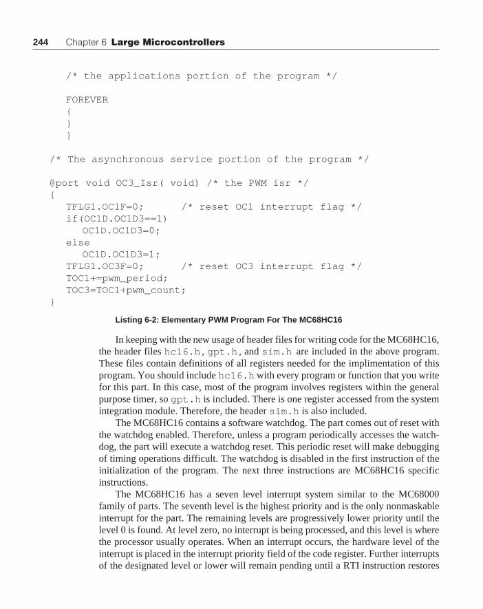
244 Chapter 6 Large Microcontrollers
/* the applications portion of the program */
FOREVER{}}
/* The asynchronous service portion of the program */
@port void OC3_Isr( void) /* the PWM isr */{
TFLG1.OC1F=0; /* reset OC1 interrupt flag */if(OC1D.OC1D3==1)
OC1D.OC1D3=0;else
OC1D.OC1D3=1;TFLG1.OC3F=0; /* reset OC3 interrupt flag */TOC1+=pwm_period;TOC3=TOC1+pwm_count;
}
Listing 6-2: Elementary PWM Program For The MC68HC16
In keeping with the new usage of header files for writing code for the MC68HC16,the header files hc16.h , gpt.h , and sim.h are included in the above program.These files contain definitions of all registers needed for the implimentation of thisprogram. You should include hc16.h with every program or function that you writefor this part. In this case, most of the program involves registers within the generalpurpose timer, so gpt.h is included. There is one register accessed from the systemintegration module. Therefore, the header sim.h is also included.
The MC68HC16 contains a software watchdog. The part comes out of reset withthe watchdog enabled. Therefore, unless a program periodically accesses the watch-dog, the part will execute a watchdog reset. This periodic reset will make debuggingof timing operations difficult. The watchdog is disabled in the first instruction of theinitialization of the program. The next three instructions are MC68HC16 specificinstructions.
The MC68HC16 has a seven level interrupt system similar to the MC68000family of parts. The seventh level is the highest priority and is the only nonmaskableinterrupt for the part. The remaining levels are progressively lower priority until thelevel 0 is found. At level zero, no interrupt is being processed, and this level is wherethe processor usually operates. When an interrupt occurs, the hardware level of theinterrupt is placed in the interrupt priority field of the code register. Further interruptsof the designated level or lower will remain pending until a RTI instruction restores

245
the IP field to a lower level. This approach provides for priority selection amongseveral internal or external interrupt sources.
Another potential problem occurs when two internal modules are assigned thesame priority level. In this case, a second level of arbitration is set-up to chooseamong these several modules in the event that more than one module requests aninterrupt at the same time. The module control register of each module has a fieldcalled IARB. This four-bit field is assigned by the programmer and it is an arbitrationlevel that will be applied when the processor must select between two equal priorityinterrupts that occur simultaneously. The interrupting module with the largest IARBvalue will be given control of the processor. The IARB field can contain values from0 to 15. When the module is being used, its IARB field must be assigned a non-zerovalue, and no two modules can contain the same IARB value. The code line
GPT_MCR.IARB=5;
places a value 5 into the IARB of the general purpose timer.The interrupt level 6 is assigned to the GPT by the code line
ICR.IRL=6;
and the vector base address is assigned a value of 40 by the code line
ICR.VBA=4;
The means by which the vector assignment is accomplished in the GPT isdifferent from the remaining modules in the MC68HC16. For the GPT, a 4-bitvector base address field is found in the interrupt configuration register. A vector isan 8-bit value.
Table 6-2: GPT Interrupt Priorities And Vector Addresses
A Pulse Width Modulation Program
Name Function Priority VectorLevel Address
Adjusted Channel 0 (highest) 0xV0IC1 Input Capture 1 1 0xV1IC2 Input Capture 2 2 0xV2IC3 Input Capture 3 3 0xV3OC1 Output Compare 1 4 0xV4OC2 Output Compare 2 5 0xV5OC3 Output Compare 3 6 0xV6OC4 Output Compare 4 7 0xV7
IC4/OC5 Input Capture 4/ Output Compare 5 8 0xV8TOF Timer Overflow 9 0xV9
PAOVF Pulse Accumulator Overflow 10 0xVAPAIF Pulse Accumulator Input 11(lowest) 0xVB

246 Chapter 6 Large Microcontrollers
The vector assignment is accomplished when the value placed in the VBA fieldof the ICR is used as the high nibble of an 8-bit number. The lower four bits arespecified by the contents of Table 6-2. There you will note that the vector address ofOC3 is at 0xV6 . When the contents of the VBA field is 4, then the vector for OC3 is0x46 . The vector address is twice the value of the vector or 0x8c in this case. That isthe reason that the address OC3_Isr is placed in the address 0x8c in the vectorinitialization routine.
You will note that each interrupt in the timer will be assigned a vector with themost significant nibble of the value placed in the VBA field of the ICR. There is aprearranged priority among these several interrupts. One interrupt can be moved tothe highest priority among the several timer interrupts if desired. The priority adjustbits PAB field in the ICR allows this shift. For example, if the number 6 were placedin the PAB field, then the priority of OC3 would be shifted from 6 to 0, where 0 is thehighest priority of the 11 levels with the GPT. In this case, the vector for OC3 wouldbe located at 0x40 , and the vector address would be 0x80 . None of the otherinterrupt vectors or priorities would be changed by this operation.
The remaining code of the initialization section of the above program is almostthe same as that found in Listing 5-5. The register and bit naming conventions usedwith the MC68HC16 are such that the code written for the MC68HC11 can be useddirectly on the MC68HC16. There is one change. In the MC68HC11, it was neces-sary to set the DDRA7 bit to allow the output from OC1 to show up on the pin PA7.The GPT has a different output pin arrangement on the MC68HC16 and it does notrequire the use of the DDRA register at all.
One additional modification. A cli() instruction was used in Chapter 5 toenable the system interrupts. There is no single bit in the MC68HC16 that can beused to enable the interrupts. The three-bit field in the condition code register namedIP sets the level of interrupt that can be acknowledged. Since there is no equivalentinstruction, a macro definition of an instruction
#define cli() ("andp $ff1f \n")
is included in the header file hc16.h. There is also a macro
#define sei() ("orp $00e0\n")
These two macros accomplish the equivalent of the same instructions for theMC68HC16. The cli() instruction clears the bits of the IP to zero, so that anyinterrupt will be acknowledged by the processor. The sei() instruction set the IPbits so that only a nonmaskable interrupt will be acknowledged. Additional macroscan be written that enable the programmer to set the interrupt level anywhere between1 and 7 if needed.
Recall that with the MC68HC11 the two registers TFLG1 and TFLG2 weredifferent from the usual registers in the part. To reset bits in these registers, it is

247
necessary to write ones to the designated bits rather than zeros. On the MC68HC16,this anomoly has been corrected. On the MC68HC16, to reset bits in the TFLG1 andTFLG2 registers the program must write zeros to the appropriate bits. That changeshows up in two locations in the OC3_Isr routine. The much more logical
TFLG1.OC1F=0;..TFLG1.OC3F=0;
instructions are used here. Otherwise, the remainder of the interrupt service routineshown in Listing 6-2 is the same as that found in Listing 5-5.
This portability is what you should expect when changing between the MC68HC11and the MC68HC16 family of parts. Care has been used in the design to assure thatregister names and bitfield names are common between the families. Therefore, codewritten for the MC68HC11 should move to the MC68HC16 with little change. Theneed for change at all is caused by the fact that architecture of the basic machines aredifferent.
EXERCISES1. Modify the program shown in Figure 6-2 to allow the PWM range to vary from 1
to 0XFFF. Compile this program and test the code.
2. Write a macro that will permit the program to put an arbitrary value between 0and 7 into the IP field of the condition code register.
Intermetrics MC68HC16 CompilerThe Intermetrics compiler for the MC68HC16 is quite similar to the MC68HC11
compiler. Its operation is the same. Several command files are used in the course ofexecuting a compilation, and these files will be shown here. The first file is theprogram that completely compiles and links the program. This file is shown below:
c -dlistcs +s +o %1.clnkh16 < %1.lnkhexh16 -s -o %1.hex %1.h16pause
This command file requires as an input a file with a .c extension. For exampleif you were to compile the program newpwm.c , you would enter
c:\>comp newpwm
Intermetrics MC68HC16 Compiler

248 Chapter 6 Large Microcontrollers
The first line will envoke the compiler and create a listing file, a source assemblylisting, and an object file named newpwm.o . The second line envokes the linkernamed lnkh16 , and requires in input file named newpwm.lnk . The .lnk file issimilar to that one discussed in Chapter 5, and a listing of the one for this programis shown below.
# Link command file for NEWPWM.c+h # multi-segment output-max 0xfffff # maximum size-ps16 -pc. # set up banking options-o newpwm.h16 # output file name+text -b 0 # reset vectors start addressvector.o # vectors+text -b 0x400 # program start address+data -b 0x700 # data start addresscrts.o # startup routinenewpwm.o # application programc:/cc16/lib/libi.h16 # C library (if needed)c:/cc16/lib/libm.h16 # machine library+def __memory=__bss__ # symbol used by library
Here the entries are fairly well explained by the comments. Note that twoadditional input files are required by this link file. The vector table vector.o is acompiled version of the vector listing given in Listing 6-1. The crts.o objectmodule is an assembled version of the start-up routine for this machine. Both of theseroutines must be written and compiled or assembled for the specific program. Other-wise, the link command file is as discussed in Chapter 5. A version of crts.s isshown below:
; C STARTUP FOR 68HC16; Copyright (c) 1991 by COSMIC (France); .external _main, __memory .external ._main, .__bss__ .public _exit, __stext .psect _bsssbss: .psect _text__stext: ldk #.__bss__ tbek tbxk tbzk ldab #0fh ; start of the i/o memory space

249
tbyk ; put it in y ldx #sbss ; start of bss clrd ; to be zeroed bra mtest ; start loopbcl: std 0,x ; clear memory aix #2 ; next wordmtest: cpx #__memory ; end of memory ? blo bcl ; no, continue aix #1000h ; 4K stack txs ; for instance jsr _main,#._main ; call application_exit: bra _exit ; loop here if return;.end
In the above code, the EK, XK, and ZK registers are initialized the the valuefound in .__bss__ . The initial value of YK is set to 0xf . The Y register will beused by the compiler to contain an offset to all of the data contained in the controlregisters found in the header files. Therefore, the YK register must be set to the topmemory block in the computer memory space.
Using the SCI Portion of the Queued Serial ModuleThe queued serial module (QSM) contains two parts. The first is a convenient serial
communications interface (SCI) which provides asynchronous serial communicationsthat is used between computers and other devices. The remainder of the QSM is aqueued serial peripheral interface that is often used for high speed communicationsbetween computers and peripheral devices. This interface is strictly synchronous.
Let’s examine an interface between the program and a terminal much like thatfound in Chapter 5. Here, the interface will simply read in a number from the screenand put that number into the pwm_count value for the PWM program. With thisoperation in place, the operator can type in a value and change the PWM on time atwill. The Listing 6-3 contains a program that will accomplish this end.
#include "hc16.h"#include "gpt.h"#include "sim.h"#include "qsm.h"
@port void OC3_Isr(void);WORD pwm_period=0x1000, pwm_count=0x0800,new_input=0;
Intermetrics MC68HC16 Compiler
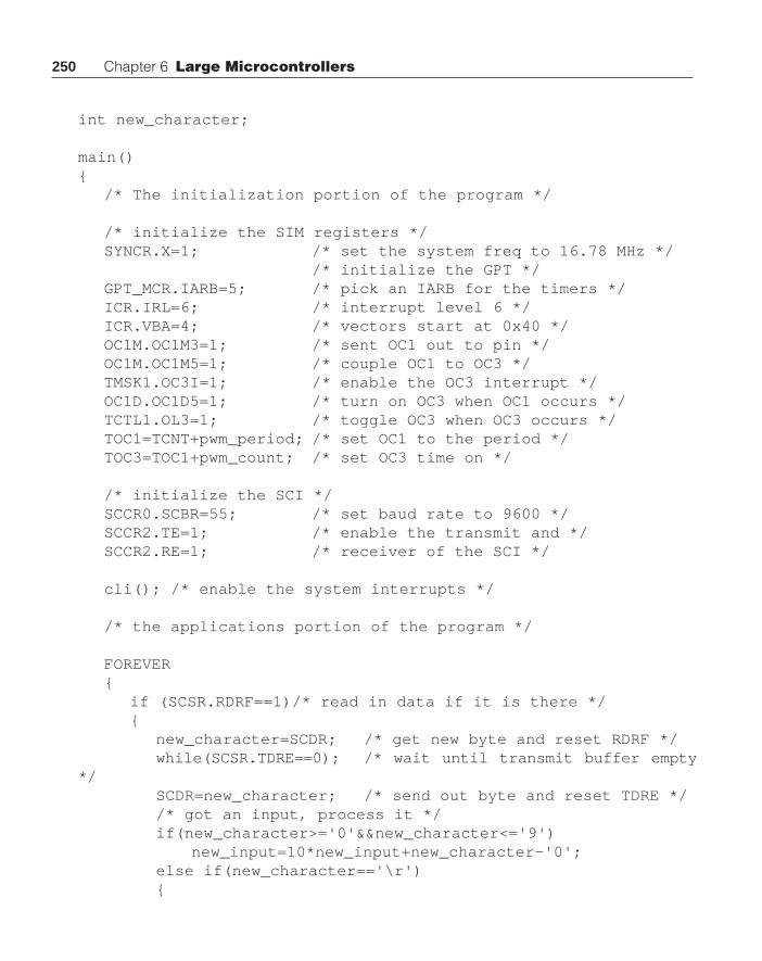
250 Chapter 6 Large Microcontrollers
int new_character;
main(){
/* The initialization portion of the program */
/* initialize the SIM registers */SYNCR.X=1; /* set the system freq to 16.78 MHz */
/* initialize the GPT */GPT_MCR.IARB=5; /* pick an IARB for the timers */ICR.IRL=6; /* interrupt level 6 */ICR.VBA=4; /* vectors start at 0x40 */OC1M.OC1M3=1; /* sent OC1 out to pin */OC1M.OC1M5=1; /* couple OC1 to OC3 */TMSK1.OC3I=1; /* enable the OC3 interrupt */OC1D.OC1D5=1; /* turn on OC3 when OC1 occurs */TCTL1.OL3=1; /* toggle OC3 when OC3 occurs */TOC1=TCNT+pwm_period; /* set OC1 to the period */TOC3=TOC1+pwm_count; /* set OC3 time on */
/* initialize the SCI */SCCR0.SCBR=55; /* set baud rate to 9600 */SCCR2.TE=1; /* enable the transmit and */SCCR2.RE=1; /* receiver of the SCI */
cli(); /* enable the system interrupts */
/* the applications portion of the program */
FOREVER{
if (SCSR.RDRF==1)/* read in data if it is there */{
new_character=SCDR; /* get new byte and reset RDRF */while(SCSR.TDRE==0); /* wait until transmit buffer empty
*/SCDR=new_character; /* send out byte and reset TDRE *//* got an input, process it */if(new_character>='0'&&new_character<='9')
new_input=10*new_input+new_character-'0';else if(new_character=='\r'){

251Intermetrics MC68HC16 Compiler
/* reject any number out of range *//* and start over again */if(new_input>=1 && new_input<=4000)
pwm_count=new_input;new_input=0;
}else
new_input=0; /*reject everything else */}
}}
/* The asynchronous service portion of the program */
@port void OC3_Isr( void) /* the PWM isr */{
TFLG1.OC1F=0; /* reset OC1 interrupt flag */if(OC1D.OC1D3==1)
OC1D.OC1D3=0;else
OC1D.OC1D3=1;TFLG1.OC3F=0; /* reset OC3 interrupt flag */TOC1+=pwm_period;TOC3=TOC1+pwm_count;
}Listing 6-3: PWM System With Keyboard Input
The qsm.h header file is included to add all of the register &defines neededfor the operation of the SCI. We are going to place the operation of the SCI into theapplications portion of the program. Implementation of the SCI requires that a baudrate be selected and the transmit enable along with the receive enable bits be set inthe serial communications control register number 2. The baud rate is set to 9600by placing a 55 into the SCBR field of SCCR0. With these lines of code, the serialcommunications interface is set up and ready to work.
The code inside of the application portion of the program is essentially identicalto that found in Chapter 5. The only difference is that the variable names are changed tobe more compliant with this application. Here is another interesting case where the codewritten for the MC68HC11 will move directly to the MC68HC16 with minimal change.
This program is a minimum SCI system. The SCI portion of this chip hascomprehensive capabilities that are not exploited in the above program. These capa-bilities and error checking devices are all available on the chip, and their access anduse is explained in detail in the QSM Reference Manual. Access of the variouscapabilities will be exactly the same as was shown above in this program.

252 Chapter 6 Large Microcontrollers
Periodic InterruptTo make the problem a little more interesting, let’s add another load to the
machine by making use of the periodic interrupt capability provided in the SIM tocreate an interrupt. With this interrupt, we will build a time-of-day clock similar tothat developed in Chapter 4. In this case you will see that the applications codedeveloped for the MC68HC05 will work fine for the MC68HC16. Of course, theinitialization code and the interrupt service routine will be completely different forthe MC68HC16. This additional code will be put right into the program listed inListing 6-3. It is asserted that there will be no adverse interactions between thevarious sections of the code.
#include "hc16.h"#include "gpt.h"#include "sim.h"#include "qsm.h"
@port void OC3_Isr(void);@port void PIT_Isr(void);void output_time(void);void putch(int);void send_out(WORD);char convert_bcd(signed char );
WORD pwm_period=0x1000, pwm_count=0x0800,new_input=0;WORD hrs,mts,sec,been_here=0;char new_character;
main(){
/* The initialization portion of the program */
/* initialize the SIM registers */SYNCR.X=1; /* set the system freq to 16.78 mHz */SYPCR.SWE=0; /* disable the watchdog */SIM_MCR.IARB=4; /* IARBs for each module is different */PICR.PIRQL=6; /* put all timers at level 6 */PICR.PIV=0x38; /* vector is 0x38, address is 0x70
*/PITR.PTP=1; /* 512 prescaler */PITR.PITM=16; /* divide by 16*4, 1 tic per second */
/* initialize the GPT */

253
GPT_MCR.IARB=5; /* pick an IARB for the timers */ICR.IRL=6; /* interrupt level 6 */ICR.VBA=4; /* vectors start at 0x40 */OC1M.OC1M3=1; /* sent OC1 out to pin */OC1M.OC1M5=1; /* couple OC1 to OC3 */TMSK1.OC3I=1; /* enable the OC3 interrupt */OC1D.OC1D5=1; /* turn on OC3 when OC1 occurs */TCTL1.OL3=1; /* toggle OC3 when OC3 occurs */TOC1=TCNT+pwm_period; /* set OC1 to the period */TOC3=TOC1+pwm_count; /* set OC3 time on */
/* initialize the SCI */SCCR0.SCBR=55; /* set baud rate to 9600 */SCCR2.TE=1; /* enable the transmit and */SCCR2.RE=1; /* receiver of the SCI */
cli(); /* enable the system interrupts */
/* the applications portion of the program */
FOREVER{
if (SCSR.RDRF==1) /* read in data if it is there */{
new_character=SCDR; /* get new byte and reset RDRF */while(SCSR.TDRE==0); /* wait until transmit buffer empty
*/SCDR=new_character; /* send out byte and reset TDRE *//* got an input, process it */if(new_character>='0'&&new_character<='9')
new_input=10*new_input+new_character-'0';else if(new_character=='\r'){
/* reject any number out of range *//* and start over again */if(new_input>=1 && new_input<=4048)
pwm_count=new_input;new_input=0;
}else
new_input=0; /*reject everything else*/}
Intermetrics MC68HC16 Compiler

254 Chapter 6 Large Microcontrollers
if(sec==60){
sec=0;if(++mts==60){
mts=0;if(++hrs==13)
hrs=1;}
}if(been_here &&! new_input){
been_here=0;output_time();
}}
}
void output_time(void){
int i;putch('\r'); /* send out a carriage return */putch('\t');putch('\t'); /* tab over the pwm_count */putch('\t'); /* on the screen */send_out(hrs);putch(':');send_out(mts);putch(':');send_out(sec);putch('\r');
}
void putch(int x){
while(SCSR.TDRE==0); /* wait until data register is empty*/SCDR = (char) x;
}
void send_out(WORD data){
char i=convert_bcd((signed char)data);

255
putch(i>>4|'0');putch(i&0x0f|'0');
}
char convert_bcd(signed char n){
int result;
result=0;while((n-=10)>=0)
result+=0x10;n+=10;return result | n;
}
/* The asynchronous service portion of the program */
@port void OC3_Isr( void) /* the PWM isr */{
TFLG1.OC1F=0; /* reset OC1 interrupt flag */if(OC1D.OC1D3==1)
OC1D.OC1D3=0;else
OC1D.OC1D3=1;TFLG1.OC3F=0; /* reset OC3 interrupt flag */TOC1+=pwm_period;TOC3=TOC1+pwm_count;
}
@port void PIT_Isr( void) /* the PIT isr */{
been_here++;sec++;
}
Listing 6-4: Clock Routine Added to PWM
If you compare the above listing with that shown in Listing 6-3, you will find thatthere are few structural changes to the program. The code used to initialize the SIM ischanged by the addition of the initialization of the periodic timer interrupt. This codeis shown below.
Intermetrics MC68HC16 Compiler

256 Chapter 6 Large Microcontrollers
SIM_MCR.IARB=4; /* IARBs for each module is different */PICR.PIRQL=6; /* put all timers at level 6 */PICR.PIV=0x38; /* vector is 0x38, address is 0x70 */PITR.PTP=1; /* 512 prescaler */PITR.PITM=16; /* divide by 16*4, 1 tic per second */
The interrupt arbitration level field in the SIM module control register is set to 4.Recall that the value here can be anywhere between 1 and 15, with 15 the highestpriority. All active internal modules that are to use an interrupt must have a uniqueIARB value. The IARB value for the GPT was set to 5. Note that the interrupt levelfor both the GPT and the PIT are set to the level 6. Therefore, both sources of timinghave the same interrupt priority; however, since the IARB of the GPT is higher thanthat of the PIT , in the event of a simultaneous occurrence of the two interrupts, theGPT service routine will be executed before the PIT .
The interrupt vector for the PIT is placed at 0x38 . Because, the address of thevector is twice the value of the vector, the interrupt vector address is 0x70 . A pointerto the PIT interrupt service routine will be placed at this address in the vector.croutine. The periodic timer itself is set up by the next two lines of code. This clock isdriven by the EXTAL signal. In our case, the frequency of the EXTAL signal is32768 Hz, not some number around 16 MHz. The formula to calculate the periodicinterrupt time is
Tpit
= 4 PITM (511 PTP + 1) / Fextal
Here PITM is the 8-bit field with the same name found in the PITR . PTP is asingle bit field in the PITR that can have a value of either 0 or 1. As such, if PTP is 1,the prescaller value of 512 is used. Otherwise, when there is no prescaller, the valuein the parenthesis reduces to 1. With the values placed in these fields in the abovecode, i.e., PTP of 1, and PITM of 64, and with a 32768 Hz external crystal, theperiodic interrupt time should be one second.
Two additional blocks of code are added to the applications section of the code.This code is shown below:
if(sec==60){
sec=0;if(++mts==60){
mts=0;if(++hrs==13)
hrs=1;}
}

257
if(been_here){
been_here=0;output_time();
}
The first eight lines of code here are taken directly from similar clocking codefound in Chapter 4. This code merely counts the time in seconds, minutes, and hours.The second block of code determines if an PIT has been serviced, and if it has, itresets the been_here flag that indicated that the PIT service routine has beenentered and then sends the time out the serial port when output_time( ) isexecuted.
Here is a case where several subroutines are used in the applications portion ofthe program. output_time( ) calls functions putch( ) and send_out( ) .In turn send_out( ) calls convert_bcd( ) . putch( ) is straightforward.This routine waits until the transmit data register is empty and then stores thecharacter to be transmitted into the serial communications data register.
The routine send_out( ) takes the character parameter passed to it and causesit to be converted from integer format to two binary coded decimal BCD characters.These two characters are then converted to ASCII characters by the addition of thecharacter ‘0’ to each and then sent to the output. (Recall that convert_bcd( )was shown in Chapter 4 in Listing 4-8.) Another version of this function is shown inListing 4-7. This alternate version has been tried in the above program and it works aswell as the function used above.
With the functions putch( ) and send_out( ) available, it is a simplematter to write the code that will output the time to the center of the top line of thescreen. It is assumed that the cursor is on the top line when the program begins to run.
The last remaining modification is the interrupt service routine PIT_Isr( ) .Within this function, the been_here flag is set, and the value in sec is incre-mented. Since the applications portion of the program will process sec and reset itwhenever it reaches a value of 60, there is no need for other code in this isr . Forinterest, listed below is the output from the compiler for both OC3_Isr( ) andPIT_Isr( ) .
; 131 @port void OC3_Isr( void) /* the PWM isr */; 132 { .even_OC3_Isr: pshm k,z,y,x,d,e; 133 TFLG1.OC1F=0;/* reset OC1 interrupt flag */ ldy _GPT_Register+2 bclr 34,y,#8; 134 if(OC1D.OC1D3==1)
Intermetrics MC68HC16 Compiler

258 Chapter 6 Large Microcontrollers
ldab 9,y andb #8 cmpb #8 bne L162; 135 OC1D.OC1D3=0; bclr 9,y,#8; 136 else bra L172L162: ; line 136, offset 29; 137 OC1D.OC1D3=1; ldy _GPT_Register+2 bset 9,y,#8L172: ; line 137, offset 35; 138 TFLG1.OC3F=0;/* reset OC3 interrupt flag */ ldy _GPT_Register+2 bclr 34,y,#32; 139 TOC1+=pwm_period; ldd _pwm_period addd 20,y std 20,y; 140 TOC3=TOC1+pwm_count; addd _pwm_count std 24,y; 141 } pulm k,z,y,x,d,e rti; 142; 143; 144 @port void PIT_Isr( void) /* the PIT isr */; 145 { .even_PIT_Isr:; 146 been_here++; incw _been_here; 147 sec++; incw _sec; 148 } rti
Listing 6-5: Interrupt Service Routines
Lines 131 through 142 above are the interrupt service routine OC3_Isr( ) andlines 143 through 148 comprise the PIT_Isr( ) . The main item that is observed

259
here is the quality of the optimizer for the compiler. In general interrupt serviceroutines, ISR , must save the complete status of the machine prior to executing anycode. The CCR along with the PC are both saved by the interrupt sequence. Theremainder of the registers must also be saved if the ISR can use any of the additionalregister resources of the computer. Usually this case will be found. Note, for example,in OC3_Isr( ) the first instruction is
pshm k,z,y,x,d,e
This instruction causes the contents of all significant registers to be saved on thestack, so that the status of the machine at the time the interrupt occurred can berestored before control is returned to the portion of the program that was interrupted.This restoration is completed by the two instructions
pulm k,z,y,x,d,erti
which will refill all of the registers with the values they contained when the ISR wasentered, and the rti instruction will restore the condition code register to the value ithad and the program counter is then restored. Thus, the status of the machine isrestored and the program control is returned to the interrupted instruction.
Note that the ISR PIT_Isr( ) compiles to a much simpler routine. Thisroutine has simply two increment instructions and requires no register resources. Theoptimizer recognizes this simple operation and does not save the status beyond thatsaved when the interrupt occurred.
The above routine has probably been pushed further than it should be for demon-stration purposes. This routine demonstrates multiple interrupts working simulta-neously, keyboard input and output, and generates a simple pulse width modulationsignal whose on period is determined by a number entered from the keyboard. All ofthese operations are quite similar to those shown in Chapter 5; however, some majormodifications in approach are required to meet the several requirements of theperipheral components on the MC68HC16. Let us now look at some other applica-tions often used with microcontrollers.
Table Look-UpOften in the implementation of a practical problem it is necessary to implement a
conversion of data in a completely heuristic manner. Observations are made and acurve of sorts is fit to the data. It is then desired to put a few samples of this curve intoa data table and then calculate values between these samples with an accuracy thatusually requires interpolation between the points contained in the data table. Suchtables are usually sparce in that the number of measured points across the rangecovered by the table are few. The curve shown in Figure 6-1 below shows an exampleof such a conversion table, and the table itself is shown in Figure 6-2.
Table Look-Up

260 Chapter 6 Large Microcontrollers
Figure 6-2: Look-Up Table
The object of the program is to deliver to the program a number like 67 and getthe proper result back from the table look-up routine. The x value of 67 lies betweenthe 40 and the 80 entry in the table. Therefore, the interpolation calculation needed inthis case is
(67 - 40)Result = 15 + (50 - 15)________ = 38.625
(80 - 40)
Notice that there is a product and a division that is the same for all input valuesbetween 40 and 80 in this case. This calculation is the slope of the line between thetwo points being interpolated. Usually table look-up operations are used where timeconstraints on the program are great so that these operations, multiply and divide(especially divide) are unwelcome in these programs. There is a way to avoid thedivide operation. Note that between each set of points the slope is a constant.Therefore, if the slope of the line is built into the table, the calculation would involveone subtraction, one multiply, and one addition. Let us modify the table above tocontain the slopes of the lines between each point.
Figure 6-1: Data Conversion Curve
0
50
100
150
200
250
20 40 80 120 180
X Y
20 5
40 15
80 50
120 120
180 240
Figure 6-1: Look-Up Table

261
Figure 6-3: Look-Up Table With Slopes
Note that the slope of the line runs from the lower point to the next point.Therefore, there is no slope for the last point. When this table is built in memory, itconsists of a header followed by a four byte entry for each entry in the table. Theheader consists of a single byte that indicates the length of the table. In this case, sincethe table starts with an independent variable value of 20, there are expected to be noinput values less than 20. If there are however, the value of 5 will be used for theseoutput values. Also, if the value of the independent variable is greater than themaximum of 180, a value of 240 will be returned from the routine. With data from theabove table, the calculation above would reduce to
Result = 15 + 0.875(67 - 40) = 38.625
which requires a multiply, a subtract and one add. Of course, the routine will truncatethe fractional part of the result so that the value returned will be 38.
Each table entry contains four bytes. The first byte is the independent variablevalue, often designated as x. The second byte contains the dependent variable value,usually called y, and the final two bytes contain a floating point format of the slope.The slope must be floating point. The third byte contains the integer poition of theslope, and the fourth byte contains the fractional value of the slope. With the binarypoint placed between the third and fourth bytes of the table entry, we can accomplishsome interesting multiply operations. Prior to looking at the coding of this problem,let us complete the table and convert the slopes into hexidecimal format.
Table Look-Up
20 5 0.5
40 15 0.875
80 50 1.75
120 120 2
180 240
5
20 5 0x00 0x80
40 15 0x00 0xe0
80 50 0x01 0xc0
120 120 0x02 0x00
180 240
Figure 6-4: Look-Up Table With Hexidecimal Slopes
How does one build a table of this nature in C. Of course, it is an array ofstructures, or it could be a structure that contains an array of structures. The latterapproach would be

262 Chapter 6 Large Microcontrollers
struct entry{char x;char y;int slope;};
struct lut{char entries;struct entry data[5];} _ lut ={5,20, 5, 0x0080,40, 15, 0x00e0,80, 50, 0x01c0,120, 120, 0x0200,180, 240};
Note that in the above table, the slopes are entered in the table as two-byteintegers. There is no binary point in the the slope. The conversion of these integers tofloating point numbers is accomplished easily. We must merely recognize that thesenumbers are a factor of 128 too large, so after the slope is used as a multiplier, theresult must be divided by 128 to get the correct answer. Of course, division by 128can be accomplished by a shift right by 8, or more practically merely choosing the leftbyte of the product.
A function that will make use of this table is
char table_look_up( char x_in){
int i;for(i=0;x_in>_lut.data[i].x && i<=_lut.entries; i++);if(i>=_lut.entries)
return _lut.data[_lut.entries-1].y;else if (i==0)
return _lut.data[0].y;else
return _lut.data[i-1].y+(((x_in-_lut.data[i-1].x)*_lut.data[i-1].slope)>>8);
}Listing 6-6: Table Look-Up Routine, Version 1

263
The compiler optimizer will recoginze that the shift right by 8 in the abovefunction and will merely select the upper byte of the result rather than executing theshift operation indicated.
This function was checked on an evaluation system for the single input value of67 and the result was the expected value of 38. Of course, that did not check thefunction over its full range of operation. The check over the full range was accom-plished on a host machine. It is a simple matter to include the above function andtable in the following program.
#include "tlu.h"void main(void){
int i;for(i=0;i< 256; i++)
printf(" i = %d r = %d\n",i,table_look_up(i));}
Where tlu.h contains the function and the table above. This code compiles andruns on a MS-DOC PC, and the result is as expected. Here, the program scans theentire input range and prints out the resultant value at each point. A check of theoutputs will show that the function hits the break value at each break, and creates alinear interpolation between all points. For values above or below the range, theproper output is observed.
In a normal control system, there will often be need for several table look-upoperations. The above code is not too good in this case because the code to do the look-up must be repeated with each table. This extra code can be eliminated if the functiontable_look_up( ) is passed two parameters: the first parameter is the interpola-tion value, and the second value is a pointer to the look-up table as is shown below
char table_look_up( char x_in, struct lut* table){
int i;for(i=0;x_in>table->data[i].x && i<=table->entries; i++);if(i>=table->entries)
return table->data[table->entries-1].y;else if (i==0)
return table->data[0].y;else
return table->data[i-1].y+(((x_in-table->data[i-1].x)* table->data[i-
1].slope)>>8);}
Listing 6-7: Table Look-Up, Version 2
Table Look-Up
264 Chapter 6 Large Microcontrollers
This form of the table look-up should probably be used in all cases. Here isanother example of where it is wise to examine the code generated by a compiler. Itwill not be listed here, but the assembly code required for Listing 6-11 is 182 byteslong, and that for listing 6.12 is but 142 bytes. This greatly improved utility automati-cally gives a substantial savings in code.
It was pointed out that the compiler optimizer will sometimes change the basiccode dictated by the programmer. Perhaps, it should be stated that the optimizerchanges the code suggested by the programmer. Often when you examine the codegenerated by the compiler, the operations that take place will not even resemble thosethat the programmer had in mind. This alteration of the code will show up with shifts,and divides or products of powers of two. A proper optimizer should determine if amultiply or a shift is better and provide the best code. Often you will find that thecompiler optimizer will provide either fastest execution or minimum code. Usuallythe two will be different. Faster code will almost always take more memory.
It may seem that the lost time is small, but you will always find that if you wantfast code, you will not use any looping constructs. The code that increments a counterand tests the counter must be executed each loop. Without the looping construct, thiscode is completely eliminated, and its exection each loop will be completely elimi-nated. Therefore, if you are wanting fast code, you should eliminate looping con-structs and repeat the code within the loop the desired number of times. The cost ofthis move is more code. We have also seen that recursive code can require aninordinant amount of time. Again, recursive code merely creates hidden loopingconstructs that require frequent generation of stack frames prior to new function calls.The construction of these stack frames and return from functions require time whichwill often be masked by the elegant appearance of the code. Usually you will producefaster code if you figure a way to accomplish the same end operation without calls tothe executing function.
Today, we are on the very beginning of a completely new set of microcontrollers.These machines will be based on RISC (reduced instruction set computer) tech-niques. Do not be misled. RISC does not really mean reduced instruction set. Theinstruction sets are complete and extensive. However, the basic architecture of aRISC machine is quite different from the older machines like those we have beenworking with. One of the main differences is that the design of the machine is toprovide for the execution of one or more instructions with each clock cycle. Astandard RISC will allow almost one instruction per clock cycle, and a super scalerarchitecture will allow two or more instructions per clock cycle. This operation isenabled by the use of instruction pipelines and multiple arithmetic logic units (ALUs).Some times, an instruction must use more than one clock to complete an instruction.For example, an integer multiply instruction might require five clock cycles. In thatcase, an instruction pipe five instructions long would be implimented within theinteger ALU. Therefore, a multiply instruction would be launched into the instruction

265Digital Signal Processor Operations
pipe for execution. In the mean time, other instructions could execute while themultiply is progressing through the pipe.
Compiler optimization for these machines must take into account all of the pipes,the separate ALUs, and other unique operations when creating the required assemblycode. Clearly, a straightforward creation of code in the order that might seem to benatural to a programmer will not necessarily create the quickest code for a RISCmachine. Here speed optimization will be to arrange the code so that, as nearly aspossible, the maximum number of instructions will be launched each clock cycle.This rearrangement of your code will make it extremely difficult to examine theassembly code version of the program and even make sense of it. So long as theresults are not altered, the optimizer for a RISC machine will move instructionsaround in the code stream to accomplish this end. Therefore, from a practical sense,any debugging on a RISC machine will probably be done with a source leveldebugger, and not an assemebly language version of the program.
EXERCISE1. Sometimes two input values are needed to specify a parameter. For example, if
you recall from Chapter 5, the change in pulse on tiume to properly control themotor speed was given by
∆p∆pe = -3809500___
p2
create a sparse two dimensional look-up table whose inputs are p and ∆p andprovides ∆p
c as the result of three interpolations. Is the look-up table better than
the calculation in any way—less code, quicker, etc.? Why would you use a look-up table in a problem like this one?
Digital Signal Processor OperationsMost microcontrollers, regardless of their basic speed, are not very able to
process signals in real time. The basic speed of the processors is fast enough toaccomplish most signal processing; however, the set of things needed to do digitalsignal processing is not usually available in the regular microcontroller. The basicdigital signal processor (DSP) function that is required is summarized by threeactions: 1) the processor must multiply two values, 2) the processor must add theproduct into a value, and 3) it must prepare for the next multiply. This set of oper-ations must execute quickly enough that the computer can keep ahead of the real-time input of data being processed. Almost all signal processing operations are basedon the multiply-accumulate sequence. Filtering, correlation operations, scalar prod-ucts of vectors, Fourier and other transformations, and convolutions are but a few of

266 Chapter 6 Large Microcontrollers
the operations that are built around the DSP multiply and accumulate sequenceabove. The MC68HC16 family has an extension to its core that can execute basicDSP operations fast enough to support real-time filtering, correlation, and so forth.
Unfortunately, C compilers do not know of these added functions so the Cprogrammer would seem be unable to inculde DSP operations in programs. We willsee here that, while it is rather inconvenient, it is possible to write assembly functionsthat will permit the programmer access to the complete DSP capabilities found in thisfamily of devices.
One of the good features of C is that it is not necessary for the programmer tohave detailed knowledge of the nature of the basic computer being programmed. Sofar, we have had little to say about accumulators or index registers or the like. Nomore! We must now get inside of the computer to create functions that will accom-plish our DSP needs. When these functions are complete, we should be able to treatthe DSP operations in much the same manner that we would any other function call.
The DSP contains four registers and controls three bits in the condition coderegister (CCR). The first two registers are called the MAC multiplier input registers Hand I, respectively. These register must be loaded with the multiplier and the multiplicanto be executed. Data stored in these registers are signed fractional binary numberswith the radix point between bits 15 and 14. The product will be accumulated into theMAC accumulator M register. This register is 36 bits long. For convenience, theregister is broken into two portions, bits 35 through 16 and bits 15 through 0. We willsee later that different portions of this register are moved by different instructions, sothat breaking this register into the two parts is logical.
The last register in the DSP register model is the MAC XY mask register.Automatic selection of the addresses for the next multiply needs modulo arithmetic.We will see more modulo arithmetic later. The mask register contains the modulobase for both the x and y index registers which will allow fixed coefficient tables,which can be manipulated as either single or two dimensional arrays, to be traversedautomatically during successive multiply and accumulate instructions. The DSPregister model is shown in Figure 6-13 below.
20 16 15 8 7 0 Bit Position
H R MAC Multiplier Register
I R MAC Multplican Register
A M MAC Accumulator MSB[35-16]
A M MAC Accumulator LSB[15-0]
XMSK YMSK MAC XY Mask Register
Figure 6-4: MC68HC16 DSP Register Model

267
The CCR contains three bits that are associated with the DSP. Bits 14 and 12 areDSP overflow flags. These flags will be discussed in detail later. Bit 4 is called theSM bit and is the DSP saturation mode control bit.
15 3 0
S M V H EV N Z V C I1 I2 I3 SM PK CCR
DSP Cont rol Bits
Figure 6-5: DSP Control Bits In The CCR
The accumulator is 36 bits with the radix point between bits 31 and 30. Whenaccumulating into the MAC accumulator AM, there are two types of overflow thatcan occur. The first is when an addition operation, which should always add fractions,cause an overflow from bit 30 to 31. This type of overflow is reversable because thearithmetic that caused the overflow cannot cause more than a one bit overflow error,and bits AM[34-31] are there to absorb this type of overflow. The contents of thisregister is signed, so that bit 35 of AM is the sign bit. The maximum value that can beplaced in the 36-bit AM register is 0x7ffffffff. This value has a decimal value of15.999969482. The minimum value is 0x800000000 which corresponds to -16.Whenever arithmetic involves the bits AM[34-31] the EV bit will be set, and theprogram will know that the bits in AM[35-31] are the signed integer part of thenumber. If successive operations cause the overflow to disappear, the EV bit will bereset.
Another situation is less tractable. Suppose an overflow occurs as a result of anarithmetic operation into the AM that causes bit 34 to overflow into bit 35. This typeof error is not reversable as is the case above. When this overflow occurs, the MV bitwill be set to notify the program of the result. An internal latch known as the signlatch SL will contain the value of A[35] after the overflow has occurred. Therefore,SL is the complement of the sign-bit when the overflow occurred.
To communicate with the DSP portion of the MC68HC16, we will have to useassembly language. In keeping with the basic rule to use C whenever possible, theapproach to be taken will be to create C callable functions that access these importantcapabilities. What features should we include in these functions? Obviously, allpossible functions cannot be conceived. A set of functions that will embody the mostimportant feature of the DSP capabilities will be written.
Let us examine how this compiler transfers parameters to a function. When morethan one parameter is passed, the parameters are pushed on the stack starting with theright-most parameter in the function argument list. The leftmost parameter is put intothe D register. If a single parameter is passed, it is placed in the D register prior to thefunction call. Within the function, the D and X register is saved on the stack, and thestack pointer is decremented by an amount needed to provide space for all of the
Timer Operations

268 Chapter 6 Large Microcontrollers
function variables. At that point, the stack pointer is transferred into the X register.An example of this code is shown below. This little function receives three param-eters and merely puts these values into three local variable locations.
void dot_product(char length, int* xdata, int* ydata){
int i,*xp, *yp;
xp=xdata;yp=ydata;i=length;
}
Listing 6-8: Sample Parameter Handling Function
The compiled version of the above function is shown below. The first importantinstruction is the .even assembly directive that causes the code to follow to start onan even boundary. Code must be started at an even address. Note in the programabove that three parameters are passed to the function. After the contents of the X andthe D registers are saved, the stack pointer is decremented by 6 to provide space forthe variables i , *xp , and *yp . The two pointer parameters require 16 bits each, andthe character parameter needs only 8 bits. The program, in favor of greater speed, willstore the variable i in a 16 bit location even though i is only 8 bits wide. At this time,the value contained in the stack pointer is transferred into the X register. During thistransfer, the value will be automatically incremented by two so that the contents ofthe X register will be pointed to the last value stored on the stack rather than to thenext empty location on the stack as is found in the stack pointer.
1 ; Compilateur C pour MC68HC16 (COSMIC-France) 2 .include "macro.h16" 3 .list + 4 .psect _text 5 ; 1 void dot_product(char length, int* xdata, int* ydata) 6 ; 2 { 7 .even 8 _dot_product: 9 pshm x,d 10 ais #-6 11 tsx 12 .set OFST=6 13 ; 3 int i,*xp, *yp; 14 ; 4 15 ; 5 xp=xdata;

269
16 ldd OFST+8,x 17 std OFST-4,x 18 ; 6 yp=ydata; 19 ldd OFST+10,x 20 std OFST-6,x 21 ; 7 i=length; 22 ldab OFST+3,x 23 clra 24 std OFST-2,x 25 ; 8 26 ; 9 } 27 ldx 6,x 28 ais #10 29 rts 30 .public _dot_product 31 .even 32 .psect _data 33 .even 34 .psect _bss 35 .even 36 .end
Listing 6-9: Compiled Version Of Parameter Handling Function
The diagram shown in Figure 6-6 will help you visualize what is happeninghere. On the right side of this diagram you will find the location at which the stackpointer is pointed at various times in during the function call and its execution. On theleft side of the diagram, you will see the locations pointed to by the X register. Anoffset named OFST is established by the program. This offset will have a value equalto the space emptied on the stack with the ais instruction: in other words, in thiscase OFST will be 6. In every case from this point forward in the program, variableand parameter accesses will be indexed relative to the X register, and the totaloffset from the X register will be a value OFST+k where k is a positive or negativevalue that corresponds to the address of the parameter being accessed. For example,the instruction
ldd OFST+8,x
will load the value at x+OFST+8 which you can see in Figure 6.x is the value*xdata . This value is stored at the location x+OFST-4 by the instruction
std OFST-4,x
Digital Signal Processor Operations

270 Chapter 6 Large Microcontrollers
➝➝
which is the location where xp is stored on the stack. Remember that each word onthe stack is two bytes, so that all of the offsets and address will be even numbers.
The code in lines 16 through 20 above save the values of xdata and ydatain xp and yp respectively. The operations shown in lines 21 through 24 save the8-bit value found in the B register to the 16-bit location at x+OFST-2 . To be certainthat the value is not corrupted by some garbage value in the A register, the clrainstruction is inserted prior to the time that the value is saved.
Stack Contents
SP after ais #-6
X after tsx *yp
*xp
length SP after pushm x, dX + OFST X
SP at rts D SP after function call
CCR
PC SP before function call
*xdata
*ydata
Figure 6-6: Stack Contents During Function Operation
After the closing brace of the function in the above function, two importantoperations take place. First, the contents contained in the X register on entry to thefunction is restored by the instruction
ldx 6,x
and the stack pointer content is restored to the value it contained when the functionwas entered. At this point in the program, an rts instruction will return the programcontrol to the instruction following the jsr or bsr instruction used to enter the functioncode originally.
When the function return is executed, the registers D, E, Y, Z, and CCR are allundefined. A 16-bit return from the function will be returned in the D register, and a32-bit return will be contained in the E and the D register. The least significantportion of the return is in the D register.
What is a dot_product( ) ? In vector algebra, a dot product, or a scalarproduct, operates on all of the members of two vectors and returns a single scalar
➝➝
➝
➝

271
result. This value is the magnitude of the projection of one vector on the other. Thefamiliar arithmetic form for a dot product is
c akbk
n
=−
∑0
1
Note that all corresponding members of the two vectors are multiplied andsummed. The result is a single number. Another important calculation needed to beaccomplished by a DSP is called the convolution. A convolution is the time domainoperation of a filter. Most of the time, a designer thinks of a filter as operating onthe different frequencies of the signal being processed. In the frequency domain, atevery frequency the filter has a gain which is complex. “Complex” in this case meansthe gain has two dimensions that can be thought of magintude and phase. The signalalso has a similar two-dimensional description in frequency. At each frequency, themagnitude of the filter gain multiplies the magnitude portion of the signal, and thephase of the filter gain adds to the corresponding phase of the signal. There are easyways to treat this operation in the frequency domain. In fact, the design of most filterstakes place in the frequency domain.
However, the frequency domain is an artifact that we can never really get ourhands on. In reality, the signals we must deal with are varying voltages or currents.These varying signals can be continuous, or when converted to a tractable form foroperation in a computer, they are a series of samples. Let us call them x
k. Here x is the
value of the signal at sample points k. Now k might be thought of as related to time,and in fact different values of k do correspond to samples taken at different times.Usually, k corresponds to samples taken periodically at carefully spaced, equalintervals.
A filter in the time domain has what is called a weighting function. The weightingfunction is indeed the Fourier transform of the complex frequency response of thefilter. In the continuous domain, there is a mathmatical trick that will allow theweighting function to be shown. A function called a Dirac Delta function is definedas a function that is 0 everywhere except at one point. The integral across this point isone. Such a function really does not exist. However, if such a function were deliveredinto the input of a filter, the output of the filter would be the filter weighting function.
As we move to the digital realm, the Dirac Delta function is replaced by theKroniker Delta function. This simple function, δ
k, is 0 for all values of k except for
k = 0 where its value is 1. If this function is sent through a digital filter, the outputobserved is the weighting function of the filter.
In both cases, analog and digital, the frequency response of the filter is theFourier transform of the filter weighting function. This duality between the frequencyresponse and the time domain response makes it possible to design filters to accom-plish what is really desired. Usually, the filter specification is best established in thefrequency domain. The designer knows what frequencies are to be passed or rejected
Digital Signal Processor Operations

272 Chapter 6 Large Microcontrollers
by the filter. There has been a long history in the field of passive network synthesisdevoted to the “approximation problem.” How does one specify a filter to meetaccurately a desired frequency response? This problem has lead to many sophisti-cated approaches to the specification by mathmatics of a frequency response to meetthe system need. More important, these frequency responses have a nature that can berealized by a finite collection of passive electrical components—resistors, capacitors,and inductors. In other words, these frequency responses are realizable.
A series of mathmatical transformations exist that can be used to transformfrequency responses directly to filter weighting functions. We will not go into thesetransformations here, but will refer you to Elliott for practical means to specify theweighting functions for digital filters.7
A more general text on this subject by Antoniou.8
The time domain response calculation is called a convolution. If there is a signalx
k applied to a filter with a weighting function h
k there will be an output from the filter
at each time sample, and this output will be called yk. The relations between these
parameters are given by the equation
y = x h k k - i i
i =0
n-1
∑The convolution is little more than a series of dot products, one dot product for
each otuput sample. Therefore, if you have a function that will calculate a dotproduct, it can also calculate a convolution.
An item of consequence is the use of modular arithmetic in calculation of the dataaddresses. Often times, it is desirable to traverse an array and return to its beginningautomatically when the end is reached. Modular arithmetic allows this type ofoperation. When working in combination with an unusual step value, modular arith-metic will permit the collection of coefficients from a rectangular array placed inlinear memory space. Here the step value refers to one of the numbers associated withthe mac or the rmac instruction. These two values are called xo and yo . This valueis used to increment the address of the corresponding register whenever data is loadedinto either the H or the I register. The location of the array in memory should beplaced at special location in memory. This location is discussed below. The effectiveaddress for the next value to be placed in the X after the value is incremented by xoregister is given by
IX = (IX)&~XMASK | ((IX)+xo)&XMASK
Note that XMASK here is an 8-bit mask that defines the length of the circulararray. The array length must be a power of two less than or equal to 256. The valueplaced in XMASK is one less than the array length. When the contents of IX, or (IX),
7 Elliott, Douglas F. Handbook of Digital Signal Processing and Applications: Academic Press Inc. 19878 Antoniou, Andreas, Digital Filter Analysis and Design: McGraw Hill, 1979

273
is anded with the complement of the sign extended value of XMASK , the value that isleft is the starting address of the array. The second term above causes the contents inIX to be incremented. As the value in IX is replaced by ((IX)+ xo)&XMASK aftereach multiply and accumulate operation. Since XMASK must contain a number thatis one less than a power of two raised to the n: its least significant n bits are 1. Thevalue placed in IX is the address with the n least significant bits masked off. Whenthese two values are ORed together, an address is created that will range from thebeginning to the end of the array and then back to the beginning in steps of xo . Therequirements to make this scheme work are:
1. The array length must be a power of two less than or equal to 256.
2. The array must begin on a specific address. This address is any value where theleast n bits are zero. Here n is determined by
n = log2 (array length)
orarray length = 2n
3. The value in xo must be equal to the step between adjacent data samples in thearray.
This scheme can be used to move, in a modular manner, around multiple dimen-sional arrays as well as one dimensional arrays. Let us now modify the earlier code into show how a circular buffer can be used to advantage.
The above compilations uses the default memory model for the Intermetrics Ccompiler for the MC68HC16. This computer has a memory addressing space of 20bits. In the design of the part, the basic address registers were all made 16-bits wide,and the additional bits required to address the total space were placed in extensionregisters. Therefore, for each of the addressing registers, the stack pointer, theprogram counter, and the index registers X, Y and Z, there is a 4-bit extensionregister. These registers are called SK, PK, XK, YK, and ZK respectively. Asmentioned earlier, several of these extension registers are initialized upon reset, andthe remainder must be initialized prior to the execution of the main program. Usually,when a calculation alters a value in an extension register, this change takes placeseamlessly. It is typically not necessary to worry about the contents of the extensionregisters. Recall in the code for the initialization routine listed above, crts.s , thatthe values for XK, and ZK were set to 0 and the value placed in YK was 0xf . Thereason for this choice is that the compiler automatically uses the Y register as anoffset when calculating the addresses listed in the various header files. Since all ofthese registers are in the highest memory page, the YK value of 0xf is appropriate.
The default memory model is called the compact model, and the code is compiledin the compact model so that all code, data, and stack memory space is containedwithin one 65 kilobyte (K) memory bank. Therefore, the initialized values of theextension registers need never change. On the other hand, it is sometimes necessary
Digital Signal Processor Operations

274 Chapter 6 Large Microcontrollers
➝
to change the values in these registers, and it is desirable to have the compiler takecare of this bookkeeping when needed. All of the additional memory models willprovide this tracking of the extension registers. These models are: small, one 65 Kbank for code and one 65 K bank for data and stack; program, multiple 65 K banksfor code and one 65 K bank for data and stack; data, one 65 K bank for code andmultiple 65K banks for data and stack; and finally far, multiple 65 K banks for code,data, and stack. With each of these memory models, it is necessary to keep track andoften change the contents of the extension registers. As a result, with these models, itis necessary to alter slightly the stacking sequence shown in Figure 6-16. Such asequence is shown in Figure 6-17. The function call that will cause the stack to bearranged as is shown in the figure below has four arguments. From left to right thesearguments are xlen , *xdata , ylen , and *ydata . The lengths are simple charac-ter values, and the pointers in this case must be 20-bit values. If a function call to thisroutine is compiled with the small memory model, or any other model with theexception of the compact model, the stacking will include the extension registers asshown below.
Stack Contents
SP after XK is saved
X after tsx XK SP after pushm x,dX
SP at rts D SP after function call
CCR
PC SP before function call
*xdatak
*xdata
ylen
*ydatak
*ydata
Figure 6-7: Stacking Sequence That Passes Extension Registers
The B register, which is the right hand side of the D register, will contain the left-most parameter when the function is called. Therefore, the parameter xlen will befound in the least significant bits of the location labled D in the above stack outline.
The routine shown below will make use of both the X and the Y registers. Thecompiler allows for all registers with the exception of the x register to be altered byany function call. Therefore, it is necessary to save the contents of the x register priorto altering this register.
➝
➝➝
➝
➝

275
; int circular_conv(char xlen, int* xdata, char ylen, int* ydata) .even .set xlen=5 .set xk=11 .set xdata=12 .set ylen=15 .set yk=17 .set ydata=18
_circular_conv: pshm x,d txK ; save old xk pshm d tsx clrm ; clear the m register clra ; put ylen into e register ldab ylen,x ; ylen addb #-1 ; decrement count to get correct tde ; number of iterations ldaa xlen,x ; xlen is the circular part asla ; of the convolution. Create coma ; a mask that is the compliment clrb ; of twice the length. tdmsk ; put xlen in XMASK ldab yk,x tbyk ldy ydata,x ; ydata with yk extension pshm x ; save x ldab xk,x tbxk ldx xdata,x ; xdata with the xk extension ldhi ; load H and I registers for mpy rmac 2,2 ; do rmac ylen times tmer ; send result to e and then pulm x ; restore x ldx 2,x ; restore it to its original value pulm d ; restore old xk tbxk ais #4 ; fix the stack ted ; data to be returned rts ; return .public _circular_conv .end
Listing 6-10: Circular Convolution Routine In Assembly Language
Digital Signal Processor Operations

276 Chapter 6 Large Microcontrollers
Variable names get lost from the program when executing an assembly languageprogram when called from C. Therefore, when a function is entered, the names of thevariables are replaced by offsets from a table saved by the compiler. Programmingfunctions without the aid labels and variable names requires careful attention to thedetails stacking and unstacking these data. It is recommended that when a program isto be prepared, an abbreviated version like the function dot_product( ) above—which will guide the programmer in setting up the variable locations in memory—bewritten. In the above routine, the use of the offset OFST was not used, and the variousoffsets were assigned names that corresponds to the variables. This approach makes iteasier to understand what the program is doing and easier to write the code correctly.
It is important that the contents of the XK register be restored to its initial valuewhen a function call is returned to the calling program. The content of the X and Dregisters are saved on the stack and the value or XK is then saved. The contents ofthe stack are placed in the X register, and this register is incremented by two that itwill point to the last data pushed on the stack. The M register is cleared, and theparameter ylen is moved into the E register. This value is used with the rmacinstruction to tell how many times the mac instruction is to be repeated. The valueof xlen is the length of the buffer that contains input data. This buffer is fedcircularly so that when the calculation reaches the last entry in the buffer the pointerinto the buffer will be returned to the top of the buffer to get its next entry. Thelength xlen is the number of entries in the buffer, but the length for the calculationmust be the number of bytes in the buffer. Therefore, the value of xlen must bedoubled prior to the creation of a mask to be used in XMASK . In this case, XMASKvalue is calculated, and YMASK which is stored as the B register content of the Dregister is made zero. Therefore, there will be a circular buffer calculation on X, butthere will be no circular calculation on the Y register.
After the MASKs are set up, the two 20-bit pointer registers, X and Y, areassigned the values passed as parameters, and then the product data are put into place.The rmac instruction is then executed the number of times indicated by the contentsof the E register. The register contents are then restored and the result of the singlepoint convolution is moved into the D register before control is returned to the callingprogram.
A simple program was written to test the operation of this function. This functiondoes not attempt to make a digital filter, but it rather sets up to show how the circularconvolution will work. In this case, it was intended that the program was to run on anEVB16 board which has a normal serial interface to an RS232 port. Therefore, thedata being tested can be sent out of the serial port to a terminal. The purpose of theprogram is really quite simple. It is to execute a convolution between a short set ofcoefficients and a long set of data. The coefficient set is 32 integers long, and the dataset is 64 integers long. The coefficient data is a descending array of numbers that arein the upper byte of the number. These numbers start at 31 and reduce successively tozero. The data that will be used here is merely the numbers 0 through 63 in the upper

277
byte of the number. The system is set up, the system frequency is set to 16.78 MHz,and the watchdog is disabled. The serial port is set to 9600 baud and the SCItransmitter is enabled.
#include "hc16.h"#include "sim.h"#include "qsm.h"
int putchar(char new_character);void dprint (int c);
void main(void){
int circular_conv(char, int*, char, int*);int data[64], coef[32],point[64],i,j,*ip;
/* initialize the SIM */SYNCR.X=1; /* set the system freq to 16.78 MHz */SYPCR.SWE=0; /* disable the watchdog */
/* initialize the SCI */SCCR0.SCBR=55; /* set baud rate to 9600 */SCCR2.TE=1; /* enable the transmit of the SCI */
for(i=0;i<64;i++)data[i]=i*0x100;
for(i=0;i<32;i++)coef[i]=(31-i)*0x100;
for(i=0;i<64;i++){
ip=data+i;point[i]=circular_conv(64,ip,32,coef);
}
for(i=0;i<8;i++){
for(j=0;j<8;j++){
dprint(point[j+8*i]);putchar(' ');
}
Digital Signal Processor Operations

278 Chapter 6 Large Microcontrollers
putchar(0xd);putchar(0xa);
}
}
int putchar(char new_character){
while(SCSR.TDRE==0); /* wait untiltransmit buffer empty */
SCDR=new_character;/* send out byte and reset TDRE */}
void dprint (int c){
if(c<0){
putchar('-');c=-c;
}if ( c/10)dprint(c/10);
putchar(c%10+'0');}
Listing 6-11: A Test Program For The Circular Convolution
Next, the circular convolution program is executed 64 times. These results arestored in the array point[] . This array is then sent out the the terminal eightnumbers at a time. A few lines of code are extracted from Figure 6-4 to make theputchar() function. Finally, the function dprint() sends the data out of theserial port to the terminal. The output from this program is as follows :
64 64 64 64 64 64 64 6464 64 64 64 64 64 64 6464 64 64 64 64 64 64 6464 64 64 64 64 64 64 6464 64 64 64 64 64 64 6464 64 64 64 64 64 64 6464 64 64 64 64 64 64 6464 64 64 64 64 64 64 64

279Digital Signal Processor Operations
This program is merely a test program to show that the circular convolution doesindeed work. The fact that the output data is always the same value, decimal 64,shows that the addresses are handled correctly inside of the circular convolution. Letus examine first to determine why the answer should be 64. The coefficients and dataare each 0x100 . Two of these values are multiplied and summed 32 or 0x20 times.Therefore, one would expect that the result would be 0x20000 . However, you mustremember that each of the above products are in fact the product of two binaryfractional numbers. The binary point in each case is between bit numbers 14 and 15.The product of these numbers will yield 0x1000 , but in that case, with the binarypoint between bits 29 and 30. Actually, the binary point dictated by the microcontrolleris between bits 30 and 31. The answer is corrected to this binary point location in theM register, and the result of the product is then 0x20000 . This number is summed32 times and the final result is 0x400000 . When the M register is moved into the Eregister and then into the D register, the value that is saved is 0x40 , or 64 as the testprogram showed.
Remember Equation 6-1 for the convolution:
y = x h k k - i i
i =0
n-1
∑ (6-1)
In this expression, it seems possible that the x subscript can have a negative value.Such a case is not possible because a negative subscript implies that data is usedbefore it is available. Positive subscripts correspond to time that has already passed.Values of x will be zero for negative subscripts. If the kth sample corresponds to now,increasing values of i will get older samples of x. This operation can lead to a littleproblem is creating the code for the convolution. The looping construct within theassembly program above selects the different values of i in the above equation. Thecoefficients h
i are placed in memory in successive order so that an increase in the
value of i will select the correct next coefficient. However, if the data values x wereplaced in memory as one would naturally expect, the newest value of data would be atthe current array index, and old values of the data would be at lesser index values.This arrangement will not work correctly. The data must be placed in the arraybackwards in order to get the convolution to work. Older data must be at higherindicies than the current data sample. Also, when filling the array initially, theprogram should start at the top of the array rather than the bottom. The routine listedbelow will store the data properly in the array.
int data[64];
int handle_data(char new_data){
static int i=63;

280 Chapter 6 Large Microcontrollers
if(i<0)i=63;data[i—]=new_data;return i+1;
}
Listing 6-11: Convenient Data Storage For DSP Use
This routine is integrated into the code shown in Figure 6-19 and used to testthe circular convolution. This resultant program is shown in Figure 6-21. In thiscase, the variables data and coef are moved outside of the function main() tomake them global. Then the
#include "hc16.h"#include "sim.h"#include "qsm.h"
int putchar(char new_character);void dprint (int c);int handle_data(int new_data);
int data[64] @0x2000;int coef[32] @0x2100;
void main(void){
int circular_conv(char, int*, char, int*);int point[128],i,j,*ip;
/* initialize the SIM */SYNCR.X=1; / * set the system freq to 16.78 MHz */SYPCR.SWE=0; /* disable the watchdog */
/* initialize the SCI */SCCR0.SCBR=55; /* set baud rate to 9600 */SCCR2.TE=1; /* enable the transmit of the SCI */
for(i=0;i<64;i++)data[i]=0x00;
for(i=0;i<32;i++)coef[i]=0x100;
for(i=0;i<64;i++)

281Digital Signal Processor Operations
{/* get new data — use 0x100 for this test */
ip=data+handle_data(0x100);point[i]=circular_conv(64,ip,32,coef);
}
for(i=0;i<8;i++){
for(j=0;j<8;j++){
dprint(point[j+8*i]);putchar(' ');
}putchar(0xd);putchar(0xa);
}
}int handle_data(int new_data){
static int i=63;
data[i—]=new_data;i &=63;return (i==63)?0:i+1;
}
Listing 6-12: Test Program For The Circular Convolution
code to send the data to the circular_conv() is modified slightly to that shownbelow.
for(i=0;i<64;i++){/* get new data — use 0x100 for this test */
ip=data+handle_data(0x100);point[i]=circular_conv(64,ip,32,coef);
}
The value 0x100 is sent into the function handle_data , and the return is theindex into the array where the data was stored in the array data. When this integer is

282 Chapter 6 Large Microcontrollers
added to data, which is a pointer to a type int , the pointer ip will point to thelocation into the array where the latest value was stored in memory. Under normalcircumstances, this piece of code would be entered under control of a clock and thedata sent into the routine handle_data() would be new input from an analog todigital converter. Also, the for statement is not expected in a practical application.
The output from this program is:
2 4 6 8 10 12 14 1618 20 22 24 26 28 30 3234 36 38 40 42 44 46 4850 52 54 56 58 60 62 6464 64 64 64 64 64 64 6464 64 64 64 64 64 64 6464 64 64 64 64 64 64 6464 64 64 64 64 64 64 64
The data array starts out empty, and the coefficients are each 0x100 . The outputis as you would expect. The output starts and increases linerally from 0 to 64 in thefirst 32 samples. The output then remains at 64 until the end of the test. This linearramp is exactly what one would expect when sending a step function into the aconstant weighting function.
There is one important point to be found in the above program. It was statedearlier that the programmer should attempt keep the code in C whenever possible. Inthe above case, we introducted a rather simple function in assembly language. Thefact that the program was a function, and it was necessary to use a large memorymodel, the code required to handle the data as it was passed into the function is muchlonger than you would expect. Also, the implied C code in preparing the machine forthe function call and the handling of the extension registers in the main programmakes the overall program larger than expected. Unfortunately, it is not possible toaccess the DSP with C, so if you wish to do DSP operations, assembly languageaccess is all that you can do.
Other MC68HC16 ConsiderationsThe discussion in this chapter has been deticated to the MC68HC16 microcon-
troller. Of course, there are components of this microcontroller that are not coveredin this chapter. No attempt was made to outline the access to the analog-to-digitalconverter, several features of the general purpose timer, the serial peripheral inter-face, or the static RAM. However, the programs shown here do cover enough of thepart to demonstrate that the on board peripherals can be accessed from the C language.The approach used in which the header files contain all of the bit field definitionsneeded to access any bit or bit field in any control register in the part.

283
Appendix A
MC68HC05 Header FilesThe following are several header files that can be used to compile MC68HC05
family microcontroller programs.
HC05J1.H Header File for the MC68HC05.J1#pragma option L- /* turn the listing off */
#pragma portrw PORTA @ 0x00;#pragma portrw PORTB @ 0x01;#pragma portr PORTD @ 0x03;#pragma portrw DDRA @ 0x04;#pragma portrw DDRB @ 0x05;#pragma portrw TCST @ 0x08;#pragma portrw TCNT @ 0x09;
#pragma portrw __COPSVS @ 0x7f0;#pragma vector __TIMER @ 0x07f8;#pragma vector __IRQ @ 0x07fa;#pragma vector __SWI @ 0x07fc ;#pragma vector __RESET @ 0x07fe;
#pragma has STOP ;#pragma has WAIT ;#pragma has MUL ;
#pragma memory RAMPAGE0 [64] @ 0xc0;#pragma memory ROMPROG [1024] @ 0x300;
#define RT0 0 /* bits of timer_cont_stat */#define RT1 1#define RTIE 4
283

284 Appendix A MC68HC05 Header Files
#define TOFE 5#define RTIF 6#define TOF 7
#define TRUE 1#define FALSE 0#define FOREVER while(TRUE)
#pragma option L+ /* turn the listing back on */
HC05B6.H Header File for the MC68HC05B6#pragma option L- /* turn listing off */
#pragma portrw PORTA @ 0x00;#pragma portrw PORTB @ 0x01;#pragma portrw PORTC @ 0x02;#pragma portr PORTD @ 0x03;#pragma portrw DDRA @ 0x04;#pragma portrw DDRB @ 0x05;#pragma portrw DDRC @ 0x06;#pragma portrw EEPROM_CTL @ 0x07;#pragma portrw AD_DATA @ 0x08;#pragma portrw AD_CTST @ 0x09;#pragma portrw PLMA @ 0x0a;#pragma portrw PLMB @ 0x0b;#pragma portrw MISC @ 0x0c;#pragma portrw BAUD @ 0x0d;#pragma portrw SCCR1 @ 0x0e;#pragma portrw SCCR2 @ 0x0f;#pragma portrw SCSR @ 0x10;#pragma portrw SCDAT @ 0x11;#pragma portrw TCR @ 0x12;#pragma portrw TSR @ 0x13;#pragma portrw ICHI1 @ 0x14;#pragma portrw ICLO1 @ 0x15;#pragma portrw OCHI1 @ 0x16;#pragma portrw OCLO1 @ 0x17;#pragma portrw TCHI @ 0x18;

285
#pragma portrw TCLO @ 0x19;#pragma portrw ACHI @ 0x1a;#pragma portrw ACLO @ 0x1b;#pragma portrw ICHI2 @ 0x1c;#pragma portrw ICLO2 @ 0x1d;#pragma portrw OCHI2 @ 0x1e;#pragma portrw OCLO2 @ 0x1f;#pragma portrw OPTIONS @0x100;
#pragma vector __SPI @ 0x01ff2;#pragma vector __TIME_OVFLO @ 0x01ff4;#pragma vector __TIMER_OC @ 0X01ff6;#pragma vector __TIMER_IC @ 0x01ff8;#pragma vector __IRQ @ 0x01ffa;#pragma vector __SWI @ 0x01ffc ;#pragma vector __RESET @ 0x01ffe;
#pragma has STOP ;#pragma has WAIT ;#pragma has MUL ;
#pragma memory ROMPAGE0 [48] @ 0x020;#pragma memory ROMPROG [5888] @ 0x800;#pragma memory RAMPAGE0 [176] @ 0x50;#pragma memory RAMPROG [256] @ 0x100
#define ECLK 3 EEPROM_CTL bits#define E1ERA 2#define E1LAT 1#define E1PGM 0
#define EE1P 1 /* OPTIONS register bits */#define SEC_
#define COCO 7 /* A/D_CTST register bits */#define ADRC 6#define ADON 5#define CH3 3#define CH2 2#define CH1 1#define CH0 0
HC05B6.H Header File for the MC68HC05B6
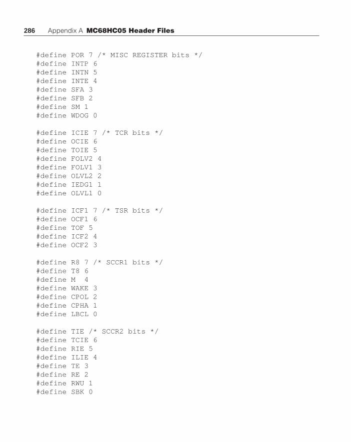
286 Appendix A MC68HC05 Header Files
#define POR 7 /* MISC REGISTER bits */#define INTP 6#define INTN 5#define INTE 4#define SFA 3#define SFB 2#define SM 1#define WDOG 0
#define ICIE 7 /* TCR bits */#define OCIE 6#define TOIE 5#define FOLV2 4#define FOLV1 3#define OLVL2 2#define IEDG1 1#define OLVL1 0
#define ICF1 7 /* TSR bits */#define OCF1 6#define TOF 5#define ICF2 4#define OCF2 3
#define R8 7 /* SCCR1 bits */#define T8 6#define M 4#define WAKE 3#define CPOL 2#define CPHA 1#define LBCL 0
#define TIE /* SCCR2 bits */#define TCIE 6#define RIE 5#define ILIE 4#define TE 3#define RE 2#define RWU 1#define SBK 0

287
#define TRDE 7 /* SCSR bits */#define TC 6#define RDRF 5#define IDLE 4#define OR 3#define NF 2#define FE 1
#define SCP1 7 /* BAUD bits */#define SCP0 6#define SCT2 5#define SCT1 4#define SCT0 3#define SCR2 2#define SCR1 1#define SCR0 0
#define TRUE 1 /* some useful macros */#define FALSE 0#define FOREVER while(TRUE)
#pragma option L+ /* turn the listing back on */
HC05C8.H Header File For The MC68HC05C8#pragma option L- /* Turn the listing off */
#pragma portrw PORTA @ 0x00;#pragma portrw PORTB @ 0x03;#pragma portrw PORTC @ 0x02;#pragma portr PORTD @ 0x03;#pragma portrw DDRA @ 0x04;#pragma portrw DDRB @ 0x05;#pragma portrw DDRC @ 0x06;#pragma portrw SPCR @ 0x0a;#pragma portrw SPSR @ 0x0b;#pragma portrw SPDR @ 0x0c;#pragma portrw BAUD @ 0x0d;#pragma portrw SCCR1 @ 0x0e;
HC05C8.H Header File For The MC68HC05C8

288 Appendix A MC68HC05 Header Files
#pragma portrw SCCR2 @ 0x0f;#pragma portrw SCSR @ 0x10;#pragma portrw SCDAT @ 0x11;#pragma portrw TCR @ 0x12;#pragma portrw TSR @ 0x13;#pragma portrw ICHI @ 0x14;#pragma portrw ICLO @ 0x15;#pragma portrw OCHI @ 0x16;#pragma portrw OCLO @ 0x17;#pragma portrw TCHI @ 0x18;#pragma portrw TCLO @ 0x19;#pragma portrw ACHI @ 0x1a;#pragma portrw ACLO @ 0x1b;#pragma portrw PROG @ 0x1c;#pragma portrw COPRST @ 0x1d;#pragma portrw COPCR @ 0x1e;#pragma portrw OPTION @ 0x1fdf;
#pragma vector __SPI @ 0x01ff4;#pragma vector __SCI @ 0x01ff6 ;#pragma vector __TIMER @ 0x01ff8;#pragma vector __IRQ @ 0x01ffa;#pragma vector __SWI @ 0x01ffc ;#pragma vector __RESET @ 0x01ffe;
#pragma has STOP ;#pragma has WAIT ;#pragma has MUL ;
#pragma memory ROMPAGE0 [48] @ 0x020;#pragma memory ROMPROG [8192] @ 0x100;#pragma memory RAMPAGE0 [176] @ 0x50;
#define COPF 4 /* COPCR bits */
#define CME 3#define COPE 2#define CM1 1#define CM0 0

289
#define ICIE 7 /* TCR bits */#define OCIE 6#define TDIE 5#define IEDG 1#define OLVL 0
#define ICF 7 /* TSR bits */#define OCF 6#define TOF 5
#define R8 7 /* SCCR1 bits */#define T8 6#define M 4#define WAKE 3
#define TIE /* SCCR2 bits */#define TCIE 6#define RIE 5#define ILIE 4#define TE 3#define RE 2#define RWU 1#define SBK 0
#define TRDE 7 /* SCSR bits */#define TC 6#define RDRF 5#define IDLE 4#define OR 3#define NF 2#define FE 1
#define SPIE 7 /* SPCR bits */#define SPE 6#define MSTR 4#define CPOL 3#define CPHA 2#define SPR1 1#define SPR0 0
HC05C8.H Header File For The MC68HC05C8

290 Appendix A MC68HC05 Header Files
#define SPIF 7 /* SPSR bits */#define WCOL 6#define MODF 4#define RAM0 7 /* OPTION bits */#define RAM1 6#define SECU 3#define IRP 1
#define LAT /* PROG bits */#define PGM 0
#pragma option L+ /* Turn the listing back on */

291
Appendix B
A typedef ExampleIn this appendix, the working code to inscribe a circle in a rectangle is completed.
The code differs little from than in the text. The major difference involves the coderequired to place the screen in the graphics mode and return it to the default mode.
/* Inscribe a circle in a rectangle */
#include <graphics.h>#include <bios.h>
typedef struct{
int x;int y;
}POINT;
typedef struct}
POINT center;int radius;
}CIRCLE;
typedef struct{
POINT p1;POINT p2;
}RECT;
CIRCLE make_circle( POINT ct, int rad ){
CIRCLE temp;
temp.center.x = ct.x;
291

292 Appendix B A typedef Example
temp.center.y = ct.y;temp.radius = rad;return temp;
}
void draw_circle(CIRCLE circ){
move_to(circ.center.x,circ.center.y);circle(circ.radius,14);
}
void draw_rectangle(RECT rect){
move_to(rect.p1.x,rect.p1.y);line_to(rect.p2.x,rect.p1.y);line_to(rect.p2.x,rect.p2.y);line_to(rect.p1.x,rect.p2.y);line_to(rect.p1.x,rect.p1.y);
}
#define min(a,b) (((a)<(b)) ? (a) : (b))#define abs(a) ((a)<0 ? -(a) : (a))
void draw_rectangle(RECT);void draw_circle(CIRCLE);
void main ( void ){
CIRCLE cir;POINT center;RECT window = { {80,80},{600,400} };int radius,xc,yc;
center.x = (window.p1.x+window.p2.x)/2;center.y = (window.p1.y+window.p2.y)/2;
xc = abs(window.p1.x - window.p2.x)/2;yc = abs(window.p1.y - window.p2.y)/2;radius=min(xc,yc);cir=make_circle(center,radius);
if(setvmode(VGA_16) != VGA_16) setvmode(HERCMODE);

293
draw_rectangle(window);draw_circle(cir);getch();setvmode(DEFAULTMODE);
}
The line of code
if(setvmode(VGA_16) != VGA_16) setvmode(HERCMODE);
determines if the machine can be placed in 16-color VGA mode. If it cannot be setto this mode, the machine is put into Hercules mode which most graphics machinescan run. The figures are drawn with standard C calls in Draw_circle() anddraw_rectangle(). After the figures are drawn, the program waits for a key-board input. When a keyboard input occurs, the machine is returned to its defaultmode, and the program is terminated.
A typedef Example

294 Appendix B A typedef Example

295
Appendix C
MC68HC11 BackgroundThe MC68HC11 contains many of the features of a stand-alone microcontroller
while at the same time it possesses features found only in general purpose computers.For example, most of these parts will come with internal memory and have anoperating mode that allows single chip operation. However, they can also be operatedin an expanded bus mode that allows the addition of external memory and peripher-als. As we shall see, the MC68HC11 family is complicated. When programming fora microcontroller in a high-level language, it is always necessary to have a muchmore detailed knowledge of the underlying computer than is necessary when pro-gramming for a larger machine. The essence of writing code for these machines is tobe able to access the on-board peripherals and control registers from a high-level lan-guage. One of the goals of a high-level language is to hide the nature of the computerfrom the programmer. This appendix, therefore, is devoted to the MC68HC11 micro-controller. To those programmers who know this part, you should skim this appendixand then proceed through Chapter 5 for details of programming this device in C.
MC68HC11 Hardware ConsiderationsFigure C-1 shows a block diagram of the MC68HC11E9. This device is but a
single part from a family of more than a dozen parts. Different members of theMC68HC11 family are designated by a suffix attached to the name of the part. Theseparts are in four main families designated by the letters A,D, E, and F. In addition to aletter suffix, there is a number that is usually the amount of on-board programmemory to be found on the part. If there is a large block of on-board electricallyerasable programmable read-only memory (EEPROM), the number 8 will be placedafter the HC in the device name. If the part contains untraviolet erasable program-mable read-only memory (EPROM), there will be the number 7 at this location in thedevice number. Therefore, a device with a name MC68HC811E2 is an E series partand it contains 2K bytes of EEPROM. Similarly, an MC68HC11E9 is an A series partwith 8 K bytes of mask ROM on-board the chip.
This text is on writing code for microcontrollers in the C language. It is not atext on the details of different microcontrollers. Therefore, enough features of the
295

296 Appendix C MC68HC11 Background
MC68HC11 to show various approaches to programming the chip in C will bediscussed. The text on the part is clearly not an exhaustive discussion of the devicesused. For a detailed description of the MC68HC11 family, you are referred to thefollowing:
• M68HC11 Reference Manual (Motorola #M68HC11RM/AD)• M68HC711E9 Technical Data (Motorola #M68HC711E9/D)• M68HC11D3 Technical Data (Motorola #MC68HC11D3/D)• M68HC11F1 Technical Data (Motorola #M68HC11F1/D)
Notice in Figure C-1 that the MC68HC11 family has five parallel or digital outputports designated ports A, B, C, D, and E. These different ports have individual inputand output pins. Ports A, B, C, and E each have eight connections to the circuit out-side of the chip, and port D has six connections. Each of these ports can serve multiplepurposes. Port A has three input only lines, four output only lines, and one line thatcan serve as both input or output. This port also provides access to the internal timersubsystem of the part.
Ports B and C can be used as standard I/O, or in the event that the part is operatingin expanded bus mode, these port pins provide a multiplexed address and data bus foraccess to the external peripherals. Port B is an output only port that has eight lines.This port contains the upper eight bits of the bus address when the chip is operating inthe expanded bus mode. Otherwise, the port B pins can be each used as an outputfrom the microcontroller. Port C is a bidirectional port that is multiplexed to providethe lower eight bits of the bus address and the chip data bus when operating in theexpanded bus mode. In the single chip mode, the pins of this port can be each used aseither a digital input or output to the microcontroller.
The direction of the pins on port C, either input or output, is controlled by theport data direction register (DDRC). The eight bits in DDRC correspond to theindividual port pins. When a bit in DDRC is set, turned on, or high, the correspondingbit in the port is an output and can be set or reset by the microcontroller program. Ifthe bit is reset—zero, low, or turned off—the corresponding port bit is an input. Whena bit is an input, its condition can be determined by the microcontroller program. Thecondition of any bit can be read by the program regardless of whether or not the bit is aninput or an output. All port pins are automatically set to input when the part is reset.
Two additional lines are associated with ports B and C. These lines are calledSTRA and STRB when operating in the single chip mode, and they are used forhandshake signals on ports B and C. In the expanded bus mode, these signals arecalled read/ write select and address strobe. These signals are used to control themultiplex of the data and address bus.
Port D contains only six bits. These bits are each input/output bits, and this porthas a six bit data direction register. Port D also serves as the connection to the twoserial subsystems on the microcontroller. Port E is an eight bit input-only port that is

297
used as inputs to the internal analog to digital converter system. Two inputs, VREFHand VREFL, provide reference voltages to the analog to digital converter.
The interrupt controller is connected to three external pins. The reset line isbidirectional. This signal must be asserted—set low—for at least four clock cycles toforce an external reset on the part. When the microcontroller senses a power on reset(POR), the reset line will be asserted for 4096 clock cycles. There is an internal clockmonitor. If the clock frequency drops below 200 kHz, a clock monitor reset will occurand the reset line will be asserted. The two interrupts, IRQ and XIRQ, are the primaryinterrupt signals into the computer. The IRQ is a maskable interrupt and the XIRQ isnonmaskable after it is enabled the first time.
MC68HC11 Hardware Considerations
ROM 8K Bytes
RAM 256 Bytes
EEPROM 512 Bytes
Accumulator
Periodic Int.
COP Timer
TIMER SUBSYSTEM
P A 7P A 6P A 5P A 4P A 3P A 2P A 1P A 0
P A 1O C 2O C 3O C 4O C 5I C 1I C 2I C 3
SPI
SCI
P D 5P D 4P D 3P D 2
PD 1PD 0
PE7PE6PE5PE4PE3PE2PE1PE0V R EF HV R EF L
MC68HC11 CPU
ADDRESS/DATA BUS
HANDSHAKE I/O
DATA DIRECTION C
PORT CPORT B
INTERRUPTS
OSCILLATOR
POWER
MODESELECT
Vss Vdd
RESET*
XIRQ*IRQ*
XTAL
EXTAL
E
MODA
MODB
EXPANDED BUS PORT
SINGLE CHIP MODE PORT
Figure C-1: MC68HC11 Block Diagram

298 Appendix C MC68HC11 Background
The oscillator subsystem has three connections to the outside of the chip. Thesignal lines XTAL and EXTAL comprise the two connections needed to use theinternal oscillator. This oscillator can be driven by a crystal, a ceramic resonator, oreven an RC circuit. Details of how to connect this oscillator can be found in (1). Thethird line from the oscillator is called E. This signal is the bus clock of the part and itis called the E clock. It runs at one-fourth of the oscillator frequency, and can be usedto synchronize external activities with the computer system.
MODA and MODB are pins that can be used to force the microcontroller into adesired mode at power-up. The four distinct modes in which the chip can operate arethe special bootstrap, special test, single chip, and expanded multiplexed modes.After the operating mode has been selected, these two pins change function. TheMODA pin becomes the LIR* pin. This pin is an open drain pin that indicates that aninstruction is starting to execute. The LIR* pin goes low during the first E clock cyclewhen an instruction is being fetched from memory.
VSTBY is the second function of the MODB pin. This pin provides a means ofpowering the internal RAM of the chip when the regular power is removed from thechip.
MC68HC11 On-Board Peripheral ComponentsAll peripheral components on the MC68HC11 microcontroller are accessed and
controlled through registers. These registers are memory mapped. Figure C-2 con-tains a map of the control registers used with this part. All of the registers are groupedtogether and in the figure their addresses are shown to begin at the 0x1000. We willsee later that 0x1000 is the default address of this memory block, and it can be movedto the beginning of any 4K block in the memory map. Details of the contents of thisregister array are found in component technical data manuals.
Memory SubsystemThe MC68HC11E9 contains 8K bytes of internal ROM. This memory can be
mask programmed at time of manufacture only. The family has components thatcontain no ROM to 24K bytes of ROM. There are also parts that contain variousamounts of EPROM which allows convenient development of systems containing thecomponents. A second version of the EPROM parts are the one-time programmableparts. These parts should be used for small production runs where it is not practical toprogram a masked part.
EEPROM is included on most of the MC68HC11 parts. This memory comes intwo varieties. There is usually a 512 byte block of EEPROM. This EEPROM issoftware writable. It is usually used to store data that must be saved through powerdown. This memory area is not often used to store program.

299MC68HC11 On-Board Peripheral Components
Figure C-2: MC68HC11E9 Register Memory Map
The sequence of events required to store data in the EEPROM of an MC68HC11is similar to that for the MC68HC05. The register used to control the EEPROMprogramming is the PPROG register at location 0x103b. The high order bits ofPPROG contain the EVEN and ODD bits used in factory test and should not be usedin normal operation. The EEPROM memory is organized into 16 rows of 32 byteseach. The program can program a row at a time or a byte at a time. Erasing a row at atime will allow the entire memory array to be erased much quicker than is possible ifthe memory is erased a byte at a time.
Bit 7 Bit 6 Bit 5 Bit 4 Bit 3 Bit 2 Bit 1 Bit 00x1000 Bit 7 - - - - - - Bit 0 PORTA I/O Port A0x1001 Reserved0x1002 STAF STAI CWOM HNDS OIN PLS EGA INVB PIOC Parallel I.O Control Reg.0x1003 Bit 7 - - - - - - Bit 0 PORTC I/O Port C0x1004 Bit 7 - - - - - - Bit 0 PORTB Output Port B0x1005 Bit 7 - - - - - - Bit 0 PORTC L Alternate Latched Port C0x1006 Reserved0x1007 Bit 7 - - - - - - Bit 0 DDRC Data Direction Reg. C0x1008 - - - - - - Bit 0 PORTD I/O Port D0x1009 - - - - - - Bit 0 DDRD Data Direction Reg. D
0x100a Bit 7 - - - - - - Bit 0 PORTE Input Port E0x100b FOC1 FOC2 FOC3 FOC4 FOC5 CFORC Compare Force Register0x100c OC1M7 OC1M6 OC1M5 OC1M4 OC1M3 OC1M OC1 Action Mask Reg.0x100d OC1D7 OC1D6 OC1D5 OC1D4 OC1D3 OC1D OC1 Action Data Reg.0x100e Bit 15 - - - - - - Bit 8 TCNT Timer Counter Register0x100f Bit 7 - - - - - - Bit 00x1010 Bit 15 - - - - - - Bit 8 TIC1 Input Capture Register 10x1011 Bit 7 - - - - - - Bit 00x1012 Bit 15 - - - - - - Bit 8 TIC2 Input Capture Register 20x1013 Bit 7 - - - - - - Bit 00x1014 Bit 15 - - - - - - Bit 8 TIC3 Input Capture Register 30x1015 Bit 7 - - - - - - Bit 00x1016 Bit 15 - - - - - - Bit 8 TOC1 Output Compare Register10x1017 Bit 7 - - - - - - Bit 00x1018 Bit 15 - - - - - - Bit 8 TOC2 Output Compare Register20x1019 Bit 7 - - - - - - Bit 00x101a Bit 15 - - - - - - Bit 8 TOC3 Output Compare Register30x101b Bit 7 - - - - - - Bit 00x101c Bit 15 - - - - - - Bit 8 TOC4 Output Compare Register40x101d Bit 7 - - - - - - Bit 00x101e Bit 15 - - - - - - Bit 8 TI405 Output Compare Register50x101f Bit 7 - - - - - - Bit 0

300 Appendix C MC68HC11 Background
Bit 7 Bit 6 Bit 5 Bit 4 Bit 3 Bit 2 Bit 1 Bit 00x1020 OM2 OL2 OM3 OL3 OM4 OL4 OM5 OL5 TCTL1 Timer Control Register 10x1021 0 0 EDG1B EDG1A EDG2B EDG2A EDG3B EDG3A TCTL2 Timer Control Register 20x1022 OC11 OC21 OC31 OC41 I405I IIC11 IC21 IC31 TMSK1 Timer Int. Mask Reg. 10x1023 OC1F OC2F OC3F OC4F I4O5F IC1F IC2F IC3F TFLG1 Timer Int. Flag Reg. 10x1024 TOI IRII PAOVI PAII PR1 PR0 TMSK2 Timer Int. Mask Reg. 20x1025 TOF RTIF PAOVF PAIF TFLG2 Timer Int. Flag Reg. 20x1026 DDRA7 PAEN PAMOD PEDGE DDRA3 I4O5 RTR1 RTR0 PACTL Pulse Accum. Cont. Reg.0x1027 Bit 7 - - - - - - Bit 0 PACNT Pulse Accumulate Reg.0x1028 SPIE SPE DWOM MSTR CPOL CPHA SPR1 SPR0 SPCR SPI Control Register0x1029 SPIF WCOL MODF SPSR SPI Status Register0x102a Bit 7 - - - - - - Bit 0 SPDR SPI Data Register0x102b TCLR SCP1 SPC0 RCKB SCR2 SCR1 SCR0 BAUD SCI Baud Rate Control0x102c R8 T8 M WAKE SCCR1 SCI Control Register 10x102d TIE TCIE RIE ILIE TE RE RWU SBK SCCR2 SCI Control Register 20x102e TDRE TC RDRF IDLE OR NF FE SCSR SCI Status Register0x102f Bit 7 - - - - - - Bit 0 SCDR SCI Data Register0x1030 CCR SCAN MULT CD CC CB CA ADCTL A/D Control Register0x1031 Bit 7 - - - - - - Bit 0 ADR1 A/D Result Register 10x1032 Bit 7 - - - - - - Bit 0 ADR2 A/D Result Register 20x1033 Bit 7 - - - - - - Bit 0 ADR3 A/D Result Register 30x1034 Bit 7 - - - - - - Bit 0 ADR4 A/D Result Register 40x1035 PTCON BPRT3 BPRT2 BPRT1 BPRTO BPROT EEPROM Block Protect0x1036 Reserved0x1037 Reserved0x1038 Reserved0x1039 ADPU CSEL IRQE DLY CME CR1 CR0 OPTION System Config. Register0x103a Bit 7 - - - - - - Bit 0 COPRS T Arm/Reset COP Timer0x103b ODD EVEN BYTE ROW ERASE EELAT EEPGM PPROG EEPROM Program Cont.0x103c RBOOT SMOD MDA IRV PSEL3 PSEL2 PSEL1 PSEL0 HPRIO High Priority/MISC.0x103d RAM3 RAM2 RAM1 RAM0 REG3 REG2 REG1 REG0 INIT RAM and I/O Mapping0x103e TILOP OCCR CBYP DISR FCM FCOP TCON TEST! Factory Test Register0x103f NOSEC COCOP RMON EEON CONFIG Configuration Register
Figure C-2: MC68HC11E9 Register Memory Map (continued)
All MC68HC11 components contain internal RAM. This RAM can be backed upby a battery and will retain its contents when the main system power is removed. Thebattery back-up system provides that the battery voltage applied to the MODB pinwill supply the internal RAM when the supply voltage VDD is less than 0.7 voltsbelow the battery voltage.
The register map shown in Figure C-2 is by default located at the address 0x1000.Also, the 512 bytes of RAM is located at the address 0x0. These two blocks can be

301
addressed to the beginning of any 4K—0xK000—memory block in the memory map.The RAM and I/O mapping register (INIT ) is located at address 0x103d. The upperfour bits of this register contain the most significant four bits of the RAM address.The lower four bits of this register contains the most significant four bits of the I/Oregister map. This register can be written only once and then only during the first 64clock cycles after reset. After this time, this register becomes a read-only register.
If the RAM is mapped into a memory area that conflicts with internal ROM onthe part, the RAM will take priority, and the conflicting ROM will be inaccessible.Also, if the I/O register map is mapped into an area that conflicts with either RAM orinternal ROM, the I/O memory map will take precedence, and the 64 byte memoryarea associated with the I/O memory map will be inaccessible to the RAM or ROM.The bit utilization of this register is shown in Figure C-3 below.
Figure C-3: Bit Configuration Of The INIT Register
Timer SubsystemAll of the port pins on the MC68HC11 family serve multiple functions. We have
seen that ports B and C are either input/output pins or expanded, multiplexed databus. Port A pins are either input or output pins, but port A is also the externalconnection to the timer subsystem of the part. The timer subsystem has three inputcaptures, four output compares, one programmable input capture/output compare,and a pulse accumulator. Each of these devices has a connection to the outside of thechip through port A. PA0, PA1, and PA2 are input only lines that are also inputs to thethree input capture systems in the part. PA3, PA4, PA5, and PA6 are output only linesthat serve as the outputs from the four output compare systems. PA7 is a bidirectionalline that is connected to the internal pulse accumulator; alternatively, PA7 can be anoutput compare or input capture line.
The operation of all of the timer subsystem are controlled by registers and bitswithin registers in the register memory map. The registers in the range 0x100cthrough 0x1027 are the registers that affect the operation of the timer subsystem. Theregisters at 0x100c and 0x100d will be discussed later. The 16-bit register at 0x100eX—the two one byte registers 0x100e and 0x100—is the timer counter register (TCR).This register can be read at any time, but it cannot be altered by the program. Thisregister should be read by a double byte read, for example LDD load the 16-bit Dregister. If the TCR low byte is accessed by a read operation, the value of the contentswill be read. If, however, the high byte is accessed first (as occurs with a double byteread), there is a transparent buffer on the low byte of the TCR that is inhibited for one
INIT Bit 7 Bit 6 BIt 5 Bit 4 Bit 3 Bit 2 Bit 1 Bit 0
0x103d RAM3 RAM2 RAM1 RAM0 REG3 REG2 REG1 REG0
MC68HC11 On-Board Peripheral Components

302 Appendix C MC68HC11 Background
bus cycle. This operation freezes the contents of the buffer until the second read iscompleted. Therefore, the two bytes belonging to each other areread by the doublebyte read.
The input capture registers and output compare registers are found in the memoryrange 0x1010 to 0x101f. These registers work the same as the corresponding registersfound in the MC68HC05 family. Control of these registers is somewhat more com-prehensive in the MC68HC11 family.
Bits 0 and 1 of the register TMSK2 at address $0x1024 control a prescaler thatsets the frequency of the input to the TCR. The external oscillator frequency on thepart is divided by four to create the internal bus frequency. A signal of this frequencyis delivered to the outside of the part as the E clock signal. The prescaler receivesthe E Clock as an input. The four possible conditions of the prescaler will allow the Eclock frequency to be divided by 1, 4, 8, or 16. The prescaler bits of TMSK2 can bewritten during the first 64 clock cycles after system reset. Otherwise, these bits areread-only bits.
Figure C-4 contains outlines of the TMSK2 and the TFLG2 registers. The bits inthese registers work in conjunction. Each active bit in the TFLG2 register has acorresponding bit in the TMSK2 register. The active bits in the TFLG2 register areeach set when a corresponding event in the timer subsystem occurs. If the corre-sponding bit in the TMSK2 register is set, an interrupt will occur when the timersubsystem event occurs. Otherwise, the bit in TFLG2 is set and can be tested by theprogram synchronously.
Figure C-4: TMSK2 And TFLG2 Registers
The bits in the TMSK2 register are as follows:
PR0, PR1 Bits 0,1 These bits control the E Clock prescaler input into the timercounter register. The prescaler divide is eight times the binarycontents of the prescaler bits.
PAII Bit 4 Pulse accumulator edge interrupt enable bit. An interrupt willoccur whenever an edge is detected on the Pulse AccumulatorInput.
TMSK2 Bit 7 Bit 6 BIt 5 Bit 4 Bit 3 Bit 2 Bit 1 Bit 0
0x1024 TOI RTI PAOVI PAII 0 0 PR1 PRO
TFLG2 Bit 7 Bit 6 BIt 5 Bit 4 Bit 3 Bit 2 Bit 1 Bit 0
0x1025 TOF RTIF PAOVF PAIF 0 0 0 0
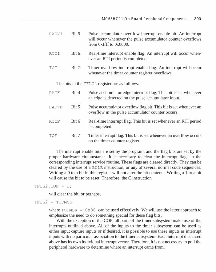
303
PAOVI Bit 5 Pulse accumulator overflow interrupt enable bit. An interruptwill occur whenever the pulse accumulator counter overflowsfrom 0xffff to 0x0000.
RTII Bit 6 Real-time interrupt enable flag. An interrupt will occur when-ever an RTI period is completed.
TOI Bit 7 Timer overflow interrupt enable flag. An interrupt will occurwhenever the timer counter register overflows.
The bits in the TFLG2 register are as follows:
PAIF Bit 4 Pulse accumulator edge interrupt flag. This bit is set wheneveran edge is detected on the pulse accumulator input.
PAOVF Bit 5 Pulse accumulator overflow flag bit. This bit is set whenever anoverflow in the pulse accumulator counter occurs.
RTIF Bit 6 Real-time interrupt flag. This bit is set whenever an RTI periodis completed.
TOF Bit 7 Timer interrupt flag. This bit is set whenever an overflow occurson the timer counter register.
The interrupt enable bits are set by the program, and the flag bits are set by theproper hardware circumstance. It is necessary to clear the interrupt flags in thecorresponding interrupt service routine. These flags are cleared directly. They can becleared by the use of a BCLR instruction, or any of several normal code sequences.Writing a 0 to a bit in this register will not alter the bit contents. Writing a 1 to a bitwill cause the bit to be reset. Therefore, the C instruction
TFLG2.TOF = 1;
will clear the bit, or perhaps,
TFLG2 = TOFMSK
where TOFMSK = 0x80 can be used effectively. We will use the latter approach toemphasize the need to do something special for these flag bits.
With the exception of the COP, all parts of the timer subsystem make use of theinterrupts outlined above. All of the inputs to the timer subsystem can be used aseither input capture inputs or if desired, it is possible to use these inputs as interruptinputs with no particular association to the timer subsystem. Each interrupt discussedabove has its own individual interrupt vector. Therefore, it is not necessary to poll theperipheral hardware to determine where an interrupt came from.
MC68HC11 On-Board Peripheral Components

304 Appendix C MC68HC11 Background
Input Capture and Output Compare SystemsThe input capture and output compare systems are similar to those found on the
MC68HC05 family. The free running counter is continuously being updated by theinternal system clock. When an input capture input occurs, the contents of the freerunning counter are saved in the proper input capture register. At this time, thecorresponding input capture flag in TFLG1 is set. If the corresponding input captureinterrupt enable bit is set in TMSK1, an interrupt will occur. Otherwise, it is necessaryfor the program to observe that the flag bit is set, reset the flag bit, and process thecontents of the input capture register. Input captures are used to measure the times ofasynchronous events
Each output compare system has an internal output compare register. When thecontents of the timer counter register match the contents of the output compareregister, the proper output compare flag bit is set in TFLG1 . If the corresponding bitin TMSK1 is set, an interrupt will occur. Output compare systems are used to generatetime periods that are very flexible. The two registers TFLG1 and TMSK1 are shownbelow.
Figure C-5: TMSK1 And TFLG1 Registers
The bits in the TMSK1 register are as follows:
ICxI Input capture interrupt enable flags. If set an interrupt is re-quested when the corresponding ICxF flag bit is set.
OCxI Output compare interrupt enable flags. If set an interrupt isrequested when the corresponding OCxF flag bit is set.
The bits in the TFLG1 register are as follows:
ICxF Input capture flags. This bit is set when an input capture occurson the corresponding timer input. Writing zero to this bit does notaffect its contents. Writing one to this bit causes it to be reset.
OCxF Output compare flags. This bit is set when an output compareoccurs on the corresponding timer output. Writing zero to thisbit does not affect its contents. Writing one to this bit causes itto be reset.
TMSK1 Bit 7 Bit 6 BIt 5 Bit 4 Bit 3 Bit 2 Bit 1 Bit 0
0x1022 OC1I OC2I OC3I OC4I OC5I IC1I IC2I IC3I
TFLG1 Bit 7 Bit 6 BIt 5 Bit 4 Bit 3 Bit 2 Bit 1 Bit 0
0x1023 OC1F OC2F OC3F OC4F OC5F IC1F IC2F IC3F

305
The timer control register 2 controls the edges on which an input to the inputcapture system occurs. This register is as follows:
Figure C-6: TCTL2 Register
The values of these bit pairs chose the edge on which the input to the inputcapture occurs. The following table contains this encoding:
The output compare systems accomplish somewhat more than was seen with theMC68HC05 components. In this family, there are five output compare systems ineach part. Four of these output compares perform identically to each other. There isone output compare that has special functions in addition to its normal operations.
We have already seen how the TMSK1 and TFLG1 registers are used to controlthe interrupts with the output compare system. The output pin associated with eachoutput control is controlled by the contents of the TCTL1 register:
Figure C-7: TCTL1 Register
These bit controls are used in accordance with the following table:
Note that there is no OMx or OLx for output compare channel 1. These controlbits are contained in the special OC1 action registers. These registers are as follows:
TCTL2 Bit 7 Bit 6 BIt 5 Bit 4 Bit 3 Bit 2 Bit 1 Bit 0
0x1021 0 0 EDG1B EDG1A EDG2B EDG2A EDG3B EDG3A
EDGxB EDGxA Configuration
0 0 No Input Capture
0 1 Rising Edge Capture
1 0 Falling Edge Capture
1 1 Any Edge Capture
TCTL1 Bit 7 Bit 6 BIt 5 Bit 4 Bit 3 Bit 2 Bit 1 Bit 0
0x1020 OM2 OL2 OM3 OL3 OM4 OL4 OM5 OL5
EDGxB EDGxA Configuration
0 0 OCx does not affect pin
0 1 Toggle OCx pin on compare
1 0 Clear OCx pin on compare
1 1 Set OCx on compare
MC68HC11 On-Board Peripheral Components

306 Appendix C MC68HC11 Background
Figure C-8: OC1M And OC1D Registers
The bits in the OC1M and the OC1D registers work together. If a bit in the OC1Mregister is set, say the OC1M5 , then when output compare 1 (OC1) occurs, output OC3will also indicate that OC1 1 has happened. The output that occurs on OC3 will be thecondition set in OC1DC. With the above capabilities, one output compare output,OC1, can control up to the remaining four OCx outputs. Also, OC1 can be used jointlywith several of the other OCx outputs to create multiple pulse width modulationoutputs. Implementations of these operations in C are shown in Chapter 5.
It is sometimes desirable to have an output from an output compare occur ondemand. The compare force register accommodates this need:
Figure C-9: Compare Force Register
If the program sets FOCx it will cause the action programmed for output comparex to occur. The OCxF flag will not be set, and no interrupt will occur. FOCx of zerowill cause no action.
Pulse AccumulatorThe pulse accumulator is an 8-bit counter that is controlled by the PACTL
register.
Figure C-10: Pulse Accumulator Control Register
The bit functions of this register are as follows:
RTR1 Bit 1 Real time interrupt rates, see below.RTR0 Bit 0
PEDGE Bit 4 Pulse accumulator edge control. This bit works in conjunctionwith PAMD bit as follows:
OC1M Bit 7 Bit 6 BIt 5 Bit 4 Bit 3 Bit 2 Bit 1 Bit 0
0x100c OC1M7 OC1M6 OC1M5 OC1M4 OC1M3 0 0 0
OC1D Bit 7 Bit 6 BIt 5 Bit 4 Bit 3 Bit 2 Bit 1 Bit 0
0x100d OC1D7 OC1D6 OC1D5 OC1D4 OC1D3 0 0 0
CFORC Bit 7 Bit 6 BIt 5 Bit 4 Bit 3 Bit 2 Bit 1 Bit 0
0x100b FOC1 FOC2 FOC3 FOC4 FOC5 0 0 0
PACTL Bit 7 Bit 6 BIt 5 Bit 4 Bit 3 Bit 2 Bit 1 Bit 0
0x1026 DDRA7 PAEN PAMD PEDGE 0 0 RTR1 RTR0

307
PAMD Bit 5 Pulse accumulator mode. When this bit is zero, the pulse accu-mulator counts external events. When this bit is 1, the pulseaccumulator is in the gated time accumulation mode.
PAEN Bit 6 Pulse accumulator system enable bit. The pulse accumulatorsystem is enabled when this bit is 1.
DDRA7 Bit 7 Data direction bit for Port A Bit 7. Port A Bit 7 is an output ifthis bit is 1.
In the event counting mode, the 8-bit pulse accumulator counter is incrementedeach time an input is detected on the pulse accumulator input. The maximum accu-mulator rate is E clock divided by 2 (0.5 MHz for a 4 MHz crystal frequency). In thegated accumulation mode, the 8-bit counter is driven by a frequency of one sixty-fourth of the E clock. This counting occurs only when the PAI pin is properlyasserted.
Real Time InterruptIn Chapter 4, several timer interrupt sequences were demonstrated. In each case,
these interrupts were programmed to occur periodically, and the system time basewas derived from these interrupts. The MC68HC11 family has a real time interruptthat will allow these types of operations to occur without having the somewhatcomplicated interrupt service routines seen in Chapter 4. A real time interrupt is aninterrupt sequence that occurs periodically. The business in the interrupt serviceroutine is merely to reset the RTIF —real time interrupt flagæwhenever the interruptoccurs. There is no need to update an output compare register to a new value inpreparation for the next interrupt. The real time interrupt enable—RTI —bit is foundin the TMSK2 register and the RTIF (real time interrupt flag) is found in the TFLG2register. Operations of these bits are discussed following Figure C-4. The followingtable shows the rates at which real time interrupts occur for differing values of RTR1and RTR0:
PAMD PEDGE Configuration
0 0 Falling Edge Input
0 1 Rising Edge Input
1 0 0 on PAI Inhibits Counting
1 1 1 on PAI Inhibits Counting
RTR1 RTR0 Interrupt Frequency-e/2^13 divided by
0 0 1
0 1 2
1 0 3
1 1 4
MC68HC11 On-Board Peripheral Components

308 Appendix C MC68HC11 Background
The real time interrupt operation can be polled rather than interrupt driven. If theRTI bit is not set, the RTIF flag will be set whenever the real time period expires. Ifthe operation is being used in this synchronous manner, it is necessary that the RTIFbe reset in preparation for completion of the next time period whenever it is found tobe set. The RTIF is reset in the same manner as any of the other interrupt flags as dis-cussed earlier.
Computer Operating ProperlyThe computer operating properly (COP) system is an excellent safeguard against
accidental loss of control by the microcontroller. The COP system is a timer thatcounts at a somewhat slower rate than the slowest periodic operation within themicrocontroller. The COP counter can be reset to 0 by first writing a 0x55 to theCOPRST register in the I/O register map followed by writing a 0xaa to the samelocation. The first write arms the timer clearing mechanism, and the second writeclears the contents of the COP counter. If the COP counter ever overflows, themicrocontroller will be reset. In other words, the program must periodically reset theCOP counter. If the program gets lost for some reason and does not reset the COPcounter, the part will be reset and reinitialize the program. This sequence shouldrecover the system from its lost condition.
The COP is designed to rely minimally on the microcontroller. The COP can beturned off by the program on initialization, but the part must be reinitialized after theCOP is disabled before the change can take place. The microcontroller oscillator and avery simple ripple counter is used to generate the COP frequency. This frequency andthe operation of the COP itself does not depend on any way on the competentoperation of the microcontroller. Therefore, the COP operation is as nearly independentof the actual microcontroller operation as can be accomplished on the same silicon.
The COP operating period is set by the condition of CR1 and CR2 in the OPTIONregister as follows:
Serial Communications SubsystemsThere are two serial communications subsystems on the MC68HC11 family of
parts. The first is an asynchronous system that provides serial communications—SCI—that is compatible with modems and terminals. This relatively slow communi-cations system will communicate with practically any terminal or other asynchronoussystem. The SCI is a competent universal asynchronous receiver transmitter system.
CR1 CR2 COPFrequency-E/2^15 divided by
0 0 1
0 1 4
1 0 16
1 1 64

309
The second serial system is a high speed synchronous system called a serialperipheral interface (SPI). The SPI is designed to communicate at very high ratesbetween microcontrollers and other peripheral components that can access these highrates. Since the Motorola microcontrollers mostly have SPI systems, the logicalapproach to communicate between two or more microcontrollers is through their SPIsystems.
Both the SCI and the SPI make use of the pins of Port D. Therefore, the conditionof the Data Direction Register for Port D is important to operation of either of theserial communications devices. The Port D Data Direction Register, DDRD, is shownin Figure C-17.
Figure C-11: DDRD And Serial I/O Control
Bits 0 through 7 are data detection register bits for Port D. It is also necessary toset these bits correctly for the proper operation of the serial communications capabil-ity of the microcontroller. Normally, in a data direction register, setting a bit to onewill cause the corresponding port line to be an output. The reference operations ofthese bits are as follows:
RxD Bit 0 SCI receiver input bit. When the RE bit in the SCCR2 registeris set, the operation of Port D bit 0 is controlled by the SCI.A value written to this bit will not alter the output state; how-ever, any value will be retained in a latch and will be deliveredto bit D0 when the SCI is disabled if DDRD0 is set.
TxD Bit 1 SCI transmit output bit. When the SCI transmitter is active, bit1 of DDRD is overridden and the output buffer is forced tooutput and is driven by the SCI output.
MISO Bit 2 Master in/slave out. When the SPI system is enabled as amaster, SPE=1 and MSTR=1 in the SPCR , this line becomes theSPI receiver input. This operation does not depend on thecondition of DDRD bit 2. If the SPI system is enabled as a slave,SPE=1 and MSTR=0, this pin is the SPI output line and DDRDbit 2 must be set to allow this pin to be an output.
MOSI Bit 3 Master out/slave in. When the SPI system is enabled as amaster, SPE=1 and MSTR=1 in the SPCR, this line becomes theSPI transmit output DDRD bit 3 must be set the part is to operateas a master. If the SPI system is enabled as a slave, SPE=1 andMSTR=0, this pin is the SPI input line. This operation does notdepend on the condition of DDRD bit 3.
Serial Communications Subsystems
0x1009 Bit 7 Bit 6 BIt 5 Bit 4 Bit 3 Bit 2 Bit 1 Bit 0
DDRD - - DDRD5 DDRD4 DDRD3 DDRD2 DDRD1 DDRD0
REFERENCE - - SS* SCK MOSI MISO TxD RxD

310 Appendix C MC68HC11 Background
SCK Bit 4 Serial clock for SPI. When theSPI system is enabled as a slave,the SCK pin acts as the SPI serial clock input. This pin is aninput regardless of the state of DDRD bit 4. When the SPI sys-tem is enabled as a master, the SCK pin acts as the system SPIserial clock output. The DDRD bit 4 must be set to force this pinto be an output.
SS* Bit 5 This pin is a multipurpose signal. When the SPI system isenabled as a slave, this pin is the slave select input regardlessof the value of DDRD bit 5. When the SPI system is enabled as amaster, the function of this pin depends on the setting of DDRDbit 5.
0 = The SS* pin is used as an input to detect mode fault errors. Alow on this pin indicates that another device on a multiplemaster system is trying to use this device as a slave. It ispossible to create output contention in this situation. To avoidpossibly harmful contention, the device detecting mode faultimmediately changes all of its SPI pins to high impedance.
1 = The pin acts as a general purpose output not affected by the SPIsystem. The mode fault detection is disabled.
The Serial Communications InterfaceThe serial communications interface (SCI) of the MC68HC11 family is a univer-
sal asynchronous receiver transmitter (UART). This UART is capable of full duplexcommunications at a variety of baud rates. The input and output for this system bothuse logic level signals, so that an interface will be needed to convert these logic levelsignals to standard communication signals such as RS232 or RS422 before they canbe connected to external communications devices. All of the input/output for both theSCI and the SPI is through Port D. The discussion of the Port D pin use and the Port Ddata direction register is found in the following section of the serial peripheralinterface.
The SCI is comprised of two separate components: the receiver and the transmit-ter. These two components are—with the exception of the baud rate generator—completely independent. The receiver serves to convert the serial data received by thesystem to parallel date, and perform several tests on the incoming data to assureintegrity of the received data. The receiver is double buffered, so that the program hasapproximately one received character time to process the incoming data before it isoverwritten by the next received character. The system can process either 8- or 9-bitcharacter streams.

311
A wake-up mode is available for the receiver. When placed in the wake-up orstandby mode, the receiver does not normally respond to data received on the serialinput. The receiver system has two special wake-up operations that will remove itfrom the standby mode. The first is called idle line detect. In this mode, the receiverwill sense continuing data transfers on the receive line, and if the line is idle for a timeperiod corresponding to one complete character, the receiver will be enabled. Thesecond approach is the address mark method. With this method, the most significantbit of each character in the data stream must be zero. When the receiver detects thatthe most significant bit of a character is one, the receiver wakes up to processes thatcharacter. This character is usually an identifier of some sort that will let the receiverknow if the following data stream is directed to it. If it is not for the microcontroller,the receiver will be placed back into the standby mode. This method is used with aseven bit ASCII data set and 8-bit character transmissions, or the optional 9-bitcharacter length is used with an 8-bit character set.
Data bits are sampled at the time center of when each incoming bit should occur.This sampling can occur because the sample clock is run at 16 times the baud rate ofthe receiver. Each bit is sampled three times, and if all three bits are not the same, thebit value selected is the sample that occurs most often. In other words, a vote is takenand the most popular result is selected. Whenever such a sequence occurs, a noiseflag is set to notify the program that noisy data has been receiver.
If the transmitter serial register is empty when data are written to the transmit dataregister, the data are immediately transferred to the serial register, and the transmitsequence is initiated. An interrupt can occur whenever the transmit data register isemptied to allow for continuous flow of serial data from the output of the transmitsystem.
The SCI is controlled by a series of registers that are shown in Figure C-2. Theseregisters are found in the address range of 0x102b to 0x102f. Each of these registers isdiscussed below.
The baud rate of the SCI is controlled by bits in the BAUD register located at theaddress 0x102b. This register is shown below.
Figure C-12: BAUD Register
The bits in the BAUD Register are as follows:
SCR0-SCR2 Bit 0,1,2 These bits are the baud rate select bits. These control bitswork in conjunction with the prescaler bits in accor-dance with the table shown below.
BAUD Bit 7 Bit 6 BIt 5 Bit 4 Bit 3 Bit 2 Bit 1 Bit 0
0x102b TCLR 0 SCP1 SCP0 RCKB SCR2 SCR1 SCR0
Serial Communications Subsystems

312 Appendix C MC68HC11 Background
RCKB Bit 3 This bit is a baud rate clock test bit and is used in the testmode only.
SCP0-SCP1 Bit 4,5 These bits are the baud rate prescaler bits. These bitscreate a signal with a frequency of the E clock dividedby 1, 3, 4, or 13.
TCLR Bit 7 This bit is the clear baud rate timing chain and is used inthe test mode only.
The two tables below are taken from the MC68HC11 Reference Manual (Motorola#MC68HC11RF/AD Rev. 1). The first table is a listing of several maximum baudrates available from the baud rate generator for different crystal frequencies. Maxi-mum baud rates are shown for the settings of the baud rate scaling bits, SCP0 andSCP1. These rates are also shown for several different crystal frequencies. The nexttable provides SCI baud rates based upon the highest baud rate taken from the firsttable. In this table, the SCI baud rate selection bits SCR0 through SCR2 values arechosen to give the different final
Figure C-13: Baud Rate Prescaler Selects
baud for the system. All standard baud rates from 75 to 19200 bits per second areavailable with the crystal frequencies shown above.
Figure C-14: Baud Rate Selects
Crystal Frequency
SCP1 SCP0 Division 2^23 Hz 8 MHz 4.9152 MHz 4 MHz 3.6864 MHzFactor Highest Baud Rate
0 0 1 131072 125000 76800 62500 57600
0 1 3 43691 41667 25600 20833 19200
1 0 4 32768 31250 19200 15625 14400
1 1 13 10082 9600 5908 4800 4431
SCR2 SCR1 SCR0 Division Highest Baud RateFactor 131.072 K 32.768 K 76.80 K 19.20 K 96.00 K
SCI Baud Rate
0 0 0 1 131072 32768 76800 19200 9600
0 0 1 2 65536 16384 36.4 K 9600 4800
0 1 0 4 32768 8192 19.2 K 4800 2400
0 1 11 8 16384 4096 9600 2400 1200
1 0 0 16 8192 2048 4800 1200 600
1 0 1 32 4096 1024 2400 600 300
1 1 0 64 2048 512 1200 300 150
1 1 1 128 1024 256 600 150 75

313
The SCI Control Register 1, SCCR1, is located at 0x102c. This register containstwo control bits and the most significant bits for data transfer if a 9-bit data format isselected.
Figure C-15: SCCR1 Register
WAKE Bit 3 Wake-up selection. If 0, in idle line mode, and will wake upwhen a full character time of idle line is received. If 1, inaddress mark mode, and will wake up whenever the mostsignificant bit of the received character is one.
M Bit 4 Character length bit. When this bit is 0, a transmitter or re-ceived character will consist of one start bit, eight data bits,and one stop bit. When this bit is 1, a transmitted or receivedcharacter will consist of one start bit, nine data bits, and onestop bit.
T8 Bit 6 The ninth and most significant bit of the transmit data registerTDR when the M bit is one.
R8 Bit 7 The ninth and most significant of the receive data register RDRwhen the M bit is one.
The control register SCCR2 is the main control register for the SCI.
Figure C-16: SCI Secondary Control Register
The use of these bits is as follows:
SBK Bit 0 Send break. When 0, normal transmission occurs. When 1, atleast one break sequence is sent. A break sequence is 10 or 11bit times of logic zero. The length of the sequence is deter-mined by the status of the M bit in SCCR1.
RWU Bit 1 Receiver wake-up. When 0, normal operation, the wake-upfeature is not enabled. When 1, places the SCI receiver in thestand-by mode. The condition that causes wake-up depends onthe state of the WAKE bit in SCCR1.
SCCR1 Bit 7 Bit 6 BIt 5 Bit 4 Bit 3 Bit 2 Bit 1 Bit 0
0x102c R8 T8 0 M WAKE 0 0 0
SCCR2 Bit 7 Bit 6 BIt 5 Bit 4 Bit 3 Bit 2 Bit 1 Bit 0
0x102d TIE TCIE RIE ILIE TE RE RWU SBK
Serial Communications Subsystems
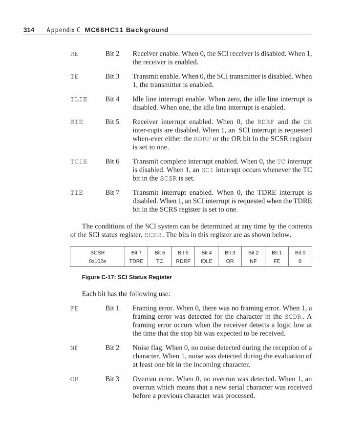
314 Appendix C MC68HC11 Background
RE Bit 2 Receiver enable. When 0, the SCI receiver is disabled. When 1,the receiver is enabled.
TE Bit 3 Transmit enable. When 0, the SCI transmitter is disabled. When1, the transmitter is enabled.
ILIE Bit 4 Idle line interrupt enable. When zero, the idle line interrupt isdisabled. When one, the idle line interrupt is enabled.
RIE Bit 5 Receiver interrupt enabled. When 0, the RDRF and the ORinter-rupts are disabled. When 1, an SCI interrupt is requestedwhen-ever either the RDRF or the OR bit in the SCSR registeris set to one.
TCIE Bit 6 Transmit complete interrupt enabled. When 0, the TC interruptis disabled. When 1, an SCI interrupt occurs whenever the TCbit in the SCSR is set.
TIE Bit 7 Transmit interrupt enabled. When 0, the TDRE interrupt isdisabled. When 1, an SCI interrupt is requested when the TDREbit in the SCRS register is set to one.
The conditions of the SCI system can be determined at any time by the contentsof the SCI status register, SCSR . The bits in this register are as shown below.
Figure C-17: SCI Status Register
Each bit has the following use:
FE Bit 1 Framing error. When 0, there was no framing error. When 1, aframing error was detected for the character in the SCDR . Aframing error occurs when the receiver detects a logic low atthe time that the stop bit was expected to be received.
NF Bit 2 Noise flag. When 0, no noise detected during the reception of acharacter. When 1, noise was detected during the evaluation ofat least one bit in the incoming character.
OR Bit 3 Overrun error. When 0, no overrun was detected. When 1, anoverrun which means that a new serial character was receivedbefore a previous character was processed.
SCSR Bit 7 Bit 6 BIt 5 Bit 4 Bit 3 Bit 2 Bit 1 Bit 0
0x102e TDRE TC RDRF IDLE OR NF FE 0

315
IDLE Bit 4 Idle line detect. When 0, the RxD line is either active now orhas been active since IDLE was last cleared. When 1, the RxDline has become idle. Once IDLE has been cleared, it cannotbecome set again until the RxD line has become active andreturned to the idle state again.
RDRF Bit 5 Receive data register full. When 0, nothing has been receivedsince the SCDR was last read. When 1, a character has beenreceived and has been transferred from the receive shift registerto the SCDR where it can be read by the program.
TC Bit 6 Transmit complete. When 0, the transmitter is busy sending acharacter. When 1, the transmitter has completed sending thecharacter and is in the idle state.
TDRE Bit 7 Transmit data register empty. When 0, the TDR is not empty.When 1, a new character can be written to the TDR .
Figure C-18: SCI Data Register SCDR
The SCI data register appears as two registers at the address 0x102f. In fact theRDR—the receiver data register—is a read-only register, and the TDR (transmit dataregister) is a write only register at the same address. Reading the RDR will not affectthe contents of the TDR and vice versa.
The Serial Peripheral InterfaceThe serial peripheral interface (SPI) is a high speed synchronous communica-
tions interface that operates at computer speeds. This interface is designed for shortdistance communications between microcontrollers and other devices that are ca-pable of synchronous communications. Usually, the SPI communications is confinedto a single circuit board. The SPI has only three registers to control its operation. (Thecontrol bits in DDRD are discussed in Chapter 5.) Data are transferred into and out ofthe SPI through the SPI data register, the SPDR. This register is located at address0x102a. The bits in the remaining registers are outlined below.
Figure C-19: SPI Control Register (SPCR)
0x102f Bit 7 Bit 6 BIt 5 Bit 4 Bit 3 Bit 2 Bit 1 Bit 0
RDR R7 R6 R5 R4 R3 R2 R1 R0
TDR T7 T6 T5 T4 T3 T2 T1 T0
SPCR Bit 7 Bit 6 BIt 5 Bit 4 Bit 3 Bit 2 Bit 1 Bit 0
0x1028 SPIE SPE DWOM MSTR CPOL CPHA SPR1 SPR0
Serial Communications Subsystems

316 Appendix C MC68HC11 Background
SPR0 Bit 0, 1 SPI bit rate select. When the SPI is operating SPR1 as a masterthe bit rate of the system will be determined by the followingtable. When the SPI is operating as a slave, SPR0 and SPR1are not used.
CPHA Bit 2 Clock phase select.
CPOL Bit 3 Clock polarity select. A 0 causes the serial clock to idle low,and 1 causes the serial clock to idle high.
MSTR Bit 4 Master/slave select. When 0, the SPI is configured as a slave;when 1, the SPI is configured as a master.
DWOM Bit 5 Port D wired or mode select. When 0, Port D outputs are allpush-pull. When 1, the pull-ups on all six bits of Port D aredisabled, allowing Port D outputs to act as open drain drivers.
SPE Bit 6 SPI system enable. When 0, the SPI system is turned off. When1, the SPI system is turned on.
SPIE Bit 7 SPI interrupt enable. When 0, the SPI interrupt is disabled.When 1, the SPI interrupt request is enabled and will be re-quested whenever the SPIF or the MODF flags are set.
Figure C-20: SPI Bit Rate Selection
The SPI status register contains three active bits. This register is shown ifFigure C-19.
Figure C-21: The SPI Status Register SPSR
SPR1 SPR0 E Clock Divided by
0 0 2
0 1 4
1 0 16
1 1 32
SPSR Bit 7 Bit 6 BIt 5 Bit 4 Bit 3 Bit 2 Bit 1 Bit 0
0x1029 SPIF WCOL 0 MODF 0 0 0 0

317
The active bits are as follows:
MODF Bit 4 Mode fault error flag. This flag is automatically set if SS* goeslow when the SPI system is configured as a master (MSTR=1).MODF is cleared by reading the SPSR while MODF is setfollowed by a write to the SPCR . When a mode fault is de-tected, the MSTR bit in the SPCR and all four of the associatedbits in the DDRD are cleared and an interrupt is generated. Thisoperation protects from multiple masters attempting to transmiton the SPI bus simultaneously.
WCOL Bit 6 Write collision error flag. This flag is automatically set if theSPDR is written while a transfer is in progress. The WCOL bit isreset by reading the SPSR with the WCOL set followed by anaccess of the SPDR .
SummaryThe main thrust of this appendix has been to introduce in some detail the
MC68HC11 device family. While this book was not specifically aimed at program-ming any specific component in C, it was necessary to choose an example part todiscuss certain techniques such as accessing specific memory locations and handlinginterrupt vectors. The data in this appendix is very brief, and some complete sub-systems of the MC68HC11E9 are not even discussed. If you want to make use of theMC68HC11 family, get a copy of the MC68HC11 Reference Manual (Motorolamanual #MC68HC11RM/AD).
Summary

318 Appendix C MC68HC11 Background

319
Appendix D
MC68HC11E9 Header FileFollowing is a copy of a header file that can be used when compiling code to run
on the MC68HC11E9. It is assumed that you will use the default configuration thatputs the register block at an address of 0x1000. If you want to change the memorylocation of the registers, you must put the beginning address of the register block intothe integer value Register_Set below.
If several different modules are going to be compiled together, and if it is desiredto debug the modules separately, it will probably be required that the header file beincluded in each module. When they are compiled together, the conditional compila-tion statements at the beginning of the header file will allow only one inclusion of theheader file in the whole program even though it is included in each of the severalmodules.
#ifndef HC11e9#define HC11e9
typedef struct{ unsigned char bit0 : 1; unsigned char bit1 : 1; unsigned char bit2 : 1; unsigned char bit3 : 1; unsigned char bit4 : 1; unsigned char bit5 : 1; unsigned char bit6 : 1; unsigned char bit7 : 1;} Register;
unsigned int Register_Set=0x1000 ;
#define PORTA (*(volatile Register*)(Register_Set+0))#define PIOC (*(Register*)(Register_Set+2))#define PORTC (*(volatile Register*)(Register_Set+3))
319

320 Appendix D MC68HC11E9 Header File
#define PORTB (*(volatile Register*)(Register_Set+4))#define PORTCL (*(volatile Register*)(Register_Set+5))#define DDRC (*(Register*)(Register_Set+7))#define PORTD (*(volatile Register*)(Register_Set+8))#define DDRD (*(Register*)(Register_Set+9))#define PORTE (*(volatile Register*)(Register_Set+0xA))#define CFORC (*(Register*)(Register_Set+0xB))#define OC1M (*(Register*)(Register_Set+0xC))#define OC1D (*(Register*)(Register_Set+0xD))#define TCNT (*(volatile unsigned int *)(Register_Set+0xE))#define TIC1 (*(volatile unsigned int *)(Register_Set+0x10))#define TIC2 (*(volatile unsigned int *)(Register_Set+0x12))#define TIC3 (*(volatile unsigned int *)(Register_Set+0x14))#define TOC1 (*(volatile unsigned int *)(Register_Set+0x16))#define TOC2 (*(volatile unsigned int *)(Register_Set+0x18))#define TOC3 (*(volatile unsigned int *)(Register_Set+0x1A))#define TOC4 (*(volatile unsigned int *)(Register_Set+0x1C))#define TOC5 (*(volatile unsigned int *)(Register_Set+0x1E))#define TCTL1 (*(Register*)(Register_Set+0x20))#define TCTL2 (*(Register*)(Register_Set+0x21))#define TMSK1 (*(Register*)(Register_Set+0x22))#define TFLG1 (*(volatile unsigned char*)(Register_Set+0x23))#define TMSK2 (*(Register*)(Register_Set+0x24))#define TFLG2 (*(volatile unsigned char*)(Register_Set+0x25))#define PACTL (*(Register*)(Register_Set+0x26))#define PACNT (*(volatile Register*)(Register_Set+0x27))#define SPCR (*(Register*)(Register_Set+0x28))#define SPSR (*(volatile Register*)(Register_Set+0x29))#define SPDR (*(volatile Register*)(Register_Set+0x2A))#define BAUD (*(Register*)(Register_Set+0x2B))#define SCCR1 (*(volatile Register*)(Register_Set+0x2C))#define SCCR2 (*(Register*)(Register_Set+0x2D))#define SCSR (*(volatile Register*)(Register_Set+0x2E))#define SCDR (*(volatile unsigned char*)(Register_Set+0x2F))#define ADCTL (*(volatile Register*)(Register_Set+0x30))#define ADR1 (*(volatile unsigned char*)(Register_Set+0x31))#define ADR2 (*(volatile unsigned char*)(Register_Set+0x32))#define ADR3 (*(volatile unsigned char*)(Register_Set+0x33))#define ADR4 (*(volatile unsigned char*)(Register_Set+0x34))#define BPROT (*(Register*)(Register_Set+0x35))#define OPTION (*(Register*)(Register_Set+0x39))#define COPRSR (*(unsigned char*)(Register_Set+0x3A))

321
#define PPROG (*(Register*)(Register_Set+0x3B))#define HPRIO (*(Register*)(Register_Set+0x3C))#define INIT (*(Register*)(Register_Set+0x3D))#define TEST1 (*(Register*)(Register_Set+0x3E))#define CONFIG (*(Register*)(Register_Set+0x3F))
/* Bit names for general use */
#define Bit_7 7#define Bit_6 6#define Bit_5 5#define Bit_4 4#define Bit_3 3#define Bit_2 2#define Bit_1 1#define Bit_0 0
/* PIOC bit definitions 0x0*/
#define STAF bit7#define STAI bit6#define CWOM bit5#define HNDS bit4#define OIN bit3#define PLS bit2#define EGA bit1#define INVB bit0
/* CFORC bit definitions 0xB*/
#define FOC1 bit7#define FOC2 bit6#define FOC3 bit5#define FOC4 bit4#define FOC5 bit3
/* OC1M bit definitions 0xC*/
#define OC1M7 bit7#define OC1M6 bit6#define OC1M5 bit5
MC68HC11E9 Header File

322 Appendix D MC68HC11E9 Header File
#define OC1M4 bit4#define OCMM3 bit3
/* OC1D bit definitions 0xD*/
#define OC1D7 bit7#define OC1D6 bit6#define OC1D5 bit5#define OC1D4 bit4#define OCMD3 bit3
/* TCTL1 bit definition 0x20*/
#define OM2 bit7#define OL2 bit6#define OM3 bit5#define OL3 bit4#define OM4 bit3#define OL4 bit2#define OM5 bit1#define OL6 bit0
/* TCTL2 bit definitions 0x21 */
#define EDG4B bit7#define EDG4A bit6#define EDG1B bit5#define EDG1A bit4#define EDG2B bit3#define EDG2A bit2#define EDG3B bit1#define EDG3A bit0
/* TMSK1 bit definitions 0x22 */
#define OC1I bit7#define OC2I bit6#define OC3I bit5#define OC4I bit4#define I4O5I bit3#define IC1I bit2

323MC68HC11E9 Header File
#define IC2I bit1#define IC3I bit0
/* TFLG1 bit definitions 0x23 */
#define OC1F 0x80#define OC2F 0x40#define OC3F 0x20#define OC4F 0x10#define I4O5F 0x08#define IC1F 0x04#define IC2F 0x02#define IC3F 0x01
/* TMSK2 bit definitions 0x24 */
#define TOI bit7#define RTII bit6#define PAOVI bit5#define PAII bit4#define PR1 bit1#define PR0 bit0
/* TFLG2 bit definitions 0x25 */
#define TOF 0x80#define RTIF 0x40#define PAOVF 0x20#define PAIF 0x10
/* PACTL bit definitions 0x26 */
#define DDRA7 bit7#define PAEN bit6#define PAMOD bit5#define PEDGE bit4#define DDRA3 bit3#define I4O5 bit2#define RTR1 bit1#define RTR0 bit0/* SPCR bit definitions 0x28 */

324 Appendix D MC68HC11E9 Header File
#define SPIE bit7#define SPE bit6#define DWOM bit5#define MSTR bit4#define CPOL bit3#define CPHA bit2#define SPR1 bit1#define SPR0 bit0
/* SPSR bit definitions 0x29 */
#define SPIF bit7#define WCOL bit6#define MODV bit4
/* BAUD bit definitions 0x2B */
#define TCLR bit7#define SCP1 bit5#define SCP0 bit4#define RCKB bit3#define SCR2 bit2#define SCR1 bit1#define SCR0 bit0
/*SCCR1 bit definition 0x2C*/
#define R8 bit7#define T8 bit6#define M bit4#define WAKE bit3
/* SCCR2 bit definitions 0x2D */
#define TIE bit7#define TCIE bit6#define RIE bit5#define ILIE bit4#define TE bit3#define RE bit2

325
#define RWU bit1#define SBK0 bit0
/* SCSR bit definitions 0x2E */
#define TDRE bit7#define TC bit6#define RDRF bit5#define IDLE bit4#define OR bit3#define NF bit2#define FE bit1
/* ADCTL bit definitions 0x30 */
#define CCF bit7#define SCAN bit5#define MULT bit4#define CD bit3#define CC bit2#define CB bit1#define CA bit0
/* BPROT bit definitions 0x35 */
#define PTCON bit4#define BPRT3 bit3#define BPRT2 bit2#define BPRT1 bit1#define BPRT0 bit0
/* OPTION bit definitions 0x39 */
#define ADPU bit7#define CSEL bit6#define IRQE bit5#define DLY bit4#define CME bit3#define CR1 bit1#define CR0 bit0
MC68HC11E9 Header File

326 Appendix D MC68HC11E9 Header File
/* PPROG bit definitions 0x3B */
#define ODD bit7#define EVEN bit6#define ELAT bit5#define BYTE bit4#define ROW bit3#define ERASE bit2#define EELAT bit1#define EEPGM bit0
/* HPRIO bit definitions 0x3C */
#define RBOOT bit7#define SMOD bit6#define MDA bit5#define IRV bit4#define PSEL3 bit3#define PSEL2 bit2#define PSEL1 bit1#define PSEL0 bit0
/* INIT bit definitions 0x3D */
#define RAM3 bit7#define RAM2 bit6#define RAM1 bit5#define RAM0 bit4#define REG3 bit3#define REG2 bit2#define REG1 bit1#define REG0 bit0
/* TEST1 bit definitions 0x3E */
#define TILOP bit7#define OCCR bit5#define CBYP bit4#define DISR bit3#define FCM bit2#define FCOP bit1#define TCON bit0

327
/* CONFIG bit definitions 0x3F */
#define NOSEC bit3#define NOCOP bit2#define ROMON bit1#define EEON bit0
/* Macros and function to permit interrupt service routine programming from C.
To use the vector call, do vector(isr, vector_address) where isr is a pointer to the interrupt service routine, and vector_address is the vector address where the isr pointer must be stored. The program must use the return_int() function fro each return from an interrupt or exception. */
#define vector(isr,vector_address) (*(void**)(vector_address)=(isr))#define cli() _asm(“cli\n”)#define sei() _asm(“sei\n”)#define return_int() _asm(“rti\n”)#define TRUE 1#define FALSE 0#define FOREVER while(TRUE)typedef unsigned int WORD;typedef unsigned char BYTE;
#endif
Vector AddressesThe vector field in the MC68HC11 is 64 bytes long. The table shown below is a
listing of each vector, its location, whether it can be disabled by the I bit in the CCR,and the mask bit that will disable it. Notice that most of the interrupts have a vector.The major exception to this rule is the SCI interface. All SCI interrupt functions arevectored from the address 0XFFD6,0XFFD7. The other exception is the handshakeinterrupt on the parallel port and the external IRQ* line interrupt. These two inter-rupts share the vector at 0XFFF2 AND 0XFFF3.
Vector Addresses

328 Appendix D MC68HC11E9 Header File
Vector Address Interrupt Source CCR Mask Bit Local Mask
FFC0,C1-- Reserved -- --FFD4,D5
FFD6,D7 SCI Serial System I
SCI Transmit Complete TCIE
SCI Transmit Data Register Empty TIE
SCI Idle Line Detect ILIE
SCI Receiver Overrun RIE
SCI Receiver Data Register full RIE
FFD8,D9 SPI Serial Transfer Complete I SPIE
FFDA,DB Pulse Accumulator Input Edge I PAII
FFDC,DD Pulse Accumulator Overflow I PAOVI
FFDE,DF Timer Overflow I TOI
FFE0,E1 Timer Input Capture 4/Output Compare 5 I I4/O5I
FFE2,E3 Timer Output Compare 4 I OC4I
FFE4,E5 Timer Output Compare 3 I OC3I
FFE6,E7 Timer Output Compare 2 I OC2I
FFE8,E9 Timer Output Compare 1 I OC1I
FFEA,EB Timer Input Capture 3 I IC3I
FFEC,ED Timer Input Capture 2 I IC2I
FFEE,FFEF Timer Input Capture 1 I OC1I
FFF0,F1 Real Time Interrupt I RTII
FFF2,F3 Parallel I/O Handshake I STAI
IRQ* (External Pin) None
FFF4,F5 XIRQ* Pin X None
FFF6,F7 Software Interrupt None None
FFF8,F9 Illegal Opcode Trap None None
FFFA,FB Cop Failure None NOCOP
FFFC,FD Cop Clock Monitor Fail None CME
FFFE,FF RESET* None None
Table D-1: MC68HC11E9 Interrupt Vectors

329
Appendix E
MC68HC16Z1“Ready Reference” Guide
This appendix contains address maps, register diagrams, and bit/field definitionsfor the MC68HC16Z1. This appendix is intended only as a quick reference; in-depthinformation about register function is provided in the appropriate sections of theMotorola manual.
Except for central processing unit resources, information is presented in theintermodule bus address order shown in Table E–1.
Table E-1: MC68HC16Z1 Module Address Map
Control registers for all the modules in the microcontroller are mapped into a 4kilobyte block. The state of the module mapping (MM) bit in the SIM moduleconfiguration register (SIMCR) determines where the control registers block islocated in the system memory map. When MM = 0, register addresses range from$7FF000 to $7FFFFF; when MM = 1, register addresses range from $FFF000 to$FFFFFF.
In the MC68HC16Z1, ADDR[23:20] follow the logic state of ADDR19 unlessexternally driven. MM corresponds to IMB ADDR23 — if it is cleared, the SIM mapsIMB modules into address space $7FF000–$7FFFFF, which is inaccessible to theCPU16. Modules remain inaccessible until reset occurs. The reset state of MM is one,but the bit is one-time writable — initialization software should make certain itremains set.
329
Module Size Address Bus Decoding Base
(Bytes 23 12 11 0 Address
ADC 64 M11 1111 1111 0111 00XX XXXX $YFF700
GPT 64 M11 1111 1111 1001 00XX XXXX $YFF900
SIM 128 M11 1111 1111 1010 0XXX XXXX $YFFA00
SRAM 8 M11 1111 1111 1011 0000 0XXX $YFFB00
QSM 512 M11 1111 1111 110X XXXX XXXX $YFFC00

330 Appendix E MC68HC16Z1 Register Summary
E.1 Central Processing UnitCPU16 registers are not part of the module address map. The following diagram
is a functional representation of CPU resources.
E.1.1 CPU16 Register Model20 16 15 8 7 0 BIT POSITION
A B ACCUMULATORS A AND B
D ACCUMULATORS D (A:B)
E ACCUMULATOR E
XK IX INDEX REGISTER X
YK IY INDEX REGISTER Y
ZK IZ INDEX REGISTER Z
SK SP STACK POINTER
PK PC PROGRAM COUNTER
CCR PK CONDITION CODEREGISTER/PC EXTENSION
REGISTER
EK XK YK ZK ADDRESS EXTENSIONREGISTER
SK STACK EXTENSIONREGISTER
HR MAC MULTIPLIERREGISTER
IR MAC MULTIPLICANDREGISTER
AM MAC ACCUMULATORMSB [35:16]
AM MAC ACCUMULATORLSB [15:0]

331
The CCR contains processor status flags, the interrupt priority field, and theprogram counter address extension field. The CPU16 has a special set of instructionsthat manipulate the CCR.
S — STOP Enable0 = Stop clock when LPSTOP instruction is executed.
1 = Perform NOP when LPSTOP instruction is executed.
MV — Accumulator M overflow flag — Accumulator M overflow flag Set when overflow into AM35 has occurred.
H — Half Carry Flag— Half Carry FlagSet when a carry from A3 or B3 occurs during BCD addition.
EV — Extension Bit Overflow Flag— Extension Bit Overflow FlagSet when an overflow into AM31 has occurred.
N — Negative Flag— Negative FlagSet when the MSB of a result register is set.
Z — Zero Flag— Zero FlagSet when all bits of a result register are zero.
V — Overflow Flag— Overflow FlagSet when twos complement overflow occurs as the result of an operation.
C — Carry Flag— Carry FlagSet when carry or borrow occurs during arithmetic operation. Also used duringshift and rotate to facilitate multiple word operations.
IP[2:0] — Interrupt Priority Field[20] — Interrupt Priority FieldThe priority value in this field (0 to 7) is used to mask interrupts.
SM — Saturate Mode Bit— Saturate Mode BitWhen SM is set, if either EV or MV is set, data read from AM using TMER orTMET will be given maximum positive or negative value, depending on thestate of the AM sign bit before overflow.
PK[3:0] — Program Counter Address Extension Field[30] —Program Counter Address Extension FieldThis field is concatenated with the program counter to form a 20-bit address.
E.1 Central Processing Unit
15 14 13 12 11 10 9 8 7 6 5 4 3 2 1 0
S MV H EV N Z V C IP SM PK

332 Appendix E MC68HC16Z1 Register Summary
E.2 Analog-to-Digital Converter ModuleEDGxB 15 8 7 0
$YFF700 MODULE CONFIGURATION (ADCMCR)
$YFF702 FACTORY TEST (ADTEST)
$YFF704 (RESERVED)
$YFF706 PORT ADA DATA (PORTADA)
$YFF708 MODULE CONFIGURATION (ADCMCR)
$YFF70A MODULE CONFIGURATION (ADCMCR)
$YFF70E MODULE CONFIGURATION (ADCMCR)
$YFF710 RIGHT-JUSTIFIED UNSIGNED RESULT 0 (RJURR0)
$YFF712 RIGHT-JUSTIFIED UNSIGNED RESULT 1 (RJURR1)
$YFF714 RIGHT-JUSTIFIED UNSIGNED RESULT 2 (RJURR2)
$YFF716 RIGHT-JUSTIFIED UNSIGNED RESULT 3 (RJURR3)
$YFF718 RIGHT-JUSTIFIED UNSIGNED RESULT 4 (RJURR4)
$YFF71A RIGHT-JUSTIFIED UNSIGNED RESULT 6 (RJURR5)
$YFF71C RIGHT-JUSTIFIED UNSIGNED RESULT 6 (RJURR6)
$YFF71E RIGHT-JUSTIFIED UNSIGNED RESULT 7 (RJURR7)
$YFF720 LEFT-JUSTIFIED SIGNED RESULT 0 (LJSRR0)
$YFF722 LEFT-JUSTIFIED SIGNED RESULT 1 (LJSRR1)
$YFF724 LEFT-JUSTIFIED SIGNED RESULT 2 (LJSRR2)
$YFF726 LEFT-JUSTIFIED SIGNED RESULT 3 (LJSRR3)
$YFF728 LEFT-JUSTIFIED SIGNED RESULT 4 (LJSRR4)
$YFF72A LEFT-JUSTIFIED SIGNED RESULT 5 (LJSRR5)
$YFF72C LEFT-JUSTIFIED SIGNED RESULT 6 (LJSRR6)
$YFF72E LEFT-JUSTIFIED SIGNED RESULT 7 (LJSRR7)
$YFF730 LEFT-JUSTIFIED UNSIGNED RESULT 0 (LJURR0)
$YFF732 LEFT-JUSTIFIED UNSIGNED RESULT 1 (LJURR1)
$YFF734 LEFT-JUSTIFIED UNSIGNED RESULT 2 (LJURR2)
$YFF736 LEFT-JUSTIFIED UNSIGNED RESULT 3 (LJURR3)
$YFF738 LEFT-JUSTIFIED UNSIGNED RESULT 4 (LJURR4)
$YFF73A LEFT-JUSTIFIED UNSIGNED RESULT 5 (LJURR5)
$YFF73C LEFT-JUSTIFIED UNSIGNED RESULT 6 (LJURR6)
$YFF73E LEFT-JUSTIFIED UNSIGNED RESULT 7 (LJURR7)
E.2.1 ADCMCR — ADC Module Configuration Register $YFF70015 14 13 12 8 7 6 0
STOP FRZ NOT USED SUPV NOT USED
RESET:1 0 0 0
ADCMCR controls ADC operation during low-power stop and freeze modes.
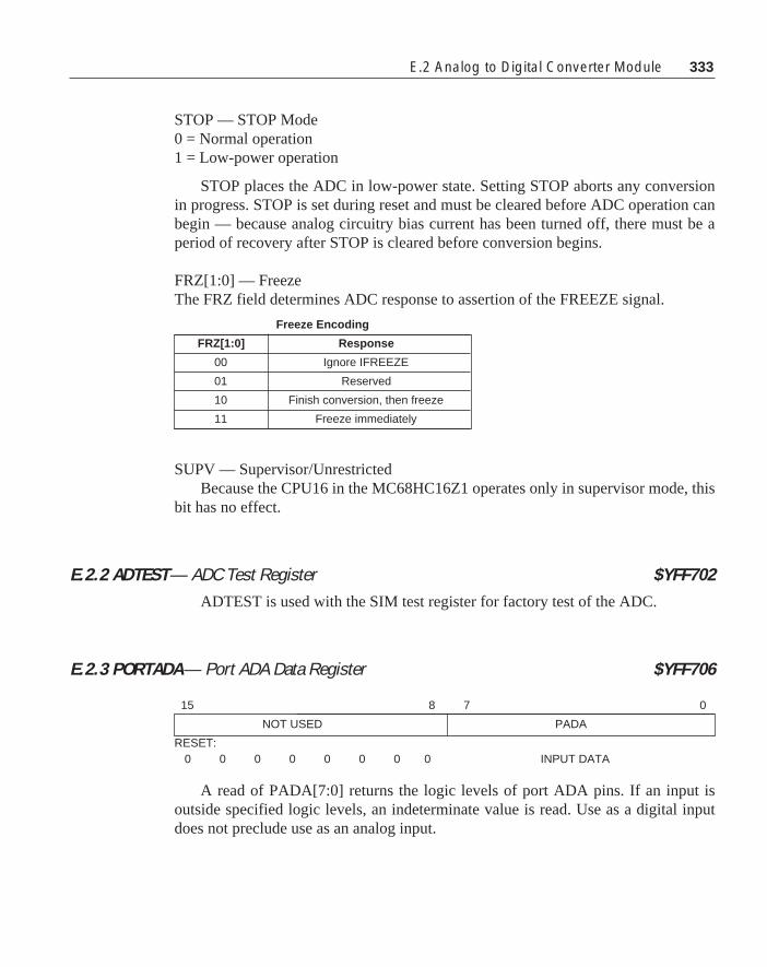
333E.2 Analog to Digital Converter Module
STOP — STOP Mode0 = Normal operation1 = Low-power operation
STOP places the ADC in low-power state. Setting STOP aborts any conversionin progress. STOP is set during reset and must be cleared before ADC operation canbegin — because analog circuitry bias current has been turned off, there must be aperiod of recovery after STOP is cleared before conversion begins.
FRZ[1:0] — FreezeThe FRZ field determines ADC response to assertion of the FREEZE signal.
SUPV — Supervisor/UnrestrictedBecause the CPU16 in the MC68HC16Z1 operates only in supervisor mode, this
bit has no effect.
E.2.2 ADTEST — ADC Test Register $YFF702ADTEST is used with the SIM test register for factory test of the ADC.
E.2.3 PORTADA — Port ADA Data Register $YFF706
A read of PADA[7:0] returns the logic levels of port ADA pins. If an input isoutside specified logic levels, an indeterminate value is read. Use as a digital inputdoes not preclude use as an analog input.
Freeze Encoding
FRZ[1:0] Response
00 Ignore IFREEZE
01 Reserved
10 Finish conversion, then freeze
11 Freeze immediately
15 8 7 0
NOT USED PADA
RESET:0 0 0 0 0 0 0 0 INPUT DATA

334 Appendix E MC68HC16Z1 Register Summary
E.2.4 ADCTL0 — A/D Control Register 0 $YFF70A
ADCTL0 is used to select resolution, sample time, and clock/prescaler value.Writing ADCTL0 aborts any conversion in progress — ADC activity halts untilADCTL1 is written.
RES10 — 10-Bit Resolution0 = 8-bit conversion1 = 10-bit conversion
STS[1:0] — Sample Time SelectionThe STS field selects one of four sample times.
PRS[4:0] — Prescaler Rate SelectionADC clock is generated from system clock using a modulus counter and a divide-
by-two circuit. PRS contains the counter modulus.
15 8 7 6 5 4 3 2 1 0
NOT USED RES10 STS PRS
RESET:0 0 0 0 0 0 0 0 0 0 0 0 0 0 1 1
Sample Time Selection
STS[1:0] Response
00 4 A/D Clock Periods
01 8 A/D Clock Periods
10 16 A/D Clock Periods
11 32 A/D Clock Periods
ADC Clock Selection
PRS[4:0] ADCCLK
%00000 RESERVED
%00001 Sys Clk/4
%00010 Sys Clk/6
... ...
%11101 Sys Clk/60
%11110 Sys Clk/62
%11111 Sys Clk/64

335
E.2.5 ADCTL1 — A/D Control Register 1 $YFF70C
ADCTL1 selects conversion mode and the analog channel or channels. WritingADCTL1 aborts any conversion in progress and initiates a new conversion sequence.
SCAN — Scan Mode Selection0 = Single conversion sequence1 = Continuous conversion
MULT — Multichannel Conversion0 = Conversion sequence(s) run on a single channel selected by [CD:CA].1 = Sequential conversion of four or eight channels selected by [CD:CA].
S8CM — Select Eight-Conversion Sequence Mode0 = Four-conversion sequence1 = Eight-conversion sequence
[CD:CA] — Channel SelectionBits in this field select input channel or channels for analog-to-digital conversion.Conversion mode determines which channel or channels are selected for conver-
sion and which result registers are used to store conversion results. The followingtables summarize the effects of ADCTL1 bits and fields.
E.2 Analog to Digital Converter Module
15 7 6 5 4 3 2 1 0
NOT USED SCAN MULT S8CM CD CC CB CA
RESET:0 0 0 0 0 0 0 0 0 0 0 0 0 0 0 0
ADC Conversion Modes
SCAN MULT S8CM MODE
0 0 0 SINGLE 4-CONVERSION SINGLE-CHANNEL SEQUENCE
0 0 1 SINGLE 8-CONVERSION SINGLE-CHANNEL SEQUENCE
0 1 0 SINGLE 4-CONVERSION MULTICHANNEL SEQUENCE
0 1 1 SINGLE 8-CONVERSION MULTICHANNEL SEQUENCE
1 0 0 MULTIPLE 4-CONVERSION SINGLE-CHANNEL SEQUENCES
1 0 1 MULTIPLE 8-CONVERSION SINGLE-CHANNEL SEQUENCES
1 1 0 MULTIPLE 4-CONVERSION MULTICHANNEL SEQUENCES
1 1 1 MULTIPLE 8-CONVERSION MULTICHANNEL SEQUENCES
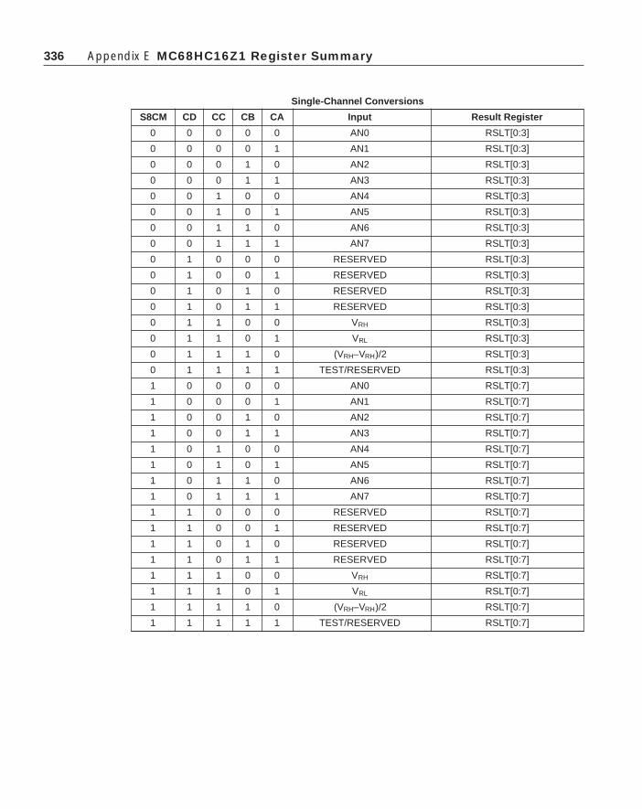
336 Appendix E MC68HC16Z1 Register Summary
Single-Channel Conversions
S8CM CD CC CB CA Input Result Register
0 0 0 0 0 AN0 RSLT[0:3]
0 0 0 0 1 AN1 RSLT[0:3]
0 0 0 1 0 AN2 RSLT[0:3]
0 0 0 1 1 AN3 RSLT[0:3]
0 0 1 0 0 AN4 RSLT[0:3]
0 0 1 0 1 AN5 RSLT[0:3]
0 0 1 1 0 AN6 RSLT[0:3]
0 0 1 1 1 AN7 RSLT[0:3]
0 1 0 0 0 RESERVED RSLT[0:3]
0 1 0 0 1 RESERVED RSLT[0:3]
0 1 0 1 0 RESERVED RSLT[0:3]
0 1 0 1 1 RESERVED RSLT[0:3]
0 1 1 0 0 VRH RSLT[0:3]
0 1 1 0 1 VRL RSLT[0:3]
0 1 1 1 0 (VRH–VRH)/2 RSLT[0:3]
0 1 1 1 1 TEST/RESERVED RSLT[0:3]
1 0 0 0 0 AN0 RSLT[0:7]
1 0 0 0 1 AN1 RSLT[0:7]
1 0 0 1 0 AN2 RSLT[0:7]
1 0 0 1 1 AN3 RSLT[0:7]
1 0 1 0 0 AN4 RSLT[0:7]
1 0 1 0 1 AN5 RSLT[0:7]
1 0 1 1 0 AN6 RSLT[0:7]
1 0 1 1 1 AN7 RSLT[0:7]
1 1 0 0 0 RESERVED RSLT[0:7]
1 1 0 0 1 RESERVED RSLT[0:7]
1 1 0 1 0 RESERVED RSLT[0:7]
1 1 0 1 1 RESERVED RSLT[0:7]
1 1 1 0 0 VRH RSLT[0:7]
1 1 1 0 1 VRL RSLT[0:7]
1 1 1 1 0 (VRH–VRH)/2 RSLT[0:7]
1 1 1 1 1 TEST/RESERVED RSLT[0:7]

337E.2 Analog to Digital Converter Module
Single-Channel Conversions
S8CM CD CC CB CA Input Result Register
0 0 0 X X AN[0:3] RSLT[0:3]
0 0 1 X X AN{4:7] RSLT[0:3]
0 1 0 X X RESERVED RSLT[0:3]
0 1 1 X X VRH RSLT0
VRL RSLT1
(VRH–VRH)/2 RSLT2
TEST/RESERVED RSLT3
1 0 X X X AN[0:7] RSLT[0:7]
1 1 X X X RESERVED RSLT0
RESERVED RSLT1
RESERVED RSLT2
RESERVED RSLT3
VRH RSLT4
VRL RSLT5
(VRH–VRH)/2 RSLT6
TEST RESERVED RSLT7
E.2.6 ADSTAT — ADC Status Register $YFF70E
ADSTAT is a read-only register that contains the sequence complete flag, theconversion counter, and a channel-converted flag for each of the input channels.
SCF — Sequence Complete Flag0 = Sequence not complete1 = Sequence complete
When SCAN = 0, SCF is set at the end of a conversion sequence. When SCAN =1, SCF is set at the end of the first conversion sequence. SCF is cleared whenconverter activity is halted or restarted by a write to ADCTL0.
CCTR[2:0] — Conversion CounterThis field shows the content of the conversion counter pointer during a conver-
sion sequence. The value is the number of the next result register to be written.
15 14 11 10 8 7 0
SCF NOT USED RES10 CCF
RESET:0 0 0 0 0 0 0 0 0 0 0 0 0 0 0 0

338 Appendix E MC68HC16Z1 Register Summary
CCF[7:0] — Conversion Complete FlagsEach bit in this field corresponds to an A/D result register. A bit is set when
conversion of the corresponding input is complete. It remains set until the resultregister is read. It is cleared when the register is read.
E.2.7 RSLT[0:7] — ADC Result Registers $YFF710–$YFF73EResult registers contain conversion results. Data format depends on the address
from which it is read. The notation 10 in a diagram indicates that a bit is used only for10-bit resolution and is cleared during 8-bit conversion. The notation 8/10 indicates abit is used for both 8-bit and 10-bit resolution. Unused bits return zeros when read.
E.2.7.1 RJURR — Unsigned Right-Justified Result Registers $YFF710–$YFF71F
E.2.7.2 LJSRR — Signed Left-Justified Result Registers $YFF720–$YFF72F
This data format assumes that the zero reference point is (VRH
– VRL
)/2. Bit 15thus indicates the sign of the result. When bit 15 = 1, the result is positive; when bit15 = 0, the result is negative. Bits [5:0] return zeros when read.
E.2.7.3 LJURR — Unsigned Left-Justified Result Registers $YFF730–$YFF73F
15 10 9 8 7 6 5 4 3 2 1 0
NOT USED 10 10 8/10 8/10 8/10 8/10 8/10 8/10 8/10 8/10
15 14 13 12 11 10 9 8 7 6 5 0
8/10 8/10 8/10 8/10 8/10 8/10 8/10 8/10 10 10 NOT USED
15 14 13 12 11 10 9 8 7 6 5 0
8/10 8/10 8/10 8/10 8/10 8/10 8/10 8/10 10 10 NOT USED

339E.3 General-Purpose Timer
E.3 General-Purpose TimerAddress 15 8 7 0
$YFF900 GPT MODULE CONFIGURATION (GPTMCR)
$YFF902 (RESERVED FOR TEST)
$YFF904 INTERRUPT CONFIGURATION (ICR)
$YFF906 PGP DATA DIRECTION (DDRGP) PGP DATA (PORTGP)
$YFF908 OC1 ACTION MASK (OC1M) OC1 ACTION DATA (OC1D)
$YFF90A MODULE CONFIGURATION (ADCMCR)
$YFF90C PA CONTROL (PACTL) PA COUNTER (PACNT)
$YFF90E INPUT CAPTURE 1 (TIC1)
$YFF910 INPUT CAPTURE 2 (TIC2)
$YFF912 INPUT CAPTURE 3 (TIC3)
$YFF914 OUTPUT COMPARE 1 (TOC1)
$YFF916 OUTPUT COMPARE 2 (TOC2)
$YFF918 OUTPUT COMPARE 3 (TOC3)
$YFF91A OUTPUT COMPARE 4 (TOC4)
$YFF91C INPUT CAPTURE 4/OUTPUT COMPARE 5 (TI4/O5)
$YFF91E TIMER CONTROL 1 (TCTL1) TIMER CONTROL 2 (TCTL2)
$YFF920 TIMER MASK 1 (TMSK1) TIMER MASK 2 (TMSK2)
$YFF922 TIMER FLAG 1 (TFLG1) TIMER FLAG 2 (TFLG2)
$YFF924 FORCE COMPARE (CFORC) PWM CONTROL C (PWMC)
$YFF926 PWM CONTROL A (PWMA) PWM CONTROL B (PWMB)
$YFF928 PWM COUNT (PWMCNT)
$YFF92A PWMA BUFFER (PWMBUFA) PWMB BUFFER (PWMBUFB)
$YFF92C GPT PRESCALER (PRESCL)
$YFF92E RESERVED
$YFF92E
E.3.1 GPTMCR — GPT Module Configuration Register $YFF900
GPTMCR bits control freeze, low-power stop, and single-step modes.
STOP — Stop Clocks0 = Internal clocks not shut down1 = Internal clocks shut down
Table E-3: GPT Address Map
15 14 13 12 11 10 9 8 7 6 5 4 3 2 1 0
STOP FRZ1 FRZ0 STOPP INCP 0 0 0 SUPV 0 0 0 IARB3 IARB2 IARB1 IARB0
RESET:0 0 0 0 0 0 0 0 0 0 0 0 0 0 0 0

340 Appendix E MC68HC16Z1 Register Summary
FRZ[1:0] — FREEZE ResponseFRZ1 is not used; FRZ0 encoding determines response to the IMB FREEZE signal.
0 = Ignore IMB FREEZE signal1 = FREEZE the current state of the GPT
STOPP — Stop Prescaler0 = Normal operation1 = Stop prescaler and pulse accumulator from incrementing. Ignore changes to input
pins.
INCP — Increment Prescaler0 = Has no meaning1 = If STOPP is asserted, increment prescaler once and clock input synchronizers
once.
SUPV — Supervisor/Unrestricted Data SpaceBecause the CPU16 in the MC68HC16Z1 operates in supervisor mode only, this
bit has no effect.
IARB[3:0] — Interrupt ArbitrationEach module that generates interrupts must have an IARB value. IARB values
are used to arbitrate between interrupt requests of the same priority.
E.3.2 GPTMTR — GPT Module Test Register (Reserved) $YFF902This address is currently unused and returns zeros when read. It is reserved for
GPT factory test.
E.3.3 ICR — GPT Interrupt Configuration Register $YFF904
ICR fields determine internal and external interrupt priority, and provide theupper nibble of the interrupt vector number supplied to the CPU when an interrupt isacknowledged.
IPA — Interrupt Priority AdjustSpecifies which of the 11 internal GPT interrupt sources is assigned highest
priority.
IPL — Interrupt Priority LevelSpecifies the priority level of GPT interrupt requests.
15 14 13 12 11 10 9 8 7 6 5 4 3 2 1 0
IPA 0 IRL IVBA 0 0 0 0
RESET:0 0 0 0 0 0 0 0 0 0 0 0 0 0 0 0

341
IVBA — Interrupt Vector Base AddressContains the most significant nibble of interrupt vector numbers supplied by the
GPT.
E.3.4 DDRGP — Port GP Data Direction Register $YFF906
PORTGP — Port GP Data Register $YFF907
When GPT pins are used as an 8-bit port, DDRGP determines whether pins areinput or output and PORTGP holds the 8-bit data.
DDRGP[7:0] — Parallel Data Direction Register0 = Input only1 = Output
PORTGP[7:0] — Parallel Data Register
E.3.5 OC1M — OC1 Action Mask Register $YFF908
OC1D — OC1 Action Data Register $YFF909
All OC outputs can be controlled by the action of OC1. OC1M contains a maskthat determines which pins are affected, and OC1D determines what the outputs are.
OC1M[5:1] — OC1 Mask0 = Corresponding output compare pin is not affected by OC1 compare.1 = Corresponding output compare pin is affected by OC1 compare.OC1M[5:1] correspond to OC[5:1].
OC1D[5:1] — OC1 Data0 = If OC1 mask bit is set, clear corresponding output compare pin on OC1 match.1 = If OC1 mask bit is set, set corresponding output compare pin on OC1 match.OC1D[5:1] correspond to OC[5:1].
E.3 General-Purpose Timer
15 8 7 0
DDRGP PORTGP
RESET:0 0 0 0 0 0 0 0 0 0 0 0 0 0 0 0
15 14 13 12 11 10 9 8 7 6 5 4 3 2 1 0
OC1M 0 0 0 0 OC1D 0 0 0 0
RESET:0 0 0 0 0 0 0 0 0 0 0 0 0 0 0 0

342 Appendix E MC68HC16Z1 Register Summary
E.3.6 TCNT — Timer Counter Register $YFF90ATCNT is the 16-bit free-running counter associated with the input capture, output
compare, and pulse accumulator functions of the GPT module.
E.3.7 PACTL — Pulse Accumulator Control Register $YFF90CPACNT — Pulse Accumulator Counter $YFF90D
PACTL enables the pulse accumulator and selects either event counting or gatedmode. In event counting mode, PACNT is incremented each time an event occurs. Ingated mode, it is incremented by an internal clock.
PAIS — PAI Pin State (Read Only)
PAEN — Pulse Accumulator Enable0 = Pulse accumulator disabled1 = Pulse accumulator enabled
PAMOD — Pulse Accumulator Mode0 = External event counting1 = Gated time accumulation
PEDGE — Pulse Accumulator Edge ControlThe effects of PEDGE and PAMOD are shown in the following table.
PCLKS — PCLK Pin State (Read Only)
I4/O5 — Input Capture 4/Output Compare 50 = Output compare 5 enabled1 = Input capture 4 enabled
PACLK[1:0] — Pulse Accumulator Clock Select (Gated Mode)
15 14 13 12 11 10 9 8 7 6 5 4 3 2 1 0
PAIS PAEN PAMOD PEDGE PCLKS I4/05 PACLK PULSE ACCUMULATOR COUNTER
RESET:0 0 0 0 U 0 0 0 0 0 0 0 0 0 0 0
PAMOD PEDGE Effect
0 0 PAI Falling Edge Increments Counter
0 1 PAI Rising Edge Increments Counter
1 0 Zero on PAI Inhibits Counting
1 1 One on PAI Inhibits Counting
PACLK[1:0] Pulse Accumulator Clock Selected
00 System Clock Divided by 512
01 Same Clock Used t Increment TCNT
10 TOF Flag from TCNT
11 External Clock, PCLK

343
PACNT — Pulse Accumulator CounterEight-bit read/write counter used for external event counting or gated time
accumulation.
E.3.8 TIC[1:3] — Input Capture Registers 1–3 $YFF90E–$YFF912The input capture registers are 16-bit read-only registers which are used to latch
the value of TCNT when a specified transition is detected on the corresponding inputcapture pin. They are reset to $FFFF.
E.3.9 TOC[1:4] — Output Compare Registers 1–4 $YFF914–$YFF91AThe output compare registers are 16-bit read/write registers which can be used as
output waveform controls or as elapsed time indicators. For output compare func-tions, they are written to a desired match value and compared against TCNT tocontrol specified pin actions. They are reset to $FFFF.
E.3.10 TI4/O5 — Input Capture 4/Output Compare 5 Register $YFF91CThis register serves either as input capture register 4 or output compare register 5,
depending on the state of I4/O5 in PACTL.
E.3.11 TCTL1/TCTL2 — Timer Control Registers 1 and 2 $YFF91E
TCTL1 determines output compare mode and output logic level. TCTL2 deter-mines the type of input capture to be performed.
OM/OL[5:2] — Output Compare Mode Bits and Output Compare Level BitsEach pair of bits specifies an action to be taken when output comparison is
successful.
EDGE[4:1] — Input Capture Edge ControlEach pair of bits configures input sensing logic for the corresponding input capture.
E.3 General-Purpose Timer
OM/OL[5:2] Action Taken
00 Timer Disconnected from Output Logic
01 Toggle OCx Output Line
10 Clear OCx Output Line to 0
11 Set OCx Output Line to 1
EDGE[4:1] Configuration
00 Capture Disabled
01 Capture on Rising Edge Only
10 Capture on Falling Edge Only
11 Capture on Any (Rising or Falling) Edge
15 14 13 12 11 10 9 8 7 6 5 4 3 2 1 0
OM5 OL5 OM4 OL4 OM3 OL3 OM2 OL2 EDGE4 EDGE3 EDGE2 EDGE1
RESET:0 0 0 0 0 0 0 0 0 0 0 0 0 0 0 0

344 Appendix E MC68HC16Z1 Register Summary
E.3.12 TMSK1/TMSK2 — Timer Interrupt Mask Registers 1 and 2 $YFF920
TMSK1 enables OC and IC interrupts. TMSK2 controls pulse accumulatorinterrupts and TCNT functions.
I4/O5I — Input Capture 4/Output Compare 5 Interrupt Enable0 = IC4/OC5 interrupt disabled1 = IC4/OC5 interrupt requested when I4/O5F flag in TFLG1 is set
OCI[4:1] — Output Compare Interrupt Enable0 = OC interrupt disabled1 = OC interrupt requested when OC flag setOCI[4:1] correspond to OC[4:1].
ICI[3:1] — Input Capture Interrupt Enable0 = IC interrupt disabled1 = IC interrupt requested when IC flag setICI[3:1] correspond to IC[3:1].
TOI — Timer Overflow Interrupt Enable0 = Timer overflow interrupt disabled1 = Interrupt requested when TOF flag is set
PAOVI — Pulse Accumulator Overflow Interrupt Enable0 = Pulse accumulator overflow interrupt disabled1 = Interrupt requested when PAOVF flag is set
PAII — Pulse Accumulator Input Interrupt Enable0 = Pulse accumulator interrupt disabled1 = Interrupt requested when PAIF flag is set
CPROUT — Compare/Capture Unit Clock Output Enable0 = Normal operation for OC1 pin1 = TCNT clock driven out OC1 pin
15 14 11 10 8 7 6 5 4 3 2 0
I4/O5I OCI ICI TOI 0 PAOVI PAII CPROUT CPR
RESET:0 0 0 0 0 0 0 0 0 0 0 0 0 0 0 0

345
CPR[2:0] — Timer Prescaler/PCLK Select FieldThis field selects one of seven prescaler taps or PCLK to be TCNT input.
E.3.13 TFLG1/TFLG2 — Timer Interrupt Flag Registers 1and 2 $YFF922
These registers show condition flags that correspond to various GPT events. If thecorresponding interrupt enable bit in TMSK1/TMSK2 is set, an interrupt will occur.
I4/O5F — Input Capture 4/Output Compare 5 FlagWhen I4/O5 in PACTL is zero, this flag is set each time TCNT matches the value
in TOC5. When I4/O5 in PACTL is one, the flag is set each time a selected edge isdetected at the I4/O5 pin.
OCF[4:1] — Output Compare FlagsAn output compare flag is set each time TCNT matches the corresponding TOC
register. OCF[4:1] correspond to OC[4:1].
ICF[3:1] — Input Capture FlagsA flag is set each time a selected edge is detected at the corresponding input
capture pin. ICF[3:1] correspond to IC[3:1].
TOF — Timer Overflow FlagThis flag is set each time TCNT advances from a value of $FFFF to $0000.
PAOVF — Pulse Accumulator Overflow FlagThis flag is set each time the pulse accumulator counter advances from a value of
$FF to $00.
PAIF — Pulse Accumulator FlagIn event counting mode, this flag is set when an active edge is detected on the PAI
pin. In gated time accumulation mode, it is set at the end of the timed period.
E.3 General-Purpose Timer
CPR[2:0] System ClockDivide-by factor
000 4
001 8
010 16
011 32
100 64
101 128
110 256
111 PCLK
15 14 11 10 8 7 6 5 4 3 2 1 0
I4/O5F OCF ICF TOF 0 PAOVF PAIF 0 0 0 0
RESET:0 0 0 0 0 0 0 0 0 0 0 0 0 0 0 0

346 Appendix E MC68HC16Z1 Register Summary
E.3.14 CFORC — Compare Force Register $YFF924
PWMC — PWM Control Register C $YFF925
Setting a bit in CFORC will cause a specific output on OC or PWM pins. PWMCsets PWM operating conditions.
FOC[5:1] — Force Output Compare0 = Has no meaning1 = Causes pin action programmed for corresponding OC pin, but the OC flag is not set.FOC[5:1] correspond to OC[5:1].
FPWMA — Force PWMA Value0 = Normal PWMA operation1 = The value of F1A is driven out on the PWMA pin, regardless of the state of
PPROUT.
FPWMB — Force PWMB Value0 = Normal PWMB operation1 = The value of F1B is driven out on the PWMB pin.
PPROUT — PWM Clock Output Enable0 = Normal PWM operation on PMWA1 = TCNT clock driven out PWMA pin.
PPR[2:0] — PWM Prescaler/PCLK SelectThis field selects one of seven prescaler taps or PCLK to be PWMCNT input.
SFA — PWMA Slow/Fast Select0 = PWMA period is 256 PWMCNT increments long.1 = PWMA period is 32768 PWMCNT increments long.
15 11 10 9 8 7 6 4 3 2 1 0
OCI 0 FPWMA FPWMB PPROUT PPR SFA SFB F1A F1B
RESET:0 0 0 0 0 0 0 0 0 0 0 0 0 0 0 0
PPR[2:0] System ClockDivide-by factor
000 4
001 8
010 16
011 32
100 64
101 128
110 256
111 PCLK

347
SFB — PWMB Slow/Fast Select0 = PWMB period is 256 PWMCNT increments long.1 = PWMB period is 32768 PWMCNT increments long.
The following table shows the effects of SF settings on PWM frequency (16.78-MHz system clock).
F1A — Force Logic Level One on PWMA0 = Force logic level zero output on PWMA pin.1 = Force logic level one output on PWMA pin.
F1B — Force Logic Level One on PWMB0 = Force logic level zero output on PWMB pin.1 = Force logic level one output on PWMB pin.
E.3.15 PWMA/PWMB — PWM Registers A/B $YFF926, $YFF927The value in these registers determines pulse-width of the corresponding PWM
output. A value of $00 corresponds to continuously low output; a value of $80 to 50%duty cycle. Maximum value ($FF) selects an output which is high for 255/256 of theperiod. Writes to these registers are buffered by PWMBUFA and PWMBUFB.
E.3.16 PWMCNT — PWM Count Register $YFF928PWMCNT is the 16-bit free-running counter used for GPT PWM functions.
E.3.17 PWMBUFA — PWM Buffer Register A $YFF92A
PWMBUFB — PWM Buffer Register B $YFF92BIn order to prevent glitches when PWM duty cycle is changed, the contents of
PWMA and PWMB are transferred to these read-only registers at the end of eachduty cycle. Reset state is $0000.
E.3.18 PRESCL — GPT Prescaler $YFF92CThe 9-bit prescaler value can be read from bits [8:0] at this address. Bits [15:9]
always read as zeros. Reset state is $0000.
E.3 General-Purpose Timer
PPR[2:0] Prescaler tap SFA/B = 0 SFA/B = 1
000 Div 2 = 8.39 MHz 32.8 kHz 256 Hz
001 Div 4 = 4.19 MHz 16.4 kHz 128 Hz
010 Div 8 = 2.10 MHz 8.19 kHz 64.0 Hz
011 Div 16 = 1.05 MHz 4.09 kHz 32.0 Hz
100 Div 32 = 524 kHz 2.05 kHz 16.0Hz
101 Div 64 = 262 kHz 1.02 kHz 8.0 Hz
110 Div 128 = 131 kHz 512 Hz 4.0 Hz
111 PCLK PCLK/256 PCLK/32768
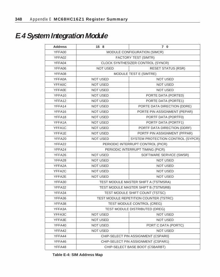
348 Appendix E MC68HC16Z1 Register Summary
E.4 System Integration ModuleAddress 15 8 7 0
YFFA00 MODULE CONFIGURATION (SIMCR)
YFFA02 FACTORY TEST (SIMTR)
YFFA04 CLOCK SYNTHESIZER CONTROL (SYNCR)
YFFA06 NOT USED RESET STATUS (RSR)
YFFA08 MODULE TEST E (SIMTRE)
YFFA0A NOT USED NOT USED
YFFA0C NOT USED NOT USED
YFFA0E NOT USED NOT USED
YFFA10 NOT USED PORTE DATA (PORTE0)
YFFA12 NOT USED PORTE DATA (PORTE1)
YFFA14 NOT USED PORTE DATA DIRECTION (DDRE)
YFFA16 NOT USED PORTE PIN ASSIGNMENT (PEPAR)
YFFA18 NOT USED PORTF DATA (PORTF0)
YFFA1A NOT USED PORTF DATA (PORTF1)
YFFA1C NOT USED PORTF DATA DIRECTION (DDRF)
YFFA1E NOT USED PORTF PIN ASSIGNMENT (PFPAR)
YFFA20 NOT USED SYSTEM PROTECTION CONTROL (SYPCR)
YFFA22 PERIODIC INTERRUPT CONTROL (PICR)
YFFA24 PERIODIC INTERRUPT TIMING (PICR)
YFFA26 NOT USED SOFTWARE SERVICE (SWSR)
YFFA28 NOT USED NOT USED
YFFA2A NOT USED NOT USED
YFFA2C NOT USED NOT USED
YFFA2E NOT USED NOT USED
YFFA30 TEST MODULE MASTER SHIFT A (TSTMSRA)
YFFA32 TEST MODULE MASTER SHIFT B (TSTMSRB)
YFFA34 TEST MODULE SHIFT COUNT (TSTSC)
YFFA36 TEST MODULE REPETITION COUNTER (TSTRC)
YFFA38 TEST MODULE CONTROL (CREG)
YFFA3A TEST MODULE DISTRIBUTED (DREG)
YFFA3C NOT USED NOT USED
YFFA3E NOT USED NOT USED
YFFA40 NOT USED PORT C DATA (PORTC)
YFFA42 NOT USED NOT USED
YFFA44 CHIP-SELECT PIN ASSIGNMENT (CSPAR0)
YFFA46 CHIP-SELECT PIN ASSIGNMENT (CSPAR1)
YFFA48 CHIP-SELECT BASE BOOT (CSBARBT)
Table E-4: SIM Address Map

349E.4 System Integration Module
Address 15 8 7 0
YFFA4A CHIP-SELECT OPTION BOOT (CSORBT)
YFFA4C CHIP-SELECT BASE 0 (CSBAR0)
YFFA4E CHIP-SELECT OPTION 0 (CSOR0)
YFFA50 CHIP-SELECT BASE 1 (CSBAR1)
YFFA52 CHIP-SELECT OPTION 1 (CSOR1)
YFFA54 CHIP-SELECT BASE 2 (CSBAR2)
YFFA56 CHIP-SELECT OPTION 2 (CSOR2)
YFFA58 CHIP-SELECT BASE 3 (CSBAR3)
YFFA5A CHIP-SELECT OPTION 3 (CSOR3)
YFFA5C CHIP-SELECT BASE 4 (CSBAR4)
YFFA5E CHIP-SELECT OPTION 4 (CSOR4)
YFFA60 CHIP-SELECT BASE 5 (CSBAR5)
YFFA62 CHIP-SELECT OPTION 5 (CSOR5)
YFFA64 CHIP-SELECT BASE 6 (CSBAR6)
YFFA66 CHIP-SELECT OPTION 6 (CSOR6)
YFFA68 CHIP-SELECT BASE 7 (CSBAR7)
YFFA6A CHIP-SELECT OPTION 7 (CSOR7)
YFFA6C CHIP-SELECT BASE 8 (CSBAR8)
YFFA6E CHIP-SELECT OPTION 8 (CSOR8)
YFFA70 CHIP-SELECT BASE 9 (CSBAR9)
YFFA72 CHIP-SELECT OPTION 9 (CSOR9)
YFFA74 CHIP-SELECT BASE 10 (CSBAR10)
YFFA76 CHIP-SELECT OPTION 10 (CS0R10)
YFFA78 NOT USED NOT USED
YFFA7A NOT USED NOT USED
YFFA7C NOT USED NOT USED
YFFA7E NOT USED NOT USED
Table E-4: SIM Address Map (continued)
E.4.1 SIMCR — Module Configuration Register $YFFA00
SIMCR controls system configuration. Can be read or written at any time, exceptfor the module mapping (MM) bit, which can be written once, and must remain set.
15 14 13 12 11 10 9 8 7 6 5 4 3 2 1 0
EXEOFFFRZSW FRZBM 0 SLVEN 0 SHEN SUPV MM 0 0 IARB
RESET:0 0 0 0 DATA11 0 0 0 1 1 0 0 1 1 1 1

350 Appendix E MC68HC16Z1 Register Summary
EXOFF — External Clock Off0 = The CLKOUT pin is driven from an internal clock source.1 = The CLKOUT pin is placed in a high-impedance state.
FRZSW — Freeze Software Enable0 = When FREEZE is asserted, the software watchdog and periodic interrupt timer
counters continue to run.1 = When FREEZE is asserted, the software watchdog and periodic interrupt timer
counters are disabled, preventing interrupts during software debug.
FRZBM — Freeze Bus Monitor Enable0 = When FREEZE is asserted, the bus monitor continues to operate.1 = When FREEZE is asserted, the bus monitor is disabled.
SLVEN — Factory Test Mode Enabled0 = IMB is not available to an external master.1 = An external bus master has direct access to the IMB.
SHEN[1:0] — Show Cycle EnableThis field determines what the EBI does with the external bus during internal
transfer operations.
SUPV — Supervisor/User Data SpaceThe MC68HC16Z1 operates only in supervisory mode — SUPV has no effect.
MM — Module MappingBecause ADDR[23:20] follow the state of ADDR19 in the CPU16, MM must
remain set.0 = Internal modules are addressed from $7FF000 — $7FFFFF.1 = Internal modules are addressed from $FFF000 — $FFFFFF.
IARB[3:0] — Interrupt Arbitration FieldDetermines SIM interrupt arbitration priority. The reset value is $F (highest
priority), to prevent SIM interrupts from being discarded during initialization.
E.4.2 SIMTR — System Integration Test Register $YFFA02SIMTR is used for factory test only.
E.4.3 SYNCR — Clock Synthesizer Control Register $YFFA0415 14 13 12 11 10 9 8 7 6 5 4 3 2 1 0
W X Y EDIV 0 0 SLIMP SLOCK RSTEN STSIM STEXT
RESET:0 0 1 1 1 1 1 1 0 0 0 U U 0 0 0

351
SYNCR determines system clock operating frequency and mode of operation.Clock frequency is determined by SYNCR bit settings as follows:
FSYSTEM =
FREFERENCE
[4(Y + 1)(22W + X)]
W — Frequency Control (VCO)0 = Base VCO frequency.1 = VCO frequency multiplied by four.
X — Frequency Control Bit (Prescale)0 = Base system clock frequency1 = System clock frequency multiplied by two.
Y[5:0] — Frequency Control (Counter)The Y field is the initial value for the modulus 64 down counter in the synthesizer
feedback loop. Values range from 0 to 63.
EDIV — ECLK Divide Rate0 = ECLK is system clock divided by 8.1 = ECLK is system clock divided by 16.
SLIMP — Limp Mode0 = External crystal is VCO reference.1 = Loss of crystal reference.
SLOCK — Synthesizer Lock0 = VCO is enabled, but has not locked.1 = VCO has locked on the desired frequency or system clock is external.
RSTEN — Reset Enable0 = Loss of reference causes the MCU to operate in limp mode.1 = Loss of reference causes system reset.
STSIM — Stop Mode System Integration Clock0 = SIM clock driven by an external source and VCO off during low-power stop.1 = SIM clock driven by VCO during low-power stop.
STEXT — Stop Mode External Clock0 = CLKOUT held low during low-power stop.1 = CLKOUT driven from SIM clock during low-power stop.
E.4.4 RSR — Reset Status Register $YFFA07
E.4 System Integration Module
15 14 13 12 11 10 9 8 7 6 5 4 3 2 1 0
NOT USED EXT POW SW HLT 0 LOC SYS TST

352 Appendix E MC68HC16Z1 Register Summary
RSR contains a status bit for each reset source in the MCU. RSR is updated whenthe MCU comes out of reset. A set bit indicates what type of reset occurred. Ifmultiple sources assert reset signals at the same time, more than one bit in RSR maybe set. This register can be read at any time; a write has no effect.
EXT — External ResetReset caused by an external signal.
POW — Power-Up ResetReset caused by the power-up reset circuit.
SW — Software Watchdog ResetReset caused by the software watchdog circuit.
HLT — Halt Monitor ResetReset caused by the halt monitor.
LOC — Loss of Clock ResetReset caused by loss of clock frequency reference.
SYS — System ResetReset caused by a CPU RESET instruction. Not used by MC68HC16Z1. The
CPU16 has no reset instruction.
TST — Test Submodule ResetReset caused by the test submodule. Used during system test only.
E.4.5 SIMTRE — System Integration Test Register (ECLK) $YFFA08Register is used for factory test only.
E.4.6 PORTE0/PORTE1 — Port E Data Register $YFFA11, $YFFA13
PORTE is an internal data latch that can be accessed at two locations — it can beread or written at any time. If a pin in I/O port E is configured as an output, thecorresponding bit value is driven out on the pin. When a pin is configured for output,a read of PORTE returns the latched bit value; when a pin is configured for input, aread returns the pin logic level. Reads of PE3 always return one.
15 14 13 12 11 10 9 8 7 6 5 4 3 2 1 0
NOT USED PE7 PE6 PE5 PE4 PE3 PE2 PE1 PE0
RESET: U U U U U U U U

353
E.4.7 DDRE — Port E Data Direction Register $YFFA15
Bits in this register control the direction of the port E pin drivers when pins areconfigured for I/O. Setting a bit configures the corresponding pin as an output;clearing a bit configures the corresponding pin as an input. This register can be reador written at any time.
E.4.8 PEPAR — Port E Pin Assignment Register $YFFA17
Bits in this register determine the function of port E pins. Setting a bit assigns thecorresponding pin to a bus control signal; clearing a bit assigns the pin to I/O port F.PE3 is not connected to a pin. DDE3, PE3, and PEPAR3 can be read and written, buthave no function.
E.4.9 PORTF0/PORTF1— Port F Data Register $YFFA19, $YFFA1B
PORTF is an internal data latch that can be accessed at two locations. It can beread or written at any time. If a pin in I/O port F is configured as an output, thecorresponding bit value is driven out on the pin. When a pin is configured for output,a read of PORTF returns the latched bit value; when a pin is configured for input, aread returns the pin logic level.
E.4.10 DDRF — Port F Data Direction Register $YFFA1D
Bits in this register control the direction of the port F pin drivers when pins areconfigured for I/O. Setting a bit configures the corresponding pin as an output;clearing a bit configures the corresponding pin as an input. This register can be reador written at any time.
15 14 13 12 11 10 9 8 7 6 5 4 3 2 1 0
NOT USED DDE7 DDE6 DDE5 DDE4 DDE3 DDE2 DDE1 DDE0
RESET: 0 0 0 0 0 0 0 0
15 14 13 12 11 10 9 8 7 6 5 4 3 2 1 0
NOT USED PE7 PE6 PE5 PE4 PE3 PE2 PE1 PE0(SIZ1) (SIZ0) (AS) (DS) (AVEC) DSACK1 \S\UP4(F
(,DSACK0))
RESET: DATA8 DATA8 DATA8 DATA8 DATA8 DATA8 DATA8 DATA8
15 14 13 12 11 10 9 8 7 6 5 4 3 2 1 0
NOT USED PF7 PF6 PF5 PF4 PF3 PF2 PF1 PF0
RESET: U U U U U U U U
15 14 13 12 11 10 9 8 7 6 5 4 3 2 1 0
NOT USED DDF7 DDF6 DDF5 DDF4 DDF3 DDF2 DDF1 DDF0
RESET: 0 0 0 0 0 0 0 0
E.4 System Integration Module

354 Appendix E MC68HC16Z1 Register Summary
E.4.11 PFPAR — Port F Pin Assignment Register $YFFA1F
Bits in this register determine the function of port F pins. Setting a bit assigns thecorresponding pin to a bus control signal; clearing a bit assigns the pin to I/O port E.
E.4.12 SYPCR — System Protection Control Register $YFFA21
SYPCR controls system monitor functions, software watchdog clock prescaling,and bus monitor timing. This register can be written once following power-on or reset.
SWE — Software Watchdog Enable0 = Software watchdog disabled1 = Software watchdog enabled
SWP — Software Watchdog Prescale0 = Software watchdog clock not prescaled1 = Software watchdog clock prescaled by 512
SWT[1:0] — Software Watchdog TimingThis field selects software watchdog timeout period.
HME — Halt Monitor Enable0 = Disable halt monitor function1 = Enable halt monitor function
15 14 13 12 11 10 9 8 7 6 5 4 3 2 1 0
NOT USED PF7 PF6 PF5 PF4 PF3 PF2 PF1 PF0(IRQ7) (IRQ6) (IRQ5) (IRQ4) (IRQ3) (IRQ2) (IRQ1) (MODCLK)
RESET: DATA9 DATA9 DATA9 DATA9 DATA9 DATA9 DATA9 DATA9
15 14 13 12 11 10 9 8 7 6 5 4 3 2 1 0
NOT USED SWE SWP SWT HME BME BMT
RESET: 1 \S\UP5\ 0 0 0 0 0 0F(.MODCLK1)
SWP SWT Ratio
0 00 29
0 01 211
0 10 213
0 11 215
1 00 218
1 01 220
1 10 222
1 11 224

355
BME — Bus Monitor External Enable0 = Disable bus monitor function for an internal to external bus cycle.1 = Enable bus monitor function for an internal to external bus cycle.
BMT[1:0] — Bus Monitor TimingThis field selects bus monitor timeout period.
E.4.13 PICR — Periodic Interrupt Control Register $YFFA22
Contains information concerning periodic interrupt priority and vectoring.PICR[10:0] can be read or written at any time. PICR[15:11] are unimplemented andalways return zero.
PIRQL[2:0] — Periodic Interrupt Request LevelThis field determines the priority of periodic interrupt requests.
PIV[7:0] — Periodic Interrupt VectorThe bits of this field contain the periodic interrupt vector number supplied by the
SIM when the CPU acknowledges an interrupt request.
E.4.14 PITR — Periodic Interrupt Timer Register $YFFA24
Contains the count value for the periodic timer. This register can be read orwritten at any time.
PTP — Periodic Timer Prescaler Control1 = Periodic timer clock prescaled by a value of 5120 = Periodic timer clock not prescaled
E.4 System Integration Module
Bus Monitor Period
BMT Bus Monitor Timeout Period
00 64 System Clocks
01 32 System Clocks
10 16 System Clocks
11 8 System Clocks
15 14 13 12 11 10 9 8 7 6 5 4 3 2 1 0
0 0 0 0 0 0 PIRQL PIV
RESET:0 0 0 0 0 0 0 0 0 0 0 0 1 1 1 1
15 14 13 12 11 10 9 8 7 6 5 4 3 2 1 0
0 0 0 0 0 0 0 PTP PITM
RESET:0 0 0 0 0 0 0 \s\up4(f 0 0 0 0 0 0 0 0
(.MODCLK))

356 Appendix E MC68HC16Z1 Register Summary
PITM[7:0] — Periodic Interrupt Timing ModulusThis is the 8-bit timing modulus used to determine periodic interrupt rate. Use the
following expression to calculate timer period.
PIT Period = [(PIT Modulus)(Prescaler value)(4)]/EXTAL Frequency
E.4.15 SWSR — Software Service Register $YFFA27
When the software watchdog is enabled, a service sequence must be written tothis register within a specific interval. When read, SWSR always returns $00. Regis-ter shown with read value.
E.4.16 TSTMSRA — Master Shift Register A $YFFA30Register is used for factory test only.
E.4.17 TSTMSRB — Master Shift Register B $YFFA32Register is used for factory test only.
E.4.18 TSTSC — Test Module Shift Count $YFFA34Register is used for factory test only.
E.4.19 TSTRC — Test Module Repetition Count $YFFA36Register is used for factory test only.
E.4.20 CREG — Test Submodule Control Register $YFFA38Register is used for factory test only.
E.4.21 DREG — Distributed Register $YFFA3ARegister is used for factory test only.
E.4.22 PORTC — Port C Data Register $YFFA41
PORTC latches data for chip-select pins that are used for discrete output.
15 14 13 12 11 10 9 8 7 6 5 4 3 2 1 0
NOT USED 0 0 0 0 0 0 0 0
RESET: 0 0 0 0 0 0 0 0
15 14 13 12 11 10 9 8 7 6 5 4 3 2 1 0
NOT USED 0 DO6 DO5 DO4 DO3 DO2 DO1 DO0
RESET: 0 0 0 0 0 0 0 0

357
E.4.23 CSPAR0 — Chip Select Pin Assignment Register 0 $YFFA44
Contains seven 2-bit fields (CS[5:0] and CSBOOT) that determine the functionsof corresponding chip-select pins. CSPAR0[15:14] are not used. These bits alwaysread zero; write has no effect. CSPAR0 bit 1 always reads one; writes to CSPAR0 bit1 have no effect. Mnemonics in parentheses show alternate functions that can beenabled by data bus mode selection during reset.
E.4.24 CSPAR1 — Chip Select Pin Assignment Register 1 $YFFA46
Contains five 2-bit fields (CS[10:6]) that determine the functions of correspond-ing chip-select pins. CSPAR1[15:10] are not used. These bits always read zero; writehas no effect. Mnemonics in parentheses show alternate functions that can be enabledby data bus mode selection during reset.
E.4.25 CSBARBT — Chip Select Base Address Register Boot ROM $YFFA48
E.4.26 CSBAR[0:10] — Chip Select Base Address Registers $YFFA4C–$YFFA74
15 14 13 12 11 10 9 8 7 6 5 4 3 2 1 0 ___ ___ ___ ___ ___ ___ _______
0 0 CS5 CS4 CS3 CS2 CS1 CS0 CSBOOT (FC2) (FC1) (FC0) (BGACK) (BG) (BR)
RESET:0 0 DATA2 1 DATA2 1 DATA2 1 DATA1 1 DATA1 1 DATA1 1 1 DATA0
15 14 13 12 11 10 9 8 7 6 5 4 3 2 1 0___ ___ ___ ___ _______
0 0 0 0 0 0 CS10 CS9 CS8 CS7 CS6(ADDR23) (ADDR22) (ADDR21) (ADDR20) (ADDR22)
RESET:0 0 0 0 0 0 DATA7 1 DATA6 1 DATA5 1 DATA4 1 DATA3 1
Pin Assignment Field Encoding
Bit Field Configuration
00 Discrete Output*
01 Alternate Function*
10 Chip Select (8-Bit Port)
11 Chip Select (16-Bit Port)
15 14 13 12 11 10 9 8 7 6 5 4 3 2 1 0
ADDR ADDR ADDR ADDR ADDR ADDR ADDR ADDR ADDR ADDR ADDR ADDR ADDR BLKSZ23 22 21 20 19 18 17 16 15 14 13 12 11
RESET:0 0 0 0 0 0 0 0 0 0 0 0 0 1 1 1
15 14 13 12 11 10 9 8 7 6 5 4 3 2 1 0
ADDR ADDR ADDR ADDR ADDR ADDR ADDR ADDR ADDR ADDR ADDR ADDR ADDR BLKSZ23 22 21 20 19 18 17 16 15 14 13 12 11
RESET:0 0 0 0 0 0 0 0 0 0 0 0 0 0 0 0
E.4 System Integration Module
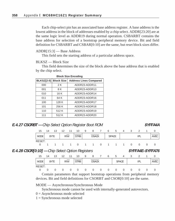
358 Appendix E MC68HC16Z1 Register Summary
Each chip-select pin has an associated base address register. A base address is thelowest address in the block of addresses enabled by a chip select. ADDR[23:20] are atthe same logic level as ADDR19 during normal operation. CSBARBT contains thebase address for selection of a bootstrap peripheral memory device. Bit and fielddefinition for CSBARBT and CSBAR[0:10] are the same, but reset block sizes differ.
ADDR[15:3] — Base AddressThis field sets the starting address of a particular address space.
BLKSZ — Block SizeThis field determines the size of the block above the base address that is enabled
by the chip select.
E.4.27 CSORBT — Chip Select Option Register Boot ROM $YFFA4A
E.4.28 CSOR[0:10] — Chip Select Option Registers $YFFA4E–$YFFA76
Contain parameters that support bootstrap operations from peripheral memorydevices. Bit and field definitions for CSORBT and CSOR[0:10] are the same.
MODE — Asynchronous/Synchronous ModeSynchronous mode cannot be used with internally-generated autovectors.
0 = Asynchronous mode selected1 = Synchronous mode selected
Block Size Encoding
BLKSZ[2:0] Block Size Address Lines Compared
000 2 K ADDR23-ADDR11
001 8 K ADDR23-ADDR13
010 16 K ADDR23-ADDR14
011 64 K ADDR23-ADDR16
100 128 K ADDR23-ADDR17
101 256 K ADDR23-ADDR18
110 512 K ADDR23-ADDR19
111 512 K ADDR23-ADDR20
15 14 13 12 11 10 9 8 7 6 5 4 3 2 1 0 __ _____ ______ _____
MODE BYTE R/W STRB DSACK SPACE IPL AVEC
RESET:0 1 1 1 1 0 1 1 0 1 1 1 0 0 0 0
15 14 13 12 11 10 9 8 7 6 5 4 3 2 1 0 __ _____ ______ _____
MODE BYTE R/W STRB DSACK SPACE IPL AVEC
RESET:0 0 0 0 0 0 0 0 0 0 0 0 0 0 0 0

359
BYTE — Upper/Lower Byte OptionThe value in this field determines whether a select signal can be asserted.
R/W — Read/WriteThis field causes a chip select to be asserted only for a read, only for a write, or
for both read and writE.
STRB — Address Strobe/Data Strobe1 = Data strobe0 = Address strobe
DSACK — Data Strobe AcknowledgeThis field specifies the source of DSACK in asynchronous mode and controls
wait state insertion.
SPACE — Address Space SelectThis field selects an address space to be used by the chip-select logic.
IPL — Interrupt Priority LevelThis field determines interrupt priority level when a chip-select is used for
interrupt acknowledge. It does not affect CPU interrupt recognition.
AVEC — Autovector EnableDo not enable autovector support when in synchronous mode.
1 = Autovector enabled0 = External interrupt vector enabled
Option Register Function Summary
MODE BYTE R/W STRB DSACK SPACE IPL AVEC
0=ASYNC 00=Disable 01=Rvsd 0=AS 0000=0 WAIT 00=CPU SP 000=All 0=Off
01=Lower 01=Read 1=DS 0001=1 WAIT 01=CPU SP 001=Priority 1 0=On
10=Upper 10=Write 0010=2 WAIT 10=Supb SP 010=Priority 2
11=Both 0011=3 WAIT 11=S/U SP 011=Priority 3
0100=4 WAIT 100=Priority 4
0101=5 WAIT 101=Priority 5
0110=6 WAIT 110=Priority 6
0111=7 WAIT 111=Priority 7
1000=8 WAIT
1001=9 WAIT
1010=10 WAIT
1011=11 WAIT
1100=12 WAIT
1101=13 WAIT
1110 = F term
1111=External
E.4 System Integration Module

360 Appendix E MC68HC16Z1 Register Summary
E.5.1 RAMMCR — RAM Module Configuration Register $YFFB00
RAMMCR is used to determine whether the RAM is in STOP mode or normalmode. It is also used to determine in which space the array resides, and controlsaccess to the base array registers. Reads of unimplemented bits always return zeros.Writes do not affect unimplemented bits.
STOP — Stop Control0 = RAM array operates normally.1 = RAM array enters low-power stop mode.
This bit determines whether the RAM array is in low-power stop mode. Resetstate is one, leaving the array configured for low-power stop operation. In stop mode,the array retains its contents, but cannot be read or written by the CPU. This bit can beread or written at any time.
RLCK — RAM Base Address Lock0 = SRAM base address registers can be written from IMB1 = SRAM base address registers are lockedRLCK defaults to zero on reset; it can be written once to one.
RASP[1:0] — RAM Array SpaceRASP limits access to the SRAM array in microcontrollers that support separate
user and supervisor operating modes. Because the CPU16 operates in supervisormode only, RASP1 has no effect.
E.5.2 RAMTST — RAM Test Register $YFFB02RAMTST is used for factory test only. Reads of this register return zeros, and
writes have no effect.
E.5 Standby RAM Module
Table E-5: SRAM Address Map
Address 15 8 7 0
$YFFB00 RAM MODULE CONFIGURATION REGISTER (RAMMCR)
$YFFB02 RAM TEST REGISTER (RAMTST)
$YFFB04 RAM ARRAY BASE ADDRESS REGISTER HIGH (RAMBAH)
$YFFB06 RAM ARRAY BASE ADDRESS REGISTER LOW (RAMBL)
15 14 13 12 11 10 9 8 7 6 5 4 3 2 1 0
STOP 0 0 0 RLCK 0 RASP NOT USED
RESET:1 0 0 0 0 0 1 1
RASP Space
X0 Program and Data
X1 Program

361
E.5.3 RAMBAH — Array Base Address Register High $YFFB04
E.5.4 RAMBAL — Array Base Address Register Low $YFFB06
RAMBAH and RAMBAL are used to specify an SRAM array base address.RAMBAH and RAMBAL can only be written while the SRAM is in low-powermode (RAMMCR STOP = 1) and the base address lock (RAMMCR RLCK = 0) isdisabled. This prevents accidental remapping of the array.
E.6 Queued Serial Module
15 14 13 12 11 10 9 8 7 6 5 4 3 2 1 0
NOT USED ADDR ADDR ADDR ADDR ADDR ADDR ADDR ADDR23 22 21 20 19 18 17 16
RESET:0 0 0 0 0 0 0 0 0 0 0 0 0 0 0 0
15 14 13 12 11 10 9 8 7 6 5 4 3 2 1 0
ADDR ADDR ADDR ADDR ADDR ADDR ADDR ADDR ADDR ADDR ADDR ADDR ADDR ADDR ADDR ADDR15 14 13 12 11 10 9 8 7 6 5 4 3 2 1 0
RESET:0 0 0 0 0 0 0 0 0 0 0 0 0 0 0 0
Address 15 8 7 0
$YFFC00 QSM MODULE CONFIGURATION (QSMCR)
$YFFC02 QSM TEST (QTEST)
$YFFC04 QSM INTERRUPT LEVEL (QUILR)
$YFFC06 RESERVED
$YFFC08 RESERVED
$YFFC0A RESERVED
$YFFC0C RESERVED
$YFFC0E RESERVED
$YFFC10 RESERVED
$YFFC12 RESERVED
$YFFC14 RESERVED
$YFFC16 PQS PIN ASSIGNMENT (PQSPAR) PQS DATA DIRECTION (DDRQS)
$YFFC18 SPI CONTROL 0 (SPCR0)
$YFFC1A SPI CONTROL 1 (SPCR1)
$YFFC1C SPI CONTROL 2 (SPCR2)
$YFFC1E SPI CONTROL 3 (SPCR3) SPI STATUS (SPSR)
$YFFC20-$YFFCFF RESERVED
$YFFC20-$YFFCFF RECEIVE RAM (RR[0:F])
$YFFC20-$YFFCFF TRANSMIT RAM (TR[0:F])
$YFFC20-$YFFCFF COMMAND RAM (CR[0:F])
Table E-6: QSM Address Map
E.6 Queued Serial Module

362 Appendix E MC68HC16Z1 Register Summary
E.6.1 QSMCR — QSM Configuration Register $YFFC00
QSMCR bits enable stop and freeze modes, and determine the arbitration priorityof QSM interrupt requests.
STOP — Stop Enable0 = Normal QSM clock operation1 = QSM clock operation stopped
When STOP is set, the QSM enters low-power stop mode. System clock input tothe module is disabled. While STOP is asserted, only QSMCR reads are guaranteedto be valid, but writes to QSPI RAM or any register are guaranteed valid. STOP is setduring reset. The SCI receiver and transmitter must be disabled before STOP is set.To stop the QSPI, set the HALT bit in SPCR3, wait until the HALTA flag is set, thenset STOP.
FRZ[1:0] — Freeze Control0 = Ignore the FREEZE signal on the IMB1 = Halt the QSPI (on a transfer boundary)
FRZ1 determines what action is taken by the QSPI when the FREEZE signal ofthe IMB is asserted. FREEZE is asserted whenever the CPU enters backgroundmode. FRZ0 is reserved for future use.
Bits [12:8] — Not Implemented
SUPV — Supervisor/UnrestrictedBecause the CPU16 in the MC68HC16Z1 operates only in supervisor mode, this
bit has no effect.
Bits [6:4] — Not Implemented
IARB — Interrupt ArbitrationEach module that generates interrupts must have an IARB value. IARB values
are used to arbitrate between interrupt requests of the same priority.
E.6.2 QTEST — QSM Test Register $YFFC02Used for factory test only.
E.6.3 QILR — QSM Interrupt Level Register $YFFC04
15 14 13 12 11 10 9 8 7 6 5 4 3 2 1 0
STOP FRZ1 FRZ0 0 0 0 PIRQL 0 SUPV 0 0 0 PIV
RESET:0 0 0 0 0 0 0 0 1 0 0 0 0 0 0 0

363
QIVR — QSM Interrupt Vector Register $YFFC05
The values of the ILQSPI and ILSCI fields in QILR determine the priority ofQSPI and SCI interrupt requests. QIVR determines the value of the interrupt vectornumber the QSM supplies when it responds to an interrupt acknowledge cycle. Atreset, QIVR is initialized to vector number $0F, the uninitialized interrupt vectornumber. To use interrupt-driven serial communication, a user-defined vector numbermust be written to QIVR.
ILQSPI — Interrupt Level for QSPIWhen an interrupt request is made, ILQSPI value determines which of the inter-
rupt request signals is asserted; when a request is acknowledged, the QSM comparesthis value to a mask value supplied by the CPU16 to determine whether to respond.ILQSPI must have a value in the range $0 (lowest priority) to $7 (highest priority).
ILSCI — Interrupt Level for SCIWhen an interrupt request is made, ILSCI value determines which of the interrupt
request signals is asserted. When a request is acknowledged, the QSM compares thisvalue to a mask value supplied by the CPU16 to determine whether to respond. Thefield must have a value in the range $0 (lowest priority) to $7 (highest priority).
If ILQSPI and ILSCI have the same nonzero value, and both submodules simul-taneously request interrupt service, the QSPI has priority.
INTV[7:0] — Interrupt Vector NumberThe values of INTV[7:1] are the same for both QSPI and SCI interrupt requests;
the value of INTV0 used during an interrupt acknowledge cycle is supplied by theQSM. INTV0 is at logic level zero during an SCI interrupt and at logic level oneduring a QSPI interrupt. A write to INTV0 has no effect. Reads of INTV0 return avalue of one.
E.6.4 PORTQS — Port QS Data Register $YFFC15
PORTQS latches I/O data. Writes drive pins defined as outputs. Reads return datapresent on the pins. To avoid driving undefined data, first write a byte to PORTQS,then configure DDRQS.
15 14 13 12 11 10 9 8 7 6 5 4 3 2 1 0
0 0 PIRQL SUPV INTV
RESET:0 0 0 0 0 0 0 0 0 0 0 0 1 1 1 1
15 8 7 6 5 4 3 2 1 0
RESERVED PQS7 PQS6 PQS5 PQS4 PQS3 PQS2 PQS1 PQS0
RESET: 0 0 0 0 0 0 0 0
E.6 Queued Serial Module

364 Appendix E MC68HC16Z1 Register Summary
E.6.5 PQSPAR — Pin Assignment Register $YFFC16
DDRQS — Data Direction Register $YFFC17
Clearing a bit in PQSPAR assigns the corresponding pin to general-purpose I/O;setting a bit assigns the pin to the QSPI. PQSPAR does not affect operation of theSCI. DDRQS determines whether pins are inputs or outputs. Clearing a bit makes thecorresponding pin an input; setting a bit makes the pin an output. DDRQS affectsboth QSPI function and I/O function. DDRQS determines the direction of the TXDpin only when the SCI transmitter is disabled. When the SCI transmitter is enabled,the TXD pin is an output.
E.6.6 SPCR0 — QSPI Control Register 0 $YFFC18
SPCR0 contains parameters for configuring the QSPI and enabling variousmodes of operation. The CPU has read/write access to SPCR0, but the QSM has readaccess only. SPCR0 must be initialized before QSPI operation begins. Writing a newvalue to SPCR0 while the QSPI is enabled disrupts operation.
MSTR — Master/Slave Mode Select0 = QSPI is a slave device.1 = QSPI is system master.
WOMQ — Wired-OR Mode for QSPI Pins0 = Outputs have normal MOS drivers.1 = Pins designated for output by DDRQS have open-drain drivers.
BITS — Bits Per TransferThe BITS field determines the number of serial data bits transferred.
CPOL — Clock Polarity0 = The inactive state value of SCK is logic level zero.1 = The inactive state value of SCK is logic level one.
15 14 13 12 11 10 9 8 7 6 5 4 3 2 1 0
PQSPAR DDRQS
RESET:
0 0 0 0 0 0 0 0 0 0 0 0 0 0 0 0
15 14 13 12 11 10 9 8 7 6 5 4 3 2 1 0
MSTR WOMQ BITS CPOL CPHA BR
RESET:
0 0 0 0 0 0 0 1 0 0 0 0 0 1 0 0

365
CPHA — Clock Phase0 = Data captured on the leading edge of SCK and changed on the following edge of SCK.1 = Data is changed on the leading edge of SCK and captured on the following edge
of SCK.
SPBR — Serial Clock Baud RateQSPI Baud rate is selected by writing a value from 2 to 255 into SPBR. Giving
BR a value of zero or one disables SCK (disable state determined by CPOL). At reset,BAUD is initialized to a 2.1-MHz SCK frequency.
E.6.7 SPCR1 — QSPI Control Register 1 $YFFC1A
SPCR1 enables the QSPI and specified transfer delays. The CPU has read/writeaccess to SPCR1, but the QSM has read access only to all bits but enable bit SPF.SPCR1 must be written last during initialization because it contains SPF. Writing anew value to SPCR1 while the QSPI is enabled disrupts operation.
SPE — QSPI Enable0 = QSPI is disabled. QSPI pins can be used for general-purpose I/O.1 = QSPI is enabled. Pins allocated by PQSPAR are controlled by the QSPI.
DSCKL — Delay before SCKWhen the DSCK bit in command RAM is set, this field determines the length of
delay from PCS valid to SCK transition. PCS may be any of the four peripheral chip-select pins.
DTL — Length of Delay after TransferWhen the DT bit in command RAM is set, this field determines the length of
delay after serial transfer.
E.6.8 SPCR2 — QSPI Control Register 2 $YFFC1C
SPCR2 contains QSPI queue pointers, wraparound mode control bits, and aninterrupt enable bit. The CPU has read/write access to SPCR2, but the QSM has readaccess only. SPCR2 is buffered — new SPCR2 values become effective only after
15 14 13 12 11 10 9 8 7 6 5 4 3 2 1 0
SPE DSCKL DTL
RESET:
0 0 0 0 0 1 0 0 0 0 0 0 0 1 0 0
E.6 Queued Serial Module
15 14 13 12 11 10 9 8 7 6 5 4 3 2 1 0
SPIFIE WREN WRTO 0 ENDQP 0 0 0 0 NEWQP
RESET:
0 0 0 0 0 0 0 1 0 0 0 0 0 0 0 0

366 Appendix E MC68HC16Z1 Register Summary
completion of the current serial transfer. Rewriting NEWQP in SPCR2 causesexecution to restart at the designated location. SPCR2 reads return the value of theregister, not the buffer.
SPIFIE — SPI Finished Interrupt Enable0 = QSPI interrupts disabled1 = QSPI interrupts enabled
WREN — Wrap Enable0 = Wraparound mode disabled1 = Wraparound mode enabled
WRTO — Wrap To0 = Wrap to pointer address $01 = Wrap to address in NEWQP
Bit 12 — Not Implemented
ENDQP — Ending Queue PointerThis field contains the last QSPI queue address.
Bits [7:4] — Not Implemented
NEWQP — New Queue Pointer ValueThis field contains the first QSPI queue address.
E.6.9 SPCR3 — QSPI Control Register 3 $YFFC1E
SPSR — QSPI Status Register $YFFC1F
SPCR3 contains the loop mode enable bit, halt and mode fault interrupt enables,and the halt control bit. The CPU has read/write access to SPCR3, but the QSM hasread access only. SPCR3 must be initialized before QSPI operation begins. Writing anew value to SPCR3 while the QSPI is enabled disrupts operation. SPSR containsinformation concerning the current serial transmission. Only the QSPI can set bits inSPSR. The CPU reads SPSR to obtain QSPI status information and writes it to clearstatus flags.
Bits [15:11] — Not Implemented
15 14 13 12 11 10 9 8 7 6 5 4 3 2 1 0
0 0 0 0 0 LOOPQ HMIE HALT SPIEF MODF HALTA 0 CPTQP
RESET:
0 0 0 0 0 0 0 0 0 0 0 0 0 0 0 0

367
LOOPQ — QSPI Loop Mode0 = Feedback path disabled1 = Feedback path enabled
HMIE — HALTA and MODF Interrupt Enable0 = HALTA and MODF interrupts disabled1 = HALTA and MODF interrupts enabled
HALT — Halt0 = Halt not enabled1 = Halt enabled
SPIF — QSPI Finished Flag0 = QSPI not finished1 = QSPI finished
MODF — Mode Fault Flag0 = Normal operation1 = Another SPI node requested to become the network SPI master while the QSPI
was enabled in master mode (sup6(f(,SS)) input taken low).
HALTA — Halt Acknowledge Flag0 = QSPI not halted1 = QSPI halted
Bit 4 — Not Implemented
CPTQP — Completed Queue PointerCPTQP points to the last command executed. It is updated when the current
command is complete. When the first command in a queue is executing, CPTQPcontains either the reset value ($0) or a pointer to the last command completed in theprevious queue.
E.6.10 RR[0:F] — Receive Data RAM $YFFD00–$YFFD0EData received by the QSPI is stored in this segment. The CPU reads this segment
to retrieve data from the QSPI. Data stored in receive RAM is right-justified. Unusedbits in a receive queue entry are set to zero by the QSPI upon completion of theindividual queue entry. The CPU can access the data using byte, word, or long-wordaddressing.
E.6.11 TR[0:F] — Transmit Data RAM $YFFD20–$YFFD3EData that is to be transmitted by the QSPI is stored in this segment. The CPU nor-
mally writes one word of data into this segment for each queue command to be executed.
E.6 Queued Serial Module

368 Appendix E MC68HC16Z1 Register Summary
Information to be transmitted must be written to transmit data RAM in a right-justified format. The QSPI cannot modify information in the transmit data RAM. TheQSPI copies the information to its data serializer for transmission. Informationremains in transmit RAM until overwritten.
E.6.12 CR[0:F] — Command RAM $YFFD40–$YFFD4F
*The PCS0 bit represents the dual-function PCS0/SS.
Command RAM is used by the QSPI when in master mode. The CPU writes onebyte of control information to this segment for each QSPI command to be executed.The QSPI cannot modify information in command RAM.
Command RAM consists of 16 bytes. Each byte is divided into two fields. Theperipheral chip-select field enables peripherals for transfer. The command controlfield provides transfer options.
A maximum of 16 commands can be in the queue. Queue execution proceedsfrom the address in NEWQP through the address in ENDQP (both of these fields arein SPCR2).
PCS[3:0] — Peripheral Chip SelectPeripheral chip-select bits are used to select an external device for serial data
transfer. More than one peripheral chip select may be activated at a time, and morethan one peripheral chip may be connected to each PCS pin, provided proper fanout isobserved. PCS0 shares a pin with the slave select sup6(f(,SS)) signal, which initiatesslave mode serial transfer. If sup6(f(,SS)) is taken low when the QSPI is in mastermode, a mode fault occurs.
CONT — Continue0 = Control of chip selects returned to PORTQS after transfer is complete.1 = Peripheral chip selects remain asserted after transfer is complete.
BITSE — Bits per Transfer Enable0 = 8 bits1 = Number of bits set in BITS field of SPCR0
DT — Delay after TransferThe QSPI provides a variable delay at the end of serial transfer to facilitate
interfacing with peripherals that have a latency requirement. The delay betweentransfers is determined by the SPCR1 DTL field.
7 6 5 4 3 2 1 0
CONT BITSE DT DSCK PCS3 PCS2 PCS1 PCS0*
— — — — — — — —
CONT BITSE DT DSCK PCS3 PCS2 PCS1 PCS0*
COMMAND CONTROL PERIPHERAL CHIP SELECT

369
DSCK — PCS to SCK Delay0 = PCS valid to SCK transition is one-half SCK.1 = SPCR1 DSCKL field specifies delay from PCS valid to SCK.
E.6.13 SCCR0 — SCI Control Register 0 $YFFC08
SCCR0 contains the SCI baud rate selection field. Baud rate must be set beforethe SCI is enabled. The CPU can read and write SCCR0 at any time. Changing thevalue of SCCR0 bits during a transfer operation can disrupt operation.
Bits [15:13] — Not Implemented
SCBR — SCI Baud RateSCI baud rate is programmed by writing a 13-bit value to this field. Writing a
value of zero to SCBR disables the baud rate generator. Baud clock rate is calculatedas follows:
SCI Baud Clock Rate = System Clock/(32SCBR)
E.6.14 SCCR1 — SCI Control Register 1 $YFFC0A
SCCR1 contains SCI configuration parameters, including transmitter and re-ceiver enable bits, interrupt enable bits, and operating mode enable bits. The CPU canread and write SCCR0 at any time. The SCI can modify the RWU bit under certaincircumstances. Changing the value of SCCR1 bits during a transfer operation candisrupt operation.
Bit 15 — Not Implemented
LOOPS — Loop Mode0 = Normal SCI operation, no looping, feedback path disabled1 = Test SCI operation, looping, feedback path enabled
WOMS — Wired-OR Mode for SCI Pins0 = If configured as an output, TXD is a normal CMOS output.1 = If configured as an output, TXD is an open-drain output.
15 14 13 12 11 10 9 8 7 6 5 4 3 2 1 0
0 LOOPS WOMS ILT PT PE M WAKE TIE TCIE RIE ILIE TE RE RWU SBK
RESET:
0 0 0 0 0 0 0 0 0 0 0 0 0 0 0 0
15 14 13 12 11 10 9 8 7 6 5 4 3 2 1 0
0 0 0 SCBR
RESET:
0 0 0 0 0 0 0 1 0 0 0 0 0 1 0 0
E.6 Queued Serial Module

370 Appendix E MC68HC16Z1 Register Summary
ILT — Idle-Line Detect Type0 = Short idle-line detect (start count on first one)1 = Long idle-line detect (start count on first one after stop bit(s))
PT — Parity Type0 = Even parity1 = Odd parity
PE — Parity Enable0 = SCI parity disabled1 = SCI parity enabled
M — Mode Select0 = 10-bit SCI frame1 = 11-bit SCI frame
WAKE — Wakeup by Address Mark0 = SCI receiver awakened by idle-line detection1 = SCI receiver awakened by address mark (last bit set)
TIE — Transmit Interrupt Enable0 = SCI TDRE interrupts inhibited1 = SCI TDRE interrupts enabled
TCIE — Transmit Complete Interrupt Enable0 = SCI TC interrupts inhibited1 = SCI TC interrupts enabled
RIE — Receiver Interrupt Enable0 = SCI RDRF and OR interrupts inhibited1 = SCI RDRF and OR interrupts enabled
ILIE — Idle-Line Interrupt Enable0 = SCI IDLE interrupts inhibited1 = SCI IDLE interrupts enabled
TE — Transmitter Enable0 = SCI transmitter disabled (TXD pin may be used as I/O)1 = SCI transmitter enabled (TXD pin dedicated to SCI transmitter)
RE — Receiver Enable0 = SCI receiver disabled (status bits inhibited)1 = SCI receiver enabled

371
RWU — Receiver Wakeup0 = Normal receiver operation (received data recognized)1 = Wakeup mode enabled (received data ignored until awakened)
SBK — Send Break0 = Normal operation1 = Break frame(s) transmitted after completion of current frame
E.6.15 SCSR — SCI Status Register $YFFC0C
SCSR contains flags that show SCI operating conditions. These flags are clearedeither by SCI hardware or by a CPU read/write sequence. The sequence consists ofreading SCSR, then reading or writing SCDR.
If an internal SCI signal for setting a status bit comes after the CPU has read theasserted status bits, but before the CPU has written or read SCDR, the newly setstatus bit is not cleared — SCSR must be read again with the bit set, and SCDR mustbe written or read before the status bit is cleared.
A long-word read can consecutively access both SCSR and SCDR. This actionclears receive status flag bits that were set at the time of the read, but does not clearTDRE or TC flags. Reading either byte of SCSR causes all 16 bits to be accessed, andany status bit already set in either byte will be cleared on a subsequent read or write ofregister SCDR.
TDRE — Transmit Data Register Empty0 = Register TDR still contains data to be sent to the transmit serial shifter.1 = A new character may now be written to register TDR.
TC — Transmit Complete0 = SCI transmitter is busy.1 = SCI transmitter is idle.
RDRF — Receive Data Register Full0 = Register RDR is empty or contains previously read data.1 = Register RDR contains new data.RAF — Receiver Active0 = SCI receiver is idle.1 = SCI receiver is busy.
15 14 13 12 11 10 9 8 7 6 5 4 3 2 1 0
NOT USED TDRE TC RDRF RAF IDLE OR NF FE PF
RESET:
0 0 0 0 0 0 0 0 0 0 0 0 0 0 0 0
E.6 Queued Serial Module

372 Appendix E MC68HC16Z1 Register Summary
IDLE — Idle-Line Detected0 = SCI receiver did not detect an idle-line condition.1 = SCI receiver detected an idle-line condition.
OR — Overrun Error0 = RDRF is cleared before new data arrives.1 = RDRF is not cleared before new data arrives.
NF — Noise Error0 = No noise detected on the received data.1 = Noise occurred on the received data.
FE — Framing Error1 = Framing error or break occurred on the received data.0 = No framing error on the received data.
PF — Parity Error1 = Parity error occurred on the received data.0 = No parity error on the received data.
E.6.16 SCDR — SCI Data Register $YFFC0E
SCDR consists of two data registers at the same address. RDR is a read-onlyregister that contains data received by the SCI serial interface. Data comes into thereceive serial shifter and is transferred to RDR. TDR is a write-only register thatcontains data to be transmitted. Data is first written to TDR, then transferred to thetransmit serial shifter, where additional format bits are added before transmission.R[7:0]/T[7:0] contain either the first eight data bits received when SCDR is read, orthe first eight data bits to be transmitted when SCDR is written. R8/T8 are used whenthe SCI is configured for 9-bit operation. When it is configured for 8-bit operation,they have no meaning or effect.
15 14 13 12 11 10 9 8 7 6 5 4 3 2 1 0
0 0 0 0 0 0 0 R8/T8 R7/T7 R6/T6 R5/T5 R4/T4 R3/T3 R2/T2 R1/T1 R0/T0
RESET:
0 0 0 0 0 0 0 U U U U U U U U U

373Appendix F
Appendix F
Header Files For MC68HC16 FamilyThe header files for the MC68HC16 family are broken into several different files.
The first header is for the base MC68HC16 module and it contains some generaldefinitions that are useful throughout development of code for these devices. Theremainder of the files are for the several individual modules that will be found on theMC68HC16 family. These include the general purpose timer, gpt.h, the systemintegration module, sim.h, the analog to digital converter, adc.h, the queued serialcommunications module, qsm.h, and the static RAM module, sram.h.
You will note that many different structures of bit fields are defined throughoutthese files. This approach allows the custom creation of registers with several differ-ent bit field configurations in each for the easy programming of these fields.
Following is the general header file for the MC68HC16 family:
#ifndef HC16#define HC16 1
typedef struct{ unsigned bit0 : 1; unsigned bit1 : 1; unsigned bit2 : 1; unsigned bit3 : 1; unsigned bit4 : 1; unsigned bit5 : 1; unsigned bit6 : 1; unsigned bit7 : 1; unsigned bit8 : 1; unsigned bit9 : 1; unsigned bit10: 1; unsigned bit11: 1; unsigned bit12: 1; unsigned bit13: 1; unsigned bit14: 1;
373

374 Appendix F Header Files for MC68HC16 Family
unsigned bit15: 1;} Register;
typedef struct{ unsigned iarb : 4; unsigned bit4 : 1; unsigned bit5 : 1; unsigned bit6 : 1; unsigned bit7 : 1; unsigned bit8 : 1; unsigned bit9 : 1; unsigned bit10: 1; unsigned bit11: 1; unsigned bit12: 1; unsigned bit13: 1; unsigned bit14: 1; unsigned bit15: 1;} MCR_Register;
#define ADC_Register (unsigned long) 0xff700#define GPT_Register (unsigned long) 0xff900#define SIM_Register (unsigned long) 0xffa00#define SRAM_Register (unsigned long) 0xffb00#define QSM_Register (unsigned long) 0xffc00
* Macros and function to permit interrupt service routine programming from C.
To use the vector call, do vector(isr, vector_address) where isr is a pointer to the interrupt service routine, and vector_address is the vector address where the isr pointer must be stored. The program must use the return_int() function fro each return from an interrupt or exception. */
#define vector(isr,vector_address) (*(void**)(vector_address)=(isr))#define cli() _asm("andp #0FF1FH\n") /* enable interrupts */#define sei() _asm("orp #00e0H\n") /* disable maskable interrupts*/#define return_int() _asm("rti\n")#define TRUE 1

375Appendix F
#define FALSE 0#define FOREVER while(TRUE)
#endif
The system integration module (SIM) is the means by which the computer isconnected to the outside world. There are many registers in the SIM that containseveral different bit field configurations. These registers are each defined as anindividual type so that the bit fields can be accessed directly. This approach is used inthe SIM and other modules as needed.
#ifndef SIM#define SIM 1
typedef struct{ unsigned STEXT :1; unsigned STSIM :1; unsigned RSTEN :1; unsigned SLOCK :1; unsigned SLIMP :1; unsigned NUL1 :2; unsigned EDIV :1; unsigned Y :6; unsigned X :1; unsigned W :1;} Syncr;
typedef struct{ unsigned BMT :2; unsigned BME :1; unsigned HME :1; unsigned SWT :2; unsigned SWP :1; unsigned SWE :1;}Sypcr;
typedef struct{ unsigned PIV :8; unsigned PIRQL :3;

376 Appendix F Header Files for MC68HC16 Family
unsigned NUL2 :5;} Picr;
typedef struct{ unsigned PITM :8; unsigned PTP :1; unsigned NUL3 :7;}Pitr;
typedef struct{ unsigned pr0 :2; unsigned pr1 :2; unsigned pr2 :2; unsigned pr3 :2; unsigned pr4 :2; unsigned pr5 :2; unsigned pr6 :2; unsigned pr7 :2;} Cspar;
typedef struct{ unsigned BLKSZ :3; unsigned HIADDR :13;} Csbar;
typedef struct{ unsigned AVEC :1; unsigned IPL :3; unsigned SPACE :2; unsigned DSACK :4; unsigned STRB :1; unsigned RSW :2; unsigned BYTE :2; unsigned MODE :1;} Csor;
#define SIM_MCR (*(MCR_Register*)(SIM_Register))

377Appendix F
#define SYNCR (*(Syncr*)(SIM_Register+0x4))#define RSR (*(Register*)(SIM_Register+0x6))#define SIMTRE (*(Register*)(SIM_Register+0x8))#define PORTE0 (*(Register*)(SIM_Register+0x10))#define PORTE1 (*(Register*)(SIM_Register+0x12))#define DDRE (*(Register*)(SIM_Register+0x14))#define PEPAR (*(Register*)(SIM_Register+0x16))#define PORTF0 (*(Register*)(SIM_Register +0x18))#define PORTF1 (*(Register*)(SIM_Register+0x1a))#define DDRF (*(Register*)(SIM_Register+0x1c))#define PFPAR (*(Register*)(SIM_Register+0x1e))#define SYPCR (*(Sypcr*)(SIM_Register+0x20))#define PICR (*(Picr*)(SIM_Register+0x22))#define PITR (*(Pitr*)(SIM_Register+0x24))#define SWSR (*(int*)(SIM_Register+0x26))#define PORTC (*(Register*)(SIM_Register+0x40))#define CSPAR0 (*(Cspar*)(SIM_Register+0x44))#define CSPAR1 (*(Cspar*)(SIM_Register+0x46))#define CSBARBT (*(Csbar*)(SIM_Register+0x48) )#define CSORBT (*(Csor*)(SIM_Register+0x4a))#define CSBAR0 (*(Csbar*)(SIM_Register+0x4c))#define CSOR0 (*(Csor*)(SIM_Register+0x4e))#define CSBAR1 (*(Csbar*)(SIM_Register+0x50))#define CSOR1 (*(Csor*)(SIM_Register+0x52))#define CSBAR2 (*(Csbar*)(SIM_Register+0x54))#define CSOR2 (*(Csor*)(SIM_Register+0x56))#define CSBAR3 (*(Csbar*)(SIM_Register+0x58))#define CSOR3 (*(Csor*)(SIM_Register+0x5a))#define CSBAR4 (*(Csbar*)(SIM_Register+0x5c))#define CSOR4 (*(Csor*)(SIM_Register+0x5e))#define CSBAR5 (*(Csbar*)(SIM_Register+0x60))#define CSOR5 (*(Csor*)(SIM_Register+0x62))#define CSBAR6 (*(Csbar*)(SIM_Register+0x64))#define CSOR6 (*(Csor*)(SIM_Register+0x66))#define CSBAR7 (*(Csbar*)(SIM_Register+0x68))#define CSOR7 (*(Csor*)(SIM_Register+0x6a))#define CSBAR8 (*(Csbar*)(SIM_Register+0x6c))#define CSOR8 (*(Csor*)(SIM_Register+0x6e))#define CSBAR9 (*(Csbar*)(SIM_Register+0x70))#define CSOR9 (*(Csor*)(SIM_Register+0x72))#define CSBAR10 (*(Csbar*)(SIM_Register+0x74))#define CSOR10 (*(Csor*)(SIM_Register+0x76))

378 Appendix F Header Files for MC68HC16 Family
/* Bitfields in RSR */
#define TST bit0;#define SYS bit1;#define LOC bit2;#define HLT bit4;#define SW bit5;#define POW bit6;#define EXT bit7;
/* Bitfields in PORTE0, PORTE1 and PEPAR*/
#define PE0 bit0;#define PE1 bit1;#define PE2 bit2;#define PE3 bit3;#define PE4 bit4;#define PE5 bit5;#define PE6 bit6;#define PE7 bit7;
/* Bitfields in DDRE */
#define DDE0 bit0;#define DDE1 bit1;#define DDE2 bit2;#define DDE3 bit3;#define DDE4 bit4;#define DDE5 bit5;#define DDE6 bit6;#define DDE7 bit7;
/* Bitfields in PORTF0, PORTF1 and PFPAR*/
#define PF0 bit0;#define PF1 bit1;#define PF2 bit2;#define PF3 bit3;#define PF4 bit4;#define PF5 bit5;#define PF6 bit6;#define PF7 bit7;

379Appendix F
/* Bitfields in DDRF */
#define DDF0 bit0;#define DDF1 bit1;#define DDF2 bit2;#define DDF3 bit3;#define DDF4 bit4;#define DDF5 bit5;#define DDF6 bit6;#define DDF7 bit7;
/* Bitfields in CSPAR0 */
#define CSBOOT pr0#define CSPA01 pr1#define CSPA02 pr2#define CSPA03 pr3#define CSPA04 pr4#define CSPA05 pr5#define CSPA06 pr6
/* Bitfields in CSPAR1 */
#define CSPA10 pr0#define CSPA11 pr1#define CSPA12 pr2#define CSPA13 pr3#define CSPA14 pr4
#endif
The general purpose timer, while appearing to be different, is very much like thetimer found on the MC68HC11. The register and bit names are the same in the twofamilies. Care in the naming of the bits and registers have made it quite easy totransfer code written for the MC68HC11 to the MC68HC16. One major difference isfound in the bits in the two flag registers, TFLG1 and TFLG2. These bits are reset bywriting a one to the proper bits in the corresponding flag register. In the MC68HC16,these bits are reset by writing a zero to the corresponding bits. Therefore, standard bitmanipulation operations can be used without chance of error.

380 Appendix F Header Files for MC68HC16 Family
#ifndef GPT#define GPT 1
typedef struct{ unsigned Null : 4; unsigned VBA : 4; unsigned IRL : 3; unsigned Nul : 1; unsigned PAB : 4;}ICRreg ;
#define GPT_MCR (*(MCR_Register*)(GPT_Register+0))#define ICR (*(ICRreg*)(GPT_Register+4))#define PDDR (*(Register*)(GPT_Register+6))#define OC1M (*(Register*)(GPT_Register+8))#define OC1D OC1M#define TCNT (*(unsigned volatile int*)(GPT_Register+0xa))#define PACTL (*(Register*)(GPT_Register+0xc))#define PACNT (*(unsigned volatile char*)(GPT_Register+0xd))#define TIC1 (*(unsigned volatile int*)(GPT_Register+0xe))#define TIC2 (*(unsigned volatile int*)(GPT_Register+0x10))#define TIC3 (*(unsigned volatile int*)(GPT_Register+0x12))#define TOC1 (*(unsigned volatile int*)(GPT_Register+0x14))#define TOC2 (*(unsigned volatile int*)(GPT_Register+0x16))#define TOC3 (*(unsigned volatile int*)(GPT_Register+0x18))#define TOC4 (*(unsigned volatile int*)(GPT_Register+0x1a))#define TI4O5 (*(unsigned volatile int*)(GPT_Register+0x1c))#define TCTL1 (*(Register*)(GPT_Register+0x1e))#define TCTL2 TCTL1#define TMSK1 (*(Register*)(GPT_Register+0x20))#define TMSK2 TMSK1#define TFLG1 (*(Register*)(GPT_Register+0x22))#define TFLG2 TFLG1#define CFORC (*(Register*)(GPT_Register+0x24))#define PWMC CFORC#define PWMA (*(Bytes*)(GPT_Register+0x26))#define PWMA PWMB#define PWMCNT (*(unsigned int*)(GPT_Register+0x28))#define PWMABUF (*(Bytes*)(GPT_Register+0x2a))#define PWMBBUF PWMABUF#define PRESCALER (*(unsigned int*)(GPT_Register+0x2c))

381Appendix F
/* MCR bit definitions 0x0 */
#define STOP bit15#define FRZ1 bit14#define FRZ0 bit13#define STOPP bit12#define INCP bit11#define SUPV bit7
/* PDDR bit definitions 0x6 */
#define DDRI4O5 bit15#define DDRO4 bit14#define DDRO3 bit13#define DDRO2 bit12#define DDRO1 bit11#define DDRI3 bit10#define DDRI2 bit9#define DDRI1 bit8
/* PDR bit definitions 0x6 */
#define IC4OC5 bit7#define OC4 bit6#define OC3 bit5#define OC2 bit4#define OC1 bit3#define IC3 bit2#define IC2 bit1#define IC1 bit0
/* OC1M bit definitions 0x8*/
#define OC1M7 bit15#define OC1M6 bit14#define OC1M5 bit13#define OC1M4 bit12#define OCMM3 bit11
/* OC1D bit definitions 0x8*/
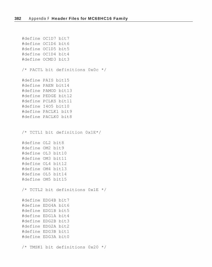
382 Appendix F Header Files for MC68HC16 Family
#define OC1D7 bit7#define OC1D6 bit6#define OC1D5 bit5#define OC1D4 bit4#define OCMD3 bit3
/* PACTL bit definitions 0x0c */
#define PAIS bit15#define PAEN bit14#define PAMOD bit13#define PEDGE bit12#define PCLKS bit11#define I4O5 bit10#define PACLK1 bit9#define PACLK0 bit8
/* TCTL1 bit definition 0x1E*/
#define OL2 bit8#define OM2 bit9#define OL3 bit10#define OM3 bit11#define OL4 bit12#define OM4 bit13#define OL5 bit14#define OM5 bit15
/* TCTL2 bit definitions 0x1E */
#define EDG4B bit7#define EDG4A bit6#define EDG1B bit5#define EDG1A bit4#define EDG2B bit3#define EDG2A bit2#define EDG3B bit1#define EDG3A bit0
/* TMSK1 bit definitions 0x20 */

383Appendix F
#define IC1I bit8#define IC2I bit9#define IC3I bit10#define OC1I bit11#define OC2I bit12#define OC3I bit13#define OC4I bit14#define I4O5I bit15
/* TMSK2 bit definitions 0x20 */
#define TOI bit7#define PAOVI bit5#define PAII bit4#define CPROUT bit3#define CPR2 bit2#define CPR2 bit1#define CPR0 bit0
/* TFLG1 bit definitions 0x22 */
#define IC1F bit8#define IC2F bit9#define IC3F bit10#define OC1F bit11#define OC2F bit12#define OC3F bit13#define OC4F bit14#define I4O5F bit15
/* TFLG2 bit definitions 0x22 */
#define TOF bit7#define PAOVF bit5#define PAIF bit4
/* CFORC bit definitions 0x24*/
#define FOC1 bit15#define FOC2 bit14

384 Appendix F Header Files for MC68HC16 Family
#define FOC3 bit13#define FOC4 bit12#define FOC5 bit11#define FPWMA bit9#define FPWMB bit8
/* PWMC Bit definitions 0x24*/
#define PPROUT bit7#define PPR2 bit6#define PPR1 bit5#define PPR0 bit4#define SFA bit3#define SFB bit2#define F1A bit1#define F1B bit0
#endif
The queued serial module contains two parts: the serial communications inter-face, and the queued serial peripheral interface. The SCI operation on the MC68HC11and the MC68HC16 is the same. A queue has been added to the SPI on the MC68HC16to facilitate continuous communications from this part.
#ifndef QSM#define QSM 1
typedef struct{ unsigned INTV :8; unsigned ILSCI :3; unsigned ILQSPI :3; unsigned NUL1 :2;} Qirl;
typedef struct{ unsigned SP :8; unsigned CPHA :1; unsigned CPOL :1; unsigned BITS :4;

385Appendix F
unsigned WOMQ :1; unsigned MSTR :1;} Spcr0;
typedef struct{ unsigned DTL :8; unsigned DSCLK :7; unsigned SPE :1;} Spcr1;
typedef struct{ unsigned NEWQP :4; unsigned NULL :4; unsigned ENDQP :4; unsigned NUL2 :1; unsigned WRTO :1; unsigned WREN :1; unsigned SPIFIE:1;} Spcr2;
typedef struct{ unsigned char PCS :4; unsigned char DSCK :1; unsigned char DT :1; unsigned char BITSE :1; unsigned char CONT :1;}Cr;
typedef struct{ unsigned SCCR0 :13; unsigned NUL3 :3;} Sccr0;
#define QSMCR (*(MCR_Register*)(QSM_Register + 0x00))#define QILR (*(Qilr*)(QSM_Register + 0x04))#define QIVR QILR#define SCCR0 (*(int*)(QSM_Register+0x08))

386 Appendix F Header Files for MC68HC16 Family
#define SCCR1 (*(Register*)(QSM_Register+0x0a))#define SCSR (*(volatile Register*)(QSM_Register+0x0c))#define SCDR (*(volatile int*)(QSM_Register+0x0e))#define PORTQS (*(volatile Register*)(QSM_Register +0x14))#define PQSPAR (*(volatile Register*)(QSM_Register +0x16))#define DDRQS PQSPAR#define SPCR0 (*(Spcr0*)(QSM_Register + 0x18))#define SPCR1 (*(Spcr1*)(QSM_Register +0x1a))#define SPCR2 (*(SPCR2*)(QSM_Register +0x1c))#define SPCR3 (*(MCR_Register)(QSM_Register+0x1e))#define RR ((int*)(QSM_Register+0x100))#define TR ((int*)(QSM_Register+0x120))#define CR ((Cr*)(QSM_Register+0x140))
/*QSMCR bit definitions */
#define IARB iarb#define SUPV bit7#define FRZ0 bit13#define FRZ1 bit14#define STOP bit15
/* SPCR3 bit definitions */#define CPTQP iarb#define HALTA bit5#define MODF bit6#define SPIF bit7#define HALT bit8#define HMIE bit9#define LOOPQ bit10
/* SCCR1 bit definitions */#define SBK bit0#define RWU bit1#define RE bit2#define TE bit3#define ILIE bit4#define RIE bit5#define TCIE bit6#define TIE bit7#defint WAKE bit8

387Appendix F
#define M bit9#define PE bit10#define PT bit11#define ILT bit12#define WOMS bit13#define LOOPS bit14
/* SCSR bit definitions */#define PF bit0#define FE bit1#define NF bit2#define OR bit3#define IDLE bit4#define RAF bit5#define RDRF bit6#define TC bit7#define TDRE bit8
#endif
The analog to digital converter on the MC68HC16 is completely different fromthat found on the MC68HC11. No attempt should be made to reuse code from anMC68HC11 application of these parts.
#ifndef ADC#define ADC 1
typedef struct{ unsigned bit0 :1; unsigned bit1 :1; unsigned bit2 :1; unsigned bit3 :1; unsigned bit4 :1; unsigned bit5 :1; unsigned bit6 :1; unsigned bit7 :1; unsigned cctr :3; unsigned null :4; unsigned bit15:1;} Stat_Register;

388 Appendix F Header Files for MC68HC16 Family
#define ADC_MCR (*(MCR_Register*)(ADC_Register+0))#define PORTADA (*(char*)(ADC_Register+7))#define ADCTL0 (*(Register*)(ADC_Register+0xa))#define ADCTL1 (*(Register*)(ADC_Register+0xc))#define ADSTAT (*(Stat_Register*)(ADC_Register+0xe))#define RJUUR (*(int*)(ADC_Register+0x10))#define LJSRR (*(int*)(ADC_Register+0x20))#define LJURR (*(int*)(ADC_Register+0x30))
/* ADC_MCR bit definitions */
#define STOP bit15#define FRZ1 bit14#define FRZ0 bit13#define SUPV bit7
/* ADCTL0 bit definitions */
#define RES10 bit7#define STS1 bit6#define STS0 bit5#define PRS4 bit4#define PRS3 bit3#define PRS2 bit2#define PRS1 bit1#define PRS0 bit0
/* ADCTL1 bit definitions */
#define SCAN bit6#define MULT bit5#define S8CM bit4#define CD bit3#define CC bit2#define CB bit1#define CA bit0
/* ADSTAT bit definitions */
#define SCF bit15

389Appendix F
#define CCTR cctr#define CCF7 bit7#define CCF6 bit6#define CCF5 bit5#define CCF4 bit4#define CCF3 bit3#define CCF2 bit2#define CCF1 bit1#define CCF0 bit0
#endif
Following is the header file for the static RAM module.
#ifndef SRAM#define SRAM 1
typedef struct{ unsigned NUL1 :8; unsigned RASP :2; unsigned NUL2 :1; unsigned RCLK :1; unsigned NUL3 :3; unsigned STOP :1;}Rammcr;
#define RAMMCR (*(Rammcr*)(SRAM_Register + 0x00))#define RAMBAH (*(int*)(SRAM_Register + 0x04))#define RAMBAL (*(int*)(SRAM_Register + 0x06))
#endif


391Index
391
Index
// 12/’ 12/” 12/ooo 12/xxx 12+ 17- 17* 17/ 17% 17&& 19|| 19< 19<= 19> 19>= 19== 19!= 19& 20, 47| 20^ 20>> 20<< 20~ 20
\a 12abs() 39analog to digital converter (ADC) 97, 150AND 19, 20applications section 144array 16arithmetic shift 21argv[] 57arvc 57array initialization 60arithmetic logic unit (ALU) 91assign 4assignment 27assignment operator 23association 6
associativity 24-25asynchronous 94, 137asynchronous service section 144atan() 89atan2() 89auto 10autoexec.bat 172automatic 10, 11
\b 12background debug mode (BDM) 110BAUD 311binary coded decimal (BCD) 160, 161binary operator 17binary tree 72, 189bit fields 82block protect 119break 35ByteCraft compiler 111
calloc() 87case 36cast 20char 8, 11char constants 12chip selects 242comma operator 29comments 13comp.bat 172complicated declarations 63computer operating
properly (COP) 97, 125, 308condition code register (CCR) 154conditional expression 24config register 174const 118continue 36control 26conversion commands 8convolution 265

392 Index
correlation 265cos() 89counter register 140CPU16 core processor 234ctype.h 73
%d 4data compression 189decrement operator 22#define 13dereference 47digital input/output 97digital signal processor operation 265digital to analog converter (DAC) 162Dirac delta function 271div 112do/while 29double 8, 11draw_circle() 68draw_rectangle() 68dynamic allocation 76
EEPROM 94, 114, 116, 295EEPROM control register 119EEPROM erasure 124EEPROM program bit 119else 31else if 33EOF 74enum 15EPROM 94, 114, 295escape character 2evaluation 100exception 92exclusive OR 20exit() 44exp() 89expanded bus 116exponent 12expressions 17extern 9, 11external 9external bus interface 241
\f 11fabs() 89
factorial 45FALSE 6, 8fclose() 85fgets() 85Fibonacci number 45FILE 84filter 265float 8floating point 3flow 26fopen() 84for loop 28FOREVER 132Fourier transform 265fprintf() 85fputs() 85free() 88fscanf() 86function 37function arguments 51function prototype 38
general purpose I/O 242getc() 84getchar() 13, 14global 9, 11goto 35
Harvard architecture 92header 2, 129, 163Hoar, C. A. R. 177Huffman code 189Huffman decode function 192Huffman tree 192Hungarian naming system 103
if 31if/else 31#ifndef 163in-line code 38#include 1inclusive OR 20increment operator 22index 16init register 174initialization section 144

393Index
input capture 96, 137, 204input capture register 141, 304int 3, 8integer 3Intermetrics compiler 164, 172, 247interrupt 63, 241interrupt service routine 63, 93, 111isalnum() 78, 88, 89isdigit() 88islower() 88isspace() 78, 89isupper() 88itoa() 30
key words 8Kroniker delta function 271
label 35lifo 43linker command file 173log() 89log10() 89logic analyzer 100logical operators 18logical shift 18long 8, 11loop control 26looping construct 5lvalue 50
macro 39, 41main() 1, 2, 3make_circle() 68malloc() 76, 87MC68HC16 234members 66modulus 18mul 112multidimensional arrays 59multifunctional timer 124
\n 2, 12names 7nest 13Newton loop 27
octal 12operators 17options register 119, 174OR 19, 20output compare 96, 137output compare register 141output compare subsystem 198, 304
page zero 118periodic interrupt 252pivot 177pointer 49pointers to pointers 57pointers to structures 66port replacement unit 106postfix 22#pragma 112precedence table 25prefix 22preprocessor 2precedence 4, 24printf() 1print conversion command 86prototype 38pull() 43pulse accumulator 306pulse width modulation (PWM) 155, 242push() 43putc() 84
queued serial module 249quick sort 177
\r 12random access memory (RAM) 95, 113, 114, 295read-only memory (ROM) 94, 113, 114, 295real time interrupt 126, 307recursion 45, 117, 186reference 51register 10, 11relational operator 18reset 92, 127reset and sustem initialization 242return 44RISC 264RTI 134

394 Index
RTS 134rvalue 50
string 2scalar product 265scanf() 86scope 9scrncat() 88security 119serial communications
interface (SCI) 98, 223, 249,308, 310
serial peripheral interface (SPI) 98, 309, 315Shell, D.L. 177shell_sort() 55Shell sort 177, 178short 8, 11signed 8sin() 89sorting routines 176source level debug 100sprintf() 85sqr() 39sqrt() 89sscanf() 86stack 43, 51, 116static 10, 11stdio.h 1stdlib.h 58stop 112strcat() 88strchr() 88strcmp.h 59, 88strcomp() 54strcpy() 88strict binary tree 189string.h 73strlen() 53strncmp() 88strncpy() 88strnchr() 88struct 145switch 36switch bounce 205synchronous 94
system() 89system clock 241system configuration and protection 241system integration module (SIM) 240
\t 5, 12table look-up 259tag name 65TFLG1, TFLG2 174, 196timers 125timer counter register 126, 138timer counter status register 128timer processor unit (TPU) 97timer operations 195timer overflow interrupt 126timer status register 139timer subsystem 96tolower() 78, 89toupper() 89trace buffer 100tree sort 72TRUE 6, 18type 3, 8(type name) 20typedef 70
unary 17union 81, 145universal asynchronous receiver
transmitter (UART) 99unsigned 8
\v 12vector() 65vector 93, 111vector table 93void 2, 38volatile 165, 167Von Neumann architecture 92
wait 112watchdog 97weighting function 271while 5, 6, 26

395Index
Order FormPlease photocopy and mail
Automation Technology ServicesP.O. Box 501645Indianapolis, IN 46250
Please ship _______ copies of Programming Microcontrollers in C supportdisks. These disks contain all source code shown in the book plus anMC68HC05, an MC68HC11 and an MC68HC16 demonstration compilers.Ship the disks to
Name______________________________________________________________
Company___________________________________________________________
Address ____________________________________________________________
City_______________________________ State_______ Zip _________________
Number of copies _________ @ $30.00 each _____________________
Indiana Residents only Indiana Sales Tax 5% _____________________
Total _____________________
■■ Payment Enclosed
■■ Please charge my ■ ■ MasterCard or ■ ■ Visa
Account Number ____________________________________________________
Expiration Date ______________________________________________________
Signature ___________________________________________________________


