Pallet stacker Original instructions - STILL Luxembourg
152
Pallet stacker FXV 14 N FXV 16 N Original instructions 1537 1538 2376 2377 11748011551 EN - 02/2021 - 09
-
Upload
khangminh22 -
Category
Documents
-
view
0 -
download
0
Transcript of Pallet stacker Original instructions - STILL Luxembourg

Pallet stacker
FXV 14 NFXV 16 N
Original instructions
1537 1538 2376 2377
11748011551 EN - 02/2021 - 09


Address of manufacturer andcontact details
STILL GmbHBerzeliusstraße 1022113 Hamburg, GermanyTel. +49 (0) 40 7339-0Fax: +49 (0) 40 7339-1622Email: [email protected]: http://www.still.de
Preface
I11748011551 EN - 02/2021 - 09


1 Introduction Your industrial truck . . . . . . . . . . . . . . . . . . . . . . . . . . . . . . . . . . . . . . . . . . . . . . . . . . . 2General . . . . . . . . . . . . . . . . . . . . . . . . . . . . . . . . . . . . . . . . . . . . . . . . . . . . . . . . . . . . . . 2CE labelling . . . . . . . . . . . . . . . . . . . . . . . . . . . . . . . . . . . . . . . . . . . . . . . . . . . . . . . . . . 3Copyright and property rights . . . . . . . . . . . . . . . . . . . . . . . . . . . . . . . . . . . . . . . . . . . . . 3
EC declaration of conformity . . . . . . . . . . . . . . . . . . . . . . . . . . . . . . . . . . . . . . . . . . . . 4
Identification label . . . . . . . . . . . . . . . . . . . . . . . . . . . . . . . . . . . . . . . . . . . . . . . . . . . . 5
Rules for the operating company of industrial trucks. . . . . . . . . . . . . . . . . . . . . . . . . . 5
Eco-design requirements for electric motors and variable speed drives . . . . . . . . . . . 6
Spare parts list . . . . . . . . . . . . . . . . . . . . . . . . . . . . . . . . . . . . . . . . . . . . . . . . . . . . . . 7
Proper usage . . . . . . . . . . . . . . . . . . . . . . . . . . . . . . . . . . . . . . . . . . . . . . . . . . . . . . . 8
Description of use and climatic conditions. . . . . . . . . . . . . . . . . . . . . . . . . . . . . . . . . . 8
Unauthorised use. . . . . . . . . . . . . . . . . . . . . . . . . . . . . . . . . . . . . . . . . . . . . . . . . . . . . 9
Explanation of symbols used . . . . . . . . . . . . . . . . . . . . . . . . . . . . . . . . . . . . . . . . . . . . 9
Disposing of components and batteries. . . . . . . . . . . . . . . . . . . . . . . . . . . . . . . . . . . . 9
2 Safety Safety regulations . . . . . . . . . . . . . . . . . . . . . . . . . . . . . . . . . . . . . . . . . . . . . . . . . . . . 12
Safety regulations for handling consumables . . . . . . . . . . . . . . . . . . . . . . . . . . . . . . . 13Permissible consumables . . . . . . . . . . . . . . . . . . . . . . . . . . . . . . . . . . . . . . . . . . . . . . . . 13Oils . . . . . . . . . . . . . . . . . . . . . . . . . . . . . . . . . . . . . . . . . . . . . . . . . . . . . . . . . . . . . . . . . 13Hydraulic fluid . . . . . . . . . . . . . . . . . . . . . . . . . . . . . . . . . . . . . . . . . . . . . . . . . . . . . . . . . 14Battery acid . . . . . . . . . . . . . . . . . . . . . . . . . . . . . . . . . . . . . . . . . . . . . . . . . . . . . . . . . . . 14Disposal of consumables. . . . . . . . . . . . . . . . . . . . . . . . . . . . . . . . . . . . . . . . . . . . . . . . . 15
Emissions . . . . . . . . . . . . . . . . . . . . . . . . . . . . . . . . . . . . . . . . . . . . . . . . . . . . . . . . . . 16Noise emission values. . . . . . . . . . . . . . . . . . . . . . . . . . . . . . . . . . . . . . . . . . . . . . . . . . . 16Vibration characteristics for vibrations to which the body is exposed . . . . . . . . . . . . . . . 16
Residual dangers, residual risks . . . . . . . . . . . . . . . . . . . . . . . . . . . . . . . . . . . . . . . . . 17
Stability . . . . . . . . . . . . . . . . . . . . . . . . . . . . . . . . . . . . . . . . . . . . . . . . . . . . . . . . . . . . 17
Definition of responsible persons. . . . . . . . . . . . . . . . . . . . . . . . . . . . . . . . . . . . . . . . . 18Operating company . . . . . . . . . . . . . . . . . . . . . . . . . . . . . . . . . . . . . . . . . . . . . . . . . . . . . 18Specialist . . . . . . . . . . . . . . . . . . . . . . . . . . . . . . . . . . . . . . . . . . . . . . . . . . . . . . . . . . . . . 18Drivers . . . . . . . . . . . . . . . . . . . . . . . . . . . . . . . . . . . . . . . . . . . . . . . . . . . . . . . . . . . . . . . 18
Safety tests . . . . . . . . . . . . . . . . . . . . . . . . . . . . . . . . . . . . . . . . . . . . . . . . . . . . . . . . . 20Regular safety inspection of the truck . . . . . . . . . . . . . . . . . . . . . . . . . . . . . . . . . . . . . . . 20
Table of contents
III11748011551 EN - 02/2021 - 09

3 Overviews Overview . . . . . . . . . . . . . . . . . . . . . . . . . . . . . . . . . . . . . . . . . . . . . . . . . . . . . . . . . . . 22General view . . . . . . . . . . . . . . . . . . . . . . . . . . . . . . . . . . . . . . . . . . . . . . . . . . . . . . . . . . 22General view of the technical compartment . . . . . . . . . . . . . . . . . . . . . . . . . . . . . . . . . . 23
Operating and display devices. . . . . . . . . . . . . . . . . . . . . . . . . . . . . . . . . . . . . . . . . . . 24Driver's compartment . . . . . . . . . . . . . . . . . . . . . . . . . . . . . . . . . . . . . . . . . . . . . . . . . . . 24Electronic key (option) . . . . . . . . . . . . . . . . . . . . . . . . . . . . . . . . . . . . . . . . . . . . . . . . . . 25Display operating unit . . . . . . . . . . . . . . . . . . . . . . . . . . . . . . . . . . . . . . . . . . . . . . . . . . . 27
Markings . . . . . . . . . . . . . . . . . . . . . . . . . . . . . . . . . . . . . . . . . . . . . . . . . . . . . . . . . . . 28Location of markings . . . . . . . . . . . . . . . . . . . . . . . . . . . . . . . . . . . . . . . . . . . . . . . . . . . 28Serial number . . . . . . . . . . . . . . . . . . . . . . . . . . . . . . . . . . . . . . . . . . . . . . . . . . . . . . . . . 29
4 Use Technical description . . . . . . . . . . . . . . . . . . . . . . . . . . . . . . . . . . . . . . . . . . . . . . . . . . 32
List of checks prior to start-up . . . . . . . . . . . . . . . . . . . . . . . . . . . . . . . . . . . . . . . . . . . 34
Starting up . . . . . . . . . . . . . . . . . . . . . . . . . . . . . . . . . . . . . . . . . . . . . . . . . . . . . . . . . 35
Checks and actions prior to commissioning . . . . . . . . . . . . . . . . . . . . . . . . . . . . . . . . 36Checking the emergency off switch . . . . . . . . . . . . . . . . . . . . . . . . . . . . . . . . . . . . . . . . 36Checking the brakes . . . . . . . . . . . . . . . . . . . . . . . . . . . . . . . . . . . . . . . . . . . . . . . . . . . . 36Checking the horn . . . . . . . . . . . . . . . . . . . . . . . . . . . . . . . . . . . . . . . . . . . . . . . . . . . . . 37
Truck operating instructions . . . . . . . . . . . . . . . . . . . . . . . . . . . . . . . . . . . . . . . . . . . . 38
Stepping on/off the truck . . . . . . . . . . . . . . . . . . . . . . . . . . . . . . . . . . . . . . . . . . . . . . . 40
Operation of operator presence detection . . . . . . . . . . . . . . . . . . . . . . . . . . . . . . . . . . 41
Driver's compartment settings . . . . . . . . . . . . . . . . . . . . . . . . . . . . . . . . . . . . . . . . . . . 43Adjusting the seat . . . . . . . . . . . . . . . . . . . . . . . . . . . . . . . . . . . . . . . . . . . . . . . . . . . . . . 43Adjusting the floor . . . . . . . . . . . . . . . . . . . . . . . . . . . . . . . . . . . . . . . . . . . . . . . . . . . . . . 43Seat heater option . . . . . . . . . . . . . . . . . . . . . . . . . . . . . . . . . . . . . . . . . . . . . . . . . . . . . . 44
Using the display-operating unit . . . . . . . . . . . . . . . . . . . . . . . . . . . . . . . . . . . . . . . . . 45Selection buttons . . . . . . . . . . . . . . . . . . . . . . . . . . . . . . . . . . . . . . . . . . . . . . . . . . . . . . . 45Display of the drive wheel position . . . . . . . . . . . . . . . . . . . . . . . . . . . . . . . . . . . . . . . . . 45Operation of the display unit . . . . . . . . . . . . . . . . . . . . . . . . . . . . . . . . . . . . . . . . . . . . . . 45
Driving safety guidelines . . . . . . . . . . . . . . . . . . . . . . . . . . . . . . . . . . . . . . . . . . . . . . . 51
Driving . . . . . . . . . . . . . . . . . . . . . . . . . . . . . . . . . . . . . . . . . . . . . . . . . . . . . . . . . . . . . 52Defining directions . . . . . . . . . . . . . . . . . . . . . . . . . . . . . . . . . . . . . . . . . . . . . . . . . . . . . 52Driving . . . . . . . . . . . . . . . . . . . . . . . . . . . . . . . . . . . . . . . . . . . . . . . . . . . . . . . . . . . . . . . 52Braking . . . . . . . . . . . . . . . . . . . . . . . . . . . . . . . . . . . . . . . . . . . . . . . . . . . . . . . . . . . . . . 53Horn . . . . . . . . . . . . . . . . . . . . . . . . . . . . . . . . . . . . . . . . . . . . . . . . . . . . . . . . . . . . . . . . 54
Table of contents
IV 11748011551 EN - 02/2021 - 09

Drive program . . . . . . . . . . . . . . . . . . . . . . . . . . . . . . . . . . . . . . . . . . . . . . . . . . . . . . . . . 55Joystick function (option) . . . . . . . . . . . . . . . . . . . . . . . . . . . . . . . . . . . . . . . . . . . . . . . . 56Steering Knob option . . . . . . . . . . . . . . . . . . . . . . . . . . . . . . . . . . . . . . . . . . . . . . . . . . . . 57Using the truck on a slope . . . . . . . . . . . . . . . . . . . . . . . . . . . . . . . . . . . . . . . . . . . . . . . . 59
Operating the FleetManager™ option . . . . . . . . . . . . . . . . . . . . . . . . . . . . . . . . . . . . . 61Description of the FleetManager option. . . . . . . . . . . . . . . . . . . . . . . . . . . . . . . . . . . . . . 61Commissioning a truck equipped with the FleetManager™ option . . . . . . . . . . . . . . . . 62FleetManager™ option: Colour code for the LEDs . . . . . . . . . . . . . . . . . . . . . . . . . . . . . 63Disconnecting a truck equipped with the FleetManager™ option . . . . . . . . . . . . . . . . . 65
Transporting loads . . . . . . . . . . . . . . . . . . . . . . . . . . . . . . . . . . . . . . . . . . . . . . . . . . . . 67Load handling safety rules. . . . . . . . . . . . . . . . . . . . . . . . . . . . . . . . . . . . . . . . . . . . . . . . 67Grabbing a loading unit . . . . . . . . . . . . . . . . . . . . . . . . . . . . . . . . . . . . . . . . . . . . . . . . . . 67Transporting pallets or other containers . . . . . . . . . . . . . . . . . . . . . . . . . . . . . . . . . . . . . 68Lift control elements . . . . . . . . . . . . . . . . . . . . . . . . . . . . . . . . . . . . . . . . . . . . . . . . . . . . 69Reading the capacity plate . . . . . . . . . . . . . . . . . . . . . . . . . . . . . . . . . . . . . . . . . . . . . . . 71Progressive stopping of the carriage in the lower position . . . . . . . . . . . . . . . . . . . . . . . 72Handling a single load . . . . . . . . . . . . . . . . . . . . . . . . . . . . . . . . . . . . . . . . . . . . . . . . . . . 73
Driving assistance system: Dynamic Load Control . . . . . . . . . . . . . . . . . . . . . . . . . . . 77Description of the Dynamic Load Control (DLC) . . . . . . . . . . . . . . . . . . . . . . . . . . . . . . . 77The No Dynamic Load Control (DLC) display . . . . . . . . . . . . . . . . . . . . . . . . . . . . . . . . 78Using Dynamic Load Control (DLC) version 1. . . . . . . . . . . . . . . . . . . . . . . . . . . . . . . . . 79Using Dynamic Load Control (DLC) version 3. . . . . . . . . . . . . . . . . . . . . . . . . . . . . . . . . 81Rules for using the Dynamic Load Control . . . . . . . . . . . . . . . . . . . . . . . . . . . . . . . . . . . 84
Cold store usage (optional) . . . . . . . . . . . . . . . . . . . . . . . . . . . . . . . . . . . . . . . . . . . . . 87
Parking the truck.. . . . . . . . . . . . . . . . . . . . . . . . . . . . . . . . . . . . . . . . . . . . . . . . . . . . . 89
Handling the battery. . . . . . . . . . . . . . . . . . . . . . . . . . . . . . . . . . . . . . . . . . . . . . . . . . . 90Battery type . . . . . . . . . . . . . . . . . . . . . . . . . . . . . . . . . . . . . . . . . . . . . . . . . . . . . . . . . . . 90Order picking . . . . . . . . . . . . . . . . . . . . . . . . . . . . . . . . . . . . . . . . . . . . . . . . . . . . . . . . . . 90Opening and closing the battery hood . . . . . . . . . . . . . . . . . . . . . . . . . . . . . . . . . . . . . . 91Charging the battery using an external charger . . . . . . . . . . . . . . . . . . . . . . . . . . . . . . . 92Changing the side access battery . . . . . . . . . . . . . . . . . . . . . . . . . . . . . . . . . . . . . . . . . . 94
Handling the truck in an emergency . . . . . . . . . . . . . . . . . . . . . . . . . . . . . . . . . . . . . . 99Emergency lowering of the mast . . . . . . . . . . . . . . . . . . . . . . . . . . . . . . . . . . . . . . . . . . . 99Truck towing procedure . . . . . . . . . . . . . . . . . . . . . . . . . . . . . . . . . . . . . . . . . . . . . . . . . . 100
Handling the truck in specific situations. . . . . . . . . . . . . . . . . . . . . . . . . . . . . . . . . . . . 102Slinging the truck . . . . . . . . . . . . . . . . . . . . . . . . . . . . . . . . . . . . . . . . . . . . . . . . . . . . . . . 102Lifting the truck . . . . . . . . . . . . . . . . . . . . . . . . . . . . . . . . . . . . . . . . . . . . . . . . . . . . . . . . 103Transporting the truck . . . . . . . . . . . . . . . . . . . . . . . . . . . . . . . . . . . . . . . . . . . . . . . . . . . 103
Table of contents
V11748011551 EN - 02/2021 - 09

Transporting the truck in the lift . . . . . . . . . . . . . . . . . . . . . . . . . . . . . . . . . . . . . . . . . . . . 104Driving on loading bridges . . . . . . . . . . . . . . . . . . . . . . . . . . . . . . . . . . . . . . . . . . . . . . . . 104
5 Maintenance General maintenance information . . . . . . . . . . . . . . . . . . . . . . . . . . . . . . . . . . . . . . . . 106General . . . . . . . . . . . . . . . . . . . . . . . . . . . . . . . . . . . . . . . . . . . . . . . . . . . . . . . . . . . . . . 106Servicing and maintenance personnel training and qualification. . . . . . . . . . . . . . . . . . . 107Battery maintenance staff . . . . . . . . . . . . . . . . . . . . . . . . . . . . . . . . . . . . . . . . . . . . . . . . 107Maintenance operations that do not require special training . . . . . . . . . . . . . . . . . . . . . . 107Ordering spare parts and consumables . . . . . . . . . . . . . . . . . . . . . . . . . . . . . . . . . . . . . 107
Safety guidelines for maintenance. . . . . . . . . . . . . . . . . . . . . . . . . . . . . . . . . . . . . . . . 108Servicing and maintenance measures . . . . . . . . . . . . . . . . . . . . . . . . . . . . . . . . . . . . . . 108Working on the electrical equipment . . . . . . . . . . . . . . . . . . . . . . . . . . . . . . . . . . . . . . . 108Safety devices . . . . . . . . . . . . . . . . . . . . . . . . . . . . . . . . . . . . . . . . . . . . . . . . . . . . . . . . 108
Technical data for inspection and maintenance . . . . . . . . . . . . . . . . . . . . . . . . . . . . . 109
Recommended lubricants . . . . . . . . . . . . . . . . . . . . . . . . . . . . . . . . . . . . . . . . . . . . . . 110
Accessing the technical compartment . . . . . . . . . . . . . . . . . . . . . . . . . . . . . . . . . . . . 111
1000-hour maintenance plan . . . . . . . . . . . . . . . . . . . . . . . . . . . . . . . . . . . . . . . . . . . . 113
5000-hour maintenance plan . . . . . . . . . . . . . . . . . . . . . . . . . . . . . . . . . . . . . . . . . . . 114
10,000-hour service plan . . . . . . . . . . . . . . . . . . . . . . . . . . . . . . . . . . . . . . . . . . . . . . 114
Chassis, bodywork and fittings . . . . . . . . . . . . . . . . . . . . . . . . . . . . . . . . . . . . . . . . . . 115Cleaning the truck . . . . . . . . . . . . . . . . . . . . . . . . . . . . . . . . . . . . . . . . . . . . . . . . . . . . . . 115General information on battery maintenance . . . . . . . . . . . . . . . . . . . . . . . . . . . . . . . . . 117Checking the condition of the forks . . . . . . . . . . . . . . . . . . . . . . . . . . . . . . . . . . . . . . . . 118
Steering and wheels . . . . . . . . . . . . . . . . . . . . . . . . . . . . . . . . . . . . . . . . . . . . . . . . . . 119Checking the condition of the wheels . . . . . . . . . . . . . . . . . . . . . . . . . . . . . . . . . . . . . . . 119
Electrical equipment . . . . . . . . . . . . . . . . . . . . . . . . . . . . . . . . . . . . . . . . . . . . . . . . . . 120Cleaning and blowing out the electrical components . . . . . . . . . . . . . . . . . . . . . . . . . . . 120Checking the battery acid level and electrolyte density . . . . . . . . . . . . . . . . . . . . . . . . . 120Checking the condition of cables, terminals and the battery connector . . . . . . . . . . . . . 122
Hydraulic systems . . . . . . . . . . . . . . . . . . . . . . . . . . . . . . . . . . . . . . . . . . . . . . . . . . . . 123Checking the hydraulic system for leaks . . . . . . . . . . . . . . . . . . . . . . . . . . . . . . . . . . . . . 123Checking the hydraulic oil level . . . . . . . . . . . . . . . . . . . . . . . . . . . . . . . . . . . . . . . . . . . . 123
Table of contents
VI 11748011551 EN - 02/2021 - 09
Lift mast . . . . . . . . . . . . . . . . . . . . . . . . . . . . . . . . . . . . . . . . . . . . . . . . . . . . . . . . . . . . 125Cleaning and lubricating the chains. . . . . . . . . . . . . . . . . . . . . . . . . . . . . . . . . . . . . . . . . 125Adjusting the length of the mast chains. . . . . . . . . . . . . . . . . . . . . . . . . . . . . . . . . . . . . . 125Checking the protective screen . . . . . . . . . . . . . . . . . . . . . . . . . . . . . . . . . . . . . . . . . . . . 126
Storage and decommissioning . . . . . . . . . . . . . . . . . . . . . . . . . . . . . . . . . . . . . . . . . . 128Storage of truck . . . . . . . . . . . . . . . . . . . . . . . . . . . . . . . . . . . . . . . . . . . . . . . . . . . . . . . . 128Permanent Putting Out of Commission (Destruction) . . . . . . . . . . . . . . . . . . . . . . . . . . . 129
6 Technical specifications FXV 14N / 16N datasheet . . . . . . . . . . . . . . . . . . . . . . . . . . . . . . . . . . . . . . . . . . . . . . 132
FXV 14N / 16N mast types . . . . . . . . . . . . . . . . . . . . . . . . . . . . . . . . . . . . . . . . . . . . . 136
Table of contents
VII11748011551 EN - 02/2021 - 09


1
Introduction

Your industrial truckGeneralThe truck described in these operating instruc-tions corresponds to the applicable standardsand safety regulations.
If the truck is to be operated on public roads, itmust conform to the existing national regula-tions for the country in which it is being used.The driving permit must be obtained from theappropriate office.
The truck has been fitted with state-of-the-arttechnology. Following these operating instruc-tions will allow the truck to be handled safely.By complying with the specifications in theseoperating instructions, the functionality and theapproved features of the truck will be retained.
Get to know the technology, understand it anduse it safely - these operating instructions pro-vide the necessary information and help toavoid accidents and to keep the truck readyfor operation beyond the warranty period.
Therefore:
– Before commissioning the truck, read theoperating instructions and follow the instruc-tions.
– Always follow all of the safety informationcontained in the operating instructions andon the truck.
Introduction1Your industrial truck
2 11748011551 EN - 02/2021 - 09
CE labelling The manufacturer uses CE labelling to indi-cate that the truck complies with the standardsand regulations valid at the time of marketing.The supplied EC declaration of conformityconfirms this. The CE labelling is attached tothe nameplate.
An independent structural change or an addi-tion to the tow tractor can compromise safety,thereby invalidating the EC declaration of con-formity.
The EC declaration of conformity must becarefully stored and made available to the re-sponsible authorities.
Copyright and property rightsThis manual - and any excerpts thereof - maynot be reproduced, translated or transmitted inany form to third parties without the expresswritten permission of the manufacturer.
CE-Symbol
Introduction 1Your industrial truck
311748011551 EN - 02/2021 - 09

EC declaration of conformity
Declaration STILL GmbH Berzeliusstrasse 10 22113 Hamburg
GERMANY
We declare that the machine Industrial truck according to these operating instructionsModel according to these operating instructions conforms to the latest version of the Machinery Directive 2006/42/EC. Person authorised to compile the technical documents: See EC compliance declaration STILL S.A.S.
The manufacturer declares that the truck com-plies with the requirements of the EC direc-tives valid at the time of marketing. This isconfirmed by the EC declaration of conformityand by the EC labelling on the nameplate.
An independent structural change or additionto the truck can compromise safety, thus inva-lidating the EC declaration of conformity.
The EC declaration of conformity must becarefully stored and made available to the rel-evant authorities.
Introduction1EC declaration of conformity
4 11748011551 EN - 02/2021 - 09

Identification label
NOTE
Indicate the serial number for all technical en-quiries.
Rules for the operating com-pany of industrial trucksIn addition to these operating instructions, acode of practice containing additional informa-tion for the operating companies of industrialtrucks is also available.
This guide provides information for handlingindustrial trucks:● Information on how to select suitable indus-
trial trucks for a particular area of applica-tion
● Prerequisites for the safe operation of in-dustrial trucks
● Information on the use of industrial trucks● Information on transport, initial commission-
ing and storage of industrial trucks
ModelManufacturerSerial numberYear of manufactureUnladen weight (without battery) in kgMaximum battery weightMinimum battery weight (for a lithium-ionbattery, the weight of the ballast container isincluded)Additional weight (ballast weight) in kgNominal motor power (kW)Battery voltage in VNominal capacity in kgEC conformity symbol
1234567
89101112
Introduction 1Identification label
511748011551 EN - 02/2021 - 09

Internet address and QR codeThe information can be accessed at any timeby pasting the address https://m.still.de/vdmain a web browser or by scanning the QR code.
Eco-design requirements forelectric motors and variablespeed drivesAll motors in this industrial truck are exemptfrom Regulation (EU) 2019/1781 becausethese motors do not meet the description giv-en in Article 2 "Scope", Item (1) (a) and be-cause of the provisions in Article 2 (2) (h) "Mo-tors in cordless or battery-operated equip-ment" and Article 2 (2) (o) "Motors designedspecifically for the traction of electric vehicles".
All variable speed drives in this industrial truckare exempt from Regulation (EU) 2019/1781because these variable speed drives do notmeet the description given in Article 2"Scope", Item (1) (b).
Introduction1Eco-design requirements for electric motors and variable speed drives
6 11748011551 EN - 02/2021 - 09

Spare parts list The spare parts list can be downloaded by en-tering the address https://sparepartlist.still.euinto a web browser or by scanning the QRcode displayed to the side.
When the web page is open, please type inthe following password: Spareparts24!
On the next screen, please enter your emailaddress and truck serial number to receive thelink by email. Then download the spare partslist.
2511
Introduction 1Spare parts list
711748011551 EN - 02/2021 - 09

Proper usage The truck described in these operating instruc-tions is suitable for lifting, transporting andstacking loads.
The truck should only be used for the purpo-ses for which it was designed, as described inthese instructions.
If the truck needs to be used for purposes oth-er than those specified in these instructions,you should first:● Obtain permission from the manufacturer● Obtain permission from the competent au-
thorities, if applicable
The purpose of obtaining these permissions inadvance is to limit danger as far as possible.
The capacity label specifies the maximumload that can be raised. This limit must not beexceeded.
Description of use and climatic conditionsNormal use– Indoor and outdoor use.
– Ambient temperature in tropical and Nordicregions ranging from -10°C to 45°C
– Start capability from -10°C to 45°C.
– Maximum start time of 20 seconds
– Use at up to 2000 metres above sea level.
Special use (partly with special meas-ures) for trucks equipped with Gel orLead batteries– Use, for example, in the event of abrasive
dust (such as AL203), lint, acid, leach, saltand incombustible substances.
– Ambient temperature in tropical regions upto 55 °C.
– Start capability at -25°C.
– Use at up to 3,500 metres above sea level.
Introduction1Proper usage
8 11748011551 EN - 02/2021 - 09

Unauthorised useAny danger caused as a result of unauthor-ised use becomes the responsibility of the op-erator or driver and not that of the manufactur-er.
Use for purposes other than those describedin these operating instructions is prohibited.
Transporting people is prohibited.
The forklift truck should not be used in areaswhere there is a risk of fire, explosion or corro-sion, or in areas that are particularly dusty.
Stacking or unstacking is not permissible oninclined surfaces or ramps.
Explanation of symbols used DANGER
Compulsory procedure that must be followed toavoid life-threatening danger or physical harm.
WARNINGCompulsory procedure that must followed to avoidinjury.
CAUTIONCompulsory procedure that must be followed toavoid damage to and/or destruction of equipment.
NOTE
For technical requirements that require specialattention.
ENVIRONMENT NOTE
To prevent environmental damage.
Disposing of components and batteriesThe truck is made up of different materials.
If components or batteries must be replacedand scrapped, they must be:● disposed of● treated or● recycled in accordance with regional and
national regulations
NOTE
The documentation provided by the batterymanufacturer must be observed when dispos-ing of batteries.
ENVIRONMENT NOTE
We recommend working with a waste man-agement company when disposing of compo-nents and batteries.
Introduction 1Unauthorised use
911748011551 EN - 02/2021 - 09

Introduction1Disposing of components and batteries
10 11748011551 EN - 02/2021 - 09

2
Safety

Safety regulationsThese operating instructions, which come withthe truck, must be communicated to all thoseconcerned and in particular to personnel re-sponsible for maintenance and driving. Theemployer must make sure that the forklift op-erator has properly understood all the safetyinformation.
Please observe the directives and safety regu-lations attached, in particular:● Information concerning the use of materials
handling trucks● Regulations concerning traffic lanes and
working areas● Appropriate behaviour, rights and responsi-
bilities of the driver● Use in particular areas● Information about the weight and dimen-
sions of pallets or any other container● Information concerning starting, driving and
braking● Information concerning maintenance and
repair
● Regular checks and technical inspections● Recycling of lubricants, oils and batteries● Residual risks.
Care is recommended both for the user andthe person in charge (employer) with regard toadhering to all safety rules concerning the useof material-handling trucks.
When instructing forklift operators, we recom-mend the following points are emphasized:● The features of the truck● The special accessories● The specific features of the working envi-
ronment.
Train the user in how to drive the truck, until itis under proper control.
Then, and only then, proceed to transferringpallets.
Forklift truck stability is guaranteed when theunit is used correctly.
Safety2Safety regulations
12 11748011551 EN - 02/2021 - 09

Safety regulations for handling consumablesPermissible consumables
WARNINGConsumables can be dangerous.It is necessary to follow the safety regulations whenhandling these substances.
Refer to the maintenance data table for thepermissible substances necessary for opera-tion.
Oils DANGER
Oils are flammable!– Follow the statutory regulations– Do not allow oils to come into contact
with hot motor parts.– No smoking, fires or flames!
DANGER
Oils are toxic!– Avoid contact and consumption– In case of inhalation of steam or
fumes, breathe fresh air immediately.– After contact with the eyes, rinse thor-
oughly with water (for at least 10 mi-nutes) and then consult an eye spe-cialist.
– If swallowed, do not induce vomiting.Seek immediate medical attention.
WARNING
Prolonged intensive contact with the skincan result in loss of skin oils and causeirritation.– Avoid contact and consumption.– Wear protective gloves!– After any contact, wash the skin with
soap and water and then apply a skincare product.
– Immediately change soaked clothingand shoes.
WARNINGThere is a risk of slipping on spilled oil, particularlywhen combined with water!– Collect spilled oil immediately using an oil-binding
agent and dispose of it in accordance with regula-tions.
ENVIRONMENT NOTE
Oils are water pollutants!
Always store oil in containers that comply withthe applicable regulations.
Avoid spilling oils.
Collect spilt oil immediately using an oil bind-ing agent and dispose of it in accordance withregulations.
Dispose of old oils according to the applicableregulations.
Safety 2Safety regulations for handling consumables
1311748011551 EN - 02/2021 - 09

Hydraulic fluid
WARNING
During operation of the forklift truck, hy-draulic fluids are pressurised and arehazardous to your health.– Do not spill these fluids!– Follow the statutory regulations– Do not allow the fluids to come into
contact with hot motor parts.– Do not allow to come into contact with
the skin.– Avoid inhaling the spray– Penetration of pressurised fluids into
the skin is particularly dangerous ifthese fluids escape at high pressuredue to leaks in the hydraulic system.In case of such injury, seek medicaladvice immediately.
– To avoid injury, use appropriate per-sonal protective equipment (e.g. pro-tective gloves, industrial goggles, skinprotection and skin care products).
ENVIRONMENT NOTE
Hydraulic fluid is a water-polluting substance!
Always store hydraulic fluid in containers com-plying with the regulations.
Avoid spilling.
Spilt hydraulic fluid should be removed withoil-binding agents at once and disposed of ac-cording to the regulations.
Dispose of old hydraulic fluid according to reg-ulations.
Battery acid
WARNING
Battery acid contains dissolved sulphuricacid. This is toxic.– Avoid contact and consumption.– In case of injury, seek medical advice
immediately.
WARNING
Battery acid contains dissolved sulphuricacid. This is corrosive.– When working with battery acid, al-
ways wear protective clothing andeye protection.
– Do not allow any acid to get onto theclothing or skin or into the eyes; if thisdoes happen, rinse immediately withplenty of clean water.
– In case of injury, seek medical adviceimmediately.
– Immediately rinse away spilt batteryacid with plenty of water.
– Follow the statutory regulations
ENVIRONMENT NOTE
– Dispose of used battery acid in line with theapplicable regulations.
Safety2Safety regulations for handling consumables
14 11748011551 EN - 02/2021 - 09

Disposal of consumables
ENVIRONMENT NOTE
Materials that have to be disposed of followingmaintenance, repair and cleaning must besystematically collected and disposed of in ac-cordance with regulations. Observe the na-tional regulations for your country. Work mayonly be carried out in areas designated for thispurpose. Take care to minimise, as far as pos-sible, any impact on the environment.
● Any spillage of fluids such as hydraulic oil,brake fluid or gear lubricant oil must be im-mediately soaked up with an oil-bindingagent.
● The regulations for disposal of used oil areapplicable.
● Any spillage of battery acid must be neutral-ised immediately.
Safety 2Safety regulations for handling consumables
1511748011551 EN - 02/2021 - 09

EmissionsNoise emission valuesCalculated during the test cycle performed inaccordance with standard EN 12053.
Acoustic pressure level in the driver's com-partmentFXV 14N, FXV 16N LPAZ = 65 dB (A)Uncertainty KPA ± 2.5 dB (A)
NOTE
Lower or higher noise values may occur whenusing industrial trucks, e.g. due to the mode ofoperation, environmental factors and othersources of noise.
Vibration characteristics for vibrations to which the body is exposedThe values were determined according to EN13059 using trucks with standard equipmentaccording to the datasheet (driving over testcourse with humps).
Specified characteristics for upper limb vi-brationsVibration characteristics < 2.5 m/s2
NOTE
The vibration characteristics for bodily vibra-tions cannot be used to determine the actualload level of vibrations during operation. Thisdepends on the operating conditions (state ofground, mode of operation etc.) and shouldtherefore be determined on site, where appro-priate. It is mandatory to specify the hand-armvibrations even where the values do not indi-cate any hazard, as in this case.
Safety2Emissions
16 11748011551 EN - 02/2021 - 09

Residual dangers, residual risksDespite all operational precautions and com-pliance with standards and rules, the possibili-ty of additional risks when using the truck can-not be entirely excluded.
The truck and all its components comply withthe regulations relating to current applicablesafety rules.
Persons in the vicinity of the truck must beparticularly cautious and react immediately inthe event of any malfunction, incident, break-down etc.
WARNINGPersonnel in contact with the truck must be informedof the risks related to using the truck.These operating instructions draw your attention tothe safety rules.
The risks are:● Escape of consumables due to leaks, rup-
tured lines and tanks etc.● Risk of accident when driving over difficult
ground such as slopes, soft or irregular sur-faces or in poor visibility etc.
● Falling, tripping etc. when moving on the in-dustrial truck, especially in the wet, withleaking consumables or icy surfaces.
● Loss of stability due to the load being unsta-ble or the load slipping etc.
● Risk of fire and explosion due to batteriesand electrical voltages.
● Human error - Disregarding safety regula-tions.
It is important to adjust the speed of the truckdepending on the load and ground conditions.
The stability of the truck has been tested tothe latest standards. These standards onlytake account of the static and dynamic tiltingforces that can arise during operation thatcomplies with the specifications and operatingrules. Risks caused by misuse or incorrect op-eration that jeopardise the stability cannot beruled out in extreme situations.
StabilityForklift truck stability is guaranteed only if theunit is used according to the indicated recom-mendations.
It is not guaranteed in the event of:
– cornering at excessive speeds
– moving with the load raised
– moving with a load that is protruding to theside (e.g. sideshift),
– turning and driving diagonally across de-scents or ascents,
– driving on descents or ascents with the loadon the downhill side,
– loads that are too wide or too heavy,
– driving with a swinging load,
– ramp edges or steps.
Safety 2Residual dangers, residual risks
1711748011551 EN - 02/2021 - 09

Definition of responsible personsOperating companyThe operating company is the natural or legalperson or group who operates the truck or onwhose authority the truck is used.
The operating company must ensure that thetruck is only used for its intended purpose andin compliance with the safety guidelines setout in these operating instructions.
The operating company must ensure that allusers read and understand the safety informa-tion in these instructions.
The operating company is responsible for thescheduling and correct performance of regularsafety checks.
It is recommended that these checks complywith national performance specifications.
SpecialistA specialist is deemed to be:● A person whose experience and technical
training has allowed him to develop relevantknowledge of industrial trucks
● A person who is also familiar with nationalhealth and safety regulations and generallyrecognised technical directives and conven-
tions (standards, VDE regulations, technicalregulations of other European Union mem-ber states or countries that are signatoriesto the treaty that established the EuropeanEconomic Area). This expertise allows himto assess the condition of industrial trucksin terms of health and safety
DriversThis truck may only be driven by suitable per-sons who are at least 18 years of age, havebeen trained in driving, have demonstratedtheir skills in driving and handling loads, andhave been specifically designated to drive thetruck. Specific knowledge of the truck is alsonecessary.
Driver rights,duties and rules of behav-iourThe driver must be duly informed of his rightsand duties.
The driver must be granted the required rights.
The driver must wear protective equipment(protection suit, safety helmet, industrial gog-gles and protective gloves) that is appropriatefor the conditions, the task and the load to belifted. The driver must also wear safety foot-wear to be able to drive and brake in completesafety.
The driver must be familiar with the operatinginstructions and have access to them at alltimes.
The driver must:● Have read and understood the operating in-
structions● Have familiarised himself with safe opera-
tion of the truck● Be physically and mentally able to drive the
truck safely
DANGERThe use of drugs, alcohol or medications that affectreactions impair the ability to drive the truck.Individuals under the influence of the above-men-tioned substances are not permitted to perform workof any kind on or with the truck.
Safety2Definition of responsible persons
18 11748011551 EN - 02/2021 - 09

Prohibition of use by unauthorised per-sonsThe driver is responsible for the truck duringworking hours. He must not allow unauthor-ised persons to operate the truck.
When leaving the truck, the driver must secureit against unauthorised use.
Safety 2Definition of responsible persons
1911748011551 EN - 02/2021 - 09

Safety testsRegular safety inspection of thetruckSafety inspection based on time and ex-traordinary incidentsThe operating company (see chapter entitled"Definition of responsible persons") must en-sure that the truck is checked by a specialistat least once a year or after noteworthy inci-dents.
As part of this inspection:● A full check of the technical condition of the
truck in terms of accident safety must beperformed
● The truck must be thoroughly checked todetect any damage that may have beencaused by improper use
● A test log must be created.
The results of the inspection must be retaineduntil at least a further two inspections havebeen carried out.
The inspection date is indicated by an adhe-sive label on the truck.
– Arrange for the service centre to performperiodic safety inspections on the truck.
– Observe the guidelines for tests carried outon the truck in accordance with FEM 4.004.
The operator is responsible for ensuring thatany defects are remedied immediately.
– Contact your service centre.
NOTE
Observe the regulations in force in your coun-try.
Regelmäßige Prüfung(FEM 4.004)
nach nationalen Vorschriftenbasierend auf den EG-Richtlinien:95/63/EG, 99/92/EG, 2001/45/EG
Die Prüfplakette ersetzt nicht das Prüfprotokoll
Nächste Prüfung
5634
4391
019
Mitglied der:FédérationEuropéenede la Manutention
STILL GmbH Hamburg
0000_003-001_V3
Safety2Safety tests
20 11748011551 EN - 02/2021 - 09

3
Overviews

OverviewGeneral view
Overhead guardProtective screenControl moduleSeatLift cylinderPlatformDrive wheel
1234567
Stabiliser wheelOperator presence pedalBattery compartmentForksLoad wheels or bogiesMastEmergency off switch
891011121314
Overviews3Overview
22 11748011551 EN - 02/2021 - 09

General view of the technical compartment
Pump-motor unitFanHornTraction motor
1234
FusesTankES30-24 steering unit
567
Overviews 3Overview
2311748011551 EN - 02/2021 - 09
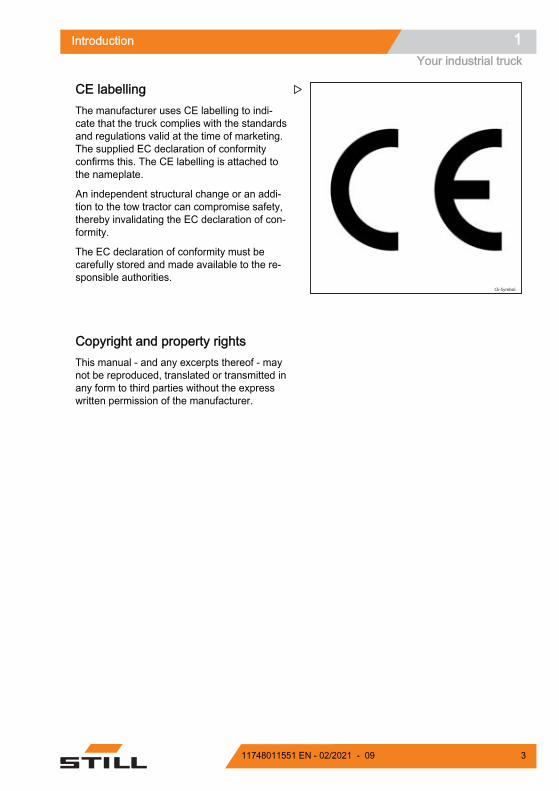
Operating and display devicesDriver's compartment
Control unit or joystick (depending on optionselected)Emergency off switchSwitch key (or electronic key)
1
23
DisplayControl button (Steering Knob device)Steering wheelHandle for stepping on and off the truck
4567
Overviews3Operating and display devices
24 11748011551 EN - 02/2021 - 09

Electronic key (option)
Switch ON (operating mode)Switch OFF and awaiting codeProgramming mode active
123
Key fault or incorrect codeTime delay of automatic switch-off
45
Operation Enter Status of LEDs CommentsUSE
ON * 1 2 3 4 5 # (by de-fault)
○ red off ● continuousgreen (1) (correct PIN)● red flashing ○ greenoff (4) (incorrect PIN)
1 2 3 4 5 default PIN
OFF # (3 seconds) ○ red off ● green flash-ing (2) Truck power off
PROGRAMMING (truck switch OFF only (2)) ADMINISTRA-
TOR CODE ES-SENTIAL FOR
ALL ELECTRON-IC KEY SET-
TINGS
* 0 0 0 0 0 0 0 0# (by default)
● continuous red ● con-tinuous green (3)
Once the LEDs havegone out, the electronic
key automatically revertsto "operating mode".
New operatorcode * 0 * 4 5 6 7 8 # ○ red off ● green flash-
ing (2) (code accepted)Example of new opera-
tor code: 45678Allocating opera-
tor codes* 2 * 5 4 3 2 1 # ○ red off ● green flash-
ing (2) (code accepted)*2*: operator reference10 options from 0 to 9
Deleting operatorcodes * 2 * #
○ red off ● green flash-ing (2) (deletion accep-
ted)
*2*: operator reference(between 0 and 9)
Modifying admin-istrator codes
* * 9 * 1 2 3 4 56 7 8 #
○ red off ● green flash-ing (2) (code accepted)
Overviews 3Operating and display devices
2511748011551 EN - 02/2021 - 09

PROGRAMMING (truck switch OFF only (2))
Restoring the ini-tial administrator
code
To reactivate the defaultadministrator code
(00000000), please con-tact your agent or
nearest dealer.
Activating the au-tomatic switch-off
* * 2 * 1 #● red flashing ● greenflashing (5) (5 seconds
before switch-off)
Power switches off auto-matically after 10 mi-
nutes (600 seconds bydefault) if the truck is not
in use.
Setting the timedelay of the auto-matic switch-off
* * 3 * 6 0 # ○ red off ● green flash-ing (2) (value accepted)
Example: automaticallyswitches off after 1 mi-nute (60 seconds) if not
in use.Minimum setting = 10seconds/maximum =
3000 secondsDeactivating the
automatic switch-off
* * 2 * 0 #○ red off ● green flash-ing (2) (command ac-
cepted)
Overviews3Operating and display devices
26 11748011551 EN - 02/2021 - 09

Display operating unit
Operator presence indicator lightBattery indicator lightTemperature indicator lightSettings indicator lightWarning indicator lightDrive programme indicator lightActivity indicator lightError Code menu
12345678
Settings menuLoad Management and Drive wheel positionmenuStatus menuDisplay of the operating time of the truckDisplay of the battery chargeDisplay of the date and time
910
11121314
For more information, refer to chapter 4 Usingthe display operating unit.
Overviews 3Operating and display devices
2711748011551 EN - 02/2021 - 09
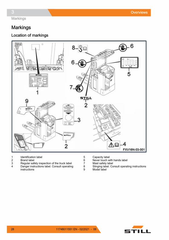
MarkingsLocation of markings
Identification labelBrand labelRegular safety inspection of the truck labelDanger instructions label. Consult operatinginstructions
1234
Capacity labelNever touch with hands labelMast safety labelSlinging label. Consult operating instructionsModel label
56789
Overviews3Markings
28 11748011551 EN - 02/2021 - 09

Serial number
NOTE
Indicate the serial number for all technical en-quiries.
The serial number contains the following infor-mation:
1 Production location
2 Type
3 Year of production
4 Count number
7090_921-004
xx xxxx x xxxxx
1
2
3
4
Overviews 3Markings
2911748011551 EN - 02/2021 - 09

Overviews3Markings
30 11748011551 EN - 02/2021 - 09

4
Use
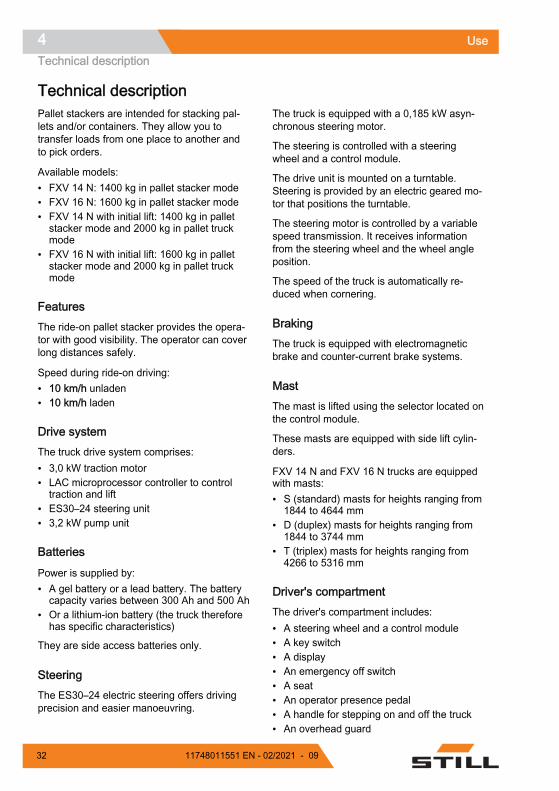
Technical descriptionPallet stackers are intended for stacking pal-lets and/or containers. They allow you totransfer loads from one place to another andto pick orders.
Available models:● FXV 14 N: 1400 kg in pallet stacker mode● FXV 16 N: 1600 kg in pallet stacker mode● FXV 14 N with initial lift: 1400 kg in pallet
stacker mode and 2000 kg in pallet truckmode
● FXV 16 N with initial lift: 1600 kg in palletstacker mode and 2000 kg in pallet truckmode
FeaturesThe ride-on pallet stacker provides the opera-tor with good visibility. The operator can coverlong distances safely.
Speed during ride-on driving:● 10 km/h unladen● 10 km/h laden
Drive systemThe truck drive system comprises:● 3,0 kW traction motor● LAC microprocessor controller to control
traction and lift● ES30–24 steering unit● 3,2 kW pump unit
Batteries
Power is supplied by:● A gel battery or a lead battery. The battery
capacity varies between 300 Ah and 500 Ah● Or a lithium-ion battery (the truck therefore
has specific characteristics)
They are side access batteries only.
SteeringThe ES30–24 electric steering offers drivingprecision and easier manoeuvring.
The truck is equipped with a 0,185 kW asyn-chronous steering motor.
The steering is controlled with a steeringwheel and a control module.
The drive unit is mounted on a turntable.Steering is provided by an electric geared mo-tor that positions the turntable.
The steering motor is controlled by a variablespeed transmission. It receives informationfrom the steering wheel and the wheel angleposition.
The speed of the truck is automatically re-duced when cornering.
BrakingThe truck is equipped with electromagneticbrake and counter-current brake systems.
Mast The mast is lifted using the selector located onthe control module.
These masts are equipped with side lift cylin-ders.
FXV 14 N and FXV 16 N trucks are equippedwith masts:● S (standard) masts for heights ranging from
1844 to 4644 mm● D (duplex) masts for heights ranging from
1844 to 3744 mm● T (triplex) masts for heights ranging from
4266 to 5316 mm
Driver's compartmentThe driver's compartment includes:● A steering wheel and a control module● A key switch● A display● An emergency off switch● A seat● An operator presence pedal● A handle for stepping on and off the truck● An overhead guard
Use4Technical description
32 11748011551 EN - 02/2021 - 09

Optional equipment available (this list is notexhaustive):● Electronic key● Cold store (-35°C)● Document holder● Steering knob● Joystick
NOTE
The operating instructions can be found in thedocument holder, located on the technicalcompartment door.
Use 4Technical description
3311748011551 EN - 02/2021 - 09

List of checks prior to start-up WARNING
Damage or other defects on the forklift truck or at-tachments (special equipment) can result in acci-dents.If damage or other faults are noticed on the truck orattachments (special equipment) during the followinginspections, do not use the truck until it has beenproperly repaired. Do not remove or disable the safe-ty systems and switches. Do not change the pre-setvalues.
WARNINGRisk of falling!When working on high-level parts of the truck, do notuse truck components for access or to stand on.– Use suitable access equipment.
Before start-up, ensure that the truck operatescorrectly.
To do this, perform the following checks:
– Fork arms or other load-carrying equipmentshould not show any signs of noticeabledamage (for example: bending, cracks, sig-nificant wear).
– Check that there are no signs of leakingconsumables under the truck.
– Do not restrict the field of vision. Ensure thevisible area specified by the manufacturer isobserved.
– Attachment parts (special equipment) mustbe properly secured and function accordingto their operating instructions.
– Damaged or missing stickers must be re-placed in compliance with the marking posi-tion table.
– The guard grille must be intact and securelymounted.
– The roller guide rails must be coated in avisible layer of grease.
– The wheels must show no signs of defectsor heavy wear. They must be mounted cor-rectly.
– Check that there are no foreign objects thatcould hinder the operation of the wheelsand rollers.
– The warning devices (horn etc.) must work.
– The battery cover must be closed.
– Check that the covers are correctly posi-tioned.
– The chains must be in perfect condition andmust be evenly and correctly tensioned.
– The operator must be qualified to drive thetruck. The operator must be able to reachthe controls and operate them (especiallythe anti-crush device). Do not obstruct ac-cess to the controls.
Please inform your supervisor if you noticeany defects.
Use4List of checks prior to start-up
34 11748011551 EN - 02/2021 - 09

Starting up
NOTE
● Check that no controls are activated beforestarting the truck.
● Check that the battery hood is closed.● Check that the battery is locked.
– Check that the battery is connected.
– Check that the battery compartment hood isclosed and locked correctly.
– Climb onto the truck using the handle.
– Sit on the seat.
– Press the operator presence pedal.
– Release the emergency off switch (1) if ithas been pressed.
– Turn the key (2). For models equipped withan electronic key or the FleetManager™ op-tion, enter the PIN code.
The display (3) lights up. The truck is ready foroperation.
Use 4Starting up
3511748011551 EN - 02/2021 - 09

Checks and actions prior to commissioningChecking the emergency off switch To check the operation of the emergency offswitch, proceed as follows:
– Drive the truck
– Press the emergency off switch (1)
The truck stops immediately. The truck powersupply is cut. The electrical controls and mo-tors are no longer supplied with power.
– Pull the emergency off switch (1)
The functions are available again.
NOTE
Ensure that the stabiliser wheels operate cor-rectly. This influences braking effectiveness.
Checking the brakes Braking by releasing the drive switch– Drive the truck in direction (1) or (2)
– Release the drive switch
The brake is activated until the truck stopscompletely.
Braking by reversing the drive direction– Drive the truck in direction (1) or (2)
– Move the drive switch in the opposite direc-tion
The truck slows down and then moves off inthe opposite direction.
NOTE
Also ensure that the stabiliser wheels operatecorrectly. This influences braking effective-ness.
Use4Checks and actions prior to commissioning
36 11748011551 EN - 02/2021 - 09

Checking the horn The horn is located on the rear side of thecontrol module.
To check the operation of the horn, proceedas follows:
– Press the button (1) on the control module
The horn sounds.
Use 4Checks and actions prior to commissioning
3711748011551 EN - 02/2021 - 09

Truck operating instructions The trucks are designed for indoor and out-door use in non-hazardous atmospheres. Thetemperature should be between -10°C and+45°C and the relative humidity of the air lessthan 95%.
NOTE
A cold store option is available for lower tem-peratures.
The places where the truck is used must com-ply with the applicable regulations (conditionof the ground, lighting etc.).
The trucks must be used on dry, clean andflat ground.
Before using the truck, it is essential to checkthe working environment. This check can takethe form of visual inspection.
The work area must be clear. The truck's pathmust be free of obstacles and people.
The operator must be alert to anything thatmight prevent manoeuvres being carried outsafely. The following may create a potentialdanger:● A person near the truck● A person below the forks when they are
raised● The operator must not use an MP3 player
or any other electrical equipment that couldimpair awareness of his/her surroundings
● There must be no signs of oil or grease onthe floor
The operator must take care when transport-ing a load. The load dimensions can interferewith manoeuvres and restrict the field of vi-sion. The speed of the truck must also be re-duced as the truck could tip over when break-ing or cornering.
The loads must be consistent, with a maxi-mum recommended height of 2 m.
For uses other than those shown above,please consult the After-Sales Service Centre.
It is important to use pallets that are in goodcondition.
Speed must be reduced when moving overobstacles to prevent the truck from becomingunbalanced and vibrations in the operator'sarms.
The trucks can drive across ramps and shal-low inclines. With an initial lift, they can crosslarger obstacles.
WARNINGRisk of loss of stability– Always adapt your driving to the ground condi-
tions (uneven surfaces etc.), particularly hazard-ous working areas and the load.
NOTE
● To prevent the bottom of the load lift systemfrom scraping the ground, always move theforks to the raised position before setting off
● Always switch off the ignition before leavingthe truck
● The mast protective screen must always becorrectly positioned, properly secured andclean
WARNINGRisk of damaging the truckEnsure that the height of the mast is lower than ob-stacles (racks, doors etc.).
WARNINGRisk of injuryAlways keep your hands on the controls. Never putyour hands near moving parts and assemblies with-out first lowering the load arms to the ground anddisconnecting the battery.
For effective protection, safety shoes must be worn.
Do not climb on the hoods of the truck (battery, chas-sis etc.).
Use4Truck operating instructions
38 11748011551 EN - 02/2021 - 09

WARNINGDriving safety guidelines:– The driver must drive slowly around corners and
when entering narrow passageways.– The driver must always maintain a safe braking
distance from vehicles or people in front of him.– The driver must avoid stopping suddenly, making
U-turns too quickly and overtaking in dangerousareas with poor visibility.
CAUTIONRisk of injuryBefore using a side access truck, check that the bat-tery is correctly locked.
Use 4Truck operating instructions
3911748011551 EN - 02/2021 - 09
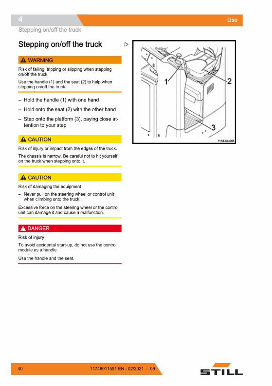
Stepping on/off the truck
WARNINGRisk of falling, tripping or slipping when steppingon/off the truck.Use the handle (1) and the seat (2) to help whenstepping on/off the truck.
– Hold the handle (1) with one hand
– Hold onto the seat (2) with the other hand
– Step onto the platform (3), paying close at-tention to your step
CAUTIONRisk of injury or impact from the edges of the truck.The chassis is narrow. Be careful not to hit yourselfon the truck when stepping onto it.
CAUTIONRisk of damaging the equipment– Never pull on the steering wheel or control unit
when climbing onto the truck.
Excessive force on the steering wheel or the controlunit can damage it and cause a malfunction.
DANGERRisk of injuryTo avoid accidental start-up, do not use the controlmodule as a handle.
Use the handle and the seat.
Use4Stepping on/off the truck
40 11748011551 EN - 02/2021 - 09

Operation of operator pres-ence detectionThe truck is equipped with two operator pres-ence detectors:● The chair (2)● The presence pedal (1)
These two components are truck safety devi-ces.
First, the forklift operator must sit on the chair(2). The operator detection contact is then ac-tivated.
The forklift operator presence pedal (1) mustthen be depressed before and while the truckis moving.
The pedal allows you to operate all the con-trols of the truck.
In reverse travel (fork direction), it is possibleto rise from the chair in the event of poor visi-bility. The truck then travels at 2 km/h. Theforklift operator presence pedal must be keptdepressed.
Before rising from the chair, it is essential toslow down the truck to a very low pace and tocheck the working environment.
WARNINGRisk of injuryDo not rise from the chair when the truck is travellingat full speed.
NOTE
Do not rise from the chair to slow down thetruck.
If the forklift operator sits down again, thetruck continues to travel at a limited speed.The drive switch must be released. When theforklift operator presses the drive switch, thetruck returns to its normal speed.
Use 4Operation of operator presence detection
4111748011551 EN - 02/2021 - 09

CAUTIONDisabling of controlsIf the operator presence pedal is released whenmoving:
- The truck brake is automatically activated
- The controls no longer work
Use4Operation of operator presence detection
42 11748011551 EN - 02/2021 - 09

Driver's compartment settingsAdjusting the seat The seat is equipped with an operator pres-ence detector.
The operator must adjust his weight by incre-ments of 10 kg to trigger this detection.
Proceed as follows:
– Sit on the seat
– Turn the adjustment wheel (1) until the de-sired weight is reached
– Put the truck into service
The seat's operator presence detector cannotbe activated if the weight setting is too high ortoo low.
This operation also enables you to adjust thehardness of the seat.
Adjusting the floorThe floor is fitted with a pressure-based heightadjustment system.
To adjust the floor height, proceed as follows:
– Sit on the seat.
– Press the floor unlocking button (2) andhold it down for the duration of the opera-tion.
– Exert pressure on the floor (3) by pushing itwith your legs to obtain a good driving posi-tion.
– Release the button.
NOTE
Adjusting the floor is not possible when thetruck is in cold store. The cylinder for adjust-ment does not work at low temperatures.
Use 4Driver's compartment settings
4311748011551 EN - 02/2021 - 09

Seat heater optionThe driver's seat may be equipped with theseat heater option.
The heater turns on when the operator's pres-ence on the seat is detected.
To activate the heater, proceed as follows:
– Sit on the seat
– Adjust the weight of the operator
– Put the truck into service
– Press the LED button (1) to activate theheating
The LED button (1) illuminates to indicate thatthe heater is in operation.
NOTE
When the driver gets up or leaves the seat,the heating stops in order to conserve batterypower.
No visual information is shown on the display.
– Check whether the LED button (1) is on
– Press the LED button (1) to reactivate theheater
Use4Driver's compartment settings
44 11748011551 EN - 02/2021 - 09

Using the display-operating unitSelection buttonsThe operator selects the menus using the fourselection buttons:● The Blue Q button (1) to select Blue Q
mode, hare mode or tortoise mode● The left arrow button (2) to scroll left
through the drop-down menu● The right arrow button (3) to scroll right
through the drop-down menu● The confirm button (4) to confirm the high-
lighted choice on the screen
Display of the drive wheel position The forklift operator can find out the position ofthe drive wheel by referring to the display.
Proceed as follows:
– Press the left arrow or right arrow button toscroll through the menu.
– Select the Wheel menu (2).
– Press the confirm button (1).
The position of the drive wheel is then shownon the display (3).
Operation of the display unitOperator presence For the truck to operate, the operator must bedetected on the seat and then on the pedal.
When the truck is switched on, the light indi-cating the operator's presence on the seat (1)comes on and flashes.
Use 4Using the display-operating unit
4511748011551 EN - 02/2021 - 09

– Sit on the seat
The light indicating the operator's presenceon the seat (1) is replaced by the light indicat-ing the operator's presence on the pedal (2),which flashes.
– Press the operator presence pedal withyour left foot
The light indicating the operator's presenceon the pedal (2) remains continuously illumi-nated for two seconds and then goes out.
Use4Using the display-operating unit
46 11748011551 EN - 02/2021 - 09
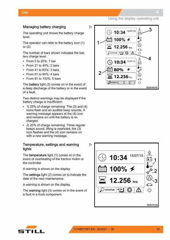
Managing battery charging The operating unit shows the battery chargelevel.
The operator can refer to the battery icon (1)or (2).
The number of bars shown indicates the bat-tery charge level.● From 0 to 20%: 1 bar● From 21 to 40%: 2 bars● From 41 to 60%: 3 bars● From 61 to 80%: 4 bars● From 81 to 100%: 5 bars
The battery light (3) comes on in the event ofa deep discharge of the battery or in the eventof a fault.
Two distinct warnings may be displayed if thebattery charge is insufficient:● 1) 25% of charge remaining: The (3) and (4)
icons flash and an audible beep sounds. Awarning message appears at the (4) iconand remains on until the battery is re-charged.
● 2) 20% of charge remaining: Three regularbeeps sound, lifting is restricted, the (3)icon flashes and the (4) icon remains onwith a new warning message.
Temperature, settings and warninglightsThe temperature light (1) comes on in theevent of overheating of the traction motor orthe controller.
A warning is shown on the display.
The settings light (2) comes on to indicate thedate of the next maintenance.
A warning is shown on the display.
The warning light (3) comes on in the event ofa fault in a truck component.
Use 4Using the display-operating unit
4711748011551 EN - 02/2021 - 09

Drive programThe drive program light (1) is permanently illu-minated when a travel mode is selected.
There are three different drive modes:● Tortoise mode (2)● Hare mode (3)● Blue Q mode (4)
The icon of the drive mode selected appearson the display.
– Select the desired drive mode using thenavigation keys
Activity indicator The activity indicator light (1) flashes continu-ously while the truck is in operation.
When the indicator is off, the display unit islocked or frozen. A warning is shown on thedisplay.
Use4Using the display-operating unit
48 11748011551 EN - 02/2021 - 09
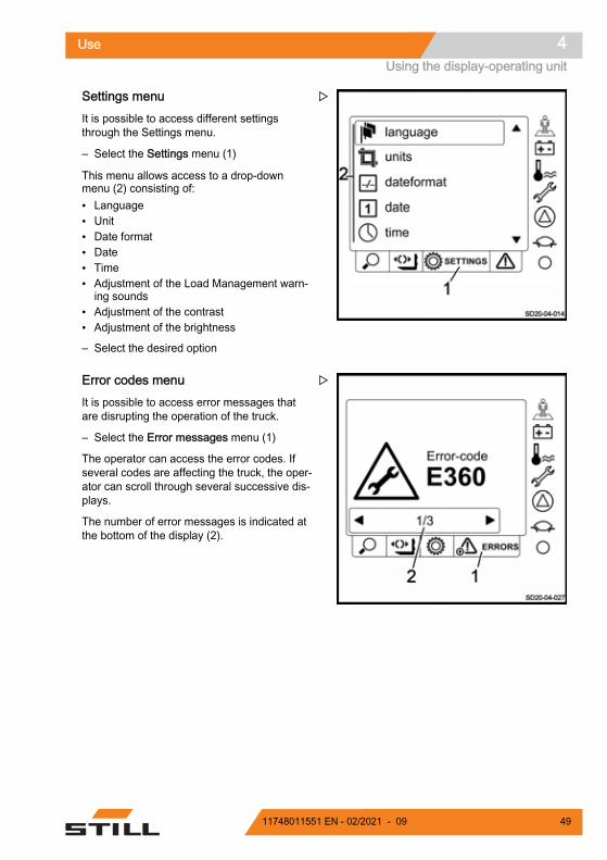
Settings menu It is possible to access different settingsthrough the Settings menu.
– Select the Settings menu (1)
This menu allows access to a drop-downmenu (2) consisting of:● Language● Unit● Date format● Date● Time● Adjustment of the Load Management warn-
ing sounds● Adjustment of the contrast● Adjustment of the brightness
– Select the desired option
Error codes menuIt is possible to access error messages thatare disrupting the operation of the truck.
– Select the Error messages menu (1)
The operator can access the error codes. Ifseveral codes are affecting the truck, the oper-ator can scroll through several successive dis-plays.
The number of error messages is indicated atthe bottom of the display (2).
Use 4Using the display-operating unit
4911748011551 EN - 02/2021 - 09

Start-up screen
In addition to the various menus and lightsmentioned above, additional data is available:● The Truck status menu (1) displays the
truck menu● The hourglass icon (2) indicates the operat-
ing time of the truck● The clock icon (3) indicates the time and
date
Use4Using the display-operating unit
50 11748011551 EN - 02/2021 - 09

Driving safety guidelinesBehaviour when drivingOperators must obey the same rules withinthe plant as on the road. They must drive atspeeds appropriate for the driving conditions.
Therefore, they must drive slowly:● When cornering● Through narrow passageways● Through swing doors● In low-visibility areas● When the roadway is uneven
Operators must always maintain a safe brak-ing distance from vehicles or people in front ofthem. They must always maintain control ofthe truck. They must avoid sudden stops,making fast U-turns, overtaking other vehiclesin potentially hazardous or low-visibility areas.
Driving the truck while sitting on the dash-board is prohibited. The operator must be rest-ing against the seat.
These trucks are designed to be used as apallet stacker, double pallet stacker and pallettruck. Therefore:
● Never sit on the dashboard to drive thetruck
● The truck must not be used as a stepladder● The truck is not designed to transport peo-
ple● Operators must always stay within the truck
clearance● Stay in the safety area (working area de-
fined by the manufacturer)● Ensure the stability of the truck and do not
exceed its capacity
Use of a telephone or radio with the truck ispermitted.
However, do not use these devices when driv-ing as they may distract you.
Take a test drive on an open surface.
NOTE
Drivers must wear safety shoes that fit proper-ly to be able to drive and brake in completesafety.
Use 4Driving safety guidelines
5111748011551 EN - 02/2021 - 09

DrivingDefining directions Names used in the text refer to the componentinstallation position with respect to the driver'scompartment.● Reverse travel (1)● Forward travel (3)● To the right (4)● To the left (2)
The load is positioned at the rear.
Driving
WARNINGBe aware of the position of the drive wheelSlowly start the truck.
Check the position of the drive wheel on the display.
NOTE
Always operate the drive switch slowly, as thetruck reacts immediately. Abrupt starts, brak-ing or reversal of drive direction must be avoi-ded at all costs.
The drive switch is located on the control unit.
NOTE
Always keep hands and feet inside the driver'scompartment while the truck is moving.
Use4Driving
52 11748011551 EN - 02/2021 - 09

Forward travel– Using your thumb, push the drive switch to
the left (2) to travel forwards (opposite forkdirection).
– When the drive switch is released, the truckbrakes electrically.
Reverse travel– Using your thumb, push the drive switch to
the right (1) to travel backwards (fork direc-tion).
– When the drive switch is released, the truckbrakes electrically.
WARNINGRestricted visibilityDuring reverse travel, visibility may be restricted. Bevery careful. Make sure that the path behind is clearbefore travelling backwards.
Reversing the drive direction– Push the drive switch in direction (1) or (2).
– Release the drive switch.
– Operate it progressively in the opposite di-rection until the required speed is reached.
Braking
WARNINGThe quality of the floor surface affects the brakingdistance of the truck.This should be taken into consideration when driving.
Use 4Driving
5311748011551 EN - 02/2021 - 09

Braking by reversing the drive direction – Move the drive direction switches (2) or (3)
in the opposite drive direction.
Braking by releasing the drive switch – While travelling, completely release the
drive switch.
The brake is automatically activated. The truckis immobilised.
Electromagnetic brakingThe electromagnetic brake is activated auto-matically if one of the following conditions ismet:● The operator releases the operator pres-
ence pedal (decelerates and then brakes)● The operator gets up from the seat (decel-
erates and then brakes)● The drive switch is in the neutral position● The power supply is cut off● The operator presses the emergency off
switch
Horn The horn is positioned on the rear side of thecontrol module.
It is used:● On routes where there is poor visibility● At junctions● In the event of immediate danger
– Press the button (1) on the control module.
The horn sounds.
Use4Driving
54 11748011551 EN - 02/2021 - 09

Drive programThe indicator light (1) is on during operation ofthe truck. The shape of the indicator light indi-cates the selected program.
The truck is equipped with three different driveprograms:● Hare mode (3)● BlueQ mode (4)● Tortoise mode (2)
NOTE
When the operator restarts the truck, the lastmode selected is automatically activated.
NOTE
The drive program is instantly changed. If theoperator changes mode while driving thetruck, he must remain vigilant.
Hare mode When Hare mode is selected on the screen,the truck operates at its maximum perform-ance.
Blue Q mode
Selecting Blue Q mode allows you to slightlyreduce the performance of the truck:● The travel speed of the truck is reduced
(70% of maximum speed)● The speed of lifting and lowering the forks is
reduced (90% of maximum speed)
This mode allows you to save battery.
Tortoise mode
Selecting Tortoise mode allows you to reducethe performance of the truck:● The travel speed of the truck is reduced to
6 km/h● The speed of lifting and lowering the forks is
considerably reduced
The different speeds can be adjusted. Contactthe After-Sales Service Centre to changethese.
Use 4Driving
5511748011551 EN - 02/2021 - 09

Joystick function (option)The truck may be equipped with a joystick inplace of the control unit.
The operation is therefore different.
NOTE
Always operate the joystick slowly, as thetruck reacts immediately. Abrupt starts, brak-ing or reversal of drive direction must be avoi-ded at all costs.
Front of the joystick
The front of the joystick is used to:● Move the truck forwards or backwards● Raise or lower the forks
Forward travel
– Push the joystick to the left (1) to travel for-wards (opposite fork direction).
Reverse travel
– Push the joystick to the right (2) to travelbackwards (fork direction).
Fork lifting
– Tilt the joystick downwards (4)
Fork lowering
– Tilt the joystick to upwards (3)
Use4Driving
56 11748011551 EN - 02/2021 - 09

Rear of the joystick
The rear of the joystick is used to:● Sound the horn● Raise or lower the load arms
Horn
– Press the button (5) on the joystick.
Raising the load arms (initial lift)
– Press the button (6) on the joystick.
Lowering the load arms (initial lift)
– Press the button (7) on the joystick.
Steering Knob optionThe Steering Knob device can replace thesteering wheel controls.
WARNINGRisk of sharp truck movementThe Steering Knob device is highly sensitive. It is im-portant to handle the turning knob with caution.
The turning knob allows you to adjust the posi-tion of the wheel. There is no need to reposi-tion it when driving if the trajectory is straight.
When the button is positioned in the centre atthe zero point (1), the truck travels in a straightline.
Two stops, one on the left (2) and one on theright (3), delimit the axis of rotation. The oper-ator adjusts the turning knob within this axis todrive.
In forward travel (opposite direction to theforks)
– Move the turning knob to the left (anti-clock-wise) (2) to turn to the left
– Move the turning knob to the right (clock-wise) (2) to turn to the right
In reverse travel (fork direction)
Use 4Driving
5711748011551 EN - 02/2021 - 09

– Move the turning knob to the left (anti-clock-wise) (2) to turn to the right
– Move the turning knob to the right (clock-wise) (2) to turn to the left
Use4Driving
58 11748011551 EN - 02/2021 - 09

Using the truck on a slope
NOTE
Incorrect use of the truck on a slope is not rec-ommended. It places particular stress on thetraction motor, brakes and battery.
Slopes must be approached with great cau-tion:● Never attempt a slope whose gradient is
greater than that specified in the truck's da-tasheet.
● Make sure that the ground is clean and hasa non-slip surface and that the route isclear.
Travelling up slopesAlways travel up slopes in reverse. The loadfaces uphill.
Without a load, we recommend that you go upa slope forwards.
Use 4Driving
5911748011551 EN - 02/2021 - 09

Travelling down slopesAlways travel down slopes forwards. The loadfaces uphill.
Without a load, we recommend that you de-scend a slope forwards.
In all cases, you must travel at a very lowspeed and brake gradually.
DANGERDanger of death and/or risk of serious damage toequipmentNever park the truck on a slope. Never make a U-turn or take shortcuts on a slope.
On a slope, the operator must drive more slowly.
WARNINGRisk of serious injury and/or serious damage toequipmentDriving on slopes steeper than 10% is prohibited dueto braking capacity and stability. The load beingtransported could tip over.
Starting on a slopeProceed as follows:
– Move the drive switch in the required direc-tion.
– Release the drive switch to apply the park-ing brake.
Use4Driving
60 11748011551 EN - 02/2021 - 09

Operating the FleetManager™ optionDescription of the FleetManager optionThe FleetManager option allows you to controlaccess to the truck. The option is a fleet man-agement system.
You can access the system:● Either by using a keypad● Or by using a reading device for a trans-
ponder or an RFID card
The fleet manager sets the access details viathe web interface. This affects the transpondercards or PIN codes for the correspondingtrucks. It is possible to change the amount oftime for which the access authorisation is val-id.
Software is also available.
Additional options:● Shock sensor● Tools for wireless data management:
▶ GSM(2)GPRS(1) module with antenna
The options available on the truck are:● Access control● Access control and shock sensor● Access control and GPRS module● Access control, shock sensor and GPRS
module(1) GPRS: General Packet Radio Service
(2) GSM: Global System for Mobile Communi-cation
Shock sensorThis sensor allows you to record the shocksreceived by the truck.
If the truck receives a shock, it is possible toconfigure a speed reduction.
The fleet manager is the only person who isable to change certain parameters.
NOTE
Replace the sensor if it is faulty.
GSMGPRS moduleThe module consists of a GSM modem and anantenna.
The module allows you to:● Access truck information remotely● Use geolocation
The data is stored on a server.
Data is transmitted by Bluetooth (default) or byGSM module (optional).
Use 4Operating the FleetManager™ option
6111748011551 EN - 02/2021 - 09
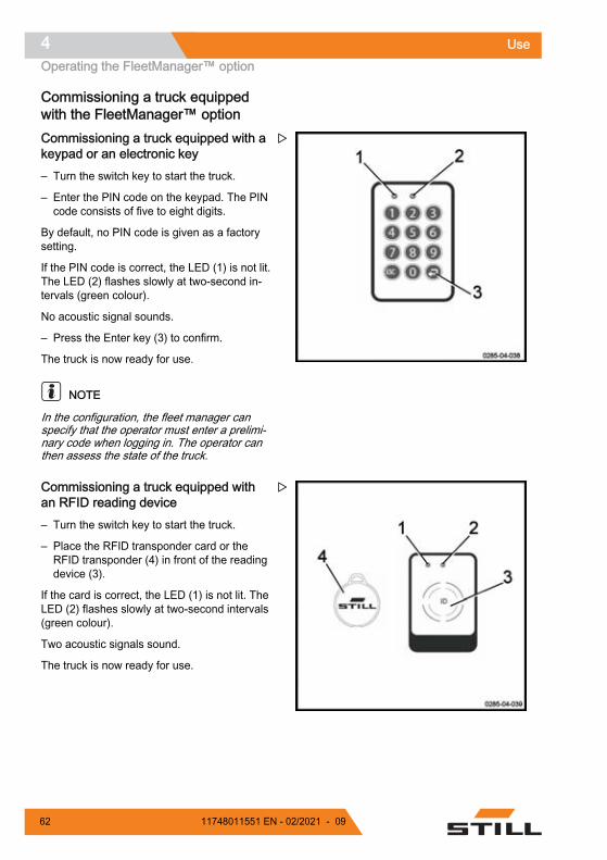
Commissioning a truck equippedwith the FleetManager™ option Commissioning a truck equipped with akeypad or an electronic key – Turn the switch key to start the truck.
– Enter the PIN code on the keypad. The PINcode consists of five to eight digits.
By default, no PIN code is given as a factorysetting.
If the PIN code is correct, the LED (1) is not lit.The LED (2) flashes slowly at two-second in-tervals (green colour).
No acoustic signal sounds.
– Press the Enter key (3) to confirm.
The truck is now ready for use.
NOTE
In the configuration, the fleet manager canspecify that the operator must enter a prelimi-nary code when logging in. The operator canthen assess the state of the truck.
Commissioning a truck equipped withan RFID reading device – Turn the switch key to start the truck.
– Place the RFID transponder card or theRFID transponder (4) in front of the readingdevice (3).
If the card is correct, the LED (1) is not lit. TheLED (2) flashes slowly at two-second intervals(green colour).
Two acoustic signals sound.
The truck is now ready for use.
Use4Operating the FleetManager™ option
62 11748011551 EN - 02/2021 - 09

FleetManager™ option: Colour code for the LEDs The LEDs can have different statuses and dif-ferent colours. Below is the list of the mostcommon messages and their meanings.
Malfunction Cause SolutionLED status
Signal transmitter LED 1 LED 2
Lit continuouslyRed colour Off A long acoustic
signal sounds
Reading devicevariant: no valid
access authorisa-tion Generate a valid
access authorisa-tion using the in-
terfaceKeypad variant:no valid accessauthorisation forthe PIN code en-
tered
Keypad variant:PIN code enteredincorrect or notconfirmed using
the Enter key
Re-enter the PINcode
Lit continuouslyRed colour
Flashes onceGreen colour
A long acousticsignal sounds
The operator hasbeen granted ac-cess authorisa-
tion. But the peri-od of validity has
expired.
Use the interfaceto enter a new pe-
riod of validity
The date of thetruck is incorrect
Update the dateof the truck
Flashes quicklyYellow colour
Lit continuouslyGreen colour Memory is 80%
full Clear the memory
Flashes quicklyRed colour
Flashes quicklyRed colour
A long acousticsignal sounds
upon activation
There are severalpossible causes:- Reading deviceor keypad not ac-
cessible- GPRS modulenot accessible
- Built-in re-chargeable bat-
tery flat- Memory full
Contact the After-Sales Service
Centre
Use 4Operating the FleetManager™ option
6311748011551 EN - 02/2021 - 09

Malfunction Cause SolutionLED status
Signal transmitter LED 1 LED 2
Flashes quicklyRed colour
Lit continuouslyGreen colour A shock has oc-
curred Reset the shock
Flashes quicklyBlue colour Off
The truck is con-nected via a Blue-tooth link. The op-erating data is be-
ing read. Thereading process
can take up to fiveminutes.
The truck isswitched on but isnot moving. Waitfor all of the rele-vant data to be
read. As soon asthe LEDs changeto a different sta-tus, resume work.
Use4Operating the FleetManager™ option
64 11748011551 EN - 02/2021 - 09

Disconnecting a truck equipped withthe FleetManager™ option
NOTE
Operators must not log off intentionally whiledriving.
WARNINGAccess to the truck must be disabled.Unauthorised users are not allowed to use the truck.
Disconnecting a truck equipped with akeypad or electronic key – Park the truck in a safe place.
– Press the button (3) to log off. Keep the but-ton pressed in.
No LEDs light up. A long acoustic signalsounds.
The LED (1) lights up for a second (red col-our). The LED (2) is not lit. A long acousticsignal sounds.
The LED (1) is no longer lit. The LED (2) flash-es slowly at two-second intervals (green col-our). No acoustic signal sounds.
The truck is disabled.
– Turn the switch key to the off position toswitch the truck off completely.
Use 4Operating the FleetManager™ option
6511748011551 EN - 02/2021 - 09

Disconnecting a truck equipped with anRFID reading device – Park the truck in a safe place.
– Briefly place the RFID card or the RFIDtransponder (4) in front of the reading de-vice (3).
The LED (1) lights up for a second (red col-our). The LED (2) is not lit. A long acousticsignal sounds.
The LED (1) is no longer lit. The LED (2) flash-es slowly at two-second intervals (green col-our). No acoustic signal sounds.
The truck is disabled.
– Turn the switch key to the off position toswitch the truck off completely.
Use4Operating the FleetManager™ option
66 11748011551 EN - 02/2021 - 09

Transporting loadsLoad handling safety rules
WARNING
Carefully observe the following instructions beforepicking up loads. Never touch or stand on movingparts of the truck (e.g. lifting device, pushing devices,work installations or devices for picking up loads).
WARNINGTake care not to trap hands or feet when operatingthe truck.
Grabbing a loading unitWatch out for the following elements:● the load must be well-balanced and centred
correctly between the fork arms● the fork arms must be sufficiently slid un-
derneath the load to guarantee stability.
The load must not protrude too far over thefork arms, nor should the fork arms protrudetoo far out from the load.
Use 4Transporting loads
6711748011551 EN - 02/2021 - 09

Transporting pallets or other con-tainersAs a general rule, loading units must be trans-ported one by one (e.g. pallets). Transportingseveral loading units at a time is only author-ised:● when the safety preconditions are fulfilled.● by order of the monitoring agent.
The forklift operator must ensure that the load-ing unit is properly packaged. He must onlymove loading units that have been carefullyprepared and that meet the safety require-ments.
0252_003-103
0252_003-104
Use4Transporting loads
68 11748011551 EN - 02/2021 - 09

Lift control elements
WARNINGRisk of injuryThe safety instructions must be strictly adhered to.
Do not touch or stand on moving parts (e.g. lifting de-vice, pushing devices, work installations, load liftingdevices).
CAUTIONRisk of the load swinging and loss of stabilityDo not drive with a load in the raised position with-out load on the load arms. The high load must belowered as close as possible to the load in the lowposition. The forklift operator must lower the forksagain before moving the truck.
The truck has two lift systems:
Main liftLifting the fork arms
– Start the truck.
– Push the fork lifting control (1) upwards (A).
The fork arms are raised.
Lowering the fork arms
– Pull the fork lowering control (1) downwards(B).
The fork arms are lowered.
When the lifting control (1) is released, theforks stabilise at the required height.
NOTE
The speed of lifting and lowering movementsis determined by the degree to which the con-trol (1) is moved. It automatically returns toneutral position when it is released.
CAUTIONLifting and lowering the forksAlways use this control (1) gently without jerking.
Use 4Transporting loads
6911748011551 EN - 02/2021 - 09

Base liftLifting the load arms
– Pull the control (2) downwards (D).
The load arms are raised.
Lowering the load arms
– Push the control (2) upwards (C).
The load arms are lowered.
Use4Transporting loads
70 11748011551 EN - 02/2021 - 09

Reading the capacity plate
CAUTIONRisk of loss of controlBefore picking up a load, make sure that its weightdoes not exceed the lifting capacity of the machine.
Refer to the nominal capacity specified on the truck'scapacity plate (1).
The values shown correspond to compact, homoge-neous loads. They must not be exceeded. If they areexceeded, the stability of the truck and the resistanceof the mast and the chassis are no longer guaran-teed.
The distance of the load centre of gravity from theback of the fork and the lift height determine themaximum load weight. Check that the pallet is ingood condition.
FXV 14/16 N capacity — without initial lift
FXV 14 N: 1400 kg
FXV 16 N: 1600 kg
FXV 14/16 N capacity — with initial lift
FXV 14 N: 1400 kg
FXV 16 N: 1600 kg
Usage in pallet truck mode: 2000 kg at aheight of 210 mm.
Reading the capacity plate
Example using an FXV 16 N with initial lift,fitted with a 4716-mm triplex mast:● 1: Maximum lift height: 4802 mm● 2: Maximum mast capacity: 820 kg with a
height of 4802 mm (centre of gravity:400 mm)
● 3: Maximum mast capacity: 820 kg with aheight of 4802 mm (centre of gravity: 500mm)
● 4: Maximum mast capacity: 820 kg with aheight of 4802 mm (centre of gravity600 mm)
● 5: Lift height: 3000 mm● 6: Mast capacity: 1600 kg with a height of
3000 mm (centre of gravity: 400 mm)● 7: Mast capacity: 1600 kg with a height of
3000 mm (centre of gravity: 500 mm)
Use 4Transporting loads
7111748011551 EN - 02/2021 - 09

● 8: Mast capacity: 1600 kg with a height of3000 mm (centre of gravity: 600 mm)
● 9: Maximum lift height: 210 mm with2000 kg in pallet truck mode
● 10: Maximum capacity in pallet truck mode:2000 kg with a height of 210 mm
● 11: Model
Progressive stopping of the carriagein the lower position A detector (1) that senses when the position ofthe forks is 30 cm from the bottom part of themast triggers an automatic slowing of the low-ering action. This detector prevents a violentimpact at the end of travel.
– Push the fork lowering control until the car-riage is fully lowered.
The progressive shutoff device for the carriageprevents the buffer from being hit at the end oftravel.
Use4Transporting loads
72 11748011551 EN - 02/2021 - 09

Handling a single load DANGER
Risk of truck fallingDo not stack the initial lift high.
Before picking up a load
Ensure that the load weight does not exceedthe capacity of the truck.● Refer to the nominal capacity specified on
the truck's capacity label● You must also make sure that the load is
stable, well-balanced, attached firmly andcentred between the fork arms in order toavoid dropping any part of the load
● Check that the width of the load is compati-ble with the width of the fork arms
● Check that the load is not damaged
CAUTIONRisk of injurySafety shoes must be worn.
Transporting people is strictly prohibited. Do not usethe forks to lift a person.
DANGERRisk of tippingIt is essential to slow down when approaching a cor-ner or on wet ground.
CAUTIONArrangement of loadsDo not touch nearby loads or loads positioned at theside or in front of the load being handled.
Arrange the loads with a small space between themto prevent them hooking onto one another.
DANGERRisk of crushing fingers, hands and armsDo not put your hands above the mast protection. Donot disassemble the mast protection.
Use 4Transporting loads
7311748011551 EN - 02/2021 - 09

Picking up a load from the ground – Use the initial lift to raise a load of up to
2000 kg several centimetres from theground.
Transporting a load
DANGERRisk of accidentThere must be no one under or near the truck whenthe load is in the raised position.
DANGERRisk of fallingNever transport a load with the forks in the raised po-sition as the truck may become unstable.
Observe the following recommendations:● Drive forwards for optimum visibility● Travel up or down slopes with the load up-
hill Do not travel across the slope or make aU-turn
● Reverse travel is used for setting down theload Adjust your speed, as the position ofthe forklift operator is now less comfortable
● Do not drive with an unstable load● If visibility is poor, let someone guide you● Raise the forks slightly in order to pass ob-
stacles● Be careful of low passageways, low door-
ways, scaffolding, pipes etc.● Check that the width of the load is not
greater than the width of the aisle
Setting a load down on the ground Proceed as follows:
– Drive the truck to the required location.
– Carefully move the load into the unloadingzone.
– Lower the load until the forks are free.
– Withdraw the truck in a straight line.
– Raise the forks a few centimetres.
Use4Transporting loads
74 11748011551 EN - 02/2021 - 09

CAUTIONRisk of fallingDo not touch nearby loads or loads positioned be-hind the truck.
CAUTIONRisk of accidentBefore you set down the load, ensure that no one isaround the truck or the load.
Stacking a load
DANGERRisk of loss of stabilityIn order to retain maximum stability and to avoidany risk of overloading the truck, do not use the ini-tial lift control to disengage the load from the stor-age area.
Proceed as follows:
– Drive the truck to the required location.
– Lower the load arms completely.
– Raise the forks clearly above the levelwhere the load is to be placed.
– Drive the truck forward into the rack.
– Lower the load until the forks are free.
– Withdraw the truck in a straight line.
– Lower the forks again until they are severalcentimetres from the ground.
DANGERRisk of fatal accidentThere must be no one under or near the truck whenthe load is in the raised position.
Use 4Transporting loads
7511748011551 EN - 02/2021 - 09

Picking up a load at a height Proceed as follows:
– Drive the truck to the required location.
– Lower the load arms completely.
– Lift the forks to the height of the pallet.
– Carefully move the forks forward under thepallet.
– Lift the forks until the pallet is lifted free ofthe rack.
– Move slowly to withdraw the forks from therack.
DANGERRisk of hooking the mast on the rackDo not start lowering the forks until they are com-pletely clear of the rack. The forklift operator must re-main vigilant and ensure that there are no obstaclespreventing the lowering of the forks.
– With the load on the forks, lower the forksagain until they reach the ground.
– Lift the load arms to move the truck.
Before leaving the truck
NOTE
Always stop the truck on level ground awayfrom traffic routes.
Proceed as follows:
– Lower the forks to the lowered position.
– Switch off the ignition (key or electronickey).
– In the event of a prolonged shutdown, pressthe emergency off switch. Then disconnectthe battery.
Use4Transporting loads
76 11748011551 EN - 02/2021 - 09

Driving assistance system: Dynamic Load ControlDescription of the Dynamic LoadControl (DLC)The Dynamic Load Control function (DLC) isa system that assists when driving and usingthe truck.
The forklift operator must remain vigilant un-der all circumstances and adhere to the truckcapacity plate.
The weight shown on the display has a toler-ance of ±50 kg in static mode.
The Load tab allows you to view the informa-tion relating to the Dynamic Load Control op-tion. This option exists in versions of varyingcomplexity.
CAUTIONRisk of accidentDespite this function, the operator must remain vigi-lant. The safety guidelines must be observed.
This function enables you to manage the re-sidual capacity of the truck.
On this truck, three different types of DLC areavailable:● No DLC● DLC 1● DLC 3
The No DLC and DLC 1 versions use the mastsensor between 300 mm and 1500 mm.
The DLC 3 version uses an ultrasonic heightsensor. This sensor consists of two distinctcomponents:● An A unit, called the slave unit (1), located
on the fork carriage● A B unit, called the master unit (2), located
on the chassis
These two components communicate with oneanother by ultrasound.
Use 4Driving assistance system: Dynamic Load Control
7711748011551 EN - 02/2021 - 09

CAUTIONRisk of loss of warranty.The A unit (1) contains a battery. Only a technicianapproved by the After Sales Service Centre maychange this battery. It is normally changed every twoyears or after 2000 hours of operation.
CAUTIONRisk of incorrect use of the truck.The operator must be trained on and familiar with thevarious features of this function.
The No Dynamic Load Control(DLC) display The No DLC display (1) may appear on thetruck display with the DLC1 option.
When the DLC is not active, the messagedoes not appear on the display. In a configura-tion without DLC, nothing is displayed.
It appears when the forks are lifted beyond1500 millimetres. Simply lower the forks againto restore the Dynamic Load Control function.
The initial lift must be in the lowered positionto be able to raise the forks above 1500 mm. Ifthe initial lift is lifted, the main lift is blocked at1500 mm. The following screen (2) appearson the display until the initial lift is loweredcompletely.
CAUTIONRisk of incorrect use of the truckThe forklift operator must be trained in the use of thisoption and remain vigilant.
Use4Driving assistance system: Dynamic Load Control
78 11748011551 EN - 02/2021 - 09

Using Dynamic Load Control (DLC)version 1The Dynamic Load Control (DLC) option ver-sion 1 informs the forklift operator of:● The maximum weight allowed on the forks
(nominal load) when the maximum value isclose or has been exceeded. At all othertimes, the maximum weight allowed on theforks is not displayed
● The weight present on the forks
WARNINGThere is a risk of striking a rack or a loadThe display values on the screen (load) are providedfor information only. Due to the tolerance range, thevalues cannot be used for precision operations.
The operator must visually check that the forks are atthe correct height when handling loads in a rack.
Example of reading a display with the Dy-namic Load Control (DLC) option version 1:
The weight of the load on the forks (2) is notdisplayed.
The maximum authorised load is 1400 kg (1).
NOTE
It may be necessary to update the weight.This is done automatically by the software.The display then shows "Weight update".
Use 4Driving assistance system: Dynamic Load Control
7911748011551 EN - 02/2021 - 09

Example of reading a display with the Dy-namic Load Control (DLC) option version 1:load weight close to maximum values
The weight of the load on the forks is 2000 kg(2). A tolerance of ± 50 kg applies. The dis-played weight takes this into account.
The maximum authorised load (1) on the forksis 2000 kg.
The measured weight is the maximum weight.A warning beep sounds once and a yellow tri-angle symbol (3) is shown on the display. Themeasured weight (2) flashes.
An arrow indicates whether it is possible tocontinue raising or lowering the forks. Thebeep indicates that the weight is approachingthe maximum weight.
Example of reading a display with the Dy-namic Load Control (DLC) option version 1:weight of the load significantly exceeded
The weight of the load on the forks is 1600 kg(3). A tolerance of ± 50 kg applies. The dis-played weight takes this into account.
The maximum authorised load (1) on the forksis 1400 kg.
The measured weight exceeds the maximumweight. Warning beeps sound and a red trian-gle symbol (2) is shown on the display. Themeasured weight (3) flashes.
The arrow points downwards only.
The operator must lower the forks immediate-ly. The symbol disappears and the beepsstop.
WARNINGRisk of loss of stabilityWhile driving the truck, the operator must not listento an MP3 player or any other device that could im-pair awareness of his/her working environment.He/she also must be very vigilant in case of loud am-bient noise. He/she might not hear the warningbeeps.
Use4Driving assistance system: Dynamic Load Control
80 11748011551 EN - 02/2021 - 09

Using Dynamic Load Control (DLC)version 3The Dynamic Load Control (DLC) option ver-sion 3 allows you to:● Manage the residual capacity of the truck in
relation to the load weight and the mastheight
● Adjust the maximum speed of the truck inrelation to the load weight and the mastheight
The maximum height is always displayed.
This option is not compatible with the ColdStore option.
Managing residual capacityThe Dynamic Load Control (DLC) option ver-sion 3 shows height and load values. Howev-er, this is only an aid to driving, and the opera-tor must remain vigilant under all circumstan-ces.
WARNINGThere is a risk of striking a rack or a loadThe values displayed on the screen (height and load)are provided for information only. Due to the toler-ance range, the values cannot be used for precisionoperations.
The operator must visually check that the forks are atthe correct height when handling loads in a rack.
Example of reading a display with the Dy-namic Load Control (DLC) option version 3:
Use 4Driving assistance system: Dynamic Load Control
8111748011551 EN - 02/2021 - 09

The weight of the load on the forks (4) is notdisplayed.
The lift height measured (3) is 2.9 m.
The maximum permitted height is 3.3 m (1)with a maximum load of 1400 kg (2).
NOTE
It may be necessary to update the weight.This is done automatically by the software.The display then shows "Weight update".
Example of reading a display with the Dy-namic Load Control (DLC) option version 3:load weight or lift close to maximum values
The weight of the load on the forks is 1250 kg(6). A tolerance of ± 50 kg applies. The dis-played weight takes this into account.
The maximum authorised load (3) on the forksis 1400 kg.
The maximum authorised height (1) is 3.3 m.
The lift height measured (4) is 3.2 m.
The measured weight is close to the maximumweight. The lift height is close to the maximumauthorised height. A warning beep soundsonce and a yellow triangle symbol (2) isshown on the display. The measured weightand the measured height flash.
An arrow (5) indicates whether it is possible tocontinue raising or lowering the forks. Thebeep indicates that the weight and/or the liftare near the maximum.
If the measured weight alone had been closeto the maximum value, it would have been theonly one to flash.
If the measured height alone had been closeto the maximum value, it would have been theonly one to flash.
Use4Driving assistance system: Dynamic Load Control
82 11748011551 EN - 02/2021 - 09

Example of reading a display with the Dy-namic Load Control (DLC) option version 3:weight of the load slightly exceeded
The weight of the load on the forks is 1450 kg(6). A tolerance of ± 50 kg applies. The dis-played weight takes this into account.
The maximum authorised load (3) on the forksis 1400 kg.
The maximum authorised height (1) is 3.3 m.
The measured lift height (4) is 2.9 m. Theweight of load on the forks exceeds the au-thorised value for this height. The lift height islower than the maximum authorised height. Awarning beep sounds once and a yellow trian-gle symbol (2) is shown on the display. Themeasured weight flashes.
The arrow (5) points downwards only.
The operator must lower the forks and thesymbol disappears. However, lifting can con-tinue in order to free a load.
There is a similar display when the measuredlift is greater than the authorised lift.
Example of reading a display with the Dy-namic Load Control (DLC) option version 3:weight of the load significantly exceeded
The weight of the load on the forks is 1600 kg(6). A tolerance of ± 50 kg applies. The dis-played weight takes this into account.
The maximum authorised load (3) on the forksis 1400 kg.
The maximum authorised height for the maxi-mum weight (1) is 3.3 m.
The measured lift height (4) is 2.9 m. The loadon the forks is too heavy. The lift height is low-er than the maximum authorised height. Warn-ing beeps sound and a red triangle symbol (2)is shown on the display. The measured weightflashes.
The arrow (5) points downwards only. Lifting isthen blocked.
The operator must lower the forks immediate-ly. The symbol disappears and the beepsstop.
Use 4Driving assistance system: Dynamic Load Control
8311748011551 EN - 02/2021 - 09

However, the operator can still continue liftingto free a load. To authorise this activity, hemust proceed in the following manner:
– Validate the message "Caution."" ""Capaci-ty exceeded" (1) using the confirmation but-ton (2).
The controller records the confirmation of thismessage. The beeps continue until the forksare lowered.
There is a similar display when the measuredlift is greater than the authorised lift.
DANGERLoss of stabilityThe operator could lose control of the truck stabilityby continuing the lift despite the warning beeps. Theoperator is then responsible in case of an accident.
WARNINGRisk of loss of stabilityWhile driving the truck, the operator must not listento an MP3 player or any other device that could im-pair awareness of his/her working environment.He/she also must be very vigilant in case of loud am-bient noise. He/she might not hear the warningbeeps.
Rules for using the Dynamic LoadControl
WARNINGThere is a risk of striking a rack or a loadThe values displayed on the screen (height and load)are provided for information only. Due to the toler-ance range, the values cannot be used for precisionoperations.
The operator must visually check that the forks are atthe correct height when handling loads in a rack.
Use4Driving assistance system: Dynamic Load Control
84 11748011551 EN - 02/2021 - 09
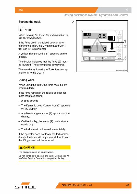
Starting the truck
NOTE
When starting the truck, the forks must be inthe lowered position.
If the forks are in the raised position whenstarting the truck, the Dynamic Load Con-trol icon (3) is highlighted.
A yellow triangle symbol (1) appears on thedisplay.
The display indicates that the forks (2) mustbe lowered. The arrow points downwards.
The mandatory lowering of forks function ap-plies only to the DLC 3.
During work When using the truck, the forks must be low-ered regularly.
If the forks remain in the raised position formore than four hours:
– A beep sounds
– The Dynamic Load Control icon (3) appearson the display
– A yellow triangle symbol (1) appears on thedisplay.
– On the display, the arrow (2) points down-wards only.
– The forks must be lowered immediately
If the operator does not lower the forks imme-diately, the truck will only move at 4 km/h andthe lifting speed will be reduced.
CAUTIONThe display screen no longer works.Do not continue to operate the truck. Contact the Af-ter-Sales Service Centre to change the display.
Use 4Driving assistance system: Dynamic Load Control
8511748011551 EN - 02/2021 - 09

In the event of error code L354 The error code L354 (1) may appear on thedisplay screen.
It is therefore necessary to check that:● Nothing is blocking the field between the
two sensors The presence of an object mayblock it
● The sensors are clean
After these checks, the forklift operator mustrestart the truck.
If the error code L354 appears again after therestart, please contact the After-Sales Service.
Use4Driving assistance system: Dynamic Load Control
86 11748011551 EN - 02/2021 - 09

Cold store usage (optional)
CAUTIONStandard trucks risk being subject to significant dam-age if used in extreme conditions.Only trucks with the Cold Store option may be usedinside cold storage. Specific oil designed for coldstores must be used.
These trucks are identified by their Cold Storelabel.
Area of UseTrucks with the Cold Store option may beused in two different areas:● operating range 1: the truck can operate at
a temperature of -5 °C and, for short peri-ods, at a temperature of -10 °C. It must beparked outside of the cold store.
● operating range 2 (Entry / Exit applica-tions): the truck must be used alternately in-side and outside of the cold store. It canwithstand temperatures between -30 °C and+45 °C. Specific rules should be followed soas not to damage the truck and to avoid theoccurrence of streaming (see the followingparagraph). The truck is parked outside ofthe cold store.
Precautions for UseThe difference in temperature between thecold store and the room temperature zonemay result in the formation of condensationwater.
This water can freeze when the truck goesback into the cold store and jam the movingparts of the truck.
Streaming occurs if the truck remains outsideof the cold store for more than ten minutes.Therefore, it is essential to leave the truck out-side of the cold store for 30 minutes so thatthe condensation disappears.
DANGERIf the condensation freezes in the cold store, it isprohibited to operate the jammed parts.This could cause permanent damage to the truck.
Use 4Cold store usage (optional)
8711748011551 EN - 02/2021 - 09

ParkingThe truck must be parked outside of the coldstore.
Parking inside the cold store could cause seri-ous damage to the electrical and mechanicalequipment (seals, hoses, rubber and syntheticparts).
CAUTIONDo not leave discharged or unused batteries in thecold store.They could be permanently damaged.
Use4Cold store usage (optional)
88 11748011551 EN - 02/2021 - 09

Parking the truck. WARNING
Risk of injuryNever leave the truck with the load in the raised posi-tion.
Do not stop the truck on a slope. If absolutely neces-sary, secure the truck with wedges.
Stopping the truck – Immobilise the truck.
– Lower the forks.
– Switch off the ignition (key or electronickey).
– Press the emergency off switch.
Restarting work – Switch on the ignition again (key or elec-
tronic key).
– Press the operator presence pedal.
– Pull the emergency off switch.
Use 4Parking the truck.
8911748011551 EN - 02/2021 - 09

Handling the batteryBattery typeTrucks can be fitted with different types of bat-tery. Comply with the information indicated onyour battery's type plate, as well as with itsfeatures.
WARNINGThe weight and size of the battery influence the sta-bility of the truck.The new battery must weigh the same as the oldone. Do not remove extra weight or change its posi-tion.
CAUTIONBe careful not to damage any wiring when replacingthe battery.
Order pickingMaintenance personnelThe battery must be replaced by speciallytrained personnel. Personnel must follow themanufacturer's instructions for the battery, thecharger and the truck.
It is also necessary to follow the battery main-tenance instructions.
Fire protection measures
WARNING
Do not smoke or create a flame whenhandling batteries. There must be nocombustible material or tools that pro-duce sparks within a minimum radius of2 m around the truck and the batterycharger.
The work area must be well ventilated.Fire extinguishers must be provided andlocated near the work area.
Use4Handling the battery
90 11748011551 EN - 02/2021 - 09
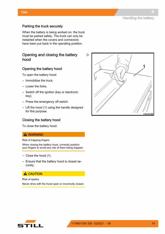
Parking the truck securelyWhen the battery is being worked on, the truckmust be parked safely. The truck can only berestarted when the covers and connectorshave been put back in the operating position.
Opening and closing the batteryhood
Opening the battery hood To open the battery hood:
– Immobilise the truck.
– Lower the forks.
– Switch off the ignition (key or electronickey).
– Press the emergency off switch.
– Lift the hood (1) using the handle designedfor this purpose.
Closing the battery hood To close the battery hood:
WARNINGRisk of trapping fingersWhen closing the battery hood, correctly positionyour fingers to avoid any risk of them being trapped.
– Close the hood (1).
– Ensure that the battery hood is closed se-curely.
CAUTIONRisk of sparksNever drive with the hood open or incorrectly closed.
Use 4Handling the battery
9111748011551 EN - 02/2021 - 09

Charging the battery using an exter-nal charger
CAUTIONDeep discharging may damage the battery.– Charge the battery immediately.
– Park the truck safely.
– Before charging, check the condition of thebattery cable and the charger cable. Re-place them if necessary.
– Open the hood and leave open.
– Remove the battery handle connector (1)from the truck plug (2).
– Connect the battery connector to the wall-mounted connector.
WARNINGElectrical riskOnly unplug the battery connector from the batterycharger when both the battery charger and truck areswitched off.
NOTE
Follow the instructions provided by the batteryand battery charger manufacturers (equalisingcharge).
WARNINGRisk of damage, short circuit or explosion.Do not place any metallic objects or tools on the bat-tery.
Smoking is prohibited.
WARNINGThe electrolyte (diluted sulphuric acid) is toxic andvery caustic.Follow the safety regulations when handling batteryacid.
Use4Handling the battery
92 11748011551 EN - 02/2021 - 09

WARNINGExplosive gases are generated during battery charg-ing.– Make sure that the area is well-ventilated.– Make sure that the battery hood remains open for
the entire time the battery is charging.
Use 4Handling the battery
9311748011551 EN - 02/2021 - 09
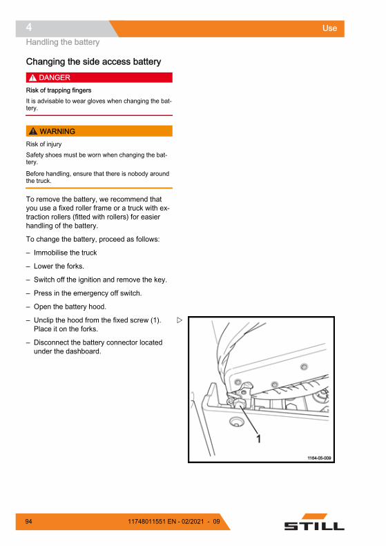
Changing the side access battery DANGER
Risk of trapping fingersIt is advisable to wear gloves when changing the bat-tery.
WARNINGRisk of injurySafety shoes must be worn when changing the bat-tery.
Before handling, ensure that there is nobody aroundthe truck.
To remove the battery, we recommend thatyou use a fixed roller frame or a truck with ex-traction rollers (fitted with rollers) for easierhandling of the battery.
To change the battery, proceed as follows:
– Immobilise the truck
– Lower the forks.
– Switch off the ignition and remove the key.
– Press in the emergency off switch.
– Open the battery hood.
– Unclip the hood from the fixed screw (1).Place it on the forks.
– Disconnect the battery connector locatedunder the dashboard.
Use4Handling the battery
94 11748011551 EN - 02/2021 - 09

– Place the connector on the battery cells.
– Position the truck with extraction rollers orthe roller frame (4) in the upright positionnext to the battery compartment on levelground.
– Operate and pull the locking handle (2) inthe direction indicated by the arrow.
Use 4Handling the battery
9511748011551 EN - 02/2021 - 09
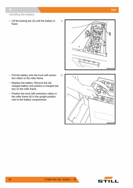
– Lift the locking bar (3) until the battery isfreed.
– Pull the battery onto the truck with extrac-tion rollers or the roller frame.
– Replace the battery. Remove the dis-charged battery and position a charged bat-tery on the roller frame.
– Position the truck with extraction rollers orthe roller frame (4) in the upright positionnext to the battery compartment.
Use4Handling the battery
96 11748011551 EN - 02/2021 - 09

– Carefully push the battery into the compart-ment.
DANGERRisk of trapping fingersPush the battery from the rear side (A) of the battery.Take care not to trap your fingers by pushing fromthe top or the side of the battery.
DANGERRisk of injuryThe battery is correctly positioned but is not yetlocked.
– Push it down to the end of the compart-ment.
Use 4Handling the battery
9711748011551 EN - 02/2021 - 09

– Lower and lock the handle (2) of the lockingbar (3) in the direction indicated by the ar-row. The locking bar must be horizontal andmust be right up against the stop (5).
CAUTIONRisk of locking the battery incorrectlyThe locking bar should not in any circumstances bepositioned under or on top of the stop. It must bepositioned against the stop.
– Reconnect the battery connector.
– Refit the battery hood.
– Return the truck to service.
WARNINGRisk of injuryBefore restarting the truck, ensure that the battery iscorrectly installed. Check that the battery is lockedand that the battery hood is closed.
Use4Handling the battery
98 11748011551 EN - 02/2021 - 09
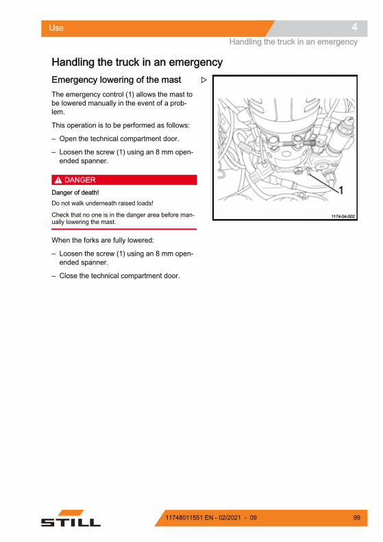
Handling the truck in an emergencyEmergency lowering of the mastThe emergency control (1) allows the mast tobe lowered manually in the event of a prob-lem.
This operation is to be performed as follows:
– Open the technical compartment door.
– Loosen the screw (1) using an 8 mm open-ended spanner.
DANGERDanger of death!Do not walk underneath raised loads!
Check that no one is in the danger area before man-ually lowering the mast.
When the forks are fully lowered:
– Loosen the screw (1) using an 8 mm open-ended spanner.
– Close the technical compartment door.
Use 4Handling the truck in an emergency
9911748011551 EN - 02/2021 - 09

Truck towing procedureIt is not possible to tow the truck with no elec-trical function. The electromagnetic brake re-mains in the closed position.
Truck towing is authorised with a rigid connec-tion (tow bar) if the truck to be towed can nolonger be braked. Check that the towing vehi-cle is sufficiently powerful to pull and brake thetruck being towed.
Moving with no battery
NOTE
In the event of an electrical fault or no battery,it is possible to unlock the brake manually.
CAUTIONThis procedure must be carried out by authorisedpersonnel.
– Unload the fork arms, then disconnect thebattery.
– Remove the engine cover.
– Two M5 X 35 screws (1) are required.
– Screw the screws (1) to the brake (2) in theholes (3). The brake is then unlocked.
CAUTIONThe truck must only be towed at low speeds.
0252_003-109
1
Use4Handling the truck in an emergency
100 11748011551 EN - 02/2021 - 09

– After towing, chock the truck to prevent itfrom moving.
– To re-establish brake operation, unscrewand remove the two screws (1).
– Refit the covers.
WARNINGIt is essential that the covers are correctly refitted be-fore the machine is used.
0252_003-110
3
2
Use 4Handling the truck in an emergency
10111748011551 EN - 02/2021 - 09

Handling the truck in specific situationsSlinging the truck
DANGERDanger of truck fallingOnly use slings and a hoist of sufficient quality.Check the weight of the machine (including battery)in order to choose a suitable device. Refer to thetechnical features.
Observe the following instructions:
– Shut off the truck and disconnect the bat-tery connector.
– Remove any items that could fall.
– Protect all parts that come into contact withthe lifting device.
– Attach the lifting device to the sling ring (1).
NOTE
Do not sling the truck by the control module orthe steering wheel.
– Carefully lift the truck.
DANGERRisk of fallingMake sure no one is under or near the truck whenslinging the truck.
Use4Handling the truck in specific situations
102 11748011551 EN - 02/2021 - 09

Lifting the truck
DANGERDanger of swingingTruck lifting must be performed carefully.
For some work, it is necessary to lift the truck.
– Lift the load arms.
– Switch off the ignition and disconnect thebattery connector.
– Use a jack with adequate lifting capacity.
Front section of the truck:
– Place a jack under the chassis (1).
For work on the lifting device:
– Position the jack under the battery frame(2).
Maintenance of the load wheels:
– Place the jack under the forks in the indica-ted locations (3).
As a safety precaution, always insert a wood-en chock.
WARNINGRisk of truck fallingImmobilise and chock the truck after lifting it.
Transporting the truck
CAUTIONAlways switch off the ignition and disconnect the bat-tery.Never tie down or sling the truck by the control unitor other points not designed for this.
CAUTIONRisk of damage to the truck.Use a hoist and woven NON METALLIC slings withan adequate lifting capacity. Refer to the load weightshown on the truck's capacity plate.
The lifting operations must be performed by qualifiedpersonnel.
Trucks are generally transported by road or byrail.
Use 4Handling the truck in specific situations
10311748011551 EN - 02/2021 - 09

The truck must be suitably protected from theeffects of the weather during transport andstorage.
To load or unload the truck, use an inclinedplane or a mobile ramp.
If the truck is out of service or if the batteryhas been removed, sling the truck. See Chap-ter 4 Slinging the truck.
DANGERDanger of death.Do not stand within the hoist's operating radius orbelow the lifted truck.
Transporting the truck in the liftThe truck must only be taken in lifts with anadequate loading capacity that are designedfor this purpose, and for which authorisationhas been received from the operator. Insidethe lift, the truck must be immobilised so thatno part is in contact with the wall of the liftcage.
A minimum safety distance of 100 mm fromthe walls of the lift must always be observed.
Anyone transported with the truck must onlyenter the lift after the truck has been correctlyimmobilised and they must exit the lift first.
Driving on loading bridgesBefore crossing a loading bridge, the operatormust make sure it is properly attached and se-cured and its load capacity is sufficient. Crossthe loading bridge slowly and carefully. Thedriver must be sure that the vehicle to be en-tered is secured sufficiently against movement
and that it can support the load of the forklifttruck.
The lorry driver and lift truck operator must co-ordinate the departure time of the lorry.
Use4Handling the truck in specific situations
104 11748011551 EN - 02/2021 - 09

5
Maintenance

General maintenance informationGeneral The following instructions contain all the infor-mation required for maintenance of your truck.Carry out the various maintenance work incompliance with the maintenance plan. Thiswill ensure that your truck is reliable and ingood working order and that the warranty re-mains valid.
Maintenance plan One of the display functions indicates thetruck's hours of use. Refer to it and consult thetruck's maintenance plan.
The maintenance plan is followed by advice tofacilitate work.
Maintenance intervals must be reduced if thetruck is used under harsh conditions (extremeheat or cold, large quantities of dust).
Grade and quantity of lubricants andother consumables Only lubricants and other consumables speci-fied in these operating instructions are author-ised for use in maintenance work.
Lubricants and other consumables requiredfor truck maintenance are listed in the mainte-nance specifications table.
Never mix different grades of grease or oil. If itis absolutely necessary to change brands,make sure to flush thoroughly beforehand.
Before changing any filters or working on thehydraulic system, thoroughly clean the surfaceand the areas around the part.
All containers used to pour oil must be clean.
Maintenance5General maintenance information
106 11748011551 EN - 02/2021 - 09

Servicing and maintenance personnel training and qualificationTruck maintenance must only be carried outby qualified and authorised personnel.
The annual inspection for prevention of acci-dents at work must be carried out by a personqualified to do so. The person carrying out thisinspection must provide their expertise andopinion without being influenced by economicfactors or company internal issues. Safety isthe only critical deciding factor.
The person responsible for carrying out the in-spection must have sufficient knowledge andexperience to be able to assess the conditionof the truck and the efficiency of the protectiveinstallations in accordance with the technicalregulations and principles established forchecking industrial trucks.
Battery maintenance staffBatteries must only be recharged, maintainedand changed by specially trained personnel.Personnel must follow the manufacturer's in-structions of the battery, the battery chargerand the truck.
It is essential to follow the battery mainte-nance instructions and the battery charger op-erating instructions.
Maintenance operations that do not require special trainingSimple maintenance operations such aschecking the hydraulic fluid level or checkingthe battery electrolyte level can be carried outby persons with no special training.
A specific qualification is not necessary.
Refer to the maintenance section of this man-ual for further information.
Ordering spare parts and consumablesSpare parts are provided by our spare partsservice department. You will find the informa-tion required to place an order in the spareparts and fitting catalogue.
Only use spare parts recommended by themanufacturer.
Unauthorised spare parts may increase therisk of accidents due to faults relating to quali-ty or incorrect choices. Anyone who uses non-compliant spare parts must assume full re-sponsibility in the event of an accident.
Maintenance 5General maintenance information
10711748011551 EN - 02/2021 - 09
Safety guidelines for maintenanceServicing and maintenance measures To avoid accidents during servicing and main-tenance operations, take all necessary safetymeasures. For example:
– Ensure that there is no risk of the truckmoving or starting up unexpectedly. For thisreason, remove the battery connector.
Working on the electrical equipment Operations on the truck's electrical systemmust only be carried out when there is no volt-age supply.
Operating checks, testing and adjustmentwork on parts supplied with voltage must onlybe carried out by personnel:● who have received detailed instructions● who have been authorised to perform this
work● who have taken the necessary precaution-
ary measures.
Rings, metal bracelets etc., must be removedbefore carrying out any operations on electriccomponents.
Remove the electric equipment (which compri-ses electric components such as the tractioncontroller) before carrying out any welding op-erations. This precaution prevents this electricequipment from being damaged.
Operations on the electric system require theconsent of the manufacturer.
Safety devices After any repair or maintenance work, it isnecessary:● to refit all safety devices● to check these for correct operation.
Maintenance5Safety guidelines for maintenance
108 11748011551 EN - 02/2021 - 09

Technical data for inspection and maintenanceAssembly Consumables/lubricants Capacities/adjustment values
Hydraulic system Hydraulic oil Minimum oil volume: 7.7 litresMaximum oil volume: 8.3 litres
Transmission gear Transmission gear oil 0.98 lTraction motor (3 kW) 1F1 fuse Power: 300 A, quantity: 1Steering unit ES30–24(0.185 kW S1) 3F1 fuse Power: 40 A, quantity: 1
Pump motor (3.2 kW) 1F1 fuse Power: 300 A, quantity: 1Control fuse 1F3 fuse Control: 7.5 A, quantity: 1Control fuse 1F4 fuse Control: 5 A, quantity: 1Battery Distilled water As requiredJoints Lithium soap grease As required
Maintenance 5Technical data for inspection and maintenance
10911748011551 EN - 02/2021 - 09

Recommended lubricants CAUTION
Damage to equipment if non-recommended lubri-cants are used.Only use recommended lubricants. Only the lubri-cants listed below are approved by the manufacturer.Do not mix lubricants. If in doubt, please contact theAfter-Sales Service Centre.
Hydraulic oilRecommended oil for standard use:
ISO-L-HM 46 as per ISO 6743-4 or ISOVG46-HLP as per DIN 51524-2
Recommended oil for heavy-duty use:
ISO-L-HM 68 as per ISO 6743-4 or ISOVG68-HLP as per DIN 51524-2
Recommended oil for the cold store version:
ISO-L-HM 32 as per ISO 6743-4 or ISOVG32-HLP as per DIN 51524-2
Transmission oil Recommended oil:
SAE 85W 90 API GL4
Aerosol can for chainsStandard chain spray
Grease for pinion gear and steering ring
CAUTION
Follow the maintenance and safety guidelines.
Multi-purpose greaseLithium soap grease with EP agents andMoS 2KPF 2N - 20 complying with the stand-ard DIN 51825.
ENVIRONMENT NOTE
Used oil must be stored safely until it is dis-posed of in accordance with environmentalregulations. No one should have access to theused oil. Do not dispose of used oil in drainsor allow it to penetrate soil.
Maintenance5Recommended lubricants
110 11748011551 EN - 02/2021 - 09

Accessing the technical com-partment In order to perform maintenance on varioustruck components, it is necessary to accessthe technical compartment.
– Immobilise the truck
– Lower the forks
– Switch off the truck (key or electronic key)
– Press the emergency off switch
– Disconnect the battery connector
– Move the seat all the way forwards
– Remove the mounting screw (1) at the bot-tom of the door
Maintenance 5Accessing the technical compartment
11111748011551 EN - 02/2021 - 09

– Open the technical compartment door (2)
You must close the technical compartment af-ter the operation is finished.
– Close the door (2)
CAUTIONRisk of trapping fingers.Take care not to trap your fingers between the doorand the chassis.
Be careful not to trap your fingers in the externalhinges (3).
– Refit the mounting screw
– Reconnect the battery connector
– Return the truck to service
Maintenance5Accessing the technical compartment
112 11748011551 EN - 02/2021 - 09

1000-hour maintenance planDepending on the application, environmental conditions and driving style, the following proce-dures should be carried out every 1000, 2000, 3000, 4000, 6000, 7000, 8000 and 9000 hours PreparationClean the truckCheck the error codes using the diagnostic toolChassis and equipmentCheck the condition of the forksCheck the electromagnetic brake and ensure that it is working correctlyCheck and lubricate the hingesCheck the pump motor brushes for wearEnsure that the floor adjusts and locks correctlyEnsure that the seat adjusts and locks correctlyCheck the transmission gear for noise and leaksLubricate the gearsWheelsCheck the condition and tightness of the wheelsCheck the stabilisersElectrical equipmentClean the electric steering system and lifting motorsCheck the condition of the cables and the battery sockets and ensure that they are positionedcorrectlyCheck the electrical insulation between the chassis and the electric componentsCheck the electrical insulation between the chassis and the electronic componentsCheck the fusesCheck the battery acid level and the electrolyte levelHydraulicsCheck the hydraulic oil levelCheck the condition of the pipe linesLoad lift systemCheck the condition and the length of the mast chainLubricate the forks and the mast guide rollersCheck the condition and mounting of the guard grilleCheck the pin clearance
Maintenance 51000-hour maintenance plan
11311748011551 EN - 02/2021 - 09

5000-hour maintenance plan Depending on the application, environmental conditions and driving style, the following proce-dures should be carried out every 5000 and 10,000 hours InformationCarry out all 1000-hour maintenance workHydraulicsDrain the hydraulic oil
10,000-hour service plan Depending on the application, environmental conditions and driving style, the following proce-dures should be carried out every 10,000 hours InformationCarry out all 1000-hour maintenance workCarry out all 5000-hour maintenance workMotorDrain the transmission gear oil
Maintenance55000-hour maintenance plan
114 11748011551 EN - 02/2021 - 09
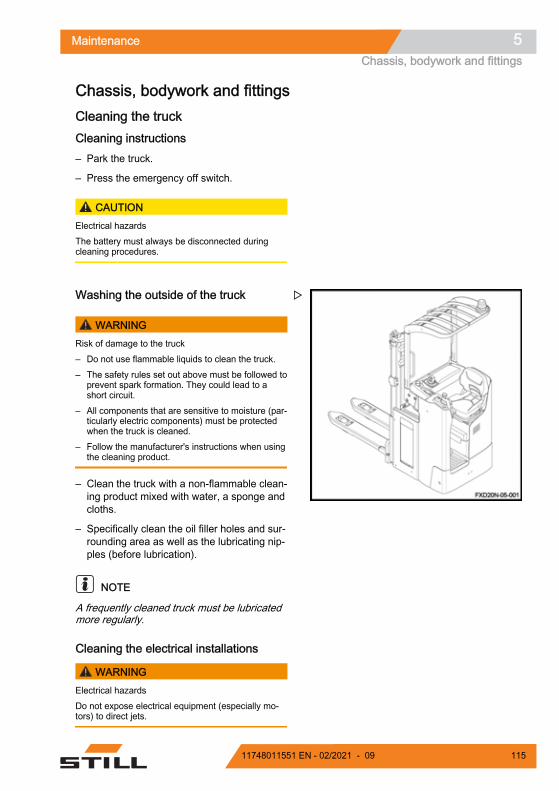
Chassis, bodywork and fittingsCleaning the truckCleaning instructions– Park the truck.
– Press the emergency off switch.
CAUTIONElectrical hazardsThe battery must always be disconnected duringcleaning procedures.
Washing the outside of the truck
WARNINGRisk of damage to the truck– Do not use flammable liquids to clean the truck.– The safety rules set out above must be followed to
prevent spark formation. They could lead to ashort circuit.
– All components that are sensitive to moisture (par-ticularly electric components) must be protectedwhen the truck is cleaned.
– Follow the manufacturer's instructions when usingthe cleaning product.
– Clean the truck with a non-flammable clean-ing product mixed with water, a sponge andcloths.
– Specifically clean the oil filler holes and sur-rounding area as well as the lubricating nip-ples (before lubrication).
NOTE
A frequently cleaned truck must be lubricatedmore regularly.
Cleaning the electrical installations
WARNINGElectrical hazardsDo not expose electrical equipment (especially mo-tors) to direct jets.
Maintenance 5Chassis, bodywork and fittings
11511748011551 EN - 02/2021 - 09

NOTE
● Only use dry cleaning products● Do not remove the cowlings
– Clean the electrical installations with a non-metal brush and dry with lightly compressedair.
After washing– Carefully dry the truck (e.g. with com-
pressed air).
WARNINGUse of compressed airIt is advisable to wear protection goggles and amask.
– Restart the truck in accordance with the in-structions.
NOTE
If, despite taking precautions, traces of mois-ture remain in the motor, dry it using com-pressed air. After having eliminated any tracesof moisture, the truck may be reactivated. Donot do so before then to prevent any corro-sion.
Maintenance5Chassis, bodywork and fittings
116 11748011551 EN - 02/2021 - 09

General information on battery maintenance DANGER
Risk of injuryBefore carrying out any operations on the electric in-stallation, turn the truck power supply off. Disconnectthe battery connector.
Precautions to be taken during batterymaintenance The plugs on the battery cells must always bedry and clean.
Neutralise any spilt battery acid immediately.
The battery terminals and lugs must be clean,lightly covered with grease for terminals andsecurely tightened.
Charging the batteryDuring the charging process, the surface ofthe battery cells must be clear to ensure suffi-cient ventilation.
Do not place metal objects on the battery.
The battery cover must remain open duringcharging. See the chapter entitled Batterycharging using an external charger.
Battery typeLead or gel batteries are used. It is advisableto choose a compatible charger.
Before charging, ensure that the charger issuitable for the type of battery.
CAUTIONGel batteries are subject to specific charging, mainte-nance and treatment instructions. A non-compatiblecharger may result in a battery failure.Observe the manufacturer's recommendations.
NOTE
● The discharge indicators used to check thebattery must also be suitable for the type ofbattery
● Contact the relevant After-Sales ServiceCentre
Charging the battery – Park the truck in an area without condensa-
tion or pollution and with sufficient ventila-tion.
– Stop the truck.
– Press the emergency off switch.
– Open the battery hood.
– Follow the instructions.
CAUTIONDo not expose the charger to water, rain, oils, greaseor any similar substances.The charger becomes hot during the operation.
CAUTIONRisk of injuryDo not obstruct the ventilation. Allow the charger tocool down for 10 minutes after charging is completebefore touching it. Do not use the charger out of thetruck.
Maintenance 5Chassis, bodywork and fittings
11711748011551 EN - 02/2021 - 09
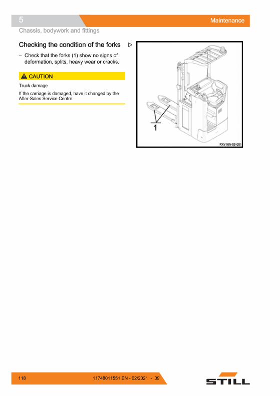
Checking the condition of the forks – Check that the forks (1) show no signs of
deformation, splits, heavy wear or cracks.
CAUTIONTruck damageIf the carriage is damaged, have it changed by theAfter-Sales Service Centre.
Maintenance5Chassis, bodywork and fittings
118 11748011551 EN - 02/2021 - 09

Steering and wheelsChecking the condition of thewheels– Raise the truck until the wheels are off the
ground.
– Check that the wheels rotate freely and re-move any objects that may prevent themfrom turning or may obstruct them.
CAUTIONRisk of damaging the wheelsIn order to avoid any risk of damaging the bearingsand tyres of the wheels, it is essential to remove anywires or plastic strips that may wind around thewheel hubs and bearings.
Maintenance 5Steering and wheels
11911748011551 EN - 02/2021 - 09

Electrical equipmentCleaning and blowing out the elec-trical components
CAUTIONElectrical hazardsAlways disconnect the battery connector beforeworking on an electrical component.
– Press in the emergency off switch.
– Disconnect the battery connector.
– Open the technical compartment hood.
– Blow the electrical components with com-pressed air.
WARNINGUse of compressed airIt is advisable to wear protection goggles and amask.
– Check the condition of the cable harnessconnector pins.
Checking the battery acid level andelectrolyte density
NOTE
Remove the battery from its compartment tocheck the water level.
Maintenance5Electrical equipment
120 11748011551 EN - 02/2021 - 09

WARNINGThe electrolyte (diluted sulphuric acid) is poisonousand corrosive.– Always wear suitable protective equipment (indus-
trial protection goggles, safety gloves) when work-ing on a battery.
– Never wear a watch or jewellery when handlingbattery acid.
– Do not allow any acid to get onto the clothing orskin or into the eyes. If this does happen, rinse im-mediately with plenty of clean water.
– Immediately rinse away any spilled battery acidwith plenty of water.
– In case of injury, seek medical advice immediate-ly.
– Always follow the safety information provided bythe battery manufacturer.
– Comply with the regulations in force.
– Check the battery acid level and electrolytedensity according to the battery manufactur-er's recommendations.
– The cell covers of the battery must be keptdry and clean.
– Any spillage of battery acid must be neutral-ised immediately.
ENVIRONMENT NOTE
Dispose of any used battery acid in accord-ance with the regulations.
Maintenance 5Electrical equipment
12111748011551 EN - 02/2021 - 09

Checking the condition of cables,terminals and the battery connector – Check that the cable insulation is undam-
aged
– Check that there are no signs of heat build-up in the connections
– Check that the "+" and "-" output terminalsare not sulphated (presence of white salt)
– Check the condition of the battery connec-tor contacts and the presence of the keyingpin
CAUTIONRisk of damaging the equipment.The points mentioned above can cause serious inci-dents. In the event of an incident, contact our After-Sales Service Centre as quickly as possible.
Maintenance5Electrical equipment
122 11748011551 EN - 02/2021 - 09

Hydraulic systemsChecking the hydraulic system forleaks– Switch off the truck and disconnect the bat-
tery connector
– Move the seat all the way forwards
– Open the technical compartment door
– Inspect the hydraulic system: pipes, hosesand connections between the pump unitand the cylinders
– Check the cylinders for leaks
– Check that the hoses are attached correctlyand show no signs of friction wear
– Check the external pipes and hoses on thetechnical compartment
– Close the technical compartment door
– Return the truck to service
CAUTIONRisk of damaging the truckIn the event of leakage, please contact the After-Sales Service Centre.
Checking the hydraulic oil levelTo check the hydraulic oil level, proceed asfollows:
– Immobilise the truck
– Lower the forks
– Switch off the ignition and remove the key
– Press in the emergency off switch
– Disconnect the battery connector
– Move the seat all the way forwards
Maintenance 5Hydraulic systems
12311748011551 EN - 02/2021 - 09

– Open the technical compartment door
To ensure proper usage of the truck functions,the oil level must be between the minimum (3)and maximum (2) marks on the tank.
– Remove the plug (1). If necessary, top upvia the opening
– Refit the plug (1) afterwards
CAUTIONRisk of damage to hydraulic componentsOnly use hydraulic oil that complies with the manu-facturer's specifications (see table of recommendedlubricants).
– Close the technical compartment door
– Reconnect the battery connector
– Return the truck to service
Maintenance5Hydraulic systems
124 11748011551 EN - 02/2021 - 09

Lift mastCleaning and lubricating the chains
NOTE
If the lifting chain is too dirty, clean it.
– Place a recipient underneath the liftingchain.
– Clean using a paraffin-based product (pe-troleum, fuel oil etc.). Observe the manufac-turer's safety guidelines.
– If using a steam jet, do not use additives.
– Immediately dry the chain and its joints withcompressed air. Move the chain frequentlyduring this operation.
– Lubricate the chain immediately using aspecial aerosol chain lubricant.
CAUTIONRisk of the equipment becoming worn or damaged.Chains are safety components. Use of cold cleaningagents, chemical products, acid or chlorinated prod-ucts could destroy the chains.
NOTE
Use of high pressure liquid cleaning devices isnot advisable.
DANGERDanger of death and/or risk of serious damage toequipmentOn trucks fitted with macrolon mast protection, cleanthe translucent screen thoroughly after lubricationoperations.
Adjusting the length of the mastchains
NOTE
Depending on the use of the truck, the chainsare liable to stretch and as a result they haveto be adjusted regularly.
Maintenance 5Lift mast
12511748011551 EN - 02/2021 - 09
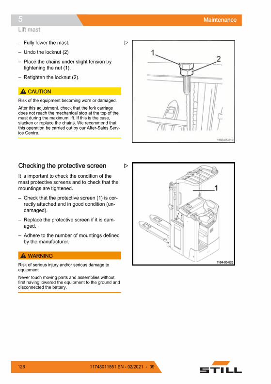
– Fully lower the mast.
– Undo the locknut (2)
– Place the chains under slight tension bytightening the nut (1).
– Retighten the locknut (2).
CAUTIONRisk of the equipment becoming worn or damaged.After this adjustment, check that the fork carriagedoes not reach the mechanical stop at the top of themast during the maximum lift. If this is the case,slacken or replace the chains. We recommend thatthis operation be carried out by our After-Sales Serv-ice Centre.
Checking the protective screenIt is important to check the condition of themast protective screens and to check that themountings are tightened.
– Check that the protective screen (1) is cor-rectly attached and in good condition (un-damaged).
– Replace the protective screen if it is dam-aged.
– Adhere to the number of mountings definedby the manufacturer.
WARNINGRisk of serious injury and/or serious damage toequipmentNever touch moving parts and assemblies withoutfirst having lowered the equipment to the ground anddisconnected the battery.
Maintenance5Lift mast
126 11748011551 EN - 02/2021 - 09

DANGERPoor visibilityThe screen must be installed and correctly attached.
Do not attach anything to the screen that could affectthe visibility of the forks.
When cleaning the fork carriage side, only clean thescreen when the fork carriage is in the lowered posi-tion.
Maintenance 5Lift mast
12711748011551 EN - 02/2021 - 09

Storage and decommissioningStorage of truckPrecautions should be taken if the truck mustnot be used for a reasonably long period. Theoperations depend on the length of time it isunused.
Long-term truck storageThe following work must be carried out on thetruck to prevent corrosion if it needs to be stor-ed for a long period of time. If the truck is to bestored for more than two months, it must bepositioned in a clean and dry area. The areamust be well-ventilated with no risk of freez-ing.
The following operations must be performed:
– Clean the truck thoroughly.
– Check the hydraulic oil level and refill if nec-essary.
– Lower the forks onto a suitable support (e.g.a pallet) until the chains are slack.
– Coat any unpainted metal parts with a thinlayer of oil or grease.
– Grease all hinges and joints.
– Check battery condition and electrolyte den-sity. Maintain the battery in accordance withthe manufacturer's requirements. (Followthe instructions).
– Spray contacts with an aerosol product de-signed for contacts.
– Raise and chock the truck: the wheels mustnot touch the ground in order to prevent ir-reversible deformation of the tyres.
– Cover the truck with a cotton cover to pro-tect it from dust.
CAUTIONWe recommend that you do not use a plastic sheetas this encourages condensation to form.
Consult the service department for furthermeasures to take if the truck must be storedfor a longer period of time.
Recommissioning after storageIf the truck has been stored for more than sixmonths, it must be checked carefully beforebeing recommissioned. This check is similar tothe workplace accident prevention inspection.It is therefore necessary to check all pointsand systems that are important for truck safe-ty.
Carry out the following operations:
– Clean the truck thoroughly.
– Grease all hinges and joints.
– Check the condition and density of electro-lyte, and, if necessary, recharge the battery.
– Check that there are no traces of condensa-tion water in the hydraulic oil. Drain if nec-essary.
– Carry out the same maintenance work asfor the first time it was commissioned.
– Commission the truck.
– In particular, check the following duringstart-up:
● traction, control and steering.● brakes (service brake and parking brake).● lifting device.
Maintenance5Storage and decommissioning
128 11748011551 EN - 02/2021 - 09

Permanent Putting Out of Commis-sion (Destruction) When scrapping the truck, it is necessary to:
– Remove the various parts of the truck (cov-ers, battery, chains, motors etc.)
– Sort out the components depending on theirtype: pipes, rubber components, lubricants,aluminium, iron etc.
– Before scrapping the truck, notify the com-petent authorities of your country in writing.
– After receiving the authorisation from thecompetent authorities, remove any compo-nents according to national standards.
NOTE
The client is solely responsible for any irregu-larities he has committed during or after thescrapping of the truck's components and theremoval of components.
Maintenance 5Storage and decommissioning
12911748011551 EN - 02/2021 - 09

Maintenance5Storage and decommissioning
130 11748011551 EN - 02/2021 - 09

6
Technical specifications

FXV 14N / 16N datasheet
Technical specifications6FXV 14N / 16N datasheet
132 11748011551 EN - 02/2021 - 09

DESCRIPTION FXV 14N / FXV16N
FXV 14Ni / FXV16Ni
1.1 Manufacturer STILL
1.2 Model type FXV 14N / FXV16N
FXV 14Ni / FXV16Ni
1.3 Method of propulsion:battery, diesel, petrol, LPG, mains power Battery Battery
1.4 Driving: manual, pedestrian, standing,seated, order picking Seated Seated
1.5 Main lift nominal capacity only:LP/LI; LI only Q (kg) 1400/1600 1400 (2000)/1600
(2000)1.6 Centre of gravity C (mm) 600 600
1.8 Distance from load wheel axle to loadmating face (±5 mm) X 724 724
1.9 Wheelbase (±5 mm) Y 1597 1597
WEIGHT FXV 14N / FXV16N
FXV 14Ni / FXV16Ni
2.1 Kerb weight with battery (±10%) kg 1580(2) 1499(2)
2.2 Load per laden axle, drive side/load side(±10%) kg 1271/1909 (1) 1179/1920 (1)
2.3 Load per unladen axle, drive side/load side(±10%) kg 1050/530 (1) 971/528 (1)
WHEELS FXV 14N / FXV16N
FXV 14Ni / FXV16Ni
3.1 Tyre: polyurethane, rubber, drive side/load side P+P/P P+P/P
3.2 Drive wheel dimensions (width at theground)
Ø xL (mm) Ø254 x L102 Ø254 x L102
3.3 Wheel dimensions, load side Ø xL (mm)
Ø85 x L85 (bo-gies: Ø85 x L60)
Ø85 x L85 (bo-gies: Ø85 x L60)
3.4 Additional wheels (dimensions) Ø xL (mm) 2 x Ø140 x L50 2 x Ø140 x L50
3.5 Number of wheels at drive side/load side(X = drive wheel) 1X + 1/2 (1X +
1/4)1X + 1/2 (1X +
1/4)3.6 Drive side track width (±5 mm) mm 541 5413.7 Load side track width (±5 mm) mm 380 380
DIMENSIONS FXV 14N / FXV16N
FXV 14Ni / FXV16Ni
4.2 Lowered mast height (±5 mm) h1 (mm) 1915 19154.3 Free lift (±5 mm) h2 (mm) 150 1504.4 Lift (±5 mm) h3 (mm) 2844 2844
Technical specifications 6FXV 14N / 16N datasheet
13311748011551 EN - 02/2021 - 09

4.5 Extended mast height h4 (mm) 3364(4) 3364(4)
4.6 Initial lift h5 (mm) / 1254.7 Overhead guard height (cab) h6 (mm) 2378 2378
4.8 Seat height relative to the SIP/height ofsupport (±5 mm) h7 (mm) 1024 1024
4.10 Load arm/ground height h8 (mm) 80 80
4.15
Height at the ends of the fork and on loadmating face (±5 mm)
h13(mm) 86 86
4.19 Total length (0/+5 mm) l1 (mm) 2187 2187
4.20 Length to front of forks (±5 mm) l2 (mm) 1037 1037
4.21 Total width (±5 mm) b1 (mm) 820 820
4.22 Fork dimensions s/e/l
(mm) 71/180/1150 71/180/1150
4.23 Load arm dimensions b3 (mm) 75/150/1115 75/150/1115
4.24 Fork carriage width b4 (mm) 780 780
4.25
Outside fork spread, minimum/maximum(±5 mm) b5 (mm) 560 560
4.26 Inside load arm spread b4 (mm) 255 255
4.32
Ground clearance at the centre of thewheelbase(±2 mm)
m2 (mm) 30 20
4.33 Dimension of the b12 x L6 load mm 800 x 1200 800 x 1200
4.34 Aisle width with predetermined load Ast (mm
) 2606(3) 2606(3)
4.35
Turning radius (minimum) (±20 mm),Initial lift raised/lowered
Wa(mm) 1783 1783
PERFORMANCE DATA FXV 14N / FXV16N
FXV 14Ni / FXV16Ni
5.1 Travel speed when laden/unladen(±5%) km/h 10/10 10/10
5.2
Initial lift speed when laden/unladen(±10%) m/s 0.045/0.088 0.045/0.088
Main lift speed when laden/unladen(±10%) m/s 0.144/0.447 0.144/0.447
5.3 Initial lift lowering speed when laden/unla-den (±10%) m/s 0.076/0.072 0.076/0.072
Technical specifications6FXV 14N / 16N datasheet
134 11748011551 EN - 02/2021 - 09

Main lift lowering speed when laden/unla-den (±10%) m/s 0.343/0.342 0.343/0.342
5.8 Maximum gradient (0 kg, 1200 kg,2000 kg) % 20/11/- 20/11/9
5.9 Acceleration time (10 m) s 6.1/5 6.1/55.10 Service brake electromagnetic electromagnetic
DRIVE SYSTEM FXV 14N / FXV16N
FXV 14Ni / FXV16Ni
6.1 Traction motor, S2, 60 minutes kW 3.0 3.0
6.2 Lift motor, S3, at 10% utilisation kW 3.2 3.2
6.3 Battery type in accordance withDIN 43 535 3 PzS SL 3 PzS SL
6.4 Battery voltage and capacity(discharge in 5 hours) V/Ah
24/375 24/3754PzS SL Li-ion 205 Ah: 23/2054PzS SL Li-ion 410 Ah: 23/410
6.5Battery weight (±10%)
(kg)290 290
Battery weight with tray (±10%) 4PzS SL Li-ion 205 Ah: 312Battery weight with tray (±10%) 4PzS SL Li-ion 410 Ah: 351
6.6 Energy consumption according to stand-ardised VDI cycle kWh/1h 1.65 1.65
6.7 Turnover output according to VDI cycle t/h 64 646.8 Energy consumption at turnover output kWh/1h 2.26 2.26
MISCELLANEOUS FXV 14N / FXV16N
FXV 14Ni / FXV16Ni
8.1 Speed control (AC controller) LAC LAC10.7 Noise level at operator's ears (±2.5) dB (A) 65 65
Vibrations transmitted to the operator (EN13059) m/s² 0.56 0.56
1) Weight according to line 2.1
2) With battery line 6.5
3) Ast = Wa + R + a (pallet stacker)
Safety distance a = 200 mm
Technical specifications 6FXV 14N / 16N datasheet
13511748011551 EN - 02/2021 - 09

FXV 14N / 16N mast typesMast type Standard
1844S 2344S 2844S 3244S 3744S 4144S 4644Sh1 1415 1665 1915 2115 2365 2565 2815h1' 1490 1740 1990 2190 2440 2640 2890h2 150 150 150 150 150 150 150h3 1844 2344 2844 3244 3744 4144 4644h4 2364 2864 3364 3764 4264 4664 5164
Mast type Duplex 1844D 2344D 2844 3244D 3744D
h1 1415 1665 1915 2115 2365h1' / / / / /h2 895 1145 1395 1595 1845h3 1844 2344 2844 3244 3744h4 2364 2864 3364 3764 4264
Mast type Triplex 4266T 4716T 5316T
h1 1915 2065 2265h1' / / /h2 1395 1545 1745h3 4266 4716 5316h4 4786 5236 5836
Technical specifications6FXV 14N / 16N mast types
136 11748011551 EN - 02/2021 - 09
AAccessing the technical compartment. . . 111Address of manufacturer. . . . . . . . . . . . . . . IAdjusting the floor. . . . . . . . . . . . . . . . . . . 43Adjusting the length of the mast chains. . 125Adjusting the seat. . . . . . . . . . . . . . . . . . . 43Aerosol can for chains. . . . . . . . . . . . . . . 110
BBatteries. . . . . . . . . . . . . . . . . . . . . . . . . . . 32Battery
Closing the battery hood. . . . . . . . . . . . 91Opening the battery hood. . . . . . . . . . . 91Type. . . . . . . . . . . . . . . . . . . . . . . . . . . 90
Battery acid. . . . . . . . . . . . . . . . . . . . . . . . 14Before leaving the truck. . . . . . . . . . . . . . . 76Before picking up a load. . . . . . . . . . . . . . 73Braking. . . . . . . . . . . . . . . . . . . . . . . . . 32, 53Braking by releasing the drive switch. 36, 54Braking by reversing the drive direction. 36, 54
CCE labelling. . . . . . . . . . . . . . . . . . . . . . . . . 3Changing the side access battery. . . . . . . 94Charging the battery. . . . . . . . . . . . . . . . 117Charging the battery using an external
charger. . . . . . . . . . . . . . . . . . . . . . . . . . 92Checking the battery acid level and elec-
trolyte density. . . . . . . . . . . . . . . . . . . . 120Checking the brakes. . . . . . . . . . . . . . . . . 36Checking the cables, terminals and the
battery connector. . . . . . . . . . . . . . . . . 122Checking the condition of the forks. . . . . 118Checking the emergency off switch. . . . . . 36Checking the horn. . . . . . . . . . . . . . . . . . . 37Checking the protective screen. . . . . . . . 126Checks prior to start-up. . . . . . . . . . . . . . . 34Cleaning and lubricating the chains. . . . . 125Cleaning the truck. . . . . . . . . . . . . . . . . . 115Climatic conditions. . . . . . . . . . . . . . . . . . . . 8cold store. . . . . . . . . . . . . . . . . . . . . . . . . . 87Cold store usage. . . . . . . . . . . . . . . . . . . . 87Consumables. . . . . . . . . . . . . . . . . . . . . . . 13
Battery acid safety instructions. . . . . . . 14Disposal. . . . . . . . . . . . . . . . . . . . . . . . 15
Oil Safety Information. . . . . . . . . . . . . . 13Safety information for handling hydraul-
ic fluid. . . . . . . . . . . . . . . . . . . . . . . . . 14Contact details. . . . . . . . . . . . . . . . . . . . . . . ICopyright and property rights. . . . . . . . . . . 3
DDefining directions. . . . . . . . . . . . . . . . . . . 52Description of the Dynamic Load Control
(DLC). . . . . . . . . . . . . . . . . . . . . . . . . . . . 77Description of use. . . . . . . . . . . . . . . . . . . . 8Destruction. . . . . . . . . . . . . . . . . . . . . . . . 129Display of the drive wheel position. . . . . . 45Display operating unit. . . . . . . . . . . . . . . . 27Display unit
Activity indicator. . . . . . . . . . . . . . . . . . 48Drive program. . . . . . . . . . . . . . . . . . . . 48Error codes menu. . . . . . . . . . . . . . . . . 49Operator presence. . . . . . . . . . . . . . . . 45Settings. . . . . . . . . . . . . . . . . . . . . . . . . 47Start-up screen. . . . . . . . . . . . . . . . . . . 50Temperature. . . . . . . . . . . . . . . . . . . . . 47Warnings. . . . . . . . . . . . . . . . . . . . . . . 47
Disposing of components and batteries. . . . 9Drive program
Blue Q mode. . . . . . . . . . . . . . . . . . . . . 55Hare mode. . . . . . . . . . . . . . . . . . . . . . 55Tortoise mode. . . . . . . . . . . . . . . . . . . . 55
Driver rights,duties and rules of behaviour. 18Drivers. . . . . . . . . . . . . . . . . . . . . . . . . . . . 18Driver's compartment. . . . . . . . . . . . . . 24, 32Drive system. . . . . . . . . . . . . . . . . . . . . . . 32Driving. . . . . . . . . . . . . . . . . . . . . . . . . . . . 52Driving on loading bridges. . . . . . . . . . . . 104Driving safety guidelines. . . . . . . . . . . . . . 51During work. . . . . . . . . . . . . . . . . . . . . . . . 85
EEC declaration of conformity. . . . . . . . . . . . 4Electrical equipment
Cleaning and blowing out the compo-nents. . . . . . . . . . . . . . . . . . . . . . . . 120
Electromagnetic braking. . . . . . . . . . . . . . 54Electronic key (option). . . . . . . . . . . . . . . . 25Emergency lowering. . . . . . . . . . . . . . . . . 99
Index
13711748011551 EN - 02/2021 - 09

FFeatures. . . . . . . . . . . . . . . . . . . . . . . . . . . 32FleetManager™
Colour code for the LEDs. . . . . . . . . . . 63Commissioning a truck equipped with a
keypad or an electronic key. . . . . . . . 62Commissioning a truck equipped with
an RFID reading device. . . . . . . . . . . 62Description. . . . . . . . . . . . . . . . . . . . . . 61Disconnecting a truck equipped with a
keypad or electronic key. . . . . . . . . . 65Disconnecting a truck equipped with an
RFID reading device. . . . . . . . . . . . . 66Disconnecting the truck. . . . . . . . . . . . 65Start-up. . . . . . . . . . . . . . . . . . . . . . . . . 62
FXV 14N / 16N datasheet. . . . . . . . . . . . 132FXV 14N / 16N mast types. . . . . . . . . . . 136
GGeneral. . . . . . . . . . . . . . . . . . . . . . . . 2, 106General information on battery mainte-
nance. . . . . . . . . . . . . . . . . . . . . . . . . . 117General view. . . . . . . . . . . . . . . . . . . . . . . 22General view of the technical compartment. 23Grade and quantity of lubricants and other
consumables. . . . . . . . . . . . . . . . . . . . . 106Grease for pinion gear and steering ring. 110
HHandling a single load. . . . . . . . . . . . . . . . 73Horn. . . . . . . . . . . . . . . . . . . . . . . . . . . . . . 54Hydraulic fluid. . . . . . . . . . . . . . . . . . . . . . 14Hydraulic oil. . . . . . . . . . . . . . . . . . . . . . . 110Hydraulic system
Checking the hydraulic oil level. . . . . 123Checking the hydraulic system for
leaks. . . . . . . . . . . . . . . . . . . . . . . . . 123
IIdentification label. . . . . . . . . . . . . . . . . . . . 5In the event of error code L354. . . . . . . . . 86
JJoystick function
Front of the joystick. . . . . . . . . . . . . . . 56Rear of the joystick. . . . . . . . . . . . . . . . 57
LLift control elements. . . . . . . . . . . . . . . . . . 69Lifting
Base lift. . . . . . . . . . . . . . . . . . . . . . . . . 70Main lift. . . . . . . . . . . . . . . . . . . . . . . . . 69
Lifting the truck. . . . . . . . . . . . . . . . . . . . 103Load handling safety rules. . . . . . . . . . . . . 67Location of markings. . . . . . . . . . . . . . . . . 28
MMaintenance plan. . . . . . . . . . . . . . . . . . 106
1000 hours. . . . . . . . . . . . . . . . . . . . . 1135000 hours. . . . . . . . . . . . . . . . . . . . . 114
Managing battery charging. . . . . . . . . . . . 47Managing residual capacity. . . . . . . . . . . . 81Mast. . . . . . . . . . . . . . . . . . . . . . . . . . . . . . 32Multi-purpose grease. . . . . . . . . . . . . . . . 110
NNo Dynamic Load Control (DLC). . . . . . . . 78Noise emission values. . . . . . . . . . . . . . . . 16
OOils. . . . . . . . . . . . . . . . . . . . . . . . . . . . . . . 13Operating company. . . . . . . . . . . . . . . . . . 18Operator presence detection. . . . . . . . . . . 41Ordering spare parts and consumables. . 107Order picking. . . . . . . . . . . . . . . . . . . . . . . 90
PPermanent Putting Out of Commission. . 129Picking up a load at a height. . . . . . . . . . . 76Picking up a load from the ground. . . . . . . 74Precautions to be taken during battery
maintenance. . . . . . . . . . . . . . . . . . . . . 117Progressive stopping of the carriage in the
lower position. . . . . . . . . . . . . . . . . . . . . 72Prohibition of use by unauthorised persons. 19Proper usage. . . . . . . . . . . . . . . . . . . . . . . . 8
RReading the capacity plate. . . . . . . . . . . . 71Recommended lubricants. . . . . . . . . . . . 110Residual dangers, residual risks. . . . . . . . 17Restarting work. . . . . . . . . . . . . . . . . . . . . 89Rules for using the Dynamic Load Control. 84
Index
138 11748011551 EN - 02/2021 - 09

SSafety devices. . . . . . . . . . . . . . . . . . . . . 108Safety Inspection. . . . . . . . . . . . . . . . . . . . 20Seat heater
Optional. . . . . . . . . . . . . . . . . . . . . . . . 44Selection buttons. . . . . . . . . . . . . . . . . . . . 45Serial number. . . . . . . . . . . . . . . . . . . . . . 29Service plan
10,000 hours. . . . . . . . . . . . . . . . . . . . 114Servicing and maintenance measures. . . 108Setting a load down on the ground. . . . . . 74Settings menu. . . . . . . . . . . . . . . . . . . . . . 49Slinging the truck. . . . . . . . . . . . . . . . . . . 102Spare parts list. . . . . . . . . . . . . . . . . . . . . . . 7Specialist. . . . . . . . . . . . . . . . . . . . . . . . . . 18Stability. . . . . . . . . . . . . . . . . . . . . . . . . . . 17Stacking a load. . . . . . . . . . . . . . . . . . . . . 75Starting on a slope. . . . . . . . . . . . . . . . . . . 60Starting the truck. . . . . . . . . . . . . . . . . . . . 85Starting up. . . . . . . . . . . . . . . . . . . . . . . . . 35Steering. . . . . . . . . . . . . . . . . . . . . . . . . . . 32Steering knob option. . . . . . . . . . . . . . . . . 57Stepping on/off the truck. . . . . . . . . . . . . . 40Stopping the truck. . . . . . . . . . . . . . . . . . . 89Symbols used. . . . . . . . . . . . . . . . . . . . . . . 9
TTechnical data for inspection and mainte-
nance. . . . . . . . . . . . . . . . . . . . . . . . . . 109
Technical description. . . . . . . . . . . . . . . . . 32Transmission oil. . . . . . . . . . . . . . . . . . . . 110Transporting a load. . . . . . . . . . . . . . . . . . 74Transporting the truck. . . . . . . . . . . . . . . 103Transporting the truck in the lift. . . . . . . . 104Travelling down slopes. . . . . . . . . . . . . . . 60Travelling up slopes. . . . . . . . . . . . . . . . . . 59Truck operating instructions. . . . . . . . . . . . 38
UUnauthorised use. . . . . . . . . . . . . . . . . . . . . 9Using Dynamic Load Control (DLC) ver-
sion 1. . . . . . . . . . . . . . . . . . . . . . . . . . . . 79Using Dynamic Load Control (DLC) ver-
sion 3. . . . . . . . . . . . . . . . . . . . . . . . . . . . 81Using the truck on a slope. . . . . . . . . . . . . 59
VVibrations
Vibration characteristics for vibrationsto which the body is exposed. . . . . . . 16
WWheels
Checking the condition of the wheels. 119Working on the electrical equipment. . . . 108
Index
13911748011551 EN - 02/2021 - 09


STILL GmbH
11748011551 EN - 02/2021 - 09