ORCHESTRATING INTER-DATACENTER BULK ...
90
ORCHESTRATING INTER-DATACENTER BULK TRANSFERS WITH CODEDBULK A Dissertation Presented to the Faculty of the Graduate School of Cornell University in Partial Fulfillment of the Requirements for the Degree of Doctor of Philosophy by Shih-Hao Tseng December 2018
-
Upload
khangminh22 -
Category
Documents
-
view
2 -
download
0
Transcript of ORCHESTRATING INTER-DATACENTER BULK ...
ORCHESTRATING INTER-DATACENTER BULKTRANSFERS WITH CODEDBULK
A Dissertation
Presented to the Faculty of the Graduate School
of Cornell University
in Partial Fulfillment of the Requirements for the Degree of
Doctor of Philosophy
by
Shih-Hao Tseng
December 2018

c© 2018 Shih-Hao Tseng
ALL RIGHTS RESERVED

ORCHESTRATING INTER-DATACENTER BULK TRANSFERS
WITH CODEDBULK
Shih-Hao Tseng, Ph.D.
Cornell University 2018
Over the past decades, data centers are built across the globe in response to
the ever-growing Internet traffic. The data centers are managed and operated
by the service providers through private inter-datacenter wide area networks
(WANs). Unlike WANs involving multiple service providers, these private
inter-datacenter WANs exhibit a number of unique characteristics. For exam-
ple, the end-hosts and the network fabric are controlled by one single provider;
scheduled bulk traffic transfers terabits of data across expensive WAN links
for replication and migration; also, major service providers embrace software-
defined networking (SDN) in their inter-datacenter WANs for easier manage-
ment and better performance. These unique characteristics enable new solu-
tions that were either infeasible or impractical in traditional WANs.
We present CodedBulk, an end-to-end system that reduces the bandwidth
required for inter-datacenter bulk transfers. CodedBulk is rooted in a known
technique from the information theory community – network coding. Net-
work coding has been known not only for its significant theoretical benefits
but also for its challenging real-world implementation and adoption. Coded-
Bulk addresses the technical implementation challenges of network coding by
exploiting the unique characteristics of inter-datacenter bulk transfers. The de-
sign of CodedBulk is agnostic to the underlying transport layer, which allows
smooth integration into existing infrastructure. We run our system prototype

on inter-datacenter networks, and it demonstrates a significant throughput im-
provement resulting from the bandwidth reduction.

BIOGRAPHICAL SKETCH
Shih-Hao Tseng earned his Bachelor of Science degree in Engineering, with a
minor in Economics, from National Taiwan University, Taiwan, in 2012. He
graduated as an Honorary Member of the Phi Tau Phi Scholastic Honor Society.
Later, he joined the M.S/Ph.D program in the School of Electrical and Com-
puter Engineering at Cornell University in August, 2013. Since then, he worked
as a member of the Networks Group led by Dr. A. Kevin Tang, focusing on
the fundamental limits and efficient algorithm designs in the era of software-
defined networking and network function virtualization. While pursuing his
degree, he also interned at AT&T in 2016 and cooperated with Dr. John C.S. Lui
as a research assistant at the Chinese University of Hong Kong in 2017.
He was a recipient of the Studying Abroad Scholarship from Taiwan’s Min-
istry of Education, the Jacobs Fellowship, and the George W. Holbrook Jr. ’52
Graduate Research Award. His research interests include networks, control, and
optimization.
iii

This dissertation is dedicated to my wife Ling, my parents, and my whole
family for their unconditional support and love during the challenges of
graduate school and life.
iv

ACKNOWLEDGEMENTS
Throughout the fruitful five years at Cornell, the one I would like to thank
the most should be my adviser professor A. Kevin Tang. Kevin has always been
a supportive mentor who not only guides me through the process toward an in-
dependent researcher but also grants me much freedom to explore my research
interests. Besides the techniques I learned from him, I especially cherish the vi-
sion and the philosophy of doing research that he shared with me. Meanwhile,
I also want to thank my committee for their advice and guidance. Professor
Lang Tong taught me how to present in an academic way right after I started
my PhD. I enjoyed collaborating with professor Eilyan Y. Bitar on several inter-
esting control projects. He also emphasized to me the importance of fluent oral
presentation, which I then kept on practicing in the following years.
In addition to my committee, I want to thank several professors for their
inspiring courses (sorted by the last name): Rachit Agarwal, Hsiao-Dong Chi-
ang, David F. Delchamps, Adrian Lewis, Emin Gun Sirer, Aaron B. Wagner, and
David P. Williamson. Especially, the “law of conservation of writing and read-
ing effort” by professor Wagner has a significant impact on my writing. The
administrative staff at Cornell is superb. Scott E. Coldren, T. Daniel Richter, and
Patricia L. Gonyea helped me a lot during my PhD years.
I have met several amazing people at Cornell. It is my pleasure to work with
the members of Cornell Networks Group: Nithin Michael, Chiun Lin Lim, An-
drey Gushchin, Ning Wu, Yingjie Bi, and Jiangnan Cheng. My office mates that
share Rhodes 359 with me – Yiting Xie, Shuang Liu, Evan Yu, and Zhilu Zhang
– broaden my horizons. I would miss the Friday jogging with the people of the
Fried Chicken Running Club: Rohit R Singh, Yi (James) Xia, and Matsuoka Fu-
miaki (including the founders Chun-Ti Chang and Hung-Lun Hsu, who will be
v

mentioned later). I also cherish the friendships since the first-year TA training
class: Kittikun Chris Songsomboon, Suwon Bae, Misook Park, and Zhen Tan.
These five years, my ECE (and MAE) friends have been pretty support-
ive: Charles Jeon, Ramina Ghods, Oscar Castaneda, Florian Glaser, Khalid Al-
Hawaj, Ritchie Zhao, Raphael Louca, Weixuan Lin, Kia Khezeli, Ibrahim Issa,
Nirmal Shende, Omer Bilgen, Sevi Baltaoglu, Earth Visarute Pinrod, Robert
Owusu-Mireku, and Kevin J. Kircher. I still remember the day when Charles
greeted with me in the orientation. Since then, he has been my good friend and
given me good advice at several critical moments throughout my PhD.
I am also grateful for the support from my Taiwanese friends Hung-Lun
Hsu, Wei-Liang Chen, Ju-Chen Chia, Kevin Lee, Yi-Hsiang (Sean) Lai, Han-
Yuan Liu, Jen-Yu Huang, Chih-Chieh (Tracy) Huang, Kai-Yuan Chen, Chun-Ti
Chang, Michelle Lee, and Hong Kong friend Henry Chu. They helped me deal
with several difficulties I encounter in a foreign environment. Hung-Lun has
been a great housemate who shared with me a lot of information about starting
a new life here.
Thanks also to other Taiwanese (and Hong Kong) people in Ithaca: Wei-
Hua Chang, Wen-Hsuan Chang, Chih-Yin Chen, I-Tzu (Wanda) Chen, Jiun-
Reuy Chen, Po-Cheng Chen, Ting-Hsuan (Julia) Chen, Wei-Han (Brian) Chen,
Yi-Chen (Eric) Chiang, Ying-Ling Chiang, Joyce Fang, Yi-Yun Ho, Hsien-Lien
Huang, Ding-Yuan Kuo, Wei-Chih Kuo, Ti-Yen Lan, Ben Li, Jui-Yun Liao, Kuan-
Chuan Peng, Hsiang-Han Su, Lieh-Ting (Adrian) Tung, Dah-Jiun Fu, Yi-An
Yang, and Yu-Chern (Chad) Wong. The life here would be so dull without the
memories and the activities we had together.
My family deserves a special place on this list. I thank my father Chun-
Sheng Tseng, my mother Shu-Yi Yen, and my sister Yu-Fen Tseng. Without their
vi

unconditional love, support, and encouragement, I would have never pursued
my PhD thousand miles away from Taiwan five years ago.
Above all, my deepest gratitude goes to my wife, Ling. Her constant support
and love are critical for me to overcome the obstacles along the way down the
academic path. Thank you for accompanying me through the dark and the
bright, day and night, sunset and sunrise.
vii

TABLE OF CONTENTS
Biographical Sketch . . . . . . . . . . . . . . . . . . . . . . . . . . . . . . iiiDedication . . . . . . . . . . . . . . . . . . . . . . . . . . . . . . . . . . . ivAcknowledgements . . . . . . . . . . . . . . . . . . . . . . . . . . . . . . vTable of Contents . . . . . . . . . . . . . . . . . . . . . . . . . . . . . . . viiiList of Tables . . . . . . . . . . . . . . . . . . . . . . . . . . . . . . . . . . xList of Figures . . . . . . . . . . . . . . . . . . . . . . . . . . . . . . . . . xi
1 Introduction 11.1 Motivation . . . . . . . . . . . . . . . . . . . . . . . . . . . . . . . . 11.2 Related Work . . . . . . . . . . . . . . . . . . . . . . . . . . . . . . 21.3 Contributions and Organization of the Dissertation . . . . . . . . 5
2 Network Coding Priliminaries 82.1 Benefits of Network Coding: the Butterfly Example . . . . . . . . 82.2 Max-Flow/Min-Cut Theorems . . . . . . . . . . . . . . . . . . . . 92.3 Linear Network Coding . . . . . . . . . . . . . . . . . . . . . . . . 10
2.3.1 Symbols, Base Fields, and Information Vectors . . . . . . . 112.3.2 Generalization to Finite Fields . . . . . . . . . . . . . . . . 12
3 System Overview 143.1 Opportunities . . . . . . . . . . . . . . . . . . . . . . . . . . . . . . 143.2 Challenges . . . . . . . . . . . . . . . . . . . . . . . . . . . . . . . . 163.3 Design Decisions . . . . . . . . . . . . . . . . . . . . . . . . . . . . 193.4 CodedBulk in a Nutshell . . . . . . . . . . . . . . . . . . . . . . . . 21
4 Design Details 234.1 Multicast Agent . . . . . . . . . . . . . . . . . . . . . . . . . . . . . 234.2 TCP Proxy . . . . . . . . . . . . . . . . . . . . . . . . . . . . . . . . 254.3 Hop-by-Hop TCP and Flow Identifier . . . . . . . . . . . . . . . . 274.4 Codec Manager . . . . . . . . . . . . . . . . . . . . . . . . . . . . . 284.5 Codec . . . . . . . . . . . . . . . . . . . . . . . . . . . . . . . . . . . 29
5 Coding Algorithm 345.1 Codec Generation . . . . . . . . . . . . . . . . . . . . . . . . . . . . 355.2 Dependency Deadlock Resolve . . . . . . . . . . . . . . . . . . . . 365.3 Cycle-Aware Coding Algorithm . . . . . . . . . . . . . . . . . . . . 41
6 Implementation Challenges 436.1 Load Balancing . . . . . . . . . . . . . . . . . . . . . . . . . . . . . 43
6.1.1 Hop-by-Hop Data Accumulation . . . . . . . . . . . . . . . 436.1.2 Concurrent Multicast Flows . . . . . . . . . . . . . . . . . . 456.1.3 Asymmetric Bandwidth and Blocking Effect . . . . . . . . 45
6.2 Codec Efficiency . . . . . . . . . . . . . . . . . . . . . . . . . . . . . 47
viii

6.2.1 Code Map Decoupling . . . . . . . . . . . . . . . . . . . . . 476.2.2 Redundant Dependency Reduction . . . . . . . . . . . . . 48
6.3 Coding Performance . . . . . . . . . . . . . . . . . . . . . . . . . . 496.3.1 Simple Forwarding . . . . . . . . . . . . . . . . . . . . . . . 496.3.2 Batch Processing . . . . . . . . . . . . . . . . . . . . . . . . 506.3.3 Parallel Computing and In-order Delivery . . . . . . . . . 51
6.4 Memory Management . . . . . . . . . . . . . . . . . . . . . . . . . 526.4.1 Local Memory Allocation . . . . . . . . . . . . . . . . . . . 536.4.2 Notifier and Memory Deallocation . . . . . . . . . . . . . . 54
7 Evaluation 557.1 Setup . . . . . . . . . . . . . . . . . . . . . . . . . . . . . . . . . . . 557.2 Inter-Datacenter WAN Experiments . . . . . . . . . . . . . . . . . 597.3 Controlled Testbed Experiments . . . . . . . . . . . . . . . . . . . 597.4 Microbenchmarks . . . . . . . . . . . . . . . . . . . . . . . . . . . . 65
7.4.1 Software implementation . . . . . . . . . . . . . . . . . . . 657.4.2 Hardware implementation . . . . . . . . . . . . . . . . . . 66
8 Summary and Future Work 688.1 Current Achievement . . . . . . . . . . . . . . . . . . . . . . . . . . 688.2 Possible Improvement . . . . . . . . . . . . . . . . . . . . . . . . . 688.3 Future Directions . . . . . . . . . . . . . . . . . . . . . . . . . . . . 69
ix

LIST OF TABLES
3.1 Design decisions of CodedBulk. . . . . . . . . . . . . . . . . . . . 20
4.1 The code maps of the registered codecs at each node in the 7-node example. . . . . . . . . . . . . . . . . . . . . . . . . . . . . . 32
7.1 Resource utilization of the hardware codec implementation. . . . 66
x

LIST OF FIGURES
2.1 The butterfly example. . . . . . . . . . . . . . . . . . . . . . . . . . 82.2 Multiple coding schemes exist to achieve the min-cut capacity. . 102.3 Linear coding expresses each coded symbol by a column vector. 11
3.1 Google’s B4 inter-datacenter network. . . . . . . . . . . . . . . . . 153.2 The 7-node example. . . . . . . . . . . . . . . . . . . . . . . . . . . 163.3 Bandwidth under-utilization led by interactive traffic. . . . . . . 183.4 Inter-datacenter network topologies. . . . . . . . . . . . . . . . . 183.5 Architecture overview of CodedBulk. . . . . . . . . . . . . . . . . 21
4.1 Multicast agents disseminate data from a source to correspond-ing destinations. . . . . . . . . . . . . . . . . . . . . . . . . . . . . 24
4.2 Proxies receive data from a multicast agent sender and multicastit to the destinations . . . . . . . . . . . . . . . . . . . . . . . . . . 26
4.3 Proxy architecture. . . . . . . . . . . . . . . . . . . . . . . . . . . . 274.4 Codec manager forwards data stream from FIr to the corre-
sponding codecs. . . . . . . . . . . . . . . . . . . . . . . . . . . . . 294.5 A coding scheme of the 7-node example. . . . . . . . . . . . . . . 31
5.1 3-node cyclic network example. . . . . . . . . . . . . . . . . . . . 375.2 Insufficiency of rouging in a partially undirected network. . . . . 395.3 Resolving dependency deadlock by dummy node installation. . 41
6.1 Imbalanced bandwidth and back-pressure rate control. . . . . . . 446.2 The example of blocking effect and CodedBulk’s priority-based
solution. . . . . . . . . . . . . . . . . . . . . . . . . . . . . . . . . . 466.3 A task collects blocks of symbols for coding. . . . . . . . . . . . . 516.4 Thread pool and batch processing. . . . . . . . . . . . . . . . . . . 526.5 The comparison of the coding throughput under operating sys-
tem and manual memory management. . . . . . . . . . . . . . . . 53
7.1 The topology of Internet2 network. . . . . . . . . . . . . . . . . . 577.2 inter-datacenter WAN experiment results. . . . . . . . . . . . . . 607.3 The controlled testbed experiment results under varying interac-
tive traffic loading level. . . . . . . . . . . . . . . . . . . . . . . . . 617.4 The controlled testbed experiment results under varying number
of sources. . . . . . . . . . . . . . . . . . . . . . . . . . . . . . . . . 637.5 The controlled testbed experiment results under varying number
of destinations. . . . . . . . . . . . . . . . . . . . . . . . . . . . . . 647.6 Evaluation of the scalability of CodedBulk. . . . . . . . . . . . . . 65
xi

CHAPTER 1
INTRODUCTION
1.1 Motivation
Today, web and cloud-based applications like search engines, social networks,
online file storage, video streaming, etc., provide services to potentially millions
of users and therefore the service providers require dedicated data centers to
store and process the large amounts of application and user data [1, 2, 3]. More-
over, these providers often use multiple of such data centers spread geograph-
ically in order to provide improved user-level performance and fault-tolerance
[4, 5]. These data centers are connected via private WANs, with links which
can span across continents [6, 7]. Further, these links carry traffic at rates above
several terabits per second, resulting in very high associated infrastructure costs
[7]. Moreover, additional objectives for the providers, like guaranteeing at least
over five nines of reliability [8], requires the operators to overprovision the net-
work, achieving less than half of the WAN utilization on average [6, 7], adding
further to the cost of the inter-datacenter networks.
Several designs [6, 7] tried to curb this under-utilization by employing cen-
tralized traffic engineering to dynamically adapt the rates at which traffic is sent
across the inter-datacenter network, particularly the delay-tolerant bulk-traffic
or the background traffic, which forms the majority of the data sent across the
inter-datacenter network [7, 9, 10]. Contrary to the low-volume, higher-priority
interactive traffic, bulk-traffic does not directly impact user-level performance
thus does not have any application specific deadlines [7]. One of the main
sources of bulk traffic is data replication – providers create geographically iso-
1

lated copies of data for higher fault-tolerance and resilience, cache highly ac-
cessed data near to the locations with higher demands for reduced latency, or
simply create multiple backup copies for scheduled maintenance. Since a large
fraction of inter-datacenter traffic is bulk traffic, our main goal would be to re-
duce the required amount of bandwidth for the bulk-traffic, which accounts for
the major chunk of the infrastructure costs of the inter-datacenter networks.
The continuing decrease of the price and the power consumption of compu-
tation and storage at data centers leads to new design opportunities: We can use
computation and storage sources in exchange for lower bandwidth utilization –
through network coding. By treating the data as bits rather than commodities,
network coding, a subfield in information theory, illustrates that an appropri-
ate coding scheme allows each destination in a multicast session to reach its
max-flow throughput without additional link capacity [11, 12]. In other words,
network coding has the potential to send more data using less bandwidth.
1.2 Related Work
inter-datacenter Networks inter-datacenter networks interconnect geograph-
ically distributed data centers. Two well-known examples are SDN-enabled
Google’s B4 [6] and Microsoft’s SWAN [7]. Managing the wide-spread data
across inter-connected data centers is a challenging task, and a large fraction
of the literature addresses this issue. Microsoft’s Volley automatically places
application data across geo-distributed data centers while taking into account
the data sharing and inter-dependency [13]. Google operates a global scale
database named Spanner [14]. Mesa, a data warehousing system, handles the
2
measurement data related to Google’s advertising business across multiple data
centers [15]. SPANStore provides a unified view of the storage services across
geo-distributed data centers [16]. JetStream aggregates and degrades the stored
data to save the bandwidth needed to assemble the data [17]. Iridium aims to
achieve low latency geo-distributed analytics by prelocating datasets before the
arrivals of the queries [18]. Geode saves the inter-datacenter bandwidth for per-
forming data analytics by caching the intermediate results and transferring only
the differences [19].
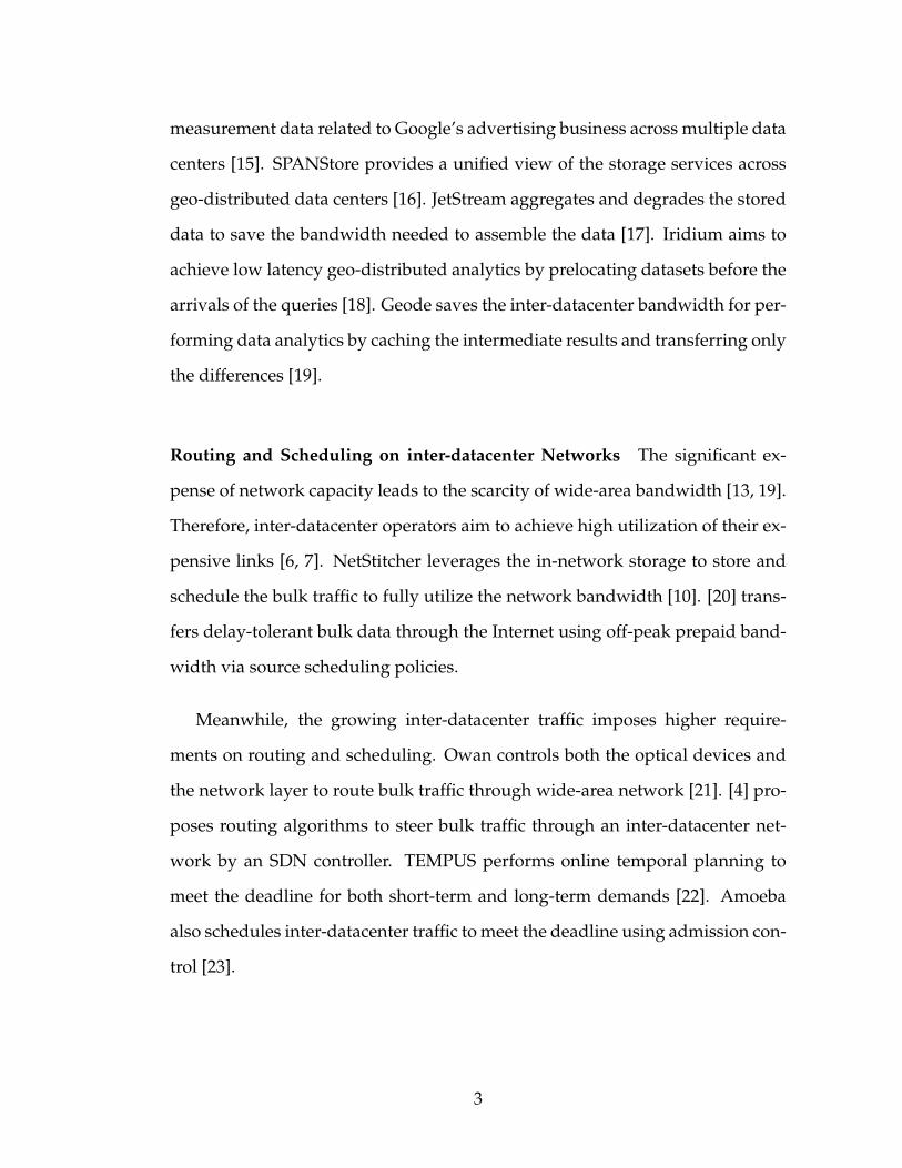
Routing and Scheduling on inter-datacenter Networks The significant ex-
pense of network capacity leads to the scarcity of wide-area bandwidth [13, 19].
Therefore, inter-datacenter operators aim to achieve high utilization of their ex-
pensive links [6, 7]. NetStitcher leverages the in-network storage to store and
schedule the bulk traffic to fully utilize the network bandwidth [10]. [20] trans-
fers delay-tolerant bulk data through the Internet using off-peak prepaid band-
width via source scheduling policies.
Meanwhile, the growing inter-datacenter traffic imposes higher require-
ments on routing and scheduling. Owan controls both the optical devices and
the network layer to route bulk traffic through wide-area network [21]. [4] pro-
poses routing algorithms to steer bulk traffic through an inter-datacenter net-
work by an SDN controller. TEMPUS performs online temporal planning to
meet the deadline for both short-term and long-term demands [22]. Amoeba
also schedules inter-datacenter traffic to meet the deadline using admission con-
trol [23].
3

Multicast Point to multiple points transfer is one of the long-lasting topics in
networking. Classical multicast solutions focus on the construction of and the
load balancing among a forest of multicast trees [24, 25, 26, 27, 28]. There is also
a line of work focusing on application layer multicasting such as [29], and we
refer the reader to [30] for a comprehensive survey.
Network Coding With negligible link latency, network coding demonstrates
that min-cut throughput can be achieved per destination by coding the symbols
[11]. [12] then shows that linear codes are sufficient for achieving the min-cut
throughput. As to how the linear codes can be generated, [31] proposes alge-
braic network coding that takes into account the information sent to each des-
tination; [32] uses random network coding that codes the symbols randomly
while maintaining probabilistic decoding guarantees; [33] gives a polynomial
time algorithm to compute the linear codes for each edge in a topological-
ordered network. In our work, we generalize the method in [33] to deal with
any given path sets.
A few attempts were made in the past to build a system that employs net-
work coding to improve throughput. One of the proposals is [34], which incor-
porates the encoding vectors into the packets and the packets are distinguished
by different redundancy offsets. Another design is COPE [35]. COPE aims to
perform network coding under wireless environments. One key difference be-
tween a wireless and a wired network is that the packets are broadcast to all
neighboring nodes in a wireless network, while the packet flows are routed
through paths in a wired network. As a result, COPE focuses on per-hop cod-
ing benefit rather than end-to-end coding as considered in this work. For radio
networks, analog network coding (ANC) proposes to exploit the interference,
4

which is essentially a summation operation of the signals, to increase the net-
work capacity [36].
Although the above designs focus on practical networks, their deployment
to real networks is rarely seen as those designs run on routers [34] or base
stations [35, 36], which require the upgrade of the current devices to support
computationally-intense network coding functionality.
Other Network Coded Systems Network coding is also considered useful for
other purposes [37]. A line of work focuses on coding different segments or
blocks in the TCP connection to improve the robustness [38, 39]. [40] simulates
the benefit of network coding for a large-scale content distribution system. A
distributed storage system can also adopt network coding to reduce the stored
data while providing the same level of reliability [41]. The reader is referred to
[42] for a comprehensive survey.
1.3 Contributions and Organization of the Dissertation
We present CodedBulk, the first inter-datacenter bulk transfer system that em-
ploys network coding to reduce the bandwidth utilization of the bulk traffic.
CodedBulk demonstrates a 2× to 4× throughput improvement of the bulk traf-
fic over the non-coded cases without disturbing the interactive counterpart in
geo-distributed wide-area networks. The benefits are offered by overcoming the
following challenges.
5

Multiple coded multicast sessions In an inter-datacenter network, multiple
multicast sessions can exist for data replication among different data centers.
Network coding saves the occupied bandwidth of each multicast session while
allocating bandwidth to multiple coded multicast flows involves fairness and
performance concerns, which remains open nowadays. By performing coding
at the application layer, load balancing among multiple coded multicast ses-
sions is achieved automatically by TCP fair sharing on each link.
Interactive non-coded traffic inter-datacenter networks have both the bulk
and the interactive traffic. The time-sensitive non-coded interactive traffic is
usually assigned a higher priority, which would make bulk traffic lack available
bandwidth. Such shared network condition is not considered in the traditional
network coding papers, which focus on a network dedicated to one coded traf-
fic only. CodedBulk addresses the bandwidth imbalance issues caused by the
interactive traffic by a bi-priority design that allows the coded bulk traffic to
adapt to bandwidth imbalance and utilize the available bandwidth fully.
Asymmetric delay and network asynchrony The latency varies among differ-
ent pairs of data centers in an inter-datacenter network due to the geographi-
cal distance and the underlying queueing policies. The asymmetric delay pat-
tern results in network asynchrony that prevents the nodes to collect all the re-
quired coding inputs at the same time, which serves as a foundation in most of
the network coding literature. To deal with network asynchrony, we introduce
the store-and-forward model using multihop TCPs. Unlike the end-to-end TCP
which performs rate control over one path. Multihop TCPs require some flow
control scheme to handle several segments. We apply a simple backpressure
6

mechanism to ensure the multihop TCPs converge to the bottleneck capacity.
The dissertation is organized as follows. We first provide the network coding
preliminaries in Chapter 2. An overview of CodedBulk is given in Chapter 3 to
discuss the opportunities, challenges, design decisions, and system architecture.
The detailed architecture descriptions are elaborated in Chapter 4, followed by
our proposed coding algorithm in Chapter 5. We illustrate in Chapter 6 the
implementation challenges and our solutions. The performance of the imple-
mented CodedBulk is evaluated in Chapter 7. Chapter 8 summarizes the design
and lists some possible future directions.
7
CHAPTER 2
NETWORK CODING PRILIMINARIES
2.1 Benefits of Network Coding: the Butterfly Example
Network coding is a subfield in information theory that examines the maximum
achievable throughput from a source to each of the destinations. One of the first
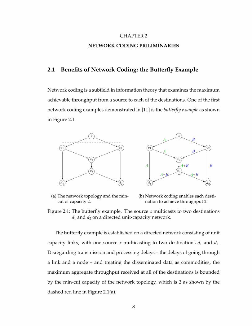
network coding examples demonstrated in [11] is the butterfly example as shown
in Figure 2.1.
s
v1 v2
v3
v4
d1 d2
(a) The network topology and the min-cut of capacity 2.
s
v1 v2
v3
v4
d1 d2
A
A
A
B
B
BA+B
A+B A+B
(b) Network coding enables each desti-nation to achieve throughput 2.
Figure 2.1: The butterfly example. The source s multicasts to two destinationsd1 and d2 on a directed unit-capacity network.
The butterfly example is established on a directed network consisting of unit
capacity links, with one source s multicasting to two destinations d1 and d2.
Disregarding transmission and processing delays – the delays of going through
a link and a node – and treating the disseminated data as commodities, the
maximum aggregate throughput received at all of the destinations is bounded
by the min-cut capacity of the network topology, which is 2 as shown by the
dashed red line in Figure 2.1(a).
8

An important observation made by [11] is that the disseminated information
can not only be relayed as commodities but also be coded and decoded as bits.
Figure 2.1(b) shows one possible coding scheme, a set of codes for a multicast
flow, that improves the aggregate throughput. Let A and B be two bits sent out
from s at the same time. The node v3 combines A and B by a modulo 2 addition
(written as +), or an exclusive-or (XOR) operation. By doing so, both destina-
tions d1 and d2 have sufficient information to decode A and B independently. As
a result, the throughput per destination is 2, and the aggregate throughput is
boosted to 4, which is twice the throughput without coding.
2.2 Max-Flow/Min-Cut Theorems
The butterfly example reveals that the multicast throughput can be improved
through coding, and a natural followup question is how much gain can be ob-
tained by appropriate designed coding schemes. The question is answered by
the Theorem 1 in [11], which we summarize in the following theorems.
Theorem 2.2.1 (Max-Flow Theorem). There exists a coding scheme that achieves the
max-flow throughput of a (multicast) flow from the source to each destination.
Since the well-known max-flow min-cut theorem suggests that the max-flow
equals to the min-cut, we can express Theorem 2.2.1 in its dual form as follows.
Theorem 2.2.2 (Min-Cut Theorem). There exists a coding scheme that achieves the
min-cut capacity of a (multicast) flow from the source to each destination.
The butterfly example is a case achieving the min-cut capacity. As in Fig-
ure 2.1(a), the min-cut from s to either d1 or d2 is 2, and the codes allows both d1
9

and d2 to reach their min-cut capacities.
2.3 Linear Network Coding
Although Theorem 2.2.1 (and Theorem 2.2.2) depicts the maximum achievable
throughput, it does not dictate which coding schemes should be used. In gen-
eral, there exist multiple coding schemes that all achieve per destination max-
flow.
As an illustration, we revisit the butterfly example in Figure 2.2. Figure 2.2(a)
shows a coding scheme, different from the one in Figure 2.1(b), which also al-
lows both destinations to decode A and B. It is possible to design an even more
complicated coding scheme to send max-flow to each destination like the one in
Figure 2.2(b), which involves negations.
s
v1 v2
v3
v4
d1 d2
A+B
A+B
A+B
B
B
BA
A A
(a) Another coding scheme that leadsto per destination max-flow.
s
v1 v2
v3
v4
d1 d2
¬A
A
¬A
B
¬B
¬BA+B
A+B ¬(A+B)
(b) A more complicated coding schemeinvolving negation (¬).
Figure 2.2: Multiple coding schemes exist to achieve the min-cut capacity.
Despite the existence of numerous coding schemes, it is critical to ask how
one coding scheme can be obtained. [12] suggests one focus on linear codes only.
We illustrate what linear codes are as follows.
10

2.3.1 Symbols, Base Fields, and Information Vectors
Instead of referring to the disseminated data in bits, we deem them as symbols
over some base field in the sense of information theory. Each symbol represents
a fixed length series of bits, and the size of the corresponding base field is the
number of distinct symbols. For instance, a symbol representing 1 bit belongs
to a base field of size 21 = 2. Similarly, an 8-bit symbol indicates a base field of
size 28 = 256.
The information transmitted from the source is partitioned into fixed dimen-
sion row vectors of symbols. Such row vectors are named information vectors. In
the butterfly example, each information vector, previously written by[
A B
],
has dimension 2.
Given an information vector, the linear codes specify the linear combina-
tions of the symbols in the information vector in the form of column vectors.
Figure 2.3 shows the column vectors that lead to the same coding scheme as the
one in Figure 2.1(b).
s
v1 v2
v3
v4
d1 d2
[10
]
[10
]
[10
]
[01
]
[01
]
[01
][11
]
[11
] [11
]
Figure 2.3: Linear coding expresses each coded symbol by a column vector.
The inner product of the information vector and the column vector gives
11

the corresponding sent symbol. For instance, symbol A is sent through (s, v1) in
Figure 2.1(b), which can be written as
A = 1 · A + 0 · B =[
A B
] 1
0
.
Therefore, the column vector
1
0
gives symbol A. Similarly, the symbol A + B
can be represented by the column vector
1
1
as it can be written as
A + B = 1 · A + 1 · B =[
A B
] 1
1
.
2.3.2 Generalization to Finite Fields
Besides the binary base field in the above example, linear coding can also be
generalized for a field with a larger base field size by adopting finite field op-
erations. A finite field, sometimes named “Galois field” with the shorthand
notation GF, is a field containing a finite number of elements. A field, in the
sense of mathematics, is a set on which addition, subtraction (inverse-addition),
multiplication, and division (inverse-multiplication) are defined along with the
additive identity (usually written as “0”) and multiplicative identity (usually
written as “1”). The following field axioms are satisfied by the addition and the
multiplication operations. Let a, b, and c be three arbitrary elements in a field, a
field satisfies
12

• Associativity of addition and multiplication.
a + (b + c) = (a + b) + c a · (b · c) = (a · b) · c
• Commutativity of addition and multiplication.
a + b = b + a a · b = b · a
• Distributivity of multiplication over addition.
a · (b + c) = (a · b) + (a · c)
The number of elements in a finite field is called the order of the field. For
example, the binary base field in the butterfly example is a GF(2), a finite field
of order 2, and XOR is the addition operation over GF(2).
In this work, our system codes over GF(28). To perform linear coding over
a base field with a larger size, we map the base field to a finite field with the
same order. The key step in the mapping is to determine the two arithmetic
operations: addition and multiplication. The addition can be done by the bit-
wise XOR operation, and the multiplication is chosen as the one used in the
Advanced Encryption Standard [43].
13

CHAPTER 3
SYSTEM OVERVIEW
We give an overview of CodedBulk in this chapter. The chapter starts with
the design opportunities and challenges, followed by the design decisions. An
architecture overview of CodedBulk is given at the end of the chapter.
3.1 Opportunities
The inter-datacenter networks exhibit some special characteristics that differen-
tiate them from other router-based networks. We discuss in the followings the
new design opportunities resulting from those characteristics.
Delay-tolerant bulk transfers Over an inter-datacenter network, bulk trans-
fers are performed by large-scale service providers across data centers to
shorten content delivery latency, improve fault tolerance, increase data avail-
ability, and achieve load balancing. Those bandwidth demanding but delay
tolerant tasks are often scheduled in advance and carried by low-priority bulk
traffic.
The aforementioned nature of the bulk traffic allows new trade-offs in the
context of inter-datacenter networks. In particular, techniques that minimize the
bandwidth to transfer bulk traffic while not inflating the latency significantly are
highly desirable.
14

s
v1
v2
v3 v4
d2
d1
Figure 3.1: Google’s SDN-enabled inter-datacenter network, B4, is a cross-continental wide-area network connecting 13 data centers. We markin blue a subnetwork as the 7-node example henceforth for conceptillustration.
Small-scale programmable networks Contrary to the huge number of nodes
in the Internet and the wide-area networks formed by multiple ISPs, inter-
datacenter networks comprise much fewer cites, only tens of data centers. For
example, Figure 3.1 shows Google’s B4 inter-datacenter network, which consists
of 13 nodes worldwide. Such a small scale allows solving complex optimization
problems that would otherwise lead to scalability concerns in data centers with
hundreds or thousands of switches. In addition, inter-datacenter networks like
B4 [6] and SWAN [7] are controlled by a single entity and often software-defined
enabled, thus making it easy to program the network by pre-configuring routes
and coding functions to efficiently implement coded bulk transfers.
Resource-rich intermediate nodes Unlike data center networks where nodes
along the path between the source and the destination are resource-constrained
switches, each node in an inter-datacenter network is a data center with abun-
dant computation and storage capacity. As a result, we can leverage the inter-
mediate nodes to buffer and code data before forwarding it at line rate, which
15

sv1
v2v3
v4d1 d2
A
A
A
B
B
BA+B
A+B A+B
Figure 3.2: A closer look of the 7-node topology from Figure 3.1. Assuming eachlink has a unit capacity, we consider a multicast flow with source sand two destinations d1 and d2. This 7-node example demonstrateshow a coding scheme can be deployed to allow both destinationsreceive two unit symbols, A and B, concurrently in a network withmin-cut capacity 2. The symbols are merged at node v3 and decodedat the destinations.
is impossible using commodity switches in data centers. By doing so, we can
trade-off a little computation and storage resources for less bulk traffic band-
width through network coding. For instance, the intermediate node v3 in Fig-
ure 3.2 buffers the symbols received from v1 and v2 and forwards the merged
symbols to v4 and d1, which is not feasible if v3 is a commodity switch instead of
a data center.1
3.2 Challenges
Multiple bulk transfers Traditional network coding literature examines the
case of a single source multicast traffic sending traffic over an empty network.
However, an inter-datacenter network can have multiple concurrent bulk trans-
fers at the same time. The coexistence of multiple bulk transfers leads to the rate
1It is also possible to achieve per destination min-cut capacity in the 7-node example byrouting and mirroring. Here we use the 7-node example for simpler coding scheme illustration.
16

sharing issues that are not well-studied in the network coding literature. As a
result, we need to address the rate sharing issues among multiple coded bulk
transfers in our design, which can involve throughput, fairness, or utilization
concerns.
Non-uniform bandwidth availability An inter-datacenter network has not
only the low-priority bulk transfers but also the high-priority interactive traf-
fic. In particular, B4 carries three main kinds of traffic [6]: high priority (and
latency sensitive) interactive traffic comprising copying of end-user application
data mainly for higher availability, lower priority traffic linked with retrieval of
remotely stored data for computational purposes, and the lowest priority (and
relatively most latency agnostic) bulk traffic mainly comprising of large-scale
copies of datasets across the sites for synchronization among the data centers.
This layered priority design grants bandwidth accordingly and results in vary-
ing bandwidth for the lower-priority traffic, especially the bulk transfers. Such
a non-uniform bandwidth availability can hurt the performance of the designed
coding scheme, which we illustrate in Figure 3.3.
Figure 3.3(a) shows the fully-utilized 7-node network using the coding
scheme in Figure 3.2. The co-existing high-priority interactive traffic shares
some link with the coded bulk traffic and causes the under-utilization of the
other links as in Figure 3.3(b). We name this phenomenon the blocking effect,
which will be discussed in details in Chapter 6.
Asymmetric transmission latency Non-uniform delay across paths is not con-
sidered in traditional network coding literature. Disregarding propagation de-
lay and processing time, the network is deemed fully synchronized, which al-
17

sv1
v2v3
v4d1 d2
(a) The coded traffic fully utilizes allavailable bandwidth.
sv1
v2v3
v4d1 d2
(b) The existence of interactive traffic (reddashed arrow) leads to bandwidthunder-utilization.
Figure 3.3: In the presence of interactive traffic, the available bandwidth for thecoded bulk traffic decreases, which leads to under-utilization of non-congested links.
(a) Google’s B4. (b) Microsoft’s SWAN
Figure 3.4: Inter-datacenter networks spread worldwide. Different links con-necting different pairs of cites can lead to different transmission la-tency, which prevents the network being perfectly synchronized.
lows the symbols being coded and forwarded upon arrival. An inter-datacenter
network, however, operates asynchronously in practice due to asymmetric
transmission latency among the paths. For instance, Figure 3.4 shows the inter-
datacenter network topologies of Google’s B4 (Figure 3.4(a)) and Microsoft’s
SWAN (Figure 3.4(b)), in which the geographically separated cites are connected
by links of various lengths and delays. As a result, the symbols collected from
distinct cites undergo different delays that prevent them from being received at
the same time for coding.
18

3.3 Design Decisions
We design CodedBulk to allow minimal-change integration to existing inter-
datacenter networks, such as B4 [6] and SWAN [7]. To start with, we elaborate
the design features of the existing inter-datacenter networks.
Existing inter-datacenter designs like B4 [6] and SWAN [7] leverage central-
ized SDN-based traffic engineering to improve the average inter-datacenter link
utilization. The key motivating factor behind the approach is twofold – First,
complete programmability is possible as all data centers belong to one same en-
tity end-to-end from physical infrastructure to application software; Second, the
scalability concerns about centralization are ruled out by the small scale of the
inter-datacenter networks consisting of only tens of the data centers. These de-
signs also introduce a prioritized framework for the interactive (high priority)
and the bulk (low priority) traffic. Moreover, their centralized routing mech-
anisms periodically find the optimal paths for the flows depending upon the
traffic and program the switches across all the sites in a synchronized manner.
We design CodedBulk to exploit the existing features, explore the new op-
portunities, and handle the aforementioned challenges, and our design deci-
sions are summarized in Table 3.1. In particular, CodedBulk employs network
coding on top of the network/transport layer functionalities provided by these
SDN-based approaches. Hence, routing and transport for the non-coded inter-
active traffic remain unchanged from the underlying network design. For the
coded bulk traffic, CodedBulk introduce the store-and-forward model to tackle
the asymmetric transmission latency. Multi-hop TCPs are used to perform load
balancing among multiple coded sessions. Taking the pre-scheduled bulk ses-
19

Table 3.1: Design decisions of CodedBulk with their corresponding rationaleand implementation challenges. The challenges will be addressed inChapter 6.
Design Decision Rationale Challenges
Network coding Each node is a data center of richcomputation resources.
Computational over-head at intermediatenodes.
Store-and-forwardmodel
Each node is a data center havingplenty of storage.Bulk traffic is delay-tolerant.
Data accumulation atintermediate nodes.
Multi-hop TCP Fair sharing among multiple bulktraffic is done on a per-link basis.Coding above the transport layerleverages existing lower layer net-work functions.
End-to-end flow ratecontrol.
Centralized codingscheme computation
SDN-enabled network allows cen-tralized computation and deploy-ment of the coding scheme.Bulk traffic is pre-scheduled.
Non-uniform band-width availablility.
sions into account, the corresponding coding schemes are generated by the cen-
tralized SDN controller which maintains a full view of the network topology.
The design decisions accompany some implementation challenges: Network
coding imposes computational overhead at each node; the store-and-forward
model would lead to data accumulation at an intermediate node when its avail-
able upstream and downstream bandwidth is imbalanced; Breaking end-to-end
TCP into multi-hop TCPs requires an appropriate rate control mechanism to
orchestrate the resulting subconnections; Non-uniform bandwidth availability
can obsolete the pre-computed coding scheme. We will discuss our approaches
to those challenges in Chapter 6.
20

CentralizedController
Data Center Data CenterData Center
Proxy
MulticastAgent
MulticastAgent
MulticastAgent
Figure 3.5: Architecture overview of CodedBulk.
3.4 CodedBulk in a Nutshell
In Figure 3.5, we provide a brief architecture overview of CodedBulk. Coded-
Bulk consists of three main parts in an inter-datacenter network: the multicast
agents, the proxies, and the centralized controller.
Each multicast agent handles one multicast bulk transfer. When a data cen-
ter issues a multicast task, it creates one corresponding multicast agent sender.
The multicast agent sender will inform the destination data centers to create the
multicast agent receivers. Meanwhile, it notifies the centralized controller of the
source and the destinations of the bulk transfer for coding scheme computation.
Once the coding scheme is established, the multicast agent forwards the bulk
traffic for coding to the proxy at the node. Logically, each data center has one
proxy that performs the network coding functions installed by the centralized
controller. The proxy establishes multi-hop TCPs with and forwards coded traf-
fic to the proxies at the neighboring data centers. The proxy also decodes the
21

information and dispatches it to the corresponding multicast agent receivers.
The centralized controller maintains a global view of the underlying inter-
datacenter network, collects the bulk traffic information from the multicast
agents, computes the coding schemes, and deploys the coding functions to the
proxies.
We will scrutinize the architectures of the multicast agent and the proxy in
Chapter 4 and elaborate our coding algorithm at the centralized controller in
Chapter 5.
22

CHAPTER 4
DESIGN DETAILS
The main task of CodedBulk is to improve the throughput of bulk transfer.
We leverage network coding to approach such goal. Network coding reduces
the bandwidth requirement of a multicast traffic and hence min-cut capacity can
be achieved at each destination in theory [11]. In this chapter, we present our
system design to incorporate network coding into inter-datacenter bulk transfer.
We begin the chapter with the two basic entities in the system: multicast agent
and TCP proxy. The TCP proxies establish hop-by-hop TCPs and we introduce
flow identifier to identify the connections. On top of the TCP proxies, we develop
the coding functionality. At each proxy, we install a codec manager that aggre-
gates the codecs. Codecs are described by the code maps to merge the incoming
data streams.
In the following context, we let G = (V, E) be the underlying network topol-
ogy, where V is the set of nodes (data centers) and E is the set of the edges.
Without further specification, edge capacity is included in the topology infor-
mation at each edge. A path is defined as a single-path route in the network,
and we use the terms “path” and “route” interchangeably without confusion.
4.1 Multicast Agent
A multicast flow disseminates data to a set of destinations through a multicast
agent (MA), which handles the communication between the source and the des-
tinations. In practice, the data of a multicast flow can be generated by an appli-
cation, and the multicast agent can be a socket, an interface, or the application
23

itself that supports multicast functionality. A multicast agent consists of two
sides: the sender side and the receiver sides, and we refer to the sender side by
MAt and the receiver sides by MAr.
MAt sends data to each MAr through a set of multicast path sets (MPSs). An
MPS consists of one path to each destination. Although the edges occupied by
the paths in an MPS form a tree, we still present such multicast structure in
terms of a set of paths rather than a tree, which allows us to assign two different
symbols to two different paths sharing the same edge later in the chapter.
For each path in an MPS, MAt and MAr establish a TCP connection on it
as in Figure 4.1. As such, MAt can send data through a specific path by send-
ing it through the corresponding TCP. The TCPs also limit the data rate of an
MPS. MAt sends data through the paths in an MPS with a rate no more than the
smallest throughput within the corresponding TCPs.
When multiple MPSs are available for an MAt, the MAt can multicast data
through the MPSs1. Regarding the load balancing among those MPSs, this work
relies on the convergence of the TCPs to determine a “fair share” for each MPS.
App
IPC
MAt
App
MAr
App
MAr TCP
Figure 4.1: Multicast agents disseminate data from a source to correspondingdestinations. Dashed squares represent the nodes.
The MPSs can be given by some existing routing algorithms. In CodedBulk,
1Some sequence reordering mechanisms might be needed for MAr to guarantee in orderdelivery as in MPTCP [44].
24

an SDN centralized controller is in charge of generating MPSs for multicast
flows. The multicast agents first report their source and destinations to the SDN
centralized controller. The controller will generate a set of MPSs for each mul-
ticast flow by Algorithm 1 and install those sets of MPSs to the corresponding
multicast agents. Each multicast agents then send data through the assigned
MPSs.
Algorithm 1 generates the MPSs by first finding a set of routes to each desti-
nation. Those routes are explored by a greedy path exploration algorithm (Al-
gorithm 2), which keeps searching for a path until no path can be found. Algo-
rithm 2 starts with a full network topology, repeatedly finds an available path
in a greedy fashion, removes the path with maximum available bandwidth, and
terminates when the source is separated from the destination.
Algorithm 1: Multicast path set generationInput: The network topology G = (V, E). The multicast flow f with source
s ∈ V and the destinations D ⊂ V where s < D.Output: The set of MPSsMD
s .1: MD
s ← ∅.2: Obtain Psd using Algorithm 2 for all d ∈ D.3: while Psd is non-empty for all d ∈ D do4: Let psd be a path in Psd for all d ∈ D.5: Generate an MPS M =
⋃d∈D{psd} and add it toMD
s .
6: Psd ← Psd \ psd for all d ∈ D.7: end while8: return MD
s .
4.2 TCP Proxy
Performing network coding requires computation at each node. We perform
the computations at the application layer by introducing a proxy at each data
25

Algorithm 2: Greedy path explorationInput: The network topology G = (V, E). The source s ∈ V and the destination
d ∈ V .Output: The set of distinct paths Psd between s and d.
1: Psd ← ∅.2: Let G′ be a copy of G.3: while There exists a path p from s to d with non-zero bandwidth in G′ do4: Find the maximum available bandwidth for p and subtract it from the
capacity of the edges that p goes through from G′.5: Psd ← Psd ∪ {p}.6: end while7: return Psd.
App
IPC
MAt
IPC
Proxy
App
MAr
Proxy
App
MAr
Proxy ProxyTCP
Figure 4.2: Proxies receive data from a multicast agent sender and multicast itto the destinations. The data is coded hop-by-hop and forwarded bythe proxies.
center. As the proxy operates at the application layer, the ordering and loss
issues of the data stream is handled by the underlying transport layer, and the
coding is performed on the data.
Without proxies, MAt sends to each MAr directly. We introduce proxies such
that MAt sends data to the proxy at the source using inter-process communica-
tion (IPC) and relies on the proxies to deliver the data to each MAr as in Fig-
ure 4.2. One thing noticeable is that a node can have multiple MAs, but there is
only one proxy at each node.
26

Figure 4.3 shows the architecture of a proxy. In this work, we consider
TCP proxies, which break an end-to-end TCP connection into multiple hop-by-
hop TCP connections. Each hop-by-hop TCP connection lies between a pair of
neighboring proxies. Such scheme is also known as “split TCP” [45].
A proxy contains a codec manager that manages a set of registered codecs.
Once new data is received, the proxy stores the data and calls the codec manager
to match the data to the corresponding codecs.
Data Center
Proxy
Data Center
Proxy
Data Center
ProxyCodec Manager
Codec Codec Codec
TCP Connections
Figure 4.3: Proxy architecture.
4.3 Hop-by-Hop TCP and Flow Identifier
Given a simple path p1, we partition it into hop-by-hop TCP connections and
mark those connections with a flow identifier (FI) p1. In this work, FI is a 4-byte
integer. Each node will have at most one TCP sender and one TCP receiver
of the same FI, we mark them FIt and FIr, respectively. With a slight abuse of
notation, we refer to a path by its FI and vice versa.
To setup the hop-by-hop TCP connections, the centralized controller specify
27

the next hop for each FI at each proxy. This procedure is similar to installing a
routing rule at a router. Although the next hop information is available, the FIt
is not established until the proxy needs to forward data to it.
As to how hop-by-hop TCP connections will be established, the proxy listens
to a predetermined TCP port for hop-by-hop TCP establishment. When a TCP
client at the remote, or an FIt, connects to the port, the proxy creates a TCP server
that expects FI as the first message, followed by the data stream. Once the TCP
connection is established, the client sends its FI to the server and the server will
be assigned as FIr. As such the FIt and FIr pair is connected, and the data will be
streamed from FIt to FIr.
We deem each byte in the data stream a symbol, which is the basic coding
unit in network coding theory. In the literature, a symbol is represented by a
single bit [35], an 8-bit, or a 16-bit unit [34]. We choose one byte as the basic
unit, since finite field arithmetic operations over GF(28) is a building block for
the well-known Advanced Encryption Standard (AES) [43].
4.4 Codec Manager
Each proxy has one codec manager which aggregates the available codecs and
provides a unified interface for coded data stream handling. Whenever a proxy
receives a data stream from some FIr, it consults with its codec manager to deter-
mine if some codecs require the data stream. If so, the data stream is distributed
to the required codecs by the codec manager. Otherwise, the data stream is
discarded as if no rule routes it from the inport to an outport in a router.
28

Proxy
Codec Manager
Codecs
(FI1,FI2) → (FI1,FI4)
(FI2,FI3) → (FI3)
FIr1
FIr2
FIr3
FIt1
FIt4
FIt3
Figure 4.4: Codec manager forwards data stream from FIr to the correspondingcodecs. The output data stream is then sent to the FIt.
The above workflow is demonstrated in Figure 4.4. Comparing with a router,
registering a codec at the codec manager is analogous to installing a routing rule
at the routing table. In that sense, coding is similar to routing. The difference
is that routing does not generate additional packets, and each packet can only
be forwarded according to one rule (or one sequence of rules). In contrast, one
data stream can “match against” several codecs, and each codec can produce
multiple output data streams.
4.5 Codec
As shown in Figure 4.4, the codec manager maintains a set of codecs that code
the input data streams to be output data streams. In this work, the codecs are
registered at the codec manager by the centralized controller. The controller
computes the codes for each proxy in the form of code maps and the codecs are
created accordingly.
A codec performs coding based on its code map. A code map is defined by
the input FIrs, the output FIts, and the code matrix that describes the linear map
29
from the inputs to the outputs. We illustrate how a code map is written in the
following simple example.
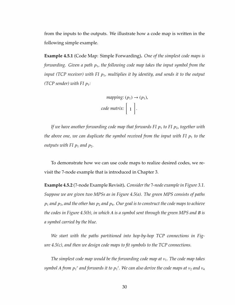
Example 4.5.1 (Code Map: Simple Forwarding). One of the simplest code maps is
forwarding. Given a path p1, the following code map takes the input symbol from the
input (TCP receiver) with FI p1, multiplies it by identity, and sends it to the output
(TCP sender) with FI p1:
mapping: (p1)→ (p1),
code matrix:[
1
].
If we have another forwarding code map that forwards FI p1 to FI p2, together with
the above one, we can duplicate the symbol received from the input with FI p1 to the
outputs with FI p1 and p2.
To demonstrate how we can use code maps to realize desired codes, we re-
visit the 7-node example that is introduced in Chapter 3.
Example 4.5.2 (7-node Example Revisit). Consider the 7-node example in Figure 3.1.
Suppose we are given two MPSs as in Figure 4.5(a). The green MPS consists of paths
p1 and p3, and the other has p2 and p4. Our goal is to construct the code maps to achieve
the codes in Figure 4.5(b), in which A is a symbol sent through the green MPS and B is
a symbol carried by the blue.
We start with the paths partitioned into hop-by-hop TCP connections in Fig-
ure 4.5(c), and then we design code maps to fit symbols to the TCP connections.
The simplest code map would be the forwarding code map at v1. The code map takes
symbol A from p1r and forwards it to p1
t. We can also derive the code maps at v2 and v4
30

sv1
v2v3
v4d1 d2
p1
p2
p4
p3
(a) 2 given MPSs consist of 4 paths.
sv1
v2v3
v4d1 d2
A
A
AB
A+B
A+B
B
B
A+B
(b) The desirable codes.
sv1
v2v3
v4d1 d2
p1
p1
p1
p2
p2
p2
p2
p3
p3
p4
p4
p4
p4
(c) Hop-by-hop TCP connections and theirFIs.
sv1
v2v3
v4d1 d2
p1
p1
p1
p2
p2
p2
p3
p3
p4
(d) Established TCP connections.
Figure 4.5: The 7-node example. Given the MPSs and the desirable codes, wecan derive the corresponding code maps to realize the codes. Thederived code maps establish only a subset of the available hop-by-hop TCP connections.
easily. As shown in the previous example, duplication can be done by two forwarding
code maps.
The code maps at the source s involves selection. s selects only A to send to p1t
(and only B to p3t), which is equivalent to multiplying the symbols from p1
r and p4r
by identity and zero, respectively, and summing the results together. Such operation
can be written as a matrix multiplication, which leads to the code map in Table 4.1.
Similarly, merging symbols, or linear combining symbols, can also be expressed by a
31

Table 4.1: The code maps of the registered codecs at each node in the 7-nodeexample.
Node Code Maps
s(p1, p4)→ (p1),
[1 0
](p2, p3)→ (p3),
[1 0
]v1 (p1)→ (p1),
[1]
v2(p3)→ (p2),
[1]
(p3)→ (p3),[
1]
v3(p1, p2)→ (p1),
[1 0
](p1, p2)→ (p2),
[1 1
]v4
(p2)→ (p2),[
1]
(p2)→ (p4),[
1]
d1 (p1, p2)→ (p1, p2),[
1 01 1
]d2 (p3, p4)→ (p3, p4),
[1 11 0
]
matrix multiplication. One such case is at v3, the symbols from p1r and p2
r are combined
and sent to p2t.
Deriving the code maps at the destinations is a little more involved. At d1, we want
to decode A for p1t and B for p2
t, while we receive A from p1r and A + B from p2
r.
Therefore, we can express the relationship by the following equationsymbol from pr
1
symbol from pr2
=
1 0
1 1
symbol to pt1
symbol to pt2
.As a result, the code map can be written as
mapping: (p1, p2)→ (p1, p2),
code matrix:
1 0
1 1
−1
=
1 0
1 1
.And the code map at d2 can be obtained in the same way.
32

At this point, we have learned how to derive all the code maps in Table 4.1. We
remark that not all the hop-by-hop TCP connections will be established and utilized by
the derived code maps: only the ones in Figure 4.5(d) will be used.
As demonstrated in the example above, we don’t and need not differentiate
between coding and decoding. Essentially, they are the same: multiplying the
symbols by a code matrix.
33

CHAPTER 5
CODING ALGORITHM
As to how the code maps can be generated, we develop a cycle-aware coding
algorithm in this chapter. It computes the code maps at each node by greed-
ily merging the given paths. The purpose of the algorithm is to produce codes
using the given paths from any existing network layer. Since no constraint is im-
posed on the given paths, cycles may exist among them, which paralyze existing
coding algorithm. Our cycle-aware coding algorithm takes such situations into
account and remains effective even in the presence of cycles.
In the literature, most of the network coding algorithms aim to associate a
symbol with each edge. In this work, however, we assign a symbol to each
hop-by-hop TCP connection. Since an edge can carry several hop-by-hop TCP
connections, several symbols can be sent through the same edge, which allows
superposition of different coded flows.
Besides the edge-based code generation, most network coding algorithms,
including the well-known polynomial-time coding algorithm [33], require the
knowledge of the network to both generate paths (or sometimes trees) and the
corresponding symbols on each edge for the multicast session. In our design,
we develop an algorithm that takes only predetermined MPSs as the input, and
generate the codecs at each node that leads to the corresponding symbols for
each hop-by-hop TCP connections.
The coding algorithm we develop in this work, named cycle-aware coding
algorithm (Algorithm 6), is inspired by [33]. However, our algorithm is more
general than [33] as
34
• the network topology is not needed as our algorithm assumes the MPSs
are given and it will not jointly determine the paths and the codes.
• our algorithm does not require the given paths to be edge-disjoint and a
topological order of the network topology to exist. It assigns symbols to
hop-by-hop TCPs instead of edges and resolves the dependency deadlock
when the given paths form cycles.
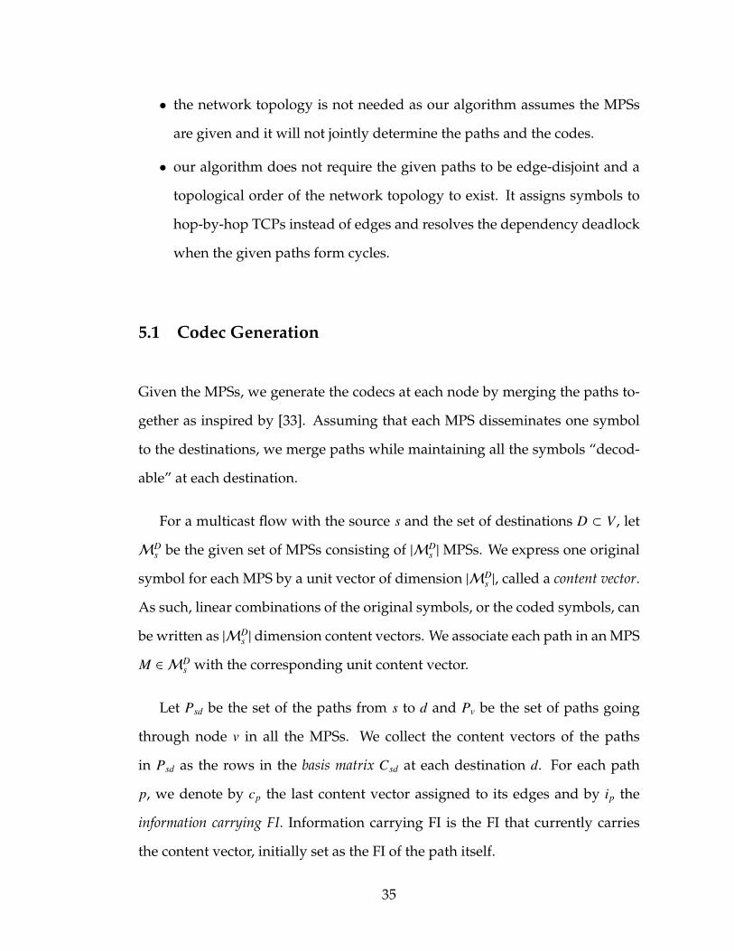
5.1 Codec Generation
Given the MPSs, we generate the codecs at each node by merging the paths to-
gether as inspired by [33]. Assuming that each MPS disseminates one symbol
to the destinations, we merge paths while maintaining all the symbols “decod-
able” at each destination.
For a multicast flow with the source s and the set of destinations D ⊂ V , let
MDs be the given set of MPSs consisting of |MD
s |MPSs. We express one original
symbol for each MPS by a unit vector of dimension |MDs |, called a content vector.
As such, linear combinations of the original symbols, or the coded symbols, can
be written as |MDs | dimension content vectors. We associate each path in an MPS
M ∈ MDs with the corresponding unit content vector.
Let Psd be the set of the paths from s to d and Pv be the set of paths going
through node v in all the MPSs. We collect the content vectors of the paths
in Psd as the rows in the basis matrix Csd at each destination d. For each path
p, we denote by cp the last content vector assigned to its edges and by ip the
information carrying FI. Information carrying FI is the FI that currently carries
the content vector, initially set as the FI of the path itself.
35

Algorithm 3: Codec generation for node vInput: The set of paths Pv and the basis matrices Csd for all d ∈ D.Output: Updated basis matrices Csd for all d ∈ D.
1: while Pv , ∅ do2: Select the paths from Pv that go through the same next edge after v but
with different destinations, and store them in P.3: Use the method in [33] to find a vector u =
∑p∈P
ηpcp such that Csd for all
d ∈ D are all full-rank (invertible) after replacing cp with u for all p ∈ P.4: Let P = {p1, p2, . . . , pn}. Register a codec at v with the code map
mapping: (ip1 , ip2 , . . . , ipn)→ (p1),
code matrix:[ηp1 ηp2 · · · ηpn
].
5: cp ← u and ip ← p1 for all p ∈ P.6: P← P \ Pv.7: end while8: return Csd for all d ∈ D.
We summarize in Algorithm 3 how the codecs are generated at each node
v, which will be the building block of our cycle-aware coding algorithm (Algo-
rithm 6).
5.2 Dependency Deadlock Resolve
Algorithm 3 can generate the codecs at a node v if the codecs have been decided
for all nodes prior to v of the paths in Pv. In [33], the authors assume the exis-
tence of a topological order in the network, and generate the codes accordingly.
Generating codecs under a topological order ensures all prior nodes have been
processed before a node is under consideration.
In our setting, it is possible that a topological order does not exist because
the network topology is not necessarily directed acyclic. Instead, an inter-
36

datacenter network usually consists of bidirectional links. As a result, the un-
derlying network layer can give MPSs that contain paths forming cycles. In
other words, the paths of the given MPSs do not hold a topological order, and
we aim to code such given MPSs as well.
A cycle tangles a pair of nodes to depend on each other. We call such issue a
dependency deadlock. In the following example, we explains how cycles create a
dependency deadlock and why we can’t simply ignore the cycle.
s
d1 d2
p2p1 p3
p4
(a) The paths p2 and p4 forms a cycle onedge (d1, d2).
s
d1 d2
A A
(b) Sending traffic on the maximum ca-pacity directed subgraph achievesthroughput 1.
s
d1 d2
A B
A
B
(c) The optimal throughput involves the utilization of the bandwidthin both directions.
Figure 5.1: A cyclic network with s multicasting to d1 and d2.
Example 5.2.1 (Cycles and Dependency Deadlock). The simplest dependency dead-
lock example would be coding over a triangular network. Consider three nodes s, d1, and
d2 in Figure 5.1. Suppose the two given MPSs are
MPS1 : p1 = (s, d1), MPS2 : p2 = (s, d2, d1),
p3 = (s, d2). p4 = (s, d1, d2).
37

The MPSs are marked green and blue in Figure 5.1(a).
After the codecs at s are computed, the codes for all the hop-by-hop TCPs on (s, d1)
and (s, d2) are determined. Meanwhile, we encounter a dependency deadlock when
choosing the next node to code. If we choose d1 as the next node, since the code on
(d2, d1) is not yet decided, we can’t compute the codec at d1. Similar problem is encoun-
tered if we choose d2 to code first.
One way to deal with the cycles is to ignore them. For instance, one might extract
the maximum capacity directed subgraph from the original network first and send traffic
only upon it. However, such approach would lead to performance degradation as shown
in Figure 5.1(b).
To resolve this dependency deadlock, we can choose one node arbitrarily, say d2, and
force all the incoming paths forwarding the latest decided symbols to the node. In this
case, we ask p4 to forward through (d2, d1) the same symbol as the symbol on (s, d2).
Therefore, the symbol on the hop-by-hop TCP (d2, d1) is decided (which is B in this
case), and the codecs at d1 can be computed. In this way, we can send the traffic that
achieves the min-cut capacity per destination as in Figure 5.1(c).
The optimal coding scheme in Example 5.2.1 can be realized by pure routing
and one might suspect if pure routing is sufficient when cycles are presented.
In the following example, we show that we must leverage both directions of a
cycle to reach the optimal performance.
Example 5.2.2 (Insufficiency of Routing under Cycles). Consider a tweaked but-
terfly example in Figure 5.2. One multicast flow sends from s to three destinations d1,
d2, and d3. A bidirectional link (d1, d3) provides unit capacity for both directions. The
optimal coding scheme involves merging the symbols at v3 and utilizes both directions
38

s
d3 v2
v3
v4
d1 d2
A+B B
A+B B
BA
A A
A+BA
Figure 5.2: Routing is insufficient in achieving the per destination min-cut ca-pacity in a unit capacity network consisting of some undirectedlinks. A multicast flow sends from s to three destinations d1, d2, andd3. The red line represents an undirected link, and the optimal cod-ing scheme both performs coding at v3 and utilizes the bandwidth of(d1, d3) bidirectionally.
of (d1, d3) to achieve per destination min-cut capacity 2. If one direction is neglected,
the min-cut capacity becomes 1, which implies that no coding scheme would be able to
achieve throughput more than 1 per destination.
This cycle issue is also observed in the network coding literature [11, 46]. To
handle the cycles, convolutional network coding is adopted and proven optimal
theoretically [46]. Convolutional network coding takes into account the delay
of the links and cross-codes the symbols that belong to different time steps. As a
result, the computation of the convolutional codes requires precise knowledge
of the network delay; the coding scheme will be time-dependent; the codec ar-
chitecture would be much more complicated; and the existing algorithm [46] is
much harder to implement than [33]. Therefore, we introduce a simple tweak
into [33] that allows our simple codec architecture to deal with the dependency
deadlock without needing the precise delay information.
As in the above examples, the idea of dealing with dependency deadlock is
39

to “skip” some nodes in some paths to restore the topological order. To do so,
we introduce a node pointer np for each path p. The node pointer points to the
first node in path that no codec has been installed regarding the symbol sent on
the path. In other words, a node pointer specifies the node at which new codecs
should be installed for the path. By definition, np points to the source node s in
the beginning for all paths.
To decide which node to generate codes, we check if there exists a node that
the paths going through it have all the prior nodes processed. If so, the node will
be chosen to generate codecs. Otherwise, we choose a node arbitrarily and skip
all prior non-processed nodes for each path by installing a forwarding codec.
The procedure is summarized in Algorithm 4. We remark that Algorithm 4
results in a topological order whenever there exists one.
Algorithm 4: Finding the next node to codeInput: The set Pwhich consists of non-empty Pv.Output: The next node to code v.
1: if There exists v where Pv ∈ P such that np = v for all p ∈ Pv then2: return v3: end if4: Pick Pv ∈ P for some v.5: for p ∈ Pv do6: while np , v do7: Pnp ← Pnp \ p. If Pnp = ∅, remove it from P.8: Register a forwarding codec at np with the code map
mapping: (ip)→ (p),
code matrix:[
1].
9: ip ← p.10: Point np to the next hop.11: end while12: end for13: return v
Algorithm 4 can be viewed from another angle. Consider again the 3-node
40

cyclic network in Example 5.2.1. In Figure 5.1(c), the node d2 is chosen to be
“skipped,” which can be deemed as if we replace the link (d2, d1) by installing
a dummy mirroring node on (s, d2). Such operation is depicted in Figure 5.3(a).
After the transformation, the network is acyclic with a topological order. Ac-
cording to the topological order, we can find the codecs at each node by Algo-
rithm 3.
s
d1 d2
(a) The cycle can be removed by addinga dummy mirroring node on the up-stream link (s, d2).
s
d1 d2
AB
B
BA
B
(b) Adding the dummy node makes thenetwork acyclic, and hence the codingscheme can be found by Algorithm 3according to a topological order.
Figure 5.3: Algorithm 4 resolves dependency deadlock by breaking the cyclesarbitrarily. Alternatively, the operation can also be interpreted asinstalling auxiliary dummy nodes.
5.3 Cycle-Aware Coding Algorithm
Combining the codec generation (Algorithm 3) and the next node finding (Al-
gorithm 4) procedures, we propose our cycle-aware coding algorithm in Al-
gorithm 6. To improve readability, we specify the initialization setup in Algo-
rithm 5.
In our system, the centralized controller collects the source and the desti-
nations of the multicast flows in the network and utilizes Algorithm 1 to route
41

them through MPSs according to the sensed network topology. The generated
MPSs are then fed to Algorithm 6 to register codecs at each node.
After generating the codes for all the nodes besides the destinations, we de-
rive the code matrices for the decoding code maps at each destination as in line
8 of Algorithm 6. Notice that Csd is invertible since Algorithm 3 maintains each
Csd full-rank when merging the symbols.
Algorithm 5: Variable Initialization1: for each destination d ∈ D do2: Assign a distinct unit content vector of dimension |MD
s | for each MPS.3: Let Pv be the set of paths going through node v in all the MPSs.4: Let P be the set of all non-empty Pv, v < D.5: Let Psd be the set of the paths from s to d.6: Setup basis matrices Csd.7: end for8: for each path p do9: Setup content vectors cp to be the same as the content vector of the
corresponding MPS.10: Setup information carrying FI ip ← p.11: Setup node pointers np ← s.12: end for
Algorithm 6: Cycle-aware coding algorithmInput: The set of MPSsMD
s with the source s and the set of destinations D.Output: The codecs at each node v traversed by some path inMD
s .1: Initialize the variables (Algorithm 5).2: while P , ∅ do3: Obtain the next node v to code by Algorithm 44: Generate the codecs at v by Algorithm 3.5: P ← P \ Pv.6: end while7: for d ∈ D do8: Let Psd = {p1, p2, . . . , pn}. Register at destination d a decoding code map
mapping: (ip1 , ip2 , . . . , ipn)→ (p1, p2, . . . , pn),
code matrix: C −1sd .
9: end for
42

CHAPTER 6
IMPLEMENTATION CHALLENGES
In this chapter, we describe the implementation challenges of our system de-
sign. We categorize the main challenges into four major groups: load balancing,
codec efficiency, coding performance, and memory management. In the follow-
ing subsections, we describe those challenges and the corresponding methods
CodedBulk adopt to deal with them.
6.1 Load Balancing
Since a network is shared by a huge number of flows, the bandwidth available
for each flow is usually asymmetric. We elaborate below the load balancing
techniques in CodedBulk.
6.1.1 Hop-by-Hop Data Accumulation
In CodedBulk, we adopt hop-by-hop TCP to send coded traffic as stated in Sec-
tion 4.3. Without any rate control mechanism, greedy hop-by-hop transfer can
result in data accumulation at the intermediate nodes when the incoming rate is
larger than the outgoing rate. Such accumulation can be unbounded when the
downstream links are shared and congested while there is plenty of bandwidth
on the upstream links.
To avoid unbounded accumulation, one can perform rate control over the
hop-by-hop TCPs. In CodedBulk, we utilize a back-pressure based rate control
43

s v1 v2
(a) The coded traffic fully utilizes all avail-able bandwidth.
s v1 v2
×
(b) A full buffer will stop taking inputfrom the receiver.
s1
s2
v1 v2
(c) Two buffers are installed per TCPreceiver when multiple inputs aremerged into one output.
s1
s2
v1 v2
×
(d) As such, the sending rates of the up-stream TCPs are both confined by thedownstream.
Figure 6.1: The imbalanced bandwidth between the upstream and the down-stream TCPs is handled by a back-pressure rate control mechanismusing buffers. One buffer is associated with each TCP receiver. Oncethe upstream TCP sends faster than the downstream. The buffer willbe filled and stop getting input, which slows down the upstreamTCP.
as shown in Figure 6.1 that can be done locally. The idea is simple: we intro-
duce an RX buffer at the proxy for each FIr and impose a limit on it. Such a
proxy RX buffer keeps pulling data from FIr until it is full. When the proxy RX
buffer is full and stops pulling from FIr, the TCP RX buffer of FIr will be filled
and the transport layer protocol slows down FIr automatically. Meanwhile, an
input symbol is removed from the proxy RX buffer when its corresponding out-
put symbols are sent. As such, the downstream congestion can slow down the
upstream by this simple design.
44

6.1.2 Concurrent Multicast Flows
An inter-datacenter network may carry multiple concurrent multicast flows.
Supporting multiple flows can easily be done with CodedBulk by superposi-
tion. As long as a distinct FI is given to each path, the codecs generated for each
multicast flow will access different FIrs and FIts.
Distinct FIs allow multiple multicast flows send through the network at the
same time. What is left unspecified is the bandwidth sharing amongst the con-
current bulk traffic. In CodedBulk, we leverage the underlying TCP congestion
control mechanism to lead to the fair-share convergence of the hop-by-hop TCP
connections. Together with the rate control design in Section 6.1.1, the band-
width sharing at each link can be automatically achieved.
6.1.3 Asymmetric Bandwidth and Blocking Effect
Although Algorithm 6 does not need the bandwidth information for each path
to generate the codecs, asymmetric available bandwidth can still affect the per-
formance of coding. We illustrate the problem below.
Consider a codec which merges two data streams from p1r and p2
r to one
output data stream. If the data rate of p1r is smaller than p2
r, the codec can
only output at the data rate no more than p1r’s. As a result, the unprocessed p2
r
data is accumulated. Given the back pressure rate control mechanism in Section
6.1.1, p2r will reduce its data rate when the accumulation exceeds the imposed
limit. In other words, the low data rate of p1r “blocks” p2
r, and hence we name
this phenomenon the blocking effect.
45
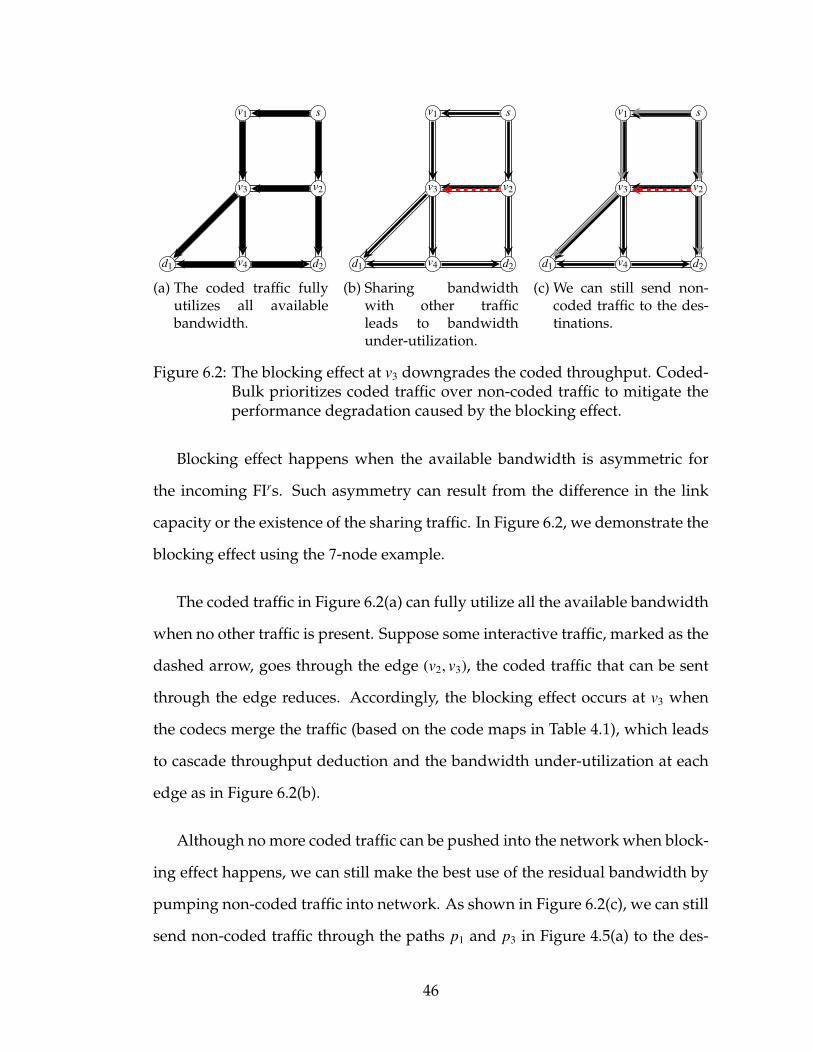
sv1
v2v3
v4d1 d2
(a) The coded traffic fullyutilizes all availablebandwidth.
sv1
v2v3
v4d1 d2
(b) Sharing bandwidthwith other trafficleads to bandwidthunder-utilization.
sv1
v2v3
v4d1 d2
(c) We can still send non-coded traffic to the des-tinations.
Figure 6.2: The blocking effect at v3 downgrades the coded throughput. Coded-Bulk prioritizes coded traffic over non-coded traffic to mitigate theperformance degradation caused by the blocking effect.
Blocking effect happens when the available bandwidth is asymmetric for
the incoming FIrs. Such asymmetry can result from the difference in the link
capacity or the existence of the sharing traffic. In Figure 6.2, we demonstrate the
blocking effect using the 7-node example.
The coded traffic in Figure 6.2(a) can fully utilize all the available bandwidth
when no other traffic is present. Suppose some interactive traffic, marked as the
dashed arrow, goes through the edge (v2, v3), the coded traffic that can be sent
through the edge reduces. Accordingly, the blocking effect occurs at v3 when
the codecs merge the traffic (based on the code maps in Table 4.1), which leads
to cascade throughput deduction and the bandwidth under-utilization at each
edge as in Figure 6.2(b).
Although no more coded traffic can be pushed into the network when block-
ing effect happens, we can still make the best use of the residual bandwidth by
pumping non-coded traffic into network. As shown in Figure 6.2(c), we can still
send non-coded traffic through the paths p1 and p3 in Figure 4.5(a) to the des-
46

tinations. CodedBulk adopts a prioritization approach to prefer sending coded
traffic over non-coded traffic. As such, CodedBulk codes as much traffic as pos-
sible, while filling the unused bandwidth under the blocking effect by the non-
coded traffic.
6.2 Codec Efficiency
At each node, the same coding function can be performed using different com-
binations of codecs. These combinations may be equivalent in theory, while the
efficiency can differ in practice due to asymmetric output bandwidth and net-
work asynchrony. In this subsection, we illustrate two such situations and our
codec assignment techniques to improve the coding efficiency.
6.2.1 Code Map Decoupling
A multi-row code map describes a codec that outputs to several FIts at the same
time. It works fine when none of the FIts encounters congestion. Once one of the
FIts congests, the codec gets stuck although other FIts might still have enough
bandwidth.
One way to deal with the issue is to divide the codec to a set of codecs,
each of which outputs to one FIt only. It can be done by decoupling the multi-
row code matrix into several code maps consisting of single-row matrices. For
47

instance, a code map
mapping: (p1, p2)→ (p1, p2),
code matrix:
1 2
2 1
can be decoupled into two code maps
mapping: (p1, p2)→ (p1),and
(p1, p2)→ (p2),
code matrix:[
1 2
],
[2 1
].
Such decoupling not only avoids the asymmetric output bandwidth issues
but also allows parallel computation.
6.2.2 Redundant Dependency Reduction
To merge several data streams, a codec waits for the receipt of all streamed input
symbols before merging. Since the network is asynchronous, the arrival of the
input symbols varies in time, which degrades the coding efficiency.
In some cases, the efficiency degradation can be mitigated by expecting
fewer input streams. One such cases is when redundancy exists in the code
map. More specifically, the column dimension of a single-row code matrix can
be reduced without changing the output of the corresponding code map if some
zero entries exist. For instance, the code map
mapping: (p1, p2, p3)→ (p1),
code matrix:[
1 0 2
]
48
is equivalent to
mapping: (p1, p3)→ (p1),
code matrix:[
1 2
].
Eliminating the zero entries reduces the number of input data streams the
codec needs to wait, which mitigates the impact of network asynchrony.
6.3 Coding Performance
To achieve high coding throughput, the proxy should perform the computation
efficiently. We introduce the following performance improvement techniques to
accelerate coding process.
6.3.1 Simple Forwarding
Coding is in general an expensive operation as it involves per-symbol arithmetic
operations. A simple idea to improve the coding performance is then to avoid
as many arithmetic operations as possible. In fact, there exists a special case in
which coding can be performed without any arithmetic operation: forwarding.
As shown in Example 4.5.1, a forwarding code map consists of an identity
coding matrix. The codec can perform coding by simply bypassing the data
streams from the FIrs to the corresponding FIts. In practice, such bypassing can
be done much more efficiently than the per-symbol identity multiplication. In
CodedBulk, forwarding involves only passing the memory pointers.
49

6.3.2 Batch Processing
With code maps, coding the symbols of the incoming data streams is a simple
code matrix multiplication. Such operation can be done when the input symbols
are in place. Since the incoming data streams are asynchronous, it is possible
that some input symbols of a codec are received earlier than the others, and the
codec will need to wait until all the symbols arrive.
Due to the asynchronous nature of the incoming data streams, a codec per-
forming per-symbol coding is forced to switch between the waiting phase and
the coding phase, which is highly inefficient as several function calls may be
involved. A better way to handle the asynchrony is to perform batch coding,
i.e., collecting more symbols and coding them together.
We design tasks for this purpose. Each task waits for a certain block of sym-
bols. Once the blocks are received from all input streams, the task will be pro-
cessed.
To denote the block of symbols, we receive and save data streams in blocks
and mark each block a serial number. As a task collects the inputs with, and
marks the outputs by, the same serial number, we can also refer to a task by its
codec and the serial number of the blocks it waits for.
As an example, consider a codec taking three data streams corresponding to
FI p1, p2, and p3 as the inputs in Figure 6.3. Blocks are created by packing every
10 received symbols (shaded symbols) and we assign each block a serial number
in order. Whenever a new serial number is assigned, we create a corresponding
task. In the example, three tasks are created, and task 1 has collected all the
blocks to be coded.
50

1 2 3serialnumber
p1
p2
p3
Figure 6.3: Three tasks in a codec, represented by the dotted rectangles, take p1,p2, and p3 as the inputs. Each small rectangle represents a symbol.In this example, 10 symbols form a block (shaded symbols), and task1 is ready to be coded.
A task that has collected all blocks is called a ready task and moved to a ready
task queue for coding. The processor will pull tasks from the ready task queue
and generate the outputs accordingly. Instead of pulling one task at a time, the
processor will pull a batch of them whenever it is possible. Such batch pro-
cessing mitigates the contention of accessing the ready task queue where ready
tasks are enqueued and the processor dequeues tasks.
6.3.3 Parallel Computing and In-order Delivery
Parallel computing is a common technique to boost the throughput of a system.
We illustrate below the task-level parallelism in CodedBulk, while hardware-
aid symbol-level parallelism is also possible as stated later.
In CodedBulk, we implement a thread pool that maintains a set of worker
threads. Each worker thread pulls and codes a batch of tasks from the ready
task queue. The architecture is shown in Figure 6.4.
51

TaskTaskTaskTaskTask Ready Task Queue
Worker Threads
Figure 6.4: A thread pool consisting of 6 worker threads performs coding. Eachfilled circle is a running thread, while an empty circle represents anidle thread. Each idle thread pulls a batch of tasks from the readytask queue and starts coding.
It is noticeable that coding a task can be accelerated by hardware. Essentially,
a task is a collection of several per-symbol arithmetic operations. With the aid
of hardware, these operation can be parallelized to boost the throughput.
Although parallelism and batch processing boost the coding throughput,
they disturb the order of the data streams. Since the proxies run at the appli-
cation layer, we have to restore the order before releasing the disturbed output
data stream. Using the serial numbers, we sort the blocks of output symbols to
restore in-order delivery.
6.4 Memory Management
We adopt the store-and-forward model to merge the incoming data streams,
which requires memories for storing the incoming data. Although the alloca-
tion of the memories can be handled by the underlying operating system, we
manually acquire, manage, and release the memory to improve the coding per-
formance. The advantage is significant: as shown in Figure 6.5, manual memory
management leads to around twice the throughput than relying on the operat-
ing system when we increase the number of worker threads. We describe below
52

1 2 4 6 8 10 12 14 160
5
10
15
20
25
30
Number of Worker Threads
Cod
ing
Thr
ough
put
(Gbp
s)
Operating SystemManual
Figure 6.5: The comparison of the coding throughput under operating systemand manual memory management. On a 16-core server, increas-ing the number of worker threads gives nearly linear throughputgain when managing memory manually. Operating system, how-ever, cannot fully enjoy the additional computation resources.
our memory management techniques.
6.4.1 Local Memory Allocation
The reason that the operating system fails to achieve high coding throughput
in Figure 6.5 is the frequent memory allocation/deallocation. Such memory
acquisition operations are time consuming and eventually block the compu-
tation when storing the coded output symbols. To prevent doing so, we ask
for a sufficiently large chunk of memory from the operating system upon the
establishment of an FIr and the creation of a worker thread. We then locally
store the incoming data streams at the receiving FIr and the outgoing coded
symbols at the producing worker thread. With an appropriate flagging system
over the original memory chunk, we achieve high performance memory alloca-
tion/deallocation with flags.
53
6.4.2 Notifier and Memory Deallocation
As demonstrated in Table 4.1 and Section 6.2.1, an input data stream may be
merged by the codecs to produce different output data streams. Since each FIt
may stream in distinct data rate and we perform the input rate control by buffer
limitation as stated in Section 6.1.1, we should release a stored input symbol
after all its corresponding output symbols are generated and sent. To do so, we
maintain a counter for each input block and introduce a notifier for each task.
When a serial number is assigned to an input block, its counter is set to keep
track of the total number of tasks that depend on the input block. Meanwhile,
each notifier at a task maintains a counter that tracks the number of unsent out-
puts coded from the task. While all the outputs are sent, the notifier deallocates
the memory of the task and decrements the corresponding input block counters.
Similarly, when the input block counter returns to zero, the memory of the input
block is released.
Together, the input block counters and the notifiers guarantee the memory
deallocation of an input block after all dependent output symbols are sent.
54
CHAPTER 7
EVALUATION
In this chapter, we evaluate the performance of CodedBulk through exten-
sive experiments. The chapter starts with our experimental setup and perfor-
mance metric in Section 7.1. We first showcase the performance of Coded-
Bulk via inter-datacenter WAN experiments in Section 7.2. In comparison with
the inter-datacenter WAN experiments that run in the wild, we conduct ex-
periments over our fully controlled testbed in Section 7.3. Finally, Section 7.4
demonstrates the scalability of CodedBulk by software-based and hardware-
based microbenchmarks.
7.1 Setup
We elaborate our experimental setup below. Starting with the evaluated scenar-
ios and the performance metrics, we then describe the network settings and the
traffic workloads behind the scenes.
Evaluated Scenarios We consider three bulk transfer scenarios for compari-
son: unipath multicast, multipath multicast, and CodedBulk. These three sce-
narios are different in the way the bulk traffic is sent. In the unipath multicast
scenario, the bulk traffic is sent from the source to each destination using a single
chosen multicast path set. For evaluation, we consider the path set obtained by
shortest paths from source to each destination. The second scenario is when the
network is allowed to send bulk traffic via all available multicast path sets, but
not employing network coding. We employ TCP fair sharing for this scenario
55

to distribute bandwidth among various multicast path sets. The CodedBulk
scenario is our network coded bulk transfer design.
Besides the three bulk transfer scenarios, we also calculate the ideal through-
put for the controlled testbed. The ideal scenario gives the ideal CodedBulk
steady state performance assuming that hop-by-hop TCPs acquire their fair
sharing bandwidth. Under the ideal setting, the header overhead is considered
(40 bytes per 1500 byte packet) while the transient behaviors, such as additive-
increase-multiplicative-decrease and delay, are ignored.
Performance Metric The key performance metric used to adjudge Coded-
Bulk’s benefits is the normalized aggregate throughput (NAT). NAT is calculated
by normalizing the aggregate throughput by the link capacity. We obtain the
aggregate throughput of both bulk and interactive traffic by aggregating the
throughput of the corresponding transfers. The throughput of a transfer is the
average of the measured throughput, in data rate, at each destination. For ex-
ample, the throughput of a unicast transfer is simply the receiving data rate at
its destination, while the throughput of a multicast transfer with two destina-
tions is the summation of the receiving data rates at both destinations divided
by two.
Network Settings Our experiments are conducted based on three network
topologies: the 7-node example (Figure 3.2), B4 (Figure 3.1), and Internet2 (Fig-
ure 7.1), where Internet2 [47] and B4 are already employed WAN topologies,
and the 7-node example is a subset of B4.
We establish the topologies under two different experiment environments:
56

Figure 7.1: The topology of Internet2 network, a high-speed wide-area networkestablished for research and education.
inter-datacenter WAN and controlled testbed. The inter-datacenter WAN en-
vironment incorporates real world impacts on the performance of CodedBulk
such as cross-continental propagation delay and varying link bandwidth, while
the controlled testbed does not reflect those factors.
Under the inter-datacenter WAN environment, we replicate B4 and Internet2
topologies on Amazon EC2 by launching geographically distributed server in-
stances among various cluster regions. The locations of the servers are selected
to match the target topology as closely as possible. Each link within the target
topology is emulated by a pair of network interface cards (NICs), whose avail-
able bandwidth is throttled by the link capacity. Accordingly, the traffic going
through a link is sent between its corresponding pair of NICs and routed by
underlying routing mechanisms.
On the other hand, we establish our controlled testbed on a simple star-
shaped network with an OpenFlow switch at the hub. The testbed emulates
a target topology by representing each node in the topology by a server at the
57

leaves. A link between a pair of data centers is emulated by a fixed path through
the hub provided by the network layer between the corresponding servers.
Again, we throttle the bandwidth of the path to provide the designated link
capacity.
Workloads The network is loaded with randomly generated low-priority bulk
and high-priority interactive traffic. Each bulk transfer is a multicast session
from a source to several chosen destinations; while each interactive transfer is a
unicast session between a source-destination pair. All the traffic source pushes
data into the network whenever the available bandwidth allows. A bulk source
has infinite amount of data to send. On contrary, an interactive source dissemi-
nates time-dependent workload.
We generate traffic as follows. A number of nodes are randomly selected as
the bulk traffic sources and each bulk session is associated with a number of
random destinations. On the other hand, interactive traffic is generated for spe-
cific network load levels (mainly around 5 to 20% of network capacity) and the
loading level 0% refers to the case without interactive traffic. Given a load level,
we generate the data transferred across the network by constructing a series
of randomly sampled source, destination, arrival time, and data size. Among
the generated data transfers, we bundle those with the same source/destination
pair as one interactive transfer for the purpose of congestion control.
In the following experiments, we impose a baseline case consisting of 6 bulk
transfers multicasting to 4 destinations each. Without further specification, no
interactive traffic is considered in the baseline case.
58

7.2 Inter-Datacenter WAN Experiments
We first demonstrate the effectiveness of CodedBulk under the inter-datacetner
WAN environment. Figure 7.2(a) and Figure 7.2(b) show the NAT of bulk and
interactive traffic for the three aforementioned scenarios – unipath, multipath,
and coded multicast (CodedBulk) – under B4 and Internet2 topologies.
As shown in the figures, none of the scenarios changes the interactive traffic
throughput since it is assigned the highest priority. In contrast, CodedBulk in-
creases the bulk throughput over the unipath multicast by around 2.6 times for
B4 and 1.9 times for Internet2. Multicasting through multiple path sets grants
more throughput improvement over unipath mutlicasting on B4 comparing to
Internet2. The reason is that B4 has higher path diversity, i.e., it is less likely
to have overlapped paths. As a result, load balancing among multiple path
sets helps. On the other hand, multipath also introduces connection overhead.
When the load balancing gain is not enough to compensate the connection over-
head, the throughput performance can degrade as we see in Figure 7.2(b). In
both figures, increasing the loading level of interactive traffic reduces the lower
priority bulk traffic, but the improvements of CodedBulk over other two sce-
narios remain almost constant independent of interactive traffic load.
7.3 Controlled Testbed Experiments
We then examine the performance of CodedBulk on our controlled testbed,
which emulates B4 and Internet2 topologies. Figure 7.3 shows NAT for bulk
and interactive traffic for the baseline workload with varying interactive traffic
59

Unipath Multicast Multipath Multicast CodedBulk Interactive
0 0.05 0.1 0.15 0.20
1
2
3
4
Loading Level
Nor
mal
ized
Agg
rega
teTh
roug
hput
(a) B4
0 0.05 0.1 0.15 0.20
1
2
3
4
Loading Level
Nor
mal
ized
Agg
rega
teTh
roug
hput
(b) Internet2
Figure 7.2: We conduct inter-datacenter WAN experiments on Amazon EC2based on replicated topologies according to the well-known WANsB4 and Internet2. In each experiment, 6 distinct bulk sessions, eachmulticasts to 4 destinations, are scheduled by CodedBulk along withvarious loading levels of high-priority interactive traffic. Under bothB4 and Internet2 topologies, the results show that CodedBulk im-proves the bulk throughput by 1.5 to 3 times. The relative improve-ment stays nearly the same when the interactive traffic grabs morebandwidth from the bulk traffic under higher loading levels.
60

Unipath Multicast Multipath Multicast CodedBulk Interactive
0 0.05 0.1 0.15 0.20
1
2
3
4
5
Loading Level
Nor
mal
ized
Agg
rega
teT
hrou
ghpu
t
(a) B4
0 0.05 0.1 0.15 0.20
1
2
3
4
Loading Level
Nor
mal
ized
Agg
rega
teTh
roug
hput
(b) Internet2
Figure 7.3: Using our controlled testbed, we emulate B4 and Internet2 topolo-gies to compare the performance of CodedBulk under the baselinescenario (6 bulk source, each has 4 destinations) with different inter-active traffic loading levels. The trend of the results match the WANexperiments’, while the performance gain is higher.
61

load. As expected, Figure 7.3(a) and 7.3(b) both show similar trends in perfor-
mance gains as in Figure 7.2(a) and 7.2(b) respectively. The absolute value of
NAT is higher in the controlled testbed, since the RTT in the testbed is shorter
comparing to WAN and there is no other co-existing traffic that might interfere
the performance.
We also run several experiments to showcase the effect of varying number
of bulk transfers and number of destinations per transfer on the CodedBulk
performance benefits.
Varying Number of Bulk Transfers Figure 7.4(a) and 7.4(b) shows Coded-
Bulk performance gains for varying number of concurrent bulk transfers. Each
transfer has 4 randomly chosen destinations. The NAT increases when more
concurrent bulk sessions exist and it saturates in the meantime due to the fixed
available link capacity. Although the blocking effect among bulk sessions causes
the relative throughput gain decreases from around 2 to 4 times, the gain is still
significant. Also, the average of the ideal throughput shows that the CodedBulk
achieves the throughput close to the ideal.
Varying Number of Destinations per Transfer Figure 7.5(a) and 7.5(b) show-
cases NAT for the case with 6 concurrent bulk transfers but varying number
of destinations per transfer. Increasing the number of destinations for a fixed
number of bulk transfer would decrease the aggregate throughput as more net-
work resources would be spent on each transfer. However, more destinations
also create more room for network coding to improve the performance. In the-
ory, a well-coded bulk transfer will be able to achieve min-cut throughput per
destination. Although bandwidth sharing among different multicast session
62

Unipath Multicast Multipath Multicast CodedBulk Ideal
1 2 3 4 5 6 7 8 9 10 11 12 130
1
2
3
4
Number of Multicast Sources
Nor
mal
ized
Agg
rega
teTh
roug
hput
(a) B4
1 2 3 4 5 6 7 8 90
1
2
3
Number of Multicast Sources
Nor
mal
ized
Agg
rega
teTh
roug
hput
(b) Internet2
Figure 7.4: In the controlled testbed emulating B4 and Internet2, we randomlygenerate different number of sources multicasting to 4 random desti-nations each. The aggregate throughput increases as more bulk traf-fic is created. The average throughput of the ideal scenarios is alsoplotted, which suggests that the results are close to the ideal scenar-ios.
63

Unipath Multicast Multipath Multicast CodedBulk Ideal
2 3 4 5 6 7 8 9 10 11 120
1
2
3
4
5
Number of Destinations
Nor
mal
ized
Agg
rega
teTh
roug
hput
(a) B4
2 3 4 5 6 7 80
1
2
3
4
Number of Destinations
Nor
mal
ized
Agg
rega
teTh
roug
hput
(b) Internet2
Figure 7.5: 6 concurrent bulk transfers multicast to various number of desti-nations in the controlled testbed emulating B4 and Internet2. Aseach bulk session sends to more destinations, the bandwidth sharingleads to throughput degradation. However, CodedBulk improvesthe relative gain in the presence of more destinations. The results areclose to the ideal throughput.
64

induces the blocking effect that diminishes such coding benefit, we can still ob-
serve the improvement of the relative performance gain when more destinations
are added. Similarly, our results are close to the ideal.
7.4 Microbenchmarks
We also conduct several experiments to determine the scalaibility of CodedBulk
through software and hardware microbenchmarks.
7.4.1 Software implementation
Unipath Multicast Multipath Multicast CodedBulk Ideal
50 100 150 200 250 300 350 400 450 5000
100
200
300
400
500
600
700
800
Link Bandwidth (Mbps)
Agg
rega
teTh
roug
hput
(Mbp
s)
Figure 7.6: We evaluate the scalability of the system by deploying the 7-node ex-ample on our controlled testbed. Under varying access link capacity,the performance of CodedBulk is sustained when enough resourcesare available up to around 450 Mbps. Before then, CodedBulk canachieve the throughput almost identical to the ideal throughput.
Since CodedBulk requires computation at each node for performing cod-
65

Element Used Available Utilization
LUT 736 433200 0.17%BRAM 16.5 1470 1.12%
Table 7.1: Resource utilization of a 128-bit codec using Xilinx Virtex-7XC7VX690T FPGA. Our implementation can provide up to 31.25Gbps throughput with 0.17% LUTs and1.12% BRAMs. No DSP isneeded in our design.
ing/decoding operations, for a fixed compute capacity, the performance gains
should start to debilitate after increasing link bandwidths at a certain thresh-
old amount because of scarce computation power, memory, or link bandwidth.
When the resources are sufficient, we would expect the throughput gain pro-
portional to the bandwidth increase. We try to obtain that threshold link capac-
ity for the 7-node topology using 4-core servers with modest 4 GB RAM and a
NIC of 1 Gbps access link capacity emulating the incoming/outgoing network
interfaces. The results are shown in Figure 7.6, which suggest the threshold
link capacity is around 450 Mbps. Before reaching 450 Mbps, the aggregate
throughput scales linearly as expected, and it is almost identical to the ideal
throughput. The reason of the performance degradation at 450 Mbps is due
to the lack of emulated link bandwidth and computational resources. Given
the linear growth under sufficient resources, the system would keep scaling lin-
early and the threshold link capacity would be pushed upward when sufficient
resources are supplied.
7.4.2 Hardware implementation
Inter-DC links are usually of several hundred Gbps bandwidths, and pure soft-
ware computation can be the bottleneck to support such a high throughput. To
66

tackle this issue, we leverage hardware to parallelize the computation and pro-
vide line-rate coding.
We synthesize a simple 128-bit codec that can process 16 symbols (bytes)
within one clock cycle on Xilinx Virtex-7 XC7VX690T FPGA, which offers 100,
200, and 250 MHz fabric clocks. With respect to the clocks, our FPGA-based
codec can achieve throughput 12.5, 25, and 31.25 Gbps. Without needing any
DSP, our hardware design consumes only 0.17% LUTs and 1.12% BRAMs as
shown in Table 7.1, and hence it can be scaled easily to provide even higher
throughput.
67

CHAPTER 8
SUMMARY AND FUTURE WORK
This chapter summarizes the achievements of CodedBulk and portrays the pos-
sible next steps and the future extensions of the work.
8.1 Current Achievement
In this dissertation, we design and implement CodedBulk to improve the
throughput of inter-datacenter bulk transfers using network coding. Our ap-
proach is possible thanks to the new properties exhibited by the inter-datacenter
context, including delay-tolerant bulk transfers, small-scale programmable net-
works, and resource-rich intermediate nodes. We leverage those design op-
portunities to overcome the implementation challenges. Through the inter-
datacenter experiments, the resulting CodedBulk demonstrates a twice to four
times throughput improvement of the inter-datacenter bulk traffic.
8.2 Possible Improvement
Close-loop control over coding schemes CodedBulk operates under an open-
loop control: Given the multicast sessions reported from the multicast agent
senders, the controller computes and deploys the coding scheme to the network
based on its current global view. However, the varying interactive traffic leads
to different topology for the bulk traffic, which can impact the effectiveness of
the deployed coding schemes. This issue can be alleviated if the centralized
68

controller reevaluates the installed coding scheme once a while based on the
updated global view. That gives a feedback-style close-loop control.
Localized coding The generation of coding schemes depends on a global view
from one centralized controller, which prevents a full distributed computation
and exposes the system under a single point of failure. By extending the code
generation algorithm to compute based on only the localized information, the
information that is collected from only a part of the network, we would be able
to distribute the computation to several controllers and improve the robustness
of the system.
8.3 Future Directions
Time-dependent coding Although our cycle-aware coding algorithm can deal
with cyclic network topology, our approach does not guarantee the min-cut
throughput per destination even in theory. One way to achieve the optimal
coding throughput in a cyclic network is through the time-dependent convo-
lutional network coding. Convolutional network coding requires coding the
symbols sent out from the source at different time. To support convolutional
network coding, we will need to extend our code map and algorithm designs.
Learning-based coding Recently, machine learning has demonstrated its great
potential in making predictions and dealing with non-linear optimization. As
such, an online feedback system can adopt machine learning as its controller
and improve the dynamic performance. Is might be possible to use machine
69

learning to monitor the incoming interactive traffic and update the codecs on
the fly.
70

BIBLIOGRAPHY
[1] Mohammad Al-Fares, Alexander Loukissas, and Amin Vahdat. A scal-
able, commodity data center network architecture. ACM SIGCOMM CCR,
38(4):63–74, 2008.
[2] Arjun Roy, Hongyi Zeng, Jasmeet Bagga, George Porter, and Alex C Sno-
eren. Inside the social network’s (datacenter) network. ACM SIGCOMM
CCR, 45(4):123–137, 2015.
[3] Arjun Singh, Joon Ong, Amit Agarwal, Glen Anderson, Ashby Armistead,
Roy Bannon, Seb Boving, Gaurav Desai, Bob Felderman, Paulie Germano,
et al. Jupiter rising: A decade of Clos topologies and centralized control in
Google’s datacenter network. ACM SIGCOMM CCR, 45(4):183–197, 2015.
[4] Yu Wu, Zhizhong Zhang, Chuan Wu, Chuanxiong Guo, Zongpeng Li, and
Francis CM Lau. Orchestrating bulk data transfers across geo-distributed
datacenters. IEEE Trans. Cloud Comput., 5(1):112–125, 2017.
[5] Chunqiang Tang, Thawan Kooburat, Pradeep Venkatachalam, Akshay
Chander, Zhe Wen, Aravind Narayanan, Patrick Dowell, and Robert Karl.
Holistic configuration management at Facebook. In Proc. ACM SOSP,
pages 328–343. ACM, 2015.
[6] Sushant Jain, Alok Kumar, Subhasree Mandal, Joon Ong, Leon Poutievski,
Arjun Singh, Subbaiah Venkata, Jim Wanderer, Junlan Zhou, Min Zhu,
Jonathan Zolla, Urs Holzle, Stephen Stuart, and Amin Vahdat. B4: Expe-
rience with a globally-deployed software defined WAN. ACM SIGCOMM
CCR, 43(4):3–14, 2013.
71

[7] Chi-Yao Hong, Srikanth Kandula, Ratul Mahajan, Ming Zhang, Vijay Gill,
Mohan Nanduri, and Roger Wattenhofer. Achieving high utilization with
software-driven WAN. ACM SIGCOMM CCR, 43(4):15–26, 2013.
[8] Andrew Hiles. Five nines: Chasing the dream? http://www.
continuitycentral.com/feature0267.htm.
[9] Yingying Chen, Sourabh Jain, Vijay Kumar Adhikari, Zhi-Li Zhang, and
Kuai Xu. A first look at inter-data center traffic characteristics via Yahoo!
datasets. In Proc. IEEE INFOCOM, pages 1620–1628. IEEE, 2011.
[10] Nikolaos Laoutaris, Michael Sirivianos, Xiaoyuan Yang, and Pablo Ro-
driguez. Inter-datacenter bulk transfers with NetStitcher. ACM SIGCOMM
CCR, 41(4):74–85, 2011.
[11] Rudolf Ahlswede, Ning Cai, Shuo-Yen Robert Li, and Raymond W Yeung.
Network information flow. IEEE Trans. Inf. Theory, 46(4):1204–1216, 2000.
[12] Shuo-Yen Robert Li, Raymond W Yeung, and Ning Cai. Linear network
coding. IEEE Trans. Inf. Theory, 49(2):371–381, 2003.
[13] Sharad Agarwal, John Dunagan, Navendu Jain, Stefan Saroiu, Alec Wol-
man, and Harbinder Bhogan. Volley: Automated data placement for geo-
distributed cloud services. In Proc. USENIX NSDI, pages 2–2. USENIX As-
sociation, 2010.
[14] James C Corbett, Jeffrey Dean, Michael Epstein, Andrew Fikes, Christopher
Frost, Jeffrey John Furman, Sanjay Ghemawat, Andrey Gubarev, Christo-
pher Heiser, Peter Hochschild, et al. Spanner: Google’s globally distributed
database. ACM TOCS, 31(3):8, 2013.
72
[15] Ashish Gupta, Fan Yang, Jason Govig, Adam Kirsch, Kelvin Chan, Kevin
Lai, Shuo Wu, Sandeep Govind Dhoot, Abhilash Rajesh Kumar, Ankur
Agiwal, Sanjay Bansali, Mingsheng Hong, Jamie Cameron, Masood Sid-
diqi, David Jones, Jeff Shute, Andrey Gubarev, Shivakumar Venkataraman,
and Divyakant Agrawal. Mesa: Geo-replicated, near real-time, scalable
data warehousing. Proc. VLDB Endowment, 7(12):1259–1270, 2014.
[16] Zhe Wu, Michael Butkiewicz, Dorian Perkins, Ethan Katz-Bassett, and Har-
sha V Madhyastha. SPANStore: Cost-effective geo-replicated storage span-
ning multiple cloud services. In Proc. ACM SOSP, pages 292–308. ACM,
2013.
[17] Ariel Rabkin, Matvey Arye, Siddhartha Sen, Vivek S Pai, and Michael J
Freedman. Aggregation and degradation in JetStream: Streaming analytics
in the wide area. In Proc. USENIX NSDI, volume 14, pages 275–288, 2014.
[18] Qifan Pu, Ganesh Ananthanarayanan, Peter Bodik, Srikanth Kandula,
Aditya Akella, Paramvir Bahl, and Ion Stoica. Low latency geo-distributed
data analytics. ACM SIGCOMM CCR, 45(4):421–434, 2015.
[19] Ashish Vulimiri, Carlo Curino, Philip Brighten Godfrey, Thomas Jungblut,
Jitu Padhye, and George Varghese. Global analytics in the face of band-
width and regulatory constraints. In Proc. USENIX NSDI, volume 7, pages
7–8, 2015.
[20] Nikolaos Laoutaris, Georgios Smaragdakis, Rade Stanojevic, Pablo Ro-
driguez, and Ravi Sundaram. Delay tolerant bulk data transfers on the
Internet. IEEE/ACM Trans. Netw., 21(6):1852–1865, 2013.
[21] Xin Jin, Yiran Li, Da Wei, Siming Li, Jie Gao, Lei Xu, Guangzhi Li, Wei
73

Xu, and Jennifer Rexford. Optimizing bulk transfers with software-defined
optical WAN. In Proc. ACM SIGCOMM, pages 87–100. ACM, 2016.
[22] Srikanth Kandula, Ishai Menache, Roy Schwartz, and Spandana Raj Bab-
bula. Calendaring for wide area networks. ACM SIGCOMM CCR,
44(4):515–526, 2014.
[23] Hong Zhang, Kai Chen, Wei Bai, Dongsu Han, Chen Tian, Hao Wang,
Haibing Guan, and Ming Zhang. Guaranteeing deadlines for inter-data
center transfers. IEEE/ACM Trans. Netw., 25(1):579–595, 2017.
[24] John C Lin and Sanjoy Paul. RMTP: A reliable multicast transport protocol.
In Proc. IEEE INFOCOM, volume 3, pages 1414–1424. IEEE, 1996.
[25] Miguel Castro, Peter Druschel, Anne-Marie Kermarrec, Animesh Nandi,
Antony Rowstron, and Atul Singh. SplitStream: high-bandwidth multicast
in cooperative environments. In ACM SIGOPS Operating Systems Review,
volume 37, pages 298–313. ACM, 2003.
[26] Aakash Iyer, Praveen Kumar, and Vijay Mann. Avalanche: Data center
multicast using software defined networking. In IEEE COMSNETS, pages
1–8. IEEE, 2014.
[27] John Jannotti, David K Gifford, Kirk L Johnson, M Frans Kaashoek, et al.
Overcast: Reliable multicasting with an overlay network. In Proc. USENIX
OSDI, page 14. USENIX Association, 2000.
[28] Mohammad Noormohammadpour, Cauligi S Raghavendra, Srikanth Kan-
dula, and Sriram Rao. QuickCast: Fast and efficient inter-datacenter trans-
fers using forwarding tree cohorts. In Proc. IEEE INFOCOM. IEEE, 2018.
74
[29] Suman Banerjee, Bobby Bhattacharjee, and Christopher Kommareddy.
Scalable application layer multicast. ACM SIGCOMM CCR, 32(4):205–217,
2002.
[30] Mojtaba Hosseini, Dewan Tanvir Ahmed, Shervin Shirmohammadi, and
Nicolas D Georganas. A survey of application-layer multicast protocols.
IEEE Commun. Surveys & Tutorials, 9(1-4):58–74, 2007.
[31] Ralf Koetter and Muriel Medard. An algebraic approach to network cod-
ing. IEEE/ACM Trans. Netw., 11(5):782–795, 2003.
[32] Tracey Ho, Muriel Medard, Ralf Koetter, David R Karger, Michelle Effros,
Jun Shi, and Ben Leong. A random linear network coding approach to
multicast. IEEE Trans. Inf. Theory, 52(10):4413–4430, 2006.
[33] Sidharth Jaggi, Peter Sanders, Philip A Chou, Michelle Effros, Sebastian
Egner, Kamal Jain, and Ludo MGM Tolhuizen. Polynomial time algo-
rithms for multicast network code construction. IEEE Trans. Inf. Theory,
51(6):1973–1982, 2005.
[34] Philip A Chou, Yunnan Wu, and Kamal Jain. Practical network coding. In
Proc. Allerton, volume 41, pages 40–49, 2003.
[35] Sachin Katti, Hariharan Rahul, Wenjun Hu, Dina Katabi, Muriel Medard,
and Jon Crowcroft. XORs in the air: Practical wireless network coding.
ACM SIGCOMM CCR, 36(4):243–254, 2006.
[36] Sachin Katti, Shyamnath Gollakota, and Dina Katabi. Embracing wireless
interference: Analog network coding. ACM SIGCOMM CCR, 37(4):397–
408, 2007.
75

[37] Jonas Hansen, Daniel E Lucani, Jeppe Krigslund, Muriel Medard, and
Frank HP Fitzek. Network coded software defined networking: Enabling
5G transmission and storage networks. IEEE Commun. Mag., 53(9):100–107,
2015.
[38] Jay Kumar Sundararajan, Devavrat Shah, Muriel Medard, Michael Mitzen-
macher, and Joao Barros. Network coding meets TCP. In Proc. IEEE INFO-
COM, pages 280–288. IEEE, 2009.
[39] MinJi Kim, Jason Cloud, Ali ParandehGheibi, Leonardo Urbina, Kerim
Fouli, Douglas Leith, and Muriel Medard. Network coded TCP (CTCP).
arXiv preprint arXiv:1212.2291, 2012.
[40] Christos Gkantsidis and Pablo Rodriguez Rodriguez. Network coding for
large scale content distribution. In Proc. IEEE INFOCOM, volume 4, pages
2235–2245. IEEE, 2005.
[41] Alexandros G Dimakis, P Brighten Godfrey, Yunnan Wu, Martin J Wain-
wright, and Kannan Ramchandran. Network coding for distributed stor-
age systems. IEEE Trans. Inf. Theory, 56(9):4539–4551, 2010.
[42] Alexandros G Dimakis, Kannan Ramchandran, Yunnan Wu, and Changho
Suh. A survey on network codes for distributed storage. Proc. IEEE,
99(3):476–489, 2011.
[43] Joan Daemen and Vincent Rijmen. The Design of Rijndael: AES – the Ad-
vanced Encryption Standard. Springer Science & Business Media, 2013.
[44] Costin Raiciu, Sebastien Barre, Christopher Pluntke, Adam Greenhalgh,
Damon Wischik, and Mark Handley. Improving datacenter performance
76

and robustness with multipath TCP. ACM SIGCOMM CCR, 41(4):266–277,
2011.
[45] Swastik Kopparty, Srikanth V Krishnamurthy, Michalis Faloutsos, and
Satish K Tripathi. Split TCP for mobile ad hoc networks. In Proc. IEEE
GLOBECOM, volume 1, pages 138–142. IEEE, 2002.
[46] Elona Erez and Meir Feder. Efficient network code design for cyclic net-
works. IEEE Trans. Inf. Theory, 56(8):3862–3878, 2010.
[47] The Internet2 network.
77