OPTIOMIZATION OF PROCESS PARAMETERS AND STUDY OF WEAR DURING HARD FACING OF MILD STEEL USING TAGUCHI...
10
[Kamboj, 4(3): March, 2015] ISSN: 2277-9655 Scientific Journal Impact Factor: 3.449 (ISRA), Impact Factor: 2.114 http: // www.ijesrt.com © International Journal of Engineering Sciences & Research Technology [652] IJESRT INTERNATIONAL JOURNAL OF ENGINEERING SCIENCES & RESEARCH TECHNOLOGY OPTIOMIZATION OF PROCESS PARAMETERS AND STUDY OF WEAR DURING HARD FACING OF MILD STEEL USING TAGUCHI METHOD Vikas Kamboj*, Mr. Brij Bhushan, Mr. Kuldeep Kumar * M.Tech Research scholar A.P at H.E.C, Jagadhri (Haryana) A.P at M.M.U , mullana, ambala (Haryana) ABSTRACT Hard facing is an important tool in tribology in which a layer of wear resistant material deposited over base metal or substrate to improve surface characteristics. There are numerous processes and consumables available in the market to improve the surface characteristics of components. This technique has potential to deposit hard-faced layer on substrate. The properties usually sought are greater resistance to wear from abrasion, impact, adhesion (metal-to- metal), heat, corrosion or any combination of these factors. Hard facing is applied only to specific areas of metal parts that are exposed to wear. There is often no need to protect the entire surface of a component from wear. Hard facing can be applied selectively and in different thickness to suit the exact requirements of a piece of equipment, thereby proving a most economical way of combating wear Shielded metal arc welding is most commonly used process for hard facing due to its easy availability and versatility of operation. Low carbon steel is selected for the present work as substrate material due to its low cost, easy availability and variety of applications. In the present work a detailed study was done to study the effect of different level of current and different layer of hard facing electrode on mild steel, deposited by SMAW. Minitab software was used to determine the no. experiments to be performed with different factors at different levels. A total of Eight experiments were performed according to the combinations given by the software. test were carried out on the above samples like wear test, bead geometry to record the observations. Optimization of the parameters was done with Taguchi Method and wear rate among the eight sample in study. It was observed that with an increase in number of layer there is the wear resistance is also improved. KEYWORDS: Hard facing, Wear, SMAW INTRODUCTION Welding plays an important role in the development of our society and mankind as a whole. One of the indexes used for measuring the prosperity of a country is the per capita steel consumption. Higher the production of steel, the greater is the role of welding. Welding is a process of permanent joining of two materials through localized coalescence resulting from a suitable combination of temperature, pressure and metallurgical conditions. Depending upon the combination of temperature and pressure from a high temperature with low pressure to a high pressure with low temperature, a wide range of welding processes has been developed. While there are many methods for joining metals, welding is one of the most convenient and rapid methods available. It is a principal means of fabricating and repairing metal parts. The term welding refers to the process of joining metals by heating them to their melting temperature and causing the molten metal to flow together. These range from simple steel brackets to nuclear reactors. Welding, like any skilled trade, is broad in scope and one cannot become a welder simply by reading a book. One need practice and experience as well as patience, however much can be gained through study. Historically the welding was developed in the ancient times and can be traced during the Bronze Age when the lap joints were made by heating and hammering the two metal pieces. During excavation, parts and tools have been found, which were welded by pressure welding during the time as back as 1000 B.C. The earliest known form of welding, called forge welding, dates back to the year 2000 B.C. Forge welding is a primitive process of joining metals by heating and hammering until the metals are fused (mixed) together. Although forge
-
Upload
independent -
Category
Documents
-
view
3 -
download
0
Transcript of OPTIOMIZATION OF PROCESS PARAMETERS AND STUDY OF WEAR DURING HARD FACING OF MILD STEEL USING TAGUCHI...
[Kamboj, 4(3): March, 2015] ISSN: 2277-9655
Scientific Journal Impact Factor: 3.449
(ISRA), Impact Factor: 2.114
http: // www.ijesrt.com © International Journal of Engineering Sciences & Research Technology
[652]
IJESRT INTERNATIONAL JOURNAL OF ENGINEERING SCIENCES & RESEARCH
TECHNOLOGY
OPTIOMIZATION OF PROCESS PARAMETERS AND STUDY OF WEAR DURING
HARD FACING OF MILD STEEL USING TAGUCHI METHOD Vikas Kamboj*, Mr. Brij Bhushan, Mr. Kuldeep Kumar
* M.Tech Research scholar
A.P at H.E.C, Jagadhri (Haryana)
A.P at M.M.U , mullana, ambala (Haryana)
ABSTRACT Hard facing is an important tool in tribology in which a layer of wear resistant material deposited over base metal or
substrate to improve surface characteristics. There are numerous processes and consumables available in the market
to improve the surface characteristics of components. This technique has potential to deposit hard-faced layer on
substrate. The properties usually sought are greater resistance to wear from abrasion, impact, adhesion (metal-to-
metal), heat, corrosion or any combination of these factors. Hard facing is applied only to specific areas of metal parts
that are exposed to wear. There is often no need to protect the entire surface of a component from wear. Hard facing
can be applied selectively and in different thickness to suit the exact requirements of a piece of equipment, thereby
proving a most economical way of combating wear
Shielded metal arc welding is most commonly used process for hard facing due to its easy availability and versatility
of operation. Low carbon steel is selected for the present work as substrate material due to its low cost, easy availability
and variety of applications. In the present work a detailed study was done to study the effect of different level of
current and different layer of hard facing electrode on mild steel, deposited by SMAW.
Minitab software was used to determine the no. experiments to be performed with different factors at different levels.
A total of Eight experiments were performed according to the combinations given by the software. test were carried
out on the above samples like wear test, bead geometry to record the observations. Optimization of the parameters
was done with Taguchi Method and wear rate among the eight sample in study. It was observed that with an increase
in number of layer there is the wear resistance is also improved.
KEYWORDS: Hard facing, Wear, SMAW
INTRODUCTIONWelding plays an important role in the development of
our society and mankind as a whole. One of the
indexes used for measuring the prosperity of a country
is the per capita steel consumption. Higher the
production of steel, the greater is the role of welding.
Welding is a process of permanent joining of two
materials through localized coalescence resulting from
a suitable combination of temperature, pressure and
metallurgical conditions. Depending upon the
combination of temperature and pressure from a high
temperature with low pressure to a high pressure with
low temperature, a wide range of welding processes
has been developed. While there are many methods for
joining metals, welding is one of the most convenient
and rapid methods available. It is a principal means of
fabricating and repairing metal parts. The term
welding refers to the process of joining metals by
heating them to their melting temperature and causing
the molten metal to flow together. These range from
simple steel brackets to nuclear reactors. Welding, like
any skilled trade, is broad in scope and one cannot
become a welder simply by reading a book. One need
practice and experience as well as patience, however
much can be gained through study. Historically the
welding was developed in the ancient times and can be
traced during the Bronze Age when the lap joints were
made by heating and hammering the two metal pieces.
During excavation, parts and tools have been found,
which were welded by pressure welding during the
time as back as 1000 B.C. The earliest known form of
welding, called forge welding, dates back to the year
2000 B.C. Forge welding is a primitive process of
joining metals by heating and hammering until the
metals are fused (mixed) together. Although forge
[Kamboj, 4(3): March, 2015] ISSN: 2277-9655
Scientific Journal Impact Factor: 3.449
(ISRA), Impact Factor: 2.114
http: // www.ijesrt.com © International Journal of Engineering Sciences & Research Technology
[653]
welding still exists, it is mainly limited to the
blacksmith trade. Some of the most recently welding
technologies include: Friction welding, which uses
rotational speed and upset pressure to provide friction
heat, was developed in the Soviet Union. It is a
specialized process and has applications only where a
sufficient volume of similar parts is to be welded
because of the initial expense for equipment and
tooling. This process is called inertia welding. Laser
welding is one of the newest processes.
HARD FACING Hard facing is a process of depositing a layer of
material over base metal or substrate either to improve
surface characteristics like corrosion resistance, wear
resistance etc. or to get required size of dimension. If
a hard wear resistant material is deposited over a soft,
ductile material to improve the wear resistance then
the process is called hard facing. When the layer of
material deposited for corrosion resistance the process
is known as cladding. Sometime worn out parts are
built up to required size so that they can be put back
into service. Hard facing is one of the most useful and
economical ways to improve the performance of
components submitted to severe wear condition. Hard
facing is commonly employed method to improve
surface properties of agriculture tools, components for
mining operation, soil preparation equipment’s and
other. An alloy is homogeneously deposited into the
surface of a soft material (usually low or medium
carbon steels) by welding with the purpose of increase
hardness and wear resistance without significant loss
in ductility and toughness of the substrate. A wide
variety of hard facing alloys is commercially available
for protection against wear. Deposits with a
microstructure composed by disperse carbides in
austenite matrix are extensively used for abrasion
application and are typically classified according to
the expected hardness. Durability and longevity of any
material is priceless for any nation especially
developing countries like India. All types of industrial
set ups irrespective of whether being in manufacturing
or service sector had off late drawn their reputation
from the durability and reliability of their products.
Degradation of material by wear and corrosion cost a
very high loss whether it is of reputation or economic
loss to all the countries. Although considerable
attention has already been paid by the researchers to
develop modern techniques and methods to arrest and
control the problems resulting from wear and
corrosion, still there is a need for further research to
reduce the losses incurred because of them.
It is estimated that more that 30% of wear and
corrosion related cost can be reduced by developing
and using better techniques of controlling wear and
corrosion. These wear and corrosion related problems
can be minimized mainly by two methods.
1. By using high cost wear and corrosion and
corrosion resistant alloys better than the
existing low cost ones.
2. By improving the wear and corrosion
resistance of the existing metals and alloys by
applying certain modifications to the surface
Wear
It is the removal of material from a solid surface as a
result of sliding action. It constitutes the main reason
why the artifacts of society (automobiles, washing
machines, tape recorders, cameras, and clothing)
become useless and have to be replaced. Different
persons and agencies have defined wear in different
ways but all, at the end, mean the same. Few
definitions are given below:-
“Damage or loss of quality by usage” -
Dictionary definition and general concept of
the wear.
The removal of material from the solid
surface as a result of a mechanical action” –
Mr. Ernest Rabinowicz.
“Removal of material from surface in relative
motion by mechanical and/or chemical
process” - Mr. D. Tabor.
“The progressive loss of the substance from
the operating surface of a body, occurring as
a result of a relative motion of surfaces” -
OECD Scientific Committee.
“The destruction of material, produced as a
result of repeated disturbances of friction
bonds” - Mr. Kragelski.
Factors Affecting Wear
The main factors affecting wear are:
1. Design
2. Applied load
3. Contact area and degree of movement
4. Lubrication
5. Environment
6. Material properties (surface finish, hardness
and steel microstructure).
Different Types of Wear
The wear can be categorized into different types based
on the sources/causes of wear mentioned earlier. The

[Kamboj, 4(3): March, 2015] ISSN: 2277-9655
Scientific Journal Impact Factor: 3.449
(ISRA), Impact Factor: 2.114
http: // www.ijesrt.com © International Journal of Engineering Sciences & Research Technology
[654]
wear, encountered in industrial situations, can broadly
be divided into following types and a rough share of
each type of wear as a percentage of all the wears taken
together, is against each type as shown in causes like
vibration, cavitations’ and environmental attack etc.
Table 1.1 Types of Wear
Types of wear Abrasive
wears
Adhesive
wear
Erosive wear Corrosive
wear
Fretting wear Others
Percentage 50% 15% 8% 5% 8% 14%
The action of one material sliding over another with
surface interaction and welding (adhesion) at localized
contact. [2] As we know, strong adhesive force sets up
when the atoms from two materials come into intimate
contact. During sliding, a small patch of the surfaces
comes into intimate contact with a small patch of other
surface and if this bond is strong, this contact is
broken. This breakage is usually not of the interface of
the two patches; however it takes place from within
one of the materials depending upon the bond strength.
This is known as adhesive wear.
Abrasive wear
Abrasive wear occurs when a hard rough surface slides
against a soft surface, digs into it and plows a series of
grooves. The materials, originally in the grooves,
normally come out in the form of loose fragments.
This is known as two bodies wear. Abrasive wear also
occurs when hard abrasive particles are introduced
between two sliding surfaces and these particles
abrade either or both materials. The mechanism is that
an abrasive particle adheres temporarily to one of the
sliding surfaces or, else, gets embedded in it and plows
out grooves in the other surface. This form of abrasive
wear is known as three bodies wear. Two body wear
does not occur much when the hard sliding surfaces
are smooth. Similarly three-body wear does not
normally occur when the particles, introduced in
between the sliding surfaces are small, or they are
softer than sliding materials.
Corrosive wear
Corrosive wear occurs as a result of chemical reaction
on a wearing surface. The most common form of
corrosion is due to a reaction between the metal and
oxygen (oxidation); however, other chemicals may
also contribute. Corrosion products, usually oxide,
have shear strengths different from those of the
wearing surface metals from which they are formed.
The oxides tend to flake away, resulting in the pitting
of wearing surfaces to reduce frictional effects.
Corrosive pitting is especially detrimental to these
bearings. Corrosive wear occurs in situations in which
the environment surrounding a sliding surface is
corrosive and interacts chemically with the sliding
surface. As such, this wear is also known as “chemical
wear”. Corrosive wear differs from corrosion as, in
corrosion, no sliding of surfaces takes place and
formation of reaction films on the surface tends to
slow down the process with increase of thickness of
layer and may avoid further corrosion after some
critical thickness; but it becomes corrosive wear when
sliding of the surfaces occurs and continues as, in that
case, the sliding action continuously wears out the
films of reaction from the surface and fresh corrosive
attack continuous.
Erosive wear
Erosive wear is caused by particles that impinge on a
component surface or edge and remove material from
that surface due to momentum effects. This type of
wear is especially noticed in components with high
velocity flows such as servo and proportional valves.
Particles repeatedly striking the surface may also
cause denting and eventual fatigue of the surface. It is
the damage produced by sharp particles impinging on
an object. For example particles in water erode the
rocks over which a river flows or the erosion of both,
rope and stone pulley when the rope continuously
slides over the pulley.
EXPERIMENTATION This chapter is about the experimental procedure and
other related aspects of the present study. The chapter
deals with the methodology adopted to achieve the
goals or objectives for the present work which
includes the hard facing of mild steel using hard facing
electrode and analysis of result with Taguchi
methodology. After finalization of process parameters
and levels, the complete set of eight trials has been
prepared as per orthogonal array selected from the
Minitab software

[Kamboj, 4(3): March, 2015] ISSN: 2277-9655
Scientific Journal Impact Factor: 3.449
(ISRA), Impact Factor: 2.114
http: // www.ijesrt.com © International Journal of Engineering Sciences & Research Technology
[655]
Base Plate & Electrode Used
According to the AISI standard the grade of Low
carbon Mild steel 1020 is used having dimensions
150x50 x10 (mm3).The chemical compositions are
shown in table 3.1
Table 3.1 Chemical composition of base plate
C Si Mn P S Fe
0.20 0.19 0.52 0.03 0.033 Rest
The electrode used for experimentation is
DUROBUILD-A and DUROBUILD-C. It is an all
position electrode for structural work. Medium
penetration for lower dilution levels with least spatter.
Versatile electrode used for variety of application of
welding. Almost all general purpose welding is done
by shielded metal arc welding using coated electrode.
The coating electrodes consist of core wire with a
covering of coating material.
Table 3.2- Chemical composition of electrodes
DUROBUILD-A composition
C Si Mn cr Mo V Fe
0.50 0.70 0.70 7.00 0.80 0.50 Rest
DUROBUILD-C composition
Conducting Trials Runs
Trail runs were conducted on the base plate according
to different parameters selected randomly from the
orthogonal array. It is also worth mentioning that the
welding conditions such as electrode type, electrode
size, electrode to work angle, baking and hence
moisture content conditions, welding positions and
welding speed etc. were kept constant to the maximum
possibility. In the trial runs it was observed changing
the electrode changes the wear rate . Also same
variation was encountered with changing the number
of welding layers. Number of specimens were
prepared and examined visually and then selective
specimens were selected for further investigations
based upon the visual examination wear test
examinations were conducted over selected
specimens.
Conducting Actual Runs
Beads on mild steel plates have been deposited as per
orthogonal array using hard facing electrode with
dimensions of4mm×450mm. and 5mm×450mm.
DCEN polarity was used to minimize the dilution
which otherwise will decrease the hardness.
Experiments were conducted according to orthogonal
array with different combinations of selected
parameters.
Base Metal Preparation
Low carbon mild steel was used as a base metal. The
surfaces to be joined must be clean to obtain good
C Si Mn cr Fe
0.18 0.42 0.76 2.00 Rest

[Kamboj, 4(3): March, 2015] ISSN: 2277-9655
Scientific Journal Impact Factor: 3.449
(ISRA), Impact Factor: 2.114
http: // www.ijesrt.com © International Journal of Engineering Sciences & Research Technology
[656]
fusion between the filler metal and the base metal. This
means that they must be free of relatively thick oxide,
moisture, greases, oils, paints or any other substance.
Testing
Following tests were conducted on the samples
obtained after experiment
Wear Test
Wear test was done on pin on disc apparatus at MMU
MULLANA. Prior to wear testing, pins with
dimensions of 8mm dia. and 30 mm length were
prepared with CNC Wire Cut available at CITCO
Chandigarh.
CNC wire cut machine
Table 3.3 Wear test data
Applied load 5kg
Speed 500 rpm
Disk diameter 80 mm.
Time 10 minutes
Specimen size 30 mm (length)*8 mm (diameter)

[Kamboj, 4(3): March, 2015] ISSN: 2277-9655
Scientific Journal Impact Factor: 3.449
(ISRA), Impact Factor: 2.114
http: // www.ijesrt.com © International Journal of Engineering Sciences & Research Technology
[657]
Fig. 3.4 Schematics wear testing machine
Pin on Disk Apparatus
As outlined by ASTM G99-03, pin-on-disk testing
consists of a rotating disk in contact with a fixed pin
with a spherical top. For the pin-on-disk wear test, two
specimens are required. One a pin with radius tip is
positioned perpendicular to the other, usually a flat
circular disk. A ball rigidly held, is often used as the
pin specimen. The test machine specimen causes
either the disk specimen or pin specimen to revolve
about disk center. A schematic is shown below.
Fig. 3.5 Exploded view of pin on disk wear test system
Where, F-Applied normal force on the pin
d-pin or ball diameter
D-Disk diameter
R-Wear track radius
W-Rotation velocity of the disk
The pin specimen is pressed against the disk at a
specified load usually by means of arm or lever and
attached weights. According to ASTM standers under
the section of G-99 the amount of wear in any system
will, in general depend upon the number of system
factor such as applied load, machine characteristics,
sliding speed sliding distance the environments, and
the material properties.
Test Specimen and Sample Preparation
Materials- This test method may be applied to variety
of materials. The only requirement is that specimens
having the specified dimensions can be prepared and
that they will withstand the stresses imposed during
the test without failure or excessive flexure. The
typical pin specimen is cylindrical or spherical in
shape. Typically cylindrical or spherical pin specimen
diameter range from 2 to 10 mm. The typically disk
specimen diameters range from 30 to 100 mm and
have a thickness in the range of 2 to 10 mm.
Wear test conditions
1. Load- Values of the force in Newton at the wearing
contact.
2. Speed-The relative sliding speed between the
contacting surfaces in meters per second.
3. Distance- The accumulated sliding distance in
meter.
3. Temperature- The temperature of one or both
specimen at location close to the wearing contact.
5. Atmosphere- The atmosphere (laboratory air,
relative humidity, argon, lubricants, etc.) surrounding
the wear contact.
Wear Test Procedures

[Kamboj, 4(3): March, 2015] ISSN: 2277-9655
Scientific Journal Impact Factor: 3.449
(ISRA), Impact Factor: 2.114
http: // www.ijesrt.com © International Journal of Engineering Sciences & Research Technology
[658]
1. Prior to measurement, testing the specimen were
categorized according to the input conditions design
matrix via variation in composition of paste applied
and welding current with which hard facing was done.
2. The specimen was weighed and corresponding
weight was recorded.
3. Disk was mounted on the wear testing machine and
checked on ideal conditions (no load) .To check the
circularity, ovality etc on the disk.
4. The pin specimen was mounted on the cantilever as
per schematic show in the figure.
5. The load was adjusted and kept condition for all the
specimen=5kg
6. RPM of the disk was set at 500 rpm and kept
constants for all the readings.
7. The revolution counters were set to the desired
number of revolutions.
8. Now the specimen is ready for start for were testing
and is contact under load the machine was started at
fixed rpm and the test was stopped in desired time.
That is number of revolution achieve these test was not
interrupted.
RESULTS AND DISCUSSION Experimental Results
The results of the experimentation regarding overlays
for hard facing of low carbon steels using hard facing
electrode have been discussed in this chapter, the
mechanical testing of welded specimens are given in
Table 4.1the samples are categorized as 1 to 8 as per
the welding conditions which are welding
current,electrode and number of layer . From Minitab
software L8 orthogonal array is selected and
accordingly S/N ratios for responses is calculated.
Table 4.1 S/N ratio for wear rate
Sample no. Welding current Electrode NOL Weight loss in
gms
SNRA
1 160 A 1 0.0413 27.68
2 160 A 3 0.0247 32.15
3 180 A 1 0.0623 24.11
4 180 A 3 0.0147 36.65
5 160 C 1 0.0034 49.37
6 160 C 3 0.0002 73.98
7 180 C 1 0.0008 61.94
8 180 C 3 0.0003 70.46
Table 4.2 Response for Signal to Noise Ratios smaller is better
Level Electrode Current NOL
1 30.15 45.79 40.77
2 63.94 48.29 53.31
Delta 33.79 2.50 12.53
Rank 1 3 2
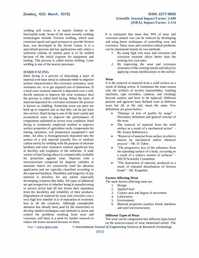
Main Effects Plot for S/N Ratios
The main effect plots for S/N ratios are shown in figure
4.5. This plot shows the variation of weight loss with
change in three parameters: welding current (A),
electrodes and no. of welding layers. In the plots, the
x-axis indicates the value of each process parameter
(at three levels for welding current, electrodes (A& C),
and no. of welding layers y-axis the response value
(wear rate). Horizontal line indicates the mean value
of the response or micro-hardness. The main effects
plots are used to determine the optimal design
conditions to obtain the optimum Weight loss. Main
effects plots for weight loss here are plotted between.
1. Weight loss v/s Welding Current
2. Weight loss v/s Electrode
3. Weight loss v/s no. of electrodes
The effect of each parameter on the Weight loss is
plotted on the graph in form of lines. From the figure
4.5 main effects plot for S/N ratios it can be clearly
seen that the weight loss increases as the current is
increased. Main effects plot for S/N ratios between
electrodes, no. of welding layers and Weight loss show
that the Weight loss value decreases linearly from low
to intermediate composition and again decreases
linearly with change the electrode and increasing no.
of welding layers from intermediate to high. From this
we can easily conclude that the electrodes and no. of
[Kamboj, 4(3): March, 2015] ISSN: 2277-9655
Scientific Journal Impact Factor: 3.449
(ISRA), Impact Factor: 2.114
http: // www.ijesrt.com © International Journal of Engineering Sciences & Research Technology
[659]
layers has the most significant effect on the Weight
loss the samples. An increase in the value of the
current increases the Weight loss due to decrease in
the value of hardness.
Fig.4. 5 Main effect plots for S/N ratio
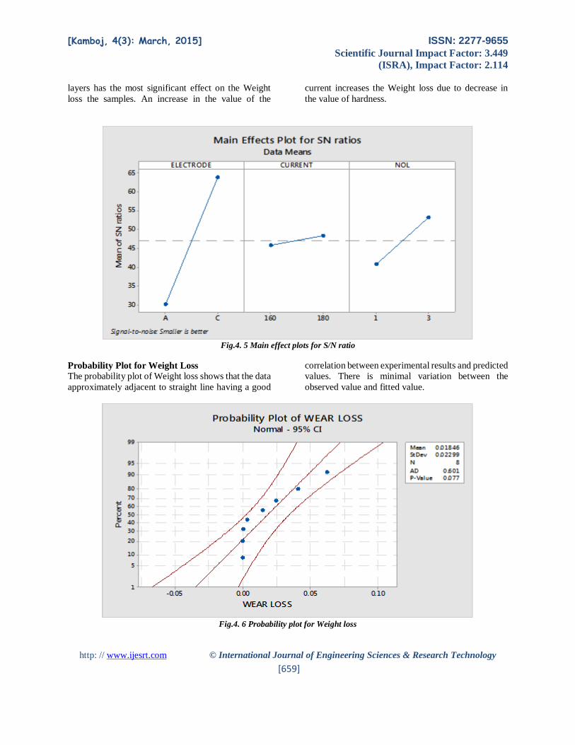
Probability Plot for Weight Loss
The probability plot of Weight loss shows that the data
approximately adjacent to straight line having a good
correlation between experimental results and predicted
values. There is minimal variation between the
observed value and fitted value.
Fig.4. 6 Probability plot for Weight loss

[Kamboj, 4(3): March, 2015] ISSN: 2277-9655
Scientific Journal Impact Factor: 3.449
(ISRA), Impact Factor: 2.114
http: // www.ijesrt.com © International Journal of Engineering Sciences & Research Technology
[660]
A normal distribution with a mean of .008744 and a
standard deviation of .002661 appears to fit the data
fairly well:
The plotted points form a reasonably straight
line.
The plotted points follow the fitted
distribution line fairly closely.
The p-value for the Anderson-Darling test is
above 0.10.
Because the distribution fits the data, we can use the
fitted line to estimate percentiles for the population.
Main Effect Plot for Weight Loss:
Main effect of current on Weight loss can be revealed
from figure 4.8. As the value of current is increased,
the value of Weight loss is increased due to increase in
dilution. Further there is slight decrease in Weight loss
due to human error i.e. during the depositing of multi
layer on the base metal. Weight loss is minimum
(0.0002gms) at low value of current (160 amp),
electrode C and 3 layers of welding and maximum
(0.0623gms) at highest value of current (180 amp),
electrode A and 1 layers of welding.
Fig. 4.8 Main effect plot for weight loss v/s current
ACKNOWLEDGEMENT I am highly grateful to the Principal, Haryana
Engineering College,Jagadhri for providing me the
opportunity to carry out my research. I express my
deep sense of gratitude to my Research Supervisor Er.
BRIJ BHUSHAN for his expert guidance, stimulating
discussions as well as continued impetus throughout
the period of this work.
I would like to thank whole heartedly Dr. ABHISHEK
KAMBOJ, HOD, Department of ME, HEC, jagadhri
for encouraging solicited advice and all kind of help
extended during the period of this work.
I also express my gratitude to my all other teaching
staff members, for their valuable and precious help
during this thesis. Finally, I am thankful to all those
people who are directly or indirectly related with this
work. Above all I pay my regards to the Almighty for
always having his hand on me.
REFERENCES 1. Afrox Product Reference Manual - Welding
Consumables - Hard facing
2. Atarment S. (1988) “Stability, wear
resistance and microstructure of iron, cobalt
and nickel based hard facing alloys.” Post
Doctorate, Univ. of Cambridge.
3. BayhanYilmaz (2006) “Reduction of wear
via hard facing of chisel ploughshare”
Tribology International 39, pp. 570–574
4. Amado Cruz Crespoa, Am´ericoScottib,
Manuel Rodriguez P´erez (2008)
“Operational behavior assessment of coated
tubular electrodes for SMAW hard facing.

[Kamboj, 4(3): March, 2015] ISSN: 2277-9655
Scientific Journal Impact Factor: 3.449
(ISRA), Impact Factor: 2.114
http: // www.ijesrt.com © International Journal of Engineering Sciences & Research Technology
[661]
journal of materials processing technology
199, pp. 265–273
5. Buchanan V.E, Shipway P.H, McCartney
D.G, “Microstructure and abrasive wear
behavior of shielded metal arc welding hard
facing used in the sugarcane industry” Wear,
Vol. 263 (2007), pp. 99–110.
6. Buchely M.F, Guttierz J.C and Leon L.M
(2005) “The effect of microstructure on
abrasive wear of hard facing alloys.” Wear
Vol. 259, pp. 52-61.
7. Chang C.M, Chen Y.C and Wu Weite (2010)
“Micro structural, abrasive wear
characteristics ofhigh carbon Fe-based hard
facing alloy.” Trib. Int. vol. 43, pp. 929-934.
8. Chatterjee S, Pal T.K, “Wear behaviour of
hard facing deposits on cast iron” Wear, Vol.
255 (2003), pp. 417–425.
9. Choteborsky R, Hrabe P, Muller M and Jirka
M (2008) “Abrasive wear of high chromium
Fe-Cr-C hard facing alloys.” Res. Agr. Eng.
Vol. 54, pp. 192-198.
10. Coronado John J, Caicedo Holman F and
Gomez Adolfo L (2009) “Effect of welding
processes on abrasive wear resistance for
hard facing deposits.” Trib. Int. vol. 42, pp.
745-749.
11. Fijisova N, James L. Natalie and Woodard
J.C (2003) “A novel pin-on apparatus.”
Wear, vol. 254, pp. 111-119.
12. Horvata Z, Filipovicb D, Kosuticb S, Emert
K (2008), “ Reduction of mould board plough
share wear by a combination technique of
hard facing” Tribology International 41, pp.
778–782
13. Jones A.H, Roffey P (2009), “The
improvement of hard facing coatings for
ground engaging applications by the addition
of tungsten carbide” Wear 267, pp. 925–933
14. Kirchgaßner M, Badisch E, Franek F (2008),
“Behaviour of iron-based hard facing alloys
under abrasion and impact” Wear 265, pp.
772–779
15. Khanna, O.P “A textbook of welding
technology” Pub: Dhanpat Rai publication
ltd.
16. Kumar S, Mondel D.P, Khaira H.K and Jha
A.K (1999) “Improvement in high stress
abrasive wear properties of steel by hard
facing.” ASM Int. vol. 8, pp. 711-715.
17. Montgomery, Douglas C (2010) “Design and
analysis of experiments.” Pub: John Villey
and Sons Pvt. Ltd. Asia, 5th edition.
18. Nadkarni S.V (1989) “Modern arc welding
processes.” Pub: Oxford and Ibh Publishing
co. pvt. Ltd, New Delhi, India.
19. Pandey Sunil, Manoj Kumar (2010),
“Chromium carbide hard-faced layer made
by paste technique using 6013 SMAW
electrode.”