On the Measurement of Young's Modulus - Zenodo
11
This content has been downloaded from IOPscience. Please scroll down to see the full text. Download details: IP Address: 130.15.241.167 This content was downloaded on 01/10/2015 at 14:11 Please note that terms and conditions apply. On the Measurement of Young's Modulus View the table of contents for this issue, or go to the journal homepage for more 1901 Proc. Phys. Soc. London 18 215 (http://iopscience.iop.org/1478-7814/18/1/316) Home Search Collections Journals About Contact us My IOPscience
-
Upload
khangminh22 -
Category
Documents
-
view
0 -
download
0
Transcript of On the Measurement of Young's Modulus - Zenodo

This content has been downloaded from IOPscience. Please scroll down to see the full text.
Download details:
IP Address: 130.15.241.167
This content was downloaded on 01/10/2015 at 14:11
Please note that terms and conditions apply.
On the Measurement of Young's Modulus
View the table of contents for this issue, or go to the journal homepage for more
1901 Proc. Phys. Soc. London 18 215
(http://iopscience.iop.org/1478-7814/18/1/316)
Home Search Collections Journals About Contact us My IOPscience

ON THR MEASUREMENT OF YOUNG’S MODULUS. 215
XVI. On the LMeasurement of Young’s ModuTus. By w. CASSIE, M. A., Projhsor of Phtysics in the Royal €101- loway College *.
A RELIABLE oscillation method of measuring the stretch modulus ought to have advantages in accur:icy and con- venience which would give it some practical value. A method depending upon the oscillations of a spiral spring has been given by Prof. L. R. Wilberforce *, and a simplifi- cation of that method depending upon flexural vibrations of n straight piece of wire has been given by Mr. G. F. C. Searle t. The apparatus described in the present paper yields an oscillation method which is fairly simple, and i t has the additional advantage that without any change of the apparatus a statical measurement of the stretch modulus can also be easily inade.
If a horizontal bar AB, fig. 1 (hereafter called the needle), is symmetricdly supported by two equal parallel wires pq, rs, it may Le made to execute a small oscillation in the plane of the paper about an axis passing through the middle point of q~ perpendicular to the plane of the paper. This oscil- lation is accompanied by alternate extension and contraction of the supporting wires: so that the resistance to stretching of these wires controls the oscillntion and determines its period. The period of the oscillation for a given pair of wires may be made of any convenient length by altering the niotnent of inertia of the neadle. Some of the dimensions of the apparatus can be eliminated by observing other inodes of oscillation of‘ the system: so that in its simplest form the experiment gives an expression for the stretch ~i lodulus iuvolving only four periods and the weight of the needle, quantities which can be messurcd with ease and accuracy.
I n the statical inethod a small weight is hung on the needle at a measured distance from the centre. This produces
* Rend Kovembei* 22, 2901. t Ibid. Feb. 1900.
t Phil. Mng. Oct. 1894.
VOL. XViIJ . Q m

216 . PROF. W. CASSIE ON THE
a known difference between the tensions in the wires, and the consequent difference in extension can be measured on a
Fig. 1.
scale by a beam of light reflected from a small mirror attached to the needle. By hanging the small weight at various distances a series of measurements can be made.
I. FIRST OSCILLATION METHOD. TER Needle.-The vibrating needle AB may be conveniently
made of a straight bar or tube with a heavy cylinder fixed at each end of the bar by set screws. If these cylinders are
UEASUREXENT OF YOUNG’S MODULUS, 217 hollow, and each made with four set screws placed as shown in figs. 2 and 3, their positions can easily be adjusted in
Fig. 2. Fig. S.
any way that may be required. The centre of the bar is fixed with a set screw into a short flanged tube, fig. 4, and
Fig. 4.
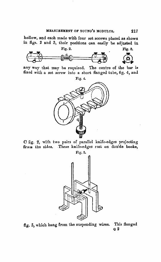
C Eg. 2, with two pairs of parallel knife-edges projecting froin the sides. These knife-edges rest on double hooks,
Fig. 5.
fig. 5, which hang from the suspending wires. This flanged 0 2

218 PROF. W. CASSIE ON THE '
tube with the knife-edges carries also a vertical screw with a nut--n gravity bob-for adjusting the position of its centre of gravity.
The Suspension.-The parallel wires to be stretched consist of a single length of wire with its ends fixed bel3w to the hooks supporting the needle, and passing above over a pulley, P (fig. 6), of diameter equal to the distance between the
Fig. 6.
parallel knife-edges on the needle. A slight groove is made round the pulley to keep the wire in position. After the adjustments are complete the pulley is clamped between the blocks X, Y, fig. 6 , which sw'ing down to each side of it, so that the suspending wires are rigidly fixed at the top.
&justment.-To adjust the apparatus the needle is placed with it,s knife-edges on the hooks, and while the pulley is

DfEASUREM%NT OF YOU,NG'S MODULUS. e19
free to turn the needle is adjusted until it rests in a horizontal position. The centre of gravity of the needle is then in a vertical line midway between the suspending wires. The pulley is then clamped, and the equality of tension of the wires tested by seeing that they give the same note when struck. If now the centre of gravity of the needle is a t the same level as the knife-edges, the pitching oscillation will be due entirely to the stretching and contrwtion of the wires. If in practice, however, the centre of gravity does not occupy exactly this position, the effect of a small error in this respect proves to be so small that i t ma? usually be neglected. I n any case it can be allowed for. The cnlcnlations are given below. The position of' the centre of gravity of the central tube can be separately adjusted to the right level by means of the gravity bob, G: fig. 4, which is :ittached to the tube for that purpose. And as the weight of the central tube is a very small fraction of the whole weight of the needle, any outstanding error in the position of its centre of gravity would be quite inappreciable in its egect.
I n the bifilar oscillation the period is affected by the resistance to torsion of the wires. This effect is eliminated by observing the periods with the needle suspended by first the inner, and second the outer pair of knife-edges, so that the suspending wires are a t two diffrrerit distances Rpart. The supporting pulleys on which the wires are clamped at the top are made of diameters equal to the distances between the knife-edges, so that the wires are parallel in each experiment. Tlie free lengths of' the wires are taken the same in each expcriment~ ; this can be secured autoinatically by an.apprapi'iatc iirrangLment of the pulleys.
Calcultctioiz of tlie Periods . -Of the oscillntions possible to this syst,ern we sliall ninlie use of three. Thcy are rotations about three perpendicular axes through the centre of the needle, viz. :-
1. About a vertical axis-the LiGlnr oscills '1 t ' 1011. 2. About, a horizontal axis perpendicular to the length of
3. About a horizoutul axis d o n g the length of tho needle- the needle-pitching.
rolling.

220 PROF. W. CASRIE ON THE
Let I be the length of each of the wires, 51 the mass of the needle, X the modulus of stretching of each of the wires, T the modulus of torsion of each of the wires, IEz the radius of gyration of the needle about its axis of
figure, L1 the radius of gyration of the needle about an axis
perpendicular to its axis of figure through the centre of gravity. The needle is made a figure of revolution so that this radius of gyration may be taken the same in all such directions.
Firstly, assume that the mass of the hooks on which the knife-edges rest may be neglected in comparison with that of the needle, and tbat the centre of gravity of the needle is at the same level as the knife-edges. Then the equation of motion of the bifilar oscillation when the wires are distant 2c apart is
Mk128'= -(Mg C2 + 27) 8,
and the frequency nl is given by
Siniilarly the frequency n,' when the wires are distant 2d apart is given by
,qd2 27 49r2ki2n{2~ - + M, 1
therefore 47?kle(n12-n,'e) = g (C2-d2). . . . (1)
1 Again, the equation of motion for the pitching oscill ;1. t' ion when the wires are distnnt.2~ apart is
and the frequency n2 is given by
Likewise the frequency of pitching n2/ when the wires are

MEASUREMENT OF YOUNG'S MODULUS. 221 distant 2d apart is given by
Therefore 2x MI 4+k1"(n22--nJ9 = -((c"#). . . . (2)
a result requiring no measurement except the periods and the weight of the needle.
Secondly, if t.he centre of gravity of the needle is at a distance x below the level of the knife-edges the equation of motion for pitching with the wires 2c apart is
M ( k , 9 + 3 ) 8 = - ( - 2y2 + Mgz) 6,
and the frequency is given by
Likewise the frequency with the wires 2d apart is given by
The periods of the bifilar oscillation are the same as in the first case. So that equations (1) and (4) give
as x is always small compared to k,. . ~ * / k , ~ is usually negligible, and when this is so equation ( 5 ) reduces to (3).
Thirdly, to :daw for the hooks supporting the knife-edges, let m be the sum of their masses, and k3 their radius of gyration about a vertical axis through their commoii centre of gravity. Then if' n4 and n l are the frequencies of pitching, and n8 and izi of bifilar oscillation with the wires distant 2c

222 PROF. W. CASSIE ON
and 2d apart respectively, we have
and corresponding equations with d substituted for C.
Thus we get
>, ( 6 ) n39 - nJ2 m CQ+iF-k32
A=+(,M+m)g nAZ - n l q (‘+m. since is small compared with M, and e, d, and k3 are small compared with k,. TVhen the fraction in the last brncket is negligible, or when the hooks are so shaped that k3= dc2 + d2, equation (6) reduces to the original result of (3).
11. SECOND OSCILLATIOX METHOD. I n certain cases it is necessary to clamp the wires direct to
the needle instead of attaching them to hooks which support the needle by knife-edges. In this case flesure of the wires has to be taken account of.
I n the bifilar oscillation the effect of flexure is negligible. I n the rolling oscillation when the centre of gravity is a t
the sanie level as the points of attachment of the wires there is a quick oscillation due entirely to the resistance to flexure of the wires.
I n the pitching oscillation both stretching and flexure of the wires a re involved. The influence of flexure alone may Le ascertained from the rolling oscillation, and by allowing for this in the pitching oscillation the stretch modulus may be deduced.
This method has the diaadvnntage of reqiiiring the inoinents of inertia of the needle to be sepra te ly detennined. This, Iiowever, can be avoided by the following modification of the experiment.
If tlie centre of gravity of the n e d e is raised above the level of the points of attachment of the wires the period of the rolliao osciliation is lengthened ; and by snitably acljiisting the licight of the centre of gravity tliia period may be macle -.

MEPSUREMENT OF YOUKG’S MODULUS. 223
infinite. In that case the effect of gravity exactly counteracts the effect of flexure for a sniall rolling displacement. This being so, if we set the needle to pitch, the effects of gravity and of the flexure will still exactly counteract each other, and the resistance to stretching of the wires will alone control and determine the period of the pitching.
In adjusting the apparatns for this experiment i t is neces- sary to take care that the rnoments of inertia involved in the bifilar and pitching oscillations are equal. This may be secured by fixing at each end of the bar of the needle a cross consisting of four equal screws at right angles to the length of the needle, two horizontal and two vertical. Nuts on these screws afford a convenient inenns of adjusting the position of the centre of gravity and the moments of inertia.
For the determination of the stretch modulus, however, this adjustment of the centre of gravity is not necessary. The double observation which eliminates the effect of torsion eliiniiintes at the same time the effect of flexure of the wires.
The equation of motion of the pitching oscillation inay be written
where fe expresses the couple due to flexure, this couple being independent of the distance between the wires. The frequencies of pitching with the wires 2c and 2d apart respectively are given by
2 x 2 f 47~k:n~~ = - < +a and
so that %X
47Tk12(T122-n2’2) = j j j ( C 2 - ( i 2 ) . . . . (7)
Tho bifilar periods still satisfy equation (l), so that
as before.

224 ON THE MEASUREMENT OF YOUNG'S MODULUS.
111. STATICAL METHOD. The apparatus of the first method also lends itself readily
to the statical measurement of the stretch modulus. Let the bar of the needle be divided in centimetres and let a small weight, say 100 grams, be hung on the needle at a succession of measured distances from the centre. Then in each position the sinall weight produces a known difference in the tensions of the suspending wires, and with a small mirror attached to the needle, the differences of extension of the wires may be read by a beam of light reflected on to a scale,
If the small mass hung on the needle is w, the distance between the vertical wires is 2a, and the distance of the scale from the mirror on the needle is h, it is easily seen that if a displacement z of w along the needle produces a dis- placeirient y of the spot on the scale,
For if the displacement z of zu turns the needle through an angle 8, one wire is stretched 2aB more than the other, and
the tension on that wire is increased by an amount y m o r e
than the tension on the other. 2a
So that
The chief precaution required in this experiment besides those usual in measuring a stretch modulus is to place the mirror so that the displacement of the spot on the scale due to the bifilar motion of the needle is a t right angles to that due to the stretching of the wires.