No Time for Look Alikes!
78
Machining Intelligently ISCAR HIGH Q LINES 9 No Time for Look Alikes! Don't Settle for Less Use ISCAR's Innovative Products V Imitation Machining Intelligently ISCAR HIGH Q LINES
-
Upload
khangminh22 -
Category
Documents
-
view
0 -
download
0
Transcript of No Time for Look Alikes!

Machining IntelligentlyISCAR HIGH Q LINES
9
No Time for Look Alikes!Don't Settle for Less
Use ISCAR's Innovative Products
VImitation
Machining IntelligentlyISCAR HIGH Q LINES

10
1. Application
Feed (ipr) ap (in)
F Finishing .003-.008 .012-.060
M Medium .006-.018 .028-.177
R Roughing .014-.028 .118-.276
H Heavy Roughing .024-.060 .236-.787
T Turn Feed .020-.100 .040-.120
As ISOTURN tools are used for most of the metal removal in turning, ISCAR has created a new line of ISOTURN inserts with new chipformers. This line combines the new SUMO TEC grades with upgraded chipformers.
In order to help endusers select the correct chipformer for an application (according to workpiece material and turning characteristics), they will be designated by a new chipformer code key. Each character of this key will represent an applicative feature of the chipformer.
An accurate description of the chipformer willhelp the enduser select the most appropriate chipformer for his application, which will thus be the most productive.
The chipbreakers’ description will consist of 3-4 characters: For example: M3PW
3. Workpiece Material Group
P Steel
M Stainless Steel
K Cast Iron
N Nonferrous & Aluminum
S High Temperature Alloys
4. Wiper Geometry
Without wiper
W Wiper Geometry
2. Chip Load
2 For special cases
3 General recommendation for all applications
4 For special cases
ASA Standard Designation
CNMG 4 3 21 2 3 4
M 3 P W-
Machining IntelligentlyISCAR HIGH Q LINES
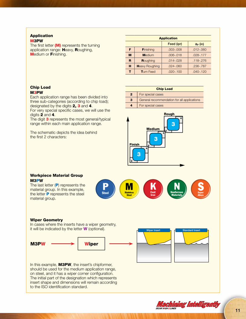
ApplicationM3PWThe first letter (M) represents the turning application range: Heavy, Roughing,Medium or Finishing.
Chip LoadM3PWEach application range has been divided into three sub-categories (according to chip load); designated by the digits 2, 3 and 4. For very special specific cases, we will use the digits 2 and 4. The digit 3 represents the most general/typical range within each main application range.
The schematic depicts the idea behindthe first 2 characters:
2
4
33
2
4
33Finish
Medium
Rough
2
4
33
Workpiece Material GroupM3PWThe last letter (P) represents the material group. In this example, the letter P represents the steel material group.
Wiper GeometryIn cases where the inserts have a wiper geometry, it will be indicated by the letter W (optional).
In this example, M3PW, the insert’s chipformer, should be used for the medium application range,on steel, and it has a wiper corner configuration. The initial part of the designation which represents insert shape and dimensions will remain accordingto the ISO identification standard.
M3PW Wiper
Standard InsertWiper Insert
Chip Load
2 For special cases
3 General recommendation for all applications
4 For special cases
Application
Feed (ipr) ap (in)
F Finishing .003-.008 .012-.060
M Medium .006-.018 .028-.177
R Roughing .014-.028 .118-.276
H Heavy Roughing .024-.060 .236-.787
T Turn Feed .020-.100 .040-.120
11

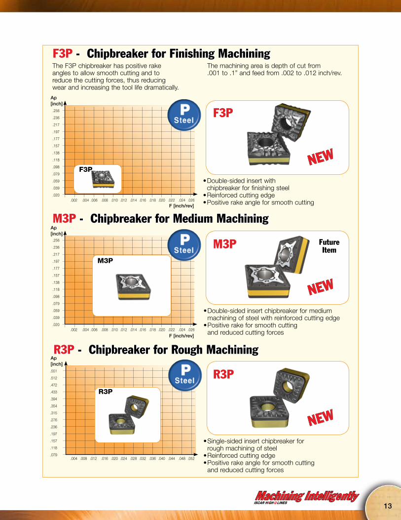
Together with the new IC8150, IC8250 and IC8350 grades, ISCAR is also introducing new and innovative chipbreakers designated F3P, M3P, and R3P, designed especially for machining steel.
Finishing
Turn Feed
Roughing
Medium
Depth of Cut
Feed
Heavy
F3P
M3P
R3P
H6P
T3P
NEWCHIPBREAKERS
FOR STEEL
NEW
NEW
NEW
NEW
12
No Time for Look Alikes!VImitation
Machining IntelligentlyISCAR HIGH Q LINES
F3P - Chipbreaker for Finishing MachiningThe F3P chipbreaker has positive rake angles to allow smooth cutting and to reduce the cutting forces, thus reducingwear and increasing the tool life dramatically.
The machining area is depth of cut from .001 to .1” and feed from .002 to .012 inch/rev.
• Double-sided insert with chipbreaker for finishing steel
• Reinforced cutting edge• Positive rake angle for smooth cutting
.256
.236
.217
.197
.177
.157
.138
.118
.098
.079
.059
.039
.020
Ap [inch]
F [inch/rev].002 .004 .006 .008 .010 .012 .014 .016 .018 .020 .022 .024 .026
F3P
F3P
.256
.236
.217
.197
.177
.157
.138
.118
.098
.079
.059
.039
.020.002 .004 .006 .008 .010 .012 .014 .016 .018 .020 .022 .024 .026
• Double-sided insert chipbreaker for medium machining of steel with reinforced cutting edge
• Positive rake for smooth cutting and reduced cutting forces
M3P - Chipbreaker for Medium MachiningAp [inch]
F [inch/rev]
M3P FutureItem
.004 .008 .012 .016 .020 .024 .028 .032 .036 .040 .044 .048 .052
• Single-sided insert chipbreaker for rough machining of steel
• Reinforced cutting edge• Positive rake angle for smooth cutting
and reduced cutting forces
R3P - Chipbreaker for Rough Machining.551
.512
.472
.433
.394
.354
.315
.276
.236
.197
.157
.118
.079
Ap [inch]
R3P
R3P
M3P
NEW
NEW
NEW
13

14
No Time for Look Alikes!VImitation
Together with the new IC6015 and IC6025 grades, ISCAR is also introducing new and innovative chipbreakers designated F3M, M3M, and R3M, designed for machining stainless steel.
Finishing
Roughing
Medium
Depth of Cut
Feed
F3M
M3M
R3M
NEWCHIPBREAKERS
FOR STAINLESS STEEL
NEW
NEW
NEW

Machining IntelligentlyISCAR HIGH Q LINES
F3M - Chipbreaker for Finishing MachiningThe F3M chipbreaker has positive rake angles for smooth cutting, reduced cutting forces and insert wear, leading to dramatically increased tool life.
The machining application area is .012-.120” D.O.C and .002-.012 inch/rev
• Double-sided insert with chipbreaker for finishing stainless steel
• Reinforced cutting edge• Positive rake angle for smooth cutting and low forces
.256
.236
.217
.197
.177
.157
.138
.118
.098
.079
.059
.039
.020
Ap [inch]
F [inch/rev].002 .004 .006 .008 .010 .012 .014 .016 .018 .020 .022 .024 .026
F3M
.256
.236
.217
.197
.177
.157
.138
.118
.098
.079
.059
.039
.020.002 .004 .006 .008 .010 .012 .014 .016 .018 .020 .022 .024 .026
• Double-sided insert chipbreaker for medium machining of stainless steel with a reinforced cutting edge
• Positive rake for smooth cutting and reduced cutting forces
• The machining application range is .020-.240” D.O.C. and .006-.024 inch/rev
M3M - Chipbreaker for Medium MachiningAp [inch]
F [inch/rev]
.004 .008 .012 .016 .020 .024 .028 .032 .036 .040 .044 .048 .052
• Double-sided insert for rough machining of stainless steel with a reinforced cutting edge
• Positive rake angle for smooth cutting and reduced cutting forces
• The machining application range is .080-.440” D.O.C. and .006-.028 inch/rev
R3M - Chipbreaker for Rough Machining.551
.512
.472
.433
.394
.354
.315
.276
.236
.197
.157
.118
.079
Ap [inch]
M3M
F3M
R3M
FutureItemM3M
R3M
NEW
NEW
NEW
15

ISOTURN Small Size InsertsIn many turning applications people tend to use larger inserts than are actually required for the machining parameters being applied. ISCAR is introducing a wide range of ISOTURN small size inserts, which provide an economical advantage regarding cost per cutting edge.The new inserts are available in a wide range of geometries, corner radii, chipformers and the most advanced carbide grades.
They are available in WNMG, CNMG, SNMG, DNMG and TNMG geometries. These inserts are thicker than the standard inserts of the same sizes, which provides higher durability. Also available are small size HELITURN LD inserts in CNMX and TNMX geometries. These inserts, like their larger counterparts, have high positive radial, helical cutting edges and positive rake angles - a combination that substantially reduces cutting forces.
16
No Time for Look Alikes!VImitation
Machining IntelligentlyISCAR HIGH Q LINES
17
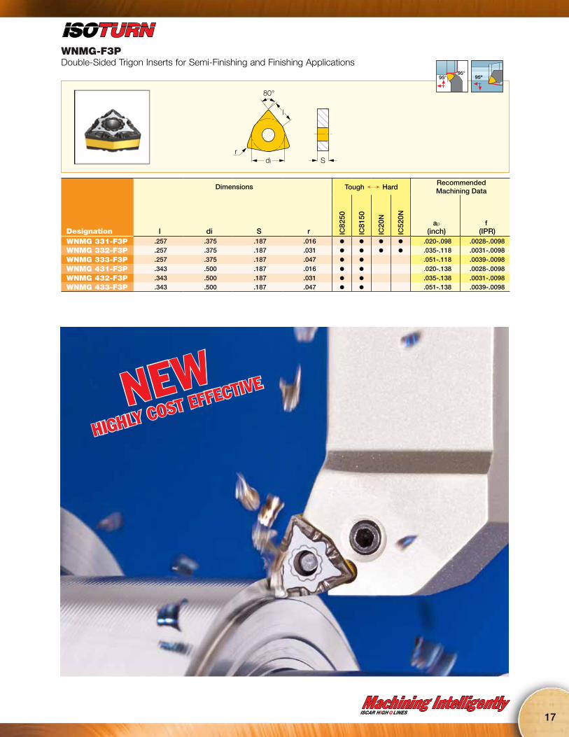
WNMG-F3PDouble-Sided Trigon Inserts for Semi-Finishing and Finishing Applications
di
80°
l
rS
95°95° 95º
Dimensions Tough Ö HardRecommended Machining Data
Designation l di S r IC82
50
IC81
50
IC20
N
IC52
0N
ap
(inch)f
(IPR)WNMG 331-F3P .257 .375 .187 .016 l l l l .020-.098 .0028-.0098WNMG 332-F3P .257 .375 .187 .031 l l l l .035-.118 .0031-.0098
WNMG 333-F3P .257 .375 .187 .047 l l .051-.118 .0039-.0098
WNMG 431-F3P .343 .500 .187 .016 l l .020-.138 .0028-.0098
WNMG 432-F3P .343 .500 .187 .031 l l .035-.138 .0031-.0098WNMG 433-F3P .343 .500 .187 .047 l l .051-.138 .0039-.0098
NEWHIGHLY COST EFFECTIVE
18
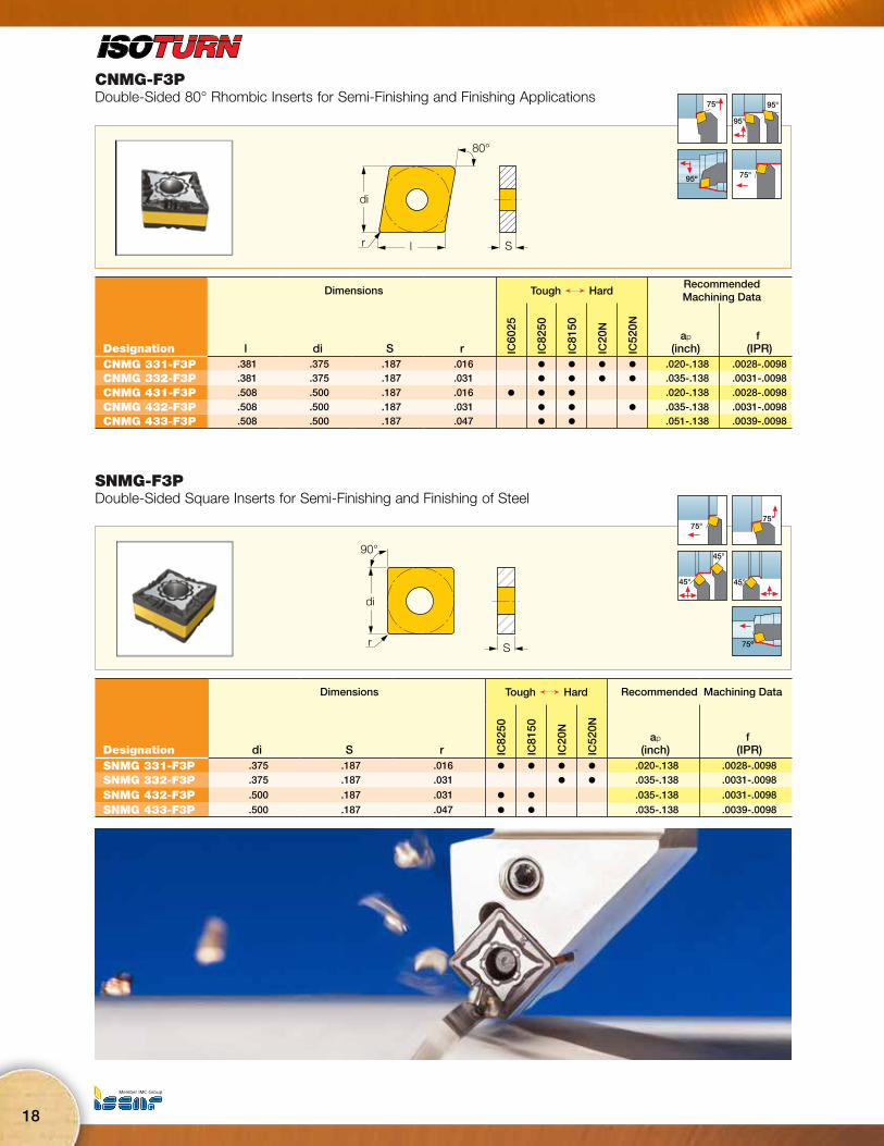
CNMG-F3PDouble-Sided 80° Rhombic Inserts for Semi-Finishing and Finishing Applications
80°
di
r l S
75° 95°
95°
95º 75°
Dimensions Tough Ö HardRecommended Machining Data
Designation l di S r IC60
25
IC82
50
IC81
50
IC20
N
IC52
0N
ap
(inch)f
(IPR)CNMG 331-F3P .381 .375 .187 .016 l l l l .020-.138 .0028-.0098CNMG 332-F3P .381 .375 .187 .031 l l l l .035-.138 .0031-.0098
CNMG 431-F3P .508 .500 .187 .016 l l l .020-.138 .0028-.0098
CNMG 432-F3P .508 .500 .187 .031 l l l .035-.138 .0031-.0098CNMG 433-F3P .508 .500 .187 .047 l l .051-.138 .0039-.0098
SNMG-F3PDouble-Sided Square Inserts for Semi-Finishing and Finishing of Steel
90°
di
Sr
75°75°
45°
45°
45°
75º
Dimensions Tough Ö Hard Recommended Machining Data
Designation di S r IC82
50
IC81
50
IC20
N
IC52
0N
ap
(inch)f
(IPR)SNMG 331-F3P .375 .187 .016 l l l l .020-.138 .0028-.0098
SNMG 332-F3P .375 .187 .031 l l .035-.138 .0031-.0098
SNMG 432-F3P .500 .187 .031 l l .035-.138 .0031-.0098
SNMG 433-F3P .500 .187 .047 l l .035-.138 .0039-.0098
Machining IntelligentlyISCAR HIGH Q LINES
19
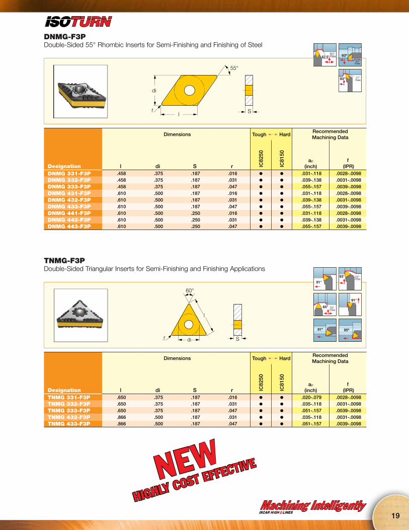
DNMG-F3PDouble-Sided 55° Rhombic Inserts for Semi-Finishing and Finishing of Steel
di
55°
Srl
60° max62.5° 93º
30ºmax
27°max93°
Dimensions Tough Ö HardRecommended Machining Data
Designation l di S r IC82
50
IC81
50
ap
(inch)f
(IPR)DNMG 331-F3P .458 .375 .187 .016 l l .031-.118 .0028-.0098DNMG 332-F3P .458 .375 .187 .031 l l .039-.138 .0031-.0098
DNMG 333-F3P .458 .375 .187 .047 l l .055-.157 .0039-.0098
DNMG 431-F3P .610 .500 .187 .016 l l .031-.118 .0028-.0098
DNMG 432-F3P .610 .500 .187 .031 l l .039-.138 .0031-.0098
DNMG 433-F3P .610 .500 .187 .047 l l .055-.157 .0039-.0098
DNMG 441-F3P .610 .500 .250 .016 l l .031-.118 .0028-.0098
DNMG 442-F3P .610 .500 .250 .031 l l .039-.138 .0031-.0098DNMG 443-F3P .610 .500 .250 .047 l l .055-.157 .0039-.0098
TNMG-F3PDouble-Sided Triangular Inserts for Semi-Finishing and Finishing Applications
di
60°
Sr
l
91°
93° 22° max
60° 55° max
91°
91º 95º
Dimensions Tough Ö HardRecommended Machining Data
Designation l di S r IC82
50
IC81
50
ap
(inch)f
(IPR)TNMG 331-F3P .650 .375 .187 .016 l l .020-.079 .0028-.0098TNMG 332-F3P .650 .375 .187 .031 l l .035-.118 .0031-.0098
TNMG 333-F3P .650 .375 .187 .047 l l .051-.157 .0039-.0098
TNMG 432-F3P .866 .500 .187 .031 l l .035-.118 .0031-.0098TNMG 433-F3P .866 .500 .187 .047 l l .051-.157 .0039-.0098
NEWHIGHLY COST EFFECTIVE

20
VNMG-F3PDouble-Sided 35° Rhombic Inserts for Semi-Finishing and Finishing Applications
35°
l
di
Sr
50° max93°
72.5° 70° max
93º
50ºmax
Dimensions Tough Ö HardRecommended Machining Data
Designation l di S r IC82
50
IC81
50
ap
(inch)f
(IPR)VNMG 331-F3P .654 .375 .187 .016 l l .028-.079 .0028-.0094VNMG 332-F3P .654 .375 .187 .031 l l .039-.118 .0031-.0094
WNMG-M3PDouble-Sided Trigon Inserts for Medium Machining Conditions on Steel
di
80°
l
rS
95°95° 95º
Dimensions Tough Ö HardRecommended Machining Data
Designation l di S r IC82
50
IC81
50
IC50
10
ap
(inch)f
(IPR)WNMG 3-1-M3P .257 .375 .156 .016 l .018-.098 .0039-.0177WNMG 3-2-M3P .257 .375 .156 .031 l l .020-.118 .0059-.0197
WNMG 3-3-M3P .257 .375 .156 .047 l .031-.118 .0071-.0236
WNMG 331-M3P .257 .375 .187 .016 l l .018-.098 .0039-.0177
WNMG 332-M3P .257 .375 .187 .031 l l .020-.118 .0059-.0197
WNMG 333-M3P .257 .375 .187 .047 l .031-.118 .0071-.0236
WNMG 431-M3P .343 .500 .187 .016 l l .016-.138 .0039-.0177
WNMG 432-M3P .343 .500 .187 .031 l l l .020-.157 .0059-.0197
WNMG 433-M3P .343 .500 .187 .047 l l l .031-.157 .0071-.0236
WNMG 434-M3P .343 .500 .187 .063 l .039-.157 .0091-.0256
Machining IntelligentlyISCAR HIGH Q LINES
21
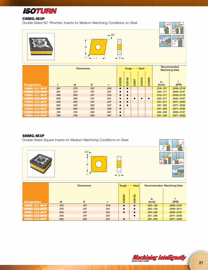
CNMG-M3PDouble-Sided 80° Rhombic Inserts for Medium Machining Conditions on Steel
80°
di
r l S
75° 95°
95°
95º 75°
Dimensions Tough Ö HardRecommended Machining Data
Designation l di S r IC82
50
IC81
50
IC80
7
IC50
10
IC50
05
ap
(inch)f
(IPR)CNMG 331-M3P .381 .375 .187 .016 l l .016-.157 .0039-.0118CNMG 332-M3P .381 .375 .187 .031 l l .020-.177 .0059-.0197
CNMG 431-M3P .508 .500 .187 .016 l l .016-.217 .0039-.0118
CNMG 432-M3P .508 .500 .187 .031 l l l l l .020-.217 .0059-.0197
CNMG 433-M3P .508 .500 .187 .047 l l .031-.217 .0071-.0236
CNMG 543-M3P .626 .625 .250 .047 l l .031-.283 .0071-.0236
CNMG 544-M3P .626 .625 .250 .063 l .031-.283 .0071-.0236
CNMG 642-M3P .760 .750 .250 .031 l .020-.339 .0059-.0197CNMG 643-M3P .760 .750 .250 .047 l .031-.339 .0071-.0236
SNMG-M3PDouble-Sided Square Inserts for Medium Machining Conditions on Steel
90°
di
Sr
75°75°
45°
45°
45°
75º
Dimensions Tough Ö Hard Recommended Machining Data
Designation di S r IC82
50
IC81
50
ap
(inch)f
(IPR)SNMG 331-M3P .375 .187 .016 l l .020-.138 .0059-.0197SNMG 332-M3P .375 .187 .031 l l .020-.138 .0059-.0217
SNMG 432-M3P .500 .187 .031 l l .020-.236 .0059-.0197
SNMG 433-M3P .500 .187 .047 l .031-.236 .0071-.0236SNMG 543-M3P .625 .250 .047 l .031-.295 .0071-.0236

22
DNMG-M3PDouble-Sided 55° Rhombic Inserts for Medium Machining Conditions on Steel
di
55°
Srl
60° max62.5° 93º
30ºmax
27°max93°
Dimensions Tough Ö HardRecommended Machining Data
Designation l di S r IC82
50
IC81
50
ap
(inch)f
(IPR)DNMG 332-M3P .458 .375 .187 .031 l l .020-.197 .0059-.0197DNMG 333-M3P .458 .375 .187 .047 l .031-.197 .0071-.0236
DNMG 432-M3P .610 .500 .187 .031 l l .020-.236 .0059-.0197
DNMG 442-M3P .610 .500 .250 .031 l l .020-.236 .0059-.0197DNMG 443-M3P .610 .500 .250 .047 l l .031-.236 .0071-.0236
TNMG-M3PDouble-Sided Triangular Inserts for Medium Machining Conditions on Steel
di
60°
Sr
l
91°
93° 22° max
60° 55° max
91°
91º 95º
Dimensions Tough Ö HardRecommended Machining Data
Designation l di S r IC83
0
IC82
50
IC81
50
ap
(inch)f
(IPR)TNMG 331-M3P .650 .375 .187 .016 l l .016-.197 .0039-.0118TNMG 332-M3P .650 .375 .187 .031 l l .020-.197 .0059-.0197
TNMG 333-M3P .650 .375 .187 .047 l l .031-.197 .0071-.0236
TNMG 432-M3P .866 .500 .187 .031 l l .020-.260 .0059-.0197
TNMG 433-M3P .866 .500 .187 .047 l .031-.260 .0071-.0236
TNMG 434-M3P .866 .500 .187 .063 l .039-.260 .0091-.0256
Machining IntelligentlyISCAR HIGH Q LINES
23
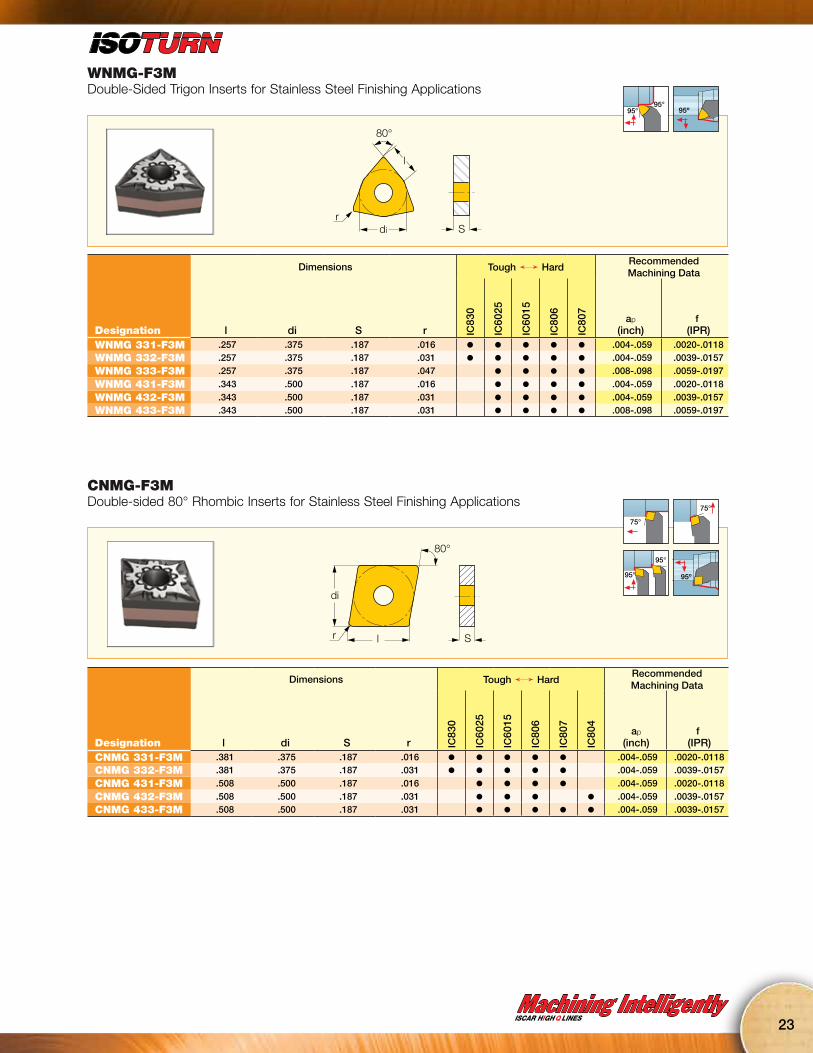
WNMG-F3MDouble-Sided Trigon Inserts for Stainless Steel Finishing Applications
di
80°
l
rS
95°95° 95º
Dimensions Tough Ö HardRecommended Machining Data
Designation l di S r IC83
0
IC60
25
IC60
15
IC80
6
IC80
7
ap
(inch)f
(IPR)WNMG 331-F3M .257 .375 .187 .016 l l l l l .004-.059 .0020-.0118WNMG 332-F3M .257 .375 .187 .031 l l l l l .004-.059 .0039-.0157
WNMG 333-F3M .257 .375 .187 .047 l l l l .008-.098 .0059-.0197
WNMG 431-F3M .343 .500 .187 .016 l l l l .004-.059 .0020-.0118
WNMG 432-F3M .343 .500 .187 .031 l l l l .004-.059 .0039-.0157WNMG 433-F3M .343 .500 .187 .031 l l l l .008-.098 .0059-.0197
CNMG-F3MDouble-sided 80° Rhombic Inserts for Stainless Steel Finishing Applications
80°
di
r l S
75°
75°
95°
95° 95º
Dimensions Tough Ö HardRecommended Machining Data
Designation l di S r IC83
0
IC60
25
IC60
15
IC80
6
IC80
7
IC80
4
ap
(inch)f
(IPR)CNMG 331-F3M .381 .375 .187 .016 l l l l l .004-.059 .0020-.0118CNMG 332-F3M .381 .375 .187 .031 l l l l l .004-.059 .0039-.0157
CNMG 431-F3M .508 .500 .187 .016 l l l l .004-.059 .0020-.0118
CNMG 432-F3M .508 .500 .187 .031 l l l l .004-.059 .0039-.0157CNMG 433-F3M .508 .500 .187 .031 l l l l l .004-.059 .0039-.0157
24
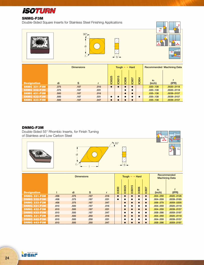
SNMG-F3MDouble-Sided Square Inserts for Stainless Steel Finishing Applications
90°
di
Sr
75°75°
45°
45°
45°
75º
Dimensions Tough Ö Hard Recommended Machining Data
Designation di S r IC60
25
IC60
15
IC80
6
IC80
7
IC80
4
ap
(inch)f
(IPR)SNMG 331-F3M .375 .187 .016 l l l l .020-.138 .0020-.0118SNMG 332-F3M .375 .187 .031 l l .020-.138 .0020-.0118
SNMG 431-F3M .500 .187 .016 l l .035-.138 .0039-.0157
SNMG 432-F3M .500 .187 .031 l l l l l .035-.138 .0039-.0157SNMG 433-F3M .500 .187 .047 l l l l .035-.138 .0039-.0157
DNMG-F3MDouble-Sided 55° Rhombic Inserts, for Finish Turning of Stainless and Low Carbon Steel
di
55°
Srl
60° max62.5° 93º
30ºmax
27°max93°
Dimensions Tough Ö HardRecommended Machining Data
Designation l di S r IC83
0
IC60
25
IC60
15
IC80
6
IC80
7
ap
(inch)f
(IPR)DNMG 331-F3M .458 .375 .187 .016 l l l l l .004-.059 .0020-.0126DNMG 332-F3M .458 .375 .187 .031 l l l l l .004-.059 .0039-.0165
DNMG 333-F3M .458 .375 .187 .047 l l l l .006-.079 .0059-.0205
DNMG 431-F3M .610 .500 .187 .016 l l l l .004-.059 .0020-.0118
DNMG 432-F3M .610 .500 .187 .031 l l l l .004-.059 .0039-.0157
DNMG 433-F3M .610 .500 .187 .047 l l l l .008-.098 .0059-.0197
DNMG 441-F3M .610 .500 .250 .016 l l l l .004-.059 .0020-.0118
DNMG 442-F3M .610 .500 .250 .031 l l l l .004-.059 .0039-.0157DNMG 443-F3M .610 .500 .250 .047 l l l l .008-.098 .0059-.0197
Machining IntelligentlyISCAR HIGH Q LINES
25
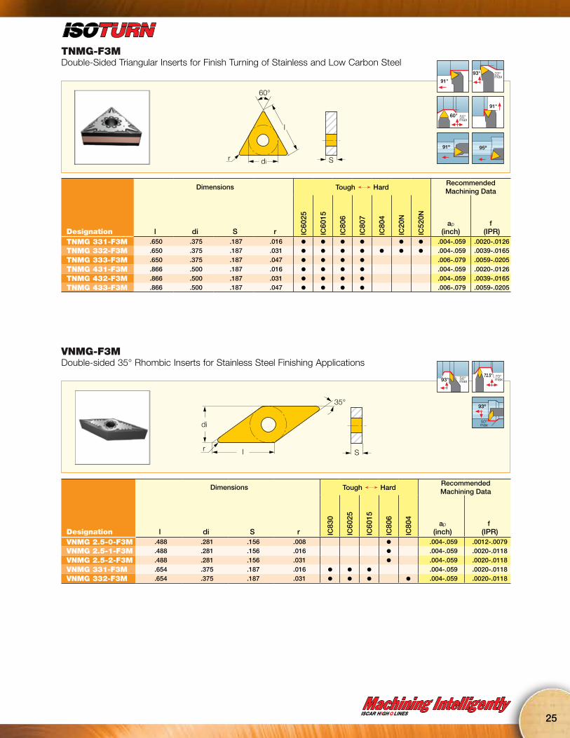
TNMG-F3MDouble-Sided Triangular Inserts for Finish Turning of Stainless and Low Carbon Steel
di
60°
Sr
l
91°
93° 22° max
60° 55° max
91°
91º 95º
Dimensions Tough Ö HardRecommended Machining Data
Designation l di S r IC60
25
IC60
15
IC80
6
IC80
7
IC80
4
IC20
N
IC52
0N
ap
(inch)f
(IPR)TNMG 331-F3M .650 .375 .187 .016 l l l l l l .004-.059 .0020-.0126TNMG 332-F3M .650 .375 .187 .031 l l l l l l l .004-.059 .0039-.0165
TNMG 333-F3M .650 .375 .187 .047 l l l l .006-.079 .0059-.0205
TNMG 431-F3M .866 .500 .187 .016 l l l l .004-.059 .0020-.0126
TNMG 432-F3M .866 .500 .187 .031 l l l l .004-.059 .0039-.0165TNMG 433-F3M .866 .500 .187 .047 l l l l .006-.079 .0059-.0205
VNMG-F3MDouble-sided 35° Rhombic Inserts for Stainless Steel Finishing Applications
35°
l
di
Sr
50° max93°
72.5° 70° max
93º
50ºmax
Dimensions Tough Ö HardRecommended Machining Data
Designation l di S r IC83
0
IC60
25
IC60
15
IC80
6
IC80
4
ap
(inch)f
(IPR)VNMG 2.5-0-F3M .488 .281 .156 .008 l .004-.059 .0012-.0079VNMG 2.5-1-F3M .488 .281 .156 .016 l .004-.059 .0020-.0118
VNMG 2.5-2-F3M .488 .281 .156 .031 l .004-.059 .0020-.0118
VNMG 331-F3M .654 .375 .187 .016 l l l .004-.059 .0020-.0118VNMG 332-F3M .654 .375 .187 .031 l l l l .004-.059 .0020-.0118
26
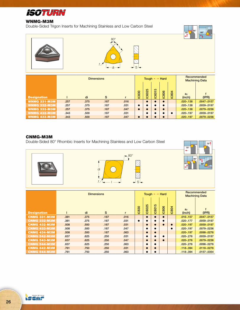
WNMG-M3MDouble-Sided Trigon Inserts for Machining Stainless and Low Carbon Steel
di
80°
l
rS
95°95° 95º
Dimensions Tough Ö HardRecommended Machining Data
Designation l di S r IC83
0
IC60
25
IC60
15
IC80
6
IC80
4
ap
(inch)f
(IPR)WNMG 331-M3M .257 .375 .187 .016 l l l .020-.138 .0047-.0157WNMG 332-M3M .257 .375 .187 .031 l l l l .020-.138 .0059-.0197
WNMG 333-M3M .257 .375 .187 .047 l l l l .020-.138 .0079-.0236
WNMG 432-M3M .343 .500 .187 .031 l l l l .020-.197 .0059-.0197WNMG 433-M3M .343 .500 .187 .047 l l l l .020-.197 .0079-.0236
CNMG-M3MDouble-Sided 80° Rhombic Inserts for Machining Stainless and Low Carbon Steel
80°
di
r l S
75°
75°
95°
95° 95º
Dimensions Tough Ö HardRecommended Machining Data
Designation l di S r IC83
0
IC60
25
IC60
15
IC80
6
IC80
4
ap
(inch)f
(IPR)CNMG 331-M3M .381 .375 .187 .016 l l l .016-.157 .0047-.0157CNMG 332-M3M .381 .375 .187 .031 l l l l .020-.177 .0059-.0197
CNMG 432-M3M .508 .500 .187 .031 l l l l .020-.197 .0059-.0197
CNMG 433-M3M .508 .500 .187 .047 l l l .020-.197 .0079-.0236
CNMG 434-M3M .508 .500 .187 .063 l l .020-.197 .0098-.0276
CNMG 542-M3M .637 .625 .250 .031 l l l .020-.276 .0059-.0197
CNMG 543-M3M .637 .625 .250 .047 l l l .020-.276 .0079-.0236
CNMG 544-M3M .637 .625 .250 .063 l l .020-.276 .0098-.0276
CNMG 642-M3M .761 .750 .250 .031 l l .118-.394 .0118-.0276CNMG 644-M3M .761 .750 .250 .063 l l .118-.394 .0157-.0354

Machining IntelligentlyISCAR HIGH Q LINES
27
SNMG-M3MDouble-Sided Square Inserts with a Special Chipformer for Heavy Machining
90°
di
Sr
75°75°
45°
45°
45°
75º
Dimensions Tough Ö Hard Recommended Machining Data
Designation di S r IC60
25
IC60
15
IC80
6
IC80
4
ap
(inch)f
(IPR)SNMG 332-M3M .375 .187 .031 l l .020-.177 .0059-.0197
SNMG 432-M3M .500 .187 .031 l l l .020-.197 .0059-.0197
SNMG 433-M3M .500 .187 .047 l l l .020-.197 .0079-.0236
SNMG 434-M3M .500 .187 .063 l l .020-.197 .0098-.0276
SNMG 543-M3M .625 .250 .047 l l .020-.315 .0039-.0236
SNMG 544-M3M .625 .250 .063 l l .020-.315 .0039-.0256
SNMG 643-M3M .750 .250 .047 l l .004-.374 .0039-.0236SNMG 644-M3M .750 .250 .063 l l .004-.374 .0039-.0256
DNMG-M3MDouble-Sided 55° Rhombic Inserts for Machining Stainless and Low Carbon Steel
55°
di
l Sr
60° max62.5° 93º
30ºmax
27°max93°
Dimensions Tough Ö HardRecommended Machining Data
Designation l di S r IC83
0
IC60
25
IC60
15
IC80
6
ap
(inch)f
(IPR)DNMG 331-M3M .458 .375 .187 .016 l l l .020-.138 .0047-.0157DNMG 332-M3M .458 .375 .187 .031 l l l l .020-.157 .0059-.0197
DNMG 333-M3M .458 .375 .187 .047 l l l l .020-.157 .0079-.0236
DNMG 432-M3M .610 .500 .187 .031 l l l .020-.197 .0059-.0197
DNMG 433-M3M .610 .500 .187 .047 l l l .020-.197 .0079-.0236
DNMG 442-M3M .610 .500 .250 .031 l l l .020-.197 .0059-.0197DNMG 443-M3M .610 .500 .250 .047 l l l .020-.197 .0079-.0236
28
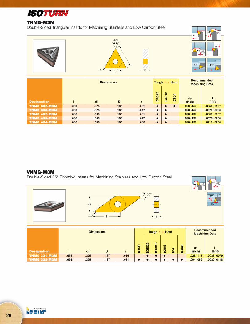
TNMG-M3MDouble-Sided Triangular Inserts for Machining Stainless and Low Carbon Steel
di
60°
Sr
l
91°
93° 22° max
60° 55° max
91°
91º 95º
Dimensions Tough Ö HardRecommended Machining Data
Designation l di S r IC60
25
IC60
15
IC80
4
ap
(inch)f
(IPR)TNMG 332-M3M .650 .375 .187 .031 l l l .020-.157 .0059-.0197TNMG 333-M3M .650 .375 .187 .047 l l .020-.157 .0079-.0236
TNMG 432-M3M .866 .500 .187 .031 l l .020-.197 .0059-.0197
TNMG 433-M3M .866 .500 .187 .047 l l .020-.197 .0079-.0236TNMG 434-M3M .866 .500 .187 .063 l l .020-.197 .0118-.0256
VNMG-M3MDouble-Sided 35° Rhombic Inserts for Machining Stainless and Low Carbon Steel
35°
l
di
Sr
50° max93°
72.5° 70° max
93º
50ºmax
Dimensions Tough Ö HardRecommended Machining Data
Designation l di S r IC83
0
IC60
25
IC60
15
IC80
6
IC4
IC80
4
ap
(inch)f
(IPR)VNMG 331-M3M .654 .375 .187 .016 l l l .028-.118 .0028-.0079VNMG 332-M3M .654 .375 .187 .031 l l l l l l .004-.059 .0020-.0118
Machining IntelligentlyISCAR HIGH Q LINES
29
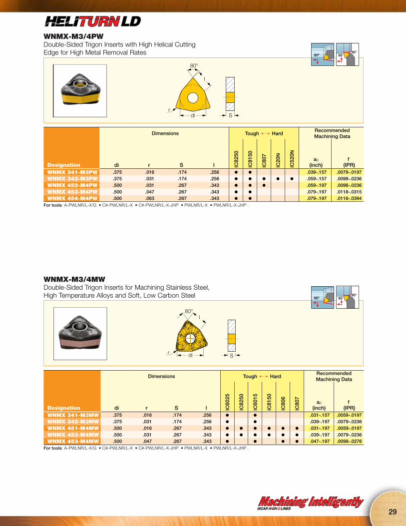
WNMX-M3/4PWDouble-Sided Trigon Inserts with High Helical Cutting Edge for High Metal Removal Rates
80°
l
di Sr
95º95°
95°
Dimensions Tough Ö HardRecommended Machining Data
Designation di r S l IC82
50
IC81
50
IC80
7
IC20
N
IC52
0N
ap
(inch)f
(IPR)WNMX 341-M3PW .375 .016 .174 .256 l l .039-.157 .0079-.0197WNMX 342-M3PW .375 .031 .174 .256 l l l l l .059-.157 .0098-.0236
WNMX 452-M4PW .500 .031 .267 .343 l l l .059-.197 .0098-.0236
WNMX 453-M4PW .500 .047 .267 .343 l l .079-.197 .0118-.0315WNMX 454-M4PW .500 .063 .267 .343 l l .079-.197 .0118-.0394
For tools: A-PWLNR/L-X/G • C#-PWLNR/L-X • C#-PWLNR/L-X-JHP • PWLNR/L-X • PWLNR/L-X-JHP .
WNMX-M3/4MWDouble-Sided Trigon Inserts for Machining Stainless Steel, High Temperature Alloys and Soft, Low Carbon Steel
Sdi
l80°
r
95º95°
95°
Dimensions Tough Ö HardRecommended Machining Data
Designation di r S l IC60
25
IC82
50
IC60
15
IC81
50
IC80
6
IC80
7
ap
(inch)f
(IPR)WNMX 341-M3MW .375 .016 .174 .256 l l .031-.157 .0059-.0197WNMX 342-M3MW .375 .031 .174 .256 l l .039-.197 .0079-.0236
WNMX 451-M4MW .500 .016 .267 .343 l l l l l l .031-.197 .0059-.0197
WNMX 452-M4MW .500 .031 .267 .343 l l l l l l .039-.197 .0079-.0236WNMX 453-M4MW .500 .047 .267 .343 l l l l .047-.197 .0098-.0276
For tools: A-PWLNR/L-X/G • C#-PWLNR/L-X • C#-PWLNR/L-X-JHP • PWLNR/L-X • PWLNR/L-X-JHP .

30
CNMX-M3/4MWDouble-Sided 80° Rhombic Inserts with High Helical Cutting Edge for High Metal Removal Rates of Stainless Steel
di
F
F
l
S
80º88º
Wiper Zone
r
95º
95°
95°
Dimensions Tough Ö HardRecommended Machining Data
Designation l di S r IC83
0
IC60
25
IC60
15
IC81
50
IC80
6
IC80
7
ap
(inch)f
(IPR)CNMX 341-M3MW .381 .375 .174 .016 l l .031-.157 .0059-.0177CNMX 342-M3MW .381 .375 .174 .031 l l .039-.197 .0079-.0236
CNMX 451-M4MW .508 .500 .266 .016 l l l .031-.197 .0059-.0177
CNMX 452-M4MW .508 .500 .266 .031 l l l l l l .039-.236 .0079-.0236CNMX 453-M4MW .508 .500 .266 .047 l l l l l .079-.236 .0118-.0315
• PCLNR/L...X and A..-PCLNR/L-X are most recommended as they were designed especially for this insert
For tools: A-PCLNR/L-X/G • C#-PCLNR/L-X • C#-PCLNR/L-X-JHP • DCLNR/L • PCLNR/L-X • PCLNR/L-X-JHP .
CNMX-M3/4PWDouble-Sided 80° Rhombic Inserts with High Helical Cutting Edge for High Metal Removal Rates
S
di
F
F
Wiper zoner
80º88º
l
95º
95°
95°
Dimensions Tough Ö HardRecommended Machining Data
Designation l di S r IC83
50
IC82
50
IC81
50
IC80
7
IC90
7
IC20
N
IC52
0N
ap
(inch)f
(IPR)CNMX 341-M3PW .381 .375 .174 .016 l l .039-.177 .0079-.0197CNMX 342-M3PW .381 .375 .174 .031 l l l l .059-.197 .0098-.0236
CNMX 452-M4PW .508 .500 .266 .031 l l l l l .059-.236 .0098-.0236
CNMX 453-M4PW .508 .500 .266 .047 l l l l l .079-.236 .0118-.0315
CNMX 454-M4PW .508 .500 .266 .063 l l l l l .079-.236 .0118-.0394
CNMX 553-M4PW .634 .625 .250 .047 l l l .079-.315 .0118-.0315
CNMX 554-M4PW .634 .625 .250 .063 l l l .079-.315 .0118-.0394• PCLNR/L...X and A..-PCLNR/L-X are most recommended as they were designed especially for this insert
For tools: A-PCLNR/L-X/G • C#-PCLNR/L-X • C#-PCLNR/L-X-JHP • DCLNR/L • PCLNR/L-X • PCLNR/L-X-JHP .
Machining IntelligentlyISCAR HIGH Q LINES
31
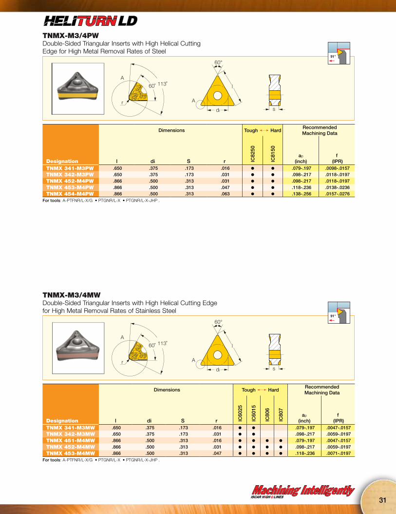
TNMX-M3/4PWDouble-Sided Triangular Inserts with High Helical Cutting Edge for High Metal Removal Rates of Steel
A
A
r
60˚ 113˚
s
60°
l
di
91°
Dimensions Tough Ö HardRecommended Machining Data
Designation l di S r IC82
50
IC81
50
ap
(inch)f
(IPR)TNMX 341-M3PW .650 .375 .173 .016 l l .079-.197 .0098-.0157TNMX 342-M3PW .650 .375 .173 .031 l l .098-.217 .0118-.0197
TNMX 452-M4PW .866 .500 .313 .031 l l .098-.217 .0118-.0197
TNMX 453-M4PW .866 .500 .313 .047 l l .118-.236 .0138-.0236TNMX 454-M4PW .866 .500 .313 .063 l l .138-.256 .0157-.0276
For tools: A-PTFNR/L-X/G • PTGNR/L-X • PTGNR/L-X-JHP .
TNMX-M3/4MWDouble-Sided Triangular Inserts with High Helical Cutting Edge for High Metal Removal Rates of Stainless Steel
A
A
r
60˚ 113˚
s
60°
l
di
91°
Dimensions Tough Ö HardRecommended Machining Data
Designation l di S r IC60
25
IC60
15
IC80
6
IC80
7
ap
(inch)f
(IPR)TNMX 341-M3MW .650 .375 .173 .016 l l .079-.197 .0047-.0157TNMX 342-M3MW .650 .375 .173 .031 l l .098-.217 .0059-.0197
TNMX 451-M4MW .866 .500 .313 .016 l l l l .079-.197 .0047-.0157
TNMX 452-M4MW .866 .500 .313 .031 l l l l .098-.217 .0059-.0197TNMX 453-M4MW .866 .500 .313 .047 l l l l .118-.236 .0071-.0197
For tools: A-PTFNR/L-X/G • PTGNR/L-X • PTGNR/L-X-JHP .

32
NEWHIGHLY COST EFFECTIVECNMX 34
CNMX 45CNMX 55
TCX 3TCX 4TCX 5
CNMG 33CNMG 43CNMG 54
TCN 323TCN 443TCN 53
PCLNR/L-XLever Lock Toolholders for CNMX/CNMG 80° Rhombic Inserts
f
h
l2
b
h
l1
95°
95°
Designation h b l1 l2 f Ga° Gr° InsertPCLNR/L 10-3X .625 .625 4.500 1.00 1.00 -6 -6 CNMX 34. CNMG 33.PCLNR/L 12-3X .750 .750 4.500 1.00 1.00 -6 -6 CNMX 34. CNMG 33.
PCLNR/L 16-3X 1.000 1.000 6.000 1.00 1.25 -6 -6 CNMX 34. CNMG 33.
PCLNR/L 12-4X .750 .750 4.500 1.22 1.25 -6 -6 CNMX 45. CNMG 43.
PCLNR/L 16-4X 1.000 1.000 6.000 1.22 1.25 -6 -6 CNMX 45. CNMG 43.
PCLNR/L 20-4X 1.250 1.250 6.000 1.22 1.50 -6 -6 CNMX 45. CNMG 43.
PCLNR/L 20-5X 1.250 1.250 7.000 1.26 1.57 -6 -6 CNMX 55. CNMG 54.PCLNR/L 24-5X 1.500 1.500 7.000 1.85 2.00 -6 -6 CNMX 55. CNMG 54.
• Supplied with TCX 3 seat for CNMX 34. inserts and TCN 323 seat for CNMG 33. inserts, TCX 4 seat for CNMX 45. inserts and TCN 443 seat for CNMG 43. inserts, TCX 5 seat for CNMX 55. inserts and TCN 53 seat for CNMG 54. inserts.
Spare PartsDesignation Seat Seat 1 Spring Pin Lever Screw Key PunchPCLNR/L 12-3X TCX 3 TCN 323 SP 3 LR 3 SR 117-2014 HW 2.5 PN 3-4PCLNR/L 16-3X TCX 3 TCN 323 SP 3 LR 3 SR 117-2014 HW 2.5 PN 3-4
PCLNR/L 12-4X TCX 4 TCN 443 SP 4 LR 4DH SR 117-2010 HW 3.0 PN 3-4L
PCLNR/L 16-4X TCX 4 TCN 443 SP 4 LR 4DH SR 117-2010 HW 3.0 PN 3-4L
PCLNR/L 20-4X TCX 4 TCN 443 SP 4 LR 4DH SR 117-2010 HW 3.0 PN 3-4L
PCLNR/L 20-5X TCX 5 TCN 53 SP 5 LR 5 SR LCS 5 HW 3.0 SPP 5-6*PCLNR/L 24-5X TCX 5 TCN 53 SP 5 LR 5 SR LCS 5 HW 3.0 SPP 5-6*
* (Optional, should be ordered separately)
Right-hand shown
Machining IntelligentlyISCAR HIGH Q LINES
33
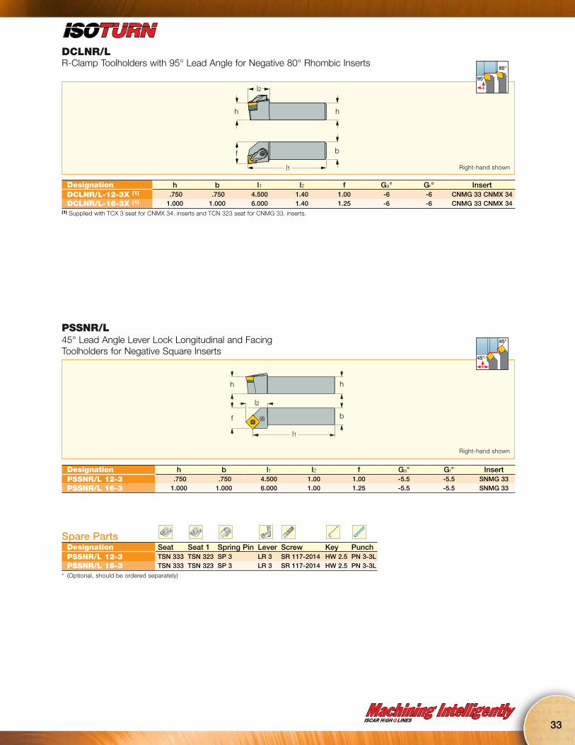
DCLNR/LR-Clamp Toolholders with 95° Lead Angle for Negative 80° Rhombic Inserts
l2
h
l1
h
bf
95°
95°
Designation h b l1 l2 f Ga° Gr° InsertDCLNR/L-12-3X (1) .750 .750 4.500 1.40 1.00 -6 -6 CNMG 33 CNMX 34DCLNR/L-16-3X (1) 1.000 1.000 6.000 1.40 1.25 -6 -6 CNMG 33 CNMX 34
(1) Supplied with TCX 3 seat for CNMX 34. inserts and TCN 323 seat for CNMG 33. inserts.
Right-hand shown
PSSNR/L45° Lead Angle Lever Lock Longitudinal and Facing Toolholders for Negative Square Inserts
hh
f b
l2
l1
45°
45°
Designation h b l1 l2 f Ga° Gr° InsertPSSNR/L 12-3 .750 .750 4.500 1.00 1.00 -5.5 -5.5 SNMG 33PSSNR/L 16-3 1.000 1.000 6.000 1.00 1.25 -5.5 -5.5 SNMG 33
Spare PartsDesignation Seat Seat 1 Spring Pin Lever Screw Key PunchPSSNR/L 12-3 TSN 333 TSN 323 SP 3 LR 3 SR 117-2014 HW 2.5 PN 3-3LPSSNR/L 16-3 TSN 333 TSN 323 SP 3 LR 3 SR 117-2014 HW 2.5 PN 3-3L
* (Optional, should be ordered separately)
Right-hand shown
34
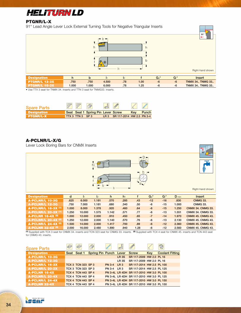
PTGNR/L-X91° Lead Angle Lever Lock External Turning Tools for Negative Triangular Inserts
l1
f b
l2
hh
91°
Designation h b l1 l2 f Ga° Gr° InsertPTGNR/L 12-3X .750 .750 4.500 .78 1.00 -6 -6 TNMX 34.. TNMG 33..PTGNR/L 16-3X 1.000 1.000 6.000 .78 1.25 -6 -6 TNMX 34.. TNMG 33..
• Use TTX 3 seat for TNMX 34. inserts and TTN 3 seat for TNMG33. inserts.
Spare PartsDesignation Seat Seat 1 Spring Pin Lever Screw Key PunchPTGNR/L-X TTX 3 TTN 3 SP 3 LR 3 SR 117-2014 HW 2.5 PN 3-4
Right-hand shown
A-PCLNR/L-X/GLever Lock Boring Bars for CNMX Inserts
h1
fl2
l1
D
h
d
95º
Designation d l1 l2 h h1 f Ga° Gr° D min InsertA-PCLNR/L 10-3G .625 6.000 1.181 .570 .285 .43 -12 -16 .830 CNMG 33.A-PCLNR/L 12-3G .750 7.000 1.181 .680 .340 .50 -6 -15 1.000 CNMG 33.
A-PCLNR/L 16-3X (1) 1.000 8.000 1.378 .920 .460 .64 -6 -15 1.250 CNMX 34. CNMG 33.
A-PCLNR/L 20-3X (1) 1.250 10.000 1.575 1.142 .571 .77 -6 -13 1.551 CNMX 34. CNMG 33.
A-PCLNR 16-4X (2) 1.000 12.000 2.000 .910 .450 .65 -7 -14 1.970 CNMX 45. CNMG 43.
A-PCLNR/L 20-4X (2) 1.250 12.000 2.000 1.140 .570 .76 -6 -13 2.130 CNMX 45. CNMG 43.
A-PCLNR/L 24-4X (2) 1.500 14.000 2.000 1.417 .700 .89 -6 -12 2.360 CNMX 45. CNMG 43.A-PCLNR 32-4X (2) 2.000 16.000 2.480 1.890 .940 1.28 -6 -12 2.560 CNMX 45. CNMG 43.
(1) Supplied with TCX 3 seat for CNMX 34. inserts and TCN 323 seat for CNMG 33. inserts. (2) Supplied with TCX 4 seat for CNMX 45. inserts and TCN 443 seat for CNMG 43. inserts.
Spare PartsDesignation Seat Seat 1 Spring Pin Punch Lever Screw Key Coolant FittingA-PCLNR/L 10-3G LR 3S SR 117-2009 HW 2.0 PL 16A-PCLNR/L 12-3G LR 3S SR 117-2009 HW 2.0 PL 16
A-PCLNR/L 16-3X TCX 3 TCN 323 SP 3 PN 3-4 LR 3 SR 117-2014 HW 2.5 PL 100
A-PCLNR/L 20-3X TCX 3 TCN 323 SP 3 PN 3-4 LR 3 SR 117-2014 HW 2.5 PL 125
A-PCLNR 16-4X TCX 4 TCN 443 SP 4 PN 3-4L LR 4DH SR 117-2010 HW 3.0 PL 100
A-PCLNR/L 20-4X TCX 4 TCN 443 SP 4 PN 3-4L LR 4DH SR 117-2010 HW 3.0 PL 125
A-PCLNR/L 24-4X TCX 4 TCN 443 SP 4 PN 3-4L LR 4DH SR 117-2010 HW 3.0 PL 150A-PCLNR 32-4X TCX 4 TCN 443 SP 4 PN 3-4L LR 4DH SR 117-2010 HW 3.0 PL 150
Right-hand shown
Machining IntelligentlyISCAR HIGH Q LINES
35
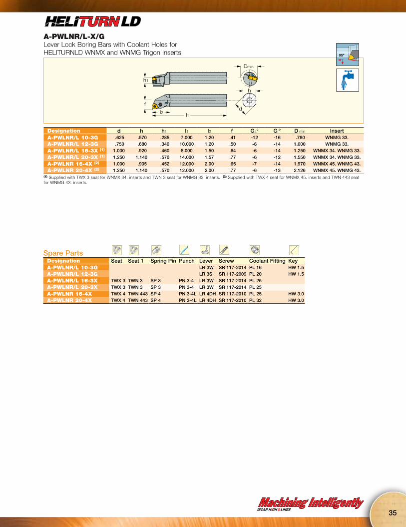
A-PWLNR/L-X/GLever Lock Boring Bars with Coolant Holes for HELITURNLD WNMX and WNMG Trigon Inserts
Dmin
h
df
h1
l1l2
95º
Designation d h h1 l1 l2 f Ga° Gr° D min InsertA-PWLNR/L 10-3G .625 .570 .285 7.000 1.20 .41 -12 -16 .780 WNMG 33.A-PWLNR/L 12-3G .750 .680 .340 10.000 1.20 .50 -6 -14 1.000 WNMG 33.
A-PWLNR/L 16-3X (1) 1.000 .920 .460 8.000 1.50 .64 -6 -14 1.250 WNMX 34. WNMG 33.
A-PWLNR/L 20-3X (1) 1.250 1.140 .570 14.000 1.57 .77 -6 -12 1.550 WNMX 34. WNMG 33.
A-PWLNR 16-4X (2) 1.000 .905 .452 12.000 2.00 .65 -7 -14 1.970 WNMX 45. WNMG 43.A-PWLNR 20-4X (2) 1.250 1.140 .570 12.000 2.00 .77 -6 -13 2.126 WNMX 45. WNMG 43.
(1) Supplied with TWX 3 seat for WNMX 34. inserts and TWN 3 seat for WNMG 33. inserts. (2) Supplied with TWX 4 seat for WNMX 45. inserts and TWN 443 seat for WNMG 43. inserts.
Spare PartsDesignation Seat Seat 1 Spring Pin Punch Lever Screw Coolant Fitting KeyA-PWLNR/L 10-3G LR 3W SR 117-2014 PL 16 HW 1.5A-PWLNR/L 12-3G LR 3S SR 117-2009 PL 20 HW 1.5
A-PWLNR/L 16-3X TWX 3 TWN 3 SP 3 PN 3-4 LR 3W SR 117-2014 PL 25
A-PWLNR/L 20-3X TWX 3 TWN 3 SP 3 PN 3-4 LR 3W SR 117-2014 PL 25
A-PWLNR 16-4X TWX 4 TWN 443 SP 4 PN 3-4L LR 4DH SR 117-2010 PL 25 HW 3.0A-PWLNR 20-4X TWX 4 TWN 443 SP 4 PN 3-4L LR 4DH SR 117-2010 PL 32 HW 3.0
36
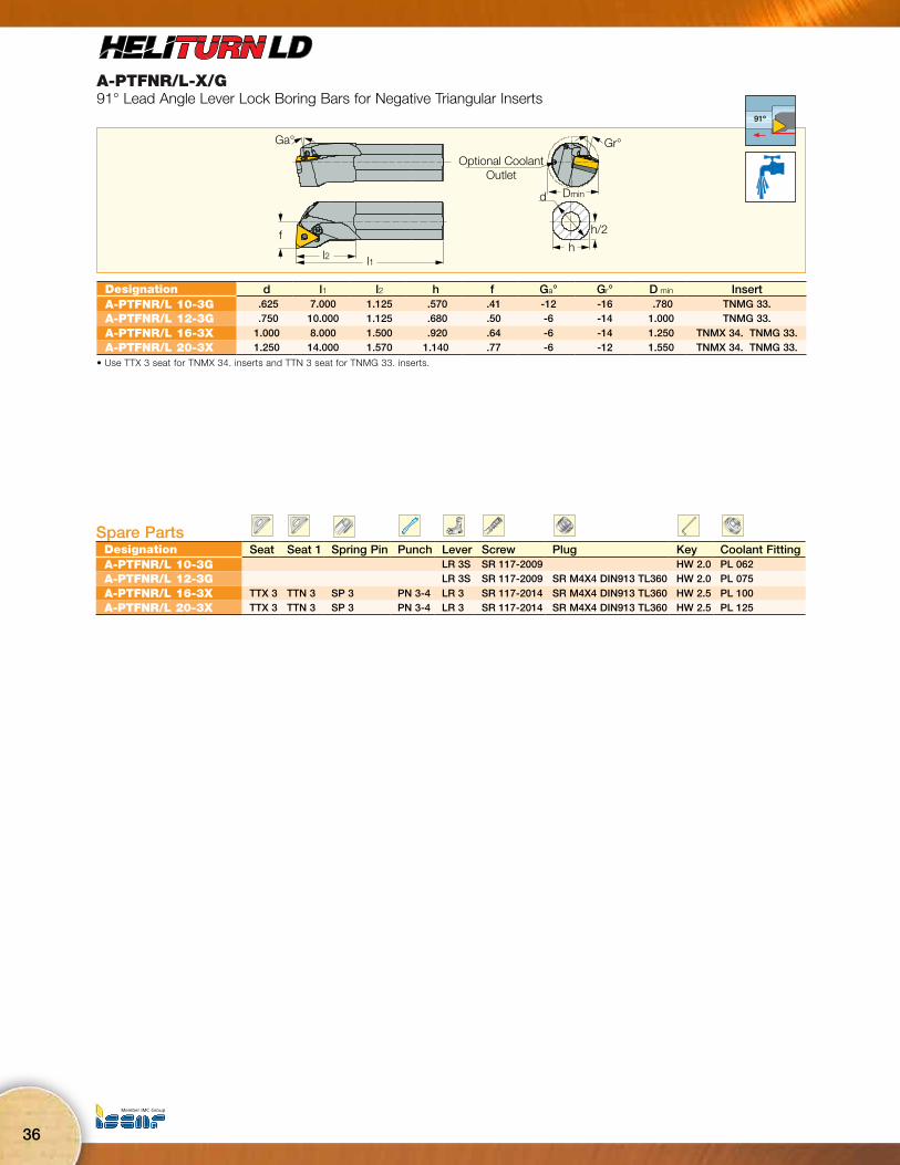
A-PTFNR/L-X/G91° Lead Angle Lever Lock Boring Bars for Negative Triangular Inserts
Gr°
Dmind
h
h/2
Optional CoolantOutlet
Ga°
f
l2 l1
91º
Designation d l1 l2 h f Ga° Gr° D min InsertA-PTFNR/L 10-3G .625 7.000 1.125 .570 .41 -12 -16 .780 TNMG 33. A-PTFNR/L 12-3G .750 10.000 1.125 .680 .50 -6 -14 1.000 TNMG 33.
A-PTFNR/L 16-3X 1.000 8.000 1.500 .920 .64 -6 -14 1.250 TNMX 34. TNMG 33. A-PTFNR/L 20-3X 1.250 14.000 1.570 1.140 .77 -6 -12 1.550 TNMX 34. TNMG 33.
• Use TTX 3 seat for TNMX 34. inserts and TTN 3 seat for TNMG 33. inserts.
Spare PartsDesignation Seat Seat 1 Spring Pin Punch Lever Screw Plug Key Coolant FittingA-PTFNR/L 10-3G LR 3S SR 117-2009 HW 2.0 PL 062A-PTFNR/L 12-3G LR 3S SR 117-2009 SR M4X4 DIN913 TL360 HW 2.0 PL 075
A-PTFNR/L 16-3X TTX 3 TTN 3 SP 3 PN 3-4 LR 3 SR 117-2014 SR M4X4 DIN913 TL360 HW 2.5 PL 100A-PTFNR/L 20-3X TTX 3 TTN 3 SP 3 PN 3-4 LR 3 SR 117-2014 SR M4X4 DIN913 TL360 HW 2.5 PL 125

Machining IntelligentlyISCAR HIGH Q LINES
37
A-PSKNR/L-3Lever Lock Boring Bars for 90° Negative Square Inserts
h
Dmin
d
f 75°
l2l1
h1
75º
Designation d l1 l2 h h1 f Ga° Gr° D min InsertA-PSKNR/L 10-3 .625 7.000 1.380 .570 .285 .43 -14 -16 .866 SNMG 33A-PSKNR/L 12-3 .750 10.000 1.380 .680 .340 .50 -10 -14 .984 SNMG 33
A-PSKNR/L 16-3 1.000 12.000 1.380 .920 .460 .64 -15 -15 1.260 SNMG 32 SNMG 33A-PSKNR/L 20-3 1.250 14.000 1.570 1.140 .570 .77 -13 -13 1.417 SNMG 32 SNMG 33
Spare PartsDesignation Seat Seat 1 Spring Pin Punch Lever Screw Screw 1 Key Coolant FittingA-PSKNR/L 10-3 LR 3S SR 117-2009 HW 2.0 PL 16A-PSKNR/L 12-3 LR 3S SR 117-2009 HW 2.0 PL 20
A-PSKNR/L 16-3 TSN 323 TSN 333 SP 3 PN 3-3L LR 3 SR 117-2014 SR M4X5DIN913 45H 1 HW 2.5 PL 25A-PSKNR/L 20-3 TSN 323 TSN 333 SP 3 PN 3-3L LR 3 SR 117-2014 SR M4X5DIN913 45H 1 HW 2.5 PL 25

NEW25° CORNER ANGLE
NARROWEST TURNING INSERTISOTURN YNMGSmall Size InsertsISCAR has added a new geometry to its line of small economical inserts: YNMG 33…, which fits into the standard pocket of VNMG 33… insert. The YNMG 33… insert features a 25º corner angle. It was designed for turning of very narrow V-shaped grooves which cannot be machined by the standard 35º inserts.
38
No Time for Look Alikes!VImitation

Machining IntelligentlyISCAR HIGH Q LINES
39
YNMG-F3PDouble-Sided 25° Corner Inserts for Internal and External Deep and Narrow Profiling and Undercutting
25°
35°
l
di
Sr
50° max93°
72.5° 70° max
Dimensions Tough Ö HardRecommended Machining Data
Designation l di lt S r IC82
50
IC81
50
ap
(inch)f
(IPR)YNMG 331-F3P .654 .375 .22 .187 .016 l l .016-.118 .0012-.0047YNMG 332-F3P .654 .375 .21 .187 .031 l l .035-.157 .0020-.0059
• Use IYSN 322 seat for these inserts

Highly Rigid Profiling Toolsfor Accurate ContoursISCAR is introducing the SDNCN 16-13-SL screw lock toolholder for 55° diamond inserts with a 7° clearance angle. A long groove on the pocket and a matching ridge at the insert bottom ensure high rigidity in profiling applications. The new design ensures high edge location after indexing and no backlash when changing machining direction, as required in profiling applications.The new DCMT 13T5..-SL 55° rhombicpositive flank inserts with new F3P and M3M
chipformers were designed for semi-finishing and finishing of steel and stainless steel. A ridge at the insert bottom which fits onto along groove on the tool’s seat ensures high edge location precision.The new design enables machining at high chip load, thus reducing machining cycle time while maintaining high profile accuracy.
40
No Time for Look Alikes!VImitation
Machining IntelligentlyISCAR HIGH Q LINES
41
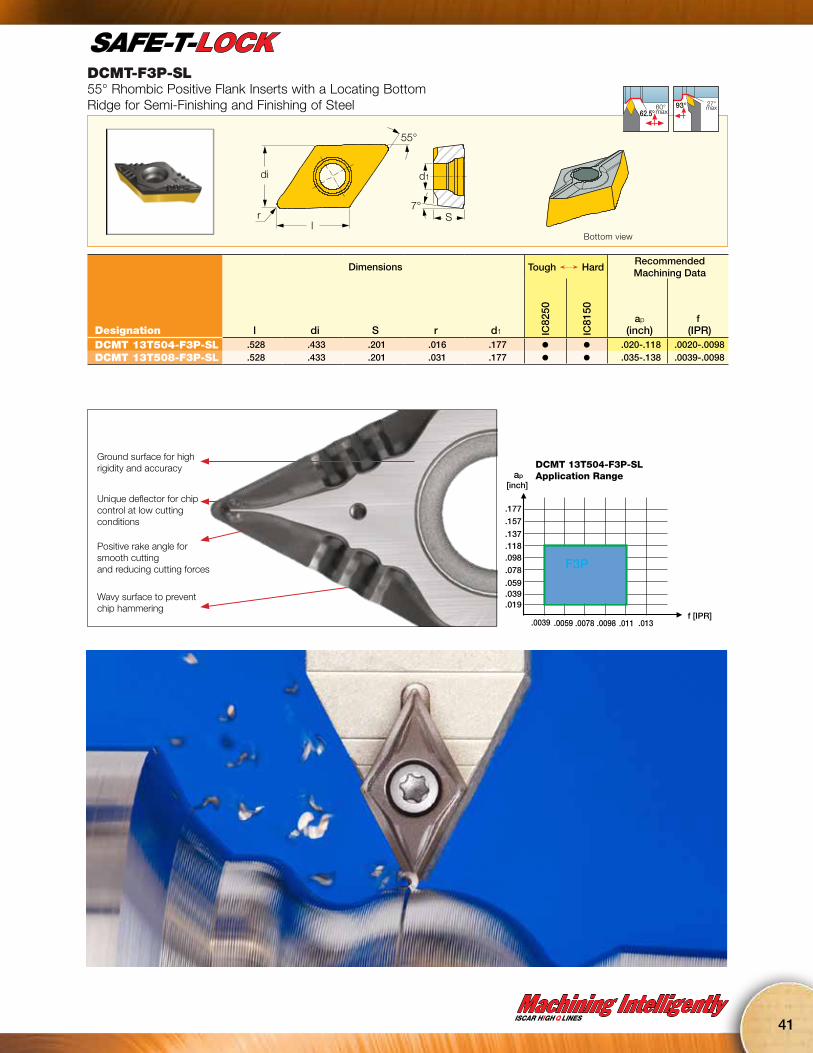
DCMT-F3P-SL55° Rhombic Positive Flank Inserts with a Locating Bottom Ridge for Semi-Finishing and Finishing of Steel
55°
7°S
di d1
rl
60° max62.5°
27°max93°
Dimensions Tough Ö HardRecommended Machining Data
Designation l di S r d1 IC82
50
IC81
50
ap
(inch)f
(IPR)DCMT 13T504-F3P-SL .528 .433 .201 .016 .177 l l .020-.118 .0020-.0098DCMT 13T508-F3P-SL .528 .433 .201 .031 .177 l l .035-.138 .0039-.0098
Bottom view
.019
.039
.059
.078
.098
.118
.137
.157
.177
.0039 .0059 .0078 .0098 .011 .013f [IPR]
F3P
ap
[inch]
Ground surface for high rigidity and accuracy
Unique deflector for chipcontrol at low cutting conditions
Positive rake angle for smooth cuttingand reducing cutting forces
Wavy surface to prevent chip hammering
DCMT 13T504-F3P-SL Application Range

42
DCMT-M3M-SL55° Rhombic Positive Flank Inserts with a Locating Bottom Ridge, for Machining Stainless and Low Carbon Steel
55°
7°S
di d1
rl
60° max62.5°
27°max93°
Dimensions Tough Ö HardRecommended Machining Data
Designation l di S r d1 IC60
25
IC60
15
ap
(inch)f
(IPR)DCMT 13T508-M3M-SL .528 .433 .201 .031 .177 l l .035-.138 .0039-.0098DCMT 13T512-M3M-SL .528 .433 .201 .047 .177 l l .035-.138 .0059-.0118
Bottom view
.019
.039
.059
.078
.098
.118
.137
.157
.177
.0039 .0059 .0078 .0098 .011 .013f [IPR]
ap
[inch]
M3M
Unique deflector design
Strong radius
Reinforced cutting edge preventsnotch wear
Positive rake anglefor smooth cuttingand reducing cutting forces
DCMT 13T508-M3M-SL Application Range
Machining IntelligentlyISCAR HIGH Q LINES
43
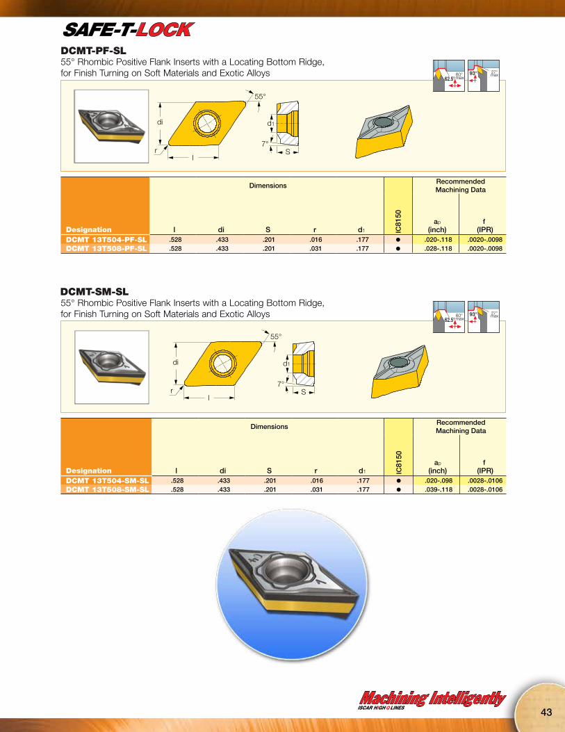
DCMT-PF-SL55° Rhombic Positive Flank Inserts with a Locating Bottom Ridge, for Finish Turning on Soft Materials and Exotic Alloys
55°
7°S
di d1
rl
60° max62.5°
27°max93°
DimensionsRecommended Machining Data
Designation l di S r d1 IC81
50
ap
(inch)f
(IPR)DCMT 13T504-PF-SL .528 .433 .201 .016 .177 l .020-.118 .0020-.0098DCMT 13T508-PF-SL .528 .433 .201 .031 .177 l .028-.118 .0020-.0098
DCMT-SM-SL55° Rhombic Positive Flank Inserts with a Locating Bottom Ridge, for Finish Turning on Soft Materials and Exotic Alloys
55°
7°S
di d1
rl
60° max62.5°
27°max93°
DimensionsRecommended Machining Data
Designation l di S r d1 IC81
50
ap
(inch)f
(IPR)DCMT 13T504-SM-SL .528 .433 .201 .016 .177 l .020-.098 .0028-.0106DCMT 13T508-SM-SL .528 .433 .201 .031 .177 l .039-.118 .0028-.0106
44
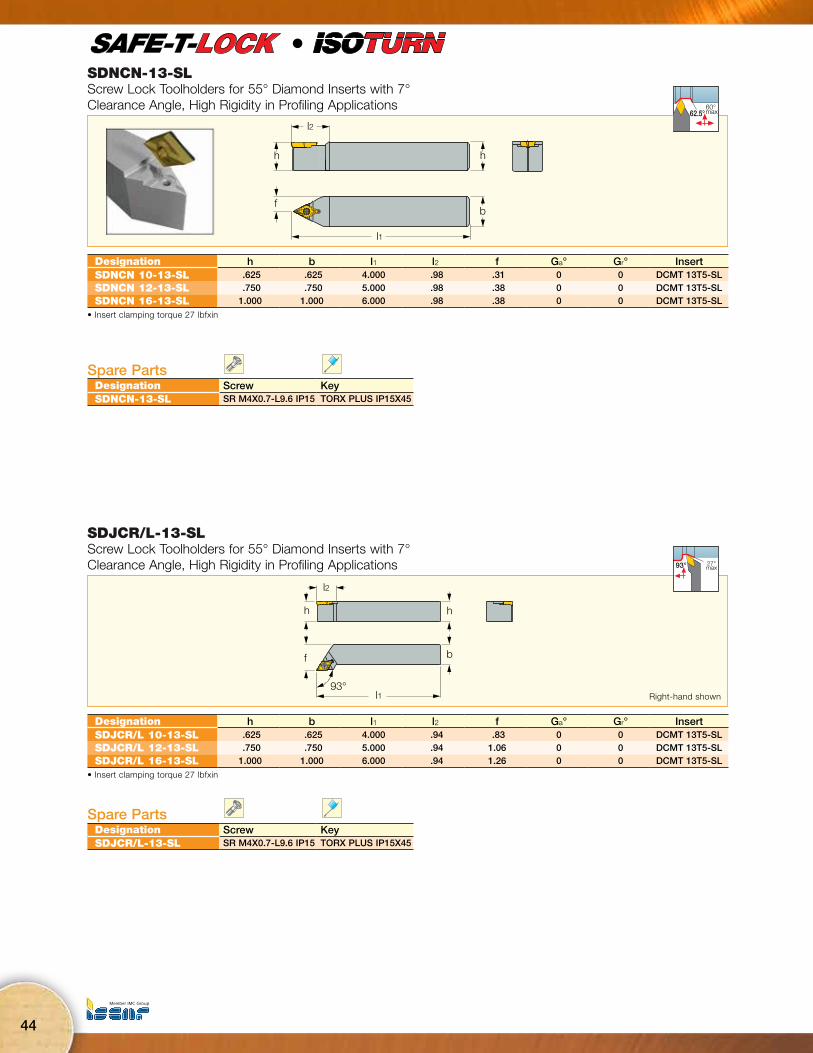
SDNCN-13-SLScrew Lock Toolholders for 55° Diamond Inserts with 7° Clearance Angle, High Rigidity in Profiling Applications
l2
hh
l1
fb
60° max62.5°
l
Designation h b l1 l2 f Ga° Gr° InsertSDNCN 10-13-SL .625 .625 4.000 .98 .31 0 0 DCMT 13T5-SLSDNCN 12-13-SL .750 .750 5.000 .98 .38 0 0 DCMT 13T5-SLSDNCN 16-13-SL 1.000 1.000 6.000 .98 .38 0 0 DCMT 13T5-SL
• Insert clamping torque 27 lbfxin
Spare PartsDesignation Screw KeySDNCN-13-SL SR M4X0.7-L9.6 IP15 TORX PLUS IP15X45
SDJCR/L-13-SLScrew Lock Toolholders for 55° Diamond Inserts with 7° Clearance Angle, High Rigidity in Profiling Applications
l2
l1
f
93°
b
hh
27°max93°
Designation h b l1 l2 f Ga° Gr° InsertSDJCR/L 10-13-SL .625 .625 4.000 .94 .83 0 0 DCMT 13T5-SLSDJCR/L 12-13-SL .750 .750 5.000 .94 1.06 0 0 DCMT 13T5-SLSDJCR/L 16-13-SL 1.000 1.000 6.000 .94 1.26 0 0 DCMT 13T5-SL
• Insert clamping torque 27 lbfxin
Spare PartsDesignation Screw KeySDJCR/L-13-SL SR M4X0.7-L9.6 IP15 TORX PLUS IP15X45
Right-hand shown

Machining IntelligentlyISCAR HIGH Q LINES
45
A-SDUCR/L-13-SLScrew Lock Boring Bars for 55° Rhombic Inserts with 7° Clearance Angle, High Rigidity in Profiling Applications
h
Dmin
d
f 93°
l1
h1
l2
93º
30ºmax
Designation d l1 l2 h h1 f D min Ga° Gr° Shank m. InsertA-SDUCR/L 12-13-SL .750 10.000 1.400 .670 .339 .57 1.000 0 -7 S DCMT 13T5-SLA SDUCR/L 16-13-SL 1.000 12.000 1.800 .920 .460 .67 1.250 0 -6 S DCMT 13T5-SL
Spare PartsDesignation Screw Key Coolant FittingA-SDUCR/L 12-13-SL SR M4X0.7-L9.6 IP15 TORX PLUS IP15X45 PL 20A SDUCR/L 16-13-SL SR M4X0.7-L9.6 IP15 TORX PLUS IP15X45 PL 25
NEWHIGHLY RIGID
PROFILING TOOL
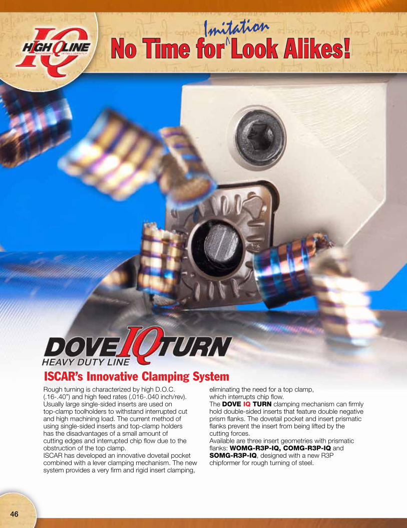
ISCAR’s Innovative Clamping SystemRough turning is characterized by high D.O.C.(.16-.40”) and high feed rates (.016-.040 inch/rev).Usually large single-sided inserts are used ontop-clamp toolholders to withstand interrupted cut and high machining load. The current method ofusing single-sided inserts and top-clamp holdershas the disadvantages of a small amount of cutting edges and interrupted chip flow due to the obstruction of the top clamp. ISCAR has developed an innovative dovetail pocket combined with a lever clamping mechanism. The new system provides a very firm and rigid insert clamping,
eliminating the need for a top clamp, which interrupts chip flow. The DOVE IQ TURN clamping mechanism can firmly hold double-sided inserts that feature double negative prism flanks. The dovetail pocket and insert prismatic flanks prevent the insert from being lifted by the cutting forces. Available are three insert geometries with prismatic flanks: WOMG-R3P-IQ, COMG-R3P-IQ and SOMG-R3P-IQ, designed with a new R3P chipformer for rough turning of steel.
46
No Time for Look Alikes!VImitation
Machining IntelligentlyISCAR HIGH Q LINES
47
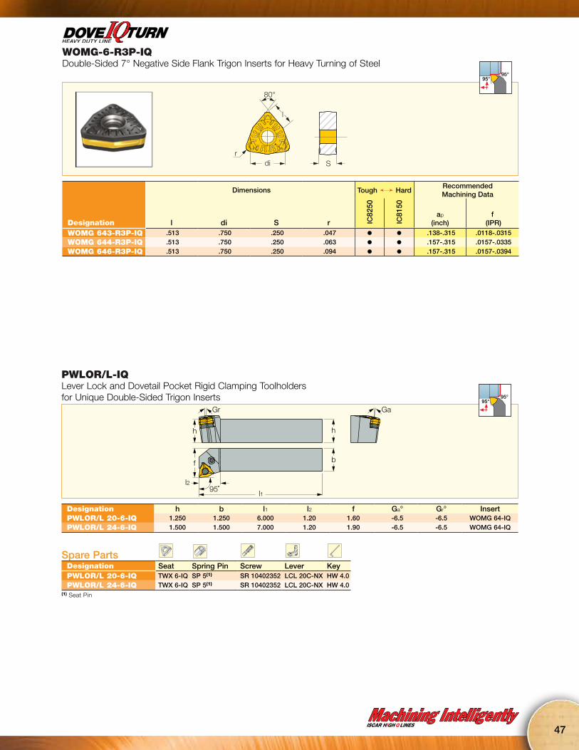
WOMG-6-R3P-IQDouble-Sided 7° Negative Side Flank Trigon Inserts for Heavy Turning of Steel
di
80°
l
rS
95°95°
Dimensions Tough Ö HardRecommended Machining Data
Designation l di S r IC82
50
IC81
50
ap
(inch)f
(IPR)WOMG 643-R3P-IQ .513 .750 .250 .047 l l .138-.315 .0118-.0315WOMG 644-R3P-IQ .513 .750 .250 .063 l l .157-.315 .0157-.0335WOMG 646-R3P-IQ .513 .750 .250 .094 l l .157-.315 .0157-.0394
PWLOR/L-IQLever Lock and Dovetail Pocket Rigid Clamping Toolholders for Unique Double-Sided Trigon Inserts
Gr Ga
h
f
l295˚
l1
b
h
95°95°
Designation h b l1 l2 f Ga° Gr° InsertPWLOR/L 20-6-IQ 1.250 1.250 6.000 1.20 1.60 -6.5 -6.5 WOMG 64-IQPWLOR/L 24-6-IQ 1.500 1.500 7.000 1.20 1.90 -6.5 -6.5 WOMG 64-IQ
Spare PartsDesignation Seat Spring Pin Screw Lever KeyPWLOR/L 20-6-IQ TWX 6-IQ SP 5(1) SR 10402352 LCL 20C-NX HW 4.0PWLOR/L 24-6-IQ TWX 6-IQ SP 5(1) SR 10402352 LCL 20C-NX HW 4.0
(1) Seat Pin

48
C#-PWLOR/L-IQLever Lock and Dovetail Pocket Tools with CAMFIX Shanks for Unique Double-Sided Trigon Inserts
95°l1
Gr°
SSf
95°95°
l
Designation SS f l1 Ga° Gr° InsertC6 PWLOR/L-45065-13-IQ 63 1.77 2.559 -6.5 -6.5 WOMG 1306-IQ
Spare PartsDesignation Cooling Nozzle Key Lever Screw Seat Spring PinC#-PWLOR/L-IQ SATZ-M10X1-M5 HW 4.0 LCL 20C-NX SR 10402352 TWX 6-IQ SP 5
COMG-R3P-IQDouble-Sided 7° Negative Side Flank 80° Rhombic Inserts for Heavy Turning of Steel
Sr l
di
80°
95°
95° 75°
Dimensions Tough Ö HardRecommended Machining Data
Designation l di S r IC82
50
IC81
50
ap
(inch)f
(IPR)COMG 542-R3P-IQ .635 .625 .250 .031 l l .079-.354 .0098-.0197COMG 543-R3P-IQ .635 .625 .250 .047 l l .079-.354 .0118-.0236
COMG 544-R3P-IQ .635 .625 .250 .063 l l .079-.354 .0118-.0276
COMG 643-R3P-IQ .761 .750 .250 .047 l l .118-.472 .0118-.0315
COMG 644-R3P-IQ .761 .750 .250 .063 l l .138-.472 .0138-.0354
COMG 646-R3P-IQ .761 .750 .250 .094 l l .138-.472 .0138-.0354COMG 866-R3P-IQ 1.015 1.000 .375 .094 l l .157-.591 .0157-.0394

Machining IntelligentlyISCAR HIGH Q LINES
49
PCLOR/L-IQLever Lock and Dovetail Pocket Rigid Clamping Toolholders for Unique Double-Sided 80° Rhombic Inserts
Ga°
h
b
l195°
f
h
Gr°
l2
95°
95°
Designation h b l1 l2 f Ga° Gr° InsertPCLOR/L 20-5-IQ 1.250 1.250 6.000 1.30 1.60 -6 -6 COMG 54PCLOR/L 20-6-IQ 1.250 1.250 6.000 1.50 1.60 -6 -6 COMG 64
PCLOR/L 24-6-IQ 1.500 1.500 7.000 1.50 2.00 -6 -6 COMG 64
PCLOR/L 24-8-IQ 1.500 1.500 7.000 2.00 2.00 -6 -6 COMG 86PCLOR/L 32-8-IQ 2.000 2.000 8.000 2.00 2.40 -6 -6 COMG 86
Spare PartsDesignation Seat Spring Pin Screw Lever KeyPCLOR/L 20-5-IQ TCX 5-IQ SP 5 SR LCS 5 LCL 16-NX HW 3.0PCLOR/L 20-6-IQ TCX 6-IQ SP 5 SR 10402352 LCL 20C-NX HW 4.0
PCLOR/L 24-6-IQ TCX 6-IQ SP 5 SR 10402352 LCL 20C-NX HW 4.0
PCLOR/L 24-8-IQ TCX 8-IQ SP 8 SR LCS 8-L39 LCL 32-NX HW 5.0PCLOR/L 32-8-IQ TCX 8-IQ SP 8 SR LCS 8-L39 LCL 32-NX HW 5.0
C#-PCLOR/L-IQLever Lock and Dovetail Pocket Tools with CAMFIX Shanks for Unique Double-Sided 80° Rhombic Inserts
Gr°
SSf
95°l1
95°
95°
l
Designation SS f l1 Ga° Gr° InsertC6 PCLOR/L-45065-16-IQ 63 1.77 2.559 -6 -6 COMG 1606C6 PCLOR/L-45065-19-IQ 63 1.77 2.559 -6 -6 COMG 1906
C8 PCLOR/L-55080-19-IQ 80 2.17 3.150 -6 -6 COMG 1906C8 PCLOR/L-55080-25-IQ 80 2.17 3.150 -6 -6 COMG 2509
Spare PartsDesignation Seat Lever Spring Pin Cooling Nozzle Key ScrewC6 PCLOR/L-45065-16-IQ TCX 5-IQ LCL 16-NX SP 5 SATZ-M10X1-M5 HW 3.0 SR LCS 5-L25.5C6 PCLOR/L-45065-19-IQ TCX 6-IQ LCL 20C-NX SP 5 SATZ-M10X1-M5 HW 4.0 SR 10402352

50
PCBOR/L-IQLever Lock and Dovetail Pocket Rigid Clamping Toolholders for Unique Double-Sided 80° Rhombic Inserts
Gr° Ga°
h
f
75° l1
h
l2
b
75°
Designation h b l1 l2 f Ga° Gr° InsertPCBOR/L 20-5-IQ 1.250 1.250 6.000 1.25 1.06 -6 -6 COMG 54PCBOR/L 20-6-IQ 1.250 1.250 6.000 1.50 1.10 -6 -6 COMG 64
PCBOR/L 24-6-IQ 1.500 1.500 7.000 1.50 1.40 -6 -6 COMG 64
PCBOR/L 24-8-IQ 1.500 1.500 7.000 2.00 1.30 -6 -6 COMG 86PCBOR/L 32-8-IQ 2.000 2.000 8.000 2.00 1.80 -6 -6 COMG 86
Spare PartsDesignation Seat Spring Pin Screw Lever KeyPCBOR/L 20-5-IQ TCX 5-IQ SP 5 SR LCS 5 LCL 16-NX HW 3.0PCBOR/L 20-6-IQ TCX 6-IQ SP 5 SR 10402352 LCL 20C-NX HW 4.0
PCBOR/L 24-6-IQ TCX 6-IQ SP 5 SR 10402352 LCL 20C-NX HW 4.0
PCBOR/L 24-8-IQ TCX 8-IQ SP 8 SR LCS 8-L39 LCL 32-NX HW 5.0PCBOR/L 32-8-IQ TCX 8-IQ SP 8 SR LCS 8-L39 LCL 32-NX HW 5.0
SOMG-R3P-IQDouble-Sided 7° Negative Side Flank Square Inserts for Heavy Turning of Steel
di=l
rS
di 90°
75° 45°
Dimensions Tough Ö HardRecommended Machining Data
Designation l di S r IC82
50
IC81
50
ap
(inch)f
(IPR)SOMG 543-R3P-IQ .625 .625 .250 .047 l l .079-.354 .0118-.0236
SOMG 544-R3P-IQ .625 .625 .250 .063 l l .079-.354 .0118-.0276
SOMG 643-R3P-IQ .750 .750 .250 .047 l l .118-.472 .0118-.0315
SOMG 644-R3P-IQ .750 .750 .250 .063 l l .138-.472 .0138-.0335
SOMG 646-R3P-IQ .750 .750 .250 .094 l l .138-.472 .0157-.0394SOMG 866-R3P-IQ 1.000 1.000 .375 .094 l l .157-.591 .0157-.0394
Machining IntelligentlyISCAR HIGH Q LINES
51
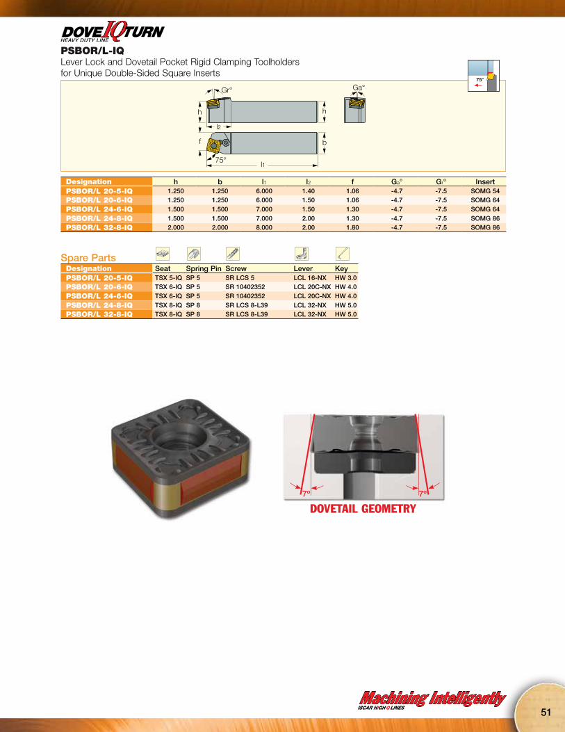
PSBOR/L-IQLever Lock and Dovetail Pocket Rigid Clamping Toolholders for Unique Double-Sided Square Inserts
Ga°
b
l175°
f
h
Gr°
l2
h
75°
Designation h b l1 l2 f Ga° Gr° InsertPSBOR/L 20-5-IQ 1.250 1.250 6.000 1.40 1.06 -4.7 -7.5 SOMG 54PSBOR/L 20-6-IQ 1.250 1.250 6.000 1.50 1.06 -4.7 -7.5 SOMG 64
PSBOR/L 24-6-IQ 1.500 1.500 7.000 1.50 1.30 -4.7 -7.5 SOMG 64
PSBOR/L 24-8-IQ 1.500 1.500 7.000 2.00 1.30 -4.7 -7.5 SOMG 86PSBOR/L 32-8-IQ 2.000 2.000 8.000 2.00 1.80 -4.7 -7.5 SOMG 86
Spare PartsDesignation Seat Spring Pin Screw Lever KeyPSBOR/L 20-5-IQ TSX 5-IQ SP 5 SR LCS 5 LCL 16-NX HW 3.0PSBOR/L 20-6-IQ TSX 6-IQ SP 5 SR 10402352 LCL 20C-NX HW 4.0
PSBOR/L 24-6-IQ TSX 6-IQ SP 5 SR 10402352 LCL 20C-NX HW 4.0
PSBOR/L 24-8-IQ TSX 8-IQ SP 8 SR LCS 8-L39 LCL 32-NX HW 5.0PSBOR/L 32-8-IQ TSX 8-IQ SP 8 SR LCS 8-L39 LCL 32-NX HW 5.0
DOVETAIL GEOMETRY7º 7º
52
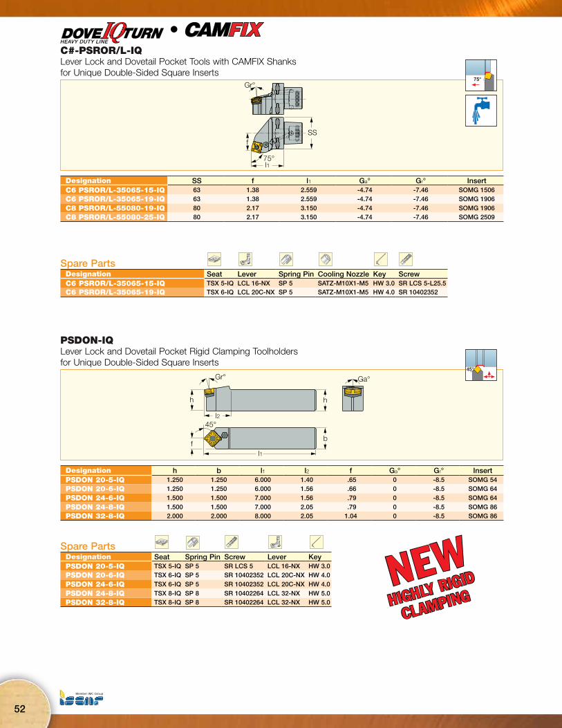
PSDON-IQLever Lock and Dovetail Pocket Rigid Clamping Toolholders for Unique Double-Sided Square Inserts
h
Ga°
l2
l1
Gr°
h
f
45°
b
45°
Designation h b l1 l2 f Ga° Gr° InsertPSDON 20-5-IQ 1.250 1.250 6.000 1.40 .65 0 -8.5 SOMG 54PSDON 20-6-IQ 1.250 1.250 6.000 1.56 .66 0 -8.5 SOMG 64
PSDON 24-6-IQ 1.500 1.500 7.000 1.56 .79 0 -8.5 SOMG 64
PSDON 24-8-IQ 1.500 1.500 7.000 2.05 .79 0 -8.5 SOMG 86PSDON 32-8-IQ 2.000 2.000 8.000 2.05 1.04 0 -8.5 SOMG 86
Spare PartsDesignation Seat Spring Pin Screw Lever KeyPSDON 20-5-IQ TSX 5-IQ SP 5 SR LCS 5 LCL 16-NX HW 3.0PSDON 20-6-IQ TSX 6-IQ SP 5 SR 10402352 LCL 20C-NX HW 4.0
PSDON 24-6-IQ TSX 6-IQ SP 5 SR 10402352 LCL 20C-NX HW 4.0
PSDON 24-8-IQ TSX 8-IQ SP 8 SR 10402264 LCL 32-NX HW 5.0PSDON 32-8-IQ TSX 8-IQ SP 8 SR 10402264 LCL 32-NX HW 5.0
NEWHIGHLY RIGID
CLAMPING
C#-PSROR/L-IQLever Lock and Dovetail Pocket Tools with CAMFIX Shanks for Unique Double-Sided Square Inserts
Gr°
f
75°l1
SS
75°
l
Designation SS f l1 Ga° Gr° InsertC6 PSROR/L-35065-15-IQ 63 1.38 2.559 -4.74 -7.46 SOMG 1506C6 PSROR/L-35065-19-IQ 63 1.38 2.559 -4.74 -7.46 SOMG 1906
C8 PSROR/L-55080-19-IQ 80 2.17 3.150 -4.74 -7.46 SOMG 1906C8 PSROR/L-55080-25-IQ 80 2.17 3.150 -4.74 -7.46 SOMG 2509
Spare PartsDesignation Seat Lever Spring Pin Cooling Nozzle Key ScrewC6 PSROR/L-35065-15-IQ TSX 5-IQ LCL 16-NX SP 5 SATZ-M10X1-M5 HW 3.0 SR LCS 5-L25.5C6 PSROR/L-35065-19-IQ TSX 6-IQ LCL 20C-NX SP 5 SATZ-M10X1-M5 HW 4.0 SR 10402352
Machining IntelligentlyISCAR HIGH Q LINES
53
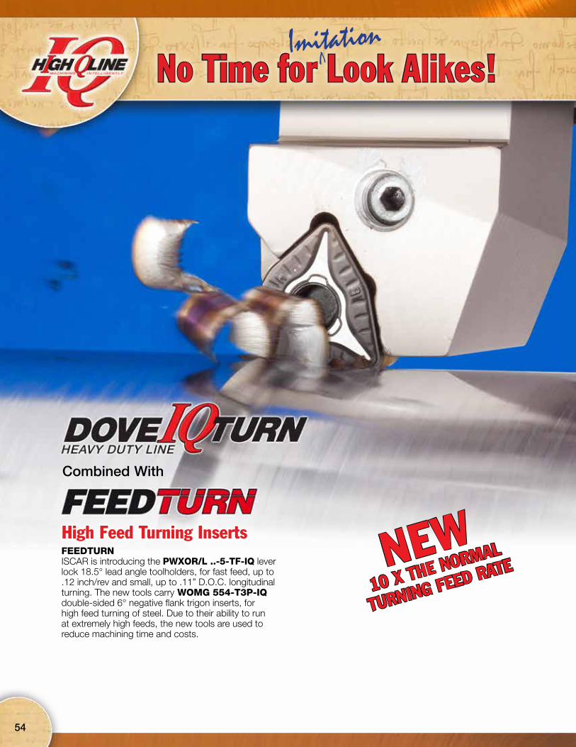
Combined With
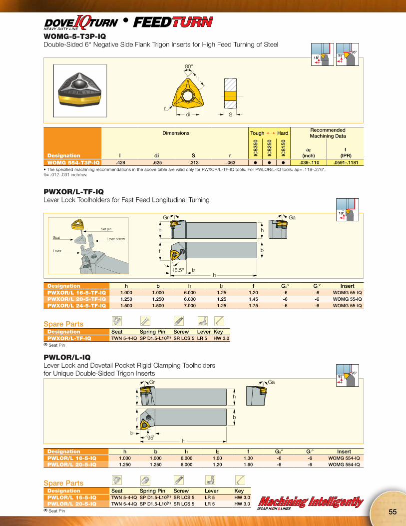
High Feed Turning InsertsFEEDTURNISCAR is introducing the PWXOR/L ..-5-TF-IQ lever lock 18.5° lead angle toolholders, for fast feed, up to .12 inch/rev and small, up to .11” D.O.C. longitudinal turning. The new tools carry WOMG 554-T3P-IQ double-sided 6° negative flank trigon inserts, for high feed turning of steel. Due to their ability to run at extremely high feeds, the new tools are used to reduce machining time and costs.
NEW10 X THE NORMAL
TURNING FEED RATE
54
No Time for Look Alikes!VImitation
Machining IntelligentlyISCAR HIGH Q LINES
55
WOMG-5-T3P-IQDouble-Sided 6° Negative Side Flank Trigon Inserts for High Feed Turning of Steel
di
80°
l
rS
18°
95°95°
l
Dimensions Tough Ö HardRecommended Machining Data
Designation l di S r IC83
50
IC82
50
IC81
50
ap
(inch)f
(IPR)WOMG 554-T3P-IQ .428 .625 .313 .063 l l l .039-.110 .0591-.1181
• The specified machining recommendations in the above table are valid only for PWXOR/L-TF-IQ tools. For PWLOR/L-IQ tools: ap= .118-.276", ft= .012-.031 inch/rev.
PWXOR/L-TF-IQLever Lock Toolholders for Fast Feed Longitudinal Turning
h
f
18.5°
b
h
l2l1
Gr Ga18°
Designation h b l1 l2 f Ga° Gr° InsertPWXOR/L 16-5-TF-IQ 1.000 1.000 6.000 1.25 1.20 -6 -6 WOMG 55-IQPWXOR/L 20-5-TF-IQ 1.250 1.250 6.000 1.25 1.45 -6 -6 WOMG 55-IQPWXOR/L 24-5-TF-IQ 1.500 1.500 7.000 1.25 1.75 -6 -6 WOMG 55-IQ
Spare PartsDesignation Seat Spring Pin Screw Lever KeyPWXOR/L-TF-IQ TWN 5-4-IQ SP D1.5-L10(1) SR LCS 5 LR 5 HW 3.0
(1) Seat Pin
Set pin
Seat
Lever
Lever screw
PWLOR/L-IQLever Lock and Dovetail Pocket Rigid Clamping Toolholders for Unique Double-Sided Trigon Inserts
Gr Ga
h
f
l295˚
l1
b
h
95°95°
Designation h b l1 l2 f Ga° Gr° InsertPWLOR/L 16-5-IQ 1.000 1.000 6.000 1.00 1.30 -6 -6 WOMG 554-IQPWLOR/L 20-5-IQ 1.250 1.250 6.000 1.20 1.60 -6 -6 WOMG 554-IQ
Spare PartsDesignation Seat Spring Pin Screw Lever KeyPWLOR/L 16-5-IQ TWN 5-4-IQ SP D1.5-L10(1) SR LCS 5 LR 5 HW 3.0PWLOR/L 20-5-IQ TWN 5-4-IQ SP D1.5-L10(1) SR LCS 5 LR 5 HW 3.0
(1) Seat Pin

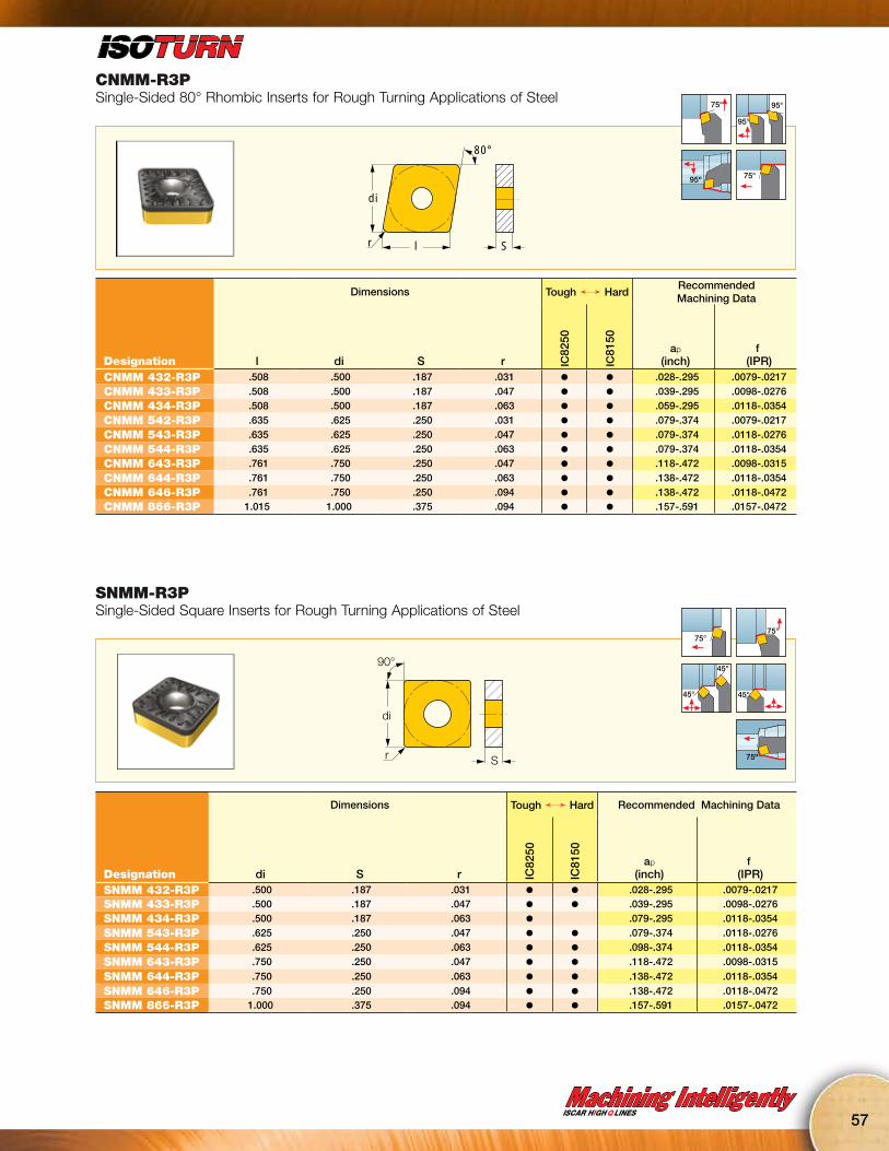
R3P Chipbreakerfor Rough Machining
• Single-sided insert chipbreaker for rough machining of steel
• Reinforced cutting edge• Positive rake angle for smooth
cutting and reduced cutting forces
NEWR3P CHIPBREAKER
56
No Time for Look Alikes!VImitation
Machining IntelligentlyISCAR HIGH Q LINES
57
CNMM-R3PSingle-Sided 80° Rhombic Inserts for Rough Turning Applications of Steel
80°
di
r l S
75° 95°
95°
95º 75°
Dimensions Tough Ö HardRecommended Machining Data
Designation l di S r IC82
50
IC81
50
ap
(inch)f
(IPR)CNMM 432-R3P .508 .500 .187 .031 l l .028-.295 .0079-.0217
CNMM 433-R3P .508 .500 .187 .047 l l .039-.295 .0098-.0276
CNMM 434-R3P .508 .500 .187 .063 l l .059-.295 .0118-.0354
CNMM 542-R3P .635 .625 .250 .031 l l .079-.374 .0079-.0217
CNMM 543-R3P .635 .625 .250 .047 l l .079-.374 .0118-.0276
CNMM 544-R3P .635 .625 .250 .063 l l .079-.374 .0118-.0354
CNMM 643-R3P .761 .750 .250 .047 l l .118-.472 .0098-.0315
CNMM 644-R3P .761 .750 .250 .063 l l .138-.472 .0118-.0354
CNMM 646-R3P .761 .750 .250 .094 l l .138-.472 .0118-.0472CNMM 866-R3P 1.015 1.000 .375 .094 l l .157-.591 .0157-.0472
SNMM-R3PSingle-Sided Square Inserts for Rough Turning Applications of Steel
90°
di
r S
75°75°
45°
45°
45°
75º
Dimensions Tough Ö Hard Recommended Machining Data
Designation di S r IC82
50
IC81
50
ap
(inch)f
(IPR)SNMM 432-R3P .500 .187 .031 l l .028-.295 .0079-.0217SNMM 433-R3P .500 .187 .047 l l .039-.295 .0098-.0276
SNMM 434-R3P .500 .187 .063 l .079-.295 .0118-.0354
SNMM 543-R3P .625 .250 .047 l l .079-.374 .0118-.0276
SNMM 544-R3P .625 .250 .063 l l .098-.374 .0118-.0354
SNMM 643-R3P .750 .250 .047 l l .118-.472 .0098-.0315
SNMM 644-R3P .750 .250 .063 l l .138-.472 .0118-.0354
SNMM 646-R3P .750 .250 .094 l l .138-.472 .0118-.0472SNMM 866-R3P 1.000 .375 .094 l l .157-.591 .0157-.0472
58
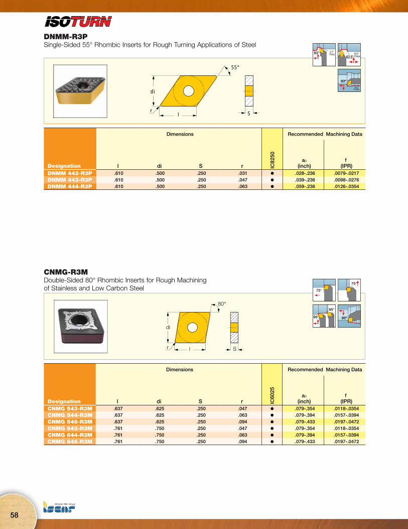
DNMM-R3PSingle-Sided 55° Rhombic Inserts for Rough Turning Applications of Steel
55°
di
l Sr
27°max93° 60°
max62.5°
93º
30ºmax
Dimensions Recommended Machining Data
Designation l di S r IC82
50
ap
(inch)f
(IPR)DNMM 442-R3P .610 .500 .250 .031 l .028-.236 .0079-.0217
DNMM 443-R3P .610 .500 .250 .047 l .039-.236 .0098-.0276DNMM 444-R3P .610 .500 .250 .063 l .059-.236 .0126-.0354
CNMG-R3MDouble-Sided 80° Rhombic Inserts for Rough Machining of Stainless and Low Carbon Steel
80°
di
r l S
75°
75°
95°
95° 95º
Dimensions Recommended Machining Data
Designation l di S r IC60
25
ap
(inch)f
(IPR)CNMG 543-R3M .637 .625 .250 .047 l .079-.354 .0118-.0354CNMG 544-R3M .637 .625 .250 .063 l .079-.394 .0157-.0394
CNMG 546-R3M .637 .625 .250 .094 l .079-.433 .0197-.0472
CNMG 643-R3M .761 .750 .250 .047 l .079-.354 .0118-.0354
CNMG 644-R3M .761 .750 .250 .063 l .079-.394 .0157-.0394CNMG 646-R3M .761 .750 .250 .094 l .079-.433 .0197-.0472
Machining IntelligentlyISCAR HIGH Q LINES
59
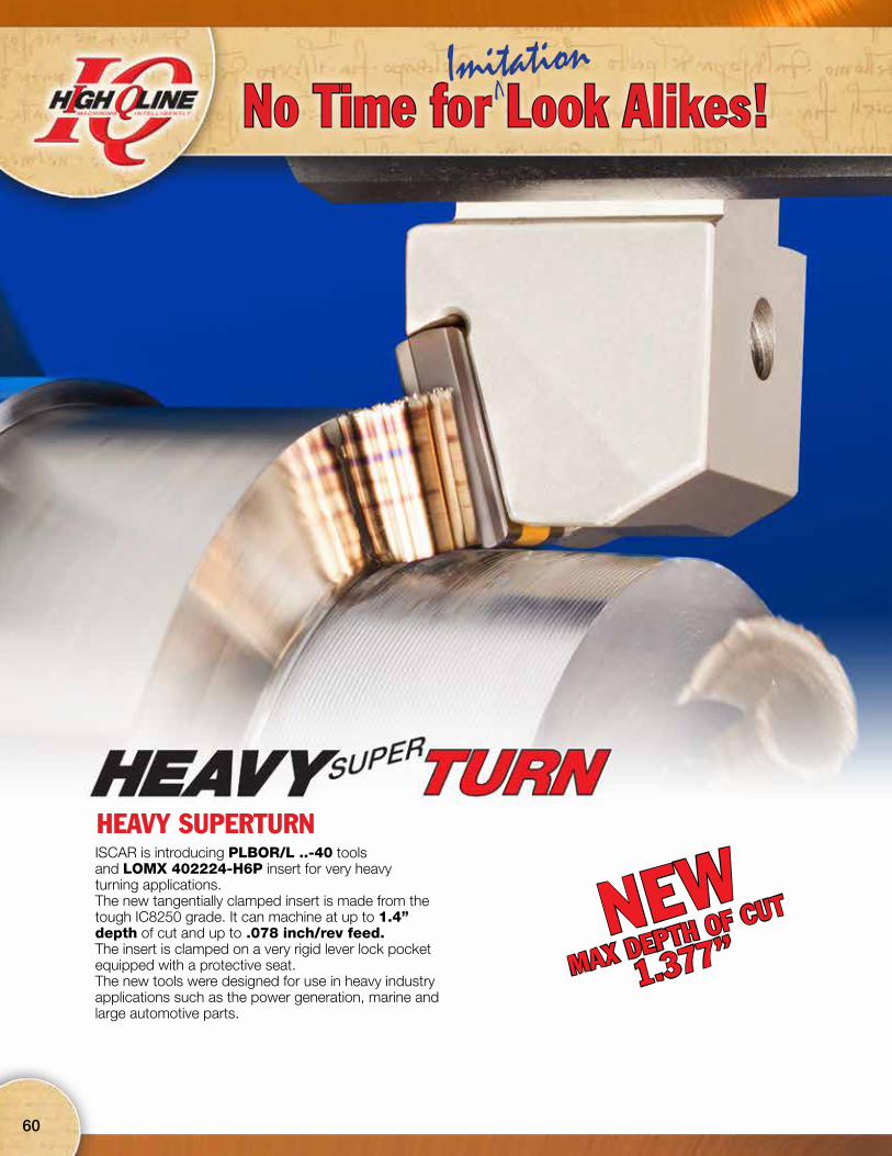
HEAVY SUPERTURNISCAR is introducing PLBOR/L ..-40 tools and LOMX 402224-H6P insert for very heavyturning applications.The new tangentially clamped insert is made from the tough IC8250 grade. It can machine at up to 1.4” depth of cut and up to .078 inch/rev feed. The insert is clamped on a very rigid lever lock pocket equipped with a protective seat.The new tools were designed for use in heavy industry applications such as the power generation, marine and large automotive parts.
NEWMAX DEPTH OF CUT
1.377”
60
No Time for Look Alikes!VImitation
Machining IntelligentlyISCAR HIGH Q LINES
61
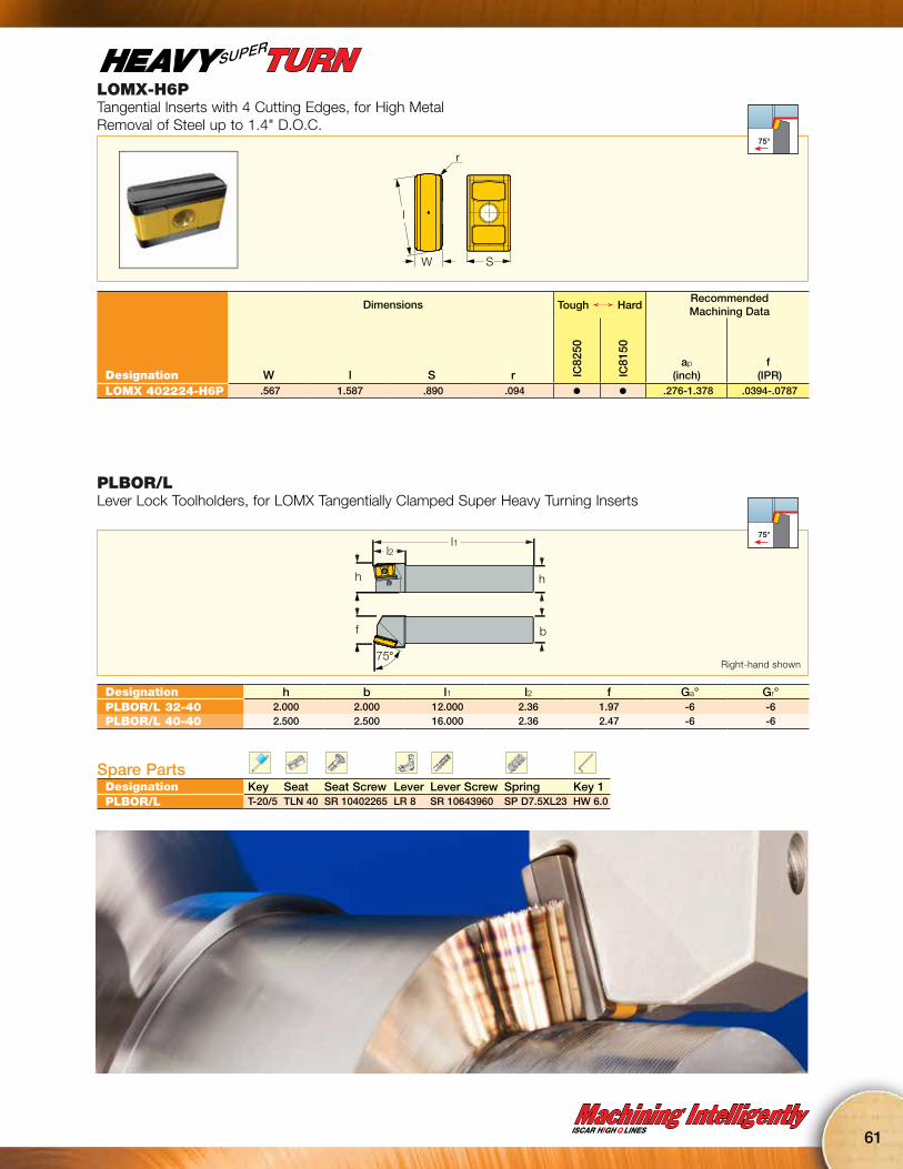
LOMX-H6PTangential Inserts with 4 Cutting Edges, for High Metal Removal of Steel up to 1.4" D.O.C.
I
S
r
W
75°
SUPER
Dimensions Tough Ö HardRecommended Machining Data
Designation W l S r IC82
50
IC81
50
ap
(inch)f
(IPR)LOMX 402224-H6P .567 1.587 .890 .094 l l .276-1.378 .0394-.0787
PLBOR/LLever Lock Toolholders, for LOMX Tangentially Clamped Super Heavy Turning Inserts
f
75°
h
l2
b
h
l175°
Designation h b l1 l2 f Ga° Gr°PLBOR/L 32-40 2.000 2.000 12.000 2.36 1.97 -6 -6PLBOR/L 40-40 2.500 2.500 16.000 2.36 2.47 -6 -6
Spare PartsDesignation Key Seat Seat Screw Lever Lever Screw Spring Key 1PLBOR/L T-20/5 TLN 40 SR 10402265 LR 8 SR 10643960 SP D7.5XL23 HW 6.0
Right-hand shown

TOP LEVERISCAR is introducing an upgraded lever lock to improve the clamping rigidity of the popular anduser-friendly insert clamping system.The new design combines the advantages of the current lever with the extra clamping rigidity of the top clamp method. The current lever pushes the insert against the pocket, exerting perpendicular force to the cutting force. This method sometimes fails during interrupted cut or heavy load applications, which cause the rear side of the insert to rise. The top clamp mechanism does provide high clamping security, but on the other hand, edge or insert indexing is inconvenient and time consuming and the top clamp obstructs the chip flow –
especially during internal turning applications. ISCAR’s new LR 4TL TOP LEVER combines the advantages of both systems. It firmly holds the insert in the pocket and also exerts an upper force on the rear side of the insert. It leaves the insert rake face unobstructed for free chip flow, while maintaining convenient insert handling and extremely high clamping security.The new LR 4TL TOP LEVER can replace the standard LR 4 lever in any tool.
62
No Time for Look Alikes!VImitation

Machining IntelligentlyISCAR HIGH Q LINES
63
AdvantagesInsert locking in two directions from the top and bottom provides better stability and rigidity.This improves the tool life, increasing productivity in comparison to the conventional lever.There is no need to change tools, as the top lever can be clamped on our standard tools.
Conventional Locking of the Insert in One Direction
Top Lever Locking of the Insert in Two Directions
NEWHIGHLY SECURE
CLAMPING

Turning Tools for High Pressure CoolantHigh temperature alloys produce a very high temperature as they are being cut. By effectively removing the heat, the chips become less ductile and thus easier to break.
Shorter chips are easily managed - they do not tangle around the workpiece or machine parts, so there is no need to stop the process frequently.Usually in conventional cooling the chip prevents the coolant from reaching the insert rake face in the cutting zone. The coolant stream of the JHP tools is directed precisely between the insert rake face and the flowing chip. This results in longer tool life and a much more reliable process.
The use of high pressure coolant is growing as manufacturers are looking for ways to reducecutting time, improve machining process reliabilityand achieve longer tool life.
ISCAR’s new JHP tools provide all of these advantages.
The coolant channels of the tools feature outletsvery close to the cutting edges, thus gaining the following advantages:
• Shorter machining time – The cutting speed can be increased by up to 200% when machining titanium and heat resistant alloys.• Longer tool life – tool life increases by up to 100% not only on titanium and heat resistant alloys, but also on stainless and alloy steels.• Improved chip control – even on the most ductile and problematic materials, small chips can be obtained.• Very effective cooling down of the cutting edge, which reduces sensitivity to heat fluctuations• Safer and more stable process• Enables higher cutting speeds (increasing productivity)
NEWMAX 4350 PSI
64
No Time for Look Alikes!VImitation
Machining IntelligentlyISCAR HIGH Q LINES
65
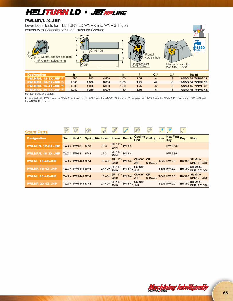
PWLNR/L-X-JHPLever Lock Tools for HELITURN LD WNMX and WNMG Trigon Inserts with Channels for High Pressure Coolant
l2
f
l1
b
hh
G 1/8"-28
Central coolant direction4°
4°(8° rotation adjustment)
95°
Gr°
Frontal coolant on/off screw
Frontalcoolant hole
Internal coolant forPWLNR/L... 06X
95°95°
4350PSI
l
Designation h b l1 l2 f Ga° Gr° InsertPWLNR/L 12-3X-JHP (1) .750 .750 4.500 1.00 1.25 -6 -6 WNMX 34. WNMG 33.PWLNR/L 16-3X-JHP (1) 1.000 1.000 6.000 1.00 1.25 -6 -6 WNMX 34. WNMG 33.
PWLNR/L 16-4X-JHP (2) 1.000 1.000 6.000 1.30 1.25 -6 -6 WNMX 45. WNMG 43.PWLNR/L 20-4X-JHP (2) 1.250 1.250 6.000 1.30 1.50 -6 -6 WNMX 45. WNMG 43.
For user guide see pages
(1) Supplied with TWX 3 seat for WNMX 34. inserts and TWN 3 seat for WNMG 33. inserts. (2) Supplied with TWX 4 seat for WNMX 45. inserts and TWN 443 seat for WNMG 43. inserts.
Spare PartsDesignation Seat Seat 1 Spring Pin Lever Screw Punch Cooling
Unit O-Ring Key Hex Flag Key Key 1 Plug
PWLNR/L 12-3X-JHP TWX 3 TWN 3 SP 3 LR 3SR 117-2014
PN 3-4 HW 2.5/5
PWLNR/L 16-3X-JHP TWX 3 TWN 3 SP 3 LR 3SR 117-2014
PN 3-4 HW 2.5/5
PWLNL 16-4X-JHP TWX 4 TWN 443 SP 4 LR 4DHSR 117-2010
PN 3-4LCU-CW-JHP
OR 6.4X0.9N
T-8/5 HW 2.0 HW 3.0SR M4X4 DIN913 TL360
PWLNR 16-4X-JHP TWX 4 TWN 443 SP 4 LR 4DHSR 117-2010
PN 3-4LCU-CW-JHP
T-8/5 HW 2.0 HW 3.0SR M4X4 DIN913 TL360
PWLNL 20-4X-JHP TWX 4 TWN 443 SP 4 LR 4DHSR 117-2010
PN 3-4LCU-CW-JHP
OR 6.4X0.9N
T-8/5 HW 2.0 HW 3.0SR M4X4 DIN913 TL360
PWLNR 20-4X-JHP TWX 4 TWN 443 SP 4 LR 4DHSR 117-2010
PN 3-4LCU-CW-JHP
T-8/5 HW 2.0 HW 3.0SR M4X4 DIN913 TL360
66
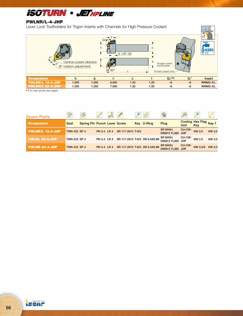
PWLNR/L-4-JHPLever Lock Toolholders for Trigon Inserts with Channels for High Pressure Coolant
f
l1
b
95°
l2
hh
G 1/8"-28
Gr°
Central coolant direction4°
4°(8° rotation adjustment)
Frontal coolant on/off screw
Frontal coolant hole
95°95°
4350PSI
l
Designation h b l1 l2 f Ga°(1) Gr° InsertPWLNR/L 16-4-JHP 1.000 1.000 6.000 1.30 1.25 -6 -6 WNMG 43..PWLNR/L 20-4-JHP 1.250 1.250 7.000 1.30 1.50 -6 -6 WNMG 43..
• For user guide see pages
Spare PartsDesignation Seat Spring Pin Punch Lever Screw Key O-Ring Plug Cooling
UnitHex Flag Key Key 1
PWLNR/L 16-4-JHP TWN 423 SP 4 PN 3-4 LR 4 SR 117-2010 T-8/5SR M4X4 DIN913 TL360
CU-CW-JHP
HW 2.0 HW 3.0
PWLNL 20-4-JHP TWN 423 SP 4 PN 3-4 LR 4 SR 117-2010 T-8/5 OR 6.4X0.9NSR M4X4 DIN913 TL360
CU-CW-JHP
HW 2.0 HW 3.0
PWLNR 20-4-JHP TWN 423 SP 4 PN 3-4 LR 4 SR 117-2010 T-8/5 OR 6.4X0.9NSR M4X4 DIN913 TL360
CU-CW-JHP
HW 2.5/5 HW 3.0

Machining IntelligentlyISCAR HIGH Q LINES
67
PCLNR/L-X-JHPLever Lock Toolholders for CNMX/CNMG 80° Rhombic Inserts with Channels for High Pressure Coolant
h
b
l1l2
h
G 1/8"-28
Gr°
fCentral coolant direction
(8° rotation adjustment)
4°
4°Frontal coolant on/off screw
Frontal coolanthole
PCLNR/L…-3X-JHP
95°
95°
4350PSI
l
Designation b h l1 l2 f Ga° Gr° InsertPCLNR/L 10-3X-JHP .625 .625 6.000 1.30 1.25 -6 -6 CNMX 34. CNMG 33.PCLNR/L 12-3X-JHP .750 .750 4.500 1.30 1.25 -6 -6 CNMX 34. CNMG 33.
PCLNR/L 16-3X-JHP 1.000 1.000 6.000 1.30 1.25 -6 -6 CNMX 34. CNMG 33.
PCLNR/L 16-4X-JHP 1.000 1.000 6.000 1.30 1.25 -6 -6 CNMX 45. CNMG 43.PCLNR/L 20-4X-JHP 1.250 1.250 6.000 1.30 1.50 -6 -6 CNMX 45. CNMG 43.
• Supplied with TCX 3 seat for CNMX 34. inserts and TCN 323 seat for CNMG 33. inserts. TCX 4 seat for CNMX 45. inserts and TCN 443 seat for CNMG 43. inserts. • For user guide see pages
Spare PartsDesignation Seat Seat 1 Spring Pin Lever Screw Punch Cooling
Unit O-Ring Key Hex Flag Key Key 1 Plug
PCLNR/L 10-3X-JHP TCX 3 TCN 323 SP 3 LR 3SR 117-2014
PN 3-4 HW 2.5/5
PCLNR/L 12-3X-JHP TCX 3 TCN 323 SP 3 LR 3SR 117-2014
PN 3-4 HW 2.5
PCLNR/L 16-3X-JHP TCX 3 TCN 323 SP 3 LR 3SR 117-2014
PN 3-4 HW 2.5
PCLNL 16-4X-JHP TCX 4 TCN 443 SP 4 LR 4DHSR 117-2010
PN 3-4LCU-CW-JHP
OR 6.4X0.9N
T-8/5 HW 2.0 HW 3.0SR M4X4 DIN913 TL360
PCLNR 16-4X-JHP TCX 4 TCN 443 SP 4 LR 4DHSR 117-2010
PN 3-4LCU-CW-JHP
T-8/5 HW 2.0 HW 3.0SR M4X4 DIN913 TL360
PCLNR/L 20-4X-JHP TCX 4 TCN 443 SP 4 LR 4DHSR 117-2010
PN 3-4LCU-CW-JHP
OR 6.4X0.9N
T-8/5 HW 2.0 HW 3.0SR M4X4 DIN913 TL360

68
PDJNR/L-4-JHPLever Lock Toolholder for 55° Negative Inserts with Channels for High Pressure Coolant
Gr°
h
G 1/8"-28
l2 l1
b
h
f
93°
Central coolant direction4°
4°(8° rotation adjustment) Frontal coolant
on/off screwFrontalcoolant hole
27°max93°
4350PSI
l
Designation b h l1 l2 f Ga°(1) Gr° InsertPDJNR/L 16-4-JHP 1.000 1.000 6.000 1.45 1.25 -6 -6 DNMG 44PDJNR/L 20-4-JHP 1.250 1.250 6.000 1.45 1.50 -6 -6 DNMG 44
• For DN.. 43. inserts use TDN 432 seat (ordered separately) • For user guide see pages
Spare PartsDesignation Seat Key Lever Key 1 Screw Key 2 Cooling Unit Spring Pin Punch O-RingPDJNL 16-4-JHP TDN 422 HW 2.5 LR 4D HW 3.0 SR 117-2010 T-8/5 CU-D-JHP SP 4 PN 3-4PDJNR 16-4-JHP TDN 422 HW 2.0 LR 4D HW 3.0 SR 117-2010 T-8/5 CU-D-JHP SP 4 PN 3-4 OR 6.4X0.9NPDJNR/L 20-4-JHP TDN 422 HW 2.0 LR 4D HW 3.0 SR 117-2010 T-8/5 CU-D-JHP SP 4 PN 3-4
PCLNR/L-4-JHPLever Lock Toolholders for 80° Negative Rhombic Inserts with Channels for High Pressure Coolant
Gr°
h
G 1/8"-28
h
b
l1l2
fCentral coolant direction
(8° rotation adjustment)
4°
4°
Frontal coolant on/off screw
Frontal coolant hole
95°
95°
4350PSI
Designation h b l1 l2 f Ga°(1) Gr° InsertPCLNR/L 16-4-JHP 1.000 1.000 6.000 1.30 1.25 -6 -6 CNMG 43PCLNR/L 20-4-JHP 1.250 1.250 6.000 1.30 1.25 -6 -6 CNMG 43
• For user guide see pages
Spare PartsDesignation Seat Spring Pin Lever Screw Punch Cooling Unit Plug Key Key 1 Key 2
PCLNR/L-4-JHP TCN 423 SP 4 LR 4 SR 117-2010 PN 3-4 CU-CW-JHP SR M4X4 DIN913 TL360 HW 2.0 HW 3.0 T-8/5

Machining IntelligentlyISCAR HIGH Q LINES
69
l
PSSNR/L-JHPLever Lock 45° Longitudinal and Facing Tools for Negative Square Inserts with Channels for High Pressure Coolant
l1L3
b
h
l2
h
fInside coolant forPSSNR/L... 3
G 1/8"-28
45°
45°
4350PSI
Designation h b l1 l2 f Ga° Gr° L3 InsertPSSNR/L 12-3-JHP .750 .750 4.500 1.38 1.00 -5.5 -5.5 4.791 SNMG 3..
For user guide see pages
Spare PartsDesignation Seat Seat 1 Spring Pin Punch Lever Screw KeyPSSNR/L 12-3-JHP TSN 323 TSN 333 SP 3 PN 3-3L LR 3 SR 117-2014 HW 2.5
* (Optional, should be ordered separately)
(1) When SNMG-EM-M/-R inserts are used, replace the standard seat.
Right-hand shown
PTGNR/L-X-JHP91° Lead Angle Lever Lock External Turning Tools for Negative Triangular Inserts with Channels for High Pressure Coolant
f b
l1l2
F1
h
Ga°Gr°
h
G 1/8"-28
91°
Designation h b l1 l2 f F1 Ga° Gr° InsertPTGNR/L 12-3X-JHP .750 .750 4.500 .79 1.00 1.25 -6 -6 TNMX 34., TNMG 33.PTGNR/L 16-3X-JHP 1.000 1.000 6.000 .79 1.25 - -6 -6 TNMX 34., TNMG 33.
• Supplied with TTX 3 seat for TNMX 34. inserts and TTN 3 seat for TNMG 33. inserts. • For user guide, see pages
Spare PartsDesignation Seat Seat 1 Spring Pin Lever Screw Key PunchPTGNR/L-X-JHP TTX 3 TTN 3 SP 3 LR 3 SR 117-2014 HW 2.5 PN 3-4
Right-hand shown
70
l
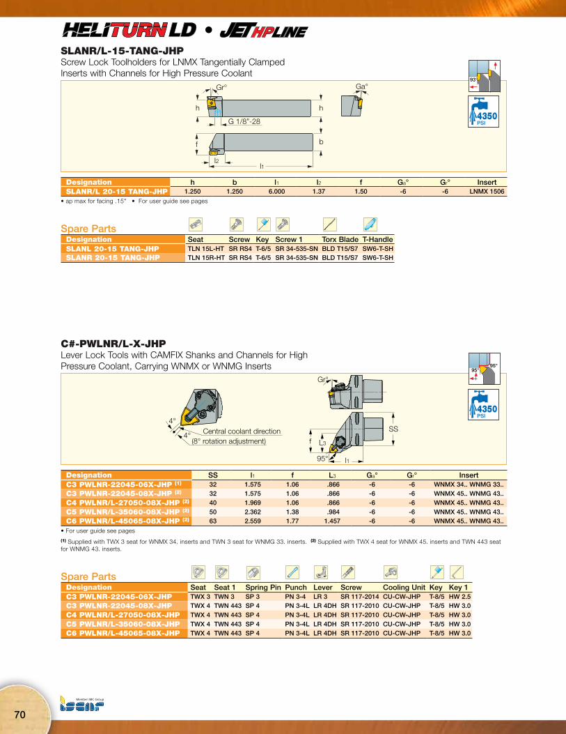
SLANR/L-15-TANG-JHPScrew Lock Toolholders for LNMX Tangentially Clamped Inserts with Channels for High Pressure Coolant
h
Gr°
G 1/8”-28
Ga°
h
b
l2l1
f
93°
4350PSI
Designation h b l1 l2 f Ga° Gr° InsertSLANR/L 20-15 TANG-JHP 1.250 1.250 6.000 1.37 1.50 -6 -6 LNMX 1506
• ap max for facing .15" • For user guide see pages
Spare PartsDesignation Seat Screw Key Screw 1 Torx Blade T-HandleSLANL 20-15 TANG-JHP TLN 15L-HT SR RS4 T-6/5 SR 34-535-SN BLD T15/S7 SW6-T-SHSLANR 20-15 TANG-JHP TLN 15R-HT SR RS4 T-6/5 SR 34-535-SN BLD T15/S7 SW6-T-SH
C#-PWLNR/L-X-JHPLever Lock Tools with CAMFIX Shanks and Channels for High Pressure Coolant, Carrying WNMX or WNMG Inserts
Gr°
f
95°
SS
L3
l1
Central coolant direction4°
4°(8° rotation adjustment)
95°95°
4350PSI
Designation SS l1 f L3 Ga° Gr° InsertC3 PWLNR-22045-06X-JHP (1) 32 1.575 1.06 .866 -6 -6 WNMX 34.. WNMG 33..C3 PWLNR-22045-08X-JHP (2) 32 1.575 1.06 .866 -6 -6 WNMX 45.. WNMG 43..
C4 PWLNR/L-27050-08X-JHP (2) 40 1.969 1.06 .866 -6 -6 WNMX 45.. WNMG 43..
C5 PWLNR/L-35060-08X-JHP (2) 50 2.362 1.38 .984 -6 -6 WNMX 45.. WNMG 43..C6 PWLNR/L-45065-08X-JHP (2) 63 2.559 1.77 1.457 -6 -6 WNMX 45.. WNMG 43..
• For user guide see pages
(1) Supplied with TWX 3 seat for WNMX 34. inserts and TWN 3 seat for WNMG 33. inserts. (2) Supplied with TWX 4 seat for WNMX 45. inserts and TWN 443 seat for WNMG 43. inserts.
Spare PartsDesignation Seat Seat 1 Spring Pin Punch Lever Screw Cooling Unit Key Key 1C3 PWLNR-22045-06X-JHP TWX 3 TWN 3 SP 3 PN 3-4 LR 3 SR 117-2014 CU-CW-JHP T-8/5 HW 2.5C3 PWLNR-22045-08X-JHP TWX 4 TWN 443 SP 4 PN 3-4L LR 4DH SR 117-2010 CU-CW-JHP T-8/5 HW 3.0
C4 PWLNR/L-27050-08X-JHP TWX 4 TWN 443 SP 4 PN 3-4L LR 4DH SR 117-2010 CU-CW-JHP T-8/5 HW 3.0
C5 PWLNR/L-35060-08X-JHP TWX 4 TWN 443 SP 4 PN 3-4L LR 4DH SR 117-2010 CU-CW-JHP T-8/5 HW 3.0C6 PWLNR/L-45065-08X-JHP TWX 4 TWN 443 SP 4 PN 3-4L LR 4DH SR 117-2010 CU-CW-JHP T-8/5 HW 3.0
Machining IntelligentlyISCAR HIGH Q LINES
71
l
l
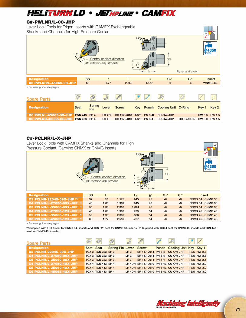
C#-PWLNR/L-08-JHPLever Lock Tools for Trigon Inserts with CAMFIX Exchangeable Shanks and Channels for High Pressure Coolant
Gr°
f
SS
L3
l1
Central coolant direction4°
4°(8° rotation adjustment)
95°95°
4350PSI
Designation SS f l1 L3 Ga° Gr° InsertC6 PWLNR/L-45065-08-JHP 63 1.77 2.559 1.457 -6 -6 WNMG 43..
• For user guide see pages
Spare Parts
Designation Seat Spring Pin Lever Screw Key Punch Cooling Unit O-Ring Key 1 Key 2
C6 PWLNL-45065-08-JHP TWN 443 SP 4 LR 4DH SR 117-2010 T-8/5 PN 3-4L CU-CW-JHP HW 3.0 HW 1.5C6 PWLNR-45065-08-JHP TWN 423 SP 4 LR 4 SR 117-2010 T-8/5 PN 3-4 CU-CW-JHP OR 6.4X0.9N HW 3.0 HW 1.5
Right-hand shown
C#-PCLNR/L-X-JHPLever Lock Tools with CAMFIX Shanks and Channels for High Pressure Coolant, Carrying CNMX or CNMG Inserts
Gr°
a°
f
SS
95°L3
l1
Central coolant direction(8° rotation adjustment)
4°
4°
95°
95°
4350PSI
Designation SS f l1 L3 a° Ga° Gr° InsertC3 PCLNR-22045-09X-JHP (1) 32 .87 1.575 .945 45 -6 -6 CNMX 34., CNMG 33.C4 PCLNR/L-27050-09X-JHP (1) 40 1.06 1.969 .945 45 -6 -6 CNMX 34., CNMG 33.
C5 PCLNR/L-35060-09X-JHP (1) 50 1.38 2.362 1.024 45 -6 -6 CNMX 34., CNMG 33.
C4 PCLNR/L-27050-12X-JHP (2) 40 1.06 1.969 .709 54 -6 -6 CNMX 45., CNMG 43.
C5 PCLNR/L-35060-12X-JHP (2) 50 1.38 2.362 .866 54 -6 -6 CNMX 45., CNMG 43.C6 PCLNR/L-45065-12X-JHP (2) 63 1.77 2.559 .787 54 -6 -6 CNMX 45., CNMG 43.
• For user guide see pages
(1) Supplied with TCX 3 seat for CNMX 34.. inserts and TCN 323 seat for CNMG 33. inserts. (2) Supplied with TCX 4 seat for CNMX 45. inserts and TCN 443 seat for CNMG 43. inserts.
Spare PartsDesignation Seat Seat 1 Spring Pin Lever Screw Punch Cooling Unit Key Key 1C3 PCLNR-22045-09X-JHP TCX 3 TCN 323 SP 3 LR 3 SR 117-2014 PN 3-4 CU-CW-JHP T-8/5 HW 2.5C4 PCLNR/L-27050-09X-JHP TCX 3 TCN 323 SP 3 LR 3 SR 117-2014 PN 3-4 CU-CW-JHP T-8/5 HW 2.5
C5 PCLNR/L-35060-09X-JHP TCX 3 TCN 323 SP 3 LR 3 SR 117-2014 PN 3-4 CU-CW-JHP T-8/5 HW 2.5
C4 PCLNR/L-27050-12X-JHP TCX 4 TCN 443 SP 4 LR 4DH SR 117-2010 PN 3-4L CU-CW-JHP T-8/5 HW 3.0
C5 PCLNR/L-35060-12X-JHP TCX 4 TCN 443 SP 4 LR 4DH SR 117-2010 PN 3-4L CU-CW-JHP T-8/5 HW 3.0C6 PCLNR/L-45065-12X-JHP TCX 4 TCN 443 SP 4 LR 4DH SR 117-2010 PN 3-4L CU-CW-JHP T-8/5 HW 3.0
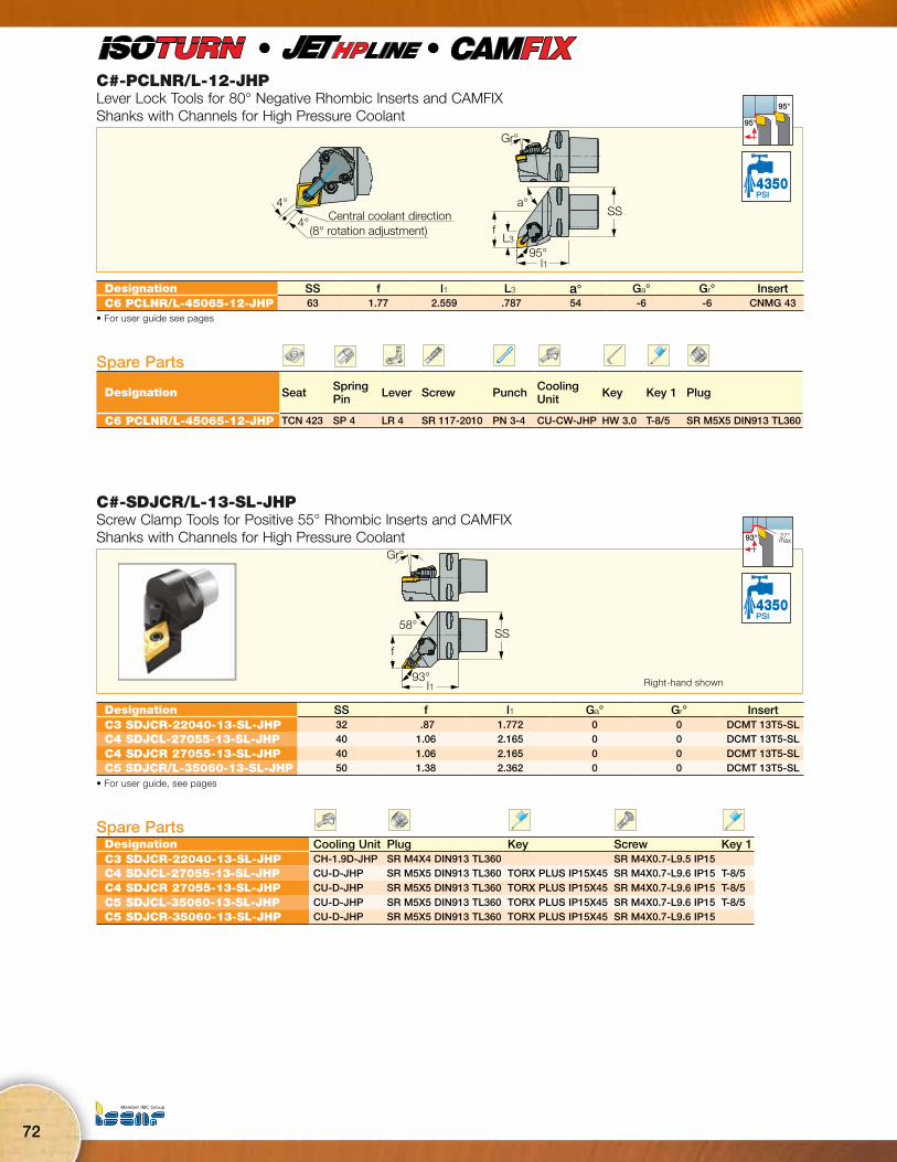
72
C#-PCLNR/L-12-JHPLever Lock Tools for 80° Negative Rhombic Inserts and CAMFIX Shanks with Channels for High Pressure Coolant
Gr°
a°
f
SS
95°L3
l1
Central coolant direction(8° rotation adjustment)
4°
4°
95°
95°
4350PSI
l
l
Designation SS f l1 L3 a° Ga° Gr° InsertC6 PCLNR/L-45065-12-JHP 63 1.77 2.559 .787 54 -6 -6 CNMG 43
• For user guide see pages
Spare Parts
Designation Seat Spring Pin Lever Screw Punch Cooling
Unit Key Key 1 Plug
C6 PCLNR/L-45065-12-JHP TCN 423 SP 4 LR 4 SR 117-2010 PN 3-4 CU-CW-JHP HW 3.0 T-8/5 SR M5X5 DIN913 TL360
C#-SDJCR/L-13-SL-JHPScrew Clamp Tools for Positive 55° Rhombic Inserts and CAMFIX Shanks with Channels for High Pressure Coolant
Gr°
58°
93°
f
SS
l1
27°max93°
4350PSI
Designation SS f l1 Ga° Gr° InsertC3 SDJCR-22040-13-SL-JHP 32 .87 1.772 0 0 DCMT 13T5-SLC4 SDJCL-27055-13-SL-JHP 40 1.06 2.165 0 0 DCMT 13T5-SL
C4 SDJCR 27055-13-SL-JHP 40 1.06 2.165 0 0 DCMT 13T5-SLC5 SDJCR/L-35060-13-SL-JHP 50 1.38 2.362 0 0 DCMT 13T5-SL
• For user guide, see pages
Spare PartsDesignation Cooling Unit Plug Key Screw Key 1C3 SDJCR-22040-13-SL-JHP CH-1.9D-JHP SR M4X4 DIN913 TL360 SR M4X0.7-L9.5 IP15C4 SDJCL-27055-13-SL-JHP CU-D-JHP SR M5X5 DIN913 TL360 TORX PLUS IP15X45 SR M4X0.7-L9.6 IP15 T-8/5
C4 SDJCR 27055-13-SL-JHP CU-D-JHP SR M5X5 DIN913 TL360 TORX PLUS IP15X45 SR M4X0.7-L9.6 IP15 T-8/5
C5 SDJCL-35060-13-SL-JHP CU-D-JHP SR M5X5 DIN913 TL360 TORX PLUS IP15X45 SR M4X0.7-L9.6 IP15 T-8/5C5 SDJCR-35060-13-SL-JHP CU-D-JHP SR M5X5 DIN913 TL360 TORX PLUS IP15X45 SR M4X0.7-L9.6 IP15
Right-hand shown

Machining IntelligentlyISCAR HIGH Q LINES
73
C#-SDNCN-13-SL-JHPScrew Clamp Tools for Positive 55° Rhombic Inserts and CAMFIX Shanks with Channels for High Pressure Coolant
Gr°
l1
f
SS
60° max62.5°
4350PSI
l
l
Designation SS f l1 Ga° Gr° InsertC3 SDNCN-00045-13-SL-JHP 32 .02 1.772 0 0 DCMT 13T5-SLC4 SDNCN-00060-13-SL-JHP 40 .02 2.362 0 0 DCMT 13T5-SLC5 SDNCN-00060-13-SL-JHP 50 .02 2.362 0 0 DCMT 13T5-SL
• For user guide, see pages
Spare PartsDesignation Cooling Unit Flat Washer Key Plug Screw Key 1
C3 SDNCN-00045-13-SL-JHP CH-1.9D-JHPWASHER 4.2X5.6X0.5
SR M4X4 DIN913 TL360
SR M4X0.7-L9.5 IP15
C4 SDNCN-00060-13-SL-JHP CU-D-JHP TORX PLUS IP15X45 SR M4X0.7-L9.6 IP15 T-8/5C5 SDNCN-00060-13-SL-JHP CU-D-JHP TORX PLUS IP15X45 SR M4X0.7-L9.6 IP15 T-8/5
C#-PDJNR/L-JHPLever Lock Tools for Negative 55° Inserts with CAMFIX Exchangeable Heads and Channels for High Pressure Coolant
Gr°
a°
f
93° l1
SSCentral coolant direction4°
4°(8° rotation adjustment)
27°max93°
4350PSI
Designation SS f l1 Ga° Gr° a° InsertC3 PDJNR-22045-11-JHP 30 .87 1.772 -6 -6 58 DN.. 3..C4 PDJNR/L 27050-11-JHP 40 1.06 2.165 -6 -6 58 DN.. 3..
C5 PDJNR/L 35060-11-JHP 50 1.38 2.362 -6 -6 58 DN.. 3..
C4 PDJNR/L 27055-15-JHP 40 1.06 2.165 -6 -6 58 DN.. 4..
C5 PDJNR/L 35060-15-JHP 50 1.38 2.362 -6 -6 58 DN.. 4..C6 PDJNR/L 45065-15-JHP 63 1.77 2.559 -6 -6 58 DN.. 4..
• For user guide see pages
Spare PartsDesignation Seat Spring Pin Lever Screw Punch Cooling Unit O-Ring Key Hex Flag KeyC3 PDJNR-22045-11-JHP TDN 322 SP 3 LR 3D SR 117-2014 PN 3-4 CU-D-JHP T-8/5 HW 2.5/5C4 PDJNL 27050-11-JHP TDN 322 SP 3 LR 3D SR 117-2014 PN 3-4 CU-D-JHP OR 6.4X0.9N T-8/5 HW 2.5/5
C4 PDJNR 27050-11-JHP TDN 322 SP 3 LR 3D SR 117-2014 PN 3-4 CU-D-JHP T-8/5 HW 2.5/5
C5 PDJNR/L 35060-11-JHP TDN 322 SP 3 LR 3D SR 117-2014 PN 3-4 CU-D-JHP T-8/5 HW 2.5/5
C4 PDJNR/L 27055-15-JHP TDN 422 SP 4 LR 4D SR 117-2010 PN 3-4 CU-D-JHP OR 6.4X0.9N T-8/5 HW 3.0
C5 PDJNR/L 35060-15-JHP TDN 422 SP 4 LR 4D SR 117-2010 PN 3-4 CU-D-JHP OR 6.4X0.9N T-8/5 HW 3.0C6 PDJNR/L 45065-15-JHP TDN 422 SP 4 LR 4D SR 117-2010 PN 3-4 CU-D-JHP T-8/5 HW 3.0

74
C#-SVJCR/L-JHPScrew Lock Tools for 35° Rhombic Inserts with 7° Clearance Angle and CAMFIX Exchangeable Shanks
Gr°
a°
f
l1
SS
L3
Central coolant direction
4°
4° (8° rotation adjustment)
50° max93°
4350PSI
l
l
Designation SS f l1 Ga° Gr° a° L3 InsertC3 SVJCR-22040-11-JHP 32 .87 1.575 0 0 70 - VCMT 1103C4 SVJCR/L-27055-16-JHP 40 1.06 2.165 0 0 70 - VCMT 33
C5 SVJCR/L-35060-16-JHP 50 1.38 2.362 0 0 70 - VCMT 33C6 SVJCR-45065-16-JHP 63 1.77 2.559 0 0 70 .661 VCMT 33
• For user guide see pages
Spare PartsDesignation Seat Seat Screw Key Screw Cooling Unit O-Ring Key 1 Key 2C3 SVJCR-22040-11-JHP SR 14-560 CH-1.9D-JHP T-8/5C4 SVJCR/L-27055-16-JHP TVC 3-1 SR TC-3 T-15/5 SR 16-236 P CU-V-JHP OR 6.4X0.9N T-8/5 HW 2.5
C5 SVJCR/L-35060-16-JHP TVC 3-1 SR TC-3 T-15/5 SR 16-236 P CU-V-JHP OR 6.4X0.9N T-8/5 HW 2.5C6 SVJCR-45065-16-JHP TVC 3-1 SR TC-3 T-15/5 SR 16-236 P CU-V-JHP T-8/5 HW 2.5
C#-SRGCR-12-JHPScrew Lock Tools for Round Inserts with 7° Clearance Angle and CAMFIX Exchangeable Shanks
Gr
a°
fSS
L3l1
Central coolant direction(8° rotation adjustment)
4°
4°
4350PSI
Designation SS f l1 a° L3 InsertC6 SRGCR-45065-12-JHP 63 1.77 2.559 60 .630 RCMT 1204MO
• For user guide see pages
Spare PartsDesignation Seat Seat Screw Key Screw Key 1 Cooling Unit Key 2C6 SRGCR-45065-12-JHP TRC 4-0 SR TC-4 T-20/5 SR 16-212 HW 3.0 CU-R-JHP T-8/5
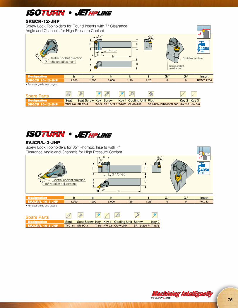
Machining IntelligentlyISCAR HIGH Q LINES
75
SRGCR-12-JHPScrew Lock Toolholders for Round Inserts with 7° Clearance Angle and Channels for High Pressure Coolant
h
Gr°
f
h
Ga°
Frontal coolant on/off screw
Frontal coolant hole
b
l2G 1/8"-28
l1Central coolant direction(8° rotation adjustment)
4°
4°
4350PSI
l
Designation h b l1 l2 f Ga° Gr° InsertSRGCR 16-12-JHP 1.000 1.000 6.000 1.20 1.25 0 0 RCMT 1204
• For user guide see pages
Spare PartsDesignation Seat Seat Screw Key Screw Key 1 Cooling Unit Plug Key 2 Key 3SRGCR 16-12-JHP TRC 4-0 SR TC-4 T-8/5 SR 16-212 T-20/5 CU-R-JHP SR M4X4 DIN913 TL360 HW 2.0 HW 3.0
SVJCR/L-3-JHPScrew Lock Toolholders for 35° Rhombic Inserts with 7° Clearance Angle and Channels for High Pressure Coolant
h
l1
l2
bf
h
G 1/8"-28
Gr°Ga°
93°
Central coolant direction
4°
4° (8° rotation adjustment)
50° max93°
4350PSI
l
Designation h b l1 l2 f Ga° Gr° InsertSVJCR/L 16-3-JHP 1.000 1.000 6.000 1.65 1.25 0 0 VC..33
• For user guide see pages
Spare PartsDesignation Seat Seat Screw Key Key 1 Cooling Unit Screw Key 2SVJCR/L 16-3-JHP TVC 3-1 SR TC-3 T-8/5 HW 2.5 CU-V-JHP SR 16-236 P T-15/5

76
PVACR/L-JHPLever Lock Tools with Channels for High Pressure Coolant for 35° Positive Rhombic Inserts for Swiss Automatic Machines
h
f1
l2l1
b
h
UNF 5/16”-24 typx3
f
91°
Gr Ga
52° max91°
PSI
l
Designation h b l1 l2 f Ga° Gr° InsertPVACR/L 08-2S-JHP .500 .500 4.000 1.00 .51 0 0 VC..22PVACR/L 10-2S-JHP .625 .625 4.000 1.00 .63 0 0 VC..22PVACR 12-2S-JHP .750 .750 4.000 1.00 .76 0 0 VC..22
• For user guide see pages
Spare PartsDesignation Lever Locking Pin Screw Hex Flag Key Plug Cooling UnitPVACR/L-JHP SL LV-2 SL PI-2 PIN SR 10400611 HW 2.0/5 SR 5/16UNF TL360 S-CU-JHP
PCLCR/L-JHPLever Lock Tools with Channels for High Pressure Coolant for 80° Positive Rhombic Inserts for Swiss Automatic Machines
h
f1
l295°
l1
UNF 5/16”-24 typex3
b
h
f
GaGr
95°
95°
PSI
Designation h b l1 l2 f f1 Ga° Gr° InsertPCLCR/L 08-3S-JHP .500 .500 4.000 .90 .51 .550 0 0 CC.. 3PCLCR/L 10-3S-JHP .625 .625 4.000 .90 .63 - 0 0 CC.. 3PCLCR 12-3S-JHP .750 .750 4.000 .90 .76 - 0 0 CC.. 3
• For user guide see pages
Spare PartsDesignation Lever Locking Pin Screw Hex Flag Key Plug Cooling UnitPCLCR/L-JHP SL LV-3 SL PI-3 SR 10400150 HW 2.5/5 SR 5/16UNF TL360 S-CU-JHP

Machining IntelligentlyISCAR HIGH Q LINES
77
PCACR/L-JHPLever Lock Tools with Channels for High Pressure Coolant for 80° Positive Rhombic Inserts for Swiss Automatic Machines
h
f1
l2 l1Th
Th
b
h
f
90°
GaGr29° max
91°
PSI
l
Designation h b l1 l2 f f1 Ga° Gr° a° Th InsertPCACR/L 08-3S-JHP .500 .500 4.000 .90 .51 .550 0 0 90 UNF 5/16" CC..3..
• For user guide see pages
Spare PartsDesignation Lever Locking Pin Screw Hex Flag Key Plug Plug 1 Cooling UnitPCACR/L 08-3S-JHP SL LV-3 SL PI-3 SR 10400150 HW 2.5/5 SR 5/16UNF TL360 SR M4X4 DIN913 TL360 S-CU-JHP
PDACR/L-JHPLever Lock Tools with Channels for High Pressure Coolant for 55° Positive Rhombic Inserts for Swiss Automatic Machines
h
Gr
f
90° l2 l1
UNF 5/16”-24 typex3
b
h
Ga29° max
91°
PSI
Designation h b l1 l2 f Ga° Gr° InsertPDACR/L 08-3S-JHP .500 .500 4.000 1.10 .51 0 0 DCMT 3..PDACR/L 10-3S-JHP .625 .625 4.000 1.10 .63 0 0 DCMT 3..PDACR 12-3S-JHP .750 .750 4.000 1.10 .79 0 0 DCMT 3..
• For user guide see pages
Spare PartsDesignation Lever Locking Pin Screw Hex Flag Key Plug Cooling UnitPDACR/L-JHP SL LV-3 SL PI-3 SR 10400150 HW 2.5/5 SR 5/16UNF TL360 S-CU-JHP
NEWMAX 300 BAR
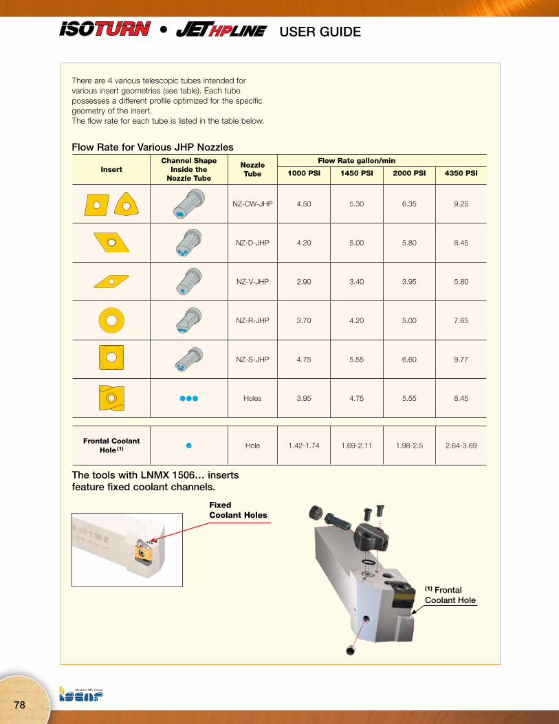
78
USER GUIDE •
Fixed Coolant Holes
The tools with LNMX 1506… inserts feature fixed coolant channels.
There are 4 various telescopic tubes intended for various insert geometries (see table). Each tube possesses a different profile optimized for the specific geometry of the insert.The flow rate for each tube is listed in the table below.
Flow Rate for Various JHP Nozzles
(1) FrontalCoolant Hole
InsertChannel Shape
Inside theNozzle Tube
Nozzle Tube
Flow Rate gallon/min
1000 PSI 1450 PSI 2000 PSI 4350 PSI
NZ-CW-JHP 4.50 5.30 6.35 9.25
NZ-D-JHP 4.20 5.00 5.80 8.45
NZ-V-JHP 2.90 3.40 3.95 5.80
NZ-R-JHP 3.70 4.20 5.00 7.65
NZ-S-JHP 4.75 5.55 6.60 9.77
Holes 3.95 4.75 5.55 8.45
Frontal CoolantHole (1) Hole 1.42-1.74 1.69-2.11 1.98-2.5 2.64-3.69
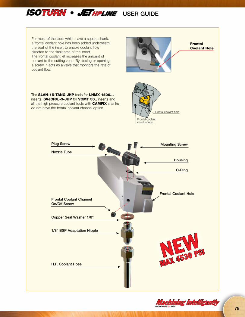
Machining IntelligentlyISCAR HIGH Q LINES
79
USER GUIDE •
For most of the tools which have a square shank, a frontal coolant hole has been added underneath the seat of the insert to enable coolant flow directed to the flank area of the insert.The frontal coolant jet increases the amount of coolant to the cutting zone. By closing or opening a screw, it acts as a valve that monitors the rate of coolant flow.
Frontal Coolant Hole
The SLAN-15-TANG JHP tools for LNMX 1506… inserts, SVJCR/L-3-JHP for VCMT 33.. inserts and all the high pressure coolant tools with CAMFIX shanks do not have the frontal coolant channel option.
Housing
Mounting Screw
Frontal Coolant Hole
O-Ring
Copper Seal Washer 1/8”
1/8" BSP Adaptation Nipple
Frontal Coolant ChannelOn/Off Screw
H.P. Coolant Hose
Plug Screw
Nozzle Tube
Frontal coolant on/off screw
Frontal coolant hole
NEWMAX 4530 PSI
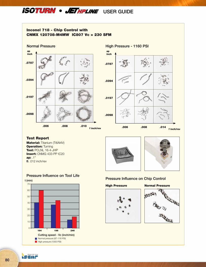
80
Inconel 718 - Chip Control withCNMX 120708-M4MW IC807 Vc = 230 SFM
.0787
.0394
.0197
.0098
.006 .008 .010
apinch
f inch/rev
.0787
.0394
.0197
.0098
.006 .008 .014
apinch
f inch/rev
High Pressure - 1160 PSINormal Pressure
Test ReportMaterial: Titanium (Ti6Al4V) Operation: TurningTool: PCLNL 16-4-JHPInsert: CNMG 433-PP IC20ap: .1”f: .012 inch/rev
t (min)
High pressure (1000 PSI)
Normal pressure (87-116 PSI)
0
10
164 196 246
Cutting speed - Vc (inch/min)
20
30
40
50
60
70High Pressure Normal Pressure
Pressure Influence on Chip ControlPressure Influence on Tool Life
USER GUIDE •
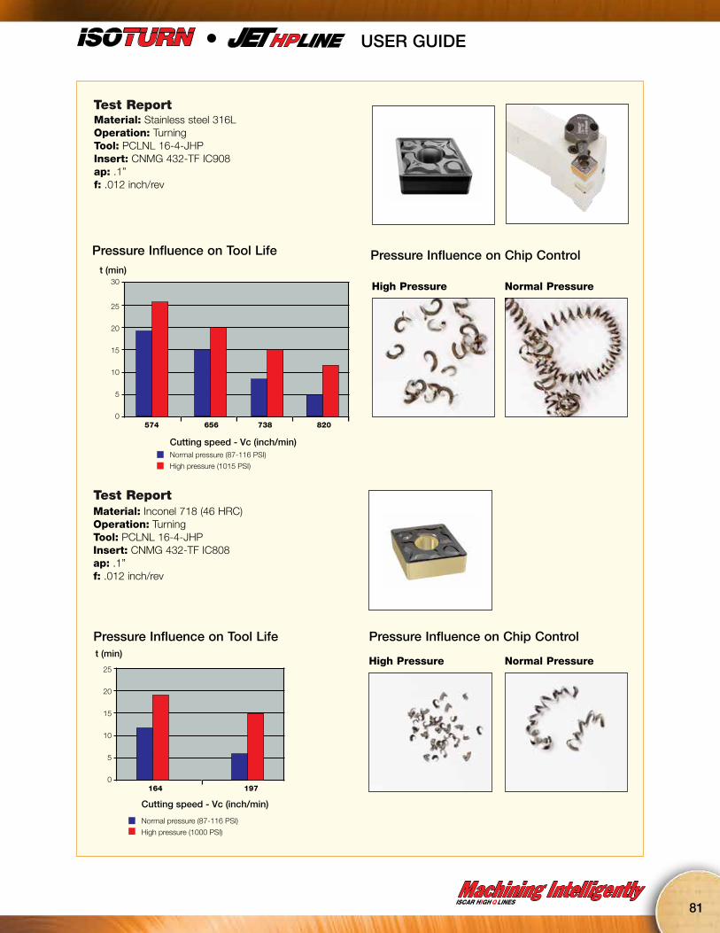
Machining IntelligentlyISCAR HIGH Q LINES
81
Test ReportMaterial: Stainless steel 316L Operation: TurningTool: PCLNL 16-4-JHPInsert: CNMG 432-TF IC908ap: .1”f: .012 inch/rev
t (min)
0
5
574
Normal pressure (87-116 PSI)
High pressure (1015 PSI)
656 738
Cutting speed - Vc (inch/min)
10
15
20
25
30
820
High Pressure Normal Pressure
Pressure Influence on Chip ControlPressure Influence on Tool Life
Test ReportMaterial: Inconel 718 (46 HRC) Operation: TurningTool: PCLNL 16-4-JHPInsert: CNMG 432-TF IC808ap: .1”f: .012 inch/rev
t (min)
0
5
Normal pressure (87-116 PSI)
High pressure (1000 PSI)
164 197
Cutting speed - Vc (inch/min)
10
15
20
25High Pressure
Pressure Influence on Chip ControlPressure Influence on Tool Life
Normal Pressure
USER GUIDE •
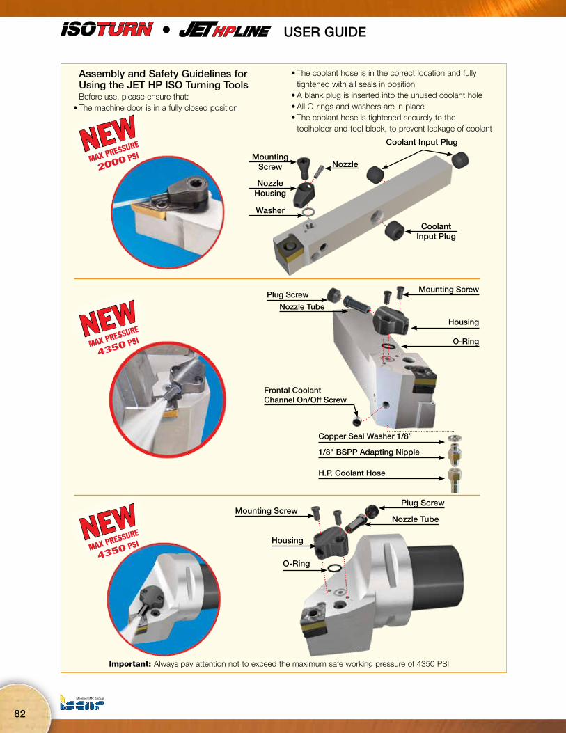
82
Assembly and Safety Guidelines for Using the JET HP ISO Turning Tools
Before use, please ensure that:• The machine door is in a fully closed position
• The coolant hose is in the correct location and fully tightened with all seals in position
• A blank plug is inserted into the unused coolant hole• All O-rings and washers are in place• The coolant hose is tightened securely to the
toolholder and tool block, to prevent leakage of coolant
Housing
Mounting Screw
O-Ring
Copper Seal Washer 1/8”
H.P. Coolant Hose
Frontal Coolant Channel On/Off Screw
Plug Screw
Nozzle Tube
1/8" BSPP Adapting Nipple
Important: Always pay attention not to exceed the maximum safe working pressure of 4350 PSI
Mounting Screw
Housing
O-Ring
Plug Screw
Nozzle Tube
Coolant Input Plug
Coolant Input Plug
NozzleMounting
Screw
Nozzle Housing
Washer
USER GUIDE •
NEWMAX PRESSURE
2000 PSI
NEWMAX PRESSURE
4350 PSI
NEWMAX PRESSURE
4350 PSI

Machining IntelligentlyISCAR HIGH Q LINES
83
USER GUIDE •
ISOTURN JHP ToolsThe unique high pressure coolant system is composed of a static housing and telescopic tube to direct the coolant exactly to the cutting edge of the insert. The telescopic tube embedded in the housing skews right
and left, according to the working direction of the tool(see drawing). The advantage of this system is that there is no need to detach the housing of the tool when changing an insert. This reduces setup time.
Central Coolant Direction4°
4°(8° Rotation Adjustment)
To mount or change an insert: Press on the telescopic tube in a backward direction.
After indexing the insert cutting edge, starting the coolant flow will extract the tube automatically to its operating position.
Insert Indexing Procedure
1
2
3
4
ap .0
98ap= .098

84
JHP HOSEHigh Pressure Coolant Hose
L
L
ThreadSize (Th)
ThreadSize (Th1)
2
1
BB
BS
PSI
Designation L Fig. Th Th1
JHP HOSE G1/8-7/16-200BS 7.874 1 G1/8”-28 BSPP UNF 7/16” -20FLARE 37°JHP HOSE 5/16-G1/8-200BS 7.874 1 5/16”-24 UNF G1/8”-28 BSPP
JHP HOSE 5/16-7/16-200BS 7.874 1 5/16”-24 UNF UNF 7/16” -20FLARE 37°
JHP HOSE G1/8-G1/8-200BB 7.874 2 G1/8”-28 BSPP G1/8”-28 BSPP
JHP HOSE G1/8-7/16-250BS 9.843 1 G1/8”-28 BSPP UNF 7/16” -20FLARE 37°JHP HOSE G1/8-G1/8-250BB 9.843 2 G1/8”-28 BSPP G1/8”-28 BSPP
Spare PartsDesignation Banjo Bolt Coolant FittingJHP HOSE G1/8-7/16-200BS JHP BANJO BOLT G1/8" JHP COPPER SEAL 1/8"*JHP HOSE 5/16-G1/8-200BS JHP BANJO BOLT 5/16" UNF JHP COPPER SEAL 5/16"
JHP HOSE 5/16-7/16-200BS JHP BANJO BOLT 5/16" UNF JHP COPPER SEAL 5/16"
JHP HOSE G1/8-G1/8-200BB JHP BANJO BOLT G1/8"* JHP COPPER SEAL 1/8"*
JHP HOSE G1/8-7/16-250BS JHP BANJO BOLT G1/8" JHP COPPER SEAL 1/8"*JHP HOSE G1/8-G1/8-250BB JHP BANJO BOLT G1/8"* JHP COPPER SEAL 1/8"*
* (Optional, should be ordered separately)

Machining IntelligentlyISCAR HIGH Q LINES
85
JHP NIPPLEHigh Pressure Adaptation Nipple
.54.157
.2791.13
.55
7/16”-20 UNF(Flare 37°)
37°
1/8”-28 BSPPHEX 9/16”
PSI Max
Designation LJHP NIPPLE G1/8"-7/16"UNF 1.132
Spare PartsDesignation Coolant FittingJHP NIPPLE JHP COPPER SEAL 1/8"
JHP CONNECTORHigh Pressure Connector
SW=.472
.511
.157
.433
5/16”-24 UNF
.23.354
G1/8”-28 BSPP
.984
PSI Max
Designation LJHP CONECTOR 5/16"-G1/8" .984
Spare PartsDesignation Coolant FittingJHP CONNECTOR JHP COPPER SEAL 5/16"-2.5
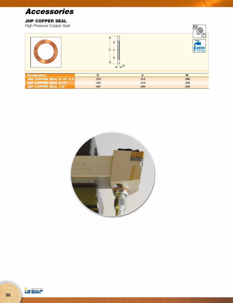
86
JHP COPPER SEALHigh Pressure Copper Seal
dD
W
PSI Max
Designation D d WJHP COPPER SEAL 5/16"-2.5 .370 .315 .098JHP COPPER SEAL 5/16" .433 .315 .039JHP COPPER SEAL 1/8" .591 .394 .039