
Nintendo Ultra64 RSP Programmer's Guide
331
Version 1.1 Nintendo Ultra64 RSP Programmer’s Guide Silicon Graphics Computer Systems, Inc. 2011 N. Shoreline Blvd. Mountain View, CA 94043-1389 ©1996 Silicon Graphics Computer Systems, Inc. All Rights Reserved.
-
Upload
khangminh22 -
Category
Documents
-
view
6 -
download
0
Transcript of Nintendo Ultra64 RSP Programmer's Guide

Version 1.1
Nintendo Ultra64 RSP Programmer’s Guide
Silicon Graphics Computer Systems, Inc.2011 N. Shoreline Blvd.Mountain View, CA 94043-1389
©1996 Silicon Graphics Computer Systems, Inc. All Rights Reserved.
1

2

Table of Contents
1. Introduction ..................................................................................................................... 15
Document Description ................................................................................................. 16What It Is .................................................................................................................. 16What It Is Not .......................................................................................................... 16Information Presentation ....................................................................................... 17
RSP Software Development Tools.............................................................................. 19rspasm....................................................................................................................... 19cpp............................................................................................................................. 20m4.............................................................................................................................. 21buildtask................................................................................................................... 21rsp2elf ....................................................................................................................... 21rsp, rspg.................................................................................................................... 21Gameshop Debugger (gvd) ................................................................................... 22
2. RSP Architecture ............................................................................................................. 23
Overview........................................................................................................................ 24Slave to the CPU...................................................................................................... 24Part of the RCP ........................................................................................................ 24R4000 Core ............................................................................................................... 25Clock Speed.............................................................................................................. 26Vector Processor...................................................................................................... 26
Major R4000 Differences .............................................................................................. 27Pipeline Depth......................................................................................................... 27No Interrupts, Exceptions, or Traps..................................................................... 27Coprocessors............................................................................................................ 27Missing Instructions ............................................................................................... 27
3

Modified Instructions............................................................................................. 28
IMEM .............................................................................................................................. 29Addressing............................................................................................................... 29Explicitly Managed................................................................................................. 29
DMEM ............................................................................................................................ 30Addressing............................................................................................................... 30Explicitly Managed Resource................................................................................ 30
External Memory Map ................................................................................................. 31
Scalar Unit Registers..................................................................................................... 32SU Register Format ................................................................................................. 32Register 0 .................................................................................................................. 32Register 31 ................................................................................................................ 32SU Control Registers............................................................................................... 33
Vector Unit Registers.................................................................................................... 34VU Register Format ................................................................................................ 34VU Register Addressing ........................................................................................ 34
Computational Instructions........................................................................ 34Loads, Stores, and Moves ........................................................................... 35
Accumulator ............................................................................................................ 36VU Control Registers.............................................................................................. 36
Vector Compare Code Register (VCC) ..................................................... 36Vector Carry Out Register (VCO).............................................................. 37Vector Compare Extension Register (VCE).............................................. 38
SU and VU Interaction ................................................................................................. 39Dual Issue of Instructions ...................................................................................... 39
RSP Instruction Set........................................................................................................ 40Instruction Formats................................................................................................. 40
SU Instruction Format ................................................................................. 40
4

Revision 1.0
VU Instruction Format ................................................................................ 40Distinguishing SU and VU Instructions .............................................................. 40Illegal Instructions .................................................................................................. 40
Execution Pipeline ........................................................................................................ 41RSP Block Diagram................................................................................................. 41Mary Jo’s Rules........................................................................................................ 43Register Hazards ..................................................................................................... 43SU is Bypassed......................................................................................................... 44
Coprocessor 0 ............................................................................................................... 45
Interrupts, Exceptions, and Processor Status............................................................ 46Interrupts.................................................................................................................. 46Exceptions ................................................................................................................ 46Processor Status....................................................................................................... 46
3. Vector Unit Instructions................................................................................................. 47
VU Loads and Stores .................................................................................................... 48Normal...................................................................................................................... 50Packed....................................................................................................................... 52Transpose ................................................................................................................. 54
VU Register Moves ....................................................................................................... 56
VU Computational Instructions.................................................................................. 57Using Scalar Elements of a Vector Register ........................................................ 58
VU Multiply Instructions............................................................................................. 61Vector Multiply Examples ..................................................................................... 64
VU Add Instructions .................................................................................................... 67Vector Add Examples............................................................................................. 68
5

VU Select Instructions .................................................................................................. 70Vector Select Examples .......................................................................................... 73
VU Logical Instructions ............................................................................................... 74
VU Divide Instructions ................................................................................................ 75Reciprocal Table Lookup ....................................................................................... 77Higher Precision Results........................................................................................ 78Vector Divide Examples......................................................................................... 78
4. RSP Coprocessor 0 .......................................................................................................... 81
Register Descriptions.................................................................................................... 82RSP Point of View ................................................................................................... 82
$c0................................................................................................................... 83$c1................................................................................................................... 83$c2, $c3 ........................................................................................................... 83$c4................................................................................................................... 85$c5................................................................................................................... 88$c6................................................................................................................... 88$c7................................................................................................................... 88$c8................................................................................................................... 88$c9................................................................................................................... 89$c10................................................................................................................. 89$c11................................................................................................................. 90$c12................................................................................................................. 92$c13................................................................................................................. 92$c14................................................................................................................. 93$c15................................................................................................................. 93
CPU Point of View.................................................................................................. 93Other RSP Addresses................................................................................... 95
DMA ............................................................................................................................... 96Alignment Restrictions........................................................................................... 96Timing....................................................................................................................... 96
6

Revision 1.0
DMA Full.................................................................................................................. 96DMA Wait ................................................................................................................ 96DMA Addressing Bits ............................................................................................ 97CPU Semaphore ...................................................................................................... 97DMA Examples ....................................................................................................... 97
Controlling the RDP ................................................................................................... 100How to Control the RDP Command FIFO ........................................................ 100Examples ................................................................................................................ 101
5. RSP Assembly Language ............................................................................................. 105
Different From Other MIPS Assembly Languages ................................................ 106Why? ....................................................................................................................... 106Major Differences from the R4000 Instruction Set ........................................... 106
Syntax ........................................................................................................................... 107Tokens..................................................................................................................... 107Identifiers ............................................................................................................... 107Constants................................................................................................................ 107Operators................................................................................................................ 108Comments .............................................................................................................. 108Program Sections................................................................................................... 109Labels ...................................................................................................................... 109Keywords ............................................................................................................... 109Expressions ............................................................................................................ 110
Expression Operators ................................................................................ 110Precedence .................................................................................................. 111Expression Restrictions ............................................................................. 111
Registers ................................................................................................................. 112Vector Register Element Syntax.......................................................................... 112Program Statements.............................................................................................. 113
Assembly Directives ................................................................................................... 114.align........................................................................................................................ 114
7

.bound..................................................................................................................... 114
.byte......................................................................................................................... 115
.data......................................................................................................................... 115
.dmax ...................................................................................................................... 115
.end.......................................................................................................................... 116
.ent ........................................................................................................................... 116
.half.......................................................................................................................... 116
.name....................................................................................................................... 116
.print........................................................................................................................ 117
.space....................................................................................................................... 117
.symbol ................................................................................................................... 117
.text .......................................................................................................................... 117
.unname.................................................................................................................. 118
.word....................................................................................................................... 118
BNF Specification of the RSP Assembly Language................................................ 119
6. Advanced Information................................................................................................. 125
DMEM Organization and Usage ............................................................................. 126Jump Tables ........................................................................................................... 126Constants................................................................................................................ 126Labels in DMEM ................................................................................................... 127Dynamic Data ........................................................................................................ 127Diagnostic Information ........................................................................................ 127
Performance Tips ........................................................................................................ 128Dual Execution ...................................................................................................... 128Vectorization.......................................................................................................... 128
Software Pipelining ................................................................................... 130Loop Inversion ........................................................................................... 131Loop Unrolling ........................................................................................... 132Program Flow of Control .......................................................................... 132
Profiling RSP Code ............................................................................................... 133
8

Revision 1.0
Microcode Overlays.................................................................................................... 135Memory System Implications ............................................................................. 135Entirely Up to You ................................................................................................ 135RSP Assembler Tricks........................................................................................... 136A Sample RSP Linker ........................................................................................... 136Overlay Example................................................................................................... 138
Overlay Makefile........................................................................................ 138Overlay DMEM Initialization .................................................................. 139Overlay Initialization Code ...................................................................... 140Overlay Decision Code ............................................................................. 141Overlay DMA Code................................................................................... 141
Controlling the RSP from the CPU.......................................................................... 142Starting RSP Tasks ................................................................................................ 142
RSP Boot Microcode .................................................................................. 142Hidden OS Functions ........................................................................................... 143
__osSpDeviceBusy ..................................................................................... 143__osSpRawStartDma()............................................................................... 143__osSpRawReadIo()................................................................................... 143__osSpRawWriteIo() .................................................................................. 144__osSpGetStatus() ...................................................................................... 144__osSpSetStatus() ....................................................................................... 144__osSpSetPc() .............................................................................................. 144
Microcode Debugging Tips ....................................................................................... 145
RSP Yielding ................................................................................................................ 147Requesting a Yield ..................................................................................... 148Checking for Yield ..................................................................................... 148Yielding ....................................................................................................... 148Saving a Yielded Process .......................................................................... 149Restarting a Yield Process......................................................................... 149
A. RSP Instruction Set Details .......................................................................................... 151Instruction Notation Examples ........................................................................... 154
9

10

List of Figures
Figure 2-1 Block Diagram of the RCP ..........................................................................................25Figure 2-2 SU Register Format......................................................................................................32Figure 2-3 VU Register Format .....................................................................................................34Figure 2-4 VU Accumulator Format..............................................................................................36Figure 2-5 VCC Register Format...................................................................................................37Figure 2-6 VCO Register Format ..................................................................................................37Figure 2-7 VCE Register Format ...................................................................................................38Figure 2-8 RSP Block Diagram .....................................................................................................42Figure 2-9 Pipeline Bypassing .......................................................................................................44Figure 3-1 VU Load and Store Instruction Format........................................................................48Figure 3-2 Long, Quad, and Rest Loads and Stores ......................................................................51Figure 3-3 Packed Loads and Stores..............................................................................................53Figure 3-4 Packed Load and Store Alignment...............................................................................54Figure 3-5 Transpose Loads and Stores.........................................................................................55Figure 3-6 VU Coprocessor Moves ...............................................................................................56Figure 3-7 VU Computational Instruction Format ........................................................................57Figure 3-8 Scalar Half and Scalar Quarter Vector Register Elements...........................................59Figure 3-9 VU Multiply Opcode Encoding ...................................................................................61Figure 3-10 Double-precision VU Multiply ....................................................................................64Figure 3-11 VU Add Opcode Encoding ..........................................................................................67Figure 3-12 VU Select Opcode Encoding .......................................................................................70Figure 3-13 VU Logical Opcode Encoding .....................................................................................74Figure 3-14 VU Divide Opcode Encoding ......................................................................................75Figure 4-1 DMA Transfer Length Encoding .................................................................................84Figure 4-2 DMA Read/Write Example..........................................................................................98Figure 4-3 DMA Wait Example ....................................................................................................99Figure 4-4 RDP Initialization Using the XBUS ..........................................................................101Figure 4-5 OutputOpen Function Using the XBUS.....................................................................102Figure 4-6 OutputClose Function Using the XBUS ....................................................................103Figure 6-1 Real-time Clock Watching on the RSP......................................................................134
11

Figure 6-2 buildtask Operation ....................................................................................................137
12

List of Tables
Table 3-1 VU Load/Store Instruction Summary .......................................................49Table 3-2 VU Computational Instruction Opcode Encoding....................................57Table 3-3 VU Computational Instruction Element Encoding ...................................58Table 3-4 VU Multiply Instruction Summary...........................................................61Table 3-5 VU Add Type Encoding............................................................................67Table 3-6 VU Select Type Encoding..........................................................................70Table 3-7 VU Logical Type Encoding .......................................................................74Table 3-8 VU Divide Type Encoding.........................................................................75Table 3-9 VU Divide Instruction Summary...............................................................76Table 4-1 RSP Coprocessor 0 Registers ....................................................................82Table 4-2 RSP Status Register ...................................................................................85Table 4-3 RSP Status Write Bits ................................................................................86Table 4-4 RDP Status Register...................................................................................90Table 4-5 RSP Status Write Bits (CPU VIEW) .........................................................91Table 4-6 RSP Coprocessor 0 Registers (CPU VIEW)..............................................94Table 4-7 Other RSP Addresses (CPU VIEW)..........................................................95Table 5-1 Expression Operators ..............................................................................110Table 5-2 Expression Operator Precedence ............................................................111Table A-1 RSP Instruction Operation Notations ......................................................153
13

14

Revision 1.0
Chapter 1
1. Introduction
The RSP (Reality Signal Processor) is a powerful processor which is part of the RCP (Reality Co-Processor), the heart of the Nintendo Ultra64.
The RSP operates in parallel with the host CPU (MIPS R4300i) and dedicated graphics hardware on the RCP. Software running on the RSP (microcode) implements the graphics geometry pipeline (transformations, clipping, lighting, etc.) and audio processing (wavetable synthesis, sampled sound, etc.).
The RSP acts as a slave processor to the host CPU, and as such, programming the RSP requires a conspiracy of RSP microcode, R4300 interfaces, and mastery of the features of the RCP. This document addresses the first two of these necessary skills; details of the RDP (Reality Display Processor) component of the RCP can be found elsewhere.
15

Introduction
Document Description
What It Is
The goal of this document is to enable RSP microcode software development:
• Explain architectural details of the RSP.
• Explain relevant architectural details of other parts of the RCP.
• Describe the RSP from a microcode programmer’s point-of-view.
• Describe the RSP (and interfaces) from the host CPU’s point-of-view.
• Explain the RSP microcode assembly language.
• Explain the RSP software development environment.
What It Is Not
In order to present material at a sufficient level of detail without clutter, allowing the programmer to “see the forest and the trees”, so to speak, we have adopted several specific non-goals of this document:
• Basic assembly language programming concepts are not discussed. The reader is assumed to have a thorough technical background.
• Basic concepts of vector processing architectures are not discussed, however some specific issues relating to the RSP are discussed briefly. A good reference for computer architecture which discusses RISC processors and SIMD (vector) architectures is “Computer Organization and Design, The Hardware/Software Interface”1, by Patterson and Hennessy.
• Details of the MIPS Microprocessor Instruction Set Architecture (ISA) are not presented. The design of the RSP instruction set
1 Patterson, D., Hennessy, J., “Computer Organization and Design, The Hardware/Software Interface”, Morgan Kaufmann Publishers, 1994, ISBN 1-55860-281-X.
16

Revision 1.0 Document Description
borrows much from the R4000 ISA; the reader is referred to the “MIPS R4000 Microprocessor User’s Manual”1 for more information.
• Application-specific information is not presented. “How to Write Graphics Microcode for the RSP” or “How to Write Audio Microcode for the RSP” are topics worthy of a book themselves, and are not discussed here.
• How to use the programming tools. There are detailed man pages for each tool used during RSP software development. Although all of these tools are mentioned in this document (and explained briefly), the reader is referred to documentation for individual tools for more information.
• Certain examples and advanced topics refer to higher-level Ultra64 features or RCP operations (operating system, graphics, audio, etc.). These things are explained in other documents; a thorough background knowledge of the Ultra64 is assumed in this document.
Information Presentation
Mastery of the information presented in this document will occur slowly, as the information is both voluminous and of tremendous breadth. Some concepts, such as the hardware architecture of the RSP and the microcode assembly language, are of course thoroughly intertwined; discussion of one is impossible without the other.
In order to present this material clearly, we have divided it up into the following chapters. Each chapter presents its specific topic in detail, usually assuming information contained in other chapters as background. We have attempted to present the information in a logical, top-down fashion, with liberal cross-references to assist the reader.
• Chapter 1, “Introduction,” is this chapter. It describes the document itself, and briefly illuminates the RSP development environment.
1 Heinrich, J., “MIPS R4000 Microprocessor User’s Manual”, Prentice Hall Publishing, 1993, ISBN 0-13-1-5925-4.
17

Introduction
• Chapter 2, “RSP Architecture,” describes the architecture of the RSP in great detail.
• Chapter 3, “Vector Unit Instructions,” explains the vector unit (VU) instructions, building on the RSP architecture and leading into RSP programming.
• Chapter 4, “RSP Coprocessor 0,” describes the RSP’s Coprocessor 0. The RSP Coprocessor 0 controls DMA activity, RDP synchronization, and host CPU interaction.
• Chapter 5, “RSP Assembly Language,” details the assembly language of the RSP, including assembler directives and some programming conventions.
• Chapter 6, “Advanced Information,” builds on information in the previous chapters in order to address sophisticated issues including RSP performance, microcode overlays, host CPU interactions, and additional programming conventions.
• Appendix A, “RSP Instruction Set Details,” contains a concise description of each RSP instruction, intended to be used as a reference.
18

Revision 1.0 RSP Software Development Tools
RSP Software Development Tools
A brief introduction to the RSP programming environment will provide a framework for future discussions.
The following software tools are typically used for developing RSP code. This section only mentions the critical, RSP-specific tools; other, more general tools (like make and other UNIX tools) are not discussed.
rspasm
The assembler used to compile RSP microcode is rspasm. It is a simple, 2-pass assembler developed specifically for the RSP.
It interprets a simple assembly language, which is very R4000-like, but is not MIPS compatible. The source language and assembler directives are unique to the RSP.
The language, explained in more detail in Chapter 5, “RSP Assembly Language,” has the following major features:
• Mnemonic opcode syntax for all SU and VU instructions.
• Support for labels in the text section (for branching) and the data section (for referencing DMEM).
• Simple expression parsing.
The language also includes a rich set of assembler directives, used to instruct the assembler during compilation:
• Data directives, used to initialize DMEM.
• Symbol naming directives, used to assign meaningful names to registers, labels, constants, etc.
• Diagnostic directives, used to enforce memory alignment, print diagnostic messages, etc.
rspasm does not build standard ELF object files, which are required by the makerom utility in order to include RSP microcode objects into a game. ELF file creation is decoupled from the assembler and accomplished by the rsp2elf tool.
19

Introduction
The rspasm assembler outputs several special files. The root filename for these files can be specified with the -o flag.
• <rootname>, is the binary executable code (text section). This file can be loaded into the RSP simulator instruction memory (IMEM) and executed.
• <rootname>.dat, is the binary data section. This is usually loaded into RSP data memory (DMEM).
• <rootname>.lst, is a text program listing generated by the assembler.
• <rootname>.sym, is a “symbol file” used by the RSP simulator to perform source level debugging.
• <rootname>.dbg, is a “symbol file” used by the rsp2elf utility in order to build an ELF object that can be used with makerom and the gvd debugger.
The RSP assembler has no provisions for linking separately-compiled objects. Since IMEM only holds 1024 instructions and assembling is so fast, the lack of a sophisticated linker is not a problem. Source code can be broken up into separate files and #include’d to enforce modularity.
Facilities to support dynamic linking, such as code overlays, are provided by the buildtask tool.
cpp
By default, rspasm invokes the C preprocessor (/usr/bin/cc -E, actually) before assembly so that source code can use #define, #include, #ifdef, etc.
Like other MIPS assemblers, rspasm defines _LANGUAGE_ASSEMBLY (useful for sharing header files with C programs).
20

Revision 1.0 RSP Software Development Tools
m4
The m4 macro processor is a useful tool that can optionally be invoked by the assembler (rspasm -m). If requested, m4 will process the source code after cpp, but before assembly.
Although this is a powerful feature, it is not used to build the currently released software.
buildtask
This tool is a simple ‘linker’ which facilitates dynamic code overlays. its use is not required.
buildtask uses a conspiracy between RSP microcode, DMEM usage, and RSP task invocation to assist with code overlays. It concatenates code (and data) objects (enforcing alignment) in the order provided on the command line, and updates a table in DMEM with offsets and code sizes. This allows the microcode to find a piece of code and overlay it into IMEM during execution.
Additional details and examples of code overlays are described in Chapter 6, “Advanced Information.”
rsp2elf
Since ELF files are required by makerom and gvd, this tool is necessary to construct final microcode objects out of the rspasm output. It creates a dummy ELF .o and inserts the code and data sections into the appropriate locations. It also synthesizes some program symbols from the file name, so that the application code can reference the RSP text and data sections. From this .o, makerom can link the RSP microcode object into the game.
rsp, rspg
This tool is a software simulation of the RSP with a debugger-like interface.
21

Introduction
Originally developed to verify hardware design and enable parallel hardware and software development, it remains useful for developing RSP microcode in a stand-alone fashion.
It has two interfaces, a simple text window interface (rsp) and a fancy window interface (rspg). The window interface supports source-level debugging, which is extremely useful.
Gameshop Debugger (gvd)
The Gameshop debugger, gvd, can be used to debug RSP microcode running on the real hardware.
Detailed instructions are beyond the scope of this document, but if you open the “Coprocessor View” on gvd and set the program counter appropriately you will be looking at IMEM. From here you can trace execution and examine memory and registers.
22

Revision 1.0
Chapter 2
2. RSP Architecture
This chapter explains the significant architectural details of the Reality Signal Processor (RSP). It is not intended to be a comprehensive hardware specification, but it does describe the hardware features in sufficient detail for software development.
Standing alone, the RSP is an extremely powerful processor; a fixed-point RISC CPU capable of over half a billion arithmetic operations per second!1 As part of the RCP, the RSP is an integral part of the graphics/audio/video processing pipelines.
Recommended background for this chapter includes a solid foundation in computer architecture, including RISC processors and SIMD (Single Instruction, Multiple Data) machines.
1 This is not a misprint. At 62.5Mhz with an 8-element vector pipeline, the RSP could perform 500,000,000 multiply-accumulate operations per second. Since the RSP dual-issues scalar instructions, you could also do another 62,500,000 scalar operations during that same second. That is more than three times the performance of the Cray supercomputers from twenty years ago.
23

RSP Architecture
Overview
Slave to the CPU
The RSP operates as a slave to the CPU. As such, there are limited error recovery facilities and many features are explicitly managed at a low level (booting, IMEM, DMEM, etc.)
Part of the RCP
Figure 2-1, reproduced from the Nintendo 64 Programming Manual, illustrates the major functional blocks of the RCP.
The RSP, along with the RDP and the IO subsystem, comprise the RCP chip. The RSP and RDP operate independently and are connected with the XBUS.
The IO block of the RCP also includes memory interfaces and separate DMA engines for the RSP and RDP.
24

Revision 1.0 Overview
Figure 2-1 Block Diagram of the RCP
R4000 Core
The RSP implements an R4000 core instruction set, with additional extensions.
The core instruction unit (without the extensions) is referred to as the Scalar Unit (SU).
RSP
SU VU
IMEM
DMEM
IO
RDP
CPU VI AI PI SI
R4300 Audio Game Contollers Video Cartridge
RDRAM (Rambus Memory)
RCP
STATE
RS
TX
CC
BL MEM
TMEMTF
CP0
25

RSP Architecture
Clock Speed
The RSP clock runs at 62.5 Mhz. Normally, the CPU and the RCP clock rates run in a 3:2 ratio.
Vector Processor
The RSP has a vector processor, implemented as MIPS Coprocessor 2. The vector unit (VU) has 32 128-bit wide vector registers (which can also be accessed as 8 vector slices), a vector accumulator (which also has 8 vector slices), and several special-purpose vector control registers.
The VU instruction set includes all useful computational instructions (add, multiply, logical, reciprocal, etc.) plus additional “multimedia instructions” which are well suited for graphics and audio processing. These instructions are thoroughly explained in Chapter 3, “Vector Unit Instructions”.
26

Revision 1.0 Major R4000 Differences
Major R4000 Differences
The MIPS R4000 series processors provide a convenient framework for learning about the RSP.
Pipeline Depth
Pipeline depth varies among MIPS processors and their implementations. The RSP has a pipeline depth of 5.
No Interrupts, Exceptions, or Traps
The RSP operates as a slave processor. There is no support for interrupts, exceptions, or traps.
Coprocessors
The RSP implements the following MIPS Coprocessors:
• Coprocessor 0 (system control). The RSP coprocessor 0 is not compatible with the R4000 coprocessor 0. The RSP coprocessor 0 is explained in Chapter 4, “RSP Coprocessor 0”.
• Coprocessor 2 (VU) implements the vector unit.
Other MIPS coprocessors, including coprocessor 1 (floating point processor) are not implemented.
Missing Instructions
The following R4000 instructions are not present in the RSP instruction set:
• LDL, LDR, LWL, LWR, LWU, SWL, SDL, SDR, SWR, LL, LLD, LDC1, LDC2, LD, SDC1, SDC2, SD, (all 64-bit loads/stores, load locked, and load/store left/right)
• SC, SCD, (store conditionals)
27

RSP Architecture
• BEQL, BNEL, BLEZL, BGTZL, BLTZL, BGEZL, BLTZALL, BGTZALL, BGEZALL, (all “likely” branches)
• MFHI, MTHI, MFLO, MTLO, (all HI/LO register moves)
• DADDI, DADDIU, DSLLV, DSRLV, DSRAV, DMULT, DMULTU, DDIV, DDIVU, DADD, DADDU, DSUB, DSUBU, DSLL, DSRL, DSRA, DSLL32, DSRL32, DSRA32, (all 64-bit instructions)
• MULT, MULTU, DIV, DIVU, (all multiply/divide instructions)
• SYSCALL, (RSP does not generate exceptions)
• SYNC, (this instruction is intended for multiprocessor systems)
• BCzF, BCzT (all branch-on-coprocessor instructions)
• TGE, TGEU, TLT, TLTU, TEQ, TNE, TGEI, TGEIU, TLTI, TLTIU, TEQI, TNEI, (all TRAP instructions)
Modified Instructions
Some RSP instructions do not behave precisely like their R4000 counterparts. Some major differences:
• ADD/ADDU, ADDI/ADDIU, SLTI/SLTIU, SUB/SUBU. Each pair of these is synonymous with each other, since the RSP does not signal overflow exceptions.
• BREAK does not generate a trap; instead condition bits in the RSP status register are set and an interrupt is signaled.
Detailed behavior of all instructions is presented in Appendix A , “RSP Instruction Set Details”.
28

Revision 1.0 IMEM
IMEM
The RSP has 4K bytes (1K instructions) of instruction memory (IMEM).
Addressing
The RSP PC is only 12-bits; only the lowest 12-bits of any address or branch target are used. Other address bits are ignored.
Explicitly Managed
IMEM must be explicitly managed by the RSP program. IMEM contents can only be loaded with a DMA operation (or programmed IO write from the CPU).
29

RSP Architecture
DMEM
The RSP has 4K bytes of data memory (DMEM).
Addressing
Since DMEM is 4K bytes, only the lowest 12-bits of addresses are used to address DMEM. Other address bits are ignored.
Explicitly Managed Resource
DMEM must be managed by the RSP program. All RSP loads/stores can only access DMEM; data must first be transferred between DMEM and external DRAM using a DMA operation (or programmed IO write from the CPU).
30

Revision 1.0 External Memory Map
External Memory Map
The RSP memory and control registers map into the host CPU address space as defined in the file rcp.h.
This memory map is used by the CPU program to manage the RSP.
It is also convenient to use this address map with the RSP assembler (rspasm) and RSP simulator (rsp). Since only the lower 12-bits of addresses and branch targets are used, the upper bits are safely ignored.
Chapter 4, “RSP Coprocessor 0”, details this address space; in particular, Table 4-6, “RSP Coprocessor 0 Registers (CPU VIEW),” on page 94 and Table 4-7, “Other RSP Addresses (CPU VIEW),” on page 95.
General-purpose SU and VU registers cannot be addressed externally.
31

RSP Architecture
Scalar Unit Registers
The RSP Scalar Unit has 32 general-purpose registers, each 32 bits wide.
SU Register Format
The RSP has big-endian byte ordering.
Figure 2-2 SU Register Format
Register 0
Register 0 ($0) is a special register. It always contains a zero, and cannot be modified. Attempting to modify $0 is a null operation.
Since DMEM addresses are only 12-bits, it can be convenient to use $0 as the base register for loads/stores (the entire DMEM address will fit in the 16-bit offset field).
Register 31
Register 31 ($31) is a special register. The jal and jalr instructions store their return address in this register.
If these instructions are avoided, this register can be treated as any other SU register.
31 0
byte 0 byte 1 byte 2 byte 3
32

Revision 1.0 Scalar Unit Registers
SU Control Registers
RSP control registers are part of Coprocessor 0, and are explained in Chapter 4, “RSP Coprocessor 0,” particularly Table 4-2, “RSP Status Register,” on page 85.
33

RSP Architecture
Vector Unit Registers
The RSP Vector Unit has 32 general-purpose vector registers, each 128 bits wide.
Depending on the operation, vector registers can be accessed as a single unit, by bytes, or by 16-bit elements corresponding to a vector slice.
VU Register Format
The RSP has big-endian byte ordering.
Figure 2-3 VU Register Format
Bits within a byte or register element are numbered similarly, little-endian.
VU Register Addressing
VU registers can be accessed in a variety of formats, depending on the instruction being executed.
Computational Instructions
Most computational instructions operate on VU registers as vectors, performing the same operation on 8 16-bit vector elements, on an element-by-element basis, with the 8 elements corresponding to the vector slices.
127 0
byte 0 byte 1 byte 2 byte 3 byte 4 byte 5 byte 6 byte 7 byte 8 byte 9 byte 10 byte 11 byte 12 byte 13 byte 14 byte 15
element 0 element 1 element 2 element 3 element 4 element 5 element 6 element 7
34

Revision 1.0 Vector Unit Registers
Instructions can operate on pairs of elements, adding two vectors (8 pairs of numbers), for example.
VU registers can also be addressed as scalars, allowing you to add 1 number (the same number) to a vector (8 numbers), for example.
Further, registers can be broken into scalar halves and scalar quarters, allowing you to treat pieces of VU as subsets, performing the same operations on consecutive ranges of elements. This is best understood with an illustrated example, see Figure 3-8, “Scalar Half and Scalar Quarter Vector Register Elements,” on page 59.
RSP assembly language syntax for vector registers is explained in the section “Vector Register Element Syntax” in Chapter 5.
Loads, Stores, and Moves
VU loads, stores, and moves always reference data within VU registers by their bytes. So if you want to load a short (2 bytes) into element 3 of a VU register, you must do this:
lsv $v1[6], 0($1)
Element 3 corresponds to byte 6, of the VU registers.
Caution: A very common programming error is to confuse the “byte index” of a VU load/store with the “element index” of a computational instruction.
35

RSP Architecture
Accumulator
Each vector slice has a 48-bit accumulator associated with it. Each 16-bit element of a vector register maps to a vector slice, and therefore to a different 48-bit accumulator.
Figure 2-4 VU Accumulator Format
The accumulator is modified by most VU computational instructions, but it is used most heavily by the multiply-accumulate instructions. For these instructions, 16-bits of the accumulator is written out after accumulation. “Which” 16-bits to be written is usually an accumulator element. Consult “VU Multiply Instructions” in Chapter 3 for more information.
One VU instruction, vsar, can directly reference the accumulator directly.
VU Control Registers
Vector Compare Code Register (VCC)
This 16-bit register contains 2 bits per 16-bit slice of the VU and is used by the select instructions.
47 0
byte 2 byte 3 byte 4 byte 5byte 0 byte 1
high lowmiddle
36

Revision 1.0 Vector Unit Registers
The low 8 bits are used for most compares (vlt, veq, vne, vge) and merge (vmrg), and all 16 bits are used for the clip compares (vcl, vch, vcr).
Figure 2-5 VCC Register Format
Vector Carry Out Register (VCO)
This 16-bit register contains 2 bits per 16-bit slice of the VU and is used by some of the add and select instructions to perform double-precision operations.
The low 8 bits are CARRY, and are set by vaddc or vsubc instructions that generate a carry out (or borrow, in the case of vsubc). The upper 8 bits are NOT EQUAL, set by vaddc or vsubc if the operands are not equal.
vadd, vsub, and select compare instructions (vlt, veq, vne, vge) use VCO as inputs and clear VCO. Select compare instructions use VCO which was previously set by a vsubc instruction.
Figure 2-6 VCO Register Format
0
elem7
elem6
elem5
elem4
elem3
elem2
elem1
elem0
elem7
elem6
elem5
elem4
elem3
elem2
elem1
elem0
123456789101112131415
vs <= -vt (for clip compares)select compare is TRUE
(vs >= vt, for clip compares)
0
elem7
elem6
elem5
elem4
elem3
elem2
elem1
elem0
elem7
elem6
elem5
elem4
elem3
elem2
elem1
elem0
123456789101112131415
NOT EQUAL is TRUE CARRY is TRUE
37

RSP Architecture
Vector Compare Extension Register (VCE)
This 8-bit register contains one bit for each VU slice, set to 1 if the vch comparison was -1, 0 otherwise. Expressed in a high-level language:
if ((vs[elem] < 0 && vt[elem] >= 0) || (vs[elem] >= 0 && vt[elem] < 0) {if (vs[elem] + vt[elem] == -1)
VCE[elem] = 1;else
VCE[elem] = 0;} else {
VCE[elem] = 0;}
This is used for double-precision clip compares by vcl (in addition to VCC and VCO); vcl clears VCE.
Figure 2-7 VCE Register Format
0
elem7
elem6
elem5
elem4
elem3
elem2
elem1
elem0
1234567
compare is -1
38

Revision 1.0 SU and VU Interaction
SU and VU Interaction
The RSP can execute two instructions per clock cycle, one scalar instruction and one vector instruction. The scalar unit and vector unit operate in parallel.
Dual Issue of Instructions
The instruction fetch cycle can fetch at most two instructions, one SU and one VU. If there are no register conflicts, both instructions can be issued in parallel.
Instructions are paired in order, they are not re-ordered to facilitate dual issue. They do not need to be aligned as one SU and one VU in a 64-bit word.
If the pipeline stalls due to register conflicts (see “Register Hazards” on page 43), no instructions are issued.
39

RSP Architecture
RSP Instruction Set
The details of the instruction set can be found in Appendix A, however several important properties are worth mentioning here.
Instruction Formats
All RSP instructions are implemented within the MIPS R4000 Instruction Set Architecture.
SU Instruction Format
The SU instructions include all three formats found in the MIPS ISA: immediate (I-type), jump (J-type), and register (R-type). Consult the MIPS R4000 Microprocessor User’s Manual for more information.
VU Instruction Format
VU instructions are implemented as coprocessor instructions, as defined by the MIPS ISA.
Detailed discussion of VU instructions can be found in Chapter 3.
Distinguishing SU and VU Instructions
If the opcode mnemonic starts with a ‘v’, it is a vector unit instruction.
It is important to re-iterate that VU loads, stores, and moves are SU instructions; they are executed in the scalar unit (possibly in parallel with other VU instructions).
Illegal Instructions
If an illegal instruction is issued (incorrectly aligned load, incorrect VU element usage, etc.) execution will still occur. Something will happen, possibly modifying RSP state or the instruction flow, possibly not in the expected way.
40

Revision 1.0 Execution Pipeline
Execution Pipeline
RSP Block Diagram
The RSP execution pipeline is illustrated in Figure 2-8.
The scalar unit of the RSP has a five stage pipeline:
IF Instruction Fetch. During this stage, two instruction are fetched and decoded, dual-issuing, if possible.
RD Register Access and Instruction Decode. Control is set up for functional units based on instruction decode.
EX Execute. For computational operations, the result is calculated; for loads/stores/branches, the address is calculated.
DF Data Fetch. For loads, the data is fetched; store data is stored.
WB Write Back. Results are written back to registers.
The vector unit also has a five stage pipeline:
IF Instruction Fetch. Nothing happens in the VU during this stage.
RD Register Access and Instruction Decode. Muxing for “scalar mode”.
MUL Multiply. During this stage, computational operations are computed. Reciprocal operations begin table-lookup.
ACC Accumulate. Additional computation is performed. Reciprocal operations perform table-lookup.
WB Write Back. Minor computations and writing of data to vector registers.
41

RSP Architecture
Figure 2-8 RSP Block Diagram
(sig
ned/
uns/
mix
)
scal
ar V
T
Acc
umul
ate
32bx
32 r
egis
ter
file
2R1W
SU
Pip
elin
e 32
bits
48b
+/-
/z-d
etec
t
32x1
6b r
egis
ter
file
16*1
6->
32b
mul
3R2W
VU
Pip
elin
e 16
bit
Sli
ce, r
eplic
ated
8 ti
mes
DM
em4K
Byt
e12
8bx2
56
Shi
fter
load
_dat
a
IMem
4KB
yte
64bx
512
Add
r
PC
inst
stor
e_da
ta +/-
+8
pc
next
_pc
rese
t_pc
bran
ch_p
c
<47
:0>
Var
ious
Rou
ndin
g
VC
O
1616
Com
plem
ent?
Shi
ft
Pri
Enc
RO
M
Com
plem
ent?
16
Shif
t Rig
ht
Rec
ipro
cal
clam
pva
lues
0’s
0’s
1’s
==
Dat
aIn
Dat
aOut
valu
es
NO
P
Var
ious
shi
fts
Log
ical
Ops
Stor
e
Loa
d
Mux
es
Mux
es
EX
DF
RD
WBIF
IF RD
AC
C
WB
MU
L
Var
ious
bi
t ran
ges
+/-
42

Revision 1.0 Execution Pipeline
Mary Jo’s Rules1
Avoiding pipeline stalls in software can be accomplished by understanding the following rules.
1. VU register destination writes 4 cycles later (need 3 cycles between load and use). This applies to vector computational instructions, vector loads, and coprocessor 2 moves (mtc2).
2. SU register load takes 3 cycles (need 2 cycles between load and use). This applies to SU loads and coprocessor moves (mfc0, cfc2, mfc2). SU computational results are available in the next cycle (see “SU is Bypassed” on page 44).
3. Any load followed by any store 2 cycles later, causes a one cycle bubble. Coprocessor moves (mtc0, mfc0, mtc2, mfc2, ctc2, cfc2) count as both loads and stores.
4. A branch target not 64-bit aligned always single issues.
5. Branches:
a. Can dual issue (with preceding instruction).
b. No branch instruction permitted in a delay slot.
c. Delay slot always single issues.
d. Taken branch causes a 1 cycle bubble.
Register Hazards
The RSP hardware implements register hazard locking for SU and VU registers. Once an instruction is fetched and decoded, its destination register is marked as a “hazard”; if this register is used as an input to a subsequent instruction, the pipeline will stall.
1 Named after Mary Jo Doherty, the designer of the RSP.
43

RSP Architecture
Obviously, pipeline stalls should be avoided by the programmer (when possible) for the best performance.
Because the SU is bypassed (see below), this section only applies to SU registers for loads (and coprocessor moves) and VU registers.
SU is Bypassed
Bypassing, or forwarding, is a technique commonly used to accelerate RISC execution pipelines.
Instead of waiting for the result of a previous instruction to be written to its destination register, a subsequent instruction can use the (correct) value which is residing in a temporary register in the arithmetic and logical unit.
Figure 2-9 Pipeline Bypassing
For software, this means that results from SU instructions are available in the next clock cycle, removing the concern of preventing pipeline stalls.1
1 An obvious question is “why isn’t the VU bypassed?” As illustrated in Figure 2-8, the final result of a vector computation is not available until very late in the WB stage of the pipeline.
IF RD EX DF WBadd $4, $4, $5
IF RD EX DF WBadd $3, $4, $6
IF RD EX DF WBadd $7, $3, $8
IF RD EX DF WBsw $7, 0($10)
44

Revision 1.0 Coprocessor 0
Coprocessor 0
The RSP coprocessor 0 is thoroughly discussed in Chapter 4, but is mentioned here for completeness.
Coprocessor 0 in the MIPS R4000 architecture is designated as the “system control coprocessor”. Since the RSP is a slave processor, the system control functions are greatly reduced, and therefore the usage of coprocessor 0 does not conform to the MIPS R4000 architecture specification.
The RSP does use coprocessor 0 for “system control” functions, these functions (and their registers) are explained in Chapter 4.
45

RSP Architecture
Interrupts, Exceptions, and Processor Status
Interrupts
The RSP does not respond to interrupts, and it can only generate a single interrupt (MI_INTR_SP), triggered by the break instruction.
Exceptions
No RSP instruction can cause an exception, and there are no exception handling facilities in the RSP.
Processor Status
The RSP has a processor status register in coprocessor 0, this register can be used to communicate with the CPU. See page 85 for more information.
46

Revision 1.0
Chapter 3
3. Vector Unit Instructions
Details about each specific instruction are contained in Appendix A, but it is useful to discuss issues common to all of the vector unit instructions, as well as to discuss each related group of vector unit instructions in context.
There are two categories of vector unit instructions discussed in this chapter:
• Vector Loads/Stores/Moves. These are actually scalar unit instructions (executed in the SU, possibly in parallel with VU computational instructions) which load/store/modify vector unit general purpose or control registers.
• Vector Computational Instructions. These instructions are executed in the vector unit in parallel with any scalar instructions.
All of these instructions are implemented with the MIPS coprocessor extensions to the MIPS R4000 Instruction Set Architecture, which permit coprocessor-specific interpretation of some instruction bits. It is these “coprocessor-specific” details which are the subject of this chapter.
47

Vector Unit Instructions
VU Loads and Stores
Vector loads and stores are scalar unit (SU) instructions used to move the contents of DMEM to and from VU registers (see “VU Register Format” on page 34). VU loads and stores can only access DMEM; they cannot access DRAM. Data must be transferred into DMEM using a DMA operation before use.
VU Load and Store instructions follow the general format of MIPS Coprocessor loads and stores (LWC2, SWC2), except for a different interpretation of the 16 offset bits. This usage of the 16 bit offset field in MIPS coprocessor opcode space extends the number of memory operations, without using up a lot of instruction space.
Figure 3-1 VU Load and Store Instruction Format
The operands are:
Base is an SU register containing a DMEM memory address. Only the lower 12 bits of this register are used, other bits are ignored.
VT is the VU register to or from which memory data is written.
The opcode is the memory item type and operation being performed.
Element is the byte element of the VU register being accessed.
Offset is a 7 bit constant shifted by the memory item size and added to the memory address in base. This means that the offset supplied in the assembly language must be an operand-size-aligned integral; a multiple of 2 bytes for a short load, 4 bytes for a long, etc. Since the offset is added to the base, the effective address can still be byte-aligned, however.
All VU loads are delayed load instructions, with three load delay slots (results from a VU load are available for use in the fourth instruction following the load). If a VU instruction attempts to use the destination
016212631
vtbaseLWC2 or SWC2 elementopcode
11 7
offset
25 20 15 10 6
48

Revision 1.0 VU Loads and Stores
register of a VU load, hardware interlocking will stall the processor until the data arrives.
Note: VU stores use an identical pipeline; since accesses to memory always occur in the same VU pipeline stage, a VU store followed by an immediate load from the same memory location is guaranteed to fetch the correct data.
VU stores followed by SU loads are also guaranteed to fetch the correct data, for similar reasons.
VU loads and stores are of three types, normal, packed, and transpose. Normal operations allow the movement of the usual integer memory data items of powers of two numbers of bytes between memory and VU registers with memory byte alignment, and VU element alignment to the size of the item.
The packed operations support access to memory byte data and two and four byte per pixel image data (such as YUV or RGBA).
Transpose accesses are discussed in a subsequent section, and include a transposed or wrapped store, and a transposed and wrapped load.
Table 3-1 VU Load/Store Instruction Summary
Opcode Memory ItemMemory
AlignmentVU Element
(legal values)Offset Shift
Amount
lbv, sbv 8b (byte) byte 0-15 << 0
lsv, ssv 16b (short) byte 0-14 by 2 << 1
llv, slv 32b (long) byte 0-12 by 4 << 2
ldv, sdv 64b (double) byte 0, 8 << 3
lqv, sqv 128b (quad) byte (see below) 0 << 4
lrv, srv 128b (rest) byte (see below) 0 << 4
lpv, spv 8 8b, signed (pack) byte (bit 15) 0 << 3
luv, suv 8 8b, unsigned (upack) byte (bit 14) 0 << 3
lhv, shv 8 8b every 2nd, unsigned (half pack)
quad+0,1 0 << 4
Nor
mal
Pac
ked
49

Vector Unit Instructions
If an illegal alignment (or element value) is attempted, something will be loaded or stored, but probably not what was intended.
Normal
Normal loads and stores move a single memory item to or from an element of a VU register. Items are byte (8 bit), short (16 bit), long (32 bit), double (64 bit), and quad or rest (128 bit). The memory address is byte aligned. The VU element is aligned to the size of the item.
Quad and rest operands update the portion of the memory item or VU register which fall within the aligned quad word.
Quad operations move a byte-aligned quad word up to the 16 byte boundary, that is, (address) to ((address & ~15) + 15) to/from VU register element 0 to (address & 15).
Rest is used to move a byte-aligned quad word up to the byte address, that is, (address & ~15) to (address - 1) to/from VU register element (16 - (address & 15)) to 15. A rest with a byte address of zero writes no bytes.
The quad and rest pair can then move a byte-aligned quad word to/from an entire vector register in two instructions. (This can also be performed with two byte-aligned double instructions, although quad and rest allow the two quad words to be disjoint.) A quad word on a quad word boundary can be moved in one quad instruction.
lfv, sfv 4 8b every 4th, unssigned (fourth pack)
quad+0 to 3 0, 8 << 4
ltv, stv, swv
8 16b (transpose, wrap) quad 0-14 by 2 << 4
Opcode Memory ItemMemory
AlignmentVU Element
(legal values)Offset Shift
Amount
Tra
nspo
se
50

Revision 1.0 VU Loads and Stores
Figure 3-2 Long, Quad, and Rest Loads and Stores
VU register
Memory word
Element
Byte Address128b alignment Item size
VU register
Memory word
Element
Byte Address128b alignment Item size
Long item:
Quad item crossing memory word:
VU register
Memory word
Element
Byte Address128b alignment Item size
Rest item crossing memory word:
51

Vector Unit Instructions
Packed
Packed loads and stores move memory bytes to or from short elements of the VU register, which are aligned to shorts. They are useful for accessing one, two, or four channel byte image data for VU processing as shorts, such as for VU multiplies.
When only some bits of a slice receive data from memory the remaining bits in the slice get zeros.
lpv/spv (pack) moves 8 consecutive bytes to or from a memory.
luv/suv (unsigned pack) is similar to lpv/spv, except the memory byte MSB is aligned to bit 14 of the VU short for unsigned data.
lhv/shv (half) moves every other memory byte, and the selection of odd or even bytes is controlled by the memory byte address.
lfv/sfv (fourth) moves every fourth memory byte, and the selection of which bytes is controlled by the memory byte address. Since fourth only access four bytes within a memory word, element specifies whether the low or high four shorts of the VU register are accessed.
Packed loads and stores are illustrated in Figure 3-3.
52

Revision 1.0 VU Loads and Stores
Figure 3-3 Packed Loads and Stores
VU register
Memory word
Element
Byte Address
128b alignment
VU register
Memory word
Byte Address
128b alignment
VU register
Memory word
Byte Address128b alignment
Pack, Unsigned Pack
Fourth
Half
53

Vector Unit Instructions
The alignment of various pack formats with VU short elements is shown in the Figure 3-4
Figure 3-4 Packed Load and Store Alignment
Unsigned pack, half, and fourth items are intended to support unsigned bytes for one, two, or four channel image data. Pack is a signed byte, for example for 8 bit audio or geometric normal or difference vectors. The alignment to the VU short MSB optimizes usage as signed or unsigned fractions in subsequent VU multiplies.
Transpose
Transpose loads and stores can be used to transpose an 8 by 8 block of shorts in 16 instructions.
The instructions are stv, swv, and ltv. Transpose loads and stores move a 128 bit VU register to and from an aligned 128 bit memory word as 8 16 bit values, one from each VU slice. The VU register number of each slice is computed as:
(VT & 0x18) | ((Slice + (Element >> 1)) & 0x7)
which is to say, vt specifies a base register of an 8 register group. Within that group, the register address is a function of the slice number and the element number treated as 0 to 7. A store gathers a diagonal vector of shorts from 8 VU registers into a memory word, or a load scatters a memory word into a diagonal vector of shorts in 8 VU registers, without writing the other shorts in each register. Wrap loads and stores perform a circular left shift of the 8 shorts by (element >> 1), which is equivalent to:
0
Memory byte item
VU short element
Pack Upack, Half, Fourth
00 141515 78Zero Zero
54

Revision 1.0 VU Loads and Stores
dest_short[ Slice ] = source_short[((Slice +(Element >> 1)) & 0x7)]
A transpose is shown in Figure 3-5, with 8x8 block of 8 shorts in 8 VU registers numbered in row order for the 64 elements of the block. The other 14 vector loads and stores needed for the transpose are similar. For a memory-to-memory transpose, the instructions used are ltv and swv, and for a register-to-register transpose, stv and ltv.
Interlock is performed by enabling the source and destination register comparisons on only the upper two register number bits, that is, making any interlock comparison to the 8 registers within a transpose block true.
Figure 3-5 Transpose Loads and Stores
3
12
21
30
39
40
49
58
3 12 21 30 3940 49 58
3
12
21
30
39
40
49
58
Store Transpose, Element 5 Load Transpose, Element 3
128b memory word
VT
VT+7
55

Vector Unit Instructions
VU Register Moves
VU register move instructions follow the general format of MIPS Coprocessor moves (MTC2, MFC2, CTC2, CFC2), with additional interpretation of the lower 11 bits.
Figure 3-6 VU Coprocessor Moves
The low 16 bits of the SU register rt are moved from or to the 16 bit element of the VU register vs specified in element. The SU register is sign extended when moved from the VU register.
For general VU register moves, element is a byte element, which must be one of [0,2,4,6,8,10,12,14].
For control register moves, the vs field specifies the VCO, VCC, or VCE control registers, and element is ignored. See “VU Control Registers” on page 36 for explanation of each control register.
Moves to VU registers have the same load delay characteristics as VU loads. Moves to SU registers have the same load delay characteristics as SU loads.
0162131
rtCOP2 move opcode element
10
vs
6
undefined
20 15 11 7
56

Revision 1.0 VU Computational Instructions
VU Computational Instructions
The VU computational instructions adhere to the general format of MIPS Coprocessor Operate instructions (COP2).
Figure 3-7 VU Computational Instruction Format
Most VU computational instructions are three operand:
VD = VS operation VT
where each operand is one of 32 vector registers. The vt operand can also be a scalar operand in some instructions, that is, one 16 bit element of the vector register, as defined in the element field. The value written to vd is clamped (saturated) to the minimum and maximum values of the element (-32768 and +32767 for 16-bit signed elements), before being written.
A vector accumulator register (see “Accumulator” on page 36) is available to accumulate results over several instructions. The accumulator is modified by all multiply and some add instructions, but its contents are unchanged after other VU instructions. The major types of VU computational instructions are multiply, add, select, logical, and divide. The upper bits of the opcode field select the instruction type, and are encoded as in Table 3-2.
Table 3-2 VU Computational Instruction Opcode Encoding
Opcode Instruction
0 0 x x x x Multiply
0 1 x x x x Add
1 0 0 x x x Select
1 0 1 x x x Logical
1 1 0 x x x Divide
061116212531
vt vs vd opcodeelementCOP2 1
26 24 20 15 10 5
57

Vector Unit Instructions
Using Scalar Elements of a Vector Register
Element encodings are shown in Table 3-3, where x indicates the bit field used to select which element. Scalar elements can be selected within quarters, halves, or the whole vector.
Table 3-3 VU Computational Instruction Element Encoding
This is useful for operating on multiple “vectors” within one instruction cycle, such as working on two 3D points/vectors.
Consider the following code to compute the square of the distance between two points:
## dist^2 = (xa-xb)^2 + (ya-yb)^2 + (za-zb)^2## Assumes single precision, all in range, etc.#vsub $v3, $v1, $v2 # calc (xa-xb), (ya-yb), (za-zb)vmudh $v3, $v3, $v3 # square the differencesvadd $v3, $v3, $v3[1q]# collect the termsvadd $v3, $v3, $v3[2h]
In this example, scalar half and scalar quarter element references are used in the vadd instructions to collect the intermediate terms. We can also compute the distance between two groups of point-pairs at once, by putting each
TypeAssembly
Syntax ExampleElement
FieldUsage
Vector $v1 0 0 0 0 vector operand
Scalar Quarter $v1[xq] 0 0 1 x 1 of 2 elements for 4 2-element quarters of vector
Scalar Half $v1[xh] 0 1 x x 1 of 4 elements for 2 4-element halves of vector
Scalar Whole $v1[x] 1 x x x 1 of 8 elements for whole vector
58

Revision 1.0 VU Computational Instructions
point-pair in the same half of the vector registers. The register contents and operations are illustrated in Figure 3-8.
Figure 3-8 Scalar Half and Scalar Quarter Vector Register Elements
(xa-xb) (ya-yb) (za-zb) 0 (xa-xb) (ya-yb) (za-zb) 0$v3
x’+y’+z’ y’+y’+z’ z’+z’ z’ x’+y’+z’ y’+y’+z’ z’+z’ z’$v3
(xa-xb) (ya-yb) (za-zb) 0 (xa-xb) (ya-yb) (za-zb) 0$v3
x’ y’ z’ 0 x’ y’ z’ 0$v3
x’+y’ y’+y’ z’+0 0+0 x’+y’ y’+y’ z’+0 0+0$v3
vmudh $v3, $v3, $v3
vadd $v3, $v3, $v3[2h]
vadd $v3, $v3, $v3[1q]
* * * * * * * *
+ +
+ +
++
xa ya za 0 xa ya za 0$v1
xb yb zb 0 xb yb zb 0$v2
vsub $v3, $v1, $v2 - - - - - - - -
59

Vector Unit Instructions
In the above example (since add is commutative), a slightly different usage of the vector registers could have been used to direct the final result to be in a different element. Replacing:
vadd $v3, $v3, $v3[1q]
with
vadd $v3, $v3, $v3[0q]
would leave the final result in element [1h] instead of [0h]. This might be important, in order to align the results for the next computation.
60

Revision 1.0 VU Multiply Instructions
VU Multiply Instructions
Figure 3-9 VU Multiply Opcode Encoding
VU multiply instructions perform various multiplies, specified by the following fields:
Element: Vector or scalar element of vt.
A: When a == 1, Accumulate the product, otherwise round the product and load the accumulator. The round value is determined by the format.
Format: Select various product and result options.
The product is the 32 bit signed result from the 16x16 signed multiply. Each element of the accumulator is 48 bits wide (see “Accumulator” on page 36). The result is the 16 bits of the accumulator written to vd. Double precision (32 bit) operands are supported by multiplying and accumulating the low 16 bits from one vector operand and the upper 16 bits from another vector operand in several multiply instructions. Formats for various product and result options are shown in Table 3-4.
Table 3-4 VU Multiply Instruction Summary
Fmt S, T signedProd Shift
Round Value Result Clamping Instructions
0 0 0 sign, sign << 1 +32768 b31-16 sign, b31-msb vmulf, vmacf
0 0 1 sign, sign << 1 +32768 b31-16 uns, b31-msb vmulu, vmacu
0 1 0 NA, sign NA +VT if Acc b31-16 sign, b31-msb vrndp, vrndn
0 1 1 sign, sign << 16 +31 if Prod b32-17 sign, b32-msb vmulq, vmacq
1 0 0 uns, uns >> 16 0 b15-0 sign, b31-msb vmudl, vmadl
1 0 1 sign, uns 0 0 b31-16 sign, b31-msb vmudm, vmadm
format
0235
0 0 a
4
61

Vector Unit Instructions
vmulf and vmulu support operands with 15 fraction bits, and differ only in whether the result is clamped signed or unsigned. Small integer operands can be multiplied with vmudh (if the result is bigger than 16 bits, double precision should be used.)
vmulq is intended specifically to support 12 bit MPEG inverse quantization1. The product is shifted left by 16 in order to clamp on the upper accumulator. The round value (31<<16) is added to the product if the product is negative, otherwise zero is added. The result is clamped and shifted right by 17 before being written to vd and AND’d with 0xFFF0, producing a result from -2048 to 2047 aligned to the short MSB. In other words,
VD = (ACC >> 17) & 0xFFF0
vmacq ignores the vs and vt operands, and performs oddification1 of the accumulator by adding (32<<16) if the accumulator is negative and bit 21 is zero, adding (-32<<16) if positive and bit 21 is zero, or adding zero if the accumulator bits 47-21 is zero or bit 21 is one. The clamp and shift is the same as vmulq.
vrnd is intended to specifically support MPEG DCT rounding1. The vt operand is conditionally added to the accumulator. For vrndn, vt is added if the accumulator is negative, otherwise zero is added. For vrndp, vt is added if the accumulator is positive, otherwise zero is added. vt is shifted left by 16 if the register number vs is 1, or not shifted if vs is zero (note this is the instruction field vs, not the contents of vs).
1 1 0 uns, sign 0 0 b15-0 sign, b31-msb vmudn, vmadn
1 1 1 sign, sign << 16 0 b31-16 sign, b31-msb vmudh, vmadh
1 MPEG1 Specification, ISO/IEC 11172-2. MPEG documentation is available from the American National Standards Institute (ANSI), New York, N.Y.; or from the Japanese Industrial Standards Committee (JISC), Tokyo, Japan.
Fmt S, T signedProd Shift
Round Value Result Clamping Instructions
62

Revision 1.0 VU Multiply Instructions
Rounding is performed for single precision multiplies by adding the appropriate rounding value (as dictated by the format) to the accumulator.
Clamping (saturation) is performed by testing certain accumulator bits above the 16 bit result field, and substituting maximum or minimum 16 bit signed or unsigned numbers, as dictated by the format.
The operations vmul* and vmac* (or vmud* and vmad*) either load the accumulator or add the product to the accumulator. Typically a vmac* or vmad* must immediately follow a vmul* or vmud* instruction or else the accumulator contents are undefined.
vmulf supports signed fractions. vmulu supports signed fractions with clamping to an unsigned result, such as for pixel color values. For double precision, vmudl performs the low partial product, vmudm and vmudn the middle partial products, and vmudh the high partial product.
Ignoring clamping, the multiply instructions are equivalent to:
for (i=0; i<8; i++) VD[i] = (ACC[i] = (VS[i] * VT[i] << 1) + Round) >> 16;
and the multiply accumulate instructions are equivalent to:
for (i=0; i<8; i++) VD[i] = (ACC[i] += VS[i] * VT[i] << 1) >> 16;
or in either case, possibly times vt[element].
The double precision multiply instructions are equivalent to1:
for (i=0; i<8; i++) VD[i] = ((ACC[i] = (VS[i] * VT[i]) <<>> prod_shift) >>
result_shift);
and the double precision multiply accumulate instructions are equivalent to:
for (i=0; i<8; i++) VD[i] = ((ACC[i] += (VS[i] * VT[i]) <<>> prod_shift) >>
result_shift);
1 in the following examples, the notation ‘<<>>’ means “shifted up or down, whichever is appropriate”.
63

Vector Unit Instructions
Double precision operands use a register pair, one register containing the upper signed 16 bits and another containing the low unsigned 16 bits.
Double precision multiplication is illustrated in Figure 3-10.
Figure 3-10 Double-precision VU Multiply
Since double precision returns at most a 32 bit result, software must keep numbers in range.
Mixed precision, that is a 16x32 multiply, can be performed with different combinations of multiply instructions.
In some instances, it is necessary to use an additional multiply instruction to extract the rest of the answer from the accumulator. This is necessary because one of the partial-product multiplies may change the sign of the result, requiring you to retrieve a portion of the result from the accumulator again.
High 16b signed int,
vmudl SL * TL >> 16
vmadm SH * TL >> 0
vmadn SL * TH >> 0
vmadh SH * TH << 16
H 16b int, L 16b fract
+
+
+
+
Accumulator
VS and VT operands
VD result
Low 16b unsigned frac
64

Revision 1.0 VU Multiply Instructions
Vector Multiply Examples
The following code fragments illustrate various multiplies. In this section, the following notation is used:
• I is a signed 16-bit integer.
• F is an unsigned 16-bit fraction.
• IF is a 32-bit number, with the signed upper 16 bits contained in one register, and the unsigned lower 16 bits contained in a second register.
• _int is a named vector register holding a signed 16 bit number.
• _frac is a named vector register holding an unsigned 16 bit fraction.
• dev_null is a named vector register containing all zeros.
IFxI: # # mixed precision multiply: # IF * I = IF #vmudn res_frac, s_frac, t_intvmadh res_int, s_int, t_intvmadn res_frac, dev_null, dev_null[0]
IxIF: # # mixed precision multiply: # I * IF = IF #vmudm res_frac, s_int, t_fracvmadh res_int, s_int, t_intvmadn res_frac, dev_null, dev_null[0]
IFxF: # # mixed precision multiply: # IF * F = IF #vmudl res_frac, s_frac, t_frac
65

Vector Unit Instructions
vmadm res_int, s_int, t_fracvmadn res_frac, dev_null, dev_null[0]
IxI: # # single precision integer multiply: # I * I = I #vmudh res_int, s_int, t_int
IxF: # # single precision multiply: # I * F = IF # vmudm res_int, s_int, t_fracvmadn res_frac, dev_null, dev_null[0]
Other combinations are left as an exercise to the reader.
66

Revision 1.0 VU Add Instructions
VU Add Instructions
Figure 3-11 VU Add Opcode Encoding
The VU add instructions perform various types of adds, specified by the following fields:
Element: Vector or scalar element of vt (except vsar where it selects the accumulator portion).
Type: One of the following types of add instructions:
Table 3-5 VU Add Type Encoding
Type Instruction
0 0 0 0 vadd
0 0 0 1 vsub
0 0 1 0 reserved
0 0 1 1 vabs
0 1 0 0 vaddc
0 1 0 1 vsubc
0 1 1 0 reserved
0 1 1 1 reserved
1 0 0 0 reserved
1 0 0 1 reserved
1 0 1 0 reserved
1 0 1 1 reserved
1 1 0 0 reserved
035
0 1 type
4
67

Vector Unit Instructions
The VU adds are short (16 bit) add operations; they clear VCO and clamp to 16 bit signed values. vadd uses VCO as carry in, vsub uses VCO as borrow in, and vabs ignores VCO:
vadd: VD = VS + VT
vsub: VD = VS - VT.
vabs: conditional negation of vt by the sign of vs. Also performs sign().
if (VS < 0) VD = -VT;
else if (VS == 0) VD = VS;
else VD = VT;
Add operations for double precision, no clamping:
vaddc: VD = VS + VT, set VCO with carry out and not equal.
vsubc: VD = VS - VT, set VCO with borrow out and not equal.
vsar: read the accumulator and write to vd, and write the accumulator with the contents of vs. vt is ignored. The high, middle, or low 16 bits of the accumulator are selected by the element (corresponding to element values of 0, 1, and 2, respectively). No clamping is performed. vsar is useful for diagnostics and extended precision.
Vector Add Examples
The following code fragments illustrate various adds. In this section, the following notation is used:
1 1 0 1 vsar
1 1 1 0 reserved
1 1 1 1 reserved
Type Instruction
68

Revision 1.0 VU Add Instructions
• I is a signed 16-bit integer.
• F is an unsigned 16-bit fraction.
• IF is a 32-bit number, with the signed upper 16 bits contained in one register, and the unsigned lower 16 bits contained in a second register.
• _int is a named vector register holding a signed 16 bit number.
• _frac is a named vector register holding an unsigned 16 bit fraction.
• dev_null is a named vector register containing all zeros.
This code demonstrates a double-precision add:
vaddc res_frac, s_frac, t_fracvadd res_int, s_int, t_int
This code demonstrates a double-precision subtract:
vsubc res_frac, s_frac, t_fracvsub res_int, s_int, t_int
This code demonstrates reading the accumulator using vsar, following a multiply:
vmadh res_int, s_int, t_intvsar res_int, s_int, t_int[0]vsar res_frac, s_frac, t_frac[1]
Other combinations are left as an exercise to the reader.
69

Vector Unit Instructions
VU Select Instructions
The VU select operations compare pairs of vector elements and choose which one to write, based on the outcome of the test.
Figure 3-12 VU Select Opcode Encoding
Instruction fields are:
Element: Vector or scalar element of vt.
Type: One of the following operations:
Table 3-6 VU Select Type Encoding
Select compares perform an element by element comparison of vs and vt, using VCO as input, clearing VCO, setting VCC with the result of comparison, and storing the element for which the comparison is true to vd.
vlt: VS < VT
veq: VS == VT
Type Instruction
0 0 0 vlt
0 0 1 veq
0 1 0 vne
0 1 1 vge
1 0 0 vcl
1 0 1 vch
1 1 0 vcr
1 1 1 vmrg
0235
1 0 0 type
70

Revision 1.0 VU Select Instructions
vne: VS!= VT
vge: VS >= VT
vch: Clip test, single precision or high half of double precision.
vcl: Clip test, low half of double precision.
vcr: 1’s complement clamp.
vmrg: VD = VS or VT selected by VCC, VCO is ignored.
Note: To implement comparisons which are not supplied, the ‘vle’ compare can be performed by vge after swapping vs and vt operands; similarly, ‘vgt’ by vlt. If vt is scalar, the value can be decremented and then ‘vgt’ is performed by vge, and ‘vle’ by vlt.
Select merge instructions select elements of vs or vt based on the contents of the VCC and write the element to vd. Merge is useful for selecting several different operands from one comparison or after loading VCC with a bit field.
Double precision comparisons are supported in combination with the VCO register set by vsubc.
The compare operations use the contents of VCO as input and clear VCO. Usually VCO was previously set by a vsubc instruction, with a negative (carry) or not equal status bit for each element of the vector, so double precision (32 bit) compares can be accomplished.
The compares (ignoring VCO for the moment) are equivalent to
for (i=0; i<8; i++) {if (VS[i] condition VT[i])
VCC |= (1<<i); else
VCC &= ~(1<<i),VD[i] = (VCC & (1 << i))? VS[i]: VT[i];
}
Compares other than vch/vcl/vcr clear the upper 8 bits of VCC.
The merge is equivalent to
for (i=0; i<8; i++) VD[i] = (VCC & (1 << i))? VS[i]: VT[i];
71

Vector Unit Instructions
Note that vmrg uses the low 8 bits of VCC, the upper 8 as set by vcl/vcr are ignored.
The results of a compare in VCC are available to a following vmrg instruction using VCC without pipeline delays. VCC can also be accessed by the SU with VU move instructions (ctc2/cfc2) for other processing such as accumulation, branching, or patterning. VCC is only modified by compare or VU move instructions.
The vch and vcl (Clip test) comparisons are an optimization for comparing the elements of a vector vs to a scalar element in vt, or the vector vt, such as comparing w to xyz, or clamping a vector to a +/- range. vch performs (-VT >= VS >= VT) generating 16 bits in VCC and updating VCO and VCE with equal and sign values. The vch is used for singled precision (16 bit) operands. For double precision, vch is performed first on the upper 16 bits, followed by a vcl instruction on the lower 16 bits. vcl reads and writes VCO, VCC, and VCE. Because only one of the two comparisons per element can be true, vch/vcl can be executed in one comparison per vector element. The XOR of the sign of vs and vt is used to select the arithmetic operation used for the comparison, such as
if ((VS[i] ^ VT[i]) < 0) {VCC |= ((VT[i] >> 16) & 1) << i;if (VS[i] <= -VT[i]) {
VCC |= 256<<i; VD[i] = -VT[i];
} else VD[i] = VS[i];
} else {VCC |= ((VT[i] >> 8) & 256) << i;if (VS[i] >= VT[i]) {
VCC |= 1<<i; VD[i] = VT[i];
} else VD[i] = VS[i];
}
For each element of vs, one of two bits meaning <= -VT or >= VT is set in VCC, for example, bit 8 is one if the first element of vs is <= -VT, bit 0 is one if the first element of vs is >= VT, bit 9 is set if the second element of vs is <= -VT, etc. If the vch/vcl comparison is true, either -vt or vt is written to vd based on the sign of vs, else vs is written.
72

Revision 1.0 VU Select Instructions
Note: For single precision vch not followed by a vcl, VCO must be set before another compare (by a move, add, or compare whose results are not meaningful).
The vcr instruction is similar to vcl, except that vt is a 1’s complement instead of 2’s complement number, such as for clamping to a power of 2. vcr is only single precision and ignores the contents of VCO for input.
Vector Select Examples
The following code fragments illustrate various vector selects.
This code demonstrates a sort of the parallel elements within three vectors (finding the min, mid, and max of 8 triples). After executing this code, min will contain the smallest elements, max will contain the largest, and mid will contain the intermediate elements:
vge tmp1, min, midvlt min, min, midvge tmp2, min, maxvlt min, min, maxvge max, tmp1, tmp2vlt mid, tmp1, tmp2
This code demonstrates the generation of 3D clip codes for trivial rejection, testing each x,y,z component against w. It also uses vector halves, clip-testing two vertices at the same time (the first vertex is in elements 0-3, the second in elements 4-7):
vch vtmp, vout_int, vout_int[3h] # compare with wvcl vtmp, vout_frac, vout_frac[3h]cfc2 $1, $vcc # get clip codes
Other combinations are left as an exercise to the reader.
73

Vector Unit Instructions
VU Logical Instructions
The VU logical instructions perform the usual bit-wise logical operations on vs and vt, writing the result to vd.
Figure 3-13 VU Logical Opcode Encoding
Instruction fields are:
Element: Vector or scalar element of vt.
Type: One of the following operations:
Table 3-7 VU Logical Type Encoding
Type Instruction
0 0 0 vand
0 0 1 vnand
0 1 0 vor
0 1 1 vnor
1 0 0 vxor
1 0 1 vnxor
0235
1 0 1 type
74

Revision 1.0 VU Divide Instructions
VU Divide Instructions
The VU divide instructions compute the reciprocal of a scalar element of a vector register.
Figure 3-14 VU Divide Opcode Encoding
The divide instructions are two operand, vd and vt. An element specification must be provided for each operand, selecting the source and destination elements, for example:
vmov $v1[5], $v2[0]
Instruction fields are:
Element: Must be a single scalar element of the whole vector vt.
vs: The scalar element of vd is encoded as vs.
Type: One of the following operations:
Table 3-8 VU Divide Type Encoding
Type Instruction
0 0 0 vrcp
0 0 1 vrcpl
0 1 0 vrcph
0 1 1 vmov
1 0 0 vrsq
1 0 1 vrsql
1 1 0 vrsqh
1 1 1 vnop
0235
1 1 0 type
75

Vector Unit Instructions
The reciprocal (rcp) or reciprocal of the square root (rsq) of the scalar element of vt is computed by table lookup and written to the scalar element of vd.
The scalar element of vd is selected by the register number vs (0-7). Not the contents of vs, but the instruction field vs bits.
Single (16 bit) and double (32 bit) precision source values are supported, with double precision sources supplied in two instructions.
The destination is a 32 bit value, written to two register elements in two instructions.
For single precision sources, vrcp/vrsq supplies the source operand in vt[element] and the low 16 bits of the result is written to vd[vs]. The upper 16 bits of the result is written by a subsequent vrcph/vrsqh.
For double precision sources, vrcph/vrsqh supplies the upper 16 bits of the source (and writes the upper 16 bits of a previous vrcp/vrsq or vrcpl/vrsql). A subsequent vrcpl/vrsql supplies the low 16 bits of the source and writes the low 16 bits of the result.
The vmov type simply copies vt[element] to vd[vs], and is useful for reordering scalar data.
vnop ignores vd, and no register is written.
The following table shows the source and destination operand bits from each the vt and vd elements.
Table 3-9 VU Divide Instruction Summary
Type vt[element] vd[vs]
vnop NA no operation
vmov write source to result
vrcp, vrsq low low lookup source and write result
vrcph, vrsqh
high high set source, write previous result
76

Revision 1.0 VU Divide Instructions
Reciprocal Table Lookup
The results are computed by a table lookup using 10 bits of precision. The input is shifted up to remove leading 0’s (or 1’s) (actually, the first non-leading digit is also removed, since we know what it is) and the next 10 bits are used to index into the reciprocal table. The 16 bits in the table at this index are used to construct the result, which is obtained by shifting down an appropriate number of bits and possibly complementing (for negative input).
For rcp, the radix point of the output is shifted right compared to the input. For example, for double precision rcp, with input format S15.16, the output result will be S16.15, requiring the result to be multiplied by 2 in order to maintain the same format.
For rsq, the radix point moves to the left by one-half the number of integer bits. Think of it this way:
and:
vrcpl, vrsql
low low lookup source and previous, write result
Type vt[element] vd[vs]
input a 2k=
table 1
a 2k-------------------=
77

Vector Unit Instructions
so we need to also take the sqrt of the exponent:
so the result does not have the same radix point as the input.
Higher Precision Results
Algorithms which require higher precision can perform Newton-Raphson iteration on the result, such as:
R’ = R*(2-R*X); /* for VRCP */
or
R’ = R*(3-R*X)/2; /* for VRSQ */
Several divide results can be assembled into two vector registers, the high and low double precision reciprocal, for parallel Newton’s iteration. Square root can be performed by multiplying the result of vrsq by the source operand:
sqrt(X) = X * 1/sqrt(X);
Vector Divide Examples
The following code illustrates several vector divide operations. In this section, the following notation is used:
• I is a signed 16-bit integer.
• F is an unsigned 16-bit fraction.
• IF is a 32-bit number, with the signed upper 16 bits contained in one register, and the unsigned lower 16 bits contained in a second register.
• _int is a named vector register holding a signed 16 bit number.
result 1
a 2
k2---
-------------------=
78

Revision 1.0 VU Divide Instructions
• _frac is a named vector register holding an unsigned 16 bit fraction.
• dev_null is a named vector register containing all zeros.
A single precision reciprocal:
vrcp sres_frac[0], s_int[0]vrcph sres_int[0], dev_null[0]
A double precision reciprocal:
vrcph sres_int[0], s_int[0]vrcpl sres_frac[0], s_frac[0]vrcph sres_int[0], dev_null[0]
Multiple calculations can be chained together:
vrcph sres_int[0], s_int[0]vrcpl sres_frac[0], s_frac[0]vrcph sres_int[0], t_int[0]vrcpl tres_frac[0], t_frac[0]vrcph tres_int[0], dev_null[0]
In the above cases, the input format was S15.16, so after the reciprocal the radix point moves to the right, so we must shift by 1 (multiply by 2.0) in order to correct the result:
vmudn sres_frac, sres_frac, vconst[2] # constant of 2vmadm sres_int, sres_int, vconst[2]vmadn sres_frac, dev_null, dev_null[0]
Square root reciprocals are similar. Note the adjustment of the radix point after the reciprocal calculation:
# double precision:vrsqh dres_int[0], t_int[0]vrsql dres_frac[0], t_frac[0]vrsqh dres_int[0], vconst[0]
# generate constant to shift radix point:addi $1, $0, 0x200mtc2 $1, vconst[6]
# shift right by 8 bits.vmudl dres_frac, dres_frac, vconst[3]
79

Vector Unit Instructions
vmadm dres_int, dres_int, vconst[3] vmadn dres_frac, vconst, vconst[0]
80

Revision 1.0
Chapter 4
4. RSP Coprocessor 0
This chapter describes the RSP Coprocessor 0, or system control coprocessor.
The RSP Coprocessor 0 does not perform the same functions or have the same registers as the R4000-series Coprocessor 0. In the RSP, Coprocessor 0 is used to control the DMA (Direct Memory Access) engine, RSP status, RDP status, and RDP I/O.
81

RSP Coprocessor 0
Register Descriptions
RSP Point of View
RSP Coprocessor 0 registers are programmed using the mtc0 and mtf0 instructions which move data between the SU general purpose registers and the coprocessor 0 registers.
Table 4-1 RSP Coprocessor 0 Registers
Register Number
Name Defined in rsp.h
AccessMode
Description
$c0 DMA_CACHE RW I/DMEM address for DMA.
$c1 DMA_DRAM RW DRAM address for DMA.
$c2 DMA_READ_LENGTH RW DMA READ length (DRAM I/DMEM).
$c3 DMA_WRITE_LENGTH RW DMA WRITE length (DRAM I/DMEM).
$c4 SP_STATUS RW RSP Status.
$c5 DMA_FULL R DMA full.
$c6 DMA_BUSY R DMA busy.
$c7 SP_RESERVED RW CPU-RSP Semaphore.
$c8 CMD_START RW RDP command buffer START.
$c9 CMD_END RW RDP command buffer END.
$c10 CMD_CURRENT R RDP command buffer CURRENT.
$c11 CMD_STATUS RW RDP Status.
$c12 CMD_CLOCK RW RDP clock counter.
$c13 CMD_BUSY R RDP command buffer BUSY.
$c14 CMD_PIPE_BUSY R RDP pipe BUSY.
$c15 CMD_TMEM_BUSY R RDP TMEM BUSY.
82

Revision 1.0 Register Descriptions
$c0
This register holds the RSP IMEM or DMEM address for a DMA transfer.
On power-up, this register is 0x0.
$c1
This register holds the DRAM address for a DMA transfer. This is a physical memory address.
On power-up, this register is 0x0.
$c2, $c3
These registers hold the DMA transfer length; $c2 is used for a READ, $c3 is used for a WRITE.
1112 0
1 12
IMEM or DMEM addressaa=0: DMEMa=1: IMEM
23 0
24
DRAM address
11 0
12
length
19 12
8
count
31 20
12
skip
83

RSP Coprocessor 0
The three fields of this register are used to encode arbitrary transfers of rectangular areas of DRAM to/from contiguous I/DMEM. length is the number of bytes per line to transfer, count is the number of lines, and skip is the line stride, or skip value between lines. This is illustrated in Figure 4-1:
Figure 4-1 DMA Transfer Length Encoding
Note: DMA length and line count are encoded as (value - 1), that is a line count of 0 means 1 line, a byte length of 7 means 8 bytes, etc.
A straightforward linear transfer will have a count of 0 and skip of 0, transferring (length+1) bytes.
The amount of data transferred must be a multiple of 8 bytes (64 bits), hence the lower three bits of length are ignored and assumed to be all 1’s.
DMA transfer begins when the length register is written.
For more information about DMA transfers, see section “DMA” on page 96.
On power-up, these registers are 0x0.
count
skip
length
length = 7skip = 8count = 10
DRAM
DMEM
84

Revision 1.0 Register Descriptions
$c4
This register holds the RSP status.
Table 4-2 RSP Status Register
bit fieldAccessMode
Description
0 h RW RSP is halted.
1 b R RSP has encountered a break instruction.
2 db R DMA is busy.
3 df R DMA is full.
4 if R IO is full.
5 ss RW RSP is in single-step mode.
6 ib RW Interrupt on break.
7 s0 RW signal 0 is set.
8 s1 RW signal 1 is set.
9 s2 RW signal 2 is set.
10 s3 RW signal 3 is set.
11 s4 RW signal 4 is set.
12 s5 RW signal 5 is set.
13 s6 RW signal 6 is set.
14 s7 RW signal 7 is set.
6
1
ib
7
1
s0
4
1
if
5
1
ss
2
1
db
3
1
df
0
1
h
1
1
b
14
1
s7
12
1
s5
13
1
s6
10
1
s3
11
1
s4
8
1
s1
9
1
s2
85

RSP Coprocessor 0
The ‘broke’, ‘single-step’, and ‘interrupt on break’ bits are used by the debugger.
The signal bits can be used for user-defined synchronization between the CPU and the RSP.
On power-up, this register contains 0x0001.
When writing the RSP status register, the following bits are used.
Table 4-3 RSP Status Write Bits
bit Description
0(0x00000001)
clear HALT.
1(0x00000002)
set HALT.
2(0x00000004)
clear BROKE.
3(0x00000008)
clear RSP interrupt.
4(0x00000010)
set RSP interrupt.
5(0x00000020)
clear SINGLE STEP.
6(0x00000040)
set SINGLE STEP.
7(0x00000080)
clear INTERRUPT ON BREAK.
8(0x00000100)
set INTERRUPT ON BREAK.
9(0x00000200)
clear SIGNAL 0
86

Revision 1.0 Register Descriptions
10(0x00000400)
set SIGNAL 0.
11(0x00000800)
clear SIGNAL 1.
12(0x00001000)
set SIGNAL 1.
13(0x00002000)
clear SIGNAL 2.
14(0x00004000)
set SIGNAL 2.
15(0x00008000)
clear SIGNAL 3.
16(0x00010000)
set SIGNAL 3.
17(0x00020000)
clear SIGNAL 4.
18(0x00040000)
set SIGNAL 4.
19(0x00080000)
clear SIGNAL 5.
20(0x00100000)
set SIGNAL 5.
21(0x00200000)
clear SIGNAL 6.
22(0x00400000)
set SIGNAL 6.
23(0x00800000)
clear SIGNAL 7.
24(0x01000000)
set SIGNAL 7.
bit Description
87

RSP Coprocessor 0
$c5
This register maps to bit 3 of the RSP status register, DMA_FULL. It is read only.
On power-up, this register is 0x0.
$c6
This register maps to bit 2 of the RSP status register, DMA_BUSY. It is read only.
On power-up, this register is 0x0.
$c7
This register is a hardware semaphore for synchronization with the CPU, typically used to share the DMA activity. If this register is 0, the semaphore may be acquired. This register is set on read, so the test and set is atomic. Writing 0 to this register releases the semaphore.
GetSema:mfc0 $1, $c7bne $1, $0, GetSemanop
# do critical work
ReleaseSema:mtc0 $0, $7
On power-up, this register is 0x0.
$c8
This register holds the RDP command buffer START address. Depending on the state of the RDP STATUS register, this address is interpreted by the RDP
88

Revision 1.0 Register Descriptions
as either a 24 bit physical DRAM address, or a 12 bit DMEM address (see $c11).
On power-up, this register is undefined.
$c9
This register holds the RDP command buffer END address. Depending on the state of the RDP STATUS register, this address is interpreted by the RDP as either a 24 bit physical DRAM address, or a 12 bit DMEM address (see $c11).
On power-up, this register is undefined.
$c10
This register holds the RDP command buffer CURRENT address. This register is READ ONLY. Depending on the state of the RDP STATUS
23 0
24
RDP Command Start
23 0
24
RDP Command End
89

RSP Coprocessor 0
register, this address is interpreted by the RDP as either a 24 bit physical DRAM address, or a 12 bit DMEM address (see $c11).
On power-up, this register is 0x0.
$c11
This register holds the RDP status.
Table 4-4 RDP Status Register
bit fieldAccessMode
Description
0 x RW Use XBUS DMEM DMA or DRAM DMA.
1 f RW RDP is frozen.
2 fl RW RDP is flushed.
3 g RW GCLK is alive.
4 tb R TMEM is busy.
5 pb R RDP PIPELINE is busy.
6 cb R RDP COMMAND unit is busy.
23 0
24
RDP Command Current
6
1
cb
7
1
cr
4
1
tb
5
1
pb
2
1
fl
3
1
g
0
1
x
1
1
f
10
1
sv
8
1
db
9
1
ev
90

Revision 1.0 Register Descriptions
When bit 0 (XBUS_DMEM_DMA) is set, the RDP command buffer will receive data from DMEM (see $c8, $c9, $c10).
On power-up, the GCLK, PIPE_BUSY, and CMD_BUF_READY bits are set, the DMA_BUSY bit is undefined, and all other bits are 0.
When writing the RDP status register, the following bits are used.
Table 4-5 RSP Status Write Bits (CPU VIEW)
7 cr R RDP COMMAND buffer is ready.
8 db R RDP DMA is busy.
9 ev R RDP COMMAND END register is valid.
10 sv R RDP COMMAND START register is valid.
bit Description
0(0x0001)
clear XBUS DMEM DMA.
1(0x0002)
set XBUS DMEM DMA.
2(0x0004)
clear FREEZE.
3(0x0008)
set FREEZE.
4(0x0010)
clear FLUSH.
5(0x0020)
set FLUSH.
6(0x0040)
clear TMEM COUNTER.
bit fieldAccessMode
Description
91

RSP Coprocessor 0
$c12
This register holds a clock counter, incremented on each cycle of the RDP clock. This register is READ ONLY.
On power-up, this register is undefined.
$c13
This register holds a RDP command buffer busy counter, incremented on each cycle of the RDP clock while the RDP command buffer is busy. This register is READ ONLY.
On power-up, this register is undefined.
7(0x0080)
clear PIPE COUNTER.
8(0x0100)
clear COMMAND COUNTER.
9(0x0200)
clear CLOCK COUNTER
bit Description
23 0
24
RDP Clock Counter
23 0
24
RDP Command Busy Counter
92

Revision 1.0 Register Descriptions
$c14
This register holds a RDP pipe busy counter, incremented on each cycle of the RDP clock that the RDP pipeline is busy. This register is READ ONLY.
On power-up, this register is undefined.
$c15
This register holds a RDP TMEM load counter, incremented on each cycle of the RDP clock while the TMEM is loading. This register is READ ONLY.
On power-up, this register is undefined.
CPU Point of View
The RSP Coprocessor 0 registers (and certain other RSP registers) are memory-mapped into the host CPU address space.
23 0
24
RDP Pipe Busy Counter
23 0
24
RDP TMEM Load Counter
93
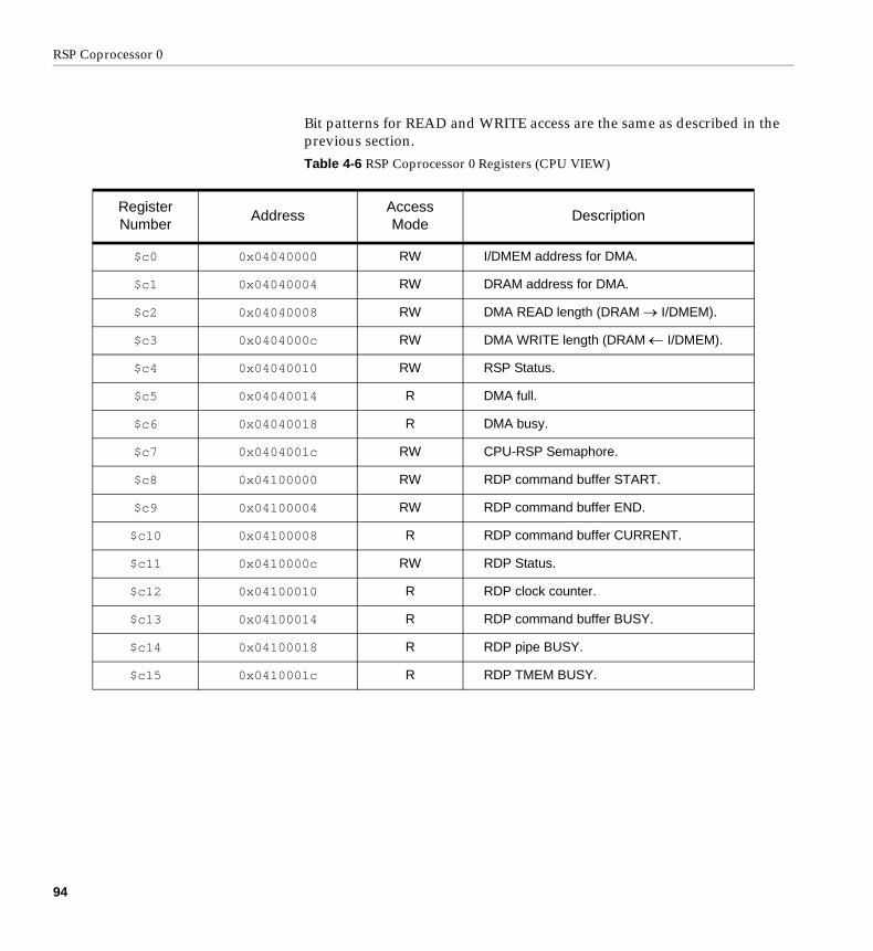
RSP Coprocessor 0
Bit patterns for READ and WRITE access are the same as described in the previous section.
Table 4-6 RSP Coprocessor 0 Registers (CPU VIEW)
Register Number
AddressAccessMode
Description
$c0 0x04040000 RW I/DMEM address for DMA.
$c1 0x04040004 RW DRAM address for DMA.
$c2 0x04040008 RW DMA READ length (DRAM I/DMEM).
$c3 0x0404000c RW DMA WRITE length (DRAM I/DMEM).
$c4 0x04040010 RW RSP Status.
$c5 0x04040014 R DMA full.
$c6 0x04040018 R DMA busy.
$c7 0x0404001c RW CPU-RSP Semaphore.
$c8 0x04100000 RW RDP command buffer START.
$c9 0x04100004 RW RDP command buffer END.
$c10 0x04100008 R RDP command buffer CURRENT.
$c11 0x0410000c RW RDP Status.
$c12 0x04100010 R RDP clock counter.
$c13 0x04100014 R RDP command buffer BUSY.
$c14 0x04100018 R RDP pipe BUSY.
$c15 0x0410001c R RDP TMEM BUSY.
94

Revision 1.0 Register Descriptions
Other RSP Addresses
These are also memory-mapped for the CPU.
Table 4-7 Other RSP Addresses (CPU VIEW)
AddressAccessMode
Description
0x04000000 RW RSP DMEM (4096 bytes).
0x04001000 RW RSP IMEM (4096 bytes).
0x04080000 RW RSP Program Counter (PC), 12 bits.
95

RSP Coprocessor 0
DMA
All data operated on by the RSP must first be DMA’d into DMEM. RSP programs can also use DMA to load microcode into IMEM.
Note: loading microcode on top of the currently executing code at the PC will result in undefined behavior.
Alignment Restrictions
All data sources and destinations for DMA transfers must be aligned to 8 bytes (64 bits), in both DRAM and I/DMEM.
Transfer lengths must be multiples of 8 bytes (64 bits).
Timing
Peak transfer rate is 8 bytes (64 bits) per cycle. There is a DMA setup overhead of 6-12 clocks, so longer transfers are more efficient.
IMEM and DMEM are single-ported memories, so accesses during DMA transfers will impact performance.
DMA Full
The DMA registers are double-buffered, having one pending request and one current active request. The DMA FULL condition means that there is an active request and a pending request, so no more requests can be serviced.
DMA Wait
Waiting for DMA completion is under complete programmer control. When DMA_BUSY is cleared, the transaction is complete.
If there is a pending DMA transaction, this transaction will be serviced before DMA_BUSY is cleared.
96

Revision 1.0 DMA
DMA Addressing Bits
Since all DMA accesses must be 64-bit aligned, the lower three bits of source and destination addresses are ignored and assumed to be all 0’s.
Transfer lengths are encoded as (length - 1), so the lower three bits of the length are ignored and assumed to be all 1’s.
The DMA LENGTH registers can be programmed with a line count and line stride, to transfer arbitrary rectangular pieces of memory (such as a portion of an image). See Figure 4-1, “DMA Transfer Length Encoding,” on page 84, for more information.
CPU Semaphore
The CPU-RSP semaphore should be used to share DMA resources. Since the CPU could possibly DMA data to/from the RSP while the RSP is running, this semaphore is necessary to share the DMA engine.
Note: The current graphics and audio microcode assume the CPU will not be DMA’ing data to/from the RSP while the RSP is running. This eliminates the need to check the semaphore (on the RSP side), saving a few instructions.
DMA Examples
The following examples illustrate programming RSP DMA transactions:
97

RSP Coprocessor 0
Figure 4-2 DMA Read/Write Example
############################################### # Procedure to do DMA reads/writes. # Registers: # $20 mem_addr # $19 dram_addr # $18 dma_len # $17 iswrite? # $11 used as tmp.name mem_addr, $20.name dram_addr, $19.name dma_len, $18.name iswrite, $17.name tmp, $11
DMAproc: # request DMA access: (get semaphore) mfc0 tmp, SP_RESERVED bne tmp, zero, DMAproc # note delay slot DMAFull: # wait for not FULL: mfc0 tmp, DMA_FULL bne tmp, zero, DMAFull nop # set DMA registers: mtc0 mem_addr, DMA_CACHE # handle writes: bgtz iswrite, DMAWrite mtc0 dram_addr, DMA_DRAM j DMADone mtc0 dma_len, DMA_READ_LENGTH DMAWrite: mtc0 dma_len, DMA_WRITE_LENGTH DMADone: jr return
# clear semaphore, delay slot mtc0 zero, SP_RESERVED.unname mem_addr.unname dram_addr.unname dma_len.unname iswrite.unname tmp # ################################################
98

Revision 1.0 DMA
Figure 4-3 DMA Wait Example
############################################ # Procedure to do DMA waits. # # Registers: # # $11 used as tmp #.name tmp, $11 DMAwait: # request DMA access: (get semaphore) mfc0 tmp, SP_RESERVED bne tmp, zero, DMAwait # note delay slot WaitSpin: mfc0 tmp, DMA_BUSY bne tmp, zero, WaitSpin nop jr return
# clear semaphore, delay slot mtc0 zero, SP_RESERVED.unname tmp # # #############################################
99

RSP Coprocessor 0
Controlling the RDP
The RDP has an independent DMA engine which reads commands from DMEM or DRAM into the command buffer. The RDP command buffer registers are programmed to direct the RDP from where to read the command data.
How to Control the RDP Command FIFO
RDP commands are transferred from memory to the command buffer by the RDP’s DMA engine.
The RDP command buffer logic examines the CMD_CURRENT and CMD_END registers and will transfer data, 8 bytes (64 bits) at a time, advancing CMD_CURRENT, until CMD_CURRENT = CMD_END.
CMD_START and CMD_END registers are double buffered, so they can be updated asynchronously by the RSP or CPU while the RDP is transferring data. Writing to these registers will set the START_VALID and/or END_VALID bits in the RDP status register, signaling the RDP to use the new pointers once the current transfer is complete.
When a new CMD_START pointer is used, CMD_CURRENT is reset to CMD_START.
Algorithm to program the RDP Command FIFO:
• start with CMD_START and CMD_END set to the same initial value.
• write RDP commands to memory, beginning at CMD_START.
• when an integral number of RDP commands have been stored to memory, advance CMD_END (CMD_END should point to the next byte after the RDP command).
• keep advancing CMD_END as subsequent RDP commands are stored to memory.
100

Revision 1.0 Controlling the RDP
Examples
The XBUS is a direct memory path between the RSP (and DMEM) and the RDP. This example uses a portion of DMEM as a circular FIFO to send data to the RDP.
This example uses an “open” and “close” interface; the “open” reserves space in the circular buffer, then the data is written, the “close” advances the RDP command buffer registers.
The first code fragment illustrates the initial conditions for the RDP command buffer registers.
Figure 4-4 RDP Initialization Using the XBUS
The OutputOpen function contains the most complicated part of the algorithm, handling the “wrapping” condition of the circular FIFO. The wrapping condition waits for CMD_CURRENT to advance before re-programming new CMD_START and CMD_END registers.
# XBUS initialization addi $4, zero, DPC_SET_XBUS_DMEM_DMA addi outp, zero, 0x1000 # DP init conditions mtc0 $4, CMD_STATUS mtc0 outp, CMD_START mtc0 outp, CMD_END
101

RSP Coprocessor 0
Figure 4-5 OutputOpen Function Using the XBUS
.name dmemp, $20
.name dramp, $19
.name outsz, $18 # caller sets to max size of write # open(size) - wait for size avail in # ring buffer. # - possibly handle wrap # - wait for ‘current’ to get # out of the way .ent OutputOpenOutputOpen: # check if the packet will fit in the buffer addi dramp, zero, (RSP_OUTPUT_OFFSET
+ RSP_OUTPUT_SIZE8) add dmemp, outp, outsz sub dramp, dramp, dmemp bgez dramp, CurrentFit nopWrapBuffer: # packet won’t fit, wait for current to wrap mfc0 dramp, CMD_STATUS andi dramp, dramp, 0x0400 bne dramp, zero, WrapBufferAdvanceCurrent: # wait for current to advance mfc0 dramp, CMD_CURRENT addi outp, zero, RSP_OUTPUT_OFFSET beq dramp, outp, AdvanceCurrent nop mtc0 outp, CMD_START # reset STARTCurrentFit: # done if current_address <= outp mfc0 dramp, CMD_CURRENT sub dmemp, outp, dramp bgez dmemp, OpenDone
# loop if current_address <= (outp + outsz) add dmemp, outp, outsz sub dramp, dmemp, dramp bgez dramp, CurrentFit nopOpenDone: jr return nop .end OutputOpen
102

Revision 1.0 Controlling the RDP
After calling OutputOpen, the program writes the RDP commands to DMEM, advancing outp. Once the complete RDP command is written to DMEM, OutputClose is called.
Figure 4-6 OutputClose Function Using the XBUS
##################################################### OutputClose#################################################### .ent OutputCloseOutputClose: # # XBUS RDP output # jr return mtc0 outp, CMD_END .end OutputClose.unname outsz.unname dramp.unname dmemp
103

RSP Coprocessor 0
104

Revision 1.0
Chapter 5
5. RSP Assembly Language
This chapter describes the RSP Assembly Language, as accepted by the rspasm assembler.
Although different in many fundamental ways, there are some similarities with the MIPS assembly language, described in the document “MIPSPro Assembly Language Programmer’s Guide” (Order number 007-2418-001). The reader is encouraged to be familiar with this document, as we will occasionally use it as a frame of reference to describe the RSP assembly language.
The machine language format of the RSP instructions is based on the R4000 instruction set; the reader is referred to the “MIPS R4000 Microprocessor User’s Manual”1 for additional information.
In the following chapter, “the assembler” refers to the rspasm assembler.
1 Heinrich, J., “MIPS R4000 Microprocessor User’s Manual”, Prentice Hall Publishing, 1993, ISBN 0-13-1-5925-4.
105

RSP Assembly Language
Different From Other MIPS Assembly Languages
Why?
Although the RSP uses the R4000 architecture, it is a specialized processor designed for a special purpose. The assembly language is similarly restricted, and does not require the full richness of the MIPS Assembly Language.
In particular, MIPS Assembly Language is designed to be generated by C, Fortran, and Pascal compilers; it therefore lacks many functions of an assembly language designed for human programmers, as well as having extra constructs in order to support these compilers.
The RSP also has limited resources, most notably only 1K instructions of IMEM. RSP programs by definition must be small and highly optimized, so a simpler assembly language is well-suited.
The RSP is also a proprietary processor, its implementation and programming interface is not publicly available. The RSP programming interface is designed to be incompatible with other MIPS products.
Major Differences from the R4000 Instruction Set
The scalar unit (SU) instruction set uses only a subset of the R4000 instruction set. See “Missing Instructions” on page 27.
The “pseudo-opcodes” or assembly directives are different from the MIPS Assembly Language. Many of the MIPS directives that are designed for high-level program flow, compilers, or large objects are not necessary. Likewise, we have added many new directives to make the language more human-friendly (register naming, compile-time diagnostics, etc.).
The machine instructions for the RSP vector unit (VU) instructions use the MIPS coprocessor extensions. For ease of programming, we have adopted friendlier mnemonics and a less “coprocessor-like” syntax for their use.
106

Revision 1.0 Syntax
Syntax
Tokens
The assembler has these tokens:
• identifiers
• constants
• operators
The assembler lets you put whitespace (blank characters, tabs, or newlines) anywhere between tokens. Whitespace must separate adjacent identifiers or constants that are not otherwise separated (by an expression operator, for instance).
Multiple statements per line are permitted, as are single statements which span multiple lines.
Identifiers
An identifier consists of a case-sensitive sequence of alphanumeric characters, plus the underscore (_) character.
Identifiers can be up to 31 characters long, and the first character must be alphabetic.
The value of an identifier can be set explicitly with the .symbol directive.
Constants
The assembler supports the following types of constants. All numeric constants are interpreted as two’s complement numbers.
• Decimal constants, which consist of a sequence of decimal digits [0123456789]* without a leading 0.
107

RSP Assembly Language
• Hexadecimal constants, which consist of the characters 0x (or 0X) followed by a sequence of hexadecimal digits [0123456789abcdefABCDEF]*.
• Octal constants, which consist of a leading zero followed by a sequence of octal digits [01234567]*.
• String constants, which consist of any sequence of alphanumeric characters (except double quotes) enclosed in double quotes. String constants are only used for the .print directive.
Operators
The following tokens comprise the list of operators:
• Instruction mnemonics, a sequence of lowercase alphanumeric characters that correspond to the opcodes listed in Appendix A, “RSP Instruction Set Details.”
• Directive mnemonics, a sequence of lowercase alphabetic characters that correspond to the list in“Assembly Directives” on page 114.
• Expression operators: +, -, *, /, %, ~, ^, &, |, <<, >>
• Other character sequences that make up the instruction syntax, such as square brackets ‘[]’, parentheses ()’, the colon ‘:’, the comma ‘,’, and the period ‘.’.
Comments
The assembler accepts three forms of comments:
• C-like comments, /*...*/. Anything between the beginning and ending C comment sequence is ignored. (Note: if cpp is used before assembly, cpp will remove these comments before the assembler can parse them)
• # comments. Anything from the ‘#’ to the end of the line is ignored. (Note: comments with the ‘#’ in column one will confuse the C pre-processor, cpp, if it is invoked on the source code before assembly)
108

Revision 1.0 Syntax
• ; comments. Anything from the ‘;’ to the end of the line is ignored.
Program Sections
An RSP program has only two sections, a text section (.text) and a data section (.data).
The text section is assembled in sequence, with only one base address for assembly (see .text directive).
The data section is built up in sequence, however multiple data section base addresses are permitted (see .data directive).
A program may switch between text and data segments many times, using .text or .data directives without base addresses.
Labels
A label is an identifier with a colon (:) appended. There can be no whitespace between the identifier and the colon. Labels can be used as program labels (targets of branching instructions) or in the data segment to define DMEM addresses (and later used as constants or in expressions).
Multiple consecutive labels in the data section are permitted, they evaluate to the same value.
Multiple consecutive labels in the text section are not permitted.
Labels in the text section can also be followed by directives. In this case, the value of the label is the address of the next executable instruction.
Keywords
Reserved keywords include all operators listed in the section “Operators” on page 108.
Reserved keywords cannot be used as identifiers.
109

RSP Assembly Language
If the assembly source code is passed through another program (such as a macro pre-processor like m4), additional reserved keywords may be implied, if they are reserved by that program.
Expressions
An expression is a sequence of symbols that represent a value. All assembler expressions evaluate to an integer data type. The assembler does arithmetic with two’s complement integers using 32 bits of precision. Expressions follow precedence rules and consist of:
• Expression Operators
• Identifiers
• Constants
Expression Operators
The list of expression operators include:
Table 5-1 Expression Operators
Operator Meaning
+ Addition
- Subtraction
* Multiplication
/ Division
% Remainder (or Modulo)
<< Shift Left
>> Shift Right (NOT sign extended)
^ Bitwise EXCLUSIVE OR
& Bitwise AND
| Bitwise OR
~ Bitwise COMPLEMENT
110

Revision 1.0 Syntax
Precedence
Expressions can be grouped with parentheses (recommended) or you can rely on the following precedence rules:
Note: The expression operator precedence differs from that of the C programming language.
Expression Restrictions
The simplified assembly language of the RSP imposes certain restrictions upon the use of expressions:
• Any identifier used in an expression must be defined before use. The expression is evaluated at parsing time, it cannot be delayed until the value of a forward-referencing symbol is determined.
• Identifiers cannot be used in expressions used as a branch target or as a vector register element.
• Identifiers cannot be used in expressions used in conjunction with the data initialization directives (.word, .half, .byte).
Note: Identifiers by themselves can be used as values for the .word and .half directives, including forward-referencing identifiers (this is a special case). Note that you can assign an
- Minus (unary)
+ Plus (unary)
Table 5-2 Expression Operator Precedence
least binding, lowest precedence: binary +,-
... binary *,/,%,<<,>>,^,&,|
most binding, highest precedence unary +,-,~
Table 5-1 Expression Operators
Operator Meaning
111

RSP Assembly Language
expression to a temporary identifier using the .symbol directive, then use this temporary identifier by itself to initialize a data directive.
Throughout this document, expressions that cannot contain identifiers are referred to as iexpressions (integer expressions).
Registers
The syntax for referring to the scalar unit (SU) registers is a dollar sign ($), followed by an integer in the range of 0...31. No whitespace between the dollar sign and the integer is permitted.
The syntax for referring to the vector unit (VU) registers is a dollar sign ($), followed by a ‘v’, followed by an integer in the range of 0...31. No whitespace between the dollar sign, the ‘v’, and the integer is permitted.
The syntax for referring to the coprocessor 0 control registers is a dollar sign ($), followed by a ‘c’, followed by an integer in the range of 0...31. No whitespace between the dollar sign, the ‘c’, and the integer is permitted.
Registers can be named using the .name directive, associating an identifier with a scalar register, vector register, or control register.
The following special built-in register names are also available:
• $sp is scalar register $29
• $at is scalar register $1
• $ra is scalar register $31
• $s8 is scalar register $30
• $vco is the vector control register VCO
• $vcc is the vector control register VCC
• $vce is the vector control register VCE
112

Revision 1.0 Syntax
Vector Register Element Syntax
In some circumstances, a scalar element of a vector register may be specified. These circumstances include the target register of most vector computational instructions and the source/destination register of all vector loads, stores, and moves.
For vector computational instructions, a vector register element syntax is one of:
• an integer (or integer expression) in the range 0...7, enclosed by square brackets ([]), representing the ordinal index of one of the 8 16-bit vector elements of the register.
• an integer (or integer expression) in the range 0...3, followed by the letter ‘h’, enclosed by square brackets ([]), representing the ordinal index of one of the 4 16-bit vector elements of the register halves.
• an integer (or integer expression) in the range 0...1, followed by the letter ‘q’, enclosed by square brackets ([]), representing the ordinal index of one of the 2 16-bit vector elements of the register quarters.
For vector loads, stores, and moves, the vector register element syntax is as follows:
• an integer (or integer expression) in the range 0...15, enclosed by square brackets ([]), representing which of the 16 bytes of the register to use as a source or destination.
In any case where a vector element may optionally be specified, but is not, a 0 is assumed.
Additional usage of vector register element syntax is explained along with the instructions that use them in a later chapter.
Program Statements
A program statement consists of an optional label, an operator keyword, and the operand(s). The operator may be a scalar instruction or a vector instruction.
113

RSP Assembly Language
Assembly Directives
Directives, or ‘pseudo-opcodes’ are instructions to the assembler that are interpreted at compile time. They do not generate executable machine instructions.
They exist to initialize data, direct the compilation, provide error checking, etc.
A directive is a period (.) followed by a sequence of lowercase alphabetic characters.
For this section, the following notation is used: An expression is a legal assembler expression, which may include identifiers (which have been defined before use). An iexpression is an integer expression, an expression composed solely of integers and no identifiers. Optional parameters are enclosed in square brackets []. Conditional parameters are denoted with a vertical bar |.
.align
.align iexpression
The current location within the text or data section is aligned to the next multiple byte boundary corresponding to the evaluated iexpression; possibly adding padding.
For the text section, the only legal evaluations are multiples of 4 bytes.
.bound
.bound iexpression
This directive performs a check, printing out an error message and aborting the program assembly if the current location within the text or data section is not aligned to the next multiple byte boundary corresponding to the evaluated iexpression.
114

Revision 1.0 Assembly Directives
.byte .byte iexpression
One byte of the data section is allocated and initialized to the value of the iexpression.
Since one byte is not sufficient to hold the address of any symbol in DMEM or IMEM, an identifier is not permitted.
This directive is only permitted in the data section.
.data .data [expression]
Switch to the data section. All data initialization directives must be contained in the data section.
If the optional expression is present, it is evaluated and used as the base address to continue packing the data section. Only the least significant 12 bits of the base address is used, since DMEM is only 4K bytes.
Multiple base addresses are permitted, any “holes” between initialized data will remain un-initialized (all 0’s). The assembler keeps track of the maximum address initialized, and all data up to that point (including any holes) will be output.
.dmax
.dmax iexpression
This directive performs a check, printing out an error message and aborting the program assembly if the current location within the text or data section exceeds the value corresponding to the evaluated iexpression.
This is useful during compilation to ensure that you do not exceed IMEM or DMEM limits.
115

RSP Assembly Language
.end
.end identifier [, expression]
End a procedure. The assembler outputs debugging information for the gvd debugger, including the beginning and ending locations of procedures.
.ent
.ent identifier [, expression]
Begin a procedure. The assembler outputs debugging information for the gvd debugger, including the beginning and ending locations of procedures.
.half
.half identifier | iexpression
Two bytes (one half word) of the data section are allocated and initialized to the value of the identifier or the iexpression.
The identifier may be a forward-referencing symbol which is not defined yet. This is useful for building program jump tables which must be filled in during the second pass of the assembler. In order to accommodate this useful feature, we accept the restriction that any expression used to initialize this data be an iexpression, not an expression.
Since there are only 4K bytes of IMEM and DMEM, 16-bits is sufficient to hold the address of any symbol.
This directive is only permitted in the data section.
.name
.name identifier, register
The identifier is associated with the register.
The register may be a scalar, vector, or control register, and must be specified using proper register syntax.
116

Revision 1.0 Assembly Directives
.print string-constant [, expression][, expression]...
The quoted string constant is printed to stderr during assembly.
The string constant may contain C-like numeric printf conversions (%d,%x, etc.) and the expressions will be evaluated and printed to stderr.
A maximum of four expressions are permitted per .print directive.
If this directive has a label associated with it, the label cannot be contained in an expression being printed.
.space
.space expression
If we are in the data section, expression number of bytes are allocated and filled with zeros. The new current location in the data section will be equal to the previous location plus expression bytes.
If we are in the text section, (expression >> 2) number of instructions are padded and filled with nop’s, and the new program counter for assembly will be equal to the old program counter plus expression bytes.
If we are in the text section, the expression should also account for any assembly base, if used.
.symbol
.symbol identifier, expression
The identifier is entered into the symbol table with the value of expression.
.text
.text [expression]
117

RSP Assembly Language
Switch to the text section. All program instructions must be contained in the text section.
If the optional expression is present, it is evaluated and used as the base address for assembling the program. Only the least significant 12 bits of the base address is used, since IMEM is only 4K bytes.
Note: If the base address for assembly is changed during the course of compilation, unpredictable results will occur. There should be only one .text directive with a base address.
.unname
.unname identifier
The identifier is removed from the symbol table.
Usually this is used to free up a named register when you are finished using it, but it could be used to free up another program identifier.
.word
.word identifier | iexpression
Four bytes (one word) of the data section are allocated and initialized to the value of the identifier or the iexpression.
The identifier may be a forward-referencing symbol which is not defined yet. This is useful for building program jump tables which must be filled in during the second pass of the assembler. In order to accommodate this useful feature, we accept the restriction that any expression used to initialize this data be an iexpression, not an expression.
This directive is only permitted in the data section.
118

Revision 1.0 BNF Specification of the RSP Assembly Language
BNF Specification of the RSP Assembly Language
This section presents a formal specification of the RSP assembly language using a Backus-Naur Form (BNF). Comments are not shown because they are removed by the parser during token scanning.
<program> <instruction> | <program> <instruction>
<instruction> <directive> |<label> <directive> |<label> <label> <directive> |<scalarInstruction> |<label> <scalarInstruction> |<vectorInstruction> |<label> <vectorInstruction>
<directive> .align <iexpression> |.bound <iexpression> |.byte <iexpression> |.data |.data <iexpression>.dmax <iexpression>.end |.end <identifier> |.ent <identifier> |.ent <identifier> , <integer> |.half <identifier> |.half <iexpression> |.name <identifier> , <scalarRegister> |.name <identifier> , <vectorRegister> |.name <identifier> , <controlRegister> |.print <qstring> |.print <qstring> , <expression> |
119

RSP Assembly Language
.print <qstring> , <expression> , <expression> |
.print <qstring> , <expression> , <expression> , <expression> |
.print <qstring> , <expression> , <expression> , <expression> , <expresion> |
.space <expression> |
.symbol <identifier> , <expression> |
.text |
.text <expression> |
.unname <identifier> |
.word <identifier> |
.word <iexpression>
<scalarInstruction> <regOp> <scalarRegister> |<regRegOp> <scalarRegister> |<regRegOp> <scalarRegister> , <scalarRegister> |<regRegOp> <scalarRegister> , <controlRegister> |<regRegRegOp> <scalarRegister> , <scalarRegister> ,
<scalarRegister> |<regImmOp> <scalarRegister> , <expression> |<regRegImmOp> <scalarRegister> , <expression> |<regRegImmOp> <scalarRegister> , <scalarRegister> ,
<expression> |<regOffsetOp> <scalarRegister> , <expression> |<regOffsetOp> <expression> |<regRegOffsetOp> <scalarRegister> , <scalarRegister> ,
<expression> |<regOffsetBaseOp> <scalarRegister> , <expression> (
<scalarRegister> ) |<regRegShiftOp> <scalarRegister> , <scalarRegister> ,
<expression> |<sRegRegRegOp> <scalarRegister> , <scalarRegister> ,
<scalarRegister> |<targetOp> <expression> |
120

Revision 1.0 BNF Specification of the RSP Assembly Language
<vRegsRegOp> <vectorRegister> [ <element> ] , <expression> ( <scalarRegister> ) |
<sRegvRegOp> <scalarRegister> , <vectorRegister> |<sRegvRegOp> <scalarRegister> , <vectorRegister> [
<element> ] |<noOperandOp>
<vectorInstruction> <veRegvRegvRegOp> <vectorRegister> , <vectorRegister> , <vectorRegister> |
<veRegvRegvRegOp> <vectorRegister> , <vectorRegister> , <vectorRegister> [ <element> ] |
<vdRegvRegOp> <vectorRegister> [ <element> ] , <vectorRegister> [ <element> ]
<regOp> jr
<regRegRegOp> add | addu | and | nor | or | slt | sltu | sub | subu | xor
<regImmOp> lui
<regRegImmOp> addi | addiu | andi | ori | slti | sltiu | xori
<regOffsetOp> bgez | bgezal | bgtz | blez | bltz | bltzal
<regRegOffsetOp> beq | bne
<regOffsetBaseOp> lb | lbu | lw | lh | lhu | sb | sh | sw
<regRegShiftOp> sll | sra | srl
<sregRegRegOp> sllv | srav | srlv
121

RSP Assembly Language
<targetOp> j | jal
<vRegsRegOp> lbv | lsv | llv | ldv | lqv | lrv | lpv | luv | lhv | lfv | ltv | sbv | ssv | slv | sdv | sqv | srv | spv | suv | shv | sfv | swv | stv
<sRegvRegOp> mfc2 | cfc2 | mtc2 | ctc2
<noOperandOp> nop | vnop | break
<veRegvRegvRegOp> vmulf | vmacf | vmulu | vmacu | vrndp | vrndn | vmulq | vmacq | vmudh | vmadh | vmudm | vmadm | vmudn | vmadn | vmudl | vmadl | vadd | vsub | vabs | vaddc | vsubc | vsar | vand | vnand | vor | vnor | vxor | vnxor | vlt | veq | vne | vge | vcl | vch | vcr | vmrg
<vdRegvRegOp> vmov | vrcp | vrsq | vrcph | vrsqh | vrcpl | vrsql
<expression> ( <expression> ) |<integer> |<identifier> |~ <expression> |<expression> & <expression> |<expression> | <expression> |<expression> ^ <expression> |<expression> << <expression> |<expression> >> <expression> |<expression> * <expression> |<expression> / <expression> |<expression> % <expression> |<expression> + <expression> |<expression> - <expression> |
122

Revision 1.0 BNF Specification of the RSP Assembly Language
- <expression> |+ <expression>
<iexpression> ( <iexpression> ) |<integer> |~ <iexpression> |<iexpression> & <iexpression> |<iexpression> | <iexpression> |<iexpression> ^ <iexpression> |<iexpression> << <iexpression> |<iexpression> >> <iexpression> |<iexpression> * <iexpression> |<iexpression> / <iexpression> |<iexpression> % <iexpression> |<iexpression> + <iexpression> |<iexpression> - <iexpression> |- <iexpression> |+ <iexpression>
<scalarRegister> <identifier> |$<integer> | $sp | $s8 | $at | $ra
<vectorRegister> <identifier> | $v<integer> | $vco | $vcc | $vce
<controlRegister> <identifier> | $c<integer>
<element> <iexpression> | <iexpression>h | <iexpression>q
<identifier> <alpha> <alphanumeric>*
<alphanumeric> {<alpha> | <digit> | _}*
<qstring> “ {<ASCII text> | <whitespace> | <C print specifier>}* “
123

RSP Assembly Language
<alpha> a | b | c | d | e | f | g | h | i | j | k | l | m | n | o | p | r | s | t | u | v | w | x | y | z | A | B | C | D | E | F | G | H | I | J | K | L | M | N | O | P | Q | R | S | T | U | V | W | X | Y | Z
<integer> <digit>* | 0x<hexdigit>* | 0X<hexdigit>* | 0<octdigit>*
<digit> 0 | 1 | 2 | 3 | 4 | 5 | 6 | 7 | 8 | 9
<hexdigit> <digit> | a | b | c | d | e | f | A | B | C | D | E | F
<octdigit> 0 | 1 | 2 | 3 | 4 | 5 | 6 | 7
124

Revision 1.0
Chapter 6
6. Advanced Information
This chapter expands on some advanced topics, such as DMEM usage, RSP performance, code overlays, and the CPU-RSP relationship.
Examples and information presented in this chapter are often one of many possible approaches, the reader is encouraged to treat this chapter as inspiration, not rigorous instruction.
125

Advanced Information
DMEM Organization and Usage
Planning the layout of DMEM is an essential step of writing an RSP program. A convenient DMEM layout can save precious instructions and lead to a more optimized and bug-free program.
There are typically parts of DMEM which can be or need to be allocated and initialized at compile-time; the assembler’s data directives can accomplish this. Although the data section is built up sequentially regardless of source code files, it helps to keep all DMEM allocations centralized in one file, rather than spreading it out over several source code files.
During compilation, the assembler will produce a .dat file which represents the data section of the microcode object. This section should be loaded into DMEM as part of the task loading effort. If you make this data section as small as it can be, and keep it near the top of DMEM (0x04000000) this task loading can be as fast as possible.
Be sure to compare the size of the data that must be initialized with the size of the data loaded into DMEM via the task structure. Most programs use the value SP_UCODE_DATA_SIZE, which is defined in ucode.h with a value of 2048 (bytes). This value might not be appropriate for every RSP program.
Jump Tables
Program “jump tables” can be constructed by initializing DMEM with program labels. During the second pass of the assembler, these labels will be resolved and the contents of DMEM will be initialized correctly.
Since IMEM is only 4K bytes, a half word is sufficient to hold any IMEM address.
Constants
Program constants can be generated at compile-time and initialized in DMEM. When needed, they can be loaded directly and used.
126

Revision 1.0 DMEM Organization and Usage
It can be convenient to reserve a VU register to hold an entire vector of constants, available for use in vector computational instructions.
Labels in DMEM
Labels can be used in the data section to later reference offsets for the purposes of loading or storing things.
Since DMEM is only 4K bytes, any DMEM address can be expressed with the 16 bit offset of a load/store instruction (and using the base register of $0).
Dynamic Data
Data which will be loaded or generated by the program does not need to be initialized, however it may be useful to allocate space in your global DMEM map at compile time.
Truncating the .dat file before building the ELF object to a size that includes the static data, but not the dynamic data (which does not need to be initialized) will result in a smaller ELF object and therefore less ROM and DRAM usage.
Diagnostic Information
The assembler provides several useful directives for computing and/or printing diagnostic information. These are most useful while laying out the DMEM.
These directives include .bound, .align, .symbol, and .print. All of these directives are explained in “Assembly Directives” on page 114.
Using temporary assembler symbols to compute sizes, alignment, and hold diagnostic information is another useful tip.
127

Advanced Information
Performance Tips
Assembly language optimizations or vector processing tricks are beyond the scope of this document, however it is worthwhile to mention a few issues specifically relating to the RSP architecture.
Dual Execution
The RSP executes up to one Scalar Unit (SU) instruction and one Vector Unit (VU) instruction per clock cycle; the most efficient RSP code exploits this. Spreading loads, loop counting, and other SU “bookkeeping” code among VU computations can greatly accelerate sections of code.
Of course this is not always possible, there is not always useful work that can be done in both units.
Interleaving SU and VU code inhibits code readability somewhat; a consistent coding style helps improve the chance of finding a bug that would otherwise be hidden in an unreadable section of code.
This optimization technique is best left for last. As code is reorganized during development and testing the dual-issue pattern will change.
Hint: “Keeping the both halves of the RSP busy” is going to be one of your keys to maximum performance.
Vectorization
The computational power of the RSP lies in the Vector Unit (VU). Choice of algorithm and data organization are the fundamental design decisions for optimal RSP programs.
A vector architecture like the VU of the RSP, is a SIMD (Single-Instruction, Multiple-Data) machine, meaning that one instruction may operate on several pieces of data.
Reviewing the literature in computer architecture or compiler design, it is apparent that certain kinds of programming constructs are especially good (or bad) on a vector architecture:
128

Revision 1.0 Performance Tips
for loops Programming constructs like:for (i=0; i<n; i++) {}
perform the same thing on a bunch of data. This is exactly a “vector” operation.
conversely,
switch Programming constructs which separate data (switch(), if()), performing different tasks in different data situations do not vectorize well.
scalar arithmetic General “bookkeeping” code, which increments a counter, manipulates a pointer, etc. This kind of code is usually bad because they are unique operations. (there is a formal description of this: essentially there is a “number of items”, below which it does not pay to use vector operations. This has to do with vectorization setup and pipeline priming.)
pointer de-reference For most vectorizing C compilers, accessing data through pointer de-references is hard for vector processors. Constructs like “a[b.x].value” are preferred to pointer usage like “b->x->value”. This is because computing structure offsets is a simple addition, rather than another memory access. (This is not a not a major point for the RSP, as we lack a vectorizing C compiler)
There is another important lesson worth mentioning from the body of previous vectorization work. Most of the recent efforts in compiler design and high-level software engineering for SIMD systems are designed to be scalable; as more vector units are added, performance improves. Lots of recent work has been applied to developing good vectorizing compilers1. In those efforts, the focus has been to automatically distribute the data across the vector units and minimize vectorization start-up costs, letting the programmer not really worry about the number of vector elements. This is an important difference from our situation for two reasons: (1) we are programming at a much lower level. We know how many vector elements
1 For a good introduction and references to further reading, consult Hennessy, J., Patterson, D., “Computer Architecture, A Quantitative Approach”, Morgan Kauffmann Publishers, 1990, ISBN 1-55880-069-8.
129

Advanced Information
there are, and this number is not variable. (2) we have severe code space constraints. Abstracting the vector unit size has severe implications on the vector code start-up.
The point of this discussion is to observe that the hardware architecture is clearly visible in the microcode. We program for a specific vector size, and we waste no code generalizing data parallelism.
The good news is that this limitation also has a major benefit: We are exposed to the hardware at a low enough level that we can, by inspection, determine if the vector unit is fully utilized. This is rarely possible, if at all, on a machine with an architecture or compiler designed for configurable vector elements (like a Cray).
Hint: “Keeping the vector elements full” is going to be one of your keys to maximum performance.
Software Pipelining
SIMD processing achieves maximum performance when there is a high degree of data parallelism. This simply means that their are lots of independent data items that can all be operated on at once.
An important idea in vector processing is that data recurrence is not allowed. Consider this code fragment:
for (i=0; i<n; i++) {a[i] = a[i-1] * 2.0;
}
In this example, we could not vectorize this loop because element a[i] depends on element a[i-1]. The elements are not independent. This provides a restriction on the kind of loops we can vectorize and the organization of our data (which “axis” we choose to vectorize). It also suggests games we might want to play with our loops (See “Loop Inversion” on page 131.).
A similar problem, another kind of pipelining problem, is data dependency. Because the vector unit has a non-zero pipeline delay, we cannot attempt to use the results of an instruction until several clock cycles after that instruction is “executed”:
130

Revision 1.0 Performance Tips
vadd $v1, $v2, $v3vadd $v4, $v4, $v1
In this example, the second vadd instruction could not execute until the first vadd has completed and written back its result. There is a data dependency on register $v1. The result will be a pipeline stall that will effectively serialize the vector code, seriously dampening its performance.
Note: Fortunately, the hardware does do register usage locking in this case; the above code may be slow, but at least it is guaranteed to generate the correct results.
If a data dependency cannot be avoided, try rearranging code so that at least some useful work is done during the delay.
Hint: “Keeping the pipeline full” is going to be one of your keys to maximum performance.
Loop Inversion
A common trick used in vector programming is loop inversion. This means swapping inner and outer loops, in order to create the simplest loop with the largest number of iterations so we can maximize vectorization.
Consider the following code fragment which could be used for vertex translation:
for (i = 0; i < num_pts; i++) {/* for each point */for (j=0; j<4; j++) {/* for each dimension */
point[i][j] += offset[j];}
}
Since we can only vectorize the inner-most operation (the addition), we would only be using 50% of our vector unit.
Now suppose we have an infinite number of vector elements. If we did, we could swap the loops and do the outer loop four times, vectorizing the inner loop across num_pts elements:
for (i = 0; i < 4; i++) {/* for each dimension */for (j=0; j<num_pts; j++) {/* for each point */
point[j][i] += offset[i];}
131

Advanced Information
}
In this fictitious example, we have theoretically improved our program’s speed by (num_pts - 4)*(time to do the translation). A big improvement! This technique is common to help vectorizing compilers “recognize” loops that can be vectorized. The compiler will actually break up the loop into multiple vector operations the size of the number of vector elements.
Loop inversion is not free. By changing which loop is vectorized, we change the start-up costs associated with the loop. In terms of microcode, this means the organization of the data, the use of registers, and the “overhead” associated with this code fragment will be different.
An additional consideration for our implementation is that we know the vector unit size and characteristics. While the above code fragment might be better code for a Cray machine with a vectorizing compiler and unknown CPU resources, on the RSP we must vectorize the loop by hand, breaking up the iterations into 8 elements at a time (the size of our vector unit).
Careful evaluation of each loop should include trying to maximize the vector elements (keeping them filled) as well as avoiding unnecessary loop start-up and loop overhead.
Loop Unrolling
Unrolling a loop or section of code, while consuming precious IMEM space and registers, can potentially double the speed of a section of code that has lots of data dependencies. Unrolling a loop is the simplest way to perform useful work during pipeline delays.
Program Flow of Control
Since program flow constructs like conditional branches interfere with vectorization, it is often more efficient to do some “extra” work (which vectorizes) and decide later which result to use, rather than having a more complex program using conditional execution to minimize computation.
For example, in the triangle rasterization setup code, the vertex attributes (r, g, b, a, s, t, w, z) fit nicely in vector registers. Rather than having complicated
132

Revision 1.0 Performance Tips
code which decides which attributes are necessary, we always compute them all and only output the ones we are interested in.
This approach also saves precious IMEM space.
Profiling RSP Code
The RSP simulator can help profile your code, it can show pipeline stalls, load delays, and DMA wait states. The RSP clock (CLK) of the simulator is always available as a register.
Note: Although it is accurate within a few percent, the RSP simulator is not cycle accurate with the actual hardware. The differences are mainly in VU loads and moves.
It is also useful to use the RDP Command Counter to profile code on the actual hardware. This value can be sampled, saved to DMEM or DMA’d to DRAM for later analysis. A sample code fragment to read and store the RDP Command Counter is shown in Figure 6-1, “Real-time Clock Watching on the RSP,” on page 134.
133

Advanced Information
Figure 6-1 Real-time Clock Watching on the RSP
Since IMEM is relatively small, critical sections of code can also be profiled by inspection, examining the code and following the pipelining rules, “Mary Jo’s Rules” on page 43
Dividing the number of instructions a section of code uses by the number of clocks it takes to execute the section gives you a ratio that expresses dual-execution efficiency and VU pipeline usage. A perfect ratio of 2.0 means you are executing two instructions per clock (one SU, one VU) with no pipeline delays. A ratio less than 1.0 means you are experiencing execution stalls due to data dependencies and/or not keeping both execution units busy.
Inserting dummy display list instructions (temporarily customizing the microcode) to mark coarse timing boundaries is another useful trick.
In the RSP microcode:
# Checkpoint the clock before the critical section:mfc0 $1, $c12sw $1, 0($0)
(Perform the critical section)
# Checkpoint the clock after the critical section:mfc0 $1, $c12lw $2, 0($0)sub $1, $1, $2sw $1, 0($0)
After the task has completed, this value can be retrieved by the application code on the CPU:
while (__osSpRawReadIo((u32) (SP_DMEM_START + 0x0),(u32 *) &(scratch_int)))
;
Depending on what you are timing, take care to consider that the RDP Counter is only 24 bits (be careful of wrap conditions).
A more complex example might DMA data to DRAM for later analysis instead.
134

Revision 1.0 Microcode Overlays
Microcode Overlays
One of the challenges of RSP programming is working within the limited instruction memory. IMEM is an explicitly managed resource; you are free to load new code as you see fit.
RSP microcode loading can be divided into two situations: a swap, initiated by the host CPU, which loads the entire IMEM while the RSP is halted, and an overlay, which loads part of IMEM and is triggered by the currently executing RSP program. The latter case is the most interesting and is the subject of this section, covering related architectural issues and explaining one scheme for microcode overlays in detail.
Memory System Implications
The Rambus memory system is most efficient at large block transfers, so microcode loading can approach peak memory transfer speeds.
Like all DMA transfers, the source and destination must be 64-bit aligned; some care must be taken planning microcode overlays to meet this restriction. The assembler provides several directives to guarantee code alignment.
Since IMEM is single-ported memory, only one control unit can access it at a time; if microcode is loaded while a program is currently executing, IMEM accesses are shared between the DMA engine and the RSP control unit (which is fetching instructions). This means that dynamic microcode overlays can only approach 50% of peak DMA transfer rate.
Entirely Up to You
The decision to overlay microcode and the labor to perform the overlay must be embedded in the RSP program. Overlay techniques involve the RSP development tools, the RSP software, and possibly even the display list or other data that the RSP program is designed to interpret.
Choosing when to overlay microcode should be done carefully; although such DMA transfers are relatively efficient, they are not free.
135

Advanced Information
RSP Assembler Tricks
The RSP assembler rspasm has several features designed to assist developing microcode overlays.
IMEM Alignment Alignment directives like .bound and .align can be used in the text section to ensure that overlay destinations are 64-bit aligned, as required by the DMA engine.
DMEM Initialization Initialization directives like .word and .half can be used to create a table of information necessary to perform overlays.
DMEM Labels Labels can be used in the .data section so that overlay information can be easily accessed from the program.
DMEM Symbols Program symbols (labels) can be used to initialize DMEM data, generating code overlay destinations (IMEM addresses) automatically in the second pass of the assembler.
External Symbol Tables The -S option to the assembler allows you to specify another microcode object to use as an external symbol table. This allows you to branch to locations outside the current microcode object.
A Sample RSP Linker
While not a true “linker”, the program buildtask can be used to combine multiple RSP objects (both text and data sections) into a larger object.
The buildtask algorithm is quite simple, it concatenates the text and data sections, in the order supplied on the command line. It enforces 64-bit alignment and computes the sizes and offsets from the beginning for each different overlay object. This information is stored back in the data section (beginning at 0x0, or the value supplied by the -d flag), completing a table of information necessary to perform overlays.
The behavior of buildtask output is illustrated in Figure 6-2, “buildtask Operation,” on page 137.
136

Revision 1.0 Microcode Overlays
Figure 6-2 buildtask Operation
size 0 dest 0offset 0
size 1 dest 1offset 1
size 2 dest 2offset 2
size 3 dest 3offset 3
.
.
.
ucodeobject 3
ucodeobject 2
ucodeobject 1
ucodeobject 0
offset 0
offset 1
offset 2
offset 3
size 0
size 1
size 2
size 3
alignment padding
Output Object Text Section Output Object Data Section
The offset field is 32 bits, the size and destination are both 16 bits.
The destination field is not generated by buildtask, it is generated by the assembler (usually as an IMEM label).
At run time, the DRAM address of the microcode object (part of the OSTask structure) must be added to the offset field to generate the correct DRAM address for each overlay.
Data objects for subsequent overlays may be redundant and need not be used. The -f argument can be used to ignore these data sections.
ucode dataobject 1
ucode data
object 3
ucode dataobject 2
ucode dataobject 0-d offset
137

Advanced Information
With this information, a DMA transaction can be programmed to load an overlay into IMEM.
Overlay Example
To see exactly how this works, let’s examine the source code and Makefile for a simple example.
Overlay Makefile
######################################################### use the RSP linker ‘buildtask’ to construct the tasks# from the objects.## use the rsp2elf program to construct the debug# executables and library objects#
gspLine3D:gspLine3D.u newt.u${BUILDTASK} -f 1 -o $@ gspLine3D.u newt.u
gspLine3D.o:gspLine3D${RSP2ELF} -p -r $?
...
######################################################### build the individual objects.#
newt.u:gspLine3D.u ../newt.s ${COMMON_GFX_CODE}${RSPASM} ${LCINCS} ${LCDEFS} -DNEWT_ALONE \
-S gspLine3D.u -o $@ ../newt.s
gspLine3D.u:${COMMON_GFX_CODE} ${LINE_CODE}${RSPASM} ${LCINCS} ${LCDEFS} -o $@ ../gmain.s
In this example, there are two microcode objects: the main program, gspLine3D.u, and one overlay, newt.u. Each is compiled separately;
138

Revision 1.0 Microcode Overlays
notice the usage of the -S flag used when compiling newt.u in order to access the external symbols of gspLine3D.u.
The -f argument passed to buildtask prevents concatenation of the newt.dat section; this data section is redundant (any static data needed for newt.u is planned for and included in gspLine3D.u).
The rsp2elf program is used to build an ELF object using buildtask’s output, this ELF object is what will be linked into the game application by makerom.
Overlay DMEM Initialization
This code fragment shows the initialization of DMEM for this example.
################################################### ########### OVERLAY TABLE ######################### ################################################### # # Program module overlay table. Offsets and sizes are # filled in by the ‘buildtask’ utility, destinations are # the responsibility of the ucode. # # OVERLAY_OFFSET: offset from beginning of microcode in # RDRAM and in .o file (filled in by # buildtask). # OVERLAY_SIZE: length of overlay in bytes (filled in # by buildtask). # OVERLAY_DEST: where in IMEM to put the overlay # (filled in by assembler). # # The overlay table must be the first thing in DMEM. # The 1st overlay must be the initial code. #
.bound 0x80000000
OVERLAY_TAB_OFFSET:
#define OVERLAY_OFFSET 0#define OVERLAY_SIZE 4#define OVERLAY_DEST 6
#========================================== #============= MAIN CODE OVERLAY ==========
139

Advanced Information
#==========================================OVERLAY_0_OFFSET: # main module. .word 0x0 # offset from start of code .half 0x0 # size in bytes (-1) .half 0x1080 # destination
#========================================== #============= NEWTONS OVERLAY ============ #==========================================OVERLAY_1_OFFSET:OVERLAY_NEWTON: # Newton’s module laid over boot code. .word 0x0 # offset from start of code .half 0x0 # size in bytes (-1) .half 0x1000 # destination
The size and offset of the microcode objects will be filled in by buildtask, see Figure 6-2, “buildtask Operation,” on page 137.
Overlay Initialization Code
Before we load the overlay we must update the overlay table with the correct DRAM address for the start of the code. This is usually done immediately at the beginning of the program, since we require the OSTask structure which has been copied into DMEM (and may need to be overwritten by the program).
##################################################### # # code overlays: # # update table to be real DRAM address:
lw $5, OS_TASK_OFF_UCODE($1) # ucode base pointer
# PATCH NEWTON ONLYlw $2, (OVERLAY_1_OFFSET + OVERLAY_OFFSET)(zero)add $2, $2, $5sw $2, (OVERLAY_1_OFFSET + OVERLAY_OFFSET)(zero)
140

Revision 1.0 Microcode Overlays
Overlay Decision Code
Deciding when to perform an overlay is specific to each program and overlay function and therefore an example is not necessary. In this case, we always perform the overlay, since we are loading it over the RSP boot microcode (reclaiming precious IMEM space!)
Overlay DMA Code
Actually overlaying the new microcode is the same as any other DMA transfer (See “DMA” on page 96); we use the information from the overlay table to set the source, destination, and length of the transfer.
# overp points to the proper entry in the # overlay table.loadOverlay: lw dram_addr, OVERLAY_OFFSET(overp) lh dma_len, OVERLAY_SIZE(overp) lh imem_addr, OVERLAY_DEST(overp) jal DMAproc addi iswrite, zero, 0 # delay slot jal DMAwait nop jr overeturn nop
Remember to encode the length as (length-1), or else you might over-write some important instructions.
141
Advanced Information
Controlling the RSP from the CPU
The operating system running on the CPU includes facilities to control the RSP. The major function calls and some RSP details are explained in this section.
Starting RSP Tasks
The man page for osSpTaskStart() explains the CPU-side details of managing the RSP. The include file sptask.h contains additional information in the comments.
The algorithm to start a task is as follows:
• Halt the RSP (if it is not halted already).
• DMA the OSTask structure into the low part of DMEM (0x1000 - sizeof(OSTask)).
• DMA the RSP boot microcode into IMEM at 0x0.
• Set the RSP PC to 0x0.
• Clear the HALT bit of the RSP status register.
Once the HALT bit is cleared, the RSP begins execution using the current PC and contents of IMEM.
RSP Boot Microcode
The boot microcode copies the task microcode into IMEM (at 0x80) and the task data into DMEM (at 0x0). Since the task data might overwrite the OSTask structure, it is the task’s responsibility to either not need the OSTask or guarantee that it is not overwritten (by initializing less than 4K bytes of DMEM).
Each microcode task typically has “initialization” work of its own; usually this is performed immediately, possibly loading in additional microcode.
142

Revision 1.0 Controlling the RSP from the CPU
Hidden OS Functions
There are undocumented OS functions to access the RSP from the CPU. These functions should not be used in the regular course of game programming; their use may interfere with other core OS functionality. They can be useful for RSP program development, particularly post-mortem analysis of RSP state.
These functions are internal OS calls and are not guaranteed to be supported in the future; use at your own risk.
__osSpDeviceBusy
int__osSpDeviceBusy(void)
This function returns 1 if the RSP is busy performing IO operations.
__osSpRawStartDma()
s32__osSpRawStartDma(s32 direction, u32 devAddr,
void *dramAddr, u32 size)
Based on the input direction (OS_READ or OS_WRITE), set up a DMA transfer between RDRAM and RSP memory address space.
devAddr and dramAddr specifies the DMA buffer address of RSP memory and RDRAM, respectively. size contains the number of bytes to transfer. Note that these addresses must be 64-bit aligned and size must be a multiple of 8 bytes. Maximum transfer size is 4K bytes.
If the interface is busy, return a -1 and abort the operation.
__osSpRawReadIo()s32__osSpRawReadIo(u32 devAddr, u32 *data)
Perform a 32-bit programmed IO read from RSP memory address space. Note that devAddr must be 32-bit aligned.
If the interface is busy, return a -1 and abort the operation.
143

Advanced Information
__osSpRawWriteIo()
s32__osSpRawWriteIo(u32 devAddr, u32 data)
Perform a 32-bit programmed IO write to RSP memory address space. Note that devAddr must be 32-bit aligned.
If the interface is busy, return a -1 and abort the operation.
__osSpGetStatus()
u32__osSpGetStatus(void)
Return the RSP status register.
__osSpSetStatus()
void__osSpSetStatus(u32 data)
Update the RSP status register.
__osSpSetPc()
s32__osSpSetPc(u32 data)
Set the RSP program counter (PC).
If the RSP is not halted, return a -1 and abort the operation.
Address spaces used as parameters to these functions are defined in the file rcp.h.
144

Revision 1.0 Microcode Debugging Tips
Microcode Debugging Tips
There are two different environments for debugging microcode: (1) the RSP simulator (rsp or rspg) and (2) the coprocessor view of Gameshop (gvd).
Each tool has its advantages; Gameshop is discussed in separate documentation. This section explains the first technique and provides some other tips.
The first tip is to develop as much of the RSP microcode as possible using the RSP simulator. The tools are more friendly, more powerful, and the turn-around time is much shorter. In order to facilitate this, you may wish to also develop driver or stub tools that can create the data necessary to debug the program.
Once everything is mostly working, and you progress to integrating the new microcode with an application running on the CPU, using the RSP simulator becomes a little trickier. In order to use the RSP simulator you must create a DRAM image containing all the necessary pieces for the RSP task, and an OSTask structure. Briefly, the technique is:
• Run the RSP simulator.
• Copy the DRAM image into memory at 0x0.
• Copy the OSTask structure into the bottom of DMEM at (0x04001000 - sizeof(OSTask)).
• Copy the rspboot microcode into IMEM at 0x04001000. Note that this is not the ELF image of rspboot, but the RSP executable.
• Set the PC to 0x04001000.
• Run (or step) the RSP program.
At this point, everything is in place to execute a task on the RSP simulator.
The hardest step is creating the DRAM image that contains all the necessary elements in their proper places. Fortunately, there are some tools to help here:
145

Advanced Information
guDumpGbiDL() This library function can be called directly from the game to dump the necessary pieces back out to the Indy. It uses the rmonPrintf() and creates a (potentially very large) ASCII file that can be read by gbi2mem.
guDumpGbiDL() works by saving the OSTask structure, the microcode, the display list, and traversing the display list following any data (textures, matrices, vertices, etc.) pointers to save that data also. This results in the minimum amount of data to transfer back to the Indy in order to simulate the RSP task.
gbi2mem This tool takes the file dumped by guDumpGbiDL() and creates the .mem and .tsk files, containing the DRAM image and OSTask structure, respectively.
gbi2mem works by reading the ASCII file and creating a binary DRAM image, with all objects located at the proper address.
Since rmonPrintf() writes to the terminal, the proper invocation is to pipe the output of gload to gbi2mem:
% gload | gbi2mem -o <filename>
This method of dumping data from the hardware back to the Indy is not terribly efficient; it works best if the display list is as minimal as possible1.
1 One obvious improvement would be to use the binary host I/O interface, rather than the ASCII rmonPrintf().
146

Revision 1.0 RSP Yielding
RSP Yielding
One of the more complex issues of synchronization between the CPU and the RSP is the concept of yielding. The motivation for yielding is discussed at length in higher-level documentation; some of the implementation details are discussed here.
For typical applications with graphics and audio processing that must share the resources of the RSP, there must be a higher-level synchronization to assure that neither task is starved.
It is the nature of graphics processing that the amount of RSP processing required on a frame-to-frame basis may be difficult to predict. The amount of graphics computations can depend on the data in the scene, the location of the camera, and other parameters of visual complexity. A varying amount of graphics processing determines the “frame rate” of an application. If a new graphics frame is not computed, the video circuitry will just re-display the old frame.
Audio processing, on the other hand, is usually a function of sample rate, number of voices, or other data which is more constant and easier to predict. Audio processing is more susceptible to discontinuities caused by processor starvation, however. If the next frame of audio is not computed, the audio circuitry will not have any data to play, and the sound will stop (or click or pop).
The solution implemented is to allow graphics tasks to yield, meaning that at quiescent times, the graphics task politely inquires to see if the CPU is requesting that it stop computation. If the answer is yes, the graphics task saves its state to DMEM sufficiently so that it can be restarted, and the task will exit.
The operating system discriminates a yield condition from a normal task completion using the status register of the RSP. It then saves the contents of DMEM and returns to the application so that the audio task may be scheduled. When the graphics task is to be resumed, flags in the OSTask structure tell the rspboot microcode to behave slightly differently and restore the previously-yielded task.
147

Advanced Information
Requesting a Yield
An application requests an RSP task to yield by calling osSpTaskYield().
This function sets the Coprocessor 0 Status Register bit SP_SET_YIELD, which is #define’d as SIG0 in rcp.h.
Checking for Yield
The microcode checks periodically for a yield request. It would be inefficient to check too often, but it would also be dangerous to not check often enough, possibly detecting the yield too late.
For the released graphics microcode, we check for the yield after processing every display list command. The test is relatively cheap, only a few cycles, and this guarantees that we will test every several hundred clock cycles at the most.
# we’re done with this command, do the next one (if# available)...#
GfxDone: # stick our head up, see if we need to yield the SP.# If so,checkpoint everything then exit.#
mfc0 yield, SP_STATUS # need to yield?andi yield, yield, SP_STATUS_YIELDbne yield, zero, RSPYieldlh overeturn, TASKYIELD(zero) # return where?
Yielding
The microcode’s responsibility during yield is, by design, minimal.
The microcode saves a handful of important registers to DMEM, then DMA’s the necessary portion of DMEM to the yield buffer (originally supplied to the task as part of the task header).
The microcode also sets the SP_YIELDED bit in the Coprocessor 0 Status Register, this bit is #define’d as SIG1 in rcp.h.
148

Revision 1.0 RSP Yielding
Saving a Yielded Process
After requesting a yield, the host CPU must wait for the RSP task to finish and verify that it actually yielded.
It might also modify internal state, so that the yielded task can be restarted.
Restarting a Yield Process
Restarting a previously yielded task is conceptually simple; the previously-saved DMEM data (from the yield buffer) is used as the ucode_data field in the task header, and the OS_TASK_YIELDED bit in the task header is set.
The microcode will detect the OS_TASK_YIELDED bit in the task header flags and perform the proper initialization, before resuming execution.
This initialization should include restoring registers (from the saved DMEM) and possibly overlaying code segments.
149

Advanced Information
150

Appendix A
A. RSP Instruction Set Details
This appendix describes the machine-language format of the RSP instructions and formally describes the behavior of each instruction.
Since the RSP instruction set conforms to the MIPS ISA, the format and notation of this appendix is the same as Appendix A in the book “MIPS R4000 Microprocessor User’s Manual”1.
Vector Unit instructions are also discussed in Chapter 3, “Vector Unit Instructions.”
In this appendix, all variable subfields in an instruction format (such as rs, rt, immediate, etc.) are shown in lowercase names.
For the sake of clarity, we sometimes use an alias for a variable subfield in the formats of specific instructions. For example, we use rs = base in the format for load and store instructions. Such an alias is always lower case, since it refers to a variable subfield.
In the instruction descriptions that follow, the Operation section describes the operation performed by each instruction using a high-level language notation.
Special symbols used in the notation are described in Table A-1, “RSP Instruction Operation Notations,” on page 152.
1 Heinrich, J., “MIPS R4000 Microprocessor User’s Manual”, Prentice Hall Publishing, 1993, ISBN 0-13-1-5925-4.
151

Table A-1RSP Instruction Operation Notations
Symbol Meaning
Assignment.
|| Bit string concatenation.
xy Replication of bit value x into a y-bit string. Note: x is always a single-bit value.
xy...z Selection of bits y through z of bit string x. Little-endian bit notation is always used. If y is less than z, this expression is an empty (zero length) bit string.
+ 2’s complement or floating-point addition.
- 2’s complement or floating-point subtraction.
* 2’s complement or floating-point multiplication.
div 2’s complement integer division.
mod 2’s complement modulo.
/ Floating-point division.
< 2’s complement less than comparison.
and Bit-wise logical AND.
or Bit-wise logical OR.
xor Bit-wise logical XOR.
nor Bit-wise logical NOR.
GPR[x] General-Register x. The content of GPR[0] is always zero. Attempts to alter the content of GPR[0] have no effect.
CPR[z,x] Coprocessor unit z, general register x.
CCR[z,x] Coprocessor unit z, control register x.
VR[x][e] Vector Unit register x, byte e. (a VU register is 16 bytes wide)
152

Revision 1.0
Instruction Notation Examples
The following examples illustrate the application of some of the instruction notation conventions:
ACC[e] Vector Unit Accumulator, element e. The ACC has 8 elements each 48 bits wide.
dmem[x] DMEM contents beginning at byte address x.
T+i: Indicates the time steps between operations. Each of the statements within a time step are defined to be executed in sequential order (as modified by conditional and loop constructs). Operations which are marked T+i: are executed at instruction cycle i relative to the start of execution of the instruction. Thus, an instruction which starts at time j executes operations marked T+i: at time i + j. The interpretation of the order of execution between two instructions or two operations which execute at the same time should be pessimistic; the order is not defined.
Clamp_Signed(x) x is clamped to prevent overflow (signed clamp).
Table A-1RSP Instruction Operation Notations
Symbol Meaning
153

Example #1:
GPR[rt]
Sixteen zero bits are concatenated with an immediate value (typically 16 bits), and the 32-bit string (with the lower16 bits set to zero) is assigned to General-Purpose Register rt.
Example #2:
Bit 15 (the sign bit) of an immediate value is extended for16 bit positions, and the result is concatenated with bits 15through 0 of the immediate value to form a 32-bit signextended value.
immediate || 016
(immediate15)16 || immediate15...0
Example #3:
VR[vt][e]15...0 (dmem[Addr]7...0 || 08)
Eight zero bits are concatenated with the byte of DMEM atAddr, and assigned to the 16 bit element at byte e of VU register vt.
Example #4:
The 16 bit element at byte 2 of VU register vs is AND’dwith the 16 bit element at byte 2 of VU register vt,the result is assigned to the 16 bit element at byte 2 of VUregister vd.
VR[vd][2]15...0 (VR[vs][2]15...0 and VR[vt][2]15...0)
154

Revision 1.0
155

156
Format:
add rd, rs, rt
Description:
The contents of general register rs and the contents of general register rt are added to form the result. The result is placed into general register rd.
Since the RSP does not signal an overflow exception for ADD, this command behaves identically to ADDU.
Operation:
Exceptions:
None
ADDAdd
31 2526 2021 1516
SPECIAL rs rt
6 5 5
rd 0 ADD
5 5 6
11 10 6 5 0
0 0 0 0 0 0 0 0 0 0 0 1 0 0 0 0 0
ADD
T: GPR[rd] GPR[rs] + GPR[rt]

Revision 1.0
157
Format:
addi rt, rs, immediate
Description:
The 16-bit immediate is sign-extended and added to the contents of general register rs to form the result. The result is placed into general register rt.
Since the RSP does not signal an overflow exception for ADDI, this command behaves identically to ADDIU.
Operation:
Exceptions:
None
ADDI Add Immediate
31 2526 2021 1516 0
ADDI rs rt immediate
6 5 5 16
0 0 1 0 0 0
ADDI
T: GPR [rt] GPR[rs] + ((immediate15)16 || immediate15...0)

158
Format:
addiu rt, rs, immediate
Description:
The 16-bit immediate is sign-extended and added to the contents of general register rs to form the result. The result is placed into general register rt.
Since the RSP does not signal an overflow exception for ADDI, this command behaves identically to ADDI.
Operation:
Exceptions:
None
ADDIU Add Immediate Unsigned
31 2526 2021 1516 0
ADDIU rs rt immediate
6 5 5 16
0 0 1 0 0 1
ADDIU
T: GPR [rt] GPR[rs] + ((immediate15)16 || immediate15...0)

Revision 1.0
159
Format:
addu rd, rs, rt
Description:
The contents of general register rs and the contents of general register rt are added to form the result. The result is placed into general register rd.
Since the RSP does not signal an overflow exception for ADD, this command behaves identically to ADD.
Operation:
Exceptions:
None
ADDU Add Unsigned
31 2526 2021 1516
SPECIAL rs rt
6 5 5
rd 0 ADDU
5 5 6
11 10 6 5 0
0 0 0 0 0 0 0 0 0 0 0 1 0 0 0 0 1
ADDU
T: GPR[rd] GPR[rs] + GPR[rt]

160
Format:
and rd, rs, rt
Description:
The contents of general register rs are combined with the contents of general register rt in a bit-wise logical AND operation. The result is placed into general register rd.
Operation:
Exceptions:
None
ANDAnd
31 2526 2021 1516
SPECIAL rs rt
6 5 5
rd 0 AND
5 5 6
11 10 6 5 0
0 0 0 0 0 0 0 0 0 0 0 1 0 0 1 0 0
AND
T: GPR[rd] GPR[rs] and GPR[rt]

Revision 1.0
161
Format:
andi rt, rs, immediate
Description:
The 16-bit immediate is zero-extended and combined with the contents of general register rs in a bit-wise logical AND operation. The result is placed into general register rt.
Operation:
Exceptions:
None
ANDI And Immediate
31 2526 2021 1516 0
ANDI rs rt immediate
6 5 5 16
0 0 1 1 0 0
ANDI
T: GPR[rt] 016 || (immediate and GPR[rs]15...0)

162
Format:
beq rs, rt, offset
Description:
A branch target address is computed from the sum of the address of the instruction in the delay slot and the 16-bit offset, shifted left two bits and sign-extended. The contents of general register rs and the contents of general register rt are compared. If the two registers are equal, then the program branches to the target address, with a delay of one instruction.
Since the RSP program counter is only 12 bits, only 12 bits of the calculated address are used.
Operation:
Exceptions:
None
BEQBranch On EqualBEQ31 2526 2021 1516 0
BEQ rs rt offset
6 5 5 16
0 0 0 1 0 0
T: target (offset15)14 || offset || 02
condition (GPR[rs] = GPR[rt])T+1: if condition then
PC11...0 PC11...0 + target11...0 endif

Revision 1.0
163
Format:
bgez rs, offset
Description:
A branch target address is computed from the sum of the address of the instruction in the delay slot and the 16-bit offset, shifted left two bits and sign-extended. If the contents of general register rs have the sign bit cleared, then the program branches to the target address, with a delay of one instruction.
Since the RSP program counter is only 12 bits, only 12 bits of the calculated address are used.
Operation:
Exceptions:
None
BGEZOr Equal To ZeroBranch On Greater Than
31 2526 2021 1516 0
REGIMM rs BGEZ offset
6 5 5 16
0 0 0 0 0 1 0 0 0 0 1
BGEZ
T: target (offset15)14 || offset || 02
condition (GPR[rs]31 = 0)T+1: if condition then
PC11...0 PC11...0 + target11...0 endif

164
Format:
bgezal rs, offset
Description:
A branch target address is computed from the sum of the address of the instruction in the delay slot and the 16-bit offset, shifted left two bits and sign-extended. Unconditionally, the address of the instruction after the delay slot is placed in the link register, r31. If the contents of general register rs have the sign bit cleared, then the program branches to the target address, with a delay of one instruction.
General register rs may not be general register 31, because such an instruction is not restartable.
Since the RSP program counter is only 12 bits, only 12 bits of the calculated address are used.
Operation:
Exceptions:
None
BGEZAL Or Equal To Zero And LinkBranch On Greater Than
31 2526 2021 1516 0
REGIMM rs BGEZAL offset
6 5 5 16
0 0 0 0 0 1 1 0 0 0 1
BGEZAL
T: target (offset15)14 || offset || 02
condition (GPR[rs]31 = 0)
T+1: if condition then PC11...0 PC11...0 + target11...0 endif
GPR[31] PC + 8

Revision 1.0
165
Format:
bgtz rs, offset
Description:
A branch target address is computed from the sum of the address of the instruction in the delay slot and the 16-bit offset, shifted left two bits and sign-extended. The contents of general register rs are compared to zero. If the contents of general register rs have the sign bit cleared and are not equal to zero, then the program branches to the target address, with a delay of one instruction.
Since the RSP program counter is only 12 bits, only 12 bits of the calculated address are used.
Operation:
Exceptions:
None
BGTZBranch On Greater Than Zero
31 2526 2021 1516 0
BGTZ rs 0 offset
6 5 5 16
0 0 0 1 1 1 0 0 0 0 0
BGTZ
T: target (offset15)14 || offset || 02
condition (GPR[rs]31 = 0) and (GPR[rs] 032)
T+1: if condition then PC11...0 PC11...0 + target11...0 endif

166
Format:
blez rs, offset
Description:
A branch target address is computed from the sum of the address of the instruction in the delay slot and the 16-bit offset, shifted left two bits and sign-extended. The contents of general register rs are compared to zero. If the contents of general register rs have the sign bit set, or are equal to zero, then the program branches to the target address, with a delay of one instruction.
Since the RSP program counter is only 12 bits, only 12 bits of the calculated address are used.
Operation:
Exceptions:
None
BLEZBranch on Less Than
31 2526 2021 1516 0
BLEZ rs 0 offset
6 5 5 16
Or Equal To Zero
0 0 0 1 1 0 0 0 0 0 0
BLEZ
T: target (offset15)14 || offset || 02
T+1: if condition then PC11...0 PC11...0 + target11...0 endif
condition (GPR[rs]31 = 1) or (GPR[rs] = 032)

Revision 1.0
167
Format:
bltz rs, offset
Description:
A branch target address is computed from the sum of the address of the instruction in the delay slot and the 16-bit offset, shifted left two bits and sign-extended. If the contents of general register rs have the sign bit set, then the program branches to the target address, with a delay of one instruction.
Since the RSP program counter is only 12 bits, only 12 bits of the calculated address are used.
Operation:
Exceptions:
None
BLTZBranch On Less Than Zero
31 2526 2021 1516 0
REGIMM rs BLTZ offset
6 5 5 160 0 0 0 0 1 0 0 0 0 0
BLTZ
T: target (offset15)14 || offset || 02
condition (GPR[rs]31 = 1)T+1: if condition then
PC11...0 PC11...0 + target11...0 endif

168
Format:
bltzal rs, offset
Description:
A branch target address is computed from the sum of the address of the instruction in the delay slot and the 16-bit offset, shifted left two bits and sign-extended. Unconditionally, the address of the instruction after the delay slot is placed in the link register, r31. If the contents of general register rs have the sign bit set, then the program branches to the target address, with a delay of one instruction.
General register rs may not be general register 31, because such an instruction is not restartable.
Since the RSP program counter is only 12 bits, only 12 bits of the calculated address are used.
Operation:
Exceptions:
None
BLTZAL Zero And LinkBranch On Less Than
31 2526 2021 1516 0
REGIMM rs BGEZAL offset
6 5 5 16
0 0 0 0 0 1 1 0 0 0 1
BLTZAL
T: target (offset15)14 || offset || 02
condition (GPR[rs]31 < 0)
T+1: if condition then PC11...0 PC11...0 + target11...0 endif
GPR[31] PC + 8

Revision 1.0
169
Format:
bne rs, rt, offset
Description:
A branch target address is computed from the sum of the address of the instruction in the delay slot and the 16-bit offset, shifted left two bits and sign-extended. The contents of general register rs and the contents of general register rt are compared. If the two registers are not equal, then the program branches to the target address, with a delay of one instruction.
Since the RSP program counter is only 12 bits, only 12 bits of the calculated address are used.
Operation:
Exceptions:
None
BNEBranch On Not Equal
31 2526 2021 1516 0
BNE rs rt offset
6 5 5 16
0 0 0 1 0 1
BNE
T: target (offset15)14 || offset || 02
condition (GPR[rs] GPR[rt])T+1: if condition then
PC11...0 PC11...0 + target11...0endif

170
Format:
break
Description:
A breakpoint occurs, halting the RSP and setting the SP_STATUS_BROKE bit in the RSP status register.
When the SP_STATUS_INTR_BREAK is set in the RSP status register, the RSP interrupt is signaled (MI_INTR_SP).
Operation:
Exceptions:
None
BREAKBreakpoint
31 2526
SPECIAL
6
0
BREAKcode
6 5
620
0 0 0 0 0 0 0 0 1 1 0 1
BREAK
T: break

Revision 1.0
171
Format:
cfc2 rt, rd
Description:
The contents of coprocessor 2 (VU) control register rd are loaded into general register rt.
Operation:
Exceptions:
None
Coprocessor 2 (VU)CFC2
11
Move Control From
31 2526 2021 1516
COP2 CF rt
6 5 5
rd 0
5
11 10 0
0 1 0 0 1 0 0 0 0 1 0 0 0 0 0 0 0 0 0 0 0 0
CFC2
T: data CCR[rd]T+1: GPR[rt] data

172
Format:
ctc2 rt, rd
Description:
The contents of general register rt are loaded into control register rd of the VU (coprocessor unit 2).
Operation:
Exceptions:
None
CTC2
11
Move Control to
31 2526 2021 1516
COP2 CT rt
6 5 5
rd 0
5
11 10 0
0 1 0 0 1 0 0 0 1 1 0 0 0 0 0 0 0 0 0 0 0 0
CTC2Coprocessor 2 (VU)
T: data GPR[rt]
T + 1: CCR[rd] data

Revision 1.0
173
Format:
j target
Description:
The 26-bit target address is shifted left two bits and combined with the high-order bits of the address of the delay slot. The program unconditionally jumps to this calculated address with a delay of one instruction.
Since the RSP program counter is only 12 bits, only 12 bits of the calculated address are used.
Operation:
Exceptions:
None
J Jump
31 2526
J
6
0
target
26
0 0 0 0 1 0
J
T: temp target T+1: PC11...0 temp11...2 || 02

174
Format:
jal target
Description:
The 26-bit target address is shifted left two bits and combined with the high-order bits of the address of the delay slot. The program unconditionally jumps to this calculated address with a delay of one instruction. The address of the instruction after the delay slot is placed in the link register, r31.
Since the RSP program counter is only 12 bits, only 12 bits of the calculated address are used.
Operation:
Exceptions:
None
JAL Jump And Link
31 2526
JAL
6
0
target
26
0 0 0 0 1 1
JAL
GPR[31] PC + 8
T: temp target
T+1: PC11...0 temp11...2 || 02

Revision 1.0
175
Format:
jalr rs jalr rd, rs
Description:
The program unconditionally jumps to the address contained in general register rs, with a delay of one instruction. The address of the instruction after the delay slot is placed in general register rd. The default value of rd, if omitted in the assembly language instruction, is 31.
Register specifiers rs and rd may not be equal, because such an instruction does not have the same effect when re-executed. However, an attempt to execute this instruction is not trapped, and the result of executing such an instruction is undefined.
Since instructions must be word-aligned, a Jump and Link Register instruction must specify a target register (rs) whose two low-order bits are zero.
Since the RSP program counter is only 12 bits, only 12 bits of the calculated address are used.
Operation:
Exceptions:
None
JALR Jump And Link Register
31 2526 2021 1516
SPECIAL rs 0
6 5 5
rd 0 JALR
5 5 6
11 10 6 5 0
0 0 1 0 0 10 0 0 0 00 0 0 0 00 0 0 0 0 0
JALR
T: tempGPR [rs]GPR[rd] PC + 8
T+1: PC11...0 temp11...0

176
Format:
jr rs
Description:
The program unconditionally jumps to the address contained in general register rs, with a delay of one instruction.
Since instructions must be word-aligned, a Jump Register instruction must specify a target register (rs) whose two low-order bits are zero.
Since the RSP program counter is only 12 bits, only 12 bits of the calculated address are used.
Operation:
Exceptions:
None
JRJump Register
21 2031 2526
SPECIAL
6
0
JRrs 0
6 5
5 15 6
0 0 0 0 0 0 0 0 0 0 0 0 0 0 0 0 0 0 0 0 0 0 0 1 0 0 0
JR
T: temp GPR[rs]
T+1: PC11...0temp11...0

Revision 1.0
177
Format:
lb rt, offset(base)
Description:
The 16-bit offset is sign-extended and added to the contents of general register base to form a DMEM address. The contents of the byte at the DMEM location specified by the effective address are sign-extended and loaded into general register rt.
Since DMEM is only 4K bytes, only the lower 12 bits of the effective address are used.
Operation:
Exceptions:
None
LB Load Byte
31 2526 2021 1516 0
LB base rt offset
6 5 5 16
1 0 0 0 0 0
LB
T: Addr ((offset15)16 || offset15...0) + GPR[base]GPR[rt]31...0 (dmem[Addr]7
24 || dmem[Addr11...0]7...0)

178
Format:
lbu rt, offset(base)
Description:
The 16-bit offset is sign-extended and added to the contents of general register base to form a DMEM address. The contents of the byte at the DMEM location specified by the effective address are zero-extended and loaded into general register rt.
Since DMEM is only 4K bytes, only the lower 12 bits of the effective address are used.
Operation:
Exceptions:
None
LBULoad Byte Unsigned
31 2526 2021 1516 0
LBU base rt offset
6 5 5 16
1 0 0 1 0 0
LBU
T: Addr ((offset15)16 || offset15...0) + GPR[base]GPR[rt]31...0 (024 || dmem[Addr11...0]7..0)

Revision 1.0
179
Format:
lbv vt[element], offset(base)
Description:
This instruction loads a byte (8 bits) from the effective address of DMEM into byte e of vector register vt.
The effective address is computed by adding the offset to the contents of the base register (a SU GPR).
This instruction has three load delay slots (results are available in the fourth instruction following this load). If an attempt is made to use the target register vt in a delay slot, hardware register interlocking will stall the processor until the load is completed.
Note: The element specifier element is the byte element of the vector register, not the ordinal element count, as in VU computational instructions.
Operation:
Exceptions:
None
LBVinto Vector RegisterLoad Byte
31 26 2021 1516 0
LWC2 base vt
6 5 51 1 0 0 1 0
LBV
45
element
610 711
7
LBV0 0 0 0 0
25
offset
T: Addr ((offset15)16 || offset15...0) + GPR[base]VR[vt][element]7...0 dmem[Addr11...0]7...0

180
Format:
ldv vt[element], offset(base)
Description:
This instruction loads a double (64 bits) from the effective address of DMEM into vector register vt starting at byte e.
The effective address is computed by shifting the offset up by 3 bits and adding it to the contents of the base register (a SU GPR).
The offset field of the instruction is encoded by shifting the offset used in the source code down 3 bit, so the offset used in the source code must be a multiple of 8 bytes.
This instruction has three load delay slots (results are available in the fourth instruction following this load). If an attempt is made to use the target register vt in a delay slot, hardware register interlocking will stall the processor until the load is completed.
Note: The element specifier element is the byte element of the vector register, not the ordinal element count, as in VU computational instructions.
Operation:
Exceptions:
None
LDVinto Vector RegisterLoad Double
31 26 2021 1516 0
LWC2 base vt
6 5 51 1 0 0 1 0
LDV
45
element
610 711
7
LDV0 0 0 1 1
25
offset
T: Addr ((offset15)13 || offset15...0 || 03) + GPR[base]VR[vt][element]63...0 dmem[Addr11...0]63...0

Revision 1.0
Format:
lfv vt[element], offset(base)
Description:
This instruction loads every fourth byte of a 128-bit word into a VU register element. Since lfv only moves four bytes, the element field selects the upper or lower group of four destination register elements. The bytes are loaded with their MSB positioned at bit 14 in the register element. See Figure 3-3, “Packed Loads and Stores,” on page 53.
The effective address is computed by adding the offset to the contents of the base register (a SU GPR).
This instruction has three load delay slots (results are available in the fourth instruction following this load). If an attempt is made to use the target register vt in a delay slot, hardware register interlocking will stall the processor until the load is completed.
Note: The element specifier element is the byte element of the vector register, not the ordinal element count, as in VU computational instructions.
LFVinto Vector RegisterLoad Packed Fourth
31 26 2021 1516 0
LWC2 base vt
6 5 51 1 0 0 1 0
LFV
45
element
610 711
7
LFV0 1 0 0 1
25
offset
181

Operation:
Exceptions:
None
T: Addr ((offset15)16 || offset15...0) + GPR[base]for i in 0...3
Addr = Addr + i * 4VR[vt][element + i*2]15...0 (01 || dmem[Addr11...0]7...0 || 07)
endfor
182

Revision 1.0
183
Format:
lh rt, offset(base)
Description:
The 16-bit offset is sign-extended and added to the contents of general register base to form a DMEM address. The contents of the halfword at the DMEM location specified by the effective address are sign-extended and loaded into general register rt.
Since DMEM is only 4K bytes, only the lower 12 bits of the effective address are used.
Operation:
Exceptions:
None
LH Load Halfword
31 2526 2021 1516 0
LH base rt offset
6 5 5 16
1 0 0 0 0 1
LH
T: Addr ((offset15)16 || offset15...0) + GPR[base]GPR[rt]31...0 (dmem[Addr]7
16 || dmem[Addr11...0]15..0)

184
Format:
lhu rt, offset(base)
Description:
The 16-bit offset is sign-extended and added to the contents of general register base to form a DMEM address. The contents of the halfword at the DMEM location specified by the effective address are zero-extended and loaded into general register rt.
Since DMEM is only 4K bytes, only the lower 12 bits of the effective address are used.
Operation:
Exceptions:
None
LHULoad Halfword Unsigned
31 2526 2021 1516 0
LHU base rt offset
6 5 5 16
1 0 0 1 0 1
LHU
T: Addr ((offset15)16 || offset15...0) + GPR[base]GPR[rt]31...0 (016 || dmem[Addr11...0]15..0)

Revision 1.0
Format:
lhv vt[0], offset(base)
Description:
This instruction loads every second byte of a 128-bit word into a VU register element. The bytes are loaded with their MSB positioned at bit 14 in the register element. See Figure 3-3, “Packed Loads and Stores,” on page 53.
The effective address is computed by adding the offset to the contents of the base register (a SU GPR).
This instruction has three load delay slots (results are available in the fourth instruction following this load). If an attempt is made to use the target register vt in a delay slot, hardware register interlocking will stall the processor until the load is completed.
Note: The element specifier element should be 0.
This instruction could be used for unpacking pixel chroma (UV) values, as required by MPEG video compression.
LHVinto Vector RegisterLoad Packed Half
31 26 2021 1516 0
LWC2 base vt
6 5 51 1 0 0 1 0
LHV
45
element
610 711
7
LHV0 1 0 0 0
25
offset
185

Operation:
Exceptions:
None
T: Addr ((offset15)16 || offset15...0) + GPR[base]for i in 0...7
Addr = Addr + i * 2VR[vt][i*2]15...0 (01 || dmem[Addr11...0]7...0 || 07)
endfor
186

Revision 1.0
187
Format:
llv vt[element], offset(base)
Description:
This instruction loads a long (32 bits) from the effective address of DMEM into vector register vt starting at byte e.
The effective address is computed by shifting the offset up by 2 bits and adding it to the contents of the base register (a SU GPR).
The offset field of the instruction is encoded by shifting the offset used in the source code down 2 bit, so the offset used in the source code must be a multiple of 4 bytes.
This instruction has three load delay slots (results are available in the fourth instruction following this load). If an attempt is made to use the target register vt in a delay slot, hardware register interlocking will stall the processor until the load is completed.
Note: The element specifier element is the byte element of the vector register, not the ordinal element count, as in VU computational instructions.
Operation:
Exceptions:
None
LLVinto Vector RegisterLoad Long
31 26 2021 1516 0
LWC2 base vt
6 5 51 1 0 0 1 0
LLV
45
element
610 711
7
LLV0 0 0 1 0
25
offset
T: Addr ((offset15)14 || offset15...0 || 02) + GPR[base]VR[vt][element]31...0 dmem[Addr11...0]31...0

188
Format:
lpv vt[0], offset(base)
Description:
This instruction loads eight consecutive bytes into the upper bytes of eight VU register elements. See Figure 3-3, “Packed Loads and Stores,” on page 53.
The effective address is computed by adding the offset to the contents of the base register (a SU GPR).
This instruction has three load delay slots (results are available in the fourth instruction following this load). If an attempt is made to use the target register vt in a delay slot, hardware register interlocking will stall the processor until the load is completed.
Note: The element specifier element should be 0.
Operation:
Exceptions:
None
LPVinto Vector RegisterLoad Packed Bytes
31 26 2021 1516 0
LWC2 base vt
6 5 51 1 0 0 1 0
LPV
45
element
610 711
7
LPV0 0 1 1 0
25
offset
T: Addr ((offset15)16 || offset15...0) + GPR[base]for i in 0...7
Addr = Addr + iVR[vt][i*2]15...0 (dmem[Addr11...0]7...0 || 08)
endfor

Revision 1.0
189
Format:
lqv vt[0], offset(base)
Description:
This instruction loads a byte-aligned quad word (128 bits) from the effective address of DMEM up to the 128 bit boundary, that is (address) to ((address & ~15) + 15), into vector register vt starting at byte element 0 up to (address & 15). The remaining portion of the quad word can be loaded with the appropriate LRV instruction. See Figure 3-2, “Long, Quad, and Rest Loads and Stores,” on page 51.
The effective address is computed by adding the offset to the contents of the base register (a SU GPR).
This instruction has three load delay slots (results are available in the fourth instruction following this load). If an attempt is made to use the target register vt in a delay slot, hardware register interlocking will stall the processor until the load is completed.
TOperation:
Exceptions:
None
LQVinto Vector RegisterLoad Quad
31 26 2021 1516 0
LWC2 base vt
6 5 51 1 0 0 1 0
LQV
45
0
610 711
7
LQV0 0 1 0 0
25
offset
T: Addr ((offset15)16 || offset15...0) + GPR[base]VR[vt][0]127...0 dmem[Addr11...0]127...0

190
Format:
lrv vt[0], offset(base)
Description:
This instruction loads a byte-aligned quad word from the 128 bit aligned boundary up to the byte address, that is (address & ~15) to (address - 1), into vector register byte element (16 - (address & 15)) to 15. See Figure 3-2, “Long, Quad, and Rest Loads and Stores,” on page 51. A LRV with a byte address of zero reads no bytes.
The effective address is computed by adding the offset to the contents of the base register (a SU GPR).
This instruction has three load delay slots (results are available in the fourth instruction following this load). If an attempt is made to use the target register vt in a delay slot, hardware register interlocking will stall the processor until the load is completed.
Operation:
Exceptions:
None
LRVinto Vector RegisterLoad Quad (Rest)
31 26 2021 1516 0
LWC2 base vt
6 5 51 1 0 0 1 0
LRV
45
0
610 711
7
LRV0 0 1 0 1
25
offset
T: Addr ((offset15)16 || offset15...0) + GPR[base]VR[vt][0]127...0 dmem[Addr11...0]127...0

Revision 1.0
191
Format:
lsv vt[element], offset(base)
Description:
This instruction loads a short (16 bits) from the effective address of DMEM into vector register vt starting at byte e.
The effective address is computed by shifting the offset up by 1 bit and adding it to the contents of the base register (a SU GPR).
The offset field of the instruction is encoded by shifting the offset used in the source code down 1 bit, so the offset used in the source code must be a multiple of 2 bytes.
This instruction has three load delay slots (results are available in the fourth instruction following this load). If an attempt is made to use the target register vt in a delay slot, hardware register interlocking will stall the processor until the load is completed.
Note: The element specifier element is the byte element of the vector register, not the ordinal element count, as in VU computational instructions.
Operation:
Exceptions:
None
LSVinto Vector RegisterLoad Short
31 26 2021 1516 0
LWC2 base vt
6 5 51 1 0 0 1 0
LSV
45
element
610 711
7
LSV0 0 0 0 1
25
offset
T: Addr ((offset15)15 || offset15...0 || 01) + GPR[base]VR[vt][element]15...0 dmem[Addr11...0]15...0

192
Format:
ltv vt[element], offset(base)
Description:
This instruction loads an aligned 128 bit memory word into a group of 8 vector registers, scattering this memory word into a diagonal vector of shorts in 8 VU registers. The VU register number of each slice is computed as (VT & 0x18) | ((Slice + (Element >> 1)) & 0x7) , which is to say that vt specifies the beginning of an 8 register group.
The effective address is computed by adding the offset to the contents of the base register (a SU GPR).
This instruction has three load delay slots (results are available in the fourth instruction following this load). If an attempt is made to use the target register vt in a delay slot, hardware register interlocking will stall the processor until the load is completed.
Note: The element specifier element is the byte element of the vector register, not the ordinal element count, as in VU computational instructions.
Operation:
See “Transpose” on page 54.
Exceptions:
None
LTVinto Vector RegisterLoad Transpose
31 26 2021 1516 0
LWC2 base vt
6 5 51 1 0 0 1 0
LTV
45
element
610 711
7
LTV0 1 0 1 1
25
offset

Revision 1.0
193
Format:
lui rt, immediate
Description:
The 16-bit immediate is shifted left 16 bits and concatenated to 16 bits of zeros. The result is placed into general register rt.
Operation:
Exceptions:
None
LUI Load Upper Immediate
31 2526 2021 1516 0
LUI rt immediate
6 5 5 16
0 0 1 1 1 1
LUI
00 0 0 0 0
T: GPR[rt] immediate15...0 || 016

Format:
luv vt[0], offset(base)
Description:
This instruction loads eight consecutive bytes into the upper bytes of eight VU register elements. The bytes are loaded with their MSB positioned at bit 14 in the register element. See Figure 3-3, “Packed Loads and Stores,” on page 53.
The effective address is computed by adding the offset to the contents of the base register (a SU GPR).
This instruction has three load delay slots (results are available in the fourth instruction following this load). If an attempt is made to use the target register vt in a delay slot, hardware register interlocking will stall the processor until the load is completed.
Note: The element specifier element should be 0.
This instruction could be used to unpack 8-bit pixel data such as RGBA or luma (Y) values.
LUVinto Vector RegisterLoad Unsigned Packed
31 26 2021 1516 0
LWC2 base vt
6 5 51 1 0 0 1 0
LUV
45
element
610 711
7
LUV0 0 1 1 1
25
offset
194

Revision 1.0
Operation:
Exceptions:
None
T: Addr ((offset15)16 || offset15...0) + GPR[base]for i in 0...7
Addr = Addr + iVR[vt][i*2]15...0 (01 || dmem[Addr11...0]7...0 || 07)
endfor
195

196
Format:
lw rt, offset(base)
Description:
The 16-bit offset is sign-extended and added to the contents of general register base to form a DMEM address. The contents of the word at the DMEM location specified by the effective address are loaded into general register rt.
Since DMEM is only 4K bytes, only the lower 12 bits of the effective address are used.
Operation:
Exceptions:
None
LWLoad Word
31 2526 2021 1516 0
LW base rt offset
6 5 5 16
1 0 0 0 1 1
LW
T: Addr ((offset15)16 || offset15...0) + GPR[base]GPR[rt]31...0 dmem[Addr11...0]31..0

Revision 1.0
197
Format:
mfc0 rt, rd
Description:
The contents of coprocessor register rd of the CP0 are loaded into general register rt.
Operation:
Exceptions:
None
MFC0 Move From
rd
11 10
5
31 2526 2021 1516 0
COP0 MF rt 0
6 5 5 11
System Control Coprocessor
0 1 0 0 0 0 0 0 0 0 0 0 0 0 0 0 0 0 0 0 0 0
MFC0
T: data CPR[0,rd]
T+1: GPR[rt] data

198
Format:
mfc2 rt, vd[e]
Description:
The 16-bit contents at byte element e of VU register vd are sign-extended and loaded into general register rt.
Operation:
Exceptions:
None
MFC2
7
Move From
31 2526 2021 1516
COP2 MF rt
6 5 5
rd 0
5
11 10 0
0 1 0 0 1 0 0 0 0 0 0 0 0 0 0 0 0 0
MFC2 Coprocessor 2 (VU)7 6
e
4
T: data15...0 VR[vd][e]15...0
T+1: GPR[rt]31...0 data1516 || data15...0

Revision 1.0
199
Format:
mtc0 rt, rd
Description:
The contents of general register rt are loaded into coprocessor register rd of CP0.
Operation:
Exceptions:
None
MTC0 Move To
rd
11 10
5
31 2526 2021 1516 0
COP0 MT rt 0
6 5 5 11
System Control Coprocessor
0 1 0 0 0 0 0 0 1 0 0 0 0 0 0 0 0 0 0 0 00
MTC0
T: data GPR[rt]T+1: CPR[0,rd] data

200
Format:
mtc2 rt, vd[e]
Description:
The least significant 16 bits of general register rt are loaded at byte element e of VU register vd.Operation:
Exceptions:
None
MTC2
7
Move To
31 2526 2021 1516
COP2 MT rt
6 5 5
rd 0
5
11 10 0
0 1 0 0 1 0 0 0 1 0 0 0 0 0 0 0 0 0
MTC2 Coprocessor 2 (VU)7 6
e
4
T: data15...0 GPR[rt]15...0
T+1: VR[vd][e]15...0 data15...0

Revision 1.0
201
Format:
nop
Description:
This instruction does nothing; it modifies no registers and changes no internal RSP state.
It is useful for program instruction padding or insertion into branch delay slots (when no useful work can be done).
Operation:
Exceptions:
None
NOP Null Operation
31 2526 2021 1516
SPECIAL rs rt
6 5 5
rd 0 NOP
5 5 6
11 10 6 5 0
0 0 0 0 0 0 0 0 0 0 0 0 0 0 0 0 0
NOP
T: nothing happens

202
Format:
nor rd, rs, rt
Description:
The contents of general register rs are combined with the contents of general register rt in a bit-wise logical NOR operation. The result is placed into general register rd.
Operation:
Exceptions:
None
NOR Nor
31 2526 2021 1516
SPECIAL rs rt
6 5 5
rd 0 NOR
5 5 6
11 10 6 5 0
0 0 0 0 0 0 0 0 0 0 0 1 0 0 1 1 1
NOR
T: GPR[rd] GPR[rs] nor GPR[rt]

Revision 1.0
203
Format:
or rd, rs, rt
Description:
The contents of general register rs are combined with the contents of general register rt in a bit-wise logical OR operation. The result is placed into general register rd.
Operation:
Exceptions:
None
OROr
31 2526 2021 1516
SPECIAL rs rt
6 5 5
rd 0 OR
5 5 6
11 10 6 5 0
0 0 0 0 0 0 0 0 0 0 0 1 0 0 1 0 1
OR
T: GPR[rd] GPR[rs] or GPR[rt]

204
Format:
ori rt, rs, immediate
Description:
The 16-bit immediate is zero-extended and combined with the contents of general register rs in a bit-wise logical OR operation. The result is placed into general register rt.
Operation:
Exceptions:
None
31 2526 2021 1516 0
ORI rs rt immediate
6 5 5 16
0 0 1 1 0 1
ORIOr ImmediateORI
T: GPR[rt] GPR[rs]31...16 || (immediate or GPR[rs]15...0)

Revision 1.0
205
Format:
sb rt, offset(base)
Description:
The 16-bit offset is sign-extended and added to the contents of general register base to form a DMEM address. The least-significant byte of register rt is stored at the DMEM address.
Since DMEM is only 4K bytes, only the lower 12 bits of the effective address are used.
Operation:
Exceptions:
None
SBStore Byte
31 2526 2021 1516 0
SB base rt offset
6 5 5 16
1 0 1 0 0 0
SB
T: Addr ((offset15)16 || offset15...0) + GPR[base]data GPR7...0StoreDMEM (BYTE, data, Addr11...0)

206
Format:
sbv vt[element], offset(base)
Description:
This instruction stores a byte from a vector register vt into DMEM.
The effective address is computed by adding the offset to the contents of the base register (a SU GPR).
Note: The element specifier element is the byte element of the vector register, not the ordinal element count, as in VU computational instructions.
Operation:
Exceptions:
None
SBVfrom Vector RegisterStore Byte
31 26 2021 1516 0
SWC2 base vt
6 5 51 1 1 0 1 0
SBV
45
element
610 711
7
SBV0 0 0 0 0
25
offset
T: Addr ((offset15)16 || offset15...0) + GPR[base]data VR[vt][element]7...0StoreDMEM (BYTE, data, Addr11...0)

Revision 1.0
207
Format:
sdv vt[element], offset(base)
Description:
This instruction stores a double word (64 bits) from a vector register vt into DMEM.
The effective address is computed by adding the offset to the contents of the base register (a SU GPR).
Note: The element specifier element is the byte element of the vector register, not the ordinal element count, as in VU computational instructions.
Operation:
Exceptions:
None
SDVfrom Vector RegisterStore Double
31 26 2021 1516 0
SWC2 base vt
6 5 51 1 1 0 1 0
SDV
45
element
610 711
7
SDV0 0 0 1 1
25
offset
T: Addr ((offset15)16 || offset15...0) + GPR[base]data VR[vt][element]63...0StoreDMEM (DOUBLEWORD, data, Addr11...0)

208
Format:
sfv vt[element], offset(base)
Description:
This instruction stores a byte from each of four VU regsiter elements, to every fourth byte of a 128-bit word in DMEM. Since sfv only moves four bytes, the element field selects the upper or lower group of four destination register elements. The bytes are taken from the register elements with their MSB positioned at bit 14. See Figure 3-3, “Packed Loads and Stores,” on page 53.
The effective address is computed by adding the offset to the contents of the base register (a SU GPR).
Note: The element specifier element is the byte element of the vector register, not the ordinal element count, as in VU computational instructions.
Operation:
Exceptions:
None
SFVfrom Vector RegisterStore Packed Fourth
31 26 2021 1516 0
SWC2 base vt
6 5 51 1 1 0 1 0
SFV
45
element
610 711
7
SFV0 1 0 0 1
25
offset
T: Addr ((offset15)16 || offset15...0) + GPR[base]for i in 0...3
Addr = Addr + i * 4data VR[vt][element + i*2]14...7StoreDMEM (BYTE, data, Addr11...0)
endfor

Revision 1.0
209
Format:
sh rt, offset(base)
Description:
The 16-bit offset is sign-extended and added to the contents of general register base to form an unsigned DMEM address. The least-significant halfword of register rt is stored at the DMEM address.
Since DMEM is only 4K bytes, only the lower 12 bits of the effective address are used.
Operation:
Exceptions:
None
SH Store Halfword
31 2526 2021 1516 0
SH base rt offset
6 5 5 16
1 0 1 0 0 1
SH
T: Addr ((offset15)16 || offset15...0) + GPR[base]data GPR15...0StoreDMEM (HALFWORD, data, Addr11...0)

210
Format:
shv vt[0], offset(base)
Description:
This instruction stores a byte from each of eight VU regsiter elements, to every second byte of a 128-bit word in DMEM. The bytes are taken from the register elements with their MSB positioned at bit 14. See Figure 3-3, “Packed Loads and Stores,” on page 53.
The effective address is computed by adding the offset to the contents of the base register (a SU GPR).
Note: The element specifier element should be 0.
This instruction could be used to pack pixel chroma (UV) values, as required for MPEG compression.
Operation:
Exceptions:
None
SHVfrom Vector RegisterStore Packed Half
31 26 2021 1516 0
SWC2 base vt
6 5 51 1 1 0 1 0
SHV
45
element
610 711
7
SHV0 1 0 0 0
25
offset
T: Addr ((offset15)16 || offset15...0) + GPR[base]for i in 0...7
Addr = Addr + i * 2data VR[vt][i*2]14...7StoreDMEM (BYTE, data, Addr11...0)
endfor

Revision 1.0
211
Format:
sll rd, rt, sa
Description:
The contents of general register rt are shifted left by sa bits, inserting zeros into the low-order bits.
The result is placed in register rd.
Operation:
Exceptions:
None
SLLShift Left Logical
31 2526 2021 1516
SPECIAL rt
6 5 5
rd sa SLL
5 5 6
11 10 6 5 0
0 0 0 0 0 0 0 0 0 0 0 0
SLL
00 0 0 0 0
T: GPR[rd] GPR[rt]31– sa...0 || 0sa

212
Format:
sllv rd, rt, rs
Description:
The contents of general register rt are shifted left the number of bits specified by the low-order five bits contained in general register rs, inserting zeros into the low-order bits.
The result is placed in register rd.
Operation:
Exceptions:
None
SLLV Shift Left Logical Variable
31 2526 2021 1516
SPECIAL rt
6 5 5
rd 0 SLLV
5 5 6
11 10 6 5 0
0 0 0 0 0 0 0 0 0 1 0 00 0 0 0 0
SLLV
rs
T: s GP[rs]4...0
GPR[rd] GPR[rt](31–s)...0 || 0s

Revision 1.0
213
Format:
slt rd, rs, rt
Description:
The contents of general register rt are subtracted from the contents of general register rs. Considering both quantities as signed integers, if the contents of general register rs are less than the contents of general register rt, the result is set to one; otherwise the result is set to zero.
The result is placed into general register rd.
Operation:
Exceptions:
None
SLTSet On Less Than
31 2526 2021 1516
SPECIAL rs rt
6 5 5
rd 0 SLT
5 5 6
11 10 6 5 0
0 0 0 0 0 0 1 0 1 0 1 00 0 0 0 0
SLT
T: if GPR[rs] < GPR[rt] thenGPR[rd] 031 || 1
elseGPR[rd] 032
endif

214
Format:
slti rt, rs, immediate
Description:
The 16-bit immediate is sign-extended and subtracted from the contents of general register rs. Considering both quantities as signed integers, if rs is less than the sign-extended immediate, the result is set to one; otherwise the result is set to zero.
The result is placed into general register rt.
Since the RSP does not signal an overflow exception for SLTI, this command behaves identically to SLTIU.
Operation:
Exceptions:
None
SLTI Set On Less Than Immediate
31 2526 2021 1516 0
SLTI rs rt immediate
6 5 5 16
0 0 1 0 1 0
SLTI
T: if GPR[rs] < (immediate15)16 || immediate15...0 thenGPR[rd] 031 || 1
elseGPR[rd] 032
endif

Revision 1.0
215
Format:
sltiu rt, rs, immediate
Description:
The 16-bit immediate is sign-extended and subtracted from the contents of general register rs. Considering both quantities as unsigned integers, if rs is less than the sign-extended immediate, the result is set to one; otherwise the result is set to zero.
The result is placed into general register rt.
Since the RSP does not signal an overflow exception for SLTI, this command behaves identically to SLTI.
Operation:
Exceptions:
None
SLTIUImmediate UnsignedSet On Less Than
31 2526 2021 1516 0
SLTIU rs rt immediate
6 5 5 16
0 0 1 0 1 1
SLTIU
T: if (0 || GPR[rs]) < (immediate15)16 || immediate15...0 thenGPR[rd] 031 || 1
elseGPR[rd] 032
endif

216
Format:
sltu rd, rs, rt
Description:
The contents of general register rt are subtracted from the contents of general register rs. Considering both quantities as unsigned integers, if the contents of general register rs are less than the contents of general register rt, the result is set to one; otherwise the result is set to zero.
The result is placed into general register rd.
Operation:
Exceptions:
None
SLTU Set On Less Than Unsigned
31 2526 2021 1516
SPECIAL rs rt
6 5 5
rd 0 SLTU
5 5 6
11 10 6 5 0
0 0 0 0 0 0 0 0 0 0 0 1 0 1 0 1 1
SLTU
T: if (0 || GPR[rs]) < 0 || GPR[rt] thenGPR[rd] 031 || 1
elseGPR[rd] 032
endif

Revision 1.0
217
Format:
slv vt[element], offset(base)
Description:
This instruction stores a long word (32 bits) from vector register vt into DMEM.
The effective address is computed by adding the offset to the contents of the base register (a SU GPR).
Note: The element specifier element is the byte element of the vector register, not the ordinal element count, as in VU computational instructions.
Operation:
Exceptions:
None
SLVfrom Vector RegisterStore Long
31 26 2021 1516 0
SWC2 base vt
6 5 51 1 1 0 1 0
SLV
45
element
610 711
7
SLV0 0 0 1 0
25
offset
T: Addr ((offset15)16 || offset15...0) + GPR[base]data VR[vt][element]31...0StoreDMEM (WORD, data, Addr11...0)

218
Format:
spv vt[0], offset(base)
Description:
This instruction stores the upper byte from each of eight VU regsiter elements, to consecutive bytes of a 128-bit word in DMEM. See Figure 3-3, “Packed Loads and Stores,” on page 53.
The effective address is computed by adding the offset to the contents of the base register (a SU GPR).
Note: The element specifier element should be 0.
Operation:
Exceptions:
None
SPVfrom Vector RegisterStore Packed Bytes
31 26 2021 1516 0
SWC2 base vt
6 5 51 1 1 0 1 0
SPV
45
element
610 711
7
SPV0 0 1 1 0
25
offset
T: Addr ((offset15)16 || offset15...0) + GPR[base]for i in 0...7
Addr = Addr + idata VR[vt][i*2]15...8StoreDMEM (BYTE, data, Addr11...0)
endfor

Revision 1.0
219
Format:
sqv vt[0], offset(base)
Description:
This instruction stores a vector register vt starting at byte element 0 up to byte (address & 15), to a byte-aligned quad word (128 bits) at the effective address of DMEM up to the 128 bit boundary, that is (address) to ((address & ~15) + 15) . The remaining portion of the quad word can be stored with the appropriate SRV instruction. See Figure 3-2, “Long, Quad, and Rest Loads and Stores,” on page 51.
The effective address is computed by adding the offset to the contents of the base register (a SU GPR).
Note: The element specifier element should be 0.
Operation:
Exceptions:
None
SQVfrom Vector RegisterStore Quad
31 26 2021 1516 0
SWC2 base vt
6 5 51 1 1 0 1 0
SQV
45
element
610 711
7
SQV0 0 1 0 0
25
offset
T: Addr ((offset15)16 || offset15...0) + GPR[base]data VR[vt][0]127...0StoreDMEM (QUADWORD, data, Addr11...0)

220
Format:
sra rd, rt, sa
Description:
The contents of general register rt are shifted right by sa bits, sign-extending the high-order bits.
The result is placed in register rd.
Operation:
Exceptions:
None
SRAShift Right Arithmetic
31 2526 2021 1516
SPECIAL 0 rt
6 5 5
rd sa SRA
5 5 6
11 10 6 5 0
0 0 0 0 0 0 0 0 0 0 0 0 0 0 0 1 1
SRA
T: GPR[rd] (GPR[rt]31)sa || GPR[rt] 31...sa

Revision 1.0
221
Format:
srav rd, rt, rs
Description:
The contents of general register rt are shifted right by the number of bits specified by the low-order five bits of general register rs, sign-extending the high-order bits.
The result is placed in register rd.
Operation:
Exceptions:
None
SRAV Shift Right
31 2526 2021 1516
SPECIAL rs rt
6 5 5
rd 0 SRAV
5 5 6
11 10 6 5 0
0 0 0 0 0 0 0 0 0 0 0 0 0 0 1 1 1
SRAVArithmetic Variable
T: s GPR[rs]4...0
GPR[rd] (GPR[rt]31)s || GPR[rt]31...s

222
Format:
srl rd, rt, sa
Description:
The contents of general register rt are shifted right by sa bits, inserting zeros into the high-order bits.
The result is placed in register rd.
Operation:
Exceptions:
None
SRLShift Right Logical
31 2526 2021 1516
SPECIAL rt
6 5 5
rd sa SRL
5 5 6
11 10 6 5 0
0 0 0 0 0 0 0 0 0 0 1 0
SRL
00 0 0 0 0
T: GPR[rd] 0 sa || GPR[rt]31...sa

Revision 1.0
223
Format:
srlv rd, rt, rs
Description:
The contents of general register rt are shifted right by the number of bits specified by the low-order five bits of general register rs, inserting zeros into the high-order bits.
The result is placed in register rd.
Operation:
Exceptions:
None
SRLV Shift Right Logical Variable
31 2526 2021 1516
SPECIAL rs rt
6 5 5
rd 0 SRLV
5 5 6
11 10 6 5 0
0 0 0 0 0 0 0 0 0 0 0 0 0 0 1 1 0
SRLV
T: s GPR[rs]4...0
GPR[rd] 0s || GPR[rt]31...s

224
Format:
srv vt[e], offset(base)
Description:
This instruction stores a vector register from byte element (16 - (address & 15)) to 15, to the 128 bit aligned boundary up to the byte address, that is (address & ~15) to (address - 1). See Figure 3-2, “Long, Quad, and Rest Loads and Stores,” on page 51. A SRV with a byte address of zero writes no bytes.
The effective address is computed by adding the offset to the contents of the base register (a SU GPR).
Note: The element specifier e is the byte element of the vector register, not the ordinal element count, as in VU computational instructions.
Operation:
Exceptions:
None
SRVfrom Vector RegisterStore Quad (Rest)
31 26 2021 1516 0
SWC2 base vt
6 5 51 1 1 0 1 0
SRV
45
element
610 711
7
SRV0 0 1 0 1
25
offset
T: Addr ((offset15)16 || offset15...0) + GPR[base]data VR[vt][0]127...0StoreDMEM (QUADWORD, data, Addr11...0)

Revision 1.0
225
Format:
ssv vt[element], offset(base)
Description:
This instruction stores a half word (16 bits) from a vector register vt into DMEM.
The effective address is computed by adding the offset to the contents of the base register (a SU GPR).
Note: The element specifier element is the byte element of the vector register, not the ordinal element count, as in VU computational instructions.
Operation:
Exceptions:
None
SSVfrom Vector RegisterStore Short
31 26 2021 1516 0
SWC2 base vt
6 5 51 1 1 0 1 0
SSV
45
element
610 711
7
SSV0 0 0 0 1
25
offset
T: Addr ((offset15)16 || offset15...0) + GPR[base]data VR[vt][element]15...0StoreDMEM (HALFWORD, data, Addr11...0)

226
Format:
stv vt[element], offset(base)
Description:
This instruction gathers a diagonal vector of shorts from a group of eight VU registers, writing to an aligned 128 bit memory word. The VU register number of each slice is computed as (VT & 0x18) | ((Slice + (Element >> 1)) & 0x7) , which is to say that vt specifies the beginning of an 8 register group.
The effective address is computed by adding the offset to the contents of the base register (a SU GPR).
Note: The element specifier element is the byte element of the vector register, not the ordinal element count, as in VU computational instructions.
Operation:
See “Transpose” on page 54.
Exceptions:
None
STVfrom Vector RegisterStore Transpose
31 26 2021 1516 0
SWC2 base vt
6 5 51 1 1 0 1 0
STV
45
element
610 711
7
STV0 1 0 1 1
25
offset

Revision 1.0
227
Format:
sub rd, rs, rt
Description:
The contents of general register rt are subtracted from the contents of general register rs to form a result. The result is placed into general register rd.
Since the RSP does not signal an overflow exception for SUB, this command behaves identically to SUBU.
Operation:
Exceptions:
None
SUB SUBSubtract
31 2526 2021 1516
SPECIAL rs rt
6 5 5
rd 0 SUB
5 5 6
11 10 6 5 0
0 0 0 0 0 0 0 0 0 0 0 1 0 0 0 1 0
T: GPR[rd] GPR[rs] – GPR[rt]

228
Format:
subu rd, rs, rt
Description:
The contents of general register rt are subtracted from the contents of general register rs to form a result.
The result is placed into general register rd.
Since the RSP does not signal an overflow exception for SUB, this command behaves identically to SUBU.
Operation:
Exceptions:
None
SUBU Subtract Unsigned
31 2526 2021 1516
SPECIAL rs rt
6 5 5
rd 0 SUBU
5 5 6
11 10 6 5 0
0 0 0 0 0 0 0 0 0 0 0 1 0 0 0 1 1
SUBU
T: GPR[rd] GPR[rs] – GPR[rt]

Revision 1.0
229
Format:
suv vt[0], offset(base)
Description:
This instruction stores eight consecutive bytes in DMEM, extracted from the upper bytes of eight VU register elements. The bytes are extracted with their MSB positioned at bit 14 from the register element. See Figure 3-3, “Packed Loads and Stores,” on page 53.
The effective address is computed by adding the offset to the contents of the base register (a SU GPR).
Note: The element specifier element should be 0.
This instruction could be used to pack 8-bit pixel data such as RGBA or luma (Y) values.
Operation:
Exceptions:
None
SUVfrom Vector RegisterStore Unsigned Packed
31 26 2021 1516 0
SWC2 base vt
6 5 51 1 1 0 1 0
SUV
45
element
610 711
7
SUV0 0 1 1 1
25
offset
T: Addr ((offset15)16 || offset15...0) + GPR[base]for i in 0...7
Addr = Addr + idata7...0 VR[vt][i*2]14...7StoreDMEM (BYTE, data, Addr11...0)
endfor

230
Format:
sw rt, offset(base)
Description:
The 16-bit offset is sign-extended and added to the contents of general register base to form a DMEM address. The contents of general register rt are stored at the DMEM location specified by the DMEM address.
Since DMEM is only 4K bytes, only the lower 12 bits of the effective address are used.
Operation:
Exceptions:
None
SWStore Word
31 2526 2021 1516 0
SW base rt offset
6 5 5 16
1 0 1 0 1 1
SW
T: Addr ((offset15)16 || offset15...0) + GPR[base]data GPR31...0StoreDMEM (WORD, data, Addr11...0)

Revision 1.0
231
Format:
swv vt[element], offset(base)
Description:
This instruction gathers a diagonal vector of shorts from a group of eight VU registers, writing to an aligned 128 bit memory word. The VU register number of each slice is computed as (VT & 0x18) | ((Slice + (Element >> 1)) & 0x7) , which is to say that vt specifies the beginning of an 8 register group. SWV performs a circular shift of the 8 shorts by (element >> 1), which is equivalent to:
dest_short[ Slice ] = source_short[((Slice + (Element >> 1)) & 0x7)]
The effective address is computed by adding the offset to the contents of the base register (a SU GPR).
Note: The element specifier element is the byte element of the vector register, not the ordinal element count, as in VU computational instructions.
Operation:
See “Transpose” on page 54.
Exceptions:
None
SWVfrom Vector RegisterStore Wrapped
31 26 2021 1516 0
SWC2 base vt
6 5 51 1 1 0 1 0
SWV
45
element
610 711
7
SWV0 0 1 1 1
25
offset

Format:
vabs vd, vs, vtvabs vd, vs, vt[e]
Description:
The 16-bit elements of vector register vt are conditionally negated on an element-by-element basis by the sign of the elements of vector register vs and placed into vector register vd. If vs is equal to 0, vs is placed into vector register vd.
If an element specification e is present for vector register vt, the selected scalar element(s) of vt is used as described below.
VABSof Short ElementsVector Absolute Value
31 2526 2021 1516 0
COP2 e vt
6 4 5
0 1 0 0 1 0
VABS
1
1 55
vdvs
510 611
6
VABS0 1 0 0 1 1
24
232

Revision 1.0
Operation:
Exceptions:
None
T: for i in 0...7
if (e3...0 = 0000) then /* vector operand */ j i
elseif ((e3...0 & 1110) = 0010) then /* scalar quarter of vector */j (e3...0 & 0001) + (i & 1110)
elseif ((e3...0 & 1100) = 0100) then /* scalar half of vector */j (e3...0 & 0011) + (i & 1100)
elseif ((e3...0 & 1000) = 1000) then /* scalar whole of vector */j (e3...0 & 0111)
endif
if (VR[vs][i*2]15...0 < 0) thenresult15...0 -(VR[vt][j*2]15...0)
elseif (VR[vs][i*2]15...0 = 015...0) thenresult15...0 015...0
elseif (VR[vs][i*2]15...0 > 0) thenresult15...0 VR[vt][j*2]15...0
endifVR[vd][i*2]15...0 result15...0
ACC[i]15...0 result15...0
endfor
233

Format:
vadd vd, vs, vtvadd vd, vs, vt[e]
Description:
The 16-bit elements of vector register vt are added on an element-by-element basis to the elements of vector register vs. The vector control register VCO is used as carry in; and VCO is cleared.
The results are clamped to 16 bit signed values and placed into vector register vd.
If an element specification e is present for vector register vt, the selected scalar element(s) of vt is used as described below.
VADDof Short ElementsVector Add
31 2526 2021 1516 0
COP2 e vt
6 4 5
0 1 0 0 1 0
VADD
1
1 55
vdvs
510 611
6
VADD0 1 0 0 0 0
24
234

Revision 1.0
Operation:
Exceptions:
None
T: for i in 0...7
if (e3...0 = 0000) then /* vector operand */ j i
elseif ((e3...0 & 1110) = 0010) then /* scalar quarter of vector */j (e3...0 & 0001) + (i & 1110)
elseif ((e3...0 & 1100) = 0100) then /* scalar half of vector */j (e3...0 & 0011) + (i & 1100)
elseif ((e3...0 & 1000) = 1000) then /* scalar whole of vector */j (e3...0 & 0111)
endifresult15...0 VR[vs][i*2]15...0 + VR[vt][j*2]15...0 + VCOiVR[vd][i*2]15...0 Clamp_Signed(result15...0)ACC[i]15...0 result15...0
endforVCO15...0 <-- 016
235

Format:
vaddc vd, vs, vtvaddc vd, vs, vt[e]
Description:
The 16-bit elements of vector register vt are added on an element-by-element basis to the elements of vector register vs. The vector control register VCO is used as carry out. The results are not clamped.
The results are placed into vector register vd.
If an element specification e is present for vector register vt, the selected scalar element(s) of vt is used as described below.
VADDCWith CarryVector Add Short Elements
31 2526 2021 1516 0
COP2 e vt
6 4 5
0 1 0 0 1 0
VADDC
1
1 55
vdvs
510 611
6
VADDC0 1 0 1 0 0
24
236

Revision 1.0
Operation:
Exceptions:
None
T: for i in 0...7
if (e3...0 = 0000) then /* vector operand */j i
elseif ((e3...0 & 1110) = 0010) then /* scalar quarter of vector */j (e3...0 & 0001) + (i & 1110)
elseif ((e3...0 & 1100) = 0100) then /* scalar half of vector */j (e3...0 & 0011) + (i & 1100)
elseif ((e3...0 & 1000) = 1000) then /* scalar whole of vector */j (e3...0 & 0111)
endifresult16...0 VR[vs][i*2]15...0 + VR[vt][j*2]15...0
ACC[i]15...0 result15...0
VR[vd][i*2]15...0 result15...0
VCOi+8 0VCOi result16
endfor
237

Format:
vand vd, vs, vtvand vd, vs, vt[e]
Description:
The 16-bit elements of vector register vt are AND’d on an element-by-element basis with the elements of vector register vs.
The results are placed into vector register vd.
If an element specification e is present for vector register vt, the selected scalar element(s) of vt is used as described below.
VANDof Short ElementsVector AND
31 2526 2021 1516 0
COP2 e vt
6 4 5
0 1 0 0 1 0
VAND
1
1 55
vdvs
510 611
6
VAND1 0 1 0 0 0
24
238

Revision 1.0
Operation:
Exceptions:
None
T: for i in 0...7
if (e3...0 = 0000) then /* vector operand */ j i
elseif ((e3...0 & 1110) = 0010) then /* scalar quarter of vector */j (e3...0 & 0001) + (i & 1110)
elseif ((e3...0 & 1100) = 0100) then /* scalar half of vector */j (e3...0 & 0011) + (i & 1100)
elseif ((e3...0 & 1000) = 1000) then /* scalar whole of vector */j (e3...0 & 0111)
endifresult15...0 VR[vs][i*2]15...0 and VR[vt][j*2]15...0
ACC[i]15...0 result15...0
VR[vd][i*2]15...0 result15...0endfor
239

Format:
vch vd, vs, vtvch vd, vs, vt[e]
Description:
The 16-bit elements of vector register vt are compared and selected on an element-by-element basis with the elements of vector register vs. The clip test selects are an optimization for comparing the elements in vs to a scalar element in vt, or the vector vt, such as comparing w to xyz or clamping a vector to a +/- range. VCH performs
(-VT >= VS <= VT)
generating 16 bits in VCC and updating VCO and VCE with equal and sign values.
The results are placed into vector register vd.
If an element specification e is present for vector register vt, the selected scalar element(s) of vt is used as described below.
VCHTest HighVector Select Clip
31 2526 2021 1516 0
COP2 e vt
6 4 5
0 1 0 0 1 0
VCH
1
1 55
vdvs
510 611
6
VCH1 0 0 1 0 1
24
240

Revision 1.0
Operation:
T: VCC15...0 016
VCO15...0 016
VCE7...0 08
for i in 0...7if (e = 0000) then /* vector operand */
j ielseif ((e3...0 & 1110) = 0010) then /* scalar quarter of vector */
j (e3...0 & 0001) + (i & 1110)elseif ((e3...0 & 1100) = 0100) then /* scalar half of vector */
j (e3...0 & 0011) + (i & 1100)elseif ((e3...0 & 1000) = 1000) then /* scalar whole of vector */
j (e3...0 & 0111)endifsign ((VR[vs][i*2]15...0 xor VR[vt][j*2]15...0) < 0)if (sign) then
ge (VR[vt][j*2]15...0) < 0)le (VR[vs][i*2]15...0 + VR[vt][j*2]15...0) <= 0)vce (VR[vs][i*2]15...0 + VR[vt][j*2]15...0) = -1)eq (VR[vs][i*2]15...0 + VR[vt][j*2]15...0) = 0)di15...0 (le) ? -(VR[vt][j*2]15...0) : VR[vs][i*2]15...0
ACC[i]15...0 di15...0
elsele (VR[vt][j*2]15...0) < 0)ge (VR[vs][i*2]15...0 - VR[vt][j*2]15...0) >= 0)vce 0eq (VR[vs][i*2]15...0 - VR[vt][j*2]15...0) = 0)di15...0 (ge) ? VR[vt][j*2]15...0 : VR[vs][i*2]15...0
ACC[i]15...0 di15...0
endif
241

Exceptions:
None
VR[vd][i*2]15...0 di15...0neq ~eq and 1VCC15...0 VCC15...0 or (ge << (i + 8)) or (le << i)VCO15...0 VCO15...0 or (neq << (i + 8)) or (sign << i)VCE7...0 VCE7...0 or (vce << (i + 8))
endfor
242

Revision 1.0
Format:
vcl vd, vs, vtvcl vd, vs, vt[e]
Description:
The 16-bit elements of vector register vt are compared and selected on an element-by-element basis with the elements of vector register vs. The clip test selects are an optimization for comparing the elements in vs to a scalar element in vt, or the vector vt, such as comparing w to xyz or clamping a vector to a +/- range. VCL performs
(-VT >= VS <= VT)
generating 16 bits in VCC and updating VCO and VCE with equal and sign values.
The results are placed into vector register vd.
If an element specification e is present for vector register vt, the selected scalar element(s) of vt is used as described below.
VCLTest LowVector Select Clip
31 2526 2021 1516 0
COP2 e vt
6 4 5
0 1 0 0 1 0
VCL
1
1 55
vdvs
510 611
6
VCL1 0 0 1 0 0
24
243

Operation:
T: for i in 0...7
if (e = 0000) then /* vector operand */ j i
elseif ((e3...0 & 1110) = 0010) then /* scalar quarter of vector */j (e3...0 & 0001) + (i & 1110)
elseif ((e3...0 & 1100) = 0100) then /* scalar half of vector */j (e3...0 & 0011) + (i & 1100)
elseif ((e3...0 & 1000) = 1000) then /* scalar whole of vector */j (e3...0 & 0111)
endifle (VCC15...0 >> i) and 1ge (VCC15...0 >> (i+8)) and 1vce (VCE7...0 >> i) and 1eq ~(VCO15...0 >> (i+8)) and 1sign (VCO15...0 >> i) and 1if (sign) then
di15...0 VR[vs][i*2]15...0 + VR[vt][j*2]15...0
carrry (di15...0 > 116)if (eq) then
le (not vce and (((di15...0 and 116) = 0) and not carry)) or(vce and (((di15...0 and 116) = 0) or not carry))
endifdi15...0 (le) ? -(VR[vt][j*2]15...0) : VR[vs][i*2]15...0
ACC[i]15...0 di15...0
VCEi 0else
244

Revision 1.0
Exceptions:
None
di15...0 VR[vs][i*2]15...0 - VR[vt][j*2]15...0
if (eq) thenge (di15...0 >= 0)
endifdi15...0 (ge) ? VR[vt][j*2]15...0 : VR[vs][i*2]15...0
ACC[i]15...0 di15...0
endifVR[vd][i*2]15...0 di15...0
VCC15...0 VCC15...0 and (~(1 || 07 || 1) << i) or (ge << (i+8)) or (le << i)endforVCO15...0 0VCE7...0 0
245

Format:
vcr vd, vs, vtvcr vd, vs, vt[e]
Description:
The 16-bit elements of vector register vt are compared and selected on an element-by-element basis with the elements of vector register vs. The clip test selects are an optimization for comparing the elements in vs to a scalar element in vt, or the vector vt, such as comparing w to xyz or clamping a vector to a +/- range. VCR performs
(-VT >= VS <= VT)
generating 16 bits in VCC and updating VCO and VCE with equal and sign values. It interprets vt as a 1’s complement number, useful for clamping to a power of 2. VCR is a single-precision instruction, and ignores VCO for input.
The results are placed into vector register vd.
If an element specification e is present for vector register vt, the selected scalar element(s) of vt is used as described below.
VCRTest LowVector Select Crimp
31 2526 2021 1516 0
COP2 e vt
6 4 5
0 1 0 0 1 0
VCR
1
1 55
vdvs
510 611
6
VCR1 0 0 1 1 0
24
246

Revision 1.0
Operation:
T: VCC15...0 016
for i in 0...7if (e = 0000) then /* vector operand */
j ielseif ((e3...0 & 1110) = 0010) then /* scalar quarter of vector */
j (e3...0 & 0001) + (i & 1110)elseif ((e3...0 & 1100) = 0100) then /* scalar half of vector */
j (e3...0 & 0011) + (i & 1100)elseif ((e3...0 & 1000) = 1000) then /* scalar whole of vector */
j (e3...0 & 0111)endifsign ((VR[vs][i*2]15...0 xor VR[vt][j*2]15...0) < 0)if (sign) then
ge (VR[vt][j*2]15...0) < 0)le (VR[vs][i*2]15...0 + VR[vt][j*2]15...0 + 1) <= 0)di15...0 (le) ? ~(VR[vt][j*2]15...0) : VR[vs][i*2]15...0
ACC[i]15...0 di15...0
elsele (VR[vt][j*2]15...0) < 0)ge (VR[vs][i*2]15...0 - VR[vt][j*2]15...0) >= 0)di15...0 (ge) ? VR[vt][j*2]15...0 : VR[vs][i*2]15...0
ACC[i]15...0 di15...0
endifVR[vd][i*2]15...0 di15...0
VCC15...0 VCC15...0 or (ge << (i+8)) or (le << i)endforVCO15...0 0VCE7...0 0
247

Exceptions:
None
248

Revision 1.0
Format:
veq vd, vs, vtveq vd, vs, vt[e]
Description:
The 16-bit elements of vector register vt are compared and selected on an element-by-element basis with the elements of vector register vs. VCO and VCE are used as input, VCO and VCE are cleared on output, and VCC is set with the results of the comparison (the element which is equal).
The results are placed into vector register vd.
If an element specification e is present for vector register vt, the selected scalar element(s) of vt is used as described below.
VEQEqualVector Select
31 2526 2021 1516 0
COP2 e vt
6 4 5
0 1 0 0 1 0
VEQ
1
1 55
vdvs
510 611
6
VEQ1 0 0 0 0 1
24
249

Operation:
T: for i in 0...7
if (e3...0 = 0000) then /* vector operand */ j i
elseif ((e3...0 & 1110) = 0010) then /* scalar quarter of vector */j (e3...0 & 0001) + (i & 1110)
elseif ((e3...0 & 1100) = 0100) then /* scalar half of vector */j (e3...0 & 0011) + (i & 1100)
elseif ((e3...0 & 1000) = 1000) then /* scalar whole of vector */j (e3...0 & 0111)
endif
if ((VR[vs][i*2]15...0 = VR[vt][j*2]15...0 ) and VCEi) thenVCCi 1
elseVCCi 0
endif
if (VCCi) thenresult15...0 VR[vs][i*2]15...0
elseresult15...0 VR[vt][j*2]15...0
endifACC[i]15...0 result15...0
VR[vd][i*2]15...0 result15...0
VCOi 0VCOi+8 0VCEi 0
endfor
250

Revision 1.0
Exceptions:
None
251

Format:
vge vd, vs, vtvge vd, vs, vt[e]
Description:
The 16-bit elements of vector register vt are compared and selected on an element-by-element basis with the elements of vector register vs. VCO and VCE are used as input, VCO and VCE are cleared on output, and VCC is set with the results of the comparison (the element which is greater than or equal).
The results are placed into vector register vd.
If an element specification e is present for vector register vt, the selected scalar element(s) of vt is used as described below.
VGEGreater Than or EqualVector Select
31 2526 2021 1516 0
COP2 e vt
6 4 5
0 1 0 0 1 0
VGE
1
1 55
vdvs
510 611
6
VGE1 0 0 0 1 1
24
252

Revision 1.0
Operation:
T: VCC 0for i in 0...7
if (e = 0000) then /* vector operand */ j i
elseif ((e3...0 & 1110) = 0010) then /* scalar quarter of vector */j (e3...0 & 0001) + (i & 1110)
elseif ((e3...0 & 1100) = 0100) then /* scalar half of vector */j (e3...0 & 0011) + (i & 1100)
elseif ((e3...0 & 1000) = 1000) then /* scalar whole of vector */j (e3...0 & 0111)
endif
if (VR[vs][i*2]15...0 > VR[vt][j*2]15...0) thenVCCi 1
elseif ((VR[vs][i*2]15...0 = VR[vt][j*2]15...0) and (~VCOi | VCEi)) thenVCCi 1
elseVCCi 0
endifif (VCCi) then
result15...0 VR[vs][i*2]15...0
elseresult15...0 VR[vt][j*2]15...0
endifACC[i]15...0 result15...0
VR[vd][i*2]15...0 result15...0
VCOi 0VCOi+8 0VCEi 0
endfor
253

Exceptions:
None
254

Revision 1.0
Format:
vlt vd, vs, vtvlt vd, vs, vt[e]
Description:
The 16-bit elements of vector register vt are compared and selected on an element-by-element basis with the elements of vector register vs. VCO and VCE are used as input, VCO and VCE are cleared on output, and VCC is set with the results of the comparison (the element which is less than).
The results are placed into vector register vd.
If an element specification e is present for vector register vt, the selected scalar element(s) of vt is used as described below.
VLTLess ThanVector Select
31 2526 2021 1516 0
COP2 e vt
6 4 5
0 1 0 0 1 0
VLT
1
1 55
vdvs
510 611
6
VLT1 0 0 0 0 0
24
255

Operation:
T: VCC 0for i in 0...7
if (e3...0 = 0000) then /* vector operand */ j i
elseif ((e3...0 & 1110) = 0010) then /* scalar quarter of vector */j (e3...0 & 0001) + (i & 1110)
elseif ((e3...0 & 1100) = 0100) then /* scalar half of vector */j (e3...0 & 0011) + (i & 1100)
elseif ((e3...0 & 1000) = 1000) then /* scalar whole of vector */j (e3...0 & 0111)
endif
if (VR[vs][i*2]15...0 < VR[vt][j*2]15...0) thenVCCi 1
elseif ((VR[vs][i*2]15...0 = VR[vt][j*2]15...0) and VCOi and ~VCEi) thenVCCi 1
elseVCCi 0
endifif (VCCi) then
result15...0 VR[vs][i*2]15...0
elseresult15...0 VR[vt][j*2]15...0
endif
ACC[i]15...0 result15...0
VR[vd][i*2]15...0 result15...0
endforVCO 0VCE 0
256

Revision 1.0
Exceptions:
None
257

Format:
vmacf vd, vs, vtvmacf vd, vs, vt[e]
Description:
The 16-bit elements of vector register vt are multiplied on an element-by-element basis to the elements of vector register vs, and added to bits 47...16 of the accumulator.
Bits 31...16 of the accumulator are clamped to 16 bit signed values and placed into vector register vd.
If an element specification e is present for vector register vt, the selected scalar element(s) of vt is used as described below.
VMACFof Signed FractionsVector Multiply-Accumulate
31 2526 2021 1516 0
COP2 e vt
6 4 5
0 1 0 0 1 0
VMACF
1
1 55
vdvs
510 611
6
VMACF0 0 1 0 0 0
24
258

Revision 1.0
Operation:
Exceptions:
None
T: for i in 0...7
if (e3...0 = 0000) then /* vector operand */ j i
elseif ((e3...0 & 1110) = 0010) then /* scalar quarter of vector */j (e3...0 & 0001) + (i & 1110)
elseif ((e3...0 & 1100) = 0100) then /* scalar half of vector */j (e3...0 & 0011) + (i & 1100)
elseif ((e3...0 & 1000) = 1000) then /* scalar whole of vector */j (e3...0 & 0111)
endifproduct31...0 VR[vs][i*2]15...0 * VR[vt][j*2]15...0
ACC47...16 ACC47...16 + (product30...0 || 0)VR[vd][i*2]15...0 Clamp_Signed(ACC31...16)
endfor
259

Format:
vmacq vd, vs, vtvmacq vd, vs, vt[e]
Description:
This instruction ignores vs and vt inputs, and performs oddification1 of the accumulator by adding (32 << 16) if the accumulator is negative and ACC21 is zero; adding (-32<<16) if the accumulator is positive and ACC21 is zero; or adding zero if ACC47...21 are zero or ACC21 is 1.
Bits 32...17 of the accumulator are clamped to 16 bit signed values and placed into vector register vd.
If an element specification e is present for vector register vt, the selected scalar element(s) of vt is used as described below.
1 Oddification is performed as described in the MPEG1 specification, ISO/IEC 11172-2.
VMACQOddificationVector Accumulator
31 2526 2021 1516 0
COP2 e vt
6 4 5
0 1 0 0 1 0
VMACQ
1
1 55
vdvs
510 611
6
VMACQ0 0 1 0 1 1
24
260

Revision 1.0
Operation:
Exceptions:
None
T: for i in 0...7
if (e3...0 = 0000) then /* vector operand */ j i
elseif ((e3...0 & 1110) = 0010) then /* scalar quarter of vector */j (e3...0 & 0001) + (i & 1110)
elseif ((e3...0 & 1100) = 0100) then /* scalar half of vector */j (e3...0 & 0011) + (i & 1100)
elseif ((e3...0 & 1000) = 1000) then /* scalar whole of vector */j (e3...0 & 0111)
endifif (ACC47...0 < 0 and not ACC21) then
ACC47...0 ACC47...0 + (026 || 1 || 021)else if (ACC47...0 > 0 and not ACC21) then
ACC47...0 ACC47...0 + (126 || 1 || 021)else
ACC47...0 ACC47...0 + 048
endifVR[vd][i*2]15...0 Clamp_Signed(ACC32...17)
endfor
261

Format:
vmacu vd, vs, vtvmacu vd, vs, vt[e]
Description:
The 16-bit elements of vector register vt are multiplied on an element-by-element basis to the elements of vector register vs, and added to bits 47...16 of the accumulator.
Bits 31...16 of the accumulator are clamped to 16 bit unsigned values and placed into vector register vd.
If an element specification e is present for vector register vt, the selected scalar element(s) of vt is used as described below.
VMACUof Unsigned FractionsVector Multiply-Accumulate
31 2526 2021 1516 0
COP2 e vt
6 4 5
0 1 0 0 1 0
VMACU
1
1 55
vdvs
510 611
6
VMACU0 0 1 0 0 1
24
262

Revision 1.0
Operation:
Exceptions:
None
T: for i in 0...7
if (e3...0 = 0000) then /* vector operand */ j i
elseif ((e3...0 & 1110) = 0010) then /* scalar quarter of vector */j (e3...0 & 0001) + (i & 1110)
elseif ((e3...0 & 1100) = 0100) then /* scalar half of vector */j (e3...0 & 0011) + (i & 1100)
elseif ((e3...0 & 1000) = 1000) then /* scalar whole of vector */j (e3...0 & 0111)
endifproduct31...0 VR[vs][i*2]15...0 * VR[vt][j*2]15...0
ACC47...16 ACC47...16 + (product30...0 || 0)VR[vd][i*2]15...0 Clamp_Unsigned(ACC31...16)
endfor
263

Format:
vmadh vd, vs, vtvmadh vd, vs, vt[e]
Description:
The 16-bit elements of vector register vt are multiplied on an element-by-element basis to the elements of vector register vs, shifted up by 16, and added to bits 31...0 of the accumulator. This instruction is designed for the high partial product, multiplying an integer (vs) times an integer (vt).
Bits 31...16 of the accumulator are clamped to 16 bit signed values and placed into vector register vd.
If an element specification e is present for vector register vt, the selected scalar element(s) of vt is used as described below.
VMADHof High Partial ProductsVector Multiply-Accumulate
31 2526 2021 1516 0
COP2 e vt
6 4 5
0 1 0 0 1 0
VMADH
1
1 55
vdvs
510 611
6
VMADH0 0 1 1 1 1
24
264

Revision 1.0
Operation:
Exceptions:
None
T: for i in 0...7
if (e3...0 = 0000) then /* vector operand */ j i
elseif ((e3...0 & 1110) = 0010) then /* scalar quarter of vector */j (e3...0 & 0001) + (i & 1110)
elseif ((e3...0 & 1100) = 0100) then /* scalar half of vector */j (e3...0 & 0011) + (i & 1100)
elseif ((e3...0 & 1000) = 1000) then /* scalar whole of vector */j (e3...0 & 0111)
endifproduct31...0 VR[vs][i*2]15...0 * VR[vt][j*2]15...0
ACC31...0 ACC31...0 + (product31...16 || 016)VR[vd][i*2]15...0 Clamp_Signed(ACC31...16)
endfor
265

Format:
vmadl vd, vs, vtvmadl vd, vs, vt[e]
Description:
The 16-bit elements of vector register vt are multiplied on an element-by-element basis to the elements of vector register vs, shifted down by 16, and added to bits 31...0 of the accumulator. This instruction is designed for the low partial product, multiplying a fraction (vs) times a fraction (vt).
Bits 15...0 of the accumulator are clamped to 16 bit signed values and placed into vector register vd.
If an element specification e is present for vector register vt, the selected scalar element(s) of vt is used as described below.
VMADLof Low Partial ProductsVector Multiply-Accumulate
31 2526 2021 1516 0
COP2 e vt
6 4 5
0 1 0 0 1 0
VMADL
1
1 55
vdvs
510 611
6
VMADL0 0 1 1 0 0
24
266

Revision 1.0
Operation:
Exceptions:
None
T: for i in 0...7
if (e3...0 = 0000) then /* vector operand */ j i
elseif ((e3...0 & 1110) = 0010) then /* scalar quarter of vector */j (e3...0 & 0001) + (i & 1110)
elseif ((e3...0 & 1100) = 0100) then /* scalar half of vector */j (e3...0 & 0011) + (i & 1100)
elseif ((e3...0 & 1000) = 1000) then /* scalar whole of vector */j (e3...0 & 0111)
endifproduct31...0 VR[vs][i*2]15...0 * VR[vt][j*2]15...0
ACC31...0 ACC31...0 + product31...16
VR[vd][i*2]15...0 Clamp_Signed(ACC15...0)endfor
267

Format:
vmadm vd, vs, vtvmadm vd, vs, vt[e]
Description:
The 16-bit elements of vector register vt are multiplied on an element-by-element basis to the elements of vector register vs, and added to bits 31...0 of the accumulator. This instruction is designed for the mid partial product, multiplying an integer (vs) times a fraction (vt).
Bits 31...16 of the accumulator are clamped to 16 bit signed values and placed into vector register vd.
If an element specification e is present for vector register vt, the selected scalar element(s) of vt is used as described below.
VMADMof Mid Partial ProductsVector Multiply-Accumulate
31 2526 2021 1516 0
COP2 e vt
6 4 5
0 1 0 0 1 0
VMADM
1
1 55
vdvs
510 611
6
VMADM0 0 1 1 0 1
24
268

Revision 1.0
Operation:
Exceptions:
None
T: for i in 0...7
if (e3...0 = 0000) then /* vector operand */ j i
elseif ((e3...0 & 1110) = 0010) then /* scalar quarter of vector */j (e3...0 & 0001) + (i & 1110)
elseif ((e3...0 & 1100) = 0100) then /* scalar half of vector */j (e3...0 & 0011) + (i & 1100)
elseif ((e3...0 & 1000) = 1000) then /* scalar whole of vector */j (e3...0 & 0111)
endifproduct31...0 VR[vs][i*2]15...0 * VR[vt][j*2]15...0
ACC31...0 ACC31...0 + product31...0
VR[vd][i*2]15...0 Clamp_Signed(ACC31...16)endfor
269

Format:
vmadn vd, vs, vtvmadn vd, vs, vt[e]
Description:
The 16-bit elements of vector register vt are multiplied on an element-by-element basis to the elements of vector register vs, and added to bits 31...0 of the accumulator. This instruction is designed for the mid partial product, multiplying a fraction (vs) times an integer (vt).
Bits 15...0 of the accumulator are clamped to 16 bit signed values and placed into vector register vd.
If an element specification e is present for vector register vt, the selected scalar element(s) of vt is used as described below.
VMADNof Mid Partial ProductsVector Multiply-Accumulate
31 2526 2021 1516 0
COP2 e vt
6 4 5
0 1 0 0 1 0
VMADN
1
1 55
vdvs
510 611
6
VMADN0 0 1 1 1 0
24
270

Revision 1.0
Operation:
Exceptions:
None
T: for i in 0...7
if (e3...0 = 0000) then /* vector operand */ j i
elseif ((e3...0 & 1110) = 0010) then /* scalar quarter of vector */j (e3...0 & 0001) + (i & 1110)
elseif ((e3...0 & 1100) = 0100) then /* scalar half of vector */j (e3...0 & 0011) + (i & 1100)
elseif ((e3...0 & 1000) = 1000) then /* scalar whole of vector */j (e3...0 & 0111)
endifproduct31...0 VR[vs][i*2]15...0 * VR[vt][j*2]15...0
ACC31...0 ACC31...0 + product31...0
VR[vd][i*2]15...0 Clamp_Signed(ACC15...0)endfor
271

272
Format:
vmov vd[de], vt[e]
Description:
The scalar 16-bit element e of vector register vt is moved to the scalar 16-bit element de of vector register vd.
Operation:
Exceptions:
None
VMOVScalar MoveVector Element
31 2526 2021 1516 0
COP2 e vt
6 4 5
0 1 0 0 1 0
VMOV
1
1 55
vdde
510 611
6
VMOV1 1 0 0 1 1
24
T: VR[vd][de]15...0 VR[vt][e]15...0
ACC15...0 VR[vt][e]15...0

Revision 1.0
Format:
vmrg vd, vs, vtvmrg vd, vs, vt[e]
Description:
This instruction selects, on an element by element basis, an element from vs or vt, based on the value of VCC for that element. The values of VCC, VCO, and VCE remain unchanged.
The results are placed into vector register vd.
If an element specification e is present for vector register vt, the selected scalar element(s) of vt is used as described below.
VMRGMergeVector Select
31 2526 2021 1516 0
COP2 e vt
6 4 5
0 1 0 0 1 0
VMRG
1
1 55
vdvs
510 611
6
VMRG1 0 0 1 1 1
24
273

Operation:
Exceptions:
None
T: for i in 0...7
if (e3...0 = 0000) then /* vector operand */ j i
elseif ((e3...0 & 1110) = 0010) then /* scalar quarter of vector */j (e3...0 & 0001) + (i & 1110)
elseif ((e3...0 & 1100) = 0100) then /* scalar half of vector */j (e3...0 & 0011) + (i & 1100)
elseif ((e3...0 & 1000) = 1000) then /* scalar whole of vector */j (e3...0 & 0111)
endifif (VCCi) then
result15...0 VR[vs][i*2]15...0
elseresult15...0 VR[vt][j*2]15...0
endif
VR[vd][i*2]15...0 result15...0
ACC15...0 result15...0 endfor
274

Revision 1.0
Format:
vmudh vd, vs, vtvmudh vd, vs, vt[e]
Description:
The 16-bit elements of vector register vt are multiplied on an element-by-element basis to the elements of vector register vs, shifted up by 16, and loaded into the accumulator. This instruction is designed for the high partial product, multiplying an integer (vs) times an integer (vt).
Bits 31...16 of the accumulator are clamped to 16 bit signed values and placed into vector register vd.
If an element specification e is present for vector register vt, the selected scalar element(s) of vt is used as described below.
VMUDHof High Parital ProductsVector Multiply
31 2526 2021 1516 0
COP2 e vt
6 4 5
0 1 0 0 1 0
VMUDH
1
1 55
vdvs
510 611
6
VMUDH0 0 0 1 1 1
24
275

Operation:
Exceptions:
None
T: for i in 0...7
if (e3...0 = 0000) then /* vector operand */ j i
elseif ((e3...0 & 1110) = 0010) then /* scalar quarter of vector */j (e3...0 & 0001) + (i & 1110)
elseif ((e3...0 & 1100) = 0100) then /* scalar half of vector */j (e3...0 & 0011) + (i & 1100)
elseif ((e3...0 & 1000) = 1000) then /* scalar whole of vector */j (e3...0 & 0111)
endifproduct31...0 VR[vs][i*2]15...0 * VR[vt][j*2]15...0
ACC31...0 product31...16 || 016
VR[vd][i*2]15...0 Clamp_Signed(ACC31...16)endfor
276

Revision 1.0
Format:
vmudl vd, vs, vtvmudl vd, vs, vt[e]
Description:
The 16-bit elements of vector register vt are multiplied on an element-by-element basis to the elements of vector register vs, shifted down by 16, and loaded into the accumulator. This instruction is designed for the low partial product, multiplying a fraction (vs) times a fraction (vt).
Bits 15...0 of the accumulator are clamped to 16 bit signed values and placed into vector register vd.
If an element specification e is present for vector register vt, the selected scalar element(s) of vt is used as described below.
VMUDLof Low Parital ProductsVector Multiply
31 2526 2021 1516 0
COP2 e vt
6 4 5
0 1 0 0 1 0
VMUDL
1
1 55
vdvs
510 611
6
VMUDL0 0 0 1 0 0
24
277

Operation:
Exceptions:
None
T: for i in 0...7
if (e3...0 = 0000) then /* vector operand */ j i
elseif ((e3...0 & 1110) = 0010) then /* scalar quarter of vector */j (e3...0 & 0001) + (i & 1110)
elseif ((e3...0 & 1100) = 0100) then /* scalar half of vector */j (e3...0 & 0011) + (i & 1100)
elseif ((e3...0 & 1000) = 1000) then /* scalar whole of vector */j (e3...0 & 0111)
endifproduct31...0 VR[vs][i*2]15...0 * VR[vt][j*2]15...0
ACC31...0 product3116 || product31...16
VR[vd][i*2]15...0 Clamp_Signed(ACC15...0)endfor
278

Revision 1.0
Format:
vmudm vd, vs, vtvmudm vd, vs, vt[e]
Description:
The 16-bit elements of vector register vt are multiplied on an element-by-element basis to the elements of vector register vs, and loaded into the accumulator. This instruction is designed for the mid partial product, multiplying an integer (vs) times a fraction (vt).
Bits 31...16 of the accumulator are clamped to 16 bit signed values and placed into vector register vd.
If an element specification e is present for vector register vt, the selected scalar element(s) of vt is used as described below.
VMUDMof Mid Parital ProductsVector Multiply
31 2526 2021 1516 0
COP2 e vt
6 4 5
0 1 0 0 1 0
VMUDM
1
1 55
vdvs
510 611
6
VMUDM0 0 0 1 0 1
24
279

Operation:
Exceptions:
None
T: for i in 0...7
if (e3...0 = 0000) then /* vector operand */ j i
elseif ((e3...0 & 1110) = 0010) then /* scalar quarter of vector */j (e3...0 & 0001) + (i & 1110)
elseif ((e3...0 & 1100) = 0100) then /* scalar half of vector */j (e3...0 & 0011) + (i & 1100)
elseif ((e3...0 & 1000) = 1000) then /* scalar whole of vector */j (e3...0 & 0111)
endifproduct31...0 VR[vs][i*2]15...0 * VR[vt][j*2]15...0
ACC31...0 product31...0
VR[vd][i*2]15...0 Clamp_Signed(ACC31...16)endfor
280

Revision 1.0
Format:
vmudn vd, vs, vtvmudn vd, vs, vt[e]
Description:
The 16-bit elements of vector register vt are multiplied on an element-by-element basis to the elements of vector register vs, and loaded into the accumulator. This instruction is designed for the mid partial product, multiplying a fraction (vs) times an integer (vt).
Bits 15...0 of the accumulator are clamped to 16 bit signed values and placed into vector register vd.
If an element specification e is present for vector register vt, the selected scalar element(s) of vt is used as described below.
VMUDNof Mid Parital ProductsVector Multiply
31 2526 2021 1516 0
COP2 e vt
6 4 5
0 1 0 0 1 0
VMUDN
1
1 55
vdvs
510 611
6
VMUDN0 0 0 1 1 0
24
281

Operation:
Exceptions:
None
T: for i in 0...7
if (e3...0 = 0000) then /* vector operand */ j i
elseif ((e3...0 & 1110) = 0010) then /* scalar quarter of vector */j (e3...0 & 0001) + (i & 1110)
elseif ((e3...0 & 1100) = 0100) then /* scalar half of vector */j (e3...0 & 0011) + (i & 1100)
elseif ((e3...0 & 1000) = 1000) then /* scalar whole of vector */j (e3...0 & 0111)
endifproduct31...0 VR[vs][i*2]15...0 * VR[vt][j*2]15...0
ACC31...0 product31...0
VR[vd][i*2]15...0 Clamp_Signed(ACC15...0)endfor
282

Revision 1.0
Format:
vmulf vd, vs, vtvmulf vd, vs, vt[e]
Description:
The 16-bit elements of vector register vt are multiplied on an element-by-element basis to the elements of vector register vs, and loaded into the accumulator.
Bits 31...16 of the accumulator are clamped to 16 bit signed values and placed into vector register vd.
If an element specification e is present for vector register vt, the selected scalar element(s) of vt is used as described below.
VMULFof Signed FractionsVector Multiply
31 2526 2021 1516 0
COP2 e vt
6 4 5
0 1 0 0 1 0
VMULF
1
1 55
vdvs
510 611
6
VMULF0 0 0 0 0 0
24
283

Operation:
Exceptions:
None
T: for i in 0...7
if (e3...0 = 0000) then /* vector operand */ j i
elseif ((e3...0 & 1110) = 0010) then /* scalar quarter of vector */j (e3...0 & 0001) + (i & 1110)
elseif ((e3...0 & 1100) = 0100) then /* scalar half of vector */j (e3...0 & 0011) + (i & 1100)
elseif ((e3...0 & 1000) = 1000) then /* scalar whole of vector */j (e3...0 & 0111)
endifproduct31...0 VR[vs][i*2]15...0 * VR[vt][j*2]15...0
ACC47...16 product30...0 || 0ACC47...0 ACC47...0 + (1 || 015)VR[vd][i*2]15...0 Clamp_Signed(ACC31...16)
endfor
284

Revision 1.0
Format:
vmulq vd, vs, vtvmulq vd, vs, vt[e]
Description:
The 16-bit elements of vector register vt are multiplied on an element-by-element basis to the elements of vector register vs, and loaded into the accumulator.
This instruction is specifically designed to support MPEG inverse quantization. The accumulator is rounded if the product is negative, otherwise zero is added.
Bits 32...17 of the accumulator are clamped to 16 bit signed values and AND’d with 0xFFF0 (producing a result from -2048 to 2047 aligned to the short MSB), writing the results into vector register vd.
If an element specification e is present for vector register vt, the selected scalar element(s) of vt is used as described below.
VMULQMPEG QuantizationVector Multiply
31 2526 2021 1516 0
COP2 e vt
6 4 5
0 1 0 0 1 0
VMULQ
1
1 55
vdvs
510 611
6
VMULQ0 0 0 0 1 1
24
285

Operation:
Exceptions:
None
T: for i in 0...7
if (e3...0 = 0000) then /* vector operand */ j i
elseif ((e3...0 & 1110) = 0010) then /* scalar quarter of vector */j (e3...0 & 0001) + (i & 1110)
elseif ((e3...0 & 1100) = 0100) then /* scalar half of vector */j (e3...0 & 0011) + (i & 1100)
elseif ((e3...0 & 1000) = 1000) then /* scalar whole of vector */j (e3...0 & 0111)
endifproduct31...0 VR[vs][i*2]15...0 * VR[vt][j*2]15...0
if (product31...0 < 0) thenACC47...16 product15...0 + (010 || 1 || 05)
elseACC47...16 product15...0
endifVR[vd][i*2]15...0 (Clamp_Signed(ACC32...17) and (112 || 04))
endfor
286

Revision 1.0
Format:
vmulu vd, vs, vtvmulu vd, vs, vt[e]
Description:
The 16-bit elements of vector register vt are multiplied on an element-by-element basis to the elements of vector register vs, and loaded into the accumulator.
Bits 31...16 of the accumulator are clamped to 16 bit unsigned values and placed into vector register vd.
If an element specification e is present for vector register vt, the selected scalar element(s) of vt is used as described below.
VMULUof Unsigned FractionsVector Multiply
31 2526 2021 1516 0
COP2 e vt
6 4 5
0 1 0 0 1 0
VMULU
1
1 55
vdvs
510 611
6
VMULU0 0 0 0 0 1
24
287

Operation:
Exceptions:
None
T: for i in 0...7
if (e3...0 = 0000) then /* vector operand */ j i
elseif ((e3...0 & 1110) = 0010) then /* scalar quarter of vector */j (e3...0 & 0001) + (i & 1110)
elseif ((e3...0 & 1100) = 0100) then /* scalar half of vector */j (e3...0 & 0011) + (i & 1100)
elseif ((e3...0 & 1000) = 1000) then /* scalar whole of vector */j (e3...0 & 0111)
endifproduct31...0 VR[vs][i*2]15...0 * VR[vt][j*2]15...0
ACC47...16 product30...0 || 0ACC47...0 ACC47...0 + (1 || 015)VR[vd][i*2]15...0 Clamp_Unsigned(ACC31...16)
endfor
288

Revision 1.0
Format:
vnand vd, vs, vtvnand vd, vs, vt[e]
Description:
The 16-bit elements of vector register vt are NAND’d on an element-by-element basis with the elements of vector register vs.
The results are placed into vector register vd.
If an element specification e is present for vector register vt, the selected scalar element(s) of vt is used as described below.
VNANDof Short ElementsVector NAND
31 2526 2021 1516 0
COP2 e vt
6 4 5
0 1 0 0 1 0
VNAND
1
1 55
vdvs
510 611
6
VNAND1 0 1 0 0 1
24
289

Operation:
Exceptions:
None
T: for i in 0...7
if (e3...0 = 0000) then /* vector operand */ j i
elseif ((e3...0 & 1110) = 0010) then /* scalar quarter of vector */j (e3...0 & 0001) + (i & 1110)
elseif ((e3...0 & 1100) = 0100) then /* scalar half of vector */j (e3...0 & 0011) + (i & 1100)
elseif ((e3...0 & 1000) = 1000) then /* scalar whole of vector */j (e3...0 & 0111)
endifresult15...0 VR[vs][i*2]15...0 nand VR[vt][j*2]15...0
ACC[i]15...0 result15...0
VR[vd][i*2]15...0 result15...0endfor
290

Revision 1.0
Format:
vne vd, vs, vtvne vd, vs, vt[e]
Description:
The 16-bit elements of vector register vt are compared and selected on an element-by-element basis with the elements of vector register vs. VCO and VCE are used as input, VCO and VCE are cleared on output, and VCC is set with the results of the comparison (the element which is not equal).
The results are placed into vector register vd.
If an element specification e is present for vector register vt, the selected scalar element(s) of vt is used as described below.
VNENot EqualVector Select
31 2526 2021 1516 0
COP2 e vt
6 4 5
0 1 0 0 1 0
VNE
1
1 55
vdvs
510 611
6
VNE1 0 0 0 1 0
24
291

Operation:T:
VCC 0for i in 0...7
if (e3...0 = 0000) then /* vector operand */ j i
elseif ((e3...0 & 1110) = 0010) then /* scalar quarter of vector */j (e3...0 & 0001) + (i & 1110)
elseif ((e3...0 & 1100) = 0100) then /* scalar half of vector */j (e3...0 & 0011) + (i & 1100)
elseif ((e3...0 & 1000) = 1000) then /* scalar whole of vector */j (e3...0 & 0111)
endifif (VR[vs][i*2]15...0 < VR[vt][j*2]15...0 ) then
VCCi 1elseif (VR[vs][i*2]15...0 > VR[vt][j*2]15...0 ) then
VCCi 1elseif ((VR[vs][i*2]15...0 = VR[vt][j*2]15...0 ) and ~VCEi) then
VCCi 1else
VCCi 0endifif (VCCi) then
result15...0 VR[vs][i*2]15...0
elseresult15...0 VR[vt][j*2]15...0
endifVR[vd][i*2]15...0 result15...0
ACC[i]15...0 result15...0
VCOi 0VCEi 0
endfor
292

Revision 1.0
Exceptions:
None
293

294
Format:
vnop
Description:
This instruction does nothing; it modifies no registers and changes no internal RSP state.
It is useful for program instruction padding or insertion into branch delay slots (when no useful work can be done).
The Operation:
Exceptions:
None
VNOPNull InstructionVector
31 2526 2021 1516 0
COP2 e vt
6 4 5
0 1 0 0 1 0
VNOP
1
1 55
vdvs
510 611
6
VNOP1 1 0 1 1 1
24
T: nothing happens

Revision 1.0
Format:
vnor vd, vs, vtvnor vd, vs, vt[e]
Description:
The 16-bit elements of vector register vt are NOR’d on an element-by-element basis with the elements of vector register vs.
The results are placed into vector register vd.
If an element specification e is present for vector register vt, the selected scalar element(s) of vt is used as described below.
VNORof Short ElementsVector NOR
31 2526 2021 1516 0
COP2 e vt
6 4 5
0 1 0 0 1 0
VNOR
1
1 55
vdvs
510 611
6
VNOR1 0 1 0 1 1
24
295

Operation:
Exceptions:
None
T: for i in 0...7
if (e3...0 = 0000) then /* vector operand */ j i
elseif ((e3...0 & 1110) = 0010) then /* scalar quarter of vector */j (e3...0 & 0001) + (i & 1110)
elseif ((e3...0 & 1100) = 0100) then /* scalar half of vector */j (e3...0 & 0011) + (i & 1100)
elseif ((e3...0 & 1000) = 1000) then /* scalar whole of vector */j (e3...0 & 0111)
endifresult15...0 VR[vs][i*2]15...0 nor VR[vt][j*2]15...0
ACC[i]15...0 result15...0
VR[vd][i*2]15...0 result15...0
endfor
296

Revision 1.0
Format:
vnxor vd, vs, vtvnxor vd, vs, vt[e]
Description:
The 16-bit elements of vector register vt are NXOR’d on an element-by-element basis with the elements of vector register vs.
The results are placed into vector register vd.
If an element specification e is present for vector register vt, the selected scalar element(s) of vt is used as described below.
VNXORof Short ElementsVector NXOR
31 2526 2021 1516 0
COP2 e vt
6 4 5
0 1 0 0 1 0
VNXOR
1
1 55
vdvs
510 611
6
VNXOR1 0 1 1 0 1
24
297

Operation:
Exceptions:
None
T: for i in 0...7
if (e3...0 = 0000) then /* vector operand */ j i
elseif ((e3...0 & 1110) = 0010) then /* scalar quarter of vector */j (e3...0 & 0001) + (i & 1110)
elseif ((e3...0 & 1100) = 0100) then /* scalar half of vector */j (e3...0 & 0011) + (i & 1100)
elseif ((e3...0 & 1000) = 1000) then /* scalar whole of vector */j (e3...0 & 0111)
endifresult15...0 VR[vs][i*2]15...0 nxor VR[vt][j*2]15...0
ACC[i]15...0 result15...0
VR[vd][i*2]15...0 result15...0endfor
298

Revision 1.0
Format:
vor vd, vs, vtvor vd, vs, vt[e]
Description:
The 16-bit elements of vector register vt are OR’d on an element-by-element basis with the elements of vector register vs.
The results are placed into vector register vd.
If an element specification e is present for vector register vt, the selected scalar element(s) of vt is used as described below.
VORof Short ElementsVector OR
31 2526 2021 1516 0
COP2 e vt
6 4 5
0 1 0 0 1 0
VOR
1
1 55
vdvs
510 611
6
VNOR1 0 1 0 1 0
24
299

Operation:
Exceptions:
None
T: for i in 0...7
if (e3...0 = 0000) then /* vector operand */ j i
elseif ((e3...0 & 1110) = 0010) then /* scalar quarter of vector */j (e3...0 & 0001) + (i & 1110)
elseif ((e3...0 & 1100) = 0100) then /* scalar half of vector */j (e3...0 & 0011) + (i & 1100)
elseif ((e3...0 & 1000) = 1000) then /* scalar whole of vector */j (e3...0 & 0111)
endifresult15...0 VR[vs][i*2]15...0 or VR[vt][j*2]15...0
ACC[i]15...0 result15...0
VR[vd][i*2]15...0 result15...0
endfor
300

Revision 1.0
Format:
vrcp vd[de], vt[e]
Description:
The 32-bit reciprocal of the scalar 16-bit element e of vector register vt is calculated and the lower 16 bits are stored in the scalar 16-bit element de of vector register vd.
Operation:
VRCPReciprocal (Single Precision)Vector Element Scalar
31 2526 2021 1516 0
COP2 e vt
6 4 5
0 1 0 0 1 0
VRCP
1
1 55
vdde
510 611
6
VRCP1 1 0 0 0 0
24
T: if (VR[vt][e]15...0 < 0) then
DivIn31...0 016 || -VR[vt][e]15...0
elseDivIn31...0 016 || VR[vt][e]15...0
endiflshift 0i 0while (i < 32 and ~found)
if (DivIni = 1)lshift 0found 1
endifi i + 1
endwhile
301

Exceptions:
None
if (DivIn31...0 = 032) thenlshift 16
endif
addr15...0 DivIn(31-lshift)...(31-lshift-9)
romData15...0 rcpRom[addr15...0]result31...0 0 || 1 || romData15...0 || 014
rshift ~lshift and 15
result31...0 0rshift || result31...(32-rshift)
if (VR[vt][e]15...0 < 0) thenresult31...0 ~result31...0
endifif (VR[vt][e]15...0 = 0) then
result31...0 0 || 131
DivOut31...0 result31...0 // internal register used by vrcphfor i in 0...7
ACC[i]15...0 VR[vt][e]15...0
endforVR[vd][de*2]15...0 DivOut15...0
302

Revision 1.0
303
Format:
vrcph vd[de], vt[e]
Description:
The upper 16 bits of the reciprocal previously calculated is stored in the scalar 16-bit element de of vector register vd. The 16-bit element e of vector register vt is loaded as the upper 16 bits for a pending double-precision reciprocal operation.
Operation:
Exceptions:
None
VRCPHReciprocal (Double Prec. High)Vector Element Scalar
31 2526 2021 1516 0
COP2 e vt
6 4 5
0 1 0 0 1 0
VRCPH
1
1 55
vdde
510 611
6
VRCPH1 1 0 0 1 0
24
T: DivIn31...0 VR[vt][e]15...0 || 016
for i in 0...7ACC[i]15...0 VR[vt][e]15...0
endforVR[vd][de*2]15...0 DivOut31...16 // internal register set by vrcp/vrcpl

Format:
vrcpl vd[de], vt[e]
Description:
The 16-bit element e of vector register vt is used as the lower 16 bits of a double-precision reciprocal calculation (combined with data previously loaded by vrcph). The 32-bit reciprocal is calculated and the lower 16-bits are stored in the scalar 16-bit element de of vector register vd.
Operation:
VRCPLReciprocal (Double Prec. Low)Vector Element Scalar
31 2526 2021 1516 0
COP2 e vt
6 4 5
0 1 0 0 1 0
VRCPL
1
1 55
vdde
510 611
6
VRCPL1 1 0 0 0 1
24
T: DivIn31...0 DivIn31...16 || VR[vt][e]15...0
lshift 0i 0while (i < 32 and ~found)
if (DivIni = 1)lshift 0found 1
endifi i + 1
endwhile
if (DivIn31...0 = 032) thenlshift 0
endif
304

Revision 1.0
Exceptions:
None
addr15...0 DivIn(31-lshift)...(31-lshift-9)
romData15...0 rcpRom[addr15...0]result31...0 0 || 1 || romData15...0 || 014
rshift ~lshift and 15
result31...0 0rshift || result31...(32-rshift)
if (VR[vt][e]15...0 < 0) thenresult31...0 ~result31...0
endifif (VR[vt][e]15...0 = 0) then
result31...0 0 || 131
DivOut31...0 result31...0 // internal register used by vrcphfor i in 0...7
ACC[i]15...0 VR[vt][e]15...0
endforVR[vd][de*2]15...0 DivOut15...0
305

Format:
vrndn vd, vs, vtvrndn vd, vs, vt[e]
Description:
This instruction is specifically designed to support MPEG DCT rounding.
The vector register vt is shifted left 16 bits if the vs field is 1 (not the contents of vs, but the vs instruction field bits) and conditionally added to the accumulator. If the accumulator is negative, vt is added, otherwise zero is added.
If an element specification e is present for vector register vt, the selected scalar element(s) of vt is used as described below.
VRNDNDCT Rounding (Negative)Vector Accumulator
31 2526 2021 1516 0
COP2 e vt
6 4 5
0 1 0 0 1 0
VRNDN
1
1 55
vdvs
510 611
6
VRNDN0 0 1 0 1 0
24
306

Revision 1.0
Operation:
Exceptions:
None
T: for i in 0...7
if (e3...0 = 0000) then /* vector operand */ j i
elseif ((e3...0 & 1110) = 0010) then /* scalar quarter of vector */j (e3...0 & 0001) + (i & 1110)
elseif ((e3...0 & 1100) = 0100) then /* scalar half of vector */j (e3...0 & 0011) + (i & 1100)
elseif ((e3...0 & 1000) = 1000) then /* scalar whole of vector */j (e3...0 & 0111)
endifif (vs and 1) then
product31...0 VR[vt][i*2]15...0 || 016
elseproduct31...0 VR[vt][i*2]15
16 || VR[vt][i*2]15...0
endifif (ACC47...0 < 0) then
ACC47...0 ACC47...0 + (product3116 || product31...0)
else ACC47...0 ACC47...0 + 048
endifVR[vd][i*2]15...0 Clamp_Signed(ACC31...16)
endfor
307

Format:
vrndp vd, vs, vtvrndp vd, vs, vt[e]
Description:
This instruction is specifically designed to support MPEG DCT rounding.
The vector register vt is shifted left 16 bits if the vs field is 1 (not the contents of vs, but the vs instruction field bits) and conditionally added to the accumulator. If the accumulator is positive, vt is added, otherwise zero is added.
If an element specification e is present for vector register vt, the selected scalar element(s) of vt is used as described below.
VRNDPDCT Rounding (Positive)Vector Accumulator
31 2526 2021 1516 0
COP2 e vt
6 4 5
0 1 0 0 1 0
VRNDP
1
1 55
vdvs
510 611
6
VRNDP0 0 0 0 1 0
24
308

Revision 1.0
Operation:
Exceptions:
None
T: for i in 0...7
if (e3...0 = 0000) then /* vector operand */ j i
elseif ((e3...0 & 1110) = 0010) then /* scalar quarter of vector */j (e3...0 & 0001) + (i & 1110)
elseif ((e3...0 & 1100) = 0100) then /* scalar half of vector */j (e3...0 & 0011) + (i & 1100)
elseif ((e3...0 & 1000) = 1000) then /* scalar whole of vector */j (e3...0 & 0111)
endifif (vs and 1) then
product31...0 VR[vt][i*2]15...0 || 016
elseproduct31...0 VR[vt][i*2]15
16 || VR[vt][i*2]15...0
endifif (ACC47...0 >= 0) then
ACC47...0 ACC47...0 + (product3116 || product31...0)
else ACC47...0 ACC47...0 + 048
endifVR[vd][i*2]15...0 Clamp_Signed(ACC31...16)
endfor
309

Format:
vrsq vd[de], vt[e]
Description:
The 32-bit reciprocal of the square root of the scalar 16-bit element e of vector register vt is calculated and the lower 16 bits are stored in the scalar 16-bit element de of vector register vd.
Operation:
VRSQSQRT ReciprocalVector Element Scalar
31 2526 2021 1516 0
COP2 e vt
6 4 5
0 1 0 0 1 0
VRSQ
1
1 55
vdde
510 611
6
VRSQ1 1 0 1 0 0
24
T: if (VR[vt][e]15...0 < 0) then
DivIn31...0 016 || -VR[vt][e]15...0
elseDivIn31...0 016 || VR[vt][e]15...0
endiflshift 0i 0while (i < 32 and ~found)
if (DivIni = 1)lshift 0found 1
endifi i + 1
endwhile
310

Revision 1.0
Exceptions:
None
if (DivIn31...0 = 032) thenlshift 16
endif
addr15...0 DivIn(31-lshift)...(31-lshift-9)
addr15...0 (addr15...0 or (06 || 1 || 09)) and (06 || 19 || 0) or (lshift mod 2)
romData15...0 rsqRom[addr15...0]result31...0 0 || 1 || romData15...0 || 014
rshift (~lshift and 15)/2result31...0 0rshift || result31...(32-rshift)
if (VR[vt][e]15...0 < 0) thenresult31...0 ~result31...0
endifif (VR[vt][e]15...0 = 0) then
result31...0 0 || 131
DivOut31...0 result31...0 // internal register used by vrsqhfor i in 0...7
ACC[i]15...0 VR[vt][e]15...0
endforVR[vd][de*2]15...0 DivOut15...0
311

312
Format:
vrsqh vd[de], vt[e]
Description:
The upper 16 bits of the reciprocal of the square root previously calculated is stored in the scalar 16-bit element de of vector register vd. The 16-bit element e of vector register vt is loaded as the upper 16 bits for a pending double-precision reciprocal of a square root operation.
Operation:
Exceptions:
None
VRSQHReciprocal (Double Prec. High)Vector Element Scalar SQRT
31 2526 2021 1516 0
COP2 e vt
6 4 5
0 1 0 0 1 0
VRSQH
1
1 55
vdde
510 611
6
VRSQH1 1 0 1 1 0
24
T: DivIn31...0 VR[vt][e]15...0 || 016
for i in 0...7ACC[i]15...0 VR[vt][e]15...0
endforVR[vd][de*2]15...0 DivOut31...16 // internal register set by vrsql

Revision 1.0
Format:
vrsql vd[de], vt[e]
Description:
The 16-bit element e of vector register vt is used as the lower 16 bits of a double-precision square root reciprocal calculation (combined with data previously loaded by vrsqh). The 32-bit square root reciprocal is calculated and the lower 16-bits are stored in the scalar 16-bit element de of vector register vd.
Operation:
VRSQLReciprocal (Double Prec. Low)Vector Element Scalar SQRT
31 2526 2021 1516 0
COP2 e vt
6 4 5
0 1 0 0 1 0
VRSQL
1
1 55
vdde
510 611
6
VRSQL1 1 0 1 0 1
24
T: DivIn31...0 DivIn31...16 || VR[vt][e]15...0
lshift 0i 0while (i < 32 and ~found)
if (DivIni = 1)lshift 0found 1
endifi i + 1
endwhile
if (DivIn31...0 = 032) thenlshift 0
endif
313

Exceptions:
None
addr15...0 DivIn(31-lshift)...(31-lshift-9)
addr15...0 (addr15...0 or (06 || 1 || 09)) and (06 || 19 || 0) or (lshift mod 2)
romData15...0 rsqRom[addr15...0]result31...0 0 || 1 || romData15...0 || 014
rshift (~lshift and 15)/2result31...0 0rshift || result31...(32-rshift)
if (VR[vt][e]15...0 < 0) thenresult31...0 ~result31...0
endifif (VR[vt][e]15...0 = 0) then
result31...0 0 || 131
DivOut31...0 result31...0 // internal register used by vrsqhfor i in 0...7
ACC[i]15...0 VR[vt][e]15...0
endforVR[vd][de*2]15...0 DivOut15...0
314

Revision 1.0
Format:
vsar vd, vs, vt[e]
Description:
The upper, middle, or low 16-bit portion of the accumulator elements are selected by e and read out to the elements of vd.
The elements of vs are stored into the same portion of the accumulator.
Operation:
VSARRead (and Write)Vector Accumulator
31 2526 2021 1516 0
COP2 e vt
6 4 5
0 1 0 0 1 0
VSAR
1
1 55
vdvs
510 611
6
VSAR0 1 1 1 0 1
24
T: for i in 0...7
if (e = 0) thenVR[vd][i*2]15...0 ACC[i]47...32
ACC[i]47...32 VR[vs][i*2]15...0
else if (e = 1) thenVR[vd][i*2]15...0 ACC[i]31...16
ACC[i]31...16 VR[vs][i*2]15...0
else if (e = 2) thenVR[vd][i*2]15...0 ACC[i]15...0
ACC[i]15...0 VR[vs][i*2]15...0
endifendfor
315

Exceptions:
None
316

Revision 1.0
Format:
vsub vd, vs, vtvsub vd, vs, vt[e]
Description:
The 16-bit elements of vector register vt are subtracted on an element-by-element basis from the elements of vector register vs. The vector control register VCO is used as borrow in; and VCO is cleared.
The results are clamped to 16 bit signed values and placed into vector register vd.
If an element specification e is present for vector register vt, the selected scalar element(s) of vt is used as described below.
VSUBof Short ElementsVector Subtraction
31 2526 2021 1516 0
COP2 e vt
6 4 5
0 1 0 0 1 0
VSUB
1
1 55
vdvs
510 611
6
VSUB0 1 0 0 0 1
24
317

Operation:
Exceptions:
None
T: for i in 0...7
if (e3...0 = 0000) then /* vector operand */ j i
elseif ((e3...0 & 1110) = 0010) then /* scalar quarter of vector */j (e3...0 & 0001) + (i & 1110)
elseif ((e3...0 & 1100) = 0100) then /* scalar half of vector */j (e3...0 & 0011) + (i & 1100)
elseif ((e3...0 & 1000) = 1000) then /* scalar whole of vector */j (e3...0 & 0111)
endifresult15...0 VR[vs][i*2]15...0 - VR[vt][j*2]15...0 - VCOi
ACC[i]15...0 result15...0
VR[vd][i*2]15...0 Clamp_Signed(result15...0)endforVCO15...0 016
318

Revision 1.0
Format:
vsubc vd, vs, vtvsubc vd, vs, vt[e]
Description:
The 16-bit elements of vector register vt are subtracted on an element-by-element basis from the elements of vector register vs. The vector control register VCO is used as borrow out. The results are not clamped.
The results are placed into vector register vd.
If an element specification e is present for vector register vt, the selected scalar element(s) of vt is used as described below.
VSUBCElements With CarryVector Subtraction of Short
31 2526 2021 1516 0
COP2 e vt
6 4 5
0 1 0 0 1 0
VSUBC
1
1 55
vdvs
510 611
6
VSUBC0 1 0 1 0 1
24
319

Operation:
Exceptions:
None
T: VCO15...0 016
for i in 0...7if (e3...0 = 0000) then /* vector operand */
j ielseif ((e3...0 & 1110) = 0010) then /* scalar quarter of vector */
j (e3...0 & 0001) + (i & 1110)elseif ((e3...0 & 1100) = 0100) then /* scalar half of vector */
j (e3...0 & 0011) + (i & 1100)elseif ((e3...0 & 1000) = 1000) then /* scalar whole of vector */
j (e3...0 & 0111)endifresult16...0 VR[vs][i*2]15...0 - VR[vt][j*2]15...0
ACC[i]15...0 result15...0
VR[vd][i*2]15...0 result15...0
if (result16...0 < 0) thenVCOi 1VCOi+8 1
else if (result16...0 > 0) thenVCOi 0VCOi+8 1
elseVCOi 0VCOi+8 0
endifendfor
320

Revision 1.0
Format:
vxor vd, vs, vtvxor vd, vs, vt[e]
Description:
The 16-bit elements of vector register vt are XOR’d on an element-by-element basis with the elements of vector register vs.
The results are placed into vector register vd.
If an element specification e is present for vector register vt, the selected scalar element(s) of vt is used as described below.
VXORof Short ElementsVector XOR
31 2526 2021 1516 0
COP2 e vt
6 4 5
0 1 0 0 1 0
VXOR
1
1 55
vdvs
510 611
6
VXOR1 0 1 1 0 0
24
321

Operation:
Exceptions:
None
T: for i in 0...7
if (e3...0 = 0000) then /* vector operand */ j i
elseif ((e3...0 & 1110) = 0010) then /* scalar quarter of vector */j (e3...0 & 0001) + (i & 1110)
elseif ((e3...0 & 1100) = 0100) then /* scalar half of vector */j (e3...0 & 0011) + (i & 1100)
elseif ((e3...0 & 1000) = 1000) then /* scalar whole of vector */j (e3...0 & 0111)
endifresult15...0 VR[vs][i*2]15...0 xor VR[vt][j*2]15...0
ACC[i]15...0 result15...0
VR[vd][i*2]15...0 result15...0
endfor
322

Revision 1.0
323
Format:
xor rd, rs, rt
Description:
The contents of general register rs are combined with the contents of general register rt in a bit-wise logical exclusive OR operation.
The result is placed into general register rd.
Operation:
Exceptions:
None
XORExclusive Or
31 2526 2021 1516
SPECIAL rs rt
6 5 5
rd 0 XOR
5 5 6
11 10 6 5 0
0 0 0 0 0 0 1 0 0 1 1 00 0 0 0 0
XOR
T: GPR[rd]GPR[rs] xor GPR[rt]

324
Format:
xori rt, rs, immediate
Description:
The 16-bit immediate is zero-extended and combined with the contents of general register rs in a bit-wise logical exclusive OR operation.
The result is placed into general register rt.
Operation:
Exceptions:
None
XORI Exclusive OR Immediate
31 2526 2021 1516 0
XORI rs rt immediate
6 5 5 16
0 0 1 1 1 0
XORI
T: GPR[rt] GPR[rs] xor (016 || immediate)

Index
Symbols- 108, 110, 122, 123# 108#define 20#ifdef 20#include 20$ 112, 123$0 32$31 32, 174, 175$at 123$c 123$c0 82, 83, 94$c1 82, 83, 94$c10 82, 89, 94$c11 82, 90, 94$c12 82, 92, 94$c13 82, 92, 94$c14 82, 93, 94$c15 82, 93, 94$c2 82, 83, 94$c3 82, 83, 94$c4 82, 85, 94$c5 82, 88, 94$c6 82, 88, 94$c7 82, 88, 94$c8 82, 88, 94$c9 82, 89, 94$ra 123$s8 123$sp 123$v 123$vcc 112, 123$vce 112, 123$vco 112, 123% 108, 110, 122& 108, 110, 122( 122() 108) 122* 108, 110, 122*/ 108+ 108, 110, 122, 123, 108
. 108
.align 119, 127, 136
.bound 119, 127, 136
.byte 111, 119
.dat 20, 126, 127
.data 109, 119, 136
.dbg 20
.dmax 119
.end 119
.ent 119
.half 111, 119, 136
.lst 20
.name 112, 119
.print 108, 119, 120, 127
.space 120
.sym 20
.symbol 107, 111, 120, 127
.text 109, 120
.unname 120
.word 111, 120, 136/ 108, 110, 122/* 108: 108, 109; 108<< 108, 110, 122>> 108, 110, 122[] 108^ 108, 110, 122_ 107__osSpDeviceBusy 143__osSpGetStatus 144__osSpRawReadIo 134, 143__osSpRawStartDma 143__osSpRawWriteIo 144__osSpSetPc 144__osSpSetStatus 144_LANGUAGE_ASSEMBLY 20| 108, 110, 122~ 108, 110, 122
Numerics0x04000000 95, 1260x04001000 95, 145
325

Nintendo Ultra 64 RSP Programmer’s Guide
0x04040000 940x04040004 940x04040008 940x0404000c 940x04040010 940x04040014 940x04040018 940x0404001c 940x04080000 950x04100000 940x04100004 940x04100008 940x0410000c 940x04100010 940x04100014 940x04100018 940x0410001c 940x80 142128-bit 2648-bit 3664-bit 43
AACC, pipeline stage 41accumulator 26, 36, 57, 61add 28, 121, 156, 159addi 28, 121, 157, 158addition 110addiu 28, 121, 157, 158addu 28, 121, 156, 159alignment 43American National Standards Institute 62and 121, 160andi 121, 161ANSI 62assembler 19assembly directive 106
BBackus-Naur 119base address for assembly 109BCzF 28BCzT 28beq 121, 162BEQL 28bgez 121, 163bgezal 121, 164, 168BGEZALL 28BGEZL 28
bgtz 121, 165BGTZALL 28BGTZL 28big-endian 32, 34bitwise and 110bitwise exclusive or 110bitwise or 110blez 121, 166BLEZL 28bltz 121, 167bltzal 121BLTZALL 28BLTZL 28bne 121, 169BNEL 28BNF 119BNF Specification of the RSP Assembly Language 119borrow in 37branch 132branch target 43break 28, 46, 122, 170breakpoint 170buildtask 21, 136, 139, 140built-in register names 112bypass (pipeline) 44bypassing 44byte ordering, big-endian 34
Cc 112C compiler 20C programming language 20, 111carry out 37cc 20cfc0 43cfc2 43, 56, 72, 122, 171chroma 185, 210clamping 63clip compare 37CLK 133CMD_BUF_READY 91CMD_BUSY 82CMD_CLOCK 82CMD_CURRENT 82, 100, 101CMD_END 82, 100, 101CMD_PIPE_BUSY 82CMD_START 82, 100, 101CMD_STATUS 82CMD_TMEM_BUSY 82
326

Revision 1.0 Index
colon 108, 109comments 108, 119complement 110consecutive labels 109constants 107, 109, 110, 126control register 112COP2 57coprocessor 0 27, 33, 45, 81, 148coprocessor 2 26, 27, 171cpp 20, 108CPU 24, 46CPU-RSP semaphore 82, 97Cray 23, 130, 132ctc2 43, 56, 72, 122, 172
DDADD 28DADDI 28DADDIU 28DADDU 28data dependency 130, 134data memory 30data recurrence 130data section 20, 109DCT rounding, MPEG 62, 306DDIV 28DDIVU 28debugger 21, 22debugging, microcode 145decimal constants 107delay slot 43delayed load instructions 48DF, pipeline stage 41directive 109, 119DIV 28divide 75division 110DIVU 28DMA 24, 29, 30, 48, 83, 96DMA Examples 97DMA FULL 96DMA LENGTH 97DMA READ length 82DMA setup 96DMA transfer 84, 135, 141, 143DMA WRITE length 82DMA_BUSY 82, 88, 91, 96DMA_CACHE 82DMA_DRAM 82
DMA_FULL 82, 88DMA_READ_LENGTH 82DMA_WRITE_LENGTH 82DMEM 24, 30, 48, 95, 109, 126DMULT 28DMULTU 28Doherty, Mary Jo 43double precision add 37double precision compare 37, 71double precision multiply 63double precision reciprocal 79DPC_SET_XBUS_DMEM_DMA 101DRAM 48DSLL 28DSLL32 28DSLLV 28DSRA 28DSRA32 28DSRAV 28DSRL 28DSRL32 28DSRLV 28DSUB 28DSUBU 28dual execution 128, 134dual issue 39, 43
Eelement 34, 58, 75, 123ELF 19, 20, 21, 127, 139EX, pipeline stage 41exception 46exception handling 46exceptions 27expression 109, 110, 111, 122expression operators 110
Ffloating point 27flushed 90forwarding 44forward-referencing symbol 111fourth 52frozen 90
GGameshop 22, 145gbi2mem 146GCLK 90, 91
327

Nintendo Ultra 64 RSP Programmer’s Guide
guDumpGbiDL() 146gvd 21, 22, 145
Hh 113half 52halves 58hazard 43Heinrich, J. 17Hennessy, J. 16hexadecimal constants 108host I/O interface 146
Iidentifier 107, 109, 110, 111, 123iexpression 111, 115, 116, 118, 123IF, pipeline stage 41IMEM 24, 29, 95, 106, 126Indy 146instruction 119instruction fetch cycle 39instruction memory 29instruction ordering 39integer expression 111, 114interrupt 46, 85interrupts 27inverse quantization, MPEG 62, 285ISA 16I-type (instruction) 40
Jj 122, 173jal 32, 122, 174jalr 32, 175Japanese Industrial Standards Committee 62JISC 62jr 121, 176J-type (instruction) 40jump tables 126
Kkeywords 109
Llabel 109, 119, 127labels 109lb 121, 177lbu 121, 178lbv 49, 122, 179
LD 27LDC1 27LDC2 27LDL 27LDR 27ldv 49, 122, 180lfv 49, 52, 122, 181lh 121, 183lhu 121, 184lhv 49, 52, 122, 185linker 21, 136linking RSP objects 20listing 20LL 27LLD 27llv 49, 122, 187load delay 56load delay slot 48loop inversion 131loop unrolling 132lpv 49, 52, 122, 188lqv 49, 122, 189lrv 49, 122, 190lsv 49, 122, 191ltv 54, 122, 192lui 121, 193luma 194, 229luv 49, 52, 122, 194lw 121, 196lwc2 48LWL 27LWR 27LWU 27
Mm4 21, 109makerom 21man 17Mary Jo’s Rules 43merge 71mfc0 43, 197mfc2 43, 56, 122, 198MFHI 28MFLO 28MI_INTR_SP 46, 170minus (unary) 110MIPS assembly language 105, 106MIPS coprocessor 0 27MIPS coprocessor 1 27
328

Revision 1.0 Index
MIPS coprocessor 2 27MIPS coprocessor extensions 25, 40, 106MIPS Instruction Set Architecture 16, 25, 40, 47MIPS R4000 Microprocessor User’s Manual 17, 40mixed precision multiply 64modulo 110MPEG 62, 185, 210, 260, 285, 306, 308MPEG specification 62mtc0 43, 82, 199mtc2 43, 56, 122, 200mtf0 82MTHI 28MTLO 28MUL, pipeline stage 41MULT 28multimedia instructions 26multiplication 110MULTU 28
NNewton-Raphson 78nop 122nor 121, 201, 202normal VU loads and stores 50
Ooctal constants 108oddification, MPEG 62, 260operator 107, 108, 109or 121, 203ori 121, 204OS_READ 143OS_TASK_YIELDED 149OS_WRITE 143osSpTaskStart() 142osSpTaskYield() 148OSTask 137, 140, 142, 145, 146, 147overlay, microcode 21, 135
Ppack 52packed VU loads and stores 52parentheses 111Patterson, D. 16PC 29, 95PIPE_BUSY 91pipeline delay 130, 134pipeline depth 27pipeline stall 39, 43, 44
plus (unary) 110precedence, assembler expressions 111profiling 133program 119program sections, RSP 109programmed IO 144pseudo-opcode 106
Qq 113quad 50quarters 58
RR4000 25R4000 instruction set 27, 40, 105Rambus 135RCP 24rcp.h 31, 144, 148RD, pipeline stage 41RDP clock counter 82RDP command buffer 82, 88RDP command buffer BUSY 82RDP COMMAND END 91RDP Command FIFO 100RDP COMMAND START 91RDP pipe BUSY 82RDP status 82, 90RDP TMEM BUSY 82Reality Signal Processor 23reciprocal 76register conflict (see also "register hazard") 39register halves 113register hazard 43register quarters 113registers 112remainder 110rest 50RISC 16, 23, 44rmonPrintf() 146rounding 62rsp (simulator) 21, 22, 31, 145RSP boot microcode 142RSP clock 26RSP interrupt 170RSP Program Counter 95RSP simulator 133RSP status 82, 85, 86RSP status register 46, 170
329

Nintendo Ultra 64 RSP Programmer’s Guide
RSP yielding 147rsp.h 82rsp2elf 19, 20, 21, 139rspasm 19, 20, 21, 31, 105, 136rspboot 145rspg (simulator) 21, 22, 145R-type (instruction) 40
Ssb 121, 205sbv 49, 122, 206SC 27scalar element of a vector register 112scalar half 35, 58scalar instruction 113, 119scalar quarter 35, 58scalar register 112scalar unit 25SCD 27SD 27SDC1 27SDC2 27SDL 27SDR 27sdv 49, 122, 207semaphore 88sfv 49, 52, 122, 208sh 121, 209shift left 110shift right 110shv 49, 52, 122, 210SIG0 148SIG1 148signal 0 85, 148signal 1 85, 148signal 2 85signal 3 85signal 4 85signal 5 85signal 6 85signal 7 85SIMD 16, 23, 128, 129, 130single issue 43single-step 85slave processor 27, 45sll 121, 211sllv 121, 212slt 121, 213slti 28, 121, 214, 215
sltiu 28, 121, 214, 215sltu 121, 216slv 49, 122, 217software pipelining 130SP_RESERVED 82SP_SET_YIELD 148SP_STATUS 82SP_STATUS_BROKE 170SP_STATUS_INTR_BREAK 170SP_UCODE_DATA_SIZE 126SP_YIELDED 148sptask.h 142spv 49, 52, 122, 218square root 76sqv 49, 122, 219sra 121, 220srav 121, 221srl 121, 222srlv 121, 223srv 49, 122, 224ssv 49, 122, 225statements 107, 113status register, RSP 28, 148string constants 108stv 54, 122, 226SU 25sub 121, 227subtraction 110subu 121, 228suv 49, 52, 122, 229sw 121, 230swap, microcode 135swc2 48SWL 27SWR 27swv 54, 122, 231SYNC 28SYSCALL 28system control coprocessor 45
TTEQ 28TEQI 28text section 20, 109TGE 28TGEI 28TGEIU 28TGEU 28TLT 28
330

Revision 1.0 Index
TLTI 28TLTIU 28TLTU 28TMEM 90, 93TNE 28TNEI 28tokens 108transpose VU loads and stores 54traps 27
Uucode.h 126ucode_data 149unsigned pack 52
Vv 112vabs 67, 122, 232vadd 67, 122, 234vaddc 37, 67, 122, 236vand 74, 122, 238VCC 36, 38, 56, 70, 72, 112VCE 38, 56, 112vch 37, 38, 70, 72, 122, 240vcl 37, 38, 70, 72, 122, 243VCO 37, 38, 56, 68, 70, 112vcr 37, 70, 73, 122, 246vector add 68vector carry out register 37vector compare code register 36vector compare extension register 38vector computational instructions 112vector control register 26, 112vector divide 75, 78vector instruction 47, 113, 119vector loads, stores, and moves 35, 40, 47, 113vector multiply 36, 64vector register 26, 34, 112vector register element 112, 113vector select 37, 73vector slice 34vector unit 26, 34vectorization 128veq 37, 70, 122, 249vge 37, 70, 122, 252vlt 37, 70, 122, 255vmacf 61, 122, 258vmacq 61, 62, 122, 260vmacu 61, 122, 262
vmadh 62, 122, 264vmadl 61, 122, 266vmadm 61, 122, 268vmadn 61, 122, 270vmov 75, 76, 122, 272vmrg 37, 70, 122, 273vmudh 62, 63, 122, 275vmudl 61, 63, 122, 277vmudm 61, 63, 122, 279vmudn 61, 63, 122, 281vmulf 61, 62, 63, 122, 283vmulq 61, 62, 122, 285vmulu 61, 62, 63, 122, 287vnand 74, 122, 289vne 37, 70, 122, 291vnoop 75, 76, 122vnop 294vnor 74, 122, 295vnxor 74, 122, 297vor 74, 122, 299vrcp 75, 76, 122, 301vrcph 75, 76, 122, 303vrcpl 75, 76, 77, 122, 304vrnd 62vrndn 61, 62, 122, 306vrndp 61, 62, 122, 308vrsq 75, 76, 122, 310vrsqh 75, 76, 122, 312vrsql 75, 76, 77, 122, 313vsar 36, 68, 122, 315vsub 67, 122, 317vsubc 37, 67, 71, 122, 319VU 26, 27vxor 74, 122, 321
WWB, pipeline stage 41whitespace 107, 109, 112
XXBUS 24, 90, 101XBUS initialization 101XBUS_DMEM_DMA 91xor 121, 323xori 121, 324
Yyielding 147
331