N93- 28 279 - CORE
12
N93- SELECTED RESULTS FOR LDEF THERMAL CONTROL COATINGS 28 279 ,lghnny L. Golden Boeing Defense & Space Group PO Box 3999 M/S 82-32 Seattle, WA 98214-2499 Phone: (206) 773-2055, FAX: (206) 773-4946 SUMMARY Several different thermal control coatings have been analyzed as part of LDEF Materials Special Investigation Group activity and as part of the Space Environment Effects on Spacecraft Materials Experiment M0003. This paper presents a brief discussion of the results obtained for these materials. INTRODUCTION Several thermal control coatings have been analyzed through activities supporting the Long Duration Exposure Facility (LDEF) Materials Special Investigation Group (MSIG), and as investigators on LDEF subexperiment M0003-8. The materials to be discussed here are polyurethane paints (specifically the Chemglaze A276, A971, and Z306 coatings), black chromium plate, chromate conversion coating on aluminum, and chromic acid anodize on aluminum. The Z306 black and A276 white polyurethane coatings were applied to a graphite epoxy composite panel on experiment M0003-8. This experiment was located on tray D9, with the coatings subsequently exposed to 8.7 x 10²¹ oxygen atoms / cm 2 and to 11,200 equivalent sun hours (ESH) of ultraviolet (UV) radiation (ref. 1). Further description of the, graphite epoxy panel and its changes due to environmental exposure are reported elsewhere in this conference publication (ref.2). The A971 yellow polyurethane coating specimen was a trunnion scuff plate, located between trays C3 and D3 on the LDEF center ring frame. The A971 coating was exposed to 1.3 x 10¹⁷ O atoms/cm 2 and to 11,100 ESH of UV radiation (ref. 1). The black chromium plate was from a solar absorber panel, which acted as the heat source for the Cascade Variable Conductance Heat Pipe Experiment A0076. This specimen, located on tray F9, was exposed to 8.7 x 10²¹ AO atoms / cm 2 and to 11,200 ESH of UV radiation (ref. 1). PREC._OING P,-"_3E BLANK NOT FILMED 1099 U https://ntrs.nasa.gov/search.jsp?R=19930019090 2020-03-17T04:44:31+00:00Z
-
Upload
khangminh22 -
Category
Documents
-
view
0 -
download
0
Transcript of N93- 28 279 - CORE
N93-SELECTED RESULTS FOR LDEF THERMAL CONTROL COATINGS
28 279
,lghnny L. Golden
Boeing Defense & Space GroupPO Box 3999 M/S 82-32
Seattle, WA 98214-2499
Phone: (206) 773-2055, FAX: (206) 773-4946
SUMMARY
Several different thermal control coatings have been analyzed as part of LDEF
Materials Special Investigation Group activity and as part of the Space Environment
Effects on Spacecraft Materials Experiment M0003. This paper presents a briefdiscussion of the results obtained for these materials.
INTRODUCTION
Several thermal control coatings have been analyzed through activities supporting the
Long Duration Exposure Facility (LDEF) Materials Special Investigation Group (MSIG),
and as investigators on LDEF subexperiment M0003-8. The materials to be discussed
here are polyurethane paints (specifically the Chemglaze A276, A971, and Z306
coatings), black chromium plate, chromate conversion coating on aluminum, andchromic acid anodize on aluminum.
The Z306 black and A276 white polyurethane coatings were applied to a graphite
epoxy composite panel on experiment M0003-8. This experiment was located on tray
D9, with the coatings subsequently exposed to 8.7 x 10²¹ oxygen atoms / cm 2 and to
11,200 equivalent sun hours (ESH) of ultraviolet (UV) radiation (ref. 1). Further
description of the, graphite epoxy panel and its changes due to environmental exposure
are reported elsewhere in this conference publication (ref.2).
The A971 yellow polyurethane coating specimen was a trunnion scuff plate, located
between trays C3 and D3 on the LDEF center ring frame. The A971 coating was
exposed to 1.3 x 10¹⁷ O atoms/cm 2 and to 11,100 ESH of UV radiation (ref. 1).
The black chromium plate was from a solar absorber panel, which acted as the heat
source for the Cascade Variable Conductance Heat Pipe Experiment A0076. This
specimen, located on tray F9, was exposed to 8.7 x 10²¹ AO atoms / cm 2 and to 11,200
ESH of UV radiation (ref. 1).
PREC._OING P,-"_3E BLANK NOT FILMED 1099
U
https://ntrs.nasa.gov/search.jsp?R=19930019090 2020-03-17T04:44:31+00:00Z

The chromate conversion coating on aluminum involved specimens taken from a
6061-T6 aluminum panel used on experiment M0003 as a mounting plate for composite
test specimens. The panel was located on tray D3 and was generally exposed to 1.3 x
1017 AO atoms/cm 2 and 11,100 ESH of UV radiation (ref. 1). Areas of the panel were,
however, partially protected from exposure to these environmental conditions due to the
specimens located above its surface. The aluminum panel was not intended as an
experimental surface, and so did not have baseline optical properties measured prior tointegration into LDEF.
The chromic acid anodized aluminum data was from measurements made on 156 of
the LDEF tray clamps, taken from all possible exposure locations on the LDEF structure.
The substrate material was 6061-T6, and the clamps were treated by NASA LaRC usinga variable anodic process to achieve specific values of solar absorptance and thermal
emittance (ref. 3). An initial report on the analysis of the chromic acid anodized trayclamps is available (ref. 4).
RESULTS AND DISCUSSION
Z306 Black Polyurethane
The Z306 polyurethane paint was almost completely eroded away from the composite
substrate to which it was applied. The red coloration characteristic of the primer pigment
was visible and significant erosion into the composite substrate was observed (ref. 2).Attempts to obtain SEM images of the surface were unsuccessful due to excessive
charging, despite having applied three coatings of conductive metal. Based on the
specified coating thickness used for the Z306 coating (there were no 'protected' areas of
the Z306 on the composite panel to use for an initial surface reference) and the near
complete removal of the coating, the erosion rate is estimated to be at least 5 x 10 -25
cm3/O atom.
The optical properties of the Z306 coated specimen were measured. The solar
absorptance was measured to be 0.93, which is only a 0.02 unit reduction from the initial
absorptance of 0.95 for the coating. This was somewhat of a surprising result
considering the amount of red primer pigment readily visible on the surface. The
thermal emittance was measured as 0.94, which is an increase of 0.04 apparently due tothe roughening and diffuse character of the eroded surface.
1100
A971 Yellow Polyurethane
Optical properties have been analyzed for the A971 yellow coating. Solar absorptance
was measured to be 0.58, which is about 0.10 higher than what is expected from vendor
literature. It is interesting that the absorptance of this particular A971 coating is
comparable to that measured for A276 white polyurethane paint exposed to the same
environmental conditions. The thermal emittance was measured as 0.87, essentially no
change from what is expected for a gloss polyurethane paint without atomic oxygen
exposure and consistent with observations for comparably exposed A276 white
polyurethane paint.
Black Chromium Plate
Initial analyses for the black chromium plated absorber panel on Experiment A0076
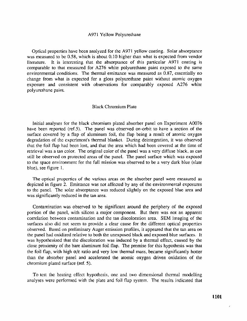
have been reported (ref.5). The panel was observed on-orbit to have a section of the
surface covered by a flap of aluminum foil, the flap being a result of atomic oxygen
degradation of the experiment's thermal blanket. During deintegration, it was observed
that the foil flap had been lost, and that the area which had been covered at the time of
retrieval was a tan color. The original color of the panel was a very diffuse black, as can
still be observed on protected areas of the panel. The panel surface which was exposed
to the space environment for the full mission was observed to be a very dark blue (slate
blue), see figure 1.
The optical properties of the various areas on the absorber panel were measured as
depicted in figure 2. Emittance was not affected by any of the environmental exposures
to the panel. The solar absorptance was reduced slightly on the exposed blue area and
was significantly reduced in the tan area.
Contamination was observed to be significant around the periphery of the exposed
portion of the panel, with silicon a major component. But there was not an apparent
correlation between contamination and the tan discoloration area. SEM imaging of the
surfaces also did not seem to provide a clear cause for the different optical properties
observed. Based on preliminary Auger emission profiles, it appeared that the tan area on
the panel had oxidized relative to both the unexposed black and exposed blue surfaces. It
was hypothesized that the discoloration was induced by a thermal effect, caused by the
close proximity of the bare aluminum foil flap. The premise for this hypothesis was that
the foil flap, with high 0qE ratio and very low thermal mass, became significantly hotter
than the absorber panel and accelerated the atomic oxygen driven oxidation of the
chromium plated surface (ref. 5).
To test the heating effect hypothesis, one and two dimensional thermal modelling
analyses were performed with the plate and foil flap system. The results indicated that
1101

the foil flap, though experiencing 300°F thermal cycles, could not have heated the
absorber panel under it to a temperature higher than that achieved by the exposedsurface.
With the heating effect hypothesis discredited, surface analysis was again tried in
order to illuminate the differences between the blue and tan areas on the absorber panel.Figure 3 is an ESCA surface survey of the iridescent or 'rainbow' area in one corner of
the exposed area. Most notable in this survey are the high levels of oxygen, silicon, and
carbon, indicative of silicone contamination. Figure 4 is an ESCA survey of the exposed
blue area, where the silicon levels are significant but much less than that observed the
corners of the exposed area. Figure 5 is a survey of the tan area, which appears to havelower silicon levels than the exposed blue area.
Elemental Auger profiles for the blue and tan areas are shown in figures 6 and 7. The
blue area in figure 6 indicates initially chromium and oxygen, changing to mostly
chromium metal with sputtering just as the nickel underplate begins to become apparent.
The data from figure 6 is consistent with what is expected for both this system and for
the unexposed original black surface. The tan area profile in figure 7 was unexpected.
Note the scale on the y-axis is 10% of that in figure 6. It appears that the tan area is
much thicker and more completely oxidized than the blue area. A consistent picture for
this particular coating and the changes it exhibits has not been achieved; the analysis iscontinuing.
Chromate Conversion Coating on Aluminum
The chromate conversion coating was only partially exposed to the LDEF environment
of tray D3. The surface still had the characteristic iridescence observed for chromate
conversion coatings. Optical properties of the surface were measured even though there
were no initial readings of the surface taken prior to LDEF integration. The solar
absorptance of the surface varied between 0.55 and 0.57, which is about 0.1 higher than
what has been typical for chromated conversion coatings measured at Boeing. In lieu of
what has been observed on other surfaces on the trailing edge of LDEF, it is likely that
this darkening of the coating is due to contaminant deposition. The emittance of the
surface was measured at between 0.09 and 0.11, which is certainly in the expected rangefrom Boeing experience.
The chromate conversion coating was also analyzed by X-ray absorption spectroscopy
(XAS), to determine the amount and oxidation state of the chromium in the coating.
XAS indicated that of the chromium in the coating, only 4% was as hexavalent
chromium. This appears to be a significant depletion of Cr (VI) when compared to the
24% level typically observed by XAS in fresh chromate conversion coatings.
Hexavalent chromium depletion in conversion coatings is generally associated with a
reduction in the corrosion resistance afforded to the aluminum substrate. Therefore,
1102

three 3" x 5" samples of the M0003 chromate conversion coated panel were subjected to
the salt spray corrosion test (ASTM B117) for seven days, as is customary for evaluating
fresh conversion coatings on aluminum from aerospace processing. The M0003
chromate conversion coating passed the corrosion resistance test, with no pitting
observed on any of the three samples. The salt spray result was, therefore, contrary to
what was expected from the XAS results. It is possible that the UV-fixed contaminant
layer provided some degree of protection to the test specimens during the salt spray test.
But because the specimens did "wet" completely in the salt spray test, it is more likely
that the conversion coating itself provided a continuous protective barrier, reducing the
need for the corrosion inhibition provided by the hexavalent chromium ion.
Chromic Acid Anodize
The results obtained for LDEF tray clamps treated with chromic acid anodize are shown
in table 1. The standard deviations for the populations indicate that the results from one
environmental condition to another essentially overlap, with slight indication of
absorptance increase for the surfaces not subject to significant levels of atomic oxygen.
However, even with this slight increase in absorptance, the results indicate that the
optical properties of chromic acid anodize are quite stable in the low earth orbit
environment.
A276 White Polyurethane
The A276 paint on composite (Experiment M0003, Tray D9) had areas protected from
atomic oxygen erosion, where washers were used in the attachment of the panel to
support structure. The atomic oxygen eroded the polyurethane portion of the paint in
exposed areas, leaving behind a loose agglomeration of paint pigment particles. We were
curious to know how deep the atomic oxygen was able to penetrate into this network of
pigment particles, or how deep the exposed paint was damaged from a physical integrity
perspective.
Specimens from the composite panel were taken from around the protected attachment
areas, and the loose pigment on those specimens was removed by rag wiping. The
specimens were then measured using laser profilometry. Height profiles from two
different areas along the protected-to-unprotected interface are shown in figures 8 and 9.
The figure 8 profile was taken perpendicular to the LDEF axis along the surface toward
row 10. The LDEF yaw offset gave the incident atomic oxygen direct access to the paint
at the washer interface, yielding a steep erosion profile. Figure 9 was also taken
perpendicular to the LDEF axis, but along the surface toward row 8 (180 ° from figure 8).
Here the yaw offset allowed the washer to shield the paint from atomic oxygen erosion at
the interface, yielding a tapered erosion profile. The total erosion depth measured using
these two profiles, plus four additional measurements, indicated atomic oxygen attack
1103

into the A276 paint surface to a depth of about 101.tm (0.0004 inch). Correlation has not
been established between the depth of attack and the pigment layer porous structure
(0.2t.tm TiO 2 panicles, 1-21.tm talc particles, 40.6 volume percent solids). It is not
certain that this measured erosion depth is the limit for which atomic oxygen can
penetrate into the A276 pigment layer. However, it seems likely that this must be the
penetration limit based on the tortuous path atomic oxygen would have to follow in order
to continue reacting with the paint resin layer.
The UV degradation of A276 paint on LDEF has been discussed previously (ref. 6).
A276 on surfaces not exposed to atomic oxygen has exhibited a sharp increase in solar
absorptance with UV exposure. Attempts made to locate ground-based test data for
comparison with the LDEF results were essentially unsuccessful. Literature data for
numerous white coatings (including A276) have been found, but these reports are
typically limited to less than 1000 ESH total UV exposure, due to the moderate UV
source intensities that must be used. Another limitation is that ground-based test results
are from in-situ reflectance measurements, because of the recognized recovery effect thatoccurs when short-term UV exposure test specimens come in contact with air. The
precise extent of reflectance recovery that may have occurred with the LDEF A276 paint
specimens is unknown. The present levels of discoloration in the A276 coating have
been determined to be due to degradation of the polyurethane resin portion of the
coating, a degradation which cannot "recover".
For engineering purposes, it is essential to establish accelerated test criteria which can
be used to predict performance life in a cost effective and timely manner. It was for this
reason that comparison of the LDEF A276 results to ground-based UV exposure results
was attempted. Failing this, a more controversial approach was made in applying the
concept of radiation equivalence. Recent measurements have been made at Boeing
Combined Radiation Effects Test Center (CRETC) on the A276 paint, concerning the
effects of proton/electron radiation on solar absorptance. 1 A276 was irradiated
with 40 keV protons and electrons, simultaneously and in roughly equal fluences to
prevent sample charging. Significant degradation in solar absorptance was observed in-
situ as a function of radiation fluence. For the purposes of trend comparison, the
radiation fluence which produced a solar absorptance reading of 0.52 was arbitrarily
equated with a LDEF UV exposure of 8300 ESH. All other particulate radiation fluence
levels were scaled from this point. The scaled data set was then compared to the results
for A276 white paint data from the LDEF tray clamps, as is shown in figure 10. The
trends in the data are significantly similar. The comparison of these two sets of
measurements is made here partly as a curiosity. But this comparison is made principally
to stimulate thought on the concept of radiation equivalence for materials testing,
recognizing the significant impact such an approach could have on long-termperformance life prediction.
IL. Fogdall and M. Wilkinson, Boeing Defense & Space Group, personal
communication of results to be published.
1104

REFERENCES
. R. J. Bourassa: Atomic Oxygen And Ultraviolet Radiation Mission Total Exposures
For LDEF Experiments. Second LDEF Post-Retrieval Symposium, NASA CP-
3194, 1993.
2. P. George: Results From Analysis of Boeing Composite Specimens Flown on LDEF
Experiment M003. Second LDEF Post-Retrieval Symposium, NASA CP-3194,1993.
3. R. J. Duckett and C. S. Gilliland: Variable Anodic Thermal Control Coating on
Aluminum, AIAA-83-1492. AIAA 18th Thermophysics Conference. June, 1983.
. W. L. Plagemann: Space Environmental Effects On The Integrity Of Chromic Acid
Anodized Coatings. First LDEF Post-Retrieval Symposium, NASA CP-3134,1992.
5. J. L. Golden: Changes In Oxidation State Of Chromium During LDEF Exposure.
LDEF Materials Workshop '91, NASA CP-3162, 1992.
6. J. L. Golden: Results Of Examination Of The A276 White And Z306 Black Thermal
Control Paint Disks Flown On LDEF. First LDEF Post-Retrieval Symposium,NASA CP-3134, 1992.
Measurements On FliightUnexposed
ct= O.340.01
Tray ClampsExposed- Exposed-
Leading Trailinl_ct = 0.33 ct = 0.35
0.0 1 0.02
e = 0.15 e- 0.150.01 0.01
ot/e = 2.2 ot/e = 2.3
Ex pose d -Space
ct = 0.350.02
Exposed -Earth
ct = 0.350.01
Data From
AIAA-83-1492
ct = 0.32
Measurements
On Unused
Clampsct= 0.36
e= 0.16 e= 0.16 e= 0.17 e= 0.16 e= 0.180.01 0.02 0.01
a/e = 2. I ot/e = 2.2 me = 2. I me = 2.0 a/e = 2.0
Note: Second Value Is Standard Deviation
Table 1. Averages of optical property measurements for groups of anodized tray clamps.
1105
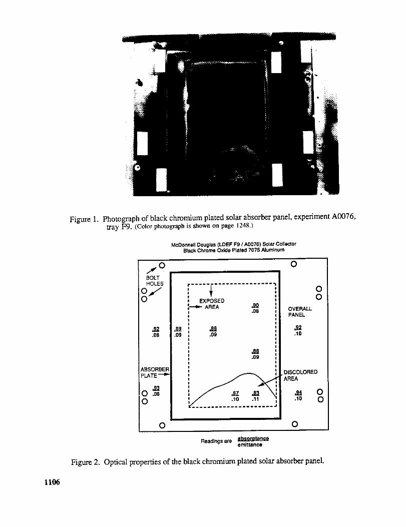
Figure 1.
Figure 2.
Photograph of black chromium plated solar absorber panel, experiment A0076,
tray F9. (Color photograph is shown on page 1248.)
McDonnell Douglas (LDEF F9 / A0076) Solar CollectorBlack Chrome Oxide Plated 7075 Aluminum
OJBOLTHOLES
.92
.08
ABSORBERPLATE
:::::::::::::::::::::::
EXPOSEDAREA .90
.08
.O8
.09
.88
.09
O
O O
OO
OVERALLPANEL
.O2
.10
DISCOLOREDAREA
Readings are ebsorotanceemlttance
Optical properties of the black chromium plated solar absorber panel.
1106

I11194.52 874.52
2
L
' I
654.52
Rainbow Area In Comer
"" 2A •
• O.i
434'.52 i i214.52 -5.48
Surface Co_positton Table 8ummry
Element Blndtna Fnmr_v atom,F (ls) 688.78 0.72 %Cr (2p) 578.06 1.75O (ls) 532.87 51.70 %
N (ls} 401.12 1.32 %
C (ls) 285.00 20.59 %$I (28) 153.69 23.93 %
Total Percent i00.00 %
Figure 3. ESCA survey of a rainbow colored area on the black chromium plated solarabsorber panel
2gU
_'_- Blue AreaIll _ I
_u ,..a, i
OO w_. J •
(h _ kOI
....I I ' I
1182.19 882'. 19 662.19 442'. 19 m 222'. 19 ' 2.19
Surface Composltlon Table Summary
Element B1ndln_ RnmroV atomCr (2p3) 578.50 4.16
O (ls) 532.68 44.02 %
C (Is) 285.00 43.05 %
SI {28) 154.37 8.78 %
Total Percent 100.00 %
Figure 4. ESCA survey of a blue colored area on the black chromium plated solar absorberpanel
1107

3811OO
7
i 665'. 18 u1125.18 885'. 18 m
Tan Area
-- @
445.18 u iZ2S. 18 5.18
Surface Composition Table Smeary
E1_t Bindlna Enorav atom •
Cr (2p3) 577.15 6.29 %
O (ls) 531.82 43.19 %
N (Is) 400.04 0.80 %C (ls) 285.00 45.14 %
Sl (2p) 101.58 4.58 %
Total Percent I00.00 %
Figure 5. ESCA survey of a tan colored area on the black chromium plated solar absorberpanel
IM
Blue Area
I i ' I _ i I8 Z48 480 960 1288
Figure 6. Auger profile of blue area on the black chromium plated solar absorber panel.
11{)8

- LlaOOID
Tan AreaO
I I ' '_ I ,
0 240 490 _ _ l IZO0
Figure 7. Auger profile of tan area on the black chromium plated solar absorber panel.
LASER PAOFILOMETRY SCAN OF LDEF ATOMIC OXYGEN EAOSION
0.8
0.6
0.4
0.2
-0.2
-0.4
-0.6
SAMPLE: _-276 WHITE URETHANE SCAN: I
MEAN - -0.34
I I I I I I I I I
20 40 60 80 100 120 140 160 180
X IN 0.0005 INCH UNITS
200
Figure 8. Laser profilometry of A276 white paint on tray D9 at a protected/unprotectedinterface towards row 10.
1109

tASER PROFILOHETRY SCAN OF LDEF ATOMIC OXYGEN EROSION
%
H
EL.q
08
0.6
04
0.2
SAMPLE: A-276 WHITE URETHANE SCAN: 2
MEAN - -0.43
-13.4
-0 6 L I L I I _ _ I I I20 40 60 80 100 120 140 160 1 B0 200
X IN 0.0005 INCH UNITS
Figure 9. Laser profilometry of A276 white paint on tray D9 at a protected/unprotectedinterface towards row 8.
Figure 10.
0.7
0.1
UZ<{I'-fl" 0.Sn-O
m,,¢
0.4
<..JO
0.3CONIBOI.
0.2
J/=
/-
i, °lJ
_JliHmoK E/_
PREFUGI ITI
5000
TRAILIN _ EDGE f
[]
LEA ING EDGR, • -| _ B,,o
I I
IS00010000
SOLAR FLUENCE (ESH)
f
20000
• 40 keV Electron + Protons
i Flucnce(pcrcm ) Sc_¢dESH Absorptanc¢0 0 0.23
1 x 10¹⁴ 420 0.27
6 x 10¹⁴ 2500 0.36
2 x 10¹⁵ 8300 0.525 x 10¹⁵ 20800 0.66
Comparison of LDEF results with ground-based radiation test result fromBoeing CRETC for A276 white paint.
1110