Mustansiriyah University / College of Science Department of ...
20
اضرة ا( 1 ) اد اعد: أ. م. د. د جبار زوري هؤينصريتستهعت اا ا/ علوميت ال كل/ سياء قسن الفيMustansiriyah University / College of Science Department of Physics optics
-
Upload
khangminh22 -
Category
Documents
-
view
1 -
download
0
Transcript of Mustansiriyah University / College of Science Department of ...
(1)احملاضرة :اعداد
هؤيد جبار زوري. د.م.أ قسن الفيسياء/كليت العلوم/اجلاهعت املستنصريت
Mustansiriyah University / College of Science Department of Physics
optics
Superposition of Waves Many interesting wave phenomena in nature cannot be described by a single traveling wave. Instead, one
must analyze complex waves in terms of a combination of traveling waves. To analyze such wave
combinations, one can make use of the superposition principle:
If two or more traveling waves are moving through a medium, the resultant value of the wave function at
any point is the algebraic sum of the values of the wave functions of the individual waves.
The principle of superposition applies to electromagnetic wave also and is the most important principle in
wave optics. In case of electromagnetic waves, the term displacement refers to the amplitude of electric field
vector. Interference is an important consequence of superposition of coherent waves. Waves that obey this
principle are called linear waves. Waves that violate the superposition principle are called nonlinear waves.
Mustansiriyah University / College of Science Department of Physics
optics
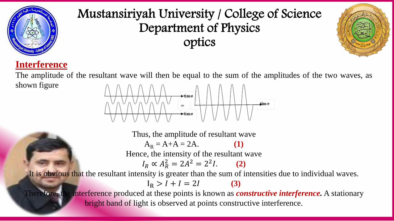
Interference The amplitude of the resultant wave will then be equal to the sum of the amplitudes of the two waves, as
shown figure
Thus, the amplitude of resultant wave
AR = A+A = 2A. (1)
Hence, the intensity of the resultant wave
𝐼𝑅 ∝ 𝐴𝑅2 = 2𝐴2 = 22𝐼. (2)
It is obvious that the resultant intensity is greater than the sum of intensities due to individual waves.
IR > 𝐼 + 𝐼 = 2𝐼 (3)
Therefore, the interference produced at these points is known as constructive interference. A stationary
bright band of light is observed at points constructive interference.
Mustansiriyah University / College of Science Department of Physics
optics
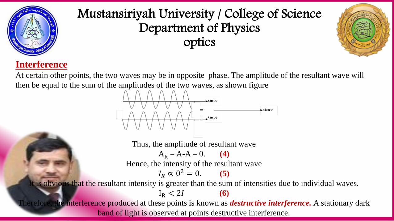
Interference At certain other points, the two waves may be in opposite phase. The amplitude of the resultant wave will
then be equal to the sum of the amplitudes of the two waves, as shown figure
Thus, the amplitude of resultant wave
AR = A-A = 0. (4)
Hence, the intensity of the resultant wave
𝐼𝑅 ∝ 02 = 0. (5)
It is obvious that the resultant intensity is greater than the sum of intensities due to individual waves.
IR < 2𝐼 (6)
Therefore, the interference produced at these points is known as destructive interference. A stationary dark
band of light is observed at points destructive interference.
Mustansiriyah University / College of Science Department of Physics
optics
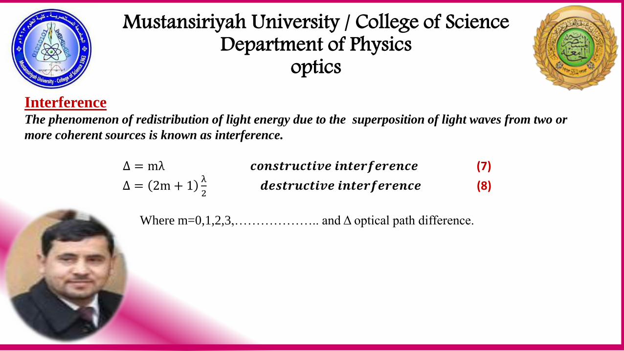
Interference The phenomenon of redistribution of light energy due to the superposition of light waves from two or
more coherent sources is known as interference.
Δ = mλ 𝒄𝒐𝒏𝒔𝒕𝒓𝒖𝒄𝒕𝒊𝒗𝒆 𝒊𝒏𝒕𝒆𝒓𝒇𝒆𝒓𝒆𝒏𝒄𝒆 (7)
Δ = 2m + 1λ
2 𝒅𝒆𝒔𝒕𝒓𝒖𝒄𝒕𝒊𝒗𝒆 𝒊𝒏𝒕𝒆𝒓𝒇𝒆𝒓𝒆𝒏𝒄𝒆 (8)
Where m=0,1,2,3,……………….. and Δ optical path difference.
Mustansiriyah University / College of Science Department of Physics
optics
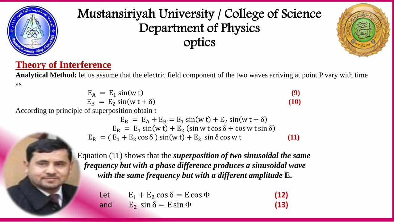
Theory of Interference Analytical Method: let us assume that the electric field component of the two waves arriving at point P vary with time
as
EA = E1 sin w t (9)
EB = E2 sin w t + δ (10)
According to principle of superposition obtain t
ER = EA + EB = E1 sin w t + E2 sin w t + δ
ER = E1 sin w t + E2 sin w t cos δ + cos w t sin δ
ER = ( E1 + E2 cos δ ) sin w t + E2 sin δ cos w t (11)
Equation (11) shows that the superposition of two sinusoidal the same
frequency but with a phase difference produces a sinusoidal wave
with the same frequency but with a different amplitude E.
Let E1 + E2 cos δ = E cos Φ (12) and E2 sin δ = E sin Φ (13)
Mustansiriyah University / College of Science Department of Physics
optics
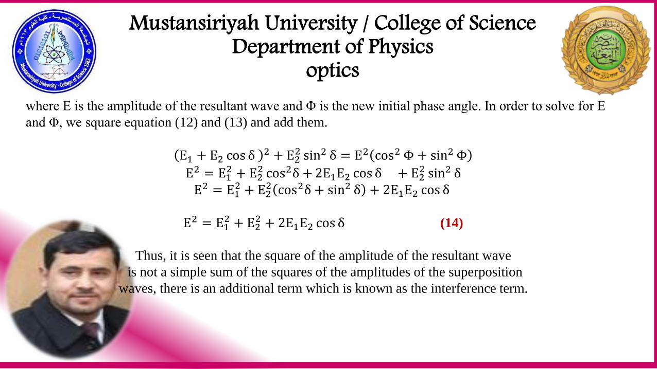
where E is the amplitude of the resultant wave and Φ is the new initial phase angle. In order to solve for E
and Φ, we square equation (12) and (13) and add them.
E1 + E2 cos δ 2 + E22 sin2 δ = E2 cos2 Φ + sin2 Φ
E2 = E12 + E2
2 cos2δ + 2E1E2 cos δ + E22 sin2 δ
E2 = E12 + E2
2 cos2δ + sin2 δ + 2E1E2 cos δ
E2 = E12 + E2
2 + 2E1E2 cos δ (14)
Thus, it is seen that the square of the amplitude of the resultant wave
is not a simple sum of the squares of the amplitudes of the superposition
waves, there is an additional term which is known as the interference term.
Mustansiriyah University / College of Science Department of Physics
optics
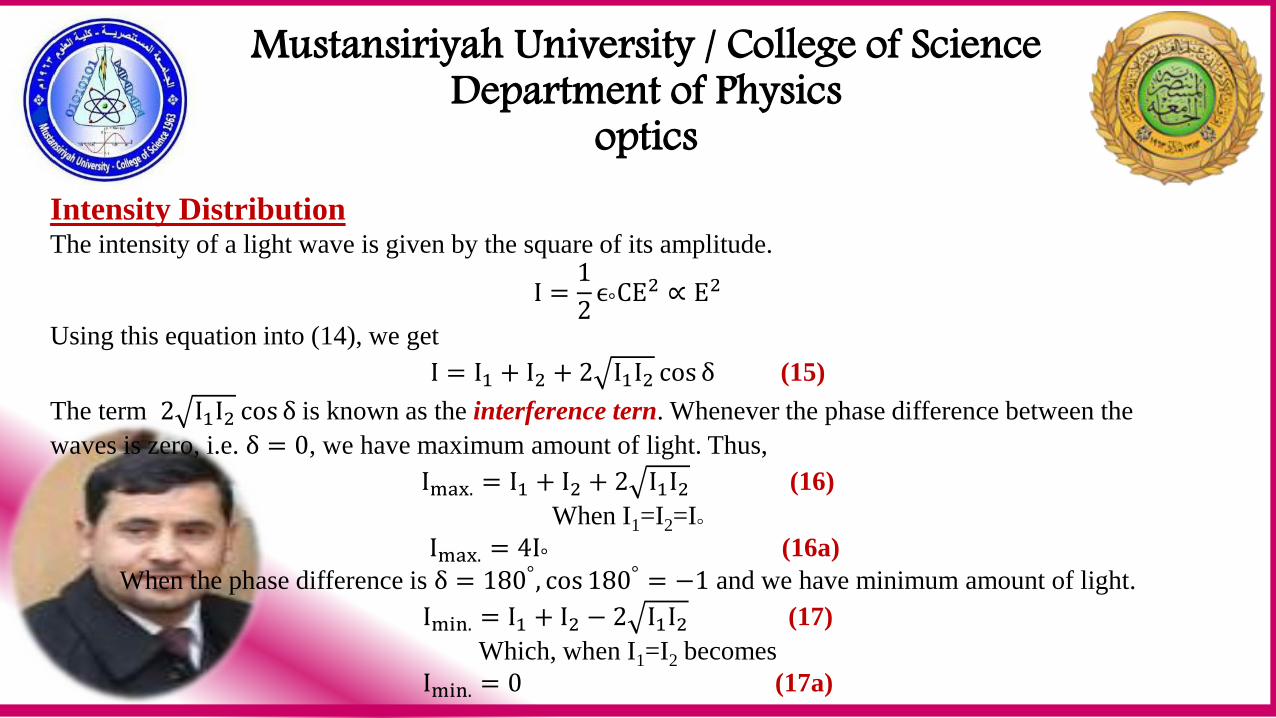
Intensity Distribution The intensity of a light wave is given by the square of its amplitude.
I =1
2ϵ°CE2 ∝ E2
Using this equation into (14), we get
I = I1 + I2 + 2 I1I2 cos δ (15)
The term 2 I1I2 cos δ is known as the interference tern. Whenever the phase difference between the
waves is zero, i.e. δ = 0, we have maximum amount of light. Thus,
Imax. = I1 + I2 + 2 I1I2 (16)
When I1=I2=I°
Imax. = 4I° (16a)
When the phase difference is δ = 180°, cos 180° = −1 and we have minimum amount of light.
Imin. = I1 + I2 − 2 I1I2 (17)
Which, when I1=I2 becomes
Imin. = 0 (17a)
Mustansiriyah University / College of Science Department of Physics
optics
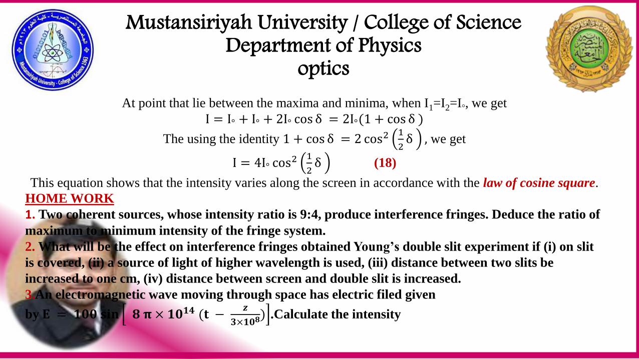
At point that lie between the maxima and minima, when I1=I2=I°, we get
I = I° + I° + 2I° cos δ = 2I°(1 + cos δ )
The using the identity 1 + cos δ = 2 cos2 1
2δ , we get
I = 4I° cos2 1
2δ (18)
This equation shows that the intensity varies along the screen in accordance with the law of cosine square.
WORKHOME 1. Two coherent sources, whose intensity ratio is 9:4, produce interference fringes. Deduce the ratio of
maximum to minimum intensity of the fringe system.
2. What will be the effect on interference fringes obtained Youngʼs double slit experiment if (i) on slit
is covered, (ii) a source of light of higher wavelength is used, (iii) distance between two slits be
increased to one cm, (iv) distance between screen and double slit is increased.
3.An electromagnetic wave moving through space has electric filed given
by 𝐄 = 𝟏𝟎𝟎 𝐬𝐢𝐧 𝟖 𝛑 × 𝟏𝟎𝟏𝟒 (𝐭 − 𝒛
𝟑×𝟏𝟎𝟖) .Calculate the intensity
Mustansiriyah University / College of Science Department of Physics
optics
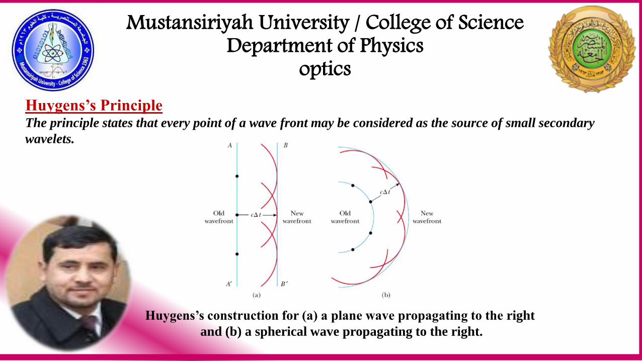
Huygens’s Principle The principle states that every point of a wave front may be considered as the source of small secondary
wavelets.
Huygens’s construction for (a) a plane wave propagating to the right
and (b) a spherical wave propagating to the right.
Mustansiriyah University / College of Science Department of Physics
optics
Techniques of Obtaining Interference The techniques used for creating coherent sources of light can be divided into the following two broad
classes.
1. Wave front splitting: one of the method consists in dividing a light wave front, emerging from a narrow
slit, by passing it through two slits closely spaced side by side. The two parts of the same wave front
travel through different path and reunite on a screen to produce fringe pattern. This is known as
interference due to division of wave front. This method is useful only with narrow sources. Young’s
double slit, Fresnel’s double mirror, Fresnel’s biprism, Lloyd’s mirror, etc employ this technique.
2. Amplitude splitting: Alternately, the amplitude (intensity) of a light wave is divided into two part,
namely reflected and transmitted components, by partial reflection at a surface. The two part travel
through different path and reunite to produce interference fringes. this is known as interference due to
division of amplitude. Optical elements such as beam splitters, mirror are used for achieving amplitude
division. Interference in thin films (wedge, Newton’s ring etc), Michelson’s interferometer etc
interferometers utilize this method. This method requires extended source.
Mustansiriyah University / College of Science Department of Physics
optics
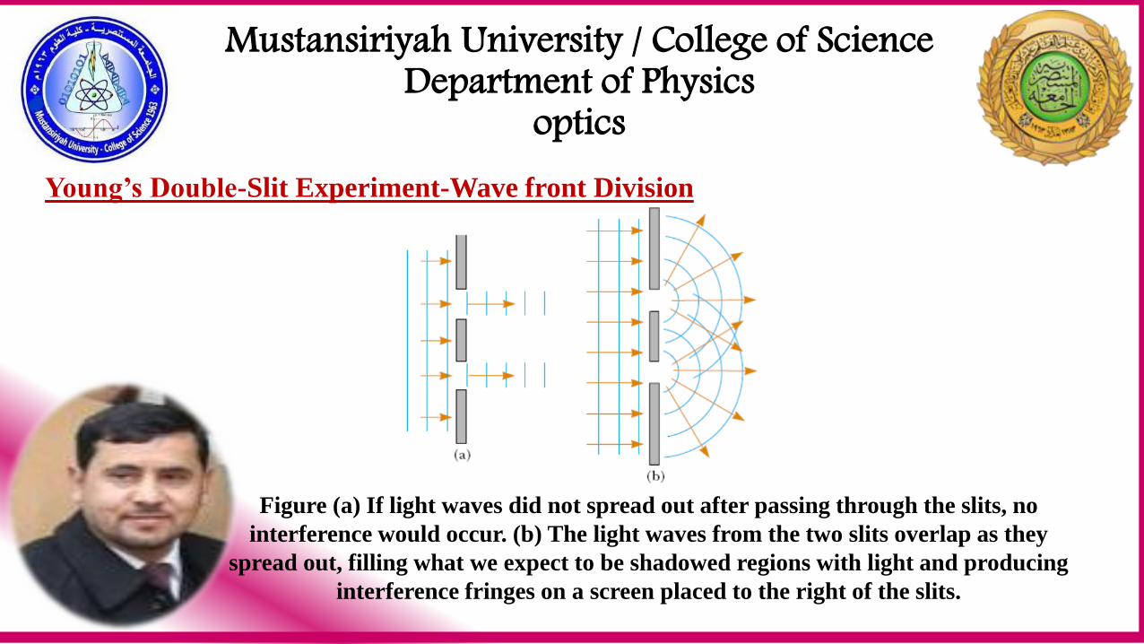
Young’s Double-Slit Experiment-Wave front Division
Figure (a) If light waves did not spread out after passing through the slits, no
interference would occur. (b) The light waves from the two slits overlap as they
spread out, filling what we expect to be shadowed regions with light and producing
interference fringes on a screen placed to the right of the slits.
Mustansiriyah University / College of Science Department of Physics
optics
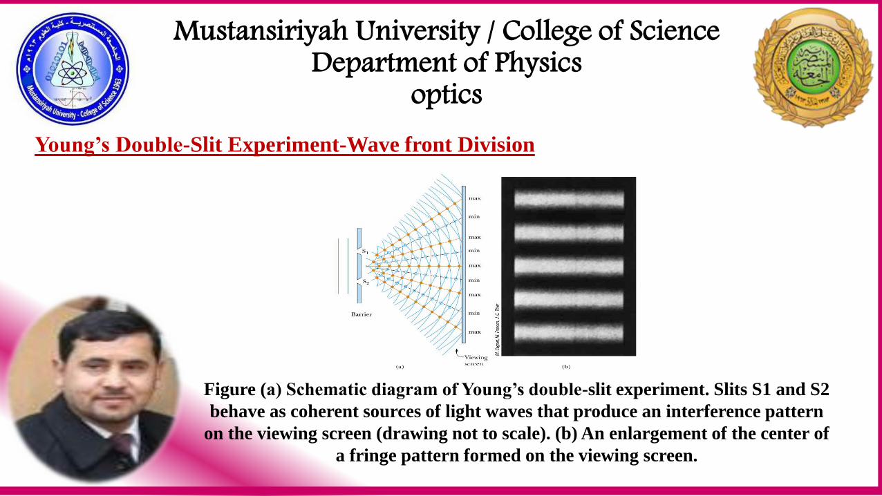
Young’s Double-Slit Experiment-Wave front Division
Figure (a) Schematic diagram of Young’s double-slit experiment. Slits S1 and S2
behave as coherent sources of light waves that produce an interference pattern
on the viewing screen (drawing not to scale). (b) An enlargement of the center of
a fringe pattern formed on the viewing screen.
Mustansiriyah University / College of Science Department of Physics
optics
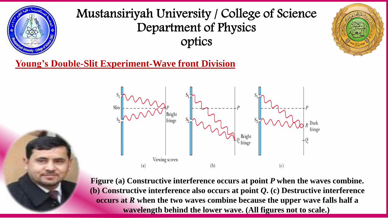
Young’s Double-Slit Experiment-Wave front Division
Figure (a) Constructive interference occurs at point P when the waves combine.
(b) Constructive interference also occurs at point Q. (c) Destructive interference
occurs at R when the two waves combine because the upper wave falls half a
wavelength behind the lower wave. (All figures not to scale.)
Mustansiriyah University / College of Science Department of Physics
optics
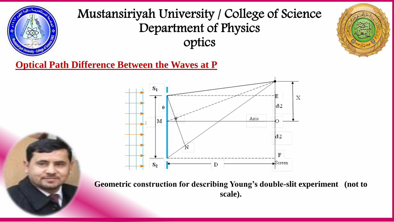
Optical Path Difference Between the Waves at P
Geometric construction for describing Young’s double-slit experiment (not to
scale).
Mustansiriyah University / College of Science Department of Physics
optics
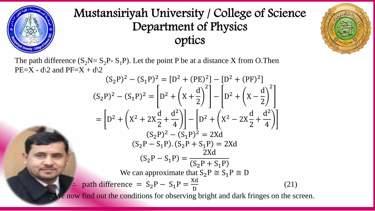
The path difference (S2N= S2P- S1P). Let the point P be at a distance X from O.Then
PE=X - d\2 and PF=X + d\2
S2P 2 − S1P 2 = D2 + PE 2 − D2 + PF 2
S2P 2 − S1P 2 = D2 + X +d
2
2
− D2 + X −d
2
2
= D2 + X2 + 2Xd
2+
d2
4− D2 + X2 − 2X
d
2+
d2
4
S2P 2 − S1P 2 = 2Xd
S2P − S1P . S2P + S1P = 2Xd
S2P − S1P =2Xd
S2P + S1P
We can approximate that S2P ≅ S1P ≅ D
∴ path difference = S2P − S1P =Xd
D (21)
We now find out the conditions for observing bright and dark fringes on the screen.
Mustansiriyah University / College of Science Department of Physics
optics
Bright Fringes The condition for finding a bright fringe at P is that
S2P − S1P = mλ
Using equation (21), it means that Xd
D= mλ (22)
Where m is called the order of fringe.
Where m = 0 called zero- order of fringe , m = 1 called first- order bright fringe and m = 2 called second-
order bright fringe.
Dark Fringes The condition for finding a dark fringe is
Xd
D= 2m + 1
λ
2 (23)
Where m = 0 called first- order dark fringe, m = 1 called second- order dark fringe.
Mustansiriyah University / College of Science Department of Physics
optics
Separation Between Neighboring Bright Fringe The mth order fringe occurs when
Xm =mλD
d
And the (m +1)th order fringe when
Xm+1 =m + 1 λD
d
The fringe separation, β is given by
β = Xm+1 − Xm =λD
d (24)
The same result will be obtained for dark fringes. Thus, the distance between any two consecutive bright or
dark fringes known as the fringe width and is same everywhere on the screen. Further, the width of the
bright fringe is equal to the dark fringe. Therefore, the alternate bright and dark fringes are parallel.
Mustansiriyah University / College of Science Department of Physics
optics
From equation (24), we find the following:
1. The fringe width β is independent of the order of the fringe. It is directly proportional
to the wavelength of light, i.e. 𝜷 ∝ 𝝀.
2. The fringes produced by red light are less closer compared to those produced by blue
light.
3. The width of the fringe is directly proportional to the distance the of the screen from
the two slits 𝜷 ∝ 𝑫. the farther the screen, the wider is the fringe separation.
4. The width of the fringe is inversely proportional to the distance between two slits.
The closer are the slits, the width will be the fringes.
Mustansiriyah University / College of Science Department of Physics
optics
Example: A light source emits light of two wavelength 4300A˚ and 5100A˚. The source is used in a double
slit experiment. The distance between the source and the screen is 1.5m and the distance between the slits is
0.025 mm. Calculate the separation between the third order bright fringes due to these two wavelengths.
Solution: It is given thatλ1 = 4300A˚ = 4300 × 10−8 cm,λ2 = 5100A˚ = 5100 × 10−8 cm, m=3,
D=1.5m=150cm and d=0.025mm=0.0025cm.Now X1 =mDλ1
d and X2 =
mDλ2
d
X2 − X1 =mD
dλ2 − λ1 =
3 × 150cm
0.0025cm5100 × 10−8 cm − 4300 × 10−8 cm = 1.44 cm
H.W.: What happens if the monochromatic light used in Young’s double slit experiment is replaced by white
light?
Mustansiriyah University / College of Science Department of Physics
optics