Motors and Motor Circuit Calculations - Dan Dudley
54
Copyright 1999-2019 Dan Dudley Motors and Motor Circuit Calculations 2017 NEC Requirements
-
Upload
khangminh22 -
Category
Documents
-
view
1 -
download
0
Transcript of Motors and Motor Circuit Calculations - Dan Dudley
Copyright 1999-2019 Dan Dudley
Motors and MotorCircuit Calculations
2017 NEC Requirements
Copyright 1999-2019 Dan Dudley
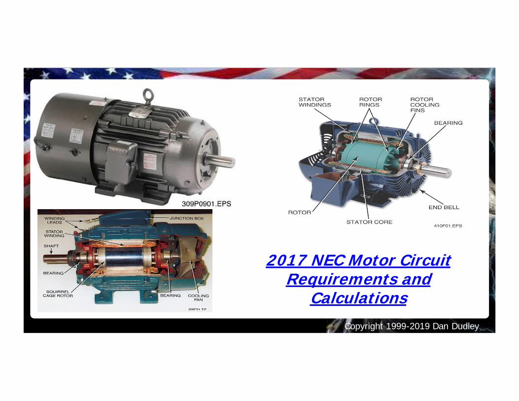
2017 NEC Motor CircuitRequirements and
Calculations
Copyright 1999-2019 Dan Dudley
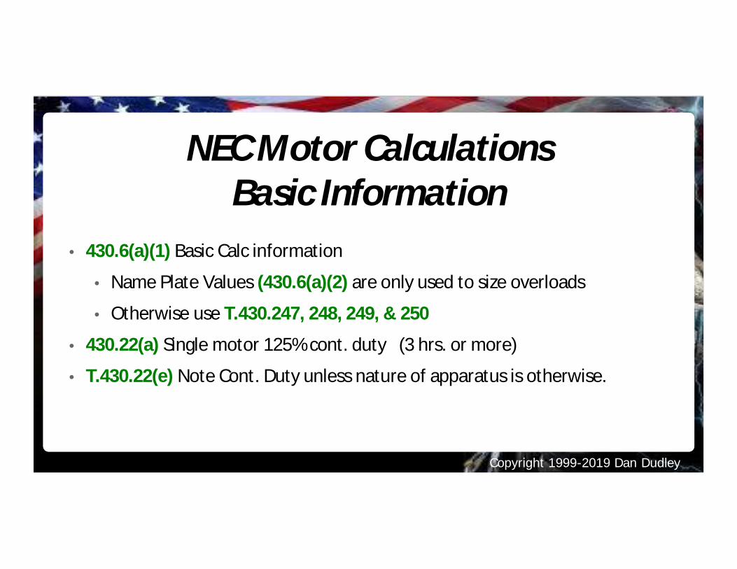
NEC Motor CalculationsBasic Information
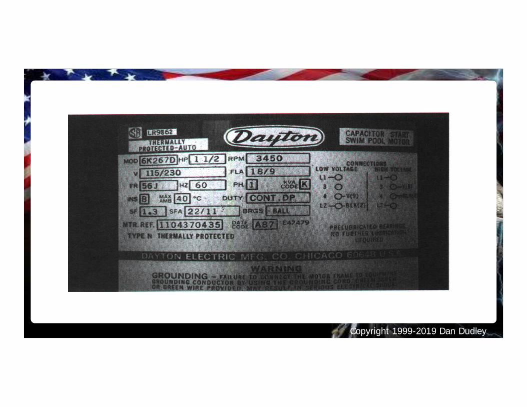
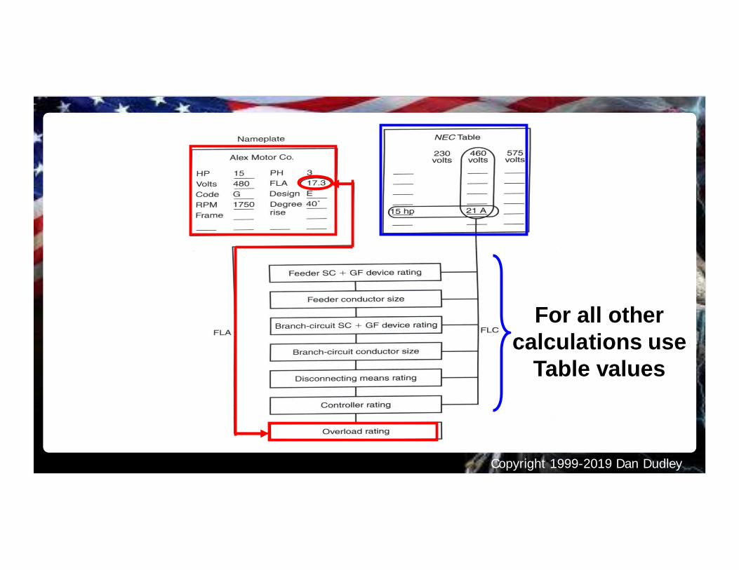
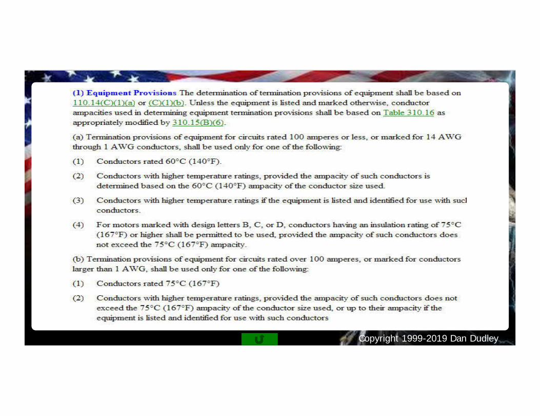
• 430.6(a)(1) Basic Calc information
• Name Plate Values (430.6(a)(2) are only used to size overloads
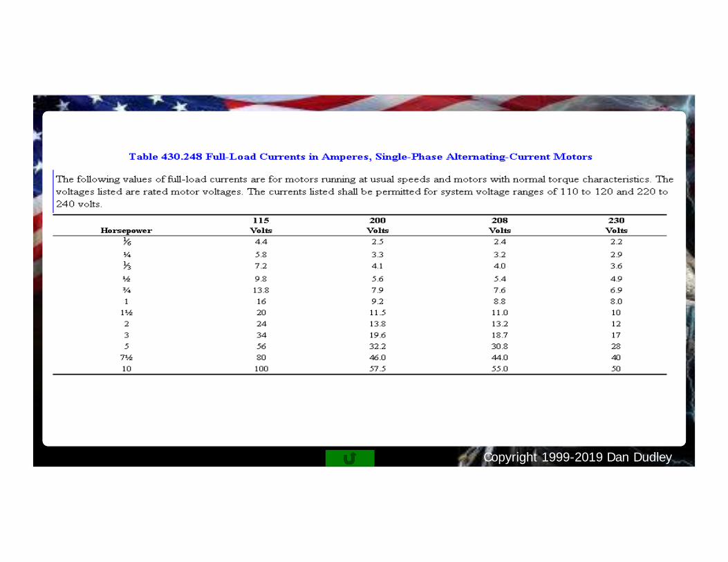
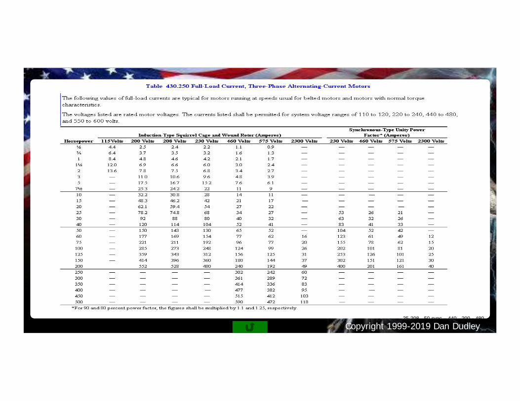
• Otherwise use T.430.247, 248, 249, & 250
• 430.22(a) Single motor 125% cont. duty (3 hrs. or more)
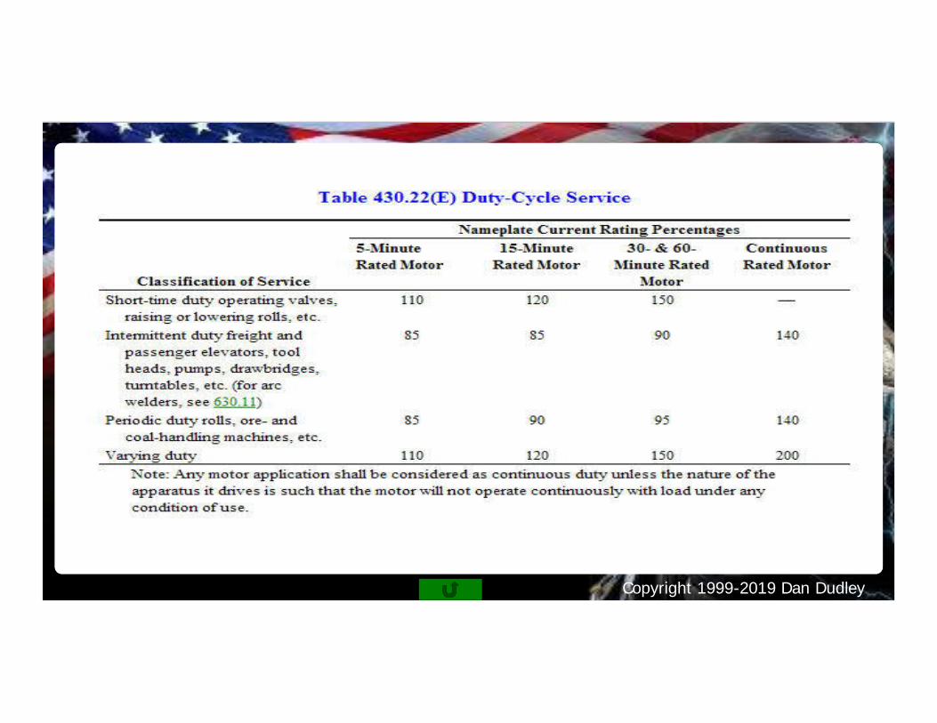
• T.430.22(e) Note Cont. Duty unless nature of apparatus is otherwise.
Copyright 1999-2019 Dan Dudley
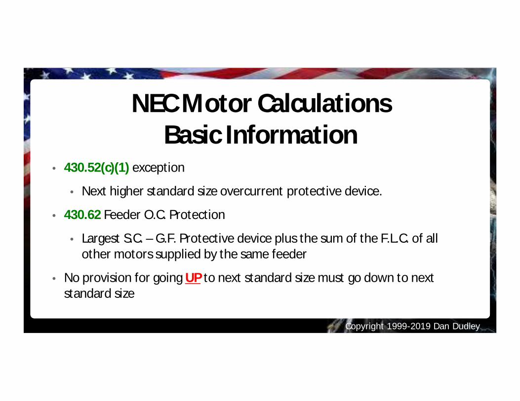
NEC Motor CalculationsBasic Information
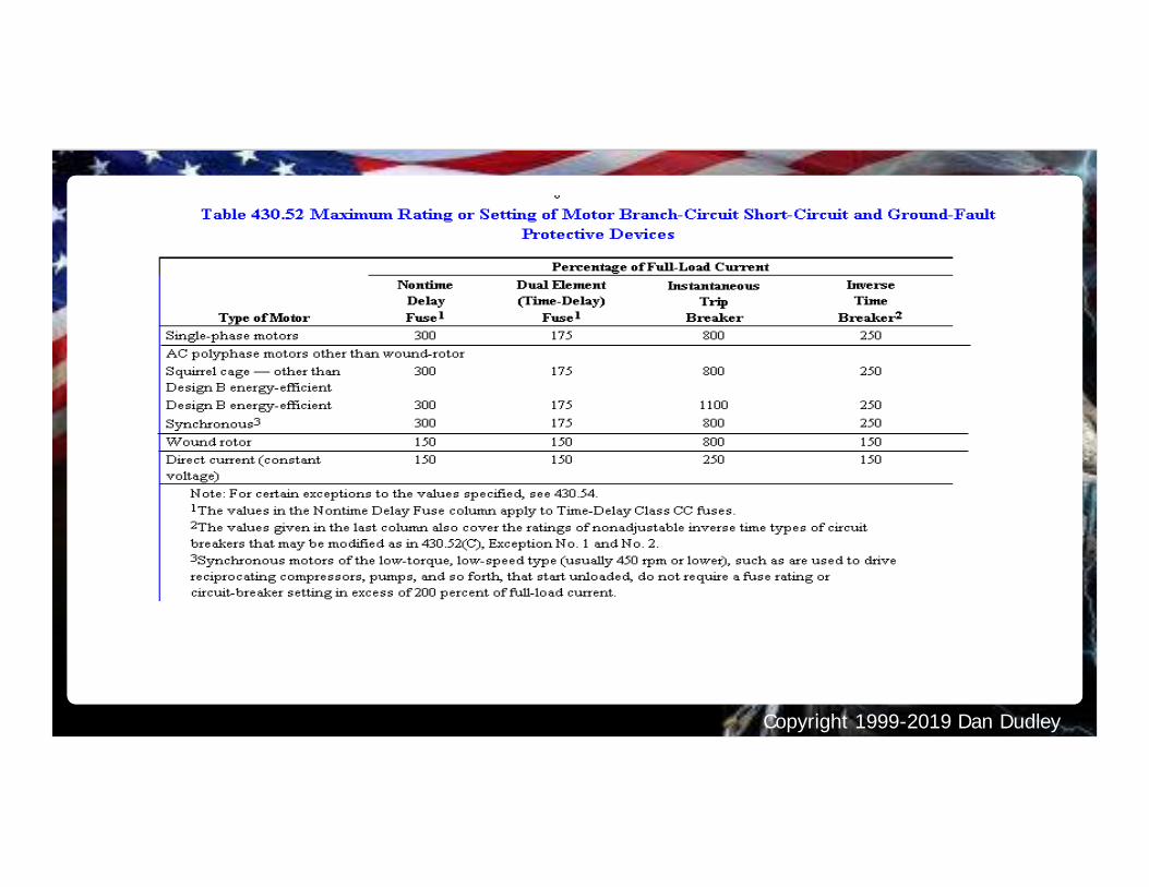
• 430.52(c)(1) exception
• Next higher standard size overcurrent protective device.
• 430.62 Feeder O.C. Protection
• Largest S.C. – G.F. Protective device plus the sum of the F.L.C. of allother motors supplied by the same feeder
• No provision for going UP to next standard size must go down to nextstandard size
Copyright 1999-2019 Dan Dudley
Copyright 1999-2019 Dan Dudley
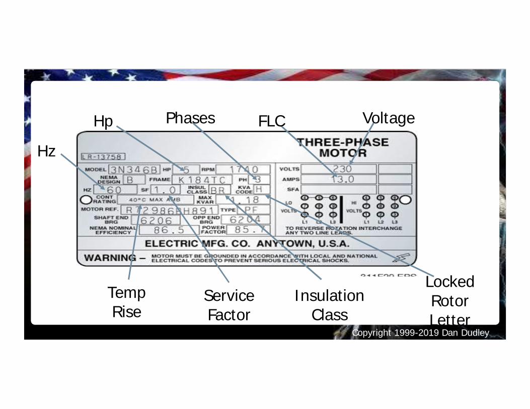
Hz
Hp Phases FLC Voltage
TempRise
ServiceFactor
LockedRotorLetter
InsulationClass
Copyright 1999-2019 Dan Dudley
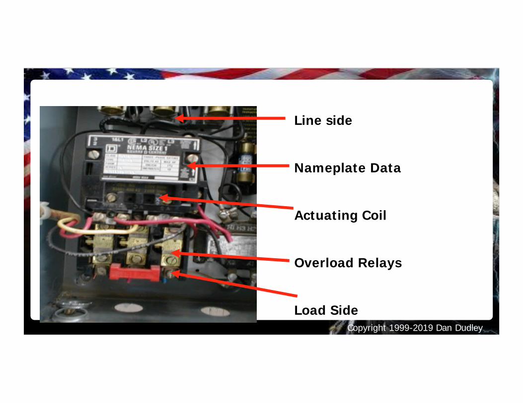
Line side
Nameplate Data
Actuating Coil
Overload Relays
Load Side
Copyright 1999-2019 Dan Dudley
For all othercalculations use
Table values
Copyright 1999-2019 Dan Dudley
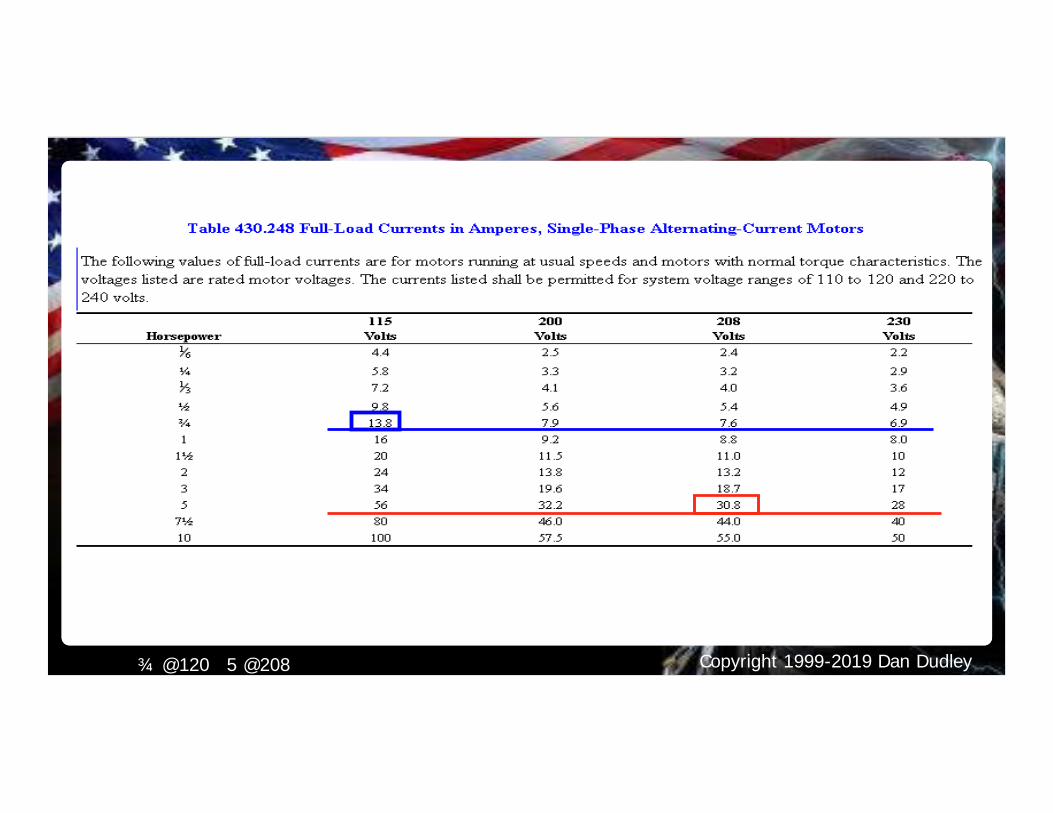
Copyright 1999-2019 Dan Dudley¾ @120 5 @208
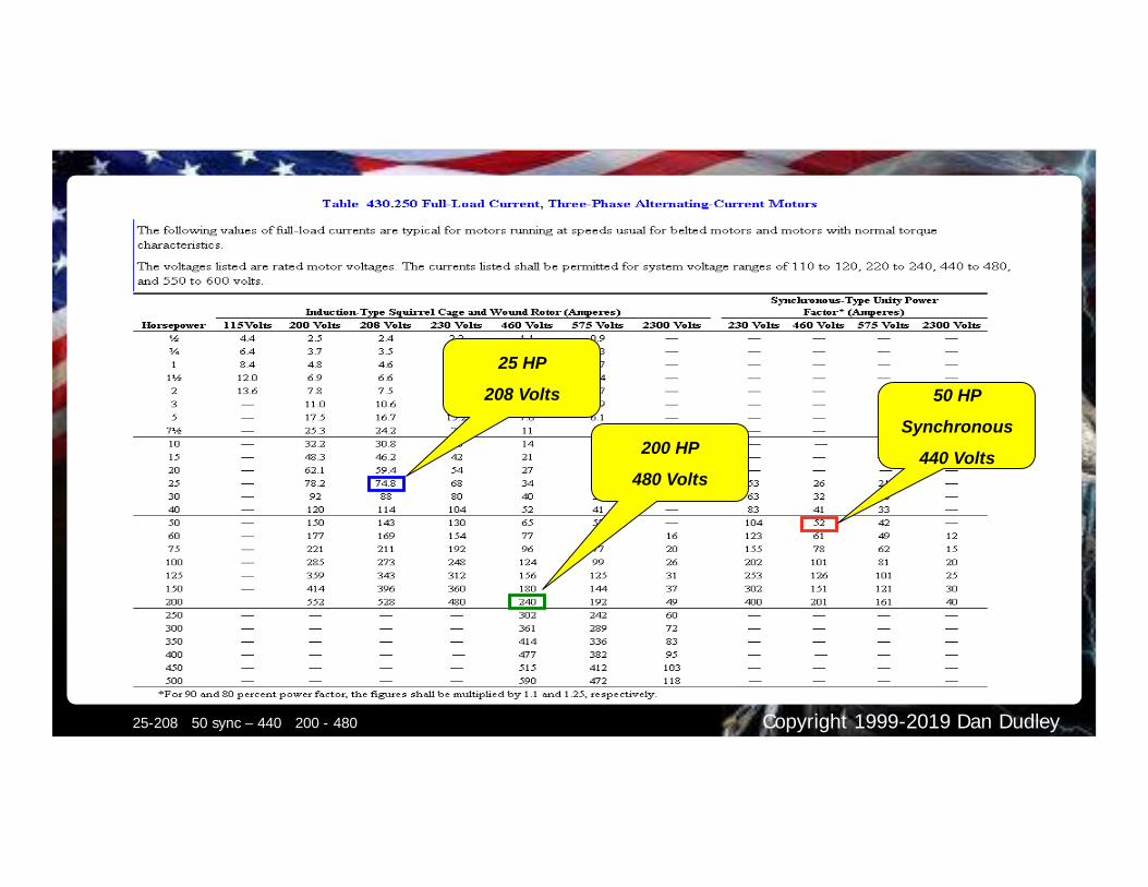
Copyright 1999-2019 Dan Dudley25-208 50 sync – 440 200 - 480
50 HP
Synchronous
440 Volts200 HP
480 Volts
25 HP
208 Volts
Copyright 1999-2019 Dan Dudley
Copyright 1999-2019 Dan Dudley
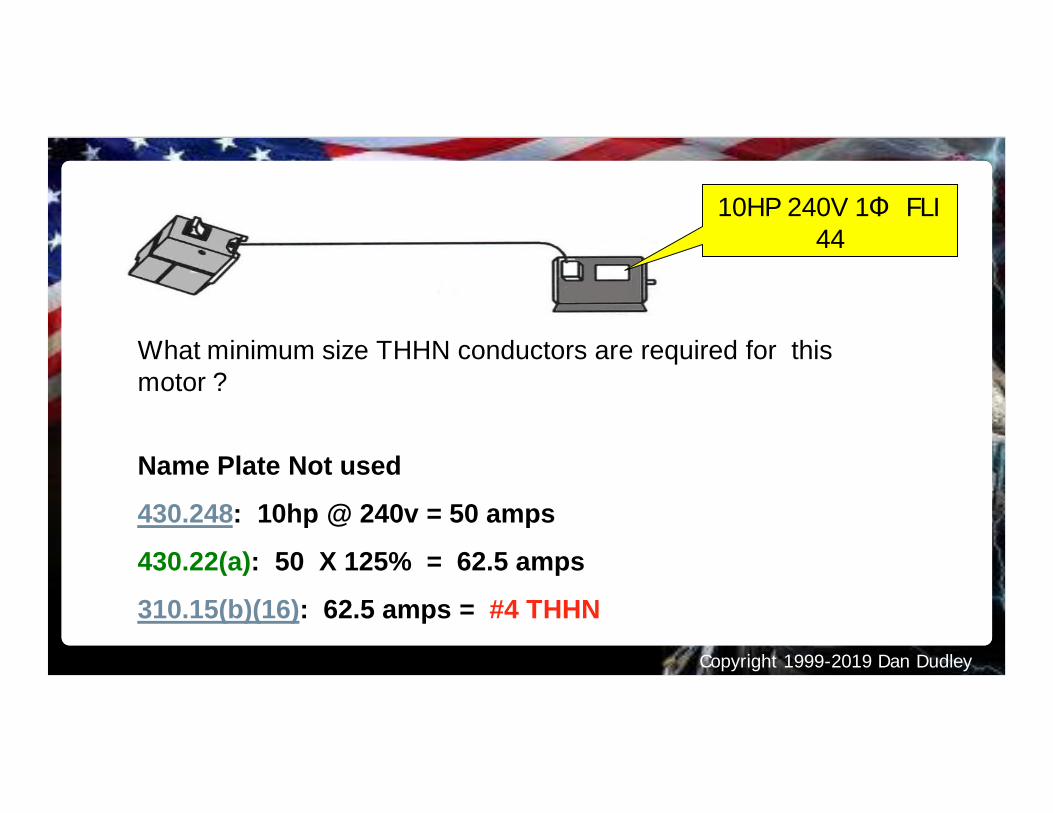
What minimum size THHN conductors are required for thismotor ?
Name Plate Not used
430.248: 10hp @ 240v = 50 amps
430.22(a): 50 X 125% = 62.5 amps
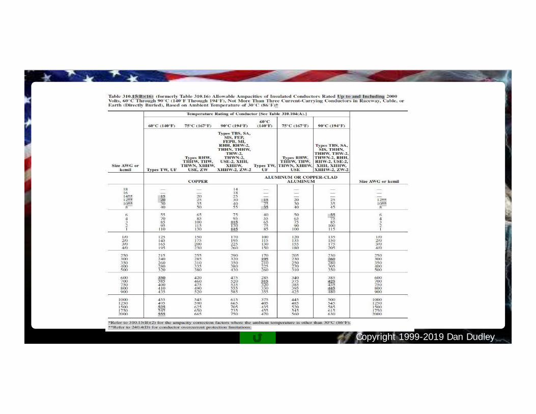
310.15(b)(16): 62.5 amps = #4 THHN
10HP 240V 1Φ FLI44
Copyright 1999-2019 Dan Dudley
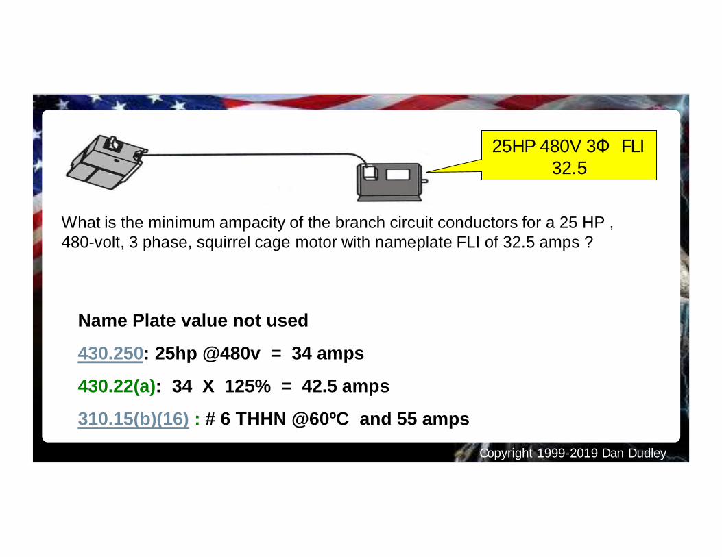
What is the minimum ampacity of the branch circuit conductors for a 25 HP ,480-volt, 3 phase, squirrel cage motor with nameplate FLI of 32.5 amps ?
Name Plate value not used
430.250: 25hp @480v = 34 amps
430.22(a): 34 X 125% = 42.5 amps
310.15(b)(16) : # 6 THHN @60ºC and 55 amps
25HP 480V 3Φ FLI32.5
Copyright 1999-2019 Dan Dudley
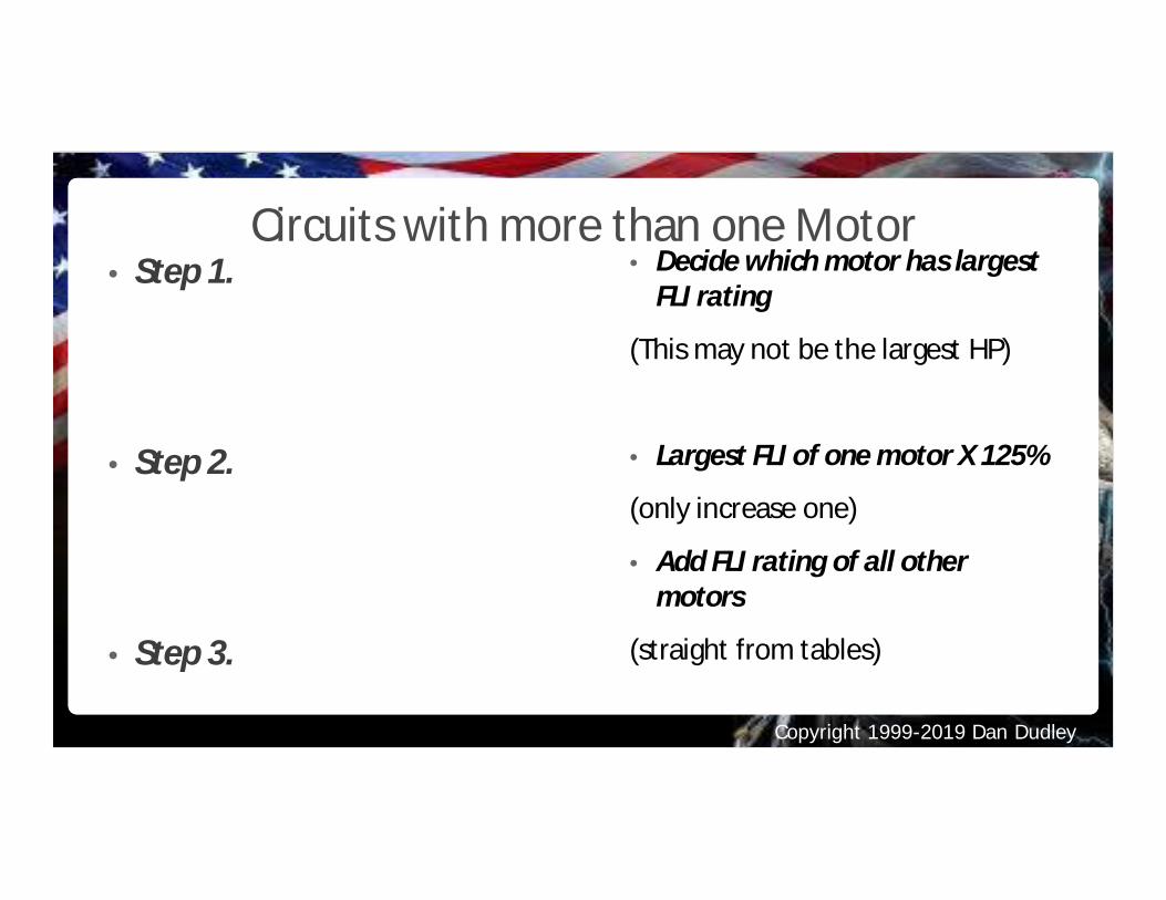
Circuits with more than one Motor• Step 1.
• Step 2.
• Step 3.
• Decide which motor has largestFLI rating
(This may not be the largest HP)
• Largest FLI of one motor X 125%
(only increase one)
• Add FLI rating of all othermotors
(straight from tables)
Copyright 1999-2019 Dan Dudley
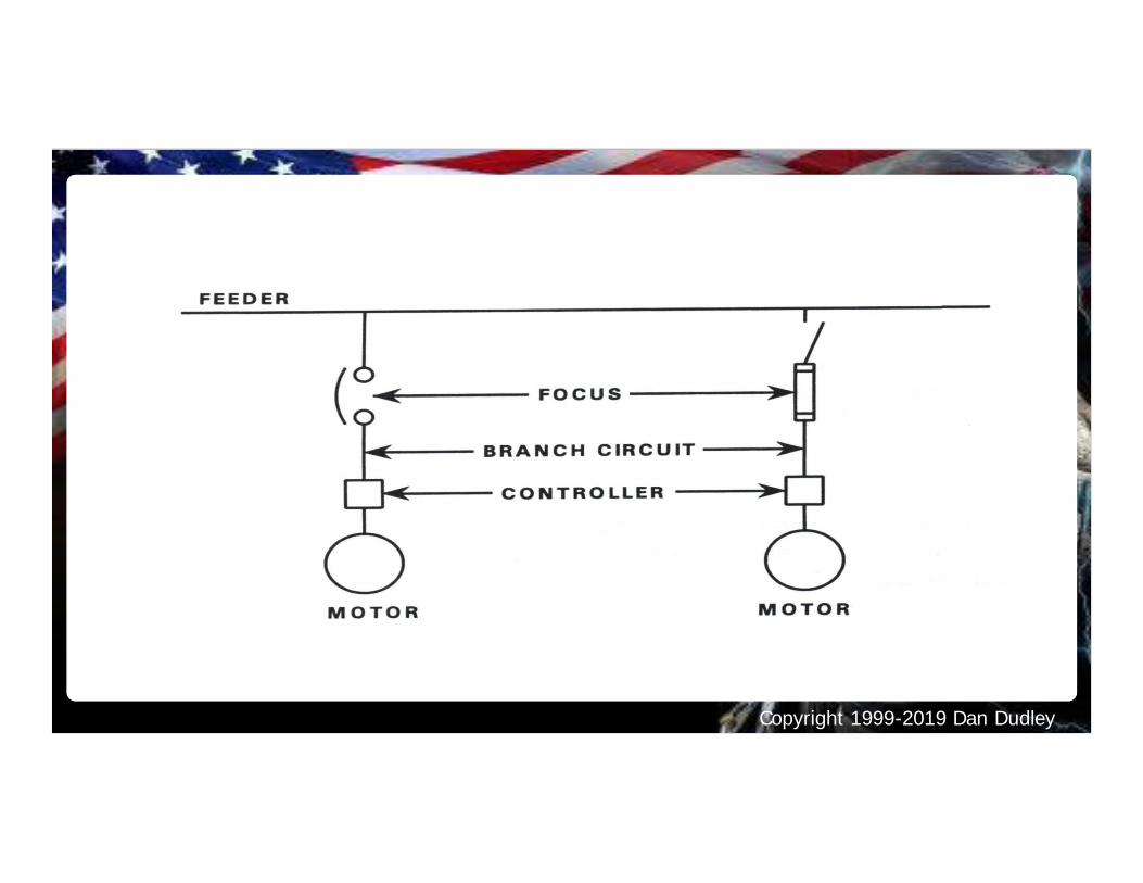
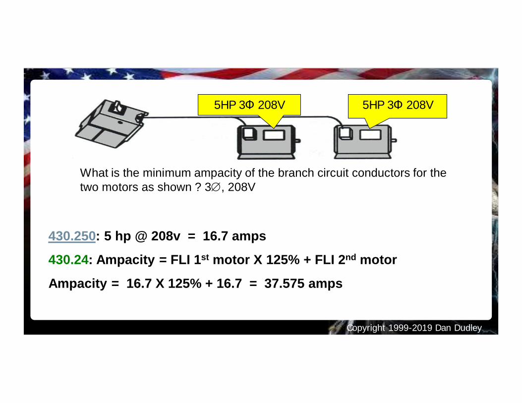
What is the minimum ampacity of the branch circuit conductors for thetwo motors as shown ? 3Æ, 208V
430.250: 5 hp @ 208v = 16.7 amps
430.24: Ampacity = FLI 1st motor X 125% + FLI 2nd motor
Ampacity = 16.7 X 125% + 16.7 = 37.575 amps
5HP 3Φ 208V5HP 3Φ 208V
Copyright 1999-2019 Dan Dudley
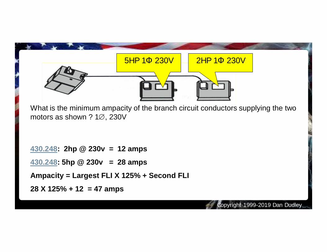
What is the minimum ampacity of the branch circuit conductors supplying the twomotors as shown ? 1Æ, 230V
430.248: 2hp @ 230v = 12 amps
430.248: 5hp @ 230v = 28 amps
Ampacity = Largest FLI X 125% + Second FLI
28 X 125% + 12 = 47 amps
5HP 1Φ 230V 2HP 1Φ 230V
Copyright 1999-2019 Dan Dudley
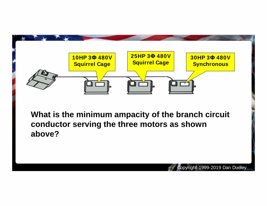
What is the minimum ampacity of the branch circuitconductor serving the three motors as shownabove?
10HP 3Φ 480VSquirrel Cage
25HP 3Φ 480VSquirrel Cage
30HP 3Φ 480VSynchronous
Copyright 1999-2019 Dan Dudley
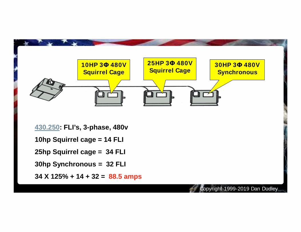
430.250: FLI’s, 3-phase, 480v
10hp Squirrel cage = 14 FLI
25hp Squirrel cage = 34 FLI
30hp Synchronous = 32 FLI
34 X 125% + 14 + 32 = 88.5 amps
10HP 3Φ 480VSquirrel Cage
25HP 3Φ 480VSquirrel Cage
30HP 3Φ 480VSynchronous
Copyright 1999-2019 Dan Dudley
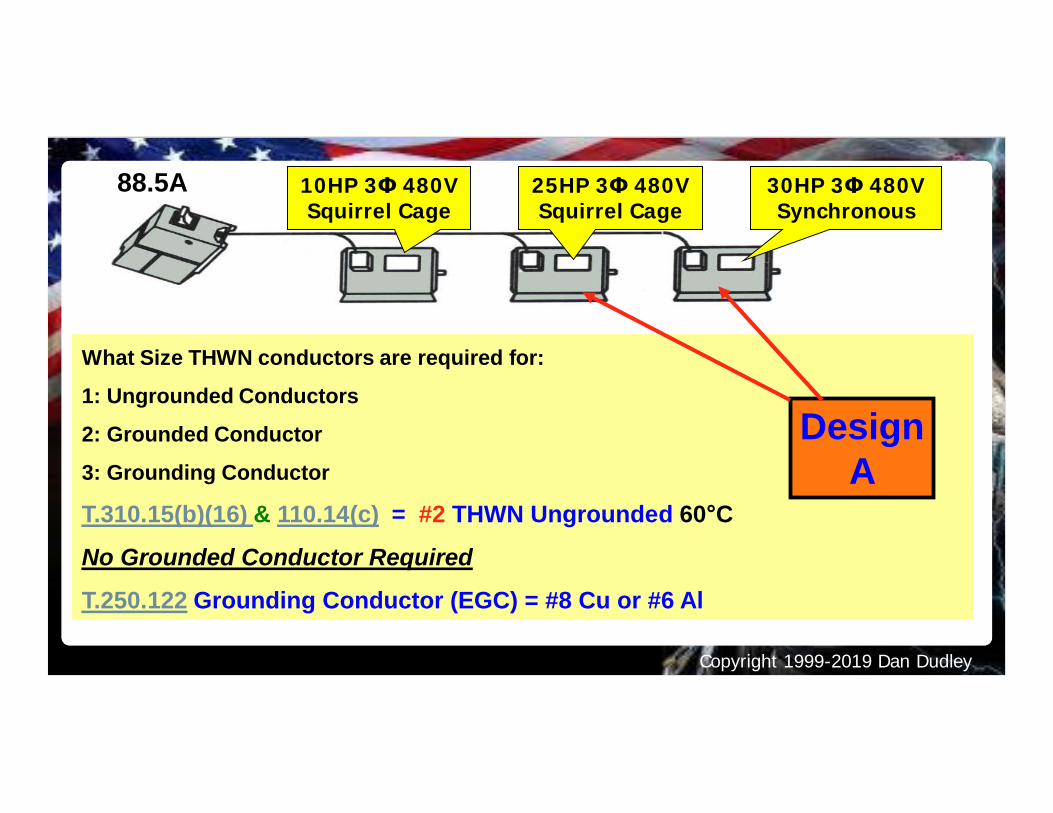
What Size THWN conductors are required for:
1: Ungrounded Conductors
2: Grounded Conductor
3: Grounding Conductor
88.5A
T.310.15(b)(16) & 110.14(c) = #2 THWN Ungrounded 60°C
No Grounded Conductor Required
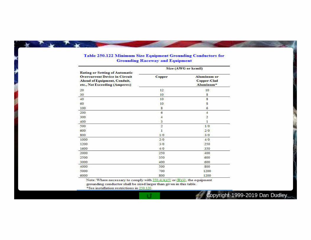
T.250.122 Grounding Conductor (EGC) = #8 Cu or #6 Al
DesignA
10HP 3Φ 480VSquirrel Cage
25HP 3Φ 480VSquirrel Cage
30HP 3Φ 480VSynchronous
Copyright 1999-2019 Dan Dudley
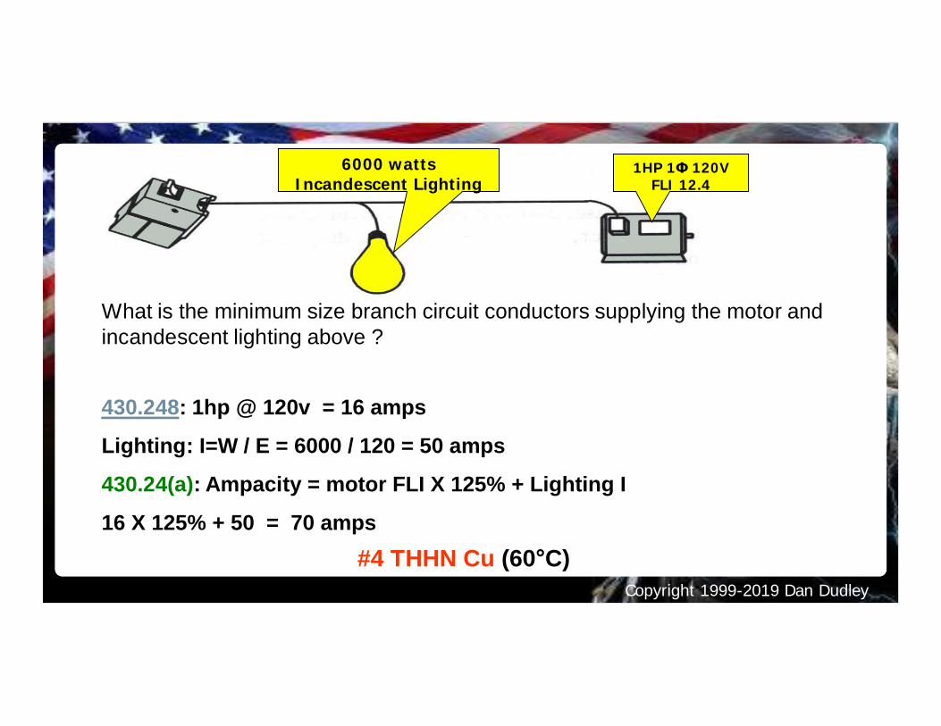
What is the minimum size branch circuit conductors supplying the motor andincandescent lighting above ?
430.248: 1hp @ 120v = 16 amps
Lighting: I=W / E = 6000 / 120 = 50 amps
430.24(a): Ampacity = motor FLI X 125% + Lighting I
16 X 125% + 50 = 70 amps#4 THHN Cu (60°C)
6000 wattsIncandescent Lighting
1HP 1Φ 120VFLI 12.4
Copyright 1999-2019 Dan Dudley
Copyright 1999-2019 Dan Dudley
Copyright 1999-2019 Dan Dudley
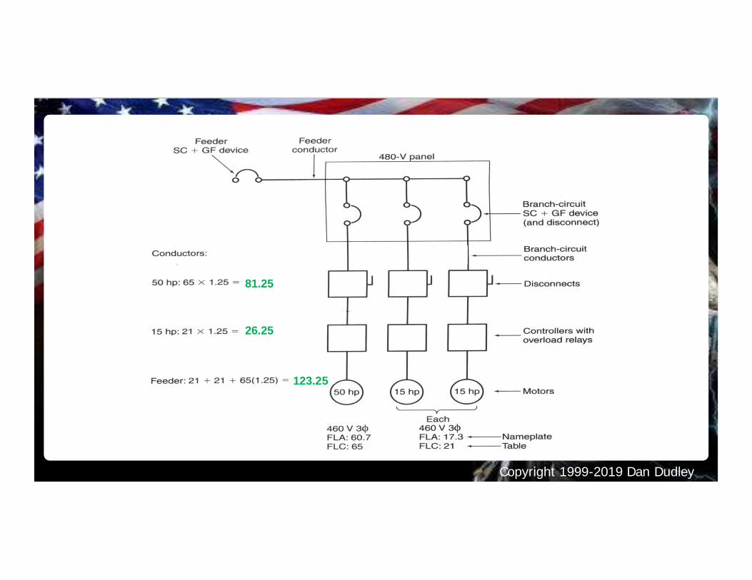
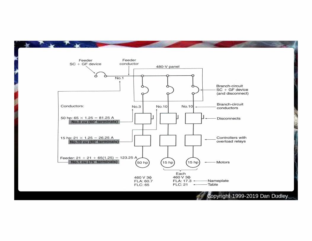
81.25
26.25
123.25
Copyright 1999-2019 Dan Dudley
Copyright 1999-2019 Dan Dudley
Copyright 1999-2019 Dan Dudley
Copyright 1999-2019 Dan Dudley
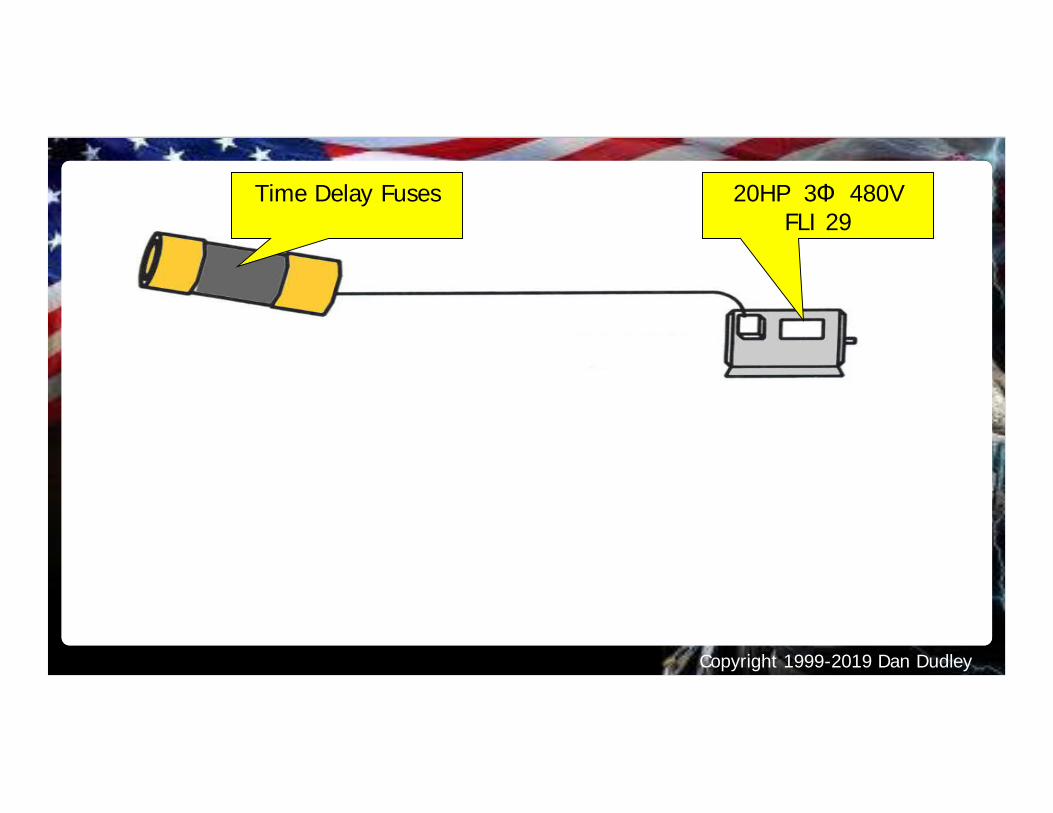
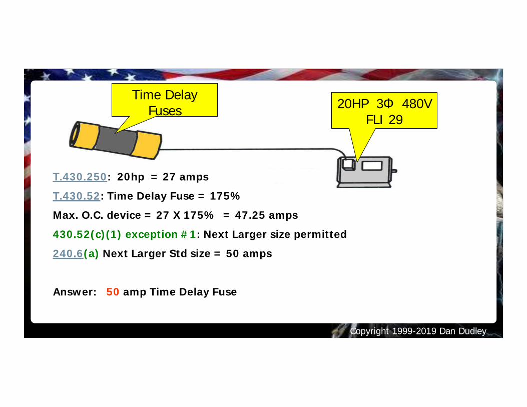
Time Delay Fuses 20HP 3Φ 480VFLI 29
Copyright 1999-2019 Dan Dudley
Time DelayFuses 20HP 3Φ 480V
FLI 29
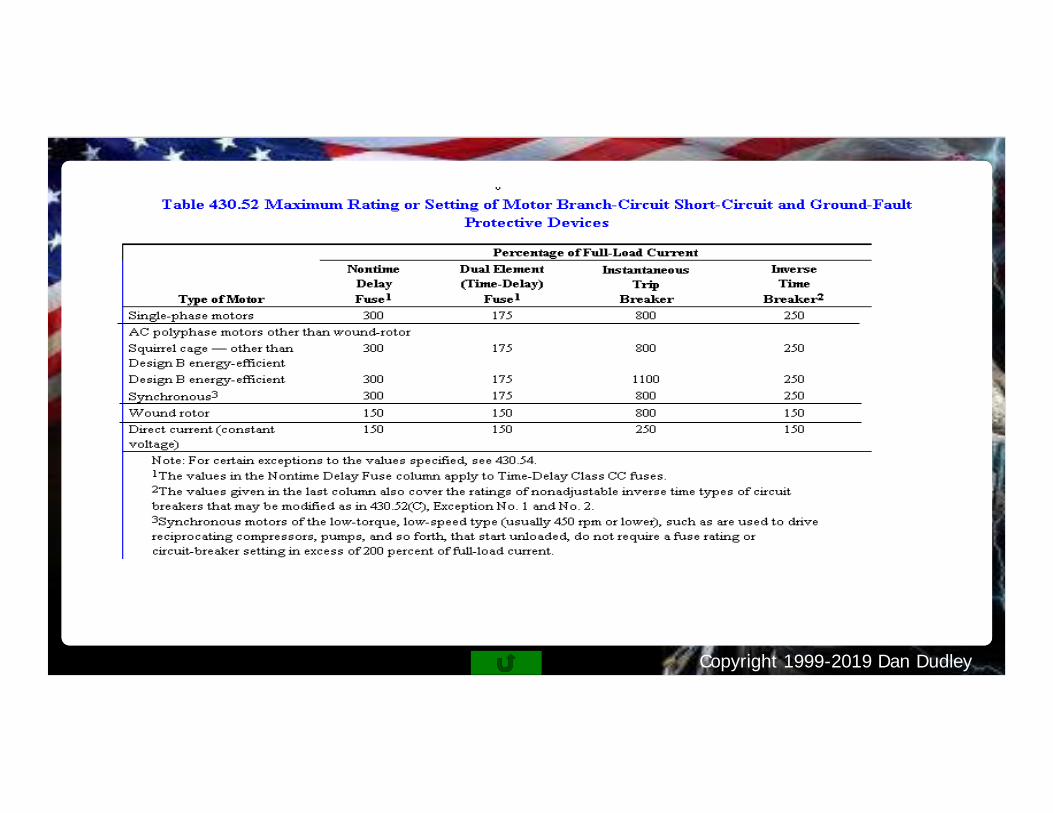
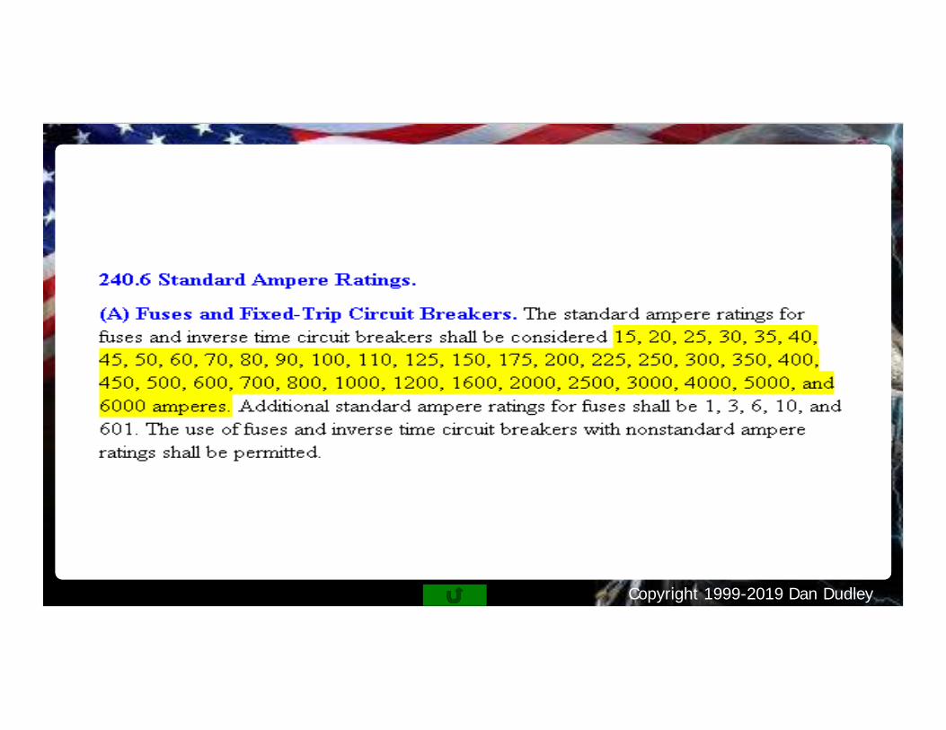
T.430.250: 20hp = 27 ampsT.430.52: Time Delay Fuse = 175%Max. O.C. device = 27 X 175% = 47.25 amps430.52(c)(1) exception #1: Next Larger size permitted240.6(a) Next Larger Std size = 50 amps
Answer: 50 amp Time Delay Fuse
Copyright 1999-2019 Dan Dudley
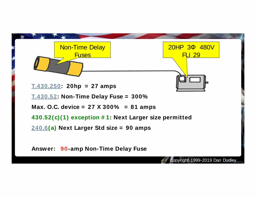
Non-Time DelayFuses
20HP 3Φ 480VFLI 29
T.430.250: 20hp = 27 ampsT.430.52: Non-Time Delay Fuse = 300%Max. O.C. device = 27 X 300% = 81 amps430.52(c)(1) exception #1: Next Larger size permitted240.6(a) Next Larger Std size = 90 amps
Answer: 90-amp Non-Time Delay Fuse
Copyright 1999-2019 Dan Dudley
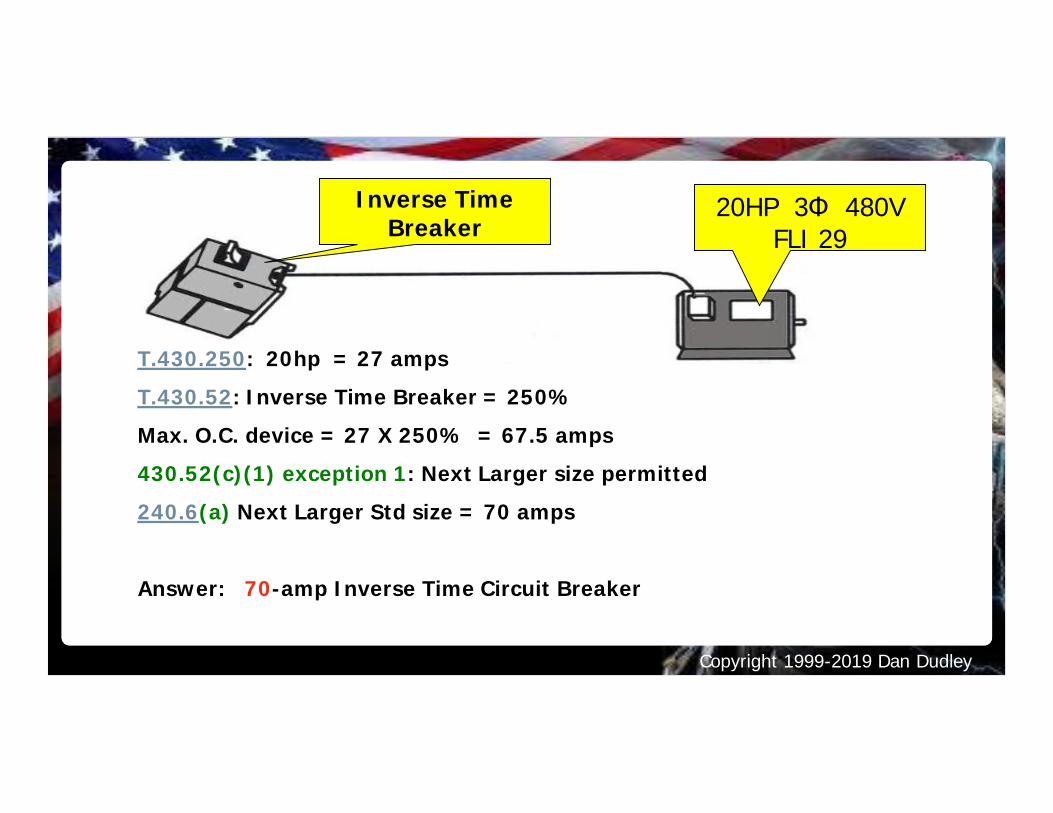
Inverse TimeBreaker
20HP 3Φ 480VFLI 29
T.430.250: 20hp = 27 ampsT.430.52: Inverse Time Breaker = 250%Max. O.C. device = 27 X 250% = 67.5 amps430.52(c)(1) exception 1: Next Larger size permitted240.6(a) Next Larger Std size = 70 amps
Answer: 70-amp Inverse Time Circuit Breaker
Copyright 1999-2019 Dan Dudley
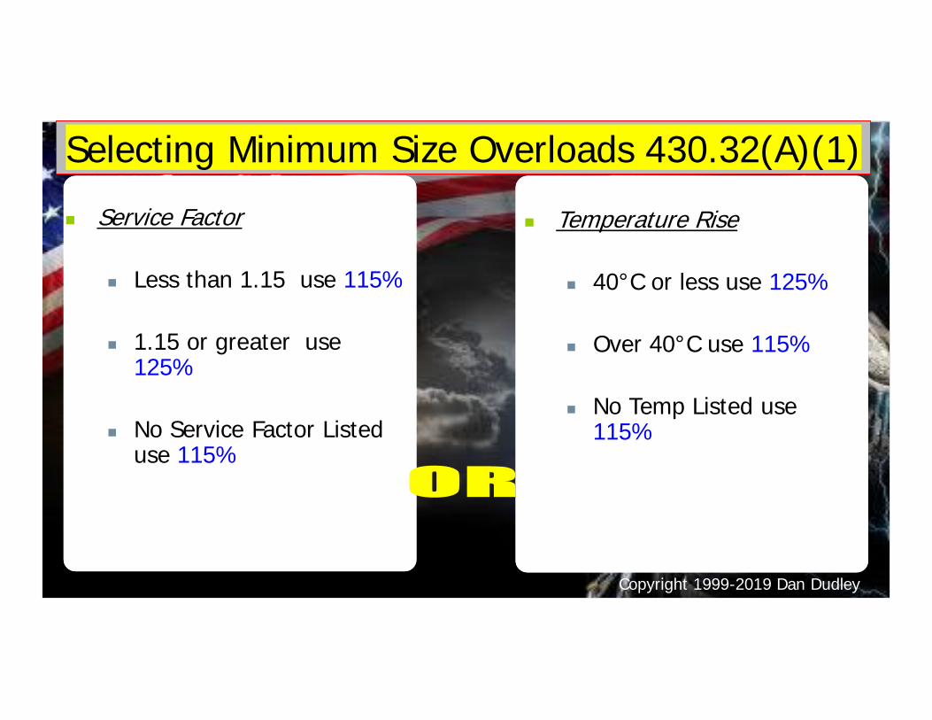
Selecting Minimum Size Overloads 430.32(A)(1)n Service Factor
n Less than 1.15 use 115%
n 1.15 or greater use125%
n No Service Factor Listeduse 115%
n Temperature Rise
n 40°C or less use 125%
n Over 40°C use 115%
n No Temp Listed use115%
Copyright 1999-2019 Dan Dudley
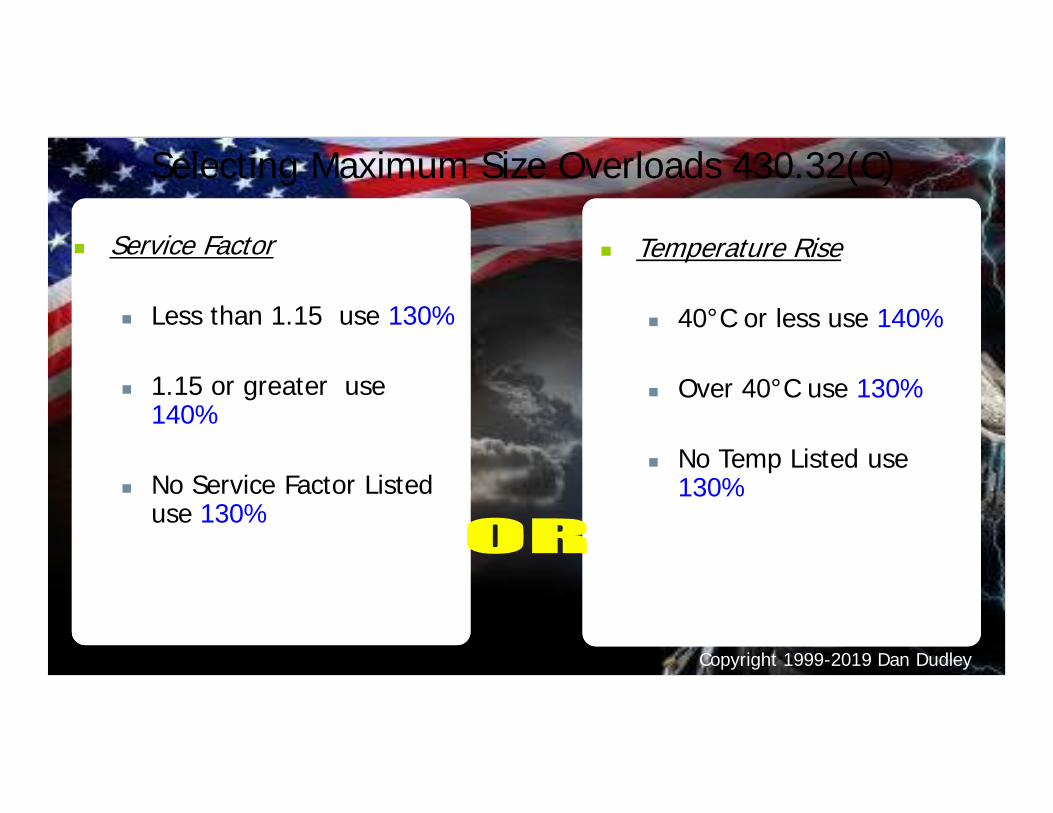
Selecting Maximum Size Overloads 430.32(C)
n Service Factor
n Less than 1.15 use 130%
n 1.15 or greater use140%
n No Service Factor Listeduse 130%
n Temperature Rise
n 40°C or less use 140%
n Over 40°C use 130%
n No Temp Listed use130%
Copyright 1999-2019 Dan Dudley
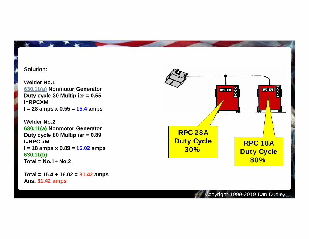
Solution:
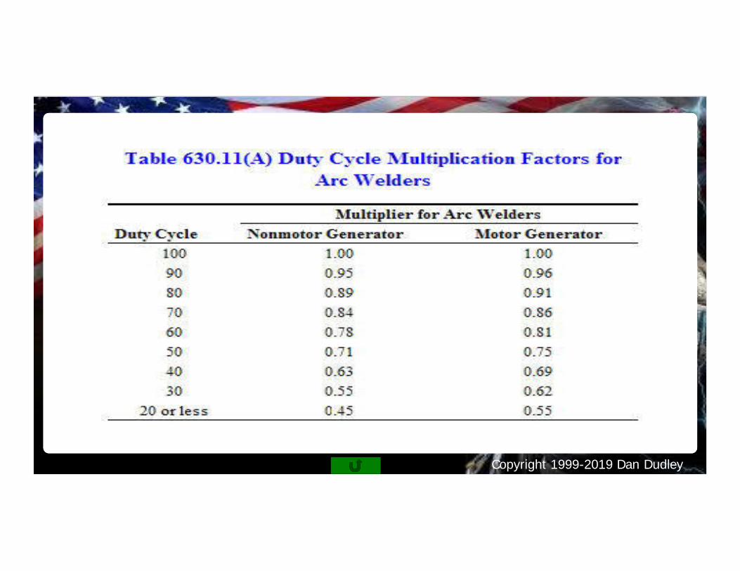
Welder No.1630.11(a) Nonmotor GeneratorDuty cycle 30 Multiplier = 0.55I=RPCXMI = 28 amps x 0.55 = 15.4 amps
Welder No.2630.11(a) Nonmotor GeneratorDuty cycle 80 Multiplier = 0.89I=RPC xMI = 18 amps x 0.89 = 16.02 amps630.11(b)Total = No.1+ No.2
Total = 15.4 + 16.02 = 31.42 ampsAns. 31.42 amps
RPC 28ADuty Cycle
30%RPC 18A
Duty Cycle80%
Motors with a Duty Cycle - Welders
Copyright 1999-2019 Dan Dudley
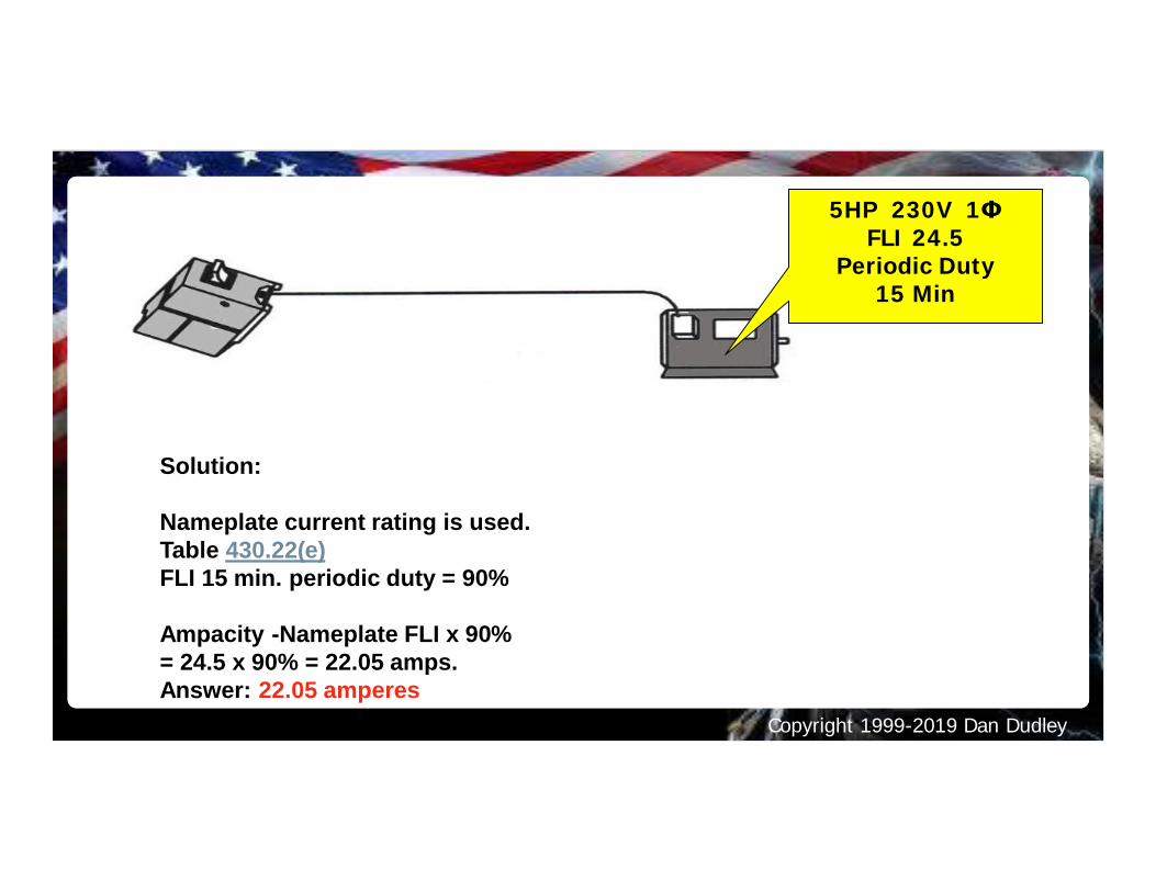
Solution:
Nameplate current rating is used.Table 430.22(e)FLI 15 min. periodic duty = 90%
Ampacity -Nameplate FLI x 90%= 24.5 x 90% = 22.05 amps.Answer: 22.05 amperes
5HP 230V 1ΦFLI 24.5
Periodic Duty15 Min
Copyright 1999-2019 Dan Dudley
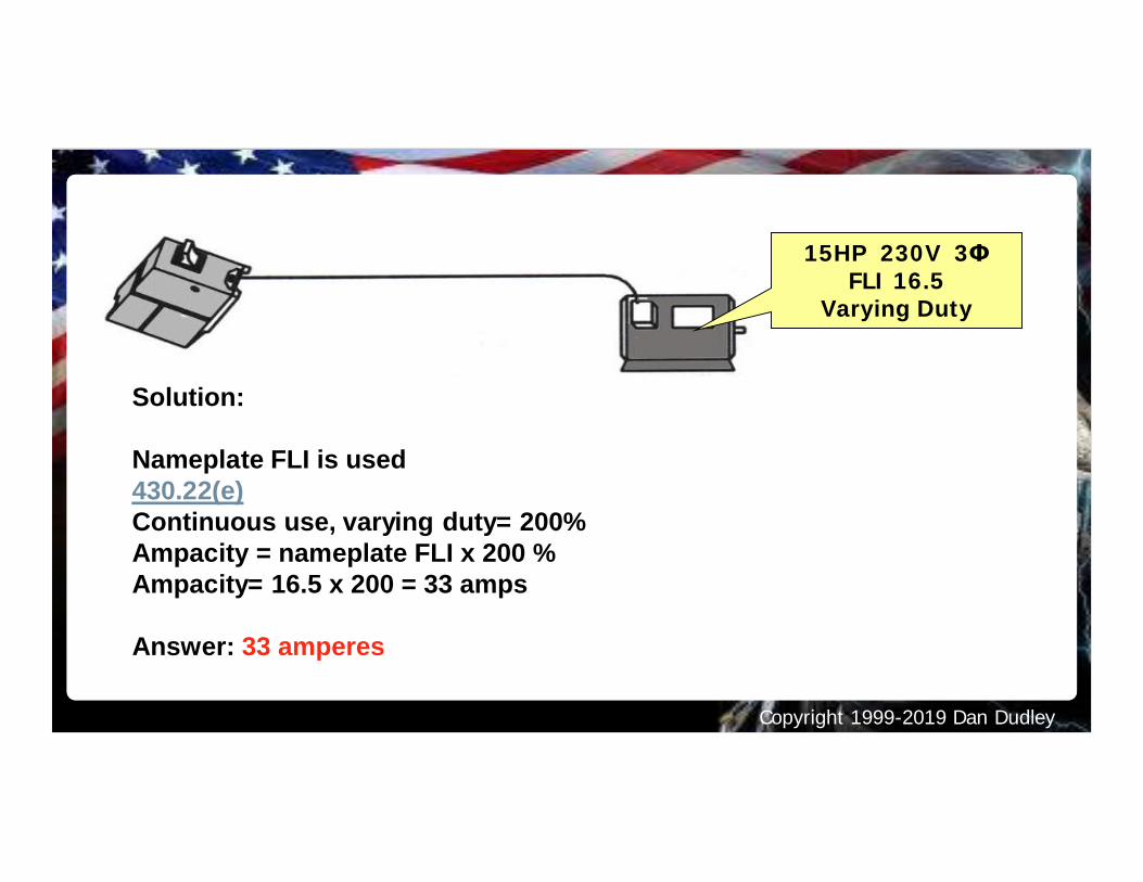
Solution:
Nameplate FLI is used430.22(e)Continuous use, varying duty= 200%Ampacity = nameplate FLI x 200 %Ampacity= 16.5 x 200 = 33 amps
Answer: 33 amperes
15HP 230V 3ΦFLI 16.5
Varying Duty
Copyright 1999-2019 Dan Dudley
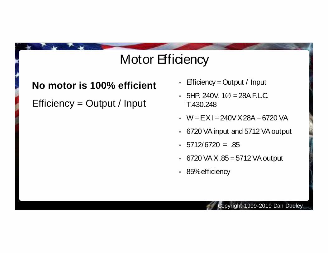
Motor Efficiency• Efficiency = Output / Input
• 5HP, 240V, 1Æ = 28A F.L.C.T.430.248
• W = E X I = 240V X 28A = 6720 VA
• 6720 VA input and 5712 VA output
• 5712/6720 = .85
• 6720 VA X .85 = 5712 VA output
• 85% efficiency
No motor is 100% efficient
Efficiency = Output / Input
Copyright 1999-2019 Dan Dudley
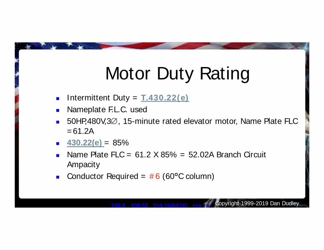
Motor Duty Ratingn Intermittent Duty = T.430.22(e)n Nameplate F.L.C. usedn 50HP,480V,3Æ, 15-minute rated elevator motor, Name Plate FLC
=61.2An 430.22(e) = 85%n Name Plate FLC = 61.2 X 85% = 52.02A Branch Circuit
Ampacityn Conductor Required = #6 (60°C column)
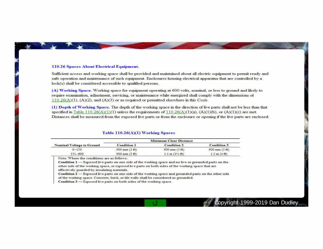
240.6 310.15(b)(16) 110.14430.52

Copyright 1999-2019 Dan Dudley
Motor CalculationsPractice Questions
30 Minutes
Copyright 1999-2019 Dan Dudley
Copyright 1999-2019 Dan Dudley
Copyright 1999-2019 Dan Dudley25-208 50 sync – 440 200 - 480
Copyright 1999-2019 Dan Dudley
Copyright 1999-2019 Dan Dudley
Copyright 1999-2019 Dan Dudley
Copyright 1999-2019 Dan Dudley

Copyright 1999-2019 Dan Dudley
Copyright 1999-2019 Dan Dudley
Copyright 1999-2019 Dan Dudley
Copyright 1999-2019 Dan Dudley
Copyright 1999-2019 Dan Dudley
Copyright 1999-2019 Dan Dudley
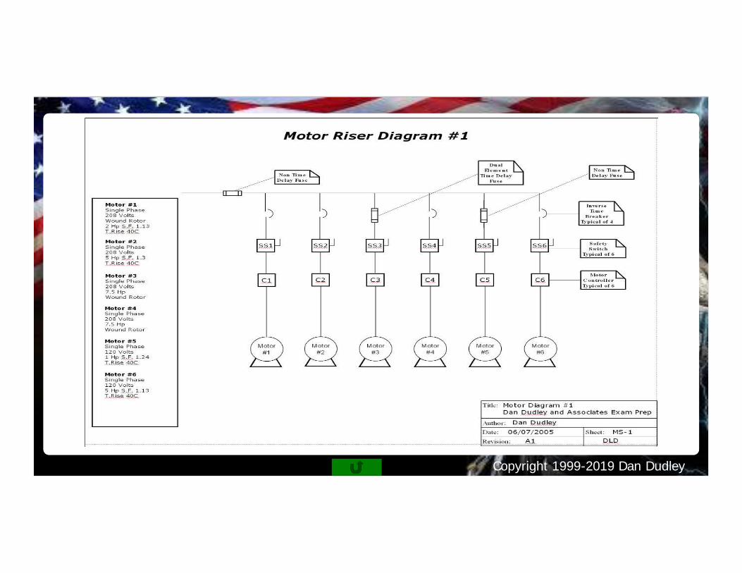
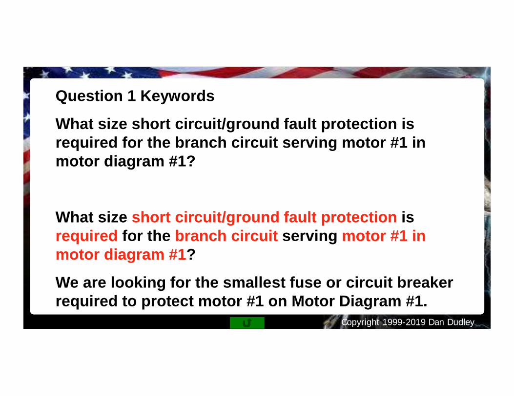
Question 1 Keywords
What size short circuit/ground fault protection isrequired for the branch circuit serving motor #1 inmotor diagram #1?
What size short circuit/ground fault protection isrequired for the branch circuit serving motor #1 inmotor diagram #1?
We are looking for the smallest fuse or circuit breakerrequired to protect motor #1 on Motor Diagram #1.
Copyright 1999-2019 Dan Dudley
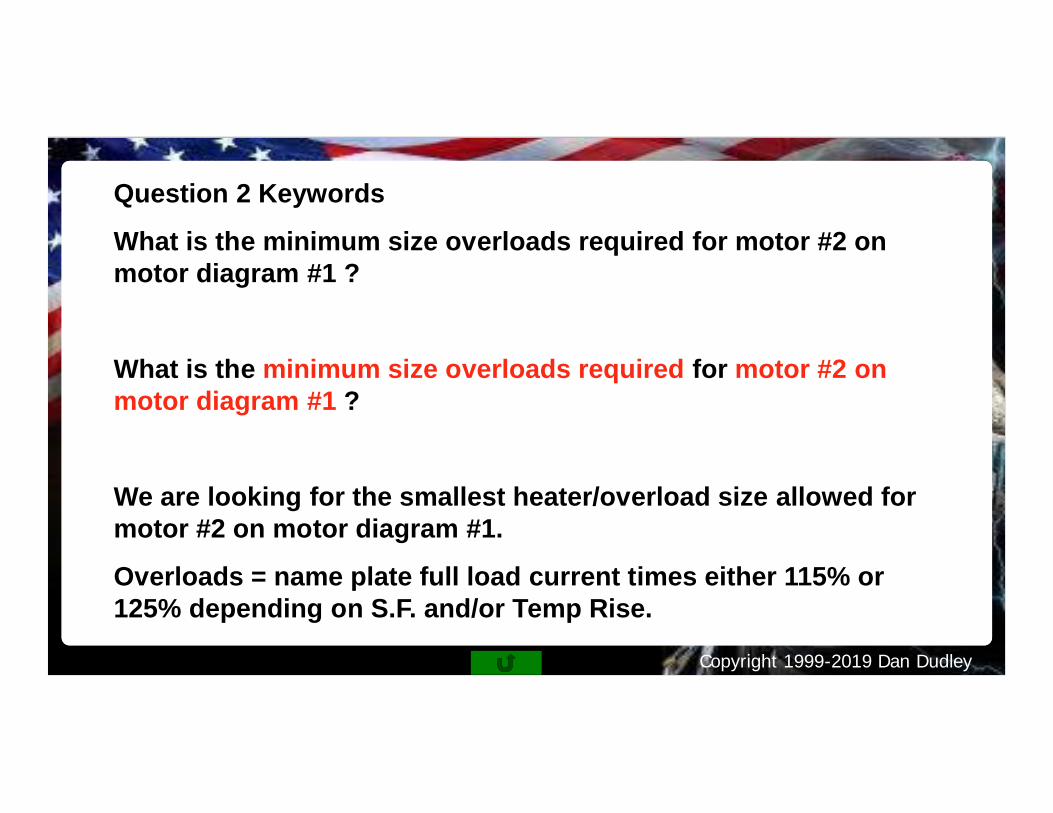
Question 2 Keywords
What is the minimum size overloads required for motor #2 onmotor diagram #1 ?
What is the minimum size overloads required for motor #2 onmotor diagram #1 ?
We are looking for the smallest heater/overload size allowed formotor #2 on motor diagram #1.
Overloads = name plate full load current times either 115% or125% depending on S.F. and/or Temp Rise.
Copyright 1999-2019 Dan Dudley
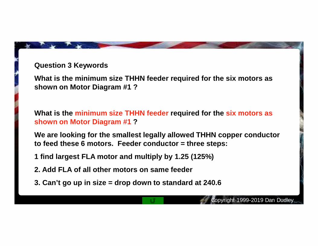
Question 3 Keywords
What is the minimum size THHN feeder required for the six motors asshown on Motor Diagram #1 ?
What is the minimum size THHN feeder required for the six motors asshown on Motor Diagram #1 ?
We are looking for the smallest legally allowed THHN copper conductorto feed these 6 motors. Feeder conductor = three steps:
1 find largest FLA motor and multiply by 1.25 (125%)
2. Add FLA of all other motors on same feeder
3. Can’t go up in size = drop down to standard at 240.6