Microwave-Assisted Functionalization of Carbon Nanostructures in Ionic Liquids
Upload
khangminh22Category
view
3download
0
University of Nebraska - LincolnDigitalCommons@University of Nebraska - Lincoln
NASA Publications National Aeronautics and Space Administration
2015
Molecular modelling of ionic liquids in the orderedmesoporous carbon CMK-5Xiaoxia HeCain Department of Chemical Engineering, Louisiana State University, Baton Rouge, LA
Joshua MonkCain Department of Chemical Engineering, Louisiana State University, Baton Rouge, LA
Ramesh SinghCain Department of Chemical Engineering, Louisiana State University, Baton Rouge, LA
Francisco R. HungCain Department of Chemical Engineering, Louisiana State University, Baton Rouge, LA, [email protected]
Follow this and additional works at: http://digitalcommons.unl.edu/nasapub
This Article is brought to you for free and open access by the National Aeronautics and Space Administration at DigitalCommons@University ofNebraska - Lincoln. It has been accepted for inclusion in NASA Publications by an authorized administrator of DigitalCommons@University ofNebraska - Lincoln.
He, Xiaoxia; Monk, Joshua; Singh, Ramesh; and Hung, Francisco R., "Molecular modelling of ionic liquids in the ordered mesoporouscarbon CMK-5" (2015). NASA Publications. 174.http://digitalcommons.unl.edu/nasapub/174

Molecular SiMulation, 2015http://dx.doi.org/10.1080/08927022.2015.1089992
Molecular modelling of ionic liquids in the ordered mesoporous carbon CMK-5
Xiaoxia Hea‡, Joshua Monka,b‡, Ramesh Singha§ and Francisco R. Hunga,c
acain Department of chemical engineering, louisiana State university, Baton rouge, la, uSa; bthermal Protection Materials Branch, naSa ames research center, Moffett Field, ca, uSa; ccenter for computation and technology, louisiana State university, Baton rouge, la, uSa
ABSTRACTWe performed classical molecular dynamics simulations of the ionic liquids (ILs) [dmim+][Cl−] and [emim+][NTf2
−], confined in a model CMK-5 material, which consists of amorphous carbon nanopipes (ACNPs) arranged in a hexagonal array. We compare our findings against the behaviour of the same ILs inside an isolated ACNP (i.e. no IL adsorbed on the outer surface of the ACNP) and inside a model CMK-3 material (which is similar to CMK-5, but is formed by amorphous carbon nanorods). Our results indicate that the presence of IL adsorbed in the outer surface of an uncharged ACNP in CMK-5 affects the dynamics and the density of an IL adsorbed inside the ACNP and vice versa. ILs adsorbed outside the nanopipes in CMK-5 (i.e. with IL also adsorbed inside the nanopipes) have faster dynamics and remain closer to the carbon surfaces when compared to the same ILs adsorbed on CMK-3 materials. The trends are IL-specific: [dmim+][Cl−] has slower dynamics when inside an isolated ACNP than when inside the ACNPs in CMK-5, but in contrast, [emim+][NTf2
−] moves faster when it is inside an isolated ACNP than when it is inside the ACNPs in CMK-5 (i.e. with IL adsorbed outside the nanopipes).
© 2015 taylor & Francis
KEYWORDSionic liquid; cMK-5; molecular dynamics
ARTICLE HISTORYreceived 15 May 2015 accepted 30 august 2015
CONTACT Francisco r. Hung [email protected] ‡ equal contribution.§ currrent address: South arkansas community college, el Dorado, ar 71730, uSa.
1. Introduction
Understanding the properties of ionic liquids (ILs) inside nano-pores has attracted a lot of attention in the last few years, mostly because of the relevance of ILs as electrolytes in energy-related devices such as electrochemical double-layer capacitors (EDLCs) [1–10] and dye-sensitised solar cells (DSSCs).[11–16] Molecu-lar simulations can contribute towards achieving a fundamental understanding of the properties of ILs inside nanoporous materi-als and complement experimental work in this area. A few recent review papers [17–20] (as well as references therein) provide an excellent overview of the progress in this field of research, which has literally exploded over the last few years. Most of the studies reviewed in these papers focused on electrified (charged) nano-porous electrodes, which is not surprising considering the rele-vance of these systems as electrolytes in energy storage devices. Nevertheless, a fundamental understanding of the properties of ILs inside uncharged nanoporous materials is particularly relevant to the development of novel nanomaterials based on ILs. For example, inserting ILs inside the templating nanopo-rous materials (e.g. carbon nanotubes, templated mesoporous silicas, anodic alumina membranes) is one step in the synthe-sis of optically active (fluorescent) and magnetic nanomaterials based on ILs.[21–27] These nanomaterials (dubbed ‘GUMBOS’, for Group of Uniform Materials Based on Organic Salts) have the highly tunable properties of ILs and can be prepared via simple procedures, and thus have potential applications in opto-electronics, photovoltaics, separations, analytical chemistry and
biomedicine. Furthermore, ILs confined inside sol–gels (iono-gels) have potential applications as electrolyte membranes and in optics, catalysis and biocatalysis, drug delivery and sensing and biosensing.[28–30]
Here, we report classical molecular dynamics (MD) simula-tions of two ILs, [emim+][NTf2
−] and [dmim+][Cl−] (Figure 1), inside an uncharged model of the ordered mesoporous carbon CMK-5.[31,32] This material consists of hexagonally packed nanopipes made of amorphous carbon, and thus the ILs can adsorb inside and outside the amorphous carbon nanopipes (ACNPs) (see Figure 3(d)). The ACNPs in CMK-5 have uniform diameters and exhibit thin carbon walls with corrugations and curvature, and thus, the nanopores in CMK-5 are interconnected in a regular way. We compare our results with simulations of the same ILs in another ordered mesoporous carbon, CMK-3,[31,33] of similar pore sizes. This material is very similar to CMK-5, but is made of hexagonally packed amorphous carbon nanorods (ACNRs, see Figure 3(b)). Because of their uniform structure, the ordered mesoporous carbons CMK-3 and CMK-5 are well suited for fundamental studies aimed at understanding the effects of variables such as pore size, pore geometry, sur-face roughness and pore interconnectivity on the properties of confined ILs. In addition, the ordered mesoporous carbons CMK-3 and CMK-5 have been used as electrodes in EDLCs in previous experimental studies.[34–40] We also studied the properties of the same ILs inside an isolated ACNP (i.e. no IL adsorbed on the outer surface of the ACNP, see Figure 2(d)). We
2 X. He eT AL.
mimicking a SBA-15 material.[54–56] In these simulations, the interactions between the carbon atoms were modelled using the empirical REBO potential,[57] and the carbon–silica interac-tions were accounted for using the PN-TrAZ potential.[58] If the silica nanopore is completely filled with carbon, the simu-lation protocol yields an ACNR with a diameter of 2.8 nm and a length of 10.69 nm, which is then used to prepare the model CMK-3 materials used here and in our previous study.[50] If the silica pore is only partially filled with carbon,[53] the pro-cedure yields an ACNP that exhibits inner and outer surfaces with roughness at atomic scales (Figure 2). The ACNP has an average external diameter of 2.8 nm, a length of 10.69 nm and a varying inner diameter, as can be observed in the three cross sections of this ACNP shown in Figure 2. The internal pore size distribution (PSD) of the ACNP was determined following the procedures described in the previous studies.[59–62] The PSD shown in Figure 2(c) indicates that the internal diameter of the ACNPs has an average value of approximately D = 1.5 nm and can reach values of up to 1.8 nm. The average wall thick-ness of the ACNP is equal to 0.45 nm. We estimated that the total accessible volume inside the ACNP is ~19 nm3. This value was determined by dividing the axial length of the ACNP (10.69 nm) into 40 slices of length zΔ. After that, we determined the average pore diameter DΔ for each slice, approximated the volume of each slice as a cylinder of VΔ = �D
2
ΔzΔ∕4 and added the volumes of the 40 slices. The ACNP was replicated and arranged into a periodic hexagonal pattern to form the model CMK-5 materials used here; similarly, replicas of the ACNR were arranged into a periodic hexagonal array to build our model CMK-3 materials.
Figure 3 shows the CMK-3 and CMK-5 model materials with a pore size H = 2.5 nm filled with the IL [emim+][NTf2
−]. CMK-5 model materials with a pore size H = 1.8 nm were considered for our simulations with the IL [dmim+][Cl−], in order to make direct comparisons with our previous study [50] for the same IL inside a model CMK-3 material of similar characteristics. The pore size of our CMK-3 and CMK-5 models was defined as the distance between the centres of two nearest ACNRs/ACNPs minus their outer diameter (2.8 nm) and minus the Lennard–Jones size parameter of a carbon atom (0.34 nm). The set-up used in our simulations mirrored our recent study of ILs inside a coconut shell-activated carbon model.[63] The set-up consisted of placing our model porous carbons in the centre of an orthor-hombic simulation box, while the z direction was extended to allow space for IL reservoirs at each end of the carbon model as seen in Figure 3. The x and y dimensions of the orthorhombic simulation box matched the x and y dimensions of the materials.
found significant differences in the densities and mobilities of ions in CMK-3, CMK-5 and in an isolated ACNP. Overall, our results indicate that the presence of an IL in the outer surface of an uncharged carbon nanopipe can affect the dynamics and the density of an IL adsorbed inside the carbon nanopipe and vice versa. The remainder of the paper is structured as follows: Section 2 introduces the computational methods used in these simulations. In Section 3, we present and discuss the structure and dynamics of the ILs inside our model materials, and in Sec-tion 4, we summarise and discuss our findings.
2. Methods
We performed classical MD simulations of the ILs [dmim+][Cl−] and [emim+][NTf2
−] (Figure 1), confined inside a single ACNP, and inside the model-ordered mesoporous carbons CMK-3 and CMK-5. No electrical charges were present in any of our model carbon materials. We used the GROMACS 4.5.4 MD package [41] for our calculations. The IL [emim+][NTf2
−] was modelled using the force field (FF) of Kodderman et al. [42] which can adequately reproduce experimental values of relevant physical properties such as density, heat of vaporisation, shear viscosi-ties, self-diffusion coefficients and NMR rotational correlation times.[42] For example, the bulk density of [emim+][NTf2
−] is 1.477 g/cm3 at 333 K, which is less than 1% difference from the experimental density (1.4858 g/cm3) at the same temperature.[43] The IL [dmim+][Cl−] was modelled using the FF of Lopes et al. [44,45] Although this FF has well-known shortcomings in reproducing the experimental values of properties such as heats of vaporisation, diffusivities, viscosities and ionic conduc-tivities,[46–49] we chose this FF nevertheless because we used it in our previous study of [dmim+][Cl−] inside CMK-3 model materials.[50] Moreover, in that previous study, we determined that the FF of Lopes et al. was able to give reasonable values for most experimental properties of interest for this particular IL. For example, we calculated the self-diffusivity of [dmim+][Cl−] in the bulk and found values that were in good agreement with results from previous simulation studies.[49,51] Furthermore, the simulated density of [dmim+][Cl−] is 1.132 g/cm3 at 425 K, which is less than 1% difference from the experimental density (1.1254 g/cm3) found by Fannin et al. [52]
The ACNP used to build the model CMK-5, as well as the amorphous carbon nanorod (ACNR) used in the model CMK-3 material considered here, were developed by Jain and co-workers.[53] The carbon nanorod and nanopipe were cre-ated using grand canonical Monte Carlo simulations to model the adsorption of carbon atoms into a cylindrical silica pore
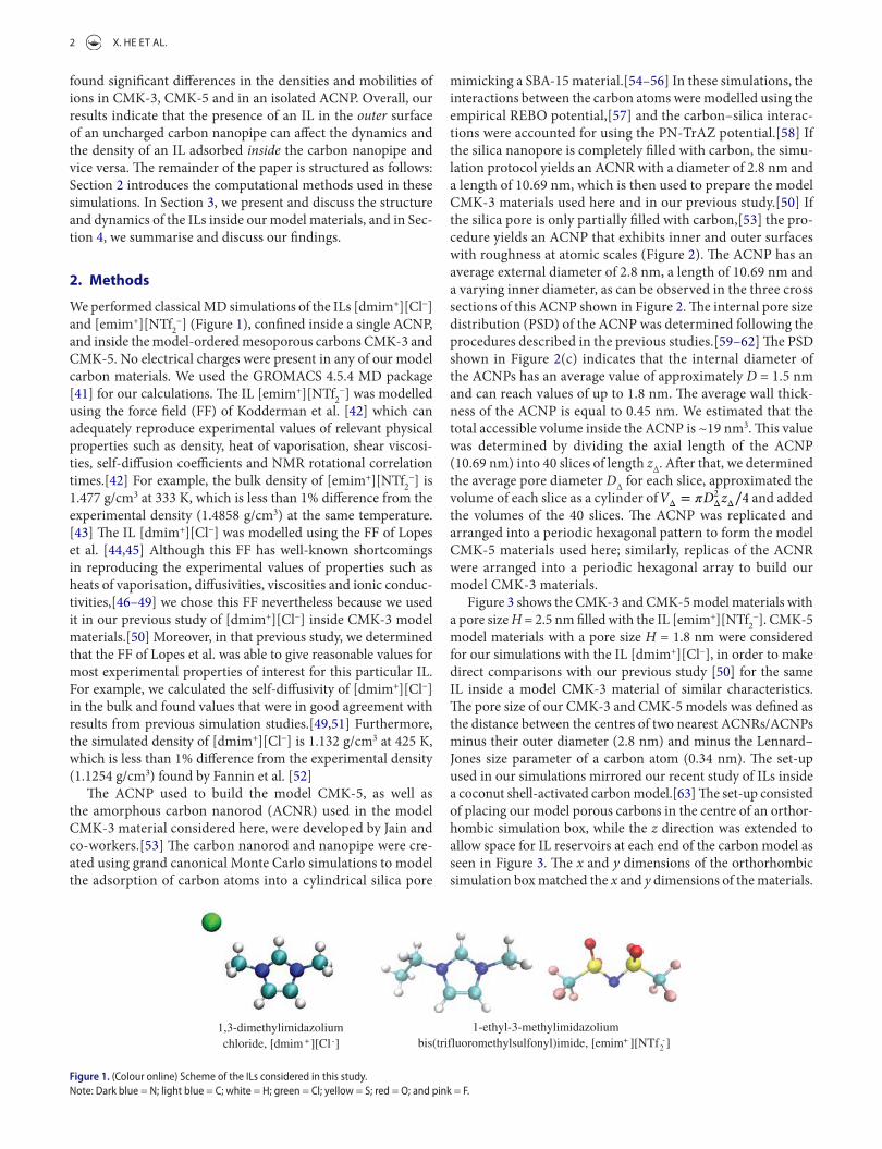
1-ethyl-3-methylimidazolium bis(trifluoromethylsulfonyl)imide, [emim+ ][NTf2
-] 1,3-dimethylimidazolium chloride, [dmim + ][Cl -]
Figure 1. (colour online) Scheme of the ils considered in this study.note: Dark blue = n; light blue = c; white = H; green = cl; yellow = S; red = o; and pink = F.

MOLeCuLAR SIMuLATION 3
Periodic boundary conditions were applied in all three directions and therefore, the ILs confined in the model CMK-3 and CMK-5 materials were periodic in the x and y directions. A representative simulation box for our systems with [emim+][NTf2
−] and CMK-5 had dimensions Lx = 7.98, Ly = 9.21 and Lz = 40.0 nm; a smaller simulation box (Lx = 7.98, Ly = 4.61 and Lz = 40.0 nm) yielded satisfactory results for the same IL within CMK-3 materials. In both cases, the pore size of our materials was H = 2.5 nm. In our simulations with [dmim+][Cl−] and CMK-5, our model material had a pore size H = 1.8 nm and the length of our ACNRs and ACNPs was 10.69 nm; for our simulations with [emim+][NTf2
−], we used ACNRs and ACNPs with shorter lengths (5.5 nm) to reduce computational costs. For our simulations with a single ACNP, we used a simulation box of dimensions Lx = 5.0, Ly = 5.0 and Lz = 40.0 nm. The ACNP was placed in the centre of this sim-ulation box and was directly connected to two reservoirs of IL at both sides in the z direction; therefore, the ACNP was surrounded by a big vacuum region in the radial direction (Figure 2(d)),
(a) (b)
(c)
z
x
(d)
0.5 1.0 1.5 2.0
Pore size (nm)
Pore
size
dist
ribu
tion
(arb
itrar
y un
its)
0.0
Figure 2. (colour online) (a) three cross sections of amorphous carbon nanopipe (acnP) filled with [dmim+][cl−], showing the non-uniform inner diameter. Here, cations and anions are coloured in purple and green. (b) Side view of an acnP filled with [dmim+][cl−]; the rectangles represent the location of the cross sections shown in (a). the total length of the acnP here is 10.69 nm. (c) internal pore size distribution (PSD) of the acnP, showing its internal diameter. (d) representative simulation snapshot of [emim+][ntf2
−] inside an isolated acnP.notes: Here, cations and anions are depicted in blue and purple; the total length of the acnP is 5.5 nm and the vertical grey lines represent carbon walls which do not allow the il to adsorb on the outer surface of the acnP (the il can only adsorb inside the acnP).
which was large enough to avoid any interactions between the adsorbed ions and their nearest periodic image in the x and y directions.
MD simulations in the canonical ensemble at 333 K were conducted for [emim+][NTf2
−] inside a single ACNP and inside the model CMK-3 and CMK-5 materials. Likewise, simulations at 425 K were performed for [dmim+][Cl−] inside a single ACNP and inside a model CMK-5 material; these results were com-pared with those obtained from our previous study of the same IL inside a model CMK-3 material.[50] The carbon atoms in our model materials were modelled as Lennard–Jones spheres with σc = 0.340 nm and εc/kB = 28.0 K. Initially, all the ions were placed in a lattice at both sides of the carbon materials in the z direction with auxiliary walls closing the entrances to the pores. The car-bon atoms in the system were kept fixed in space throughout our simulations. First, the system was subjected to an energy minimi-sation procedure using a standard steepest descent scheme. After that, the IL was melted at 600 K and subsequently annealed from

4 X. He eT AL.
density profiles of the ions outside the ACNPs in CMK-5 and outside the ACNRs in CMK-3 (Figure 4(d)). Peaks in the density profiles are observed in all cases with the number of peaks and their positions varying with pore size H and with size of the ions ([emim+], and [NTf2
−] are larger than [dmim+] and [Cl−]).In Figure 5, we show representative simulation snapshots
of [emim+] and [NTf2−] inside the CMK-3 and CMK-5 model
materials, where the atoms of each ion are coloured according to their total mobilities over a time of 10 ns. These results quali-tatively show that the ions near the amorphous carbon surfaces have lower mobility compared to that of the ions that are further away from the pore walls. In the CMK-3 systems (Figure 5(a) and (b)), the ions that are in the layers that are closer to the carbon walls have a consistent dark blue in colour indicating that their dynamics are slow and relatively homogeneous. In contrast, the ions in the layers closer to the outside surfaces of the ACNPs in CMK-5 have more mixed colours indicating that the dynamics of the ions in these layers are more heterogeneous and faster as compared to those of their counterparts in CMK-3. Spatial het-erogeneity in the dynamics is also noticeable for the ions that are further away from the carbon surfaces of CMK-3 and CMK-5. These snapshots also indicate that the ions inside the ACNPs of CMK-5 have the slowest dynamics, mainly because of the small value of the average internal diameter of the ANCPs (~1.5 nm) which subject the ions to a very large degree of confinement. Results for [dmim+][Cl−] inside CMK-3 and CMK-5 (Figure S2, Supporting Information) show trends that are qualitatively simi-lar to those observed for [emim+][NTf2
−]; however, the dynamics of [dmim+][Cl−] inside the ACNPs of CMK-5 seem to be at least qualitatively similar to those of the same ions outside the ACNPs.
600 to 333 K in three steps for 3 ns. Following this procedure, the auxiliary walls were removed and the ions can enter the carbon porous materials. Averages were accumulated over 20 ns and over at least two independent simulation runs of the same system. To make sure that our systems were properly equilibrated, in addi-tion to the monitoring standard variables (e.g. energy), we also examined the mean square displacement (MSD) and ensured that the ILs have reached the diffusive regime (Figures 6 and 7). We also monitored the time correlation functions for the rotation of the cations (data not shown for brevity) and ensured that our simulations were long enough to decorrelate the reorientation of the cations with the only exception being the cations located within the very narrow carbon nanopipes. The rest of the simu-lation details and methods are exactly the same as those used in our previous studies.[50,63–68]
3. Results and discussion
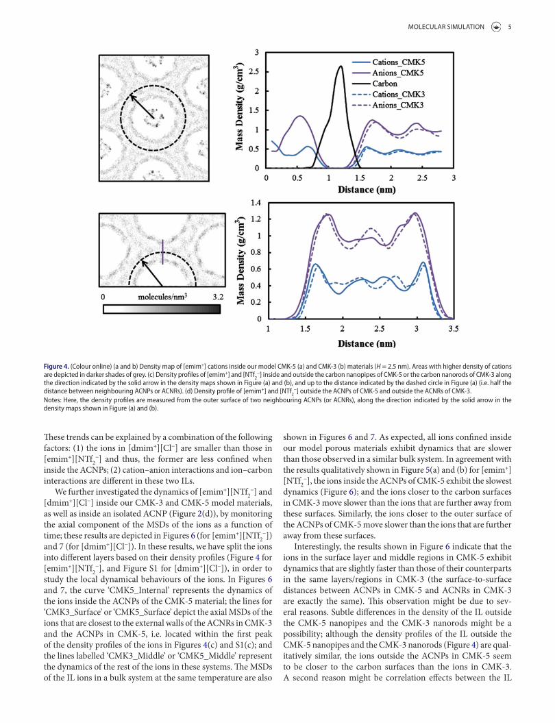
In Figure 4(a) and (b), we show density maps of [emim+] in the CMK-5 and CMK-3 model materials with H = 2.5 nm and in Figure 4(c) and (d), we show mass density profiles (in g/cm3) of [emim+] and [NTf2
−] in the same model materials (in CMK-5, the IL can be adsorbed inside and outside the ACNPs). The mass density profiles shown in Figure 4(c) and (d) were determined along the direction indicated by the solid arrow in the density maps shown in Figure 4(a) and (b). The results shown in Figure 4 are very similar to those obtained for [dmim+][Cl−] inside CMK-5 materials with H = 1.8 nm (Figure S1, Supplemental data) and inside CMK-3 materials of the same pore size (from our previous study [50]). Slight differences are observed in the
(a)
(c)
z
x
(b)
(d)
Figure 3. (colour online) representative simulation snapshots of [emim+][ntf2−] inside a model cMK-3 material (a and b), and inside a model cMK-5 material (c and d)
with a pore size H = 2.5 nm.note: the cations and anions are depicted in blue and purple; carbon atoms are represented in dark grey.
MOLeCuLAR SIMuLATION 5
shown in Figures 6 and 7. As expected, all ions confined inside our model porous materials exhibit dynamics that are slower than those observed in a similar bulk system. In agreement with the results qualitatively shown in Figure 5(a) and (b) for [emim+][NTf2
−], the ions inside the ACNPs of CMK-5 exhibit the slowest dynamics (Figure 6); and the ions closer to the carbon surfaces in CMK-3 move slower than the ions that are further away from these surfaces. Similarly, the ions closer to the outer surface of the ACNPs of CMK-5 move slower than the ions that are further away from these surfaces.
Interestingly, the results shown in Figure 6 indicate that the ions in the surface layer and middle regions in CMK-5 exhibit dynamics that are slightly faster than those of their counterparts in the same layers/regions in CMK-3 (the surface-to-surface distances between ACNPs in CMK-5 and ACNRs in CMK-3 are exactly the same). This observation might be due to sev-eral reasons. Subtle differences in the density of the IL outside the CMK-5 nanopipes and the CMK-3 nanorods might be a possibility; although the density profiles of the IL outside the CMK-5 nanopipes and the CMK-3 nanorods (Figure 4) are qual-itatively similar, the ions outside the ACNPs in CMK-5 seem to be closer to the carbon surfaces than the ions in CMK-3. A second reason might be correlation effects between the IL
These trends can be explained by a combination of the following factors: (1) the ions in [dmim+][Cl−] are smaller than those in [emim+][NTf2
−] and thus, the former are less confined when inside the ACNPs; (2) cation–anion interactions and ion–carbon interactions are different in these two ILs.
We further investigated the dynamics of [emim+][NTf2−] and
[dmim+][Cl−] inside our CMK-3 and CMK-5 model materials, as well as inside an isolated ACNP (Figure 2(d)), by monitoring the axial component of the MSDs of the ions as a function of time; these results are depicted in Figures 6 (for [emim+][NTf2
−]) and 7 (for [dmim+][Cl−]). In these results, we have split the ions into different layers based on their density profiles (Figure 4 for [emim+][NTf2
−], and Figure S1 for [dmim+][Cl−]), in order to study the local dynamical behaviours of the ions. In Figures 6 and 7, the curve ‘CMK5_Internal’ represents the dynamics of the ions inside the ACNPs of the CMK-5 material; the lines for ‘CMK3_Surface’ or ‘CMK5_Surface’ depict the axial MSDs of the ions that are closest to the external walls of the ACNRs in CMK-3 and the ACNPs in CMK-5, i.e. located within the first peak of the density profiles of the ions in Figures 4(c) and S1(c); and the lines labelled ‘CMK3_Middle’ or ‘CMK5_Middle’ represent the dynamics of the rest of the ions in these systems. The MSDs of the IL ions in a bulk system at the same temperature are also
Figure 4. (colour online) (a and b) Density map of [emim+] cations inside our model cMK-5 (a) and cMK-3 (b) materials (H = 2.5 nm). areas with higher density of cations are depicted in darker shades of grey. (c) Density profiles of [emim+] and [ntf2
−] inside and outside the carbon nanopipes of cMK-5 or the carbon nanorods of cMK-3 along the direction indicated by the solid arrow in the density maps shown in Figure (a) and (b), and up to the distance indicated by the dashed circle in Figure (a) (i.e. half the distance between neighbouring acnPs or acnrs). (d) Density profile of [emim+] and [ntf2
−] outside the acnPs of cMK-5 and outside the acnrs of cMK-3.notes: Here, the density profiles are measured from the outer surface of two neighbouring acnPs (or acnrs), along the direction indicated by the solid arrow in the density maps shown in Figure (a) and (b).

6 X. He eT AL.
the IL adsorbed in CMK-3 materials only interacts with the car-bon atoms of the ACNRs. The results depicted in Figure 7 also indicate that [dmim+] inside an isolated ACNP moves slower than the same cations inside the ACNPs in CMK-5; however, the opposite behaviour was observed for [emim+][NTf2
−] (Figure 6(a)), namely the ions inside an isolated ACNP move slightly faster than the same ions inside the ACNPs in CMK-5 (i.e. with IL adsorbed in the outer surface of the ACNPs). Furthermore, results from Figure 7 indicate that the MSD of [dmim+] inside the ACNPs in CMK-5 (average internal diameter D = 1.5 nm) is slightly larger than the average MSD of all the cations in a CMK-3 material of pore size H = 1.8 nm.
The results shown in Figures 6 and 7, and in Table 1 (self-dif-fusion coefficients in the z-direction as calculated from the MSDs shown in Figures 6 and 7) indicate that the ions adsorbed outside the ACNPs in CMK-5 have faster dynamics than the same ions adsorbed outside the ACNRs of the same external diameter in CMK-3 materials of the same pore size. Our results also show that the dynamics of an IL inside an ACNP can be significantly affected when IL is present outside the ACNP in CMK-5 materials. These observations might be due to corre-lation effects between the ILs inside and outside the ACNPs in CMK-5 (the average thickness of the carbon wall in the ACNPs is about 0.45 nm). Interactions between molecules located in neighbouring pores can act in a co-operative way and are known to induce important changes in the behaviour of con-
that is inside the CMK-5 nanopipes and the IL that is adsorbed on the outer surface of the ACNPs. We raise this issue because in Figure 6, we also report results for the axial MSD of the ions inside an isolated ACNP (i.e. no IL adsorbed outside the ACNP, Figure 2(d)). These results indicate that the ions of [emim+][NTf2
−] inside an isolated ACNP move slightly faster than the ions inside the ACNPs in CMK-5 (which have an IL adsorbed at the outer surface of the ACNPs). However, this dynamical behaviour seems to depend on the particular IL; in Figure 7, we show results similar to those presented in Figure 6(a), but now for the cations of [dmim+][Cl−] inside CMK-3 and CMK-5 materials with a pore size of H = 1.8 nm (the average internal diameter of the ACNPs is ~1.5 nm, same as in our simulations with [emim+][NTf2
−]; results for the [Cl−] anions follow the same trends as the [dmim+] and are not shown for brevity). The results shown in Figure 7 indicate that [dmim+] outside the ACNPs in CMK-5 has slightly faster dynamics than the cations outside the nanorods in a CMK-3 material of the same pore size, in analogy to what we observed for [emim+] in Figure 6(a). These results suggest that the presence of IL inside the ACNPs can accelerate the dynamics of the IL outside the ACNPs in CMK-5 with respect to those observed for the same ILs in CMK-3 mate-rials. The IL adsorbed outside the ACNPs in CMK-5 experi-ences long-range electrostatic interactions with the ions inside the ACNPs in addition to the interactions with the thin carbon walls of the ACNPs (average thickness = 0.45 nm); in contrast,
(a) (b)
(c) (d)
Lower mobility Higher mobility
Figure 5. (colour online) representative simulation snapshots of [emim+] (left) and [ntf2−] (right) inside our cMK-3 (top) and cMK-5 (bottom) model materials, H = 2.5 nm.
notes: the ions are coloured according to their displacement over a time of 10 ns. the carbon atoms in our cMK-3 and cMK-5 model materials are not shown.

MOLeCuLAR SIMuLATION 7
wall = 0.45 nm) can affect the dynamics of an IL adsorbed inside the carbon nanopipe and vice versa (as the dynamics of the ILs outside of the ACNPs in CMK-5 were found to be faster than those of the same ILs in CMK-3). Differences in the cation–anion interactions, as well as the ion–walls interactions might also cause differences in the dynamics, as [dmim+][Cl−] inside an isolated ACNP moves slower than inside the ACNPs in CMK-5 (Figure 7 and Table 1), but [emim+][NTf2
−] inside an isolated ACNP moves slightly faster than inside the ACNPs in CMK-5 (Figure 6 and Table 1).
To further explore the properties of the ions inside the ACNPs when the nanopipes have, or do not have, an IL adsorbed in their outer surface, in Figure 8, we show radial and axial density profiles of [emim+] and [NTf2
−] inside an isolated ACNP (i.e. no IL adsorbed on its outer surface, Figure 2(d)) and inside the ACNPs in CMK-5 (i.e. IL present outside the ACNPs, Figure 3(c) and (d)). The radial density profiles for [dmim+][Cl−] inside an isolated ACNP are included in Figure S3 (Supporting Informa-tion); similar results for the same IL, but now inside the ACNPs in CMK-5 are shown in Figure S1(c) (Supporting Information). The axial density profiles for the same IL inside an isolated ACNP and inside the ACNPs in CMK-5 are depicted in Figure 9. The peaks in the radial density profiles of the ions inside the ACNPs (Figures 8(a), S1 and S2) are closer to the carbon surfaces when IL is adsorbed in the outer surfaces of the ACNPs in CMK-5, as compared to the case of an isolated ACNP (i.e. no IL outside the ACNP). The mass density profiles of the ions inside the ACNP as a function of the axial distance, which are depicted in Figures 8(b) and 9, show a slightly non-uniform distribution of the ions that might be caused by the uneven internal diameter of the ACNP (Figure 2). The average axial density of the ions inside
fined fluids. For example, molecular simulations [69] have shown that methane inside neighbouring cylindrical pores in the zeolite AlPO4–5 can undergo a gas–liquid phase transition; however, no phase transitions are observed when methane is inside an isolated cylindrical pore of the same material and size because the pore diameter is smaller than twice the molecular diameter of methane and thus, the system is very close to the one-dimensional limit.[70] Very recently, an order–disorder transition was also observed in molecular simulations of water inside a membrane with neighbouring, narrow cylindrical pores arranged in a square lattice.[71] Kondrat et al. [72] and Péan et al. [73] indicate that ILs inside sub-nm pores can experience very fast dynamics during charging processes due to a complex interplay between factors such as confinement in very narrow pores, ion crowding, screened interactions and changes in the structure of the double layer caused by the charging process. Kondrat et al. [72] also report that tuning the interactions of the ions with the pore walls (e.g. using mixtures of ILs or by add-ing surfactants) to have ‘ionophobic’ pore surfaces can further accelerate the dynamics of the confined ions during the charging process. Our results indicate that the presence of IL in the outer surface of an uncharged ACNP (average thickness of the carbon
Figure 6. (colour online) axial component (z-direction) of the mean square displacement (MSD) of the (a) [emim+] cations and (b) [ntf2
−] anions in the model cMK-3 and cMK-5 materials, and inside an isolated amorphous carbon nanopipe (acnP).notes: the different curves depicted represent the following: ‘Bulk’ = ions in a bulk system; ‘cMK3_Surface’ or ‘cMK5_Surface’ = ions that are outside the acnrs in cMK-3 or the acnPs in cMK-5 and close to the external carbon walls of the acnrs or acnPs (i.e. located within the first peak of the density profiles of the ions in Figure (c); ‘cMK3_Middle’ or ‘cMK5_Middle’ = ions that are outside the acnrs in cMK-3 or the acnPs in cMK-5 and away from the external carbon walls of the acnrs or acnPs (i.e. located outside the first peak of the density profiles of the ions in Figure (c); ‘cMK5_internal’ = ions inside the acnPs of the cMK-5 material; ‘acnP’ = ions inside an isolated acnP.
Time (ns)
Bulk
CMK-5_Surface
CMK-5_Middle
ACNP
CMK-5 (overall, outside)
CMK-5_Internal
CMK-3 (overall)
0 2 4 6 8 0.0
0.1
0.2
0.3
0.4
0.5
0.6
0.7
0.8
Mea
n sq
uare
disp
lace
men
t (nm
2 )
Figure 7. (colour online) axial component (z-direction) of the mean square displacement (MSD) of the cations in [dmim+][cl−] in the model cMK-3 and cMK-5 materials and inside an isolated amorphous carbon nanopipe (acnP).notes: the different curves depicted represent the following: ‘Bulk’ = ions in a bulk system; ‘cMK5_Surface’ = ions that are outside the acnPs in cMK-5 and close to the external carbon walls of the acnrs or acnPs (i.e. located within the first peak of the density profiles of the ions in Figure S1(c)); ‘cMK5_Middle’ = ions that are outside the acnPs in cMK-5 and away from the external carbon walls of the acnrs or acnPs (i.e. located outside the first peak of the density profiles of the ions in Figure S1(c)); ‘cMK-5 (overall, outside)’ = all the ions that are outside the acnPs in cMK-5; ‘cMK5_internal’ = ions inside the acnPs of the cMK-5 material; ‘cMK-3 (overall)’ = all the ions that are outside the acnrs in cMK-3 and ‘acnP’ = ions inside an isolated acnP.

8 X. He eT AL.
compared to those of the bulk IL reflect the difference in the interactions between the carbon walls and [dmim+][Cl−] and [emim+][NTf2
−], which in turn also affect the dynamical behav-iour of these ILs inside our model materials (Figures 6 and 7). Differences in pore size might also play a role in these observa-tions (H = 2.5 nm for [emim+][NTf2
−], whereas H = 1.8 nm for [dmim+][Cl−]).
4. Concluding remarks
Classical MD simulations were conducted to study the structure and dynamics of the ILs [dmim+][Cl−] and [emim+][NTf2
−], con-fined inside a model CMK-5 material of pore sizes H = 1.8 and 2.5 nm, respectively. This material is formed by nanopipes made of amorphous carbon, where the nanopipes are arranged in a hex-agonal array; the ACNPs have an average diameter D = 1.5 nm
the ACNPs is slightly larger in CMK-5 (when IL is adsorbed outside the ACNPs) than inside an isolated ACNP. These results suggest that the presence of IL adsorbed in the outer surfaces of the ACNPs in CMK-5 induce changes in the density of the IL inside the ACNPs, which in turn affects the dynamics of the ions inside the ACNPs. Our previous studies [50, 63–68] indicate that variations in the amount of IL inside the nanopores can affect significantly the dynamics of the confined ions. Furthermore, the ions of [dmim+][Cl−] inside the ACNPs (both isolated and in CMK-5) seem to have average axial densities that are similar to those of the bulk IL (Figure 9). In contrast, the average axial densities of [emim+] and [NTf2
−] inside the ACNPs appear to be slightly lower than the densities of the same ions in the bulk-like reservoirs at both sides of the porous materials (Figure 8(b)). These differences in the density of the ILs inside the ACNPs as
Table 1. Diffusion coefficients for [dmim+][cl−] and [emim+][ntf2−] in the bulk and along the axial direction in our pore systems. Values inside parentheses represent the
uncertainties in our calculations.
D (× 10−7 cm2/s)
[dmim+] [Cl−] [emim+] [NTf2−]
Bulk 2.45 (0.02) 1.86 (0.05) 12.30 (0.05) 9.01 (0.04)cMK-3 (overall) 0.73 (0.03) 0.48 (0.06) 4.36 (0.03) 3.42 (0.02)cMK-3 (surface) – – 2.85 (0.02) 1.75 (0.03)cMK-3 (middle) – – 4.89 (0.03) 4.02 (0.02)cMK-5 (outside, overall) 1.04 (0.13) 0.58 (0.05) 5.92 (0.04) 4.56 (0.04)cMK-5 (outside, surface) 0.66 (0.13) 0.38 (0.03) 4.00 (0.04) 3.27 (0.03)cMK-5 (outside, middle) 1.31 (0.02) 0.75 (0.13) 6.71 (0.06) 5.35 (0.06)cMK-5 (inside) 0.82 (0.01) 0.58 (0.01) 0.76 (0.01) 0.72 (0.01)isolated acnP 0.28 (0.02) 0.20 (0.02) 1.62 (0.02) 1.11 (0.02)
Figure 8. (colour online) Mass density profiles for [emim+][ntf2−] inside the acnPs
of cMK-5 and inside a single acnP. (a) radial density profiles, and (b) axial density profiles.note: the dashed lines indicate the approximate location of the edges of the acnPs in our simulation boxes (see Figures 2(d) and 3(c)).
(a)
(b)
Axial distance (nm)
Axi
al m
ass d
ensit
y (g
/cm
3 )
0.0 0 2 4 6 8 10
0 2 4 6 8 10
0.2
0.4
0.6
0.8
1.0
1.2
1.4
1.6
1.8
Cations
Anions
Cations
Anions
0.0
0.2
0.4
0.6
0.8
1.0
1.2
1.4
1.6
1.8
Figure 9. (colour online) Mass density profiles in the axial direction for [dmim+][cl−] inside (a) an isolated acnP and (b) the acnPs in cMK-5.notes: Dotted lines are cation and anion densities in a simulated bulk il system at the same temperature.

MOLeCuLAR SIMuLATION 9
FundingThis work was partially supported by the National Science Foundation CAREER Award [CBET-1253075]; EPSCoR Cooperative Agreement [EPS-1003897]; and the Louisiana Board of Regents. High-performance compu-tational resources for this research were provided by High- Performance Computing at Louisiana State University (http://www.hpc.lsu.edu) and by the Louisiana Optical Network Initiative (http://www.loni.org).
References [1] Armand M, Endres F, MacFarlane DR, et al. Ionic-liquid materials
for the electrochemical challenges of the future. Nat. Mater. 2009;8:621–629.
[2] Arbizzani C, Biso M, Cericola D, et al. Safe, high-energy supercapacitors based on solvent-free ionic liquid electrolytes. J. Power Sources. 2008;185:1575–1579.
[3] Simon P, Gogotsi Y. Materials for electrochemical capacitors. Nat. Mater. 2008;7:845–854.
[4] Largeot C, Portet C, Chmiola J, et al. Relation between the ion size and pore size for an electric double-layer capacitor. J. Am. Chem. Soc. 2008;130:2730–2731.
[5] Lin R, Huang P, Ségalini J, et al. Solvent effect on the ion adsorption from ionic liquid electrolyte into sub-nanometer carbon pores. Electrochim. Acta. 2009;54:7025–7032.
[6] Choi NS, Chen ZH, Freunberger SA, et al. Challenges facing lithium batteries and electrical double-layer capacitors. Angew. Chem. Int. Ed. 2012;51:9994–10024.
[7] Orita A, Kamijima K, Yoshida M. Allyl-functionalized ionic liquids as electrolytes for electric double-layer capacitors. J. Power Sources. 2010;195:7471–7479.
[8] Matsumoto K, Hagiwara R. Electrochemical properties of the ionic liquid 1-ethyl-3-methylimidazolium difluorophosphate as an electrolyte for electric double-layer capacitors. J. Electrochem. Soc. 2010;157:A578–A581.
[9] Zhai YP, Dou YQ, Zhao DY, et al. Carbon materials for chemical capacitive energy storage. Adv. Mater. 2011;23:4828–4850.
[10] Chakrabarti MH, Mjalli FS, AlNashef IM, et al. Prospects of applying ionic liquids and deep eutectic solvents for renewable energy storage by means of redox flow batteries. Renew. Sustain. Energy Rev. 2014;30:254–270.
[11] Hagfeldt A, Boschloo G, Sun L, et al. Dye-sensitized solar cells. Chem. Rev. 2010;110:6595–6663.
[12] Cao Y, Zhang J, Bai Y, et al. Dye-sensitized solar cells with solvent-free ionic liquid electrolytes. J. Phys. Chem. C. 2008;112:13775–13781.
[13] Ito S, Zakeeruddin SM, Comte P, et al. Bifacial dye-sensitized solar cells based on an ionic liquid electrolyte. Nat. Photonics. 2008;2:693–698.
[14] Kuang D, Wang P, Ito S, et al. Stable mesoscopic dye-sensitized solar cells based on tetracyanoborate ionic liquid electrolyte. J. Am. Chem. Soc. 2006;128:7732–7733.
[15] Kuang D, Uchida S, Humphry-Baker R, et al. Organic dye-sensitized ionic liquid based solar cells: remarkable enhancement in performance through molecular design of indoline sensitizers. Angew. Chem. Int. Ed. 2008;47:1923–1927.
[16] MacFarlane DR, Tachikawa N, Forsyth M, et al. Energy applications of ionic liquids. Energy Environ. Sci. 2014;7:232–250.
[17] Burt R, Birkett G, Zhao XS. A review of molecular modelling of electric double layer capacitors. Phys. Chem. Chem. Phys. 2014;16:6519–6538.
[18] Fedorov MV, Kornyshev AA. Ionic liquids at electrified interfaces. Chem. Rev. 2014;114:2978–3036.
[19] Kornyshev AA, Qiao R. Three-dimensional double layers. J. Phys. Chem. C. 2014;118:18285–18290.
[20] Ike IS, Sigalas I, Iyuke S, et al. An overview of mathematical modeling of electrochemical supercapacitors/ultracapacitors. J. Power Sources. 2015;273:264–277.
[21] Tesfai AE-Z, Bwambok B, Baker DK, et al. Controllable formation of ionic liquid micro- and nanoparticles via a melt-emulsion-quench approach. Nano Lett. 2008;8:897–901.
and an average wall thickness of 0.45 nm. In CMK-5, the ILs can be adsorbed inside and outside the ACNPs (Figure 3(d)). Our findings were compared against similar results observed for the same ILs inside an isolated ACNP (i.e. no IL adsorbed on the outer surface of the ACNP) and inside a model CMK-3-ordered mesoporous carbon of similar pore size. CMK-3 is very similar to CMK-5, but is made of hexagonally packed ACNRs (see Figure 3(b)). No electrical charges were present in any of these carbon materials. Our results indicate that the presence of IL adsorbed in the outer surface of an uncharged carbon nanopipe can affect significantly the dynamics and the density of an IL adsorbed inside the carbon nanopipe and vice versa. Both of the ILs examined here have faster dynamics when they are adsorbed outside the ACNPs in CMK-5 (i.e. with IL inside the ACNPs) than when they are in CMK-3 materials of the same pore size. Radial density profiles indicate that the ions prefer to remain closer to the carbon walls in CMK-5 than in CMK-3, possibly due to the presence of ions inside and outside the thin walls of the ACNPs (average wall thickness = 0.45 nm). The average axial density of both ILs inside the ACNPs is slightly larger in CMK-5 (when IL is adsorbed out-side the ACNPs) than inside an isolated ACNP. These results sug-gest that the presence of IL adsorbed in the outer surfaces of the ACNPs in CMK-5 induces changes in the density of the IL inside the ACNPs. The presence of IL adsorbed outside the ACNPs also affects the dynamics of the IL inside the ACNPs; [dmim+][Cl−] inside an isolated ACNP has slower dynamics than when inside the ACNPs in CMK-5 (i.e. with IL adsorbed outside the ACNPs), but in contrast, [emim+][NTf2
−] inside an isolated ACNP moves faster than when inside the ACNPs in CMK-5. Furthermore, the average axial density of [dmim+][Cl−] inside the ACNPs (both isolated and in CMK-5) seems to be similar to that of the same IL in the bulk, whereas [emim+][NTf2
−] inside the ACNPs has an average axial density that is slightly lower than that of the bulk IL. These results strongly suggest that the interactions between the ions and the pore walls significantly influence the structure and dynamics of the ILs in these systems. Overall, our results suggest the presence of correlation effects between the IL inside and outside the ACNPs in CMK-5. Interactions between mole-cules located in neighbouring pores can act in a cooperative way and are known to induce important changes in the behaviour of several nonpolar and polar fluids inside nanopores.[70,71] Cor-relation effects might play an important role in determining the macroscopic properties of the electrical double-layer near charged surfaces [25,26]; these effects deserve further investigation in fol-low-up studies.
AcknowledgementsWe thank Surendra K. Jain, Benoit Coasne (CNRS/MIT), Roland J.-M. Pellenq (CNRS/MIT) and Keith E. Gubbins (NC State University) for giving us access to their model CMK-5 material. We are also grateful to Jeremy C. Palmer (University of Houston) for allowing us to use his code to calculate pore size distributions in the amorphous carbon structures.
Supplemental dataSupplemental data for this article can be accessed here http://dx.doi.org/ 10.1080/08927022.2015.1089992.

10 X. He eT AL.
[46] Dommert F, Wendler K, Berger R, et al. Force fields for studying the structure and dynamics of ionic liquids: a critical review of recent developments. ChemPhysChem. 2012;13:1625–1637.
[47] Maginn, EJ. Molecular simulation of ionic liquids: current status and future opportunities. J. Phys.-Condes. Matter 2009;21:373101.
[48] Borodin O. Polarizable force field development and molecular dynamics simulations of ionic liquids. J. Phys. Chem. B. 2009;113: 11463–11478.
[49] Bhargava, BL, Balasubramanian S. Dynamics in a room-temperature ionic liquid: a computer simulation study of 1,3-dimethylimidazolium chloride. J. Chem. Phys. 2005;123: 144505.
[50] Monk J, Singh R, Hung FR. Effects of pore size and pore loading on the properties of ionic liquids confined inside nanoporous CMK-3 carbon materials. J. Phys. Chem. C. 2011;115:3034–3042.
[51] Kowsari MH, Alavi S, Ashrafizaadeh M, et al. Molecular dynamics simulation of imidazolium-based ionic liquids. I. Dynamics and diffusion coefficient. J. Chem. Phys. 2008;129:224508.
[52] Fannin AA, Floreani DA, King LA, et al. Properties of 1,3-dialkylimidazolium chloride-aluminum chloride ionic liquids. 2. Phase transitions, densities, electrical conductivities, and viscosities. J. Chem. Phys. 1984;88:2614–2621.
[53] Jain, SK. Molecular modeling of microporous and templated mesoporous carbons [PhD thesis]. ACS Nano, North Carolina State University; 2008. (http://www.lib.ncsu.edu/resolver/1840.16/4386).
[54] Hung FR, Bhattacharya S, Coasne B, et al. Argon and krypton adsorption on templated mesoporous silicas: molecular simulation and experiment. Adsorption. 2007;13:425–437.
[55] Coasne B, Hung FR, Pellenq RJM, et al. Adsorption of simple gases in MCM-41 materials: the role of surface roughness. Langmuir. 2005;22:194–202.
[56] Bhattacharya S, Coasne B, Hung FR, et al. Modeling micelle-templated mesoporous material SBA-15: atomistic model and gas adsorption studies. Langmuir. 2009;25:5802–5813.
[57] Brenner DW. Empirical potential for hydrocarbons for use in simulating the chemical vapor deposition of diamond films. Phys. Rev. B. 1990;42:9458–9471.
[58] Pellenq RJM, Nicholson D. Intermolecular potential function for the physical adsorption of rare gases in silicalite. J. Phys. Chem. 1994;98:13339–13349.
[59] Gelb LD, Gubbins KE. Pore size distributions in porous glasses: a computer simulation study. Langmuir. 1998;15:305–308.
[60] Thomson KT, Gubbins KE. Modeling structural morphology of microporous carbons by reverse Monte Carlo. Langmuir. 2000;16:5761–5773.
[61] Turner CH, Pikunic J, Gubbins KE. Influence of chemical and physical surface heterogeneity on chemical reaction equilibria in carbon micropores. Mol. Phys. 2001;99:1991–2001.
[62] Palmer JC, Brennan JK, Hurley MM, et al. Detailed structural models for activated carbons from molecular simulation. Carbon. 2009;47:2904–2913.
[63] Rajput NN, Monk J, Hung FR. Ionic liquids confined in a realistic activated carbon model: a molecular simulation study. J. Phys. Chem. C. 2014;118:1540–1553.
[64] Singh R, Monk J, Hung FR. A computational study of the behavior of the ionic liquid [BMIM+][PF6-] confined inside multi-walled carbon nanotubes. J. Phys. Chem. C. 2010;114:15478–15485.
[65] Singh R, Monk J, Hung FR. Heterogeneity in the dynamics of the ionic liquid BMIM(+). PF(6)(−). Confined in a slit nanopore. J. Phys. Chem. C. 2011;115:16544–16554.
[66] Rajput NN, Monk J, Singh R, et al. On the influence of pore size and pore loading on structural and dynamical heterogeneities of an ionic liquid confined in a slit nanopore. J. Phys. Chem. C. 2012;116:5169–5181.
[67] Rajput NN, Monk J, Hung FR. Structure and dynamics of an ionic liquid confined inside a charged slit graphitic nanopore. J. Phys. Chem. C. 2012;116:14504–14513.
[22] Tesfai A, El-Zahab B, Kelley AT, et al. Magnetic and nonmagnetic nanoparticles from a group of uniform materials based on organic salts. ACS Nano. 2009;3:3244–3250.
[23] Bwambok DK, El-Zahab B, Challa SK, et al. Near-infrared fluorescent NanoGUMBOS for biomedical imaging. ACS Nano. 2009;3:3854–3860.
[24] Das S, Bwambok D, El-Zahab B, et al. Nontemplated approach to tuning the spectral properties of cyanine-based fluorescent NanoGUMBOS. Langmuir. 2010;26:12867–12876.
[25] Dumke JC, El-Zahab B, Challa S, et al. Lanthanide-based luminescent NanoGUMBOS. Langmuir. 2010;26:15599–15603.
[26] de Rooy SL, El-Zahab B, Li M, et al. Fluorescent one-dimensional nanostructures from a group of uniform materials based on organic salts. Chem. Commun. 2011;47:8916–8918.
[27] Regmi BP, Monk J, El-Zahab B, et al. A novel composite film for detection and molecular weight determination of organic vapors. J. Mater. Chem. 2012;22:13732–13741.
[28] Le Bideau J, Viau L, Vioux A. Ionogels, ionic liquid based hybrid materials. Chem. Soc. Rev. 2011;40:907–925.
[29] Lunstroot K, Driesen K, Nockemann P, et al. Lanthanide-doped luminescent ionogels. Dalton Trans. 2009;298–306. doi:10.1039/b812292j.
[30] Néouze, MA, Bideau, JL, Gaveau P, et al. Ionogels, new materials arising from the confinement of ionic liquids within silica-derived networks. J. Chem. Phys. 2006;18:3931–3936.
[31] Lu AH, Schüth F. Nanocasting: a versatile strategy for creating nanostructured porous materials. Adv. Mater. 2006;18: 1793–1805.
[32] Joo SH, Choi SJ, Oh I, et al. Ordered nanoporous arrays of carbon supporting high dispersions of platinum nanoparticles. Nature. 2001;412:169–172.
[33] Jun S, Joo SH, Ryoo R, et al. Synthesis of new, nanoporous carbon with hexagonally ordered mesostructure. J. Am. Chem. Soc. 2000;122:10712–10713.
[34] Lee J, Yoon S, Hyeon T, et al. Synthesis of a new mesoporous carbon and its application to electrochemical double-layer capacitors. Chem. Commun. 1999;2177–2178. doi:10.1039/a906872d.
[35] Joo SH, Choi SJ, Oh I, et al. Correction: ordered nanoporous arrays of carbon supporting high dispersions of platinum nanoparticles. Nature. 2001;414:470–470.
[36] Fuertes AB, Pico F, Rojo JM. Influence of pore structure on electric double-layer capacitance of template mesoporous carbons. J. Power Sources. 2004;133:329–336.
[37] Lee J, Kim J, Hyeon T. Recent progress in the synthesis of porous carbon materials. Adv. Mater. 2006;18:2073–2094.
[38] Su DS, Schlögl R. Nanostructured carbon and carbon nanocomposites for electrochemical energy storage applications. ChemSusChem. 2010;3:136–168.
[39] Zhang LL, Zhao XS. Carbon-based materials as supercapacitor electrodes. Chem. Soc. Rev. 2009;38:2520–2531.
[40] Liu C, Li F, Ma LP, et al. Advanced materials for energy storage. Adv. Mater. 2010;22:E28–E62.
[41] Hess B, Kutzner C, van der Spoel D, et al. GROMACS 4: algorithms for highly efficient, load-balanced, and scalable molecular simulation. J. Chem. Theory Comput. 2008;4:435–447.
[42] Köddermann T, Paschek D, Ludwig R. Molecular dynamic simulations of ionic liquids: a reliable description of structure, thermodynamics and dynamics. ChemPhysChem. 2007;8:2464–2470.
[43] Fredlake CP, Crosthwaite JM, Hert DG, et al. Thermophysical properties of imidazolium-based ionic liquids. J. Chem. Eng. Data. 2004;49:954–964.
[44] Canongia Lopes JNC, Deschamps J, Pádua AAH. Modeling ionic liquids using a systematic all-atom force field. J. Phys. Chem. B. 2004;108:2038–2047.
[45] Canongia Lopes JNC, Pádua AAH, Shimizu K. Molecular force field for ionic liquids IV: trialkylimidazolium and alkoxycarbonyl-imidazolium cations; alkylsulfonate and alkylsulfate anions. J. Phys. Chem. B. 2008;112:5039–5046.

MOLeCuLAR SIMuLATION 11
[71] Menzl G, Köfinger J, Dellago C. Phase transition and interpore correlations of water in nanopore membranes. Phys. Rev. Lett. 2012;109:020602.
[72] Kondrat S, Wu P, Qiao R, et al. Accelerating charging dynamics in subnanometre pores. Nat. Mater. 2014;13:387–393.
[73] Péan C, Merlet C, Rotenberg B, et al. On the dynamics of charging in nanoporous carbon-based supercapacitors. ACS Nano. 2014;8:1576–1583.
[68] Singh R, Rajput NN, He X, et al. Molecular dynamics simulations of the ionic liquid [EMIM+][TFMSI−] confined inside rutile (110) slit nanopores. Phys. Chem. Chem. Phys. 2013;15:16090–16103.
[69] Radhakrishnan R, Gubbins KE. Quasi-one-dimensional phase transitions in nanopores: pore-pore correlation effects. Phys. Rev. Lett. 1997;79:2847–2850.
[70] Peterson BK, Gubbins KE, Heffelfinger GS, et al. Lennard-Jones fluids in cylindrical pores: nonlocal theory and computer simulation. J. Chem. Phys. 1988;88:6487–6500.
Copyright © 2022 FDOKUMEN