MODEL ANSWER
26
MAHARASHTRA STATE BOARD OF TECHNICAL EDUCATION (Autonomous) (ISO/IEC - 27001 - 2005 Certified) __________________________________________________________________________________________________ Page No. 1 of 26 MODEL ANSWER SUMMER– 17 EXAMINATION Sub ject Title: Automotive Electrical & Electronics Systems Subject Code: Important Instructions to examiners: 1) The answers should be examined by key words and not as word-to-word as given in the model answer scheme. 2) The model answer and the answer written by candidate may vary but the examiner may try to assess the understanding level of the candidate. 3) The language errors such as grammatical, spelling errors should not be given more Importance (Not applicable for subject English and Communication Skills. 4) While assessing figures, examiner may give credit for principal components indicated in the figure. The figures drawn by candidate and model answer may vary. The examiner may give credit for any equivalent figure drawn. 5) Credits may be given step wise for numerical problems. In some cases, the assumed constant values may vary and there may be some difference in the candidate’s answers and model answer. 6) In case of some questions credit may be given by judgement on part of examiner of relevant answer based on candidate’s understanding. 7) For programming language papers, credit may be given to any other program based on equivalent concept. Q. No. Sub Q. N. Answer Marking Scheme 1. a) Attempt any THREE of the following. 12 i) State the purpose of following electrical components. 1 Relays 2 Solenoid 4 Answer: i) Relays: 1. Purpose of relay is to control a load circuit with the use of small current carrying control circuit. 2. It saves the size of wiring connected to the switch/es and reduces weight. ii) Solenoid: 1. Purpose of a solenoid is to control a larger current carrying circuit with use of small current carrying circuit. 2. It converts electrical energy into mechanical movement of core. 2 2 ii) Define battery rating and enlist its types. 4 Answer: ( Definition: 2 marks, any four Types: 2 marks) Battery ratings: It is a measure of the energy stored in the battery. It is expressed in terms of the period during which the battery will give the rated current before it reaches the specified final voltage. 2 17617
-
Upload
khangminh22 -
Category
Documents
-
view
1 -
download
0
Transcript of MODEL ANSWER

MAHARASHTRA STATE BOARD OF TECHNICAL EDUCATION (Autonomous)
(ISO/IEC - 27001 - 2005 Certified)
__________________________________________________________________________________________________
Page No. 1 of 26
MODEL ANSWER SUMMER– 17 EXAMINATION Subject Title: Automotive Electrical & Electronics Systems Subject Code:
Important Instructions to examiners: 1) The answers should be examined by key words and not as word-to-word as given in the model answer
scheme. 2) The model answer and the answer written by candidate may vary but the examiner may try to assess the
understanding level of the candidate. 3) The language errors such as grammatical, spelling errors should not be given more Importance (Not
applicable for subject English and Communication Skills. 4) While assessing figures, examiner may give credit for principal components indicated in the figure. The
figures drawn by candidate and model answer may vary. The examiner may give credit for any equivalent figure drawn.
5) Credits may be given step wise for numerical problems. In some cases, the assumed constant values may vary and there may be some difference in the candidate’s answers and model answer.
6) In case of some questions credit may be given by judgement on part of examiner of relevant answer based on candidate’s understanding.
7) For programming language papers, credit may be given to any other program based on equivalent concept.
Q. No.
Sub Q. N.
Answer Marking Scheme
1. a) Attempt any THREE of the following. 12
i) State the purpose of following electrical components. 1 Relays 2 Solenoid
4
Answer: i) Relays:
1. Purpose of relay is to control a load circuit with the use of small current carrying
control circuit.
2. It saves the size of wiring connected to the switch/es and reduces weight.
ii) Solenoid:
1. Purpose of a solenoid is to control a larger current carrying circuit with use of
small current carrying circuit.
2. It converts electrical energy into mechanical movement of core.
2
2
ii) Define battery rating and enlist its types. 4
Answer: ( Definition: 2 marks, any four Types: 2 marks)
Battery ratings: It is a measure of the energy stored in the battery. It is expressed in terms of the period during which the battery will give the rated current before it reaches the specified final voltage.
2
17617

MAHARASHTRA STATE BOARD OF TECHNICAL EDUCATION (Autonomous)
(ISO/IEC - 27001 - 2005 Certified)
__________________________________________________________________________________________________
Page No. 2 of 26
Types of Battery ratings (any four)
1) Ampere-hours (A-h) 2) Cranking amperes (CA) 3) Cold cranking amperes (CCA). 4) Hot cranking amperes (HCA) 5) Reserve capacity minutes (RCM).
2
iii) State types and functions of starter drives. 4
Answer: ( Types : 2 marks , functions:- 2 marks)
Types of Starter Drives: (any four)
1) Bendix drive
2) Folo-thru drive
3) Barrel type drive
4) Gear reduction drive
5) Overrunning clutch
6) Dyer drive
7) Friction clutch drive
Function of starter drives :(Any two)
To transmit the turning force to the engine when the starting motor runs and to disconnect the starting motor from the engine immediately after the engine has started and
To provide a gear reduction ratio between the starting motor and the engine.
When the engine starts and is running under its own power, the ring gear attempts to drive the pinion gear faster than the starter motor. Thus to protects the starter motor from getting driven by the started engine, vehicle need starter drive. It is necessary to avoid damage of starter motor while engine is running, hence drives are used.
It ensures the starter motor engagement while cranking, and immediate disengagement upon engine starting. This prevents the engine from driving and damaging the starter.
2
2
iv) List four components of conventional ignition system and state their functions. 4
Answer: (List : 2 marks, Functions: 1/2 marks)
Components of ignition system:(any four)
i. Ignition Coil.
ii. Distributor.
iii. Spark Plug.
iv. Condenser
Functions: i) Ignition Coil: An ignition coil (also called a spark coil) is an induction coil in an automobile's
2
2

MAHARASHTRA STATE BOARD OF TECHNICAL EDUCATION (Autonomous)
(ISO/IEC - 27001 - 2005 Certified)
__________________________________________________________________________________________________
Page No. 3 of 26
ignition system which transforms the battery's low voltage (6 to 12 volts) to the thousands
of volts needed to create an electric spark in the spark plugs to ignite the fuel.
ii) Distributor:
To interrupt the flow of current through the primary winding so that a high voltage is
produced in the secondary winding.
To distribute the high voltage surge to different plugs at the right moment.
iii) Spark Plug:
Purpose of spark plug is to provide an arc to ignite the air fuel mixture within the
combustion chamber of a SI engine.
iv) Condenser:
The condenser is used to prevent the arc action in case of ignition system with
distributor contact points. Also improve the life of contact breaker points.
b) Attempt any ONE of the following 6
i) Draw the sketch of speedometer gauge and describe its construction and working. 6
Answer: ( construction & working: 3marks, sketch: 3 marks)
Mechanical Speedometer: The speedometer is driven from the transmission output shaft by a set of gears. The driven gear fastens to a flexible shaft or speedometer cable. It runs from the transmission output shaft to the back of the speedometer head. Inside the speedometer, the cable turns a shaft with a small magnet on it. The rotating magnetic field produces a varying pull on the metal ring surrounding the magnet. A pointer is attached to the metal ring. As the magnetic field spins, it causes the ring to overcome a light spring and swing with the magnetic field. This moves the pointer which then indicates car speed. The faster the vehicle speed, the faster the magnet spins, and the farther the pointer moves.
3
3

MAHARASHTRA STATE BOARD OF TECHNICAL EDUCATION (Autonomous)
(ISO/IEC - 27001 - 2005 Certified)
__________________________________________________________________________________________________
Page No. 4 of 26
OR Electrical / Electronic Speedometer: The electronic Speedometer receives voltage signal from the vehicle speed sensor (VSS). This sensor can be a PM generator, Hall effect sensor or Optical sensor. Such speedometer operates using conventional speedometer cable. The cable rotates a slotted wheel between a light-emitting diode (LED) and a phototransistor. As the slots in the wheel break the light, the transistor conducts an electronic pulse signal to the speedometer. An integrated circuit rectifies the analog input signal from the optical sensor and counts the pulses per second. The value is calculated into kilometers per hour and displayed in the digital readout. The display is updated every ½ second.
3
3
ii) State precaution to be taken while charging of lead acid battery. 6
Answer: Precautions during charging of lead acid battery: (any six)
1. Always follow manufacturer’s instructions.
2. Before placing a battery on charge, ensure that the terminals are clean
3. Verify that the electrolyte level is proper in all the cells. If not, add enough distilled water
to cover the plates.
4. Remember to wear eye protection and gloves.
5. If battery has vent plugs, the same are removed along with exhaust tube.
6. Connect the charger to the battery, observing proper polarity- the positive charger lead to
the positive battery post and the negative charger lead to the negative post. Make sure the
connections are tight.
7. Turn the charger on and slowly increase the charging rate until the recommended ampere
value is reached.
6

MAHARASHTRA STATE BOARD OF TECHNICAL EDUCATION (Autonomous)
(ISO/IEC - 27001 - 2005 Certified)
__________________________________________________________________________________________________
Page No. 5 of 26
8. Charging should be done in a well-ventilated area, away from sparks and open flames.
9. During charging, the battery electrolyte temperature should be monitored. If the
temperature reaches 54°C, then discontinue charging. Resume charging after allowing the
battery to cool to 45°C.
10. The charger should be off before connecting or disconnecting the leads to the battery.
When the battery is charged, turn the charger off and disconnect it.
11. Do not add additional electrolyte to the battery, during recharging. If electrolyte level is
low, add only distilled water.
12. If there is any evidence of smoke or dense vapour or liquid coming out of the battery,
shut off the charger. The battery should be rejected or the charging rate reduced or
temporarily halted.
2 Attempt any FOUR of the following. 16
a) State the types and function of switches. 4
Answer: ( Types: 2 marks, Functions of any switches: 2 marks)
Types of switches:(any four)
1. Single Pole Single Throw (SPST)
2. Single Pole Double Throw (SPDT)
3. Double Pole, Double Throw (DPDT)
4. Ganged Switch
5. Mercury switch
Function of switches:(any two)
1. Single Pole Single Throw (SPST)
It is switch that only has a single input and can connect only to one output .it serves in circuit as
on-off switches. When the switch is closed, the circuit is on .when the switch is open, the
circuit is off.
2. Single Pole Double Throw (SPDT)
A Single Pole Double Throw (SPDT) switch is a switch that only has a single input and can connect to and switch between 2 outputs. This means it has one input terminal and two output terminals.
3. Double Pole, Double Throw (DPDT)
It can control two separate circuits, but are always switched together by a single actuator.
4. Ganged Switch
A number of circuits can be controlled simultaneously. Ganged switches are frequently used in
application where the motion of switch is needed to control more than one circuit.
5. Mercury switch
2
2

MAHARASHTRA STATE BOARD OF TECHNICAL EDUCATION (Autonomous)
(ISO/IEC - 27001 - 2005 Certified)
__________________________________________________________________________________________________
Page No. 6 of 26
It opens and closes a circuit when a small amount of liquid metal mercury connects metal
electrodes to close the circuit.
b) List the various circuit defects and describe short circuit with suitable sketch. 4
Answer: (List: 2 Marks, Description & Sketch: 2)
Types of circuit defects.
i. Open Circuit
ii. Short Circuit
iii. Short to ground
iv. Resistance in connection ( Voltage Drop)
Short circuit defects: (Student should explain with any one similar simple sketch)
When the feed or switch wires insulation is damaged and the conductor touches the metal
frame, some or all of the current will take this ‘easy’ path to earth. This alternative path offers
the current a short path back to the battery, so the term SHORT CIRCUIT is used to describe
this condition.
The extent of the short-to-earth, i.e. the resistance of the alternative path, governs the
potential difference that is left to act on the lamp in figure. As the resistance in the short circuit
path is reduced, the potential difference across the lamp is also reduced so the effect of the
voltage reduction will be a proportional decrease in the lamp brightness.
A dead short describes a very low resistance path to the earth. When this occurs, the very
high current flow that results will soon make the cable glow red-hot. This melts the plastic
covering of the cable and often starts a fire. Some circuit – protection device such as a fuse is
needed if this danger is to be avoided.
2
2

MAHARASHTRA STATE BOARD OF TECHNICAL EDUCATION (Autonomous)
(ISO/IEC - 27001 - 2005 Certified)
__________________________________________________________________________________________________
Page No. 7 of 26
OR
c) Describe the current draw test. 4
Answer: (Description - 4 marks, credit may be given to sketch, if drawn)
The current draw test measures the amount of current the starter draws when actuated. It
determines the electrical and mechanical condition of the starting system.
Starting System Current draw test procedure:
1. Connect the large red and black test leads on the battery posts, observing polarity.
2. Zero the ammeter of VAT (Volt amp. tester).
3. Connect the ampere inductive probe around the battery ground cable. If more than one
ground cable is used, clamp the probe around all of them.
4. Make sure all loads are turned off (lights, radio and so on).
5. Disable the ignition system to prevent the vehicle from starting. This may be done by
removing the ignition coil secondary wire from the distributor cap and putting it to
ground OR by removing the ignition system fuse / fuel pump fuse / PCM fuse, OR by
disconnecting the primary wires from the coils of an EI system.
6. Crank the engine and note the voltmeter reading. Never crank the engine for more than
15 seconds
7. Read the ammeter scale to determine the amount of current draw.
4

MAHARASHTRA STATE BOARD OF TECHNICAL EDUCATION (Autonomous)
(ISO/IEC - 27001 - 2005 Certified)
__________________________________________________________________________________________________
Page No. 8 of 26
d) Draw the wiring diagram of power window circuit and explain its working. 4
Answer: (Diagram - 2 marks, working- 2 marks ,credit given to equivalent diagram)
Working of Power window circuit:
Major components of a typical Power windows system are – master control switch, individual window control switches, lock switch and the window drive motors as shown in figure. A permanent magnet motor operates each power window. Each motor raises or lowers the glass when voltage is applied to it. The direction that the motor moves the glass is determined by the supply voltage. The motors are permanent magnet reversible DC motors The master control switch provides overall system control. A lock switch is safety device to prevent children from opening the windows without the driver’s knowledge. Circuit breakers are generally used on power windows to open the circuit if an overload occurs. Without a circuit breaker to open, the motor may be damaged trying to move the window against the ice. As ice is removed, the breaker will cool, close and allow future window operation.
2
2

MAHARASHTRA STATE BOARD OF TECHNICAL EDUCATION (Autonomous)
(ISO/IEC - 27001 - 2005 Certified)
__________________________________________________________________________________________________
Page No. 9 of 26
e) Enlist functions of fuses and maxi fuses used in automobile. Draw neat labeled sketch of
cartridge fuse.
4
Answer:(Functions -1 marks each & sketch 2 marks)
Fuses:
A fuse is the most common circuit protection device. A fuse is placed in an electrical circuit so
that, when current flow exceeds the rating of the fuse, it blows or blows out i.e. it is designed
to turn off the circuit that it protects.
Maxi-Fuse:
Maxi-Fuse is a fast-acting blade fuse, standard for vehicle circuit protection. Designed to
Provide predictable time delay and low heat dissipation. Color-coded for easy identification of
fuse ratings.
Cartridge fuse:
1
1
2
f) Draw the block diagram of starting system and describe its working 4
Answer: (Working- 2 mark, Equivalent circuit diagram – 2.)
Working:
The Electric Starter Motor converts electrical current into rotary motion. In doing so converts
electrical energy into mechanical energy. The interaction of two magnetic fields produces this
rotational force. The field coils (either electromagnetic or permanent) located in the housing
produce magnetic flux lines. Within the stationary field coils is the armature, a loop of wire
(conductor) with one end connected to B+, the other to B-. When current is applied to the
armature flux lines circle the loop in one direction on one side and in the opposite direction on
the other side. The interaction of the flux lines on the armature and the flux lines from the field
coil cause the armature to rotate. The armature will only rotate to the point where the
magnetic force is equal on both sides. (Armature 90o to magnetic flux lines of field) For the
armature to continue to rotate, the polarity or direction of current flow must be reversed.
Through the brushes and the commutator, the current flow is reversed as the magnetic forces
become equal, causing the armature to continue to rotate. This constant reversal of current
flow in the armature provides continual rotation.
2

MAHARASHTRA STATE BOARD OF TECHNICAL EDUCATION (Autonomous)
(ISO/IEC - 27001 - 2005 Certified)
__________________________________________________________________________________________________
Page No. 10 of 26
2
3 Attempt any FOUR of the following: 16
a) List the common antitheft systems used in car. Describe any one. 4
Answer-(list -2 marks, describe any one -2 marks)
Following are the common anti theft systems used in car: Three basic types of antitheft devices are available: locking devices, disabling devices, and alarm systems. i. Locks and keys ii. Passkey Systems iii. Keyless Entry Systems iv. Alarm Systems Anti-theft system: (any one) An anti-theft system is any device or method used to prevent or deter the unauthorized appropriation of items considered valuable. Anti-theft systems have been around since individuals began stealing other people's property and have evolved accordingly to thwart increasingly complex methods of theft. From the invention of the first lock and key to the introduction of RFID tags and biometric identification, anti-theft systems have evolved to match the introduction of new inventions to society and the resulting theft of them by others. a) Locks and keys: Locks are designed to deny entry to the engine, passenger, and trunk compartments of the car as well as to prevent a thief from driving the car away. Most locks deny entry by moving a mechanical block between the vehicle's body and the door. Latches and keys simply move those blocks. b) Passkey Systems The passkey is a specially designed key, or transponder, that is selected and programmed just for the vehicle for which it was intended. Although another key may fit into the ignition switch or door lock, the system does not allow the engine to start without the correct electrical signal from the key. c) Keyless Entry Systems
2
2

MAHARASHTRA STATE BOARD OF TECHNICAL EDUCATION (Autonomous)
(ISO/IEC - 27001 - 2005 Certified)
__________________________________________________________________________________________________
Page No. 11 of 26
A keyless entry system allows the driver to unlock the doors or trunk lid from outside of the vehicle without using a key. It has two main components: an electronic control module and a coded-button keypad on the driver's door or a key fob d) Alarm Systems: The two methods for activating alarm systems are passive and active. Passive systems switch on automatically when the ignition key is removed or the doors are locked. They are often more effective than active systems. Active systems are activated manually with a key fob transmitter, keypad, key, or toggle switch.
b) State the Purpose of OBD-II .Define the term Drive Cycle. 4
Answer- (Purpose –2marks, Define the term -2marks)
Purposes of OBD-II: (any four) 1. To enable the computer systems to monitor the ability of systems and components to maintain low emission. 2. The standardized data link connector, that allows for these tools to communicate with the PCM. 3. Identifying faults in the computer-controlled systems and to notify the driver by means of a malfunction indicator light if the emission related fault causes an increase in emission up to 1.5 times the allowable standard. 4. In addition a diagnostic trouble code (DTC) was stored in the computer`s memory. 5. For easier diagnosis of a problem by a technician by using added information stored in the PCM. 6. It brings standardization in components and systems used by various automobile manufacturers. e.g. Data link connectors, data circuits, diagnostic tests and diagnostic trouble codes and generic codes. 7. It provides almost complete engine control and also monitors parts of the chassis, body and accessory devices, as well as the diagnostic control network of a vehicle. Drive Cycle: A drive cycle may be defined as an engine startup and vehicle operation that allows the PCM to enter closed loop and allows all the monitors to complete their function.
OR An OBD- II drive cycle is a method of driving that begins with an engine starts. The engine is then run until the system goes into closed loop. The drive cycle continues to include whatever specific operating conditions are necessary either to initiate and complete a specific monitoring sequence or to verify a symptom or verify a repair
2
2
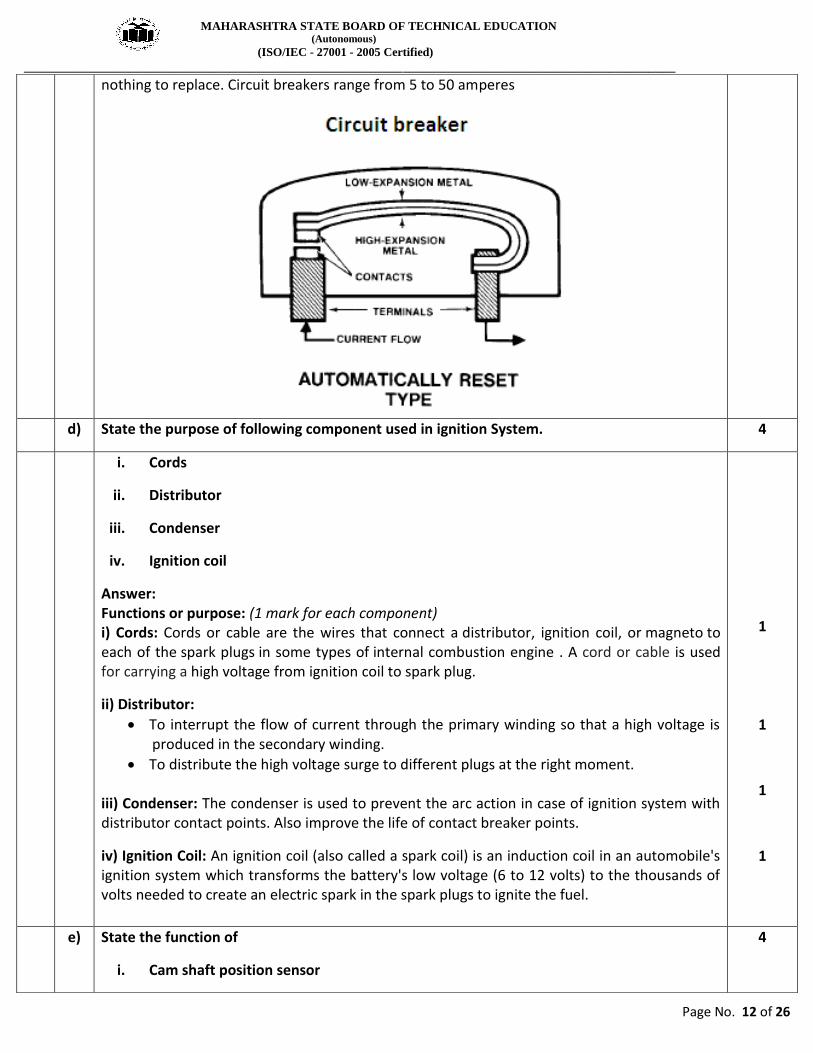
c) Describe working of automatic resetting type circuit breaker with neat sketch. 4
Answer: (Sketch – 2 Marks & Working -2 Marks) The automatic resetting type circuit breaker is designed to open when circuit current exceeds a given level. It uses a bimetallic strip that opens if current draw is excessive.
Automatic Resetting type of Circuit breakers- Automatic resetting type of circuit breaker uses a thermally sensitive element (bimetal strip) that snaps open the contact points when overheated by excessive amperage. But after a short cooling-down period, the circuit breaker resets itself. The bimetal strip has two metals of different coefficient of expansion. There is
MAHARASHTRA STATE BOARD OF TECHNICAL EDUCATION (Autonomous)
(ISO/IEC - 27001 - 2005 Certified)
__________________________________________________________________________________________________
Page No. 12 of 26
nothing to replace. Circuit breakers range from 5 to 50 amperes
d) State the purpose of following component used in ignition System. 4
i. Cords
ii. Distributor
iii. Condenser
iv. Ignition coil
Answer: Functions or purpose: (1 mark for each component) i) Cords: Cords or cable are the wires that connect a distributor, ignition coil, or magneto to each of the spark plugs in some types of internal combustion engine . A cord or cable is used for carrying a high voltage from ignition coil to spark plug.
ii) Distributor:
To interrupt the flow of current through the primary winding so that a high voltage is produced in the secondary winding.
To distribute the high voltage surge to different plugs at the right moment. iii) Condenser: The condenser is used to prevent the arc action in case of ignition system with distributor contact points. Also improve the life of contact breaker points.
iv) Ignition Coil: An ignition coil (also called a spark coil) is an induction coil in an automobile's ignition system which transforms the battery's low voltage (6 to 12 volts) to the thousands of volts needed to create an electric spark in the spark plugs to ignite the fuel.
1
1
1
1
e) State the function of
i. Cam shaft position sensor
4

MAHARASHTRA STATE BOARD OF TECHNICAL EDUCATION (Autonomous)
(ISO/IEC - 27001 - 2005 Certified)
__________________________________________________________________________________________________
Page No. 13 of 26
ii. Cylinder Identification sensor
Answer- (function of each sensor carry 2 marks)
i) Function of the Camshaft Sensor: 1. The camshaft sensor informs the PCM of the camshaft position relative to the crankshaft. By monitoring the camshaft position, the PCM remains informed as to the timing of the opening and closing of the intake valves. By monitoring the camshaft sensor and comparing it with the crankshaft sensor, the PCM knows when each cylinder is approaching top dead center and where the valves are positioned. ii) Cylinder Identification sensor: The function of cylinder identification sensor used in ignition system is to detect the position of the engine camshaft. Camshaft position is used to identify when piston 1 is 26° before top dead center (BTDC) of its compression stroke. The DIS module uses the CID signal to select the proper coil to fire. It uses a Hall-effect pickup.
2
2
4 a) Attempt any THREE of the following: 16
i) Describe the operation of automatic door lock system. 4
Answer: (Description- 4 marks & credit should be given to sketch) Operation of automatic door lock system: Motors used in power door locks are of permanent magnet type and are operated through a relay by conventional switches. These motors are controlled by a double pole double throw switch that is externally grounded. A clockwise rotation of the motor output shaft extends the shaft to unlock the door. When polarity is reversed, the output shaft rotates anticlockwise retracting the shaft to lock the doors. The purpose of automatic door lock system is to prevent entry to engine, passenger and trunk compartments of the car as well as to prevent a thief from driving the car away. The automatic door lock system is an additional safety and convenience system. The system may use the body computer to control the door lock relays, or a separate
controller. The controller (or body computer) takes the place of the door lock switches for
automatic operation.
4

MAHARASHTRA STATE BOARD OF TECHNICAL EDUCATION (Autonomous)
(ISO/IEC - 27001 - 2005 Certified)
__________________________________________________________________________________________________
Page No. 14 of 26
ii) State the salient features of keyless entry system 4
Answer: (Any 4 points 4 Marks) 1. The keyless entry system allows the driver to unlock the doors or trunk lid from outside the vehicle without using a key. 2. The main components of the keyless entry system include: 1) A control module 2) A coded button keypad located on the driver’s door 3) Door lock motors 3. The keypad consists of five normally open, single-poles, and single-throw switches. Each switch represents two numbers 1-2, 3-4, 5-6, 7-8, 9-0. 4. The keypad is wired into the circuit to provide input to the control module. The control module is programmed to lock the doors with door lock motors when the 7-8, and 9-0 switches are closed at the same time. 5. The driver’s door can be unlocked by entering a five-digit code through the keypad. 6. Remote controlled keyless entry systems are also available. They use a hand held transmitter attached as a key chain. 7. It can be operated within a range of 25 to 50 feet and from any direction. The operating is done by a button press, then driver door is unlocked, theft security is disarmed. During exit, lock button locks all doors.
4
iii) Describe the working of intake air temperature sensor 4
Answer: (Description- 4 marks & credit should be given to sketch) The IAT is used to measure the temperature of air which is coming in to the engine. According to the temperature ECU monitor the fuel delivery and spark occurring in the cylinder. It also works on the principle of thermistor which states when the temperature of heating element or thermistor is changed, it changes its resistance.
4

MAHARASHTRA STATE BOARD OF TECHNICAL EDUCATION (Autonomous)
(ISO/IEC - 27001 - 2005 Certified)
__________________________________________________________________________________________________
Page No. 15 of 26
A heating element is used in this sensor which is located at the passage of intake air. When the air passes from these elements, it generates high or less resistance according to the temperature. This generated resistance is sent to the ECU which gives the output to the fuel sensor and spark plug to work according to it. It is always used with the manifold absolute pressure sensor and mass flow sensor.
Intake air temperature sensor
iv) Describe DTC structure as detected by SAE J-2012 4
Answer-( Description-2 marks,sketch-2marks) SAE J-2012 (Diagnostic Trouble Codes) defines a set of diagnostic trouble codes (DTCs) where industry uniformity has been achieved. DTCs (five digits) consist of an alpha character followed by four characters. The first digit of the code indicates if the DTC is generic or manufacturer specific. A “0” indicates the code is generic while a “1” indicates it is manufacturer specific. The second digit indicates the vehicle the vehicle system that generated the fault code.
2
2

MAHARASHTRA STATE BOARD OF TECHNICAL EDUCATION (Autonomous)
(ISO/IEC - 27001 - 2005 Certified)
__________________________________________________________________________________________________
Page No. 16 of 26
b) Attempt any ONE of the following: 6
i) Describe the working of alternator with neat Sketch. 6
Answer: (working- 3 marks Diagram - 3 marks. Credit should be given to an equivalent sketch ) Working of alternator As alternator gets drive from the engine, rotor provides rotating magnetic field. The conductors in the stator are subjected to changing magnetic field. Due to change in magnetic field, associated with the stator windings AC is generated. This AC current is rectified using power diodes. The alternator receives current for excitation from battery. The alternator output is regulated by a voltage regulator and it is connected to battery using a diode trio.
3
3

MAHARASHTRA STATE BOARD OF TECHNICAL EDUCATION (Autonomous)
(ISO/IEC - 27001 - 2005 Certified)
__________________________________________________________________________________________________
Page No. 17 of 26
ii) How are the hydrometer and digital voltmeter used to check the state of charge of automobile battery?
6
Answer-
Checking the state of charge of automobile battery by hydrometer (3 marks)
1) Remove all battery vent caps. 2) Check the electrolyte level. It must be high enough to withdraw the correct amount of
solution into hydrometer. 3) Squeeze the bulb and place the pick-up tube into the electrolyte of a cell. 4) Slowly release the rubber bulb. Draw in enough solution until the float is freely
suspended in the barrel. Hold the hydrometer in vertical position. 5) The float rises and specific gravity is read where the float scale intersects the top of the
solution. 6) The reading must also be compensated for temperature.
OR
Checking the state of charge of automobile battery by Digital voltmeter (3 marks)
Procedure to measure the battery's state of charge with the help of digital voltmeter as follow. Digital meter is easier to read and will give you a more accurate reading.
1) First, make sure the ignition key is off, and all the vehicle's lights are off. 2) To check your battery's state of charge, connect the red or positive voltmeter test lead
to your battery positive terminal. 3) The positive terminal will be marked with a plus symbol (+), and the battery cable that
is connected to the positive terminal is often color coded red. 4) Connect the black or negative voltmeter test lead to your battery negative terminal. 5) The negative terminal will be marked with a minus symbol (-), and the battery cable
that is connected to the negative terminal is often color coded black.
3
3

MAHARASHTRA STATE BOARD OF TECHNICAL EDUCATION (Autonomous)
(ISO/IEC - 27001 - 2005 Certified)
__________________________________________________________________________________________________
Page No. 18 of 26
5 Attempt any FOUR of the following: 16
a) State the function of microprocessor used in Automotive 4
Answer: (Any four functions - 1 mark each)
Function of microprocessor in vehicle: 1. Power train and chassis control: Engine, automatic transmission, hybrid control, steering, brake, and suspension. 2. Body electronics: Instrument panel, key, door, window, lighting, air bag, seat belt. 3. Multimedia applications: Car audio, Car navigation, traffic information, electronic toll collection. 4. Integrated systems/ services: Electronic Stability control, Pre-crash safety, lane keeping assistance, parking assistance.
OR Functions of microprocessor / Microprocessor is used in management of following systems: 1. Engine and drive train control, 2. Instrumentation, ride control, 3. Antilock braking and other safety systems, 4. Entertainment 5. Heating/air conditioning control 6. Anti-theft devices 7. Automatic seat position control
4
b) Describe the operation of park assists system. 4
Answer: (Explanations - 4marks. Credit should be given to an equivalent sketch.)
Operation of park assists system:
Parking sensors make reversing into tricky/ tight spaces easier and help prevent minor damage to a vehicle. The park assist system sensors make it easier by warning when you're getting too close to something, preventing small knocks and scratches. The system has up to six ultrasonic sensors located in the rear - and sometimes the front - bumpers. Each of the sensors receives battery voltage and ground from the park assist module. Each sensor has a dedicated serial bus communication circuit to the module. The sensors monitor a range of up to 150 centimeters behind and, depending on the model, in front of the vehicle. The system comes into action when reverse gear is engaged, or at very low speed. It uses the principle of the echo sounder to detect obstacles and their distance from your car.
4

MAHARASHTRA STATE BOARD OF TECHNICAL EDUCATION (Autonomous)
(ISO/IEC - 27001 - 2005 Certified)
__________________________________________________________________________________________________
Page No. 19 of 26
The park assist system is a parking aid that alerts the driver to obstacles located in the path immediately behind the vehicle / in the path of vehicle. Ultrasonic sensors evaluate attributes of a target by interpreting the echoes from sound waves. When an object is detected, the system uses an LED display and warning chimes to provide the driver with visual and audible warning of the object’s presence. It starts to sound an intermittent warning tone which gets faster the nearer you are. The warning signal becomes continuous when the vehicle gets so close that will result in a collision.
c) What are the causes and troubles from battery overcharging and under charging? 4
Answer: (For overcharging & under charging 2 marks each)
1. Overcharging: a) If a battery is subjected to prolonged period of charging to restore it to its full charge
condition, excessive heat will be produced, which will cause the positive plates to expand & warp.
b) The swelling of positive plates takes place because the free oxygen continues to enter the positive plates even after complete conversion of lead sulphate into active material.
c) This free oxygen starts attacking the grid and gradually converts it into lead peroxide .Since lead peroxide, since lead peroxide needs more space than lead, the plates expands & push upwards, raising the cell covers.
d) Overcharging also affect the negative plates of battery. The negative plates become hard & dense.
2. Under charging:
Undercharging occurs if the battery is not receiving enough charge to return it to a full state of charge, this will slowly cause sulphation. This fault can occur if the car is being used only occasionally for short journeys.
a) During battery discharge, the active material in negative & positive plates gets converted into lead sulphate.
b) If battery is recharged without allowing it to stand in this condition, the lead sulphate will get reconverted into active material without any difficulty.
c) On the other hand, if the battery is allowed to stand in discharged condition for a longer period, the lead sulphate will become hard, which shall resist reconversion. Plates tend to expand and break the grid.
d) During this process, the negative plate becomes grayish white whereas positive plate tends to become milky white.
2
2

MAHARASHTRA STATE BOARD OF TECHNICAL EDUCATION (Autonomous)
(ISO/IEC - 27001 - 2005 Certified)
__________________________________________________________________________________________________
Page No. 20 of 26
d) Write the procedure for sound test for testing electronic fuel injector. 4
Answer: (For procedure 4 marks) Procedure for sound test for testing electronic fuel injector: The use of auto fuel injectors is a sophisticated way to provide the right fuel and air mix to an engine for a vehicle. The small cylindrical fuel injectors play a specific role in a larger fuel intake system, along with other elements like the fuel pump and the fuel tank. Over time, fuel injectors may need to be maintained or checked for proper functioning.
1) The electronic fuel injection system relies on electronic signals that control how these items operate
2) Along with checking a fuel injector electronically, you can listen for certain kinds of sounds that will tell you when a fuel injector might not be working correctly.
3) A clunking sound or similar warning sound may show that the fuel injector is not functioning the way it should.
4) If the injector electrical leads are difficult to access, an injector power balance test is hard to perform. As an alternative, start the engine and use a technician stethoscope to listen for correct injector operation.
5) A good injector makes a rhythmic clicking sound as the solenoid is energized and de energized several times each second.
6) If clunk- clunk instead of steady click-click is heard, chances are the problem injector has been found.
7) Cleaning or replacement is in order. 8) If an injector does not produce any clicking noise, the injector, connecting wires or PCM
may be defective. 9) When the injector clicking noise is erratic, the injector plunger may be sticking. 10) If there is no injector clicking noise, proceed with the injector resistance test and light
to locate the cause of problem. 11) If a stethoscope is not handy, use a thin steel rod, wooden dowel, or fingers to feel for a
steady on/off pulsing of the injector solenoid.
4
e) How alternator voltage and current output are controlled? 4
Answer: (2 marks each) Control of alternator voltage: Voltage regulator prevents the generation of excessive voltage, thus avoiding damage to the electric units and also overcharging of the battery. The voltage regulator limits the maximum voltage in the electrical system. The voltage regulator will also cause the alternator to produce more output, when voltage (pressure) at the electrical system is low. When the generator is operating (battery low or a number of devices running) its voltage may stay below that for which the control is set. When the battery is connected to the alternator, its voltage will increase until the predetermined voltage is reached. At this stage contacts of the regulator will start opening and closing to maintain required voltage. Control of alternator Current: Even though the alternator's voltage is controlled it is possible for its current to run too high. This would overheat the alternator, so a current regulator is incorporated to prevent
2
2

MAHARASHTRA STATE BOARD OF TECHNICAL EDUCATION (Autonomous)
(ISO/IEC - 27001 - 2005 Certified)
__________________________________________________________________________________________________
Page No. 21 of 26
premature failure.
Similar in appearance to the voltage regulator's iron core, the current regulator's core is wound with a few turns of heavy wire and connected in series with the alternator's armature. In operation, current flow increases to the predetermined setting of the unit. At this time, current flow through the heavy wire windings will cause the core to draw the armature down, opening the current regulator points. In order to complete the circuit the field circuit must pass through a resistor. This lowers current output, points close, output increases, points open, output down, points close, and so on. The points, therefore, vibrate open and closed much as the voltage regulator's points do, many times every second.
f) Sketch and describe the procedure for testing alternator rotor and stator. 4
Answer :( Sketch and Procedure of stator & rotor - 2 marks each; credit given to equivalent sketch) Rotor Testing: Remove the rotor from end frame 1) Extract the retainer plate screws 2) Remove the retainer plate 3) Remove the end frame bearing 4) Remove the three attaching screws & separate the stator from end frame. 5) Attach one lead of a 110 volts test lamp or an ohmmeter to either slip ring & outer lead to the rotor- shaft or poles. 6) Note down reading of ohmmeter 7) Attach lamp or ohmmeter connections to each slip ring 8) Note down reading of ohmmeter or observe the lamp light 9) Connect 12 V battery and an ohmmeter in series with the slip rings of rotor 10) Record reading of ammeter 11) Connect an ohmmeter in series with slip ring of rotor 12) Record reading of ohmmeter
2

MAHARASHTRA STATE BOARD OF TECHNICAL EDUCATION (Autonomous)
(ISO/IEC - 27001 - 2005 Certified)
__________________________________________________________________________________________________
Page No. 22 of 26
Stator Testing: 1. Connect the test lamp or ohmmeter to the stator frame & one of the stator leads. 2. Record reading of ohmmeter / lamp illumination 3. Connect the test lamp or ohmmeter between each pair of stator leads 4. Record reading of the ohmmeter / lamp illumination. If the ohmmeter reads infinity between any two of the three stator windings, the stator is open and, therefore, defective. The ohmmeter should read infinity between any stator lead and the steel laminations. If the reading is less than infinity, the stator is grounded. Stator windings can be tested if shorted because the normal resistance is very low.
2

MAHARASHTRA STATE BOARD OF TECHNICAL EDUCATION (Autonomous)
(ISO/IEC - 27001 - 2005 Certified)
__________________________________________________________________________________________________
Page No. 23 of 26
6 Attempt any FOUR of the following: 16
a) Describe construction & working of maintenance free batteries. 4
Answer: (construction- 2 marks ,working -2 marks credit should be given to sketch)
Construction & working of maintenance free (dry) batteries:
Construction: In a maintenance-free battery there is no provision for the addition of water to the cells. The battery is sealed. It contains cell plates made of a slightly different compound than what is in a conventional battery. The plate grids contain calcium, cadmium, or strontium to reduce gassing and self-discharge. Gassing is the conversion of the battery water into hydrogen and oxygen gas. This process is also called electrolysis. The antimony used in conventional batteries is not used in maintenance-free batteries because it increases the breakdown of water into hydrogen and oxygen and because of its low resistance to overcharging. The use of calcium, cadmium, or strontium reduces the amount of vaporization that takes place during normal operation. The grid may be constructed with additional supports to increase its strength and to provide a shorter path, with less resistance, for the current to flow to the top tab.
Working: The battery is sealed except for a small vent so the electrolyte and vapors cannot escape. An expansion or condensation chamber allows the water to condense and drain back into the cells. Because the water cannot escape from the battery, it is not necessary to add water to the battery on a periodic basis. Containing the vapors also reduces the possibility of corrosion and discharge through the surface because of electrolyte on the surface of the
2
2

MAHARASHTRA STATE BOARD OF TECHNICAL EDUCATION (Autonomous)
(ISO/IEC - 27001 - 2005 Certified)
__________________________________________________________________________________________________
Page No. 24 of 26
battery. Vapors leave the case only when the pressure inside the battery is greater than atmospheric pressure. Some maintenance-free batteries have a built-in hydrometer to indicate the state of charge. A hydrometer is a test instrument that is used to check the specific gravity of the electrolyte to determine the battery’s state of charge. If the dot that is at the bottom of the hydrometer is green, then the battery is fully charged (more than 65% charged). If the dot is black, the battery state of charge is low. If the battery does not have a built-in hydrometer, it cannot be tested with a hydrometer because the battery is sealed.
b) Describe working of Bendix drive and where it is used? 4
Answer: (working - 3marks, use-1 mark credit given to sketch)
Working: Bendix Drive 1. When the motor starts, the armature shaft rotates causing the sleeve to rotate and
because the pinion cannot rotate due to unbalance weight, it moves axially towards the motor till it is engaged with flywheel.
2. Further movement of the pinion is prevented by the collar attached on the sleeve and because of this pinion has to start rotating.
3. As it is also mesh with engine flywheel, the flywheel is rotated and the engine starts. 4. When the engine starts, it is flywheel that rotates the pinion and because of its bigger
size, the flywheel rotates the pinion much faster than the armature (which by now, has slowed down due to releasing of the self- starter switch) with the result that the pinion backed out of mesh with the flywheel
3

MAHARASHTRA STATE BOARD OF TECHNICAL EDUCATION (Autonomous)
(ISO/IEC - 27001 - 2005 Certified)
__________________________________________________________________________________________________
Page No. 25 of 26
Use of Bendix drive:
1 It is used to transmit the turning force to the engine when the starting motor runs and to disconnect the starting motor from the engine immediately after the engine has started.
2. In starting system of an automobile.
1
d) Differentiate between conventional and electronic ignition system. 4
Answer: (any four points)
Sr.no. Conventional ignition systems Electronic ignition systems
1. Spark timing is not depends upon speed
Proper spark timing is achieved throughout the speed range.
2. Moderate energy output from the ignition coil is obtained.
High energy output from the ignition coil is obtained.
3. Noise occurs during high speed It gives noiseless operation at high speed.
4. Some carbon deposition occurs on Spark plug electrode.
Spark plug electrode remains clean off carbon deposits & ash deposits.
5. More Emissions occurs Reduction in emission.
6. Less output power Increased output power.
4
e) Explain operation of Hall effect switch with neat sketch.
Answer: (Hall Effect- 1 mark. Explanation with sketch – 3 marks. Equivalent sketch is acceptable.)
Hall Effect: When a thin rectangular gold conductor carrying a current is crossed at right angles by a magnetic field, a difference of potential is produced at the edges of the gold conductor.
1

MAHARASHTRA STATE BOARD OF TECHNICAL EDUCATION (Autonomous)
(ISO/IEC - 27001 - 2005 Certified)
__________________________________________________________________________________________________
Page No. 26 of 26
.
Modern Hall effect units use semiconductor material e.g. silicon.
Working of Hall Effect:
The Hall Effect switch consists of a Hall unit (Silicon), a permanent magnet, and a rotating shutter wheel.
Whenever the opening of the rotating shutter wheel comes in between the Hall unit and the permanent magnet, it allows the magnetic field to strike the sensor and a small voltage is produced and is sent to the electronic control unit.
As the distributor rotates, a blocking shutter diverts the magnetic field and the current stops flowing from the sensor.
The electronic control units can be designed to either turn on or turn off the ignition coil primary current when the shutter blades are blocking.
OR
3