Microphones andLoudspeakers - GCWK
78
Microphones and Loudspeakers 1 Unit- 1 and 2 Skill Based – III Audio and Video Systems
-
Upload
khangminh22 -
Category
Documents
-
view
5 -
download
0
Transcript of Microphones andLoudspeakers - GCWK

Microphones andLoudspeakers1
Unit- 1 and 2
Skill Based – III Audio and Video Systems

Content
Loudspeakers
• Crystal Loudspeaker,• Dynamic Loudspeaker,• Electrostatic loudspeaker,• Permanent Magnet Loudspeaker,• Woofers and• Tweeters.
Microphones
• Microphone Characteristics,• Crystal Microphone,• Carbon Microphones,• Dynamic Microphones and• Wireless Microphones.
2

Introduction
3
• Consumer electronics or home electronics (i.e. analog ordigital) are equipment intended for everyday use, typically inhomes.
• Consumer electronics include devices such as
– Entertainment (flat screen TVs, DVD players, video games, remote control cars, etc.),
– Communications (telephones, cell phones, e-mail-capable laptops, etc.), and
– Home-office activities (e.g., desktop computers, printers etc.)
Component Inventor Year Application
Lou
dsp
eake
r Johann Philipp Reis
1861An electric loudspeaker installed in his telephone
Alexander Graham Bell
1876
He patented his first electric loudspeaker(capable of reproducing intelligible speech) aspart of his telephone
History
First commercial version of the speaker

Loudspeaker
Loudspeaker is a transducer
which converts an electrical
signal into sound signal.
A device that converts variations
in a physical quantity, such as
pressure or brightness, into an
electrical signal, or vice versa
called as transducer.
Eg:- Microphone, Speaker.
The lowest frequency that a humanear can hear is 20 Hz
4
SpeakerParts

Characteristics
• There are a number of interrelated factors that must be considered indesigning transducer for converting electrical energy into acoustic energy.– sound travel fastest in Steel and cannot travel through a vacuum
• These include• Electroacoustic efficiency,• Uniformity of frequency response,• Linearity of amplitude response,• Transient response,• Power handling capacity,• Size,• Durability and• Cost. 8
• Would have an electroacoustic efficiency approaching 100 per cent.• Would have an acoustic output response that is independent of
frequency over the entire audible range.• Would introduce neither harmonic nor intermodulation distortion
into its output.• Would faithfully reproduce transients as well as steady input signals.• Would be capable of producing a nondirectional radiation.
No single transducer has been designed that is capable of satisfying all theabove requirements.
IdealLoudspeaker

6
Note
• A loudspeaker must be able to reproduce a wide range of audio frequencies
(i.e., 20 Hz to 20 kHz).
• Sound wave has two main characteristics, which are Pitch and loudness
Cross SectionView

Cont.
7working

Cone
The body of the cone can be
8
paper,
carbon
black
fiber,
made from
polypropolene,
aluminum,
magnesium, etc.
titanium,
Today’s
replacement cones may or may not be
available in all materials to match the
originals.
Voice CoilIt is a set of windings wound on analuminum or other material form that fitsinto the magnetic voice coil gap.
The length of the former and length of thewindings are customized to thecomponent. It can be made using flatwound or round wound wire.
Common nominal impedances are 2, 4,6, 8, 10, 16 or 32 ohms.

Spider
The Spider fits around the speakervoice coil and is attached to thespeaker basket. It is one of thecomponents (along with the cone)that help to keep the voice coilcentered in the magnetic gap andaffects excursion (movement).
It can be soft or hard (stiffness), hasdifferent size voice coil openings,different widths and can be flat orcup shaped.
9
Terminal
The Pigtail or Tinsel Lead connectthe voice coil to the speakerTerminal.

Dustcap
The Dustcap, Dustcover or CenterDome.
It fits on top of the voice coil formerand it attaches to the cone. Itprotects the magnetic gap from dirt.It can be made of paper, felt, screen,aluminum, rubber or polypropolene.
10
GasketThe Gasket or Ring fits over the edgeof the cone annulus onto the outsideof the speaker frame and acts as aspacer.
They can be foam, rubitex (rubber)or chip (cardboard).
Not all speakers have a ring.

Description Function
Rigid / frame/Basket
A metal frame which holds the speaker together, which in turn is held by the speaker case.
MagnetThe voice coil is suspended above the center of a large magnet with the end of the voice coil attached to terminals on the basket.
Top plate Typically made of iron.
Bottom Plate Holds the pole piece and magnet
Pole Piece: Directs the voice coil magnetic field
Cables The wires that connect to the voice coil from whatever the input source.
Other components in the loudspeaker
11

Cont.
A Loudspeaker consists of a number of driversto reproduce a wide range of frequencies forhigh sound pressure level or high fidelityapplications.
• These drivers comprise of
✓ subwoofers for very low frequencies,
✓ woofers for low frequencies,
✓ squawkers for middle frequencies,
✓ tweeters for high frequencies and
✓ super tweeters for very highfrequencies.
12

22
FrequencyresponseSpecification
(For reference Only)

Speakers
A Woofer is driver that reproduces a band of frequencies generally between 0–1 kHz
14
A mid-range speaker is driver that reproduces a bandof frequencies generally between 2–6 kHz
A Tweeter is driver that reproduces frequencies generally between 10–16 kHz
a band of

Woofer
15
A Woofer is driver that reproduces aband of frequencies generallybetween 0–1 kHz
A subwoofer is a woofer driver usedonly for the lowest-pitched part of theaudio spectrum: typically below 200 Hzfor consumer systems, below100 Hz for professional live sound, andbelow 80 Hz in THX- approved systems
Woofer

Mid- range
A mid-range speaker isdriver that reproduces aband of frequenciesgenerally between 2–6 kHz
16
Mid- range

Tweeter
A Tweeter is driver thatreproduces a band offrequencies generallybetween 10–16 kHz
17
Size of the voice coil is vary for all speakers with
respect to output frequency
• Two mostly used loud speaker is
– Dynamic
– Horn
• The speaker system itself can be divided into 3 functional parts
– Electromagnetic
– Mechanical
– Acoustic

Cont.
18
• The electromagnetic part consisting of the Voice coil and the field magnet. Audio
frequency electric current in the coil causes mechanical motion of the cone or
diaphragm on which it is mounted. This part is often referred to as the driver or
motor of the system.
• The mechanical part, in which the driving coil is usually mounted and which is set
into mechanical motion by the audio frequency electrical current in the driving
coil.
• The acoustic part, which transmits the sound energy developed by the mechanical
part of the area served by the system in the most efficient and faithful manner.
• A low value of impedance tells us that the air moves easily in response to anapplied pressure (low pressure, high velocity), and a high value of impedance tellsus that it is hard to move (high pressure, low velocity).
• Manufacturers of loudspeakers give us a nominal impedance of 4, 6, 8 ohms asthis is the dominant characteristic.
• Most loudspeakers have a power response that drops 10dB to 20dB fromlow to high frequencies.
Note
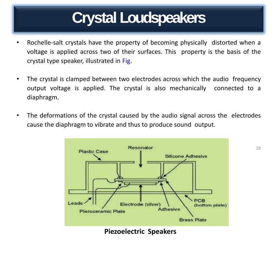
Crystal Loudspeakers
19
• Rochelle-salt crystals have the property of becoming physically distorted when a
voltage is applied across two of their surfaces. This property is the basis of the
crystal type speaker, illustrated in Fig.
• The crystal is clamped between two electrodes across which the audio frequency
output voltage is applied. The crystal is also mechanically connected to a
diaphragm.
• The deformations of the crystal caused by the audio signal across the electrodes
cause the diaphragm to vibrate and thus to produce sound output.
Piezoelectric Speakers

Cont.
20
• Piezoelectric speakers are frequently used as beepers in watches and other electronic
devices, and are sometimes used as tweeters in less-expensive speaker systems, such as
computer speakers and portable radios.
• Piezoelectric speakers have several advantages over conventional loudspeakers: they are
resistant to overloads that would normally destroy most high frequency drivers, and they can
be used without a crossover due to their electrical properties.
• There are also disadvantages: some amplifiers can oscillate when driving capacitive loads like
most piezoelectrics, which results in distortion or damage to the amplifier.
• This is why they are generally used in single frequency (beeper) or non-critical applications.
The white ceramic piezoelectric material can be seen fixed to a metal diaphragm
Piezoelectric Speakers

Schematic view for a crystal speaker
21
A mid-range speaker is driver that reproduces aband of frequencies generally between 2–6 kHz
Mid-Range

Permanent magnet Loud speaker
22
(Moving Coil)

• Function
• Working
• Advantages
• Disadvantages
• Applications
Permanent magnet Loud speaker(Moving Coil)

Permanent magnet Loud speaker
24
(Moving Coil)
Function• The most popular type of loudspeaker today is the permanent magnet.
• Working is based on interaction between Magnetic and Electric field.
• A coil is placed in a uniform magnetic field and we pass audio signalthrough the coil and that current through the coil will result in mechanicalforce.
• Generated force is directly proportional to audio current, hence it to itproduces vibrational motion in coil, and that is what resulting intogeneration of sound.

Working
25
• Because of its comparative simplicity of construction and design, theprecision that may be built into it, and ease with which it is interfacedwith other equipment.
• An electromagnet called a voice coil attaches to the center of the cone. Apermanent magnet - a magnet that keeps its magnetic field withoutelectricity - sits behind the voice coil on the other side of the cone.
• This means that a speaker uses two different types of magnets, which iswhat gives speakers the power to push and pull against the atmosphererapidly.
• The PM speaker contains a very light coil of wire affixed to the diaphragmand located concentrically around or within the permanent magnet.
• In operation, a steady current flows through the field coil, magnetizing thefield as shown in the next figure.
• The coil and the driver's magnetic system interact, generating amechanical force that causes the coil (attached with cone) to move backand forth, accelerating and reproducing sound under the control of theapplied electrical signal coming from the amplifier.

Magnets have two poles
26
electromagnet's poles can switch
• When current flows in one direction through the voice coil, it creates amagnetic field which reacts with the field in the gap and makes the conemove slightly to the right. When the audio signal current reversesdirection, it makes the cone move to the left.
• The audio signal is always an alternating current, so as the currentfluctuates in response to the power amplifier's output signal, the speakercone faithfully reproduces the variations of the audio signal as mechanicalmotion, and the large surface area of the cone effectively generates asound wave which is replica of audio signal.

27• The arrangement is such that the voice coil lies in the gap between the
north and south magnet poles.
• The coil (voice coil) is free to move in the field of the magnet. Electricalimpulses, varying at an audio rate, are applied to the voice coil by theamplifier.
• Because these impulses are constantly changing in amplitude anddirection, a changing magnetic field is set up in the voice coil. This fieldreacts with the constant field of the permanent magnet.

• Applying electrical signal in voice coil, change in current, change in force in coil,
• So the diaphragm get move front and back, then the sound willproduce.
28

Force on movingcoil
29
• Force on coil due to interaction of current and magnetic field is given by
• 𝐹 = 𝐵𝐼𝐿 × 𝑠𝑖𝑛θ• F is force on coil
• B is magnetic field
• I is current through coil
• L is length of coil
• θ is angle between coil and field
• Force is maximum for 90 degree angle
• Audio current flows through voice coil
• Force = B*I*L
• Two types of transformation
– Electro mechanical
– Mechanical acoustic
• Electro mechanical - electrical signal is fed in to coil, coil contains –(resistance and inductance)
• When Coil get energized, diaphragm gets motions produce acoustic signal
• In force to voltage analogy– Damping constant B =R
– Mass M = L
– Compliance K = 1/c

Characteristics
30
SNR 30dB
Frequency responseFor woofer up to 40Hz
Tweeter up to 10khz
Directivity Omni Directional
Distortion 10%
Efficiency Low
Impedance 2 to 32ohms
Power handling Milli to 25W
Application• You can find small permanent magnets in toys, handheld gadgets such as
electric razors, and clasps for bracelets and watches.
• It is found in the smallest pocket radios and is a major component of the most elaborate theatre systems.
• Larger permanent magnets are useful in household appliance motors and in stereo speakers.
• The electric motors in hybrid vehicles use very strong permanentmagnets.

Dynamic Loudspeaker
31

Dynamic Loudspeaker
32
• There are two varieties of dynamic loudspeakers : electrodynamics andpermanent magnet (PM) speakers. Both work in exactly the same way, thedifference is in their construction.
• The electrodynamics speaker has a soft iron magnetic circuit, non-retentive of magnetism, around whose centre leg, a large, multilayer fieldcoil is wound, as shown in Fig. 4.7.
• When dc flows through this field coil, it magnetizes the iron core. Amagnetic flux field directly proportional to the strength of the currentthrough the coil is thus set up across the air gap. The iron core is notpermanently magnetized, it stays magnetized only as long as current flowsthrough the field coil.
The dynamic loudspeaker has found acceptance in all kinds of reproducing systems.

33

34

Dynamic and Electrostatic Speakers
There is a huge differencebetween dynamic and electrostatic speakers. For moreinformation, see electrostatic speaker.
35

Woofer
A Woofer is driver that reproduces a band of frequencies generally between 0–1 kHz
36• A woofer is a driver that reproduces low frequencies. The driver works with the
characteristics of the enclosure to produce suitable low frequencies.
• Some loudspeaker systems use a woofer for the lowest frequencies,sometimes well enough that a subwoofer is not needed.
• Additionally, some loudspeakers use the woofer to handle middle frequencies,eliminating the mid-range driver.
• This can be accomplished with the selection of a tweeter that can work low enoughthat, combined with a woofer that responds high enough, the two drivers addcoherently in the middle frequencies.

Cont.
37
• Woofer is the term commonly used for a loudspeaker driver designed to produce lowfrequency sounds, typically from around 40 Hz up to about a KHz or higher.
• There are two types of low frequency speaker, the commonly known woofer, and themore recent addition the subwoofer.
• The latter is used for the reproduction of frequencies below those produced by thewoofer and it is generally purchased as an add-on to an existing system.
• The low frequencies speaker provides the bass of any hi-fi system. The prime requisite forlow frequency reproduction is a large diaphragm the larger the better.
• In addition to large size, the diaphragm must be of fairly heavy construction Lightdiaphragms just can't hold up under the vibrations encountered under the lower audioranges.
• A woofer must be able to vibrate back and forth very easily i.e have high compliance. Oneway to accomplish this is to have the diaphragm loosely connected to the frame. Thegasket that holds the edge of diaphragm to the frame basket is fastened, so that it barelykeeps the diaphragm from slipping loose.
• Rather than the loose suspension system, the cone is supported by a very flexible material,so that it can be moved very easily by the voice coil. The suspension is tight cabin the sinewave at the diaphragm edge is made very flexible.
• A woofer must also have a large voice coil to handle considerable heat. The larger the voicecoil, the more the current produced by the amplifier output circuit and, therefore, themore the power the woofer can handle.
• Finally, a strong magnet can be of great help to move the heavy voice coil and coneassembly too well. The better the woofer, the heavier the magnet assembly (unless it'sceramic).

Tweeter
A Tweeter is driver that reproduces a band of frequencies generally between 10–16 kHz
38

Tweeters
39
• A tweeter is a loudspeaker designed to produce high audio
frequencies, typically from around 2,000 Hz to 20,000 Hz.
• Some tweeters can manage response up to 65 kHz.
• Nearly all tweeters are electro-dynamic drivers, using a voice coil
suspended within a fixed magnetic field.
• There are two main types of high frequency speakers; the well-
known tweeter and the more recent super tweeter.
Six basic high-frequency tweeters
i. The cone is a physically disincentive version of the woofer.
ii. The dome, so called because of its dome-shaped diaphragm.
iii. The horn, so named because it is a horn.
iv. The Heil air-motion transformer which uses the principle of lever in its
operation, named after its inventor, Dr. Oskar Heil.
v. High polymer molecular-film tweeter, uses the piezoelectric effect
for its principle of operation (used exclusively by Pioneer).
vi. The electrostatic tweeter works on the principle of attraction or
repulsion between two metal plates.

Types
40
• Types of tweeters– Cone tweeter
– Dome tweeters
– Horn tweeters
• Cone tweeters have the same basic design and form as a woofer withoptimizations to operate at higher frequencies. The optimizations usuallyare:
• A very small and light cone so it can move rapidly;
• Cone materials chosen for stiffness (e.g., ceramic cones in onemanufacturer's line), or good damping properties (e.g., silk or coatedfabric) or both.
• The suspension (or spider) is stiffer than for other drivers—less flexibility is needed for high frequency reproduction;
• Small voice coils (3/4 inch is typical) and light (thin) wire,which also helps the tweeter cone move rapidly.
• Cone tweeters are relatively cheap, but do not have thedispersion characteristics of domes. Thus they are routinelyseen in low cost applications such as factory car speakers,shelf stereo systems, and boom boxes. Cone tweeters can alsobe found in older stereo hi-fi system speakers designed andmanufactured before the advent of the dome tweeter. Theyare now a rare sight in modern hi-fi usage.

Dometweeters
41
• A dome tweeter is constructed by attaching a voice coil to a dome, whichis attached to the magnet or the top plate via a low compliancesuspension. These tweeters typically do not have a frame or basket, but asimple front plate attached to the magnet assembly.
• Dome tweeters are categorized by their voice coil diameter. The majorityof dome tweeters presently used in hi-fi speakers are 25 mm (1 in) indiameter. A variation is the ring radiator in which the 'suspension' of thecone or dome becomes the major radiating element. These tweeters havedifferent directivity characteristics when compared to standard dometweeters.

Horn tweeters
42
• A horn tweeter is any of the above tweeters coupled to a flared or horn structure.Horns are used for two purposes — to control dispersion, and to couple thetweeter diaphragm to the air for higher efficiency.
• The tweeter in either case is usually termed a compression driver and is quitedifferent from more common types of tweeters (see above). Properly used, a hornimproves the off-axis response of the tweeter by controlling (i.e., reducing) thedirectivity of the tweeter. It can also improve the efficiency of the tweeter bycoupling the relatively high acoustic impedance of the driver to the lowerimpedance of the air.
• The larger the horn, the lower the frequencies atwhich it can work, since large horns providecoupling to the air at lower frequencies. Thereare different types of horns, including radial andconstant directivity (CD). Horn tweeters mayhave a somewhat 'different' sonic signature thansimple dome tweeters.
• Poorly designed horns, or improperly crossed-over horns, have predictable problems in theaccuracy of their output, and the load that theypresent to the amplifier. Perhaps concernedabout the image of poorly designed horns,some manufacturers use horn loaded tweeters,but avoid using the term. Their euphemismsinclude "elliptical aperture" "Semi-horn" and"Directivity controlled". These are, nonetheless,a form of horn loading.

Microphones
43

History
44
Component Inventor Year Application
Microphone
first microphone wasinvented by AlexanderGraham Bell
1876It was a liquid device and that was notvery practical.
Thomas AlvaEdison invented thefirst practical carbonmicrophone.
1886
The carbon microphone was used forradio transmissions and extensively intelephone transmitters until the 1970swhen they were replaced bypiezoelectric ceramic elements.
Microphones Characteristics• In order to provide some background for these techniques it is useful first to
understand some of the important characteristics of the microphones.
• For live sound applications are their operating principle, frequencyresponse and directionality.
• Impedance
– Generally, microphones can be divided into low (50–1,000 ohms), medium (5,000–15,000 ohms) and high (20,000+ ohms) impedance
• Sensitivity
– Typically, the microphone output (in a sound field of specified intensity) is stated in dB (decibels) as reference level.

Microphones
45
• Microphones are a type of transducer - a device which converts acoustical energy(sound waves) into electrical energy (the audio signal). Different types ofmicrophone have different ways of converting energy but they all share one thingin common.
• Diaphragm. This is a thin piece of material (such as paper, plastic or aluminium)which vibrates when it is struck by sound waves. In a typical hand-held mic, thediaphragm is located in the head of the microphone. When the diaphragmvibrates, it causes other components to vibrate. These vibrations are convertedinto an electrical current which becomes the audio signal.
Microphones
46

SNR
47

FrequencyResponse
48

FrequencyResponse
49

Distortion
50

Directivity
51

Output Impedance
52

Crystal Microphone
53

144
Outline
Basic

Crystal Microphone
55
• Crystals which demonstrate the piezoelectric effect produce voltageswhen they are deformed. The crystal microphone uses a thin strip ofpiezoelectric material attached to a diaphragm.
• The two sides of the crystal acquire opposite charges when the crystal isdeflected by the diaphragm. The charges are proportional to the amountof deformation and disappear when the stress on the crystal disappears.
• Later microphones used ceramic materials such as barium titanate andlead zirconate.
• The electric output of crystal microphones is comparatively large, but thefrequency response is not comparable to good as dynamic microphone, sothey are not serious contenders for the music market.

Elements
56
• This means that when mechanical stress is placed upon the material, avoltage electromagnetic force (EMF) is generated.
• Since Rochelle salt has the largest voltage output for a given mechanicalstress, it is the most commonly used crystal in microphones.
• View (A) of figure is a crystal microphone in which the crystal is mountedso that the sound waves strike it directly.
• View (B) has a diaphragm that is mechanically linked to the crystalso that the sound waves are indirectly coupled to the crystal
Working

• Sound wave compression – compress crystal
• Refraction – converse take place – crystal is extended and is undertension
• Due to this compression and extension – varying potential difference isgenerated which is proportional to the mechanical pressure applied to thecrystal by the sound waves – pressure microphone
Cont.
57
Internal structure

58

59

Carbon Microphone
60
160
Outline

Carbon Microphone
61
• The carbon microphone was widely used for many years being one of the earliest reliable microphones. But it was not widely used now a days.
Construction• The basic concept behind the carbon microphone is the fact that when
carbon granules are compressed their resistance decreases. This occursbecause the granules come into better contact with each other when theyare pushed together by the higher pressure.
• The carbon microphone comprises carbon granules that are containedwithin a small contained that is covered with a thin metal diaphragm. Abattery is also required to cause a current to flow through themicrophone.
• The carbon microphone is consisting of two metal plates separated bygranules of carbon.
• One plate faces outward and acts as a diaphragm.
• When sound waves strike this plate, the pressure on the granules changes,which in turn changes the electrical resistance between the plates.(Higher pressure lowers the resistance as the granules are pushed closertogether.)

Operation
62

Structure
63

Working
64
• The varying current can be passed through a transformer or a capacitor to enableit to be used within a telephone, or by some form of amplifier.
• The frequency response of the carbon microphone, however, is limited to anarrow range, and the device produces significant electrical noise.
• Often the microphone would produce a form of crackling noise which could beeliminated by shaking it or giving it a small sharp knock. This would shake thecarbon granules and enable them to produce a more steady current.
• The change in contact resistance causes a current from a battery connected inseries with the carbon button and the primary of a transformer to vary inamplitude, resulting in a current waveform similar to the acoustic waveformstriking the diaphragm.
• One of the main disadvantages of the carbon microphone is that it hascontinuous high frequency hiss caused by the changing contact resistancebetween the carbon granules.

65

Application
• Carbon microphones were an ideal choice of microphone in the early daysof the telephone. Because they gave a high output which meant noamplification was used.
• It is also used in portable radio communication set
Carbon microphones were used intelephones like this vintage BritishGPO 300 series telephone
66
advantages• High output
• Simple principle & construction
• Cheap and simple to manufacture
disadvantages• Very noisy - high background noise and on occasions it would crackle. (Constant
BACKGROUND HISS (hissing noise)which results from random changes in theresistance between individual carbon granules).
• Poor sensitivity and frequency response.
• Requires battery or other supply for operation
• The disadvantages, however, are offset by advantages that make its use inmilitary applications widespread. It is lightweight, rugged, and can produce anextremely high output.

Dynamic Microphone
67
Outline

68
• Dynamic microphones are versatile and ideal for general-purpose use.They use a simple design with few moving parts.
• They are relatively strong and flexible to rough handling. They are alsobetter suited to handling high volume levels, for examples they will dealbetter with certain instruments are amplifiers.
• They have no internal amplifier and do not require batteries or externalpower. When a magnet is moved near a coil of wire, an electrical currentis generated in the wire.
• Using this electromagnet principle, the dynamic microphone uses awire coil and magnet to create the audio signal.
• The diaphragm is attached to the coil. When this vibrates (due to soundwaves) the coil moves backward and forward to the magnet.
• This creates a current in the coil, which is channeled from the microphonealong wires.
• A physical cone act like a lens to concentrate the incoming sound waves. Itemploys a diaphragm, a voice coil, and a magnet.
• The voice coil is surrounded by a magnetic field and is attached to the rearof the diaphragm. The motion of the voice coil in the magnetic fieldgenerates the electrical signal corresponding to the picked up sound.

69

Structure
70

Structure
71

Elements
72
Working

Working
73
• This classification includes ribbon mics (velocitymics).
• Rugged, resistant to hand noise.
• Standard equipment used by musical performers.
• Handle extremely high sound levels.– Sound waves strike the diaphragm.
– Diaphragm vibrates in response.
– The voice coil, attached with the diaphragm, vibrates with it.
– The voice coil is surrounded by a magnetic field created by the magnet.
– The motion of the voice coil in this magnetic field generates the electrical signal.

74
• Shaped frequencyresponse
• Designed for professional vocal use in live performances.

• relatively inexpensive• they are not sensitive to
change in humidity• they do not need internal or
external power to operate• they usually have a resonant
peak in the mid frequency response
• can be weak in the high frequency response about 10khz
Characteristics
75
76

Wireless or Cordless Microphone
77
• A wireless microphone is a microphone without a physical cableconnecting it directly to the sound recording or amplifying equipment withwhich it is associated.
• It has a small, battery‐powered radio transmitter in the microphone body,which transmits the audio signal from the microphone by radio waves to anearby receiver unit, which recovers theaudio.
• The other audio equipment is connected to the receiver unit by cable.
• Wireless microphones are widely used in the entertainmentindustry, television broadcasting, and public speaking to allow publicspeakers, interviewers, performers, and entertainers to move about freelywhile using a microphone to amplify theirvoices.
• These are Hand held and collar type as shown in figure

Advantages
78
• Greater freedom of movement for the artist orspeaker.
• Avoidance of cabling stressing problems common with wired microphones.
• Reduction of cable "trip hazards" in the performancespace
Disadvantages
• Some wireless systems have a shorter range, while more expensive models can exceed that distance.
• Possible interference with or, more often, from other radioequipment or other radio microphones.
• Operation time is limited relative to battery life.