
Memory management for operating systems and runtimes
116
626 NNT : 2021IPPAS008 Memory management for operating systems and runtimes Th` ese de doctorat de l’Institut Polytechnique de Paris pr´ epar ´ ee ` aT´ el´ ecom SudParis ´ Ecole doctorale n ◦ 626 ´ Ecole doctorale de l’Institut Polytechnique de Paris (EDIPP) Sp´ ecialit ´ e de doctorat : Informatique Th` ese pr ´ esent ´ ee et soutenue ` a Palaiseau, le 12 Juillet 2021, par ALEXIS L ESCOUET Composition du Jury : Amel BOUZEGHOUB Professeure, T´ el´ ecom SudParis (SAMOVAR) Pr´ esident Laurent R ´ EVEILL ` ERE Professeur, Universit´ e de Bordeaux (Labri) Rapporteur Micha ¨ el HAUSPIE Maˆ ıtre de Conf ´ erence HDR, Universit ´ e de Lille (CRIStAL) Rapporteur Samuel THIBAULT Maˆ ıtre de Conf ´ erence HDR, Universit ´ e de Bordeaux (Labri) Examinateur Ga¨ el THOMAS Professeur, T´ el´ ecom SudParis (SAMOVAR) Directeur de th ` ese ´ Elisabeth BRUNET Maˆ ıtre de Conf ´ erence, T ´ el´ ecom SudParis (SAMOVAR) Co-directeur de th ` ese
-
Upload
khangminh22 -
Category
Documents
-
view
5 -
download
0
Transcript of Memory management for operating systems and runtimes

626
NN
T:2
021I
PPA
S00
8
Memory management for operatingsystems and runtimes
These de doctorat de l’Institut Polytechnique de Parispreparee a Telecom SudParis
Ecole doctorale n◦626 Ecole doctorale de l’Institut Polytechnique de Paris (EDIPP)Specialite de doctorat : Informatique
These presentee et soutenue a Palaiseau, le 12 Juillet 2021, par
ALEXIS LESCOUET
Composition du Jury :
Amel BOUZEGHOUBProfesseure, Telecom SudParis (SAMOVAR) President
Laurent REVEILLEREProfesseur, Universite de Bordeaux (Labri) Rapporteur
Michael HAUSPIEMaıtre de Conference HDR, Universite de Lille (CRIStAL) Rapporteur
Samuel THIBAULTMaıtre de Conference HDR, Universite de Bordeaux (Labri) Examinateur
Gael THOMASProfesseur, Telecom SudParis (SAMOVAR) Directeur de these
Elisabeth BRUNETMaıtre de Conference, Telecom SudParis (SAMOVAR) Co-directeur de these


Abstract
During the last decade, the need for computational power has increased due to the emergenceand fast evolution of fields such as data analysis or artificial intelligence. This tendency is alsoreinforced by the growing number of services and end-user devices. Due to physical constraints,the trend for new hardware has shifted from an increase in processor frequency to an increasein the number of cores per machine.
This new paradigm requires software to adapt, making the ability to manage such a paral-lelism the cornerstone of many parts of the software stack.
Directly concerned by this change, operating systems have evolved to include complexrules each pertaining to different hardware configurations. However, more often than not,resources management units are responsible for one specific resource and make a decision inisolation. Moreover, because of the complexity and fast evolution rate of hardware, operatingsystems, not designed to use a generic approach have trouble keeping up. Given the advanceof virtualization technology, we propose a new approach to resource management in complextopologies using virtualization to add a small software layer dedicated to resources placementin between the hardware and a standard operating system.
Similarly, in user space applications, parallelism is an important lever to attain high perfor-mances, which is why high performance computing runtimes, such as MPI, are built to increaseparallelism in applications. The recent changes in modern architectures combined with fastnetworks have made overlapping CPU-bound computation and network communication a keypart of parallel applications. While some degree of overlap might be attained manually, this isoften a complex and error prone procedure. Our proposal automatically transforms blockingcommunications into nonblocking ones to increase the overlapping potential. To this end, weuse a separate communication thread responsible for handling communications and a memoryprotection mechanism to track memory accesses in communication buffers. This guaranteesboth progress for these communications and the largest window during which communicationand computation can be processed in parallel.
iii


Acknowledgements
This document concludes four years of work that would not have been possible without thesupport of many people.
First and foremost, I would like to thank my advisors, Gael Thomas and Elisabeth Brunetfor their guidance during these years full of unforeseen developments and their unfalteringproofreading during the last months. I would like to extend special thanks to Francois Trahay,for being my unofficial advisor, and helping me decipher the MPI specification.
I would like to thank Laurent Reveillere and Michael Hauspie for taking the time to readand evaluate this document as well as being part of my jury. I also thank Amel Bouzeghouband Samuel Thibault for their participation in my jury.
These four years in the PDS Group, former HP2, would have been very different if not forthe great atmosphere cultivated by all professors and students. Thanks to Denis Conan andAmina Guermouch for their counseling and the conversations we had over a cup of tea.
I am grateful to Gauthier Voron, for bearing with me while I discovered virtualization. Iwould also like to express my gratitude to the PhD students of room B312 and affiliated, whichare always available for a coffee or two.
Alexis Colin, our C++ expert, for all the metaprogramming and template conversations.Tuanir Franca-Rezende for sharing with me the ups and downs of the daily PhD student life.Anatole Lefort for convincing me of the benefits of vertical screens. Damien Thenot for sharingScalevisor with me.
Special thanks to Yohan Pipereau, my reference for kernel issues, and Subashiny Tanigas-salame, for their great musical tastes.
Finally, I would like to thank my friends and family for their unfailing support.My grand-parents and my sister for always asking me about my work. Thanks to Vivien
for its great proofreading. Thanks to Sylvie for finding the right words. Deep thanks to Laurefor being there when it mattered the most. And to my mother, thank you for always believingin me.
v

Contents
Abstract iii
Acknowledgements v
Contents vi
List of Figures viii
List of Tables x
1 Introduction 1
2 Background and motivation 5
2.1 An overview of multicore architectures . . . . . . . . . . . . . . . . . . . . . . . 6
2.1.1 SMP architectures . . . . . . . . . . . . . . . . . . . . . . . . . . . . . . 6
2.1.2 Non Uniform Memory Access architectures . . . . . . . . . . . . . . . . 10
2.2 Memory management in the operating system . . . . . . . . . . . . . . . . . . . 17
2.2.1 Paging and the page table structure . . . . . . . . . . . . . . . . . . . . 17
2.2.2 Paging and memory management in user space . . . . . . . . . . . . . . 23
2.3 State of the art: resources management and NUMA . . . . . . . . . . . . . . . 25
2.3.1 User space solutions . . . . . . . . . . . . . . . . . . . . . . . . . . . . . 25
2.3.2 Runtimes and kernel policies . . . . . . . . . . . . . . . . . . . . . . . . 29
2.3.3 Operating system solutions . . . . . . . . . . . . . . . . . . . . . . . . . 32
2.4 Conclusion . . . . . . . . . . . . . . . . . . . . . . . . . . . . . . . . . . . . . . 34
3 Commmama, motivation and design 35
3.1 Background and motivation . . . . . . . . . . . . . . . . . . . . . . . . . . . . . 36
3.1.1 MPI primitives and semantics . . . . . . . . . . . . . . . . . . . . . . . . 37
3.1.2 Overlapping communication with computation . . . . . . . . . . . . . . 39
3.1.3 Commmama: blocking simplicity, nonblocking efficiency . . . . . . . . . 44
vi
CONTENTS vii
3.2 Our overlapping infrastructure: Commmama . . . . . . . . . . . . . . . . . . . 463.2.1 The interception layer . . . . . . . . . . . . . . . . . . . . . . . . . . . . 473.2.2 The offloading system . . . . . . . . . . . . . . . . . . . . . . . . . . . . 483.2.3 The protection mechanism . . . . . . . . . . . . . . . . . . . . . . . . . . 49
3.3 Evaluation of the overlapping potential . . . . . . . . . . . . . . . . . . . . . . . 553.3.1 Base overhead analysis . . . . . . . . . . . . . . . . . . . . . . . . . . . . 553.3.2 Overlap evaluation . . . . . . . . . . . . . . . . . . . . . . . . . . . . . . 56
3.4 Conclusion . . . . . . . . . . . . . . . . . . . . . . . . . . . . . . . . . . . . . . 59
4 A multicore resource management driver 614.1 Background and motivation . . . . . . . . . . . . . . . . . . . . . . . . . . . . . 63
4.1.1 Software techniques . . . . . . . . . . . . . . . . . . . . . . . . . . . . . 634.1.2 Hardware techniques . . . . . . . . . . . . . . . . . . . . . . . . . . . . . 654.1.3 State of the art: Virtualization . . . . . . . . . . . . . . . . . . . . . . . 71
4.2 A driver for NUMA architectures: Scalevisor . . . . . . . . . . . . . . . . . . . 814.2.1 Presenting an abstract memory/CPU topology . . . . . . . . . . . . . . 814.2.2 Managing memory migration . . . . . . . . . . . . . . . . . . . . . . . . 834.2.3 Managing CPU migration . . . . . . . . . . . . . . . . . . . . . . . . . . 834.2.4 Scalevisor internals . . . . . . . . . . . . . . . . . . . . . . . . . . . . . . 854.2.5 Assessments . . . . . . . . . . . . . . . . . . . . . . . . . . . . . . . . . . 90
5 Conclusion and future work 91
Bibliography 95

List of Figures
2.1 SMP architecture . . . . . . . . . . . . . . . . . . . . . . . . . . . . . . . . . . . . . 6
2.2 Example cache hierarchy . . . . . . . . . . . . . . . . . . . . . . . . . . . . . . . . . 7
2.3 MESI State diagram . . . . . . . . . . . . . . . . . . . . . . . . . . . . . . . . . . . 9
2.4 NUMA architecture . . . . . . . . . . . . . . . . . . . . . . . . . . . . . . . . . . . 11
2.5 Intel Xeon E5 ring architecture (Intel documentation [27, chap. 1.1]) . . . . . . . . 13
2.6 Intel’s directory-based coherency example . . . . . . . . . . . . . . . . . . . . . . . 14
2.7 Intel Xeon Scalable family mesh architecture (Intel documentation [26]) . . . . . . 15
2.8 Latency (CPU cycles), for the Skylake Scalable machine (left) and one die (right) . 16
2.9 Latency (CPU cycles), for the AMD EPYC machine (left) and one die (right) . . . 16
2.10 Translation mechanism (Intel documentation [28, chap. 4.5]) . . . . . . . . . . . . 19
3.1 Comparison of eager and rendez-vous for blocking communications . . . . . . . . . 40
3.2 Comparison of eager and rendez-vous for nonblocking communications . . . . . . . 42
3.3 Comparison of eager and rendez-vous with Commmama . . . . . . . . . . . . . . . 46
3.4 Commmama’s architecture . . . . . . . . . . . . . . . . . . . . . . . . . . . . . . . 47
3.5 Queuing procedure, from local thread to offload thread . . . . . . . . . . . . . . . . 49
3.6 Evolution of the memory state through a simple send operation . . . . . . . . . . . 50
3.7 The two types of shared memory between buffers . . . . . . . . . . . . . . . . . . . 52
3.8 Evolution of the memory state during a merge procedure . . . . . . . . . . . . . . 53
3.9 Round-trip latency with no compute . . . . . . . . . . . . . . . . . . . . . . . . . . 56
3.10 Expected execution timeline for microbenchmark . . . . . . . . . . . . . . . . . . . 57
3.11 Round-trip latency and speedup for tcompute = 4000 µs . . . . . . . . . . . . . . . . 58
3.12 Round-trip latency and speedup for tcompute = 40000 µs . . . . . . . . . . . . . . . 58
3.13 Round-trip latency and speedup for tcompute = 400 µs . . . . . . . . . . . . . . . . 59
4.1 Software stack including Scalevisor . . . . . . . . . . . . . . . . . . . . . . . . . . . 62
4.2 Shadow Page table . . . . . . . . . . . . . . . . . . . . . . . . . . . . . . . . . . . . 64
4.3 VMCS state machine (Intel documentation [28, chap. 24.1]) . . . . . . . . . . . . . 66
4.4 Second level translation overhead . . . . . . . . . . . . . . . . . . . . . . . . . . . . 68
4.5 Intel VT-d tree hierarchy (Intel documentation [29, chap. 3.4.3]) . . . . . . . . . . 71
viii
LIST OF FIGURES ix
4.6 Abstract topology . . . . . . . . . . . . . . . . . . . . . . . . . . . . . . . . . . . . 824.7 Migration using EPT mappings . . . . . . . . . . . . . . . . . . . . . . . . . . . . . 844.8 Software architecture of Scalevisor . . . . . . . . . . . . . . . . . . . . . . . . . . . 864.9 Operating modes of x86 64 architecture (AMD documentation [1, chap. 1.3]) . . . 87

List of Tables
2.1 Format of a last level page table entry . . . . . . . . . . . . . . . . . . . . . . . . . 202.2 Correspondence between x86 page table bits and mprotect flags . . . . . . . . . . 242.3 Related work on NUMA: user space solutions . . . . . . . . . . . . . . . . . . . . . 252.4 Related work on NUMA: runtime and kernel approaches . . . . . . . . . . . . . . . 292.5 Related work on NUMA: New operating system designs . . . . . . . . . . . . . . . 32
3.1 Blocking send modes . . . . . . . . . . . . . . . . . . . . . . . . . . . . . . . . . . . 38
4.1 Related work on virtualization . . . . . . . . . . . . . . . . . . . . . . . . . . . . . 724.2 Related work on virtualization and NUMA . . . . . . . . . . . . . . . . . . . . . . 76
x

Chapter 1
Introduction
Recently, the computation power and network throughput have reached unprecedented heights.While this much needed power helps to develop new fields of research such as data analysis orartificial intelligence, it also requires new techniques to fully exploit its potential.
This growth of computation power and network throughput has only been possible throughthe use of complex internal hardware structures for the new machines supporting them. Firstof all, with the increased frequency of the processor clocks, the rate at which instructions areexecuted has far exceeded the rate at which the memory controller can answer queries. This ledto the introduction of smaller but faster memory banks, called caches, to decrease the visiblelatency of memory requests. Moreover, as all the cores of the machine shared the bandwidthof a unique memory controller, increasing the number of cores led to an overwhelming pressureon the memory controller. As it became impossible to further extend machines featuring asingle memory controller, multiple memory controllers, distributed inside the machine, havebeen added. Because the access time of a given CPU to a given memory location dependson the proximity of the CPU and the memory controller owning this specific location, thisarchitecture is named Non-Uniform Memory Access (NUMA).
This new topology, made of an important pool of processing, memory and network re-sources, requires to efficiently manage parallelism in order to leverage the full machine poten-tial. In order to increase parallelism and simplify the use of NUMA architecture, this documentproposes an approach in two parts.
Commmama The first obstacle to parallelism is to overlap network communication withcomputation. For this part, we focus on user space level with the MPI (Message PassingInterface) runtime. MPI provides two types of communication primitives, blocking ones, whichare simple to use but cannot overlap communication with computation, and nonblocking oneswhich are more complex to use but have some overlapping capabilities. This forces developersto choose between the simplicity of blocking communications and the efficiency of nonblocking
1
2 CHAPTER 1. INTRODUCTION
communications.
In order to avoid trading simplicity for efficiency, we propose Commmama, which auto-matically transforms blocking MPI primitives into nonblocking ones at runtime. Moreover, weshow that two main factors contribute to increasing the overlapping ratio. First, backgroundprogress which guarantees communications are processed while computation is running. Sec-ond, the size of the window during which both communication and computation can be run inparallel. Commmama addresses both these factors.
Scalevisor The second obstacle to parallelism is the contention on shared hardware re-sources. As explained above, the complexity of multicore machines has greatly increased toanswer the need for computational power. As core frequencies rose, the performance gap withthe memory controller has increased. This is commonly known as the memory wall. To avoidmodern processors being blocked by the memory subsystem, small but fast memory cacheshave been added on the memory path to mask the latency of the slow main memory. Someof these caches are shared among cores, making them a contented resource. Moreover, as thenumber of cores per machine increases, so does the pressure on the memory subsystem. Toovercome this issue, NUMA architectures feature multiple memory controllers, each managinga part of the machine’s memory. While the multiplicity of memory controllers helps dealingwith the contention on a given memory controller, it introduces another issue, the congestionon the network linking the different parts of the machine. This congestion is aggravated by thecaches synchronization protocol which also uses this same internal network. Finally, each newaddition to the already complex machine topology forces the overlying software to take intoaccount the changes. Current operating systems already incorporate different resource man-agement policies trying to deal with the different topologies, including NUMA architectures.However, modifying and maintaining efficient heuristics in code bases with millions of lines ofcode is a very difficult task.
In order to mask the complexity of the hardware while managing memory efficiently, thesecond part of our approach is a multicore resource management driver that uses virtualizationtechnology, Scalevisor. Scalevisor is a small layer placed between the hardware and the oper-ating system, which masks the real topology of the machine and exposes a simpler abstracttopology for the overlying operating system. Virtualization technology thus allows Scalevisorto manage resources below the operating system transparently. Moreover, as Scalevisor tendsto remain simple, focusing only on resource management, implementing or extending policiesshould be easier than changing kernel code.
This document is divided in multiple chapters. Chapter 2 describes the challenges ofmulticore architectures and more specifically of NUMA architectures. Chapter 3 describes thedesign and implementation of Commmama. Chapter 4 presents the design and implementationof Scalevisor. Chapter 5 concludes this document and presents future work. These chaptersare organized as follows.

3
Background and motivation
Chapter 2 addresses the challenges of resources management on multicore machines. First,this chapter describes the internals of multicore machines, and more specifically of NUMAmachines, in detail. This entails explaining the hardware mechanisms responsible for theperformance issues from which multicore architectures suffer. Because Scalevisor masks thehardware topology to the overlying operating system, these mechanisms need to be under-stood in order to be correctly dissimulated. Second, we present a commonly used techniqueto manage memory: paging. This technique is important for both Commmama and Scalevisoras it is used in both cases to manage resources, either with the user space interface in Com-mmama, or by directly programming the hardware in Scalevisor. We present specifics of thex86 hardware mechanism that impact implementation of both Commmama and Scalevisor.Finally, this chapter describes solutions proposed in related work to solve the challenges ofmulticore architectures. We show that the main factors leading to non optimal performancesare hardware resource contention and the increased latency of memory accesses, due to wrongmemory placement.
Commmama, motivation and design
Chapter 3 presents a specific aspect of resource management: overlapping network communi-cation with CPU-bound communication in the scope of the MPI user space runtime. First, thischapter describes the semantics of MPI communication primitives. The chapter then showsthat two key factors influence how well primitives can overlap communication with computa-tion, background progress and the duration during which the overlapping can occur. Studiestargeted at improving either of these factors are presented. The chapter then introducesCommmama, which transforms blocking communications into nonblocking ones at runtime toimprove the overlapping window while providing efficient background progress. Second, thischapter details the internal design of Commmama, composed of three different layers, the in-terception layer, offload layer, and protection layer. We present how each of these layers works.Finally, we present an evaluation of Commmama for communication with different messagesizes and computation time. This final section shows that Commmama is able to overlapalmost all the communication with computation when enough computation time is provided.This leads to a speedup of up to 73% for medium sized messages.
A multicore resource management driver
Chapter 4 presents Scalevisor, our approach to resource management using virtualization tech-niques. First, it presents virtualization techniques, both software and hardware assisted toemulate parts of the machine behavior. This section details the issues related to virtualizationin general. It also presents studies related to the impact of virtualization on performances ingeneral and on NUMA architectures in particular. Second, this chapter describes the design
4 CHAPTER 1. INTRODUCTION
of Scalevisor. The chapter shows how Scalevisor uses virtualization techniques to abstract themachine topology and to mask complex hardware resources, such as CPU caches, but alsothe distributed nature of NUMA architectures. The section then details the implementationof Scalevisor. The implementation of Scalevisor is incomplete. Scalevisor is able to boot acomplete Linux operating system on an Intel machine, but, because of a lack of time, we havenot implemented the interface to access hard drives. For this reason, we don’t have evalua-tions that highlight the performance impact of Scalevisor. Instead, the chapter discusses ourfinding regarding the implementation of a new operating system, and especially reflects on thedifficulty to create a new system given the complexity of current hardware without a full-timededicated team.
Conclusion and future work
Chapter 5 concludes this thesis. It sums up the different contributions and teachings aboutmanaging resources to increase parallelism on complex topologies for both Commmama at theuser space level and Scalevisor, at the hypervisor level. This chapter then discusses futurework on both proposals. For Commmama, the main axis of evolution should be decreasingthe overhead of the protection mechanism, with a secondary axis being the evaluation of MPIcollective primitives and larger applications. For Scalevisor, the first task should be to finishthe implementation of necessary parts of the system, and furthermore, developing and studyingresource management heuristics.

Chapter 2
Background and motivation
As presented in chapter 1, both Commmama and Scalevisor aim to improve resource manage-ment. Commmama increases the parallelism of network communication and CPU computationusing memory management techniques (paging and memory protection). Scalevisor uses virtu-alization techniques, among which virtualized paging to manage resources below the operatingsystem, while exposing an abstract topology. In both cases, understanding how memory andpaging work is important. In the case of Scalevisor, masking the topology requires an evenbetter understanding of specifics of the hardware and the related issues.
This chapter thus addresses the challenge of managing resources in machines exhibitingcomplex topologies, known as NUMA architectures: as multicore architectures are composedof an important number of computation units, reaching good parallelism is important to fullyexploit a machine potential. However, the distributed topology of NUMA machines inducesnew performance issues. We show that topology awareness is key in avoiding these issues andfavoring scalability.
First, in order to better understand the aforementioned challenges, this chapter presents thearchitectural details of multicore machines in general and the specificities of NUMA machinesin particular. We describe the hardware mechanism and protocols responsible for smoothoperation of the architecture and the associated issues.
Then, we explain how operating systems and applications in the user space can leveragethis hardware to manage memory through a commonly used data structure, the page table,and associated mechanisms.
Finally, we present solutions proposed in related work to increase efficiency of operatingsystems and applications on such architectures. We show that the main factors leading tonon optimal performances are the contention of hardware resources or the increased latency ofaccess, both due to wrong memory placement.
5

6 CHAPTER 2. BACKGROUND AND MOTIVATION
2.1 An overview of multicore architectures
Previously, Moore’s law, which implied a doubling of the number of transistors per processingunit every two years, had the direct consequence of raising the frequency of processors. Asevidenced by the number of transistors in recent processors, Moore’s law is still valid as oftoday, but due to physical constraints, such as thermal dissipation, these transistors cannotcontribute to the frequency factor as much as they used to. Since the introduction of IBM’sPOWER4 processor in 2001, the increasing number of transistors serves the different purposeof adding more computing nodes in a single chip, marking the debut of a change in paradigmfor computer software, from sequential to parallel programs.
At its core, a computer is composed of three different hardware units, a processing unitor CPU, some memory accessed using a memory controller and some I/O devices accessedthrough an I/O controller. These three components communicate with one another using thesystem bus.
This layout was later extended to use multiple CPUs on the system bus to increase thecomputational power in ways that were unattainable by simply increasing the core frequency.This architecture, composed of multiple CPUs, a memory controller and an I/O controller iscommonly known as Symmetric Multiprocessing (SMP) and was already in service decades agoin mainframes.
MemoryI/O
Bus
CPU
Cache
CPU
Cache
CPU
Cache
Figure 2.1: SMP architecture
2.1.1 SMP architectures
In SMP architectures, represented in Figure 2.1, the cost of accessing a memory location isthe same for all processors as they are all connected through the single bus to the memorycontroller.
A standard multicore processor is composed of several computation units called cores,capable of executing multiple instructions at the same time. These cores are packed into a

2.1. AN OVERVIEW OF MULTICORE ARCHITECTURES 7
single chip package, generally referred to as CPU or processor, which, when connected to asystem bus featuring a memory controller and an I/O controller, acts as an SMP system.
To fully leverage the power of an SMP machine, the different processors must be used inparallel which in turn implies the need for the software run on such an architecture to leverageparallelism. As with many parallel systems, performance limitations lie in shared states andsynchronization. For SMP machine, whether built from a multicore CPU or multiple processor,there are multiple hardware parts which are shared or need synchronization.
The first of these shared devices is the memory controller. In an SMP system, all theprocessing units are running in parallel and interact with the memory controller simultane-ously. With the evolution of processor frequency, most modern multicores are now executinginstruction at a very fast pace compared to the latency at which the memory controller canrespond. This effect, commonly called memory wall pushes multicore CPUs to include fastmemory, used as a cache, inside the CPU package to mask the latency of the main memory.
In modern CPUs, there are multiple such caches organized as a hierarchy with smallerand faster memory being used first, while bigger, slower caches are used when previous cachesdid not contain the wanted memory. Current hierarchies of caches generally contain threedifferent levels of caches. The first one on the path to main memory called L1, is composed oftwo separate caches, one for data fetches called L1d and one for instruction fetches called L1i.These L1 caches are per core and thus replicated for each core of a CPU package. The nextcache level, L2 is also private to each core, the Last Level Cache (LLC), L3 is the biggest cacheand shared by all the cores of the CPU package. Common sizes for these caches are respectively32 KB each for L1i and L1d, between 256 KB (laptop) and 1024 KB (high performance server)for the L2 cache. Because it is shared by all the cores, the size of the L3 cache varies more,with approximately 2 MB per core for modern CPUs, leading to 4 MB on a laptop computerand around 20 MB for server class CPUs. Figure 2.2 shows an example hierarchy of caches ona dual-core processor with three cache levels.
CPU 0
L1i (32kB)
L1d (32kB)
L2 (256kB)
L3 (4096kB)(Last Level Cache)
CPU 1
L1i (32kB)
L1d (32kB)
L2 (256kB)
Memory(8GB)
CPU Package
Figure 2.2: Example cache hierarchy
The first level of cache is separated into two distinct caches, L1i and L1d, for two reasons.First, separating caches multiplies the throughput allowing instruction fetches and data fetches

8 CHAPTER 2. BACKGROUND AND MOTIVATION
to be independent. Second, separating the caches allows to specialize their behaviors. In thecase of the instruction cache, it allows to encode the cache content differently than randomdata.
While these caches may participate in increasing the overall performances by masking mostof the latency of instruction and data fetches compared to the main memory, caches private tocore must be synchronized in order to present a correct, uniform view of the sequence of loadand stores on all cores. Different procedures have been developed to keep processor reads andwrites consistent with the states of the different caches and main memory.
Cache coherency protocols for SMP architectures Caches are said to be coherent if allloads and stores of all cores to a given memory location appear to execute in a total order thatrespects the program order. In order to guarantee the sequential consistency of the memory,two properties must be satisfied.
First, write propagation, if a processor P1 reads from a shared memory location X aftera write by another processor P2 to the same memory location X, P1 must read the valuewritten by P2 and not the old value. Second, serialization, if two values A and B are writtento location X in this order from two different processors, no processor may read B then A.
To ensure caches are coherent in an SMP system, multiple protocols have been designed,starting with the MSI protocol and its derivatives, such as the MESI and MOESI protocols.In these protocols, the blocks of data, called cache lines, which reside in a cache are taggedwith a state. These states represent the state of the memory in regards to both the state ofthe memory (modified or not) and the state of the same location across the different caches(exclusive or shared). The protocol names are derived from the names of the different possiblestates of a memory location in the cache, M stands for Modified, S for Shared, I for Invalid, Efor Exclusive and O for Owned.
The original MSI protocol operates as a reader-writer lock (single writer, multiple readers).The Modified state represents exclusive ownership as a writer, the Shared state representsshared ownership as a reader while Invalid means neither reader nor writer. Traditionallywith reader-writer locks, acquiring the lock to write means no reader currently holds the lock.For cache coherency protocol, transitioning to the Modified state forces all other caches toforgo their Shared state and invalidate the location. Alternatively, when a cache requests toload a location, if another cache holds this location in the Modified state, meaning the valuestored in memory is not up to date, the modified value is first committed to main memorytransitioning both caches to the Shared state.
While this protocol is theoretically correct, it is not optimal in regard to the number of busmessages. When a cache is the only one to contain the value for a given location and writes tothis location, it must broadcast a message on the bus to force other caches to invalidate theirentries, which could be avoided in this case. To solve this issue and avoid unneeded messageson the bus, the MESI protocol was introduced by Papamarcos et al. [43]. According to Intel’s

2.1. AN OVERVIEW OF MULTICORE ARCHITECTURES 9
Software Developer Manual [28, chap. 11.4], the MESI protocol is still in use in current Intelprocessors.
The MESI protocol contains an additional state, Exclusive which means a value at a givenlocation is valid but not present in any other caches. When a memory location is read by thecore and tagged as Invalid, the core broadcasts a message on the bus to request the value, ifat least one other cache contains the wanted value they both transition to the Shared state.This is true for both the MSI and MESI protocols, but in the MESI protocol, if all responsesare negative, the requester cache loads the value from memory and transition to the Exclusivestate. Once in this state, any write to the same location causes a transition to the Modifiedstate without the need to issue a message on the bus invalidating this location for other caches.
When using the MESI protocol, in case of a load request directly followed by a write, ifthe requesting core is the only one using the data it saves one bus message. This is especiallyimportant on sequential parts of an application as only one core will access and modify a givenlocation at a time, resulting in improved performances over the MSI protocol.
The MESI protocol can be implemented using two core-side requests and three bus-siderequests. Core-side requests, for cache transactions initiated by the core are PrRd to get accessto the value of a cache line and PrWr to write a value to a cache line. Bus-side requests areBusRd to get the value of a cache line (emitted after a read miss), BusRdX to get ownershipof a cache line for writing or notify of a write (emitted after a write miss), Flush to commit ablock to main memory, generally in response to a BusRd or BusRdX request. A complete statetransition diagram presenting the interaction of these different messages and the evolution ofa cache line state in response is presented in Figure 2.3.
M E S IPrRd/-PrWr/-
PrWr/BusRdX
PrRd/BusRd(S)
PrRd/BusRd(E)
BusRd/Flush BusRdX/Flush
BusRd/-
PrRd/- PrRd/-
PrWr/BusRdX
PrWr/-
BusRd/Flush
BusRdX/Flush
Core initiatedIn response to bus
Transitions:
Figure 2.3: MESI State diagram
The issue with MSI and less importantly in MESI is the repeated use of the system bus toconvey different cache protocol messages and data.
A standard implementation of a cache coherency protocol such as MESI operates using twotypes of communications as mentioned previously, local to core (core to cache) and through the

10 CHAPTER 2. BACKGROUND AND MOTIVATION
bus linking the different cores and the main memory. The two local operations are a requestfrom the core either to read from the cache, or write to the cache. Depending on the state ofthe cache location targeted by these operation, the core may need to issue messages on thebus to either request the wanted value, or request the value and notify it intends to modifyit, or inform other components of a modification of an already cached value. Because of thedistributed nature of the caches and the wanted coherency property, all these messages arebroadcast on the bus and decrease the available bandwidth for other operations.
Moreover, when a memory location is frequently used by multiple cores, it is still flushedto the main memory store1 which is shared by all cores.
The SMP architecture, while providing more processing power with parallelism is limitedby the strain it incurs on the shared components, the system bus, and both the memory andI/O controllers. This architecture is thus viable for a reasonable number of cores but cannotscale efficiently.
2.1.2 Non Uniform Memory Access architectures
The cache hierarchy of SMP architectures does reduce the amount of requests reaching thememory controller. However, when there is an important number of cores and amount of shareddata, the SMP model with its unique shared memory controller does not scale well. In order toreduce the load on the memory controller, a new layout featuring multiple memory controllersdistributed in different nodes is used, Non Uniform Memory Access (NUMA) architectures.These architectures feature multiple memory controllers distributed among the cores, whichalleviates the pressure on a given controller and allows for better memory performances.
As represented in Figure 2.4, this kind of machines is composed of different nodes, each withits own memory region and cores which are connected with an inter-socket network called aninterconnect. The topology of the communication network varies from one machine to another.Common topologies for NUMA machines comprising four sockets are either ring (all socketshave two peers) or crossbar (complete graph). For machines comprised of eight sockets, thereare more variations, commonly, no more than two hops from any given socket are necessary toreach any other socket.
While having completely separate memory controllers, NUMA machines still provide aglobal address space in which every memory zone in the system is accessible by other hardwarewith its unique physical address.
Given this new topology, NUMA machines have two different kinds of memory accesses,local ones, when the targeted memory is managed by the controller located on the same nodeas the CPU and remote ones, when a CPU is accessing another node’s memory.
By adding more memory controllers, NUMA machines can make use of more cores withoutoverloading the memory subsystem as SMP would. However, the distributed topology exhibits
1This can be the LLC when it is inclusive, which is the case for most L3 caches in Intel processors.

2.1. AN OVERVIEW OF MULTICORE ARCHITECTURES 11
MemoryBus
CPU
Cache
CPU
Cache
CPU
Cache
I/O
Node
Node
Node Node
Node Node
Figure 2.4: NUMA architecture
different kinds of performance issues. On one hand, memory accesses through the interconnectare slower than local ones, making locality of memory accesses important, on the other hand,the interconnect has a limited bandwidth which can lead to congestion in the event too manydistant accesses would occur.
Moreover, as explained in Section 2.1.1, for performance reasons, modern CPUs have acache hierarchy used to reduce the number of memory accesses reaching the high latency mainmemory. This cache hierarchy is also present in NUMA architectures and creates two subtypesof NUMA machines, the ones in which the cache coherency is local to a given node and theones for which cache coherency is ensured between nodes. The latter are called cache coherentNUMA or ccNUMA.
While non-cache-coherent NUMA machines have some use cases, the lack of a global cachecoherence breaks the usual shared memory abstraction, making these suffer from a lack ofprogrammability as described in Yunheung Paek et al. [42]. Thus, most currently used NUMAmachines are cache coherent and according to Martin et al. [35] this is not going to change in theforeseeable future for mainstream machines. They argue there still is some design space to makecache coherent hardware scale, but more importantly, forcing software to explicitly managecoherence would simply shift the complexity of cache coherency protocols from hardware tosoftware.
However, while cache-coherency is very important to ease programming of such machines,it comes with its drawbacks as well. Using the MESI cache protocol for NUMA machines wouldforce communications between the cache controllers of different nodes, which was already anexpensive solution for SMP machines with a far smaller number of cores. To avoid overloadingthe interconnect network with cache protocol messages, multiple modifications to the cache

12 CHAPTER 2. BACKGROUND AND MOTIVATION
coherency system are made.
Cache coherency for NUMA machines Independently of the protocol used, cache co-herency implementations can be realized using messages directly broadcast on the bus asexplained earlier but the resulting traffic on the interconnect network would scale propor-tionally with the number of cores in the system. This approach called bus snooping is thusinappropriate for large NUMA machines which can contain hundreds of cores.
In snoop-based implementations of the cache coherency protocol, the LLC is responsiblefor broadcasting the relevant messages on the system bus. In directory-based implementations,the so called directory maintains the information of the state of cache lines and which nodes,if any, are sharing that line. This system avoids the need to broadcast the coherency protocolmessages on the bus, allowing a given requester cache to directly target the right cache throughthe use of the directory.
The directory system can be implemented using multiple possible methods, for exampleusing a different component, acting as the bookkeeper or with each cache tracking the potentialother copies of a given memory address using a range of bits co-located with the state tag inthe cache line metadata.
Intel machines use their own form of directory-based protocol for their NUMA servers.Recent hardware from the manufacturer has been using a Network-on-Chip design, in whichcores, caches and memory controller are linked via a specific on-chip network. The interconnectnetwork then connects chips. Two iterations of this network have been in use in modernservers, QuickPath Interconnect (QPI) before 2017 and UltraPath Interconnect (UPI) withthe introduction of the new Skylake Scalable (Skylake-SP) microarchitecture.
For Intel’s platform, the part responsible for handling the interface between private caches(L1 and L2) and the LLC is called the caching agent. This caching agent is thus responsiblefor starting caches transactions, as well as sending and receiving the bus messages generatedby these transactions. There is one caching agent per core.
The caching agent communicates with the private cache levels through a basic snoop-basedcache coherency protocol which is local to the core. For outgoing communications, all cachingagents are linked using a ring topology to the QuickPath Interconnect and communicate usinga directory-based approach with a home agent as represented in Figure 2.5.
There is one home agent per memory controller, each responsible for its range of memoryaddresses. When a cache miss occurs in the caching agent of a given core, the caching agentsends a request to the home agent responsible for the wanted memory location. This homeagent then uses the information of its directory to send a snoop request only to the cachingagents of the cores which may have a cached copy of the wanted memory. One of the agents2
with a copy of the data sends a copy to the requester caching agent and an acknowledgment to
2The one with the F (Forward) state from the MESIF protocol explained below.

2.1. AN OVERVIEW OF MULTICORE ARCHITECTURES 13
Figure 2.5: Intel Xeon E5 ring architecture (Intel documentation [27, chap. 1.1])
the home agent. The home agent concludes the transaction. These four steps are illustratedin Figure 2.6.
As the number of message increases with the number of caching agent involved, avoiding tobroadcast these messages reduces the consumption of the already limited interconnect band-width. This methods thus reduces interconnect bandwidth consumption in exchange for anincreased latency of cache coherency transactions.
In addition to the directory information used by the home agent which is an implementationof directory-based cache coherency, Intel’s cache agents also use a modified version of the MESIprotocol, called MESIF, initially proposed by Goodman et al. [22], [23]. The MESIF protocolintroduces an additional specialized form of the Shared state, the Forward state which is aread-only (cache line has not been modified) state attributed to at most one cache agent fora given cache line. It designates the given cache agent as the primary responder for requestsconcerning the given cache line. This additional state allows direct cache-to-cache transfers,

14 CHAPTER 2. BACKGROUND AND MOTIVATION
P1 P2
P3 P4
P1 P2
P3 P4
P1 P2
P3 P4
P1 P2
P3 P4
(a) (b) (c) (d)
read
snoop
dataif F/M/E
ack
ack, dataif needed
Figure 2.6: Intel’s directory-based coherency example
thus avoiding either the home agent having to fetch data from the slow main memory or allpeers in the Shared state responding at the same time. The Forward state is given to a cacheagent after a read miss, either by the previous Forward owner responding to the request orbecause no cache agent currently has the Forward state for given cache line.
However, even with the multiple enhancements brought by the QPI network and cachecoherency system, the increase in the number of cores per CPU in the Skylake-SP microarchi-tecture forced a new on-chip network to be designed as well as a new interconnect network.
The new Skylake Scalable CPU aims to further increase the number of cores per CPUleading to NUMA machines with even higher number of cores. The new UltraPath Interconnectdeveloped for Skylake-SP machines has several improvements over its QuickPath Interconnectpredecessor, among these an updated cache coherency protocol, and is integrated more tightlyin the new Skylake-SP chips due to different modifications of the socket internal topology.
First, the network topology has been changed from a ring in old Xeon processors to amesh in new Skylake-SPs reducing the number of hops from a given caching agent to another.This aims to improve the performances by decreasing latency of the cache coherency system.Moreover, the home agent previously located between the on-chip network and the memorycontroller is now fused with the caching agent at a rate of one per core to further increasescalability. This new architecture is represented in Figure 2.7. Each home agent has a cachefor directory lookup used when performing a cache coherence transaction.
The new mesh topology and the distributed Caching-Home Agent (CHA) greatly improvesockets performances for cache coherency transactions and memory loads. However, our ex-periments show that NUMA effects, while reduced are still present, thus increasing the latencyof memory accesses over the interconnect network.
The still existing limitations of NUMA architectures Our experiments are run on aquad socket Skylake Scalable Platform machine with four Xeon Gold 6130 processors.

2.1. AN OVERVIEW OF MULTICORE ARCHITECTURES 15
Figure 2.7: Intel Xeon Scalable family mesh architecture (Intel documentation [26])
These processors are organized as follows. The CPU package (the whole processor con-tainer) is composed of one die which is a single continuous piece of silicon. This die features anumber of cores, in our case 16 cores in the only die, physical cores expose two logical coresdue to Intel’s Hyper-threading.
Our experiments consist in measuring the time of a read operation done by a reading corer of a memory location which is allocated by an allocator core a for different couples (r, a).Figure 2.8 shows the results as a heat map, for all core combinations on the left and only onedie on the right.
On the left, featuring all the processors, the figure shows a latency around 220 cycles fornode local reads and around 350 cycles for non-local reads. This still represents a 59% increasefor distant loads.

16 CHAPTER 2. BACKGROUND AND MOTIVATION
Figure 2.8: Latency (CPU cycles), for the Skylake Scalable machine (left) and one die (right)
Moreover, while previous explanations about the cache coherency mechanism and architec-ture of modern Intel servers are not identical to the mechanism used in machines manufacturedby AMD, the global theory can be transposed. The same experiments run on a dual socketAMD EPYC server shows similar results as shown on Figure 2.9.
Figure 2.9: Latency (CPU cycles), for the AMD EPYC machine (left) and one die (right)
AMD EPYC processors contain four distinct dies per physical package, each containingmultiple cores grouped by Compute clusters (two by die). Each compute cluster contains 4cores and a shared last level cache. Once again, memory accesses inside a die are between 180and 200 cycles, but due to the hierarchical nature of the AMD machine, we observe NUMA

2.2. MEMORY MANAGEMENT IN THE OPERATING SYSTEM 17
effects in two different types of accesses. The first NUMA effect is visible between a die localaccess, at around 200 cycles, and a socket-local access on another die, at around 300 cycles.The second NUMA effect can be seen when accessing memory of another socket, with up to600 cycles.
These measurements show that the placement of memory even in modern NUMA architec-tures is very important to avoid degrading the performances of running software. As forcingthe software to manage memory placement using only physical memory would be limiting, thehardware supplies a number of facilities to ease the task of memory management as well asdifferent mechanisms to increase efficiency.
2.2 Memory management in the operating system
There are multiple possible techniques that can be used in order to manage memory. Commontechniques which are supported by hardware include memory segmentation and paging. Seg-mentation uses a segment base, and an offset to represent linear addresses, this technique wasin use in early x86 processors and still exists in modern processors in compatibility modes suchas real mode, protected mode in order to keep some backward compatibility with old software.While segmentation is not available anymore in 64-bit mode for modern x86 64 processors,its simplicity and efficiency lead to its consideration as an alternative to paging by Taebe etal. [52].
Paging memory is the most common technique existing at the moment in modern computersand has many advantages. This mechanism and its implementation are developed in the nextsubsection.
2.2.1 Paging and the page table structure
The paging mechanism allows the operating system to use an abstract view of the memory.This is done by using a translation mechanism to resolve memory addresses in executed code,called virtual addresses as physical addresses which are direct identifiers for real memory zones.
The paging mechanism is beneficial in a number of ways as it allows virtual memoryaddresses to exist independently of the resident storage on which are located the real data.
One of the most important feature of virtual memory is to isolate different memory spaces.This is used to isolate the memory of processes from one another, but also to isolate thememory from the processes and the kernel. The memory of processes is separated by onlymapping physical memory of a process in the virtual space of its owner. The kernel memoryis separated from the rest using a different mechanism provided by the hardware. Memorypages can be marked available for kernel only or for everyone. This distinction allows to isolatethe memory of the kernel from the rest of the system. These two distinct memory spaces arecommonly called kernel space and user space (or userland).

18 CHAPTER 2. BACKGROUND AND MOTIVATION
Virtual memory is also at the base of the swap system in which some data are offloaded toanother storage type, mostly hard drive, to alleviate the strain on RAM. When some memoryis accessed rarely, the content of the corresponding pages is written to disk and the physicalmemory used to store them is made available for other use. When the virtual addresses of suchmemory are accessed, the access is detected by the operating system which in turns loads thecontent back from disk transparently.
By the same token, virtual memory can be used to reserve memory without any residentstorage, processes can thus allocate more virtual memory than physically available memoryin a given machine. This mechanism, called memory overcommitment is commonly used byoperating systems and virtualization systems when processes or virtual machine are requestingmore memory than they need to maximize the number of such processes or virtual machineson a given hardware unit. In the case where the full amount of requested memory wouldbe required by the processes, the system can use swap to fulfill requests albeit with worseperformances.
Additionally to the above system mechanisms, paging is can also be used to share phys-ical memory between processes (shared memory segments), to optimize process creation byduplicating the pages of a parent process on the first write, or to optimize file access withon-demand paging.
The page table structure In modern computers, the translation mechanism is done byspecialized hardware, called the Memory Management Unit (MMU) which is now a part of theCPU. The MMU uses an in-memory structure to store the different mappings between physicaland virtual address space. This structure is called a page table.
The format of a page table is hardware dependent as it is determined by the MMU whichexpects a specific layout. Modern x86 CPUs use a multi-level page table (four level in currenthardware, five in upcoming Intel processors) which takes the form of an n-ary tree, moreprecisely a tree of arity 512 for x86 processors. The root of the tree, which is needed as thestaring point for traversals, is available to the MMU through a CPU register called cr3 inwhich the system needs to write the physical address of the page table root.
As presented by Figure 2.10, this tree structure is traversed by splitting a requested virtualaddress in five part (for a four level paging structure). The first 12 bits represent the offset inthe 4 KB page, the four next parts (9 bits each) represent an offset in the levels of the pagetable tree structure. The Page Map Level 4 (PML4) entry at the offset given by the bit 39-47of the virtual address contains the address to a Page Directory Pointer Table (PDPT). Thepointer at the offset given by bits 30-38 of the virtual address gives access to the Page Directory(PD) and the rest of the bits to the Page Table (PT) level and finally the index inside the PTlevel which contains the physical address of the four kilobyte page corresponding to the givenvirtual address. The offset in the page is obtained by adding the 12 least significant bits tothis four kilobytes aligned physical page address (12 last bits are null).

2.2. MEMORY MANAGEMENT IN THE OPERATING SYSTEM 19
Figure 2.10: Translation mechanism (Intel documentation [28, chap. 4.5])
As the entries of each level in the page table nodes are physical addresses of page frames inphysical memory, these addresses are four kilobytes aligned, meaning the twelve least significantbits of such an address must be zero. The page table mechanism can thus use these bits tostore some metadata about the pointed memory. The format of a last level page table entryis given in Table 2.1.
Access rights and page fault Some metadata stored in the least significant bits of thepage table entries are related to access rights, these are the bits “Present (P)”, “Read/write(R/W)”, “User/Supervisor (U/S)”. When an access occurs to a virtual address belonging to agiven page frame, the page table entry describing this page frame is loaded by the MMU whiletraversing the page table. If the combination of bits P, R/W or U/S does not allow the access,the processor emits a “page fault” exception.

20 CHAPTER 2. BACKGROUND AND MOTIVATION
32· · ·M-1M51525354555657585960616263
XD
PKEY MBZ Address ...
0123456789101112· · ·31
... Address GPAT
D APCD
PWT
U/S
R/W
P
Offset Name Description
63 XD If IA32 EFER.NXE = 1, execute-disable (if 1, instruction fetches are not allowed from the4-KByte page controlled by this entry); otherwise, reserved (must be 0)
62:59 PKEY Protection key; if CR4.PKE = 1, determines the protection key of the page; ignored otherwise
58:52 Ignored
51:M MBZ Reserved (must be 0)
(M-1):12 Address Physical address of the 4-KByte page referenced by this entry
11:9 Ignored
8 G Global; if CR4.PGE = 1, determines whether the translation is global; ignored otherwise
7 PAT Indirectly determines the memory type used to access the 4-KByte page referenced by thisentry
6 D Dirty; indicates whether software has written to the 4-KByte page referenced by this entry
5 A Accessed; indicates whether software has accessed the 4-KByte page referenced by this entry
4 PCD Page-level cache disable; indirectly determines the memory type used to access the 4-KBytepage referenced by this entry
3 PWT Page-level write-through; indirectly determines the memory type used to access the 4-KBytepage referenced by this entry
2 U/S User/supervisor; if 0, user-mode accesses are not allowed to the 4-KByte page referenced bythis entry
1 R/W Read/write; if 0, writes may not be allowed to the 4-KByte page referenced by this entry
0 P Present; must be 1 to map a 4-KByte page
Table 2.1: Format of a last level page table entry
This exception can (and must) be intercepted by the operating system in order to correctthe situation before continuing the execution of the faulting context. This mechanism is at thefoundation of the multiple use cases of paging.
The operating system can give a process an address range with a bit P set to zero to loaddata only when an access to the given page frame would cause a page fault, this is called lazymapping and is used by the swap and memory overcommitment mechanisms mentioned before,but also lazy file access for file with an arbitrary big size.
Similarly, copy-on-write (COW) semantics for memory are obtained by giving a range ofaddresses without write access. While accessible for read accesses, the memory will cause apage fault to be emitted when an attempted write operation occurs, thus giving the systemthe opportunity to copy the content of the faulting page frame to another location in physicalmemory, updating the page table mapping to point to this new location and continue the
2.2. MEMORY MANAGEMENT IN THE OPERATING SYSTEM 21
execution. From there, the write operation will occur in the new location, effectively modifyinga copy of the old read-only data. Copy-on-write is used in the fork system call to avoid copyingall the parent process data to the offspring process while unneeded.
Finally, the U/S bit is used to differentiate between user-accessible pages and kernel-onlypages when running a process in user mode and is the base of kernel and process memoryisolation, and thus, of the userland concept mentioned earlier.
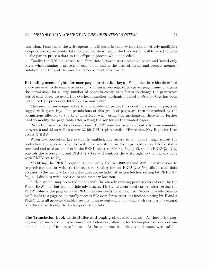
Extending access rights for user page: protection keys While the three bits describedabove are used to determine access rights for an access regarding a given page frame, changingthe permissions for a large number of pages is costly as it forces to change the permissionbits of each page. To avoid this overhead, another mechanism called protection keys has beenintroduced for processors Intel Skylake and newer.
This mechanism assigns a key to any number of pages, thus creating a group of pages alltagged with given key. The permissions of this group of pages are then determined by thepermissions affected to the key. Therefore, when using this mechanism, there is no furtherneed to modify the page table after setting the key for all the wanted pages.
Protection keys use the aforementioned PKEY zone in a page table entry to store a numberbetween 0 and 15 as well as a new 32-bit CPU register called “Protection Key Right for Useraccess (PKRU)”.
When the protection key system is enabled, any access to a memory range causes theprotection key system to be checked. The key stored in the page table entry PKEY slot isretrieved and used as an offset in the PKRU register. For 0 ≤ key ≤ 15, the bit PKRU[2×key]controls the access right and PKRU[2× key + 1] controls the write right to the memory zonewith PKEY set to key.
Modifying the PKRU register is done using the two RDPKRU and WRPKRU instructions torespectively read or write to the register. Setting the bit PKRU[2 × key] disables all dataaccesses to the memory location, this does not include instruction fetches, setting bit PKRU[2×key + 1] disables write accesses to the memory location.
Such a system may seem redundant with the already existing permissions enforced by theP and R/W bits, but has multiple advantages. Firstly, as mentioned earlier, after setting thePKEY value of the page only the PKRU register needs to be modified. Secondly, while clearingbit P leads to a page being totally inaccessible even for instructions fetches, setting bit P and aPKEY with all accesses disabled results in an execute-only mapping, such permissions cannotbe achieved with only the legacy permission bits.
The Translation Look-aside Buffer and paging structure caches As shown, the pag-ing mechanism adds multiple convenient behaviors, allowing for techniques like swap or on-demand loading of frames to be used. At the same time it inevitably adds some overhead due
22 CHAPTER 2. BACKGROUND AND MOTIVATION
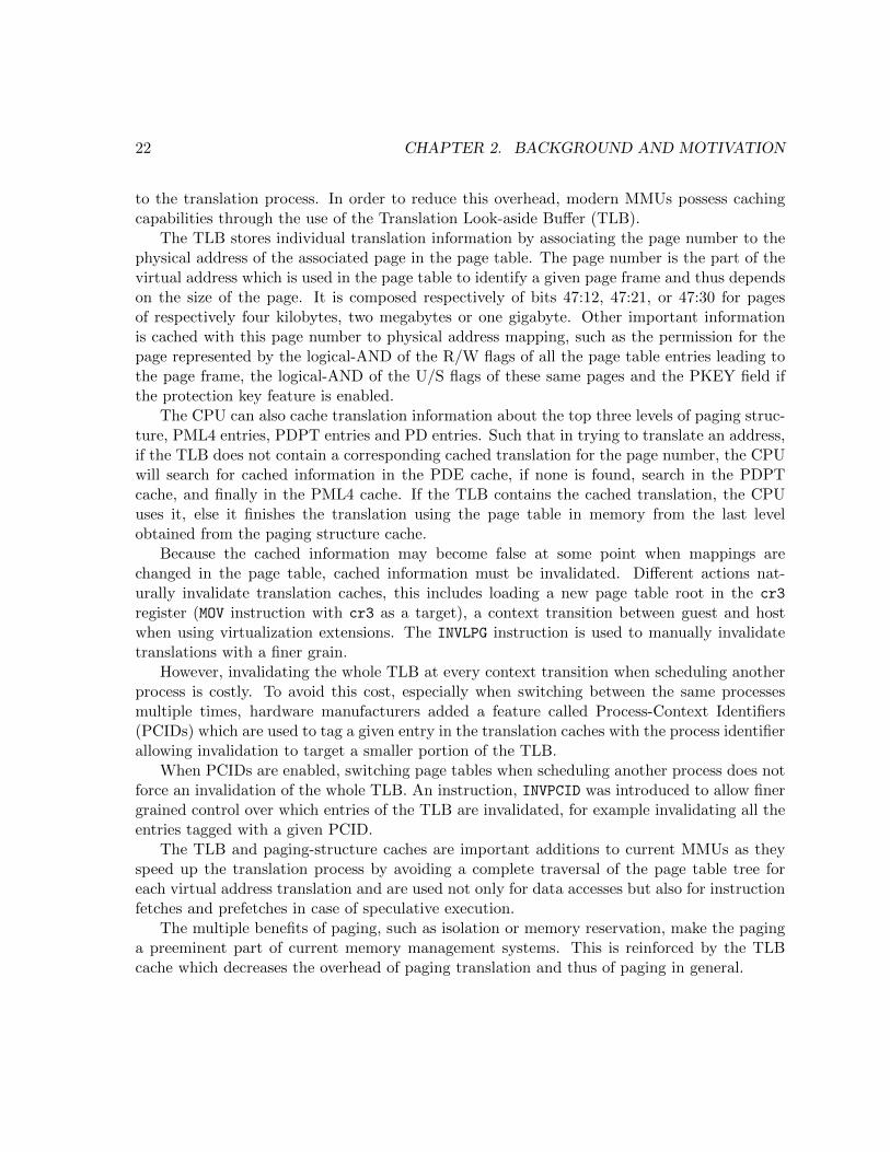
to the translation process. In order to reduce this overhead, modern MMUs possess cachingcapabilities through the use of the Translation Look-aside Buffer (TLB).
The TLB stores individual translation information by associating the page number to thephysical address of the associated page in the page table. The page number is the part of thevirtual address which is used in the page table to identify a given page frame and thus dependson the size of the page. It is composed respectively of bits 47:12, 47:21, or 47:30 for pagesof respectively four kilobytes, two megabytes or one gigabyte. Other important informationis cached with this page number to physical address mapping, such as the permission for thepage represented by the logical-AND of the R/W flags of all the page table entries leading tothe page frame, the logical-AND of the U/S flags of these same pages and the PKEY field ifthe protection key feature is enabled.
The CPU can also cache translation information about the top three levels of paging struc-ture, PML4 entries, PDPT entries and PD entries. Such that in trying to translate an address,if the TLB does not contain a corresponding cached translation for the page number, the CPUwill search for cached information in the PDE cache, if none is found, search in the PDPTcache, and finally in the PML4 cache. If the TLB contains the cached translation, the CPUuses it, else it finishes the translation using the page table in memory from the last levelobtained from the paging structure cache.
Because the cached information may become false at some point when mappings arechanged in the page table, cached information must be invalidated. Different actions nat-urally invalidate translation caches, this includes loading a new page table root in the cr3
register (MOV instruction with cr3 as a target), a context transition between guest and hostwhen using virtualization extensions. The INVLPG instruction is used to manually invalidatetranslations with a finer grain.
However, invalidating the whole TLB at every context transition when scheduling anotherprocess is costly. To avoid this cost, especially when switching between the same processesmultiple times, hardware manufacturers added a feature called Process-Context Identifiers(PCIDs) which are used to tag a given entry in the translation caches with the process identifierallowing invalidation to target a smaller portion of the TLB.
When PCIDs are enabled, switching page tables when scheduling another process does notforce an invalidation of the whole TLB. An instruction, INVPCID was introduced to allow finergrained control over which entries of the TLB are invalidated, for example invalidating all theentries tagged with a given PCID.
The TLB and paging-structure caches are important additions to current MMUs as theyspeed up the translation process by avoiding a complete traversal of the page table tree foreach virtual address translation and are used not only for data accesses but also for instructionfetches and prefetches in case of speculative execution.
The multiple benefits of paging, such as isolation or memory reservation, make the paginga preeminent part of current memory management systems. This is reinforced by the TLBcache which decreases the overhead of paging translation and thus of paging in general.

2.2. MEMORY MANAGEMENT IN THE OPERATING SYSTEM 23
2.2.2 Paging and memory management in user space
While the page table structure is maintained by the kernel, its benefits are also available inuser space both indirectly: isolation of kernel and user space, isolation between processes; anddirectly, through the use of different system calls.
The paging mechanism is activated per CPU and so is activated for both the kernel anduser space. Depending on the kernel model, the page table could be common for all executioncontexts, but using a different page table enforces some isolation between processes beingexecuted in user space.
The Linux kernel uses a different page table for each process in user space, with severalconsequences. On one hand, the memory spaces of processes are separated, forbidding accessfor a process to the memory of another. On another hand, Linux allows mappings to be reusedacross different processes in order to create shared memory segments.
This ability is important to avoid a change of page table when switching to kernel mode,as each process needs the kernel to be mapped in its address space for system calls. The kerneluses a clever trick to avoid having to change every process page table when modifying kernelmappings by reserving one top level entry in the PML4 for kernel usage when a process pagetable is instantiated. This top level entry is the same for every process allowing the kernelto change mappings in subsequent entries without having to modify the page table of eachprocess.
Moreover, using copy-on-write semantics described previously, shared library containingmutable data can be shared without inducing a big memory footprint as the memory is shareduntil a mutable part is modified in which case copy-on-write is used to copy only the modifiedpage frame.
Creating a mapping mmap is the most preeminent system call for user space memory lowlevel management. It enables the programmer to create a new mapping between virtual andphysical memory space. Depending on the parameters (MAP_ANONYMOUS or not) the phys-ical memory is either empty memory or file backed memory. In case the memory is file-backed, this system call exhibits the different advantages mentioned in Section 2.2.2. Usingthe MAP_PRIVATE option creates a copy-on-write mapping. As mmap mappings are page tablemappings, they only manipulate virtual memory, backing physical memory is only allocatedwhen needed (first access).
Changing access rights mprotect is a primitive used to modify permissions on a givenmemory mapping previously obtained by using mmap. As explained in Section 2.2.1, thepage table entries contain permission bits determining which types of access are allowed for agiven zone of memory. The mprotect system call defines several boolean flags among whichPROT_NONE, PROT_READ, PROT_WRITE and PROT_EXEC which can be combined to define if a pagecan be read, written or executed.

24 CHAPTER 2. BACKGROUND AND MOTIVATION
While these flags are defined by the POSIX standard and thus used in the Linux systemcall, their presence in the system call interface does not imply every combination is actuallysupported by the underlying hardware.
The bits from an x86 page table entry used to determine access rights are bit “Present(P)”, “Read/write (R/W)”, “User/Supervisor (U/S)”, from Table 2.1. Because the bit U/Sis always activated for page meant to be accessed in user space, bits P and R/W are the onlyones used to determine permissions. However, as putting the present bit to 0 causes a pagefault when trying to access the page either by reading or writing, this means no combination ofbits can fulfill a PROT_WRITE only permission set. This is summed up in Table 2.2. Moreover,x86 processors have a bit to disable execution on a given page but for the same reasons asabove, the PROT_EXEC flag is equivalent to the PROT_READ flag in Linux.
Table 2.2: Correspondence between x86 page table bits and mprotect flags
mprotect flags Page table bits
PROT_NONE ¬PPROT_READ P | ¬R/WPROT_WRITE not possible
PROT_READ | PROT_WRITE P |R/W
Working with protection keys In kernel version starting from 4.9, the protection keyfeature introduced by Intel is also available in user space memory management through thepkey_alloc, pkey_free, and pkey_mprotect system calls and the pkey_set utility function.The protection key mechanism allows a developer to further restrict accesses to a memory zoneby disabling write or all kinds of accesses (read and write) to the given zone.
This is done by first using pkey_alloc to allocate a protection key with the right set of per-missions, either PKEY_DISABLE_ACCESS or PKEY_DISABLE_WRITE, and then use pkey_mprotectto atomically change both regular protection flags available to mprotect and set a protectionkey to the given memory range.
Thanks to this interface, the advantages of protection keys described previously are avail-able in user space, it is thus possible to create an execute-only mapping by combining thePROT_EXEC (equivalent to PROT_READ) flag with a protection key allocated withPKEY_DISABLE_ACCESS. This method also reduces the cost of changing permissions on pages,as it requires neither changing all the permission bits as explained before nor switching tokernel space as the RDPKRU and WRPKRU instructions are available in user space and usablethrough the wrapper pkey_set. Only the initial setup of the PKEY using pkey_alloc andpkey_mprotect is switching to kernel space.
2.3. STATE OF THE ART: RESOURCES MANAGEMENT AND NUMA 25
To summarize, this section presents the hardware mechanisms and tools built on them whichare commonly used to manage memory, either in kernel space or user space. As explained,changing mappings have a cost, both directly, and indirectly by forcing the TLB cache to beflushed. Therefore their efficiency relies on the ability of the system to properly use them.
2.3 State of the art: resources management and NUMA
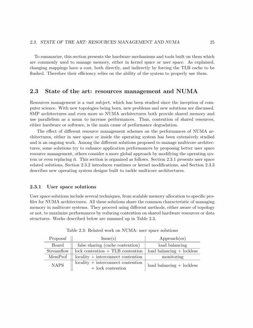
Resources management is a vast subject, which has been studied since the inception of com-puter science. With new topologies being born, new problems and new solutions are discussed.SMP architectures and even more so NUMA architectures both provide shared memory anduse parallelism as a mean to increase performances. Thus, contention of shared resources,either hardware or software, is the main cause of performance degradation.
The effect of different resource management schemes on the performances of NUMA ar-chitectures, either in user space or inside the operating system has been extensively studiedand is an ongoing work. Among the different solutions proposed to manage multicore architec-tures, some solutions try to enhance application performances by proposing better user spaceresource management, others consider a more global approach by modifying the operating sys-tem or even replacing it. This section is organized as follows. Section 2.3.1 presents user spacerelated solutions, Section 2.3.2 introduces runtimes or kernel modifications, and Section 2.3.3describes new operating system designs built to tackle multicore architectures.
2.3.1 User space solutions
User space solutions include several techniques, from scalable memory allocation to specific pro-filer for NUMA architectures. All these solutions share the common characteristic of managingmemory in multicore systems. They proceed using different methods, either aware of topologyor not, to maximize performances by reducing contention on shared hardware resources or datastructures. Works described below are summed up in Table 2.3.
Table 2.3: Related work on NUMA: user space solutions
Proposal Issue(s) Approach(es)
Hoard false sharing (cache contention) load balancing
Streamflow lock contention + TLB contention load balancing + lockless
MemProf locality + interconnect contention monitoring
NAPSlocality + interconnect contention
+ lock contentionload balancing + lockless

26 CHAPTER 2. BACKGROUND AND MOTIVATION
Hoard: A Scalable Memory Allocator for Multithreaded Applications As explainedin Section 2.1.1 and 2.1.2, processor caches carry at the same time an important increasein terms of memory access latency but also introduce different issues related to the cachecoherency mechanism. False sharing is the name given to one such issue that arises whendifferent processors are accessing data from two different locations that are close and thusshare a cache line. As cache controllers load and store data at the granularity of a cacheline, when two different processors write to different data in the same cache line they forceeach other to invalidate the cache line even though there is no logical reason to do so, greatlydegrading performances.
Berger et al. [4], propose Hoard, a memory allocator which avoids false sharing whenpossible.
The root causes of false sharing situations are numerous, those studied in their proposalare classified in three categories. Program induced, when the program creates a false sharingsituation not related to the allocator, such as giving away memory to another processor. Ac-tively induced by the allocator when the allocator is the cause of the false sharing situationsuch as satisfying requests from different processors using part of the same cache line. Finally,passively induced when the program is the cause of the false sharing situation but the allocatordoes not solve the issue when it could. This happens when a processor P1 gives some of itsmemory to another processor P2, this memory is freed by P2, and the allocator reuses thisfreed memory to satisfy allocation requests from P2. In this case, the memory should havebeen reclaimed by the core which initially allocated the memory for P1.
Hoard uses per processor heaps and a global heap. Each heap owns different superblockswhich are allocated by requesting virtual memory from the operating system (using mmap).When multiple threads allocate memory simultaneously, they allocate from differentsuperblocks, avoiding actively induced false sharing. Deallocated blocks are always returnedto their original superblock, avoiding passively-induced false sharing.
Moreover, Berger et al. improves multiprocessor scalability by bounding the blowup oftheir allocator, which they define for a given allocator as “its worst-case memory consumptiondivided by the ideal worst-case memory consumption for a serial memory allocator”. Theyprove that Hoard worst case memory consumption does not grow with the memory requiredby the program.
However, Hoard does not solve contention due to synchronization between processors ac-cessing the same heap. Berger et al. consider that an application with a bad access patternis itself not scalable, they consider the producer-consumer pattern to be the worst acceptablescenario. They evaluate Hoard behavior for this pattern to a twofold slowdown.
To sum up, Hoard is a memory allocator designed to tackle false sharing, a type of cachecontention, by balancing allocation across the different cores.

2.3. STATE OF THE ART: RESOURCES MANAGEMENT AND NUMA 27
Scalable Locality-Conscious Multithreaded Memory Allocation – Streamflow Sim-ilarly to several thread-safe memory allocators, including Hoard, Streamflow, proposed bySchneider et al. [48], uses thread-private heaps to manage memory in order to reduce con-tention between threads.
In order to increase scalibility while reducing cache and paging related bottlenecks, theirprimary contribution is to decouple local operations from their remote counterpart. Thisenables local operations for their allocator to be synchronization-free, avoiding both lock con-tention and the latency of atomic instructions. The remote deallocation mechanism uses alock-free list in which freed blocks are pushed, letting the local thread reclaim these blockswhen needed, without disrupting local operations.
Moreover, as explained in Section 2.2.1, the page table traversal can constitute a bottleneckwhen accessing memory as it contains multiple levels and is the reason why a cache for pagetable translation, the TLB, was introduced. However, the TLB, as any other type of cache,suffers from cache-related issues such as cache pollution when numerous different pages areaccessed. To avoid TLB pollution by diminishing the number of stored TLB entries, Streamflowuses huge pages as the backing memory for their thread-local allocators. Finally, as recentCPUs often implement cache prefetching, the contiguous nature of these large allocationstakes advantage of the larger private CPU caches.
In the continuity of Streamflow, Marotta et al. [34] focus on the improvement of the scali-bility of the back-end allocator. While Streamflow uses hugepages in a centralized fashion inthe back-end for contiguous allocation, Marotta et al. tackle the issue of the back-end scalabiltythrough a lockless approach.
The memory allocation strategy presented above tries to increase scalability by avoidingTLB pollution (page cache contention) and reducing lock contention through balancing memoryaccesses across cores and using a lockless approach.
MemProf: A Memory Profiler for NUMA Multicore Systems Works presentedabove often favor locality as a mean to avoid concurrent accesses to allocators themselves,and thus contention, by balancing allocation requests. However, while favoring locality at allo-cation time solves part of the problem, good memory placement during the whole applicationlife is key to satisfying performances.
In order to improve memory placement during the whole application life, Lachaize et al. [31]propose to apply small scale application-level optimizations to the source code. In order todetect the patterns of memory accesses and threads interactions, they introduce MemProf,a profiler targeted at detecting these patterns on NUMA architectures. It consists of anuser library and a kernel module which allows the profiler to monitor memory accesses usingInstruction-Based Sampling, a hardware feature from the processor.
They consider three different classes of access patterns that can negatively impact perfor-mances on NUMA machines. First, remote usage of a memory location previously allocated

28 CHAPTER 2. BACKGROUND AND MOTIVATION
on another node, which is solved either by changing the original allocation node or if the lat-ter cannot be determined statically, migrating the memory at runtime. The second patternconsists of alternate, non-concurrent remote accesses to a memory location by two differentnodes, which can be solved either by collocating both accessing threads on the node owningthe memory or if applicable, migrating the thread over time on the node owning the memory.Third, concurrent remote accesses to the same location can be treated either by collocatingthreads on the owning node or by duplicating the object and synchronizing the copies overtime (this is recommended solely for read-only or mostly-read objects). Finally, when too muchlocality causes the memory controller to be saturated, the authors suggest to balance the mostused objects over several nodes.
To conclude, Lachaize et al. propose to reduce the overhead of NUMA architectures byincreasing locality and reducing interconnect contention through a profiler using monitoringto detect bad access patterns.
A Study of the Scalability of Stop-the-world Garbage Collectors on Multicores –NAPS As Lachaize et al. suggest, the lack of NUMA-awareness in applications is the causeof severe performance bottlenecks. Gidra et al. [20] focus on garbage collectors as an exampleof such applications. They present and evaluate different approaches to alleviate the load onmemory controllers and increase memory locality.
The algorithm of Parallel Scavenge, the garbage collector of OpenJDK7, classifies objectsaccording to their age, into three different categories, young generation composed of newlycreated objects, old generation representing long-lived objects and permanent generation con-taining the Java classes.
Regularly, the garbage collector stops the program execution and collects the memory inorder to free objects unreachable by the application. When an object from the young generationsurvives the first collection it is moved to a transition space, after a new collection, all survivingobjects from the transition space are promoted to the old generation space.
Gidra et al. introduce a garbage collector called NAPS, which implements different policies.The first approach presented, called Interleaved Spaces allocates the pages for the differentmemory spaces using a round robin policy, which reduces imbalance. The second approachFragmented spaces divides the spaces in multiple fragments each physically belonging to agiven node. Under this policy a thread allocates only from a fragment belonging to the nodeon which it executes. This improves locality as a thread tends to access recently allocatedobjects and thread migration is rare. However, this second approach can increase imbalancewhen a specific thread allocates objects for others. The last approach Segregated space usesthe memory layout of fragmented space but additionally forbids access to remote objects forall garbage collector threads. This forces perfect memory locality at the cost of exchangingmessages between nodes.
The evaluation shows that balancing memory accesses among the nodes greatly increases

2.3. STATE OF THE ART: RESOURCES MANAGEMENT AND NUMA 29
performances by reducing the strain on a given memory controller. The evaluation also showsthat improving locality becomes important when reaching a certain number of cores, to avoidsaturating the interconnect network.
Gidra et al. also tackle the issue of lock contention. The garbage collector of OpenJDK7uses locks to synchronize accesses to internal data structures. In NAPS, the lock contentionis removed either by changing these data structures for lock-free alternatives or changing thesynchronization mechanism to remove locks.
A second study of Gidra et al. [21] on garbage collection with a different design increasesmemory locality not only for newly allocated objects (young generation) but also older objects,further improving performances on NUMA architectures.
NAPS increases the performances of the garbage collection for Java by increasing locality,reducing interconnect contention and removing lock contention through a combination of twotechniques: balancing memory accesses and lockless synchronization.
2.3.2 Runtimes and kernel policies
While careful resources placement for a given program improves performances for one usecase, it is a complex task as evidenced by the need for specific tools such as MemProf [31].Another approach to better handle NUMA architectures is through runtimes or generic policiesintegrated in the operating system.
Works presented thereafter tackles NUMA related issues such as locality, or contentionusing different techniques, without directly modifying applications. These approaches aresummed up in Table 2.4 and described in more details below.
Table 2.4: Related work on NUMA: runtime and kernel approaches
Proposal Issue(s) Approach(es)
MCTOP locality + code portability monitoring + generic policies
CarrefourCarrefour-LP
contention (memory + interconnect) monitoring + load balancing
AsymSched interconnect contention monitoring + load balancing
Abstracting Multi-Core Topologies with MCTOP While applications-specific opti-mizations can lead to improved performances on NUMA architectures as shown above, thesemodifications are too often linked to a specific topology or operating system specific topologydiscovery. Chatzopoulos et al. [10] propose a library which allows developers to define resourcesplacement for their application in a portable manner, using an inferred topology.
MCTOP defines an abstraction of multicore topology using generic concepts, they thusdefine hw context, which is a hardware thread if the machine supports hardware multithreading

30 CHAPTER 2. BACKGROUND AND MOTIVATION
(SMT) or a core, hwc group which can be a core (group of hardware thread) or a group of core,node a memory node, socket which contains a hwc group with additional information aboutmemory nodes and interconnect which represents the connection between sockets and includeinformation such as the communication latencies.
Using these abstractions, MCTOP infers the topology of ccNUMA machines using latencymeasurements. They proceed as follows, first they collect hw context to hw context latencymeasurements, then group components together depending on both the communication latencybetween each other and the communication latencies to other groups. Finally, they assign rolesto the components, thus creating a multicore representation.
Chatzopoulos et al. propose multiple standard policies built on top of their deduced topolo-gies, such as “Topology-Aware Work Stealing”, “Topology-Aware Reduction Trees” (which canbe used to implement MapReduce paradigm) or “Educated Backoffs”.
For portability reasons, this abstraction avoids the operating system representation of thetopology. It uses monitoring techniques to determine the topology and apply generic policiesto increase both locality and code portability.
Traffic Management: A Holistic Approach to Memory Placement on NUMA Sys-tems – Carrefour Unlike MCTOP, Dashti et al. [13] propose to introduce a new placementalgorithm, called Carrefour in the Linux kernel.
Carrefour specifically targets congestion on the memory controller and interconnect net-work. It operates using four mechanisms. Page collocation relocates a physical page close tothe thread accessing it, which is efficient when the memory is accessed by a single thread orcollocated threads. Page interleaving balances some pages among the different nodes. Pagereplication consists in replicating the memory on different nodes and keeping it synchronizedwith a coherency protocol. Finally, Thread clustering collocates threads sharing some memory.
In order to decide which mechanism is adapted to a given situation, Carrefour first gathersinformation about memory and cache accesses using hardware instruction sampling. Using thisinformation, Carrefour takes two decisions. First whether or not it generates enough memorytraffic to justify the use of Carrefour. Second, if this application would benefit from page repli-cation, interleaving or collocation, multiple mechanisms can be enabled for a given application.Finally, when a page is sufficiently accessed during the application lifetime, Carrefour decidesfor this given page which of the globally enabled mechanisms is the most appropriate.
Considering that memory bandwidth is more susceptible to cause performances issues innewer NUMA architectures than remote accesses latency, this approach from Dashti et al.addresses the congestion of both the memory controllers and the interconnect.
A followup work by Gaud et al. [19] extends the original Carrefour algorithm to large pages.As large pages are known to reduce both the overhead of paging translation and TLB missrate, they are used in different memory management mechanisms as testified by Schneider etal. [48]. However, Gaud et al. [19] reveal that they may also increase the imbalance in the

2.3. STATE OF THE ART: RESOURCES MANAGEMENT AND NUMA 31
distribution of memory controller requests and reduce accesses locality, the two main factorsof performances on NUMA architectures.
In their work, they identify two new issues related to large pages and NUMA. First, largepages cause the number of pages susceptible to be migrated to decrease. In some cases, this caneven lead to fewer very accessed large pages than NUMA nodes, making balancing impossible.Second, as the size of individual pages grows, they are more susceptible to contain individualblocks of data used by different threads. They refer to this problem as page-level false sharingbecause of the similarity with the false sharing problem in cache lines.
To correct these issues, the extension of the Carrefour algorithm, called Carrefour-LPcombines two different approaches, the reactive approach which monitors large pages andsplits them into normal sized pages before applying the standard Carrefour algorithm, and theconservative approach which, to the contrary, merges small pages into large ones when betterperformances are expected. These decisions are based on the same performance counters(instruction sampling) than the original Carrefour algorithm.
Both Carrefour and Carrefour-LP use monitoring to detect memory access patterns andbalance the load across NUMA nodes. This approach aims to reduce the contention on thememory controller and interconnect network.
Thread and Memory Placement on NUMA Systems: Asymmetry matters – Asym-Sched The different heuristics presented above try to solve performance issues on NUMAarchitectures by collocating, or conversely, spreading the resources on different nodes depend-ing on the access patterns. However, the nature of the connection between these nodes canplay an important role in deciding of the resources placement.
Dasthi et al. [13] consider that the congestion on the interconnect is more important thanthe latency of remote accesses. Similarly, Lepers et al. [32] study the impact of the interconnectasymmetry on placement decisions.
In particular, they show that it is best to prioritize the path with the maximal bandwidthrather than with the minimal number of hops. They propose an algorithm to place threadsand memory such that the most intensive CPU-to-CPU or CPU-to-memory communicationsoccur on a link with the best possible bandwidth.
Similarly to Carrefour, their placement algorithm, AsymSched uses hardware counters togather information. However, the lack of CPU-to-CPU or CPU-to-RAM counters, makes thenumber of accesses from a given CPU to a node, which encompasses both of the precedingcases, the only available metric.
Because of the lack of specific CPU-to-CPU and CPU-to-RAM counters, they consider thatany CPU with a high recorded level of access to a given node might be communicating withany CPU on the accessed node. Moreover, they cannot determine the access patterns of a CPUaccessing its local node, and thus consider it might be communicating with all the CPUs of itslocal node. Using the gathered information, AsymSched computes the possible placements and

32 CHAPTER 2. BACKGROUND AND MOTIVATION
chooses the configuration that both maximizes the overall communication bandwidth acrossall applications and minimizes the number of page migrations.
This work adds a third criterion, the asymmetry in bandwidth of the interconnect, to theusual two criteria which characterize performances on a NUMA machine, the congestion of theinterconnect and memory controllers on one hand, the latency of remote accesses on anotherhand.
2.3.3 Operating system solutions
With different approaches ranging from per application optimizations to OS-level schedulingand placement policies, proposals described before all use a standard operating system, notone specifically designed to manage NUMA architectures. Works presented thereafter all sharethe common idea that current operating systems are not correctly managing large multicores.Therefore, they propose entirely new operating system designs. Table 2.5 sums up the studiedproposals.
Table 2.5: Related work on NUMA: New operating system designs
Proposal Issue(s) Approach(es)
Corey OS-level structures contentionavoid sharing
(processes decide what is shared)
The Multikernel OS-level structures contentionmessage passing
(one kernel per core)
fos contention + portabilitymessage passing
(processes and OS do not share cores)
Corey: An Operating System for Many Cores Because classic operating systems sharedata structures across the whole machine, they introduce an overhead which cannot be removedusing only user space mechanisms or OS-level resources placement. To solve this issue, Boyd-Wickizer et al. [6] propose a new operating system design to avoid the bottleneck of sharedOS-level data structures.
This work is guided by the principle that applications should control sharing of operatingsystem data structures and propose three abstractions demonstrating this principle. Addressranges allow applications to control which parts of the address space are private per coreand which are shared, Kernel cores allow applications to dedicate cores to run specific kernelfunctions and Shares control which kernel object identifiers are visible to other cores.
Address ranges control how virtual memory mapping are shared by cores. As each processorusually contains its own page table pointer and corresponding structures, sharing and updatingsaid structures for all cores has a cost, which address ranges aim to control. A core with a non-shared address range can update it without requiring synchronization or TLB shootdowns. A

2.3. STATE OF THE ART: RESOURCES MANAGEMENT AND NUMA 33
shared address range will incur the cost of synchronization. Kernel cores allow an application todedicate a core to kernel functionalities such as networking, reducing the contention for driverdata structures and related synchronization mechanisms. Finally, Shares allow applications tokeep some common kernel identifiers such as process identifier or file descriptors private.
Because typical kernel structures are shared and rely on expensive mechanisms such ascache-coherency, avoiding implicit sharing is one method to greatly increase performances onmulticore architectures.
The Multikernel: A new OS architecture for scalable multicore systems In thesame manner as Corey, Baumann et al. [3] propose a new kernel design reducing implicitsharing of kernel data structures. Their proposed design, the multikernel, treats the machineas a network of independent cores and uses message passing for inter-core communication. Todemonstrate the new multikernel design, they produce an implementation called Barrelfish.
This design relies on three main principles, all inter-core communication are explicit, OSstructure is independent of hardware and OS state is replicated, not shared.
For the same reasons as Corey, using explicit communications and replicated states avoidsthe cost of synchronization when updating shared data structures. It also favors locality ofaccesses to kernel structures. The distributed architecture of the multikernel simplifies thereasoning of programmers by making the kernel structure modular but also makes it easier topreserve OS structure while hardware evolves.
Factored Operating Systems (fos): The Case for a Scalable Operating System forMulticores While the multikernel design does not use shared memory directly, the messagepassing mechanism, used to explicitly communicate between cores, still uses some form ofshared memory. In contrast, Wentzlaff et al. [59] propose an operating system design whichdoes not rely on shared memory or cache coherence, Factored Operating System (fos).
Considering that future machines will feature a very important number of cores (hundreds),fos proposes to exploit this specificity by using a client/server architecture for both the oper-ating system and applications. Similarly to the multikernel design, servers communicate onlyvia message passing, which is delegated to hardware.
The goal of fos is to leverage standard Internet servers optimizations such as caching,replication or spatial distribution. To this end, the operating system functionalities themselvesare split into different services which are distributed on several cores. The components of fosarchitectures are the following. A thin microkernel which provides the communication API andacts as a name server to contact other cores. This microkernel executes on every core. An OSlayer, which provides standard operating systems services such as resources management (cores,memory), I/O functions (file system, networking). These OS functionalities are implementedas servers. They run on top of the common microkernel and are distributed across the machine.

34 CHAPTER 2. BACKGROUND AND MOTIVATION
Distributing applications and OS services on different cores avoids implicitly sharing percore resources such as data caches or TLB, leading to improved performances. Moreover,avoiding shared memory nullifies the impact of cache coherency on performances and as withthe multikernel, eases to preserve the new design while hardware evolves.
2.4 Conclusion
This chapter presents different multicore architectures and more specifically the NUMA ar-chitecture. Nowadays, NUMA architecture has become the most common architecture forservers, with hundreds of cores distributed in multiple nodes. While the high density of re-sources, both compute or memory, allows very important computation power, this can be doneonly by correctly managing the complex topology, caches, memory controller, interconnectnetwork.
In this chapter, we presented NUMA machines, their components and how resources place-ment is the main cause of performance degradation. Then we explained how to modify re-sources placement through the use of memory management techniques, both in kernel space,with the page table, and in user space with tools derived from the kernel page table. Finally,we presented some solutions proposed in related work to remedy aforementioned performance-degrading patterns. These solutions can be classified into three categories: first, user spacesolutions which target a specific application or class of applications; second, runtimes andchanges to the kernel placement policy, more generic approaches; third, complete redesigns ofthe operating system layer.
The first part of our approach to resources placement falls in the second category, runtimessolutions. As increasing parallelism is important to better leverage these new architectures, ourapproach, Commmama uses memory management techniques to overlap communication withcomputation in the Message Passing Interface (MPI) runtime used by many high performancecomputing applications.
The second part, Scalevisor, falls between the second and the third categories as it proposesto use virtualization techniques to manage resources in a layer below the operating system.Scalevisor avoids the hassle of modifying the code of legacy operating systems while proposinga new design to memory management in complex architectures.

Chapter 3
Commmama, motivation and design
With the evolution of computer architectures, especially the growing number of cores and fastnetworks, one of the keys to performance improvement is maximizing parallelism by correctlymanaging compute, memory, and network resources. At the user space level with messagepassing in applications, this means focusing on the ability to overlap network communicationswith CPU-bound computation. This chapter thus addresses the challenge of maximizing theparallelism in applications using both computation and network.
MPI is a widely used library for HPC applications. It offers a message-based interfaceto communicate between nodes, with either two nodes involved (point-to-point operations) ormore than two nodes (collective operations). The MPI specification features an importantnumber of communication primitives, each offering different semantics. These semantics rangefrom blocking senders and receivers until the communication is completed to letting the sendersand receivers overlap communication with computation. The data provided by the applicationto the MPI runtime cannot be modified until the communication is completed. In blockingcommunications, this is transparent to the user as blocking communications block until thecommunication is completed. However, for nonblocking communication, the application mustnot modify the communication buffers containing the data of an ongoing communication.
Implementing an application that efficiently uses the nonblocking primitives is complex. Asnonblocking primitives do not block until the communication is completed, the application canoverlap communication with computation while the nonblocking communication is underway.However, the application must track which buffers are involved in ongoing communications andexplicitly wait for these communications to end if they need to access said buffers. Choosingthe right point in the program to wait for the completion of an operation may be difficultwhen nested functions may access the memory or not. This difficulty leads developers totake a pessimistic approach in which the communication completion is awaited earlier thannecessary, thus losing some overlapping potential. In the worst scenario, the developer willuse blocking communication to ensure the program correctness, thus trading efficiency for
35

36 CHAPTER 3. COMMMAMA, MOTIVATION AND DESIGN
simplicity of design.
In order to improve the performance of MPI applications we propose Commmama. Comm-mama automatically transforms blocking primitives into nonblocking ones at runtime. To thisend, Commmama uses a separate communication thread responsible for communications anda memory protection mechanism to track memory accesses in communication buffers. Thisallows communications transformed by Commmama to progress in parallel until their data areneeded.
This chapter is organized as follows. In a first part, in order to better understand thechallenges of overlapping communication with computation, this chapter details the differenttypes of communications available in MPI and their characteristics. We show there are two keyfactors needed to improve parallelism. First, background progress which guarantees commu-nications are processed while computation is running. Second, the size of the window duringwhich computation and communication can be run in parallel.
In a second part, we present our proposal, Commmama, which transforms blocking com-munications primitives into nonblocking ones to increase the potential for communication andcomputation overlap. Commmama guarantees both progress for these communications and thelargest window during which communication and computation can be processed in parallel.Commmama combines both the simplicity of blocking communications and the efficiency ofnonblocking ones to provide an efficient and hassle-free approach to MPI application design,thus avoiding the aforementioned trade-off between efficiency and simplicity of design.
Finally, we present an evaluation of Commmama and show that it increases parallelism byoverlapping communication with computation. Our results show that when there is enoughcomputation to overlap the communication phase, the whole communication is done in thebackground. In contrast, when there is not enough computation, we show that our approachstill performs well, with little overhead compared to a standalone MPI runtime.
3.1 Background and motivation
Message Passing Interface (MPI) [37] is a specification designed to establish a standard formessage passing libraries used in high performance applications. This specification is imple-mented by different open-source libraries such as OpenMPI [41] or MPICH [38]. Because of itsefficiency and stability, it is used by many projects involving distributed applications or highperformance computing.
The MPI specification consists in a set of primitives and semantics which must be respectedby any given implementation. MPI focuses on message passing and thus is not designed forany particular data transfer medium. Among the different implementations, multiple transportlayers are supported, such as shared memory, Ethernet or InfiniBand, making MPI a usefultool in many different environments.

3.1. BACKGROUND AND MOTIVATION 37
This section is organized as follows. Section 3.1.1 presents the MPI specification, the dif-ferent types of communications available and their semantics. Section 3.1.2 explains why someprimitives can overlap communication with computation and some cannot. It then presentsrelated work which aims to ensure background progress or maximize the overlapping ratio.Section 3.1.3 presents how our approach combines the simplicity of blocking primitives andthe overlapping capability of nonblocking primitives.
3.1.1 MPI primitives and semantics
The MPI specification defines several primitives tailored for different use cases. MPI primitivescan be divided in two main categories, blocking ones and nonblocking ones, based on theirbehavior. This section details these primitives and their semantics.
Blocking and nonblocking communications According to the MPI specification, an op-eration completes when the user can reuse resources specified as input parameters for thisoperation, this includes input communication buffers. When the communication completes,output parameters of the functions have been updated, including any output communicationbuffers. A buffer can be used by a primitive as both input and output.
A blocking communication does not return until the operation completes, therefore, untilthe message data are either stored by the MPI runtime or transmitted through the transportlayer. In contrast, when using a nonblocking communication, the communication buffer mustnot be used before a waiting primitive, such as MPI_Wait, has been called. More precisely, thebuffer cannot be written to, in case of ongoing send operations, or accessed in case of ongoingreceive operations before the communication has completed.
In order for blocking communications to be able to return while the receiver is not readyto receive yet, the data contained into the buffer and the metadata of the operation must bestored somewhere. How data are stored is not specified in the standard and actually differsbetween implementations and transport layers. In most cases, the data is either copied in asystem buffer or simply sent through the transport layer.
Synchronous and asynchronous communications While the blocking or nonblockingproperty of a communication primitive depends on whether the communication buffers canbe reused or not when the primitive returns, the synchronous or asynchronous property of aprimitive depends on whether senders and receivers must synchronize.
A synchronous communication completes only if a matching receive is posted and thereceive operation has started receiving the data. In other words, a synchronous communicationforces synchronization with the other nodes taking part in the communication. In contrast,an asynchronous communication primitive offers no additional information on the state of theother nodes and may or may not synchronize with them.

38 CHAPTER 3. COMMMAMA, MOTIVATION AND DESIGN
The synchronicity property of an MPI primitive is independent from its blocking or non-blocking behavior. MPI primitive can thus belong to any combination of blocking or nonblock-ing and synchronous or asynchronous.
For example, in a synchronous, nonblocking send operation, the sender returns immedi-ately after starting the communication, the buffer cannot be reused before a call to a waitingprimitive, which will synchronize with the receiver. The waiting primitive will complete onlyafter the receiver has started to receive. In contrast, in an asynchronous, blocking send, thesender returns after the buffer has been copied in system buffers by the MPI runtime, thebuffer can then be reused but the receiver node may not have executed the receive primitiveyet.
Illustration: the MPI_Send function family The MPI_Send function family illustrates thedifferent properties of blocking, synchronicity or lack thereof.
There are multiple variants of the “send” function: the standard MPI_Send, MPI_Bsend,MPI_Ssend and MPI_Rsend and their nonblocking counterparts. The distinction between thesefour functions depends on two concepts, the message buffering or lack thereof and the syn-chronous or asynchronous component of the primitive. The characteristics of the differentblocking send primitives are summed up in Table 3.1, more details on each primitives follow.
Table 3.1: Blocking send modes
Synchronous Buffered
MPI_Send No Implementation dependent (for small message)
MPI_Bsend No Yes
MPI_Ssend Yes Irrelevant
MPI_Rsend No Implementation dependent (for small message)
As explained earlier, message buffering is the act of copying the data contained in thecommunication buffer to an alternate buffer in which the data will stay until the communicationis completed. This allows the communication buffer to be reused by the application while thecommunication proceeds.
MPI_Send also called “standard mode” send is the basic send primitive, for performancereasons, most MPI libraries implements buffering for small messages when using the standardmode MPI_Send primitive. The primitive may thus choose either to synchronize with thereceiver or to buffer the message depending on its size.
MPI_Bsend is similar to MPI_Send except that if the matching receive has not been postedMPI_Bsend must copy the message in MPI internal buffers and return, whereas MPI_Send canwait for the matching receive and avoid buffering.
MPI_Ssend is a synchronous communication primitive, it can return only after a matchingreceive has been posted, it never needs to copy the message content to MPI internal buffers as

3.1. BACKGROUND AND MOTIVATION 39
it can directly initiate the sending operation after the matching receive is detected.
MPI_Rsend has the same semantics as a MPI_Send except that it informs the runtime thata matching receive has been posted already.
As nonblocking primitives only notify the MPI runtime that a communication starts, allthese primitives return immediately, this is the case for example of MPI_Isend, and evenMPI_Issend. However, the send-complete operation, ensured by a call to a waiting primitive,has the same semantics as its respective blocking version, presented in Table 3.1. For example,a MPI_Wait following a MPI_Issend is synchronous, and must wait for the matching receiveto be posted. In all cases, MPI semantics specify that when the communication is completed,whether because the message has been buffered or not, the communication buffer is free to bemodified by the application.
Point-to-point and collective communication primitives The MPI specification pro-vides point-to-point primitives and collective primitives. A point-to-point primitive involvesexactly two processes: a sender and a receiver. A collective primitive involves more than twoprocesses.
These primitives represent different communication patterns, such as one sending to all(MPI_Bcast), all sending to all (MPI_Alltoall), or all sending to one (MPI_Gather) and theirrespective nonblocking versions, added in the third edition of the specification, MPI_Ibcast,MPI_Ialltoall and MPI_Igather.
In contrast to the point-to-point primitives above, collective communications have no syn-chronous versions, the only synchronous collective primitive is MPI_Barrier, other collectiveoperations are not required to synchronize the processes inside of the communication group.
3.1.2 Overlapping communication with computation
While message buffering allows blocking communication primitives to overlap communicationwith computation to a certain degree, it also produces an overhead due to copying the commu-nication data to an internal buffer. This becomes costlier when message size increases, hencethe compromise used in multiple MPI implementations to buffer MPI_Send data only for smallmessage sizes. The difference between blocking and nonblocking communications thus residesin the ability for nonblocking communications to be overlapped with computation.
To honor a send request, the runtime has two main options. First it can send the full dataand let the receiving process buffer the data until a matching receive is posted. This first optionis known as eager. Second, it can send only a protocol message indicating a send operation isposted and wait for the receiving side to respond when a matching receive is posted. In thissecond option, called rendez-vous, a handshake occurs before the data are sent, allowing thedata to be received by the other process directly in the user provided communication buffer.

40 CHAPTER 3. COMMMAMA, MOTIVATION AND DESIGN
Figure 3.1 depicts such communications. The brown bar represents the location of the data(horizontal axis) through time (vertical axis). Thus a long brown bar means data stay a longtime in a given memory zone, either user memory or internal MPI runtime memory.
For example, in the eager communication on the left, the data evolves as follow. At thebeginning, data are stored in user memory, then during the call to MPI_Send they are copiedto a buffer owned by the MPI runtime. The MPI runtime then proceeds to send the datathrough the network, which are received by the other process and buffered. The data are nowstored in a buffer owned by the MPI runtime of the second process. When the second processcalls the MPI_Recv primitive, the data are copied to the receive buffer of the user.
For rendez-vous, on the right, the data are stored in the user buffer until the handshakehas occurred, when the matching receive has been posted. Data are then sent directly to thereceiving user buffer during the end of the MPI_Recv primitive.
Eager Rendez-vous
Time
Memory location
MPI_Send
MPI_Recv
Data
UserMPI
runtimeMPI
runtime User
MPI_Send
MPI_Recv
Data movement(Copy / Transfer) Handshake
User UserMPI
runtimeMPI
runtime
Figure 3.1: Comparison of eager and rendez-vous for blocking communications
With the eager protocol, the sender does not have to wait for the receiver to be ready toreceive this particular message. In other terms, there is no need for synchronization betweenthe sender and the receiver. While this can improve performances, it forces the MPI runtimeon the receiver side to allocate sufficient buffer space to contain all the in-flight messages.Moreover, when the receiver calls the matching receive primitive, it still needs to copy thecontent of the already received message from the temporary buffer to the final applicationbuffer. This protocol is thus not profitable for bigger message size.

3.1. BACKGROUND AND MOTIVATION 41
In contrast, for the rendez-vous protocol, the sender only sends the message metadata(source and destination among others) to the receiver and waits for an acknowledgment beforesending the data. This acknowledgment is sent back by the receiver when it enters the receivingprimitive which in turns forces a synchronization between the two processes runtimes. Thisprotocol directly writes the data into the application buffer given to the respective receivingprimitive thus avoiding a copy and the need for internal buffer space.
For blocking communications using the eager protocol, the send primitive returns immedi-ately after the data are copied. The application can thus continue its computation. Therefore,the communication is overlapped with computation except for the time taken to copy data toMPI internal buffers. In contrast, this is not possible due to the synchronizing nature of therendez-vous protocol.
Nonblocking communication and progress In order to improve performances, nonblock-ing primitives were designed to help overlapping communication with computation.
Nonblocking primitives are composed of two parts, the “start” primitive (MPI_Isend forexample) and the completion primitive (MPI_Wait for example). As the nonblocking version ofthe primitive only registers the intent to do a send or receive operation, it returns immediately,without waiting for the communication to complete. The theoretical overlapping windowextends from the start of communication to the completion primitive call.
For eager protocol, data can be pushed into the distant runtime buffer between the callto the MPI_Isend primitive and the call to the waiting primitive. This data transfer does notrequire a corresponding receive to be posted. When the call to the receive-complete occurs,either because the call is blocking or because of a waiting primitive, the runtime buffer is copiedto the local buffer. When supported by the communication controller, the sending or receivingprocedure can thus take place concurrently and the program can continue its execution untilthe communication result is needed, at which point it calls a waiting primitive. This allowscommunication to be overlapped with computation.
For the rendez-vous protocol, this does not work in most of the cases because the MPIruntime shares the thread with the application. In details, for the rendez-vous protocol, theapplication needs to interact with the MPI runtime twice, a first time for the handshake and asecond time for exchanging the data. This issue appears for nonblocking communications, evenif the communication controller supports sending data in the background. If the MPI_Isend
starts the handshake, when it receives the answer from the receiving process, the MPI runtimefrom the sender side will not be able to do any message matching while the sender runscomputation, because the shared thread is busy. Thus, most of the time the acknowledgmentfrom the sender is seen during the waiting primitive and all the data transfer occurs there.These two cases are represented in Figure 3.2
To avoid this issue, it is possible to force the application to enter the MPI runtime, givingthe latter the opportunity to get the acknowledgment and start the data transfer. This can be

42 CHAPTER 3. COMMMAMA, MOTIVATION AND DESIGN
MPI_Irecv
MPI_Wait
Eager Rendez-vous
Time
Memory location
Data
UserMPI
runtimeMPI
runtime User
Data movement(Copy / Transfer) Handshake
User UserMPI
runtimeMPI
runtime
MPI_Isend
MPI_Wait
MPI_Isend
MPI_Irecv
MPI_Wait MPI_Wait
Figure 3.2: Comparison of eager and rendez-vous for nonblocking communications
achieved by calling the MPI_Probe primitive to help the MPI runtime get CPU time. Whilethis basic solution can help overlapping communication with computation in some simple cases,it becomes overly complicated when the algorithm is not composed of simple loops. Further-more, while this solves the latency issue caused by some process waiting for the handshaketo terminate, depending on the type of transport layer, some of the copy operation will stealCPU time from application. In order to correctly process the rendez-vous acknowledgmentand avoid stealing CPU time from the application, a background progress thread is necessary.
Ensuring background progress for communications In order to better overlap commu-nication with computation, a number of techniques have been developed to ensure the progressof the ongoing communication. This is the case of Denis et al. [14] and Trahay et al. [54] whichuse threads to increase asynchronous progress by running communications in separate tasks.This avoids the issue mentioned above of stealing CPU time from the compute thread.
Vaidyanathan et al. [57], probably the closest approach to ours, delegate MPI nonblockingcalls to a standalone thread. This approach reduces the CPU time consumed to perform theMPI calls in the application thread, and ensures the progression of offloaded communications.However, this does not increase the overlapping ratio, which directly depends on the waitingprimitive placement in the application code.

3.1. BACKGROUND AND MOTIVATION 43
Similarly, Min Si et al. [49] present an asynchronous progress system using processes inplace of threads and is targeted at many-core architectures.
Didelot et al. [15] propose a different approach, with no added parallel execution unit,which uses idle cycles created by imbalance in computation time to improve progression.
Works presented here focus on making communication progress, most of the time using aseparate execution context to process communications.
Maximizing the overlapping ratio While ensuring background progress of the commu-nications is an important part in maximizing the efficiency of communication overlapping,ensuring an important overlapping ratio is also of the utmost importance.
Maximizing the ratio of communication overlapped with computation is the best method toleverage background progress and thus maximize performance. To this end, some approachesuse compile time techniques to evaluate the best position for nonblocking primitives and specif-ically MPI_Wait calls to maximize the overlapping portion of communication and computation.
This is the case of Martin et al. [36] which use source to source translation to remodelthe code. They use compiler pragmas to divide the code into three types of regions: send,receive and compute. This allows some communication to be overlapped with computationby running communication and compute regions in parallel on different cores. However, thecompute region still needs to start with a waiting primitive (in most cases MPI_Waitall) whichin turn seems too coarse grained to attain a satisfying overlap ratio in complex cases.
Fishgold et al. [16] propose a finer grained, automated technique which detects patternspresenting an opportunity for transformation by parsing the source code and then modifies it.This approach focuses on finding compute loops filling parts of communication buffers at eachiteration and modifying them to send these parts when ready. While this technique covers alarge portion of MPI applications, especially High Performance Computing related ones, ourapproach works for a broader field of application. Moreover, they focus on MPI_Alltoall
collective while our work does not target a specific communication primitive.
A similar approach from Guo et al. [25] uses static code analysis to replace blocking com-munications by nonblocking communications in loop based computations thus overlappingcommunication step i with computation step i+ 1. This approach uses compile time analysis,compute loops, and does the communication progression using MPI_Test primitives inserted inthe loop body, which gives the MPI runtime some CPU time to make the loop communicationsprogress. This approach is closely related to that of Murthy et al. [39].
Another attempt to increase the overlap of communication and computation is presentedby Anthony Danalis et al. [12]. They describe an algorithm used to optimize the overlapwindow at compile time by replacing blocking primitives with nonblocking ones and placingthe waiting primitive as far as possible to increase performances. However, unlike previouswork they make the assumption that the compiler is aware of MPI semantics. While thisallows for an even better increase in the overlap window, this makes the work of compiler

44 CHAPTER 3. COMMMAMA, MOTIVATION AND DESIGN
developers and MPI developers more complicated, which is not the case in our approach asit operates transparently. Nguyen et al. [40] propose a similar solution which uses clang toperform modifications.
The method presented by Saillard et al. [47] uses code instrumentation and offline analysisto determine code fragments where overlapping capabilities are not fully exploited. After theinstrumented run has terminated, their tool uses the trace files to perform optimizations.
While the field of background progress for MPI primitives has been extensively studiedwith approaches using either compile-time or run-time techniques, all these proposals focuson the standard way of producing overlapped communications and computation: nonblockingprimitives.
3.1.3 Commmama: blocking simplicity, nonblocking efficiency
As described in Section 3.1.2, the application can overlap some communication with compu-tation using nonblocking primitives. Two key factors increase the efficiency of nonblockingcommunications. First, a progress engine transforms a potential overlapped communicationinto an effectively overlapped communication. Second, the size of the temporal window duringwhich overlapping communication and computation occurs directly determines the amount ofoverlapped communication. However, using nonblocking primitive adds a degree of complexityin comparison to simple blocking primitives.
All nonblocking primitives must be completed using one of the waiting primitives, called ona request object which represents the ongoing communication. The code thus becomes morecomplex because of both needs to call the waiting primitive and to manage the different requestobjects. This is illustrated by comparing Listing 3.1 demonstrating a contrived example of ablocking MPI_Send usage and Listing 3.2, a nonblocking version of the same example.
1 void write_function(int* buffer , ...) {
2 int* result = do_long_computation ();
3 memcpy(buffer , result , ...);
4 }
56 void example(int* buffer) {
7 MPI_Send(buffer , ...);
8 read_only_function(buffer , ...);
9 write_function(buffer , ...);
10 }
Listing 3.1: Simple example using blocking communication
Moreover, the placement of the MPI_Wait primitive in Listing 3.2, while allowing to over-lap the send operation with the read_only_function execution, is nonetheless not optimal.If the write_function starts with some computation sequence not writing directly into the

3.1. BACKGROUND AND MOTIVATION 45
1 void write_function(int* buffer , ...) {
2 int* result = do_long_computation ();
3 memcpy(buffer , result , ...);
4 }
56 void example(int* buffer) {
7 MPI_Request handle;
8 MPI_Isend(buffer , ..., &handle );
9 read_only_function(buffer , ...);
10 MPI_Wait (&handle , ...);
11 write_function(buffer , ...);
12 }
Listing 3.2: Overlapping using nonblocking communication
communication buffer, the waiting primitive could be placed further in the execution sequence,after this computation, to provide a higher degree of overlapping and thus better overall per-formances.
While this contrived example easily demonstrates the misplacement of the waiting primi-tive, in a complex program containing deep nested functions or callbacks, placing the waitingprimitive in its optimal place is close to impossible. Because statically placing the waitingprimitive is difficult, and because blocking communications are easier to handle in general, wepropose a method to transparently overlap blocking communication with computation.
In order to benefit from both the simplicity of blocking communications and the overlappingcapabilities of nonblocking communications, we developed Commmama, an overlapping libraryand progress engine which automatically transforms blocking communications into nonblockingones at runtime and manages the memory used for communication buffers to enforce the MPIspecification semantics.
Commmama offloads communications to another thread, acting as an intermediary betweenthe application and the MPI runtime. The offload thread is responsible for starting commu-nications and ensuring background progress. This reduces tasks executed on the critical pathfor the computation thread to a minimum, maximizing the time dedicated to computation.In case the communication uses the eager protocol, the offload thread avoids the applicationthread having to wait for the data to be copied in the MPI runtime internal buffers. This isshown in Figure 3.3 on the left. When the MPI runtime switches to the rendez-vous protocol,the offload thread avoids the computation thread to be blocked while waiting for the handshaketo complete (blocking case) or for the whole data transfer to occur in the waiting primitive(nonblocking case). This is illustrated on the right part of Figure 3.3.
Our proposal thus performs well on eager protocol but above all provides an importantimprovement on rendez-vous protocol by ensuring communications progress while the mainthread continues to run computation until communication results are needed. Moreover, Com-

46 CHAPTER 3. COMMMAMA, MOTIVATION AND DESIGN
Time
Memory location Data movement(Copy / Transfer) Handshake
Eager
MPI_Send
MPI_Recv
Data
User UserMPI MPI
protectsbuffer
addedoverlap
time
addedoverlap
time
Comm-mama
Comm-mama
Rendez-vous
MPI_Send
MPI_Recv
User User
protectsbuffer
addedoverlap
time
MPI MPIComm-mama
Comm-mama
addedoverlap
time
protectsbuffer
protectsbuffer
Figure 3.3: Comparison of eager and rendez-vous with Commmama
mmama does not need to introduce any modification in the application code such as addingcalls to MPI_Probe because it directly replaces blocking calls with our custom versions. Inorder to increase efficiency while still enforcing the MPI specification, Commmama protectsthe communication buffer provided by the application. Commmama can thus detect any ac-cess which would otherwise ignore MPI semantics. When such an access occurs, Commmamaforces the application thread to wait until the communication operation has completed accord-ing to MPI. The specifics of Commmama design and operation principles are described in thefollowing section.
3.2 Our overlapping infrastructure: Commmama
In order to transform blocking communications into nonblocking ones, but still enforce theMPI specification, Commmama must guarantee the integrity of communication buffers. More-over, to avoid the need to modify the user code, our proposal automatically replaces originalMPI primitives with our custom ones. Finally, Commmama ensures ongoing communicationprogress to increase efficiency of communications overlapped with computation. These threefeatures are the core of the project and thus direct its design.
Commmama is composed of three different layers. The interception layer, which interceptsand transforms standard blocking primitives into multiple calls to other layers of our library.The protection layer which manages memory for communication buffers and enforces MPI

3.2. OUR OVERLAPPING INFRASTRUCTURE: COMMMAMA 47
semantics when an otherwise incorrect memory access would occur. The progress layer whichis responsible for communications and offloads communications to a standalone thread.
These different layers and their interactions are represented on Figure 3.4 and detailed inthe following sections.
Application MPI_Send
Interception transform code
messagequeue
MPI runtime
ProgressMPI_Isend end_of_comm_handler
Protectionunprotect
sigsegv(only if memory is accessed)
Protection protectaccess_handler
Progress offloadwait
unlocks
User thread Progress thread
Figure 3.4: Commmama’s architecture
3.2.1 The interception layer
The first step toward overlapping blocking communication with computation is to replace thebase primitives of the MPI library by our custom versions. There are already multiple MPIlibraries implementing the MPI specification, some of which are well-known and tested.
We chose to avoid modifying directly any MPI runtime to be compatible with any imple-mentation and to avoid maintaining a forked version. Therefore, Commmama uses a sharedlibrary which replaces needed MPI functions by custom versions.
Our interception library first stores all the existing MPI library functions into dedicatedfunction pointers and then declares functions with their original names. This library is thenloaded before the real MPI library using LD PRELOAD, effectively renaming MPI librarysymbols and replacing them with ours. To ease the use of this shared library, we provide anexecutable managing this configuration and using the interception library becomes as simpleas mpirun mpi_interceptor [args].
On top of being easy to use, this method allows a developer to use the library on anysoftware without requiring any modification of the application code or recompilation. It isthus easy to benefit from the full efficiency of Commmama on existing software.
Moreover, using LD PRELOAD gives our library complete control over all the MPI primi-tives, not only communication primitives. Among these, two are of specific interest:MPI_Alloc_Mem and MPI_Free_Mem. According to the MPI specification, these two primi-tives exist to allocate special memory which is dedicated to message-passing operations andcould make such operations faster. In Commmama, we leverage these two functions to let

48 CHAPTER 3. COMMMAMA, MOTIVATION AND DESIGN
the user explicitly allocate specific memory for the use of our protection layer, as detailed inSection 3.2.3.
3.2.2 The offloading system
The offloading subsystem provides asynchronous progress for MPI communications. It consistsof a standalone thread which is spawned when the MPI runtime is initialized (one thread perMPI process) and a lock-free FIFO queue in which are registered requests to be treated by theoffloading thread.
The lock-free queue allows for multiple concurrent producers to enqueue new request whichmakes the offloading system designed to support multi-threaded calls, such as MPI+X work-loads.
The offloading thread polls the queue for any new request to treat, if none are currently wait-ing, the thread performs calls to the MPI runtime to make pending communications progress.When a request completes according to the MPI runtime, the offloading thread invokes acallback function to which it passes the request metadata.
Metadata are stored in custom structures which are divided in two parts, a generic headerpart, common to all functions and a function specific part which contains the parametersneeded for the function call. For efficiency reason, the header size has been reduced as muchas possible, containing only an enum value denoting the type of the request, the underlyingMPI_Request, the underlying MPI_Status, and a data pointer. Due to this division, extendingthe existing pool of available functions is easily done by adding a new structure.
Moreover, even if these structures are small in size, memory allocations on the criticalpath when calling communication primitives would decrease performances. To this end, theoffloading system maintains a pool of preallocated metadata structures in ring buffers. Thispool supports two different allocation policies. With the strict policy, asking the pool toprovide a metadata structure when the ring buffer is empty results in an allocation error.With the relaxed policy, an allocation that cannot be fulfilled by the ring buffer will return anewly allocated structure using the system memory allocator. Metadata structures are freedby putting them back in the ring buffer.
Once again, the ring buffer structure supports multiple simultaneous enqueue and dequeueoperations, thus allowing multi-threaded workloads.
The offloading library proposes functions with the same prototype than the MPI standardnonblocking functions for ease of use. These functions are proxy which fill the correspond-ing metadata structure and enqueue the structure in the message queue as represented inFigure 3.5.
After emptying the queue and thus starting the new communications, the offload threadmust ensure ongoing communications are progressing. All real MPI runtime function usedby the offloading thread are nonblocking, the progress can thus easily be done using a non-blocking test function for all ongoing communications at once, MPI_Testsome. Because the

3.2. OUR OVERLAPPING INFRASTRUCTURE: COMMMAMA 49
to metadatastructure
FIFO queue dispatch
offload_Isend
offload_Ibcast
offload_Igather
MPI_Isend
MPI_Ibcast
MPI_Igather
main thread offload thread
Figure 3.5: Queuing procedure, from local thread to offload thread
MPI_Testsome function tries to complete all the ongoing communications, faster or smallercommunications can finish as soon as possible, independently of their starting order.
Finally, when a communication completes, the offload thread calls a callback to notify ofthe completion. While this callback allows for a completion to be treated as an event, offloadedrequests can still be waited using the offload_MPI_Wait function, equivalent of the standardMPI_Wait.
As a standalone library, this offloading subsystem only takes care of communication pro-gression and can thus be used on its own to provide asynchronous progress to nonblockingprimitives. In addition to providing progress to nonblocking calls, the callback executed at theend of communications let blocking communications benefit from the progress engine as well,through the use of the protection mechanism.
3.2.3 The protection mechanism
The protection mechanism is responsible for enforcing the semantics of the MPI specificationon communication buffer accesses. It uses the interface provided by the offloading subsystemto enable a memory protection mechanism on the communication buffer before offloading itand disable it when the communication buffer can be accessed freely. This corresponds, forclassic nonblocking communications, to the end of the MPI_Wait function.
The protection framework provides two primitives respectively to enable and disable pro-tection on a specific buffer. Both of these functions internally call the Posix mprotect functionwhich allows a program to restrict access to its own address space as explained in Section 2.2.2.When an unwanted access occurs, the page fault occurring in the kernel is notified to the userspace program as a segmentation fault signal (SIGSEGV).
According to the Posix standard, the behavior of the mprotect system call is undefinedwhen called on a region of memory which was not obtained through a call to the mmap system

50 CHAPTER 3. COMMMAMA, MOTIVATION AND DESIGN
call. For this reason, we intercept and replace the calls to MPI_Alloc_mem and MPI_Free_mem
by an allocating scheme using mmap.
While these two primitives take care of all the specifics, allowing the external interface tostay simple, internally, the protection mechanism must handle a variety of cases.
Simple sending primitive The simplest case is a simple sending primitive, consideringthat the program executing will not post simultaneously two send operations for which userprovided communication buffers share some memory frames.
For send operations, the communication buffer cannot be modified until the communicationcompletes. For blocking communication this is after the sending primitive returns, for non-blocking communications this is after a call to a waiting primitive on the suitable MPI_Request.Thus, when the original MPI_Send is called, it is replaced by a protection primitive which for-bids write access by setting the permissions for the buffer as PROT_READ (read only).
Any write access following the change of permissions would result in a segmentation fault.Our custom handler for the segmentation fault signal first checks whether the memory addresson which a bad access occurred is a zone managed by the protection mechanism. If the zoneis protected by Commmama, it calls a modifiable callback function (called access_handler
in the rest of the document). By default, this callback is set to automatically wait for theoffloaded communication to complete.
Whether a forbidden access occurs or not, when the communication is completed, theoffloading subsystem calls the callback function which in this case consists in changing thepermissions back to the original setting (which should most often than not be PROT_READ |PROT_WRITE). The evolution of the memory state is represented in Figure 3.6. This figurepresents the different states of the memory depending on the events occurring in the programexecution. I is the initial state, F is the final state, P and W are intermediary states and standfor “Protected” and “Waiting” respectively.
buffer
explicit call
event
protectedwriteend_of_comm
end_of_comm
I
PF
W
MPI_Sendpage 1 page 2 page 3State
PW
IF
Figure 3.6: Evolution of the memory state through a simple send operation

3.2. OUR OVERLAPPING INFRASTRUCTURE: COMMMAMA 51
The communication buffer being read-only, the underlying MPI primitive can still accessthe data and perform the send operation normally, while the specification required behavior isenforced.
Simple receiving primitive However, as mentioned in Section 2.2.2, even if the PosixAPI represents protection as an arbitrary combination of the three PROT_READ, PROT_WRITEand PROT_EXEC flags, the x86 page table system cannot support a write-only setting.
As a write-only mapping is impossible to obtain using the x86 page table, receiving prim-itives cannot be protected using the simple technique explained above. This concerns anyprimitive which actually receives some data, thus including both the functions of the MPI_Recvfamily and almost all collective primitives.
To solve this issue, the functions MPI_Alloc_mem and MPI_Free_mem, already used to allo-cate memory through a call to mmap, have been modified to produce a double mapping. One ofthese mappings is returned to the application which allocates the memory, the other is storedfor further use. We call the buffer returned to the application the “public” buffer or simplythe buffer and the buffer kept for internal use the “shadow” buffer.
When protecting communication buffers used for receive operations, the protection layerchanges the permissions of the public mapping of the given buffer to PROT_NONE and starts theunderlying communication using the shadow buffer whose permissions are unaltered. Settingthe permissions of the public buffer to PROT_NONE satisfies the specification by catching allunwanted accesses during the communication. In the same manner, the shadow buffer allowsthe real MPI primitive to perform correctly. The evolution of the memory state is the same as inFigure 3.6 except for the access rights on the protected zone which are PROT_READ for the sendprimitive and PROT_NONE for the receive primitive. Accesses for the underlying communicationare done through the shadow buffer.
Overlapping memory zones: serialization and merge While the previous mechanismis sufficient for simple send and receive operations, more issues arise when the communicationbuffer is shared between multiple communication primitives.
There are two different cases of communication buffer sharing. Firstly, because we trans-form blocking communications into nonblocking ones, a buffer may be used successively fordifferent communications as illustrated by Listing 3.3.
In this example, the ring function receives a value from the previous peer of the commu-nicator, prints it and sends it unmodified to the next peer. While printing the value forcesthe receive operation to be completed because it reads the value val, when the loop passesfrom one iteration to the next the sending operation is directly followed by the next receivingoperation.
In general, this case we call serialization happens when the range of memory of the twocommunication buffers overlap at the byte level, as illustrated by the first case in Figure 3.7.

52 CHAPTER 3. COMMMAMA, MOTIVATION AND DESIGN
1 void ring(int* val) {
2 for (int i = 0; i < nb_iter; i++) {
3 MPI_Recv(val , ..., rank - 1, ...);
4 printf("rank: %d, token: %d\n", rank , *val);
5 MPI_Send(val , ..., rank + 1, ...);
6 }
7 }
Listing 3.3: Shared communication buffer due to unblocked communication
To avoid issues in this case, we track the precise memory location (starting address andlength) which are involved in any ongoing communication. When a second operation triesto protect a memory range used in another communication, it triggers a modifiable callback(called re_protect_handler in the rest of the document). This function is currently set towait for the end of the ongoing communication before starting the new one.
The second case of communication buffers sharing is less straightforward. It occurs becauseof the mprotect system call whose granularity cannot be smaller than a page frame. When aprogram allocates a range of memory and uses it in multiple communications for which addressranges are not overlapping, if these address ranges are not page aligned, a page frame may beshared between two different communications. This is illustrated by the first case in Figure 3.7and is referred by Gaud et al. [19] as page-level false sharing.
buffer 2
buffer 1
page 1 page 2 page 3
shared page(no memory shared)
page 1 page 2 page 3
shared memory(page is necessarily shared too)
Figure 3.7: The two types of shared memory between buffers
In this case, the two communication buffers do not share any memory at the byte level butstill share a page frame, making it impossible to choose two different sets of permissions forthe two different communication buffers. In order to solve this conflict, the protection layerproceeds in three steps. First, it merges the two requests metadata structures by creating adummy third one which is linked to the two conflicting ones. Second, it makes this dummyrequest the active one for the conflicting page frame. Finally, it changes the permissions for thispage frame to the intersection of the permissions of the first and second requests. The evolutionof the memory state for two requests involving a merge operation is illustrated in Figure 3.8.As for Figure 3.6, I, F, P, and W respectively stand for “Initial”, “Final”, “Protected” and“Waiting”. They are suffixed with the number of the request they refer to, P1 is a state inwhich the memory of first primitive is “Protected”. For any states a and b, a1 + b2 refers to
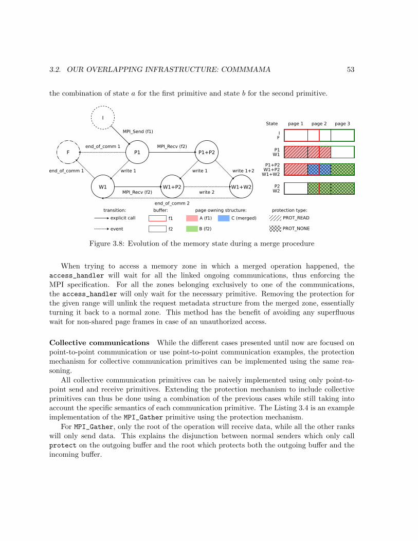
3.2. OUR OVERLAPPING INFRASTRUCTURE: COMMMAMA 53
the combination of state a for the first primitive and state b for the second primitive.
MPI_Send (f1)
write 1end_of_comm 1
end_of_comm 1
I
P1F P1+P2
W1 W1+P2 W1+W2
MPI_Recv (f2)
end_of_comm 2
write 1
write 2MPI_Recv (f2)
write 1+2
page 1 page 2 page 3State
P1+P2W1+P2
W1+W2
P1W1
IF
P2W2
buffer:
f1
f2
page owning structure:
A (f1)
B (f2)
C (merged)explicit call
event
transition: protection type:
PROT_READ
PROT_NONE
Figure 3.8: Evolution of the memory state during a merge procedure
When trying to access a memory zone in which a merged operation happened, theaccess_handler will wait for all the linked ongoing communications, thus enforcing theMPI specification. For all the zones belonging exclusively to one of the communications,the access_handler will only wait for the necessary primitive. Removing the protection forthe given range will unlink the request metadata structure from the merged zone, essentiallyturning it back to a normal zone. This method has the benefit of avoiding any superfluouswait for non-shared page frames in case of an unauthorized access.
Collective communications While the different cases presented until now are focused onpoint-to-point communication or use point-to-point communication examples, the protectionmechanism for collective communication primitives can be implemented using the same rea-soning.
All collective communication primitives can be naively implemented using only point-to-point send and receive primitives. Extending the protection mechanism to include collectiveprimitives can thus be done using a combination of the previous cases while still taking intoaccount the specific semantics of each communication primitive. The Listing 3.4 is an exampleimplementation of the MPI_Gather primitive using the protection mechanism.
For MPI_Gather, only the root of the operation will receive data, while all the other rankswill only send data. This explains the disjunction between normal senders which only callprotect on the outgoing buffer and the root which protects both the outgoing buffer and theincoming buffer.

54 CHAPTER 3. COMMMAMA, MOTIVATION AND DESIGN
1 int MPI_Gather(const void* sendbuf , int sendcount , MPI_Datatype sendtype ,
2 void* recvbuf , int recvcount , MPI_Datatype recvtype ,
3 int root , MPI_Comm comm) {
4 const void* shadow_sendbuf = shadow_ptr(sendbuf );
5 void* shadow_recvbuf = shadow_ptr(recvbuf );
67 int stsize , rtsize;
8 MPI_Type_size(sendtype , &stsize );
9 MPI_Type_size(recvtype , &rtsize );
1011 struct prot_req* send_prot =
12 protect(sendbuf , sendcount * stsize , PROT_READ );
1314 /* mpii_infos contains info on the current call */
15 if (mpii_infos.rank == root) {
16 struct prot_req* recv_prot =
17 protect(recvbuf , recvcount * rtsize * mpii_infos.size , PROT_NONE)
18 link_pr(2, send_prot , recv_prot );
19 }
2021 int ret = offload_MPI_Igather(shadow_sendbuf , sendcount , sendtype ,
22 shadow_recvbuf , recvcount , recvtype ,
23 root , comm , send_prot ->req);
24 return ret;
25 }
Listing 3.4: MPI_Gather implementation using protection API
In the case of the root, the semantic implies that only read operations are allowed in theoutgoing buffer while no accesses are allowed in the incoming buffer. This is correctly enforcedby the permissions PROT_READ and PROT_NONE respectively. To ensure that any unwanted accessto any buffer will trigger the access_handler and correctly wait until the communication iscompleted, the two protection metadata structures are linked (using link_pr). This is similarto the way merged memory regions are handled, but for the whole memory range of bothcommunication buffers.
Finally, the offloaded version of MPI_Igather is called using the shadow buffers for bothbuffers, letting the underlying MPI primitive the freedom to read or modify buffers as needed.
The rest of the collective primitives are implemented using a similar method, by protectingthe needed memory ranges and linking protection metadata structures when needed.
All the different cases presented above are handled by the protection mechanism internally.Using the protect, unprotect functions and occasionally linking multiple protection zones issufficient to transform most blocking point-to-point and collective primitives into nonblockingones.

3.3. EVALUATION OF THE OVERLAPPING POTENTIAL 55
The combination of the protection mechanism and the offloading library guarantees twoimportant behaviors, every buffer on which memory protection is enabled during a call to acommunication primitive will see its protection disabled eventually and any unwanted accessto the memory will cause the application thread to wait as though a real call to MPI_Wait wasissued. Therefore, the period during which communication is overlapped with computation isdynamically decided by the first forbidden access to the buffer, which in turns corresponds tothe optimal limit we can afford according to the MPI specification.
3.3 Evaluation of the overlapping potential
This section presents the results of our evaluation of Commmama. All the experiments aredone using the Grid’5000 [24] grimoire cluster. Nodes of this cluster consist of dual socket8 core Intel Xeon E5-2630 v3 with 128 GB memory. These nodes are connected using 56Gb/s Mellanox Technologies ConnectX-3 InfiniBand network adapters. We use GCC 8.3.0 andOpenMPI 3.1.3 [17]. All the results presented thereafter are produced using this test bed byrunning the mentioned benchmark 2000 times and taking a mean value.
This section is organized as follows. First we present an evaluation of the base overhead ofour method. This is done by comparing our approach with a standard MPI runtime, OpenMPI,in the worst-case scenario (no computation, only communication). Then we present the resultsfor different message sizes and different computation times. We show that our approach has agood overlap ratio, and even that when the computation time is sufficient, the communicationis completely overlapped. We compare to the OpenMPI runtime, and with a good ratio ofcommunication and computation Commmama reaches up to 73% speedup.
3.3.1 Base overhead analysis
In this section we compare our approach, Commmama, to a baseline version using only Open-MPI. This aims to study the effect of our system on base performances. This is done usinga ping-pong microbenchmark with no computation to exhibit the overhead introduced by ourmethod.
Figure 3.9 represents the round-trip latency of messages of varying sizes, both axes arerepresented using log scale. Depicted on this figure, the overhead incurred by Commmama islinear until important message sizes where it becomes negligible. This is mostly due to thecost of the protection subsystem and more specifically the linear cost of the mprotect systemcall.
This overhead is indeed due to the modification of the page table structure during themprotect call used to enforce memory protection on the process address space. With thegrowth of message size, the range of memory protected by the system call grows which in turnsincreases in a linear fashion the number of page structures to modify. However, this overhead

56 CHAPTER 3. COMMMAMA, MOTIVATION AND DESIGN
0.1
1
10
100
1000
10000
10000 100000 1×10⁶ 1×10⁷
round-t
rip late
ncy
(µ
s)
message size (bytes)
openmpiCommmama
Figure 3.9: Round-trip latency with no compute
is not as important as to impact the capacity to overlap communication with computation asdemonstrated in the next subsection.
3.3.2 Overlap evaluation
To evaluate the quantity of overlapped communication provided by our design, we use a modi-fied version of the ping-pong microbenchmark with added computation time between commu-nication phases.
This benchmark executes as follows. Process rank 0 calls MPI_Send, computes for a giventime, writes one byte to the buffer then calls MPI_Recv, computes for a given time and readsone byte from the buffer. Process rank 1 does the same but starting by MPI_Recv, followed bythe compute period and the read operation then MPI_Send, the compute period and the writeoperation.
In this second benchmark the memory operation plays an important role as it ensures theprevious communication (either send or receive) is completed before continuing. This simulatesthe first access to buffer data in the computation period following a communication.
The expected execution timelines are presented in Figure 3.10.
The results presented thereafter use this benchmark with a varying amount of computa-tion time, respectively 2 × 200, 2 × 2000 and 2 × 20000 microseconds. The openmpi curverepresents the default OpenMPI behavior. The Commmama curve represents the behaviorof our approach on top of the same OpenMPI runtime. The optimal completion time curverepresents the theoretical optimum which is max(tcompute, tcomm), where tcompute is the total

3.3. EVALUATION OF THE OVERLAPPING POTENTIAL 57
Rank 0 Rank 1
progressthread
userthread
progressthread
userthread
openmpi+overlapRank 0 Rank 1
userthread
idlethread
userthread
idlethread
openmpi
compute
send (real) send (intercepted)
recv (real) recv (intercepted)
data transfer offloading call
Figure 3.10: Expected execution timeline for microbenchmark
time of computation (i.e. the sum of both occurrences for a given process) and tcomm is thetime of completion of the communication for the default OpenMPI implementation taken fromSection 3.3.1.
Round-trip latencies in Figure 3.13, 3.11 and 3.12 all demonstrate two different behaviors.Between 4 KB and a certain value called sthreshold below, Commmama remains very close ofthe optimal completion time, while openmpi is equal to tcompute + tcomm. Finally, betweensthreshold and 64 MB, both openmpi and Commmama increase gradually, with Commmamastaying close to the optimal value.
The default OpenMPI implementation cannot overlap any communication with computa-tion, resulting in an increased completion time. This is particularly visible when the com-munication time and computation time are close. For example, on Figure 3.11 for 16 MBmessage size, the raw measurement for openmpi gives a latency of 5419 µs which is close totcompute = 4000 µs for this experiment. The measured time for Figure 3.11 at 16 MB is 9404 µs,almost exactly tcompute + tcomm.
On the contrary, Commmama performs well, showing a high overlapping capability. Theraw measurement for Commmama is 5446 µs at 16 MB on Figure 3.11, only 30 µs more

58 CHAPTER 3. COMMMAMA, MOTIVATION AND DESIGN
0
5000
10000
15000
20000
25000
30000
35000
10000 100000 1×10⁶ 1×10⁷
round-t
rip late
ncy
(µ
s)
message size (bytes)
openmpiCommmama
optimal completion time
Round-trip latency for 4000µs compute
0
20
40
60
80
100
10000 100000 1×10⁶ 1×10⁷
perc
ent
speedup
message size (bytes)
Speedup
Speedup for 4000µs compute
Figure 3.11: Round-trip latency and speedup for tcompute = 4000 µs
than native openmpi. With 4000 µs computation time, Commmama overlaps communicationperfectly, with a measured time of 5440 µs. This second behavior persists until message sizeattains sthreshold, the message size until which tcomm < tcompute, which for this example is formessage sizes between 8 MB and 16 MB.
0
10000
20000
30000
40000
50000
60000
70000
10000 100000 1×10⁶ 1×10⁷
round-t
rip late
ncy
(µ
s)
message size (bytes)
openmpiCommmama
optimal completion time
Round-trip latency for 40000µs compute
0
20
40
60
80
100
10000 100000 1×10⁶ 1×10⁷
perc
ent
speedup
message size (bytes)
Speedup
Speedup for 40000µs compute
Figure 3.12: Round-trip latency and speedup for tcompute = 40000 µs
As for the second phase, when message size exceeds sthreshold, both openmpi and Comm-mama round-trip latencies start increasing, with Commmama still being close to the optimalcompletion time value which is now tcomm as exceeding sthreshold, tcomm has become the longesttask required for completion. This behavior is better seen in Figure 3.12 for message sizes big-ger than 2 MB. On this part of the curve, openmpi completion time gradually increases untilreaching 65 ms while Commmama is close to tcompute with only 40.185 ms for 32 MB and43.800 ms for 64 MB.
While our proposal is less efficient for small computation times because the window for

3.4. CONCLUSION 59
overlapping communication and computation is smaller and thus closer to the potential over-head of our approach, Figure 3.13 still demonstrates good results, especially the speeduprepresentation which reaches 10% for 128 KB and up to 42% for 512 KB.
0
5000
10000
15000
20000
25000
30000
10000 100000 1×10⁶ 1×10⁷
round-t
rip late
ncy
(µ
s)
message size (bytes)
openmpiCommmama
optimal completion time
Round-trip latency for 400µs compute
0
20
40
60
80
100
10000 100000perc
ent
speedup
message size (bytes)
Speedup
Speedup for 400µs compute
Figure 3.13: Round-trip latency and speedup for tcompute = 400 µs
Favoring communication and computation overlap, our approach can really shine whenthere is enough computation to overlap communication with. As shown by the speedup plotin Figure 3.11 in which speedup reaches 73% and is good in any case when tcompute is slightlybigger than tcomm. For small communications, with a small compute time of 400 microseconds,speedup attains 42%, with 4 milliseconds of compute time, speedup attains its best value formedium-sized communications, 73% for 1 MB messages. After this point the speedup decreasesdue to the compute time becoming insufficient to correctly overlap communication for biggermessages. With 40 milliseconds of compute time, big communications are at their best withup to 50% speedup.
3.4 Conclusion
This chapter presents the challenges of overlapping network communication with CPU-boundcommunication in the scope of MPI. The MPI specification provides two types of primitives.Blocking primitives, which are simple to use but cannot overlap communication with compu-tation, and nonblocking ones, which are more complex to use but allow some communicationto be overlapped.
In this chapter we present the different types of primitives, their semantics, and explainwhich of these primitives can overlap communication with computation. We show that twokey factors are important to reach efficient overlapping of communications, the window dur-ing which communication and computation are overlapped and the presence of a backgroundprogress mechanism. Works aiming to improve one of these factors are presented.

60 CHAPTER 3. COMMMAMA, MOTIVATION AND DESIGN
We then introduce Commmama which transforms blocking communications into nonblock-ing ones at runtime. Using this approach, Commmama combines the simplicity of blockingcommunications and the efficiency of nonblocking communications while enforcing the MPIspecification. In order to enforce the MPI specification for communication primitives, Comm-mama protects the memory used by the application to store data sent or received with MPI.This allows to detect unwanted accesses and force the application to wait if needed. This isdescribed in detail in the section related to the internal architecture of Commmama and itsthree layers: interception layer, offload layer, and protection layer. This architecture enablesCommmama to be used easily by developers. As an intermediate layer, Commmama can beused without modifying legacy software and with most MPI runtimes.
Finally, this chapter presents an evaluation of Commmama’s ability to overlap communica-tion with computation. This evaluation shows that Commmama is able to reach good speedup(up to 73%) when computation time is sufficient to overlap communication.
To conclude, Commmama, increases network and CPU parallelism using memory protec-tion as a layer between the MPI runtime and the application. In contrast to this user spacesolution, Scalevisor, the second part of our approach, manages resources at a lower level, belowthe operating system using virtualization techniques.

Chapter 4
A multicore resource managementdriver
As explained in section 2.1, computer architectures have evolved through the years and con-tinue to do so. Because taking into account the topology is necessary to use a machine fullpotential, operating systems have to evolve and include complex rules each pertaining to dif-ferent hardware configurations. Thus, each new topology creates its own specific needs in termof scheduling, memory management and I/O management.
Resource management in modern operating systems is often treated by having a piece ofthe system manage one specific resource. These subsystems are mostly isolated parts of theoperating system, like the scheduler or memory manager, which do not communicate to takedecisions about the optimal state of the system. More often that not, decisions are taken byconsidering the distribution of other resources as fixed or even to really make a specific resourcestatic while having the other adjusted regularly.
While this method of resource management has been studied (some examples are presentedin section 2.3) and can provide good results in simple cases, with the added complexity of newarchitectures and the multiplicity of applications, a new approach to resource managementtreating the system as a whole is needed.
Current operating systems were not designed to use this global approach, moreover, toaccommodate the large number of applications, they include generic heuristics which are nottailored to provide a sufficient gain in performance. Because of the size of the code base anddesign of current operating systems, it seems impossible to implement new efficient policiesand maintain them in multiple systems for multiple hardware configurations.
Given the advance of virtualization technology, especially in the field of hardware virtual-ization, we propose a new approach to resource management in complex topologies that usesvirtualization to add a small layer dedicated to resource placement in the usual software stack.This intermediate layer, Scalevisor, placed between the hardware and the operating system,
61

62 CHAPTER 4. A MULTICORE RESOURCE MANAGEMENT DRIVER
manages resources placement and simulates a flat topology for the overlying operating system.This flat topology forces the overlying operating system to behave as if it were running ona simple topology and thus ignore the real topology when managing resources. Figure 4.1represents a software stack with Scalevisor integrated in between the real topology and theoperating system.
Leg
acy
syste
mR
eal to
polo
gy
top
olo
gy
Ab
stract
vCPU 1 vCPU 2 vCPU 3 vCPU 4
Virtual memory
I/O
Node
Node
Node Node
Node Node
IOMMUtranslation
OS
ScalevisorSimulates flat topology
Manages resources placement
Application
HintingInterface
Figure 4.1: Software stack including Scalevisor
While Scalevisor primary purpose is to act as a black-box resource management systembelow the operating system, its design includes an hinting interface accessible to the guest andapplications through paravirtualization. This interface can be used by applications to describetheir operating patterns and thus make placement decisions more efficient.
The first step toward this multi-resources placement driver is to simulate an abstract mem-ory and CPU topology using virtualization techniques. This chapter is organized as follows.Section 4.1 presents both software and hardware virtualization techniques, and describes over-head created by using such techniques. This section then presents related work on virtualizationand more specifically about the issues of using virtualization on NUMA architectures. Sec-tion 4.2 presents Scalevisor, starting from its design and how to mask the underlying topology,then describes Scalevisor internal structure and components. Finally, this section presentsthe unrealized parts of the project due to a lack of time. While Scalevisor is able to boot a

4.1. BACKGROUND AND MOTIVATION 63
Linux system, some parts are not mature enough to evaluate heuristics. We thus concludewith some reflections on the task of writing a new operating system given the complexity ofcurrent hardware.
4.1 Background and motivation
Virtualization consists in providing virtual resources to an operating system, most of the timein order to allow multiple systems to coexist on a single hardware unit. Virtual resourcesare created using different methods, currently for performance reasons, a lot of virtualizedresources are created and managed using hardware-assisted techniques.
Real machine are mainly composed of compute units, memory and devices. In the sameway, these constitute the main components of a virtualized machine, thus, the parts that needto be virtually duplicated in such a system are the CPUs, the page table responsible for memorymapping, and the device drivers.
This section first describes currently available virtualization techniques, then presents re-lated work. It is organized as follows. Sections 4.1.1 and 4.1.2 present software techniques andhardware assisted techniques respectively. Section 4.1.3 details related work on virtualization,first presenting generic virtualization issues, then specific problems arising from the use ofvirtualization on NUMA architectures.
4.1.1 Software techniques
The concept of virtualization includes several notions but the property expected of a reliableVirtual Machine Manager (VMM) are threefold. First, the virtual machine should be func-tionally equivalent to the hardware machine as far as the guest operating system is concerned.Secondly, the guest should be isolated from the rest of the system, either from other virtualmachines or the VMM itself. Finally, performances should be mostly equivalent to runningdirectly on the hardware when inside the virtual machine.
According to Popek et al. [44], “For any conventional third generation computer, a virtualmachine monitor may be constructed if the set of sensitive instructions for that computer isa subset of the set of privileged instructions”. Sensitive instructions are divided in two cate-gories, behavior sensitive instructions and control sensitive instructions. A behavior sensitiveinstruction is one that depends on the state of the processor (for example being in user or sys-tem mode, or the real memory location). A control sensitive instruction is one that modifiesthe processor state (changing from user mode to system mode).
Sensitive instructions need to be privileged to allow the VMM to catch any attempt fromthe guest software either to change the real state of the hardware to an unwanted state forcontrol sensitive instructions or to react differently because of virtualization in the case ofbehavior sensitive instructions. This implies that to correctly virtualize the CPU behavior,
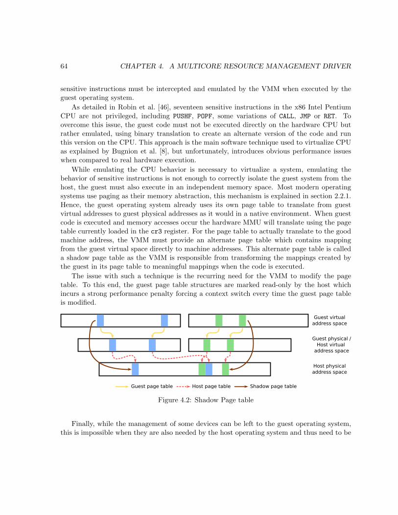
64 CHAPTER 4. A MULTICORE RESOURCE MANAGEMENT DRIVER
sensitive instructions must be intercepted and emulated by the VMM when executed by theguest operating system.
As detailed in Robin et al. [46], seventeen sensitive instructions in the x86 Intel PentiumCPU are not privileged, including PUSHF, POPF, some variations of CALL, JMP or RET. Toovercome this issue, the guest code must not be executed directly on the hardware CPU butrather emulated, using binary translation to create an alternate version of the code and runthis version on the CPU. This approach is the main software technique used to virtualize CPUas explained by Bugnion et al. [8], but unfortunately, introduces obvious performance issueswhen compared to real hardware execution.
While emulating the CPU behavior is necessary to virtualize a system, emulating thebehavior of sensitive instructions is not enough to correctly isolate the guest system from thehost, the guest must also execute in an independent memory space. Most modern operatingsystems use paging as their memory abstraction, this mechanism is explained in section 2.2.1.Hence, the guest operating system already uses its own page table to translate from guestvirtual addresses to guest physical addresses as it would in a native environment. When guestcode is executed and memory accesses occur the hardware MMU will translate using the pagetable currently loaded in the cr3 register. For the page table to actually translate to the goodmachine address, the VMM must provide an alternate page table which contains mappingfrom the guest virtual space directly to machine addresses. This alternate page table is calleda shadow page table as the VMM is responsible from transforming the mappings created bythe guest in its page table to meaningful mappings when the code is executed.
The issue with such a technique is the recurring need for the VMM to modify the pagetable. To this end, the guest page table structures are marked read-only by the host whichincurs a strong performance penalty forcing a context switch every time the guest page tableis modified.
Guest page table Host page table Shadow page table
Guest virtualaddress space
Guest physical /Host virtual
address space
Host physicaladdress space
Figure 4.2: Shadow Page table
Finally, while the management of some devices can be left to the guest operating system,this is impossible when they are also needed by the host operating system and thus need to be

4.1. BACKGROUND AND MOTIVATION 65
shared. Emulating devices is done differently depending on the type of device. For example,when the communication medium with the device are memory mapped I/O (MMIO), theVMM needs to create a read-only mapping in place of the device real I/O zone to generate apage fault when the device is used and take action depending of the guest input. This kind ofemulation is expansive because it causes the VMM to regain control at each interaction withthe device and cannot be avoided in general.
While different techniques either for CPU, memory or device emulation exists and allowsa real software virtualization hypervisor to be achieved, each of them is quite costly in term ofperformance, and when combined can incur significant overhead.
4.1.2 Hardware techniques
As virtualization became ubiquitous, the need for faster, safer, virtualization techniques wastackled by introducing hardware features directly targeted at system virtualization.
The two big manufacturers of x86 64 CPUs, Intel and AMD both have added some hardwarevirtualization capabilities to their CPUs. This new hardware was originally presented byIntel [56] in 2005, and continues to evolve. Both Intel’s and AMD’s versions enhance thecommon instruction set with virtualization related instructions and a virtual machine controlstructure stored in memory. In Intel’s case the control structure is called Virtual MachineControl data Structure (VMCS).
CPU virtualization: Intel VT-x and VMCS The VT-x extension adds the aforemen-tioned VMCS control structure which occupies a four-kilobyte aligned memory page in physicalmemory. The pointer to this memory zone is used to reference a given VMCS for any subse-quent operation on this structure.
There is a direct correspondence between the concept of virtual CPU (vCPU) and theVMCS structure which defines the behavior of a given vCPU. As such, it is possible and evenrequired to have multiple VMCS to emulate multiple vCPUs but at any given time, only oneVMCS can be the “current” VMCS for a given physical CPU (pCPU).
To interact with the virtualization capabilities and the VMCS, the Intel VT-x extensionprovides a number of new instructions. The first set of instructions is used to change whichVMCS is the current one on the processor executing the instruction as well as make a VMCSactive for a given processor. This first set of instructions contains:
• VMCLEAR: Reset the VMCS to an inactive, not current, not launched state
• VMPTRLD: Make a VMCS current and active for a given processor
• VMLAUNCH: Make the current VMCS launched
• VMPTRST: Return the pointer to the current VMCS

66 CHAPTER 4. A MULTICORE RESOURCE MANAGEMENT DRIVER
An “active” VMCS is one which is already attached to a given CPU, this means it can beloaded again with VMPTRLD on the same processor but not on another. A “launched” VMCSis one which is running guest code and cannot be launched again before being cleared. Thedifferent states and transitions are represented in figure 4.3.
Figure 4.3: VMCS state machine (Intel documentation [28, chap. 24.1])
When a VMCS is successfully loaded in the processor using VMPTRLD, it can then be inter-acted with using the second set of instructions:
• VMREAD: Read a field from the VMCS
• VMWRITE: Write some data in a given VMCS field
While the VMCS is a structure stored in memory, it cannot be read or written throughdirect memory accesses for two different reasons. Firstly, the format of the VMCS is implemen-tation specific and thus the real layout of the fields is not disclosed by the Intel documentation.Secondly, a loaded VMCS is partly cached inside its related pCPU which means a direct mem-ory access would neither make sure that the content of the processor cache was flushed back

4.1. BACKGROUND AND MOTIVATION 67
to memory in case of a read nor the current data in the processor cache was updated correctlyafter a write.
When a VMCS is launched using the VMLAUNCH instruction it enters guest mode, calledVMX non-root mode for Intel in opposition to host mode which is called VMX root mode,the context in which is executed the hypervisor or Virtual Machine Manager (VMM) code.Entering VMX non-root mode is commonly called a VMEnter event while existing this modeand thus going back to VMX root mode is called a VMExit. The VMCS contains numerousconfiguration options, some of which can trigger a conditional VMExit, for example when aprivileged register is accessed or a privileged instruction is used. Two instructions of the newVT-x extension interact with the VMCS when already launched:
• VMCALL: Trigger a VMExit (called by guest)
• VMRESUME: Return from a VMExit to VMX non-root mode (called by VMM)
The VMCALL instruction can be called when operating in VMX non-root mode to returncontrol to the VMM directly, this is called mostly for paravirtualization to let the guest com-municate with the hypervisor in the same manner as a process in a standard operating systemwould call a system call.
The VMCS and new instructions are the hardware mechanisms needed to virtualize thecomputation component of a system, the CPU. This solution avoids the need for binary trans-lation mentioned in section 4.1.1 and reduces the overhead of virtualization as shown in sec-tion 4.1.3.
Second level page table: Intel EPT The shadow page table technique, while allowing aVMM to emulate a second level paging system introduces overhead. Mirroring the physicalCPU page table to manage memory mappings, vCPUs obtained through the use of hardwareassisted virtualization, introduce a hardware solution to second level paging.
As explained in section 2.2.1, for physical CPUs, the page table physical memory locationis stored inside the specific cr3 register. This register has its own equivalent in the VMCScalled the Extended Page Table Pointer (EPTP). This pointer contains the address to a secondlevel page table used to emulate the behavior of the normal page table when in VMX non-root(guest) mode.
This second level page table is called Extended Page Table on Intel processors and is usedto translate guest physical addresses, equivalent to host virtual addresses, to host physicaladdresses which are real hardware addresses.
The EPT system acts in place of the shadow page table doing the translation and allows forguest physical addresses translation to be isolated from the VMM page table. On top of thisvirtualized paging system, the guest is free to use any memory management mechanism, eithersegmentation which is common for compatibility reasons when booting, or paging with its own

68 CHAPTER 4. A MULTICORE RESOURCE MANAGEMENT DRIVER
page table stored in the VMCS cr3 register and acting as normal when in VMX non-rootmode.
The EPT achieves an important performance gain by replacing the shadow page table inwhich every page fault caused by the guest would require a VMExit followed by the VMMactually doing the mapping, actualizing the shadow table and returning control to the guest.Evaluation of Intel EPT in the VMware platform has shown up to 48% gains for MMU-intensivebenchmarks and up to 600% for MMU-intensive microbenchmarks [5].
However, this improvement is not free either, because of the nature of the page table system.A classic page table uses bits of the virtual address to navigate in the different levels of tablesas explained in section 2.2.1. These tables are stored in physical memory and thus each leveldown the tree is accessed by getting its physical address from the upper level. With secondlevel paging, the address stored in the guest page table is in fact a guest physical address whichneeds to be translated through the EPT.
EPTP EPT PML4 EPT PD EPT PTEPT PDPT
Guest virtual
EPTP EPT PML4 EPT PD EPT PTEPT PDPT
EPTP EPT PML4 EPT PD EPT PTEPT PDPT
EPTP EPT PML4 EPT PD EPT PTEPT PDPT
EPTP EPT PML4 EPT PD EPT PTEPT PDPT
cr3
PML4
PDPT
PD
PT
TLB
Host Physical
Figure 4.4: Second level translation overhead
As shown in figure 4.4, because the address stored in the guest page table needs to betranslated using the EPT, translation from virtual (guest virtual) to real memory increasesfrom following 4 pointers in the native page table to a combined 24 pointers in the EPT andguest page table.

4.1. BACKGROUND AND MOTIVATION 69
Behavior of the TLB when using second level translation Fortunately, the secondlevel translation system benefits from the TLB described in section 2.2.1 in the similar manneras a regular MMU. When EPT is enabled, the TLB caches two kinds of information, guest-physical mappings and combined mappings.
Guest-physical mappings are derived from the EPT paging structures, they include guest-physical translation, mapping guest-physical addresses to memory frames, and guest-physicalpaging-structure-cache entries, which link a part of the guest-physical address to an intermedi-ate paging structures in the EPT. Combined mappings are derived from both the EPT pagingstructures and the guest page table located in the cr3 register when EPT and paging areboth enabled. These combined mappings contain cached translations, mapping guest linearaddresses to physical addresses, and combined paging-structure-cache entries which link theupper portion of the linear address to the physical address of the corresponding guest pagetable paging structure.
When EPT and paging for the guest are enabled, combined mappings greatly increase theefficiency of the translation process by giving a direct guest linear address to host physicaladdress translation. Moreover, the combined paging-structure-cache avoid going through theEPT table to retrieve the host physical address of the guest paging structure reducing theoverhead described in figure 4.4, caused by using EPT and paging simultaneously.
As for non-virtualization behavior, when using virtualization extensions, the TLB must beinvalidated when mappings become invalid. In section 2.2.1, the context transition betweenguest and host is mentioned as a reason of invalidation. While this is the case with the firstversion of VT-x included in older CPUs, it resulted in poor performances because even whenusing hardware virtualization, switching between VMX root and VMX non-root mode is quitefrequent.
To avoid this issue, in modern CPUs, a VPID feature similar to PCID was introduced.When VPID support is activated, TLB entries are tagged using a 16-bit identifier storedin the VMCS and operations that would invalidate the TLB caches will only do so for thecurrent VPID. VMX transitions no longer invalidate neither guest-physical mappings nor linearmappings. Two instructions, INVVPID and INVEPT are used to invalidate TLB cached entriesat a fine grain, mirroring the behavior of INVLPG for the native page table.
The caching mechanism provided by the TLB is really important to offset the cost ofrepeated translations through the combination of the EPT and guest page table. Combinedmappings, which directly map a guest virtual address to a host physical address allow a onehop translation, on par with TLB performances in a native environment.
Managing devices using the IOMMU: Intel VT-d While the Intel EPT provides secondlevel translation for CPU memory accesses, the devices which are using memory to read orwrite data are not concerned by this behavior. In order to provide the same advantages todevices, a similar system named IOMMU is present in modern hardware.

70 CHAPTER 4. A MULTICORE RESOURCE MANAGEMENT DRIVER
An important number of devices use memory mapped input/output (MMIO) to commu-nicate with the rest of the system, either to share data or for configuration. In the context ofa native system, these devices simply access the physical memory, but in a virtualized envi-ronment, the guest physical address space is already built on top of a translation mechanism,the EPT. In this case, when the device tries to access memory, it needs to access the rightguest physical address (not a real physical one) and for isolation reasons, its access needs tobe limited to addresses accessible to the virtual machine.
The solution to this situation is to introduce a step of translation for memory accessesinitiated by devices, called DMA (Direct Memory Access) remapping. In Intel VT-d system,this is done using a tree hierarchy to associate a translation structure similar to a page tablefor each address of the PCI bus on which devices are connected. The root table contains255 entries, each one referencing a bus ID, and each entry contains the location to a contexttable with 255 entries corresponding to the 255 device addresses of a given bus. The IOMMUthus associates for each unique PCI device address (bus number and device number) a set oftranslation structures for the device. This tree hierarchy is depicted in figure 4.5
This answers the two previous needs, translation is done for a given device accordingto the translation structure associated with its ID and as a device is only given access tohost physical addresses reachable through these paging structure, a device with non-presentor limited translation structures will not be able to access unwanted zone of the hardwarememory.
AMD-v, NPT, AMD-vi: different names same concepts As the second contender inthe x86 CPU world, AMD CPUs also contain virtualization enhancing hardware. While notidentical, these hardware features are very similar.
AMD-v, the VT-x equivalent, uses a similar structure in place of Intel’s VMCS, the VMCB.In opposition to Intel’s approach using dedicated instructions to interact with the content ofthe VMCS, the VMCB is a memory mapped structure accessible using classic memory accesses,other functionalities are similar.
AMD CPUs also include a second level translation system, named Nested Page Table(NPT) which is very similar to EPT, both being directly inspired by the standard x86 pagetable structure.
Finally, AMD-vi is the name of AMD’s IOMMU, which while configured differently hasan identical purpose of allowing devices to interact with memory while using second leveltranslation.
Both software and hardware techniques presented previously are the cornerstone of virtual-ization as they are needed to simulate an abstract memory and CPU topology for the guestoperating system. This abstract topology guarantees the isolation property and allows thehypervisor to manage resources independently of the overlying guest operating system.
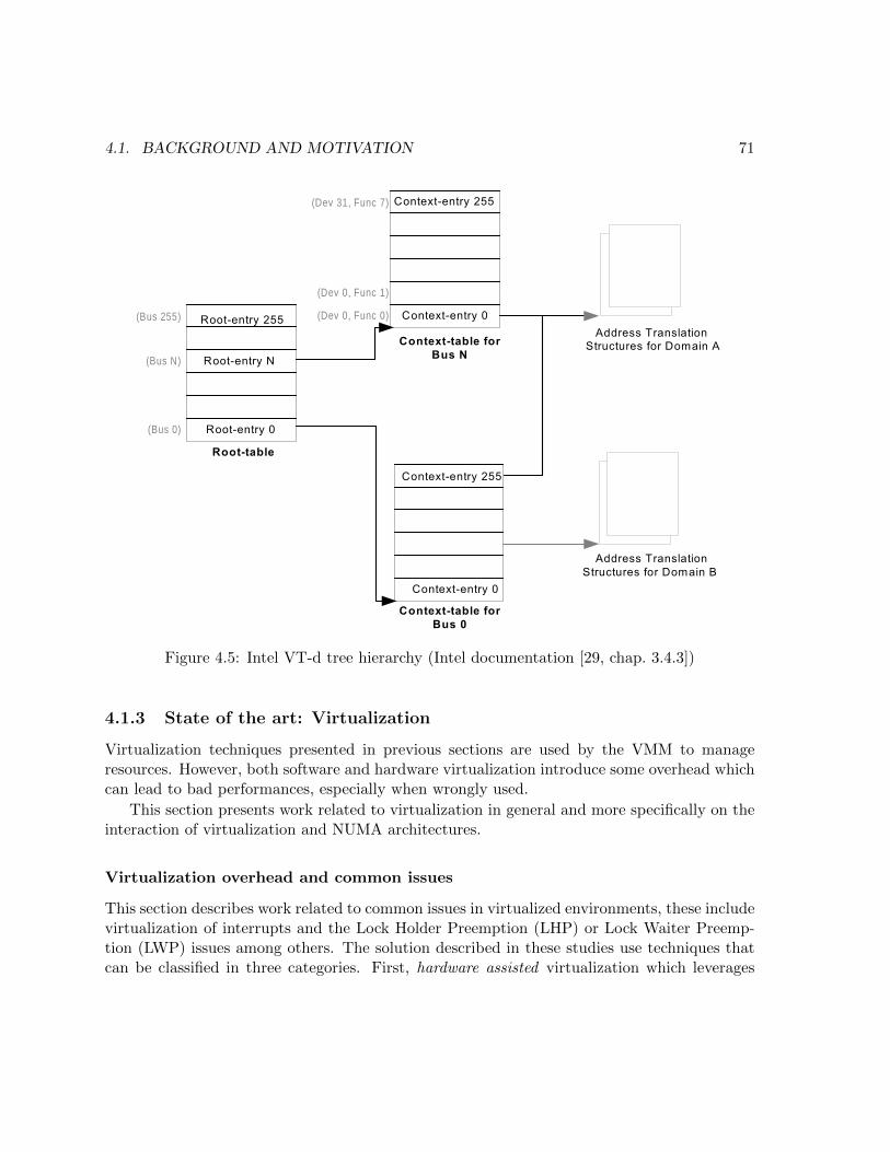
4.1. BACKGROUND AND MOTIVATION 71
Figure 4.5: Intel VT-d tree hierarchy (Intel documentation [29, chap. 3.4.3])
4.1.3 State of the art: Virtualization
Virtualization techniques presented in previous sections are used by the VMM to manageresources. However, both software and hardware virtualization introduce some overhead whichcan lead to bad performances, especially when wrongly used.
This section presents work related to virtualization in general and more specifically on theinteraction of virtualization and NUMA architectures.
Virtualization overhead and common issues
This section describes work related to common issues in virtualized environments, these includevirtualization of interrupts and the Lock Holder Preemption (LHP) or Lock Waiter Preemp-tion (LWP) issues among others. The solution described in these studies use techniques thatcan be classified in three categories. First, hardware assisted virtualization which leverages

72 CHAPTER 4. A MULTICORE RESOURCE MANAGEMENT DRIVER
existing hardware mechanisms. Second, paravirtualization when isolation is relaxed to allowinteractions, in any direction, between the VMM and guest OS. Third, transparency whenisolation is relaxed because the VMM shares information with the guest OS. Approaches arefurther detailed below, and summed up in table 4.1.
Table 4.1: Related work on virtualization
Proposal Issues Approach
Ganesan et al. [18] – –
DID IPI hardware assisted
Kilic et al. [30] IPI paravirtualization
vScale LHP paravirtualization
I-Spinlock LHP + LWP transparency
Empirical study of performance benefits of hardware assisted virtualization Ap-plications or operating systems performances can suffer from virtualization as it introducesits own overhead. However, as explained in section 4.1.2, some hardware mechanisms wereintroduced in recent machines to decrease this overhead. Ganesan et al. [18] study the impactof hardware assisted virtualization on performances.
Because the VMM has to conserve the control on hardware resources, it needs to removeprivileges from the guest operating system. Before hardware assisted virtualization was intro-duced, CPU virtualization used software techniques such as binary translation. Ganesan etal. evaluate the overhead of virtualization measuring three different metrics, CPU utilization,throughput and execution time in three different execution contexts, native (no virtualization),virtualization with no hardware assistance, and hardware assisted virtualization.
For CPU bound applications, they conclude that with only one vCPU and one instance ofthe benchmark the overhead is similar for both software virtualization and hardware virtual-ization with a 6% decrease in throughput. However, when scaling the number of vCPUs, theyconclude that software virtualization speedup is 0.73 compared to the native linear speedupwhile virtualization speedup is 0.96, nearly linear.
For network bound applications, they measure the increase in CPU utilization and concludethat while both types of virtualization increase CPU utilization, hardware assisted virtualiza-tion is far superior with an increase of 18% compared to software virtualization at 110%. Theyalso show that with hardware assisted network virtualization (SR-IOV) throughput is nearnative.
Finally, they measure the impact of the IOMMU on disk I/O performances, and show thatwhile software virtualization presents significant I/O contention due to disk accesses, hardwareassisted virtualization measured contention is near native, instead inducing an increase in CPUutilization.

4.1. BACKGROUND AND MOTIVATION 73
While this work does not in itself address any issue, it shows that hardware assisted virtu-alization really reduces the overhead of virtualization for CPU and memory but not so muchfor I/Os. The overhead of I/O operations being partially due to the overhead of managinginterrupts in a virtualized context.
A Comprehensive Implementation and Evaluation of Direct Interrupt Delivery– DID As demonstrated by Ganesan et al., the overhead introduced by virtualization hasbeen largely mitigated by hardware assisted virtualization except for I/Os. Tu et al. [55]present a method, called DID, for reducing the cost of I/O virtualization by managing interruptdelivery to the guest vCPUs without involving the VMM. They identify two challenges, directlydelivering interrupt to the guest OS and signal successful delivery to the controller hardwarewithout involving the hypervisor in both cases.
To this end, Tu et al. leverage the interrupt remapping capabilities of the IOMMU. Theysend interrupts directly to the vCPU when its target VM is running else to the hypervisorwhich will queue incoming interrupts and deliver them as virtual interrupts when the vCPUis scheduled again. They also manage timer interrupts and migrate them from core to coreto follow the migration of vCPUs. To avoid the overhead of Local APIC emulation, they usethe hardware assisted virtualization feature known as APICv. By using both the IOMMU andthe APICv, they avoid two causes of VMExit, those caused by devices sending interrupts orcaused by CPU receiving interrupts targeted at their currently running vCPU.
Using this method, they reduce the latency of interrupt invocation from 14 µs to 2.9 µs,on their Memcached benchmark, VMExit rate is reduced from 97 k per second to less than 1 kper second.
Tu et al. tackle the issue of virtualizing inter-processor interrupts using hardware assistedfeatures added in newer generation of CPUs, reducing the number of VMExit and thus theoverhead of virtualization, especially I/O virtualization.
Overcoming Virtualization Overheads for Large-vCPU Virtual Machines As stud-ied by Tu et al., interrupt virtualization is the cause of an important part of virtualizationoverhead. Kilic et al. [30] tackle this issue in the specific setting of virtual machines with morevCPUs than physically available cores.
Inter-processor Interrupts (IPIs) are a type of interrupt commonly used in operating sys-tems to let a given CPU trigger the scheduling of some specific task on another CPU. Forexample, IPIs are used in Linux to flush the TLB caches of others CPU when changing map-pings (TLB shootdowns). However, while processing IPIs in a non-virtualized context is fast,when running inside a VM, IPIs between vCPUs must be emulated which is slower. Thisoverhead scales with the number of vCPUs of a VM.
Kilic et al. also treat the issue of double scheduling, which arises because the VMM schedulerand the guest OS scheduler are unaware of each other decisions and can thus lead to a vCPU

74 CHAPTER 4. A MULTICORE RESOURCE MANAGEMENT DRIVER
migration canceling the scheduling choice of the guest OS for a thread.
In order to solve these issues, Kilic et al. propose a paravirtualization approach in twosteps. First, they dedicate a vCPU per thread, pinning the thread in the guest OS (usingparavirtualization), this solves the double scheduling issue as well as reduces the number ofIPIs used by the kernel to implement work stealing. Second, they replace IPIs used in TLBshootdowns by a hypercall which instructs the VMM to flush the TLB in place of the guestOS. Using these methods, they demonstrate that running a virtual machine with 255 vCPUson a machine comprising 6 pCPUs adds little to no overhead compared to running one vCPUper pCPU.
In the specific case of virtual machines with an important ratio of vCPU per pCPU, thevirtualization of interrupts takes another dimension, Kilic et al. propose a paravirtualizationapproach to reduce the number of such interrupts.
vScale: automatic and efficient processor scaling for SMP virtual machines Toprotect critical sections with shared data in the code, operating systems use synchronizationprimitives, such as spinlocks. A spinlock is a busy-waiting primitive, meaning the thread whichdoes not acquire the lock (the waiter) waits on a loop checking the lock state.
In a native Linux system, both the lock holder and waiter cannot be preempted to avoidblocking the system. If the lock holder was preempted, it could not release the lock andthus would make every waiting thread waste CPU cycles for a long duration. However, asmentioned earlier, the VMM vCPU scheduler and the guest OS scheduler are unaware of eachother. Thus, in a virtualized environment, vCPUs can be preempted by the VMM schedulerwhen holding the lock, this is known as the Lock Holder Preemption problem.
According to Cheng et al. [11], the Lock Holder Preemption issue is caused by the operatingsystem not knowing the real share of compute power it possesses. Because all virtual machineson a server share the CPUs, and the number of vCPU of a given VM is fixed, this makes aVM’s pCPU allocation dependent of the other VMs’ CPU consumption.
Cheng et al. thus propose to make the guest operating system use a varying number ofvCPUs which represent its real consumption. To the contrary of standard hypervisors changingthe time share of vCPUs to increase or decrease available compute time for a VM, they keepconstant time slices. They provide a kernel module to force the guest operating system toreschedule threads when changing the number of vCPUs for a given VM, thus avoiding avCPU to be preempted while holding a lock.
The Lock Holder preemption issue is caused by the opacity introduced by virtualization.Cheng et al. use paravirtualization to coordinate changes in the amount of computing poweravailable for a virtual machine with its guest scheduling.
The lock holder and the lock waiter preemption problems: nip them in the budusing informed spinlocks (I-Spinlock) Spinlocks can be implemented using a number
4.1. BACKGROUND AND MOTIVATION 75
of methods. One of them, called ticket-lock consists of giving an always increasing value, the“ticket” to the thread trying to acquire the lock and give the lock to the one holding thesmallest value. When the holder releases the lock, the current allowed value is bumped by one,allowing the next in line to hold the lock.
While this implementation has the advantage of being fair, it can lead to a slight variationof the Lock Holder Preemption problem discussed earlier. When a thread tries to acquirethe lock, this thread obtains a ticket. If this ticket does not hold the smallest value butis preempted, all ticket holders with greater values will be forced to wait for this thread toacquire and release the lock before getting their turns. This create a Lock Waiter Preemptionproblem in which the previous lock holder has released the lock but the next in line blocks thewhole lock by being preempted.
Taebe et al. [50] propose an implementation of the spinlock called Informed Spinlock (I-Spinlock) which only allows a thread to acquire a ticket if its time-to-preemption is sufficient towait for its turn, enter, and leave the critical section. In order to implement this solution, theypropose to share the remaining vCPU scheduling quantum with the guest operating system.When trying to acquire the lock, a thread first compares the remaining time slice of its vCPUwith the time required to wait and execute the critical section.
This approach uses transparency to inform the guest operating system of the remainingquantum for a given vCPU, avoiding spinlocks inside the guest to suffer from both Lock HolderPreemption or Lock Waiter Preemption issues.
Studies presented before try to solve commonly seen issues in virtualized environment suchas virtualization of interrupts, or the lock holder/waiter problems, which are specific cases ofdouble scheduling. Presented solutions most of the time reduce the opacity between the hyper-visor and the guest operating system, either by sharing some information or even introducingsome form of communication through paravirtualization.
Virtualization on NUMA architectures
While virtualization inherently creates issues, combining a virtualized environment on top of aNUMA architecture introduces different issues, closer to those detailed in section 2.1.2. Mostof the time, the studied problem arises either from contention on different resources, LLC,memory controller, interconnect, or bad locality of accesses. Because of the opacity inducedby the virtualization layer, most approaches use a mix of performance counter monitoring(getting information without cooperating with the guest) or paravirtualization (cooperatingwith the guest). Related work detailed below are summed up in table 4.2. In table 4.2, with nofurther indication, contention means contention for LLC, interconnect and memory controller,PV stands for paravirtualization, “delegated” means that issues are delegated to the overlyingoperating system and applications.

76 CHAPTER 4. A MULTICORE RESOURCE MANAGEMENT DRIVER
Table 4.2: Related work on virtualization and NUMA
Proposal Issue(s) Managed Resource(s) Approach
AQL Sched LHP + contention (LLC) vCPU monitoring
Merlin contention vCPU + memory monitoring
BRM contention vCPU monitoring + PV
Liu et al. [33] contention + locality memory monitoring(PV)
vProbe contention vCPU monitoring
Xen+ contention + locality memory monitoring + PV
XPV delegated vCPU + memory PV
Application-specific quantum for multi-core platform scheduler – AQL Sched Inthe same manner as the operating system scheduler, the VMM scheduler is responsible formanaging compute resources by scheduling vCPUs. According to Taebe et al. [51], an impor-tant parameter of a scheduler is the quantum length, as a higher quantum length penalizeslatency-critical applications but favors memory intensive applications by reducing cache con-tention. They thus claim that a fixed quantum length cannot benefit all applications andpropose a scheduling policy for hypervisors using variable quanta, depending of the needs ofthe executed applications.
Their proposal, AQL Sched, assigns an application type to each vCPU, which can evolveduring its lifetime, and clusters vCPUs of the same type in a pool of pCPUs. They identify threetypes of applications with different patterns and related issues. First, CPU-bound applicationswhich intensively use compute power and memory, these are susceptible to cache contention.Second, I/O intensive applications, which generate intense I/O traffic. These applicationsuse interrupts to perform I/O requests and thus fail to use their CPU quantum while waiting.Third, concurrent applications which are composed of multiple threads and need to synchronizewith one another, these are susceptible to the lock holder preemption issue mentioned before.
AQL Sched identifies the type of application among the aforementioned three using fourparameters, the number of I/O requests, the frequency at which they use spinlocks (detectedby intercepting the PAUSE instruction), the total number of LLC requests, and the number ofLLC misses among those requests.
Depending on the LLC miss metrics, AQL Sched determines which vCPUs are runningeither cache friendly or cache trashing applications. The first step is to separate these twotypes of applications by clustering the first on a pool of pCPU and the other on anotherpool. Then, AQL Sched assigns quantum lengths to the vCPUs. CPU/memory intensivetypes are given an important quantum length (90ms), vCPUs of the type “I/O intensive” or“concurrent”, a small quantum length (1ms), finally, quantum agnostic trashing applicationsare given a medium quantum (30ms).
Taebe et al. tackle the issue of contention by classifying vCPUs behaviors using monitoring,

4.1. BACKGROUND AND MOTIVATION 77
and segregating vCPUs into different pools of pCPUs. They also reduce occurrences of theLock Holder Preemption problem by changing the quantum of vCPUs depending on theirclassification.
Merlin: Application- and Platform-aware Resource Allocation in ConsolidatedServer Systems As virtualization overhead decreases, the trend in datacenter is to collo-cate a maximum of services on a single machine using virtualization. In order to maximizemachine utilization, efficient workload consolidation has become an important part of hyper-visors. Because machine architectures are more and more complex, a change in one resourceallocation can have an indirect effect on another type of resource. For example, changing thecompute or memory share may lead to an increase in cache usage.
In order to limit these issues, Tembey et al. [53], propose the Merlin resource allocator whichmanages resources by taking all the different resource dimensions into account. Merlin seeksthe best possible resource allocation that also avoids hurting other applications performancesas a side effect.
Merlin groups set of applications in virtual platforms VPs and arbitrates VP resource sharesby allocating resources while minimizing the differences between performance degradation ofall applications. This leads to performance degradation being fairly shared between VPs.
They proceed in three steps, first, they evaluate the relative importance of each resource foreach VP. Some applications may suffer greatly from cache contention or rather from memorycontention. These metrics are evaluated from data provided by performance counters. Second,Merlin allocates the initial resources for all applications taking into account their specificneeds. Third, using the performance counters, Merlin monitors the evolution of resource usageof each VP. Finally, Merlin adjusts the resources placement by choosing the cheapest possiblereconfiguration method, among the following ones (from lowest resource consumption to highestconsumption): changing CPU time shares, migrating vCPUs inside a NUMA node, migratingvCPUs from a NUMA node to another, migrating memory pages across nodes.
This proposal uses monitoring to evaluate pressure on different resource types and thusreduce contention through balancing of vCPUs and memory.
Optimizing virtual machine scheduling in NUMA multicore systems – BRM Asdescribed in section 2.1.2, resource management on NUMA machines must consider multiplearchitectural specificities, such as cache coherency or memory location to avoid the increasedlatency of remote accesses or congestion on the interconnect.
Because hypervisors have little information on the overlying operating system and appli-cations, standard techniques described in section 2.3 are not applicable directly.
Instead Rao et al. [45] propose to characterize aforementioned problematic behaviors usinga metric based on the penalty incurred by accessing the “uncore” memory. This metric,the uncore penalty, represents the number of stall cycles due to communicating on the network

78 CHAPTER 4. A MULTICORE RESOURCE MANAGEMENT DRIVER
outside the core. This number is defined as the number of L2 misses multiplied by the cost of anL2 miss, and represent the overhead due to a wrong memory placement forcing communicationoutside of the core.
Rao et al. exploit this metric by proposing a Bias Random vCPU Migration (BRM) al-gorithm to adjust the vCPU-to-core assignment. This algorithm is composed of three steps.First, evaluate the uncore penalty using hardware performance counters. Second, identify can-didate vCPUs for migration. This is achieved by modifying the guest operating system tonotify the hypervisor when a thread asks the kernel for a specific scheduling policy using thesched_setaffinity system call. Third, migrate a vCPU, randomly choosing the destinationbut with a bias toward the node which would minimize the uncore penalty.
The randomness in the migration decision statistically avoids simultaneously moving twocompeting or communicating vCPUs, which would reproduce the same situation after migra-tion but on different nodes.
To sum up, Rao et al. introduce a metric based on monitoring data to reduce contentionon the LLC, interconnect, and memory controller by balancing a subset of vCPUs. They useparavirtualization to detect which vCPUs are susceptible to need a special scheduling policy.
Optimizing virtual machine consolidation performance on NUMA server architec-ture for cloud workloads To enhance consolidation performances on modern machines,correctly managing these machines architectures is essential. For this reason, Liu et al. [33]study memory placement for NUMA architectures in virtualized cloud workloads. To thisend, they distinguish four sources of overhead, LLC contention, memory controller congestion,interconnect congestion and remote memory access latency.
Their NUMA-aware memory management system estimates the memory access patternusing three metrics obtained through performance counters, the rate of instruction execution(IPC), the L3 cache hit rate and the L3 cache miss rate. These performance counters areupdated by the guest through paravirtualization. Using these three metrics, they quantify theoverhead relative to each of the four types. LLC contention is evaluated from the highest valueof LLC hit rate among vCPUs of a VM. Memory controller congestion is determined using bothcache hit rate and miss rate, as with a constant cache hit rate, cycles lost by cache misses aredirectly linked to memory controller congestion. Interconnect congestion is computed usingthe L3 cache miss rate of all the CPUs on a remote node. Finally, remote memory accesslatency is computed using the IPC ratio between local and remote accesses.
Using the estimated behavior of each memory zone, they manage memory with two differentmechanisms, for allocations, the buddy allocator chooses nodes with the smallest overhead(preferring local node). During execution, they associate their overhead metric with each entryof the hypervisor second level page table. When a second level translation violation (equivalentof page fault) occurs, if the overhead for faulting memory zone exceeds a predefined threshold,it is exchanged with a page of another node with a lower estimated overhead.

4.1. BACKGROUND AND MOTIVATION 79
Liu et al. use paravirtualization to collect metrics. They include this information in theirhypervisor page table to reduce contention and locality when allocating pages for the guestsystem.
vProbe: Scheduling Virtual Machines on NUMA Systems The management ofNUMA resources in virtualized environments is made more complex by the opacity intro-duced by the virtualization layer. As mentioned, some approaches use a black-box approachsuch as Rao et al. [45], others use paravirtualization such as Liu et al. [33].
However, according to Wu et al. [60], using only the uncore penalty metric, Rao et al.treat all performance-degrading factors equally which prevent the ensuing optimization to beprecisely targeted at a specific factor. To solve this issue, and avoid breaking the isolation ofthe virtualization layer as Liu et al. do, they propose vProbe a NUMA-aware vCPU scheduler.
Similarly to other proposals, vProbe uses hardware counters to gather information on therunning virtual machines, more specifically, about LLC accesses and the node containing thehigher number of pager regularly accessed by a given vCPU.
vProbe classify vCPUs into three categories depending upon their LLC access pattern,akin to AQL Sched [51]. LLC trashing vCPUs (LLC-T) cause many LLC misses, LLC fittingvCPUs (LLC-FI) intensively use the LLC but have a low LLC miss rate when there is no LLCcontention, LLC friendly vCPUs (LLC-FR) are not impacted much by the LLC. Using thisinformation, they introduce two different mechanisms to favor NUMA-friendly placement ofvCPUs.
First, the vCPU periodical partitioning mechanism periodically reassigns all the memoryintensive vCPUs (LLC-T and LLC-FI) to each node evenly, preferring their local nodes. Thismechanism repeatedly selects the node with the least amount of memory intensive vCPUsassigned and adds an LLC-T vCPU, when no LLC-T remain, it does the same for LLC-FIvCPUs. This intends to reduce shared resource contention while preserving locality.
Second, to avoid the default scheduler of the hypervisor reverting changes introduced bythe vCPU periodical partitioning algorithm, vProbe adds its own NUMA-aware load balancer.When a pCPU is idle, it steals work from other pCPUs by checking their run-queues, startingfirst by the pCPUs from the local node, preferably those with the highest workload. In orderto avoid disrupting the balance of LLC contention, the stolen vCPU is chosen with the smallestLLC access footprint.
To conclude, vProbe reduces contention by favoring NUMA-friendly placement for vC-PUs using different metrics. These metrics are obtained through monitoring using hardwareperformance counters.
An interface to implement NUMA policies in the Xen hypervisor – Xen+ Multiplestudies focus on enhancing performances on NUMA architectures as detailed in section 2.3.In particular some describe new heuristics to manage NUMA resources at the OS level such
80 CHAPTER 4. A MULTICORE RESOURCE MANAGEMENT DRIVER
as Carrefour by Dashti et al. [13]. Moreover, previous research showed that, for virtualizedenvironments executing on NUMA architecture, the main issue is the coordination betweenthe hypervisor and the guest operating system.
In their work, Voron et al. [58] propose to reduce the overhead of virtualization on NUMAarchitectures by implementing resource management policies already existing in native environ-ments inside Xen [2]. Their implementation contains four different policies. First-touch, whichis the default memory allocation policy in Linux, allocates the backing memory of a virtualmapping the first time it is accessed on the node containing the accessing thread. Round-4Kalso part of Linux, allocates pages using a round-robin policy. Round-1G is the default policyof the Xen hypervisor, it allocates blocks of one gigabyte using a round-robin policy if possi-ble, if the memory must be fragmented, it falls back to smaller sizes. Carrefour is the policyproposed by Dashti et al. and originally implemented in Linux. In Xen+, the policy can bechosen by the guest using a hypercall.
Policies are implemented by moving memory using the hypervisor’s second level transla-tion. When a page is allocated by the guest operating system, it signals the VMM using adedicated hypercall, allowing the VMM to correctly place the page according to the chosenpolicy. Conversely, when a page is released by the guest operating system it signals the hy-pervisor which in turn changes its own mappings. This last case allows detecting page beingreused after being released in particular for the first-touch policy.
Voron et al. implement different NUMA policies which can either reduce remote accesses orbalance accesses to reduce congestion of memory controllers. The policy is chosen by the guestoperating system through paravirtualization. The Carrefour policy, ported from the originalLinux implementation uses monitoring to determine placement.
When eXtended Para - Virtualization (XPV) Meets NUMA When the hypervisormigrates vCPUs or memory, it changes the topology on which the virtual machine executes.However, in classic hypervisors, due to the opacity between the hypervisor and virtual ma-chine, guest operating systems cannot take this virtual topology into account when managingresources.
Bui et al. [9] propose a new design to manage NUMA topologies in a virtualized con-text, which dynamically informs the guest operating system of the virtual topology offered tothe virtual machine. This allows guest operating systems and NUMA-aware applications toreconfigure their behavior depending on the underlying changes advertised by the hypervisor.
Their method, “eXtended Paravirtualization” (XPV), is based on a split-driver. The hy-pervisor part of this driver is responsible for updating the NUMA topology presented to theguest when modifying vCPU or memory placement. The guest part of the driver retrieves theNUMA topology exposed by the other part and updates its internal structures and resourceplacement according to the new topology. However, this method forces to modify the guestkernel memory allocator and scheduler to take the information of the NUMA split-driver into

4.2. A DRIVER FOR NUMA ARCHITECTURES: SCALEVISOR 81
account. A strictly increasing counter representing the version of the NUMA topology allowsto detect changes in the dynamic topology.
XPV uses paravirtualization to present the guest operating system and applications adynamic map of the NUMA topology, guests operating systems and applications are responsiblefor using this information wisely.
Presented studies address the issues caused by virtualization, in general, and more specifi-cally when running on NUMA machines. The opacity introduced by the virtualization layer isoften the cause of these issues, explaining why these methods often rely on monitoring to cir-cumvent the isolation. Moreover, the advent of efficient hardware assistance for virtualization,as described in section 4.1 reduces the cost of virtualization in general. While some proposeto use transparency to help the operating system or applications better manage the specificsof the architecture, this often forces modification in the code of either the OS or both the OSand applications.
4.2 A driver for NUMA architectures: Scalevisor
Studies described in section 4.1.3 show that monitoring is a good solution to avoid opacityrelated issues when dealing with virtualization on NUMA architectures. However, our proposalis not a hypervisor in the common sense as it uses virtualization techniques to extract the roleof managing resources from the operating system but does not pretend to guarantee any otherclassic properties of hypervisors.
First of all, this limits the features which need to be implemented and thus makes Scalevisorlightweight, in term of both the size of the code base and the execution behavior.
Second, as Scalevisor does not aim to support multiple guests, our only focus is on isolatingour only guest operating system from the hardware NUMA topology. We can give full accessto devices not used by our system. The opacity in our approach is reduced to presenting theguest with a simpler topology.
This section first presents how this abstract topology is built, how it is used to manipulatecompute and memory resources underneath the guest operating system, and finally, describesScalevisor internal structures. We conclude with some teachings about our approach.
4.2.1 Presenting an abstract memory/CPU topology
By presenting an abstract topology to the overlying operating system, Scalevisor allows theoperating system resource management to stay the same regardless of the real hardware topol-ogy.
Virtualization techniques are used to provide a simple, linear view of the memory to theoperating system and a pool of computation units, vCPUs. To this end, we first need to
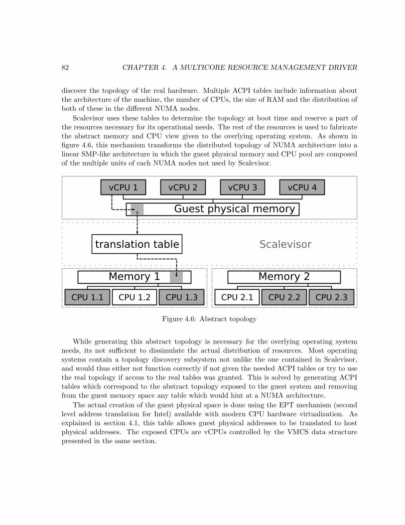
82 CHAPTER 4. A MULTICORE RESOURCE MANAGEMENT DRIVER
discover the topology of the real hardware. Multiple ACPI tables include information aboutthe architecture of the machine, the number of CPUs, the size of RAM and the distribution ofboth of these in the different NUMA nodes.
Scalevisor uses these tables to determine the topology at boot time and reserve a part ofthe resources necessary for its operational needs. The rest of the resources is used to fabricatethe abstract memory and CPU view given to the overlying operating system. As shown infigure 4.6, this mechanism transforms the distributed topology of NUMA architecture into alinear SMP-like architecture in which the guest physical memory and CPU pool are composedof the multiple units of each NUMA nodes not used by Scalevisor.
Memory 1
CPU 1.1 CPU 1.2 CPU 1.3
Memory 2
CPU 2.1 CPU 2.2 CPU 2.3
vCPU 1 vCPU 2 vCPU 3 vCPU 4
Guest physical memory
translation table Scalevisor
Figure 4.6: Abstract topology
While generating this abstract topology is necessary for the overlying operating systemneeds, its not sufficient to dissimulate the actual distribution of resources. Most operatingsystems contain a topology discovery subsystem not unlike the one contained in Scalevisor,and would thus either not function correctly if not given the needed ACPI tables or try to usethe real topology if access to the real tables was granted. This is solved by generating ACPItables which correspond to the abstract topology exposed to the guest system and removingfrom the guest memory space any table which would hint at a NUMA architecture.
The actual creation of the guest physical space is done using the EPT mechanism (secondlevel address translation for Intel) available with modern CPU hardware virtualization. Asexplained in section 4.1, this table allows guest physical addresses to be translated to hostphysical addresses. The exposed CPUs are vCPUs controlled by the VMCS data structurepresented in the same section.

4.2. A DRIVER FOR NUMA ARCHITECTURES: SCALEVISOR 83
4.2.2 Managing memory migration
The abstract topology is used by the operating system to allocate memory and schedule tasks.As explained before the ideal abstract topology is one were the physical topology does notplay a role at all. To the opposite, our system needs to correctly manage memory placementin order to reach better performances.
Scalevisor already uses the EPT to create this abstract topology and thus uses it to managememory migration.
In order to migrate the memory, the targeted page is marked read-only in the correspondingEPT structure to forbid any write access, thus making it safe to copy it to the new location. Ifa write access would occur during the migration process, it will cause a VMExit for the vCPUintending to write, and the vCPU will be preempted until the migration process is over. Whenthe page is copied to the new memory location, the mapping in the EPT structure is changedto match the new page location as shown in figure 4.7.
If an EPT violation occurs due to the page being marked read-only, the corresponding TLBentry is invalidated decreasing performances, but as the mapping is changed, the TLB entrywill need to be invalided anyway. As explained later in section 4.2.3, if the hardware supportsVPIDs, others TLB caches are not modified by the VMExit do to an EPT violation.
These procedures are correct when migrating memory which is only used by CPUs. Whensome memory is used to interact with the I/O subsystem, and more specifically when it isthe source or target of a DMA operation, migrating the page would make the current I/Ooperation fail or the migrated data incomplete.
In current operating systems, avoiding this issue is done by keeping a list of ongoing I/Ooperations, but when using the IOMMU to give control over some device to the guest operatingsystem, it becomes impossible to monitor I/O operations, thus making it probably impossibleto implement correct memory migration efficiently. In our prototype, we do not handle thisproblem: if Scalevisor migrates a page while it is written by a device, the write performed bythe device is lost.
4.2.3 Managing CPU migration
Managing CPU migration is akin to scheduling thread except for the VMCS structure whichis located in memory and thus also benefits from memory locality. While the vCPU structureand thus the execution context will move, from the operating system point of view, the OSthread will still execute on the same CPU, allowing an execution context to be moved withoutthe overlying OS noticing. As explained in section 4.1.3, for classic virtualization purposes,this opacity tends to diminish performances of virtual machines because of double scheduling.However, by exposing a flat virtual topology, the operating system will have less reasons tomove threads around and thus double scheduling occurrences will remain uncommon.

84 CHAPTER 4. A MULTICORE RESOURCE MANAGEMENT DRIVER
Memory 2
CPU 2.1 CPU 2.2
Memory 1
CPU 1.1 CPU 1.2
vCPU 1 vCPU 2 vCPU 3 vCPU 4
Guest physical memory
translation table Scalevisor
Memory 2
CPU 2.1 CPU 2.2
Memory 1
CPU 1.1 CPU 1.2
vCPU 1 vCPU 2 vCPU 3 vCPU 4
Guest physical memory
translation table Scalevisor
Change mapping of memory in table
Figure 4.7: Migration using EPT mappings
Several operations are constitutive of migrating a vCPU. Firstly, the vCPU needs to bestopped as a result of a VMExit. It is thus possible to use any cause of VMExit to reschedulea vCPU on another physical CPU, but in order to have a reliable frequent source of VMExit,a specific VMCS option named “VMX preemption timer” can be used. This option allowsthe VMM to set a counter at a given value which will be decreased at a rate proportional tothat of the time stamp counter (TSC, counts the number of CPU cycles). When the counterreaches zero, this will automatically cause a VMExit, thus allowing the VMM to performneeded management operations regularly.
When the physical CPU on which the vCPU is currently running exits VMX non-rootmode, the VMM takes control and can either call VMRESUME if no changes are needed or chooseto migrate the vCPU by calling VMCLEAR on the current physical CPU and VMPTRLD on the

4.2. A DRIVER FOR NUMA ARCHITECTURES: SCALEVISOR 85
destination CPU. The vCPU is then ready to be launched again using VMLAUNCH as representedin figure 4.3.
While migrating vCPUs is needed to make better use of a given machine depending of itsarchitecture, it has performance implications.
Firstly, while VMX transitions do not force a TLB flush neither for guest-physical nor linearmappings when VPID is enabled (see section 4.1), the TLB caches are per CPU caches andthus not shared across different physical CPUs. This means whether VPIDs are supported andenabled in VMCS or not, migrating a vCPU on a new physical CPU will make it run withoutthe new TLB caches containing the previously used mappings.
Secondly, the VMCS memory region is used to store data from the vCPU state, and eventhough some of its content is cached directly in the physical CPU on which the VMCS operates,the interaction between this memory region and the corresponding physical CPU must beefficient. Thus, migrating the vCPU to another NUMA node can suffer from any of thememory issues introduced in section 2.1.2, such as bad locality or causing congestion on theinterconnect. Moreover, migrating vCPUs frequently can cause these same issues and thusgreatly reduce performances for the guest operating system.
Finally, same as physical CPUs using interrupts to communicate with other hardware,vCPUs need to be able to send and receive interrupts. When vCPUs are pinned on theirattributed physical CPU and never migrated, most interrupts can just be directly receivedby the CPU without leaving VMX non-root mode and without VMM interaction. If vCPUsare to be migrated, interrupts must be correctly directed to the target vCPU. This can beachieved by making the VMM reprogram each interrupt attached to the previous physicalCPU which targets the migrated vCPU to be assigned to the destination CPU. However,changing targets for multiple interrupts is neither atomic nor efficient, thus using interruptremapping capabilities of the IOMMU to perform dynamic interrupt migration is better asdescribed by Tu et al.
4.2.4 Scalevisor internals
Scalevisor can be divided in two main parts. First, an operating system part, as the projectneeds to be able to boot on the target hardware. This includes the kernel which managesthe boot process, memory allocation and driver communication, as well as drivers needed tointeract with the minimum necessary hardware (timers, ACPI, IOMMU). The second part iscomposed of the “resources driver” capabilities and requires a working set of virtualizationfeatures and the vCPU scheduling and memory migration features. Figure 4.8 represents thesedifferent parts of Scalevisor grouped into the four logical groups: kernel, drivers, virtualizationand scheduler.
Scalevisor’s kernel Although called minimal, because it contains only the minimum set offunctionalities to boot and run, the kernel is quite complex, as any operating system, even

86 CHAPTER 4. A MULTICORE RESOURCE MANAGEMENT DRIVER
Scalevisor
driverskernel
virtualscheduler
earlyspace
pagetablememory allocator
interrup handling
acpi
apic
hpetpci
iommu
vCPUs guest memory
fault handler
?
vCPUs scheduling
memory migration
Figure 4.8: Software architecture of Scalevisor
minimalist, must deal with numerous hardware parts or behaviors.
Scalevisor is different from a classic hypervisor because it has been designed to manageresources in NUMA architectures. In Scalevisor, the architecture is represented by a Domainstructure which encompasses all the information about a NUMA domain. This structurecontains the CPUs assigned to a domain, the memory regions which belong to the givendomain, and a number of methods which interact with the domain. Each domain has its ownmemory pool composed of the free memory regions and its own local memory allocator.
The aforementioned CPU structure contains all the logic used to control the CPU, electinga thread or executing a remote task using an Inter-Processor Interrupt as a trigger. It alsoabstracts vendor specific functionalities.
Domains and CPUs are globally managed through a super structure called Machine whichcontains most other non-NUMA related hardware, access to the console, and more importantlydrivers.
For retro-compatibility needs, booting on a modern bare-metal machine means bootingin real mode (16-bit, segmentation memory management scheme) and switching to protected

4.2. A DRIVER FOR NUMA ARCHITECTURES: SCALEVISOR 87
mode then long mode. Page table and paging memory need to be set up during these steps,more specifically when transitioning from protected mode to long mode as shown in figure 4.9.
Figure 4.9: Operating modes of x86 64 architecture (AMD documentation [1, chap. 1.3])
During the process of booting, the Machine super structure is progressively filled usinginformation from various sources while corresponding hardware is initialized.
At first, a fake domain is built using memory ranges given by the bootloader, this domainand the Bootstrap Processor (BSP) are used by our Machine structure to discover the restof the topology. The number of CPUs and real memory ranges are then discovered usingACPI tables, Multiple APIC Description Table (MADT) and System Resource Affinity Table(SRAT) respectively, leading to a correct creation of Domain structures. This step concludesthe bootstrapping of our kernel which is now able to correctly allocate and map memory butstill uses the BSP as its sole processor. In order to wake up the other processor, called Auxiliary

88 CHAPTER 4. A MULTICORE RESOURCE MANAGEMENT DRIVER
Processors (APs), we need to use Inter-Processor Interrupts (IPIs) which are managed throughthe local APIC.
Device drivers The local APIC is the part of a core which is responsible for sending andreceiving interrupts for this given core. This piece of hardware must be configured before it canbe used for a variety of purposes, such as having a basic method of counting elapsed time, orcommunicating with other processors. The booting process effectively starts on one processor,the BSP, while the other processors, APs are woken up when receiving a specific interrupt sentfrom the BSP local APIC.
The second part of Scalevisor, device drivers, includes this local APIC, but also the HighPrecision Event Timer (HPET) which gives a more reliable and precise timer or the IOMMUwhich is used latter by the virtualization subsystem. Currently when multiple IOMMUs arepresent in a physical machine, the virtual machine cannot benefit from hardware assistedinterruption remapping. When using complex topologies in state of the art hardware, multipleIOMMUs are often present and manage different devices. Once again, our IOMMU structureabstracts the differences between Intel and AMD IOMMUs.
The initialization of the IOMMU device is done by reading a specific ACPI table, the DMARemapping Reporting table (DMAR) which indicates which hardware unit is located at whichphysical address, and when multiple IOMMUs are present which devices is a given IOMMUresponsible for.
Virtualization For virtualization management, the architecture follows a design similar tothe kernel part. The Guest structure contains the memory ranges available for a given guestand the related EPT mappings and IOMMU mappings. This structure is linked to one or morevCPUs represented by a same-named structure.
The Vcpu structure contains all the hardware CPU virtualization related logic and abstractsvendor specific configurations. For Intel vCPUs, this structure populates and controls theVMCS by providing a set of higher level methods to access fields. It also enforces hardwareconstraints by checking the global state of the VMCS is coherent with the vendor specification,which currently represents 246 different constraints.
The Vcpu is responsible for managing the different VMExit conditions using a set of cas-cading handlers, thus abstracting virtualization instructions such as VMRESUME, VMCLEAR orVMLAUNCH.
This layer is responsible of creating the abstract topology presented in section 4.2.1. Thefirst step toward presenting a linear memory abstraction is to intercept the classic detectionfeatures used by the guest operating system to determine the topology.
The main interface to detect features supported by the CPU is through a call to the CPUID
instruction, this instruction is thus intercepted and emulated using a Vcpu handler. Most ofthe values are returned without being modified, but some settings need to be. For example to

4.2. A DRIVER FOR NUMA ARCHITECTURES: SCALEVISOR 89
disable support for some instructions which cannot be directly executed because they modifyprivileged state but cannot be emulated either. This is the case of the XSAVE instruction whichis shown as not available when queried through the CPUID interface.
When booting, the guest operating system tries to discover the memory topology by in-teracting with the BIOS. These functions are accessed by setting some values inside the CPUgeneral registers and raising a software interrupt using the INT instruction. Multiple BIOSfunctions exist [7] to discover the memory map, linked to interrupt number 15 and identifiedby different values of the eax register, such as 0xe801, 0x88 or 0xe820.
The BIOS function bound to interrupt number 15 with eax = 0xe820, is the most commonand precise method of discovering memory. It returns a list of memory zones, in which zonesare described by their starting address, length and memory type (usable RAM, not usable,ACPI memory).
In order to present the guest operating system with an abstract memory topology, Scale-visor intercepts the interrupt number 15 and emulates the behavior of the BIOS for the e820interrupt. If done correctly, other methods are not used by Linux to further confirm the resultsobtained with the e820 method. Therefore, we only have to intercept the e820 method whichsimplifies the implementation of our system.
Virtual scheduler The virtual scheduler is the part of Scalevisor which should control howresources are allocated and managed for the guest operating system. Managing resources canbe seen as a three step process.
First, the scheduler accumulates data from the running guest operating system throughdifferent sources such as Intel’s Precise Event Base Sampling (PEBS) for which Scalevisor hasan interface. This interface produces raw data about which memory address is actively usedby which CPU, or which memory address causes cache misses. The scheduler must then decidewhether a given resource should be migrated and where. Finally, it actually migrates the givenresource.
The memory migration system first allocates memory from the wanted domain correspond-ing allocator and uses the Guest structure described earlier to replace EPT mappings for agiven memory range. As explained in section 4.2.2, the EPT mapping is changed to read-onlyduring the copy and in case a write operation occurs, the vCPU will be stopped until the endof the procedure.
As for the vCPU migration, Scalevisor implements kernel-level threading, which allows avCPU to be started in a thread context. When a window occurs during which the vCPU isstopped, the corresponding thread is then elected through an Inter Processor Interrupt (IPI)on the target CPU and the vCPU structure naturally resumes executing the previous contextthrough a call to VMLAUNCH.
While the data collection of the first step and the mechanisms needed to migrate resourcesin step three are implemented, the decision mechanism, mainly based on heuristics has not

90 CHAPTER 4. A MULTICORE RESOURCE MANAGEMENT DRIVER
been implemented due to a lack of time.
4.2.5 Assessments
While heuristics haven’t been implemented due to a lack of time, this approach of a driver forresource management is rich in findings. Scalevisor contains 20 k lines of code. It implementsa large working set of functionalities: system level memory management, system interrupts,vCPU and VMCS structure, guest level memory management and masked topology. Scalevisoris able to boot a Linux guest entirely, but some parts are not mature enough to run evaluations.
This is especially the case for devices such as the IOMMU, whose complicated specificationbrought to light the impossibility for an individual or a small team to sufficiently master modernhardware. Nowadays, modern computer hardware includes a lot more devices with each its ownquirks making development of a full operating system very complicated, even more in the caseof a hypervisor which must leverage additional functionalities and specific hardware to reachsatisfying performances. The complexity of hardware does not only affect devices, even CPUsbecame quite complicated, Intel’s Software Developer’s Manual [28] contains approximatelyfive thousand pages of documentation and does not even include devices related informationsuch as the IOMMU documentation or ACPI specification.
In general, it revealed that implementing a complex system such as a hypervisor in theconstrained time of a PhD thesis is close to impossible, especially without a full team dedicatedto the project.
Future work may build upon the already working set of functionalities, using the existingimplementation to produce a viable test bed for experiments on heuristics.

Chapter 5
Conclusion and future work
Their important computation power has lead multicore architectures and NUMA in particularto become ubiquitous in context where this power is required. Nowadays, High PerformanceComputing applications, data analysis or artificial intelligence are all benefiting from thesenew architectures which are frequently encountered in datacenters or experimental setups.However, the NUMA architecture increases the computational power by making the internalmachine topology more complex, with multiple CPUs and memory controllers.
This thesis studies how to manage resources in order to increase parallelism in NUMAarchitectures. This work focuses on two different approaches at two different levels in thesoftware stack.
First, increasing CPU and network parallelism through automatically overlapping com-munication and computation in user space. This approach, Commmama, shows that usingmemory protection can enforce the constraints of the MPI specification while still increasingthe parallelism by ensuring background progress for communications. Evaluation shows that,without having to modify neither the application code nor the MPI runtime, Commmamagreatly increases the overlapping ratio between communication and computation. When theapplication time is balanced between communication and computation phases, the speedupobtained through this method reaches up to 73%.
Second, introducing an intermediate layer between the hardware and the operating system,Scalevisor aims to manage the complex topology of the machine. To this end, Scalevisor usesvirtualization techniques to present an abstract topology to the overlying operating system.This additional software layer aims to ease the creation of new resource management policiesby extracting architecture specific policies outside of the operating system. While the currentimplementation of Scalevisor is incomplete, it includes most of the needed functionalities ofa standard operating system and implements enough of the virtualization features needed torun a guest Linux system. Because it is not mature enough, this work lacks evaluation topresent the impact of Scalevisor on performances. However, working on Scalevisor revealed
91

92 CHAPTER 5. CONCLUSION AND FUTURE WORK
that implementing such a system using modern virtualization hardware is close to impossible,in the time constraint of a PhD thesis. This reinforces our views that the complexity of currentand future hardware needs to be abstracted using an approach such as Scalevisor.
Future work
Both Commmama and Scalevisor need further study in order to provide their full potential.This section presents three possible improvements for Commmama, one related to evaluatingthe effect on other primitives, and two which focus on decreasing the overhead of the memoryprotection layer. This section then follows with three possible improvements for Scalevisor,finishing implementation of missing features, resource management heuristics, and an hintinginterface to better manage applications with unusual behaviors.
Commmama As far as Commmama is concerned, while the maximum overlapping ratio ob-tained depends on the ratio of communication and computation in the application, we showedthat for balanced application, Commmama was able to almost completely overlap communi-cation with computation. Thus, most of the refinement targets identifying and reducing thecauses of overhead in Commmama.
First, while our evaluation of point-to-point primitives with Commmama shows this ap-proach is promising, Commmama supports collective primitives, which have not been evalu-ated. Moreover, Commmama has not been evaluated yet with large scale applications. Asdifferent applications produce different memory access patterns and communication patterns,identifying these could provide clues for improving Commmama.
Second, Commmama current implementation uses the standard mprotect system call tochange memory access rights on user provided communication buffers. While the results usingthis approach are satisfying, most of the overhead currently introduced by Commmama can beattributed to this memory protection system call. As mentioned in Section 2.2.2, when sup-ported by the machine and kernel, the protection keys feature is another mechanism availableto protect memory ranges. This mechanism could decrease the base overhead of Commmama’smethod. However, the number of protection keys and thus the number of possible differentpermission sets is limited to 15. Modifying Commmama to dynamically use protection keysor standard paging permissions could be a good trade-off between low overhead and broaduse-case support.
Third, Commmama uses MPI_Alloc_Mem and MPI_Free_Mem to provide buffers with doublemapping to the user application using the mmap system call. However, memory ranges obtainedthrough this mechanism are allocated with each call to MPI_Alloc_Mem and freed with eachcall to MPI_Free_Mem. While this is not an issue if the user application reuses the reservedmemory for multiple communication, this could increase the overhead of our approach other-wise. Introducing a better memory management scheme by reserving pages in advance wouldprevent this issue for applications not carefully designed.

93
Scalevisor While Scalevisor was not mature enough to provide a reliable testing environmentfor evaluations, we think our experience with the complexity of hardware shows that thisapproach is an interesting one to study.
First, completing the implementation of Scalevisor in its current state should be feasible.Most of the needed features are already implemented, and the missing features, while stillcomplex to add, are few. Moreover, the code base of the project is still manageable forindividuals with approximately 20 kSLOC, whereas the code of modern operating systemssuch as Linux, with more than 20 MSLOC, cannot be fully mastered by an individual. Missingfunctionalities include some critical drivers (hard drive support for example) and some lessimportant features such as hardware assisted virtualization for some tasks (virtual interruptmanagement for example).
Second, developing and studying resource management heuristics is at the heart of theScalevisor project. Some leads can be found in studies presented in both Section 2.3, focusedon NUMA architectures and Section 4.1.3, presenting issues linked to the use of virtualization.As Scalevisor is neither a full-fledged hypervisor nor a standard operating system, it can beexpected to present some issues pertaining to hypervisors but not all.
Third, Scalevisor primary purpose is to act as a black-box resource management systembetween the standard operating system and the hardware. However, we anticipate issueswith applications featuring very unusual access patterns. As presented by related work onvirtualization, paravirtualization is often a good solution to break the isolation of the hypervisorand solve issues related to this isolation. Therefore, introducing an hinting interface usingparavirtualization would allow applications with unusual patterns to inform Scalevisor. Suchan interface is shown in Figure 4.1.


Bibliography
[1] AMD. AMD64 Architecture Programmer’s Manual Volume 2: System Programming, April2016. https://www.amd.com/system/files/TechDocs/24593.pdf.
[2] P. Barham, B. Dragovic, K. Fraser, S. Hand, T. Harris, A. Ho, R. Neugebauer, I. Pratt,and A. Warfield. Xen and the art of virtualization. In M. L. Scott and L. L. Peterson,editors, Proceedings of the 19th ACM Symposium on Operating Systems Principles 2003,SOSP 2003, Bolton Landing, NY, USA, October 19-22, 2003, pages 164–177. ACM, 2003.
[3] A. Baumann, P. Barham, P. Dagand, T. Harris, R. Isaacs, S. Peter, T. Roscoe,A. Schupbach, and A. Singhania. The multikernel: a new OS architecture for scalablemulticore systems. In J. N. Matthews and T. E. Anderson, editors, Proceedings of the 22ndACM Symposium on Operating Systems Principles 2009, SOSP 2009, Big Sky, Montana,USA, October 11-14, 2009, pages 29–44. ACM, 2009.
[4] E. D. Berger, K. S. McKinley, R. D. Blumofe, and P. R. Wilson. Hoard: A scalablememory allocator for multithreaded applications. In L. Rudolph and A. Gupta, editors,ASPLOS-IX Proceedings of the 9th International Conference on Architectural Support forProgramming Languages and Operating Systems, Cambridge, MA, USA, November 12-15,2000, pages 117–128. ACM Press, 2000.
[5] N. Bhatia. Performance evaluation of intel ept hardware assist. Technical report, VMware,2009. https://www.vmware.com/pdf/Perf_ESX_Intel-EPT-eval.pdf.
[6] S. Boyd-Wickizer, H. Chen, R. Chen, Y. Mao, M. F. Kaashoek, R. T. Morris, A. Pesterev,L. Stein, M. Wu, Y. Dai, Y. Zhang, and Z. Zhang. Corey: An operating system formany cores. In R. Draves and R. van Renesse, editors, 8th USENIX Symposium onOperating Systems Design and Implementation, OSDI 2008, December 8-10, 2008, SanDiego, California, USA, Proceedings, pages 43–57. USENIX Association, 2008.
[7] R. Brown. Ralf brown’s interrupt list. https://www.cs.cmu.edu/~ralf/files.html.
95

96 BIBLIOGRAPHY
[8] E. Bugnion, S. Devine, M. Rosenblum, J. Sugerman, and E. Y. Wang. Bringing virtualiza-tion to the x86 architecture with the original vmware workstation. ACM Trans. Comput.Syst., 30(4):12:1–12:51, 2012.
[9] V. Q. B. Bui, D. Mvondo, B. Teabe, K. Jiokeng, P. L. Wapet, A. Tchana, G. Thomas,D. Hagimont, G. Muller, and N. D. Palma. When extended para - virtualization (XPV)meets NUMA. In G. Candea, R. van Renesse, and C. Fetzer, editors, Proceedings ofthe Fourteenth EuroSys Conference 2019, Dresden, Germany, March 25-28, 2019, pages7:1–7:15. ACM, 2019.
[10] G. Chatzopoulos, R. Guerraoui, T. Harris, and V. Trigonakis. Abstracting multi-coretopologies with MCTOP. In G. Alonso, R. Bianchini, and M. Vukolic, editors, Proceed-ings of the Twelfth European Conference on Computer Systems, EuroSys 2017, Belgrade,Serbia, April 23-26, 2017, pages 544–559. ACM, 2017.
[11] L. Cheng, J. Rao, and F. C. M. Lau. vscale: automatic and efficient processor scalingfor SMP virtual machines. In C. Cadar, P. R. Pietzuch, K. Keeton, and R. Rodrigues,editors, Proceedings of the Eleventh European Conference on Computer Systems, EuroSys2016, London, United Kingdom, April 18-21, 2016, pages 2:1–2:14. ACM, 2016.
[12] A. Danalis, L. L. Pollock, D. M. Swany, and J. Cavazos. Mpi-aware compiler optimiza-tions for improving communication-computation overlap. In M. Gschwind, A. Nicolau,V. Salapura, and J. E. Moreira, editors, Proceedings of the 23rd international conferenceon Supercomputing, 2009, Yorktown Heights, NY, USA, June 8-12, 2009, pages 316–325.ACM, 2009.
[13] M. Dashti, A. Fedorova, J. R. Funston, F. Gaud, R. Lachaize, B. Lepers, V. Quema,and M. Roth. Traffic management: a holistic approach to memory placement on NUMAsystems. In V. Sarkar and R. Bodık, editors, Architectural Support for ProgrammingLanguages and Operating Systems, ASPLOS ’13, Houston, TX, USA - March 16 - 20,2013, pages 381–394. ACM, 2013.
[14] A. Denis. pioman: A pthread-based multithreaded communication engine. In M. Danesh-talab, M. Aldinucci, V. Leppanen, J. Lilius, and M. Brorsson, editors, 23rd EuromicroInternational Conference on Parallel, Distributed, and Network-Based Processing, PDP2015, Turku, Finland, March 4-6, 2015, pages 155–162. IEEE Computer Society, 2015.
[15] S. Didelot, P. Carribault, M. Perache, and W. Jalby. Improving MPI communicationoverlap with collaborative polling. In J. L. Traff, S. Benkner, and J. J. Dongarra, editors,Recent Advances in the Message Passing Interface - 19th European MPI Users’ GroupMeeting, EuroMPI 2012, Vienna, Austria, September 23-26, 2012. Proceedings, volume7490 of Lecture Notes in Computer Science, pages 37–46. Springer, 2012.

BIBLIOGRAPHY 97
[16] L. Fishgold, A. Danalis, L. L. Pollock, and D. M. Swany. An automated approach toimprove communication-computation overlap in clusters. In G. R. Joubert, W. E. Nagel,F. J. Peters, O. G. Plata, P. Tirado, and E. L. Zapata, editors, Parallel Computing: Cur-rent & Future Issues of High-End Computing, Proceedings of the International ConferenceParCo 2005, 13-16 September 2005, Department of Computer Architecture, University ofMalaga, Spain, volume 33 of John von Neumann Institute for Computing Series, pages481–488. Central Institute for Applied Mathematics, Julich, Germany, 2005.
[17] E. Gabriel, G. E. Fagg, G. Bosilca, T. Angskun, J. J. Dongarra, J. M. Squyres, V. Sahay,P. Kambadur, B. Barrett, A. Lumsdaine, R. H. Castain, D. J. Daniel, R. L. Graham, andT. S. Woodall. Open MPI: goals, concept, and design of a next generation MPI imple-mentation. In D. Kranzlmuller, P. Kacsuk, and J. J. Dongarra, editors, Recent Advancesin Parallel Virtual Machine and Message Passing Interface, 11th European PVM/MPIUsers’ Group Meeting, Budapest, Hungary, September 19-22, 2004, Proceedings, volume3241 of Lecture Notes in Computer Science, pages 97–104. Springer, 2004.
[18] R. Ganesan, Y. Murarka, S. Sarkar, and K. Frey. Empirical study of performance benefitsof hardware assisted virtualization. In R. K. Shyamasundar, L. Shastri, D. Janakiram,and S. Padmanabhuni, editors, Proceedings of the 6th ACM India Computing Convention,COMPUTE 2013, Vellore, Tamil Nadu, India, August 22 - 24, 2013, pages 1:1–1:8. ACM,2013.
[19] F. Gaud, B. Lepers, J. Decouchant, J. R. Funston, A. Fedorova, and V. Quema. Largepages may be harmful on NUMA systems. In G. Gibson and N. Zeldovich, editors, 2014USENIX Annual Technical Conference, USENIX ATC ’14, Philadelphia, PA, USA, June19-20, 2014, pages 231–242. USENIX Association, 2014.
[20] L. Gidra, G. Thomas, J. Sopena, and M. Shapiro. A study of the scalability of stop-the-world garbage collectors on multicores. In V. Sarkar and R. Bodık, editors, ArchitecturalSupport for Programming Languages and Operating Systems, ASPLOS ’13, Houston, TX,USA - March 16 - 20, 2013, pages 229–240. ACM, 2013.
[21] L. Gidra, G. Thomas, J. Sopena, M. Shapiro, and N. Nguyen. Numagic: a garbage collec-tor for big data on big NUMA machines. In O. Ozturk, K. Ebcioglu, and S. Dwarkadas, ed-itors, Proceedings of the Twentieth International Conference on Architectural Support forProgramming Languages and Operating Systems, ASPLOS ’15, Istanbul, Turkey, March14-18, 2015, pages 661–673. ACM, 2015.
[22] J. R. Goodman and H. H. J. Hum. Mesif: A two-hop cache coherency protocol for point-to-point interconnects. Technical report, University of Auckland, 2004. http://hdl.
handle.net/2292/11593.
98 BIBLIOGRAPHY
[23] J. R. Goodman and H. H. J. Hum. Mesif: A two-hop cache coherency protocol for point-to-point interconnects. Technical report, University of Auckland, 2009. http://hdl.
handle.net/2292/11594.
[24] Grid’5000: A large-scale and flexible testbed for experiment-driven research. https:
//www.grid5000.fr.
[25] J. Guo, Q. Yi, J. Meng, J. Zhang, and P. Balaji. Compiler-assisted overlapping of commu-nication and computation in MPI applications. In 2016 IEEE International Conferenceon Cluster Computing, CLUSTER 2016, Taipei, Taiwan, September 12-16, 2016, pages60–69. IEEE Computer Society, 2016.
[26] Intel® xeon® processor scalable family technical overview. https:
//software.intel.com/content/www/us/en/develop/articles/
intel-xeon-processor-scalable-family-technical-overview.html.
[27] Intel. Intel® Xeon® Processor E5 v2 and E7 v2 Product Families Uncore PerformanceMonitoring Reference Manual, February 2014. https://www.intel.com/content/dam/
www/public/us/en/documents/manuals/xeon-e5-2600-v2-uncore-manual.pdf.
[28] Intel. Intel® 64 and IA-32 Architectures Software Developer’s Manual, Octo-ber 2017. https://software.intel.com/content/dam/develop/external/us/en/
documents-tps/325462-sdm-vol-1-2abcd-3abcd.pdf.
[29] Intel. Intel® Virtualization Technology for Directed I/O, November 2017.https://software.intel.com/content/dam/develop/external/us/en/documents/
vt-directed-io-spec.pdf.
[30] O. Kilic, S. Doddamani, A. Bhat, H. Bagdi, and K. Gopalan. Overcoming virtualiza-tion overheads for large-vcpu virtual machines. In 26th IEEE International Symposiumon Modeling, Analysis, and Simulation of Computer and Telecommunication Systems,MASCOTS 2018, Milwaukee, WI, USA, September 25-28, 2018, pages 369–380. IEEEComputer Society, 2018.
[31] R. Lachaize, B. Lepers, and V. Quema. Memprof: A memory profiler for NUMA mul-ticore systems. In G. Heiser and W. C. Hsieh, editors, 2012 USENIX Annual TechnicalConference, Boston, MA, USA, June 13-15, 2012, pages 53–64. USENIX Association,2012.
[32] B. Lepers, V. Quema, and A. Fedorova. Thread and memory placement on NUMAsystems: Asymmetry matters. In S. Lu and E. Riedel, editors, 2015 USENIX AnnualTechnical Conference, USENIX ATC ’15, July 8-10, Santa Clara, CA, USA, pages 277–289. USENIX Association, 2015.

BIBLIOGRAPHY 99
[33] M. Liu and T. Li. Optimizing virtual machine consolidation performance on NUMAserver architecture for cloud workloads. In ACM/IEEE 41st International Symposiumon Computer Architecture, ISCA 2014, Minneapolis, MN, USA, June 14-18, 2014, pages325–336. IEEE Computer Society, 2014.
[34] R. Marotta, M. Ianni, A. Pellegrini, A. Scarselli, and F. Quaglia. A non-blocking buddysystem for scalable memory allocation on multi-core machines. CoRR, abs/1804.03436,2018.
[35] M. M. K. Martin, M. D. Hill, and D. J. Sorin. Why on-chip cache coherence is here tostay. Commun. ACM, 55(7):78–89, 2012.
[36] S. M. Martin, M. J. Berger, and S. B. Baden. Toucan - A translator for communicationtolerant MPI applications. In 2017 IEEE International Parallel and Distributed ProcessingSymposium, IPDPS 2017, Orlando, FL, USA, May 29 - June 2, 2017, pages 998–1007.IEEE Computer Society, 2017.
[37] MPI-3.1 standard reference document. https://www.mpi-forum.org/docs/mpi-3.1/mpi31-report.pdf, 2015.
[38] MPICH: A high performance and widely portable implementation of the mpi standard.https://www.mpich.org.
[39] K. Murthy and J. Mellor-Crummey. A compiler transformation to overlap communicationwith dependent computation. In Proceedings of the 2015 9th International Conferenceon Partitioned Global Address Space Programming Models, page 90–92. IEEE ComputerSociety, 2015.
[40] V. M. Nguyen, E. Saillard, J. Jaeger, D. Barthou, and P. Carribault. Automatic codemotion to extend MPI nonblocking overlap window. In H. Jagode, H. Anzt, G. Juckeland,and H. Ltaief, editors, High Performance Computing - ISC High Performance 2020 In-ternational Workshops, Frankfurt, Germany, June 21-25, 2020, Revised Selected Papers,volume 12321 of Lecture Notes in Computer Science, pages 43–54. Springer, 2020.
[41] OpenMPI: A high performance message passing library. https://www.open-mpi.org.
[42] Y. Paek, A. G. Navarro, E. L. Zapata, J. Hoeflinger, and D. A. Padua. An advanced com-piler framework for non-cache-coherent multiprocessors. IEEE Trans. Parallel DistributedSyst., 13(3):241–259, 2002.
[43] M. S. Papamarcos and J. H. Patel. A low-overhead coherence solution for multiprocessorswith private cache memories. In D. P. Agrawal, editor, Proceedings of the 11th AnnualSymposium on Computer Architecture, Ann Arbor, USA, June 1984, pages 348–354. ACM,1984.

100 BIBLIOGRAPHY
[44] G. J. Popek and R. P. Goldberg. Formal requirements for virtualizable third generationarchitectures. Commun. ACM, 17(7):412–421, 1974.
[45] J. Rao, K. Wang, X. Zhou, and C. Xu. Optimizing virtual machine scheduling in NUMAmulticore systems. In 19th IEEE International Symposium on High Performance Com-puter Architecture, HPCA 2013, Shenzhen, China, February 23-27, 2013, pages 306–317.IEEE Computer Society, 2013.
[46] J. S. Robin and C. E. Irvine. Analysis of the intel pentium’s ability to support a securevirtual machine monitor. In S. M. Bellovin and G. Rose, editors, 9th USENIX SecuritySymposium, Denver, Colorado, USA, August 14-17, 2000. USENIX Association, 2000.
[47] E. Saillard, K. Sen, W. Lavrijsen, and C. Iancu. Maximizing communication overlapwith dynamic program analysis. In Proceedings of the International Conference on HighPerformance Computing in Asia-Pacific Region, HPC Asia 2018, Chiyoda, Tokyo, Japan,January 28-31, 2018, pages 1–11. ACM, 2018.
[48] S. Schneider, C. D. Antonopoulos, and D. S. Nikolopoulos. Scalable locality-consciousmultithreaded memory allocation. In E. Petrank and J. E. B. Moss, editors, Proceedings ofthe 5th International Symposium on Memory Management, ISMM 2006, Ottawa, Ontario,Canada, June 10-11, 2006, pages 84–94. ACM, 2006.
[49] M. Si, A. J. Pena, J. R. Hammond, P. Balaji, M. Takagi, and Y. Ishikawa. Casper: Anasynchronous progress model for MPI RMA on many-core architectures. In 2015 IEEEInternational Parallel and Distributed Processing Symposium, IPDPS 2015, Hyderabad,India, May 25-29, 2015, pages 665–676. IEEE Computer Society, 2015.
[50] B. Teabe, V. Nitu, A. Tchana, and D. Hagimont. The lock holder and the lock waiterpre-emption problems: nip them in the bud using informed spinlocks (i-spinlock). InG. Alonso, R. Bianchini, and M. Vukolic, editors, Proceedings of the Twelfth EuropeanConference on Computer Systems, EuroSys 2017, Belgrade, Serbia, April 23-26, 2017,pages 286–297. ACM, 2017.
[51] B. Teabe, A. Tchana, and D. Hagimont. Application-specific quantum for multi-coreplatform scheduler. In C. Cadar, P. R. Pietzuch, K. Keeton, and R. Rodrigues, editors,Proceedings of the Eleventh European Conference on Computer Systems, EuroSys 2016,London, United Kingdom, April 18-21, 2016, pages 3:1–3:14. ACM, 2016.
[52] B. Teabe, P. Yuhala, A. Tchana, F. Hermenier, D. Hagimont, and G. Muller. Mem-ory virtualization in virtualized systems: segmentation is better than paging. CoRR,abs/2006.00380, 2020.

BIBLIOGRAPHY 101
[53] P. Tembey, A. Gavrilovska, and K. Schwan. Merlin: Application- and platform-awareresource allocation in consolidated server systems. In E. Lazowska, D. Terry, R. H.Arpaci-Dusseau, and J. Gehrke, editors, Proceedings of the ACM Symposium on CloudComputing, Seattle, WA, USA, November 3-5, 2014, pages 14:1–14:14. ACM, 2014.
[54] F. Trahay, A. Denis, O. Aumage, and R. Namyst. Improving reactivity and communicationoverlap in MPI using a generic I/O manager. In F. Cappello, T. Herault, and J. J.Dongarra, editors, Recent Advances in Parallel Virtual Machine and Message PassingInterface, 14th European PVM/MPI User’s Group Meeting, Paris, France, September 30- October 3, 2007, Proceedings, volume 4757 of Lecture Notes in Computer Science, pages170–177. Springer, 2007.
[55] C. Tu, M. Ferdman, C. Lee, and T. Chiueh. A comprehensive implementation and eval-uation of direct interrupt delivery. In A. Gavrilovska, A. D. Brown, and B. Steensgaard,editors, Proceedings of the 11th ACM SIGPLAN/SIGOPS International Conference onVirtual Execution Environments, Istanbul, Turkey, March 14-15, 2015, pages 1–15. ACM,2015.
[56] R. Uhlig, G. Neiger, D. Rodgers, A. L. Santoni, F. C. M. Martins, A. V. Anderson, S. M.Bennett, A. Kagi, F. H. Leung, and L. Smith. Intel virtualization technology. Computer,38(5):48–56, 2005.
[57] K. Vaidyanathan, D. D. Kalamkar, K. Pamnany, J. R. Hammond, P. Balaji, D. Das,J. Park, and B. Joo. Improving concurrency and asynchrony in multithreaded MPI ap-plications using software offloading. In J. Kern and J. S. Vetter, editors, Proceedings ofthe International Conference for High Performance Computing, Networking, Storage andAnalysis, SC 2015, Austin, TX, USA, November 15-20, 2015, pages 30:1–30:12. ACM,2015.
[58] G. Voron, G. Thomas, V. Quema, and P. Sens. An interface to implement NUMA policiesin the xen hypervisor. In G. Alonso, R. Bianchini, and M. Vukolic, editors, Proceedings ofthe Twelfth European Conference on Computer Systems, EuroSys 2017, Belgrade, Serbia,April 23-26, 2017, pages 453–467. ACM, 2017.
[59] D. Wentzlaff and A. Agarwal. Factored operating systems (fos): the case for a scalableoperating system for multicores. ACM SIGOPS Oper. Syst. Rev., 43(2):76–85, 2009.
[60] S. Wu, H. Sun, L. Zhou, Q. Gan, and H. Jin. vprobe: Scheduling virtual machines onNUMA systems. In 2016 IEEE International Conference on Cluster Computing, CLUS-TER 2016, Taipei, Taiwan, September 12-16, 2016, pages 70–79. IEEE Computer Society,2016.

Resume en Francais
Avec l’emergence et l’evolution rapide de domaines scientifiques tels que l’analyse de donneesou l’intelligence artificielle, les besoins en puissance de calcul ont fortement augmente. Depuisdes annees, en raison de contraintes physiques, l’augmentation de la puissance des processeursse fait au travers d’une augmentation du nombres de cœurs et non plus d’une augmentationde la frequence.
Cette augmentation de la puissance de calcul et du debit reseau a ete rendue possible gracea l’utilisation de machines dotees d’architectures materielles complexes. Les ameliorations dela frequence du processeur ont cree une difference importante entre la vitesse d’execution desinstructions et celle a laquelle la memoire peut repondre aux requetes de donnees. Pour reduirecette difference, les processeurs modernes incorporent de petites zones memoires tres rapidesappellees des caches. Ces caches permettent de reduire la latence des acces a la memoire.De plus, le nombre de requetes en memoire augmentant avec le nombre de processeurs, lapression occasionnee sur le controleur memoire est devenue trop importante pour des machinesdotees d’un grand nombre de cœurs. Afin de pallier le manque de bande passante, plusieurscontroleurs permettant de gerer la memoire ont ete ajoutes, distribues a l’interieur d’une seulemachine. Cette nature distribuee entraıne une difference de latence selon les positions relativesdu processeur qui accede a la memoire et de la zone de memoire acccedee par celui-ci. Cesarchitectures sont appellees Memoire a Acces Non-Uniforme (NUMA).
Ce nouveau paradigme necessite une evolution du logiciel afin de pouvoir developper toutela puissance de ces machines, faisant ainsi du parallelisme une pierre angulaire de la pilelogicielle. Ce document propose une approche en deux parties.
Commmama Le premier obstacle a une augmentation du parallelisme est de recouvrir lacommunication reseau avec le calcul. Pour cette partie, nous nous sommes concentres sur leniveau utilisateur dans le cadre de l’environnement d’execution MPI (Message Passing Inter-face). MPI propose deux types de communications, les communications bloquantes et non-bloquantes. Les communications bloquantes sont simples d’utilisation pour le developpeurmais ne peuvent pas recouvrir les communications avec du calcul, a l’inverse, les communica-tions non-bloquantes sont plus complexes mais permettent de recouvrir une certaine quantitede communication.
103
Dans le but de combiner la simplicite et l’efficacite, nous proposons Commmama quitransforme automatiquement les communications MPI bloquantes en communications non-bloquantes au cours de l’execution. Nous montrons ainsi que deux principaux facteurs con-tribuent a l’augmentation du recouvrement. Premierement le progres en arriere plan, quigarantie que les communications ont lieu pendant que s’effectue le calcul. Deuxiemement, lataille de la fenetre temporelle pendant laquelle la communication et le calcul peuvent avoir lieuen parallele.
Pour s’assurer de la conformite a la specification MPI lorsque les communications blo-quantes sont transformees en communications non-bloquantes, Commmama doit garantir queles buffers de communications ne sont pas accedes de facon incorrecte pendant la dureede la communication. Commmama est compose de trois couches differentes. La couched’interception remplace les primitives bloquantes par des primitives non-bloquantes, evitantainsi au developpeur de modifier le code. La couche de protection protege la memoire desbuffers de communications a l’aide de la primitive systeme mprotect au debut de la commu-nication et retire cette protection lors de la fin de la communication. Cette couche permetd’intercepter les acces incorrects lorsque la communication est en cours. Enfin, la couche deprogres effectue la communication dans un fil d’execution separe, permettant ainsi au calculde s’effectuer en parallele.
Nous avons evalue Commmama en comparant deux executions, l’une utilisant unique-ment OpenMPI, l’autre utilisant Commmama au-dessus de OpenMPI. Les resultats confirmentqu’OpenMPI ne parvient pas a recouvrir correctement la communication avec du calcul, avecun temps de calcul superieur au temps de communication, Commmama au-dessus d’OpenMPIeffectue quasiment la totalite de la communication en parallele avec le calcul, resultant en uneacceleration de l’execution du programme de 73%.
Scalevisor Bien que le recouvrement de la communication avec du calcul permet d’augmenterle parallelisme, la contention sur des ressources materielles partagees diminue egalement la ca-pacite du logiciel a exploiter les performances de la machine.
Comme explique precedemment, la complexite des machines multicoœurs a grandementaugmente pour repondre au besoin de puissance de calcul. Cependant, cette complexite desarchitectures NUMA cree d’autres problemes dont peuvent souffrir les machines si le logicielgere de facon incorrecte les ressources. La presence de plusieurs controleurs memoire peutcauser un encombrement du reseau interne reliant les differentes parties de la machine. Cetencombrement est aggrave par les caches qui utilisent eux-memes ce reseau interne pour queles donnees stockees dans ces caches soient coherentes.
Pour masquer la complexite du materiel et gerer la memoire efficacement, la deuxiemepartie de notre approche utilise des techniques de virtualisation pour gerer les ressources defacon transparente. Scalevisor est une couche legere placee entre le materiel et le systemed’exploitation. Cette couche permet de presenter une topologie materielle simple au systeme
104

d’exploitation tout en gerant les ressources en tenant compte de la veritable topologie.Scalevisor utilise les techniques de virtualisation materielle recentes pour gerer les ressources.
Le deuxieme niveau de pagination, EPT, fourni par les processeurs Intel recents permet demigrer la memoire simplement et de facon transparente d’un emplacement memoire a unautre. De meme, la virtualisation materielle des processeurs permet de migrer les vCPUs.Pour faciliter l’integration de nouvelles politiques de placement, Scalevisor est compose dequatre modules. Premierement, une partie noyau, responsable du demarrage et du fonction-nement propre de Scalevisor. Deuxiemement, une partie virtualisation contenant les primitivesnecessaires a l’utilisation de la virtualisation materielle et permettant la gestion du systemeinvite. Troisiemement, une partie pilotes, contenant les pilotes essentiels, en particulier la ges-tion de la communication inter-processeurs. Finalement, une partie ordonnanceur, contenantles politiques de gestion des ressources.
105

Titre : Gestion memoire pour les systemes d’exploitation et environnements d’execution
Mots cles : Gestion memoire, Virtualisation, informatique en nuage
Resume : Avec l’emergence et l’evolution rapide de do-maines scientifiques tels que l’analyse de donnees ou l’in-telligence artificielle, les besoins en puissance de calculont fortement augmente. Depuis des annees, en raisonde contraintes physiques, l’augmentation de la puissancedes processeurs se fait au travers d’une augmentation dunombres de cœurs et non plus d’une augmentation de lafrequence.Ce nouveau paradigme necessite une evolution du logicielafin de pouvoir developper toute la puissance de ces ma-chines, faisant ainsi du parallelisme une pierre angulaire dela pile logicielle.Les systemes d’exploitation, directement concernes,doivent inclure differentes regles permettant la bonne ges-tion de differents types de machines. Cependant, la gestionde ressources est souvent divisee en differentes unitesresponsables chacune d’une ressource specifique, quiprennent des decisions sans vision globale du systeme.De plus, en raison de la complexite et de l’evolution rapidedu materiel, les systemes d’exploitation ont de plus en plusde difficultes a tenir compte des variations subtiles entredeux machines. L’important developpement de la technolo-gie de virtualisation nous permet de proposer une nouvelle
approche pour la gestion de ressources qui utilise la virtua-lisation pour ajouter une couche de gestion des ressourcesdediee entre la machine et le systeme d’exploitation habi-tuel.Au meme titre que les systemes d’exploitation, les appli-cations doivent executer une partie de leur code en pa-rallele pour obtenir des performances elevees. C’est le casen particulier pour les environnements d’execution tels queMPI qui ont pour but d’aider a la parallelisation d’applica-tions. Avec les architectures materielles modernes doteesde reseaux rapides, le recouvrement de la communica-tion reseau avec du calcul est devenu partie integrante duparallelisme applicatif. Une certaine quantite de recouvre-ment peut etre obtenue manuellement mais cela reste uneprocedure complexe. Notre approche propose de transfor-mer automatiquement les communications bloquantes encommunications non bloquantes, augmentant ainsi le po-tentiel de recouvrement. Pour cela, nous utilisons un threadsepare pour les communications et controlons les acces ala memoire des communications. Nous garantissons ainsila progression des communications et une meilleure pa-rallelisation de celles-ci et des calculs.
Title : Memory managment for operating systems and runtimes
Keywords : Memory managment, Virtualization, Cloud computing
Abstract : During the last decade, the need for compu-tational power has increased due to the emergence andfast evolution of fields such as data analysis or artificial in-telligence. This tendency is also reinforced by the growingnumber of services and end-user devices. Due to physicalconstraints, the trend for new hardware has shifted from anincrease in processor frequency to an increase in the num-ber of cores per machine.This new paradigm requires software to adapt, making theability to manage such a parallelism the cornerstone ofmany parts of the software stack.Directly concerned by this change, operating systems haveevolved to include complex rules each pertaining to differenthardware configurations. However, more often than not, re-sources management units are responsible for one specificresource and make a decision in isolation. Moreover, be-cause of the complexity and fast evolution rate of hardware,operating systems, not designed to use a generic approachhave trouble keeping up. Given the advance of virtualizationtechnology, we propose a new approach to resource ma-
nagement in complex topologies using virtualization to adda small software layer dedicated to resources placement inbetween the hardware and a standard operating system.Similarly, in user space applications, parallelism is an im-portant lever to attain high performances, which is why highperformance computing runtimes, such as MPI, are builtto increase parallelism in applications. The recent changesin modern architectures combined with fast networks havemade overlapping CPU-bound computation and networkcommunication a key part of parallel applications. Whilesome degree of overlap might be attained manually, this isoften a complex and error prone procedure. Our proposalautomatically transforms blocking communications into non-blocking ones to increase the overlapping potential. To thisend, we use a separate communication thread responsiblefor handling communications and a memory protection me-chanism to track memory accesses in communication buf-fers. This guarantees both progress for these communica-tions and the largest window during which communicationand computation can be processed in parallel.
Institut Polytechnique de Paris91120 Palaiseau, France