
Mechanical--Engineering--Paper--I.pdf - IES Master
53
-
Upload
khangminh22 -
Category
Documents
-
view
2 -
download
0
Transcript of Mechanical--Engineering--Paper--I.pdf - IES Master


MECHANICAL ENGINEERING - Paper I
F-126, Katwaria Sarai, New Delhi - 110 016 011-41013406, Mobile: 8130909220, 9711853908Ph:
Web: www.iesmaster.org | E-mail: [email protected]
Mains Exam Solution
SECTION-AQ1–(a): The velocity components in a two-dimensional incompressible flow are:
= = +2 3 2 38 8u 8x y – y and v –8xy x .3 3
Show that these velocity components represents a possible case of an irrotational flow.[12 Marks]
Sol: Given: The velocity components in a 2-D flow are, 2 3 2 38 8u 8x y y and v 8xy x3 3
Show that it is a case of irrotational flow.
For irrotational flow, z 0
z =
1 v u2 x y
=
2 3 2 31 8 88xy x 8x y y2 x 3 y 3
= 2 2 2 21 8y 8x 8x 8y
2
z = 0
These functions represents, it is an irrotational flow.Q1–(b): (i) Carnot efficiency and 2nd law efficiency of a heat engine are 70% and 90% respectively.
Determine the first law efficiency.[4 Marks]
Sol: (i) II =carnot
I ... (i)
where, I = 1st law efficiency
II = 2nd law efficiency
So, from equation (i), I = carnot II
=70 90
100 100 =
63100 = 63%
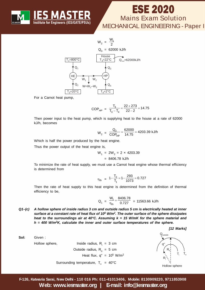
Q1–(b) (ii) A heat engine operates between two reservoirs at 800°C and 20°C. One-half of thework output of the engine is used to drive a Carnot heat pump that removes heatfrom the cold surroundings at 2°C and transfers it to a house maintained at 22°C.If the house is losing heat at a rate of 62,000 kJ/h, determine the minimum rate ofheat supply to the heat engine required to keep the house at 22°C.
[8 Marks]
Sol: (ii) Given: Heat engine,
Two reservoir, T1 = 800°C
T2 = 20°C
MECHANICAL ENGINEERING - Paper I
F-126, Katwaria Sarai, New Delhi - 110 016 011-41013406, Mobile: 8130909220, 9711853908Ph:
Web: www.iesmaster.org | E-mail: [email protected]
Mains Exam Solution
W2 = 1W2
Q3 = 62000 kJ/h
HE
T =20°C2
T =800°C1
HP
T =2°C4
HouseT =22°C3
Q3
Q4Q2
Q1
W1 W2
W=W –1 W2
Q =62000kJ/hloss
For a Carnot heat pump,
COPHP =
3
3 4
T 22 273 14.75T T 22 2
Then power input to the heat pump, which is supplying heat to the house at a rate of 62000kJ/h, becomes
W2 = 3
HP
Q 62000 4203.39 kJ/hCOP 14.75
Which is half the power produced by the heat engine.
Thus the power output of the heat engine is,
W1 = 2W2 = 2 × 4203.39
= 8406.78 kJ/h
To minimize the rate of heat supply, we must use a Carnot heat engine whose thermal efficiencyis determined from
th = 2
1
T 2931 1 0.727T 1073
Then the rate of heat supply to this heat engine is determined from the definition of thermalefficiency to be,
Q1 =
1
th
W 8406.780.727 = 11563.66 kJ/h
Q1–(c) A hollow sphere of inside radius 3 cm and outside radius 5 cm is electrically heated at innersurface at a constant rate of heat flux of 105 W/m2. The outer surface of the sphere dissipatesheat to the surroundings air at 40°C. Assuming k = 15 W/mK for the sphere material andh = 400 W/m2K, calculate the inner and outer surface temperatures of the sphere.
[12 Marks]
Sol: Given :
Hollow sphere, Inside radius, Ri = 3 cm
Ri
Ro
q
Ti To
Qoutside
Hollow sphere
Outside radius, Ro = 5 cm
Heat flux, q'' = 105 W/m2
Surrounding temperature, T = 40°C

MECHANICAL ENGINEERING - Paper I
F-126, Katwaria Sarai, New Delhi - 110 016 011-41013406, Mobile: 8130909220, 9711853908Ph:
Web: www.iesmaster.org | E-mail: [email protected]
Mains Exam Solution
Conductivity, k = 15 W/m-K
Heat transfer coefficient, h = 400 W/m2-K
Considering heat transfer through hollow sphere,
Heat flux, q'' =
i o
o i
o i2i
T TR R4 kR R
4 R
=
i o i o o i o2
i o io i i
T T 4 kR R kR T TR R RR R 4 R
105 =
i o15 0.05 T T
0.03 0.05 0.03
Ti – To = 80 ... (i)
Considering heat transfer through a outer surface,
Heat transfer, Q = 2iq 4 R
= 2510 4 0.03
= 1130.97 W
Q = 2o oh 4 R T T
1130.97 = 2o400 4 0.05 T 40
Outer surface temperature, To = 130°C
Using To value in equation (i)
Inner surface temperature, Ti = 80 + To
= 80 + 130 = 210°C
Q1–(d) A V-8 engine with 7.5 cm bores is redesigned from two valves per cylinder to four valvesper cylinder. The old design had one inlet valve of 34 mm diameter and one exhaust valveof 29 mm diameter per cylinder. These are replaced with two inlet valves of 27 mm diameterand two exhaust valves of 2 mm diameter. If the maximum valve lift equals 22% of the valvediameter for all valves, calculate the increase of inlet flow area per cylinder. Also discussthe advantages and disadvantages of the new system.
[6+6 Marks]
Sol: Given: Inlet flow area, A = vd l
Here, dv = diameter of valve
l = valve lift
Inlet flow area in old design, A1 = v 11d l
= 3434 0.222
= 798.97 mm2
Inlet flow area in new design, A2 = v 222 d l
MECHANICAL ENGINEERING - Paper I
F-126, Katwaria Sarai, New Delhi - 110 016 011-41013406, Mobile: 8130909220, 9711853908Ph:
Web: www.iesmaster.org | E-mail: [email protected]
Mains Exam Solution
= 2 27 0.22 27
= 1007.69 mm2
Increase of inlet flow area per cylinder,
A = A2 – A1
= 1007.69 – 798.97
= 208.72 mm2 or 2.08 cm2
Advantages :
Greater intake valve flow area which improves volumetric efficiency.
Greater exhaust valve flow area which allows for a shorter exhaust blowdown process.
Greater flexibility in intake be allowing variation in valve timing and lift between two valves.
Disadvantages :
Need for greater number and/or more complex camshafts.
Higher cost in manufacturing.
Difficulty of fitting valves into combustion chamber surface.
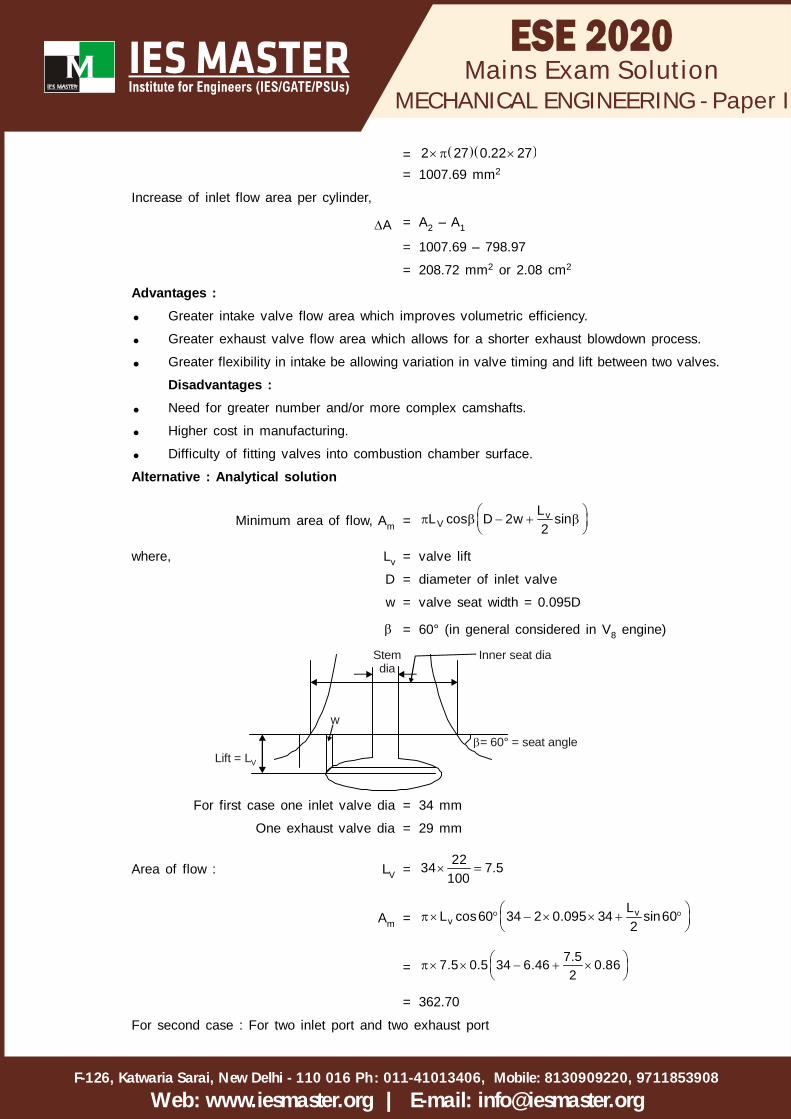
Alternative : Analytical solution
Minimum area of flow, Am = vV
LL cos D 2w sin2
where, Lv = valve lift
D = diameter of inlet valve
w = valve seat width = 0.095D
= 60° (in general considered in V8 engine)
w
Lift = LV
= 60° = seat angle
Stemdia
Inner seat dia
For first case one inlet valve dia = 34 mm
One exhaust valve dia = 29 mm
Area of flow : LV =2234 7.5
100
Am = vv
LL cos60 34 2 0.095 34 sin602
=7.57.5 0.5 34 6.46 0.862
= 362.70
For second case : For two inlet port and two exhaust port

MECHANICAL ENGINEERING - Paper I
F-126, Katwaria Sarai, New Delhi - 110 016 011-41013406, Mobile: 8130909220, 9711853908Ph:
Web: www.iesmaster.org | E-mail: [email protected]
Mains Exam Solution
VL =2227
100 = 5.94
So, minimum area of flow Am = vV
L2 L cos D 2w sin2
= 5.942 5.94cos60 27 2 0.095 27 sin60
2
= 456.11
So, Increased inflow area = 456.11 – 362.44
= 93.67 mm2
Q1–(e) Describe briefly the working principle of a vortex tube refrigeration system mentioningits advantages and disadvantages.
[12 Marks]Sol: This device, called the vortex tube consists of a straight length of a tube with a concentric orifice
located in a diaphragm near one end and a nozzle located tangentially near the outer radiusadjacent to the orifice plate shown in figure (I) Compressed gas enters the tube tangentially througha nozzle forming a vortex kind of motion. The diaphragm prevents leftward motion of the vortexwhich , therefore, travels towards the right-hand side of the tube called the hot end. A hot streamat temperature Th which is above the temperature of supply, say, T3 ejects from the hot end throughthe throttle valve, while the cold stream at temperature Tc below the temperature of supply isreceived at the cold end through the orifice. The throttle-valve opening controls the temperatureand proportion of the cold stream with respect to the hot stream; the larger the throttle valveopening, the lower the temperature of the cold stream and the smaller its fraction and vice versa.The throttle valve is placed sufficiently distant from the nozzle and the diaphragm immediatelyclose to it.
CompressedGas
TangentialNozzle Hot Gas
ColdGas
Diaphragm
d D
Orifice
L
Vortex Tube
ThrottleValve
Figure (i)
The geometry of the vortex tube can be described by the diameter of the vortex tube D, diameterof the orifice d, length of the vorted tube L, geometry and number of nozzles and design of thevalve. The setting of the valve determines the ratio of the hot and cold mass flow fractions
h c and respectively. The optimum diameter of the orifice is found to be half the tube diameter..
It may be seen from figure (i) that the vortex tube system is a modification of the open-type air-refrigeration system with the expander having been replaced by a vortex tube. In the Joule cycle,a temperature drop is obtained equal to the isentropic temperature drop, s 3 4T T T figure (ii).

MECHANICAL ENGINEERING - Paper I
F-126, Katwaria Sarai, New Delhi - 110 016 011-41013406, Mobile: 8130909220, 9711853908Ph:
Web: www.iesmaster.org | E-mail: [email protected]
Mains Exam Solution
The work of expansion is utilized to either run a cooling fan or a secondary compressor. Thetemperature drop obtained with the vortex tube, T3 – Tc, is smaller than the isentropic drop. Theair first expands to a state n in the nozzle reaching a temperature T4 and velocity C given by
2C2
= Cp (T3 – T4)
If all this kinetic energy could be removed, we would obtain cold air at temperature T4 But withoutthe separation of kinetic energy, it is as good as air at temperature T3 which is the stagnationtemperature of the gas.
From the nozzle, the high-velocity gas travels from the periphery of the tube to the axis duringwhich the separation of kinetic energy occurs. The kinetic energy is retained by the outer layersdue to which they are heated and emerge from the hot end of the tube at state h. The central coreafter having lost some kinetic energy emerges from the cold end at state c, i.e., at a temperatureslightly abvoe the static temperature of the expanded gas. The pressure of the cold-gas stream isusually lowered further due to expansion in the vortex chamber.
It can be seen that the temperature drop is less than the isentropic-temperature drop. Also, thequantity of cold air is only a fraction of the air supplied. Thus the COP of the sysem is much lowerthan that of the Joule cycle. The energy balance of the vortex tube gives.
T3 = c c h hT T
where c h 1 and TTc and Th are the stagnation temperature of the two streams.
The energy efficiency e of the vortex tube can now be defined as the ratio of the coefficient ofperformance of the vortex tube to that of an ideal refrigerating machine in which the work doneby the expander is not recovered.
e =
c 3 c
3 4
T TT T
It is seen that if all the air goes through the throttle valve, there will be no energy separation. Also,if all the air leaves through the orifice, there will again be no energy separation. Thus, there willbe optimum values of fractions c h and for the maximum temperature drop, refrigerating effectand COP.
It possesses several advantages as listed below:
(i) Since air is used as the working medium, the minor leakages are insignificant
(ii) Its design is quite simple, and needs control of valves, etc. for appropriate functioning.
(iii) No moving parts are used, the life of the vortex tube is expected to be infinite and maintenanceis thus almost nil.
(iv) It is light in weight, quite compact, easy to cool even in a complicated space, just byintroducing air to the point under consideration since a stream of cool air comes out of thevortex tube.
(v) Cheaper in initial investment
(vi) Overall no expert attendant is required
The main disadvantage is due to very poor COP and hence not suitable for large capacity refrigerationunit.

MECHANICAL ENGINEERING - Paper I
F-126, Katwaria Sarai, New Delhi - 110 016 011-41013406, Mobile: 8130909220, 9711853908Ph:
Web: www.iesmaster.org | E-mail: [email protected]
Mains Exam Solution
Q–2(a): (i) Prove that equipotential lines and constant function streamlines are orthogonal toeach other.
[4 Marks]How do you distinguish between developing flow and fully developed flow?
[2 Marks]
Sol: (i) Equipotential Line : A line along which the velocity potential is constant, is calledequipotential line.
For equipotential line, = constant
d = 0
But = f(x, y) for steady flow
d = dx dyx y
= –udx – vdy u ; vx x
= –(udx + vdy)
For equipotential line, d = 0
or, –(udx + vdy) = 0 or udx + vdy = 0
dydx =
uv
... (i)
Butdydx = Slope of equipotential line
Line of constant stream function : = Constant
d = 0
But d = dx dyx y
= +vdx – udy v ; ux y
For a line of constant stream function
d = 0 or vdx – udy = 0
ordydx =
vu ... (ii)
But dydx is slope of stream line.
From equation (i) and (ii), it is clear that the product of the slope of the equipotential line and theslope of the stream line at the point of intersection is equal to –1. Thus, the equipotential lines areorthogonal to the stream lines at all points of intersection.
Entry length is the distance a flow travels after entering a pipe before the flow becomes fullydeveloped. When the boundary layer expands to fill the entire pipe, the developing flow becomesa fully developed flow, where flow characteristics no longer change with increased distance along

MECHANICAL ENGINEERING - Paper I
F-126, Katwaria Sarai, New Delhi - 110 016 011-41013406, Mobile: 8130909220, 9711853908Ph:
Web: www.iesmaster.org | E-mail: [email protected]
Mains Exam Solution
the pipe.
Hydrodynamic entrance lengthLaminar flow, Lh, laminar = 0.05 ReD
Turbulent flow, Lh, turbulent = 4.4 D (Re)1/6
The entry length in turbulent flow is much shorter as compared to laminar one. This entrance effectbecomes insignificant beyond a pipe length of 10 times the diameter, Lh, turbulent = 10 D, where Reis the Reynolds number and D is the diameter of the pipe.
Thermal entrance length
Laminar flow, fdte D
lam
x 0.05 R Pr,D
DeR Reynolds No.
Turbulent flow, fdt
Turb
x 10D
where, xfdt = Thermal entrance length D = Pipe inside diameter
Q–2(a): (ii) A spherical balloon having 3 m diameter weighs 130 N and contains helium havingdensity of 0.22 kg/m3, whereas the surroundings air has a density of 1.225 kg/m3. Theballoon is tied with the cable which is inclined to the ground. Determine the inclinationof the cable to the ground when a wind of 5 m/s blows past the balloon. Take CD =0.2.
[14 Marks]
Sol. (ii)
Balloon
Given : Dia of balloon = 3 m
Weight of balloon = 130 N
helium = 0.22 kg/m3
air = 1.225 kg/m3
CD = 0.2
FB
FD
W
T
Buoyant force, FB = air balloonV g
MECHANICAL ENGINEERING - Paper I
F-126, Katwaria Sarai, New Delhi - 110 016 011-41013406, Mobile: 8130909220, 9711853908Ph:
Web: www.iesmaster.org | E-mail: [email protected]
Mains Exam Solution
= 31.225 3 9.816
= 169.88 N
Total weight, W = Wballoon + Wgas
= helium balloon130 gV
= 3130 0.22 9.81 36
= 160.511 N
yF = 0
T sin W = FB
T sin = FB – W
= 169.889 – 160.511
T sin = 9.378N ... (i)
xF = 0
T cos = FD = 2air
1 AV2
T cos = 21 0.2 1.225 7.0685 52
= 21.647N ... (ii)
From equation (i) / equation (ii),TsinTcos
=9.378
21.647
23.423
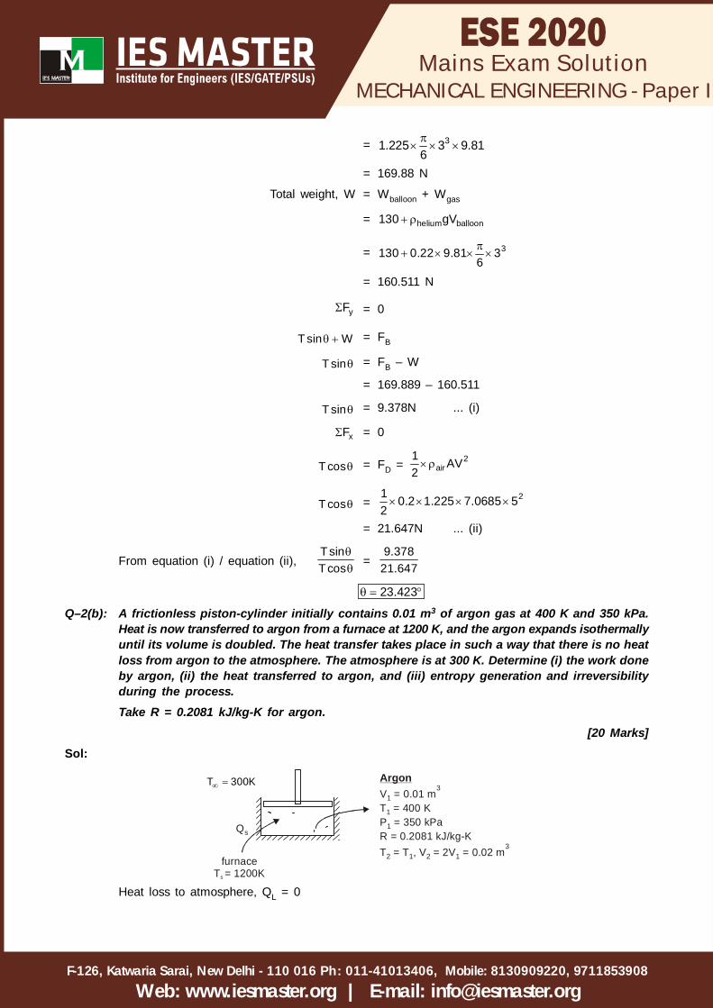
Q–2(b): A frictionless piston-cylinder initially contains 0.01 m3 of argon gas at 400 K and 350 kPa.Heat is now transferred to argon from a furnace at 1200 K, and the argon expands isothermallyuntil its volume is doubled. The heat transfer takes place in such a way that there is no heatloss from argon to the atmosphere. The atmosphere is at 300 K. Determine (i) the work doneby argon, (ii) the heat transferred to argon, and (iii) entropy generation and irreversibilityduring the process.Take R = 0.2081 kJ/kg-K for argon.
[20 Marks]Sol:
ArgonV = 0.01 mT = 400 KP = 350 kPaR = 0.2081 kJ/kg-KT = T , V = 2V = 0.02 m
1
1
1
2 1 2 1
3
3
furnaceT = 1200Ks
Qs
T 300K
Heat loss to atmosphere, QL = 0

MECHANICAL ENGINEERING - Paper I
F-126, Katwaria Sarai, New Delhi - 110 016 011-41013406, Mobile: 8130909220, 9711853908Ph:
Web: www.iesmaster.org | E-mail: [email protected]
Mains Exam Solution
mass of Argon,
1 1
1
P V 350 0.01m 0.042 kgRT 0.2081 400
(i) Work done by ArgonArgon expands isothermally,
W =
2 11 1
1 1
V 2VP V n 350 0.01 n 2.426 kJV V
(ii) Heat transferred to ArgonAccording to first law of thermodynamics,
Q = W U0
Q = 2.429 kJ
(iii) Entropy generation and irreversibility during the process,
Entropy generation,
2
gen 2 1entropy 1change entropy
transfer
dQS S ST
Entropy change,
S2 – S1 = 2 2v
1 1
V TmR n mC nV T
0
= 0.042 0.2081 n 2
= 6.058 × 10⁻³ kJ/K
Entropy transfer,
dQT
=
s L
s
Q QT T
0
= 32.426 2.0216 10 kJ/K1200
Entropy generation, Sgen = 6.058 – 2.0216
= 4.0364 J/K
Irreversibility, I = T0 Sgen
= 300 × 4.0364
= 1.21 kJ
Q–2(c): Show that for fully developed laminar flow in a tube with a parabolic velocity profile u
= 2 2
mru 1 ,R
the Nusselt number is 4811 if the wall temperature increases linearly
with x. Symbols have their usual meanings.[20 Marks]
Sol: Let a fluid enter a pipe with a mean inlet temperature of Ti and let the mean exit temperature offluid be Te. Then, the heat transfer rate can be written as:
MECHANICAL ENGINEERING - Paper I
F-126, Katwaria Sarai, New Delhi - 110 016 011-41013406, Mobile: 8130909220, 9711853908Ph:
Web: www.iesmaster.org | E-mail: [email protected]
Mains Exam Solution
Q = s p e iq A m C T T
Or, the mean exit temperature of fluid may be written as:
Te =
si
p
q ATm C
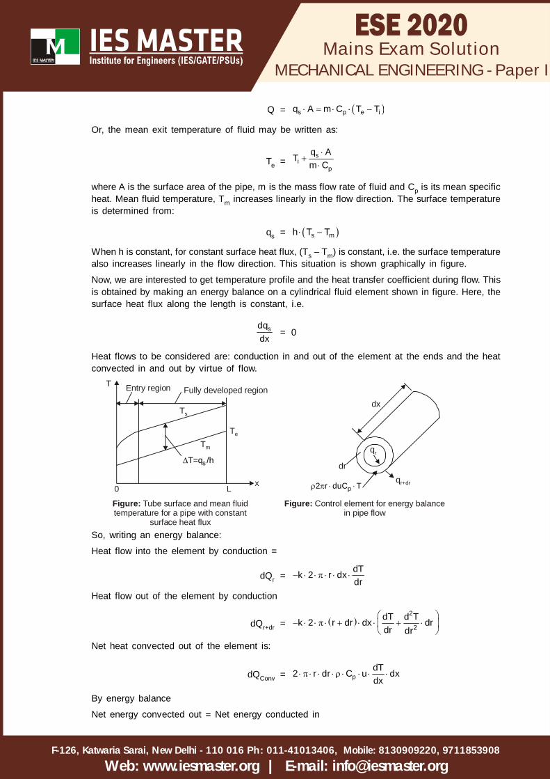
where A is the surface area of the pipe, m is the mass flow rate of fluid and Cp is its mean specificheat. Mean fluid temperature, Tm increases linearly in the flow direction. The surface temperatureis determined from:
qs = s mh T T
When h is constant, for constant surface heat flux, (Ts – Tm) is constant, i.e. the surface temperaturealso increases linearly in the flow direction. This situation is shown graphically in figure.
Now, we are interested to get temperature profile and the heat transfer coefficient during flow. Thisis obtained by making an energy balance on a cylindrical fluid element shown in figure. Here, thesurface heat flux along the length is constant, i.e.
sdqdx
= 0
Heat flows to be considered are: conduction in and out of the element at the ends and the heatconvected in and out by virtue of flow.
dx
Entry region Fully developed regionT
0 Lx
Te
Ts
Tm
sT=q /hdr
qr+dr p2 r duC T
Figure: Tube surface and mean fluid temperature for a pipe with constant
surface heat flux
Figure: Control element for energy balancein pipe flow
qr
So, writing an energy balance:
Heat flow into the element by conduction =
dQr = dTk 2 r dxdr
Heat flow out of the element by conduction
dQr+dr =
2
2dT d Tk 2 r dr dx drdr dr
Net heat convected out of the element is:
dQConv = pdT2 r dr C u dxdx
By energy balance
Net energy convected out = Net energy conducted in

MECHANICAL ENGINEERING - Paper I
F-126, Katwaria Sarai, New Delhi - 110 016 011-41013406, Mobile: 8130909220, 9711853908Ph:
Web: www.iesmaster.org | E-mail: [email protected]
Mains Exam Solution
dQConv = dQr – dQr+dr
Substituting for the above terms and simplifying neglecting higher order differentials,
we get:
1 d dTr
u r dr dr = 1 dT
dx
The average fluid temperature increase linearly with x, so that dT/dx = constant i.e. temperatureprofiles will be similar at different locations along the length.
To solve equation we have to insert the expression for the velocity profile by equation with theboundary conditions:
dTdr
= 0 at r = 0
and
r R
dTkdr = qs = constant
So, equation becomes
d dTrdr dr =
2
max 21 dT ru 1 r
dx R
Integrating
dTrdr
=
2 4
max 121 dT r ru C
dx 2 4 RIntegrating again,
T =
2 4
max 1 221 dT r ru C ln r C
dx 4 16 RApplying the first B.C., we get: C1 = 0. Also, T = Tc at r = 0, at centre of the pipe, i.e. C2 = TC
Therefore, temperature distribution in terms of temperature at the centre of the pipe is:
T – Tc =
2 42maxu R1 dT r 1 r
dx 4 R 4 R ...(i)
Bulk temperature:For convection heat transfer in a pipe, we have:
local heat flux, q = s bh T T
where Ts is the wall temperature, and Tb the ‘bulk temperature’, which is an energy averagedtemperature across the pipe, calculated from:
Tb =
Rp0
Rp0
2 r u C Tdr
2 r u C dr
Again, we have already shown that bulk temperature is a linear function of x for constant heat flowat the wall. Performing the calculation in equation, (using equation) we get:
Tb =
2max
cu R7 dTT
96 dxAnd, wall (or, surface) temperature is given by:

MECHANICAL ENGINEERING - Paper I
F-126, Katwaria Sarai, New Delhi - 110 016 011-41013406, Mobile: 8130909220, 9711853908Ph:
Web: www.iesmaster.org | E-mail: [email protected]
Mains Exam Solution
Ts =
2max
cu R3 dTT
16 dx
....(from equation (i), with r = R)...
Now, the heat transfer coefficient is given by:
Q =
s br R
dTh A T T kdr
A
i.e. h =
r R
s b
dTkdr
T T
Now, the numerator in equation is the temperature gradient and is given by:
r R
dTdr =
3max max
2r R
u u RdT r r dTdx 2 4 dx4 R
Substituting above expression and we get
h = 24 k 48 k11 R 11 D
Or, in terms of Nusselt number:
NuD =h D 4.364
k
Note the interesting result that for steady, fully developed laminar flow in a pipe whose wallsare subjected to a constant heat flux, the Nusselt number is a constant = 4.364. Of course, atthe entrance region, value of Nusselt number will be somewhat higher.
Q3–(a): (i) Prove that the total pressure which is the summation of static and dynamic pressure,also known as stagnation pressure, decreases in an irreversible adiabatic processwhen a gas is flowing in a steady flow device of constant cross-section without anywork transfer.
[6 Marks]
Sol: (i) Flow in a constant area duct with friction in absence of work and heat transfer is known asFanno line. On this curve maximum entropy occur at sonic velocity.
The Fanno curves is drawn by the help of equation continuity is
m = AV ...(i)
The mass flow density is
G =m vA
V =G ...(ii)
By the energy equation is
21h V2
= h0 ...(iii)
MECHANICAL ENGINEERING - Paper I
F-126, Katwaria Sarai, New Delhi - 110 016 011-41013406, Mobile: 8130909220, 9711853908Ph:
Web: www.iesmaster.org | E-mail: [email protected]
Mains Exam Solution
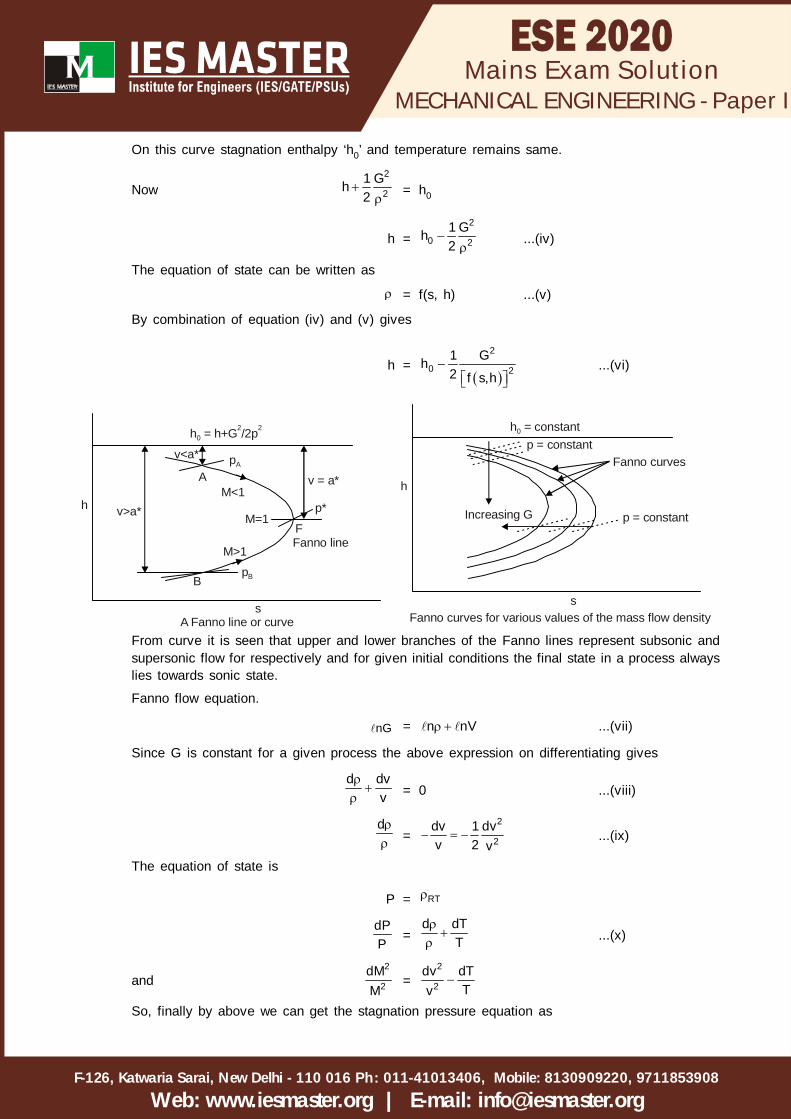
On this curve stagnation enthalpy ‘h0’ and temperature remains same.
Now2
21 Gh2
= h0
h =2
0 21 Gh2
...(iv)
The equation of state can be written as
= f(s, h) ...(v)
By combination of equation (iv) and (v) gives
h =
2
0 21 Gh2 f s,h
...(vi)
v<a*
h = h+G /2p022
v = a*
Fanno lineM>1
M<1
pA
v>a*h
s
A
M=1F
pBB
p*
A Fanno line or curve
Increasing G
h = constant0
p = constant
p = constant
Fanno curves
h
sFanno curves for various values of the mass flow density
From curve it is seen that upper and lower branches of the Fanno lines represent subsonic andsupersonic flow for respectively and for given initial conditions the final state in a process alwayslies towards sonic state.
Fanno flow equation.
nG = n nV ...(vii)
Since G is constant for a given process the above expression on differentiating gives
d dvv
= 0 ...(viii)
d =
2
2dv 1 dvv 2 v
...(ix)
The equation of state is
P = RT
dPP
=d dT
T
...(x)
and2
2dMM
=2
2dv dT
Tv
So, finally by above we can get the stagnation pressure equation as
MECHANICAL ENGINEERING - Paper I
F-126, Katwaria Sarai, New Delhi - 110 016 011-41013406, Mobile: 8130909220, 9711853908Ph:
Web: www.iesmaster.org | E-mail: [email protected]
Mains Exam Solution
0
0
dPP =
2 2
22
1 M dM1 M2 1 M
2
...(xi)
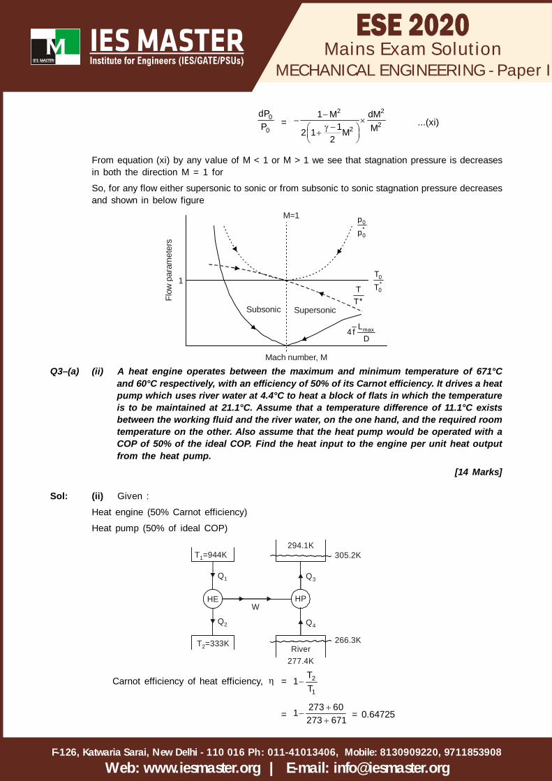
From equation (xi) by any value of M < 1 or M > 1 we see that stagnation pressure is decreasesin both the direction M = 1 for
So, for any flow either supersonic to sonic or from subsonic to sonic stagnation pressure decreasesand shown in below figure
1
M=10*0
pp
0*0
TTT
*T
maxL4 f
D
Subsonic Supersonic
Flow
par
amet
ers
Mach number, M
Q3–(a) (ii) A heat engine operates between the maximum and minimum temperature of 671°Cand 60°C respectively, with an efficiency of 50% of its Carnot efficiency. It drives a heatpump which uses river water at 4.4°C to heat a block of flats in which the temperatureis to be maintained at 21.1°C. Assume that a temperature difference of 11.1°C existsbetween the working fluid and the river water, on the one hand, and the required roomtemperature on the other. Also assume that the heat pump would be operated with aCOP of 50% of the ideal COP. Find the heat input to the engine per unit heat outputfrom the heat pump.
[14 Marks]
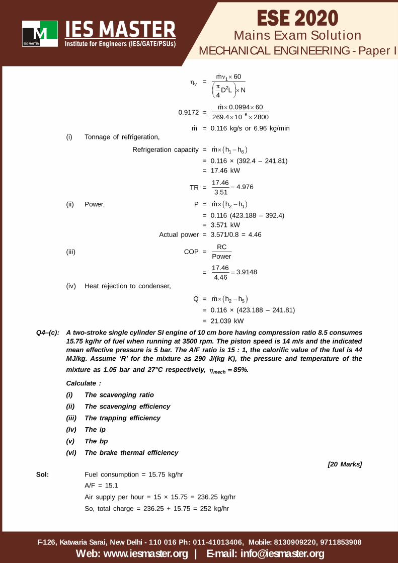
Sol: (ii) Given :
Heat engine (50% Carnot efficiency)
Heat pump (50% of ideal COP)
HE
T =333K2
T =944K1
HP
294.1K
Q3
Q4Q2
Q1
W
305.2K
277.4K
266.3KRiver
Carnot efficiency of heat efficiency, = 2
1
T1
T
=273 601273 671
= 0.64725

MECHANICAL ENGINEERING - Paper I
F-126, Katwaria Sarai, New Delhi - 110 016 011-41013406, Mobile: 8130909220, 9711853908Ph:
Web: www.iesmaster.org | E-mail: [email protected]
Mains Exam Solution
Actual efficiency of heat engine, a = 0.5
= 0.5 × 0.64725
= 0.3236
0.3236 =2
1
Q1
Q
2
1
QQ = 0.6764
Ideal COP =305.2
305.2 266.4 = 7.866
Actual (COP)a = 0.5 × (Ideal COP)
= 0.5 × 7.866 = 3.933
(COP)a = 3QW
= 3.933
If Q3 = 1 kJ
W = 3Q3.933
=1 0.25426 kJ/kJ, heat input to block
3.933
W = Q1 – Q2 = Q1 – 0.6764Q1
= 0.3236Q1
Q1 =0.254260.3236
= 0.7857 kJ/kJ heat input to block
Q3–(b): (i) A cubical oven has inner sides equal to 0.4 m. One of the faces of the oven forms thedoor. If the five other inside faces are black and maintained at 600°C, find the rate ofheat loss if the oven door is kept open.
Take Stefan constant 8 2 45.67 10 W /m K .
[10 Marks]
Sol: (i) F21 + F22 = 1F22 = 0
F12 = 2 221
1 1
A AF
A A
F11 = 212
1
A1 F 1
A

MECHANICAL ENGINEERING - Paper I
F-126, Katwaria Sarai, New Delhi - 110 016 011-41013406, Mobile: 8130909220, 9711853908Ph:
Web: www.iesmaster.org | E-mail: [email protected]
Mains Exam Solution
A1
Door (A )2
0
0
where A1 = area of the five inside faces
= 5 × 0.4 × 0.4 = 0.8 m2
A2 = area of the door through which energy streams out
= 0.4 × 0.4 = 0.16
F11 = 0.161 0.80.8
Rate of heat when the door is open
Q = 4 11
1 1 11 11
1 FA T
1 1 F
= 48 1 0.85.67 10 0.8 8731
= 5274 W = 5.274 kW
Q3–(b): (ii) Explain briefly why dropwise condensation is preferred to filmwise condensation.[10 Marks]
Sol: (ii) There are two modes of condensation: filmwise, in which the condensate wets the surfaceforming a continuous film which covers the entire surface and dropwise in which the vapourcondenses into small liquid droplets of various sizes which fall down the surface in a randomfashion.
Filmwise condensation generally occurs on clean uncontaminated surfaces. In this type ofcondensation the film covering the entire surface grows in thickness as it moves down the surfaceby gravity. There exists a thermal gradient in the film and so it acts as a resistance to heat transfer.In dropwise condensation a large portion of the area of the plate is directly exposed to the vapour,making heat transfer rates much larger (5 to 10 times) than those in filmwise condensation.
In dropwise condensation, the small droplets that form at the nucleation sites on the surface growas a result of continued condensation, coalesce into large droplets, and slide down when they reacha certain size, clearing the surface and exposing it to vapor. There is no liquid film in this caseto resist heat transfer. As a result, with dropwise condensation, heat transfer coefficients can beachieved that are more than 10 times larger than those associated with film condensation. Largeheat transfer coefficients enable designers to achieve a specified heat transfer rate with a smallersurface area, and thus a smaller (and less expensive) condenser. Therefore, dropwise condensationis the preferred mode of condensation in heat transfer application.
Q3–(c): In an air-conditioning system, the inside conditions are dry bulb temperature 25°C andrelative humidity 50%. The outside conditions are dry bulb temperature 40°C and wet bulbtemperature 27°C. The room sensible heat factor is 0.8. 50% of room air is rejected toatmosphere and an equal quantity of fresh air is added before air enters the air-conditioningapparatus.

MECHANICAL ENGINEERING - Paper I
F-126, Katwaria Sarai, New Delhi - 110 016 011-41013406, Mobile: 8130909220, 9711853908Ph:
Web: www.iesmaster.org | E-mail: [email protected]
Mains Exam Solution
Assuming fresh air is added at a rate of 100 m3/minute, draw the process diagram anddetermine the following :(i) Room sensible and latent heat load(ii) Sensible and latent heat load due to fresh air(iii) Apparatus dew point(iv) Humidity ratioTake density of air = 1.2 kg/m3 at a pressure of 1.01325 bar and humid specific heat = 1.022kJ/kgK. Bypass factor is zero.
[20 Marks]
Sol:
o 50% mas
mai= 50% mas
Room
mas
21
50% of mas
50% ma0 i
As bypass factor = 0, supply of air temperature and Apparatus Dew Point are same.
From heat for outside air at 27° wbt and 40° dbt 0 0.0172
For 25° dbt and 50% RH, specific humidity of inside air is
i = 0.010
1 = 0 i0.5 0.5
0.5 0.5
=0.5 0.0172 0.5 0.010
1
= 0.0136 kg/kgda
Enthalpy of state ‘o’ = 86 kJ/kg air from chart = ho
Enthalpy of state ‘i’ = 50 kJ/kg air = hi
hi = 50 kJ/kg air
h1 = 0 i0.5 h 0.5 h0.5 0.5
=0.5 50 0.5 86
1
= 68 kJ/kg of air
1 & h1 we can get point 1 on graph.
From psychrometric chart,
TADP = 12°C

MECHANICAL ENGINEERING - Paper I
F-126, Katwaria Sarai, New Delhi - 110 016 011-41013406, Mobile: 8130909220, 9711853908Ph:
Web: www.iesmaster.org | E-mail: [email protected]
Mains Exam Solution
Humidity Ratio, ADP = 0.009 kg/kgd.a.
1 = 0.0136 kg/kgd.a.
i = 0.01 kg/kgd.a.
0 = 0.0172 kg/kgd.a.
ADP1
O
iSHF=0.8
25°C 40°CDry bulb temperature
HumidityRatio( )
Enthalpy,hi = 50 kJ/kgd.a.
hADP = 33 kJ/kgd.a.h2 = 47 kJ/kgd.a.h0 = 85 kJ/kgd.a.
Room sensible heat load
RSHL = airi ADP
cmm C T T60
= 1.2 100 1.022 25 1260
= 26.572 kJ/s
ADP 2
i
RSHF
RLHL = airi 2
cmm h h60
= 1.200 50 47 6 kJ/s60
Sensible and latent heat load due to fresh airFrom Pyschrometric chart,
h3 = 67.5 kJ/kgd.a.
i 3
0
OASH = air0 i
cmm C T T60
= 1.2 100 1.022 40 25 30.66 kJ/s60
OALH = air0 3
cmm h h60
= 1.2 100 85 67.5 35kJ/s60
Q4–(a): (i) For the same compression ratio and heat rejection, show that the efficiency of Ottocycle is greater than Diesel cycle using T-s plot.
[4 Marks]

MECHANICAL ENGINEERING - Paper I
F-126, Katwaria Sarai, New Delhi - 110 016 011-41013406, Mobile: 8130909220, 9711853908Ph:
Web: www.iesmaster.org | E-mail: [email protected]
Mains Exam Solution
Sol: (i)T
1
2
3
4
5 6 S
3
Cycle 1234 is ottocycle on T-S diagram while 123'41 is Diesel cycle on T-S diagram.
Now area 1654 is area of heat rejection which is common for both cycle.
Length of 1-2 is same for both cycle as there is same compression ratio
From the T-S diagram, area of 6235 > area 623'5
So, for the same heat rejection and compression ratio, heat input to otto cycle is more.
As, =R
in
Q1
Q
(Qin)otto > (Qin)disel
So, otto( ) > disel( )
Q4–(a): (ii) An ideal gas is compressed reversibly and adiabatically from state a to state b. It isthen heated reversibly at constant volume to state c. After expanding reversibly andadiabatically to state d such that Tb = Td , the gas is again reversibly heated atconstant pressure to state e such that Te = Tc. Heat is then rejected reversibly from
the gas at constant volume till it returns to state a. Show that 1
pba
vc
CTT ; where =CT
[16 Marks]
Sol: (ii)
a
b
c
d
e
v=c
p=c
T
SGiven : Tb = Td
Tc = Te
Show : Ta =1
b
c
TT
1. Process a to b : Reversible and adiabatic compression

MECHANICAL ENGINEERING - Paper I
F-126, Katwaria Sarai, New Delhi - 110 016 011-41013406, Mobile: 8130909220, 9711853908Ph:
Web: www.iesmaster.org | E-mail: [email protected]
Mains Exam Solution
2. Process b to c : Reversible heat addition at constant volume
3. Process c to d : Reversible and adiabatic expansion
4. Process d to e : Reversible heated to constant pressure
5. Process e to a : Reversible heat rejection at constant volume
Entropy of cycle, cycleS = 0
ab bc cd de eaS S S S S
o o
= 0
c e av p v
b d e
T T TC ln C ln C ln
T T T
= 0
c c av p v
b b c
T T TC ln C ln C ln
T T T
= 0
c a cp v
b c b
T T TC ln C lnT T T
= 0
a
b
Tln
T
=p c b
v b c
C T Tln lnC T T
Ta =1
b bb
c c
T TTT T
(Hence proved)
Q4–(b): The following data refers to a single-stage vapour compression system:Refrigerant used : R -134aCondensing temperature = 35°CEvaporator temperature = – 10°CCompressor : rpm = 2800
Efficiency = 0.8Clearance volume/Swept volume = 0.03Swept volume = 269.4 cm3
Expansion index = 1.12Condensate subcooling = 5°CDetermine : (i) tonnage, (ii) power, (iii) COP of refrigeration and (iv) heat rejectionto condenser.Properties of R – 134 a:
3g f g f gt , C P, bar V ,m /kg h ,kJ /kg h ,kJ /kg s , kJ/kg s , kJ/kgK
10 2.014 0.0994 186.7 392.4 0.9512 1.73335 8.870 249.1 417.6 1.1680 1.715
Assume : Specific heat of vapour at 8.87 bar is 1.1 kJ/kgK and that of liquid is 1.458 kJ/kgK.Suction vapour is dry saturated and compression process is isentropic. Compressor issingle acting.
[20 Marks]

MECHANICAL ENGINEERING - Paper I
F-126, Katwaria Sarai, New Delhi - 110 016 011-41013406, Mobile: 8130909220, 9711853908Ph:
Web: www.iesmaster.org | E-mail: [email protected]
Mains Exam Solution
Sol–4(b):
35°C30°C
–10°C
T
1
2
34
5
6
S
T1 = –10°C = 263 K = T6
T3 = 35°C = 308K = T4
Condensate sub-cooling = 5°C
T4 – T5 = 5°C
T5 = 35 – 5 = 30°C = 303K
Process 1-2 is isentropic compression,
S2 = S1
23 PV
3
TS C ln
T = S1
2T1.715 1.1ln308
= 1.733
T2 = 313.08 K
Now, h1 = 392.4 kJ/kg
h2 = h3 + CPV(T2 – T3)
= 417.6 + 1.1(313.08 – 308)
= 423.188 kJ/kg
h3 = 417.61 kJ/kg
h4 = 249.1 kJ/kg
h5 = h4 – CPV(T4 – T5) = 249.1 – 1.458 × 5
= 241.81 kJ/kg
Process 5-6 is isenthalpic
h5 = h6 = 241.81 kJ/kg
Volumetric efficiency, v =1/n
2
1
P1 C C
P
Given that,C
S
VV = 0.03 = Clearance ratio
VC = 0.03 × 269.4 = 8.082 cm3
v =1/1.128.871 0.03 0.03
2.014
= 0.9172
MECHANICAL ENGINEERING - Paper I
F-126, Katwaria Sarai, New Delhi - 110 016 011-41013406, Mobile: 8130909220, 9711853908Ph:
Web: www.iesmaster.org | E-mail: [email protected]
Mains Exam Solution
v = 1
2
m 60
D L N4
0.9172 = 6m 0.0994 60
269.4 10 2800
m = 0.116 kg/s or 6.96 kg/min(i) Tonnage of refrigeration,
Refrigeration capacity = 1 6m h h
= 0.116 × (392.4 – 241.81)= 17.46 kW
TR =17.46 4.9763.51
(ii) Power, P = 2 1m h h
= 0.116 (423.188 – 392.4)= 3.571 kW
Actual power = 3.571/0.8 = 4.46
(iii) COP =RC
Power
=17.46 3.91484.46
(iv) Heat rejection to condenser,
Q = 2 5m h h
= 0.116 × (423.188 – 241.81)= 21.039 kW
Q4–(c): A two-stroke single cylinder SI engine of 10 cm bore having compression ratio 8.5 consumes15.75 kg/hr of fuel when running at 3500 rpm. The piston speed is 14 m/s and the indicatedmean effective pressure is 5 bar. The A/F ratio is 15 : 1, the calorific value of the fuel is 44MJ/kg. Assume ‘R’ for the mixture as 290 J/(kg K), the pressure and temperature of themixture as 1.05 bar and 27°C respectively, mech 85%.
Calculate :(i) The scavenging ratio(ii) The scavenging efficiency(iii) The trapping efficiency(iv) The ip(v) The bp(vi) The brake thermal efficiency
[20 Marks]Sol: Fuel consumption = 15.75 kg/hr
A/F = 15.1
Air supply per hour = 15 × 15.75 = 236.25 kg/hr
So, total charge = 236.25 + 15.75 = 252 kg/hr
MECHANICAL ENGINEERING - Paper I
F-126, Katwaria Sarai, New Delhi - 110 016 011-41013406, Mobile: 8130909220, 9711853908Ph:
Web: www.iesmaster.org | E-mail: [email protected]
Mains Exam Solution
N = 3500 rpm
Pimep = 5 bar
CV = 44 × 103 kJ
Pmixture = 1.05 bar
Tam = 27°C
Piston speed; S = 2 × L × N ...(i)
where L = length
N = 3500 rpm
S = 14 m/sec
So, from equation (i)
14 = 35002 L
60
So, L =14 60 127000
So, Swept volume = 2D L
4...(ii)
where D = 10 cm givenSo, from (ii)
Vs = 210 12 942.47 CC
4
Cylinder volume = srV
r 1where, r = compression ratio = 8.5 (Given)
Cylinder volume = s
8.5 8.5V 942.478.5 1 7.5
= 1068.14CC
Now ambient air scavenging density of charge is a' '
a =
5P 1.05 10RT 290 273 27
= 1.206 kg/m3
Mass flow rate or delivered volume of air
a delm = fm 15.75 236.25 kg/hr1F / A15
(i) Rdel = ref
mass of fresh charge per cyclem
Vs = 942.47 CC
Vcycle = 1068.14 CC
As mass of fresh charge of cycle is not given in question so,
We assume that fresh charge in cylinder is swept volume mass at atmospheric condition.

MECHANICAL ENGINEERING - Paper I
F-126, Katwaria Sarai, New Delhi - 110 016 011-41013406, Mobile: 8130909220, 9711853908Ph:
Web: www.iesmaster.org | E-mail: [email protected]
Mains Exam Solution
So, Rdel =
a del
ref6
m 236.2560 3500m
1068.14 10 1.206 0.87 = 87%
(ii) Scavenging efficiency sc
sc = delR 0.871 e 1 e 0.5824 = 58.24%(iii) Trapping efficiency
tr =
sc
del
0.5824 66.94%R 0.87
(iv) ip = imep s 3NP V
60 10
=
6 53
35005 942.47 10 1060 10
= 27.48 kW
bp = m ip 0.85 27.48 23.39 kW
(v) bth = 3f
b.p 23.3915.75CV m 44 103600
= 12.15%
SECTION-B
Q–5(a): Reciprocating pump gives fluctuating output and you want uniform or near uniform outputfrom it. Suggest possible solutions or modifications with justifications and illustrations.
[12 marks]Sol: For an uniform or near uniform output for a reciprocating pump, we can use air vessel to reduce
the fluctuating output.Air Vessel
Air vessel fordelivery pipe
Hd
vdH
hdv
hsv
Hsv
Hs
Air vessel forsuction pipe
ldv
lsv
Reciprocating pump with air vessels

MECHANICAL ENGINEERING - Paper I
F-126, Katwaria Sarai, New Delhi - 110 016 011-41013406, Mobile: 8130909220, 9711853908Ph:
Web: www.iesmaster.org | E-mail: [email protected]
Mains Exam Solution
Air vessel is a closed chamber fitted on the suction as well as on the delivery side, near the pumpcylinder, to reduce the accelerating head.
To reduce the acceleration head we need to reduce the length of suction pipe (ls) and length of deliverypipe (ld) in which fluctuation of velocity occurs.This is done by the fitting air vessels as close to cylinder as possible. Thus between air vessel andcylinder only fluctuating velocity will occur. Below air vessel on suction side and above air vessel ondelivery side velocity will be constant.
Due to movement of piston, when there is excess velocity above average between suction side air vesseland cylinder, water is supplied from air vessel and when there is to be below average velocity, water isstored in the air vessel on suction side. There by compressing the air in the cylinder. This compressedair pressure is responsible for producing larger discharge when more discharge is needed. A similarphenomenon occurs on delivery side.
Functions:(a) Suction side
1. Reduce the possibility of separation.2. Pump can be run at higher speed for a given pressure head and hence discharge can be increased.3. Length of suction pipe below the air vessel can be increased.
(b) Delivery side1. Constant rate of discharge (Qmean) can be ensured.
2. Save power required to drive the pump. (For single acting cylinder pump, percentage work savedis 84.8% and for double acting single cylinder the percentage work save is 39.2%).
3. For a given pressure head, running speed and hence discharge can be increased.
ExplanationDue to insertion of air vessel, the length of suction pipe (ls) where the fluctuation of acceleration take placecan be effectively reduced to lsv and thus reducing the acceleration (or inertia) head and hence the possibilityof separation is eliminated.
For no separation
= 2s v
ss
A P10.3 – H – ra g
l
As ls is reduced the net positive head will increase, which ensure no cavitation.
vPAt 20 C for water 2.5m of water
2
ss
s
A rH 7.8a g
l
Note: Similar explanation can be done for delivery side for no separation and higher speed.
As ls is reduced, shall be increased, which ensure that pump can run at higher speed.
Due to reduction in ls to lsv and that of ld to ldv the frictional loss is reduced and hence pumpcan be placed at greater height above the available water surface or the length of pipe belowthe air vessel can be increased.Without air vessel the rate of discharge varies according to the sine curve as shown below:

MECHANICAL ENGINEERING - Paper I
F-126, Katwaria Sarai, New Delhi - 110 016 011-41013406, Mobile: 8130909220, 9711853908Ph:
Web: www.iesmaster.org | E-mail: [email protected]
Mains Exam Solution
180
Q
Suction Delivery
3600
For single acting
By fitting the air vessel constant rate of discharge will be ensured. By making the flow constant due to presence of air vessels, the head lost due to friction is reduced. Thus
work is saved i.e., power required to drive the pump is saved.
Expression for mean discharge
Mean discharge (Qth) = ALN A2r Ar60 2
Vmd (mean constant velocity of dischrage) in the pipe is
Vmd ad = Ar
mdd
ArVa
Q–5(b): Draw an equivalent thermal-circuit diagram of a liquid flat plate collector with two glasscovers considering the thermal resistance of glass covers. Neglect thermal resistance fromsides.
[12 marks]Sol:
Glass cover-2
Glass cover-1
Solar radiationDirect Diffuse
Absorber
InsulationTubes carrying heattransfer fluid
Ta
Ta
t1t2
TS
1/hr,2-a
Ta
1/hc2-a
1/hc1-2 1/hr,1-2
1/hc1-p 1/hr1-p
Surface Ts
Ta Ta
Tp
x/k
Tb1/hrp
1/hcp
1
1
t Glass cover 2k
2
2
t Glass cover 1k
insulation
insulation
UAA

MECHANICAL ENGINEERING - Paper I
F-126, Katwaria Sarai, New Delhi - 110 016 011-41013406, Mobile: 8130909220, 9711853908Ph:
Web: www.iesmaster.org | E-mail: [email protected]
Mains Exam Solution
Note: x
K
= Pipe conduction resistance subscript ‘c’ for convection and subscript ‘r’ for radiation
subscript ‘p’ for pipe.
Q–5(c): What are the different types of stresses induced in steam turbine blades? How are thesecomputed and designed to safely bear them?
[12 marks]Sol: The determination of blade stresses is a critical factor in the design of blades. The severest
stresses are imposed by the centrifugal forces due to high rotative speeds. Bending stresses arealso imposed by centrifugal forces, fluid-pressure differences, and vibration.
Centrifugal stresses are a function of the mass of material in the blade, blade length and speed.The component of centrifugal force acting radially outward exerts a tensile stress at the root.Sufficient cross-sectional area must be provided in the blade at the root and a material capableof withstanding the stress without fatigue must also be provided.
If the blade is tapered, the mass of material is reduced, thereby reducing the centrifugal stress.Since the stress exerted at any section of the blading decreases radially, reaching a minimum nearthe tip, a constant cross-sectional area is not required for strength. Hence, where the centrifugalstresses are severe the blade is tapered by decreasing both its thickness and width.
Impulse blade are subject to bending from centrifugal stress and the tangential force exerted bythe fluid. Reaction blades have an additional bending stress due to large axial thrust because ofthe pressure drop which occurs in the blades. All turbine blades may be subjected to bendingbecause of vibration. The total stress at a given point on a turbine blade may be found by addingthe centrifugal stress at that point to the bending stress.
Q–5(d): What are regenerative fuel cells? Briefly describe its working with a properly labelled diagram.[4+8 marks]
Sol: A regenerative fuel cell is one in which the fuel cell product (e.g., water in the hydrogen-oxygenfuel cell) is recovered into its reactants (e.g., hydrogen and oxygen) by one of several possiblemethods–thermal, chemical, photochemical, electrical or radio chemical.
Since there are two stages in a regenerative fuel cell:
1. Conversion of fuel cell reactants into products while producing electrical energy, and
2. Reconversion of fuel cell products into reactants, – it is clear that the overall efficiency ofregenerative fuel cell is the product of the efficiencies of these two stages. In the following section,the principle of the regenerative systems is explained by considering the photochemical mode ofregeneration.
Photochemically regenerative fuel cells. In this method, the products of the fuel cell reaction aretransformed into its reactants by light. Because of the ample availability of solar energy, thismethod should be valuable, provided that there are suitable substances which can undergo photochemical dissociation.
The sequence of reactions which are taking place in this fuel cell can be represented as follows:
Electrochemical : A + B AB + electricity
Photochemical : AB + light A + B
Overall : Light + electricity
The nitric oxide – chlorine fuel cell, in which the overall reaction is,

MECHANICAL ENGINEERING - Paper I
F-126, Katwaria Sarai, New Delhi - 110 016 011-41013406, Mobile: 8130909220, 9711853908Ph:
Web: www.iesmaster.org | E-mail: [email protected]
Mains Exam Solution
2NO + Cl2 2 NOCl
the product nitrosyl chloride is decomposed Photochemically to chlorine and nitrous oxide. Thesystem is schematically represented in Figure
Absorber
Cl2
Cl2Cl2
Storage
Stripper NoSeparator
Load
NoStorage
Electrolyte
NoNOCl
Evaporator
Cl2NOCl
SolarRegenerator
RTED NOCl
NO, Cl2 and Unconve–
Figure: Regenerative fuel cell
The cell has a standard reversible-cell potential of 0.21 volt. The reactants may be regretted fromNOCl, in the liquid phase by light. Under these conditions, the quantum yield is low because theback reaction is also rapid. In the gas phase regeneration is easier although there is some problemof separating the NO and Cl2. The currents obtainable are low, probably as a result of the low valueof the reversible potential.
Q–5(e): A gas turbine power plant operating on an ideal Brayton cycle takes in air at the initialconditions of 5°C and 1.03 bar. The pressure ratio is 7 and the maximum temperature is816°C. Determine the work ratio and the mass flow rate of air for a net output of 3750 kW.
For air Cp = 1.005 kJ/kg K and = 1.4.
[12 marks]Sol: Ideal Brayton cycle
Given: Air,
Initial condition, P1 = 1.03 bar
T1 = 5°C = 278 K
Pressure Ratio rp = 7
Maximum temperature, T3 = 816°C = 1089 K
Net power output, P = 3750kW
Assumptions:(i) Isentropic compression and expansion
(ii) Constant pressure heat addition and rejection

MECHANICAL ENGINEERING - Paper I
F-126, Katwaria Sarai, New Delhi - 110 016 011-41013406, Mobile: 8130909220, 9711853908Ph:
Web: www.iesmaster.org | E-mail: [email protected]
Mains Exam Solution
wT
4
QR
Q5
2
1
Wc
3
278K
1089
T(K)
S
2
1
TT =
11 1.4 1
1.42p
1
P r T 1.7436P
T2 = 1.7436 × 278 = 484.73 K
3
4
TT =
11
3p
4
P r 1.7436P
T4 = 1089 624.57 K
1.7436Compressor Work, WC = CP (T2 – T1)
= 1.005 (484.73 – 278)
= 207.76 kJ/kg
Turbine work, WT = CP(T3 – T4)
= 1.005 (1089 – 624.57)
= 466.75 kJ/kg
Net work, Wnet = WT – WC
= 466.75 – 207.76 = 258.99 kJ/kg
Mass flow rate, m =Power output
Net work
= 3750 14.48 kg/s
258.99
Work Ratio, WR = net
T
W 258.99 0.55W 466.75
Q–6(a): An axial compression stage has the following data :Temperature and pressure at entry = 300 K, 1.0 bar
Degree of reaction = 50%Mean blade ring diameter = 36 cm
Rotational speed = 18000 rpmBlade height at entry = 6 cm
Air angles at rotor and stator exit = 25°Axial velocity = 180 m/s

MECHANICAL ENGINEERING - Paper I
F-126, Katwaria Sarai, New Delhi - 110 016 011-41013406, Mobile: 8130909220, 9711853908Ph:
Web: www.iesmaster.org | E-mail: [email protected]
Mains Exam Solution
Work done factor = 0.88Stage efficiency = 85%
Mechanical efficiency = 96.7%Determine :(i) Air angles at rotor and stator entry(ii) Mass flow rate of air(iii) Power required to drive the compressor(iv) Loading coefficient(v) Pressure ratio developed by the stage
[20 marks]
Sol: u =dN 0.36 18000 339.292 m/s60 60
= xc 180 0.530u 339.292
(i) Referring to figure:
3
cx3c3
Figure: Velocity triangles for a compressor stage
h , p33
h , p0303
3
1 1
cx1c1
h , p11
h , p01011
w1
Upstreamguide vanes
Entry velocitytriangle
wy1 cy1uRotorblades
u
22w2 cx2
wy2 cy2u
c2 Exit velocitytriangle
Diffuserblades
h , p22
h , p0202
2
1
cy1 = x 1c tan 180 tan 25 = 83.935 m/s
wy1 = 339.292 – 83.935 = 255.357 m/s
1tan =255.357 1.418
180

MECHANICAL ENGINEERING - Paper I
F-126, Katwaria Sarai, New Delhi - 110 016 011-41013406, Mobile: 8130909220, 9711853908Ph:
Web: www.iesmaster.org | E-mail: [email protected]
Mains Exam Solution
1 = 54.82° (Ans)
Since the stage has 50% reaction
2 = 1 1 254.82 ; 25
(ii) 1 =5
31
1
p 1.0 10 1.161 kg/mRT 287 300
m = 1 x 1c d h
m = 1.161×180 0.36 0.06
m = 14.18 kg/s (Ans)
(iii) Specific work
w = x 1 2u c tan tan
w = 0.88 × 339.292 × 180 (1.418 – 0.466)
w = 51164.15 J/kg
P =m
1 14.18 51.164mw0.967
P = 750 kW
(iv) = 2 2w 51164.15 0.444u 339.292
(Ans)
(v) aT =p
w 51164.15 50.91 Cc 1005
Isentropic temperature rise
sT = 0.2861 r st aT p 1 T 0.85 50.91
0.286r300 p 1 = 43.273
0.286r
43.273p 1300
= 1.144
pr = 1.6 (Ans)
Q–6(b): A centrifugal pump with backward curved vanes is running at 1200 rpm against a head of35 m. The discharge through the pump is 0.28 m3/s. If the blade angle at outlet is 30°, flowvelocity at outlet is 4 m/s and hydraulic or manometric efficiency is 0.85, determine diameterand width of impeller at outlet. Draw velocity triangles.
[20 marks]
Sol: Given: N = 1200 rpm
Hm = 35 m
Q = 0.28 m3/s
2 = 30°
2fV = 4 m/s

MECHANICAL ENGINEERING - Paper I
F-126, Katwaria Sarai, New Delhi - 110 016 011-41013406, Mobile: 8130909220, 9711853908Ph:
Web: www.iesmaster.org | E-mail: [email protected]
Mains Exam Solution
mano = 0.85
2 2
Vf2
Vw2u – V2 w2
u2
Vr2V2
Velocity triangle
mano =2
m
w 2
gHV u
2w 2V u =m
mano
gH 9.81 35 403.940.85
2tan =2
2
f
2 w
Vu V
22 wu V = 2f
2
V 4 6.928tan tan30
22
403.94uu
= 6.928
22 2u 6.928u 403.94 = 0
u2 = 23.85, –16.93
Adopting, u2 = 23.85 m/s
u2 = 2D N60
D2 = 260u 60 23.85N 1200
= 0.379 m
Q = 22 2 fD B V
0.28 = 20.379 B 4
B2 = 0.0588 m
Diameter of impeller at outlet D2 = 37.9 cm
Width of impeller at outlet B2 = 5.88 cm
Q–6(c): (i) How is biogas production related to sustainable waste management?(ii) What is meant by biogas enrichment?(iii) Explain the working of a power generation set-up using municipal organic waste
[4+6+10 marks]
Sol: (i) The biogas is a sustainable source of energy because, (1) it is fully energy self-sufficient(itself produce the heat and electricity to run the process); (2) independent of any fossil fuel;(3) renewable, (4) carbon neutral and (5) reduces the emission of green house gases (GSGs)

MECHANICAL ENGINEERING - Paper I
F-126, Katwaria Sarai, New Delhi - 110 016 011-41013406, Mobile: 8130909220, 9711853908Ph:
Web: www.iesmaster.org | E-mail: [email protected]
Mains Exam Solution
to the environment. The substrates from plants and animals only emit the carbon dioxidethey have accumulated during their life cycle and which they would have emitted also withoutthe energetic utilization. On the whole, electricity produced from biogas generates much lesscarbon dioxide than conventional energy and thus will be helpful in reducing green house gasemission. Keeping this in mind, at least 25% of all bioenergy in the future may originate frombiogas. Waste management, manure production, health care and employment generation arethe benefits of biogas system.
(ii) Biogas Enrichment: Conversion of the biogas to renewable electricity and useful heat withcogeneration/combined heat and power. Upgradation of biogas is primarily achieved bycarbon dioxide removal which then enhances the value of the gas to give longer, drivingdistances with a fixed gas storage volume. Removal of carbon dioxide also provides aconsistent quality with respect to energy value.
Biogas produced in both solid and liquid waste treatment plants (biomethanization plants)and wastewater treatment stations, is a mixture of:
• Methane : 50 - 70%
• Carbon Dioxide 30-45%
• Hydrogen Sulphate
• Water
• Siloxanes
• other impurities
This mixture with this content of methane doesn’t allow it to be released into the atmosphere dueto its high pollutant potential (it is one of the main greenhouse gases), its high calorific value meansit can be harnessed for electric power production (cogeneration)
Thus, the production and reuse of biogas enables this type of installation to be every more self-sufficient in terms of energy. Biogas enrichment can be reused onsite or in connection to thenetwork of natural gas supply.
Nevertheless one of the primary impediments to the use of biogas for electric power productionis determined by the nature of the impurities that accompany the biogas. These impurities includethe following: H2S and Siloxanes. CO2 and H2O aren’t real impurities but it’s necessary to removethem for results optimization.
(iii) Waste to Energy (WTE) processes play an important role in the substainable managementof Municipal Solid Waste (MSW) worldwide. In some developed European countries,sustainable development policies are aimed at reducing and recycling waste as well as usingit to produce electricity.
WTE involves the recovery of heat and electricity from waste, especially non-recyclablewaste. MSW can be defined as urban and rural waste, which consists mainly of waste paper,cardboard, food, organic material, mixed plastics and textiles among other elements. WTE israpidly growing all over the world because it can reduce the demand for landfills, prevent dependenceon fossil fuels; reduce greenhouse gas (GHG) emissions and have a positive impact on economicgrowth.
Biological conversion technologies enable the exploitation of biogas produced from the massfraction of solid waste and several studies have evaluated the potential of landfill biogas forproducing electricity. In the field of thermal conversion, incineration is a widely used technology indeveloped countries as a waste management strategy and for the production of electricity andsteam. China, which produces more MSW than any other country and depends heavily on landfills,

MECHANICAL ENGINEERING - Paper I
F-126, Katwaria Sarai, New Delhi - 110 016 011-41013406, Mobile: 8130909220, 9711853908Ph:
Web: www.iesmaster.org | E-mail: [email protected]
Mains Exam Solution
incinerated about 19% of the MSW that it produced in 2010. In Japan, there are around 1900 wasteincineration plants but only 10% of them are equipped with appropriate technology for generatingelectricity.
In developing countries, incineration (generally without pretreatment) is considered to be the mostreliable and economical form of WTE. Some of the advantages of this technology include wastevolume reduction and the use of bottom and fly ash from incineration plants in road constructionand cement production.
Gasification, another thermal conversion technology, is considered a potential candidate for recoveringenergy from MSW, which reduces the waste volume in 95% and produces less emissions comparedto incineration.
In addition to the above-mentioned energy conversion technologies, other alternatives, such asmicrobial fuel cells and microbial electrolysis cells, are considered to be very promising in thefuture They can convert MSW into electricity, hydrogen gas and other chemical feedstocks.
The techno-economic evaluation of WTE projects have the positive impact of government supportin the promotion of those technologies.
Waste separation is a condition for the operation of WTE facilities. Therefore, classifying the wasteat the source should be promoted among the population. To change people’s behavior, campaignsshould motivate citizens to demonstrate their moral commitment to the planet. Such campaignsshould seek to raise environmental awareness. The commercialization of reusable waste shouldalso be promoted to further motivate the separation, recycling and reuse of waste.
Q–7(a): Parabolic trough collector based solar thermal power plants with thermal storage arebecoming popular as they can generate power even during off-sunshine hours. Explain theworking of such a plant with neat sketch. Also explain the basic thermodynamic cycle, onwhich such plants operate, using T-s plot.
[20 marks]
Sol–7: Distributed Collector Solar Thermal Electric Power PlantIn distributed collector system, solar thermal energy is collected from a large number of sun-tracking solar collector, cylindrical parabolic through type or paraboloidal dish type. Each collectortransfers heat to a heat transport fluid. This heat transport fluid, available at high temperature fromthe collectors, is pooled at some central power station. The heat transfer fluid could be water/steam, to be used directly in a steam turbine, or it could be some thermo-chemical storage mediummuch as ammonia. The advantage of later scheme is that thermal energy is stored as chemicalenergy at ambient temperature and no heat is lost in its transmission over a long distance or instoring it overnight for continuous power generation.

MECHANICAL ENGINEERING - Paper I
F-126, Katwaria Sarai, New Delhi - 110 016 011-41013406, Mobile: 8130909220, 9711853908Ph:
Web: www.iesmaster.org | E-mail: [email protected]
Mains Exam Solution
Steam
Turbine
Synthesizer/boiler
(450°C) Alternator
Coolingtower
Separator
N +H +NH2 2 3
NH3Storage
To/fromother
collectors
NH3 N2+H2
N2+H2
HeatexchangerDissociator
(700°C)
Solarcollector
Distributed collector solar thermal electric power plant
a
1
2 f
e
Condenser
3
b4
The schematic diagram of a typical distributed collector power generation plant is shown in figure.The heat collected in collectors is used to dissociate ammonia into nitrogen and hydrogen at highpressure (approx. 300 atm). The heat of reaction, 46 kJ/mole (of NH3) is provided by the solarenergy. This nitrogen, hydrogen mixture is transported to central plant where N2 and H2 arerecombined in a synthesizer, using a catalyst. The heat released during the reaction is utilized ina heat engine to generate electric power through an alternator. In the synthesizer only a part ofnitrogen and hydrogen recombine to produce ammonia. The products of synthesizer are cooled toliquefy ammonia, separate it out and send it to collector system. The mixture of nitrogen andhydrogen that remains in gaseous state is fed back to synthesizer.
b
a
1
5Synthesizer
/boiler2
f
4
3
e Cooling water
s
p 1
p 2
Condenser
Heat from exchanger(solar)
T
1 – 2 – 3 – 4 – 5 is a steam power plant and b – a is the amount of heat received for solarcollector through heat exchanger.
Q–7(b): A Kaplan turbine generates 12 MW of shaft power under 20 m head. If inlet guide vane angleis 30° and diameters of runner and hub are taken to be 6 m and 4 m respectively, determine(a) runner vane angles (inlet and outlet), (b) guide vane angle at outlet, and (c) speed ofrunner. The absolute velocity at the outlet should be kept minimum. Assume hydraulicefficiency as 80% and overall efficiency as 75%. Draw velocity triangles.
[20 marks]

MECHANICAL ENGINEERING - Paper I
F-126, Katwaria Sarai, New Delhi - 110 016 011-41013406, Mobile: 8130909220, 9711853908Ph:
Web: www.iesmaster.org | E-mail: [email protected]
Mains Exam Solution
Sol–7: Given :
P = 12 MW = 12000 kW
H = 20 m
1 = 30°
D1 = 6 m
Dh = 4 m
h = 0.8
o = 0.75
The absolute velocity at the outlet should be kept minimum.
This will happen when 2 = 90°, u2 = u1, V2 = 2 1f fV V
1 1
Vf1
Vw1u – V1 w1
u1
Vr1V1
(a)
2 = 90°
u = u2 1
Vr2V = 2 Vf1
(b)
2
Velocity triangle (a) Inlet (b) Outlet
P = o QH
12000 = 0.75 × 9.81 × Q × 20
Q = 81.55 m3/s
Q = 1
2 21 h fD D V
4
81.55 = 1
2 2f6 4 V
4
1fV = 5.192 m/s
1tan =1
1
f
w
VV
1wV = 1f
1
V 5.192tan tan30
= 8.99 m/s
h = 11 wu VgH
u1 =1
h
w
gH 0.8 9.81 20V 8.99
= 17.46 m/s
u1 = 1D N60
MECHANICAL ENGINEERING - Paper I
F-126, Katwaria Sarai, New Delhi - 110 016 011-41013406, Mobile: 8130909220, 9711853908Ph:
Web: www.iesmaster.org | E-mail: [email protected]
Mains Exam Solution
N =1
1
60u 60 17.46D 6
= 55.57 rpm
(a) Runner vane angles, 1tan =1
1
f
1 w
V 5.192u V 17.46 5.192
= 0.613
1 = 31.5°
2tan = 1f2
2 1
VV 5.192u u 17.46
= 0.297
2 = 16.56°
(b) Guide vane angle at outlet, 2 = 90°
(c) Speed of runner, N = 55.57 rpm
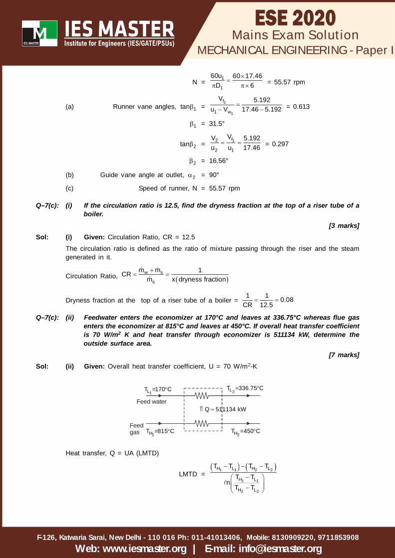
Q–7(c): (i) If the circulation ratio is 12.5, find the dryness fraction at the top of a riser tube of aboiler.
[3 marks]Sol: (i) Given: Circulation Ratio, CR = 12.5
The circulation ratio is defined as the ratio of mixture passing through the riser and the steamgenerated in it.
Circulation Ratio, w s
s
m m 1CRm x dryness fraction
Dryness fraction at the top of a riser tube of a boiler = 1 1 0.08
CR 12.5
Q–7(c): (ii) Feedwater enters the economizer at 170°C and leaves at 336.75°C whereas flue gasenters the economizer at 815°C and leaves at 450°C. If overall heat transfer coefficientis 70 W/m2 K and heat transfer through economizer is 511134 kW, determine theoutside surface area.
[7 marks]Sol: (ii) Given: Overall heat transfer coefficient, U = 70 W/m2-K
1LT =170 C 2LT =336.75 C
2HT =450 C1HT =815 C
Q 511134 kW Feed water
Feedgas
Heat transfer, Q = UA (LMTD)
LMTD = 1 1 2 2
1 1
2 2
H L H L
H L
H L
T T T TT T
nT T

MECHANICAL ENGINEERING - Paper I
F-126, Katwaria Sarai, New Delhi - 110 016 011-41013406, Mobile: 8130909220, 9711853908Ph:
Web: www.iesmaster.org | E-mail: [email protected]
Mains Exam Solution
= 815 170 450 336.75 305.66
815 170n450 336.75
Outside surface area,
A = Q 511134 1000
U LMTD 70 305.66
= 23889m2
Q–7(c): (iii) A surface condenser receives 250 t/h of steam at 40°C with 12% moisture. The coolingwater enters at 32°C and leaves at 38°C. The pressure inside the condenser is foundto be 0.078 bar. The velocity of circulating water is 1.8 m/s. The condenser tubes areof 25.4 mm outer diameter and 1.25 mm thickness. Taking overall heat transfer coefficientas 2600 W/m2 K, determine the rate of flow of cooling water, the rate of air leakage intothe condenser shell, the length of tubes and number of tubes. At 40°C, hfg = 2407 kJ/kg, psat = 0.07375 bar, vf = 0.001008 m3/kg and vfg = 19.544 m3/kg.
[10 marks]
Sol: (iii)x2 = 0.88
h2 = hf + 0.88hfg
h3 = hf
40°C
T
S
2s 2
(a)
Steam t =40°Csat
t =38°Cc2C.W.
A or Lo t = 2°Ce
t =32°Cc1
tt =40°Csat
(b)
1
3
At 40°C, hfg = 2407 kJ/kg
h2 – h3 = 0.88hfg = 0.88 × 2407 = 2118.16 kJ/kg
By energy balance, s 2 3h h = 2 1c pc c cc t t
250 1000 2118.163600
= c × 4.187(38 – 32)
c = 5855.2 kg/s
c = Rate of flow of cooling water = 5855.2 kg/sec
At 40°C psat = 0.07375 bar
p = psat + pair = 0.078 bar
pair = 0.078 – 0.07375
= 0.00425 bar = 0.425 kN/m3

MECHANICAL ENGINEERING - Paper I
F-126, Katwaria Sarai, New Delhi - 110 016 011-41013406, Mobile: 8130909220, 9711853908Ph:
Web: www.iesmaster.org | E-mail: [email protected]
Mains Exam Solution
2 = f 2 fgx
= 0.001008 + 0.88 × 19.544 = 17.2 m3/kg
Now, air s 2p = air air shR T
250 10000.425 17.23600
= air 0.287 313
air = 5.651 kg/s
So, rate of air leakage = 5.651kg/sec
1, mt = i e
i e
t t 8 2 4.33 Cln t / t ln 8 / 2
Q = 0 0 1, m s 2 3U A t h h
2.6 × A0 × 4.33 =250 1000 2118.16
3600
A0 = 13066 m2
c =2in d V
4
= 5855.2 kg/s
2 6n 25.4 2.5 10 1000 1.84
= 5855.2
n =65.8552 4 10
524.41 1.8
= 7898
So, Number of tubes ‘n’ = 7898
Again, A0 = 0n d l = 13066 m2
l = 0 313066n d
7898 25.4 10
= 20.73 m
So length of tube ' ' = 20.73 m
Q–8(a): Wind is blowing at a speed of 12 m/s. It enters a turbine wheel at standard atmosphericpressure and 15°C. The turbine wheel has a cross-sectional area of 90 m2. Determine thepower of the incoming wind, theoretical maximum possible power available according toBetz criterion and a reasonably attainable turbine power in kW assuming 40% efficiency ofthe turbine. Find out the torque if the turbine wheel rotates at 30 RPM. Also determine theaxial thrust if the turbine were operating at maximum efficiency.
[20 marks]
Sol: Free wind velocity, Uo = 12 m/s
Atmospheric pressure, P = 1.01325 × 10⁵ Pa
Temperature, T = 15°C
Rotor area, A = 90 m2
Efficiency of turbine, = 40%
Rotor speed, N = 30 rpm

MECHANICAL ENGINEERING - Paper I
F-126, Katwaria Sarai, New Delhi - 110 016 011-41013406, Mobile: 8130909220, 9711853908Ph:
Web: www.iesmaster.org | E-mail: [email protected]
Mains Exam Solution
Incoming wind power, Po = 3o
1 Au2
Density, =
5P 1.01325 10RT 287 273 15
= 1.225 kg/m3
Po =12
× 1.225 × 90 × (12)3
= 95256 W or 95.256 KW
Maximum possible power available according to Betz criterion is 59% of available wind power.
(PT)max = 0.59 × Po
= 0.59 × 95.256
= 56.201 KW
Reasonably attainable power, PT = 0.4 × (PT)max
= 0.4 × 56.201
= 22.48 KW
Torque and axial thrust, when turbine were operating at maximum efficiency,
Rotor speed, =2 N 30260 60
= 3.141 rad/s
Tip speed ratio, =o
Ru
Rotor radius, R =1/2A
2A R
= 5.352 m
=3.141 5.352
12
= 1.4
Maximum torque on turbine rotor, Tm =o
o
P 95.256R 5.352u 12
= 42.484 kN-m
CT,max = P, maxC 0.5931.4
= 0.423
Torque produced at the shaft at maximum output,
Tsh, max = CT, max × Tm
= 0.423 × 42.484
= 17.97 kN-m
Maximum axial thrust on the turbine,
FA, max =2 2oAu 1.225 90 12
2 2
= 7938N

MECHANICAL ENGINEERING - Paper I
F-126, Katwaria Sarai, New Delhi - 110 016 011-41013406, Mobile: 8130909220, 9711853908Ph:
Web: www.iesmaster.org | E-mail: [email protected]
Mains Exam Solution
Axial thrust according to Betz criterion,FA = CF × (FA)max
=89 × 7938
= 7056N
Q–8(b): The following data refers to a two-row velocity compounded impulse wheel which forms thefirst stage of a combination turbine :Steam velocity at nozzle outlet : 630 m/sMean blade velocity : 12 m/sNozzle angle : 16°Outlet angle, first row of moving blades : 18°Outlet angle, fixed guide blades : 22°Outlet angle, second row of moving blades : 36°Steam flow rate : 2.6 kg/sThe ratio of the relative velocity at outlet to that at inlet is 0.84 for all the blades.Calculate :(i) The velocity of whirl(ii) The tangential thrust on the blades(iii) The axial thrust on the blades(iv) The power developed(v) The blade efficiency
[20 marks]
Sol: V1 = 630 m/s
Vb = 125 m/s
= 16°
2 = 18°
ms = 2.6 kg/s
1 = 22°
4 = 36°
1
Vr1
V1
Vw1
Va1
12
Vr2
Vb
V2

MECHANICAL ENGINEERING - Paper I
F-126, Katwaria Sarai, New Delhi - 110 016 011-41013406, Mobile: 8130909220, 9711853908Ph:
Web: www.iesmaster.org | E-mail: [email protected]
Mains Exam Solution
3
Vr3
V3
Vw2
Va2
114
Vr4
Vb
V4
1tan =1
1 b
V sinV cos V
=630 sin16
630 cos16 125
= 0.3613
1 = 19.86°
1rV =
1
1
V sinsin
=
630 sin16sin19.86
1rV = 511.15 m/s
2rV = 0.84 × 511.15 = 429.37 m/s
1tan =2
2
r 2
r 2 b
V sinV cos V
=429.37 sin18
429.37 cos18 125
= 0.4682
1 = 25.09°
V2 = 2r 2
1
V sin 429.37 sin18sin sin25.09
V2 = 312.9 m/s
V3 = 0.84 × V2
= 0.84 × 312.9 = 262.84 m/s
1wV = 1 2r 1 r 2V cos V cos
= 511.15 × cos19.86 + 429.37 × cos18°
= 889.1 m/s
1aV = 1 2 1V sin V sin
= 630 × sin16 – 312.9 × sin25.09
= 40.96 m/s
3tan =3 1
3 1 b
V sinV cos V
=262.84 sin22
262.84 cos22 125
= 0.8294

MECHANICAL ENGINEERING - Paper I
F-126, Katwaria Sarai, New Delhi - 110 016 011-41013406, Mobile: 8130909220, 9711853908Ph:
Web: www.iesmaster.org | E-mail: [email protected]
Mains Exam Solution
3 = 36.67°
3rV =
3 1
3
V sinsin
=
262.84 sin22sin36.67
3rV = 164.87 m/s
4rV = 0.84 × 164.87 = 138.49 m/s
2wV = 3 4r 3 r 4V cos V cos
= 164.87cos36.67 + 138.49 × cos36°
= 244.28 m/s
a2V = 43 1 r 4V sin V sin
= 262.84 × sin22 – 138.49 × sin36°
= 17.06 m/s
(i) Velocity of whirl, wV = 1 2w wV V
= 889.1 + 244.28
= 1133.38 m/s
(ii) Tangential thrust on blades, Pt = s wm V
= 2.6 × 1133.38
= 2946.79N or 2.946 kN
(iii) Axial thrust on blades, Pa = s am V
= 2.6 × (40.96 + 17.06)
= 150.852N or 0.15 kN
(iv) Power developed, wD = Pt × Vb
= 2.946 × 125
= 368.25 KW
(v) Blade efficiency, D =w b21
2 V VV
= 2
2 1133.38 125630
= 0.7138 or 71.38%
Q–8(c): A Francis turbine is running at 500 rpm under a head of 190 m. The blade angle at inlet is50° and guide vane angle at inlet is 20°. If the peripheral speed of runner at inlet is 35 m/s and discharge is 9 m3/s, determine (i) power developed by the runner, (ii) diameter andwidth of the runner at inlet, and (iii) hydraulic efficiency of the turbine.Draw velocity triangle at inlet.
[20 marks]
Sol: Given : N = 500 rpm
H = 190 m

MECHANICAL ENGINEERING - Paper I
F-126, Katwaria Sarai, New Delhi - 110 016 011-41013406, Mobile: 8130909220, 9711853908Ph:
Web: www.iesmaster.org | E-mail: [email protected]
Mains Exam Solution
1 = 50°
1 = 20°
u1 = 35 m/s
Q = 9 m3/s
1 1
Vf1
Vw1u – V1 w1
u1
Vr1V1
1tan =1
1
f
w
VV
1fV = 1w 1V tan ...(i)
1tan =1
1
f
1 w
Vu V
1fV = 11 w 1u V tan ...(ii)
From equation (i) and (ii),
1wV tan20 = 1w35 V tan50
1wV = 26.81 m/s
1fV = 26.81 × tan 20° = 9.758 m/s
(i) Power developed by runner, P = 11 wQu V
= 1000 × 9 × 35 × 26.81
= 8445.64 kW = 8.445 MW
(ii) u1 = 1D N60
D1 = 160u 60 35N 500
= 1.34 m
Q = 11 1 fD B V
B1 =11 f
Q 9D V 1.34 9.758
= 0.22 m
(iii) Hydraulic efficiency, h = 1w 1V u 26.81 35gH 9.81 190
= 0.503