MATH: Reinforced Concrete Design 02
18
CHAPTER 7 SHORT COLUMNS SUBJECT TO AXIAL LOAD AND BENDING AXIAL LOAD AND BENDING All columns are subject to axial forces as well as some bending and they need to be proportioned to resist both tones. The load capacity given by Eq. 6-2 and Eq. 6-3 are only applicable of an eccentricity of 0.10h for tied column and 0.05h for spiral columns. Columns will tend to bend under the action of moment, which produces compression on one side of the column and tension on the other side. The following failures are possible under the combined axial and bending loads. 1. Large axial load with negligible moment. Failure under this condition occur by crushing of concrete with all reinforcing bars in the column having reached their yield stress in compression 2. Large axial load and small moment with the entire cross- section in compression - Failure occurs by crushing of concrete with all bars in compression. 3. Large axial load with moment larger than in (2) - Bars in far side in tension but have not yielded. Failure occurs by crushing of concrete. 4. Balanced loading condition - Bars on tensile side yield at the same time concrete on compression side crushes at 0.85 f,. 5. Large moment, relatively small axial - Failure initiated by yielding of tensile bars 6. Largo bending moment - Failure occurs like a beam. PLASTIC CENTROID The plastic centroid of a column cross section is the point through which the resultant column load must pass to produce uniform strain in failure. It represents the location of the resultant force produced by the steel and concrete. The eccentricity of a column load is the distance from the load to the plastic centroid of the column.
Transcript of MATH: Reinforced Concrete Design 02

CHAPTER 7SHORT COLUMNS SUBJECT TO AXIAL LOAD AND BENDING
AXIAL LOAD AND BENDING
All columns are subject to axial forces as well as some bending and theyneed to be proportioned to resist both tones. The load capacity given by Eq.6-2 and Eq. 6-3 are only applicable of an eccentricity of 0.10h for tiedcolumn and 0.05h for spiral columns.Columns will tend to bend under the action of moment, which producescompression on one side of the column and tension on the other side. Thefollowing failures are possible under the combined axial and bending loads.
1. Large axial load with negligible moment. Failure under thiscondition occur by crushing of concrete with all reinforcingbars in the column having reached their yield stress incompression
2. Large axial load and small moment with the entire cross-section in compression - Failure occurs by crushing ofconcrete with all bars in compression.
3. Large axial load with moment larger than in (2) - Bars infar side in tension but have not yielded. Failure occurs bycrushing of concrete.
4. Balanced loading condition - Bars on tensile side yield atthe same time concrete on compression side crushes at 0.85f,.
5. Large moment, relatively small axial - Failure initiatedby yielding of tensile bars
6. Largo bending moment - Failure occurs like a beam.
PLASTIC CENTROID
The plastic centroid of a column cross section is the point through whichthe resultant column load must pass to produce uniform strain in failure. Itrepresents the location of the resultant force produced by the steel andconcrete. The eccentricity of a column load is the distance from the load tothe plastic centroid of the column.
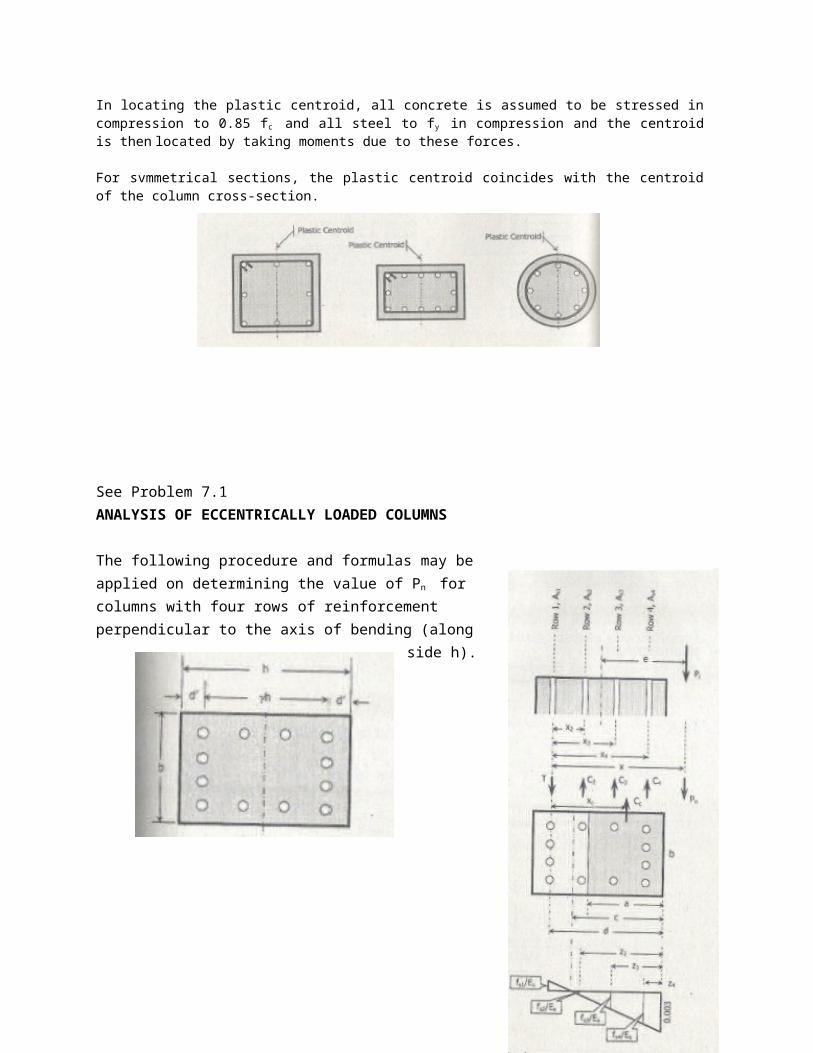
In locating the plastic centroid, all concrete is assumed to be stressed incompression to 0.85 fc and all steel to fy in compression and the centroidis then located by taking moments due to these forces.
For svmmetrical sections, the plastic centroid coincides with the centroidof the column cross-section.
See Problem 7.1ANALYSIS OF ECCENTRICALLY LOADED COLUMNS
The following procedure and formulas may beapplied on determining the value of Pn forcolumns with four rows of reinforcementperpendicular to the axis of bending (along
side h).
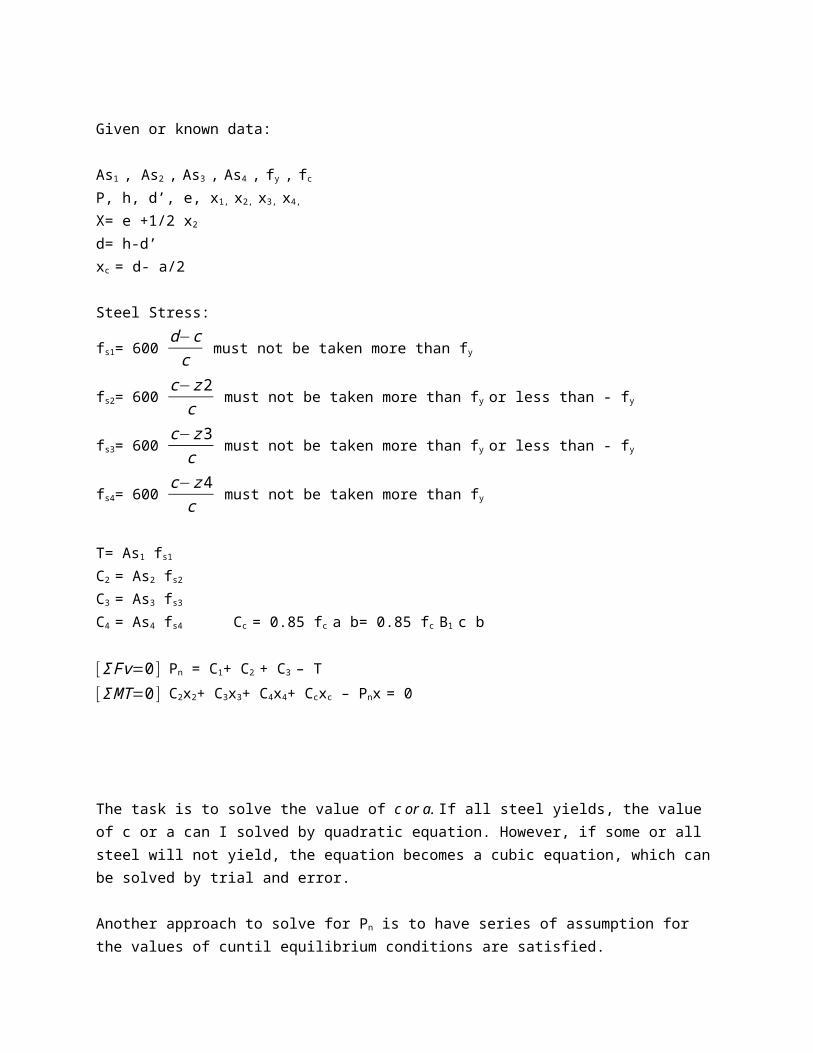
Given or known data:
As1 , As2 , As3 , As4 , fy , fc
P, h, d’, e, x1, x2, x3, x4,
X= e +1/2 x2
d= h-d’xc = d- a/2
Steel Stress:
fs1= 600 d−cc must not be taken more than fy
fs2= 600 c−z2c must not be taken more than fy or less than - fy
fs3= 600 c−z3c must not be taken more than fy or less than - fy
fs4= 600 c−z4c must not be taken more than fy
T= As1 fs1
C2 = As2 fs2
C3 = As3 fs3
C4 = As4 fs4 Cc = 0.85 fc a b= 0.85 fc B1 c b
[ΣFv=0 ] Pn = C1+ C2 + C3 – T[ΣMT=0 ] C2x2+ C3x3+ C4x4+ Ccxc – Pnx = 0
The task is to solve the value of c or a. If all steel yields, the value of c or a can I solved by quadratic equation. However, if some or all steel will not yield, the equation becomes a cubic equation, which canbe solved by trial and error.
Another approach to solve for Pn is to have series of assumption for the values of cuntil equilibrium conditions are satisfied.
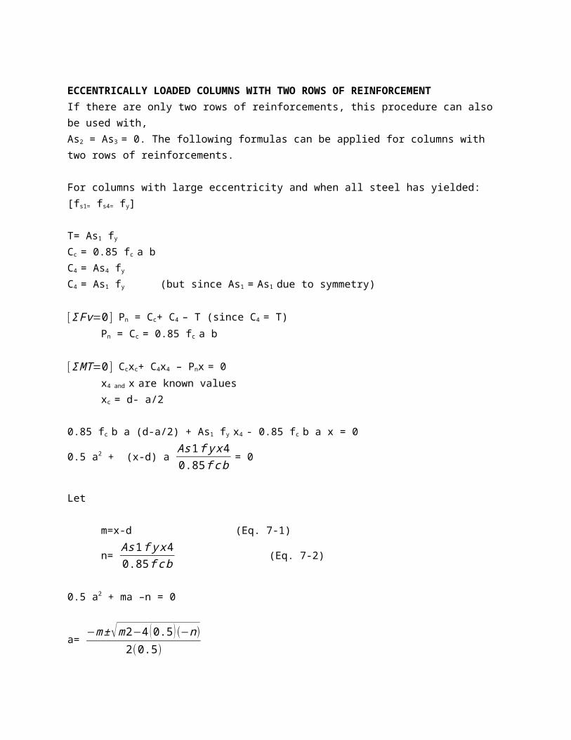
ECCENTRICALLY LOADED COLUMNS WITH TWO ROWS OF REINFORCEMENTIf there are only two rows of reinforcements, this procedure can also be used with, As2 = As3 = 0. The following formulas can be applied for columns with two rows of reinforcements.
For columns with large eccentricity and when all steel has yielded:[fs1= fs4= fy]
T= As1 fy
Cc = 0.85 fc a b C4 = As4 fy
C4 = As1 fy (but since As1 = As1 due to symmetry)
[ΣFv=0 ] Pn = Cc+ C4 – T (since C4 = T)Pn = Cc = 0.85 fc a b
[ΣMT=0 ] Ccxc+ C4x4 – Pnx = 0x4 and x are known valuesxc = d- a/2
0.85 fc b a (d-a/2) + As1 fy x4 - 0.85 fc b a x = 0
0.5 a2 + (x-d) a As1fyx40.85fcb = 0
Let
m=x-d (Eq. 7-1)
n= As1fyx40.85fcb (Eq. 7-2)
0.5 a2 + ma –n = 0
a= −m±√m2−4 (0.5) (−n)
2(0.5)
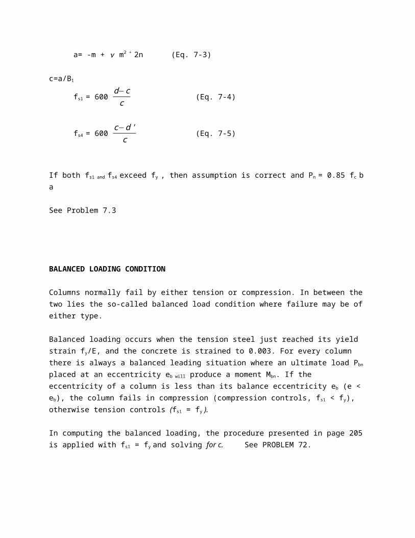
a= -m + √ m2 + 2n (Eq. 7-3)
c=a/B1
fs1 = 600 d−cc (Eq. 7-4)
fs4 = 600 c−d'c (Eq. 7-5)
If both fs1 and fs4 exceed fy , then assumption is correct and Pn = 0.85 fc ba
See Problem 7.3
BALANCED LOADING CONDITION
Columns normally fail by either tension or compression. In between thetwo lies the so-called balanced load condition where failure may be ofeither type.
Balanced loading occurs when the tension steel just reached its yield strain fy/E, and the concrete is strained to 0.003. For every column there is always a balanced leading situation where an ultimate load Pbn
placed at an eccentricity eb will produce a moment Mbn. If the eccentricity of a column is less than its balance eccentricity eb (e < eb), the column fails in compression (compression controls, fs1 < fy), otherwise tension controls (fs1 = fy ).
In computing the balanced loading, the procedure presented in page 205is applied with fs1 = fy and solving for c. See PROBLEM 72.
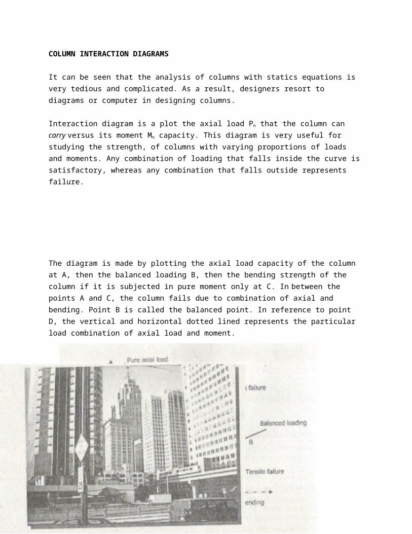
COLUMN INTERACTION DIAGRAMS
It can be seen that the analysis of columns with statics equations is very tedious and complicated. As a result, designers resort to diagrams or computer in designing columns.
Interaction diagram is a plot the axial load Pn that the column can carry versus its moment Mn capacity. This diagram is very useful for studying the strength, of columns with varying proportions of loads and moments. Any combination of loading that falls inside the curve issatisfactory, whereas any combination that falls outside represents failure.
The diagram is made by plotting the axial load capacity of the column at A, then the balanced loading B, then the bending strength of the column if it is subjected in pure moment only at C. In between the points A and C, the column fails due to combination of axial and bending. Point B is called the balanced point. In reference to point D, the vertical and horizontal dotted lined represents the particular load combination of axial load and moment.
ILLUSTRATIVE EXAMPLESPLASTIC CENTROID
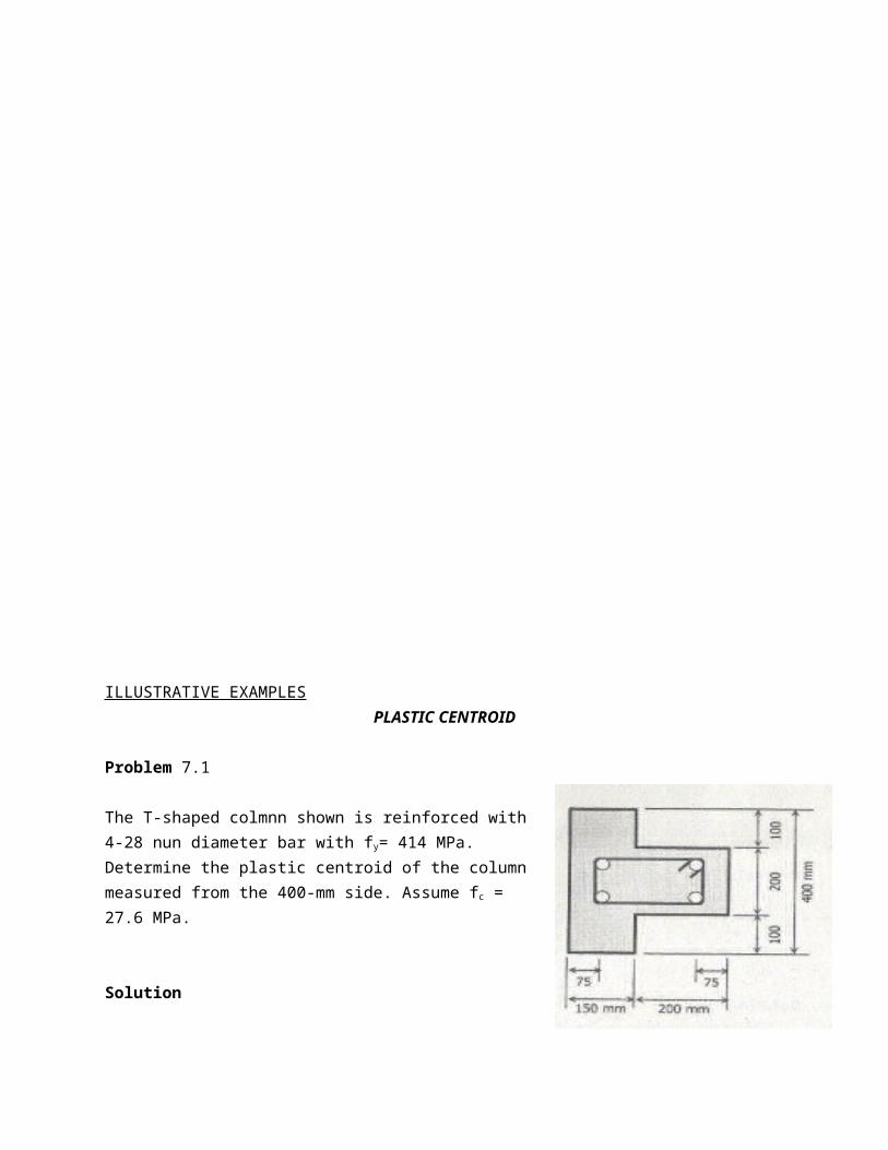
Problem 7.1
The T-shaped colmnn shown is reinforced with4-28 nun diameter bar with fy= 414 MPa.Determine the plastic centroid of the columnmeasured from the 400-mm side. Assume fc =27.6 MPa.
Solution
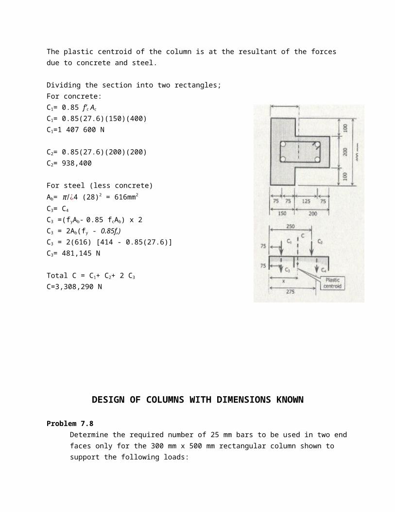
The plastic centroid of the column is at the resultant of the forces due to concrete and steel.
Dividing the section into two rectangles;For concrete:C1= 0.85 f’c Ac
C1= 0.85(27.6)(150)(400) C1=1 407 600 N
C2= 0.85(27.6)(200)(200) C2= 938,400
For steel (less concrete)Ab= π /¿4 (28)2 = 616mm2
C3= C4
C3 =(fyAb- 0.85 fcAb) x 2C3 = 2Ab(fy - 0.85f,)C3 = 2(616) [414 - 0.85(27.6)] C3= 481,145 N
Total C = C1+ C2+ 2 C3
C=3,308,290 N
DESIGN OF COLUMNS WITH DIMENSIONS KNOWN
Problem 7.8Determine the required number of 25 mm bars to be used in two endfaces only for the 300 mm x 500 mm rectangular column shown to support the following loads:
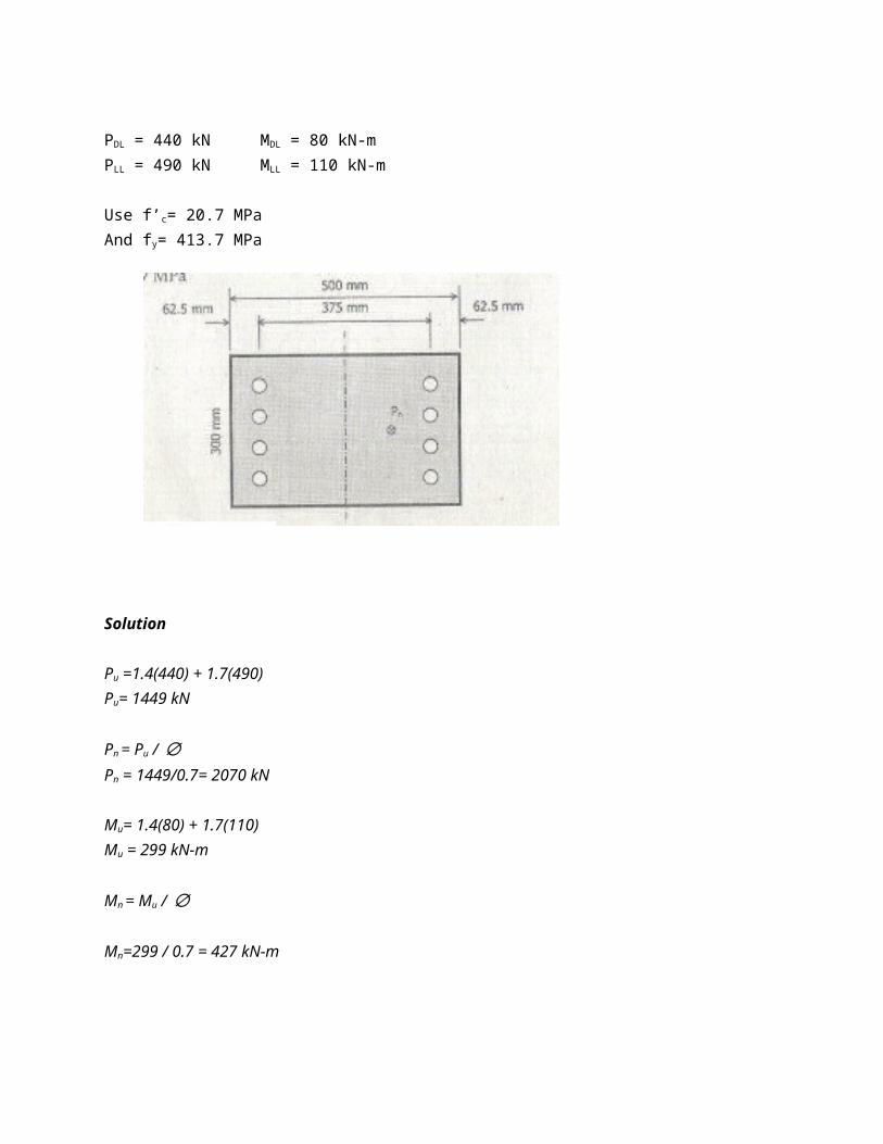
PDL = 440 kN MDL = 80 kN-mPLL = 490 kN MLL = 110 kN-m
Use f’c= 20.7 MPaAnd fy= 413.7 MPa
Solution
Pu =1.4(440) + 1.7(490)Pu= 1449 kN
Pn = Pu / ∅Pn = 1449/0.7= 2070 kN
Mu= 1.4(80) + 1.7(110) Mu = 299 kN-m
Mn = Mu / ∅
Mn=299 / 0.7 = 427 kN-m
[e= Mn / Mn ]
e= 427/2070 = 0.206 mm= 206mm
e/h = 206/500 = 0.412 y = 375/500 = 0.75
∅Pn / Ag = 0.7(2070x103)/ 500(300) =9.66 MPa=1.4 ksi
From the interaction diagram in Figure 7.5: Pg - 0.032 < 0.06 (OK)As= pg Ag
As. = 0.032(300 x 500) = 4,800 mm2
π /4(25)2 N = 4,800 mm2
N= 9.78 say 10 bars (5 on each side)
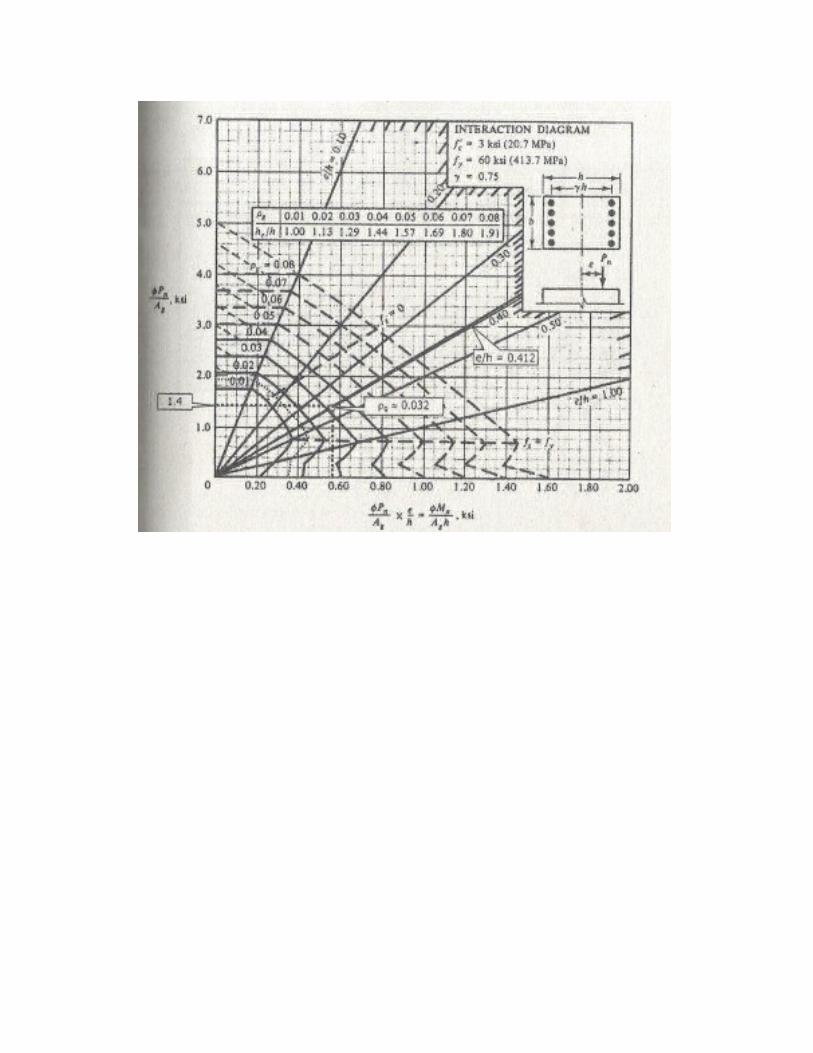
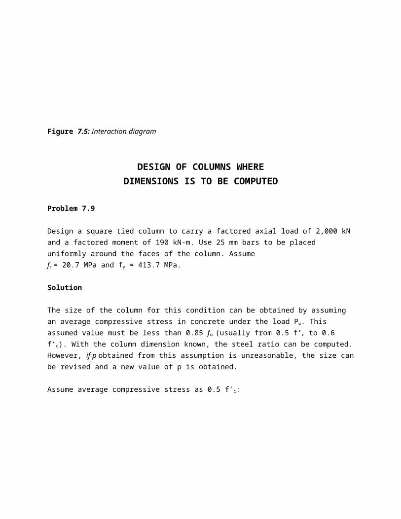
Figure 7.5: Interaction diagram
DESIGN OF COLUMNS WHERE DIMENSIONS IS TO BE COMPUTED
Problem 7.9
Design a square tied column to carry a factored axial load of 2,000 kNand a factored moment of 190 kN-m. Use 25 mm bars to be placed uniformly around the faces of the column. Assume fc = 20.7 MPa and fy = 413.7 MPa.
Solution
The size of the column for this condition can be obtained by assuming an average compressive stress in concrete under the load Pu. This assumed value must be less than 0.85 fc, (usually from 0.5 f’c to 0.6 f’c). With the column dimension known, the steel ratio can be computed.However, if p obtained from this assumption is unreasonable, the size canbe revised and a new value of p is obtained.
Assume average compressive stress as 0.5 f’c:
Ag= Pu / 0.5 f’c
Ag= 2000x103 / 0.5(20.7)Ag= 193,237 mm2 = h2 h = 439 mm
Try 450 x 450 columne=Mu /Pu
e= 190/2000e= 0.095 m e= 95mm
e/h = 95/450 e/h = 0.211
y= 325/450y=0.722
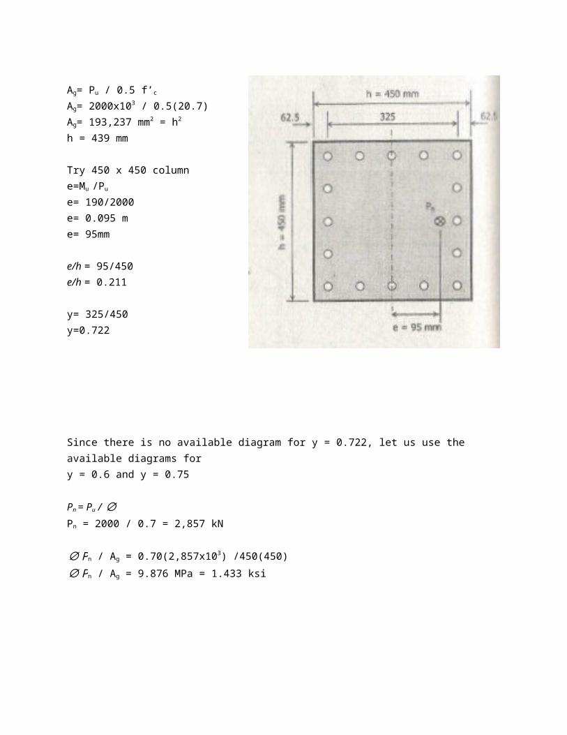
Since there is no available diagram for y = 0.722, let us use the available diagrams for y = 0.6 and y = 0.75
Pn = Pu / ∅Pn = 2000 / 0.7 = 2,857 kN
∅Pn / Ag = 0.70(2,857x103) /450(450)∅Pn / Ag = 9.876 MPa = 1.433 ksi
From the diagram, pg = 0.018
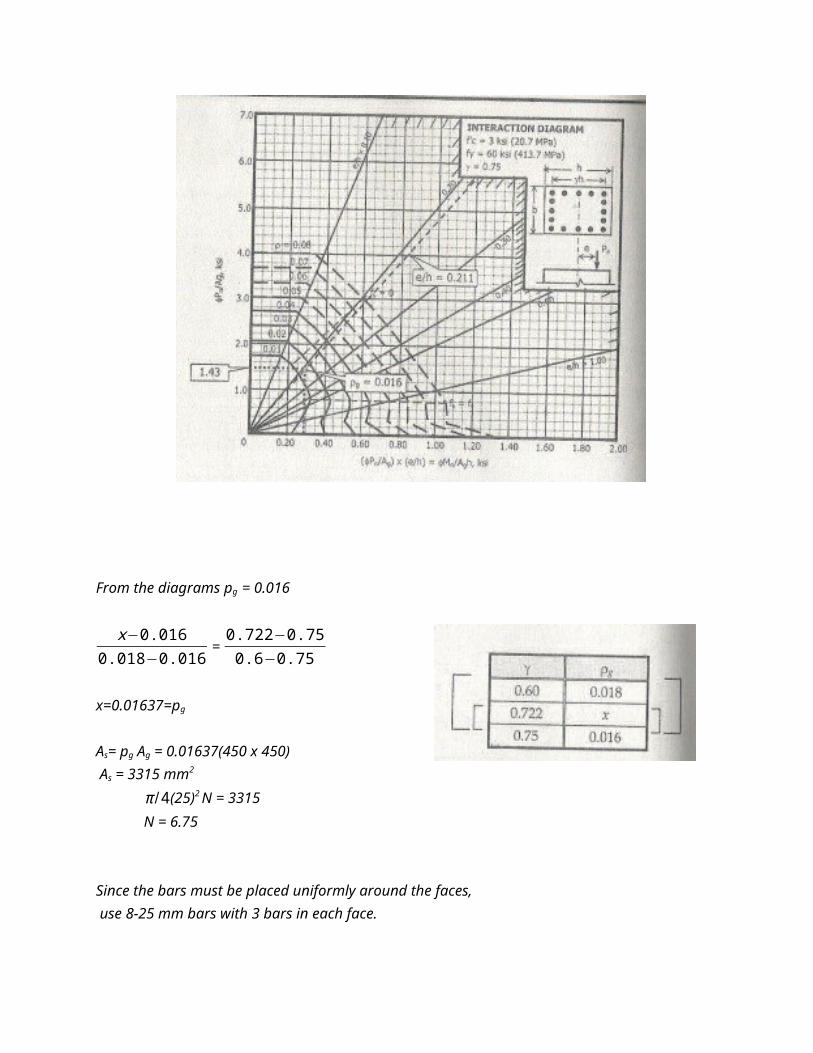
From the diagrams pg = 0.016
x−0.0160.018−0.016 =
0.722−0.750.6−0.75
x=0.01637=pg
As= pg Ag = 0.01637(450 x 450) As = 3315 mm2
π /4(25)2 N = 3315 N = 6.75
Since the bars must be placed uniformly around the faces, use 8-25 mm bars with 3 bars in each face.

Computer calculation for this column (with 8-25 mm bars and e = 95 mm yields the following results:
Pn = 3,089 kN Pu = 2162.3 kN >2000 (OK)Mn = 293 kN-mMu =205.1 kN-m >190 (OK)
AXIAL LOAD PLUS BENDING IN BOTH AXES(AXIAL BENDING)
In most cases, columns are subject to bending in both axes, or biaxialbending. This is the usual case of corner columns in buildings where beams or girders frame to the column from both directions only.
Axial bending on circular columns would not be a problem due to polar symmetry of the column. If there is bending moment about both x and y axes, the axial moment and eccentricity can be computed from the following formulas:
Mu = √(Mux)2+(Muy)2 (Eq. 7-6)e= √(ex)2+(ey)2 (Eq. 7-7)
For column shapes other than circular ones, the analysis would be as shown in the figure below:

One could think how difficult to solve for Pn using the statics equation as presented in PROBLEM 7.4. Such solution would lead to correct answer, but the mathematics involved is so complicated that the method is not a practical one, but with the aid of computer such is not a problem.
BRESLER EQUATION
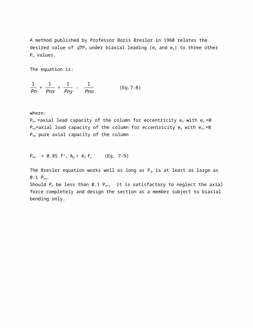
A method published by Professor Boris Bresler in 1960 relates the desired value of ∅Pn under biaxial leading (ex and ey) to three other Pu values.
The equation is:
1Pn =
1Pnx +
1Pny -
1Pno (Eq.7-8)
where:Pnx =axial lead capacity of the column for eccentricity ex with ey =0 Pny=axial load capacity of the column for eccentricity ey with ex,=0 Pno pure axial capacity of the column
Pno = 0.85 f’c Ag + As fy (Eq. 7-9)
The Bresler equation works well as long as P„ is at least as large as 0.1 Pno. Should Pn be less than 0.1 Pno, it is satisfactory to neglect the axialforce completely and design the section as a member subject to biaxialbending only.