MassHunter Data Acquisition Software for 5975/5977 Series ...
72
Agilent MassHunter Data Acquisition Software for 5975/5977 Series GC/MSD Familiarization Guide
-
Upload
khangminh22 -
Category
Documents
-
view
1 -
download
0
Transcript of MassHunter Data Acquisition Software for 5975/5977 Series ...

Agilent MassHunter Data Acquisition Software for 5975/5977 Series GC/MSD
Familiarization Guide

Notices© Agilent Technologies, Inc. 2019
No part of this manual may be repro-duced in any form or by any means (including electronic storage and retrieval or translation into a foreign lan-guage) without prior agreement and written consent from Agilent Technolo-gies, Inc. as governed by United States and international copyright laws.
Manual Part NumberG7077-90021
EditionFirst edition, January 2019Printed in USA
Agilent Technologies, Inc. 5301 Stevens Creek Boulevard Santa Clara, CA 95051
WarrantyThe material contained in this docu-ment is provided “as is,” and is subject to being changed, without notice, in future editions. Further, to the maxi-mum extent permitted by applicable law, Agilent disclaims all warranties, either express or implied, with regard to this manual and any information contained herein, including but not lim-ited to the implied warranties of mer-chantability and fitness for a particular purpose. Agilent shall not be liable for errors or for incidental or consequen-tial damages in connection with the furnishing, use, or performance of this document or of any information con-tained herein. Should Agilent and the user have a separate written agree-ment with warranty terms covering the material in this document that conflict with these terms, the warranty terms in the separate agreement shall control.
Technology Licenses The hardware and/or software described in this document are furnished under a license and may be used or copied only in accordance with the terms of such license.
Restricted Rights LegendU.S. Government Restricted Rights. Soft-ware and technical data rights granted to the federal government include only those rights customarily provided to end user customers. Agilent provides this customary commercial license in Soft-ware and technical data pursuant to FAR 12.211 (Technical Data) and 12.212 (Computer Software) and, for the Depart-ment of Defense, DFARS 252.227-7015 (Technical Data -Commercial Items) and DFARS 227.7202-3 (Rights in Commer-cial Computer Software or Computer Software Documentation).
Safety Notices
CAUTION
A CAUTION notice denotes a hazard. It calls attention to an operating procedure, practice, or the like that, if not correctly performed or adhered to, could result in damage to the product or loss of important data. Do not proceed beyond a CAUTION notice until the indicated conditions are fully understood and met.
WARNING
A WARNING notice denotes a hazard. It calls attention to an operating procedure, practice, or the like that, if not correctly performed or adhered to, could result in personal injury or death. Do not proceed beyond a WARNING notice until the indicated conditions are fully understood and met.

MassHunter Data Acquisition Software for 5975/5977 Series GC/MSD Familiarization Guide 3
In This Guide...This manual will serve as a familiarization or quick reference guide for first-time users of MassHunter Data Acquisition.
Before operating your instruments, be sure to read all safety and regulatory information included with your instruments.
1 Introduction
Chapter 1 provides an overview of how to start up and tune your system.
2 Create a Scan Method
Chapter 2 you will learn how to edit, save, and run a data acquisition Scan method.
3 Create a SIM Quantitation Method
Chapter 3 you will learn how to create a SIM method.
4 Running Samples
Chapter 4 describes how to run a single sample and how to run a sequence.
5 General Information
Chapter 5 includes miscellaneous information on commonly used features in MassHunter.

4 MassHunter Data Acquisition Software for 5975/5977 Series GC/MSD Familiarization Guide
Where to Find More InformationAccompanying your hardware and software is a comprehensive collection of manuals, videos, user applications, and method development tools. These are located on the:
• Agilent GC and GC/MS Manuals and Tools DVD set
• Agilent GC/MS Software Information and Manuals memory stick
To Install Your Hardware Library
Insert Disk 1 into your DVD drive and follow the prompts.
This can be installed by anyone who has authority to copy information onto the receiving computer.
To Install Your Software Library
Insert the memory stick into a USB port and follow the prompts.
This can be installed by anyone who has authority to copy information onto the receiving computer.
© 2013 Agilent Technologies, Inc. All rights reserved.
Made in USA
Agilent TechnologiesGC/GCMS Hardware User Manuals and Videos
S1
Disk 2/3
To install:1. Insert disk into DVD drive2. Follow the instructions on the screen.3. If autoplay is not enabled, double-click "index_xx.html" on the DVD where xx is: en for English ch for 中文 jp for 日本語
Version B.01.05 January, 2013
See the Agilent 5977 Series MSD System Quick Start document for more details on how to install this information on your computer.

MassHunter Data Acquisition Software for 5975/5977 Series GC/MSD Familiarization Guide 5
ContentsIn This Guide... 3
Where to Find More Information 4
1 Introduction
Start up the Hardware 8
Tune your MS 10
Run Autotune 11
2 Create a Scan Method
Edit the Entire Method Option - Overview 14
1) Edit Method dialog 15
2) Method Information dialog 16
3) Inlet and Injection Parameters dialog 17
4) GC Edit Parameters dialog 18GC Configuration panel 18GC ALS panel 23GC Valves panel 25GC Inlets panel 26GC Columns panel 27GC Oven panel 28GC Detector panel 29GC Aux Heaters panel 30GC Events panel 31GC Signals panel 32GC Counters panel 33GC Readiness panel 34GC Calculators panel 35
5) Real-Time Plots dialog 36
6) MS Method Editor dialog- Scan Method Setup 37Sections of the MS Editor dialog 37

6 MassHunter Data Acquisition Software for 5975/5977 Series GC/MSD Familiarization Guide
Sections to complete for all methods 38Settings for Scan Methods 42Scan Time Segments group box 43
7) Select Monitors dialog 44
8) Save The Method 45
3 Create a SIM Quantitation Method
Introduction 48
Create a SIM Method - MS Method Editor Dialog 49
Simultaneously Acquire Scan and SIM Data (SIM/Scan Mode) 51
SIM/Scan Mode Cycle Frequency 52
4 Running Samples
Running a Single Sample 54Load the Method 54Run the Method 54
Running a Sequence 57Create the Sequence 57Save the Sequence 59Load the Sequence 60Run the Sequence 61Print the Sequence Log 62
5 General Information
Editing Individual GC Parameters 66
Add a Column to Your Local Column Inventory 68
Upload Parameters from the 7890X GC 70
Customize the Status Panel View 70

MassHunter Data Acquisition Software for 5975/5977 Series GC/MSD Familiarization Guide 7
1 IntroductionStart up the Hardware 8
Tune your MS 10
Run Autotune 11
Included in this chapter is a general list of steps to follow when you start up your hardware. Also included is a brief introduction to tuning and an explanation of how to run an autotune on the instrument.

1 Introduction Start up the Hardware
8 MassHunter Data Acquisition Software for 5975/5977 Series GC/MSD Familiarization Guide
Start up the HardwareBelow is a general list of steps to follow when you start up your hardware.
1 Review the Agilent Gas Chromatograph and MSD Operating Guides for important safety information and start up details before powering on your instruments.
2 Verify that the inlet septum, liner, and O-ring are clean, properly installed, and in good condition.
3 Install a conditioned column that is appropriate for your method in the GC. Attach the column inlet to the inlet and its outlet to the MSD transfer line. See the Agilent MSD Operation Manual for details.
4 Verify the ion source is installed.
5 Verify the carrier gas required by your method is attached to your inlet.
6 Power on the Agilent GC.
7 From the GC keypad, turn off the oven, Aux 2 heated zone (GC/MSD transfer line), and inlet heater. If equipped, turn off any GC detectors.
8 Before you turn on or attempt to operate the MSD verify the following:• The vent valve must be closed (the knob turned all the way clockwise).• All other vacuum seals and fittings must be in place and fastened
correctly.• The front side plate screw should not be tightened.• The MSD is connected to a grounded power source.• The GC/MSD interface extends into the GC oven.• A conditioned capillary column is installed in the GC inlet and in the
GC/MSD interface.• The GC is on, but the heated zones for the GC/MSD interface, the GC inlet,
and the oven are off.• Carrier gas of at least 99.9995% purity is plumbed to the GC with the
recommended traps.• The foreline pump exhaust is properly vented.
9 Open the MSD analyzer top cover.
10 Close the MSD vent valve.

1 Introduction Start up the Hardware
MassHunter Data Acquisition Software for 5975/5977 Series GC/MSD Familiarization Guide 9
11 Press the Power button on the front of the MSD to power it on. The foreline pump will make a gurgling noise. Press lightly on the metal box mounted on the MSD side board until the air noise stops to ensure a correct seal.
12 Close the MSD analyzer top cover.
13 On the MSD local control panel:a Press Menu repeatedly until Maintenance appears.b Press Item repeatedly until Pumpdown appears.c Press Yes/Select to start the pumpdown.
The pumpdown is completed automatically and does not require operator actions.
After the turbo pump starts and the ion gauge valve reaches 100 mTorr, allow the MSD to operate for a minimum of two hours before acquiring sample data.

1 Introduction Tune your MS
10 MassHunter Data Acquisition Software for 5975/5977 Series GC/MSD Familiarization Guide
Tune your MSTuning is the process that adjusts the MS for good performance over the entire mass range. Using a known compound as a calibrator, the tune parameters are set to achieve sensitivity, resolution, and mass assignments for the known calibration ions.
Tuning is performed using either the autotune or manual tune features.
The autotune program described in this section adjusts the MS for good performance over the entire mass range and is recommended for most applications.
Manual tune allows you to adjust an MS tune parameter while viewing the results easily in profile scans and spectra.
Manual tuning is used:
• To achieve maximum sensitivity by sacrificing some resolution
• To tune specifically for the very low end of the mass range (< 150 amu)
• To tune with a compound other than the standard calibrator

1 Introduction Run Autotune
MassHunter Data Acquisition Software for 5975/5977 Series GC/MSD Familiarization Guide 11
Run Autotune1 From the PC desktop, click the Instrument Control shortcut icon to open
MassHunter Data Acqusition.
2 Select Method/Load Method then navigate to and select the method you want to use for data acquisition (e.g., default.m in the MassHunter/GCMS/1/methods directory), and click OK.
3 To check which Tune file is currently associated with your method, in the Instrument Control view, click the Instrument MS Parameters icon to display the Quadrupole Method Editor dialog.
4 In the Tune File group, verify the tune file shown is the one you wish to use for this method. (Atune.U is a good choice.) Click Browse, and select a new one if necessary.
5 Click the MS Tune icon to display the Select Tune Type dialog.
Figure 1. Select Tune Type dialog display
6 Select Tune MSD to perform a complete autotune, or select Quick Tune to adjust peak width, mass assignment, and abundance, without changing ion ratios. Alternatively, select Manual Tune to display the Manual Tune dialog and graphs for doing manual edits to the Tune file.
7 Click OK to close this dialog and start the tune.
8 Wait for the tune to complete and to generate the report.
9 To evaluate the tune results, select Evaluate Tune from the Checkout menu. To view history of tune results, in the Instrument Control view select Checkout > View Previous Tunes....
See the online Help provided with your MassHunter Data Acquisition software for additional information about tuning.

1 Introduction Run Autotune
12 MassHunter Data Acquisition Software for 5975/5977 Series GC/MSD Familiarization Guide

MassHunter Data Acquisition Software for 5975/5977 Series GC/MSD Familiarization Guide 13
2 Create a Scan MethodEdit the Entire Method Option - Overview 14
1) Edit Method dialog 15
2) Method Information dialog 16
3) Inlet and Injection Parameters dialog 17
4) GC Edit Parameters dialog 18
5) Real-Time Plots dialog 36
6) MS Method Editor dialog- Scan Method Setup 37
7) Select Monitors dialog 44
8) Save The Method 45
A good way to create a new method is to begin with an existing one, edit the settings, and save it as a new method, using the Edit Entire Method option.
This chapter describes how to use the Edit Entire Method option to open the default method and modify its Method Information and Instrument/Acquisition settings to represent a scan method, then save it as a new method name.

2 Create a Scan Method Edit the Entire Method Option - Overview
14 MassHunter Data Acquisition Software for 5975/5977 Series GC/MSD Familiarization Guide
Edit the Entire Method Option - OverviewFor this example, we will modify the Method Information and Instrument/Acquisition settings of the default method to represent a scan method. During this process you will be presented with seven primary dialogs. Each is described on the following pages.
Figure 1. Edit the entire method option - overview
1. Edit Method dialog
To identify the parts of the method you will be editing. (See page 15.)
2. Method Information dialog
To describe the method, where it is saved, and how it is used. (See page 16.)
3. Inlet and Injection Parameters dialog
To select the sample type, inlet, and injection source. (See page 17.)4. GC Edit Parameters dialog
To define the settings for your GC. Here you will click each icon to display and complete the corresponding window for each component. (See page 18.)5. Real-Time Plots dialog
To select which signals you want displayed. (See page 36.)
6. MS Method Editor dialog
To define the Tune File, SIM, Real-Time Plot, and Timed Events, settings. (See page 37.)
7. Monitors dialog
To define the MS monitors you wish to display. (See page 44.)

2 Create a Scan Method 1) Edit Method dialog
MassHunter Data Acquisition Software for 5975/5977 Series GC/MSD Familiarization Guide 15
1) Edit Method dialogThe first dialog you will see when you select the Edit Entire Method option is the Edit Method dialog.
Here you will identify the parts of the method you want to address as you create your method.
To begin the process:
1 Click the Load Method icon , or select Method/Load Method.
2 Navigate to and select the method you want to start with (e.g., default.m in the MassHunter/GCMS/1/methods directory), and click OK.
3 Select Method/Edit Entire Method...The Edit Method dialog opens.
4 Check each section you want included in this method.• Method Information - To provide a description of the method, specify
whether or not to save a copy of the method with the collected data, and define what parts of the method sections to run.
• Instrument/Acquisition - To have the Edit Entire Method process display all the dialogs required to edit the acquisition parameters for both the GC and MS parts of the currently loaded method.
• Data Analysis - To display the Data Analysis portions of the method. Data Analysis settings are beyond the scope of this guide, so we are not including data analysis in our example.
5 Click OK to close the Edit Method dialog and continue.The Method Information dialog opens.

2 Create a Scan Method 2) Method Information dialog
16 MassHunter Data Acquisition Software for 5975/5977 Series GC/MSD Familiarization Guide
2) Method Information dialogIn the Method Information dialog you will provide a description of the method, decide whether or not to save a copy of the method with the collected data, and define what parts of the method sections to run. For example:
1 In the Method Comments field, enter a description of this method.
2 Mark the Save Copy of Method With Data checkbox. This causes MassHunter to save a copy of the method along with the sample data collected.
3 In the Method Sections to Run group box, mark the Data Acquisition checkbox only. This specifies that the Data Acquisition will run when this method is used, but the data analysis and post-run macros will not be run.
4 Click OK to close the Method Information dialog. Because we are running the Edit Entire Method option, and we did check the Instrument/Acquisition option in the previous step, the Inlet and Injection Parameters dialog displays next.

2 Create a Scan Method 3) Inlet and Injection Parameters dialog
MassHunter Data Acquisition Software for 5975/5977 Series GC/MSD Familiarization Guide 17
3) Inlet and Injection Parameters dialogIn the Inlet and Injection Parameters dialog, specify the Sample inlet and Injection Source and the inlet and MS locations.
1 From the Sample Inlet dropdown list, select GC.
2 From the Injection Source dropdown list, select your source.• If you are injecting from the GC using the Automatic Liquid Sampler (ALS),
select GC ALS.• If you are manually injecting or using another injection source, select
Manual.
3 Mark the Use MS checkbox to allow MassHunter to turn on the MS analyzer and save the MS sample data acquired during the run. Uncheck this box only if you do no want to collect Mass Spec data. For example, you would uncheck this box if you are running a GC (non-MS) detector and you were acquiring data for the GC detector only.
4 In the Inlet Location box, select the location where your inlet is attached to the MS through the column.
5 In the MS Connected to box, select the location where your inlet is attached to the MS through the column.
6 Click OK to close the Inlet and injection Parameters dialog. Because we are running the Edit Entire Method option, the GC Edit Parameters window displays next.

2 Create a Scan Method 4) GC Edit Parameters dialog
18 MassHunter Data Acquisition Software for 5975/5977 Series GC/MSD Familiarization Guide
4) GC Edit Parameters dialogThe GC Edit Parameters window contains several icons. Each icon contains one or more panels where you will define the GC instrument settings. We explain each one here.
To begin, we address the Configuration panel because some of the settings made here will affect settings in other panels.
GC Configuration panelOn the Configuration panel, there are four tabs:
• Miscellaneous
• Columns
• Modules
• ALS
The following pages include a general description of the settings used in these tabs. Check the online Help for additional details.
Figure 2. Valve Configuration panel

2 Create a Scan Method GC Configuration panel
MassHunter Data Acquisition Software for 5975/5977 Series GC/MSD Familiarization Guide 19
GC Configuration panel - Miscellaneous tab
Under the Miscellaneous tab you will define your method’s pressure units, configure valve types and oven fan parameters (slow fan_), and view the thermal aux configuration.
Figure 3. GC Configuration panel - Miscellaneous tab

2 Create a Scan Method GC Configuration panel
20 MassHunter Data Acquisition Software for 5975/5977 Series GC/MSD Familiarization Guide
GC Configuration panel - Columns tab
Under the Configuration > Columns tab you will define and configure a column for each position (1-6) in your GC. You can also calibrate a column, lock a column’s configuration, describe how each column connects to GC devices, and tell the system how each column is heated.
Figure 4. GC Configuration panel - Columns tab

2 Create a Scan Method GC Configuration panel
MassHunter Data Acquisition Software for 5975/5977 Series GC/MSD Familiarization Guide 21
GC Configuration panel - Modules tab
Under the Configuration > Modules tab you will define the gas types for your inlets, detectors, and any Aux EPC modules.
Figure 5. GC Configuration panel - Modules tab

2 Create a Scan Method GC Configuration panel
22 MassHunter Data Acquisition Software for 5975/5977 Series GC/MSD Familiarization Guide
GC Configuration panel - ALS tab
If you have a front or back injector installed, under the Configuration > ALS tab you will see the installed injector type and current firmware revision.
From here you will set the configuration parameters to match your installed syringe and desired wash mode.
The configured syringe information must match the actual syringe to achieve accurate injection amounts.
Depending upon the installed injector and turret, these parameters may be available to configure multiple solvent wash bottles usage. If necessary, refer to your injector user documentation for details.
Some syringes are labeled so that the labeled syringe size reflects the maximum injectable volume, rather than the full syringe volume. The maximum injectable volume for a syringe installed in an Agilent injector is 50% of the full syringe volume. If the highest syringe volume marking is only halfway up the syringe barrel, enter double that value as the syringe size. Agilent systems calculate injection volume based on full plunger stroke.
Figure 6. GC Configuration panel - ALS tab
CAUTION

2 Create a Scan Method GC ALS panel
MassHunter Data Acquisition Software for 5975/5977 Series GC/MSD Familiarization Guide 23
GC ALS panelALS - Front/Back Injector tab
Use the Front/Back Injector panels to configure injection parameters, washes and pumps settings, dwell time, plunger speed, sample depth, and the type of your injections.
Note that wash behavior varies depending on syringe size:
• For 100-uL and smaller syringes, the sampler draws the solvent volume specified in the Volume field. After the needle leaves the wash solvent, the injector draws the plunger up until the solvent rinses 80% of the syringe volume, then dispenses to waste.
• For 250-uL and larger syringes, the injector draws and dispenses the exact wash volume of solvent specified in the Volume field. The injector rinses only the volume specified.
Figure 7. ALS - Front/Back Injector parameters

2 Create a Scan Method GC ALS panel
24 MassHunter Data Acquisition Software for 5975/5977 Series GC/MSD Familiarization Guide
ALS - Tray/Other tab
Use the Tray/Other tab to set the barcode reader, vial mixer, and vial heater parameters, if installed and supported on your system.
Sample overlap is also set on the Tray/Other tab. Sample overlap can increase throughput by allowing the ALS to begin processing the next sample before the current run finishes. ALS sample preparation does not have to be finished before the current runs ends.
To use Sample Overlap, select Enable Sample Overlap, then select the preferred timing for the overlap and enter a time (in minutes) as needed.
Figure 8. ALS - Tray/Other parameters

2 Create a Scan Method GC Valves panel
MassHunter Data Acquisition Software for 5975/5977 Series GC/MSD Familiarization Guide 25
GC Valves panelThe Valves icon is available only if your GC and method configuration have installed and configured valves.
Refer to your GC documentation to determine the valve types and capabilities available with your GC type.
In a method, you can specify the initial setting for valve parameters such as the On/Off state, Position, Load Time (min), and Inject Time (min) depending on the valves configured in your GC.
Figure 9. GC Valves panel

2 Create a Scan Method GC Inlets panel
26 MassHunter Data Acquisition Software for 5975/5977 Series GC/MSD Familiarization Guide
GC Inlets panelUse the Inlets panel to set parameters for the front and back inlet installed in your GC. This example shows Split/Splitless (SSL) inlet parameters and setpoints. The column can be either pressure or flow controlled.
Settings made in Columns Parameters automatically modify Pressure and Flow parameters in Inlet Parameters, and vice versa. For example, entering a Column panel Pressure of 30 psi sets Inlet panel Pressure to 30 psi.
The actual GC parameter value for each setpoint displays next to the setpoint field.
Gas Saver reduces the carrier gas flow rate from the split vent after a sample is within the column. The program maintains column head pressure and flow rate while purge and split vent flow rates are decreased. Gas Saver can be used in any column mode.
In general, start Gas Saver after inlet purge time for splitless injection or two minutes after a split injection. Reduced flow rates continue until the next run.
Figure 10. GC Inlet panel
NOTE

2 Create a Scan Method GC Columns panel
MassHunter Data Acquisition Software for 5975/5977 Series GC/MSD Familiarization Guide 27
GC Columns panelUse the Columns panel to control column flow and pressure behavior during the run.
Column parameters are available only if your GC and method configuration have installed and configured columns.
From the Selection box, select the desired column or auxiliary pressure control device for your method.
Select the Control Mode checkbox to enable the inlet EPC control, then configure the column Flow, Pressure, Average Velocity, and Holdup Time parameters.
Select a constant pressure, constant flow, ramped pressure, or ramped flow program. If you selected a ramped pressure or ramped flow program, configure the ramp table.
If desired, you can change an installed column using the Change Column option.
Figure 11. GC Columns panel

2 Create a Scan Method GC Oven panel
28 MassHunter Data Acquisition Software for 5975/5977 Series GC/MSD Familiarization Guide
GC Oven panelUse the Oven panel to control oven temperature parameters and to configure temperature ramps during and following a run.
If the current heater settings will adversely affect the columns you have specified for this method, they will be highlighted in yellow. Change the column selections, or your heater settings to resolve the problem before continuing.
Note that the oven total Run Time controls the maximum Run Time in all other flow, pressure, and temperature programs. For example, inlet and column program times cannot exceed the total oven Run Time.
Select Override Column Max (in °C) if you need to allow an oven temperature greater than the column maximum temperature setpoint. If the Maximum Oven Temperature is greater than the column maximum temperature, this label highlights.
The Post Run temperature value is the temperature at which the oven heats or cools to and holds for the specified time in the Post Run Time field. Set these if appropriate for your method.
Figure 12. GC Oven panel

2 Create a Scan Method GC Detector panel
MassHunter Data Acquisition Software for 5975/5977 Series GC/MSD Familiarization Guide 29
GC Detector panelClick the Detectors icon to open the Detectors panel and set parameters that control the front, back, and auxiliary detectors on your GC. The detector control parameters you see are based upon the type of detector you have installed and configured.
For example, if you have a Flame Ionization Detector (FID) detector, you would see a screen similar to the one shown in Figure 13.
The FID passes sample and carrier gas from the column through a hydrogen-air flame. The hydrogen-air flame alone creates few ions, but, when an organic compound is burned, there is an increase in ions produced. A polarizing voltage attracts these ions to a collector. The current produced is proportional to the amount of sample being burned. An electrometer senses the current, converts it to digital form, and sends the data as output.
Complete the Heater, Air Flow, H2 Fuel Flow, Makeup Flow: (N2) settings as appropriate for your method. See the online Help for more details on each of these settings.
Figure 13. Detector panel

2 Create a Scan Method GC Aux Heaters panel
30 MassHunter Data Acquisition Software for 5975/5977 Series GC/MSD Familiarization Guide
GC Aux Heaters panelClick the Aux Heaters icon to open the Aux Heaters panel and set parameters that enable or disable an auxiliary heated zone and control its temperature.
Typically, a Thermal Aux zone is used to control a heated valve box. Other uses include heated transfer lines for a mass spectrometer (MSD) or atomic emission detector (AED).
A given device connected to an auxiliary heated zone may have an upper limit in temperature above which damage could occur. Enter a temperature that is lower than the column maximum temperature and the temperature that would degrade the compounds you are trying to analyze.
Figure 14. GC Aux Heaters panel

2 Create a Scan Method GC Events panel
MassHunter Data Acquisition Software for 5975/5977 Series GC/MSD Familiarization Guide 31
GC Events panelUse the Events panel to schedule events to occur automatically during a run. The events available depend on the hardware installed on your GC.
At the end of a run, the program automatically returns all setpoints to their original values, except for Switching Valve state changes. If you rotate a switching valve as a run time event, the program does not automatically return it to its initial setpoint position at the end of the run. You must specify this reset operation as a run time event.
For example, you could:
• Set a new detector fuel gas flow, or turn on/off (if applicable for the detector)
• Turn the valve On/Off
• Change an inlet's septum purge flow, or turn on/off (if applicable for the inlet)
• Use to change the source signal for Signal 1 and Signal 2 analog outputs
Please read online Help for more details on this option.
Figure 15. GC Events panel
2 Create a Scan Method GC Signals panel
32 MassHunter Data Acquisition Software for 5975/5977 Series GC/MSD Familiarization Guide
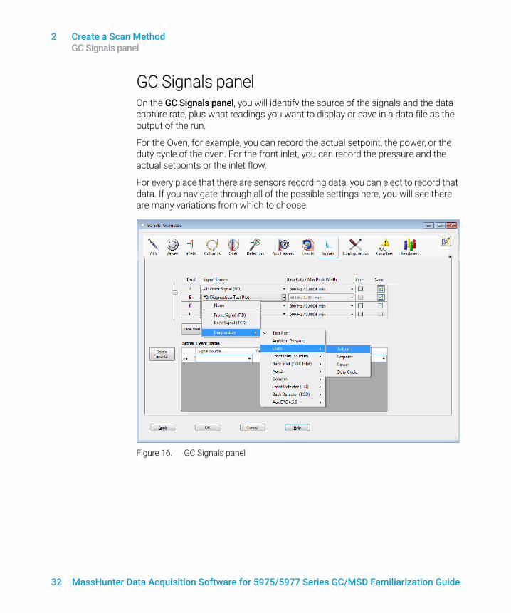
GC Signals panelOn the GC Signals panel, you will identify the source of the signals and the data capture rate, plus what readings you want to display or save in a data file as the output of the run.
For the Oven, for example, you can record the actual setpoint, the power, or the duty cycle of the oven. For the front inlet, you can record the pressure and the actual setpoints or the inlet flow.
For every place that there are sensors recording data, you can elect to record that data. If you navigate through all of the possible settings here, you will see there are many variations from which to choose.
Figure 16. GC Signals panel

2 Create a Scan Method GC Counters panel
MassHunter Data Acquisition Software for 5975/5977 Series GC/MSD Familiarization Guide 33
GC Counters panelUse the Counters panel to identify the items you want to track as they are used each time this method is processed.
For example, if you are using the Front Inlet Liner and Front Inlet Gold Seal, and you would like to keep track of how many times these have been used, you could check these items here. Then, each time this method is run, the total usage counters for these items is tracked by the GC.
Figure 17. GC Counters panel

2 Create a Scan Method GC Readiness panel
34 MassHunter Data Acquisition Software for 5975/5977 Series GC/MSD Familiarization Guide
GC Readiness panelUse the Readiness panel to select which instrument components your method requires to be ready before a run starts.
For example, if you are using the Oven and it needs to be at a specific temperature before the run starts, you should check the Oven checkbox so the instrument will wait for the oven to reach the specified temperature before posting the Ready prompt.
This feature is useful if you wish to ignore the readiness state of hardware that is not used in your method. For example, if you use only the front detector, you do not need to wait for the back detector to reach temperature before starting the run, so you would leave the back detector checkbox unchecked.
Figure 18. GC Readiness state panel

2 Create a Scan Method GC Calculators panel
MassHunter Data Acquisition Software for 5975/5977 Series GC/MSD Familiarization Guide 35
GC Calculators panelYou can use the GC Calculator panel to help you translate methods, pressure flows, solvent vent calculations, etc.
The calculations you receive here are for information purposes only. They are not saved as part of the method.
Figure 19. GC Calculators panel

2 Create a Scan Method 5) Real-Time Plots dialog
36 MassHunter Data Acquisition Software for 5975/5977 Series GC/MSD Familiarization Guide
5) Real-Time Plots dialogWhen you have finished entering all your GC parameters, click OK to close the GC Edit Parameters window.
The next window that displays as part of the Edit Entire Method routine is the Real-Time Plots dialog.
Use the Real-Time Plots dialog to identify which GC signals you want displayed as real-time plots in the Instrument Control panel during the run.
Click OK to save the settings you make here, and close the dialog box. The MS Method Editor dialog displays next.
Figure 20. GC Real-Time Plots dialog

2 Create a Scan Method 6) MS Method Editor dialog- Scan Method Setup
MassHunter Data Acquisition Software for 5975/5977 Series GC/MSD Familiarization Guide 37
6) MS Method Editor dialog- Scan Method SetupThis dialog box is used to enter instrument parameters, select parameters to record during the run, and specify the curves to appear as real-time plots for the MS part of a method.
Sections of the MS Editor dialogThe screen capture shown below, shows three general areas:
• 1 Applies to all methods; Scan, SIM, or SIM/SCAN. (See Sections to complete for all methods on page 38.)
• 2 Applies to Scan methods only. (See Settings for Scan Methods on page 42)
• 3 Applies to SIM methods only. (See Create a SIM Method - MS Method Editor Dialog on page 49).
In this example, we are creating a Scan method. So we will be completing the sections labeled 1 and 2.
Figure 21. Sections of the MS Method Editor dialog
1
23
3

2 Create a Scan Method Sections to complete for all methods
38 MassHunter Data Acquisition Software for 5975/5977 Series GC/MSD Familiarization Guide
Sections to complete for all methodsRegardless of the type of method you are creating, SIM, Scan, or SIM/Scan, you will complete the:
Tune File group box Detector Settings group box
Acquisition Type Real-Time Plot tab
Run Time Timed Events tab
Solvent Delay
Each of these entries are described in this section.
Tune File group box• Tune file name - Displays the current tune file selected for the method.
Autotune is a good choice. However, you may click Browse to select a different one.
• Tune Type - Displays the ion source and polarity configured when the tune file was obtained.
• Tune EMV- Displays the EMV setting configured when the tune file was obtained.
• CI Gas Valve - Displays the channel selected for reagent gas.
• CI Flow - A read only field obtained from the method’s tune file.
• MS Source and MS Quad - Displays the MS Source and MS Quad setpoint values used during the method’s tune and the current temperatures. Click Apply to send the MS Source and MS Quad temperature setpoints to the instrument for immediate control to these setpoint values.
Check online Help for more details on the Tune File.
Figure 22. MS Method Editor dialog - Tune File group box

2 Create a Scan Method Sections to complete for all methods
MassHunter Data Acquisition Software for 5975/5977 Series GC/MSD Familiarization Guide 39
Acquisition Type
Under the Acquisition Type dropdown menu, select Scan (RAW) to create a Scan method. Scan stores all data.
Run Time
When the acquisition instrument is configured without a GC, the value entered in the Run time is the time span during which MS data is acquired. MS data is not collected during the solvent delay. If a GC is configured, its run time is used.
Solvent Delay
The solvent delay is the time in minutes after the start of the run when the mass spectrometer is turned on.
Figure 23. MS Method Editor dialog - Acquisition Type, Run Time, and Solvent Delay

2 Create a Scan Method Sections to complete for all methods
40 MassHunter Data Acquisition Software for 5975/5977 Series GC/MSD Familiarization Guide
Detector Settings• Check the Trace Ion Detection checkbox to turn this feature ON.
Trace Ion Detection (TID) allows you to obtain lower Method Detection Limits (MDL’s) during analysis. It decreases the noise content of Total and Extracted Ion Chromatograms.
The lower noise level results in more reproducible baselines for calculating the peak height and peak area for analyses and standards.
TID also reduces the number of peaks requiring manual integration in complex chromatograms.
TID will be reported in Print Method.
• Under EM Setting, select one of the following:• Gain Factor - The default and also the recommended EM.• Delta EMV - Delta EMV is not recommended for most applications.• Absolute EMV
See online Help for more details on these settings.
• Gain Factor - If Gain Factor is selected in the EM Setting drop-down list, the Gain Factor can be specified here.
An EM gain factor adjusts the signal sensitivity of the detector. EM gain factors have the advantage of remaining constant as the multiplier ages. Therefore, the use of a gain factor produces much higher signal reproducibility for any instrument and better consistency between instruments.
• Applied EM Voltage is a read only field that displays the electron multiplier voltage reading of the detector.
• To use EM Saver, select this checkbox, and then select a Limit. This feature is only available in SIM mode.
EM Saver is used to prevent a non-linear detector response at the upper range of a compound's calibration curve. This non-linear response can be caused by setting the gain value or dwell time too high on compounds with high ion concentrations. With EM Saver, high gain values and dwell times can be used without saturating the EM.
EM Saver is used with SIM mode in a single quadrupole configuration and MRM mode in a triple quadrupole configuration. A benefit of using EM Saver is a more consistent detector response and an extended EM life.

Figure 24. MS Method Editor dialog - Detector Settings
2 Create a Scan Method Sections to complete for all methods
MassHunter Data Acquisition Software for 5975/5977 Series GC/MSD Familiarization Guide 41
Real-Time Plot tab
Use the Real-Time Plot tab, to specify the Spectrum and Chromatogram for display in the real-time plots dialogs in Instrument Control view. Also specify Extracted Ion Chromatograms to display the EIC in the Instrument Control view Chromatogram panel with the label you specify here.
Timed Events tab
Use the Timed Events tab to schedule an event that you want to occur during a specified time in the data acquisition run.
Figure 25. MS Method Editor dialog - Real-Time Plot and Timed Events tabs

2 Create a Scan Method Settings for Scan Methods
42 MassHunter Data Acquisition Software for 5975/5977 Series GC/MSD Familiarization Guide
Settings for Scan MethodsWhen you are creating a Scan method, complete the sections labeled 1 and 2 of the MS Editor dialog (show in Figure 26).
• Items included in Section 1 are described in Sections to complete for all methods on page 38.
• The following describes how to complete the entries for Section 2, which apply to Scan methods.
• Section 3 is for creating SIM methods, and is discussed in Chapter 3, Create a SIM Quantitation Method on page 47.
Figure 26. Sections of the MS Method Editor dialog
1
23
3

2 Create a Scan Method Scan Time Segments group box
MassHunter Data Acquisition Software for 5975/5977 Series GC/MSD Familiarization Guide 43
Scan Time Segments group boxIn the Scan Time Segments group box (shown in Figure 27) you will define the time segments for the Scan run.
• The Time field displays what is entered in the Solvent Delay field. This the time at which the mass spec will turn on and start gathering data.
• In the Start Mass and End Mass, enter the mass range containing your ion of interest for this time segment.
• In the Threshold field, enter the abundance value below which data is considered noise, and should be ignored.
• From the Scan Speed dropdown menu select the atomic mass units you wish to scan in a second.
Click OK when you have entered your MS method settings, and the Select Monitors dialog box is displayed.
Figure 27. Scan Time Segments group box

2 Create a Scan Method 7) Select Monitors dialog
44 MassHunter Data Acquisition Software for 5975/5977 Series GC/MSD Familiarization Guide
7) Select Monitors dialogUse the Select Monitors dialog to identify the GC and MS monitors you wish to see displayed in the Instrument Control view.
After selecting the monitors you want to see, click OK to complete the process. The Save Method dialog box is automatically displayed.

2 Create a Scan Method 8) Save The Method
MassHunter Data Acquisition Software for 5975/5977 Series GC/MSD Familiarization Guide 45
8) Save The MethodThis is the final step in the Edit The Entire Method process.
Type a name for your method, and click OK.
This completes the Edit Entire Method process. Your method is now saved.
Figure 28. Save Method As dialog

2 Create a Scan Method 8) Save The Method
46 MassHunter Data Acquisition Software for 5975/5977 Series GC/MSD Familiarization Guide

MassHunter Data Acquisition Software for 5975/5977 Series GC/MSD Familiarization Guide 47
3 Create a SIM Quantitation MethodIntroduction 48
Create a SIM Method - MS Method Editor Dialog 49
Simultaneously Acquire Scan and SIM Data (SIM/Scan Mode) 51
SIM/Scan Mode Cycle Frequency 52
This chapter describes how to create a SIM method by revising an existing Scan method.

3 Create a SIM Quantitation Method Introduction
48 MassHunter Data Acquisition Software for 5975/5977 Series GC/MSD Familiarization Guide
IntroductionSelected ion monitoring (SIM) mode is a data acquisition technique where only selected ion fragments are monitored to obtain maximum sensitivity.
To find appropriate conditions for the SIM data acquisition, analyze your scan data for:
• Ions (m/z) monitored for each peak - MS SIM parameters allow you to define up to 100 groups (SIM Time Segments) of up to 60 ions each for selected ion monitoring, however, Agilent recommends you use as few ions in a group as possible to maximize the signal to noise ratio (S/N).
• The best time to switch groups - Agilent recommends that you choose a time to switch groups (Start a new Time Segment) where the peaks are well separated to avoid variations in retention time due to sample matrix effects.

3 Create a SIM Quantitation Method Create a SIM Method - MS Method Editor Dialog
MassHunter Data Acquisition Software for 5975/5977 Series GC/MSD Familiarization Guide 49
Create a SIM Method - MS Method Editor Dialog
When you create a SIM method, complete all the common settings (labeled as 1 in Figure 21 on page 37), plus the SIM Time Segments settings (labeled as 3 in Figure 21 on page 37), and described here.
Previously, we accessed the Single Quadrupole Method Editor dialog automatically during the Edit an Entire Method procedure. This time we will access this dialog directly since we are not changing other parts of the method.
To begin the process:
1 Click the Load Method icon, or select Method/Load Method.
2 Navigate to and select the method you want to start with (e.g., the Scan method created in Chapter 2), and click OK.
3 Click the MS Instrument Parameters icon, or select Instrument/MS Edit Parameters... to open the Single Quadrupole Method Editor dialog.
4 See Sections to complete for all methods on page 38 for details on filling out the general method settings (those that are common to both SIM and Scan).
5 Under the Acquisition Type dropdown menu select SIM and then specify the SIM parameters for each time segment that you define in the table below.
6 In the SIM Time Segments group box enter the SIM parameters for the run’s first time segment when the Acquisition type is set to SIM or SIM and Scan analysis.

3 Create a SIM Quantitation Method Create a SIM Method - MS Method Editor Dialog
50 MassHunter Data Acquisition Software for 5975/5977 Series GC/MSD Familiarization Guide
Assign a Group Name for this time segment, select a Resolution of High or Low, and if needed enter a different value for the specified EM Setting (Gain Factor, Absolute EMV, Delta EM) for this time segment only. If you do not enter a value here, the EM Setting specified in the Detector Settings area located in labeled area 1 is used. Next, specify the ions to acquire in this time segment.
7 Click the SIM tab, and specify each ion to acquire for this time segment. For each ion, in the Dwell Time column enter the time in ms to acquire the ion’s abundance. Select Plot Ion to have the EIC displayed in the Instrument Control view Chromatogram panel labeled with the ion m/z.
8 To add additional SIM time segments, right-click within the SIM Time Segments area and from the context menu click Add. In the new time segments Time column enter the starting time for this segment which is also the ending time for the previous time segment.
Enter the acquisition parameters that define this time segment and enter the ions to acquire as above.
9 Exit the Single Quadrupole Method Editor dialog by clicking OK, and then save the method.

3 Create a SIM Quantitation Method Simultaneously Acquire Scan and SIM Data (SIM/Scan Mode)
MassHunter Data Acquisition Software for 5975/5977 Series GC/MSD Familiarization Guide 51
Simultaneously Acquire Scan and SIM Data (SIM/Scan Mode)
An MSD can simultaneously acquire SIM and Scan data if it equipped with fast electronics like the Agilent 5977 MSD and 5975 MSD (fast electronics model). The cycle time displayed for both Scan and SIM are not corrected for simultaneous acquisition. See SIM/Scan Mode Cycle Frequency on page 52.
1 Open the Single Quadrupole Method Editor dialog.
2 From the Acquisition Type dropdown list, select SIM and Scan and notice that the areas for entering both the SIM data and the Scan data are in edit mode.
3 Edit the Scan and SIM acquisition parameters, as needed. Refer to 6) MS Method Editor dialog- Scan Method Setup on page 37 and Create a SIM Method - MS Method Editor Dialog on page 49.
4 At a time during the run where you require the number of peak data points generated, write down both the Scan and SIM cycle times in the time segments that bracket this time.
In SIM/Scan mode the number of data points taken in each mode is reduced and we will see how that impacts the total cycle frequency in SIM/Scan Mode Cycle Frequency on page 52.
5 Save the method.

3 Create a SIM Quantitation Method SIM/Scan Mode Cycle Frequency
52 MassHunter Data Acquisition Software for 5975/5977 Series GC/MSD Familiarization Guide
SIM/Scan Mode Cycle FrequencyTo complete one cycle in SIM/Scan mode, the MSD acquires a single group of SIM data followed by a single group of Scan data. It may be necessary to increase the Scan speed or decrease the SIM dwell time to achieve the desired number of data points for effective chromatographic integration. See Figure 1.
Figure 1. SIM/Scan mode
Actual cycle frequency is calculated with the equation in Figure 2.
Figure 2. SIM/Scan cycle
When switching from the SIM data acquisition mode to the Scan mode, about 5% of the available run time will be consumed.
For our example, Scan = 2.44 cycles/sec and SIM = 1.97 which results in an actual cycle time of 1.04 cycles/sec. To improve the number of data points, we could reduce the SIM dwell time, and increase the scan speed.

MassHunter Data Acquisition Software for 5975/5977 Series GC/MSD Familiarization Guide 53
4 Running SamplesRunning a Single Sample 54
Running a Sequence 57

4 Running Samples Running a Single Sample
54 MassHunter Data Acquisition Software for 5975/5977 Series GC/MSD Familiarization Guide
Running a Single SampleThe following describes how to run a single sample in MassHunter Data Acquisition.
Load the Method1 From the PC desktop, click the MassHunter shortcut icon. The
Instrument Control window opens.
2 Click the Load Method icon (red box 1) to open the Load Method dialog, and select the method you want to use to acquire data. Click OK to load the method and close the dialog. The method name is displayed in the title bar of the Instrument Control window (red box 4).
1 3
24
Run the MethodFor an automated injection, with your method loaded and a sample vial loaded in the ALS, begin the run as follows:
1 Click the Run Method icon (red box 1 or 3). The Start Run dialog box opens.
2 Enter the method parameters in the start run dialog for this sample run.

4 Running Samples Run the Method
MassHunter Data Acquisition Software for 5975/5977 Series GC/MSD Familiarization Guide 55
Basic Tab
The top part of the dialog displays the parameters specified by the method (See Figure 1). These are read-only fields. To modify these entries you need to edit the method. Included are the:
• Current Method Inject Style
• Inlet Location
• MS Connected To
Figure 1. Start run dialog
Operator Name - Optional. Enter the name of the person performing the run. This name will be stored in the data file.
Data Path - The current data path is displayed. If you wish to have data files placed in a different data file directory, click Browse, and select the new directory.
Data File Name - Required. The file used for data storage. You can also click Browse to select a different data file name.

4 Running Samples Run the Method
56 MassHunter Data Acquisition Software for 5975/5977 Series GC/MSD Familiarization Guide
Sample Name - Optional. This is the name you give to your sample. This field is informational only, and is stored in the data file.
Misc Info - Optional. Enter any additional information about the sample or the method. This field is stored in the data file.
Expected Barcode - Optional. Enter the barcode for the current sample. This is greyed out if a barcode reader is not installed.
Sample Amount - A divisor to convert the absolute amounts of compounds to a percentage of the original sample. If you are generating a quantitative report, this item may be needed.
Multiplier - A multiplier to correct for dilution or other sample handling adjustments. If you are generating a quantitative report, this item may be needed.
Vial Number - This is the vial number containing your sample.
Tray Name - Some ALS models have multiple trays. Select a tray name from the drop-down list if configured.
Injection Volume - Click the injection volume option. You may select the volume from the current method, or specify a sample volume by clicking the Override option.
Method Sections to Run - This section allows you to specify whether you want to run a Data Acquisition method, a Data Analysis method, or both.
3 When the instrument is in a ready state as shown by a green Ready indicator in the instrument status, click OK and Run Method to close the dialog and start the run. The ready state indicator changes to Run.

4 Running Samples Running a Sequence
MassHunter Data Acquisition Software for 5975/5977 Series GC/MSD Familiarization Guide 57
Running a SequenceA sequence is a list of samples to be analyzed automatically without operator intervention. Each sample is assigned a method to be used for analysis.
To begin the process you must first create a sequence.
Create the Sequence1 Click the Edit Sequence icon . The Sequence Table opens. This is
where you will create the list of samples to be analyzed and designate the method to be used for each analysis.
2 To select the cells you wish to edit in the Sequence Table:• Left-click in a cell to select it• Click and drag to select multiple cells• Select a series of cells by left-clicking the first cell, holding Shift, and
left-clicking the final cell• Select specific multiple cells by holding the Ctrl key while left-clicking each
cell• Select a rows of cells by left-clicking in the grey column on the left
3 To add lines to the table, with a line in the table selected, click New Sample(s). From the drop down menu that is displayed, select 1 Sample to insert one new sample or 5 Samples to insert five new samples at the bottom of the table, or select N Samples to specify the number of samples to add to the table. For this example, we will just use the three default lines provided.
4 In the Name column, type the name for your sample.

4 Running Samples Create the Sequence
58 MassHunter Data Acquisition Software for 5975/5977 Series GC/MSD Familiarization Guide
5 To increment this value down through all the subsequent lines in this table, select the cell with the information you want to increment, and click the Increment icon.
6 Under the Vial column, enter the location of the sample(s) in the ALS tray. You can use the Increment icon here too.
7 Under the Method File column, select the ellipses and browse to the method you want to use to acquire the data from this sample.
8 To copy this method name down to all the subsequent cells, select the cell and click the Copy Down icon.
9 In the Data File column, enter the name you want to be used for the data collected from this sample. Use the Increment icon here, if desired.
10 From the Type drop down box, select the applicable sample type for each line in your table. This entry identifies how the sample is processed by the MassHunter Data Analysis programs. For this example, we are using the type called Sample.
11 When you have finished entering all the samples you want to run in this sequence, click OK to close the Sequence table. You are returned to the main MassHunter Data Acquisition window.

4 Running Samples Save the Sequence
MassHunter Data Acquisition Software for 5975/5977 Series GC/MSD Familiarization Guide 59
Save the Sequence1 Click the Save Sequence As… icon . The Save Sequence dialog box
opens.
2 In the File name field, type a name for your sequence.
3 Click Save. The dialog box closes and the sequence is saved.

4 Running Samples Load the Sequence
60 MassHunter Data Acquisition Software for 5975/5977 Series GC/MSD Familiarization Guide
Load the Sequence1 Click the Load Sequence icon.
2 Navigate to and select the sequence you want to load, or type the name in the File Name field.
3 Click Open to close the dialog box and load the sequence.

4 Running Samples Run the Sequence
MassHunter Data Acquisition Software for 5975/5977 Series GC/MSD Familiarization Guide 61
Run the Sequence1 Click the Run Sequence icon . The Start Sequence dialog box opens.
This dialog is used to set some general parameters to control the sequence process.
2 In the Sequence Comment field, enter a description of the sequence.
3 In the Operator Name field, enter your name.
4 In the Data File Directory field, accept the default location for this data file, or click Browse to select a new path.
5 The Pre-Sequence and Post Sequence Macros/Commands options let you specify data acquisition or data analysis marcos or commands to run before or after the sequence.
6 When you have completed your selections, click Run Sequence.
4 Running Samples Print the Sequence Log
62 MassHunter Data Acquisition Software for 5975/5977 Series GC/MSD Familiarization Guide
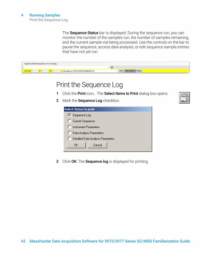
The Sequence Status bar is displayed. During the sequence run, you can monitor the number of the samples run, the number of samples remaining, and the current sample vial being processed. Use the controls on the bar to pause the sequence, access data analysis, or edit sequence sample entries that have not yet run.
Print the Sequence Log1 Click the Print icon, . The Select Items to Print dialog box opens.
2 Mark the Sequence Log checkbox.
3 Click OK. The Sequence log is displayed for printing.

Figure 2. Printed sequence log
4 Running Samples Print the Sequence Log
MassHunter Data Acquisition Software for 5975/5977 Series GC/MSD Familiarization Guide 63

4 Running Samples Print the Sequence Log
64 MassHunter Data Acquisition Software for 5975/5977 Series GC/MSD Familiarization Guide

MassHunter Data Acquisition Software for 5975/5977 Series GC/MSD Familiarization Guide 65
5 General InformationEditing Individual GC Parameters 66
Add a Column to Your Local Column Inventory 68
Upload Parameters from the 7890X GC 70
Customize the Status Panel View 70
5 General Information Editing Individual GC Parameters
66 MassHunter Data Acquisition Software for 5975/5977 Series GC/MSD Familiarization Guide
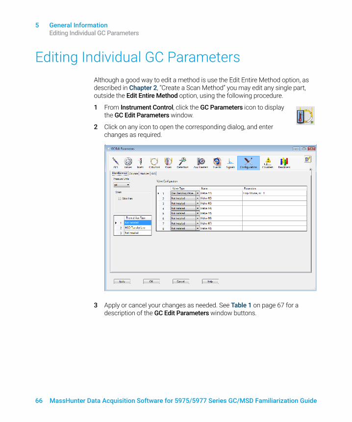
Editing Individual GC ParametersAlthough a good way to edit a method is use the Edit Entire Method option, as described in Chapter 2, “Create a Scan Method” you may edit any single part, outside the Edit Entire Method option, using the following procedure.
1 From Instrument Control, click the GC Parameters icon to display the GC Edit Parameters window.
2 Click on any icon to open the corresponding dialog, and enter changes as required.
3 Apply or cancel your changes as needed. See Table 1 on page 67 for a description of the GC Edit Parameters window buttons.

Table 1 GC Edit Parameters window buttons
Button Action
Apply Downloads any settings that have been changed to the GC.
OK Downloads any settings that have been changed to the GC and closes the GC Edit Parameters window.
Cancel Discards any settings that have been changed and closes the GC Edit Parameters window.
Help Displays help topics for the current parameter.
5 General Information Editing Individual GC Parameters
MassHunter Data Acquisition Software for 5975/5977 Series GC/MSD Familiarization Guide 67

5 General Information Add a Column to Your Local Column Inventory
68 MassHunter Data Acquisition Software for 5975/5977 Series GC/MSD Familiarization Guide
Add a Column to Your Local Column Inventory
Use the Catalog option to select a column from the Column Catalog and add it to your Local Column Inventory.
1 Click the Configuration icon, then the Columns tab to display the columns configured for the instrument.
2 Click Catalog to display a local database that is shared across all instrument sessions on your data system. The database contains popular column models, plus any custom columns entered.
3 Use the GC Column Catalog to select a column model to add to your Column Inventory, or to select a column model already entered in your inventory.

5 General Information Add a Column to Your Local Column Inventory
MassHunter Data Acquisition Software for 5975/5977 Series GC/MSD Familiarization Guide 69
4 Click Actions Menu in the upper left corner of the screen, to display the actions available in this catalog.

5 General Information Upload Parameters from the 7890X GC
70 MassHunter Data Acquisition Software for 5975/5977 Series GC/MSD Familiarization Guide
5 Once you define a column, the column information displays in your method editor, the GC actuals, and in the report following a run.
Refer to online Help for details on how to complete the actions shown here.
Upload Parameters from the 7890X GC1 On the Instrument > GC Edit Parameters screen, right-click in the blank area.
2 From the shortcut menu, select Upload Method from GC.
Customize the Status Panel View1 In the status panel, click the Setup Actuals icon, the Status Items
dialog box opens.
2 Mark the checkboxes of the items in the Status Item list that you want to have displayed in the status panel.
3 To move an item up or down in the displayed list, select the item and then the up or down arrow buttons until it is in the desired position.
4 Click Save to save the settings and return to the GC Edit Parameters window.

MassHunter Data Acquisition Software for 5975/5977 Series GC/MSD Familiarization Guide 71

www.agilent.comAgilent Technologies, Inc. 2019
First edition, January 2019
*G7077-90021*G7077-90021